SlimPanel_InstallationInsturctions_24APRIL2018 4inch Slim Panel Installation Instructions
4Inch Slimpanel Installation-Instructions 4inch_SlimPanel_Installation-Instructions 4inch_SlimPanel_Installation-Instructions 30495 s redactor_assets system shopperplus 3:
2019-03-27
: 4Inch Slimpanel Installation-Instructions 4inch_SlimPanel_Installation-Instructions 30495 s redactor_assets system
Open the PDF directly: View PDF ![]() .
.
Page Count: 2
L3503-XXXX
L3504-XXXX
L3506-XXXX
L3508-XXXX
L3512-XXXX
White/Black/Brushed Nickel
White/Black/Brushed Nickel
White/Black/Brushed Nickel
White/Black/Brushed Nickel
White/Black/Brushed Nickel
76
100
150
205
280
3" Round Slim Panel
4" Round Slim Panel
6" Round Slim Panel
8" Round Slim Panel
12" Round Slim Panel
ORDER
CODE
HOLE
SIZE (MM)
DESCRIPTION TRIM COLOR
Installation Instructions
LED Slim Panel (Recessed Light Fixture)
1. Cut a hole in the ceiling in accordance to the hole
dimensions mentioned above (approximate size).
2. Open the hardware box swing cover and remove box
knock-outs with a screwdriver.
3. AC-120v 50/60Hz – Run your cable Romex (NMD90) or
AC90 (BX) into the box and secure cable with proper
Romex / BX connectors (not provided).
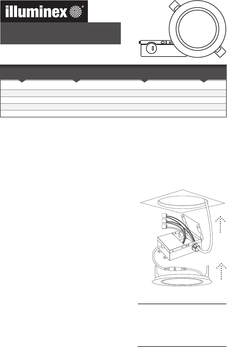
4. Using wire nut / push fit connector connect the following
cables. Connect the Ground cable (G) green, with the
ground cable. Connect the White cable (W) to the white
wire in the box. Connect the Black cable (L) to the black
wire in the box (see figure).
5. Ensure all cables are in the box, and screw lid closed.
6. Locate and fix the box in a suitable position, which would be
a stud, joist, mounting plate or similar fixed structural
material.
7. Connect the slim panel to the hardware by inserting the
male and female connectors together.
8. Hold spring clips against fixture and gently guide into
mounting hole until spring clips snap into place. Fixture
should be flush with ceiling.
9. Once assembly is complete turn on power to confirm fixture
is working correctly.
Applicable Models
Important Safety Instructions
Read all instructions at least one time before installation and retain for future reference.
Safety
Installation Instructions
Warning
For your safety this fixture must be wired in accordance to the local electrical codes and ordinances and
should be installed by a qualified electrician (NEC/CEC regulations).
Risk of electric shock! Before installation or completing any maintenance, make sure power is off.
Turn off the power supply at the breaker or fuse panel.
ü
i
L (Black)
N (White)
G (Green)
Cable to
Fixture Power Supply
It is reccommended and always good
practice to keep each slim panel
matched with the junction box that
comes with it when installing multiple
panels.
Suitable for Damp location. Access
above ceiling required.
1-800-361-7820 | www.illuminexled.com
Figure

Veuillez lire toutes les consignes de sécurité au moins une fois avant de procéder à l'installation et
conservez-les pour référence future.
L3503-XXXX
L3504-XXXX
L3506-XXXX
L3508-XXXX
L3512-XXXX
Blanc/Noir/Nickel Brossé
Blanc/Noir/Nickel Brossé
Blanc/Noir/Nickel Brossé
Blanc/Noir/Nickel Brossé
Blanc/Noir/Nickel Brossé
76
100
150
205
280
3" Ronde Panneau Mince
4" Ronde Panneau Mince
6" Ronde Panneau Mince
8" Ronde Panneau Mince
12" Ronde Panneau Mince
CODE DE
COMMANDE
DIMENSION
DU TROU (MM)
LA DESCRIPTION COULEUR DE
GARNITURE
Instructions d'installation
Panneau Mince DEL (Luminaire Ecastré)
Modèles applicables
Sécurité
Avertissement
1. Taillez une ouverture dans le plafond conformément aux
dimensions d'ouverture mentionnées ci-dessous (mesures
approximatives).
2. Ouvrez le couvercle amovible du boîtier et enlevez les pièces
défonçables à l'aide d'un tournevis.
3. Ac-120v 50/60Hz – Installez votre câble Romex (NMD90) ou
AC90 (BX) dans le boîtier et fixez-le avec des raccords
Romex / BX appropriés (non inclus).
4. À l'aide de capuchons de connexion / raccord rapide,
raccordez les câbles suivants. Raccordez le Conducteur de
terre vert (G) au conducteur de terre. Raccordez le câble
Blanc (W) au fil blanc dans le boîtier. Raccordez le câble Noir
(L) au fil noir dans le boîtier (voir le dessin).
5. Vérifiez si tous les câbles sont bien insérés dans le boîtier.
Vissez le couvercle pour le fermer.
6. Fixez le boîtier sur une surface appropriée comme un
montant, une solive, plaque de montage ou autre matériau de
structure fixe similaire.
7. Raccordez le panneau au matériel en insérant les raccords
mâle et femelle.
8. Tenez les attaches à ressort contre l'appareil et insérez
délicatement dans l'orifice de fixation jusqu'à ce que les
attaches à ressort s'emboîtent. L'appareil devrait être en
affleurement avec le plafond.
9. Lorsque l'assemblage est terminé, remettez le courant pour
confirmer que l'appareil fonctionne bien.
Consignes de sécurité importantes
Instructions d'installation
Pour votre sécurité, cet appareil doit être câblé conformément aux règlements et codes de l'électricité en
vigueur dans votre région et doit être installé par un électricien qualifié (règlements du CNE/CEC).
Risque de choc électrique! Avant de procéder à l'installation ou à la maintenance, vérifiez si
L'alimentation a été coupée. Coupez le courant dans le panneau de disjoncteurs ou de fusibles.
L (NoirR)
N (Blanc)
G (Mise à la terre)
Câble sur
le montage
Block d’ alimentation
ü
i
Il est conseillé et il vaut toujours mieux
d'assortir chaque panneau à la boîte de
jonction qui est fournie avec le panneau
lors de l'installation de plusieurs
panneaux.
Convient pour un emplacement humide.
Accès requis à l'espace au-dessus du plafond.
1-800-361-7820 | www.illuminexled.com
Dessin
