5120 SI EI Installation Guide(18Nov13)
User Manual: 5120 SI
Open the PDF directly: View PDF ![]() .
.
Page Count: 87
- Title Page
- Contents
- Preparing for installation
- Installing the switch
- Installing a 5120 EI switch in a 19-inch rack
- Installing a 5120 SI switch in a 19-inch rack
- Mounting the switch on a workbench
- Mounting the switch to a wall
- Mounting the switch through magnet mounting
- Grounding the switch
- Connecting the power cord
- Installing/removing an interface card (only for the 5120 EI switches)
- Verifying the installation
- Accessing the switch for the first time
- Setting up an IRF fabric
- IRF fabric setup flowchart
- Planning IRF fabric setup
- Configuring basic IRF settings
- Connecting the physical IRF ports
- Accessing the IRF fabric to verify the configuration
- Maintenance and troubleshooting
- Support and other resources
- Appendix A Chassis views and technical specifications
- Chassis views
- 5120-24G EI (2 slots)/5120-24G EI TAA (2 slots)
- 5120-48G EI (2 slots)/5120-48G EI TAA (2 slots)
- 5120-24G EI
- 5120-48G EI
- 5120-24G-PoE+ EI (2 slots)/5120-24G-PoE+ EI TAA (2 slots)
- 5120-48G-PoE+ EI (2 slots)/5120-48G-PoE+ EI TAA (2 slots)
- 5120-8G SI
- 5120-16G SI
- 5120-24G SI
- 5120-48G SI
- 5120-8G-PPoE+ SI
- 5120-8G-PoE+ SI
- 5120-24G-PPoE+ SI
- 5120-24G-PoE+ SI
- Technical specifications
- Environmental specifications
- Power specifications
- Cooling system
- Chassis views
- Appendix B FRUs and compatibility matrixes
- Appendix C Ports and LEDs
- Index

HP 5120 EI & 5120 SI Switch Series
Installation Guide
Part number: 5998-1773
Document version: 6W104-20131118
Legal and notice information
© Copyright 2013 Hewlett-Packard Development Company, L.P.
No part of this documentation may be reproduced or transmitted in any form or by any means without
prior written consent of Hewlett-Packard Development Company, L.P.
The information contained herein is subject to change without notice.
HEWLETT-PACKARD COMPANY MAKES NO WARRANTY OF ANY KIND WITH REGARD TO THIS
MATERIAL, INCLUDING, BUT NOT LIMITED TO, THE IMPLIED WARRANTIES OF MERCHANTABILITY
AND FITNESS FOR A PARTICULAR PURPOSE. Hewlett-Packard shall not be liable for errors contained
herein or for incidental or consequential damages in connection with the furnishing, performance, or
use of this material.
The only warranties for HP products and services are set forth in the express warranty statements
accompanying such products and services. Nothing herein should be construed as constituting an
additional warranty. HP shall not be liable for technical or editorial errors or omissions contained
herein.

i
Contents
Preparing for installation ············································································································································· 1
Safety recommendations ·················································································································································· 1
Examining the installation site ········································································································································· 1
Temperature/humidity ············································································································································· 1
Cleanness ·································································································································································· 2
EMI ············································································································································································· 2
Laser safety ································································································································································ 2
Installation tools ································································································································································· 3
Installing the switch ······················································································································································ 4
Installing a 5120 EI switch in a 19-inch rack ················································································································ 5
Mounting brackets ···················································································································································· 5
Rack-mounting by using only front mounting brackets ························································································· 6
Rack-mounting by using front mounting brackets and a rack shelf ····································································· 8
Rack-mounting by using front and rear mounting brackets ·················································································· 9
Installing a 5120 SI switch in a 19-inch rack ············································································································· 12
Mounting brackets and mounting positions ········································································································ 13
Attaching the mounting brackets to the switch chassis ······················································································ 13
Rack-mounting the switch ······································································································································ 16
Mounting the switch on a workbench ·························································································································· 18
Mounting the switch to a wall ······································································································································· 18
Wall anchor kit ······················································································································································ 18
Installation procedure ··········································································································································· 19
Mounting the switch through magnet mounting ·········································································································· 20
Magnetic mounting kit ·········································································································································· 20
Installation procedure ··········································································································································· 20
Grounding the switch ···················································································································································· 22
Grounding the switch with a grounding strip ····································································································· 22
Grounding the switch with a grounding conductor buried in the earth ground ············································· 24
Grounding the switch by using the AC power cord ·························································································· 25
Connecting the power cord ·········································································································································· 25
Connecting the AC power cord ··························································································································· 26
Connecting the switch to a +12 VDC output RPS ······························································································ 27
Connecting the switch to a –52 to –55 VDC output RPS ·················································································· 28
Installing/removing an interface card (only for the 5120 EI switches) ···································································· 29
Installing an interface card ··································································································································· 29
Removing an interface card ································································································································· 30
Installing/removing a dedicated CX4/SFP+ cable ··························································································· 30
Verifying the installation ················································································································································ 31
ii
Accessing the switch for the first time ······················································································································· 32
Setting up the configuration environment ···················································································································· 32
Connecting the console cable ······································································································································ 32
Console cable ························································································································································ 32
Connecting the console cable ······························································································································ 32
Setting terminal parameters ·········································································································································· 33
Powering on the switch·················································································································································· 36
Setting up an IRF fabric ············································································································································· 37
IRF fabric setup flowchart ·············································································································································· 37
Planning IRF fabric setup ··············································································································································· 38
Planning IRF fabric size and the installation site ································································································ 38
Identifying the master switch and planning IRF member IDs ············································································ 38
Planning IRF topology and connections ·············································································································· 39
Identifying physical IRF ports on the member switches ····················································································· 40
Planning the cabling scheme ······························································································································· 41
Configuring basic IRF settings ······································································································································· 43
Connecting the physical IRF ports ································································································································ 44
Accessing the IRF fabric to verify the configuration ··································································································· 44
Maintenance and troubleshooting ···························································································································· 45
Power supply failure ······················································································································································ 45
Fan failure (only for the 5120 EI switches) ················································································································· 46
Configuration terminal problems ·································································································································· 46
Support and other resources ····································································································································· 48
Contacting HP ································································································································································ 48
Subscription service ·············································································································································· 48
Related information ························································································································································ 48
Documents ······························································································································································ 48
Websites ································································································································································· 48
Conventions ···································································································································································· 49
Appendix A Chassis views and technical specifications ························································································ 51
Chassis views ································································································································································· 52
5120-24G EI (2 slots)/5120-24G EI TAA (2 slots) ··························································································· 52
5120-48G EI (2 slots)/5120-48G EI TAA (2 slots) ··························································································· 53
5120-24G EI ························································································································································· 53
5120-48G EI ························································································································································· 54
5120-24G-PoE+ EI (2 slots)/5120-24G-PoE+ EI TAA (2 slots) ········································································ 55
5120-48G-PoE+ EI (2 slots)/5120-48G-PoE+ EI TAA (2 slots) ········································································ 56
5120-8G SI ···························································································································································· 57
5120-16G SI ························································································································································· 57
5120-24G SI ························································································································································· 58
5120-48G SI ························································································································································· 58
5120-8G-PPoE+ SI ················································································································································ 59
iii
5120-8G-PoE+ SI ·················································································································································· 59
5120-24G-PPoE+ SI ·············································································································································· 60
5120-24G-PoE+ SI ················································································································································ 61
Technical specifications ················································································································································· 62
Chassis dimensions and weights ························································································································· 62
Ports and interface card slots ······························································································································· 62
Environmental specifications ········································································································································· 63
Power specifications ······················································································································································ 63
Power input types ·················································································································································· 63
AC input voltage specifications ··························································································································· 63
RPS DC input voltage specifications and RPS compatibility ············································································· 64
Power consumption specifications for non-PoE switches ··················································································· 64
Power consumption specifications for PoE switches ·························································································· 64
Cooling system ······························································································································································· 65
Appendix B FRUs and compatibility matrixes ·········································································································· 66
Interface cards (only for the 5120 EI switches) ·········································································································· 66
SFP/SFP+/XFP transceiver modules and SFP+/CX4 cables (only for the 5120 EI switches) ································ 66
GE SFP transceiver modules ································································································································· 67
10-GE SFP+ transceiver modules ························································································································· 68
SFP+ cables ···························································································································································· 68
10-GE XFP transceiver modules ··························································································································· 69
CX4 cables ····························································································································································· 69
SFP transceiver modules and SFP Stacking Kit (only for the 5120 SI switches) ······················································ 70
Appendix C Ports and LEDs ······································································································································ 72
Ports ················································································································································································· 72
Console port ·························································································································································· 72
10/100/1000Base-T Ethernet port ···················································································································· 72
SFP port ·································································································································································· 72
Combo interface (only available on the 5120 EI switches) ·············································································· 73
LEDs (for the 5120 EI switches) ···································································································································· 73
System status LED··················································································································································· 73
RPS status LED ························································································································································ 74
Port mode LED ························································································································································ 74
Seven-segment LED ················································································································································ 74
10/100/1000Base-T Ethernet port LED ············································································································· 76
SFP port LED ··························································································································································· 76
Interface card status LED ······································································································································· 77
LEDs (for the 5120 SI switches) ···································································································································· 77
Power LED ······························································································································································ 77
RPS status LED ························································································································································ 78
Port mode LED ························································································································································ 78
10/100/1000Base-T Ethernet port LED ············································································································· 78
1000Base-X SFP port LED ····································································································································· 80

1
Preparing for installation
Safety recommendations
To avoid any equipment damage or bodily injury caused by improper use, read the following safety
recommendations before installation. Note that the recommendations do not cover every possible
hazardous condition.
• Before cleaning the switch, unplug all power cords. Do not clean the switch with wet cloth or liquid.
• Do not place the switch near water or in a damp environment. Prevent water or moisture from
entering the switch chassis.
• Do not place the switch on an unstable case or desk. The switch might be severely damaged in case
of a fall.
• Ensure proper ventilation of the equipment room and keep the air inlet and outlet vents of the switch
free of obstruction.
• Make sure the operating voltage is in the required range.
• To avoid electrical shocks, do not open the chassis while the switch is operating or when the switch
is just powered off.
• When replacing FRUs, wear an ESD-preventive wrist strap to avoid damaging the units.
Examining the installation site
The 5120 EI and 5120 SI switches must be used indoors. You can mount your switch in a rack or on a
workbench, but make sure:
• Adequate clearance is reserved at the air inlet and exhaust vents for ventilation.
• The rack or workbench has a good ventilation system.
• The rack is sturdy enough to support the switch and its accessories.
• The rack or workbench is well earthed.
To ensure normal operation and long service life of your switch, install it in an environment that meets the
requirements described in the following subsections.
Temperature/humidity
Maintain appropriate temperature and humidity in the equipment room.
• Lasting high relative humidity can cause poor insulation, electricity creepage, mechanical property
change of materials, and metal corrosion.
• Lasting low relative humidity can cause washer contraction and ESD and bring problems including
loose captive screws and circuit failure.
• High temperature can accelerate the aging of insulation materials and significantly lower the
reliability and lifespan of the switch.
For the temperature and humidity requirements, see "Appendix A Chassis views and technical
specifications."

2
Cleanness
Dust buildup on the chassis might result in electrostatic adsorption, which causes poor contact of metal
components and contact points, especially when indoor relative humidity is low. In the worst case,
electrostatic adsorption can cause communication failure.
Table 1 Dust concentration limit in the equipment room
Substance Concentration limit (
p
articles/m³)
Dust ≤ 3 x 10⁴ (no visible dust on the tabletop over three days)
NOTE:
Dust diameter ≥ 5 μm
The equipment room must also meet strict limits on salts, acids, and sulfides to eliminate corrosion and
premature aging of components, as shown in Table 2.
Table 2 Harmful gas limits in the equipment room
Gas Maximum concentration (m
g
/m3)
SO2 0.2
H2S 0.006
NH3 0.05
Cl2 0.01
EMI
All electromagnetic interference (EMI) sources, from outside or inside of the switch and application
system, adversely affect the switch in a conduction pattern of capacitance coupling, inductance coupling,
electromagnetic wave radiation, or common impedance (including the grounding system) coupling. To
prevent EMI, take the following actions:
• If AC power is used, use a single-phase three-wire power receptacle with protection earth (PE) to
filter interference from the power grid.
• Keep the switch far away from radio transmitting stations, radar stations, and high-frequency
devices.
• Use electromagnetic shielding, for example, shielded interface cables, when necessary.
• Route interface cables only indoors to prevent signal ports from getting damaged by overvoltage or
overcurrent caused by lightning strikes.
Laser safety
The HP 5120 EI and 5120 SI switches are Class 1 laser devices.
W
ARNING!
Do not stare into any fiber port when the switch has power. The laser li
g
ht emitted from the optical fiber
might hurt your eyes.
3
Installation tools
• Flathead screwdriver
• Phillips screwdriver
• Needle-nose pliers
• Wire-stripping pliers
• Diagonal pliers
• ESD-preventive wrist strap
• Blow dryer
All these installation tools are user supplied.
4
Installing the switch
CAUTION:
Keep the tamper-proof seal on a mountin
g
screw on the chassis cover intact, and if you want to open the
chassis, contact your local HP a
g
ent for permission. Otherwise, HP shall not be liable for any consequence
caused thereby.
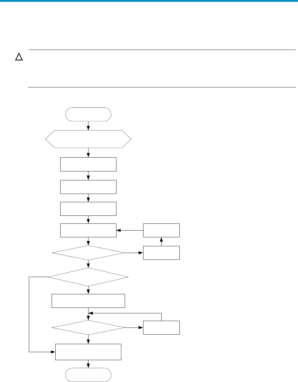
Figure 1 Hardware installation flow
Start
Install the switch to a 19-in
rack or workbench
Ground the switch
Connect the power
cord
Verify the installation
Power on the switch
Operating properly? Power off the
switch
Troubleshoot
the switch
Install interface cards?
Yes
Yes
No
No
Install interface cards
Operating properly?
Yes
No Troubleshoot
the switch
End
Connect transceiver
modules, connectors, and
cables
5
Installing a 5120 EI switch in a 19-inch rack
You can install a 5120 EI switch in a 19-inch standard rack by using different mounting positions. Table
3 shows the installation methods available for the switches of different depths.
Table 3 Installation methods
Chassis Depth
Use front
mounting
brackets
onl
y
Use front mounting
brackets and a rack
shelf
Use front and
rear mounting
brackets
5120-24G EI (2 slots)
5120-24G EI TAA (2 slots)
5120-48G EI (2 slots)
5120-48G EI TAA (2 slots)
5120-24G EI
5120-48G EI
300 mm
(11.81 in)
Yes (see
"Rack-mounti
ng by using
only front
mounting
brackets"
Yes (see
"Rack-mounting by
using front mounting
brackets and a rack
shelf")
No
5120-24G-PoE+ EI (2 slots)
5120-24G-PoE+ EI TAA (2 slots)
5120-48G-PoE+ EI (2 slots)
5120-48G-PoE+ EI TAA (2 slots)
420 mm
(16.54 in)
No
Yes (see
"Rack-mounting by
using front mounting
brackets and a rack
shelf")
Yes (see
"Rack-mounting
by using front
and rear
mounting
brackets")
NOTE:
For a switch with a 420 mm (16.54 in) of depth, the front mounting brackets are not weight-bearing.
Mounting brackets
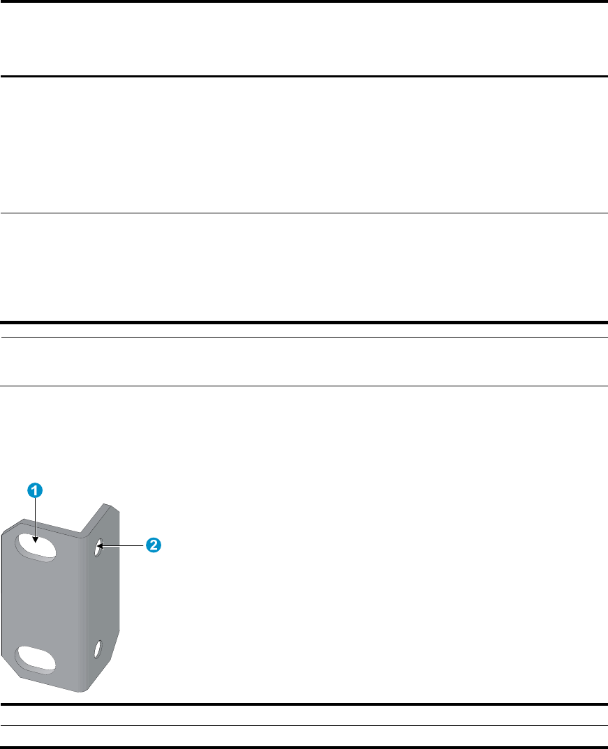
Figure 2 Front mounting bracket
(1) Hole for attaching to a rack (by using an M6 screw)
(2) Hole for attachin
g
to the switch chassis
6
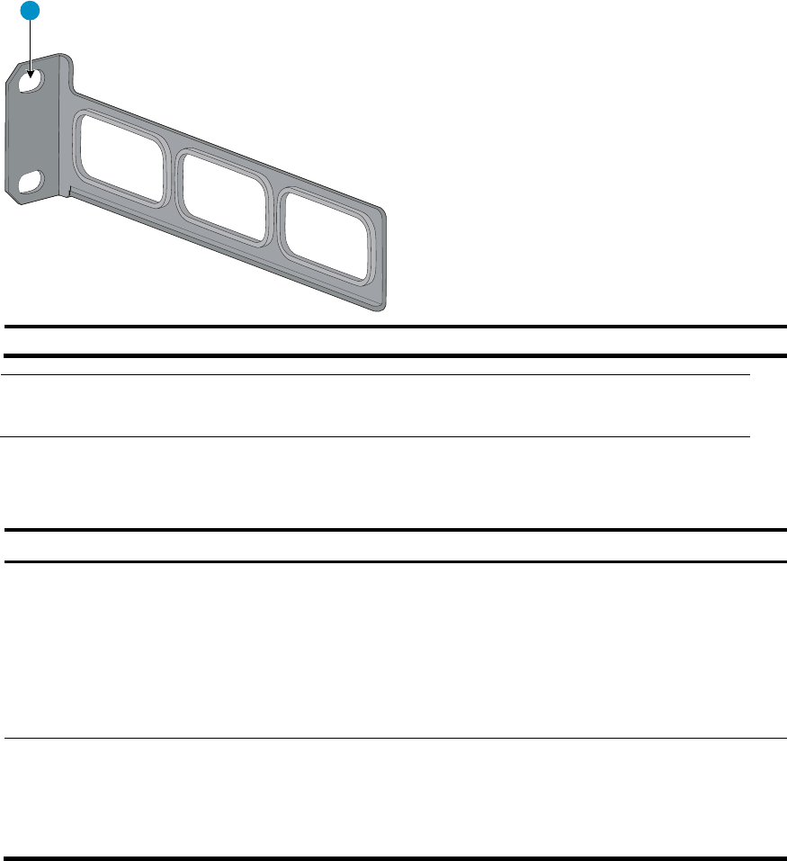
Figure 3 Rear mounting bracket
1
(1) Hole for attachin
g
to a rack (by usin
g
an M6 screw)
NOTE:
The M6 screws for attaching the brackets to a rack are user supplied.
Table 4 shows the mounting bracket shipment for different switch models.
Table 4 Mounting bracket kit shipped with the 5120 EI switches
Chassis Front mountin
g
brackets
Rear mountin
g
brackets
5120-24G EI (2 slots)
5120-24G EI TAA (2 slots)
5120-48G EI (2 slots)
5120-48G EI TAA (2 slots)
5120-24G EI
5120-48G EI
One pair N/A
5120-24G-PoE+ EI (2 slots)
5120-24G-PoE+ EI TAA (2 slots)
5120-48G-PoE+ EI (2 slots)
5120-48G-PoE+ EI TAA (2 slots)
One pair One pair
Rack-mounting by using only front mounting brackets
This installation method is available only for the 5120-24G EI (2 slots), 5120-24G EI TAA (2 slots),
5120-48G EI (2 slots), 5120-48G EI TAA (2 slots), 5120-24G EI, and 5120-48G EI switches.
This task requires two persons.
To mount a switch in a 19-inch standard rack by using only the front mounting brackets:
1. Wear an ESD-preventive wrist strap and make sure it makes good skin contact and is well
grounded.
2. Verify that the rack is well grounded and can support the weight of the switch chassis and all its
accessories.
7
3. Unpack the front mounting brackets and the screws for attaching the brackets to the switch chassis.
4. Align the round holes in one bracket with the holes in the front mounting position of the switch
chassis, and use the screws to attach the mounting bracket to the chassis, as shown in Figure 4.
5. Repeat the previous step to attach the other mounting bracket to the chassis.
Figure 4 Attaching the front mounting brackets to the chassis
(1) Front panel of the switch (2) Front mountin
g
bracket
(3) Screw
6. Install cage nuts (user-supplied) in the mounting holes in the rack posts.
7. One person holds the switch chassis and aligns the oval holes in the brackets with the mounting
holes in the rack posts, and the other person attaches the mounting brackets with M6 screws
(user-supplied) to the rack, as shown in Figure 5.
8
Figure 5 Attaching the front mounting brackets to the rack
(1) Front square-holed post (2) Front panel
(3) Screw for attaching the bracket to the square-holed post (4) Front mounting bracket
Rack-mounting by using front mounting brackets and a rack
shelf
This installation method is available for all 5120 EI switches.
To mount a switch in a 19-inch rack by using the front mounting brackets and a rack shelf:
1. Wear an ESD-preventive wrist strap and make sure it makes good skin contact and is well
grounded.
2. Verify that the rack is well grounded and can support the weight of the switch chassis and all its
accessories.
3. Attach the rack shelf horizontally in a proper position in the rack.
4. Unpack the front mounting brackets and the screws for attaching the brackets to the switch chassis.
5. Align the round holes in one bracket with the holes in the front mounting position of the switch
chassis, and use the removed screws to attach the mounting bracket to the chassis, as shown
in Figure 4.
6. Repeat the previous step to attach the other mounting bracket to the chassis.
7. Install cage nuts (user-supplied) in the mounting holes in the rack posts.
8. Place the switch on the rack shelf, push it into the rack until the brackets touch the rack posts, and
attach the mounting brackets with M6 screws (user-supplied) to the rack, as shown in Figure 5.
9
Rack-mounting by using front and rear mounting brackets
This installation method is available only for the 5120-24G-PoE+ EI (2 slots), 5120-24G-PoE+ EI TAA (2
slots), 5120-48G-PoE+ EI (2 slots), and 5120-48G-PoE+ EI TAA (2 slots) switches.
This task requires two persons.
To install the switch in a 19-inch rack by using the front and rear mounting brackets:
1. Wear an ESD-preventive wrist strap and make sure it makes good skin contact and is well
grounded.
2. Unpack the front mounting brackets and the screws for attaching the brackets to the switch chassis.
3. Align the round holes in one front mounting bracket with the holes in the front mounting position of
the switch chassis, and use the removed screws to attach the mounting bracket to the chassis, as
shown in Figure 4.
4. Repeat the previous step to attach the other front mounting bracket to the chassis.
5. Unpack the rear mounting brackets and the load-bearing screws.
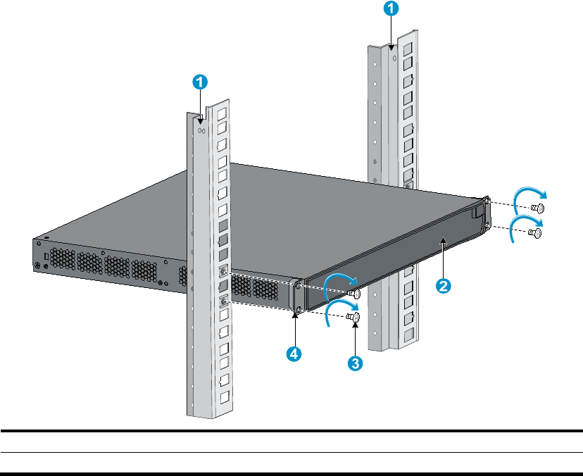
6. Attach the load-bearing screws in one of the rear mounting positions (see callout 2 in Figure 6) as
needed.
Figure 6 Attaching the front mounting brackets and load-bearing screws to the chassis
(1) Load-bearing screw (2) Rear mounting positions
(3) Front panel (4) Front mountin
g
bracket
(5) Screw for attachin
g
the front mountin
g
bracket to the switch
NOTE:
The rear mounting brackets must closely contact with the load-bearin
g
screws to support the chassis
w
ei
g
ht.
7. Install cage nuts (user-supplied) in the mounting holes in the front and rear rack posts.
8. Attach the rear mounting brackets to the rear posts with M6 screws (user supplied), as shown
in Figure 7.
10
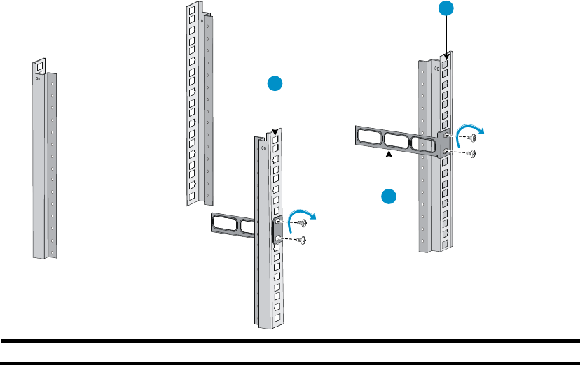
Figure 7 Attaching the rear mounting brackets to a rack
1
2
1
(1) Rear square-holed post (2) Rear mounting bracket
9. One person supports the chassis bottom with one hand, holds the front part of the chassis with the
other hand, and pushes the chassis into the rack gently.
Make sure the load-bearing screws closely contact with the upper edges of the rear mounting
brackets, as shown in Figure 8.
11
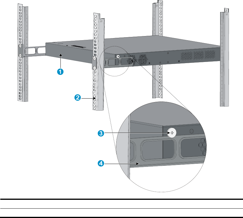
Figure 8 Mounting the switch in the rack
(1) Rear panel (2) Rear square-holed post
(3) Load-bearin
g
screw (4) Rear mountin
g
bracket
10. The other person aligns the oval holes in the front brackets with the mounting holes in the front rack
posts, and attaches the front mounting brackets with M6 screws (user supplied) to the front rack
posts, as shown in Figure 9.
Make sure the front and rear mounting brackets have secured the switch in the rack.
12
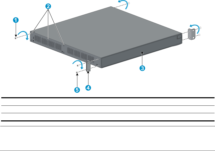
Figure 9 Attaching the front brackets to the rack
1 2
3
4
5
6
(1) Load-bearin
g
screw (2) Rear mountin
g
bracket
(3) Front panel (4) A screw used to attach the front mountin
g
bracket to the rack
(5) Front mounting bracket (6) Front square-holed post
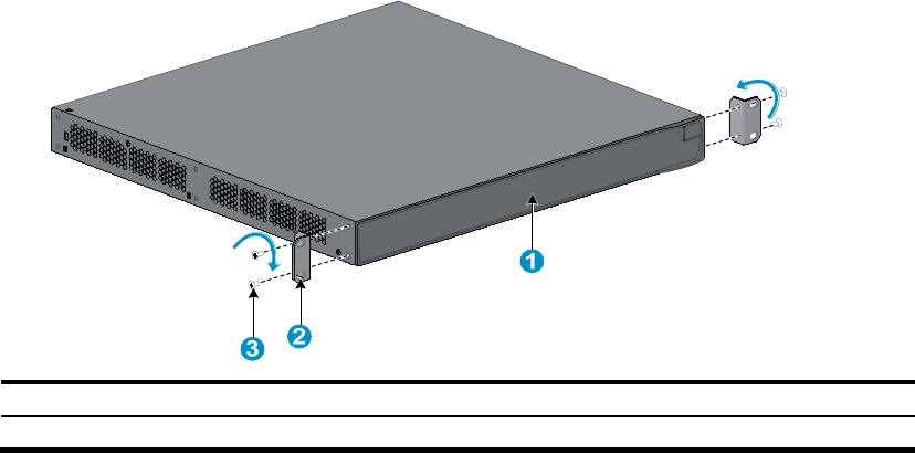
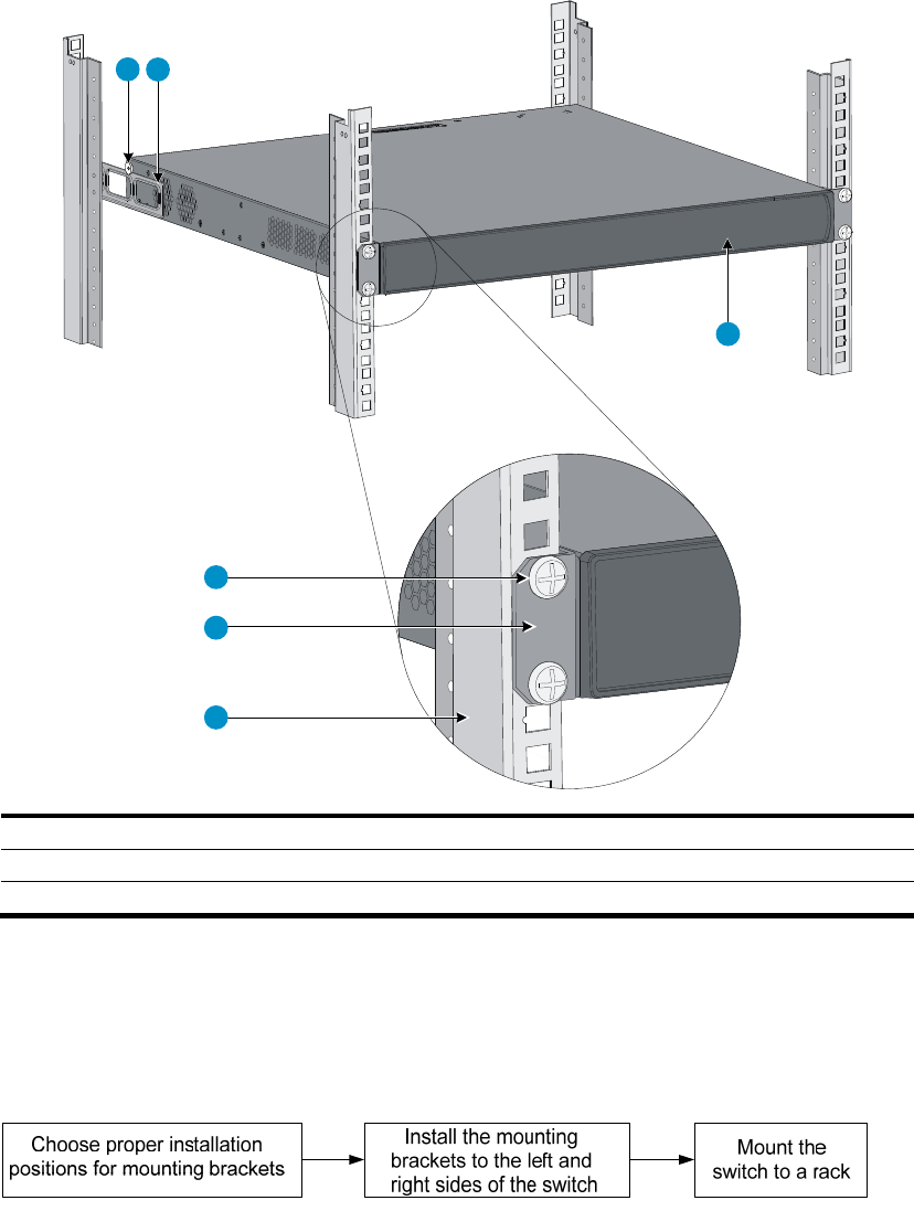
Installing a 5120 SI switch in a 19-inch rack
Figure 10 shows the general procedure for installing a 5120 SI switch in a 19-inch rack.
Figure 10 Install a 5120 SI switch in a 19-inch rack
13
Mounting brackets and mounting positions
Table 5 Mounting brackets for the 5120 SI switches
Chassis Bracket vie
w
Mountin
g
p
osition
• 5120-16G SI
• 5120-24G SI See callout A in Figure 11.
• Front mounting (see Figure 12)
• Rear mounting (see Figure 13)
5120-8G SI See callout B in Figure 11.
• Front mounting (see Figure 14)
• Rear mounting (see Figure 15)
5120-8G-PoE+ SI See callout D in Figure 11.
• Front mounting (see Figure 16)
• Rear mounting (see Figure 17))
5120-8G-PPoE+ SI
• 5120-24G-PoE+ SI
• 5120-24G-PPoE+ SI See callout C in Figure 11.
• Front mounting (see Figure 18)
• Mid-mounting (see Figure 19)
• Rear mounting (see Figure 20)
5120-48G SI
• Front mounting (see Figure 18)
• Rear mounting (see Figure 20)
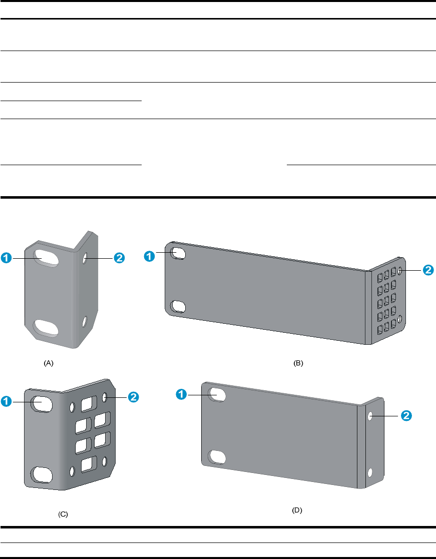
Figure 11 Mounting brackets
(1) Holes for attachin
g
to a rack (by usin
g
M6 screws)
(2) Holes for attaching to the switch chassis
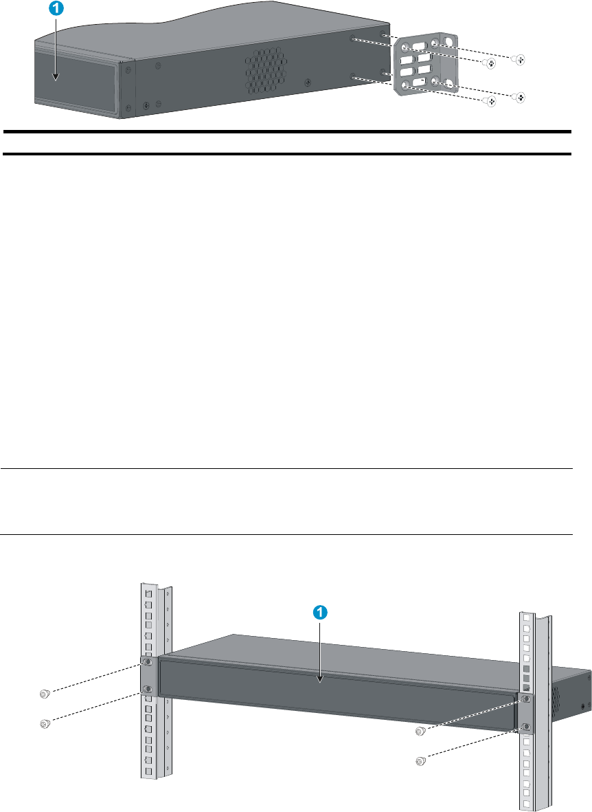
Attaching the mounting brackets to the switch chassis
1. Identify the correct mounting position (see Table 5).
14
2. Align the round holes in one bracket with the holes in the mounting position.
3. Use screws to attach the mounting bracket to the chassis.
4. Repeat the preceding steps to attach the other mounting bracket to the chassis.
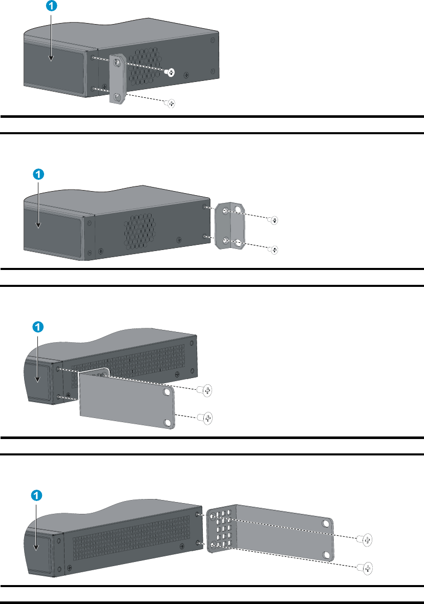
Figure 12 Front mounting position (5120-16G SI/5120-24G SI)
(1) Front panel
Figure 13 Rear mounting position (5120-16G SI/5120-24G SI)
(1) Front panel
Figure 14 Front mounting position (5120-8G-SI)
(1) Front panel
Figure 15 Rear mounting position (5120-8G-SI)
(1) Front panel
15
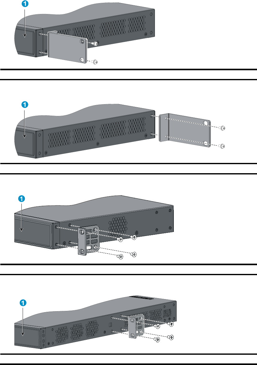
Figure 16 Front mounting position (5120-8G-PoE+ SI/5120-8G-PPoE+ SI)
(1) Front panel
Figure 17 Rear mounting position (5120-8G-PoE+ SI/5120-8G-PPoE+ SI)
(1) Front panel
Figure 18 Front mounting position (5120-24G-PoE+ SI/5120-24G-PPoE+ SI/5120-48G SI)
(1) Front panel
Figure 19 Mid-mounting position (5120-24G-PoE+ SI/5120-24G-PPoE+ SI)
(1) Front panel
16
Figure 20 Rear mounting position (5120-24G-PoE+ SI/5120-24G-PPoE+ SI/5120-48G SI)
(1) Front panel
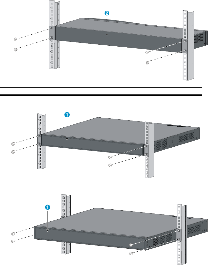
Rack-mounting the switch
This task requires two persons.
To mount the switch in a rack:
1. Wear an ESD-preventive wrist strap and make sure it makes good skin contact and is well
grounded.
2. Verify that the rack is well grounded and can support the weight of the switch chassis and all its
accessories.
3. Verify that the mounting brackets have been secured to the switch chassis.
4. Install cage nuts (user-supplied) in the mounting holes in the rack posts.
5. One person holds the switch chassis and aligns the oval holes in the brackets with the mounting
holes in the rack posts, and the other person attaches the mounting brackets with M6 screws
(user-supplied) to the rack, as shown in Figure 21 or Figure 22.
NOTE:
If a rack shelf is available, you can put the switch on the rack shelf, slide the switch to an appropriate
location, and attach the switch to the rack with the mounting brackets.
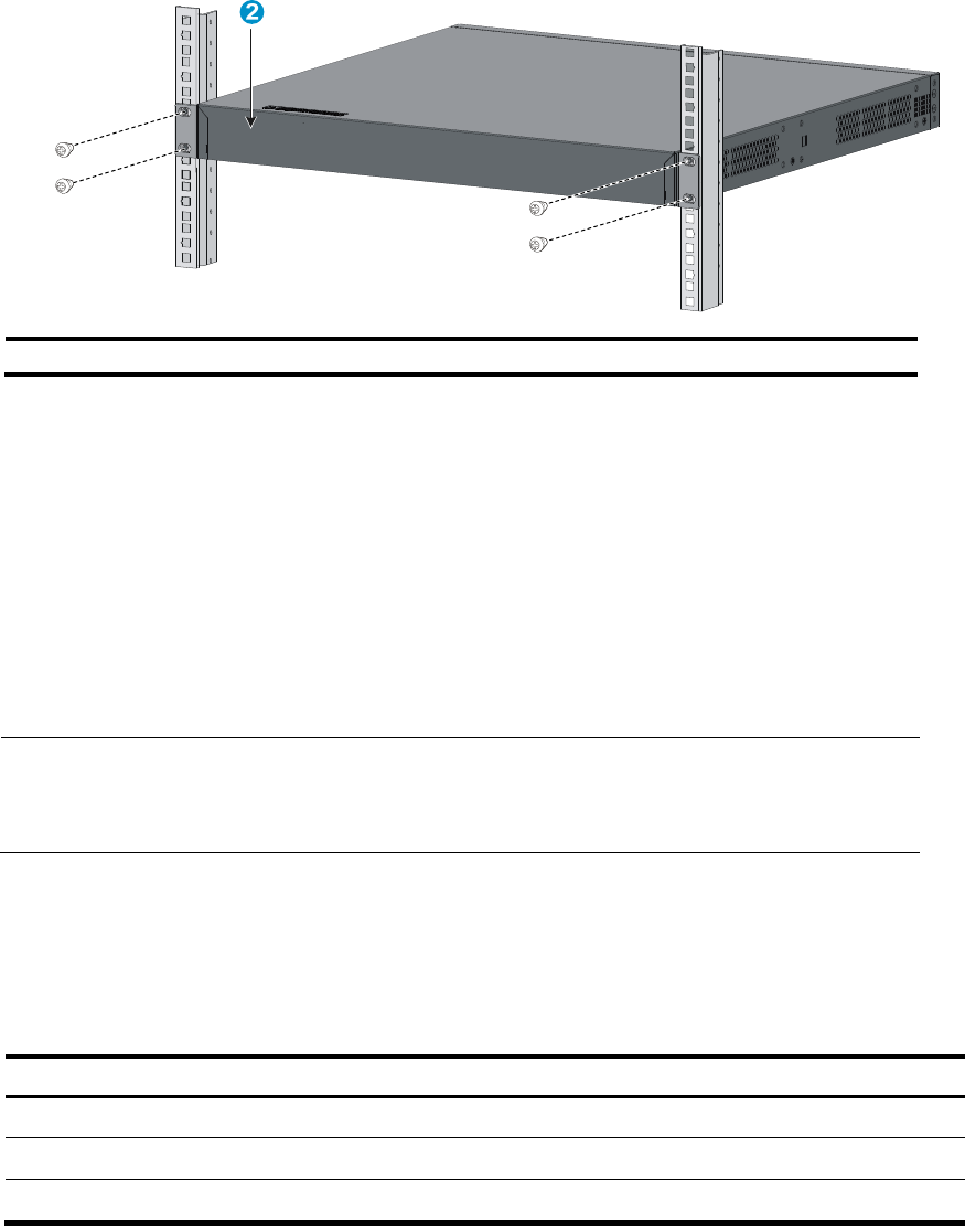
Figure 21 Mounting the switch in a rack (5120-16G SI)
17
(1) Front panel (2) Rear panel
Figure 22 Mounting the switch in a rack (5120-24G-PoE+ SI/5120-24G-PPoE+ SI)
18
(1) Front panel (2) Rear panel
Mounting the switch on a workbench
This installation method is available for all 5120 EI and 5120 SI switches.
To mount the switch on a workbench:
1. Verify that the workbench is sturdy and well grounded.
2. Place the switch with bottom up, and clean the round holes in the chassis bottom with dry cloth.
3. Attach the rubber feet to the four round holes in the chassis bottom.
4. Place the switch with upside up on the workbench.
NOTE:
• Ensure good ventilation and 10 cm (3.9 in) of clearance around the chassis for heat dissipation.
• Avoid placing heavy objects on the switch.
Mounting the switch to a wall
You can mount the 5120-8G SI, 5120-8G-PoE+ SI, and 5120-8G-PPoE+ SI on concrete or wood walls.
Table 6 Models supporting wall mounting
Model Hole distance
5120-8P SI 98.5 mm (3.88 in)
5120-8G-PoE+ SI 174.0 mm (6.85 in)
5120-8G-PPoE+ SI 174.0 mm (6.85 in)
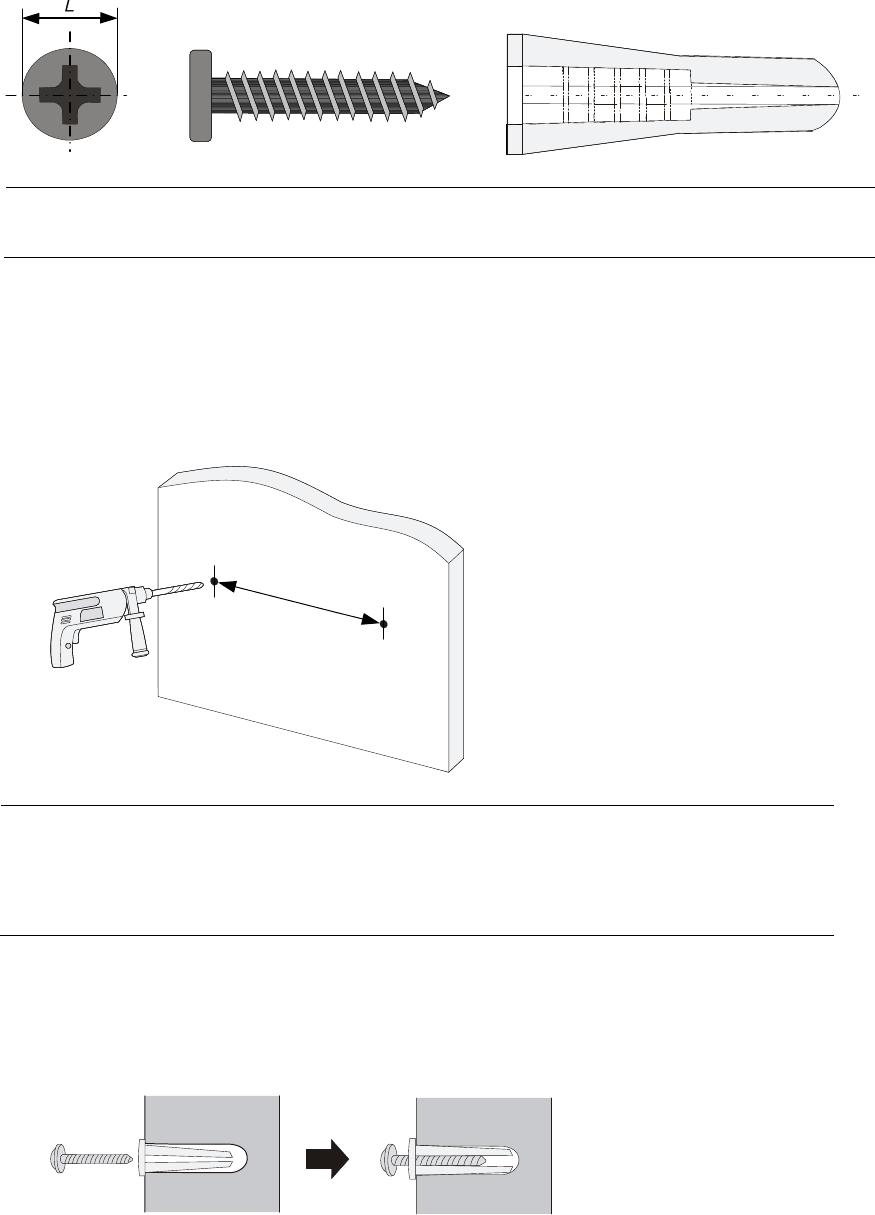
Wall anchor kit
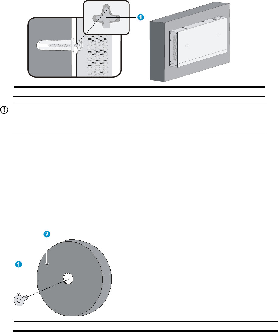
A wall anchor kit comprises an anchor and a screw, as shown in Figure 23. The screw must have an outer
diameter of no less than 4 mm (0.16 in) for wall mounting.
19
Figure 23 Wall anchor kit
NOTE:
No wall anchor kit is provided with the 5120 SI Switch Series.
Installation procedure
To mount the switch to a wall:
1. Drill two holes at the same height and X mm apart at the locations you marked. See Figure 24.
Figure 24 Drilling holes
Xmm
NOTE:
• The distance X between holes varies with devices. For specific distances, see Table 6.
• Drill holes according to the sizes of the anchors and screws so that the anchors can go into the holes
with only the edges remaining outside, and the screws can be tightly secured on the wall.
2. Insert an anchor into each hole until the anchor is flush with the wall surface. See Figure 25.
3. Drive a screw into each wall anchor, leaving a gap of at least 1.5 mm (0.06 in) between the base
of the screw head and the wall anchor so that the switch can hang on the screws securely.
Figure 25 Installing a wall anchor
4. Align the two installation holes at the switch bottom with the two screws and hang the switch.
See Figure 26.
20
Figure 26 Wall mounting
(1) Installation hole
IMPORTANT:
W
hen
you mount the switch, keep the Ethernet ports of the switch facin
g
downwards and the two sides
w
ith ventilation holes vertical to the
g
round.
Mounting the switch through magnet mounting
The 5120-8G SI, 5120-8G-PoE+ SI, and 5120-8G-PPoE+ SI support magnet mounting.
Magnetic mounting kit
A magnetic mounting kit comprises one permanent magnet and one M3*6 countersunk head screw, as
shown in Figure 27. Four magnetic mounting kits are needed for each switch.
Figure 27 Magnet mounting kit
(1) M3*6 countersunk head screw (2) Permanent ma
g
net
Installation procedure

21
CAUTION:
• Apply magnet mounting to only the 5120-8G SI, 5120-8G-PoE+ SI, and 5120-8G-PPoE+ SI. Otherwise,
a falloff or mis-operation might occur.
• Select the installation location carefully. In the case of poor surface, magnet mounting might not be
reliable.
• Put the switch at a stable place free from vibrations or shocks. Otherwise, personal injuries or equipmen
t
damage might occur.
• Avoid installing the switch at a high place because bodily injuries or equipment damage might occur in
case of a falloff.
• Avoid frequently moving the desk-mounted switch because such movements might dama
g
e the surface
coating.
• To install the device vertically, keep the front panel of the switch facing downwards and the two sides
with ventilation holes vertical to the ground.
• Make sure the weight of external cables does not bring about a falloff, which might result in bodily
injuries or equipment damage.
• Keep magnetic cards away from magnets to avoid erasure of any information.
• Keep computers and monitors that are easily influenced by magnetic fields away from magnets.
Otherwise, faults might occur to these electronic devices.
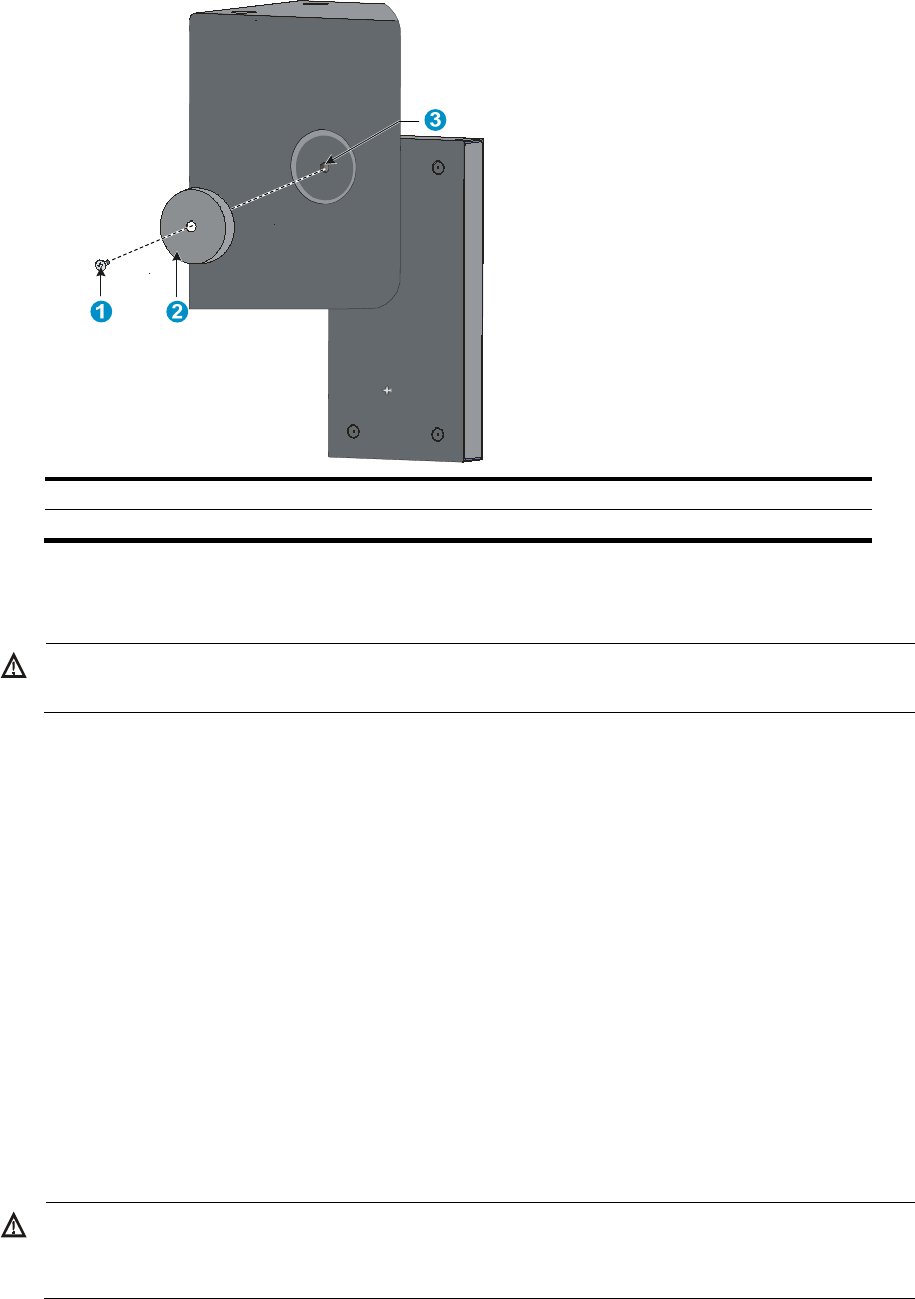
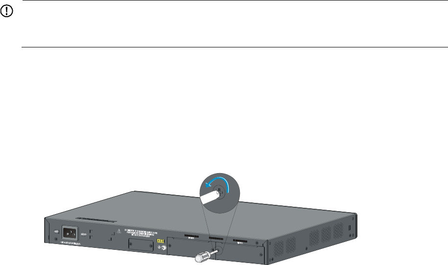
To complete magnet mounting:
1. Use a Phillips screwdriver to pass the countersunk head screw through the round hole at the center
of the permanent magnet, fasten it to a blind nut in the dent of the switch bottom, and make sure
the permanent magnet and the switch are fastened reliably. See Figure 28.
IMPORTANT:
• Remove the cushion, if any, from the dent before installation.
• To ensure the firmness of installation, be sure to use four permanent magnets to secure each switch.
2. Attach the magnet-mounted switch to the specified location. Do not get your fingers stuck between.
22
Figure 28 Magnet mounting
(1) M3*6 countersunk head screw (2) Permanent magnet
(3) Blind nut in the dent of the switch bottom
Grounding the switch
W
ARNING!
Correctly connecting the switch grounding cable is crucial to lightning protection and EMI protection.
The power and grounding terminals in this section are for illustration only.
The power input end of the switch has a noise filter, whose central ground is directly connected to the
chassis to form the chassis ground (commonly known as PGND). You must securely connect this chassis
ground to the earth so the faradism and leakage electricity can be safely released to the earth to
minimize EMI susceptibility of the switch.
You can ground the switch in one of the following ways, depending on the grounding conditions
available at the installation site:
• Grounding the switch with a grounding strip
• Grounding the switch with a grounding conductor buried in the earth ground
• Grounding the switch by using the AC power cord
Grounding the switch with a grounding strip
If a grounding strip is available at the installation site, connect the grounding cable to the grounding
strip.
W
ARNING!
Connect the
g
roundin
g
cable to the
g
roundin
g
system in the equipment room. Do not connect it to a fire
main or lightning rod.
23
The 5120 EI series, 5120-24G-PoE+ SI, and 5120-24G-PPoE+ SI switches come with a ring terminal for
connecting to a grounding strip. For other switch models, you must prepare ring terminals yourself.
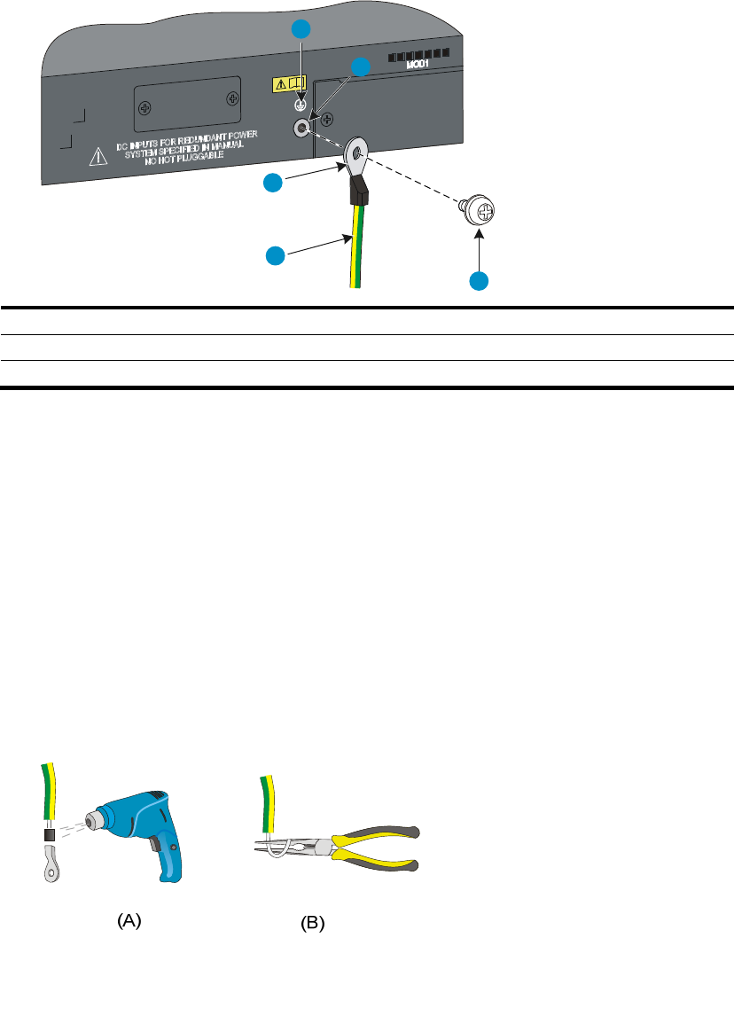
To connect the grounding cable, for example, to a 5120-48G EI (2 slots) switch:
1. Identify the grounding point (with a grounding sign) on the rear panel of the switch chassis, and
remove the grounding screw from the grounding point.
2. Attach the grounding screw to the ring terminal of the grounding cable.
3. Use a screwdriver to fasten the grounding screw into the grounding screw hole.
Figure 29 Connecting the grounding cable to the grounding hole of the switch chassis
1
2
3
4
5
(1) Groundin
g
si
g
n
(2) Groundin
g
hole
(3) Rin
g
terminal (4) Groundin
g
cable
(5) Grounding screw
4. Remove the hex nut of a grounding post on the grounding strip.
5. Cut the grounding cable as appropriate for connecting to the grounding strip.
6. Make the connector for connecting to the grounding strip:
{ If a ring terminal is available, peel 5 mm (0.20 in) of insulation sheath by using a wire stripper,
and insert the bare metal part through the black insulation covering into the end of the ring
terminal, secure the metal part of the cable to the ring terminal with a crimper, cover the joint
with the insulation covering, and heat the insulation covering with a blow dryer to completely
cover the metal part (see callout A in Figure 30).
{ If no ring terminal is available, peel the insulation sheath as appropriate by using a wire stripper,
and bend the bare metal part into a ring (see callout B in Figure 30). Attach the ring terminal
or the ring to the grounding strip through the grounding post, and fasten it with the removed hex
nut, see Figure 31.
Figure 30 Making a grounding cable connector
24
Figure 31 Connecting the grounding cable to a grounding strip
(1) Grounding post (2) Grounding strip
(3) Groundin
g
cable (4) Hex nut
Grounding the switch with a grounding conductor buried in the
earth ground
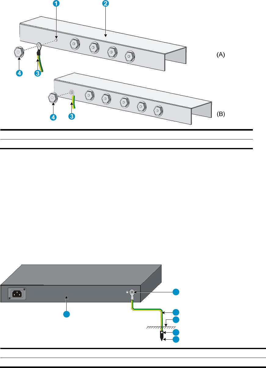
If the installation site has no grounding strips, but earth ground is available, hammer a 0.5 m (1.64 ft) or
longer angle iron or steel tube into the earth ground to serve as a grounding conductor.
The dimensions of the angle iron must be at least 50 × 50 × 5 mm (1.97 × 1.97 × 0.20 in). The steel tube
must be zinc-coated and its wall thickness must be at least 3.5 mm (0.14 in).
Weld the yellow-green grounding cable to the angel iron or steel tube and treat the joint for corrosion
protection.
Figure 32 Grounding the switch by burying the grounding conductor into the earth ground
1
2
3
4
5
6
(1) Grounding screw (2) Grounding cable (3) Earth
(4) Joint (5) Groundin
g
conductor
(6) Chassis rear panel
25
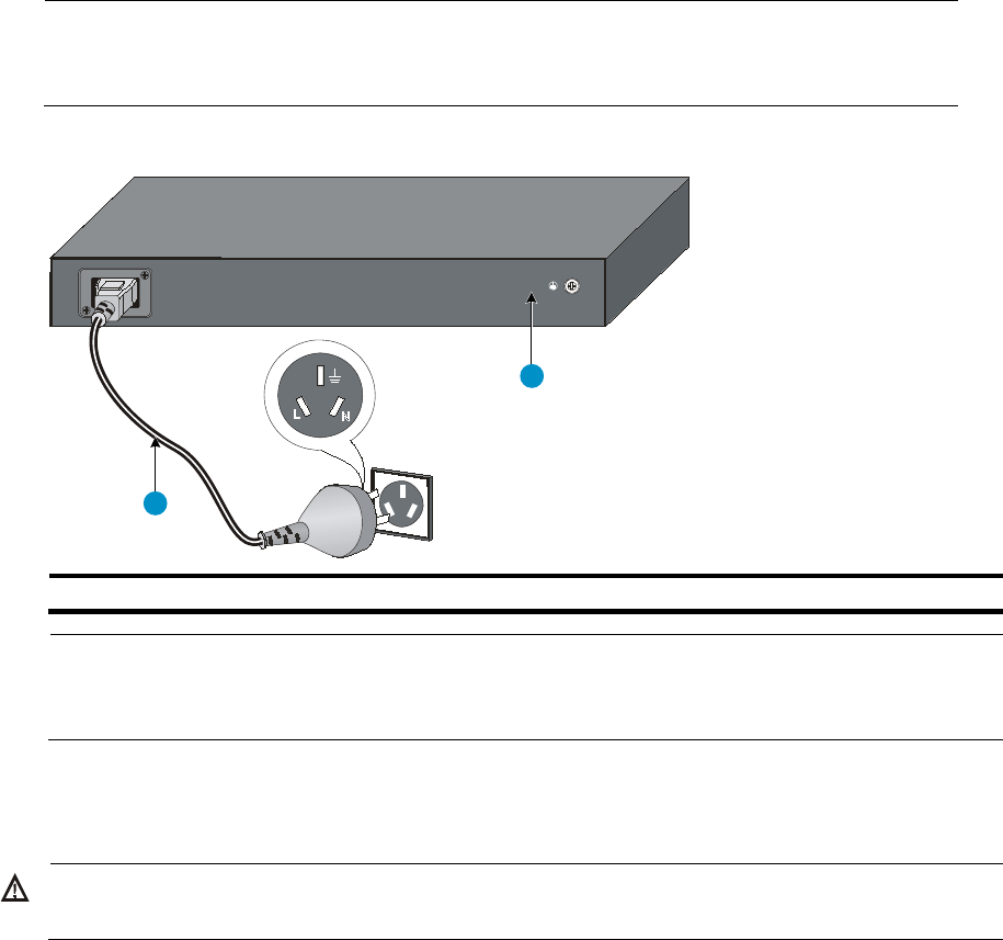
Grounding the switch by using the AC power cord
If the installation site has no grounding strips or earth ground, you ground an AC-powered switch through
the PE wire of the power cord, but must make sure:
• The power cord has a PE terminal.
• The ground contact in the power outlet is securely connected to the ground in the power distribution
room or on the AC transformer side.
• The power cord is securely connected to the power outlet.
NOTE:
If the ground contact in the power outlet is not connected to the ground, report the problem and
reconstruct the grounding system.
Figure 33 Grounding through the PE wire of the AC power cord
1
2
(1) Three-wire AC power cord (2) Chassis rear panel
NOTE:
To guarantee the grounding effect, use the grounding cable provided with the switch to connect to the
grounding strip in the equipment room as long as possible.
Connecting the power cord
W
ARNING!
Make sure the grounding cable has been correctly connected before powering on the switch.
Use Table 7 to identify the power cord connection procedures available for your switch.

26
Table 7 Power cord connection methods at a glance
Chassis Connection
p
rocedure
5120-8G SI
5120-16G SI
5120-24G SI
5120-48G SI
5120-8G-PPoE+ SI
5120-8G-PoE+ SI
5120-24G-PPoE+ SI
Connecting the AC power cord
5120-24G-PoE+ SI
AC-input:
Connecting the AC power cord
RPS input:
Connecting the switch to a –52 to –55 VDC output RPS
5120-24G EI (2 slots)
5120-24G EI TAA (2 slots)
5120-48G EI (2 slots)
5120-48G EI TAA (2 slots)
5120-24G EI
5120-48G EI
AC-input:
Connecting the AC power cord
RPS input:
Connecting the switch to a +12 VDC output RPS
5120-24G-PoE+ EI (2 slots)
5120-24G-PoE+ EI TAA (2 slots)
5120-48G-PoE+ EI (2 slots)
5120-48G-PoE+ EI TAA (2 slots)
AC-input:
Connecting the AC power cord
RPS input:
Connecting the switch to a –52 to –55 VDC output RPS
Connecting the AC power cord
1. Wear an ESD-preventive wrist strap and make sure it makes good skin contact and is well
grounded.
2. Connect one end of the AC power cord to the AC-input power receptacle on the switch.
Figure 34 uses a 5120-48G EI switch for illustration, and Figure 35 uses a 5120-24G SI switch for
illustration.
3. Connect the other end of the AC power cord to the AC power outlet.
Figure 34 Connecting the AC power cord to the 5120-48G EI switch
27
Figure 35 Connecting the AC power cord to the 5120-24G SI switch
Connecting the switch to a +12 VDC output RPS
This section applies to the 5120-24G EI (2 slots), 5120-24G EI TAA (2 slots), 5120-48G EI (2 slots),
5120-48G EI TAA (2 slots), 5120-24G EI, and 5120-48G EI switches.
To connect these switches to the RPS that provides +12 VDC output:
1. Wear an ESD-preventive wrist strap and make sure it makes good skin contact and is well
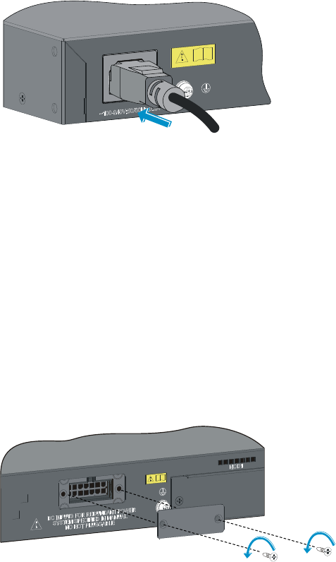
grounded.
2. Loosen the captive screws on the RPS receptacle protective cover and remove the protective cover,
see Figure 36.
If you do not use the RPS receptacle, install the protective cover.
Figure 36 Removing the RPS receptacle protective cover
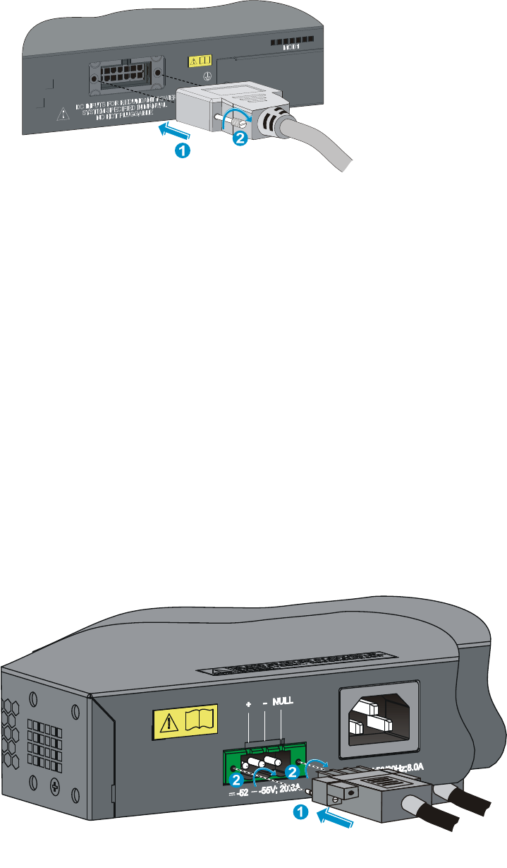
3. Unpack the RPS cable shipped with the RPS, identify the plug for connecting to the switch, correctly
orient the plug with the RPS receptacle on the switch chassis, and insert the plug into the receptacle
(see callout 1 in Figure 37).
The RPS receptacle is foolproof. If you cannot insert the plug into the receptacle, re-orient the plug
rather than use excessive force to push it in.
4. Tighten the screws on the plug with a flat-blade screwdriver to secure the plug in the RPS receptacle
(see callout 2 in Figure 37).
5. Connect the other end of the power cord to the RPS.
28
Figure 37 Connecting the RPS cable to the +12 VDC RPS receptacle
Connecting the switch to a –52 to –55 VDC output RPS
This section applies to the 5120-24G-PoE+ EI (2 slots), 5120-24G-PoE+ EI TAA (2 slots), 5120-48G-PoE+
EI (2 slots), 5120-48G-PoE+ EI TAA (2 slots) and 5120-24G-PoE+ SI switches.
To connect these switches to the RPS that provides –52 to –55 VDC output:
1. Wear an ESD-preventive wrist strap and make sure it makes good skin contact and is well
grounded.
2. Unpack the RPS cable shipped with the RPS, identify the plug for connecting to the switch, correctly
orient the plug with the RPS receptacle on the switch chassis, and insert the plug into the receptacle
(see callout 1 in Figure 38).
The RPS receptacle is foolproof. If you cannot insert the plug into the receptacle, re-orient the plug
rather than use excessive force to push it in.
3. Tighten the screws on the plug with a flat-blade screwdriver to secure the plug in the RPS receptacle
(see callout 2 in Figure 38).
4. Connect the other end of the power cord to the RPS.
5. Make sure the RPS is supplying power and verify that the RPS status LED is ON.
Figure 38 Connecting the RPS cable to the –52 to –55 RPS receptacle
29
Installing/removing an interface card (only for the
5120 EI switches)
This section applies to all 5120 EI switches but the 5120-24G EI and 5120-48G EI. For the interface cards
available for the switches, see "Interface cards (only for the 5120 EI switches)."
This section uses the LSPM2SP2P interface card as an example to describe the procedures of installing
and removing an interface card.
IMPORTANT:
To set up a 5120 EI IRF fabric, you must install interface cards. To choose a correct slot for an interface
card, see "Planning the cabling scheme for a 5120 EI IRF fabric."
Installing an interface card
1. Wear an ESD-preventive wrist strap and make sure it makes good skin contact and is well
grounded.
2. Loosen the mounting screws on the filler panel over the interface card slot with a Phillips
screwdriver and remove the filler panel.
Figure 39 Removing the filler panel over an interface card slot
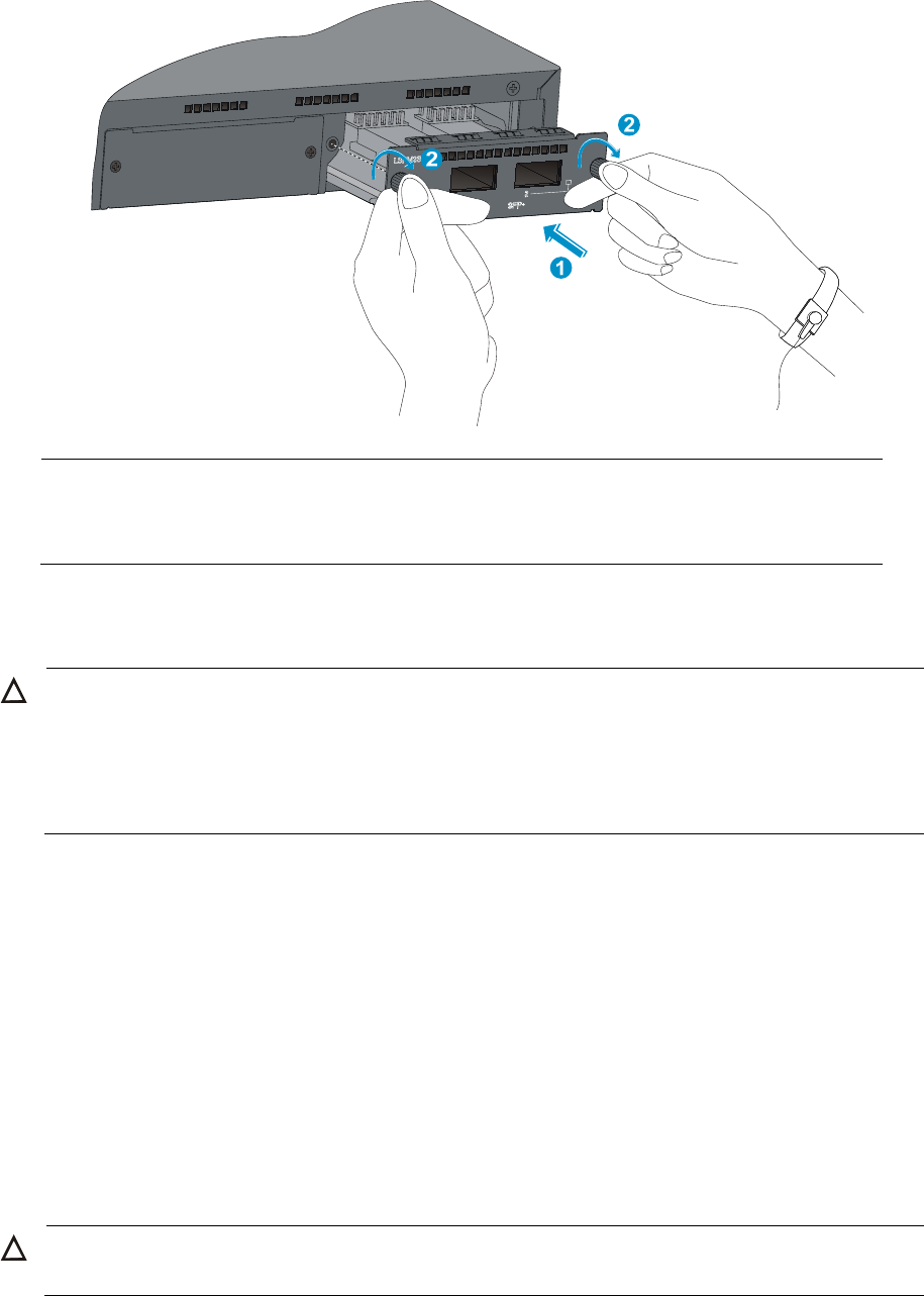
3. Hold the captive screws on the front panel of the interface card, and gently push the interface card
in along the slot guide rail until the interface card is in close contact with the switch chassis (see
callout 1 in Figure 40).
4. Tighten the captive screws with a Phillips screwdriver to secure the interface card in the slot (see
callout 2 in Figure 40).
30
Figure 40 Installing an interface card (II)
NOTE:
• Put away the removed filler panel for future use.
• When you tighten the captive screws, the torque must not be higher than 0.4 N-m.
Removing an interface card
CAUTION:
• Do not touch the surface-mounted components directly with your hands.
• Do not use too much force during the operation.
• If no new card is to be installed, install the filler panel to prevent dust and ensure
g
ood ventilation in the
switch.
To remove an interface card:
1. Wear an ESD-preventive wrist strap and make sure it makes good skin contact and is well
grounded.
2. Use a Phillips screwdriver to completely loosen the captive screws at both sides of the interface
card.
3. Pull the interface card along the guide rails until it completely comes out of the switch chassis.
Installing/removing a dedicated CX4/SFP+ cable
The dedicated CX4 and SFP+ cables for the 5120 EI switches are hot swappable.
Installing a dedicated CX4/SFP+ cable
CAUTION:
The cable bending radius must be at least eight times the cable diameter.
31
To connect a CX4 or SFP+ cable to a port on a CX4/SFP+ interface card:
1. Wear an ESD-preventive wrist strap and make sure it makes good skin contact is well grounded.
2. Correctly orient one connector of the cable with the port and insert the cable connector into the
port.
Removing a dedicated CX4/SFP+ cable
1. Wear an ESD-preventive wrist strap and make sure it makes good skin contact and is well
grounded.
2. Hold the cable connector and pull the pull latch of the connector to remove the cable from the
switch.
Verifying the installation
After you complete the installation, verify that:
• There is enough space for heat dissipation around the switch, and the rack or workbench is stable.
• The grounding cable is securely connected.
• The correct power source is used.
• The power cords are correctly connected.
• All the interface cables are cabled indoors. If any cable is routed outdoors, verify that the socket
strip with lightning protection and lightning arresters for network ports have been correctly
connected.
32
Accessing the switch for the first time
Setting up the configuration environment
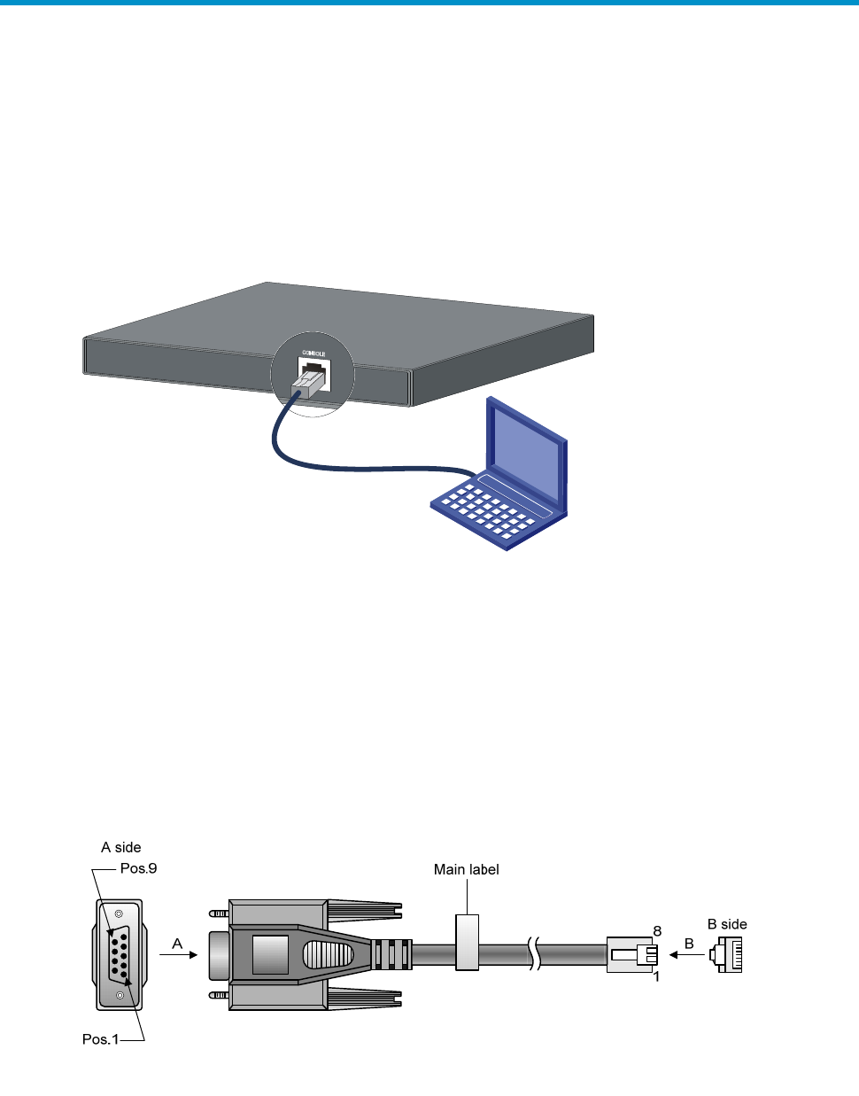
The first time you access the switch you must use a console cable to connect a console terminal, for
example, a PC, to the console port on the switch.
Figure 41 Connecting the console port to a terminal
Connecting the console cable
Console cable
A console cable is an 8-core shielded cable, with a crimped RJ-45 connector at one end for connecting
to the console port of the switch, and a DB-9 female connector at the other end for connecting to the
serial port on the console terminal.
Figure 42 Console cable
Connecting the console cable
To connect a terminal, for example, a PC, to the switch:
1. Plug the DB-9 female connector of the console cable to the serial port of the PC.
33
2. Connect the RJ-45 connector to the console port of the switch.
NOTE:
• Identify the mark on the console port and make sure you are connecting to the correct port.
• The serial ports on PCs do not support hot swapping. If the switch has been powered on, connect the
console cable to the PC before connecting to the switch, and when you disconnect the cable, first
disconnect from the switch.
Setting terminal parameters
To configure and manage the switch, you must run a terminal emulator program on the console terminal.
The following are the required terminal settings:
• Bits per second—9,600
• Data bits—8
• Parity—None
• Stop bits—1
• Flow control—None
• Emulation—VT100
To set terminal parameters, for example, on a Windows XP HyperTerminal:
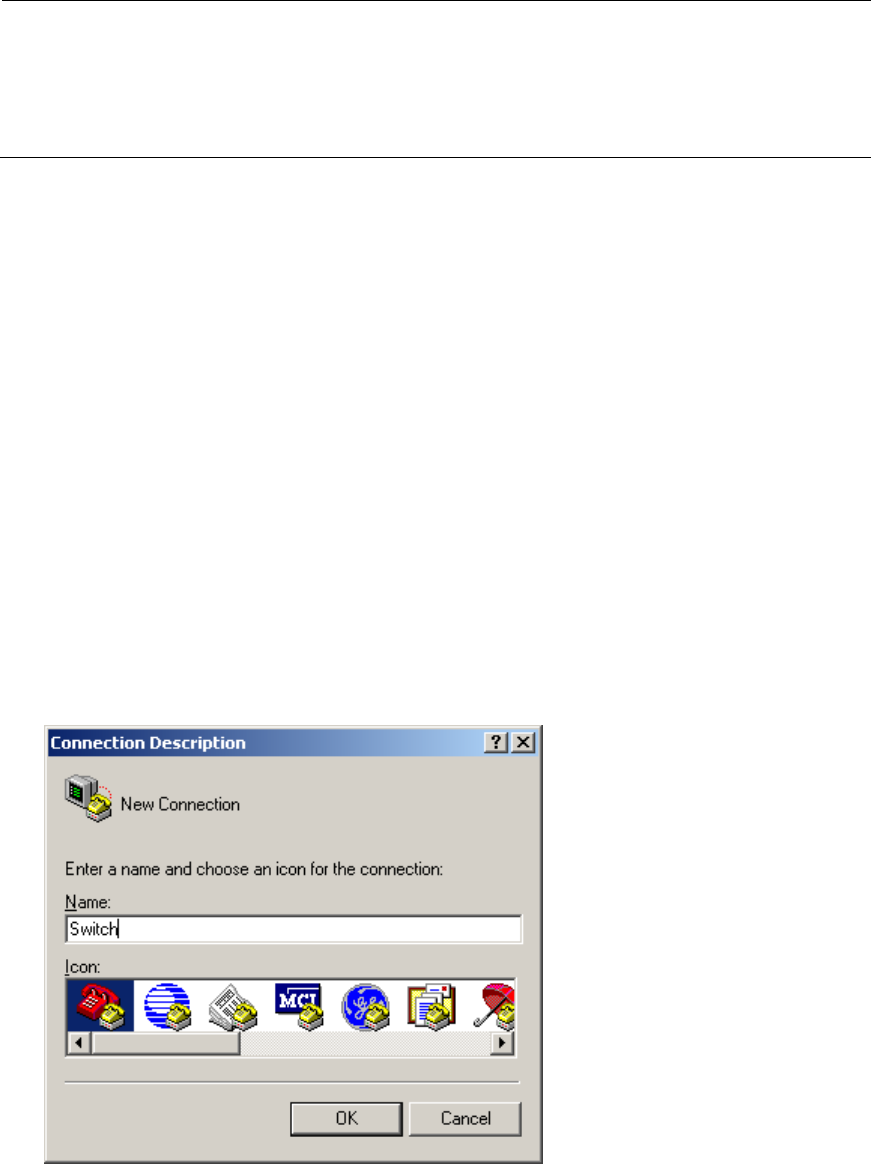
1. Select Start > All Programs > Accessories > Communications > HyperTerminal.
The Connection Description dialog box appears.
2. Enter the name of the new connection in the Name field and click OK.
Figure 43 Connection description
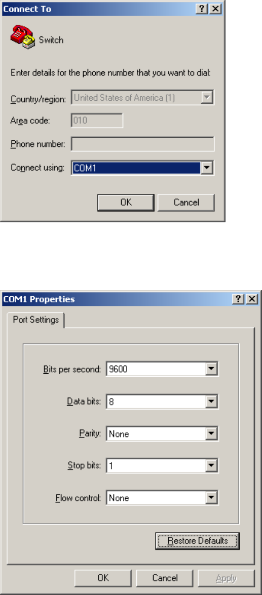
3. Select the serial port to be used from the Connect using list, and click OK.
34
Figure 44 Setting the serial port used by the HyperTerminal connection
4. Set Bits per second to 9600, Data bits to 8, Parity to None, Stop bits to 1, and Flow control to None,
and click OK.
Figure 45 Setting the serial port parameters
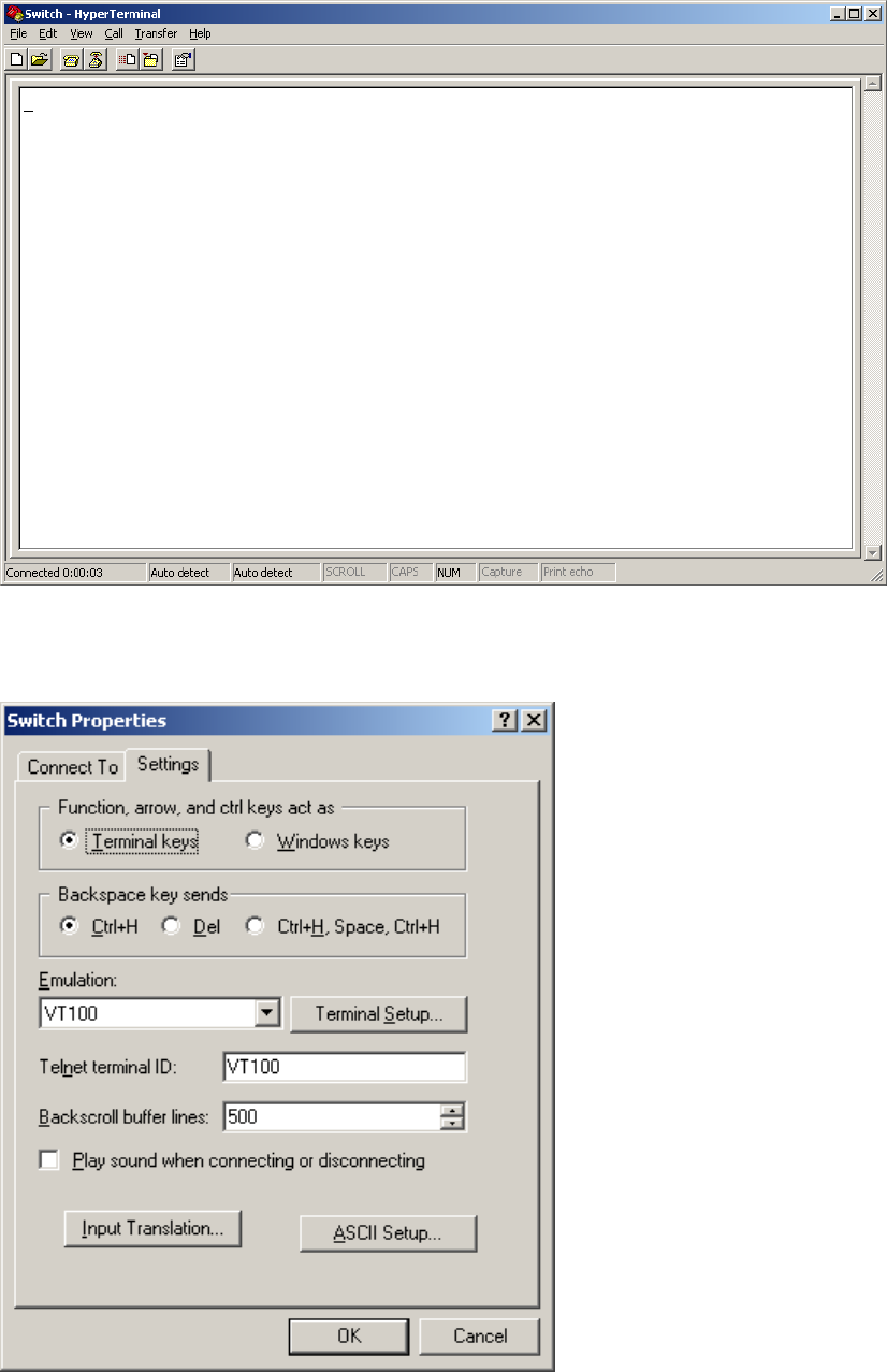
5. Select File > Properties in the HyperTerminal window.
35
Figure 46 HyperTerminal window
6. On the Settings tab, set the emulation to VT100 and click OK.
Figure 47 Setting terminal emulation in Switch Properties dialog box
36
Powering on the switch
Before powering on the switch, verify that the following conditions are met:
• The power cord is correctly connected.
• The input power voltage meets the requirement of the switch.
• The console cable is correctly connected.
• The configuration terminal (a PC, for example) has started, and its serial port settings are consistent
with the console port settings on the switch.
Power on the switch. During the startup process, you can access Boot ROM menus to perform tasks such
as software upgrade and file management. The Boot ROM interface and menu options differ with
software versions. For more information about Boot ROM menu options, see the software-matching
release notes for the device.
After the startup completes, you can access the CLI to configure the switch.
For more information about the configuration commands and CLI, see the configuration guides and
command references for the switch.
37
Setting up an IRF fabric
You can use HP Intelligent Resilient Framework (IRF) technology to connect and virtualize 5120 EI switches
or 5120 SI switches into a virtual switch called an "IRF fabric" or "IRF virtual device" for flattened network
topology, and high availability, scalability, and manageability.
NOTE:
• IRF is not available on the 5120-24G EI or 5120-48G EI switch. The "5120 EI switches" in this documen
t
does not include those two switch models.
• An IRF fabric cannot have both 5120 EI and 5120 SI switches.
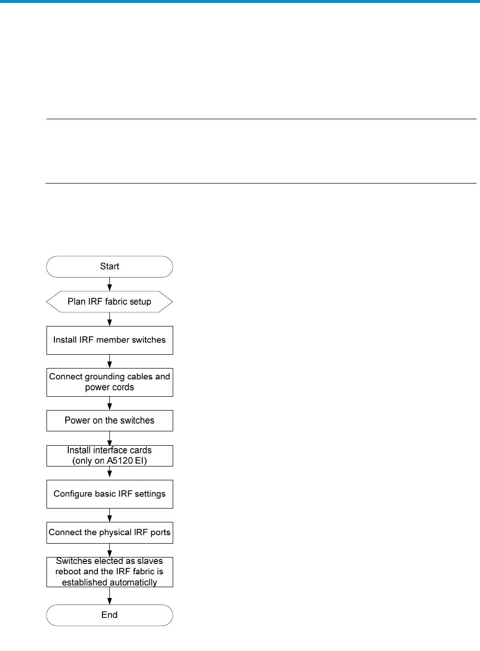
IRF fabric setup flowchart
Figure 48 IRF fabric setup flowchart
To set up an IRF fabric:

38
Ste
p
Descri
p
tion
1. Plan IRF fabric setup
Plan the installation site and IRF fabric setup parameters:
• Planning IRF fabric size and the installation site
• Identifying the master switch and planning IRF member IDs
• Planning IRF topology and connections
• Identifying physical IRF ports on the member switches
• Planning the cabling scheme
2. Install IRF member
switches See "Installing the switch."
3. Connect the grounding
cable and power cords See "Grounding the switch" and "Connecting the power cord."
4. Power on the switches N/A
5. Install interface cards This step is required only for the 5120 EI switches.
See "Installing/removing an interface card (only for the 5120 EI switches)."
6. Configure basic IRF
settings See "Configuring basic IRF settings."
7. Connect the physical IRF
ports
See "Connecting the physical IRF ports."
All switches except the master switch automatically reboot, and the IRF fabric
is established.
Planning IRF fabric setup
Planning IRF fabric size and the installation site
Choose switch models and identify the number of required IRF member switches, depending on the user
density and upstream bandwidth requirements. The switching capacity of an IRF fabric equals the total
switching capacities of all member switches.
NOTE:
A
s your business
g
rows, you can plu
g
a switch into an IRF fabric to increase the
switchin
g
capacity withou
t
any topology change or replacement.
Identifying the master switch and planning IRF member IDs
Determine which switch you want to use as the master for managing all member switches in the IRF fabric.
An IRF fabric has only one master switch. You configure and manage all member switches in the IRF
fabric at the command line interface of the master switch.
NOTE:
IRF member switches will automatically elect a master. You can affect the election result by assigning a
high member priority to the intended master switch. For more information about master election, see the
IRF configuration guide for your switch.
Prepare an IRF member ID assignment scheme. An IRF fabric uses member IDs to uniquely identify and
manage its members, and you must assign each IRF member switch a unique member ID.
39
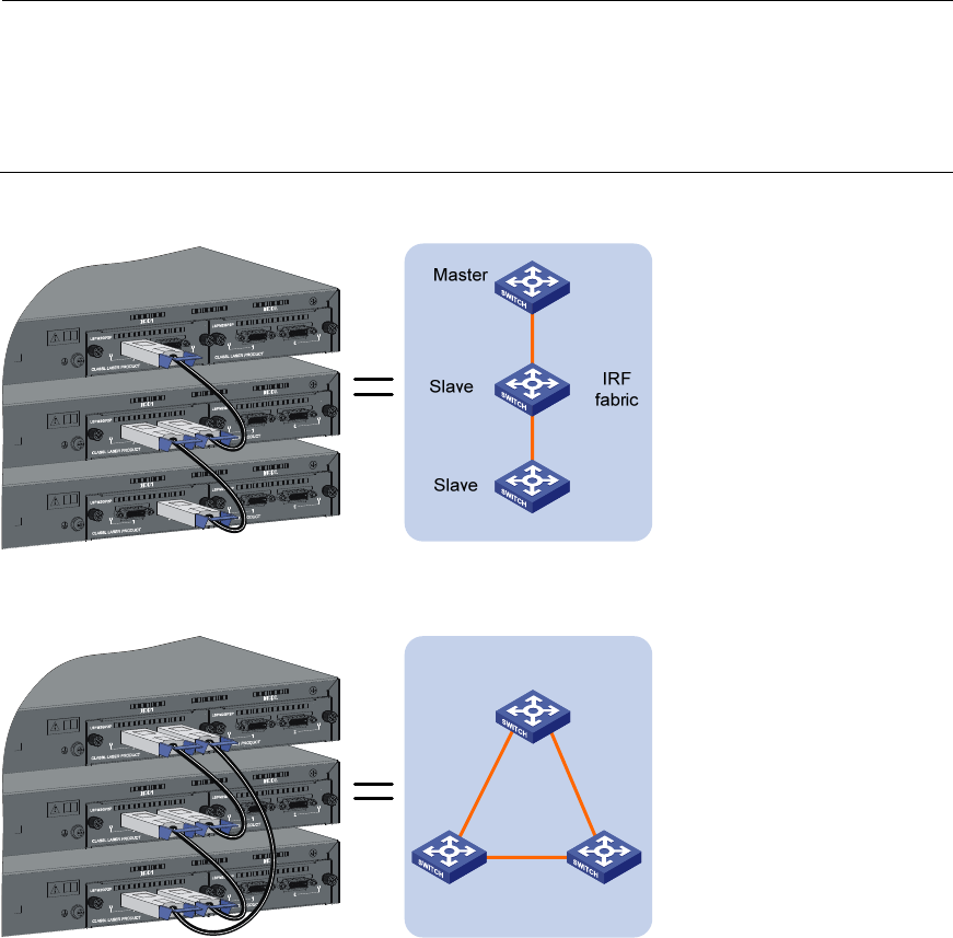
Planning IRF topology and connections
You can create an IRF fabric in daisy chain topology, or more reliably, ring topology. In ring topology,
the failure of one IRF link does not cause the IRF fabric to split as in daisy chain topology. Rather, the IRF
fabric changes to a daisy chain topology without interrupting network services.
You connect the IRF member switches through IRF ports. An IRF port is a logical interface for the internal
connection between IRF member switches. Each IRF member switch has two IRF ports: IRF-port 1 and
IRF-port 2. To use an IRF port, you must bind physical ports to it.
When connecting two neighboring IRF member switches, you must connect the physical ports of IRF-port
1 on one switch to the physical ports of IRF-port 2 on the other switch.
You can bind several physical ports to an IRF port to create an aggregate IRF link for increased
bandwidth and availability.
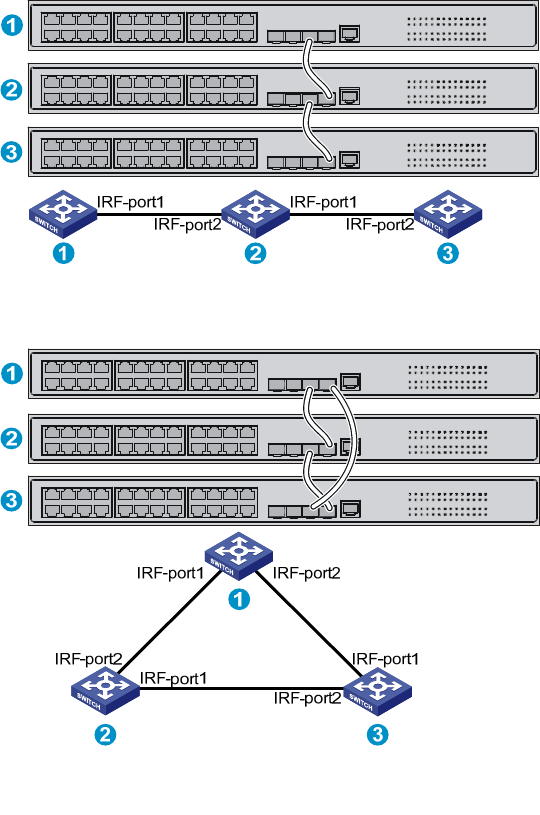
NOTE:
• Figure 49 and Figure 50 show the topologies of a 5120 EI IRF fabric. Figure 51 and Figure 52 show the
topologies of a 5120-24G SI IRF fabric.
• The IRF port connections in these figures are for illustration only, and more connection methods are
available.
Figure 49 5120 EI IRF fabric in daisy chain topology
Figure 50 5120 EI IRF fabric in ring topology
IRF
fabric
Slave Slave
Master
40
Figure 51 5120 SI IRF fabric in daisy chain topology
Figure 52 5120 SI IRF fabric in ring topology
Identifying physical IRF ports on the member switches
Identify the physical IRF ports on the member switches according to your topology and connection
scheme.
Table 8 shows the physical ports that can be used for IRF connection and the port use restrictions.
41
Table 8 Physical IRF port requirements
Switch chassis Candidate physical
IRF
p
orts
Requirements
5120 EI switches
(excluding the 5120-24G
EI and the 5120-48G EI)
Ports on the expansion
interface cards on the
rear panel
• You must order interface cards separately. For
long-distance connections, use XFP/SFP+
transceiver modules and fibers. For short-distance
connections, use CX4/SFP+ cables or twisted-pair
cables. For more information, see "Interface cards
(only for the 5120 EI switches)" and
"SFP/SFP+/XFP transceiver modules and
SFP+/CX4 cables (only for the 5120 EI switches)."
• Ports assigned to the same IRF port must be on the
same interface card.
• All 5120 EI switches in a ring topology and the
non-edge switches in a daisy chain topology must
have at least one two-port interface card or two
one-port interface cards.
5120 SI switches All network ports
HP recommends that you use Gigabit SFP ports and
HP A3600 Switch SFP Stacking Kit cables for IRF
connection.
For more information, see "SFP transceiver modules
and SFP Stacking Kit (only for the 5120 SI switches)."
Planning the cabling scheme
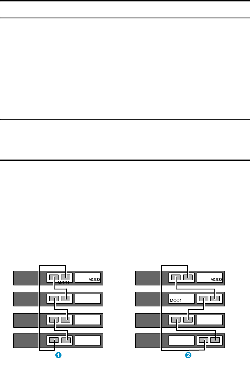
Planning the cabling scheme for a 5120 EI IRF fabric
If 2-port interface cards are used and the IRF links are not aggregate, follow these guidelines on
connecting two neighboring 5120 EI switches:
• You can connect the interface card in slot 1 (MOD 1) on a member switch to the MOD 1 or MOD
2 card on its neighboring switch.
• Connect the left port on one interface card to the right port on the other interface card, as shown
in Figure 53.
Figure 53 Use 2-port interface cards to set up single-link IRF connection
42
If 2-port interface cards are used and IRF links are aggregate, follow these guidelines on connecting two
neighboring switches:
• The ports on the interface card MOD 1 on one switch must connect to the ports on the interface card
MOD 2 on the other switch.
• A port on one interface card can connect to any port on the other interface card, as shown in Figure
54. For example, you can connect the left port on one interface card to the left or right port on the
other interface card.
Figure 54 Use 2-port interface cards to set up multi-link IRF connection
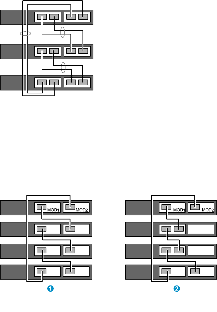
If 1-port interface cards are used, follow these guidelines on connecting neighboring switches:
• If both of the switches use 1-port interface cards, the port on MOD 1 on one switch must connect to
the port on MOD 2 on the other switch (see callout 1 in Figure 55).
• If one switch uses a 1-port interface card but the other switch uses a 2-port interface card:
{ If the 1-port interface card is in the MOD 1 slot, the port on the card must connect to the right
port on the 2-port interface card (see callout 2 in Figure 55.)
{ If the 1-port interface card is in the MOD 2 slot, the port on the card must connect to the left port
on the 2-port interface card.
Figure 55 Cable connections for an IRF fabric with 1-port interface cards
43
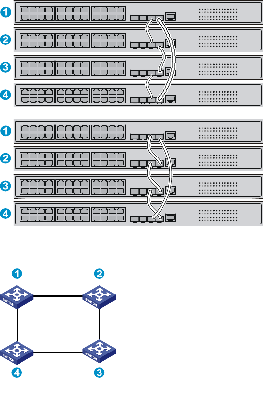
Planning the cabling scheme for a 5120 SI IRF fabric
HP recommends that you use Gigabit SFP ports and HP A3600 Switch SFP Stacking Kit cables for IRF
connection.
Figure 56 shows two IRF connection schemes and uses Gigabit SFP ports and HP A3600 Switch SFP
Stacking Kit cables for IRF connection. All these schemes use a ring topology.
Figure 57 shows the IRF fabric topology.
Figure 56 Connect the IRF member switches
Figure 57 IRF fabric topology
Configuring basic IRF settings
After you install the IRF member switches, power on the switches, and log in to each IRF member switch
(see the fundamentals configuration guide for your switch) to configure their member IDs, member
priorities, and IRF port bindings.
Follow these guidelines when you configure the neighboring switches:
• Assign the master switch higher member priority than any other switch.
• Bind physical ports to IRF port 1 on one switch and to IRF port 2 on the other switch.

44
• Execute the irf-port-configuration active command to activate the IRF port configuration.
• Execute the display irf configuration command to verify the basic IRF settings.
For more information about configuring basic IRF settings, see the IRF configuration guide for your switch.
Connecting the physical IRF ports
Connect the IRF member switches as planned.
NOTE:
W
ear an ESD-preventive wrist strap when you connect the physical IRF ports. For how to connect them,
see
Pluggable SFP/SFP+/XFP Transceiver Modules Installation Guide
.
Accessing the IRF fabric to verify the configuration
To verify the basic functionality of the IRF fabric after you finish configuring basic IRF settings and
connecting IRF ports:
1. Log in to the IRF fabric through the console port of any member switch.
2. Create a Layer 3 interface, assign it an IP address, and make sure the IRF fabric and the remote
network management station can reach each other.
3. Use Telnet, web or SNMP to access the IRF fabric from the network management station.
See the fundamentals configuration guide for your switch.
4. Verify that you can manage all member switches as if they were one node.
5. Display the running status of the IRF fabric by using the commands in the table bellow.
Task Command
Display information about the IRF fabric. display irf
Display all members’ configurations that take
effect after switch reboots. display irf configuration
Display topology information about the IRF
fabric. display irf topology
NOTE:
To avoid IP address collision and network problems, configure at least one multi-active detection
(MAD) mechanism to detect the presence of multiple identical IRF fabrics and handle collisions. For
more information about MAD detection, see the IRF configuration guide for your switch.

45
Maintenance and troubleshooting
Power supply failure
The 5120 EI switches and the 5120 SI switches use built-in power supplies. All 5120 EI switches and the
5120-24G-PoE+ SI switch support three power input modes: AC input, RPS DC input, and concurrent AC
and RPS DC inputs. All other 5120 SI switches have only one AC power input.
To identify a power failure:
• On any 5120 EI switch, look at the system status LED and the RPS status LED of the switch. For more
information, see "LEDs (for the 5120 EI switches)."
• On the 5120-24G-PoE+ SI switch, look at the power LED and the RPS status LED of the switch. For
more information, see "LEDs (for the 5120 SI switches)."
• On any other 5120 SI switch, look at the power LED of the switch. For more information, see "LEDs
(for the 5120 SI switches)."
NOTE:
In the following subsections, the system status LED collectively refers to both the system status LED on a
5120 EI switch and the power LED on a 5120 SI switch.
AC input
If the system status LED is off, an AC input failure has occurred. Verify the following items:
• The AC power cord is securely connected to the switch, and the AC-input power receptacle on the
switch and the connected AC power outlet are in good condition.
• The external AC power system is correctly working.
• The operating temperature of the switch is in the normal range, and the power module has good
ventilation. Over-temperature can cause the power module to stop working and enter the protection
state.
RPS DC input
If the system status LED or RPS status LED is off, an RPS input failure has occurred. Verify the following
items:
• The switch is securely connected to the RPS.
• The RPS is correctly working.
• The operating temperature of the switch is in the normal range, and the power supply has good
ventilation. Over-temperature can cause the power supply to stop working and enter the protection
state).
Concurrent RPS and AC inputs
1. If the system status LED is off, the AC power supply and the RPS both have an input failure.
Verify the following items:
{ The AC power cord is securely connected to the switch, and the AC-input power receptacle on
the switch and the connected AC power outlet are in good condition.

46
{ The external AC power system is correctly working.
{ The switch is securely connected to the RPS.
{ The RPS is correctly working.
{ The operating temperature of the switch is in the normal range, and the power supply has good
ventilation. Over-temperature can cause the power supply to stop working and enter the
protection state.
2. If the system status LED is on but the RPS status LED is steady yellow, an AC input failure has
occurred.
Verify the following items:
{ The AC power cord is securely connected to the switch, and the AC-input power receptacle on
the switch and the connected AC power outlet are in good condition.
{ The external AC power system is correctly working.
3. If the system status LED is on but the RPS status LED is off, an RPS input failure has occurred.
Verify the following items:
{ The switch is securely connected to the RPS.
{ The RPS is correctly working.
NOTE:
If the problem persists, contact the HP technical support for help.
Fan failure (only for the 5120 EI switches)
You can look at the system status LED and the seven-segment LED of a 5120 EI switch to identify a fan
failure. If both LEDs are behaving as described in Table 9, a fan failure occurs.
Table 9 LED behaviors that identify a fan failure
LED Mar
k
State
System status LED PWR Steady red
Seven-segment LED Unit
The LED flashes F for fan failure.
The 5120 EI switches use built-in fans. If a fan failure occurs, contact the HP technical support for help and
do not attempt to fix the problem yourself.
Configuration terminal problems
If the configuration environment setup is correct, the configuration terminal displays booting information
when the switch is powered on. If the setup is incorrect, the configuration terminal would display nothing
or garbled text.
No terminal display
If the configuration terminal displays nothing after the switch is powered on, verify the following items:
• The power supply is supplying power to the switch.
47
• The console cable is correctly connected.
• The console cable has no problem and the terminal settings are correct.
Garbled terminal display
If terminal display is garbled, verify that the following settings are configured for the terminal, for
example, HyperTerminal:
• Baud rate—9,600
• Data bits—8
• Parity—none
• Stop bits—1
• Flow control—none
• Emulation—VT100

48
Support and other resources
Contacting HP
For worldwide technical support information, see the HP support website:
http://www.hp.com/support
Before contacting HP, collect the following information:
• Product model names and numbers
• Technical support registration number (if applicable)
• Product serial numbers
• Error messages
• Operating system type and revision level
• Detailed questions
Subscription service
HP recommends that you register your product at the Subscriber's Choice for Business website:
http://www.hp.com/go/wwalerts
After registering, you will receive email notification of product enhancements, new driver versions,
firmware updates, and other product resources.
Related information
Documents
To find related documents, browse to the Manuals page of the HP Business Support Center website:
http://www.hp.com/support/manuals
• For related documentation, navigate to the Networking section, and select a networking category.
• For a complete list of acronyms and their definitions, see HP A-Series Acronyms.
Websites
• HP.com http://www.hp.com
• HP Networking http://www.hp.com/go/networking
• HP manuals http://www.hp.com/support/manuals
• HP download drivers and software http://www.hp.com/support/downloads
• HP software depot http://www.software.hp.com
• HP Education http://www.hp.com/learn

49
Conventions
This section describes the conventions used in this documentation set.
Command conventions
Convention Descri
p
tion
Boldface Bold text represents commands and keywords that you enter literally as shown.
Italic Italic text represents arguments that you replace with actual values.
[ ] Square brackets enclose syntax choices (keywords or arguments) that are optional.
{ x | y | ... }
Braces enclose a set of required syntax choices separated by vertical bars, from which
you select one.
[ x | y | ... ]
Square brackets enclose a set of optional syntax choices separated by vertical bars, from
which you select one or none.
{ x | y | ... } *
Asterisk-marked braces enclose a set of required syntax choices separated by vertical
bars, from which you select at least one.
[ x | y | ... ] *
Asterisk-marked square brackets enclose optional syntax choices separated by vertical
bars, from which you select one choice, multiple choices, or none.
&<1-n> The argument or keyword and argument combination before the ampersand (&) sign can
be entered 1 to n times.
# A line that starts with a pound (#) sign is comments.
GUI conventions
Convention Descri
p
tion
Boldface Window names, button names, field names, and menu items are in bold text. For
example, the New User window appears; click OK.
> Multi-level menus are separated by angle brackets. For example, File > Create > Folder.
Symbols
Convention Descri
p
tion
WARNING An alert that calls attention to important information that if not understood or followed can
result in personal injury.
CAUTION An alert that calls attention to important information that if not understood or followed can
result in data loss, data corruption, or damage to hardware or software.
IMPORTANT An alert that calls attention to essential information.
NOTE An alert that contains additional or supplementary information.
TIP An alert that provides helpful information.

50
Network topology icons
Represents a generic network device, such as a router, switch, or firewall.
Represents a routing-capable device, such as a router or Layer 3 switch.
Represents a generic switch, such as a Layer 2 or Layer 3 switch, or a router that supports
Layer 2 forwarding and other Layer 2 features.
Port numbering in examples
The port numbers in this document are for illustration only and might be unavailable on your device.

51
Appendix A Chassis views and technical
specifications
The HP 5120 EI Switch Series includes the models in Table 10, and the HP 5120 SI Switch Series includes
the models in Table 11.
Table 10 Models in the HP 5120 EI Switch Series
T
yp
e Product code HP descri
p
tion
Alias
Non-PoE
JE066A HP 5120-24G EI Switch 5120-24G EI
JE067A HP 5120-48G EI Switch 5120-48G EI
JE068A HP 5120-24G EI Switch with 2 Interface
Slots 5120-24G EI (2 slots)
JG245A HP 5120-24G EI TAA Switch with 2
Interface Slots 5120-24G EI TAA (2 slots)
JE069A HP 5120-48G EI Switch with 2 Interface
Slots 5120-48G EI (2 slots)
JG246A HP 5120-48G EI TAA Switch with 2
Interface Slots 5120-48G EI TAA (2 slots)
PoE
JG236A HP 5120-24G-PoE+ EI Switch with 2
Interface Slots 5120-24G-PoE+ EI (2 slots)
JG247A HP 5120-24G-PoE+ EI TAA Switch with 2
Interface Slots
5120-24G-PoE+ EI TAA (2
slot)
JG237A HP 5120-48G-PoE+ EI Switch with 2
Interface Slots 5120-48G-PoE+ EI (2 slots)
JG248A HP 5120-48G-PoE+ EI TAA Switch with 2
Interface Slots
5120-48G-PoE+ EI TAA (2
slots)
Table 11 Models in the HP 5120 SI Switch Series
Type Product
code HP description Alias
Non-PoE
JE073A HP 5120-16G SI Switch 5120-16G SI
JE074A HP 5120-24G SI Switch 5120-24G SI
JE072A HP 5120-48G SI Switch 5120-48G SI
JG308A HP 5120-8G SI Switch 5120-8G SI
PoE
JG092A HP 5120-24G-PPoE+ SI Switch 5120-24G-PPoE+ SI
JG091A HP 5120-24G-PoE+ SI Switch 5120-24G-PoE+ SI
JG310A HP 5120-8G-PPoE+ SI Switch 5120-8G-PPoE+ SI
JG309A HP 5120-8G-PoE+ SI Switch 5120-8G-PoE+ SI
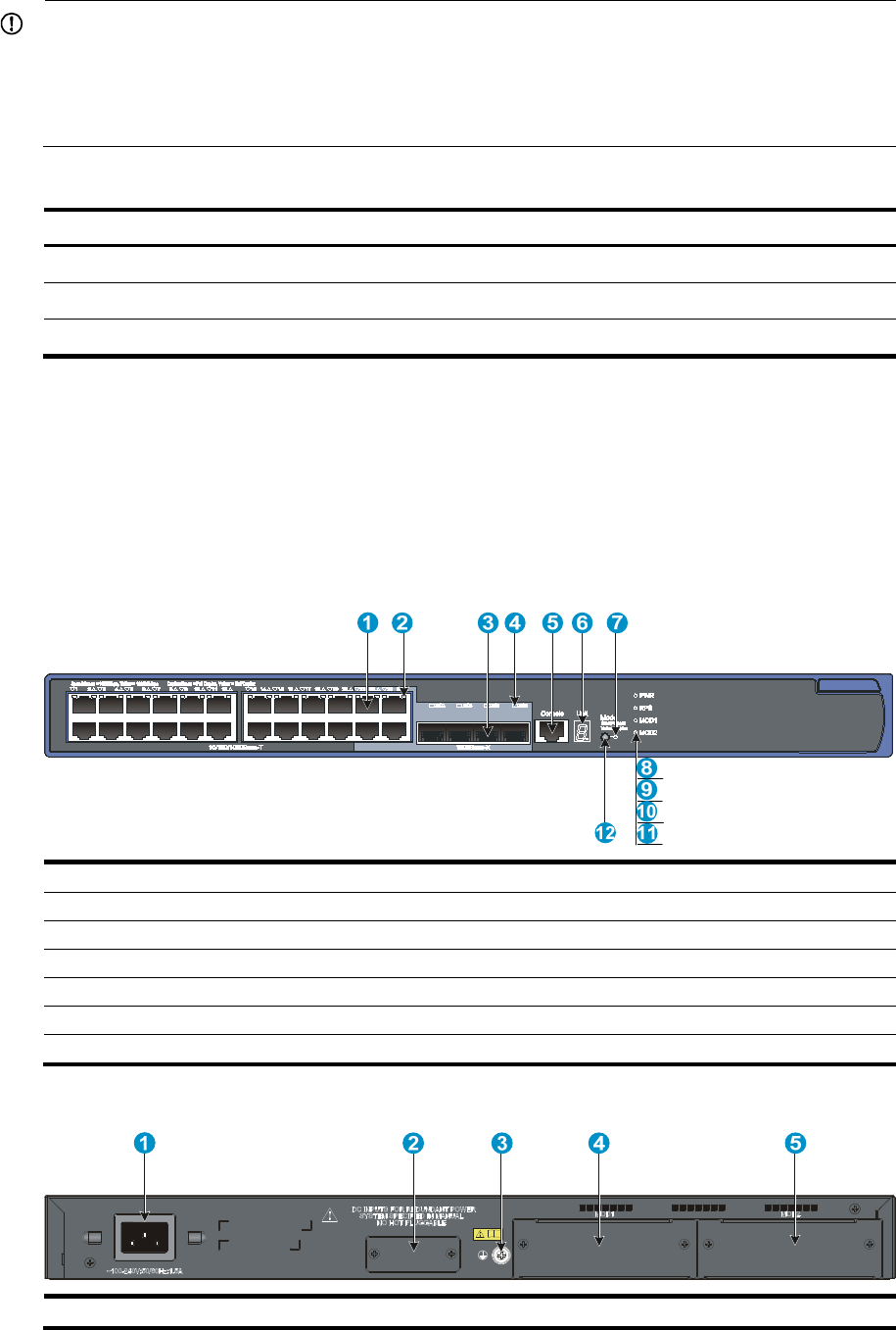
52
IMPORTANT:
For regulatory identification purposes, the HP 5120-8G SI, HP 5120-8G-PPoE+ SI, and HP
5120-8G-PoE+ SI products are assigned Regulatory Model Numbers (RMN). The Regulatory Model
Numbers for these products are listed below. These re
g
ulatory numbers should not be confused with the
marketing names HP 5120, or product numbers JG308A, JG310A, and JG309A.
Table 12 Regulatory Model Numbers in the HP 5120 8G SI Switch Series
Product code RMN HP description
JG308A BJNGA-AD0006 HP 5120-8G SI Switch
JG310A BJNGA-AD0007 HP 5120-8G-PPoE+ SI Switch
JG309A BJNGA-AD0008 HP 5120-8G-PoE+ SI Switch
This chapter describes the chassis panel views of the 5120 EI and 5120 SI switches.
Chassis views
5120-24G EI (2 slots)/5120-24G EI TAA (2 slots)
Figure 58 Front panel
(1) 10/100/1000Base-T auto-sensin
g
Ethernet port
(2) 10/100/1000Base-T Ethernet port LED
(3) 1000Base-X SFP port (4) 1000Base-X SFP port LED
(5) Console port (6)
Seven-se
g
ment LED (Unit)
(7) Port mode LED (Mode) (8)
System status LED (PWR)
(9) RPS status LED (RPS) (10) Interface card 1 status LED (MOD1)
(11) Interface card 2 status LED (MOD2)
(12)
Port LED mode switchin
g
button
Figure 59 Rear panel
(1) AC-input power receptacle (2) RPS receptacle (shipped with a protective cover)
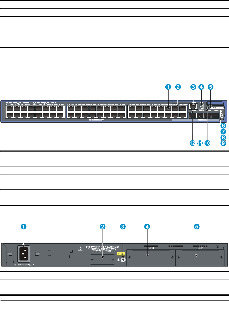
53
(3) Groundin
g
screw (4) Interface card slot 1
(MOD1)
(5) Interface card slot 2 (MOD2)
NOTE:
The 5120-24G EI (2 slots) and 5120-24G EI TAA (2 slots) switches come with the expansion interface
card slots covered by filler panels.
5120-48G EI (2 slots)/5120-48G EI TAA (2 slots)
Figure 60 Front panel
(1) 10/100/1000Base-T auto-sensin
g
Ethernet port
(2) 10/100/1000Base-T Ethernet port LED
(3) Console port (4) Seven-segment LED (Unit)
(5) Port mode LED (Mode) (6)
System status LED (PWR)
(7) RPS status LED (RPS) (8)
Interface card 1 status LED (MOD1)
(9) Interface card 2 status LED (MOD2) (10) Port LED mode switching button
(11) 1000Base-X SFP port (12)
1000Base-X SFP port LED
Figure 61 Rear panel
(1) AC-input power receptacle (2) RPS receptacle (shipped with a protective cover)
(3) Groundin
g
screw (4) Interface card slot 1
(MOD1)
(5) Interface card slot 2 (MOD2)
NOTE:
The 5120-48G EI (2 slots) and 5120-48G EI TAA (2 slots) switches come with the expansion interface
card slots covered by filler panels.
5120-24G EI
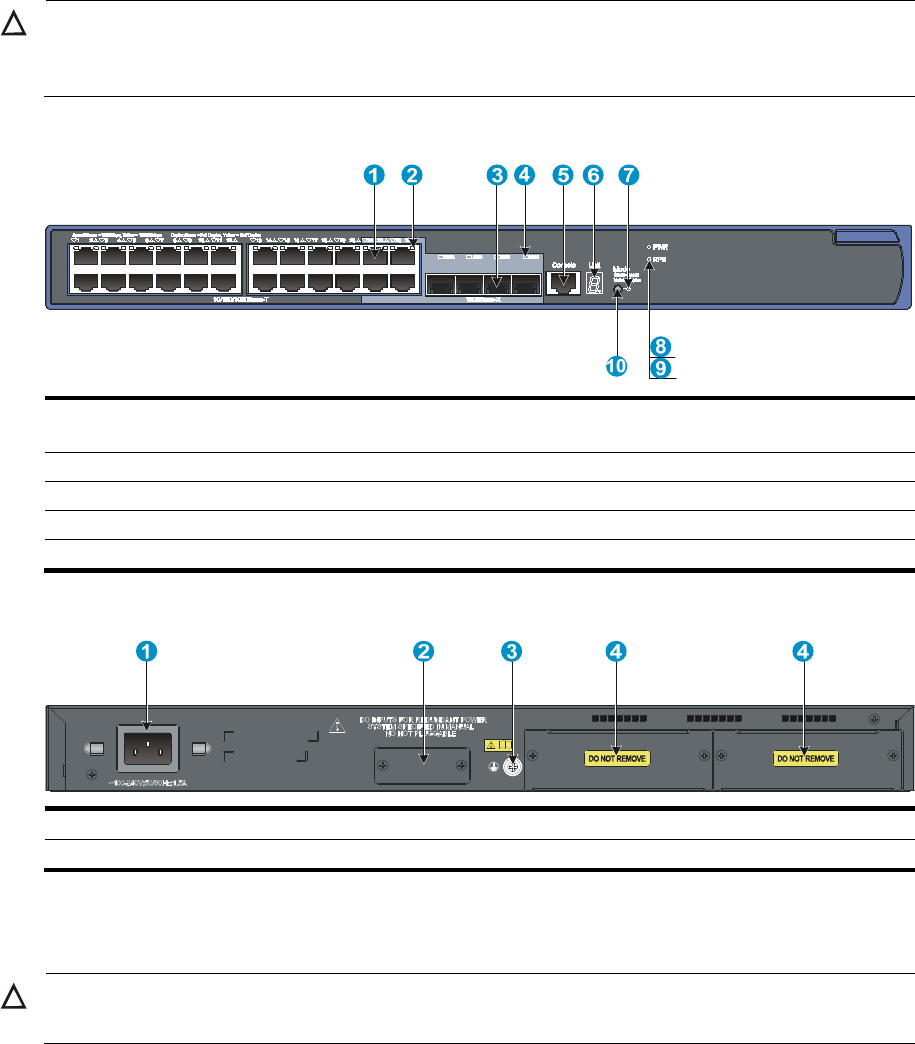
54
CAUTION:
The 5120-24G EI switch does not support interface cards. To ensure
g
ood ventilation, do not remove the
interface card slot filler panels.
Figure 62 Front panel
(1) 10/100/1000Base-T auto-sensing Ethernet
port
(2) 10/100/1000Base-T Ethernet port LED
(3) SFP port (4)
SFP port LED
(5) Console port (6) Seven-segment LED (Unit)
(7) Port mode LED (Mode) (8)
System status LED (PWR)
(9) RPS status LED (RPS) (10)
Port LED mode switchin
g
button
Figure 63 Rear panel
(1) AC-input power receptacle (2) RPS receptacle
(3) Groundin
g
screw (4) "DO NOT REMOVE" label
5120-48G EI
CAUTION:
The 5120-48G EI switch does not support interface cards.
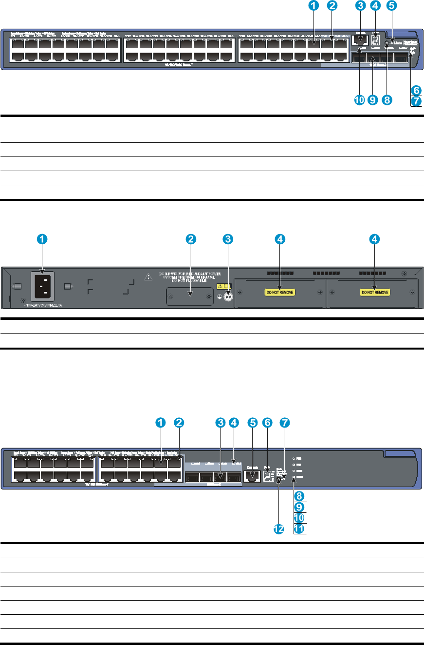
55
Figure 64 Front panel
(1) 10/100/1000Base-T auto-sensing Ethernet
port
(2) 10/100/1000Base-T Ethernet port LED
(3) Console port (4)
Seven-se
g
ment LED (Unit)
(5) Port mode LED (Mode) (6) System status LED (PWR)
(7) RPS status LED (RPS) (8)
Port LED mode switchin
g
button
(9) SFP port (10)
SFP port LED
Figure 65 Rear panel
(1)
A
C-input power receptacle (2)
RPS receptacle (with filler panel)
(3) Groundin
g
screw (4) "DO NOT REMOVE" label
5120-24G-PoE+ EI (2 slots)/5120-24G-PoE+ EI TAA (2 slots)
Figure 66 Front panel
(1) 10/100/1000Base-T auto-sensing Ethernet port
(2) 10/100/1000Base-T Ethernet port LED
(3) 1000Base-X SFP port (4)
1000Base-X SFP port LED
(5) Console port (6) Seven-segment LED (Unit)
(7) Port mode LED (Mode) (8)
System status LED (PWR)
(9) RPS status LED (RPS) (10) Interface card 1 status LED (MOD1)
(11) Interface card 2 status LED (MOD2) (12) Port LED mode switching button
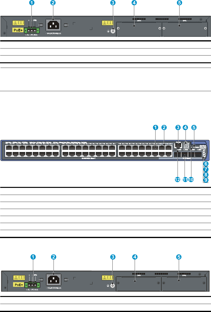
56
Figure 67 Rear panel
(1) RPS receptacle (2) AC-input power receptacle
(3) Groundin
g
screw (4) Interface card slot 1
(MOD1)
(5) Interface card slot 2 (MOD2)
NOTE:
The 5120-24G-PoE+ EI (2 slots) and 5120-24G-PoE+ EI TAA (2 slots) switches come with the expansion
interface card slots covered by filler panels.
5120-48G-PoE+ EI (2 slots)/5120-48G-PoE+ EI TAA (2 slots)
Figure 68 Front panel
(1) 10/100/1000Base-T auto-sensin
g
Ethernet port
(2) 10/100/1000Base-T Ethernet port LED
(3) Console port (4) Seven-segment LED (Unit)
(5) Port mode LED (Mode) (6)
System status LED (PWR)
(7) RPS status LED (RPS) (8)
Interface card 1 status LED (MOD1)
(9) Interface card 2 status LED (MOD2) (10) Port LED mode switching button
(11) 1000Base-X SFP port (12)
1000Base-X SFP port LED
Figure 69 Rear panel
(1) RPS receptacle (2) AC-input power receptacle
(3) Grounding screw (4) Interface card slot 1 (MOD1)
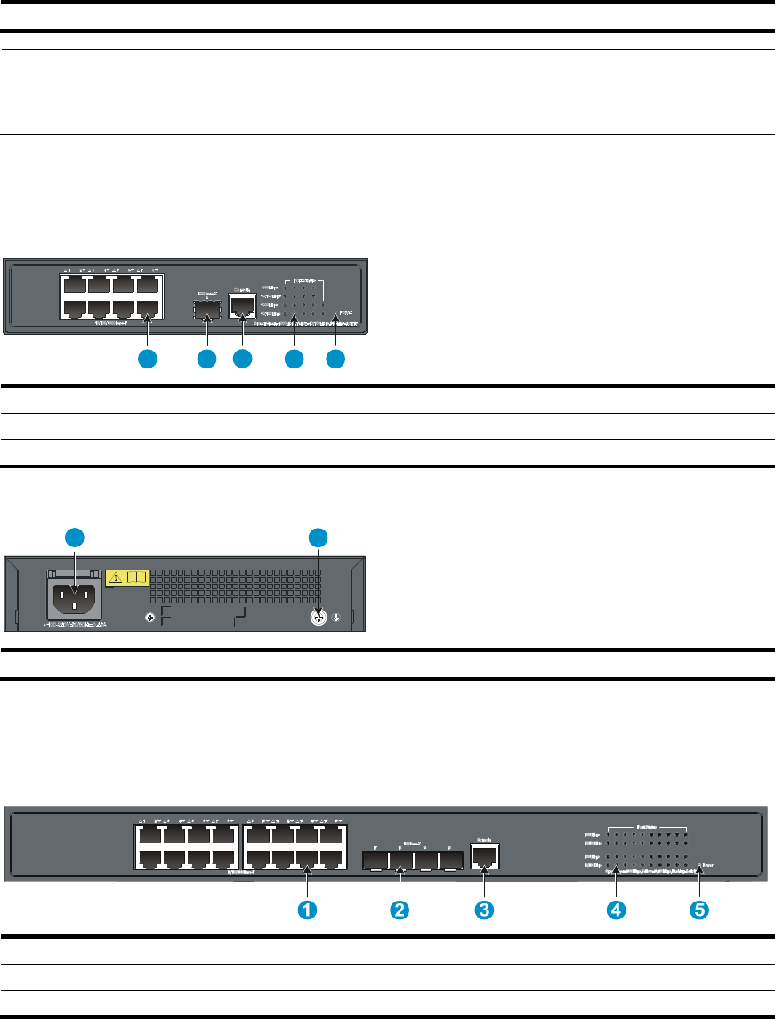
57
(5) Interface card slot 2 (MOD2)
NOTE:
The 5120-48G-PoE+ EI (2 slots) and 5120-48G-PoE+ EI TAA (2 slots) switches come with the expansion
interface card slots covered by filler panels.
5120-8G SI
Figure 70 Front panel
1 2 34 5
(1) 10/100/1000Base-T auto-sensin
g
Ethernet port
(2) 1000Base-X SFP port
(3) Console port (4) Port LED
(5) Power LED (Power)
Figure 71 Rear panel
21
(1) AC-input power receptacle (2) Grounding screw
5120-16G SI
Figure 72 Front panel
(1) 10/100/1000Base-T auto-sensin
g
Ethernet port
(2) 1000Base-X SFP port
(3) Console port (4) Port LED
(5) Power LED (Power)
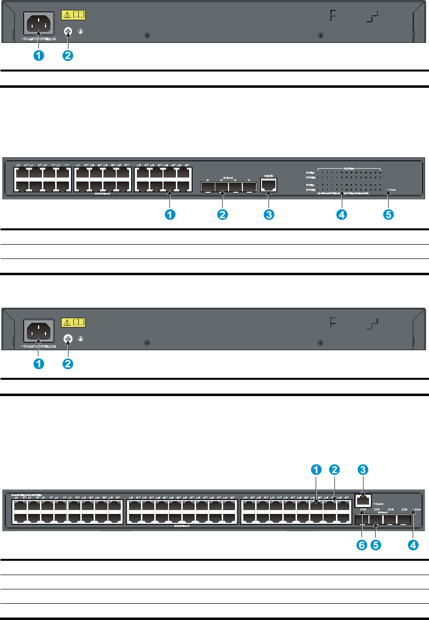
58
Figure 73 Rear panel
(1) AC-input power receptacle (2) Grounding screw
5120-24G SI
Figure 74 Front panel
(1) 10/100/1000Base-T auto-sensin
g
Ethernet port
(2) 1000Base-X SFP port
(3) Console port (4) Port LED
(5) Power LED (Power)
Figure 75 Rear panel
(1) AC-input power receptacle (2) Grounding screw
5120-48G SI
Figure 76 Front panel
(1) 10/100/1000Base-T auto-sensin
g
Ethernet port
(2) 10/100/1000Base-T Ethernet port LED
(3) Console port (4) Power LED (Power)
(5) 1000Base-X SFP port (6) 1000Base-X SFP port LED
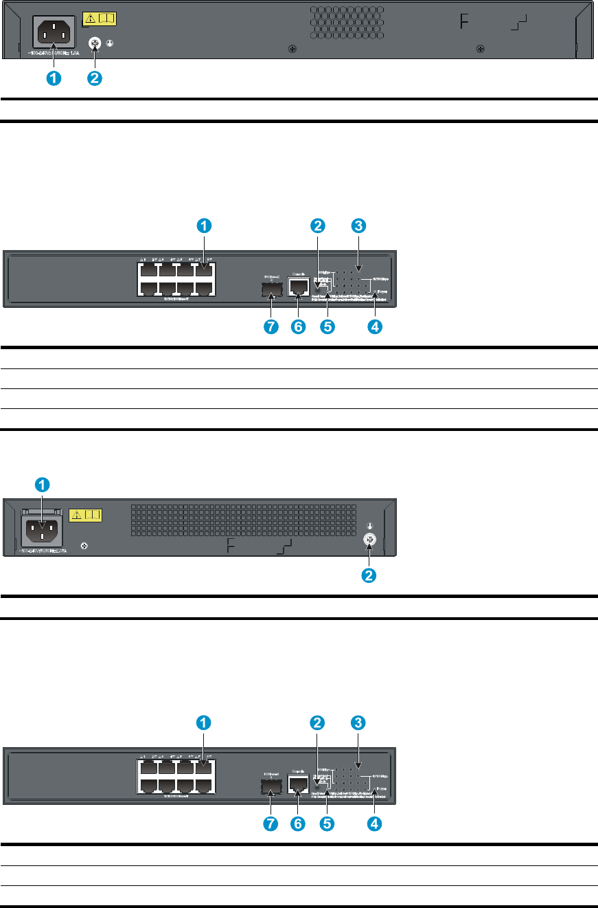
59
Figure 77 Rear panel
(1) AC-input power receptacle (2) Grounding screw
5120-8G-PPoE+ SI
Figure 78 Front panel
(1) 10/100/1000Base-T auto-sensing Ethernet port (2) Port LED mode switching button
(3) Port LED (4) Power LED (Power)
(5) Port mode LED
(6) Console port
(7) 1000Base-X SFP port
Figure 79 Rear panel
(1) AC-input power receptacle (2) Grounding screw
5120-8G-PoE+ SI
Figure 80 Front panel
(1) 10/100/1000Base-T auto-sensing Ethernet port (2) Port LED mode switching button
(3) Port LED (4) Power LED (Power)
(5) Port mode LED
(6) Console port
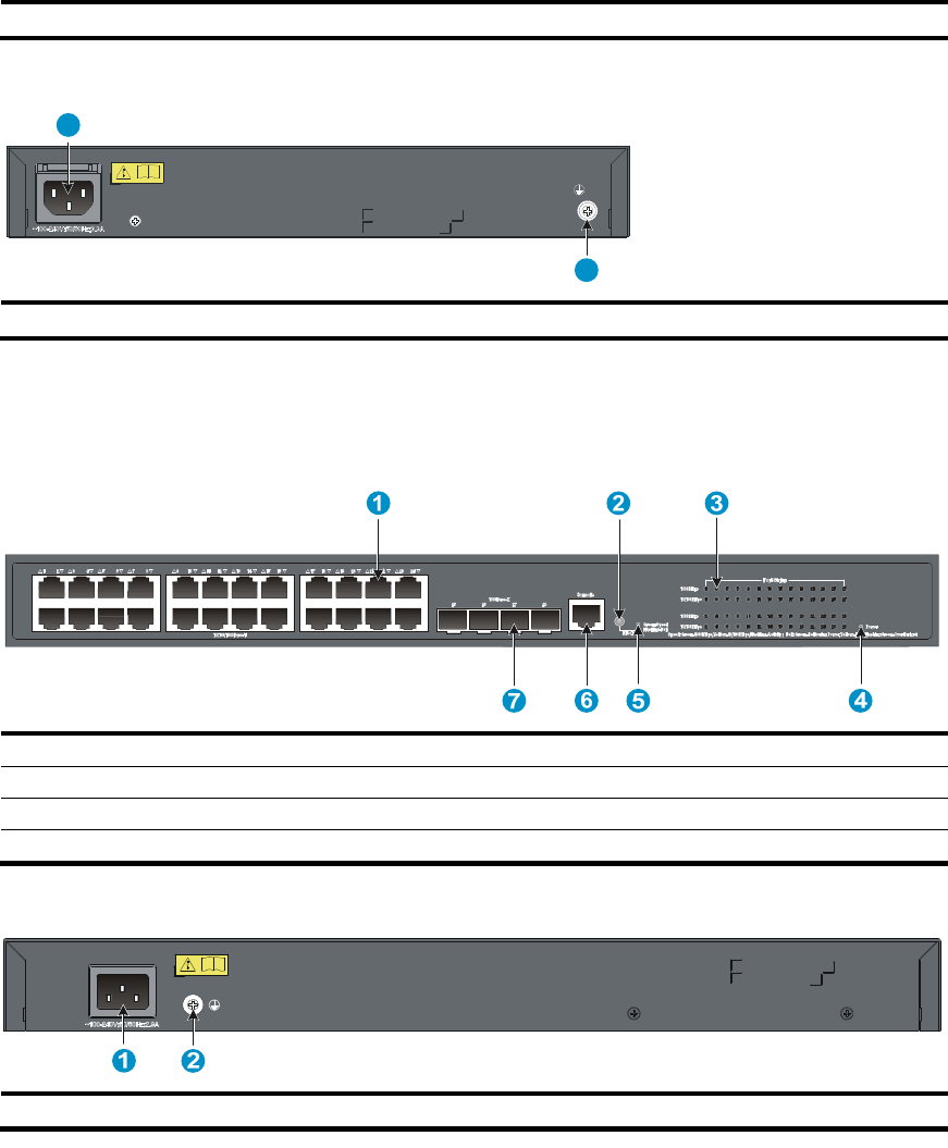
60
(7) 1000Base-X SFP port
Figure 81 Rear panel
2
1
(1)
A
C-input power receptacle (2) Groundin
g
screw
5120-24G-PPoE+ SI
Figure 82 Front panel
(1) 10/100/1000Base-T auto-sensin
g
Ethernet port
(2) Port LED mode switchin
g
button
(3) Port LED (4) Power LED (Power)
(5) Port mode LED
(6) Console port
(7) 1000Base-X SFP port
Figure 83 Rear panel
(1)
A
C-input power receptacle (2) Groundin
g
screw
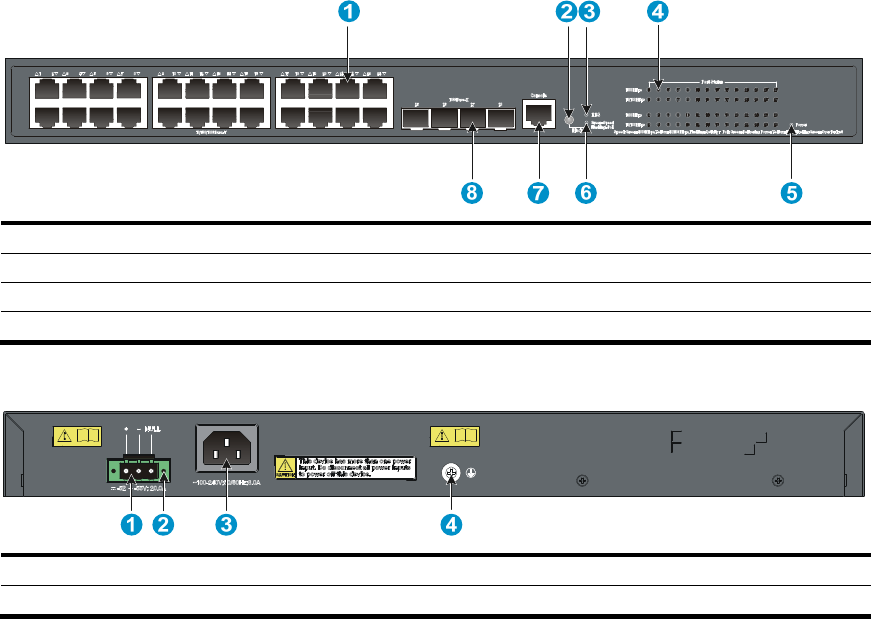
61
5120-24G-PoE+ SI
Figure 84 Front panel
(1) 10/100/1000Base-T auto-sensing Ethernet port (2) Port LED mode switching button
(3) RPS status LED (RPS) (4) Port LED
(5) Power LED (Power) (6) Port mode LED
(7) Console port (8) 1000Base-X SFP port
Figure 85 Rear panel
(1) DC receptacle (2) Screw hole of the plug
(3)
A
C-input power receptacle (4) Groundin
g
screw

62
Technical specifications
Chassis dimensions and weights
Chassis Dimensions (H ×
W ×
D)
Wei
g
ht
5120-24G EI
5120-24G EI (2 slots)
5120-24G EI TAA (2 slots)
43.6 × 440 × 300 mm
(1.72 × 17.32 × 11.81 in) < 4.5 kg (9.92 lb)
5120-24G-PoE+ EI (2 slots)
5120-24G-PoE+ EI TAA (2 slots)
43.6 × 440 × 420 mm
(1.72 × 17.32 × 16.54 in) < 7.0 kg (15.43 lb)
5120-48G EI
5120-48G EI (2 slots)
5120-48G EI TAA (2 slots)
43.6 × 440 × 300 mm
(1.72 × 17.32 × 11.81 in) < 5 kg (11.02 lb)
5120-48G-PoE+ EI (2 slots)
5120-48G-PoE+ EI TAA (2 slots)
43.6 × 440 × 420 mm
(1.72 × 17.32 × 16.54 in) < 7.5 kg (16.53 lb)
5120-8G SI 43.6 × 210 × 210 mm
(1.72 × 8.27 × 8.27 in) ≤ 2 kg (4.41 lb)
5120-16G SI
5120-24G SI
43.6 × 440 × 160 mm
(1.72 × 17.32 × 6.30 in) ≤ 3 kg (6.61 lb)
5120-8G-PPoE+ SI
5120-8G-PoE+ SI
43.6 × 300 × 260 mm
(1.72 × 11.81 × 10.24 in) ≤ 3 kg (6.61 lb)
5120-24G-PPoE+ SI
5120-24G-PoE+ SI
43.6 × 440 × 420 mm
(1.72 × 17.32 × 16.54 in) ≤ 7 kg (15.43 lb)
5120-48G SI 43.6 × 440 × 260 mm
(1.72 × 17.32 × 10.24 in) ≤ 5 kg (11.02 lb)
Ports and interface card slots
Chassis Console
ports
10/100/1000Base-T
auto-sensing Ethernet
p
orts
1000Base-X
SFP ports
Interafce
card slots
5120-24G EI 1 24 4 N/A
5120-24G EI (2 slots)
5120-24G EI TAA (2 slots) 1 24 4 2
5120-24G-PoE+ EI (2 slots)
5120-24G-PoE+ EI TAA (2 slots) 1 24, PoE+ 4 2
5120-48G EI 1 48 4 N/A
5120-48G EI (2 slots)
5120-48G EI TAA (2 slots) 1 48 4 2

63
Chassis Console
ports
10/100/1000Base-T
auto-sensing Ethernet
p
orts
1000Base-X
SFP ports
Interafce
card slots
5120-48G-PoE+ EI (2 slots)
5120-48G-PoE+ EI TAA (2 slots) 1 48, PoE+ 4 2
5120-8G SI 1 8 1 N/A
5120-16G SI 1 16 4 N/A
5120-24G SI 1 24 4 N/A
5120-8G-PoE+ SI 1 8, PoE+ 1 N/A
5120-8G-PPoE+ SI 1 8, PPoE+ 1 N/A
5120-24G-PoE+ SI 1 24, PoE+ 4 N/A
5120-24G-PPoE+ SI 1 24, PPoE+ 4 N/A
5120-48G SI 1 48 4 N/A
NOTE:
On a 5120 EI switch, the last four 10/100/1000Base-T Ethernet ports and the four SFP ports are
copper/fiber combo ports in pairs, as shown in Table 15. They form four combo interfaces. When one
port in a pair is activated, the other port automatically shuts down.
Environmental specifications
Chassis O
p
eratin
g
tem
p
erature
Relative humidit
y
All chassis 0°C to 45°C (32°F to 113°F) 10% to 90%, noncondensing
Power specifications
Power input types
Chassis AC-in
p
ut
p
ower rece
p
tacle
RPS rece
p
tacle
All 5120 EI chassis,
5120-24G-PoE+ SI 1 1
All 5120 SI chassis but the
5120-24G-PoE+ SI 1 N/A
The RPS can supply power to your switch when the AC power line fails or cannot supply sufficient power.
AC input voltage specifications
Chassis Rated volta
g
e ran
g
e
Max volta
g
e ran
g
e
All chassis 100 VAC to 240 VAC @ 50 Hz or 60
Hz 90 VAC to 264 VAC @ 47 Hz to 63 Hz

64
RPS DC input voltage specifications and RPS compatibility
Chassis RPS input rated voltage
ran
g
e
Compatible RPS
5120-24G EI
5120-24G EI (2 slots)
5120-24G EI TAA (2 slots)
5120-48G EI
5120-48G EI (2 slots)
5120-48G EI TAA (2 slots)
10.8 VDC to 13.2 VDC A-RPS800 (JD183A)
5120-24G-PoE+ EI (2 slots)
5120-24G-PoE+ EI TAA (2 slots)
5120-48G-PoE+ EI (2 slots)
5120-48G-PoE+ EI TAA (2 slots)
–52 VDC to –55 VDC A-RPS1600 (JG136A)
5120-24G-PoE+ SI –52 VDC to –55 VDC A-RPS1600 (JG136A)
Power consumption specifications for non-PoE switches
Chassis Minimum power
consum
p
tion
Maximum power consumption
5120-24G EI 35 W 62 W
5120-24G EI (2 slots)
5120-24G EI TAA (2 slots) 36 W 103 W
5120-48G EI 54 W 110 W
5120-48G EI (2 slots)
5120-48G EI TAA (2 slots) 55 W 145 W
5120-8G SI 8.7 W 14.4 W
5120-16G SI 11.9 W 25.1 W
5120-24G SI 13.4 W 31.5 W
5120-48G SI 25.7 W 59.8 W
Power consumption specifications for PoE switches
Chassis
Maximum
PoE power
p
er
p
ort
Total PoE output
Minimum
power
consum
p
tion
Maximum power
consumption (including
total PoE out
p
ut)
5120-24G-PoE+ EI (2
slots)
5120-24G-PoE+ EI
TAA (2 slots)
30 W 370 W 62 W 585 W at AC input
491 W at RPS DC input

65
Chassis
Maximum
PoE power
p
er
p
ort
Total PoE output
Minimum
power
consum
p
tion
Maximum power
consumption (including
total PoE out
p
ut)
5120-48G-PoE+ EI (2
slots)
5120-48G-PoE+ EI
TAA (2 slots)
30 W
370 W at AC input
740 W at RPS DC
input (370 W for
ports 1 to 24, and
370 W for ports 25
to 48)
90 W 651 W at AC input
921 W at RPS DC input
5120-8G-PoE+ SI 30 W 180 W 19 W 230 W
5120-8G-PPoE+ SI 30 W 65 W 10 W 95 W
5120-24G-PoE+ SI 30 W
370 W at AC input
740 W at RPS DC
input
45.6 W at AC
input
27.5 W at RPS
DC input
528 W at AC input
832 W at RPS DC input
5120-24G-PPoE+ SI 30 W 170 W 25.0 W 255 W
Cooling system
Chassis Built-in
fans
5120-24G EI
5120-24G EI (2 slots)
5120-24G EI TAA (2 slots)
5120-48G EI
5120-48G EI (2 slots)
5120-48G EI TAA (2 slots)
4
5120-24G-PoE+ EI (2 slots)
5120-24G-PoE+ EI TAA (2 slots)
5120-48G-PoE+ EI (2 slots)
5120-48G-PoE+ EI TAA (2 slots)
6
5120-8G SI
5120-8G-PPoE+ SI N/A
5120-16G SI
5120-24G SI
5120-48G SI
1
5120-8G-PoE+ SI
5120-24G-PPoE+ SI 3
5120-24G-PoE+ SI 6

66
Appendix B FRUs and compatibility matrixes
This appendix describes the FRUs available for the 5120 EI and 5120 SI switches and their compatibility.
Interface cards (only for the 5120 EI switches)
The interface cards in this section are available for all 5120 EI switches but the 5120-24G EI and
5120-48G EI switches.
Card model Product
code Description Support for IRF
Compatible transceiver
modules/cables
LSPM2GP2P JD367A Provides two Gbps SFP
fiber ports No
See "GE SFP transceiver
modules."
NOTE:
The card does not support the
transceiver module coded
JD089B.
LSPM2SP2P JD368B Provides two 10 Gbps
SFP+ fiber ports Yes See "10-GE SFP+ transceiver
modules" and "SFP+ cables."
LSPM1XP2P JD359B Provides two 10 Gbps
XFP fiber ports Yes See "10-GE XFP transceiver
modules."
LSPM1XP1P JD361B Provides one 10 Gbps
XFP fiber port Yes See "10-GE XFP transceiver
modules."
LSPM1CX2P JD360B Provides two 10 Gbps
copper ports Yes See "CX4 cables."
LSPM1XGT2P JG535A
Provides two
1/10GBase-T Ethernet
ports
Yes N/A
NOTE:
For more information about the interface cards, see the user guides for the interface cards.
SFP/SFP+/XFP transceiver modules and SFP+/CX4
cables (only for the 5120 EI switches)
To guarantee the functionality of the SFP/SFP+/XFP ports, use only HP transceiver modules.
The transceiver modules available for this switch series are subject to change over time. For the most
up-to-date list of transceiver modules, consult your HP sales representative or technical support engineer.
For the transceiver module specifications, see HP A-Series Switches Transceiver Modules User Guide. For
information about installing a transceiver module, see Pluggable SFP/SFP+/XFP Transceiver Modules
Installation Guide.

67
GE SFP transceiver modules
Product
code Module description
Central
wavelength
(nm)
Cable/fiber
diameter
(μm)
Multimode
fiber modal
bandwidth
(MHz × km)
Max
transmission
distance
JD118B HP X120 1G SFP LC SX
Transceiver 850
50/125
500 550 m
(1804.46 ft)
400 500 m
(1640.42 ft)
62.5/125
200 275 m
(902.23 ft)
160 220 m
(721.78 ft)
JD119B HP X120 1G SFP LC LX
Transceiver 1310
9/125 N/A 10 km (6.21
miles)
50/125 500, 400
550 m
(1804.46 ft)
62.5/125 500 550 m
(1804.46 ft)
JD061A HP X125 1G SFP LC LH40
1310nm Transceiver 1310 9/125 N/A 40 km (24.86
miles)
JD062A HP X120 1G SFP LC LH40
1550nm Transceiver 1550 9/125 N/A 40 km (24.86
miles)
JD063B HP X125 1G SFP LC LH70
Transceiver 1550 9/125 N/A 70 km (43.50
miles)
JD103A HP X120 1G SFP LC
LH100 Transceiver 1550 9/125 N/A 100 km (62.14
miles)
JD098B HP X120 1G SFP LC BX
10-U Transceiver
TX: 1310nm
RX: 1490nm 9/125 N/A 10 km (6.21
miles)
JD099B HP X120 1G SFP LC BX
10-D Transceiver
TX: 1490nm
RX: 1310nm 9/125 N/A 10 km (6.21
miles)
JD089B HP X120 1G SFP RJ45 T
Transceiver N/A Category-5
twisted pair N/A 100 m
(328.08 ft)
IMPORTANT:
You must use the transceiver modules coded JD098B and JD099B in pairs.

68
10-GE SFP+ transceiver modules
Product code Module
description
Central
wavelength
(nm)
Fiber
diameter
(μm)
Multimode fiber
modal bandwidth
(MHz × km)
Max
transmission
distance
JD092B
HP X130 10G
SFP+ LC SR
Transceiver
850
50/125
2000 300 m (984.25
ft)
500 82 m (269.03 ft)
400 66 m (216.54 ft)
62.5/125 200 33 m (108.27 ft)
160 26 m (85.3 ft.)
JD093B
HP X130 10G
SFP+ LC LRM
Transceiver
1310
50/125
1500, 500 220 m (721.78
ft)
400 100 m (328.08
ft)
62.5/125 200, 160 220 m (721.78
ft)
JD094B
HP X130 10G
SFP+ LC LR
Transceiver
1310 9/125 N/A 10 km (6.21
miles)
JG234A
HP X130 10G
SFP+ LC ER
40km
Transceiver
1550 9/125 N/A 40 km (24.86
miles)
NOTE:
For the SFP+ cables available for connecting the SFP+ ports, see "SFP+ cables."
SFP+ cables
Product code Cable descri
p
tion
Cable len
g
th
JD095C HP X240 10G SFP+ SFP+ 0.65m DA Cable 0.65 m (2.13 ft)
JD096C HP X240 10G SFP+ SFP+ 1.2m DA Cable 1.2 m (3.94 ft)
JD097C HP X240 10G SFP+ SFP+ 3m DA Cable 3 m (9.84 ft)
JG081C HP X240 10G SFP+ SFP+ 5m DA Cable 5 m (16.40 ft)
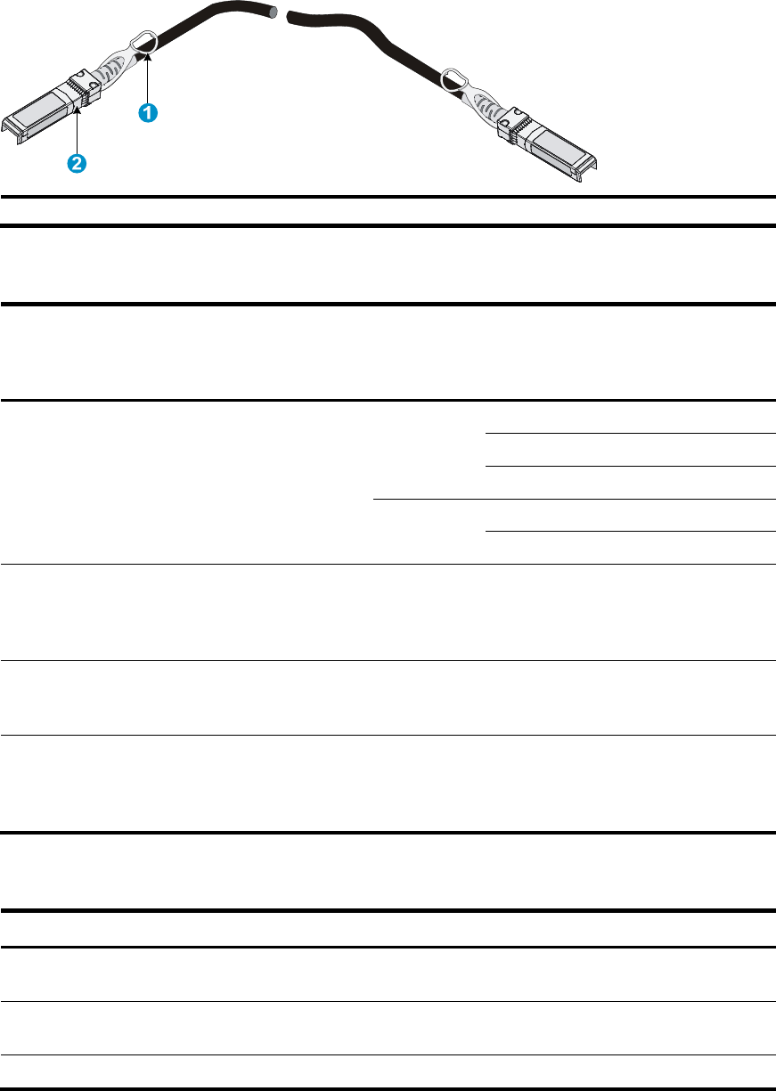
69
Figure 86 SFP+ cable
(1) Pull latch (2) Connector
10-GE XFP transceiver modules
Product code Module
description
Central
wavelength
(nm)
Fiber
diameter
(μm)
Multimode
fiber modal
bandwidth
(MHz
×
km)
Max transmission
distance
JD117B
HP X130 10G
XFP LC SR
Transceiver
850
50/125
2000 300 m (984.25 ft)
500 82 m(269.03 ft)
400 66 m(216.54 ft)
62.5/125 220 33 m (108.27 ft)
160 26 m (85.3 ft)
JD108B
HP X130 10G
XFP LC LR
1310nm
Transceiver
1310 9/125 N/A 10 km (6.21 miles)
JD121A
HP X135 10G
XFP LC ER
Transceiver
1550 9/125 N/A 40 km (24.86 miles)
JD107A
HP X130 10G
XFP LC ZR
1550nm
Transceiver
1550 9/125 N/A 80 km (49.71 miles)
CX4 cables
Product code Cable description Connector type Cable length
JD363B HP X230 Local Connect 50cm
CX4 Cable 4X Infiniband 0.5 m (19.69 in)
JD364B HP X230 Local Connect 100cm
CX4 Cable 4X Infiniband 1 m (39.37 in)
JD365A HP X230 CX4 to CX4 3m Cable
4X Infiniband 3 m (118.11 in)
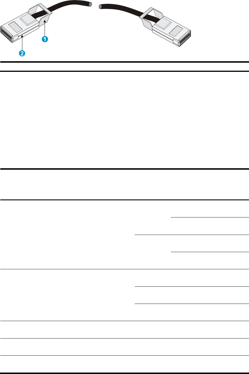
70
Figure 87 CX4 cable
(1) Pull latch (2) Connector
SFP transceiver modules and SFP Stacking Kit (only
for the 5120 SI switches)
To guarantee the functionality of the SFP ports, use only HP SFP transceiver modules.
The SFP transceiver modules available for this switch series are subject to change over time. For the most
up-to-date list of SFP transceiver modules, consult your HP sales representative or technical support
engineer.
For the SFP transceiver module specifications, see HP A-Series Switches Transceiver Modules User Guide.
Product
code Module description
Central
wavelength
(nm)
Cable/fiber
diameter
(μm)
Multimode
fiber modal
bandwidth
(MHz × km)
Maximum
transmission
distance
JD118B HP X120 1G SFP LC SX
Transceiver 850
50/125
500 550 m
(1804.46 ft)
400 500 m
(1640.42 ft)
62.5/125
200 275 m
(902.23 ft)
160 220 m
(721.78 ft)
JD119B HP X120 1G SFP LC LX
Transceiver 1310
9/125 N/A 10 km (6.21
miles)
50/125 500, 400
550 m
(1804.46 ft)
62.5/125 500 550 m
(1804.46 ft)
JD061A HP X125 1G SFP LC LH40
1310nm Transceiver 1310 9/125 N/A 40 km (24.86
miles)
JD062A HP X120 1G SFP LC LH40
1550nm Transceiver 1550 9/125 N/A 40 km (24.86
miles)
JD063B HP X125 1G SFP LC LH70
Transceiver 1550 9/125 N/A 70 km (43.50
miles)

71
Product
code Module description
Central
wavelength
(nm)
Cable/fiber
diameter
(μm)
Multimode
fiber modal
bandwidth
(MHz × km)
Maximum
transmission
distance
JD098B HP X120 1G SFP LC BX
10-U Transceiver
TX: 1310nm
RX: 1490nm 9/125 N/A 10 km (6.21
miles)
JD099B HP X120 1G SFP LC BX
10-D Transceiver
TX: 1490nm
RX: 1310nm 9/125 N/A 10 km (6.21
miles)
JD089B HP X120 1G SFP RJ45 T
Transceiver N/A Category-5
twisted pair N/A 100 m
(328.08 ft)
JD324A HP A3600 Switch SFP
Stacking Kit N/A UTP/STP N/A 1.5 m (4.92 ft)
IMPORTANT:
You must use the transceiver modules coded JD098B and JD099B in pairs.

72
Appendix C Ports and LEDs
Ports
Console port
Every 5120 EI or 5120 SI switch provides one console port on the front panel.
Table 13 Console port specifications
Item S
p
ecification
Connector type RJ-45
Compliant standard EIA/TIA-232
Transmission baud rate 9600 bps (default) to 115200 bps
Service
• Provides connection to an ASCII terminal.
• Provides connection to the serial port of a local or remote
(through a pair of modems) PC running terminal emulation
program.
10/100/1000Base-T Ethernet port
Table 14 10/100/1000Base-T Ethernet port specifications
Item S
p
ecification
Connector type RJ-45
Interface standard
• 10 Mbps, half/full duplex
• 100 Mbps, half/full duplex
• 1000 Mbps, full duplex
• MDI/MDI-X, auto-sensing
Max transmission distance 100 m (328.08 ft)
Transmission medium Category-5 (or above) twisted pair cable
Standards IEEE 802.3i, 802.3u, 802.3ab
SFP port
All 5120 EI and 5120 SI switches have 1000Base-X SFP ports. For the SFP transceiver modules available
for the 5120 EI switches, see "GE SFP transceiver modules." For the SFP transceiver modules available for
the 5120 SI switches, see "SFP transceiver modules and SFP Stacking Kit (only for the 5120 SI switches)."

73
Combo interface (only available on the 5120 EI switches)
On a 5120 EI switch, the last four 10/100/1000Base-T Ethernet ports and the four SFP ports are
copper/fiber combo ports in pairs, as shown in Table 15. They form four combo interfaces. When one
port in a pair is activated, the other port automatically shuts down. For more information about combo
interfaces, see HP 5120 EI Switch Series Configuration Guides.
Table 15 Copper/fiber combo ports in pairs
Chassis SFP
p
ort 10/100/1000Base-T Ethernet
p
ort
5120-24G EI (2 slots)
5120-24G EI TAA (2 slots)
5120-24G-PoE+ EI (2 slots)
5120-24G-PoE+ EI TAA (2 slots)
5120-24G EI
GigabitEthernet 1/0/25 GigabitEthernet 1/0/22
GigabitEthernet 1/0/26 GigabitEthernet 1/0/24
GigabitEthernet 1/0/27 GigabitEthernet 1/0/21
GigabitEthernet 1/0/28 GigabitEthernet 1/0/23
5120-48G EI (2 slots)
5120-48G EI TAA (2 slots)
5120-48G-PoE+ EI (2 slots)
5120-48G-PoE+ EI TAA (2 slots)
5120-48G EI
GigabitEthernet 1/0/49 GigabitEthernet 1/0/46
GigabitEthernet 1/0/50 GigabitEthernet 1/0/48
GigabitEthernet 1/0/51 GigabitEthernet 1/0/45
GigabitEthernet 1/0/52 GigabitEthernet 1/0/47
LEDs (for the 5120 EI switches)
Table 16 LEDs at a glance
LED Availabilit
y
System status LED Entire series
RPS status LED Entire series
Port mode LED Entire series
Seven-segment LED Entire series
10/100/1000Base-T Ethernet port LED Entire series
SFP port LED Entire series
Interface card status LED Entire series (except the 5120-24G EI and 5120-48G EI)
System status LED
The system status LED shows the operating status of the switch.
Table 17 System status LED description
LED mark Status
Descri
p
tion
PWR
Steady green The switch is operating correctly.
Flashing green (1 Hz) The switch is performing power-on self
test (POST).

74
LED mark Status
Descri
p
tion
Steady red POST has failed.
Flashing yellow (1 Hz) Some ports have failed to pass POST.
Off The switch is powered off.
RPS status LED
The RPS status LED shows the operating status of the RPS DC input.
Table 18 RPS status LED description for the non-PoE switches
LED mark Status Descri
p
tion
RPS
Steady green Both the RPS DC input and the AC input are normal, or an RPS is
connected and the AC input is normal.
Steady yellow The RPS DC input is normal, but the AC input is disconnected or
has failed.
Off No RPS is connected.
Table 19 RPS status LED description for the PoE switches
LED mark Status Descri
p
tion
RPS
Steady green Both the RPS DC input and the AC input are normal.
Steady yellow The RPS power input is normal, but the AC input is disconnected or
has failed.
Off The RPS power input is abnormal or no RPS is connected.
Port mode LED
The port mode LED indicates the type of information that the network port LEDs are showing. You can use
the port LED mode switching button to change the type of displayed port information.
Table 20 Port mode LED description
LED mark Status Descri
p
tion
Mode
Steady green The network port LEDs are showing port rates.
Flashing green (1 Hz) (available
only for the PoE switches)
The network port LEDs are showing the status of
PoE power supply on the ports.
Steady yellow The network port LEDs are showing duplex
modes.
Seven-segment LED
The seven-segment LED, together with the system status LED, shows detailed system operating information
(see Table 21).
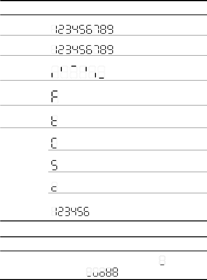
75
The seven-segment LED can also show the total PoE output power as a percentage of the maximum PoE
output power that a PoE switch can supply (see Table 22). The PoE switches include 5120-24G-PoE+ EI (2
slots), 5120-24G-PoE+ EI TAA (2 slots), 5120-48G-PoE+ EI (2 slots), and 5120-48G-PoE+ EI TAA (2 slots).
Table 21 Seven-segment LED description (I)
System status LED
(PWR) status Seven-segment LED (Unit) status Description
Flashing green
The LED displays numbers one by one.
POST is running, and the LED displays
the ongoing test item ID.
Flashing red
The LED displays flashing numbers.
POST has failed, and the LED flashes
the ID of the failed test item.
Flashing green
A bar rotates clockwise around the LED.
Software is loading.
Steady red
The LED displays a flashing F character.
The switch is experiencing a fan
failure.
Steady red
The LED displays a flashing t character.
The switch is in an over-temperature
condition.
Steady green
The LED displays a capital C character.
The switch is the command switch in a
cluster.
The LED displays an S character.
The switch is a member switch in a
cluster.
The LED displays a lowercase c character.
The switch is a candidate switch for a
cluster.
The LED displays a number.
The member ID of the switch in an IRF
fabric.
The 5120-24G EI and 5120-48G EI
switches do not support IRF.
Table 22 Seven-segment LED description (II)
Port mode LED
(Mode) status
System status LED
(PWR) status
Seven-segment
LED
(Unit) status
Description
Flashing green (1
Hz) (PoE mode) Steady green
The LED displays
different signs.
0 - 20
%
21 -40
%
41 -60
%
61 -80
%
81 -10
0
For example, the sign indicates that
the switch is outputting 0 to 20% of the
maximum PoE output power.

76
10/100/1000Base-T Ethernet port LED
Each 10/100/1000Base-T auto-sensing Ethernet port has a status LED to show port operating status and
activities. The port mode LED indicates the type of information (for example, port rate or duplex mode)
that the port LEDs are showing. You can use the port LED mode switching button to change the type of
displayed port information.
Table 23 10/100/1000Base-T auto-sensing Ethernet port LEDs description
Port mode LED (Mode)
status Port LED status Description
Steady green (rate mode)
Steady green
The port is operating at 1000 Mbps. The port LED
fast flashes when the port is sending or receiving
data.
Steady yellow
The port is operating at 10/100 Mbps. The port LED
fast flashes when the port is sending or receiving
data.
Flashing yellow (3 Hz) POST has failed on the port.
Off No link is present on the port.
Flashing green (1 Hz)
(PoE mode, available
only for PoE switches)
Steady green PoE power supply is normal.
Flashing green (1 Hz)
The device attached to the port requires power
higher than the maximum or currently available PoE
output power on the port.
Steady yellow
The port is experiencing a PoE failure.
The port is not supplying power, because the device
attached to the port is not a powered device.
Flashing yellow (3 Hz) POST has failed on the port.
Off The port is not supplying PoE power.
Steady yellow (duplex
mode)
Steady green
The port is operating in full duplex mode. The port
LED fast flashes when the port is sending or
receiving data.
Steady yellow
The port is operating in half duplex mode. The port
LED fast flashes when the port is sending or
receiving data.
Flashing yellow (3 Hz) POST has failed on the port.
Off No link is present on the port.
SFP port LED
Each 1000Base-X SFP port has a status LED to show port operating status and activities. The port mode
LED indicates the type of information (for example, port rate or duplex mode) that the port LEDs are
showing. You can use the port LED mode switching button to change the type of displayed port
information.

77
Table 24 SFP port LEDs description
Port mode LED (Mode) status Port LED
status
Descri
p
tion
Steady green (rate mode) or
flashing green (1 Hz, PoE mode)
Steady green
The port is operating at 1000 Mbps.
The port LED fast flashes when the port
is sending or receiving data.
Flashing yellow (3 Hz) POST has failed on the port.
Off No link is present on the port.
Steady yellow (duplex mode)
Steady green
The port is operating in full duplex
mode. The port LED fast flashes when
the port is sending or receiving data.
Flashing yellow (3 Hz) POST has failed on the port.
Off No link is present on the port.
Interface card status LED
Table 25 Interface card status LED description
LED mark Status Descri
p
tion
MOD1
MOD2
Green The interface card is in position and operating correctly.
Flashing yellow The switch does not support the interface card model, or the interface
card has failed.
Off The expansion interface card slot is empty.
LEDs (for the 5120 SI switches)
Table 26 LEDs at a glance
LED Availabilit
y
Power LED Entire series
RPS status LED 5120-24G-PoE+ SI
Port mode LED 5120-8G-PPoE+ SI, 5120-8G-PoE+ SI, 5120-24G-PPoE+ SI,
5120-24G-PoE+ SI
10/100/1000Base-T Ethernet port LED Entire series
1000Base-X SFP port LED Entire series
Power LED
The power LED shows the operation status of the switch.

78
Table 27 Power LED description
LED mark Status Description
Power
Steady green The switch is operating correctly.
Flashing green (1 Hz) The system is performing power-on self test (POST) or
downloading software.
Flashing green (3 Hz) POST has failed or another fatal error has been detected.
Off The switch has been powered off.
RPS status LED
The 5120-24G-PoE+ SI switch has one RPS status LED on its front panel to show the operating status of the
RPS DC input.
Table 28 RPS status LED description
LED mark Status Descri
p
tion
RPS Steady green The RPS DC input is normal.
Off The RPS unit is not connected or the RPS DC input is abnormal.
Port mode LED
The 5120-8G-PPoE+ SI, 5120-8G-PoE+ SI, 5120-24G-PPoE+ SI and 5120-24G-PoE+ SI switches have a
port mode LED to indicate the type of information that the network port LEDs (excluding the SFP port LEDs)
are showing. You can use the port LED mode switching button to change the type of displayed port
information.
Table 29 Port mode LED description
LED mark Status Descri
p
tion
Mode
Steady green The network port LEDs are showing port rates.
Flashing green (1 Hz) The network port LEDs are showing the status of PoE power
supply on the ports.
10/100/1000Base-T Ethernet port LED
The 5120-48G SI switch has one bi-color LED (see Table 30) for each 10/100/1000Base-T Ethernet port,
and all other 5120 SI switches have two LEDs (see Table 31) for each 10/100/1000Base-T Ethernet port.
The 5120-8G-PPoE+ SI, 5120-24G-PoE+ SI, 5120-24G-PPoE+ SI, and 5120-24G-PoE+ SI switches also use
a port mode LED to indicate the type of information that the port LEDs are displaying (see Table 32).
Table 30 Ethernet port LED description (5120-48G SI)
Status Descri
p
tion
Steady green The port is operating at 1000 Mbps.
Fast flashing green The port is sending or receiving data at 1000 Mbps.

79
Status Descri
p
tion
Steady yellow The port is operating at 10/100 Mbps.
Fast flashing yellow The port is sending or receiving data at 10/100 Mbps.
Off No link is present on the port.
Table 31 Ethernet port LEDs description (5120-16G SI/5120-24G SI)
LED Status Descri
p
tion
Green
On The port is operating at 1000 Mbps.
Fast flashing The port is sending or receiving data at 1000
Mbps.
Off The port has no link or is not operating at 1000
Mbps.
Yellow
On The port is operating at 10/100 Mbps.
Fast flashing The port is sending or receiving data at 10/100
Mbps.
Off The port has no link or is not operating at 10/100
Mbps.
Table 32 Ethernet port LED description (5120-24G-PPoE+ SI/5120-24G-PoE+ SI)
Port mode LED (Mode)
status Port LED Port LED status Description
Steady green (rate
mode)
Green
On The port is operating at 1000 Mbps.
Fast flashing The port is sending or receiving data at 1000
Mbps.
Off The port has no link or is not operating at 1000
Mbps.
Yellow
On The port is operating at 10/100 Mbps.
Fast flashing The port is sending or receiving data at
10/100 Mbps.
Off No link is present on the port.
Flashing green (PoE
mode)
Green
On PoE power supply is normal.
Flashing at 3 Hz
The device attached to the port requires power
higher than the maximum or currently
available PoE output power on the port.
Off The port is not supplying power.
Yellow
On The device attached to the port is not a
powered device or a PoE failure has occurred.
Off The port is supplying power normally or not
supplying power.

80
1000Base-X SFP port LED
Table 33 1000Base-X SFP port LEDs description
Status Descri
p
tion
Steady green The port is operating at 1000 Mbps.
Flashing green The port is sending or receiving data.
Off No link is present on the port.

81
Index
A C E F G I L M P R S T V
A
Accessing the IRF fabric to verify the configuration,44
C
Chassis views,52
Configuration terminal problems,46
Configuring basic IRF settings,43
Connecting the console cable,32
Connecting the physical IRF ports,44
Connecting the power cord,25
Contacting HP,48
Conventions,49
Cooling system,65
E
Environmental specifications,63
Examining the installation site,1
F
Fan failure (only for the 5120 EI switches),46
G
Grounding the switch,22
I
Installation tools,3
Installing a 5
120 EI switch in a 19-inch rack,5
Installing a 5
120 SI switch in a 19-inch rack,12
Installing/removing an interface card (only for the
5120 EI switches),29
Interface cards (only for the 5120 EI switches),66
IRF fabric setup flowchart,37
L
LEDs (for the 5120 EI switches),73
LEDs (for the 5120 SI switches),77
M
Mounting the switch on a workbench,18
Mounting the switch through magnet mounting,20
Mounting the switch to a wall,18
P
Planning IRF fabric setup,38
Ports,72
Power specifications,63
Power supply failure,45
Powering on the switch,36
R
Related information,48
S
Safety recommendations,1
Setting terminal parameters,33
Setting up the configuration environment,32
SFP transceiver modules and SFP Stacking Kit (only for
the 5120 SI switches),70
SFP/SFP+/XFP transceiver modules and SFP+/CX4
cables (only for the 5120 EI switches),66
T
Technical specifications,62
V
Verifying the installation,31
