5207 Installation Manual
User Manual: 5207 Installation Manual AlarmHow.net Library
Open the PDF directly: View PDF ![]() .
.
Page Count: 96

150865 i
Contents
Section 1
Introduction . . . . . . . . . . . . . . . . . . . . . . . . . . . . . . . . . . . . . . . . . . . . . . . . . . . . . . . . . . . . . . . . . . . . . . .1-1
1.1 About This Manual . . . . . . . . . . . . . . . . . . . . . . . . . . . . . . . . . . . . . . . . . . . . . . . . . . . . . . . . . . . . . . . . . . . . 1-1
1.2 Optional Accessories . . . . . . . . . . . . . . . . . . . . . . . . . . . . . . . . . . . . . . . . . . . . . . . . . . . . . . . . . . . . . . . . . . 1-2
Section 2
Agency Listings and Requirements . . . . . . . . . . . . . . . . . . . . . . . . . . . . . . . . . . . . . . . . . . . . . . . . . . .2-1
2.1 Federal Communications Commission (FCC) . . . . . . . . . . . . . . . . . . . . . . . . . . . . . . . . . . . . . . . . . . . . . . . 2-1
2.2 Underwriters Laboratories (UL) . . . . . . . . . . . . . . . . . . . . . . . . . . . . . . . . . . . . . . . . . . . . . . . . . . . . . . . . . . 2-2
2.2.1 Requirements for All Installations . . . . . . . . . . . . . . . . . . . . . . . . . . . . . . . . . . . . . . . . . . . . . . . . . . . 2-2
2.2.2 Requirements for Central Station Fire Alarm Systems . . . . . . . . . . . . . . . . . . . . . . . . . . . . . . . . . . . 2-2
2.2.3 Requirements for Auxiliary Protected Fire Alarm Systems for Fire Alarm Service . . . . . . . . . . . . . 2-3
2.2.4 Requirements for Remote Station Protected Fire Alarm Systems,
for Digital Communication or Polarity Reversal . . . . . . . . . . . . . . . . . . . . . . . . . . . . . . . . . . . . . . . 2-3
2.3 California Fire Marshal (CFM). . . . . . . . . . . . . . . . . . . . . . . . . . . . . . . . . . . . . . . . . . . . . . . . . . . . . . . . . . . 2-3
2.4 Factory Mutual (FM) . . . . . . . . . . . . . . . . . . . . . . . . . . . . . . . . . . . . . . . . . . . . . . . . . . . . . . . . . . . . . . . . . . 2-3
2.5 Materials and Equipment Board of Acceptance Division (MEA) . . . . . . . . . . . . . . . . . . . . . . . . . . . . . . . . 2-3
Section 3
Control Panel Installation . . . . . . . . . . . . . . . . . . . . . . . . . . . . . . . . . . . . . . . . . . . . . . . . . . . . . . . . . . .3-1
3.1 Electrical Specifications . . . . . . . . . . . . . . . . . . . . . . . . . . . . . . . . . . . . . . . . . . . . . . . . . . . . . . . . . . . . . . . . 3-1
3.2 Environmental Specifications. . . . . . . . . . . . . . . . . . . . . . . . . . . . . . . . . . . . . . . . . . . . . . . . . . . . . . . . . . . . 3-1
3.3 Wiring Specifications . . . . . . . . . . . . . . . . . . . . . . . . . . . . . . . . . . . . . . . . . . . . . . . . . . . . . . . . . . . . . . . . . . 3-2
3.4 Model 5207 Wiring Diagram . . . . . . . . . . . . . . . . . . . . . . . . . . . . . . . . . . . . . . . . . . . . . . . . . . . . . . . . . . . . 3-3
3.5 Current Draw Worksheet . . . . . . . . . . . . . . . . . . . . . . . . . . . . . . . . . . . . . . . . . . . . . . . . . . . . . . . . . . . . . . . 3-4
3.5.1 Worksheet Example . . . . . . . . . . . . . . . . . . . . . . . . . . . . . . . . . . . . . . . . . . . . . . . . . . . . . . . . . . . . . . 3-5
3.5.2 Worksheet Requirements . . . . . . . . . . . . . . . . . . . . . . . . . . . . . . . . . . . . . . . . . . . . . . . . . . . . . . . . . . 3-6
3.6 Power Supply Wiring . . . . . . . . . . . . . . . . . . . . . . . . . . . . . . . . . . . . . . . . . . . . . . . . . . . . . . . . . . . . . . . . . . 3-8
3.6.1 Connecting the 5198 to AC Power . . . . . . . . . . . . . . . . . . . . . . . . . . . . . . . . . . . . . . . . . . . . . . . . . . 3-9
3.6.2 Connecting the 5198 to Batteries . . . . . . . . . . . . . . . . . . . . . . . . . . . . . . . . . . . . . . . . . . . . . . . . . . . . 3-9
3.7 Mounting the 5207 . . . . . . . . . . . . . . . . . . . . . . . . . . . . . . . . . . . . . . . . . . . . . . . . . . . . . . . . . . . . . . . . . . . . 3-9
3.8 Terminal Strip Description . . . . . . . . . . . . . . . . . . . . . . . . . . . . . . . . . . . . . . . . . . . . . . . . . . . . . . . . . . . . . 3-10
3.9 Telephone Line Connection. . . . . . . . . . . . . . . . . . . . . . . . . . . . . . . . . . . . . . . . . . . . . . . . . . . . . . . . . . . . 3-12
3.10 Cable Connectors . . . . . . . . . . . . . . . . . . . . . . . . . . . . . . . . . . . . . . . . . . . . . . . . . . . . . . . . . . . . . . . . . . . 3-13
Section 4
Compatible Product Installation . . . . . . . . . . . . . . . . . . . . . . . . . . . . . . . . . . . . . . . . . . . . . . . . . . . . . .4-1
4.1 Class A (Style D) Zones . . . . . . . . . . . . . . . . . . . . . . . . . . . . . . . . . . . . . . . . . . . . . . . . . . . . . . . . . . . . . . . . 4-1
4.2 Class B (Style A) Zones. . . . . . . . . . . . . . . . . . . . . . . . . . . . . . . . . . . . . . . . . . . . . . . . . . . . . . . . . . . . . . . . 4-2
4.3 Four-Wire Smoke Detector Connection . . . . . . . . . . . . . . . . . . . . . . . . . . . . . . . . . . . . . . . . . . . . . . . . . . . . 4-3
4.4 Two-Wire Smoke Detector Connection . . . . . . . . . . . . . . . . . . . . . . . . . . . . . . . . . . . . . . . . . . . . . . . . . . . . 4-4
4.5 Model 4180 Status Display Module . . . . . . . . . . . . . . . . . . . . . . . . . . . . . . . . . . . . . . . . . . . . . . . . . . . . . . . 4-4
4.6 Model 5210 Zone Expander Wiring. . . . . . . . . . . . . . . . . . . . . . . . . . . . . . . . . . . . . . . . . . . . . . . . . . . . . . . 4-6
4.7 Model 5220 Direct Connect Module . . . . . . . . . . . . . . . . . . . . . . . . . . . . . . . . . . . . . . . . . . . . . . . . . . . . . . 4-7
4.7.1 City Box Connection . . . . . . . . . . . . . . . . . . . . . . . . . . . . . . . . . . . . . . . . . . . . . . . . . . . . . . . . . . . . . 4-7
4.7.2 NFPA 72 Polarity Reversal . . . . . . . . . . . . . . . . . . . . . . . . . . . . . . . . . . . . . . . . . . . . . . . . . . . . . . . . 4-8
4.8 Keltron 95M3158 Tones Transmitter Module . . . . . . . . . . . . . . . . . . . . . . . . . . . . . . . . . . . . . . . . . . . . . . . 4-9
4.9 Model 5230 Remote Annunciator. . . . . . . . . . . . . . . . . . . . . . . . . . . . . . . . . . . . . . . . . . . . . . . . . . . . . . . . 4-10
4.9.1 Setting ID Codes . . . . . . . . . . . . . . . . . . . . . . . . . . . . . . . . . . . . . . . . . . . . . . . . . . . . . . . . . . . . . . . 4-10

Model 5207 Fire Control/Communicator Installation and Operation Manual
ii 150865
4.9.2 5230 Permanent Connection . . . . . . . . . . . . . . . . . . . . . . . . . . . . . . . . . . . . . . . . . . . . . . . . . . . . . . 4-11
4.9.3 Mounting the 5230 Remote Annunciator . . . . . . . . . . . . . . . . . . . . . . . . . . . . . . . . . . . . . . . . . . . . 4-12
4.9.4 Temporary Annunciator Connection . . . . . . . . . . . . . . . . . . . . . . . . . . . . . . . . . . . . . . . . . . . . . . . . 4-12
4.10 Model 5395 Signal Power Expander . . . . . . . . . . . . . . . . . . . . . . . . . . . . . . . . . . . . . . . . . . . . . . . . . . . . 4-13
4.11 Model 7181 Zone Converter. . . . . . . . . . . . . . . . . . . . . . . . . . . . . . . . . . . . . . . . . . . . . . . . . . . . . . . . . . . 4-14
4.12 Supervised Notification Appliance Outputs . . . . . . . . . . . . . . . . . . . . . . . . . . . . . . . . . . . . . . . . . . . . . . 4-15
4.13 Auxiliary Relays . . . . . . . . . . . . . . . . . . . . . . . . . . . . . . . . . . . . . . . . . . . . . . . . . . . . . . . . . . . . . . . . . . . . 4-16
Section 5
Operation . . . . . . . . . . . . . . . . . . . . . . . . . . . . . . . . . . . . . . . . . . . . . . . . . . . . . . . . . . . . . . . . . . . . . . . . .5-1
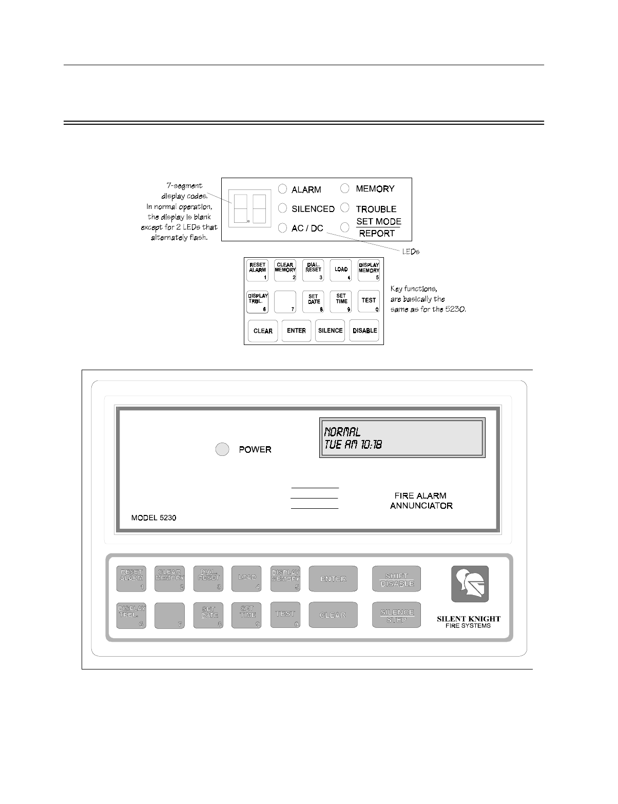
5.1 Built-in Touchpad and Model 5230 Operation. . . . . . . . . . . . . . . . . . . . . . . . . . . . . . . . . . . . . . . . . . . . . . . 5-2
5.1.1 Built-in Touchpad Display Codes . . . . . . . . . . . . . . . . . . . . . . . . . . . . . . . . . . . . . . . . . . . . . . . . . . . 5-4
5.1.2 LED Indicators . . . . . . . . . . . . . . . . . . . . . . . . . . . . . . . . . . . . . . . . . . . . . . . . . . . . . . . . . . . . . . . . . . 5-5
5.2 System Testing . . . . . . . . . . . . . . . . . . . . . . . . . . . . . . . . . . . . . . . . . . . . . . . . . . . . . . . . . . . . . . . . . . . . . . . 5-5
5.2.1 Fire Drills . . . . . . . . . . . . . . . . . . . . . . . . . . . . . . . . . . . . . . . . . . . . . . . . . . . . . . . . . . . . . . . . . . . . . . 5-5
5.2.2 Walk Test (Mode 22) . . . . . . . . . . . . . . . . . . . . . . . . . . . . . . . . . . . . . . . . . . . . . . . . . . . . . . . . . . . . . 5-6
5.2.3 Automatic Self Test . . . . . . . . . . . . . . . . . . . . . . . . . . . . . . . . . . . . . . . . . . . . . . . . . . . . . . . . . . . . . . 5-6
5.3 Watchdog Circuit . . . . . . . . . . . . . . . . . . . . . . . . . . . . . . . . . . . . . . . . . . . . . . . . . . . . . . . . . . . . . . . . . . . . . 5-6
Section 6
Programming: Quick Reference . . . . . . . . . . . . . . . . . . . . . . . . . . . . . . . . . . . . . . . . . . . . . . . . . . . . . .6-1
Section 7
Programming: Step-by-Step Complete Reference . . . . . . . . . . . . . . . . . . . . . . . . . . . . . . . . . . . . . . .7-1
7.1 Using Step Programming . . . . . . . . . . . . . . . . . . . . . . . . . . . . . . . . . . . . . . . . . . . . . . . . . . . . . . . . . . . . . . . 7-1
7.1 Programming Examples . . . . . . . . . . . . . . . . . . . . . . . . . . . . . . . . . . . . . . . . . . . . . . . . . . . . . . . . . . . . 7-3
7.2 Step Programming Options. . . . . . . . . . . . . . . . . . . . . . . . . . . . . . . . . . . . . . . . . . . . . . . . . . . . . . . . . . . . . . 7-4
Step 1. Power Up Clear . . . . . . . . . . . . . . . . . . . . . . . . . . . . . . . . . . . . . . . . . . . . . . . . . . . . . . . . . . . 7-4
Step 2. Device Enables . . . . . . . . . . . . . . . . . . . . . . . . . . . . . . . . . . . . . . . . . . . . . . . . . . . . . . . . . . . . 7-4
Step 3. More System Options . . . . . . . . . . . . . . . . . . . . . . . . . . . . . . . . . . . . . . . . . . . . . . . . . . . . . . . 7-5
Step 4. Display Rate . . . . . . . . . . . . . . . . . . . . . . . . . . . . . . . . . . . . . . . . . . . . . . . . . . . . . . . . . . . . . . 7-5
Step 5. Miscellaneous Options . . . . . . . . . . . . . . . . . . . . . . . . . . . . . . . . . . . . . . . . . . . . . . . . . . . . . . 7-6
Step 6. Internal Zone Options . . . . . . . . . . . . . . . . . . . . . . . . . . . . . . . . . . . . . . . . . . . . . . . . . . . . . . . 7-6
Step 7. External Zone Options . . . . . . . . . . . . . . . . . . . . . . . . . . . . . . . . . . . . . . . . . . . . . . . . . . . . . . 7-9
Step 8. Number of Zones . . . . . . . . . . . . . . . . . . . . . . . . . . . . . . . . . . . . . . . . . . . . . . . . . . . . . . . . . 7-10
Step 9. Dialer Options . . . . . . . . . . . . . . . . . . . . . . . . . . . . . . . . . . . . . . . . . . . . . . . . . . . . . . . . . . . 7-10
Step 10. Total Number of Attempts . . . . . . . . . . . . . . . . . . . . . . . . . . . . . . . . . . . . . . . . . . . . . . . . . 7-11
Step 11. Number of Events Before Dialer Failed . . . . . . . . . . . . . . . . . . . . . . . . . . . . . . . . . . . . . . . 7-11
Step 12. Low AC Hours . . . . . . . . . . . . . . . . . . . . . . . . . . . . . . . . . . . . . . . . . . . . . . . . . . . . . . . . . . 7-11
Step 13. Number of Rings . . . . . . . . . . . . . . . . . . . . . . . . . . . . . . . . . . . . . . . . . . . . . . . . . . . . . . . . 7-11
Step 14. Report to Telephone Numbers . . . . . . . . . . . . . . . . . . . . . . . . . . . . . . . . . . . . . . . . . . . . . . 7-12
Step 15. Computer Phone Number . . . . . . . . . . . . . . . . . . . . . . . . . . . . . . . . . . . . . . . . . . . . . . . . . . 7-13
Step 16. Central Station Phone Numbers . . . . . . . . . . . . . . . . . . . . . . . . . . . . . . . . . . . . . . . . . . . . . 7-13
Step 17. Central Station Account Numbers . . . . . . . . . . . . . . . . . . . . . . . . . . . . . . . . . . . . . . . . . . . 7-13
Step 18. Dialer Format and Number of Attempts . . . . . . . . . . . . . . . . . . . . . . . . . . . . . . . . . . . . . . . 7-14
Step 19. Telephone Line to Use for Accounts . . . . . . . . . . . . . . . . . . . . . . . . . . . . . . . . . . . . . . . . . 7-14
Step 20. Duration of Delays . . . . . . . . . . . . . . . . . . . . . . . . . . . . . . . . . . . . . . . . . . . . . . . . . . . . . . . 7-15
Step 21. Test Time . . . . . . . . . . . . . . . . . . . . . . . . . . . . . . . . . . . . . . . . . . . . . . . . . . . . . . . . . . . . . . 7-16
Step 22. Secret Codes . . . . . . . . . . . . . . . . . . . . . . . . . . . . . . . . . . . . . . . . . . . . . . . . . . . . . . . . . . . . 7-16
Step 23. Group Relays and Bells . . . . . . . . . . . . . . . . . . . . . . . . . . . . . . . . . . . . . . . . . . . . . . . . . . . 7-17
Step 24. Alarm Relays and Bells (by Zone) . . . . . . . . . . . . . . . . . . . . . . . . . . . . . . . . . . . . . . . . . . . 7-19
Step 25. Zone Types . . . . . . . . . . . . . . . . . . . . . . . . . . . . . . . . . . . . . . . . . . . . . . . . . . . . . . . . . . . . . 7-20
Step 26. Zone Location Descriptions . . . . . . . . . . . . . . . . . . . . . . . . . . . . . . . . . . . . . . . . . . . . . . . . 7-21
Steps 27 and 28. Temporal Patterns . . . . . . . . . . . . . . . . . . . . . . . . . . . . . . . . . . . . . . . . . . . . . . . . . 7-22

150865 iii
Section 8
Reporting . . . . . . . . . . . . . . . . . . . . . . . . . . . . . . . . . . . . . . . . . . . . . . . . . . . . . . . . . . . . . . . . . . . . . . . . .8-1
8.1 Notes for All Formats . . . . . . . . . . . . . . . . . . . . . . . . . . . . . . . . . . . . . . . . . . . . . . . . . . . . . . . . . . . . . . . . . . 8-1
8.2 SIA Format Printed Messages . . . . . . . . . . . . . . . . . . . . . . . . . . . . . . . . . . . . . . . . . . . . . . . . . . . . . . . . . . . 8-2
8.3 FSK & SK 4+2 Format. . . . . . . . . . . . . . . . . . . . . . . . . . . . . . . . . . . . . . . . . . . . . . . . . . . . . . . . . . . . . . . . . 8-4
8.4 16-Zone 4+2 Format. . . . . . . . . . . . . . . . . . . . . . . . . . . . . . . . . . . . . . . . . . . . . . . . . . . . . . . . . . . . . . . . . . . 8-5
8.5 Radionics BFSK Format. . . . . . . . . . . . . . . . . . . . . . . . . . . . . . . . . . . . . . . . . . . . . . . . . . . . . . . . . . . . . . . . 8-6
Section 9
Troubleshooting . . . . . . . . . . . . . . . . . . . . . . . . . . . . . . . . . . . . . . . . . . . . . . . . . . . . . . . . . . . . . . . . . . .9-1
9.1 Problems With the Model 5198 Power Supply . . . . . . . . . . . . . . . . . . . . . . . . . . . . . . . . . . . . . . . . . . . . . . 9-1
9.1.1 Isolating the Problem . . . . . . . . . . . . . . . . . . . . . . . . . . . . . . . . . . . . . . . . . . . . . . . . . . . . . . . . . . . . . 9-1
9.1.2 Measuring Battery Charging Voltage . . . . . . . . . . . . . . . . . . . . . . . . . . . . . . . . . . . . . . . . . . . . . . . . 9-1
9.2 P3 and P4 Earth Ground Faults. . . . . . . . . . . . . . . . . . . . . . . . . . . . . . . . . . . . . . . . . . . . . . . . . . . . . . . . . . . 9-2
9.3 Accu-Zone® Troubleshooting (Mode 25) . . . . . . . . . . . . . . . . . . . . . . . . . . . . . . . . . . . . . . . . . . . . . . . . . . 9-2
9.3.1 Mode 25 Display . . . . . . . . . . . . . . . . . . . . . . . . . . . . . . . . . . . . . . . . . . . . . . . . . . . . . . . . . . . . . . . . 9-2
9.4 Troubleshooting and System Messages . . . . . . . . . . . . . . . . . . . . . . . . . . . . . . . . . . . . . . . . . . . . . . . . . . . . 9-4
Appendix A
Compatible Devices . . . . . . . . . . . . . . . . . . . . . . . . . . . . . . . . . . . . . . . . . . . . . . . . . . . . . . . . . . . . . . . . . . . . . . . . A-1
A.1 Smoke Detectors . . . . . . . . . . . . . . . . . . . . . . . . . . . . . . . . . . . . . . . . . . . . . . . . . . . . . . . . . . . . . . . . . . . A-1
Two-Wire Smoke Detectors . . . . . . . . . . . . . . . . . . . . . . . . . . . . . . . . . . . . . . . . . . . . . . . . . . . . . . . . A-1
Four Wire Smoke Detectors . . . . . . . . . . . . . . . . . . . . . . . . . . . . . . . . . . . . . . . . . . . . . . . . . . . . . . . . A-3
A.2 Notification Appliances . . . . . . . . . . . . . . . . . . . . . . . . . . . . . . . . . . . . . . . . . . . . . . . . . . . . . . . . . . . . . A-3

Model 5207 Fire Control/Communicator Installation and Operation Manual
iv 150865

150865 1-1
Section 1
Introduction
The Model 5207 is an 8-zone fire alarm control panel (expandable up to 16 zones) with a dig-
ital communicator that meets NFPA 72 requirements. The 5207 cabinet can be surface
mounted or semi-flush mounted.
1.1 About This Manual
The Model 5207 Fire Control/Communicator Installation Manual (P/N 150865) is intended
for those persons involved with the installation and maintenance of the 5207 panel. It is a
comprehensive guide, providing detailed instructions, and should be kept for reference. As
much as possible, we have tried to organize the manual chronologically by the tasks that need
to be performed.
This manual is intended to be used with printed circuit board (PCB), Revision M. If you are
using a different board, contact Silent Knight Security Systems for the appropriate instruc-
tions.
IMPORTANT:
Previous versions of the 5207 were selectable between 12V and 24V. This release is 24V
only. *All information regarding 12V have been removed from this manual.
Some versions of the 5207 product documentation were made up of two manuals, one for
hardware installation and one for programming. We have combined both manuals into one.
With the exception of information about the obsolete 5521 programmer*, this manual con-
tains all information previously contained in the two manuals.
*Contact Silent Knight if you need this information.
A clear rectangle represents a key that you press on a
touchpad.
LCD DISPLAY
MESSAGE
The font shown to the left represents messages that you
see on a liquid crystal display (LCD) or the seven-seg-
ment (built-in touchpad) display.
1-1, 2-3, etc.
This manual is organized into sections. Section numbers
are part of the page numbers. For example, 1-1 means
Page 1 of Section 1.
KEY

Model 5207 Fire Control/Communicator Installation and Operation Manual
1-2 150865
1.2 Optional Accessories
Table 1-1: Compatible Modules
Manufactured by Silent Knight
Model What It Does
4180 Status Display/Relay
Module For remote annunciation of alarm and trouble
status information for each zone.
5210 Zone Expander Adds 8 zones to the 5207 for a total expansion of
the system to 16 zones.
5220 Direct Connect Module For direct alarming and trouble transmission from
the 5207 to a supervising station.
5230 Remote Annunciator For remote annunciation, operation, and on-site
programming.
Quick connect program cable,
part number 130294 For temporarily connecting the 5230 to the 5207
for programming.
5395 Signal Power Expander Notification circuit power for additional
notification appliances. Provides additional 6A of
24 VDC, supervised.
5541 Downloading Software For remote programming of the 5207 using a
personal computer.
5530 Modem Modem for downloading; required if the 5541
software is used.
7181 Zone Converter Converts a zone from class B to class A or from
class A to class B. One 7181 per zone to be
converted.

150865 2-1
Section 2
A
g
enc
y
Listin
g
s and Requirements
2.1 Federal Communications Commission (FCC)
1. If requested by the telephone company, the following information must be provided before the
5207 can be connected to the phone lines:
2. This device may not be directly connected to coin telephone or party line services.
3. This device cannot be adjusted or repaired in the field. In case of trouble with the device, notify
the installing company or return to:
Silent Knight Security Systems
7550 Meridian Circle
Maple Grove, MN 55369-4927
612-493-6455
800-328-0103
4. If the 5207 causes harm to the telephone network, the telephone company will notify the user in
advance that temporary discontinuance of service may be required. When advance notice is not
practical, the telephone company will notify the user as soon as possible. Users have the right to
file complaints, if necessary, with the Federal Communications Commission.
5. The telephone company may make changes in its facilities, equipment, operations, or procedures
that could affect the operation of the equipment. If this happens, the telephone company will pro-
vide advance notice to allow you to make the necessary modifications to maintain uninterrupted
service.
A. Manufacturer: Silent Knight Security Systems
B. Model Number: 5207
C. FCC registration number: AC6USA-65475-AL-E
Ringer equivalence: 0.9B
D. Type of jack (to be installed by the telephone
company): RJ31X
Warning
This device has been verified to comply with FCC Rules Part 15. Operation is subject to the
two following conditions: (1) This device may not cause radio interference; and (2) This device
must accept any interference received including interference that may cause undesired
operation.

Model 5207 Fire Control/Communicator Installation and Operation Manual
2-2 150865
2.2 Underwriters Laboratories (UL)
The 5207 is UL Listed as a control unit for use in Central Station Fire-Protective Signaling
systems. If the 5207 and its accessories are to be used as part of a UL installation, carefully
read the UL requirements in this section. The following applicable NFPA 72 standards can be
found in more detail in the NFPA 72 National Fire Alarm Code, 1993 Edition:
Chapter 3
• Local Protected Fire Alarm Systems, Chapter 4
Chapter 4
• Central Station Fire Alarm Systems
• Auxiliary Protected Fire Alarm Systems for Fire Alarm Service (City Box)
• Remote Station Protected Fire Alarm Systems (Polarity Reversal)
• Proprietary Fire Alarm Systems
2.2.1 Requirements for All Installations
General requirements are described below. The sections that follow describe additional
requirements for the type of installation (for example, Central Station Fire Alarm systems,
Local Protected Fire Alarm systems, and so on).
1. All field wiring must be 18-gauge or larger (for example, 16, 14, and so on).
2. Use UL listed smoke detectors compatible with the 5207. Refer to Appendix A.
3. Use UL listed compatible notification devices. Refer to Appendix A.
4. All notification devices must be UL listed.
2.2.2 Requirements for Central Station Fire Alarm Systems
1. The Ground Fault Detection option must be selected (programming Step 5).
2. The Phone Line #2 Enable option must be selected (programming Step 9).
3. The Phone Line Monitor Enable option must be selected (programming Step 9).
4. Set the Total Attempts option for between 5-10 attempts (programming Step 10).
5. Do not select the Ground Start Option (programming Step 9).
6. Enable the automatic daily test by selecting a phone number for the Report Test to Phone
#1-4 option (programming Step 14.4).
7. On class A (style D) zones, the number of waterflow devices is limited to five.
8. Auxiliary relays may not be programmed to activate for Pre-Alarm. See Section 4.13.

Agency Listings and Requirements
150865 2-3
2.2.3 Requirements for Auxiliary Protected Fire Alarm Systems for
Fire Alarm Service
1. Follow the current load restrictions shown in Section 3.5.
2. The Model 5220 Direct Connect module must be installed (see Section 4.7 for wiring).
2.2.4 Requirements for Remote Station Protected Fire Alarm
Systems, for Digital Communication or Polarity Reversal
1. Follow the current load restrictions shown in Section 3.5.
2. Use the 5207’s built-in dialer or install the Model 5220 Direct Connect Module (see
Section 4.7).
2.3 California Fire Marshal (CFM)
The CFM approval number for the 5207 is 7165-0559:111.
2.4 Factory Mutual (FM)
The Model 5207 is FM approved under project # OQ1A3.AY when used with the Silent
Knight Model 9000 Receiver.
2.5 Materials and Equipment Board of Acceptance
Division (MEA)
The 5207 is approved under MEA. Approval was previously given from the City of New
York Board of Standards and Appeals (BSA), the 5207 is still approved under BSA Calendar
Number 703-88-SA.

Model 5207 Fire Control/Communicator Installation and Operation Manual
2-4 150865

150865 3-1
Section 3
Control Panel Installation
3.1 Electrical Specifications
3.2 Environmental Specifications
It is important to protect the 5207 control panel from water. To prevent water damage, the
following conditions should be AVOIDED when mounting the units:
• Do not mount directly on exterior walls, especially masonry walls (condensation).
• Do not mount directly on exterior walls below grade (condensation).
• Protect from plumbing leaks.
• Protect from splash caused by sprinkler system inspection ports.
• Do not mount in areas with humidity-generating equipment (such as dryers, production
machinery).
When selecting a location to mount the 5207 control panel, the unit should be mounted where
it will NOT be exposed to temperatures outside the range of 0°C-49°C (32°F-120°F) or
humidity outside the range of 10%-85% at 30°C (86°F) noncondensing.
See also the mounting recommendations in 3.7 for additional environmental specifications.
Table 3-1 Electrical Specifications
Primary AC 120 Vrms at 60 Hz, 2A
Total DC Load 5A
Accessory Power 18.4 V to 27.6 V max., 1A
Smoke Power 18.4 V to 27.6 V max., 1A
Battery Charging Voltage 27.3
Battery Charging Current 2.62 A max.
Class B (style A) Circuit Current 60 mA max.
Telephone Minimum Input Sensitivity 45 dB
Good Phone Line Voltage 3 V
Maximum Low Battery Detect 20.4
Minimum Low AC Detect 98
Maximum Watchdog Response Time 4 sec.
Notification Power 1A max. per output (4A total)
Model 5207 Fire Control/Communicator Installation and Operation Manual
3-2 150865
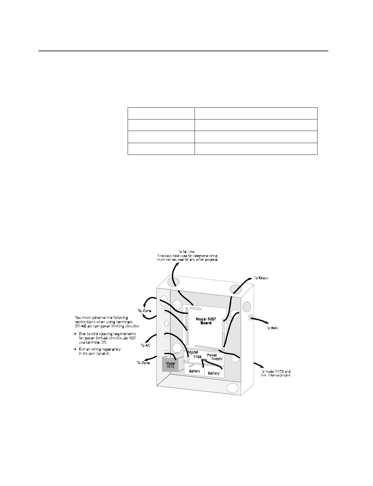
3.3 Wiring Specifications
To avoid induced noise (transfer of electrical energy from one wire to another), keep input
wiring isolated from high current output and power wiring. Induced noise can interfere with
telephone communication or even cause false alarms. Avoid pulling one multiconductor
cable for the entire panel. Instead, separate the wiring as follows:
DO NOT pull wires from different groups through the same conduit. If you must run them
together, do so for as short a distance as possible or use shielded cable. Connect the shield to
earth ground at the panel only.
For the same reasons, wiring within the cabinet should be routed around the perimeter of the
cabinet. It should not cross the printed circuit board where it could induce noise into the sen-
sitive microelectronics or pick up unwanted RF noise from the high speed circuits.
High frequency noise, such as that produced by the inductive reactance of a speaker or bell,
can also be reduced by running the wire through ferrite shield beads or by wrapping it around
a ferrite toroid. Figure 3-1 provides an example.
Figure 3-1 Wire Routing Example
1/4" spacing must be maintained Input/Output Type Wiring
between each of these circuit types; High current: AC power, speaker, and notification devices
as well as between power limited Low current: Annunciator and zone loop wiring
and non-power limited circuits. Audio: Telephone wiring
Control Panel Installation
150865 3-3
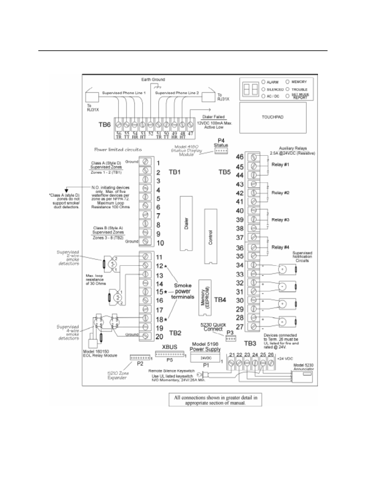
3.4 Model 5207 Wiring Diagram
Figure 3-2 is a wiring diagram for wiring the Model 5207 panel.
Figure 3-2 Model 5207 Wiring Reference

Model 5207 Fire Control/Communicator Installation and Operation Manual
3-4 150865
3.5 Current Draw Worksheet
Table 3-2 Current Draw Worksheet
Device Number of
Devices Current per Device Standby
Current Alarm
Current
For each device, use this formula: This column X This column = Current per number of devices.
5207 Control Panel 1 Standby: 120 mA 120 mA
Alarm: 700 mA
(worst case) 700 mA
5210 Zone Expander 1 Standby: 40 mA mA
Alarm: 40 mA mA
5220 Direct Connect 1 Standby: 50 mA mA
Alarm: 50 mA mA
5230 Annunciator Standby: 60 mA mA
(7 max.) Alarm: 120 mA mA
4180 Status Display Standby: 20 mA mA
(2 max.) Alarm: 140 mA mA
A Current Subtotals: mA mA
Smoke Detectors Refer to device manual for current ratings. See Appendix A for compatible devices.
Standby: mA mA
Alarm: mA mA
Standby: mA mA
Alarm: mA mA
Standby: mA
Alarm: mA mA
B Current Subtotal: mA mA
Notification Appliances Refer to device manual for current ratings. See Appendix A for compatible devices.
mA
mA
mA
mA
C Current Subtotal: mA
Additional Devices
Standby: mA mA
Alarm: mA mA
Standby: mA mA
Alarm: mA mA
Standby: mA mA
Alarm: mA mA
D Current Subtotal: mA mA
Total current ratings of all devices in system (add A-D): mA mA
ETotal current ratings converted to amperes (x .001): A A
Note: Use this information in conjunction with Table 3-3 and Table 3-4 to complete battery calculations.
Control Panel Installation
150865 3-5
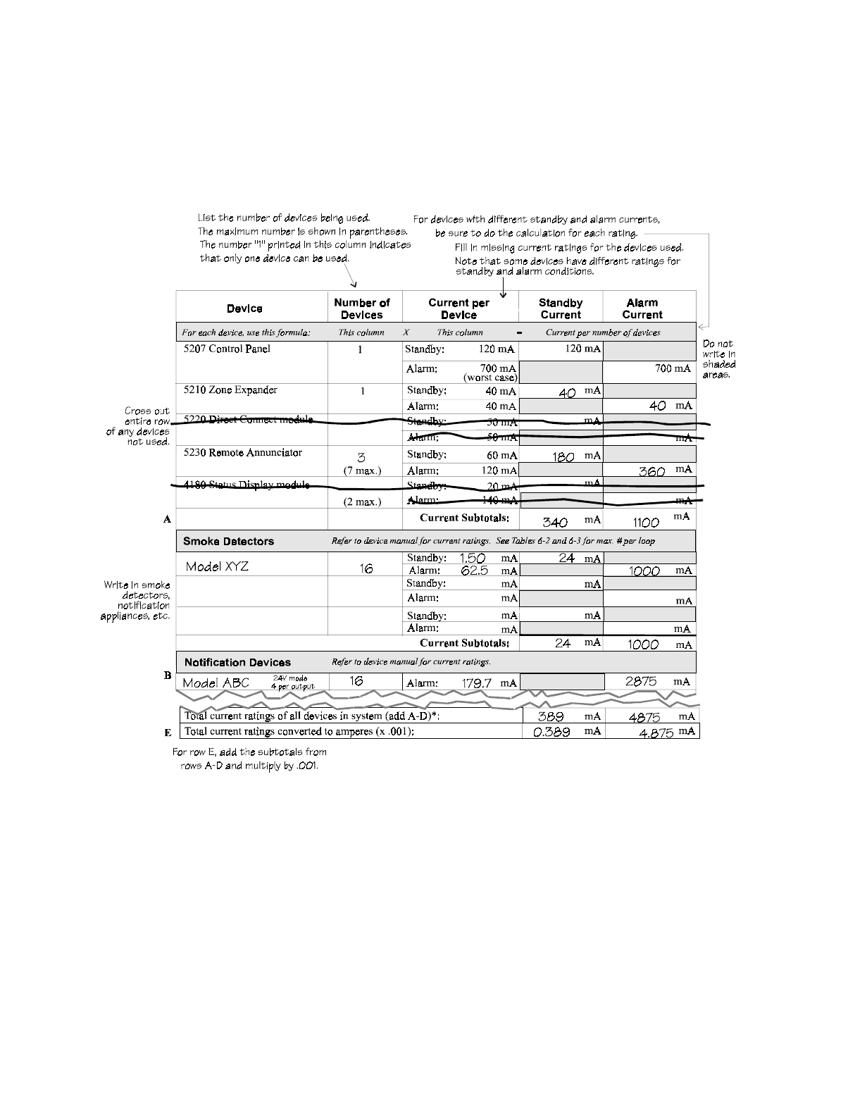
3.5.1 Worksheet Example
The Current Draw worksheet is included to help you calculate the amount of current the sys-
tem draws on standby and in an alarm condition. Refer to Table 3-4 for available battery sizes
and the maximum standby current load each can support.
Figure 3-3 is an example of a completed worksheet.
Figure 3-3 Current Draw Worksheet Example

Model 5207 Fire Control/Communicator Installation and Operation Manual
3-6 150865
3.5.2 Worksheet Requirements
The following steps must be taken when determining Model 5207 current ratings:
1. Measure the alarm current. If only one current rating is listed, the draw for that device is
the same whether the system is in alarm or standby condition. The exception is for notifi-
cation devices, which are rated at alarm current only. Standby current for notification
devices is 0 mA.
2. To detect the actual maximum alarm current, measure the current draw (with no devices
connected to the panel) by connecting a DC amp meter in series with one of the batteries.
Disconnect the AC power source. Put the panel in alarm. The meter will indicate the
alarm current, which will be in the range of 120-700 mA. Fill in the system alarm current
in the Current per Device column of the Current Draw worksheet. You can estimate with-
out measuring the alarm current by filling in the maximum total alarm current of 700 mA.
3. For smoke detectors, notification devices, and devices not mentioned in the manual, refer
to the device manual for the current ratings. The worksheet example shown on the previ-
ous page provides rough estimates for a “worst case” installation.
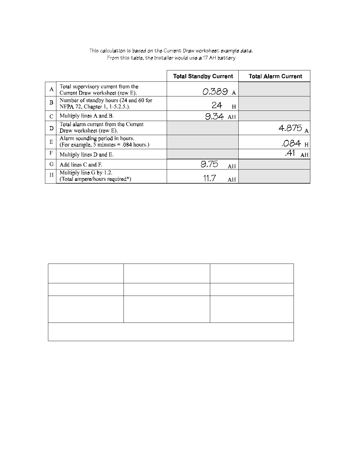
4. Use Table 3-3 to calculate the correct battery AH rating needed for your installation. See
also the example (Figure 3-4) on the next page. Note that the calculated rating in Row H
cannot exceed the ratings shown in Table 3-4.
Table 3-3 Battery Calculations
Total Standby Current Total Alarm Current
A Total supervisory current from the Current Draw
Worksheet (row E). A
B Number of standby hours (24 and 60 for NFPA 72,
Chapter 1, 1-5.2.5). H
C Multiply Lines A and B. AH
D Total alarm current from the Current Draw worksheet
(row E). A
E Alarm sounding period in hours. (For example, 5
minutes = .084 hours.) H
F Multiply lines D and E. AH
G Add lines C and F. AH
H Multiply line G by 1.2.
(Total ampere/hours required*) AH
*Use next size battery with capacity greater than required.
Control Panel Installation
150865 3-7
Figure 3-4 Battery Calculation Example
5. Refer to to verify the battery size you need to provide at least the total standby current you
have calculated. If the installation must meet requirements for NFPA 72 (Auxiliary Pro-
tected Fire Alarm Systems for Fire Alarm Service or Remote Station Protected Fire Alarm
Systems, Digital Communication or Polarity Reversal), the total standby current cannot
exceed the amount shown in the last column of the following table:
Table 3-4 Maximum Battery Standby Load
6. Ensure that the total current of all items attached to the 5207, including the 5207 itself,
does not exceed 5 A when the panel is in alarm (see Section 3.1).
Rechargeable
Battery Size Max. Load for 24 hrs.
Standby, 5 mins. Alarm *Max. Load for 60 hrs.
Standby, 5 mins. Alarm
17 AH 435 mA 175 mA
34 AH (if wired in parallel)
(Largest size battery that can
be used.)
873 mA 350 mA
* Required for NFPA 72 Auxiliary Protected Fire Alarm Systems for Fire Service (City Box) and
Remote Station Protected Fire Alarm Systems (Polarity Reversal).
Model 5207 Fire Control/Communicator Installation and Operation Manual
3-8 150865
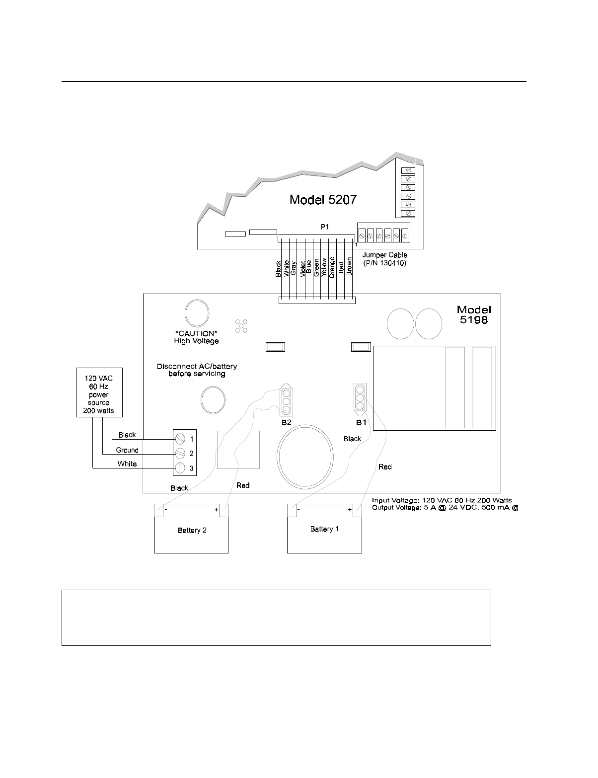
3.6 Power Supply Wiring
The Model 5198 power supply delivers 24 VDC at 5A for loop power, smoke detector power,
notification device power, and accessory power. The Model 6914 is a 12-Volt, 17-AH bat-
tery. Figure 3-5 shows the power supply wiring.
Figure 3-5 Power Supply Wiring
Note: All conduit and wiring connected to the 5207 must meet the applicable National Electric Code, NFPA Stan-
dards, state, and local building code requirements. In all cases, the authority having jurisdiction takes pre-
cedence.
Warning
To reduce the risk of electrical shock, make sure that all power has been turned off or disconnected before attempting
to connect the Model 5198 power supply. Do NOT apply power to this panel until all accessories are properly
connected.

Control Panel Installation
150865 3-9
3.6.1 Connecting the 5198 to AC Power
The Model 5198 is mounted behind the power shield.
• Connect the black wire from the 120 VAC 60 Hz source to terminal 1 on the 5198.
• Connect the white (neutral) wire from the 120 VAC 60 Hz AC source to terminal 3 on the
5198.
• Connect the ground wire from the 120 VAC 60 Hz source to terminal 2 on the 5198.
3.6.2 Connecting the 5198 to Batteries
The tables in Section 4 will help you determine correct battery size.
When using two batteries, it is recommended that they be of the same ampere hour (AH) rat-
ing.
The Model 5198 provides two sets of battery leads to connect two 12 VDC batteries in series.
1. Connect the first red battery lead to the positive side of battery #1.
2. Connect the first black battery lead to the negative side of battery #1.
3. Connect the second red battery lead to the positive side of battery #2.
4. Connect the second black battery lead to the negative side of battery #2.
Note: The total current draw on loop power, accessory power, and notification device outputs
must not exceed 6A.
3.7 Mounting the 5207
Read the environmental specifications in 3.2 before mounting the 5207 panel.
The 5207 cabinet dimensions are: 16"x 26.4" x 4" (HxWxD).
The 5207 panel should be located within a secured area, where it is accessible to main drop
wiring runs and where it can be easily tested and serviced. End-users responsible for main-
taining the panel should be able to hear alarms and troubles. When selecting a location, keep
in mind that the panel itself is the main source of alarm and trouble annunciation.
When mounting on interior walls, use appropriate screw anchors in plaster. When mounting
on concrete, especially when moisture is expected, attach a piece of 3/4 inch plywood to the
concrete surface and then attach the 5207 to the plywood. Also mount any other desired com-
ponents to the plywood.
DO NOT flush-mount the 5207 cabinet in a wall designated as a fire break.
Caution
Apply AC power before connecting the batteries to the power supply to prevent arcing on battery terminals.

Model 5207 Fire Control/Communicator Installation and Operation Manual
3-10 150865
3.8 Terminal Strip Description
The terminal strips on the PC board are nonremovable. Table 3-5 on the next page lists the
function and electrical rating of each terminal. See Section 3.4 for the wiring diagram.
Table 3-5 Terminal Strip Description
Terminal # Terminal Description Electrical Ratings
TB1
1 Circuit Ground
2 Zone 1 input (class A, style D) Loop A Out
3 Zone 1 input (class A, style D) Loop B Out
4 Zone 1 input (class A, style D) Loop B In
5 Zone 1 input (class A, style D) Loop A In
6 Zone 2 input (class A, style D) Loop A Out
7 Zone 2 input (class A, style D) Loop B Out
8 Zone 2 input (class A, style D) Loop B In
9 Zone 2 input (class A, style D) Loop A In
10 Circuit Ground
TB2
11 Zone 3 Input (class B, style A)
12 Loop Power Output 24 VDC
13 Zone 4 Input (class B, style A)
14 Zone 5 Input (class B, style A)
15 Loop Power Output 24 VDC
16 Zone 6 Input (class B, style A)
17 Zone 7 Input (class B, style A)
18 Loop Power Output 24 VDC
19 Zone 8 Input (class B, style A)
20 Circuit Ground
TB3
21 Remote Silence
22 Annunciator Output
23 Annunciator Input
24 Annunciator Power Output +12 VDC nominal
25 Annunciator Ground
26 Accessory Power +24 VDC
TB4 Note: Outputs can also be used for polarity revising outputs (polarity shown active).
27 Notification device output #4 Negative 1 amp max.
28 Notification device output #4 Positive
29 Notification device output #3 Negative 1 amp max.
30 Notification device output #3 Positive

Control Panel Installation
150865 3-11
31 Notification device output #2 Negative 1 amp max.
32 Notification device output #2 Positive
33 Notification device output #1 Negative 1 amp max.
34 Notification device output #1 Positive
35 Auxiliary Relay #4 Normally Open Contact 2.5 amp max.
36 Auxiliary Relay #4 Common
TB5
37 Auxiliary Relay #4 Normally Closed Contact 2.5 amp max.
38 Auxiliary Relay #3 Normally Open Contact 2.5 amp max.
39 Auxiliary Relay #3 Common
40 Auxiliary Relay #3 Normally Closed Contact 2.5 amp max.
41 Auxiliary Relay #2 Normally Open Contact 2.5 amp max.
42 Auxiliary Relay #2 Common
43 Auxiliary Relay #2 Normally Closed Contact 2.5 amp max.
44 Auxiliary Relay #1 Normally Open Contact 2.5 amp max.
45 Auxiliary Relay #1 Common
46 Auxiliary Relay #1 Normally Closed Contact 2.5 amp max.
TB6
47 Dialer Failed Output (Active Low) 100 mA, 12 VDC max.
48 House Phone 2 Tip
49 House Phone 2 Ring
50 Telco 2 Tip
51 Telco 2 Ring
52 Earth Ground
53 House Phone 1 Tip
54 House Phone 1 Ring
55 Telco 1 Tip
56 Telco 1 Ring
Table 3-5 Terminal Strip Description
Terminal # Terminal Description Electrical Ratings
Model 5207 Fire Control/Communicator Installation and Operation Manual
3-12 150865
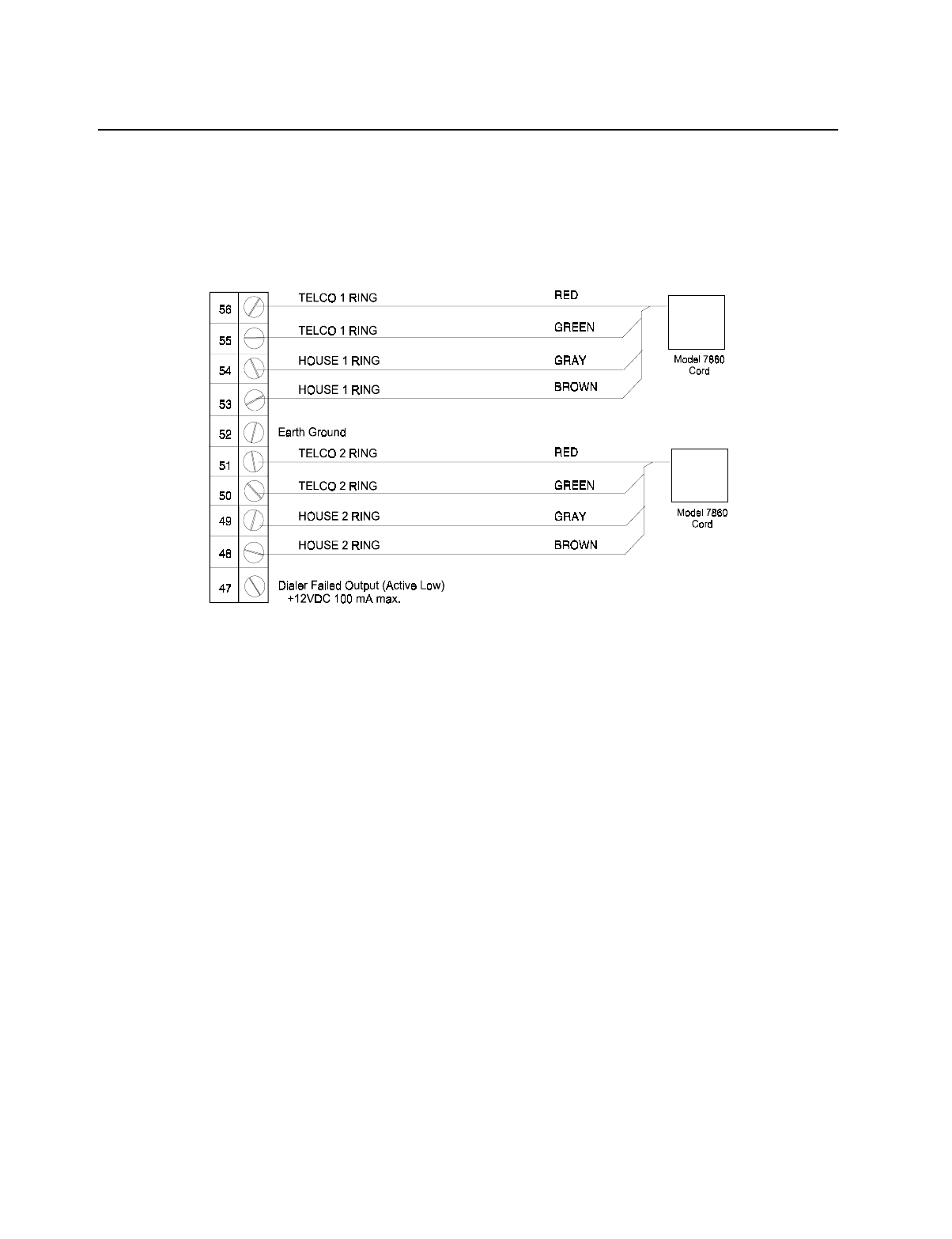
3.9 Telephone Line Connection
The 5207 connects to two separate telephone lines to report data to the central station. An
RJ31X jack should be installed by the telephone company for each line. Figure 3-6 shows
how to wire the telephone line interconnect cords (not provided) to the 5207.
Note: To reduce the possibility of false alarms and transient damage, DO NOT bundle telephone
wires together with notification device wires.
Figure 3-6 Telephone Line Connection
The 5207 has built-in dual phone line monitors. These circuits will detect any fault in the
phone lines by monitoring the DC voltage present on the lines. If phone line voltage drops
below 3 VDC and is not corrected within approximately 40 seconds, an audible trouble signal
will sound and the panel will report a line fault trouble over the remaining phone line.
A situation could occur where both phone lines appear to be good, but the dialer cannot get
through to the central station on the first line. In this case, the 5207 will switch phone lines
and attempt the call again using the second line. Make sure the phone lines are programmed
properly (see Section 7).
Notice: To comply with industry standards, this product is equipped with line seizure. Any time
the system’s dialer needs to communicate with the central station, it will not be possible
to use any telephones that are on the same line(s) as the system. Normally, this condition
will last approximately one minute, but under adverse telephone circuit conditions, could
last for as long as 15 minutes.

Control Panel Installation
150865 3-13
3.10 Cable Connectors
Power Supply Connector (P1)
Connects the 5207 control panel to the 5198 power supply.
Model 5210 (P2)
Connects the 5210 zone expander to the 5207.
Quick Connect (P3)
For temporarily connecting a 5230 for programming or troubleshooting. Requires cable
assembly 130294 (not included).
Status (P4)
Connects the 4180 display module to the 5207.
XBUS Connector (P5)
A 12-pin connector used to connect the 5221 Desktop Programmer (no longer manufactured).

Model 5207 Fire Control/Communicator Installation and Operation Manual
3-14 150865
150865 4-1
Section 4
Compatible Product Installation
This manual refers to fire zone types using the latest NFPA standard designations. Refer to
the NFPA 72 National Fire Alarm Code, 1993 Edition for additional information.
Note: For purposes of this manual, a normally open device’s contacts conduct when in an alarm state and do
not conduct in a non-alarm state.
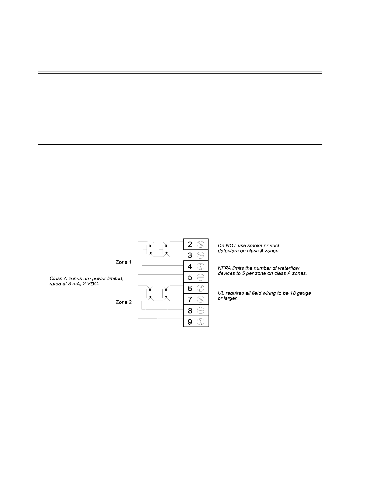
4.1 Class A (Style D) Zones
Zones 1 and 2 are class A (style D) zones. They are intended for use with non-powered
devices such as waterflow switches. Do NOT use smoke or duct detectors on Class A zones.
Each class A zone is a four-wire circuit that allows an alarm to be detected even after a single
open or ground fault occurs. When a single open or ground fault occurs, the audible trouble
signal will sound and the 5207 will report the trouble to the central station (if programmed to
report troubles).
Figure 4-1 shows how to wire a class A (style D) loop. No end-of-line (EOL) resistors are
needed for these zones. These zones must be wired using normally open contacts.
Figure 4-1 Class A (style D) Supervised Fire Loop
(Normally Open Sensors Only)
Model 5207 Installation and Operation Manual
4-2 150865
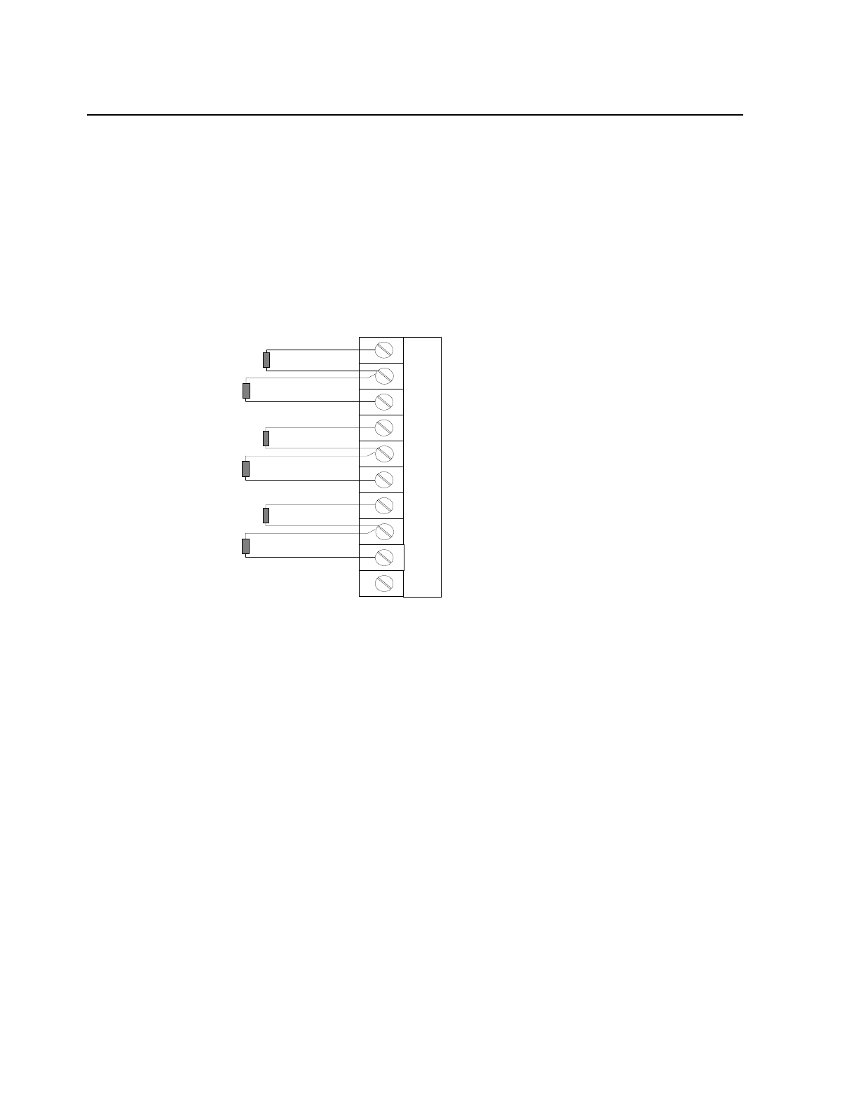
4.2 Class B (Style A) Zones
Zones 3 through 8 are class B (style A) fire zones. Each class B zone consists of a two-wire
circuit that will detect the occurrence of an open in the loop, but may not be able to detect an
alarm after such an occurrence. The detection of an open will cause the audible trouble signal
to sound and the 5207 will report the trouble to the central station (if programmed to do so).
Figure 4-2 shows how to wire a class B (style A) loop. One side of each class B loop connects
to a zone input terminal and the other side of each loop connects to loop power. For each
loop, use a 4.7K-ohm EOL resistor wired in parallel with the normally open contact farthest
from the panel.
Figure 4-2 Model 5207 Class B (style A) Loops
Maximum Loop Resistance - 30 ohms
Maximum Total alarm current for all class B (style A) zones - 1 A
Maximum Standby Current per Zone:
24V system - 2.0 mA
Note: UL requires all wiring to be at least 18 gauge.
11
12
13
14
15
16
17
18
19
20
Zone 3 Input
Zone 4 Input
Zone 5 Input
Zone 6 Input
Zone 7 Input
Zone 8 Input
Loop Power
Loop Power
Loop Power
Circuit Ground
4.7 K EOL
4.7 K EOL
4.7 K EOL
4.7 K EOL
4.7 K EOL
4.7 K EOL
Compatible Product Installation
150865 4-3
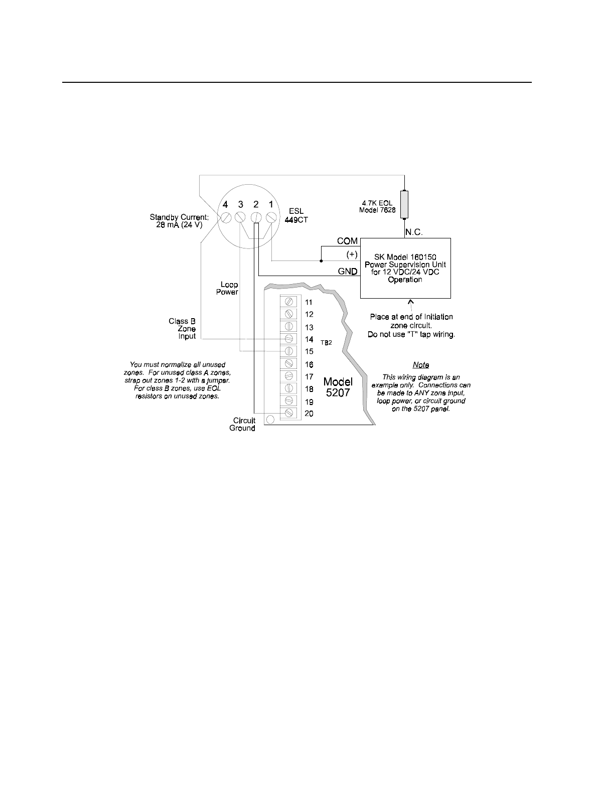
4.3 Four-Wire Smoke Detector Connection
Figure 4-3 illustrates how UL listed four-wire smoke detectors must be connected to class B
(style A) zones.
When wiring a four-wire smoke detector to the class B (style A) zones, you must use a Power
Supervision Unit, such as Silent Knight’s 160150.
Figure 4-3 Four-Wire Smoke Detector Wiring
See Appendix A for a list of four-wire smoke detectors that may be used with the 5207.
Model 5207 Installation and Operation Manual
4-4 150865
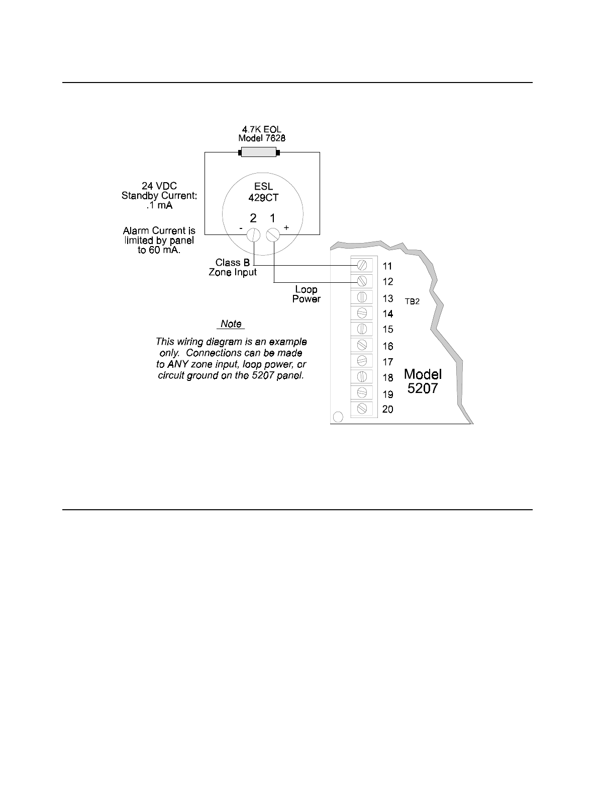
4.4 Two-Wire Smoke Detector Connection
Figure 4-4 shows how to connect two-wire smoke detectors to class B (style A) zones.
Figure 4-4 Two-Wire Smoke Detector Wiring
See Appendix A for a list of two-wire smoke detectors that may be used with the 5207.
4.5 Model 4180 Status Display Module
The Model 4180 Status Display module provides remote annunciation of alarm and trouble
status information for each zone.
The 4180 has 2 connectors, each of which has 8 outputs available for annunciation. These
outputs are active high at +12 VDC. Each output can provide up to 100 mA of current, with a
total limitation of 700 mA. The module has 4 normally open non-dedicated relays that can be
wired to be active with any of the outputs. The 4180 is not supervised.

Compatible Product Installation
150865 4-5
Wire the 4180 as shown in Figure 4-5. Make sure power is OFF at the panel before plugging
in the 4180. Maintain a physical separation of one-half inch or more between field wires and
connection points to prevent damage from transients.
Note: SILENCE does not affect 4180 outputs. To reset a 4180 output, the alarm or trouble condition must be
restored and event memory cleared.
The 4180 can be used to interface to long-range RF systems.
Figure 4-5 Model 4180 Connection
Model 5207 Installation and Operation Manual
4-6 150865
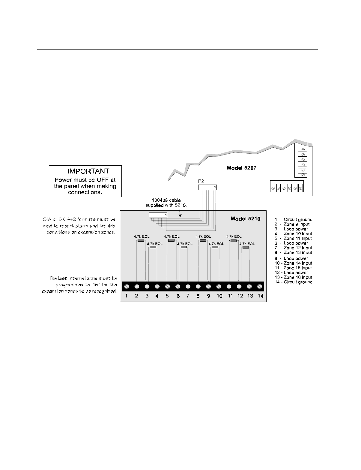
4.6 Model 5210 Zone Expander Wiring
The Model 5210 provides the 5207 with eight additional class B (style A) zones. Figure 4-6
shows how to wire the 5210. Use a 4.7k end of line resistor for each class B loop. The EOL
must be wired in parallel with the normally open contact farthest from the panel. See Appen-
dix A for a list of the smoke detectors that can be used with the 5210.
Maximum Loop Resistance - 30 ohms
Maximum Total Alarm current (powered from loop power) for all class B (style A) zones - 1 A
Maximum Standby Current Per Zone - 1 mA
Voltage ranges:
• When used with the 5207 - 24 VDC (Model 5210 Identifier 24A): 17.8 VDC - 27.4 VDC
Figure 4-6 Model 5210 Style A Loops
Installation Instructions
The 5210 is equipped with a metal bracket. To install, fit the bracket over the 5198 power
supply unit in the 5207 cabinet. With panel power OFF, use the cable provided to connect the
5210 to its connector (P2) on the 5207. Insert screws provided. Place the four plastic stand-
offs into the bracket and snap onto the PC board. Then plug the 8-pin cable from the PC board
into the P2 connector on the 5207.
Compatible Product Installation
150865 4-7
4.7 Model 5220 Direct Connect Module
The 5220 Direct Connect module can be used with the 5207 to meet NFPA 72 standards. The
5220 requires four connections to the 5207 and provides outputs for city box and polarity
reversal applications. The 5220 cannot be used for sprinkler supervisory.
The 5220 provides a current that reverses polarity during alarm or removes current during a
trouble condition.
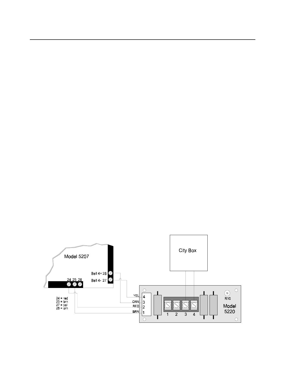
4.7.1 City Box Connection
This section describes how to connect the 5207 to a municipal fire alarm box or "city box" as
required by NFPA 72 Auxiliary Protected Fire Alarm systems for fire alarm service. The city
(master) box is an enclosure that contains a manually operated transmitter used to send an
alarm to the municipal communication center which houses the central operating part of the
fire alarm system.
The maximum coil and wire resistance (combined) must not exceed 30 ohms.
To install the 5220 for city box connection:
1. Locate the knockout on the right side of the 5207 cabinet to connect the 5220 using a short
piece of conduit (must not exceed 20 feet in length).
2. Wire the 5220 to the 5207 as shown in Figure 4-7. This drawing also shows how to con-
nect the city box coil to terminals 3 and 4 on the 5220.
3. Select notification circuit #4 to be supervised (Step 5), but do not install an EOL resistor in
the notification circuit terminals. Do not select pulsing fire bells.
It is not possible to reset the remote indication until you clear the condition and reset the 5207.
Figure 4-7 City Box Connection
Model 5207 Installation and Operation Manual
4-8 150865
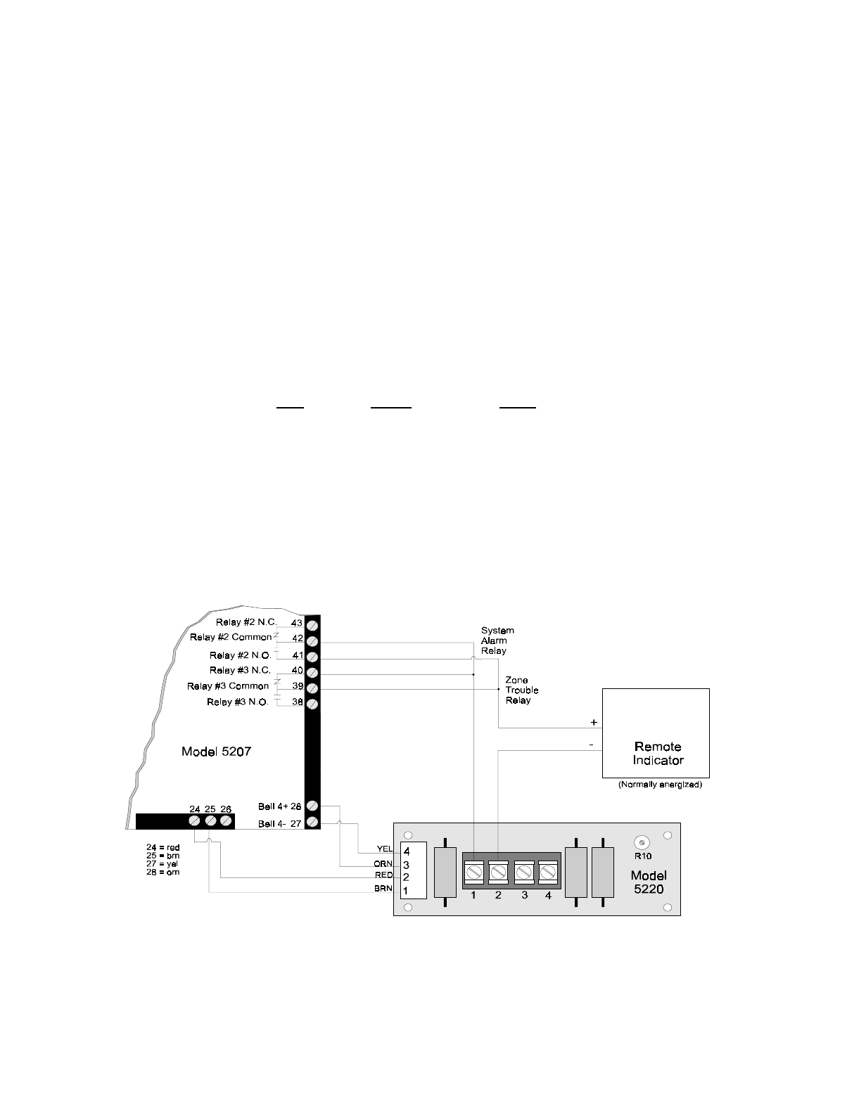
4.7.2 NFPA 72 Polarity Reversal
When the 5220 is wired and programmed for polarity reversal, it reports alarm and trouble
events to a remote site. Alarms will override trouble conditions and it will not be possible to
reset the remote indicator until the condition is cleared and the 5207 panel is reset.
If an alarm condition occurs, the alarm relay will close, overriding the trouble condition.
To install the 5220 for polarity reversal, follow the steps below:
1. Locate the knockout on the right side of the 5207 cabinet to connect the 5220 using a short
piece of conduit (must not exceed 20 feet in length).
2. Wire the 5220 to the 5207 using the four-wire pigtail provided as shown in Figure 4-8
(next page). This diagram also shows how to connect the 5220 to the remote indicator.
3. Program relays as shown in the chart below:
4. Program notification circuit 4 to be non-supervised (Step 5) and non-silencing (Step 23.6,
Bell #4). Do not select pulsing bells.
5. If necessary, adjust loop current using potentiometer R10 on the 5220 board. Normal loop
current is 4-to-8 mA with a 1k ohm remote station receiving unit. Maximum loop resis-
tance is 3k ohm.
Figure 4-8 Polarity Reversal Connection
Step Option Select
23.4 Fire Alarm Relay 2
23.5 Trouble Relay 3
23.6 No Silence Relay 3 and Bell 4
Compatible Product Installation
150865 4-9
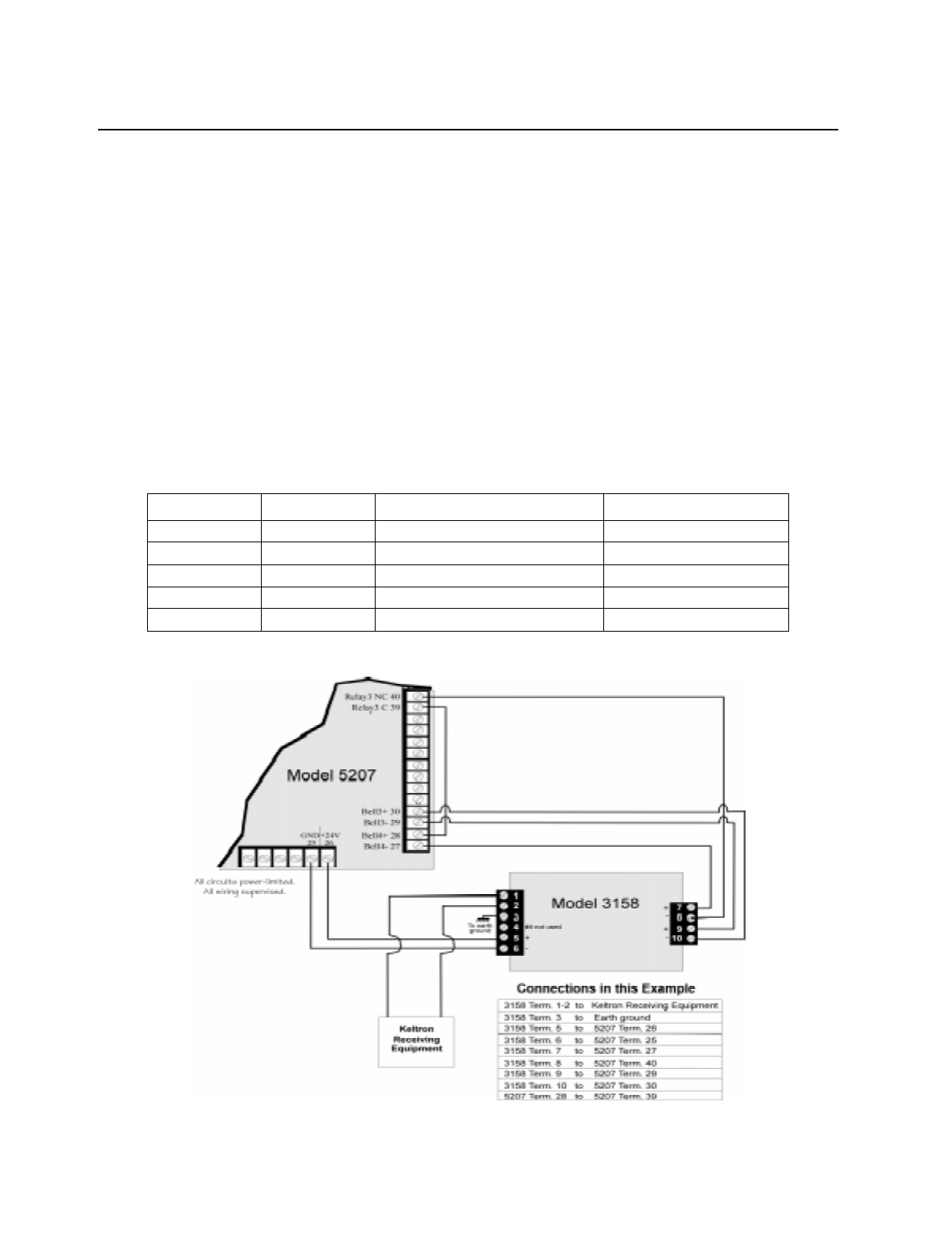
4.8 Keltron 95M3158 Tones Transmitter Module
This section of the manual shows the specific connections you will make when wiring the
5207 to the Keltron 95M3158 Tones Transmitter Module (3158). Refer to the installation
sheet shipped with the 95M3158 for complete information. (Note: The 3158 is not available
from Silent Knight.)
Note: The 3158 Keltron Module must be mounted within 3 feet of the control panel and all wiring must be run in
conduit. The Keltron Module shall be enclosed in the TBX1 enclosure.
1. Wire the 3158 to the 5207 as shown in the figure below.
2. Program Relay 3 to activate for all trouble conditions and no silence. Relay 2 should be
programmed to activate for Alarms.
3. Program notification circuit 3 and 4 to be non-supervised and non-silencing.
4. Program Bell 3 as “Special”.
The chart below shows which selections to make in step programming.
Note: DO NOT select pulsing bells.
Figure 4-9 Wiring the Keltron 3158 to the 5207
Step Option Select De-select
5 Misc Opts Bell 3 and Bell 4
23.3 Special Bell 3
23.4 Fire Alarm Relay 2 Bell 3
23.5 Trouble Relay 3
23.6 No Silence Relay 3, Bell 3 and Bell 4

Model 5207 Installation and Operation Manual
4-10 150865
4.9 Model 5230 Remote Annunciator
The 5230 performs all system operation. It also provides trouble and alarm information and
can be used for programming.
4.9.1 Setting ID Codes
Before permanently installing the Model 5230 Remote Annunciator, you must first set its
identification codes. Each annunciator to be supervised must be given its own identification
codes. The ID numbers must start at 1 and progress sequentially to 7 (7 annunciators max.).
Upon initial power up, the address of each annunciator is displayed. (Annunciators with
address 0 will not be supervised.)
On the back of each annunciator is a small 4-position dip switch used to set the ID code. Use
the chart below to determine the dip switch positions for each possible ID code.
Table 1-1: Model 5230 Dip Switch Settings
ID Number Switches
1234
0 * UpUpUpUp
1 DownUpUpUp
2 UpDownUp Up
3 Down Down Up Up
4 Up UpDownUp
5 DownUpDownUp
6 Up Down Down Up
7 Down Down Down Up
*Not supervised Up = On Down = Off
Compatible Product Installation
150865 4-11
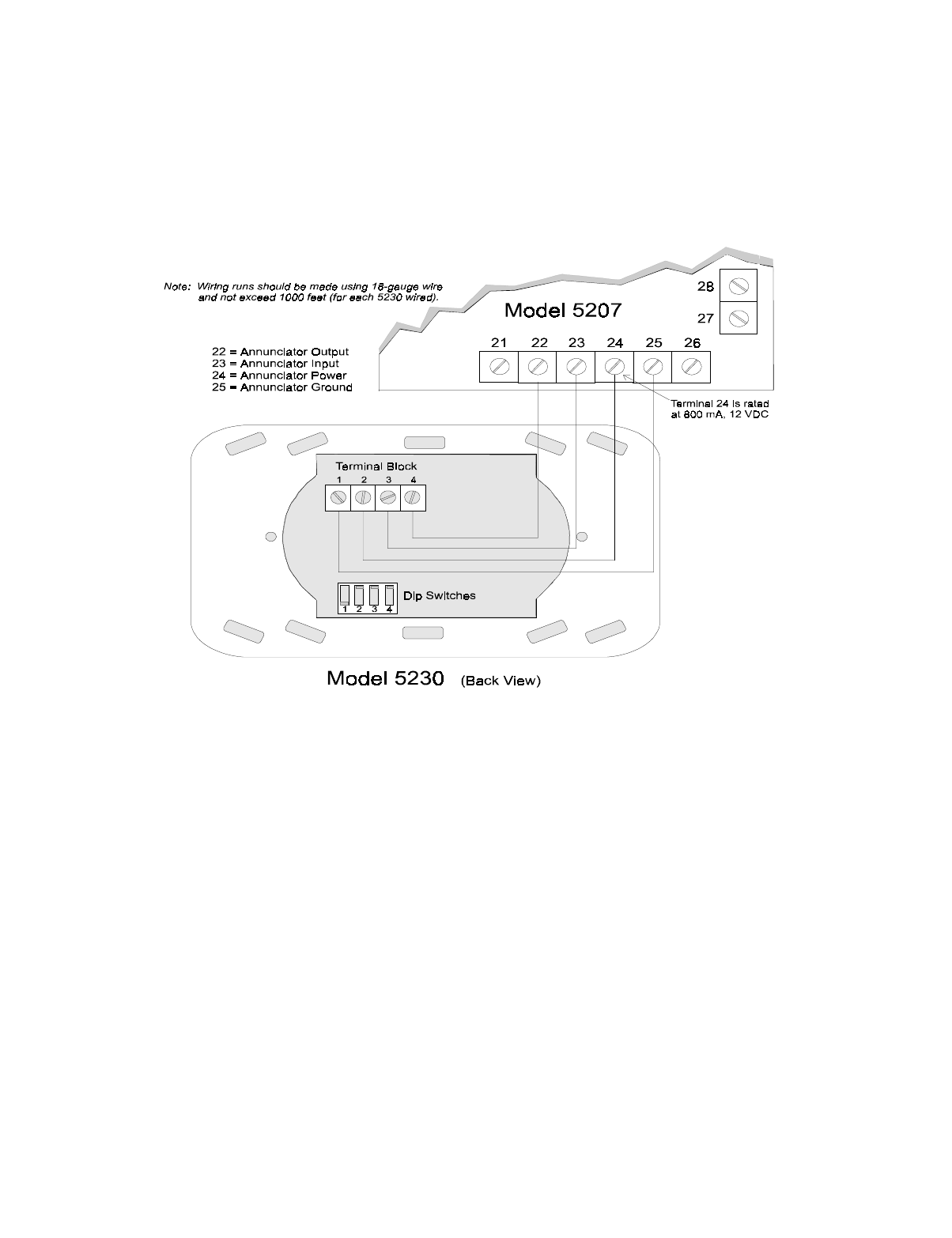
4.9.2 5230 Permanent Connection
Wire permanent 5230s as shown in Figure 4-10. When the annunciator powers up, it will dis-
play its ID code and current status of the panel.
A temporary 5230 can be connected for programming and troubleshooting. See Section 4.9.4
for temporary annunciator connection.
Figure 4-10 Model 5230 Connection
Model 5207 Installation and Operation Manual
4-12 150865
4.9.3 Mounting the 5230 Remote Annunciator
For UL installations, the 5230 Remote Annunciators must be mounted on a dual gang electri-
cal box and all wiring runs must be made using 18-gauge wire or larger.
To mount the annunciator:
1. Remove the rear mounting plate by inserting a #4 flat blade screwdriver into the slots on
the bottom edge of the annunciator. Gently turn the screwdriver until the mounting plate
pulls away from the frame.
2. Secure it to the wall using #6 or #8 screws. The mounting plate should be oriented so that
the word TOP is toward the top of the plate and facing you. A square hole is provided in
the mounting plate to run the wiring to the annunciator.
3. When all of the wires have been connected to the annunciator, set the top of the annuncia-
tor over the tabs on the top of the mounting plate. Make sure the wires do not get pinched
between the frame and the mounting plate. Press each corner of the bottom side onto the
annunciator mounting plate until you hear it click. You may have to gently squeeze the
annunciator (top to bottom) to align it while snapping the bottom edge into place.
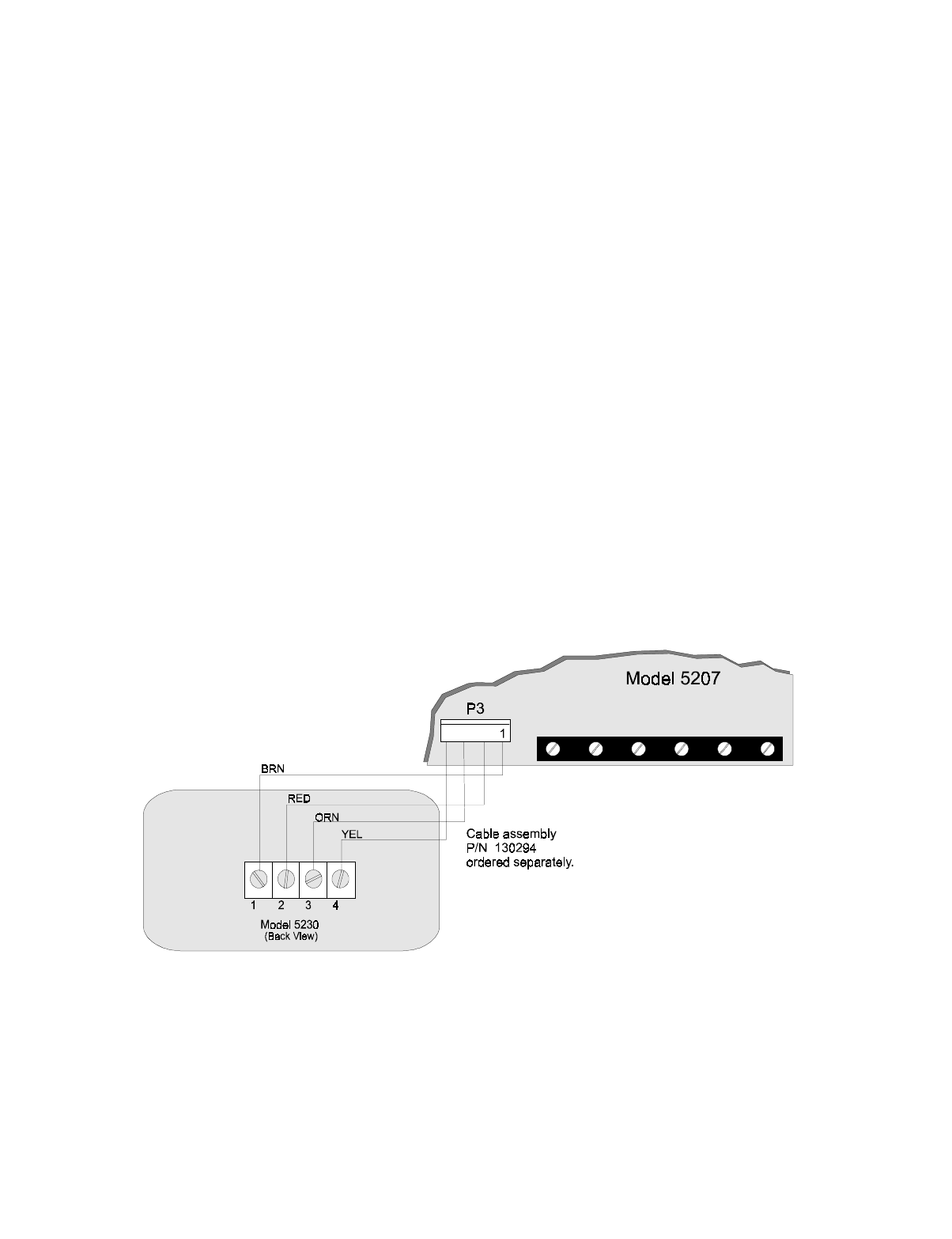
4.9.4 Temporary Annunciator Connection
If you are using an annunciator for programming or troubleshooting only, you can use cable
P/N 130294 (ordered separately) to temporarily attach the 5230 at connector P3. Figure 4-11
shows the connections. A temporary annunciator must have an ID number (1 or higher) but
does not need to be enabled through programming.
Figure 4-11 Temporary Annunciator Connection
Compatible Product Installation
150865 4-13
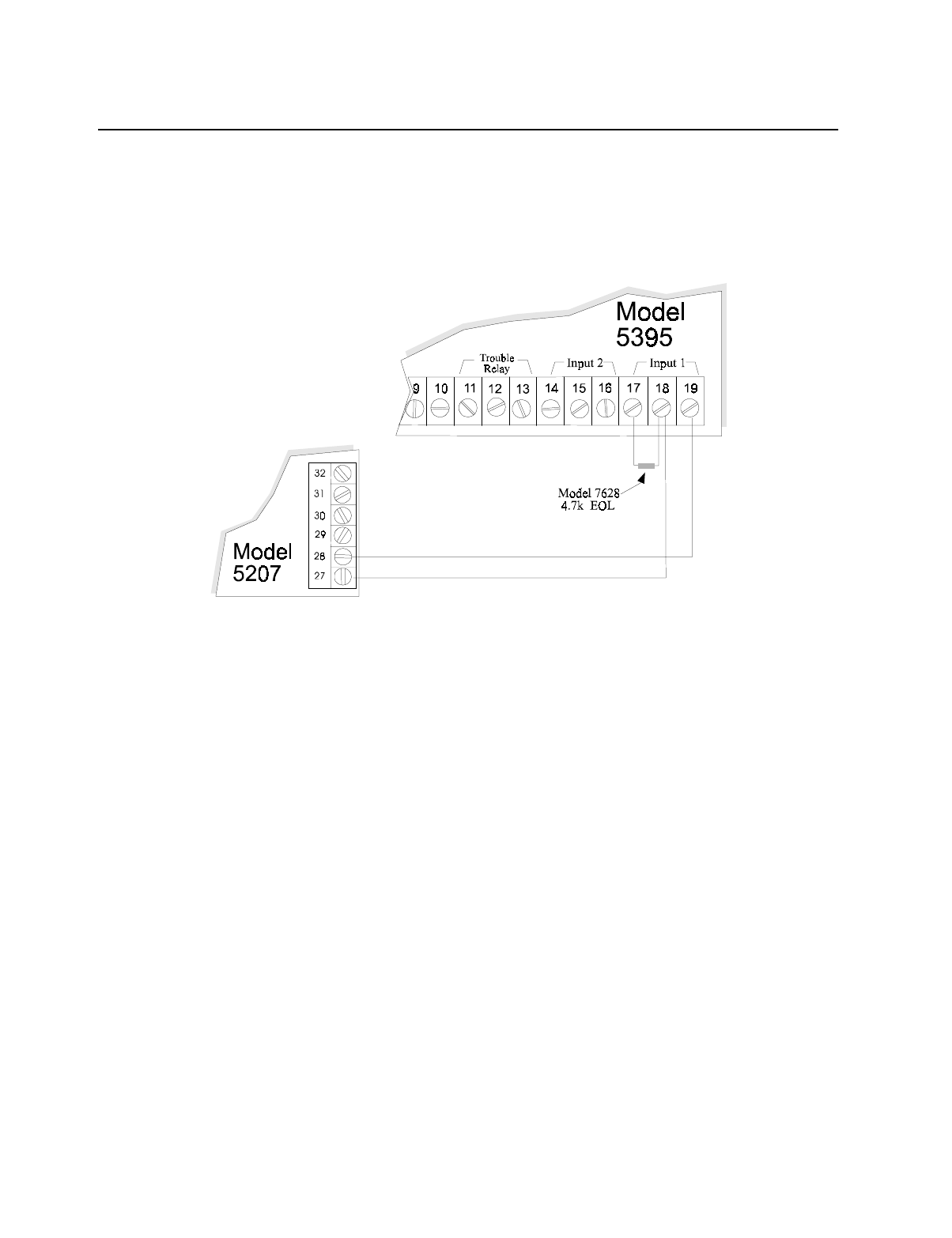
4.10 Model 5395 Signal Power Expander
The Model 5395 is a notification and auxiliary power expander that provides up to 6.0 amps
of regulated, 24-volt power for powering notification appliances and auxiliary devices.
Figure 4-12 shows you how to connect the Model 5395 to the Model 5207 panel. See the 5395
installation manual (P/N 150933) for complete information.
Figure 4-12 5395 Connection to 5207
Model 5207 Installation and Operation Manual
4-14 150865
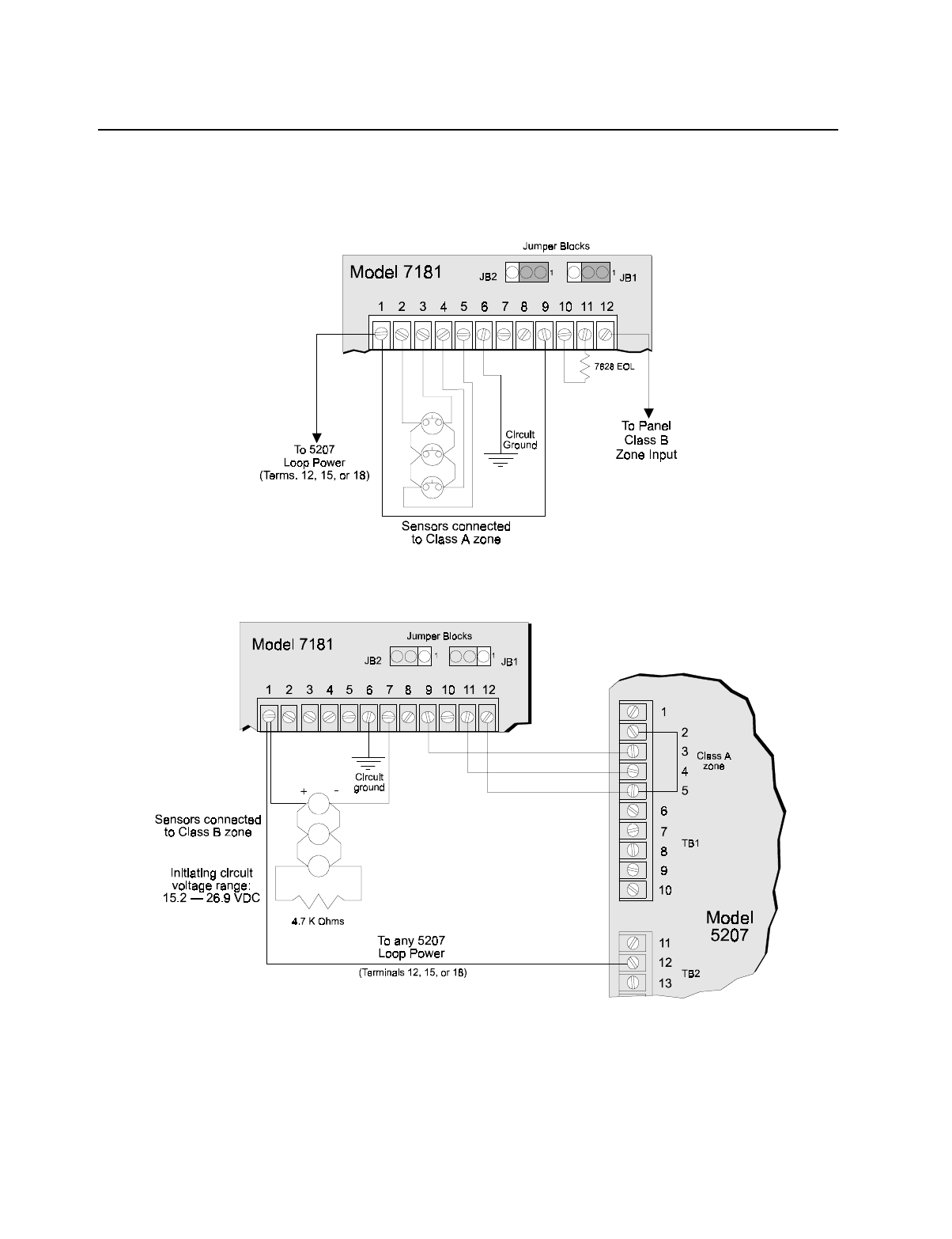
4.11 Model 7181 Zone Converter
The Model 7181 Zone Converter lets you interchange zone types on the 5207. Figure 4-13
and Figure 4-14 show how to make conversions. Refer to the Model 7181 Installation Manual
(P/N 150632) for complete information.
Figure 4-13 Connecting Class A (Style D) Sensor to Class B (Style A) Panel
Figure 4-14 Connecting Class B (Style A) Sensor to Class A (Style D) Panel
Compatible Product Installation
150865 4-15
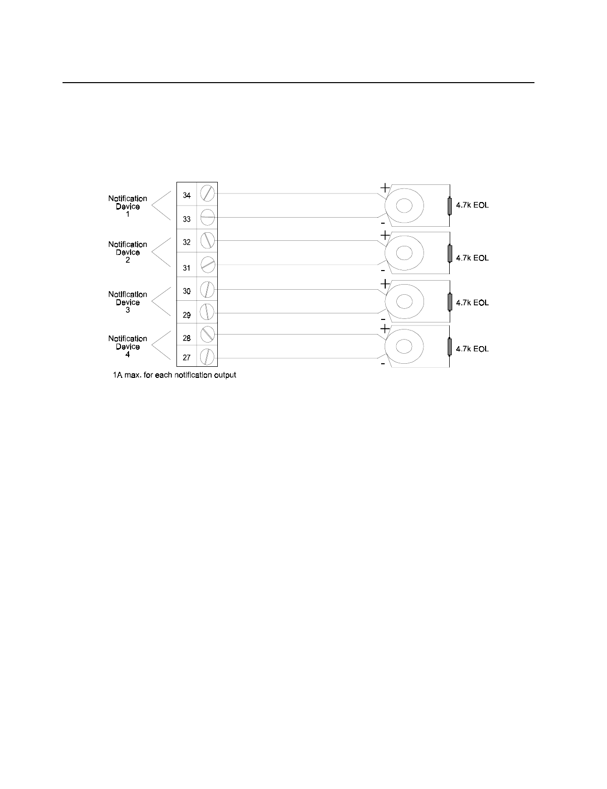
4.12 Supervised Notification Appliance Outputs
Note: To reduce the possibility of false alarms and transient damage, DO NOT bundle telephone wires together with
notification circuit wires.
The 5207 provides four supervised notification circuit outputs to annunciate alarm conditions.
For proper operation, you must use polarized sounding devices with a 4.7k ohm end-of-line
resistor on each loop. Figure 4-15 shows how to connect the notification circuits to the 5207.
Figure 4-15 Supervised Notification Appliance Wiring
See Appendix A for a list the UL sounding appliances that can be used with the 5207. Contact
Silent Knight if you have any questions about compatible notification circuits.
Model 5207 Installation and Operation Manual
4-16 150865
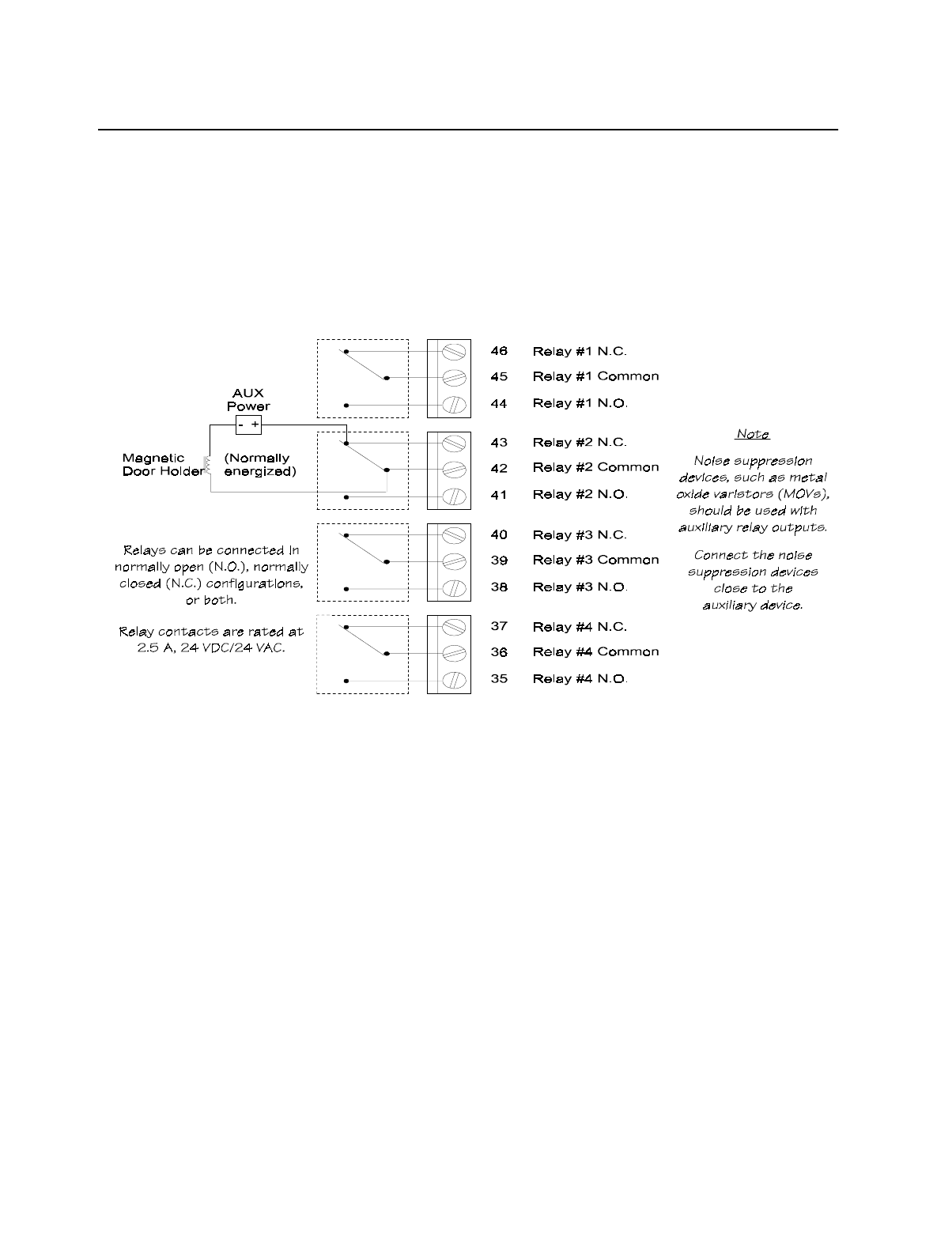
4.13 Auxiliary Relays
The 5207 provides four programmable auxiliary relay outputs. Relays can be programmed to
activate for the following conditions, either for all zones or by individual zone: pre-alarm
(entry delay) (not acceptable for NFPA 72 Central Station), fire alarm, auxiliary alarm, alarm
by zone, and system or loop troubles (loss of AC, low battery, failed to communicate, phone
line troubles, and notification circuit troubles).
Refer to the 5207 programming manual for more information. Figure 4-16 shows the relay
contact connections using a doorstrike application as an example.
Figure 4-16 Auxiliary Relays
150865 5-1
Section 5
Operation
To operate the 5207 you can use either the built-in touchpad or the Model 5230 Remote
Annunciator.
Figure 5-1 Built-in Touchpad (Seven-Segment Display)
Figure 5-2 Model 5230 Remote Annunciator
Model 5207 Fire Control/Communicator Installation and Operation Manual
5-2 150865
5.1 Built-in Touchpad and Model 5230 Operation
Basic operation of both the 5230 and the built-in touchpad is described in Table 5-1. Note that
if no keys are pressed for 15 minutes while in program mode, the system will time out and
resume normal operation.
Notes: A valid operating code is required for most functions when using the 5230. In Table 5-1, code = any valid
operating code, code 0 = installer’s code, and code 1 = main user’s code.
If the NEED CODE AT PANEL option is selected in programming (Step 3), the following operations will
require a valid code when using the built-in touchpad: Silence, Reset alarms, Clear alarm memory, Test.
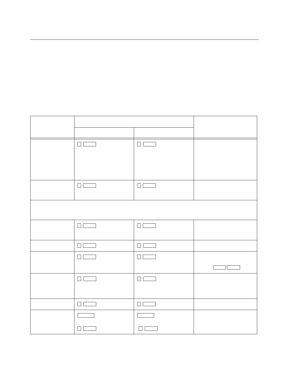
Table 5-1 5207 Operation
To Additional Information
5230 Annunciator Built-in Touchpad
Test the system + code The system will perform a
display lamp test, a bell test, and
a communicator test.
(Note: Bells or relays
programmed to activate on
"Pre-Alarm" or "Trouble" do
not activate during a test.)
Reset alarms (or
smoke detectors) + code If there is no alarm, this
procedure resets the smoke
detectors.
When a trouble condition occurs and you reset the alarm, the trouble condition is stored in memory until you clear the alarm
memory. If the alarm memory is not cleared, the trouble condition is displayed the next time a trouble condition occurs,
implying incorrectly that more than one trouble condition exists.
Clear alarm memory + code Clears alarm memory and resets
the 4180. (This function
removes all memory of alarms.)
Reset the dialer + code 0 or 1
+ code 0 or 1 Resets the dialer (aborts a call).
Initiate download + code 0 or 1 + code 0 or 1 Starts the downloading process.
Exit downloading mode by
pressing .
Display alarm
memory Displays current alarm memory.
(It is recommended that you
clear alarm memory after
displaying it.)
Display troubles Displays trouble conditions.
Silence troubles or
alarms + code
OR
+ code
OR
If silencing audible signals, you
may need to enter a code.
0ENTER 0 ENTER
1 ENTER 1 ENTER
2 ENTER 2 ENTER
3 ENTER 3 ENTER
4 ENTER 4 ENTER
CLEAR CLEAR
5 ENTER 5 ENTER
6 ENTER 6 ENTER
SILENCE
7 ENTER
SILENCE
7 ENTER

Operation
150865 5-3
Set date + code 0 or 1 See explanation below.
The SET MODE LED will turn on and the built-in touchpad display will flash "-8" indicating that you are in SET DATE
mode. Enter six digits for the date. For example, to set the date for 08/15/97, enter the following digits:
Once you press the last digit of the date, the SET TIME LED will turn off and the date will be changed.
To exit Set Date mode, press .
Set time + code 0 or 1 See explanation below.
The SET MODE LED will turn on and the built-in touchpad display will flash "9" indicating that you are in Set Time mode.
Enter six digits for the time. The first digit indicates day of the week ( = Sunday, = Monday, etc.). The second digit
indicates time of day ( = AM, = PM). The last four digits are the actual time. For example, to set the time for
Wednesday, 4:30 p.m., you would enter: .
Once you press the last digit of the time, the SET TIME LED will turn off and the time will be changed.
To exit Set Time mode in the middle of the sequence, press .
Note: If you are powering up the 5207, you will be in Set Time mode with "-9" showing on the display. In thise case, you
don’t need to press . Just enter the six digits for the time.
Disable/Enable zones Zone # + + code Zone # + + code Disables or enables a zone.
When a zone is disabled, there
will be an alert tone that cannot
be silenced until the zone is
enabled.
Fire drill Begin:
+
code 0 or 1
End: + code
Begin:
+
code 0 or 1
End:
Complete instructions appear in
Section 5.2.1.
Walk test Enter:
+ code 0 or 1
Exit:
Enter:
+ code 0 or 1
Exit:
Complete instructions appear in
Section 5.2.2.
Zone trouble-
shooting mode
Enter:
+ code 0 or 1
Exit:
Enter:
+ code 0 or 1
Exit:
Complete instructions appear in
Section 9.3
Step programming
mode Enter:
+ code 0
Exit:
Not applicable. Step programming is explained
in detail in Section 7.
Table 5-1 5207 Operation
To Additional Information
5230 Annunciator Built-in Touchpad
8ENTER 8 ENTER
081597
CLEAR CLEAR
9 ENTER 9 ENTER
0 1
0 1
310430
CLEAR
CLEAR
9
DISABLE DISABLE
2 0 ENTER
SILENCE
2 0
ENTER
SILENCE
2 2 ENTER
SILENCE SILENCE
CLEAR CLEAR
2 2
ENTER
SILENCE
SILENCE
CLEAR
CLEAR
2 5 ENTER
CLEAR CLEAR
2 5
ENTER
CLEAR
CLEAR
2 7 ENTER
STEP STEP CLEAR
CLEAR

Model 5207 Fire Control/Communicator Installation and Operation Manual
5-4 150865
5.1.1 Built-in Touchpad Display Codes
The following table briefly describes the codes that are displayed on the built-in touchpad. For
complete information and for 5230 display messages, see Section 9.
Table 5-2 Built-in Touchpad Display Codes
Display Meaning
0 Fire drill (with Alarm, Alarm Memory, or Trouble LED).
1 - 16 Zone numbers (with Alarm, Alarm Memory, or Trouble LED).
A1 - A4 Trouble with specified bell output.
AC Low AC condition.
dC Low battery condition.
dF Dialer failed after programmed number of attempts have been made.
dL Data lost during attempt to transmit to the central station. This condition occurs after total
attempts to communicate have been made.
E0 Trouble with the dialer.
E7 Trouble with EEPROM.
F0 5230 annunciator power trouble.
F1 - F7 Trouble with specified annunciator (1-7).
L1 - L2 Phone line fault on specified phone line.
P0 Printer is out of paper.
P1 Trouble with smoke detector power.
P2 Accessory power (terminal 26) trouble.
P3 Earth ground fault to circuit ground. See Section 9.2 for more information.
P4 Earth ground fault to power. See Section 9.2 for more information.
-0 Fire drill
-2 Walk test
-4 Downloading
-5 Zone troubleshooting mode
-6 Hex programming mode
-7 Step programming mode
-8 Set Time mode
-9 Set Date mode
2-, 3-, etc. Prompts indicating that the user needs to enter a code.

Operation
150865 5-5
5.1.2 LED Indicators
Six light emitting diodes (LEDs) appear in the 5207 cabinet window. The chart below
explains the meaning of these LEDs.
5.2 System Testing
This section describes operation of fire drills, zone testing, and the 24-hour automatic test.
5.2.1 Fire Drills
Fire drills can be run from either the built-in touchpad or the Model 5230 Remote Annuncia-
tor. To initiate a fire drill, press + Code 0 or 1. The system will sound an alarm and
report a fire test. To end the fire drill, press + code.
LED Status Condition
ALARM (red) Off Normal condition
On Supervisory and Tamper condition
Flashing Alarm
SILENCED (yellow) Off Normal condition.
On Alarm or trouble condition has been silenced but
condition still exists.
AC / DC (green) On Panel is running on AC (normal condition);
standby battery fully charged.
Off Panel has lost all power.
Flashing Panel is running on battery power only or AC
power only.
MEMORY (yellow) Off Normal condition
On An alarm condition has been reset. Alarm memory
contains data.
TROUBLE (yellow) Off Normal condition
On Trouble condition exists
SET MODE (yellow)
REPORT Off Normal condition
On System is in a Set (Test or Program) mode.
Flashing System is reporting.
2 0 ENTER
SILENCE

Model 5207 Fire Control/Communicator Installation and Operation Manual
5-6 150865
5.2.2 Walk Test (Mode 22)
The walk test is designed to be used for onsite testing only.
To enter walk test mode, press
+ code 0 or 1. The LCD will indicate that you are in
walk test mode. When a zone is tripped, the 5207 will activate the bell outputs for approxi-
mately one second and will cycle smoke power off and on for the programmed time interval.
(Pre-alarm zones will not be delayed, but smoke verification zones will go through the verifi-
cation delay.) When smoke power is restored, there is a two-second power up delay before the
zone will respond to additional test inputs.
The system will time out and resume normal operation in 15 minutes if no keys are pressed or
no zones are tripped during the walk test.
To exit walk test mode, press .
Note: The ESL-429 series smoke detectors are NOT compatible when operating the 5207 panel in walk test mode.
In walk test mode, the built-in self test on the ESL 429 series smoke detectors may be unreliable.
If the built-in self test is required, it should be done in the normal operating mode with the zone speed set
to 3 seconds or higher.
Note that these smoke detectors are incompatible only for walk tests, not for any other normal 5207 sys-
tem operation.
5.2.3 Automatic Self Test
The Model 5207 lets you select the time of day that the 24-hour automatic test signal will be
sent to the central station.
The Auto Test dialer test sent automatically at specified times. Immediately following the test,
the 5207 also sends all unrestored events as required by UL. The events will have no indica-
tion when they occurred, so central station personnel should maintain records of unrestored
events, or, if that is not possible, treat all alarms, troubles, and supervisories that come in dur-
ing an auto test as if they were new events.
5.3 Watchdog Circuit
During normal operation, the control microprocessor of the 5207 is constantly running pro-
grams to check inputs and carry out other routine functions. If the program should ever stop
running, the watchdog circuit will automatically detect this and attempt to resume normal
operation by resetting the microprocessors. Each time the watchdog circuit initiates a reset
signal, it will also sound the audible trouble signal for approximately four seconds.
2 2 ENTER
SILENCE SILENCE
CLEAR
CLEAR

150865 6-1
Section 6
Pro
g
rammin
g
: Quick Reference
This section of the manual briefly describes all available programming options and lists the
factory programmed default values. Section 7 of this manual is a complete, step-by-step guide
that provides details, including LCD diagrams, of each programming step. Please read Section
7 thoroughly, especially if you have never programmed the 5207 before.
The quick reference chart can be used for keeping track of how options have been pro-
grammed for an installation. The drawing below explains how to use the quick reference
chart.
Figure 6-1 How to Use the Programming Quick Reference Chart
Step # Option Default Your Selection
1
Pg. 7-4
1st digit:
Bell Test at Restore:
0 = No test
8 = Test
2nd digit:
Power up Mode Report:
0 = No report
1 = Report sent
00
2
Pg. 7-4
Enable Devices:
0 = Dialer
1 = Printer
2-6 Unused
7 = 24V system
(Do not change factory
programming.)
0 - - - - - - 7
3
Pg. 7-5
Options:
0 = Cadenced pulsing of
bells
1 = Code required at panel
2 = Trouble alert tone for
pre-alarm sound
3 = Pulsing fire bells
4 = Sound smoke delay
5 = Report fast restores
6 = Do not de-select.
7 = Time displays in
military format
- - - - - - 6 -

Model 5207 Fire Control/Communicator Installation and Operation Manual
6-2 150865
4
Pg. 7-5
1st digit:
(Display Rate)
0 = .5 sec
1 = 1 sec.
2 = 1.5 sec.
3 = 3 sec.
2nd digit:
0-7 = Max. number of
supervised touchpads
(0 means none.)
20
5
Pg. 7-6
Misc. Options:
0 = Report walk tests
1 = Do NOT de-select
2 = Detect ground fault
3 = Sequential bell test
4 - 7 = Supervise bells 1-4
-1234567
6
6.1
6.2
6.3
6.4
6.5
6.6
6.7
6.8
6.9
6.10
Begins on
Pg. 7-6
Internal Zone Options (zones 1-8)
24-hour alarm (do not change default)
Select zones to be supervised for trouble
Unused (do not change default)
Zones will be Normally Open (do not change default)
Zone response speed 2 or 4
Zone response speed 3 or 4
Unused
Pre-alarm delay
Smoke verification delay
Number of zones that can be disabled
12345678
12345678
- - - - - - - -
12345678
12345678
- - - - - - - -
- - - - - - - -
- - - - - - - -
- - - - - - - -
12345678
__________________________
__________________________
__________________________
__________________________
__________________________
__________________________
7
7.1
7.2
7.3
7.4
7.5
7.6
7.7
7.8
7.9
7.10
Begins on
Pg. 7-9
External Zone Options (zones 9-16)
24-hour alarm (do not change default)
Select zones to be supervised for trouble
Unused (do not change default)
Zones will be Normally Open (do not change default)
Zone response speed 2 or 4
Zone response speed 3 or 4
Unused
Pre-alarm delay
Smoke verification delay
Number of zones that can be disabled
90123456
90123456
- - - - - - - -
90123456
90123456
- - - - - - - -
- - - - - - - -
- - - - - - - -
- - - - - - - -
90123456
__________________________
__________________________
__________________________
__________________________
__________________________
__________________________
8
Pg. 7-10
Total number of zones in system 8
9
Pg. 7-10
Dialer Options:
0 = Retry if fail
1 = Enable phone line 2
2 = Unused (do not select)
3 = Ground start (do not use
in UL installations)
4 = Enable phone line
monitor
5 = Answer ring detect
6 = Unused (do not select)
7 = Up/downloading
- 1 - - - 5 - 7
Step # Option Default Your Selection

Programming: Quick Reference
150865 6-3
10
Pg. 7-11
Total number of dialing attempts. 0
11
Pg. 7-11
Number of dialing attempts before dialer fail. 0
12
Pg. 7-11
Low AC hours (UL requires range of 6-12 hours.) 6
13
Pg. 7-11
Number of rings to activate downloading. 10
14
14.1
Begins on
Pg. 7-12
Telephone # for reporting:
Report alarms to:
1 = Ph. #1
2 = Ph. #2
3 = Ph. #3
4 = Ph. #4
Report troubles to:
5 = Ph. #1
6 = Ph. #2
7 = Ph. #3
8 = Ph. #4
1 - - - 5 - - -
14.2 Report disabled zones to:
1 = Ph. #1
2 = Ph. #2
3 = Ph. #3
4 = Ph. #4
Report restores to:
5 = Ph. #1
6 = Ph. #2
7 = Ph. #3
8 = Ph. #4
1 - - - 5 - - -
14.3 Report open resets to:
1 = Ph. #1
2 = Ph. #2
3 = Ph. #3
4 = Ph. #4
5-8 = Not used.
1 - - - - - - - -
14.4 1-4 = Not used. Report tests to:
5 = Ph. #1
6 = Ph. #2
7 = Ph. #3
8 = Ph. #4
- - - - 5 - - -
14.5 Must Report:
1 = Ph. #1
2 = Ph. #2
3 = Ph. #3
4 = Ph. #4
Select Options:
5 = Line 1 is Touch-Tone
6 = Line 1 is Touch-Tone
7 = Use Touch-Tone only
8 = Enable 16-zone
reporting
1 - - - - - - -
15
Pg. 7-13
Computer phone number for up/downloading. [blank]
Step # Option Default Your Selection

Model 5207 Fire Control/Communicator Installation and Operation Manual
6-4 150865
16
16.1
16.2
16.3
16.4
Begins on
Pg. 7-13
Central station phone numbers:
Phone number 1
Phone number 2
Phone number 3
Phone number 4
555
1234567890
- - - - - - - -
- - - - - - - -
- - - - - - - -
__________________________
__________________________
__________________________
__________________________
17
17.1
17.2
17.3
17.4
Central station account numbers:
Account number 1
Account number 2
Account number 3
Account number 4
005207
- - - - - - - -
- - - - - - - -
- - - - - - - -
__________________________
__________________________
__________________________
__________________________
18.1 -
18.4
Pg. 7-14
1st digit:
Number of attempts before
switching to next account
for Accounts 1-4.
2nd digit:
Dialer format for Accts. 1-4:
0 = SIA8 4 = BFSK23
1 = FSK1 5 = SIA20
2 = Not used 6 = SK4+2
3 = BFSK14
1 0 Account 1 _______
Account 2 _______
Account 3 _______
Account 4 _______
19.1 -
19.4
Pg. 7-14
Telephone options for accounts 1-4:
0 = Unused 3 = 9000 Direct (do not select)
1 = Use line 1 only 4-9 = Unused (do not select)
2 = Use line 2 only
- - - - - - - - Account 1 _______
Account 2 _______
Account 3 _______
Account 4 _______
20
20.1
20.2
20.3
20.4
20.5
20.6
Pg. 7-15
Duration of delays:
Bell shutdown time delay
Unused (do not change default)
Pre-alarm delay
Smoke verification delay
Smoke reset time
Unused (do not change default)
90
30
30
30
2
24
21
Pg. 7-16
Test Time 000000
22.0
Pg. 7-16
Installer’s code (access to all functions) 123456
22.1
Pg. 7-16
Main user’s code (access to all functions except
programming)
1111
22.2-
22.9
Pg. 7-16
Other users (basic operating functions - can reset alarms and
disable zones).
[blank]
Step # Option Default Your Selection

Programming: Quick Reference
150865 6-5
23
23.1
23.2
23.3
23.4
23.5
23.6
Pg. 7-17
Select relays (digits 1-4) and bells (digits 5-8) to activate for:
Pre-alarm conditions
Tamper alarms
Special (auxiliary) alarms
Fire alarms
Trouble conditions
No silence conditions
- - - - - - - -
- - - - - - - -
- - - - - - - -
- - - - 5678
1 - - - - - - -
- - - - - - - -
__________________________
__________________________
__________________________
__________________________
__________________________
__________________________
24.0 -
24.16
Pg. 7-19
Select alarm relay (digits 1-4) and bells (digits 5-8) to
activate by zone.
24.0 selects bells and relays to activate during a fire drill.
Steps 24.1-24.16 select bells and relays to activate for alarms
in zones 1-16.
- - - - - - - -
25.0 -
25.16
Pg. 7-20
1st digit: Audible signal
0 = Bells can shut down
2 = Cross alarm delay
4 = No manual bell sound
8 = No auto bell shutdown
A = Cross alarm and no shut
down
2nd digit: Zone type
0 = Fire drill
1 = Fire
3 = Panic
5 = Tamper
6 = Sprinkler
7 = Undefined auxiliary
8 = Water
9 = Heat
A = Cold
B = Local
C = Unused (do not select)
8 1 Use space on next page to record
options.
26.1-
26.16
Pg. 7-21
Zone location descriptions. See Table 6-1 for list. WORDS Use space on next page to record
options.
27
Pg. 7-22
Length of temporal (pulsing) pattern 32 Use space on next page to record
options.
28
28.1
28.2
28.3
28.4
Pg. 7-22
Cadence pattern (used with step 27)
First group of 8 bits
Second group of 8 bits (Each substep controls up to
Third group of 8 bits four seconds.)
Fourth group of 8 bits
12345678
12345678
12345678
- - - - - - - -
Use space on next page to record
options.
Step # Option Default Your Selection

Model 5207 Fire Control/Communicator Installation and Operation Manual
6-6 150865
Zone Zone
Type Audio
Type Bells/Relays to
Activate in Alarm Location Descriptions
1
2
3
4
5
6
7
8
9
10
11
12
13
14
15
16

150865 7-1
Section 7
Pro
g
rammin
g
: Step-b
y
-Step Complete Reference
The Model 5230 Remote Annunciator is for programming the 5207 panel. You must be in
Step Programming Mode (also known as mode 27) to program the panel. See the following
sections for details.
7.1 Using Step Programming
Enter Step
Programming mode Press , followed by the code that has been programmed as code 0 (the
factory programmed value for code 0 is 123456). If you have entered mode 27
correctly, the display will show 1 PWR UP CLR (Step 1, Power-up Clear). Press
to make selections for this step. Press again to move to the next
step.
Note: If you receive a trouble beep and the message TRY AGAIN appears, either you are
not using the correct code 0, or the EEPROM could be malfunctioning. If the problem is the
EEPROM, you must obtain a new default EEPROM from Silent Knight.
Exit Step Programming Press . You will return to normal operation.
Moving through the
Steps and Sub-Steps
To move sequentially through the options:
Press until you reach the step (option) you want to program.
To go directly to step:
If you know the step you want to go to, you can save time by moving directly to
the step. Press . Enter the desired step number, then press . The
new step will be displayed.
To go to directly a sub-step:
Some steps contain sub-steps (see the diagram on the next page for an example).
To go to a particular sub-step, first go to the step. Then, press followed by
the substep number and press . For example, to go to step 14.2, you would
press the following sequence of keys:
chart continued on next page
2 7 ENTER
ENTER ENTER
STEP STEP CLEAR CLEAR
ENTER
STEP STEP ENTER
STEP
ENTER
STEP STEP 1 4 ENTER STEP 2
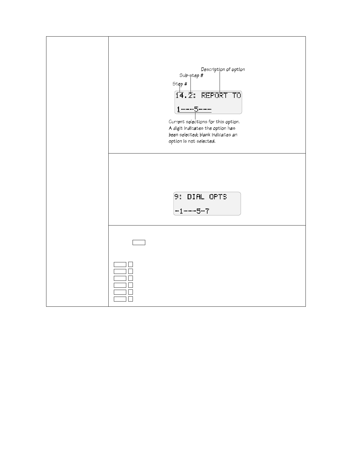
Model 5207 Fire Control/Communicator Installation and Operation Manual
7-2 150865
Selecting Options Scrolling
For most options, you enter numbers in the same way as if you were using a
calculator. The digits appear on the right side of the display and scroll to the left as
you continue to enter data.
Toggling
In some steps, pressing a key will cause the corresponding digit to appear and
disappear on the display. When a digit appears, it indicates that the option is
selected. A dash indicates that the option is not selected. In the following
example, options 1, 5, and 7 are selected:
Entering numbers greater than 9
Use the key as shown below to enter numbers
10-15. Hexadecimal digits (in parentheses) appear on the screen to represent these
numbers.
= 10 (A)
= 11 (B)
= 12 (C)
= 13 (D)
= 14 (E)
= 15 (F)
SHIFT
SHIFT 1
SHIFT 2
SHIFT 3
SHIFT 4
SHIFT 5
SHIFT 6

Programming: Step-by-Step Complete Reference
150865 7-3
Programming Examples
The following examples demonstrate how to use Step Programming. The selections you
make in each installation will vary depending on each customer’s needs. The way you move
through Mode 27 may also vary from how it is described here.
Example 1: Programming
Location Description Names
Suppose you want to program
the Model 5230 Annunciator to
display meaningful location
names for Zones 3 and 5. The
words you wish to display are
GARAGE for Zone 3 and EAST
OFFICE for Zone 5. These
words are part of the 5230
library of names and can be
selected using Step
Programming. See Table 2-2 for
a complete list of words
contained in the library.
One-Word Display
1. From the 1 PWR UP CLR display, press to go to Step
26.1.
2. Press until you reach Zone 3. The first line of the LCD will
read .
3. Press as many times as necessary until the word GARAGE is dis-
played on the LCD. Press to select.
Two-Word Display
To program Zone 5 to display EAST OFFICE, you will have an
additional step since you are programming two words instead of one.
1. If necessary, enter Step Programming mode from the Date/Time dis-
play by pressing , then enter your access code.
2. From the 1 PWR UP CLR display, press to go to Step
26.1. (If you are already in Step 26, just press , then the num-
ber of the zone you want to change and press .)
3. Press until you reach Zone 5. The first line of the LCD will
read .
4. Press as many times as necessary until the word EAST is dis-
played on the LCD.
5. To add the second word, press until you reach OFFICE. Press
to select.
Example 2: Adding a New
Access Code 1. If necessary, enter Step Programming mode from the Date/Time dis-
play by pressing , then enter your access code.
2. From the 1 PWR UP CLR display, press .
3. Press .
4. Press the number of the code you want to add or change. Press
.
5. Enter the new access code number. Press .
2 6 ENTER
ENTER
26.3
1
ENTER
2 7 ENTER
2 6 ENTER
STEP
ENTER
ENTER
26.5
1
2
2 7 ENTER
2 7 ENTER
2 2 ENTER
STEP
ENTER
ENTER
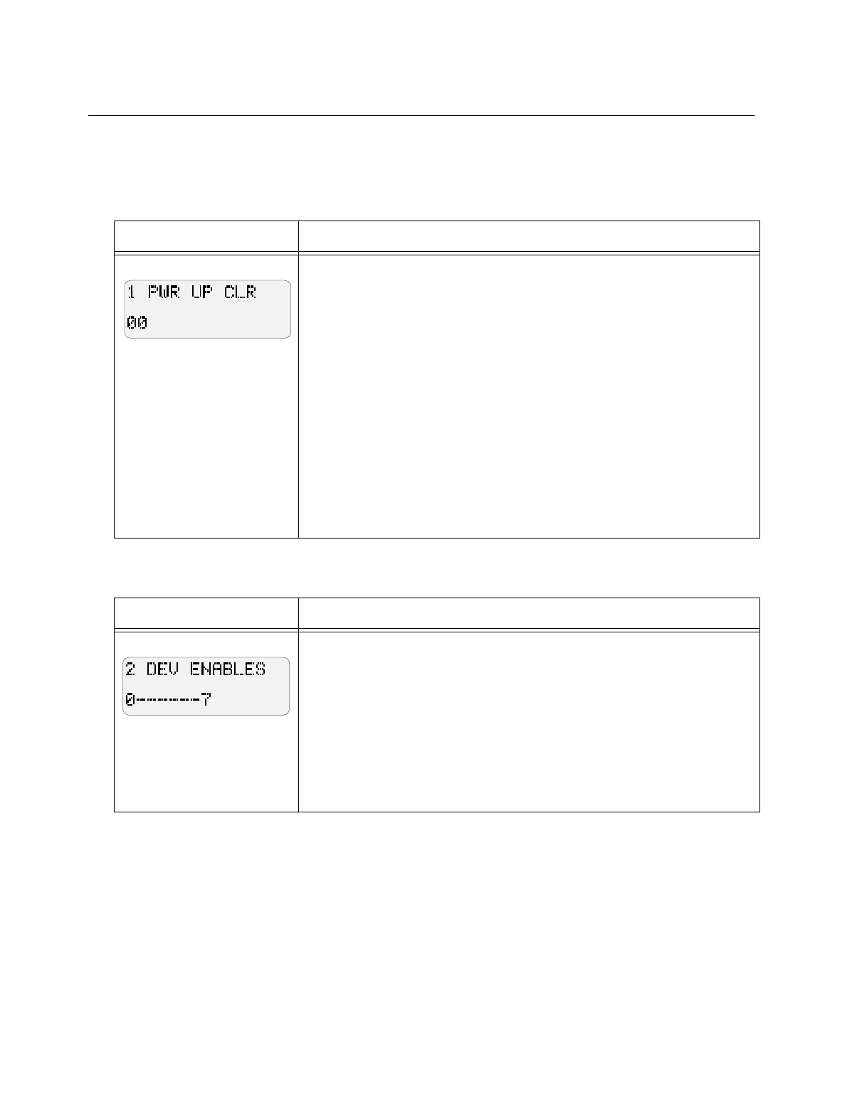
Model 5207 Fire Control/Communicator Installation and Operation Manual
7-4 150865
7.2 Step Programming Options
This section is organized in step order and provides complete instructions for each step.
Step 1. Power Up Clear
Step 2. Device Enables
Display Description
The two digits of this step are used to program two options, BELL TEST AT
RESTORE (digit 1) and DEFAULT MODE (power up) REPORTING (digit
2).
Digit 1:
0 = No bell test at restore.
8 = Bell test will occur at restore.
Digit 2:
0 = A report will not be sent if the system enters power up mode.
1 = An "open" report will be sent if the system enters power up mode.
Example 1: If you select "80" for this step, a bell test will occur at restore (dig-
it 1) and no report will occur if the system enters power up mode (digit 2).
Example 2: If you select "01" for this step, a bell test will not occur at restore
(digit 1) and the system will report "Open" if it enters power up mode (digit 2).
Display Description
Step 2 allows you to enable the dialer, printer, and 24-volt smoke power.
0 = Dialer. The dialer must be enabled. Do not change the factory program-
ming.
1 = Printer. Enable the printer if your installation includes a 5260 printer in-
terface. (The 5260 is not UL listed for use with the 5207.)
7 = 24-V System. Enables 24V power. Do NOT disable.
2 - 6 = Unused. These digits are reserved by the manufacturer for future use.
Leave these blank at all times.
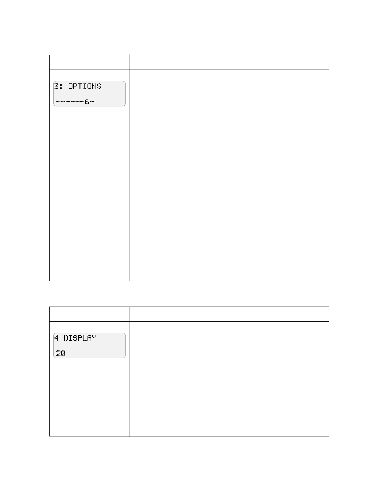
Programming: Step-by-Step Complete Reference
150865 7-5
Step 3. More System Options
Step 4. Display Rate
Display Description
Step 3 allows you to select seven system options shown below. To select an
option, press its number.
0 = Cadenced pulsing of bells. If you select this option, bells will pulse in
the pattern shown below (for customizing patterns, refer to Steps 27 and 28):
3.5 seconds on, .5 seconds off
3.5 seconds on, .5 seconds off
3.5 seconds on, 4.5 seconds off
1 = Code required at the panel. If you select this option, users will have to
enter a code to perform tasks on the built-in touchpad.
2 = Trouble alert tone used for pre-alarm sound. If you choose this option
the built-in trouble alert will sound when a trouble condition occurs.
3 = Pulsing fire bells. Select this option if you want fire alarm bells to pulse
one second on, one second off. (If you want fire bells to have cadenced
pulsing instead of one second on, one second off pulsing, choose both this
option AND cadenced pulsing.)
4 = Trouble alert tone will sound during smoke delays. If you choose this
option, the built-in trouble alert sounder will sound when a trouble condition
occurs.
5 = Report fast restores. This option causes restores that occur as soon as the
alarm situation is corrected instead of waiting for the shutdown time.
6 = Must be enabled. Do NOT de-select.
7 = Time displays in military format. If you select this option, the system
time will display in the 24-hour military format instead of the 12-hour with
AM/PM format.
Display Description
The two digits of this step are used to program two options that have to do
with the Model 5230 Remote Annunciator.
Digit 1 = The rate that the 5230 LCD displays text, that is, how long a
display stays on the LCD. The choices are:
0 = 0.5 sec
1 = 1 sec
2 = 1.5 sec
3 = 3 sec
Digit 2 = Maximum number of supervised annunciators. Enter 0-7. "0"
means no annunciators will be supervised.
Example:
Entering "14" for this step indicates that all annunciators will display text for 1
second (Digit 1) and your installation has 4 (1-4) annunciators (Digit 2).
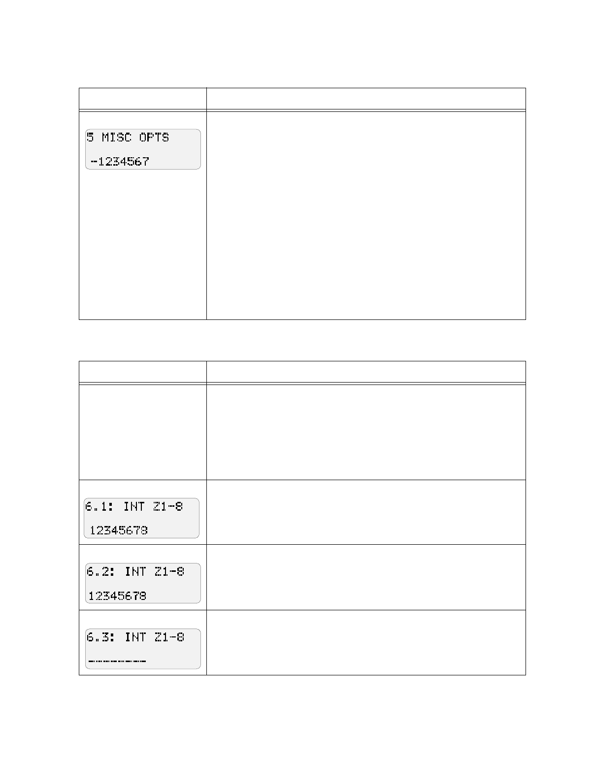
Model 5207 Fire Control/Communicator Installation and Operation Manual
7-6 150865
Step 5. Miscellaneous Options
Step 6. Internal Zone Options
Display Description
Step 5 is for programming several system options, including bell supervision.
0 = Walk tests will be reported. Select this option if you want walk tests
reported to the central station.
1 = A feature that makes the system clock more accurate. Do NOT de-
select.
2 = Ground fault detection enabled. This is required. Do NOT de-select.
3 = Sequential bell test. Enabling this option means that when a dialer test or
power-up occurs, the four bells will ring sequentially (first bell 1, then bell 2
and so on), instead of all four at the same time.
4 = Bell 1 is supervised. This option must be enabled if bell 1 is used.
5 = Bell 2 is supervised. This option must be enabled if bell 2 is used.
6 = Bell 3 is supervised. This option must be enabled if bell 3 is used.
7 = Bell 4 is supervised. This option must be enabled if bell 4 is used.
Display Description
Step 6 is for programming various options for zones 1-8. To select an option
for a zone, go to the appropriate substep and enter the zone number. (Options
for expansion zones 9-16 are programmed in Step 7.)
Example:
Suppose you want zones 2 and 3 to be pre-alarm delayed. Pre-alarm delays are
programmed at Step 6.8. Press "23" at Step 6.8.
24 Hour alarmZones will be active 24 hours. Must be selected for all zones.
Do NOT change the factory programming for this step.
Trouble SupervisedSelect zones that will be supervised for trouble (typi-
cally this is all zones).
Option not used. Do NOT select anything.
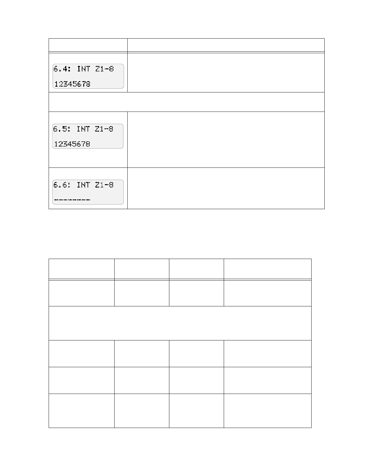
Programming: Step-by-Step Complete Reference
150865 7-7
Programming Zone Response Time (Steps 6.5 & 6.6)
There are four possible response times. To program the response times, select the zone number
that should have that response time in Steps 6.5 and 6.6, as follows:
Normally Open zonesZones will be Normally Open. Must be selected for
all zones. Do NOT change the factory programming for this step (NFPA re-
quires that all fire zones be programmed as N.O. supervised).
Steps 6.5 and 6.6 are for programming zone response time. For more information see “Programming Zone
Response Time”, especially if you have never programmed loop response times with the 5207.
Use this step to select the 3-to-4 second or 30-to-40 second response times for
zones 1-8. Select the zone numbers of the zones that should have either of
these speeds. For the 30-to-40 second speed, you will have to enter the zone
numbers again in Step 6.6. Note that the default for all zones is 3 to 4
seconds. You will need to de-select any zones that should not have the 3-to-4
or 30-to-40 response times by pressing the zone number so that it is not
displayed on the LCD. See Table 6-1.
Use this step to select the 15-to-20 second or 30-to-40 second response times
for zones 1 to 8. Select the numbers of the zones that should have either of
these speeds. For the 30-40 second speed, you should also have entered the
zone numbers in Step 6.5. Be sure to de-select any zones that should not be
displayed in this step. See Table 6-1.
Table 6-1 Steps 6.5 and 6.6 Programming
Desired Speed
for Zone Step 6.5 Step 6.6 Explanation
0.094 - 0.25 seconds Do not select zone
number. Do not select zone
number. Leave the zone number blank in
both steps for any zones that
should have this response time.
Note: This very fast response time can increase the possibility of false alarms, since transients and other
interference can set off alarm conditions in such a short time span. Silent Knight recommends that you
do not use this response time unless you have to (because, for example, the installation you are
protecting requires this quick a response time even if false alarms could result).
3 to 5 seconds Select zone num-
ber. Do not select zone
number.
In Step 6.5 only, select the zone
number of zones 1-8 that should
have this response time.
15 to 20 seconds Do not select zone
number. Select zone num-
ber.
In Step 6.6 only, select the zone
number of zones 1-8 that should
have this response time.
30 to 40 seconds Select zone
number. Select zone num-
ber.
In both Steps 6.5 and 6.6, select
the zone number of zones 1-8
that should have this response
time.
Display Description
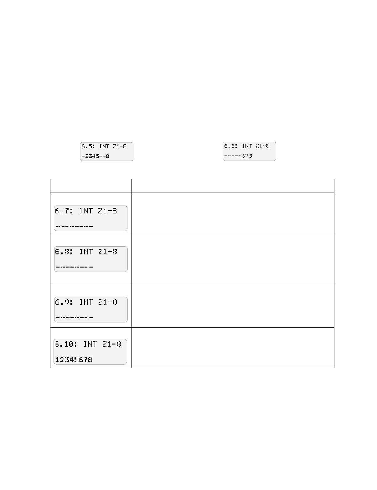
Model 5207 Fire Control/Communicator Installation and Operation Manual
7-8 150865
Example:
To program an 8-zone installation where you want loop response speeds to be as follows:
Zone 1: 0.094 - 0.125 sec.
Zones 2-5: 3-4 sec.
Zones 6-7: 15-20 sec.
Zone 8: 30-40 sec.
Do This:
In Step 6.5, select zones 2, 3, 4, 5, and 8. Make sure
that zone 1 is not selected. Your LCD would appear as
shown below:
In Step 6.6, select zones 6, 7, and 8. Make sure that
zone 1 is not selected. Your LCD would appear as
shown below:
Display Description
Not used. Do not select any zones for this option.
Pre-alarm delay. Use this step to select a pre-alarm delay for zones 1 to 8.
When this delay is selected for a zone, it means that the panel will not
immediately go into alarm. Alarm responses and reporting will be delayed for
the programmed duration (duration programmed in Step 20.3). Any outputs
programmed for pre-alarm (in Step 23.1) will activate. At the end of the pre-
alarm time, if the alarm has not been reset, the panel will go into alarm.
Smoke verification delay. For use with smoke detectors only (not for
manual pull stations). Use this step to select any zones that will be controlled
by a smoke detector delay. This means that the smoke detector will delay for
a specified amount of time before responding to an alarm condition. (The
duration of the delay is programmed in Step 20.4.)
Can be disabled. For zones 1-8, enter the number of zones that can be
disabled.
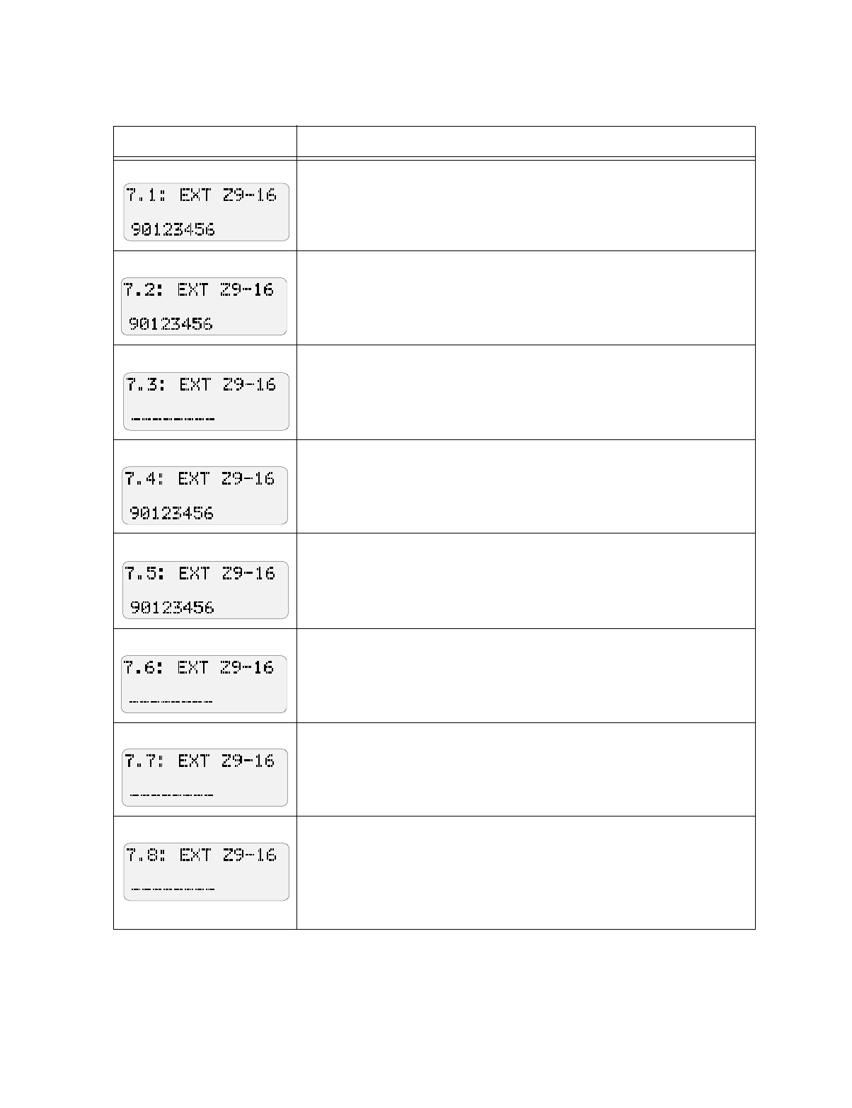
Programming: Step-by-Step Complete Reference
150865 7-9
Step 7. External Zone Options
Display Description
24 Hour alarmZones will be active 24 hours. Must be selected for all
zones. Do NOT change the factory programming for this step.
Trouble supervisedFor zones 9 to 16, enter the number of zones that will
be trouble supervised.
Not used. Do NOT select any zones for this option.
This step sets all expansion zones as Normally Open. Do not change the
factory programming for this step.
Use this step to select the 3-to-4 second or 30-to-40 second loop response time
for zones 9 to 16. If you need more information about how to program loop
response time, see the explanation at Steps 6.5 and 6.6.
Use this step to select the 15-to-20 second or 30-to-40 second loop response
time for zones 9 to 16. If you need more information about how to program
loop response time, see the explanation at Steps 6.5 and 6.6.
Not used. Do not select any zones for this option.
Pre-alarm delay. Use this step to select a pre-alarm delay for zones 1 to 8.
When this delay is selected for a zone, it means that the panel will not
immediately go into alarm. Alarm responses and reporting will be delayed for
the programmed duration (duration programmed in Step 20.3). Any outputs
programmed for pre-alarm (in Step 23.1) will activate. At the end of the pre-
alarm time, if the alarm has not been reset, the panel will go into alarm.
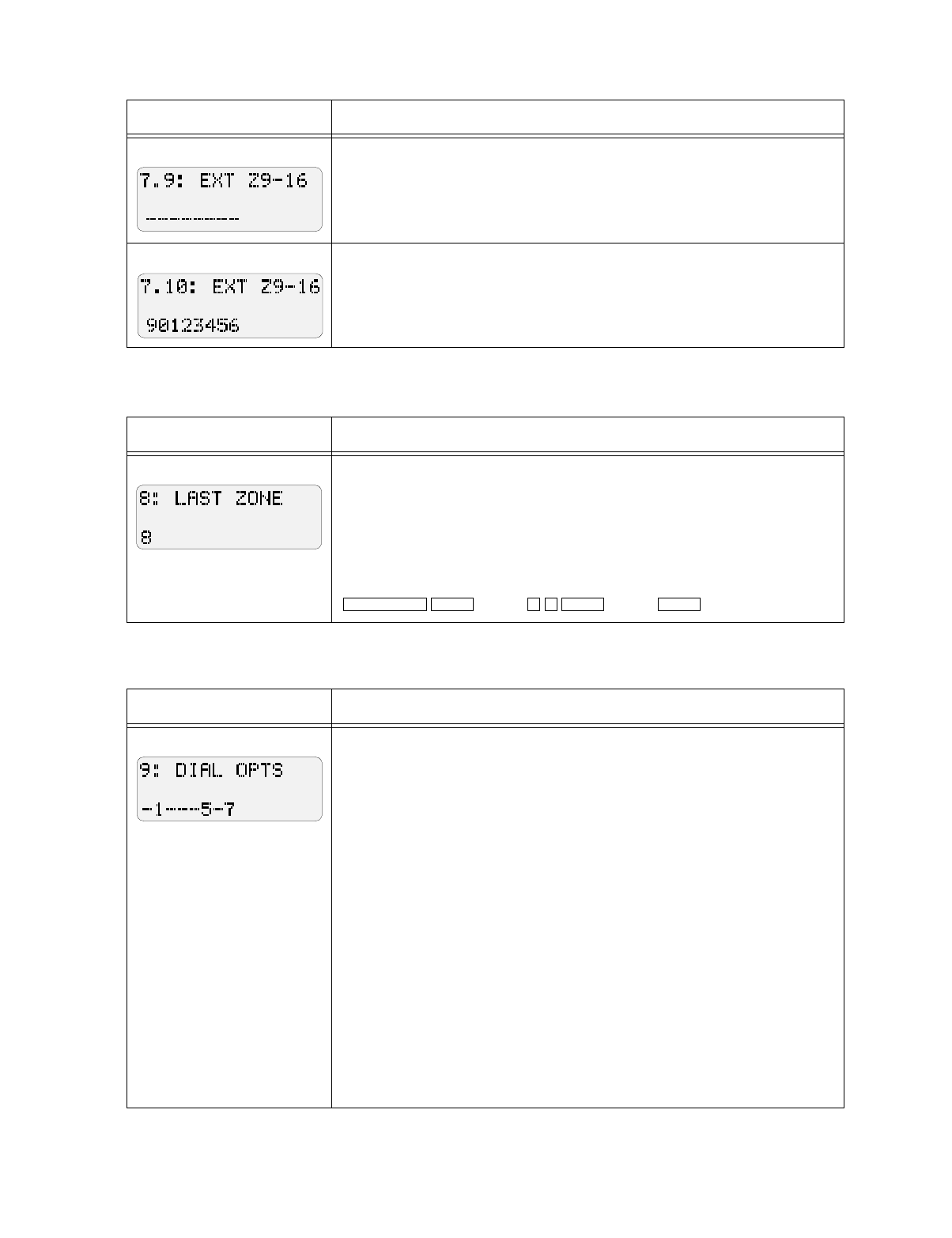
Model 5207 Fire Control/Communicator Installation and Operation Manual
7-10 150865
Step 8. Number of Zones
Step 9. Dialer Options
Smoke verification delay. Use for smoke detectors only (not for manual pull
switches) to select zones that will be controlled by a smoke detector delay.
This means that the smoke detector will delay for a specified amount of time
before responding to an alarm condition. (The duration of the delay is
programmed in Step 20.4.)
Can be disabled. For zones 9-16, enter the number of zones that can be
shunted.
Display Description
Enter the total number of zones. Do not enter more zones then the installa-
tion has. Doing so will trigger an alarm.
Note: The last internal zone must be 8 unless the 5210 is used. Entering a larg-
er number will trigger an alarm condition and you could experience difficulty
returning to programming mode. If this occurs, press the following keys rapid-
ly, repeating the sequence several times if necessary:
(code)
(code)
Display Description
0 = Retry if fail. If you want the 5207 to try again to send a report 15 minutes
after all previous attempts have failed, select 0.
1 = Enable phone line 2. Choose if using a second phone line with the
system.
2 = Not used. Do NOT select.
3 = Ground start. Must be selected for installations using a ground start
telephone network. Ground start cannot be supervised by the line monitors as
there is no DC voltage normally present. This option should not be used in
UL installations.
4 = Enable phone line monitor.
5 = Answer ring detect. Select if you want to the panel to answer after the
specified number of rings for an up/download from a computer. The number
of rings is programmed in step 13.
6 = Not used. Do NOT select.
7 = Enable up/downloading. Select this option if you will be using up/
downloading with the system.
Display Description
ALARM RESET ENTER 2 7 ENTER ENTER
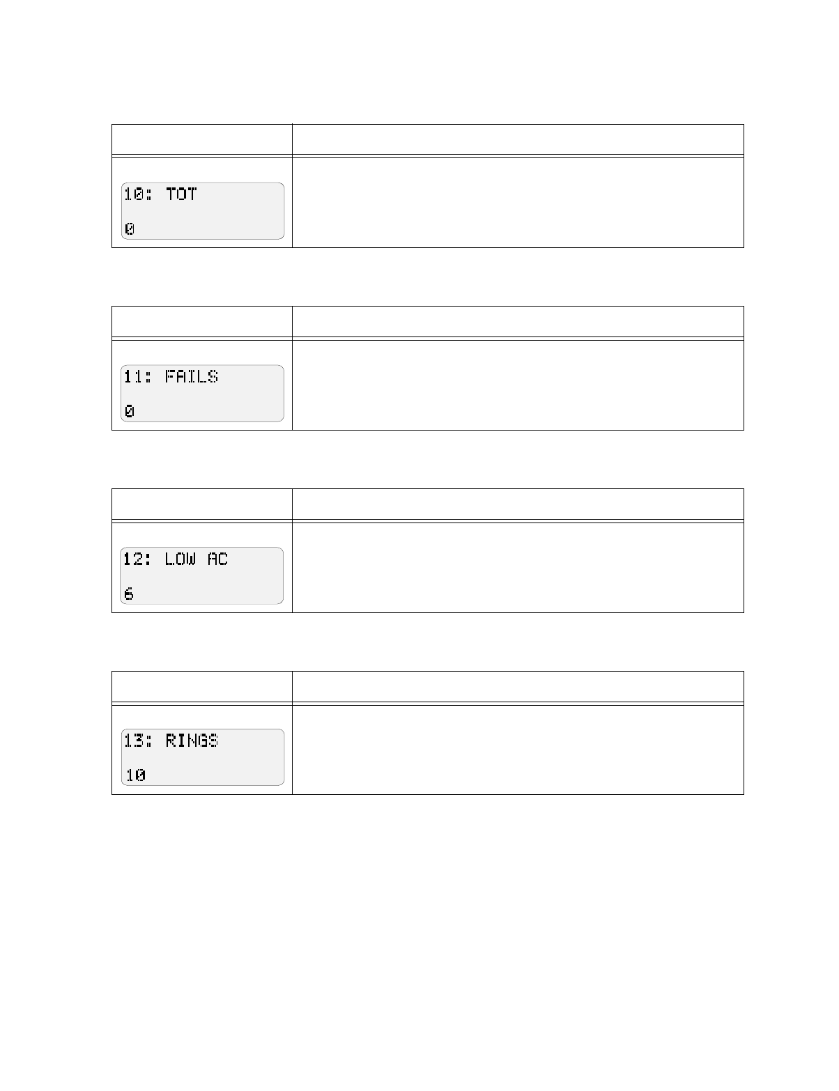
Programming: Step-by-Step Complete Reference
150865 7-11
Step 10. Total Number of Attempts
Step 11. Number of Events Before Dialer Failed
Step 12. Low AC Hours
Step 13. Number of Rings
Display Description
Total number of attempts to dial. Select a number from 5 to 15. For a
local-only system, select "0" for this step and for Step 11.
Display Description
Number of dialing attempts before the system locally annunciates a dialer
failed condition. For a local-only system (no report to central station), select
“0" for this step and for Step 10.
Display Description
Number of hours (6-12) that AC is low before system reports AC TROUBLE.
UL requires a range of 6-12 hours.
Display Description
Number of rings before panel answers for up/downloading. Enter a
number from 1 to 15, or enter 0 if not used. If you are using this option, you
must also select options “5” and “7” in step 9.
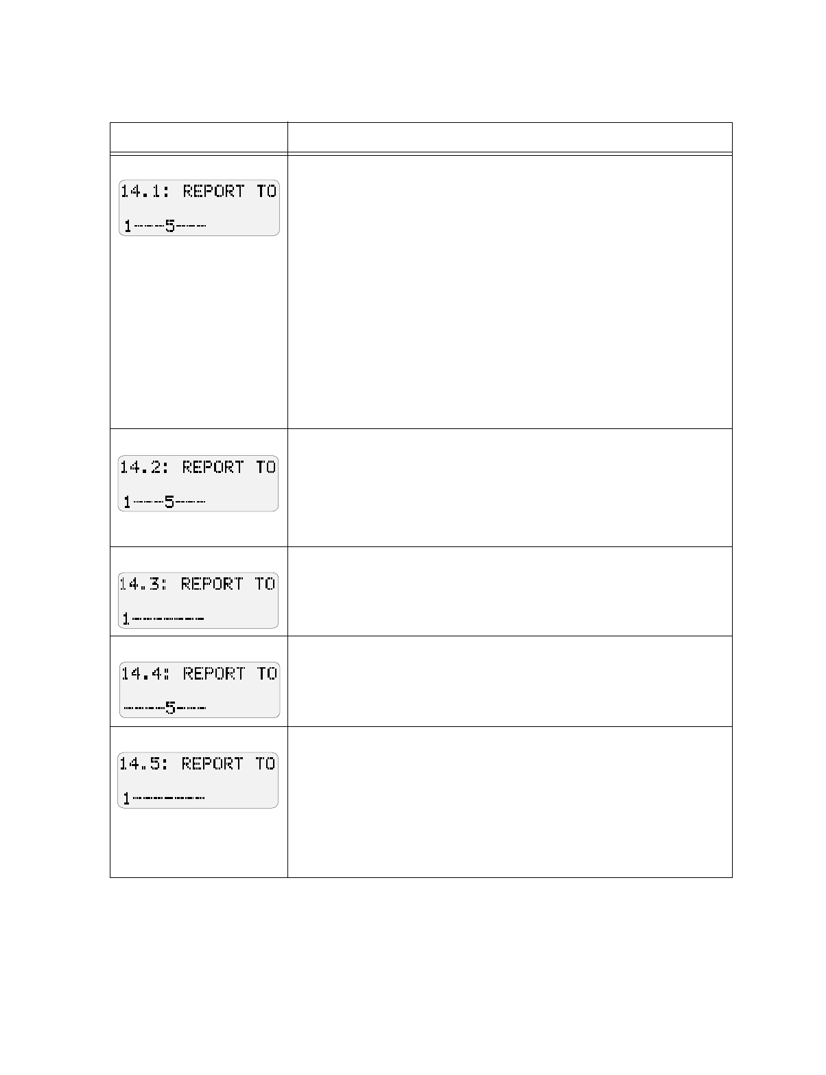
Model 5207 Fire Control/Communicator Installation and Operation Manual
7-12 150865
Step 14. Report to Telephone Numbers
Display Description
The phone number to which alarms should be reported.
Select 1-4 for phone numbers 1-4.
1 = Report alarms to phone number 1
2 = Report alarms to phone number 2
3 = Report alarms to phone number 3
4 = Report alarms to phone number 4
The phone number to which troubles should be reported.
Select 5-8 for phone numbers 1-4.
5 = Report troubles to phone number 1
6 = Report troubles to phone number 2
7 = Report troubles to phone number 3
8 = Report troubles to phone number 4
Example:
Selecting "15" for this step indicates that both alarms and troubles will be
reported to telephone number 1.
The phone number to which disabled zones should be reported. Select 1-
4 for phone numbers 1-4.
The phone number to which restores should be reported. Select 5-8 for
phone numbers 1-4.
(This step is programmed the same as 14.1. See the explanation for Step 14.1
if you need more information.)
The phone number to which open resets should be reported. Select 1-4 for
phone numbers 1-4.
Not used. Do NOT select digits 5-8.
Not used. Do NOT select digits 1-4.
The phone number to which tests should be reported. Select 5-8 for phone
numbers 1-4.
The number to which reports MUST be sent. Select 1-4 for phone numbers
1-4. This means that if the dialer is not able to report to this number, a failed
message will automatically be generated.
Select 5-8 according to the following:
5 = Line 1 is Touch-Tone.
6 = Line 2 is Touch-Tone.
7 = Use Touch-Tone only.
8 = Enable 16-zone reporting.
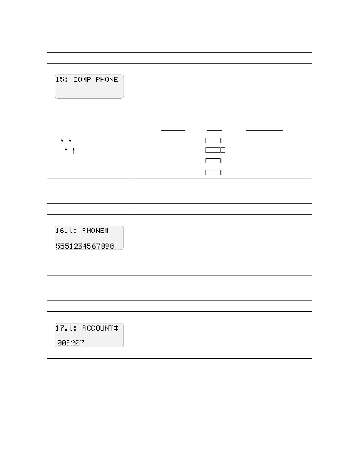
Programming: Step-by-Step Complete Reference
150865 7-13
Step 15. Computer Phone Number
Step 16. Central Station Phone Numbers
Step 17. Central Station Account Numbers
Display Description
Enter the phone number the system will dial to up- or download system
data.
Entering Phone Numbers
Phone numbers are 16 digits maximum. Besides numbers, you can enter
characters representing a pause, * (star or asterisk key), # (number sign or
pound key), and a second dial tone (see example).
Example:
Display Description
The 5207 can report to four different central station telephone numbers.
Two are required. Enter the numbers in Steps 16.1 - 16.4.
See Step 15 if you need to know how to select digits and special
characters for phone numbers.
Steps 16.2 through 16.4 are programmed in the same way. Step 16.2 is
for phone #2, 16.3 is for phone #3, 16.4 is for phone #4. (Default is blank
for Steps 16.2-16.4.)
Display Description
Enter central station account #1. If the account number is less than six
digits, you must enter leading zeros.
Steps 17.2 through 17.4 are programmed in the same way. Step 17.2 is for
account #2, 17.3 is for account #3, 17.4 is for account #4. (Default is
blank for Steps 17.2-17.4.)
9A1D8885551212
pause
2nd
dial tone
outside
line "1" preceding long distance #
T
o
E
nter:
P
ress:
LCD
Di
sp
l
ays:
Pause A
D
2nd dial tone
SHIFT 1
B
*
2
SHIFT
C
#
3SHIFT
4
SHIFT
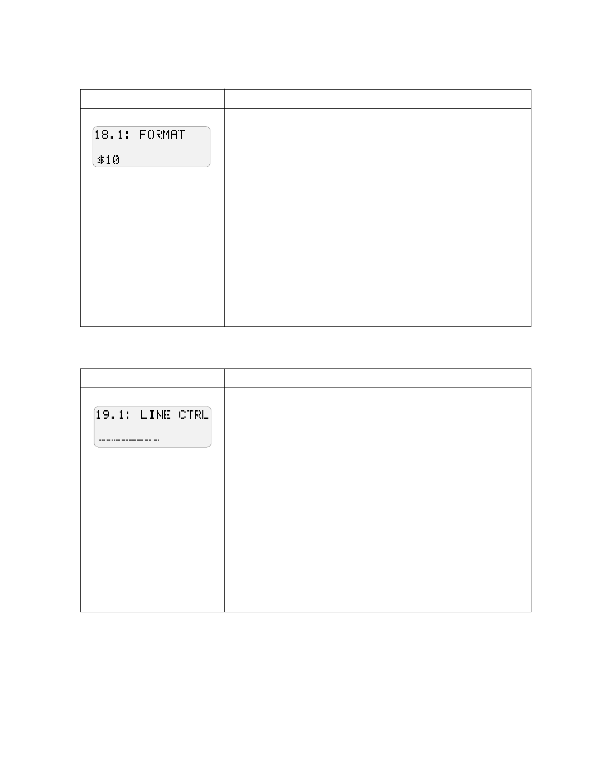
Model 5207 Fire Control/Communicator Installation and Operation Manual
7-14 150865
Step 18. Dialer Format and Number of Attempts
Step 19. Telephone Line to Use for Accounts
Display Description
Digit 1 = Enter the number of attempts for account number 1. This
number is how many times the dialer will attempt to report to this account
number before switching to the next number. (If only one account
number is used, this number must be the same as Step 10.)
Digit 2 = Enter the reporting format to be used for account number 1.
(Formats described in Section 8.)
Options:
0 = SIA8
1 = FSK1
2 = Not used (do NOT select)
3 = BFSK14
4 = BFSK23
5 = SIA20
6 = SK 4+2
Steps 18.2 - 18.4 are programmed in the same way. Step 18.2 is for
account #2, 18.3 is for account #3, 18.4 is for account #4.
Display Description
Program options for account number 1.
1 = Use line 1 only.
2 = Use line 2 only.
3 = 9000 Direct line (no dial tone); do not use.
0 and 4-9 are not used. Do NOT Select.
If two lines are programmed, the panel automatically switches from line 1
to line 2. Use this step only if you have two different types of phone lines;
for example, line 1 is loop start and line 2 is a PBX that requires a “9” or
other number before to dial out.
Steps 19.2 - 19.4 are programmed in the same way. Step 19.2 is for
account #2, 19.3 is for account #3, 19.4 is for account #4.
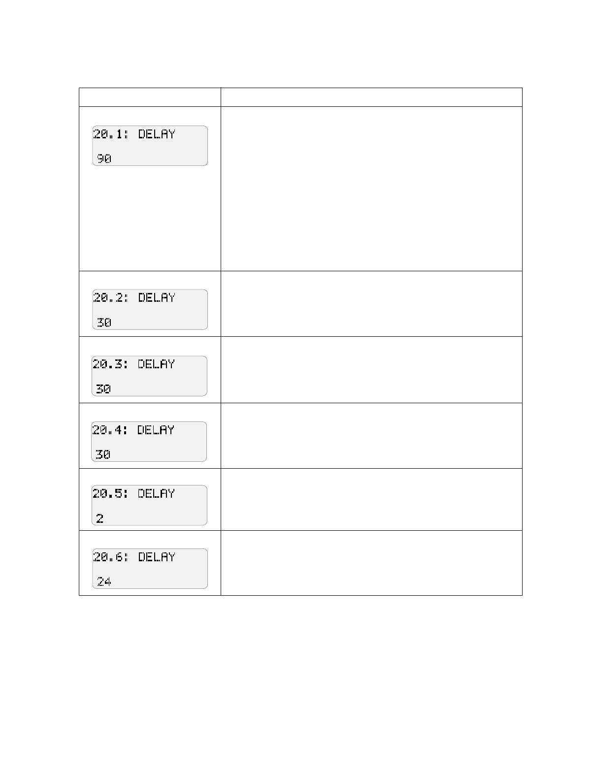
Programming: Step-by-Step Complete Reference
150865 7-15
Step 20. Duration of Delays
Display Description
Bell Shutdown Time (1-255)
Divide by 10 and enter the number indicating the time that you want
audio alarms to be active.
Example:
Suppose you want audio alarms to be active for 900 seconds (or 15
minutes). Enter 900 divided by 10 or “90”.
Common shutdown times:
5 minutes = 300 seconds. Enter “30.”
10 minutes = 600 seconds. Enter “60.”
15 minutes = 900 seconds. Enter “90.”
20 minutes = 1200 seconds. Enter “120.”
25 minutes = 1500 seconds. Enter “150.”
30 minutes = 1800 seconds. Enter “180.”
Step 20.2 is not used.
Do NOT change the factory-programmed setting of “30”.
Use this step to program the duration (1-255 sec.) of the pre-alarm delay.
Use this step to set the duration (1-255 sec.) of the smoke verification
delay.
Use this step to program the number of seconds (2-7 sec.) it will take
smoke detectors to reset. Refer to the manufacturer’s specification sheet
for the times approved for your smoke detectors.
Step 20.6 is not used.
Do NOT change the factory-programmed selection of “24.”
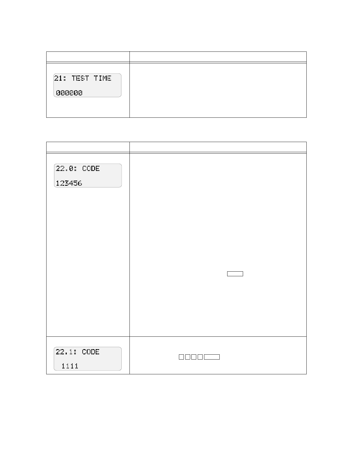
Model 5207 Fire Control/Communicator Installation and Operation Manual
7-16 150865
Step 21. Test Time
Step 22. Secret Codes
Display Description
Enter time that automatic daily test should occur using 24-hour military
time. Enter 6 digits with leading zeros.
Examples:
To program the daily test to occur at:
2:30 AM, enter 000230.
11:45 PM, enter 002345.
Midnight, enter 000000.
Display Description
Step 22 is for programming the 4- to 6-digit codes that give access to the
system.
Code 0, programmed in Step 22.0, is the installer's code. This is the only
code that can activate all system features. This code must be unique from
all others. See IMPORTANT below.
Code 1, programmed in Step 22.1, is the main user's code. This code can
access all system features except programming.
Codes 2-9 are user codes. These codes enable users to bypass zones and
reset alarms, but they cannot perform a walk test or change programming
options.
The 5207 can have up 100 user codes, but the 5230 annunciator can
program only 10 codes (codes 0-9). If you need more than 10 codes, use
the 5541 downloading software.
To change a code, type in the new number when you are at the step for
the code you want to change, then press .
IMPORTANT:
When programming codes, make sure that the first four digits
of Code 0 are different from the first four digits of all other
codes. If other codes have the same digits, all users could be
locked out of programming mode.
Example:
Suppose you want to change Code 1 from "1111" to "5982."
At Step 22.1, press .
ENTER
5
982ENTER
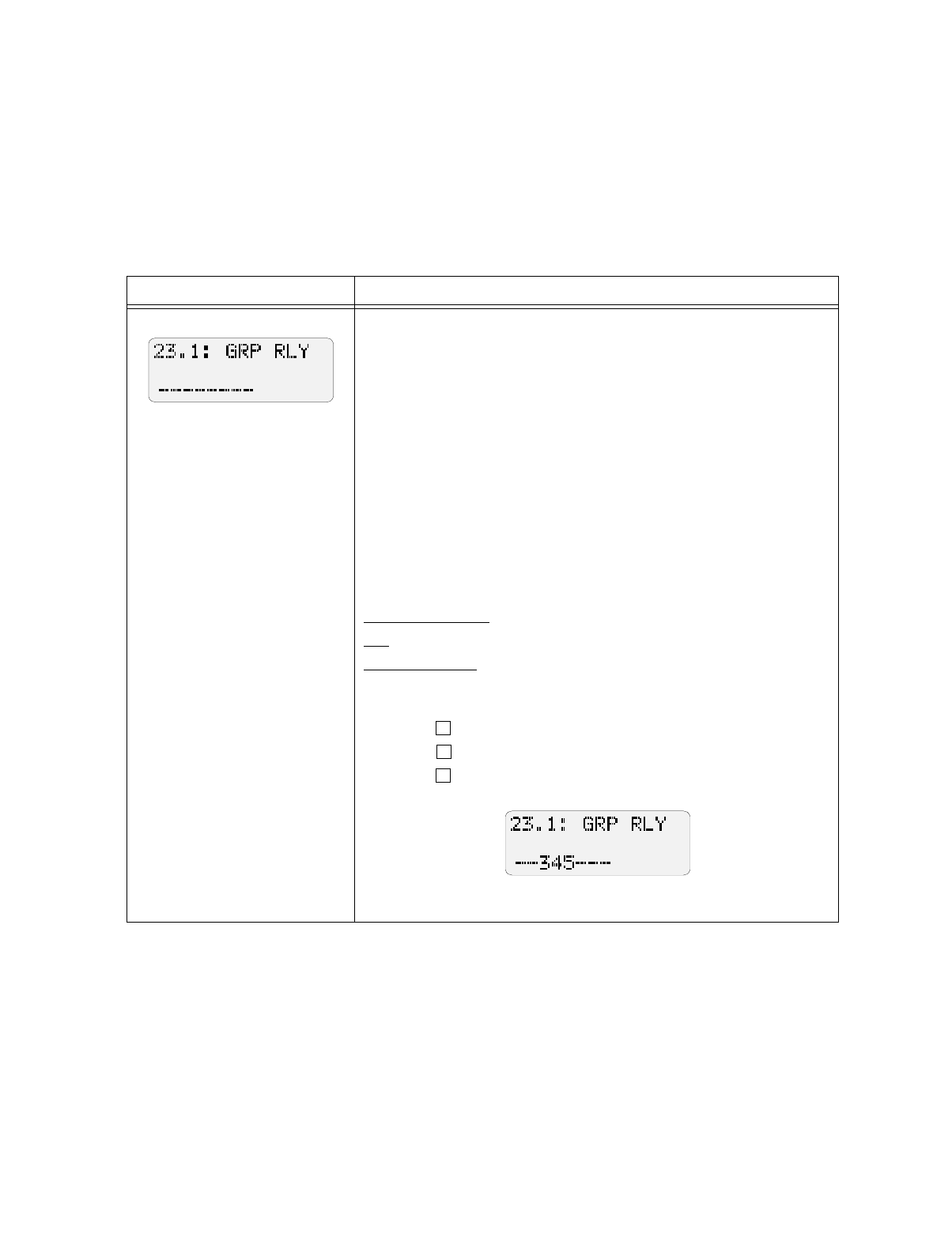
Programming: Step-by-Step Complete Reference
150865 7-17
Step 23. Group Relays and Bells
IMPORTANT:
You can program relays and bells in either the Group section (Step 23) or the By Zone section (Step 24), but not
both.
Relays and bells are programmed for the type of condition that causes them to activate, not by zone. An excep-
tion is relays and bells that activate for alarms, which can be programmed by zone. Use Step 24 to program alarm
relays and bells by zone.
Display Description
This step selects bells and relays
by type of condition. Step 24 is
for selecting bells and relays by
zone.
Step 23 is used to select the relays and/or bells that you want to activate
for particular conditions. This means that relays and/or bells
programmed would activate when the specified conditions occurred in a
zone.
Digits 1-4 select relays. Digits 5-8 select bells.
Step 23.1 selects relays/bells to activate for Pre-alarm conditions.
Step 23.2 selects relays/bells to activate for Tamper alarm conditions.
Step 23.3 selects relays/bells to activate for Special (Auxiliary)
conditions.
Step 23.4 selects relays/bells to activate for Fire conditions.
Step 23.5 selects relays/bells to activate for Trouble conditions.
Step 23.6 selects relays/bells to activate for No Silence conditions.
Example: Use the steps below to program your system for the following:
Pre-alarm condition: Activate Relays 3 and 4 and Bell 1.
Fire: Activate Bells 1, 2, 3, and 4.
Trouble condition: Activate Relays 1 and 2 and Bells 1 and 2.
1. Pre-alarm condition relays/bells are programmed in Step 23.1.
a. Press to select Relay 3
b. Press to select Relay 4
c. Press to select Bell 1
Your LCD would appear as shown below:
example continued on next page
3
4
5
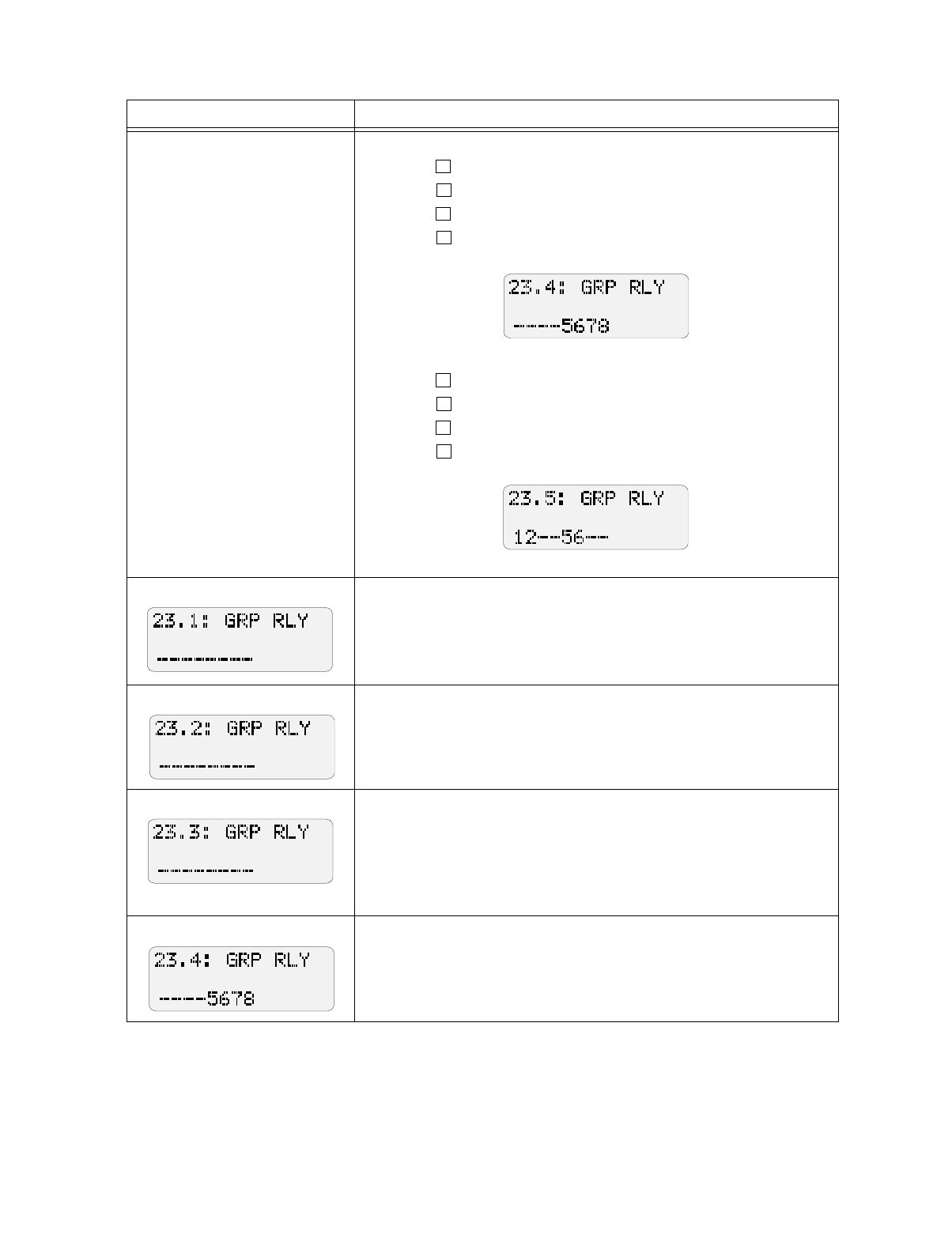
Model 5207 Fire Control/Communicator Installation and Operation Manual
7-18 150865
Display Description
Step 23 continued 2. Fire condition relays/bells are programmed in Step 23.4.
a. Press to select Bell 1
b. Press to select Bell 2
c. Press to select Bell 3
d. Press to select Bell 4
Your LCD would appear as shown below:
3. Trouble condition relays/bells are programmed in Step 23.5.
a. Press to select Relay 1
b. Press to select Relay 2
c. Press to select Bell 1
d. Press to select Bell 2
Your LCD would appear as shown below:
Pre-Alarm Relays and Bells
1-4 = Relays that will activate during a pre-alarm condition.
5-8 = Bells that will activate during a pre-alarm condition.
Note: Relays or bells selected as Pre-alarm will not activate during a test.
Tamper Alarm Relays and Bells
1-4 = Relays that will activate during a tamper alarm condition.
5-8 = Bells that will activate during a tamper alarm condition.
Special (Auxiliary) Alarm Relays and Bells
1-4 = Relays that will activate during a special alarm condition.
5-8 = Bells that will activate during a special alarm condition.
Note: If Sprinkler zone types are used, do not connect audible devices to
Special Alarm relays.
Fire Alarm Relays and Bells
1-4 = Relays that will activate during a fire alarm condition.
5-8 = Bells that will activate during a fire alarm condition.
5
6
7
8
1
2
5
6
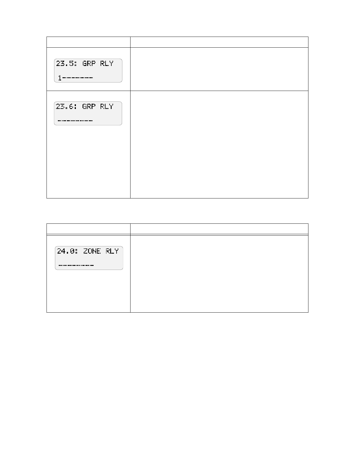
Programming: Step-by-Step Complete Reference
150865 7-19
Step 24. Alarm Relays and Bells (by Zone)
Display Description
Trouble Relays and Bells
1-4 = Relays that activate during a trouble condition.
5-8 = Bells that activate during a trouble condition.
Note: Relays or bells selected as Trouble will not activate during a test.
No Silence Relays and Bells
This option is intended for use with applications such as strobes.
1-4 = Relays that will remain active when the 5207 is silenced. (Alarm
relays always remain active until reset.)
You can use this step to program a trouble relay to remain active after the
panel is silenced. Select the relay that should remain active in this step.
5-8 = Outputs that will remain active when the 5207 is silenced.
You can use this step to make sure that strobes on the system continue to
activate when bells and horns are silenced. To do this, make sure strobes
are on separate outputs from horns and bells, then select the strobe
outputs in this step.
Note: If you are using the 5220 Direct Connect Module for supervision,
see Section 4.7 for information on programming relays and bells.
Display Description
This step selects bells and relays
to activate by zone. Step 23 is
for selecting bells and relays by
type of condition.
Use this step to select the relays and/or bells that will activate during an
alarm condition in each zone. Step 24.0 selects bells and relays to
activate during a fire drill ("Zone 0"). Step 24.1 selects bells and relays to
activate for an alarm in Zone 1, Step 24.2 selects bells and relays for Zone
2, and so on.
1-4 = Relays that will activate during an alarm in the zone.
5-8 = Bells that will activate during an alarm in the zone.
Note: If using the Model 5220 Direct Connect Module for supervision,
select Relay 3 for Zone 3. See Section 4.7 for more information.
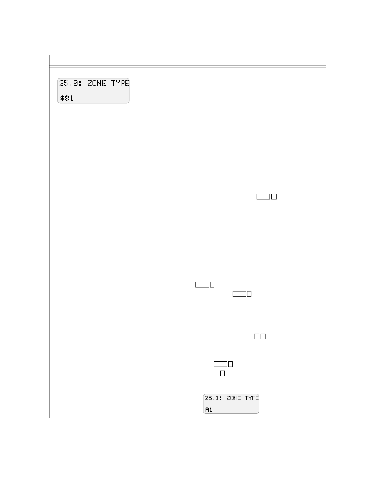
Model 5207 Fire Control/Communicator Installation and Operation Manual
7-20 150865
Step 25. Zone Types
Display Description
In Steps 25.1 through 25.16, you will program two numbers.
Digit 1 programs the audible signals for the zone.
Digit 2 programs the zone type.
Move through the steps to make sure that all zones in your installation
have been programmed the way you want them to be. For any zones that
require changes, follow the steps for changing zone types as described in
the examples above. You can record zone options in the Quick Reference
chart in Section 6.
Audible Signal (Step 25, Digit 1)
0 = Bells can shut down
2 = Cross alarm delay (alarm report delayed until a second alarm
occurs on another zone)
4 = No manual bell silence (waterflow zones)
8 = No automatic bell shutdown (fire zones)
A = Cross alarm and no shutdown. (Press for letter “A”.)
Zone Types (Step 25, Digit 2)
0 = Fire Drill
1 = Fire (includes waterflow switches, smoke detectors, heat, etc.)
3 = Panic
5 = Tamper
6 = Sprinkler (supervisory zones)
7 = Undefined Auxiliary
8 = Water (Auxiliary for high or low water)
9 = Heat
A = Cold (Press for letter “A”.)
B = Local (not reported) (Press for letter “B”.)
C = Not used. Do NOT select.
Example 1:
Suppose you want Zone 1 to be a fire type zone with no automatic bell
shutdown. At Step 25.1, make sure the digits “81,” the factory-
programmed selections, are displayed. Press if necessary.
Example 2:
Suppose you want Zone 2 to be a fire type zone with cross-alarm delayed
and no bell shutdown. Press to select “A” for digit 1 (cross
alarm and no shutdown). Press for Digit 2 to select fire type. Your
LCD would appear as shown below.
SHIFT 1
SHIFT
1
SHIFT 2
8 1
SHIFT 1
1
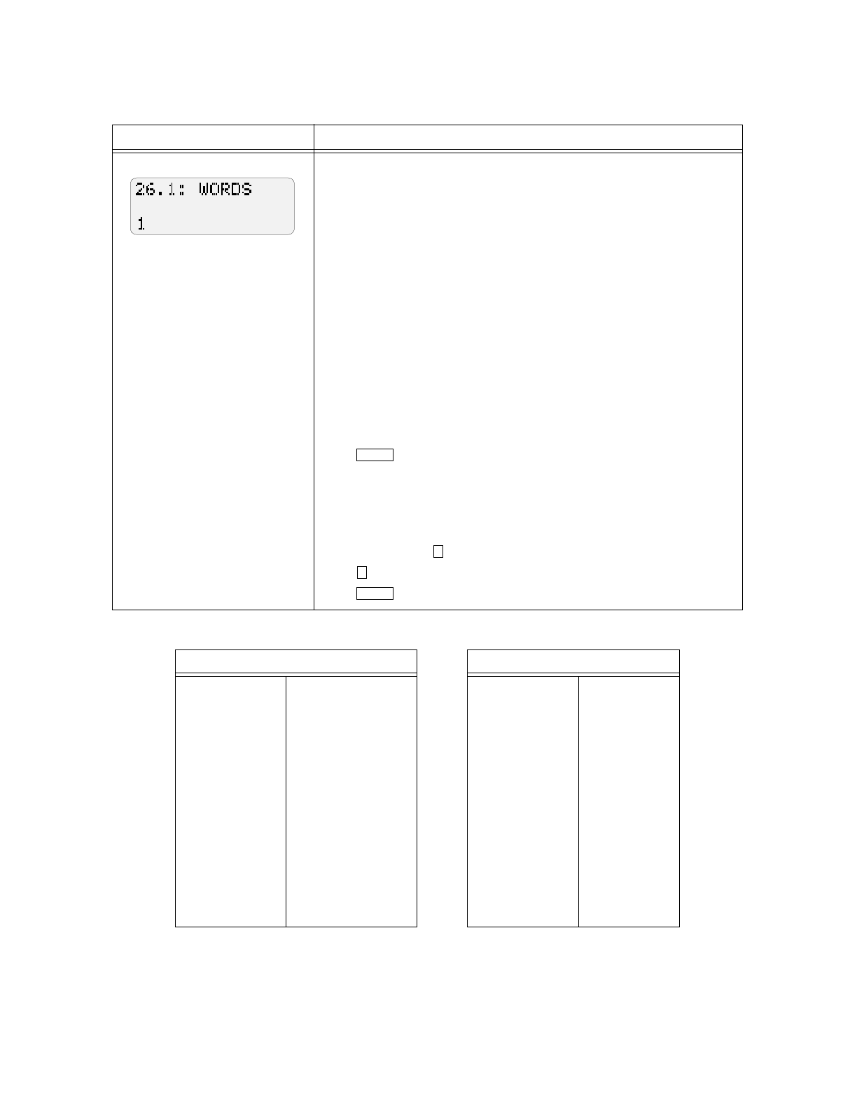
Programming: Step-by-Step Complete Reference
150865 7-21
Step 26. Zone Location Descriptions
Display Description
The following instructions explain how to select zone descriptions for
the 5230 display.
For Steps 26.1-26.16, the factory-programmed default is “WORDS”
(“WORDS” appears on the LCD). You can choose one- or two-word
descriptions for each zone from the 5207 word list (library) shown below.
Note: You cannot customize the library using the 5230 annunciator. If
you want to use words other than those contained in the library, you must
use the 5541 downloading software.
The step numbers correlate to zone numbers. For example, Step 26.1 is
where you program a zone description for Zone 1, Step 26.2 is for Zone 2,
and so on. Read the examples below to learn how to select zone
descriptions.
Example 1: Programming a One-Word Description
Suppose you want to program Zone 3 to display "GARAGE."
At Step 26.3, press until the word "GARAGE" displays on the LCD.
Press to select.
Example 2: Programming a Two-Word Description
Suppose you want to program Zone 5 to display "EAST OFFICE".
Because "EAST OFFICE " is a two-word display, an additional step is
required.
At Step 26.5, press until you reach the word "EAST.”
Press until you read the word "OFFICE."
Press to select.
Table 6-1 Zone Description Words
First Word Second Word
FRONT HEAT FLOOR 2ND FLR
BACK FIRE HALL 3RD FLR
NORTH VALVE ROOM 4TH FLR
SOUTH WATERFLOW OFFICE WINDOW
EAST SPRINKLER DOOR BATH
WEST PULL STATION VALVE SAFE
LOBBY 1ST SMOKE GLASS
BASEMENT 2ND HEAT LEVEL
GARAGE 3RD WATERFLOW TEMP
WAREHOUSE 4TH SPRINKLER RM
MEZZANINE WHSE 1ST FLR DR
SMOKE
ENTER
1
2
ENTER
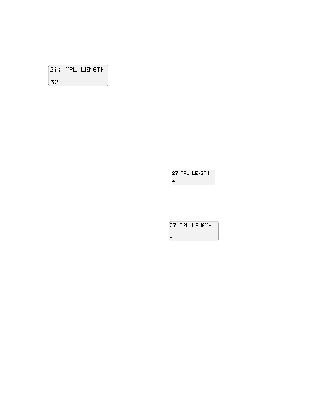
Model 5207 Fire Control/Communicator Installation and Operation Manual
7-22 150865
Steps 27 and 28. Temporal Patterns
Display Description
This step programs the length of
the pattern.
Steps 27 and 28 are used together to control the temporal (pulsing)
pattern of the bell outputs. You can use these steps to create any temporal
pattern you want, including the pattern required by NFPA 72.
Step 27 determines the length (number of bits) of the pattern. This
number can be 1 to 32, allowing for patterns that are up to 16 seconds (or
32 half-seconds) in duration.
The default setting is 32.
Note: If you are using this step to create a customized temporal pattern,
both cadenced pulsing (option 0) and pulse fire bells (option 3) must be
enabled in Step 3.
Example 1: Simple two-second pattern
Suppose you want to create the simple temporal pattern one second ON,
one second OFF. In Step 27, you would enter “4” because the length of
the pattern is four half-seconds (or two seconds).
After programming this example, your LCD would appear as shown
below.
See Example 1 in Step 28.1 for setting the pattern.
Example 2: NFPA 72 required pattern
In an NFPA 72 installation, the temporal pattern must be ON OFF ON
OFF ON OFF OFF OFF. Program Step 27 as shown below to achieve
this pattern length.
See Example 2 in Step 28.1 for setting the pattern.
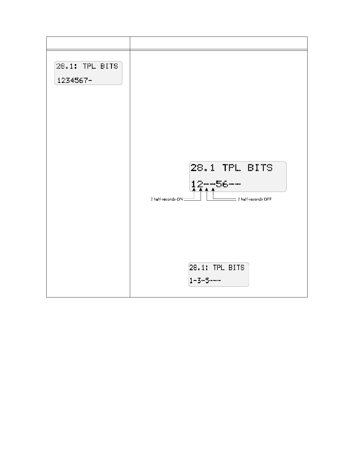
Programming: Step-by-Step Complete Reference
150865 7-23
Display Description
This step selects the actual
pattern.
Steps 28.1-28.4 determine the pattern. Select a digit for each half-second
ON; de-select a digit (display shows a dash) for each half-second OFF.
Each sub-step controls up to four seconds. The pattern you create will
repeat as long as the bell output is active.
The default setting is the 32-bit temporal pattern:
ON ON ON ON ON ON ON OFF
ON ON ON ON ON ON ON OFF
ON ON ON ON ON ON ON OFF
OFF OFF OFF OFF OFF OFF OFF OFF
If using the 5541, Y indicates ON and a dash indicates OFF.
Example 1: Simple two-second pattern
To create the simple temporal pattern one second ON, one second OFF.
In Step 28.1, you would select a digit for each half-second ON and de-
select a digit for each half-second OFF as follows:
See Example 1 in Step 27 for setting the length.
Note: If using this step to create a customized temporal pattern, both
cadenced pulsing (option 0) and pulse fire bells (option 3) must be
enabled in Step 3.
Example 2: NFPA 72 required pattern
In an NFPA 72 installation, the temporal pattern must be ON OFF ON
OFF ON OFF OFF OFF. Program Step 28.1 as shown below to achieve
this pattern.

Model 5207 Fire Control/Communicator Installation and Operation Manual
7-24 150865

150865 8-1
Section 8
Reportin
g
The following formats can be used to report to Silent Knight receivers and are explained fur-
ther in this section:
•SIA
• FSK & SK 4+2
• 16 Zone 4+2
• Radionics BFSK
The following Trouble Conditions may generate a report to the central station:
• Low AC
• Low battery
• Loss of smoke detector power
• Loss of accessory power
• Supervised notification device trouble
• Earth ground fault
• Dialer trouble (Device 0)
• Annunciator trouble
8.1 Notes for All Formats
The 5207 can report to the formats described in the following sections. The following infor-
mation applies to all formats:
1. The 5207 can hold up to 30 alarm events in its memory. If more events occur, the first
event will be replaced with the message DATA LOST 01. Any older events will be
replaced by newer events.
2. Momentary alarms will report a restore immediately if manually silenced by Alarm Reset.
3. Failure of the annunciator bus is not reported or printed, but an audible trouble tone will
sound and the display will indicate the problem. The code F0 appears on the built-in
touchpad display and the LCD reads "BUS TROUBLE".
4. When a fire drill is reset, it will not report an Open Reset.

Model 5207 Fire Control/Communicator Installation and Operation Manual
8-2 150865
8.2 SIA Format Printed Messages
The Security Industry Association (SIA) format can be used with a Silent Knight Model 9000
receiver. Each message is displayed in English followed by the zone number. Due to limited
space on the 9000 display, some messages may be in abbreviated form.
Table 8-1 shows the information that is printed at the Silent Knight 9000 receiver when the
SIA format is used for data transmission.
Table 8-1: SIA Messages
SIA Code 9000 Printer 5207 Status
YT0 LOW BATTERY 0 System battery is low.
YR0 BATTERY RESTORE 0 Battery voltage is back to normal.
AT0 AC TROUBLE 0 AC power is off or low.
AR0 AC RESTORE 0 AC power is back on.
LT1-2 PHONE LINE TROUBLE 1-2 Trouble on phone line (1 or 2).
LR1-2 PHONE LINE RESTORE 1-2 Phone line (1 or 2) back to normal.
ET0 EXPANSION TROUBLE 0 Dialer trouble.
ET1 EXPANSION TROUBLE 1 Printer trouble.
ET7 EXPANSION TROUBLE 7 EE memory trouble.
ET8 EXPANSION TROUBLE 8 XBUS trouble.
ET17-23 EXPANSION TROUBLE 17-23 Annunciator 1-7 trouble.
ET32-35 EXPANSION TROUBLE 32-35 Notification device 1-4 trouble.
ET36 EXPANSION TROUBLE 36 Smoke power trouble.
ET37 EXPANSION TROUBLE 37 Accessory power trouble.
ET38 EXPANSION TROUBLE 38 Earth ground fault to circuit ground.
ET39 EXPANSION TROUBLE 39 Earth ground fault to power.
ER0 EXPANSION RESTORE 0 Dialer back to normal.
ER1 EXPANSION RESTORE 1 Printer back to normal.
ER7 EXPANSION RESTORE 7 EE memory back to normal.
ER8 EXPANSION RESTORE 8 XBUS back to normal.
ER17-23 EXPANSION RESTORE 17-23 Annunciator 1-7 back to normal.
ER32-35 EXPANSION RESTORE 32-35 Notification device 1-4 back to normal.
ER36 EXPANSION RESTORE 36 Smoke power back to normal.
ER37 EXPANSION RESTORE 37 Accessory power back to normal.
ER38 EXPANSION RESTORE 38 Circuit ground earth fault removed.
ER39 EXPANSION RESTORE 39 Power earth ground fault removed.
OR0-99 OPEN RESET ALARM ID 0-99 Alarm reset by access code 0 - 99.
FA1-16 FIRE ALARM 1-16 Alarm in fire zone 1-16.
FT1-16 FIRE TROUBLE 1-16 Trouble condition in fire zone 1-16.
FB1-16 FIRE BYPASS 1-16 Zone 1-16 has been bypassed.
FR1-16 FIRE RESTORE 1-16 Alarm or trouble restore in zone 1-16.
FU1-16 FIRE UNBYPASS 1-16 Zone (1-16) that was disabled has been restored.
PA1-16 PANIC ALARM 1-16 Alarm in panic zone 1-16.
PT1-16 PANIC TROUBLE 1-16 Trouble condition in panic zone 1-16.
PB1-16 PANIC BYPASS 1-16 Zone 1-16 has been bypassed.
PR1-16 PANIC RESTORE 1-16 Alarm or trouble restore in zone 1-16.
PU1-16 PANIC UNBYPASS 1-16 Zone (1-16) that was disabled has been restored.

Reporting
150865 8-3
TA1-16 TAMPER ALARM 1-16 Alarm in tamper zone 1-16.
TT1-16 TAMPER TROUBLE 1-16 Trouble condition in tamper zone 1-16.
TB1-16 TAMPER BYPASS 1-16 Zone 1-16 has been bypassed.
TR1-16 TAMPER RESTORE 1-16 Alarm or trouble restore in zone 1-16.
TU1-16 TAMPER UNBYPASS 1-16 Zone (1-16) that was disabled has been restored.
SA1-16 SPRINKLER ALARM 1-16 Alarm in sprinkler zone 1-16.
ST1-16 SPRINKLER TROUBLE 1-16 Trouble condition in sprinkler zone 1-16.
SB1-16 SPRINKLER BYPASS 1-16 Zone 1-16 has been bypassed.
SR1-16 SPRINKLER RESTORE 1-16 Alarm or trouble restore in zone 1-16.
SU1-16 SPRINKLER UNBYPASS 1-16 Zone (1-16) that was disabled has been restored.
UA1-16 UNDEFINED ALARM 1-16 Alarm in auxiliary zone 1-16.
UT1-16 UNDEFINED TROUBLE 1-16 Trouble condition in auxiliary zone 1-16.
UB1-16 UNDEFINED BYPASS 1-16 Zone 1-16 has been bypassed.
UR1-16 UNDEFINED RESTORE 1-16 Alarm or trouble restore in zone 1-16.
UU1-16 UNDEFINED UNBYPASS 1-16 Zone (1-16) that was disabled has been restored.
WA1-16 WATER ALARM 1-16 Alarm in water zone 1-16.
WT1-16 WATER TROUBLE 1-16 Trouble condition in water zone 1-16.
WB1-16 WATER BYPASS 1-16 Zone 1-16 has been bypassed.
WR1-16 WATER RESTORE 1-16 Alarm or trouble restore in zone 1-16.
WU1-16 WATER RESTORE 1-16 Zone (1-16) that was disabled has been restored.
KA1-16 HEAT ALARM 1-16 Alarm in heat zone 1-16.
KT1-16 HEAT TROUBLE 1-16 Trouble condition in heat zone 1-16.
KB1-16 HEAT BYPASS 1-16 Zone 1-16 has been bypassed.
KR1-16 HEAT RESTORE 1-16 Alarm or trouble restore in zone 1-16.
KU1-16 HEAT RESTORE 1-16 Zone (1-16) that was disabled has been restored.
ZA1-16 COLD ALARM 1-16 Alarm in cold zone 1-16.
ZT1-16 COLD TROUBLE 1-16 Trouble condition in cold zone 1-16.
ZB1-16 COLD BYPASS 1-16 Zone 1-16 has been bypassed.
ZR1-16 COLD RESTORE 1-16 Alarm or trouble restore in zone 1-16.
ZU1-16 COLD RESTORE 1-16 Zone (1-16) that was disabled has been restored.
RP0 AUTO TEST 0 Automatic dialer test occurred.
RX0-1 MANUAL TEST 0-1 System tested by access code 0 or 1.
RX2-99 MANUAL TEST (2-99) System tested by access code 2-99.
RT0 DATA LOST 0 Previous event could not be reported and the infor-
mation was lost.
RS0 REMOTE PROG. PASS Data has been downloaded successful.
RU0 REMOTE PROG. FAIL Problem with downloading; data transfer did not
occur.
FX00 FIRE DRILL Fire drill
Table 8-1: SIA Messages
SIA Code 9000 Printer 5207 Status

Model 5207 Fire Control/Communicator Installation and Operation Manual
8-4 150865
8.3 FSK & SK 4+2 Format
You must use either the FSK or SK 4+2 format when reporting to the Silent Knight Model
8520 Receiver. Since the 8520 has only two digits for alarm codes, event type and zone num-
bers are combined into one message. The first digit of the code is the type of report, the sec-
ond digit is the last number of the zone.
Example:
Any two-digit code beginning with the digit 0 is a fire alarm.
Code 01 = Fire alarm in zone 1 or 11
Code 05 = Fire alarm in zone 5 or 15
If you selected the 16-zone report option at Step 14.5 of Step Programming (Section 2 of the
5207 programming manual), the above information does not apply to you. Zone numbers will
report as 1 - 16. See for more information.
The 4+2 format repeats after 10.
*Note: Expansion refers to all the expansion troubles and restores listed in the SIA format (Section 8.2).
Table 8-2: FSK and SK 4+2 Codes/Zones
FSK and 4+2 Description
Y=Last digit of the user ID number.
Z=last number of the zone.
Fire Codes
0Z Alarm
20 Disable Restore (Fire type zones report as 20)
50 Disable Zone (Fire type zones report as 50)
6Z Supervisory or Trouble
7Z Alarm Restore, Supervisory Restore, and Trouble Restore
Other Zones
30 Dialer Test, Walk Test, Fire Drill
31 Phone Line 1 Trouble
32 Phone Line 2 Trouble
*33 Expansion Trouble (see Note below)
35 Phone Line 1 Restore
36 Phone Line 2 Restore
*37 Expansion Restore (see Note below)
39 Data Lost
60 AC Lost
69 Low Battery
70 AC Restore
79 Battery Restore
9Y Reset Alarm by Code #

Reporting
150865 8-5
8.4 16-Zone 4+2 Format
When *selected, the FSK1 and SK 4+2 formats will send alarms on zones 1 through 16 as
01-16. All 16 zones have unique alarm codes. However, there are some limitations. Zone
troubles and restores cannot be completely distinguished from alarms. Zones 9 and 10 share
some codes with battery and AC supervision. Table 8-3 shows which codes will be reported
when the 16-zone 4+2 format is used. (The codes that will be reported if this option is not
selected appear in Table 8-2.)
*Important: In order to use this format, you must select “8” in programming step 14.5.
Table 8-3: 16-Zone 4+2 Format
Zone Code Description
Alarm Zone 1 01 ALARM 1
... ...
Alarm Zone 8 08 ALARM 8
Alarm Zone 9 09 ALARM 9
Alarm Zone 10 10 ALARM 10
Alarm Zone 11 11 ALARM 11
...
Alarm Zone 16 16 ALARM 16
Trouble Zone 1 61 TROUBLE 1
... ...
Trouble Zone 8 68 TROUBLE 8
Trouble Zone 9 69 TROUBLE 9
Trouble Zone 10 60 TROUBLE 10
Trouble Zone 11 61 TROUBLE 11
...
Trouble Zone 16 66 TROUBLE 16
Restore Zone 1 71 RESTORE 1
... ...
Restore Zone 8 78 RESTORE 8
Restore Zone 9 79 RESTORE 9
Restore Zone 10 20 RESTORE 10
Restore Zone 11 21 RESTORE 11
...
Restore Zone 16 26 RESTORE 16

Model 5207 Fire Control/Communicator Installation and Operation Manual
8-6 150865
8.5 Radionics BFSK Format
Model 5207 can transmit using the Radionics BFSK format with 1400 Hz or 2300 Hz
acknowledge. The messages that will be printed are listed with the codes for FSK1 and SK
4+2.
Radionics BFSK format can only report eight zone codes. Zones 9 through 16 report as zones
1 through 8; zones 17 through 24 report as zones 1 through 8, and so on. Because of this lim-
itation, programming the 5207 to report in both the Radionics BFSK and either the FSK or SK
4+2 formats is NOT advised. Use only if required by the receiver.
The Radionics BFSK format repeats after 8. It is recommended that you use no more than 8
zones if your system is programmed to report in Radionics BFSK format. However, if you
choose to use more than 8 zones with the Radionics BFSK format, it is a good idea to make
every 8th zone (such as Fire, Tamper Sprinkler, etc.) the same zone type (such as Fire). If you
assign the zones in this manner, the letter X in will be a digit that represents every 8th zone
number, as shown below:
Digit Reported (X) 12345678
Zone Numbers 12345678
9 10111213141516
17 18 19 ...
Table 8-4: Radionics BFSK
BFSK Radionics BFSK Description
Fire Codes
X Alarm Zone X Alarm on zone X (see chart above for actual number).
E0 Restore Zone 0 Disable restore zone 0.
F0 Trouble Zone 0
was Forced Armed Trouble zone 0 (zone disabled).
FX Trouble Zone X Trouble zone X (see chart above page for actual num-
ber).
EX Restore Zone X Alarm or trouble restore zone X (see chart above for
actual number).
Other Zones
E9 Restore Zone 9 Test/restore zone 9.
FB Trouble Zone B Phone line fault
*FC Trouble Zone C Expansion trouble (see Note below)
EB Restore Zone B Phone line trouble restore.
*EC Restore Zone C Expansion restore (see Note below)
E9 Test/restore Zone 9 Data lost.
F0 Trouble Zone 0. AC lost.
F9 Trouble Zone 9. Low battery.
E0 Restore Zone 0. AC restore.
E9 Restore zone 9 Battery restore.
BY Open zone (Code #) Reset alarm by user code #.
Note: "Expansion" refers to all expansion trouble/restores listed in SIA format, Table 8-1.

150865 9-1
Section 9
Troubleshootin
g
9.1 Problems With the Model 5198 Power Supply
If you experience problems with the power supply, use the troubleshooting techniques
described in the following sections. There are separate procedures for 12-volt and 24-volt
power supplies.
The following display messages indicate that the power supply and panel voltage selections
are not the same: A1, A2, A3, A4, P1, P2. See programming step 2 (Section 7).
9.1.1 Isolating the Problem
Use this procedure to test the power supply to make sure that it is the device that is causing a
problem.
Remove the power supply connector (P1) from the 5207 board. Disconnect the battery from
the power supply. Make all power supply measurements with 120 VAC applied to the power
supply.
Place a 4.7k resistor between pins 1 (brown) and 3 (orange). Use a DC voltmeter set to the
50V range to measure the voltage across the resistor. The voltage reading should be between
26 and 28 volts. Remove all power from the power supply before replacing connector P1 on
the panel.
9.1.2 Measuring Battery Charging Voltage
The power supply puts batteries in series for you. Measure from the negative of one set of
cables to the positive of the other set. One combination should read 0V; the other combination
should read between 27.3-27.5.
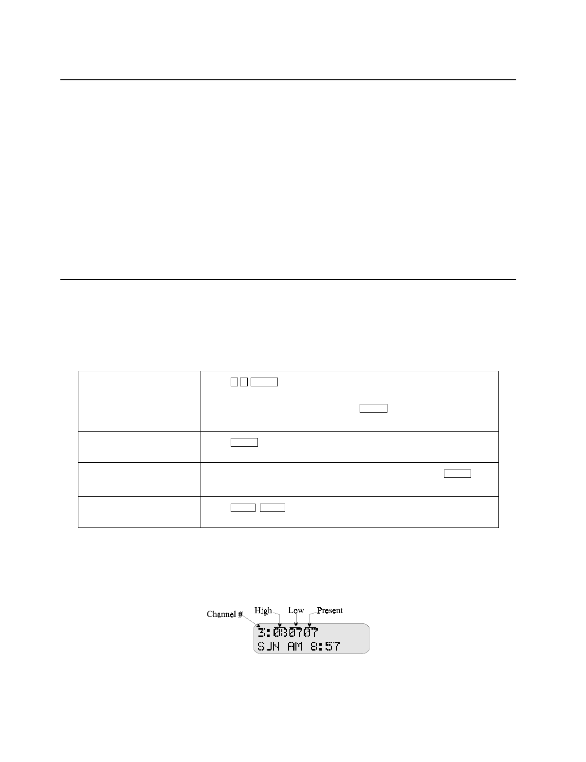
Model 5207 Fire Control/Communicator Installation and Operation Manual
9-2 150865
9.2 P3 and P4 Earth Ground Faults
A P3 trouble indicates that the panel has detected a short between earth ground (terminal 52)
and circuit ground (terminals 1, 10, 20, 25).
A P4 trouble indicates that the panel has detected a short between any power source and earth
ground. Some common power sources are terminals 12, 15, 18, 24, 26, 28, 30, 32, 34 or the
batteries.
To determine the location of the short, place a DC volt meter with ground on terminal 1 and
positive on terminal 52. The meter should be continuously fluctuating between 0 and 2.5 volts
DC. Remove and leave off field wiring from the panel until the meter reads in this range. You
can also use Accu-Zone® Troubleshooting to determine the location (see Section 9.3).
9.3 Accu-Zone® Troubleshooting (Mode 25)
Accu-Zone® Troubleshooting allows you to locate shorts and other system troubles (including
AC power and battery power) without using a voltmeter. All alarms and troubles are disabled
while you are using Mode 25 allowing you to trip sensors, adjust wiring, and so on. You must
use the Model 5230 Remote Annunciator for Accu-Zone troubleshooting (see Table 9-1).
9.3.1 Mode 25 Display
The first line of the display will show the channel (input) number followed by six digits
known as “step numbers”. Although the step numbers are not actual voltage readings, they
can identify any voltage fluctuations that may have occurred.
Figure 9-1 Mode 25 Display
To enter troubleshooting
mode: Press + Code 0 or 1.
The first line of the display will show the default channel number (3).
(See Figure 9-1 for an example.) Press if you want to view infor-
mation for channel 3.
To move sequentially
through the channels: Press until you arrive at the channel you want to view.
To skip to a different step: Enter the number of the channel you want to view and press .
Channel numbers and the inputs they represent are shown in Table 9-1.
To exit troubleshooting
mode: Press .
2 5 ENTER
ENTER
ENTER
ENTER
CLEAR CLEAR

Troubleshooting
150865 9-3
When you momentarily put a zone into alarm, the touchpad will display the Present (current)
value along with the High (spikes) and Low (voltage drop) values. This is also useful in locat-
ing intermittent connections.
Step numbers range from 0 to 16. Using Table 9-1, you can determine if the step numbers are
within the acceptable range for each input.
Table 9-1 Significance of Mode 25 Readings
Input Term. # Chan. # Typical
Reading Significance
Zone 1
Class A (style D) 3 17 11 In normal condition, the following is true:
1) Terminals 3 and 4 are the same;
AND
2) Terminal 2 and 5 are the same;
AND
3) Terminals 3 and 4 are not the same as
2 and 5.
If any of the conditions is not true, it indicates
an alarm or trouble condition.
418 11
219 6
520 6
Zone 2
Class A (style D) 7 21 11 In normal condition, the following is true:
1) Terms. 7 and 8 are the same
AND
2) Terms. 6 and 9 are the same
AND
3) Terms. 7 and 8 are not the same as 6 and 9.
If any of the conditions is not true, it indicates
an alarm or trouble condition.
822 11
623 6
924 6
Zones 3-8
Class B (style B) 11-19 3-8 8-9 Above 10 = Alarm
Below 6 = Trouble
Zones 9-16
Class B (style B) (5210) 9-16 8-9 Above 10 = Alarm
Below 6 = Trouble
Accessory Power 26 30 6-7 Above 8 = Trouble
Below 4 = Trouble
Earth Ground 52 31 1-9 Fluctuates continuously from 1-9 in normal
condition.
Notif. Circuits 1-4 27-34 25-28 10-11 Above 12 = Trouble
Below 8 = Trouble
Smoke Power 12, 15, 18 29 11-12 Above 12 = Trouble
Below 8 = Trouble

Model 5207 Fire Control/Communicator Installation and Operation Manual
9-4 150865
9.4 Troubleshooting and System Messages
Table 9-2 shows the messages that may appear on the Model 5230 Touchpad display and the
codes that may appear on the 5207 built-in touchpad display.
For troubleshooting, you can connect a 5230 temporarily if it is not part of the installation (see
4.9.2).
Table 9-2 System Messages and Codes
5230 Annunciator Built-in Annunciator
Display / LEDs Explanation
System messages. 1- Alarm reset. Alarm reset code is being entered on
the annunciator.
System messages. 2- Alarm memory has been cleared.
System messages. 3- Dialer being reset.
0 ENTER 0-
Set Mode LED is on. Fire drill or system test in progress.
*CALLING COMPUTER -4 Data is being up- or downloaded.
DATA LOST DL Most common reason for this message is that the
communicator has lost data that was being trans-
mitted to the central station.
(This message could also indicate that alarm mem-
ory buffer is full. Press + code to clear.)
FAILED DF Dialer failed. The communicator has failed to
report.
*REPORTING Set Time LED flashes An event is being reported to the central station.
Prompts for input. -7
Set Mode LED is on. The 5207 is in Step Programming mode.
System data. -5
Set Mode LED is on. A zone test is in progress.
XXXX ALARM
yy -n
(n= zone number) The alarm memory is being displayed.
XXXX = Alarm type
YY = Zone number
ALARM ZONE
1-16 1-16
ALARM LED:
Flashing = Fire
Steady on = supervisory
Alarm in the indicated zone.
If more than one zone is in alarm, the top line of
the 5230 will cycle through the status messages for
each zone.
BAD EEPROM
5230 piezo sounds on and
off.
E7
LEDs and 5207 piezo turn
on and off.
Problem with EEPROM. Replace chip.
*When the transmission is completed, the 5230 annunciator resets and displays its ID.
2ENTER

Troubleshooting
150865 9-5
DISABLED: ZONE #
ZONE DESCRIPTION Panel beeps. Press
to see bypassed zone.
(Cannot be silenced until
zone is restored.)
Disabled zone. (Zone descriptions appear only if
selected during programming.)
NORMAL -- No trouble, alarm, or other condition exists.
y
XX SEC TO ALARM
Y=Prealarm zone number
XX=countdown (seconds)
Number of zone in pre-
alarm. An alarm condition exists in the indicated zone but
will not sound and report an alarm until the pre-
alarm time has elapsed. During prealarm, pressing
+ Code will prevent sound-
ing and reporting.
BUS TROUBLE No display. Annunciator data wires are shorted or reversed.
SILENCED SILENCE LED is on. A trouble condition exists and has been silenced.
SMOKE ZONE # 1-16 Smoke verification time, zone 1-16.
SPRINKLER ALARM
X1-16 Sprinkler supervisory alarm. X = zone number.
TIME? -9
SET MODE LED is on. The 5207 is in Set Time mode.
TROUBLE:
X1-16 Sprinkler supervisory trouble. X = zone number.
TROUBLE:
KEYSTATION n F0
Trouble LED on A 5230 annunciators is in trouble.
TROUBLE:
AC AC
TROUBLE LED flashes. AC power has been lost. Check connection to AC
power source.
TROUBLE:
BATTERY DC
TROUBLE LED on. Battery power has been lost, or polarity has been
reversed. Measure the battery voltage and replace
the battery or reverse polarity as needed.
TROUBLE:
BELL X A1 - A4
TROUBLE LED on. A trouble condition exists on the indicated notifi-
cation circuit. X = bell number.
TROUBLE:
POWER 3 P3 and P4
TROUBLE LED 1. An earth to circuit ground fault condition exists.
Use Mode 25 to locate and correct the condition.
2. Earth ground shorted to power. Use Mode 25 to
locate and correct the problem.
TROUBLE:
LINE # L1 or L2 A trouble condition exists on indicated phone line.
TROUBLE ZONE
X1-16
TROUBLE LED is on. A trouble condition exists in the indicated zone.
See Section 9.3 for more information about cor-
recting trouble conditions. (X = zone number)
Table 9-2 System Messages and Codes
5230 Annunciator Built-in Annunciator
Display / LEDs Explanation
DISABLE
RESET ALARM
ENTER

Model 5207 Fire Control/Communicator Installation and Operation Manual
9-6 150865
TRY AGAIN -- A keystroke error has been made. Press
and enter the correct keystrokes.
WALK TEST
SUN AM 12:19 -2
SET MODE LED is on. A walk test is being conducted. The top line of the
5230 display may also show the zone number in a
trouble condition.
Table 9-2 System Messages and Codes
5230 Annunciator Built-in Annunciator
Display / LEDs Explanation
CLEAR

150865 A-1
Appendix A
Compatible Devices
This section of the manual lists devices (smoke detectors and notification appliances) that are
compatible with the 5207. Contact Silent Knight if you have a question about whether a
device not listed here is compatible.
A.1 Smoke Detectors
This section of the manual contains information about smoke detectors that are compatible
with the 5207.
Notes:
The maximum number of smoke detectors per zone is determined by both the current draw and the impedance of
the smoke detector. If too many smoke detctors are used on any zone, false alarms could occur.
Do not mix different models of detectors on any zone; false alarms could occur.
Control unit Smoke Reset Time must be programmed for a number greater than or equal to the maximum reset
time of the smoke detector.
Two-Wire Smoke Detectors
The table below lists two-wire smoke detectors that are compatible with the 5207. The table is
organized by manufacturer. Information for both 12V and 24V mode and for the 5210 Zone
Expander Module is included. The columns show the number of detectors per loop that can be
used.
5207 5210
Identifier 24D 24A
Voltage Range 19.4-28 VDC 17.8-27.4 VDC
Manufacturer Model Name or Number
(Base model name or number in parentheses.) 5207 5210
Apollo 55000-250 (45681-200) 24 / loop 8 / loop
Apollo 55000-350 (45681-200) 24 / loop 8 / loop
Detection Systems DS200 (MB200-2W) 24 / loop 12 / loop
Detection Systems DS200HD (MB200-2W) 24 / loop 12 / loop
Detection Systems DS250 (MB2W or MB2WL) 18 / loop 8 / loop
Detection Systems DS250HD (MB2W or MB2WL) 18 / loop 8 / loop
Detection Systems DS250TH (MB2W or MB2WL) 18 / loop 8 / loop
ESL 425 40 / loop 20 / loop
ESL 425C 40 / loop 20 / loop
ESL 425CR 40 / loop 20 / loop
ESL 425CRT 40 / loop 20 / loop
ESL 425CT 40 / loop 20 / loop
ESL 429C (S10A) 30 / loop 14 / loop
ESL 429CRT (S11A) 30 / loop 14 / loop

Model 5207 Fire Control/Communicator Installation and Operation Manual
A-2 150865
ESL 429CST (S11A) 30 / loop 14 / loop
ESL 429CT (S10A) 30 / loop 14 / loop
ESL 609U01-11 40 / loop 24 / loop
ESL 609U02-11 40 / loop 24 / loop
ESL 611U (601U or 602U) 40 / loop 24 / loop
ESL 611UD (601U or 602U) 40 / loop 24 / loop
ESL 611UT (601U or 602U) 40 / loop 24 / loop
ESL 612U (601U or 602U) 40 / loop 24 / loop
ESL 612UD (601U or 602U) 40 / loop 24 / loop
ESL 711U (701E or 701U) 25 / loop 15 / loop
ESL 712U (701E or 701U) 25 / loop 15 / loop
ESL 713-5U (702E or 701U) 25 / loop 15 / loop
ESL 713-6U (702E or 701U) 25 / loop 15 / loop
ESL 721-U (S10A) 30 / loop 15 / loop
ESL 721-UT (S10A) 30 / loop 15 / loop
Falcon 525 17 / loop 8 / loop
Falcon 525T 17 / loop 8 / loop
Faraday 9374 20 / loop 10 / loop
Faraday 9375 20 / loop 10 / loop
Faraday 9376 20 / loop 10 / loop
Hochiki SIH-24F (HS-224D or HSB-224) 25 / loop 10 / loop
Hochiki SLK-12 25 / loop 10 / loop
Hochiki SLK-24F (HS-224D) 25 / loop 10 / loop
Hochiki SLK-24FH (HS-224D) 25 / loop 10 / loop
Hochiki (HS224L) Heat Detector base 30 / loop 30 / loop
System Sensor 1100 20 / loop 8 / loop
System Sensor 1100T 20 / loop 8 / loop
System Sensor 1100TB 20 / loop 8 / loop
System Sensor 1151 (110LP) 20 / loop 8 / loop
System Sensor 1400 20 / loop 8 / loop
System Sensor 1451 (B401B) 20 / loop 8 / loop
System Sensor 1800 20 / loop 8 / loop
System Sensor 1851B (B101B) 20 / loop 8 / loop
System Sensor 1851DH (DH1851DC) 20 / loop 8 / loop
System Sensor 2100 20 / loop 8 / loop
System Sensor 2100T 20 / loop 8 / loop
System Sensor 2100TB 20 / loop 8 / loop
System Sensor 2151 (B110LP or B110LRP) 20 / loop 8 / loop
System Sensor 2300T 20 / loop 8 / loop
System Sensor 2400 20 / loop 8 / loop
System Sensor 2400 (DH400) 20 / loop 8 / loop
System Sensor 2400AIT 20 / loop 8 / loop
System Sensor 2400AT 20 / loop 8 / loop
System Sensor 2400TH 20 / loop 8 / loop
Manufacturer Model Name or Number
(Base model name or number in parentheses.) 5207 5210

150865 A-3
Four Wire Smoke Detectors
A.2 Notification Appliances
The chart below lists notification appliances compatible with the 5207.
System Sensor 2451 (B401B) 20 / loop 8 / loop
System Sensor 2451DH (DH 400) 20 / loop 8 / loop
System Sensor 2451TH (B401B) 20 / loop 8 / loop
System Sensor 2800 20 / loop 8 / loop
System Sensor 2800TH 20 / loop 8 / loop
System Sensor 2851B (B101B) 20 / loop 8 / loop
System Sensor 2851BTH (B101B) 20 / loop 8 / loop
System Sensor 2851DH 20 / loop 8 / loop
System Sensor 2851TH (B101B) 20 / loop 8 / loop
Manufacturer Model
Silent Knight SD-P24F with SD-B4@ base
Detection Systems DS200/DS200HD
MB200
ESL 445 Series
449 Series
System Sensor 1851B
2851/2851BTH
DH200ADCD
Manufacturer Model Type
Faraday 446X 12/24VDC Vibrating Bell
Faraday 476X 12/24VDC Vibrating Bell
Faraday 477X 12/24VDC Single Stroke Bell
Faraday 5303B-0-14-( )-DC Chime (flush)
Faraday 5304B-0-14-( )-DC Chime (surface)
Faraday 5305B-0-4-( )-DC Chime (ceiling)
Faraday 5306B-0-14-( )-24-DC Chime/Strobe (flush)
Faraday 5307B-0-14-( )-24-DC Chime/Strobe (surface)
Faraday 5308B-0-4-( )-24-DC Chime/Strobe (ceiling)
Faraday 5333B-0-14-24-DC Multi-Tone Horn (flush)
Faraday 5334B-0-14-24-DC Multi-Tone Horn (surface)
Faraday 5336B-( )-14-24-DC Multi-Tone Horn/Strobe (flush)
Faraday 5337B-( )-14-24-DC Multi-Tone Horn/Strobe (surface)
Faraday 5338B-( )-4-24-DC Multi-Tone Horn/Strobe (ceiling)
Faraday 5343B-0-14-24-DC Single Tone Horn/Strobe (flush)
Faraday 5344B-0-14-24-DC Single Tone Horn/Strobe (surface)
Faraday 5345B-0-4-24-DC Single Tone Horn/Strobe (ceiling)
Faraday 5348B-( )-4-24-DC Single Tone Horn/Strobe (ceiling)
Manufacturer Model Name or Number
(Base model name or number in parentheses.) 5207 5210

Model 5207 Fire Control/Communicator Installation and Operation Manual
A-4 150865
Faraday 5373B-0-14-24-DC 8-Tone Horn/Strobe (flush)
Faraday 5374B-0-14-24-DC 8-Tone Horn/Strobe (surface)
Faraday 5375B-0-4-24-DC 8-Tone Horn/Strobe (ceiling)
Faraday 5376B-0-14-24-DC 8-Tone Horn/Strobe (flush)
Faraday 5377B-0-14-24-DC 8-Tone Horn/Strobe (surface)
Faraday 5378B-0-4-24-DC 8-Tone Horn/Strobe (ceiling)
Faraday 5405B-0-14-24-DC Sync Control Unit
Faraday 5508B-( )-14-24-DC Single Gang Sync Strobe (flush)
Faraday 5521B-( )-14-24-DC 4” Square Sync Strobe (surface)
Faraday 5522B-( )-14-24-DC 4” Square Sync Strobe (flush)
Faraday 6126B-U-14-24 VDC Horn/Strobe
Faraday 6223B-0-14-24-DC Horn (flush)
Faraday 6224B-0-14-24-DC Horn (surface)
Faraday 6225B-0-4-24-DC Horn (ceiling)
Faraday 6226B-( )-14-24-DC Horn/Strobe (flush)
Faraday 6227B-( )-14-24-DC Horn/Strobe (surface)
Faraday 6228B-( )-4-24-DC Horn/Strobe (ceiling)
Faraday 6243B-0-14-24-DC Electron-Mechanical Horn (flush)
Faraday 6244B-0-14-24-DC Electron-Mechanical Horn (surface)
Faraday 6245B-0-4-24-DC Electron-Mechanical Horn (ceiling)
Faraday 6246B-( )-14-24-DC Electron-Mechanical Horn/Strobe (flush)
Faraday 6247B-( )-14-24-DC Electron-Mechanical Horn/Strobe
(surface)
Faraday 6248B-( )-4-24-DC Electron-Mechanical Horn/Strobe
(ceiling)
Faraday 6300B-0-14-24-DC Mini-Horn (flush)
Faraday 6301B-0-14-24-DC Mini-Horn (surface)
Faraday 6302B-( )-4-24-DC Mini-Horn (ceiling)
Faraday 6310B-0-14-24-DC Mini-Horn/Strobe/Strobe (flush)
Faraday 6311B-0-14-24-DC Mini-Horn/Strobe/Strobe (surface)
Faraday 6312B-( )-14-24-DC Mini-Horn/Strobe/Strobe (ceiling)
Faraday 6320B-0-14-24-DC Sync Mini Horn/Strobe (1 gang)
Faraday 6321B-0-14-24-DC Sync Mini Horn/Strobe (1,2 gang)
Faraday 6322B-( )-14-24-DC Mini Horn/Sync Strobe (1,2 gang, 4SQ)
Federal Signal 450 Horn
Federal Signal VALS Horn/Strobe
Gentex GX90-4 Horn
Gentex GXS-4-15-1 Strobe
Gentex GXS-4-1575 Strobe
Gentex GX90S-4-15 Horn
Gentex GX90S-4-1575 Horn
Gentex HG124 Horn
Gentex SHG24-1575 Horn/Strobe
Gentex SHG24-15 Horn/Strobe
Gentex GMH-24-X Horn
Manufacturer Model Type

150865 A-5
Gentex GMS-24-X Horn/Strobe
Gentex GMS-24-X Horn/Strobe
Gentex G0T24 Horn
Gentex G0S24-X Horn
Gentex WGMS-24-X Horn/Strobe
System Sensor MASS241 Horn/Strobe
System Sensor MASS24110ADA Horn/Strobe
System Sensor MASS2415ADA Horn/Strobe
System Sensor MASS2475ADA Horn/Strobe
System Sensor SS4110ADA Strobe
System Sensor SS2415ADA Strobe
System Sensor SS2475ADA Strobe
System Sensor PS2415ADA Mini-Horn/Strobe
System Sensor PS241575ADA Mini-Horn/Strobe
System Sensor PS24110ADA Mini-Horn/Strobe
System Sensor PS2475ADA Mini-Horn/Strobe
Wheelock 46T-G4-24-R Bell
Wheelock 46T-G6-24-R Bell
Wheelock 46T-G10-24-R Bell
Wheelock 46T-G6-24-WS-24-HF-R Strobe/Bell
Wheelock 46T-G10-24-WS-24-HF-R Strobe/Bell
Wheelock 46T-G6-24-WH-24-HF-R Strobe/Bell
Wheelock 46T-G10-24-WH-24-HF-R Strobe/Bell
Wheelock 7001T-12\24-W-FR Strobe Horn
Wheelock 7002T-12\24-W-FR Strobe Horn
Wheelock AES-DL1-R Multitone Horn
Wheelock AES-EL1-R Multitone Horn
Wheelock AES-DL1-WS-24-VF-R Multitone Horn
Wheelock AES-EL1-WS-24-VF-R Multitone Horn
Wheelock AES-DL1-WH-24-VF-R Multitone Horn
Wheelock AES-EL1-WH-24-VF-R Multitone Horn
Wheelock AES-DL1-WM-24-VF-R Multitone Horn
Wheelock AES-EL1-WM-24-VF-R Multitone Horn
Wheelock AH-24-R Horn
Wheelock AMT-12\24-R Strobe Horn
Wheelock AMT-24-LS-VFR Strobe Horn
Wheelock AMT-24-LSM-VFR Strobe Horn
Wheelock AMT-24-IS-VFR Strobe Horn
Wheelock AS-2415-VFR Strobe Horn
Wheelock AS-241575-VFR Strobe Horn
Wheelock AS-2430-VFR Strobe Horn
Wheelock AS-2475-VFR Strobe Horn
Wheelock AS-24110-HFR Strobe Horn
Wheelock SM-12\24-R Strobe Horn Controller
Wheelock DSM-12\24-R Strobe Horn Controller
Manufacturer Model Type

Model 5207 Fire Control/Communicator Installation and Operation Manual
A-6 150865
Wheelock CF-BF1 Chime
Wheelock CF-BF1-R Chime
Wheelock CH-CF1 Chime
Wheelock CH-CF1-R Chime
Wheelock CH-CF1-W Chime
Wheelock CH-DF1 Chime
Wheelock CH-DF1-R Chime
Wheelock CH-BF1-WS-24-HF-R Strobe Chime
Wheelock CH-CF1-LS-24 Strobe Chime
Wheelock CH-CF1-MS-24 Strobe Chime
Wheelock CH-CF1-IS-24 Strobe Chime
Wheelock CH-CF1-LS-24-CFW Strobe Chime
Wheelock CH-CF1-MS-24-CFW Strobe Chime
Wheelock CH-CF1-IS-24-CFW Strobe Chime
Wheelock CH-CF1-WS-24-CF-W Strobe Chime
Wheelock CH-DF1-LS-24 Strobe Chime
Wheelock CH-DF1-MS-24 Strobe Chime
Wheelock CH-DF1-IS-24 Strobe Chime
Wheelock CH-DF1-LS-24-VFR Strobe Chime
Wheelock CH-DF1-LSM-24-VFR Strobe Chime
Wheelock CH-DF1-MS-24-VFR Strobe Chime
Wheelock CH-DF1-IS-24-VFR Strobe Chime
Wheelock CH-DF1-WM-24-VFR Strobe Chime
Wheelock CH-DF1-WS-24-VF-R Strobe Chime
Wheelock DSM-12/24 Sync Module
Wheelock EH-DL1-R Electronic Horn
Wheelock EH-EL1-R Electronic Horn Electronic Horn
Wheelock EHS-DL1-W-VF-R Strobe Horn (single input)
Wheelock EHS-EL1-W-VF-R Strobe Horn (single input)
Wheelock EH-DL1-WS-24-VF-R Strobe Horn (dual input)
Wheelock EH-EL1-WS-24-VF-R Strobe Horn (dual input)
Wheelock EH-DL1-WH-24-VF-R Strobe Horn (dual input)
Wheelock EH-EL1-WH-24-VF-R Strobe Horn (dual input)
Wheelock EH-DL1-WM-24-VF-R Strobe Horn (dual input)
Wheelock EH-EL1-WM-24-VF-R Strobe Horn (dual input)
Wheelock HSW-24-HFR Remote Strobe
Wheelock HS2W-24-HFR Remote Strobe
Wheelock HSPW-24-HFR Remote Strobe
Wheelock IS-24-VFR Remote Strobe
Wheelock IS1-24-VFR Remote Strobe
Wheelock IS3-24-VFR Remote Strobe
Wheelock ISP-24-HFR Remote Strobe
Wheelock LS-24-VFR Remote Strobe
Wheelock LS1-24-VFR Remote Strobe
Wheelock LS3-24-VFR Remote Strobe
Manufacturer Model Type

150865 A-7
Wheelock LSP-24-HFR Remote Strobe
Wheelock LSM-24-VFR Remote Strobe
Wheelock LS1M-24-VFR Remote Strobe
Wheelock LS3M-24-VFR Remote Strobe
Wheelock LSPM-24-VFR Remote Strobe
Wheelock MS-24-VFR Remote Strobe
Wheelock MS1-24-VFR Remote Strobe
Wheelock MS3-24-VFR Remote Strobe
Wheelock MSP-24-HFR Remote Strobe
Wheelock MB-G6-24-R Motor Bell
Wheelock MB-G10-24-R Motor Bell
Wheelock MBS-G6-24-W-HF-R Motor Bell with Strobe
Wheelock MBS-G10-24-W-HF-R Motor Bell with Strobe
Wheelock MIZ-24-R Mini-Horn
Wheelock MIZ-24-W Mini-Horn
Wheelock MIZ-24-LS-VFR Mini-Horn/Strobe
Wheelock MIZ-24-LSM-VFR Mini-Horn/Strobe
Wheelock MIZ-24-MS-VFR Mini-Horn/Strobe
Wheelock MIZ-24-HSW-HFR Mini-Horn/Strobe
Wheelock MIZ-24-IS-VFR Mini-Horn/Strobe
Wheelock MIZ-24-WS-VF-R Mini-Horn/Strobe
Wheelock MIZ-24-WS-VF-W Mini-Horn/Strobe
Wheelock MIZ-24-WH-VF-W Mini-Horn/Strobe
Wheelock MIZ-24-WM-VF-W Mini-Horn/Strobe
Wheelock MT-12/24-R Strobe Horn
Wheelock MT-24-LS-VFR Strobe Horn
Wheelock MT-24-LSM-VFR Strobe Horn
Wheelock MT-24-MS-VFR Strobe Horn
Wheelock MT-24-IS-VFR Strobe Horn
Wheelock MT-24-SL-VFR Strobe Horn
Wheelock MT-24-SLM-VFR Synch. Multitone Strobe
Wheelock MT-24-WM Strobe
Wheelock MT-24-WM-VF-R Horn
Wheelock MT-24-WM-VFR Horn
Wheelock RS-2415-HFR Strobe
Wheelock RSP-2415-VFR Strobe
Wheelock RS-241575-VFR Strobe
Wheelock RSP-241575-VFR Strobe
Wheelock RS-2430-VFR Strobe
Wheelock RS-2430-HFR Strobe
Wheelock RS-2475-VFR Strobe
Wheelock RSP-2475-HFR Strobe
Wheelock RS-24110-HFR Strobe
Wheelock RSP-24110-HFR Strobe
Wheelock SL-24-VFR Synchronized Remote Strobe
Manufacturer Model Type

Model 5207 Fire Control/Communicator Installation and Operation Manual
A-8 150865
Wheelock SL1-24-VFR Synchronized Remote Strobe
Wheelock SL3-24-VFR Synchronized Remote Strobe
Wheelock SLP-24-VFR Synchronized Remote Strobe
Wheelock SLM-24-VFR Synchronized Remote Strobe
Wheelock SL1M-24-VFR Synchronized Remote Strobe
Wheelock SL3M-24-VFR Synchronized Remote Strobe
Wheelock SLPM-24-VFR Synchronized Remote Strobe
Wheelock SHW-24-VFR Synchronized Remote Strobe
Wheelock SH2W-24-VFR Synchronized Remote Strobe
Wheelock SHPW-24-VFR Synchronized Remote Strobe
Wheelock SCM-24-R Controller for Synchronized Strobes
Wheelock SM-12/24-R Sync Module
Wheelock SR-2415-VFR Sync Strobe
Wheelock SRP-2415-HFR Sync Strobe
Wheelock SR-241575-VFR Sync Strobe
Wheelock SRP-241575-VFR Sync Strobe
Wheelock SR-2475-VFR Sync Strobe
Wheelock SR-2475-HFR Sync Strobe
Wheelock SR-24110-HFR Sync Strobe
Wheelock SRP-24110-HFR Sync Strobe
Wheelock V7001T-12\24-W-FR Strobe Horn
Wheelock WM3T-24-FR Remote Strobe
Wheelock WM3T-24-VFR Remote Strobe
Wheelock WS1T-24-FR Strobe
Wheelock WS3T-24-FR Strobe
Wheelock WST-24-FR Strobe
Manufacturer Model Type
