Text.p70 Hitachi Cordless Drill DS 12DVF3 5385
User Manual: Hitachi Cordless Drill DS 12DVF3
Open the PDF directly: View PDF ![]() .
.
Page Count: 34
- MODELS DS12DVF3/DS9DVF3
- REMARK
- CONTENTS
- 1. PRODUCT NAME
- 2. MARKETING OBJECTIVE
- 3. APPLICATIONS
- 4. SELLING POINTS
- 5. SPECIFICATIONS
- 6. COMPARISONS WITH SIMILAR PRODUCTS
- 7. WORKING PERFORMANCE PER SINGLE CHARGE
- 8. PRECAUTIONS IN SALES PROMOTION
- 9. REFERENCE MATERIALS
- 10. REPAIR GUIDE
- 11. STANDARD REPAIR TIME (UNIT) SCHEDULES
TECHNICAL DATA
AND
SERVICE MANUAL
CORDLESS DRIVER DRILLS
DS 12DVF3
DS 9DVF3
SPECIFICATIONS AND PARTS ARE SUBJECT TO CHANGE FOR IMPROVEMENT
LIST Nos. DS 12DVF3: G818
DS 9DVF3: G817
Mar. 2005
D
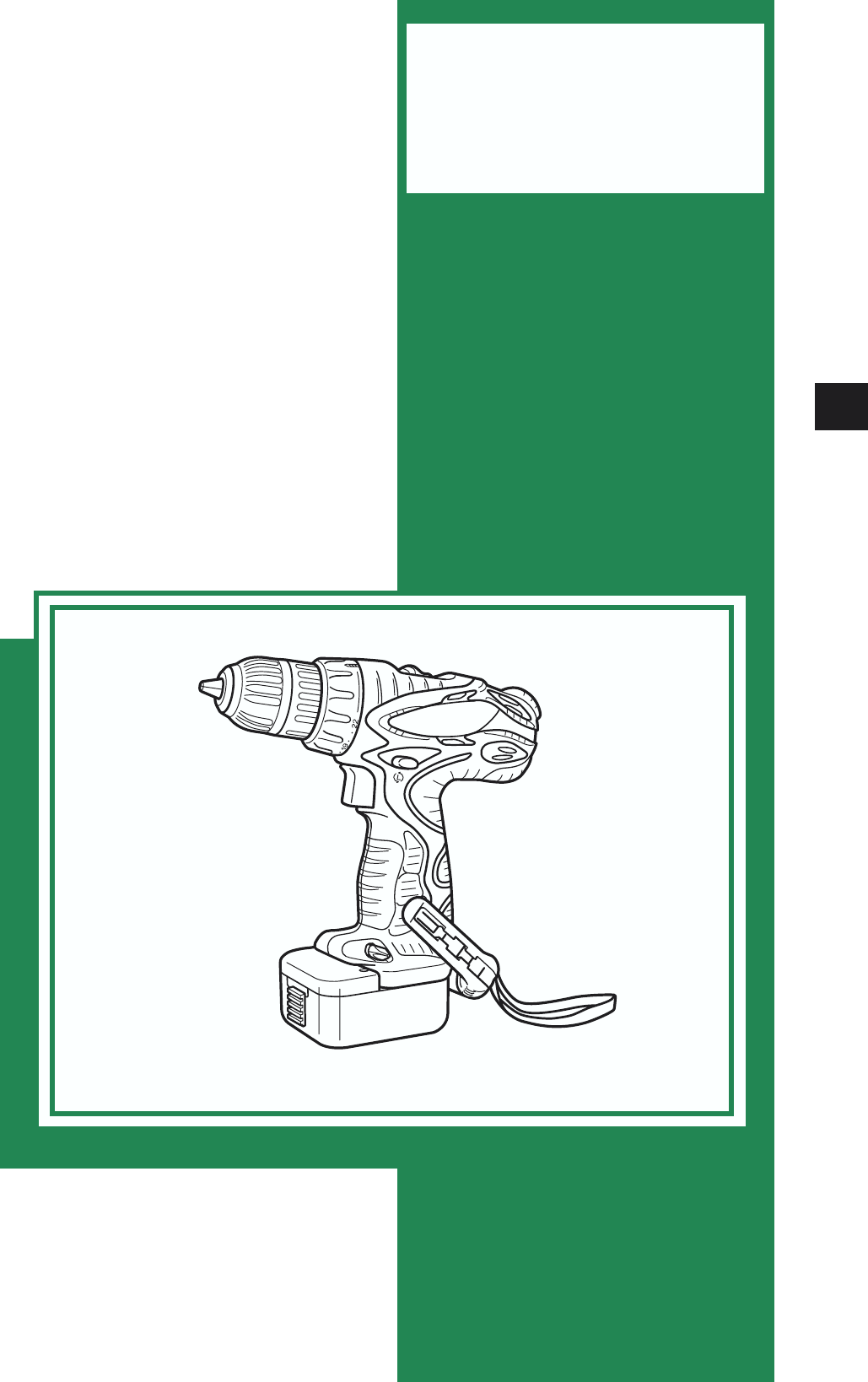
MODELS
DS 12DVF3
DS 9DVF3
DS 12DVF3
Hitachi
Power Tools

REMARK:
Throughout this TECHNICAL DATA AND SERVICE MANUAL, a symbol(s)
is(are) used in the place of company name(s) and model name(s) of our
competitor(s). The symbol(s) utilized here is(are) as follows:
Symbols Utilized
Competitors
Company Name Model Name
MAKITA 6227D, 6226D
C
BOSCH GSR12V, GSR9.6V
B
Page
CONTENTS
1. PRODUCT NAME .............................................................................................................................. 1
2. MARKETING OBJECTIVE ................................................................................................................ 1
3. APPLICATIONS ................................................................................................................................. 1
4. SELLING POINTS ............................................................................................................................. 1
4-1. Selling Point Descriptions ...................................................................................................................2
5. SPECIFICATIONS ............................................................................................................................. 4
5-1. DS 12DVF3 .........................................................................................................................................4
5-2. DS 9DVF3 ...........................................................................................................................................5
6. COMPARISONS WITH SIMILAR PRODUCTS ................................................................................. 6
6-1. DS 12DVF3 .........................................................................................................................................6
6-2. DS 9DVF3 ...........................................................................................................................................7
7. WORKING PERFORMANCE PER SINGLE CHARGE ..................................................................... 8
7-1. DS 12DVF3 .........................................................................................................................................8
7-2. DS 9DVF3 ...........................................................................................................................................9
8. PRECAUTIONS IN SALES PROMOTION ...................................................................................... 10
8-1. Safety Instructions ............................................................................................................................10
8-2. Inherent Drawbacks of Cordless Driver Drills Requiring Particular Attention
During Sales Promotion ....................................................................................................................12
9. REFERENCE MATERIALS ............................................................................................................. 13
10. REPAIR GUIDE ............................................................................................................................. 14
10-1. Precautions in Disassembly and Reassembly ................................................................................14
10-2. Precautions in Disassembly and Reassembly of Battery Charger .................................................21
11. STANDARD REPAIR TIME (UNIT) SCHEDULES......................................................................... 22
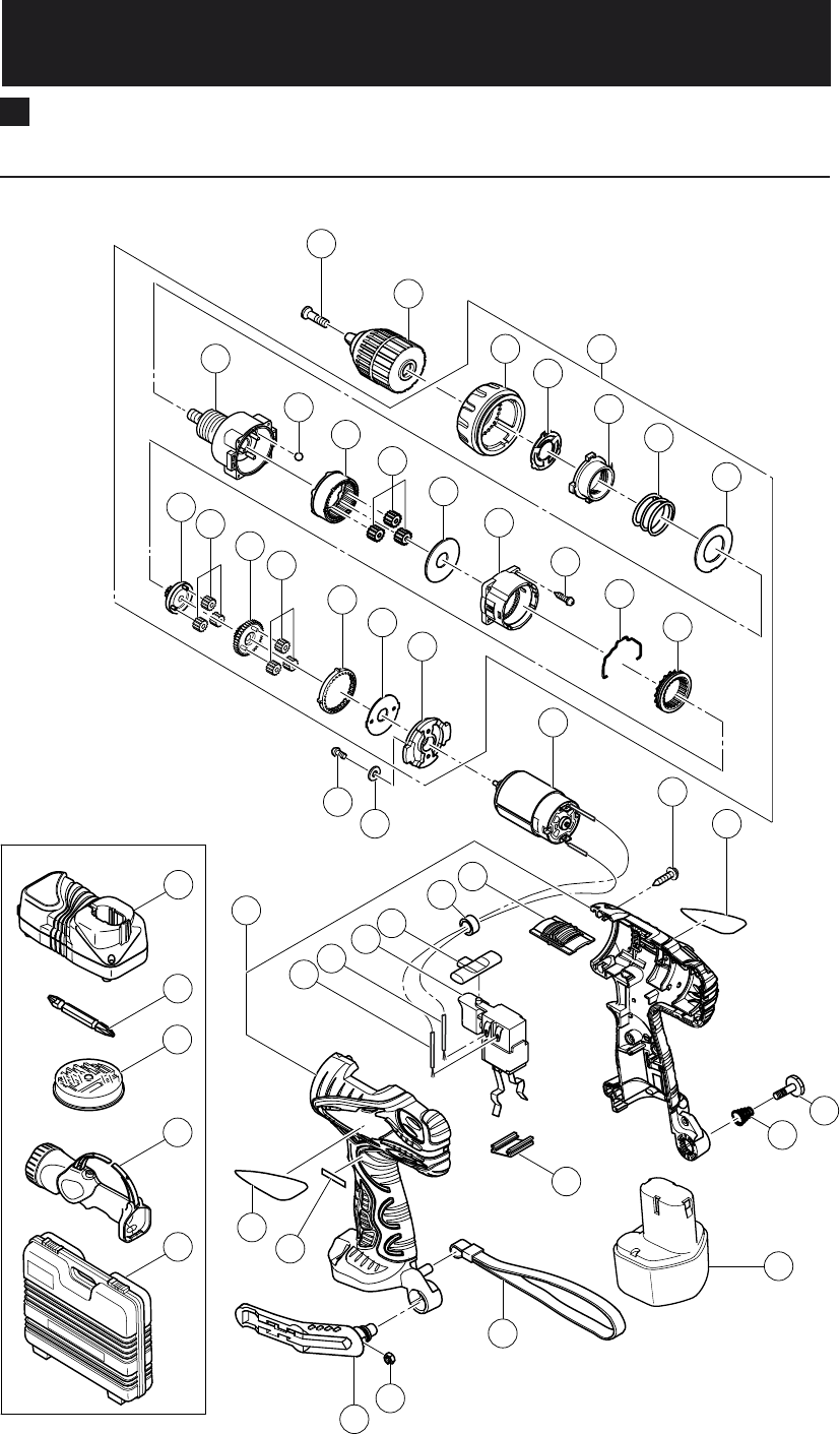
Assembly Diagram for DS 12DVF3
Assembly Diagram for DS 9DVF3
--- 1 ---
1. PRODUCT NAME
Hitachi 12 V Cordless Driver Drill, Model DS 12DVF3
Hitachi 9.6 V Cordless Driver Drill, Model DS 9DVF3
2. MARKETING OBJECTIVE
The current Models DS 12DVF2 and DS 9DVF2 are popular as reasonable professional-use cordless driver drills.
However, about one year has already passed since the sales start. To cope with this situation, the above two
models are upgraded to the more convenient and stylish Models DS 12DVF3 (12 V) and DS 9DVF3 (9.6 V) at the
same time.
3. APPLICATIONS
Tightening and loosening wood screws, self-tapping screws and machine screws
Drilling into wood materials, plastic, mild steel and aluminum
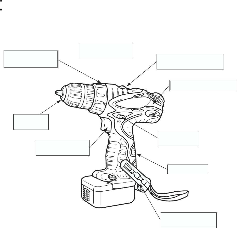
4. SELLING POINTS
Two-speed transmission with
one-touch speed shift knob
[Model DS 12DVF3]
Soft-grip handle
Push-button type
reversing switch
5-position belt hook with
integrated bit holder
Compact body
Overall length 198 mm
Improved overload durability
Variable speed switch
with braking function
Equipped with feedback
power control
10 mm (3/8")
keyless chuck
Variable torque setting
for fastener tightening
22-position adjustable
torque setting
--- 2 ---
4-1. Selling Point Descriptions
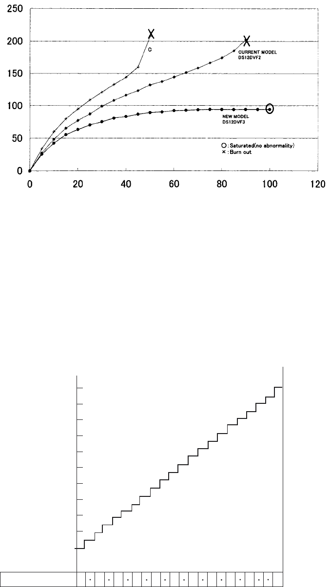
4-1-1. Improved overload durability
The cooling fan incorporated in the motor and the air vents provided in its outer frame greatly enhance the cooling
effect, ensuring improved durability in continuous operation.
Fig. 2 Clutch torque
1
60
55
50
45
40
35
30
25
20
15
10
5.9
5.4
4.9
4.4
3.9
3.4
2.9
2.5
2.0
1.5
1.0
Clutch position
Adjustable torque is about 0.2 N¥m
at each click within the torque range
of 1.0 --- 5.9 N¥m.
Torque (N¥m) (kgf¥cm)
3 5 7 9 11 13 15 17 19 22
4-1-2. Soft-grip handle
The grip of the Models DS 12DVF3 and DS 9DVF3 is soft, slip-resistant and comfortable thanks to the soft resin
(elastomer) covered on the handle.
4-1-3. 22-position adjustable torque setting
The torque can be set finely thanks to the adoption of the 22 clutch positions to improve the operability.
Time [minutes]
Temperature rise outside the motor [K]
1.37 N.m {14 kgf.cm intermitted load test}
Fig. 1
--- 3 ---
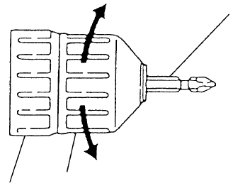
4-1-4. 10 mm (3/8") keyless chuck
The keyless chuck facilitates fast and easy replacement of driver bits. Replacement can be carried out simply by
holding the ring with one hand, while turning the sleeve with the other hand.
4-1-5. Variable speed switch with braking function
The braking function allows the driver unit to stop rotation immediately when the trigger switch is released, which
is a convenient feature during actual working. Also, the feedback system ensures a sufficiently large torque even
in the variable speed range.
Fig. 3
Ring Sleeve
Tighten
Loosen
Driver bit

--- 4 ---
5. SPECIFICATIONS
Capacity Screwdriver
Drill
Keyless chuck
(10TLRF-N)
Rotation speed
Type of motor
Torque
Type of switch
Handle configuration
Enclosure
Battery
(Type EB 1214S
/EB 1220BL)
Charger
(Model UC 18YG)
Weight Net
Standard
accessories
2SGX
DS 12DVF2 (2SGX) (With EB 1214S) •••••••••••••••••••••••••••• 4.4 kg (9.7 Ibs.)
DS 12DVF2 (3SGK) (With EB 1214S) •••••••••••••••••••••••••••• 4.6 kg (10.1 Ibs.)
DS 12DVF2 (2BLGK) (With EB 1220BL) ••••••••••••••••••••••••• 4.5 kg (9.9 Ibs.)
Main body (including battery EB 1214S) •••••••••••••••••••••••••• 1.5 kg (3.3 Ibs.)
Main body (including battery EB 1220BL) •••••••••••••••••••••••• 1.6 kg (3.5 Ibs.)
Charger unit (including cord) •••••••••••••••••••••••••••••••••••••••••• 0.3 kg (0.7 Ibs.)
3SGK
Charger (UC 18YG) ••••••••••••••••••••••••••••••••••••••••••••••••••••••••••••••••••••••••••• 1
Battery (EB 1214S) •••••••••••••••••••••••••••••••••••••••••••••••••••••••••••••••••••••••••••• 2
Phillips (plus) driver bit (No. 2) ••••••••••••••••••••••••••••••••••••••••••••••••••••••••••••1
Case •••••••••••••••••••••••••••••••••••••••••••••••••••••••••••••••••••••••••••••••••••••••••••••••• 1
Bit set ••••••••••••••••••••••••••••••••••••••••••••••••••••••••••••••••••••••••••••••••••••••••••••••••1
Torchlight (UB 12D) •••••••••••••••••••••••••••••••••••••••••••••••••••••••••••••••••••••••••••• 1
Kind of battery
Nominal battery
Nominal life
Nominal capacity
Charging time
Machine screw •••••••• 6 mm (1/4")
Wood screw ••••••••••••• 5.8 mm dia. x 63 mm (#12 x 2-1/2")
Metal •••••• Mild steel 12 mm (15/32") [Thickness 1.6 mm (1/16")]
Aluminum 15 mm (19/32") [Thickness 1.6 mm (1/16")]
Wood •••••••••••••••••••••• 25 mm (1") [Thickness 18 mm (11/16")]
Mount type •••••• Screw-on (UNF 3/8" --- 24)
Diameter ••••••••• 0.8 --- 10 mm (1/32" --- 3/8")
Low: 0 --- 350/min, High: 0 --- 1,050/min
Slip torque ••••••••• 1.0 --- 5.9 N•m (10 --- 60 kgf•cm, 9 --- 52 in-lbs.) [22 stages]
Max. torque ••••••• 26 N•m (265 kgf•cm , 230 in-lbs.)
DC magnet motor
Trigger switch with change lever for CW* and CCW** rotation
T-type (with soft-grip handle)
Body •••••••••••••••••••••• Glassfiber reinforced polycarbonate resin (black)
and thermoplastic elastomer (green)
Battery ••••••••••••••••••• ABS resin (black)
Charger •••••••••••••••••• ABS resin (black)
Sealed cylindrical nickel cadmium storage battery
DC 12 V
Charging/discharging: approximately 300 times/500 times
1.4 Ah/2.0 Ah
30 minutes
(with standard accessory charger at ambient temperature of 20 ûC)
Charging
temperature
Overcharge prevention circuit:
A thermostat monitors the surface temperature of the battery and, on
detecting the temperature rise which occurs on completion of charging,
automatically turns off the unit to prevent the battery from overcharge.
Input capacity: 70 W
Indication method: Pilot lamp indicator of battery charging
Function: On •••••••••••••••••••••During charging
Off ••••••••••••••••••••• Charging completed
10 ûC --- 40 ûC (50 ûF --- 104 ûF)
Charger (UC 18YG) •••••••••••••••••••••••••••••••••••••••••••••••••••••••••••••••••••••••••• 1
Battery (EB 1214S) ••••••••••••••••••••••••••••••••••••••••••••••••••••••••••••••••••••••••••• 3
Phillips (plus) driver bit (No. 2) ••••••••••••••••••••••••••••••••••••••••••••••••••••••••••••1
Case •••••••••••••••••••••••••••••••••••••••••••••••••••••••••••••••••••••••••••••••••••••••••••••••• 1
Bit set ••••••••••••••••••••••••••••••••••••••••••••••••••••••••••••••••••••••••••••••••••••••••••••••••1
CW*: Clockwise CCW**: Counterclockwise
5-1. DS 12DVF3
Gross
2BLGK
Charger (UC 18YG) ••••••••••••••••••••••••••••••••••••••••••••••••••••••••••••••••••••••••••• 1
Battery (EB 1220BL) •••••••••••••••••••••••••••••••••••••••••••••••••••••••••••••••••••••••••• 2
Phillips (plus) driver bit (No. 2) ••••••••••••••••••••••••••••••••••••••••••••••••••••••••••••1
Case •••••••••••••••••••••••••••••••••••••••••••••••••••••••••••••••••••••••••••••••••••••••••••••••• 1

--- 5 ---
Capacity Screwdriver
Drill
Keyless chuck
(10TLRF-N)
Rotation speed
Type of motor
Torque
Type of switch
Handle configuration
Enclosure
Battery
(Type EB 914S)
Charger
(Model UC 18YG)
Weight Net
Gross
Standard
accessories
2SGX
DS 9DVF3 (2SGX) (With EB 914S) ••••••••••••••••••••••••••••••••• 4.1 kg (9.0 Ibs.)
DS 9DVF3 (2SGK) (With EB 914S) ••••••••••••••••••••••••••••••••• 3.8 kg (8.4 Ibs.)
Main body (including battery EB 914S) ••••••••••••••••••••••••••••• 1.4 kg (3.1 Ibs.)
Charger unit (including cord) ••••••••••••••••••••••••••••••••••••••••••••0.3 kg (0.7 Ibs.)
Charger (UC 18YG) ••••••••••••••••••••••••••••••••••••••••••••••••••••••••••••••••••••••••••• 1
Battery (EB 914S) •••••••••••••••••••••••••••••••••••••••••••••••••••••••••••••••••••••••••••••
2
Phillips (plus) driver bit (No. 2) ••••••••••••••••••••••••••••••••••••••••••••••••••••••••••••1
Case •••••••••••••••••••••••••••••••••••••••••••••••••••••••••••••••••••••••••••••••••••••••••••••••• 1
Bit set ••••••••••••••••••••••••••••••••••••••••••••••••••••••••••••••••••••••••••••••••••••••••••••••••1
Torchlight (UB 12D) •••••••••••••••••••••••••••••••••••••••••••••••••••••••••••••••••••••••••••• 1
Kind of battery
Nominal battery
Nominal life
Nominal capacity
Charging time
Machine screw •••••••• 6 mm (1/4")
Wood screw ••••••••••••• 5.8 mm dia. x 45 mm (#12 x 1-25/32")
Metal •••••• Mild steel 10 mm (3/8") [Thickness 1.6 mm (1/16")]
Aluminum 12 mm (15/32") [Thickness 1.6 mm (1/16")]
Wood •••••••••••••••••••••• 21 mm (13/16") [Thickness 18 mm (11/16")]
Mount type •••••• Screw-on (UNF 3/8" --- 24)
Diameter ••••••••• 0.8 --- 10 mm (1/32" --- 3/8")
Low: 0 --- 280/min, High: 0 --- 840/min
Slip torque •••••••••1.0 --- 5.9 N•m (10 --- 60 kgf•cm, 9 --- 52 in-lbs.) [22 stages]
Max. torque ••••••• 22 N•m (224 kgf•cm , 195 in-lbs.)
DC magnet motor
Trigger switch with change lever for CW* and CCW** rotation
T-type (with soft-grip handle)
Body •••••••••••••••••••••• Glassfiber reinforced polycarbonate resin (black)
and thermoplastic elastomer (green)
Battery ••••••••••••••••••• ABS resin (black)
Charger •••••••••••••••••• ABS resin (black)
Sealed cylindrical nickel cadmium storage battery
DC 9.6 V
Charging/discharging: approximately 300 times
1.4 Ah
30 minutes
(with standard accessory charger at ambient temperature of 20 ûC)
Charging
temperature
Overcharge prevention circuit:
A thermostat monitors the surface temperature of the battery and, on
detecting the temperature rise which occurs on completion of charging,
automatically turns off the unit to prevent the battery from overcharge.
Input capacity: 70 W
Indication method: Pilot lamp indicator of battery charging
Function: On •••••••••••••••••••••During charging
Off ••••••••••••••••••••• Charging completed
10 ûC --- 40 ûC (50 ûF --- 104 ûF)
CW*: Clockwise CCW**: Counterclockwise
5-2. DS 9DVF3
2SGK
Charger (UC 18YG) •••••••••••••••••••••••••••••••••••••••••••••••••••••••••••••••••••••••••• 1
Battery (EB 914S) ••••••••••••••••••••••••••••••••••••••••••••••••••••••••••••••••••••••••••••• 2
Phillips (plus) driver bit (No. 2) ••••••••••••••••••••••••••••••••••••••••••••••••••••••••••••1
Case •••••••••••••••••••••••••••••••••••••••••••••••••••••••••••••••••••••••••••••••••••••••••••••••• 1

--- 6 ---
Maker
Model name
Max. capacity
Battery
Screwing
Machine
screw
Wood
screw
Mild steel
Aluminum
Soft wood
Drilling
Rotation
speed (/min.)
Low
High
Slip torque
Max. torque
Nominal capacity
Nominal voltage
Charging time*
Dimesions Overall length
Weight
Remarks* •••••••• Charging time may vary depending on the type of charger to be used.
HITACHI
DS 12DVF3
C
Drill
chuck Type
Capacity
Max. torque (Hard)
(Actually measured value)
DS 12DVF2
Spindle lock function
Soft-grip handle
Switch Feedback circuit Equipped
Electric brake
Overall height
6 mm (1/4")
5.5 mm dia. x 63 mm
(#12 x 2-1/2")
12 mm (15/32")
15 mm (19/32")
21 mm (13/16")
0 --- 350
0 --- 1,050
1.0 --- 5.9 N•m
10 --- 60 kgf•cm
(9 --- 52 in-lbs.)
[22 stages]
26 N•m (265 kgf•cm)
(230 in-lbs.)
1.4 Ah
12 V
60 min.
(Model UC 12SD)
220 mm (8-21/32")
1.6 kg (3.5 lbs.)
Equipped
10 mm (3/8")
34 N•m (349 kgf•cm)
(303 in-lbs.)
None
Double sleeve
Equipped
234 mm (9-7/32")
6 mm (1/4")
5.8 mm dia. x 63 mm
(#12 x 2-1/2")
12 mm (15/32")
15 mm (19/32")
25 mm (1")
0 --- 350
0 --- 1,050
1.0 --- 5.9 N•m
10 --- 60 kgf•cm
(9 --- 52 in-lbs.)
[22 stages]
26 N•m (265 kgf•cm)
(230 in-lbs.)
1.4 Ah
12 V
30 min.
(Model UC 18YG)
198 mm (7-3/4")
1.5 kg (3.3 lbs.)
10 mm (3/8")
34 N•m (349 kgf•cm)
(303 in-lbs.)
None
Double sleeve
Equipped
221 mm (8-3/4")
B
Equipped
Equipped
Not indicated
5.1 mm dia. x 63 mm
(#11 x 2-1/2")
10 mm (3/8")
Not indicated
24 mm (15/16")
0 --- 350
0 --- 1,100
Not indicated
22 N•m (224 kgf•cm)
(195 in-lbs.)
1.3 Ah
12 V
60 min.
220 mm (8-21/32")
1.5 kg (3.3 lbs.)
None
10 mm (3/8")
47 N•m (481 kgf•cm)
(418 in-lbs.)
None
Double sleeve
Equipped
233 mm (9-11/64")
[16 stages]
Equipped
Not indicated
7 mm dia.
(#16)
11 mm (7/16")
Not indicated
25 mm (1")
0 --- 400
0 --- 1,200
1 --- 8 N•m
10 --- 82 kgf•cm
(9 --- 71 in-lbs.)
[16 stages]
19 N•m (194 kgf•cm)
(168 in-lbs.)
1.3 Ah
12 V
60 min.
228 mm (8-31/32")
1.6 kg (3.5 lbs.)
Equipped
10 mm (3/8")
Can not measure
(Slip)
Equipped
Single sleeve
Equipped
238 mm (9-3/8")
Equipped
6. COMPARISONS WITH SIMILAR PRODUCTS
6-1. DS 12DVF3

--- 7 ---
Maker
Model name
Max. capacity
Battery
Screwing
Machine
screw
Wood
screw
Mild steel
Aluminum
Soft wood
Drilling
Rotation
speed (/min.)
Low
High
Slip torque
Max. torque
Nominal capacity
Nominal voltage
Charging time*
Dimesions Overall length
Weight
HITACHI
DS 9DVF3
C
Drill
chuck Type
Capacity
Max. torque (Hard)
(Actually measured value)
DS 9DVF2
Spindle lock function
Soft-grip handle
Switch Feedback circuit Equipped
Electric brake
Overall height
6 mm (1/4")
5.5 mm dia. x 45 mm
(#12 x 1-25/32")
10 mm (3/8")
12 mm (15/32")
18 mm (23/32")
0 --- 280
0 --- 840
1.0 --- 5.9 N•m
10 --- 60 kgf•cm
(9 --- 52 in-lbs.)
[22 stages]
22 N•m (224 kgf•cm)
(195 in-lbs.)
1.4 Ah
9.6 V
60 min.
(Model UC 9SD)
220 mm (8-21/32")
1.5 kg (3.3 lbs.)
Equipped
10 mm (3/8")
29 N•m (295 kgf•cm)
(256 in-lbs.)
None
Double sleeve
Equipped
229 mm (9-1/64")
6 mm (1/4")
5.8 mm dia. x 45 mm
(#12 x 1-25/32")
10 mm (3/8")
12 mm (15/32")
21 mm (13/16")
0 --- 280
0 --- 840
1.0 --- 5.9 N•m
10 --- 60 kgf•cm
(9 --- 52 in-lbs.)
[22 stages]
22 N•m (224 kgf•cm)
(195 in-lbs.)
1.4 Ah
9.6 V
30 min.
(Model UC 18YG)
198 mm (7-3/4")
1.4 kg (3.1 lbs.)
10 mm (3/8")
29 N•m (295 kgf•cm)
(256 in-lbs.)
None
Double sleeve
Equipped
215 mm (8-1/2")
B
Equipped
Equipped
Not indicated
5.1 mm dia. x 38 mm
(#11 x 1-1/2")
10 mm (3/8")
Not indicated
21 mm (13/16")
0 --- 350
0 --- 1,100
Not indicated
19 N•m (194 kgf•cm)
(168 in-lbs.)
1.3 Ah
9.6 V
60 min.
220 mm (8-21/32")
1.4 kg (3.1 lbs.)
None
10 mm (3/8")
29 N•m (297 kgf•cm)
(258 in-lbs.)
None
Double sleeve
Equipped
233 mm (9-11/64")
[16 stages]
Equipped
Not indicated
6 mm dia.
(#14)
10 mm (3/8")
Not indicated
20 mm (3/4")
0 --- 300
0 --- 1,100
1 --- 8 N•m
10 --- 82 kgf•cm
(9 --- 71 in-lbs.)
[15 stages]
15 N•m (153 kgf•cm)
(133 in-lbs.)
1.3 Ah
9.6 V
60 min.
228 mm (8-31/32")
1.5 kg (3.3 lbs.)
Equipped
10 mm (3/8")
Can not measure
(Slip)
Equipped
Single sleeve
Equipped
238 mm (9-3/8")
Equipped
6-2. DS 9DVF3
--- 8 ---
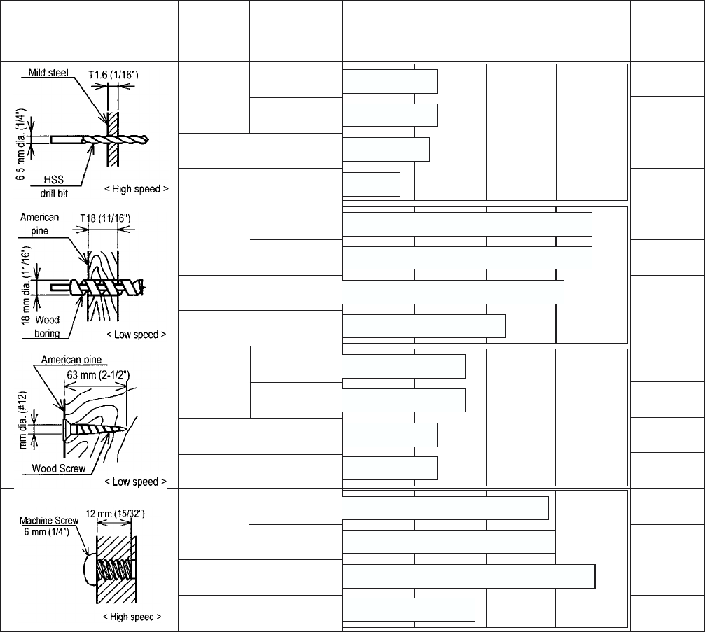
7. WORKING PERFORMANCE PER SINGLE CHARGE
Drilling and fastening performance comparison per charge
7-1. DS 12DVF3
Remarks*: Number of machine screws fastened per charge
Remarks*1: Number of holes or fasteners per charge
The above table shows an example of test data obtained using the battery which is standard for this tool.
As actually measured values listed in the above table may vary depending on the sharpness of the drill bit,
workpiece hardness (particularly in wood materials), moisture content of wood, charging condition, operator skill,
etc. This data should be used as a comparative guide only.
Type of work Maker Model name
Working capacity (*1) Drilling
speed
(sec./pc.)
*0
0
*300
50
*600
100
*900
150
*1200
200
65
60
HITACHI
HITACHI
9.1
40
65
DS 12DVF3
C
B
DS 12DVF2
4.2
9.1
9.7
9.8
4.3
4.8
4.2
DS 12DVF3
C
B
DS 12DVF2
4.8
5.1
6.1
5.0
0.8
0.9
0.9
0.8
175
155
115
175
HITACHI
DS 12DVF3
C
B
DS 12DVF2
85
65
65
85
*875
*1060
*555
*900
HITACHI
DS 12DVF3
C
B
DS 12DVF2
5.8
--- 9 ---
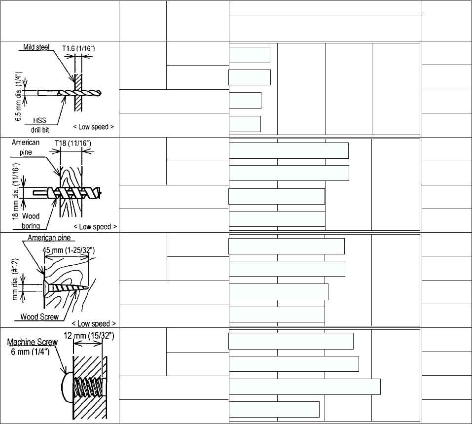
7-2. DS 9DVF3
Remarks*: Number of machine screws fastened per charge
Remarks*1: Number of holes or fasteners per charge
The above table shows an example of test data obtained using the battery which is standard for this tool.
As actually measured values listed in the above table may vary depending on the sharpness of the drill bit,
workpiece hardness (particularly in wood materials), moisture content of wood, charging condition, operator skill,
etc. This data should be used as a comparative guide only.
Type of work Maker Model name
Working capacity (*1) Drilling
speed
(sec./pc.)
*0
0
*300
50
*600
100
*900
150
*1200
200
45
35
HITACHI
HITACHI
26.9
35
45
DS 9DVF3
C
B
DS 9DVF2
5.4
26.9
22.1
23.2
5.8
5.4
5.4
DS 9DVF3
C
B
DS 9DVF2
4.4
4.2
4.3
4.4
1.0
1.0
1.0
1.0
< High speed>
125
100
100
125
HITACHI
DS 9DVF3
C
B
DS 9DVF2
120
105
100
120
*755
*925
*575
*780
HITACHI
DS 9DVF3
C
B
DS 9DVF2
5.8
--- 10 ---
8. PRECAUTIONS IN SALES PROMOTION
8-1. Safety Instructions
In the interest of promoting the safest and most efficient use of the Models DS 12DVF3 and DS 9DVF3 Cordless
Driver Drills by all of our customers, it is very important that at the time of sale, the salesperson carefully ensures
that the buyer seriously recognizes the importance of the contents of the Handling Instructions, and fully
understands the meaning of the precautions listed on the Caution Plate and Name Plate attached to each tool.
A. Handling Instructions
Salespersons must be thoroughly familiar with the contents of the Handling Instructions in order to give pertinent
advice to the customer. In particular, they must have a thorough understanding of the precautions for use of the
cordless tools which are different from those of ordinary electric power tools.
(1) Before use, ensure that the unit is fully charged.
New units are not fully charged. Even if the units were fully charged at the factory, long periods of inactivity,
such as during shipping, cause the storage battery to lose its charge. Customers must be instructed to fully
charge the unit prior to use.
(2) When charging storage batteries, use only the exclusive Model UC 18YG Charger provided with the tool.
Because of the designed rapid-charging feature (about 30 minutes), use of other battery chargers is
hazardous.
(3) Connect the Charger to an AC power outlet only.
Use of any other power source (DC outlet, fuel powered generator, etc.) will cause the Charger to overheat
and burn out.
(4) Do not use any voltage increasing equipment (transformer etc.) between the power source and the Charger.
If the Charger is used with voltage higher than that indicated on the unit, it will not function properly.
(5) Conduct battery charging at an ambient temperature range of 10 ûC --- 40 ûC (50 ûF --- 104 ûF).
Special temperature sensitive devices are employed in the Charger to permit rapid charging. Ensure that
customers are instructed to use the Charger at the indicated ambient temperature range. At temperature
under 10 ûC (50 ûF) the thermostat will not function properly, and the storage battery may be overcharged.
At temperature over 40 ûC (104 ûF), the storage battery cannot be sufficiently charged. The optimum
temperature range is 20 ûC --- 25 ûC (68 ûF --- 77 ûF).
(6) The battery charger should not be used continuously.
At high ambient temperature, if over three storage batteries are charged in succession, the temperature of the
coils on the transformer will rise and there is a chance that the temperature fuse inserted in the interior of the
transformer will inadvertently melt. After charging one battery, please wait about 15 minutes before charging
the next battery.
--- 11 ---
(7) Do not insert foreign objects into the air vents on the Charger
The Charger case is equipped with air vents to protect the internal electronic components from overheating.
Caution the customer not to allow foreign materials, such as metallic or flammable objects, to be dropped or
inserted into the air vents. This could cause electrical shock, fire, or other serious hazards.
(8) Do not attempt to disassemble the Storage Battery or the Charger.
Special devices, such as a thermostat, are built into the storage battery and charger to permit rapid charging.
Incorrect parts replacement and/or wiring will cause malfunctions which could result in fire or other hazards.
Instruct the customer to bring these units to an authorized service center in the event repair or replacement is
necessary.
(9) Disposal of the Storage Batteries (Types EB 1214S and EB 914S)
Ensure that all customers understand that Types EB 1214S and EB 914S Storage Batteries should be
returned to the Hitachi power tool sales outlet or the authorized service center when they are no longer
capable of being recharged or repaired. If thrown into a fire, the batteries may explode, or, if discarded
indiscriminately, leakage of the cadmium compound contained in the battery may cause environmental
pollution.
B. Caution Plate
The following cautions are listed on the Name Plate attached to each of Types EB 1214S and EB 914S Storage
Batteries.
For Europe
--- 12 ---
8-2. Inherent Drawbacks of Cordless Driver Drills Requiring Particular Attention During Sales Promotion
The cordless driver drill offers many advantages; it can be used in places where no power source is available, the
absence of a cord allows easy use, etc. However, any cordless tool has certain inherent drawbacks.
Salespersons must be thoroughly familiar with these drawbacks in order to properly advise the customer in the
most efficient use of the tool.
A. Suggestions and precautions for the efficient use of the tool
(1) Use the Cordless Driver Drill for comparatively light work.
Because they are battery driven, the output of the motor in cordless driver drills is rather low in comparison
with conventional electric power tools. Accordingly, they are not suitable for continuous drilling of many holes
in succession, or for drilling into particularly hard materials which creates a heavy load. Salespersons should
recommend conventional electric power tools for such heavy work.
(2) Drilling of large diameter holes should be conducted at low speed.
Instruct the customer that drilling of large diameter holes or other work which requires particularly strong
torque should be done at low speed. Because there is less torque at high speed, attempting such work at high
speed will not improve working efficiency.
(3) Do not insert a foreign object into body vent holes.
The body of this tool has vent holes for improving the cooling efficiency. As a fan is built into the motor, a
foreign object inserted through a vent hole may cause a failure. Please instruct customers to never insert a
foreign object into the vent hole.
(4) Avoid "Locking" of the motor.
Locking of the motor will cause an overload current that could result in burning of the motor and/or rapid
deterioration of the battery. Salespersons should advise the customer to immediately release the switch and
stop operation if the motor becomes locked. (A jammed drill bit can be disengaged from the workpiece
material by setting the switch to reverse rotation, or by manually turning the main body of the tool.)
(5) Variation in amount of work possible per charge
Although the nominal chargeable capacity of the storage batteries used with the Models DS 12DVF3 and
DS 9DVF3 are 1.4 Ah, the actual capacity may vary within 10% of that value depending on the ambient
temperature during use and charging, and the number of times the batteries have been recharged. It should
be noted that other factors which may have a bearing on the amount of work possible per charge are the
working conditions (ambient temperature, type and moisture content of the workpiece, sharpness of the drill
bit, etc.) and the operational skill of the user.
(6) Precautions in the use of HSS Drill Bits
For example, although the Model DS 12DVF3 is designed for drilling capacities of 25 mm (1") in wood, and
15 mm (19/32") in aluminum, and 12 mm (15/32") in mild steel, this capability is not as efficient as
conventional electric power tools. In particular, when drilling through aluminum material with a 15 mm (19/32")
drill bit, the drill tends to become locked when the drill bit penetrates through the material. For this reason, the
customer should be cautioned to reduce the thrust on the main body of the drill when drilling completely
through the material to avoid locking the tool. Repeated locking of the drill causes excessive current flow from
the batteries which not only decreases the amount of work possible per charge, but could also result in
burning of the motor.
--- 13 ---
B. Suggestions and precautions for the efficient use of the charger and storage batteries
If the Types EB 1214S, EB 1220BL and EB 914S Storage Batteries are exposed to direct sunlight for an extended
period or if the tool has just been operated for a long time, charging may not be possible if the temperature of a
battery is above 40 ûC (104 ûF). In such a case, the customer should be advised to place the battery in a shaded
area with a good airflow, and allows sufficient cooling before recharging. This phenomenon is common to all
existing batteries and chargers which employ temperature sensitive overcharge protection devices. The cooling
time required before recharging can be accomplished varies from a few minutes to about 30 minutes, depending
on the load, duration of use, and ambient temperature.
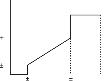
9. REFERENCE MATERIALS
Speed Control Mechanism
Spindle rotation speed of the Models DS 12DVF3 and DS 9DVF3 can be controlled by simply varying the amount
by which the trigger switch is depressed. The relationship between the amount the trigger switch is depressed (in
millimeters) and the rotation speed is illustrated in Fig. 4.
NOTE: The gradient and values illustrated in Fig. 4 are intended for reference only, and will vary slightly
due to differences in the discharge condition of the battery, the ambient temperature, and
individual speed-control element accuracy.
100
Rotation speed
60 5
(%)
12 8
02.2 0.5 6.5 0.5 8+0.5
0
Amount trigger switch is depressed (mm)
Fig. 4

--- 14 ---
10. REPAIR GUIDE
Be sure to remove the storage batteries from the main body before servicing. Inadvertent triggering of the switch
with the storage battery connected will result in the danger of accidental turning of the motor.
10-1. Precautions in Disassembly and Reassembly
The [Bold] numbers in the description below correspond to the item numbers in the Parts List and exploded
assembly diagram.
10-1-1. Disassembly
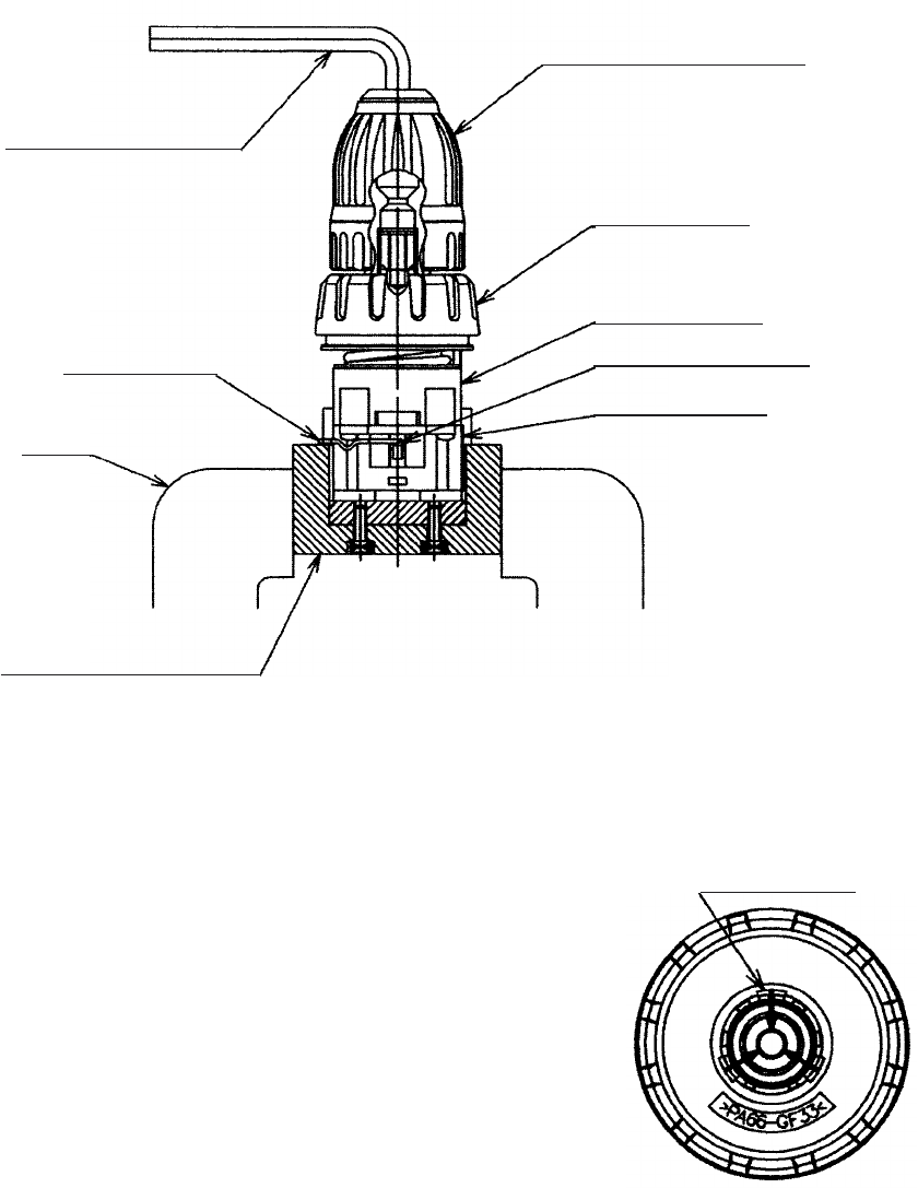
(1) Removal of the Hook Ass'y [39]
Remove the Special Screw M5 [44] with a flat-blade screwdriver or a coin. Remove the Hook Ass'y [39] and
the Hook Spring [43].
(2) Removal of Housing (A). (B) Set [30]
First, align the drill mark " " at the Clutch Dial [4] with the triangle mark at Housing (A). (B) Set [30].
Remove the eight Tapping Screws (W/Flange) D3 x 16 (Black) [26] secured to the main body. Gently open
housing (A) and housing (B) while holding their battery loading sections.
(3) After housing (B) has been removed, all the internal parts, assembled or separate, can be taken out as they
are. Lift the entire contents from housing (A) while holding the Motor [25] and the Clutch Dial [4].
(4) Removal of the Drill Chuck 10TLRK-N (W/O Chuck Wrench) [2] (See Fig. 5.)
(a) Turn the Motor [25] counterclockwise (when viewed from the rear) and remove it from the Rear Case [14].
Remove the Shift Knob [36] from the Shift Arm [16]. Take care not to remove the Shift Arm [16] from the
Rear Case [14] in this operation.
(b) Attach the motor spacer (an accessory of the special repair tool J-292, Code No. 316-379) to the assembly
of the Drill Chuck 10TLRK-N (W/O Chuck Wrench) [2], Clutch Dial [4], Front Case [9] and Rear Case [14]
then mount it in special repair tool J-292 clamped in the vise as illustrated in Fig. 5. In this operation, check
that the pinion press-fitted in the special repair tool J-292 and Planet Gear (A) Set [21] are engaged
properly.
(c) Secure the Slide Ring Gear [17] to the Front Case [9] side with the Shift Arm [16].
(d) Turn the sleeve of the Drill Chuck 10TLRK-N (W/O Chuck Wrench) [2] counterclockwise (when viewed
from the front) to fully open the jaws of the Drill Chuck 10TLRK-N (W/O Chuck Wrench) [2]. Turn the
Special Screw (Left Hand) M5 x 27 [1] clockwise and remove it. (Note that the special screw is left-hand
threaded.)
(e) Fit the hexagonal bar wrench M10 into the Drill Chuck 10TLRK-N (W/O Chuck Wrench) [2] as illustrated in
Fig. 5 and remove the Drill Chuck 10TLRK-N (W/O Chuck Wrench) [2] by turning the hexagonal bar
wrench counterclockwise.
--- 15 ---
(5) Disassembly of the gear unit
Remove the Shift Arm [16] from the Rear Case [14], then remove the
Screw Set D3 x 12 (4 pcs.) [15] connecting the Front Case [9] and the
Rear Case [14]. Remove Washer (A) [13], Planet Gear (C) Set
(3 pcs.) [12], Ring Gear [11] and six Steel Balls D5 [10] from the Front
Case [9] in order. Take care not to lose the six Steel Balls D5 [10] in
this operation.
(6) Disassembly of the clutch unit
(a) After press up the hook of Front Case [9] with the small flat-blade
screwdriver, the Clutch Dial [4] and Click Spring [5] can be taken out
as they are. (See Fig. 6.)
(b) Turn the Nut [6] counterclockwise and remove it from the Front
Case [9], then remove the Spring [7] and Washer (D) [8] from the
Front Case [9].
NOTE: Do not remove the Front Case [9].
Fig. 5
Hexagonal bar wrench
Shift Arm [16]
Special repair tool (J-292)
Vise
Clutch Dial [4]
Drill Chuck 10TLRK-N
(W/O Chuck Wrench) [2]
Front Case [9]
Slide Ring Gear [17]
Rear Case [14]
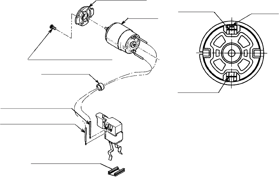
(7) Disassembly of the power supply unit
NOTE: Do not remove the heat sink secured to the DC-Speed Control Switch [33] with a screw.
Remove the two Machine Screws M3 x 8 [28], and take the Motor [25] and the Motor Spacer [24] apart.
Disconnect Internal Wires (B) [31] [32] from the Motor [25] with a soldering iron, then disconnect them from
the DC-Speed Control Switch [33] with a soldering iron in the same manner.
Fig. 6
Hook (3 pcs.)
--- 16 ---
10-1-2. Reassembly
Reassembly can generally be carried out as the reverse of the disassembly procedure, with some items to be
noted as follows.
(1) Reassembly of the power supply unit
(a) Perform wiring according to the wiring diagram (Fig. 7).
Fig. 7
(b) Pay attention to the polarity of the Motor [25] when soldering Internal Wires (B) [31] [32] to the Motor [25].
The red-marked side of the Motor [25] is positive. (See Fig. 8.)
(c) Apply grease (Hitachi Motor Grease No. 29, Code No. 930035 is recommended) to the pinion press-fitted
on the Motor [25] shaft.
(2) Reassembly of the clutch unit
(a) Mount Washer (D) [8] and the Spring [7] to the Front Case [9]. (See Fig. 9.)
When mounting Washer (D) [8] into the Front Case [9], align the projection on the Front Case [9] with the
notch of Washer (D) [8].
Fig. 8
Motor Spacer [24]
Motor [25]
Machine Screw M3 x 8 [28]
Internal Wire (B) (Red) [32]
Internal Wire (B) (Black) [31]
Ferrite Core [35]
Terminal Support (A) [42]
Positive side Red mark
Negative side
--- 17 ---
Fig. 9
[4]
[5]
[6]
[9]
[7]
[8]
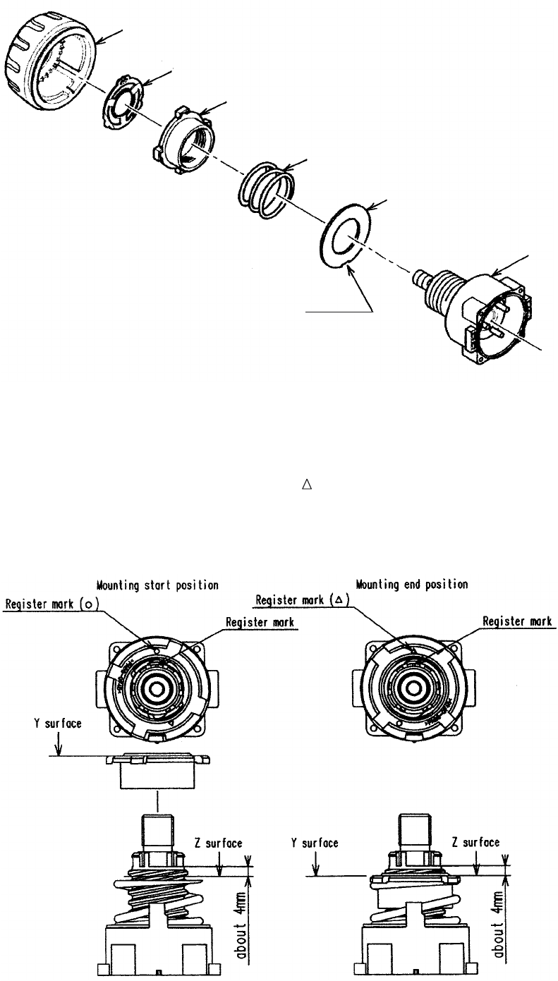
(b) Mount the Nut [6] to the Front Case [9]. (See Fig. 10.)
Align the register mark (o) on the Nut [6] with the register mark on the Front Case [9]. Turn the Nut [6]
about 1-1/2 turns clockwise so that the register mark ( ) on the Nut [6] is aligned with the register mark on
the Front Case [9]. Check that the Y surface of the Nut [6] is aligned with the Z surface of the Front Case
[9].
Fig. 10
Notch
--- 18 ---
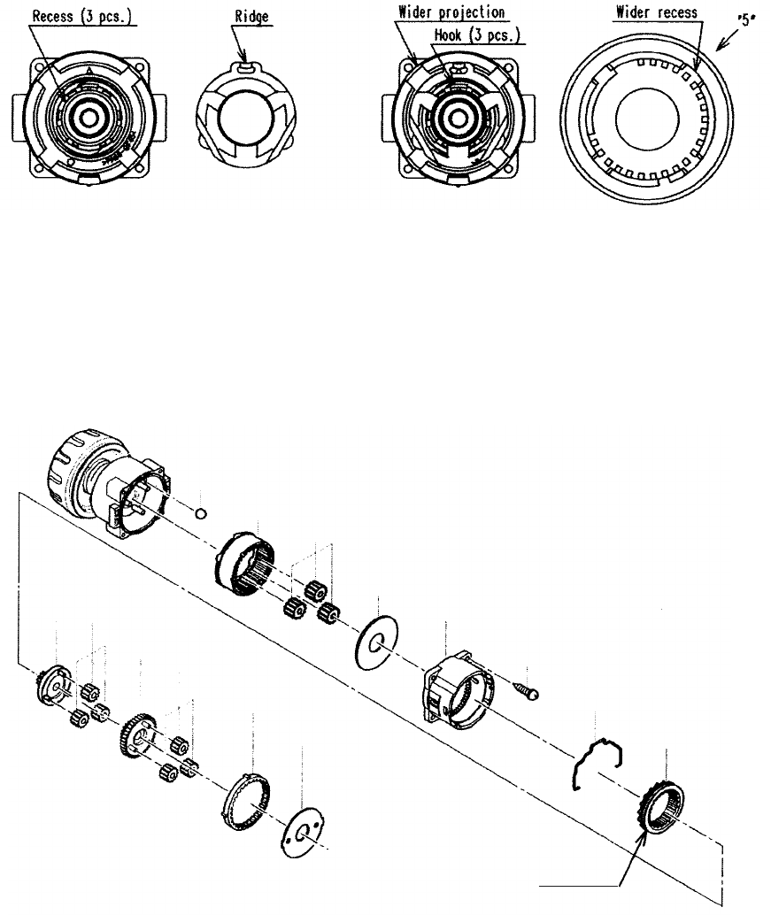
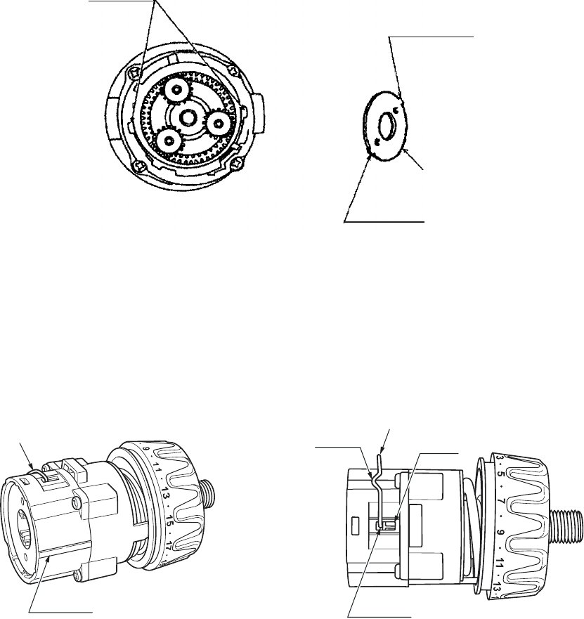
(c) With the ridge at the Click Spring [5] facing the front-side, insert Click Spring [5] into the recess of the Front
Case [9]. (See Fig. 11.)
(d) Insert the Clutch Dial [4] to the Front Case [9]. (See Fig. 12.)
Mount the Nut [6] into the Clutch Dial [4] engaging the wider projection of the Nut [6] with the wider recess
of the Clutch Dial [4]. (The wider recess of the Clutch Dial [4] is positioned at "5" when viewed from the
outside.) Make sure that the hook of Front Case [9] is fitted into the hole in the Clutch Dial [4].
(3) Reassembly of the gear unit
(a) Apply grease (Hitachi Motor Grease No. 29, Code No. 930035) to the meshing parts of the gear.
(b) Install the parts series from the six Steel Balls D5 [10] to Washer (B) [23] into the assembly reassembled in
step (2). (See Fig. 13.)
Fig. 13
[17]
[20]
[19]
[18] [14]
[13]
[12]
[11]
[10]
[23]
[21]
[22] [16]
[15]
Groove
Fig. 11 Fig. 12
--- 19 ---
(i) Note the direction of the groove when installing the Slide Ring Gear [17] so that the groove faces
toward the Motor [25].
(ii) Install the Front Case [9] and the Rear Case [14] together with the mark on the Front Case [9] aligned
with the mark on the Rear Case [14]. (See Fig. 15.)
(iii) Install Washer (B) [23] in the Rear Case [14] with the projections of Washer (B) [23] engaged with the
recesses in the Rear Case [14], and turn Washer (B) [23] clockwise until it can turn no further. (See
Fig. 14.)
Fig. 14
Recess
Projection
Projection
[23]
Fig. 15
(c) Install the Shift Arm [16] into the assembly reassembled in step (b).
With the ridge at the Shift Arm [16] facing the Motor [25] side, first install them on the unmarked side of the
assembly reassembled in step (b). Then insert the projections on the Shift Arm [16] into the holes in the
Rear Case [14] and make sure that the projections are fitted into the grooves in the Slide Ring Gear [17]
mounted within the Rear Case [14]. (See Fig. 15.)
(d) Install the Drill Chuck 10TLRK-N (W/O Chuck Wrench) [2].
Install the Drill Chuck 10TLRK-N (W/O Chuck Wrench) [2] using the special repair tool (J-292, Code No.
316-379) and secure it with the Special Screw (Left Hand) M5 x 27 [1].
(e) Install the Shift Knob [36] into the assembly reassembled in step (d).
When installing the Shift Knob [36] into the Shift Arm [16], note that the "LOW" mark on the Shift Knob [36]
faces the Motor [25] with the Shift Arm [16] engaged with the recess in the Shift Knob [36].
Hole
Ridge
[16] [16]
Groove
Mark
--- 20 ---
(f) Install the assembly reassembled in step (1) and the assembly
reassembled in step (e) together. (See Fig. 16.)
Fit the projection on the Motor Spacer [24] into the recess in
the Rear Case [14] while ensuring that the Shift Knob [36] is
aligned with the positive side of the Motor [25] and turn the
Motor Spacer [24] clockwise when viewed from the rear of the
Motor [25] until it can turn no further. During installation, make
sure that the pinion press-fitted onto the shaft of the Motor [25]
and Planet Gear (A) Set [21] mesh properly.
Fig. 16
Projection
Recess
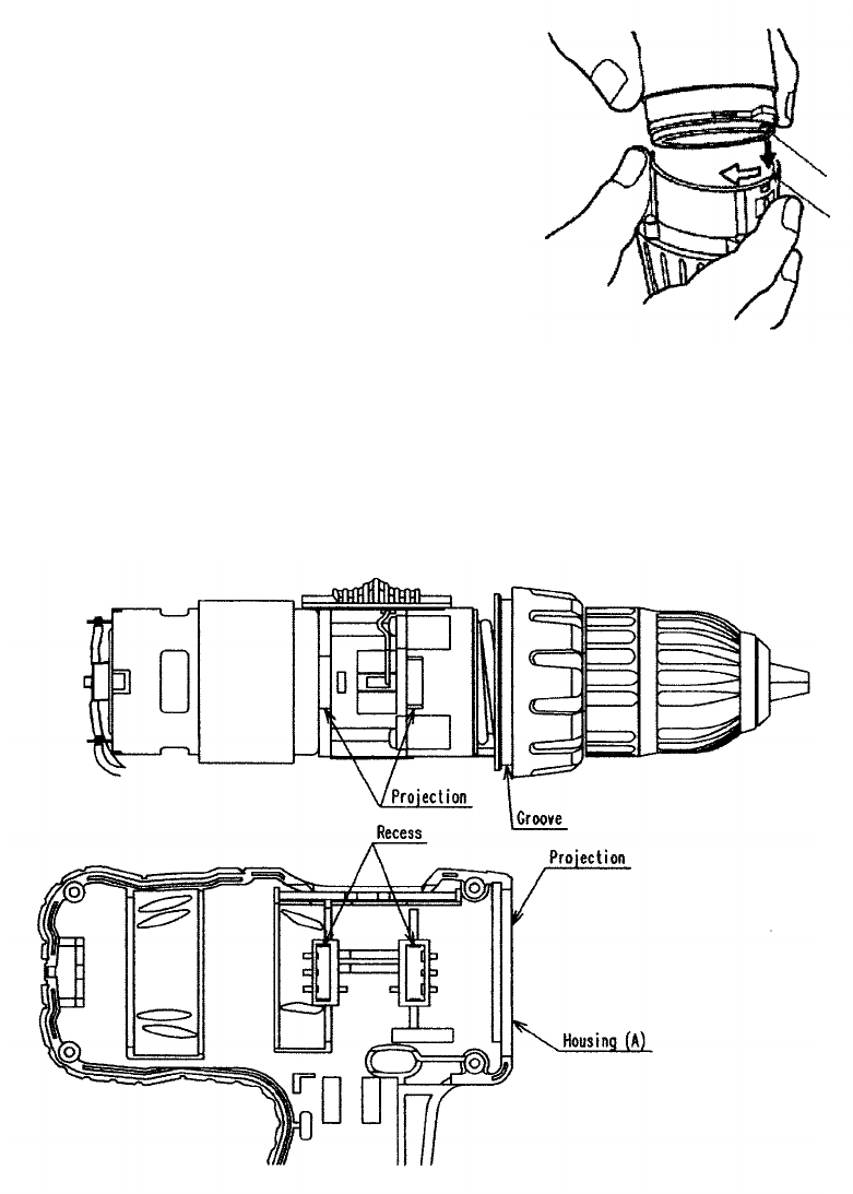
(4) Installation of the assembly reassembled in step (3) into Housing (A). (B) Set [30]
(a) Install the assembly reassembled in step (3) into housing (A). Note that the projections on the Front Case
[9] and the Motor Spacer [24] are engaged in the recesses in housing (A), and the projection on housing
(A) is engaged in the groove of the Clutch Dial [4]. (See Fig. 17.)
(b) Mount the Pushing Button [34] to housing (A). Check that the protrusion of the forward/reverse
changeover lever of the DC-Speed Control Switch [33] is inserted into the groove of the Pushing Button
[34].
(c) Mount the Strap [41] to Housing (A) [30].
Fig. 17

--- 21 ---
(6) Other precautions in reassembling
After completion of reassembly, check that the rotating direction of the Drill Chuck 10TLRK-N (W/O Chuck
Wrench) [2] matches the position of the Pushing Button [34]. When the Pushing Button [34] is pressed from
the (R) side, the rotating direction of the Drill Chuck 10TLRK-N (W/O Chuck Wrench) [2] should be clockwise
as viewed from behind. Switch on and off the Models DS 12DVF3 and DS 9DVF3 using the battery. Check
that the runout of the Drill Chuck 10TLRK-N (W/O Chuck Wrench) [2] is 0.8 mm or less at the position 85 mm
away from the tip of the chuck using a 9-mm dia. test bar.
(7) Screw tightening torque
Special Screw (Left Hand) M5 x 27 [1] : 2.9 --- 3.9 N•m ( 30 --- 40 kgf•cm)
Drill Chuck 10TLRK-N (W/O Chuck Wrench)
[2] : 12.7 --- 16.7 N•m (130 --- 170 kgf•cm)
Screw Set D3 x 12 [15] : 0.6 --- 1.0 N•m ( 6 --- 10 kgf•cm)
Machine Screw M3 x 8 [28] : 1.1 --- 1.9 N•m ( 11 --- 19 kgf•cm)
Tapping Screw (W/Flange) D3 x 16 [26] : 1.1 --- 1.9 N•m ( 11 --- 19 kgf•cm)
Special Screw M5 [44] : 1.5 --- 2.5 N•m ( 15 --- 25 kgf•cm)
10-2. Precautions in Disassembly and Reassembly of Battery Charger
Please refer to the Technical Data and Service Manual for precautions in disassembly and reassembly of the
Battery Charger UC 18YG.
(d) Set the assembly reassembled in step (C) to housing (B) and secure it with the eight Tapping Screws (W/
Flange) D3 x 16 (Black) [26].
(e) Verify proper operation of the Clutch Dial [4] and the Shift Knob [36].
When the reassembly procedure up to step (d) is completed, ensure that the number "1" through the drill
mark " " on the Clutch Dial [4] are in alignment with the triangle mark on Housing (A). (B) Set [30]
respectively and the Clutch Dial [4] turns moderately. If the number "1" or the drill mark " " on the
Clutch Dial [4] cannot reach the triangle mark on Housing (A). (B) Set [30], correctly reinstall the Clutch
Dial [4] referring to step (2) as it is improperly mounted. Verify proper operation of the Shift Knob [36].
Check that the speed changes between high and low properly by shifting the Shift Knob [36]. If the speed
cannot change properly or moderately, correctly reinstall the Shift Knob [36] referring to step (3) as it is
improperly mounted.
(5) Reassembly of the Hook Ass'y [39]
Check that the V-Lock Nut M5 [40] is mounted to the Hook Ass'y [39]. Mount the Hook Spring [43] and secure
it with the Special Screw M5 [44] . Make sure to mount the Hook Spring [43] with its larger diameter side
pointing inward the housing.
--- 22 ---
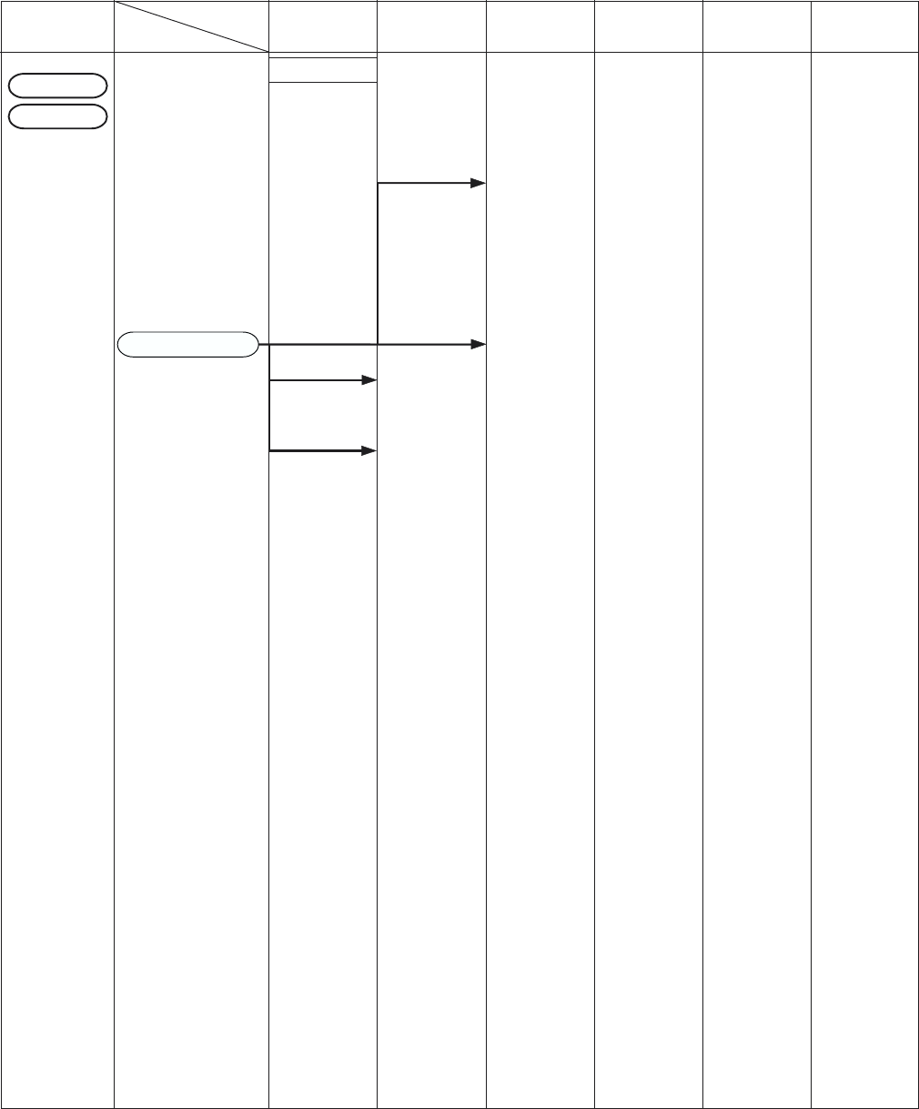
11. STANDARD REPAIR TIME (UNIT) SCHEDULES
MODEL 10 20 30 40
Fixed
Variable
Work Flow
60
50
Housing
(A).(B) Set
Motor
DC-Speed
Control Switch
Shift Knob
Gear Box Ass'y
Clutch Dial
Click Spring
Nut
Spring
Front Case
Ring Gear
Planet Gear
(C) Set
Rear Case
Shift Arm
Slide Ring Gear
Pinion (C)
Planet Gear
(B) Set
Pinion (B)
Planet Gear
(A) Set
First Ring Gear
Drill Chuck
(Keyless)
General Assembly
DS
9
DVF3
DS 12DVF3
Hook Ass'y
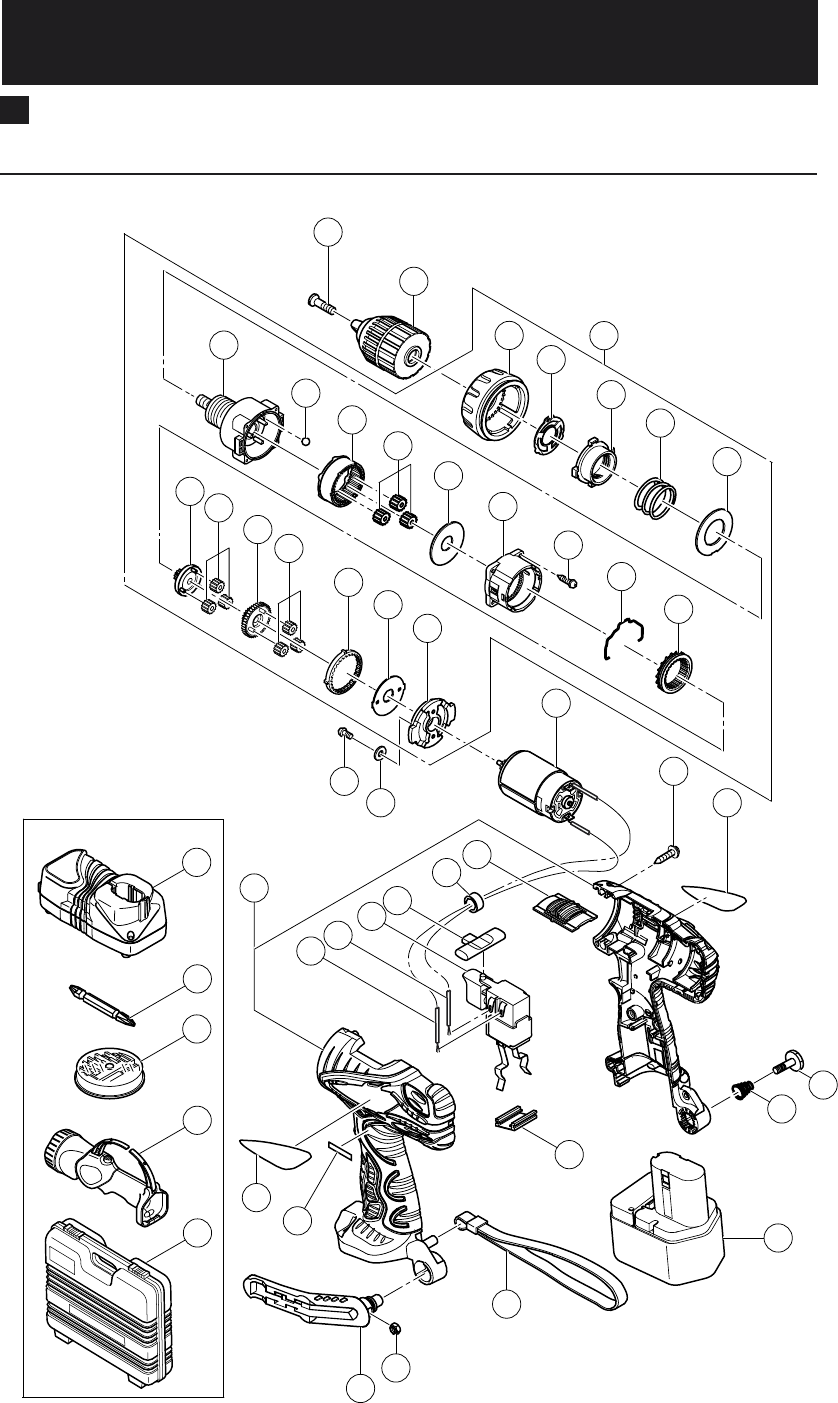
ELECTRIC TOOL PARTS LIST
LIST NO. G818
CORDLESS DRIVER DRILL
Model DS 12DVF3
2005
•
3
•
30
(E1)
Hitachi Power Tools
501
502
505
503
504
38
1
2
3
4
5
6
7
8
9
10
11
12
13
14
15
16
17
18
19
20
21
22
23
24
25
26
27
28
29
30
31
32
33
34
35
36
37
39
40
41
42
43
44
45

* ALTERNATIVE PARTS--- 2 ---
ITEM
NO. CODE NO. DESCRIPTION REMARKS
NO.
USED
PARTS
3 -- 05
DS 12DVF3
1318-228 SPECIAL SCREW (LEFT HAND) M5X27 1
2323-250
DRILL CHUCK 10TLRK-N (W/O CHUCK WRENCH)
1
3324-106 GEAR BOX ASS’Y 1 INCLUD. 4-24
4324-114 CLUTCH DIAL 1
5324-108 CLICK SPRING 1
6324-109 NUT 1
7324-110 SPRING 1
8324-347 WASHER (D) 1
9324-107 FRONT CASE 1
10 306-936 STEEL BALL D5 6
11 324-111 RING GEAR 1
12 324-348 PLANET GEAR (C) SET (3 PCS.) 3
13 324-349 WASHER (A) 1
14 324-350 REAR CASE 1
15 324-357 SCREW SET D3X12 (4 PCS.) 4
16 324-115 SHIFT ARM 1
17 324-351 SLIDE RING GEAR 1
18 324-112 PINION (C) 1
19 324-352 PLANET GEAR (B) SET (3 PCS.) 3
20 324-113 PINION (B) 1
21 324-354 PLANET GEAR (A) SET (3 PCS.) 3
22 324-353 FIRST RING GEAR 1
23 324-355 WASHER (B) 1
24 324-356 MOTOR SPACER 1
25 318-244 MOTOR 1
26 313-687 TAPPING SCREW (W/FLANGE) D3X16 (BLACK) 8
27 NAME PLATE 1
28 949-203 MACHINE SCREW M3X8 (10 PCS.) 2
29 949-451 SPRING WASHER M3 (10 PCS.) 2
30 324-363 HOUSING (A). (B) SET 1
31 324-121 INTERNAL WIRE (B) 90L (BLACK) 1
32 324-120 INTERNAL WIRE (B) 140L (RED) 1
33 324-119 DC-SPEED CONTROL SWITCH 1
34 324-117 PUSHING BUTTON 1
*35 323-229 FERRITE CORE 1 FOR EUROPE
36 324-116 SHIFT KNOB 1
37 HITACHI LABEL 1
*38 LABEL (CHINA) 2 FOR TPE
39 320-287 HOOK ASS’Y 1 INCLUD. 40
40 320-288 V-LOCK NUT M5 1
41 306-952 STRAP (BLACK) 1
42 315-141 TERMINAL SUPPORT (A) 1
43 319-926 HOOK SPRING 1
44 319-927 SPECIAL SCREW M5 1
*45 320-387 BATTERY EB 1220BL (W/ENGLISH N.P.) 2
*45 322-629 BATTERY EB 1214S (W/ENGLISH N.P.) 2
*45 324-360 BATTERY EB 1214S (W/ENGLISH N.P.) 2 FOR USA, CAN
*45 324-361 BATTERY EB 1214S (W/ENGLISH N.P.) 2 FOR TPE
*45 324-362 BATTERY EB 1214S (W/ENGLISH N.P.) 2 FOR KOR

* ALTERNATIVE PARTS --- 3 ---
ITEM
NO. CODE NO. DESCRIPTION REMARKS
NO.
USED
STANDARD ACCESSORIES
3 -- 05
DS 12DVF3
501 CHARGER (MODEL UC 18YG) 1
502 983-006 + DRIVER BIT NO. 2 65L 1
503 BIT SET 1
*504 TORCHLIGHT (MODEL UB 12D) 1 EXCEPT FOR GBR
505 324-083 CASE (BLACK) 1

--- 4 ---
ITEM
NO. CODE NO. DESCRIPTION REMARKS
NO.
USED
3 -- 05
DS 12DVF3
Printed in Japan
(050330N)
ELECTRIC TOOL PARTS LIST
LIST NO. G817
CORDLESS DRIVER DRILL
Model DS 9DVF3
2005
•
3
•
30
(E1)
Hitachi Power Tools
501
502
505
503
504
1
2
3
4
5
6
7
8
9
10
11
12
13
14
15
16
17
18
19
20
21
22
23
24
25
26
27
28
29
30
31
32
33
34
35
36
37
39
40
41
42
43
44
45
38

* ALTERNATIVE PARTS--- 2 ---
ITEM
NO. CODE NO. DESCRIPTION REMARKS
NO.
USED
PARTS
3 -- 05
DS 9DVF3
1318-228 SPECIAL SCREW (LEFT HAND) M5X27 1
2323-250
DRILL CHUCK 10TLRK-N (W/O CHUCK WRENCH)
1
3324-106 GEAR BOX ASS’Y 1 INCLUD. 4-24
4324-114 CLUTCH DIAL 1
5324-108 CLICK SPRING 1
6324-109 NUT 1
7324-110 SPRING 1
8324-347 WASHER (D) 1
9324-107 FRONT CASE 1
10 306-936 STEEL BALL D5 6
11 324-111 RING GEAR 1
12 324-348 PLANET GEAR (C) SET (3 PCS.) 3
13 324-349 WASHER (A) 1
14 324-350 REAR CASE 1
15 324-357 SCREW SET D3X12 (4 PCS.) 4
16 324-115 SHIFT ARM 1
17 324-351 SLIDE RING GEAR 1
18 324-112 PINION (C) 1
19 324-352 PLANET GEAR (B) SET (3 PCS.) 3
20 324-113 PINION (B) 1
21 324-354 PLANET GEAR (A) SET (3 PCS.) 3
22 324-353 FIRST RING GEAR 1
23 324-355 WASHER (B) 1
24 324-356 MOTOR SPACER 1
25 318-244 MOTOR 1
26 313-687 TAPPING SCREW (W/FLANGE) D3X16 (BLACK) 8
27 NAME PLATE 1
28 949-203 MACHINE SCREW M3X8 (10 PCS.) 2
29 949-451 SPRING WASHER M3 (10 PCS.) 2
30 324-363 HOUSING (A). (B) SET 1
31 324-121 INTERNAL WIRE (B) 90L (BLACK) 1
32 324-120 INTERNAL WIRE (B) 140L (RED) 1
33 324-119 DC-SPEED CONTROL SWITCH 1
34 324-117 PUSHING BUTTON 1
*35 323-229 FERRITE CORE 1 EXCEPT FOR SAF, TPE, KOR
36 324-116 SHIFT KNOB 1
37 HITACHI LABEL 1
38 LABEL (CHINA) 1 FOR TPE
39 320-287 HOOK ASS’Y 1 INCLUD. 40
40 320-288 V-LOCK NUT M5 1
41 306-952 STRAP (BLACK) 1
42 315-141 TERMINAL SUPPORT (A) 1
43 319-926 HOOK SPRING 1
44 319-927 SPECIAL SCREW M5 1
*45 324-079 BATTERY EB 914S (W/ENGLISH N.P.) 2
*45 324-078 BATTERY EB 914S (W/ENGLISH N.P.) 2 FOR SAF, KOR
*45 324-080 BATTERY EB 914S (W/ENGLISH N.P.) 2 FOR TPE

* ALTERNATIVE PARTS --- 3 ---
ITEM
NO. CODE NO. DESCRIPTION REMARKS
NO.
USED
STANDARD ACCESSORIES
3 -- 05
DS 9DVF3
501 CHARGER (MODEL UC 18YG) 1
502 983-006 + DRIVER BIT NO. 2 65L 1
*503 BIT SET 1 EXCEPT FOR SAF
*504 TORCHLIGHT (MODEL UB 12D) 1 EXCEPT FOR SAF
505 324-083 CASE (BLACK) 1

--- 4 ---
ITEM
NO. CODE NO. DESCRIPTION REMARKS
NO.
USED
3 -- 05
DS 9DVF3
Printed in Japan
(050330N)