Administration Guide For Cisco Unified MeetingPlace Video Integration Release 5.4 Meeting Place 54mpviagx
User Manual: MeetingPlace Video Integration
Open the PDF directly: View PDF ![]() .
.
Page Count: 170 [warning: Documents this large are best viewed by clicking the View PDF Link!]
- Administration Guide for Cisco Unified MeetingPlace Video Integration
- Contents
- Preface
- Introducing Cisco Unified MeetingPlace Video Integration and Video Administration
- Cisco Unified MeetingPlace Video Integration Components and Process
- Overview of Components
- Supported Cisco Unified MeetingPlace System Configurations
- About the Cisco Unified MeetingPlace Video Conferencing Process
- How Video Conferences Are Scheduled
- How Video Conferences Start
- How the Link Between the Cisco Unified Videoconferencing MCU and the Cisco Unified MeetingPlace Audio Server Is Established
- How Video Conferences Run
- About Displaying the Status and Options of Video Participants in the Meeting Room
- How Cisco Unified MeetingPlace Video Integration Tracks Port Availability
- How Video Conferences End
- Installing Video Administration for Cisco Unified MeetingPlace
- Configuring Video Administration for Cisco Unified MeetingPlace
- Installing Cisco Unified MeetingPlace Video Integration
- Before You Install
- Verifying That Component Systems Are Up and Running
- Verifying Your Video-Conferencing License
- About Configuring the Cisco Unified Videoconferencing MCU to Use Cisco Unified MeetingPlace
- Verifying that Video Endpoints Can Connect to the Cisco Unified Videoconferencing MCU
- Setting Cisco Unified Videoconferencing MCU Parameters That Are Required to Support Cisco Unified MeetingPlace
- Creating Cisco Unified Videoconferencing MCU Services for Cisco Unified MeetingPlace
- Configuring NTP on Cisco Unified Videoconferencing MCUs
- Configuring the Cisco IOS H.323 Gatekeeper
- Configuring Video Administration for Cisco Unified MeetingPlace
- Configuring the Cisco Unified MeetingPlace Web Conferencing Server
- Configuring the Cisco Unified MeetingPlace Audio Server
- Configuring Cisco Unified MeetingPlace H.323/SIP Gateway
- Configuring Load-Balancing Configurations for Video Conferencing
- About Installing and Configuring Video Endpoints
- (Optional) Configuring Cisco Unified MeetingPlace for Outlook
- (Optional) Configuring Cisco Unified MeetingPlace for Lotus Notes
- Configuring Cisco Unified CallManager
- Preparing to Install the Video Integration with DMZ Configurations
- Gathering Installation Values
- Installing Cisco Unified MeetingPlace Video Integration
- Upgrading Cisco Unified MeetingPlace Video Integration to Release 5.4
- Uninstalling Cisco Unified MeetingPlace Video Integration
- Before You Install
- Configuring and Managing Cisco Unified MeetingPlace Video Integration
- About the Cisco Unified MeetingPlace MeetingTime Software Application
- About Video-Conferencing Access Information
- About Changing System Configuration Settings
- About Managing Video-Conferencing Resources
- About Managing User Profiles for Video Use
- About Video Terminal Profiles
- About Video-Conferencing Statistics
- Securing the Communications Between Video Administration and Video Integration
- Using Cisco Unified MeetingPlace Video Conferencing
- Supported Meeting Types
- About Setting Up End Users for Video Conferencing in Cisco Unified MeetingPlace
- About Scheduling Video Conferences
- About Attending Cisco Unified MeetingPlace Video Conferences
- How Users Join a Cisco Unified MeetingPlace Video Conference
- Attending Video Conferences by Outdialing from Web Conferencing
- Attending Video Conferences Via Cisco Unified MeetingPlace for Outlook
- Attending Video Conferences Via SMTP E-Mail Clients
- Attending Video Conferences Via Cisco Unified Video Advantage Video Endpoints
- Attending Video Conferences By Dialing In
- Attending Video-Only Conferences
- Attending Ad-Hoc Video Conferences
- Attending Password-Protected Meetings
- Attending Invitation-Only or Profiled-User-Only Meetings
- How Users Join a Cisco Unified MeetingPlace Video Conference
- Video Features and Functions in the Meeting Room During the Conference
- Information for End Users
- Using the Video Administration All Meetings Section
- Video Administration Configuration Tool
- Managing Video Administration for Cisco Unified MeetingPlace
- Video Administration Backup and Restore Procedures
- Troubleshooting
- Viewing the Eventlog
- General Troubleshooting Guidelines
- Problems Configuring and Initiating Cisco Unified MeetingPlace Video Integration
- Problems Scheduling a Video Conference
- Problems Joining a Video Conference
- Problems During a Video Conference
- Problems with the Video Administration for Cisco Unified MeetingPlace server
- Index


THE SPECIFICATIONS AND INFORMATION REGARDING THE PRODUCTS IN THIS MANUAL ARE SUBJECT TO CHANGE WITHOUT NOTICE. ALL
STATEMENTS, INFORMATION, AND RECOMMENDATIONS IN THIS MANUAL ARE BELIEVED TO BE ACCURATE BUT ARE PRESENTED WITHOUT
WARRANTY OF ANY KIND, EXPRESS OR IMPLIED. USERS MUST TAKE FULL RESPONSIBILITY FOR THEIR APPLICATION OF ANY PRODUCTS.
THE SOFTWARE LICENSE AND LIMITED WARRANTY FOR THE ACCOMPANYING PRODUCT ARE SET FORTH IN THE INFORMATION PACKET THAT
SHIPPED WITH THE PRODUCT AND ARE INCORPORATED HEREIN BY THIS REFERENCE. IF YOU ARE UNABLE TO LOCATE THE SOFTWARE LICENSE
OR LIMITED WARRANTY, CONTACT YOUR CISCO REPRESENTATIVE FOR A COPY.
The Cisco implementation of TCP header compression is an adaptation of a program developed by the University of California, Berkeley (UCB) as part of UCB’s public
domain version of the UNIX operating system. All rights reserved. Copyright © 1981, Regents of the University of California.
NOTWITHSTANDING ANY OTHER WARRANTY HEREIN, ALL DOCUMENT FILES AND SOFTWARE OF THESE SUPPLIERS ARE PROVIDED “AS IS” WITH
ALL FAULTS. CISCO AND THE ABOVE-NAMED SUPPLIERS DISCLAIM ALL WARRANTIES, EXPRESSED OR IMPLIED, INCLUDING, WITHOUT
LIMITATION, THOSE OF MERCHANTABILITY, FITNESS FOR A PARTICULAR PURPOSE AND NONINFRINGEMENT OR ARISING FROM A COURSE OF
DEALING, USAGE, OR TRADE PRACTICE.
IN NO EVENT SHALL CISCO OR ITS SUPPLIERS BE LIABLE FOR ANY INDIRECT, SPECIAL, CONSEQUENTIAL, OR INCIDENTAL DAMAGES, INCLUDING,
WITHOUT LIMITATION, LOST PROFITS OR LOSS OR DAMAGE TO DATA ARISING OUT OF THE USE OR INABILITY TO USE THIS MANUAL, EVEN IF CISCO
OR ITS SUPPLIERS HAVE BEEN ADVISED OF THE POSSIBILITY OF SUCH DAMAGES.
Any Internet Protocol (IP) addresses used in this document are not intended to be actual addresses. Any examples, command display output, and figures included in the
document are shown for illustrative purposes only. Any use of actual IP addresses in illustrative content is unintentional and coincidental.
Administration Guide for Cisco Unified MeetingPlace Video Integration Release 5.4
© 2007 Cisco Systems, Inc. All rights reserved.
CCVP, the Cisco logo, and the Cisco Square Bridge logo are trademarks of Cisco Systems, Inc.; Changing the Way We Work, Live, Play, and Learn is a service mark of Cisco Systems,
Inc.; and Access Registrar, Aironet, BPX, Catalyst, CCDA, CCDP, CCIE, CCIP, CCNA, CCNP, CCSP, Cisco, the Cisco Certified Internetwork Expert logo, Cisco IOS, Cisco
Press,
Cisco Systems, Cisco Systems Capital, the Cisco Systems logo, Cisco Unity, Enterprise/Solver, EtherChannel, EtherFast, EtherSwitch, Fast Step, Follow Me Browsing,
FormShare, GigaDrive, HomeLink, Internet Quotient, IOS, iPhone, IP/TV, iQ Expertise, the iQ logo, iQ Net Readiness Scorecard, iQuick Study, LightStream, Linksys,
MeetingPlace, MGX, Networking Academy, Network Registrar, Pack e t, PIX, ProConnect, ScriptShare, SMARTnet, StackWise, The Fastest Way to Increase Your Internet
Quotient, and TransPath are registered trademarks of Cisco Systems, Inc. and/or its affiliates in the United States and certain other countries.
All other trademarks mentioned in this document or Website are the property of their respective owners. The use of the word partner does not imply a partnership relationship
between Cisco and any other company. (0705R)

iii
Administration Guide for Cisco Unified MeetingPlace Video Integration Release 5.4
OL-11153-02
CONTENTS
Preface ix
Audience ix
Scope ix
Naming Conventions Used in This Guide x
Documentation Conventions x
Cisco Unified MeetingPlace Documentation xi
Obtaining Documentation, Obtaining Support, and Security Guidelines xi
CHAPTER
1Introducing Cisco Unified MeetingPlace Video Integration and Video Administration 1-1
Overview of Cisco Unified MeetingPlace Video Integration 1-1
Features and Benefits of Cisco Unified MeetingPlace Video Integration 1-2
CHAPTER
2Cisco Unified MeetingPlace Video Integration Components and Process 2-1
Overview of Components 2-1
Supported Cisco Unified MeetingPlace System Configurations 2-4
About the Cisco Unified MeetingPlace Video Conferencing Process 2-5
How Video Conferences Are Scheduled 2-6
How Video Conferences Start 2-6
How the Link Between the Cisco Unified Videoconferencing MCU and the Cisco Unified MeetingPlace
Audio Server Is Established 2-7
How Video Conferences Run 2-9
About Displaying the Status and Options of Video Participants in the Meeting Room 2-9
How Cisco Unified MeetingPlace Video Integration Tracks Port Availability 2-9
How Video Conferences End 2-10
CHAPTER
3Installing Video Administration for Cisco Unified MeetingPlace 3-1
Video Administration Installation Overview 3-1
Before Installing Video Administration 3-1
Supported Databases 3-1
Login Information Requirements 3-2
Port Considerations 3-2
Minimum System Requirements 3-3
Configuring Network Time Protocol (NTP) 3-3

Contents
iv
Administration Guide for Cisco Unified MeetingPlace Video Integration Release 5.4 OL-11153-02
Installing MSDE 3-3
Installing Video Administration 3-5
Confirming Installation 3-7
Uninstalling Video Administration 3-7
CHAPTER
4Configuring Video Administration for Cisco Unified MeetingPlace 4-1
Getting Started 4-1
Video Administration Configuration Workflow 4-1
Starting Video Administration 4-2
Restarting Video Administration 4-2
Logging In 4-2
Resource Management 4-3
Using the Gatekeeper/SIP Server Tab 4-3
Using the MCU Tab 4-5
Using the Gateway Tab 4-8
Using the Terminals Tab 4-11
Meeting Types 4-13
Meeting Type Name Display 4-14
Naming a Meeting Type 4-14
Using the Active Meeting Type Tab 4-14
Using the Inactive Meeting Types Tab 4-20
CHAPTER
5Installing Cisco Unified MeetingPlace Video Integration 5-1
Before You Install 5-1
Verifying That Component Systems Are Up and Running 5-2
Verifying Your Video-Conferencing License 5-2
About Configuring the Cisco Unified Videoconferencing MCU to Use Cisco Unified
MeetingPlace 5-2
Verifying that Video Endpoints Can Connect to the Cisco Unified Videoconferencing MCU 5-3
Setting Cisco Unified Videoconferencing MCU Parameters That Are Required to Support Cisco Unified
MeetingPlace 5-4
Creating Cisco Unified Videoconferencing MCU Services for Cisco Unified MeetingPlace 5-6
Configuring NTP on Cisco Unified Videoconferencing MCUs 5-13
Configuring the Cisco IOS H.323 Gatekeeper 5-13
Configuring Video Administration for Cisco Unified MeetingPlace 5-14
Configuring the Cisco Unified MeetingPlace Web Conferencing Server 5-14
Configuring the Cisco Unified MeetingPlace Audio Server 5-15
Configuring Cisco Unified MeetingPlace H.323/SIP Gateway 5-17
Configuring Load-Balancing Configurations for Video Conferencing 5-17

Contents
v
Administration Guide for Cisco Unified MeetingPlace Video Integration Release 5.4
OL-11153-02
About Installing and Configuring Video Endpoints 5-18
(Optional) Configuring Cisco Unified MeetingPlace for Outlook 5-18
(Optional) Configuring Cisco Unified MeetingPlace for Lotus Notes 5-19
Configuring Cisco Unified CallManager 5-19
Preparing to Install the Video Integration with DMZ Configurations 5-22
Gathering Installation Values 5-23
Installing Cisco Unified MeetingPlace Video Integration 5-24
Upgrading Cisco Unified MeetingPlace Video Integration to Release 5.4 5-25
Uninstalling Cisco Unified MeetingPlace Video Integration 5-26
CHAPTER
6Configuring and Managing Cisco Unified MeetingPlace Video Integration 6-1
About the Cisco Unified MeetingPlace MeetingTime Software Application 6-1
About Video-Conferencing Access Information 6-1
About Changing System Configuration Settings 6-2
Changing Values Entered During Installation of Cisco Unified MeetingPlace Video Integration 6-3
Changing the Active Video Integration Server 6-3
Changing Settings in Other Components 6-4
About Managing Video-Conferencing Resources 6-4
About Managing User Profiles for Video Use 6-6
Important Information About DMZ Configurations and Video Conferencing 6-8
About Video-Conferencing Bandwidth 6-9
About Video Terminal Profiles 6-9
About Video-Conferencing Statistics 6-10
CHAPTER
7Securing the Communications Between Video Administration and Video Integration 7-1
Configuring a Basic Level of Security by Using OpenSSL 7-1
CHAPTER
8Using Cisco Unified MeetingPlace Video Conferencing 8-1
Supported Meeting Types 8-1
About Setting Up End Users for Video Conferencing in Cisco Unified MeetingPlace 8-3
About Scheduling Video Conferences 8-3
Who Can Schedule Video Conferences 8-3
When Video Conferences Can Be Scheduled 8-4
How Users Schedule Video Conferences 8-4
About Rescheduling Video Conferences 8-5
About Attending Cisco Unified MeetingPlace Video Conferences 8-5
How Users Join a Cisco Unified MeetingPlace Video Conference 8-6

Contents
vi
Administration Guide for Cisco Unified MeetingPlace Video Integration Release 5.4 OL-11153-02
Video Features and Functions in the Meeting Room During the Conference 8-9
Modifying the Video Transmission 8-10
Modifying the Video Transmission of Other Participants 8-10
Recording a Video-Conferencing Session 8-10
Entering a Breakout Session 8-11
Participating in Lecture Style Meetings 8-11
Extending a Video Conference 8-11
Leaving a Video Conference 8-11
Ending a Video Conference 8-12
Information for End Users 8-12
CHAPTER
9Using the Video Administration All Meetings Section 9-1
Overview of All Meetings 9-1
Using the All Meetings Section 9-2
Using the Current Tab 9-2
Using the Meeting: Conference ID – Conference Subject Screen 9-3
Basic Procedures 9-6
Defining Video Layout and Display 9-9
Defining the Video Output Schemes 9-9
Activating and Deactivating Auto-Switching 9-10
Displaying a Participant or Terminal Name 9-10
Setting a Voice-Activated Frame 9-10
Enabling and Disabling Dynamic Layout 9-11
Changing the Layout 9-11
Inviting Participants 9-12
Using the Participant List Tab 9-12
Controlling Media Status 9-13
Using the Statistics Tab 9-14
Using the Advanced Invitation Tab 9-15
Using the Upcoming Tab 9-17
Using the History Tab 9-18
CHAPTER
10 Video Administration Configuration Tool 10-1
Overview 10-1
Java Runtime Environment Quick Setup 10-1
Launching the Video Administration Configuration Tool 10-2
Uninstalling the Video Administration Configuration Tool 10-3
System Configuration Tab 10-3

Contents
vii
Administration Guide for Cisco Unified MeetingPlace Video Integration Release 5.4
OL-11153-02
General Settings Tab 10-3
Scheduling Settings Tab 10-4
UI Settings Tab 10-6
Customized Settings Tab 10-6
Database Settings Tab 10-7
Security Settings Tab 10-8
SNMP Security Traps Settings Tab 10-8
CHAPTER
11 Managing Video Administration for Cisco Unified MeetingPlace 11-1
Network Management 11-1
Using the IP Topology Tab 11-2
Using the ISDN Topology Tab 11-4
Changing the Host Name of the Video Administration Server 11-6
CHAPTER
12 Video Administration Backup and Restore Procedures 12-1
Backup Procedure 12-1
Backing Up the Database 12-1
Backing Up Configuration Files 12-3
Backing Up Branding and Sound Files 12-4
Restoring Procedure 12-4
Procedure Overview 12-4
Restoring the Database 12-5
Restoring Configuration Files 12-6
Restoring Branding and Sound Files 12-6
Restart the Video Administration Service 12-6
CHAPTER
13 Troubleshooting 13-1
Viewing the Eventlog 13-1
General Troubleshooting Guidelines 13-2
Problems Configuring and Initiating Cisco Unified MeetingPlace Video Integration 13-2
Problems Scheduling a Video Conference 13-4
Problems Joining a Video Conference 13-6
Problems During a Video Conference 13-9
Problems with the Video Administration for Cisco Unified MeetingPlace server 13-11
I
NDEX

Contents
viii
Administration Guide for Cisco Unified MeetingPlace Video Integration Release 5.4 OL-11153-02

ix
Administration Guide for Cisco Unified MeetingPlace Video Integration Release 5.4
OL-11153-02
Preface
See the following sections:
• Audience, page ix
• Scope, page ix
• Naming Conventions Used in This Guide, page x
• Documentation Conventions, page x
• Cisco Unified MeetingPlace Documentation, page xi
• Obtaining Documentation, Obtaining Support, and Security Guidelines, page xi
Audience
This guide is intended for Cisco Unified MeetingPlace system administrators who are familiar with the
following products, which are prerequisites for Cisco Unified MeetingPlace Video Integration:
• Cisco Unified MeetingPlace Audio Server and the Cisco Unified MeetingPlace MeetingTime
software application
• Cisco Unified MeetingPlace Web Conferencing
• Other Cisco Unified MeetingPlace integration products that are part of the Cisco Unified
MeetingPlace system
• Cisco Unified CallManager (if your environment includes this product)
• Cisco Unified Videoconferencing MCU and its required components
Scope
This guide describes how to install, configure, manage, and troubleshoot the Cisco Unified MeetingPlace
Video Integration and the Video Administration for Cisco Unified MeetingPlace. This guide does not
describe in detail how to set up Cisco Unified MeetingPlace audio and web conferencing, nor does it
describe how to set up or configure the Cisco Unified Videoconferencing MCU or any of its components,
including H.323 gatekeepers, video endpoints, or gateways. This guide also does not describe in detail
how to configure Cisco Unified CallManager. Cisco Unified Videoconferencing, Cisco Unified
CallManager, and Cisco Unified MeetingPlace audio and web-conferencing systems must be up and
running before you install Cisco Unified MeetingPlace Video Integration.

x
Administration Guide for Cisco Unified MeetingPlace Video Integration Release 5.4 OL-11153-02
Preface
Naming Conventions Used in This Guide
The following naming conventions are used in this guide.
Documentation Conventions
Cisco Unified MeetingPlace documentation also uses the following conventions:
Note Means reader take note. Notes contain helpful suggestions or references to material not covered in the
document.
Caution Means reader be careful. In this situation, you might do something that could result in equipment damage
or loss of data.
Official Name Abbreviation
Cisco Unified MeetingPlace 8100 Series server
with Cisco Unified MeetingPlace Audio Server
software
Cisco Unified MeetingPlace Audio Server
Cisco Unified MeetingPlace MeetingTime MeetingTime
Video Administration for Cisco Unified
MeetingPlace Video Administration, Video Admin
Table 1 Conventions for Cisco Unified MeetingPlace Documentation
Convention Description
boldfaced text Used for:
• Commands that you must enter exactly as shown.
• Key and button names.
• Information that you enter.
italicized text Used for arguments for which you supply values.
[ ]
(square brackets)
Used for elements that are optional.
text in Courier font Used for information that appears on the screen.
^
(caret)
Used to indicate use of the Control key. (For example, ^D means press
the Control and D keys simultaneously.)
< >
(angle brackets)
Used for nonprinting characters, such as passwords.

xi
Administration Guide for Cisco Unified MeetingPlace Video Integration Release 5.4
OL-11153-02
Preface
Cisco Unified MeetingPlace Documentation
For descriptions and locations of Cisco Unified MeetingPlace documentation on Cisco.com, see the
Documentation Guide for Cisco Unified MeetingPlace. The document is shipped with Cisco Unified
MeetingPlace and is available at
http://www.cisco.com/en/US/products/sw/ps5664/ps5669/products_documentation_roadmaps_list.htm
l.
Obtaining Documentation, Obtaining Support, and Security
Guidelines
For information on obtaining documentation, obtaining support, providing documentation feedback,
security guidelines, and also recommended aliases and general Cisco documents, see the monthly
What’s New in Cisco Product Documentation, which also lists all new and revised Cisco technical
documentation, at:
http://www.cisco.com/en/US/docs/general/whatsnew/whatsnew.html

xii
Administration Guide for Cisco Unified MeetingPlace Video Integration Release 5.4 OL-11153-02
Preface

CHAPTER
1-1
Administration Guide for Cisco Unified MeetingPlace Video Integration Release 5.4
OL-11153-02
1
Introducing Cisco Unified MeetingPlace Video
Integration and Video Administration
See the following sections:
• Overview of Cisco Unified MeetingPlace Video Integration, page 1-1
• Features and Benefits of Cisco Unified MeetingPlace Video Integration, page 1-2
Overview of Cisco Unified MeetingPlace Video Integration
Cisco Unified MeetingPlace Video Integration is a separately-licensed add-on to Cisco Unified
MeetingPlace conferencing that integrates the voice and web-conferencing capabilities of Cisco Unified
MeetingPlace with the video-conferencing functionality provided by the Cisco Unified
Videoconferencing Multipoint Control Unit (MCU). Voice, web, and video conference participants
interact seamlessly in a single rich-media conference.
The visual channel of the video-conferencing medium is handled entirely by the Cisco Unified
Videoconferencing MCU and runs parallel to the voice and web conference. All media (video, voice, and
data) are linked but independent, so that each stream maintains its full feature set and functional
richness.
The following steps provide a simplified overview of how the Cisco Unified MeetingPlace Video
Integration solution works (in a system that includes e-mail notifications):
1. You set up user profiles in Cisco Unified MeetingPlace that control who can schedule video
conferences.
2. Users whose profile authorizes them to schedule video conferences submit a single Cisco Unified
MeetingPlace form to schedule a meeting that includes video, voice, and web-conferencing
functionality. Users can require passwords, or specify that only profiled or invited users can attend.
3. The Video Administration for Cisco Unified MeetingPlace component keeps track of available video
conferencing resources on the Cisco Unified Videoconferencing MCUs. If there are sufficient
resources on both the Audio Server and the Cisco Unified Videoconferencing MCUs to
accommodate the request of the scheduler, Cisco Unified MeetingPlace schedules the meeting and
sends notifications to the invitees. These notifications include the information that participants need
in order to access all conference media.
4. At the scheduled meeting time, invitees use the information in the meeting notification to join each
aspect of the conference: the Cisco Unified MeetingPlace web and voice conferences and the video
conference hosted on the Cisco Unified Videoconferencing MCU. Video participants attend the

1-2
Administration Guide for Cisco Unified MeetingPlace Video Integration Release 5.4 OL-11153-02
Chapter 1 Introducing Cisco Unified MeetingPlace Video Integration and Video Administration
Features and Benefits of Cisco Unified MeetingPlace Video Integration
video aspect of the conference via a room-based video system or via IP video cameras on their
desktops, such as Cisco Unified Video Advantage. Participants can join the different media using
any of several methods.
5. Cisco Unified MeetingPlace initiates the voice conference on the Cisco Unified MeetingPlace
system and the video conference on the Cisco Unified Videoconferencing MCU, and establishes the
audio link that joins the audio of the video conference with the audio of the voice conference.
6. After participants are in the integrated conference, audio-only and video participants can converse
seamlessly with each other. Video participants can control their audio and video transmission and
display from within the Cisco Unified MeetingPlace web-conferencing meeting room.
7. If the conference needs to continue past the time it was scheduled to end, Cisco Unified
MeetingPlace evaluates whether conferencing resources are available on both the Cisco Unified
MeetingPlace Audio Server and on the Cisco Unified Videoconferencing MCUs, then determines
whether the conference can be extended.
Video conferences can also be added to an existing Cisco Unified MeetingPlace conference on an ad-hoc
basis, if resources are available.
For details about the end user experience and process for using Cisco Unified MeetingPlace Video
Integration, see the “Using Cisco Unified MeetingPlace Video Conferencing” and “Cisco Unified
MeetingPlace Video Integration Components and Process” chapters.
Features and Benefits of Cisco Unified MeetingPlace Video
Integration
Cisco Unified MeetingPlace Video Integration offers the following features:
• Enhances meeting effectiveness by bringing together multiple media to create a rich-media
conferencing environment.
• Offers a solution that integrates readily into existing networks and IP infrastructure.
• Includes tools to manage video-conferencing resources for optimal availability.
• Simplifies the processes of scheduling, distributing notifications, attending, and participating in
multiple media for end users.
• Leverages the existing video-conferencing capability of the Cisco Unified Videoconferencing MCU
and networking and telephony infrastructure, such as Cisco Unified CallManager, to provide a
complete and unified multipoint conferencing solution for Cisco customers.
• The Video Administration for Cisco Unified MeetingPlace component provides important resource
management tools from Cisco Unified MeetingPlace to the Cisco Unified Videoconferencing MCU,
allowing you to plan, allocate, and measure resource use, and thus to maximize the utility of
video-conferencing resources.
• Resource management features that include the following:
–
Being able to schedule video-conferencing resources in advance. Video Administration for
Cisco Unified MeetingPlace manages the scheduling of video-conferencing resources on the
Cisco Unified Videoconferencing MCU, which does not have built-in scheduling functionality.
–
User profiles to limit use of conferencing resources to designated meeting schedulers and
groups.
–
Statistics on video usage that are included in standard Cisco Unified MeetingPlace reports, so
that you can easily evaluate needs and manage all resources.

1-3
Administration Guide for Cisco Unified MeetingPlace Video Integration Release 5.4
OL-11153-02
Chapter 1 Introducing Cisco Unified MeetingPlace Video Integration and Video Administration
Features and Benefits of Cisco Unified MeetingPlace Video Integration
• Ease-of-use features that simplify the rich-media conferencing process for users include the
following:
–
Unified scheduling, which allows users to coordinate all conferencing resources from a single
point. Scheduling is done through familiar desktop applications such as Microsoft Outlook,
Lotus Notes, or a web browser.
–
Notifications for each meeting that include the links and instructions to access all conference
media for that meeting.
–
Users can initiate or join a video conference on an ad-hoc basis, as long as video-conferencing
resources are available.
–
Preference information in user profiles, which automates parts of the attend process.
–
Video controls in the Cisco Unified MeetingPlace web-conferencing meeting room, which
allow users to control all aspects of their conferencing experience from a single interface.

1-4
Administration Guide for Cisco Unified MeetingPlace Video Integration Release 5.4 OL-11153-02
Chapter 1 Introducing Cisco Unified MeetingPlace Video Integration and Video Administration
Features and Benefits of Cisco Unified MeetingPlace Video Integration

CHAPTER
2-1
Administration Guide for Cisco Unified MeetingPlace Video Integration Release 5.4
OL-11153-02
2
Cisco Unified MeetingPlace Video Integration
Components and Process
This chapter describes the components that are required for the Cisco Unified MeetingPlace Video
Integration solution.
See the following sections:
• Overview of Components, page 2-1
• Supported Cisco Unified MeetingPlace System Configurations, page 2-4
• About the Cisco Unified MeetingPlace Video Conferencing Process, page 2-5
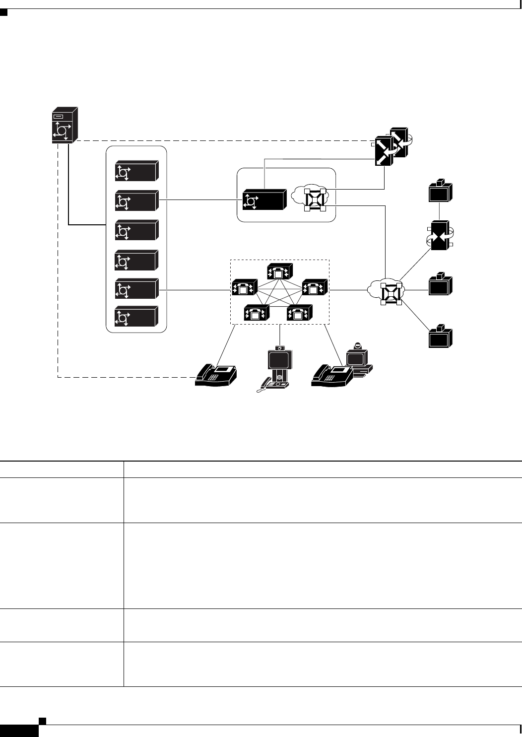
Overview of Components
The components shown in Figure 2-1 and described in Table 2-1 work together to provide video
conferences that are integrated with Cisco Unified MeetingPlace voice and web conferences.
In the Cisco Unified MeetingPlace Video Integration solution, Cisco Unified MeetingPlace components
provide audio conferencing and web conferencing data collaboration, and the Cisco Unified
Videoconferencing MCU and its associated components provide video conferencing. Video Integration
and Video Administration for Cisco Unified MeetingPlace integrate the two solutions to provide
integrated voice, data, and video conferencing.
2-2
Administration Guide for Cisco Unified MeetingPlace Video Integration Release 5.4 OL-11153-02
Chapter 2 Cisco Unified MeetingPlace Video Integration Components and Process
Overview of Components
Figure 2-1 Cisco Unified MeetingPlace Video Integration Components
Table 2-1 Components Needed to Integrate Video Conferencing in Cisco Unified MeetingPlace
Component Functions
Cisco Unified MeetingPlace
Audio Server • Handles the audio conference.
• Sets the parameters that are interpreted by Cisco Unified MeetingPlace Video Integration,
which uses these parameters to control conference resources.
Cisco Unified MeetingPlace
H.323/SIP Gateway
(MP IPGW)
• Allows the Cisco Unified MeetingPlace system to communicate with IP telephony devices.
• Connects the Cisco Unified MeetingPlace Audio Server to the network and to Cisco
Unified CallManager or the H.323/SIP Gateway.
• Establishes the audio link between the Audio Server and the Cisco Unified
Videoconferencing MCU to enable video and audio participants to hear and speak to each
other.
Cisco Unified
Videoconferencing MCU • Processes the video streams to provide the video capability of the system.
• Communicates with the video endpoints.
Cisco IOS H.323 gatekeeper • Routes calls between the video endpoints and Video Administration for Cisco Unified
MeetingPlace, based on the number dialed.
• Handles the IP protocol signaling.
GWSIM
Cisco Unified CallManager
Cisco
IOS H.323
Gatekeeper
Cisco Unified
Video Advantage
endpoint
SIP/SCCP
video
endpoint
Cisco Unified
IP Phone
H.320
video
endpoint
H.323
video
endpoint
H.323
video
endpoint
92342
RTP
XML
C
isco Unified
M
eetingPlace
A
udio Server
Cisco Unified
Videoconfere
nci
PRI Gateway
Cisco Unified
Videoconferencing
MCU(s)
XML, SOAP
MCS
H.323
H.323
SIP/
SCCP
H.323/SIP
MCS
RTP IP
LCS
Integ
MP
MP
Dir Svcs
MP
MP
MP
Web
MP
Video
Integ
MP
MP
Outlook
MP
MP
IPGW
MP
Video
Admin
MP
Gatekeeper
IP
M
M M
M
M

2-3
Administration Guide for Cisco Unified MeetingPlace Video Integration Release 5.4
OL-11153-02
Chapter 2 Cisco Unified MeetingPlace Video Integration Components and Process Overview of Components
Cisco Unified MeetingPlace
Web Conferencing
(MP Web)
• Displays a user interface to schedule and attend meetings.
• Displays video participant status.
• Provides the web-conferencing meeting room from which users can join and control video
conferences.
• Includes components that enable the Audio Server to communicate with Video Integration.
• Includes a Replication Service that synchronizes video terminal profiles and meeting types
from Video Administration to Web Conferencing.
Cisco Unified MeetingPlace
for Outlook (Optional) • Presents a convenient scheduling interface to end users.
• Provides meeting notifications that offer users two ways to “click to attend” video, voice,
and web conferences.
Cisco Unified MeetingPlace
for Lotus Notes (Optional) • Schedule and attend Cisco Unified MeetingPlace meetings that include video directly from
the Lotus Notes environment.
Cisco Unified
Videoconferencing PRI
Gateway (Optional)
• Enables H.320 video endpoints to participate in video conferences on the Cisco Unified
Videoconferencing MCU.
Video endpoints • Capture and transmit video images and audio from each user or location.
• Receive and display video images and audio from other video-conference participants to
the user or location.
Cisco Unified CallManager
(Optional) On networks configured with Cisco Unified CallManager:
• Allows SCCP and SIP endpoints to participate in Cisco Unified MeetingPlace conferences.
• Routes call traffic.
Cisco Unified MeetingPlace
Video Integration
(Video Integ)
• Authorizes Video Administration to create and initiate video conferences on the Cisco
Unified Videoconferencing MCU.
• Passes current configuration and status information between Video Administration and the
Audio Server.
• Initiates the creation of the audio channel between the Cisco Unified Videoconferencing
MCU and the Audio Server.
• Coordinates capacity by transmitting meeting scheduling, initiation, and termination
information between the various components.
• Controls entry of participants into video conferences, based on the number of video ports
scheduled on the Audio Server for the conference.
• Keeps track of information for all conference participants in the Cisco Unified
Videoconferencing MCU and their corresponding participant IDs assigned by the Audio
Server.
• Monitors the link between the Audio Server and the Cisco Unified Videoconferencing
MCU and supports recovery if the connection is lost.
• Tells Video Administration when to terminate video conferences.
Table 2-1 Components Needed to Integrate Video Conferencing in Cisco Unified MeetingPlace (continued)
Component Functions

2-4
Administration Guide for Cisco Unified MeetingPlace Video Integration Release 5.4 OL-11153-02
Chapter 2 Cisco Unified MeetingPlace Video Integration Components and Process
Supported Cisco Unified MeetingPlace System Configurations
Supported Cisco Unified MeetingPlace System Configurations
Supported Cisco Unified MeetingPlace system configurations include the following. Complete system
requirements and a Cisco Unified MeetingPlace version compatibility matrix are in the System
Requirements for Cisco Unified MeetingPlace, at
http://www.cisco.com/en/US/products/sw/ps5664/ps5669/prod_installation_guides_list.html.
• One Cisco Unified MeetingPlace 8100 series server.
• One or more Cisco Unified MeetingPlace H.323/SIP Gateway servers.
• Cisco Unified MeetingPlace Web Conferencing servers in any configuration that is supported in this
release. Cisco Unified MeetingPlace Video Integration must be installed on all Web Conferencing
servers. However, the Video Integration can only be activated to host video conferences on one Web
Conferencing server.
• Cisco Unified MeetingPlace Video Integration installed on all Cisco Unified MeetingPlace Web
Conferencing servers. If your system has a DMZ configuration, see the “Preparing to Install the
Video Integration with DMZ Configurations” section on page 5-22 for important considerations
before installing Video Integration. A DMZ configuration includes one or more servers in a DMZ
outside the corporate firewall.
• Video Administration for Cisco Unified MeetingPlace installed on a separate server.
• One or more Cisco Unified Videoconferencing MCU with all components including an H.323
gatekeeper.
• (Optional) Cisco Unified MeetingPlace for Outlook.
• (Optional) Cisco Unified MeetingPlace for Lotus Notes.
• (Optional) Cisco Unified MeetingPlace SMTP E-Mail Gateway.
• (Optional) Cisco Unified CallManager.
Video Administration for
Cisco Unified MeetingPlace
(Video Admin)
• Monitors the configuration of the Cisco Unified Videoconferencing MCU and passes
current status to the Video Integration.
• Tells the Cisco Unified Videoconferencing MCU to create and initiate video conferences.
• Schedules and tracks the video conference port resources for the Cisco Unified
Videoconferencing MCU.
• Controls the behavior of the Cisco Unified Videoconferencing MCU based on meeting type
and requests placed via the Web Conferencing meeting room.
• Tells the Cisco Unified Videoconferencing MCU when to terminate conferences.
• Provides a web interface for entering and storing video terminal information.
• Provides cascading meeting functionality that combines meetings hosted on multiple Cisco
Unified Videoconferencing MCUs.
• Includes an internal ECS gatekeeper with which the MCUs must register.
Table 2-1 Components Needed to Integrate Video Conferencing in Cisco Unified MeetingPlace (continued)
Component Functions
2-5
Administration Guide for Cisco Unified MeetingPlace Video Integration Release 5.4
OL-11153-02
Chapter 2 Cisco Unified MeetingPlace Video Integration Components and Process About the Cisco Unified MeetingPlace Video Conferencing Process
For detailed information on deployment options, refer to the “Cisco Unified MeetingPlace” chapter of
the applicable Cisco Unified Communications Solution Reference Network Design (SRDN) guide,
available at
http://www.cisco.com/en/US/products/sw/voicesw/ps556/products_implementation_design_guides_list
.html
About the Cisco Unified MeetingPlace Video Conferencing
Process
The process of creating, running, and terminating an integrated video, audio, and web conference is
described in this section.
Participants who are using audio-only devices connect to the Cisco Unified MeetingPlace Audio Server.
Participants with video equipment connect to the Cisco Unified Videoconferencing MCU, which
processes both the video and the audio channel of the video endpoints. Cisco Unified MeetingPlace
Video Integration mixes the audio streams from both systems to allow all participants to hear and speak
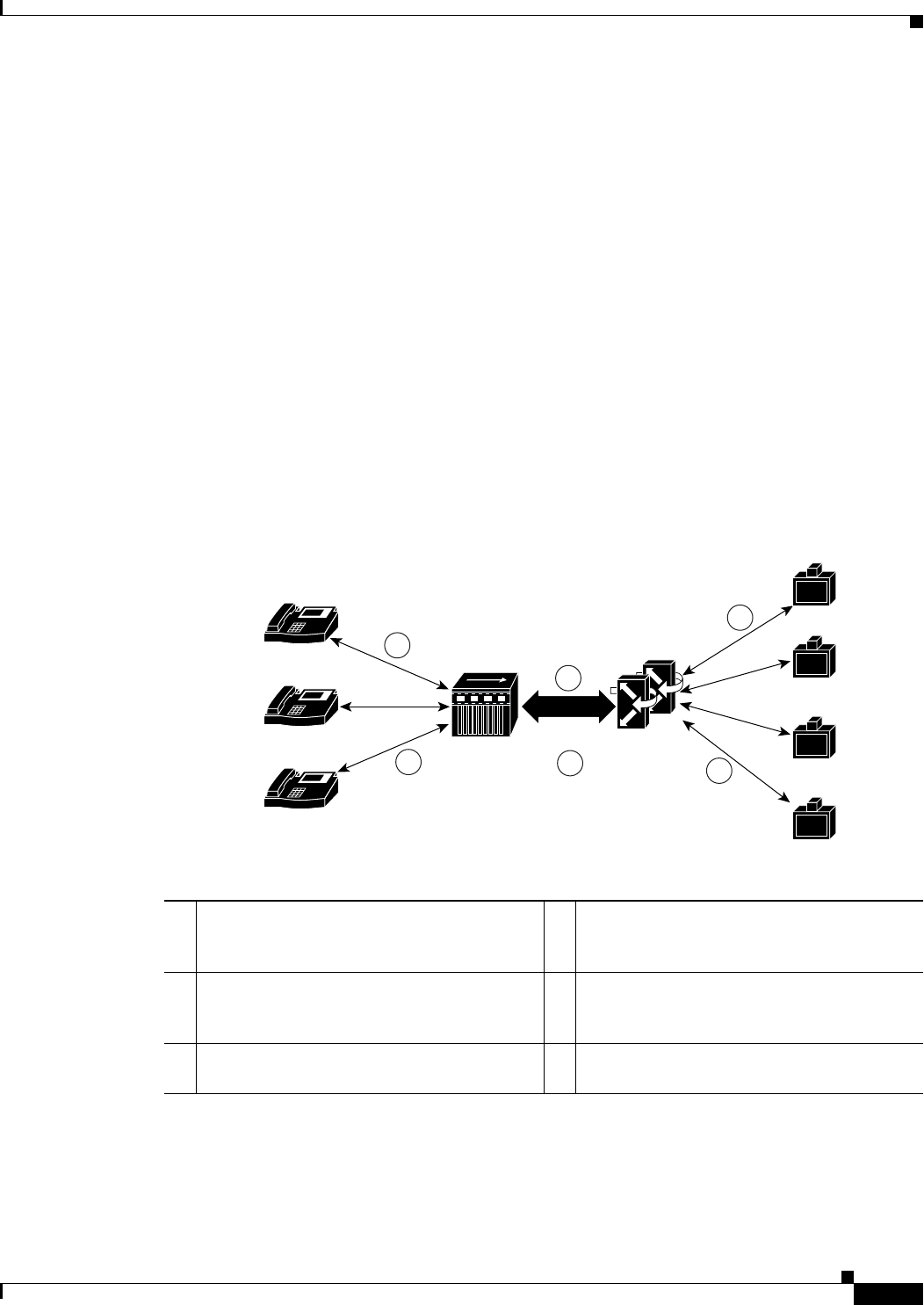
to each other. Figure 2-2 shows this process.
Figure 2-2 Cisco Unified MeetingPlace Video Conferencing Process
1The audio of the phone participants is
processed by the Cisco Unified MeetingPlace
Audio Server.
4The audio and video channels of the video
endpoints are processed by the Cisco Unified
Videoconferencing MCU(s).
2The audio channels from phone participants
are sent to join the audio on the Cisco Unified
Videoconferencing MCU(s).
5The audio channels of the video endpoints are
sent to join the audio in Cisco Unified
MeetingPlace audio conferencing.
3Video participants hear the audio from phone
participants. 6Phone participants hear the audio from video
endpoints.
3
1
2
4
5
6
Cisco Unified
MeetingPlace
Audio Server
IP
IP
IP
C
isco Unified
IP Phone
C
isco Unified
IP Phone
C
isco Unified
IP Phone
Video
endpoint
Video
endpoint
Video
endpoint
Video
endpoint
92341
Cisco Unified
Videoconferencing
MCU(s)

2-6
Administration Guide for Cisco Unified MeetingPlace Video Integration Release 5.4 OL-11153-02
Chapter 2 Cisco Unified MeetingPlace Video Integration Components and Process
About the Cisco Unified MeetingPlace Video Conferencing Process
How Video Conferences Are Scheduled
A user fills in a standard Cisco Unified MeetingPlace conference scheduling form in Microsoft Outlook,
Lotus Notes, or Cisco Unified MeetingPlace Web Conferencing, and then the user submits that form to
the Cisco Unified MeetingPlace Audio Server. If the user has indicated that the conference will include
video participants, the Audio Server verifies with the Video Administration component that resources
are available, and if so, schedules the requested number of video ports and (depending on system
configuration) notifies invitees.
When using Microsoft Outlook or Lotus Notes to schedule video meetings, users can specify only the
number of video ports they need for a meeting. When using Cisco Unified MeetingPlace Web
Conferencing to schedule video meetings, users can:
• Invite specific video terminals from a list
• Choose to have video endpoints automatically outdialed at the start of the meeting
• Choose the specific meeting video layout and characteristics that are available
• Schedule a video-only meeting type
How Video Conferences Start
The Cisco Unified Videoconferencing MCU is configured to allow Video Administration for Cisco
Unified MeetingPlace to control all H.323 video-conferencing resources and meeting operations on the
Cisco Unified Videoconferencing MCU, including initiating meetings. Cisco Unified MeetingPlace does
not control SCCP resources on the Cisco Unified Videoconferencing MCU. (Note that SCCP video
endpoints that are connected to the Cisco Unified Videoconferencing MCU will also be using the H.323
resources on the MCU. This is made possible by the Cisco Unified CallManager to which the SCCP
video endpoints are registered.)
If video ports are reserved, Video Administration starts the video conference on the Cisco Unified
Videoconferencing MCU at the same time as the audio conference is started on the Audio Server. Both
the video and audio conferences use the same guard times.
If video ports are not reserved, participants can attempt to join the video conference on an ad-hoc basis.
In this case, the first Cisco Unified MeetingPlace conference participant who joins the video conference
initiates the creation of the video conference on the Cisco Unified Videoconferencing MCU. Cisco
Unified MeetingPlace Video Integration verifies that the conference is currently in session or within the
guard times of the existing meeting, then tells Video Administration, which in turn tells the Cisco
Unified Videoconferencing MCU to immediately create a video conference with the Meeting ID.
The Meeting ID for the video conference includes the MeetingPlace video service code that was chosen
by the meeting scheduler plus the standard Cisco Unified MeetingPlace Meeting ID for that conference.
The Meeting ID is used by the gatekeeper or Cisco Unified CallManager to route incoming calls for this
conference over the network to Video Administration. Video Administration then routes the call to the
applicable Cisco Unified Videoconferencing MCUs.
Conferences cannot be created by dialing in to Video Administration unless the meeting has been
scheduled on Audio Server. If a participant dials in to Video Administration to start a conference, Video
Administration sends information about the new video conference to Cisco Unified MeetingPlace Video
Integration. If the conference has not been scheduled in Cisco Unified MeetingPlace, is not currently in
session, or is outside the guard times of a scheduled meeting, Video Integration instructs Video
Administration not to create the conference.

2-7
Administration Guide for Cisco Unified MeetingPlace Video Integration Release 5.4
OL-11153-02
Chapter 2 Cisco Unified MeetingPlace Video Integration Components and Process About the Cisco Unified MeetingPlace Video Conferencing Process
How the Link Between the Cisco Unified Videoconferencing MCU and the
Cisco Unified MeetingPlace Audio Server Is Established
When the first video participant joins an authorized video conference, either by outdialing from the
Cisco Unified MeetingPlace Web Conferencing meeting room or by dialing in to Video Administration,
Cisco Unified MeetingPlace creates the link that connects the audio channel of the video conference and
the audio channel of the Cisco Unified MeetingPlace Audio Server.
To initiate this link, Cisco Unified MeetingPlace Video Integration tells the Audio Server to outdial to
Video Administration, and then the call is routed through the H.323/SIP Gateway to Cisco Unified
CallManager or to the H.323 gatekeeper, either of which has been configured to route the call to Video
Administration. Video Administration then routes the call to the correct Cisco Unified
Videoconferencing MCU and conference. The routing pattern (outdialed number) for this transaction is
composed of one of the service prefixes that identify Cisco Unified MeetingPlace conferences on the
Cisco Unified Videoconferencing MCU (and also are unique among the routing patterns configured on
the gatekeeper and Cisco Unified CallManager) plus the Cisco Unified MeetingPlace Meeting ID of the
conference. Video Integration tries three times to establish this link.
After the link is established, the entire audio channel of the video conference on the Cisco Unified
Videoconferencing MCU becomes a participant in the Cisco Unified MeetingPlace audio conference and
vice versa.
Note The audio link appears as a “Video Participant” in the in-session tab in MeetingTime, but not in the Cisco
Unified MeetingPlace Web Conferencing meeting room. It also is included in some reports, but not all.
See the “About Video-Conferencing Statistics” section on page 6-10.
After the link is established, all further communication between the Cisco Unified Videoconferencing
MCU and the Cisco Unified MeetingPlace Audio Server is handled through the Cisco Unified
MeetingPlace Video Integration and Video Administration components, which communicate with the
Audio Server through MPAgent. MPAgent is a component of Cisco Unified MeetingPlace Web
Conferencing, which is a prerequisite to installation of Video Integration. Video Integration
communicates with Video Administration by using proprietary XML and SOAP messaging. The Video
Administration component communicates with the Cisco Unified Videoconferencing MCU by using
proprietary XML messaging.
If the link between Cisco Unified MeetingPlace and the Cisco Unified Videoconferencing MCU is
disconnected, Video Integration attempts to reestablish it three times, checking every minute, or when
another participant joins the conference.
About Cascading Video MCUs
Beginning with Cisco Unified MeetingPlace version 5.4, video conferences are no longer limited to a
single MCU. The new Video Administration component enables Cisco Unified MeetingPlace to
communicate with multiple MCUs transparently. If there are multiple MCUs in the same conference, the
Video Administration component designates one of the MCUs as the primary MCU for that conference;
the rest of the MCUs are designated secondary MCUs. Cisco Unified MeetingPlace establishes an audio
link with only the primary MCU. The secondary MCUs all connect to the primary MCU.
Cascading is only supported with Cisco Unified Videoconferencing 5.x and later. With Cisco Unified
Videoconferencing 5.x, video capabilities are provided by Enhanced Media Processors (EMPs) in the
MCU. One port on each of the secondary EMPs will be used to connect to the primary EMP, leaving a
maximum of 23 ports on each EMP for participants. The primary EMP must use one port to connect to

2-8
Administration Guide for Cisco Unified MeetingPlace Video Integration Release 5.4 OL-11153-02
Chapter 2 Cisco Unified MeetingPlace Video Integration Components and Process
About the Cisco Unified MeetingPlace Video Conferencing Process
the Cisco Unified MeetingPlace Audio Server and one port to connect with each of the secondary EMPs.
Therefore, the maximum number of EMPs that you can connect to the primary EMP is 23. The maximum
number of video participants in a single video conference that has been tested is 244.
On the Audio Server, there will always be only one port per meeting used to connect to the primary Cisco
Unified Videoconferencing MCU.
How Video Conference Participants Join Meetings
There are several ways that additional participants can join the video conference. The process of adding
participants to the conference depends on how they enter the meeting.
If a Participant Joins a Scheduled Video Conference by Outdialing from the Cisco Unified MeetingPlace Web
Conferencing Meeting Room
When a participant clicks Connect from within Cisco Unified MeetingPlace Web Conferencing, or in a
calendar entry in Cisco Unified MeetingPlace for Lotus Notes, or in the MeetingPlace tab of a meeting
notification in Cisco Unified MeetingPlace for Outlook, Video Administration for Cisco Unified
MeetingPlace sends a message to the Cisco Unified Videoconferencing MCU to outdial to the endpoint
of the participant. When the participant has successfully joined the video conference, the Cisco Unified
Videoconferencing MCU notifies Video Administration, which notifies Video Integration, and the status
of the participant is recorded in the participant list that is displayed in the Web Conferencing meeting
room.
If a Participant Joins a Scheduled Video Conference by Dialing in to Video Administration for Cisco Unified
MeetingPlace
If a video conference does not have password restriction, participants can dial in to the conference from
their video endpoint. Participants dial in to the conference from their endpoint by using the number
provided in the Connect dialog box in the Cisco Unified MeetingPlace Web Conferencing meeting room.
This number is the service prefix on the Cisco Unified Videoconferencing MCU that the meeting
scheduler chose for the Cisco Unified MeetingPlace conference, plus the Cisco Unified MeetingPlace
Meeting ID. Cisco Unified CallManager or the gatekeeper routes all incoming H.323 calls that begin
with the specified service prefix to Video Administration for Cisco Unified MeetingPlace, which routes
each call to the correct Cisco Unified Videoconferencing MCU and video conference based on the Cisco
Unified MeetingPlace meeting ID number portion of the number that was dialed.
When participants attempt to join the video conference by dialing in from their video endpoint, Video
Administration checks with Cisco Unified MeetingPlace Video Integration to see if the conference is
restricted to profiled or invited users and does not require a password. If the conference is restricted to
profiled or invited users, participants will be granted access if their video terminal has a profile or was
invited to the meeting. If the participant is granted access, Video Integration checks to see if the meeting
is in session and within the guard times and if so, tells Video Administration to admit the participant to
the video conference on the Cisco Unified Videoconferencing MCU. Video Administration notifies
Video Integration that the participant has joined the conference. Video Integration notifies Web
Conferencing and the Cisco Unified MeetingPlace Audio Server of the status of the participant.
If a Participant Joins a Video Conference on an Ad-Hoc Basis
If all scheduled video-conferencing ports for a meeting that is already in progress are in use, and an
additional participant attempts to join the video conference, the user may be able to join on an ad-hoc
basis. In this case, Video Administration for Cisco Unified MeetingPlace checks to see if
video-conferencing ports are available, and if they are, Video Administration allows the participant to
join the conference.

2-9
Administration Guide for Cisco Unified MeetingPlace Video Integration Release 5.4
OL-11153-02
Chapter 2 Cisco Unified MeetingPlace Video Integration Components and Process About the Cisco Unified MeetingPlace Video Conferencing Process
How Video Conferences Run
About the Video Images
The visual stream to and from the video endpoints is entirely processed by the Cisco Unified
Videoconferencing MCU. After the call is connected, the media stream is routed from the video
endpoint, through the Cisco Unified Videoconferencing MCU for processing into a unified video stream,
and back to the video endpoints for display to the users. However, users control the status of the
transmission (for example, started, paused, or terminated) from within the Cisco Unified MeetingPlace
Web Conferencing meeting room. See the “About Displaying the Status and Options of Video
Participants in the Meeting Room” section on page 2-9.
About the Audio Channel
The audio streams of the Cisco Unified Videoconferencing MCU and Cisco Unified MeetingPlace are
mixed to allow audio and video-conferencing participants to hear and speak to each other. The audio
channel from each video endpoint is routed to the Cisco Unified Videoconferencing MCU, then passed
through the audio link to the Cisco Unified MeetingPlace Audio Server, where it is mixed with the audio
from audio-only endpoints and sent back to all users, to form a seamless audio experience for
participants on both video and audio-only endpoints.
About Displaying the Status and Options of Video Participants in the Meeting
Room
When Video Administration for Cisco Unified MeetingPlace admits a participant to a video conference,
Video Administration notifies Cisco Unified MeetingPlace Video Integration, which notifies Cisco
Unified MeetingPlace Web Conferencing. Web Conferencing identifies the participant as a video
participant in the participant list in the Web Conferencing meeting room. The participant name that is
displayed comes from the participant profile or guest information if they outdialed from Cisco Unified
MeetingPlace, and from the gatekeeper if they dialed in to the video conference. When a participant
mutes, pauses, changes the view of, or terminates their video connection, Web Conferencing registers
this change in the meeting room user interface and passes the request to Cisco Unified MeetingPlace
Video Integration, which passes the request to Video Administration, which passes the request to the
Cisco Unified Videoconferencing MCU where it is performed. If the user terminates the connection by
hanging up the video endpoint, the Cisco Unified Videoconferencing MCU notifies Video
Administration, which notifies Video Integration, which then notifies Web Conferencing so that the
status of that participant can be updated.
When a video participant speaks, the Now Speaking display shows the participant name or the name of
the video endpoint of the participant.
How Cisco Unified MeetingPlace Video Integration Tracks Port Availability
The number of available video ports is determined by the Video Administration component. The Audio
Server queries Video Administration real-time to determine whether video resources are available to
schedule a video conference. Video port availability is not displayed in MeetingTime.

2-10
Administration Guide for Cisco Unified MeetingPlace Video Integration Release 5.4 OL-11153-02
Chapter 2 Cisco Unified MeetingPlace Video Integration Components and Process
About the Cisco Unified MeetingPlace Video Conferencing Process
How Video Conferences End
The video conference on the Cisco Unified Videoconferencing MCU ends when the Cisco Unified
MeetingPlace conference ends, according to the standard rules for ending conferences on the Cisco
Unified MeetingPlace Audio Server. At this time, Cisco Unified MeetingPlace Video Integration tells
Video Administration, which in turn tells the Cisco Unified Videoconferencing MCU(s) to terminate the
video conference.

CHAPTER
3-1
Administration Guide for Cisco Unified MeetingPlace Video Integration Release 5.4
OL-11153-02
3
Installing Video Administration for Cisco Unified
MeetingPlace
Video Administration Installation Overview
This chapter provides procedures for installing Video Administration.
See the following sections:
• Before Installing Video Administration, page 3-1
• Installing MSDE, page 3-3
• Installing Video Administration, page 3-5
• Confirming Installation, page 3-7
• Uninstalling Video Administration, page 3-7
Before Installing Video Administration
The following information is important to consider before installing Video Administration. See the
following sections:
• Supported Databases, page 3-1
• Login Information Requirements, page 3-2
• Port Considerations, page 3-2
• Minimum System Requirements, page 3-3
• Configuring Network Time Protocol (NTP), page 3-3
Supported Databases
You can configure Video Administration to use any of the following databases:
• Microsoft SQL Server 2000 Standard Edition
• Microsoft SQL Server 2000 Enterprise Edition
• Microsoft SQL Server 2000 Desktop Edition (MSDE)

3-2
Administration Guide for Cisco Unified MeetingPlace Video Integration Release 5.4 OL-11153-02
Chapter 3 Installing Video Administration for Cisco Unified MeetingPlace
Before Installing Video Administration
A copy of MSDE is included with Video Administration. See the “Installing MSDE” section on page 3-3
for detailed installation instructions. If you prefer to use the Standard or Enterprise Editions of Microsoft
SQL Server 2000, you must install the relevant database before installing Video Administration.
Login Information Requirements
Login information must comply with the following requirements:
• Number of characters in database name—32 or fewer
• Number of characters in username—16 or fewer
• Number of characters in password—12 or fewer
Port Considerations
In this document, the term “port” refers to the Video Administration connection to an endpoint.
Examples of Port Usage
Different situations require different port usage, as shown in the following examples:
• A meeting with five participating video endpoints uses six ports—five for video and one for the
audio link to the Cisco Unified MeetingPlace Audio Server.
• A call via a gateway to an MCU uses one port.
• A meeting spans multiple MCUs for bandwidth optimization, therefore an additional port is required
on each MCU for cascading.
• A meeting spans two MCUs with three participating endpoints on the first MCU and four
participants on the second MCU. Ten ports (7 endpoints, 2 MCUs, 1 audio link) are required.
Port Assignment
The default installation port for Video Administration is port 8080.
On certain platforms, some applications such as the Internet Information Services Web Server (IIS) also
use port 8080.
Port 8443 is used for SSL connection only.
For media conferences that use audio and video, one additional port is required. This port is reserved for
the audio link to the Video Administration Audio Server.
To Avoid a Port Conflict
Step 1 Before installing Video Administration, disable the specific application that occupies port 8080.
or
Install Video Administration on a port other than port 8080.

3-3
Administration Guide for Cisco Unified MeetingPlace Video Integration Release 5.4
OL-11153-02
Chapter 3 Installing Video Administration for Cisco Unified MeetingPlace Installing MSDE
To Add Ports to the Programs and Services List If Windows 2003 Service Pack 1 Firewall Is Enabled on the
Designated Server
Step 1 In Windows FireWall > Exceptions, add the following ports to the Programs and Services list:
Video Admin Web Server Port: TCP 8080 (default)
Video Admin Internal Gatekeeper Authorization Port: TCP 7777 (default)
Minimum System Requirements
• Internet browser—IE version 6.0 is required.
• Network Time Protocol (NTP) must be configured on the Video Administration Server.
Configuring Network Time Protocol (NTP)
To Configure NTP on the Video Administration Server
Step 1 From the Start menu, click Run, then enter cmd to open a command prompt.
Step 2 Enter the following command:
net time /setsntp:<NTP-SERVER-NAME-OR-IP>
where <NTP-SERVER-NAME-OR-IP> is the IP address or DNS name of the NTP time server.
Step 3 Close the command window.
Step 4 From the Start menu, click Settings > Control Panel > Administrative Tools > Services.
Step 5 From the list of services currently running on the server, right-click Windows Time and select
Properties.
Step 6 In the Startup Type field, select Automatic.
Step 7 Under Server Status, click Start.
Step 8 Click OK.
Step 9 Close the Services control panel.
Installing MSDE
Use the following procedure to install Microsoft SQL Server 2000 Desktop Edition (MSDE) as the
server database. MSDE is included with Video Administration. Installation of MSDE is optional,
depending on your requirements.
Note the following when navigating through the installation process:
• The menu on the left side of each installation screen indicates at which stage you are in the
installation.

3-4
Administration Guide for Cisco Unified MeetingPlace Video Integration Release 5.4 OL-11153-02
Chapter 3 Installing Video Administration for Cisco Unified MeetingPlace
Installing MSDE
• To return to a previous screen during the installation process, click the Previous button until you
reach the screen you require.
• To cancel the installation at any time during the installation process, click the Cancel button in the
installation screen that is currently open.
To Install MSDE
Note Quit all applications before beginning the MSDE installation.
Step 1 Insert the Video Administration for Cisco Unified MeetingPlace CD.
Step 2 On the desktop, click Setup_MSDE.exe.
The MSDE installer opens.
Step 3 In the Installation screen, read the instructions, and then click Next.
Step 4 In the Choose Shortcut Folder screen, select a location for product icons. The following options are
available:
• In a New Program Group (Selected by default. “MSDE2000” appears automatically in the field.)
• In an Existing Program Group
• In the Start Menu
• On the Desktop
• In the Quick Launch Bar
• Other (Click Choose to select another location in a browser screen.)
• Do Not Create Icons
• Create Icons for All Users (Checked by default.)
Step 5 Click Next.
Step 6 In the Choose Install Folder screen, in the Where Would You Like to Install? field, choose the location
of the folder:
• Use the default location (\Program Files\MSDE2000).
• To select a different location, click Choose, and in the browser screen that opens, select a location.
• To return to the default location settings, click Restore Default Folder. The path appears
automatically in the Where Would You Like to Install? field.
Step 7 Click Next.
In the MSDE Administration Information screen, information appears automatically in the Server Name
field and the Login ID field.
Step 8 Enter information in the Server Port field and the Password field.
Step 9 Click Install.
The Installing MSDE2000 screen appears and includes an installation progress bar.
When the installation is successfully completed, a message appears.
Step 10 Continue with the “To Install Video Administration” procedure on page 3-5.

3-5
Administration Guide for Cisco Unified MeetingPlace Video Integration Release 5.4
OL-11153-02
Chapter 3 Installing Video Administration for Cisco Unified MeetingPlace Installing Video Administration
Note Do not remove the Video Administration for Cisco Unified MeetingPlace CD. It is required to
install Video Administration.
Installing Video Administration
This section describes the steps involved in a basic initial installation of Video Administration.
Note the following when navigating through the installation process:
• The menu on the left side of each installation screen indicates at which stage you are in the
installation.
• To return to a previous screen during the installation process, click the Previous button until you
reach the screen you require.
• To cancel the installation at any time during the installation process, click the Cancel button in the
installation screen that is currently open.
To Install Video Administration
Note Quit all applications before beginning the Video Administration installation.
Step 1 If you are not continuing from doing the MSDE installation, insert the Video Administration for Cisco
Unified MeetingPlace CD.
Step 2 To start the Video Administration installation, double-click the Cisco_Video_Admin_<version #>.exe
icon that appears on the desktop.
An installation progress bar appears. When the installer is ready, the Introduction screen appears.
Step 3 Read the information on the screen, and then click Next.
The License Agreement screen appears.
Step 4 Select I Accept the Terms of the License Agreement, and then click Next.
The Directory Selection screen appears.
Step 5 In the Directory Selection screen, in the Where Would You Like to Install? field, choose the location of
the folder:
• Use the default location (\Program Files\Cisco\Video Admin).
• To select a different location, click Choose, and in the browser screen that opens, select a location.
• To return to the default location settings, click Restore Default Folder. The path appears
automatically in the Where Would You Like to Install? field.
Step 6 Click Next.
The Video Admin Default Language Selection screen appears.
Step 7 From the Default Language Selection list, select a language and then click Next. English is selected by
default.

3-6
Administration Guide for Cisco Unified MeetingPlace Video Integration Release 5.4 OL-11153-02
Chapter 3 Installing Video Administration for Cisco Unified MeetingPlace
Installing Video Administration
The Video Admin Server Information screen appears. By default, the host name of the Video Admin
machine that you are using appears in the first field, and the default port (8080) appears in the Port
Number field. This information is used in links published by Video Administration, such as links
appearing in invitation e-mail.
Step 8 Change the host name or IP address if applicable, first verifying that the host name or IP address that
you provide is accessible from any location from which you intend to use Video Administration, and then
click Next.
The installer checks for port conflicts.
Step 9 If a port conflict is found, click Previous, and on the Video Admin Server Information screen, do one of
the following:
• Enter a different port number.
• Free the Video Admin port setting.
Step 10 Click Next.
The Database Server Administration Information screen appears. The fields in the Database Server
section are Server Name and Server Port. The fields in the Administrator Account section are Login ID
and Password. Information appears automatically in the fields. Edit as required.
Step 11 Click Next.
The Video Admin Database Information screen appears. The following default information appears in
the fields:
• Database Name—cisco_core_db
• Login ID—cisco_core_user
• Password—cisco_core_1111
Step 12 Edit the information if required, and then click Next.
The Video Admin Account Information screen appears.
Step 13 Enter information in the Login ID, Password, Confirm Password, and e-mail fields, and then click Next.
A message appears informing you that Video Administration is being configured on the system.
The Pre-Installation Summary screen appears and includes the following information regarding the
installation: Product Name, Install Folder, Shortcut Folder, and Disk Space Information (for Installation
Target).
Step 14 Review the information in the Pre-Installation Summary screen.
Note Make sure free disk space is adequate. If it is necessary to change the location of the installation
folder, click Previous until you return to the relevant screen in the installation wizard, change
the location, and then click Next to proceed again with the installation.
Step 15 To proceed with the installation, click Install.
The Installing Cisco Video Admin screen appears.
If the database is successfully installed, an Installation Complete screen appears.
Step 16 Click Done to exit the installer.
The login screen appears.

3-7
Administration Guide for Cisco Unified MeetingPlace Video Integration Release 5.4
OL-11153-02
Chapter 3 Installing Video Administration for Cisco Unified MeetingPlace Confirming Installation
Caution When you install Video Administration for the first time, the User Provisioning screen appears
after initial login. Do not change the selections that appear automatically. Click OK.
Confirming Installation
Use the following procedure to confirm successful installation.
To Confirm a Successful Installation
Step 1 Go to http://<va-host>/va.
Note If you have modified the Video Administration web server port default setting, add the
string:<new port number> after <va-host> in the URL. For example, http://<va-host>:8080/va.
After system initialization, the Video Administration login screen appears.
Uninstalling Video Administration
To Uninstall Video Administration
Step 1 Do one of the following steps:
• From the system Start menu, in the Video Administration program file group, click Uninstall Video
Administration.
• In the Control Panel, in Add/Remove Programs, select the Video Administration program, and then
select Uninstall Program.
The Video Administration server is uninstalled, but the SQL database is not uninstalled.

3-8
Administration Guide for Cisco Unified MeetingPlace Video Integration Release 5.4 OL-11153-02
Chapter 3 Installing Video Administration for Cisco Unified MeetingPlace
Uninstalling Video Administration

CHAPTER
4-1
Administration Guide for Cisco Unified MeetingPlace Video Integration Release 5.4
OL-11153-02
4
Configuring Video Administration for Cisco
Unified MeetingPlace
Procedures in this chapter must be completed before installing the Cisco Unified MeetingPlace Video
Integration software on the Web Conferencing server. This chapter can also be used as a reference for
adding and changing settings later.
See the following sections:
• Getting Started, page 4-1
• Resource Management, page 4-3
• Meeting Types, page 4-13
Getting Started
This section includes information about starting and restarting Video Administration, and logging in
according to your user type.
See the following sections:
• Video Administration Configuration Workflow, page 4-1
• Starting Video Administration, page 4-2
• Restarting Video Administration, page 4-2
• Logging In, page 4-2
Video Administration Configuration Workflow
We recommend that Video Administration administrators configure Video Administration according to
the following workflow:
• Installation
• Initial Login
• Resource Configuration
–
Gatekeepers/SIP servers
–
MCUs
–
Gateways

4-2
Administration Guide for Cisco Unified MeetingPlace Video Integration Release 5.4 OL-11153-02
Chapter 4 Configuring Video Administration for Cisco Unified MeetingPlace
Getting Started
–
Terminals
• Configure Meeting Types
–
Download/Upload Meeting Types
By default, some sections of the user interface are hidden, according to settings in the Configuration
Tool; however, these sections may appear in the documentation. For details about using the
Configuration Tool, see the “Video Administration Configuration Tool” chapter.
Starting Video Administration
Video Administration is installed as a Windows Service on your server. Video Administration
automatically starts when the server is started.
Restarting Video Administration
To restart Video Administration, you must either restart the server or the Video Administration service.
To Restart the Video Administration Service
Step 1 From the Start menu, click Settings > Control Panel > Administrative Tools > Services.
Step 2 From the list of services currently running on the server, select the Video Administration for Cisco
Unified MeetingPlace service.
Note When Video Administration is restarted, it may take a few minutes for Video Administration to
properly initialize before web pages can be loaded.
Logging In
After installation is complete, you can log in according to your role.
To Log In to Video Administration
Step 1 Go the location provided in your user setup notification e-mail.
Step 2 In the login screen that appears, enter the required information, and then click Login.
Step 3 If you are logging in for the first time, the User Provisioning screen appears. One of the following
options is automatically selected. Do not change the selection.
• Via Video Administration for Cisco Unified MeetingPlace—To use the internal Video
Administration database.
• Via external server only.
Step 4 Click OK.

4-3
Administration Guide for Cisco Unified MeetingPlace Video Integration Release 5.4
OL-11153-02
Chapter 4 Configuring Video Administration for Cisco Unified MeetingPlace Resource Management
Resource Management
Use the Resource Management section to organize, assign, and monitor resources.
The following resources are currently supported by Video Administration:
• MCU
–
Cisco MCU version 4.x and 5.x
–
Cisco Unified Videoconferencing 35xx
• Gatekeepers/SIP servers
–
Cisco GK—the internal (ECS) gatekeeper installed with the Video Administration
–
Cisco Multimedia Conference Manager (MCM)—also known as the IOS H.323 Gatekeeper.
–
Microsoft LCS
To Access Resource Management
Step 1 In the sidebar menu, go to Resource Management.
Step 2 The Resource Management section contains the following tabs:
• Gatekeeper/SIP server—See the “Using the Gatekeeper/SIP Server Tab” section on page 4-3.
• MCU—See the “Using the MCU Tab” section on page 4-5.
• Gateway—See the “Using the Gateway Tab” section on page 4-8.
• Terminals—See the “Using the Terminals Tab” section on page 4-11.
Note We recommend that you configure the tabs in the order that they appear, from left to right.
Using the Gatekeeper/SIP Server Tab
On the Gatekeeper/SIP server tab you can monitor, add, delete and modify gatekeeper and SIP server
information.
A gatekeeper/SIP must be listed in the Gatekeeper/SIP server tab before you can add an MCU to its
registry.
Cisco GK is listed on the Gatekeeper/SIP server tab. This is an internal gatekeeper.
See the following procedures:
• To Access the Gatekeeper/SIP Server Tab, page 4-4
• To Add a Gatekeeper/SIP Server, page 4-4
• To Modify a Gatekeeper/SIP Server Definition, page 4-4
• To Delete a Gatekeeper/SIP server, page 4-4
• To Search for a Gatekeeper/SIP Server, page 4-5

4-4
Administration Guide for Cisco Unified MeetingPlace Video Integration Release 5.4 OL-11153-02
Chapter 4 Configuring Video Administration for Cisco Unified MeetingPlace
Resource Management
To Access the Gatekeeper/SIP Server Tab
Step 1 In the sidebar menu, select Resource Management.
Step 2 In Resource Management, select the Gatekeeper/SIP Server tab.
To Add a Gatekeeper/SIP Server
The procedure for adding a gatekeeper/SIP server differs slightly depending on which model you select.
When you add a gatekeeper, it is automatically defined as the neighbor of the internal gatekeeper.
Step 1 On the Gatekeeper/SIP Server tab, click Add.
The New Gatekeeper/SIP server screen appears.
Step 2 In the Name field, enter the name of the Gatekeeper/SIP server.
Step 3 In the IP Address field, enter an IP address for the Gatekeeper/SIP server.
Step 4 From the Model list, select the type of server that you want to add. Select “Cisco MCM 500” for a Cisco
IOS H.323 Gatekeeper.
The screen displays options relevant to the server you select. For example, the display of the Protocol
list, the Dialing Plan Information, and the Advanced section is dependent on which server you select.
Step 5 From the Location list, set the Device Island to which the device belongs.
Step 6 Do not configure anything in the Dialing Plan Information section or the Advanced section.
Step 7 Click OK.
To Modify a Gatekeeper/SIP Server Definition
Step 1 On the Gatekeeper/SIP server tab, click the name of the server that you want to modify.
Step 2 In the Modify Gatekeeper/SIP server screen, edit the details as required.
Step 3 Click OK.
To Delete a Gatekeeper/SIP server
You cannot recover a Gatekeeper/SIP server once it is deleted.
Step 1 On the Gatekeeper/SIP server tab, click the name of the server that you want to delete.
Step 2 In the Modify Gatekeeper/SIP server screen, click Delete.
Step 3 If you want to delete the IP addresses for additional gateways in the Gateway pool, click the Modify
button next to the IP Address field, and then in the Modify Gateway screen, click Delete.
Depending on the current use of the gatekeeper/SIP server, the following events may occur:
• If there are any meetings scheduled within two hours of the time of deletion that will use this
gatekeeper/SIP server, Video Administration does not allow the deletion.

4-5
Administration Guide for Cisco Unified MeetingPlace Video Integration Release 5.4
OL-11153-02
Chapter 4 Configuring Video Administration for Cisco Unified MeetingPlace Resource Management
• If the gatekeeper/SIP server has other gateways mapped as children, Video Administration
reconfigures the gateway dialing plan by using those children as root gatekeeper/SIP servers and
dialing accordingly.
• If there are devices registered to the deleted gatekeeper/SIP server, after deletion, they appear as not
registered to any gatekeeper/SIP server.
Note Reconfigure manually, if necessary, after a gatekeeper/SIP server is deleted.
To Search for a Gatekeeper/SIP Server
You can search for a gatekeeper/SIP server by name.
Step 1 In the Name field, enter all or part of the name of the gatekeeper or SIP server that you want to find.
Step 2 Click Search.
If a Gatekeeper/SIP server is found, it appears in the list.
Step 3 To view the complete list of Gatekeeper/SIP servers, clear the Search field, and then click Search.
The following information about connection status is available in the list of search results:
• Authorization Connection—indicates whether the Internal Gatekeeper/Video Administration
authorization link is established. This connection is established only as needed; therefore, it can
appear disconnected, which is not an error.
• Call Control Connection—indicates whether the Internal Gatekeeper/API connection is established
by Video Administration.
• SNMP Connection—indicates whether the SNMP connection between Video Administration and
the Internal Gatekeeper is established.
Using the MCU Tab
On the MCU tab you can monitor, add, delete and modify MCUs.
See the following procedures:
• To Select a Priority for Meeting Cascading, page 4-6
• To Add an MCU, page 4-6
• To Modify an MCU, page 4-7
• To Delete an MCU, page 4-8
• To Search for an MCU, page 4-8

4-6
Administration Guide for Cisco Unified MeetingPlace Video Integration Release 5.4 OL-11153-02
Chapter 4 Configuring Video Administration for Cisco Unified MeetingPlace
Resource Management
To Select a Priority for Meeting Cascading
Cascading of MCUs is used to reduce potential drain on network resources and to increase the efficiency
of MCU usage. The following points about cascading should be noted:
• The service representing the required meeting must be available on all participating MCUs.
• Video Administration meeting control features may not function correctly in manually cascaded
meetings.
• We recommend that you not work with clustered MCUs (multiple MP units on a single MCU).
Clustered MCU configurations have no control-overload balancing and may cause a single point of
failure. Contact Cisco Customer Support for further information.
• Each master MCU uses one port for every slave MCU.
• Each slave MCU that is used in a cascaded meeting requires one additional port.
• Video Administration supports meeting cascading via the Prioritize field that appears in several
locations in the Video Administration user interface. Cascading is conducted according to the
priority you select.
To select a priority for meeting cascading, you must configure the Local MCU Prioritization Setting in
MeetingTime. See Table Table 6-2 on page 6-5 for details.
To Add an MCU
Step 1 In the MCU tab, click Add.
The New MCU screen opens on the Basic tab.
Step 2 From the Model list, select the model of the MCU.
Step 3 If you want to register the MCU to a gatekeeper, select from the Registered To list.
Step 4 If you want to register the MCU to an SIP server, check the SIP Only check box.
Note Verify that the MCU is registered to a SIP server and not registered to a H.323 gatekeeper. When
you check the SIP Only check box, the Registered To field is inactive.
Step 5 From the Location list, select the Device Island to which the MCU belongs.
Step 6 If you want to designate a specific port via which Video Administration communicates with the MCU,
or to designate SNMP Community passwords (passwords for retrieving and sending information), click
the Advanced tab and edit the default entries in the fields.
Note The Advanced tab is active only for certain MCU models, and its fields vary according to the
MCU model.
Step 7 On either the Basic or the Advanced tab, click OK.
The new MCU appears in the list on the MCU tab.
Note If Video Administration and an MCU are located on different networks, your security policy
must allow SNMP and XML API connections between Video Administration and the MCU.

4-7
Administration Guide for Cisco Unified MeetingPlace Video Integration Release 5.4
OL-11153-02
Chapter 4 Configuring Video Administration for Cisco Unified MeetingPlace Resource Management
Note Video Administration cannot connect to a newly configured MCU. The MCU is added but its
status is Offline. In this case, in the Modify MCU screen, select the Online option, and then click
OK. For information about modifying an MCU, see the “To Modify an MCU” procedure on
page 4-7.
To Modify an MCU
You can modify MCU information on the Basic tab and on the Advanced tab.
If the specified gatekeeper/SIP server is configured to remove prefixes, MCU service prefixes cannot
begin with the same digits as the gatekeeper/SIP server prefix.
Step 1 On the MCU tab, click the name of an MCU in the list.
The Modify MCU screen appears.
Step 2 On the Basic tab, edit the details as required.
Step 3 In the Advanced section of the Basic tab, select from the following options:
• Online—Default setting for all MCUs.
• Offline Up to Date—To set the date when the MCU should be online again, click the calendar button
and select a date. Video Administration does not automatically bring an MCU online; you must
bring the MCU online manually on the specified date.
Step 4 If you want the MCU to be permanently set to the offline option, check the Permanently check box.
This activates fields in the screen for editing that are otherwise read-only.
If you take an MCU offline, the following occurs:
• Video Administration cannot schedule meetings for the offline MCU.
• All currently in-progress meetings are terminated. Video Administration attempts to reschedule
upcoming meetings for the offline MCU on other MCUs by using the same services and with
sufficient, available resources. If no replacement MCUs are available, upcoming meetings are lost
and not restored if the MCU status is changed to online.
• Video Administration attempts to reschedule all meetings that are scheduled to this MCU from the
time the MCU goes offline to the date specified in the Offline Up to Date field of the Modify MCU
screen.
• If the MCU is set to be Offline Permanently, Video Administration attempts to reschedule all future
meetings.
The selection appears on the MCU tab, in the Status column.
Step 5 On the Advanced tab, edit the details as required.
Step 6 Click OK.
The changes appear in the MCU tab list.

4-8
Administration Guide for Cisco Unified MeetingPlace Video Integration Release 5.4 OL-11153-02
Chapter 4 Configuring Video Administration for Cisco Unified MeetingPlace
Resource Management
To Delete an MCU
Caution If you delete an MCU, it cannot be recovered. Note that deleting an MCU, or taking an MCU
offline, interrupts any meetings that are in progress and causes any future meetings that are
scheduled for the MCU to be rescheduled. There is no guarantee of successful rescheduling.
Step 1 On the MCU tab, click the name of the MCU that you want to delete.
Step 2 In the MCU screen, select Offline, and then check the Permanent check box.
Step 3 Click Delete.
Step 4 In the message that appears, click OK.
The MCU is deleted from the list in the MCU tab.
To Search for an MCU
You can search for an MCU by name.
Step 1 In the Name field, enter all or part of the name of an MCU.
Step 2 Click Search.
If the MCU is located, the MCU name and details appear in the list on the MCU tab.
Information in the Connection column indicates whether or not a communication connection is
established between Video Administration and the MCU.
Using the Gateway Tab
Registered gateways are listed on the Gateway tab. You can monitor, add, delete, and modify gateways
on the Gateway tab.
Video Administration does not control or communicate with gateways. Video Administration uses
gateway setup information to determine resource allocation. It is important for gateway setup
information to be accurate.
Note It is rare that you will need to make modifications on the Gateway Tab. When making modifications,
ensure that the gateway is installed and set up prior to configuring it in the Video Administration. For
details see the Administration Guide applicable to your gateway at:
http://www.cisco.com/en/US/products/hw/video/ps1870/prod_maintenance_guides_list.html
See the following procedures:
• To Add a Gateway, page 4-9
• To Modify a Gateway, page 4-10
• To Delete a Gateway, page 4-10
• To Search for a Gateway, page 4-10

4-9
Administration Guide for Cisco Unified MeetingPlace Video Integration Release 5.4
OL-11153-02
Chapter 4 Configuring Video Administration for Cisco Unified MeetingPlace Resource Management
To Add a Gateway
When you add a gateway, settings in Video Administration must be consistent with the actual gateway
configuration. We recommend the following guidelines:
• If you make changes to the gateway, maintain IVR and DID numbers in Video Administration.
• To ensure that there are gateway ports available for scheduled and ad hoc calls, maintain capacity
information.
Step 1 In the Resource Management section, click the Gateway tab.
Step 2 Click Add.
The New Gateway screen opens on the Basic tab.
Step 3 Enter information in the fields as required.
Step 4 From the Gateway Model list, if you select ViaIP-GW-S40, the IMUX field appears. Select an IMUX
server for ISDN connection to the network.
Step 5 From the Registered To list, select the gatekeeper/SIP server to which the gateway is registered. A
complete list of zone prefixes that are configured in Video Administration is displayed following the
gatekeeper/SIP server name.
Step 6 To enable gateway pooling, modify the IP Address or add additional gateway IP addresses.
Step 7 If the gateway supports only dial-in calls, check the Dial-In check box.
Step 8 (Optional) In the Description field, enter a description for the gateway.
Step 9 In the International Access code field, enter the numeric prefix that is required to make an international
long distance call.
Step 10 In the Domestic Long Distance Prefix field, enter the numeric prefix that is required to make a long
distance call within the same country.
Step 11 In the Country Code field, enter the country code for the gateway phone numbers. Video Administration
adds this prefix when dial-out is performed from this gateway to a terminal located in a country different
from the gateway.
Step 12 If applicable, check the Allow Out of Area Calls check box.
If you do not check the Allow Out of Area Calls check box, only endpoints with the same area code as
the gateway are allowed to reach Video Administration via the gateway. In addition, if the check box is
unchecked, and you request reserved ports for a gateway, you must verify that the specified gateway has
sufficient resources to provide the additional ports.
If you check the Allow Out of Area Calls check box, the gateway accepts incoming calls to Video
Administration from endpoints with a different area code that is different from the gateway area code.
By default, the check box is checked.
Step 13 In the Area Code field, enter the domestic area code of the gateway number.
Step 14 In the Telephone Number field, specify a local phone number that you assign to the specific port.
Step 15 Enter a number in the To Access an Outside Line for Local Calls, Dial field, for a gateway with no direct
access to an outside line for local calls.
Step 16 Enter a number in the To Access an Outside Line for Long Distance Calls, Dial field, for a gateway with
no direct access to an outside line for long distance calls.
Step 17 To add or modify an gateway service, click Add Service.
Step 18 To dele]te a gateway service, click Add Service, and then click Delete Service.

4-10
Administration Guide for Cisco Unified MeetingPlace Video Integration Release 5.4 OL-11153-02
Chapter 4 Configuring Video Administration for Cisco Unified MeetingPlace
Resource Management
Step 19 In the Bandwidth section, if you check the Restricted Mode check box, 56 appears in the Kbps list.
Multiples of 56 Kbps are used instead of multiples of 64 Kbps.
Step 20 To add additional phone numbers to a gateway, click Add Services, and then enter the required
information.
To Modify a Gateway
Modification of the gateway is restricted to adding Service Prefixes and Bandwidth, unless you take the
gateway offline.
Step 1 On the Gateway tab, click the name of a gateway in the list.
The Modify Gateway screen appears.
Step 2 If you want to change the gateway name, enter a new name in the Name field.
Step 3 To add a Service Prefix, click Add Service.
Step 4 If you want to edit other fields in the Modify Gateway screen, click Offline.
All fields become active.
Step 5 Click OK.
To Delete a Gateway
Step 1 On the Gateway tab, click the name of a gateway in the list.
The Modify Gateway screen appears.
Step 2 Click the Offline option.
Step 3 Check the Permanently check box.
Step 4 Click Delete.
The gateway is deleted.
All upcoming meetings that were scheduled to use the deleted gateway are rescheduled. For each
meeting that is successfully rescheduled, the organizer and participants are notified of the new gateway
information. If there are insufficient resources on the network to support a meeting, the meeting is
cancelled and the organizer and participants are notified of the cancellation.
To Search for a Gateway
You can search for a gateway by name.
Step 1 In the Name field, enter all or part of the gateway name.
Step 2 Click Search.
If the gateway is located, the gateway name and details appear in the list on the Gateway tab.

4-11
Administration Guide for Cisco Unified MeetingPlace Video Integration Release 5.4
OL-11153-02
Chapter 4 Configuring Video Administration for Cisco Unified MeetingPlace Resource Management
The Connection column indicates whether Video Administration established a communication channel
with the gateway.
Using the Terminals Tab
Registered terminals are listed on the Terminals tab. You can monitor, add, delete, and modify terminals
on the Terminals tab.
Adding terminals to the Video Administration database is necessary in order to provide the ability to
automatically outdial video participants at the start of a meeting. You can also add personal video
endpoints such as Cisco Unified CallManager SCCP or SIP endpoints.
If the terminal information cannot be displayed on one screen, at the bottom of the screen, click the
previous or next arrows or click a page number to move between Terminal screen pages.
The current number of terminals being used and the total number of available terminals appears at the
bottom of the Terminals tab.
See the following procedures:
• To Add a Terminal, page 4-11
• To Modify a Terminal, page 4-12
• To Delete a Terminal, page 4-12
• To Search for a Terminal, page 4-13
To Add a Terminal
Step 1 In the Terminals tab, click Add.
The Add Terminal screen appears.
Note Do not use the Default Users button. Users are configured on the Cisco Unified MeetingPlace
Audio Server.
Step 2 In the Name field, enter the name of the terminal.
Step 3 From the Terminal Type list, select the applicable option:
• IP(H.323)—choose this for SCCP endpoints
• ISDN/PSTN(H.320)
• Dual(H.320 and H.323)
• IP(SIP)—If you select this option, in the SIP URL field, the terminal name is automatically
displayed followed by the SIP server domain name and a suffix derived from the domain name of
the SIP server. For example, <terminal name>@<SIP server domain name> or
“user@domain_name.com.”
• Mobile—Supports 3G or non-3G terminals
Step 4 In the IP Phone number field, enter an E.164 IP phone number that is associated with the terminal. This
field only appears when IP(H323) or IP(SIP) is selected in the Terminal Type field.

4-12
Administration Guide for Cisco Unified MeetingPlace Video Integration Release 5.4 OL-11153-02
Chapter 4 Configuring Video Administration for Cisco Unified MeetingPlace
Resource Management
Step 5 From the Registered To list, select a gatekeeper/SIP server to which you want the terminal to be
registered.
Note In a multi-zone dialing plan, if the terminal is registered to a gatekeeper/SIP server that is not
configured to remove prefixes, you must append the zone prefix to the E.164 number.
Step 6 From the Location list, select the meeting room location of the terminal. If the terminal is not located in
a meeting room within your organization, select None.
Step 7 From the Bandwidth list, select an applicable value in Kbps. Do not use the default value of “audio.”
Step 8 From the Meeting Room list, select the meeting room in which the terminal is located.
Step 9 If you want to receive e-mail notifications regarding terminals, check the Notification E-Mail check
box, and then click Browse to select a location for the e-mail notifications.
Step 10 If you want to change the Default Time Zone for the terminal, select a time zone from the list.
Step 11 Click OK.
The new terminal appears in the list on the Terminals tab.
Note When a new terminal is added to the Terminals tab, it is available to users in the Meeting
Schedule section, on the Invite tab.
To Modify a Terminal
You can modify a terminal that appears in the list on the Terminals tab.
Step 1 On the Terminals tab, click the name of a terminal in the list.
Step 2 In the Modify Terminal screen that appears, complete the fields as required.
Note Tabs on the Modify Terminal screen are the same as on the Add Terminal screen. For details, see
the “To Add a Terminal” procedure on page 4-11.
To Delete a Terminal
You can delete a meeting room from the list on the Meeting Rooms tab.
Step 1 On the Terminals tab, click the name of a terminal in the list.
Step 2 In the Modify Terminals screen that appears, click Delete.
The terminal is deleted from the Meeting Rooms list.

4-13
Administration Guide for Cisco Unified MeetingPlace Video Integration Release 5.4
OL-11153-02
Chapter 4 Configuring Video Administration for Cisco Unified MeetingPlace Meeting Types
To Search for a Terminal
You can search for a terminal by name or by dialing information.
Step 1 To search for a terminal, do one of the following:
• In the Name field, enter all or part of a terminal name, and then click Search.
• To search for a terminal by number, in the Dialing Info field, enter all or part of a terminal IP number
or ISDN phone number, and then click Search.
Note The ISDN phone number of the terminal should be include without any dashes or spaces
(available only when ISDN(H320) or Dual(H320 and H323) are selected in the Terminal Type
field).
Note Both IP and ISDN numbers are displayed if the terminal is configured as a dual terminal.
Search results are displayed in the Terminal tab list.
Meeting Types
In Meeting Types, you can name and define the types of meetings (services) available to the
organization. Meeting types include features and options for the user that are designated by the
administrator. Deployment and modification of meeting types is applied across the network.
Available options for multipoint meeting types are based on the service features of the MCU. For
detailed information about the services your MCU supports, see the relevant MCU manufacturer
manuals.
The Meeting Types section includes the following tabs:
• Active Meeting Types—From the Active Meeting Types tab, you can add, deactivate, and upload
meetings types. The Status column indicates if the meeting type is currently in use or designated for
use in a scheduled meeting.
• Inactive Meeting Types—Meeting types not currently designated for use. Inactive meeting types are
available for selection as active meeting types.
See the following sections:
• Meeting Type Name Display, page 4-14
• Naming a Meeting Type, page 4-14
• Using the Active Meeting Type Tab, page 4-14
• Using the Inactive Meeting Types Tab, page 4-20

4-14
Administration Guide for Cisco Unified MeetingPlace Video Integration Release 5.4 OL-11153-02
Chapter 4 Configuring Video Administration for Cisco Unified MeetingPlace
Meeting Types
Meeting Type Name Display
The way a meeting type name is displayed provides useful information about that meeting type:
• Name followed by an asterisk (*)—MCU meeting type, not meeting types defined by Video
Administration.
• Name in bold black characters, followed by asterisk (*)—MCU meeting type currently available to
users, successfully downloaded from an MCU, or successfully uploaded to other MCUs.
• Name in bold red characters—An MCU meeting type downloaded from an MCU, modified in Video
Administration but not uploaded to an MCU, and currently not available to any users.
• Name in bold red characters, followed by asterisk (*)—MCU meeting type downloaded from an
MCU but no longer on network MCUs and not currently available to users.
Naming a Meeting Type
Each meeting type (service) must have a unique name. If you do not assign a name to a meeting type and
try to upload it, a prompt appears requesting that you name the service.
We recommend that you make meeting type names meaningful to users in the organization.
Using the Active Meeting Type Tab
The Meeting Types section opens by default on the Active Meeting Types tab.
The first time you log in to Video Administration, no meetings appear in the Active Meeting Types tab.
Cisco MCU version 4.x and 5.x and Cisco Unified Videoconferencing 35xx contain a range of
preconfigured meeting types.
To Access Meeting Types
Step 1 In the sidebar menu, click Meeting Types.
The Meeting Types screen opens on the Active Meeting Types tab.
See the following procedures:
• To Add an Audio + Video Meeting Type, page 4-15
• To Add an Audio Meeting Type, page 4-16
• To Modify a Meeting Type, page 4-16
• To Upload and Download a Meeting Type, page 4-16
• To Resolve Meeting Type Conflicts, page 4-18
• To Deploy a Meeting Type, page 4-18
• To Add an MCU, page 4-19
• To Upload Meeting Types, page 4-19
• To Define an Audio-only Meeting Type, page 4-19

4-15
Administration Guide for Cisco Unified MeetingPlace Video Integration Release 5.4
OL-11153-02
Chapter 4 Configuring Video Administration for Cisco Unified MeetingPlace Meeting Types
• To Deactivate a Meeting Type, page 4-20
• To Search for a Meeting Type, page 4-20
To Add an Audio + Video Meeting Type
Use the following procedure to define and add a new audio + video meeting type to the Available
Meeting Types list.
Step 1 On the Meeting Types tab, click Add.
The Meeting Type Details screen opens.
At the top of the screen, the Audio + Video option is selected by default.
Step 2 In the Service Prefix field, enter a numerical service prefix for the meeting type. This prefix is appended
to the meeting ID. The number of digits in the meeting type prefix affects the number of digits needed
to dial in to a meeting.
Note The service prefix for multipoint services must match the service prefix of the corresponding
MCU service.
Step 3 In the Name field, enter a name for the meeting type.
Step 4 In the Description field, enter a meaningful description of the meeting type that includes significant
details for reference.
Step 5 If the meeting type is for video conferencing, click the Change button next to the Max Video Layout
field. In the Select Preferred Video Layout screen, select an on-screen layout for the meeting type, and
then click OK.
The selection appears graphically beside the Max Video Layout field. The Max Video Layout default is
Single Participant.
Step 6 If the meeting type is for video conferencing, click the Change button next to the Initial Video Layout
field. In the Select Preferred Video Layout screen, select an on-screen layout for the start of a meeting,
and then click OK.
The selection appears graphically beside the Initial Video Layout field. The Initial Video Layout default
is Single Participant. The other option is the Max Video Layout selection.
Step 7 From the Bit Rate list, select the maximum available video bit rate in kilobytes.
• Symmetric—If you want incoming and outgoing bit rates to be matched, check the Symmetric
check box. Terminals receive images at the highest possible bit rate, regardless of the match rate.
• Forced CP Symmetric—If you want to use the same bit rate for all terminals in the meeting, check
the Forced CP Symmetric check box.
Step 8 If you want to view the bit rate used for rate-matching, check the Rate-Matching check box.
Step 9 To add T-120 data collaboration capabilities to the meeting type, check the Enable T-20 check box. At
least one MCU must be T-120 enabled to use this option.
Step 10 From the Frame Rate list, select a rate (in frames per second) from the available options (7, 10, 15, 30).
Step 11 From the Picture Format list, select a format.
Step 12 From the Video Format list, select a format.
Step 13 From the Audio XCoding Priority list, select the priority you require.
Step 14 Click OK.

4-16
Administration Guide for Cisco Unified MeetingPlace Video Integration Release 5.4 OL-11153-02
Chapter 4 Configuring Video Administration for Cisco Unified MeetingPlace
Meeting Types
The new meeting type appears in the list on the Active Meeting Type tab.
To Add an Audio Meeting Type
Use the following procedure to define and add a new audio meeting type to the Available Meeting Types
list.
Step 1 On the Meeting Types tab, click Add.
The Meeting Type Details screen opens.
Step 2 At the top of the screen, select the Audio option.
Available options for an audio-only meeting appear.
Step 3 In the Service Prefix field, enter a service prefix for the meeting type. This prefix is appended to the
meeting type ID. The number of digits in the meeting type prefix affects the number of digits needed to
dial in to a meeting of this type.
Step 4 In the Name field, enter a name for the meeting type.
Step 5 In the Description field, enter a meaningful description of the meeting type that includes significant
details for reference.
To Modify a Meeting Type
You can modify meeting types only if they are not currently in use.
Do not modify an MCU meeting type that is currently in use for a scheduled meeting. We recommend
that you modify all meeting types (services) on a Cisco MCU or Cisco Unified Videoconferencing unit,
and then download the new meeting type values from these devices to Video Administration.
Step 1 If the meeting you want to modify is currently active, deactivate it. For details, see the “To Deactivate
a Meeting Type” procedure on page 4-20.
Step 2 On the Active Meeting Types tab, click the name of the meeting type you want to modify.
Step 3 In the Meeting Type Details screen, edit the fields as required. Information on the Meeting Type Details
screen represents all selections and factors associated with the meeting type.
Step 4 Click OK.
On the Active Meeting Types tab, the modified meeting type appears in the list.
To Upload and Download a Meeting Type
Step 1 On the Active Meeting Types tab, click Upload.
When you upload a meeting type, it appears in the MCU Selection screen, in the Available MCUs list.
Step 2 Click the arrow buttons to move MCUs from list to list as required.
Step 3 Click OK.
Video Administration checks for conflicts between a new meeting type and existing meeting types,
meeting types not in use, and MCU prefixes. If there are no conflicts, Video Administration deletes the
original meeting type from the MCU and includes the modified meeting type.

4-17
Administration Guide for Cisco Unified MeetingPlace Video Integration Release 5.4
OL-11153-02
Chapter 4 Configuring Video Administration for Cisco Unified MeetingPlace Meeting Types
Step 4 If a conflict is found, select a definition for the meeting type in the Download Meeting Type (Services)
screen.
Step 5 To rename a meeting type, enter a new name in the Name column.
Step 6 If you need further information about the MCU or its status, click Detail.
Step 7 Click Download to download the meeting types to all other MCUs.
During download, Video Administration checks all MCUs for existing meeting types, updates meeting
type resource factors, and then includes new and modified meeting types in the Video Administration
database.
Note See the “Considerations When Uploading or Downloading a Meeting Type” section on
page 4-17 for additional information.
Step 8 If an MCU does not support a meeting type, on the Active Meeting Types tab, select another MCU
service from the list in the MCUs column.
If Video Administration finds new meeting types on a network MCU and the download is processed with
no conflicts and no failures, the Download Meeting Types (Services) screen lists the new meeting types.
If meeting types are located on a network MCU and there are no conflicts or failures associated with the
download, the new meeting types appear in the Download Meeting Types (Services) screen.
Step 9 In the Use Meeting Type (Service) Definition from column, select the definition you want to use for each
meeting type list.
If there are no definitions to choose from in the Download Meeting Types (Services) screen, the meeting
type cannot be downloaded. In this case, you must first modify it on the MCU, and then download it.
Step 10 In the Name column, you can rename the meeting type. By default, the meeting type is given a number
for a name.
Step 11 Click OK.
The Video Administration uploads the meeting type definitions to all MCUs on the MCUs Selection
screen, in the Selected MCUs column.
Considerations When Uploading or Downloading a Meeting Type
Note the following:
• If you are using the LDAP server, modified meeting types are included in the LDAP database.
• If there is an error or conflict during a meeting type download, a detailed warning message appears.
• If Video Administration detects an invalid prefix during the upload, no action is taken by Video
Administration.
• If a new meeting type prefix is detected by Video Administration, you can create a new meeting type
via the Download log screen. Meeting type names cannot be created by the MCU itself.
• If the MCU is registered to a non-stripping Internal Gatekeeper, the MCU service prefix must begin
with the Internal Gatekeeper prefix.

4-18
Administration Guide for Cisco Unified MeetingPlace Video Integration Release 5.4 OL-11153-02
Chapter 4 Configuring Video Administration for Cisco Unified MeetingPlace
Meeting Types
To Resolve Meeting Type Conflicts
The Meeting Types (Service) Conflicts screen displays meeting type prefix conflicts between individual
MCUs and groups of MCUs, as well as conflicts between meeting types on MCUs and meeting types in
Video Administration database.
The locations of meeting types with the same prefix are grouped together in a row of the Service Prefix
column.
If Invalid Prefix is displayed, that indicates that the meeting type prefix on the MCU is a subset or
contains a subset of another prefix already in the Video Administration system.
Step 1 Click the MCU tab.
Step 2 Click the meeting type name, and then in the Modify MCU screen, change the meeting type prefix of the
MCU.
Step 3 Click OK.
Step 4 Repeat the download process from the Meeting Types screen. For details, see the “To Upload and
Download a Meeting Type” procedure on page 4-16.
To Deploy a Meeting Type
When an administrator deploys a meeting type, consistency in meeting type definitions is maintained
across the network.
We recommend that you create all meeting types on a Cisco MCU or a Cisco Unified Videoconferencing
unit.
You can deploy more than one meeting type at the same time.
Step 1 In Meeting Types, on the Active Meeting Types tab, check the check box next to the meeting type that
you want to deploy.
Step 2 Click Download.
If appropriate MCUs are registered and online, the meeting type is downloaded to Video Administration.
Step 3 On the Active Meeting Types tab, select the same meeting type from the list, and then click Upload.
The MCU Selection screen appears.
Step 4 By using the arrow buttons, select the MCUs for this meeting type from the Available MCUs list, and
move them to the Selected MCUs list.
Step 5 Click OK.
If there are no conflicts, the meeting type is uploaded to and synchronized with all other MCUs.
If a meeting type is not supported by the MCU, any meeting type on that MCU with the same prefix as
the unsupported meeting type is deleted.
Note For details about meeting type conflicts, see the “To Resolve Meeting Type Conflicts”
procedure on page 4-18.

4-19
Administration Guide for Cisco Unified MeetingPlace Video Integration Release 5.4
OL-11153-02
Chapter 4 Configuring Video Administration for Cisco Unified MeetingPlace Meeting Types
To Add an MCU
Step 1 In the Resource Management screen, on the MCU tab, click Add.
Step 2 In the New MCU screen, complete the details and then click OK.
Note Do not interrupt the synchronization process.
Step 3 If this is the first MCU you are adding to the network, manually synchronize the meeting types of this
MCU.
Step 4 To increase the number of T.120 ports per meeting type, in the Modify Meeting Type screen, increase
the T.120 ports allocated to the MCU for this meeting type.
Step 5 Click OK to update the meeting types.
To Upload Meeting Types
Step 1 In Meeting Types, on the Active Meeting Types tab, select all meeting types that you want to update,
then select Upload to display them in the MCU Selection screen.
Step 2 Verify that the meeting type in the upper left section of the screen is the meeting type that you want
upload.
Step 3 In the Available MCUs section, we recommend that you select all available MCUs for uploading.
Step 4 To include MCUs in the Selected MCUs list, click the Right Arrow.
All of the meeting types to be uploaded appear in the list.
Step 5 Click OK.
The meeting types are uploaded to the available MCUs. When the upload is complete, the files are
updated and the Upload Log displays any failed uploads or deletions.
To Define an Audio-only Meeting Type
You can create a meeting type for multipoint audio and for multipoint audio-video. This procedure
defines an audio-only meeting type.
Step 1 In the Meeting Type Detail screen, select Audio Only.
Caution Meeting type prefixes must be unique. A meeting type prefix cannot conflict with other
prefixes already present in Video Administration or on network MCUs. In addition, a meeting
type prefix cannot contain another meeting type prefix. For example, if a meeting type prefix
“123” is defined, there can be no meeting types “1” or “12.” Similarly, if a meeting type “1”
is created, there can be no meeting types “12” or “123.” For more information, refer to your
MCU documentation.

4-20
Administration Guide for Cisco Unified MeetingPlace Video Integration Release 5.4 OL-11153-02
Chapter 4 Configuring Video Administration for Cisco Unified MeetingPlace
Meeting Types
Caution MCU service prefixes must not begin with the same digits as the gatekeeper prefix for
gatekeepers which are configured to remove prefixes.
To Deactivate a Meeting Type
If a specific meeting type is no longer available or desirable, it can be deactivated.
Step 1 Check the check box in front of the meeting type name.
Step 2 Click Deactivate.
Users will no longer have access to this meeting type when scheduling a meeting. To avoid affecting any
in-session or upcoming meetings scheduled with this meeting type, the relevant meeting type will move
to the Inactive Meeting Types tab.
To Search for a Meeting Type
Step 1 In the Name box, enter the name or part of the name of the meeting type for which you are searching.
Step 2 Click Search.
Meeting types that are found appear in list.
Using the Inactive Meeting Types Tab
In the Meeting Types section, click the Inactive Meeting Types tab to view a list of inactive meeting
types. From this tab, you can view inactive meeting type details or delete obsolete meeting types.
The following information is displayed on the Inactive Meeting Types tab:
• Name—Name of the specified meeting type.
• Description—Description of the specified meeting group.
• Prefix—Meeting type prefix for multipoint services.
• In Use—Status of the meeting type. “Yes” appears if the meeting type is in use by an in-session
meeting or for an upcoming meeting. “No” appears if this meeting type is not assigned to an
in-session meeting or for an upcoming meeting.
To Delete a Inactive Meeting Type
If the In Use setting indicates that the specified meeting type is not being used by any upcoming or
in-session meetings, you can delete the meeting type.
Step 1 On the Inactive Meeting Types tab, from the list, select one or more meeting types.
Step 2 Click Clear Obsolete to delete these meeting types from Video Administration and from the MCU(s).

4-21
Administration Guide for Cisco Unified MeetingPlace Video Integration Release 5.4
OL-11153-02
Chapter 4 Configuring Video Administration for Cisco Unified MeetingPlace Meeting Types

4-22
Administration Guide for Cisco Unified MeetingPlace Video Integration Release 5.4 OL-11153-02
Chapter 4 Configuring Video Administration for Cisco Unified MeetingPlace
Meeting Types

CHAPTER
5-1
Administration Guide for Cisco Unified MeetingPlace Video Integration Release 5.4
OL-11153-02
5
Installing Cisco Unified MeetingPlace Video
Integration
Do the following tasks to set up Cisco Unified MeetingPlace Video Integration:
• Before You Install, page 5-1
• Installing Cisco Unified MeetingPlace Video Integration, page 5-24
• Upgrading Cisco Unified MeetingPlace Video Integration to Release 5.4, page 5-25
• Uninstalling Cisco Unified MeetingPlace Video Integration, page 5-26
Before You Install
Review the following sections, completing the tasks in order, before you run the Cisco Unified
MeetingPlace Video Integration installer:
• Verifying That Component Systems Are Up and Running, page 5-2
• Verifying Your Video-Conferencing License, page 5-2
• About Configuring the Cisco Unified Videoconferencing MCU to Use Cisco Unified MeetingPlace,
page 5-2
• Verifying that Video Endpoints Can Connect to the Cisco Unified Videoconferencing MCU,
page 5-3
• Setting Cisco Unified Videoconferencing MCU Parameters That Are Required to Support Cisco
Unified MeetingPlace, page 5-4
• Creating Cisco Unified Videoconferencing MCU Services for Cisco Unified MeetingPlace,
page 5-6
• Configuring NTP on Cisco Unified Videoconferencing MCUs, page 5-13
• Configuring the Cisco IOS H.323 Gatekeeper, page 5-13
• Configuring Video Administration for Cisco Unified MeetingPlace, page 5-14
• Configuring the Cisco Unified MeetingPlace Web Conferencing Server, page 5-14
• Configuring the Cisco Unified MeetingPlace Audio Server, page 5-15
• Configuring Cisco Unified MeetingPlace H.323/SIP Gateway, page 5-17
• Configuring Load-Balancing Configurations for Video Conferencing, page 5-17
• About Installing and Configuring Video Endpoints, page 5-18

5-2
Administration Guide for Cisco Unified MeetingPlace Video Integration Release 5.4 OL-11153-02
Chapter 5 Installing Cisco Unified MeetingPlace Video Integration
Before You Install
• (Optional) Configuring Cisco Unified MeetingPlace for Outlook, page 5-18
• (Optional) Configuring Cisco Unified MeetingPlace for Lotus Notes, page 5-19
• Configuring Cisco Unified CallManager, page 5-19
• Preparing to Install the Video Integration with DMZ Configurations, page 5-22
• Gathering Installation Values, page 5-23
Verifying That Component Systems Are Up and Running
Several component systems must be working independently before you prepare to install Cisco Unified
MeetingPlace Video Integration.
Verify the following:
• Release 5.4 of the Cisco Unified MeetingPlace system is up and running, including Cisco Unified
MeetingPlace Audio Server and Cisco Unified MeetingPlace Web Conferencing.
• All video endpoints that your organization supports (H.323, SCCP, and ISDN) can successfully
participate in video conferences on the Cisco Unified Videoconferencing MCU. Endpoints must be
able to join both by dialing in and by having the Cisco Unified Videoconferencing MCU call the
endpoint.
Verifying Your Video-Conferencing License
Verify that your Cisco Unified MeetingPlace system is licensed for Video Integration.
The Cisco Unified MeetingPlace MeetingTime utility is fully documented in the applicable
Administration Guide for Cisco Unified MeetingPlace Audio Server, at
http://www.cisco.com/en/US/products/sw/ps5664/ps5669/prod_maintenance_guides_list.html.
To Verify Your Video-Conferencing License
Step 1 In MeetingTime, click the Configure tab, then click System Options.
Step 2 Click Query.
Step 3 Click the > button until you see Cisco Unified MeetingPlace Video Integration.
Step 4 The Number of Licenses should be set to 1. If it is set to 0 (zero) contact your Cisco technical support
representative.
About Configuring the Cisco Unified Videoconferencing MCU to Use Cisco
Unified MeetingPlace
Before you configure the Cisco Unified Videoconferencing MCU for Cisco Unified MeetingPlace Video
Integration, verify that the Cisco Unified Videoconferencing MCU is working independently of Video
Integration, and that it can host and manage video conferences.

5-3
Administration Guide for Cisco Unified MeetingPlace Video Integration Release 5.4
OL-11153-02
Chapter 5 Installing Cisco Unified MeetingPlace Video Integration Before You Install
For detailed information about video-conferencing parameters, see the Cisco Unified Videoconferencing
MCU documentation, at
http://www.cisco.com/en/US/products/hw/video/ps1870/tsd_products_support_series_home.html.
All H.323 resources on the Cisco Unified Videoconferencing MCU are dedicated to the Cisco Unified
MeetingPlace services, and Cisco Unified MeetingPlace controls all H.323 resources on the Cisco
Unified Videoconferencing MCU. However, conferences can be created by using SCCP (Skinny
protocol), and Cisco Unified MeetingPlace does not control those conferences. Cisco Unified
Videoconferencing MCU resources will be shared between the Cisco Unified MeetingPlace service and
any SCCP services.
The service prefixes associated with the Cisco Unified MeetingPlace service will be used to route callers
to Video Administration for Cisco Unified MeetingPlace and must not conflict with other routing
patterns in the gatekeeper or Cisco Unified CallManager.
The following optional cards for the Cisco Unified Videoconferencing MCU are not supported:
• Rate Matching card
• Data Conferencing card
If your Cisco Unified MeetingPlace Audio Server is configured to use G.729 codec, verify that the Cisco
Unified Videoconferencing MCU is configured to support G.729. If you are using Cisco Unified
Videoconferencing 4.x, a transcoder card may be needed. For information about specifying an audio
codec, see the Cisco Unified Videoconferencing MCU Help.
We do not recommend changing settings in the Cisco Unified Videoconferencing MCU after users have
begun to schedule conferences via Cisco Unified MeetingPlace if such changes reduce the number of
available video conferences or ports. Before changing the settings in the Cisco Unified
Videoconferencing MCU, see the “Changing Settings in Other Components” section on page 6-4.
To configure your Cisco Unified Videoconferencing MCU to provide video content for Cisco Unified
MeetingPlace conferences, do the following tasks in the order shown:
1. Verify that all video endpoints can connect to a conference on the Cisco Unified Videoconferencing
MCU, and that the Cisco Unified Videoconferencing MCU can call out to all video endpoints. See
the “Verifying that Video Endpoints Can Connect to the Cisco Unified Videoconferencing MCU”
section on page 5-3.
2. Set Cisco Unified Videoconferencing MCU management parameters that are required to support
Cisco Unified MeetingPlace. See the “Setting Cisco Unified Videoconferencing MCU Parameters
That Are Required to Support Cisco Unified MeetingPlace” section on page 5-4.
3. Create Cisco Unified Videoconferencing MCU services for Cisco Unified MeetingPlace. See the
“Creating Cisco Unified Videoconferencing MCU Services for Cisco Unified MeetingPlace”
section on page 5-6.
4. Configure Network Time Protocol (NTP) on all MCUs. See the “Configuring NTP on Cisco Unified
Videoconferencing MCUs” section on page 5-13.
Verifying that Video Endpoints Can Connect to the Cisco Unified
Videoconferencing MCU
Endpoints must be able to join video conferences on the Cisco Unified Videoconferencing MCU before
Cisco Unified MeetingPlace Video Integration can run.
If you have questions about routing calls through the gatekeeper and you use a Cisco IOS H.323
Gatekeeper, see the Cisco IOS H.323 Configuration Guide.

5-4
Administration Guide for Cisco Unified MeetingPlace Video Integration Release 5.4 OL-11153-02
Chapter 5 Installing Cisco Unified MeetingPlace Video Integration
Before You Install
To Verify that Video Endpoints Connect to the Cisco Unified Videoconferencing MCU
Step 1 Follow the instructions in the documentation for your Cisco Unified Videoconferencing MCU to have
each video endpoint dial in to a video conference.
Step 2 Follow the instructions in the documentation for your Cisco Unified Videoconferencing MCU to have
the Cisco Unified Videoconferencing MCU call each video endpoint.
Setting Cisco Unified Videoconferencing MCU Parameters That Are Required
to Support Cisco Unified MeetingPlace
To use your Cisco Unified Videoconferencing MCUs with Cisco Unified MeetingPlace, you must
configure certain Cisco Unified Videoconferencing MCU parameters to provide video for Cisco Unified
MeetingPlace conferences.
Do the following procedures on each Cisco Unified Videoconferencing MCU that is to be used with
Cisco Unified MeetingPlace.
Note that there are two procedures for configuring Cisco Unified Videoconferencing MCU parameters:
one for Release 4.x, and one for Release 5.x. Use the procedure for your version.
To Configure Cisco Unified Videoconferencing MCU 4.x Parameters for Cisco Unified MeetingPlace (Cisco Unified
Videoconferencing 4.x Only)
Step 1 Log in to the Cisco IP/VC Administrator of the Cisco Unified Videoconferencing MCU that you want
the Cisco Unified MeetingPlace server to use.
Step 2 Choose MCU > Settings > Basics.
Step 3 In the MCU Mode field, click MCU.
Note If you will be configuring SCCP ports, see the applicable Administration Guide for your Cisco
Unified Videoconferencing MCU at
http://www.cisco.com/en/US/products/hw/video/ps1870/prod_maintenance_guides_list.html.
Step 4 Click the Conference Mgmt button.
Step 5 Set the following parameters on the Conference Mgmt page:
a. In the External Conference Authorization Policy field, click None.
Note If you are upgrading from Cisco Unified MeetingPlace version 5.3, change this setting from
Authorize to None.
b. In the Allow Conference Creation Using field, click Scheduler Only.
c. In the Allow Conference Joining Using field, click Invite and Dial-in.
d. In the Dial-in Conference Terminates When field, click Last Participant Leaves.
Step 6 Click the Advance button.

5-5
Administration Guide for Cisco Unified MeetingPlace Video Integration Release 5.4
OL-11153-02
Chapter 5 Installing Cisco Unified MeetingPlace Video Integration Before You Install
Step 7 We recommend that you check Disconnect Participants on Communications (ICMP) Failure and
click Audio Failure in the Disconnect On field.
Step 8 To save these settings to memory, click Upload.
Step 9 Repeat Step 1 through Step 8 for each Cisco Unified Videoconferencing MCU that is to be used with
Cisco Unified MeetingPlace.
To Configure Cisco Unified Videoconferencing MCU 5.x Parameters for Cisco Unified MeetingPlace (Cisco Unified
Videoconferencing 5.x Only)
Step 1 Log in to the Cisco IP/VC Administrator of the Cisco Unified Videoconferencing MCU that you want
the Cisco Unified MeetingPlace server to use.
Step 2 Choose MCU > Protocols > H.323.
Step 3 Check the Enable H323 Protocol field.
Step 4 In the Gatekeeper Address field, enter the IP Address of the Video Administration server with
Gatekeeper Port 1719.
Step 5 Click Advanced H.323 Settings.
Step 6 In the Advanced H.323 Settings dialog box, confirm that Ras Port is set to 2719, Signalling Port is set
to 2720, Registration Refresh Rate is set to 300 Seconds, and MCU Registration Mode is set to MCU
(default setting).
Step 7 Click OK.
Note SCCP protocol can be configured for use by Cisco Unified CallManager video telephony ad-hoc
calls if desired, but any SCCP ports configured will take away from H.323 ports for Cisco
Unified MeetingPlace Video Integration use. Size the MCU appropriately for both H.323 and
SCCP use. For details, see the applicable Administration Guide for your Cisco Unified
Videoconferencing MCU at
http://www.cisco.com/en/US/products/hw/video/ps1870/prod_maintenance_guides_list.html.
Step 8 Choose Settings > Advanced.
Step 9 Set the following parameters on the Advanced page:
a. In the Conferences Can Be Created Using field, click Scheduler Only.
b. In the Participants Can Join the Conference Using field, click Invite and Dial-in.
c. In the Ad Hoc Conferences Terminate When field, click Last Participant Leaves.
d. In the External Conference Authorization Policy field, click None.
e. We recommend that you check Disconnect Participants on Communications (ICMP) Failure and
click Audio Failure in the Disconnect On field.
Step 10 To save these settings to memory, click Upload.
Step 11 Repeat Step 1 through Step 10 for each Cisco Unified Videoconferencing MCU that is to be used with
Cisco Unified MeetingPlace.

5-6
Administration Guide for Cisco Unified MeetingPlace Video Integration Release 5.4 OL-11153-02
Chapter 5 Installing Cisco Unified MeetingPlace Video Integration
Before You Install
To Set the Audio Indication Interval (Optional)
If video participants join a conference that has not yet started, they must wait in the waiting room. Do
this procedure to play an announcement while participants wait.
Step 1 Click MCU, then click Settings.
Step 2 Click the Advanced button.
Step 3 Click the Commands button.
The Advanced Command dialog box appears.
Step 4 In the Advanced Command dialog box, do the following:
a. In the Available commands window, click First Audio Announcement Interval (msec).
Your selection appears in the Command field.
b. In the Parameter field, enter the value in milliseconds that you want Cisco Unified MeetingPlace to
announce to video participants that they are in the waiting room and that the conference has not
formally started.
Tip We recommend entering 1500 to establish an interval of 15 seconds.
c. Click Send, then click Close.
Step 5 Repeat Step 1 through Step 4 for each Cisco Unified Videoconferencing MCU that is to be used with
Cisco Unified MeetingPlace.
Creating Cisco Unified Videoconferencing MCU Services for Cisco Unified
MeetingPlace
You must create at least one Cisco Unified Videoconferencing MCU service for Cisco Unified
MeetingPlace. Before you create a service in the Cisco Unified Videoconferencing MCU, verify that the
media processor (MP) that the Cisco Unified Videoconferencing MCU uses supports Cisco Unified
MeetingPlace.
Table 5-1 provides information about which Cisco Unified Videoconferencing media processors support
Cisco Unified MeetingPlace.
Table 5-1 Media Processors That Support Video in Cisco Unified MeetingPlace
Cisco Unified Videoconferencing Media
Processor Software Supporting Cisco Unified
MeetingPlace
Local Cisco Unified Videoconferencing
MCU media processor Release 4.0 or later
Cisco Unified Videoconferencing EMP Release 3.0.5 or later
Cisco Unified Videoconferencing Rate
Matching module Does not support Cisco Unified MeetingPlace
Data Conferencing Card Does not support Cisco Unified MeetingPlace

5-7
Administration Guide for Cisco Unified MeetingPlace Video Integration Release 5.4
OL-11153-02
Chapter 5 Installing Cisco Unified MeetingPlace Video Integration Before You Install
You can use one of the preconfigured Cisco Unified MeetingPlace service templates or manually create
a Cisco Unified MeetingPlace service. The procedures vary slightly depending on whether you are using
Cisco Unified Videoconferencing MCU Release 4.x or Release 5.x. Follow the procedures for your
version.
1. Do the procedure in the “Using Preconfigured Service Templates” section on page 5-7.
2. Manually create a Cisco Unified Videoconferencing MCU service. Do the procedures in the
applicable section:
–
Creating a Service Manually for Cisco Unified Videoconferencing MCU Release 4.x Only,
page 5-8
–
Creating a Service Manually for Cisco Unified Videoconferencing MCU Release 5.x Only,
page 5-11
Using Preconfigured Service Templates
Cisco Unified Videoconferencing MCU Release 4.x includes three preconfigured services that are
designed for Cisco Unified MeetingPlace. Cisco Unified Videoconferencing MCU Release 5.x includes
one preconfigured service that is designed for Cisco Unified MeetingPlace.
Note The Cisco Unified MeetingPlace service prefixes appear automatically on the IP/VC Administrator
Services page for new Cisco Unified Videoconferencing MCUs. However, these services do not appear
when you upgrade your Cisco Unified Videoconferencing MCU. To display these services, you can use
the restore factory defaults option. However, in doing so, you will lose your current configuration.
To Install the Cisco Unified MeetingPlace Service Templates on an Existing Cisco Unified Videoconferencing
MCU Installation and Erase Existing Services
Step 1 Run the Cisco Unified Videoconferencing MCU installer.
Step 2 At the first install screen, click Customize.
Step 3 Check the MCU Config File check box.
Step 4 Continue with the installation.
Step 5 After installation, log in to the Cisco Unified Videoconferencing MCU as administrator.
Step 6 Click MCU on the sidebar and click the Services tab.
Step 7 In the Services tab, choose the applicable template. Voice Activated allows participants to View Active
Speaker, while Continuous Presence allows participants to View Multiple People. These settings are
available to participants in the web-conferencing meeting room.
Cisco Unified Videoconferencing MCU Release 4.x includes these default MeetingPlace service codes:
Service Prefix Supported Views Supported
Endpoints Processors
Required Format Allow Dynamic
Scheme
887 Voice Activated and
Continuous Presence H.323 MP H.261 Unchecked

5-8
Administration Guide for Cisco Unified MeetingPlace Video Integration Release 5.4 OL-11153-02
Chapter 5 Installing Cisco Unified MeetingPlace Video Integration
Before You Install
Cisco Unified Videoconferencing MCU Release 5.x includes this default MeetingPlace service code:
Creating a Service Manually for Cisco Unified Videoconferencing MCU Release 4.x Only
To create a Cisco Unified Videoconferencing MCU service for Cisco Unified MeetingPlace, do the
following procedures in the order presented:
• To Set the Core Service Parameters for Cisco Unified Videoconferencing MCU Release 4.x,
page 5-8
• To Set Audio Indications for Cisco Unified Videoconferencing MCU Release 4.x, page 5-9
• To Verify That a Conference Password Is Not Required for Cisco Unified Videoconferencing MCU
Release 4.x, page 5-9
• To Set Conference View Parameters for Cisco Unified Videoconferencing MCU Release 4.x,
page 5-10
• To Set Video Schemes Parameters for Cisco Unified Videoconferencing MCU Release 4.x,
page 5-10
• To Save Your Service, page 5-11
To Set the Core Service Parameters for Cisco Unified Videoconferencing MCU Release 4.x
Step 1 Click MCU on the sidebar and click the Services tab.
Step 2 Click the Add button.
The Select Service dialog box appears.
Step 3 To create a new service, click OK.
The Add Service dialog box appears.
Step 4 In the Service Prefix field, enter the value that you want to use for the Cisco Unified MeetingPlace
service.
Step 5 Uncheck the SCCP Service check box. Users of SCCP endpoints can still attend Cisco Unified
MeetingPlace conferences.
888 Voice Activated SCCP,
H.323 MP H.263 Checked
889 Voice Activated and
Continuous Presence SCCP,
H.323 MP and
EMP H.263 Checked for both
views
Service Prefix Supported Views Supported
Endpoints Processors
Required Format Allow Dynamic
Scheme
Service Prefix Supported Views Supported
Endpoints Processors
Required Format
72 Voice Activated and
Continuous Presence SCCP,
H.323 MP and
EMP H.261,
H.263,
H.264

5-9
Administration Guide for Cisco Unified MeetingPlace Video Integration Release 5.4
OL-11153-02
Chapter 5 Installing Cisco Unified MeetingPlace Video Integration Before You Install
Step 6 In the Service Description field, enter the description for this service that you want to appear on the
Create Conference page.
Step 7 In the Media Types section, check Video and uncheck Data. (Cisco Unified MeetingPlace provides data
collaboration in conferences, so you must disable data collaboration in the Cisco Unified
Videoconferencing MCU if it is currently enabled.)
Step 8 Specify the number of ports that you want the Cisco Unified Videoconferencing MCU to reserve for each
conference as follows:
a. In the Reserved Number of Parties field, enter 2.
Note One of these ports is reserved for the Cisco Unified MeetingPlace server.
Tip You can ascertain the maximum number of ports this service can support by entering 200 in the
Maximum Number of Parties field and choosing OK at the bottom of the page. The error
message that appears indicates the maximum number of ports the current configuration allows
based on the video bandwidth value specified in the Conference Views section.
b. In the Maximum Number of Parties field, enter the total number of Cisco Unified Videoconferencing
MCU ports that are available for conferences.
To Set Audio Indications for Cisco Unified Videoconferencing MCU Release 4.x
Step 1 Click the Indications button.
The Indications Settings dialog box appears.
Step 2 Verify that all parameters are checked. We recommend that you enable all audio-indication parameters.
Step 3 Click OK.
To Verify That a Conference Password Is Not Required for Cisco Unified Videoconferencing MCU Release 4.x
Step 1 Click the Management button.
The Management Settings dialog box appears.
Step 2 Verify that password-related parameters are unchecked.
Step 3 Click OK.

5-10
Administration Guide for Cisco Unified MeetingPlace Video Integration Release 5.4 OL-11153-02
Chapter 5 Installing Cisco Unified MeetingPlace Video Integration
Before You Install
To Set Conference View Parameters for Cisco Unified Videoconferencing MCU Release 4.x
When you set view parameters, use the Cisco Unified MeetingPlace service template as a model. The
templates are described in the “Using Preconfigured Service Templates” section on page 5-7. A Voice
Activated view allows participants to View Active Speaker, while a Continuous Presence view allows
participants to View Multiple People.
Note One Voice Activated, 1-participant layout is required. A Continuous Presence view is optional,
if your hardware supports it. Do not create multiple identical views for a single service code.
Each view must be unique.
Step 1 Click the Edit View icon.
The Edit View dialog box appears.
Step 2 In the Use Processor field, click the type of media processor that you want this service to use.
Note The MP and RM option does not support Cisco Unified MeetingPlace.
• Click MP to specify that the service uses only the local media processor to process video conference
calls.
• Click EMP to specify that the service uses the Cisco Unified Videoconferencing Enhanced Media
Processor (EMP) register with the Cisco Unified Videoconferencing MCU to process video
conference calls.
• Click Auto to allow the Cisco Unified Videoconferencing MCU to choose the media processor it
will use to process a specific video conference.
Step 3 In the Video Picture Size field, click the video format that you anticipate most endpoints will use.
Step 4 To enable the Cisco Unified Videoconferencing MCU to switch the video to the speaker who is speaking
the loudest, check Enable Voice Activate.
Step 5 In the Voice Activate Method field, we recommend that you click All See One to have all participants
see the current speaker.
Step 6 To disable automatic switching of nonspeaking participants, uncheck Enable Auto-Switch.
Step 7 To save these conference-view parameters and to close the Edit View dialog box, click OK.
To Set Video Schemes Parameters for Cisco Unified Videoconferencing MCU Release 4.x
Step 1 Select the Video Settings Schemes profile that you want to edit and click the Edit button.
The Edit Video Scheme dialog box appears.
Step 2 In the Max Bit Rate field, click the maximum video bandwidth that you want this service to support. This
number must be less than or equal to the bandwidth settings in Cisco Unified MeetingPlace (and in Cisco
Unified CallManager, if your network uses Cisco Unified CallManager.)
Note Endpoints that are not capable of supporting this bandwidth receive only the conference audio
unless dynamic scheme is allowed.

5-11
Administration Guide for Cisco Unified MeetingPlace Video Integration Release 5.4
OL-11153-02
Chapter 5 Installing Cisco Unified MeetingPlace Video Integration Before You Install
Step 3 To save these Video Scheme changes and to close this dialog box, click OK.
Step 4 To save these conference-view parameters and to close the Edit View dialog box, click OK.
To Save Your Service
Step 1 To save your service, click OK at the bottom of the Service page.
Creating a Service Manually for Cisco Unified Videoconferencing MCU Release 5.x Only
To create a Cisco Unified Videoconferencing MCU service for Cisco Unified MeetingPlace, do the
following procedures in the order presented:
• To Set the Core Service Parameters for Cisco Unified Videoconferencing MCU Release 5.x,
page 5-11
• To Set Audio Indications for Cisco Unified Videoconferencing MCU Release 5.x, page 5-12
• To Verify That a Conference Password Is Not Required for Cisco Unified Videoconferencing MCU
Release 5.x, page 5-12
• To Set Conference View Parameters for Cisco Unified Videoconferencing MCU Release 5.x,
page 5-12
• To Save Your Service, page 5-13
To Set the Core Service Parameters for Cisco Unified Videoconferencing MCU Release 5.x
Step 1 Click MCU on the sidebar and click the Services tab.
Step 2 Click the Add button.
The Automatic Service Definition dialog box appears.
Step 3 In the Service Prefix field, enter the value that you want to use for the Cisco Unified MeetingPlace
service.
Step 4 Uncheck the SCCP Service check box. Users of SCCP endpoints can still attend Cisco Unified
MeetingPlace conferences.
Step 5 In the Service Description field, enter the description for this service that you want to appear on the
Create Conference page.
Step 6 In the Service Type field, select Standard Rate Video or High Rate Video.
Note High Definition Video is not supported with Cisco Unified MeetingPlaceVideo Integration.
Step 7 In the Data Collaboration section, uncheck the three check boxes. (Cisco Unified MeetingPlace provides
data collaboration in conferences, so you must disable data collaboration in the Cisco Unified
Videoconferencing MCU if it is currently enabled.)
Step 8 Specify the number of ports that you want the Cisco Unified Videoconferencing MCU to reserve for each
conference as follows:
a. Click the Advanced Management and Security button.

5-12
Administration Guide for Cisco Unified MeetingPlace Video Integration Release 5.4 OL-11153-02
Chapter 5 Installing Cisco Unified MeetingPlace Video Integration
Before You Install
The Management and Security dialog box appears.
b. Click the Port Reservation & Limits tab.
c. In the Number of Ports Guaranteed (Reserved) When a Conference Starts field, enter 2.
Note One of these ports is reserved for the Cisco Unified MeetingPlace server.
d. Check the Allow Conference to Grow Over Guaranteed Value check box if you would like
conferences to be allowed to grow on an ad hoc basis if resources are available.
To Set Audio Indications for Cisco Unified Videoconferencing MCU Release 5.x
Step 1 Click the Advanced Management and Security button.
The Management and Security dialog box appears.
Step 2 Click the Indications tab.
Step 3 Verify that all parameters are checked. We recommend that you enable all audio-indication parameters.
Step 4 Click OK.
To Verify That a Conference Password Is Not Required for Cisco Unified Videoconferencing MCU Release 5.x
Step 1 Click the Advanced Management and Security button.
The Management and Security dialog box appears.
Step 2 On the PIN Settings tab, verify that the Force Conference PIN Protection check box is unchecked and
that the Do Not Ask for Conference PIN When Dialing-Out to Invitees check box is checked.
Step 3 Click OK.
To Set Conference View Parameters for Cisco Unified Videoconferencing MCU Release 5.x
When you set view parameters, use the Cisco Unified MeetingPlace service template as a model. The
templates are described in the “Using Preconfigured Service Templates” section on page 5-7. A Voice
Activated view allows participants to View Active Speaker, while a Continuous Presence view allows
participants to View Multiple People.
Note One Voice Activated, 1-participant layout is required. Other views are optional. Do not create
multiple identical views for a single service code. Each view should be unique.
Step 1 Click the Advanced Video Settings button.
The Advanced Video Settings dialog box appears.
Step 2 In the Support Image Size Up To field, click the largest video format that your endpoints will use.
Step 3 To disable automatic switching of nonspeaking participants, uncheck Enable Auto-Switch.

5-13
Administration Guide for Cisco Unified MeetingPlace Video Integration Release 5.4
OL-11153-02
Chapter 5 Installing Cisco Unified MeetingPlace Video Integration Before You Install
Step 4 Configure other view parameters as desired.
Note Cisco Unified MeetingPlace supports custom layouts, but does not support 3G videophone
layouts.
Step 5 To save these conference-view parameters and to close the Advanced Video Settings dialog box, click
OK.
To Save Your Service
Step 1 To save your service, click Upload at the bottom of the Service page.
Configuring NTP on Cisco Unified Videoconferencing MCUs
Network Time Protocol (NTP) must be configured on all MCUs. Do the following procedure on all
MCUs:
To Configure NTP on Cisco Unified Videoconferencing MCUs
Step 1 In the Cisco Unified Videoconferencing Administrator interface, on the sidebar, click Board.
Step 2 Make sure the Basics tab is selected.
Step 3 Next to the Date/Time field, click Change.
The Change Time dialog box appears.
Step 4 Select the NTP Enabled check box.
Step 5 Select the Synchronize with NTP Server Address radio button and enter the IP address of a network
server clock.
Step 6 Click Upload.
Configuring the Cisco IOS H.323 Gatekeeper
The Cisco IOS H.323 Gatekeeper is a neighbor to the Video Administration server internal (ECS)
gatekeeper, which was installed with the Video Administration software. All endpoints and Cisco
Unified CallManager trunks should be registered to the Cisco IOS H.323 Gatekeeper. All MCUs and
ISDN gateways should be registered to the Video Administration’s internal (ECS) gatekeeper.
In order for calls to correctly route to the Video Administration ECS gatekeeper, and to the Cisco Unified
Videoconferencing MCUs, add a remote zone to your Cisco IOS H.323 Gatekeeper and a route for each
service prefix that is configured on the MCUs.
Adding a Remote Zone To Route Video Calls to the Video Administration Internal Gatekeeper
In addition to what is already configured on the Cisco IOS H.323 Gatekeeper, add the following entries:

5-14
Administration Guide for Cisco Unified MeetingPlace Video Integration Release 5.4 OL-11153-02
Chapter 5 Installing Cisco Unified MeetingPlace Video Integration
Before You Install
zone remote <VIDEO ADMINISTRATION ZONE> <company.com> <VIDEO ADMINISTRATION IP
ADDRESS> 1719
zone prefix <VIDEO ADMINISTRATION ZONE> <MCU SERVICE PREFIX>*
lrq forward-queries add-hop-count
no use-proxy <LOCAL ZONE NAME> <VIDEO ADMINISTRATION ZONE> inbound-to terminal
no use-proxy <LOCAL ZONE NAME> <VIDEO ADMINISTRATION ZONE> outbound-from terminal
*Add this entry for each service prefix that is configured on the Cisco Unified Videoconferencing
MCUs.
For more information about routing calls through a Cisco IOS H.323 Gatekeeper, see the Cisco IOS
H.323 Configuration Guide.
Configuring Video Administration for Cisco Unified MeetingPlace
Video Administration for Cisco Unified MeetingPlace must be installed and configured before installing
Cisco Unified MeetingPlace Video Integration. If you have not already done so, do the following tasks
on the Video Administration server:
• Install the Video Administration software. Follow the instructions in the “Installing Video
Administration for Cisco Unified MeetingPlace” chapter.
• Add entries for each MCU in your deployment. For details, see the “To Add an MCU” procedure on
page 4-6.
• Add entries for the IOS Gatekeeper in your deployment. For details see the “To Add a
Gatekeeper/SIP Server” procedure on page 4-4.
• Configure Video Terminals. For details see the “Using the Terminals Tab” section on page 4-11.
• Configure Video Meeting Types. Video Meeting Types on the Video Administration server must be
synchronized with Service Codes on the Cisco Unified Videoconferencing MCUs. Add video
meeting types on the Video Administration server and then download them to the Cisco Unified
Videoconferencing MCUs. Alternatively, you can configure the service codes on the Cisco Unified
Videoconferencing MCUs first and then upload them to the Video Administration server. For details
on configuring service codes on the Cisco Unified Videoconferencing MCUs, see the “About
Configuring the Cisco Unified Videoconferencing MCU to Use Cisco Unified MeetingPlace”
section on page 5-2. For details on uploading or downloading meeting types on the Video
Administration server, see the “Meeting Types” section on page 4-13.
• In order for the audio and video portions of a conference to release ports at the same time, you must
configure the Early Mtg Start (min) parameter on the Audio Server to match the Early Meeting Start
parameter on Video Administration. To find the Early Mtg Start (min) parameter on the Audio
Server, see the “To Confirm the Early Meeting Start Parameter on the Audio Server” section on
page 5-16. To configure the Early Meeting Start parameter on the Video Administration server to
match the one on the Audio Server, see the “Video Administration Configuration Tool” chapter.
• Configure Network Time Protocol (NTP) on the Video Administration Server. See the “Configuring
Network Time Protocol (NTP)” section on page 3-3.
Configuring the Cisco Unified MeetingPlace Web Conferencing Server
Do the following procedures before you install Cisco Unified MeetingPlace Video Integration:
• To Configure Network Time Protocol (NTP) on the Web Conferencing Server, page 5-15
• To Configure the Video Terminal and Video Meeting Type Synchronization Period, page 5-15

5-15
Administration Guide for Cisco Unified MeetingPlace Video Integration Release 5.4
OL-11153-02
Chapter 5 Installing Cisco Unified MeetingPlace Video Integration Before You Install
To Configure Network Time Protocol (NTP) on the Web Conferencing Server
Step 1 In the Windows Control Panel, double-click MeetingPlace Gateways.
Step 2 Click the Internet Time tab.
Step 3 Check the Synchronize Server Time with NTP Server check box.
Step 4 Enter the time that you want the server to synchronize.
Step 5 Click OK.
Step 6 Repeat Step 1 through Step 5 on every Web Conferencing server.
To Configure the Video Terminal and Video Meeting Type Synchronization Period
Video terminals and video meeting types are automatically synchronized from Video Administration to
Cisco Unified MeetingPlace Web Conferencing servers by the Cisco Unified MeetingPlace Replication
Service.
Step 1 Sign in to Cisco Unified MeetingPlace Web Conferencing.
Step 2 From the Welcome page, click Admin, then click Site Administration.
Step 3 In the View section, click the name of the site that you want to configure.
Step 4 In the Video Terminals/Meeting Types Refresh Period field, enter a value (in days).
Step 5 Click Submit.
Configuring the Cisco Unified MeetingPlace Audio Server
Do the following procedures to configure the Cisco Unified MeetingPlace Audio Server:
• To Modify the Translation Table, page 5-15
• About Setting the Audio Codec Negotiation Priority, page 5-16
• To Confirm the Early Meeting Start Parameter on the Audio Server, page 5-16
• To Configure Network Time Protocol (NTP) on the Audio Server, page 5-16
To Modify the Translation Table
Step 1 If your Cisco Unified MeetingPlace system supports IP phones only, you do not need to change the
translation table on the Cisco Unified MeetingPlace Audio Server.
If your Audio Server is configured for both PSTN and IP interfaces, and your organization does not have
a certified Cisco Unified MeetingPlace technician, contact Cisco Unified MeetingPlace Professional
Services to modify the translation table on the Audio Server. For information, contact your Cisco
technical support representative.

5-16
Administration Guide for Cisco Unified MeetingPlace Video Integration Release 5.4 OL-11153-02
Chapter 5 Installing Cisco Unified MeetingPlace Video Integration
Before You Install
About Setting the Audio Codec Negotiation Priority
Sound quality and bandwidth use are determined partly by the audio codec that the Cisco Unified
MeetingPlace and Cisco Unified Videoconferencing systems use. The video signal of the video endpoint
and its audio channel must share available bandwidth. As a result, better picture quality may degrade
audio quality or delay audio transmission.
The Cisco Unified MeetingPlace Audio Server supports the G.711 and G.729a compression codecs. To
allocate resources between audio and video to best meet your needs, specify a voice data compression
protocol on the Audio Server by using the setipcodec command. Use the following guidelines:
• To make more bandwidth available for video, assign G.729 the highest priority.
Note If the Audio Server is configured to use only G.729, verify that the Cisco Unified
Videoconferencing MCU is configured to support G.729. A transcoder card may be needed.
• For better audio sound quality, assign G.711 the highest priority.
For detailed instructions, see the applicable Configuration Guide for Cisco Unified MeetingPlace Audio
Server, at
http://www.cisco.com/en/US/products/sw/ps5664/ps5669/products_installation_and_configuration_gui
des_list.html.
To Confirm the Early Meeting Start Parameter on the Audio Server
In order for the audio and video portions of a conference to release ports at the same time, you must
configure the Early Mtg Start (min) parameter on the Audio Server to match the Early Meeting Start
parameter on the Video Administration server.
Step 1 Go to the MeetingTime Configure tab.
Step 2 Under the Company Specific Information heading, select Scheduling Parameters.
Step 3 Scroll down in the panel on the right to the Early Mtg Start (min) field under the Run-time Params
heading.
Step 4 Click Query to populate the field values.
Step 5 Confirm that the Early Mtg Start (min) value is the same value that you entered in Video
Administration (see the “Configuring Video Administration for Cisco Unified MeetingPlace” section on
page 5-14).
To Configure Network Time Protocol (NTP) on the Audio Server
Step 1 Go to the MeetingTime Configure tab.
Step 2 Under the System Configuration heading, select System Parameters.
Step 3 In the right hand panel, enter the IP address of the NTP server.
Step 4 Click Save Changes.

5-17
Administration Guide for Cisco Unified MeetingPlace Video Integration Release 5.4
OL-11153-02
Chapter 5 Installing Cisco Unified MeetingPlace Video Integration Before You Install
Configuring Cisco Unified MeetingPlace H.323/SIP Gateway
The Cisco Unified MeetingPlace H.323/SIP Gateway connects the Cisco Unified MeetingPlace system
to the network. The H.323/SIP Gateway also initiates the call that connects the Cisco Unified
MeetingPlace Audio Server with the Cisco Unified Videoconferencing MCU.
If the H.323/SIP Gateway is not already connected to your network, use the following information to
configure all necessary components:
• If your Cisco Unified MeetingPlace system currently supports Cisco IP telephony, you do not need
to make further changes to the H.323/SIP Gateway.
• If your network includes Cisco Unified CallManager and you have not yet configured the H.323/SIP
Gateway and Cisco Unified CallManager to route calls to each other, see instructions in the
Administration Guide for Cisco Unified MeetingPlace H.323/SIP Gateway Release 5.2.1, at
http://www.cisco.com/en/US/products/sw/ps5664/ps5669/prod_maintenance_guides_list.html.
• If Cisco Unified CallManager is not part of your network environment, the H.323/SIP Gateway can
register itself directly to the H.323 gatekeeper. For instructions on configuring the H.323/SIP
Gateway for use with an H.323 gatekeeper, see the Administration Guide for Cisco Unified
MeetingPlace H.323/SIP Gateway Release 5.2.1. If it is correctly configured, the H.323/SIP
Gateway appears in the endpoint registration table in the gatekeeper.
If your Cisco Unified MeetingPlace system includes more than one H.323/SIP Gateway, and if the
gateways are connecting to a gatekeeper, the E.164 number of each H.323/SIP Gateway must be
unique. (The E.164 numbers do not need to be unique if they connect to Cisco Unified
CallManager.)
Configuring Load-Balancing Configurations for Video Conferencing
In Cisco Unified MeetingPlace deployments for large numbers of users, multiple Cisco Unified
MeetingPlace Web Conferencing servers can be configured in clusters, and meetings are distributed
among the servers in a cluster. However, you can activate Cisco Unified MeetingPlace Video Integration
on only one of those Web Conferencing servers, and meetings that include video conferencing must be
held on that server.
Meetings that are scheduled with video ports are automatically held on the server that has Video
Integration activated on it. However, in order to ensure that ad-hoc video conferences can occur,
configure Web Conferencing so that meetings that are scheduled by users whose profiles allow them to
schedule video conferences are always hosted on the server that has Video Integration activated on it.
If your Cisco Unified MeetingPlace system is configured for load balancing, set the system to allow
ad-hoc video conferencing.
Note Do the following procedure even if Video Integration is not installed on a server in a cluster that includes
load balancing.
To Configure Load Balancing for Video Conferencing
Step 1 Sign in to the Cisco Unified MeetingPlace Web Conferencing interface by using your system manager
password.
Step 2 Click Admin.
Step 3 Click Site Properties.

5-18
Administration Guide for Cisco Unified MeetingPlace Video Integration Release 5.4 OL-11153-02
Chapter 5 Installing Cisco Unified MeetingPlace Video Integration
Before You Install
Step 4 On the Web Conferencing Administration page for your site, confirm that Allow Web Load Balancing
in Ad Hoc Video Meetings is set to No.
How Load Balancing Works
If the server with Cisco Unified MeetingPlace Video Integration is not available at the start of a
conference, the meeting rolls to another server after 5 times the Load Stats Poll Period value on the Cisco
Unified MeetingPlace Web Conferencing Site Administration page. The Load Stats Poll Period
parameter defaults to 1 minute. In this situation, video conferencing is not possible, but data and voice
conferencing are available as usual.
If you do not set this option to No, all web conferences will be load-balanced. Video conferencing will
not be available to conferences that are held on Web Conferencing servers other than the one on which
Video Integration is activated.
For general information about load-balancing configurations, see the applicable Installation and
Upgrade Guide for Cisco Unified MeetingPlace Web Conferencing, at
http://www.cisco.com/en/US/products/sw/ps5664/ps5669/prod_installation_guides_list.html.
About Installing and Configuring Video Endpoints
Video endpoints are the hardware and software that capture, send, receive, and display video images and
audio. They can be either of the following:
• Room-based video systems.
• Desktop video systems (for example, a digital camera that is attached to the computer or IP phone
of an individual user, and software to display images on the computer screen).
Cisco Unified MeetingPlace Video Integration supports all video endpoints that are supported by Cisco
Unified Videoconferencing MCU version 4.0 or later. SCCP video endpoints (such as Cisco Unified
Video Advantage) require Cisco Unified CallManager. ISDN video endpoints require a Cisco Unified
Videoconferencing PRI Gateway as part of the Cisco Unified Videoconferencing MCU configuration.
All endpoints must be able to participate successfully in a video conference on the Cisco Unified
Videoconferencing MCU independently of Video Integration.
If Cisco Unified MeetingPlace Audio Server is configured to use only G.729, make sure your Cisco
Unified Videoconferencing MCU supports this protocol.
If an endpoint is correctly configured to work with the Cisco Unified Videoconferencing MCU and
configured to optimize audio quality according to the documentation that came with the product, no
additional configuration is required for Video Integration. To optimize sound quality, see the
troubleshooting tips in the “Problems During a Video Conference” section on page 13-9.
Because SCCP endpoints do not support the H.261 protocol, they support View Multiple People mode
only if the Cisco Unified Videoconferencing MCU has an EMP processor and you have configured views
on the Cisco Unified Videoconferencing MCU to support Continuous Presence, according to instructions
in the “To Set Conference View Parameters for Cisco Unified Videoconferencing MCU Release 4.x”
section on page 5-10.
(Optional) Configuring Cisco Unified MeetingPlace for Outlook
If your Cisco Unified MeetingPlace system includes Cisco Unified MeetingPlace for Outlook, do the
procedure in this section. If not, skip this section.

5-19
Administration Guide for Cisco Unified MeetingPlace Video Integration Release 5.4
OL-11153-02
Chapter 5 Installing Cisco Unified MeetingPlace Video Integration Before You Install
Cisco Unified MeetingPlace for Outlook generates meeting notifications that users receive when they
are invited to a meeting. These notifications are generated from templates that you can customize.
For complete information about customizing meeting notification templates, see the applicable
Administration Guide for Cisco Unified MeetingPlace for Outlook, at
http://www.cisco.com/en/US/products/sw/ps5664/ps5669/prod_maintenance_guides_list.html.
When the system includes Cisco Unified MeetingPlace Video Integration, three video-specific templates
are used. By default, these templates include parameters for dial in numbers for IP and ISDN video
endpoints. They also direct users to join the web conference first, then join the video or voice conference.
(This is the preferred method. Users who join the video conference from within the web conference have
full access to the video controls and features in the Web Conferencing meeting room.)
You can remove information from meeting notifications that is not applicable, or add special instructions
or other information that your users can use to attend conferences that include video.
To Configure Cisco Unified MeetingPlace for Outlook Meeting Notifications
Step 1 Examine the three video-specific notification templates to determine whether they include the
information that your video users need.
Step 2 If not, customize the video-related meeting notifications.
(Optional) Configuring Cisco Unified MeetingPlace for Lotus Notes
If your Cisco Unified MeetingPlace system includes Cisco Unified MeetingPlace for Lotus Notes, do
the procedure in this section. If not, skip this section.
The following steps provide a general overview. For complete instructions, see the applicable
Administration Guide for Cisco Unified MeetingPlace for Lotus Notes, at
http://www.cisco.com/en/US/products/sw/ps5664/ps5669/prod_maintenance_guides_list.html.
To Configure Cisco Unified MeetingPlace for Lotus Notes
Step 1 Configure the video-related settings in the MeetingPlace Server Agent database (MPSA.nsf):
• On the MeetingPlace Functionality Settings page, configure the Hide # of Video Callers field and
Make Meetings Web Only.
• On the MeetingPlace Scheduling Parameters page, configure the # of Video Ports to Schedule field.
Configuring Cisco Unified CallManager
If your environment does not include Cisco Unified CallManager, skip this section and follow
instructions in the “Configuring Cisco Unified MeetingPlace H.323/SIP Gateway” section on page 5-17
to route calls to and from Cisco Unified MeetingPlace via the H.323 gatekeeper.
If your environment includes Cisco Unified CallManager, set up Cisco Unified CallManager to route
calls between the components that are involved in integrating video conferencing with Cisco Unified
MeetingPlace.

5-20
Administration Guide for Cisco Unified MeetingPlace Video Integration Release 5.4 OL-11153-02
Chapter 5 Installing Cisco Unified MeetingPlace Video Integration
Before You Install
There are many ways to set up Cisco Unified CallManager to work with Cisco Unified MeetingPlace
Video Integration. For example, you can use the guidelines in the Cisco IP Video Telephony Solution
Reference Network Design to set up Cisco Unified CallManager to route all calls, or you can follow the
example in this section to have the gatekeeper route H.323 calls. The best solution will depend on your
network environment and requirements. Determining the best configuration of Cisco Unified
CallManager for your network is beyond the scope of this document; see the documentation for Cisco
Unified CallManager or contact your Cisco technical support representative.
Note If your Cisco Unified MeetingPlace H.323/SIP Gateway is not yet configured for use with Cisco Unified
CallManager, see the Administration Guide for Cisco Unified MeetingPlace H.323/SIP Gateway
Release 5.2.1 for configuration instructions, at
http://www.cisco.com/en/US/products/sw/ps5664/ps5669/prod_maintenance_guides_list.html.
Do the following procedures to configure Cisco Unified CallManager, in the order presented:
• To Set Up Cisco Unified CallManager When Using a Gatekeeper to Route Calls, page 5-20
• To Gather Configuration Values, page 5-20
• To Add an H.323 Gatekeeper, page 5-20
• To Create an H.225 Trunk for the IOS Gatekeeper, page 5-21
• To Add Route Patterns to Route Calls to the Video Administration for Cisco Unified MeetingPlace
and Cisco Unified Videoconferencing MCUs, page 5-22
To Set Up Cisco Unified CallManager When Using a Gatekeeper to Route Calls
Step 1 Create a gatekeeper device that points to the IOS gatekeeper that routes to the internal gatekeeper that is
associated with Cisco Unified MeetingPlace Video Administration.
Step 2 Create an H.225 (Gatekeeper Controlled) trunk for accessing the IOS Gatekeeper.
Step 3 Create route patterns to route calls to the H.225 (Gatekeeper Controlled) trunk for the Cisco Unified
Videoconferencing MCUs.
To Gather Configuration Values
Step 1 Make a note of the following:
• The IP address or hostname of the IOS (H.323) gatekeeper.
• All of the service codes for Cisco Unified MeetingPlace conferences that you specified in the Cisco
Unified Videoconferencing MCU.
To Add an H.323 Gatekeeper
Step 1 Launch and log in to the Cisco Unified CallManager Administration interface.
Step 2 Choose Device > Gatekeeper.
Step 3 Click Add a New Gatekeeper.
Step 4 Enter options as specified in the following table:

5-21
Administration Guide for Cisco Unified MeetingPlace Video Integration Release 5.4
OL-11153-02
Chapter 5 Installing Cisco Unified MeetingPlace Video Integration Before You Install
Step 5 Click Insert.
To Create an H.225 Trunk for the IOS Gatekeeper
Step 1 From the Cisco Unified CallManager Administration menu bar, choose Device > Trunk.
Step 2 Click Add a New Trunk.
Step 3 For Trunk Type, choose H.225 (Gatekeeper Controlled).
Step 4 Click Next.
Step 5 Enter options as specified in the following table:
Step 6 Click Insert.
Step 7 Click OK.
Step 8 Click Reset Trunk.
Field Value
Host Name / IP Address IP address of the IOS gatekeeper that is in a neighborhood with the
Video Administration internal gatekeeper.
Description A name that identifies this gatekeeper.
Enable Device Check the check box.
Other options Values as appropriate for your environment.
Field Value
Device Name A name that identifies this trunk.
Description A descriptive name for this trunk that connects to your IOS gatekeeper.
Retry Video Call as Audio Check the check box.
Wait for Far End H.245
Terminal Capability Set Uncheck the check box.
Gatekeeper Name Select the IOS H.323 Gatekeeper that was configured in the “To Add
an H.323 Gatekeeper” section on page 5-20.
Terminal Type Gateway.
Technology Prefix The prefix or pattern that will route calls to Cisco Unified CallManager
from the gatekeeper.
Zone Enter the name of the local zone you that you configured on the IOS
Gatekeeper. This value is case-sensitive.
Other parameters Values as appropriate for your environment.

5-22
Administration Guide for Cisco Unified MeetingPlace Video Integration Release 5.4 OL-11153-02
Chapter 5 Installing Cisco Unified MeetingPlace Video Integration
Before You Install
To Add Route Patterns to Route Calls to the Video Administration for Cisco Unified MeetingPlace and Cisco Unified
Videoconferencing MCUs
Step 1 From the Cisco Unified CallManager Administration menu bar, do one of the following:
• In Cisco Unified CallManager 4.0, choose Route Plan > Route Pattern/Hunt Pilot.
• In Cisco Unified CallManager 4.1, choose Route Plan > Route /Hunt > Route Pattern.
• In Cisco Unified Communication Manager 5.x and 6.x, choose Route Plan > Route /Hunt > Route
Pattern.
Step 2 Click Add a New Route Pattern/Hunt Pilot.
Step 3 Enter options as specified in the following table:
Step 4 Click Insert.
Step 5 Repeat Step 2 through Step 4 for each service code you defined on the Cisco Unified Videoconferencing
MCU.
Preparing to Install the Video Integration with DMZ Configurations
A DMZ is an area on the corporate network that is outside the corporate firewall. In order to allow
external participants to attend Cisco Unified MeetingPlace conferences without compromising security,
one or more Cisco Unified MeetingPlace Web Conferencing servers are deployed behind the firewall,
and one or more Web Conferencing servers are deployed in a DMZ. These configurations are called
Segmented Meeting Access (SMA) configurations; they are described fully in the Configuration Guide
for Cisco Unified MeetingPlace Web Conferencing, at
http://www.cisco.com/en/US/products/sw/ps5664/ps5669/products_installation_and_configuration_gu
ides_list.html.
Cisco Unified MeetingPlace Video Integration must be activated on one and only one server on which
Web Conferencing is installed:
• If it is activated behind the firewall, only internal participants can attend video conferences.
• If it is activated in the DMZ, external participants can also attend.
Parameter Value
Route Pattern/Hunt Pilot The MeetingPlace service prefix you defined on the Cisco Unified
Videoconferencing MCU, followed by an exclamation point (!).
Description A name that describes this route pattern.
Cisco Unified CallManager 4.0:
Gateway or Route/Hunt List
Cisco Unified CallManager 4.1:
Gateway or Route List
The IP address or hostname of the H225 Trunk (Gatekeeper
Controlled) that you created.
Provide Outside Dialtone Uncheck this check box.
Other parameters. Values as appropriate for your environment.

5-23
Administration Guide for Cisco Unified MeetingPlace Video Integration Release 5.4
OL-11153-02
Chapter 5 Installing Cisco Unified MeetingPlace Video Integration Before You Install
Use the following information to determine whether you will activate Video Integration behind the
firewall or in the DMZ:
• If you want to host video conferences in the DMZ, you must install Video Integration on all Web
Conferencing servers inside and outside the corporate firewall so that scheduling of meetings can
be done from any Web Conferencing server. Activate only one Web Conferencing server in the
DMZ area to host video conferences.
• If Video Integration is activated in the DMZ, meeting schedulers must allow Internet access for all
conferences that will include video, even if only internal participants will attend. The web and video
conferences will be held on the server in the DMZ.
• If Video Integration is activated in the DMZ, and if the Video Administration for Cisco Unified
MeetingPlace server is installed behind the firewall, open TCP port 3336 and 8080 through the
firewall to allow you to connect Video Integration to the Video Administration server. (If you are
running in secure mode, open port 8443 instead of 8080).
• If Video Integration is activated behind the firewall in a DMZ configuration, users cannot include
video conferencing in a meeting that also includes Web Conferencing participants who are outside
the firewall.
• Additional caveats apply. See the “Important Information About DMZ Configurations and Video
Conferencing” section on page 6-8.
Gathering Installation Values
You need to know the following in order to install Cisco Unified MeetingPlace Video Integration:
Item Value
Determine which Web Conferencing server will
host video conferences.
To enable scheduling of video conferences, Cisco
Unified MeetingPlace Video Integration must be
installed on all Web Conferencing servers, but
only one of the Web Conferencing servers can
host video conferences.
----------------------------------------------------------
IP address or host name of the Video
Administration for Cisco Unified MeetingPlace
server. ----------------------------------------------------------
The E.164 number or numbers assigned to the
Cisco Unified MeetingPlace H.323/SIP Gateway.
If more than one Cisco Unified MeetingPlace
H.323/SIP Gateway is connected to the same
Cisco Unified MeetingPlace Audio Server, each
IP Gateway must have a unique E.164 number.
List up to five E.164 numbers, each separated by
a semicolon (;).
----------------------------------------------------------
The account user name and password on the Video
Administration for Cisco Unified MeetingPlace
server that Video Integration will use to control
video conferences.
----------------------------------------------------------
----------------------------------------------------------

5-24
Administration Guide for Cisco Unified MeetingPlace Video Integration Release 5.4 OL-11153-02
Chapter 5 Installing Cisco Unified MeetingPlace Video Integration
Installing Cisco Unified MeetingPlace Video Integration
Installing Cisco Unified MeetingPlace Video Integration
Cisco Unified MeetingPlace Video Integration must be installed on each Cisco Unified MeetingPlace
Web Conferencing server.
To Install Cisco Unified MeetingPlace Video Integration on Each Web Conferencing Server
Step 1 Verify that you have completed all prerequisite tasks documented in this chapter.
Step 2 Verify that Cisco Unified MeetingPlace is not in use. The Video Integration installer will stop the Web
Conferencing master service and all subordinate services.
Step 3 Verify that the current version of Web Conferencing is installed on the server.
Step 4 Verify that the Video Administration server and the Cisco Unified Videoconferencing MCUs are
available on the network (reachable via IP addresses).
Step 5 Insert the Cisco Unified MeetingPlace Video Integration CD.
Step 6 Run the Cisco Unified MeetingPlace Video Integration Setup.exe and follow the prompts. Enter the
values that you collected in the “Gathering Installation Values” section on page 5-23. Check the Host
Video Conferences check box on only one Web Conferencing server.
Step 7 All Cisco Unified MeetingPlace services will restart automatically after the installation is complete.
Click Refresh in the Services window to update the view.
Step 8 To verify that your system is configured correctly, click the orange Cisco Unified MeetingPlace icon
in the system tray at the bottom of the computer screen and choose Eventlog.
If the installation is configured properly, the following message appears:
Cisco MeetingPlace Video Integration -> CConferenceTechnologyProvider::initialize()
STATUS: Cisco MeetingPlace Video Integration READY to receive requests from MPAgent.
Step 9 Configure parameters as specified in the following table:
Parameter See
The default video service code for video conferences. Table 6-1, Video Conferencing Access
Information
If your Cisco Unified Videoconferencing system supports
ISDN endpoints, configure the video phone number. Table 6-1, Video Conferencing Access
Information
The maximum number of video ports that users can
schedule for a conference. Table 6-2, Conference and Port Parameters
The default number of video ports to schedule for each
conference. Table 6-2, Conference and Port Parameters
User profiles. About Managing User Profiles for Video
Use, page 6-6
Video terminal profiles. About Video Terminal Profiles, page 6-9

5-25
Administration Guide for Cisco Unified MeetingPlace Video Integration Release 5.4
OL-11153-02
Chapter 5 Installing Cisco Unified MeetingPlace Video Integration Upgrading Cisco Unified MeetingPlace Video Integration to Release 5.4
Upgrading Cisco Unified MeetingPlace Video Integration to
Release 5.4
Restrictions for Upgrading to Cisco Unified MeetingPlace Video Integration Release 5.4
• You must install and configure the Video Administration for Cisco Unified MeetingPlace software
on a separate MCS server before upgrading to Cisco Unified MeetingPlace Video Integration
Release 5.4. For more information, see Chapter 3, “Installing Video Administration for Cisco
Unified MeetingPlace,” and Chapter 4, “Configuring Video Administration for Cisco Unified
MeetingPlace.”
• Cisco Unified MeetingPlace Video Integration must be installed on every Cisco Unified
MeetingPlace Web Conferencing server to allow for scheduling of video conferences from any Web
Conferencing server.
• Only one Video Integration can be activated to host video conferences.
• For information on compatibility to other Cisco Unified MeetingPlace components, see the
Installation Planning Guide for Cisco Unified MeetingPlace, at
http://www.cisco.com/en/US/products/sw/ps5664/ps5669/prod_installation_guides_list.html.
• We do not support upgrading to Release 5.4 by using Terminal Services.
• You can upgrade to Release 5.4 from Release 5.3 only.
To Upgrade to Cisco Unified MeetingPlace Video Integration Release 5.4
Step 1 Read the “Restrictions for Upgrading to Cisco Unified MeetingPlace Video Integration Release 5.4”
section on page 5-25.
Step 2 Install the Video Administration for Cisco Unified MeetingPlace software by following the instructions
in Chapter 3, “Installing Video Administration for Cisco Unified MeetingPlace.”
Step 3 Read the “Before You Install” section on page 5-1, paying special attention to the following:
a. On the Cisco Unified Videoconferencing MCUs, change the External Conference Authorization
Policy parameter to None. For more details, see the “About Configuring the Cisco Unified
Videoconferencing MCU to Use Cisco Unified MeetingPlace” section on page 5-2.
b. Follow all of the instructions in the “Configuring the Cisco IOS H.323 Gatekeeper” section on
page 5-13.
c. Follow all of the instructions in the “Configuring the Cisco Unified MeetingPlace Web
Conferencing Server” section on page 5-14.
d. Enable NTP and configure the Early Start Time on the Audio Server. For more details, see the
“Configuring the Cisco Unified MeetingPlace Audio Server” section on page 5-15.
Step 4 Run the Cisco Unified MeetingPlace Video Integration Setup program and follow the installation
process described in the “Installing Cisco Unified MeetingPlace Video Integration” section on
page 5-24.

5-26
Administration Guide for Cisco Unified MeetingPlace Video Integration Release 5.4 OL-11153-02
Chapter 5 Installing Cisco Unified MeetingPlace Video Integration
Uninstalling Cisco Unified MeetingPlace Video Integration
Uninstalling Cisco Unified MeetingPlace Video Integration
To uninstall Cisco Unified MeetingPlace Video Integration, use Add/Remove Programs in the Control
Panel, or run the installer again.
The uninstall process will automatically stop the Cisco Unified MeetingPlace Web Conferencing service
and other Cisco Unified MeetingPlace services, including the Video Integration service.
If you plan to reinstall Web Conferencing and Video Integration, uninstall Video Integration first; then
uninstall Web Conferencing.
All services will automatically start again when the uninstallation is complete.

CHAPTER
6-1
Administration Guide for Cisco Unified MeetingPlace Video Integration Release 5.4
OL-11153-02
6
Configuring and Managing Cisco Unified
MeetingPlace Video Integration
See the following sections:
• About the Cisco Unified MeetingPlace MeetingTime Software Application, page 6-1
• About Video-Conferencing Access Information, page 6-1
• About Changing System Configuration Settings, page 6-2
• About Managing Video-Conferencing Resources, page 6-4
• About Managing User Profiles for Video Use, page 6-6
• About Video Terminal Profiles, page 6-9
• About Video-Conferencing Statistics, page 6-10
About the Cisco Unified MeetingPlace MeetingTime Software
Application
Some parameters relevant to Cisco Unified MeetingPlace Video Integration can be viewed or modified
in Cisco Unified MeetingPlace MeetingTime, the PC-based utility for the Cisco Unified MeetingPlace
Audio Server. For complete information about MeetingTime, see the applicable Administration Guide
for Cisco Unified MeetingPlace Audio Server, at
http://www.cisco.com/en/US/products/sw/ps5664/ps5669/prod_maintenance_guides_list.html.
About Video-Conferencing Access Information
Each video conference is identified by a code that is composed of two numbers:
• The service prefix that the conference scheduler chose.
• The Cisco Unified MeetingPlace Meeting ID.
For example, if the scheduler chose service prefix “67” and the Cisco Unified MeetingPlace conference
ID of a conference is 1234, then the corresponding video conference is identified as 671234. Cisco
Unified CallManager and the gatekeeper use this number to route participants through the network to
Video Administration for Cisco Unified MeetingPlace, and then the gatekeeper or Video Administration
uses the Meeting ID part of this number to direct callers to the correct Cisco Unified Videoconferencing
MCU and conference.

6-2
Administration Guide for Cisco Unified MeetingPlace Video Integration Release 5.4 OL-11153-02
Chapter 6 Configuring and Managing Cisco Unified MeetingPlace Video Integration
About Changing System Configuration Settings
Users of ISDN video endpoints dial in by using an ordinary E.164 number, wait for an IVR prompt, and
then enter the code for the conference that they want to attend.
About Changing System Configuration Settings
Cisco Unified MeetingPlace Video Integration components are configured to work together. Settings in
each component enable communication between the components. If you change settings in one
component, you must also change the corresponding setting you entered in other components.
If you need to change values that you entered during installation of Video Integration, or change
configuration settings in any of the other component parts needed to make the system work, see the
following sections:
• Changing Values Entered During Installation of Cisco Unified MeetingPlace Video Integration,
page 6-3
• Changing the Active Video Integration Server, page 6-3
Table 6-1 Video Conferencing Access Information
Parameter Values Where Specified
Video Service Code The video service code defines the
capabilities of a meeting, such as
the video layout, which codecs are
allowed, and what the bandwidth
limits are. Users select a video
service code when they schedule
meetings.
The Video Service Codes that are
available in Cisco Unified
MeetingPlace are replicated from
the Meeting Types in Video
Administration, which are
downloaded from the Service
Prefixes configured in the Cisco
Unified Videoconferencing
MCUs.
To specify the default video service
code for meetings:
In MeetingTime, click the Configure
tab, look for the Company Specific
Information heading, click Scheduling
Parameters, then scroll down in the
panel on the right to the Video Service
Code field under the Video meetings
heading.
Note: In a WebConnect deployment
that includes video, all Cisco Unified
MeetingPlace servers at all sites must
have the default video service code
configured in MeetingTime.
Main Video Phone
Number If your Cisco Unified
Videoconferencing MCU system
is configured to support ISDN
video endpoints, enter the phone
number that those endpoints use to
dial in to the Cisco Unified
Videoconferencing PRI Gateway.
This is the DID number assigned
to the Cisco Unified
Videoconferencing PRI Gateway.
In MeetingTime, click the Configure
tab, look for the System Configuration
heading, click Telephony Access, then
scroll down in the panel to the right to
the Video Information section.
1st alternate video phone
number
2nd alternate video
phone number
Cisco Unified MeetingPlace does
not currently use these fields. In MeetingTime, click the Configure
tab, look for the System Configuration
heading, click Telephony Access, then
scroll down in the panel to the right to
the Video Information section.

6-3
Administration Guide for Cisco Unified MeetingPlace Video Integration Release 5.4
OL-11153-02
Chapter 6 Configuring and Managing Cisco Unified MeetingPlace Video Integration About Changing System Configuration Settings
• Changing Settings in Other Components, page 6-4
Changing Values Entered During Installation of Cisco Unified MeetingPlace
Video Integration
When you installed Cisco Unified MeetingPlace Video Integration, you specified settings for the
components needed to run Video Integration.
To Change Values Entered During Installation of Video Integration
Step 1 Stop the Cisco Unified MeetingPlace Web Conferencing master service. The Cisco Unified
MeetingPlace Video service will automatically stop.
Step 2 In the Windows Control Panel, double-click MeetingPlace Gateways.
Step 3 Click the Video tab.
Step 4 Change any of the following settings:
• Tracing Level (logging verbosity)
• Video Administration Server IP Address
• Video Administration Port
• Host Video Conferences (Check this check box if this server is to be the active Video Integration)
• Video Administration server User Account (this can be an Operator- or Administrator-level account)
• Video Administration server User Password (password for the user account)
• Voice Link E.164
Step 5 Click OK.
Step 6 Restart the Web Conferencing master service. The Cisco Unified MeetingPlace Video service will
automatically restart.
Changing the Active Video Integration Server
In Cisco Unified MeetingPlace deployments that have multiple Cisco Unified MeetingPlace Web
Conferencing servers configured in clusters, Cisco Unified MeetingPlace Video Integration must be
installed on every Web Conferencing server, but only one server can be activated to host video
conferences.
To Change Which Web Conferencing Server Hosts Video Conferences
Step 1 Stop the Cisco Unified MeetingPlace Web Conferencing master service. The Cisco Unified
MeetingPlace Video service will automatically stop.
Step 2 In the Windows Control Panel, double-click MeetingPlace Gateways.
Step 3 Click the Video tab.
Step 4 To activate this server, check the Host Video Conferences check box. Or, to deactivate this server,
uncheck the Host Video Conferences check box.

6-4
Administration Guide for Cisco Unified MeetingPlace Video Integration Release 5.4 OL-11153-02
Chapter 6 Configuring and Managing Cisco Unified MeetingPlace Video Integration
About Managing Video-Conferencing Resources
Step 5 Ensure that only one Web Conferencing server in the cluster is activated to host video conferences.
Note When you are activating a server that was previously inactive, confirm that the correct Voice Link E.164
value is entered the Cisco Unified MeetingPlace H.323/SIP Gateway.
Changing Settings in Other Components
To change settings in other components that are required for Cisco Unified MeetingPlace Video
Integration, such as the Cisco Unified Videoconferencing MCU or Cisco Unified MeetingPlace
H.323/SIP Gateway, do the following procedure.
To Change Settings in Other Components
Step 1 Plan to make changes during a time when your system is not in use.
Step 2 If changes that you make to settings in the Cisco Unified Videoconferencing MCU will reduce the
number of conferences or ports available, verify that there are still enough resources to accommodate
conferences that have already been scheduled. See the “About Video-Conferencing Statistics” section on
page 6-10.
Step 3 Stop the Cisco Unified MeetingPlace Web Conferencing service, which will also stop the Video
Integration service.
Step 4 Make the changes in the other components according to the appropriate section in the “Installing Cisco
Unified MeetingPlace Video Integration” chapter and the documentation for those components.
Step 5 If you change any of the following, make the corresponding changes in Cisco Unified MeetingPlace
Video Integration, as described in the “Changing Values Entered During Installation of Cisco Unified
MeetingPlace Video Integration” section on page 6-3:
• Video Administration server IP Address
• Video Administration server User Account
• Video Administration server User Password (password for the user account)
• Voice Link E.164 number
Step 6 Restart the Web Conferencing service. This will restart all necessary services.
About Managing Video-Conferencing Resources
Video-conferencing capacity (the number of video conferences and the total number of ports available
at one time) is determined by the Cisco Unified Videoconferencing MCU hardware and settings.
Several factors affect video-conferencing resource availability. You can manage the availability of ports
and conferences by doing one or more of the following:
• Configure the MeetingPlace service on the Cisco Unified Videoconferencing MCU to use non
resource-intensive features. For example, on the Settings > Basics page, set the Number of SCCP
ports to 0.

6-5
Administration Guide for Cisco Unified MeetingPlace Video Integration Release 5.4
OL-11153-02
Chapter 6 Configuring and Managing Cisco Unified MeetingPlace Video Integration About Managing Video-Conferencing Resources
• Raise or lower the default and maximum number of video ports users can schedule. See Table 6-2.
• Restrict user access to video-conferencing resources. See the “About Managing User Profiles for
Video Use” section on page 6-6.
• Modify the default bandwidth of participant connections. See the “About Managing User Profiles
for Video Use” section on page 6-6.
Table 6-2 contains conference and port parameters. For more information about MeetingTime, see the
applicable Administration Guide for Cisco Unified MeetingPlace Audio Server, at
http://www.cisco.com/en/US/products/sw/ps5664/ps5669/prod_maintenance_guides_list.html.
Table 6-2 Conference and Port Parameters
Parameter Values Where Specified
Maximum number of video
ports that users can schedule
for a conference.
The maximum number of ports that can be
scheduled in advance.
Entering a large number into this field may
limit the availability of ports and
simultaneous conferences.
Entering 0 means that video conferences
cannot be scheduled.
In MeetingTime, click the Configure tab, then
Scheduling Parameters, then scroll down in the
panel on the right to the Video meetings heading,
Max Ports per Meeting field.
Default number of video ports
to schedule for each
conference.
This number appears by
default in the # of Video
Callers field on the
scheduling form of users
whose profiles allow them to
schedule video conferences.
If users do not change this
value when they schedule a
conference, this number of
video ports will be scheduled
for that conference.
Any number between 0 (zero) and the
maximum number of video ports in the
system that can be scheduled. By default,
this parameter is set to zero.
Entering a large number into this field may
limit the availability of ports and
simultaneous conferences.
In MeetingTime, click the Configure tab, then
click Scheduling Parameters, then scroll down in
the panel on the right to the Video meetings
heading, Default # of Ports to Schedule field.

6-6
Administration Guide for Cisco Unified MeetingPlace Video Integration Release 5.4 OL-11153-02
Chapter 6 Configuring and Managing Cisco Unified MeetingPlace Video Integration
About Managing User Profiles for Video Use
For additional details about these settings, see the Cisco Unified Videoconferencing documentation at
http://www.cisco.com/en/US/products/hw/video/ps1870/tsd_products_support_series_home.html.
About Managing User Profiles for Video Use
Use profile settings for users and groups to manage video-conferencing resources and to simplify video
conferencing for users.
Users can be assigned to groups to simplify assigning privileges and parameters. Enter settings in the
MeetingTime application by using the information in Table 6-3 and Table 6-4.
Manage the use of video resources by doing the following:
• Control which users and groups can schedule video conferences. There are no restrictions on
attending video conferences.
• Prioritize bandwidth use by assigning default bandwidths to profiled users and groups.
By default, video conferencing is not enabled in user profiles, and video endpoint bandwidth is set to the
maximum, 384 kbps.
Table 6-3 shows settings for groups; Table 6-4 shows settings for individual profiled users.
The prioritization level for the
MCUs Bandwidth—Video Administration
allocates resources to conserve bandwidth.
For example, at a site with two users and
an MCU, Video Administration creates a
local meeting. In some cases, this may
cause a meeting to cascade to conserve
bandwidth, even though a single MCU is
available to host the meeting.
Delay—Video Administration allocates
resources to ensure the best video quality.
Video Administration invites all users
directly to a main MCU, whatever their
location. Since Delay can be costly in
terms of bandwidth, we recommend that
you take topology into account before
selecting the Delay option.
Local MCU—Select this option if Video
Administration has more than one MCU.
Video Administration invites all of the
participating terminals to meetings hosted
on their respective local MCUs (according
to IP Topology settings), and then cascades
these meetings together to form a single
conference.
In MeetingTime, click the Configure tab, then
click Scheduling Parameters, then scroll down in
the panel on the right to the Video meetings
heading, Local MCU Prioritization Setting field.
Table 6-2 Conference and Port Parameters (continued)
Parameter Values Where Specified

6-7
Administration Guide for Cisco Unified MeetingPlace Video Integration Release 5.4
OL-11153-02
Chapter 6 Configuring and Managing Cisco Unified MeetingPlace Video Integration About Managing User Profiles for Video Use
Table 6-3 Available Settings for Each Group
Item Values Where to Configure in MeetingTime
Allow Video Scheduling? No
Yes
In the specific User Group profile, in
the Restrictions section.
Endpoint Bandwidth
This value is the default bandwidth for the
group to which a user has been assigned.
For more information about bandwidth use,
see the “About Video-Conferencing
Bandwidth” section on page 6-9.
128K
256K
384K (Default)
512 kbps
768 kbps
1472 kbps
1920 kbps
In the specific User Group profile, in
the Video Meetings section.
Table 6-4 Configure for Each User
Item Values Where to Configure
Allow video scheduling?
Users who are allowed to schedule meetings
will see the video scheduling option when
they schedule a meeting. Otherwise, the video
scheduling option will not appear on the
scheduling form.
No
Yes
Group Dflt (Group Default)
In the profile of the user, in the
Restrictions section.
Endpoint Bandwidth
The default video endpoint bandwidth of this
user.
For more information about bandwidth use,
see the “About Video-Conferencing
Bandwidth” section on page 6-9.
128 kbps
256 kbps
384 kbps
512 kbps
768 kbps
1472 kbps
1920 kbps
Group Dflt (Group Default: the
bandwidth set for the group to which
this user is assigned)
In the profile of the user, in the
Video Meetings section.

6-8
Administration Guide for Cisco Unified MeetingPlace Video Integration Release 5.4 OL-11153-02
Chapter 6 Configuring and Managing Cisco Unified MeetingPlace Video Integration
About Managing User Profiles for Video Use
Important Information About DMZ Configurations and Video Conferencing
When users schedule immediate or reservationless meetings, their profile settings determine whether the
meeting allows Internet access to the web conference. Because video conferences must be held on the
server on which Cisco Unified MeetingPlace Video Integration is installed, this profile setting therefore
also determines whether an immediate or reservationless meetings can include video conferencing and
who can attend the video and web conferences.
Use Table 6-6 to determine the appropriate setting for the Allow Internet Access profile parameter for
users who are allowed to schedule video conferences.
Endpoint Address
Default video endpoint address that Cisco
Unified MeetingPlace outdials to bring the
user into the video conference.
Entering a value for this parameter simplifies
for users the process of attending video
conferences.
For H.323 or SCCP endpoints:
Enter the E.164 phone number of the
endpoint of the user.
For ISDN endpoints:
Precede the E.164 phone number of the
video endpoint with the service code of
the Cisco Unified Videoconferencing
PRI Gateway. For example, if the
phone number of the ISDN video
endpoint is 1-800-555-0101, and the
service prefix for the type of call that is
appropriate for that endpoint is 89,
enter 8918005550101.
In the profile of the user, in the
Video Meetings section.
Table 6-4 Configure for Each User (continued)
Item Values Where to Configure
Table 6-5 Allow Internet Access Profile Parameter Settings
If Cisco Unified
MeetingPlace Video
Integration Is Activated
And the Allow
Internet Access
Parameter in the
Profile of the
Meeting Scheduler
Is Set To
Then That Scheduler Can Initiate
Immediate or Reservationless
Meetings That Include
But That Scheduler Cannot
Initiate Immediate or
Reservationless Meetings That
Include
Behind the firewall No Video conferencing for internal
participants and participants with
ISDN video endpoints
Web-conferencing participants
or IP-based video-conferencing
participants who are outside the
firewall
Behind the firewall Yes Web-conferencing participants who
are outside the firewall Any video conferencing
In the DMZ No —Any video conferencing, or
web-conferencing participants
who are outside the firewall
In the DMZ Yes All video- and web-conferencing
participants —

6-9
Administration Guide for Cisco Unified MeetingPlace Video Integration Release 5.4
OL-11153-02
Chapter 6 Configuring and Managing Cisco Unified MeetingPlace Video Integration About Video Terminal Profiles
Note Users can work around the limitations described in this section by scheduling standard scheduled
meetings that start as soon as they are scheduled, instead of scheduling immediate or reservationless
meetings. They must include a meeting ID that is different from their profile ID when they schedule the
meeting.
About Video-Conferencing Bandwidth
The default bandwidth for video conferencing when users outdial to their video endpoint from Cisco
Unified MeetingPlace Web Conferencing is set in the profile for each user, or for the group that each
user is assigned to.
Users can change their bandwidth setting at any time. Changes take effect if they rejoin the web
conference, or the next time that they join a web conference. When participants dial in, the endpoint and
the Cisco Unified Videoconferencing MCU negotiate to determine the minimum usable bandwidth.
Users can change their video connection bandwidth via the Account Basics page in Web Conferencing,
or in MeetingTime.
If the endpoint does not support the specified bandwidth, participants will have only voice capability. If
the Cisco Unified Videoconferencing MCU has an MP card, viewing multiple participants (continuous
presence mode) requires more bandwidth than viewing only the active speaker.
About Video Terminal Profiles
A video terminal is a video endpoint that has a Cisco Unified MeetingPlace user profile. For example,
you might set up a video terminal profile for a conference room video system. When scheduling
meetings with video, users with video scheduling capabilities can view the availability of various video
terminals on the day of the meeting and reserve one or more video terminals for the meeting. Meeting
notifications list the invited terminals and the dial-in number for each terminal.
Video terminal profiles are created in Cisco Unified MeetingPlace Video Administration and are then
synchronized to Cisco Unified MeetingPlace Web Conferencing by using the Replication Service.
Having the profile information in both components enables the scheduling, reporting, and displaying of
video endpoints for video conferences. Video terminal profiles are displayed in MeetingTime along with
User Profiles, but their Profile Type value is set to “Video terminal.” Video terminal profiles have values
configured for additional video terminal parameters, including video terminal name, ID, and
classification.
For information about creating and managing video terminals in Video Administration, see the
“Resource Management” section on page 4-3. Note that the user-related fields found in the video
terminal configuration pages of the Video Administration interface do not have any relation to user
pages in MeetingTime. The user fields in Video Administration should be left blank as they do not have
any effect on the Cisco Unified MeetingPlace application.
For information about synchronizing video terminal profiles from Cisco Unified MeetingPlace Video
Administration to Cisco Unified MeetingPlace Web Conferencing by using the Replication Service, see
the applicable Configuration Guide for Cisco Unified MeetingPlace Web Conferencing, at
http://www.cisco.com/en/US/products/sw/ps5664/ps5669/products_installation_and_configuration_gui
des_list.html.

6-10
Administration Guide for Cisco Unified MeetingPlace Video Integration Release 5.4 OL-11153-02
Chapter 6 Configuring and Managing Cisco Unified MeetingPlace Video Integration
About Video-Conferencing Statistics
Note If you are configuring video terminal profiles in Video Administration, we recommend that you set the
meeting start and end guard times to zero. This will allow for back-to-back scheduling of video terminal
resources.
About Video-Conferencing Statistics
Use the tools described in this section to monitor video-conferencing usage. The reports described in
Table 6-6 include non-video statistics in addition to video-conferencing statistics. Reports in
MeetingTime that are not listed in the table do not include video-conferencing statistics.
Complete information about reporting in MeetingTime is available in the applicable Administration
Guide for Cisco Unified MeetingPlace Audio Server, at
http://www.cisco.com/en/US/products/sw/ps5664/ps5669/prod_maintenance_guides_list.html.
Table 6-6 Video-Conferencing Statistics
Statistic To View This Information
For each meeting or instance of a recurring meeting, you
can view the following values:
• The scheduled number of video locations.
• The actual number of video locations that attended
the meeting.
This number includes the link between the Audio
Server and the Cisco Unified Videoconferencing
MCU.
• The bandwidth used for that conference.
In MeetingTime, click the Review tab. Search for the meeting or
meetings you are interested in. In the window on the left, click a
meeting. View information about that meeting in the window on the
right.
Information in the Review tab is best for onscreen viewing. For
statistics that you can save and manipulate in other applications,
use the Report tab and the information in the remaining rows of this
table.
For each conference in the range of dates you choose,
view or save the following video-conferencing statistics:
• The number of video ports scheduled
(nVideoPortsReq).
• The number of video ports actually used
(ActNumVideoPorts).
• The total number of seconds of video attended by all
video participants in that conference
(TotVideoPortSecs).
In MeetingTime, click the Report tab, then click Raw Meeting
Details Info in the panel on the left. In the window on the right, in
the Values column, click an option such as the start date for your
report, then enter a value and click OK. Choose a value for each
option. You cannot change items that appear in italics. Finally,
click Generate Report.
Statistics in this report do not include the link between the Audio
Server and the Cisco Unified Videoconferencing MCU.

6-11
Administration Guide for Cisco Unified MeetingPlace Video Integration Release 5.4
OL-11153-02
Chapter 6 Configuring and Managing Cisco Unified MeetingPlace Video Integration About Video-Conferencing Statistics
For each conference in the range of dates you choose,
view or save the following video-conferencing statistic:
• The length of the video conference.
In MeetingTime, click the Report tab, then click Raw Mtg
Participant Info in the panel on the left. In the window on the right,
in the Values column, click an option such as the start date for your
report, then enter a value and click OK. You cannot change items
that appear in italics. Choose a value for each option. Finally, click
Generate Report.
Look for videolink in the uid column for the conferences
(confnum) that you are interested in; the value in the nVSecInConf
column for the videolink row for that conference is the length in
seconds of the video conference, from the time the first video
participant entered the conference to the time the last video
participant left, plus five minutes.
Statistics in this report include the link between the Audio Server
and the Cisco Unified Videoconferencing MCU. This link is called
videolink.
For the range of dates you choose, the unidentified
participants who attended meetings via video endpoint,
and when each participant entered and left the video
conference.
In MeetingTime, click the Report tab, then click Raw Participant
Join Leave Info in the panel on the left. In the window on the right,
in the Values column, click an option such as the start date or end
date for your report, then enter a value and click OK. You cannot
change items that are written in italics. Choose a value for each
option. Finally, click Generate Report.
Each line in this report represents one participant in one
conference. A conference is listed as many times as there were
participants in that conference. In the Device column, number 4084
indicates a video endpoint. Therefore, if four lines for a particular
conference list 4084 in the Device column, then four participants
attended that conference via video endpoint.
Statistics in this report do not include the link between the Audio
Server and the Cisco Unified Videoconferencing MCU.
A summary of profile information includes the following
video-related fields:
• Allow Video Scheduling.
• Video Endpoint Bandwidth.
• Video Endpoint Address.
In MeetingTime, click the Report tab, then click Raw Profile Info
in the panel on the left. In the window on the right, in the Values
column, choose a value for each option. You cannot change items
that are written in italics. Finally, click Generate Report.
In this report, gd represents Group Default.
A summary of group information includes the following
video-related fields:
• Allow Video Scheduling.
• Video Endpoint Bandwidth.
In MeetingTime, click the Report tab, then click Raw Group Info
in the panel on the left. In the window on the right, in the Values
column, choose a value for each option. You cannot change items
that are written in italics. Finally, click Generate Report.
Table 6-6 Video-Conferencing Statistics (continued)
Statistic To View This Information

6-12
Administration Guide for Cisco Unified MeetingPlace Video Integration Release 5.4 OL-11153-02
Chapter 6 Configuring and Managing Cisco Unified MeetingPlace Video Integration
About Video-Conferencing Statistics

CHAPTER
7-1
Administration Guide for Cisco Unified MeetingPlace Video Integration Release 5.4
OL-11153-02
7
Securing the Communications Between Video
Administration and Video Integration
There are two forms of communication that exist between Cisco Unified MeetingPlace Video Integration
and the Video Administration for Cisco Unified MeetingPlace. One uses SOAP over HTTP(s) and one
uses a proprietary XML protocol over a persistent TCP socket. We recommend that you secure the
communication between these two servers to guard against security attacks.
A set of server and client certificates are installed with Video Integration by default. These certificates
are signed by using a Certificate Authority key that is generated by using OpenSSL. After installing
Video Integration, SSL is turned off by default.
Configuring a Basic Level of Security by Using OpenSSL
To encrypt the communication between the Video Administration server and the Web Conferencing
servers that have Video Integration installed, you can use the OpenSSL configuration files that are
installed by default.
You must do both of the following procedures:
• To Configure Basic Security on the Video Administration Server, page 7-1
• To Configure Basic Security on the Cisco Unified MeetingPlace Video Integration Servers, page 7-4
Caution It is important that you back up all files before editing. Restoring to a known working configuration can
be difficult without backups of the default files.
To Configure Basic Security on the Video Administration Server
Step 1 Browse to a file named vcs-core.properties, which can be found in \Program Files\Cisco\Video
Admin\VA\jboss-3.2.5\bin.
Step 2 Make a backup copy of the file.
Step 3 Open the file with Notepad and search for a section beginning with #for MCU proxy XML API.
Step 4 Confirm that the following six lines are in the vcs-core.properties file. If they are not, add them. If they
begin with a #, remove the #.
com.radvision.icm.dciproxy.server.useSystemKeyStore=false
com.radvision.icm.mcuproxy.useSSL=true

7-2
Administration Guide for Cisco Unified MeetingPlace Video Integration Release 5.4 OL-11153-02
Chapter 7 Securing the Communications Between Video Administration and Video Integration
Configuring a Basic Level of Security by Using OpenSSL
com.radvision.icm.dciproxy.server.keystore=..\\server\\all\\conf\\icmservice.keystore
com.radvision.icm.dciproxy.server.keystorePassword=radvision
com.radvision.icm.dciproxy.server.trustKeystore=..\\server\\all\\conf\\icmservice.keyst
ore
com.radvision.icm.dciproxy.server.trustKeystorePassword=radvision
Note You will probably need to modify the second line from
com.radvision.icm.mcuproxy.useSSL=false to com.radvision.icm.mcuproxy.useSSL=true (This
enables SSL.)
Step 5 Browse to a file named server.xml, which can be found in \Program Files\Cisco\Video
Admin\VA\jboss-3.2.5\server\all\deploy\jbossweb-tomcat50.sar.
Step 6 Make a backup copy of the file.
Step 7 Open the file for editing with Notepad and confirm that the following eight lines are in the server.xml
file. If they are not, add them:
<Connector port="8443" address="${jboss.bind.address}"
maxThreads="100" minSpareThreads="5" maxSpareThreads="15"
scheme="https" secure="true" clientAuth="false"
keystoreFile="${jboss.server.home.dir}/conf/icmservice.keystore"
keystorePass="radvision"
truststoreFile="${jboss.server.home.dir}/conf/icmservice.keystore"
truststorePass="radvision"
sslProtocol = "TLS" />
Note You probably will not need to modify the server.xml file.
Step 8 Browse to a file named web.xml, which can be found in \Program Files\Cisco\Video
Admin\VA\jboss-3.2.5\server\all\deploy\icmservice.war\WEB-INF.
Note If you find an icmservice.war file instead of an icmservice.war folder, you can use a zip/unzip
program to open the .war file and edit the web.xml file. You do not need to unzip the .war file.
Step 9 Make a backup copy of the file.
Step 10 Open the file for editing with Notepad and confirm that the following lines are in the web.xml file. If
they are not, add them:
<!--
<security-constraint>
<web-resource-collection>
<web-resource-name>ScheduleService</web-resource-name>
<description>ScheduleService</description>
<url-pattern>/1.0/ScheduleService/*</url-pattern>
<http-method>POST</http-method>
</web-resource-collection>
<auth-constraint>
<role-name>SvrAdmin</role-name>

7-3
Administration Guide for Cisco Unified MeetingPlace Video Integration Release 5.4
OL-11153-02
Chapter 7 Securing the Communications Between Video Administration and Video Integration Configuring a Basic Level of Security by Using OpenSSL
</auth-constraint>
</security-constraint>
<security-constraint>
<web-resource-collection>
<web-resource-name>ResourceService</web-resource-name>
<description>ResourceService</description>
<url-pattern>/1.0/ResourceService/*</url-pattern>
<http-method>POST</http-method>
</web-resource-collection>
<auth-constraint>
<role-name>SvrAdmin</role-name>
</auth-constraint>
</security-constraint>
<security-constraint>
<web-resource-collection>
<web-resource-name>ControlService</web-resource-name>
<description>ControlService</description>
<url-pattern>/1.0/ControlService/*</url-pattern>
<http-method>POST</http-method>
</web-resource-collection>
<auth-constraint>
<role-name>SvrAdmin</role-name>
</auth-constraint>
</security-constraint>
<login-config>
<auth-method>CLIENT-CERT</auth-method>
<realm-name>icmservice</realm-name>
</login-config>
<security-role>
<role-name>SvrAdmin</role-name>
</security-role>
-->
Step 11 Delete the first and last lines of this example (“<!--” and “-->”) and save and close the file.
Step 12 Browse to a file named login-config.xml, which can be found in \Program Files\Cisco\Video
Admin\VA\jboss-3.2.5\server\all\conf.
Step 13 Make a backup copy of the file.
Step 14 Open the file for editing with Notepad and confirm that the following ten lines are in the
login-config.xml file. If they are not, add them:
</application-policy>
<application-policy name="icmservice">
<authentication>
<login-module code="com.radvision.icm.service.security.ICMServiceCertLoginModule"
flag="required">
<module-option name="password-stacking">useFirstPass</module-option>
<module-option

7-4
Administration Guide for Cisco Unified MeetingPlace Video Integration Release 5.4 OL-11153-02
Chapter 7 Securing the Communications Between Video Administration and Video Integration
Configuring a Basic Level of Security by Using OpenSSL
name="securityDomain">java:/jaas/SecurityDomainICMService</module-option>
<module-option name="rolesProperties">roles.properties</module-option>
</login-module>
</authentication>
</application-policy>
Note You probably will not need to modify the login-config.xml file.
Step 15 Browse to a file named jboss-service.xml, which can be found in \Program Files\Cisco\Video
Admin\VA\jboss-3.2.5\server\all\conf.
Step 16 Make a backup copy of the file.
Step 17 Open the file for editing with Notepad and confirm that the following eight lines are in the
jboss-server.xml file. If they are not, add them:
<mbean code="org.jboss.security.plugins.JaasSecurityDomain"
name="jboss.web:service=SecurityDomain">
<constructor>
<arg type="java.lang.String" value="SecurityDomainICMService"/>
</constructor>
<attribute name="KeyStoreURL">resource:icmservice.keystore</attribute>
<attribute name="KeyStorePass">radvision</attribute>
</mbean>
Note You probably will not need to modify the jboss-service.xml file.
To Configure Basic Security on the Cisco Unified MeetingPlace Video Integration Servers
Step 1 Stop the Cisco Unified MeetingPlace Web Conferencing master service. The Cisco Unified
MeetingPlace Video service will automatically stop.
Step 2 In the Windows Control Panel, double-click MeetingPlace Gateways.
Step 3 Click the Video Security tab.
Step 4 Check the Encrypt Video Administration Communication checkbox. Answer Yes to the question
about changing the port to 8443. (This changes the Video Administration Port setting on the Video tab.
You can also do it manually.)
Step 5 Do not check the Verify Server Certificates check box.
Step 6 Check the Use Client Certificates check box.
Step 7 Click OK.
Step 8 Restart the Cisco Unified MeetingPlace Web Conferencing master service. The Cisco Unified
MeetingPlace Video service will automatically restart.
Step 9 Repeat Step 2 through Step 8 on every server that has Cisco Unified MeetingPlace Video Integration
installed.

7-5
Administration Guide for Cisco Unified MeetingPlace Video Integration Release 5.4
OL-11153-02
Chapter 7 Securing the Communications Between Video Administration and Video Integration Configuring a Basic Level of Security by Using OpenSSL
Once security is configured on the Video Administration server and on all of the Web Conferencing
servers that have Video Integration installed, any future changes to the security levels must be made on
all servers, including the Video Administration server. In addition, services must be restarted whenever
changes to security settings are made.

7-6
Administration Guide for Cisco Unified MeetingPlace Video Integration Release 5.4 OL-11153-02
Chapter 7 Securing the Communications Between Video Administration and Video Integration
Configuring a Basic Level of Security by Using OpenSSL

CHAPTER
8-1
Administration Guide for Cisco Unified MeetingPlace Video Integration Release 5.4
OL-11153-02
8
Using Cisco Unified MeetingPlace Video
Conferencing
This chapter contains a detailed description of Cisco Unified MeetingPlace video-conferencing from a
nontechnical perspective. It assumes all necessary hardware and software are up and running.
See the following sections:
• Supported Meeting Types, page 8-1
• About Setting Up End Users for Video Conferencing in Cisco Unified MeetingPlace, page 8-3
• About Scheduling Video Conferences, page 8-3
• About Attending Cisco Unified MeetingPlace Video Conferences, page 8-5
• Video Features and Functions in the Meeting Room During the Conference, page 8-9
• Information for End Users, page 8-12
Supported Meeting Types
Cisco Unified MeetingPlace video capability is available for the meeting types listed in Table 8-1; for
more information about these meeting types see the applicable Administration Guide for Cisco Unified
MeetingPlace Audio Server, at
http://www.cisco.com/en/US/products/sw/ps5664/ps5669/prod_maintenance_guides_list.html.
Table 8-1 Supported Meeting Types
Meeting Type Video-Conferencing Behavior
Standard scheduled meetings As described in this document.
Recurring meetings As described in this document.
Immediate meetings Video conferences are not scheduled with immediate meetings but
can be created and attended on an ad-hoc basis. See the “Attending
Ad-Hoc Video Conferences” section on page 8-8 for requirements.
Other behavior is as described in this document.

8-2
Administration Guide for Cisco Unified MeetingPlace Video Integration Release 5.4 OL-11153-02
Chapter 8 Using Cisco Unified MeetingPlace Video Conferencing
Supported Meeting Types
Reservationless meetings (not all Cisco Unified
MeetingPlace systems have this functionality) Video conferences are not scheduled with reservationless meetings
but can be created and attended on an ad-hoc basis when users join
the conference or during the conference. See the “Attending Ad-Hoc
Video Conferences” section on page 8-8 for requirements.
As with audio conferences, participants who join the meeting before
the scheduler arrives will wait in the waiting room until the
scheduler starts the video conference.
Other behavior is as described in this document.
Continuous meetings Video ports and video terminals cannot be scheduled for continuous
meetings. Cisco Unified MeetingPlace will try to create an ad-hoc
video meeting as video endpoints attempt to join a continuous
meeting. See the “Attending Ad-Hoc Video Conferences” section on
page 8-8 for requirements.
Other behavior is as described in this document.
Lecture-style meetings (excluding Q and A mode,
which is not enabled for video conferencing in Cisco
Unified MeetingPlace Video Integration, but which is
available for audio-only conferences)
See the “Participating in Lecture Style Meetings” section on
page 8-11.
Video-only meetings If no audio ports are scheduled, the audio link between the Cisco
Unified Videoconferencing MCU and the Audio Server is not
established. Audio for the meeting can only be provided by the
video MCU; audio users dialing into the Audio Server will be
prevented from joining the meeting.
Meeting participants can still use the Cisco Unified MeetingPlace
Web Conferencing attend process and meeting console, and
notifications are sent to participants with video dial-in information.
Conference room only meetings You can create video terminal profiles to represent conference
rooms that contain video endpoints, which can be reserved by users
for specific meeting timeframes. Users with video scheduling
capabilities can book one or more video terminals without
dedicating ports for a Cisco Unified MeetingPlace conference by
selecting either the Point to Point or the Non Video Conference
service code. This causes the video terminal(s) to display as
unavailable for the duration of the meeting, so that other users who
are scheduling meetings know that the room will be in use.
A Point to Point conference is used for a video call from one
location to another that does not need ports for additional
conference participants.
A Non Video Conference is used to reserve a conference room that
has a video terminal, but does not necessarily need to use the video
terminal.
Table 8-1 Supported Meeting Types (continued)
Meeting Type Video-Conferencing Behavior

8-3
Administration Guide for Cisco Unified MeetingPlace Video Integration Release 5.4
OL-11153-02
Chapter 8 Using Cisco Unified MeetingPlace Video Conferencing About Setting Up End Users for Video Conferencing in Cisco Unified MeetingPlace
About Setting Up End Users for Video Conferencing in Cisco
Unified MeetingPlace
After end-user desktop or room-based video equipment is installed and running, set the Cisco Unified
MeetingPlace profiles of designated users to allow them to schedule meetings that include video
conferencing. See the “About Managing User Profiles for Video Use” section on page 6-6.
Users see video options when they schedule meetings only if their Cisco Unified MeetingPlace profiles
are enabled for video conferencing. Users without Cisco Unified MeetingPlace profiles cannot schedule
video conferences. Users do not need a Cisco Unified MeetingPlace profile to attend video conferences.
In MeetingTime, you can set or change the video-conferencing bandwidth for groups and individual
users, and set or change the default video-conferencing endpoint address for each user.
Users can set or change their video-conferencing bandwidth and default endpoint address in Cisco
Unified MeetingPlace Web Conferencing on the Account Basics page (if the optional Account link is
displayed, allowing access to that page).
The endpoint address can be a phone number or an H.323 endpoint address. The endpoint address must
be less than 128 digits; however, some endpoints require fewer than 128 digits.
For details about administrative functions in MeetingTime and Web Conferencing, see the applicable
Administration Guide for Cisco Unified MeetingPlace Audio Server at
http://www.cisco.com/en/US/products/sw/ps5664/ps5669/prod_maintenance_guides_list.html, and the
Configuration Guide for Cisco Unified MeetingPlace Web Conferencing, at
http://www.cisco.com/en/US/products/sw/ps5664/ps5669/products_installation_and_configuration_gui
des_list.html.
About Scheduling Video Conferences
All aspects of Cisco Unified MeetingPlace conferences (data, voice, and video) must be scheduled on
the Cisco Unified MeetingPlace Audio Server before anyone can attend them. However, they do not need
to be scheduled in advance; they can be scheduled as immediate or reservationless meetings.
See the following sections for additional details:
• Who Can Schedule Video Conferences, page 8-3
• When Video Conferences Can Be Scheduled, page 8-4
• How Users Schedule Video Conferences, page 8-4
• About Rescheduling Video Conferences, page 8-5
Who Can Schedule Video Conferences
Only profiled users whose profiles allow video conference scheduling can schedule video conferences.
Users who cannot schedule video conferences do not see video conference options when they schedule
meetings.

8-4
Administration Guide for Cisco Unified MeetingPlace Video Integration Release 5.4 OL-11153-02
Chapter 8 Using Cisco Unified MeetingPlace Video Conferencing
About Scheduling Video Conferences
When Video Conferences Can Be Scheduled
Video conferences can be scheduled with the other aspects of the Cisco Unified MeetingPlace
conference in advance of the meeting, or they can be initiated at the beginning of a reservationless or
immediate meeting, or in the middle of any Cisco Unified MeetingPlace meeting (see the “Attending
Ad-Hoc Video Conferences” section on page 8-8.)
In either case, video-conferencing resources must be available and the meeting must be scheduled by a
user whose profile is enabled for scheduling video conferencing.
How Users Schedule Video Conferences
Users schedule video-conferencing functionality when they schedule a Cisco Unified MeetingPlace
voice or web conference via the standard Cisco Unified MeetingPlace scheduling interfaces in Cisco
Unified MeetingPlace Web Conferencing, Cisco Unified MeetingPlace for Outlook, and Cisco Unified
MeetingPlace for Lotus Notes. Video conferencing cannot be scheduled via the telephone user interface
(TUI) or via MeetingTime.
For step-by-step instructions on scheduling video conferences in Cisco Unified MeetingPlace for
Outlook, Cisco Unified MeetingPlace for Lotus Notes, and Web Conferencing, see the Help available
within each application.
The following caveats apply to scheduling video conferences:
• If the necessary number of video or audio ports is unavailable, Cisco Unified MeetingPlace will not
schedule the meeting.
• The number of ports reserved for a video conference cannot be changed while the meeting is in
session, although it may be possible for additional participants to join the video conference on an
ad-hoc basis. See the “Attending Ad-Hoc Video Conferences” section on page 8-8.
• Cisco Unified MeetingPlace cannot reserve video ports when an immediate, continuous, or
reservationless meeting is scheduled. However, it may be possible for participants to initiate video
conferencing on an ad-hoc basis. See the “Attending Ad-Hoc Video Conferences” section on
page 8-8.
• Passwords are never required to attend an immediate or reservationless meeting, even if meeting
schedulers enter a password when they schedule a meeting. To schedule a meeting that has password
protection, schedulers can include a Meeting ID that is different from their profile ID when they
schedule the meeting.
• For scheduled meetings that include both video conferencing and external access:
–
If Cisco Unified MeetingPlace Video Integration is deployed in the DMZ to allow attendees
outside the firewall to participate in video conferences, meeting schedulers must set the Allow
Internet Access option to Yes each time that they schedule video ports, whether or not external
participants will attend.
–
If Video Integration is deployed behind the firewall, people who are outside the firewall cannot
attend video conferences via IP-based endpoints, and meeting schedulers must set Allow
Internet Access to No if they want to enable video conferencing for internal users with IP-based
endpoints. In this case, people who are outside the firewall cannot attend the web conference.
If meeting schedulers want to allow participants outside the firewall to attend the web
conference, they must set Allow Internet Access to Yes, and video conferencing will not be
available for this conference. External users of ISDN video endpoints can join the video
conference even if Video Integration is installed behind the firewall.

8-5
Administration Guide for Cisco Unified MeetingPlace Video Integration Release 5.4
OL-11153-02
Chapter 8 Using Cisco Unified MeetingPlace Video Conferencing About Attending Cisco Unified MeetingPlace Video Conferences
• When users schedule immediate or reservationless meetings in configurations that include both
video conferencing and external access, the profile settings of each user for the Allow Internet
Access parameter may affect their ability to schedule video conferences and their ability to include
web-conferencing participants who are outside the firewall. See the “Important Information About
DMZ Configurations and Video Conferencing” section on page 6-8. Users can choose which
functionality they want for each meeting by scheduling meetings that start as soon as they are
scheduled (rather than immediate or reservationless meetings.) In order to do this, they must include
a meeting ID that is different from their profile ID.
• The Meeting ID becomes part of the dial string that video endpoints use if they dial in to attend the
conference. Some endpoints can accommodate only relatively short dial strings. We recommend that
you determine the number of digits your endpoints can accommodate and recommend that your
users keep their Meeting IDs short enough to work with that limit.
• On the Meeting Options page, users can select a service code for the video meeting. In addition to
the customized service codes that can be created on either Video Administration or the Cisco
Unified Videoconferencing MCU, Video Administration has two special built-in service codes that
indicate that the conference is to be a conference room only meeting without dedicating ports for a
Cisco Unified MeetingPlace conference.
–
The Point to Point service code is used for a video call from one location to another that does
not need ports for additional conference participants.
–
The Non Video Conference service code is used to reserve a conference room that has a video
terminal, but does not necessarily need to use the video terminal.
About Rescheduling Video Conferences
Meeting schedulers can reschedule meetings that include video capability in the same way that they
reschedule meetings that do not include video conferencing.
Required conditions for scheduling video conferences also apply to rescheduling them.
About Attending Cisco Unified MeetingPlace Video
Conferences
If video ports are reserved, the video conference is started on the Cisco Unified Videoconferencing MCU
at the same time that the audio conference is started on the Audio Server. For participants who attend
via a desktop video endpoint, the video image appears separately in the window of their desktop video
endpoint, not in the Cisco Unified MeetingPlace Web Conferencing meeting room window.
Profiled users connect with the bandwidth specified in their profile or with the default bandwidth if their
profile does not specify a bandwidth. Guest connections enter with the default bandwidth you specified
in MeetingTime.
About Attending Reservationless Meetings
If the meeting is reservationless and the organizer has not yet started the conference at the time a
participant joins the video conference, video participants will stay in the video waiting room until the
organizer starts the voice or web conference. As with data and voice conferencing, no in-meeting
functionality is available to conference participants in the waiting room.

8-6
Administration Guide for Cisco Unified MeetingPlace Video Integration Release 5.4 OL-11153-02
Chapter 8 Using Cisco Unified MeetingPlace Video Conferencing
About Attending Cisco Unified MeetingPlace Video Conferences
How Users Join a Cisco Unified MeetingPlace Video Conference
Participants should always start their video endpoints before attempting to join the Cisco Unified
MeetingPlace video conference.
Users of Apple computers should always dial in from their video endpoints.
If participants join a single conference with both an audio-only device and a video endpoint, they should
mute one or the other.
Participants can join the video conference as described in the following sections:
• Attending Video Conferences by Outdialing from Web Conferencing, page 8-6
• Attending Video Conferences Via Cisco Unified MeetingPlace for Outlook, page 8-6
• Attending Video Conferences Via SMTP E-Mail Clients, page 8-7
• Attending Video Conferences Via Cisco Unified Video Advantage Video Endpoints, page 8-7
• Attending Video Conferences By Dialing In, page 8-7
• Attending Video-Only Conferences, page 8-7
• Attending Ad-Hoc Video Conferences, page 8-8
• Attending Password-Protected Meetings, page 8-8
• Attending Invitation-Only or Profiled-User-Only Meetings, page 8-8
Attending Video Conferences by Outdialing from Web Conferencing
In Web Conferencing, users can join the video conference in several ways:
• From the Current Meeting page by clicking the Connect button
• From the meeting room by clicking the Connect button
• From the meeting room by choosing Connect from the Personal menu
In each case, users enter the number for their video endpoint if it is not automatically entered, then click
Connect. For users of ISDN endpoints, the number of their video endpoint must be preceded by the
appropriate service prefix defined on the Cisco Unified Videoconferencing PRI Gateway. For detailed
information, see the Cisco Unified Videoconferencing documentation at
http://www.cisco.com/en/US/products/hw/video/ps1870/tsd_products_support_series_home.html.
Note that Web Conferencing does not support joining a video conference from the Apple Safari client.
Users attending a web conference by using Safari will not see the Use My Video Endpoint Number field
and will not be able to join video conferences.
Attending Video Conferences Via Cisco Unified MeetingPlace for Outlook
If video conference resources were scheduled with the Cisco Unified MeetingPlace conference, users
can click the MeetingPlace tab of a notification they have received in Microsoft Outlook, then click the
Connect Me button to have Cisco Unified MeetingPlace dial their video endpoint and connect them to
the video conference. They can also dial in from their video endpoint using the dial-in number provided
in the text of the meeting notification. If the meeting requires a password or is restricted to profiled or
invited users, participants must join the video conference by clicking the Connect Me button in the
notification, or from within the Cisco Unified MeetingPlace Web Conferencing meeting room.

8-7
Administration Guide for Cisco Unified MeetingPlace Video Integration Release 5.4
OL-11153-02
Chapter 8 Using Cisco Unified MeetingPlace Video Conferencing About Attending Cisco Unified MeetingPlace Video Conferences
Attending Video Conferences Via SMTP E-Mail Clients
Cisco Unified MeetingPlace SMTP E-Mail Gateway provides Cisco Unified MeetingPlace meeting
notifications to users of SMTP e-mail applications. SMTP notifications include instructions for
attending a video conference and a hypertext link to bring up the Current Meeting page in Web
Conferencing, from which participants can have the conference outdial to their video endpoint. For
meetings that require a password or are restricted to profiled or invited users, users can attend only by
having the system outdial to their endpoint.
Attending Video Conferences Via Cisco Unified Video Advantage Video Endpoints
Cisco Unified Video Advantage consists of the Cisco Unified Video Advantage software application and
a Cisco VT Camera, a video telephony USB camera. These work with a Cisco IP phone to provide video
conferencing.
To attend a Cisco Unified MeetingPlace video conference via a Cisco Unified Video Advantage video
endpoint, users can plug in their desktop endpoint, launch their Cisco Unified Video Advantage
software, and join via one of the following methods:
• Outdial to their Cisco Unified Video Advantage endpoints by clicking Connect and entering the
number for their Cisco Unified Video Advantage endpoint, if this number is not already entered in
to their profile.
• Dial the number for the conference on their IP phone keypad. The number to dial is shown when
users click the Connect button in the Cisco Unified MeetingPlace Web Conferencing meeting room,
and in e-mailed meeting notifications if the scheduler included video conferencing with the meeting.
There may be a delay while the call is connected. This is normal. Users cannot dial in if the meeting
has attendance restrictions.
Attending Video Conferences By Dialing In
If a video conference does not have password or profile access restrictions, participants can dial in to the
conference from their endpoint. The number to enter in to their endpoint is shown on the Current
Meeting page in Cisco Unified MeetingPlace Web Conferencing and at the bottom of the dialog box that
comes up if a user clicks Connect in the Cisco Unified MeetingPlace Web Conferencing meeting room.
This number is also included in the text of e-mailed meeting notifications if the scheduler included video
conferencing. If users dial in from an endpoint, their video endpoint is listed separately from their web
presence in the participant list in the meeting room. Instructions for dialing a number via the endpoint
are in the documentation for the endpoint or its software. There may be a delay before the call is
connected to the meeting.
Anyone who has the access information can dial in to the conference. If access to the meeting is
restricted, participants who try to dial in with their video endpoints may not receive an error message,
but they will not be connected to the meeting.
Users who dial in from an ISDN endpoint must dial the number provided for ISDN endpoints; at the IVR
prompt, they enter the remaining digits provided.
Attending Video-Only Conferences
If a conference has been scheduled for video ports only, no audio link is established between the Cisco
Unified Videoconferencing MCU and the Audio Server. The conference will only exist on the MCU.
Participants can join by either outdialing from Cisco Unified MeetingPlace Web Conferencing or by
directly dialing in from their video endpoint.

8-8
Administration Guide for Cisco Unified MeetingPlace Video Integration Release 5.4 OL-11153-02
Chapter 8 Using Cisco Unified MeetingPlace Video Conferencing
About Attending Cisco Unified MeetingPlace Video Conferences
Attending Ad-Hoc Video Conferences
If a meeting scheduler did not or could not schedule video-conferencing ports with the meeting, it may
still be possible for video callers to participate.
Ad-hoc video conferencing is convenient in situations like these:
• The meeting is an immediate, continuous, or reservationless meeting.
• The conference scheduler did not schedule video resources with the meeting.
• The conference was scheduled via the TUI.
• More participants need to join the video conference than the scheduler included on the scheduling
form.
Ad-hoc video conferences can occur only if the following conditions are met:
• The profile of the meeting scheduler is enabled for video.
• The meeting has been scheduled on the Cisco Unified MeetingPlace Audio Server. This includes
reservationless and immediate meetings.
• The meeting is in session, or a user is trying to initiate the ad-hoc conference within the guard times
of a scheduled meeting.
• The maximum number of video conferences has not been reached. (Note: this only applies to Cisco
Unified Videoconferencing Release 4.x. Cisco Unified Videoconferencing Release 5.x does not have
a limitation on the number of video conferences.)
• The minimum number of ports that can be scheduled for a video conference is available.
A participant can join an existing video conference on an ad-hoc basis if one video-conferencing port is
available.
Participants join ad-hoc video conferences the same way they join scheduled video conferences.
Attending Password-Protected Meetings
If a scheduler schedules a Cisco Unified MeetingPlace conference that requires a password for entry, all
participants must enter the video conference by outdialing from Cisco Unified MeetingPlace Web
Conferencing or from the MeetingPlace tab in a Cisco Unified MeetingPlace for Outlook notification.
Attending Invitation-Only or Profiled-User-Only Meetings
If a meeting is not a public meeting (attendance is by invitation only, or is only available to profiled
users), then only recipients of the meeting notification, attendees of the voice or web conference who
outdial to a video endpoint, or profiled users can attend the video conference. Participants cannot dial in
to these video conferences unless their video endpoint has a profile and the endpoint was invited to the
meeting.
Note Cisco Unified MeetingPlace cannot authenticate an endpoint that is outdialed to. It is assumed that users
are familiar with and authorized to include the number they are outdialing to.

8-9
Administration Guide for Cisco Unified MeetingPlace Video Integration Release 5.4
OL-11153-02
Chapter 8 Using Cisco Unified MeetingPlace Video Conferencing Video Features and Functions in the Meeting Room During the Conference
Video Features and Functions in the Meeting Room During the
Conference
After participants join the video conference, their video image appears on the video monitor in a
room-based system, or in a separate window on the desktop of participants who are using a
computer-based video endpoint.
The video image can be the active speaker only (or the room the active speaker is in, in the case of
room-based systems), or multiple people (or rooms) including the active speaker (or the room the active
speaker is in, in the case of room-based systems.) If multiple images are displayed, participants do not
control which participants are shown. If an audio-only participant is the active speaker, the last active
video speaker continues to display until another video participant speaks.
When video participants are speaking through their video endpoint, the Now Speaking feature in the
Cisco Unified MeetingPlace Web Conferencing meeting room displays the name as it appears in the
Participant List. If the video participant dialed out to their video end point from Web Conferencing, their
name or Guest ID is displayed. If the video participant dialed in from their video endpoint, the name of
the video endpoint is displayed because their video endpoint is listed separately from their web presence
in the participant list.
In the Web Conferencing meeting room, video-conference participants are identified in the participant
list by icons for a video camera and a microphone. Status information about the video transmission, such
as whether a participant is muted or paused, is also indicated in the participant list.
The audio link does not appear in the participant list in the Web Conferencing meeting room, but it
displays as a phone in MeetingTime.
All voice (phone) and Web Conferencing features are available as usual to all participants.
Note Telephone User Interface (TUI) commands that are available to audio conference participants are not
available to video conference participants because they are not connected directly to the Cisco Unified
MeetingPlace Audio Server. For example, the #5 phone key combination that mutes an audio endpoint
does not affect the audio transmission of a video endpoint.
The following sections describe the video-related functionality available to video participants in the
meeting room:
• Modifying the Video Transmission, page 8-10
• Modifying the Video Transmission of Other Participants, page 8-10
• Recording a Video-Conferencing Session, page 8-10
• Entering a Breakout Session, page 8-11
• Participating in Lecture Style Meetings, page 8-11
• Extending a Video Conference, page 8-11
• Leaving a Video Conference, page 8-11
• Ending a Video Conference, page 8-12

8-10
Administration Guide for Cisco Unified MeetingPlace Video Integration Release 5.4 OL-11153-02
Chapter 8 Using Cisco Unified MeetingPlace Video Conferencing
Video Features and Functions in the Meeting Room During the Conference
Modifying the Video Transmission
Participants can control certain aspects of their video transmission from within the Cisco Unified
MeetingPlace Web Conferencing meeting room. Video participants who are accustomed to controlling
their video options through the Cisco Unified Videoconferencing interface can also do that.
At any time during a Cisco Unified MeetingPlace conference, participants can modify their own video
transmission, via the Personal menu in the Web Conferencing meeting room:
• Connect to or disconnect from the video conference while remaining in the data and voice
conference.
• Pause or play (resume) video transmission of their own image from their video endpoint. If
transmissions from multiple endpoints are displayed, the image from the camera of a paused
participant is omitted from the display rotation. If only the active speaker is showing and the paused
participant is the current speaker, the video image of the user or room freezes at the last image sent,
without hanging up the video call. Pausing video transmission does not affect the audio channel of
the video transmission.
• Mute or unmute all audio sources the user has (video microphone, phone, and so on). To mute the
audio in their video transmission without affecting their audio-only connection, participants must
mute the endpoint by using the hardware or software of the endpoint. Muting the audio channel of
the video transmission does not affect transmission of the visual image from that endpoint. Voice
conferencing keystrokes such as #5 do not apply to video endpoints, because they are not connected
directly to the Cisco Unified MeetingPlace Audio Server.
• View only the active speaker (or the room the speaker is in) or view multiple participants (or the
rooms they are in).
The participant list indicates when a video participant joins or leaves, mutes or unmutes, or pauses or
resumes their video transmission.
Modifying the Video Transmission of Other Participants
Any profiled user can do the following to any video participant by clicking the name or Guest ID of that
person in the participant list:
• Pause or play (resume) the video transmission of that participant.
• Disconnect another video participant from the video conference. This action does not remove the
participant from the voice or web conference.
• Eject a participant from all media used in the meeting (video, voice, and web conferencing.)
Recording a Video-Conferencing Session
When video-conferencing participants are present in a Cisco Unified MeetingPlace meeting that is
recorded, the audio channel of their video transmission is recorded. The visual image of a video
transmission is not recorded.

8-11
Administration Guide for Cisco Unified MeetingPlace Video Integration Release 5.4
OL-11153-02
Chapter 8 Using Cisco Unified MeetingPlace Video Conferencing Video Features and Functions in the Meeting Room During the Conference
Entering a Breakout Session
Breakout sessions are only available to audio participants. Video endpoints cannot enter a breakout
session. If a video user attempts to enter a breakout session, the audio channel of the video transmission
of that participant, and the focus of the web conference, remain in the main meeting room.
In order to participate in a breakout session, video participants must also join the Cisco Unified
MeetingPlace conference via an audio device (such as a phone or speaker phone) and must manually
mute the audio channel of their video endpoint from the video endpoint (not by using the meeting room
interface, which mutes all audio channels) before exiting the main meeting room.
Participating in Lecture Style Meetings
Lecture style meetings have one or more presenters, and all other participants are the audience. The
audience can be granted speaking privileges. For general information about lecture-style meetings, see
the applicable Administration Guide for Cisco Unified MeetingPlace Audio Server, at
http://www.cisco.com/en/US/products/sw/ps5664/ps5669/prod_maintenance_guides_list.html.
In a lecture-style meeting, standard rules apply to video attendees, except that:
• If the floor is closed, all video participants are muted (including the presenter) but can see each
other. The presenters must join the audio conference with a standard audio device in order to speak.
Any participant can speak via a standard audio connection, subject to the rules that govern
lecture-style meetings in audio conferences.
• If the floor is open, all video participants can speak and see each other.
• It is not possible for the speaker to mute or unmute the endpoints of individual video participants.
However, participants in an open-floor meeting can mute and unmute themselves.
• If participants are in the waiting room, they can neither speak to nor see each other.
• Lecture style meetings cannot be video-only conference. They must also be an Audio + Web
conference.
The meeting scheduler determines whether all invitees enter as audience or all invitees enter an
“open-floor” meeting and can speak.
Extending a Video Conference
A conference will be extended only if enough video and audio ports are available to accommodate all
participants.
Leaving a Video Conference
Participants can leave the video conference while remaining in the Web conference by doing one of the
following:
• Disconnecting their video by choosing Disconnect My Video in the meeting room.
• Hanging up their video endpoint.

8-12
Administration Guide for Cisco Unified MeetingPlace Video Integration Release 5.4 OL-11153-02
Chapter 8 Using Cisco Unified MeetingPlace Video Conferencing
Information for End Users
Ending a Video Conference
A video conference continues as long as the Cisco Unified MeetingPlace web conference continues and
at least two video participants or one audio and one video participant are present.
The Cisco Unified MeetingPlace web conference ends if one of the following occurs:
• All participants close the meeting room window to exit the Cisco Unified MeetingPlace web
conference, or choose Personal > Leave Meeting.
• The meeting scheduler chooses End Meeting from the Meeting menu in the Cisco Unified
MeetingPlace Web Conferencing meeting room.
Information for End Users
A Quick Start Guide with step-by-step instructions is available for video-conferencing users at
http://www.cisco.com/en/US/products/sw/ps5664/ps5669/products_user_guide_list.html.
Step-by-step instructions for end users, including video-conferencing functionality, are also in Cisco
Unified MeetingPlace Web Conferencing, Cisco Unified MeetingPlace for Outlook, and Cisco Unified
MeetingPlace for Lotus Notes Help.

CHAPTER
9-1
Administration Guide for Cisco Unified MeetingPlace Video Integration Release 5.4
OL-11153-02
9
Using the Video Administration All Meetings
Section
This chapter describes how to use the All Meetings screens.
See the following sections:
• Overview of All Meetings, page 9-1
• Using the All Meetings Section, page 9-2
• Using the Current Tab, page 9-2
• Using the Meeting: Conference ID – Conference Subject Screen, page 9-3
• Using the Participant List Tab, page 9-12
• Using the Statistics Tab, page 9-14
Overview of All Meetings
The All Meetings section displays the meeting schedule for the organization. It includes information
about scheduled meetings in the past, present and future. If you have in-meeting control privileges, you
can take control of a meeting in the All Meetings section.
The All Meetings section includes the following tabs:
• Current—Lists all meetings currently in progress in the organization.
• Upcoming—Lists all upcoming meetings for the entire organization.
• History—Lists all past meetings for the entire organization.
To Access the All Meetings Section
Step 1 In the sidebar menu, click All Meetings.
The Current tab is displayed.

9-2
Administration Guide for Cisco Unified MeetingPlace Video Integration Release 5.4 OL-11153-02
Chapter 9 Using the Video Administration All Meetings Section
Using the All Meetings Section
Using the All Meetings Section
On the Current tab, you can view a list of all meetings currently in progress in the organization. You can
also search for meetings.
A list of all meetings that are currently in progress is displayed. Information about each meeting is
included under the following column headings:
• Subject—Subject of the meeting. To sort by subject, click the column heading. To monitor a
meeting, click the meeting subject in the Subject column. For details, see the “To Monitor a
Meeting” procedure on page 9-3.
• Deployment—Deployment in which the meeting is scheduled.
• Start Time—Meeting date and start time. To sort by start time, click the column heading. Note: This
value will be different than the value reported in Cisco Unified MeetingPlace if the Meeting Start
Guard Time parameter is used. Video Administration uses the guard time as the start time.
• Duration—Length of the meeting, in minutes. To sort by meeting duration, click the column
heading. Note: This value will be different than the value reported in Cisco Unified MeetingPlace if
meeting start and end guard time parameters are used. Video Administration includes the meeting
start and end guard times as part of the duration.
• Host—Name of the designated host of the meeting. To sort by host name, click the column heading.
• Status—Meeting creation status. To sort by failure status, click the column heading. The color of the
status indicator indicates the following status:
–
Green—Successful status
–
Orange—Alert status
–
Red—Failure status
There are three status indicators in each row:
–
First (left) status icon—Indicates meeting creation status.
–
Second (middle) status icon—Indicates participant/terminal status.
If the second status indicator is red, a participant/terminal is not connected.
If the second status indicator is orange, a participant/terminal is disconnecting from the
meeting.
–
Third (right) status icon—Indicates meeting termination.
–
No status indicator indicates that there are no designated meeting participants/terminals.
To view the Reason Failed error message, click the red status indicator, and then click Retry to
resend the meeting information to the MCU.
If a terminal is disconnected correctly via Video Administration in-meeting control, there is no red
status indicator. For details, see the “To Terminate a Meeting” procedure on page 9-9.
• MCU—Each MCU that is currently hosting a meeting is listed, including the master MCU.
Using the Current Tab
On the Current tab, you can view all meetings of a specified user or organization that are currently in
progress. You can also search for meetings.
See the following procedures:

9-3
Administration Guide for Cisco Unified MeetingPlace Video Integration Release 5.4
OL-11153-02
Chapter 9 Using the Video Administration All Meetings Section Using the Meeting: Conference ID – Conference Subject Screen
• To Search for a Meeting, page 9-3
• To Monitor a Meeting, page 9-3
To Search for a Meeting
Step 1 In the Subject field, enter the subject or partial subject of the meeting for which you are searching.
Step 2 In the E164 field, enter an E164 number for an IP terminal. Any participating IP terminal with that
number is listed in the search results.
Step 3 Click the Calendar button next to the From field, and in the screen that opens, select the date at which
you want the search for the meeting to begin.
Step 4 Click the Calendar button next the To field, and in the screen that opens, select the date at which you
want the search for the meeting to end.
Step 5 Click Search.
The search results are listed on the tab.
To Monitor a Meeting
You can monitor any meeting within an organization. If you have been granted in-meeting control
privileges, you can take control of the meeting, as described in the “To Use In-Meeting Controls”
procedure on page 9-7.
Step 1 On the Current tab, click the subject of the meeting that you want to monitor.
The Meeting: Conference ID – Conference Subject screen appears.
Note All options in the Meeting: Conference ID – Conference Subject screen are active if you have
chair-control privileges.
Using the Meeting: Conference ID – Conference Subject Screen
The Meeting: Conference ID – Conference Subject screen contains the following tabs:
• Participant List—Enables you to view a list of meeting participants and available display layouts.
• Statistics—For user with chair-control privileges, to view general media traffic statistics related to
the meeting.
• Advanced Invitation—For user with chair-control privileges, to invite multiple participants to the
meeting simultaneously.
See Figure 9-1 and Table 9-1 for detailed information on the screen.
See the following sections for more information:
• Basic Procedures, page 9-6
• Defining Video Layout and Display, page 9-9
• Defining the Video Output Schemes, page 9-9
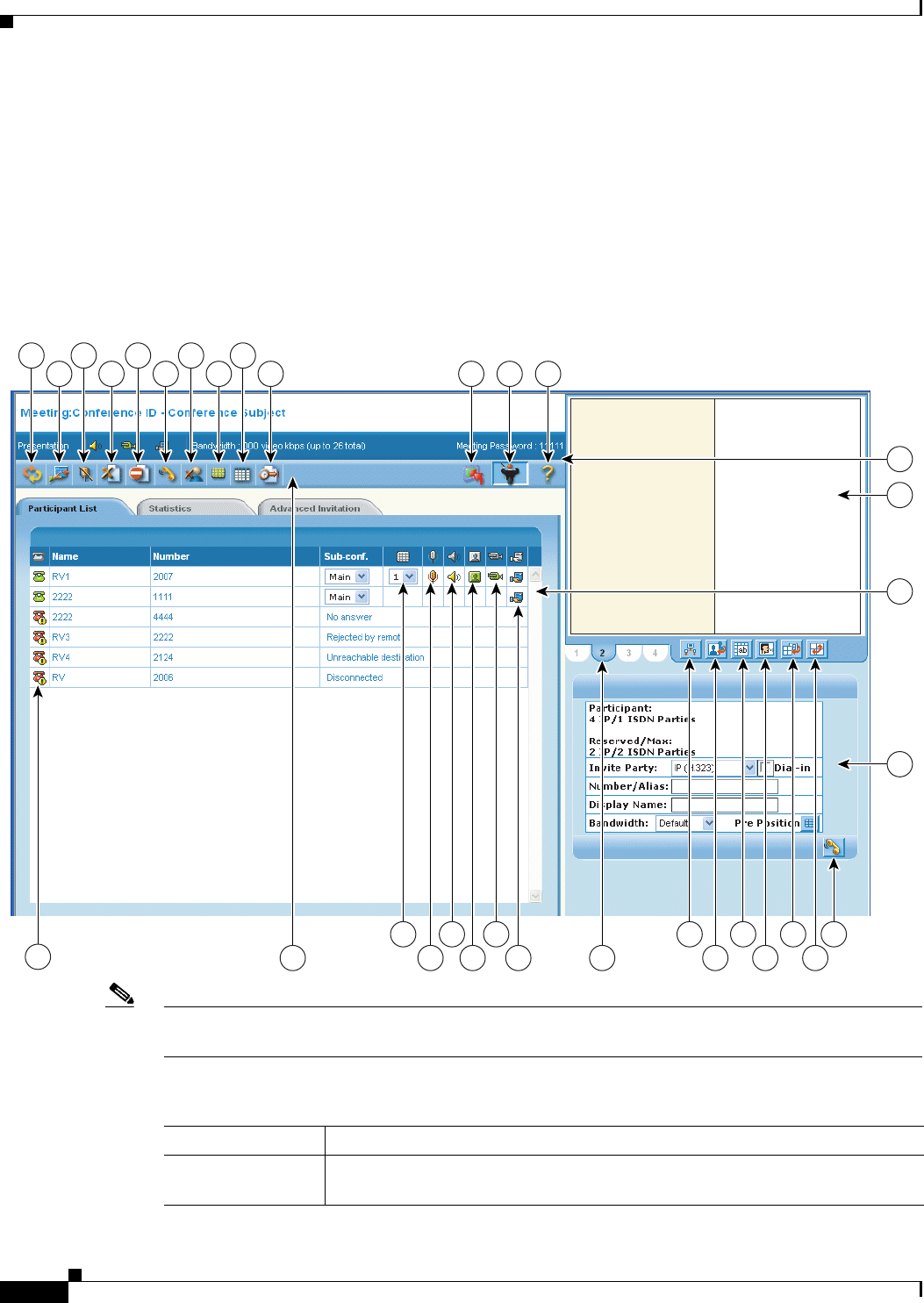
9-4
Administration Guide for Cisco Unified MeetingPlace Video Integration Release 5.4 OL-11153-02
Chapter 9 Using the Video Administration All Meetings Section
Using the Meeting: Conference ID – Conference Subject Screen
• Activating and Deactivating Auto-Switching, page 9-10
• Displaying a Participant or Terminal Name, page 9-10
• Setting a Voice-Activated Frame, page 9-10
• Enabling and Disabling Dynamic Layout, page 9-11
• Changing the Layout, page 9-11
• Inviting Participants, page 9-12
Figure 9-1 Orientation to the Meeting: Conference ID – Conference Subject Screen
Note If you have chair-control privileges, all options in the Meeting: Conference ID – Conference Subject
screen are displayed.
Table 9-1 Reference for Meeting: Conference ID – Conference Subject Screen
Reference Number Description
1Refresh button—Active with chair-control permission. You can refresh the
meeting status at any time.
12345678910 131211
3
0
3
1
3
2
3
3
29
2822
27
26
25
24
23
21
20
19
18
17
16
15
14
190315

9-5
Administration Guide for Cisco Unified MeetingPlace Video Integration Release 5.4
OL-11153-02
Chapter 9 Using the Video Administration All Meetings Section Using the Meeting: Conference ID – Conference Subject Screen
2Join Data Collaboration button—Active with chair-control permission. You can
enable data collaboration between participants that support T.120 data sharing.
Note If the meeting organizer or administrator checks the Start Only When the
Host Joins check box in the Meeting Scheduling section on the Advanced
tab, the Join Data Collaboration button is not available.
3Mute/Enable All button—Active with chair-control permission.
• If you want to mute all participants, select Mute All from the list.
• If you want audio enabled for all participants, select Enable All from the list.
Note If you want to mute or enable audio for a specific participant, on the
Participant tab in the Control Panel area, click the Mic. Enabled button.
4Terminate Meeting button.
5Block Entry button—Active with chair-control permission. To block a
participant from entering a current meeting.
6Reconnect All button.
7Delete Participant button—Active with chair-control permission. You can
disconnect a participant and delete the participant from the Participant List.
Note Before using the Delete Participant button, on the Participant List tab,
select the participant you want to disconnect and remove it from the list.
8Change View to All Participants button.
9Sub Conference button.
10 Extend Conference Duration button.
11 Start Meeting button—Active with chair-control permission.
Note The meeting starts when the host joins the meeting, if the meeting
organizer or administrator checked the Start Only When the Host Joins
check box in the Meeting Scheduling section on the Advanced tab.
12 Take Control button—Active with chair-control permission. To activate the
control panel, on the toolbar click the Take Control button. When chair-control
of the meeting is established, additional options appear in the user interface.
13 Help button.
14 Connection Status icon.
15 Toolbar.
16 Location in View icon.
17 Mic. Enabled icon.
18 Loudspeaker Enabled icon.
19 Monitor Enabled icon.
20 Camera Enabled icon.
21 Data Collaboration Enabled icon.
22 Video Layout tab.
23 Output Scheme Settings button.
Table 9-1 Reference for Meeting: Conference ID – Conference Subject Screen (continued)
Reference Number Description

9-6
Administration Guide for Cisco Unified MeetingPlace Video Integration Release 5.4 OL-11153-02
Chapter 9 Using the Video Administration All Meetings Section
Using the Meeting: Conference ID – Conference Subject Screen
Basic Procedures
See the following procedures:
• To Use In-Meeting Controls, page 9-7
• To Disconnect a Participant, page 9-7
• To Reconnect a Disconnected Participant, page 9-7
• To Reconnect All Participants, page 9-7
• To Change the Meeting View for a Participant, page 9-8
• To Invite a Sub-Conference, page 9-8
• To Extend Meeting Duration, page 9-8
• To Terminate a Meeting, page 9-9
24 Auto-switch button.
25 Display Participant Name in Frame button.
26 Active Speaker button.
27 Dynamic Layout button.
28 Change Layout button.
29 Invite button.
30 General Meeting Display and Control area—Displays general information about
a current meeting (for example, available media types, bandwidth, and meeting
password). The toolbar contains controls as described in the “To Use In-Meeting
Controls” procedure on page 9-7.
31 Video Display area—For adjustment of settings related to video and display
while a meeting is in progress. For details, see the “Defining Video Layout and
Display” section on page 9-9.
32 Control Panel—Includes tabs to access list of participants and terminals in a
meeting, as well as general status information.
33 Video Layout area—Current video layout. Used to adjust settings related to
video layout while a meeting is in progress. For details, see the “Defining Video
Layout and Display” section on page 9-9.
Table 9-1 Reference for Meeting: Conference ID – Conference Subject Screen (continued)
Reference Number Description

9-7
Administration Guide for Cisco Unified MeetingPlace Video Integration Release 5.4
OL-11153-02
Chapter 9 Using the Video Administration All Meetings Section Using the Meeting: Conference ID – Conference Subject Screen
To Use In-Meeting Controls
If you have in-meeting control privileges, you can chair a meeting and you have permissions that include
performance of the following types of tasks:
• Monitoring the entrance of a participant into the meeting
• Re-invitation of a participant who has not connected
• Muting of a participant who is generating background noise
• Blocking of a participant from connecting to a meeting
Only one person is allowed chair-control of a meeting at any given time.
Step 1 On the Current tab, click the subject of the meeting that you want to control.
The Meeting: Conference ID – Conference Subject screen appears.
Note To access the Meeting: Conference ID – Conference Subject screen, you can also click the link
in the e-mail notification for the meeting.
Step 2 To activate the control panel, on the toolbar, click Take Control.
When your chair-control of the meeting is established, additional options appear in the user interface.
Note If the Meeting Organizer selects the Start only when the host joins option, the Take Control
button is unavailable until the host joins the meeting, and the meeting starts.
To Disconnect a Participant
You can disconnect a participant and delete the participant from the Participant List.
Step 1 On the Participant List tab, select the participant you want to disconnect and remove from the list.
Step 2 Click the Delete Participant button on the toolbar.
The participant is disconnected from the meeting, and removed from the list.
To Reconnect a Disconnected Participant
You can reconnect a participant that is disconnected from a meeting.
Step 1 On the Participants List tab, in the Status column, click the red status indicator for the disconnected
participant.
The participant is reconnected.
To Reconnect All Participants
Step 1 On the toolbar, click Reconnect All.

9-8
Administration Guide for Cisco Unified MeetingPlace Video Integration Release 5.4 OL-11153-02
Chapter 9 Using the Video Administration All Meetings Section
Using the Meeting: Conference ID – Conference Subject Screen
All participants are reconnected to the current meeting.
To Change the Meeting View for a Participant
While a meeting is in progress, you can change the meeting view for a single selected participant or for
all participants simultaneously.
Step 1 On the Participant List tab, select the participant for whom you want to change the view.
Note If you do not select a participant, the view changes for all participants.
Step 2 On the toolbar, click the Change View to All Participants button.
The Change participants view screen appears.
Step 3 From the Change to View list, select a view for the participant.
Step 4 Click OK.
To Invite a Sub-Conference
You can divert selected participants in the Participants List of the current conference to attend a new or
currently running private audio sub-conference. Sub-conference participants are hidden in the video
layout.
Step 1 In the Participant List tab, select the participant(s) to invite to a sub-conference.
Step 2 Click the Sub-Conference button on the toolbar.
The Select Sub-Conference screen appears.
Step 3 From the list, select a sub-conference to which you want to invite participants.
Step 4 Click OK.
Note A maximum of three sub-conferences can be supported per meeting. The number of supported
sub-conferences depends on the meeting type configuration.
To Extend Meeting Duration
You can extend the meeting duration while a meeting is in progress.
Step 1 Click the Extend Conference Duration button on the toolbar.
The Extend screen appears.
Step 2 In the Extend field, enter the number of minutes by which you want to extend the duration of the meeting.
Step 3 Click OK.

9-9
Administration Guide for Cisco Unified MeetingPlace Video Integration Release 5.4
OL-11153-02
Chapter 9 Using the Video Administration All Meetings Section Using the Meeting: Conference ID – Conference Subject Screen
To Terminate a Meeting
You can terminate a meeting at any time.
Step 1 On the toolbar, click the Terminate Meeting button.
The meeting is immediately terminated.
Defining Video Layout and Display
The Video Layout and Display area allows meeting controllers to spontaneously control and adjust all
aspects of meeting video. When first accessed, this area displays the video layout as selected during
meeting scheduling. From this view, the meeting controller can do the following:
• In Continuous Presence Mode, view which terminals are set for which video frames.
• View a list of scheduled attendees per terminal by placing the mouse over a video frame (frames set
to auto-switch will not display names).
• Rearrange the video layout per terminal by clicking and dragging terminal names from the Control
Panel terminal list to the desired frame.
• Set voice activated sub-frames.
Defining the Video Output Schemes
When enabled, the video output schemes display up to four available video layouts. Video
Administration can produce up to four different video layouts per meeting to meet the needs of
participants with different video support capabilities, or different viewing purposes.
Multiple meeting views are configured per service with settings that specify video layout, layout
switching and participant layout switching behavior, picture resolution, bandwidth settings, frame rate
and video format.
Multiple meeting views enable the speaker in a lecture to view the participants while the participants
view the speaker. In a meeting with varying connection speeds, participants with high video capabilities
and participants with low video capabilities can take part at the same time without one affecting the
experience of the other.
This is available with EMP support only.
To Set Multiple Video Output Schemes
Step 1 In the Video Display area, click the Output Scheme Settings button.
The Video Scheme Settings dialog box opens.
Step 2 In the Bandwidth column, enter the bandwidth for each video scheme.
Step 3 Click OK.

9-10
Administration Guide for Cisco Unified MeetingPlace Video Integration Release 5.4 OL-11153-02
Chapter 9 Using the Video Administration All Meetings Section
Using the Meeting: Conference ID – Conference Subject Screen
Activating and Deactivating Auto-Switching
Auto-switching mode displays all the participants of a large meeting on a rotating basis when
Continuous Presence mode is selected in the video layout. Participant images can be replaced at preset
intervals either in batches or one by one by way of a queue system.
You can activate or deactivate auto-switching at any time.
Auto-switching overrides any existing video display options.
To Activate and Deactivate Auto-Switching
Step 1 In the Video Display area, click the Auto-Switch button.
The Auto-switch interval screen appears.
Step 2 In the relevant field, enter an auto-switching interval value, between 10 and 108,000 seconds (30
minutes).
Step 3 Click OK.
Video from participating terminals (randomly selected) appears on all other terminals at the defined
interval.
Note To disable auto-switching, click the Auto-Switch button.
Displaying a Participant or Terminal Name
You can display a participant or endpoint (terminal) name in a specific position within the video layout
frame.
Video Administration supports text overlay on participant images when there is EMP support and the
text overlay option is configured for the meeting type.
To Display a Participant or Terminal Name
Step 1 In the Video Display area, click the Display Participant Name in Frame button.
Each participant or endpoint is clearly identified by name, in a text overlay on the video image. The
image of the active speaker is indicated by a border.
Setting a Voice-Activated Frame
You can set a voice-activated frame.
This functionality is available only for views for which a sub-frame is configured.

9-11
Administration Guide for Cisco Unified MeetingPlace Video Integration Release 5.4
OL-11153-02
Chapter 9 Using the Video Administration All Meetings Section Using the Meeting: Conference ID – Conference Subject Screen
To Set a Voice-Activated Frame
Step 1 In the Video Display area, drag the Active Speaker button into the required position within the video
layout frame.
Enabling and Disabling Dynamic Layout
With a dynamic layout, you can switch between a wide range of video layouts for the meeting. With
dynamic layout, the video image automatically includes the number of frames equal to the number of
participant images (up to a maximum of 16). The layout changes according to the number of participants
that join or exit the meeting.
Dynamic layout conserves bandwidth, eliminates the display of empty frames in the video image, and
makes optimal use of the video image display. Dynamic layout is especially suited to a meeting that has
a high rate of participant traffic joining and exiting the meeting, or to an adaptive meeting type that has
a variety of meeting sizes.
Dynamic layout is only available with EMP support.
To Enable or Disable Dynamic Layout
Step 1 To enable a dynamic layout, in the Video Display area, click the Dynamic Layout button.
Step 2 To disable the dynamic layout, click the Dynamic Layout button again.
Note When Dynamic Layout is selected, Change Layout is disabled.
Changing the Layout
Video Administration supports drag and drop control in the meeting control interface for positioning
participant images in the layout during a meeting and in advanced invitations when selecting participants
to join predefined meetings.
To Change the Layout
Step 1 In the Video Display area, click the Change Layout button. The Select Layout screen displays.
Step 2 Select the layout from the options in the Select Layout screen, and then drag and drop the option in the
selected layout area in the Video Display area.

9-12
Administration Guide for Cisco Unified MeetingPlace Video Integration Release 5.4 OL-11153-02
Chapter 9 Using the Video Administration All Meetings Section
Using the Participant List Tab
Inviting Participants
If you have the appropriate privileges, you can invite multiple participants simultaneously to join the
meeting by using the Web interface.
To Invite Participants
Step 1 On the Invite tab, in the Video Layout area, select from the list the type of terminal that you want to
invite. The following options are available:
• IP (H.232)
• IP (SIP)
• PSTN/ISDN (H.320)
• Mobile
Step 2 To enable dial-in terminals to connect to the meeting, check the Dial-In check box.
Step 3 In the Number/Alias field, enter a unique alias for the participant.
Step 4 In the Display Name field, enter the participant name to be displayed on the video screen.
Step 5 In the Bandwidth field, select the appropriate video bandwidth rate from the drop-down list.
Step 6 To position participants in the layout before a meeting, drag the Pre-Position icon to the required position
in the Video Display area.
Step 7 Click the Invite button.
The participant is invited to the meeting. When the participant joins the meeting, the selected video
layout is pre-selected.
Using the Participant List Tab
The Participant List tab enables you to view meeting participant details including media connection
types and available video layouts for the meeting. You can view the details in an alphabetical list or
according to cascaded connections.
Users with chair-control have permission to do the following:
• Invite participants
• Modify participant media connections
• Manually reposition participant images in a video layout
• Modify meeting view layouts
• Specify the position of a voice-activated image in the meeting view
• Create sub-conferences
• View additional participant details
On the Participant List tab, all participants currently invited to a meeting are listed. The following
information about each participant or terminal is included:
• Status—Participant status. To sort by status, click the column heading.

9-13
Administration Guide for Cisco Unified MeetingPlace Video Integration Release 5.4
OL-11153-02
Chapter 9 Using the Video Administration All Meetings Section Using the Participant List Tab
–
Orange status indicates the participant is connecting.
–
Green status indicates that the participant is connected.
–
Red status indicates that the participant is disconnected. Disconnected participants remain in the
Participant List for the duration of the meeting. To reconnect a disconnected participant, click
the red status icon.
–
No status indicator indicates that there are no meeting participants.
• Name—Displays the participant name.
• Number—Displays the endpoint number of the meeting participant.
• Sub-conf.—To divert selected participants in the current meeting to a new meeting or to a private
audio meeting that is currently in progress. This option only appears when sub-conferences are in
progress during a meeting. For more information, see the “To Invite a Sub-Conference” procedure
on page 9-8.
• Location in View—Indicates the meeting view being used for a current participant. When a meeting
is configured with more than one view, select from the list of available views to modify a view for
the selected participant.
• Media Icons—Indicate participant equipment and capacities, such as microphone, loudspeaker,
monitor, camera, and data collaboration. The icons are enabled for users with chair-control
permission related to the media type status for a selected participant. For more information, see the
“Controlling Media Status” section on page 9-13.
Controlling Media Status
If you have chair-control access for controlling the media type status, you can enable or disable the
media capabilities of selected users. See the following procedures:
• To Mute or Enable a Selected Microphone, page 9-13
• To Mute or Enable a Selected Loudspeaker, page 9-14
• To Enable a Selected Monitor, page 9-14
• To Block a Selected Camera, page 9-14
• To Enable Data Collaboration, page 9-14
To Mute or Enable a Selected Microphone
This option is useful in cases when there is unwanted background noise related to a specific participant
or terminal.
Step 1 To mute or enable audio for a selected participant, click the Mic. Enabled icon next to the participant
name.

9-14
Administration Guide for Cisco Unified MeetingPlace Video Integration Release 5.4 OL-11153-02
Chapter 9 Using the Video Administration All Meetings Section
Using the Statistics Tab
To Mute or Enable a Selected Loudspeaker
You can enable or disable a specific participant loudspeaker.
Step 1 To mute or disable a specific loudspeaker, click the Loudspeaker Enabled icon next to a participant
name.
To Enable a Selected Monitor
You can enable a selected monitor.
Step 1 Click the Monitor Enabled icon next to a participant name.
The monitor is enabled for use during the meeting.
To Block a Selected Camera
You can block or unblock a video stream sent by a meeting participant. For example, if the video
connection of a participant affects meeting processing and degrades performance, you can block the
video connection of that participant until endpoint issues are resolved.
Step 1 To enable use of a camera for a participant, click the Camera Enabled icon next to the participant name.
To Enable Data Collaboration
You can enable data collaboration if the terminal of the participant supports T.120 data sharing.
Step 1 To enable data collaboration, click the Data Collaboration Enabled icon next to a participant name.
Using the Statistics Tab
The Statistics tab provides a comprehensive set of statistical information about bandwidth usage and
audio/video packet behavior. Statistics are frequently updated automatically to enable effective
monitoring of meeting performance. Table 9-2 details the elements on the Statistics tab.
Note Information on the Statistics tab is read-only.
Table 9-2 Statistics Tab Elements
Tab Name Description
IP address Participant endpoint IP address.
Description Participant description.
Video Out Addr. IP address and port to which video is sent to the participant.

9-15
Administration Guide for Cisco Unified MeetingPlace Video Integration Release 5.4
OL-11153-02
Chapter 9 Using the Video Administration All Meetings Section Using the Advanced Invitation Tab
Using the Advanced Invitation Tab
The Advanced Invitation tab enables you to invite multiple participants into a meeting at the same time.
Each invite entry box can also contain multiple participant numbers, by using separators. This greatly
extends the number of participants that you can invite at the same time. You can also select a lower
bandwidth rate with which to connect individual participants.
Advanced settings allow you to drag and drop participant images into preferred positions in the layout
of each meeting view supported in the meeting, and to specify the layout which invited participants see
when joining a meeting.
The following sub-tabs are available in the Advanced Invitation tab:
• User—Enables you to simultaneously invite multiple participants to a meeting.
• Terminal—Enables you to simultaneously invite multiple terminals to a meeting.
See the following procedures:
• To Invite Multiple Participants to a Meeting, page 9-15
• To Invite Multiple Terminals to a Meeting, page 9-16
To Invite Multiple Participants to a Meeting
Step 1 In the Advanced Invitation tab, click the User sub-tab.
Step 2 Select the attendees to invite from the Users in Groups drop-down list.
Fps in/out Frame rate of video sent and received by the participant.
Pic. Size in/out Picture size of video sent and received by the participant.
Video Jitter In:
curr/min/max Accumulated video packets received from the participant. Includes the
current value and average values for the minimum and maximum number
of packets received from the participant.
Data IP
Audio BW in/out Total audio bandwidth sent and received by the participant.
Audio Packets in/out Total number of audio packets sent and received by the participant.
Audio Bytes in/out Total number of audio bytes sent and received by the participant.
Audio Out Addr. IP address and port to which audio is sent to the participant.
Audio Jitter In:
curr/min/max Accumulated audio packets received from the participant. Includes the
current value and average values for the minimum and maximum number
of packets received from the participant.
Audio Out of Order
Packets in/out Total number of audio packets sent to and received from the participant
out of sequence.
Audio Lost Packet in/out Total number of lost audio packets sent to and received from the
participant
Table 9-2 Statistics Tab Elements (continued)
Tab Name Description

9-16
Administration Guide for Cisco Unified MeetingPlace Video Integration Release 5.4 OL-11153-02
Chapter 9 Using the Video Administration All Meetings Section
Using the Advanced Invitation Tab
Note If required, you can search for users by entering all or part of the name in the search field, and
clicking Search.
Step 3 Click the right arrow to include these users in the list to be invited.
Step 4 In the Kbps field, select the bit rate to be used when inviting a participant to a meeting. Use the default
setting for optimal bit rate performance.
Step 5 If required, click Advanced and then select a layout option from the view list. Your selection presets the
position of the invited participant image in the video layout when the participant enters the meeting.
Step 6 Drag the Lock Image icon into the preferred position in the Layout Display Frame displayed on the right
side of the Advanced Invitation tab.
Note You can specify a position for the participant image in all layouts currently supported in the
meeting.
Step 7 Click Invite to send the invitation.
To Invite Multiple Terminals to a Meeting
Step 1 On the Advanced Invitation tab, click the Terminal sub-tab.
Step 2 Select the terminals to include in the meeting.
Note If required, you can search for terminals by entering all or part of the name in the search field,
and clicking Search.
Step 3 Click the right arrow to include these terminals in the list to be invited.
Step 4 In the Kbps field, select the bit rate to be used when inviting a terminal to a meeting. Use the default
setting for optimal bit rate performance.
Step 5 If required, click Advanced and then select a layout option from the view list. Your selection presets the
position of the invited terminal image in the video layout when the participant enters the meeting.
Step 6 Drag the Lock Image icon into the preferred position in the Layout Display Frame located on the right
side of the Advanced Invitation tab.
Note You can specify a position for the participant image in all layouts currently supported in the
meeting.
Step 7 Click Invite to send the invitation.

9-17
Administration Guide for Cisco Unified MeetingPlace Video Integration Release 5.4
OL-11153-02
Chapter 9 Using the Video Administration All Meetings Section Using the Upcoming Tab
Using the Upcoming Tab
The Upcoming tab lists all the upcoming video meetings for the entire organization. Information about
each meeting is included under the following column headings:
• Subject—Displays the subject of the meeting. You can click the subject to modify the meeting, for
example to invite additional participants.
• Start Time—Displays the date and time that the meeting is scheduled to start.
• Duration—Displays the meeting length, in minutes.
• Host—Displays the name of the person who is specified as the host of the meeting. The host is
selected from the Host drop-down list in the Attendees Settings tab in the Schedule A New Meeting
section.
• Meeting ID—Displays the unique identifier for the meeting.
You can sort a column by clicking the column header.
See the following procedures:
• To Generate Reports from the Upcoming Tab, page 9-17
• To Modify Upcoming Meetings, page 9-18
To Generate Reports from the Upcoming Tab
You can generate a report in .xls format that shows all of the upcoming meetings that are scheduled
between selected dates. After saving the report, you can view it by using Microsoft Excel.
Step 1 In the Upcoming tab, in the From and To fields, click the calendar icons to select a start and end date
from the popup calendar.
Step 2 Click Generate Report.
Information about each meeting is included in the report. For details, see the “Generated Report
Information Categories” section on page 9-17.
Step 3 To save the report, click Save.
Step 4 In the dialog box that opens, browse to the location in which you want to save the file, enter the file name
and type, and then click Save.
Generated Report Information Categories
The following is a list of the information categories that are included in a generated report.
Note A report generated from the History tab includes the same information categories.
• Virtual Meeting ID
• Master Meeting ID
• Slave Meeting ID
• Cisco Meeting ID
• Subject
• Meeting Type

9-18
Administration Guide for Cisco Unified MeetingPlace Video Integration Release 5.4 OL-11153-02
Chapter 9 Using the Video Administration All Meetings Section
Using the History Tab
• Reference Code
• Start Time
• Duration
• Meeting Room
• Organizer Name
• Service Prefix
• Services
• MCU Name(s)
• Terminals
• Number of Extra IP Ports Reserved
• Number of Extra ISDN Ports Reserved
• Dial-in IP Terminals
• Dial-out IP Terminals
• Dial-in ISDN Terminals
• Dial-out ISDN Terminals
• Gateway List
• Device Failure Cause (Device Name, IP Failure, Cause)
• Attendee Failure Cause (Name, Number, ISDN, Dial-in, Total Time, Failing Attempts, Last Failure
Cause)
To Modify Upcoming Meetings
You can modify an upcoming meeting at any time.
Step 1 On the Upcoming tab, click the Subject of the meeting that you want to modify.
The Modify Meeting screen appears.
Step 2 Enter information according to your requirements.
Using the History Tab
On the History tab, you can view past meetings of a specified user or organization. You can also search
for meetings. A list of all past meetings is displayed.
Information about each meeting is included under the following column headings:
• Subject—Subject of the meeting. To sort by subject, click the column heading.
• Deployment—Deployment in which the meeting was scheduled.
• Start Time—Meeting date and start time. To sort by start time, click the column heading.
• Duration—Length of the meeting, in minutes. To sort by meeting duration, click the column
heading.
• Host—Name of the designated host of the meeting. To sort by host name, click the column heading.

9-19
Administration Guide for Cisco Unified MeetingPlace Video Integration Release 5.4
OL-11153-02
Chapter 9 Using the Video Administration All Meetings Section Using the History Tab
• Status—Meeting termination status. To sort by failure status, click the column heading.
–
Green status indicates successful meeting termination and all participants successfully exited
the meeting.
–
Red status indicates unsuccessful meeting termination or the abnormal exiting of a terminal
from the meeting. To view the Reason Failed error message, click the red status indicator.
Note If a terminal is disconnected correctly via Video Administration in-meeting control, no red
status indicator appears on the History tab details. For details, see the “To Terminate a
Meeting” procedure on page 9-9.
• No status indicator indicates that there are no designated meeting participants.
See the following procedures:
• To Generate Reports from the History Tab, page 9-19
• To View Past Meeting Details, page 9-19
• To Delete Meeting History, page 9-20
To Generate Reports from the History Tab
You can generate a report in .xls format that shows all of the past meetings that were scheduled between
selected dates. After saving the report, you can view it by using Microsoft Excel.
Step 1 In the History tab, in the From and To fields, click the calendar icons to select a start and end date from
the popup calendar.
Step 2 Click Generate Report.
Step 3 To save the report, click Save.
Step 4 In the dialog box that opens, browse to the location in which you want to save the file, enter the file name
and type, and then click Save.
Generated Report Information Categories
For details about information categories that appear in a generated history report, see the “Generated
Report Information Categories” section on page 9-17.
A report generated from the Upcoming and History tabs includes the same information categories.
To View Past Meeting Details
You can view the details of past meetings at any time.
Step 1 On the History tab, click the Subject of the meeting that you want to view.
The Meeting Details screen appears. Each tab on the Meeting Details screen displays settings configured
for all past meetings.

9-20
Administration Guide for Cisco Unified MeetingPlace Video Integration Release 5.4 OL-11153-02
Chapter 9 Using the Video Administration All Meetings Section
Using the History Tab
To Delete Meeting History
You can delete meetings from the History tab at any time.
Step 1 In the History tab, click Delete History.
All past meetings are deleted from the History tab.
Note Deleted meetings appear in billing and reporting statements.
Note History tab search results do not include deleted meetings.
Defining Duration of Meeting History Display
The length of time meeting history remains on the History tab is defined in the My Preferences section.

CHAPTER
10-1
Administration Guide for Cisco Unified MeetingPlace Video Integration Release 5.4
OL-11153-02
10
Video Administration Configuration Tool
This chapter provides information on the requirements, setup and use of the Video Administration
Configuration Tool.
See the following sections:
• Overview, page 10-1
• Java Runtime Environment Quick Setup, page 10-1
• Launching the Video Administration Configuration Tool, page 10-2
• Uninstalling the Video Administration Configuration Tool, page 10-3
• System Configuration Tab, page 10-3
Overview
The Video Administration Configuration Tool is a client-server application, based on Java Web Start.
The Video Administration Configuration Tool allows the system administrator to configure Video
Administration system settings.
During initial installation of Video Administration, network environment settings are defined, while
other configurables (such as page length and meeting identifier) are set to default values so that Video
Administration will run on installation without additional configuration. The Video Administration
Configuration Tool allows the system administrator to access these settings and modify them as
necessary.
Java Runtime Environment Quick Setup
The first time you access the Video Administration Configuration Tool at
http://va_serverhost:port/va-config, the tool automatically detects whether Java Runtime Environment is
installed on the client machine. If it is not, a message appears with a link to the download site.
To Install the Java Runtime Environment
Step 1 Click the Install Java Runtime Environment link.
The Java download web page opens.
Step 2 Click the download link.

10-2
Administration Guide for Cisco Unified MeetingPlace Video Integration Release 5.4 OL-11153-02
Chapter 10 Video Administration Configuration Tool
Launching the Video Administration Configuration Tool
The Java Runtime Environment is installed on your computer and the Java download Web page displays
again.
Step 3 Click the previous page link.
The Video Administration Configuration Tool launch page appears.
Launching the Video Administration Configuration Tool
The Video Administration Configuration Tool can be accessed from any client machine with the Java
Web Start application installed.
See the following procedures:
• To Access the Video Administration Configuration Tool from a Browser, page 10-2
• To Set Up Access via a Shortcut, page 10-2
To Access the Video Administration Configuration Tool from a Browser
Step 1 Go to http://va_serverhost:port/va-config. The Video Administration Configuration Tool launch page
displays.
Step 2 Click the Launch Video Administration Configuration Tool link.
On launching, the configuration tool checks for any updated files to download to the client machine. The
Warning Security screen appears.
Step 3 Click Yes to display the login screen.
Step 4 Enter the applicable login ID and password.
Note To retrieve a forgotten password, click the green arrow in the Video Administration
Configuration Tool login screen, enter the applicable login ID, and press Send. The password
will be sent to the e-mail address for that login ID.
Step 5 Enter the administrator security credentials set during installation. The Configuration Tool opens.
To Set Up Access via a Shortcut
The second time that the Video Administration Configuration Tool is opened from a client machine, you
will be asked if you would like to place a shortcut on the desktop and/or in the start menu.
Step 1 To create shortcuts, leave one or both check boxes checked.
Step 2 Click Yes.

10-3
Administration Guide for Cisco Unified MeetingPlace Video Integration Release 5.4
OL-11153-02
Chapter 10 Video Administration Configuration Tool Uninstalling the Video Administration Configuration Tool
Uninstalling the Video Administration Configuration Tool
This section describes how you uninstall the Video Administration Configuration Tool when working
with either Java Runtime Environment (JRE) 1.5/5.0.
To Uninstall the Video Administration Configuration Tool When Working with JRE 1.5/5.0
Step 1 From the Start menu, go to Settings > Control Panel > Add or Remove Programs.
Step 2 Select Video Administration Configuration Tool and click Change/Remove to remove the Video
Administration Configuration Tool from the system.
System Configuration Tab
Video Administration system configuration uses the System Configuration tab. The System
Configuration tab contains the following sub-tabs:
• General Settings Tab, page 10-3
• Scheduling Settings Tab, page 10-4
• UI Settings Tab, page 10-6
• Customized Settings Tab, page 10-6
• Database Settings Tab, page 10-7
• Security Settings Tab, page 10-8
• SNMP Security Traps Settings Tab, page 10-8
General Settings Tab
The General Settings tab allows the system administrator to configure basic system settings for the Video
Administration server. Values displayed are values currently in effect.
E-Mail Server Settings
This section allows configuration of settings for the e-mail server used to send the Video Administration
e-mail notifications for meeting reservations and updates as well as user maintenance.
Host—Enter the mail server address, using either IP address or domain name.
Port—Enter the mail server communications port.
Login ID—Enter the security principal if necessary for sending an e-mail.
Password—Enter the security principal if necessary for sending an e-mail.
EP Unconnected Timeout
If an endpoint does not respond to a connection request from the system within the designated timeout
period, the system treats this endpoint as an unconnected endpoint.

10-4
Administration Guide for Cisco Unified MeetingPlace Video Integration Release 5.4 OL-11153-02
Chapter 10 Video Administration Configuration Tool
System Configuration Tab
IVR Message Index
This section enables you to configure the Video Administration to play an IVR billing announcement
every time a user joins a meeting.
Message Index for Dial-in Endpoints—Enter an IVR message index for billing all dial-in participants.
Message Index for Dial-out Endpoints—Enter an IVR message index for billing all dial-out
participants.
Resource Allocation
Low-Usage Threshold—Designate a percentage of total MCU ports as the low usage threshold. If more
than one MCU is equally suited to host a meeting, Video Administration will allocate the meeting under
a load balancing principle by using this threshold. If over this threshold, Video Administration will not
balance the load across MCUs, but rather fill one MCU at a time to reserve space on other MCUs for a
larger meeting and to avoid unnecessarily spanning the meeting across multiple MCUs.
Note The term “port” refers to a Video Administration connection to an endpoint. For example, a
meeting with five participating endpoints uses five ports. A call via a gateway to an MCU uses
one port. Where a meeting spans multiple MCUs for bandwidth optimization, an additional port
is required on each MCU. For example, a meeting spanning two MCUs in which three
participating endpoints are on the first MCU and four participants are on the second MCU
requires nine ports (7 endpoints + 2 MCUs).
Max. Reservation Threshold—Designate the percentage of total MCU ports that can be scheduled by
Video Administration. The default setting is 80 percent, leaving 20 percent of resources for extended
meetings or additional unscheduled resource needs.
Display Settings
Number of Table Rows per Page—Designate the number of table row entries per page for Video
Administration tables, including in-session meetings, upcoming meetings, history meetings, user table,
terminal table, and so on.
Command Delay
Delay Between Two Commands from Video Administration to MCU—Enter a value to determine the
length of time Video Administration waits between sending internal communication messages to an
MCU.
Scheduling Settings Tab
The Scheduling Settings tab allows the system administrator to configure basic system settings for the
Video Administration server. Values displayed are values currently in effect.
Meeting Settings
Authorize Endpoint Initiated Calls—Check to allow the Video Administration to authorize and
perform resource allocation and management of calls that are initiated by an endpoint, in the same way
that it does for ad hoc calls initiated from Video Administration. This option is selected by default but
may be deselected to improve performance.
Duration of Endpoint Initiated Calls—Enter the duration of calls that are initiated by endpoints. This
value is used by Video Administration for resource allocation and meeting creation, and is set by default
to 30 minutes.

10-5
Administration Guide for Cisco Unified MeetingPlace Video Integration Release 5.4
OL-11153-02
Chapter 10 Video Administration Configuration Tool System Configuration Tab
Authorize MCU Calls—Check to allow Video Administration to authorize MCU-to-endpoint calls
according to the scheduled meeting in Video Administration. Doing so ensures that the gateway chosen
is the one that is allocated for the call within Video Administration. This option is selected by default,
but can be deselected for all-IP or single-gateway networks to improve performance.
Admit Unresolved PSTN/ISDN Calls—When checked, enables PSTN/ISDN terminals for which
source information is not available to dial into a Video Administration-scheduled meeting. Unresolved
terminals are allowed into the meeting if there are resources available (if extra PSTN/ISDN ports have
been reserved or if a PSTN/ISDN terminal has been deleted from the ongoing meeting). When
unchecked, unresolved ISDN terminals are rejected during authorization for dial-in calls. By default,
field is checked.
Default Dialing Mode—Set the default value for whether a participant dials into a conference or the
conference dials out to the participant.
Meeting ID Length—Enter the number of digits to be used in meeting ID strings.
Minimum # Terminals Allowed in a Scheduled Meeting—Set the minimum number of terminals that
must be selected to create a valid meeting.
Maximum # Terminals Allowed in a Scheduled Meeting—Set the maximum number of terminals that
can be added to a meeting.
Minimum # Terminals Allowed in an Ad-Hoc Meeting—Set the minimum number of terminals that
must be selected to create a valid meeting.
Maximum # Terminals Allowed in an Ad-Hoc Meeting—Set the maximum number of terminals that
can be added to a meeting.
Launch Meetings—Set the length of time before the scheduled start time of a meeting that you want the
meeting to be launched.
Meeting Auto Extension Length—Define the number of minutes by which a meeting auto-extends.
Maximum Length of Meeting Extension—Set the maximum amount of time by which any meeting can
be extended, and select the unit of time.
Allowable Scheduling Interval—Set the minimum time before a meeting start time the meeting must
be scheduled, and the maximum time before the meeting start time that the meeting may be scheduled.
For example, if this value is set to be from 1 hour to 30 days, a meeting must be scheduled at least an
hour before its start time and cannot be scheduled more than 30 days in advance. These settings do not
apply to ad hoc meetings.
Allowable Duration for a Scheduled Meeting—Set the minimum and maximum length of scheduled
meetings. For example, setting this value to be from 10 minutes to 2 hours means that Video
Administration will not validate any meeting shorter than 10 minutes or longer than 2 hours.
Allowable Duration for an Ad Hoc Meeting—Set the minimum and maximum length of ad hoc
meetings. For example, setting this value to be from 10 minutes to 2 hours means that Video
Administration will not validate any meeting shorter than 10 minutes or longer than 2 hours.
Waiting Room Timeout—If waiting room is enabled for a conference, define the number of minutes a
conference remains in waiting room mode until the host joins. If the host does not join within the defined
time period, the conference ends.
Recurring Meeting Scheduling Settings
Schedule Recurring Meetings—Enter a value in days to set the time interval for which Video
Administration allocates meeting resources when a recurring meeting is scheduled. For example, when
set to 30 days, Video Administration allocates all meeting instances within a 30-day period at the time
a recurring meeting is scheduled and sends an e-mail detailing information for those meetings. 30 days

10-6
Administration Guide for Cisco Unified MeetingPlace Video Integration Release 5.4 OL-11153-02
Chapter 10 Video Administration Configuration Tool
System Configuration Tab
from the time the recurrence was scheduled, Video Administration will allocate the meeting to occur
within the following 30 days. This cycle continues until all instances within the series have been
scheduled.
UI Settings Tab
The UI Settings tab suppresses the advanced configuration screen to simplify the Web interface.
IP Topology—Uncheck to hide the IP Topology screen under Admin > Network Management.
ISDN Topology—Uncheck to hide the ISDN Topology screen under Admin > Network Management.
Gatekeeper Definition—Uncheck to hide the Gatekeeper/SIP Server screen under Admin > Resource
Management.
Meeting Scheduling/Meeting Template—Uncheck to hide the Meeting Scheduling and Meeting
Template menus under User.
All Meetings—Uncheck to hide the All Meetings menu under Admin.
My Meetings—Uncheck to hide the My Meetings menu under User.
Advanced Settings—Uncheck to hide the Advanced Settings menu under Admin.
Other Settings—Uncheck to hide the Other Settings screen under Admin > Advanced Settings.
User Management—Uncheck to hide the User Management menu under Admin.
Customization Tool—Uncheck to hide the Customization tool icon next to the Help About screen icon.
The Customization Tool is used to define custom display labels for the Web interface. Click the
Customization Tool icon to open a pop-up window in which you can configure custom display labels in
the Web interface.
Customized Settings Tab
The Customized Settings tab displays any non-standard or new time zones that have been added to the
time zone selection box. Once added, a time zone cannot be modified or deleted.
Custom Time Zone(s)
Displays a list of time zones that have been added to the Video Administration standard time zone set.
If no time zones have been added, the list displayed will be empty. Click a time zone to display its profile
to the right.
Time Zone Name—Displays the name of the specified time zone.
Time Difference from GMT—Displays the number of hours before or after GMT.
Daylight Saving—Displays the number of minutes the clock is set forward or back at the designated
start and end times.
DST Start Time—Set the date and time at which daylight saving begins.
DST End Time—Set the date and time at which daylight saving ends.
Add a New Time Zone—Click to display the New Time Zone dialog box. For more information, see
the “Adding a New Time Zone” section on page 10-7.

10-7
Administration Guide for Cisco Unified MeetingPlace Video Integration Release 5.4
OL-11153-02
Chapter 10 Video Administration Configuration Tool System Configuration Tab
Reset—Click to remove a time zone. After you add a time zone, but before you click Save in the
Customized Settings tab (not Save in the New Time Zone dialog box), clicking Reset enables you to
remove the time zone. You cannot remove a time zone after you have clicked Save in the Customized
Settings tab.
Branding Customized
Enables you to select the product and vendor logo to display in Video Administration.
Product Logo File Name—Enter the name of the file holding the required product logo, or navigate to
the file by using the Browse button.
Browse—Click to navigate to the file holding the required product logo.
URL—Enter the URL of the required product logo.
Note Product logo-related options are available in Video Administration only if the Branding option
is checked in the Installation With Advanced Options installation screen.
Reset to Default—Click to restore the system default product logo. Enabled only if the license allows
product logo branding.
Billing Customized
For the billing code field in the meeting scheduling process, define a custom field label and specify the
format of the value that can be entered.
Adding a New Time Zone
In the Customized Settings tab, click Add a New Time Zone. The New Time Zone dialog box displays.
Time Zone Name—Enter the name of the new time zone.
Time Difference from GMT—Select the number of hours and minutes before or after GMT.
Observes Daylight Saving—Check to enable Daylight Saving settings.
DST Start Time—Set the date and time which daylight saving begins.
DST End Time—Set the date and time which daylight saving ends.
Save—Click to save the new time zone. The new time zone is added to your Video Administration time
zone set.
Database Settings Tab
The Database Settings tab is used for configuring the database server settings.
Server Name—Name of IP address of the database server.
Server Port—Database port number of the database server.
Connection Account—User account used by the system to connect to the database.
Connection Password—User account password used by the system to connect to the database.
Test Button—Used to test whether database configuration is correct.
Reset Button—Roll back unsaved changes.

10-8
Administration Guide for Cisco Unified MeetingPlace Video Integration Release 5.4 OL-11153-02
Chapter 10 Video Administration Configuration Tool
System Configuration Tab
Security Settings Tab
The Security Settings tab is used to configure password and other security settings.
Passwords Management
Display Password in User Profile—Check to display the user profile password.
Modify Password in User Profile—Check to modify the user profile password.
Allow Only Secure Passwords—Only accept strong passwords as user passwords. Strong passwords
need to follow the rules for Minimum Password Length, Maximum Login Attempts, Password Expires
in xxx Day(s), and Cannot Be the Same as the Last xxx Password(s).
Minimum Password Length—Minimum length of a user password in number of characters.
Maximum Login Attempts—Maximum number of incorrect logins a user can attempt before the user
account is locked.
Password Expires in xxx Day(s)—A user password expires in the specified number of days since it was
last changed.
Cannot Be the Same as the Last xxx Password(s)—A new user password cannot duplicate the
specified number of old user passwords.
Display Login Message—Check the check box to display a welcome screen after user login. The text
of the welcome screen can be customized by entering text in the text area.
SNMP Security Traps Settings Tab
The SNMP Security Traps Settings tab is used to define the IP addresses and port numbers of the SNMP
trap servers to which the system sends traps.

CHAPTER
11-1
Administration Guide for Cisco Unified MeetingPlace Video Integration Release 5.4
OL-11153-02
11
Managing Video Administration for Cisco Unified
MeetingPlace
This chapter contains optional procedures that may or may not need to be done, depending on your
deployment. For procedures that are required for configuration of the Video Administration, see the
“Configuring Video Administration for Cisco Unified MeetingPlace” chapter.
See the following sections:
• Network Management, page 11-1
• Changing the Host Name of the Video Administration Server, page 11-6
Network Management
The Network Management section enables you to map topology for IP and ISDN resources.
Note Network Management is hidden by default according to settings in the Configuration Tool. For details
about using the Configuration Tool, see the “Video Administration Configuration Tool” chapter.
To Access Network Management
Step 1 In the sidebar menu, go to Network Management.
Step 2 The Network Management section contains the following tabs:
• IP Topology—See the “Using the IP Topology Tab” section on page 11-2.
• ISDN Topology—See the “Using the ISDN Topology Tab” section on page 11-4.
Note We recommend that you configure the tabs in the order that they appear.

11-2
Administration Guide for Cisco Unified MeetingPlace Video Integration Release 5.4 OL-11153-02
Chapter 11 Managing Video Administration for Cisco Unified MeetingPlace
Network Management
Using the IP Topology Tab
IP Network Topology is the foundation of intelligent resource allocation. It allows Video Administration
to model the video network by recording distance and bandwidth between Device Islands—IP locations
where central and essential devices (such as gatekeepers, MCUs, and gateways) are placed—and to
perform Least Cost Routing over the IP network. An IP endpoint is also associated with its nearest
Device Island when the endpoint is configured in Video Administration. This information is used by
Video Administration to determine the best MCU and gateway resources to reserve for any call.
IP Network Topology is an advanced that is feature enabled in the Video Administration Configuration
Tool.
In general, a Device Island should be created for each location containing network devices, such as an
MCU, endpoint or terminal. Video Administration monitors the bandwidth limitations and distance
between each of the Device Islands.
The IP Topology tab displays distance and bandwidth information for all Device Islands within your
video meeting network.
The following parameters are included in the IP Topology table
• Distance—Distance between the specified Device Islands relative to all other configured islands on
the organization LAN. This setting is used to find and allocate the best available resources. The
Distance value is a weight factor that describes relative network delay between two Device Islands.
The larger the distance, the larger the round trip delay caused by the network between two Device
Islands. The distance should be an attribute proportional to the network delay. One logical way to
model delay is to “ping” the connection between the two LANs and use the average delay results.
• Bandwidth—Bandwidth connection (in Kbps) between specified Device Islands. This setting is used
in bandwidth control during resource allocation. The Bandwidth field represents the connection
bandwidth (in Kbps) between any two Device Islands that can be used for video meetings. This is
defined by the narrowest section of bandwidth, usually one of the outgoing connections from the
LAN.
See the following procedures:
• To Access the IP Topology Tab, page 11-2
• To View Device Islands, page 11-2
• To Connect Device Islands, page 11-3
• To Add a Device Island, page 11-3
• To Modify a Device Island, page 11-3
• To Delete a Device Island, page 11-4
To Access the IP Topology Tab
Step 1 In the sidebar menu, select Network Management.
By default, the IP Topology tab is displayed.
To View Device Islands
Step 1 Click Display Location.

11-3
Administration Guide for Cisco Unified MeetingPlace Video Integration Release 5.4
OL-11153-02
Chapter 11 Managing Video Administration for Cisco Unified MeetingPlace Network Management
Note By default, upon first viewing of the IP Topology screen, the first eight Device Islands are
displayed.
Step 2 In the screen that opens, select the IP locations that you want to be included in the grid display on the
IP Topology tab. A maximum of eight locations can be displayed.
Step 3 Click Search.
The selected device islands appear in the grid display.
To Connect Device Islands
Step 1 Verify that information is included in the Distance and Bandwidth fields in the cell between the Device
Islands.
Step 2 To remove connectivity between two Device Islands, delete the Distance and Bandwidth values.
Because there may be two cells that display the same connectivity setting between two Device Islands,
if you modify the values in one of the cells, the same new values appear in the other cell.
To Add a Device Island
Step 1 On the IP Topology tab, click Add.
An empty row appears with all of the existing Device Island displayed as columns, and at the bottom of
the tab, an OK button and a Cancel button replace the Add button.
Step 2 In the Distance and Bandwidth fields in each column, enter information for the new Device Island.
Step 3 Click OK.
The Device Island is added to the IP topology.
To Modify a Device Island
You can modify the parameters of a Device Island.
Step 1 On the IP Topology tab, search for the Device Islands that you want to modify. For details, see the “To
View Device Islands” procedure on page 11-2.
Step 2 For each Device Island you want to modify, edit the Distance or Bandwidth field as required.
Step 3 Click OK.

11-4
Administration Guide for Cisco Unified MeetingPlace Video Integration Release 5.4 OL-11153-02
Chapter 11 Managing Video Administration for Cisco Unified MeetingPlace
Network Management
To Delete a Device Island
You can delete a Device Island that is no longer needed in the topology. Note that you cannot recover a
Device Island once it is deleted.
Step 1 On the IP Topology tab, search for the Device Islands that you want to delete. For details, see the “To
View Device Islands” procedure on page 11-2.
Step 2 Click the X mark above the Device Island that you want to delete.
Step 3 If any devices are currently assigned to the Device Island that you want to delete, in the Reassign Device
Island screen that appears, select the Device Island you want to reassign the devices to, and then click
Reassign.
Using the ISDN Topology Tab
ISDN Network Topology is designed to intelligently manage ISDN/PSTN network connectivity and
cost, gateway numbers, and ISDN terminal numbers are assigned to ISDN Device Islands. This allows
Video Administration to perform Least Cost Routing over the ISDN network.
ISDN Network Topology is an advanced feature enabled in the Video Administration Configuration
Tool.
ISDN/PSTN Least Cost Routing is also performed based on country codes, area codes of gateway
numbers and ISDN terminal numbers belonging to the same ISDN Device Island. Costly phone or ISDN
line-usage is reduced by selecting the least costly gateway resources.
The ISDN Topology tab displays connectivity and distance information for all Device Islands within
your ISDN network. The following parameter is included in the ISDN Topology table:
• Cost—Cost of an ISDN call between the specified Device Islands relative to all other configured
islands on the organization ISDN network. This setting is used to find and allocate the best available
resources.
See the following procedures:
• To Access the ISDN Topology Tab, page 11-4
• To View Device Islands, page 11-5
• To Connect Device Islands, page 11-5
• To Add a Device Island, page 11-5
• To Modify a Device Island, page 11-5
• To Delete a Device Island, page 11-6
To Access the ISDN Topology Tab
Step 1 In the sidebar menu, select Network Management.
Step 2 In Network Management, select the ISDN Topology tab.

11-5
Administration Guide for Cisco Unified MeetingPlace Video Integration Release 5.4
OL-11153-02
Chapter 11 Managing Video Administration for Cisco Unified MeetingPlace Network Management
To View Device Islands
Step 1 Click Display Location.
Note By default, upon first viewing of the ISDN Topology screen, the first eight Device Islands are
displayed.
Step 2 In the screen that opens, select the IP locations that you want to be included in the grid display on the
ISDN Topology tab. A maximum of eight locations can be displayed.
Step 3 Click Search.
The selected device islands appear in the grid display.
To Connect Device Islands
Step 1 Verify that information is included in the Cost field for the device.
Step 2 To remove the connectivity between two Device Islands, delete the Cost value.
Because there may be two cells that display the same connectivity setting between two Device Islands,
if you modify the values in one of the cells, the same new values appear in the other cell.
To Add a Device Island
Step 1 On the ISDN Topology tab, click Add.
An empty row appears with all of the existing Device Islands displayed as columns, and at the bottom
of the tab, an OK button and a Cancel button replace the Add button.
Step 2 In the Cost field in each column, enter information for the new Device Island.
Step 3 Click OK.
The Device Island is added to the ISDN topology.
To Modify a Device Island
Step 1 On the ISDN Topology tab, search for the Device Islands that you want to modify. For details, see the
“To View Device Islands” procedure on page 11-5.
Step 2 For each Device Island that you want to modify, edit the Cost field as required.
Step 3 Click OK.

11-6
Administration Guide for Cisco Unified MeetingPlace Video Integration Release 5.4 OL-11153-02
Chapter 11 Managing Video Administration for Cisco Unified MeetingPlace
Changing the Host Name of the Video Administration Server
To Delete a Device Island
You can delete a Device Island that is no longer needed in the topology. Note that you cannot recover a
Device Island once it is deleted.
Step 1 On the ISDN Topology tab, search for the Device Islands that you want to delete. For details, see the “To
View Device Islands” procedure on page 11-5.
Step 2 Click the X mark above the Device Island that you want to delete.
Step 3 If any devices are currently assigned to the Device Island that you want to delete, in the Reassign Device
Island screen that appears, select the Device Island you want to reassign the devices to, and then click
Reassign.
Changing the Host Name of the Video Administration Server
To manually change the host name of the Video Administration server, do the following procedure:
To Change the Host Name of the Video Administration Server
Step 1 Go to C:\Program Files\Cisco\Video Admin\VA\jboss-3.2.5\bin (default).
Step 2 Make a backup copy of the file Vcs-config.xml.
Step 3 Open the file Vcs-config.xml with a text editing tool.
Step 4 Modify the <host-url> element to the required value, then save the file.
Step 5 Restart the Video Admin service.

CHAPTER
12-1
Administration Guide for Cisco Unified MeetingPlace Video Integration Release 5.4
OL-11153-02
12
Video Administration Backup and Restore
Procedures
This chapter provides procedures for backing up and restoring the Video Administration database and
configuration files. See the following sections:
• Backup Procedure, page 12-1
• Restoring Procedure, page 12-4
Backup Procedure
This section describes how to back up Video Administration data. See the following sections:
• Backing Up the Database, page 12-1
• Backing Up Configuration Files, page 12-3
• Backing Up Branding and Sound Files, page 12-4
Backing Up the Database
This section describes how to back up the Video Administration database using the Enterprise Manager
utility that comes with Microsoft SQL Server 2000 Standard and Enterprise editions. The Microsoft SQL
Server 2000 Desktop Edition (MSDE) installation does not come with the Enterprise Manager utility by
default. For a database on an MSDE server, you need an external Microsoft SQL Enterprise Manager to
connect to the MSDE server.
Note The external server with Microsoft SQL Enterprise Manager must be in the same subnet as the MSDE
server for the backup procedure to be successful.
If you configured Video Administration to use Microsoft SQL Server 2000 Desktop Edition (MSDE)
perform the following procedures:
• “To Connect To an MSDE Database Server” procedure on page 12-2
• “To Back Up the Database” procedure on page 12-2
If you configured Video Administration to use Microsoft SQL Server 2000 Standard Edition or
Enterprise Edition, perform the following procedure:

12-2
Administration Guide for Cisco Unified MeetingPlace Video Integration Release 5.4 OL-11153-02
Chapter 12 Video Administration Backup and Restore Procedures
Backup Procedure
• “To Back Up the Database” procedure on page 12-2
To Connect To an MSDE Database Server
Step 1 Open Microsoft SQL Enterprise Manager on a SQL 2000 Server.
Step 2 In Enterprise Manager, right-click SQL Server Group and select New SQL Server Registration. The
Register SQL Server Wizard launches.
Step 3 Click Next. The Select a SQL Server page appears.
Step 4 From the list of Available Servers, select the name of the server that the Video Administration is installed
on and click Add.
Step 5 Click Next. The Select an Authentication Mode page appears.
Step 6 Select the SQL Server Authentication radio button and click Next.
Step 7 Select the Login Automatically Using My SQL Server Account Information radio button.
Step 8 Enter the Login Name and Password that you created when you installed MSDE.
To Back Up the Database
Step 1 Open the Video Administration database by using the MSSQL Enterprise Manager. By default, the
installed Video Administration database name is cisco_core_db and the default user name is
cisco_core_user. The actual name of the database and user name is configurable during the installation
process.
Step 2 In Enterprise Manager, under the server name that the Video Administration database resides, right-click
Databases and select New Database. The Database Properties dialog box displays.
Step 3 Give the new database a name, for example cisco_core_db_new, and click OK.
Step 4 Right-click the cisco_core_db_new database, and select All Tasks > Import Data. This will launch the
DTS Import/Export Wizard.
Step 5 In the Choose a Data Source dialog box:
–
In the Data Source field, select Microsoft OLE DB Provider for SQL Server (default).
–
Select the server from the list.
–
Select the Use SQL Server Authentication radio button.
–
Enter the username and password for cisco_core_db.
–
Choose cisco_core_db as the database.
–
Click Next.
Step 6 In the Choose a Destination dialog box, cisco_core_db_new should be selected by default as the
database destination. Click Next.
Step 7 In the Specify Table Copy or Query dialog box, select the Copy Table(s) and View(s) From the Source
Database radio button and click Next.
Step 8 In the Select Source Tables and Views dialog box, click Select All and then click Next.
Step 9 In the Save, Schedule, and Replicate Package dialog box, check the Run Immediately check box and
click Next to run the import procedure.

12-3
Administration Guide for Cisco Unified MeetingPlace Video Integration Release 5.4
OL-11153-02
Chapter 12 Video Administration Backup and Restore Procedures Backup Procedure
Step 10 To generate an SQL script from the cisco_core_db database to reapply the relationship between tables,
go to cisco_core_db database and select All Tasks > Generate SQL Script. The Generate SQL Scripts
dialog box opens.
Step 11 On the General tab:
–
Click the Show All button
–
Check the Script All Objects check box.
Step 12 On the Formatting tab, uncheck all of the check boxes.
Step 13 On the Options tab:
–
Uncheck the check boxes in the Security Scripting Options
–
Check the check boxes in the Table Scripting Options
–
Select the Windows Text (ANSI) radio button
–
Select the Create One File radio button
–
Click OK.
Step 14 In the Save As dialog box, give the script file a name that ends with .sql.
Step 15 Once the SQL script is created, open the script in a text editor and replace all instances of the string
“[cisco_core_user]” with “[dbo]”.
Note cisco_core_user is the database owner of the database cisco_core_db. The goal is to change the
owner of the new cisco_core_db_new database to “dbo” so that this database can be restored on
any external database.
Step 16 To run the script on cisco_core_db_new database, select the cisco_core_db_new database, and select
the Tools > SQL Query Analyzer menu.
Step 17 In SQL Query Analyzer, open the script file you created in Step 14.
Step 18 Press F5 to apply the script to the database. You will see the following message in the Query Analyzer
window:
The command(s) completed successfully.
Step 19 Close SQL Query Analyzer.
Step 20 Select and right-click the cisco_core_db_new database, and select All Tasks > Backup Database to
create a database backup file.
Step 21 In the SQL Server Backup dialog box:
–
Check the Database - Complete radio button (default).
–
Click the Add button, select a file name for backup destination, and click OK.
–
Click OK.
Backing Up Configuration Files
This section describes how to back up the following files by copying them to a different physical
location:
• Database Connectivity Property File, page 12-4

12-4
Administration Guide for Cisco Unified MeetingPlace Video Integration Release 5.4 OL-11153-02
Chapter 12 Video Administration Backup and Restore Procedures
Restoring Procedure
• Configuration Files, page 12-4
• LDAP Configuration Files, page 12-4
Database Connectivity Property File
Back up the mssql-ds.xml file under the directory C:\Program Files\Cisco\Video
Admin\VA\jboss-3.2.5\server\all\deploy to a different physical location.
Configuration Files
Back up the following files under the directory C:\Program Files\Cisco\Video
Admin\VA\jboss-3.2.5\bin to a different physical location:
• vcs-cdr-config.xml
• vcs-config.xml
• vcs-core.properties
• vnex.properties
LDAP Configuration Files
Back up the following files under the directory C:\Program Files\Cisco\Video
Admin\VA\jboss-3.2.5\bin\configFiles to a different physical location:
• All files (if any) under this directory.
Backing Up Branding and Sound Files
Back up all files (if any) located under the directory C:\Program Files\Cisco\Video
Admin\VA\jboss-3.2.5\server\default\deploy\branding.war\image to a different physical location.
Restoring Procedure
This section describes how to restore Video Administration data. See the following sections:
• Procedure Overview, page 12-4
• Restoring the Database, page 12-5
• Restoring Configuration Files, page 12-6
• Restoring Branding and Sound Files, page 12-6
• Restart the Video Administration Service, page 12-6
Procedure Overview
The restoring procedure includes the following stages:
1. Stop the Video Administration service:
–
Go to Control Panel > Administrative Tools > Services.

12-5
Administration Guide for Cisco Unified MeetingPlace Video Integration Release 5.4
OL-11153-02
Chapter 12 Video Administration Backup and Restore Procedures Restoring Procedure
–
Find the service named “Cisco Video Administration” and stop it.
2. Restore the database—see the “Restoring the Database” section on page 12-5.
3. Restore the configuration files—see the “Restoring Configuration Files” section on page 12-6.
4. Restore the Branding and Sound Files—see the “Restoring Branding and Sound Files” section on
page 12-6.
5. Start the Video Administration service.
Restoring the Database
This section describes how to restore the Video Administration database using the MSSQL Enterprise
Manager. Prior to restoring, you must have the Video Administration software installed. You will be
restoring a backed up database into the existing database.
To Restore the Database
Step 1 Stop the Video Administration service:
–
Go to Control Panel > Administrative Tools > Services.
–
Find the service named “Cisco Video Administration” and stop it.
Step 2 Open the Video Administration Database by using the Microsoft SQL Enterprise Manager utility. The
Microsoft SQL Server 2000 Desktop Edition (MSDE) installation does not come with Enterprise
Manager by default. For a database on an MSDE server, you need an external Microsoft SQL Enterprise
Manager to connect to the MSDE server.
Step 3 Select and right-click the clisco_core_db database and select All Tasks > Restore Database. The
Restore Database dialog box opens.
Step 4 On the General tab:
–
Select the From Device radio button
–
Click the Select Devices button and browse to the MSSQL database backup file you created in
the backup procedure.
–
Select the Restore Backup Set and Database-Complete radio buttons.
Step 5 On the Options tab:
–
Check the Force Restore Over Existing Database check box.
–
Under the “Move to Physical File Name” column, make sure that the name of the data and log
files are cisco_core_db.MDF and cisco_core_db_Log.LDF.
–
Leave the values under the “Logic File Name” column untouched.
–
Select the Leave Database Operational – No Additional Transaction Logs Can Be Restored
radio button.
–
Click OK.
The database is successfully restored.
Step 6 In the SQL server tree control, select Security > Logins and double-click the Video Administration
database user (for example, cisco_core_user). The SQL Server Login Properties dialog box opens.
Step 7 On the Database Access tab:

12-6
Administration Guide for Cisco Unified MeetingPlace Video Integration Release 5.4 OL-11153-02
Chapter 12 Video Administration Backup and Restore Procedures
Restoring Procedure
–
Under “Specify Which Databases Can Be Accessed by This Login,” select the Permit check
box for the Video Administration database (for example, cisco_core_db).
–
Under “Database Roles for cisco_core_db,” select Permit check box options for Public role
and db_owner role.
–
Click OK.
Step 8 On the General tab, make sure that the database name, user name, and password are the same that were
used on the old database that you backed up. The specifics are indicated in mssql-ds.xml:
<connection-url>jdbc:microsoft:sqlserver://IP_address:1433;
databasename=cisco_core_db;SendStringParametersAsUnicode=
false</connection-url>
<driver-class>com.microsoft.jdbc.sqlserver.
SQLServerDriver</driver-class>
<user-name> cisco_core_user </user-name>
<password>…</password>
Restoring Configuration Files
Restore the configuration files listed in the “Backing Up Configuration Files” section on page 12-3.
Restoring Branding and Sound Files
Restore the files mentioned in the “Backing Up Branding and Sound Files” section on page 12-4.
Restart the Video Administration Service
To Restart the Video Administration service
Step 1 Go to Control Panel > Administrative Tools > Services.
Step 2 Find the service named “Cisco Video Administration” and start it.

CHAPTER
13-1
Administration Guide for Cisco Unified MeetingPlace Video Integration Release 5.4
OL-11153-02
13
Troubleshooting
Troubleshooting topics are divided into the following areas:
• Viewing the Eventlog, page 13-1
• General Troubleshooting Guidelines, page 13-2
• Problems Configuring and Initiating Cisco Unified MeetingPlace Video Integration, page 13-2
• Problems Scheduling a Video Conference, page 13-4
• Problems Joining a Video Conference, page 13-6
• Problems During a Video Conference, page 13-9
• Problems with the Video Administration for Cisco Unified MeetingPlace server, page 13-11
Viewing the Eventlog
All Cisco Unified MeetingPlace logging is made to the Gateway SIM eventlog.
To view the event log, right-click the Cisco Unified MeetingPlace icon (the orange door) in the system
tray and choose Eventlog.
To Set the Level of Logging Detail
Step 1 In the Windows Control Panel, double-click MeetingPlace Gateways.
Step 2 Click the Video tab.
Step 3 In the Tracing Level field, enter a value from the following table. All entries are case-sensitive.
For This Level of Detail Set the Tracing Level To
Minimal logging information, including error and video
conference status from Cisco Unified MeetingPlace Video
Integration.
Retail.
This is the default value.
More detailed logging than the Retail setting, less detailed than
the Detail setting. Mid.
Detailed data for debugging purposes.
Set the key for this level only when needed, because this setting
quickly fills the log.
Detail.

13-2
Administration Guide for Cisco Unified MeetingPlace Video Integration Release 5.4 OL-11153-02
Chapter 13 Troubleshooting
General Troubleshooting Guidelines
Step 4 Click OK. This change may take up to one minute to take effect.
General Troubleshooting Guidelines
The items in this section are general things to check if you are experiencing problems with your system.
The Cisco Unified MeetingPlace system and the Cisco Unified Videoconferencing system must each be
running successfully in order for Cisco Unified MeetingPlace Video Integration to work. If you have
problems, first verify that each of these systems is working correctly, independently of the Video
Integration:
• Create and attend an audio and web conference in Cisco Unified MeetingPlace.
• Create and attend a video conference on the Cisco Unified Videoconferencing MCU. If you have
already configured the Cisco Unified Videoconferencing MCU to allow Cisco Unified MeetingPlace
to control its resources, you cannot test the independent video-conferencing functionality until you
disable the authorization you set in the External Conference Authorization Policy field on the Cisco
Unified Videoconferencing MCU.
In addition, consider the following general guidelines:
• Check to be sure that all components are configured correctly for Video Integration, according to
the instructions in the “Installing Cisco Unified MeetingPlace Video Integration” chapter.
• Check the eventlog for errors and warnings.
• Use the gwcptrace CLI command for Cisco Unified MeetingPlace Audio Server to look for items
related to the Video Integration. These items are identified by MPVidSvc.
Problems Configuring and Initiating Cisco Unified
MeetingPlace Video Integration
Problem Cisco Unified MeetingPlace Video Integration failed to initialize.
Solution Video Integration was unable to do at least one of the following, and will continue to attempt
to initialize until it is successful or the Video Integration service is stopped.
Note See the specific error messages below for each of these possible problems/solutions.
• Connect to the Cisco Unified Videoconferencing MCU.
• Register as authorizer to the Cisco Unified Videoconferencing MCU.
• Synchronize with the Cisco Unified MeetingPlace Audio Server the status of an existing conference
on the Cisco Unified Videoconferencing MCU.

13-3
Administration Guide for Cisco Unified MeetingPlace Video Integration Release 5.4
OL-11153-02
Chapter 13 Troubleshooting Problems Configuring and Initiating Cisco Unified MeetingPlace Video Integration
Error Message CMcuController::initialize(), ERROR: Failed to invoke MPCGICOM.\n”);
Explanation Video Integration is unable to establish a connection with Cisco Unified MeetingPlace
Web Conferencing.
Recommended Action Allow it to try again; if it continues to be unsuccessful, restart the Web
Conferencing service.
Explanation Web Conferencing is not running.
Error Message CMcuController::initialize(), ERROR: XmlMsgHandler failed to
initialize: %d\n”, ret)
Recommended Action Contact your Cisco technical support representative.
Error Message CMcuController::initialize(), ERROR: XmlSocket failed to initialize:
%d\n”, ret)
Explanation Video Integration is unable to establish a connection to the Cisco Unified
Videoconferencing MCU.
Recommended Action Ping the Cisco Unified Videoconferencing MCU to check the connectivity.
Error Message CMcuController::initialize(), ERROR: CmdHandler failed to
initialize.\n”)
Recommended Action Contact your Cisco technical support representative.
Error Message CMcuController::initialize(), ERROR: Repeatedly failed to send
resource info to MP Server. \n")
Explanation Web Conferencing is still starting up or is not running. Video Integration will try three
times at 15-second intervals to connect to Web Conferencing.
Recommended Action Wait for Web Conferencing to initialize.
Error Message CMcuController::initialize(), ERROR: Failed to register MPVideo as
authorizer.\n”)
Explanation Video Integration is unable to register itself as the authorizer on the Cisco Unified
Videoconferencing MCU.
Recommended Action Check the authorization settings on the Cisco Unified Videoconferencing
MCU. See the “Setting Cisco Unified Videoconferencing MCU Parameters That Are Required to
Support Cisco Unified MeetingPlace” section on page 5-4.
Recommended Action Check to see if another application has previously declared itself as the
authorizer on the Cisco Unified Videoconferencing MCU. If necessary, reboot the Cisco Unified
Videoconferencing MCU to disconnect all applications.

13-4
Administration Guide for Cisco Unified MeetingPlace Video Integration Release 5.4 OL-11153-02
Chapter 13 Troubleshooting
Problems Scheduling a Video Conference
Error Message CMcuController::initialize(), ERROR: Failed to register MPVideo for
Notifications.\n”)
Recommended Action Wait a few moments to allow Video Integration to try again to reinitialize.
Recommended Action If this error continues to appear, contact your Cisco technical support
representative.
Problem Error in Eventlog after installing Video Integration: “Conference Technology Provider
Initialization Failed, MCU Controller initialization failed.”
Explanation Video Integration and Web Conferencing are not yet ready to establish the connection.
Recommended Action Wait a few minutes; Video Integration will try again to establish the
connection.
Problem Video Integration does not seem to be running.
Recommended Action Check the eventlog. You should see the message “Status: Cisco Unified
MeetingPlace Video Integration ready to receive requests from MPAgent.”
Recommended Action From the Cisco Unified MeetingPlace command-line interface (CLI), enter
gwstatus. If Video Integration is running correctly, its status will be OK.
Problem The Eventlog shows socket failure during Video Integration initiation, and Video Integration is
unable to communicate with the Cisco Unified Videoconferencing MCU.
Explanation Video Integration may be on a different network domain than the Cisco Unified
Videoconferencing MCU and an IP port between the two has not been opened.
Recommended Action Open port 3336.
Explanation The Cisco Unified Videoconferencing MCU is down.
Problem Errors in Eventlog of a Web Conferencing server that does not have Video Integration installed:
“Could not find a video meeting type with name:” and “1 exceeds the number of invited terminals.”
Explanation The non-video Web Conferencing server is attached to an Audio Server that does not
have video enabled. This would only be valid in a WebConnect configuration. In a WebConnect
deployment that includes video, all Cisco Unified MeetingPlace Audio Servers at all sites must have
the default video service code configured in MeetingTime.
Recommended Action For each Audio Server: In MeetingTime, click the Configure tab, look for the
Company Specific Information heading, click Scheduling Parameters, then scroll down the panel on
the right to the Video Service Code field under the Video meetings heading.
Problems Scheduling a Video Conference
Problem A user attempted to schedule a video meeting but the meeting could not be scheduled.
Explanation One of the following may be the cause:
–
Insufficient video ports are available for the time specified. If this occurs often, consider
deploying more MCUs.

13-5
Administration Guide for Cisco Unified MeetingPlace Video Integration Release 5.4
OL-11153-02
Chapter 13 Troubleshooting Problems Scheduling a Video Conference
–
If the required minimum number of video ports per conference is not available, the meeting
cannot be scheduled. Consider decreasing the minimum number of video ports per conference
or deploying more MCUs.
Problem When attempting to schedule a video meeting from the Web Conferencing interface, the
following errors are returned:
Error:[12288] Operation failed.
Error:[22929] Failed to schedule a video meeting.
Explanation The Web Conferencing database VideoMeeting table is a mapping of the Video
Administration internal conference IDs to the MeetingPlace conference IDs. If the Video
Administration database has been rebuilt or recently reinstalled, it may be sending meeting IDs that
are already in the Web Conferencing database VideoMeeting table. The error is due to the perceived
ID conflict.
Solution If you know that the Video Administration database has been rebuilt or wiped out recently,
delete all the rows in the Web Conferencing database VideoMeeting table. Do this only if you are sure
that the errors are due to the Video Administration database.
Problem Some video terminals are not displaying.
Explanation When the Cisco Unified MeetingPlace Video Integration is deployed on the external
web server or cluster of servers in a Segmented Meeting Access configuration, all internal Cisco
Unified MeetingPlace Web Conferencing servers must also have the Video Integration installed but
not activated. This allows you to utilize the Update All Terminals command of the Replication
Service on these servers to manually refresh the list of video terminals from Cisco Unified
MeetingPlace Video Administration. However, in some cases, the internal server online
administrative interface will not display the Update All Terminals command even though the Video
Integration has been installed on the server. To fix this problem, do the following procedure.
To Activate the Update All Terminals Replication Service Command
Step 1 Verify the Host Video Conferences setting on each Web Conferencing server. (The setting should be
checked on one DMZ (external) server and unchecked on all other internal and external servers.)
a. In the Windows Control Panel, double-click MeetingPlace Gateways.
b. Click the Video tab.
c. Verify that the Host Video Conferences check box is checked or unchecked as appropriate.
Note If you need to change the Host Video Conferences setting, you must stop the Cisco Unified
MeetingPlace Web Conferencing service, change the value, and then restart the Cisco Unified
MeetingPlace Web Conferencing service.
Step 2 From the internal web server on which the problem occurs, sign in to Cisco Unified MeetingPlace Web
Conferencing by using a System Manager-level user profile.
Step 3 From the Welcome page, click Admin, then click Web Server.
Step 4 In the View section, click the name of the DMZ web server. The configuration data for the DMZ server
appears on the upper section of the page.
Step 5 Click Submit without changing any configuration fields.

13-6
Administration Guide for Cisco Unified MeetingPlace Video Integration Release 5.4 OL-11153-02
Chapter 13 Troubleshooting
Problems Joining a Video Conference
Step 6 Click Back.
Step 7 Click Replication Service. The Replication Service page opens.
Step 8 Verify whether the Update All Terminals field appears in the Replication Service Command drop-down
menu.
Problems Joining a Video Conference
Problem Cisco Unified MeetingPlace is unable to initiate the link connecting the audio channel of video
conferences on the Cisco Unified Videoconferencing MCU with the Cisco Unified MeetingPlace audio
conference.
Recommended Action Make sure that every MCU has the External Conference Authorization Policy
parameter set to None. For more information, see the “Setting Cisco Unified Videoconferencing
MCU Parameters That Are Required to Support Cisco Unified MeetingPlace” section on page 5-4.
Recommended Action Verify that the Cisco Unified MeetingPlace H.323/SIP Gateway is set correctly.
To test this, create a Cisco Unified MeetingPlace audio conference and try outdialing to an IP phone.
If the IP phone connects successfully to the audio conference, the H.323/SIP Gateway is set
correctly; check your Cisco Unified CallManager and MCU gatekeeper settings. If the IP phone
does not connect successfully to the audio conference, see the Administration Guide for Cisco
Unified MeetingPlace H.323/SIP Gateway Release 5.2.1, at
http://www.cisco.com/en/US/products/sw/ps5664/ps5669/prod_maintenance_guides_list.html.
Recommended Action Check the connectivity to the Cisco Unified Videoconferencing MCU. To test
that the routing is occurring correctly, try outdialing from a Cisco Unified MeetingPlace conference
to the corresponding video conference on the Cisco Unified Videoconferencing MCU.
Recommended Action Check the Cisco Unified MeetingPlace Audio Server to make sure the outdial
actually occurred.
Recommended Action It is possible but highly unlikely that no video port is available for the link.
Recommended Action Check in MeetingTime to be sure your video license is activated.
Problem User is unable to initiate or connect to a video conference.
Recommended Action Verify that Video Integration is running.
Recommended Action If the participant is attempting to join on an ad-hoc basis, video resources
cannot be guaranteed and may not be available.
Recommended Action Verify that all connectivity is set correctly, all calls are routed to their intended
destinations, and the intended endpoint is reachable.
Recommended Action Check the eventlog.
Recommended Action See also other problem/solution sets in this section related to outdialing and
dialing in.

13-7
Administration Guide for Cisco Unified MeetingPlace Video Integration Release 5.4
OL-11153-02
Chapter 13 Troubleshooting Problems Joining a Video Conference
Problem Cannot dial in to a meeting from the video endpoint.
Explanation The problem may be temporary.
Recommended Action Try again.
Explanation It is not possible to create an ad-hoc conference simply by dialing in to the Video
Administration for Cisco Unified MeetingPlace from a video endpoint. The meeting must first be
either in progress or scheduled in Cisco Unified MeetingPlace.
Recommended Action To start an ad-hoc conference in Cisco Unified MeetingPlace, see the
“Attending Ad-Hoc Video Conferences” section on page 8-8. After the Cisco Unified MeetingPlace
conference is in session, then initiate the video conference.
Explanation If the meeting requires a password, or is restricted to profiled or invited users, users
must join the meeting by outdialing from Web Conferencing or from a Cisco Unified MeetingPlace
for Outlook notification.
Explanation The call may not have successfully reached its intended destination.
Recommended Action Check your routing patterns. For example, make sure all the service prefixes
for Cisco Unified MeetingPlace meetings are unique in the Cisco Unified Videoconferencing
MCUs, and that the gatekeeper and Cisco Unified CallManager have no initial strings that are
identical to or begin with any of these codes. For example, if you have a service prefix 87, verify
that the gatekeeper and Cisco Unified CallManager do not have a routing instruction that routes all
calls beginning with 8* to an unintended destination.
Explanation Some endpoints may have a maximum dial string length that is shorter than the dial-in
number.
Problem Unable to outdial successfully to SCCP endpoints.
Recommended Action Verify that the technology prefix is correctly set in Cisco Unified CallManager.

13-8
Administration Guide for Cisco Unified MeetingPlace Video Integration Release 5.4 OL-11153-02
Chapter 13 Troubleshooting
Problems Joining a Video Conference
Problem A user attempts to outdial to join the video conference but nothing happens, or an outdial failure
message appears.
Explanation The video endpoint must be running before the user attempts to join the video
conference.
Explanation Video Integration may be configured with the wrong E.164 number.
Explanation There may be no more ports available on the system.
Explanation The line to be outdialed to may be already in use (busy), not connected, nonexistent,
entered incorrectly, or configured incorrectly.
Problem (For load-balancing configurations only) The voice and web conferences are up and running but
the video conference is unavailable.
Explanation The Web Conferencing server on which Video Integration is installed may have been
down or unavailable at the start of a conference. If this happens, the meeting rolls to a server on
which Video Integration is not installed, and video conferencing is not possible for this conference.
See the “Configuring Load-Balancing Configurations for Video Conferencing” section on
page 5-17.
Problem Error message when dialing out to a video endpoint: “Error:[513] A video call is already in
progress. Please wait for the call to complete.”
Explanation The E.164 number that the user has specified in the Connect dialog box is associated
with an endpoint that is already participating in the video conference, or is currently being called.
Problem A user who is trying to dial in to a conference hears a message that the call has been rejected.
Explanation The video conference is not in session, or resources are not available to accommodate
the participant.
Problem The option to join the video conference is not available from within the web conference.
Explanation In a DMZ or load-balancing configuration, if the conference is held on a server that
Video Integration is not installed on, video conferencing is not available for that conference.
Problem No video-conferencing ports are available, but ports should be available.
Explanation SCCP and H.323 share the resources on the Cisco Unified Videoconferencing MCU.
Recommended Action Verify that SCCP services are not using ports you expect to be available to
Cisco Unified MeetingPlace.
Problem When using the Outdial All Video Term. at Mgt Start option, the invited video terminals are
outdialed and they can hear each other, but they cannot see conference video. They can only see
themselves locally.
Recommended Action In Video Administration, confirm that the video terminal bandwidth setting is
not set to Audio.

13-9
Administration Guide for Cisco Unified MeetingPlace Video Integration Release 5.4
OL-11153-02
Chapter 13 Troubleshooting Problems During a Video Conference
Problem When using the Outdial All Video Term. at Mgt Start option, the invited video terminals are
outdialed earlier than the meeting start time.
Explanation Video Administration includes the meeting start guard time as part of the meeting
duration.
Recommended Action Set the Mtg Start Guard Time (Min) parameter to zero.
Problems During a Video Conference
Problem Video participants can hear audio participants, but audio participants cannot hear video
participants.
Recommended Action Verify that the audio codec priority settings on the Cisco Unified
Videoconferencing MCU are consistent with the settings on the Cisco Unified MeetingPlace Audio
Server.
Problem The video image is transmitted, but no audio is transmitted.
Recommended Action Verify that the video endpoint is not muted at the endpoint.
Problem The audio channel from the video endpoint is transmitted, but no video image is transmitted.
Explanation The conference may be set to a bandwidth that the endpoint does not support.
Explanation The endpoint may not support the video format (codec) being used.
Problem No video is available when joining a video meeting with Cisco Unified Video Advantage.
Recommended Action Verify that the video codecs match on the Cisco Unified Videoconferencing
MCU and Cisco Unified CallManager.
Problem Only View Active Speaker is available; users cannot choose to View Multiple People.
Explanation If the Cisco Unified Videoconferencing MCU has only an MP card and not an EMP
card, and the MCU is configured to allow SCCP endpoints to attend the conference, participants can
view only the current speaker.
Recommended Action If the Cisco Unified Videoconferencing MCU has an EMP card, verify that the
Continuous Presence view has been set correctly. See the “To Set Conference View Parameters for
Cisco Unified Videoconferencing MCU Release 4.x” procedure on page 5-10.

13-10
Administration Guide for Cisco Unified MeetingPlace Video Integration Release 5.4 OL-11153-02
Chapter 13 Troubleshooting
Problems During a Video Conference
Problem Poor sound quality, static, or echoes coming from the video endpoint.
Explanation These issues are not related to Cisco Unified MeetingPlace.
Recommended Action Minimize background noise by choosing a quiet location and by using the most
directional microphone available.
Recommended Action If connected via both a video endpoint with a microphone and a phone, or more
than one audio device of any kind, mute or hang up all but one device.
Recommended Action If your network uses Cisco Unified CallManager, turn off silence suppression
(the comfort noise) in Cisco Unified CallManager.
Recommended Action Configure all endpoints to optimize sound quality, according to the
documentation that came with the endpoint. Cisco Systems cannot provide technical support for
third-party endpoints.
Recommended Action If other solutions do not solve the problem, try muting the audio channel of the
video endpoint at the endpoint, then connect to the conference via phone.
Recommended Action For desktop video endpoints, try the following in addition to the previous
recommended actions:
–
Reduce the input gain (volume) of the endpoint that is generating unwanted noise.
–
Increase the output volume of an endpoint that is not loud enough.
–
The microphone built into most computers generally has poor sound quality. We recommend
using an external microphone instead.
–
There may be multiple microphones sending signal from a single user. Check for a microphone
on the computer, a microphone on the video camera, and an external microphone plugged in to
your audio card. Turn off all but one.
–
Use a headset with a directional microphone.
–
Do not use a desktop video endpoint and a soft phone (such as Cisco Unified Video Advantage
and Cisco Communicator) on the same system to attend a single conference.
–
Software-based endpoints generally have lower sound quality than hardware-based endpoints.
Problem The video image does not update to the current speaker.
Explanation The current speaker may not be video-enabled.
Recommended Action Check settings in the Cisco Unified Videoconferencing MCU. The Voice
Activated view should be set to All See One.
Problem Multiple audio links are established.
Explanation You have specified an incorrect E.164 address in Video Integration.
Recommended Action To change the entry, see the “Changing Values Entered During Installation of
Cisco Unified MeetingPlace Video Integration” section on page 6-3.

13-11
Administration Guide for Cisco Unified MeetingPlace Video Integration Release 5.4
OL-11153-02
Chapter 13 Troubleshooting Problems with the Video Administration for Cisco Unified MeetingPlace server
Problem When the first video participant joins a web conference, an additional “mystery” participant is
displayed in the Participants List.
Explanation This mystery participant is likely the number that video participants dial to join a
conference. This means that the E.164 number (or numbers) assigned to the Cisco Unified
MeetingPlace H.323/SIP Gateway has not been entered correctly.
Recommended Action To change the entry, see the “Changing Values Entered During Installation of
Cisco Unified MeetingPlace Video Integration” section on page 6-3.
Problem During a successful video conference, after a period of time the video displays terminate but
the audio portion on the Video conference stays connected.
Explanation This can be caused by mismatched duplex settings on the Cisco Unified
Videoconferencing EMP cards, which can cause port errors on the respective connected switch port,
which will eventually set the ports offline or create port errors, causing the video portion of the video
meeting to drop.
Recommended Action Confirm that the Cisco Unified Videoconferencing EMP cards and their
associated switch ports are set to Auto.
Problem During a successful video conference, after a period of time the video meeting terminates.
Explanation This can be caused by mismatched duplex settings on the Cisco Unified
Videoconferencing MCU, which can cause port errors on the respective connected switch port,
which will eventually set the ports offline or create port errors, causing the video meeting to drop.
Recommended Action Confirm that the Cisco Unified Videoconferencing MCU cards and their
associated switch ports are set to 100/Full.
Problem Phone keypad commands do not work (for example, pressing #5 to mute).
Explanation This is correct behavior. Video endpoints are connected to the Cisco Unified
Videoconferencing MCU, not directly to the Cisco Unified MeetingPlace Audio Server, so Cisco
Unified MeetingPlace key commands do not apply.
Problems with the Video Administration for Cisco Unified
MeetingPlace server
Problem After a restart of the Video Administration server, the internal gatekeeper authorization
connection status displays as “Disconnected.”
Explanation The Authorization Connection indicates whether or not the Video Administration
internal gatekeeper authorization link is established. This connection is only established as needed,
therefore sometimes it can appear as disconnected, which is not an error. A connection will be
established when the first endpoint dials into a meeting.

13-12
Administration Guide for Cisco Unified MeetingPlace Video Integration Release 5.4 OL-11153-02
Chapter 13 Troubleshooting
Problems with the Video Administration for Cisco Unified MeetingPlace server

IN-1
Administration Guide for Cisco Unified MeetingPlace Video Integration Release 5.4
OL-11153-02
INDEX
A
ad-hoc video conferencing
adding to existing conference 1-2
and load balancing 5-17
attending 8-8
initiating and joining 1-3
joining 2-8
scheduling 8-4
Allow Internet Access parameter 6-8, 8-4
attending meetings
dialing in 2-6, 2-8
outdialing 2-8
video conferences 1-1
attending video conferences
about 2-8, 8-5
ad-hoc 8-8
dialing in 8-7
outdialing 8-6
password-protected meetings 8-8
restricted meetings 8-8
troubleshooting 13-7
using Cisco Unified Video Advantage 8-7
audio link
about 2-2
displaying in video conferencing 8-9
function of 2-3
in video conferences 1-2
problems 13-6
Audio Server
configuring to work with Video Integration 5-15
prerequisites before installing Video Integration 5-2
using with Video Integration 2-2
B
bandwidth
changing in Video Integration 8-3
modifying the default when using Video
Integration 6-5
setting value for Video Integration 6-7
breakout sessions, entering 8-11
C
Cisco Unified CallManager
configuring to work with Video Integration 5-19
troubleshooting with Video Integration 13-7
using with SCCP video endpoints 5-18
using with Video Integration 2-4
Cisco Unified Video Advantage
as a video endpoint for Video Integration 5-18
attending video conferences 8-7
troubleshooting with Video Integration 13-9
using with Video Integration 1-1
Cisco Unified Videoconferencing MCU
and video conferencing 2-6
changing settings 5-3
changing settings for Video Integration 6-4
prerequisites before installing Video Integration 5-2
resource control 5-3
troubleshooting with Video Integration 13-2, 13-6, 13-9
using with Video Integration 1-2, 2-4
Cisco Unified Videoconferencing MCU cards
data conferencing card 5-3
rate matching card 5-3
codecs

Index
IN-2
Administration Guide for Cisco Unified MeetingPlace Video Integration Release 5.4 OL-11153-02
audio 5-16, 13-9
bandwidth 5-16
G.729 5-3, 5-18
negotiation priority 5-16
sound quality 5-16
conference control 2-6
conference views
continuous-presence 5-7
voice-activated 5-7
continuous meetings and video conferencing 8-2
D
data conferencing card 5-3
DMZ
configurations 2-4, 5-22, 6-8, 13-8
configurations for scheduling video conferences 8-4
using with Video Integration 5-22, 6-8
E
E.164 number installation value
about 5-23
and endpoint address 6-8
and troubleshooting video conferences 13-8
ejecting a participant 8-10
e-mail notifications, using with video conferencing 1-1,
8-6
EMP processor 5-8
ending video conferences 8-12
endpoints, setting address for video conferencing 8-3
eventlog 13-1
extending video conferences 1-2, 8-11
G
G.729 codec 5-3
H
H.225 trunk, creating for Cisco Unified Videoconferencing
MCU 5-21
H.320 video endpoints 2-3
H.323 Gatekeeper
about 5-3
configuring to work with Video Integration 5-17
using with Video Integration 2-4
H.323 video endpoints 5-2, 5-7, 6-8
I
immediate meetings and video conferencing 8-1, 8-3
ISDN video endpoints 5-2, 5-18, 5-19, 5-24, 6-2, 6-8
IVR prompts 6-2
L
leaving video conferences 8-11
lecture-style meetings
and video conferencing 8-2
attending 8-11
licenses for Video Integration 5-2
load balancing
configurations, and video conferencing 5-17
troubleshooting video conferencing 13-8
M
MCU 1-1
MeetingPlace for Lotus Notes, using with Video
Integration 2-4
MeetingPlace for Outlook
attending video conferences 8-6
configuring to work with Video Integration 5-18
using with Video Integration 2-4
MeetingPlace H.323/SIP Gateway
changing settings for Video Integration 6-4

Index
IN-3
Administration Guide for Cisco Unified MeetingPlace Video Integration Release 5.4
OL-11153-02
configuring to work with Video Integration 5-17
troubleshooting with Video Integration 13-6
using with Video Integration 2-4
meeting room
and video conferencing 2-9
and video controls 1-3
Web Conferencing 8-9
MeetingTime, using to configure Video Integration 6-1
MP processor 5-8
muting audio transmissions 8-10
N
negotiation priority for codecs 5-16
Now Speaking feature 8-9
P
participants
showing when a participant leaves 8-10
status in video conferences 2-9
passwords
needed to attend video conferences 8-8
requiring for video conferences 1-1
used for scheduling video conferences 8-4
pause video transmission 8-10
ports, tracking availability in Video Integration 2-9
processors supported in Video Integration 5-8
R
rate matching card 5-3
recording video conferences 8-10
recurring meetings 8-1
rescheduling video conferences 8-5
reservationless meetings
and video conferencing 8-2, 8-5
scheduling video conferences 8-3
resources
control 6-5
control of H.323 5-3
tracking availability 2-9
restricted meetings 1-1, 8-8
routing pattern 2-7, 5-3, 5-22
S
SCCP video endpoints 5-2, 5-3, 5-8, 5-18, 6-8, 13-7
scheduling video conferences 1-3, 2-6
service prefix 2-7, 2-8, 5-3, 6-1
service templates for Cisco Unified MeetingPlace 5-7
setting up end users 8-3
sound quality, troubleshooting 13-10
starting video conferences 1-2, 2-6
system configuration for Video Integration 2-4
T
terminating video conferences 2-10, 8-12
translation tables, modifying for Video Integration 5-15
troubleshooting
attending video conferences 13-6
audio link problems 13-6
configuring Video Integration 13-2
DMZ configurations 13-8
no video image 13-9, 13-10
poor sound quality 13-10
scheduling video conferences 13-4
using Cisco Unified Video Advantage 13-9
Video Integration 13-1
U
uninstalling Video Integration 5-26
user profiles
used to schedule video conferences 8-3

Index
IN-4
Administration Guide for Cisco Unified MeetingPlace Video Integration Release 5.4 OL-11153-02
video conferencing 1-1
V
video conferencing
ad-hoc 1-2, 1-3, 2-8, 5-17
Allow Internet Access parameter 6-8
attending 8-5
attending lecture-style meetings 8-11
attending meetings 1-1
bandwidth 6-9
breakout sessions 8-11
components 2-1
continuous meetings 8-2
displaying participant status 2-9
E.164 number 5-23, 6-8
ejecting a participant 8-10
ending 2-10
extending 1-2
extending meetings 8-11
immediate meetings 8-1
leaving a meeting 8-11
lecture-style meetings 8-2
license 5-2
load-balancing configurations 5-17
muting audio transmission 8-10
Now Speaking feature 8-9
participant list 8-10
pausing video transmission 8-10
prerequisites 5-1
recording 8-10
recurring meetings 8-1
reports 1-2
rescheduling 8-5
reservationless meetings 8-2
restricted meetings 1-1
scheduling 1-1, 1-3, 2-6
sending e-mail notifications 1-1
setting up end users 8-3
starting 1-2
terminating 8-12
tracking available ports 2-9
troubleshooting 13-1, 13-2
troubleshooting dialing in 13-7
troubleshooting load-balancing configurations 13-8
troubleshooting outdialing 13-8
troubleshooting scheduling 13-4
troubleshooting with E.164 number 13-8
video controls 1-3
views
view active speaker 8-9, 8-10
view multiple people 8-9, 8-10
video controls 1-3
video endpoints
about 1-1
address 6-8
functions of 2-3
H.323 5-2, 5-7, 6-8
installing 5-18
ISDN 5-2, 5-18, 5-19, 5-24, 6-2, 6-8
prerequisites before installing Video Integration 5-2
SCCP 5-2, 5-3, 5-8, 5-18, 6-8, 13-7
setting up 8-3
verifying connection to Cisco Unified
Videoconferencing MCU 5-3
Video Integration
about 1-1
prerequisites before installing 5-1
system configurations 2-4
uninstalling 5-26
video phone numbers 6-2
video ports
default number scheduled 6-5
maximum number 6-5
video service code 6-2
visual images in Video Integration 2-9
voice-activated conference views 5-7


Index
IN-6
Administration Guide for Cisco Unified MeetingPlace Video Integration Release 5.4 OL-11153-02
