Juniper Networks Secure Access Administration Guide 8 5.5 IVEAdmin
User Manual: 8
Open the PDF directly: View PDF ![]() .
.
Page Count: 918 [warning: Documents this large are best viewed by clicking the View PDF Link!]
- Table of Contents
- About This Guide
- Getting started
- Initial Verification and Key Concepts
- Introduction to the IVE
- What is the IVE?
- What can I do with the IVE?
- Can I use the IVE to secure traffic to all of my company’s applications, servers, and Web pages?
- Can I use my existing servers to authenticate IVE users?
- Can I fine-tune access to the IVE and the resources it intermediates?
- Can I create a seamless integration between the IVE and the resources it intermediates?
- Can I use the IVE to protect against infected computers and other security concerns?
- Can I ensure redundancy in my IVE environment?
- Can I make the IVE interface match my company’s look-and-feel?
- Can I enable users on a variety of computers and devices to use the IVE?
- Can I provide secure access for my international users?
- How do I start configuring the IVE?
- Access management framework
- General access management
- User roles
- Resource profiles
- Resource policies
- Authentication and directory servers
- Licensing: Authentication server availability
- Task summary: Configuring authentication servers
- Defining an authentication server instance
- Configuring an anonymous server instance
- Configuring an ACE/Server instance
- Configuring an Active Directory or NT Domain instance
- Configuring a certificate server instance
- Configuring an LDAP server instance
- Configuring a local authentication server instance
- Configuring an NIS server instance
- Configuring a RADIUS server instance
- Configuring an eTrust SiteMinder server instance
- Configuring a SAML Server instance
- Authentication realms
- Sign-in policies
- Single sign-on
- Endpoint defense
- Host Checker
- Licensing: Host Checker availability
- Task summary: Configuring Host Checker
- Creating global Host Checker policies
- Enabling the Secure Virtual Workspace
- Implementing Host Checker policies
- Remediating Host Checker policies
- Defining Host Checker pre-authentication access tunnels
- Specifying general Host Checker options
- Specifying Host Checker installation options
- Using Host Checker logs
- Cache Cleaner
- Host Checker
- Remote access
- Web rewriting
- Licensing: Web rewriting availability
- Task summary: Configuring the Web rewriting feature
- Web URL rewriting overview
- Defining resource profiles: Custom Web applications
- Defining resource profiles: Citrix Web applications
- Defining resource profiles: Microsoft OWA
- Defining resource profiles: Lotus iNotes
- Defining resource profiles: Microsoft Sharepoint
- Defining role settings: Web URLs
- Defining resource policies: Overview
- Defining resource policies: Web access
- Defining resource policies: Single sign-on
- Defining resource policies: Caching
- Defining resource policies: External Java applets
- Defining resource policies: Rewriting
- Defining resource policies: Web compression
- Defining resource policies: Web proxy
- Defining resource policies: HTTP 1.1 protocol
- Defining resource policies: General options
- Managing resource policies: Customizing UI views
- Hosted Java applets
- File rewriting
- Secure Application Manager
- Licensing: Secure Application Manager availability
- Task Summary: Configuring WSAM
- W-SAM overview
- Defining resource profiles: WSAM
- Defining role settings: WSAM
- Defining resource policies: WSAM
- Using the W-SAM launcher
- Task Summary: Configuring JSAM
- J-SAM overview
- Using JSAM for client/server communications
- Linux and Macintosh support
- Standard application support: MS Outlook
- Standard application support: Lotus Notes
- Standard application support: Citrix Web Interface for MetaFrame (NFuse Classic)
- Custom application support: Citrix published applications configured from the native client
- Custom application support: Citrix secure gateways
- Defining resource profiles: JSAM
- Defining role settings: JSAM
- Defining resource policies: JSAM
- Telnet/SSH
- Terminal Services
- Secure Meeting
- Email Client
- Network Connect
- Licensing: Network Connect availability
- Task Summary: Configuring Network Connect
- Network Connect overview
- Defining role settings: Network Connect
- Defining resource policies: Network Connect
- Defining system settings: Network Connect
- Using the Network Connect Launcher (NC Launcher)
- Troubleshooting Network Connect errors
- Web rewriting
- System management
- General system management
- Licensing: System management availability
- Task summary: Configuring management capabilities
- Configuring network settings
- Bonding ports
- Configuring general network settings
- Configuring internal and external ports
- Configuring SFP ports
- Configuring the Management Port
- Configuring VLANs
- Configuring virtual ports
- Task Summary: Defining Subnet Destinations Based on Roles
- Configuring static routes for network traffic
- Creating ARP caches
- Specifying host names for the IVE to resolve locally
- Specifying IP filters
- Using central management features
- Configuring system utilities
- Configuring licensing, security, and NCP
- Configuring and using the Management Port
- Configuring Management Port network settings
- Adding static routes to the management route table
- Assigning certificate to Management Port
- Controlling administrator sign-in access
- Signing in over the Management Port
- Setting role-mapping rules using custom expressions
- Troubleshooting the Management Port
- Using the Management Port on a cluster
- Importing configurations to a system with the Management Port enabled
- Certificates
- System archiving
- Logging and monitoring
- Licensing: Logging and monitoring availability
- Logging and Monitoring overview
- Configuring the Log Monitoring features
- Configuring events, user access, admin access, IDP sensor, and NC packet logs
- Monitoring the IVE as an SNMP agent
- Viewing system statistics
- Enabling client-side logs
- Viewing general status
- Monitoring active users
- Viewing and cancelling scheduled meetings
- Troubleshooting
- Licensing: Troubleshooting availability
- Simulating or tracking events
- Recording sessions
- Creating snapshots of the IVE system state
- Creating TCP dump files
- Testing IVE network connectivity
- Running debugging tools remotely
- Creating debugging logs
- Monitoring cluster nodes
- Configuring group communication monitoring on a cluster
- Configuring network connectivity monitoring on a cluster
- Clustering
- Delegating administrator roles
- Instant Virtual System (IVS)
- Licensing: IVS availability
- Deploying an IVS
- Signing in to the root system or the IVS
- Determining the subscriber profile
- Provisioning an IVS
- Understanding the provisioning process
- Configuring sign-in ports
- Configuring a Virtual Local Area Network (VLAN)
- Loading the certificates server
- Creating a virtual system (IVS profile)
- Signing in directly to the IVS as an IVS administrator
- Configuring role-based source IP aliasing
- Configuring policy routing rules on the IVS
- Clustering a virtualized IVE
- Configuring DNS for the IVS
- Configuring Network Connect for use on a virtualized IVE
- Configuring a centralized DHCP server
- Configuring authentication servers
- Delegating administrative access to IVS systems
- Accessing standalone installers
- Performing export and import of IVS configuration files
- Monitoring subscribers
- Troubleshooting VLANs
- IVS use cases
- Policy routing rules resolution use case for IVS
- Configuring a global authentication server for multiple subscribers
- Configuring a DNS/WINS server IP address per subscriber
- Configuring access to Web applications and Web browsing for each subscriber
- Configuring file browsing access for each subscriber
- Setting up multiple subnet IP addresses for a subscriber’s end-users
- Configuring multiple IVS systems to allow access to shared server
- IVE and IDP Interoperability
- General system management
- System services
- IVE serial console
- Customizable admin and end-user UIs
- Secure Access 6000
- Secure Access FIPS
- Compression
- Multi-language support
- Handheld devices and PDAs
- Supplemental information
- Index

Juniper Networks, Inc.
1194 North Mathilda Avenue
Sunnyvale, CA 94089
USA
408-745-2000
www.juniper.net
Part Number: 55A031207
Juniper Networks Secure Access
Administration Guide
Release 5.5
This product includes the Envoy SNMP Engine, developed by Epilogue Technology, an Integrated Systems Company. Copyright © 1986–1997, Epilogue
Technology Corporation. All rights reserved. This program and its documentation were developed at private expense, and no part of them is in the public
domain.
This product includes memory allocation software developed by Mark Moraes, copyright © 1988, 1989, 1993, University of Toronto.
This product includes FreeBSD software developed by the University of California, Berkeley, and its contributors. All of the documentation and software
included in the 4.4BSD and 4.4BSD-Lite Releases is copyrighted by The Regents of the University of California. Copyright © 1979, 1980, 1983, 1986, 1988,
1989, 1991, 1992, 1993, 1994. The Regents of the University of California. All rights reserved.
GateD software copyright © 1995, The Regents of the University. All rights reserved. Gate Daemon was originated and developed through release 3.0 by
Cornell University and its collaborators. Gated is based on Kirton’s EGP, UC Berkeley’s routing daemon (routed), and DCN’s HELLO routing protocol.
Development of Gated has been supported in part by the National Science Foundation. Portions of the GateD software copyright © 1988, Regents of the
University of California. All rights reserved. Portions of the GateD software copyright © 1991, D. L. S. Associates.
Juniper Networks, the Juniper Networks logo, NetScreen, NetScreen Technologies, the NetScreen logo, NetScreen-Global Pro, ScreenOS, and GigaScreen are
registered trademarks of Juniper Networks, Inc. in the United States and other countries.
The following are trademarks of Juniper Networks, Inc.: ERX, E-series, ESP, Instant Virtual Extranet, Internet Processor, J2300, J4300, J6300, J-Protect,
J-series, J-Web, JUNOS, JUNOScope, JUNOScript, JUNOSe, M5, M7i, M10, M10i, M20, M40, M40e, M160, M320, M-series, MMD, NetScreen-5GT,
NetScreen-5XP, NetScreen-5XT, NetScreen-25, NetScreen-50, NetScreen-204, NetScreen-208, NetScreen-500, NetScreen-5200, NetScreen-5400,
NetScreen-IDP 10, NetScreen-IDP 100, NetScreen-IDP 500, NetScreen-Remote Security Client, NetScreen-Remote VPN Client, NetScreen-SA 1000 Series,
NetScreen-SA 3000 Series, NetScreen-SA 5000 Series, NetScreen-SA Central Manager, NetScreen Secure Access, NetScreen-SM 3000, NetScreen-Security
Manager, NMC-RX, SDX, Stateful Signature, T320, T640, T-series, and TX Matrix. All other trademarks, service marks, registered trademarks, or registered
service marks are the property of their respective owners. All specifications are subject to change without notice.
Products made or sold by Juniper Networks or components thereof might be covered by one or more of the following patents that are owned by or licensed
to Juniper Networks: U.S. Patent Nos. 5,473,599, 5,905,725, 5,909,440, 6,192,051, 6,333,650, 6,359,479, 6,406,312, 6,429,706, 6,459,579, 6,493,347,
6,538,518, 6,538,899, 6,552,918, 6,567,902, 6,578,186, and 6,590,785.
Copyright © 2006, Juniper Networks, Inc.
All rights reserved. Printed in USA.
Juniper Networks Secure Access Administration Guide, Release 5.5
Writers: Paul Battaglia, Gary Beichler, Claudette Hobbart, Mark Smallwood
Editor: Claudette Hobbart
Juniper Networks assumes no responsibility for any inaccuracies in this document. Juniper Networks reserves the right to change, modify, transfer, or
otherwise revise this publication without notice.
Year 2000 Notice
Juniper Networks hardware and software products are Year 2000 compliant. The JUNOS software has no known time-related limitations through the year
2038. However, the NTP application is known to have some difficulty in the year 2036.
Software License
The terms and conditions for using this software are described in the software license contained in the acknowledgment to your purchase order or, to the
extent applicable, to any reseller agreement or end-user purchase agreement executed between you and Juniper Networks. By using this software, you
indicate that you understand and agree to be bound by those terms and conditions.
Generally speaking, the software license restricts the manner in which you are permitted to use the software and may contain prohibitions against certain
uses. The software license may state conditions under which the license is automatically terminated. You should consult the license for further details.
For complete product documentation, please see the Juniper Networks Web site at www.juniper.net/techpubs.
End User License Agreement
READ THIS END USER LICENSE AGREEMENT ("AGREEMENT") BEFORE DOWNLOADING, INSTALLING, OR USING THE SOFTWARE. BY
DOWNLOADING, INSTALLING, OR USING THE SOFTWARE OR OTHERWISE EXPRESSING YOUR AGREEMENT TO THE TERMS CONTAINED HEREIN, YOU
(AS CUSTOMER OR IF YOU ARE NOT THE CUSTOMER, AS A REPRESENTATIVE/AGENT AUTHORIZED TO BIND THE CUSTOMER) CONSENT TO BE
BOUND BY THIS AGREEMENT. IF YOU DO NOT OR CANNOT AGREE TO THE TERMS CONTAINED HEREIN, THEN (A) DO NOT DOWNLOAD, INSTALL, OR
USE THE SOFTWARE, AND (B) YOU MAY CONTACT JUNIPER NETWORKS REGARDING LICENSE TERMS.
1. The Parties. The parties to this Agreement are Juniper Networks, Inc. and its subsidiaries (collectively “Juniper”), and the person or organization that
originally purchased from Juniper or an authorized Juniper reseller the applicable license(s) for use of the Software (“Customer”) (collectively, the “Parties”).
2. The Software. In this Agreement, “Software” means the program modules and features of the Juniper or Juniper-supplied software, and updates and
releases of such software, for which Customer has paid the applicable license or support fees to Juniper or an authorized Juniper reseller.
3. License Grant. Subject to payment of the applicable fees and the limitations and restrictions set forth herein, Juniper grants to Customer a non-exclusive
and non-transferable license, without right to sublicense, to use the Software, in executable form only, subject to the following use restrictions:
a. Customer shall use the Software solely as embedded in, and for execution on, Juniper equipment originally purchased by Customer from Juniper or an
authorized Juniper reseller, unless the applicable Juniper documentation expressly permits installation on non-Juniper equipment.
b. Customer shall use the Software on a single hardware chassis having a single processing unit, or as many chassis or processing units for which Customer
has paid the applicable license fees.
c. Product purchase documents, paper or electronic user documentation, and/or the particular licenses purchased by Customer may specify limits to
Customer’s use of the Software. Such limits may restrict use to a maximum number of seats, registered endpoints, concurrent users, sessions, calls,
connections, subscribers, clusters, nodes, or transactions, or require the purchase of separate licenses to use particular features, functionalities, services,
applications, operations, or capabilities, or provide throughput, performance, configuration, bandwidth, interface, processing, temporal, or geographical
limits. Customer’s use of the Software shall be subject to all such limitations and purchase of all applicable licenses.
The foregoing license is not transferable or assignable by Customer. No license is granted herein to any user who did not originally purchase the applicable
license(s) for the Software from Juniper or an authorized Juniper reseller.
4. Use Prohibitions. Notwithstanding the foregoing, the license provided herein does not permit the Customer to, and Customer agrees not to and shall
not: (a) modify, unbundle, reverse engineer, or create derivative works based on the Software; (b) make unauthorized copies of the Software (except as
necessary for backup purposes); (c) rent, sell, transfer, or grant any rights in and to any copy of the Software, in any form, to any third party; (d) remove
any proprietary notices, labels, or marks on or in any copy of the Software or any product in which the Software is embedded; (e) distribute any copy of the
Software to any third party, including as may be embedded in Juniper equipment sold in the secondhand market; (f) use any ‘locked’ or key-restricted
feature, function, service, application, operation, or capability without first purchasing the applicable license(s) and obtaining a valid key from Juniper, even
if such feature, function, service, application, operation, or capability is enabled without a key; (g) distribute any key for the Software provided by Juniper to
any third party; (h) use the Software in any manner that extends or is broader than the uses purchased by Customer from Juniper or an authorized Juniper
reseller; (i) use the Software on non-Juniper equipment where the Juniper documentation does not expressly permit installation on non-Juniper equipment;
(j) use the Software (or make it available for use) on Juniper equipment that the Customer did not originally purchase from Juniper or an authorized Juniper
reseller; or (k) use the Software in any manner other than as expressly provided herein.
5. Audit. Customer shall maintain accurate records as necessary to verify compliance with this Agreement. Upon request by Juniper, Customer shall furnish
such records to Juniper and certify its compliance with this Agreement.
6. Confidentiality. The Parties agree that aspects of the Software and associated documentation are the confidential property of Juniper. As such, Customer
shall exercise all reasonable commercial efforts to maintain the Software and associated documentation in confidence, which at a minimum includes
restricting access to the Software to Customer employees and contractors having a need to use the Software for Customer’s internal business purposes.
7. Ownership. Juniper and Juniper’s licensors, respectively, retain ownership of all right, title, and interest (including copyright) in and to the Software,
associated documentation, and all copies of the Software. Nothing in this Agreement constitutes a transfer or conveyance of any right, title, or interest in
the Software or associated documentation, or a sale of the Software, associated documentation, or copies of the Software.
8. Warranty, Limitation of Liability, Disclaimer of Warranty. The warranty applicable to the Software shall be as set forth in the warranty statement that
accompanies the Software (the “Warranty Statement”). Nothing in this Agreement shall give rise to any obligation to support the Software. Support services
may be purchased separately. Any such support shall be governed by a separate, written support services agreement. TO THE MAXIMUM EXTENT
PERMITTED BY LAW, JUNIPER SHALL NOT BE LIABLE FOR ANY LOST PROFITS, LOSS OF DATA, OR COSTS OR PROCUREMENT OF SUBSTITUTE GOODS
OR SERVICES, OR FOR ANY SPECIAL, INDIRECT, OR CONSEQUENTIAL DAMAGES ARISING OUT OF THIS AGREEMENT, THE SOFTWARE, OR ANY
JUNIPER OR JUNIPER-SUPPLIED SOFTWARE. IN NO EVENT SHALL JUNIPER BE LIABLE FOR DAMAGES ARISING FROM UNAUTHORIZED OR IMPROPER
USE OF ANY JUNIPER OR JUNIPER-SUPPLIED SOFTWARE. EXCEPT AS EXPRESSLY PROVIDED IN THE WARRANTY STATEMENT TO THE EXTENT
PERMITTED BY LAW, JUNIPER DISCLAIMS ANY AND ALL WARRANTIES IN AND TO THE SOFTWARE (WHETHER EXPRESS, IMPLIED, STATUTORY, OR
OTHERWISE), INCLUDING ANY IMPLIED WARRANTY OF MERCHANTABILITY, FITNESS FOR A PARTICULAR PURPOSE, OR NONINFRINGEMENT. IN NO
EVENT DOES JUNIPER WARRANT THAT THE SOFTWARE, OR ANY EQUIPMENT OR NETWORK RUNNING THE SOFTWARE, WILL OPERATE WITHOUT
ERROR OR INTERRUPTION, OR WILL BE FREE OF VULNERABILITY TO INTRUSION OR ATTACK. In no event shall Juniper’s or its suppliers’ or licensors’
liability to Customer, whether in contract, tort (including negligence), breach of warranty, or otherwise, exceed the price paid by Customer for the Software
that gave rise to the claim, or if the Software is embedded in another Juniper product, the price paid by Customer for such other product. Customer
acknowledges and agrees that Juniper has set its prices and entered into this Agreement in reliance upon the disclaimers of warranty and the limitations of
liability set forth herein, that the same reflect an allocation of risk between the Parties (including the risk that a contract remedy may fail of its essential
purpose and cause consequential loss), and that the same form an essential basis of the bargain between the Parties.
9. Termination. Any breach of this Agreement or failure by Customer to pay any applicable fees due shall result in automatic termination of the license
granted herein. Upon such termination, Customer shall destroy or return to Juniper all copies of the Software and related documentation in Customer’s
possession or control.
10. Taxes. All license fees for the Software are exclusive of taxes, withholdings, duties, or levies (collectively “Taxes”). Customer shall be responsible for
paying Taxes arising from the purchase of the license, or importation or use of the Software.
11. Export. Customer agrees to comply with all applicable export laws and restrictions and regulations of any United States and any applicable foreign
agency or authority, and not to export or re-export the Software or any direct product thereof in violation of any such restrictions, laws or regulations, or
without all necessary approvals. Customer shall be liable for any such violations. The version of the Software supplied to Customer may contain encryption
or other capabilities restricting Customer’s ability to export the Software without an export license.
12. Commercial Computer Software. The Software is “commercial computer software” and is provided with restricted rights. Use, duplication, or
disclosure by the United States government is subject to restrictions set forth in this Agreement and as provided in DFARS 227.7201 through 227.7202-4,
FAR 12.212, FAR 27.405(b)(2), FAR 52.227-19, or FAR 52.227-14(ALT III) as applicable.
13. Interface Information. To the extent required by applicable law, and at Customer's written request, Juniper shall provide Customer with the interface
information needed to achieve interoperability between the Software and another independently created program, on payment of applicable fee, if any.
Customer shall observe strict obligations of confidentiality with respect to such information and shall use such information in compliance with any
applicable terms and conditions upon which Juniper makes such information available.
14. Third Party Software. Any licensor of Juniper whose software is embedded in the Software and any supplier of Juniper whose products or technology
are embedded in (or services are accessed by) the Software shall be a third party beneficiary with respect to this Agreement, and such licensor or vendor
shall have the right to enforce this Agreement in its own name as if it were Juniper. In addition, certain third party software may be provided with the
Software and is subject to the accompanying license(s), if any, of its respective owner(s). To the extent portions of the Software are distributed under and
subject to open source licenses obligating Juniper to make the source code for such portions publicly available (such as the GNU General Public License
(“GPL”) or the GNU Library General Public License (“LGPL”)), Juniper will make such source code portions (including Juniper modifications, as appropriate)
available upon request for a period of up to three years from the date of distribution. Such request can be made in writing to Juniper Networks, Inc., 1194
N. Mathilda Ave., Sunnyvale, CA 94089, ATTN: General Counsel. You may obtain a copy of the GPL at http://www.gnu.org/licenses/gpl.html, and a copy of
the LGPL at http://www.gnu.org/licenses/lgpl.html.
15. Miscellaneous. This Agreement shall be governed by the laws of the State of California without reference to its conflicts of laws principles. The
provisions of the U.N. Convention for the International Sale of Goods shall not apply to this Agreement. For any disputes arising under this Agreement, the
Parties hereby consent to the personal and exclusive jurisdiction of, and venue in, the state and federal courts within Santa Clara County, California. This
Agreement constitutes the entire and sole agreement between Juniper and the Customer with respect to the Software, and supersedes all prior and
contemporaneous agreements relating to the Software, whether oral or written (including any inconsistent terms contained in a purchase order), except
that the terms of a separate written agreement executed by an authorized Juniper representative and Customer shall govern to the extent such terms are
inconsistent or conflict with terms contained herein. No modification to this Agreement nor any waiver of any rights hereunder shall be effective unless
expressly assented to in writing by the party to be charged. If any portion of this Agreement is held invalid, the Parties agree that such invalidity shall not
affect the validity of the remainder of this Agreement. This Agreement and associated documentation has been written in the English language, and the
Parties agree that the English version will govern. (For Canada: Les parties aux présentés confirment leur volonté que cette convention de même que tous
les documents y compris tout avis qui s'y rattaché, soient redigés en langue anglaise. (Translation: The parties confirm that this Agreement and all related
documentation is and will be in the English language)).

Table of Contents vii
Table of Contents
About This Guide xxiii
Audience..................................................................................................... xxiii
Where to find additional information.......................................................... xxiii
Administrator and developer documentation ....................................... xxiii
Error Message Documentation ............................................................. xxiv
Hardware documentation..................................................................... xxiv
Product downloads............................................................................... xxiv
Conventions................................................................................................ xxiv
Documentation ............................................................................................ xxv
Release Notes ........................................................................................ xxv
Web Access ........................................................................................... xxv
Contacting Customer Support ...................................................................... xxv
Part 1 Getting started
Chapter 1 Initial Verification and Key Concepts 3
Verifying user accessibility ...............................................................................3
Creating a test scenario to learn IVE concepts and best practices ....................5
Defining a user role ...................................................................................6
Defining a resource profile ........................................................................8
Defining an authentication server............................................................10
Defining an authentication realm ............................................................13
Defining a sign-in policy ..........................................................................16
Using the test scenario ............................................................................19
Configuring default settings for administrators ..............................................22
Chapter 2 Introduction to the IVE 23
What is the IVE?.............................................................................................23
What can I do with the IVE?...........................................................................25
Can I use the IVE to secure traffic to all of my company’s applications,
servers, and Web pages?...................................................................25
Can I use my existing servers to authenticate IVE users?.........................27
Can I fine-tune access to the IVE and the resources it intermediates?......27
Can I create a seamless integration between the IVE and the resources it
intermediates? ..................................................................................28
Can I use the IVE to protect against infected computers and other security
concerns?..........................................................................................29
Can I ensure redundancy in my IVE environment?..................................29
Can I make the IVE interface match my company’s look-and-feel?..........29

viii Table of Contents
Juniper Networks Secure Access Administration Guide
Can I enable users on a variety of computers and devices to use the IVE?...
30
Can I provide secure access for my international users?..........................30
How do I start configuring the IVE?................................................................31
Part 2 Access management framework
Chapter 3 General access management 35
Licensing: Access management availability....................................................35
Policies, rules & restrictions, and conditions overview ...................................35
Accessing authentication realms..............................................................36
Accessing user roles ................................................................................37
Accessing resource policies......................................................................37
Policies, rules & restrictions, and conditions evaluation .................................38
Dynamic policy evaluation.............................................................................40
Understanding dynamic policy evaluation ...............................................40
Understanding standard policy evaluation...............................................41
Enabling dynamic policy evaluation ........................................................42
Configuring security requirements .................................................................42
Specifying source IP access restrictions ...................................................43
Specifying browser access restrictions.....................................................44
Specifying certificate access restrictions ..................................................47
Specifying password access restrictions...................................................48
Specifying Host Checker access restrictions.............................................49
Specifying Cache Cleaner access restrictions ...........................................49
Specifying limits restrictions....................................................................49
Chapter 4 User roles 51
Licensing: User roles availability ....................................................................52
User role evaluation .......................................................................................52
Permissive merge guidelines ...................................................................53
Configuring user roles ....................................................................................54
Configuring general role options..............................................................55
Configuring role restrictions ....................................................................56
Specifying role-based source IP aliases ....................................................57
Specifying session options.......................................................................57
Specifying customized UI settings............................................................60
Defining default options for user roles.....................................................64
Customizing user roles UI views.....................................................................66
Chapter 5 Resource profiles 71
Licensing: Resource profile availability...........................................................72
Task summary: Configuring resource profiles ................................................72
Resource profile components.........................................................................72
Defining resources...................................................................................75
Defining autopolicies ...............................................................................76
Defining roles ..........................................................................................77
Defining bookmarks ................................................................................78
Resource profile templates.............................................................................79

Table of Contents
Table of Contents ix
Chapter 6 Resource policies 81
Licensing: Resource policies availability .........................................................82
Resource policy components .........................................................................82
Specifying resources for a resource policy ...............................................83
Resource policy evaluation.............................................................................86
Creating detailed rules for resource policies ...................................................87
Writing a detailed rule .............................................................................88
Customizing resource policy UI views ............................................................89
Chapter 7 Authentication and directory servers 91
Licensing: Authentication server availability...................................................92
Task summary: Configuring authentication servers........................................92
Defining an authentication server instance ....................................................93
Defining an authentication server instance..............................................94
Modifying an existing authentication server instance ..............................94
Configuring an anonymous server instance ...................................................94
Anonymous server restrictions ................................................................95
Defining an anonymous server instance..................................................95
Configuring an ACE/Server instance...............................................................96
Defining an ACE/Server instance .............................................................97
Generating an ACE/Agent configuration file .............................................98
Configuring an Active Directory or NT Domain instance ................................99
Defining an Active Directory or Windows NT domain server instance...100
Multi-domain user authentication ..........................................................102
Active Directory and NT group lookup support ......................................104
Configuring a certificate server instance........................................................... 105
Configuring an LDAP server instance ...........................................................106
Defining an LDAP server instance .........................................................107
Configuring LDAP search attributes for meeting creators ......................110
Monitoring and deleting active user sessions.........................................110
Enabling LDAP password management .................................................111
Configuring a local authentication server instance .......................................115
Defining a local authentication server instance......................................115
Creating user accounts on a local authentication server.........................117
Managing user accounts ........................................................................118
Delegating user administration rights to end-users ................................119
Configuring an NIS server instance ..............................................................120
Configuring a RADIUS server instance .........................................................120
User experience for RADIUS users.........................................................121
Configuring the IVE to work with a RADIUS server................................122
Enabling RADIUS accounting.................................................................125
Configuring an eTrust SiteMinder server instance ........................................133
eTrust SiteMinder overview ...................................................................134
Configuring SiteMinder to work with the IVE.........................................138
Configuring the IVE to work with SiteMinder.........................................144
Debugging SiteMinder and IVE issues....................................................156
Configuring a SAML Server instance.............................................................156
Using the artifact profile and the POST profile.......................................157
Creating a new SAML Server instance....................................................161
Chapter 8 Authentication realms 165
Licensing: Authentication realms availability................................................166
Creating an authentication realm .................................................................166

xTable of Contents
Juniper Networks Secure Access Administration Guide
Defining authentication policies ...................................................................168
Creating role mapping rules .........................................................................169
Specifying role mapping rules for an authentication realm ....................170
Customizing user realm UI views .................................................................178
Chapter 9 Sign-in policies 181
Licensing: Sign-in policies and pages availability..........................................183
Task summary: Configuring sign-in policies .................................................183
Configuring sign-in policies ..........................................................................183
Defining user sign in policies.................................................................183
Defining meeting sign-in policies...........................................................185
Enabling and disabling sign-in policies ..................................................186
Specifying the order in which sign-in policies are evaluated ..................187
Configuring sign-in pages.............................................................................187
Configuring standard sign-in pages........................................................188
Chapter 10 Single sign-on 191
Licensing: Single sign-on availability ............................................................191
Single sign-on overview ...............................................................................191
Multiple sign-in credentials overview ...........................................................193
Task Summary: Configuring multiple authentication servers .................193
Task Summary: Enabling SSO to resources protected by basic
authentication.................................................................................194
Task Summary: Enabling SSO to resources protected by NTLM.............194
Multiple sign-in credentials execution....................................................196
Configuring SAML ........................................................................................201
Configuring SAML SSO profiles ....................................................................204
Creating an artifact profile .....................................................................204
Creating a POST profile .........................................................................208
Creating an access control policy...........................................................211
Creating a trust relationship between SAML-enabled systems ...............214
Part 3 Endpoint defense
Chapter 11 Host Checker 223
Licensing: Host Checker availability .............................................................224
Task summary: Configuring Host Checker ...................................................224
Creating global Host Checker policies ..........................................................226
Enabling pre-defined client-side policies (Windows only) ......................227
Creating and configuring new client-side policies ..................................231
Enabling customized server-side policies...............................................242
Enabling the Secure Virtual Workspace........................................................244
Secure Virtual Workspace features ........................................................245
Secure Virtual Workspace restrictions and defaults ...............................245
Configuring the Secure Virtual Workspace.............................................246
Implementing Host Checker policies............................................................251
Executing Host Checker policies ............................................................252
Configuring Host Checker restrictions....................................................253
Remediating Host Checker policies ..............................................................255
Host Checker remediation user experience ...........................................256

Table of Contents
Table of Contents xi
Configuring Host Checker remediation ..................................................257
Defining Host Checker pre-authentication access tunnels ............................258
Specifying Host Checker pre-authentication access tunnel definitions ...259
Specifying general Host Checker options .....................................................262
Specifying Host Checker installation options................................................264
Removing the Juniper ActiveX Control...................................................265
Using Host Checker with the GINA automatic sign-in function...............266
Automatically install Host Checker ........................................................266
Manually install Host Checker................................................................267
Using Host Checker logs...............................................................................267
Chapter 12 Cache Cleaner 269
Licensing: Cache Cleaner availability............................................................269
Setting global Cache Cleaner options ...........................................................270
Implementing Cache Cleaner options ..........................................................273
Executing Cache Cleaner .......................................................................273
Specifying Cache Cleaner restrictions ....................................................275
Specifying Cache Cleaner installation options ..............................................277
Using Cache Cleaner logs .............................................................................278
Part 4 Remote access
Chapter 13 Web rewriting 281
Licensing: Web rewriting availability............................................................282
Task summary: Configuring the Web rewriting feature................................282
Web URL rewriting overview .......................................................................283
Remote SSO overview ...........................................................................285
Passthrough-proxy overview..................................................................286
Defining resource profiles: Custom Web applications ..................................288
Defining base URLs ...............................................................................290
Defining a Web access control autopolicy..............................................290
Defining Web resources ........................................................................291
Defining a single sign-on autopolicy ......................................................292
Defining a caching autopolicy................................................................296
Defining a Java access control autopolicy ..............................................298
Defining a rewriting autopolicy..............................................................300
Defining a Web compression autopolicy................................................304
Defining a Web bookmark.....................................................................305
Defining resource profiles: Citrix Web applications......................................307
Defining resource profiles: Microsoft OWA ..................................................311
Defining resource profiles: Lotus iNotes .......................................................313
Defining resource profiles: Microsoft Sharepoint..........................................315
Defining role settings: Web URLs .................................................................316
Creating bookmarks through existing resource profiles .........................317
Creating standard Web bookmarks .......................................................317
Specifying general Web browsing options .............................................319
Defining resource policies: Overview ...........................................................322
Defining resource policies: Web access........................................................324
Defining resource policies: Single sign-on ....................................................325
Writing a Basic Authentication or NTLM Intermediation resource policy326

xii Table of Contents
Juniper Networks Secure Access Administration Guide
Writing a remote SSO Form POST resource policy ................................328
Writing a remote SSO Headers/Cookies resource policy ........................330
Defining resource policies: Caching..............................................................332
Writing a caching resource policy..........................................................332
Creating OWA and Lotus Notes caching resource policies .....................335
Specifying general caching options........................................................335
Defining resource policies: External Java applets .........................................336
Writing a Java access control resource policy ........................................336
Writing a Java code signing resource policy...........................................338
Defining resource policies: Rewriting ...........................................................339
Creating a selective rewriting resource policy ........................................340
Creating a pass-through proxy resource policy ......................................342
Creating a custom header resource policy .............................................344
Creating an ActiveX parameter resource policy .....................................346
Restoring the default IVE ActiveX resource policies ...............................348
Creating rewriting filters........................................................................349
Defining resource policies: Web compression..............................................349
Writing a Web compression resource policy..........................................350
Defining an OWA compression resource policy.....................................351
Defining resource policies: Web proxy.........................................................351
Writing a Web proxy resource policy.....................................................351
Specifying Web proxy servers ...............................................................353
Defining resource policies: HTTP 1.1 protocol..............................................354
Defining resource policies: General options..................................................355
Managing resource policies: Customizing UI views.......................................356
Chapter 14 Hosted Java applets 357
Licensing: Hosted Java applets availability ...................................................357
Task Summary: Hosting Java applets ...........................................................357
Hosted Java applets overview.......................................................................358
Uploading Java applets to the IVE ..........................................................359
Signing uploaded Java applets ...............................................................360
Creating HTML pages that reference uploaded Java applets...................361
Accessing Java applet bookmarks ..........................................................361
Defining resource profiles: Hosted Java applets............................................362
Defining a hosted Java applet bookmark ...............................................363
Use case: Creating a Citrix JICA 8.0 Java applet bookmark...........................368
Chapter 15 File rewriting 371
Licensing: File rewriting availability .............................................................371
Defining resource profiles: File rewriting......................................................371
Defining file resources...........................................................................373
Defining a file access control autopolicy ................................................374
Defining a file compression autopolicy ..................................................374
Defining a single sign-on autopolicy (Windows only).............................375
Defining a file bookmark .......................................................................376
Defining role settings: Windows resources...................................................378
Creating advanced bookmarks to Windows resources...........................379
Creating Windows bookmarks that map to LDAP servers......................380
Defining general file browsing options ..................................................381
Defining resource policies: Windows file resources......................................381
Canonical format: Windows file resources.............................................382
Writing a Windows access resource policy ............................................383

Table of Contents
Table of Contents xiii
Writing a Windows SSO resource policy................................................384
Writing a Windows compression resource policy ..................................386
Defining general file writing options......................................................387
Defining role settings: UNIX/NFS file resources ............................................387
Creating advanced bookmarks to UNIX resources .................................388
Defining general file browsing options ..................................................389
Defining resource policies: UNIX/NFS file resources.....................................389
Canonical format: UNIX/NFS file resources............................................390
Writing UNIX/NFS resource policies.......................................................391
Writing a Unix/NFS compression resource policy ..................................392
Defining general file writing options......................................................393
Chapter 16 Secure Application Manager 395
Licensing: Secure Application Manager availability ......................................396
Task Summary: Configuring WSAM .............................................................396
W-SAM overview..........................................................................................397
Securing client/server traffic using WSAM .............................................397
Antivirus and VPN client application compatibility ................................400
Launching Network Connect during a WSAM session ............................401
Debugging WSAM issues .......................................................................401
Defining resource profiles: WSAM................................................................401
Creating WSAM client application resource profiles...............................402
Creating WSAM destination network resource profiles ..........................403
Defining role settings: WSAM.......................................................................404
Specifying applications and servers for WSAM to secure .......................405
Specifying applications that need to bypass WSAM ...............................407
Specifying role-level WSAM options.......................................................408
Downloading WSAM applications ..........................................................410
Defining resource policies: WSAM................................................................410
Specifying application servers that users can access..............................410
Specifying resource level WSAM options ...............................................412
Using the W-SAM launcher...........................................................................413
Running scripts manually ......................................................................414
Running scripts automatically................................................................415
Task Summary: Configuring JSAM................................................................416
J-SAM overview ............................................................................................417
Using JSAM for client/server communications .......................................418
Linux and Macintosh support ................................................................426
Standard application support: MS Outlook.............................................427
Standard application support: Lotus Notes.............................................428
Standard application support: Citrix Web Interface for MetaFrame (NFuse
Classic)............................................................................................430
Custom application support: Citrix published applications configured from
the native client ..............................................................................431
Custom application support: Citrix secure gateways..............................434
Defining resource profiles: JSAM ..................................................................435
Defining role settings: JSAM .........................................................................439
Specifying applications for JSAM to secure ............................................439
Specifying role level JSAM options .........................................................442
Defining resource policies: JSAM..................................................................443
Automatically launching JSAM ...............................................................443
Specifying application servers that users can access..............................445
Specifying resource level JSAM options..................................................447

xiv Table of Contents
Juniper Networks Secure Access Administration Guide
Chapter 17 Telnet/SSH 449
Licensing: Telnet/SSH availability .................................................................450
Task summary: Configuring the Telnet/SSH feature .....................................450
Defining resource profiles: Telnet/SSH .........................................................450
Defining a Telnet/SSH resource profile bookmark..................................452
Defining role settings: Telnet/SSH ................................................................454
Creating advanced session bookmarks ..................................................454
Configuring general Telnet/SSH options.................................................455
Defining resource policies: Telnet/SSH .........................................................456
Writing Telnet/SSH resource policies .....................................................457
Matching IP addresses to host names....................................................458
Chapter 18 Terminal Services 461
Licensing: Terminal Services availability ......................................................461
Task Summary: Configuring the Terminal Services feature ..........................461
Terminal Services overview .........................................................................463
Terminal Services user experience ........................................................463
Terminal Services execution..................................................................464
Configuring Citrix to support ICA load balancing ...................................467
Comparing IVE access mechanisms for configuring Citrix .....................469
Defining resource profiles: Terminal Services .............................................470
Defining a Windows profile or Citrix profile using default ICA settings ..470
Defining a Citrix profile using a custom ICA settings .............................476
Defining role settings: Terminal Services .....................................................480
Creating advanced Terminal Services session bookmarks .....................481
Creating links from an external site to a terminal services session bookmark
485
Specifying general Terminal Services options ........................................487
Defining resource policies: Terminal Services ..............................................489
Configuring Terminal Services resource policies....................................489
Specifying the Terminal Services resource option..................................490
Chapter 19 Secure Meeting 493
Licensing: Secure Meeting availability ..........................................................493
Task Summary: Configuring Secure Meeting................................................494
Secure Meeting overview .............................................................................495
Scheduling meetings..............................................................................496
Sending notification emails ...................................................................497
Joining meetings....................................................................................498
Attending meetings ...............................................................................500
Conducting meetings.............................................................................500
Presenting meetings ..............................................................................501
Creating instant meetings and support meetings...................................501
Defining role settings: Secure Meeting .........................................................503
Enabling and configuring Secure Meeting..............................................503
Permissive merge guidelines for Secure Meeting ...................................506
Specifying authentication servers that meeting creators can access ......507
Defining resource policies: Secure Meeting ..................................................508
Troubleshooting Secure Meeting ..................................................................511
Monitoring Secure Meeting ..........................................................................512

Table of Contents
Table of Contents xv
Chapter 20 Email Client 513
Licensing: Email Client availability ...............................................................514
Email Client overview ..................................................................................514
Choosing an email client .......................................................................514
Working with a standards-based mail server .........................................515
Working with the Microsoft Exchange Server ........................................515
Working with Lotus Notes and the Lotus Notes Mail Server ...................517
Defining role settings: Email Client ..............................................................517
Defining resource policies: Email Client .......................................................518
Chapter 21 Network Connect 521
Licensing: Network Connect availability.......................................................523
Task Summary: Configuring Network Connect.............................................523
Network Connect overview ..........................................................................524
Network Connect execution ..................................................................525
Network Connect Connection Profiles with support for multiple DNS
settings ...........................................................................................530
Provisioning your network for Network Connect ...................................531
Client-side logging .................................................................................532
Network Connect proxy support............................................................532
Network Connect Quality of Service ......................................................533
Network Connect Multicast Support.......................................................533
Defining role settings: Network Connect ......................................................534
Defining resource policies: Network Connect...............................................536
Defining Network Connect access control policies.................................537
Defining Network Connect logging policies............................................538
Creating Network Connect connection profiles......................................539
Defining Network Connect split tunneling policies.................................544
Use case: Network Connect resource policy configuration.....................546
Defining system settings: Network Connect.................................................547
Specifying IP filters................................................................................547
Downloading the Network Connect installer..........................................548
Network Connect Installation Process Dependencies.............................549
Network Connect Un-installation Process Dependencies .......................551
Using the Network Connect Launcher (NC Launcher)...................................552
Troubleshooting Network Connect errors.....................................................553
nc.windows.app.23792 .........................................................................553
Version conflict on downgrade ..............................................................554
Part 5 System management
Chapter 22 General system management 557
Licensing: System management availability.................................................557
Task summary: Configuring management capabilities .................................558
Configuring network settings .......................................................................558
Bonding ports ........................................................................................559
Configuring general network settings ....................................................559
Configuring internal and external ports .................................................561
Configuring SFP ports............................................................................563
Configuring the Management Port.........................................................564

xvi Table of Contents
Juniper Networks Secure Access Administration Guide
Configuring VLANs ................................................................................565
Configuring virtual ports........................................................................566
Task Summary: Defining Subnet Destinations Based on Roles ..............568
Configuring static routes for network traffic ..........................................569
Creating ARP caches..............................................................................570
Specifying host names for the IVE to resolve locally ..............................571
Specifying IP filters................................................................................571
Using central management features.............................................................571
Modifying Central Management dashboard graphs................................572
Configuring system utilities..........................................................................574
Reviewing system data..........................................................................574
Upgrading or downgrading the IVE .......................................................575
Setting system options ..........................................................................575
Downloading application installers ........................................................577
Configuring licensing, security, and NCP......................................................580
Entering or upgrading IVE licenses ........................................................580
Activating and deactivating emergency mode .......................................586
Setting security options .........................................................................587
Configuring NCP and JCP.......................................................................589
Installing a Juniper software service package.........................................590
Configuring and using the Management Port ...............................................591
Configuring Management Port network settings ....................................592
Adding static routes to the management route table .............................593
Assigning certificate to Management Port..............................................593
Controlling administrator sign-in access ................................................594
Signing in over the Management Port....................................................595
Setting role-mapping rules using custom expressions............................595
Troubleshooting the Management Port..................................................596
Using the Management Port on a cluster ...............................................597
Importing configurations to a system with the Management Port enabled ..
597
Chapter 23 Certificates 599
Licensing: Certificate availability ..................................................................600
Using device certificates...............................................................................600
Importing certificates into the IVE .........................................................601
Downloading a device certificate from the IVE ......................................603
Creating a certificate signing request (CSR) for a new certificate ...........604
Using intermediate server CA certificates ..............................................605
Using multiple IVE device certificates ....................................................605
Using trusted client CAs ...............................................................................607
Enabling trusted client CAs....................................................................608
Enabling client CA hierarchies ...............................................................614
Enabling CRLs .......................................................................................615
Enabling OCSP ......................................................................................619
Using trusted server CAs ..............................................................................621
Uploading trusted server CA certificates ................................................621
Renewing a trusted server CA certificate ...............................................622
Deleting a trusted server CA certificate..................................................622
Viewing trusted server CA certificate details ..........................................623
Using code-signing certificates .....................................................................623
Additional considerations for SUN JVM users.........................................625
Task Summary: Configuring the IVE to sign or re-sign java applets .......625
Importing a code-signing certificate.......................................................626

Table of Contents
Table of Contents xvii
Chapter 24 System archiving 627
Licensing: System archiving availability .......................................................627
Archiving IVE binary configuration files .......................................................628
Creating local backups of IVE configuration files ..........................................630
Importing and exporting IVE configuration files...........................................632
Exporting a system configuration file ....................................................632
Importing a system configuration file ....................................................633
Exporting local user accounts or resource policies.................................634
Importing local user accounts or resource policies.................................635
Importing and exporting XML configuration files .........................................635
Creating and modifying XML instances .................................................637
Referential integrity constraints.............................................................641
Mapping the XML instance to UI components .......................................642
XML import modes................................................................................643
Downloading the schema file ................................................................645
Strategies for working with XML instances ............................................646
XML Import/Export use cases ................................................................650
Importing to a system with the Management Port.................................656
Pushing configurations from one IVE to another..........................................656
Defining the target IVEs.........................................................................657
Pushing the configuration settings.........................................................658
Chapter 25 Logging and monitoring 663
Licensing: Logging and monitoring availability.............................................663
Logging and Monitoring overview ................................................................664
Log file severity levels............................................................................665
Custom filter log files.............................................................................666
Dynamic log filters ................................................................................666
Viewing and deleting user sessions........................................................666
Configuring the Log Monitoring features ......................................................668
Configuring events, user access, admin access, IDP sensor, and NC packet logs
668
Creating, resetting, or saving a dynamic log query ................................669
Specifying which events to save in the log file .......................................670
Creating, editing, or deleting log filters ..................................................672
Creating custom filters and formats for your log files ............................672
Monitoring the IVE as an SNMP agent..........................................................673
Viewing system statistics .............................................................................679
Enabling client-side logs...............................................................................679
Enabling client-side logging and global options......................................680
Enabling client-side log uploads.............................................................681
Viewing uploaded client-side logs ..........................................................682
Viewing general status .................................................................................683
Viewing system capacity utilization .......................................................683
Specifying time range and data to display in graphs..............................684
Configuring graph appearance...............................................................684
Viewing critical system events...............................................................685
Downloading the current service package .............................................685
Editing the system date and time ..........................................................685
Monitoring active users................................................................................686
Viewing and cancelling scheduled meetings.................................................687

xviii Table of Contents
Juniper Networks Secure Access Administration Guide
Chapter 26 Troubleshooting 689
Licensing: Troubleshooting availability.........................................................689
Simulating or tracking events.......................................................................690
Simulating events that cause a problem ................................................690
Tracking events using policy tracing......................................................692
Recording sessions.......................................................................................694
Creating snapshots of the IVE system state..................................................695
Creating TCP dump files...............................................................................696
Testing IVE network connectivity.................................................................697
Address Resolution Protocol (ARP) ........................................................697
Ping.......................................................................................................697
Traceroute .............................................................................................698
NSlookup...............................................................................................698
Running debugging tools remotely...............................................................699
Creating debugging logs...............................................................................699
Monitoring cluster nodes..............................................................................700
Configuring group communication monitoring on a cluster .........................701
Configuring network connectivity monitoring on a cluster...........................702
Chapter 27 Clustering 705
Licensing: Clustering availability ..................................................................706
Task summary: Deploying a cluster .............................................................706
Creating and configuring a cluster................................................................707
Defining and initializing a cluster...........................................................708
Joining an existing cluster......................................................................710
Configuring cluster properties ......................................................................712
Deploying two nodes in an Active/Passive cluster..................................712
Deploying two or more units in an Active/Active cluster........................714
Synchronizing the cluster state ..............................................................715
Configuring cluster properties................................................................718
Managing and configuring clusters...............................................................720
Adding multiple cluster nodes ...............................................................720
Managing network settings for cluster nodes.........................................721
Upgrading clustered nodes ....................................................................721
Upgrading the cluster service package...................................................722
Deleting a cluster...................................................................................723
Restarting or rebooting clustered nodes ................................................723
Admin console procedures ....................................................................724
Monitoring clusters................................................................................725
Troubleshooting clusters........................................................................726
Serial console procedures.............................................................................728
Chapter 28 Delegating administrator roles 733
Licensing: Delegated administration role availability....................................734
Creating and configuring administrator roles ...............................................734
Creating administrator roles ..................................................................735
Modifying administrator roles................................................................735
Deleting administrator roles ..................................................................736
Specifying management tasks to delegate....................................................736
Delegating system management tasks...................................................737
Delegating user and role management ..................................................737
Delegating user realm management ......................................................738
Delegating administrative management ................................................739

Table of Contents
Table of Contents xix
Delegating resource policy management...............................................741
Delegating resource profile management ..............................................742
Defining general system administrator role settings ....................................743
Defining default options for administrator roles ....................................743
Managing general role settings and options...........................................743
Specifying access management options for the role ..............................744
Specifying general session options ........................................................744
Specifying UI options.............................................................................745
Delegating access to IVS systems ..........................................................746
Chapter 29 Instant Virtual System (IVS) 747
Licensing: IVS availability.............................................................................748
Deploying an IVS .........................................................................................748
Virtualized IVE architecture ...................................................................750
Signing in to the root system or the IVS .......................................................751
Signing-in using the sign-in URL prefix ..................................................751
Signing-in over virtual ports...................................................................753
Signing-in over a VLAN interface ...........................................................754
Navigating to the IVS .............................................................................754
Determining the subscriber profile...............................................................754
IVS Configuration Worksheet.................................................................754
Administering the root system ..............................................................756
Configuring the root administrator ........................................................757
Provisioning an IVS ......................................................................................757
Understanding the provisioning process ......................................................758
Configuring sign-in ports..............................................................................760
Configuring the external port.................................................................760
Configuring a virtual port for sign-in on the external port......................761
Configuring a virtual port for sign-in on the internal port.......................761
Configuring a Virtual Local Area Network (VLAN).........................................762
Configuring VLANs on the virtualized IVE..............................................763
Adding static routes to the VLAN route table .........................................764
Deleting a VLAN ....................................................................................765
Loading the certificates server......................................................................766
Creating a virtual system (IVS profile) ..........................................................766
Creating a new IVS profile .....................................................................766
Signing in directly to the IVS as an IVS administrator...................................768
Configuring role-based source IP aliasing .....................................................769
Associating roles with VLANs and the source IP address........................770
Configuring virtual ports for a VLAN ......................................................770
Associating roles with source IP addresses in an IVS .............................770
Configuring policy routing rules on the IVS ..................................................771
Routing Rules ........................................................................................772
Overlapping IP address spaces ..............................................................773
Define Resource policies........................................................................773
Clustering a virtualized IVE ..........................................................................773
Configuring DNS for the IVS.........................................................................774
Accessing a DNS server on the MSP network.........................................775
Accessing a DNS server on a subscriber company intranet....................775
Configuring Network Connect for use on a virtualized IVE ...........................777
Configuring the Network Connect connection profile ............................777
Configuring Network Connect on backend routers ................................777
Configuring a centralized DHCP server ........................................................780
Configuring authentication servers...............................................................782

xx Table of Contents
Juniper Networks Secure Access Administration Guide
Rules governing access to authentication servers ..................................782
Configuring authentication on a RADIUS server.....................................783
Configuring authentication on Active Directory .....................................783
Delegating administrative access to IVS systems..........................................784
Accessing standalone installers ....................................................................784
Performing export and import of IVS configuration files ..............................785
Exporting and importing the root system configuration ........................785
Monitoring subscribers.................................................................................787
Suspending subscriber access to the IVS................................................787
Troubleshooting VLANs................................................................................788
Performing TCPDump on a VLAN..........................................................788
Using commands on a VLAN (Ping, traceroute, NSLookup, ARP)...........789
IVS use cases................................................................................................789
Policy routing rules resolution use case for IVS......................................789
Configuring a global authentication server for multiple subscribers.......795
Configuring a DNS/WINS server IP address per subscriber ....................795
Configuring access to Web applications and Web browsing for each
subscriber .......................................................................................796
Configuring file browsing access for each subscriber.............................797
Setting up multiple subnet IP addresses for a subscriber’s end-users.....798
Configuring multiple IVS systems to allow access to shared server........799
Chapter 30 IVE and IDP Interoperability 801
Licensing: IDP availability ............................................................................802
Deployment scenarios .................................................................................802
Configuring the IVE to Interoperate with an IDP ..........................................803
Configuring IDP connections .................................................................803
Identifying and managing quarantined users manually .........................807
Part 6 System services
Chapter 31 IVE serial console 811
Licensing: Serial console availability.............................................................811
Connecting to an IVE appliance’s serial console...........................................811
Rolling back to a previous system state........................................................812
Rolling back to a previous system state through the admin console ......813
Rolling back to a previous system state through the serial console ........813
Resetting an IVE appliance to the factory setting .........................................814
Performing common recovery tasks ............................................................817
Chapter 32 Customizable admin and end-user UIs 819
Licensing: Customizable UI availability ........................................................819
Customizable admin console elements overview .........................................819
Customizable end-user interface elements overview....................................821
Chapter 33 Secure Access 6000 823
Standard hardware ......................................................................................823
Secure Access 6000 field-replaceable units ..................................................824

Table of Contents
Table of Contents xxi
Chapter 34 Secure Access FIPS 827
Licensing: Secure Access FIPS availability ....................................................827
Secure Access FIPS execution ......................................................................828
Creating administrator cards........................................................................829
Administrator card precautions .............................................................830
Deploying a cluster in an Secure Access FIPS environment..........................830
Creating a new security world......................................................................832
Creating a security world on a stand-alone IVE......................................833
Creating a security world in a clustered environment............................834
Replacing administrator cards ...............................................................834
Recovering an archived security world.........................................................835
Importing a security world into a stand-alone IVE............................... 836
Importing a security world into a cluster ...............................................837
Chapter 35 Compression 839
Licensing: Compression availability .............................................................839
Compression execution................................................................................839
Supported data types ...................................................................................840
Enabling compression at the system level....................................................841
Creating compression resource profiles and policies....................................842
Chapter 36 Multi-language support 843
Licensing: Multi-language support availability ..............................................844
Encoding files ..............................................................................................844
Localizing the user interface.........................................................................844
Localizing custom sign-in and system pages ................................................845
Chapter 37 Handheld devices and PDAs 847
Licensing: Handheld and PDA support availability .......................................848
Task summary: Configuring the IVE for PDAs and handhelds ......................848
Defining client types ....................................................................................849
Enabling WSAM on PDAs.............................................................................851
Part 7 Supplemental information
Appendix A Writing custom expressions 855
Licensing: Custom expressions availability...................................................855
Custom expressions.....................................................................................855
Wildcard matching ................................................................................859
DN variables and functions....................................................................859
System variables and examples ...................................................................860
Using system variables in realms, roles, and resource policies.....................869
Using multi-valued attributes .................................................................870
Specifying fetch attributes in a realm ....................................................871
Specifying the homeDirectory attribute for LDAP ..................................872
xxii Table of Contents
Juniper Networks Secure Access Administration Guide

Audience xxiii
About This Guide
This guide provides the information you need to understand, configure, and
maintain a Juniper Networks Instant Virtual Extranet (IVE) appliance, including:
Overview material to familiarize yourself with Secure Access products and the
underlying access management system
Overview material describing baseline and advanced features, as well as
upgrade options
Instructions for configuring and managing your IVE appliance or cluster
Audience
This guide is for the system administrator responsible for configuring Secure Access
and Secure Access FIPS products.
Where to find additional information
Administrator and developer documentation
To download a PDF version of this administration guide, go to the IVE OS
Product Documentation page of the Juniper Networks Customer Support Center.
For information about the changes that Secure Access clients make to client
computers, including installed files and registry changes, and for information
about the rights required to install and run Secure Access clients, refer to the
Client-side Changes Guide.
For information on how to develop Web applications that are compliant with
the IVE Content Intermediation Engine, refer to the Content Intermediation
Engine Best Practices Guide.
For information on how to personalize the look-and-feel of the pre-
authentication, password management, and Secure Meeting pages that the IVE
displays to end-users and administrators, refer to the Custom Sign-In Pages
Solution Guide.

Juniper Networks Secure Access Administration Guide
xxiv Conventions
For information on how to write and implement solutions through Host
Checker client and server APIs, and for information about how to check for
specific third-party solutions through Host Checker, refer to the J.E.D.I. Solution
Guide.
Error Message Documentation
For information about error messages that Network Connect and WSAM
displays to end-users, refer to Network Connect and WSAM Error Messages.
For information about error messages that Secure Meeting displays to
administrators end-users, refer to Secure Meeting Error Messages.
Hardware documentation
For help during installation, refer to the Quick Start Guide that comes with the
product.
For Secure Access and Secure Access FIPS safety information, refer to the
Juniper Networks Security Products Safety Guide.
For information on how to install hard disks, power supplies, and cooling fans
on Secure Access 6000 appliances, refer to the Secure Access 6000 Field
Replaceable Units Guide.
Product downloads
To download the latest build of the Secure Access and Secure Access FIPS OS
and release notes, go to the IVE OS Software page of the Juniper Networks
Customer Support Center.
Conventions
Table 1 defines notice icons used in this guide, and Table 2 defines text
conventions used throughout the book.
Table 1: Notice icons
Icon Meaning Description
Informational note Indicates important features or instructions.
Caution Indicates that you may risk losing data or damaging your
hardware.
Warning Alerts you to the risk of personal injury.

Documentation xxv
About This Guide
Documentation
Release Notes
Release notes are included with the product software and are available on the Web.
In the Release Notes, you can find the latest information about features, changes,
known problems, and resolved problems. If the information in the Release Notes
differs from the information found in the documentation set, follow the Release
Notes.
Web Access
To view the documentation on the Web, go to:
http://www.juniper.net/techpubs/
Contacting Customer Support
For technical support, contact Juniper Networks at support@juniper.net, or at 1-888-
314-JTAC (within the United States) or 408-745-9500 (from outside the United
States).
Table 2: Text conventions (except for command syntax)
Convention Description Examples
Bold typeface Indicates buttons, field names, dialog
box names, and other user interface
elements.
Use the Scheduling and Appointment tabs to
schedule a meeting.
Plain sans serif typeface Represents:
Code, commands, and keywords
URLs, file names, and directories
Examples:
Code:
certAttr.OU = 'Retail Products Group'
URL:
Download the JRE application from:
http://java.sun.com/j2se/
Italics Identifies:
Terms defined in text
Variable elements
Book names
Examples:
Defined term:
An RDP client is a Windows component that
enables a connection between a Windows
server and a user’s machine.
Variable element:
Use settings in the Users > User Roles >
Select Role > Terminal Services page to create
a terminal emulation session.
Book name:
See the IVE Supported Platforms document.
Juniper Networks Secure Access Administration Guide
xxvi Contacting Customer Support
1
Part 1
Getting started
The IVE is a hardened network appliance that provides robust security by
intermediating the data streams that flow between external users and internal
resources. This section contains the following information about beginning to use
and understand the IVE:
“Initial Verification and Key Concepts” on page 3
“Introduction to the IVE” on page 23
Juniper Networks Secure Access Administration Guide
2

Verifying user accessibility 3
Chapter 1
Initial Verification and Key Concepts
This section describes the tasks designed to follow initially installing and
configuring your IVE. The contents in this section assume that you have already
followed the Task Guide in the admin console to update your software image and
generate and apply your Secure Access license key.
Verifying user accessibility
You can easily create a user account in the system authentication server for use in
verifying user accessibility to your IVE. After creating the account through the
admin console, sign in as the user on IVE user sign-in page.
To verify user accessibility:
1. In the admin console, choose Authentication > Auth. Servers.
2. Select System Local.
3. Select the Users tab.
4. Click New.
5. On the New Local User page, enter “testuser1” as the username and a
password, and then click Save Changes. The IVE creates the testuser1 account.
6. In another browser window, enter the machine’s URL to access the user sign-in
page. The URL is in the format: https://a.b.c.d, where a.b.c.d is the machine IP
address you entered in the serial console when you initially configured your
IVE. When prompted with the security alert to proceed without a signed
certificate, click Yes. If the user sign-in page appears, you have successfully
connected to your IVE appliance.
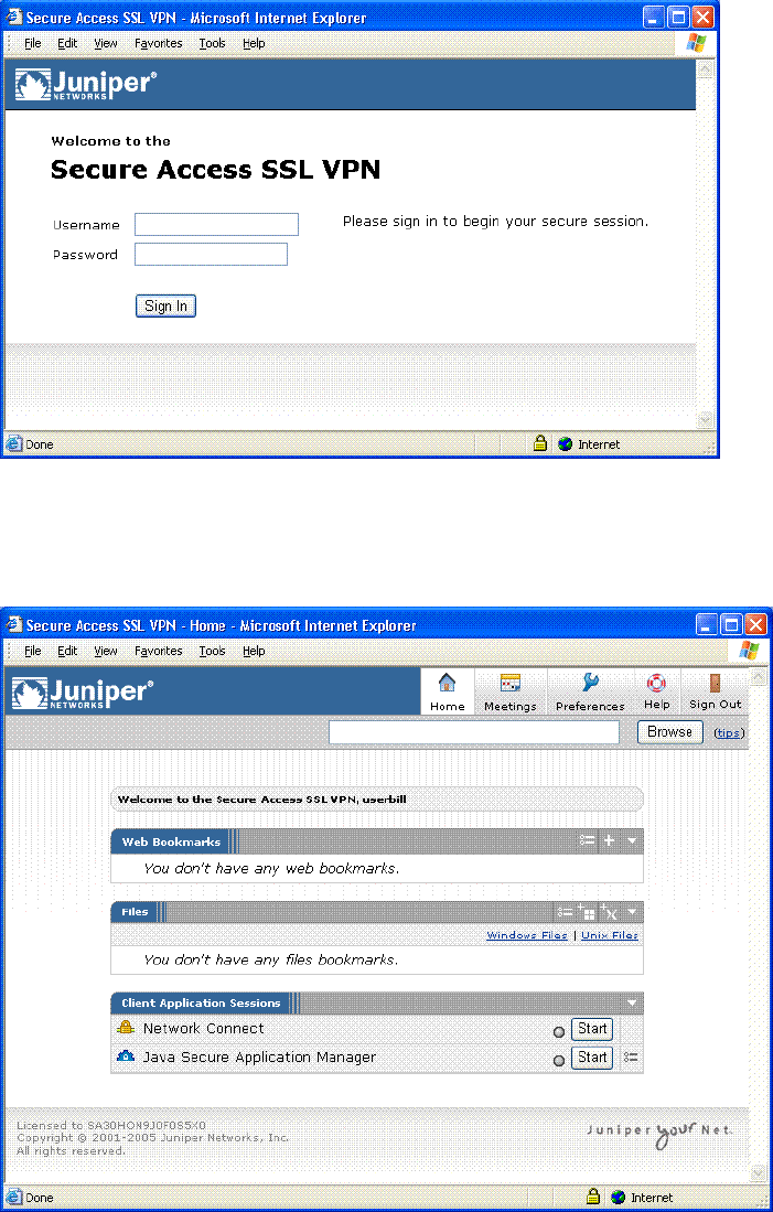
Juniper Networks Secure Access Administration Guide
4Verifying user accessibility
Figure 1: User Sign-in Page
7. On the sign-in page, enter the username and password you created for the user
account and then click Sign In to access the IVE home page for users.
Figure 2: User Home Page (default)
8. In the browser Address field, enter the URL to an internal Web server and click
Browse. The IVE opens the Web page in the same browser window, so to
return to the IVE home page, click the center icon in the browsing toolbar that
appears on the target Web page.
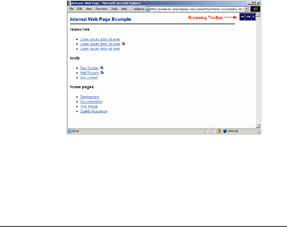
Creating a test scenario to learn IVE concepts and best practices 5
Chapter 1: Initial Verification and Key Concepts
Figure 3: Example Internal Web Page with Browsing Toolbar
9. On the IVE home page, enter the URL to your external corporate site and click
Browse. The IVE opens the Web page in the same browser window, so use the
browsing toolbar to return to the IVE home page.
10. On the IVE home page, click Browsing > Windows Files to browse available
Windows file shares or Browsing > UNIX/NFS Files to browse available
UNIX/NFS file shares.
After verifying user accessibility, return to the admin console to go through an
introduction of key concepts, as described in “Creating a test scenario to learn IVE
concepts and best practices” on page 5.
Creating a test scenario to learn
IVE
concepts and best practices
The IVE provides a flexible access management system that makes it easy to
customize a user’s remote access experience through the use of roles, resource
policies, authentication servers, authentication realms, and sign-in policies. To
enable you to quickly begin working with these entities, the IVE ships with system
defaults for each. This section describes these system defaults and shows you how
to create each access management entity by performing the following tasks:
“Defining a user role” on page 6
“Defining a resource profile” on page 8
“Defining an authentication server” on page 10
“Defining an authentication realm” on page 13
“Defining a sign-in policy” on page 16

Juniper Networks Secure Access Administration Guide
6Creating a test scenario to learn IVE concepts and best practices
“Using the test scenario” on page 19
Defining a user role
The IVE is pre-configured with one user role called “Users.” This pre-defined role
enables the Web and file browsing access features, enabling any user mapped to the
Users role to access the Internet, corporate Web servers, and any available Windows
and UNIX/NFS file servers. You can view this role on the
Users > User Roles
page.
To define a user role:
1. In the admin console, choose Users > User Roles.
2. On the Roles page, click New Role.
3. On the New Role page, enter “Test Role” in the Name field and then click Save
Changes. Wait for the IVE to display the General > Overview page for Test
Role.
4. On the Overview page, select the Web checkbox under Access features and
then click Save Changes.
5. Choose Web > Options.
6. Select the User can type URLs in the IVE browser bar checkbox, and then
click Save Changes.
NOTE: The IVE supports two types of users:
Administrators
—An
administrator
is a person who may view or modify IVE
configuration settings. You create the first administrator account through the
serial console.
Users—A user is a person who uses the IVE to gain access to corporate
resources as configured by an administrator. You create the first user account
(testuser1) in “Verifying user accessibility” on page 3.
The following test scenario focuses on using the IVE access management elements
to configure access parameters for a user. For information about the system
default settings for administrators, see “Configuring default settings for
administrators” on page 22.
NOTE: After you enable an access feature for a role (on the Users > User Roles >
Role Name page), configure the appropriate corresponding options that are
accessible from the access feature’s configuration tab.
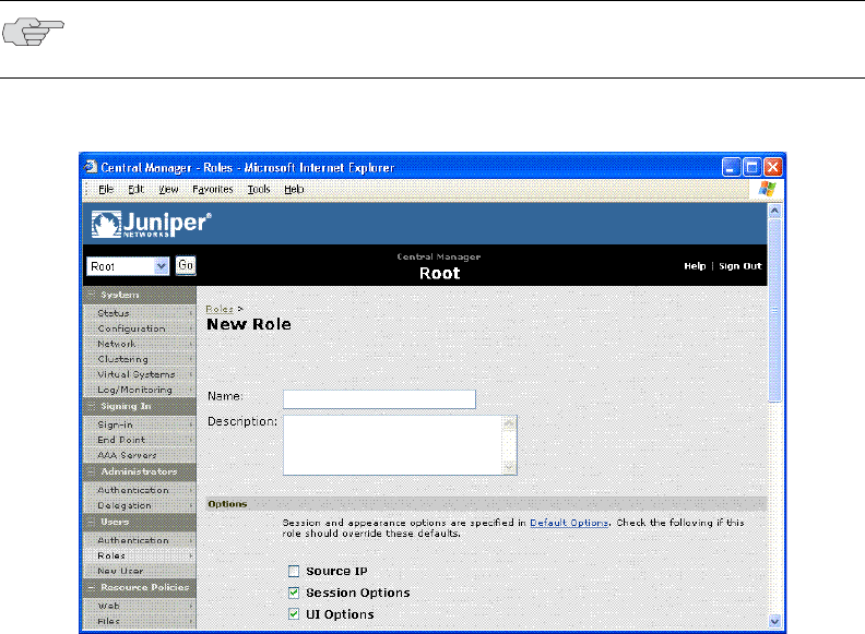
Creating a test scenario to learn IVE concepts and best practices 7
Chapter 1: Initial Verification and Key Concepts
After completing these steps, you have defined a user role. When you create
resource profiles, you can apply them to this role. You can also map users to this
role through role mapping rules defined for an authentication realm.
Figure 4: Users > User Roles > New Role page
NOTE: To quickly create a user role that enables Web and file browsing, duplicate
the Users role, and then enable additional access features as desired.

Juniper Networks Secure Access Administration Guide
8Creating a test scenario to learn IVE concepts and best practices
Figure 5: Users > User Roles > Test Role > General > Overview
Defining a resource profile
A resource profile is a set of configuration options that contains all of the resource
policies, role assignments, and end-user bookmarks required to provide access to
an individual resource.
Within a resource profile, a resource policy specifies the resources to which the
policy applies (such as URLs, servers, and files) and whether the IVE grants access
to a resource or performs an action. Note that the IVE is pre-configured with two
types of resource policies:
Web Access—The pre-defined Web Access resource policy enables all users to
access the Internet and all corporate Web servers through the IVE. By default,
this resource policy applies to the Users role.
Windows Access—The pre-defined Windows Access resource policy enables
all users mapped to the Users role to access all corporate Windows file servers.
By default, this resource policy applies to the Users role.

Creating a test scenario to learn IVE concepts and best practices 9
Chapter 1: Initial Verification and Key Concepts
To define a resource profile:
1. In the admin console, choose Users > Resource Profiles > Web > Web
Applications/Pages.
2. On the Web Applications Resource Profile page, click New Profile.
3. On the New Web Applications Resource Profile page:
a. In the Type field, keep the default option (Custom)
b. In the Name field, enter “Test Web Access”
c. In the Base URL field, enter “http://www.google.com”
d. In the Autopolicy: Web Access Control section, select the checkbox next
to the default policy created by the IVE (http://www.google.com:80/*) and
choose Delete.
e. In the Autopolicy: Web Access Control section, enter
“http://www.google.com” in the Resource field, select Deny from the
Action list, and click Add.
f. Click Save and Continue.
4. In the Roles tab:
a. Select “Test Role” in the Available Roles field and click Add to move it to
the Selected Roles field.
b. Click Save Changes.
The IVE adds “Test Web Access” to the Web Application Resource Policies page
and automatically creates a corresponding bookmark that links to google.com.
After completing these steps, you have configured a Web Access resource profile.
Note that even though the IVE comes with a resource policy that enables access to
all Web resources, users mapped to Test Role are still prohibited from accessing
http://www.google.com. These users are denied access because the autopolicy you
created during the resource profile configuration takes precedence over the default
Web access policy that comes with the IVE.
NOTE: Delete the default Web Access and Windows Access resource policies if you
are concerned about users having access to all of your Web and file content. You
can access the default Web and file resource policies on the Users > Resource
Policies > Web > Access and Users > Resource Policies > Files > Access >
Windows pages.
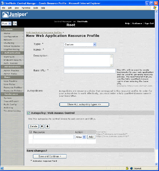
Juniper Networks Secure Access Administration Guide
10 Creating a test scenario to learn IVE concepts and best practices
Figure 6: Users > Resource Profiles > Web > Web Applications/Pages > New Profile
Defining an authentication server
An authentication server is a database that stores user credentials—username and
password—and typically group and attribute information. When a user signs in to
an IVE, the user specifies an authentication realm, which is associated with an
authentication server. The IVE forwards the user’s credentials to this authentication
server to verify the user’s identity.
The IVE supports the most common authentication servers, including Windows NT
Domain, Active Directory, RADIUS, LDAP, NIS, RSA ACE/Server, SAML Server, and
eTrust SiteMinder, and enables you to create one or more local databases of users
who are authenticated by the IVE. The IVE is pre-configured with one local
authentication server for users called “System Local.” This pre-defined local
authentication server is an IVE database that enables you to quickly create user
accounts for user authentication. This ability provides flexibility for testing
purposes and for providing third-party access by eliminating the need to create
user accounts in an external authentication server.

Creating a test scenario to learn IVE concepts and best practices 11
Chapter 1: Initial Verification and Key Concepts
You can view the default local authentication server on the Authentication >
Auth. Servers page.
To define an authentication server:
1. In the admin console, choose Authentication > Auth. Servers.
2. On the Authentication Servers page, choose Local Authentication from the
New list and then click New Server.
3. On the New Local Authentication page, enter “Test Server” in the Name field
and then click Save Changes. Wait for the IVE to notify you that the changes
are saved, after which additional configuration tabs appear.
4. Click the Users tab and then click New.
5. On the New Local User page, enter “testuser2” in the Username field, enter a
password, and then click Save Changes to create the user’s account in the Test
Server authentication server.
After completing these steps, you have created an authentication server that
contains one user account. This user can sign in to an authentication realm that
uses the Test Server authentication server.
NOTE: The IVE also supports authorization servers. An authorization server (or
directory server) is a database that stores user attribute and group information.
You can configure an authentication realm to use a directory server to retrieve
user attribute or group information for use in role mapping rules and resource
policies.
NOTE: The admin console provides last access statistics for each user account on
the respective authentication servers pages, on the Users tab under a set of
columns titled Last Sign-in Statistic. The statistics reported include the last
successful sign-in date and time for each user, the user’s IP address, and the agent
or browser type and version.

Juniper Networks Secure Access Administration Guide
12 Creating a test scenario to learn IVE concepts and best practices
Figure 7: Authentication > Auth. Servers > New Server
Figure 8: Authentication > Auth. Servers > Test Server > Users > New
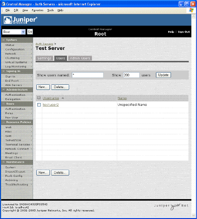
Creating a test scenario to learn IVE concepts and best practices 13
Chapter 1: Initial Verification and Key Concepts
Figure 9: Authentication > Auth. Servers > Test Server > Users
Defining an authentication realm
An authentication realm is a grouping of authentication resources, including:
An authentication server, which verifies a user’s identity. The IVE forwards
credentials submitted on a sign-in page to an authentication server.
An authentication policy, which specifies realm security requirements that
need to be met before the IVE submits credentials to an authentication server
for verification.
A directory server, which is an LDAP server that provides user and group
attribute information to the IVE for use in role mapping rules and resource
policies (optional).
Role mapping rules, which are conditions a user must meet in order for the IVE
to map a user to one or more roles. These conditions are based on information
returned by the realm's directory server, the person’s username, or certificate
attributes.
Juniper Networks Secure Access Administration Guide
14 Creating a test scenario to learn IVE concepts and best practices
The IVE is pre-configured with one user realm called “Users.” This pre-defined
realm uses the System Local authentication server, an authentication policy that
requires a minimum password length of four characters, no directory server, and
contains one role mapping rule that maps all users who sign in to the Users realm
to the Users role. The “testuser1” account you create in “Verifying user
accessibility” on page 3 is part of the Users realm, because this account is created
in the System Local authentication server. The “testuser2” account you create in
“Defining an authentication server” on page 10 is not part of the Users realm,
because you create the user account in the new “Test Server” authentication server,
which is not used by the Users realm.
You can view the default user authentication realm on the
Users > User Realms
page.
To define an authentication realm:
1. In the admin console, choose User Realms.
2. On the User Authentication Realms page, click New.
3. On the New Authentication Realm page:
a. In the Name field, enter: Test Realm
b. Under Servers, choose “Test Server” from the Authentication list.
c. Click Save Changes. Wait for the IVE to notify you that the changes are
saved and to display the realm’s configuration tabs.
4. On the Role Mapping tab, click New Rule.
5. On the Role Mapping Rule page:
a. Under Rule: If username..., enter “testuser2” in the value field.
b. Under ...then assign these roles, select “Test Role” in the Available Roles
field and click Add to move it to the Selected Roles field.
c. Click Save Changes.
After completing these steps, you have finished creating an authentication realm.
This realm uses Test Server to authenticate users and a role mapping rule to map
“testuser2” to Test Role. Because the Test Web Access resource policy applies to
Test Role, any user mapped to this role cannot access http://www.google.com.
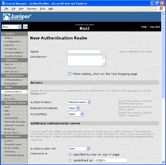
Creating a test scenario to learn IVE concepts and best practices 15
Chapter 1: Initial Verification and Key Concepts
Figure 10: Users > User Realms > New Realm

Juniper Networks Secure Access Administration Guide
16 Creating a test scenario to learn IVE concepts and best practices
Figure 11: Users > User Realms > Test Server > New Rule
Defining a sign-in policy
A sign-in policy is a system rule that specifies:
A URL at which a user may sign in to the IVE
A sign-in page to display to the user
Whether or not the user needs to type or select an authentication realm to
which the IVE submits credentials
The authentication realms to which the sign-in policy applies
All Secure Access and Secure Access FIPS IVEs are pre-configured with one sign-in
policy that applies to users: */. This default user sign-in policy (*/) specifies that
when a user enters the URL to the IVE, the IVE displays the default sign-in page for
users and requires the user to select an authentication realm (if more than one
realm exists). The */ sign-in policy is configured to apply to the Users authentication
realm, therefore this sign-in policy does not apply to the authentication realm you
create in “Defining an authentication realm” on page 13.

Creating a test scenario to learn IVE concepts and best practices 17
Chapter 1: Initial Verification and Key Concepts
You can view the default user sign-in policy on the Authentication >
Authentication > Signing In Policies page. If your IVE has the Secure Meeting
Upgrade license, the */meeting sign-in policy is also listed on this page. This policy
enables you to customize the sign-in page for secure meetings.
To define a sign-in policy:
1. In the admin console, choose
Authentication > Signing in > Sign-in Policies
.
2. On the Sign-in Policies page, click */.
3. On the */ page:
a. In the Sign-in URL field, enter “test” after “*/.”
b. Under Authentication realm, select User picks from a list of
authentication realms, and then select “Test Realm” in the Available
Roles field and click Add to move it to the Selected Realms field. (Repeat
this process for the Users role if it is not already in the Selected Realms
field.)
c. Click Save Changes.
After completing these steps, you have finished modifying the default users sign-in
policy.
Optional:
1. Choose Authentication > Authentication > Signing In Pages, and then click
New Page.
2. On the
New Sign-In Page
page, enter “Test Sign-in Page” in the
Name
field,
enter “#FF0000” (red) in the
Background color
field, and then click
Save
Changes
.
3. Choose Authentication > Authentication > Signing In Policies, and then
click New URL.
4. On the New Sign-in Policy page, enter “*/test/” in the Name field, select
Default Sign-in Page in the Sign-in Page field, and click Save Changes.
5. Choose Authentication > Authentication > Signing In Policies, and then
click */test/ under User URLs.
6. On the */test/ page, choose “Test Sign-in Page” from the Sign-in page list and
then click Save Changes.
After completing these optional steps, you have finished defining a new sign-in
page that is associated with the “*/test/” sign-in policy.
The default sign-in policy applies to all users. You can modify the URL to the IVE user
sign-in page by adding to the path, such as “*/employees,” but you cannot create
additional sign-in policies unless you purchase the Advanced license for your IVE.
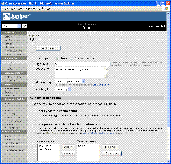
Juniper Networks Secure Access Administration Guide
18 Creating a test scenario to learn IVE concepts and best practices
Figure 12: Authentication > Authentication > Signing In Policies > */
Figure 13: Authentication > Authentication > Signing In Policies > */test/ — Using New

Creating a test scenario to learn IVE concepts and best practices 19
Chapter 1: Initial Verification and Key Concepts
Sign-in Page
Using the test scenario
The test scenario enables you to:
Access the user console using the modified default sign-in policy
Sign in as the user created in Test Server to the Test Realm
Test your Web browsing capabilities, which are dependent upon the proper
configuration of Test Role and Test Web Access
To use the test scenario:
1. In a browser, enter the machine’s URL followed by “/test” to access the user
sign-in page. The URL is in the format: https://a.b.c.d/test, where a.b.c.d is the
machine IP address you entered in the serial console during initial
configuration. When prompted with the security alert to proceed without a
signed certificate, click Yes. If the user sign-in page appears, you have
successfully connected to your IVE appliance.
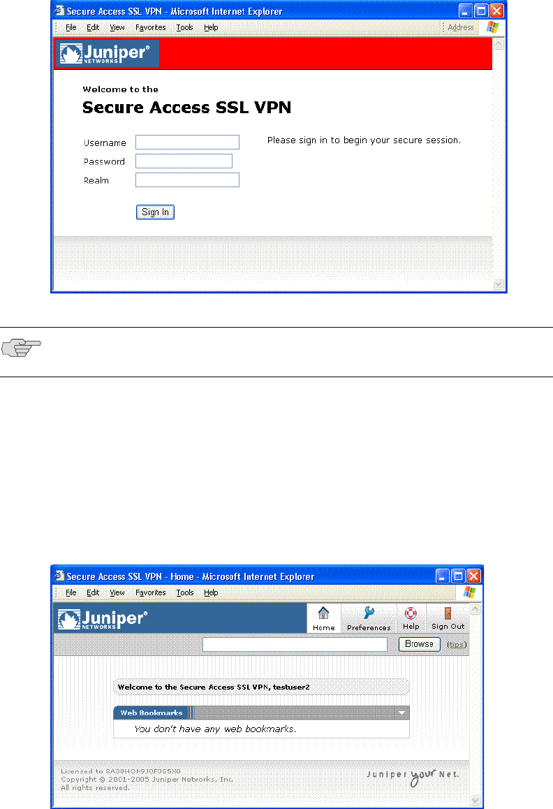
Juniper Networks Secure Access Administration Guide
20 Creating a test scenario to learn IVE concepts and best practices
Figure 14: User Sign-in Page
2. On the sign-in page, enter the username and password you created for the user
account in Test Server, specify “Test Realm” in the Realm field, and then click
Sign In to access the IVE home page for users.
The IVE forwards the credentials to Test Realm, which is configured to use Test
Server. Upon successful verification by this authentication server, the IVE
processes the role mapping rule defined for Test Realm, which maps “testuser2”
to Test Role. Test Role enables Web browsing for users.
Figure 15: User Home Page
NOTE: If you performed the optional configuration steps in “Defining a sign-in
policy” on page 16, the header color is red.
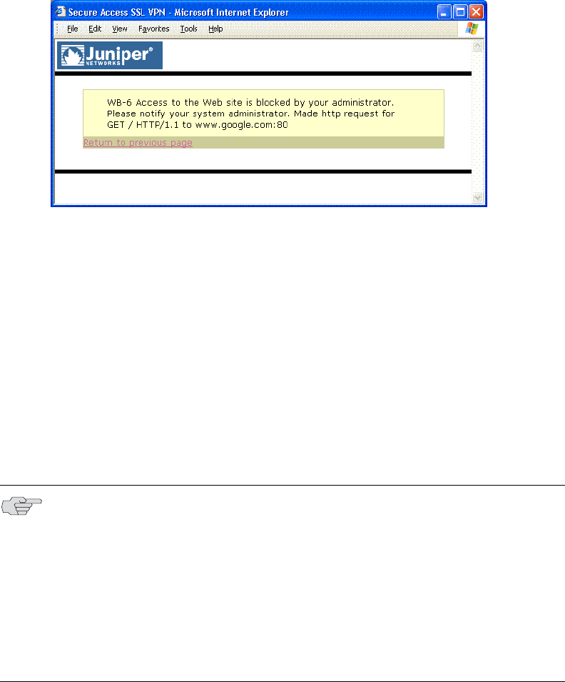
Creating a test scenario to learn IVE concepts and best practices 21
Chapter 1: Initial Verification and Key Concepts
3. In the browser Address field, enter the URL to your corporate Web site and
click Browse. The IVE opens the Web page in the same browser window, so to
return to the IVE home page, click the center icon in the browsing toolbar that
appears on the target Web page.
4. On the IVE home page, enter “www.google.com” and click Browse. The IVE
displays an error message, because the Test Web Access resource policy denies
access to this site for users mapped to Test Role.
Figure 16: Example Error Message for Denied Resource
5. Return to the IVE home page, click Sign Out, and then return to the user sign-in
page.
6. Enter the credentials for testuser1, specify the Users realm, and then click Sign
In.
7. On the IVE home page, enter “www.google.com” and click Browse. The IVE
opens the Web page in the same browser window.
The test scenario demonstrates the basic IVE access management mechanisms.
You can create very sophisticated role mapping rules and resource policies that
control user access depending on factors such as a realm’s authentication policy, a
user’s group membership, and other variables. To learn more about IVE access
management, we recommend that you take a few minutes to review the online
Help to familiarize yourself with its contents.
NOTE:
When you configure the IVE for your enterprise, we recommend that you
perform user access configuration in the order presented in this section.
For detailed configuration information, see the instructions in other sections of
this guide.
Before you make your IVE available from external locations, we recommend
that you import a signed digital certificate
from a trusted certificate authority
(CA).

Juniper Networks Secure Access Administration Guide
22 Configuring default settings for administrators
Configuring default settings for administrators
Just like for users, the IVE provides default settings that enable you to quickly
configure accounts for administrators. This list summarizes the system default
settings for administrators:
Administrator roles
.Administrators — This built-in role permits administrators to manage all
aspects of the IVE. The administrator user you create in the serial console
is mapped to this role.
.Read-Only Administrators — This built-in role permits users mapped to
the role to view (but not configure) all IVE settings. You need to map
administrators to this role if you want to restrict their access.
Administrators local authentication server — The Administrators
authentication server is an IVE database that stores administrator accounts.
You create the first administrator account in this server through the serial
console. (The IVE adds all administrator accounts created through the serial
console to this server.) You cannot delete this local server.
Admin Users authentication realm — The Admin Users authentication realm
uses the default Administrators authentication server, an authentication policy
that requires a minimum password length of four characters, no directory
server, and contains one role mapping rule that maps all users who sign in to
the Admin Users realm to the .Administrators role. The administrator account
you create in the serial console is part of the Admin Users realm.
*/admin sign-in policy — The default administrator sign-in policy (*/admin)
specifies that when a user enters the URL to the IVE followed by “/admin,” the
IVE displays the default sign-in page for administrators. This policy also
requires the administrator to select an authentication realm (if more than one
realm exists). The */admin sign-in policy is configured to apply to the Admin
Users authentication realm, therefore this sign-in policy applies to the
administrator account you create through the serial console.
NOTE: You need the Advanced license in order to create additional administrator
roles.

What is the IVE? 23
Chapter 2
Introduction to the IVE
The Juniper Networks Instant Virtual Extranet (IVE) platform serves as the
underlying hardware and software for the Juniper Networks SSL VPN appliances.
These products enable you to give employees, partners, and customers secure and
controlled access to your corporate data and applications including file servers,
Web servers, native messaging and email clients, hosted servers, and more from
outside your trusted network using just a Web browser.
This section contains the following information about the IVE:
“What is the IVE?” on page 23
“What can I do with the IVE?” on page 25
“How do I start configuring the IVE?” on page 31
What is the IVE?
The IVE is a hardened network operating system that acts as the platform for all
Juniper Networks Secure Access products. These appliances provide a range of
enterprise-class scalability, high availability, and security features that extend
secure, remote access to network resources.
The IVE provides robust security by intermediating the data that flows between
external users and your company’s internal resources. Users gain authenticated
access to authorized resources via an extranet session hosted by the appliance.
During intermediation, the IVE receives secure requests from the external,
authenticated users and then makes requests to the internal resources on behalf of
those users. By intermediating content in this way, the IVE eliminates the need to
deploy extranet toolkits in a traditional DMZ or provision a remote access VPN for
employees.
To access the intuitive IVE home page, your employees, partners, and customers
need only a Web browser that supports SSL and an Internet connection. This page
provides the window from which your users can securely browse Web or file
servers, use HTML-enabled enterprise applications, start the client/server
application proxy, begin a Windows, Citrix, or Telnet/SSH terminal session, access
corporate email servers, start a secured layer three tunnel, or schedule or attend a
secure online meeting.1
1. These capabilities depend upon the Juniper Networks Secure Access product and upgrade options you have
purchased.
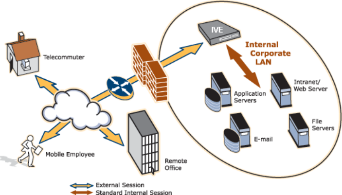
Juniper Networks Secure Access Administration Guide
24 What is the IVE?
Figure 17: The IVE working within a LAN
You can configure a Juniper Networks Secure Access appliance to:
Provide users with secure access to a variety of resources. The IVE
intermediates access to multiple types of applications and resources such as
Web-based enterprise applications, Java applications, file shares, terminal
hosts, and other client/server applications such as Microsoft Outlook, Lotus
Notes, the Citrix ICA Client, and pcAnywhere. Additionally, administrators can
provision an access method that allows full Layer 3 connectivity, providing the
same level of access that a user would get if they were on the corporate LAN.
Fine-tune user access to the appliance, resource types, or individual resources
based on factors such as group membership, source IP address, certificate
attributes, and endpoint security status. For instance, you can use dual-factor
authentication and client-side digital certificates to authenticate users to the IVE
and use LDAP group membership to authorize users’ ability to access individual
applications.
Assess the security status of your users’ computers by checking for endpoint
defense tools such as current antivirus software, firewalls, and security patches.
You can then allow or deny users access to the appliance, resource types, or
individual resources based on the computer’s security status.
The IVE acts as a secure, application-layer gateway intermediating all requests
between the public Internet and internal corporate resources. All requests that
enter the IVE are already encrypted by the end user's browser, using SSL/HTTPS
128-bit or 168-bit encryption—unencrypted requests are dropped. Since the IVE
provides a robust security layer between the public Internet and internal resources,
administrators do not need to constantly manage security policies and patch
security vulnerabilities for numerous different application and Web servers
deployed in the public-facing DMZ.

What can I do with the IVE? 25
Chapter 2: Introduction to the IVE
What can I do with the IVE?
The IVE offers a wide variety of features that you can use to secure your company’s
resources and easily maintain your environment. The following sections answer
questions you may have about the IVE’s security and management capabilities:
“Can I use the IVE to secure traffic to all of my company’s applications, servers,
and Web pages?” on page 25
“Can I use my existing servers to authenticate IVE users?” on page 27
“Can I fine-tune access to the IVE and the resources it intermediates?” on
page 27
“Can I create a seamless integration between the IVE and the resources it
intermediates?” on page 28
“Can I use the IVE to protect against infected computers and other security
concerns?” on page 29
“Can I ensure redundancy in my IVE environment?” on page 29
“Can I make the IVE interface match my company’s look-and-feel?” on page 29
“Can I enable users on a variety of computers and devices to use the IVE?” on
page 30
“Can I provide secure access for my international users?” on page 30
Can I use the IVE to secure traffic to all of my company’s applications, servers, and Web
pages?
The IVE enables you to secure access to a wide variety of applications, servers, and
other resources through its remote access mechanisms. Once you have chosen
which resource you want to secure, you can then choose the appropriate access
mechanism.
For instance, if you want to secure access to Microsoft Outlook, you can use the
Secure Application Manager (SAM). The Secure Application Manager intermediates
traffic to client/server applications including Microsoft Outlook, Lotus Notes, and
Citrix. Or, if you want to secure access to your company Intranet, you can use the
Web rewriting feature. This feature uses the IVE’s Content Intermediation Engine to
intermediate traffic to Web-based applications and Web pages.
Juniper Networks Secure Access Administration Guide
26 What can I do with the IVE?
The IVE includes remote access mechanisms that intermediate the following types
of traffic:
Web-based traffic, including Web pages and Web-based applications: Use
the Web rewriting feature to intermediate this type of content. The Web
rewriting feature includes templates that enable you to easily configure access
to applications such as Citrix, OWA, Lotus iNotes, and Sharepoint. In addition,
you can use the Web rewriting custom configuration option to intermediate
traffic from a wide variety of additional Web-based applications and Web
pages, including custom-built Web applications.
Java applets, including Web applications that use Java applets: Use the
hosted Java applets feature to intermediate this type of content. This feature
enables you to host Java applets and the HTML pages that they reference
directly on the IVE rather than maintaining a separate Java server.
File traffic, including file servers and directories: Use the file rewriting
feature to intermediate and dynamically “webify” access to file shares. The file
rewriting feature enables you to secure traffic to a variety of Windows and Unix
based servers, directories, and file shares.
Client/server applications: Use the Secure Application Manager feature to
intermediate this type of content. The Secure Application Manager comes in
two varieties (Windows and Java versions, or WSAM and JSAM). The WSAM
and JSAM features include templates that enable you to easily configure access
to applications such as Lotus Notes, Microsoft Outlook, NetBIOS file browsing,
and Citrix. In addition, you can use the WSAM and JSAM custom configuration
options to intermediate traffic from a wide variety of additional client/server
applications and destination networks.
Telnet and SSH terminal emulation sessions: Use the Telnet/SSH feature to
intermediate this type of content. This feature enables you to easily configure
access to a variety of networked devices that utilize terminal sessions including
UNIX servers, networking devices, and other legacy applications.
Windows Terminal Servers and Citrix server terminal emulation sessions:
Use the Terminal Services feature to intermediate this type of content. This
feature enables you to easily configure access to Windows Terminal Servers,
Citrix MetaFrame Servers, and Citrix Presentation Servers (formerly known as
Nfuse servers). You can also use this feature to deliver the terminal services
clients directly from the IVE, eliminating the need to use another Web server to
host the clients.
Email clients based on the IMAP4, POP3, and SMTP protocols: Use the email
client feature to intermediate this type of content. This feature enables you to
easily configure access to any corporate mail server based on the IMAP4,
POP3, and SMTP protocols, such as Microsoft Exchange Server and Lotus Notes
Mail servers.
All network traffic: Use the Network Connect feature to create a secure, layer
3 tunnel over the SSL connection, allowing access to any type of application
available on the corporate network. This feature enables you to easily connect
remote users into your network by tunneling network traffic over port 443,
enabling users full access to all of your network resources without configuring
access to individual servers, applications, and resources.
What can I do with the IVE? 27
Chapter 2: Introduction to the IVE
For more information about securing traffic using the IVE remote access
mechanisms, see “Remote access” on page 279.
Can I use my existing servers to authenticate IVE users?
You can easily configure the IVE to use your company’s existing servers to
authenticate your end-users—Users do not need to learn a new username and
password to access the IVE. The IVE supports integration with LDAP, RADIUS, NIS,
Windows NT Domain, Active Directory, eTrust SiteMinder, SAML, and RSA
ACE/Servers.
Or, if you do not want to use one of these standard servers, you can store
usernames and credentials directly on the IVE and use the IVE itself as an
authentication server. In addition, you can choose to authenticate users based on
attributes contained in authentication assertions generated by SAML authorities or
client-side certificates. Or, if you do not want to require your users to sign into the
IVE, you can use the IVE anonymous authentication server, which allows users to
access the IVE without providing a username or password.
For more information about protecting access to the IVE using authentication
servers, see “Authentication and directory servers” on page 91.
Can I fine-tune access to the IVE and the resources it intermediates?
In addition to using authentication servers to control access to the IVE, you can
control access to the IVE and the resources it intermediates using a variety of
additional client-side checks. The IVE enables you to create a multi-layered
approach to protect the IVE and your resources:
1. First, you can perform pre-authentication checks that control user access to the
IVE sign-in page. For instance, you might configure the IVE to check whether or
not the user’s computer is running a particular version of Norton Antivirus. If it
is not running, you can determine that the user’s computer is unsecure and
disable access to the IVE sign-in page until the user has updated the computer’s
antivirus software.
2. Once a user has successfully accessed the IVE sign-in page, you can perform
realm-level checks to determine whether he can access the IVE end-user home
page. The most common realm-level check is performed by an authentication
server. (The server determines whether the user enters a valid username and
password.) You can perform other types of realm-level checks, however, such
as checking that the user’s IP address is in your network or that the user is
using the Web browser type that you specify.
If a user passes the realm-level checks that you specify, he can access the IVE
end-user home page. Otherwise, the IVE does not enable him to sign in, or the
IVE displays a “stripped down” version of the IVE home page that you create.
Generally, this stripped down version contains significantly less functionality
than is available to your standard users because the user has not passed all of
your authentication criteria. The IVE provides extremely flexible policy
definitions, enabling you to dynamically alter end-user resource access based
on corporate security policies.
Juniper Networks Secure Access Administration Guide
28 What can I do with the IVE?
3. After the IVE successfully assigns a user to a realm, the appliance maps him to
a role based on your selection criteria. A role specifies which access
mechanisms a selected group of users can access. It also controls session and
UI options for that group of users. You can use a wide variety of criteria to map
users to roles. For instance, you can map users to different roles based on
endpoint security checks or on attributes obtained from an LDAP server or
client-side certificate.
4. In most cases, a user’s role assignments control which individual resources he
can access. For instance, you might configure access to your company’s
Intranet page using a Web resource profile and then specify that all members
of the “Employees” role can access that resource.
However, you can choose to further fine-tune access to individual resources.
For instance, you may enable members of the “Employees” role to access your
company’s Intranet (as described above), but add a resource policy detailed
rule that requires users to meet additional criteria in order to access the
resource. For example, you may require users to be members of the
“Employees” role and to sign into the IVE during business hours in order to
access your company Intranet.
For more information about fine-tuning access to the IVE and the resources it
intermediates, see “Access management framework” on page 33.
Can I create a seamless integration between the IVE and the resources it intermediates?
In a typical IVE configuration, you could add bookmarks directly to the IVE end-
user home page. These bookmarks are links to the resources that you configure the
IVE to intermediate. Adding these bookmarks enables users to sign into a single
place (the IVE) and find a consolidated list of all of the resources available to them.
Within this typical configuration, you can streamline the integration between the
IVE and the intermediated resources by enabling single sign-on (SSO). SSO is a
process that allows pre-authenticated IVE users to access other applications or
resources that are protected by another access management system without having
to re-enter their credentials. During IVE configuration, you can enable SSO by
specifying user credentials that you want the IVE to pass to the intermediated
resources. For more information, see “Single sign-on” on page 191.
Or, if you do not want to centralize user resources on the IVE end-user home page,
you could create links to the IVE-intermediated resources from another Web page.
For instance, you can configure bookmarks on the IVE, and then add links to those
bookmarks from your company’s Intranet. Your users can then sign into your
company Intranet and click the links there to access the intermediated resources
without going through the IVE home page. As with standard IVE bookmarks, you
can enable SSO for these external links.
What can I do with the IVE? 29
Chapter 2: Introduction to the IVE
Can I use the IVE to protect against infected computers and other security concerns?
The IVE enables you to protect against viruses, attacks, and other security concerns
using the Host Checker feature. Host Checker performs security checks on the
clients that connect to the IVE. For instance, you can use Host Checker verify that
end-user systems contain up-to-date antivirus software, firewalls, critical software
hotfixes, and other applications that protect your users’ computers. You can then
enable or deny users access to the IVE sign-in pages, realms, roles, and resources
based on the results that Host Checker returns. Or, you can display remediation
instructions to users so they can bring their computers into compliance.
You can also use Host Checker to create a protected workspace on clients running
Windows 2000 or Windows XP. Through Host Checker, you can enable the Secure
Virtual Workspace (SVW) feature which creates a protected workspace on the client
desktop, ensuring that any end-user signing in to your intranet must perform all
interactions within a completely protected environment. Secure Virtual Workspace
encrypts information that applications write to disk or the registry and then
destroys all information pertaining to itself or the IVE session when the session is
complete.
You can also secure your network from hostile outside intrusion by integrating your
IVE with a Juniper Networks Intrusion Detection and Prevention (IDP) Sensor. You
can use IDP devices to detect and block most network worms based on software
vulnerabilities, non-file-based Trojan Horses, the effects of Spyware, Adware, and
Key Loggers, many types of malware, and zero day attacks through the use of
anomaly detection.
For more information about Host Checker and other native IVE endpoint defense
mechanisms, see “Endpoint defense” on page 221. For more information about
integrating the IVE with IDP, see “IVE and IDP Interoperability” on page 801.
Can I ensure redundancy in my IVE environment?
You can ensure redundancy in your IVE environment using the IVE clustering
feature. With this feature, you can deploy two or more appliances as a cluster,
ensuring no user downtime in the rare event of failure and stateful peering that
synchronizes user settings, system settings, and user session data.
These appliances support Active/Passive or Active/Active configurations across a
LAN or a WAN. In Active/Passive mode, one IVE actively serves user requests while
the other IVE runs passively in the background to synchronize state data. If the
active IVE goes off-line, the standby IVE automatically starts servicing user
requests. In Active/Active mode, all the machines in the cluster actively handle user
requests sent by an external load balancer or Round-Robin DNS. The load balancer
hosts the cluster VIP and routes user requests to an IVE defined in its cluster group
based on source-IP routing. If an IVE goes off-line, the load balancer adjusts the
load on the active IVEs.
Can I make the IVE interface match my company’s look-and-feel?
The IVE enables you to customize a variety of elements in the end-user interface.
Using these customization features, you can update the look-and-feel of the IVE
end-user console so it will look like one of your standard company Web pages or
applications.
Juniper Networks Secure Access Administration Guide
30 What can I do with the IVE?
For instance, you can easily customize the headers, background colors, and logos
that the IVE displays in the IVE sign-in page and end-user console to match your
company’s style. You can also easily customize the order in which the IVE displays
bookmarks and the help system that the IVE displays to users.
Or, if you do not want to display the IVE end-user home page to users (either in
standard or customized form), you can choose to redirect users to a different page
(such as your company Intranet) when users first sign into the IVE console. If you
choose to use this option, you may want to add links to your IVE bookmarks on the
new page, as explained in “Can I create a seamless integration between the IVE
and the resources it intermediates?” on page 28.
If you want to further customize the IVE sign-in page, you can use the IVE’s custom
sign-in pages feature. Unlike the standard customization options that you can
configure through the IVE administration console, the custom sign-in pages feature
does not limit the number of customizations you can make to your pages. Using
this feature, you can use an HTML editor to develop a sign-in page that exactly
matches your specifications.
For more information about customizing the look-and-feel of the IVE, see
“Customizable admin and end-user UIs” on page 819.
Can I enable users on a variety of computers and devices to use the IVE?
In addition to allowing users to access the IVE from standard workstations and
kiosks running Windows, Macintosh, and Linux operating systems, the IVE also
allows end-users to access the IVE from connected PDAs, handhelds and smart
phones such as i-mode and Pocket PC. When a user connects from a PDA or
handheld device, the IVE determines which IVE pages and functionality to display
based on settings that you configure.
For more information about specifying which pages the IVE displays to different
devices, see the IVE Supported Platforms Document available on the IVE OS
Software page of the Juniper Networks Customer Support Center.
For more information about the exact operating systems, PDAs, and handheld
devices that the IVE supports, see “Handheld devices and PDAs” on page 847.
Can I provide secure access for my international users?
The IVE supports English (US), French, German, Spanish, Simplified Chinese,
Traditional Chinese, Japanese, and Korean. When your users sign into the IVE, the
IVE automatically detects the correct language to display based on the user’s Web
browser setting. Or, you can use end-user localization and custom sign-in pages
options to manually specify the language that you want to display to your end-
users.
For more information about localization, see “Multi-language support” on
page 843.

How do I start configuring the IVE? 31
Chapter 2: Introduction to the IVE
How do I start configuring the IVE?
To enable users to start using your Secure Access appliance, you must complete the
following basic steps:
1. Plug in the appliance, connect it to your network, and configure its initial
system and network settings. This quick and easy process is detailed in the
Secure Access Quick Start Guide.
2. After you connect the IVE to your network, you need to set the system date and
time, upgrade to the latest service package, and install your product licenses.
When you first sign into the administration console, the IVE displays an initial
configuration task guide that quickly walks you through this process.
3. After you install your product licenses, you need to set up your access
management framework to enable your users to authenticate and access
resources. Configuration steps include:
a. Define an authentication server that verifies the names and passwords of
your users.
b. Create user roles that enable access mechanisms, session options, and UI
options for user groups.
c. Create a user authentication realm that specifies the conditions that users
must meet in order to sign into the IVE.
d. Define a sign-in policy that specifies the URL that users must access in
order to sign into the IVE and the page that they see when they sign in.
e. Create resource profiles that control access to resources, specify which
user roles can access them, and include bookmarks that link to the
resources.
The IVE includes a task guide in its administration console that quickly walks
you through this process. To access this task guide, click the Guidance link.
Then, under Recommended Task Guides, select Base Configuration. Or, you
can use the tutorial included in this guide. For more information, see “Initial
Verification and Key Concepts” on page 3.
Once you have completed these basic steps, your Secure Access appliance is ready
for use. You can start using it as is, or configure additional advanced features such
as endpoint defense and clustering.
Juniper Networks Secure Access Administration Guide
32 How do I start configuring the IVE?
33
Part 2
Access management framework
The IVE protects resources by using the following access management
mechanisms:
Authentication realm—Resource accessibility begins with the authentication
realm. An authentication realm specify conditions that users must meet in order
to sign into the IVE. An authentication realm specification includes several
components, including an authentication server which verifies that the user is
who he claims to be. The user must meet the security requirements you define
for a realm's authentication policy or else the IVE does not forward the user's
credentials to the authentication server.
User roles—A role's configuration serves as the second level of resource access
control. A role is a defined entity that specifies IVE session properties for users
who are mapped to the role. Not only does a role specify the access
mechanisms available to a user, but you can also specify restrictions with
which users must comply before they are mapped to a role.
Resource policies—A resource policy serves as the third level of resource
access control. A resource policy is a set of resource names (such as URLs, host
names, and IP address/netmask combinations) to which you grant or deny
access or other resource-specific actions, such as rewriting and caching. While
a role may grant access to certain types of access features and resources (such
as bookmarks and applications), whether or not a user can access a specific
resource is controlled by resource policies. Note that you can create separate
resource policies or you can create automatic resource policies (called
autopolicies) during resource profile configuration (recommended).
This section contains the following information about the IVE access management
framework:
“General access management” on page 35
“User roles” on page 51
“Resource profiles” on page 71
“Resource policies” on page 81
“Authentication and directory servers” on page 91
“Authentication realms” on page 165

Licensing: Access management availability 35
Chapter 3
General access management
The IVE enables you to secure your company resources using authentication
realms, user roles, and resource policies. These three levels of accessibility allow
you to control access from a very broad level (controlling who may sign into the
IVE) down to a very granular level (controlling which authenticated users may
access a particular URL or file). You can specify security requirements that users
must meet to sign in to the IVE, to gain access to IVE features, and even to access
specific URLs, files, and other server resources. The IVE enforces the policies, rules
and restrictions, and conditions that you configure to prevent users from
connecting to or downloading unauthorized resources and content.
This section contains the following information about the access management
framework:
“Licensing: Access management availability” on page 35
“Policies, rules & restrictions, and conditions overview” on page 35
“Policies, rules & restrictions, and conditions evaluation” on page 38
“Dynamic policy evaluation” on page 40
“Configuring security requirements” on page 42
Licensing: Access management availability
The IVE access management framework is available on all Secure Access products.
The access management features, including realms, roles, resource policies, and
servers, are the base of the IVE platform on which all Secure Access products are
built.
Policies, rules & restrictions, and conditions overview
The IVE enables you to secure your company resources using authentication
realms, user roles, and resource policies. These three levels of accessibility allow
you to control access from a very broad level (controlling who may sign into the
IVE) down to a very granular level (controlling which authenticated users may
access a particular URL or file).
Juniper Networks Secure Access Administration Guide
36 Policies, rules & restrictions, and conditions overview
This section contains the following information about access management policies,
rules, restrictions, and conditions:
“Accessing authentication realms” on page 36
“Accessing user roles” on page 37
“Accessing resource policies” on page 37
Accessing authentication realms
Resource accessibility begins with the authentication realm. An authentication realm
is a grouping of authentication resources, including:
An authentication server, which verifies that the user is who he claims to be.
The IVE forwards credentials that a user submits on a sign-in page to an
authentication server. For more information, see “Authentication and directory
servers” on page 91.
An authentication policy, which specifies realm security requirements that
need to be met before the IVE submits a user's credentials to an authentication
server for verification. For more information, see “Defining authentication
policies” on page 168.
A directory server, which is an LDAP server that provides user and group
information to the IVE that the IVE uses to map users to one or more user roles.
For more information, see “Authentication and directory servers” on page 91.
Role mapping rules, which are conditions a user must meet in order for the
IVE to map the user to one or more user roles. These conditions are based on
either user information returned by the realm's directory server or the user's
username. For more information, see “Creating role mapping rules” on
page 169.
You can associate one or more authentication realms with an IVE sign-in page.
When more than one realm exists for a sign-in page, a user must specify a realm
before submitting her credentials. When the user submits her credentials, the IVE
checks the authentication policy defined for the chosen realm. The user must meet
the security requirements you define for a realm's authentication policy or else the
IVE does not forward the user's credentials to the authentication server.
At the realm level, you can specify security requirements based on various
elements such as the user's source IP address or the possession of a client-side
certificate. If the user meets the requirements specified by the realm's
authentication policy, then the IVE forwards the user's credentials to the
appropriate authentication server. If this server successfully authenticates the user,
then the IVE evaluates the role mapping rules defined for the realm to determine
which roles to assign to the user.
For more information, see “Authentication realms” on page 165.
Policies, rules & restrictions, and conditions overview 37
Chapter 3: General access management
Accessing user roles
A role is a defined entity that specifies IVE session properties for users who are
mapped to the role. These session properties include information such as session
time-outs and enabled access features. A role's configuration serves as the second
level of resource access control. Not only does a role specify the access
mechanisms available to a user, but you can also specify restrictions with which
users must comply before they are mapped to a role. The user must meet these
security requirements or else the IVE does not map the user to a role.
At the role level, you can specify security requirements based on elements such as
the user's source IP address and possession of a client-side certificate. If the user
meets the requirements specified either by a role mapping rule or a role's
restrictions, then the IVE maps the user to the role. When a user makes a request to
the backend resources available to the role, the IVE evaluates the corresponding
access feature resource policies.
Note that you may specify security requirements for a role in two places—in the
role mapping rules of an authentication realm (using custom expressions) or by
defining restrictions in the role definition. The IVE evaluates the requirements
specified in both areas to make sure the user complies before it maps the user to a
role.
For more information, see “User roles” on page 51.
Accessing resource policies
A resource policy is a set of resource names (such as URLs, host names, and IP
address/netmask combinations) to which you grant or deny access or other
resource-specific actions, such as rewriting and caching. A resource policy serves as
the third level of resource access control. While a role may grant access to certain
types of access features and resources (such as bookmarks and applications),
whether or not a user can access a specific resource is controlled by resource
policies. These policies may even specify conditions that, if met, either deny or
grant user access to a server share or file. These conditions may be based on
security requirements that you specify. The user must meet these security
requirements or else the IVE does not process the user's request.
At the resource level, you can specify security requirements based elements such
as the user's source IP address or possession of a client-side certificate. If the user
meets the requirements specified by a resource policy's conditions, then the IVE
either denies or grants access to the requested resource. You may enable Web
access at the role level, for example, and a user mapped to the role may make a
Web request. You may also configure a Web resource policy to deny requests to a
particular URL or path when Host Checker finds an unacceptable file on the user's
machine. In this scenario, the IVE checks to see if Host Checker is running and
indicates that the user's machine complies with the required Host Checker policy. If
the user's machine complies, meaning the unacceptable file is not found, then the
IVE grants the user access to the requested Web resource.
Note that you can create separate resource policies or you can create automatic
resource policies (called autopolicies) during resource profile configuration
(recommended). For more information, see:
“Resource policies” on page 81
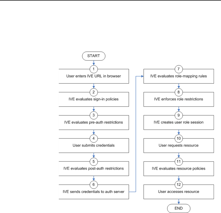
Juniper Networks Secure Access Administration Guide
38 Policies, rules & restrictions, and conditions evaluation
“Resource profile components” on page 72
Policies, rules & restrictions, and conditions evaluation
The following diagram illustrates the access management security checks that the
IVE performs when a user tries to access resources through the IVE. A detailed
description of each step follows after the diagram.
Figure 18: Security checks performed by the IVE during a user session
1. The user enters the URL of the IVE end-user console (such as
http://employees.yourcompany.com/marketing) in a Web browser.
2. The IVE evaluates its sign-in policies (starting with the administrator URLs and
continuing to user URLs) until it matches the hostname entered by the user.
Policies, rules & restrictions, and conditions evaluation 39
Chapter 3: General access management
3. The IVE evaluates pre-authentication restrictions and determines if the user’s
system passes host checks and other requirements. If the pre-authentication
checks fail, the IVE denies the user access. If the checks pass, the IVE prompts
the user to enter the username and password for the realms whose pre-
authentication checks succeeded. (If required by the realm, the IVE prompts
the user to enter two sets of credentials.) If more than one realm exists, the
user must enter a realm or choose one from a list.
4. The IVE evaluates the post-authentication restrictions and determines whether
the user’s password conforms to specified limits and requirements. If the post-
authentication checks fail, the IVE denies the user access. If the checks pass,
the IVE passes the user’s credentials to the realm’s authentication server.
5. The IVE forwards the user’s username and password to the authentication
server, which returns success or failure. (A RADIUS or SiteMinder
authentication server also returns attributes for the IVE to use in role mapping.)
If the authentication server returns failure, the IVE denies the user access. If the
server returns success, the IVE stores the user’s credentials. If the realm has a
separate LDAP authorization server, the IVE also queries the LDAP server for
attribute and group information and saves the information returned by LDAP.
If the realm includes a secondary authentication server, the IVE repeats this
process with the secondary server.
6. The IVE evaluates the realm’s role mapping rules and determines the roles for
which the user is eligible. The IVE determines eligibility using information from
the LDAP or RADIUS server or the user’s username.
7. The IVE evaluates the restrictions of the eligible roles, enabling the user to
access those roles whose restrictions the user’s computer meets. Restrictions
may include source IP, browser type, client-side certificate, Host Checker, and
Cache Cleaner.
8. The IVE creates a “session role,” determining the user’s session permissions. If
you enable permissive merging, the IVE determines session permissions by
merging all valid roles and granting the allowed resources from each valid role.
If you disable merging, the IVE assigns the user to the first role to which he is
mapped. For more information, see “User role evaluation” on page 52.
9. When the user requests a resource, the IVE checks whether the corresponding
access feature is enabled for the session user role. If not, the IVE denies the
user access. If the access feature is enabled, the evaluates resource policies.
10. The IVE evaluates resource profiles and policies related to the user’s request,
sequentially processing each until it finds the profile or policy whose resource
list and designated roles match the user’s request. The IVE denies user access
to the resource if specified by the profile or policy. Otherwise, the IVE
intermediates the user request if the profile or policy enables access. For more
information, see “Resource policy evaluation” on page 86.
11. The IVE intermediates the user request, forwarding the user’s request and
credentials (if necessary) to the appropriate server. Then, the IVE forwards the
the server’s response to the user.

Juniper Networks Secure Access Administration Guide
40 Dynamic policy evaluation
12. The user accesses the requested resource or application server. The user
session ends when the user signs out or his session times out due to time limits
or inactivity. The IVE may also force the user out if the session if you enable
dynamic policy evaluation and the user fails a policy. For more information,
see “Dynamic policy evaluation” on page 40.
Dynamic policy evaluation
Dynamic policy evaluation allows you to automatically or manually refresh the
assigned roles of users by evaluating a realm’s authentication policy, role
mappings, role restrictions, and resource policies. When the IVE performs a
dynamic evaluation, it checks whether the client’s status has changed. (For
instance, the client’s Host Checker status may have changed. Or, if the user is
roaming, the computer’s IP address may have changed.) If the status has changed,
the IVE enables or denies the user access to the dependent realms, roles, or
resource policies accordingly.
This section contains the following information about dynamic policy evaluation:
“Understanding dynamic policy evaluation” on page 40
“Understanding standard policy evaluation” on page 41
“Enabling dynamic policy evaluation” on page 42
Understanding dynamic policy evaluation
During dynamic policy evaluation, the IVE evaluates the following types of resource
policies:
Windows Secure Application Manager
Java Secure Application Manager
Network Connect
Telnet/SSH
Terminal services (Windows and Citrix)
Java Access
NOTE: If you enable dynamic policy evaluation, the IVE performs additional
checks beyond the ones mentioned here. For more information, see “Dynamic
policy evaluation” on page 40.
NOTE: The IVE does not check for changes in user attributes from a RADIUS,
LDAP, or SiteMinder server when performing dynamic policy evaluation. Instead,
the IVE re-evaluates rules and policies based on the original user attributes that it
obtained when the user signed into the IVE.

Dynamic policy evaluation 41
Chapter 3: General access management
Code signing (for java applet)
If the IVE determines after a dynamic policy evaluation that a user no longer meets
the security requirements of a policy or role, the IVE terminates the connection
immediately with the user. The user may see the closing of a TCP or application
connection, or the termination of a user session for Network Connect, Secure
Application Manager, Terminal or Telnet/SSH. The user must take the necessary
steps to meet the security requirements of the policy or role, and then sign into the
IVE again.
The IVE logs information about policy evaluation and changes in roles or access in
the Event log.
Understanding standard policy evaluation
If you do not use dynamic policy evaluation, the IVE evaluates policies and roles
only when the following events occur:
When the user first tries to access the IVE sign-in page, the IVE evaluates the
Host Checker and Cache Cleaner policies (if any) for a realm.
Immediately after the user’s initial authentication, the IVE evaluates the user’s
realm restrictions in the authentication policy, role mapping rules, and role
restrictions.
Whenever the user makes a request for a resource, the IVE evaluates resource
policies.
Whenever the Host Checker and Cache Cleaner status of the user’s machine
changes, the IVE evaluates the Host Checker and Cache Cleaner policies (if any)
for a role.
If you do not use dynamic policy evaluation and you make changes to an
authentication policy, role mapping rules, role restrictions, or resource policies, the
IVE enforces those changes only when the events described above occur. (For more
information, see “Policies, rules & restrictions, and conditions evaluation” on
page 38.)
If you do use dynamic policy evaluation, the IVE enforces changes when the events
described above occur and it also enforces changes at the times you specify. For
more information, see “Enabling dynamic policy evaluation” on page 42.
NOTE: Because the IVE evaluates Web and Files resource policies whenever the
user makes a request for a resource, dynamic policy evaluation is unnecessary for
Web and Files. The IVE does not use dynamic policy evaluation for Meetings
resource policies and Email Client resource policies.

Juniper Networks Secure Access Administration Guide
42 Configuring security requirements
Enabling dynamic policy evaluation
You can use dynamic policy evaluation in the following ways:
Evaluate all signed-in users in a realm—You can automatically or manually
refresh the roles of all currently signed-in users of a realm by using the General
tab of the Administrators > Admin Realms > Select Realm or Users > User
Realms > Select Realm page. You can trigger the IVE to perform a dynamic
policy evaluation at the realm level based on:
An automatic timer—You can specify a refresh interval that determines
how often the IVE performs an automatic policy evaluation of all currently
signed-in realm users, such as every 30 minutes. When using the refresh
interval, you can also fine-tune IVE performance by specifying whether or
not you want to refresh roles and resource policies as well as the
authentication policy, role mapping rules, and role restrictions.
On-demand—At any time, you can manually evaluate the authentication
policy, role mapping rules, role restrictions, and resource policies of all
currently signed-in realm users. This technique is especially useful if you
make changes to an authentication policy, role mapping rules, role
restrictions, or resource policies and you want to immediately refresh the
roles of a realm’s users.
Evaluate all signed-in users in all realms—At any time, you can manually
refresh the roles of all currently signed-in users in all realms by using settings in
the System > Status >Active Users page. For information, see “Monitoring
active users” on page 686.
Evaluate individual users—You can automatically refresh the roles of
individual users by enabling dynamic policy evaluation for Host Checker on the
Authentication > Endpoint Security > Host Checker page. Host Checker can
trigger the IVE to evaluate resource policies whenever a user’s Host Checker
status changes. (If you do not enable dynamic policy evaluation for Host
Checker, the IVE does not evaluate resource policies but it does evaluate the
authentication policy, role mapping rules, and role restrictions whenever a
user’s Host Checker status changes.) For more information, see “Specifying
general Host Checker options” on page 262.
Configuring security requirements
An IVE makes it easy to specify security requirements for administrators and users
through the options and features described in the following sections:
“Specifying source IP access restrictions” on page 43
“Specifying browser access restrictions” on page 44
“Specifying certificate access restrictions” on page 47
“Specifying password access restrictions” on page 48
“Specifying Host Checker access restrictions” on page 49
Configuring security requirements 43
Chapter 3: General access management
“Specifying Cache Cleaner access restrictions” on page 49
Specifying source IP access restrictions
Use a source IP restriction to control from which IP addresses users can access an
IVE sign-in page, be mapped to a role, or access a resource.
You can restrict resource access by source IP:
When administrators or users try to sign in to the IVE —The user must sign
in from a machine whose IP address/netmask combination meets the specified
source IP requirements for the selected authentication realm. If the user's
machine does not have the IP address/netmask combination required by the
realm, the IVE does not forward the user's credentials to the authentication
server and the user is denied access to the IVE. You can allow or deny access to
any specific IP address/netmask combination. For example, you can deny
access to all users on a wireless network (10.64.4.100), and allow access to all
other network users (0.0.0.0).
When administrators or users are mapped to a role—The authenticated user
must be signed in from a machine whose IP address/netmask combination
meets the specified Source IP requirements for each role to which the IVE may
map the user. If the user's machine does not have the IP address/netmask
combination required by a role, then the IVE does not map the user to that
role.
When users request a resource—The authenticated, authorized user must
make a resource request from a machine whose IP address/netmask
combination meets the specified Source IP requirements for the resource
policy corresponding to the user's request. If the user's machine does not have
the required IP address/netmask combination required by the resource, then
the IVE does not allow the user to access the resource.
To specify source IP restrictions:
1. Select the level at which you want to implement IP restrictions:
Realm level—navigate to:
Administrators > Admin Realms > SelectRealm > Authentication
Policy > Source IP
Users > User Realms > SelectRealm > Authentication Policy >
Source IP
Role level—Navigate to:
Administrators > Admin Roles > Select Role > General >
Restrictions > Source IP
Users > User Roles > Select Role > General > Restrictions >
Source IP
Juniper Networks Secure Access Administration Guide
44 Configuring security requirements
Resource policy level—Navigate to: Users > Resource Policies > Select
Resource > Select Policy > Detailed Rules > Select|CreateRule >
Condition Field
2. Choose one of the following options:
Allow users to sign in from any IP address — Enables users to sign into
the IVE from any IP address in order to satisfy the access management
requirement.
Allow or deny users from the following IP addresses — Specifies
whether to allow or deny users access to the IVE from all of the listed IP
addresses, based on their settings. To specify access from an IP address:
i. Enter the IP address and netmask.
ii. Select either:
Allow to allow users to sign in from the specified IP address.
Deny to prevent users from signing in from the specified IP address.
iii. Click Add.
iv. If you add multiple IP addresses, move the highest priority restrictions
to the top of the list by selecting the checkbox next to the IP address,
and then clicking the up arrow button. For example, to deny access to
all users on a wireless network (10.64.4.100) and allow access to all
other network users (0.0.0.0), move the wireless network address
(10.64.4.100) to the top of the list and move the (0.0.0.0) network
below the wireless network.
Enable administrators to sign in on the external port — Enables
administrators to sign in to the IVE from the external interface. You must
enable the external port before setting this option.
3. Click Save Changes to save your settings.
Specifying browser access restrictions
Use a browser restriction to control from which Web browsers users can access an
IVE sign-in page, be mapped to a role, or access a resource. If a user tries to sign in
to the IVE using an unsupported browser, the sign-in attempt fails and a message
displays stating that an unsupported browser is being used. This feature also
enables you to ensure that users sign in to the IVE from browsers that are
compatible with corporate applications or are approved by corporate security
policies.

Configuring security requirements 45
Chapter 3: General access management
You can restrict IVE and resource access by browser-type:
When administrators or users try to sign in to the IVE—The user must sign in
from a browser whose user-agent string meets the specified user-agent string
pattern requirements for the selected authentication realm. If the realm
“allows” the browser's user-agent string, then the IVE submits the user's
credentials to the authentication server. If the realm “denies” the browser's
user-agent string, then the IVE does not submit the user's credentials to the
authentication server.
When administrators or users are mapped to a role—The authenticated user
must be signed in from a browser whose user-agent string meets the specified
user-agent string pattern requirements for each role to which the IVE may map
the user. If the user-agent string does not meet the “allowed” or “denied”
requirements for a role, then the IVE does not map the user to that role.
When users request a resource—The authenticated, authorized user must
make a resource request from a browser whose user-agent string meets the
specified “allowed” or “denied” requirements for the resource policy
corresponding to the user's request. If the user-agent string does not meet the
“allowed” or “denied” requirements for a resource, then the IVE does not allow
the user to access the resource.
Specifying browser restrictions
To specify browser restrictions:
1. Select the level at which you want to implement browser restrictions:
Realm level—Navigate to:
Administrators > Admin Realms > Select Realm > Authentication
Policy > Browser
Users > User Realms > Select Realm > Authentication Policy >
Browser
Role level—Navigate to:
Administrators > Admin Realms > Select Realm > Role Mapping >
Select|Create Rule > Custom Expressions
Administrators > Admin Roles > Select Role > General >
Restrictions > Browser
Users > User Realms > Select Realm > Role Mapping >
Select|Create Rule > Custom Expression
NOTE: The browser restrictions feature is not intended as a strict access control
since browser user-agent strings can be changed by a technical user. It serves as
an advisory access control for normal usage scenarios.

Juniper Networks Secure Access Administration Guide
46 Configuring security requirements
Users > User Roles > Select Role > General > Restrictions >
Browser
Resource policy level—Navigate to: Users > Resource Policies > Select
Resource > Select Policy > Detailed Rules > Select|Create Rule >
Condition Field
2. Choose one of the following options:
Allow all users matching any user-agent string sent by the browser—
Allows users to access the IVE or resources using any of the supported Web
browsers.
Only allow users matching the following User-agent policy—Allows you
to define browser access control rules. To create a rule:
i. For the User-agent string pattern, enter a string in the format
*<browser_string>*
where start (*) is an optional character used to match any character
and <browser_string> is a case-sensitive pattern that must match a
substring in the user-agent header sent by the browser. Note that you
cannot include escape characters (\) in browser restrictions.
ii. Select either:
Allow to allow users to use a browser that has a user-agent header
containing the <browser_string> substring
Deny to prevent users from using a browser that has a user-agent
header containing the <browser_string> substring.
iii. Click Add.
3. Click Save Changes to save your settings.
For example, the string *Netscape* matches any user-agent string that contains the
substring Netscape.
The following rule set grants resource access only when users are signed in using
Internet Explorer 5.5x or Internet Explorer 6.x. This example takes into account
some major non-IE browsers that send the 'MSIE' substring in their user-agent
headers:
*Opera*Deny
*AOL*Deny
NOTE:
Rules are applied in order, so the first matched rule applies.
Literal characters in rules are case sensitive, and spaces are allowed as literal
characters.
Configuring security requirements 47
Chapter 3: General access management
*MSIE 5.5*Allow
*MSIE 6.*Allow
* Deny
Specifying certificate access restrictions
When you install a client-side certificate on the IVE through the System >
Configuration > Certificates > Trusted Client CAs page of the admin console,
you can restrict IVE and resource access by requiring client-side certificates:
When administrators or users try to sign in to the IVE—The user must sign in
from a machine that possesses the specified client-side certificate (from the
proper certificate authority (CA) and possessing any optionally specified
field/value pair requirements). If the user's machine does not possess the
certificate information required by the realm, the user can access the sign-in
page, but once the IVE determines that the user's browser does not possess the
certificate, the IVE does not submit the user's credentials to the authentication
server and the user cannot access features on the IVE.
To implement certificate restrictions at the realm level, navigate to:
Administrators > Admin Realms > SelectRealm > Authentication
Policy > Certificate
Users > User Realms > SelectRealm > Authentication Policy >
Certificate
When administrators or users are mapped to a role—The authenticated user
must be signed in from a machine that meets the specified client-side
certificate requirements (proper certificate authority (CA) and optionally
specified field/value pair requirements) for each role to which the IVE may map
the user. If the user's machine does not possess the certificate information
required by a role, then the IVE does not map the user to that role.
To implement certificate restrictions at the role level, navigate to:
Administrators > Admin Roles > SelectRole > General > Restrictions
> Certificate
Users > User Realms > SelectRealm > Role Mapping >
Select|CreateRule > CustomExpression
Users > User Roles > SelectRole > General > Restrictions >
Certificate
When users request a resource—The authenticated, authorized user must
make a resource request from a machine that meets the specified client-side
certificate requirements (proper certificate authority (CA) and optionally
specified field/value pair requirements) for the resource policy corresponding
to the user's request. If the user's machine does not possess the certificate
information required by a resource, then the IVE does not allow the user to
access the resource.

Juniper Networks Secure Access Administration Guide
48 Configuring security requirements
To implement certificate restrictions at the resource policy level, navigate to:
Users > Resource Policies > SelectResource > SelectPolicy > Detailed Rules
> Select|CreateRule > ConditionField
Specifying password access restrictions
You can restrict IVE and resource access by password-length when administrators
or users try to sign in to an IVE. The user must enter a password whose length
meets the minimum password-length requirement specified for the realm. Note
that local user and administrator records are stored in the IVE authentication
server. This server requires that passwords are a minimum length of 6 characters,
regardless of the value you specify for the realm's authentication policy.
To specify password restrictions:
1. Select an administrator or user realm for which you want to implement
password restrictions.
Navigate to:
Administrators > Admin Realms > Select Realm > Authentication
Policy > Password
Users > User Realms > Select Realm > Authentication Policy >
Password
2. Choose one of the following options:
Allow all users (passwords of any length) — Does not apply password
length restrictions to users signing in to the IVE.
Only allow users that have passwords of a minimum length — Requires
the user to enter a password with a minimum length of the number
specified.
3. Select Enable Password Management if you want to enable password
management. You must also configure password management on the IVE
authentication server configuration page (local authentication server) or
through an LDAP server. For more information about password management,
see “Enabling LDAP password management” on page 111.
4. If you have enabled a secondary authentication server, specify password length
restrictions using the restrictions above as a guideline.
5. Click Save Changes to save your settings.
NOTE: By default, the IVE requires that user passwords entered on the sign-in page
be a minimum of four characters. The authentication server used to validate a
user’s credentials may require a different minimum length. The IVE local
authentication database, for example, requires user passwords to be a minimum
length of six characters.
Configuring security requirements 49
Chapter 3: General access management
Specifying Host Checker access restrictions
For information about restricting a user’s access to the IVE, a role, or a resource
based on his Host Checker status, see “Implementing Host Checker policies” on
page 251.
Specifying Cache Cleaner access restrictions
For information about restricting a user’s access to the IVE, a role, or a resource
based on his Cache Cleaner status, see “Implementing Cache Cleaner options” on
page 273.
Specifying limits restrictions
In addition to the access management options you may specify for an
authentication policy, you may also specify a limit for concurrent users. A user who
enters a URL to one of this realm’s sign-in pages must meet any access
management and concurrent user requirements specified for the authentication
policy before the IVE presents the sign-in page to the user.
Use limits restrictions to set minimum and maximum concurrent users on the
realm.
To specify the limits restrictions:
1. Select an administrator or user realm for which you want to implement limits
restrictions.
Navigate to:
Administrators > Admin Realms > SelectRealm > Authentication
Policy > Limits
Users > User Realms > SelectRealm > Authentication Policy > Limits
2. To limit the number of concurrent users on the realm, select Limit the number
of concurrent users and then specify limit values for these options:
a. Guaranteed minimum—You can specify any number of users between
zero (0) and the maximum number of concurrent users defined for the
realm, or you can set the number up to the maximum allowed by your
license if there is no realm maximum.
b. Maximum (optional)—You can specify any number of concurrent users
from the minimum number you specified up to the maximum number of
licensed users. If you enter a zero (0) into the Maximum field, no users are
allowed to login to the realm.
3. Click Save Changes.
Juniper Networks Secure Access Administration Guide
50 Configuring security requirements
51
Chapter 4
User roles
A user role is an entity that defines user session parameters (session settings and
options), personalization settings (user interface customization and bookmarks),
and enabled access features (Web, file, application, telnet/SSH, terminal services,
network, meeting, and email access). A user role does not specify resource access
control or other resource-based options for an individual request. For example, a
user role may define whether or not a user can perform Web browsing, however,
the individual Web resources that a user may access are defined by the Web
resource policies that you configure separately.
The IVE supports two types of user roles:
Administrators—An administrator role is an entity that specifies IVE
management functions and session properties for administrators who map to
the role. You can customize an administrator role by selecting the IVE feature
sets and user roles that members of the administrator role are allowed to view
and manage. You can create and configure administrator roles through the
Administrators > Admin Roles page of the admin console.
Users—A user role is an entity that defines user session parameters,
personalization settings, and enabled access features. You can customize a
user role by enabling specific IVE access features, defining Web, application,
and session bookmarks, and configuring session settings for the enabled access
features. You can create and configure user roles through the Users > User
Roles page of the admin console.
This section includes the following information about roles:
“Licensing: User roles availability” on page 52
“User role evaluation” on page 52
“Configuring user roles” on page 54
“Customizing user roles UI views” on page 66
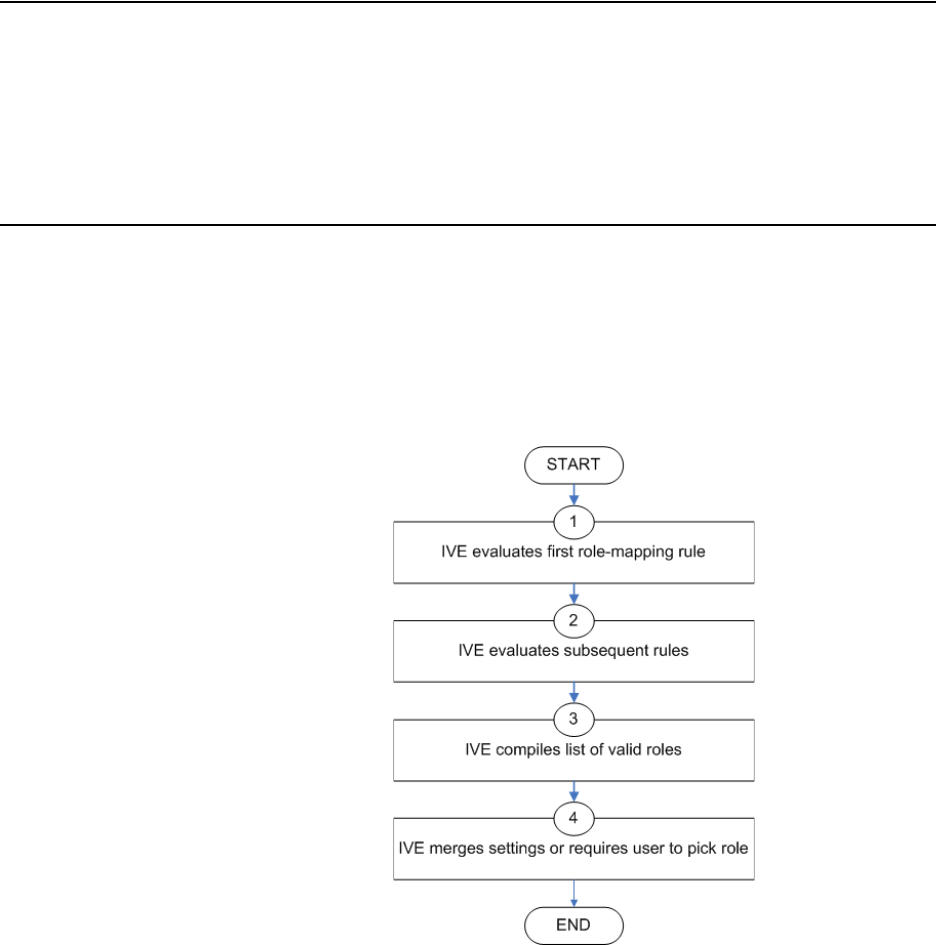
Juniper Networks Secure Access Administration Guide
52 Licensing: User roles availability
Licensing: User roles availability
User roles are an integral part of the IVE access management framework, and
therefore are available on all Secure Access products. However, you can only access
features through a user role if you are licensed for the feature. For instance, if you
are using an SA-700 appliance and have not purchased a Core Clientless Access
upgrade license, you cannot enable Web rewriting for a user role.
User role evaluation
The IVE’s role mapping engine determines a user’s session role, or combined
permissions valid for a user session, as illustrated in the following diagram. A
detailed description of each step follows after the diagram.
Figure 19: Security checks performed by the IVE to create a session role
1. The IVE begins rule evaluation with the first rule on the Role Mapping tab of
the authentication realm to which the user successfully signs in. During the
evaluation, the IVE determines if the user meets the rule conditions. If so, then:
a. The IVE adds the corresponding roles to a list of “eligible roles” available to
the user.
b. The IVE considers whether or not the “stop on match” option is configured.
If so, then the engine jumps to step 5.

User role evaluation 53
Chapter 4: User roles
2. The IVE evaluates the next rule on the authentication realm’s Role Mapping
tab according to the process in the previous step and repeats this process for
each subsequent rule. When the IVE evaluates all role mapping rules, it
compiles a comprehensive list of eligible roles.
3. The IVE evaluates the definition for each role in the eligibility list to determine
if the user complies with any role restrictions. The IVE then uses this
information to compile a list of valid roles, whose requirements the user also
meets.
If the list of valid roles contains only one role, then the IVE assigns the user to
that role. Otherwise, the IVE continues the evaluation process.
4. The IVE evaluates the setting specified on the Role Mapping tab for users who
are assigned to more than one role:
Merge settings for all assigned roles—If you choose this option, then the
IVE performs a permissive merge of all the valid user roles to determine
the overall (net) session role for a user session.
User must select from among assigned roles—If you choose this option,
then the IVE presents a list of eligible roles to an authenticated user. The
user must select a role from the list, and the IVE assigns the user to that
role for the duration of the user session.
User must select the sets of merged roles assigned by each rule—If you
choose this option, the IVE presents a list of eligible rules to an
authenticated user (that is, rules whose conditions the user has met). The
user must select a rule from the list, and the IVE performs a permissive
merge of all the roles that map to that rule.
Permissive merge guidelines
A permissive merge is a merge of two or more roles that combines enabled features
and settings following these guidelines:
Any enabled access feature in one role takes precedence over the same feature
set to disabled in another role. For example, if a user maps to two roles, one of
which disables Secure Meeting while the other role enables Secure Meeting, the
IVE allows the user to use Secure Meeting for that session.
In the case of Secure Application Manager, the IVE enables the version
corresponding to first role that enables this feature. Furthermore, the IVE
merges the settings from all the roles that correspond to the selected version.
In the case of user interface options, the IVE applies the settings that
correspond to the user’s first role.
NOTE: If you use automatic (time-based) dynamic policy evaluation or you
perform a manual policy evaluation, the IVE repeats the role evaluation process
described in this section. For more information, see “Dynamic policy evaluation”
on page 40.

Juniper Networks Secure Access Administration Guide
54 Configuring user roles
In the case of session timeouts, the IVE applies the greatest value from all of
the roles to the user’s session.
If more than role enables the Roaming Session feature, then the IVE merges
the netmasks to formulate a greater netmask for the session.
When merging two roles a user is mapped to—one in which bookmarks open
in a new window and one in which bookmarks open in the same window—the
merged role opens bookmarks in the same window.
When merging two roles in which the first role disables the browsing toolbar
and the second role enables either the framed or standard toolbar, the merged
role uses the settings from the second role and displays the specified browsing
toolbar.
The merged role uses the highest value listed for the HTTP Connection
Timeout on the Users > User Roles > Select Role > Web > Options page.
Configuring user roles
To create a user role:
1. In the admin console, choose Users > User Roles.
2. Click New Role and then enter a name and optionally a description. This name
appears in the list of Roles on the Roles page.
Once you have created a role, you can click the role’s name to begin configuring it
using the instructions in the following sections:
“Configuring general role options” on page 55
“Configuring role restrictions” on page 56
“Specifying role-based source IP aliases” on page 57
“Specifying session options” on page 57
“Specifying customized UI settings” on page 60
“Defining default options for user roles” on page 64

Configuring user roles 55
Chapter 4: User roles
Configuring general role options
Use the Overview tab to edit a role’s name and description, toggle session and user
interface options on and off, and enable access features. When you enable an
access feature, make sure to create corresponding resource policies.
To manage general role settings and options:
1. In the admin console, choose Users > User Roles > RoleName > General >
Overview.
2. Revise the name and description and then click Save Changes. (optional)
3. Under Options, check the role-specific options that you want to enable for the
role. If you do not select role-specific options, the IVE uses default settings
instead, as described in “Defining default options for user roles” on page 64.
Role-specific options include:
VLAN/Source IP—Select this option to apply the settings configured in the
General > VLAN/Source IP tab to the role. For more information, see
“Specifying role-based source IP aliases” on page 57.
Session Options—Select this option to apply the settings in the General >
Session Options tab to the role. For more information, see “Specifying
session options” on page 57.
UI Options—Select this option to apply the settings in the General > UI
Options tab to the role. For more information, see “Specifying customized
UI settings” on page 60.
4. Under Access features, check the features you want to enable for the role.
Options include:
Web—For more information, see “Web rewriting” on page 281
NOTE:
When you delete a role, the personal bookmarks, SAM settings, and other
settings may not be removed. Therefore, if you add a new role with the same
name, any users added to that new role may acquire the old bookmarks and
settings. In general, the IVE enforces referential integrity rules and does not
allow you to delete any objects if they are referenced elsewhere. For example,
if a role is used in any of the realm's role mapping rules, then the IVE rejects
the deletion of the role unless you modify or delete the mapping rules.
To create individual user accounts, you must add the users through the
appropriate authentication server (not the role). For instructions, see
“Creating user accounts on a local authentication server” on page 117 for
local authentication servers. Or for instructions on how to create users on
third-party servers, see the documentation that comes with that product.
Juniper Networks Secure Access Administration Guide
56 Configuring user roles
Files (Windows or UNIX/NFS version)—For more information, see “File
rewriting” on page 371
Secure Application Manager (Windows version or Java version)—For
more information, see “Secure Application Manager” on page 395
Telnet/SSH—For more information, see “Telnet/SSH” on page 449
Terminal Services—For more information, see “Terminal Services” on
page 461
Meetings—For more information, see “Secure Meeting” on page 493
Email Client—For more information, see “Email Client” on page 513
Network Connect—For more information, see “Network Connect” on
page 521
5. Click Save Changes to apply the settings to the role.
Configuring role restrictions
Use the Restrictions tab to specify access management options for the role. The
IVE considers these restrictions when determining whether or not to map a user to
the role. The IVE does not map users to this role unless they meet the specified
restrictions. For more information, see “General access management” on page 35.
You may configure any number of access management options for the role. If a
user does not conform to all of the restrictions, then the IVE does not map the user
to the role.
To specify access management options for the role:
1. In the admin console, choose Users > User Roles > RoleName > General >
Restrictions.
2. Click the tab corresponding to the option you want to configure for the role,
and then configure it using instructions in the following sections:
“Specifying source IP access restrictions” on page 43
“Specifying browser access restrictions” on page 44
“Specifying certificate access restrictions” on page 47
“Specifying password access restrictions” on page 48
“Specifying Host Checker access restrictions” on page 49
“Specifying Cache Cleaner access restrictions” on page 49

Configuring user roles 57
Chapter 4: User roles
Specifying role-based source IP aliases
Use the VLAN/Source IP tab to define role-based source IP aliases. If you want to
direct traffic to specific sites based on roles, you can define a source IP alias for
each role. You use these aliases to configure virtual ports you define for the internal
interface source IP address. A back-end device can then direct end-user traffic
based on these aliases, as long as you configure the back-end device, such as a
firewall, to expect the aliases in place of the internal interface source IP address.
This capability enables you to direct various end-users to defined sites based on
their roles, even though all of the end-user traffic has the same internal interface
source IP address.
To specify a source IP alias for the role:
1. In the admin console, choose Users > User Roles > RoleName > General >
VLAN/Source IP.
2. Select the VLAN you want to use from the VLAN drop-down menu, if you have
defined VLAN ports on your system.
If you have not defined VLAN ports, the option defaults to the Internal Port IP
address. If you have provisioned IVS systems, and you have defined VLAN
ports and you want any of those VLAN ports to appear in this drop-down menu,
you must include the VLAN ports in the Selected VLANs text box on the Root
IVS configuration page.
3. Select a source IP address from the drop-down menu.
4. Click Save Changes to apply the settings to the role.
Specifying session options
Use the Session tab to specify session time limits, roaming capabilities, session and
password persistency, request follow-through options, and idle timeout application
activity. Check the Session Options checkbox on the Overview tab to enable these
settings for the role.
NOTE: You must define virtual ports to take advantage of the role-based Source IP
aliases. For more information on virtual ports, see “Configuring internal and
external ports” on page 561 and “Configuring virtual ports” on page 566.
NOTE:
If an end-user is mapped to multiple roles and the IVE merges roles, the IVE
associates the source IP address configured for the first role in the list with the
merged role.
You can specify the same Source IP address for multiple roles. You cannot
specify multiple Source IP addresses for one role.

Juniper Networks Secure Access Administration Guide
58 Configuring user roles
To specify general session options:
1. In the admin console, choose Users > User Roles > RoleName > General >
Session Options.
2. Under Session Lifetime, specify values for:
Idle Timeout—Specify the number of minutes a non-administrative user
session may remain idle before ending. The minimum is 5 minutes. The
default idle session limit is ten minutes, which means that if a user’s
session is inactive for ten minutes, the IVE ends the user session and logs
the event in the system log (unless you enable session timeout warnings
described below).
Max. Session Length—Specify the number of minutes an active non-
administrative user session may remain open before ending. The
minimum is 6 minutes. The default time limit for a user session is sixty
minutes, after which the IVE ends the user session and logs the event in
the system log. During an end-user session, prior to the expiration of the
maximum session length, the IVE prompts the user to re-enter
authentication credentials, which avoids the problem of terminating the
user session without warning.
Reminder Time—Specify when the IVE should prompt non-administrative
users, warning them of an impending session or idle timeout. Specify in
number of minutes before the timeout is reached.
3. Under Enable session timeout warning:
a. Select Enabled to notify non-administrative users when they are about to
reach a session or idle timeout limit.
These warnings prompt users to take the appropriate action when they are
close to exceeding their session limits or idle timeouts, helping them save
any in-progress form data that would otherwise be lost. Users approaching
the idle timeout limit are prompted to reactivate their session. Users
approaching the session time limit are prompted to save data.
For example, an IVE user may unknowingly reach the idle timeout set for
his role while using an email client configured to work with the IVE,
because the IVE does not receive data while the user composes email. If
the session timeout warning is enabled, however, IVE prompts the user to
reactivate his IVE session before the session times out and forces the user’s
IVE session to end. This warning gives the user the opportunity to save his
partially composed email.
NOTE: If you are using Secure Meeting, you can configure meeting session limits
through the Users > Resource Policies > Meetings page of the admin console.
For more information, see “Defining resource policies: Secure Meeting” on
page 508.

Configuring user roles 59
Chapter 4: User roles
b. Check the Display sign-in page on max session time out checkbox if you
want to display a new browser sign-in page to the end-user when their
session times out. This option only appears when you choose to enable the
session timeout warning.
4. Under Roaming session, specify:
Enabled—To enable roaming user sessions for users mapped to this role. A
roaming user session works across source IP addresses, which allows
mobile users (laptop users) with dynamic IP addresses to sign in to the IVE
from one location and continue working from another. However, some
browsers may have vulnerabilities that can allow malicious code to steal
user cookies. A malicious user could then use a stolen IVE session cookie to
sign in to the IVE.
Limit to subnet—To limit the roaming session to the local subnet specified
in the Netmask field. Users may sign in from one IP address and continue
using their sessions with another IP address as long as the new IP address
is within the same subnet.
Disabled—To disable roaming user sessions for users mapped to this role.
Users who sign in from one IP address may not continue an active IVE
session from another IP address; user sessions are tied to the initial source
IP address.
5. Under Persistent session, select Enabled to write the IVE session cookie to the
client hard disk so that the user’s IVE credentials are saved for the duration of
the IVE session.
By default, the IVE session cookie is flushed from the browser’s memory when
the browser is closed. The IVE session length is determined by both the idle
timeout value and maximum session length value that you specify for the role.
The IVE session does not terminate when a user closes the browser; an IVE
session only terminates when a user signs out of the IVE.
NOTE:
If you do not select this option, the IVE only displays expiration messages to
users—it does not give them the option to extend their sessions. Instead,
users need to access the IVE sign-in page and authenticate into a new session.
This option only applies to expiration messages displayed by the end-user's
browser, not by other clients such as WSAM or Network Connect.
NOTE: If you enable the Persistent session option and a user closes the browser
window without signing out, any user may open another instance of the same
browser to access the IVE without submitting valid credentials, posing a potential
security risk. We recommend that you enable this feature only for roles whose
members need access to applications that require IVE credentials and that you
make sure these users understand the importance of signing out of the IVE when
they are finished.

Juniper Networks Secure Access Administration Guide
60 Configuring user roles
6. Under Persistent password caching, select Enabled to allow cached
passwords to persist across sessions for a role.
The IVE supports NTLM and HTTP Basic Authentication and supports servers
that are set up to accept both NTLM and anonymous sign-in. The IVE caches
NTLM and HTTP Basic Authentication passwords provided by users so that the
users are not repeatedly prompted to enter the same credentials used to sign in
to the IVE server or another resource in the NT domain. By default, the IVE
server flushes cached passwords when a user signs out. A user can delete
cached passwords through the Advanced Preferences page.
7. Under Browser request follow-through, select Enabled to allow the IVE to
complete a user request made after an expired user session after the user re-
authenticates.
8. Under Idle timeout application activity, select Enabled to ignore activities
initiated by Web applications (such as polling for emails) when determining
whether a session is active. If you disable this option, periodic pinging or other
application activity may prevent an idle timeout.
9. Under Upload Logs, select the Enable Upload Logs option to allow the user to
transmit (upload) client logs to the IVE.
10. Click Save Changes to apply the settings to the role.
Specifying customized UI settings
Use the UI Options tab to specify customized settings for the IVE welcome page
and the browsing toolbar for users mapped to this role. The IVE welcome page (or
home page) is the Web interface presented to authenticated IVE users. Check the
UI Options checkbox on the Overview tab to enable custom settings for the role;
otherwise, the IVE uses the default settings.
Personalization settings including the sign-in page, page header, page footer, and
whether or not to display the browsing toolbar. If the user maps to more than one
role, then the IVE displays the user interface corresponding to the first role to which
a user is mapped.
To customize the IVE welcome page for role users:
1. Choose Users > User Roles > RoleName > General > UI Options.
2. Under Header, specify a custom logo and alternate background color for the
header area of the IVE welcome page (optional):
Click the Browse button and locate your custom image file. The Current
appearance displays the new logo only after you save your changes.
NOTE: You must also enable client-side logs on the System > Log/Monitoring >
Client Logs > Settings page to completely enable this option for the user. For
more information, see “Enabling client-side logs” on page 679.

Configuring user roles 61
Chapter 4: User roles
Type the hexidecimal number for the background color or click the Color
Palette icon and pick the desired color. The Current appearance updates
immediately.
3. Under Sub-headers, select new background and text colors (optional):
Type the hexidecimal number for the Background color or click the Color
Palette icon and pick the desired color. The Current appearance updates
immediately.
Type the hexidecimal number for the Text color or click the Color Palette
icon and pick the desired color. The Current appearance updates
immediately.
4. Under Start page, specify the start page you want users to see after they sign in
and when they click the Home icon on the toolbar:
Bookmarks page—Select this option to display the standard IVE
Bookmarks page.
Custom page—Select this option to display a custom start page and then
specify the URL to the page. The IVE rewrites the URL and creates an
access control rule to allow users access to the URL. (Note that users can
also enter the custom URL in the IVE Browse field on the toolbar.) The IVE
evaluates the access control rule after all other policies, which means
another policy could deny access to the URL.
Also allow access to directories below this url—Select this option to
allow users access to subdirectories of the custom-page URL. For example,
if you specify http://www.domain.com/, users can also access
http://www.domain.com/dept/.
5. Under Bookmarks Panel Arrangement, arrange the panels as you want to
display them on the user's bookmarks page:
a. Select the name of a panel in the Left Column or Right Column list.
b. To position a panel above or below the other panels, click Move Up or
Move Down.
c. To move a panel to the other side of the user's bookmarks page, click
Move > or <Move.
NOTE: You can only specify a JPEG or GIF file for a custom logo image. Other
graphics formats are not displayed properly in the JSAM status window on some
OS platforms.
NOTE: The IVE displays all panels under Bookmarks Panel Arrangement for all
licensed features regardless of whether or not you enable the corresponding
feature for the role.
Juniper Networks Secure Access Administration Guide
62 Configuring user roles
6. Under Help page, select options to control the Help page that appears when
users click the Help button on the toolbar:
Disable help link—Select this option to prevent users from displaying Help
by removing the Help button from the toolbar.
Standard help page—Select this option to display the standard IVE
end-user Help.
Custom help page—Select this option to display a custom Help page.
Specify the URL to the custom help page, and then provide an optional
width and height for the help page’s window. The IVE rewrites the URL and
creates an access control rule to allow users access to the URL. (Note that
users can also enter the custom URL in the IVE Browse field on the
toolbar.) The IVE evaluates the access control rule after all other policies,
which means another policy could deny access to the URL. (Note that when
you choose this option, the IVE disables the Tips link next to the Browse
field.)
Also allow access to directories below this url—Select this option to
allow users access to subdirectories of the custom help-page URL. For
example, if you specify http://www.domain.com/help, users can also access
http://www.domain.com/help/pdf/.
7. Under User toolbar, select options for the toolbar on the IVE Bookmarks page
and other secure gateway pages on the IVE:
Home—Select this option to display the Home icon on the IVE
Bookmarks page and other secure gateway pages on the IVE.
Preferences—Select this option to display the Preferences button.
Session Counter—Select this option to display a time value on the user
toolbar that indicates the maximum remaining time allowed in the user’s
current session. Note that a period of user inactivity could also end the
current session before this maximum time expires.
Client Application Sessions—Select this option to display the Client Apps
button on the user toolbar. Users can click this button to display the Client
Application Sessions page where they can start client applications such as
Network Connect or Secure Application Manager. If you do not select this
option, the IVE displays the Client Application Sessions panel on the IVE
Bookmarks page.
8. Under Browsing toolbar, select options for the toolbar that users see when
browsing pages not located on the IVE, such as external Web sites:
Show the browsing toolbar—Select this option to display the browsing
toolbar.
Configuring user roles 63
Chapter 4: User roles
Toolbar type—Select the type of browsing toolbar you want to display:
Standard—Users can move this toolbar to the top left or top right side
of the browser window. Users can also collapse and expand the
toolbar. When collapsed, the toolbar displays the Custom Logo only.
The toolbar’s default state is expanded and on the top right side of the
browser window.
Framed—This toolbar remains fixed in a framed header section at the
top of the page.
Toolbar logo and Toolbar logo (mobile)—Specify a custom logo (such as
your company’s logo) that you want to display on the standard and framed
toolbars by browsing to the image file (optional). When the user clicks the
logo, the page you specify for the Logo links to option appears. The
current logo for the browsing toolbar appears next to these options.
Logo links to— Select an option to link the browsing toolbar logo to a page
that appears when users click the logo:
Bookmarks page—Links the logo to the IVE Bookmarks page.
“Start Page” settings—Links the logo to the custom start page you
specified under the Start Page section.
Custom URL—Links the logo to the URL you enter in the associated
text box (optional). This resource must be accessible to the IVE. The
IVE rewrites the URL and creates an access control rule to allow users
access to the URL. (Note that users can also enter the custom URL in
the IVE Browse field on the toolbar.) The IVE evaluates the access
control rule after all other policies, which means another policy could
deny access to the URL.
Also allow access to directories below this url—Select this option to
allow users access to subdirectories of the custom URL.
Specify the items you want to display in the browsing toolbar:
Enable "Home" link—Select this option to display the Home Page
button, which is linked to the IVE Bookmarks page.
Enable "Add Bookmark" link—Select this option to display the
Bookmark this Page button.
Enable "Bookmark Favorites" link—Select this option to display the
Bookmark Favorites button. When the user clicks this button, the IVE
displays a drop-down list of the bookmarks that the user specified as
favorites on the Add Web Bookmark page of the secure gateway.
Display Session Counter— Select this option to display a time value
on the browsing toolbar that indicates the maximum remaining time
allowed in the user’s current session. Note that a period of user
inactivity could also end the current session before this maximum time
expires.

Juniper Networks Secure Access Administration Guide
64 Configuring user roles
Enable "Help" link—Select this option to display the Help button,
which is linked to the Help page you specify for under Help page.
9. Under Personalized greeting, specify a greeting and notification message on
the IVE Bookmarks page (optional):
Select Enabled to display the personalized greeting. The IVE displays the
username if the full name is not configured.
Select Show notification message and enter a message in the associated
text box (optional). The message appears at the top of the IVE Bookmarks
page after you save changes and the user refreshes that page. You may
format text and add links using the following HTML tags: <i>, <b>, <br>,
<font>, and <a href>. However, the IVE does not rewrite links on the sign-in
page (since the user has not yet authenticated), so you should only point to
external sites. Links to sites behind a firewall will fail. You may also use IVE
system variables and attributes in this field, as explained in “Using system
variables in realms, roles, and resource policies” on page 869.
10. Choose whether or not you want the copyright notice and label shown in the
footer (optional). This setting applies only to those users whose license permits
disabling the copyright notice. For more information about this feature, call
Juniper Networks Support.
11. Click Save Changes. The changes take effect immediately, but current user
browser sessions may need to be refreshed to see the changes.
12. Click Restore Factory Defaults to reset all user-interface options back to
factory defaults (optional).
Defining default options for user roles
You can define default options for all user roles, just as you can for delegated
administrator roles. The options include, but are not limited to:
Session options
Session lifetime—Define the idle timeout and maximum session length in
minutes.
NOTE: If you disable the User can add bookmarks option on the Users > User
Roles > RoleName > Web > Options page, the IVE does not display the
Bookmark this Page and Bookmark Favorites buttons on the browsing toolbar
regardless of whether or not you select the Enable "Add Bookmark" link and
Enable "Bookmark Favorites" link options.)
NOTE:
The length of the personalized greeting cannot exceed 12k, or 12288
characters.
If you use unsupported HTML tags in your custom message, the IVE may
display the end user’s IVE home page incorrectly.
Configuring user roles 65
Chapter 4: User roles
Session timeout warning—Determine if warning and login page display.
Roaming session—Define level of mobility access.
Persistent session—Define state across browser instances.
Cookie state at session termination—Define cookie state.
Persistent password caching—Define password state across sessions.
Browser request follow-through—Define response to browser session
expiration.
Basic authentication intermediation—Define intermediation of
authentication.
Idle timeout application activity—Define IVE response to application
session activity.
Cache Cleaner frequency—Define frequency of Cache Cleaner checking.
UI options
Header
Sub-headers
Start page
Bookmarks panel arrangement
Help page
User toolbar
Browsing toolbar
Personalized greeting
Defining default options for user roles
To define the default options for all user roles:
1. Choose Users > User Roles.
2. Click Default Options.
3. Modify settings in the Session Options, UI Options, and Custom Messages
tabs using instructions in “Configuring general role options” on page 55 and
“Customizing messages” on page 66.
4. Click Save Changes. These become the new defaults for all new user roles.

Juniper Networks Secure Access Administration Guide
66 Customizing user roles UI views
Customizing messages
You can customize three basic messages that may be displayed to your end-users
when they sign in to the IVE. You can change the message text, and you can add
internationalized versions of the messages in Chinese (Simplified), Chinese
(Traditional), French, German, Japanese, Korean, and Spanish, in addition to
English.
To customize messages
1. Select Users > User Roles.
2. In the Roles page, click Default Options.
3. Select the Custom Messages tab.
4. Select the language you want to use from the drop down menu.
5. Enter your text in the Custom Message field, below the default message you
want to override.
6. Click Save Changes.
7. Repeat the process to create messages in additional languages.
Customizing user roles UI views
You can use customization options on the Roles page to quickly view the settings
that are associated with a specific role or set of roles. For instance, you can view all
of the user roles and any Web bookmarks that you have associated with them.
Additionally, you can use these customized views to easily link to the bookmarks
and other configuration settings associated with a role.
To view a sub-set of data on the Roles page:
1. Navigate to Users > User Roles.
2. Select an option from the View menu at the top of the page. For information
about these options, see Table 3.
3. Select one of the following options from the for list:
All roles—Displays the selected bookmarks for all user roles.
Selected roles—Displays the selected bookmarks for the user roles you
choose. If you select this option, select one or more of the checkboxes in
the Role list.
NOTE: If you do not want user roles to see the copyright notice, you can also
deselect the option in the Default Settings for user roles, in general. That way, all
subsequent roles you create do not allow the notice to appear on the end-user UI.

Customizing user roles UI views 67
Chapter 4: User roles
4. Click Update.
Table 3: View menu options
Option Description
Enabled Settings Displays a graph outlining the remote access mechanisms and
general options that you have enabled for the specified roles. Also
displays links (the checkmarks) that you can use to access the
corresponding remote access and general option configuration
pages.
Restrictions Displays Host Checker and Cache Cleaner restrictions that you
have enabled for the specified roles. Also displays links you can use
to access the corresponding Host Checker and Cache Cleaner
configuration pages.
Meetings Displays Secure Meeting settings that you have configured for the
specified roles. Also displays links you can use to access the
corresponding Secure Meeting configuration pages.
Network Connect Displays Network Connect settings that you have configured for
the specified roles. Also displays links you can use to access the
corresponding Network Connect configuration pages.
Role Mapping Rule &
Realms
Displays the assigned authentication realms, role mapping rule
conditions, and permissive merge settings for the specified
roles.Also displays links you can use to access the corresponding
realm and role mapping configuration pages.
Bookmarks: All Displays the names and types of all of the bookmarks that you
have enabled for the specified roles. Also displays links you can use
to access the corresponding bookmark configuration pages. (Note
that if you created a bookmark through a resource profile, the link
appears in the Resource column. Otherwise, the link appears in
the Bookmark column.)
Bookmarks: Web Displays the Web bookmarks that you have enabled for the
specified roles. Also displays links you can use to access the
corresponding bookmark configuration pages. (Note that if you
created a bookmark through a resource profile, the link appears in
the Resource column. Otherwise, the link appears in the Web
Bookmark column.)
Bookmarks: Files
(Windows)
Displays the Windows File bookmarks that you have enabled for
the specified roles. Also displays links you can use to access the
corresponding bookmark configuration pages. (Note that if you
created a bookmark through a resource profile, the link appears in
the Resource column. Otherwise, the link appears in the Windows
File Bookmark column.)
Bookmarks: Files (UNIX) Displays the UNIX/NFS File bookmarks that you have enabled for
the specified roles. Also displays links you can use to access the
corresponding bookmark configuration pages. (Note that if you
created a bookmark through a resource profile, the link appears in
the Resource column. Otherwise, the link appears in the UNIX File
Bookmark column.)
Bookmarks: Telnet Displays the Telnet/SSH bookmarks that you have enabled for the
specified roles. Also displays links you can use to access the
corresponding bookmark configuration pages. (Note that if you
created a bookmark through a resource profile, the link appears in
the Resource column. Otherwise, the link appears in the
Telnet/SSH Session column.)

Juniper Networks Secure Access Administration Guide
68 Customizing user roles UI views
Bookmarks: Terminal
Services
Displays the Terminal Services bookmarks that you have enabled
for the specified roles. Also displays links you can use to access the
corresponding bookmark configuration pages. (Note that if you
created a bookmark through a resource profile, the link appears in
the Resource column. Otherwise, the link appears in the Terminal
Services Session column.)
ACL Resource Policies: All Displays the resource policies that are associated with the specified
roles. Includes the type, name, description, action, and resources
for each policy. Also displays links you can use to access the
corresponding policy configuration pages.
ACL Resource Policies:
Web
Displays the Web resource policies that are associated with the
specified roles. Includes the type, name, description, action, and
resources for each policy. Also displays links you can use to access
the corresponding policy configuration pages.
ACL Resource Policies:
Files (Windows)
Displays the Windows file resource policies that are associated
with the specified roles. Includes the type, name, description,
action, and resources for each policy. Also displays links you can
use to access the corresponding policy configuration pages.
ACL Resource Policies:
Files (UNIX)
Displays the UNIX file resource policies that are associated with the
specified roles. Includes the type, name, description, action, and
resources for each policy. Also displays links you can use to access
the corresponding policy configuration pages.
ACL Resource Policies:
SAM
Displays the JSAM and WSAM resource policies that are associated
with the specified roles. Includes the type, name, description,
action, and resources for each policy. Also displays links you can
use to access the corresponding policy configuration pages.
ACL Resource Policies:
Telnet
Displays the Telnet/SSH resource policies that are associated with
the specified roles. Includes the type, name, description, action,
and resources for each policy. Also displays links you can use to
access the corresponding policy configuration pages.
ACL Resource Policies:
Terminal Services
Displays the Terminal Services resource policies that are associated
with the specified roles. Includes the type, name, description,
action, and resources for each policy. Also displays links you can
use to access the corresponding policy configuration pages.
ACL Resource Policies:
Network Connect
Displays the Network Connect resource policies that are associated
with the specified roles. Includes the type, name, description,
action, and resources for each policy. Also displays links you can
use to access the corresponding policy configuration pages.
Resource Profiles: All Displays the resource profiles that are associated with the specified
roles. Includes the type, name, bookmarks, and supporting policies
for each profile. Also displays links you can use to access the
corresponding resource profile configuration pages.
Resource Profiles: Web
Applications
Displays the Web application resource profiles that are associated
with the specified roles. Includes the name, bookmarks, and
supporting policies for each profile. Also displays links you can use
to access the corresponding resource profile configuration pages.
Resource Profiles: Web
Hosted Java Applets
Displays the hosted Java applet resource profiles that are
associated with the specified roles. Includes the name, bookmarks,
and supporting policies for each profile. Also displays links you can
use to access the corresponding resource profile configuration
pages.
Table 3: View menu options
Option Description

Customizing user roles UI views 69
Chapter 4: User roles
Resource Profiles: Files
(Windows)
Displays the Windows file resource profiles that are associated
with the specified roles. Includes the name, bookmarks, and
supporting policies for each profile. Also displays links you can use
to access the corresponding resource profile configuration pages.
Resource Profiles: Files
(UNIX)
Displays the UNIX file resource profiles that are associated with the
specified roles. Includes the name, bookmarks, and supporting
policies for each profile. Also displays links you can use to access
the corresponding resource profile configuration pages.
Resource Profiles: SAM
Client Applications
Displays the JSAM and WSAM application resource profiles that are
associated with the specified roles. Includes the name, bookmarks,
and supporting policies for each profile. Also displays links you can
use to access the corresponding resource profile configuration
pages.
Resource Profiles: SAM
WSAM destinations
Displays the WSAM destination resource profiles that are
associated with the specified roles. Includes the name, bookmarks,
and supporting policies for each profile. Also displays links you can
use to access the corresponding resource profile configuration
pages.
Resource Profiles:
Telnet/SSH
Displays the Telnet/SSH resource profiles that are associated with
the specified roles. Includes the name, bookmarks, and supporting
policies for each profile. Also displays links you can use to access
the corresponding resource profile configuration pages.
Resource Profiles:
Terminal Services
Displays the Terminal Services resource profiles that are associated
with the specified roles. Includes the name, bookmarks, and
supporting policies for each profile. Also displays links you can use
to access the corresponding resource profile configuration pages.
Table 3: View menu options
Option Description
Juniper Networks Secure Access Administration Guide
70 Customizing user roles UI views

71
Chapter 5
Resource profiles
A resource profile contains all of the resource policies, role assignments, and end-
user bookmarks required to provide access to an individual resource. Resource
profiles simplify resource configuration by consolidating the relevant settings for an
individual resource into a single page within the admin console.
The IVE comes with two types of resource profiles:
Standard resource profiles enable you to configure settings for a variety of
resource types, such as Web sites, client/server applications, directory servers,
and terminal servers. When you use this method, you choose a profile type that
corresponds to your individual resource and then provide details about the
resource.
Resource profile templates enable you to configure settings for specific
applications. When you use this method, you choose a specific application
(such as the Citrix NFuse version 4.0). Then, the IVE pre-populates a variety of
values for you based on your chosen application and prompts you to configure
additional settings as necessary.
This section contains the following information about resource profiles:
“Licensing: Resource profile availability” on page 72
“Task summary: Configuring resource profiles” on page 72
“Resource profile components” on page 72
“Resource profile templates” on page 79
NOTE: For administrators who are accustomed to using a pre-5.3 version of the
IVE product, note that you can still use the IVE role and resource policy
framework to create bookmarks and associated policies. We recommend that you
use resource profiles instead, however, since they provide a simpler, more unified
configuration structure.

Juniper Networks Secure Access Administration Guide
72 Licensing: Resource profile availability
Licensing: Resource profile availability
Resource profiles are an integral part of the IVE access management framework,
and therefore are available on all Secure Access products. However, you can only
access resource profile types that correspond to your licensed features. For
instance, if you are using an SA-700 appliance and have not purchased a Core
Clientless Access upgrade license, you cannot create Web resource profiles.
Task summary: Configuring resource profiles
To create resource profiles, you must:
1. Create user roles through the Users > User Roles page of the admin console.
For instructions, see “Configuring user roles” on page 54.
2. Create resource profiles through the Users > Resource Profiles page of the
admin console. When creating the resource profile, specify the resource, create
autopolicies, associate the profile with user roles, and create bookmarks as
necessary. For more information, see “Resource profile components” on
page 72.
Resource profile components
Resource profiles contain the following components:
Resources—When you are defining a resource profile, you must specify the
individual resource that you want to configure (such as your company Intranet
site or a Lotus Notes application). All other major settings within the profile
branch from this resource. You can configure a variety of resource types,
including Web sites, client/server applications, directory servers, and terminal
servers. For more information, see “Defining resources” on page 75.
Autopolicies—When you are defining a resource profile, you generally create
autopolicies that establish the access requirements and other settings for the
specified resource. The most common type of autopolicy enables access to the
primary resource defined in the profile. Other policy types (such as
compression and caching autopolicies) “fine-tune” how the IVE handles the
data that it passes to and from the specified resource. For more information,
see “Defining autopolicies” on page 76.
Roles—When you are defining a resource profile, you generally associate the
profile with user roles. The specified roles then inherit the autopolicies and
(optionally) the bookmarks defined in the resource profile. For more
information, see “Defining roles” on page 77.
Resource profile components 73
Chapter 5: Resource profiles
Bookmarks—When you are defining a resource profile, you may optionally
create a bookmark that links to the profile’s primary resource (such as your
company intranet’s main page). You can also create additional bookmarks that
link to various sites within the resource’s domain (such as the Sales and
Marketing intranet pages). The IVE displays these bookmarks to users who are
assigned to the user roles that you specify. For more information, see “Defining
bookmarks” on page 78.
The following diagrams illustrate how resource profiles simplify the configuration of
individual resources.
The first diagram shows how to configure resources using roles and resource
policies. Note that to enable a bookmark for multiple user roles, you must manually
re-create the bookmark and enable the appropriate access mechanism for each
role. You must also use a variety of pages in the administrator console to create
associated resource policies enabling access to the resource and other configuration
options.
The second diagram shows how to configure resources using resource profiles.
Note that you can create a bookmark, associate it with multiple user roles, and
create the associated autopolicies enabling access to the resource and other
configuration options through a single section in the administrator console. Also
note that the IVE automatically enables the appropriate access mechanism to the
roles to which you assign the bookmark.
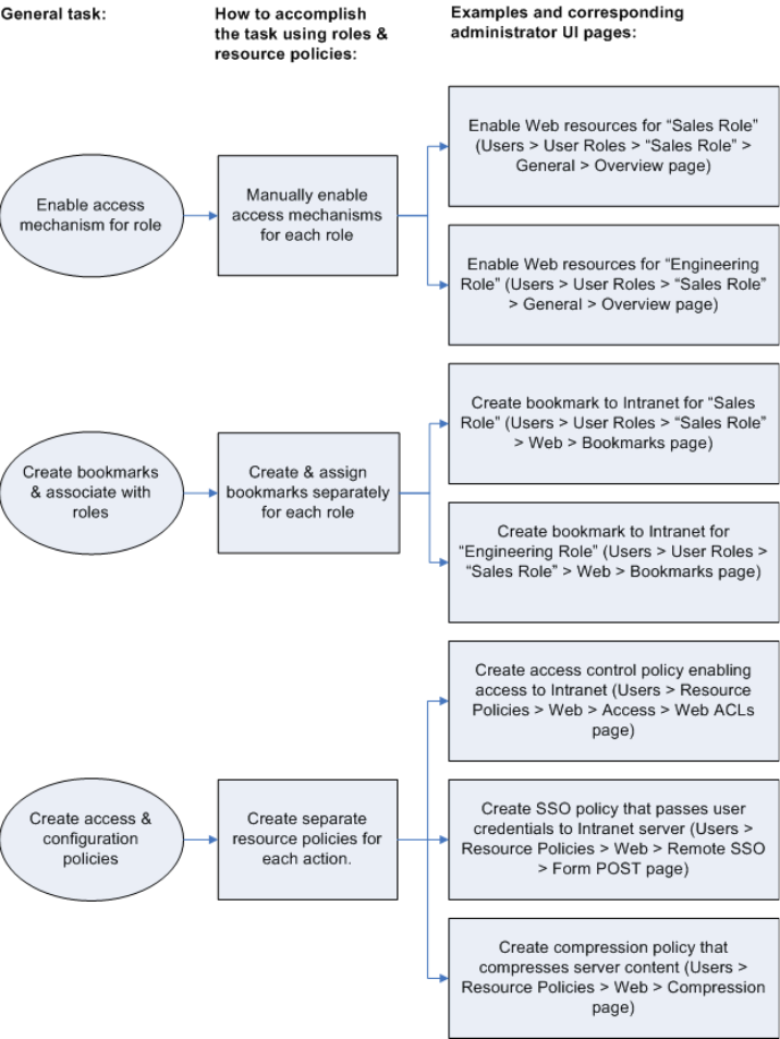
Juniper Networks Secure Access Administration Guide
74 Resource profile components
Figure 20: Using roles and resource policies to configure resources

Resource profile components 75
Chapter 5: Resource profiles
Figure 21: Using resource profiles to configure resources
Defining resources
When you are defining a resource profile, you must specify the individual resource
that you want to configure. The type of profile that you choose is dependent on the
type of resource you want to configure, as described in the following table:
Table 4: Resource profile types and configuration information
Use this type of resource
profile:
To configure this type of
resource:
For configuration instructions,
see:
Web application/pages URLs to Web applications,
Web servers, and Web
pages; Java applets that are
stored on third party
servers
“Defining resource profiles: Custom
Web applications” on page 288
Hosted java applet Java applets that you
upload directly to the IVE
“Defining resource profiles: Hosted
Java applets” on page 362
File browsing Windows and UNIX/NFS
servers, shares, and file
paths
“Defining resource profiles: File
rewriting” on page 371
SAM client application Client/server applications “Defining resource profiles: WSAM”
on page 401 and “Defining resource
profiles: JSAM” on page 435
WSAM destination Destination networks or
servers
“Defining resource profiles: WSAM”
on page 401
Telnet/SSH Telnet or SSH servers “Defining resource profiles:
Telnet/SSH” on page 450

Juniper Networks Secure Access Administration Guide
76 Resource profile components
When defining resources, you can use IVE variables, such as <user> to dynamically
link users to the correct resources. For instance, you can specify the following Web
resource in order to direct users to their own individual intranet pages:
http://yourcompany.intranet/<user>
Defining autopolicies
When you are defining a resource profile, you generally create autopolicies that
establish the access requirements and other settings for the specified resource. The
most common type of autopolicy enables access to the primary resource defined in
the profile. Other policy types (such as compression and caching autopolicies)
“fine-tune” how the IVE handles the data that it passes to and from the specified
resource.
When creating resource profiles, the IVE only displays those autopolicies that are
relevant to the resource profile type. For instance, you may choose to enable access
to a client/server application through a WSAM resource profile. When you do, the
IVE displays autopolicies that you can use to enable access to the specified
application’s server. On the other hand, the IVE does not display Java access
control autopolicies, since Java settings do not apply to WSAM.
Terminal Services Windows and Citrix
terminal servers
“Defining resource profiles: Terminal
Services” on page 470
NOTE: You cannot configure applications through Network Connect using resource profiles.
Instead, you must use roles and resource policies. For more information, see “Network Connect”
on page 521.
Table 4: Resource profile types and configuration information
Use this type of resource
profile:
To configure this type of
resource:
For configuration instructions,
see:

Resource profile components 77
Chapter 5: Resource profiles
Additionally, the IVE consolidates all of the relevant autopolicy options in a single
page of the user interface, enabling you to understand all of the configuration
possibilities and requirements for any given resource type.
Defining roles
Within a resource profile, you can assign user roles to the profile. For instance, you
might create a resource profile specifying that members of the “Customers” role
can access your company’s Support Center, while members of the “Evaluators” role
cannot. When you assign user roles to a resource profile, the roles inherit all of the
autopolicies and bookmarks defined in the resource profile.
Since the resource profile framework does not include options for creating roles,
you must create user roles before you can assign them to resource profiles.
However, the resource profile framework does include some user role configuration
options. For instance, if you assign a user role to a Web resource profile, but you
have not enabled Web rewriting for the role, the IVE automatically enables it for
you.
NOTE:
Access control autopolicies are generally based on the primary resource that
you define in the resource profile. If you change the profile’s primary
resource, however, the IVE does not necessarily update the corresponding
autopolicies. You should re-evaluate your autopolicies after changing the
profile’s primary resource.
For administrators who are accustomed to using a pre-5.3 version of the IVE
product, note that autopolicies are resource policies. The IVE allows you to
sort and order autopolicies along with standard resource policies in the Users
> Resource Policies pages of the admin console. However, the IVE does not
allow you to access more detailed configuration options for autopolicies
through this section of the admin console. Instead, if you want to change the
configuration of an autopolicy, you must access it through the appropriate
resource profile.
For administrators who are accustomed to using a pre-5.3 version of the IVE
product, note that you can also automatically create resource policies by
enabling the Auto-allow option at the role level. However, note that we
recommend that you use autopolicies instead, since they directly correspond
to the resource you are configuring rather than all resources of a particular
type. (You may also choose to enable the Auto-allow option for a role-level
feature and create autopolicies for resources of the same type. When you do,
the IVE creates policies for both and displays them in the appropriate
resource policies page of the admin console.)
NOTE: Note that you can assign roles to a resource profile through the IVE role
framework as well as the resource profile framework.

Juniper Networks Secure Access Administration Guide
78 Resource profile components
Defining bookmarks
When you create a resource profile, the IVE generally creates a bookmark that links
to the profile’s primary resource1 (such as your company intranet’s main page).
Optionally, you may also create additional bookmarks that link to various sites
within the primary resource’s domain (such as the Sales and Marketing intranet
pages). When you create these bookmarks, you can assign them to user roles,
thereby controlling which bookmarks users see when they sign into the IVE end-
user console.
For example, you may create a resource profile that controls access to your
company intranet. Within the profile, you may specify:
Resource profile name: Your Intranet
Primary resource: http://intranet.com
Web access control autopolicy: Allow access to http://intranet.com:80/*
Roles: Sales, Engineering
When you create this policy, the IVE automatically creates a bookmark called “Your
Intranet” enabling access to http://intranet.com and displays the bookmark to
members of the Sales and Engineering roles.
You may then choose to create the following additional bookmarks to associate
with the resource profile:
“Sales Intranet” bookmark: Creates a link to the http://intranet.com/sales
page and displays the link to members of the Sales role.
1. WSAM and JSAM resource profiles do not include bookmarks, since the IVE cannot launch the applications
specified in the resource profiles.

Resource profile templates 79
Chapter 5: Resource profiles
“Engineering Intranet” bookmark: Creates a link to the
http://intranet.com/engineering page and displays the link to members of the
Engineering role.
Resource profile templates
Resource profile templates enable you to configure settings for specific
applications. When you use this method, you choose a specific application (such as
the Citrix NFuse version 4.0). Then, the IVE pre-populates a variety of values for
you based on your chosen application and prompts you to configure additional
settings as necessary.
Currently, the IVE includes templates for the following third-party applications:
Citrix—For more information, see “Defining resource profiles: Citrix Web
applications” on page 307.
Lotus Notes—For more information, see “Defining resource profiles: WSAM”
on page 401 and “Defining resource profiles: JSAM” on page 435.
Microsoft Outlook—For more information, see “Defining resource profiles:
WSAM” on page 401 and “Defining resource profiles: JSAM” on page 435.
NetBIOS file browsing—For more information, see “Defining resource profiles:
WSAM” on page 401 and “Defining resource profiles: JSAM” on page 435.
NOTE: When configuring bookmarks, note that:
You can only assign bookmarks to roles that you have already associated with
the resource profile—not all of the roles defined on the IVE. To change the list
of roles associated with the resource profile, use settings in its Roles tab.
Bookmarks simply control which links the IVE displays to users—not which
resources the users can access. For instance, in the example used above, a
member of the Sales role would not see a link to the Engineering Intranet
page, but he could access it by entering http://intranet.com/engineering his
Web browser’s address bar. Similarly, if you delete a bookmark, users can still
access the resource defined in the profile.
The IVE allows you to create multiple bookmarks to the same resource. If you
assign duplicate bookmarks to the same user role, however, the IVE only
displays one of them to the users.
Bookmarks link to the primary resource that you define in the resource profile
(or a sub-directory of the primary resource). If you change the profile’s
primary resource, the IVE updates the corresponding bookmarks accordingly.
Juniper Networks Secure Access Administration Guide
80 Resource profile templates
81
Chapter 6
Resource policies
A resource policy is a system rule that specifies resources and actions for a
particular access feature. A resource is either a server or file that can be accessed
through an IVE appliance, and an action is to “allow” or “deny” a resource or to
perform or not perform a function. Each access feature has one or more types of
policies, which determine the IVE appliance’s response to a user request or how to
enable an access feature (in the case of Secure Meeting and Email Client). You may
also define detailed rules for a resource policy, which enable you to evaluate
additional requirements for specific user requests.
You can create the following types of resource policies through the Resource
Policies pages of the IVE:
Web Resource Policies—The Web resource policies specify the Web resources
to which users may or may not browse. They also contain additional
specifications such as header caching requirements, servers to which java
applets can connect, code-signing certificates that the IVE should use to sign
java applets, resources that the IVE should and should not rewrite, applications
for which the IVE performs minimal intermediation, and single sign-on options.
File Resource Policies—The file resource policies specify the Windows, UNIX,
and NFS file resources to which users may or may not browse. hey also contain
additional specifications such as file resources for which users need to provide
additional credentials.
Secure Application Manager Resource Policies—The Secure Application
Manager resource policies allow or deny access to applications configured to
use JSAM or WSAM to make socket connections.
Telnet/SSH Resource Policies—The Telnet/SSH resource policies allow or deny
access to the specified servers.
Terminal Services Policies—The Terminal Services resource policies allow or
deny access to the specified Windows servers or Citrix Metaframe servers.
Network Connect Resource Policies—The Network Connect resource policies
allow or deny access to the specified servers and specify IP address pools.
Secure Meeting Resource Policies—The Secure Meeting resource policy allows
you to enable various features such as email notifications, session limits,
daylight savings adjustments, and color-depth settings.

Juniper Networks Secure Access Administration Guide
82 Licensing: Resource policies availability
Secure Email Client Resource Policies—The Secure Email Client access
resource policy allows you to enable or disable email client support.
This section provides the following information:
“Licensing: Resource policies availability” on page 82
“Resource policy components” on page 82
“Resource policy evaluation” on page 86
“Creating detailed rules for resource policies” on page 87
“Customizing resource policy UI views” on page 89
Licensing: Resource policies availability
Resource policies are an integral part of the IVE access management framework,
and therefore are available on all Secure Access products. However, you can only
access resource policy types that correspond to your licensed features. For
instance, if you are using an SA-700 appliance and have not purchased a Core
Clientless Access upgrade license, you cannot create Web resource policy.
Resource policy components
A resource policy contains the following information:
Resources: A collection of resource names (URLs, host names, or IP
address/netmask combinations) that specifies the resources to which the policy
applies. You can specify a resource using a wildcard prefix to match host
names. The default resource for a policy is star (*), meaning that the policy
applies to all related resources. For more information, see “Specifying
resources for a resource policy” on page 83.
Roles: An optional list of user roles to which this policy applies. The default
setting is to apply the policy to all roles.
Action: The action for an IVE to take when a user requests the resource
corresponding to the Resource list. An action may specify to allow or deny a
resource or to perform or not perform an action, such as to rewrite Web
content or allow Java socket connections.
NOTE: You can also create resource policies as part of the resource profile
configuration process. In this case, the resource policies are called “advanced
policies.” For more information, see “Resource profiles” on page 71.

Resource policy components 83
Chapter 6: Resource policies
Detailed Rules: An optional list of elements that specifies resource details
(such as a specific URL, directory path, file, or file type) to which you want to
apply a different action or for which you want to evaluate conditions before
applying the action. You can define one or more rules and specify the order in
which the IVE evaluates them. For more information, see “Creating detailed
rules for resource policies” on page 87.
Specifying resources for a resource policy
The IVE platform’s engine that evaluates resource policies requires that the
resources listed in a policy’s Resources list follow a canonical format. This section
describes the canonical formats available for specifying Web, file, and server
resources. When a user tries to access a specific resource, an IVE appliance
compares the requested resource to the resources specified in the corresponding
policies, starting with the first policy in a policy list. When the engine matches a
requested resource to a resource specified in a policy’s Resources list, it then
evaluates further policy constraints and returns the appropriate action to the
appliance (no further policies are evaluated). If no policy applies, then the appliance
evaluates the auto-allow bookmarks (if defined); otherwise the default action for the
policy is returned.
General notes about the canonical formats
If a path component ends with forward-slash_star (/*), then it matches the leaf
node and everything below. If the path component ends with forward-
slash_percent (/%), then it matches the leaf node and everything one-level
below only. For example:
/intranet/* matches:
/intranet
/intranet/home.html
/intranet/elee/public/index.html
/intranet/% matches:
/intranet
/intranet/home.html
but NOT /intranet/elee/public/index.html
A resource’s host name and IP address are passed to the policy engine at the
same time. If a server in a policy’s Resources list is specified as an IP address,
then the evaluation is based on the IP address. Otherwise, the engine tries to
match the two host names—it does not perform a reverse-DNS-lookup to
determine the IP.
NOTE: You may not see the auto-allow option, if you are using a new installation,
if you use resource profiles rather than resource policies, or if an administrator
has hidden the option. For more information on this option, see “Setting system
options” on page 575.

Juniper Networks Secure Access Administration Guide
84 Resource policy components
If a host name in a policy’s Resources list is not fully qualified, such as
“juniper” is specified instead of “intranet.juniper.net”, then the engine
performs the evaluation as-is; no further qualification for the host name is
performed.
Specifying server resources
When specifying server resources for Telnet/SSH, Terminal Services, or Network
Connect resource policies, note the following guidelines.
Canonical format: [protocol://] host [:ports]
The components are:
Protocol (optional)—Possible case-insensitive values:
tcp
udp
icmp
If the protocol is missing, then all protocols are assumed. If a protocol is
specified, then the delimiter “://” is required. No special characters are
allowed.
Host (required)—Possible values:
IP address/Netmask—The IP address needs to be in the format: a.b.c.d
The netmask may be in one of two formats:
Prefix: High order bits
IP: a.b.c.d
For example: 10.11.149.2/24 or 10.11.149.2/255.255.255.0
No special characters are allowed.
DNS Hostname—For example: www.juniper.com
NOTE: Available only to Network Connect policies. For other access feature
resource policies, such as Secure Application Manager and Telnet/SSH, it is invalid
to specify this component.

Resource policy components 85
Chapter 6: Resource policies
Special characters allowed include:
Ports (optional)—Possible values:
If the port is missing, then the default port 80 is assigned for http, 443 for https.
If a port is specified, then the delimiter “:” is required. For example:
<username>.danastreet.net:5901-5910
10.10.149.149:22,23
tcp://10.11.0.10:80
udp://10.11.0.10:*
Table 5: DNS Hostname Special Characters
*Matches ALL characters
%Matches any character except dot (.)
?Matches exactly one character
NOTE: You cannot specify a host name for a Network Connect resource policy.
You can only specify an IP address.
Table 6: Port possible values
*Matches ALL ports; no other special characters are allowed
port[,port]* A comma-delimited list of single ports. Valid port numbers are [1-
65535].
[port1]-[port2] A range of ports, from port1 to port2, inclusive.
NOTE: You may mix port lists and port ranges, such as: 80,443,8080-8090
NOTE: If you configure IPsec enforcement for an that has multiple interfaces in
the source zone, the configures a unique IKE gateway, VPN, and tunnel policy for
each interface. To distinguish between the tunnel policies, the displays the name
of the vpn for each tunnel policy in the VPN column on the page after you click
Save Changes.
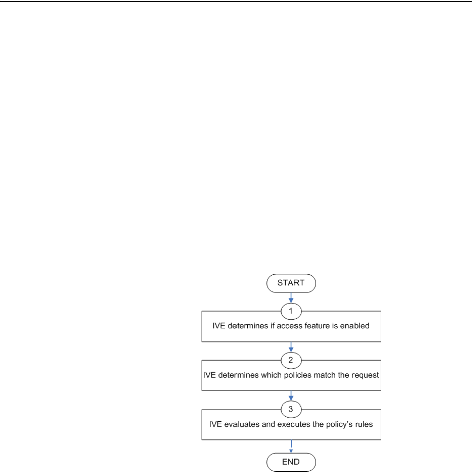
Juniper Networks Secure Access Administration Guide
86 Resource policy evaluation
Resource policy evaluation
When an IVE appliance receives a user request, it evaluates the resource policies
corresponding to the type of request. When it processes the policy that corresponds
to the requested resource, it applies the specified action to the request. This action
is defined on the policy’s General tab or Detailed Rules tab. For example, if a user
requests a Web page, the IVE knows to use the Web resource policies. In the case
of Web requests, the IVE always starts with the Web Rewriting policies (Selective
Rewriting and Pass through Proxy) to determine whether or not to handle the
request. If none of these policies applies (or none is defined), the IVE then evaluates
the Web Access policies until it finds one that pertains to the requested resource.
An IVE appliance evaluates a set of resource policies for an access feature from the
top down, meaning that it starts with the policy numbered one and then continues
down the policy list until it finds a matching policy. If you defined detailed rules for
the matching policy, the IVE evaluates the rules from the top down, starting with
the rule numbered one and stopping when it finds a matching resource in the rule’s
Resource list. The following diagram illustrates the general steps of policy
evaluation:
Figure 22: Resource policy evaluation steps
Details regarding each evaluation step:
1. The IVE receives a user request and evaluates the user’s session role to
determine if the corresponding access feature is enabled. A user’s “session
role” is based on either the role or roles to which the user is assigned during the
authentication process. The access features enabled for a user are determined
by an authentication realm’s role mapping configuration. (For more
information, see “User role evaluation” on page 52.)

Creating detailed rules for resource policies 87
Chapter 6: Resource policies
2. The IVE determines which policies match the request. The IVE evaluates the
resource policies related to the user request, sequentially processing each
policy until finding the one whose resource list and designated roles match the
request. (If you configure the IVE using resource profiles, the IVE evaluates the
advanced policies that you configure as part of the resource profile.)
The Web and file access features have more than one type of policy, so the IVE
first determines the type of request (such as to a Web page, Java applet, or
UNIX file) and then evaluates the policies related to the request. In the case of
the Web access feature, the Rewriting policies are evaluated first for every Web
request. The remaining five access features—Secure Application Manager,
Secure Terminal Access, Secure Meeting, and Secure Email Client—have only
one resource policy.
3. The IVE evaluates and executes the rules specified in the matching policies.
You can configure policy rules to do two things:
Specify resources to which an action applies at a more granular level. For
example, if you specify a Web server in the main policy settings for a Web
Access resource policy, you can define a detailed rule that specifies a
particular path on this server and then change the action for this path.
Require the user to meet specific conditions written as boolean
expressions or custom expressions in order to apply the action. for more
information, see “Creating detailed rules for resource policies” on page 87).
4. The IVE stops processing resource policies as soon as the requested resource is
found in a policy’s Resource list or detailed rule. .
Creating detailed rules for resource policies
The Web, file, Secure Application Manager, Telnet/SSH, and Network Connect
access features enable you to specify resource policies for individual Web, file,
application, and telnet servers. The Secure Meeting and Email Client access
features each have one policy that applies globally. For these two policies, you
specify server settings that are used for every role that enables these access
features. For all other access features, you can specify any number of resource
polices, and for each, you can define one or more detailed rules.
A detailed rule is a an extension of a resource policy that may specify:
Additional1 resource information—such as a specific path, directory, file, or file
type—for resources listed on the General tab.
NOTE: If you use automatic (time-based) dynamic policy evaluation or you
perform a manual policy evaluation, the IVE repeats the resource evaluation
process described in this section. For more information, see “Dynamic policy
evaluation” on page 40.
1. Note that you may also specify the same resource list (as on the General tab) for a detailed rule if the only
purpose of the detailed rule is to apply conditions to a user request.
Juniper Networks Secure Access Administration Guide
88 Creating detailed rules for resource policies
An action different from that specified on the General tab (although the options
are the same).
Conditions that must be true in order for the detailed rule to apply.
In many cases, the base resource policy—that is, the information specified on the
General tab of a resource policy—provides sufficient access control for a resource:
If a user belonging to the (defined_roles) tries to access the (defined_resources),
DO the specified (resource_action).
You may want to define one or more detailed rules for a policy when you want
perform an action based on a combination of other information, which can include:
A resource’s properties, such as its header, content-type, or file type
A user’s properties, such as the user’s username and roles to which the user
maps
A session’s properties, such as the user’s source IP or browser type, whether
the user is running Host Checker or Cache Cleaner, the time of day, and
certificate attributes
Detailed rules add flexibility to resource access control by enabling you to leverage
existing resource and permission information to specify different requirements for
different users to whom the base resource policy applies.
Writing a detailed rule
Detailed rules add flexibility to resource access control by enabling you to leverage
existing resource and permission information to specify different requirements for
different users to whom the base resource policy applies.
To write a detailed rule for a resource policy:
1. On the New Policy page for a resource policy, enter the required resource and
role information.
2. In the Action section, select Use Detailed Rules and then click Save Changes.
3. On the Detailed Rules tab, click New Rule.
4. On the Detailed Rule page:
a. In the Action section, configure the action you want to perform if the user
request matches a resource in the Resource list (optional). Note that the
action specified on the General tab is carried over by default.
b. In the Resources section, specify any of the following (required):
The same or a partial list of the resources specified on the General tab.

Customizing resource policy UI views 89
Chapter 6: Resource policies
A specific path or file on the server(s) specified on the General tab,
using wildcards when appropriate. For information about how to use
wildcards within a Resources list, see the documentation for the
corresponding resource policy.
A file type, preceded by a path if appropriate or just specify
*/*.file_extension to indicate files with the specified extension within
any path on the server(s) specified on the General tab.
c. In the Conditions section, specify one or more expressions to evaluate in
order to perform the action (optional):
Boolean expressions: Using system variables, write one or more
boolean expressions using the NOT, OR, or AND operators. See
“System variables and examples” on page 860 for a list of variables
available in resource policies.
Custom expressions: Using the custom expression syntax, write one or
more custom expressions. See “Custom expressions” on page 855 for
syntax and variable information. Note that custom expressions are
available only with the Advanced license.
d. Click Save Changes.
5. On the Detailed Rules tab, order the rules according to how you want the IVE
to evaluate them. Keep in mind that once the IVE matches the resource
requested by the user to a resource in a rule’s Resource list, it performs the
specified action and stops processing rules (and other resource policies).
Customizing resource policy UI views
You can limit which resource policies the IVE displays on any given resource policy
page based on user roles. For instance, you can configure the Users > Resource
Policies > Web page of the admin console to only display those resource policies
that are assigned to the “Sales” user role.
To control which resource policies the IVE displays:
1. Navigate to Users > Resource Policies > Policy Type.
2. From the Show all policies that apply to list, select All Roles or an individual
role.
3. Click Update. The IVE displays resource policies that are assigned to the
selected roles.
NOTE: You can use the <USER> substitution variable in ACLs for web pages, telnet,
files, and SAM. You cannot use the variable in Network Connect ACLs.
Juniper Networks Secure Access Administration Guide
90 Customizing resource policy UI views
91
Chapter 7
Authentication and directory servers
An authentication server is a database that stores user credentials—username and
password—and typically group information. When a user signs in to the IVE, the
user specifies an authentication realm, which is associated with an authentication
server. If the user meets the realm’s authentication policy, the IVE forwards the
user’s credentials to the associated authentication server. The authentication
server’s job is to verify that the user exists and is who she claims to be. After
verifying the user, the authentication server sends approval to the IVE and, if the
realm also uses the server as a directory/attribute server, the user’s group
information or other user attribute information. The IVE then evaluates the realm’s
role mapping rules to determine to which user roles the user may be mapped.
The Juniper Networks Instant Virtual Extranet platform supports the most common
authentication servers, including Windows NT Domain, Active Directory, RADIUS,
LDAP, NIS, RSA ACE/Server, and eTrust SiteMinder, and enables you to create one
or more local databases of users who are authenticated by the IVE. For server
overview and configuration information, see “Authentication and directory servers”
on page 91.
A directory server is a database that stores user and typically group information.
You can configure an authentication realm to use a directory server to retrieve user
or group information for use in role mapping rules and resource policies. Currently,
the IVE supports LDAP servers for this purpose, which means you can use an LDAP
server for both authentication and authorization. You simply need to define one
server instance, and then the LDAP server’s instance name appears in both the
Authentication and Directory/Attribute drop-down lists on a realm’s General tab.
You can use the same server for any number of realms.
In addition to LDAP, you can use a RADIUS or SiteMinder server for retrieving user
attributes that can be used in role mapping rules. Unlike an LDAP server instance,
however, a RADIUS or SiteMinder server instance name does not appear in a
realm’s Directory/Attribute drop-down list. To use a RADIUS or SiteMinder server
to retrieve user information, you simply choose its instance name in the
Authentication list and then choose Same as Above in the Directory/Attribute list.
Then, you configure role mapping rules to use attributes from the RADIUS or
SiteMinder server, which the IVE provides in an attribute list on the Role Mapping
Rule page after you select Rule based on User attribute.
This section contains the following information about authentication and directory
servers:
“Licensing: Authentication server availability” on page 92

Juniper Networks Secure Access Administration Guide
92 Licensing: Authentication server availability
“Task summary: Configuring authentication servers” on page 92
“Defining an authentication server instance” on page 93
“Configuring an anonymous server instance” on page 94
“Configuring an ACE/Server instance” on page 96
“Configuring an Active Directory or NT Domain instance” on page 99
“Configuring a certificate server instance” on page 105
“Configuring an LDAP server instance” on page 106
“Configuring a local authentication server instance” on page 115
“Configuring an NIS server instance” on page 120
“Configuring a RADIUS server instance” on page 120
“Configuring an eTrust SiteMinder server instance” on page 133
“Configuring a SAML Server instance” on page 156
Licensing: Authentication server availability
Authentication servers are an integral part of the IVE access management
framework, and therefore available on all Secure Access products. Note, however,
that the eTrust Siteminder server is not available on the SA 700 appliance and is
only available on other Secure Access appliances with an Advanced license.
Task summary: Configuring authentication servers
To specify an authentication server that a realm may use, you must first configure a
server instance on the Authentication > Auth. Servers page. When you save the
server’s settings, the server name (the name assigned to the instance) appears on
the realm’s General tab in the Authentication drop-down list. If the server is a(n):
LDAP or Active Directory server—The instance name also appears in the
Directory/Attribute drop-down list on the realm’s General tab. You may use
the same LDAP or Active Directory server for both authentication and
authorization for a realm, as well as use these servers for authorization for any
number of realms that use different authentication servers.
RADIUS server—The instance name also appears in the Accounting drop-
down list on the realm’s General tab. You may use the same RADIUS server for
both authentication and accounting for a realm, as well as use these servers for
accounting for any number of realms that use different authentication servers.
To configure authentication servers:
Defining an authentication server instance 93
Chapter 7: Authentication and directory servers
1. Set up your authentication/authorization server using instructions from the
provider.
2. Create an instance of the server starting at the Authentication >
Authentication > Auth. Servers page in the admin console.
3. Create an authentication realm using settings in the Users > User Realms or
Administrators > Admin Realms page of the admin console. For instructions,
see “Creating an authentication realm” on page 166.
4. Local authentication servers only: Add users to the server using settings in the
Authentication > Auth. Servers > Select Local Server > Users page of the
admin console. For instructions, see “Creating user accounts on a local
authentication server” on page 117.
5. Password management only: set up password management options using
instructions in “Enabling LDAP password management” on page 111.
Defining an authentication server instance
Use the Auth. Servers page to define authentication server instances.
Authentication servers authenticate user credentials and authorization servers
provide user information that the IVE uses to determine user privileges within the
system. For example, you can specify a certificate server instance to authenticate
users based on their client-side certificate attributes and then create an LDAP server
instance to authorize the users based on values contained within a CRL (certificate
revocation list). For more information about authentication servers, see
“Authentication and directory servers” on page 91.
NOTE: An authentication server must be able to contact the IVE. If an
authentication server such as RSA ACE/Server does not use IP addresses for the
agent hosts, the authentication server must be able to resolve the IVE host name,
either through a DNS entry or an entry in the authentication server’s host file.
NOTE: When determining which server type to select:
You can only create one eTrust Siteminder server instance per IVE.
If you authenticate your Active Directory server with:
NTLM protocol—Choose Active Directory/Windows NT Domain. For
more information, see “Configuring an ACE/Server instance” on page 96.
LDAP protocol—Choose LDAP Server. For more information, see
“Configuring an LDAP server instance” on page 106.
If you are creating a local authentication server instance to authenticate user
administrators, you must select Local Authentication. For more information,
see “Configuring a local authentication server instance” on page 115.

Juniper Networks Secure Access Administration Guide
94 Configuring an anonymous server instance
This section contains the following information about authentication servers:
“Defining an authentication server instance” on page 94
“Modifying an existing authentication server instance” on page 94
Defining an authentication server instance
To define an authentication server instance:
1. In the admin console, choose Authentication > Auth. Servers.
2. Choose a server type from the New drop down menu.
3. Click New Server.
4. Depending on which server you selected, specify settings for the individual
server instance.
5. Specify which realms should use the server to authenticate and authorize
administrators and users. For more information, see “Defining authentication
policies” on page 168.
6. If you are configuring the local authentication server, define local user
accounts. For instructions, see “Configuring a local authentication server
instance” on page 115.
Modifying an existing authentication server instance
To modify an authentication server instance:
1. In the admin console, choose Authentication > Auth. Servers.
2. Click the link to the server you want to modify.
3. Make your modifications on the appropriate server page.
4. Click Save Changes.
Configuring an anonymous server instance
The anonymous server feature allows users to access the IVE without providing a
username or password. Instead, when a user enters the URL of a sign-in page that
is configured to authenticate against an anonymous server, the IVE bypasses the
standard IVE sign-in page, and immediately displays the IVE welcome page to the
user.
Configuring an anonymous server instance 95
Chapter 7: Authentication and directory servers
You may choose to use anonymous authentication if you think that the resources
on the IVE do not require extreme security, or if you think that other security
measures provided through the IVE are sufficient. For example, you may create a
user role with limited access to internal resources, and then authenticate that role
with a policy that only requires users to sign in from an IP address that resides
within your internal network. This method presumes that if a user can access your
internal network, s/he is qualified to view the limited resources provided through
the user role.
This section contains the following information about anonymous servers:
“Anonymous server restrictions” on page 95
“Defining an anonymous server instance” on page 95
Anonymous server restrictions
When defining and monitoring an anonymous server instance, note that:
You can only add one anonymous server configuration.
You cannot authenticate administrators using an anonymous server.
During configuration, you must choose the anonymous server as both the
authentication server and the directory/attribute server in the Users > User
Realms > General tab. For more information, see “Creating an authentication
realm” on page 166.
When creating role mapping rules through the Users > User Realms > Role
Mapping tab (as explained in “Creating role mapping rules” on page 169), the
IVE does not allow you to create mapping rules that apply to specific users
(such as “Joe”), since the anonymous server does not collect username
information. You can only create role mapping rules based on a default
username (*), certificate attributes, or custom expressions.
For security reasons, you may want to limit the number of users who sign in
through an anonymous server at any given time. To do this, use the option on
the Users > User Realms > [Realm] > Authentication Policy > Limits tab
(where [Realm] is the realm that is configured to use the anonymous server to
authenticate users). For more information, see “Specifying limits restrictions”
on page 49.
You cannot view and delete the sessions of anonymous users through a Users
tab (as you can with other authentication servers), because the IVE cannot
display individual session data without collecting usernames.
Defining an anonymous server instance
To define an anonymous server:
1. In the admin console, choose Authentication > Auth. Servers.

Juniper Networks Secure Access Administration Guide
96 Configuring an ACE/Server instance
2. Do one of the following:
To create a new server instance on the IVE, select Anonymous Server
from the New list, and then click New Server.
To update an existing server instance, click the appropriate link in the
Authentication/Authorization Servers list.
3. Specify a name to identify the server instance.
4. Click Save Changes.
5. Specify which realms should use the server to authorize users. For more
information, see “Defining authentication policies” on page 168.
Configuring an ACE/Server instance
When authenticating users with an RSA ACE/Server, users may sign in using two
methods:
Using a hardware token and the standard IVE sign-in page—The user
browses to the standard IVE sign-in page, then enters her username and
password (consisting of the concatenation of her PIN and her RSA SecurID
hardware token’s current value). The IVE then forwards the user’s credentials
to ACE/Server.
Using a software token and the custom SoftID IVE sign-in page—The user
browses to the SoftID custom sign-in page. Then, using the SoftID plug-in, she
enters her username and PIN. The SoftID plug-in generates a pass phrase by
concatenating the user’s PIN and token and passes the pass phrase to the IVE.
For information about enabling the SoftID custom sign-in pages, the Custom
Sign-In Pages Solution Guide.
If ACE/Server positively authenticates the user, she gains access to the IVE.
Otherwise, the ACE/Server:
Denies the user access to the system if the user’s credentials were not
recognized.
Prompts the user to generate a new PIN (New PIN mode) if the user is signing
in to the IVE for the first time. (The user sees different prompts depending on
the method she uses to sign in. If the user signs in using the SoftID plug-in, she
sees the RSA prompts for creating a new pin; otherwise the user sees the IVE
prompts.)
Prompts the user to enter her next token (Next Token mode) if the token
entered by the user is out of sync with the token expected by ACE/Server. (Next
Token mode is transparent to users signing in using a SoftID token. The RSA
SecurID software passes the token through the IVE to ACE/Server without user
interaction.)

Configuring an ACE/Server instance 97
Chapter 7: Authentication and directory servers
Redirects the user to the standard IVE sign-in page (SoftID only) if the user tries
to sign-in to the RSA SecurID Authentication page on a computer that does
not have the SecurID software installed.
When a user enters the New PIN or Next Token mode, she has three minutes to
enter the required information before the IVE cancels the transaction and notifies
the user to re-enter her credentials.
The IVE can handle a maximum of 200 ACE/Server transactions at any given time.
A transaction only lasts as long as is required to authenticate against the
ACE/Server. For example, when a user signs into the IVE, the ACE/Server
transaction is initiated when the user submits her request for authentication and
ends once the ACE/Server has finished processing the request. The user may then
keep her IVE session open, even though her ACE/Server transaction is closed.
The IVE supports the following ACE/Server features: New PIN mode, Next Token
mode, DES/SDI encryption, AES encryption, slave ACE/Server support, name
locking, and clustering. The IVE also supports the New PIN and Next Token modes
of RSA SecurID through the RADIUS protocol.
This section contains the following information about ACE/Servers:
“Defining an ACE/Server instance” on page 97
“Generating an ACE/Agent configuration file” on page 98
Defining an ACE/Server instance
To define an ACE/Server:
1. Generate an ACE/Agent configuration file (sdconf.rec) for the IVE on the ACE
server. For more information, see “Generating an ACE/Agent configuration file”
on page 98.
2. In the admin console, choose Authentication > Auth. Servers.
3. Do one of the following:
To create a new server instance on the IVE, select ACE Server from the
New list, and then click New Server.
To update an existing server instance, click the appropriate link in the
Authentication/Authorization Servers list.
4. Specify a name to identify the server instance.
NOTE: Due to UNIX limitations of the ACE/Server library, you may define only one
ACE/Server configuration. For information on generating an ACE/Agent
configuration file for the IVE on the ACE server, see “Generating an ACE/Agent
configuration file” on page 98.
NOTE: You can add only one ACE/Server instance.

Juniper Networks Secure Access Administration Guide
98 Configuring an ACE/Server instance
5. Specify a default port the ACE Port field. Note that the IVE only uses this setting
if no port is specified in the sdconf.rec file.
6. Import the RSA ACE/Agent configuration file. Make sure to update this file on
the IVE anytime you make changes to the source file. Likewise, if you delete
the instance file from the IVE, go to the ACE Server Configuration Management
application, as described in “Generating an ACE/Agent configuration file” on
page 98, and remove the check from the Sent Node Secret checkbox.
7. Click Save Changes. If you are creating the server instance for the first time,
the Settings and Users tabs appear.
8. Specify which realms should use the server to authenticate and authorize
administrators and users. For more information, see “Defining authentication
policies” on page 168.
Generating an ACE/Agent configuration file
If you use ACE/Server for authentication, you must generate an ACE/Agent
configuration file (sdconf.rec) for the IVE on the ACE Server.
To generate an ACE/Agent configuration file:
1. Start the ACE/Server Configuration Management application and click Agent
Host.
2. Click Add Agent Host.
3. For Name, enter a name for the IVE agent.
4. For Network Address, enter the IP address of the IVE.
5. Enter a Site configured on your ACE server.
6. For Agent Type, select Communication Server.
7. For Encryption Type, select DES.
8. Verify that Sent Node Secret is not selected (when creating a new agent).
The first time that the ACE server successfully authenticates a request sent by
the IVE, the ACE server selects Sent Node Secret. If you later want the ACE
server to send a new Node Secret to the IVE on the next authentication request,
do the following:
a. Click the Sent Node Secret checkbox to uncheck it.
b. Sign in to the admin console and choose Authentication > Auth. Servers.
NOTE: For information about monitoring and deleting the sessions of users who
are currently signed in through the server, see “Monitoring active users” on
page 686.

Configuring an Active Directory or NT Domain instance 99
Chapter 7: Authentication and directory servers
c. Click the name of the ACE server in the Authentication/Authorization
Servers list.
d. Under Node Verification File, select the appropriate checkbox and click
Delete. These steps ensure that the IVE and ACE server are in sync.
Likewise, if you delete the verification file from the IVE, you should
uncheck the Sent Node Secret checkbox on the ACE server.
9. Click Assign Acting Servers and select your ACE server.
10. Click Generate Config File. When you add the ACE server to the IVE, you will
import this configuration file.
Configuring an Active Directory or NT Domain instance
When authenticating users with an NT Primary Domain Controller (PDC) or Active
Directory, users sign in to the IVE using the same username and password they use
to access their Windows desktops. The IVE supports Windows NT authentication
and Active Directory using NTLM or Kerberos authentication.
If you configure a native Active Directory server, you may retrieve group
information from the server for use in a realm’s role mapping rules. In this case,
you specify the Active Directory server as the realm’s authentication server, and
then you create a role mapping rule based on group membership. The IVE displays
all groups from the configured domain controller and its trusted domains.
The IVE provides separate checkboxes for each of the primary authentication
protocols: Kerberos, NTLMv2, and NTLMv1, allowing you to select or ignore each of
these protocols independent of one another. This more granular control of the
authentication process avoids unnecessarily raising the failed login count policy in
Active Directory and lets you fine-tune the protocols based on your system
requirements.

Juniper Networks Secure Access Administration Guide
100 Configuring an Active Directory or NT Domain instance
See “Creating role mapping rules” on page 169 for more information.
This section contains the following information about Active Directory and NT
Domain servers:
“Defining an Active Directory or Windows NT domain server instance” on
page 100
“Multi-domain user authentication” on page 102
“Active Directory and NT group lookup support” on page 104
Defining an Active Directory or Windows NT domain server instance
To define an Active Directory or Windows NT Domain server:
1. In the admin console, choose Authentication > Auth. Servers.
2. Do one of the following:
To create a new server instance on the IVE, select Active Directory/
Windows NT from the New list and then click New Server.
To update an existing server instance, click the appropriate link in the
Authentication/Authorization Servers list.
3. Specify a name to identify the server instance.
4. Specify the name or IP address for the primary domain controller or Active
Directory server.
NOTE:
The IVE honors trust relationships in Active Directory and Windows NT
environments.
When sending user credentials to an Active Directory authentication server,
the IVE uses whichever authentication protocol(s) you specify on the New
Active Directory/Windows NT page. The IVE defaults to the authentication
protocols in order. In other words, if you have selected the checkboxes for
Kerberos and NTLMv2, the IVE sends the credentials to Kerberos. If Kerberos
succeeds, the IVE does not send the credentials to NTLMv2. If Kerberos is not
supported or fails, the IVE uses NTLMv2 as the next protocol in order. The
configuration sets up a cascading effect if you choose to use it by setting
multiple checkboxes.For more information, see “Defining resource policies:
UNIX/NFS file resources” on page 389.
The IVE supports Domain Local Groups, Domain Global Groups, and Universal
Groups defined in the Active Directory forest. It also supports Domain Local
and Domain Global groups for NT4 servers.
The IVE allows only Active Directory security groups, not distribution groups.
Security groups allow you to use one type of group for not only assigning
rights and permissions, but also as a distribution list for email.

Configuring an Active Directory or NT Domain instance 101
Chapter 7: Authentication and directory servers
5. Specify the IP address of your back-up domain controller or Active Directory
server. (optional)
6. Enter the domain name of the Active Directory or Windows NT domain. For
example, if the Active Directory domain name is us.amr.asgqa.net and you
want to authenticate users who belong to the US domain, enter US in the
domain field.
7. If you want to specify a computer name, enter it into the Computer Name
field. The computer name field is where you specify the name that the IVE uses
to join the specified Active Directory domain as a computer. Otherwise, leave
the default identifier which uniquely identifies your system.
8. Select the Allow domain to be specified as part of username checkbox to
allow users to sign in by entering a domain name in the Username field in the
format: domain\username
9. Select the Allow trusted domains checkbox to get group information from all
trusted domains within a forest.
10. For Admin Username and Admin Password, enter an administrator username
and password for the AD or NT server.
NOTE: You may note that the computer name is pre-filled with an entry in the
format of vcNNNNHHHHHHHH, where, in an IVS system, the NNNN is the IVS ID
(assuming you have an IVS license) and the HHHHHHHH is a hex representation of
the IP address of the IVE. A unique name, either the one provided by default or
one of your own choosing, you can more easily identify your systems in the
Active Directory. In a non-IVS system, the first six characters of the name will be
‘vc0000’ because there is no IVS ID to display. For example, the name could be
something like ‘vc0000a1018dF2’ for a non-IVS system.
In a clustered environment with the same AD authentication server, this name is
also unique among all cluster nodes, and the IVE displays all of the identifiers for
all attached cluster nodes.
NOTE:
Make sure the administrator you specify is a domain administrator in the
same domain as the AD or NT server.
Do not include a domain name with the server administrator username in the
Admin Username field.
After you save changes, the IVE masks the administrator password using five
asterisk characters, regardless of the password length.

Juniper Networks Secure Access Administration Guide
102 Configuring an Active Directory or NT Domain instance
11. Under Authentication Protocol, specify which protocol the IVE should use
during authentication.
12. Under Kerberos Realm Name:
Select Use LDAP to get Kerberos realm name if you want the IVE to
retrieve the Kerberos realm name from the Active Directory server using
the specified administrator credentials.
Enter the Kerberos realm name in the Specify Kerberos realm name field
if you know the realm name.
13. Click Test Configuration to verify the Active Directory server configuration
settings, such as do the specified domain exists, are the specified controllers
Active Directory domain controllers, does the selected authentication protocol
work, and so forth. (optional)
14. Click Save Changes. If you are creating the server instance for the first time,
the Settings and Users tabs appear.
15. Specify which realms should use the server to authenticate and authorize
administrators and users. For more information, see “Creating an
authentication realm” on page 166.
Multi-domain user authentication
The IVE allows for multi-domain Active Directory and Windows NT authentication.
The IVE authenticates users in the domain you configure on the Authentication >
Auth. Servers > New Active Directory / Windows NT page, users in child
domains, and users in all domains trusted by the configured domain.
After you specify the address of a domain controller and a default domain in the
IVE Active Directory server configuration, users in the default domain authenticate
to the IVE using either just their username, or using the default domain plus
username in the format defaultdomain\username.
When you enable trusted domain authentication, users in trusted or child domains
authenticate to the IVE using the name of the trusted or child domain plus the
username in the format trusteddomain\username. Note that enabling trusted
domain authentication adds to the server’s response time.
NOTE:
For information about monitoring and deleting the sessions of users who are
currently signed in through the server, see “Monitoring active users” on
page 686.
The admin console provides last access statistics for each user account on
various Users tabs throughout the console, under a set of columns titled Last
Sign-in Statistic. The statistics reported include the last successful sign-in date
and time for each user, the user’s IP address, and the agent or browser type
and version.

Configuring an Active Directory or NT Domain instance 103
Chapter 7: Authentication and directory servers
Windows 2000 and Windows 2003 multi-domain authentication
The IVE supports Kerberos-based Active Directory authentication with Windows
2000 and Windows 2003 domain controllers. When a user logs in to the IVE, the
IVE performs Kerberos authentication and attempts to fetch the Kerberos realm
name for the domain controller, as well as all child and trusted realms, using LDAP
calls.
You can alternately specify the Kerberos realm name when configuring an Active
Directory authentication server, but we do not recommend this method for two
reasons:
You cannot specify more than one realm name. The IVE cannot then
authenticate against child or trusted realms of the realm you specify.
If you misspell the realm name, the IVE cannot authenticate users against the
proper realm.
Windows NT4 multi-domain authentication
The IVE does not support Kerberos-based authentication in Windows NT4 domain
controllers. Instead of Kerberos authentication, the IVE uses NTLM authentication.
NT user normalization
In order to support multi-domain authentication, the IVE uses “normalized” NT
credentials when contacting an Active Directory or NT4 domain controller for
authentication. Normalized NT credentials include both the domain name and the
username: domain\username. Regardless of how the user signs in to the IVE, either
using just a username or using the domain\username format, the IVE always treats
the username in the domain\username format.
When a user attempts to authenticate using only their username, the IVE always
normalizes their NT credentials as defaultdomain\username. Authentication
succeeds only if the user is a member of the default domain.
For a user who signs to the IVE using the domain\username format, the IVE always
attempts to authenticate the user as members of the domain the user specifies.
Authentication succeeds only if the user-specified domain is a trusted or child
domain of the default domain. If the user specifies an invalid or untrusted domain,
authentication fails.
NOTE:
For user authentication, the IVE joins the default domain controller server
using the machine name in the format <IVE-IPaddress>.
If the DNS configuration on the Windows NT4 domain controller changes,
make sure that the IVE can still resolve names (child and trusted domains)
using either WINS, DNS, or the Hosts file, that were able to resolve the names
prior to the configuration change.

Juniper Networks Secure Access Administration Guide
104 Configuring an Active Directory or NT Domain instance
Two variables, <NTUser> and <NTDomain>, allow you to individually refer to
domain and NT username values. The IVE populates these two variables with the
domain and NT username information.
Active Directory and NT group lookup support
The IVE supports user group lookup in Domain Local, Domain Global, and Universal
groups in the Active Directory forest, and Domain Local, and Domain Global groups
for NT4 servers.
Active Directory lookup requirements
The IVE supports user group lookup in Domain Local, Domain Global, and Universal
groups in the default domain, child domains, and all trusted domains. The IVE
obtains group membership using one of three methods that have different
capabilities:
Group information in User’s Security Context—Returns information about a
user’s Domain Global groups.
Group information obtained using LDAP search calls—Returns information
about the user’s Domain Global groups, and information about the user’s
Universal groups if the IVE queries the Global Catalog Server.
Group information using native RPC calls—Returns information about the
user’s Domain Local Group.
With respect to role mapping rules, The IVE attempts group lookup in the following
order:
The IVE checks for all Domain Global groups using the user’s security context.
If the IVE has not found that the user is a member of some of the groups
referenced in the role mapping rules, the IVE performs an LDAP query to
determine the user’s group membership.
If the IVE has not found that the user is a member of some of the groups
referenced in the role mapping rules, the IVE performs an RPC lookup to
determine the user’s Domain Local group membership.
NOTE: When using pre-existing role mapping rules or writing a new role mapping
rule for Active Directory authentication where USER = someusername, the IVE
treats this rule semantically as NTUser = someusername AND NTDomain =
defaultdomain. This allows the IVE to work seamlessly with pre-existing role
mapping rules.
NOTE: For the NT/AD group lookup to work, the IVE first tries to join the domain
using the default computer name. For this operation to succeed, you must specify
valid domain administrator credentials in the Active Directory server
configuration on the IVE.

Configuring a certificate server instance 105
Chapter 7: Authentication and directory servers
NT4 group lookup requirements
The IVE supports group lookup in the Domain Local and Domain Global groups
created in the default domain, as well as all child, and other trusted domains. The
IVE obtains Domain Global group information from the user’s security context, and
Domain Local information using RPC calls. The IVE uses no LDAP-based search
calls in the NT4 environment.
Configuring a certificate server instance
The certificate server feature allows users to authenticate based on attributes
contained in client-side certificates. You may use certificate server by itself or in
conjunction with another server to authenticate users and map them to roles.
For example, you may choose to authenticate users solely based on their certificate
attributes. If the IVE determines that the user’s certificate is valid, it signs the user
in based on the certificate attributes you specify and does not prompt the user to
enter a username or password.
Or, you may choose to authenticate users by passing their client-side certificate
attributes to a second authentication server (such as LDAP). In this scenario, the
certificate server first determines if the user’s certificate is valid. Then, the IVE can
use realm-level role-mapping rules to compare the certificate attributes with the
user’s LDAP attributes. If it cannot find the proper match, the IVE can deny or limit
the user’s access based on your specifications.
When defining a certificate server on the IVE, you must perform the following
steps:
1. Use settings in the System > Configuration > Certificates > CA Certificates
tab to import the CA certificate used to sign the client-side certificates.
2. Create a certificate server instance:
a. Navigate to Authentication > Auth. Servers.
b. Select Certificate Server from the New list, and then click New Server.
c. Specify a name to identify the server instance.
NOTE: When using client-side certificates, we strongly recommend that you train
your end-users to close their Web browsers after signing out of the IVE. If they do
not, other users may be able to use their open browser sessions to access
certificate-protected resources on the IVE without re-authenticating. (After loading
a client-side certificate, both Internet Explorer and Netscape cache the certificate’s
credentials and private key. The browsers keep this information cached until the
user closes the browser (or in some cases, until the user reboots the workstation).
For details, see: http://support.microsoft.com/?kbid=290345.) To remind users to
close their browsers, you may modify the sign out message in the Authentication
> Authentication > Signing In Pages tab.
Juniper Networks Secure Access Administration Guide
106 Configuring an LDAP server instance
d. In the User Name Template field, specify how the IVE should construct a
username. You may use any combination of certificate variables contained
in angle brackets and plain text. For a list of certificate variables, see
“System variables and examples” on page 860.
e. Click Save Changes. If you are creating the server instance for the first
time, the Settings and Users tabs appear.
3. If you want to verify certificate attributes against an LDAP server, use settings
in the Authentication > Auth. Servers page to create an LDAP server
instance. Note that you must use the Finding user entries section in the LDAP
configuration page to retrieve the user-specific attributes that you want verify
through the certificate.
4. Use settings in the Users > User Realms > RealmName > General tab or
Administrators > Admin Realms > RealmName > General tab to specify
which realms should use the certificate server to authenticate users. (You may
also use settings in these tabs to specify realms that should use an LDAP server
to verify certificate attributes.)
5. Use settings in the Authentication > Authentication > Signing In Policies
page to associate the realms configured in the previous step with individual
sign-in URLs.
6. If you want to restrict users’ access to realms, roles, or resource policies based
on individual certificate attributes, use the settings described in “Specifying
certificate access restrictions” on page 47.
Configuring an LDAP server instance
The IVE supports two LDAP-specific authentication options:
Unencrypted, in which the IVE sends the username and password to the LDAP
Directory Service in clear, simple text.
NOTE: If you choose a certificate attribute with more than one value, the IVE uses
the first matched value. For example, if you enter <certDN.OU> and the user has
two values for the attribute (ou=management, ou=sales), the IVE uses the
“management” value. To use all values, add the SEP attribute to the variable. For
example, if you enter <certDN.OU SEP=”:”> the IVE uses “management:sales”.
NOTE: For information about monitoring and deleting the sessions of users who
are currently signed in through the server, see “Monitoring active users” on
page 686.
Configuring an LDAP server instance 107
Chapter 7: Authentication and directory servers
LDAPS, in which the IVE encrypts the data in the LDAP authentication session
using Secure Socket Layer (SSL) protocol before sending it to the LDAP
Directory Service.
The IVE performs substantial input validation for the following items:
LDAP Server—The IVE provides a warning if the server is not reachable.
LDAP Port—The IVE provides a warning if the LDAP server is not reachable.
Administrator credentials—The IVE generates an error if the verification of
admin credentials fails.
Base DN for users—The IVE generates an error if the base-level search on the
Base DN value fails.
Base DN for groups—The IVE generates an error if the base-level search on the
Base DN value fails.
This section contains the following information about LDAP servers:
“Defining an LDAP server instance” on page 107
“Configuring LDAP search attributes for meeting creators” on page 110
“Monitoring and deleting active user sessions” on page 110
“Enabling LDAP password management” on page 111
Defining an LDAP server instance
To define an LDAP server instance:
1. In the admin console, choose Authentication > Auth. Servers.
2. Do one of the following:
To create a new server instance on the IVE, select LDAP Server from the
New list and then click New Server.
To update an existing server instance, click the appropriate link in the
Authentication/Authorization Servers list.
3. Specify a name to identify the server instance.
4. Specify the name or IP address of the LDAP server that the IVE uses to validate
your users.
5. Specify the port on which the LDAP server listens. This port is typically 389
when using an unencrypted connection and 636 when using SSL.

Juniper Networks Secure Access Administration Guide
108 Configuring an LDAP server instance
6. Specify parameters for backup LDAP servers (optional). The IVE uses the
specified servers for failover processing; each authentication request is first
routed to the primary LDAP server and then to the specified backup server(s) if
the primary server is unreachable.
7. Specify the type of LDAP server that you want to authenticate users against.
8. Specify whether or not the connection between the IVE and LDAP Directory
Service should be unencrypted, use SSL (LDAPs), or should use TLS.
9. Specify how long you want the IVE to wait for a connection to the primary
LDAP server first, and then each backup LDAP server in turn.
10. Specify how long you want the IVE to wait for search results from a connected
LDAP server.
11. Click Test Connection to verify the connection between the IVE appliance and
the specified LDAP server(s). (optional)
12. Select the Authentication required to search LDAP checkbox if the IVE needs
to authenticate against the LDAP directory to perform a search or to change
passwords using the password management feature. Then, enter an
administrator DN and password. For more about password management, see
“Enabling LDAP password management” on page 111. For example:
CN=Administrator,CN=Users,DC=eng,DC=Juniper,DC=com
13. Under Finding user entries, specify a:
Base DN at which to begin searching for user entries. For example:
DC=eng,DC=Juniper,DC=com
Filter if you want to fine-tune the search. For example:
samAccountname=<username> or cn=<username>
Include <username> in the filter to use the username entered on the
sign-in page for the search.
Specify a filter that returns 0 or 1 user DNs per user; the IVE uses the
first DN returned if more than 1 DN is returned.
14. The IVE supports both static and dynamic groups. (Note that the IVE only
supports dynamic groups with LDAP servers.) To enable group lookup, you
need to specify how the IVE searches the LDAP server for a group. Under
Determining group membership, specify a:
Base DN at which to begin searching for user groups.
NOTE: Backup LDAP servers must be the same version as the primary LDAP
server. Also, we recommend that you specify the IP address of a backup LDAP
server instead of its host name, which may accelerate failover processing by
eliminating the need to resolve the host name to an IP address.

Configuring an LDAP server instance 109
Chapter 7: Authentication and directory servers
Filter if you want to fine-tune the search for a user group.
Member Attribute to identify all the members of a static group. For
example:
member
uniquemember (iPlanet-specific)
Query Attribute to specify an LDAP query that returns the members of a
dynamic group. For example:
memberURL
Nested Group Level to specify how many levels within a group to search
for the user. Note that the higher the number, the longer the query time, so
we recommend that you specify to perform the search no more than 2
levels deep.
Nested Group Search to search by:
Nested groups in the LDAP Server Catalog. This option is faster
because it can search within the implicit boundaries of the nested
group.
Search all nested groups. With this option, the IVE searches the
Server Catalog first. If the IVE finds no match in the catalog, then it
queries LDAP to determine if a group member is a sub-group.
15. Under Bind Options, select:
Simple bind to send a user’s credentials in the clear (no encryption) to the
LDAP Directory Service.
StartTLS bind to encrypt a user’s credentials using the Transport Layer
Security (TLS) protocol before the IVE sends the data to the LDAP Directory
Service.
16. Click Save Changes. If you are creating the server instance for the first time,
the Settings and Users tabs appear.
17. Specify which realms should use the server to authenticate and authorize
administrators and users. For more information, see “Defining authentication
policies” on page 168.
If you want to create a Windows File bookmark that maps to a user’s LDAP home
directory, see “Creating Windows bookmarks that map to LDAP servers” on
page 380.
NOTE: Because the IVE looks in the Server Catalog to determine if a member of a
parent group is a user object or group object, you must add both the parent and all
child (nested) groups to the Server Catalog.

Juniper Networks Secure Access Administration Guide
110 Configuring an LDAP server instance
Configuring LDAP search attributes for meeting creators
Use options in the Meetings tab to specify individual LDAP attributes that a meeting
creator may use to search for IVE users when scheduling a meeting.
To configure Secure Meeting search attributes:
1. In the admin console, choose Authentication > Auth. Servers.
2. Click on an LDAP server instance.
3. Choose the Meetings tab.
4. In the User Name field, enter the username attribute for this server. For
example, enter SamAccountName for an Active Directory server or uid for an
iPlanet server.
5. In the Email Address field, enter the email attribute for this server.
6. In the Display Name, Attributes field, enter any additional LDAP attributes
whose contents you want to allow meeting creators to view (optional). (For
example, to help the meeting creator easily distinguish between multiple
invitees with the same name, you may want to expose an attribute that
identifies the departments of individual users.) Enter the additional attributes
one per line using the format: DisplayName,AttributeName. You may enter up to
10 attributes.
7. Click Save Changes.
Monitoring and deleting active user sessions
For information about monitoring and deleting the sessions of users who are
currently signed in through the server, see “Monitoring active users” on page 686.
NOTE: The IVE supports referral chasing if enabled on your LDAP server.
NOTE: The admin console provides last access statistics for each user account on
various Users tabs throughout the console, under a set of columns titled Last
Sign-in Statistic. The statistics reported include the last successful sign-in date
and time for each user, the user’s IP address, and the agent or browser type and
version.
Configuring an LDAP server instance 111
Chapter 7: Authentication and directory servers
Enabling LDAP password management
The IVE password management feature enables users who authenticate through an
LDAP server to manage their passwords through the IVE using the policies defined
on the LDAP server. For example, if a user tries to sign in to the IVE with an LDAP
password that is about to expire, the IVE catches the expired password notification,
presents it to the user through the IVE interface, and then passes the user’s
response back to the LDAP server without requiring the user to sign in to the LDAP
server separately.
Users, administrators, and help desk administrators who work in environments
where passwords have set expiration times may find the password management
feature very helpful. When users are not properly informed that their passwords
are about to expire, they can change them themselves through the IVE rather than
calling the Help Desk.
The password management feature enables users to change their passwords when
prompted or at will. For example, during the sign-in process, the IVE may inform
the user that his password is expired or about to expire. If expired, the IVE prompts
the user to change his password. If the password has not expired, the IVE may
allow the user to sign in to the IVE using his existing password. After he has signed
in, he may change his password from the Preferences page.
Once enabled, the IVE performs a series of queries to determine user account
information, such as when the user’s password was last set, if his account is
expired, and so forth. The IVE does this by using its internal LDAP or Samba client.
Many servers, such as Microsoft Active Directory or Sun iPlanet, offer an
Administrative Console to configure account and password options.
This section includes the following topics with information about the LDAP
password management feature:
“Task summary: Enabling LDAP password management” on page 111
“Supported LDAP directories and servers” on page 112
“Supported LDAP password management functions” on page 113
Task summary: Enabling LDAP password management
To enable password management through the IVE, you must:
1. Install a UPG-Password Management Integration license or the Advanced
license through the System > Configuration > Licensing page of the admin
console.
2. Create an instance of the LDAP server through the Authentication> Auth.
Servers page of the admin console.
Juniper Networks Secure Access Administration Guide
112 Configuring an LDAP server instance
3. Associate the LDAP server with a realm through the Administrators/Users >
User Realms > [Realm] > General page of the admin console.
4. Enable password management for the realm in the Administrators/Users >
User Realms > [Realm] > Authentication Policy >Password page of the
admin console. Note that the Enable Password Management option only
appears if the realm’s authentication server is an LDAP or NT/AD server.
Supported LDAP directories and servers
The IVE supports password management with the following LDAP directories:
Microsoft Active Directory/Windows NT
Sun iPlanet
Novell eDirectory
Generic LDAP directories, such as IBM Secure Directory and OpenLDAP
Additionally, the IVE supports password management with the following Windows
servers:
Microsoft Active Directory
Microsoft Active Directory 2003
Windows NT 4.0
The following sections list specific issues related to individual server types.
Microsoft Active Directory
Changes on the Active Directory domain security policy may take 5 minutes or
more to propagate among Active Directory domain controllers. Additionally,
this information does not propagate to the domain controller on which it was
originally configured for the same time period. This is a limitation of Active
Directory.
When changing passwords in Active Directory using LDAP, the IVE
automatically switches to LDAPS, even if LDAPS is not the configured LDAP
method. To support LDAPS on the Active Directory server, you must install a
valid SSL certificate into the server’s personal certificate store. Note that the
certificate must be signed by a trusted CA and the CN in the certificate’s Subject
field must contain the exact host name of the Active Directory server, for
example: adsrv1.company.com. To install the certificate, select the Certificates
Snap-In in the Microsoft Management Console (MMC).
The Account Expires option in the User Account Properties tab only changes
when the account expires, not when the password expires. As explained in
“Supported LDAP password management functions” on page 113, Microsoft
Active Directory calculates the password expiration using the Maximum
Password Age and Password Last Set values retrieved from the User Policy
and Domain Security Policy LDAP objects.

Configuring an LDAP server instance 113
Chapter 7: Authentication and directory servers
Sun iPlanet
When you select the User must change password after reset option on the iPlanet
server, you must also reset the user’s password before this function takes effect.
This is a limitation of iPlanet.
General
The IVE only displays a warning about password expiry if the password is
scheduled to expire in 14 days or less. The IVE displays the message during each
IVE sign in attempt. The warning message contains the remaining number of days,
hours, and minutes that the user has to change his password before it expires on
the server. The default value is 14 days; however, you may change it through the
Administrators|Users > Admin Realms|User Realms> Authorization >
Password configuration page of the admin console.
Supported LDAP password management functions
The following matrix describes the password management functions supported by
Juniper Networks, their corresponding function names in the individual LDAP
directories, and any additional relevant details. These functions must be set
through the LDAP server itself before the IVE can pass the corresponding messages,
functions, and restrictions to end-users. When authenticating against a generic
LDAP server, such as IBM Secure Directory, the IVE only supports authentication
and allowing users to change their passwords.
Table 7: Supported password management functions
Function Active Directory iPlanet Novell eDirectory Generic
Authenticate user unicodePwd userPassword userPassword userPassword
Allow user to change
password if licensed
and if enabled
Server tells us in bind
response (uses
ntSecurityDescriptor)
If passwordChange ==
ON
If passwordAllowChange
== TRUE
Yes
Log out user after
password change
YesYesYesYes
Force password
change at next login
If pwdLastSet == 0 If passwordMustChange
== ON
If pwdMustChange ==
TRUE
Password expired
notification
userAccountControl==
0x80000
If Bind Response includes
OID
2.16.840.1.113730.3.4.4
== 0
Check date/time value in
passwordExpirationTime
Password expiration
notification (in X
days/hours)
if pwdLastSet - now() <
maxPwdAge - 14 days
(maxPwdAge is read from
domain attributes)
(IVE displays warning if less
than 14 days)
If Bind Response includes
control OID
2.16.840.1.113730.3.4.5
(contains date/time)
(IVE displays warning if less
than 14 days)
If now() -
passwordExpirationTime<
14 days
(IVE displays warning if less
than 14 days)
Disallow
authentication if
"account
disabled/locked
userAccountControl==
0x2 (Disabled)
accountExpires
userAccountControl ==
0x10 (Locked)
lockoutTime
Bind ErrorCode: 53
"Account Inactivated"
Bind Error Code: 19
"Exceed Password Retry
Limit"
Bind ErrorCode: 53
"Account Expired"
Bind ErrorCode: 53 "Login
Lockout"

Juniper Networks Secure Access Administration Guide
114 Configuring an LDAP server instance
AD/NT Password Management Matrix
The following matrix describes the Password Management functions supported by
Juniper Networks.
Troubleshooting LDAP password management on the IVE
When troubleshooting, please provide any pertinent IVE logs, server logs,
configuration information, and a TCP trace from the IVE. If you are using LDAPS,
please switch to the “Unencrypted” LDAP option in the IVE LDAP server
configuration while taking the LDAP TCP traces.
Honor "password
history"
Server tells us in bind
response
Server tells us in bind
response
Server tells us in bind
response
Enforce "minimum
password length"
If set, IVE displays message
telling user minPwdLength
If set, IVE displays message
telling user
passwordMinLength
If set, IVE displays message
telling user
passwordMinimumLength
Disallow user from
changing password
too soon
If pwdLastSet - now() <
minPwdAge, then we
disallow
If passwordMinAge > 0,
then if now() is earlier than
passwordAllowChangeTime
, then we disallow
Server tells us in bind
response
Honor "password
complexity"
If pwdProperties == 0x1,
then enabled. Complexity
means the new password
does not contain username,
first or last name, and must
contain characters from 3
of the following 4
categories: English
uppercase, English
lowercase, Digits, and Non-
alphabetic characters (ex. !,
$, %)
Server tells us in bind
response
Server tells us in bind
response
Table 7: Supported password management functions (Continued)
Function Active Directory iPlanet Novell eDirectory Generic
Table 8: AD/NT Password Management Matrix
Function Active Directory Active Directory 2003 Windows NT
Authenticate user Yes Yes Yes
Allow user to change password if licensed and
if enabled
Yes Yes Yes
Log out user after password change Yes Yes Yes
Force password change at next login Yes Yes Yes
Password expired notification Yes Yes Yes
Account disabled Yes Yes Yes
Account expired Yes Yes Yes
Yes Yes Yes

Configuring a local authentication server instance 115
Chapter 7: Authentication and directory servers
Configuring a local authentication server instance
The IVE enables you to create one or more local databases of users who are
authenticated by the IVE. You might want to create local user records for users who
are normally verified by an external authentication server that you plan to disable
or if you want to create a group of temporary users. Note that all administrator
accounts are stored as local records, but you can choose to authenticate
administrators using an external server using instructions in “Defining
authentication policies” on page 168.
This section contains the following information about local authentication servers:
“Defining a local authentication server instance” on page 115
“Creating user accounts on a local authentication server” on page 117
“Managing user accounts” on page 118
“Delegating user administration rights to end-users” on page 119
Defining a local authentication server instance
When defining a new local authentication server instance, you need to give the
server a unique name and configure password options and password management.
These password options enable you to control the password length, character
composition, and uniqueness. If desired, you can enable users to change their
passwords and to force users to change passwords after a specified number of
days. You can also prompt the user to change the password within a certain
number of days of its expiration date.
To define a local authentication server instance:
1. In the admin console, choose Authentication > Auth. Servers.
2. Do one of the following:
To create a new server instance on the IVE, select Local Authentication
from the New list, and then click New Server.
To update an existing server instance, click the appropriate link in the
Authentication/Authorization Servers list.
3. Specify a name to identify the new server instance or edit the current name for
an existing server.
4. Specify password options:
a. Under Password options, set the minimum character length for
passwords.

Juniper Networks Secure Access Administration Guide
116 Configuring a local authentication server instance
b. Set the maximum character length for passwords (optional). The
maximum length cannot be less than the minimum length. There is no
maximum limit to the length.
c. Enable the Password must have at least_digits checkbox and specify the
number of digits required in a password (optional). Do not require more
digits than the value of the Maximum length option.
d. Enable the Password must have at least_letters checkbox and specify the
number of letters required in a password (optional). Do not require more
letters than the value of the Maximum length option. If you enable the
previous option, the combined total of the two options cannot exceed that
of the value specified in the Maximum length option.
e. Enable the Password must have mix of UPPERCASE and lowercase
letters checkbox if you want all passwords to contain a mixture of upper-
and lowercase letters (optional).
f. Enable the Password must be different from username checkbox if the
password cannot equal the username (optional).
g. Enable the New passwords must be different from previous password
checkbox if a new password cannot equal the previous password
(optional).
5. Specify password management options:
a. Under Password management, enable the Allow users to change their
passwords checkbox if you want users to be able to change their
passwords (optional).
b. Enable the Force password change after _ days checkbox and specify the
number of days after which a password expires (optional).
NOTE:
If the maximum length set on the authentication server is shorter than the
maximum length specified on the IVE, you may receive an error if you enter a
password that is longer than that specified on the authentication server. The
admin console allows you to enter passwords of any length, but your
authentication server maximum determines the validity of the password
length.
If you want all passwords to be the same character length, set both the
minimum and maximum lengths to the same value.
NOTE: Require passwords to contain at least two letters if you also require a mix of
upper- and lowercase letters.
NOTE: The default is 64 days, but you can set this value to any number you desire.

Configuring a local authentication server instance 117
Chapter 7: Authentication and directory servers
c. Enable the Prompt users to change their password _ days before current
password expires checkbox and provide the number of days before
password expiration to prompt the user (optional).
6. Click Save Changes. If you are creating the server instance for the first time,
the Users tabs and Admin Users tabs appear.
Creating user accounts on a local authentication server
When you create a local authentication server instance, you need to define local
user records for that database. A local user record consists of a username, the
user’s full name, and the user’s password. You may want to create local user
records for users who are normally verified by an external authentication server
that you plan to disable or if you want to quickly create a group of temporary users.
To create local user records for a local authentication server:
1. In the admin console, choose Authentication > Auth. Servers.
2. Click the IVE database to which you want to add a user account.
3. Select the Users tab and click New.
4. Enter a username and user’s full name. Note:
Do not include “~~” in a username.
If you want to change a user’s username after creating the account, you
must create an entirely new account.
5. Enter and confirm the password. Make sure that the password you enter
conforms to the password options specified for the associated local
authentication server instance.
6. Select One-time use (disable account after the next successful sign-in) if you
want to limit the user to one login. After one successful login, the user’s login
state is set to Disabled and the user receives an error message when
attempting subsequent sign ins. However, you can manually reset this option
in the admin console to allow the same user to login again. If you leave this
option unchecked, it means that you are creating a permanent user.
NOTE: The default value is 14 days, but you can set the value to any number up to
the number placed in the previous option.
NOTE: After you set password options and password management options, you
also need to specify which realms should use the server to authenticate and
authorize administrators and users. Use the Enable Password Management
option on the Administrators|Users > Admin Realms|User Realms > Realm >
Authentication Policy > Password page to specify whether or not the realm
inherits password management settings from the local authentication server
instance. See “Specifying password access restrictions” on page 48 for
information about enabling password management.

Juniper Networks Secure Access Administration Guide
118 Configuring a local authentication server instance
7. Select Enabled if not already selected. This option is used by the administrator
to selectively enable or disable any user (one time or permanent). Selected by
default. If the One-time use option is checked, this option changes to Disabled
after the user logs in successfully. If a permanent or one-time user is logged in
and you disable this option, the user is immediately logged out of the system
and receives an error message.
8. Select Require user to change password at next sign in if you want to force
the user to change his or her password at the next login.
9. Click Save Changes. The user record is added to the IVE database.
Managing user accounts
To manage a local user account:
1. In the admin console, choose Authentication > Auth. Servers.
2. Click the appropriate server link in the Authentication/Authorization Servers
list.
3. Select the Users tab.
4. Perform any of the following tasks:
Enter a username in the Show users named field and click Update to
search for a specific user.
Alternatively, you can use an asterisk (*) as a wildcard, where * represents
any number of zero or more characters. For example, if you want to search
for all usernames that contain the letters jo, enter *jo* in the Show users
named field. The search is case-sensitive. To display the entire list of
accounts again, either enter * or delete the field’s contents and click
Update.
Enter a number in the Show N users field and click Update to control the
number of users displayed on the page.
NOTE: If you force the user to change passwords, you must also enable the Allow
users to change their passwords option. Use options on the
Administrators|Users > Admin Realms|User Realms > [Realm] >
Authentication Policy > Password page to specify which realms should inherit
the server's password management capabilities.
NOTE: The admin console provides last access statistics for each user account on
various Users tabs throughout the console, under a set of columns titled Last
Sign-in Statistic. The statistics reported include the last successful sign-in date
and time for each user, the user’s IP address, and the agent or browser type and
version.

Configuring a local authentication server instance 119
Chapter 7: Authentication and directory servers
Click the checkbox next to individual users and click Delete to terminate
their IVE sessions.
Delegating user administration rights to end-users
User administrators can manage local authentication servers. User administrators
cannot manage realms or role mappings. Therefore, we recommend enabling the
User Admin feature only if the authentication realm’s role mapping rules permit
“unmatched” users (*) to sign in to the IVE so the user administrator can
successfully add new users without administrator interference. (When the role
mappings are automatic, the user administrator does not need the administrator to
manually map the new users to a role.)
To delegate user administration rights to an end-user:
1. In the admin console, choose Authentication > Auth. Servers.
2. Select the local authentication server instance that you want the user
administrator to manage, and then click the Admin Users tab.
3. Enter the Username of the user who you want to manage accounts for the
selected authentication server. This user does not need to be added as a local
user on the server that she manages.
4. Select the Authentication Realm that the user administrator maps to when
she signs in to the IVE.
5. Click Add. The IVE adds the new user administrator to the User Admins list
using the format: username@servername.
6. If the specified user administrator maps to multiple realms, optionally repeat
steps 3-5 for each realm so that she may manage the server regardless of
which account she uses to sign in to the IVE.
7. To revoke a user’s administration rights, select her name from the User
Admins list and click Remove.
NOTE: User administrators can only administer local authentication servers.
NOTE: Be careful when entering the user administrator’s username—it must
match exactly.
NOTE: For information about managing users from the secure gateway home
page, see the “Adding and Modifying Users” topic in the end-user help, which is
available when signing in to the IVE as an end-user.

Juniper Networks Secure Access Administration Guide
120 Configuring an NIS server instance
Configuring an NIS server instance
When authenticating users with a UNIX/NIS server, the IVE verifies that the
username and password entered through the sign-in page correspond to a valid
user ID and password pair in the NIS server. Note that the username submitted to
the IVE cannot contain two consecutive tilde symbols (~~).
To define an NIS server instance:
1. In the admin console, choose Authentication > Auth. Servers.
2. Do one of the following:
To create a new server instance on the IVE, select NIS Server from the New
list, and then click New Server.
To update an existing server instance, click the appropriate link in the
Authentication/Authorization Servers list.
3. Specify a name to identify the server instance.
4. Specify the name or IP address of the NIS server.
5. Specify the domain name for the NIS server.
6. Click Save Changes. If you are creating the server instance for the first time,
the Settings and Users tabs appear.
7. Specify which realms should use the server to authenticate and authorize
administrators and users. For more information, see “Defining authentication
policies” on page 168.
Configuring a RADIUS server instance
A Remote Authentication Dial-In User Service (RADIUS) server is a type of server
that allows you to centralize authentication and accounting for remote users. When
using a RADIUS server to authenticate IVE users, you need to configure it to
recognize the IVE as a client and specify a shared secret for the RADIUS server to
use to authenticate the client request.
NOTE: You can only use NIS authentication with the IVE if your passwords are
stored on the NIS server using Crypt or MD5 formats. Also note that you can only
add one NIS server configuration to the IVE, but you can use that configuration to
authenticate any number of realms.
NOTE: For information about monitoring and deleting the sessions of users who
are currently signed in through the server, see “Monitoring active users” on
page 686.
Configuring a RADIUS server instance 121
Chapter 7: Authentication and directory servers
The IVE supports the standard RADIUS authentication schemes, including:
Access-Request
Access-Accept
Access-Reject
Access-Challenge
The IVE also supports the RSA ACE/Server using the RADIUS protocol and a SecurID
token (available from Security Dynamics). If you use SecurID to authenticate users,
users must supply their user ID and the concatenation of a PIN and the token value.
When defining a RADIUS server, the IVE gives administrators the ability to use
either hard-coded (default) challenge expressions that support Defender 4.0 and
some RADIUS server implementations (such as Steelbelted-RADIUS and RSA
RADIUS) or to enter custom challenge expressions that allow the IVE to work with
many different RADIUS implementations and new versions of the RADIUS server,
such as Defender 5.0. The IVE looks for the response in the Access-Challenge
packet from the server and issues an appropriate Next Token, New Pin, or Generic
Passcode challenge to the user.
This topic contains the following information about RADIUS servers:
“User experience for RADIUS users” on page 121
“Configuring the IVE to work with a RADIUS server” on page 122
“Enabling RADIUS accounting” on page 125
User experience for RADIUS users
The user experience varies depending on whether you are using a PassGo Defender
RADIUS server or CASQUE authentication.
Using a PassGo Defender RADIUS Server
If you are using a PassGo Defender RADIUS Server, the user sign-in process is:
1. The user signs in to the IVE with a username and password. The IVE forwards
these credentials to Defender.
2. Defender sends a unique challenge string to the IVE and the IVE displays this
challenge string to the user.
3. The user enters the challenge string in a Defender token and the token
generates a response string.
4. The user enters the response string on the IVE and clicks Sign In.
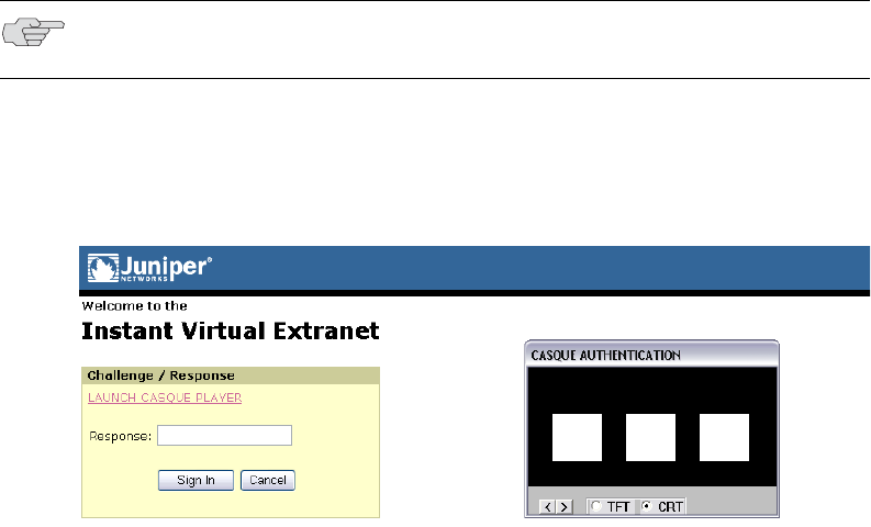
Juniper Networks Secure Access Administration Guide
122 Configuring a RADIUS server instance
Using CASQUE authentication
CASQUE authentication uses a token-based challenge/response authentication
mechanism employing a CASQUE player installed on the client system. Once
configured with CASQUE authentication, the RADIUS server issues a challenge with
a response matching the custom challenge expression (:([0-9a-zA-Z/+=]+):). The IVE
then generates an intermediate page that automatically launches the CASQUE
player installed on the user’s system.
Users must then use their CASQUE Optical Responder tokens to generate the
corresponding passcode, enter the passcode in the Response field, and click Sign
In.
Figure 23: CASQUE authentication Challenge/Response page with CASQUE player
Configuring the IVE to work with a RADIUS server
This section includes the following instructions for configuring the IVE and RADIUS
server to work together:
“Defining an IVE RADIUS server instance” on page 122
“Configuring the RADIUS server to recognize the IVE” on page 124
Defining an IVE RADIUS server instance
To configure a connection to the RADIUS server on the IVE:
1. In the admin console, choose Authentication > Auth. Servers.
2. Do one of the following:
To create a new server instance on the IVE, select Radius Server from the
New list, and then click New Server.
To update an existing server instance, click the appropriate link in the
Authentication/Authorization Servers list.
NOTE: If the CASQUE player does not launch automatically, click the Launch
CASQUE Player link.
Configuring a RADIUS server instance 123
Chapter 7: Authentication and directory servers
3. At the top of the Radius Server page, specify a name to identify the server
instance.
4. Specify the name or IP address of the RADIUS server.
5. Enter the authentication port value for the RADIUS server. Typically this port is
1812, but some legacy servers might use 1645.
6. Enter a string for the shared secret. You also need to enter this string when
configuring the RADIUS server to recognize the IVE machine as a client.
7. Enter the accounting port value for the RADIUS server. Typically this port is
1813, but some legacy servers might use 1646.
8. Enter the NAS IP Address. This allows you to control the NAS IP address value
passed to RADIUS requests. If you leave this field empty, then the IVE’s internal
IP address will be passed to RADIUS requests. If you configure the NAS IP
address, then the value will be passed, regardless of which cluster node sends
the requests.
9. Enter the interval of time for the IVE to wait for a response from the RADIUS
server before timing out the connection.
10. Enter the number of times for the IVE to try to make a connection after the first
attempt fails.
11. Select the Users authenticate using tokens or one-time passwords checkbox
if you do not want to submit the password entered by the user to other SSO-
enabled applications. You should generally select this option if the users submit
one-time use passwords to the IVE. For more information, see “Multiple sign-in
credentials overview” on page 193.
12. In the Backup Server section, enter a secondary RADIUS server for the IVE to
use if the primary server—the one defined in this instance—is unreachable. For
the secondary server, enter the server:
a. Name or IP address
b. Authentication port
c. Shared secret
d. Accounting port
13. If you want to track IVE user activity using this instance of the RADIUS server,
enter the following information in the Radius Accounting section:
a. In the NAS-Identifier field, enter the name that identifies the IVE Network
Access Server (NAS) client that communicates with the RADIUS server. If
you leave this field empty, the IVE uses the value specified in the
Hostname field of the System > Network > Overview page of the admin
console. If no value is specified in Hostname field, the IVE uses the value
“Juniper IVE.”

Juniper Networks Secure Access Administration Guide
124 Configuring a RADIUS server instance
b. In the User-Name field, specify the user information that the IVE should
send to the RADIUS accounting server. You may enter any of the
applicable session variables described in “System variables and examples”
on page 860. Applicable variables include those that are set at the time
after the user signs in and maps to a role. The default variables for this field
are:
<username> logs the user’s IVE username to the accounting server.
<REALM> logs the user’s IVE realm to the accounting server.
<ROLE> logs the user’s IVE role to the accounting server. If the user is
assigned to more than one role, the IVE comma-separates them.
c. Add an Interim Update Level (in minutes). The interim update level
enables you to accomplish more precise billing for long-lived session
clients and in case of a network failure. For more information, see
“Understanding the interim update feature” on page 133.
14. Add a custom challenge expression (optional). Three types of challenge
expressions exist with each automatically set to its pre-populated default. The
custom option allows the administrator to configure the actual string pattern to
match for any of the three modes. To add a custom expression, select the
Custom radio button under the appropriate challenge expression type, and add
a custom expression in the associated text box.
15. Click Save Changes. If you are creating the server instance for the first time,
the Settings and Users tabs appear.
16. Specify which realms should use the server to authenticate, authorize, or
account for administrators and users. For more information, see “Defining
authentication policies” on page 168.
Configuring the RADIUS server to recognize the IVE
You need to configure the RADIUS server to recognize the IVE by specifying:
The host name given to the IVE.
The network IP address of the IVE.
The IVE client type—if applicable. If this option is available, select Single
Transaction Server or its equivalent.
The type of encryption to use for authenticating client communication. This
choice should correspond to the client type.
NOTE: When using CASQUE authentication, specify:([0-9a-zA-Z/+=]+): as the
custom expression for the Generic Login Challenge Expression.
NOTE: For information about monitoring and deleting the sessions of users from
this server who are currently signed, see “Monitoring active users” on page 686.

Configuring a RADIUS server instance 125
Chapter 7: Authentication and directory servers
The shared secret you entered in the admin console for the RADIUS server on
the Authentication > Auth. Servers > Radius Server page.
Enabling RADIUS accounting
You can configure the IVE to send session start and stop messages to a RADIUS
accounting server. The IVE recognizes two categories of sessions—user-sessions
and sub-sessions. A user session may contain multiple sub-sessions. The IVE
recognizes the following types of sub-sessions:
JSAM
WSAM
Network Connect
The IVE sends a user-session start message after the user successfully signs in and
the IVE maps him to a role. The IVE sends a sub-session start message when the
sub-session becomes active; for example, after launching JSAM. The IVE sends a
sub-session stop message when there is an explicit request from the user to
terminate a sub-session, or if the user-session terminates.
Whenever a user session terminates, the IVE sends a user-session stop message to
the accounting server. A user session terminates whenever the user:
Manually signs out of the IVE
Times out of the IVE either due to inactivity or because of exceeding the
maximum session length
Is denied access due to Host Checker or Cache Cleaner role-level restrictions
Is manually forced out of the IVE by an administrator or due to dynamic policy
evaluation.
The IVE also sends stop messages for all active sub-sessions. The stop-messages for
the sub-sessions precede the stop-messages for the user-session.
.
The following three tables describe the attributes that are common to start and stop
messages, attributes that are unique to start messages, and attributes that are
unique to stop messages.
NOTE: If users are signed into an IVE cluster, the RADIUS accounting messages
may show the users signing in to one node and signing out of another.
Table 9: Attributes common to both start and stop messages
Attribute Description
User-Name (1) String that the IVE administrator specifies during RADIUS server
configuration
NAS-IP-Address (4) IVE’s IP address

Juniper Networks Secure Access Administration Guide
126 Configuring a RADIUS server instance
NAS-Port (5) The IVE sets this attribute to 0 if the user signed in using an
internal port, or 1 if an external port.
Framed-IP-Address (8) User’s source IP address
NAS-Identifier (32) Configured name for the IVE client under the RADIUS server
configuration
Acct-Status-Type (40) The IVE sets this attribute to 1 for a start message, or 2 for a stop
message in a user-session or a sub-session
Acct-Session-Id (44) Unique accounting ID that matches start and stop messages
corresponding to a user-session or to a sub-session.
Acct-Multi-Session-Id (50) Unique accounting ID that you can use to link together multiple
related sessions. Each linked session must have a unique Acct-
Session-Id and the same Acct-Multi-Session-Id.
Acct-Link-Count (51) The count of links in a multi-link session at the time the IVE
generates the accounting record
Table 10: Start attributes
Attribute Description
Acct-Authentic (45) The IVE sets this attribute to:
RADIUS—if the user authenticated to a RADIUS server
Local—if the user authenticated to an Local Authentication
Server
Remote—for anything else
Table 11: Stop attributes
Attribute Description
Acct-Session-Time (46) Duration of the user-session or the sub-session
Acct-Terminate-Cause (49) The IVE uses one of the following values to specify the event that
caused the termination of a user session or a sub-session:
User Request (1) – User manually signs out
Idle Timeout (4) – User Idle time out
Session Timeout (5) – User Max Session Timeout
Admin Reset (6) – User Forced Out from Active Users page
Acct-Input-Octets Octet-based count of JSAM/WSAM/NC session level when session
was terminated and of user session level when the session was
terminated and the interim update time arrived. From IVE to
client.
Acct-Output-Octets Octet-based count of JSAM/WSAM/NC session level when session
was terminated and of user session level when the session was
terminated and the interim update time arrived. From client to
IVE.
Table 9: Attributes common to both start and stop messages (Continued)
Attribute Description

Configuring a RADIUS server instance 127
Chapter 7: Authentication and directory servers
To distinguish between a user-session and the sub-sessions it contains, examine the
Acct-Session-Id and the Acct-Multi-Session-Id. In a user-session, both of these
attributes are the same. In a sub-session, the Acct-Multi-Session-Id is the same as
the one for the parent user-session, and the IVE indicates the sub-session by using
one of the following suffixes in the Acct-Session-Id:
“JSAM” for JSAM sessions
“WSAM” for WSAM sessions
“NC” for Network Connect sessions
Supported RADIUS attributes
The following RADIUS attributes are supported in RADIUS role mapping. For more
information, see the full descriptions (from which these descriptions were derived)
at the FreeRADIUS website located at http://www.freeradius.org/rfc/attributes.html.
Table 12: RADIUS role mapping attributes
Attribute Description
ARAP-Challenge-Response Sent in an Access-Accept packet with Framed-Protocol
of ARAP, and contains the response to the dial-in
client's challenge.
ARAP-Features Sent in an Access-Accept packet with Framed-
Protocol of ARAP. Includes password information that
the NAS must send to the user in an ARAP feature
flags packet.
ARAP-Password Present in an Access-Request packet containing a
Framed-Protocol of ARAP. Only one of User-Password,
CHAP-Password, or ARAP-Password must be included
in an Access-Request, or one or more EAP-Messages.
ARAP-Security Identifies the ARAP Security Module to be used in an
Access-Challenge packet.
ARAP-Security-Data Contains a security module challenge or response, and
is in Access-Challenge and Access-Request packets.
ARAP-Zone-Access Indicates how to use the ARAP zone list for the user.
Access-Accept Provides specific configuration information necessary
to begin delivery of service to the user.
Access-Challenge To send the user a challenge requiring a response, the
RADIUS server must respond to the Access-Request by
transmitting a packet with the Code field set to 11
(Access-Challenge).
Access-Reject If any value of the received Attributes is not
acceptable, then the RADIUS server must transmit a
packet with the Code field set to 3 (Access-Reject).
Access-Request Conveys information specifying user access to a
specific NAS, and any special services requested for
that user.
Accounting-Request Conveys information used to provide accounting for a
service provided to a user.
Accounting-Response Acknowledges that the Accounting-Request has been
received and recorded successfully.

Juniper Networks Secure Access Administration Guide
128 Configuring a RADIUS server instance
Acct-Authentic Indicates how the user was authenticated, whether by
RADIUS, the NAS itself, or another remote
authentication protocol.
Acct-Delay-Time Indicates how many seconds the client has been
trying to send this record.
Acct-Input-Gigawords Indicates how many times the Acct-Input-Octets
counter has wrapped around 2^32 over the course of
this service being provided.
Acct-Input-Octets Indicates how many octets have been received from
the port during the current session.
Acct-Input-Packets Indicates how many packets have been received from
the port during the session provided to a Framed User
Acct-Interim-Interval Indicates the number of seconds between each
interim update in seconds for this specific session.
Acct-Link-Count The count of links known to have been in a given
multilink session at the time the accounting record is
generated.
Acct-Multi-Session-Id A unique Accounting ID to make it easy to link
together multiple related sessions in a log file.
Acct-Output-Gigawords Indicates how many times the Acct-Output-Octets
counter has wrapped around 2^32 during the current
session.
Acct-Output-Octets Indicates how many octets have been sent to the port
during this session.
Acct-Output-Packets Indicates how many packets have been sent to the
port during this session to a Framed User.
Acct-Session-Id A unique Accounting ID to make it easy to match start
and stop records in a log file.
Acct-Session-Time Indicates how many seconds the user has received
service.
Acct-Status-Type Indicates whether this Accounting-Request marks the
beginning of the user service (Start) or the end (Stop).
Acct-Terminate-Cause Indicates how the session was terminated.
Acct-Tunnel-Connection Indicates the identifier assigned to the tunnel session.
Acct-Tunnel-Packets-Lost Indicates the number of packets lost on a given link.
CHAP-Challenge Contains the CHAP Challenge sent by the NAS to a
PPP Challenge-Handshake Authentication Protocol
(CHAP) user.
CHAP-Password The response value provided by a PPP Challenge-
Handshake Authentication Protocol (CHAP) user in
response to the challenge.
Callback-Id The name of a location to be called, to be interpreted
by the NAS.
Callback-Number The dialing string to be used for callback.
Called-Station-Id Allows the NAS to send the phone number that the
user called, using Dialed Number Identification (DNIS)
or similar technology.
Table 12: RADIUS role mapping attributes (Continued)
Attribute Description

Configuring a RADIUS server instance 129
Chapter 7: Authentication and directory servers
Calling-Station-Id Allows the NAS to send the phone number that the call
came from, using Automatic Number Identification
(ANI) or similar technology.
Class Sent by the server to the client in an Access-Accept
and then sent unmodified by the client to the
accounting server as part of the Accounting-Request
packet, if accounting is supported.
Configuration-Token For use in large distributed authentication networks
based on proxy.
Connect-Info Sent from the NAS to indicate the nature of the user's
connection.
EAP-Message Encapsulates Extended Access Protocol [3] packets to
allow the NAS to authenticate dial-in users by means
of EAP without having to understand the EAP
protocol.
Filter-Id The name of the filter list for this user.
Framed-AppleTalk-Link The AppleTalk network number used for the serial link
to the user, which is another AppleTalk router.
Framed-AppleTalk-Network The AppleTalk Network number which the NAS can
probe to allocate an AppleTalk node for the user.
Framed-AppleTalk-Zone The AppleTalk Default Zone to be used for this user.
Framed-Compression A compression protocol to be used for the link.
Framed-IP-Address The address to be configured for the user.
Framed-IP-Netmask The IP netmask to be configured for the user when the
user is a router to a network.
Framed-IPv6-Pool Contains the name of an assigned pool used to assign
an IPv6 prefix for the user.
Framed-IPv6-Route Routing information to be configured for the user on
the NAS.
Framed-IPX-Network The IPX Network number to be configured for the
user.
Framed-MTU The Maximum Transmission Unit to be configured for
the user, when it is not negotiated by some other
means (such as PPP).
Framed-Pool The name of an assigned address pool used to assign
an address for the user.
Framed-Protocol The framing to be used for framed access.
Framed-Route Routing information to be configured for the user on
the NAS.
Framed-Routing The routing method for the user, when the user is a
router to a network.
Idle-Timeout Sets the maximum number of consecutive seconds of
idle connection allowed to the user before termination
of the session or prompt.
Keep-Alives Use SNMP instead of keep-alives.
Login-IP-Host Indicates the system with which to connect the user,
when the Login-Service Attribute is included.
Table 12: RADIUS role mapping attributes (Continued)
Attribute Description

Juniper Networks Secure Access Administration Guide
130 Configuring a RADIUS server instance
Login-LAT-Group Contains a string identifying the LAT group codes that
this user is authorized to use.
Login-LAT-Node Indicates the Node with which the user is to be
automatically connected by LAT.
Login-LAT-Port Indicates the Port with which the user is to be
connected by LAT.
Login-LAT-Service Indicates the system with which the user is to be
connected by LAT.
Login-Service Indicates the service to use to connect the user to the
login host.
Login-TCP-Port Indicates the TCP port with which the user is to be
connected, when the Login-Service Attribute is also
present.
MS-ARAP-Challenge Only present in an Access-Request packet containing
a Framed-Protocol Attribute with the value 3 (ARAP).
MS-ARAP-Password-Change-Reason Indicates the reason for a server-initiated password
change.
MS-Acct-Auth-Type Represents the method used to authenticate the dial-
up user.
MS-Acct-EAP-Type Represents the Extensible Authentication Protocol
(EAP) [15] type used to authenticate the dial-up user.
MS-BAP-Usage Describes whether the use of BAP is allowed,
disallowed or required on new multilink calls.
MS-CHAP-CPW-1 Allows the user to change password if it has expired.
MS-CHAP-CPW-2 Allows the user to change password if it has expired.
MS-CHAP-Challenge Contains the challenge sent by a NAS to a Microsoft
Challenge-Handshake Authentication Protocol (MS-
CHAP) user.
MS-CHAP-Domain Indicates the Windows NT domain in which the user
was authenticated.
MS-CHAP-Error Contains error data related to the preceding MS-CHAP
exchange.
MS-CHAP-LM-Enc-PW Contains the new Windows NT password encrypted
with the old LAN Manager password hash.
MS-CHAP-MPPE-Keys Contains two session keys for use by the Microsoft
Point-to-Point Encryption Protocol (MPPE).
MS-CHAP-NT-Enc-PW Contains the new Windows NT password encrypted
with the old Windows NT password hash.
MS-CHAP-Response Contains the response value provided by a PPP
Microsoft Challenge-Handshake Authentication
Protocol (MS-CHAP) user in response to the challenge.
MS-CHAP2-CPW Allows the user to change password if it has expired.
MS-CHAP2-Response Contains the response value provided by an MS-
CHAP-V2 peer in response to the challenge.
MS-CHAP2-Success Contains a 42-octet authenticator response string.
MS-Filter Used to transmit traffic filters.
Table 12: RADIUS role mapping attributes (Continued)
Attribute Description

Configuring a RADIUS server instance 131
Chapter 7: Authentication and directory servers
MS-Link-Drop-Time-Limit Indicates the length of time (in seconds) that a link
must be underutilized before it is dropped.
MS-Link-Utilization-Threshold Represents the percentage of available bandwidth
utilization below which the link must fall before the
link is eligible for termination.
MS-MPPE-Encryption-Policy Signifies whether the use of encryption is allowed or
required.
MS-MPPE-Encryption-Types Signifies the types of encryption available for use with
MPPE.
MS-MPPE-Recv-Key Contains a session key for use by the Microsoft Point-
to-Point Encryption Protocol (MPPE).
MS-MPPE-Send-Key Contains a session key for use by the Microsoft Point-
to-Point Encryption Protocol (MPPE).
MS-New-ARAP-Password Transmits the new ARAP password during an ARAP
password change operation.
MS-Old-ARAP-Password Transmits the old ARAP password during an ARAP
password change operation.
MS-Primary-DNS-Server Indicates the address of the primary Domain Name
Server (DNS) [16, 17] server to be used by the PPP
peer.
MS-Primary-NBNS-Server Indicates the address of the primary NetBIOS Name
Server (NBNS) [18] server to be used by the PPP peer.
MS-RAS-Vendor Indicates the manufacturer of the RADIUS client
machine.
MS-RAS-Version Indicates the version of the RADIUS client software.
MS-Secondary-DNS-Server Indicates the address of the secondary DNS server to
be used by the PPP peer.
MS-Secondary-NBNS-Server Indicates the address of the secondary DNS server to
be used by the PPP peer.
NAS-IP-Address Indicates the identifying IP Address of the NAS that is
requesting authentication of the user, and must be
unique to the NAS within the scope of the RADIUS
server.
NAS-Identifier Contains a string identifying the NAS originating the
Access-Request.
NAS-Port Indicates the physical port number of the NAS that is
authenticating the user.
NAS-Port-Id Contains a text string that identifies the port of the
NAS that is authenticating the user.
NAS-Port-Type Indicates the type of the physical port of the NAS that
is authenticating the user.
Password-Retry Indicates how many authentication attempts a user is
allowed to attempt before being disconnected.
Port-Limit Sets the maximum number of ports to be provided to
the user by the NAS.
Prompt Indicates to the NAS whether it should echo the user's
response as it is entered, or not echo it.
Table 12: RADIUS role mapping attributes (Continued)
Attribute Description

Juniper Networks Secure Access Administration Guide
132 Configuring a RADIUS server instance
Proxy-State A proxy server can send this attribute to another
server when forwarding an Access-Request. The
attribute must be returned unmodified in the Access-
Accept, Access-Reject or Access-Challenge.
Reply-Message Text that can be displayed to the user.
Service-Type The type of service the user has requested, or the type
of service to be provided.
Session-Timeout Sets the maximum number of seconds of service to be
provided to the user before termination of the session
or prompt.
State A packet must have only zero or one State Attribute.
Usage of the State Attribute is implementation
dependent.
Telephone-number Using the Calling-Station-Id and Called-Station-Id
RADIUS attributes, authorization and subsequent
tunnel attributes can be based on the phone number
originating the call, or the number being called.
Termination-Action The action the NAS should take when the specified
service is completed.
Tunnel-Assignment-ID Indicates to the tunnel initiator the particular tunnel to
which a session is to be assigned.
Tunnel-Client-Auth-ID Specifies the name used by the tunnel initiator during
the authentication phase of tunnel establishment.
Tunnel-Client-Endpoint Contains the address of the initiator end of the tunnel.
Tunnel-Link-Reject Marks the rejection of the establishment of a new link
in an existing tunnel.
Tunnel-Link-Start Marks the creation of a tunnel link.
Tunnel-Link-Stop Marks the destruction of a tunnel link.
Tunnel-Medium-Type The transport medium to use when creating a tunnel
for those protocols (such as L2TP) that can operate
over multiple transports.
Tunnel-Medium-Type The transport medium to use when creating a tunnel
for those protocols (such as L2TP) that can operate
over multiple transports.
Tunnel-Password A password to be used to authenticate to a remote
server.
Tunnel-Preference If the RADIUS server returns more than one set of
tunneling attributes to the tunnel initiator, you should
include this attribute in each set to indicate the
relative preference assigned to each tunnel.
Tunnel-Private-Group-ID The group ID for a particular tunneled session.
Tunnel-Reject Marks the rejection of the establishment of a tunnel
with another node.
Tunnel-Server-Auth-ID Specifies the name used by the tunnel terminator
during the authentication phase of tunnel
establishment.
Tunnel-Server-Endpoint The address of the server end of the tunnel.
Table 12: RADIUS role mapping attributes (Continued)
Attribute Description

Configuring an eTrust SiteMinder server instance 133
Chapter 7: Authentication and directory servers
Understanding clustering issues
Accounting messages are sent to the RADIUS server by each cluster node without
consolidation. RADIUS accounting on the IVE follows these assumptions:
If the cluster is active/passive, all users are connected to one node at a time.
If the cluster is active/active and does not use a balancer, users are connected
to different nodes but are static.
If the cluster is active/active and uses a balancer, the balancer usually enforces
a persistent source IP. In this case, users are always connected to the same
node.
The IVE does not support load balancing for RADIUS.
Understanding the interim update feature
If you want a server to receive interim accounting messages, you can statically
configure an interim value on the client, in which case, the locally-configured value
overrides any value that might be included in the RADIUS Access-Accept message.
The octet count reported in the accounting messages is the cumulative total since
the beginning of the user session.
The interim update byte count is only supported based on a user session, not on
SAM or NC sessions.
Configuring an eTrust SiteMinder server instance
When you configure the IVE to authenticate users with an eTrust SiteMinder policy
server, the IVE passes the user’s credentials to SiteMinder during authentication.
Once SiteMinder receives the credentials, it may use standard username and
password authentication, ACE SecurID tokens, or client-side certificates to
authenticate the credentials (as explained in “Authentication using various
authentication schemes” on page 136).
Tunnel-Start Marks the establishment of a tunnel with another
node.
Tunnel-Stop Marks the destruction of a tunnel to or from another
node.
Tunnel-Type The tunneling protocol(s) to be used (in the case of a
tunnel initiator) or the tunneling protocol in use (in the
case of a tunnel terminator).
User-Name The name of the user to be authenticated.
User-Password The password of the user to be authenticated, or the
user's input following an Access-Challenge.
Table 12: RADIUS role mapping attributes (Continued)
Attribute Description
Juniper Networks Secure Access Administration Guide
134 Configuring an eTrust SiteMinder server instance
The IVE also passes a protected resource to SiteMinder during authentication in
order to determine which SiteMinder realm it should use to authenticate the user.
When the IVE passes the protected resource, SiteMinder authorizes the user’s URL
against the realm that is associated with the resource and allows the user to
seamlessly access any resources whose protection levels are equal to or less than
the resource the IVE passed (as explained in “Configuring the IVE to grant users
different protected resources” on page 145). If the user attempts to access a Web
resource with a higher protection level, either SiteMinder or the IVE handles the
request (as explained in “Reauthentication of users with insufficient protection
levels” on page 137).
This topic includes the following information about eTrust SiteMinder servers:
“eTrust SiteMinder overview” on page 134
“Configuring SiteMinder to work with the IVE” on page 138
“Configuring the IVE to work with SiteMinder” on page 144
eTrust SiteMinder overview
The IVE enables single sign-on (SSO) from the IVE to SiteMinder-protected
resources using SMSESSION cookies. A SMSESSION cookie is a security token that
encapsulates SiteMinder session information. Depending on your configuration,
either the SiteMinder Web agent or the IVE creates a SMSESSION cookie and then
posts the cookie to the following locations so the user does not have to re-
authenticate if he wants to access additional resources:
The IVE: If the user tries to access a SiteMinder resource from within his IVE
session (for example, from the IVE file browsing page), the IVE passes its
cached SMSESSION cookie to the Web agent for authentication.
The user’s Web browser: If the user tries to access a SiteMinder resource from
outside of his IVE session (for example, when using a protected resource on a
standard agent), SiteMinder uses the cached SMSESSION cookie stored in the
user’s Web browser to authenticate/authorize the user.
If you enable the Automatic Sign-In option (as explained in “Automatic Sign-In” on
page 148), the IVE can use an SMSESSION cookie generated by another agent to
enable single sign-on from a SiteMinder resource to the IVE. When a user accesses
the IVE sign-in page with an SMSESSION cookie, the IVE verifies the SMSESSION
cookie. Upon successful verification, the IVE establishes an IVE session for the user.
You can use the following authentication mechanisms when you enable automatic
sign-in through the IVE:
Custom agent: The IVE authenticates the user against the policy server and
generates a SMSESSION cookie. When you select this option, you can enable
SSO on other SiteMinder agents that use the same policy server. To enable SSO
on these agents, update each of them to accept third party cookies (as
explained in “Authenticate using custom agent” on page 149). If you select this
option and the user enters his IVE session with an SMSESSION cookie, the IVE
attempts automatic sign-in when the user enters the IVE session.

Configuring an eTrust SiteMinder server instance 135
Chapter 7: Authentication and directory servers
HTML form post: The IVE posts credentials to a standard Web agent that you
have already configured. The Web agent then creates SMSESSION cookies. If
you select this option, you cannot use SecurID New Pin and Next Token modes
or client-side certificate authentication (as explained in on “Authenticate using
HTML form post” on page 150). If you select this option and the user enters his
IVE session with an SMSESSION cookie, the IVE attempts automatic sign-in
when the user enters the IVE session.
Delegated authentication: The IVE delegates authentication to a standard
agent. If this option is enabled, the IVE tries to determine the FCC URL
associated with the protected resource. The IVE then redirects the user to the
FCC URL with the IVE sign-in URL as the TARGET. Upon successful
authentication, the user is redirected back to the IVE with an SMSESSION
cookie and the IVE does an automatic sign-in for the user (as explained in
“Delegate authentication to a standard agent” on page 151).
NOTE:
At the time of this printing, Juniper Networks supports eTrust SiteMinder
server version 6.0 and version 5.5 with standard agent versions 6 and
5QMR5. If you run older agents than the supported agents, you may
experience cookie validation problems, including crossed log entries and
intermittent user timeouts.
You can choose which eTrust SiteMinder server version you want to support
when you create a server instance. You can choose version 5.5, which
supports both versions 5.5 and 6.0, or you can choose version 6.0, which
supports only version 6.0.
SiteMinder does not store the IP address in the SMSESSION cookie, and
therefore cannot pass it to the IVE appliance.
SiteMinder sends the SMSESSION cookie to the IVE as a persistent cookie. To
maximize security, the IVE resets the persistent cookie as a session cookie
once authentication is complete.
When you use SiteMinder to authenticate, the IVE disregards any IVE session
and idle timeouts and uses session and idle timeouts set through the
SiteMinder realm instead.
The IVE logs any SiteMinder error codes on the System > Log/Monitoring >
User Access page. For information on the SiteMinder error codes, see the
SiteMinder documentation.

Juniper Networks Secure Access Administration Guide
136 Configuring an eTrust SiteMinder server instance
Authentication using various authentication schemes
Within SiteMinder, an authentication scheme is a way to collect user credentials and
determine the identity of a user. You may create different authentication schemes
and associate different protection levels with each. For example, you may create
two schemes—one that authenticates users based solely on the users’ client-side
certificates and provides them a low protection level, and a second that uses ACE
SecurID token authentication and provides users a higher protection level. The IVE
works with the following types of SiteMinder authentication schemes:
Basic username and password authentication—The user’s name and
password are passed to the SiteMinder policy server. The policy server may
then authenticate them itself or pass it to another server for authentication.
ACE SecurID token authentication—The SiteMinder policy server
authenticates users based on a username and password generated by an ACE
SecurID token.
Client-side certificate authentication—The SiteMinder policy server
authenticates users based on their client-side certificate credentials. If you
choose this authentication method, the Web browser displays a list of client
certificates from which users can select.
For configuration information, see:
“Creating a SiteMinder authentication scheme for the IVE” on page 139
“Configuring the IVE to work with multiple authentication schemes” on
page 144
NOTE:
If you choose to authenticate users with this method, you must import the
client certificate into the IVE through the System > Certificates > Trusted
Client CAs tab. For more information, see “Using trusted client CAs” on
page 607.
If you do not want to display the standard IVE sign in page to users, you may
change it using the customizable sign-in pages feature. For more information,
see the Custom Sign-In Pages Solution Guide.
SiteMinder client-side certificate authentication is separate from IVE client-
side certificate authentication. If you choose both, the IVE first authenticates
using the IVE configuration parameters. If this succeeds, it then passes
certificate values to SiteMinder for authentication.
Configuring an eTrust SiteMinder server instance 137
Chapter 7: Authentication and directory servers
Reauthentication of users with insufficient protection levels
During IVE configuration, you must specify a protected resource in order to control
the protection level allowed in the user’s SiteMinder session, as explained in
“eTrust SiteMinder overview” on page 134. If a user attempts to access a Web
resource that requires a higher protection level than he is authorized to access,
however, the IVE can also handle re-authentication by directing him to an
intermediate page (provided you have enabled the Resource for insufficient
protection level option on during IVE configuration). For more information, see
“Resource for insufficient protection level” on page 152.
The IVE intermediate page contains two options:
Continue—When the user selects this option, the IVE signs him out of his
current session, prompts him for the credentials required by the higher level
resource, and directs him to the page he is trying to access if his credentials
authenticate. (Note that if the user is running Host Checker or Cache Cleaner
and does not choose to enter his credentials when the IVE prompts him to re-
authenticate, the Host Checker and/or Cache Cleaner application continues to
run on the user’s system until his IVE session times out.)
Cancel—When the user selects this option, he is redirected to the previous
page.
Otherwise, if you choose not to re-authenticate through the IVE, the re-
authentication process is dependent on whether or not the policy server returns an
authentication scheme URL to the user. If the policy server:
Does not return an authentication scheme URL—The IVE returns a validation
failure message to the user and re-authenticates through the standard IVE sign-
in page. The user is prompted to sign back in, but is assigned his original
protection level and may still be unable to sign in to the desired page.
Returns an authentication scheme URL—The IVE redirects to the Web agent
you specify in the IVE to handle re-authentication.
For information about making the IVE handle re-authentication, see “Creating a
SiteMinder authentication scheme for the IVE” on page 139.
Determining the user’s username
With the availability of different authentication schemes and sign-in points, the IVE
may obtain a username from various sources, such as a policy server header,
certificate attribute, or from the IVE sign-in page. Listed below are the various
methods a user may employ to access the IVE and how the IVE determines the
username for each. When a user:
Signs in through the standard IVE sign-in page—The IVE first checks the
username that the policy server returned in its OnAuthAccept response header.
If SiteMinder does not define a username, the IVE uses the name that the user
entered during sign-in. Otherwise, if neither SiteMinder nor the user provide a
username because the user authenticates using a client certificate, the IVE uses
the UserDN value set by the policy server.

Juniper Networks Secure Access Administration Guide
138 Configuring an eTrust SiteMinder server instance
Automatically signs in to the IVE using SiteMinder credentials—The IVE first
checks the username that the policy server returned in its OnAuthAccept
response header. If SiteMinder does not define a username, the IVE checks the
SMSESSION cookie. Otherwise, if SiteMinder does not populate the response
header or SMSESSION cookie with a username, the IVE checks the UserDN
value in the SMSESSION cookie.
Once the IVE determines which username to use, it saves it in its session cache and
references it when a user wants to access additional resources (as explained in
“eTrust SiteMinder overview” on page 134).
In order to consistently return the correct username to the IVE, you should
configure the OnAuthAccept response on the SiteMinder policy server, as explained
in “Creating a rule/response pair to pass usernames to the IVE” on page 142.
Configuring SiteMinder to work with the IVE
The following procedures outline how to configure a SiteMinder policy server to
work with the IVE. These are not complete SiteMinder configuration instructions—
they are only intended to help you make SiteMinder work with the IVE. For in-
depth SiteMinder configuration information, refer to the documentation provided
with your SiteMinder policy server.
To configure SiteMinder to work with the IVE, you must:
1. “Configuring the SiteMinder agent” on page 139
2. “Creating a SiteMinder authentication scheme for the IVE” on page 139
3. “Creating a SiteMinder domain for the IVE” on page 141
4. “Creating a SiteMinder realm for the IVE” on page 141
5. “Creating a rule/response pair to pass usernames to the IVE” on page 142
6. “Creating a SiteMinder policy under the domain” on page 144
NOTE: The instructions shown here are for SiteMinder policy server version 5.5.
Instructions may vary slightly if you are using a different product version.

Configuring an eTrust SiteMinder server instance 139
Chapter 7: Authentication and directory servers
Configuring the SiteMinder agent
A SiteMinder agent filters user requests to enforce access controls. For instance,
when a user requests a protected resource, the agent prompts the user for
credentials based on an authentication scheme, and sends the credentials to a
SiteMinder policy server. A Web agent is simply an agent that works with a Web
server. When configuring SiteMinder to work with the IVE, you must configure the
IVE as a Web agent in most cases.
To configure the IVE as a Web agent on the SiteMinder policy server:
1. In the SiteMinder Administration interface, choose the System tab.
2. Right-click on Agents and choose Create Agent.
3. Enter a name for the Web agent and (optionally) a description. Note that you
need to enter this name when creating a SiteMinder realm, (as explained in
“Creating a SiteMinder realm for the IVE” on page 141) and when configuring
the IVE (as explained in “Agent Name, Secret” on page 147).
4. You must select the Support 5.x agents option for compatibility with the IVE.
5. Under Agent Type, select SiteMinder and then select Web Agent from the
drop-down list. You must select this setting for compatibility with the IVE.
6. Under IP Address or Host Name, enter the name or IP address of the IVE.
7. In the Shared Secret fields, enter and confirm a secret for the Web agent. Note
that you need to enter this secret when configuring the IVE (as explained in
“Agent Name, Secret” on page 147).
8. Click OK.
Creating a SiteMinder authentication scheme for the IVE
Within SiteMinder, an authentication scheme provides a way to collect credentials
and determine the identity of a user.
To configure a SiteMinder authentication scheme for the IVE:
1. In the SiteMinder Administration interface, choose the System tab.
2. Right-click on Authentication Schemes and choose Create Authentication
Scheme.
NOTE: If you select the Delegate authentication to a standard agent option, you
must set the following options in the agent configuration object of the standard
Web agent host the FCC URL:
EncryptAgentName=no
FCCCompatMode=no

Juniper Networks Secure Access Administration Guide
140 Configuring an eTrust SiteMinder server instance
3. Enter a name for the scheme and (optionally) a description. Note that you need
to enter this name when configuring the SiteMinder realm (as explained in
“Creating a SiteMinder realm for the IVE” on page 141).
4. Under Authentication Scheme Type, select one of the following options:
Basic Template
HTML Form Template
SecurID HTML Form Template1
X509 Client Cert Template
X509 Client Cert and Basic Authentication
5. Enter a protection level for the scheme. Note that this protection level carries
over to the SiteMinder realm that you associate with this scheme. For more
information, see “Creating a SiteMinder realm for the IVE” on page 141.
6. Select the Password Policies Enabled for this Authentication Scheme if you
want to reauthenticate users who request resources with a higher protection
level than they are authorized to access.
7. In the Scheme Setup tab, enter the options required by your authentication
scheme type.
If you want the IVE to re-authenticate users who request resources with a
higher protection level than they are authorized to access, you must enter the
following settings:
Under Server Name, enter the IVE host name (for example,
sales.yourcompany.net).
Select the Use SSL Connection checkbox.
1. If you are using SecurID authentication, you must choose SecurID HTML Form Template (instead of SecurID
Template). Choosing this option enables the Policy Server to send ACE sign-in failure codes to the IVE.
NOTE:
The IVE only supports the authentication scheme types listed here.
You must select HTML Form Template if you want the IVE to handle re-
authentication (as described in “Reauthentication of users with insufficient
protection levels” on page 137).
If you select X509 Client Cert Template or X509 Client Cert and Basic
Authentication, you must import the certificate into the IVE through the
System > Certificates > Trusted Client CAs tab. For more information, see
“Using trusted client CAs” on page 607.

Configuring an eTrust SiteMinder server instance 141
Chapter 7: Authentication and directory servers
Under Target, enter the IVE sign-in URL defined in this step’s first bullet
plus the parameter “ive=1” (for example, /highproturl?ive=1). (The IVE
must have a sign-in policy that uses */highproturl as the sign-in URL and
only uses the corresponding SiteMinder authentication realm.)
De-select the Allow Form Authentication Scheme to Save Credentials
checkbox.
Leave Additional Attribute List empty.
8. Click OK.
Creating a SiteMinder domain for the IVE
Within SiteMinder, a policy domain is a logical grouping of resources associated
with one or more user directories. Policy domains contain realms, responses, and
policies. When configuring the IVE to work with SiteMinder, you must give IVE
users access to a SiteMinder resource within a realm, and then group the realm into
a domain.
To configure a SiteMinder domain for the IVE, in the SiteMinder Administration
interface, choose the System tab, right-click on Domains and choose Create
Domain. Or, click on Domains and choose an existing SiteMinder domain. Note
that you need to add a realm to this domain (as explained in “Creating a SiteMinder
realm for the IVE” on page 141).
Creating a SiteMinder realm for the IVE
Within SiteMinder, a realm is a cluster of resources within a policy domain grouped
together according to security requirements. When configuring SiteMinder to work
with the IVE, you must define realms to determine which resources IVE users may
access.
To configure a SiteMinder realm for the IVE:
1. In the SiteMinder Administration interface, choose the Domains tab.
2. Expand the domain that you created for the IVE. For more information, see
“Creating a SiteMinder domain for the IVE” on page 141.
NOTE: When you save changes, ive=1 disappears from the target. This is OK. The
policy server includes ive=1 in the full authentication scheme URL that it sends to
the IVE, as you can see in the in the Parameter field of the Advanced tab.
NOTE:
If you change a SiteMinder authentication scheme on the policy server, you
must flush the cache using the Flush Cache option on the Advanced tab.
For information about configuring the IVE to handle multiple authentication
schemes, see “Configuring the IVE to work with multiple authentication
schemes” on page 144.
Juniper Networks Secure Access Administration Guide
142 Configuring an eTrust SiteMinder server instance
3. Right-click on Realms and choose Create Realm.
4. Enter a name and (optionally) description for the realm.
5. In the Agent field, select the Web agent that you created for the IVE. For more
information, see “Configuring the SiteMinder agent” on page 139.
6. In the Resource Filter field, enter a protected resource. This resource inherits
the protection level specified in the corresponding authentication scheme. For
the default protection level, enter /ive-authentication. Note that you need to
enter this resource when configuring the IVE (as explained in “Protected
Resource” on page 147). Or, if you use sign-in policies with non-default URLs
such as */nete or */cert, you must have corresponding resource filters in the
SiteMinder configuration.
7. From the Authentication Schemes list, select the scheme that you created for
the IVE (as explained in “Creating a SiteMinder authentication scheme for the
IVE” on page 139).
8. Click OK.
Creating a rule/response pair to pass usernames to the IVE
Within SiteMinder, you can use rules to trigger responses when authentication or
authorization events take place. A response passes DN attributes, static text, or
customized active responses from the SiteMinder policy server to a SiteMinder
agent. When you configure SiteMinder to work with the IVE, you must create a rule
that fires when a user successfully authenticates. Then, you must create a
corresponding response that passes the user’s username to the IVE Web agent.
To create a new rule:
1. In the SiteMinder Administration interface, choose the Domains tab.
2. Expand the domain that you created for the IVE (as explained in “Creating a
SiteMinder domain for the IVE” on page 141) and then expand Realms.
3. Right-click on the realm that you created for the IVE (as explained in “Creating
a SiteMinder realm for the IVE” on page 141) and choose Create Rule under
Realm.
4. Enter a name and (optionally) description for the rule.
5. Under Action, choose Authentication Events and then select OnAuthAccept
from the drop-down list.
6. Select Enabled.
7. Click OK.
To create a new response:
1. In the SiteMinder Administration interface, choose the Domains tab.
Configuring an eTrust SiteMinder server instance 143
Chapter 7: Authentication and directory servers
2. Expand the domain that you created for the IVE (as explained in “Creating a
SiteMinder domain for the IVE” on page 141).
3. Right-click on Responses and select Create Response.
4. Enter a name and (optionally) a description for the response.
5. Select SiteMinder and then select the IVE Web agent (as explained in
“Configuring the SiteMinder agent” on page 139).
6. Click Create.
7. From the Attribute list, select WebAgent-HTTP-Header-Variable.
8. Under Attribute Kind, select Static.
9. Under Variable Name, enter IVEUSERNAME.
10. Under Variable Value, enter a user name.
11. Click OK.
Creating SiteMinder user attributes for IVE role mapping
If you create SiteMinder user attributes on a SiteMinder policy server, you can use
those user attributes in IVE role mapping rules to map users to roles. For example,
you might want to map users to various IVE roles based on their department. To
use a SiteMinder user attribute in a role mapping rule, you reference the cookie
name contained in the SiteMinder user attribute cookie.
The following procedure is required only if you want to use SiteMinder user
attributes in IVE role mapping rules.
To create user attributes on a SiteMinder server:
1. In the SiteMinder Administration interface, choose the Domains tab.
2. Expand the domain that you created for the IVE (as explained in “Creating a
SiteMinder domain for the IVE” on page 141).
3. Right-click on Responses and select Create Response.
4. Enter a name and (optionally) a description for the response.
5. Select SiteMinder and then select the IVE Web agent (as explained in
“Configuring the SiteMinder agent” on page 139).
6. Click Create.
7. From the Attribute list, select WebAgent-HTTP-Cookie-Variable.
8. Under Attribute Kind, select User Attribute.
9. For Cookie Name, enter a name for the cookie, such as department. You can
reference this cookie name in an IVE role mapping rule.
Juniper Networks Secure Access Administration Guide
144 Configuring an eTrust SiteMinder server instance
10. For Attribute Name, enter the name of the attribute in the SiteMinder user
directory. (This refers to the attribute in the LDAP server that SiteMinder uses.)
11. Click OK.
12. Assign the User Attribute response to an OnAuthAccept type rule. (See
“Creating a rule/response pair to pass usernames to the IVE” on page 142.)
13. Reference the cookie name in a role mapping rule for an IVE realm that uses
the SiteMinder policy server. For instructions, see “Using SiteMinder user
attributes for IVE role mapping” on page 154.
Creating a SiteMinder policy under the domain
Within SiteMinder, a policy associates users with rules. To configure a SiteMinder
policy under a domain, in the SiteMinder Administration interface, choose the
Domains tab, select the domain to which you want to add a policy, right-click on
Policies, and choose Create Policy.
Configuring the IVE to work with SiteMinder
This section includes the following instructions for configuring the IVE to work with
a SiteMinder policy server:
“Configuring the IVE to work with multiple authentication schemes” on
page 144
“Configuring the IVE to grant users different protected resources” on page 145
“Defining an eTrust SiteMinder server instance” on page 146
“Defining a SiteMinder realm for automatic sign-in” on page 155
Configuring the IVE to work with multiple authentication schemes
To configure the IVE to work with multiple SiteMinder authentication schemes, you
must:
1. Configure the authentication schemes on the SiteMinder policy server. For
instructions, see “Creating a SiteMinder authentication scheme for the IVE” on
page 139.
2. Create one IVE instance of the SiteMinder policy server for all SiteMinder
authentication schemes you want to use. For instructions, see “Defining an
eTrust SiteMinder server instance” on page 146.
3. Specify which IVE realm should use the IVE instance of the SiteMinder policy
server to authenticate and authorize administrators and users. For instructions,
see “Creating an authentication realm” on page 166.
Configuring an eTrust SiteMinder server instance 145
Chapter 7: Authentication and directory servers
4. For each protected resource on the SiteMinder policy server, create an IVE sign-
in policy. In the Authentication > Authentication > Signing In Policies >
New Sign-In Policy page:
Specify an IVE sign-in URL that matches the SiteMinder protected resource
URL on the policy server. Make the path portion of the URL match the
SiteMinder resource filter in the SiteMinder realm configuration. For
example, you can specify */ACE/ as an IVE sign-in URL to match a
SiteMinder URL of XYZ/ACE, where XYZ is the name of a realm.
Select the IVE realm that you specified should use the SiteMinder policy
server.
For instructions, see “Configuring sign-in policies” on page 183.
The user signs into the IVE using one of the IVE sign-in URLs. The IVE sends the
protected resource URL to SiteMinder, and based on the resource, SiteMinder
determines which type of scheme to use to authenticate the user. The IVE collects
the credentials that the authentication scheme requires, and then passes them to
SiteMinder for authentication.
Configuring the IVE to grant users different protected resources
To configure the IVE to grant users access to various SiteMinder protected
resources (and by association, different protection levels), you must:
1. Define which resources the SiteMinder server should protect. Each of these
resources inherits a protection level from a corresponding SiteMinder
authentication scheme. For instructions, see “Creating a SiteMinder realm for
the IVE” on page 141.
2. Create one IVE instance of the SiteMinder policy server for all protected
resources and corresponding protection levels that you want to allow. For
instructions, see “Defining an eTrust SiteMinder server instance” on page 146.
3. Specify which IVE realm should use the IVE instance of the SiteMinder policy
server. For instructions, see “Creating an authentication realm” on page 166.
4. For each resource on the SiteMinder policy server, create an IVE sign-in policy
for each realm-level resource filter. In the configuration page for the sign-in
policy, specify:
An IVE sign-in URL that matches the protected resource URL on the policy
server. Make the path portion of the URL match the SiteMinder resource
filter. For example, you may define the following URLs:
https://employees.yourcompany.com/sales
https://employees.yourcompany.com/engineering
When users sign into the first URL, they can access the “sales” protected
resource, and when they sign into the second URL, they can access the
“engineering” protected resource.
To define a default resource (ive-authentication), enter * in the path portion
of the URL.

Juniper Networks Secure Access Administration Guide
146 Configuring an eTrust SiteMinder server instance
Select the IVE realm that you specified should use the SiteMinder policy
server.
For instructions, see“Configuring sign-in policies” on page 183.
During production, the user signs into the IVE using one of the URLs. The IVE
extracts the protected resource from the URL and authenticates the user against the
appropriate realm.
Defining an eTrust SiteMinder server instance
Within the IVE, a SiteMinder instance is a set of configuration settings that defines
how the IVE interacts with the SiteMinder policy server. After defining the
SiteMinder server instance, specify which IVE realm(s) should use the IVE instance
of the SiteMinder policy server to authenticate and authorize administrators and
users. For instructions, see “Creating an authentication realm” on page 166.
To define an eTrust SiteMinder server instance:
1. In the admin console, choose Authentication > Auth. Servers.
2. Do one of the following:
To create a new server instance on the IVE, select SiteMinder Server from
the New list, and then click New Server.
To update an existing server instance, click the appropriate link in the
Authentication/Authorization Servers list.
3. Configure the server using the settings described in Table 13.
4. To add SiteMinder user attributes to the SiteMinder server instance:
a. Click Server Catalog to display the server catalog.
b. Enter the SiteMinder user attribute cookie name in the Attribute field in
the server catalog and then click Add Attribute. (For information on
SiteMinder user attribute cookies, see “Creating SiteMinder user attributes
for IVE role mapping” on page 143.)
c. When you are finished adding cookie names, click OK. The IVE displays
the names of the SiteMinder user attribute cookies in the Attribute list on
the Role Mapping Rule page. For configuration instructions, see “Using
SiteMinder user attributes for IVE role mapping” on page 154.
5. Click Save Changes.
6. Set advanced SiteMinder configuration options (optional) using the settings
described in Table 14.
NOTE: For information on monitoring and deleting the sessions of users who are
currently signed in through the server, see “Monitoring active users” on page 686.

Configuring an eTrust SiteMinder server instance 147
Chapter 7: Authentication and directory servers
Table 13: eTrust SiteMinder configuration options
Option Description
Name Enter a name to identify the server instance.
Policy Server Enter the name or IP address of the SiteMinder policy server that you
want to use to authenticate users.
Backup Server(s),
Failover Mode
Enter a comma-delimited list of backup policy servers (optional). Then,
choose a failover mode:
Select Yes to have the IVE appliance use the main policy server
unless it fails.
Select No to have the IVE appliance load balance among all the
specified policy servers.
Agent Name,
Secret
Enter the shared secret and agent name specified in “Configuring the
SiteMinder agent” on page 139. Note that these are case-sensitive.
Compatible with Choose a SiteMinder server version. Version 5.5 supports versions 5.5
and 6.0. Version 6.0 supports only version 6.0 of the SiteMinder server
API. The default value is 5.5 policy servers.
On logout, redirect to Specify a URL to which users are redirected when they sign out of the
IVE (optional). If you leave this field empty, users see the default IVE
sign-in page.
Note: The On logout, redirect to field is included in the product release
for backwards-compatibility, but is scheduled for discontinuance. If you
want to redirect users to a different sign-in page when they sign out, we
strongly recommend that you use the customizable sign-in pages
feature instead. For more information, see the Custom Sign-In Pages
Solution Guide.
Protected Resource Specify a default protected resource specified in “Creating a SiteMinder
realm for the IVE” on page 141. If you do not create sign-in policies for
SiteMinder, the IVE uses this default URL to set the user’s protection
level for the session. The IVE also uses this default URL if you select the
Automatic Sign-In option. If your users are signing in to the “*” URL
(default IVE sign-in page), enter any URL (“/IVE-authentication” is the
default) to set the protection level to the default IVE value. If you do
create sign-in policies for SiteMinder, the IVE uses those sign-in policies
instead of this default URL.
Note: You must enter a forward slash (/) at the beginning of the
resource (for example, “/ive-authentication”).
Resource Action (Read-only) For new SiteMinder server instances, the IVE sets the
resource action to GET. If your SiteMinder instance is upgraded from a
3.x instance, the IVE uses the resource action (for example, GET, POST,
or PUT) that you previously chose. Note that to change an existing
resource action to GET, you must delete the old SiteMinder server
instance and then create a new instance that uses GET.

Juniper Networks Secure Access Administration Guide
148 Configuring an eTrust SiteMinder server instance
SMSESSION cookie settings
Cookie Domain Enter the cookie domain of the IVE. (A cookie domain is a domain in
which the user’s cookies are active—The IVE sends cookies to the user’s
browser in this domain.)
Note:
Multiple domains should use a leading period and be comma-
separated. For example: .sales.myorg.com, .marketing.myorg.com
Domain names are case-sensitive.
You cannot use wildcard characters.
For example, if you define “.juniper.net”, the user must access the IVE
as “http://ive.juniper.net” in order to ensure that his SMSESSION cookie
is sent back to the IVE.
Protocol (Read-only) Indicates that the IVE uses HTTPS protocol to send cookies
to the user’s Web browser.
IVE Cookie Domain Enter the Internet domain(s) to which the IVE sends the SMSESSION
cookie using the same guidelines outlined for the Cookie Domain field.
(An IVE cookie domain enables single sign-on across multiple cookie
domains. It allows a user’s information to carry with him when he
navigates from one domain to another.) If you have configured a cookie
provider to enable single sign-on across multiple cookie domains, enter
the domain of the cookie provider. Otherwise, enter the domain(s) of
the Web agents for which single sign-on is desired. For example:
.juniper.net
Protocol Choose HTTPS to send cookies securely if other Web agents are set up
to accept secure cookies, or HTTP to send cookies non-securely.
SiteMinder authentication settings
Automatic Sign-In Select the Automatic Sign-In option to automatically sign in users who
have a valid SMSESSION cookie in to the IVE. Then, select the
authentication realm to which the users are mapped. If you select this
option, note that:
If the protection level associated with a user’s SMSESSION cookie is
different from the protection level of the IVE realm, the IVE uses the
protection level associated with the cookie.
In order to enable single sign-on from another Web agent to the IVE,
the IVE needs to validate an existing SMSESSION cookie created by a
standard Web agent.
The IVE supports the following realm and role limitations with the
Automatic Sign-in feature: Host Checker, Cache Cleaner, IP address,
browser, and concurrent user limit checks. Certificate and password
restrictions are not supported since they are not applicable to
automatically signed-in users.
The IVE does not support the Automatic Sign in feature for
administrator roles. This feature is only available for end-users.
When you select the Automatic Sign-In option, you must also configure
the following sub-options:
Table 13: eTrust SiteMinder configuration options (Continued)
Option Description

Configuring an eTrust SiteMinder server instance 149
Chapter 7: Authentication and directory servers
To assign user roles, use this authentication realm
Select an authentication realm for automatically signed-in users. The
IVE maps the user to a role based on the role mapping rules defined
in the selected realm.
Note: If you map users to roles based on username, see
“Determining the user’s username” on page 137 for information
about which username the IVE uses.
If Automatic Sign In fails, redirect to
Enter an alternative URL for users who sign into the IVE through the
Automatic Sign-In mechanism explained in “Automatic Sign-In” on
page 148. The IVE redirects users to the specified URL if the IVE fails
to authenticate and no redirect response is received from the
SiteMinder policy server. If you leave this field empty, users are
prompted to sign back in to the IVE.
Note:
Users who sign in through the IVE sign-in page are always
redirected back to the IVE sign-in page if authentication fails.
If you are using the customizable UI (Custom Pages) option
explained in the Custom Sign-In Pages Solution Guide. note that the
IVE redirects to welcome.cgi in two different cases. You must
account for both of these special cases in your custom page:
Session and idle timeouts: /dana-na/auth/welcome.cgi?p=timed-
out
Failed cookie validation: /dana-na/auth/welcome.cgi?p=failed
Authenticate using
custom agent
Choose this option if you want to authenticate using the IVE custom
Web agent. Note that if you select this option, you must also:
Update all of your standard Web agents to the appropriate Siteminder
Agent Quarterly Maintenance Release (QMR) in order to accept the
cookies created by the IVE. If you are running SiteMinder version 5
Web agents, use the QMR5 hot fix. The IVE is compatible with
version 5.x and later SiteMinder agents. Older versions of SiteMinder
agents are susceptible to cookie validation failures.
Set the Accept Third Party Cookie attribute (AcceptTPCookie) to yes in
the Web agent’s configuration file (webagent.conf) or to 1 in the
Windows Registry for the IIS Web server. The location of the attribute
depends on the SiteMinder version and Web server you are using.
For more information, please refer to the documentation provided
with your SiteMinder server.
Table 13: eTrust SiteMinder configuration options (Continued)
Option Description

Juniper Networks Secure Access Administration Guide
150 Configuring an eTrust SiteMinder server instance
Authenticate using
HTML form post
Choose this option if you want to post user credentials to a standard
Web agent that you have already configured rather than contacting the
SiteMinder policy server directly. If you select this option, the Web
agent contacts the policy server to determine the appropriate sign-in
page to display to the user. In order to configure the IVE to “act like a
browser” that posts credentials to the standard Web agent, you must
enter the information defined below. The easiest way to find this
information is to:
1. Open a Web browser and enter the URL of the standard web agent
that you want to use. For example, http://webagent.juniper.net
2. Note the URL of the SiteMinder sign-in page that appears. For
example:
http://webagent.juniper.net/siteminderagent/forms/login.fcc?TYPE=
33554433&REALMOID=06-2525fa65-5a7f-11d5-9ee0-
0003471b786c&GUID=&SMAUTHREASON=0&TARGET=$SM$http
%3a%2f%2fwebagent%2ejuniper%2enet%2fportal%2findex%2ejs
p
3. Extract information from the URL to enter in the fields that follow.
Note:
You cannot use SecurID New Pin and Next Token modes, client-side
certificate authentication, or SNMP traps with the Authenticate using
HTML form post option.
The Authorize While Authenticating option is not applicable with
the HTML form post option.
You can authenticate users using this option, but if you want to
authorize them as well, you must select Authenticate using custom
agent.
When you select the Authenticate using HTML form post option, you
must also configure the following sub-options:
Target
URL on the external, eTrust-enabled Web server. In the Web agent
sign-in page URL, the target appears after &TARGET=$SM$. For
example, in the URL shown in “Authenticate using HTML form post”
on page 150, the target is:
http%3a%2f%2fwebagent%2ejuniper%2enet%2fportal%2findex%2ejsp
After converting special characters (%3a=colon, %2f=backslash,
%2e=period), the final target is:
http://webagent.juniper.net/portal/index.jsp
Protocol
Protocol for communication between IVE and the specified Web
agent. Use HTTP for non-secure communication or HTTPS for secure
communication. In the Web agent sign-in page URL, the protocol
appears first. For example, in the URL shown in “Authenticate using
HTML form post” on page 150, the protocol is HTTP.
Table 13: eTrust SiteMinder configuration options (Continued)
Option Description

Configuring an eTrust SiteMinder server instance 151
Chapter 7: Authentication and directory servers
Web Agent
Name of the Web agent from which the IVE is to obtain SMSESSION
cookies. An IP address is not allowed for this field. (Specifying the IP
address as the Web agent prevents some browsers from accepting
cookies.) In the Web agent sign-in page URL, the Web agent appears
after the protocol. For example, in the URL shown above in
“Authenticate using HTML form post” on page 150, the Web agent is:
webagent.juniper.net
Port
Port 80 for HTTP or port 443 for HTTPS.
Path
Path of the Web agent’s sign-in page. Note that the path must start
with a backslash (/) character. In the Web agent sign-in page URL, the
path appears after the Web agent. For example, in the URL shown in
“Authenticate using HTML form post” on page 150, the path is:
/siteminderagent/forms/login.fcc
Parameters
Post parameters to be sent when a user signs in. Common SiteMinder
variables that you can use include _ _USER_ _,
_ _PASS_ _, and _ _TARGET_ _. These variables are replaced by the
username and password entered by the user on the Web agent’s
sign-in page and by the value specified in the Target field. These are
the default parameters for login.fcc—if you have made
customizations, you may need to change these parameters.
Delegate
authentication to a
standard agent
Choose this option if you want to delegate authentication to a standard
agent. When the user accesses the IVE sign-in page, the IVE determines
the FCC URL associated with the protected resource’s authentication
scheme. The IVE redirects the user to that URL, setting the IVE sign-in
URL as the target. After successfully authenticating with the standard
agent, an SMSESSION cookie is set in the user’s browser and he is
redirected back to the IVE. The IVE then automatically signs in the user
and establishes an IVE session. For information about configuring the
authentication scheme, see “Creating a SiteMinder authentication
scheme for the IVE” on page 139.
NOTE:
You must enable the Automatic Sign-In option in order to use this
feature.
If you enable this option and a user already has a valid SMSESSION
cookie when he tries to access a resource, the IVE tries to
automatically sign in using the existing SMSESSION cookie. If the
cookie is invalid, the IVE clears the SMSESSION cookie and
corresponding IVE cookies and presents the user with a “timeout”
page. The IVE successfully delegates authentication when the user
clicks the “sign back in” option.
If you select this option, your authentication scheme must have an
associated FCC URL.
Table 13: eTrust SiteMinder configuration options (Continued)
Option Description

Juniper Networks Secure Access Administration Guide
152 Configuring an eTrust SiteMinder server instance
Authorize requests
against SiteMinder
policy server
Select to use SiteMinder policy server rules to authorize user Web
resource requests. If you select this option, make sure that you create
the appropriate rules in SiteMinder that start with the server name
followed by a forward slash, such as: "www.yahoo.com/",
"www.yahoo.com/*", and "www.yahoo.com/r/f1". For more information,
please refer to the documentation provided with your SiteMinder
server.
If authorization fails,
redirect to
Enter an alternative URL that users are redirected to if the IVE fails to
authorize and no redirect response is received from the SiteMinder
policy server. If you leave this field empty, users are prompted to sign
back in to the IVE.
Resource for
insufficient
protection level
Enter a resource on the Web agent to which the IVE redirects users
when they do not have the appropriate permission.
When user accesses a resource with protection level higher than the one
in his SMSESSION cookie, he gets a secured sign-in page. Then after he
re-authenticates, he obtains a SMSESSION cookie with the higher
protection level and gets redirected to a Web page. The type of web
page IVE displays depends on which method you use to re-authenticate
users*:
A standard Web agent with "FCCCompatMode = yes"
If you set your Web agent’s forms credential collector (FCC)**
compatibility mode to yes, users are redirected to page you specify in
the Resource for insufficient protection level field.
Note:
- You must redirect users to a page on the standard Web agent. The
IVE cannot direct the user to the original resource that he wanted to
access.
- You do not need to enter the entire URL leading to the resource (for
example:
https://sales.yourcompany.com/,DanaInfo=www.stdwebagent.com+inde
x.html)—you only need to enter the resource (index.html).
A standard Web agent with "FCCCompatMode = no"
If you set your Web agent’s forms credential collector (FCC)**
compatibility mode to yes, users are redirected to page you specify in
the Resource for insufficient protection level field. Or, if you leave
this field empty, the user is redirected to the original resource that he
wanted to access.
The IVE
If you re-authenticate users through the IVE, users are redirected to
the IVE intermediate page described in “Reauthentication of users
with insufficient protection levels” on page 137. Note that if you want
the IVE to redirect the user to the original resource that he wanted to
access, you must enable the Browser request follow through option
on the Users > User Roles > [Role] > General > Session Options
page of the admin console. (If you leave this field empty but do not
enable the Browser request follow through option, the IVE redirects
the user to the standard IVE user’s bookmark page.)
* For information about specifying a re-authentication method, see
“Creating a SiteMinder authentication scheme for the IVE” on page 139.
** When a user makes a request to a protected resource, SiteMinder
routes it to a forms credential collector (FCC) which then invokes a Web
form on the policy server to collect credentials.
Table 13: eTrust SiteMinder configuration options (Continued)
Option Description

Configuring an eTrust SiteMinder server instance 153
Chapter 7: Authentication and directory servers
Ignore authorization
for files with
extensions
Enter file extensions corresponding to file types that do not require
authorization. You must enter the extensions of each file type that you
want to ignore, separating each with a comma. For example, enter “.gif,
.jpeg, .jpg, .bmp” to ignore various image types. You cannot use
wildcards characters (such *, *.*, or .*) to ignore a range of file types.
Table 14: eTrust SiteMinder advanced configuration options
Option Description
Poll Interval Enter the interval at which IVE polls the Siteminder policy server to
check for a new key.
Max. Connections Controls the maximum number of simultaneous connections that the
IVE is allowed to make to the policy server. The default setting is 20.
Max. Requests/
Connection
Controls the maximum number of requests that the policy server
connection handles before the IVE ends the connection. If necessary,
tune to increase performance. The default setting is 1000.
Idle Timeout Controls the maximum number of minutes a connection to the policy
server may remain idle (the connection is not handling requests) before
the IVE ends the connection. The default setting of “none” indicates no
time limit.
Authorize while
Authenticating
Specifies that the IVE should look up user attributes on the policy server
immediately after authentication to determine if the user is truly
authenticated. For example, if your eTrust server authenticates users
based on an LDAP server setting, you can select this option to indicate
that the IVE should authenticate users through the eTrust server and
then authorize them through the LDAP server before granting them
access. If the user fails authentication or authorization, he is redirected
to the page configured on the policy server.
Note:
If you do not select this option and you have authorization options
setup through the Policy Users > Exclude tab of the policy server
configuration utility, a user whom you have denied access may
successfully authenticate into the IVE. Not until the user tries to
access a protected resource does the IVE check his authorization
rights and deny him access.
The IVE sends the same resource to the policy server for
authorization as for authentication.
This option is not supported with the Authenticate using HTML form
post option described in “Authenticate using HTML form post” on
page 150 or the Automatic sign-in option described in “Automatic
Sign-In” on page 148.
Enable Session Grace
Period,
Validate cookie every
N seconds
You can eliminate the overhead of verifying a user’s SMSESSION cookie
each time the user requests the same resource by indicating that the
IVE should consider the cookie valid for a certain period of time. During
that period, the IVE assumes that its cached cookie is valid rather than
re-validating it against the policy server. If you do not select this option,
the IVE checks the user’s SMSESSION cookie on each request. Note that
the value entered here does not affect session or idle timeout checking.
Table 13: eTrust SiteMinder configuration options (Continued)
Option Description

Juniper Networks Secure Access Administration Guide
154 Configuring an eTrust SiteMinder server instance
Using SiteMinder user attributes for IVE role mapping
After you create user attributes on a SiteMinder policy server (see “Creating
SiteMinder user attributes for IVE role mapping” on page 143), you can use them in
role mapping rules for a realm that uses the SiteMinder policy server.
To use SiteMinder user attributes for IVE role mapping:
1. In the admin console, choose Administrators > Admin Realms or Users >
User Realms.
2. On the General tab of the Authentication Realms page for the IVE realm that
uses the SiteMinder policy server, choose Same as Above from the
Directory/Attribute list. (For instructions, see “Creating an authentication
realm” on page 166.)
Ignore Query Data By default, when a user requests a resource, the IVE sends the entire
URL for that resource to the policy server (including the query
parameter, if present). For example, the IVE may send the following
URL to the policy server: http://foo/bar?param=value. (Query data
appears after the ? character in the URL. Within this URL, param=value
represents the query parameter.)
The IVE then caches the result of the authorization request for 10
minutes, including the query parameter. If the user then requests the
same resource that is specified in the cached URL, the request fails
since the query portion of the cached URL does not match the new
request. The IVE then has to re-contact the policy server to make a
request that includes the new query parameter.
If you select the Ignore Query Data option, the IVE does not cache the
query parameter in its URLs. Therefore, if a user requests the same
resource as is specified in the cached URL, the request should not fail.
For example, if you enable the Ignore Query Data option, both of the
following URLs are considered the same resource:
http://foo/bar?param=value1
http://foo/bar?param=value2
Enabling this option may improve performance.
Accounting Port The value entered in this field must match the accounting port value
entered through the Policy Server Management Console. By default, this
field matches the policy server’s default setting of 44441.
Authentication Port The value entered in this field must match the authentication port value
entered through the Policy Server Management Console. By default, this
field matches the policy server’s default setting of 44442.
Authorization Port The value entered in this field must match the authorization port value
entered through the Policy Server Management Console. By default, this
field matches the policy server’s default setting of 44443.
Flush Cache Use to delete the IVE’s resource cache, which caches resource
authorization information for 10 minutes.
Table 14: eTrust SiteMinder advanced configuration options (Continued)
Option Description
NOTE: If you choose LDAP from the Directory/Attribute list instead of Same as
Above, you can use both SiteMinder and LDAP attributes in role mapping rules.
Configuring an eTrust SiteMinder server instance 155
Chapter 7: Authentication and directory servers
3. On the IVE Role Mapping tab, create a rule based on IVE user attributes that
references a SiteMinder user attribute cookie.
For example, to reference a SiteMinder user attribute cookie named
department, add department to the list of IVE user attributes on the IVE Role
Mapping tab. Then specify a value for the SiteMinder user attribute cookie,
such as sales. For instructions, see “Creating role mapping rules” on page 169.
You can also use the following syntax to reference a SiteMinder user attribute
cookie in a custom expression for a role mapping rule:
userAttr.<cookie-name>
For example:
userAttr.department = ("sales" and "eng")
Defining a SiteMinder realm for automatic sign-in
SiteMinder Automatic Sign In requires a realm whose authentication server is the
SiteMinder server. If you perform an upgrade and you have already defined the
Automatic Sign In realm that does not specify the SiteMinder server for
authentication, and you have configured the SiteMinder server:
The realms do not appear in the SiteMinder realm list under SiteMinder
authentication settings in the admin console.
The upgrade process creates a new realm called eTrust-Auto-Login-Realm
which is based on your existing realm, but which configures the SiteMinder
server as its authentication server.
To configure the SiteMinder realm on a new installation:
1. Select Authentication > Auth. Servers.
2. Choose SiteMinder from the New list and click New Server.
3. Specify the settings you want, as described in “Defining an eTrust SiteMinder
server instance” on page 146.
4. Click Save Changes.
5. Configure the realm, as described in “Creating an authentication realm” on
page 166, and select the SiteMinder server as the authentication server.
6. Select Authentication > Auth. Servers.
7. Choose the SiteMinder server you defined previously.
8. Under SiteMinder authentication settings, select the Automatic Sign In
checkbox.
9. Choose the realm you just configured from the user authentication realm list.
10. Click Save Changes.

Juniper Networks Secure Access Administration Guide
156 Configuring a SAML Server instance
Debugging SiteMinder and IVE issues
At some point, you may encounter problems configuring the eTrust SiteMinder
server interactions with the IVE. You can use a number of debugging tools to
identify and resolve problems:
Review the IVE log file. The IVE tracks failures of cookie validation, authorizing
requests, and key rollovers.
Review the Policy Server Authentication and Authorization log files.
Review the Standard Web Agent log file if you have selected the
Authentication using HTLM Form POST option.
Confirm that the IVE contains the proper suffix that you defined in the Cookie
Domain field. If the IVE is not properly addressed, the browser may not
forward the correct SMSESSION cookie to the IVE and you may not be able to
sign in. You must enter the IVE’s FQDN on the browser, not the IVE IP address,
otherwise, your login fails.
Confirm that the IVE system time is synchronized with the SiteMinder server’s
system time. If the two system times are too divergent, the timeout settings
may not function correctly, rejecting your attempts to sign in.
In the SiteMinder server, confirm that you have defined the proper Session
Timeout options max timeout and idle in the Siteminder Realm dialog.
If you sign in to the IVE and browse to a eTrust-protected Web agent, then
reach the eTrust sign-in page instead of the single sign on (SSO) page, check the
IVE Cookie Domain value to confirm that the domain matches the domain of
the eTrust-protected Web agent. Review the setting for the Send Cookie
Securely option. If Send Cookie Securely is set to yes, SSO works only with
secure https:// sites. If Send Cookie Securely is set to no, SSO works with both
http:// and https:// sites.
Configuring a SAML Server instance
The IVE accepts authentication assertions generated by a SAML authority using
either an artifact profile or a POST profile. This feature allows a user to sign in to a
source site or portal without going through the IVE first. and then to access the IVE
with single sign-on (SSO) through the SAML consumer service.
As a result, the user who authenticates elsewhere is able to access resources behind
the IVE without signing in again.
NOTE: The user authentication realm list on the SiteMinder server page only
displays realms that are configured for SiteMinder. If you have not configured any
SiteMinder realms, the drop down menu is empty.
Configuring a SAML Server instance 157
Chapter 7: Authentication and directory servers
Using the artifact profile and the POST profile
The two supported profiles provide different methods of accomplishing the same
task. The end-user’s goal is to sign in to all desired resources once, without
experiencing multiple sign-in pages for different resources or applications.
Although the end-user wants transparency, you, the administrator, want to ensure
complete security across the resources on your system, regardless of the servers or
sites represented.
The artifact profile requires that you construct an automated request-response
HTTP message that the browser can retrieve based on an HTTP GET request. For
details about this method, see “Using the artifact profile scenario” on page 157.
The POST profile requires that you construct an HTML form that can contain the
SAML assertion, and which can be submitted by an end-user action or a script
action, using an HTTP POST method. For more details about this method, see
“Using the POST profile scenario” on page 158.
Using the artifact profile scenario
The SAML server generally supports the following artifact profile scenario:
1. The user accesses a source site via a browser. The source site might be a
corporate portal using a non-IVE authentication access management system.
2. The source site challenges the user for username and password.
3. The user provides username and password, which the source site authenticates
through a call to an LDAP directory or other authentication server.
4. The user then clicks on a link on the source site, which points to a resource on
a server that is protected behind the IVE.
5. The link redirects the user to the Intersite Transfer Service URL on the source
site. The source site pulls an authentication assertion message from its cache
and encloses it in a SOAP message. The source site constructs a SAML artifact
(a Base64 string) that it returns to the browser in a URI along with the
destination and assertion address.
6. The destination site queries the authenticated assertion from the source site,
based on the artifact it receives from the source site.
7. If the elapsed time falls within the allowable clock skew time, the IVE accepts
the assertion as a valid authentication, and the user meets any other IVE policy
restrictions, the IVE grants the user access to the requested resource.
The main tasks you are required to fulfill to support the IVE as the relying party
with the artifact profile include:
Implement the assertion consumer service, which:
Receives the redirect URL containing the artifact
Generates and sends the SAML request
Receives and processes the SAML response
Juniper Networks Secure Access Administration Guide
158 Configuring a SAML Server instance
Integrate the assertion consumer service with the existing IVE process, which:
Maps the SAML assertion to a local user
Creates an IVE user session
Performs local authorization
Serves the resource or denies access
Using the POST profile scenario
The SAML server generally supports the POST profile scenario, as follows:
1. The end-user accesses the source Web site, hereafter known as the source site.
2. The source site verifies whether or not the user has a current session.
3. If not, the source site prompts the user to enter user credentials.
4. The user supplies credentials, for example, username and password.
5. If the authentication is successful, the source site authentication server creates
a session for the user and displays the appropriate welcome page of the portal
application.
6. The user then selects a menu option or link that points to a resource or
application on a destination Web site.
7. The portal application directs the request to the local inter-site transfer service,
which can be hosted on the source site. The request contains the URL of the
resource on the destination site, in other words, the TARGET URL.
8. The inter-site transfer service sends an HTML form back to the browser. The
HTML FORM contains a SAML response, within which is a SAML assertion. The
response must be digitally signed. Typically the HTML FORM will contain an
input or submit action that will result in an HTTP POST. This can be a user-
clickable Submit button or a script that initiates the HTTP POST
programmatically.
9. The browser, either due to a user action or by way of an auto-submit action,
sends an HTTP POST containing the SAML response to the destination Web
site’s assertion consumer service.
10. The replying party's assertion consumer (in this case, on the destination Web
site) validates the digital signature on the SAML Response.
11. If valid, the assertion consumer sends a redirect to the browser, causing the
browser to access the TARGET resource.
12. The IVE, on the destination site, verifies that the user is authorized to access
the destination site and the TARGET resource.
13. If the user is authorized to access the destination site and the TARGET
resource, the IVE returns the TARGET resource to the browser.
Configuring a SAML Server instance 159
Chapter 7: Authentication and directory servers
The main tasks you are required to fulfill to support the IVE as the relying party
with the POST profile include:
Implement the assertion consumer service, which receives and processes the
POST form
Integrate the assertion consumer service with the existing IVE process, which:
Maps the SAML assertion to a local user
Creates an IVE user session
Performs local authorization
Serves the resource or denies access
Understanding Assertions
Each party in the request-response communication must adhere to certain
requirements. The requirements provide a predictable infrastructure so that the
assertions and artifacts can be processed correctly.
The artifact is a Base64-encoded string of 40 bytes. An artifact acts as a token
that references an assertion on the source site, so the artifact holder—the IVE—
can authenticate a user who has signed in to the source site and who now
wants to access a resource protected by the IVE. The source site sends the
artifact to the IVE in a redirect, after the user attempts to access a resource
protected by the IVE. The artifact contains:
TypeCode—2-byte hex code of 0x0001 that identifies the artifact type.
SourceID—20-byte encrypted string that determines the source site
identity and location. The IVE maintains a table of SourceID values and the
URL for the corresponding SAML responder. The IVE and the source site
communicate this information in a back channel. On receiving the SAML
artifact, the IVE determines whether or not the SourceID belongs to a
known source site, and, if it does, obtains the site location before sending a
SAML request. The source site generates the SourceID by computing the
SHA-1 hash of the source site’s own URL.
AssertionHandle—20-byte random value that identifies an assertion stored
or generated by the source site. At least 8 bytes of this value should be
obtained from a cryptographically secure RNG or PRNG.
The inter-site transfer service is the identity provider URL on the source site
(not the IVE). Your specification of this URL in the admin console enables the
IVE to construct an authentication request to the source site, which holds the
user’s credentials in cache. The request is similar to the following example:
GET http://<inter-site transfer host name and path>?TARGET=<Target>…<HTTP-
Version><other HTTP 1.0 or 1.1 components>

Juniper Networks Secure Access Administration Guide
160 Configuring a SAML Server instance
In the preceding sample, <inter-site transfer host name and path> consists of the
host name, port number, and path components of the inter-site transfer URL at
the source and where Target=<Target> specifies the requested target resource
at the destination (IVE protected) site. This request might look like:
GET http://10.56.1.123:8002/xferSvc?TARGET=http://www.dest.com/sales.htm
The inter-site transfer service redirects the user’s browser to the assertion
consumer service at the destination site—in this case, the IVE. The HTTP
response from the source site inter-site transfer service must be in the
following format:
<HTTP-Version> 302 <Reason Phrase>
<other headers>
Location : http://<assertion consumer host name and path>?<SAML
searchpart><other HTTP 1.0 or 1.1 components>
In the preceding sample, <assertion consumer host name and path> provides
the host name, port number, and path components of an assertion consumer
URL at the destination site and where <SAML searchpart>= …TARGET=<Target>
…SAMLart=<SAML artifact>… consists of one target description, which must be
included in the <SAML searchpart> component. At least one SAML artifact must
be included in the SAML <SAML searchpart> component. The asserting party
can include multiple SAML artifacts.
The redirect might look like:
HTTP/1.1 302 Found
Location:
http://www.ive.com:5802/artifact?TARGET=/www.ive.com/&SAMLart=artifact
The user's browser accesses the assertion consumer service, with a SAML
artifact representing the user's authentication information attached to the URL.
The HTTP request must appear as follows:
GET http://<assertion consumer host name and path>?<SAML searchpart>
<HTTP-Version><other HTTP 1.0 or 1.1 request components>
In the preceding sample, <assertion consumer host name and path> provides
the host name, port number, and path components of an assertion consumer
URL at the destination site.
<SAML searchpart>= …TARGET=<Target>…SAMLart=<SAML artifact> …
NOTE:
You can use status code 302 to indicate that the requested resource
resides temporarily under a different URI.
If <SAML searchpart> contains more than one artifact, all of the artifacts
must share the same SourceID.
Configuring a SAML Server instance 161
Chapter 7: Authentication and directory servers
A single target description MUST be included in the <SAML searchpart>
component. At least one SAML artifact MUST be included in the <SAML
searchpart> component; multiple SAML artifacts MAY be included. If more than
one artifact is carried within <SAML searchpart>, all the artifacts MUST have the
same SourceID.
You should not expose the assertion consumer URL unless over SSL 3.0 or TLS
1.0. Otherwise, transmitted artifacts might be available in plain text to an
attacker.
The issuer value is typically the URL of the source site. You can specify the
<ISSUER> variable which will return the issuer value from the assertion.
The user name template is a reference to the SAML name identifier element,
which allows the asserting party to provide a format for the user name. The
SAML specification allows for values in the following formats:
Unspecified—indicates that interpretation of the content is left up to the
individual implementations. In this case, you can use the variable
assertionName.
Email Address—indicates that content is in the form of an email address.
In this case, you can use the variable assertionName.
X.509 Subject Name—indicates that the content is in the form of an X.509
subject name. In this case, you can use the variable
assertionNameDN.<RDN>.
Windows Domain Qualified Name—indicates that the content is a string
in the form of DomainName\Username.
You should define the user name template to accept the type of user name your
SAML assertion contains.
To prevent eavesdropping on the SAML artifact, source and destination sites
should synchronize their clocks as closely as possible. The IVE provides an
Allowed Clock Skew attribute that dictates the maximum time difference
allowed between the IVE and the source site. The IVE rejects any assertions
whose timing exceeds the allowed clock skew.
Creating a new SAML Server instance
To create a new SAML server instance, and configure the common elements:
1. In the admin console, choose Authentication > Auth. Servers.
2. Select SAML Server from the New list, and then click New Server.
3. Specify a name to identify the server instance.
4. Under Settings, specify the Source Site Inter-Site Transfer Service URL.
5. Specify the issuer value for the source site. Typically the URI or hostname of
the issuer of the assertion.
Juniper Networks Secure Access Administration Guide
162 Configuring a SAML Server instance
6. Specify the user name template, which is a mapping string from the SAML
assertion to an IVE user realm. For example, enter <assertionNameDN.CN>,
which derives the username from the CN value in the assertion. For more
information about allowable values for this object, see “Configuring a SAML
Server instance” on page 156.
7. Specify the Allowed Clock Skew value, in minutes. This value determines the
maximum allowed difference in time between the IVE clock and the source site
clock.
8. Proceed to define the configuration for either the artifact profile, as described
in “Configuring the SAML Server instance to use an artifact profile” on
page 162 or for the POST profile as described in “Configuring the SAML server
instance to use the POST profile” on page 162.
Configuring the SAML Server instance to use an artifact profile
To configure the SAML Server to use an artifact profile, continue the following
procedure from the last step in “Creating a new SAML Server instance” on
page 161.
1. On the New SAML Server page, enter the Source ID. The source ID is the 20-
byte identifier that the IVE uses to recognize an assertion from a given source
site.
2. Enter the Source SOAP Responder Service URL. You should specify this URL
in the form of an HTTPS: protocol.
3. Choose the type of SOAP Client Authentication.
If you choose HTTP Basic, you must then enter the username and
password, and confirm the password.
If you choose SSL Client Certificate, choose an IVE certificate from the
drop down menu.
4. Click Save Changes. If you are creating the server instance for the first time,
the Settings and Users tabs appear.
The Settings tab allows you to modify any of the settings pertaining to the
SAML Server instance and the artifact profile. The Users tab lists valid users of
the server.
Configuring the SAML server instance to use the POST profile
To configure the SAML Server to use a POST profile, continue the following
procedure from the last step in “Creating a new SAML Server instance” on
page 161.
1. On the New SAML Server page, select the Post option.
2. Enter the name of, or browse to locate, the Response Signing Certificate. This is
the PEM-formatted signing certificate, which is loaded for the SAML response
signature verification.
Configuring a SAML Server instance 163
Chapter 7: Authentication and directory servers
The certificate you select should be the same certificate used for signing the
SAML response at the source site. The source site may send this certificate
along with the SAML response, depending on the source site configuration. By
default, the system performs signature verification of the SAML response first
on the locally configured certificate. If a certificate is not configured locally in
the SAML authentication server, then the system performs the signature
verification on the certificate included in the SAML response from the source
site.
3. Select the Enable Signing Certificate status checking option if you want the
IVE to be able to check the validity of the signing certificate configured in the
SAML authentication server POST profile. It is possible that the certificate has
already expired is has been revoked..
4. If you already have a certificate loaded and want to use another, locate the
certificate, then click Delete. You can then install another certificate.
5. Click Save Changes. If you are creating the server instance for the first time,
the Settings and Users tabs appear.
The Settings tab allows you to modify any of the settings pertaining to the
SAML Server instance and the artifact profile. The Users tab lists valid users of
the server.
Juniper Networks Secure Access Administration Guide
164 Configuring a SAML Server instance
165
Chapter 8
Authentication realms
An authentication realm specifies the conditions that users must meet in order to
sign into the IVE. A realm consists of a grouping of authentication resources,
including:
An authentication server, which verifies that the user is who he claims to be.
The IVE forwards credentials that a user submits on a sign-in page to an
authentication server. For more information, see “Authentication and directory
servers” on page 91.
A directory server, which is an LDAP server that provides user and group
information to the IVE that the IVE uses to map users to one or more user roles.
For more information, see “Authentication and directory servers” on page 91.
An authentication policy, which specifies realm security requirements that
need to be met before the IVE submits a user's credentials to an authentication
server for verification. For more information, see “Defining authentication
policies” on page 168.
Role mapping rules, which are conditions a user must meet in order for the
IVE to map the user to one or more user roles. These conditions are based on
either user information returned by the realm's directory server or the user's
username. For more information, see “Creating role mapping rules” on
page 169.
This section contains the following information about authentication realms:
“Licensing: Authentication realms availability” on page 166
“Creating an authentication realm” on page 166
“Defining authentication policies” on page 168
“Creating role mapping rules” on page 169
“Customizing user realm UI views” on page 178

Juniper Networks Secure Access Administration Guide
166 Licensing: Authentication realms availability
Licensing: Authentication realms availability
Authentication realms are an integral part of the IVE access management
framework, and therefore are available on all Secure Access products. Note,
however that custom expressions are not available on the SA 700 appliance and are
only available on all other Secure Access products by special license. Therefore,
when creating a realm, not all administrators can create advanced role-mapping
rules using custom expressions.
Creating an authentication realm
To create an authentication realm:
1. In the admin console, choose Administrators > Admin Realms or Users >
User Realms.
2. On the respective Authentication Realms page, click New. Or, select a realm
and click Duplicate to base your realm on an existing realm.
3. Enter a name to label this realm and (optionally) a description.
4. If you are copying an existing realm, click Duplicate. Then, if you want to
modify any of its settings, click the realm’s name to enter into edit mode.
5. Select When editing, start on the Role Mapping page if you want the Role
Mapping tab to be selected when you open the realm for editing.
6. Under Servers, specify:
An authentication server to use for authenticating users who sign in to this
realm.
A directory/attribute server to use for retrieving user attribute and group
information for role mapping rules and resource policies. (optional)
A RADIUS accounting server to use to track when a user signs in and out of
the IVE (optional).
NOTE: When your LDAP server is down, user authentication fails. You can find
messages and warnings in the event log files. When an attribute server is down,
user authentication does not fail. Instead, the groups/attributes list for role
mapping and policy evaluation is empty.

Creating an authentication realm 167
Chapter 8: Authentication realms
7. If you want to submit secondary user credentials to an SSO-enabled resource or
enable two-factor authentication to access the IVE (as explained in “Multiple
sign-in credentials overview” on page 193), select Additional authentication
server. Then:
a. Select the name of the secondary authentication server. Note that you
cannot choose an anonymous server, certificate server, or Netegrity
SiteMinder server.
b. Select Username is specified by user on sign-in page if you want to
prompt the user to manually submit his username to the secondary server
during the IVE sign-in process. Otherwise, if you want to automatically
submit a username to the secondary server, enter static text or a valid
variable in the predefined as field. By default, the IVE submits the
<username> session variable, which holds the same username used to sign
in to the primary authentication server.
c. Select Password is specified by user on sign-in page if you want to
prompt the user to manually submit his password to the secondary server
during the IVE sign-in process. Otherwise, if you want to automatically
submit a password to the secondary server, enter static text or a valid
variable in the predefined as field.
d. Select the End session if authentication against this server fails if you
want to control access to the IVE based on the successful authentication of
the user’s secondary credentials.
8. If you want to use dynamic policy evaluation for this realm (as explained in
“Dynamic policy evaluation” on page 40), select Dynamic policy evaluation to
enable an automatic timer for dynamic policy evaluation of this realm’s
authentication policy, role mapping rules, and role restrictions. Then:
a. Use the Refresh interval option to specify how often you want the IVE to
perform an automatic policy evaluation of all currently signed-in realm
users. Specify the number of minutes (5 to 1440).
b. Select Refresh roles to also refresh the roles of all users in this realm. (This
option does not control the scope of the Refresh Now button.)
c. Select Refresh resource policies to also refresh the resource policies (not
including Meeting and Email Client) for all users in this realm. (This option
does not control the scope of the Refresh Now button.)
NOTE: If you select Dynamic policy evaluation and you do not select Refresh
roles and Refresh resource policies, the IVE evaluates the realm’s authentication
policy, role mapping rules, and role restrictions only.

Juniper Networks Secure Access Administration Guide
168 Defining authentication policies
d. Click Refresh Now to manually evaluate the realm’s authentication policy,
role mapping rules, role restrictions, user roles, and resource policies of all
currently signed-in realm users. Use this button if you make changes to an
authentication policy, role mapping rules, role restrictions, or resource
policies and you want to immediately refresh the roles of this realm’s
users.
9. Click Save Changes to create the realm on the IVE. The General,
Authentication Policy, and Role Mapping tabs for the authentication realm
appear.
10. Perform the next configuration steps:
a. Configure one or more role mapping rules as described in “Creating role
mapping rules” on page 169.
b. Configure an authentication policy for the realm as described in “Defining
authentication policies” on page 168.
Defining authentication policies
An authentication policy is a set of rules that controls one aspect of access
management—whether or not to present a realm’s sign-in page to a user. An
authentication policy is part of an authentication realm’s configuration, specifying
rules for the IVE to consider before presenting a sign-in page to a user. If a user
meets the requirements specified by the realm's authentication policy, then the IVE
presents the corresponding sign-in page to the user and then forwards the user's
credentials to the appropriate authentication server. If this server successfully
authenticates the user, then the IVE moves on to the role evaluation process.
To specify an authentication realm policy:
1. In the admin console, choose Administrators > Admin Realms or Users >
User Realms.
2. On the respective Authentication Realms page, click a realm and then click
the Authentication Policy tab.
NOTE: Since dynamic policy evaluation can potentially impact system
performance, keep these guidelines in mind:
Since automatic (timer-based) refreshing of user roles and resource policies
can affect system performance, you can improve performance by disabling
either or both of the Refresh roles and Refresh resource policies options to
reduce the scope of the refresh.
To improve performance, set the Refresh interval option to a longer time
period.
Use the Refresh Now button at times when users may not be affected.

Creating role mapping rules 169
Chapter 8: Authentication realms
3. On the Authentication Policy page, configure one or more of the access
management options described in the following sections:
“Specifying source IP access restrictions” on page 43
“Specifying browser access restrictions” on page 44
“Specifying certificate access restrictions” on page 47
“Specifying password access restrictions” on page 48
“Specifying Host Checker access restrictions” on page 49
“Specifying Cache Cleaner access restrictions” on page 491
“Specifying limits restrictions” on page 49
Creating role mapping rules
Role mapping rules are conditions a user must meet in order for the IVE to map the
user to one or more user roles. These conditions are based on either user
information returned by the realm's directory server or the user's username. You
must specify role mapping directives in the following format:
If the specified condition is|is not true, then map the user to the selected roles.
You create a role mapping rule on Role Mapping tab of an authentication realm.
(For administrators, you create role mapping rules on the Administrators >
Admin Realms > [Realm] > Role Mapping tab. For users, you create role
mapping rules on the Users > User Realms > [Realm] > Role Mapping tab.)
When you click New Rule on this tab, the Role Mapping Rule page appears with
an inline editor for defining the rule. This editor leads you through the three steps
of creating a rule:
1. Specify the type of condition on which to base the rule. Options include:
Username
User attribute
Certificate or certificate attribute
Group membership
Custom expressions
2. Specify the condition to evaluate, which consists of:
a. Specifying one or more usernames, user attributes, certificate attributes,
groups (LDAP), or expressions depending on the type of condition selected
in step 1.
1. Not available in administrator realms.
Juniper Networks Secure Access Administration Guide
170 Creating role mapping rules
b. Specifying to what the value(s) should equate, which may include a list of
usernames, user attribute values from a RADIUS or LDAP server, client-side
certificate values (static or compared to LDAP attributes), LDAP groups, or
pre-defined custom expressions.
3. Specify the roles to assign to the authenticated user.
The IVE compiles a list of eligible roles to which a user may be mapped, which are
roles specified by the role mapping rules to which the user conforms. Next, the IVE
evaluates the definition for each role to determine if the user complies with any
role restrictions. The IVE uses this information to compile a list of valid roles, which
are roles for which the user meets any additional requirements. Finally, the IVE
either performs a permissive merge of the valid roles or presents a list of valid roles
to the user, depending on the configuration specified on the realm’s Role Mapping
tab.
For more information about roles, see “User roles” on page 51. For more
information about specifying role mapping rules, see “Specifying role mapping
rules for an authentication realm” on page 170.
Specifying role mapping rules for an authentication realm
When creating a new rule that uses LDAP or SiteMinder user attributes, LDAP group
information, or custom expressions, you must use the server catalog. For
information about this catalog, see “Using the LDAP server catalog” on page 172.
To specify role mapping rules for an authentication realm:
1. In the admin console, choose Administrators > Admin Realms or Users >
User Realms.
2. On the respective Authentication Realms page, select a realm and then click
the Role Mapping tab.
3. Click New Rule to access the Role Mapping Rule page. This page provides an
inline editor for defining the rule.
4. In the Rule based on list, choose one of the following:
Username—Username is the IVE username entered on the sign-in page.
Choose this option if you want to map users to roles based on their IVE
usernames. This type of rule is available for all realms.
User attribute—User attribute is a user attribute from a RADIUS, LDAP, or
SiteMinder server. Choose this option if you want to map users to roles
based on an attribute from the corresponding server. This type of rule is
available only for realms that use a RADIUS server for the authentication
server, or that use an LDAP or SiteMinder server for either the
authentication server or directory server. After choosing the User attribute
option, click Update to display the Attribute list and the Attributes button.
Click the Attributes button to display the server catalog.

Creating role mapping rules 171
Chapter 8: Authentication realms
To add SiteMinder user attributes, enter the SiteMinder user attribute
cookie name in the Attribute field in the server catalog, and then click
Add Attribute. When you are finished adding cookie names, click OK.
The IVE displays the names of the SiteMinder user attribute cookies in
the Attribute list on the Role Mapping Rule page.
For information on how to use the server catalog to add LDAP user
attributes, see “Using the LDAP server catalog” on page 172).
Certificate or Certificate attribute—Certificate or Certificate attribute is an
attribute supported by the users’ client-side certificate. Choose this option
if you want to map users to roles based on certificate attributes. The
Certificate option is available for all realms; the Certificate attribute option is
available only for realms that use LDAP for the authentication or directory
server. After choosing this option, click Update to display the Attribute
text box.
Group membership—Group membership is group information from an
LDAP or native Active Directory server that you add to the server catalog
Groups tab. Choose this option if you want to map users to roles based on
either LDAP or Active Directory group information. This type of rule is
available only for realms that use an LDAP server for either the
authentication server or directory server or that use an Active Directory
server for authentication. (Note that you cannot specify an Active Directory
server as an authorization server for a realm.)
Custom Expressions—Custom Expressions is one or more custom
expressions that you define in the server catalog. Choose this option if you
want to map users to roles based on custom expressions. This type of rule
is available for all realms. After choosing this option, click Update to
display the Expressions lists. Click the Expressions button to display the
Expressions tab of the server catalog.
5. Under Rule, specify the condition to evaluate, which corresponds to the type of
rule you select and consists of:
a. Specifying one or more usernames, SiteMinder user attribute cookie
names, RADIUS or LDAP user attributes, certificate attributes, LDAP
groups, or custom expressions.
I
NOTE: If you add more than one custom expression to the same rule, the IVE
creates an “OR” rule for the expressions. For example, you might add the
following expressions to a single rule:
Expression 1: cacheCleanerStatus = 1
Expression 2: loginTime = (8:00AM TO 5:00PM)
Based on these expressions, a user would match this rule if Cache Cleaner was
running on his system OR if he signed into the IVE between 8:00 and 5:00.
Juniper Networks Secure Access Administration Guide
172 Creating role mapping rules
b. Specifying to what the value(s) should equate, which may include a list of
IVE usernames, user attribute values from a RADIUS, SiteMinder, or LDAP
server, client-side certificate values (static or LDAP attribute values), LDAP
groups, or custom expressions.
For example, you can choose a SiteMinder user attribute cookie named
department from the Attribute list, choose is from the operator list, and
then enter "sales" and "eng" in the text box.
Or, you can enter a custom expression rule that references the SiteMinder
user attribute cookie named department:
userAttr.department = ("sales" and "eng")
6. Under ...then assign these roles:
a. Specify the roles to assign to the authenticated user by adding roles to the
Selected Roles list.
b. Check Stop processing rules when this rule matches if you want the IVE
to stop evaluating role mapping rules if the user meets the conditions
specified for this rule.
7. Click Save Changes to create the rule on the Role Mapping tab. When you are
finished creating rules:
Make sure to order them in the order in which you want the IVE to evaluate
them. This task is particularly important when you want to stop processing
role mapping rules upon a match.
Specify whether or not you want to merge settings for all assigned roles.
See “Permissive merge guidelines” on page 53.
Using the LDAP server catalog
The LDAP server catalog is a secondary window through which you specify
additional LDAP information for the IVE to use when mapping users to roles,
including:
Attributes—The Server Catalog Attributes tab shows a list of common LDAP
attributes, such as cn, uid, uniquemember, and memberof. This tab is accessible
only when accessing the Server Catalog of an LDAP server. You can use this tab
to manage an LDAP server’s attributes by adding custom values to and deleting
values from its IVE server catalog. Note that the IVE maintains a local copy of
the LDAP server’s values; attributes are not added to or deleted from your
LDAP server’s dictionary.
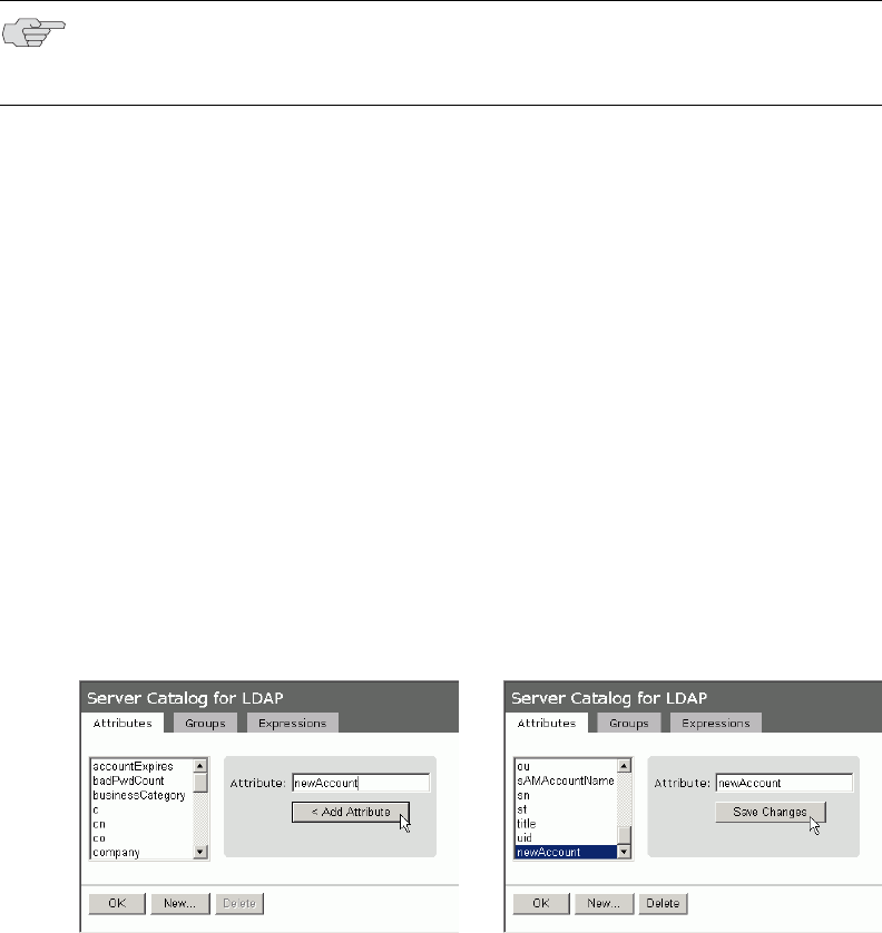
Creating role mapping rules 173
Chapter 8: Authentication realms
Groups—The Server Catalog Groups tab provides a mechanism to easily
retrieve group information from an LDAP server and add it to the server’s IVE
server catalog. You specify the BaseDN of your groups and optionally a filter to
begin the search. If you do not know the exact container of your groups, you
can specify the domain root as the BaseDN, such as dc=juniper, dc=com.The
search page returns a list of groups from your server, from which you can
choose groups to enter into the Groups list.
You can also use the Groups tab to specify groups. You must specify the Fully
Qualified Distinguished Name (FQDN) of a group, such as cn=GoodManagers,
ou=HQ, ou=Juniper, o=com, c=US, but you can assign a label for this group
that appears in the Groups list. Note that this tab is accessible only when
accessing the Server Catalog of an LDAP server.
Expressions—The Server Catalog Expressions tab provides a mechanism to
write custom expressions for the role mapping rule. For more information
about custom expressions, see “Writing custom expressions” on page 855.
To display the LDAP server catalog:
1. After choosing the User attribute option on the Role Mapping Rule page (see
“Specifying role mapping rules for an authentication realm” on page 170), click
Update to display the Attribute list and the Attributes button.
2. Click the Attributes button to display the LDAP server catalog. (You can also
click Groups after choosing the Group membership option, or click
Expressions after choosing the Custom Expressions option.)
Figure 24: Server Catalog > Attributes tab — Adding an attribute for LDAP
NOTE: The BaseDN value specified in the LDAP server’s configuration page under
"Finding user entries" is the default BaseDN value. The Filter value defaults to
(cn=*).
Juniper Networks Secure Access Administration Guide
174 Creating role mapping rules
Figure 25: Attribute added in Server Catalog is available for role mapping rule
Creating role mapping rules 175
Chapter 8: Authentication realms
Figure 26: Server Catalog > Groups tab — Adding LDAP groups
Juniper Networks Secure Access Administration Guide
176 Creating role mapping rules
Figure 27: Server Catalog > Groups tab — Adding Active Directory groups
Creating role mapping rules 177
Chapter 8: Authentication realms
Figure 28: Server Catalog > Expressions tab — Adding a custom expression
Juniper Networks Secure Access Administration Guide
178 Customizing user realm UI views
Figure 29: Custom expression added in Server Catalog is available for role mapping rule
Customizing user realm UI views
You can use customization options on the User Authentication Realms page to
quickly view the settings that are associated with a specific realm or set of realms.
For instance, you can view the role-mapping rules that you have associated with all
your user realms. Additionally, you can use these customized views to easily link to
the authentication policies, servers, role-mapping rules, and roles associated with a
user realms.
To view a sub-set of data on the User Authentication Realms page:
1. Navigate to Users > User Realms.
2. Select one of the following options from the View menu:
Overview—Displays the authentication servers and dynamic policy
evaluation settings that you have set for the specified user realms. You may
also use this setting to link to the specified server configuration pages.
Authentication Policy—Displays Host Checker and Cache Cleaner
restrictions that you have enabled for the specified user realms. You may
also use this setting to link to the specified Host Checker and Cache
Cleaner configuration pages.
Customizing user realm UI views 179
Chapter 8: Authentication realms
Role Mapping—Displays rule conditions and corresponding role
assignments that you have enabled for the specified user realms. You may
also use this setting to link to the specified rule conditions and role
assignments configuration pages.
Servers—Displays authentication server names and corresponding types
that you have enabled for the specified user realms. You may also use this
setting to link to the specified server configuration pages.
Roles—Displays role assignments and corresponding permissive merge
settings that you have enabled for the specified user realms.
3. Select one of the following options from the for list:
All realms—Displays the selected settings for all user realms.
Selected realms—Displays the selected settings for the user realms you
choose. If you select this option, select one or more of the checkboxes in
the Authentication Realm list.
4. Click Update.
Juniper Networks Secure Access Administration Guide
180 Customizing user realm UI views
181
Chapter 9
Sign-in policies
Sign-in policies define the URLs that users and administrators can use to access to
the IVE and the sign-in pages that they see. The IVE comes with two sign-in
policies—one for users and one for administrators. When configuring these
policies, you associate each with the appropriate realms, sign-in pages, and URLs.
For example, in order to allow all users to sign in to the IVE, you must add all user
authentication realms to the user sign-in policy. You may also choose to modify the
standard URL that the end-users use to access the IVE and the sign-in page that they
see. Or, if you have the proper license, you can create multiple user sign-in policies,
enabling different users to sign into different URLs and pages.
Additionally, appliances equipped with a Secure Meeting license come with a
meeting URL. You can use this URL to control the sign-in page that users see when
they sign into a meeting on the IVE appliance. If you have the proper license, you
may also create additional meeting sign-in pages, enabling different Secure Meeting
users to sign into different URLs and pages.
If you have an Advanced license, you can create multiple sign-in policies,
associating different sign-in pages with different URLs. When configuring a sign-in
policy, you must associate it with a realm or realms. Then, only members of the
specified authentication realm(s) may sign in using the URL defined in the policy.
Within the sign-in policy, you may also define different sign-in pages to associate
with different URLs.
For example, you can create sign-in policies that specify:
Members of the “Partners” realm can sign in to the IVE using the URLs:
partner1.yourcompany.com and partner2.yourcompany.com. Users who sign into
the first URL see the “partners1” sign-in page; users who sign into the second
URL see the “partners2” sign-in page.
Members of the “Local” and “Remote” realms can sign into the IVE using the
URL: employees.yourcompany.com. When they do, they see the “Employees”
sign-in page.
Members of the “Admin Users” realm can sign into the IVE using the URL:
access.yourcompany.com/super. When they do, they see the “Administrators”
sign-in page.

Juniper Networks Secure Access Administration Guide
182
When defining sign-in policies, you may use different host names (such as
partners.yourcompany.com and employees.yourcompany.com) or different paths
(such as yourcompany.com/partners and yourcompany.com/employees) to
differentiate between URLs.
This section contains the following information about sign-in policies:
“Licensing: Sign-in policies and pages availability” on page 183
“Task summary: Configuring sign-in policies” on page 183
“Configuring sign-in policies” on page 183
“Configuring sign-in pages” on page 187
NOTE: If a user attempts to sign in while there is another active user session with
the same sign-in credentials, the IVE displays a warning page showing the IP
address of the existing session and two buttons: Continue and Cancel. By clicking
the Cancel button, the user terminates the current sign-in process and redirects
the user back to the Sign-in page. By clicking the Continue button, the IVE
creates the new user session and terminates the existing session.
NOTE: When enabling multiple sign-in URLs, note that in some cases the IVE must
use cookies on the user’s machine to determine which sign-in URL and
corresponding sign-in page to display to the user. The IVE creates these cookies
when the user signs into the IVE. (When a user signs into the IVE, the IVE
responds with a cookie that includes the sign-in domain of the URL. The IVE then
attaches this cookie to every IVE request the user makes.) Generally, these cookies
ensure that the IVE displays the correct sign-in URL and page to the user. For
example, if a user signs into the IVE using the URL
http://yourcompany.net/employees and then her session times out, the IVE uses
the cookie to determine that it must display the
http://yourcompany.net/employees sign-in URL and corresponding page to the
user when she requests another IVE resource.
However, in isolated cases, the cookie on the user’s machine may not match the
resource she is trying to access. The user may sign into one URL and then try to
access a resource that is protected by a different URL. In this case, the IVE
displays the sign-in URL and corresponding sign-in page that the user signed into
most recently. For example, a user may sign into the IVE using the sign-in URL
http://yourcompany.net/employees. Then she may try to access an IVE resource
using a link on an external server, such as
https://yourcompany.net/partners/dana/term/winlaunchterm.cgi?host=<termsrvIP
>. Or, she may try to open a bookmark that she created during a different session,
such as
https://yourcompany.net/partners/,DanaInfo=.awxyBmszGr3xt1r5O3v.,SSO=U+. In
these cases, the IVE would display the http://yourcompany.net/employees sign-in
URL and page to the user, rather than the sign-in URL or page that is associated
with the external link or saved bookmark that she is trying to access.

Licensing: Sign-in policies and pages availability 183
Chapter 9: Sign-in policies
Licensing: Sign-in policies and pages availability
Sign-in policies and pages are an integral part of the IVE access management
framework, and therefore are available on all Secure Access products. However,
note that the following advanced sign-in features are not available on the SA 700
and are only available on all other Secure Access products by special license:
The ability to create multiple sign-in policies
The ability to create sign-in pages for Secure Meeting users
The ability to create and upload custom sign-in pages to the IVE
Task summary: Configuring sign-in policies
To configure sign-in policies, you must:
1. Create an authentication realm through one of the Administrators > Admin
Realms or Users > User Realms page of the admin console.
2. (Optional) Modify an existing sign-in page or create a new one using options in
the Authentication > Signing In > Sign-in Pages page of the admin console.
3. Specify a sign-in policy that associates a realm, sign-in URL, and sign-in page
using settings in the Authentication > Signing In > Sign-in Policies page of
the admin console.
4. If you differentiate between URLs using host names, you must associate each
host name with its own certificate or upload a wildcard certificate into the IVE
using options in the System > Configuration > Certificates > Device
Certificates page.
Configuring sign-in policies
Sign-in policies define the URLs that users and administrators can use to access the
IVE, as explained in “Sign-in policies” on page 181.
This section contains the following information about sign-in policies:
“Defining user sign in policies” on page 183
“Defining meeting sign-in policies” on page 185
“Specifying the order in which sign-in policies are evaluated” on page 187
“Enabling and disabling sign-in policies” on page 186
Defining user sign in policies
To create or configure administrator or user sign-in policies:

Juniper Networks Secure Access Administration Guide
184 Configuring sign-in policies
1. In the admin console, choose Authentication > Signing In > Sign-in
Policies.
2. To create a new sign-in policy, click New URL. Or, to edit an existing policy,
click a URL in the Administrator URLs or User URLs column.
3. Select Users or Administrators to specify which type of user can sign into the
IVE using the access policy.
4. In the Sign-in URL field, enter the URL that you want to associate with the
policy. Use the format <host>/<path> where <host> is the host name of the
IVE, and <path> is any string you want users to enter. For example:
partner1.yourcompany.com/outside. To specify multiple hosts, use the *
wildcard character. For instance:
To specify that all administrator URLs within the specified realm(s) should
use the sign-in page, enter */admin.
To specify that all end-user URLs within the specified realm(s) should use
the sign-in page, enter */.
5. Enter a Description for the policy (optional).
6. From the Sign-in Page list, select the page that you want to associate with the
policy. You may select the default page that comes with the IVE, a variation of
the standard sign-in page, or a custom page that you create using the
customizable UI feature. For more information, see “Configuring standard sign-
in pages” on page 188.
7. (User URLs only) In the Meeting URL field, select the meeting URL that you
want to associate with this sign-in policy. The IVE applies the specified meeting
URL to any meeting created by a user who signs into this user URL.
8. Under Authentication realm, specify which realm(s) map to the policy, and
how users and administrators should pick from amongst realms. If you select:
User types the realm name—The IVE maps the sign-in policy to all
authentication realms, but does not provide a list of realms from which the
user or administrator can choose. Instead, the user or administrator must
manually enter his realm name into the sign-in page.
NOTE: You may only use wildcard characters (*) in the beginning of the host name
portion of the URL. The IVE does not recognize wildcards in the URL path.

Configuring sign-in policies 185
Chapter 9: Sign-in policies
User picks from a list of authentication realms—The IVE only maps the
sign-in policy to the authentication realms that you choose. The IVE
presents this list of realms to the user or administrator when he signs-in to
the IVE and allows him to choose a realm from the list. (Note that the IVE
does not display a drop-down list of authentication realms if the URL is
only mapped to one realm. Instead, it automatically uses the realm you
specify.)
9. Click Save Changes.
Defining meeting sign-in policies
To create or configure meeting sign-in policies:
1. In the admin console, choose Authentication > Authentication > Signing In
Policies.
2. To create a new sign-in policy, click New URL. Or, to edit an existing policy,
click a URL in the Meeting URLs column.
3. Select Meeting.
4. In the Sign-in URL field, enter the URL that you want to associate with the
meeting policy. Use the format <host>/<path> where <host> is the host name
of the IVE, and <path> is any string you want users to enter. For example:
Partner1.YourCompany.com/OnlineConference. When creating the meeting URL,
note that:
You cannot modify the URL of the default meeting URL (*/meeting) that
comes with the product.
If you want to enable users to sign into meetings using all of the host
names defined in the associated user URL, use the * wildcard character in
your meeting URL definition. For example, you might associate the
following hosts with your user URL:
YourInternalServer.YourCompany.net
YourExternalServer.YourCompany.com
Then, if you create an */OnlineConference meeting URL definition and
associate it with the user URL, users can access the meeting sign-in page
using either of the following URLs:
http://YourInternalServer.YourCompany.net/OnlineConference
http://YourExternalServer.YourCompany.com/OnlineConference
NOTE: If you allow the user to pick from multiple realms and one of those realms
uses an anonymous authentication server, the IVE does not display that realm in
the drop-down realm list. To effectively map your sign-in policy to an anonymous
realm, you must add only that realm to the Authentication realm list.
Juniper Networks Secure Access Administration Guide
186 Configuring sign-in policies
If you create a meeting URL that includes the * wildcard character and
enable email notifications, the IVE constructs the meeting URL in the
notification email using the host name specified by the user when signing
into the IVE. For instance, a user might sign into the IVE using the
following URL from the previous example:
http://YourInternalServer.YourCompany.net
Then, if the user creates a meeting, the IVE specifies the following sign-in
URL for that meeting in the email notification:
http://YourInternalServer.YourCompany.net/OnlineConference
Note that since the email link references an internal server, out-of-network
users cannot access the meeting.
If you only want to enable users to sign into meetings using a sub-set of the
host names defined in the associated user URL, or if you want to require
users to use a completely different URL to sign into meetings, do not
include the * wildcard character in your meeting URL definition. Instead,
create a unique and specific meeting URL definition.
For instance, you can create the following meeting URL definition and
associate it with the user URL from the previous example in order to
specify that all meetings contain links to the external server only:
YourExternalServer.YourCompany.com/OnlineConference
5. Enter a Description for the policy (optional).
6. From the Sign-in Page list, select the sign-in page(s) that you want to appear to
users who access meetings using this policy. You may select the default pages
that come with the IVE, a variation of the standard sign-in pages, or customized
pages that you create using the customizable UI feature. For more information,
see “Configuring standard sign-in pages” on page 188.
7. Click Save Changes.
Enabling and disabling sign-in policies
To enable and disable sign-in policies:
1. In the admin console, choose Authentication > Signing In > Sign-in
Policies.
2. To enable or disable:
An individual policy—Select the checkbox next to the policy that you
want to change, and then click Enable or Disable.
All user and meeting policies—Select or deselect the Restrict access to
administrators only checkbox at the top of the page.
3. Click Save Changes.

Configuring sign-in pages 187
Chapter 9: Sign-in policies
Specifying the order in which sign-in policies are evaluated
The IVE evaluates sign-in policies in the same order that you list them on the Sign-
in Policies page. When it finds a URL that matches exactly, it stops evaluating and
presents the appropriate sign-in page to the administrator or user. For example,
you may define two administrator sign-in policies with two different URLs:
The first policy uses the URL */admin and maps to the default administrator
sign-in page.
The second policy uses the URL yourcompany.com/admin and maps to a custom
administrator sign-in page.
If you list the policies in this order on the Sign-in Policies page, the IVE never
evaluates or uses the second policy because the first URL encompasses the second.
Even if an administrator signs in using the yourcompany.com/admin URL, the IVE
displays the default administrator sign-in page. If you list the policies in the
opposite order, however, the IVE displays the custom administrator sign-in page to
those administrators who access the IVE using the yourcompany.com/admin URL.
Note that the IVE only accepts wildcard characters in the host name section of the
URL and matches URLs based on the exact path. For example, you may define two
administrator sign-in policies with two different URL paths:
The first policy uses the URL */marketing and maps to a custom sign-in page
for the entire Marketing Department.
The second policy uses the URL */marketing/joe and maps to a custom sign-in
page designed exclusively for Joe in the Marketing Department.
If you list the policies in this order on the Sign-in Policies page, the IVE displays
Joe’s custom sign-in page to him when he uses the yourcompany.com/marketing/joe
URL to access the IVE. He does not see the Marketing sign-in page, even though it is
listed and evaluated first, because the path portion of his URL does not exactly
match the URL defined in the first policy.
To change the order in which administrator sign-in policies are evaluated:
1. In the admin console, choose Authentication > Signing In > Sign-in
Policies.
2. Select a sign-in policy in the Administrator URLs, User URLs, or Meeting URLs
list.
3. Click the up and down arrows to change the selected policy’s placement in the
list.
4. Click Save Changes.
Configuring sign-in pages
A sign-in page defines the customized properties in the end-user’s welcome page
such as the welcome text, help text, logo, header, and footer. The IVE allows you to
create two types of sign-in pages to present to users and administrators:
Juniper Networks Secure Access Administration Guide
188 Configuring sign-in pages
Standard sign-in pages—Standard sign-in pages are produced by Juniper and
are included with all versions of the IVE. You can modify standard sign-in pages
through the Authentication > Signing In > Sign-in Pages tab of the admin
console. For more information, see “Configuring standard sign-in pages” on
page 188.
Customized sign-in pages—Customized sign-in pages are THTML pages that
you produce using the Template Toolkit and upload to the IVE in the form of an
archived ZIP file. The customized sign-in pages feature is a licensed feature that
enables you to use your own pages rather than having to modify the sign-in
page included with the IVE.
For more information on customized sign-in pages, see the Custom Sign-In Pages
Solution Guide.
Configuring standard sign-in pages
Standard sign-in pages that come with the IVE include:
Default Sign-In Page—By default, the IVE displays this page to users when
they sign into the IVE.
Meeting Sign-In Page—By default, the IVE displays this page to users when
they sign into a meeting. This page is only available if you install a Secure
Meeting license on the IVE.
You can modify these pages or create new pages that contain custom text, logo,
colors, and error message text using settings in the Authentication > Signing In
> Sign-in Pages tab of the admin console.
To create or modify a standard sign-in page:
1. In the admin console, choose Authentication > Signing In > Sign-in Pages.
2. If you are:
Creating a new page—Click New Page.
Modifying an existing page—Select the link corresponding to the page you
want to modify.
3. (New pages only) Under Page Type, specify whether this is an
administrator/user access page or a meeting page.
4. Enter a name to identify the page.

Configuring sign-in pages 189
Chapter 9: Sign-in policies
5. In the Custom text section, revise the default text used for the various screen
labels as desired. When adding text to the Instructions field, note that you may
format text and add links using the following HTML tags: <i>, <b>, <br>, <font>,
and <a href>. However, the IVE does not rewrite links on the sign-in page (since
the user has not yet authenticated), so you should only point to external sites.
Links to sites behind a firewall will fail.
6. In the Header appearance section, specify a custom logo image file for the
header and a different header color.
7. In the Custom error messages section, revise the default text that is displayed
to users if they encounter certificate errors. (Not available for the Secure
Meeting sign-in page.)
8. To provide custom help or additional instructions for your users, select Show
Help button, enter a label to display on the button, and specify an HTML file to
upload to the IVE. Note that the IVE does not display images and other content
referenced in this HTML page. (Not available for the Secure Meeting sign-in
page.)
9. Click Save Changes. The changes take effect immediately, but users with active
sessions might need to refresh their Web browsers.
NOTE: If you use unsupported HTML tags in your custom message, the IVE may
display the end-user’s IVE home page incorrectly.
NOTE: Click Restore Factory Defaults to reset the sign-in page, IVE user home
page, and admin console appearance.
Juniper Networks Secure Access Administration Guide
190 Configuring sign-in pages

Licensing: Single sign-on availability 191
Chapter 10
Single sign-on
Single sign-on (SSO) is a process that allows pre-authenticated IVE users to access
other applications or resources that are protected by another access management
system without having to re-enter their credentials.
This section contains the following information about single-sign on features:
“Licensing: Single sign-on availability” on page 191
“Single sign-on overview” on page 191
“Multiple sign-in credentials overview” on page 193
“Configuring SAML” on page 201
“Configuring SAML SSO profiles” on page 204
Licensing: Single sign-on availability
All Secure Access products contain some single sign-on features. However, note
that the Remote SSO, SAML, and eTrust SSO advanced sign-in features are not
available on the SA 700 and are only available on all other Secure Access products
by special license. Additionally, the basic authentication, NTLM intermediation, and
Telnet SSO features are only available on the SA 700 appliance if you have the Core
Clientless Access upgrade license.
Single sign-on overview
The IVE provides several integration mechanisms that allow you to configure SSO
connections from the IVE to other servers, applications, and resources. SSO
mechanisms include:
Remote SSO—The IVE provides loose integration with any application that
uses a static POST action within an HTML form to sign in users. You can
configure the IVE to post IVE credentials, LDAP attributes, and certificate
attributes to a Web-enabled application, as well as set cookies and headers,
allowing users to access the application without re-authenticating. For more
information, see “Remote SSO overview” on page 285.
Juniper Networks Secure Access Administration Guide
192 Single sign-on overview
SAML—The IVE provides loose integration with selected access management
systems that use the Security Assertion Markup Language (SAML) to
communicate with other systems. You can enable users to sign in to the IVE
and then sign in to and access resources protected by the access management
system without re-authenticating. You can also enable users to sign in to
another access management system and then access resources protected by
the IVE, without re-authenticating. For more information, see “Configuring
SAML” on page 201.
Basic authentication and NTLM intermediation to Intranet sites—The IVE
allows you to automatically submit IVE user credentials to other Web sites and
proxies within the same Intranet zone. When you enable basic authentication
intermediation through the Users > Resource Profiles > Web
Applications/Pages page of the admin console, the IVE submits the cached
credentials to Intranet Web sites whose host names end in the DNS suffix
configured in the System > Network > Overview page. To maximize
security, you may also configure the IVE to use base-64 encoding to protect the
cached credentials. For more information, see “Defining a single sign-on
autopolicy” on page 292.
Active Directory server—The IVE allows you to automatically submit Active
Directory SSO credentials to other Web sites and Windows file shares within
the same Intranet zone that are protected by native NTLM authentication.
When you enable this option, the IVE submits cached credentials to NTLM-
protected Web sites whose host names end in the DNS suffix configured in the
System > Network > Overview page of the admin console. For more
information, see “Configuring an Active Directory or NT Domain instance” on
page 99.
eTrust SiteMinder policy server—When you authenticate IVE users using a
eTrust SiteMinder policy server, you can enable them access to SiteMinder
protected resources without re-authenticating (provided they are authorized
with the correct protection level). Additionally, you can re-authenticate users
through the IVE if they request resources for which their current protection
level is inadequate and you can enable users to sign into the policy server first
and then access the IVE without re-authenticating. For more information, see
“Configuring an eTrust SiteMinder server instance” on page 133.
Terminal Sessions—When you enable the Terminal Services feature for a role,
you allow users to connect to applications that are running on a Windows
terminal server or Citrix MetaFrame server without re-authenticating. For more
information, see “Terminal Services” on page 461. You may also pass a
username to the Telnet/SSH server, as explained in “Terminal Services” on
page 461.
Email clients—When you enable the Email Client feature for a role and then
create a corresponding resource policy, you allow users to access standards-
based email such as Outlook Express, Netscape Communicator, or
Qualcomm’s Eudora without re-authenticating. For more information, see
“Email Client” on page 513.

Multiple sign-in credentials overview 193
Chapter 10: Single sign-on
The IVE determines which credentials to submit to the SSO-enabled server,
application, or resource based on the mechanism you use to connect. Most
mechanisms allow you to collect user credentials for up to two authentication
servers in the IVE sign-in page and then submit those credentials during SSO. For
more information, see “Multiple sign-in credentials overview” on page 193.
The remaining mechanisms (SAML, eTrust SiteMinder, and the Email Client) use
unique methods for enabling SSO from the IVE to the supported application. For
more information, see:
“Configuring SAML” on page 201
“Configuring SAML SSO profiles” on page 204
“Configuring an eTrust SiteMinder server instance” on page 133
“Email Client” on page 513
Multiple sign-in credentials overview
When configuring an authentication realm, you can enable up to two
authentication servers for the realm. Enabling two authentication servers allows
you to require two different sets of credentials—one for the IVE and another for
your SSO-enabled resource—without requiring the user to enter the second set of
credentials when accessing the resource. It also allows you to require two-factor
authentication in order to access the IVE.
This section contains the following information about multiple sign-in credentials:
“Task Summary: Configuring multiple authentication servers” on page 193
“Task Summary: Enabling SSO to resources protected by basic authentication”
on page 194
“Task Summary: Enabling SSO to resources protected by NTLM” on page 194
“Multiple sign-in credentials execution” on page 196
Task Summary: Configuring multiple authentication servers
To enable multiple authentication servers:
1. Create authentication server instances through the Authentication > Auth.
Servers page of the admin console. For configuration instructions, see
“Defining an authentication server instance” on page 93.
2. Associate the authentication servers with a realm using settings in the following
pages of the admin console:
Users > User Realms > Select Realm > General
Administrators > Admin Realms > Select Realm > General
Juniper Networks Secure Access Administration Guide
194 Multiple sign-in credentials overview
For configuration instructions, see “Creating an authentication realm” on
page 166.
3. (Optional) Specify password length restrictions for the secondary
authentication server using settings in the following pages of the admin
console:
Users > User Realms > Select Realm > Authentication Policy >
Password
Administrators > Admin Realms > Select Realm > Authentication
Policy > Password
For configuration instructions, see “Specifying password access restrictions” on
page 48.
Task Summary: Enabling SSO to resources protected by basic authentication
To enable single sign-on to Web servers and Web proxies that are protected by
basic authentication, you must:
1. Specify an IVE host name that ends with the same prefix as your protected
resource using settings in the System > Network > Overview page of the
admin console. (The IVE checks the host names to ensure that it is only
enabling SSO to sites within the same Intranet.)
2. Enable users to access Web resources, specify the sites to which you want the
IVE to submit credentials, create autopolicies that enable basic authentication
intermediation single sign-on, and create bookmarks to the selected resources
using settings in the Users > Resource Profiles > Web Application/Pages >
[Profile] page of the admin console.
3. If you want users to access Web servers through a proxy, configure the IVE to
recognize the appropriate servers and proxies using settings in the following
pages of the admin console:
a. Use settings in Users > Resource Policies > Web > Web proxy >
Servers page to specify which Web servers you want to protect with the
proxy.
b. Use settings in the Users > Resource Policies > Web > Web proxy >
Policies page to specify which proxies you want to use and which servers
(above) you want the proxies to protect. You may specify individual
resources on the server or the entire server.
Task Summary: Enabling SSO to resources protected by NTLM
To enable single sign-on to Web servers, Windows file servers, and Web proxies
that are protected by NTLM, you must:
1. Specify an IVE host name that ends with the same suffix as your protected
resource using settings in the System > Network > Overview page of the
admin console. (The IVE checks the host names to ensure that it is only
enabling SSO to sites within the same Intranet.)
Multiple sign-in credentials overview 195
Chapter 10: Single sign-on
2. Enable users to access the appropriate type of resource (Web or file), specify
the sites or servers to which you want the IVE to submit credentials, create
autopolicies that enable NTLM single sign-on, and create bookmarks to the
selected resources using settings in the following pages of the admin console:
Users > Resource Profiles > Web Application/Pages > [Profile]
Users > Resource Profiles > File Browsing Resource Profiles> [Profile]
3. If you want users to access Web servers through a proxy, configure the IVE to
recognize the appropriate servers and proxies using settings in the following
pages of the admin console:
a. Use settings in Users > Resource Policies > Web > Web proxy >
Servers page to specify which Web servers you want to protect with the
proxy.
b. Use settings in the Users > Resource Policies > Web > Web proxy >
Policies page to specify which proxies you want to use and which servers
(above) you want the proxies to protect. You may specify individual
resources on the server or the entire server.
Juniper Networks Secure Access Administration Guide
196 Multiple sign-in credentials overview
Multiple sign-in credentials execution
The following diagram illustrates the process that the IVE uses to collect and
authenticate multiple user credentials and submit them to SSO-enabled resources.
Each of the steps in the diagram are described in further detail in the sections that
follow.
Figure 30: Collecting and submitting credentials from multiple servers
Step 1: The IVE collects the user’s primary credentials
When the user signs in to the IVE, the IVE prompts him to enter his primary server
credentials. The IVE saves these credentials to submit to the SSO resource later, if
necessary. Note that the IVE saves the credentials exactly as the user enters them—
it does not pre-pend or append them with additional information such as the user’s
domain.
Step 2: The IVE collects or generates the user’s secondary credentials
You may configure the IVE to either manually collect or automatically generate the
user’s secondary set of credentials. If you configure the IVE to:
Manually collect the user’s secondary credentials—The user must enter his
secondary credentials directly after entering his primary credentials.

Multiple sign-in credentials overview 197
Chapter 10: Single sign-on
Automatically generate the user’s credentials—The IVE submits the values
you specified in the administration console during setup. By default, the IVE
uses the <username> and <password> variables, which hold the username and
password entered by the user for the primary authentication server.
For example, you may configure an LDAP server as your primary authentication
server and an Active Directory server as your secondary authentication server.
Then, you may configure the IVE to infer the user’s Active Directory username but
require the user to manually enter his Active Directory password. When the IVE
infers the Active Directory username, it simply takes the name entered for the
LDAP server (for example, JDoe@LDAPServer) and resubmits it to the Active
Directory (for example, JDoe@ActiveDirectoryServer).
Step 3: The IVE authenticates the primary credentials
After the IVE collects all required credentials, it authenticates the user’s first set of
credentials against the primary authentication server. Then:
If the credentials successfully authenticate, the IVE stores them in the
<username> and <password> session variables and continues on to
authenticate the secondary credentials.
If the credentials do not successfully authenticate, the IVE denies the user
access to the IVE.
Step 4: The IVE authenticates the secondary credentials
After authenticating the primary credentials, the IVE authenticates the secondary
credentials. Then:
If the credentials successfully authenticate, the IVE stores them in the
<username[2]> and <password[2]> session variables and allows the user access
to the IVE. You may also access these variables using the syntax
<username@SecondaryServer> and <password@SecondaryServer>.
NOTE: If you authenticate against a RADIUS server that accepts dynamic, time-
sensitive passwords, you may choose to not store user passwords using the IVE
session variable. For more information, see “Configuring a RADIUS server
instance” on page 120.
NOTE: If you authenticate against a RADIUS server that accepts dynamic, time-
sensitive passwords, you may choose to not store user passwords using the IVE
session variable. For more information, see “Configuring a RADIUS server
instance” on page 120.

Juniper Networks Secure Access Administration Guide
198 Multiple sign-in credentials overview
If the credentials do not successfully authenticate, the IVE does not save them.
Depending on how you configure your authentication realm, the IVE may allow
or deny the user access to the IVE if his secondary credentials do not
successfully authenticate.
Step 5: The IVE submits credentials to an SSO-enabled resource
After the user successfully signs in to the IVE, he may try to access an SSO-enabled
resource using a pre-configured bookmark or other access mechanism. Then,
depending on which type of resource the user is trying to access, the IVE submits
different credentials. If the user is trying to access a:
Web SSO, Terminal Services, or Telnet/SSH resource—The IVE submits the
credentials that you specify through the admin console, such as <username>
(which submits the user’s primary credentials to the resource) or
<username[2]> (which submits the user’s secondary credentials to the
resource). Or, if the user has entered a different username and password
through the end user console, the IVE submits the user-specified credentials.
Resource protected by a Web server, Windows server, or Web proxy that is
using NTLM authentication—The IVE submits credentials to the backend
server or proxy that is protecting the Web or file resource. Note that you cannot
disable NTLM authentication through the IVE—If a user tries to access a
resource that is protected by NTLM, the IVE automatically intermediates the
authentication challenge and submits credentials in the following order:
a. (Windows file resources only) Administrator-specified credentials—If
you create a resource profile that specifies credentials for a Windows file
resource and the user then accesses the specified resource, the IVE submits
the specified credentials.
NOTE: You can detect that secondary authentication failed by creating a custom
expression that checks for an empty user@secondaryAuth variable. You may want
to do this so that you can assign users to roles based on successful authentication.
For example, the following expression assigns users to the “MoreAccess” role if
they successfully authenticate against the “ACE server” secondary authentication
server:
user@{ACE Server} != "" then assign role MoreAccess
Note “Ace server” is shown in curly braces since the authentication server’s name
contains spaces.
NOTE: The IVE does not support submitting ACE server, certificate server, or
anonymous server credentials to a Web SSO, terminal services, or Telnet/SSH
resource. If you configure the IVE to submit credentials from one of these types of
primary authentication servers, the IVE submits credentials from the user’s
secondary authentication server instead. If these credentials fail, the IVE prompts
the user to manually enter his username and password.
Multiple sign-in credentials overview 199
Chapter 10: Single sign-on
a. Cached credentials—If the IVE does not submit administrator-specified
credentials or the credentials fail, the IVE determines whether it has stored
credentials for the specified user and resource in its cache. (See below for
information about when the IVE caches credentials.) If available, the IVE
submits its stored credentials.
b. Primary credentials—If the IVE does not submit cached credentials or the
credentials fail, the IVE submits the user’s primary IVE credentials
provided that following conditions are true:
The resource is in the same Intranet zone as the IVE (that is, the
resource’s host name ends in the DNS suffix configured in the System
> Network > Overview page of the admin console).
(Web proxies only) You have configured the IVE to recognize the Web
proxy through settings in the Users > Resource Policies > Web >
Web Proxy pages of the admin console.
The credentials are not ACE credentials.
(RADIUS credentials only) You specify in the RADIUS configuration
page that the RADIUS server does not accept one-time passwords.
c. Secondary credentials—If the primary credentials fail, the IVE determines
whether it has secondary credentials for the user. If available, the IVE
submits the user’s secondary IVE credentials provided that the conditions
described for primary credentials are true.
d. Last-entered credentials—If the IVE does not submit secondary
credentials or if the credentials fail, the IVE determines whether it has
stored credentials for the specified user and a different resource in its
cache. (See below for information about when the IVE caches credentials.)
If available, the IVE submits its stored credentials provided the conditions
described for primary credentials are true.
e. User-specified credentials (prompt)—If the IVE does not submit last-
entered credentials or if the credentials fail, the IVE prompts the user to
manually enter his credentials in the intermediate sign-in page. If the user
selects the Remember password? checkbox, the IVE caches the user-
specified credentials and, if necessary, resubmits them when the user tries
to access the same resource again. Note that when the IVE caches these
credentials, it remembers the specific user and resource, even after the
user signs out of the IVE.
Resource protected by a Web server or Web proxy using basic
authentication—The IVE submits credentials in the following order to the
backend server or proxy that is protecting the Web resource:
a. Cached credentials—If the IVE does not submit administrator-specified
credentials or the credentials fail, the IVE determines whether it has stored
credentials for the specified user and resource in its cache. (See above for
information about when the IVE caches credentials.) If available, the IVE
submits its stored credentials.

Juniper Networks Secure Access Administration Guide
200 Multiple sign-in credentials overview
b. Primary credentials—If the IVE does not submit cached credentials or the
credentials fail, the IVE submits the user’s primary IVE credentials
provided that following conditions are true:
The resource is in the same Intranet zone as the IVE (that is, the
resource’s host name ends in the DNS suffix configured in the System
> Network > Overview page of the admin console).
(Web proxies only) You have configured the IVE to recognize the Web
proxy through settings in the Users > Resource Policies > Web >
Web Proxy pages of the admin console.
The credentials are not ACE credentials.
(RADIUS credentials only) You specify in the RADIUS configuration
page that the RADIUS server does not accept one-time passwords.
c. Secondary credentials—If the primary credentials fail, the IVE determines
whether it has secondary credentials for the user. If available, the IVE
submits the user’s secondary IVE credentials provided that the conditions
described for primary credentials are true.
d. Last-entered credentials—If the IVE does not submit secondary
credentials or if the credentials fail, the IVE determines whether it has
stored credentials for the specified user and a different resource in its
cache. (See below for information about when the IVE caches credentials.)
If available, the IVE submits its stored credentials provided the conditions
described for primary credentials are true.
e. User-specified credentials (prompt)—If the IVE does not submit last-
entered credentials or if the credentials fail, the IVE prompts the user to
manually enter his credentials in the intermediate sign-in page. If the user
selects the Remember password? checkbox, the IVE caches the user-
specified credentials and, if necessary, resubmits them when the user tries
to access the same resource again. Note that when the IVE caches these
credentials, it remembers the specific user and resource, even after the
user signs out of the IVE.
NOTE:
The IVE does not support the multiple credential authentication mechanism
described in this section with the Email client and SAML SSO mechanisms.
You cannot define an anonymous server, certificate server, or eTrust
SiteMinder server as a secondary authentication server.
If you define an eTrust SiteMinder server as your primary authentication
server, you cannot define a secondary authentication server.
The IVE supports basic authentication and NTLM challenge/response scheme
for HTTP when accessing web applications, but does not support HTTP-based
cross-platform authentication via the negotiate protocol.

Configuring SAML 201
Chapter 10: Single sign-on
For more information about how the IVE uses multiple authentication within the
larger IVE authentication and authorization process, see “Policies, rules &
restrictions, and conditions evaluation” on page 38.
Configuring SAML
The IVE enables you to pass user and session state information between the IVE
and another trusted access management system that supports the Secure Access
Markup Language (SAML). SAML provides a mechanism for two disparate systems
to create and exchange authentication and authorization information using an XML
framework, minimizing the need for users to re-enter their credentials when
accessing multiple applications or domains1. The IVE supports SAML version 1.1.
SAML exchanges are dependent upon a trusted relationship between two systems
or domains. In the exchanges, one system acts as a SAML authority (also called an
asserting party or SAML responder) that asserts information about the user. The
other system acts as a relying party (also called a SAML receiver) that relies on the
statement (also called an assertion) provided by the SAML authority. If it chooses to
trust the SAML authority, the relying party authenticates or authorizes the user
based on the information provided by the SAML authority.
The IVE supports two SAML use case scenarios:
The IVE as the SAML authority—The user signs into a resource by way of the
IVE first, and all other systems are SAML receivers, relying on the IVE for
authentication and authorization of the user. Under this scenario, the IVE can
use either an artifact profile or a POST profile. For more information, see
“Configuring SAML SSO profiles” on page 204.
The IVE as the SAML receiver—The user signs into another system on the
network first, and the IVE is the SAML receiver, relying on the other system for
authentication and authorization of the user.
For example, in the first scenario, an authenticated IVE user named John Smith
may try to access a resource protected by an access management system. When he
does, the IVE acts as a SAML authority and declares “This user is John Smith. He
was authenticated using a password mechanism.” The access management system
(the relying party) receives this statement and chooses to trust the IVE (and
therefore trust that the IVE has properly identified the user). The access
management system may still choose to deny the user access to the requested
resource (for instance, because John Smith has insufficient access privileges on the
system), while trusting the information sent by the IVE.
In the second scenario, John Smith signs in to his company portal and is
authenticated using an LDAP server sitting behind the company’s firewall. On the
company’s secure portal, John Smith clicks a link to a resource protected by the
IVE. The following process occurs:
1. The Secure Access Markup Language is developed by Security Services Technical Committee (SSTC) of the
OASIS standards organization. For a technical overview of SAML, see the OASIS web site:
http://www.oasis-open.org/committees/download.php/5836/sstc-saml-tech-overview-1.1-draft-03.pdf
Juniper Networks Secure Access Administration Guide
202 Configuring SAML
1. The link redirects John Smith to an Intersite Transfer Service on the company
portal, which constructs an artifact URL. The artifact URL contains a reference
to a SAML assertion stored in the company portal’s cache.
2. The portal sends the URL to the IVE, which can decide whether or not to link to
the reference.
3. If the IVE links to the reference, the portal sends a SOAP message containing
the SAML assertion (an XML message containing the user’s credentials) to the
IVE, which can then decide whether or not to allow the user access to the
requested resource.
4. If the IVE allows the user access, the IVE presents to the user the requested
resource.
5. If the IVE rejects the SAML assertion, or the user credentials, the IVE responds
to the user with an error message.
When configuring the IVE, you can use SAML for:
Single sign-on (SSO) authentication—In a SAML SSO transaction, an
authenticated user is seamlessly signed into another system without re-
submitting his credentials. In this type of transaction, the IVE can be either the
SAML authority or the SAML receiver. When acting as the SAML authority, the
IVE makes an authentication statement, which declares the user’s username and
how he was authenticated. If the relying party (called an assertion consumer
service in SAML SSO transactions) chooses to trust the IVE, the user is
seamlessly signed into the assertion consumer service using the username
contained in the statement.
When acting as the SAML receiver, the IVE requests credential confirmation
from the SAML authority, which is the other access management system, such
as LDAP or another authentication server. The SAML authority sends an
assertion by way of a SOAP message. The assertion is a set of XML statements
that the IVE must interpret, based on criteria that the IVE administrator has
specified in a SAML server instance definition. If the IVE chooses to trust the
asserting party, the IVE allows the user to sign in seamlessly using the
credentials contained in the SAML assertion.

Configuring SAML 203
Chapter 10: Single sign-on
Access control authorization—In a SAML access control transaction, the IVE
asks an access management system whether the user has access. In this type
of transaction, the IVE is the relying party (also called a policy enforcement
point in access control transactions). It consumes and enforces an authorization
decision statement provided by the access management system (SAML
authority), which declares what the user is allowed to access. If the SAML
authority (also called a policy decision point in access control transactions)
declares that the IVE user has sufficient access privileges, the user may access
the requested resource.
For more information, see:
“Configuring SAML SSO profiles” on page 204.
“Creating an access control policy” on page 211
“Creating a trust relationship between SAML-enabled systems” on
page 214
“Configuring SAML” on page 201
“Configuring a SAML Server instance” on page 156
“Task Summary: Configuring SAML through the IVE” on page 218
NOTE:
The IVE does not support attribute statements, which declare specific details
about the user (such as “John Smith is a member of the gold group”).
The IVE does not generate authorization decision statements—it only
consumes them.
In addition to providing users access to a URL based on the authorization
decision statement returned by a SAML authority, the IVE also allows you to
define users’ access rights to a URL using IVE-only mechanisms (Users >
Resource Profiles > Web Applications/Pages tab). If you define access
controls through the IVE as well as through a SAML authority, both sources
must grant access to a URL in order for a user to access it. For example, you
may configure an IVE access policy that denies members of the “Users” role
access to www.google.com, but configure another SAML policy that bases a
user’s access rights on an attribute in an access management system. Even if
the access management system permits users access to www.google.com,
users are still denied access based on the IVE access policy.
When asked if a user may access a resource, access management systems
that support SAML may return a response of permit, deny, or indeterminate.
If the IVE receives an indeterminate response, it denies the user access.
The session timeouts on the IVE and your access management system may
not coordinate with one another. If a user’s access management system
session cookie times out before his IVE cookie (DSIDcookie) times out, then
single sign-on between the two systems is lost. The user is forced to sign in
again when he times out of the access management system.
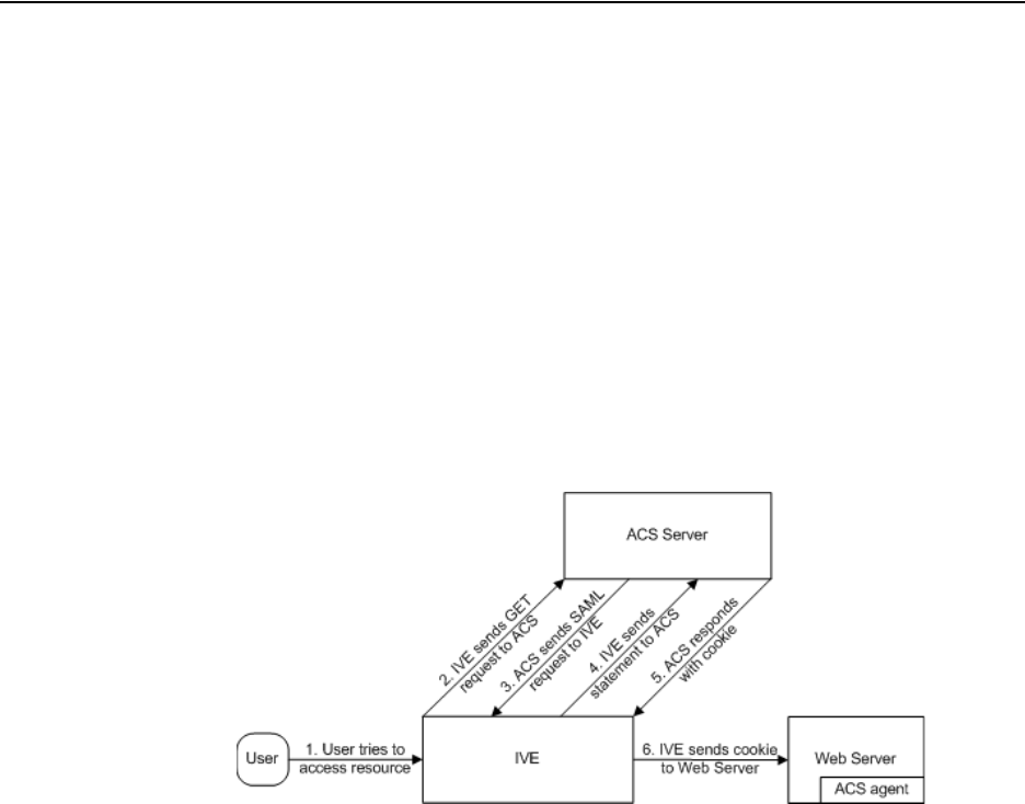
Juniper Networks Secure Access Administration Guide
204 Configuring SAML SSO profiles
Configuring SAML SSO profiles
When enabling SSO transactions to a trusted access management system, you
must indicate whether the access management system should “pull” user
information from the IVE or whether the IVE should “push” it to the access
management system. You indicate which communication method the two systems
should use by selecting a profile during configuration. A profile is a method that two
trusted sites use to transfer a SAML statement. When configuring the IVE, you may
choose to use an artifact or POST profile.
Creating an artifact profile
When you choose to communicate using the artifact profile (also called
Browser/Artifact profile) the trusted access management server “pulls”
authentication information from the IVE, as shown in Figure 31.
Figure 31: Artifact profile
The IVE and an assertion consumer service (ACS) use the following process to pass
information:
1. The user tries to access a resource—A user is signed into the IVE and tries to
access a protected resource on a Web server.
2. The IVE sends an HTTP or HTTPS GET request to the ACS—The IVE
intercepts the request and checks whether it has already performed the
necessary SSO operation to honor the request. If not, the IVE creates an
authentication statement and passes an HTTP query variable called an artifact
to the assertion consumer service.
An artifact profile is a base-64 encoded string that contains the source ID of the
source site (that is, a 20-byte string that references the IVE) and a randomly-
generated string that acts as a handle to the authentication statement. (Note
that a handle expires 5 minutes after the artifact is sent, so if the assertion
consumer service responds after 5 minutes, the IVE does not send a statement.
Also note that the IVE discards a handle after its first use to prevent the handle
from being used twice.)

Configuring SAML SSO profiles 205
Chapter 10: Single sign-on
3. The ACS sends a SAML request to the IVE—The assertion consumer service
uses the source ID sent in the previous step to determine the location of the
IVE. Then, the assertion consumer service sends a statement request wrapped
in a SOAP message to the following address on the IVE:
https://<IVEhostname>/dana-ws/saml.ws
The request includes the statement handle passed in the previous step.
4. The IVE sends an authentication statement to the ACS—The IVE uses the
statement handle in the request to find the correct statement in the IVE cache
and then sends the appropriate authentication statement back to the to the
assertion consumer service. The unsigned statement contains the user's
identity and the mechanism he used to sign into the IVE.
5. The ACS sends a cookie to the IVE—The assertion consumer service accepts
the statement and then it sends a cookie back to the IVE that enables the user’s
session.
6. The IVE sends the cookie to the Web server—The IVE caches the cookie to
handle future requests. Then the IVE sends the cookie in an HTTP request to
the Web server whose domain name matches the domain in the cookie. The
Web server honors the session without prompting the user for credentials.
To write a SAML SSO artifact profile resource policy:
1. In the admin console, navigate to Users > Resource Policies > Web.
2. If your administrator view is not already configured to show SAML policies,
make the following modifications:
a. Click the Customize button in the upper right corner of the page.
b. Select the SSO checkbox.
c. Select the SAML checkbox below the SSO checkbox.
d. Click OK.
3. Select the SSO > SAML tab.
4. Click New Policy.
NOTE: The IVE only supports type 0x0001 artifacts. This type of artifact passes a
reference to the source site’s location (that is, the source ID of the IVE), rather
than sending the location itself. To handle type 0x0001 artifacts, the assertion
consumer service must maintain a table that maps source IDs to the locations of
partner source sites.
NOTE: If you configure the IVE to use artifact profiles, you must install the IVE’s
Web server certificate on the assertion consumer service (as explained in
“Configuring certificates” on page 215).

Juniper Networks Secure Access Administration Guide
206 Configuring SAML SSO profiles
5. On the New Policy page, enter:
a. A name to label this policy.
b. A description of the policy (optional).
6. In the Resources section, specify the resources to which this policy applies. See
“Specifying resources for a resource policy” on page 83 for more information.
To enable IP-based or case sensitivity matching for these resources, see
“Writing a Web proxy resource policy” on page 351.
7. In the Roles section, specify:
Policy applies to ALL roles—To apply this policy to all users.
Policy applies to SELECTED roles—To apply this policy only to users who
are mapped to roles in the Selected roles list. Make sure to add roles to this
list from the Available roles list.
Policy applies to all roles OTHER THAN those selected below—To apply
this policy to all users except for those who map to the roles in the Selected
roles list. Make sure to add roles to this list from the Available roles list.
8. In the Action section, specify:
Use the SAML SSO defined below—The IVE performs a single-sign on
(SSO) request to the specified URL using the data specified in the SAML
SSO details section. The IVE makes the SSO request when a user tries to
access to a SAML resource specified in the Resources list.
Do NOT use SAML—The IVE does not perform a SSO request.
Use Detailed Rules—To specify one or more detailed rules for this policy.
9. In the SAML SSO Details section, specify:
SAML Assertion Consumer Service URL—Enter the URL that the IVE
should use to contact the assertion consumer service (that is, the access
management server). For example, https://hostname/acs. (Note that the
IVE also uses this field to determine the SAML recipient for its assertions.)
Profile—Select Artifact to indicate that the assertion consumer service
should “pull” information from the IVE during SSO transactions.
Source ID—Enter the source ID for the IVE. If you enter a:
Plain text string—The IVE converts, pads, or truncates it to a 20-byte
string.
NOTE: If you enter a URL that begins with HTTPS, you must install the assertion
consumer service’s root CA on the IVE (as explained in “Configuring certificates”
on page 215).

Configuring SAML SSO profiles 207
Chapter 10: Single sign-on
Base-64 encoded string—The IVE decodes it and ensures that it is 20
bytes.
If your access management system requires base-64 encoded source IDs,
you can create a 20 byte string and then use a tool such as OpenSSL to
base-64 encode it.
Issuer—Enter a unique string that the IVE can use to identify itself when it
generates assertions (typically its host name).
10. In the User Identity section, specify how the IVE and the assertion consumer
service should identify the user:
Subject Name Type—Specify which method the IVE and assertion
consumer service should use to identify the user:
DN—Send the username in the format of a DN (distinguished name)
attribute.
Email Address—Send the username in the format of an email address.
Windows—Send the username in the format of a Windows domain
qualified username.
Other—Send the username in another format agreed upon by the IVE
and the assertion consumer service.
Subject Name—Use the variables described in “System variables and
examples” on page 860 to specify the username that the IVE should pass to
the assertion consumer service. Or, enter static text.
11. In the Web Service Authentication section, specify the authentication method
that the IVE should use to authenticate the assertion consumer service:
None—Do not authenticate the assertion consumer service.
Username—Authenticate the assertion consumer service using a
username and password. Enter the username and password that the
assertion consumer service must send the IVE.
NOTE: The IVE identifier (that is, the source ID) must map to the following URL on
the assertion consumer service (as explained in “Configuring trusted application
URLs” on page 215): https://<IVEhostname>/dana-ws/saml.ws
NOTE: You must configure the assertion consumer service to recognize the IVE’s
unique string (as explained in “Configuring an issuer” on page 215).
NOTE: You must send a username or attribute that the assertion consumer service
will recognize (as explained in “Configuring user identity” on page 218).

Juniper Networks Secure Access Administration Guide
208 Configuring SAML SSO profiles
Certificate Attribute—Authenticate the assertion consumer service using
certificate attributes. Enter the attributes that the assertion consumer
service must send the IVE (one attribute per line). For example, cn=sales.
You must use values that match the values contained in the assertion
consumer service’s certificate.
12. Cookie Domain—Enter a comma-separated list of domains to which we send
the SSO cookie.
13. Click Save Changes.
14. On the SAML SSO Policies page, order the policies according to how you want
the IVE to evaluate them. Keep in mind that once the IVE matches the resource
requested by the user to a resource in a policy’s (or a detailed rule’s) Resource
list, it performs the specified action and stops processing policies.
Creating a POST profile
When you choose to communicate using a POST profile (also called Browser/POST
profile), the IVE “pushes” authentication data to the access management system
using an HTTP POST command over an SSL 3.0 connection, as shown in Figure 32.
Figure 32: POST profile
The IVE and an access management (AM) system use the following process to pass
information:
1. The user tries to access a resource—A user is signed into the IVE and tries to
access a protected resource on a Web server.
2. The IVE posts a statement—The IVE intercepts the request and checks
whether it has already performed the necessary SSO operation to honor the
request. If not, the IVE creates an authentication statement, digitally signs it,
and posts it directly to the access management server. Since the statement is
signed, the access management server must trust the certificate authority that
was used to issue the certificate. Note that you must configure which certificate
the IVE uses to sign the statement.
NOTE: If you select this option, you must install the assertion consumer service’s
root CA on the IVE (as explained in “Configuring certificates” on page 215).

Configuring SAML SSO profiles 209
Chapter 10: Single sign-on
3. The AM establishes a session—If the user has the proper permissions, the
access management server sends a cookie back to the IVE that enables the
user’s session.
4. The IVE sends the cookie to the Web server—The IVE caches the cookie to
handle future requests. Then the IVE sends the cookie in an HTTP request to
the Web server whose domain name matches the domain in the cookie. The
Web server honors the session without prompting the user for credentials.
To write a SAML SSO POST profile resource policy:
1. In the admin console, navigate to Users > Resource Policies > Web.
2. If your administrator view is not already configured to show SAML policies,
make the following modifications:
a. Click the Customize button in the upper right corner of the page.
b. Select the SSO checkbox.
c. Select the SAML checkbox below the SSO checkbox.
d. Click OK.
3. Select the SSO > SAML tab.
4. Click New Policy.
5. On the SAML SSO Policy page, enter:
a. A name to label this policy.
b. A description of the policy (optional).
6. In the Resources section, specify the resources to which this policy applies. See
“Specifying resources for a resource policy” on page 83 for more information.
To enable IP-based or case sensitivity matching for these resources, see
“Writing a Web proxy resource policy” on page 351.
7. In the Roles section, specify:
Policy applies to ALL roles—To apply this policy to all users.
Policy applies to SELECTED roles—To apply this policy only to users who
are mapped to roles in the Selected roles list. Make sure to add roles to this
list from the Available roles list.
NOTE: If you configure the IVE to use POST profiles, you must install the assertion
consumer service’s root CA on the IVE and determine which method the assertion
consumer service uses to trust the certificate (as explained in “Configuring
certificates” on page 215).

Juniper Networks Secure Access Administration Guide
210 Configuring SAML SSO profiles
Policy applies to all roles OTHER THAN those selected below—To apply
this policy to all users except for those who map to the roles in the Selected
roles list. Make sure to add roles to this list from the Available roles list.
8. In the Action section, specify:
Use the SAML SSO defined below—The IVE performs a single-sign on
(SSO) request to the specified URL using the data specified in the SAML
SSO details section. The IVE makes the SSO request when a user tries to
access to a SAML resource specified in the Resources list.
Do NOT use SAML—The IVE does not perform a SSO request.
Use Detailed Rules—To specify one or more detailed rules for this policy.
9. In the SAML SSO Details section, specify:
SAML Assertion Consumer Service URL—Enter the URL that the IVE
should use to contact the assertion consumer service (that is, the access
management server). For example, https://hostname/acs.
Profile—Select POST to indicate that the IVE should “push” information to
the assertion consumer service during SSO transactions.
Issuer—Enter a unique string that the IVE can use to identify itself when it
generates assertions (typically its host name).
Signing Certificate—Specify which certificate the IVE should use to sign its
assertions.
10. In the User Identity section, specify how the IVE and the assertion consumer
service should identify the user:
Subject Name Type—Specify which method the IVE and assertion
consumer service should use to identify the user:
DN—Send the username in the format of a DN (distinguished name)
attribute.
Email Address—Send the username in the format of an email address.
Windows—Send the username in the format of a Windows domain
qualified username.
Other—Send the username in another format agreed upon by the IVE
and the assertion consumer service.
NOTE: You must configure the assertion consumer service to recognize the IVE’s
unique string (as explained in “Configuring an issuer” on page 215).
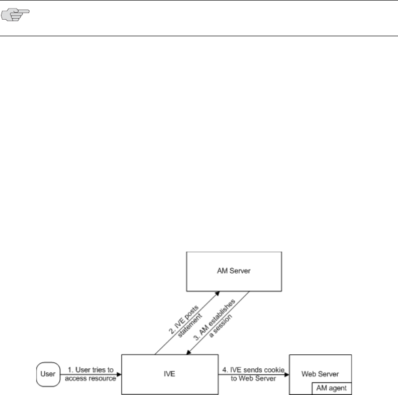
Configuring SAML SSO profiles 211
Chapter 10: Single sign-on
Subject Name—Use the variables described in “System variables and
examples” on page 860 to specify the username that the IVE should pass to
the assertion consumer service. Or, enter static text.
11. Cookie Domain—Enter a comma-separated list of domains to which we send
the SSO cookie.
12. Click Save Changes.
13. On the SAML SSO Policies page, order the policies according to how you want
the IVE to evaluate them. Keep in mind that once the IVE matches the resource
requested by the user to a resource in a policy’s (or a detailed rule’s) Resource
list, it performs the specified action and stops processing policies.
Creating an access control policy
When enabling access control transactions to a trusted access management
system, the IVE and trusted access management system exchange information
using the method shown in Figure 33.
Figure 33: Access control policies
The IVE and an access management (AM) system use the following process to pass
information:
1. The user tries to access a resource—A user is signed into the IVE and tries to
access a protected resource on a Web server.
2. The IVE posts an authorization decision query—If the IVE has already made
an authorization request and it is still valid, the IVE uses that request. (The
authorization request is valid for the period of time specified in the admin
console.) If it does not have a valid authorization request, the IVE posts an
authorization decision query to the access management system. The query
contains the user’s identity and the resource that the access management
system needs to authorize.
NOTE: You must send a username or attribute that the assertion consumer service
will recognize (as explained in “Configuring user identity” on page 218).

Juniper Networks Secure Access Administration Guide
212 Configuring SAML SSO profiles
3. The AM posts an authorization decision statement—The access management
system sends an HTTPS POST containing a SOAP message that contains the
authorization decision statement. The authorization decision statement
contains a result of permit, deny, or indeterminate.
4. The IVE sends the request to the Web browser—If the authorization decision
statement returns a result of permit, the IVE allows the user access. If not, the
IVE presents an error page to the user telling him that he does not have the
proper access permissions.
To write a SAML Access Control resource policy:
1. In the admin console, navigate to Users > Resource Policies > Web.
2. If your administrator view is not already configured to show SAML policies,
make the following modifications:
a. Click the Customize button in the upper right corner of the page.
b. Select the SAML ACL checkbox below the Access checkbox.
c. Click OK.
3. Select the Access > SAML ACL tab.
4. On the SAML Access Control Policies page, click New Policy.
5. On the New Policy page, enter:
a. A name to label this policy.
b. A description of the policy (optional).
6. In the Resources section, specify the resources to which this policy applies. See
“Specifying resources for a resource policy” on page 83 for more information.
To enable IP-based or case sensitivity matching for these resources, see
“Writing a Web proxy resource policy” on page 351.
7. In the Roles section, specify:
Policy applies to ALL roles—To apply this policy to all users.
Policy applies to SELECTED roles—To apply this policy only to users who
are mapped to roles in the Selected roles list. Make sure to add roles to this
list from the Available roles list.
Policy applies to all roles OTHER THAN those selected below—To apply
this policy to all users except for those who map to the roles in the Selected
roles list. Make sure to add roles to this list from the Available roles list.
NOTE: If you configure the IVE to use access control transactions, you must install
the SAML Web service’s root CA on the IVE (as explained in “Configuring
certificates” on page 215).

Configuring SAML SSO profiles 213
Chapter 10: Single sign-on
8. In the Action section, specify:
Use the SAML Access Control checks defined below—The IVE performs
an access control check to the specified URL using the data specified in the
SAML Access Control Details section.
Do not use SAML Access—The IVE does not perform an access control
check.
Use Detailed Rules—To specify one or more detailed rules for this policy.
9. In the SAML Access Control Details section, specify:
SAML Web Service URL—Enter the URL of the access management
system’s SAML server. For example, https://hostname/ws.
Issuer—Enter the host name of the issuer, which in most cases is the host
name of the access management system.
10. In the User Identity section, specify how the IVE and the SAML Web service
should identify the user:
Subject Name Type—Specify which method the IVE and SAML Web
service should use to identify the user:
DN—Send the username in the format of a DN (distinguished name)
attribute.
Email Address—Send the username in the format of an email address.
Windows—Send the username in the format of a Windows domain
qualified username.
Other—Send the username in another format agreed upon by the IVE
and the SAML Web service.
Subject Name—Use the variables described in “System variables and
examples” on page 860 to specify the username that the IVE should pass to
the SAML Web service. Or, enter static text.
11. In the Web Service Authentication section, specify the authentication method
that the SAML Web service should use to authenticate the IVE:
None—Do not authenticate the IVE.
NOTE: You must enter unique string that the SAML Web service uses to identify
itself in authorization assertions (as explained in “Configuring an issuer” on
page 215).
NOTE: You must send a username or attribute that the SAML Web service will
recognize (as explained in “Configuring user identity” on page 218).

Juniper Networks Secure Access Administration Guide
214 Configuring SAML SSO profiles
Username—Authenticate the IVE using a username and password. Enter
the username and password that the IVE must send the Web service.
Certificate Attribute—Authenticate the IVE using a certificate signed by a
trusted certificate authority. If you have more than one certificate installed
on the IVE, use the drop-down list to select which certificate to send to the
Web service.
12. In the Options section, specify:
Maximum Cache Time—You can eliminate the overhead of generating an
authorization decision each time the user request the same URL by
indicating that the IVE must cache the access management system’s
authorization responses. Enter the amount of time the IVE should cache
the responses (in seconds).
Ignore Query Data—By default, when a user requests a resource, the IVE
sends the entire URL for that resource (including the query parameter) to
the SAML Web service and caches the URL. You can specify that the IVE
should remove the query string from the URL before requesting
authorization or caching the authorization response.
13. Click Save Changes.
14. On the SAML Access Control Policies page, order the policies according to
how you want the IVE to evaluate them. Keep in mind that once the IVE
matches the resource requested by the user to a resource in a policy’s (or a
detailed rule’s) Resource list, it performs the specified action and stops
processing policies.
Creating a trust relationship between SAML-enabled systems
In order to ensure that SAML-enabled systems are only passing information
between trusted sources, you must create a trust relationship between the
applications that are sending and receiving information. To create a trust
relationship between the IVE and another SAML-enabled application, you must
configure the following types of information on each system:
“Configuring trusted application URLs” on page 215
“Configuring an issuer” on page 215
“Configuring certificates” on page 215
“Configuring user identity” on page 218
NOTE: If you select this option, you must install the IVE Web server’s certificate on
the access management system’s Web server and determine which method the
SAML Web service uses to trust the certificate (as explained in “Configuring
certificates” on page 215).
Configuring SAML SSO profiles 215
Chapter 10: Single sign-on
Configuring trusted application URLs
In a trust relationship, you must provide the SAML-enabled systems with the URLs
they need to contact each other. In some transactions, only the system that
initiates the transaction (the IVE) needs to know the URL of the other system. (The
IVE uses the URL to initiate the transaction.) In other transactions (SSO transactions
using artifact profiles), you need to configure each system with the URL of the
other.
Listed below are the different transaction types and the URLs you must configure
for each:
SSO transactions: Artifact profile—On the IVE, you must enter the URL of the
assertion consumer service. For example: https://hostname/acs
Also, you must enter the following URL for the IVE on the assertion consumer
service: https://<IVEhostname>/dana-ws/saml.ws
SSO transactions: POST profile—On the IVE, you must enter the URL of the
assertion consumer service. For example: https://hostname/acs
Access control transactions—On the IVE, you must enter the URL of the SAML
Web service. For example: https://hostname/ws
Configuring an issuer
Before accepting a statement from another system, a SAML-enabled entity must
trust the issuer of the statement. You can control which issuers a system trusts by
specifying the unique strings of the trusted issuers during the system’s
configuration. (When sending a statement, an issuer identifies itself by including its
unique string in the statement. SAML-enabled applications generally use host
names to identify issuers, but the SAML standard allows applications to use any
string.) If you do not configure a system to recognize an issuer’s unique string, the
system will not accept that issuer’s statements.
Listed below are the different transaction types and the issuers you must configure
for each:
SSO transactions—You must specify a unique string on the IVE (typically its
host name) that it can use to identify itself and then configure the access
management system to recognize that string.
Access control transactions—You must specify a unique string on the access
management system (typically its host name) that it can use to identify itself
and then configure the IVE to recognize that string.
Configuring certificates
Within SSL transactions, the server must present a certificate to the client, and then
the client must verify (at minimum) that it trusts the certificate authority who
issued the server’s certificate before accepting the information. You can configure
all of the IVE’s SAML transactions to use SSL (HTTPS). The following sections list
different transaction types and the certificate requirements for each.
Juniper Networks Secure Access Administration Guide
216 Configuring SAML SSO profiles
Configuring SSO transactions: Artifact profile
Artifact profile transactions involve numerous communications back and forth
between the IVE and access management system. The methods you use to pass
data and authenticate the two systems affect which certificates you must install and
configure. Listed below are the different artifact profile configuration options that
require special certificate configurations:
All artifact profile transactions—Regardless of your artifact profile
configuration, you must install the certificate of the CA that signed the IVE Web
server’s certificate on the access management system. (The IVE requires the
access management system to use an SSL connection when requesting an
authentication statement. In an SSL connection, the initiator must trust the
system to which it is connecting. By installing the CA certificate on the access
management system, you ensure that the access management system will trust
the CA that issued the IVE’s certificate.)
Sending artifacts over an SSL connection (HTTPS GET requests)—If you
choose to send artifacts to the access management system using an SSL
connection, you must install the access management system’s root CA
certificate on the IVE. (In an SSL connection, the initiator must trust the system
to which it is connecting. By installing the access management system’s CA
certificate on the IVE, you ensure that the IVE will trust the CA that issued the
access management system’s certificate.) You can install the root CA from the
System > Configuration > Certificates > Trusted Client CAs page in the
admin console. For more information, see “Using trusted client CAs” on
page 607. If you do not want to send artifacts over an SSL connection, you do
not need to install any additional certificates.
To enable SSL-based communications from the IVE to the access management
system, enter a URL that begins with HTTPS in the SAML Assertion Consumer
Service URL field during IVE configuration. You may also need to enable SSL
on the access management system.
Transactions using certificate authentication—If you choose to authenticate
the access management system using a certificate, you must:
Install the access management system’s root CA certificate on the IVE. You
can install the root CA from the System > Configuration > Certificates
> Trusted Client CAs page in the admin console. For more information,
see “Using trusted client CAs” on page 607.
Specify which certificate values the IVE should use to validate the access
management system. You must use values that match the values contained
in the access management server’s certificate.
If you do not choose to authenticate the access management system, or if you
choose to use username/password authentication, you do not need to install
any additional certificates.
Configuring SAML SSO profiles 217
Chapter 10: Single sign-on
Configuring SSO transactions: POST profile
In a POST profile transaction, the IVE sends signed authentication statements to the
access management system. Generally, it sends them over an SSL connection
(recommended), but in some configurations, the IVE may send statements via a
standard HTTP connection. Listed below are the different POST profile
configuration options that require special certificate configurations:
All POST profile transactions—Regardless of your POST profile configuration,
you must specify which certificate the IVE should use to sign its statements.
You can choose a certificate in the Users > Resource Policies > Web > SSO
> SAML > [Policy] > General page in the admin console. For more
information, see “Configuring SAML” on page 201. Then, you must install the
IVE’s device certificate on the access management system. You can download
the IVE’s certificate from the System > Configuration > Certificates >
Device Certificates > [Certificate] > Certificate Details page.
Sending POST data over an SSL connection (HTTPS)—If you choose to send
statements to the access management system using an SSL connection, you
must install the access management system’s root CA certificate on the IVE. (In
an SSL connection, the initiator must trust the system to which it is connecting.
By installing the access management system’s certificate on the IVE, you
ensure that the IVE will trust the CA that issued the access management
system’s certificate.) You can install the root CA from the System >
Configuration > Certificates > Trusted Client CAs page in the admin
console. For more information, see “Using trusted client CAs” on page 607. If
you do not want to post statements over an SSL connection, you do not need to
install any additional certificates.
To enable SSL-based communications from the IVE to the access management
system, enter a URL that begins with HTTPS in the SAML Assertion Consumer
Service URL field during IVE configuration. You may also need to enable SSL
on the access management system.
Configuring access control transactions
In an access control transaction, the IVE posts an authorization decision query to
the access management system. To ensure that the access management system
responds to the query, you must determine which certificate options are required
by your configuration. Listed below are the different access control configuration
options that require special certificate configurations:
Sending authorization data over an SSL connection—If you choose to
connect to the access management system using an SSL connection, you must
install the access management system’s root CA on the IVE. (In an SSL
connection, the initiator must trust the system to which it is connecting. By
installing the access management system’s certificate on the IVE, you ensure
that the IVE will trust the CA that issued the access management system’s
certificate.) You can install the root CA from the System > Configuration >
Certificates > Trusted Client CAs page in the admin console. For more
information, see “Using trusted client CAs” on page 607.
Juniper Networks Secure Access Administration Guide
218 Configuring SAML SSO profiles
Transactions using certificate authentication—If you choose to use certificate
authentication, you must configure the access management system to trust the
CA that issued the IVE’s certificate. Optionally, you may also choose to accept
the certificate based on the following additional options:
Upload the IVE certificate’s public key to the access management system.
Validate the IVE using specific certificate attributes.
These options require that you specify which certificate the IVE should pass to
the access management system. You can choose a certificate in the Users >
Resource Policies > Web > Access > SAML ACL > [Policy] > General page
in the admin console. For more information, see “Configuring SAML SSO
profiles” on page 204.
To determine how to configure your access management system to validate the
IVE’s certificate, see your access management system’s documentation. If your
access management system does not require certificate authentication, or if it
uses username/password authentication, you do not need to configure the IVE
to pass the access management server a certificate. If you do not specify a trust
method, your access management system may accept authorization requests
from any system.
Configuring user identity
In a trust relationship, the two entities must agree on a way to identify users. You
may choose to share a username across systems, select an LDAP or certificate user
attribute to share across systems, or hard-code a user ID. (For example, you may
choose to set the Subject Name field to “guest” to easily allow access across
systems.)
To ensure that the two systems are passing common information about users, you
must specify which information the IVE should pass using options in the User
Identity section of the Users > Resource Policies > Web > SSO > SAML >
[Policy] > General page (for more information, see “Configuring SAML” on
page 201) and the Users > Resource Policies > Web > Access > SAML ACL >
[Policy] > General page of the admin console. Choose a username or attribute that
the access management system will recognize.
Task Summary: Configuring SAML through the IVE
To configure SAML through the IVE, you must:
1. Configure a Web resource policy for a URL through the Users > Resource
Policies > Web > Access > SAML ACL and Users > Resource Policies >
Web > SSO > SAML tabs in the admin console. For more instructions, see
“Configuring SAML” on page 201.
2. Within the policy, provide information about the IVE, the trusted access
management system, and the mechanism they should use to share
information, as explained in “Creating a trust relationship between SAML-
enabled systems” on page 214.
Juniper Networks Secure Access Administration Guide
220 Configuring SAML SSO profiles
221
Part 3
Endpoint defense
Juniper Networks has developed the Juniper Endpoint Defense Initiative (J.E.D.I.) to
provide a comprehensive solution to assess the trust worthiness of SSL VPN
endpoints. J.E.D.I. uses a layered approach to address the full range of risks that
endpoints can pose to your enterprise network. Using J.E.D.I. components, you can
secure the systems of users inside and outside your network before allowing them
to connect to your IVE appliance.
J.E.D.I. components include:
Host Checker—Host Checker (also called native Host Check and policy-based
enforcement) is a native IVE component that you can use to perform endpoint
checks on hosts that connect to the IVE. Host Checker checks for third party
applications, files, process, ports, registry keys, and custom DLLs and denies or
enables access based on the results of the checks. When properly licensed, you
can also use Host Checker to download advanced malware detection software
directly to the user’s computer. When a user’s computer does not meet the
requirements you specify, you can display remediation instructions to users so
they can bring their computers into compliance. For more information, see
“Host Checker” on page 223.
Host Check Client Interface (Windows only)—The Host Check Client
Interface is an API that allows you to run your own DLLs using Host Checker.
Through the interface, you can prompt Host Checker to run a DLL that you
already installed on the user’s system or distributed as part of a corporate OS
image, including programs that check compliance with corporate images,
antivirus software, and personal firewall clients. Host Checker runs the
specified DLL when a user signs into the IVE, and then bases its subsequent
actions on the success or failure result that the DLL returns. For example, you
may deny a user access to the IVE if the client check software fails. For more
information, see the J.E.D.I. Solution Guide available on the Juniper Networks
Customer Support Center.
Host Check Server Integration Interface (Windows only)—The Host Check
Server Integration Interface is an API that allows you to tightly integrate a
J.E.D.I. compliant system with the IVE. Like the Host Check Client Interface,
you can use the Host Check Server Integration Interface to prompt Host
Checker to run third-party software on the client, including host integrity scans,
malware detectors, and virtual environments. With this interface, you may also
Juniper Networks Secure Access Administration Guide
222
specify with granularity what Host Checker should do based on the result of the
diverse policy checks that the third-party applications conduct. You can invoke
these policies to dynamically map users to realms, roles, and resources based
on the results of individual policies contained in your software package. For
more information, see the J.E.D.I. Solution Guide available on the Juniper
Networks Customer Support Center.
Cache Cleaner (Windows only)—Cache Cleaner is a native IVE component
that you can use to remove residual data, such as cookies, temporary files, or
application caches, from a user’s machine after an IVE session. Cache Cleaner
helps secure the user’s system by preventing subsequent users from finding
temporary copies of the files that the previous user was viewing and by
preventing Web browsers from permanently storing the usernames,
passwords, and Web addresses that users enter in Web forms. For more
information, see “Cache Cleaner” on page 269.
Using these endpoint defense components, you can develop a layered protection
approach, managing and provisioning a variety of endpoint checks all from within
the IVE. For example, you may choose to check for virus detection before allowing
a user access to any of the IVE realms, launch the software on the user’s system if
necessary, map the user to roles based on individual policies defined in your own
DLL, and then further restrict access to individual resources based on the existence
of spyware detection software.
Then, you may use Cache Cleaner to remove residual files and clear the user’s
application cache once the user has terminated the IVE session.
This section includes the following information about endpoint defense:
“Host Checker” on page 223
“Cache Cleaner” on page 269
223
Chapter 11
Host Checker
Host Checker is a client-side agent that performs endpoint checks on hosts that
connect to the IVE. You can invoke Host Checker before displaying an IVE sign-in
page to a user and when evaluating a role mapping rule or resource policy.
The IVE can check hosts for endpoint properties using a variety of rule types,
including rules that check for and install advanced malware protection; predefined
rules that check for antivirus software, firewalls, malware, spyware, and specific
operating systems from a wide variety of industry leaders; and custom rules that
check for certain third party DLLs, ports, processes, files, and registry key settings.
If the user’s computer does not meet any of the Host Checker policy requirements,
you can display a custom-made HTML remediation page to the user. This page can
contain your specific instructions as well as links to resources to help the user bring
his computer into compliance with each Host Checker policy.
This section contains the following information about Host Checker:
“Licensing: Host Checker availability” on page 224
“Task summary: Configuring Host Checker” on page 224
“Creating global Host Checker policies” on page 226
“Enabling the Secure Virtual Workspace” on page 244
“Implementing Host Checker policies” on page 251
“Remediating Host Checker policies” on page 255
“Defining Host Checker pre-authentication access tunnels” on page 258
“Specifying general Host Checker options” on page 262
“Specifying Host Checker installation options” on page 264
“Using Host Checker logs” on page 267

Juniper Networks Secure Access Administration Guide
224 Licensing: Host Checker availability
Licensing: Host Checker availability
Host Checker is a standard feature on all Secure Access appliances. You do not
need a special license to use the baseline Host Checker features. However, note
that Host Checker custom expressions, Host Checker detailed rules, Host Checker
remediation, and other features may not be available on the SA 700 and are only
available on all other Secure Access products by special license. Additionally, in
order to support more than 25 users with the advanced endpoint defense malware
detection policies, you must buy an upgrade license.
Task summary: Configuring Host Checker
To configure Host Checker, you must perform these tasks:
1. Create and enable Host Checker policies through the Authentication >
Endpoint Security > Host Checker page of the admin console, as explained in
“Creating global Host Checker policies” on page 226.
2. Configure additional system-level options through the Authentication >
Endpoint Security > Host Checker page of the admin console as necessary:
If you want to display remediation information to users when they fail to
meet the requirements of a Host Checker policy, configure remediation
options through the Authentication > Endpoint Security > Host
Checker page of the admin console, as explained in “Remediating Host
Checker policies” on page 255.
For Windows clients, determine whether you need to use a
pre-authentication access tunnel between the clients and policy server(s) or
resources. If necessary, create a manifest.hcif file with the tunnel definition
and upload it through the Authentication > Endpoint Security > Host
Checker page of the admin console, as explained in “Defining Host
Checker pre-authentication access tunnels” on page 258.
If you want to change the default Host Checker settings, configure them
through the Authentication > Endpoint Security > Host Checker page
of the admin console, as explained in “Specifying general Host Checker
options” on page 262.
3. Determine at which levels within the IVE access management framework you
want to enforce the policies:
To enforce Host Checker policies when the user first accesses the IVE,
implement the policies at the realm level by using the Administrators >
Admin Realms > Select Realm > Authentication Policy > Host Checker
or the Users > User Realms > Select Realm > Authentication Policy >
Host Checker pages of the admin console.

Task summary: Configuring Host Checker 225
Chapter 11: Host Checker
To allow or deny users access to roles based on their compliance with Host
Checker policies, implement the policies at the role level by using the
Administrators > Admin Roles > Select Role > General > Restrictions
> Host Checker or the Users > User Roles > Select Role > General >
Restrictions > Host Checker pages of the admin console.
To map users to roles based on their compliance with Host Checker
policies, use custom expressions in the Administrators > Admin Realms
> Select Realm > Role Mapping or the Users > User Realms > Select
Realm > Role Mapping pages of the admin console.
To allow or deny users access to individual resources based on their
compliance with Host Checker policies, use conditions in the Users >
Resource Policies > Select Resource > Select Policy > Detailed Rules >
Select|Create Rule page of the admin console.
For more information, see “Configuring Host Checker restrictions” on
page 253.
4. Specify how users can access the Host Checker client-side agent that enforces
the policies you define:
To enable automatic installation of the Host Checker client-side agent on all
platforms, use the Administrators > Admin Realms > Select Realm >
Authentication Policy > Host Checker page or the Users > User Realms
> Select Realm > Authentication Policy > Host Checker page of the
admin console.
To download the Host Checker installer and manually install it on your
Windows users’ systems, use the Maintenance > System > Installers
page of the admin console.
For configuration instructions, see “Specifying Host Checker installation
options” on page 264.
5. Determine whether you want to create client-side logs. If you enable client-side
logging through the System > Log/Monitoring > Client Logs page of the
admin console, the IVE appliance creates log files on your users’ systems and
writes to the file whenever Host Checker runs. For configuration instructions,
see “Using Host Checker logs” on page 267.
NOTE: Users must enable signed ActiveX components or signed Java applets
within their browsers in order for Host Checker to download, install, and launch
the client applications.

Juniper Networks Secure Access Administration Guide
226 Creating global Host Checker policies
Creating global Host Checker policies
In order to use Host Checker as a policy enforcement tool for managing endpoints,
you must create global Host Checker policies at the system level through the
Authentication > Endpoint Security > Host Checker page of the admin console,
and then implement the policies at the realm, role, and resource policy levels.
The IVE provides several mechanisms that you can use to enable, create, and
configure Host Checker policies:
Pre-defined policies (prevent in-network attacks or downloads malware
detection software)—The IVE comes equipped with two types of pre-defined
client-side Host Checker policies that you simply need to enable, not create or
configure, in order to use them. The Connection Control policy prevents attacks
on Windows client computers from other infected computers on the same
network. The Advanced Endpoint Defense: Malware Protection policies
download malware protection software to client computers before users sign
into the IVE. Note that these policies only work on Windows systems. For more
information, see “Enabling pre-defined client-side policies (Windows only)” on
page 227.
Pre-defined rules (check for third party applications)—Host Checker comes
pre-equipped with a vast array of pre-defined rules that check for antivirus
software, firewalls, malware, spyware, and specific operating systems from a
wide variety of industry leaders. You can enable one or more of these rules
within a Host Checker client-side policy in order to ensure that the integrated
third party applications that you specify are running on your users’ computers
in accordance with your specifications. For more information, see “Checking
for third-party applications using pre-defined rules (Windows only)” on
page 232.
Custom rules (check for additional requirements)—If the pre-defined client-
side policies and rules that come with the IVE do not meet your needs, you can
create custom rules within a Host Checker policy to define requirements that
your users’ computers must meet. Using custom rules, you can:
Configure Host Checker to check for custom third party DLLs that perform
customized client-side checks.
Verify that certain ports are open or closed on the user’s computer.
Confirm that certain processes are or are not running on the user’s
computer.
Check that certain files are or are not present on the client machine.
Evaluate the age and content of required files through MD5 checksums.
Confirm that registry keys are set on the client machine.
For more information, see “Specifying customized requirements using custom
rules” on page 236.

Creating global Host Checker policies 227
Chapter 11: Host Checker
Custom integrated applications (implement through server API)—For
Windows clients, you can define Host Checker server-side policies using the
Host Check Server Integration Interface (API) and zip up the policies into a
third-party integration package. The IVE recognizes the policies when you
upload your third-party integration package to the IVE. For more information
about creating these policies, see the J.E.D.I. Solution Guide available on the
Juniper Networks Customer Support Center.
For information about enabling the server-side policies that you create, see
“Enabling customized server-side policies” on page 242.
Within a single policy, you can create different Host Checker requirements for
Windows, Macintosh, and Linux, checking for different files, processes, and
products on each operating system. You can also can combine any number of host
check types within a single policy and check for alternative sets of rules.
Enabling pre-defined client-side policies (Windows only)
The IVE comes equipped with two types of pre-defined client-side Host Checker
policies that you simply need to enable, not create or configure, in order to use
them:
The connection control policy prevents attacks on Windows client computers
from other infected computers on the same network. For more information,
see “Enabling connection control policies” on page 228.
The advanced endpoint defense malware detection policies download Whole
Security’s Confidence Online software to client computers. This software
protects users from malicious software such as worms, viruses, key logger
software, screen capture software, and trojan horses. For more information,
see “Enabling advanced malware protection policies” on page 228.
NOTE:
The connection control and advanced endpoint defense malware detection
policies only work on Windows systems.
The connection control policy is not supported on Windows 98 systems.

Juniper Networks Secure Access Administration Guide
228 Creating global Host Checker policies
Enabling connection control policies
The pre-defined connection control Host Checker policy prevents attacks on
Windows client computers from other infected computers on the same physical
network. The Host Checker connection control policy blocks all incoming TCP
connections. This policy allows all outgoing TCP and Network Connect traffic, as
well as all connections to DNS servers, WINS servers, DHCP servers, proxy servers,
and the IVE.
To enable the pre-defined Host Checker connection control policy:
1. In the admin console, choose Authentication > Endpoint Security > Host
Checker.
2. Under Options, select the Create Host Checker Connection Control Policy
checkbox.
3. Click Save Changes. The IVE enables the Host Checker connection control
policy.
4. Implement the Host Checker connection control policy at the realm, role, or
resource policy levels using the options described in “Configuring Host Checker
restrictions” on page 253.
Enabling advanced malware protection policies
If you are properly licensed, you can enable advanced endpoint defense malware
detection policies through Host Checker. These policies download and run Whole
Security Confidence Online software on your users’ computers. This software scans
for malicious programs, including:
Trojan horses—Hackers write trojan horses to remotely administer an infected
machine. Trojan horses almost always install themselves on a user’s computer
without the authorized user’s knowledge.
NOTE:
Users must have administrator privileges in order for Host Checker to enforce
the connection control policy on the client computer.
The IVE does not support the Host Checker connection control policy on
Windows 98 client computers.
NOTE: Note that you cannot modify this policy—only enable or disable it. Also
note that since you cannot modify this policy, the IVE does not display it in the
Policies section of the Authentication > Endpoint Security > Host Checker
page with other configurable policies.
NOTE: You must evaluate or enforce the connection control policy at the realm
level to make the policy effective on client computers.

Creating global Host Checker policies 229
Chapter 11: Host Checker
Key logger software—Hackers write key logger software to eavesdrop on a user
by capturing and logging his typed keystrokes. Key logger software installs
itself on a user’s computer without the authorized user’s knowledge.
Monitoring applications—Monitoring applications are end-user software
applications that monitor and record user activity. Users typically install this
software themselves to monitor the activity of children, spouses, and other
users who share their computers.
Remote controls—Remote control applications are commercial applications
such as VNC that offer easy remote access to an authorized user for computer
administration activities.
To use the Whole Security malware protection software, you need to enable the
Advanced Endpoint Defense Malware Detection option at the system level and
enforce it at the realm, role, and/or resource policy levels.
You do not need to create or configure advanced endpoint defense malware
detection policies—Host Checker creates them for you when you enable the option
at the system level. Note that we recommend that you require and enforce an
advanced endpoint defense malware detection policy at the realm level so that
Host Checker can download the Confidence Online software to your users’
computers and check for potential threats before they sign in to the IVE, but after
their Windows logon. Once Confidence Online begins running, it continues to scan
for and block threats throughout the user’s IVE session.
To enable and configure advanced endpoint defense malware detection policies:
1. In the admin console, choose Authentication > Endpoint Security > Host
Checker.
2. Under Options, select the Enable Advanced Endpoint Defense: Malware
Protection checkbox.
3. Select the Enable Silent Enforcement of Signature Scan checkbox if you do
not want Confidence Online to notify users when it blocks trojan horse, key
logger software, and other applications that it deems malicious. (Note that
Confidence Online accesses a Whole Security server on a daily basis in order to
keep its list of malicious applications current.)
NOTE: Each user’s computer must be able to access the Whole Security site
(update.wholesecurity.com) so that Confidence Online can periodically download
the latest definition files.

Juniper Networks Secure Access Administration Guide
230 Creating global Host Checker policies
4. Select the Enable User Control over disabling Behavior Blocker checkbox if
you want to enable users to choose whether or not to block monitoring
applications, remote control software, and other potentially legitimate
applications. If you select this option, users can view and control blocked
applications through a Confidence Online icon in their system trays. (For more
information, see the Confidence Online end-user help system.) If you do not
select this option, Confidence Online simply blocks these applications without
user interaction.
5. Click Save Changes. The IVE enables the following advanced endpoint defense
malware detection policies:
Advanced Endpoint Defense: Malware Protection.Behavior Blocker—
This policy is created by Whole Security. It enables the Confidence Online
behavior blocker software to block keystroke logger software, screen
capture software, and other applications that try to eavesdrop on user
sessions.
Advanced Endpoint Defense: Malware Protection.Category One Threats
(Trojan Horses and Key Loggers)—This policy is created by Whole
Security. It enables the Confidence Online software to block trojan horse
programs, spyware, malware, and other malicious applications.
Advanced Endpoint Defense: Malware Protection.Category Two Threats
(Monitoring Applications and Remote Controls)—This policy is created
by Whole Security. It enables the Confidence Online software to block
monitoring applications, remote control software, and other potentially
legitimate applications.
Each of these policies includes remediation instructions that display a message
to users if they do not pass the specified policy. The message tells the users to
follow instructions in the pop-up window to remediate their machines.
6. Implement the advanced endpoint defense malware detection policies at the
realm, role, or resource policy levels using the options described in
“Configuring Host Checker restrictions” on page 253. (You must at least
evaluate or enforce a advanced endpoint defense malware detection policy at
the realm level to make the policy effective on client computers.)
NOTE:
Category 1 and Category 2 Signature Scans—Restricted users, power users,
and administrators can install and run the scanning feature in Confidence
Online. The scanning feature is supported on Windows 98 SE, Windows ME,
Windows NT4, Windows 2000, and Windows XP systems.
Behavior Blocker—Only administrators can install and run the behavior
blocker feature in Confidence Online. The behavior blocker feature is
supported on Windows 2000 and Windows XP systems.

Creating global Host Checker policies 231
Chapter 11: Host Checker
Creating and configuring new client-side policies
You can create a variety of policies through the Host Checker client that check for
antivirus software, firewalls, malware, spyware, and specific operating systems
from a wide variety of industry leaders. You can also create checks for custom
third-party DLLs, ports, processes, files, and registry keys. When creating the
policies, you must define the policy name, enable pre-defined rules, or create
custom rules that run the specified checks. Optionally, you can specify how Host
Checker should evaluate multiple rules within a single policy.
When creating the policies, you must define the policy name, and either enable
pre-defined rules, or create custom rules that run the specified checks. Optionally,
you can specify how Host Checker should evaluate multiple rules within a single
policy.
To create a standard client-side policy:
1. In the admin console, choose Authentication > Endpoint Security > Host
Checker.
2. Under Policies, click New.
NOTE: When enforcing advanced endpoint defense malware detection policies,
note that:
You cannot modify these policies—only enable or disable them. Also, since
you cannot modify these policies, the IVE does not display them in the
Policies section of the Authentication > Endpoint Security > Host Checker
page with other configurable policies.
If your concurrent user licenses for the IVE and Whole Security do not match,
you are constrained by the lesser of the two licenses. For example, if you have
a license that allows 100 concurrent IVE users and another license that allows
for 50 concurrent Whole Security users, this constraint allows only 50
concurrent users to access an IVE enabled with Advanced Endpoint Defense
Malware Protection policies.
If you have licensed GINA and Whole Security, you should be aware that GINA
runs prior to the user’s Windows logon, and the download of the Whole
Security Confidence Online software occurs after the user signs in to
Windows. Therefore, Whole Security does not perform its stated malware
protection until after Windows logon. If you are using Network Connect, Host
Checker, GINA, and Whole Security, but the end-user is not in user mode
when their system tries to initiate Host Checker, the end-user may receive
errors. Make certain you have configured the system to start GINA prior to the
Windows logon, and Whole Security after Windows logon.
NOTE: The Whole Security Confidence Online feature supported by Host Checker
cannot be localized currently. For more information about localizing the IVE, see
“Localizing the user interface” on page 844.
Juniper Networks Secure Access Administration Guide
232 Creating global Host Checker policies
3. Enter a name in the Policy Name field and then click Continue. (Users see this
name on the Host Checker remediation page if you enable custom instructions
for this policy.)
4. Create one or more rules to associate with the policy using instructions in the
following sections:
“Checking for third-party applications using pre-defined rules (Windows
only)” on page 232
“Specifying customized requirements using custom rules” on page 236
5. Specify how Host Checker should evaluate multiple rules within the policy
using instructions in “Evaluating multiple rules in a single Host Checker policy”
on page 242.
6. (Recommended) Specify remediation options for users whose computers do
not meet the requirements specified in the policy. For instructions, see
“Configuring Host Checker remediation” on page 257. (If you do not create
remediation instructions and the policy fails, your users will not know why they
cannot access their resources.)
7. Implement the policy at the realm, role, or resource policy levels using the
options described in “Configuring Host Checker restrictions” on page 253.
Checking for third-party applications using pre-defined rules (Windows
only)
Host Checker comes pre-equipped with a vast array of pre-defined rules that check
for antivirus software, firewalls, malware, spyware, and specific operating systems
from a wide variety of industry leaders. You can enable one or more of these rules
within a Host Checker client-side policy in order to ensure that the integrated third
party applications that you specify are running on your users’ computers in
accordance with your specifications.
To create an integrated third-party application policy using pre-defined rules:
1. In the admin console, choose Authentication > Endpoint Security > Host
Checker.
2. Create a new policy using instructions in “Creating and configuring new client-
side policies” on page 231 or click on an existing policy in the Policies section
of the page.
3. Under Rule Settings, choose one of the following options and click Add:
Predefined: AntiVirus—Select this option to create a rule that checks for
the antivirus software that you specify.
Predefined: Firewall—Select this option to create a rule that checks for the
firewall software that you specify.
Predefined: Malware—Select this option to create a rule that checks for
the malware protection software that you specify.

Creating global Host Checker policies 233
Chapter 11: Host Checker
Predefined: Spyware—Select this option to create a rule that checks for
the spyware protection software that you specify.
Predefined: OS Checks—Select this option to create a rule that checks for
the Windows operating systems and minimum service pack versions that
you specify. (Any service pack whose version is greater than or equal to the
version you specify satisfies the policy.)
4. In the Add Predefined Rule page:
In the Rule Name field, enter an identifier for the rule.
Under Criteria, choose the specific application versions or operating
systems that you want to check for and click Add. (When checking for an
operating system, you may also specify a service pack version.)
(Antivirus policies only) Select Specify age in days to configure this Host
Checker policy to require a maximum acceptable age of the virus definition
files. For Maximum age of definition files, specify the maximum number
of days.
(Antivirus policies only) Select Virus signatures must be up to date to
configure this Host Checker policy to require current virus signatures on
the client computer. To enable this functionality in the policy, you must
also manually or automatically import the current virus signature list on the
Authentication > Endpoint Security > Host Checker page. (See
“Configuring virus signature version monitoring” on page 234.)
Click Save Changes.
5. Optionally add additional rules to the policy, specify how Host Checker should
evaluate multiple rules within the policy, and define remediation options using
instructions in “Creating and configuring new client-side policies” on page 231.
NOTE: When you select more than one type of software within a pre-defined rule,
Host Checker considers the rule satisfied if any of the selected software
applications are present on the user’s machine.
NOTE: To view the currently supported applications, go to Authentication >
Endpoint Security > Host Checker and create a new policy. You can choose pre-
defined rule types from the Select Rule Type drop down list box to see a list of the
supported applications within that category. The lists of applications can be quite
extensive and are updated at each support release, so it is useful to check the list
periodically.
Juniper Networks Secure Access Administration Guide
234 Creating global Host Checker policies
Configuring virus signature version monitoring
You can configure Host Checker to monitor and verify that the virus signatures
installed on client computers are up to date. Host Checker uses a list of the current
virus signatures from the vendor(s) you specify for pre-defined antivirus rules in a
Host Checker policy. If a client computer does not have the current virus signatures
installed, the Host Checker policy fails.
You can obtain the current virus signatures list from a staging site at Juniper
Networks. You can manually download and import the current list into the IVE, or
you can automatically import the current list from the Juniper Networks staging site
or your own staging site at a specified interval.
For example, you might want to manually download and import the current virus
signatures list from a network server or local drive if you want to first test the list,
or if the IVE is unable to automatically access the Juniper Networks staging site. Or,
you can manually download the current list to a local staging site on your internal
network, and then automatically import the list from that internal staging site.
To configure virus signature version monitoring:
1. While adding a pre-defined antivirus rule on the Authentication > Endpoint
Security > Host Checker > Select Policy > Add Predefined Rule: Antivirus
page, select the Virus signatures must be up to date option. (See “Checking
for third-party applications using pre-defined rules (Windows only)” on
page 232.)
2. Choose Authentication > Endpoint Security > Host Checker.
3. Click Virus signature version monitoring.
4. To configure the IVE to automatically import the current virus signatures list:
a. Select Auto-update virus signatures list.
b. For Download path, enter the URL of the staging site where the current
virus signatures list is stored. You can specify the URL of the Juniper
Networks staging site or your own staging site. The default URL is the path
to the Juniper Networks staging site:
https://download.juniper.net/software/av/uac/avupdate.dat
c. For Download interval, specify how often you want the IVE to
automatically import the current virus signatures list.
d. If the staging site is password protected, enter the credentials in Username
and Password. To access the Juniper Networks staging site, you must enter
the credentials for a Juniper Networks Support account. You can also use
basic HTTP authentication to protect and access your own staging site.
5. To manually import the current virus signatures list:
a. Download the virus signatures list from the staging site to a network server
or local drive on your computer.

Creating global Host Checker policies 235
Chapter 11: Host Checker
b. Under Manually import virus signatures list, click Browse, select the virus
signatures list, and then click OK.
6. Click Save Changes.
Upgrading the Endpoint Security Assessment Plug-in
The Endpoint Security Assessment Plug-in (ESAP) on the IVE checks third-party
applications on endpoints for compliance with the pre-defined rules you configure
in a Host Checker policy. (See “Checking for third-party applications using pre-
defined rules (Windows only)” on page 232.) This plug-in is included in the IVE
system software package.
Juniper Networks frequently adds enhancements, bug fixes, and support for new
third-party applications to the plug-in. New plug-in releases are available
independently and more frequently than new releases of the IVE system software
package. If necessary, you can upgrade the plug-in on the IVE independently of
upgrading the IVE system software package.
You can upload up to four versions of the plug-in to the IVE, but the IVE uses only
one version at a time (called the active version). If necessary, you can rollback to a
previously active version of the plug-in.
To upgrade the Endpoint Security Assessment Plug-in:
1. Download the Endpoint Security Assessment Plug-in from the Juniper Networks
Customer Support Center to your computer:
a. Open the following page:
https://www.juniper.net/customers/csc/software/ive/
b. To access the Customer Support Center, enter a user name and password
for a Juniper Networks Support account.
c. Click the ESAP link.
d. Download the plug-in zip file to your computer.
2. Choose Authentication > Endpoint Security > Host Checker.
3. At the bottom of the Host Checker page under Manage Endpoint Security
Assessment Plug-In Versions:
a. If you have previously uploaded four versions of the component software,
you must delete one of the versions before you can upload another one.
Select the version you want to delete and click Delete.
NOTE: If you use your own staging site for storing the current virus signatures list,
you must upload the trusted root certificate of the CA that signed the staging’s
server certificate to the IVE. For more information, see “Uploading trusted server
CA certificates” on page 621.

Juniper Networks Secure Access Administration Guide
236 Creating global Host Checker policies
b. If you want the IVE to actively begin using the new component software
immediately after you upload it, select the Set as active after upload
option.
c. Click Browse, select the plug-in file you want to upload to the IVE, and click
OK.
d. Click Upload. While the IVE uploads and decrypts the plug-in .zip file, the
message “Loading...” appears in the plug-in list under Manage Endpoint
Security Assessment Plug-In Versions. If the IVE is a member of a cluster,
the IVE displays the message “Loading...” while the plug-in is transferred to
the other cluster nodes. After the plug-in is installed, the date and time of
the plug-in installation appears in the plug-in list.
e. If you did not select the Set as active after upload option, activate the
plug-in you want to use by selecting the version in the plug-in list and
clicking Activate.
Specifying customized requirements using custom rules
If the pre-defined client-side policies and rules that come with the IVE do not meet
your needs, you can create custom rules within a Host Checker policy to define
requirements that your users’ computers must meet. Using custom rules, you can:
Configure Host Checker to check for custom DLLs that perform customized
client-side checks.
NOTE:
If you attempt to activate a version of the plug-in that does not support all of
the pre-defined rules already configured in all Host Checker policies, the IVE
does not allow activation of that plug-in version. For example, if a Host
Checker policy is configured to use a pre-defined rule to check for a version of
antivirus software, and you attempt to activate a plug-in version that does not
support that particular version of the antivirus software, the IVE does not
allow you to activate that plug-in version. To view the list of supported
products for a particular plug-in version, click the plug-in’s version number
under Manage Endpoint Security Assessment Plug-In Versions.
You can rollback to an older plug-in version after upgrading to a later version
by selecting the older version as the active version. But, if you modified any
Host Checker policies after upgrading to the later version, the rollback may
not succeed. Rollback is guaranteed to succeed only if the policies did not
change.
If you upgrade the IVE system software to a newer version, or you import a
user configuration file, the currently active plug-in version does not change. If
you want to use a different plug-in version after upgrading or importing a user
configuration file, you must manually activate that plug-in version.
If the IVE already has four versions of the plug-in installed when you upgrade
the IVE system software to a newer version, the IVE automatically deletes the
oldest plug-in version and installs, but does not activate, the plug-in included
with the new IVE system software.

Creating global Host Checker policies 237
Chapter 11: Host Checker
Verify that certain ports are open or closed on the user’s computer.
Confirm that certain processes are or are not running on the user’s computer.
Check that certain files are or are not present on the client machine.
Evaluate the age and content of required files through MD5 checksums.
Confirm that registry keys are set on the client machine.
To create a client-side Host Checker policy:
1. In the admin console, choose Authentication > Endpoint Security > Host
Checker.
2. Create a new policy using instructions in “Creating and configuring new client-
side policies” on page 231 or click on an existing policy in the Policies section
of the page.
3. Click the tab that corresponds to the operating system for which you want to
specify Host Checker options—Windows, Mac, or Linux. In the same policy,
you can specify different Host Checker requirements on each operating
system. For example, you can create one policy that checks for different files or
processes on each operating system.
4. Under Rule Settings, choose one of the following options and click Add. The
Add Custom Rule page for the rule type appears.
3rd Party NHC Check (Windows only)—Use this rule type to specify the
location of a custom DLL that you write with the Host Check Client
Interface. Host Checker calls the DLL to perform customized client-side
checks. If the DLL returns a success value to Host Checker, then the IVE
considers the rule met. (For information about creating a custom DLL using
the Host Check Client Interface, see the J.E.D.I. Solution Guide on the
Juniper Networks Customer Support Center.) In the 3rd Party NHC Check
configuration page:
i. Enter a name and vendor for the 3rd Party NHC Check rule
ii. Enter the location of the DLL on client machines (path and file name).
iii. Click Save Changes.
NOTE: You can only check for registry keys and custom third-party DLLs on
Windows computers.
Juniper Networks Secure Access Administration Guide
238 Creating global Host Checker policies
Ports—Use this rule type to control the network connections that a client
can generate during a session. This rule type ensures that certain ports are
open or closed on the client machine before the user can access the IVE. In
the Ports configuration page:
i. Enter a name for the port rule.
ii. Enter a comma delimited list (without spaces) of ports or port ranges,
such as: 1234,11000-11999,1235.
iii. Select Required to require that these ports are open on the client
machine or Deny to require that they are closed.
iv. Click Save Changes.
Process—Use this rule type to control the software that a client may run
during a session. This rule type ensures that certain processes are running
or not running on the client machine before the user can access resources
protected by the IVE. In the Processes configuration page:
i. Enter a name for the process rule.
ii. Enter the name of a process (executable file), such as: good-app.exe.
You can use a wildcard character to specify the process name. For
example:
good*.exe
For more information, see “Using a wildcard or environment variable
in a Host Checker rule” on page 241.
iii. Select Required to require that this process is running or Deny to
require that this process is not running.
iv. Specify the MD5 checksum value of each executable file to which you
want the policy to apply (optional). For example, an executable may
have different MD5 checksum values on a desktop, laptop, or different
operating systems. On a system with OpenSSL installed—many
Macintosh and Linux systems have OpenSSL installed by default—you
can determine the MD5 checksum by using this command:
openssl md5 <processFilePath>
v. Click Save Changes.

Creating global Host Checker policies 239
Chapter 11: Host Checker
File—Use this rule type to ensure that certain files are present or not
present on the client machine before the user can access the IVE. You may
also use file checks to evaluate the age and content (through MD5
checksums) of required files and allow or deny access accordingly. In the
Files configuration page:
i. Enter a name for the file rule.
ii. Enter the name of a file (any file type), such as: c:\temp\bad-file.txt or
/temp/bad-file.txt.
You can use a wildcard character to specify the file name. For
example:
*.txt
You can also use an environment variable to specify the directory path
to the file. (You cannot use a wildcard character in the directory path.)
Enclose the variable between the <% and %> characters. For example:
<%windir%>\bad-file.txt
For more information, see “Using a wildcard or environment variable
in a Host Checker rule” on page 241.
iii. Select Required to require that this file is present on the client
machine or Deny to require that this file is not present.
iv. Specify the minimum version of the file (optional). For example, if you
require notepad.exe to be present on the client, you can enter 5.0 in
the field. Host Checker accepts version 5.0 and above, of notepad.exe.
v. Specify the maximum age (File modified less than n days) (in days)
for a file (optional). If the file is older than the specified number of
days, then the client does not meet the attribute check requirement.
vi. Specify the MD5 checksum value of each file to which you want the
policy to apply (optional). On Macintosh and Linux, you can determine
the MD5 checksum by using this command:
openssl md5 <filePath>
vii. Click Save Changes.
NOTE: You can use the maximum age option to check the age of virus signatures.
Make sure you specify the path to a file in the File Name field whose timestamp
indicates when virus signatures were last updated, such as a virus signature
database or log file that updates each time the database updates. For example, if
you use TrendMicro, you may specify:
C:\Program Files\Trend Micro\OfficeScan Client\TmUpdate.ini.

Juniper Networks Secure Access Administration Guide
240 Creating global Host Checker policies
Registry Setting (Windows only)—Use this rule type to control the
corporate PC images, system configurations, and software settings that a
client must have in order to access the IVE. This rule type ensures that
certain registry keys are set on the client machine before the user can
access the IVE. You may also use registry checks to evaluate the age of
required files and allow or deny access accordingly. In the Registry
Settings configuration page:
i. Enter a name for the registry setting rule.
ii. Select a root key from the drop-down list.
iii. Enter the path to the application folder for the registry subkey.
iv. Enter the name of the key’s value that you want to require (optional).
This name appears in the Name column of the Registry Editor.
v. Select the key value’s type (String, Binary, or DWORD) from the drop-
down list (optional). This type appears in the Type column of the
Registry Editor.
vi. Specify the required registry key value (optional). This information
appears in the Data column of the Registry Editor.
If the key value represents an application version, select Minimum
version to allow the specified version or newer versions of the
application. For example, you can use this option to specify version
information for an antivirus application to make sure that the client
antivirus software is current. The IVE uses lexical sorting to determine
if the client contains the specified version or higher. For example:
3.3.3 is newer than 3.3
4.0 is newer than 3.3
4.0a is newer than 4.0b
4.1 is newer than 3.3.1
vii. Click Save Changes.
5. Optionally add additional rules to the policy, specify how Host Checker should
evaluate multiple rules within the policy, and define remediation options using
instructions in “Creating and configuring new client-side policies” on page 231.
NOTE: If you specify only the key and subkey, Host Checker simply verifies the
existence of the subkey folder in the registry.

Creating global Host Checker policies 241
Chapter 11: Host Checker
Using a wildcard or environment variable in a Host Checker rule
You can use the following wildcards to specify a file name in a Custom File rule or
a process name in a Custom Process rule:
In a Custom File rule for Windows, you can use the following environment
variables to specify the directory path to a file:
In an Custom File rule for Macintosh and Linux, you can use the following
environment variables to specify the directory path to a file:
Table 15: Wildcard characters for specifying a file name or process name
Wildcard Character Description Example
*Matches any character *.txt
?Matches exactly one character app-?.exe
Table 16: Environment variables for specifying a directory path on Windows
Environment variable Example Windows Value
<%APPDATA%> C:\Documents and Settings\jdoe\Application Data
<%windir%> C:\WINDOWS
<%ProgramFiles%> C:\Program Files
<%CommonProgramFiles%> C:\Program Files\Common Files
<%USERPROFILE%> C:\Documents and Settings\jdoe
<%HOMEDRIVE%> C:
<%Temp%> C:\Documents and Settings \<user name>\Local
Settings\Temp
Table 17: Environment variables for specifying a directory path on Macintosh and Linux
Environment variable Example Macintosh Value Example Linux Value
<%java.home%> /System/Library/Frameworks/JavaVM
.framework/ Versions/1.4.2/Home
/local/local/java/j2sdk1.4.1_02/
jre
<%java.io.tmpdir%> /tmp /tmp
<%user.dir%> /Users/admin /home-shared/cknouse
<%user.home%> /Users/admin /home/cknouse
NOTE: Although environment variables are formatted in the same way as Toolkit
Template directives, they are not interchangeable and you should not confuse
them.
Juniper Networks Secure Access Administration Guide
242 Creating global Host Checker policies
Evaluating multiple rules in a single Host Checker policy
If you choose to include multiple rules within a single client-side policy, you must
specify how Host Checker should evaluate those rules.
To specify requirements for multiple rules within a Host Checker policy:
1. In the admin console, choose Authentication > Endpoint Security > Host
Checker.
2. In the Policies section of the page, click on an existing policy that includes
multiple rules.
3. In the Require section, select one of the following options:
All of the above rules—Select this option to specify that the user’s
computer must return a success value for all of the policy’s rules in order to
gain access.
Any of the above rules—Select this option to specify that the user’s
computer must return a success value for any of the policy’s rules in order
to gain access.
Custom—Select this option to customize the rules that the user’s computer
must meet in order to gain access. Then, create the custom rule using
instructions in the following step.
4. (Custom expressions only) If you want to use alternative sets of rules in the
policy, combine rules with Boolean operators (AND, OR) using the following
guidelines:
Enter the name of the rules in the Rules expression text box.
Use the AND operator to require two rules or sets of rules to return a true
value.
Use the OR operator to require either of two rules or sets to return a true
value.
Use parenthesis to combine sets of rules.
For example, you can use the following expression to require a personal
firewall to run, and require either of two possible antivirus products to run:
ZoneLabsFirewall AND (McAfeeAntivirus OR NortonAntivirus)
5. Click Save Changes.
Enabling customized server-side policies
For Windows clients, you can create global Host Checker policies which take a
J.E.D.I. DLL that you upload to the IVE and run it on client machines. For more
information about creating these policies, see the J.E.D.I. Solution Guide on the
Juniper Networks Customer Support Center.

Creating global Host Checker policies 243
Chapter 11: Host Checker
Uploading a Host Checker policy package to the IVE
In order for the IVE to recognize a package definition file, you must:
1. Name the package definition file MANIFEST.HCIF and include it a folder named
META-INF.
2. Create a Host Checker policy package by creating a zip archive. The archive
should include the META-INF folder that contains the MANIFEST.HCIF file along
with the interface DLL and any initialization files. For example, Host Checker
policy package might contain:
META-INF/MANIFEST.HCIF
hcif-myPestPatrol.dll
hcif-myPestPatrol.ini
3. Upload the Host Checker package (or packages) to the IVE using the
instructions in “Enabling customized server-side policies” on page 242. You
can upload multiple policy packages to the IVE, each containing a different
MANIFEST.HCIF file.
Host Checker creates tunnels for all of the tunnel definitions in all of the
MANIFEST.HCIF files, assuming the definitions are unique. To view the list of
pre-authentication access tunnel definition(s) for a policy package, click the
name of the policy package under 3rd Party Policy on the Host Checker
Configuration page. The IVE lists the tunnel definition(s) under Host Checker
Preauth Access Tunnels on the 3rd Party Policy page.
4. Implement the policy at the realm, role, or resource policy levels using the
options described in “Configuring Host Checker restrictions” on page 253. If
you want to verify that the package itself is installed and running on the client
computer (as opposed to a specific policy in the package passing or failing) you
can use the name you specified when you uploaded the policy package (for
example, myPestPatrol). To enforce a particular policy in the package, use the
syntax <PackageName>.<PolicyName>. For example, to enforce the FileCheck
policy in the myPestPatrol package, use myPestPatrol.FileCheck. For instructions,
see “Configuring Host Checker restrictions” on page 253.
To enable a customized server-side Host Checker policy:
1. In the admin console, choose Authentication > Endpoint Security > Host
Checker.
2. Under Policies, click New 3rd Party Policy.
3. Enter a name to identify your zip file on the IVE.
4. Browse to the local directory where your zip file is located.
NOTE: After you upload a Host Checker policy package to the IVE, you cannot
modify the package contents on the server. Instead, you must modify the package
on your local system and then upload the modified version to the IVE.

Juniper Networks Secure Access Administration Guide
244 Enabling the Secure Virtual Workspace
5. (Optional) Specify remediation instructions and actions for users whose
computers do not meet the requirements specified in the policy. For
instructions, see “Configuring Host Checker remediation” on page 257.
6. Click Save Changes. The IVE adds the policies defined in your zip file to the list
of policies on the Host Checker page.
7. Implement the policies at the realm, role, or resource policy levels using the
options described in “Configuring Host Checker restrictions” on page 253.
Enabling the Secure Virtual Workspace
The Secure Virtual Workspace guarantees the integrity of IVE session data on a
client machine running Windows 2000 or Windows XP by creating a protected
workspace on the client desktop. By enabling the Secure Virtual Workspace, you
ensure that any end-user signing in to your intranet must perform all interactions
within a completely protected environment. If the user’s applications and
interactions result in data being written to disk or to the registry, the Secure Virtual
Workspace encrypts that information. When the IVE session is complete, the
Secure Virtual Workspace destroys all information pertaining to itself or to the
session, by default. However, you can configure the state of this type of
information to suit your particular needs. For example, you might decide to allow
data to persist across Secure Virtual Workspace sessions.
The IVE follows the DoD 5220.M cleaning and sanitization standard for securely
deleting Secure Virtual Workspace data that is stored on the hard disk.
The Secure Virtual Workspace:
Removes workspace data and resources when the session ends.
Ensures that no browser Helper Objects latch onto an Internet Explorer process
before launching IE.
Prohibits desktop search products from intercepting Web traffic and indexing
the contents.
Enters all of its configuration and run-time operations in IVE logs.
The IVE hosts the Secure Virtual Workspace binary, which the client system
downloads from the IVE whenever a user connects. The Secure Virtual Workspace
creates a virtual file system and a virtual registry on the client.
You define and configure the applications that are allowed to run within the Secure
Virtual Workspace. For example, you can configure the following types of
application configurations:
Restrict launching of Internet Explorer and Outlook to the Secure Virtual
Workspace.
Restrict application installations and executions within a Secure Virtual
Workspace session. This ensures that even the application binaries are
completely removed from the client machine after the session ends.
Enabling the Secure Virtual Workspace 245
Chapter 11: Host Checker
Secure Virtual Workspace features
The IVE implementation of the Secure Virtual Workspace:
Does not require the client desktop user to have administrator privileges to
download and run the Secure Virtual Workspace.
Supports the use of the Secure Virtual Workspace in conjunction with Host
Checker, which will automatically launch in the secure workspace, when
initiated.
Provides the Secure Virtual Workspace as a J.E.D.I. module, to allow you to
create Secure Virtual Workspace policies at the user role or realm level.
Secure Virtual Workspace restrictions and defaults
The Secure Virtual Workspace imposes certain restrictions on its use, and
establishes defaults, which you may be able to modify.
By default, a platform-specific browser is allowed to run in the SVW, unless
explicitly restricted by the administrator.
The IVE does not allow software applications that update the HKLM registry
entries on installation to operate within the SVW.
The IVE does not support the standard JSAM applications Outlook and Netbios
file browsing through SVW, since these applications require registry key
changes. However, the IVE does support the Citrix and Lotus Notes JSAM
standard applications through SVW.
By default, the IVE does not allow access to external storage or printing devices
by some applications running in the SVW. You can enable access to these
devices on a role or realm basis, if needed.
By default, end-users are unable to access network shares, unless you configure
access to network shares in the SVW policy.
If your end-users use firewalls or other applications that run in the kernel
space, they may experience problems when trying to download IVE client
components in SVW. Low-level administrative applications may display
message boxes requiring user interaction. If you set the option to allow
switching to the default or real desktop, the user may be able to dismiss the
message boxes. If the switching option is disabled, users may be unable to fix
the problem.
The Secure Virtual Workspace does not support 16-bit applications.
Some Windows keyboard shortcuts may not work properly inside an SVW
session.
To display the Windows Task Manager while in SVW, you cannot use the
standard keyboard shortcut Ctrl+Alt+Del. You must right-click on the
Windows taskbar (typically on the bottom of the screen, unless you have
moved it) to display a popup menu, from which you can select Task Manager.

Juniper Networks Secure Access Administration Guide
246 Enabling the Secure Virtual Workspace
If you set the Host Checker status update interval to a value of zero (0), Host
Checker will perform the status check once and then quit. If Host Checker
quits, SVW also quits. As a result, the end-user is unable to initiate an SVW
session. Set the Host Checker status update interval to a non-zero value.
SVW only scans for file system drives when the user first starts his session. If
the user starts a session and then adds a drive (such as a USB drive), he will not
be able to access the drive during that session.
Configuring the Secure Virtual Workspace
You configure the Secure Virtual Workspace within the context of a Host Checker
policy and all Secure Virtual Workspace policies you define appear in a list at
Authentication > Endpoint Security > Host Checker.
Defining Secure Virtual Workspace permissions
You can specify which devices and resources the end-user can access when using
the Secure Virtual Workspace.
To define a new Secure Virtual Workspace permissions policy:
1. In the admin console, choose Authentication > Endpoint Security > Host
Checker.
2. Under Policies, click New Secure Virtual Workspace Policy.
3. Under Permissions, check the appropriate checkboxes for the items to which
you want to grant permissions:
Printers—Select to allow end-user access to network printers.
Restricted View of Files—When Restricted View is set, only the directories
Documents and Settings, Program Files, and the Windows system folders
on the system drive (typically c:) are available within SVW.
NOTE: Because the Secure Virtual Workspace session data is stored on the end-
user’s real desktop, you should implement the persistence feature only if each of
your end-users always uses the same client machine.
NOTE: No provision has been made to ensure that you cannot configure a sign-in
URL mapping to more than one realm configured with an SVW policy. If you
configure multiple mappings to more than one realm, the results are
unpredictable. You must explicitly configure the secure virtual desktop to allow
only one SVW policy to be evaluated at the user end.
NOTE: If you set the Restricted View of Files option, and your end-users configure
partitioned drives, they will be unable to access any applications or files residing
on any drive other than the system (c:) drive. If you allow your end-users to
partition drives, you should not use the Restricted View.

Enabling the Secure Virtual Workspace 247
Chapter 11: Host Checker
Removable Drives—Select to allow end-user access to removable drives
on the end-user’s client machine.
If an end-user installs a USB removable storage device he may experience
the two following behaviors, depending also on how you set this option:
If the user connects the USB device before initiating an SVW session,
the device will appear to be a fixed hard drive and the user will not be
able to read or write to the device during an SVW session, even when
you have set the Removable Drives option.
If the user connects the USB device after initiating an SVW session, the
device appears to be removable media and the user can access it, if
you have set the Removable Drives option when configuring SVW.
Network Share Access—Select to allow end-user access to network share
drives.
Switch to Real Desktop—Select to allow end-user to toggle between the
Secure Virtual Workspace and the end-user’s client desktop.
Desktop Persistence—Select to allow end-users to maintain a Secure
Virtual Workspace across client sessions on NTFS file systems only.
4. Continue to define the policy or click Save Changes.
Defining a Secure Virtual Workspace application policy
You can specify which applications the end-user can install or run when using the
Secure Virtual Workspace.
To define a new Secure Virtual Workspace application policy:
1. In the admin console, choose Authentication > Endpoint Security > Host
Checker.
2. Under Policies, click New Secure Virtual Workspace Policy or click the
hyperlinked name of an existing Secure Virtual Workspace policy.
3. Under Applications, select the checkboxes for the types of applications you
want to enable:
NOTE:
Desktop persistence and switching are not supported on FAT16 or FAT32 file
systems.
If you select this option, note that multiple users using the same password to
encrypt their SVW workspace on the same host could gain access to the
persistent data storage protected by that static password. We recommend
that your users employ strong password when securing their SVW persistent
data store on multi-user systems.

Juniper Networks Secure Access Administration Guide
248 Enabling the Secure Virtual Workspace
Control panel—Select to allow the end-user to access the Windows control
panel while in the Secure Virtual Workspace.
Run menu—Select to allow the end-user to access the Windows run menu
while in the Secure Virtual Workspace.
Registry editor—Select to allow the end-user to access the Windows
registry editor (regedt32.exe) while in the Secure Virtual Workspace.
Task manager—Select to allow the end-user to access the Windows Task
Manager (taskmgr.exe) and system processes while in the Secure Virtual
Workspace.
Command window—Select to allow the end-user to access the Windows
Command window (cmd.exe) and execute commands while in the Secure
Virtual Workspace.
Custom applications—You can identify custom applications that the end-
user is allowed to run while in the Secure Virtual Workspace. For example,
you might include in-house applications, non-default browsers, and other
types of applications. Enter one application, including the .exe extension
per line in the multiline text box. You can also use the * wildcard for an
entire class of applications, and you can include an optional MD5 hash
value following the executable name and a comma, telnet.exe,0414ea8.
Applications to deny—You can identify applications you want to restrict
from end-user use while in the Secure Virtual Workspace. Enter one
application, including the extension for each executable per line in the
multiline text box.
4. Continue to define the policy or click Save Changes.
After you define one or more Virtual Workspace policies, you must enable them as
Realm authentication policies at the user level, as described in “Implementing Host
Checker policies” on page 251.
Defining a Secure Virtual Workspace security policy
You can specify encryption levels and can control the use of 3rd-party extensions in
Internet Explorer and Outlook.
NOTE:
Any custom application that is not listed in the Custom applications field is
denied by default.
If you add the same application to the Custom applications text box and to
the Applications to deny text box, the deny action takes precedence and
users will be denied access to the application SVW sessions. Be aware that
this can happen if you use wildcards to specify applications in both lists. For
example, if you specify *plore.exe in the allow list and iex*.exe in the deny
list, then iexplore.exe will be denied.

Enabling the Secure Virtual Workspace 249
Chapter 11: Host Checker
To specify security options for a new Secure Virtual Workspace policy:
1. In the admin console, choose Authentication > Endpoint Security > Host
Checker.
2. Under Policies, click New Secure Virtual Workspace Policy or click the
hyperlinked name of an existing Secure Virtual Workspace policy.
3. Specify the type of AES encryption key the IVE uses to enable the Secure
Virtual Workspace on the client. The available options are 128, 192, and 256-
byte encryption keys.
4. Identify the IE or Outlook extensions you want to allow by including each
allowable DLL on a separate line in the IE/Outlook extensions to allow text
box. Any extension that is not listed is denied, by default.
These extensions are small applications that are passed into and out of the
Secure Virtual Workspace session.
5. Continue to define the policy or click Save Changes.
Defining Secure Virtual Workspace environment options
To specify environment options for a new Secure Virtual Workspace policy:
1. In the admin console, choose Authentication > Endpoint Security > Host
Checker.
2. Under Policies, click New Secure Virtual Workspace Policy or click the
hyperlinked name of an existing Secure Virtual Workspace policy.
3. Under Options, specify the maximum length of time (in minutes) a client’s
Secure Virtual Workspace session can remain idle before the connection to the
IVE times out.
4. Specify the desktop wallpaper image (Optional).
5. Specify the desktop background color (Optional).
6. Specify the sign-in URL to use to access the SVW.
The available URLs include the default User sign-in URL and any URLs you have
defined in Authentication > Signing in > Sign-in Policies. The first time
SVW puts the user into the virtual workspace and initiates a browser, it takes
the user to the IVE using a sign-in URL. By default, this sign-in URL is the same
one that the user has entered to start their IVE session. You can configure a
different sign-in URL through this option.
7. Continue to define the policy or click Save Changes.
NOTE: The IVE does not support host names that contain a wildcard, such as
*.host.com/[path].

Juniper Networks Secure Access Administration Guide
250 Enabling the Secure Virtual Workspace
Defining Secure Virtual Workspace remediation policy
To specify remediation options for a new Virtual Workspace policy:
1. In the admin console, choose Authentication > Endpoint Security > Host
Checker.
2. Under Policies, click New Secure Virtual Workspace Policy or click the
hyperlinked name of an existing Secure Virtual Workspace policy.
3. Under Remediation, select remediation options for users whose computers do
not meet the requirements specified in the policy. For instructions, see
“Configuring Host Checker remediation” on page 257.
Enable Custom Instructions—Select to expand text box in which you can
enter custom instructions, using either text or HTML, that will be presented
to end-users when the Secure Virtual Workspace encounters a remediation
problem.
Evaluate Other Policies—Select to open list boxes that allow you to
choose other existing Host Checker policies to be evaluated when initiating
the Secure Virtual Workspace.
Remediate—Select to apply remediation rules.
Kill Processes—Select to open text box in which you enter application
processes and MD5 hash values for the processes you want killed. For
example:
Application.exe
MD5: 6A7DFAF12C3183B56C44E89B12DBEF56
MD5: 9S3AJ912CC3183B56C44E89B12DI2AC9
Delete Files—Select to open text box in which you can enter file names,
one per line, of files you want deleted.
4. Click Save Changes.
NOTE: If you do not create remediation instructions and the policy fails, your users
will not know why they cannot launch the Secure Virtual Workspace or access
local resources.

Implementing Host Checker policies 251
Chapter 11: Host Checker
Implementing Host Checker policies
After you create global policies through the Authentication > Endpoint Security
> Host Checker page of the admin console, you can restrict IVE and resource
access by requiring Host Checker in a:
Realm authentication policy—When administrators or users try to sign in to
the IVE, the IVE evaluates the specified realm’s authentication policy to
determine if the pre-authentication requirements include Host Checker. You
can configure a realm authentication policy to download Host Checker, launch
Host Checker and enforce Host Checker policies specified for the realm, or not
require Host Checker. The user must sign in using a computer that adheres to
the Host Checker requirements specified for the realm. If the user’s computer
does not meet the requirements, then the IVE denies access to the user unless
you configure remediation actions to help the user bring his computer into
compliance. You can configure realm-level restrictions through the
Administrators > Admin Realms > SelectRealm > Authentication Policy >
Host Checker page or the Users > User Realms > SelectRealm >
Authentication Policy > Host Checker page of the admin console.
Role—When the IVE determines the list of eligible roles to which it can map an
administrator or user, it evaluates each role’s restrictions to determine if the
role requires that the user’s computer adheres to certain Host Checker policies.
If it does and the user's computer does not follow the specified Host Checker
policies, then the IVE does not map the user to that role unless you configure
remediation actions to help the user bring his computer into compliance. You
can configure role-mapping using settings in the Users > User Realms >
SelectRealm > Role Mapping page. You can configure role-level restrictions
through the Administrators > Admin Roles > SelectRole > General >
Restrictions > Host Checker page of the admin console or the Users > User
Roles> SelectRole > General > Restrictions > Host Checker page.
Resource policy—When a user requests a resource, the IVE evaluates the
resource policy’s detailed rules to determine if the resource requires that the
user’s computer adheres to certain Host Checker policies. The IVE denies
access to the resource if the user's computer does not follow the specified Host
Checker policies unless you configure remediation actions to help the user
bring his computer into compliance. To implement Host Checker restrictions at
the resource policy level, use settings in the Users > Resource Policies >
SelectResource > SelectPolicy > Detailed Rules page.
You may specify that the IVE evaluate your Host Checker policies only when the
user first tries to access the realm, role, or resource that references the Host
Checker policy. Or, you may specify that the IVE periodically re-evaluate the
policies throughout the user’s session. If you choose to periodically evaluate Host
Checker policies, the IVE dynamically maps users to roles and allows users access
to new resources based on the most recent evaluation.
Juniper Networks Secure Access Administration Guide
252 Implementing Host Checker policies
Executing Host Checker policies
When the user tries to access the IVE, Host Checker evaluates its policies in the
following order:
1. Initial evaluation—When a user first tries to access the IVE sign-in page, Host
Checker performs an initial evaluation. Using the rules you specify in your
policies, Host Checker verifies that the client meets your endpoint
requirements and returns its results to the IVE. Host Checker performs an
initial evaluation regardless of whether you have implemented Host Checker
policies at the realm, role, or resource policy level.
If the user navigates away from the IVE sign-in page after Host Checker starts
running but before signing in to the IVE, Host Checker continues to run on the
user’s machine until the Host Checker process times out.
If the IVE does not receive a result from Host Checker for any reason (including
because the user manually terminated Host Checker), the IVE displays an error
and directs the user back to the sign-in page.
Otherwise, if the Host Checker process returns a result, the IVE goes on to
evaluate the realm level policies.
2. Realm-level policies—The IVE uses the results from Host Checker’s initial
evaluation to determine which realms the user may access. Then, the IVE
displays or hides realms from the user, only allowing him to sign into those
realms that you enable for the sign-in page, and if he meets the Host Checker
requirements for each realm. If the user cannot meet the Host Checker
conditions required by any of the available realms, the IVE does not display the
sign-in page. Instead, it displays an error stating the user has no access unless
you configure remediation actions to help the user bring his computer into
compliance.
Note that Host Checker only performs realm-level checks when the user first
signs into the IVE. If the state of the user’s system changes during his session,
the IVE does not remove him from the current realm or allow him access to a
new realm based on his new system state.
3. Role-level policies—After the user signs into a realm, the IVE evaluates role-
level policies and maps the user to the role or roles if he meets the Host
Checker requirements for those role(s). Then, the IVE displays the IVE
homepage to the user and enables those options that the mapped role(s) allow.
If Host Checker returns a different status during a periodic evaluation, the IVE
dynamically remaps the user to roles based on the new results. If the user loses
rights to all available roles during one of the periodic evaluations, the IVE
disconnects the user’s session unless you configure remediation actions to help
the user bring his computer into compliance.
4. Resource-level policies—After the IVE allows the user to access the
homepage, the user may try to access a resource that is controlled by a
resource policy. When he does, the IVE determines whether or not to perform
the action specified in the resource policy based on the last status returned by
Host Checker.
Implementing Host Checker policies 253
Chapter 11: Host Checker
If Host Checker returns a different status during a periodic evaluation, the new
status only impacts new resources that the user tries to access. For example, if
the user successfully initiates a Network Connect session and then fails his next
resource-level host check, he may continue to access the open Network
Connect session. The IVE only denies him access if he tries to open a new
Network Connect session. The IVE checks the last status returned by Host
Checker whenever the user tries to access a new Web resource or open a new
Secure Application Manager, Network Connect, or Secure Terminal Access
session.
With either a success or fail result, Host Checker remains on the client. Windows
users may manually uninstall the agent by running uninstall.exe in the directory
where Host Checker is installed. If you enable client-side logging through the
System > Log/Monitoring > Client Logs page, this directory also contains a log
file, which the IVE rewrites each time Host Checker runs.
If you enable dynamic policy evaluation for Host Checker (see “Dynamic policy
evaluation” on page 40), the IVE evaluates resource policies implemented at the
realm level whenever a user’s Host Checker status changes. If you do not enable
dynamic policy evaluation for Host Checker, the IVE does not evaluate resource
policies but it does evaluate the authentication policy, role mapping rules, and role
restrictions whenever a user’s Host Checker status changes. For configuration
instructions, see “Specifying general Host Checker options” on page 262.
Configuring Host Checker restrictions
To specify Host Checker restrictions:
1. Navigate to: Authentication > Endpoint Security > Host Checker and
specify global options for Host Checker to apply to any user for whom Host
Checker is required in an authentication policy, a role mapping rule, or a
resource policy.
2. If you want to implement Host Checker at the realm level:
a. Navigate to:
Administrators > Admin Realms > Select Realm > Authentication
Policy > Host Checker
Users > User Realms > Select Realm > Authentication Policy >
Host Checker
b. Choose one of the following options for either all available policies or for
individual policies listed in the Available Policies column:
Evaluate Policies—Evaluates without enforcing the policy on the client
and allows user-access. This option does not require Host Checker to
be installed during the evaluation process; however, Host Checker is
installed once the user signs in to the IVE.
Juniper Networks Secure Access Administration Guide
254 Implementing Host Checker policies
Require and Enforce—Requires and enforces the policy on the client
in order for the user to log in to the specified realm. Requires that Host
Checker is running the specified Host Checker policies in order for the
user to meet the access requirement. Requires the IVE to download
Host Checker to the client machine. If you choose this option for a
realm’s authentication policy, then the IVE downloads Host Checker to
the client machine after the user is authenticated and before the user is
mapped to any roles in the system. Selecting this option automatically
enables the Evaluate Policies option.
c. Select the Allow access to realm if any ONE of the selected “Require and
Enforce” policies is passed checkbox if you do not want to require users
to meet all of the requirements in all of the selected policies. Instead, the
user can access the realm if he meets the requirements of any one of the
selected Host Checker policies.
3. If you want to implement Host Checker at the role level:
a. Navigate to:
Administrators > Admin Roles > Select Role > General >
Restrictions > Host Checker
Users > User Roles > Select Role > General > Restrictions > Host
Checker
b. Choose one of the following options:
Allow all users — Does not require Host Checker to be installed in
order for the user to meet the access requirement.
Allow only users whose workstations meet the requirements
specified by these Host Checker policies — Requires that Host
Checker is running the specified Host Checker policies in order for the
user to meet the access requirement.
c. Select the Allow access to role if any ONE of the selected “Require and
Enforce” policies is passed checkbox if you do not want to require users
to meet all of the requirements in all of the selected policies. Instead, the
user can access the role if he meets the requirements of any one of the
selected Host Checker policies.
4. If you want to create role-mapping rules based on a user’s Host Checker status:
a. Navigate to: Users > User Realms > Select Realm > Role Mapping.
b. Click New Rule, select Custom Expressions from the Rule based on list,
and click Update. Or, to update an existing rule, select it from the When
users meet these conditions list.
c. Click Expressions.

Remediating Host Checker policies 255
Chapter 11: Host Checker
d. Write a custom expression for the role mapping rule to evaluate Host
Checker’s status using the hostCheckerPolicy variable. For help writing the
custom expressions, use tips in the Expressions Dictionary. Or, see
“Custom expressions” on page 855.
e. In the ...then assign these roles section, select the roles that the IVE
should map users to when they meet the requirements specified in the
custom expression and click Add.
f. Select the Stop processing rules when this rule matches if you want the
IVE to stop evaluating role mapping rules if the user successfully meets the
requirements defined in this rule.
5. If you want to implement Host Checker at the resource policy level:
a. Navigate to: Users > Resource Policies > Select Resource > Select Policy
> Detailed Rules.
b. Click New Rule or select an existing rule from the Detailed Rules list.
c. Write a custom expression for the detailed rule to evaluate Host Checker’s
status using the hostCheckerPolicy variable. For help writing the custom
expressions, use tips in the Conditions Dictionary. Or, see “Custom
expressions” on page 855.
These options allow you to control which version of an application or service runs
on client machines.
Remediating Host Checker policies
When defining a Host Checker policy, you can specify remediation actions that you
want Host Checker to take if a user’s computer does not meet the requirements of
the policy. For example, you can display a remediation page to the user that
contains your specific instructions and links to resources to help the user bring his
computer into compliance with the Host Checker policy requirements.
For example, the user may see the following remediation page that contains
custom instructions and a link to resources:
Your computer's security is unsatisfactory.
Your computer does not meet the following security requirements. Please follow
the instructions below to fix these problems. When you are done click Try Again. If
you choose to Continue without fixing these problems, you may not have access
to all of your intranet servers.
1. Symantec
Instructions: You do not have the latest signature files. Click here to download
the latest signature files.
For each Host Checker policy, you can configure two types of remediation actions:

Juniper Networks Secure Access Administration Guide
256 Remediating Host Checker policies
User-driven—Using custom instructions, you can inform the user about the
failed policy and how to make his computer conform. The user must take
action to successfully re-evaluate the failed policy. For instance, you can create
a custom page that is linked to a policy server or Web page and enables the
user to bring his computer into compliance.
Automatic (system-driven)—You can configure Host Checker to automatically
remediate the user’s computer. For example, you can kill processes, delete
files, or launch an alternate policy when the initial policy fails. On Windows,
you can also call the HCIF_Module.Remediate () API function as part of a J.E.D.I.
DLL. Host Checker does not inform users when performing automatic actions.
(You could, however, include information in your custom instructions about the
automatic actions.)
You can enable these remediation actions in both client-side and server-side
policies. For configuration instructions, see “Creating and configuring new client-
side policies” on page 231 or “Enabling customized server-side policies” on
page 242.
Host Checker remediation user experience
Users may see the remediation page in the following situations:
Before the user signs in:
If you enable custom instructions for a policy that fails, the IVE displays the
remediation page to the user. The user has two choices:
Take the appropriate actions to make his computer conform to the
policy and then click the Try Again button on the remediation page.
Host Checker checks the user’s computer again for compliance with
the policy.
Leave his computer in its current state and click the Continue button
to sign in to the IVE. He cannot access the realm, role, or resource that
requires compliance with the failed policy.
If you do not enable custom instructions for a policy that fails, Host
Checker does not display the remediation page to the user. Instead, the IVE
displays the sign-in page but does not allow the user to access any realms,
roles, or resources that have a failed Host Checker policy.
After the user signs in:
(Windows only) During a session, if a user’s Windows computer becomes
non-compliant with the requirements of a Host Checker policy, an icon
appears in the system tray along with a pop-up message that informs the
user of the non-compliance. The user can then click the pop-up message to
display the remediation page.
NOTE: If you do not configure the IVE with at least one realm that allows access
without enforcing a Host Checker policy, the user must bring his computer into
compliance before signing into the IVE.

Remediating Host Checker policies 257
Chapter 11: Host Checker
(Macintosh or Linux) During a session, if a user’s Macintosh or Linux
computer becomes non-compliant with the requirements of a Host
Checker policy, the IVE displays the remediation page to inform the user of
the non-compliance.
Configuring Host Checker remediation
To specify remediation actions for a Host Checker policy:
1. In the admin console, choose Authentication > Endpoint Security > Host
Checker.
2. Create or enable Host Checker policies using instructions in either of the
following sections:
“Creating and configuring new client-side policies” on page 231
“Enabling customized server-side policies” on page 242
3. Specify the remediation actions that you want Host Checker to perform if a
user’s computer does not meet the requirements of the current policy:
Enable Custom Instructions—Enter the instructions you want to display
to the user on the Host Checker remediation page. You can use the
following HTML tags to format text and add links to resources such as
policy servers or web sites: <i>, <b>, <br>, <font>, and <a href>. For
example:
You do not have the latest signature files.
<a href="www.company.com">Click here to download the latest signature
files.</a>
NOTE: If the user hides the remediation page by setting a user preference, he may
only continue using the secure gateway if you configure other realms and roles
that do not enforce a Host Checker policy.
NOTE: For Windows clients, if you include in the instructions a link to an IVE-
protected policy server, define a pre-authentication access tunnel. For
information, see “Specifying Host Checker pre-authentication access tunnel
definitions” on page 259.

Juniper Networks Secure Access Administration Guide
258 Defining Host Checker pre-authentication access tunnels
Evaluate other policies—You can select one or more alternate policies
that you want Host Checker to evaluate if the user’s computer does not
meet the current policy requirements. For example, if a user attempts to
access the IVE from an outside client computer such as a kiosk, you can
use this option to evaluate an alternate policy that requires the user to
access the IVE in a Sygate Virtual Desktop environment. Select the
alternate policy in the HC Policies list and then click Add.
Remediate—(Third party DLLs only) You can select this option to perform
remediation actions specified by means of the Remediate () API function in
a third-party J.E.D.I. DLL. For more information, see the J.E.D.I. Solution
Guide on the Juniper Networks Customer Support Center.
Kill Processes—On each line, enter the name of one or more processes
you want to kill if the user’s computer does not meet the policy
requirements. You can include an optional MD5 checksum for the process.
(You cannot use wildcards in the process name.) For example:
keylogger.exe
MD5: 6A7DFAF12C3183B56C44E89B12DBEF56
Delete Files—Enter the names of files you want to delete if the user’s
computer does not meet the policy requirements. (You cannot use
wildcards in the file name.) Enter one file name per line. For example:
c:\temp\bad-file.txt
/temp/bad-file.txt
4. Click Save Changes.
Defining Host Checker pre-authentication access tunnels
If your policies require Host Checker rules or third-party J.E.D.I. DLLs to access a
policy server (or other resource) to check compliance before users are
authenticated, you can use one of the following methods to make the resource
available to the Host Checker Windows clients:
Deploy the policy server in a DMZ where Host Checker rules or third-party
J.E.D.I. DLLs can access the server directly instead of going through the
IVE—This deployment is the simplest solution because you do not have to
define a Host Checker pre-authentication access tunnel through the IVE
between clients and the policy server.
NOTE: If you configure an alternate policy to use its own alternate policy, Host
Checker does not evaluate that “second-level” alternate policy for the current
policy. In other words, Host Checker only evaluates one alternate policy per
transaction.
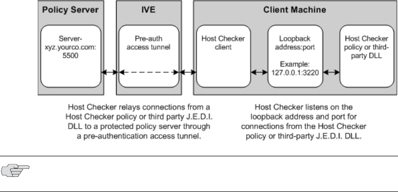
Defining Host Checker pre-authentication access tunnels 259
Chapter 11: Host Checker
Deploy the policy server in a protected zone behind the IVE (Windows
only)—This deployment requires you to define a pre-authentication access
tunnel. A pre-authentication access tunnel enables Host Checker rules or third-
party J.E.D.I. DLLs to access the IVE-protected policy server or resource before
the IVE authenticates users. To define a pre-authentication access tunnel, you
associate a loopback address (or host name) and port on the client with an IP
address and port on the policy server. You add one or more tunnel definitions
to a MANIFEST.HCIF file, which you then upload to the IVE. You can upload
multiple MANIFEST.HCIF files to the IVE. For all third-party policies enabled on a
realm, Host Checker creates tunnels for all of the tunnel definitions in all of the
MANIFEST.HCIF files, assuming the definitions are unique. For configuration
instructions, see “Uploading a Host Checker policy package to the IVE” on
page 243.
While running on a Windows client, Host Checker listens for a connection on
each loopback address and port you specify in the tunnel definitions. The
connections can originate from the integrated Host Checker rules and from
client-side or server-side J.E.D.I. DLLs. Host Checker uses the pre-
authentication access tunnel(s) to forward the connections through the IVE to
the policy server(s) or other resource.
Figure 34: Host Checker creates a tunnel from a client to a policy server behind the IVE
Specifying Host Checker pre-authentication access tunnel definitions
For Windows clients, you can define a pre-authentication access tunnel that
enables Host Checker methods or third-party J.E.D.I. DLLs to access an IVE-
protected policy server (or other resource) before users are authenticated.
A definition for a Host Checker pre-authentication access tunnel configures access
to one policy server or other resource. Each tunnel definition consists of a pair of IP
addresses and ports: one loopback IP address and port on the client, and one IP
address and port on the policy server.
NOTE: Host Checker pre-authentication access tunnels are supported on Windows
only.
Juniper Networks Secure Access Administration Guide
260 Defining Host Checker pre-authentication access tunnels
You specify one or more tunnel definition(s) in a Host Checker policy package
definition file. The package definition file, which must be named MANIFEST.HCIF,
defines the name of an interface DLL, the Host Checker policies defined in the DLL,
and the pre-authentication access tunnel definitions. Note that if you do not include
policies in your package, Host Checker simply enforces that the package has run on
the client. If you do declare policies through this file, they become available through
the admin console where you can implement them at the realm, role, and resource
policy levels.
Within the MANIFEST.HCIF file, you must include one definition per line, with a
blank line between each definition, using the following format:
HCIF-Main: <DLLName>
HCIF-Policy: <PolicyName>
HCIF-IVE-Tunnel: <client-loopback>:port <policy-server>:port
where:
<DLLName> is the name of the interface DLL, such as myPestPatrol.dll. Even if you
are not using an interface DLL, you must include a dummy DLL as a placeholder file
that has this exact name.
<PolicyName> is the name of a policy defined in the DLL, such as myFileCheck. You
can define multiple policies by using the HCIF-Policy statement for each policy. If
you are not using an interface DLL, you can use any policy name as a placeholder.
The syntax of a Host Checker tunnel definition is:
HCIF-IVE-Tunnel: <client-loopback>:port <policy-server>:port
where:
<client-loopback> is a loopback address that begins with 127. and takes any of the
following forms:
An IP address and port that takes the form of 127.*.*.*:port. To avoid conflicts
with JSAM, do not use 127.0.0.1 with port 80, but you can use 127.0.0.1 with
other ports. For example: 127.0.0.1:3220
A host name that resolves to a loopback address that begins with 127. You can
use a local hosts file on each client computer or a DNS server to resolve the
loopback address.
A host name that does not resolve to a loopback address, or resolves to a non-
loopback address. In these cases, Host Checker allocates a loopback address
and updates the local hosts file on the client with the mapping. Note that the
user must have administrator privileges in order for Host Checker to modify
the local hosts file. If the user does not have administrator privileges, Host
Checker cannot update the hosts file and cannot open the pre-authentication
access tunnel. In that case, Host Checker logs an error.
<policy-server> is the IP address or host name of the back-end policy server. The IVE
resolves the host name you specify.
Defining Host Checker pre-authentication access tunnels 261
Chapter 11: Host Checker
For example, in the following tunnel definition, 127.0.0.1:3220 is the client
loopback address and port, and mysygate.company.com:5500 is the policy server
host name and port:
HCIF-IVE-Tunnel: 127.0.0.1:3220 mysygate.company.com:5500
Or you can use a host name for the client, as in this example:
HCIF-IVE-Tunnel: mysygate.company.com:3220 mysygate.company.com:5500
Keep the following in mind when specifying tunnel definitions:
You must add a blank line between each line in the MANIFEST.HCIF file, and you
can use a semi-colon at the beginning of a line to indicate a comment. For
example:
HCIF-Main: myPestPatrol.dll
HCIF-Policy: myFileCheck
HCIF-Policy: myPortCheck
; Tunnel definitions
HCIF-IVE-Tunnel: 127.0.0.1:3220 mysygate.company.com:5500
HCIF-IVE-Tunnel: 127.1.1.1:3220 mysygate2.company.com:5500
HCIF-IVE-Tunnel: mysygate.company.com:3220 mysygate3.company.com:5500
Host Checker pre-authentication access tunnels are supported on Windows
only.
If <client-loopback> is a non-loopback address, then Host Checker cannot open
the pre-authentication access tunnel and logs an error instead.
If you use a loopback address other than 127.0.0.1 (such as 127.0.0.2 and
above), clients who are using Windows XP Service Pack 2 must install the XP
SP2 Hot Fix. See:
http://support.microsoft.com/default.aspx?scid=kb;en-us;884020

Juniper Networks Secure Access Administration Guide
262 Specifying general Host Checker options
Specifying general Host Checker options
You can specify global options for Host Checker that apply to any user for whom
Host Checker is required in an authentication policy, a role mapping rule, or a
resource policy.
To specify general Host Checker options:
1. In the admin console, choose Authentication > Endpoint Security > Host
Checker.
2. Under Options:
In the Perform check every X minutes field, specify the interval at which
you want Host Checker to perform policy evaluation on a client machine. If
the client machine fails to meet the requirements of the Host Checker
policies required by a role or resource policy, then the IVE denies the
associated user requests.
For example, you may require that a user runs a specific third-party
antivirus application in order to map to Role A, which enables network
connections from an external location. If the user’s client machine is
running the required antivirus application when the user signs in to the
IVE, then the user maps to Role A and is granted all access features
enabled for Role A. If the antivirus application stops running during the
user session, however, the next time Host Checker runs, the user fails to
meet the security requirements for Role A and therefore loses all access
privileges for Role A.
NOTE: If you are deploying a client-side or server-side third-party DLL, keep the
following in mind:
Unzip the server-side third-party DLL package and add the tunnel definitions
to the MANIFEST.HCIF file that contain the policies for the third-party DLL. (The
DLL must use the same <client-loopback> address and port or host name that
you specify in the MANIFEST.HCIF file.)
Since a pre-authentication access tunnel is open only while Host Checker is
running, a third-party DLL can access its IVE-protected policy server only
while Host Checker is running.
If a third-party DLL uses HTTPS to connect to its policy server via a host name
that resolves properly to the loopback address, no server certificate warnings
appear. However, if the third-party DLL connects explicitly via a loopback
address, then server certificate warnings do appear because the host name in
the certificate does not match the loopback address. (The developer of the
third-party DLL can configure the DLL to ignore these warnings.)
For more information on third-party DLLs, see the J.E.D.I. Solution Guide on the
Juniper Networks Customer Support Center.

Specifying general Host Checker options 263
Chapter 11: Host Checker
When an end-user logs into a Realm, Host Checker performs an initial
policy check, regardless of whether or not the policy is enforced at the
Realm, Role, and/or Resource level. The initial policy check establishes a
start time. Host Checker evaluates policies at the frequency set by the
Perform check every X minutes option starting the clock at the initial
policy check. Although the frequency setting is set globally for all Host
Checker policy checking, it is not synchronized for all end-user clients
connected to the IVE. Each client performs its own initial policy check and
starts its own X minute countdown.
If you configure the authentication policy within a realm where Host
Checker enforces policies (versus installing), the enforcement occurs only
during the pre-authentication phase. After an end-user signs in and for the
duration of the user’s session, any subsequent Host Checker policy checks
have no impact on realm access, meaning that there is no concept of
removing an end-user session from a realm once an end-user successfully
authenticates into that realm.
If you configure a role restriction where Host Checker enforces policies, the
enforcement occurs just after authentication during role mapping. Role
restrictions are enforced periodically during the end-user session at an
interval specified using the Host Checker frequency setting. If the end-user
successfully passes the Host Checker evaluation during role mapping but
later fails X minutes after login, that specific user loses rights to that role. If
the end-user loses rights to all available roles due to Host Checker policy
evaluation, the end-user session is disconnected.
If you configure a resource-based policy rule where Host Checker enforces
policies, the enforcement occurs when the end-user attempts to access the
resource/backend server. For web resources, the Host Checker evaluation
occurs at each request. For SAM and STA resources, the Host Checker
evaluation occurs when the IVE activates the connection to the backend
application/server. For Network Connect access, the Host Checker
evaluation occurs when the IVE initiates Network Connect. Existing
connections of applications running by way of SAM, Telnet/SSH
connection, and Network Connect connections are not affected by further
Host Checker evaluations. Only new Web requests, new applications
across SAM, new instances of STA, and launching Network Connect are
affected. The Host Checker evaluation is based on the most recent policy
check that occurred X minutes ago. Example, if you configure the
frequency setting to Perform check every five minutes and the end-user
attempts to access a protected resource or attempts to launch Network
Connect four minutes after the last check, then the policy evaluation is
based on the state of the client machine four minutes ago, not at the
moment the end-user attempted to access the resource.
For the Client-side process, login inactivity timeout option, specify an
interval to control timing out in the following situations:
NOTE: If you enter a value of zero, Host Checker only runs on the client machine
when the user first signs into the IVE.

Juniper Networks Secure Access Administration Guide
264 Specifying Host Checker installation options
If the user navigates away from the IVE sign-in page after Host Checker
starts running but before signing in to the IVE, Host Checker continues
to run on the user’s machine for the interval you specify.
If the user is downloading Host Checker over a slow connection,
increase the interval to allow enough time for the download to
complete.
Select Perform dynamic policy reevaluation to automatically refresh the
roles of individual users by enabling dynamic policy evaluation for Host
Checker. Host Checker can trigger the IVE to evaluate resource policies
whenever a user’s Host Checker status changes. (If you do not select this
option, the IVE does not evaluate resource policies but it does evaluate the
authentication policy, role mapping rules, and role restrictions whenever a
user’s Host Checker status changes.) For more information, see “Dynamic
policy evaluation” on page 40.
3. Click Save Changes.
Specifying Host Checker installation options
If you implement any policy at the realm, role, or resource policy level that requires
Host Checker, you must provide a mechanism by which the IVE or the user can
install Host Checker on the client machine. Otherwise, when the IVE evaluates the
Host Checker policy, the user’s machine fails because the Host Checker client is not
available to return a success status.
You can use two methods to install Host Checker on a user’s system:
The IVE automatically installs Host Checker—Enable automatic installation
through the Users/Administrators > User Realms/Administrator Realms >
[Realm] > Authentication Policy > Host Checker page of the admin console.
(For configuration instructions, see “Configuring Host Checker restrictions” on
page 253.) When you do, the IVE evaluates the realm-level option when the
user accesses the IVE sign-in page and then determines if the current version of
Host Checker is installed on the user’s machine. If Host Checker is not installed,
the IVE attempts to install it using either an ActiveX or a Java delivery method.
When a Windows user signs in to the IVE, the IVE attempts to install an ActiveX
control on the user’s system. If the IVE successfully installs the ActiveX control,
the control manages the installation of the Host Checker program.
NOTE: If you configure the Client-side process, login inactivity timeout option
for both Host Checker and Cache Cleaner, the IVE uses the larger of the two
timeout settings.

Specifying Host Checker installation options 265
Chapter 11: Host Checker
If the IVE cannot install the ActiveX control because ActiveX is turned off on the
user’s system, the IVE attempts to install Host Checker using Java. For
Macintosh and Linux hosts, the IVE always uses the Java delivery method. The
Java delivery method requires only user privileges, but Java must be enabled on
the user’s system. For the Firefox browser on Linux, the Java runtime and
plug-in must be installed.
The user or administrator manually installs Host Checker (Windows only)—
Download the Host Checker installer from the Maintenance > System >
Installers page of the admin console and use it to manually install Host
Checker on the user’s system.
Removing the Juniper ActiveX Control
If Microsoft Windows XP is running on the user’s system and you want to remove
the Juniper set-up ActiveX control:
1. Open Internet Explorer.
2. Click the Tools button and then click Internet Options.
3. Click Settings, then View Objects.
4. Select JuniperSetupSP1 and press Delete.
If Microsoft Vista is running on the user’s system and you want to remove the
Juniper set-up ActiveX control:
1. Open Internet Explorer.
2. Click the Tools button and then click Manage Add-ons.
3. In the Show list, click Downloaded ActiveX controls to display all ActiveX
controls.
4. Click JuniperSetupClient and then click Delete.
NOTE: If Microsoft Vista is running on the user’s system, the user must click the
setup link that appears during the installation process to continue installing the
setup client and Host Checker. On all other Microsoft operating systems, the setup
client and Host Checker install automatically.
NOTE: To install Host Checker, users must have appropriate privileges, as
described in the Client-side Changes Guide on the Juniper Networks Customer
Support Center. If the user does not have these privileges, use the Juniper Installer
Service available from the Maintenance > System > Installers page of the
admin console to bypass this requirement.

Juniper Networks Secure Access Administration Guide
266 Specifying Host Checker installation options
Using Host Checker with the GINA automatic sign-in function
Using Host Checker in conjunction with the Windows Graphical Identification and
Authorization (GINA) sign-in function for Network Connect requires that you pay
particular attention to the type, level, and number of items to verify on the client
before granting or rejecting access to the IVE. Since the GINA sign-in function takes
place before Windows has completely launched on the client, and therefore, before
the user profile on Windows is created, we recommend you adopt the following
practices when creating Host Checker policies you plan to use for Windows clients
featuring the GINA sign-in function:
You can check system-level processes at both realm enforce and realm
evaluate. You can check user-level processes only at realm evaluate.
If you have user-level processes at realm evaluate, create a separate Network
Connect role featuring only system-level policy checks that can be performed
before Windows has completely launched on the client. Ensure that this role
allows connectivity to the Windows Domain infrastructure in your secure
network to support drive mapping, software updates, and group policies, for
example. Mapping your users to this role allows the GINA authentication to
complete. This role is in addition to the final role that you want the user to be
mapped.
Automatically install Host Checker
To automatically install Host Checker on client computers:
1. In the admin console, choose Authentication > Endpoint Security > Host
Checker.
2. Under Options, select Auto-upgrade Host Checker if you want the IVE to
automatically download the Host Checker application to a client computer
when the version of Host Checker on the IVE is newer than the version
installed on the client. Here is a summary of what happens when the Auto-
upgrade Host Checker option is selected or not selected:
If Host Checker is not installed on the client computer, Host Checker is
installed automatically regardless of whether the Auto-upgrade Host
Checker option is selected or not selected.
If the Auto-upgrade Host Checker option is selected and a previous
version of Host Checker is installed, Host Checker is upgraded on the client
automatically.
If the Auto-upgrade Host Checker option is not selected and a previous
version of Host Checker is installed, Host Checker is not upgraded the
client automatically.
If you select the Auto-upgrade Host Checker option, note the following:
NOTE: For more information on the GINA automatic sign-in function, see
“Automatically signing into Network Connect using GINA” on page 527.

Using Host Checker logs 267
Chapter 11: Host Checker
On Windows, the user must have administrator privileges in order for
the IVE to automatically install the Host Checker application on the
client. For more information, see the Client-side Changes Guide on the
Juniper Networks Customer Support Center.
If a user uninstalls Host Checker and then signs in to an IVE for which
the Auto-upgrade Host Checker option is not enabled, the user no
longer has access to Host Checker.
3. Click Save Changes.
Manually install Host Checker
The Maintenance > System > Installers page of the admin console provides
several applications and a service for download. You can download an application
or service as a Windows executable file, which enables you to:
Distribute the file to client machines using software distribution tools. This
option enables you to install an application or service on client machines
whose users do not have Administrator privileges, which are required to install
the application or service.
Post the executable in a secure repository so that users with the proper
administrator right may download and install the appropriate version.
Download and execute a script that automatically retrieves the proper version
of the installer from an FTP server.
Using Host Checker logs
Use the System > Log/Monitoring > Client Logs > Settings tab to enable client-
side logging for the Host Checker. When you enable this option, the IVE writes a
client-side log to any client that uses Host Checker. The IVE appends to the log file
each time the feature is invoked during subsequent user sessions. This feature is
useful when working with the support team to debug problems with the respective
feature.
To specify global client-side logging settings:
1. In the admin console, choose System > Log/Monitoring > Client Log >
Settings.
2. Select the desired features for which the IVE writes client-side logs.
3. Click Save Changes to save these settings globally.
NOTE: Since these settings are global, the IVE writes a log file to all clients that use
the feature for which you enable client-side logging. Also, the IVE does not remove
client-side logs. Users need to manually delete log files from their clients. For
information about where the IVE installs log files, see the Client-side Changes Guide
on the Juniper Networks Customer Support Center.

Juniper Networks Secure Access Administration Guide
268 Using Host Checker logs
NOTE: For new IVE 5.x systems, all options are disabled by default. If you upgrade
your IVE from a 3.x configuration, all log options are enabled by default.

Licensing: Cache Cleaner availability 269
Chapter 12
Cache Cleaner
Cache Cleaner is a Windows client-side agent that removes residual data, such as
temporary files or application caches, left on a user’s machine after an IVE session.
For example, when a user signs in to the IVE from an Internet kiosk and opens a
Microsoft Word document using a browser plug-in, Cache Cleaner can remove the
temporary copy of the Word file stored in the browser cache (Windows folder)
when the session terminates. By removing the copy, Cache Cleaner prevents other
kiosk users from finding and opening the Word document after the IVE user
concludes the session.
Cache Cleaner can also prevent Web browsers from permanently storing the
usernames, passwords, and Web addresses that users enter in Web forms. By
preventing browsers from improperly caching this information, Cache Cleaner
keeps confidential user information from being stored on untrusted systems.
This section contains the following information about Cache Cleaner:
“Licensing: Cache Cleaner availability” on page 269
“Setting global Cache Cleaner options” on page 270
“Implementing Cache Cleaner options” on page 273
“Specifying Cache Cleaner installation options” on page 277
“Using Cache Cleaner logs” on page 278
Licensing: Cache Cleaner availability
Cache Cleaner is a standard feature on all Secure Access appliances—you do not
need a special license to use it.

Juniper Networks Secure Access Administration Guide
270 Setting global Cache Cleaner options
Setting global Cache Cleaner options
When you enable Cache Cleaner, it clears all content downloaded through the IVE’s
Content Intermediation Engine from a user’s system. In addition, you can use
settings in the Authentication > Endpoint Security > Cache Cleaner page of the
admin console to clear content from:
Specified hosts and domains—If you enable WSAM or JSAM, you may want to
configure Cache Cleaner to clear additional hosts and domains. When a user
browses the Internet outside the IVE using WSAM or JSAM, Internet files appear
in his temporary Internet file folder. To delete these files using Cache Cleaner,
you must specify the appropriate host name (for example, www.yahoo.com).
Specified files and folders—If you enable your users to access client-server
applications on their local systems, you may want to configure Cache Cleaner
to clear the temporary files and folders that the applications create on the
users’ systems.
To specify global Cache Cleaner options:
1. In the admin console, choose Authentication > Endpoint Security > Cache
Cleaner.
2. Under Options:
a. In the Cleaner Frequency field, specify how often Cache Cleaner runs.
Valid values range from 1-60 minutes. Each time Cache Cleaner runs, it
clears all content downloaded through the IVE’s Content Intermediation
Engine plus the browser cache, files, and folders you specify in the
Browser Cache and Files and Folders sections below.
b. In the Status Update Frequency field, specify how often the IVE expects
Cache Cleaner to update itself. Valid values range from 1-60 minutes.
For the Client-side process, login inactivity timeout option, specify an
interval to control timing out in the following situations:
If the user navigates away from the IVE sign-in page after Cache
Cleaner starts running but before signing in to the IVE, Cache Cleaner
continues to run on the user’s machine for the interval you specify.
NOTE: If you configure Cache Cleaner to remove files from a directory, Cache
Cleaner clears all files, including those that the user has explicitly saved to the
directory and files that were in the directory prior to the IVE session.

Setting global Cache Cleaner options 271
Chapter 12: Cache Cleaner
If the user is downloading Cache Cleaner over a slow connection,
increase the interval to allow enough time for the download to
complete.
c. Select the Disable AutoComplete of web addresses checkbox to prevent
the browser from using cached values to automatically fill in Web
addresses during the user’s IVE session.
When you select this option, the IVE sets the following Windows registry
value to 0 during the user’s IVE session:
HKEY_CURRENT_USER\Software\\Microsoft\\Windows\\CurrentVersion\\Ex
plorer\ AutoComplete. Then, at the end of the session, the IVE restores the
registry value to its original setting.
d. Select the Disable AutoComplete of usernames and passwords checkbox
to prevent Internet Explorer from automatically filling in user credentials in
Web forms using cached values. Selecting this option also disables the
“Save Password?” prompt on Windows systems. When you select this
option, the IVE sets the following Windows registry values to 0:
HKEY_CURRENT_USER\Software\Microsoft\Internet
Explorer\Main\FormSuggest Passwords
HKEY_CURRENT_USER\Software\Microsoft\Internet
Explorer\Main\FormSuggest Passwords\FormSuggest PW Ask
HKEY_CURRENT_USER\SOFTWARE\Microsoft\
Windows\CurrentVersion\Internet Settings\ DisablePasswordCaching
e. Select the Flush all existing AutoComplete Passwords checkbox to clear
any cached passwords that Internet Explorer has cached on the user’s
system. When you select this option, the IVE sets the following Windows
registry value to 0: HKEY_CURRENT_USER \Software\\Microsoft\\Internet
Explorer\\IntelliForms\\SPW
Then, select one of the following options:
Select For IVE session only to specify that the IVE should restore the
user’s cached passwords at the end of his IVE session.
Select Permanently to permanently delete the user’s cached
passwords.
f. Select the Uninstall Cache Cleaner at logout checkbox if you want the IVE
to uninstall Cache Cleaner from the client machine when a user’s session
ends.
NOTE: If you configure the Client-side process, login inactivity timeout option
for both Host Checker and Cache Cleaner, the IVE uses the larger of the two
timeout settings.

Juniper Networks Secure Access Administration Guide
272 Setting global Cache Cleaner options
3. Under Browser Cache, enter one or more host names or domains (wildcards
are permitted). When a user session ends, Cache Cleaner removes any content
in the browser cache that originates from these servers. Cache Cleaner also
removes this content when it runs at the specified cleaner frequency interval.
Note that the IVE does not resolve host names, so enter all possible
representations of a server, such as its host name, FQDN, and IP address.
4. Under Files and Folders:
a. Specify either:
the name of a file that you want Cache Cleaner to remove or
the complete directory path to a folder whose contents you want
Cache Cleaner to remove. If you specify a directory, select Clear
Subfolders to also clear the contents of any subdirectories within this
directory.
b. Select the Clear folders only at the end of session checkbox if you want
Cache Cleaner to clear directory contents only at the end of the user
session. Otherwise, Cache Cleaner also clears files and folders at the
specified cleaner frequency interval.
5. Click Save Changes to save these settings globally.
NOTE: When specifying files and folders to clear, note the following:
Cache Cleaner uses a cookie called DSPREAUTH to send the client’s status to
the IVE. If you delete this cookie from the user’s client, Cache Cleaner does
not work properly. To avoid problems, do not specify Internet Explorer
directories such as <userhome>\Local Settings\Temporary Internet Files\* in
the Files and Folders field. Note that Cache Cleaner still clears all of the
Internet Explorer cache downloaded from the IVE host and the other hosts
specified in the Hostnames field, regardless of what directories you specify
under Files and Folders.
For the Firefox browser, Cache Cleaner clears only those directories you
specify under Files and Folders.

Implementing Cache Cleaner options 273
Chapter 12: Cache Cleaner
Implementing Cache Cleaner options
After you specify which hosts, domains, files, and folders to clear using settings in
the Authentication > Endpoint Security > Cache Cleaner page of the admin
console, you can restrict IVE and resource access by requiring Cache Cleaner in a:
Realm authentication policy—When users try to sign in to the IVE, the IVE
evaluates the specified realm’s authentication policy to determine if the pre-
authentication requirements include Cache Cleaner. You can configure a realm
authentication policy to download Cache Cleaner, download and start running
Cache Cleaner, or not require Cache Cleaner. The user must sign in using a
computer that adheres to the Cache Cleaner requirements specified for the
realm. If the user’s computer does not meet the requirements, then the user is
denied access to the IVE. You can configure realm-level restrictions through the
Users > User Realms > Realm > Authentication Policy > Cache Cleaner
page of the admin console.
Role—When the IVE determines the list of eligible roles to which it can map an
administrator or user, it evaluates each role’s restrictions to determine if the
role requires Cache Cleaner to run on the user's workstation. If it does and the
user's machine is not already running Cache Cleaner, then the IVE does not
map the user to that role. You can control which roles the IVE maps a user to
by using settings in Users > User Realms > Select Realm > Role Mapping >
Select|Create Rule > Custom Expression. You can configure role-level
restrictions through the Users > User Roles > Role > General >
Restrictions > Cache Cleaner page of the admin console.
Resource policy—When a user requests a resource, the IVE evaluates the
resource policy’s detailed rules to determine whether or not Cache Cleaner
needs to be installed or running on the user's workstation. The IVE denies
access to the resource if the user's machine does not meet the Cache Cleaner
requirement. To implement Cache Cleaner restrictions at the resource policy
level, navigate to: Users > Resource Policies > Select Resource > Select Policy
> Detailed Rules > Select|Create Rule > Condition Field.
You may specify that the IVE evaluate your Cache Cleaner policies only when the
user first tries to access the realm, role, or resource that references the Cache
Cleaner policy. Or, you may use settings in the Authentication > Endpoint
Security > Cache Cleaner tab to specify that the IVE periodically re-evaluate the
policies throughout the user’s session. If you choose to periodically evaluate Cache
Cleaner policies, the IVE dynamically maps users to roles and allows users access to
new resources based on the most recent evaluation.
Executing Cache Cleaner
When the user tries to access the IVE, the IVE determine’s the client system’s
Cache Cleaner status and prompts it to start running using the following process:
1. Initial evaluation—When a user first tries to access the IVE sign-in page, the
IVE determines whether Cache Cleaner is running on the user’s machine. The
IVE performs this initial evaluation regardless of whether you have
implemented Cache Cleaner policies at the realm, role, or resource policy level.
Juniper Networks Secure Access Administration Guide
274 Implementing Cache Cleaner options
If the user navigates away from the IVE sign-in page after Cache Cleaner starts
running but before signing in to the IVE, Cache Cleaner continues to run on the
user’s machine until the Cache Cleaner process times out.
If the IVE does not receive a Cache Cleaner status result for any reason
(including because the user failed to enter his credentials in the sign-in page),
the IVE displays an error and directs the user back to the sign-in page.
Otherwise, if the IVE Cache Cleaner process returns a status, the IVE goes on to
execute the realm-level policies.
2. Realm-level policies—The IVE uses the results from the initial evaluation to
determine which realms the user may access. Then, the IVE displays or hides
realms from the user, only allowing him to sign into those realms that you
enable for the sign-in page, and if he meets the Cache Cleaner requirements for
each realm. If the user cannot meet the Cache Cleaner conditions required by
any of the available realms, the IVE does not display the sign-in page. Instead,
it displays an error stating that the computer does not comply with the
endpoint policy.
Note that the IVE only performs realm-level Cache Cleaner checks when the
user first signs into the IVE. If the state of the user’s system changes during his
session, the IVE does not remove him from the current realm or allow him
access to a new realm based on his new system state.
3. Role-level policies—After the user signs into a realm, the IVE evaluates role-
level policies and maps the user to the role or roles if he meets the Cache
Cleaner requirements for those role(s). Then, the IVE displays the IVE
homepage to the user and enables those options that the mapped role(s) allow.
If Cache Cleaner returns a different status during a periodic evaluation, the IVE
dynamically remaps the user to roles based on the new results. If the end user
loses rights to all available roles during one of the periodic evaluations, the IVE
disconnects the user’s session.
4. Resource-level policies—Once the IVE allows the user to access the
homepage, the user may try to access a resource that is controlled by a
resource policy. When he does, the IVE determines whether or not to perform
the action specified in the resource policy based on the last status returned by
Cache Cleaner.
If Cache Cleaner returns a different status during a periodic evaluation, the new
status only impacts new resources that the user tries to access. For example, if
successfully initiates a Network Connect session, and then fails his next
resource-level Cache Cleaner status check, he may continue to access the open
Network Connect session. The IVE only denies him access if he tries to open a
new Network Connect session. The IVE checks the last status returned by
Cache Cleaner whenever the user tries to access a new Web resource or open a
new Secure Application Manager, Network Connect, or Secure Terminal Access
session.

Implementing Cache Cleaner options 275
Chapter 12: Cache Cleaner
5. Final clean-up—Cache Cleaner performs a final cleanup and restores registry
settings when:
The user explicitly signs out of the user session—When a user clicks Sign
Out on the IVE home page, Cache Cleaner performs a final cleanup and
then uninstalls itself from the user’s system.
The user session times out—When a user session times out, Cache
Cleaner performs a cleanup, and then if user signs in again, Cache Cleaner
performs another cleanup. Cache Cleaner is aware of session timeouts,
because it periodically checks the validity of a session at the interval you
specify on the Authentication > Endpoint Security > Cache Cleaner
tab.
A client system restarts after an abnormal termination—If Cache
Cleaner terminates abnormally due to a system, session, or network
connection problem, Cache Cleaner performs a final cleanup and uninstalls
itself from the user’s system after the system restarts. Note that Cache
Cleaner cannot log data after it terminates. Also, all changes made to the
user’s registry settings after termination and before signing back in to the
IVE are lost.
With either a running or not running status, Cache Cleaner remains on the client.
Users may manually uninstall the agent by running uninstall.exe in the directory
where Cache Cleaner is installed. If you enable client-side logging through the
System > Log/Monitoring > Client Logs > Settings page, this directory also
contains a log file, which is rewritten each time Cache Cleaner runs. (Cache Cleaner
does not log entries to the standard IVE log, but can log data to the temporary
client-side text file. This encrypted log is deleted when Cache Cleaner uninstalls
itself.)
Specifying Cache Cleaner restrictions
To specify Cache Cleaner restrictions:
1. Navigate to: Authentication > Endpoint Security > Cache Cleaner and
specify global options for Cache Cleaner to apply to any user for whom Cache
Cleaner is required in an authentication policy, a role mapping rule, or a
resource policy.
2. If you want to implement Cache Cleaner at the realm level:
a. Navigate to: Users > User Realms > Select Realm > Authentication
Policy > Cache Cleaner
NOTE: When checking the validity of a user session, Cache Cleaner connects to the
IVE. This action may trigger warnings on personal firewalls. Users must permit
this traffic to ensure that Cache Cleaner functions correctly. Also note that users
with personal firewalls see a log entry every time Cache Cleaner clears the cache.
Juniper Networks Secure Access Administration Guide
276 Implementing Cache Cleaner options
b. Choose one of the following options:
Disable Cache Cleaner — Does not require Cache Cleaner to be
installed or running in order for the user to meet the access
requirement.
Just load Cache Cleaner — Does not require Cache Cleaner to be
running in order for the user to meet the access requirement but
ensures that it is available for future use. If you choose this option for a
realm’s authentication policy, then the IVE downloads Cache Cleaner
to the client machine after the user is authenticated and before the
user is mapped to any roles on the system.
Load and enforce Cache — Requires the IVE to download and run
Cache Cleaner in order for the user to meet the access requirement. If
you choose this option for a realm’s authentication policy, then the IVE
downloads Cache Cleaner to the client machine before the user may
access the IVE sign-in page.
3. If you want to implement Cache Cleaner at the role level:
a. Navigate to:
Administrators > Admin Roles > Select Role > General >
Restrictions > Cache Cleaner
Users > User Roles > Select Role > General > Restrictions >
Cache Cleaner
b. Check the Enable Cache Cleaner option. Requires Cache Cleaner to be
running in order for the user to meet the access requirement.
4. If you want to create role-mapping rules based on a user’s Cache Cleaner status:
a. Navigate to: Users > User Realms > Select Realm > Role Mapping >
Select|CreateRule > CustomExpression
b. Write a custom expression for the role mapping rule to evaluate Cache
Cleaner’s status using the cacheCleaner variable.
5. If you want to implement Cache Cleaner at the resource policy level:
a. Navigate to: Users > Resource Policies > Select Resource > Select Policy
> Detailed Rules > Select|Create Rule > Condition Field
b. Create a custom expression in a detailed rule.
Specifying Cache Cleaner installation options 277
Chapter 12: Cache Cleaner
Specifying Cache Cleaner installation options
If you implement any policy at the realm, role, or resource policy level that requires
Cache Cleaner, you must provide a mechanism by which the IVE or the user can
install Cache Cleaner on the client machine. Otherwise, when the IVE evaluates the
Cache Cleaner policy, the user’s machine fails because the Cache Cleaner client is
not available.
Enable automatic installation through the Users > User Realms > Realm >
Authentication Policy > Cache Cleaner page of the admin console to allow the
IVE to attempt to install Cache Cleaner on the user’s system. When you do, the IVE
evaluates the realm-level option when the user accesses the IVE sign-in page and
then determines if the current version of Cache Cleaner is installed on the user’s
machine. If Cache Cleaner is not installed, the IVE attempts to install it using either
an ActiveX or a Java delivery method.
When a user signs in to the IVE, the IVE attempts to install an ActiveX control on
the user’s system. If the IVE successfully installs the ActiveX control, the control
manages the installation of the Cache Cleaner program.
If the IVE cannot install the ActiveX control due to the user’s lack of administrator
or power user privileges, or because ActiveX is turned off on the user’s system, the
IVE attempts to install Cache Cleaner using Java. The Java delivery method requires
only user privileges, but Java must be enabled on the user’s system.
If the IVE cannot use the Java delivery method because Java is disabled on the
user’s system, the IVE displays an error message informing the user that the user’s
system does not allow installation of ActiveX or Java applications, therefore some
of the access security functions are not able to run.
For information on removing the Juniper ActiveX control, see “Removing the
Juniper ActiveX Control” on page 265.
NOTE: If Microsoft Vista is running on the user’s system, the user must click the
setup link that appears during the installation process to continue installing the
setup client and Cache Cleaner. On all other Microsoft operating systems, the
setup client and Cache Cleaner install automatically.
NOTE:
To install Cache Cleaner, users must have appropriate privileges, as described
in the Client-side Changes Guide on the Juniper Networks Customer Support
Center. If the user does not have these privileges, use the Juniper Installer
Service available from the Maintenance > System > Installers page of the
admin console to bypass this requirement.
Users must enable signed ActiveX components or signed Java applets within
their browsers in order for Host Checker to download, install, and launch the
client applications.

Juniper Networks Secure Access Administration Guide
278 Using Cache Cleaner logs
Using Cache Cleaner logs
Use the System > Log/Monitoring > Client Logs > Settings tab to enable client-
side logging for the Cache Cleaner. When you enable this option, the IVE writes a
client-side log to any client that uses Cache Cleaner. The IVE appends to the log file
each time the feature is invoked during subsequent user sessions. This feature is
useful when working with the support team to debug problems with the respective
feature.
To specify global client-side logging settings:
1. In the admin console, choose System > Log/Monitoring > Client Logs >
Settings.
2. Select the desired features for which the IVE writes client-side logs.
3. Click Save Changes to save these settings globally.
NOTE: Since these settings are global, the IVE writes a log file to all clients that use
the feature for which you enable client-side logging. Also, the IVE does not remove
client-side logs. Users need to manually delete log files from their clients. For
information about where the IVE installs log files, see the Client-side Changes Guide
on the Juniper Networks Customer Support Center.
NOTE: For new IVE 5.x systems, all options are disabled by default. If you upgrade
your IVE from a 3.x configuration, all log options are enabled by default.

279
Part 4
Remote access
The IVE enables you to secure access to a wide variety of applications, servers, and
other resources through its remote access mechanisms. Once you have chosen
which resource you want to secure, you can then choose the appropriate access
mechanism (as explained in “Can I use the IVE to secure traffic to all of my
company’s applications, servers, and Web pages?” on page 25.
For instance, if you want to secure access to Microsoft Outlook, you can use the
Secure Application Manager (SAM). The Secure Application Manager intermediates
traffic to client/server applications including Microsoft Outlook, Lotus Notes, and
Citrix. Or, if you want to secure access to your company Intranet, you can use the
Web rewriting feature. This feature uses the IVE’s Content Intermediation Engine to
intermediate traffic to Web-based applications and Web pages.
Table 18 briefly compares three of the IVE’s access mechanisms: Network Connect,
Windows Secure Application Manager (WSAM), and Java Secure Application
Manager (JSAM).
This section contains the following information about remote access mechanisms:
“Web rewriting” on page 281
Table 18: Comparison of remote client access methods
Network Connect WSAM JSAM
Secure network-layer access.
Performs as virtual IPsec
enabled tunnel. Compatible
with client-side firewalls and
proxies.
Secure application-layer
access. Supports Win32
Transport Data Interface (TDI)
service installation.
Compatible with client-side
firewalls and proxies.
Secure application-layer
access. Java applet-based TCP
port forwarding for
provisioned enterprise hosts.
Compatible with client-side
firewalls and proxies.
Installation handled via
Active X control for Windows
and Java applet for Mac.
Installation handled via
Active X control, Java delivery,
and standalone installers.
Requires only a single Java
applet installed on the client
Provisioning requires a static
IP address pool allocated for
network resources or a DHCP
server present on the network.
Provisioning requires a list of
IP addresses, Windows
applications, and destination
hosts to be secured. Access
control dependent upon IP
addresses.
Provisioning requires a list of
hosts and ports at the group
level. Allows users option to
define client-server
applications and security
settings. Host names preferred
over IP addresses.
Supports Windows, Mac, and
Linux clients.
Supports Windows clients. Supports Windows, Mac, and
Linux clients.
Juniper Networks Secure Access Administration Guide
280
“Hosted Java applets” on page 357
“File rewriting” on page 371
“Secure Application Manager” on page 395
“Telnet/SSH” on page 449
“Terminal Services” on page 461
“Secure Meeting” on page 493
“Email Client” on page 513
“Network Connect” on page 521
281
Chapter 13
Web rewriting
The IVE Web rewriting feature enables you to intermediate Web URLs through the
Content Intermediation Engine. You can intermediate URLs on the World Wide
Web or on your corporate Intranet.
This section contains the following information about intermediating Web content:
“Licensing: Web rewriting availability” on page 282
“Task summary: Configuring the Web rewriting feature” on page 282
“Web URL rewriting overview” on page 283
“Defining resource profiles: Custom Web applications” on page 288
“Defining resource profiles: Citrix Web applications” on page 307
“Defining resource profiles: Microsoft OWA” on page 311
“Defining resource profiles: Lotus iNotes” on page 313
“Defining resource profiles: Microsoft Sharepoint” on page 315
“Defining role settings: Web URLs” on page 316
“Defining resource policies: Overview” on page 322
“Defining resource policies: Web access” on page 324
“Defining resource policies: Single sign-on” on page 325
“Defining resource policies: Caching” on page 332
“Defining resource policies: External Java applets” on page 336
“Defining resource policies: Rewriting” on page 339
“Defining resource policies: Web compression” on page 349
“Defining resource policies: Web proxy” on page 351
“Defining resource policies: HTTP 1.1 protocol” on page 354

Juniper Networks Secure Access Administration Guide
282 Licensing: Web rewriting availability
“Defining resource policies: General options” on page 355
“Managing resource policies: Customizing UI views” on page 356
Licensing: Web rewriting availability
Web rewriting is a standard feature on all Secure Access appliances except the SA
700. If you are using an SA-700 appliance, you must install a Core Clientless Access
upgrade license in order to access baseline Web rewriting features. Note, however,
that the following advanced Web rewriting features are not available on the SA 700,
even if you have the Core Clientless Access upgrade license:
Remote SSO
WSAM & JSAM rewriting policies (available through Web application resource
profiles)
Non-Java ICA rewriting options (available through Citrix templates)
Task summary: Configuring the Web rewriting feature
To configure the Web rewriting feature:
1. Create resource profiles that enable access to Web sites, create supporting
autopolicies (such as single sign-on and Java access control policies) as
necessary, include bookmarks that link to the Web sites, and assign the policies
and bookmarks to user roles using settings in the Users > Resource Profiles>
Web Application Pages page of the admin console. For instructions, see:
“Defining resource profiles: Custom Web applications” on page 288
“Defining resource profiles: Citrix Web applications” on page 307
We recommend that you use resource profiles to configure Web rewriting (as
described above). However, if you do not want to use resource profiles, you can
configure Web rewriting using role and resource policy settings in the following
pages of the admin console instead:
a. Create resource policies that enable access to Web sites using settings in
the Users > Resource Policies> Web > Access > Web ACL page of the
admin console. For instructions, see “Defining resource policies: Web
access” on page 324.
b. As necessary, create supporting resource policies (such as single sign-on
and Java access control policies) using settings in the Users > Resource
Policies> Select Policy Type pages of the admin console. For instructions,
see:
“Defining resource policies: Single sign-on” on page 325
“Defining resource policies: Caching” on page 332

Web URL rewriting overview 283
Chapter 13: Web rewriting
“Defining resource policies: External Java applets” on page 336
“Defining resource policies: Rewriting” on page 339
“Defining resource policies: Web compression” on page 349
“Defining resource policies: Web proxy” on page 351
“Defining resource policies: HTTP 1.1 protocol” on page 354
c. Determine which user roles may access the Web sites that you want to
intermediate, and then enable Web access for those roles through the
Users > User Roles > Select Role > General > Overview page of the
admin console. For instructions, see “Configuring general role options” on
page 55.
d. Create bookmarks to your Web sites using settings in the Users > User
Roles > Select Role > Web > Bookmarks page of the admin console. For
instructions, see “Defining role settings: Web URLs” on page 316.
e. As necessary, enable Web general options that correspond to the types of
Web content you are intermediating (such as Java) using settings in the
Users > User Roles > Select Role > Web > Options page of the admin
console. For instructions, see “Specifying general Web browsing options”
on page 319.
2. After enabling access to Web applications or sites using Web rewriting resource
profiles or roles and resource policies, you can modify general role and
resource options in the following pages of the admin console:
a. (Optional) Set additional Web browsing options (such as allowing users to
create their own bookmarks or enabling hostname masking) Users > User
Roles > Select Role > Web > Options page of the admin console. For
instructions, see “Specifying general Web browsing options” on page 319.
b. (Optional) Set additional Web options for individual resources (such as
enabling the IVE to match IP addresses to host names) using settings in the
Users > Resource Policies> Web > Options page of the admin console.
For instructions, see “Defining resource policies: General options” on
page 355.
Web URL rewriting overview
When you intermediate standard Web content through the IVE, you can create
supplemental policies that “fine-tune” the access requirements and processing
instructions for the intermediated content. You can create these supplemental
policies through resource profiles (recommended) or resource policies.
NOTE: Certain Web rewriting features (such as pass-through proxy and SSO to
NTLM resources) require additional configuration. For more information, see the
appropriate configuration instructions.
Juniper Networks Secure Access Administration Guide
284 Web URL rewriting overview
Standard Web rewriting policy types include:
Web access control—Web access policies control which Web resources users
can access in order to connect to the Internet, intranet, or extranet. For
configuration instructions, see “Defining a Web access control autopolicy” on
page 290 (recommended) or “Defining resource policies: Web access” on
page 324.
Single sign-on—Single sign-on policies enable you to automatically pass user
credentials to a Web application. You can configure single sign-on policies to
intercept basic authentication and NTLM challenges or post the credentials and
headers that you specify to the Web application, as explained in “Remote SSO
overview” on page 285. For configuration instructions, see “Defining a single
sign-on autopolicy” on page 292 (recommended) or “Defining resource
policies: Single sign-on” on page 325.
Caching—Caching policies control which Web content the IVE caches on a
user’s machine. For configuration instructions, see “Defining a caching
autopolicy” on page 296 (recommended) or “Defining resource policies:
Caching” on page 332.
Java—Java policies control to which servers and ports Java applets can connect.
These policies also specify trusted servers for which the IVE resigns content.
For configuration instructions, see “Defining a Java access control autopolicy”
on page 298 (recommended) or “Defining resource policies: External Java
applets” on page 336.
Rewriting—Rewriting policies specify resources that the IVE should not
intermediate, minimally intermediation (as explained in “Passthrough-proxy
overview” on page 286), or only intermediate selectively. For configuration
instructions, see “Defining a rewriting autopolicy” on page 300
(recommended) or “Defining resource policies: Rewriting” on page 339.
Web compression—Web compression policies specify which types of Web
data the IVE should and should not compress, as explained in “Compression”
on page 839. For configuration instructions, see “Defining a Web compression
autopolicy” on page 304 (recommended) or “Defining resource policies: Web
compression” on page 349.
Web proxy—(Resource policies only) Web proxy resource policies specify Web
proxy servers for which the IVE should intermediate content. Note that the IVE
intermediates both forward and backwards proxies, but only enables single
sign-on to trusted proxies. For configuration instructions, see “Defining
resource policies: Web proxy” on page 351.
Launch JSAM—(Resource policies only) Launch JSAM policies specify URLs for
which the IVE automatically launches J-SAM on the client. This feature is useful
if you enable applications that require J-SAM but do not want to require users to
run J-SAM unnecessarily. For configuration instructions, see “Automatically
launching JSAM” on page 443.
Protocol—(Resource policies only) Protocol resource policies enable or disable
HTTP 1.1 protocol support on the IVE. For configuration instructions, see
“Defining resource policies: HTTP 1.1 protocol” on page 354.

Web URL rewriting overview 285
Chapter 13: Web rewriting
Options— (Resource policies only) You can enable IP based matching for
hostnames as well as case-sensitive matching for path and query strings in
Web resources through resource policy options. For configuration instructions,
see “Defining resource policies: General options” on page 355.
Remote SSO overview
The Remote Single Sign-On (SSO) feature enables you to specify the URL sign-in
page of an application to which you want the IVE to post a user’s credentials,
minimizing the need for users to re-enter their credentials when accessing multiple
back-end applications. You may also specify additional forms values and custom
headers (including cookies) to post to an application’s sign-in form.
Remote SSO configuration consists of specifying Web resource policies:
Form POST policy—This type of Remote SSO policy specifies the sign-in page
URL of an application to which you want to post IVE data and the data to post.
This data can include the user’s primary or secondary IVE username and
password (as explained in “Multiple sign-in credentials overview” on page 193)
as well as system data stored by system variables (described in “System
variables and examples” on page 860). You can also specify whether or not
users can modify this information.
Headers/Cookies policy—This type of Remote SSO policy specifies resources,
such as customized applications, to which you can send custom headers and
cookies.
If a user’s IVE credentials differ from those required by the back-end application,
the user can alternatively access the application:
By signing in manually—The user can quickly access the back-end application
by entering his credentials manually into the application’s sign-in page. The
user may also permanently store his credentials and other required
information in the IVE through the Preferences page as described below, but is
not required to enter information in this page.
Specifying the required credentials on the IVE—The user must provide the
IVE with his correct application credentials by setting them through the
Preferences page. Once set, the user must sign out and sign back in to save his
credentials on the IVE. Then, the next time the user clicks the Remote SSO
bookmark to sign in to the application, the IVE sends the updated credentials.
For information about configuring Remote SSO:
“Defining a single sign-on autopolicy” on page 292 (recommended method)
“Writing a remote SSO Form POST resource policy” on page 328
“Writing a remote SSO Headers/Cookies resource policy” on page 330
NOTE: Use the Remote SSO feature to pass data to applications with static POST
actions in their HTML forms. It is not practical to use Remote SSO with
applications that employ frequently changing URL POST actions, time-based
expirations, or POST actions that are generated at the time the form is generated.

Juniper Networks Secure Access Administration Guide
286 Web URL rewriting overview
Passthrough-proxy overview
The pass-through proxy feature enables you to specify Web applications for which
the IVE performs minimal intermediation. Unlike traditional reverse proxy
functionality, which also rewrites only selective parts of a server response but
requires network changes as well as complex configuration, this feature only
requires that you specify application servers and the way in which the IVE receives
client requests to those application servers:
Via an IVE port—When specifying an application for the pass-through proxy to
intermediate, you specify a port on which the IVE listens for client requests to
the application server. When the IVE receives a client request for the
application server, it forwards the request to the specified application server
port. When you choose this option, you must open traffic to the specified IVE
port on your corporate firewall.
Via virtual host name—When specifying an application for the pass-through
proxy to intermediate, you specify an alias for the application server host
name. You need to add an entry for this alias in your external DNS server that
resolves to the IVE. When the IVE receives a client request for the alias, it
forwards the request to the port you specify for the application server.
This option is useful if your company has restrictive policies about opening
firewall ports to either internal servers or servers in the DMZ. When using this
option, we recommend that each host name alias contains the same domain
substring as your IVE host name and that you upload a wild card server
certificate to the IVE in the format: *.domain.com.
For example, if your IVE is iveserver.yourcompany.com, then a host name alias
should be in the format appserver.yourcompany.com and the wild card
certificate format would be *.yourcompany.com. If you do not use a wild card
certificate, then a client’s browser issues a certificate name check warning
when a user browses to an application server, because the application server
host name alias does not match the certificate domain name. This behavior
does not prevent a user from accessing the application server, however.
NOTE: When you configure pass-through proxy to work in virtual host name
mode, users must use the IVE host name that you specify through the System >
Network > Overview page of the admin console when signing into the IVE. They
cannot access use pass-through proxy if they sign into the IVE using its IP address.

Web URL rewriting overview 287
Chapter 13: Web rewriting
Just as with the Content Intermediation Engine, the pass-through proxy option
offers increased security relative to the Secure Application Manager, because when
enabled for an application, the IVE allows the client to send only layer-7 traffic
directed to fixed application ports to the enterprise network. Use this option to
enable the IVE to support applications with components that are incompatible with
the Content Intermediation Engine, such as Java applets in Oracle e-business suite
applications or applets that run in an unsupported Java Virtual Machine (JVM).
Task summary: Configuring pass-through proxy
To configure the Web rewriting feature:
1. Create resource profiles that enable access to Web applications, create
supporting Web rewriting autopolicies that enable pass-through proxy, include
bookmarks that link to the Web applications, and assign the policies and
bookmarks to user roles using settings in the Users > Resource Profiles>
Web Application Pages page of the admin console. For instructions, see
“Defining resource profiles: Custom Web applications” on page 288.
Alternatively, you can:
a. Create resource policies that enable access to Web applications using
settings in the Users > Resource Policies> Web > Access > Web ACL
page of the admin console. For instructions, see “Defining resource
policies: Web access” on page 324.
b. Create supporting Web rewriting resource policies that enable pass-through
proxy using settings in the Users > Resource Policies> Web >
Rewriting > Web ACL page of the admin console. For instructions, see
“Defining resource policies: Rewriting” on page 339.
c. Determine which user roles may access the Web applications that you
want to intermediate with pass-through proxy, and then enable Web
access for those roles through the Users > User Roles > Select Role >
General > Overview page of the admin console. For instructions, see
“Configuring general role options” on page 55.
NOTE:
Pass-through proxy URLs must be host names. Paths of host names are not
supported.
Juniper Networks strongly recommends that you not mix pass-through proxy
Port mode and pass-through proxy Host mode.
The pass-through proxy option works only for applications that listen on fixed
ports and where the client does not make direct socket connections.
To use pass-through proxy with Oracle E-Business applications, you must
install a real certificate on the IVE and you must configure Oracle Forms to
use the Forms Listener Servlet mode.

Juniper Networks Secure Access Administration Guide
288 Defining resource profiles: Custom Web applications
d. Create bookmarks to your Web sites using settings in the Users > User
Roles > Select Role > Web > Bookmarks page of the admin console. For
instructions, see “Defining role settings: Web URLs” on page 316.
2. If your pass-through proxy resource policy enables the IVE to receive client
requests through an IVE port, open traffic to the specified port in your
corporate firewall. Or, if your policy enables requests through a virtual host
name:
a. Add an entry for each application server host name alias in your external
DNS that resolves to the IVE.
b. Define the IVE name and host name through the System > Network >
Internal Port page of the admin console. For instructions, see “Configuring
network settings” on page 558.
c. Upload a wildcard certificate to the IVE through the System >
Configuration > Certificates > Device Certificates page of the admin
console. Or, upload multiple certificates and associate a virtual port with
each certificate using settings in the same page. For instructions, see
“Importing an existing root certificate and private key” on page 601 and
“Associating a certificate with a virtual port” on page 606.
Examples of using pass-through proxy
If your IVE is iveserver.yourcompany.com and you have an Oracle server at
oracle.companynetwork.net:8000, you could specify the following application
parameters when specifying an IVE port:
Server: oracle.companynetwork.net
Port: 8000
IVE port: 11000
When the IVE receives Oracle client traffic sent to
iveserver.yourcompany.com:11000, it forwards the traffic to
oracle.companynetwork.net:8000.
Or, if you want to specify a host name alias, you could configure the application
with these parameters:
Server: oracle.companynetwork.net
Port: 8000
IVE alias: oracle.yourcompany.com
When the IVE receives Oracle client traffic sent to oracle.yourcompany.com, it
forwards the traffic to oracle.companynetwork.net:8000
Defining resource profiles: Custom Web applications
A custom Web application resource profile is a resource profile that controls access
to a Web application, Web server, or HTML page. (For more information about
resource profiles, see “Resource profiles” on page 71.)
Defining resource profiles: Custom Web applications 289
Chapter 13: Web rewriting
To create a custom Web application resource profile:
1. Navigate to the Users > Resource Profiles > Web Applications/Pages page in
the admin console.
2. Click New Profile.
3. Enter a unique name and optionally a description for the resource profile.
4. In the Base URL field, enter the URL of the Web application or page for which
you want to control access using the format: [protocol://]host[:port][/path]. For
detailed guidelines, see “Defining base URLs” on page 290. (The IVE uses the
specified URL to define the default bookmark for the resource profile.)
5. In the Autopolicy: Web Access Control section, create a policy that allows or
denies users access to the resource specified in the Base URL field. (By default,
the IVE automatically creates a policy for you that enables access to the Web
resource and all of its sub-directories.) For more detailed instructions, see
“Defining a Web access control autopolicy” on page 290.
6. (Optional) Click Show ALL autopolicy types to create additional autopolicies
that fine-tune access to the resource. Then, create the autopolicies using
instructions in the following sections:
“Defining a single sign-on autopolicy” on page 292
“Defining a caching autopolicy” on page 296
“Defining a Java access control autopolicy” on page 298
“Defining a rewriting autopolicy” on page 300
“Defining a Web compression autopolicy” on page 304
7. Click Save and Continue.
8. In the Roles tab, select the roles to which the resource profile applies and click
Add.
The selected roles inherit the autopolicies and bookmarks created by the
resource profile. If it is not already enabled, the IVE also automatically enables
the Web option in the Users > User Roles > Select Role > General >
Overview page of the admin console for all of the roles you select.
9. Click Save Changes.
10. (Optional) In the Bookmarks tab, modify the default bookmark created by the
IVE and/or create new ones using instructions in “Defining a Web bookmark”
on page 305. (By default, the IVE creates a bookmark to the base URL defined
in the Base URL field and displays it to all users assigned to the role specified in
the Roles tab.)
Juniper Networks Secure Access Administration Guide
290 Defining resource profiles: Custom Web applications
Defining base URLs
When creating a Web resource profile, you must use the following format when
defining base URLs:
[protocol://]host[:port][/path]
Within this format, the components are:
Protocol (required)—Possible values: http:// and https://. Note that you cannot
use special characters within the protocol.
Host (required)—Possible values:
DNS Hostname—For example: www.juniper.com
IP address—You must enter the IP address in the format: a.b.c.d. For
example: 10.11.149.2. You cannot use special characters in the IP address.
Ports (optional)—You must use the delimiter “:” when specifying a port. For
example: 10.11.149.2/255.255.255.0:*
Path (optional)—When specifying a path for a base URL, the IVE does not allow
special characters. If you specify a path, you must use the “/” delimiter. For
example, http://www.juniper.net/sales.
Defining a Web access control autopolicy
Web access policies control which Web resources users can access in order to
connect to the Internet, intranet, or extranet. When defining a custom Web
resource profile, you must enable a corresponding Web access control autopolicy
that enables access to the profile’s primary resource. The IVE simplifies the process
for you by automatically creating an autopolicy that allows access to the Web
resource and all of its sub-directories.
If necessary, you may choose to modify this default autopolicy or create
supplementary Web access control autopolicies that control access to additional
resources. For instance, your IT department may use one server to store Web pages
for your company intranet (http://intranetserver.com) and another server to store
the images that the Web pages reference (http://imagesserver.com). In this case,
you can create two Web access control autopolicies that enable access to both
servers so that your users can access both your Web pages and the corresponding
images.
To create a new Web access control autopolicy:
1. Create a custom Web application resource profile, as explained in the following
sections:
“Defining resource profiles: Custom Web applications” on page 288
“Defining resource profiles: Citrix Web applications” on page 307
“Defining resource profiles: Microsoft OWA” on page 311
“Defining resource profiles: Lotus iNotes” on page 313

Defining resource profiles: Custom Web applications 291
Chapter 13: Web rewriting
“Defining resource profiles: Microsoft Sharepoint” on page 315
2. If available, click the Show ALL autopolicy types button to display the
autopolicy configuration options.
3. If it is not already enabled, select the Autopolicy: Web Access Control
checkbox.
4. In the Resource field, specify the Web server or HTML page to which you want
to control access using the format: [protocol://]host[:ports][/path]. For detailed
guidelines, see “Defining Web resources” on page 291.
5. From the Action list, choose Allow to enable access to the specified resource or
Deny to block access to the specified resource.
6. Click Add.
7. Click Save Changes.
Defining Web resources
When creating a Web resource profile (for example, in “Defining resource profiles:
Custom Web applications” on page 288), you must use the following format when
defining resources for autopolicies:
[protocol://]host[:ports][/path]
Within this format, the four components are:
Protocol (required)—Possible values: http:// and https://. Note that you cannot
use special characters within the protocol.
Host (required)—Possible values:
DNS Hostname—For example: www.juniper.com
You may use the following special characters allowed in the hostname:
IP address/Netmask—You must enter the IP address in the format: a.b.c.d
You may use one of two formats for the netmask:
Prefix: High order bits
IP: a.b.c.d
For example: 10.11.149.2/24 or 10.11.149.2/255.255.255.0
You cannot use special characters in the IP address or netmask.
Table 19: DNS hostname special characters
*Matches ALL characters.
%Matches any character except dot (.)
?Matches exactly one character

Juniper Networks Secure Access Administration Guide
292 Defining resource profiles: Custom Web applications
Ports (optional)—You must use the delimiter “:” when specifying a port. For
example: 10.11.149.2/255.255.255.0:*
If the port is missing, then the default port 80 is assigned for http, 443 for https.
Path (optional)—When specifying a path for a Web access control autopolicy,
you may use a * character, meaning ALL paths match. (The IVE does not
support any other special characters.) If you specify a path, you must use the
“/” delimiter. For example:
http://www.juniper.net/sales
http://www.juniper.net:80/*
https://www.juniper.net:443/intranet/*
Defining a single sign-on autopolicy
Single sign-on policies enable you to automatically pass user credentials to the Web
application specified in your policy, as explained in “Single sign-on” on page 191.
Single sign-on autopolicies also intermediate the data that you pass.
To create a single sign-on (SSO) autopolicy:
1. Create a Web resource profile, as explained in the following sections:
“Defining resource profiles: Custom Web applications” on page 288
“Defining resource profiles: Citrix Web applications” on page 307
“Defining resource profiles: Lotus iNotes” on page 313
“Defining resource profiles: Microsoft Sharepoint” on page 315
2. If available, click the Show ALL autopolicy types button to display the
autopolicy configuration options.
Table 20: Port possible values
*Matches ALL ports; you cannot use any other special characters
port[,port]* A comma-delimited list of single ports. Valid port numbers are [1-
65535].
[port1]-[port2] A range of ports, from port1 to port2, inclusive.
NOTE: You can mix port lists and port ranges, such as: 80,443,8080-8090
NOTE: For information about configuring advanced SSO options that are not
available through resource profiles, including disabling intermediation for
specified resources or using SAML for individual resources, see “Defining resource
policies: Single sign-on” on page 325.

Defining resource profiles: Custom Web applications 293
Chapter 13: Web rewriting
3. Select the Autopolicy: Single Sign-On checkbox.
4. Select a single sign-on method and configure the corresponding SSO options:
Basic Auth—Enables the IVE to intermediate the challenge/response
sequence during basic authentication and use the credentials it collects to
sign into a protected resource within the same Intranet zone. For detailed
configuration instructions, see “Specifying basic authentication or NTLM
SSO autopolicy options” on page 293. (This option does not apply to Citrix
resource profiles.)
NTLM—Enables the IVE to intermediate the challenge/response sequence
during NTLM authentication and use the credentials it collects to sign into a
protected resource within the same Intranet zone. For detailed
configuration instructions, see “Specifying basic authentication or NTLM
SSO autopolicy options” on page 293. (This option does not apply to Citrix
resource profiles.)
Remote SSO—Enables the IVE to post the data that you specify (including
IVE usernames, passwords, and system data stored by variables) to Web
applications. This option also enables you specify custom headers and
cookies to post to Web applications. For detailed configuration
instructions, see “Specifying remote SSO autopolicy options” on page 294.
5. Click Save Changes.
Specifying basic authentication or NTLM SSO autopolicy options
To configure basic authentication or NTLM SSO autopolicy options:
1. Create an SSO autopolicy and choose Basic Auth or NTLM, as explained in
“Defining a single sign-on autopolicy” on page 292.
2. In the Resource field, specify the resources to which this policy applies. For
detailed guidelines, see “Defining Web resources” on page 291.
3. Select one of the following Action options:
Use system credentials—The IVE intermediates the challenge/response
sequence, caches the credentials it collects, and uses them to enable single
sign-on based on any system credentials you have previously configured
on the IVE.
NOTE: When entering a resource in this field, note that:
If you want the IVE to automatically post values to a specific URL when an
end-user clicks on an IVE bookmark, the resource that you enter here must
exactly match the URL that you specify in the Base URL field of the resource
profile.
If you want the IVE to automatically submit IVE user credentials to other Web
sites within the same Intranet zone, the host name that you enter here must
end in the DNS suffix configured in the System > Network > Overview page
of the admin console.

Juniper Networks Secure Access Administration Guide
294 Defining resource profiles: Custom Web applications
Use predefined credentials—The IVE intermediates the
challenge/response sequence, caches the credentials it collects, and uses
them to enable single sign-on. When you select this option, you must also
specify the following intermediation credential parameters:
Username—Specifies the SSO user name that the IVE uses to validate
sign-in credentials.
Password—Specifies the SSO password that the IVE uses to validate
sign-in credentials. You may use a static password (such as
“open_sesame”) or variable password (such as <PASSWORD>) to
validate sign-in credentials.
(NTLM only) Domain—Specifies the domain name.
Disable SSO—The IVE disables automatic SSO authentication for this user
role and, instead, prompts the user for sign-in credentials.
Specifying remote SSO autopolicy options
To configure remote SSO autopolicy options:
1. Create an SSO autopolicy through a custom Web resource profile and choose
Remote SSO, as explained “Defining a single sign-on autopolicy” on page 292.
Or, create a custom Citrix resource profile and choose Autopolicy: Single Sign
on as explained in “Defining resource profiles: Citrix Web applications” on
page 307.
2. If you want to perform a form POST when a user makes a request to the
resource specified in the Resource field, select the POST the following data
checkbox. Then:
a. In the Resource field, specify the application’s sign-in page, such as:
http://yourcompany.com. The IVE does not accept wildcard characters in
this field.
b. In the Post URL field, specify the absolute URL where the application posts
the user’s credentials, such as: http://yourcompany.com/login.cgi. You can
determine the appropriate URL using a TCP dump or by viewing the
application’s sign-in page source and searching for the POST parameter in
the FORM tag.
c. Optionally specify the user data you want to post and user modification
permissions.
To specify user data to post, enter data in the following fields and click
Add:
NOTE: If you want the IVE to automatically post values to a specific URL when an
end-user clicks on an IVE bookmark, the resource that you enter here must
exactly match the URL that you specify in the Base URL or Web Interface (NFuse)
URL field of the resource profile.
Defining resource profiles: Custom Web applications 295
Chapter 13: Web rewriting
Label—The label that appears on a user’s Preferences page in the IVE.
This field is required if you either enable or require users to modify
data to post to back-end applications.
Name—The name to identify the data of the Value field. (The back-end
application should expect this name.)
Value—The value to post to the form for the specified Name. You can
enter static data, a system variable (see “System variables and
examples” on page 860 for a list of valid variables), or IVE session
variables containing username and password values (see “Multiple
sign-in credentials overview” on page 193 for more information).
User modifiable? setting—Set to Not modifiable if you do not want
the user to be able to change the information in the Value field. Set to
User CAN change value if you want the user to have the option of
specifying data for a back-end application. Set to User MUST change
value if users must enter additional data in order to access a back-end
application. If you choose either of the latter settings, a field for data
entry appears on the user’s Advanced Preferences page in the IVE.
This field is labeled using the data you enter in the User label field. If
you enter a value in the Value field, this data appears in the field but is
editable.
d. Select the Deny direct login for this resource checkbox if you do not want
allow users to manually enter their credentials in a sign-in page. (Users
may see a sign-in page if the form POST fails.)
e. Select the Allow multiple POSTs to this resource checkbox if you want
the IVE to send POST and cookie values to the resource multiple times if
required. If you do not select this option, the IVE does not attempt single
sign-on when a user requests the same resource more than once during the
same session.
3. If you want to post header data to the specified URL when a user makes a
request to a resource specified in the Resource field, select the Send the
following data as request headers checkbox. Then:
a. In the Resource section, specify the resources to which this policy applies.
See “Defining Web resources” on page 291 for more information.
b. Optionally specify the header data to post by entering data in the following
fields and clicking Add:
Header name—The text for the IVE to send as header data.
Value—The value for the specified header.
4. Click Save Changes.

Juniper Networks Secure Access Administration Guide
296 Defining resource profiles: Custom Web applications
Defining a caching autopolicy
Caching policies control which Web content the IVE caches on a user’s machine.
To create a Web caching autopolicy:
1. Create a custom Web application resource profile, as explained in the following
sections:
“Defining resource profiles: Custom Web applications” on page 288
“Defining resource profiles: Microsoft OWA” on page 311
“Defining resource profiles: Lotus iNotes” on page 313
2. If available, click the Show ALL autopolicy types to display the autopolicy
configuration options.
3. Select the Autopolicy: Caching checkbox.
4. In the Resource field, specify the resources to which this policy applies. For
detailed guidelines, see “Defining Web resources” on page 291.
5. In the Action field, select one of the following options:
Smart—Select this option to allow the IVE to send a cache-control:no-store
header or a cache-control:no-cache header based on the user’s Web browser
and content type.
When you select this option, the IVE makes media files and zip files work
properly by removing their origin server's cache-control headers. For
example, the following logic searches for “msie” or “windows-media-player”
in user-agent headers in order to remove cache or cache-control:no-store
response headers and make the files cacheable:
(if content type has "audio/x-pn-realaudio" OR
if content type begins with "video/" OR
if content type begins with "audio/" OR
if content type is "application/octet-stream" and the file extension begins
with "rm" or "ram"
)
If the IVE finds “msie” or “windows-media-player” in the user-agent header
and any of the following apply:
Request is for Flash, .xls, .pps, .ppt files
Content-type is application/, text/rtf, text/xml, model/
NOTE: For information about configuring advanced caching options not available
through resource profiles, including specifying the maximum allowable image size
for cached content, see “Defining resource policies: Caching” on page 332. For
information about recommended caching settings for OWA and Lotus Notes
applications, see “Creating OWA and Lotus Notes caching resource policies” on
page 335.

Defining resource profiles: Custom Web applications 297
Chapter 13: Web rewriting
Origin server sends a content-disposition header
then IVE sends the cache-control:no-store header and removes the origin
server's cache-control header.
In all other cases, the IVE adds the pragma:no-cache or cache-control:no-
store response headers.
No-Store—Select this option to deliver attachments to Internet Explorer
without saving them to the disk. (The browser temporarily writes files to
the disk, but immediately removes them once it has opened the file in the
browser.) When you select this option, the IVE removes the origin server's
cache-control header and adds a cache-control:no-store response header if
the user-agent string sent by the browser contains “msie” or “windows-
media-player.”
This option might slow browsing by causing repeated content fetches,
which can cause performance issues on very slow connections.
No-Cache—Select this option to prevent the user’s browser from caching
files to the disk. When you select this option, the IVE adds the standard
HTTP pragma:no-cache header and cache-control:no-cache (CCNC) header
(HTTP 1.1) to response files. Also, the IVE does not forward the origin
server's caching headers, such as age, date, etag, last-modified, expires.
Unchanged—The IVE does not add the pragma:no-cache or cache-
control:no-store response headers and forwards the origin server's caching
headers.
6. Click Add.
7. Click Save Changes.
NOTE: Citrix .ica and QuickPlace files get some special treatment. Citrix .ica files
are always cacheable and get cache-control:private as well. QuickPlace files that do
not match a specified rule files (which takes precedence) get CCNS and cache-
control:private.
Also note that if you select this option, enable GZIP compression, and try to access
a text file attachment using Domino Web Access 6.5 through Internet Explorer,
you cannot open the attachment. To enable text attachments, you must either
install the Internet Explorer 323308 patch or enable the No Store option.
NOTE: When no-cache headers are present on certain types of attachments (PDF,
PPT, streaming files), Internet Explorer does not properly render the documents
because the rendering process requires the browser to temporarily writes these
files to cache.

Juniper Networks Secure Access Administration Guide
298 Defining resource profiles: Custom Web applications
Defining a Java access control autopolicy
A Java access control autopolicy defines the list of servers and ports to which Java
applets can connect, as explained in “Using code-signing certificates” on page 623.
This autopolicy also specifies which resources the IVE signs using the code-signing
certificate that you upload to the IVE.
When you enable Java access control using this autopolicy, the IVE automatically
enables the Allow Java applets option on the Users > User Roles > Select Role >
Web > Options page of the admin console.
To create a Java access control autopolicy:
1. Create a custom Web application resource profile, as explained in “Defining
resource profiles: Custom Web applications” on page 288.
2. Click Show ALL autopolicy types.
3. Select the Autopolicy: Java Access Control checkbox.
4. In the Resource field, specify the server resources to which this policy applies
using the format: host:[ports]. (By default, the IVE populates this field with the
server specified in your resource profile’s base URL.) For more detailed
instructions, see “Defining a server to which Java applets can connect” on
page 299.
5. Select one of the following options from the Action list:
Allow socket access—To enable Java applets to connect to the servers
(and optionally ports) in the Resource list.
Deny socket access—To prevent Java applets from connecting to the
servers (and optionally ports) in the Resource list.
6. Click Add.
7. Select the Sign applets with code-signing certificate checkbox to resign the
specified resources using the certificate uploaded through the System >
Configuration > Certificates > Code-signing Certificates page of the admin
console. (The IVE uses the imported certificate to sign the server resources that
you specify in the Resources field.)
8. Click Save Changes.
NOTE:
For information about configuring advanced Java options that are not
available through resource profiles, including preventing Java applets from
connecting to servers that you specify, see “Defining resource policies:
External Java applets” on page 336.
For information about hosting Java applets directly on the IVE, see “Hosted
Java applets” on page 357.

Defining resource profiles: Custom Web applications 299
Chapter 13: Web rewriting
Defining a server to which Java applets can connect
When defining servers to which Java applets can connect, you must use the
following format:
host[:ports]
Within this format, the two components are:
Host (required)—Possible values:
DNS Hostname—For example: www.juniper.com
You may use the following special characters allowed in the hostname:
IP address/Netmask—You must enter the IP address in the format: a.b.c.d.
You may use one of two formats for the netmask:
Prefix: High order bits
IP: a.b.c.d
For example: 10.11.149.2/24 or 10.11.149.2/255.255.255.0
You cannot use special characters in the IP address or netmask.
Ports—You must use the delimiter “:” when specifying a port. For example:
10.11.149.2/255.255.255.0:*
Table 21: DNS hostname special characters
*Matches ALL characters.
%Matches any character except dot (.)
?Matches exactly one character
Table 22: Port possible values
*Matches ALL ports; you cannot use any other special characters
port[,port]* A comma-delimited list of single ports. Valid port numbers are [1-
65535].
[port1]-[port2] A range of ports, from port1 to port2, inclusive.
NOTE: You can mix port lists and port ranges, such as: 80,443,8080-8090.

Juniper Networks Secure Access Administration Guide
300 Defining resource profiles: Custom Web applications
Defining a rewriting autopolicy
By default, the IVE intermediates all user requests to Web hosts—unless you have
configured the IVE to serve requests to certain hosts using a different mechanism,
such as the Secure Application Manager. Rewriting autopolicies enable you to “fine-
tune” the default options by changing which mechanisms the IVE should use to
rewrite Web data and defining resources that you want to minimally rewrite or not
rewrite at all.
To create a rewriting autopolicy:
1. Create a custom Web application resource profile, as explained in “Defining
resource profiles: Custom Web applications” on page 288.
2. Click Show ALL autopolicy types.
3. Select the Autopolicy: Rewriting Options checkbox.
4. Select one of the following options:
Passthrough Proxy—Select this option to specify Web applications for
which the Content Intermediation Engine performs minimal
intermediation (as explained in “Passthrough-proxy overview” on
page 286). For detailed configuration instructions, see “Specifying pass-
through proxy autopolicy options” on page 301.
No rewriting (use WSAM)—Select this option to intermediate content
using WSAM instead of the Content Intermediation Engine. (For
information about WSAM, see “W-SAM overview” on page 397.) Then,
specify the application server for which you want to intermediate content.
(At minimum, you need to click Add in order to intermediate content to
and from the server that the IVE extracts from the Web access control
policy.) For detailed configuration instructions, see “Specifying WSAM
rewriting autopolicy options” on page 302.
No rewriting (use JSAM)—Select this option to intermediate content using
JSAM instead of the Content Intermediation Engine. (For information about
JSAM, see “J-SAM overview” on page 417.) Then, specify the application
server for which you want to intermediate content.(At minimum, you need
to click Add in order to intermediate content to and from the server that
the IVE extracts from the Web access control policy.) For detailed
configuration instructions, see “Specifying JSAM rewriting autopolicy
options” on page 303.
NOTE: For information about configuring advanced rewriting options not available
through resource profiles, including specifying ActiveX parameters that the IVE
should rewrite, see “Defining resource policies: Rewriting” on page 339.

Defining resource profiles: Custom Web applications 301
Chapter 13: Web rewriting
No rewriting—Select this option to automatically create a selective
rewriting policy for the autopolicy’s URL, thereby configuring the IVE not
intermediate any content to and from the resource. For example, you may
choose this option if you do not want the IVE to intermediate traffic from
Web sites that reside outside of the corporate network, such as yahoo.com.
If you select this option, you do not have to configure any additional
rewriting settings.
5. Click Save Changes.
Specifying pass-through proxy autopolicy options
To configure pass-through proxy autopolicy options:
1. Create an rewriting autopolicy and select Passthrough Proxy, as explained in
“Defining a rewriting autopolicy” on page 300.
2. Choose the way in which you want to enable the pass-through proxy feature:
Use virtual hostname—If you choose this option, specify a host name
alias for the application server. When the IVE receives a client request for
the application server host name alias, it forwards the request to the
specified application server port in the Base URL field.
Use IVE port—If you choose this option, specify a unique IVE port in the
range 11000-11099. The IVE listens for client requests to the application
server on the specified IVE port and forwards any requests to the
application server port specified in the Base URL field.
3. Select the Rewrite XML checkbox if you want the IVE to rewrite URLs
contained within XML content. If this option is disabled, the IVE passes the
XML content “as is” to the server.
NOTE:
The corresponding URL for the resource profile must specify the application
server host name and the port used to access the application internally. You
cannot enter a path for the base URL.
In order to make Sharepoint work successfully through the IVE, you must
select the Override automatic cookie handling checkbox in Internet
Explorer under Tools Internet options > Privacy > Advanced Privacy
Settings if the following conditions true:
You select the Use virtual hostname option during Pass Through Proxy
configuration.
The virtual hostname that you specify in your Sharepoint configuration is
different from the hostname that you configure through IVE setup (that is,
if the domains are different).
You enable persistent cookies through the Users > User Roles > Select
Role > General > Session Options page of the admin console.

Juniper Networks Secure Access Administration Guide
302 Defining resource profiles: Custom Web applications
4. Select the Rewrite external links checkbox if you want the IVE to rewrite all
the URLs presented to the proxy. If this option is disabled, the IVE rewrites only
those URLs where the hostname is configured as part of the pass-through proxy
policy.
5. Select the Block cookies from being sent to the browser checkbox if you
want the IVE to block cookies destined for the client’s browser. The IVE stores
the cookies locally and sends them to applications whenever they are
requested.
6. Select the Host-Header forwarding checkbox if you want the IVE to pass the
hostname as part of the host header instead of the actual host identifier.
7. Click Save Changes.
8. If you select:
Use virtual hostname, you must also:
i. Add an entry for each application server host name alias in your
external DNS that resolves to the IVE.
ii. Upload a wildcard server certificate to the IVE (recommended). For
more information about wildcard certificates, see “Associating a
certificate with a virtual port” on page 606.
iii. Define the IVE name and host name in the Network Identity section of
the System > Network > Internal Port tab.
Use IVE port, you must also open traffic to the IVE port you specified for
the application server in your corporate firewall.
Specifying WSAM rewriting autopolicy options
To configure WSAM rewriting autopolicy options:
1. Create an rewriting autopolicy and select No rewriting (use WSAM), as
explained in “Defining a rewriting autopolicy” on page 300.
2. In the Destination field, specify resources for which WSAM secures
client/server traffic between the client and the IVE. By default, the IVE extracts
the correct server from the Web access control policy. You may choose to use
this server as-is, modify it, and/or add new servers to the list.
NOTE: The Host-Header forwarding option is only valid in pass-through proxy
Virtual hostname mode.
NOTE: If your application listens on multiple ports, configure each application port
as a separate pass-through proxy entry with a separate IVE port. If you intend to
access the server using different host names or IP addresses, configure each of
those options separately; in this case, you can use the same IVE port.

Defining resource profiles: Custom Web applications 303
Chapter 13: Web rewriting
When specifying a server, specify the host name (the wild cards '*' or '?' are
accepted) or an IP/netmask pair. Specify multiple ports for a host as separate
entries.
3. Click Add.
4. Click Save Changes.
When you intermediation through WSAM using this autopolicy, the IVE
automatically enables the Secure Application Manager option on the Users >
User Roles > Select Role > General > Overview page of the admin console.
Specifying JSAM rewriting autopolicy options
To configure JSAM rewriting autopolicy options:
1. Create an rewriting autopolicy and select No rewriting (use JSAM), as
explained in “Defining a rewriting autopolicy” on page 300.
2. In the Server Name field, enter the DNS name of the application server or the
server IP address.
3. In the Server Port field, enter the port on which the remote server listens for
client connections.
For example, to forward Telnet traffic from a remote machine, specify port 23
for both the client port (on which JSAM listens) and the server port (on which
the Telnet server listens).
4. In the Client Loopback IP field, provide a static loopback address. If you do not
provide a static IP loopback address, the IVE assigns an IP loopback address
dynamically. For more information about static loopback addresses, see
“J-SAM overview” on page 417.
5. In the Client Port field, enter the port on which JSAM should listen for client
application connections.
Typically, the local port value is the same value as the server port; the local port
value usually only differs for Linux or Macintosh users who want to add
applications for port forwarding that use ports under 1024.
You may configure more than one application on a single port, such as
app1.mycompany.com, app2.mycompany.com, app3.mycompany.com. Either you
assign a static loopback address or the IVE assigns a dynamic loopback address
(127.0.1.10, 127.0.1.11, 127.0.1.12) to each application. JSAM then listens on
these multiple loopback addresses on the specified port. For example, when
there is traffic on 127.0.1.12 on the specified port, the IVE forwards the traffic
to the app3.mycompany.com destination host.
NOTE: To enable drive mapping to this resource, enter 139 as the server port.
NOTE: To enable drive mapping to this resource, enter 139 as the server port.

Juniper Networks Secure Access Administration Guide
304 Defining resource profiles: Custom Web applications
6. Select Launch JSAM to automatically start JSAM when the IVE encounters the
Base URL.
7. Click Add.
8. Click Save Application or Save + New.
Defining a Web compression autopolicy
Web compression autopolicies specify which types of Web data the IVE should and
should not compress. For example, since javascript does not work when
compressed, you might use this feature to specify that the IVE should not compress
javascript data going to and from an email server by entering the following
resource: http://owa.juniper.net/*.js. For more information about how the IVE
compresses data, see “Compression” on page 839.
To create a Web compression autopolicy:
1. Create a custom Web application resource profile, as explained in the following
sections:
“Defining resource profiles: Custom Web applications” on page 288
“Defining resource profiles: Microsoft OWA” on page 311
“Defining resource profiles: Lotus iNotes” on page 313
2. If available, click the Show ALL autopolicy types button to display the
autopolicy configuration options.
3. Select the Autopolicy: Web compression checkbox.
4. In the Resource field, specify the resources to which this policy applies. For
detailed guidelines, see “Defining Web resources” on page 291.
5. Select one of the following options from the Action list:
Compress—The IVE compresses the supported content types from the
specified resource.
Do not compress—The IVE does not compress the supported content
types from the specified resource.
6. Click Add.
7. Click Save Changes.
NOTE: In order to properly compress data, you must enable compression at the
system level as well as creating compression autopolicies. To enable compression,
use settings in the Maintenance > System > Options page of the admin
console. For instructions, see “Enabling compression at the system level” on
page 841.

Defining resource profiles: Custom Web applications 305
Chapter 13: Web rewriting
Defining a Web bookmark
When you create a Web resource profile, the IVE automatically creates a bookmark
that links to the primary URL or domain that you specified in the resource profile.
The IVE enables you to modify this bookmark as well as create additional
bookmarks within the same domain.
For example, you may create a resource profile that controls access to your
company intranet. Within the profile, you may specify:
Resource profile name: Your Intranet
Primary resource: http://intranet.com
Web access control autopolicy: Allow access to http://intranet.com:80/*
Roles: Sales, Engineering
When you create this policy, the IVE automatically creates a bookmark called “Your
Intranet” enabling access to http://intranet.com and displays the bookmark to
members of the Sales and Engineering roles.
You may then choose to create the following additional bookmarks to associate
with the resource profile:
“Sales Intranet” bookmark: Creates a link to the http://intranet.com/sales
page and displays the link to members of the Sales role.
“Engineering Intranet” bookmark: Creates a link to the
http://intranet.com/engineering page and displays the link to members of the
Engineering role.
For more information about resource profile bookmarks, see “Defining
bookmarks” on page 78.
To configure Web resource profile bookmarks:
NOTE: When configuring bookmarks, note that:
You can only assign bookmarks to roles that you have already associated with
the resource profile—not all of the roles defined on the IVE. To change the list
of roles associated with the resource profile, use settings in its Roles tab.
Bookmarks simply control which links the IVE displays to users—not which
resources the users can access. For instance, in the example used above, a
member of the Sales role would not see a link to the Engineering Intranet
page, but he could access it by entering http://intranet.com/engineering his
Web browser’s address bar.
You cannot create bookmarks that link to additional URLs and domains
defined through Web access control autopolicies.

Juniper Networks Secure Access Administration Guide
306 Defining resource profiles: Custom Web applications
1. If you want to create a resource profile bookmark through the standard
resource profiles page:
a. Navigate to the Users > Resource Profiles > Web > Select Resource
Profile > Bookmarks page in the admin console.
b. Click the appropriate link in the Bookmark column if you want to modify
an existing bookmark. Or, click New Bookmark to create an additional
bookmark.
Alternatively, if you want to create a resource profile bookmark through the
user roles page:
a. Navigate to the Users > User Roles > Select Role > Web > Bookmarks
page in the admin console.
b. Click New Bookmark.
c. From the Type list, choose Pick a Web Resource Profile. (The IVE does not
display this option if have not already created a Web resource profile.)
d. Select an existing resource profile.
e. Click OK. (If you have not already associated the selected role with the
resource profile, the IVE automatically makes the association for you. The
IVE also enables any access control policies for the role that are required by
the resource profile.)
f. If this role is not already associated with the selected resource profile, the
IVE displays an informational message. If you see this message, click Save
Changes to add this role to the resource profile’s list of roles and to update
the profile’s autopolicies as required. Then, repeat the previous steps to
create the bookmark.
2. Optionally change the name and description of the bookmark. (By default, the
IVE populates names the bookmark using the resource profile name.)
3. In the URL field, add a suffix to the URL if you want to create links to sub-
sections of the domain defined in the primary resource profile. For information
about system variables and attributes that you can include in the bookmark,
see “Using system variables in realms, roles, and resource policies” on
page 869.
NOTE: When you create a resource profile bookmark through the user roles page
(instead of the standard resource profiles page), the IVE only associates the
generated bookmark with the selected role. The IVE does not assign the
bookmark to all of the roles associated with the selected resource profile.
NOTE: Make sure to enter a unique URL in this field. If you create two bookmarks
with the same URL, the IVE deletes one of the bookmarks from the end-user view.
You will still be able to see both bookmarks, however, in the administrator
console.

Defining resource profiles: Citrix Web applications 307
Chapter 13: Web rewriting
4. Under Options, select the Bookmark opens in new window checkbox if want
to enable the IVE to automatically open the Web resource in a new browser
window. Next, select:
Do not display browser address bar—Select this option to remove the
address bar from the browser window. This feature forces all Web traffic
through the IVE by precluding users in the specified role from typing a new
URL in the address bar, which circumvents the IVE.
Do not display browser toolbar—Select this option to remove the menu
and toolbar from the browser. This feature removes all menus, browsing
buttons, and bookmarks from the browser window so that the user
browses only through the IVE.
5. If you are configuring the bookmark through the resource profile pages, under
Roles, specify the roles to which you want to display the bookmark:
ALL selected roles—Select this option to display the bookmark to all of the
roles associated with the resource profile.
Subset of selected roles—Select this option to display the bookmark to a
subset of the roles associated with the resource profile. Then select roles
from the ALL Selected Roles list and click Add to move them to the Subset
of selected roles list.
6. Click Save Changes.
Defining resource profiles: Citrix Web applications
A Citrix Web template is a resource profile that controls access to Citrix
applications and configures Citrix settings as necessary. Citrix Web templates
significantly reduce your configuration time by consolidating configuration settings
into one place and by pre-populating a variety of resource policy settings for you
depending on the type of Citrix setup you select.
Due to their highly simplified configurations, templates are the ideal Citrix
configuration method if you want to deliver ActiveX or Java applets from a third
party Web server through the IVE or if you are using the Citrix fat clients. We
strongly recommend using Citrix templates instead of the traditional role and
resource policy configuration options available through the IVE.
Other Citrix configuration methods available through the IVE include Network
Connect, hosted Java applets, and Terminal Services. Use hosted Java applets if you
want to deliver Citrix Java applets directly from the IVE instead of a third party Web
server (as explained in “Hosted Java applets” on page 357), or use Terminal
Services if you want to deliver the Citrix client directly from the IVE instead of a
third party Web server (as explained in “Terminal Services” on page 461).

Juniper Networks Secure Access Administration Guide
308 Defining resource profiles: Citrix Web applications
For more information about resource profile templates, see “Resource profiles” on
page 71.
To create a resource profile using the Citrix template:
1. Navigate to the Users > Resource Profiles > Web Applications/Pages page in
the admin console.
2. Click New Profile.
3. Select Citrix Web Interface/JICA from the Type list.
4. Enter a unique name and optionally a description for the Citrix resource profile.
5. In the Web Interface (NFuse) URL field, enter the URL of the Citrix resource to
which you want to control access using the format:
[protocol://]host[:port][/path]. For instance, enter the URL of an NFuse server,
the Web interface for a Citrix Metaframe Presentation Server, or a Web servers
from which the IVE can download Citrix Java applets or Citrix cab files. (The
IVE uses the specified URL to define the default bookmark for the Citrix
resource profile.) You may enter a directory URL or a file URL. For detailed
guidelines on how to format Web resources, see “Defining base URLs” on
page 290.
6. Specify which type of Citrix implementation you are using in your environment
by selecting one of the following options:
Java ICA Client with Web Interface (NFuse)—Select this option if you
have deployed Citrix using Java ICA clients and the Citrix Web Interface for
MPS (i.e., NFuse).
Java ICA Client without Web Interface (NFuse)—Select this option if you
have deployed Citrix using Java ICA clients without the Citrix Web Interface
for MPS (i.e., NFuse).
Non-Java ICA Client with Web Interface (NFuse)—Select this option if
you have deployed Citrix using non-Java ICA clients and the Citrix Web
Interface for MPS (i.e., NFuse).
Non-Java ICA Client without Web Interface (NFuse)—(Read only) If you
have deployed a non-Java ICA client without the Citrix Web Interface for
MPS (i.e., NFuse), you cannot create a Citrix resource profile through this
template. Instead, click the client application profile link beneath this
option. The link brings you to the Client Application Profiles page, where
you can create a SAM resource profile. For instructions, see “Specifying
applications and servers for WSAM to secure” on page 405.
7. From the Web Interface (NFuse) version list, select which Citrix version you
are using. (The IVE uses this value to pre-populate the Forms POST SSO values
in your single sign-on autopolicy. For more information, see “Specifying
remote SSO autopolicy options” on page 294.)
NOTE: You cannot use Citrix templates in conjunction with Network Connect.
Defining resource profiles: Citrix Web applications 309
Chapter 13: Web rewriting
8. In the MetaFrame servers section, specify the Metaframe Servers to which you
want to control access and click Add. When specifying servers, you can enter
wildcards or IP ranges.
The IVE uses the values that you enter to automatically create a corresponding
resource policy that enables access to the necessary resources. For instance, if
you choose a Java ICA client option above, the IVE creates a corresponding Java
ACL resource policy that enables Java applets to connect to the specified
Metaframe servers. If you choose the non-Java ICA client option above, the IVE
creates a corresponding SAM resource policy that enables users to access the
specified Metaframe servers.
9. (Java ICA clients only) If you have deployed Citrix using a Java ICA Client, select
the Sign applets with code-signing certificate checkbox to resign the specified
resources using the certificate uploaded through the System > Configuration
> Certificates > Code-signing Certificates page of the admin console. (For
instructions, see “Using code-signing certificates” on page 623.)
When you select this option, the IVE uses all of the “allow” values that you
enter in the resource profile’s Web access control autopolicy to automatically
create a corresponding code-signing resource policy. Within this policy, the IVE
uses the specified Web resources to create a list of trusted servers.
10. (Non-Java ICA clients only) If you have deployed Citrix using a non-Java ICA
Client with a Web interface, you must use the Secure Application Manager or
Network Connect to secure traffic to your Metaframe servers instead of the
Content Intermediation Engine. To secure traffic through Network Connect, see
instructions in “Network Connect” on page 521.
To secure traffic through the Secure Application Manager, select one of the
following options in the ICA Client Access section:
ICA client connects over WSAM—Select this option to secure traffic using
WSAM instead of the Content Intermediation Engine.
ICA client connects over JSAM—Select this option to secure traffic using
JSAM instead of the Content Intermediation Engine. When you select this
option, the IVE automatically launches JSAM when a user connects to the
Web interface server that you define.
After you select ICA client connects over JSAM, configure the following
options:
i. Number of Metaframe servers—Specify the number of Metaframe
servers in your environment so the IVE can provision the correct
number of loopback IP addresses for your configuration. (For instance,
if you have five Metaframe servers and two ports, the IVE opens ten
loopback IP addresses.) For more information about loopback
addresses, see “Assigning IP loopback addresses to servers” on
page 421.
ii. Citrix Ports—Specify the ports on which the Metaframe servers listen.

Juniper Networks Secure Access Administration Guide
310 Defining resource profiles: Citrix Web applications
When you enable intermediation through WSAM or JSAM using these options,
the IVE automatically enables the Secure Application Manager option on the
Users > User Roles > Select Role > General > Overview page of the admin
console.
11. In the Autopolicy: Web Access Control section, create a policy that allows or
denies users access to the resource specified in the Web Interface (NFuse)
URL field. (By default, the IVE automatically creates a policy for you that
enables access to the resource and all of its sub-directories.) For more detailed
instructions, see “Defining a Web access control autopolicy” on page 290.
12. If you selected one of the Web interface options in above, update the SSO
policy created by the Citrix template in the Autopolicy: Single Sign on section.
(Single sign-on autopolicies configure the IVE to automatically pass IVE data
such as usernames and passwords to the Citrix application. The IVE
automatically adds the most commonly used values to the single sign-on
autopolicy based on the Citrix implementation you choose.)
At minimum, you need to select the Autopolicy: Single Sign on checkbox,
double-click the Value in the Domain column, fill in the appropriate domain,
and click the check mark on the right side of the column. For more detailed
instructions, see “Specifying remote SSO autopolicy options” on page 294.
Or, if you selected the non-Web interface option, you may optionally create
your own single sign-on autopolicy using instructions in “Defining a single sign-
on autopolicy” on page 292.
13. Click Save and Continue.
14. In the Roles tab, select the roles to which the Citrix resource profile applies and
click Add.
The selected roles inherit the autopolicies and bookmarks created by the Citrix
resource profile. If it is not already enabled, the IVE also automatically enables
the Web option in the Users > User Roles > Select Role > General >
Overview page of the admin console and the Allow Java Applets option Users
> User Roles > Select Role > Web > Options page of the admin console for
all of the roles you select.
15. Click Save Changes.
NOTE: You cannot enable WSAM and JSAM for the same role. Therefore, if you try
to create a Citrix resource profile that uses one of these access mechanisms (for
instance, JSAM) and another profile associated with role already uses the other
access mechanism (for instance, WSAM), the IVE does not enable the new access
mechanism (JSAM) for the role. Also note that you can only use WSAM or JSAM to
configure access to one Citrix application per user role.

Defining resource profiles: Microsoft OWA 311
Chapter 13: Web rewriting
16. (Optional) In the Bookmarks tab, modify the default bookmark created by the
IVE and/or create new ones using instructions in “Defining a Web bookmark”
on page 305. (By default, the IVE creates a bookmark to the Web interface
(NFuse) URL defined in the Web Interface (NFuse) URL field and displays it to
all users assigned to the role specified in the Roles tab.)
Defining resource profiles: Microsoft OWA
A Microsoft Outlook Web Access (OWA) template is a resource profile that controls
access to the application and configures OWA settings as necessary. OWA
templates significantly reduce your configuration time by consolidating
configuration settings into one place and by pre-populating a variety of resource
policy settings for you depending on the type of setup you select.
The pre-populated values vary depending on the version of OWA you select and are
based on the most common deployment of the servers.
To create a resource profile using the Microsoft OWA template:
1. Navigate to the Users > Resource Profiles > Web Applications/Pages page in
the admin console.
2. Click New Profile.
3. Select Microsoft OWA 2000 or Microsoft OWA 2003 from the Type list.
4. Enter a unique name and optionally a description for the Citrix resource profile.
5. In the Base URL field, enter the URL of the OWA resource to which you want to
control access using the format: [protocol://]host[:port][/path]. The IVE uses the
specified URL to define the default bookmark for the OWA resource profile.
You may enter a directory URL or a file URL. For detailed guidelines on how to
format Web resources, see “Defining base URLs” on page 290.
6. Select Allow caching on client to let Web browsers store non-user data, such
as Javascript and CSS files, on a user’s machine. Select Minimize caching on
client to allow the IVE to send a cache-control:no-store header or a cache-
control:no-cache header based on the user’s Web browser and content type.
This is the same as smart caching.
The Allow caching on client option caches content the backend OWA server
typically caches. This caching option improves performance by using the
cached content instead of retrieving the content from the server the next time
the page displays. The Minimize caching on client option provides security by
sending a cache-control:no-store header or a cache-control:no-cache header to
either not store content or to re-validate the cached content each time it is
requested. With both caching option, you can choose to either allow or prevent
the uploading or downloading of attachments.
7. Select Prevent download of attachments to prohibit users from downloading
attachments to their systems. Select Prevent upload of attachments to
prevent users from transmitting (uploading) attachments to the IVE.
Juniper Networks Secure Access Administration Guide
312 Defining resource profiles: Microsoft OWA
8. In the Autopolicy: Web Access Control section, create a policy that allows or
denies users access to the Web resource (and all of its sub-directories) listed in
the Resource field.
a. in the Resource field, specify the Web server or HTML page to which you
want to control access using the format: [protocol://]host[:port][/path]. For
detailed guidelines, see “Defining Web resources” on page 291.
b. From the Action list, choose Allow to enable access to the specified
resource or Deny to block access to the specified resource.
c. Click Add.
9. In the Autopolicy: Caching section, specify the resources to which this policy
applies in the Resource field. To create the caching autopolicy, follow the
instructions in “Defining a caching autopolicy” on page 296.
10. In the Autopolicy: Web Compression section, create a policy that specify
which types of Web data the IVE should and should not compress.
a. In the Resources field, specify the resources to which this policy applies.
For detailed guidelines, see “Defining Web resources” on page 291.
b. Select one of the following options from the Action list:
Compress—The IVE compresses the supported content types from the
specified resource.
Do not compress—The IVE does not compress the supported content
types from the specified resource.
c. Click Add.
11. Select the Autopolicy: Single Sign-On checkbox to pass IVE data such as the
username and password to the OWA application. To create the single sign-on
autopolicy, follow the instructions in “Defining a single sign-on autopolicy” on
page 292.
12. Click Save and Continue.
13. In the Roles tab, select the roles to which the resource profile applies and click
Add.
The selected roles inherit the autopolicies and bookmarks created by the
Microsoft OWA resource profile. If it is not already enabled, the IVE also
automatically enables the Web option in the Users > User Roles > Select Role
> General > Overview page of the admin console.
14. Click Save Changes.
15. (Optional) In the Bookmarks tab, modify the default bookmark created by the
IVE and/or create new ones using instructions in “Defining a Web bookmark”
on page 305.

Defining resource profiles: Lotus iNotes 313
Chapter 13: Web rewriting
Defining resource profiles: Lotus iNotes
A Lotus iNotes template is a resource profile that controls access to the web
application and configures iNotes settings as necessary. Lotus iNotes templates
significantly reduce your configuration time by consolidating configuration settings
into one place and by pre-populating a variety of resource policy settings for you
depending on the type of setup you select.
The pre-populated values vary depending on the version of iNotes you select and
are based on the most common deployment of the servers.
To create a resource profile using the Lotus iNotes template:
1. Navigate to the Users > Resource Profiles > Web Applications/Pages page in
the admin console.
2. Click New Profile.
3. Select the Lotus Notes version from the Type list.
4. Enter a unique name and optionally a description for the Lotus Notes resource
profile.
5. In the Base URL field, enter the URL of the Lotus iNotes resource to which you
want to control access using the format: [protocol://]host[:port][/path]. The IVE
uses the specified URL to define the default bookmark for the Lotus iNotes
resource profile. You may enter a directory URL or a file URL. For detailed
guidelines on how to format Web resources, see “Defining base URLs” on
page 290.
6. Select Allow caching on client to let Web browsers store non-user data, such
as Javascript and CSS files, on a user’s machine. Select Minimize caching on
client to allow the IVE to send a cache-control:no-store header or a cache-
control:no-cache header based on the user’s Web browser and content type.
This is the same as smart caching. For more information, see “Defining
resource policies: Caching” on page 332.
The Allow caching on client option caches content the backend iNotes server
typically caches. This caching option improves performance by using the
cached content instead of retrieving the content from the server the next time
the page displays. The Minimize caching on client option provides security by
sending a cache-control:no-store header or a cache-control:no-cache header to
either not store content or to re-validate the cached content each time it is
requested. With both caching option, you can choose to either allow or prevent
the uploading or downloading of attachments.
7. Select Prevent download of attachments to prohibit users from downloading
attachments to their systems. Select Prevent upload of attachments (available
only for Lotus iNotes 6.5 and Lotus iNotes 7) to prevent users from transmitting
(uploading) attachments to the IVE.
Juniper Networks Secure Access Administration Guide
314 Defining resource profiles: Lotus iNotes
8. In the Autopolicy: Web Access Control section, create a policy that allows or
denies users access to the Web resource (and all of its sub-directories) listed in
the Resource field.
a. in the Resource field, specify the Web server or HTML page to which you
want to control access using the format: [protocol://]host[:port][/path]. For
detailed guidelines, see “Defining Web resources” on page 291.
b. From the Action list, choose Allow to enable access to the specified
resource or Deny to block access to the specified resource.
c. Click Add.
9. In the Autopolicy: Caching section, specify the resources to which this policy
applies in the Resource field. To create the caching autopolicy, follow the
instructions in “Defining a caching autopolicy” on page 296.
10. In the Autopolicy: Web Compression section, create a policy that specify
which types of Web data the IVE should and should not compress.
a. In the Resources field, specify the resources to which this policy applies.
For detailed guidelines, see “Defining Web resources” on page 291.
b. Select one of the following options from the Action list:
Compress—The IVE compresses the supported content types from the
specified resource.
Do not compress—The IVE does not compress the supported content
types from the specified resource.
c. Click Add.
11. Select the Autopolicy: Single Sign-On checkbox to pass IVE data such as the
username and password to the Lotus iNotes application. To create the single
sign-on autopolicy, follow the instructions in “Defining a single sign-on
autopolicy” on page 292.
12. Click Save and Continue.
13. In the Roles tab, select the roles to which the Lotus iNotes resource profile
applies and click Add.
The selected roles inherit the autopolicies and bookmarks created by the Lotus
iNotes resource profile. If it is not already enabled, the IVE also automatically
enables the Web option in the Users > User Roles > Select Role > General >
Overview page of the admin console.
14. Click Save Changes.
15. (Optional) In the Bookmarks tab, modify the default bookmark created by the
IVE and/or create new ones using instructions in “Defining a Web bookmark”
on page 305.

Defining resource profiles: Microsoft Sharepoint 315
Chapter 13: Web rewriting
Defining resource profiles: Microsoft Sharepoint
A Microsoft Sharepoint template is a resource profile that controls access to the
application and configures Sharepoint settings as necessary. Microsoft Sharepoint
templates significantly reduce your configuration time by consolidating
configuration settings into one place and by pre-populating a variety of resource
policy settings for you depending on the type of setup you select.
To create a resource profile using the Microsoft Sharepoint template:
1. Navigate to the Users > Resource Profiles > Web Applications/Pages page in
the admin console.
2. Click New Profile.
3. Select Microsoft Sharepoint from the Type list.
4. Enter a unique name and optionally a description for the Sharepoint resource
profile.
5. In the Base URL field, enter the URL of the Sharepoint resource to which you
want to control access using the format: [protocol://]host[:port][/path]. The IVE
uses the specified URL to define the default bookmark for the Sharepoint
resource profile. You may enter a directory URL or a file URL. For detailed
guidelines on how to format Web resources, see “Defining base URLs” on
page 290.
6. In the Sharepoint Settings section, select Allow in-line editing of documents
within explorer view to allow users to modify files displayed in the explorer
view.
a. Under Explorer View URL, click Add and enter the URL to the explorer
view page.
b. To order the resources in the list, select the checkbox next to an item and
then use the up and down arrows to move it to the correct place in the list.
c. In the Persistent cookie timeout field, enter the number of minutes a
persistent cookie resides on a user’s computer before it expires.
Do not confuse this timeout field with Max. Session Length which
determines the number of minutes an active non-administrative user
session may remain open before ending. For more information on Max.
Session Length, see “Specifying session options” on page 57.
NOTE: In the current release, we support sending contact information from
Sharepoint to your Outlook client through the rewriter. Transferring the contact
information to the backend Exchange server requires WSAM, JSAM, or Network
Connect. To import contact information into the Sharepoint server from your
Outlook client, first export your contacts and then upload them to the Sharepoint
server.

Juniper Networks Secure Access Administration Guide
316 Defining role settings: Web URLs
7. In the Autopolicy: Web Access Control section, create a policy that allows or
denies users access to the Web resource (and all of its sub-directories) listed in
the Resource field.
a. in the Resource field, specify the Web server or HTML page to which you
want to control access using the format: [protocol://]host[:port][/path]. For
detailed guidelines, see “Defining Web resources” on page 291.
b. From the Action list, choose Allow to enable access to the specified
resource or Deny to block access to the specified resource.
c. Click Add.
8. (Optional) Click Show ALL autopolicy types to create additional autopolicies
that fine-tune access to the resource. Then, create the autopolicies using
instructions in the following sections:
“Defining a single sign-on autopolicy” on page 292
“Defining a caching autopolicy” on page 296
“Defining a rewriting autopolicy” on page 300
“Defining a Web compression autopolicy” on page 304
9. Click Save and Continue.
10. In the Roles tab, select the roles to which the resource profile applies and click
Add.
The selected roles inherit the autopolicies and bookmarks created by the
Microsoft Sharepoint resource profile. If it is not already enabled, the IVE also
automatically enables the Web option in the Users > User Roles > Select Role
> General > Overview page of the admin console.
11. Click Save Changes.
12. (Optional) In the Bookmarks tab, modify the default bookmark created by the
IVE and/or create new ones using instructions in “Defining a Web bookmark”
on page 305.
Defining role settings: Web URLs
You can use two different methods to create Web bookmarks:
Create bookmarks through existing resource profiles (recommended)—
When you select this method, the IVE automatically populates the bookmark
with key parameters (such as the Web interface (NFuse) URL) using settings
from the resource profile. Additionally, while you are creating the associated
resource profile, the IVE guides you through the process of creating any
required policies to enable access to the bookmark. For configuration
instructions, see “Creating bookmarks through existing resource profiles” on
page 317.

Defining role settings: Web URLs 317
Chapter 13: Web rewriting
Create standard bookmarks—When you select this option, you must manually
enter all bookmark parameters during configuration. Additionally, you must
enable access to the Web feature and create resource policies that enable
access to the Web sites defined in the bookmark (as explained in “Task
summary: Configuring the Web rewriting feature” on page 282). For
configuration instructions, see “Creating standard Web bookmarks” on
page 317.
This section contains information about configuring bookmarks using both of these
methods. This section also contains information about defining general role-level
settings for the Web rewriting feature. For configuration instructions, see
“Specifying general Web browsing options” on page 319.
Creating bookmarks through existing resource profiles
To associate a bookmark with an existing resource profile:
1. Navigate to the Users > User Roles > Select Role > Web > Bookmarks page
of the admin console.
2. Click New Bookmark.
3. From the Type list, choose Pick a Web Resource Profile.
4. Select an existing resource profile.
5. Click OK. (If you have not already associated the selected role with the resource
profile, the IVE automatically makes the association for you.)
6. Click Save Changes or Save + New to add another.
7. (Optional) to change the properties of the bookmark, click the link in the
Resource column of the role page. Then, click the bookmark link in the
resource profile page and update the bookmark’s settings using instructions in
“Defining a Web bookmark” on page 305.
Creating standard Web bookmarks
Use the Bookmarks tab to create bookmarks that appear on the welcome page for
users mapped to this role. You can create two types of bookmarks through this
page:
NOTE: The IVE does not display this option if have not already created a Web
resource profile.
NOTE: Information in this section is provided for backwards compatibility. We
recommend that you configure access to Web URLs and servers through resource
profiles instead, since they provide a simpler, more unified configuration method.
For more information, see “Defining resource profiles: Custom Web applications”
on page 288 and “Defining resource profiles: Citrix Web applications” on
page 307.

Juniper Networks Secure Access Administration Guide
318 Defining role settings: Web URLs
Web URL bookmarks—These bookmarks link the user to Web URLs on the
World Wide Web or on your corporate Intranet. When you create Web
bookmarks, you can insert the user’s IVE username in the URL path to provide
single sign-on access to back-end Web applications. For Web bookmark
configuration instructions, see the instructions that follow.
Java applet bookmarks—These bookmarks link the user to a Java applets that
you upload to the IVE through the Users > Resource Profiles > Web >
Hosted Java Applets page of the admin console. For Java applet bookmark
configuration instructions, see “Defining resource profiles: Hosted Java applets”
on page 362.
When you create either of these bookmark types, the corresponding links appear
on the welcome page for users mapped to this role.
To create a bookmark to a Web resource:
1. In the admin console, choose Users > User Roles > Role > Web >
Bookmarks.
2. Click New Bookmark.
3. Enter a name and description for the bookmark (optional). This information
displays on the IVE home page instead of the URL.
4. Select Web URL.
5. Enter the URL to bookmark. If you want to insert the user’s username, enter
<username> at the appropriate place in the URL. For information about
additional system variables and attributes that you can include in the
bookmark, see “Using system variables in realms, roles, and resource policies”
on page 869.
6. Under Auto-allow, click Auto-allow Bookmark to enable the IVE to
automatically create a corresponding Web access resource policy. Note that
this functionality applies only to role bookmarks and not bookmarks created by
users. Next, select:“Defining role settings: Web URLs” on page 316
Only this URL to allow users to access only the URL.
Everything under this URL to allow the user to access any path under the
URL.
NOTE: Make sure to enter a unique URL in this field. If you create two bookmarks
with the same URL, the IVE deletes one of the bookmarks from the end-user view.
You will still be able to see both bookmarks, however, in the administrator
console.
NOTE: You may not see the Auto-allow option if you are using a new installation
or if an administrator hides the option. For more information on this option, see
“Setting system options” on page 575.
Defining role settings: Web URLs 319
Chapter 13: Web rewriting
7. Under Display options, click Open bookmark in a new window to enable the
IVE to automatically open the Web resource in a new browser window. Note
that this functionality applies only to role bookmarks and not bookmarks
created by users. Next, select:
Do not display the URL address bar if you want to remove the address
bar from the browser window. This feature forces all Web traffic through
the IVE by precluding users in the specified role from typing a new URL in
the address bar, which circumvents the IVE.
Do not display the menu and the toolbar to remove the menu and
toolbar from the browser. This feature removes all menus, browsing
buttons, and bookmarks from the browser window so that the user
browses only through the IVE.
8. Click Save Changes or Save + New to add another.
Specifying general Web browsing options
The IVE enables you to configure a wide-variety of Web browsing options for a user
role. This section includes instructions for configuring basic Web browsing options
and advanced Web browsing options.
Configuring basic Web browsing options
To configure basic Web browsing options for a role:
1. In the admin console, choose Users > User Roles > RoleName > Web >
Options.
2. Select User can type URLs in IVE browse bar if you want to enable users to
enter URLs on the welcome page and browse to Internet sites.
3. Select User can add bookmarks if you want to enable users to create personal
Web bookmarks on the IVE welcome page.
4. Select Mask hostnames while browsing if you want the IVE to obscure the
target resources in the URLs to which users browse. When you select this
option, the IVE masks IP addresses and host names in the user’s:
Web browser address bar (when the user navigates to a page)
Web browser status bar (when a user hovers over a hyperlink)
HTML source files (when the user chooses to View Source)
The host name encoding feature (also called host name obfuscation or URL
obfuscation) prevents casual observers from noting the URL of an internal
resource by obscuring the target server within the URL without masking the full
path name, target file, or port number. For example, if a user navigates to
www.msn.com without selective rewriting or host name encoding enabled, the
IVE displays an un-obscured URL in his Web browser’s address bar:
http://www.msn.com/

Juniper Networks Secure Access Administration Guide
320 Defining role settings: Web URLs
If you then enable selective rewriting, the IVE might display the following URL:
https://mycompanyserver.com/,DanaInfo=www.msn.com,SSO=U+
If you then enable host name encoding, and the same user navigates to the
same site, he sees a URL in which the host name (www.msn.com) is obscured:
https://i5.asglab.juniper.net/,DanaInfo=.awxyCqxtGkxw,SSO=U+
Host name encoding uses a lightweight reversible algorithm so that users can
bookmark encoded URLs. (The IVE can translate the encoded URL and resolve
it back to the original URL.) For compatibility, previously created bookmarks to
unmasked URLs continue to work when host name encoding is enabled.
5. Click Save Changes.
Configuring advanced Web browsing options
To configure advanced Web browsing options for a role:
1. In the admin console, choose Users > User Roles > RoleName > Web >
Options.
2. Select the View advanced options checkbox.
3. Select Allow Java applets if you want to enable users to browse to Web pages
containing client-side Java applets. The IVE server appears to the application
server as a browser over SSL. The IVE transparently handles any HTTP requests
and TCP connections initiated by a Java applet and handles signed Java applets.
If you enable this feature, users can launch Java applets and run applications
that are implemented as client-side Java applets, such as the Virtual Computing
(VNC) Java client, Citrix NFuse Java client, WRQ Reflections Web client, and
Lotus WebMail. For more information, see “Defining a Java access control
autopolicy” on page 298.
4. Select Allow Flash content to enable the IVE to intermediate Flash content
through its Content Intermediation Engine. Note that IVE provides limited
support for ActionScript 2.0 and Flash Remoting, and does not support
XMLSocket connections.
NOTE:
If you enable selective rewriting and host name encoding, the IVE only
obscures the host names and IP addresses of those servers that you have
chosen to rewrite using the selective rewrite feature.
If you enable the framed toolbar and host name encoding, the IVE does not
obscure host names that the user enters in the framed toolbar’s browse field.
The IVE does not obscure host names and IP addresses in log entries,
including host name encoding log entries.

Defining role settings: Web URLs 321
Chapter 13: Web rewriting
5. Select Persistent cookies to enable users to customize their browsing
experiences by enabling them to keep persistent cookies. By default, the IVE
flushes Web cookies that are stored during a user session. A user can delete
cookies through the Advanced Preferences page if you enable this option.
6. Select Unrewritten pages open in new window to configure the IVE to open
content in a new browser window when a user access a un-rewritten Web
page. Opening content in a new windows can help remind users that they still
have a secure session. When a user request is made to a resource to which this
option applies, the IVE displays a page that contains a link to the requested
resource and directs the users to click on the link. This link opens the resource
in a new browser window and the page from which the request originates
continues to display in the IVE.
If you un-check this box, users might not realize that their IVE session is still
active and that to return to the IVE, they need to use the browser’s Back
button. Users must return to the IVE to sign out. If they simply close the
browser window, their sessions remain active until the session time limit
expires.
7. Select Allow browsing untrusted SSL Web servers to enable users to access
untrusted Web sites through the IVE. Untrusted Web sites are those whose
server certificates are not installed through the System > Configuration >
Certificates > Trusted Servers CAs tab of the admin console. For more
information, see “Using trusted server CAs” on page 621.
If you enable this option, you can specify what choices the IVE gives users
when they navigate to an untrusted Web site:
Warn users about the certificate problems—If enabled, the IVE displays a
warning to the user when he first accesses an untrusted Web site telling
him why the site’s certificate is untrusted and allowing him to either
continue or cancel. If the user chooses to continue after the IVE displays a
warning, the IVE does not display any more warnings for that site during
the current IVE session.
NOTE: If you select the Warn users about the certificate problems option and the
user accesses non-HTML content (such as images, js, and css) served from a
different SSL server than the HTML page, the page containing the links may not
display correctly. You can avoid this problem either by deselecting this option or
by uploading a valid production SSL certificate on the servers that serve the non-
HTML content.
Juniper Networks Secure Access Administration Guide
322 Defining resource policies: Overview
Allow users to bypass warnings on a server-by-server basis—If enabled,
the IVE allows the user to suppress all further warnings for an untrusted
Web site. If a user chooses this option, he never sees a warning for this site
again, provided that he accesses it from the current IVE or cluster.
8. Select Rewrite file:// URLs to configure the IVE to rewrite file:// URLs so that
they are routed through the IVE’s file browsing CGI.
9. Select Rewrite links in PDF files to configure the IVE to rewrite hyperlinks in
PDFs.
10. Under HTTP Connection Timeout, accept the default value or set the duration
to tell the IVE how long to wait for a response from an HTTP server before
timing out and closing the connection. Use values from 30 to 1800 seconds.
11. Click Save Changes.
Defining resource policies: Overview
When you enable the Web access feature for a role, you need to create resource
policies that specify which resources a user can access, whether or not the IVE
needs to rewrite the content requested by the user, and caching, applet, or single
sign-on requirements. For every Web request, the IVE first evaluates the rewriting
policies you configure1. If the user’s request is to a resource specified as “don’t
rewrite” due to either a selective rewriting or pass-through proxy resource policy,
then the IVE forwards the user’s request to the appropriate back-end resource.
Otherwise, the IVE continues to evaluate those resource policies corresponding to
the request, such as Java resource policies for a request to fetch a Java applet. After
matching a user’s request to a resource listed in a relevant policy, the IVE performs
the action specified for the resource.
You can create resource policies through the standard interface (as described in this
section) or through resource profiles (recommended method).
NOTE: If you choose to allow users to access untrusted Web sites without seeing a
warning, the IVE still logs a message to the user access log whenever a user
navigates to an untrusted site. Also note that if a user chooses to suppress
warnings, he can clear the persistent settings of the untrusted Web sites using the
Delete Passwords option in the System > Preferences > Advanced tab in the
end user console.
NOTE: Higher timeout values might exhaust IVE resources if applications do not
close connections properly or take too long to close the connections. Unless an
application requires a higher timeout value, we recommend accepting the default
value.
1. If you do not configure “rewriting” resource policies, then the IVE continues the evaluation process using the
policies that apply to the user request.

Defining resource policies: Overview 323
Chapter 13: Web rewriting
When writing a Web resource policy, you need to supply key information:
Resources—A resource policy must specify one or more resources to which the
policy applies. When writing a Web policy, you need to specify Web servers or
specific URLs, as explained in the section that follows.
Roles—A resource policy must specify the roles to which it applies. When a
user makes a request, the IVE determines what policies apply to the role and
then evaluates those policies that correspond to the request.
Actions—Each type of resource policy performs a certain action, which is
either to allow or deny a resource or to perform or not perform some function,
such as rewrite content, re-sign an applet, or post Web data. You can also write
detailed rules that apply more conditions to a user request. See “Writing a
detailed rule” on page 88.
The IVE platform’s engine that evaluates resource policies requires that the
resources listed in a policy’s Resources list follow a canonical format, as explained
in “Specifying resources for a resource policy” on page 83.
This section outlines special considerations you must consider when specifying a
Web resource using the canonical format.
Canonical format:
[protocol://]host[:ports][/path]
The four components are:
Protocol (optional)—Possible values: http and https (case-insensitive)
If the protocol is missing, then both http and https are assumed. If a protocol is
specified, then the delimiter “://” is required. No special characters are
allowed.
Host (required)—Possible values:
DNS Hostname—For example: www.juniper.com
Special characters allowed are described in the following table:
IP address/Netmask—The IP address needs to be in the format: a.b.c.d
The netmask can be in one of two formats:
Prefix: High order bits
IP: a.b.c.d
Table 23: DNS hostname special characters
*Matches ALL characters
%Matches any character except dot (.)
?Matches exactly one character
Juniper Networks Secure Access Administration Guide
324 Defining resource policies: Web access
For example: 10.11.149.2/24 or 10.11.149.2/255.255.255.0
No special characters are allowed.
Ports—You must specify a port when specifying IP/netmask as a resource. The
port is optional when specifying a DNS host name. If a port is specified, then
the delimiter “:” is required. For example: 10.11.149.2/255.255.255.0:*
If the port is missing, then the default port 80 is assigned for http, 443 for https.
Path (optional)—If the path is missing, then star (*) is assumed, meaning ALL
paths match. If a path is specified, then the delimiter “/” is required. No other
special characters are supported. For example:
http://www.juniper.com:80/*
https://www.juniper.com:443/intranet/*
*.yahoo.com:80,443/*
%.danastreet.net:80/share/users/<username>/*
Defining resource policies: Web access
Web access resource policies control which Web resources users can access in
order to connect to the Internet, intranet, or extranet. You can deny or allow access
to Web resources by URL or IP range. For URLs, you can use the “*” and “?”
wildcards to efficiently specify multiple host names and paths. For resources that
you specify by host name, you can also choose either HTTP, HTTPS, or both
protocols.
To write a Web Access resource policy:
1. In the admin console, choose Users > Resource Policies > Web > Access >
Web ACL.
2. On the Web Access Policies page, click New Policy.
3. On the New Policy page, enter:
a. A name to label this policy.
Table 24: Port possible values
*Matches ALL ports; no other special characters are allowed
port[,port]* A comma-delimited list of single ports. Valid port numbers are [1-
65535].
[port1]-[port2] A range of ports, from port1 to port2, inclusive.
NOTE: You can mix port lists and port ranges, such as: 80,443,8080-8090

Defining resource policies: Single sign-on 325
Chapter 13: Web rewriting
b. A description of the policy (optional).
4. In the Resources section, specify the resources to which this policy applies. See
“Specifying resources for a resource policy” on page 83 for more information.
To enable IP-based or case sensitivity matching for these resources, see
“Defining resource policies: General options” on page 355.
5. In the Roles section, specify:
Policy applies to ALL roles—To apply this policy to all users.
Policy applies to SELECTED roles—To apply this policy only to users who
are mapped to roles in the Selected roles list. Make sure to add roles to this
list from the Available roles list.
Policy applies to all roles OTHER THAN those selected below —To apply
this policy to all users except for those who map to the roles in the Selected
roles list. Make sure to add roles to this list from the Available roles list.
6. In the Action section, specify:
Allow access—To grant access to the resources specified in the Resources
list.
Deny access—To deny access to the resources specified in the Resources
list.
Use Detailed Rules—To specify one or more detailed rules for this policy.
See “Writing a detailed rule” on page 88 for more information.
7. Click Save Changes.
8. On the Web Access Policies page, order the policies according to how you
want the IVE to evaluate them. Keep in mind that once the IVE matches the
resource requested by the user to a resource in a policy’s (or a detailed rule’s)
Resource list, it performs the specified action and stops processing policies.
For an example Web resource policy, see the figures in “Defining resource policies:
Overview” on page 322.
Defining resource policies: Single sign-on
Single sign-on policies enable you to automatically pass user credentials to the Web
application specified in your policy. You can configure single sign-on policies to
intercept basic authentication and NTLM challenges, display an intermediate sign-in
page to collect credentials for the Web resource, and then rewrite the credentials
along with the entire challenge/response sequence. Or, you can post the credentials
and headers that you specify to the Web application.

Juniper Networks Secure Access Administration Guide
326 Defining resource policies: Single sign-on
This section contains the following instructions for creating single sign-on resource
policies:
“Writing a Basic Authentication or NTLM Intermediation resource policy” on
page 326
“Writing a remote SSO Form POST resource policy” on page 328
“Writing a remote SSO Headers/Cookies resource policy” on page 330
Writing a Basic Authentication or NTLM Intermediation resource policy
Basic Authentication or NTLM Intermediation resource policies enable you to
control NTLM intermediation on the IVE. If a user accesses a Web resource that
sends a basic authentication challenge, the IVE can intercept the challenge, display
an intermediate sign-in page to collect credentials for the Web resource, and then
rewrite the credentials along with the entire challenge/response sequence.
To write a Basic Authentication or NTLM Intermediation resource policy:
1. In the admin console, navigate to Users > Resource Policies > Web.
2. If your administrator view is not already configured to show SSO policies, make
the following modifications:
a. Click the Customize button in the upper right corner of the page.
b. Select the SSO checkbox.
c. Select the Basic Auth/NTLM checkbox below the SSO checkbox.
d. Click OK.
3. Select the SSO > Basic Auth/NTLM tab.
4. On the Basic Auth and NTLM policies page, click New Policy.
5. On the New Policy page, enter a name to label this policy (required) and a
description of the policy (optional).
6. In the Resources section, specify the resources to which this policy applies. See
“Specifying resources for a resource policy” on page 83 for more information.
To enable IP-based or case sensitivity matching for these resources, see
“Defining resource policies: General options” on page 355.
7. In the Roles section, specify:
Policy applies to ALL roles—To apply this policy to all users.
NOTE: If you want the IVE to automatically post values to a specific URL when an
end-user clicks on an IVE bookmark, the resource that you enter here must
exactly match the URL that you specify in the Users > User Roles > Role > Web
> Bookmarks page of the admin console.

Defining resource policies: Single sign-on 327
Chapter 13: Web rewriting
Policy applies to SELECTED roles—To apply this policy only to users who
are mapped to roles in the Selected roles list. Make sure to add roles to this
list from the Available roles list.
Policy applies to all roles OTHER THAN those selected below—To apply
this policy to all users except for those who map to the roles in the Selected
roles list. Make sure to add roles to this list from the Available roles list.
8. In the Action section, specify:
Basic—This option specifies that the IVE use the Basic Authentication
Intermediation method to control SSO behavior.
Enable Intermediation—When you select this option, you must also
specify the type of Basic Authentication Intermediation: Use System
Credentials for SSO, Use Specified Credentials for SSO, or Disable
SSO. These three options are described under the NTLM item, below.
Disable Intermediation—When you select this option, The IVE does
not intermediate the challenge/response sequence.
NTLM—This option specifies that the IVE use the Microsoft NTLM
Intermediation method to control SSO behavior.
Use System Credentials for SSO—The IVE intermediates the
challenge/response sequence, caches the credentials it collects, and
uses them to enable single sign-on based on any system credentials
you have previously configured on the IVE.
Use Specified Credentials for SSO—The IVE intermediates the
challenge/response sequence, caches the credentials it collects, and
uses them to enable single sign-on. When you select this option, you
must also specify the following Intermediation credential parameters:
Username—Specifies the SSO user name that the IVE uses to validate
sign-in credentials.
Variable password—Specifies the SSO variable password that the IVE
uses to validate sign-in credentials. The variable password is the text,
“<PASSWORD>” and means that the IVE uses the user’s sign-in
password as the authentication method when presenting credentials
for SSO.
NOTE:
The IVE always intermediates requests to Web proxies that require basic
authentication, even if you select Disable Intermediation.
Although you are given an option to disable basic authentication
intermediation, we do not recommend this option, as it is a very insecure
authentication method and, in some cases, can transmit user credentials over
the network in clear (unencrypted) text.
Juniper Networks Secure Access Administration Guide
328 Defining resource policies: Single sign-on
Password—Specifies the static SSO password that the IVE uses to
validate sign-in credentials. For example, you can specify a password
like “open_sesame” that the IVE automatically presents to the
authentication server when intermediating user credentials.
Domain—Specifies the domain name. Use the <userDN.DC> variable if
you are using an LDAP server. The IVE populates this variable with the
domain name. If left blank, the IVE sends the domain returned from
the NTLM challenge to the server as part of the NTLM response.
Disable SSO—The IVE disables automatic SSO authentication for this
user role and, instead, prompts the user for sign-in credentials.
Use Detailed Rules—To specify one or more detailed rules for this policy.
See “Writing a detailed rule” on page 88 for more information.
9. Click Save Changes.
10. On the Basic Auth and NTLM policies page, order the policies according to
how you want the IVE to evaluate them. Keep in mind that once the IVE
matches the resource requested by the user to a resource in a policy’s (or a
detailed rule’s) Resource list, it performs the specified action and stops
processing policies.
For an example Web resource policy, see the figures in “Defining resource policies:
Overview” on page 322.
Writing a remote SSO Form POST resource policy
Remote SSO Form POST resource policies specify Web applications to which the
IVE posts data. This data can include a user’s IVE username and password, as well
as system data stored by system variables. For more information, see “Remote
SSO overview” on page 285.
To write a remote SSO Form POST resource policy:
1. In the admin console, navigate to Users > Resource Policies > Web.
2. If your administrator view is not already configured to show SSO policies, make
the following modifications:
a. Click the Customize button in the upper right corner of the page.
b. Select the SSO checkbox.
c. Select the Form Post checkbox below the SSO checkbox.
d. Click OK.
3. Select the SSO> Form Post tab.
4. On the Form POST Policies page, click New Policy.

Defining resource policies: Single sign-on 329
Chapter 13: Web rewriting
5. On the New Policy page, enter a name to label this policy (required) and a
description of the policy (optional).
6. In the Resources section, specify the application’s sign-in page, such as:
http://yourcompany.com. See “Specifying resources for a resource policy” on
page 83 for more information. To enable IP-based or case sensitivity matching
for these resources, see “Defining resource policies: General options” on
page 355.
7. In the Roles section, specify:
Policy applies to ALL roles—To apply this policy to all users.
Policy applies to SELECTED roles—To apply this policy only to users who
are mapped to roles in the Selected roles list. Make sure to add roles to this
list from the Available roles list.
Policy applies to all roles OTHER THAN those selected below—To apply
this policy to all users except for those who map to the roles in the Selected
roles list. Make sure to add roles to this list from the Available roles list.
8. In the Action section, specify:
Perform the POST defined below—The IVE performs a form POST with
the user data specified in the POST details section to the specified URL
when a user makes a request to a resource specified in the Resources list.
Do NOT perform the POST defined below—The IVE does not perform a
form POST with the user data specified in the POST details section.
Use Detailed Rules—To specify one or more detailed rules for this policy.
See “Writing a detailed rule” on page 88 for more information.
9. In the POST details section:
In the POST to URL field, specify the absolute URL where the application
posts the user’s credentials, such as: http://yourcompany.com/login.cgi. You
can determine the appropriate URL using a TCP dump or by viewing the
application’s sign-in page source and searching for the POST parameter in
the FORM tag. (The IVE does not accept wildcard characters in this field.)
Check Deny direct login for this resource if you do not want users to be
able to access the URL directly.
Select the Allow multiple POSTs to this resource checkbox if you want
the IVE to send POST and cookie values to the resource multiple times if
required. If you do not select this option, the IVE does not attempt single
sign-on when a user requests the same resource more than once during the
same session.
NOTE: If you want the IVE to automatically post values to a specific URL when an
end-user clicks on an IVE bookmark, the resource that you enter here must
exactly match the URL that you specify in the Users > User Roles > Role > Web
> Bookmarks page of the admin console.

Juniper Networks Secure Access Administration Guide
330 Defining resource policies: Single sign-on
Specify the user data to post and user modification permission:
User label—The label that appears on a user’s Preferences page in the
IVE. This field is required if you either enable or require users to
modify data to post to back-end applications.
Name—The name to identify the data of the Value field. (The back-end
application should expect this name.)
Value—The value to post to the form for the specified Name. You can
enter static data, a system variable (see “System variables and
examples” on page 860 for a list of valid variables), or IVE session
variables containing username and password values (see “Multiple
sign-in credentials overview” on page 193 for more information).
User modifiable? setting—Set to Not modifiable if you do not want
the user to be able to change the information in the Value field. Set to
User CAN change value if you want the user to have the option of
specifying data for a back-end application. Set to User MUST change
value if users must enter additional data in order to access a back-end
application. If you choose either of the latter settings, a field for data
entry appears on the user’s Advanced Preferences page in the IVE.
This field is labeled using the data you enter in the User label field. If
you enter a value in the Value field, this data appears in the field but is
editable.
10. Click Save Changes.
11. On the Form POST Policies page, order the policies according to how you want
the IVE to evaluate them. Keep in mind that once the IVE matches the resource
requested by the user to a resource in a policy’s (or a detailed rule’s) Resource
list, it performs the specified action and stops processing policies.
For an example Web resource policy, see the figures in “Defining resource policies:
Overview” on page 322.
Writing a remote SSO Headers/Cookies resource policy
Remote SSO Headers/Cookies resource policies specify customized Web
applications to which the IVE posts custom headers and cookies. For more
information, see “Remote SSO overview” on page 285.
To write a remote SSO Headers/Cookies resource policy:
1. In the admin console, navigate to Users > Resource Policies > Web.
NOTE: When creating a Headers/Cookies policy, note that the IVE does not parse
or “understand” the headers that you enter in this section. For instance, if you add
an Accept-Encoding: gzip or Accept-Encoding:deflate header, it does not mean that
the IVE can handle gzip content or deflated content.
Defining resource policies: Single sign-on 331
Chapter 13: Web rewriting
2. If your administrator view is not already configured to show SSO policies, make
the following modifications:
a. Click the Customize button in the upper right corner of the page.
b. Select the SSO checkbox.
c. Select the Headers/Cookies checkbox below the SSO checkbox.
d. Click OK.
3. Select the SSO > Headers/Cookies tab.
4. On the Headers/Cookies Policies page, click New Policy.
5. On the New Policy page, enter:
a. A name to label this policy.
b. A description of the policy (optional).
6. In the Resources section, specify the resources to which this policy applies. See
“Specifying resources for a resource policy” on page 83 for more information.
To enable IP-based or case sensitivity matching for these resources, see
“Defining resource policies: General options” on page 355.
7. In the Roles section, specify:
Policy applies to ALL roles—To apply this policy to all users.
Policy applies to SELECTED roles—To apply this policy only to users who
are mapped to roles in the Selected roles list. Make sure to add roles to this
list from the Available roles list.
Policy applies to all roles OTHER THAN those selected below—To apply
this policy to all users except for those who map to the roles in the Selected
roles list. Make sure to add roles to this list from the Available roles list.
8. In the Action section, specify:
Append headers as defined below—The IVE posts the user data specified
in the POST details section to the specified URL when a user makes a
request to a resource specified in the Resources list.
Do NOT append headers as defined below—The IVE does not post the
user data specified in the POST details section to the specified URL when a
user makes a request to a resource specified in the Resources list.
Use Detailed Rules—To specify one or more detailed rules for this policy.
See “Writing a detailed rule” on page 88 for more information.
9. In the Headers and values section, specify the:
Header name—The text for the IVE to send as header data.

Juniper Networks Secure Access Administration Guide
332 Defining resource policies: Caching
Value—The value for the specified header.
10. Click Save Changes.
11. On the Headers/Cookies Policies page, order the policies according to how you
want the IVE to evaluate them. Keep in mind that once the IVE matches the
resource requested by the user to a resource in a policy’s (or a detailed rule’s)
Resource list, it performs the specified action and stops processing policies.
For an example Web resource policy, see the figures in “Defining resource policies:
Overview” on page 322.
Defining resource policies: Caching
Caching resource policies control which Web content is cached on a user’s
machine.
This section contains the following information about caching policies:
“Writing a caching resource policy” on page 332
“Creating OWA and Lotus Notes caching resource policies” on page 335
“Specifying general caching options” on page 335
Writing a caching resource policy
To write a Web Caching resource policy:
1. In the admin console, navigate to Users > Resource Policies > Web.
2. If your administrator view is not already configured to show caching policies,
make the following modifications:
a. Click the Customize button in the upper right corner of the page.
b. Select the Caching checkbox.
c. Select the Policies checkbox below the Caching checkbox.
d. Click OK.
3. Select the Caching > Policies tab.
4. On the Web Caching Policies page, click New Policy.
NOTE: If you need to forward a cookie to a backend server, you must set the
Header Name field to "Cookie" and the Value field to
"CookieName=CookieValue".
Defining resource policies: Caching 333
Chapter 13: Web rewriting
5. On the New Policy page, enter:
a. A name to label this policy.
b. A description of the policy (optional).
6. In the Resources section, specify the resources to which this policy applies. See
“Writing a detailed rule” on page 88 for more information. To enable IP-based
or case sensitivity matching for these resources, see “Defining resource
policies: General options” on page 355.
7. In the Roles section, specify:
Policy applies to ALL roles—To apply this policy to all users.
Policy applies to SELECTED roles—To apply this policy only to users who
are mapped to roles in the Selected roles list. Make sure to add roles to this
list from the Available roles list.
Policy applies to all roles OTHER THAN those selected below—To apply
this policy to all users except for those who map to the roles in the Selected
roles list. Make sure to add roles to this list from the Available roles list.
8. In the Action section, select one of the following options:
Smart Caching (send headers appropriate for content and browser)—
Select this option to allow the IVE to send a cache-control:no-store header or
a cache-control:no-cache header based on the user’s Web browser and
content type.
When you select this option, the IVE makes media files and zip files work
properly by removing their origin server's cache-control headers. For
example, the following logic searches for “msie” or “windows-media-player”
in user-agent headers in order to remove cache or cache-control:no-store
response headers and make the files cacheable:
(if content type has "audio/x-pn-realaudio" OR
if content type begins with "video/" OR
if content type begins with "audio/" OR
if content type is "application/octet-stream" and the file extension begins
with "rm" or "ram"
)
If the IVE finds “msie” or “windows-media-player” in the user-agent header
and any of the following apply:
Request is for Flash, .xls, .pps, .ppt files
Content-type is application/, text/rtf, text/xml, model/
Origin server sends a content-disposition header
then IVE sends the cache-control:no-store header and removes the origin
server's cache-control header.

Juniper Networks Secure Access Administration Guide
334 Defining resource policies: Caching
In all other cases, the IVE adds the pragma:no-cache or cache-control:no-
store response headers.
Don't Cache (send "Cache Control: No Store")—Select this option to
deliver attachments to Internet Explorer without saving them to the disk.
(The browser temporarily writes files to the disk, but immediately removes
them once it has opened the file in the browser.) When you select this
option, the IVE removes the origin server's cache-control header and adds
a cache-control:no-store response header if the user-agent string sent by the
browser contains “msie” or “windows-media-player.”
This option might slow browsing by causing repeated content fetches,
which can cause performance issues on very slow connections.
Alternatively, you can specify a policy that allows certain kinds of content
to be cached, such as images that do not exceed a specified size limit.
Don't Cache (send "Pragma: No Cache")—Select this option to prevent
the user’s browser from caching files to the disk. When you select this
option, the IVE adds the standard HTTP pragma:no-cache header and cache-
control:no-cache (CCNC) header (HTTP 1.1) to response files. Also, the IVE
does not forward the origin server's caching headers, such as age, date,
etag, last-modified, expires.
Unchanged (do not add/modify caching headers)—The IVE does not add
the pragma:no-cache or cache-control:no-store response headers and
forwards the origin server's caching headers.
Use Detailed Rules—To specify one or more detailed rules for this policy.
See “Writing a detailed rule” on page 88 for more information.
9. Click Save Changes.
10. On the Web Caching Policies page, order the policies according to how you
want the IVE to evaluate them. Keep in mind that once the IVE matches the
resource requested by the user to a resource in a policy’s (or a detailed rule’s)
Resource list, it performs the specified action and stops processing policies.
NOTE: Citrix .ica and QuickPlace files get some special treatment. Citrix .ica files
are always cacheable and get cache-control-private as well. QuickPlace files that
do not match a specified rule files (which takes precedence) get CCNS and cache-
control:private.
Also note that if you select this option, enable GZIP compression, and try to access
a text file attachment using Domino Web Access 6.5 through Internet Explorer,
you cannot open the attachment. To enable text attachments, you must either
install the Internet Explorer 323308 patch or enable the Don't Cache (send
"Cache Control: No Store") option.
NOTE: When no-cache headers are present on certain types of attachments (PDF,
PPT, streaming files), Internet Explorer does not properly render the documents
because the rendering process requires the browser to temporarily writes these
files to cache.

Defining resource policies: Caching 335
Chapter 13: Web rewriting
For an example Web resource policy, see the figures in “Defining resource policies:
Overview” on page 322.
Creating OWA and Lotus Notes caching resource policies
The following tables include examples of some of the content types that the IVE
supports with the Outlook Web Access (OWA) and Lotus iNotes applications.
Additionally, it specifies the cache control directives that you must implement in
Microsoft Internet Explorer in order to support opening and saving the specified
content types.
Note that for performance reasons, we recommend creating caching policies for
everything in the iNotes directory.
Specifying general caching options
You can use caching options to specify the maximum image file size that is cached
on a client. If the content-type header from the origin server begins with "image/"
and the content-length header specifies a size less than the maximum size
configured for this option, then the IVE passes along the origin server's caching
headers. Otherwise, the IVE treats the request as though caching is disabled.
To specify caching options:
1. In the admin console, navigate to Users > Resource Policies > Web.
Table 25: OWA caching resource policies
Attachment type To open the attachment, use: To save the attachment, use:
zip Cache Smart caching
ppt Smart caching Smart caching
doc Smart caching Smart caching
xls Smart caching Smart caching
pdf Smart caching Smart caching
txt Cache Cache control: No store
html Smart caching Cache control: No store
Table 26: iNotes caching resource policies
Attachment type To open the attachment, use: To save the attachment, use:
zip Cache control: No store Cache control: No store
ppt Cache control: No store Cache control: No store
doc Smart caching Smart caching
xls Cache control: No store Cache control: No store
pdf Cache control: No store Cache control: No store
txt Cache control: No store Cache control: No store
html Cache control: No store Cache control: No store
other file types Cache control: No store Cache control: No store

Juniper Networks Secure Access Administration Guide
336 Defining resource policies: External Java applets
2. If your administrator view is not already configured to show caching policies,
make the following modifications:
a. Click the Customize button in the upper right corner of the page.
b. Select the Caching checkbox.
c. Select the Options checkbox below the Caching checkbox.
d. Click OK.
3. Select the Caching > Options tab.
4. On the Caching Options page, specify a maximum allowable image size in the
Clients should cache all images less than field.
5. Click Save Changes.
Defining resource policies: External Java applets
This section contains the following information about rewriting Java applets on an
external server:
“Writing a Java access control resource policy” on page 336
“Writing a Java code signing resource policy” on page 338
Writing a Java access control resource policy
Java access control resource policies control to which servers and ports Java applets
can connect.
To write a Java access control resource policy:
1. In the admin console, navigate to Users > Resource Policies > Web.
2. If your administrator view is not already configured to show java policies, make
the following modifications:
a. Click the Customize button in the upper right corner of the page.
b. Select the Java checkbox.
c. Select the Access Control checkbox below the Java checkbox.
d. Click OK.
3. Select the Java > Access Control tab.
NOTE: For information about hosting Java applets directly on the IVE, see “Hosted
Java applets” on page 357.
Defining resource policies: External Java applets 337
Chapter 13: Web rewriting
4. On the Java Access Policies page, click New Policy.
5. On the New Policy page, enter:
a. A name to label this policy.
b. A description of the policy (optional).
6. In the Resources section, specify the resources to which this policy applies. See
“Specifying resources for a resource policy” on page 83 for more information.
To enable IP-based or case sensitivity matching for these resources, see
“Defining resource policies: General options” on page 355.
7. In the Roles section, specify:
Policy applies to ALL roles—To apply this policy to all users.
Policy applies to SELECTED roles—To apply this policy only to users who
are mapped to roles in the Selected roles list. Make sure to add roles to this
list from the Available roles list.
Policy applies to all roles OTHER THAN those selected below —To apply
this policy to all users except for those who map to the roles in the Selected
roles list. Make sure to add roles to this list from the Available roles list.
8. In the Action section, specify:
Allow socket access—To enable Java applets to connect to the servers
(and optionally ports) in the Resources list.
Deny socket access—To prevent Java applets from connecting to the
servers (and optionally ports) in the Resources list.
Use Detailed Rules—To specify one or more detailed rules for this policy.
See “Writing a detailed rule” on page 88 for more information.
9. Click Save Changes.
10. On the Java Access Policies page, order the policies according to how you want
the IVE to evaluate them. Keep in mind that once the IVE matches the resource
requested by the user to a resource in a policy’s (or a detailed rule’s) Resource
list, it performs the specified action and stops processing policies.
11. (Optional) To improve the performance of your Java applications:
a. Select Enable Java instrumentation caching on the Maintenance >
System > Options page of the admin console. This option can improve
the performance of downloading Java applications. For more information,
see “Setting system options” on page 575.
b. After you finish configuring the IVE, cache your Java applet and access it as
end-user. This action eliminates the performance hit that occurs through
the intermediation engine when the first end-user accesses the applet.
Juniper Networks Secure Access Administration Guide
338 Defining resource policies: External Java applets
For an example Web resource policy, see the figures in “Defining resource policies:
Overview” on page 322.
Writing a Java code signing resource policy
Java code signing resource policies specify how the IVE rewrites Java applets. By
default, when the IVE intermediates a signed Java applet, it re-signs the applet with
its own certificate, which is not chained to a standard root certificate. When a user
requests an applet that performs potentially high-risk tasks, such as accessing
network servers, the user’s browser displays a security warning that the root is not
a trusted root. To forestall this warning, you can import a code-signing certificate
that the IVE uses to re-sign applets that it intermediates. For more information
about code-signing certificates, see “Using code-signing certificates” on page 623.
When configuring Java code signing resource policies, enter the servers from which
you trust applets. You can enter a server IP address or domain name. The IVE only
re-signs applets served by a trusted server. If a user requests an applet from server
not on the list, the IVE does not use the imported production certificates to sign the
applet, which means the user is prompted by the browser with a security warning.
For Sun JVM users, the IVE additionally checks that the root CA of the original
applet certificate is on its list of trusted root certificate authorities.
To write a Java code signing resource policy:
1. In the admin console, navigate to Users > Resource Policies > Web.
2. If your administrator view is not already configured to show java policies, make
the following modifications:
a. Click the Customize button in the upper right corner of the page.
b. Select the Java checkbox.
c. Select the Code-Signing checkbox below the Java checkbox.
d. Click OK.
3. Select the Java > Code-Signing tab.
4. On the Java Signing Policies page, click New Policy.
5. On the New Policy page, enter:
a. A name to label this policy.
b. A description of the policy (optional).
6. In the Resources section, specify the resources to which this policy applies. See
“Specifying resources for a resource policy” on page 83 for more information.
To enable IP-based or case sensitivity matching for these resources, see
“Defining resource policies: General options” on page 355.
7. In the Roles section, specify:
Policy applies to ALL roles—To apply this policy to all users.

Defining resource policies: Rewriting 339
Chapter 13: Web rewriting
Policy applies to SELECTED roles—To apply this policy only to users who
are mapped to roles in the Selected roles list. Make sure to add roles to this
list from the Available roles list.
Policy applies to all roles OTHER THAN those selected below—To apply
this policy to all users except for those who map to the roles in the Selected
roles list. Make sure to add roles to this list from the Available roles list.
8. In the Action section, specify:
Resign applets using applet certificate—To enable Java applets to
connect to the servers (and optionally ports) in the Resources list.
Resign applets using default certificate—To prevent Java applets from
connecting to the servers (and optionally ports) in the Resources list.
Use Detailed Rules—To specify one or more detailed rules for this policy.
See “Writing a detailed rule” on page 88 for more information.
9. Click Save Changes.
10. On the Java Signing Policies page, order the policies according to how you
want the IVE to evaluate them. Keep in mind that once the IVE matches the
resource requested by the user to a resource in a policy’s (or a detailed rule’s)
Resource list, it performs the specified action and stops processing policies.
For an example Web resource policy, see the figures in “Defining resource policies:
Overview” on page 322.
Defining resource policies: Rewriting
Rewriting resource policies control which Web data the IVE rewrites or does not
rewrite through the Content Intermediation Engine. This section contains the
following information about creating rewriting resource policies:
“Creating a selective rewriting resource policy” on page 340
“Creating a pass-through proxy resource policy” on page 342
“Creating a custom header resource policy” on page 344
“Creating an ActiveX parameter resource policy” on page 346
“Restoring the default IVE ActiveX resource policies” on page 348
“Creating rewriting filters” on page 349
Juniper Networks Secure Access Administration Guide
340 Defining resource policies: Rewriting
Creating a selective rewriting resource policy
Selective rewriting resource policies enable you to define a list of hosts for which
you want the IVE to intermediate content as well as exceptions to this list. By
default, the IVE intermediates all user requests to Web hosts—unless you have
configured the IVE to serve requests to certain hosts using a different mechanism,
such as the Secure Application Manager.
Create a selective rewriting policy if you do not want the IVE to intermediate traffic
from Web sites that reside outside of the corporate network, such as yahoo.com, or
if you do not want the IVE to intermediate traffic for client/server applications you
have deployed as Web resources, such as Microsoft OWA (Outlook Web Access).
To write a selective rewriting resource policy:
1. In the admin console, navigate to Users > Resource Policies > Web.
2. If your administrator view is not already configured to show rewriting policies,
make the following modifications:
a. Click the Customize button in the upper right corner of the page.
b. Select the Rewriting checkbox.
c. Select the Selective Rewriting checkbox below the Rewriting checkbox.
d. Click OK.
3. Select the Rewriting > Selective Rewriting tab.
4. On the Web Rewriting Policies page, click New Policy.
5. On the New Policy page, enter:
a. A name to label this policy.
b. A description of the policy (optional).
6. In the Resources section, specify the resources to which this policy applies. See
“Specifying resources for a resource policy” on page 83 for more information.
To enable IP-based or case sensitivity matching for these resources, see
“Defining resource policies: General options” on page 355.
7. In the Roles section, specify:
Policy applies to ALL roles—To apply this policy to all users.
Policy applies to SELECTED roles—To apply this policy only to users who
are mapped to roles in the Selected roles list. Make sure to add roles to this
list from the Available roles list.
Policy applies to all roles OTHER THAN those selected below—To apply
this policy to all users except for those who map to the roles in the Selected
roles list. Make sure to add roles to this list from the Available roles list.

Defining resource policies: Rewriting 341
Chapter 13: Web rewriting
8. In the Action section, specify:
Rewrite content—The IVE intermediates all Web content from the
resources specified in the Resources list.1
Rewrite content as...—The IVE intermediates all Web content from the
resources specified in the Resources list and rewrites the content as if it
were the file type specified in the drop-down list.1 The available options
are:
HTML—Rewrite content as Hypertext Markup Language (HTML)
XML—Rewrite content as Extensible Markup Language (XML)
Javascript—Rewrite content as Java scripting language
VBScript—Rewrite content as Virtual Basic scripting language
CSS—Rewrite content as Cascading Style Sheets
XSLT—Rewrite content as XML Style Sheets
Flash—Rewrite content as Shockwave Flash
DTD—Rewrite content as Document Type Definitions (DTD)
HTC—Rewrite content as HTML component
Don’t rewrite content: Redirect to target Web server—The IVE does not
intermediate Web content from the resources specified in the Resources
list and automatically redirects the request to the target Web server. This is
the default option for all rewrite resource policies that you create. If you
select this option, you might want to specify that the IVE open the
unrewritten pages in a new window using options in “Defining resource
policies: General options” on page 355.
1. New IVE appliances come with an Initial Rewrite Policy that rewrites all content for all roles.
NOTE: Do not select this option if the specified content needs to access resources
inside your corporate network. For instance, if you specify that the IVE should not
rewrite a particular file, and that file calls another file within your network, the
user will see an error.

Juniper Networks Secure Access Administration Guide
342 Defining resource policies: Rewriting
Don’t rewrite content: Do not redirect to target Web server—The IVE
retrieves the content from the original Web server, but does not modify it.
This is useful in cases where users may not be able to reach the original
server, thus disabling redirection. (For example, if the Web server is not
accessible from the public internet because it resides behind a firewall.)
Use Detailed Rules—To specify one or more detailed rules for this policy.
See “Writing a detailed rule” on page 88 for more information.
9. Click Save Changes.
10. On the Web Rewriting Policies page, order the policies according to how you
want the IVE to evaluate them. Keep in mind that once the IVE matches the
resource requested by the user to a resource in a policy’s (or a detailed rule’s)
Resource list, it performs the specified action and stops processing policies.
For an example Web resource policy, see the figures in “Defining resource policies:
Overview” on page 322.
Creating a pass-through proxy resource policy
Pass-through proxy resource policies specify Web applications for which the IVE
performs minimal intermediation, as explained in “Passthrough-proxy overview”
on page 286. To create a pass-through proxy resource policy, you need to specify
two things:
Which Web application to intermediate with the pass-through proxy
How the IVE listens for client requests to the application server
To write a pass-through proxy resource policy:
1. In the admin console, navigate to Users > Resource Policies > Web.
2. If your administrator view is not already configured to show rewriting policies,
make the following modifications:
a. Click the Customize button in the upper right corner of the page.
b. Select the Rewriting checkbox.
c. Select the Passthrough Proxy checkbox below the Rewriting checkbox.
d. Click OK.
3. Select the Rewriting > Passthrough Proxy tab.
NOTE: The Don’t rewrite content: Do not redirect to target Web server option
allows users to download data from network resources via the IVE, but bypasses
the IVE rewriting engine in the process. We recommend you use this feature only
when rewriting signed Java applets—not other content types. For other content
types such as HTML and Javascript, use the Don’t rewrite content: Redirect to
target Web server option to download an applet via the IVE, thus enabling direct
connections to network resources.

Defining resource policies: Rewriting 343
Chapter 13: Web rewriting
4. On the Passthrough Proxy Policies page, click New Application.
5. On the New Passthrough Application page, enter:
a. A name to label this policy.
b. A description of the policy (optional).
6. In the URL field, specify the application server host name and the port used to
access the application internally. Note that you cannot enter a path in this field.
7. Choose the way in which you want to enable the pass-through proxy feature:
Use virtual hostname—If you choose this option, specify a host name
alias for the application server. When the IVE receives a client request for
the application server host name alias, it forwards the request to the
specified application server port in the URL field.
Use IVE port—If you choose this option, specify a unique IVE port in the
range 11000-11099. The IVE listens for client requests to the application
server on the specified IVE port and forwards any requests to the
application server port specified in the URL field.
8. In the Action section, specify the method for the IVE to use to intermediate
traffic:
Rewrite XML—If you select this option, the IVE rewrites URLs contained
within XML content. If you disable this option, the IVE passes the XML
content “as is” to the server.
Rewrite external links—If you select this option, the IVE rewrites all URLs.
If you disable this option, the IVE rewrites only those URLs that contain a
hostname specified in the pass-through proxy policy.
NOTE:
If you choose this option, you must also define the IVE name and host name
in the Network Identity section of the System > Network > Internal Port
tab.
In order to make Sharepoint work successfully through the IVE, you must
select the Override automatic cookie handling checkbox in Internet
Explorer under Tools Internet options > Privacy > Advanced Privacy
Settings if the following conditions true:
You select the Use virtual hostname option during Pass Through Proxy
configuration.
The virtual hostname that you specify in your Sharepoint configuration is
different from the hostname that you configure through IVE setup (that is,
if the domains are different).
You enable persistent cookies through the Users > User Roles > Select
Role > General > Session Options page of the admin console.

Juniper Networks Secure Access Administration Guide
344 Defining resource policies: Rewriting
Block cookies from being sent to the browser—If you select this option,
the IVE blocks cookies destined for the client’s browser. The IVE stores the
cookies locally and sends them to applications whenever they are
requested.
Host-Header forwarding—If you select this option, the IVE passes the
hostname as part of the host header instead of the actual host identifier.
9. Click Save Changes.
10. On the Pass-through Proxy Policies page, order the policies according to how
you want the IVE to evaluate them. Keep in mind that once the IVE matches
the application requested by the user to an application specified in a policy’s
(or a detailed rule’s) Resource list, it performs the specified action and stops
processing policies.
11. If you select:
Use virtual hostname, you must also:
i. Add an entry for each application server host name alias in your
external DNS that resolves to the IVE.
ii. Upload a wildcard server certificate to the IVE (recommended). For
more information about wildcard certificates, see “Associating a
certificate with a virtual port” on page 606.
Use IVE port, open traffic to the IVE port you specified for the application
server in your corporate firewall.
For an example Web resource policy, see the figures in “Defining resource policies:
Overview” on page 322.
Creating a custom header resource policy
By default, the IVE rewriting engine only sends selected custom headers to
browsers (clients) and backend servers. You can use custom header resource
policies, however, to allow or deny custom headers for specific resources.
NOTE: The Host-Header forwarding option is only valid in pass-through proxy
Virtual Host mode.
NOTE: If your application listens on multiple ports, configure each application port
as a separate pass-through proxy entry with a separate IVE port. If you intend to
access the server using different host names or IP addresses, configure each of
those options separately; in this case, you can use the same IVE port.
NOTE: Note that custom header resource policies do not control standard HTTP
headers such as Content-Type.
Defining resource policies: Rewriting 345
Chapter 13: Web rewriting
To write a custom header resource policy:
1. In the admin console, navigate to Users > Resource Policies > Web.
2. If your administrator view is not already configured to show rewriting policies,
make the following modifications:
a. Click the Customize button in the upper right corner of the page.
b. Select the Rewriting checkbox.
c. Select the Custom Headers checkbox below the Rewriting checkbox.
d. Click OK.
3. Select the Rewriting > Custom Headers tab.
4. On the Custom Header Policies page, click New Policy.
5. On the New Policy page, enter:
a. A name to label this policy.
b. A description of the policy (optional).
6. In the Resources section, specify the resources to which this policy applies. See
“Specifying resources for a resource policy” on page 83 for more information.
To enable IP-based or case sensitivity matching for these resources, see
“Defining resource policies: General options” on page 355.
7. In the Roles section, specify:
Policy applies to ALL roles—To apply this policy to all users.
Policy applies to SELECTED roles—To apply this policy only to users who
are mapped to roles in the Selected roles list. Make sure to add roles to this
list from the Available roles list.
Policy applies to all roles OTHER THAN those selected below—To apply
this policy to all users except for those who map to the roles in the Selected
roles list. Make sure to add roles to this list from the Available roles list.
8. In the Action section, specify:
Allow Custom Headers—Select this option to prevent the IVE from
blocking the headers to browsers (clients) and backend servers.
Deny Custom Headers—Select this option to use the default custom
header behavior on the IVE. When you select this option, the IVE blocks
custom headers for added security.
Use Detailed Rules—To specify one or more detailed rules for this policy.
See “Writing a detailed rule” on page 88 for more information.
9. Click Save Changes.
Juniper Networks Secure Access Administration Guide
346 Defining resource policies: Rewriting
10. On the Web Rewriting Policies page, order the policies according to how you
want the IVE to evaluate them. Keep in mind that once the IVE matches the
resource requested by the user to a resource in a policy’s (or a detailed rule’s)
Resource list, it performs the specified action and stops processing policies.
For an example Web resource policy, see the figures in “Defining resource policies:
Overview” on page 322.
Creating an ActiveX parameter resource policy
When the IVE rewrites a Web page, it does not rewrite the ActiveX controls that are
embedded in the Web page. However, you can create resource policies specifying
that the IVE should rewrite the URL and host name parameters that are passed by
the Web page to the Active X controls. To configure these resource policies, you
must obtain the following information:
Class ID—Web pages generally use a class ID to embed an ActiveX control. A
class ID is a unique, constant string that uniquely identifies an ActiveX control.
You can determine what an ActiveX object's class ID is using
Internet Explorer 6: Select Tools > Internet Options, click Settings, and then
click View Objects. Select the ActiveX object, right-click, and select Properties.
The ActiveX object’s ID is highlighted.
Language—Web pages can use either static or dynamic HTML (that is, by using
JavaScript) to embed an Active X control. When a Web page uses static HTML,
the IVE can rewrite the specified ActiveX parameters on the IVE itself while it
intermediates traffic, since all of the required information passes between the
user's browser and the application's Web server. When a Web page uses
dynamic HTML to embed an ActiveX control, however, the page frequently
pulls information from the client and then generates HTML to embed the
ActiveX control. Therefore, the IVE needs to run script in the user's browser in
order to obtain the information it needs to rewrite the specified ActiveX
parameters.
Parameter type—When configuring the IVE to rewrite a parameter, you must
determine whether the parameter is a URL or host name. The IVE does not
support any other parameter types.
Parameter name—You must specify the name of the parameter that you want
the IVE to rewrite. You can find the parameters by searching for the param tag
within an object tag. For example, you might find a flash movie embedded in a
page using the following code:
<object classid="clsid:D27CDB6E-AE6D-11cf-96B8-444553540000" > <param
name="movie" value="mymovie.swf" />
<param name="quality" value="high" />
</object>
When configuring the corresponding resource policy, you should enter movie in
the Parameter name field because movie refers to the URL requires rewriting.
Frequently, pages contain multiple param tags, but not all of them require
rewriting. In this example, the quality parameter does not require rewriting.
Defining resource policies: Rewriting 347
Chapter 13: Web rewriting
To write an ActiveX parameter rewriting resource policy:
1. In the admin console, navigate to Users > Resource Policies > Web.
2. If your administrator view is not already configured to show rewriting policies,
make the following modifications:
a. Click the Customize button in the upper right corner of the page.
b. Select the Rewriting checkbox.
c. Select the ActiveX Parameter Rewriting checkbox below the Rewriting
checkbox.
d. Click OK.
3. Select the Rewriting > ActiveX Parameter Rewriting tab.
4. On the ActiveX Parameter Rewriting Policies page, click New Policy.
5. On the New Policy page, enter:
a. The class ID of the ActiveX control that you want to control with the policy.
b. A description of the policy (optional).
6. In the Parameters section, specify the ActiveX parameters that you want to
control with the policy and the corresponding actions. Possible actions include:
Rewrite URL and response (Static HTML only)—The IVE rewrites the
specified URL parameter on the IVE. The IVE also rewrites any response
from the Web server requesting the URL. Note that you should select this
option if the Web page embeds the ActiveX control using only static HTML.
Rewrite URL and response (Static and dynamic HTML)—The IVE
rewrites the specified URL on the client in addition to rewriting on the IVE.
The IVE also rewrites any response from the Web server requesting the
URL. Note that you should select this option if the Web page embeds the
ActiveX control using dynamic HTML.
Rewrite URL (Static HTML only)—The IVE rewrites the specified URL
parameter on the IVE. Note that you should select this option if the Web
page embeds the ActiveX control using only static HTML.
Rewrite URL (Static and dynamic HTML)—The IVE rewrites the specified
URL on the client in addition to rewriting on the IVE. Note that you should
select this option if the Web page embeds the ActiveX control using
dynamic HTML.
Rewrite hostname (Static HTML only)—The IVE rewrites the specified
host name parameter on the IVE. Note that you should select this option if
the Web page embeds the ActiveX control using only static HTML.

Juniper Networks Secure Access Administration Guide
348 Defining resource policies: Rewriting
Rewrite hostname (Static and dynamic HTML)—The IVE rewrites the
specified host name on the client in addition to rewriting on the IVE. Note
that you should select this option if the Web page embeds the ActiveX
control using dynamic HTML.
Do not rewrite—The IVE does not rewrite any of the ActiveX component’s
parameters.
7. Click Save Changes.
For an example Web resource policy, see the figures in “Defining resource policies:
Overview” on page 322.
Restoring the default IVE ActiveX resource policies
The IVE comes with several predefined resource policies for rewriting the
parameters of commonly used ActiveX objects. If you choose to delete any of these
policies and then want to restore them later, you can recreate them using the
following table as a guideline.
Table 27: Predefined resource policies
Description Class ID Parameter Action
Citrix NFuse
xginen_EmbeddedApp object
238f6f83-b8b4-11cf-8771-
00a024541ee3
ICAFile Rewrite URL and response
(Static HTML only)
OrgPlus OrgViewer DCB98BE9-88EE-4AD0-9790-
2B169E8D5BBB
URL Rewrite URL and response
(Static HTML only)
Quickplace 05D96F71-87C6-11D3-9BE4-
00902742D6E0
GeneralURL
General_ServerName
Rewrite URL and response
(Static and dynamic HTML)
Rewrite host name (Static and
dynamic HTML)
iNotes Discussion 5BDBA960-6534-11D3-97C7-
00500422B550
FullURL Rewrite URL and response
(Static and dynamic HTML)
B20D9D6A-0DEC-4d76-9BEF-
175896006B4A
B20D9D6A-0DEC-4d76-9BEF-
175896006B4A
ServerURL
Error URL
Rewrite URL and response
(Static HTML only)
Rewrite URL and response
(Static HTML only)
Citrix NFuse Elite 2E687AA8-B276-4910-BBFB-
4E412F685379
ServerURL Rewrite URL and response
(Static HTML only)
WebPhotos LEAD 00120000-B1BA-11CE-ABC6-
F5B2E79D9E3F
BitmapDataPath Rewrite URL and response
(Static and dynamic HTML)
Shockwave Flash D27CDB6E-AE6D-11cf-96B8-
444553540000
Src
Movie
Rewrite URL and response
(Static and dynamic HTML)
Rewrite URL and response
(Static and dynamic HTML)
iNotes Blue 3BFFE033-BF43-11d5-A271-
00A024A51325
General_URL
General_ServerName
Rewrite URL and response
(Static and dynamic HTML)
Rewrite host name (Static and
dynamic HTML)

Defining resource policies: Web compression 349
Chapter 13: Web rewriting
Creating rewriting filters
Only use the Rewriting Filters tab when instructed to do so by the Juniper
Networks Support team.
Defining resource policies: Web compression
This section contains the following information about defining compression
resource policies:
“Writing a Web compression resource policy” on page 350
Tabular Data Control 333C7BC4-460F-11D0-BC04-
0080C7055A83
DataURL Rewrite URL (Static HTML
only)
Windows Media Player 6BF52A52-394A-11D3-B153-
00C04F79FAA6
URL Rewrite URL and response
(Static HTML only)
FlowPartPlace 4A266B8B-2BB9-47db-9B0E-
6226AF6E46FC
URL Rewrite URL and response
(Static HTML only)
HTML Help adb880a6-d8ff-11cf-9377-
00aa003b7a11
Item1 Rewrite URL and response
(Static and dynamic HTML)
MS Media Player 22d6f312-b0f6-11d0-94ab-
0080c74c7e95
FileName Rewrite URL and response
(Static HTML only)
CSV Files Handler 333c7bc4-460f-11d0-bc04-
0080c7055a83
DataURL Rewrite URL and response
(Static HTML only)
Special ActiveX control for
Microsoft OWA
D801B381-B81D-47a7-8EC4-
EFC111666AC0
mailboxUrl Rewrite URL and response
(Static HTML only)
FlowPartPlace1 639325C9-76C7-4d6c-9B4A-
523BAA5B30A8
Url Rewrite URL and response
(Static HTML only)
scriptx print control 5445be81-b796-11d2-b931-
002018654e2e
Path Rewrite URL and response
(Static HTML only)
94F40343-2CFD-42A1-A774-
4E7E48217AD4
94F40343-2CFD-42A1-A774-
4E7E48217AD4
HomeViewURL Rewrite URL and response
(Static HTML only)
Microsoft License Manager 5220cb21-c88d-11cf-b347-
00aa00a28331
LPKPath Rewrite URL and response
(Static HTML only)
Domino 7 beta 2
UploadControl
E008A543-CEFB-4559-912F-
C27C2B89F13B
General_URL
General_ServerName
Rewrite URL and response
(Static and dynamic HTML)
Rewrite host name (Static and
dynamic HTML)
iNotes 1E2941E3-8E63-11D4-9D5A-
00902742D6E0
General_URL
General_ServerName
Rewrite URL and response
(Static and dynamic HTML)
Rewrite host name (Static and
dynamic HTML)
ActiveCGM F5D98C43-DB16-11CF-8ECA-
0000C0FD59C7
FileName Rewrite URL and response
(Static HTML only)
00130000-B1BA-11CE-ABC6-
F5B2E79D9E3F
00130000-B1BA-11CE-ABC6-
F5B2E79D9E3F
BitmapDataPath Rewrite URL and response
(Static and dynamic HTML)
Table 27: Predefined resource policies (Continued)
Description Class ID Parameter Action
Juniper Networks Secure Access Administration Guide
350 Defining resource policies: Web compression
“Defining an OWA compression resource policy” on page 351
Writing a Web compression resource policy
The IVE comes pre-equipped with one Web compression policy (*:*/*) which
compresses all applicable Web data. You can enable this policy through the Users
> Resource Policies > Web > Compression pages of the admin console.
To write a Web compression resource policy:
1. In the admin console, navigate to Users > Resource Policies > Web.
2. If your administrator view is not already configured to show compression
policies, make the following modifications:
a. Click the Customize button in the upper right corner of the page.
b. Select the Compression checkbox.
c. Click OK.
3. Select the Compression tab.
4. On the Web Compression Policies page, click New Policy.
5. On the New Policy page, enter:
a. A name to label this policy.
b. A description of the policy (optional).
6. In the Resources section, specify the URLs to which this policy applies. See
“Specifying resources for a resource policy” on page 83 for more information.
To enable IP-based or case sensitivity matching for these resources, see
“Defining resource policies: General options” on page 355.
7. In the Roles section, specify:
Policy applies to ALL roles—To apply this policy to all users.
Policy applies to SELECTED roles—To apply this policy only to users who
are mapped to roles in the Selected roles list. Make sure to add roles to this
list from the Available roles list.
Policy applies to all roles OTHER THAN those selected below—To apply
this policy to all users except for those who map to the roles in the Selected
roles list. Make sure to add roles to this list from the Available roles list.
8. In the Action section, specify:
Compress—The IVE compresses the supported content types from the
specified resource.

Defining resource policies: Web proxy 351
Chapter 13: Web rewriting
Do not compress—The IVE does not compress the supported content
types from the specified resource.
Use Detailed Rules—To specify one or more detailed rules for this policy.
See “Writing a detailed rule” on page 88 for more information.
9. Click Save Changes.
Defining an OWA compression resource policy
Due to caching issues with OWA, the IVE comes with the following built-in resource
policies specifying that the IVE should not compress Javascript or CSS files that are
routed through OWA:
1. Do Not Compress *:*/exchWeb/controls/*.css (all roles)
2. Do Not Compress *:*/exchWeb/controls/*.js (all roles)
3. Do Not Compress *:*/exchWeb/*/controls/*.css (all roles)
4. Do Not Compress *:*/exchWeb/*/controls/*.js (all roles)
In the last two policies, a wildcard (*) is included in the path to account for different
OWA build versions.
Juniper Networks recommends that you do not change the compression resource
policies for OWA unless absolutely necessary.
Defining resource policies: Web proxy
Web proxy resource policies specify Web proxy servers for which the IVE should
intermediate content. Note that the IVE intermediates both forward and backwards
proxies, but only enables single sign-on to a proxy when you use these tabs to
configure the proxy and thereby specify that you trust it. For more information, see
“Single sign-on” on page 191.
This section contains the following information about Web proxy resource policies:
“Writing a Web proxy resource policy” on page 351
“Specifying Web proxy servers” on page 353
Writing a Web proxy resource policy
To write a Web proxy resource policy:
1. In the admin console, navigate to Users > Resource Policies > Web.
2. If your administrator view is not already configured to show Web proxy
policies, make the following modifications:
a. Click the Customize button in the upper right corner of the page.
Juniper Networks Secure Access Administration Guide
352 Defining resource policies: Web proxy
b. Select the Web Proxy checkbox.
c. Select the Policies checkbox below the Web Proxy checkbox.
d. Click OK.
3. Select the Web Proxy > Policies tab.
4. On the Web Proxy Policies page, click New Policy.
5. On the New Policy page, enter:
a. A name to label this policy.
b. A description of the policy (optional).
6. In the Resources section, specify the resources to which this policy applies. See
“Specifying resources for a resource policy” on page 83 for more information.
To enable IP-based or case sensitivity matching for these resources, see
“Defining resource policies: General options” on page 355.
7. In the Roles section, specify:
Policy applies to ALL roles—To apply this policy to all users.
Policy applies to SELECTED roles—To apply this policy only to users who
are mapped to roles in the Selected roles list. Make sure to add roles to this
list from the Available roles list.
Policy applies to all roles OTHER THAN those selected below—To apply
this policy to all users except for those who map to the roles in the Selected
roles list. Make sure to add roles to this list from the Available roles list.
8. In the Action section, specify:
Access Web resources directly—The IVE intermediates the user’s request
to a back-end server and the server’s response to the user for requests
made to a resource specified in the Resources list.
Access Web resources through a Web proxy—Specify a Web proxy
server in the drop-down list that you have defined in the Users >
Resource Policies > Web > Web Proxy > Servers tab. See “Defining
resource policies: Web proxy” on page 351 to define Web proxy servers.
Use Detailed Rules—To specify one or more detailed rules for this policy.
See “Writing a detailed rule” on page 88 for more information.
9. Click Save Changes.
10. On the Web Proxy Policies page, order the policies according to how you want
the IVE to evaluate them. Keep in mind that once the IVE matches the resource
requested by the user to a resource in a policy’s (or a detailed rule’s) Resource
list, it performs the specified action and stops processing policies.
Defining resource policies: Web proxy 353
Chapter 13: Web rewriting
For an example Web resource policy, see the figures in “Defining resource policies:
Overview” on page 322.
Specifying Web proxy servers
You can direct all Web requests made through the IVE to a Web proxy rather than
using the IVE to connect directly to Web servers. This feature can be useful if your
network security policy requires this configuration or if you want to use a caching
Web proxy to improve performance.
To specify servers for Web proxy resource policies:
1. In the admin console, navigate to Users > Resource Policies > Web.
2. If your administrator view is not already configured to show Web proxy
policies, make the following modifications:
a. Click the Customize button in the upper right corner of the page.
b. Select the Web Proxy checkbox.
c. Select the Servers checkbox below the Web Proxy checkbox.
d. Click OK.
3. Select the Web Proxy > Servers tab.
4. Under Web Proxy Servers, enter the name or IP address of the Web proxy
server and the port number at which the proxy server listens, and then click
Add.
5. Repeat this step to specify additional Web proxy servers.

Juniper Networks Secure Access Administration Guide
354 Defining resource policies: HTTP 1.1 protocol
Defining resource policies: HTTP 1.1 protocol
Protocol resource policies enable or disable HTTP 1.1 protocol support between the
IVE and backend servers. The IVE supports chunked Transfer-Encoding, gzip and
deflate Content-Encoding, connection persistence, and caching headers such as If-
Modified-Since, If-None-Match, If-Unmodified-Since and If-Match. The IVE supports
range requests with partial content when you select the Don’t rewrite content: Do
not redirect to target web server selective rewrite option.
To write an HTTP 1.1 protocol resource policy:
1. In the admin console, navigate to Users > Resource Policies > Web.
2. If your administrator view is not already configured to show protocol policies,
make the following modifications:
a. Click the Customize button in the upper right corner of the page.
b. Select the Protocol checkbox.
c. Click OK.
3. Select the Protocol tab.
4. On the Web Protocol Policies page, click New Policy.
NOTE:
For a detailed description of the HTTP 1.1 protocol, refer to the Hyptertext
Transfer Protocol -- HTTP 1.1 specification from the World Wide Web
Consortium.
The IVE only communicates with network servers using HTTP 1.1 if the client
also communicates using HTTP 1.1. If the client uses HTTP 1.0, the IVE
communicates with backend servers using HTTP 1.0, regardless of whether or
not HTTP 1.1 is enabled.
If you want to use HTTP 1.1 for a specific resource, enable HTTP 1.1 for that
policy and ensure that the new policy appears above the default in the list of
configured policies. You should add the HTTP 1.1 policy to the top of the
policy list because the policy evaluation engine evaluates policies from top to
bottom, stopping when it encounters a match. For more information, see
“Resource policy evaluation” on page 86.
The IVE comes with a default policy that disables HTTP 1.1 for all resources. If
you want to use HTTP 1.1 for all resources, either redefine the “*:*/*” policy
or create a new policy enabling HTTP 1.1 and move it to the top of your policy
list. If you delete this default policy (and any other policies that disable HTTP
1.1), the IVE uses HTTP 1.0 for all resources

Defining resource policies: General options 355
Chapter 13: Web rewriting
5. On the New Policy page, enter:
a. A name to label this policy.
b. A description of the policy (optional).
6. In the Resources section, specify the URLs to which this policy applies. See
“Specifying resources for a resource policy” on page 83 for more information.
To enable IP-based or case sensitivity matching for these resources, see
“Defining resource policies: General options” on page 355.
7. In the Roles section, specify:
Policy applies to ALL roles—To apply this policy to all users.
Policy applies to SELECTED roles—To apply this policy only to users who
are mapped to roles in the Selected roles list. Make sure to add roles to this
list from the Available roles list.
Policy applies to all roles OTHER THAN those selected below—To apply
this policy to all users except for those who map to the roles in the Selected
roles list. Make sure to add roles to this list from the Available roles list.
8. In the Action section, specify:
Disable HTTP 1.1—The IVE automatically communicates with backend
servers via the HTTP 1.0 protocol.
Enable HTTP 1.1—The IVE automatically communicates with backend
servers using the HTTP 1.1 protocol as long as the client also
communicates using the HTTP 1.1 protocol.
Use Detailed Rules—To specify one or more detailed rules for this policy.
See “Writing a detailed rule” on page 88 for more information.
9. Click Save Changes.
Defining resource policies: General options
When you enable the Web resource policy options described in this section, the IVE
compiles a list of host names specified in the Resources field of each Web resource
policy. The IVE then applies the enabled options to this comprehensive list of host
names.
To specify Web resource options:
1. In the admin console, navigate to Users > Resource Policies > Web.
2. If your administrator view is not already configured to show Web options,
make the following modifications:
a. Click the Customize button in the upper right corner of the page.

Juniper Networks Secure Access Administration Guide
356 Managing resource policies: Customizing UI views
b. Select the Options checkbox.
c. Click OK.
3. Select the Options tab.
4. Select IP based matching for Hostname based policy resources if you want
the to IVE look up IP address corresponding to each host name specified in a
Web resource policy. When a user tries to access a server by specifying an IP
address rather than the host name, the IVE compares the IP to its cached list of
IP addresses to determine if a host name matches an IP. If there is a match,
then the IVE accepts the match as a policy match and applies the action
specified for the resource policy.
5. Select Case sensitive matching for the Path and Query string components in
Web resources if you want to require users to enter a case-sensitive URL to a
resource. For example, use this option when passing username or password
data in a URL.
6. Click Save Changes.
Managing resource policies: Customizing UI views
You can control which Web resource policy configuration pages the IVE displays so
that you only have to view those pages that you actually use. Or, if you have a new
IVE installation, you can use these settings to display additional pages (since the IVE
only displays the most commonly used resource policy pages to new users).
To control which Web resource policy configuration pages the IVE displays:
1. Navigate to Users > Resource Policies > Web > Policy Type.
2. Click the Customize View button in the upper right corner of the console:
3. In the Customize View dialog box, specify which Web resource policies you
want to display in the admin console. You may manually select individual
checkboxes, click All Pages to display all Web resource policy configuration
pages, or click Common Pages to display the most commonly used Web
resource policy configuration pages. (Note that the IVE does not allow you to
hid the Web Access Policies page.)
4. Click OK.
NOTE: This option does not apply to host names that include wildcards and
parameters.

Licensing: Hosted Java applets availability 357
Chapter 14
Hosted Java applets
The IVE Java applet upload feature enables you to store the Java applets of your
choice directly on the IVE without employing a separate Web server to host them.
When you use this feature, you simply upload the applets to the IVE (along with
additional files that the applets reference) and create a simple Web page through
the IVE that references the files. Then, the IVE intermediates the Web page and
Java applet content using its Content Intermediation Engine.
This section contains the following information about hosting Java applets on the
IVE:
“Licensing: Hosted Java applets availability” on page 357
“Task Summary: Hosting Java applets” on page 357
“Hosted Java applets overview” on page 358
“Defining resource profiles: Hosted Java applets” on page 362
“Use case: Creating a Citrix JICA 8.0 Java applet bookmark” on page 368
Licensing: Hosted Java applets availability
The hosted Java applets feature is a standard feature on all Secure Access
appliances except the SA 700. If you are using an SA-700 appliance, you must
install a Core Clientless Access upgrade license in order to access the hosted Java
applets feature.
Task Summary: Hosting Java applets
The IVE Java applet upload feature enables you to store the Java applets of your
choice directly on the IVE without employing a separate Web server to host them,
as explained in “Hosted Java applets overview” on page 358.

Juniper Networks Secure Access Administration Guide
358 Hosted Java applets overview
To host Java applets on the IVE:
1. Specify which applets you want to upload, create IVE bookmarks that reference
the uploaded applets, and specify which roles can access the bookmarks using
settings in the Users > Resource Profiles > Web > Hosted Java Applets
page of the admin console. For instructions, see “Defining resource profiles:
Hosted Java applets” on page 362.
2. If you choose to sign your Java applets, use settings in the System >
Configuration > Certificates > Code-Signing Certificates page of the admin
console to upload the Java certificate to the IVE (optional). If you choose to skip
this step, the user sees an untrusted certificate warning each time he accesses
the corresponding bookmark. For instructions, see “Using code-signing
certificates” on page 623.
3. (Optional) To improve the performance of your Java applications:
a. Select Enable Java instrumentation caching on the Maintenance >
System > Options page of the admin console. This option can improve
the performance of downloading Java applications. For more information,
see “Setting system options” on page 575.
b. After you finish configuring the IVE, cache your Java applet and access it as
end-user. This action eliminates the performance hit that occurs through
the intermediation engine when the first end-user accesses the applet.
Hosted Java applets overview
The IVE Java applet upload feature enables you to store the Java applets of your
choice directly on the IVE without employing a separate Web server to host them.
When you use this feature, you simply upload the applets to the IVE (along with
additional files that the applets reference) and create a simple Web page through
the IVE that references the files. Then, the IVE intermediates the Web page and
Java applet content using its Content Intermediation Engine.

Hosted Java applets overview 359
Chapter 14: Hosted Java applets
For example, you might want to use the IVE to intermediate traffic between an IBM
AS/400 system on your network and individual 5250 terminal emulators on your
users’ computers. To configure the IVE to intermediate this traffic, obtain the 5250
terminal emulator’s Java applet. Then, you can upload this applet to the IVE and
create a simple Web page that references the applet. After you create the Web page
through the IVE, the IVE creates a corresponding bookmark that users can access
through their home pages.
The following sections contain information about uploading, enabling, and
accessing Java applets through the IVE:
“Uploading Java applets to the IVE” on page 359
“Signing uploaded Java applets” on page 360
“Creating HTML pages that reference uploaded Java applets” on page 361
“Accessing Java applet bookmarks” on page 361
“Use case: Creating a Citrix JICA 8.0 Java applet bookmark” on page 368
Uploading Java applets to the IVE
The IVE Java applet upload feature enables you to store the Java applets of your
choice directly on the IVE without employing a separate Web server to host them.
You can then use these applets to intermediate traffic to various types of
applications through the IVE. For example, you can upload the 3270 applet, 5250
applet, or Citrix Java applet to the IVE. These applets enable users to establish
sessions to IBM mainframes, AS/400s, and Citrix MetaFrame servers through
terminal emulators. (Note that to enable the Citrix Java ICA client through an IVE
session, you must upload multiple Citrix .jar and .cab files to the IVE. For more
information, see “Use case: Creating a Citrix JICA 8.0 Java applet bookmark” on
page 368.)
NOTE: Please note the following:
You must have a good understanding of Java applets, Java applet parameters,
and HTML to use this feature.
For information about intermediating Java applets that are hosted on an
external server, see “Defining resource policies: External Java applets” on
page 336.
Configuration options for the hosted Java applet feature have moved to the
Users > Resource Profiles > Web > Hosted Java Applets page in the
admin console. If you are upgrading the product from a pre-5.3 version, the
IVE automatically creates resource profiles from your old resource policies. If
your old bookmark referenced multiple Java applets, the IVE creates a single
container archive for the applets and associates the archive with your new
resource profile.

Juniper Networks Secure Access Administration Guide
360 Hosted Java applets overview
The IVE enables you to upload individual .jar and .cab files or .zip, .cab, or .tar
archive files. Archive files can contain Java applets and files referenced by the
applets. Within the .zip, .cab, or .tar file, the Java applet must reside at the top level
of the archive. You can upload any number of files to the IVE as long as their
combined size does not exceed 100 MB.
To ensure compatibility with both Sun and Microsoft Java Virtual Machines (JVMs),
you must upload both .jar and .cab files to the IVE. (The Sun JVM uses .jar files,
whereas the Microsoft JVM uses .cab files.)
You can upload Java applets to the IVE using resource profiles. For instructions, see
“Defining resource profiles: Hosted Java applets” on page 362.
Signing uploaded Java applets
Unlike other Java applets that users can access through the IVE, you do not have to
create a separate code-signing policy for the Java applets that you upload to the IVE.
The IVE automatically signs (or resigns) them using the appropriate code-signing
certificate. A code-signing certificate (also called an applet certificate) is a type of
server-side certificate that re-signs Java applets intermediated by the IVE, as
explained in “Using code-signing certificates” on page 623.
The IVE automatically signs (or resigns) your hosted Java applets with the code-
signing certificate that you install through the System > Configuration >
Certificates > Code-signing Certificates page of the admin console. If you do not
install a code-signing certificate on the IVE, the IVE uses its self-signed applet
certificate to sign or resign the applets. In this case, users see an “untrusted
certificate issuer” warning whenever they access the Java applets through the IVE.
NOTE:
When you upload Java applets to the IVE, the IVE asks you to read a legal
agreement before it finishes installing the applets. Please read this agreement
carefully—it obligates you to take full responsibility for the legality, operation,
and support of the Java applets that you upload.
You can only upload 100 MB of Java applets to the IVE. The IVE displays the
size of each applet that you upload to the IVE on the Java Applets page so you
can determine, if necessary, which applets you want to delete.
Uploading Java applets requires signed ActiveX or signed Java applets to be
enabled within the browser to download, install, and launch the client
applications.
NOTE: The IVE re-instruments and re-signs your uploaded java applets whenever
you change (that is, import, renew, or delete) the corresponding code-signing
certificate on the IVE.
Hosted Java applets overview 361
Chapter 14: Hosted Java applets
Creating HTML pages that reference uploaded Java applets
When uploading a Java applet to the IVE, you must create a simple Web page that
references the applet. Users can access this Web page through a bookmark on their
IVE home pages or from external Web servers (as explained in “Accessing Java
applet bookmarks” on page 361).
The Web page must contain a simple HTML page definition that references the
uploaded Java applet. The Web page can also contain any additional HTML and
JavaScript that you choose. The IVE can generate some of this Web page for you,
including the HTML page definition and the references to your Java applet. (Note,
however, that the IVE is not aware of all the applet-specific parameters that are
required by your applet—you must find and fill these parameters in yourself.)
When the IVE generates this HTML, it creates place holders for any undefined
values and prompts you to fill in the necessary values.
You can create these Web pages through Java applet upload resource profiles. For
instructions, see “Defining a hosted Java applet bookmark” on page 363.
Accessing Java applet bookmarks
Users can access the applets you upload to the IVE using two methods:
Bookmarks on the IVE end user console—When you create a Web page that
references your uploaded Java applets, the IVE creates a corresponding link to
the Web page and displays that link in the Bookmarks section of the IVE end
user console. Users who map to the appropriate role can simply click the link to
access the Java applet.
Links on external Web servers—Users can link to the Java applet bookmarks
from an external Web server by simply using the correct URLs. When the user
enters a bookmark’s URL (or clicks an external link that contains the URL), the
IVE prompts the user to enter his IVE username and password. If he properly
authenticates, the IVE allows him to access the bookmark. You can construct
the URL to the Java applet bookmark using the syntax described in either of the
following lines:
https://<IVE_hostname>/dana/home/launchWebapplet.cgi?bmname=<bookmar
kName>
https://<IVE_hostname>/dana/home/launchWebapplet.cgi?id=<resourceID>&b
mname=<bookmarkName>

Juniper Networks Secure Access Administration Guide
362 Defining resource profiles: Hosted Java applets
(You can determine the ID for a Java applet bookmark by accessing it through
the IVE home page and then extracting the ID from the Web browser’s address
bar.)
For information about creating bookmarks, see “Defining a hosted Java applet
bookmark” on page 363.
Defining resource profiles: Hosted Java applets
To create a hosted Java applet resource profile:
1. Navigate to the Users > Resource Profiles > Hosted Java Applet page in the
admin console.
2. Click New Profile.
3. Enter a unique name and optionally a description for the resource profile.
4. In the Upload Applet Resources section:
a. Browse to the applet that you want to upload to the IVE. You can upload
applets (.jar or .cab files) or archives (.zip, .jar, and .tar files) that contain
applets and all of the resources that the applets need.
b. Select the Expand uploaded archive checkbox if the actual Java applet is
archived within the file you specified above.
5. If your Java applets need to make socket connections, use settings in the
Autopolicy: Java Access Control section to enable access. For more detailed
instructions, see “Defining a Java access control autopolicy” on page 298.
6. Click Save and Continue.
7. When the following upload agreement appears, read it and click OK if you
accept its terms:
NOTE:
Although the IVE enables you to create multiple bookmarks with the same
name, we strongly recommend that you use a unique name for each. If
multiple bookmarks have the same name and a user accesses one of these
bookmarks using a URL that includes the bmname parameter, the IVE
randomly picks which of the identically named bookmarks to display to the
user. Also note that the bmname parameter is case-sensitive.
If you create links on external servers to Java applet bookmarks on the IVE
and you are using multiple customized sign-in URLs, some restrictions occur.
For more information, see the note in “Sign-in policies” on page 181.
Defining resource profiles: Hosted Java applets 363
Chapter 14: Hosted Java applets
You are about to load third party software onto the Juniper product. Before you
do, you must read and agree to the following terms on behalf of yourself (as the
purchaser of the equipment) or the organization that purchased the Juniper
product, as applicable.
By loading the third party software onto the Juniper product, you are
responsible for obtaining all rights necessary for using, copying, and/or
distributing such software in or with the Juniper product. Juniper is not
responsible for any liability arising from use of such third party software and
will not provide support for such software. The use of third party software may
interfere with the proper operation of the Juniper product and/or Juniper
software, and may void any warranty for the Juniper product and/or software.
Click on the OK button if you agree and wish to continue.
8. Read the details in the Upload Status dialog box and click OK when it is done.
Once you accept the agreement, the IVE rewrites and signs the Java content,
which may cause delay (depending on the size of the applet).
9. In the Roles tab, select the roles to which the resource profile applies and click
Add.
The selected roles inherit the autopolicies and bookmarks created by the
resource profile. If it is not already enabled, the IVE also automatically enables
the Web option in the Users > User Roles > Select Role > General >
Overview page of the admin console and the Allow Java Applets option Users
> User Roles > Select Role > Web > Options page of the admin console for
all of the roles you select.
10. Click Save Changes.
11. In the Bookmarks tab, create bookmarks using instructions in “Defining a
hosted Java applet bookmark” on page 363.
Defining a hosted Java applet bookmark
You must create bookmarks to your hosted Java applets in order to enable end-
users to access the applets. For more information about resource profile
bookmarks, see “Defining bookmarks” on page 78.
To configure hosted Java applet resource profile bookmarks:
1. If you want to create a resource profile bookmark through the standard
resource profiles page:
a. Navigate to the Users > Resource Profiles > Web > Hosted Java
Applets > Select Resource Profile > Bookmarks page in the admin
console.
b. Click the appropriate link in the Bookmark column if you want to modify
an existing bookmark. Or, click New Bookmark to create an additional
bookmark.
Alternatively, if you want to create a resource profile bookmark through the
user roles page:

Juniper Networks Secure Access Administration Guide
364 Defining resource profiles: Hosted Java applets
a. Navigate to the Users > Roles > Select Role > Web > Bookmarks page
in the admin console.
b. Click New Bookmark.
c. From the Type list, choose Pick an Applet Resource Profile. (The IVE does
not display this option if you have not already created a hosted Java applet
resource profile.)
d. Select an existing resource profile.
e. Click OK. (If you have not already associated the selected role with the
resource profile, the IVE automatically makes the association for you. The
IVE also enables any access control policies for the role that are required by
the resource profile.)
f. If this role is not already associated with the selected resource profile, the
IVE displays an informational message. If you see this message, click Save
Changes to add this role to the resource profile’s list of roles and to update
the profile’s autopolicies as required. Then, repeat the previous steps to
create the bookmark.
2. Enter a name and optionally a description for the bookmark. This information
displays on the IVE home page. (By default, the IVE names the bookmark the
same name as the corresponding resource profile.)
3. Click Generate HTML to create an HTML page definition that includes
references to your Java applets. Then, fill in any required attributes and
parameters using guidelines in the following sections:
“Required attributes for uploaded Java applets” on page 365
“Required parameters for uploaded Java applets” on page 367
NOTE: When you create a resource profile bookmark through the user roles page
(instead of the standard resource profiles page), the IVE only associates the
generated bookmark with the selected role. The IVE does not assign the
bookmark to all of the roles associated with the selected resource profile.
NOTE: We strongly recommend that you use a unique name for each bookmark in
order to make it clear to users which link they are accessing. For more
information, see “Creating HTML pages that reference uploaded Java applets” on
page 361.

Defining resource profiles: Hosted Java applets 365
Chapter 14: Hosted Java applets
You can also add any additional HTML or JavaScript that you choose to this
Web page definition. The IVE rewrites all of the code that you enter in this field.
4. Under Display options, click Bookmark opens new window to enable the IVE
to automatically open the Web resource in a new browser window. Note that
this functionality applies only to role bookmarks and not bookmarks created by
users. Next, select the following options if you want to hide UI elements from
the user:
Do not display the browser address bar—Select this option to remove the
address bar from the browser window. This feature forces all Web traffic
through the IVE by precluding users in the specified role from typing a new
URL in the address bar, which circumvents the IVE.
Do not display the browser toolbar—Select this option to remove the
menu and toolbar from the browser. This feature removes all menus,
browsing buttons, and bookmarks from the browser window so that the
user browses only through the IVE.
5. If you are configuring the bookmark through the resource profile pages, under
Roles, specify the roles to which you want to display the bookmark:
ALL selected roles—Select this option to display the bookmark to all of the
roles associated with the resource profile.
Subset of selected roles—Select this option to display the bookmark to a
subset of the roles associated with the resource profile. Then select roles
from the ALL Selected Roles list and click Add to move them to the Subset
of selected roles list.
6. Click Save Changes.
Required attributes for uploaded Java applets
When you create a Java applets bookmark through the IVE, you must define the
following attributes and their corresponding values. If you use the Generate HTML
feature, the IVE populates some of this information for you and adds
PLEASE_SPECIFY to those attributes whose values you must specify. When
specifying attributes and their corresponding values, use the attribute=”value”
format.
Attributes that are required by the IVE include:
NOTE: Make sure to enter unique HTML in this field. If you create two bookmarks
with the same HTML code, the IVE deletes one of the bookmarks in the end-user
view. You will still be able to see both bookmarks, however, in the administrator
console.
NOTE: The IVE generates parameters that it knows are required. Note, however,
that the IVE is not aware of all the applet-specific parameters that are required by
your applet—you must find and fill in these parameters yourself.
Juniper Networks Secure Access Administration Guide
366 Defining resource profiles: Hosted Java applets
code—Indicates which class file to invoke in your Java applet. Use this value to
point to your Java applet’s main function. Example:
applet code="com.citrix.JICA"
codebase—Indicates where the Web browser can fetch the applet. Use the
<<CODEBASE>> variable, which points to the location on the IVE where the IVE
stores the Java applet. When entering a path to a file, note that
<<CODEBASE>> includes a trailing slash, which means the following
example works:
<img src="<<CODEBASE>>path/to/file">
Whereas this example does not work:
<img src="<<CODEBASE>>/path/to/file">
archive—Indicates which archive file (that is, .jar, .cab, or .zip file) the Web
browser should fetch. Example:
archive="JICAEngN.jar"
width and height—Indicates the size of the Java applet window (optional).
Example:
width="640" height="480"
name—Specifies a label for the Java applet (optional). Example:
name="CitrixJICA"
align—Indicates the Java applet window’s alignment within the browser
window (optional). Example:
align="top"

Defining resource profiles: Hosted Java applets 367
Chapter 14: Hosted Java applets
Required parameters for uploaded Java applets
When you create a Java applets bookmark through the IVE, you must specify
parameters and values that the IVE should pass to the Java applet. These
parameters are completely applet-specific. When specifying parameters and their
corresponding values, use the following format:
<param name=”parameterName” value=”valueName”>
Where all of the text is literal except parameterName and valueName.
You can use IVE variables to pass values to the Java applet by enclosing the variable
names in double-brackets. For example, you might choose to pass the
<<username>> and <<password>> values to the Java applet. For a list of available
IVE variables, see “System variables and examples” on page 860.
If you find a Web page that contains an applet that you want to use, go to the
demonstration site and view the source on the page that runs the Java applet.
Within the source, look at the applet tag. Pick out the code attribute in the source
and determine if it contains any special parameters that you need to pass to the
browser. In most cases, you should be able to copy/paste the code attribute and its
corresponding parameters directly into the HTML field for your IVE bookmark.
Note, however, that if a parameter references a resource on the local Web server,
you cannot copy/paste the reference into the IVE bookmark since the IVE does not
have access to the other Web server’s local resources. When copy/pasting
parameters from another source, always check the values of the parameters.
NOTE: When defining attributes and their corresponding values, please note the
following:
We strongly recommend that you not include useslibrarycabbase parameter
in the HTML, because it causes the cab file to be permanently installed on the
user’s machine. If you later change a cab file on the IVE, all users will have to
manually delete the cab files on their machines in order to get the new
version from the IVE.
We do not support applet tags that are constructed through the
document.write function because the dynamic HTML interferes with the IVE's
parser.
We do not support relative links to URLs, documents, or images in your
HTML. If you do, the links will break when the user tries to access them from
the IVE end user console. Instead, you should include absolute links. If you
are linking to a document or image included in your zip file, use the
<<CODEBASE>> variable to indicate that the IVE can find the file in zip archive
uploaded to the IVE. For example:
<img src="<<CODEBASE>>yourcompany_logo.gif" alt="YourCompany">

Juniper Networks Secure Access Administration Guide
368 Use case: Creating a Citrix JICA 8.0 Java applet bookmark
Use case: Creating a Citrix JICA 8.0 Java applet bookmark
This section discusses how to enable access to a Citrix Metaframe server through
the IVE using the 8.0 Java version of the Citrix ICA client (JICA).
To enable the Citrix JICA 8.0 client using the Java applet upload feature:
1. Import code-signing certificates as explained in “Using code-signing
certificates” on page 623.
2. Zip up the following .jar and .cab files into a single archive:
JICA-configN.jar
JICA-coreN.jar
JICA-configM.cab
JICA-coreM.cab
(You can find these files on the Citrix Web site.)
3. Create a hosted Java applet resource profile through the Users > Resource
Profiles > Web > Hosted Java Applets page of the admin console. When
defining the resource profile:
a. Upload the archived Citrix container file to the IVE.
b. Select the Expand uploaded archive checkbox since the container file
contains multiple jar and cab files.
c. Specify any Metaframe servers to which these applets may connect.
d. Assign the resource profile to the appropriate roles.
(For detailed instructions, see “Defining resource profiles: Hosted Java applets”
on page 362.)
4. In the resource profile’s Bookmarks tab, generate the Web page for the
bookmark. The IVE automatically inserts all of the .jar and .cab files into the
corresponding Web page. Then, specify parameters for the Citrix client using
the following example as a guide. (Note that the bookmark below can contain
references to the jar and cab files that are in the zip file.)
<html>
<head>
<title>CitrixJICA Applet.</title>
<meta http-equiv="Content-Type" content="text/html; charset=iso-8859-1">
</head>
<body>
<applet code="com.citrix.JICA"
codebase="<< CODEBASE >>"
archive="JICA-configN.jar,JICA-coreN.jar"
width="640" height="480"
Use case: Creating a Citrix JICA 8.0 Java applet bookmark 369
Chapter 14: Hosted Java applets
name="CitrixJICA" align="top">
<param name="code" value="com.citrix.JICA">
<param name="codebase" value="<< CODEBASE >>">
<param name="archive" value="JICA-configN.jar,JICA-coreN.jar">
<param name="cabbase" value="JICA-configM.cab,JICA-coreM.cab">
<param name="name" value="CitrixJICA">
<param name="width" value="640">
<param name="height" value="480">
<param name="align" value="top">
<!--
Please specify additional params here after the comment.
<param name="paramname" value="paramvalue">
-->
<param name="Address" value="YourMetaFrameServer.YourCompany.net">
<param name="Username" value="<<USERNAME>>">
<param name="password" value="<<PASSWORD>>"> <param
name="initialprogram" value="#notepad">
<param name="EncryptionLevel" value="1">
<param name="BrowserProtocol" value="HTTPonTCP">
</applet>
</body>
</html>
Juniper Networks Secure Access Administration Guide
370 Use case: Creating a Citrix JICA 8.0 Java applet bookmark

Licensing: File rewriting availability 371
Chapter 15
File rewriting
A file resource profile controls access to resources on Windows server shares or
Unix servers. This section contains the following information about configuring file
writing options:
“Licensing: File rewriting availability” on page 371
“Defining resource profiles: File rewriting” on page 371
“Defining role settings: Windows resources” on page 378
“Defining resource policies: Windows file resources” on page 381
“Defining role settings: UNIX/NFS file resources” on page 387
“Defining resource policies: UNIX/NFS file resources” on page 389
Licensing: File rewriting availability
File rewriting is a standard feature on all Secure Access appliances except the SA
700. If you are using an SA-700 appliance, you must install a Core Clientless Access
upgrade license in order to access file rewriting features.
Defining resource profiles: File rewriting
A file resource profile controls access to resources on Windows server shares or
Unix servers. (For more information about resource profiles, see “Resource
profiles” on page 71.)
To create a file rewriting resource profile:
1. Navigate to the Users > Resource Profiles > Files page in the admin console.
2. Click New Profile.
3. From the Type list, select Windows or Unix.
4. Enter a unique name and optionally a description for the resource profile. (This
name becomes the default bookmark’s name.)

Juniper Networks Secure Access Administration Guide
372 Defining resource profiles: File rewriting
5. Enter the resource to which you want to control access. Note that the format of
the resource varies depending on which type of resource profile you are
creating:
Windows—Enter the server name or IP address, share name, and
optionally the path that you want to control access to in the Server/share
field. When entering the resource, use the format: \\server[\share[\path]].
Unix—Enter the server name or IP address and optionally the path that
you want to control access to in the Server field. When entering the
resource, use the format: server[/path]
For detailed guidelines, see “Defining file resources” on page 373. (The IVE
uses the specified directory to define the default bookmark for the resource
profile.)
6. In the Autopolicy: Windows File Access Control section or the Autopolicy:
Unix Access Control section, create a policy that allows or denies users access
to the resource specified the previous step. (At minimum, you need to click
Add in order to use the access control policy that the IVE automatically creates
for you. This policy allows access to the specified directory and all of its sub-
directories.) For more detailed instructions, see “Defining a file access control
autopolicy” on page 374.
7. (Optional) Click Show ALL autopolicy types to create additional autopolicies
that fine-tune access to the resource. Then, create the autopolicies using
instructions in the following sections:
“Defining a file compression autopolicy” on page 374
“Defining a single sign-on autopolicy (Windows only)” on page 375
8. Click Save and Continue.
9. In the Roles tab, select the roles to which the resource profile applies and click
Add.
The selected roles inherit the autopolicies and bookmarks created by the
resource profile. If it is not already enabled, the IVE also automatically enables
the Files, Windows option or the Files, UNIX/NFS option in the Users > User
Roles > Select Role > General > Overview page of the admin console for all
of the roles you select.
10. Click Save Changes.
NOTE: For information about specifying encoding options for Window or Unix
resources, see “Encoding files” on page 844. (Encoding is an advanced option that
currently you can only configure through resource policies.)

Defining resource profiles: File rewriting 373
Chapter 15: File rewriting
11. (Optional) In the Bookmarks tab, modify the default bookmark created by the
IVE and/or create new ones using instructions in “Defining a file bookmark” on
page 376. (By default, the IVE creates a bookmark to the resource defined in
the Windows or Unix field and displays it to all users assigned to the role
specified in the Roles tab.)
Defining file resources
When creating a file resource profile (as explained in “Defining resource profiles:
File rewriting” on page 371), you must use the following formats when defining a
resource policy’s primary resource as well as its autopolicy resources.
Windows resources:
\\server[\share[\path]]
Unix resources:
server[/path]
Within these formats, the three components are:
Server (required)—Possible values:
Hostname—You may use the system variable <username> when defining
the hostname.
IP address—The IP address needs to be in the format: a.b.c.d
The leading two back slashes are required for Windows, non-Nfs resources.
Share (required, Windows only)—The system variable <username> is allowed.
Note that when the IVE tries to connect to a Windows file share, it connects to
ports 445 and 139.
Path (optional)—Special characters allowed include:
Valid Windows resources include:
\\juniper.com\dana
\\10.11.0.10\share\web
\\10.11.254.227\public\test.doc
Table 28: Path special characters
*Matches any character. Note that you cannot use the * wildcard
character when defining a resource profile’s primary resource
(that is, the Server/share field for Windows resources or the
Server field for Unix resources).
%Matches any character except slash (/)
?Matches exactly one character
Juniper Networks Secure Access Administration Guide
374 Defining resource profiles: File rewriting
Valid Unix resources include:
juniper.com/dana
10.11.0.10/share/web
10.11.254.227/public/test.doc
Defining a file access control autopolicy
File access control policies specify resources on your file servers that users may
access. When defining a file resource profile, you must create a corresponding
access control autopolicy that enables access to the profile’s primary resource. The
IVE simplifies the process for you by automatically creating an autopolicy that
allows access to the directory specified in the Server/share field (Windows) or the
Server field (Unix) and all of its sub-directories. To enable this autopolicy, you
simply need to select it and click Add.
If necessary, you may choose to modify this default autopolicy or create
supplementary file access control autopolicies that allow or deny access to
additional resources.
To create a new file access control autopolicy:
1. Create a file resource profile, as explained in “Defining resource profiles: File
rewriting” on page 371.
2. If it is not already enabled, select the Autopolicy: Windows File Access
Control checkbox or the Autopolicy: Unix Access Control checkbox.
3. In the Resource field, specify the resource to which this policy applies using the
format: \\server[\share[\path]] for Windows resources and \\server[\path] for
Unix resources. For detailed guidelines, see “Defining file resources” on
page 373.
4. From the Action list, select one of the following options:
Allow—Select this option to enable access to the specified resource.
Read-only—Select this option to allow users to view but not edit the
specified resource.
Deny—Select this option to block access to the specified resource.
5. Click Add.
6. Click Save Changes.
Defining a file compression autopolicy
Compression autopolicies specify which types of file data the IVE should compress
when you enable GZIP compression through the Maintenance > System >
Options page of the admin console. For more information, see “Compression
execution” on page 839.
Defining resource profiles: File rewriting 375
Chapter 15: File rewriting
To create a file compression autopolicy:
1. Create a file resource profile, as explained in “Defining resource profiles: File
rewriting” on page 371.
2. Click Show ALL autopolicy types.
3. Select the Autopolicy: Windows File Compression checkbox or the
Autopolicy: Unix File Compression checkbox.
4. In the Resource field, specify the resource to which this policy applies using the
format: \\server[\share[\path]] for Windows resources and \\server[\path] for
Unix resources. For detailed guidelines, see “Defining file resources” on
page 373.
5. In the Action field, select one of the following options:
Compress—Select this option to compress data from the specified
resource.
Do not compress—Select this option to disable compression for the
specified resource.
For a list of the types of data the IVE compresses, see “Supported data types”
on page 840.
6. Click Add.
Defining a single sign-on autopolicy (Windows only)
Single sign-on (SSO) autopolicies configure the IVE to automatically submit
credentials to a Windows share or directory so that the user does not have to
reenter his credentials, as explained in “Single sign-on” on page 191.
To create a Windows SSO autopolicy:
1. Create a Windows file resource profile, as explained in “Defining resource
profiles: File rewriting” on page 371.
2. Click Show ALL autopolicy types.
3. Select the Autopolicy: Windows Server Single Sign-On checkbox.
4. In the Resource field, specify the resource to which this policy applies using the
format: \\server[\share[\path]]. For detailed guidelines, see “Defining file
resources” on page 373.

Juniper Networks Secure Access Administration Guide
376 Defining resource profiles: File rewriting
5. Select one of the following options:
Use predefined credentials—Select this option if you want to specify
credentials to pass to the Windows share or directory. Then:
i. In the Username field, enter variable (such as <USERNAME>) or a static
username (such as administrator) to submit to the Windows share or
directory. When entering a variable, you may also include a domain.
For example, yourcompany.net\<USERNAME>.
ii. Enter an IVE variable (such as <PASSWORD>) in the Variable Password
field or enter a static password in the Variable field. Note that the IVE
masks the password you enter here with asterisks.
When entering static credentials, note that the IVE file browsing server
maintains the connections open to a server share, however, so connecting
to a different folder on the same share using a different account may not
work reliably.
If the specified credentials fail, the IVE may submit alternative credentials,
as explained in “Multiple sign-in credentials overview” on page 193.
Disable SSO—Select this option if you do not want the IVE to automatically
submit credentials to the specified Windows share or directory.
6. Click Save Changes.
Defining a file bookmark
When you create a file resource profile, the IVE automatically creates a bookmark
that links to the primary resource that you specified in the resource profile. The IVE
enables you to modify this bookmark as well as create additional bookmarks within
the same domain.
NOTE: When configuring bookmarks, note that:
You can only assign bookmarks to roles that you have already associated with
the resource profile—not all of the roles defined on the IVE. To change the list
of roles associated with the resource profile, use settings in its Roles tab.
Bookmarks simply control which links the IVE displays to users—not which
resources the users can access. For instance, if you enable access to a
Windows directory but do not create a bookmark to that directory, users can
access the directory through Windows Explorer.
You cannot create bookmarks that link to additional servers defined through
file access control autopolicies.
If you use a bookmark to reference a file shortcut, note that the IVE only
displays bookmarks with shortcuts to files or folders on a network share such
as \\server5\share\users\jdoe\file.txt. However, the IVE does not display
bookmarks with shortcuts to local directories such as C:\users\jdoe\file.txt.

Defining resource profiles: File rewriting 377
Chapter 15: File rewriting
For more information about resource profile bookmarks, see “Defining
bookmarks” on page 78.
To configure file resource profile bookmarks:
1. If you want to create a resource profile bookmark through the standard
resource profiles page:
a. Navigate to the Users > Resource Profiles > Files > Select Resource
Profile > Bookmarks page in the admin console.
b. Click the appropriate link in the Bookmark column if you want to modify
an existing bookmark. Or, click New Bookmark to create an additional
bookmark.
Alternatively, if you want to create a resource profile bookmark through the
user roles page:
a. Navigate to the Users > User Roles > Select Role > Files > Windows
Bookmarks|Unix Bookmarks page in the admin console.
b. Click New Bookmark.
c. From the Type list, choose File Resource Profile. (The IVE does not display
this option if have not already created a file resource profile.)
d. Select an existing resource profile.
e. Click OK. (If you have not already associated the selected role with the
resource profile, the IVE automatically makes the association for you. The
IVE also enables any access control policies for the role that are required by
the resource profile.)
f. If this role is not already associated with the selected resource profile, the
IVE displays an informational message. If you see this message, click Save
Changes to add this role to the resource profile’s list of roles and to update
the profile’s autopolicies as required. Then, repeat the previous steps to
create the bookmark.
2. Optionally change the name and description of the bookmark. (By default, the
IVE populates names the bookmark using the resource profile name.)
NOTE: When you create a resource profile bookmark through the user roles page
(instead of the standard resource profiles page), the IVE only associates the
generated bookmark with the selected role. The IVE does not assign the
bookmark to all of the roles associated with the selected resource profile.

Juniper Networks Secure Access Administration Guide
378 Defining role settings: Windows resources
3. In the File Browsing Path field, add a suffix to the resource if you want to
create links to sub-directories of the resource defined in the primary resource
profile. For information about system variables and attributes that you can
include in the bookmark, see “Using system variables in realms, roles, and
resource policies” on page 869.
4. In the Appearance section, choose one of the following options:
Appear as bookmark on homepage and in file browsing—Select this
option if you want the bookmark to appear both on a user’s welcome page
and when browsing network files.
Appear in file browsing only—Select this option if you want the
bookmark to appear only when users are browsing network files.
5. If you are configuring the bookmark through the resource profile pages, under
Roles, specify the roles to which you want to display the bookmark:
ALL selected roles—Select this option to display the bookmark to all of the
roles associated with the resource profile.
Subset of selected roles—Select this option to display the bookmark to a
subset of the roles associated with the resource profile. Then select roles
from the ALL Selected Roles list and click Add to move them to the Subset
of selected roles list.
6. Click Save Changes.
Defining role settings: Windows resources
You can use two different methods to create Windows file bookmarks:
Create bookmarks through existing resource profiles (recommended)—
When you select this method, the IVE automatically populates the bookmark
with key parameters (such as the primary server and share) using settings from
the resource profile. Additionally, while you are creating the associated
resource profile, the IVE guides you through the process of creating any
required policies to enable access to the bookmark. For configuration
instructions, see “Defining a file bookmark” on page 376.
Create standard bookmarks—When you select this option, you must manually
enter all bookmark parameters during configuration. Additionally, you must
enable access to the file browsing at the role level and create resource policies
that enable access to the servers defined in the bookmark. For configuration
instructions, see “Creating advanced bookmarks to Windows resources” on
page 379.
NOTE: Make sure to enter a unique server and path in this field. If you create two
bookmarks that contain the same concatenated server and path string, the IVE
deletes one of the bookmarks from the end-user view. You will still be able to see
both bookmarks, however, in the administrator console.

Defining role settings: Windows resources 379
Chapter 15: File rewriting
You can create Windows bookmarks that appear on the welcome page for users
mapped to this role. You can insert the user’s IVE username in the URL path to
provide quick access to the user’s network directories.
When IVE users are browsing files on a Dfs server, the Dfs server uses the site
configuration data stored in Active Directory to return Dfs referrals to the IVE in the
right order. Referrals to closer servers are put higher in the list than referrals to
servers that are farther away. Clients try referrals in the order in which they are
received. If a request comes from a client which resides in a subnet which is not in
this list, the server will not know where the client is coming from and will return
the list of referrals to the customer in an arbitrary order. This could potentially
cause the Dfs requests from the IVE (acting as the client in this case) to access a
server much farther away. In turn, this could cause serious delays, especially if the
IVE attempts to access a server which is unreachable from the subnet which the IVE
resides in. If the IVE is installed on a subnet which is not in the Dfs server's list, the
Dfs administrator may use the “Active Directory Sites and Services” tool on the
domain controller to add the IVE's subnet to the appropriate site.
This section contains the following information about defining bookmarks and role-
level settings for Windows file browsing resources:
“Creating advanced bookmarks to Windows resources” on page 379
“Creating Windows bookmarks that map to LDAP servers” on page 380
“Defining general file browsing options” on page 381
Creating advanced bookmarks to Windows resources
To create a bookmark to a Windows resource:
1. In the admin console, choose Users > User Roles > RoleName > Files >
Windows Bookmarks.
2. Click New Bookmark and then browse to or enter the server and share name.
Specify a path to further restrict access. If you want to insert the user’s
username, enter <username> at the appropriate place in the path. For
information about additional system variables and attributes that you can
include in the bookmark, see “Using system variables in realms, roles, and
resource policies” on page 869. If you specify a name and description for the
bookmark, this information displays on the IVE home page instead of the
server/share.
NOTE: Information in this section is provided for backwards compatibility. We
recommend that you configure access to Windows shares and directories through
resource profiles instead, since they provide a simpler, more unified configuration
method. For more information, see “Defining resource profiles: File rewriting” on
page 371.

Juniper Networks Secure Access Administration Guide
380 Defining role settings: Windows resources
3. For Appearance, choose either:
Appear as bookmark on homepage and in file browsing if you want the
bookmark to appear both on a user’s welcome page and when browsing
network files.
Appear in file browsing only if you want the bookmark to appear only
when browsing network files.
4. For Access, click Enable auto-allow access to this bookmark if you want the
IVE to automatically create a corresponding Windows Access resource policy.
Note that this functionality applies only to role bookmarks and not bookmarks
created by users. Next, select:
Read-write access to enable users to save files on the server. Note that
users cannot upload files greater than 500 MB to the server.
Include sub-folders to enable users to view files in directories below the
specified bookmark path.
5. Click Save Changes or Save + New to add another.
Creating Windows bookmarks that map to LDAP servers
To create a bookmark that automatically maps to a user’s LDAP home directory:
1. Create an LDAP server instance, as described in “Defining an LDAP server
instance” on page 107.
2. Add the LDAP attribute homeDirectory to the Server Catalog.
3. Configure a realm and bind LDAP as the authentication server, as described in
“Defining an LDAP server instance” on page 107.
4. Configure role-mapping rules, as needed.
NOTE:
You may not bookmark a Windows server. You must specify both the server
and share name.
Make sure to enter a unique server and path in this field. If you create two
bookmarks that contain the same concatenated server and path string, the
IVE deletes one of the bookmarks from the end-user view. You will still be
able to see both bookmarks, however, in the administrator console.
NOTE: You may not see the Auto-allow option if you are using a new installation
or if an administrator hides the option. For more information on this option, see
“Setting system options” on page 575.

Defining resource policies: Windows file resources 381
Chapter 15: File rewriting
5. Create a Windows bookmark using instructions in one of the following
sections:
“Defining a file bookmark” on page 376
“Creating advanced bookmarks to Windows resources” on page 379
During configuration, specify <userAttr.homeDirectory> in the bookmark.
6. Click Save Changes.
Defining general file browsing options
To specify general Windows file browsing options:
1. In the admin console, choose Users > User Roles > RoleName > Files >
Options.
2. Under Windows Network Files, specify which options to enable for users:
User can browse network file shares—If enabled, users can view and
create bookmarks to resources on available Windows file shares.
User can add bookmarks—If enabled, users can view and create
bookmarks to resources on available Windows file shares.
3. Click Save Changes.
Defining resource policies: Windows file resources
When you enable the File access feature for a role, you need to create resource
policies that specify which Windows and UNIX/NFS resources a user may access, as
well as the encoding to use when communicating with Windows and NFS file
shares. When a user makes a file request, the IVE evaluates the resource policies
corresponding to the request, such as Windows access resource policies for a
request to fetch an MS Word document (.doc file). After matching a user’s request
to a resource listed in a relevant policy, the IVE performs the action specified for
the resource.
You can create resource policies through the standard interface (as described in this
section) or through resource profiles (recommended method).
When writing a File resource policy, you need to supply key information:
Resources—A resource policy must specify one or more resources to which the
policy applies. When writing a File policy, you need to specify File servers or
specific shares.
Roles—A resource policy must specify the roles to which it applies. When a
user makes a request, the IVE determines what policies apply to the role and
then evaluates those policies that correspond to the request.

Juniper Networks Secure Access Administration Guide
382 Defining resource policies: Windows file resources
Actions—Each type of resource policy performs a certain action, which is
either to allow or deny a resource or to perform or not perform some function,
such as allow a user to write to a directory. You can also write detailed rules
that apply more conditions to a user request. See “Writing a detailed rule” on
page 88.
The IVE engine that evaluates resource policies requires that the resources listed in
a policy’s Resources list follow a canonical format.
This section contains the following information about writing UNIX/NFS file
resource policies:
“Canonical format: Windows file resources” on page 382
“Writing a Windows access resource policy” on page 383
“Writing a Windows SSO resource policy” on page 384
“Writing a Windows compression resource policy” on page 386
“Defining general file writing options” on page 387
Canonical format: Windows file resources
When writing a resource policy for a Windows file resource, you need to
understand the following canonical format.
Canonical format:
\\server[\share[\path]]
The three components are:
Server (required)—Possible values:
Hostname—The system variable <username> may be used.
IP address—The IP address needs to be in the format: a.b.c.d
The leading two back slashes are required.
Share (optional)—If the share is missing, then star (*) is assumed, meaning ALL
paths match. The system variable <username> is allowed.
NOTE: Information in this section is provided for backwards compatibility. We
recommend that you configure access to Windows file servers through resource
profiles instead, since they provide a simpler, more unified configuration method.
For more information, see “Defining resource profiles: File rewriting” on
page 371.
Defining resource policies: Windows file resources 383
Chapter 15: File rewriting
Path (optional)—Special characters allowed include:
If the path is missing, then slash (/) is assumed, meaning only top-level folders
are matched. For example:
\\%.danastreet.net\share\<username>\*
\\*.juniper.com\dana\*
\\10.11.0.10\share\web\*
\\10.11.254.227\public\%.doc
Writing a Windows access resource policy
To write a Windows access resource policy:
1. In the admin console, choose Users > Resource Policies > Files > Access >
Windows.
2. On the Windows File Access Policies page, click New Policy.
3. On the New Policy page, enter:
a. A name to label this policy.
b. A description of the policy. (optional)
4. In the Resources section, specify the resources to which this policy applies. See
“Canonical format: Windows file resources” on page 382 for more information.
5. In the Roles section, specify:
Policy applies to ALL roles—To apply this policy to all users.
Policy applies to SELECTED roles—To apply this policy only to users who
are mapped to roles in the Selected roles list. Make sure to add roles to this
list from the Available roles list.
Policy applies to all roles OTHER THAN those selected below—To apply
this policy to all users except for those who map to the roles in the Selected
roles list. Make sure to add roles to this list from the Available roles list.
Table 29: Path special characters
*Matches any character
%Matches any character except slash (/)
?Matches exactly one character
NOTE: Information in this section is provided for backwards compatibility. We
recommend that you configure access to Windows file servers through resource
profiles instead, since they provide a simpler, more unified configuration method.
For more information, see “Defining resource profiles: File rewriting” on
page 371.

Juniper Networks Secure Access Administration Guide
384 Defining resource policies: Windows file resources
6. In the Action section, specify:
Allow access—To grant access to the resources specified in the Resources
list. Check Read-only to prevent users from saving files on the server.
Deny access—To deny access to the resources specified in the Resources
list.
Use Detailed Rules—To specify one or more detailed rules for this policy.
See “Writing a detailed rule” on page 88 for more information.
7. Click Save Changes.
8. On the Windows File Access Policies page, order the policies according to how
you want the IVE to evaluate them. Keep in mind that once the IVE matches
the resource requested by the user to a resource in a policy’s (or a detailed
rule’s) Resource list, it performs the specified action and stops processing
policies.
If you want to write a File resource policy that enables you to specify credentials for
the IVE to submit to a file server when a user request matches a resource in the
Resource list, you can use the following procedure to do so. You can also configure
the IVE to prompt users for credentials.
Writing a Windows SSO resource policy
To write a Windows credentials resource policy:
1. In the admin console, choose Users > Resource Policies > Files > SSO >
Windows.
2. On the Windows Credentials Policies page, click New Policy.
3. On the New Policy page, enter:
a. A name to label this policy.
b. A description of the policy. (optional)
4. In the Resources section, specify the resources to which this policy applies. See
“Canonical format: Windows file resources” on page 382 for more information.
5. In the Roles section, specify:
Policy applies to ALL roles—To apply this policy to all users.
NOTE: Information in this section is provided for backwards compatibility. We
recommend that you configure access to Windows file servers through resource
profiles instead, since they provide a simpler, more unified configuration method.
For more information, see “Defining resource profiles: File rewriting” on
page 371.
Defining resource policies: Windows file resources 385
Chapter 15: File rewriting
Policy applies to SELECTED roles—To apply this policy only to users who
are mapped to roles in the Selected roles list. Make sure to add roles to
this list from the Available roles list.
Policy applies to all roles OTHER THAN those selected below—To apply
this policy to all users except for those who map to the roles in the
Selected roles list. Make sure to add roles to this list from the Available
roles list.
6. In the Action section, specify:
Use static credentials—This option enables you to specify static
administrator credentials that the IVE submits to resources specified in the
Resources list at the folder and file level. The IVE file browsing server
maintains the connections open to a server\share, however, so connecting
to a different folder on the same share using a different account may not
work reliably. If the specified credentials fail, the IVE may submit
alternative credentials, as explained in “Single sign-on” on page 191. Note
that the IVE masks the password you enter here with asterisks.
Use variable credentials—This option enables you to specify variable
administrator credentials that the IVE submits to resources specified in the
Resources list at the folder and file level. Note that you may enter IVE
variables such as <USERNAME> and <PASSWORD> in these fields as well as
a domain. For example: yourcompany.net\<USERNAME>. If the specified
credentials fail, the IVE may submit alternative credentials, as explained in
“Single sign-on” on page 191.
Prompt for user credentials—If a file share on a resource specified in the
Resources list requires credentials, then IVE intermediates the challenge
by presenting an authentication challenge in the IVE. The user needs to
enter the credentials for the share that he is trying to access. If the
specified credentials fail, the IVE denies the user access to the resource.
Use Detailed Rules—To specify one or more detailed rules for this policy.
See “Writing a detailed rule” on page 88 for more information.
7. Click Save Changes.
8. On the Windows File Access Policies page, order the policies according to how
you want the IVE to evaluate them. Keep in mind that once the IVE matches
the resource requested by the user to a resource in a policy’s (or a detailed
rule’s) Resource list, it performs the specified action and stops processing
policies.

Juniper Networks Secure Access Administration Guide
386 Defining resource policies: Windows file resources
Writing a Windows compression resource policy
Compression policies specify which types of file data the IVE should compress
when you enable GZIP compression through the Maintenance > System >
Options page of the admin console. For more information, see “Compression
execution” on page 839.
The IVE comes pre-equipped with two file compression policies (*:*/*) which
compress all applicable file data. You may enable these policies through the
Resource Policies > Files > Compression pages of the admin console.
To write a Windows file compression resource policy:
1. In the admin console, choose Resource Policies > Files > Compression.
2. Select the Windows tab.
3. Click New Policy.
4. On the New Policy page, enter:
a. A name to label this policy.
b. A description of the policy (optional).
5. In the Resources section, specify the resources to which this policy applies. See
“Specifying resources for a resource policy” on page 83 for more information.
6. In the Roles section, specify:
Policy applies to ALL roles—To apply this policy to all users.
Policy applies to SELECTED roles—To apply this policy only to users who
are mapped to roles in the Selected roles list. Make sure to add roles to this
list from the Available roles list.
Policy applies to all roles OTHER THAN those selected below—To apply
this policy to all users except for those who map to the roles in the Selected
roles list. Make sure to add roles to this list from the Available roles list.
7. In the Action section, specify:
Compress—The IVE compresses the supported content types from the
specified resource.
Do not compress—The IVE does not compress the supported content
types from the specified resource.
Use Detailed Rules—To specify one or more detailed rules for this policy.
See “Writing a detailed rule” on page 88 for more information.
NOTE: Information in this section is provided for backwards compatibility. We
recommend that you configure compression through resource profiles instead,
since they provide a simpler, more unified configuration method. For more
information, see “Defining a file compression autopolicy” on page 374.

Defining role settings: UNIX/NFS file resources 387
Chapter 15: File rewriting
8. Click Save Changes.
Defining general file writing options
You can specify File resource options that apply to your File resource policies.
When you enable a File resource policy option, the IVE compiles a list of host
names specified in the Resources field of each File resource policy. The IVE then
applies the enabled options to this comprehensive list of host names.
To specify resource options for Windows file servers:
1. In the admin console, choose Users > Resource Policies > Files > Options.
2. Select:
IP based matching for Hostname based policy resources—The IVE looks
up the IP address corresponding to each host name specified in a File
resource policy. When a user tries to access a server by specifying an IP
address rather than the host name, the IVE compares the IP to its cached
list of IP addresses to determine if a host name matches an IP. If there is a
match, then the IVE accepts the match as a policy match and applies the
action specified for the resource policy.
Allow NTLM V1—Select this option to fall back to NTLM version 1
authentication if Kerberos authentication of administrator credentials fails.
3. Click Save Changes.
Defining role settings: UNIX/NFS file resources
You can use two different methods to create Unix file bookmarks:
Create bookmarks through existing resource profiles (recommended)—
When you select this method, the IVE automatically populates the bookmark
with key parameters (such as the server) using settings from the resource
profile. Additionally, while you are creating the associated resource profile, the
IVE guides you through the process of creating any required policies to enable
access to the bookmark. For configuration instructions, see “Defining a file
bookmark” on page 376.
Create standard bookmarks—When you select this option, you must manually
enter all bookmark parameters during configuration. Additionally, you must
enable access to the file browsing at the role level and create resource policies
that enable access to the servers defined in the bookmark. For configuration
instructions, see “Creating advanced bookmarks to UNIX resources” on
page 388.
NOTE: This option does not apply to host names that include wildcards and
parameters.

Juniper Networks Secure Access Administration Guide
388 Defining role settings: UNIX/NFS file resources
You can create Unix bookmarks that appear on the welcome page for users
mapped to this role. You can insert the user’s IVE username in the URL path to
provide quick access to the user’s network directories.
This section contains the following information about defining bookmarks and role-
level settings for Unix file browsing resources:
“Creating advanced bookmarks to UNIX resources” on page 388
“Defining general file browsing options” on page 389
Creating advanced bookmarks to UNIX resources
You can create UNIX/NFS bookmarks that appear on the IVE home page. You can
insert the user’s IVE username in the URL path to provide quick access to the user’s
network directories.
To create a bookmark to a UNIX/NFS resource:
1. In the admin console, choose Users > User Roles > RoleName > Files >
UNIX Bookmarks.
2. Click New Bookmark and then enter the server host name or IP address and
the path to the share. If you want to insert the user’s username, enter
<username> at the appropriate place in the path. If you specify a name and
description for the bookmark, this information displays on the IVE home page
instead of the server/path.
3. For Appearance, choose either:
Appear as bookmark on homepage and in file browsing if you want the
bookmark to appear both on a user’s welcome page and when browsing
network files.
Appear in file browsing only if you want the bookmark to appear only
when browsing network files.
NOTE: Information in this section is provided for backwards compatibility. We
recommend that you configure access to Unix servers through resource profiles
instead, since they provide a simpler, more unified configuration method. For
more information, see “Defining resource profiles: File rewriting” on page 371.
NOTE: Make sure to enter a unique server and path in this field. If you create two
bookmarks that contain the same concatenated server and path string, the IVE
deletes one of the bookmarks from the end-user view. You will still be able to see
both bookmarks, however, in the administrator console.

Defining resource policies: UNIX/NFS file resources 389
Chapter 15: File rewriting
4. For Access, click Enable auto-allow access to this bookmark if you want the
IVE to automatically create a corresponding UNIX/NFS resource policy. Note
that this functionality applies only to role bookmarks and not bookmarks
created by users. Next, select:
Read-write access to enable users to save files on the server. Note that
users cannot upload files greater than 500 MB to the server.
Include sub-folders to enable users to view files in directories below the
specified bookmark path.
5. Click Save Changes or Save + New to add another.
Defining general file browsing options
To specify general file browsing options:
1. In the admin console, choose Users > User Roles > RoleName > Files >
Options.
2. Under UNIX Network Files, specify which options to enable for users:
User can browse network file shares—If enabled, users can view and
create bookmarks to resources on available UNIX file shares.
User can add bookmarks—If enabled, users can view and create
bookmarks to resources on available UNIX file shares.
Allow automount shares—If enabled, users access to automount shares
specified on a NIS server.
3. Click Save Changes.
Defining resource policies: UNIX/NFS file resources
When you enable the File access feature for a role, you need to create resource
policies that specify which Windows and UNIX/NFS resources a user may access, as
well as the encoding to use when communicating with Windows and NFS file
shares. When a user makes a file request, the IVE evaluates the resource policies
corresponding to the request, such as Windows access resource policies for a
request to fetch an MS Word document (.doc file). After matching a user’s request
to a resource listed in a relevant policy, the IVE performs the action specified for
the resource.
You can create resource policies through the standard interface (as described in this
section) or through resource profiles (recommended method).
NOTE: You may not see the Auto-allow option if you are using a new installation
or if an administrator hides the option. For more information on this option, see
“Setting system options” on page 575.

Juniper Networks Secure Access Administration Guide
390 Defining resource policies: UNIX/NFS file resources
When writing a File resource policy, you need to supply key information:
Resources—A resource policy must specify one or more resources to which the
policy applies. When writing a File policy, you need to specify File servers or
specific shares.
Roles—A resource policy must specify the roles to which it applies. When a
user makes a request, the IVE determines what policies apply to the role and
then evaluates those policies that correspond to the request.
Actions—Each type of resource policy performs a certain action, which is
either to allow or deny a resource or to perform or not perform some function,
such as allow a user to write to a directory. You can also write detailed rules
that apply more conditions to a user request. See “Writing a detailed rule” on
page 88.
The IVE engine that evaluates resource policies requires that the resources listed in
a policy’s Resources list follow a canonical format.
This section contains the following information about writing UNIX/NFS file
resource policies:
“Canonical format: UNIX/NFS file resources” on page 390
“Writing UNIX/NFS resource policies” on page 391
“Writing a Unix/NFS compression resource policy” on page 392
“Defining general file writing options” on page 393
Canonical format: UNIX/NFS file resources
When writing a resource policy for a UNIX/NFS file resource, you need to
understand the following canonical format.
Canonical format:
server[/path]
The two components are:
Server (required)—Possible values:
Hostname—The system variable <username> may be used.
IP address—The IP address needs to be in the format: a.b.c.d
The leading two back slashes are required.
Path (optional)—Special characters allowed include:
Table 30: Path special characters
*Matches any character
%Matches any character except back slash (\)

Defining resource policies: UNIX/NFS file resources 391
Chapter 15: File rewriting
If the path is missing, then back slash (\) is assumed, meaning only top-level
folders are matched. For example:
%.danastreet.net/share/users/<username>/*
*.juniper.com/dana/*
10.11.0.10/web/*
10.11.254.227/public/%.txt
Writing UNIX/NFS resource policies
To write a UNIX/NFS resource policy:
1. In the admin console, choose Users > Resource Policies > Files > Access >
Unix/NFS.
2. On the Unix/NFS File Access Policies page, click New Policy.
3. On the New Policy page, enter:
a. A name to label this policy.
b. A description of the policy. (optional)
4. In the Resources section, specify the resources to which this policy applies. See
“Canonical format: UNIX/NFS file resources” on page 390 for more
information.
5. In the Roles section, specify:
Policy applies to ALL roles—To apply this policy to all users.
Policy applies to SELECTED roles—To apply this policy only to users who
are mapped to roles in the Selected roles list. Make sure to add roles to this
list from the Available roles list.
Policy applies to all roles OTHER THAN those selected below—To apply
this policy to all users except for those who map to the roles in the Selected
roles list. Make sure to add roles to this list from the Available roles list.
6. In the Action section, specify:
Allow access—To grant access to the resources specified in the Resources
list. Check Read-only to prevent users from saving files on the server.
?Matches exactly one character
Table 30: Path special characters (Continued)
NOTE: Information in this section is provided for backwards compatibility. We
recommend that you configure access to Unix file servers through resource
profiles instead, since they provide a simpler, more unified configuration method.
For more information, see “Defining resource profiles: File rewriting” on
page 371.

Juniper Networks Secure Access Administration Guide
392 Defining resource policies: UNIX/NFS file resources
Deny access—To deny access to the resources specified in the Resources
list.
Use Detailed Rules—To specify one or more detailed rules for this policy.
See “Writing a detailed rule” on page 88 for more information.
7. Click Save Changes.
8. On the Unix/NFS File Access Policies page, order the policies according to how
you want the IVE to evaluate them. Keep in mind that once the IVE matches
the resource requested by the user to a resource in a policy’s (or a detailed
rule’s) Resource list, it performs the specified action and stops processing
policies.
Writing a Unix/NFS compression resource policy
Compression policies specify which types of file data the IVE should compress
when you enable GZIP compression through the Maintenance > System >
Options page of the admin console. For more information, see “Compression
execution” on page 839.
The IVE comes pre-equipped with two file compression policies (*:*/*) which
compress all applicable file data. You may enable these policies through the
Resource Policies > Files > Compression pages of the admin console.
To write a Unix/NFS file compression resource policy:
1. In the admin console, choose Resource Policies > Files > Compression.
2. Select the Unix/NFS tab.
3. Click New Policy.
4. On the New Policy page, enter:
a. A name to label this policy.
b. A description of the policy (optional).
5. In the Resources section, specify the resources to which this policy applies. See
“Specifying resources for a resource policy” on page 83 for more information.
6. In the Roles section, specify:
Policy applies to ALL roles—To apply this policy to all users.
NOTE: Information in this section is provided for backwards compatibility. We
recommend that you configure access to Unix file servers through resource
profiles instead, since they provide a simpler, more unified configuration method.
For more information, see “Defining resource profiles: File rewriting” on
page 371.

Defining resource policies: UNIX/NFS file resources 393
Chapter 15: File rewriting
Policy applies to SELECTED roles—To apply this policy only to users who
are mapped to roles in the Selected roles list. Make sure to add roles to this
list from the Available roles list.
Policy applies to all roles OTHER THAN those selected below—To apply
this policy to all users except for those who map to the roles in the Selected
roles list. Make sure to add roles to this list from the Available roles list.
7. In the Action section, specify:
Compress—The IVE compresses the supported content types from the
specified resource.
Do not compress—The IVE does not compress the supported content
types from the specified resource.
Use Detailed Rules—To specify one or more detailed rules for this policy.
See “Writing a detailed rule” on page 88 for more information.
8. Click Save Changes.
Defining general file writing options
You can specify File resource options that apply to your File resource policies.
When you enable a File resource policy option, the IVE compiles a list of host
names specified in the Resources field of each File resource policy. The IVE then
applies the enabled options to this comprehensive list of host names.
To specify options for UNIX/NFS resources:
1. In the admin console, choose Users > Resource Policies > Files > Options.
2. Select:
IP based matching for Hostname based policy resources—The IVE looks
up the IP address corresponding to each host name specified in a File
resource policy. When a user tries to access a server by specifying an IP
address rather than the host name, the IVE compares the IP to its cached
list of IP addresses to determine if a host name matches an IP. If there is a
match, then the IVE accepts the match as a policy match and applies the
action specified for the resource policy.
Case sensitive matching for the Path component in File resources—
Select this option to require users to enter a case-sensitive URL to an NFS
resource. Use this option when passing username or password data in a
URL.
NOTE: This option does not apply to host names that include wildcards and
parameters.

Juniper Networks Secure Access Administration Guide
394 Defining resource policies: UNIX/NFS file resources
Allow NTLM V1—Select this option to fall back to NTLM version 1
authentication if Kerberos authentication of administrator credentials fails.
3. Click Save Changes.
NOTE: This option does not apply to Windows servers.
395
Chapter 16
Secure Application Manager
The Secure Application Manager option provides secure, application-level remote
access to enterprise servers from client applications. You may deploy two versions
of the Secure Application Manager:
Windows version (W-SAM)—The Windows version of the Secure Application
Manager is a Windows-based solution that enables you to secure traffic to
individual client/server applications and application servers.
Java version (J-SAM)—The Java version of the Secure Application Manager
provides support for static TCP port client/server applications, including
enhanced support for Microsoft MAPI, Lotus Notes, and Citrix NFuse. J-SAM
also provides NetBIOS support, which enables users to map drives to specified
protected resources.
This section contains the following information about Secure Application Manager:
“Licensing: Secure Application Manager availability” on page 396
“Task Summary: Configuring WSAM” on page 396
“W-SAM overview” on page 397
“Defining resource profiles: WSAM” on page 401
“Defining role settings: WSAM” on page 404
“Defining resource policies: WSAM” on page 410
“Using the W-SAM launcher” on page 413
“Task Summary: Configuring JSAM” on page 416
“J-SAM overview” on page 417
“Defining resource profiles: JSAM” on page 435
“Defining role settings: JSAM” on page 439
“Defining resource policies: JSAM” on page 443

Juniper Networks Secure Access Administration Guide
396 Licensing: Secure Application Manager availability
Licensing: Secure Application Manager availability
The Secure Application Manager features (WSAM and JSAM) are not available on
the SA 700 appliance.
Task Summary: Configuring WSAM
This section provides high-level WSAM configuration steps. These steps do not
account for preliminary IVE configuration steps such as specifying the IVE’s
network identity or adding user IDs to the IVE.
To configure WSAM:
1. Create resource profiles that enable access to client/server applications or
destination networks, create supporting autopolicies as necessary, and assign
the policies to user roles using settings in the Users > Resource Profiles>
SAM pages of the admin console. For instructions, see “Defining resource
profiles: WSAM” on page 401.
We recommend that you use resource profiles to configure WSAM (as
described above). However, if you do not want to use resource profiles, you can
configure WSAM using role and resource policy settings in the following pages
of the admin console instead:
a. Enable access to WSAM at the role-level using settings in the Users > User
Roles > Role > General > Overview page of the admin console. For
instructions, see “Configuring user roles” on page 54.
b. Specify which client/server applications and servers WSAM should
intermediate using settings in the Users > User Roles > SAM >
Applications page of the admin console. For instructions, see “Specifying
applications and servers for WSAM to secure” on page 405.
c. Specify which application servers users can access through WSAM using
settings in the Users > Resource Policies > SAM > Access page of the
admin console. For instructions, see “Specifying application servers that
users can access” on page 410.
2. After enabling access to client/server applications and/or destination networks
using WSAM resource profiles or roles and resource policies, you can modify
general role and resource options in the following pages of the admin console:
a. (Optional) Configure role-level options such as whether the IVE should
automatically launch and upgrade WSAM using settings in the Users >
User Roles > SAM > Options page of the admin console. For
instructions, see “Specifying resource level WSAM options” on page 412.
b. (Optional) Control IP based hostname matching at the resource level using
settings in the Users > Resource Policies > SAM > Options page of the
admin console. For instructions, see “Specifying resource level WSAM
options” on page 412.

W-SAM overview 397
Chapter 16: Secure Application Manager
3. Ensure that an appropriate version of WSAM is available to remote clients using
settings in the Maintenance > System > Installers page of the admin
console. For instructions, see “Downloading application installers” on
page 577.
4. If you want to enable or disable client-side logging for WSAM, configure the
appropriate options through the System > Configuration > Security >
Client-side Logs tab of the admin console. For instructions, see “Enabling
client-side logs” on page 679.
W-SAM overview
WSAM is a Windows-based solution that enables you to secure traffic to individual
client/server applications such as Lotus Notes, Microsoft Outlook, Citrix, and
NetBIOS file browsing as well as application servers. You can download and launch
WSAM using an ActiveX control hosted on the IVE, a Java delivery mechanism, or
the W-SAM launcher pre-installed on the client.
You can also enable WSAM on handheld/PDA devices. For specific information
regarding configuration and support for PDAs, see “Enabling WSAM on PDAs” on
page 851.
This section contains the following information about WSAM:
“Securing client/server traffic using WSAM” on page 397
“Antivirus and VPN client application compatibility” on page 400
“Launching Network Connect during a WSAM session” on page 401
“Debugging WSAM issues” on page 401
Securing client/server traffic using WSAM
The following diagram illustrates how WSAM secures client-server traffic. A
description of each of the steps follows the diagram.
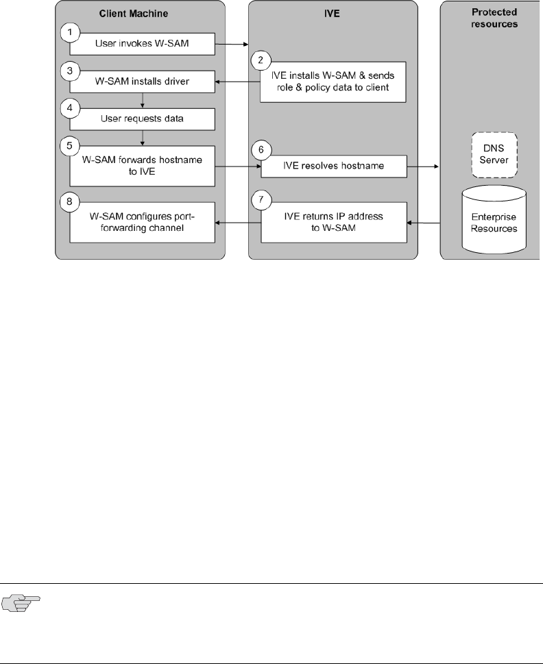
Juniper Networks Secure Access Administration Guide
398 W-SAM overview
Figure 35: Windows Secure Application Manager
1. The user invokes WSAM through his IVE session. The user can invoke WSAM
automatically or manually. If you configure WSAM to auto-launch, the user
invokes WSAM simply by signing into the IVE. Or, if you or the user disables
the auto-launch option, the user can manually invoke WSAM by clicking its link
on the IVE home page. (If you enable auto-launch, users can override the
setting through the Preferences > Applications page of the end-user console.)
2. If WSAM is not already installed on the user’s system, the IVE downloads it to
the user’s machine. The delivery mechanism then installs the W-SAM software
on the client machine. WSAM delivery mechanisms include:
ActiveX control—This primary software delivery mechanism controls all
W-SAM installation functions. It downloads from the IVE when a user
launches WSAM from the IVE home page.
Java delivery—The IVE appliance provides this secondary delivery
mechanism if the IVE fails to download or upgrade the ActiveX control due
to browser restrictions. As with the ActiveX control, the Java delivery
mechanism controls all W-SAM installation functions.
For information on removing the Juniper ActiveX control, see “Removing
the Juniper ActiveX Control” on page 265.
NOTE: If Microsoft Vista is running on the user’s system, the user must click the
setup link that appears during the installation process to continue installing the
setup client and W-SAM. On all other Microsoft operating systems, the setup client
and W-SAM install automatically.

W-SAM overview 399
Chapter 16: Secure Application Manager
Scriptable W-SAM Launcher—This tool enables users to launch W-SAM
manually from a command line or automatically from a batch file, an
application that performs a shell call, or a Win32 service. To use this
mechanism, you need to distribute the launcher to users, as described in
“Downloading application installers” on page 577. Users can then invoke
WSAM through a command prompt window using the command line
arguments described in “Using the W-SAM launcher” on page 413. Or, an
application or script may launch W-SAM by passing parameters to the
launcher. (For example, a PC batch-file script can invoke the W-SAM
launcher when the computer boots.)
The IVE feeds role and client information defined on the server to the WSAM
client machine during WSAM initialization. (If the filtering policies change, the
client machine does not reflect those changes until the next sign-in session.
Any changes to the IVE server access control rules take effect immediately.)
3. The WSAM client installs a Layered Service Provider (LSP) or Transport Driver
Interface (TDI) driver on the client to secure application traffic. (If the traffic
originates from a Windows 98 or Windows Millennium system, WSAM uses an
LSP mechanism. If the traffic originates from a Windows 2000 or Windows XP
system, WSAM uses a TDI mechanism.) The WSAM status window icon
appears in the system tray. Users can double-click this icon to see the current
session status and a list of applications and hosts specified for WSAM to
intermediate.
4. The user launches an application or requests data from a server that you have
configured through WSAM. When the client application or the process tries to
connect to the resource, WSAM intercepts the request. WSAM intercepts TCP
and UDP connection calls from applications and DNS queries for destination
server host names.
5. WSAM forwards the host name of the client application or destination server to
the IVE over SSL.
6. The IVE resolves the host name against the DNS server.
7. The IVE returns up to 8 resolved IP addresses of the target host to WSAM.
NOTE: For information about the directories in which the WSAM delivery
mechanisms run, files they install on the user’s computer, log file locations, the
rights that users must have in order to run each of these delivery mechanisms,
and browser settings users must enable, see the Client-side Changes Guide on the
Juniper Networks Customer Support Center.
Juniper Networks Secure Access Administration Guide
400 W-SAM overview
8. WSAM automatically configures a port-forwarding channel using a pre-
provisioned localhost IP address.
Antivirus and VPN client application compatibility
Table 31 shows the compatibility of several antivirus and VPN client applications
with W-SAM and Windows 98 and Windows Millennium.
Table 32 shows the compatibility of several antivirus and VPN client applications
with W-SAM for Windows 2000 and Windows XP.
NOTE:
If you enable the Persistent Session option on the Users > User Roles >
Role > General > Session Options tab, the IVE caches the username and
password in the persistent session cookie after the first successful
authentication. This poses a potential security risk since the W-SAM launcher
uses the information stored in the persistent session cookie for all subsequent
sign-in attempts during the existing session even if you terminate the W-SAM
connection. For more information about persistent sessions, see “Specifying
session options” on page 57.
Users may experience problems waiting for the Secure Application Manager
to fully load if they enable pop-up blockers through their Web browsers. This
problem occurs because a pop-up window alerting users to accept the Secure
Application Manager plug-in may appear in the background (behind the Web
browser window) where users cannot see it.
Table 31: WSAM for Windows 98 and Windows Millennium compatibility
Software Version Compatible?
Norton AntiVirus 2003 Yes
Norton AntiVirus 2004 Yes
Norton AntiVirus Professional 2004 Yes
Norton AntiVirus Corporate Edition 8.0 Yes
McAfee 7.0 No
McAfee 8.0 Yes
NOTE: If a conflict exists between WSAM and one of the third-party applications
on Windows 98 or Windows Millennium, the IVE blocks the download and
displays an error message detailing the conflict.
Table 32: WSAM for Windows 2000 and Windows XP compatibility
Software Version File-sharing disabled File-sharing enabled
Norton AntiVirus 2003 Yes Yes
Norton AntiVirus 2004 Yes Yes
Norton AntiVirus Professional 2004 Yes No
Norton AntiVirus Corporate Edition 8.0 Yes Yes
Defining resource profiles: WSAM 401
Chapter 16: Secure Application Manager
Launching Network Connect during a WSAM session
Users can launch Network Connect while signed in to the IVE via WSAM. If they do,
however, the Network Connect installer automatically terminates the WSAM
session prior to launching Network Connect. During the process, the IVE prompts
users with a warning message informing them that they are about to terminate
their WSAM session in favor of launching Network Connect.
To deal with situation, we recommend that you give users as much access to
network resources through Network Connect as through WSAM. If you do, when
the users choose to launch Network Connect (simultaneously terminating WSAM),
they will still be able to access the same network resources. For more information,
refer to “Launching Network Connect during a Windows Secure Application
Manager session” on page 529.
Debugging WSAM issues
You can use the Secure Application Manager dialog box on the an end-user’s
system to view the WSAM status and a variety of details about the user’s session.
For instance, the Secure Application Manager dialog box displays the applications
and servers that WSAM is configured to secure, event logs and Winsock data for the
user’s session, and various system diagnostics and performance data. This
information can help you or a Juniper Networks Support representative debug any
problems your users may encounter.
To access the Secure Application Manager dialog box, users simply need to
double-click the WSAM icon on their Windows task bars:
For more information about viewing information in the Secure Application
Manager dialog box, see the end-user help system available from the Help link in
the IVE end-user console.
Defining resource profiles: WSAM
You can create two types of WSAM resource profiles:
WSAM application resource profiles—These resource profiles configure
WSAM to secure traffic to a client/server application. When you create a WSAM
application resource profile, the WSAM client intercepts requests from the
specified client applications to servers in your internal network.
Trend Micro PC-cillin 2004 No Yes
TheGreenBow Personal Firewall 2.5 Yes Yes
Table 32: WSAM for Windows 2000 and Windows XP compatibility (Continued)
Software Version File-sharing disabled File-sharing enabled

Juniper Networks Secure Access Administration Guide
402 Defining resource profiles: WSAM
WSAM destination network resource profiles—These resource profiles
configure WSAM to secure traffic to a server. When you create a WSAM
destination network resource profile, the WSAM client intercepts requests from
processes running on the client that are connecting to the specified internal
hosts.
For more information about resource profiles, see “Resource profiles” on page 71.
For more information about WSAM, see “W-SAM overview” on page 397.
Creating WSAM client application resource profiles
When you create a WSAM application resource profile, the WSAM client intercepts
requests from the specified client applications to servers in your internal network.
To create a WSAM application resource profile:
1. Navigate to the Users > Resource Profiles > SAM > Client Applications
page in the admin console.
2. Click New Profile.
3. From the Type list, choose WSAM.
4. From the Application list, select one of the following options:
Custom—When you select this option, you must manually enter your
custom application’s executable file name (such as telnet.exe). Additionally,
you may specify this file’s path and MD5 hash of the executable file
(although it is not required that you specify the exact path to the
executable). If you enter an MD5 hash value, WSAM verifies that the
checksum value of the executable matches this value. If the values do not
match, WSAM notifies the user that the identity of the application could not
be verified and does not forward connections from the application to the
IVE.
NOTE:
When creating WSAM resource profiles, note that the resource profiles do not
contain bookmarks. To access the applications and servers that WSAM
intermediates, users must first launch WSAM and then launch the specified
application or server using standard methods (such as the Windows Start
menu or a desktop icon). For information about automatically launching
WSAM when the user signs into the IVE, see “Specifying role-level WSAM
options” on page 408.
When you enable JSAM or WSAM through Web rewriting autopolicies in the
Users > Resource Profiles > Web Applications/Pages page of the admin
console, the IVE automatically creates JSAM or WSAM autopolicies for you.
You can only view these SAM policies through the appropriate Web resource
profile—not through the SAM resource profile pages of the admin console. For
more information, see “Defining a rewriting autopolicy” on page 300.
For tips on configuring PDA applications through WSAM, see “Enabling
WSAM on PDAs” on page 851.

Defining resource profiles: WSAM 403
Chapter 16: Secure Application Manager
Lotus Notes—When you select this option, WSAM intermediates traffic
from the Lotus Notes fat client application.
Microsoft Outlook—When you select this option, WSAM intermediates
traffic from the Microsoft Outlook application.
NetBIOS file browsing—When you select this option, WSAM intercepts
NetBIOS name lookups in the TDI drivers on port 137.
Citrix—When you select this option, WSAM intermediates traffic from
Citrix applications.
5. Enter a unique name and optionally a description for the resource profile. The
IVE displays this information in the Client Application Sessions section of the
IVE end-user home page.
6. In the Autopolicy: SAM Access Control section, create a policy that allows or
denies users access to the server that hosts the specified application:
a. If it is not already enabled, select the Autopolicy: SAM Access Control
checkbox.
b. In the Resource field, specify the application server to which this policy
applies. You can specify the server as a host name or an IP/netmask pair.
You may also include a port.
c. From the Action list, select Allow to enable access to the specified server
or Deny to block access to the specified server.
d. Click Add.
7. Click Save and Continue.
8. In the Roles tab, select the roles to which the resource profile applies and click
Add.
The selected roles inherit the autopolicy created by the resource profile. If it is
not already enabled, the IVE also automatically enables the SAM option in the
Users > User Roles > Select Role > General > Overview page of the admin
console for all of the roles you select.
9. Click Save Changes.
Creating WSAM destination network resource profiles
When you create a WSAM destination network resource profile, the WSAM client
intercepts requests from processes running on the client to internal hosts.
NOTE: You can only use WSAM to configure access to a standard application once
per user role. For instance, you can enable one configuration of Microsoft Outlook
and one configuration of Lotus Notes for the “Users” role.

Juniper Networks Secure Access Administration Guide
404 Defining role settings: WSAM
To create a WSAM destination network resource profile:
1. Navigate to the Users > Resource Profiles > SAM > WSAM Destinations
page in the admin console.
2. Click New Profile.
3. Enter a unique name and optionally a description for the resource profile.
4. In the WSAM Destinations section, specify which servers you want to secure
using WSAM and click Add. You can specify the servers as host name or
IP/netmask pairs. You may also include a port. For information about system
variables and attributes you can use in this field, see “Using system variables in
realms, roles, and resource policies” on page 869.
5. Select the Create an access control policy allowing SAM access to this server
checkbox to enable access to the server specified in the previous step (enabled
by default).
6. Click Save and Continue.
7. In the Roles tab, select the roles to which the resource profile applies and click
Add.
The selected roles inherit the autopolicy created by the resource profile. If it is
not already enabled, the IVE also automatically enables the SAM option in the
Users > User Roles > Select Role > General > Overview page of the admin
console for all of the roles you select.
8. Click Save Changes.
Defining role settings: WSAM
This section contains the following information about configuring role-level settings
for WSAM:
“Specifying applications and servers for WSAM to secure” on page 405
“Specifying applications that need to bypass WSAM” on page 407
“Specifying role-level WSAM options” on page 408
“Downloading WSAM applications” on page 410

Defining role settings: WSAM 405
Chapter 16: Secure Application Manager
Specifying applications and servers for WSAM to secure
Use the Applications tab to specify applications and servers for which WSAM
secures traffic. When WSAM downloads to a client PC, it contains the information
you configure on the Applications tab for the role. After a user launches the Secure
Application Manager, WSAM intercepts requests from client applications to servers
in your internal network and requests from processes running on the client to
internal hosts. You define these resources on the Applications tab by configuring
two lists:
WSAM supported applications list—This list contains applications for which
you want WSAM to secure client/server traffic between the client and the IVE.
WSAM allowed servers list—This list contains hosts for which you want WSAM
to secure client/server traffic between the client and the IVE.
Specifying applications for WSAM to secure
To specify applications for which WSAM secures client/server traffic between the
client and the IVE:
1. In the admin console, choose Users > User Roles > Select Role> SAM >
Applications.
2. Click Add Application.
3. Enter the name of the application and, optionally, a description. This
information displays in the Client Application Sessions section of the IVE end-
user home page.
4. From the Type list, choose one of the following options:
Standard—If you select this option, choose one the following applications
from the Application Parameters section:
Citrix—When you select this option, WSAM intermediates traffic from
Citrix applications.
Lotus Notes—When you select this option, WSAM intermediates traffic
from the Lotus Notes fat client application.
Microsoft Outlook/Exchange—When you select this option, WSAM
intermediates traffic from the Microsoft Outlook application.
NOTE: Information in this section is provided for backwards compatibility. We
recommend that you secure traffic using WSAM resource profiles instead, since
they provide a simpler, more unified configuration method. For more
information, see “Defining resource profiles: WSAM” on page 401.

Juniper Networks Secure Access Administration Guide
406 Defining role settings: WSAM
NetBIOS file browsing—When you select this option, WSAM
intercepts NetBIOS name lookups in the TDI drivers on port 137.
Custom—Select this option to specify a custom client/server application.
Then:
i. In the Filename field, specify the name of the file’s executable file.
ii. Optionally specify the file’s path and MD5 hash of the executable file.
If you enter an MD5 hash value, WSAM verifies that the checksum
value of the executable matches this value. If the values do not match,
WSAM notifies the user that the identity of the application could not be
verified and does not forward connections from the application to the
IVE.
5. Click Save Changes or Save + New.
6. Configure a WSAM resource policy to specify to which enterprise resources
(based on IP address/port combination) the IVE may send the application.
Specifying servers for WSAM to secure
To specify servers for which WSAM secures client/server traffic between the client
and the IVE:
1. In the admin console, choose Users > User Roles > Select Role > SAM >
Applications.
2. Click Add Server.
3. Enter the name of the server and, optionally, a description.
4. Specify the server’s host name (the wild cards '*' or '?' are accepted) or an
IP/netmask pair. Specify multiple ports for a host as separate entries. For
information about system variables and attributes you can use in this field, see
“Using system variables in realms, roles, and resource policies” on page 869.
5. Click Save Changes or Save + New.
6. Configure a WSAM resource policy to specify to which enterprise resources
(based on IP address/port combination) the IVE may send a server request.
Alternatively, you can enable the Auto-allow application servers option on the
SAM > Options tab, and then the IVE automatically creates a SAM resource
policy that allows access to the specified server. Note that you need to enable
this option before specifying the application or server; otherwise, you need to
create a SAM resource policy.
NOTE: Note that in order to access a share using WSAM with NetBIOS, you need to
explicitly specify the server’s NetBIOS name (alphanumeric string up to 15
characters) in two places: on the Add Server page and in a SAM resource policy.
(Wildcards are currently not supported.) Alternatively, you can enable the Auto-
allow application servers option on the SAM > Options tab, and then the IVE
automatically creates a SAM resource policy that allows access to this server.

Defining role settings: WSAM 407
Chapter 16: Secure Application Manager
Specifying applications that need to bypass WSAM
The WSAM client comes pre-configured with a list of “passthrough” applications
bypass WSAM. The WSAM client does not secure traffic for these applications. In
addition to bypassing these pre-defined applications, you may also specify
additional applications on the IVE server that should bypass WSAM.
This section includes the following information about WSAM bypass applications:
“Specifying bypass applications” on page 407
“Default bypass applications” on page 407
Specifying bypass applications
Use the Applications tab to specify applications on the IVE server for which WSAM
does not secure traffic. These “passthrough” applications bypass WSAM.
To specify applications for WSAM to secure:
1. In the admin console, choose Users > User Roles > Select Role > SAM >
Applications.
2. Select the Add Bypass Application button. The New Bypass Application page
displays.
3. Name the application and provide a description (optional).
4. Provide the file name (required).
5. Enter the absolute path to the application (optional).
6. Select Save Changes to add the bypass application to the list or Save + New to
save the bypass application and create another bypass application.
Default bypass applications
The WSAM client is pre-configured to bypass WSAM processing for the following
applications:
apache.exe
apache*
licadmin.exe
vni.exe
lmgrd.exe
TNSLSNR.EXE
ORACLE.EXE
NOTE: WSAM does not bypass applications on Pocket PCs and other handheld
devices.
Juniper Networks Secure Access Administration Guide
408 Defining role settings: WSAM
Agntsrvc.exe
ONRSD.EXE
Pagntsrv.exe
ENCSVC.EXE
Agntsvc.exe
sqlplus.exe
sqlplusw.exe
EiSQLW.exe
Sqlservr.exe
Sqlmangr.exe
inetinfo.EXE
svchost.exe
LSASS.EXE
CSRSS.EXE
WINLOGON.EXE
SERVICES.EXE
spoolsv.exe
hostex32.exe
xstart.exe
idsd.exe
dsTermServ.exe
dsCitrixProxy.exe
dsNcService.exe
dsNetworkConnect.exe
Specifying role-level WSAM options
To specify WSAM options at the role level:
1. In the admin console, choose Users > User Roles > Select Role > SAM >
Options.
2. If it is not already enabled, select the Windows SAM option at the top of the
page.

Defining role settings: WSAM 409
Chapter 16: Secure Application Manager
3. Under Secure Application Manager options, configure the following options:
Auto-launch Secure Application Manager—If you enable this option, the
IVE automatically launches the Secure Application Manager when a user
signs in. If you do not select this option, users must manually start the
Secure Application Manager from the Client Applications Sessions section
of the IVE end-user home page.
Auto-allow application servers—If you enable this option, the IVE
automatically creates a SAM resource policy that allows access to the
server specified in the WSAM application and server lists.
4. Under Windows SAM Options, configure the following options:
Auto-uninstall Secure Application Manager—If you enable this option,
the IVE automatically un-installs the Secure Application Manager after
users sign off.
Prompt for username and password for intranet sites—If you enable this
option, the IVE requires users to enter their sign-in credentials before
connecting to sites on your internal network. This option changes Internet
Explorer’s intranet zone setting so that Internet Explorer prompts the user
for network sign-in credentials whenever the user wants to access an
intranet site.
Auto-upgrade Secure Application Manager—If you enable this option, the
IVE automatically downloads the Secure Application Manager to a client
machine when the version of Secure Application Manager on the IVE is
newer than the version installed on the client. If you select this option, note
the following:
The user must have Administrator privileges in order for the IVE to
automatically install Secure Application Manager on the client.
If a user un-installs Secure Application Manager and then signs in to an
IVE for which the Auto-upgrade Secure Application Manager option is
not enabled, the user no longer has access to Secure Application
Manager.
NOTE: Although you configure the Secure Application Manager to automatically
launch when users sign into the IVE, users can override this setting through the
Preferences > Applications page of the IVE end-user console. If you or the end-
user disables WSAM from automatically launching, users need to manually start
the Secure Application Manager by clicking its link on the IVE home page.
NOTE: You may not see the Auto-allow option if you are using a new installation
or if an administrator hides the option. For more information on this option, see
“Setting system options” on page 575.

Juniper Networks Secure Access Administration Guide
410 Defining resource policies: WSAM
Session start script and Session end script—If you want to run a batch,
application, or Win32 service file when the WSAM session starts or ends,
enter the name and path for the file. For example, if you want to terminate
an application and then restart it, you may use PSKILL.exe (an third-party
utility that terminates processes on local or remote systems).
5. Click Save Changes.
Downloading WSAM applications
To download Windows Secure Application Manager applications, go to the
Maintenance > System > Installers tab. For more information about
downloading WSAM applications, see “Downloading application installers” on
page 577.
Defining resource policies: WSAM
This section contains the following instructions for configuring WSAM resource
policies:
“Specifying application servers that users can access” on page 410
“Specifying resource level WSAM options” on page 412
Specifying application servers that users can access
When you enable the Secure Application Manager access feature for a role, you
need to create resource policies that specify which application servers a user may
access. These policies apply to both the Java version and Windows version of the
Secure Application Manager (J-SAM and W-SAM, respectively). When a user makes
a request to an application server, the IVE evaluates the SAM resource policies. If
the IVE matches a user’s request to a resource listed in a SAM policy, the IVE
performs the action specified for the resource.
NOTE: If you enable the Session start script option or Session end script option,
note the following:
You must either install the specified file on your end-user’s computers or
specify a path on an accessible network directory.
To ensure that the IVE can locate a file on different platforms, you can use
Windows variables, such as in a path such as %WINDIR%\system32\log.
The file must invoke the WSAM launcher using the appropriate command-line
options, as described in “Using the W-SAM launcher” on page 413.
NOTE: Information in this section is provided for backwards compatibility. We
recommend that you secure traffic using WSAM resource profiles instead, since
they provide a simpler, more unified configuration method. For more
information, see “Defining resource policies: WSAM” on page 410.
Defining resource policies: WSAM 411
Chapter 16: Secure Application Manager
When writing a SAM resource policy, you need to supply key information:
Resources—A resource policy must specify one or more resources to which the
policy applies. When writing a SAM policy, you need to specify application
servers to which a user may connect.
Roles—A resource policy must specify the roles to which it applies. When a
user makes a request, the IVE determines what policies apply to the role and
then evaluates those policies that correspond to the request. SAM resource
policies apply to users requests made through either version, J-SAM or W-SAM.
Actions—A Secure Application Manager resource policy either allows or denies
access to an application server.
You can create resource policies through the standard interface (as described in this
section) or through resource profiles (recommended method).
The IVE platform’s engine that evaluates resource policies requires that the
resources listed in a policy’s Resources list follow a canonical format, as explained
in “Specifying resources for a resource policy” on page 83.
To write a Secure Application Manager resource policy:
1. In the admin console, choose Users > Resource Policies > SAM > Access.
2. On the Secure Application Manager Policies page, click New Policy.
3. On the New Policy page, enter:
a. A name to label this policy.
b. A description of the policy (optional).
4. In the Resources section, specify the application servers to which this policy
applies.
5. In the Roles section, specify:
Policy applies to ALL roles—Choose this option to apply this policy to all
users.
Policy applies to SELECTED roles—Choose this option to apply this policy
only to users who are mapped to roles in the Selected roles list. Make sure
to add roles to this list from the Available roles list.
Policy applies to all roles OTHER THAN those selected below—Choose
this option to apply this policy to all users except for those who map to the
roles in the Selected roles list. Make sure to add roles to this list from the
Available roles list.
6. In the Action section, specify:
Allow socket access—Choose this option to grant access to the application
servers specified in the Resources list.

Juniper Networks Secure Access Administration Guide
412 Defining resource policies: WSAM
Deny socket access—Choose this option to deny access to the application
servers specified in the Resources list.
Use Detailed Rules—Choose this option to specify one or more detailed
rules for this policy. See “Writing a detailed rule” on page 88 for more
information.
7. Click Save Changes.
8. On the Secure Application Manager Policies page, order the policies
according to how you want the IVE to evaluate them. Keep in mind that once
the IVE matches the resource requested by the user to a resource in a policy’s
(or a detailed rule’s) Resource list, it performs the specified action and stops
processing policies.
Specifying resource level WSAM options
Use the Options tab to specify the SAM resource option to match IP addresses to
host names specified as resources in your SAM resource policies. When you enable
this option, the IVE looks up IP addresses corresponding to each host name
specified in a SAM resource policy. When a user tries to access a server by
specifying an IP address rather than the host name, the IVE compares the IP to its
cached list of IP addresses to determine if a host name matches an IP. If there is a
match, then the IVE accepts the match as a policy match and applies the action
specified for the resource policy.
When you enable this option, the IVE compiles a list of host names specified in the
Resources field of each SAM resource policy. The IVE then applies the option to this
comprehensive list of host names.
To specify the SAM resource option:
1. In the admin console, choose Users > Resource Policies > SAM > Options.
2. Select IP based matching for Hostname based policy resources. When you
select this option, the IVE looks up the IP address corresponding to each host
name specified in a Secure Application Manager resource policy. When a user
tries to access a server by specifying an IP address rather than the host name,
the IVE compares the IP to its cached list of IP addresses to determine if a host
name matches an IP. If there is a match, then the IVE accepts the match as a
policy match and applies the action specified for the resource policy.
3. Click Save Changes.
NOTE: This option does not apply to host names that include wildcards and
parameters.

Using the W-SAM launcher 413
Chapter 16: Secure Application Manager
Using the W-SAM launcher
The W-SAM launcher is a tool that signs a user into the IVE and then downloads and
launches W-SAM. The launcher provides a command-line interface that a script or
application can call. For example, you can write an application that calls the W-SAM
executable when needed.
To use the W-SAM launcher, you need to:
1. Write a script, batch file, service, or application that calls the W-SAM launcher
using command line arguments. You need to distribute this file to each client
PC that requires it. For more information, see “Running scripts manually” on
page 414 and “Running scripts automatically” on page 415.
2. Download the W-SAM launcher from Maintenance > System > Installers
page of the admin console and then distribute it to your users.
Use the command-line arguments in Table 33 to invoke the W-SAM launcher.
Table 34 lists the possible codes the W-SAM launcher returns when it exits.
Table 33: W-SAM Command Line Arguments
Argument Action
-start Initiates the W-SAM connection.
-stop Terminates the W-SAM connection.
-signout Terminates the WSAM connection and IVE user session.
-version Displays W-SAM version information and then exits.
-help Displays available arguments.
-noupgrade Cancels automatic upgrade of W-SAM software.
-reboot Automatically reboots if prompted by an upgrade. If reboot flag
is not set, W-SAM exits and does not reboot during an upgrade.
Be sure to set the reboot flag if W-SAM is operating
automatically on a remote PC.
-u <username> Specifies the user name.
-p <password> Specifies the password for authentication.
-loginscript file Specifies the location and name of the script file to run when
W-SAM launches. This command takes precedence over a script
file specified on the Users > User Roles > Select Role > SAM
> Options page.
-postscript file Specifies the location and name of the script file to run when
W-SAM exits. This command takes precedence over a script file
specified on the Users > User Roles > Select Role > SAM >
Options page.
-u <URL> Specifies the sign-in URL for the IVE.
-r <realm> Specifies the realm to which the IVE submits the user’s
credentials.
-verbose Prompts users for input through dialog boxes.

Juniper Networks Secure Access Administration Guide
414 Using the W-SAM launcher
Running scripts manually
Users may manually specify scripts to run when a W-SAM session begins or ends
using the following command-line arguments.
To manually launch a script after a W-SAM session begins:
At a command prompt, enter -loginscript file followed by a system variable or
script file name and location.
To manually launch a script after a W-SAM session ends:
At a command prompt, enter -postscript file followed by a system variable and
the script file name and location.
For example:
-loginscript file “%program files:%\Internet Explorer\IEXPLORER.EXE”
Table 34: Application Return Codes
Code Description
0Success
1Invalid Arguments
2Could Not Connect.
3Invalid Credentials
4Role Not Specified (credentials map to multiple roles)
5Pre-authentication Error (Host Checker or Cache Cleaner did not load)
6Installation Failed
7Reboot Required (if ‘-reboot’ not specified)
8Unable to perform a required software upgrade
10 The IVE does not support this feature
12 Failed to authenticate the client certificate
100 Unable to stop the Secure Application Manager
101 Unable to start the Secure Application Manager due to a software conflict
caused by another Layered Service Provider
NOTE: If you specify scripts to run through the Users > User Roles > Select Role
> SAM > Options page of the admin console, the configured script does not run
if a user manually invokes W-SAM using the launcher and specifies a different
script.
NOTE:
Place system variables, file paths, and file names in quotes
Precede and append system variables with a percent sign (%)
Using the W-SAM launcher 415
Chapter 16: Secure Application Manager
Running scripts automatically
You may automatically run a script when WSAM starts or stops by entering the
script path and name in the Session start script field or Session end script field on
the Users > User Roles > Select Role > SAM > Options page of the admin
console, as described in “Specifying role-level WSAM options” on page 408. This
section includes an example batch file that you can automatically launch.
Batch file example
The following example demonstrates how to use the W-SAM launcher to invoke
W-SAM. This sample batch file generates error messages when W-SAM launches:
SamLauncher –start –url %1 –user %2 –password %3 –realm %4
if errorlevel 1 goto error_invalid_args
if errorlevel 2 goto error_connect
if errorlevel 3 goto error_credentials
if errorlevel 4 goto error_role
if errorlevel 5 goto error_preauth
if errorlevel 6 goto error_install
if errorlevel 7 goto error_reboot
:error_invalid_args
@echo invalid arguments
goto done
:error_connect
@echo could not connect
goto done
:error_credentials
@echo invalid credentials
goto done
:error_role
@echo invalid role
goto done
:error_preauth
@echo pre auth version checking
goto done
:error_install
@echo install failed
goto done
:error_reboot
@echo reboot required
goto done
:error_success

Juniper Networks Secure Access Administration Guide
416 Task Summary: Configuring JSAM
@echo Secure Application Manager has started
goto done
:done
Win32 API example
CHAR szCmd = “SamLauncher.exe –stop”;
DWORD dwExitCode = 0;
STARTUPINFO si;
PROCESS_INFORMATION pi;
ZeroMemory(&si, sizeof(si));
si.cb = sizeof(si);
ZeroMemory(&pi, sizeof(pi));
if (!CreateProcess(NULL, szCmd, NULL, NULL, FALSE,
0, NULL, NULL, &si, &pi)) {
printf( "CreateProcess(%s) failed %d", szCmd, GetLastError());
return -1;
}
WaitForSingleObject(pi.hProcess, 20000);
GetExitCodeProcess(&pi.hProcess, &dwExitCode);
CloseHandle(pi.hProcess);
CloseHandle(pi.hThread);
printf(“SamLauncher return %d\n”, dwExitCode);
return 0;
Task Summary: Configuring JSAM
This section provides high-level JSAM configuration steps. These steps do not
account for preliminary IVE configuration steps such as specifying the IVE’s
network identity or adding user IDs to the IVE.
To configure JSAM:
1. Create resource profiles that enable access to client/server applications, create
supporting autopolicies as necessary, and assign the policies to user roles using
settings in the Users > Resource Profiles> SAM pages of the admin console.
For instructions, see “Defining resource profiles: JSAM” on page 435.
We recommend that you use resource profiles to configure JSAM (as described
above). However, if you do not want to use resource profiles, you can configure
JSAM using role and resource policy settings in the following pages of the
admin console instead:
a. Enable access to JSAM at the role-level using settings in the Users > User
Roles > Select Role > General > Overview page of the admin console.
For instructions, see “Configuring user roles” on page 54.
NOTE: If you are using Windows Vista, open the command window as an
administrator user. Standard output from the SamLauncher.exe does not display
if the command window is opened by a user without administrator privileges.

J-SAM overview 417
Chapter 16: Secure Application Manager
b. Specify which client/server applications JSAM should intermediate using
settings in the Users > User Roles > SAM > Applications page of the
admin console. For instructions, see “Specifying applications for JSAM to
secure” on page 439.
c. Specify which application servers users can access through JSAM using
settings in the Users > Resource Policies > SAM > Access page of the
admin console. For instructions, see “Specifying application servers that
users can access” on page 445.
2. After enabling access to client/server applications using JSAM resource profiles
or roles and resource policies, you can modify general role and resource
options in the following pages of the admin console:
a. (Optional) Configure role-level options such as whether the IVE should
automatically launch JSAM using settings in the Users > User Roles >
SAM > Options page of the admin console. For instructions, see
“Specifying role level JSAM options” on page 442.
b. (Optional) Control IP based hostname matching at the resource level using
settings in the Users > Resource Policies > SAM > Access page of the
admin console. For instructions, see “Specifying application servers that
users can access” on page 445.
3. If you want to enable or disable client-side logging for JSAM, configure the
appropriate options through the System > Configuration > Security >
Client-side Logs tab of the admin console. For instructions, see “Enabling
client-side logs” on page 679.
4. If you have multiple internal domains, such as company-a.com and company-
b.com, add DNS domains to the IVE using settings in the System > Network >
Overview page of the admin console so that names such as app1.company-
a.com and app2.company-b.com resolve correctly.
5. If a remote user’s PC is set up to use a Web proxy in Internet Explorer,
configure the client machine to bypass the proxy server when the user
launches applications that need to connect to the Secure Application Manager.
For instructions, see “Configuring a PC that connects to the IVE through a
proxy Web server” on page 420.
6. Enable JSAM to associate IP loopback addresses with application servers on
specific ports either by enabling JSAM to edit the hosts file on your users’
systems (as explained in “Resolving host names to localhost” on page 424) or
by creating an external DNS to route client application traffic to the J-SAM
applet (as explained in “Configuring external DNS servers and user machines”
on page 425).
J-SAM overview
The Java version of the Secure Application Manager provides support for static TCP
port client/server applications, including enhanced support for Microsoft MAPI,
Lotus Notes, and Citrix NFuse. J-SAM also provides NetBIOS support, which enables
users to map drives to specified protected resources.
Juniper Networks Secure Access Administration Guide
418 J-SAM overview
J-SAM works well in many network configurations but does not support dynamic
port TCP-based client/server applications, server-initiated connections, or UDP
traffic.
For information about the operating systems, Web browsers, and JVMs on which
Juniper Networks supports JSAM, see the Supported Platforms Document on the
Juniper Networks Customer Support Center.
This section contains the following information about JSAM:
“Using JSAM for client/server communications” on page 418
“Linux and Macintosh support” on page 426
“Standard application support: MS Outlook” on page 427
“Standard application support: Lotus Notes” on page 428
“Standard application support: Citrix Web Interface for MetaFrame (NFuse
Classic)” on page 430
“Custom application support: Citrix published applications configured from the
native client” on page 431
“Custom application support: Citrix secure gateways” on page 434
Using JSAM for client/server communications
J-SAM provides secure port forwarding by directing client application traffic to the
J-SAM applet running on a client machine. To the client application running on the
local machine, J-SAM appears as the application server. To the application server in
your network, the IVE appears as the client application.
The following diagram illustrates the interaction between a client application and its
server via the IVE. (This figure assumes that the user specified a localhost IP
address as the server in the client application.)
Figure 36: Java Secure Application Manager

J-SAM overview 419
Chapter 16: Secure Application Manager
1. The user starts a client application listed in the Client Application Sessions
section of the IVE end-user home page. 1 The application resolves the remote
server to localhost.
2. The client application connects to J-SAM running on the user's machine and
starts sending requests.
3. J-SAM encapsulates and forwards all client requests to the IVE over SSL.
4. The IVE un-encapsulates the client data and forwards it to the specified
application server.
5. The application server responds with data to the IVE server.
6. The IVE encapsulates and forwards the response from the application server to
J-SAM over SSL.
7. J-SAM un-encapsulates the application server data and forwards it to the client
application.
For more information about how JSAM executes, see “Assigning IP loopback
addresses to servers” on page 421.
1. Windows 98 operating system only—If the “Close on Exit” property is disabled in the DOS box that opens
during the JSAM boot process (for executing the “restore.bat” process), the DOS box does not close after the
batch file has completed execution. The user must manually close the DOS box before the JSAM boot process
can complete.

Juniper Networks Secure Access Administration Guide
420 J-SAM overview
For more information about how JSAM executes, see “Assigning IP loopback
addresses to servers” on page 421.
Configuring a PC that connects to the IVE through a proxy Web server
If a remote user’s PC is set up to use a Web proxy in Internet Explorer, you must
configure the client machine to bypass the proxy server and contact the Secure
Application Manager instead.
To configure a PC that connects to the IVE through a Web proxy in Internet
Explorer:
1. From the Internet Explorer Tools menu, choose Internet Options.
2. On the Connections tab, click the LAN Settings button.
3. Under Proxy server, click the Advanced button.
4. Under Exceptions, enter the addresses for which you do not want to use a
proxy server. Enter all addresses (host names and localhost) that the client
application uses when connecting through the Secure Application Manager. For
example:
If your application server is app1.company.com, enter the following exceptions:
app1;app1.company.com;127.0.0.1
NOTE:
If a remote user’s PC is set up to use a Web proxy in Internet Explorer, you
must configure the client machine to bypass the proxy server when the user
launches applications that need to connect to the Secure Application Manager.
See “Configuring a PC that connects to the IVE through a proxy Web server”
on page 420.
J-SAM allocates 20-30 MB of RAM when running (the exact amount of
memory depends on the Java Virtual Machine (JVM) used) and, if caching is
enabled, may leave a .jar file on the client machine. For more information
about files left by JSAM on client machines, see the Client-side Changes Guide
on the Juniper Networks Customer Support Center.
Users may experience problems waiting for the Secure Application Manager
to fully load if they enable pop-up blockers through their Web browsers. This
problem occurs because a pop-up window alerting users to accept the Secure
Application Manager plug-in may appear in the background (behind the Web
browser window) where users cannot see it.
When launching applications through JSAM, Juniper Networks supports
configuration of 1200 unique IP/port combinations on Windows and Mac and
800 unique IP/port combinations on Linux. Note that this limit is based on
IP/port combinations, not applications (which may listen on more than one IP
address and port). Juniper Networks determined these numbers by testing on
Windows XP and Windows 2000 machines using default JRE memory
settings.
J-SAM overview 421
Chapter 16: Secure Application Manager
If your Exchange Server is exchange.company.com, enter the following
exceptions:
exchange;exchange.company.com;127.0.0.1
Assigning IP loopback addresses to servers
For JSAM to function, it must listen on loopback addresses for client requests to
network application servers. The IVE assigns these unique IP loopback address to
each application server that you specify for a given port. For example, if you
specify:
app1.mycompany.com, app2.mycompany.com. app3.mycompany.com,...
for a single port, the IVE assigns a unique IP loopback address to each application:
127.0.1.10, 127.0.1.11, 127.0.1.12,...
When the IVE installs J-SAM on a user’s machine, J-SAM listens on the loopback
addresses (on the corresponding client port specified for the application server) for
client requests to network application servers. You can configure the IVE to
dynamically assign these loopback addresses, or you can configure static loopback
addresses yourself through the admin console (as explained in “Using static
loopback addresses” on page 422).
You must enable these associations between IP loopback addresses and
applications servers on a specific port in one of two ways:
Allow the IVE to edit the hosts file on the client system with IP loopback
assignments. The IVE makes a copy of the current hosts file and then creates a
new hosts file with the IP loopback assignments. When the user ends the
session, the IVE deletes the new hosts file and restores the original hosts file.
If the client system shuts down unexpectedly, the hosts file still points the
client to loopback addresses for outside connections. Settings in the hosts file
are returned to their original state when the client system reboots.
Users must have the proper privileges on their machines in order for the IVE to
edit the hosts file. For more information, see “Resolving host names to
localhost” on page 424.
Create an external DNS to route client application traffic to the J-SAM applet.
For more information, see“Configuring external DNS servers and user
machines” on page 425.
For more information about loopback addresses, see:
“Using static loopback addresses” on page 422
“Determining the IVE-assigned loopback address” on page 422

Juniper Networks Secure Access Administration Guide
422 J-SAM overview
“IP loopback address considerations when merging roles” on page 424
Using static loopback addresses
Using an external DNS server with dynamic loopback addresses requires an
administrator to update the DNS settings each time the J-SAM application
configuration changes. On the other hand, configuring an external DNS server
using static loopback addresses provides administrators with the highest degree of
configuration control.
For example, consider the following IP loopback assignments:
app1.mycompany.com - 127.0.1.10
app2.mycompany.com - 127.0.1.11
app3.mycompany.com - 127.0.1.12
If you configure an external DNS server using dynamic loopback address
assignments and you delete the first application server, the address assignments
change:
app2.mycompany.com - 127.0.1.10
app3.mycompany.com - 127.0.1.11
With static IP loopback addresses in an external DNS, deleting the first application
server does not affect the IP loopback assignments for the remaining application
servers:
app2.mycompany.com - 127.0.1.11
app3.mycompany.com - 127.0.1.12
You can assign static IP loopback addresses when creating a JSAM custom resource
profile through the Users > Resource Profiles > SAM > Client Applications page
of the admin console or when enabling JSAM applications through the Users >
User Roles > Select Role > SAM > Applications page of the admin console.
If you assign a static IP loopback address while creating a new application, the IVE
checks the address for conflicts against other configured applications in the same
role. If another application uses the same address, the IVE displays an error
message prompting you to enter a different IP address.
Determining the IVE-assigned loopback address
Users cannot modify the corporate DNS server for applications they add for port
forwarding. If you allow users to specify applications for J-SAM to proxy, users need
to configure a client application to use the localhost address assigned by the IVE
where they typically enter the server host name.
NOTE: Static IP loopback addresses apply only to application servers configured by
an administrator. The IVE assigns dynamic IP loopback addresses for user-defined
application servers. If the administrator does not assign an IP loopback address to
an application server, the IVE assigns a dynamic address.
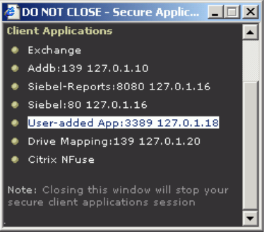
J-SAM overview 423
Chapter 16: Secure Application Manager
The Details pane of the J-SAM browser window displays the loopback IP address
assigned by the IVE along with the port specified by the user. To determine what IP
address the IVE assigns to an application specified through the Client Applications
IVE page, a user must restart the Secure Application Manager after adding the
application. The loopback address assigned to the application appears on the
Details pane of the Secure Application Manager browser window, as shown in
Figure 37.
Figure 37: Details pane of the Java Secure Application Manager (J-SAM)
In the client application, the user needs to enter the IVE-assigned loopback address
as the application server. For example, if a user wants to access a telnet server
behind your corporate firewall, the user needs to follow these steps:
1. In the Client Application Sessions section of the IVE end-user home page,
click the Item Properties icon, then click Add Application
2. On the Add Application page, specify:
The server’s fully qualified domain name or IP address in the Remote
Server field, such as terminalserver.juniper.com.
The port on which J-SAM should listen for client traffic to the server in the
Client Port field, such as 3389.
The port on which the remote server should listen for traffic from the client
application (J-SAM) in the Server Port field, such as 3389.
3. Click Add to save the information.
4. Close the Secure Application Manager browser window.
5. In the Client Application Sessions section of the IVE end-user home page,
click Start to restart the Secure Application Manager.
6. In the Secure Application Manager browser window, click Details.
7. On the Details tab, look at which loopback address the IVE assigned to the
remote server, such as 127.0.1.18.
Juniper Networks Secure Access Administration Guide
424 J-SAM overview
8. In the client application, such as Remote Desktop Connection, specify the
loopback address in the configuration field for the server. This field appears in
different places for different applications. Users may enter this information
through a setup wizard or other configuration dialog.
IP loopback address considerations when merging roles
If you plan to merge two or more roles, you may encounter IP loopback address
conflicts. Keep the following points in mind when merging roles:
If two or more roles map to the same application and each mapping contains a
different static IP loopback address, all of the static IP loopback addresses
remain unchanged.
If two or more roles map to the same application and only one role uses a static
IP loopback address, J-SAM uses only the static IP loopback address and binds
to only one statically defined socket on the client.
If two or more roles map to the same application using dynamic IP loopback
addresses, only one dynamic IP loopback address is used. The application
listener binds to only one dynamically assigned socket on the client.
If you use the same host name in multiple roles, either use the same static IP
loopback address, or dynamic addresses for all the applications.
If you use different host names associated with the same loopback address and
port combination, JSAM cannot distinguish between the two different hosts at
the back-end and, hence, cannot accurately direct IP traffic bound for those
hosts.
Resolving host names to localhost
For JSAM to successfully intermediate traffic, a client application on the user’s
machine needs to resolve the application server to the client localhost. This process
enables J-SAM to capture and securely port forward the data intended for the
application server via the IVE. J-SAM can perform automatic host-mapping, in
which it edits the client’s hosts file, to map application servers to localhost. (You
can enable automatic host-mapping through the Users > User Roles > Select Role
> SAM > Options page of the admin console.)
In order for J-SAM to edit a user’s hosts file, the user must have the appropriate
authority on the client machine:
Windows users using the FAT file system may belong to any user group. For
Exchange MAPI support, however, users must have at least Power User
privileges on their machines.
Windows users using the NTFS file system must have Administrator
privileges on their machines.
Linux (RedHat) users must launch the browser that will launch J-SAM as root.
Macintosh users must supply the Administrator password when prompted by
J-SAM.
J-SAM overview 425
Chapter 16: Secure Application Manager
If users do not have the appropriate privileges on their machines, J-SAM cannot
automatically edit the hosts file, preventing host name resolution to localhost.
Alternatives for users who do not have the appropriate privileges are:
You configure your external DNS server to resolve application servers to
localhost. If you configure your external DNS server to use a localhost address
instead of the application server host name, remote users need to configure the
order in which their machine searches DNS servers to start with the corporate
DNS. For more information, see “Configuring external DNS servers and user
machines” on page 425.
You relax the permissions on the etc directory and the etc\hosts file to enable
J-SAM to make the necessary modifications.
Users configure a client application to use the localhost address assigned by the
IVE where they typically specify the application server host name in the client
application. See “Determining the IVE-assigned loopback address” on page 422
for more information.
Configuring external DNS servers and user machines
Client applications must resolve server host names to JSAM, which proxies data
between a client and a server. On Windows PCs, server host names are stored in
the hosts file. To intercept data using JSAM, the server names in the hosts file need
to resolve to the local machine (localhost) so that the IVE can intermediate the
traffic. The recommended process for mapping application servers to a user’s local
PC is to enable the automatic host-mapping option, which enables the IVE to
automatically modify the PC hosts file to point application servers to the localhost
for secure port forwarding.
For the IVE to perform automatic host-mapping, however, PC users must have the
proper privileges on their machines (as explained in “Resolving host names to
localhost” on page 424). If your PC users do not have these privileges, you must
ensure that your internal application server names resolve externally to a PC’s
localhost by adding entries to your external Internet-facing DNS server such as:
127.0.0.1 app1.company-a.com
127.0.0.1 app2.company-b.com
127.0.0.1 exchange1.company-a.com
127.0.0.1 exchange1.company-b.com
If the client application uses an unqualified name for the application server, users
need to specify DNS suffixes so that the PC can attach the suffix and contact your
external DNS server for name resolution. For example, an MS Outlook client
typically has an unqualified name for an MS Exchange server. In order for the
qualified name to resolve to 127.0.0.1, users need to specify the appropriate DNS
suffixes on their PCs. Adding domain names does not affect other operations on
the PC, including use of the client application from within the enterprise.
To configure a user PC with DNS suffixes (Windows 2000):
1. From the Windows Start menu, choose Settings > Network and Dial-up
Connections > Local Area Connection and then choose Properties.

Juniper Networks Secure Access Administration Guide
426 J-SAM overview
2. Select Internet Protocol (TCP/IP) and then click Properties.
3. Click Advanced and then click the DNS tab.
4. Click Append these DNS suffixes and then click Add.
5. Add your enterprise’s internal domains as additional DNS suffixes.
For information about configuring your external DNS server using static loopback
addresses, see “Using static loopback addresses” on page 422.
Linux and Macintosh support
Linux users do not have access to ports below 1024 unless they are signed into
their machines as root. Macintosh users do not have access to ports below 1024
unless they supply the Administrator password when prompted by J-SAM. To
support applications that run on privileged ports (ports below 1024), such as a
telnet application:
Users may launch the browser that will launch J-SAM as root.
You or the user may specify a client port number equal to or greater than port
1024 when enabling client applications.
For example, if you specify 2041 for the client port and 23 for the server port
for a telnet application, the command to run the application is:
telnet loopbackIP 2041
where loopbackIP is the loopback IP address assigned to the application server
by the IVE. J-SAM listens on port 2041 for traffic from the telnet application and
forwards it to the IVE. The IVE then forwards the traffic to port 23 on the
destination server. For information about determining the IVE-assigned
loopback address, see “Determining the IVE-assigned loopback address” on
page 422.
NOTE: Due to the design of the Sun JVM code, Macintosh users cannot relaunch
JSAM within the same Safari user session. In order to re-launch JSAM, the user
must exit Safari and then launch JSAM again.
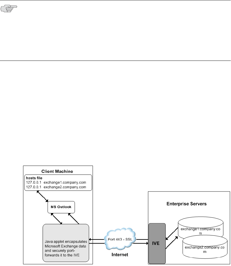
J-SAM overview 427
Chapter 16: Secure Application Manager
Standard application support: MS Outlook
Remote users can use the Microsoft Outlook client on their PCs to access email,
their calendars, and other Outlook features through the IVE. Versions of MS
Outlook currently supported are MS Outlook 2000 and MS Outlook 2002. This
ability does not require changes to the Outlook client and does not require a
network layer connection, such as VPN.
In order for this feature to work for remote users, the network settings of the user's
PC must resolve the name of the Exchange Servers embedded in the Outlook client
to the local PC (127.0.0.1, the default localhost IP address). We recommend that
you configure the IVE to automatically resolve Exchange server host names to the
localhost by temporarily updating the hosts file on a client computer through the
automatic host-mapping option.
Client/server communication using J-SAM
The following diagram describes the interactions between the Outlook client and an
Exchange Server via the IVE. This figure assumes that the IVE is configured to
perform automatic host-mapping.
Figure 38: Java Secure Application Manager and Enhanced MS Exchange Support
Figure 38 shows the IVE configured to use automatic host-mapping for the MS
Outlook client.
1. The user starts the MS Outlook client. Outlook tries to contact the Exchange
Server exchange1.yourcompany.com. The IVE resolves the Exchange Server host
name to 127.0.0.1 (localhost) through temporary changes to the hosts file.
NOTE: Refer to the Supported Platforms Document on the Juniper Networks
Customer Support Center for details on operating system support and
dependencies. See the Client-side Changes Guide for details about registry changes
made by JSAM.
Also, note that the IVE does not support Outlook through SVW, since Outlook
applications require HKLM registry key changes. For more information, see
“Enabling the Secure Virtual Workspace” on page 244.

Juniper Networks Secure Access Administration Guide
428 J-SAM overview
2. Outlook connects to the Secure Application Manager running on the user's PC
and then starts sending requests for email.
3. The Secure Application Manager encapsulates and forwards all the requests
from the Outlook client to the IVE over SSL.
4. IVE un-encapsulates the client data and looks in the MAPI request to find the
target Exchange Server. The request is then forwarded to the target server.
5. Each request in the MAPI protocol encodes the target server for the request.
When MAPI requests arrive from the Secure Application Manager, the IVE
server looks in each of them and dispatches them to the appropriate target
server. This process works transparently even if there are multiple Exchange
Servers.
6. The Exchange Server responds to the IVE with email data.
7. The IVE encapsulates and forwards the response from the Exchange Server to
the Secure Application Manager over SSL.
8. The Secure Application Manager un-encapsulates the information sent from the
IVE and forwards the normal MAPI response from the Exchange Server to the
Outlook client.
Standard application support: Lotus Notes
Remote users can use the Lotus Notes client on their PCs to access email, their
calendars, and other features through the IVE. This ability does not require a
network layer connection, such as a VPN.
Client/server communication using J-SAM
In order for this feature to work for remote users, they need to configure the Lotus
Notes client to use “localhost” as their location setting (that is, their Home Location,
Remote Location, or Travel Location setting). The Secure Application Manager then
picks up connections requested by the Lotus Notes client. The following diagram
describes the interactions between the Lotus Notes client and a Lotus Notes Server
via the IVE.
NOTE: See the Supported Platforms Document on the Juniper Networks Customer
Support Center for details on operating system support and dependencies.
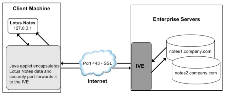
J-SAM overview 429
Chapter 16: Secure Application Manager
Figure 39: Java Secure Application Manager and Enhanced Lotus Notes Support
Figure 39 shows the Lotus Notes client location value to be configured to the
localhost.
1. The user starts the Lotus Notes client with the location setting. The client uses
the HTTP Tunnel proxy setting for its location setting. Note that you must set
the HTTP Tunnel proxy setting to use localhost (or 127.0.0.1) as the proxy
address and 1352 as the proxy port.
2. The Lotus Notes client connects to the Secure Application Manager and starts
sending requests for email.
3. The Secure Application Manager encapsulates and forwards requests from the
Lotus Notes client to IVE over SSL.
4. The IVE un-encapsulates the client data and looks in the Lotus Notes request to
find the target Lotus Notes Server. The request is then forwarded to the target
server.
Each request in the Lotus Notes protocol encodes the target server for the
request. When Lotus Notes requests arrive from the application proxy, the IVE
server obtains the target server information from the requests and dispatches
the requests to the appropriate target server. Thus, this feature works
transparently even if there are multiple Lotus Notes Servers accessed by a
single user. Note that you must create JSAM ACLs on the IVE that enable access
to these target servers.
5. The Lotus Notes Server responds with email data to the IVE.
6. The IVE encapsulates and forwards the response from the Lotus Notes Server
to the Secure Application Manager over SSL.
7. The Secure Application Manager un-encapsulates the information sent from the
IVE and forwards the normal response from the Lotus Notes Server to the Lotus
Notes client.
Juniper Networks Secure Access Administration Guide
430 J-SAM overview
Configuring the Lotus Notes client
Before a remote user can connect from Lotus Notes to a Lotus Notes Server through
the IVE, the user must edit the Lotus Notes client to set a Location document Proxy
field to the PC’s localhost port. The Location document edited should be the one
used for remote access, such as the Remote Location or Travel Location setting.
Setting the Proxy field to the PC’s localhost port enables the IVE to connect to
multiple Lotus Notes Servers, including those set up as pass-through servers.
You should use the following configuration in these cases:
JSAM is configured to use Lotus Notes as a standard application.
The Lotus Notes client can connect to multiple Lotus Notes servers.
To configure a Lotus Notes client for use with the IVE:
1. From the Lotus Notes client, choose File > Mobile > Locations.
2. Select the Location used for remote access and then click Edit Location.
3. In the Basics tab, click the Proxy icon.
4. In the Proxy Server Configuration box, enter the following in the HTTP
Tunnel field: 127.0.0.1:1352
5. Click OK.
Standard application support: Citrix Web Interface for MetaFrame (NFuse Classic)
Remote users can use the Citrix Web Interface for MetaFrame server to access a
variety of applications via the IVE. This process does not require any alterations to
the user permissions on the client.

J-SAM overview 431
Chapter 16: Secure Application Manager
After a user browses to a Citrix Web Interface for MetaFrame server and selects an
application, the server sends an ICA file to the client. When the IVE rewrites the ICA
file, it replaces host names and IP addresses with pre-provisioned loopback IP
addresses. The ICA client then sends application requests to one of the loopback IP
addresses. The Secure Application Manager encapsulates the data and sends it to
the IVE. The IVE un-encapsulates the data and sends it to the appropriate
MetaFrame server using port 1494 or 2598 (depending on the client).
Custom application support: Citrix published applications configured from the native
client
When enabling Citrix published applications on the Citrix native client through the
IVE, you must complete the steps outlined in the following sections.
1. “Specifying custom applications on JSAM to port forward” on page 432
2. “Configuring the Citrix Metaframe server for published applications” on
page 433
NOTE:
JSAM does not automatically launch when Embedded Applications are set to
“Auto” in the Citrix Web Interface for MetaFrame console. In these cases, we
recommend that you configure JSAM to automatically launch after the user
signs into the IVE. Otherwise, end-users must manually launch JSAM before
using Citrix Web Interface for MetaFrame.
If a user attempts to use the server discovery feature and then attempts to use
application discovery, the application discovery process fails. To resolve this
particular situation, shut down and restart Citrix Program neighborhood.
The IVE serves as an alternative to deploying the Citrix Secure Gateway (CSG).
To use the applet-mode of the Java client, make sure to enable Java applet
support on the Users > User Roles > Select Role > Web > Options page of
the admin console.
If you set the Network Protocol setting in the Citrix Program Neighborhood
client to TCP/IP, the IVE does not support the application through JSAM since
the TCP/IP setting produces UDP traffic.

Juniper Networks Secure Access Administration Guide
432 J-SAM overview
3. “Configuring the Citrix client for published applications” on page 433
Specifying custom applications on JSAM to port forward
When configuring JSAM to work with published applications, you must open 2
ports—ports 80 and 1494. Each opened port creates a connection through JSAM to
the Citrix Metaframe server.
To specify published applications for JSAM to port forward:
1. Add a custom application through JSAM using the instructions in “Defining
resource profiles: JSAM” on page 435. When adding the custom application,
keep the following settings in mind:
Server name—For published applications, you must enter the Metaframe
server’s fully qualified DNS name, not its IP address.
Server port—For published applications, enter 80 and 1494. (Create one
entry for port 80 and another for port 1494.) If you have multiple
Metaframe servers, you must configure all of them on the same ports.
Client port—For published applications, enter 80 and 1494. (Create one
entry for port 80 and another for port 1494.)
2. If you have multiple internal domains, such as company-a.com and company-
b.com, add DNS domains to the IVE using settings in the System > Network >
Overview page of the admin console so that names such as app1.company-
a.com and app2.company-b.com resolve correctly.
3. If a remote user’s PC is set up to use a Web proxy in Internet Explorer,
configure the client machine to bypass the proxy server when the user
launches applications that need to connect to the Secure Application Manager.
For instructions, see “Configuring a PC that connects to the IVE through a
proxy Web server” on page 420.
4. Enable JSAM to associate IP loopback addresses with application servers on
specific ports either by enabling JSAM to edit the hosts file on your users’
systems (as explained in “Resolving host names to localhost” on page 424) or
by creating an external DNS to route client application traffic to the J-SAM
applet (as explained in “Configuring external DNS servers and user machines”
on page 425).
NOTE:
These instructions assume that you are not using the Citrix Web Interface for
Citrix Presentation Server (formerly known as Nfuse server). For information
about presentation servers, see “Standard application support: Citrix Web
Interface for MetaFrame (NFuse Classic)” on page 430.
These instructions do not cover how to configure the standard Citrix
application option. (For standard Citrix application instructions, use settings
in the Users > Resource Profiles > Web > Web Applications/Pages page
of the admin console.) You can enable both the standard Citrix application
and the custom Citrix application—these settings do not impact each other.
J-SAM overview 433
Chapter 16: Secure Application Manager
Configuring the Citrix Metaframe server for published applications
When enabling Citrix published applications through the IVE, you must enable the
XML service DNS address resolution on the metaframe server. The following
instructions describe how to do this on Metaframe XP
To configure the Citrix metaframe server to work with the IVE:
1. Open the Citrix Management Console.
2. Right-click on the name of your server farm and click Properties.
3. Select the MetaFrame Settings tab.
4. Select the Enable XML Service DNS address resolution checkbox.
5. Click OK.
Configuring the Citrix client for published applications
When enabling Citrix published applications through the IVE, you must create an
ICA connection on each Citrix client using the instructions that follow.
To configure the Citrix client to work with the IVE:
1. Open the Citrix Program Neighborhood and choose the Add ICA Connection
option.
2. In the Add New ICA Connection wizard, select the connection type that your
computer uses to communicate.
3. In the next screen:
a. Enter a description of the new ICA Connection.
b. Select TCP/IP + HTTP as the network protocol.
c. Select Published Application.
d. Click Server Location, and then:
i. Deselect the Use Default checkbox.
ii. Click Add in the Locate Server or Published Application dialog box.
iii. Confirm that HTTP/HTTPS is selected from the Network Protocol list.
iv. Enter the metaframe server DNS in the Add Server Location Address
dialog box.
v. Enter 80 in the port field.
vi. Click OK in the Add Server Location Address dialog box and the
Locate Server or Published Application dialog box.
a. Select an application from the Published Application list.

Juniper Networks Secure Access Administration Guide
434 J-SAM overview
4. Enter information in the remaining wizard screens as prompted.
Custom application support: Citrix secure gateways
When enabling Citrix secure gateways (CSGs) through the IVE, you must complete
the steps outlined in the following sections:
1. Disable Citrix NFuse as a standard application through the Users > Resource
Profiles > Web > Web Applications/Pages page of the admin console.
2. Specify applications for JSAM to port forward by adding a custom application
through JSAM. Use the instructions in “Defining resource profiles: JSAM” on
page 435. When adding the custom application, keep the following settings in
mind:
Server name—For CSGs, you must enter the Citrix secure gateway server’s
fully qualified DNS name, not its IP address.
Server port—For CSGs, enter 443. If you have multiple Citrix secure
gateway servers, you must configure all of them on the same port.
Client port—For CSGs, enter 443. (Create one entry for port 80 and
another for port 443.)
3. If you have multiple internal domains, such as company-a.com and company-
b.com, add DNS domains to the IVE using settings in the System > Network >
Overview page of the admin console so that names such as app1.company-
a.com and app2.company-b.com resolve correctly.
4. If a remote user’s PC is set up to use a Web proxy in Internet Explorer,
configure the client machine to bypass the proxy server when the user
launches applications that need to connect to the Secure Application Manager.
For instructions, see “Configuring a PC that connects to the IVE through a
proxy Web server” on page 420.
5. Enable JSAM to associate IP loopback addresses with application servers on
specific ports either by enabling JSAM to edit the hosts file on your users’
systems (as explained in “Resolving host names to localhost” on page 424) or
by creating an external DNS to route client application traffic to the J-SAM
applet (as explained in “Configuring external DNS servers and user machines”
on page 425).
6. Setup your Citrix Secure Gateway and confirm that it works on your desktop.
7. Add a bookmark to the end-users’ IVE home page that points to the list of Citrix
secure gateway servers and use the IVE’s Selective Rewrite feature to turn off
rewriting for the URL.
Or, if you do not want to create a bookmark through the IVE, simply instruct
users to access the URL using their Web browser’s address bar instead of the
IVE address bar.
NOTE: You cannot enable the Citrix NFuse standard application and Citrix Secure
Gateways (CSGs) custom applications through JSAM on the same IVE.

Defining resource profiles: JSAM 435
Chapter 16: Secure Application Manager
Defining resource profiles: JSAM
JSAM resource profiles configure JSAM to secure traffic to a client/server
application. When you create a JSAM application resource profile, the JSAM client
tunnels network traffic generated by the specified client applications to servers in
your internal network.
For more information about resource profiles, see “Resource profiles” on page 71.
For more information about JSAM, see “J-SAM overview” on page 417.
To create a JSAM application resource profile:
1. Navigate to the Users > Resource Profiles > SAM > Client Applications
page in the admin console.
2. Click New Profile.
3. From the Type list, choose JSAM.
NOTE: When creating JSAM resource profiles, note that the resource profiles do
not contain bookmarks. Therefore, end-users will not see a link for the configured
application in the end-user interface. To access the applications and servers that
JSAM intermediates, users must first launch JSAM and then launch the specified
application using standard methods (such as the Windows Start menu or a
desktop icon). For information about automatically launching JSAM when the user
signs into the IVE, see “Specifying role level JSAM options” on page 442.
Also note that when you enable JSAM or WSAM through rewriting autopolicies for
Web resource profiles, the IVE automatically creates JSAM or WSAM autopolicies
for you. You can only view these SAM policies through the appropriate Web
resource profile—not through the SAM resource profile pages of the admin
console. For more information, see “Defining a rewriting autopolicy” on
page 300.

Juniper Networks Secure Access Administration Guide
436 Defining resource profiles: JSAM
4. From the Application list, select one of the following options.
Custom—Select this option to intermediate traffic to a custom application.
Then:
i. In the Server name field, enter the name or IP address of the remote
server. If you are using automatic host mapping, enter the server as it
is known to the application. If you enter an IP address, note that end-
users must connect to JSAM using that IP address in order to connect
to the specified server. For information about system variables and
attributes you can use in this field, see “Using system variables in
realms, roles, and resource policies” on page 869.
ii. In the Server Port field, enter the port on which the remote server
listens for client connections. For example, to forward Telnet traffic
from a remote machine, specify port 23 for both the client port (on
which JSAM listens) and the server port (on which the Telnet server
listens).
iii. In the Client Loopback IP field, provide a static loopback address. If
you do not provide a static IP loopback address, the IVE assigns an IP
loopback address dynamically. For more information about static
loopback addresses, see “Assigning IP loopback addresses to servers”
on page 421.
iv. In the Client Port field, enter the port on which JSAM should listen for
client application connections. Typically, the local port value is the
same value as the server port; the local port value usually only differs
for Linux or Macintosh non-root users who want to add applications for
port forwarding that use ports under 1024.
NOTE: To disable the registry change made by JSAM and restore the original copy
of the etc/hosts file, users must uninstall the JSAM client using settings in the
Preferences > Applications page of the end-user console. To re-enable the
change, they need to reboot.
NOTE:
When configuring an external DNS, do not use IP loopback addresses in the
127.0.2.x range because the IVE reserves IP loopback addresses in that range
for use with Citrix NFuse.
If you want to modify a static loopback address for a JSAM application server
configured on multiple ports, you must delete all applications referring to this
application server and re-enter these applications with the new static
loopback address.

Defining resource profiles: JSAM 437
Chapter 16: Secure Application Manager
You may configure more than one application on a single port, such as
app1.mycompany.com, app2.mycompany.com, app3.mycompany.com.
Either you assign a static loopback address or the IVE assigns a
dynamic loopback address (127.0.1.10, 127.0.1.11, 127.0.1.12) to
each application. JSAM then listens on these multiple loopback
addresses on the specified port. For example, when there is traffic on
127.0.1.12 on the specified port, the IVE forwards the traffic to the
app3.mycompany.com destination host.
v. Click Add.
vi. Select the Allow JSAM to dynamically select an available port if the
specified client port is in use checkbox if JSAM is listening for
multiple hosts on the same port and you want JSAM to select an
available port when the client port you specify is taken. The client
application must allow you to specify the port number for the
connection in order to use this option.
vii. Select the Create an access control policy allowing SAM access to
these servers checkbox to enable access to the list of servers specified
in the Server column (enabled by default).
Lotus Notes—Select this option to intermediate traffic from the Lotus
Notes fat client application, as explained in “Standard application support:
Lotus Notes” on page 428. Then, in the Autopolicy: SAM Access Control
section, create a policy that allows or denies users access to the Lotus
Notes server:
i. If it is not already enabled, select the Autopolicy: SAM Access Control
checkbox.
ii. In the Resource field, specify the application server to which this
policy applies. You can specify the server as a fully-qualified host name
or an IP/netmask pair. For example, if the fully-qualified hostname is
notes1.yourcompany.com, add notes1.yourcompany.com and notes1 to
the Resource field.
iii. From the Action list, select Allow to enable access to the specified
server or Deny to block access to the specified server.
iv. Click Add.
NOTE:
If you select the Lotus Notes option, or you configure the Lotus Notes client to
connect to multiple Lotus Notes servers, you should configure the Lotus Notes
client appropriately to work with the IVE. For instructions, see “Configuring
the Lotus Notes client” on page 430.
You can only use JSAM to configure access to one Lotus Notes application per
user role.

Juniper Networks Secure Access Administration Guide
438 Defining resource profiles: JSAM
Microsoft Outlook—Select this option to intermediate traffic from the
Microsoft Outlook application, as explained in “Standard application
support: MS Outlook” on page 427. Then:
i. Enter the hostname for each MS Exchange server in the Servers field.
For example, if the fully-qualified hostname is
exchange1.yourcompany.com, add exchange1.yourcompany.com to the
Servers field. For information about system variables and attributes
you can use in this field, see “Using system variables in realms, roles,
and resource policies” on page 869.
ii. Select the Create an access control policy allowing SAM access to
this server checkbox to enable access to the server specified in the
previous step (enabled by default).
NetBIOS file browsing—Select this option to tunnel NetBIOS traffic
through JSAM. Then:
i. Enter the fully-qualified host name for your application servers in the
Servers field.
NOTE:
You must enter the full name of the servers in this field since the IVE creates
direct one-to-one mappings between the servers you enter here and IP
addresses in the etc/hosts file. For more information about registry changes
made by JSAM, see the Client-side Changes Guide on the Juniper Networks
Customer Support Center.
The IVE does not support Outlook through SVW, since Outlook applications
require HKLM registry key changes. For more information, see “Enabling the
Secure Virtual Workspace” on page 244.
NOTE: You can only use JSAM to configure access to one Microsoft Outlook
application per user role.
NOTE:
You must enter the full name of the servers in this field since the IVE creates
direct one-to-one mappings between the servers you enter here and IP
addresses in the etc/hosts file. For more information about registry changes
made by JSAM, see the Client-side Changes Guide on the Juniper Networks
Customer Support Center.
If you want to enable drive mapping on a Windows client machine, use the
standard NetBIOS file browsing option. When you do, JSAM automatically
modifies the registry to disable port 445 on Windows XP machines, which
forces Windows XP to use port 137, 138, or 139 for drive-mapping. Windows
XP users need to reboot one time to enable the registry change to take effect.

Defining role settings: JSAM 439
Chapter 16: Secure Application Manager
ii. Select the Create an access control policy allowing SAM access to
this server checkbox to enable access to the server specified in the
previous step (enabled by default).
5. Enter a unique name and optionally a description for the resource profile. The
IVE displays this information in the Client Application Sessions section of the
IVE end-user home page.
6. Click Save and Continue.
7. In the Roles tab, select the roles to which the resource profile applies and click
Add.
The selected roles inherit the autopolicy created by the resource profile. If it is
not already enabled, the IVE also automatically enables the SAM option in the
Users > User Roles > Select Role > General > Overview page of the admin
console for all of the roles you select.
8. Click Save Changes.
Defining role settings: JSAM
This section contains the following information about configuring role-level settings
for JSAM:
“Specifying applications for JSAM to secure” on page 439
“Specifying role level JSAM options” on page 442
Specifying applications for JSAM to secure
Use the Applications tab to specify the applications for which JSAM secures traffic.
Note that for JSAM to work, the client application needs to connect to the local PC
where JSAM is running as the application server.
NOTE:
You can only use JSAM to configure NetBIOS file browsing once per user role.
The IVE does not support NetBIOS file browsing through SVW, since NetBIOS
requires HKLM registry key changes. For more information, see “Enabling the
Secure Virtual Workspace” on page 244.
NOTE: Information in this section is provided for backwards compatibility. We
recommend that you secure traffic using JSAM resource profiles instead, since
they provide a simpler, more unified configuration method. For more
information, see “Defining resource profiles: JSAM” on page 435.

Juniper Networks Secure Access Administration Guide
440 Defining role settings: JSAM
To specify applications for JSAM to secure:
1. In the admin console, choose Users > User Roles > Select Role > SAM >
Applications.
2. Select Add Application.
3. Enter the name of the application and, optionally, a description. This
information displays in the Client Application Sessions section of the IVE end-
user home page.
4. Choose either:
Standard application—Select Citrix NFuse, Lotus Notes, or Microsoft
Outlook/Exchange.
Custom application—
i. In the Server name field, enter the DNS name of the server or the
server IP address. If entering the DNS name, enter name of the remote
server as it is known to the application if you are using automatic host
mapping. For information about system variables and attributes you
can use in this field, see “Using system variables in realms, roles, and
resource policies” on page 869.
i. In the Server Name field, enter .
ii. In the Server Port field, enter the port on which the remote server
listens for client connections.
For example, to forward Telnet traffic from a remote machine, specify
port 23 for both the client port (on which JSAM listens) and the server
port (on which the Telnet server listens).
NOTE:
The IVE does not support the standard JSAM applications Outlook and Netbios
file browsing through SVW, since these applications require registry key
changes. However, the IVE does support the Citrix and Lotus Notes JSAM
standard applications through SVW. For more information, see “Enabling the
Secure Virtual Workspace” on page 244.
If you select the Lotus Notes option, or you configure the Lotus Notes client to
connect to multiple Lotus Notes servers, you should configure the Lotus Notes
client appropriately to work with the IVE. For instructions, see “Configuring
the Lotus Notes client” on page 430.
NOTE: To disable the registry change made by JSAM and restore the original copy
of the etc/hosts file, users must uninstall the JSAM client using settings in the
Preferences > Applications page of the end-user console. To re-enable the
change, they need to reboot.

Defining role settings: JSAM 441
Chapter 16: Secure Application Manager
iii. In the Client Loopback IP field, provide a static loopback address. If
you do not provide a static IP loopback address, the IVE assigns an IP
loopback address dynamically. For more information about static
loopback addresses, see “Assigning IP loopback addresses to servers”
on page 421.
iv. In the Client Port field, enter the port on which JSAM should listen for
client application connections.
Typically, the local port value is the same value as the server port; the
local port value usually only differs for Linux or Macintosh non-root
users who want to add applications for port forwarding that use ports
under 1024.
You may configure more than one application on a single port, such as
app1.mycompany.com, app2.mycompany.com, app3.mycompany.com.
Either you assign a static loopback address or the IVE assigns a
dynamic loopback address (127.0.1.10, 127.0.1.11, 127.0.1.12) to
each application. JSAM then listens on these multiple loopback
addresses on the specified port. For example, when there is traffic on
127.0.1.12 on the specified port, the IVE forwards the traffic to the
app3.mycompany.com destination host.
v. Select the Allow Secure Application Manager to dynamically select
an available port ... checkbox if JSAM is listening for multiple hosts on
the same port and you want JSAM to select an available port when the
client port you specify is taken. The client application must allow you
to specify the port number for the connection in order to use this
option.
vi. Click Add.
5. If a remote user’s PC is set up to use a Web proxy in Internet Explorer,
configure the client machine to bypass the proxy server when the user
launches applications that need to connect to the Secure Application Manager.
See “Configuring a PC that connects to the IVE through a proxy Web server” on
page 420.
NOTE:
When configuring an external DNS, do not use IP loopback addresses in
the 127.0.2.x range because the IVE reserves IP loopback addresses in
that range for use with Citrix NFuse.
If you want to modify a static loopback address for a JSAM application
server configured on multiple ports, you must delete all applications
referring to this application server and re-enter these applications with
the new static loopback address.

Juniper Networks Secure Access Administration Guide
442 Defining role settings: JSAM
6. Add DNS domains to the IVE if you have multiple internal domains, such as
company-a.com and company-b.com, so that names such as app1.company-a.com
and app2.company-b.com resolve correctly:
a. Navigate to the System > Network > Overview page in the admin
console.
b. Under DNS Name Resolution, add a comma-separated list of domains in
the to DNS Domains field.
c. Click Save Changes.
Specifying role level JSAM options
To specify JSAM options at the role level:
1. In the admin console, choose Users > User Roles > Select Role > SAM >
Options.
2. Under Secure Application Manager options, select the options to enable for
users:
Auto-launch Secure Application Manager—If enabled, the IVE
automatically launches the Secure Application Manager when a user signs
in. If you do not select this option, users must manually start the Secure
Application Manager from the Client Applications Sessions section of the
IVE end-user home page.
Auto-uninstall Secure Application Manager—If enabled, the IVE
automatically un-installs the Secure Application Manager after users sign
off.
Auto-allow application servers—If enabled, the IVE automatically creates
a SAM resource policy that allows access to the server specified in the
WSAM application and server lists and the JSAM application list.
3. Under Java SAM Options, select the options to enable for users:
User can add applications—If enabled, users can add applications. For
users to add applications, they need to know the application server DNS
name and client/server ports.
NOTE: Although you configure the Secure Application Manager to automatically
launch when users sign into the IVE, users can override this setting through the
Preferences > Applications page of the IVE end-user console. If disabled from
automatically launching, users need to manually start the Secure Application
Manager by clicking its link on the IVE home page.
NOTE: You may not see the Auto-allow option if you are using a new installation
or if an administrator hides the option. For more information on this option, see
“Setting system options” on page 575.

Defining resource policies: JSAM 443
Chapter 16: Secure Application Manager
When you enable this option, users can set up port forwarding to any host
or port in your enterprise. Before providing users with the ability to add
applications, please verify that this feature is consistent with your security
practices. If a user adds an application, the application remains available to
the user even if you later change disable the feature.
Automatic host-mapping—If enabled, the Secure Application Manager
edits the Windows PC hosts file and replaces entries of Windows
application servers with localhost. These entries are changed back to the
original data when a user closes the Secure Application Manager.
For the Java version of the Secure Application Manager to work, the client
application needs to connect to the local PC on which the Secure
Application Manager is running as the application server. The
recommended process for mapping application servers to a user’s local PC
is to enable automatic host-mapping, which enables the IVE to
automatically modify the PC’s hosts file to point application servers to the
PC’s localhost for secure port forwarding. Alternatively, you can configure
your external DNS server, as explained in “Configure your external DNS
server and user machines (if needed)” on page 96.
Skip web-proxy registry check—If enabled, JSAM does not check a user's
registry for a Web proxy. Some users do not have permissions to look at
their registries, so if JSAM tries to look at their registries, then users see an
error that they do not have permission. This option ensures that users do
not see this message.
Auto-close JSAM window on sign-out—If enabled, JS-AM automatically
closes when a user signs out of the IVE by clicking Sign Out in the IVE
browser window. JSAM continues to run if the user simply closes the
browser window.
4. Click Save Changes.
Defining resource policies: JSAM
This section contains the following instructions for configuring JSAM resource
policies:
“Automatically launching JSAM” on page 443
“Specifying application servers that users can access” on page 445
“Specifying resource level JSAM options” on page 447
Automatically launching JSAM
Use the Launch JSAM tab to write a Web resource policy that specifies a URL for
which the IVE automatically launches J-SAM on the client. The IVE launches J-SAM
in two scenarios:
When a user enters the URL in the Address field of the IVE home page.

Juniper Networks Secure Access Administration Guide
444 Defining resource policies: JSAM
When a user clicks a Web bookmark (configured by an administrator) on the
IVE home page to the URL.
This feature is useful if you enable applications that require J-SAM but don’t want to
require users to run J-SAM unnecessarily. This feature requires, however, that users
access the URL through the IVE home page. If users enter the URL in a browser
Address field, the IVE does not serve the request.
To write a Launch J-SAM resource policy:
1. In the admin console, choose Users > Resource Policies > Web.
2. If your administrator view is not already configured to show Launch JSAM
policies, make the following modifications:
a. Click the Customize button in the upper right corner of the page.
b. Select the Launch JSAM checkbox.
c. Click OK.
3. Select the Launch JSAM tab.
4. On the JSAM Autolaunch Policies page, click New Policy.
5. On the New Policy page, enter:
a. A name to label this policy.
b. A description of the policy (optional).
6. In the Resources section, specify the URLs to which this policy applies. See
“Specifying resources for a resource policy” on page 83 for more information.
To enable IP-based or case sensitivity matching for these resources, see
“Defining resource policies: General options” on page 355.
7. In the Roles section, specify:
Policy applies to ALL roles—Choose this option to apply this policy to all
users.
Policy applies to SELECTED roles—Choose this option to apply this policy
only to users who are mapped to roles in the Selected roles list. Make sure
to add roles to this list from the Available roles list.
Policy applies to all roles OTHER THAN those selected below—Choose
this option to apply this policy to all users except for those who map to the
roles in the Selected roles list. Make sure to add roles to this list from the
Available roles list.
NOTE: The IVE provides tight integration with Citrix. If you specify Citrix as a
standard J-SAM application, the IVE automatically launches J-SAM when a user
selects an ICA file even if the URL is not configured as a resource policy.

Defining resource policies: JSAM 445
Chapter 16: Secure Application Manager
8. In the Action section, specify:
Launch JSAM for this URL—The IVE downloads the Java Secure
Application Manager to the client and then serves the requested URL.
Don't Launch JSAM for this URL—The IVE does not download the Java
Secure Application Manager to the client for the requested URL. This option
is useful if you want to temporarily disable J-SAM auto-launching for the
specified URLs.
Use Detailed Rules—To specify one or more detailed rules for this policy.
See “Writing a detailed rule” on page 88 for more information.
9. Click Save Changes.
Specifying application servers that users can access
When you enable the Secure Application Manager access feature for a role, you
need to create resource policies that specify which application servers a user may
access. These policies apply to both the Java version and Windows version of the
Secure Application Manager (J-SAM and W-SAM, respectively). When a user makes
a request to an application server, the IVE evaluates the SAM resource policies. If
the IVE matches a user’s request to a resource listed in a SAM policy, the IVE
performs the action specified for the resource.
When writing a SAM resource policy, you need to supply key information:
Resources—A resource policy must specify one or more resources to which the
policy applies. When writing a SAM policy, you need to specify application
servers to which a user may connect.
Roles—A resource policy must specify the roles to which it applies. When a
user makes a request, the IVE determines what policies apply to the role and
then evaluates those policies that correspond to the request. SAM resource
policies apply to users requests made through either version, J-SAM or W-SAM.
Actions—A Secure Application Manager resource policy either allows or denies
access to an application server.
You can create resource policies through the standard interface (as described in this
section) or through resource profiles (recommended method).
NOTE: J-SAM launches automatically for the specified URL only if a user enters the
URL or selects a bookmark to the URL on the IVE home page (Browsing >
Bookmarks). The bookmark does not launch the application that is configured
through JSAM, but launches JSAM itself.
NOTE: Information in this section is provided for backwards compatibility. We
recommend that you secure traffic using JSAM resource profiles instead, since
they provide a simpler, more unified configuration method. For more
information, see “Defining resource profiles: JSAM” on page 435.
Juniper Networks Secure Access Administration Guide
446 Defining resource policies: JSAM
The IVE platform’s engine that evaluates resource policies requires that the
resources listed in a policy’s Resources list follow a canonical format, as explained
in “Specifying resources for a resource policy” on page 83.
To write a Secure Application Manager resource policy:
1. In the admin console, choose Users > Resource Policies > SAM > Access.
2. On the Secure Application Manager Policies page, click New Policy.
3. On the New Policy page, enter:
a. A name to label this policy.
b. A description of the policy (optional).
4. In the Resources section, specify the application servers to which this policy
applies.
5. In the Roles section, specify:
Policy applies to ALL roles—Choose this option to apply this policy to all
users.
Policy applies to SELECTED roles—Choose this option to apply this policy
only to users who are mapped to roles in the Selected roles list. Make sure
to add roles to this list from the Available roles list.
Policy applies to all roles OTHER THAN those selected below—Choose
this option to apply this policy to all users except for those who map to the
roles in the Selected roles list. Make sure to add roles to this list from the
Available roles list.
6. In the Action section, specify:
Allow socket access—Choose this option to grant access to the application
servers specified in the Resources list.
Deny socket access—Choose this option to deny access to the application
servers specified in the Resources list.
Use Detailed Rules—Choose this option to specify one or more detailed
rules for this policy. See “Writing a detailed rule” on page 88 for more
information.
7. Click Save Changes.
8. On the Secure Application Manager Policies page, order the policies
according to how you want the IVE to evaluate them. Keep in mind that once
the IVE matches the resource requested by the user to a resource in a policy’s
(or a detailed rule’s) Resource list, it performs the specified action and stops
processing policies.

Defining resource policies: JSAM 447
Chapter 16: Secure Application Manager
Specifying resource level JSAM options
Use the Options tab to specify the SAM resource option to match IP addresses to
host names specified as resources in your SAM resource policies. When you enable
this option, the IVE looks up IP addresses corresponding to each host name
specified in a SAM resource policy. When a user tries to access a server by
specifying an IP address rather than the host name, the IVE compares the IP to its
cached list of IP addresses to determine if a host name matches an IP. If there is a
match, then the IVE accepts the match as a policy match and applies the action
specified for the resource policy.
When you enable this option, the IVE compiles a list of host names specified in the
Resources field of each SAM resource policy. The IVE then applies the option to this
comprehensive list of host names.
To specify the SAM resource option:
1. In the admin console, choose Users > Resource Policies > SAM > Options.
2. Select IP based matching for Hostname based policy resources. When you
select this option, the IVE looks up the IP address corresponding to each host
name specified in a Secure Application Manager resource policy. When a user
tries to access a server by specifying an IP address rather than the host name,
the IVE compares the IP to its cached list of IP addresses to determine if a host
name matches an IP. If there is a match, then the IVE accepts the match as a
policy match and applies the action specified for the resource policy.
3. Click Save Changes.
NOTE: This option does not apply to host names that include wildcards and
parameters.
Juniper Networks Secure Access Administration Guide
448 Defining resource policies: JSAM

449
Chapter 17Z
Telnet/SSH
The Telnet/SSH option enables users to connect to internal server hosts in the clear
using Telnet protocols or to communicate over an encrypted Secure Shell (SSH)
session through a Web-based terminal session emulation. This feature supports the
following applications and protocols:
Network Protocols—Supported network protocols include Telnet and SSH.
Terminal Settings—Supported terminal settings include VT100, VT320, and
derivatives and screen buffers.
Security—Supported security mechanisms include Web/client security using
SSL and host security (such as SSH if desired).
You can create secure terminal session bookmarks that appear on the welcome
page for users mapped to a specific role. A terminal session bookmark defines
Terminal Session information for Telnet or SSH sessions that users may launch.
These sessions give users access to a variety of networked devices, including UNIX
servers, networking devices, and other legacy applications, that utilize terminal
sessions. The IVE supports SSH versions V1 and V2 and uses the following SSH
versions: OpenSSH_2.9.9p1, SSH protocols 1.5/2.0, and OpenSSL 0x0090607f.
This section contains the following information about Telnet/SSH:
“Licensing: Telnet/SSH availability” on page 450
“Task summary: Configuring the Telnet/SSH feature” on page 450
“Defining resource profiles: Telnet/SSH” on page 450
“Defining role settings: Telnet/SSH” on page 454
“Defining resource policies: Telnet/SSH” on page 456
NOTE: When communicating over an encrypted Secure Shell (SSH) session, note
that the Telnet/SSH feature does not support using the ^J character combination.
(Some applications use this character combination to justify text). If you want to
use this character combination, we recommend that you find a java applet that
supports it and upload that applet through the IVE using the hosted Java applets
feature.

Juniper Networks Secure Access Administration Guide
450 Licensing: Telnet/SSH availability
Licensing: Telnet/SSH availability
If you are using an SA-700 appliance, you must install a Core Clientless Access
upgrade license in order to access the Telnet/SSH feature.
Task summary: Configuring the Telnet/SSH feature
To configure the Telnet/SSH feature:
1. Create resource profiles that enable access to Telnet and SSH servers, include
bookmarks that link to those servers, and assign the bookmarks to user roles
using settings in the Users > Resource Profiles > Telnet/SSH page of the
admin console.
We recommend that you use resource profiles to configure Telnet/SSH (as
described above). However, if you do not want to use resource profiles, you can
configure Telnet/SSH using role and resource policy settings in the following
pages of the admin console instead:
a. Create resource policies that enable access to Telnet and SSH servers using
settings in the Users > Resource Policies > Telnet/SSH > Sessions page
of the admin console.
b. Determine which user roles may access the Telnet and SSH servers that
you want to intermediate, and then enable Telnet/SSH access for those
roles through the Users > User Roles > Select Role > General >
Overview page of the admin console.
c. Create bookmarks to your Telnet and SSH servers using settings in the
Users > User Roles > Select Role > Telnet/SSH > Access page of the
admin console.
2. After configuring Telnet/SSH using resource profiles or roles and resource
policies, you can modify general role and resource options in the following
pages of the admin console:
a. (Optional) Enable users to create their own connections to Telnet and SSH
sessions using settings in the Users > User Roles > Select Role >
Telnet/SSH > Options page of the admin console.
b. (Optional) Enable the IVE to match IP addresses to host names and disable
the auto-allow bookmarks option using settings in the Users > Resource
Policies> Telnet/SSH > Options page of the admin console.
Defining resource profiles: Telnet/SSH
A Telnet/SSH resource profile is a resource profile that enables users to connect to
internal server hosts in the clear using Telnet protocols or to communicate over an
encrypted Secure Shell (SSH) session through a Web-based terminal session
emulation.
Defining resource profiles: Telnet/SSH 451
Chapter 17: Telnet/SSH
To create a Telnet/SSH resource profile:
1. Navigate to the Users > Resource Profiles > Telnet/SSH page in the admin
console.
2. Click New Profile.
3. From the Type list, specify the session type (Telnet or SSH) for this resource
profile.
4. Enter a unique name and optionally a description for the resource profile. (This
name becomes the default bookmark’s name.)
5. In the Host field, enter the name or IP address of the server to which this
resource profile should connect. For information about system variables and
attributes that you can include in this field, see “Using system variables in
realms, roles, and resource policies” on page 869.
6. Select the Create an access control policy allowing Telnet/SSH access to this
server checkbox to enable access to the server specified in the previous step
(enabled by default).
7. In the Port field, enter the port on which the IVE should connect to the server.
(By default, the IVE populates this field with port number 23 if you select Telnet
and port number 22 if you select SSH.)
8. If you want to pass the user’s credentials to the server, enter a static username,
the <username> variable, or another IVE-appropriate session variable in the
Username field. (Required for SSH sessions.)
9. Click Save and Continue.
10. In the Roles tab, select the roles to which the resource profile applies and click
Add.
The selected roles inherit the autopolicy and bookmarks created by the
resource profile. If it is not already enabled, the IVE also automatically enables
the Telnet/SSH option in the Users > User Roles > Select Role > General >
Overview page of the admin console for all of the roles you select.
11. Click Save Changes.
12. (Optional) In the Bookmarks tab, modify the default bookmark created by the
IVE and/or create new ones using instructions in “Defining a Telnet/SSH
resource profile bookmark” on page 452. (By default, the IVE creates a
bookmark to the server defined in the Host field and displays it to all users
assigned to the role specified in the Roles tab.)

Juniper Networks Secure Access Administration Guide
452 Defining resource profiles: Telnet/SSH
Defining a Telnet/SSH resource profile bookmark
When you create a Telnet/SSH resource profile, the IVE automatically creates a
bookmark that links to the host that you specified in the resource profile. The IVE
enables you to modify this bookmark as well as create additional bookmarks to the
same host.
For more information about resource profile bookmarks, see “Defining
bookmarks” on page 78.
To associate bookmarks with Telnet/SSH resource profiles:
1. If you want to create a resource profile bookmark through the standard
resource profiles page:
a. Navigate to the Users > Resource Profiles > Telnet/SSH> Select
Resource Profile > Bookmarks page in the admin console.
b. Click the appropriate link in the Bookmark column if you want to modify
an existing bookmark. Or, click New Bookmark to create an additional
bookmark.
Alternatively, if you want to create a resource profile bookmark through the
user roles page:
a. Navigate to the Users > User Roles > Select Role > Telnet/SSH >
Sessions page in the admin console.
b. Click Add Session.
NOTE: When configuring bookmarks, note that:
To change the host, port, or username for a Telnet/SSH bookmark created
through a resource profile, you must edit the values through the resource
profile’s Resource tab (not its Bookmark tab).
You can only assign bookmarks to roles that you have already associated with
the resource profile—not all of the roles defined on the IVE. To change the list
of roles associated with the resource profile, use settings in its Roles tab.
Bookmarks simply control which links the IVE displays to users—not which
resources the users can access. For example, if you enable access to a Telnet
server through a resource profile but do not create a corresponding bookmark
to that server, the user can still access the server by entering it into the
Address field of the IVE home page.
Make sure to enter a unique set of parameters when defining a Telnet/SSH
bookmark. If you create two bookmarks that contain the same set of
parameters, the IVE deletes one of the bookmarks from the end-user view.
You will still be able to see both bookmarks, however, in the administrator
console.

Defining resource profiles: Telnet/SSH 453
Chapter 17: Telnet/SSH
c. From the Type list, choose Telnet/SSH Resource Profile. (The IVE does not
display this option if have not already created a Telnet/SSH resource
profile.)
d. Select an existing resource profile. (The IVE automatically populates the
Host and Port fields using settings from the selected resource profile.)
e. Click OK. (If you have not already associated the selected role with the
resource profile, the IVE automatically makes the association for you. The
IVE also enables any access control policies for the role that are required by
the resource profile.)
f. If this role is not already associated with the selected resource profile, the
IVE displays an informational message. If you see this message, click Save
Changes to add this role to the resource profile’s list of roles and to update
the profile’s autopolicies as required. Then, repeat the previous step to
create the bookmark.
2. Optionally change the name and description of the bookmark. (By default, the
IVE populates names the bookmark using the resource profile name.)
3. If you want to change the font size in the server display window, choose one of
the following options in the Font Size section:
Fixed size of _ pixels—Enter a size from 8 to 36 pixels. (By default, the IVE
sets the font size to 12.)
Resize to fit window—Dynamically changes the font size as you resize the
window. This option requires Internet Explorer. (Enabled by default.)
4. If you want to change the size of the server display window, select an option
from the Screen Size drop-down list. (By default, the IVE sets the window size
at 80 characters by 24 rows.)
5. If you want to change the number of rows that the server window retains to
display during scrolling, change the value in the Screen Buffer field (By default,
the IVE sets the buffer at 100 rows.)
6. If you are configuring the bookmark through the resource profile pages, under
Roles, specify the roles to which you want to display the bookmark:
ALL selected roles—Select this option to display the bookmark to all of the
roles associated with the resource profile.
NOTE: When you create a resource profile bookmark through the user roles page
(instead of the standard resource profiles page), the IVE only associates the
generated bookmark with the selected role. The IVE does not assign the
bookmark to all of the roles associated with the selected resource profile.
Juniper Networks Secure Access Administration Guide
454 Defining role settings: Telnet/SSH
Subset of selected roles—Select this option to display the bookmark to a
subset of the roles associated with the resource profile. Then select roles
from the ALL Selected Roles list and click Add to move them to the Subset
of selected roles list.
7. Click Save Changes.
Defining role settings: Telnet/SSH
You can use two different methods to create Telnet/SSH session bookmarks:
Create bookmarks through existing resource profiles (recommended)—
When you select this method, the IVE automatically populates the bookmark
with key parameters (such as the host, port, username, and session type) using
settings from the resource profile. Additionally, while you are creating the
associated resource profile, the IVE guides you through the process of creating
any required policies to enable access to the bookmark. For configuration
instructions, see “Defining a Telnet/SSH resource profile bookmark” on
page 452.
Create standard bookmarks—When you select this option, you must manually
enter all bookmark parameters during configuration. Additionally, you must
enable access to the Telnet/SSH feature and create resource policies that enable
access to the servers defined in the bookmark (as explained in “Task summary:
Configuring the Telnet/SSH feature” on page 450). For configuration
instructions, see “Creating advanced session bookmarks” on page 454.
This section contains the following information about defining bookmarks and role-
level settings for Telnet/SSH resources:
“Creating advanced session bookmarks” on page 454.
“Configuring general Telnet/SSH options” on page 455
Creating advanced session bookmarks
To create a bookmark for secure terminal sessions:
1. Choose Users > User Roles > Select Role > Telnet/SSH > Sessions in the
admin console.
NOTE: If you enable the Telnet/SSH option but do not give users the ability to
create their own bookmarks, make sure that you configure session bookmarks for
them. Otherwise, users cannot use this feature.
NOTE: Information in this section is provided for backwards compatibility. We
recommend that you configure access to Telnet and SSH servers through resource
profiles instead, since they provide a simpler, more unified configuration method.
For more information, see “Defining resource profiles: Telnet/SSH” on page 450.

Defining role settings: Telnet/SSH 455
Chapter 17: Telnet/SSH
2. Click Add Session. The New Telnet/SSH Session page loads.
3. From the Type list, choose Standard. (The IVE only displays the Type list if you
have already created a Telnet/SSH resource profile.)
4. Enter a bookmark name and description for the new Telnet/SSH session
(optional). If you specify a bookmark name and description, this information
appears on the Terminal Sessions page.
5. Enter the name or IP address of the remote host for this session in the Host
field. For information about system variables and attributes that you can
include in this field, see “Using system variables in realms, roles, and resource
policies” on page 869.
6. Select the Session Type, either Telnet or SSH Secure Shell, and specify the
port if different from the pre-populated port assignment.
7. Provide a username or use the <username>, or other IVE-appropriate, session
variable.
8. Specify the Font Size by selecting one of the following:
Fixed size of _ pixels—enter a size from 8 to 36 pixels.
Resize to fit window—dynamically changes the font size as you resize the
window. This option requires Internet Explorer.
9. Select the Screen Size using the drop-down list.
10. Specify the Screen Buffer size.
11. Click Save Changes or Save + New.
Configuring general Telnet/SSH options
You can enable users to create their own Telnet/SSH bookmarks, browse to a
terminal session, and to configure the IVE to create Telnet/SSH resource policies
that allow access to the servers specified in the session bookmarks.
NOTE:
In addition to creating bookmarks for secure terminal sessions, you must
create a resource policy allowing Telnet/SSH sessions for the role, or enable
Auto-allow role Telnet/SSH sessions on the Telnet/SSH > Options tab to
automatically allow access to the resources defined in the session bookmark.
Make sure to enter a unique set of parameters when defining a Telnet/SSH
bookmark. If you create two bookmarks that contain the same set of
parameters, the IVE deletes one of the bookmarks from the end-user view.
You will still be able to see both bookmarks, however, in the administrator
console.
Juniper Networks Secure Access Administration Guide
456 Defining resource policies: Telnet/SSH
When you allow users to browse to a terminal session, note that they can use two
different methods:
Use the IVE homepage—Users can enter the server and port that they want to
access into the Address field of the IVE home page. Valid formats for the URL
include:
Telnet://host:port
SSH://host:port
For example: Telnet://terminalserver.yourcompany.com:3389
Use the Web browser’s address bar—Users can enter the server and port that
they want to access (as well as session parameters such as font and window
size) into the address bars of their Web browsers using standard Web protocol.
For example:
https://iveserver/dana/term/newlaunchterm.cgi?protocol=telnet&host=termsrv.y
ourcompany.com&port=23&username=jdoe&fontsize=12&buffer=800&size=80x2
5
To specify general Telnet/SSH options:
1. In the admin console, choose Users > User Roles > Select Role > Telnet/SSH
> Options.
2. Enable User can add sessions to allow users to define their own session
bookmarks and to allows users to browse to a terminal session using telnet://
and ssh:// syntax as well as the /dana/term/newlaunchterm.cgi syntax. When
you enable this option, the Add Terminal Session button appears on the
Terminal Sessions page the next time a user refreshes the IVE welcome page.
3. Enable Auto-allow role Telnet/SSH sessions to enable the IVE to automatically
allow access to the resources defined in the session bookmark (rather than
having to create resource policies). Note that this only applies to role
bookmarks, not user bookmarks.
4. Click Save Changes.
Defining resource policies: Telnet/SSH
When you enable the Telnet/SSH access feature for a role, you need to create
resource policies that specify which remote servers a user may access. If the IVE
matches a user’s request to a resource listed in a Telnet/SSH policy, the IVE
performs the action specified for the resource.
NOTE: You may not see the Auto-allow option if you are using a new installation
or if an administrator hides the option. For more information on this option, see
“Setting system options” on page 575.

Defining resource policies: Telnet/SSH 457
Chapter 17: Telnet/SSH
You can create resource policies through the standard interface (as described in this
section) or through resource profiles (recommended method).
When writing a Telnet/SSH resource policy, you need to supply key information:
Resources—A resource policy must specify one or more resources to which the
policy applies. When writing a Telnet/SSH policy, you need to specify remote
servers to which a user may connect.
Roles—A resource policy must specify the roles to which it applies. When a
user makes a request, the IVE determines what policies apply to the role and
then evaluates those policies that correspond to the request.
Actions—A Telnet/SSH resource policy either allows or denies access to a
server.
The IVE engine that evaluates resource policies requires that the resources listed in
a policy’s Resources list follow a canonical format, as explained in “Specifying
resources for a resource policy” on page 83.
This section contains the following information about defining Telnet/SSH resource
policies:
“Writing Telnet/SSH resource policies” on page 457
“Matching IP addresses to host names” on page 458
Writing Telnet/SSH resource policies
To write a Telnet/SSH resource policy:
1. In the admin console, choose Users > Resource Policies > Telnet/SSH >
Access.
2. On the Telnet/SSH Policies page, click New Policy.
3. On the New Policy page, enter:
a. A name to label this policy.
b. A description of the policy. (optional)
4. In the Resources section, specify the servers to which this policy applies using
the guidelines described in “Specifying resources for a resource policy” on
page 83.
5. In the Roles section, specify:
Policy applies to ALL roles—Use this field to apply this policy to all users.
NOTE: Information in this section is provided for backwards compatibility. We
recommend that you configure access to Telnet and SSH servers through resource
profiles instead, since they provide a simpler, more unified configuration method.
For more information, see “Defining resource profiles: Telnet/SSH” on page 450.

Juniper Networks Secure Access Administration Guide
458 Defining resource policies: Telnet/SSH
Policy applies to SELECTED roles—Use this field to apply this policy only
to users who are mapped to roles in the Selected roles list. Make sure to
add roles to this list from the Available roles list.
Policy applies to all roles OTHER THAN those selected below—Use this
field to apply this policy to all users except for those who map to the roles
in the Selected roles list. Make sure to add roles to this list from the
Available roles list.
6. In the Action section, specify:
Allow access—Use this field to grant access to the servers specified in the
Resources list.
Deny access—Use this field to deny access to the servers specified in the
Resources list.
Use Detailed Rules—Use this field to specify one or more detailed rules for
this policy. See “Writing a detailed rule” on page 88 on page 220 for more
information.
7. Click Save Changes.
8. On the Telnet/SSH Policies page, order the policies according to how you want
the IVE to evaluate them. Keep in mind that once the IVE matches the resource
requested by the user to a resource in a policy’s (or a detailed rule’s) Resource
list, it performs the specified action and stops processing policies.
Matching IP addresses to host names
You can configure Telnet/SSH to match IP addresses to host names specified as
resources in your Telnet/SSH resource policies. When you enable this option, the
IVE looks up IP address corresponding to each host name specified in a Telnet/SSH
resource policy. When a user tries to access a server by specifying an IP address
rather than the host name, the IVE compares the IP to its cached list of IP addresses
to determine if a host name matches an IP. If there is a match, then the IVE accepts
the match as a policy match and applies the action specified for the resource policy.
When you enable this option, the IVE compiles a list of host names specified in the
Resources field of each Telnet/SSH resource policy. The IVE then applies the option
to this comprehensive list of host names.
To specify the Telnet/SSH resource option:
1. In the admin console, choose Users > Resource Policies > Telnet/SSH >
Options.
NOTE: This option does not apply to host names that include wildcards and
parameters.
Defining resource policies: Telnet/SSH 459
Chapter 17: Telnet/SSH
2. Select IP based matching for Hostname based policy resources. The IVE
looks up the IP address corresponding to each host name specified in a
Telnet/SSH resource policy. When a user tries to access a server by specifying
an IP address rather than the host name, the IVE compares the IP to its cached
list of IP addresses to determine if a host name matches an IP. If there is a
match, then the IVE accepts the match as a policy match and applies the action
specified for the resource policy.
3. Click Save Changes.
Juniper Networks Secure Access Administration Guide
460 Defining resource policies: Telnet/SSH

Licensing: Terminal Services availability 461
Chapter 18
Terminal Services
Use the Terminal Services feature to enable terminal emulation session on a
Windows terminal server, Citrix NFuse server, or Citrix Metaframe server.
This section contains the following information about Terminal Services:
“Licensing: Terminal Services availability” on page 461
“Task Summary: Configuring the Terminal Services feature” on page 461
“Terminal Services overview” on page 463
“Defining resource profiles: Terminal Services” on page 470
“Defining role settings: Terminal Services” on page 480
“Defining resource policies: Terminal Services” on page 489
Licensing: Terminal Services availability
The Terminal Services features (Windows Terminal Services and Citrix) are not
available on the SA 700 appliance.
Task Summary: Configuring the Terminal Services feature
To configure the Terminal Services feature:
1. Create resource profiles that enable access to Windows terminal servers or
Citrix servers, include session bookmarks that link to those servers, and assign
the session bookmarks to user roles using settings in the Users > Resource
Profiles > Terminal Services page of the admin console.
Juniper Networks Secure Access Administration Guide
462 Task Summary: Configuring the Terminal Services feature
We recommend that you use resource profiles to configure Terminal Services
(as described above). However, if you do not want to use resource profiles, you
can configure the Terminal Services feature using role and resource policy
settings in the following pages of the admin console instead:
a. Create resource policies that enable access to Windows terminal servers
and Citrix servers using settings in the Users > Resource Policies >
Terminal Services > Access page of the admin console. For instructions,
see “Specifying the Terminal Services resource option” on page 490.
b. Determine which user roles may access the Windows terminal servers and
Citrix servers that you want to intermediate, and then enable Terminal
Services access for those roles through the Users > User Roles > Select
Role > General > Overview page of the admin console.
c. Create session bookmarks to your Windows terminal servers and Citrix
servers using settings in the Users > User Roles > Select Role >
Terminal Services > Sessions page of the admin console. For
instructions, see “Defining role settings: Terminal Services” on page 480.
2. (Optional) After configuring Terminal Services using resource profiles or roles
and resource policies, you can modify general role and resource options in the
following pages of the admin console:
a. (Optional) Enable users to define their own terminal services sessions using
settings in the Users > User Roles > Select Role > Terminal Services >
Options page of the admin console. For instructions, see “Specifying
general Terminal Services options” on page 487. If you select this option,
you must also create corresponding resource policies or resource profiles
that enable access the specified resources, as explained in the beginning of
this section.
b. (Optional) Create links to a terminal session on the IVE that users can
access from an external Web site. For instructions, see “Creating links
from an external site to a terminal services session bookmark” on
page 485.
c. (Optional) Enable the IVE to match IP addresses to host names and enable
the auto-allow bookmarks option using settings in the Users > Resource
Policies> Terminal Services > Options page of the admin console.
3. (Citrix only) Specify where the IVE should obtain the Citrix client to upload to
the users’ systems through settings in the Users > User Roles > Select Role >
Terminal Services > Options page of the admin console. For instructions, see
“Specifying general Terminal Services options” on page 487.
Additionally, if you specify that the IVE should obtain a Citrix client from an
external Web site, you must:
a. Create a Web access resource policy that enables access to the Web site
where the Citrix client resides through settings in the Users > Resource
Policies > Web > Access > Web ACL page of the admin console. For
instructions, see “Defining resource policies: Web access” on page 324.

Terminal Services overview 463
Chapter 18: Terminal Services
b. Create a Web caching resource policy through settings in the Users >
Resource Policies > Web > Caching page of the admin console so the
user’s browser can deliver the Citrix client. (Note that you must enable the
Unchanged (do not add/modify caching headers) option.) For
instructions, see “Writing a caching resource policy” on page 332.
Terminal Services overview
Use the Terminal Services feature to enable a terminal emulation session on a
Windows terminal server, Citrix NFuse server, or Citrix Metaframe server. You can
also use this feature to deliver the terminal services through the IVE, eliminating the
need to use another Web server to host the clients.
This section includes the following information about the Terminal Services feature:
“Terminal Services user experience” on page 463
“Terminal Services execution” on page 464
“Configuring Citrix to support ICA load balancing” on page 467
“Comparing IVE access mechanisms for configuring Citrix” on page 469
Terminal Services user experience
From an end-user perspective, accessing secured terminal services resources
through the IVE is simple. When you enable the Terminal Services feature for a user
role, the end-user simply needs to:
1. Specify the resource that the user wants to access—The user can specify the
resource he wants to access by clicking a link or entering the resource in the
IVE browse bar. Or, if you enable auto-launch for a bookmark, the IVE
automatically launches the resource for the user when he signs into the IVE.
2. Enter credentials for the resource—When the user accesses a resource, the
IVE prompts him to enter his username and password (if required by the
resource). Or if you enable SSO, the IVE automatically sends this information to
the resource without prompting the user. Once the resource verifies the
credentials, the IVE launches the resource.
Users can access terminal services resources using the following methods:
Session bookmarks—A session bookmark defines various information,
including the server to which the user can connect, the terminal session’s
window parameters, and the username and password that the IVE sends to the
Windows terminal server or Metaframe server. You can create any number of
session bookmarks for a role, enabling the user to access multiple servers using
different session bookmarks for each. (Users can simultaneously open multiple
sessions to the same terminal server or to different servers.)

Juniper Networks Secure Access Administration Guide
464 Terminal Services overview
URLs from other Web sites—In most cases, users access session bookmarks
directly from the IVE end-user console. If you do not want to require users to
sign into the IVE end-user console in order to find and access terminal services
links, however, you can create URLs on other Web sites that point to session
bookmarks that you have already created on the IVE. Or, you can create URLs
that include all of the parameters that you want to pass to the Terminal
Services program, such as the host, ports, and terminal window parameters.
IVE browse bar—In addition to enabling users to link to terminal services links
through bookmarks and URLs, you can also enable them to access these
resources through the IVE browse bar on Windows systems. Users can access
Citrix Metaframe or Nfuse servers by entering ica://<hostname> in the browse
field. Or, users can access Microsoft terminal services or remote desktop
sessions by entering rdp://<hostname> in the browse field.
Terminal Services execution
Once a user accesses a terminal services resource, the IVE determines if it needs to
download an RDP client or ICA client to the user’s computer.
An RDP client is a Windows component that enables a connection between a
Windows terminal server and a user’s machine. RDP clients enable the user to run
an application on the server while only transmitting keyboard, mouse, and display
information over the network. The IVE comes pre-equipped with a default RDP
client (a Windows 2003 ActiveX control) that the IVE can install on your users’
machines if necessary. Once a connection is created, the IVE intermediates traffic
between the Windows terminal server and the RDP client installed on the user’s
system.
An ICA client, or Independent Computing Architecture (ICA) client, is a Citrix
component that enables a connection between a Citrix Metaframe server or server
farm and a user’s machine. ICA clients enable the user to run an application on the
server while only transmitting keyboard, mouse, and display information over the
network. The IVE can install the ICA client of your choice on your users’ machines if
necessary. Or, you can specify that the IVE should obtain an ICA client from the
Citrix Web site or another URL. The IVE then controls the connection to the Citrix
server using settings in its default ICA configuration file or a custom ICA file that
you upload to the IVE. Once a connection is created, the IVE intermediates traffic
between the Metaframe server and the ICA client installed on the user’s system.
The following sections specify the criteria that the IVE uses to determine when to
install an RDP client or ICA client on the user’s machine.
NOTE: If you create links on external servers to Terminal Services bookmarks on
the IVE and you are using multiple customized sign-in URLs, some restrictions
occur. For more information, see the note in “Sign-in policies” on page 181.
NOTE: For information about additional files installed by the IVE when you enable
the Terminal Services feature, as well as the rights required to install and run the
associated clients, see the Client-side Changes Guide on the Juniper Customer
Support Center.

Terminal Services overview 465
Chapter 18: Terminal Services
Determining when to install the native RDP client vs. ActiveX
The IVE considers the following factors when determining whether to install its
default RDP client on the user’s computer:
Does a native fat client exist on the user’s machine? RDP clients are
available as fat clients and ActiveX clients. Many Windows systems come pre-
installed with an RDP fat client. If the user is not trying to access an SSO-
enabled resource, this native RDP client is sufficient for accessing a Windows
terminal server through the IVE.
Is SSO enabled for the specified resource? Native RDP clients do not support
single sign-on (SSO). For this reason, the IVE checks whether SSO is enabled
through the IVE bookmark in order to determine whether or not the user needs
the ActiveX client.
Is an ActiveX client installed on the user’s machine? If the native RDP fat
client is not available on the user’s system, or if SSO is enabled through the
bookmark, the IVE checks whether an ActiveX version of the RDP client is
available.
Determining when to install the native ICA client vs. ActiveX
The IVE considers the following factors when determining whether to install a
native ICA client or ActiveX on the user’s computer:
Is the TCPBrowserAddress parameter present in the custom ICA file? ICA
clients are available as fat clients and ActiveX clients. If you upload a custom
ICA file to the IVE that contains the TCPBrowserAddress parameter, the IVE uses
the fat client instead of an ActiveX component. (By specifying the
TCPBrowserAddress parameter in a custom ICA file, you can enable a Citrix
server farm, or load balancing, through the IVE. For more information, see
“Configuring Citrix to support ICA load balancing” on page 467.)
Table 35: Determining when the IVE installs the Windows Terminal Services ActiveX
client
Native client exists?
SSO enabled for
resource?
ActiveX client
exists? Action
Yes Yes Yes The IVE uses the
existing ActiveX client.
Yes Yes No The IVE installs and
uses an ActiveX client.
Yes No NA The IVE does not
install an RDP client
and uses the existing
native client.
No Yes Yes The IVE does not
install an RDP client
and uses the existing
ActiveX client.
No Yes No The IVE installs and
uses an ActiveX client.
No No NA The IVE installs and
uses an ActiveX client.

Juniper Networks Secure Access Administration Guide
466 Terminal Services overview
Does a fat client exist on the user’s machine? Users may choose to install a
Citrix fat client (program neighborhood client) on their systems. If a user is not
trying to access an SSO-enabled resource, this native ICA client is sufficient for
accessing a Citrix Metaframe server through the IVE.
Is SSO enabled for the specified resource? ICA fat clients do not support
single sign-on (SSO). For this reason, the IVE checks whether SSO is enabled
through the IVE bookmark in order to determine whether or not the user needs
the ActiveX client.
Is an ActiveX client installed on the user’s machine? If the native ICA fat
client is not available on the user’s system, or if SSO is enabled through the
bookmark, the IVE checks whether an ActiveX version of the ICA client is
available.
NOTE:
You must use a native client with load balancing, but cannot use a native
client with SSO. Therefore, the IVE does not support load balancing and SSO
together. If you enable both of these options, the IVE gives precedence to load
balancing and makes sure that the native client is installed on the user’s
system.
To determine if the ICA ActiveX client is already installed on a machine, check
for the following entry in your Windows registry:
HKEY_CLASSES_ROOT\CLSID\{238F6F83-B8B4-11CF-8771-00A024541EE3}
Table 36: Determining when the IVE installs the Citrix ActiveX client
TCPBrowserAdd
ress param
present?
SSO enabled for
resource?
Native client
exists?
ActiveX client
exists?
Action taken by
IVE
Yes Yes Yes NA The IVE does not
install an ICA
client and uses
the native client.
Therefore, even
though SSO is
enabled, it is not
supported and
does not work.
Yes Yes No NA The IVE installs
and uses a native
client. SSO does
not work.
Yes No Yes NA The IVE does not
install an ICA
client and uses
the native client.
YesNoNoNAThe IVE installs
and uses a native
client.

Terminal Services overview 467
Chapter 18: Terminal Services
Configuring Citrix to support ICA load balancing
The IVE Terminal Services feature supports connecting to Citrix server farms in
which published applications are pre-configured (as described below). The IVE does
not support load balancing configurations in which Nfuse servers dynamically
retrieve a list of Citrix published applications within a server farm.
Citrix load balancing overview
The IVE supports the following Citrix load balancing scenario:
1. The Citrix administrator makes a published application available to multiple
Citrix servers in a farm by generating a custom ICA file. The generated ICA file
contains a parameter called HTTPBrowserAddress that points to IP address and
port number of the master browser (that is, the server that performs the load
balancing).
2. When the ICA client attempts to launch a published application on the user’s
computer, it uses the HTTPBrowserAddress parameter to connect to the master
browser.
3. The master browser pings servers in the farm to determine their respective
loads and returns the IP address of the least busy server to the ICA client.
4. The ICA client uses the IP address returned by the master browser to connect
to the appropriate terminal server.
No Yes NA Yes The IVE does not
install an ICA
client and uses
the ActiveX
client. SSO
works.
No Yes NA No The IVE installs
and uses an
ActiveX client.
SSO works.
No No Yes NA The IVE does not
install an ICA
client and uses
the native client.
No No No Yes The IVE does not
install an ICA
client and uses
the ActiveX
client.
No No No No The IVE installs
and uses the
ActiveX client.
Table 36: Determining when the IVE installs the Citrix ActiveX client
TCPBrowserAdd
ress param
present?
SSO enabled for
resource?
Native client
exists?
ActiveX client
exists?
Action taken by
IVE
Juniper Networks Secure Access Administration Guide
468 Terminal Services overview
Configuring Citrix load balancing
In order for the IVE to work properly with a Citrix farm, you must configure the
Citrix farm and IVE as described in the following steps. Note that these instructions
are based on using a Citrix Metaframe Presentation Server 3.0.
1. On the Citrix server, enable a server (or multiple servers) in your farm as a
master browser:
a. Right-click on a server in the Metaframe Farm and select Properties.
b. Select Metaframe Settings.
c. Enter the TCP/IP port for the Citrix XML service.
2. On the Citrix server, publish the applications that are hosted on MetaFrame XP
servers in the farm:
a. Right-click on the Applications link and choose Publish applications.
b. Specify which desktop or application to publish.
c. Follow the prompts in the wizard.
d. Specify the list of servers that host the application you are publishing and
click Finish.
e. The specified published application appears in the server farm.
3. On the Citrix server, generate a corresponding Citrix ICA File for the published
application:
a. Select the application you published in the previous step and select Create
ICA file.
b. Follow the prompts in the wizard.
c. On the TCP/IP + HTTP Server screen, enter the name of the HTTPBrowser
server and the port number. (The port should match the Citrix XML Service
port that you set up in the beginning of this section).
d. Save the ICA file.
4. On the IVE, upload the ICA file using settings in either of the following admin
console pages:
Users > User Roles > Select Role > Terminal Services > Sessions
Users > Resource Profiles > Select Profile
5. On the IVE, create a resource policy for the HTTPBrowser server and port
entered above.

Terminal Services overview 469
Chapter 18: Terminal Services
6. On the IVE, test the configuration by launching the bookmark as an end-user.
Comparing IVE access mechanisms for configuring Citrix
The IVE supports several mechanisms for intermediating traffic between a Citrix
server and client, including the Terminal Services, JSAM, WSAM, Network Connect,
and hosted Java applets features. We recommend using the Terminal Services
feature if you want to host the ICA client directly on the IVE instead of a third-party
server.
If you want to deliver ActiveX or Java applets from a third party Web server through
the IVE or if you are using the Citrix fat clients, you can use other access
mechanisms such as JSAM or WSAM. If you choose to use these methods, we
strongly recommend that you use Citrix templates for your configuration. Citrix
Web templates significantly reduce your configuration time by consolidating
configuration settings into one place and by pre-populating a variety of resource
policy settings for you depending on the type of Citrix setup you select. For more
information, see “Defining resource profiles: Citrix Web applications” on page 307.
The following table outlines key differences between accessing Citrix though a
Terminal Services session versus a JSAM session.
NOTE:
One of the Citrix servers in the farm performs the load balancing, not the IVE.
If the ICA client is already installed on the user’s desktop then administrator
rights are not required. For more information about the rights required to use
the Terminal Services feature, see the Client-side Changes Guide on the Juniper
Networks Customer Support Center.
SSO does not work if you are using the Citrix Load Balancing feature.
If the XML response from the master browser contains the hostname, it will
not work through the IVE. To ensure that the response is in dot-port format
(an IP address), disable the Enable XML service DNS address resolution
option during the browser server configuration. This option controls whether
the destination Citrix server is represented as a hostname or as an IP address.
Table 37: Accessing Citrix through Terminal Services versus JSAM
Requirement Citrix terminal session JSAM
Configuring ports The IVE automatically
monitors all traffic on port
1494. You do not need to
configure which ports to
monitor or which applications
to intermediate.
You must specify which ports
and applications the IVE
monitors. This enables you to
use applications such as Citrix
Secure Gateways (CSGs) and
published applications that use
ports other than 1494.
Hosting ICA client The IVE enables you to install a
custom ICA client on the IVE.
You must maintain a separate
Web server that stores the ICA
client.
Juniper Networks Secure Access Administration Guide
470 Defining resource profiles: Terminal Services
Defining resource profiles: Terminal Services
Terminal Services resource profile configuration instructions vary depending on
whether you choose to use default or custom settings for your terminal server. If
you choose to configure access to a Citrix server using a custom ICA file, you
include many of your configuration settings in the ICA file itself, and therefore do
not need to configure them through the IVE. For instructions, see “Defining a Citrix
profile using a custom ICA settings” on page 476.
If you choose to configure access to a Windows terminal server (which installs the
default RDP client on your users’ machines) or you configure access to a Citrix
server using the default ICA file on the IVE, you must configure additional settings
through the IVE. For instructions, see “Defining a Windows profile or Citrix profile
using default ICA settings” on page 470.
Defining a Windows profile or Citrix profile using default ICA settings
This section describes how to configure access to a Windows terminal server using
an RDP client or Citrix Metaframe server using a default ICA configuration file.
To create a Windows Terminal Services resource profile or Citrix resource profile
that uses default ICA settings:
1. Navigate to the in the Users > Resource Profiles > Terminal Services page in
the admin console.
2. Click New Profile.
3. From the Type list, select one of the following:
Windows Terminal Services—Use this type of resource profile to enable a
terminal session to a Windows terminal server. For more information, see
“Terminal Services execution” on page 464.
Administrator privileges In some cases, requires
administrator privileges to
install ICA client. (See
“Terminal Services execution”
on page 464 for details.) Once
installed, however, the user
does not need administrator
privileges to intermediate
traffic. For more information,
see the Client-side Changes
Guide on the Juniper Customer
Support Center.
Requires administrator
privileges to install the
Windows ICA client. Does not
require administrator
privileges to intermediate
traffic using the Java ICA
client.
Modifying host file Does not require modification
of the etc/hosts file.
Does not require modification
of the etc host file.
Table 37: Accessing Citrix through Terminal Services versus JSAM (Continued)
Requirement Citrix terminal session JSAM
Defining resource profiles: Terminal Services 471
Chapter 18: Terminal Services
Citrix using default ICA—Use this type of resource profile to enable a
terminal session to a Citrix Metaframe server using the settings in the IVE’s
default ICA file. For more information, see “Terminal Services execution”
on page 464.
4. (Citrix only) If you want to customize the default ICA file that comes with the
IVE, click the Open link, save the file to your local machine, and customize the
file as required. If you customize this file, you must replace the following
parameters in the default.ica file: <CITRIX_CLIENT_NAME>, <APPDATA> and
<TARGET_SERVER>. Once you make changes, you must upload it to the IVE
using instructions in “Defining a Citrix profile using a custom ICA settings” on
page 476.
5. Enter a unique name and optionally a description for the resource profile. (This
name becomes the default session bookmark’s name.)
6. In the Host field, specify the server and port to which this resource profile
should connect. When entering the server, you may enter a host name or IP
address. For information about system variables and attributes that you can
include in this field, see “Using system variables in realms, roles, and resource
policies” on page 869. For information about matching IP addresses to host
names, see “Specifying the Terminal Services resource option” on page 490.
7. Select the Create an access control policy allowing Terminal Service access
to this server checkbox to enable access to the server specified in the Server
Port field (enabled by default).
8. In the Server Port field, enter the port on which the terminal server listens. (By
default, the IVE populates this field with port number 3389 for Windows and
port 1494 for Citrix.)
9. Click Save and Continue.
10. In the Roles tab, select the roles to which the resource profile applies and click
Add.
The selected roles inherit the autopolicy and session bookmarks created by the
resource profile. If it is not already enabled, the IVE also automatically enables
the Terminal Services option in the Users > User Roles > Select Role >
General > Overview page of the admin console for all of the roles you select.
11. Click Save Changes.
12. (Optional) In the Bookmarks tab, modify the default session bookmark created
by the IVE and/or create new ones using instructions in “Defining a bookmark
for a Windows profile or Citrix profile using default ICA settings” on page 471.
(By default, the IVE creates a session bookmark to the server defined in the
Host field and displays it to all users assigned to the role specified in the Roles
tab.)
Defining a bookmark for a Windows profile or Citrix profile using default

Juniper Networks Secure Access Administration Guide
472 Defining resource profiles: Terminal Services
ICA settings
A terminal services session bookmark defines information about the terminal server
to which users can connect and (optionally) applications that they can use on the
terminal server. When you create a resource profile to a Windows terminal server
or a Citrix server using a default ICA file, the IVE automatically creates a session
bookmark that links to the host that you specified in the resource profile. The IVE
enables you to modify this session bookmark as well as create additional session
bookmarks to the same host. The session bookmarks that you define appear on the
Terminal Services panel in the end-user console for users who map to the
appropriate role.
You may want to create multiple bookmarks for the same terminal services
resource in order to provide easy access to multiple applications. For instance, the
server defined in your resource profile may provide access to multiple applications
(such as Siebel and Outlook). To easily provide access to each of these applications,
you can create resource profile bookmarks to each. Or, you may want to use
multiple bookmarks to configure single sign-on to one application, but not another.
For more information about resource profile bookmarks, see “Defining
bookmarks” on page 78.
To associate session bookmarks with Terminal Services resource profiles:
1. If you want to create a resource profile session bookmark through the standard
resource profiles page:
a. Navigate to the Users > Resource Profiles > Terminal Services> Select
Resource Profile > Bookmarks page in the admin console.
NOTE: When configuring session bookmarks, note that:
To change the host or ports for a Terminal Services session bookmark created
through a resource profile, you must edit the values through the resource
profile’s Resource tab (not its Bookmark tab).
You can only assign session bookmarks to roles that you have already
associated with the resource profile—not all of the roles defined on the IVE.
To change the list of roles associated with the resource profile, use settings in
its Roles tab.
Session bookmarks simply control which links the IVE displays to users—not
which resources the users can access. For example, if you enable access to a
terminal server through a resource profile but do not create a corresponding
session bookmark to that server, the user can still access the server by
entering it into the Address field of the IVE home page.
Make sure to enter a unique set of parameters when defining a Terminal
Services bookmark. If you create two bookmarks that contain the same set of
parameters, the IVE deletes one of the bookmarks from the end-user view.
You will still be able to see both bookmarks, however, in the administrator
console.

Defining resource profiles: Terminal Services 473
Chapter 18: Terminal Services
b. Click the appropriate link in the Bookmark column if you want to modify
an existing session bookmark. Or, click New Bookmark to create an
additional session bookmark.
Alternatively, if you want to create a resource profile session bookmark
through the user roles page:
a. Navigate to the Users > User Roles > Select Role > Terminal Services>
Sessions page in the admin console.
b. Click Add Session.
c. From the Type list, choose Terminal Services Resource Profile. (The IVE
does not display this option if have not already created a Terminal Services
resource profile.)
d. Select an existing resource profile that connects to a Windows terminal
server or a Citrix server using the default ICA file on the IVE. (The IVE
automatically populates the Host and Server Port fields using settings from
the selected resource profile.)
e. Click OK. (If you have not already associated the selected role with the
resource profile, the IVE automatically makes the association for you. The
IVE also enables any access control policies for the role that are required by
the resource profile.)
f. If this role is not already associated with the selected resource profile, the
IVE displays an informational message. If you see this message, click Save
Changes to add this role to the resource profile’s list of roles and to update
the profile’s autopolicies as required. Then, repeat the previous steps to
create the session bookmark.
2. (Citrix only) If you want to view the default ICA file that comes with the IVE,
click the Open link in the Type section.
3. Optionally change the name and description of the session bookmark. (By
default, the IVE populates names the session bookmark using the resource
profile name.)
4. If you want to change the size of the terminal services window on the user’s
workstation, select an option from the Screen Size drop-down list. (By default,
the IVE sets the window size to full screen.)
NOTE: When you create a resource profile session bookmark through the user
roles page (instead of the standard resource profiles page), the IVE only associates
the generated session bookmark with the selected role. The IVE does not assign
the session bookmark to all of the roles associated with the selected resource
profile.

Juniper Networks Secure Access Administration Guide
474 Defining resource profiles: Terminal Services
5. If you want to the change the color-depth of the terminal session data, select 8-
bit, 15-bit, 16-bit, 24-bit, or 32-bit color from the Color Depth list. (By default,
the IVE sets the color depth to 8-bit.)
6. If you want to automatically launch this Terminal Service session bookmark
when a user signs in to the IVE, select the Auto-launch checkbox. When you
select this option, the IVE launches the terminal services application in a
separate window when the user signs into the IVE.
7. If you do not want to require the user to sign in to the terminal server, enter
one of the following types of data in the Authentication section:
Static username and password—If you enter a static username and
password in this section, the IVE passes the same set of credentials to the
terminal server whenever a user from this role attempts to access an
application that controls the server.
Username and password variables—If you enter the <username> and
<password> variables in this section, the IVE passes the user’s IVE primary
authentication server sign-in credentials to the terminal server. To submit
the credentials for the authentication secondary server, you must qualify
them using the syntax: <username@SecondaryServerName> or
<username[2]> and <Password@SecondaryServerName> or <Password[2]>.
For more information about passing credentials to a terminal server and
other SSO-enabled applications, see “Multiple sign-in credentials overview”
on page 193.
NOTE: If you select the Full Screen option and are connecting to a Windows
terminal server, the IVE needs to modify the user’s hosts file in order to display
the correct host name in the terminal services window. If the user does not have
the proper rights to modify the hosts file, the IVE displays the loopback address
instead.
Also note that in order to restore the hosts file to its original state after running the
terminal services window, the user must properly close his application.
Otherwise, other applications that use the hosts file (such as JSAM and Host
Checker) might not run properly. The user can also restore his hosts file to its
original state by rebooting his system or by renaming the backup hosts file
(hosts_ive.bak).
NOTE: When configuring a Citrix session bookmark, note that the setting you
choose here and the user’s local desktop setting both affect the client’s color-
depth display. If these settings do not match, the user sees the lower of the two
color-depths during his session. For example, if you choose 16-bit color during IVE
configuration, but the user’s local desktop is set to 8-bit, the user sees 8-bit color
depth during his session.

Defining resource profiles: Terminal Services 475
Chapter 18: Terminal Services
The IVE passes the specified credentials to the terminal server when the user
clicks this session bookmark. If the credentials fail, the server prompts the user
to manually enter his username and password.
8. If you only want to enable the user to access specific applications on the
terminal server, use the Start Application section to specify the following
information about the application that the user can access:
Path to application—Specify where the application’s executable file
resides on the terminal server. For example, you might enter the following
directory for the Microsoft Word application:
C:\Program Files\Microsoft Office\Office10\WinWord.exe
Working directory—Specify where the terminal server should place
working files for the application. For example, you might specify that
Microsoft Word should save files to the following directory by default:
C:\Documents and Settings\<username>\My Documents
You can use IVE session variables such as <username> and <password> in
these fields. For example, when specifying an application path, you might want
to include the <username> variable to personalize the location. For example:
C:\Documents and Settings\<username>\My Documents. For a complete list of
valid IVE session variables, see “System variables and examples” on page 860.
9. In the Connect Devices section, select which local resources users can access
through the terminal services session:
Connect local drives—Connects the user’s local drive to the terminal
server, enabling the user to copy information from the terminal server to
his local client directories.
Connect local printers—Connects the user’s local printers to the terminal
server, enabling the user to print information from the terminal server to
his local printer.
10. If you are configuring the session bookmark through the resource profile pages,
under Roles, specify the roles to which you want to display the session
bookmark:
ALL selected roles—Select this option to display the session bookmark to
all of the roles associated with the resource profile.
Subset of selected roles—Select this option to display the session
bookmark to a subset of the roles associated with the resource profile.
Then select roles from the ALL Selected Roles list and click Add to move
them to the Subset of selected roles list.
NOTE: When you enable local resources through the terminal server, each user
can only access his own local resources. For instance, user 1 cannot see user 2’s
local directories.

Juniper Networks Secure Access Administration Guide
476 Defining resource profiles: Terminal Services
11. Click Save Changes.
Defining a Citrix profile using a custom ICA settings
Use this type of resource profile to enable a terminal session to a Citrix Metaframe
server using settings that you specify in a customized ICA file. Use custom ICA files
to enable terminal sessions to a Citrix Metaframe servers or NFuse servers
governing Citrix server farms (in other words, to load balance). You may also use
custom ICA files to link to single servers, if necessary. When you select this option,
the IVE uses the session parameters defined in the specified custom ICA file.
To create a Citrix resource profile that uses a custom ICA file:
1. Navigate to the in the Users > Resource Profiles > Terminal Services page in
the admin console.
2. Click New Profile.
3. From the Type list, select Citrix using custom ICA file.
4. In the Custom ICA File field, specify the ICA file that contains the session
parameters that you want use. Note that you may download and customize the
following ICA files from the IVE:
ICA file that comes with the IVE—To customize this file, see instructions
in “Defining a bookmark for a Windows profile or Citrix profile using
default ICA settings” on page 471.
ICA file that you have already associated with the resource profile—To
customize this file, click the Current ICA File link, save the file to your
local machine, and customize the file as required. Once you make changes,
you must upload the revised version to the IVE.
5. Enter a unique name and optionally a description for the resource profile. (This
name becomes the default session bookmark’s name.)
NOTE: To enable the connection between the IVE and the Citrix server farm, you
must use the TCP/IP+HTTP protocol for browsing and specify the Citrix
Metaframe or NFuse server port and IP address. The IVE does not support UDP
port-forwarding.
NOTE: Before uploading the ICA file, you should test it to make sure it initiates the
Citrix session correctly. To test, create an ICA file and access it directly. If the file
displays the Citrix session correctly then it should work through the IVE.
If you have configured TWIMode=on and you have set the initial application to
Desktop (seamless mode), you must disable SSO in the terminal services
bookmark configuration on the IVE to be able to test the ICA file as described.
Defining resource profiles: Terminal Services 477
Chapter 18: Terminal Services
6. If you want to enable access to the servers specified in the custom ICA file:
a. Select the Autopolicy: Terminal Services Access Control checkbox.
b. In the Resource field, specify the Metaframe servers to which you want to
enable access.
c. From the Action list, choose Allow to enable access to the specified
resource or Deny to block access to the specified resource.
d. Click Add.
7. Click Save and Continue.
8. In the Roles tab, select the roles to which the resource profile applies and click
Add.
The selected roles inherit the autopolicy and session bookmarks created by the
resource profile. If it is not already enabled, the IVE also automatically enables
the Terminal Services option in the Users > User Roles > Select Role >
General > Overview page of the admin console for all of the roles you select.
9. Click Save Changes.
10. (Optional) In the Bookmarks tab, modify the default session bookmark created
by the IVE and/or create new ones using instructions in “Defining a bookmark
for a Citrix profile using a custom ICA file” on page 477. (By default, the IVE
creates a session bookmark to the server defined in your custom ICA file and
displays it to all users assigned to the role specified in the Roles tab.)
Defining a bookmark for a Citrix profile using a custom ICA file
A terminal services session bookmark defines information about the terminal server
to which users can connect and (optionally) applications that they can use on the
terminal server. When you create a resource profile to a Citrix server using a
custom ICA file, the IVE automatically creates a session bookmark. The IVE enables
you to modify this session bookmark as well as create additional session
bookmarks to the same host. The session bookmarks that you define appear on the
Terminal Services panel in the end-user console for users who map to the
appropriate role.

Juniper Networks Secure Access Administration Guide
478 Defining resource profiles: Terminal Services
You may want to create multiple bookmarks for the same Metaframe server in
order to provide easy access to multiple applications. For instance, the server
defined in your resource profile may provide access to multiple applications (such
as Siebel and Outlook). To easily provide access to each of these applications, you
can create resource profile bookmarks to each. Or, you may want to use multiple
bookmarks to configure single sign-on to one application, but not another.
For more information about resource profile bookmarks, see “Defining
bookmarks” on page 78.
To associate session bookmarks with Terminal Services resource profiles:
1. If you want to create a resource profile session bookmark through the standard
resource profiles page:
a. Navigate to the Users > Resource Profiles > Terminal Services> Select
Resource Profile > Bookmarks page in the admin console.
b. Click the appropriate link in the Bookmark column if you want to modify
an existing session bookmark. Or, click New Bookmark to create an
additional session bookmark.
Alternatively, if you want to create a resource profile session bookmark
through the user roles page:
a. Navigate to the Users > User Roles > Select Role > Terminal Services>
Sessions page in the admin console.
b. Click Add Session.
c. From the Type list, choose Terminal Services Resource Profile. (The IVE
does not display this option if have not already created a Terminal Services
resource profile.)
d. Select an existing resource profile that uses a custom ICA file.
NOTE: When configuring session bookmarks, note that:
You can only assign session bookmarks to roles that you have already
associated with the resource profile—not all of the roles defined on the IVE.
To change the list of roles associated with the resource profile, use settings in
its Roles tab.
Session bookmarks simply control which links the IVE displays to users—not
which resources the users can access. For example, if you enable access to a
terminal server through a custom ICA file but do not create a corresponding
session bookmark to that server, the user can still access the server by
entering it into the Address field of the IVE home page.
Make sure to enter a unique set of parameters when defining a Terminal
Services bookmark. If you create two bookmarks that contain the same set of
parameters, the IVE deletes one of the bookmarks from the end-user view.
You will still be able to see both bookmarks, however, in the administrator
console.

Defining resource profiles: Terminal Services 479
Chapter 18: Terminal Services
e. Click OK. (If you have not already associated the selected role with the
resource profile, the IVE automatically makes the association for you. The
IVE also enables any access control policies for the role that are required by
the resource profile.)
f. If this role is not already associated with the selected resource profile, the
IVE displays an informational message. If you see this message, click Save
Changes to add this role to the resource profile’s list of roles and to update
the profile’s autopolicies as required. Then, repeat the previous steps to
create the session bookmark.
2. Optionally change the name and description of the session bookmark. (By
default, the IVE populates names the session bookmark using the resource
profile name.)
3. If you want to automatically launch this Terminal Service session bookmark
when a user signs in to the IVE, select the Auto-launch checkbox. When you
select this option, the IVE launches the terminal services application in a
separate window when the user signs into the IVE.
4. If you do not want to require the user to sign in to the terminal server, enter
one of the following types of data in the Authentication section:
Static username and password—If you enter a static username and
password in this section, the IVE passes the same set of credentials to the
terminal server whenever a user from this role attempts to access an
application that controls the server.
Username and password variables—If you enter the <username> and
<password> variables in this section, the IVE passes the user’s IVE primary
authentication server sign-in credentials to the terminal server. To submit
the credentials for the authentication secondary server, you must qualify
them using the syntax: <username@SecondaryServerName> or
<username[2]> and <Password@SecondaryServerName> or <Password[2]>.
For more information about passing credentials to a terminal server and
other SSO-enabled applications, see “Multiple sign-in credentials overview”
on page 193.
The IVE passes the specified credentials to the terminal server when the user
clicks this session bookmark. If the credentials fail, the server prompts the user
to manually enter his username and password.
NOTE: When you create a resource profile session bookmark through the user
roles page (instead of the standard resource profiles page), the IVE only associates
the generated session bookmark with the selected role. The IVE does not assign
the session bookmark to all of the roles associated with the selected resource
profile.

Juniper Networks Secure Access Administration Guide
480 Defining role settings: Terminal Services
5. Under Roles, specify the roles to which you want to display the session
bookmark:
ALL selected roles—Select this option to display the session bookmark to
all of the roles associated with the resource profile.
Subset of selected roles—Select this option to display the session
bookmark to a subset of the roles associated with the resource profile.
Then select roles from the ALL Selected Roles list and click Add to move
them to the Subset of selected roles list.
6. Click Save Changes.
Defining role settings: Terminal Services
When you enable the Terminal Services option through the admin console, you can
create IVE session bookmarks to your terminal server. A terminal services session
bookmark defines information about the terminal server to which users can connect
and (optionally) applications that they can use on the terminal server. The session
bookmarks that you define appear on the Terminal Services panel in the end-user
console for users who map to the appropriate role.
You can use two different methods to create Terminal Services session bookmarks:
Create session bookmarks through existing resource profiles
(recommended)—When you select this method, the IVE automatically
populates the session bookmark with key parameters (such as the session type)
using settings from the resource profile. Additionally, while you are creating the
associated resource profile, the IVE guides you through the process of creating
any required policies to enable access to the session bookmark. For
configuration instructions, see “Defining a bookmark for a Windows profile or
Citrix profile using default ICA settings” on page 471 and “Defining a
bookmark for a Citrix profile using a custom ICA file” on page 477.
Create standard session bookmarks—When you select this option, you must
manually enter all session bookmark parameters during configuration.
Additionally, you must enable access to the Terminal Services feature and
create resource policies that enable access to the servers defined in the session
bookmark (as explained in “Task Summary: Configuring the Terminal Services
feature” on page 461). For configuration instructions, see “Creating advanced
Terminal Services session bookmarks” on page 481.
You can also enable users to create their own session bookmarks on the IVE
homepage and browse to the terminal servers using the IVE browse bar. Or, you
can create links from an external sites to a terminal services bookmarks.
NOTE: If you enable the Terminal Services option but do not give users the ability
to create their own session bookmarks, make sure that you configure session
bookmarks for them. Otherwise, users cannot use this feature.

Defining role settings: Terminal Services 481
Chapter 18: Terminal Services
This section contains the following information about configuring session
bookmarks and other role-level settings for the Terminal Services feature:
“Creating advanced Terminal Services session bookmarks” on page 481
“Creating links from an external site to a terminal services session bookmark”
on page 485
“Specifying general Terminal Services options” on page 487
Creating advanced Terminal Services session bookmarks
To create a session bookmark for terminal sessions:
1. In the admin console, choose Users > User Roles > Role > Terminal
Services > Sessions.
2. Click Add Session.
3. At the top of the page, enter a name and (optionally) a description for the
session bookmark.
4. In the Settings section:
a. In the Host field, specify the host name or IP address of the Windows
terminal server or Metaframe terminal server. For information about
system variables and attributes that you can include in this field, see
“Using system variables in realms, roles, and resource policies” on
page 869. For information about matching IP addresses to host names, see
“Specifying the Terminal Services resource option” on page 490.
b. In the Client Port and Server Port fields, enter the ports on which the user
client communicates and terminal server listens.
NOTE:
The information in this section is provided for backwards compatibility. We
recommend that you configure access to Windows terminal servers and Citrix
servers through resource profiles instead, since they provide a simpler, more
unified configuration method. For more information, see “Defining resource
profiles: Terminal Services” on page 470.
Make sure to enter a unique set of parameters when defining a Terminal
Services bookmark. If you create two bookmarks that contain the same set of
parameters, the IVE deletes one of the bookmarks from the end-user view.
You will still be able to see both bookmarks, however, in the administrator
console.

Juniper Networks Secure Access Administration Guide
482 Defining role settings: Terminal Services
c. From the Screen Size list, specify how large you want the IVE to make the
terminal services window on the user’s workstation.
d. From the Color Depth list, specify whether the IVE should display terminal
session data in 8-bit, 15-bit, 16-bit, 24-bit, or 32-bit color.
e. Turn on the Auto-launch option to automatically launch this Terminal
Service session bookmark when a user signs in to the IVE. When you select
this option, the IVE launches the terminal services application in a separate
window when the user signs into the IVE.
5. In the Session section:
a. Under Session Type, specify the type of user session you want to create:
Windows Terminal Services—Select this option to enable a terminal
session to a Windows terminal server. When you select this option, the
IVE installs the Remote Desktop Protocol client on the user’s machine
if it is not already installed.
NOTE: If you specify a client port and the Juniper terminal services client is unable
to bind to this port, then the terminal services client will fail. However, if you
leave the Client Port field blank, the Juniper terminal services client dynamically
selects an available port.
NOTE: If you select the Full Screen option and are connecting to a Windows
terminal server, the IVE needs to modify the user’s hosts file in order to display
the correct host name in the terminal services window. If the user does not have
the proper rights to modify the hosts file, the IVE displays the loopback address
instead.
Also note that in order to restore the hosts file to its original state after running the
terminal services window, the user must properly close his application.
Otherwise, other applications that use the hosts file (such as JSAM and Host
Checker) might not run properly. The user can also restore his hosts file to its
original state by rebooting his system or by renaming the backup hosts file
(hosts_ive.bak).
NOTE: When configuring a Citrix session bookmark, note that the setting you
choose here and the user’s local desktop setting both affect the client’s color-
depth display. If these settings do not match, the user sees the lower of the two
color-depths during his session. For example, if you choose 16-bit color during IVE
configuration, but the user’s local desktop is set to 8-bit, the user sees 8-bit color
depth during his session.

Defining role settings: Terminal Services 483
Chapter 18: Terminal Services
Citrix using default ICA—Select this option to enable a terminal
services session to a Citrix Metaframe server. When you select this
option, the IVE uses default Citrix session parameters stored on the
IVE.
You can also use the Open link to open the IVE’s default ICA file, which
you can then save to your local machine and customize as required. If
you customize this file, you must replace the following parameters in
the default.ica file: <CITRIX_CLIENT_NAME>, <APPDATA> and
<TARGET_SERVER>.
Citrix using custom ICA file—Select this option to enable a terminal
services session to a Citrix Metaframe or NFuse server governing a
Citrix server farm. When you select this option, the IVE uses the
session parameters defined in the specified custom ICA file, thus
removing the Start Application and Connect Devices configuration
items from the current page.
b. If you do not want to require the user to sign in to the terminal server,
enter one of the following types of data in the Authentication section:
Static username and password—If you enter a static username and
password in this section, the IVE passes the same set of credentials to
the terminal server whenever a user from this role attempts to access
an application that controls the server.
Username and password variables—If you enter the <username> and
<password> variables in this section, the IVE passes the user’s IVE
primary authentication server sign-in credentials to the terminal
server. To submit the credentials for the authentication secondary
server, you must qualify them using the syntax:
<username@SecondaryServerName> or <username[2]> and
<Password@SecondaryServerName> or <Password[2]>. For more
information about passing credentials to a terminal server and other
SSO-enabled applications, see “Multiple sign-in credentials overview”
on page 193.
The IVE passes the specified credentials to the terminal server when the
user clicks this session bookmark. If the credentials fail, the server prompts
the user to manually enter his username and password.
NOTE: Since the IVE does not support UDP port-forwarding, you must use the
TCP/IP+HTTP protocol for browsing and specify the Citrix Metaframe or NFuse
server port and IP address to enable the connection between the IVE and the
Citrix server farm.

Juniper Networks Secure Access Administration Guide
484 Defining role settings: Terminal Services
c. If you only want to enable the user to access specific applications on the
terminal server, use the Start Application section to specify the following
information about the application that the user can access:
Path to application—Specify where the application’s executable file
resides on the terminal server. For example, you might enter the
following directory for the Microsoft Word application:
C:\Program Files\Microsoft Office\Office10\WinWord.exe
Working directory—Specify where the terminal server should place
working files for the application. For example, you might specify that
Microsoft Word should save files to the following directory by default:
C:\Temp
You can use IVE session variables such as <username> and <password> in
these fields. For example, when specifying an application path, you might
want to include the <username> variable to personalize the location. For
example: C:\Documents and Settings\<username>\My Documents. For a
complete list of valid IVE session variables, see “System variables and
examples” on page 860.
d. In the Connect Devices section, select which local resources users can
access through the terminal services session:
Connect local drives—Connects the user’s local drive to the terminal
server, enabling the user to copy information from the terminal server
to his local client directories.
Connect local printers—Connects the user’s local printers to the
terminal server, enabling the user to print information from the
terminal server to his local printer.
6. Click Save Changes or Save + New.
NOTE: If you specify Citrix using custom ICA file in the Session Type
configuration section, the Start Application configuration item is not available.
NOTE:
When you enable local resources through the terminal server, each user can
only access his own local resources. For instance, user 1 cannot see user 2’s
local directories.
If you specify Citrix using custom ICA file in the Session Type configuration
section, the Connect Devices configuration item is not available.

Defining role settings: Terminal Services 485
Chapter 18: Terminal Services
Creating links from an external site to a terminal services session bookmark
When creating a link to a terminal services session bookmark from another site,
you can construct either of the following types of URLs:
URL that includes all necessary parameters—Create a URL that includes all of
the parameters that you want to pass to the terminal services program, such as
the host, ports, and terminal window parameters. When constructing the URL,
use the following syntax:
https://<IVE>/dana/term/winlaunchterm.cgi?<param1>=<value1>&<param2>=<
value2>
When constructing your URL, you can use the case-insensitive parameter
names described in Table 38. If you want to include more than one parameter
in the session bookmark, string them together using ampersand characters (&).
For example:
https://YourIVE.com/dana/term/winlaunchterm.cgi?host=yourtermserver.yourdo
main.com&type=Windows&clientPort=1094&serverPort=3389&user=john&passw
ord=abc123&screenSize=fullScreen
URL to terminal services bookmark—Create a URL that simply points to a
session bookmark that you have already created on the IVE using the
instructions in “Creating advanced Terminal Services session bookmarks” on
page 481 (resource profile instructions) or “Defining role settings: Terminal
Services” on page 480. When constructing the URL, use the following syntax:
https://<IVE>/dana/term/winlaunchterm.cgi?bmname=<bookmarkName>
Within the URL, only define the bmName parameter.
NOTE: When using the IVE to host Terminal Services session bookmarks, you
must:
Enable the User can add sessions option in the Users > User Roles > Select
Role > Terminal Services > Options page. If you do not select this option,
users cannot link to the Terminal Services session bookmarks from external
sites.
Create a policy that prevents the IVE from rewriting the link and the page that
contains the link using settings in the Users > Resource Policies > Web >
Rewriting > Selective Rewriting page of the admin console. For
instructions, see “Creating a selective rewriting resource policy” on page 340.
Additionally, we recommend that you use https protocol instead of http.
Otherwise, when users launch the session bookmark, they see an insecure site
warning.
NOTE: If you create links on external servers to Terminal Services bookmarks on
the IVE and you are using multiple customized sign-in URLs, some restrictions
occur. For more information, see the note in “Sign-in policies” on page 181.

Juniper Networks Secure Access Administration Guide
486 Defining role settings: Terminal Services
Table 38: Case-insensitive Terminal Services session bookmark parameter names
Parameter
Name Description and Possible Values Example
host Required. Host name or IP address of
the Windows terminal server or
Metaframe terminal server.
https://YourIVE.com/dana/term/winlaunchterm.cgi?host=YourTermS
erver
type Type of terminal server. Possible
values include Windows or Citrix.
https://YourIVE.com/dana/term/winlaunchterm.cgi?host=YourTermS
erver&type=Windows
clientPort Port on which the user client
communicates.
https://YourIVE.com/dana/term/winlaunchterm.cgi?host=YourTermS
erver&clientPort=1094
serverPort Port on which the terminal server
listens. Default values are 3389 for
Windows and 1494 for Citrix.
https://YourIVE.com/dana/term/winlaunchterm.cgi?host=YourTermS
erver&serverPort=3389
user Username to pass to the terminal
server. You can enter a static
username, such as JDoe, or a variable
username such as <user> or
<username>.
https://YourIVE.com/dana/term/winlaunchterm.cgi?host=YourTermS
erver&user=jDoe
password Password to pass the terminal server. https://YourIVE.com/dana/term/winlaunchterm.cgi?host=YourTermS
erver&user=jDoe&password=<password>
bmname Specifies the session bookmark name https://<IVE>/dana/term/winlaunchterm.cgi?bmname=<bookmarkNa
me>
screenSize Terminal services window’s size.
Possible values:
fullScreen
800x600
1024x768
1280x1024
Note: For more information about
the fullScreen option, please see the
note in the “Defining role settings:
Terminal Services” on page 480.
https://YourIVE.com/dana/term/winlaunchterm.cgi?host=YourTermS
erver&screenSize=fullScreen
colorDepth Terminal services window’s color
depth, in bits. Possible values:
8
15
16
24
32
https://YourIVE.com/dana/term/winlaunchterm.cgi?host=YourTermS
erver&colorDepth=32
startApp Specifies the path of an application
executable to start.
https://YourIVE.com/dana/term/winlaunchterm.cgi?host=YourTermS
erver&startApp=C:\Program Files\Microsoft
Office\Office10\WinWord.exe
startDir Specifies where the terminal server
should place working files for the
application.
https://YourIVE.com/dana/term/winlaunchterm.cgi?host=YourTermS
erver&startapp=C:\temp
connectDrives Specifies whether the user can
connect his local drive to the terminal
server. Possible values:
Yes
No
https://YourIVE.com/dana/term/winlaunchterm.cgi?host=YourTermS
erver&connectDrives=Yes

Defining role settings: Terminal Services 487
Chapter 18: Terminal Services
Specifying general Terminal Services options
Users can create their own terminal services session bookmarks and can configure
the IVE to create Terminal Services resource policies that enable access to the
servers specified in the terminal services session bookmarks.
To specify general Terminal Services options:
1. In the admin console, choose Users > User Roles > Role > Terminal
Services > Options.
2. If you are enabling Citrix sessions, under Citrix client delivery method,
specify where the IVE should obtain the ICA client to download to users’
systems:
Downloaded from the Citrix web site—The IVE installs the latest version
of the ICA client from the Citrix web site:
http://download2.citrix.com/files/en/products/client/ica/current/wficac.cab
Downloaded from the IVE—Use the Browse button to browse to the ICA
client on your local network. Once you upload the client, the IVE uses it as
the default and downloads it to your users’ systems when necessary. You
must also specify the exact version number of the ICA client.
Downloaded from a URL—The IVE installs the ICA client of your choice
from the specified Web site. You must also specify the exact version
number of the ICA client.
connectPrinters Specifies whether the user can
connect his local printer to the
terminal server. Possible values:
Yes
No
https://YourIVE.com/dana/term/winlaunchterm.cgi?host=YourTermS
erver&connectPrinters=Yes
Table 38: Case-insensitive Terminal Services session bookmark parameter names (Continued)
Parameter
Name Description and Possible Values Example

Juniper Networks Secure Access Administration Guide
488 Defining role settings: Terminal Services
3. Enable the User can add sessions option to enable users to define their own
terminal session bookmarks and to enable users to access terminal servers
through the IVE browse bar on the IVE home page. When you enable this
option, the Add Terminal Services Session button appears on the Terminal
Services page the next time a user refreshes the IVE user console.
4. Enable the Auto-allow role Terminal Services sessions option to enable the
IVE to automatically enable access to the resources defined in the terminal
session bookmark (rather than having to create resource policies). Note that
this only applies to role bookmarks, not user bookmarks.
5. Enable the Users can connect drives and User can connect printers options
to allow users to connect local drives and printers to the remote terminal
server.
NOTE:
We recommend that you test the Citrix client that you expect the IVE to
download with the custom ICA file that you have uploaded to the IVE.
Perform this testing without the IVE to determine if the Citrix client supports
the features in the custom ICA file. If the features do not work without the
IVE, they will not work through the IVE either.
If you choose to download an ICA client from the Citrix web site or a URL, the
IVE secures the download transaction by processing the URL through the IVE
Content Intermediation Engine. Therefore, you must choose a site that is
accessible by the IVE and enabled for users within this role.
You can determine the version number of an ICA client by extracting the cab
file (for example, wficat.cab), looking for an inf file in the archive (for
example, wficat.inf), and then locating the information about each ocx in the
inf file. For example, wficat.inf (in wficat.cab) might contain the following
information:
[wfica.ocx]
file-win32-x86=thiscab
clsid={238F6F83-B8B4-11CF-8771-00A024541EE3}
FileVersion=8,00,24737,0
[wfica32.exe]
file-win32-x86=thiscab
FileVersion=8,00,24737,0
In this case, “8,00,23737,0” is the file version. (Note that the version includes
commas instead of periods.)
NOTE: You may not see the Auto-allow option if you are using a new installation
or if an administrator hides the option. For more information on this option, see
“Setting system options” on page 575.

Defining resource policies: Terminal Services 489
Chapter 18: Terminal Services
If you enable either or both of these options, the Windows Terminal Services
bookmarks portion of the secure access home page displays options allowing
users to access local drives and/or printers, accordingly.
6. Click Save Changes.
Defining resource policies: Terminal Services
This section contains the following information about configuring resource policies
for the Terminal Services feature:
“Configuring Terminal Services resource policies” on page 489
“Specifying the Terminal Services resource option” on page 490
Configuring Terminal Services resource policies
When you enable the Terminal Services feature for a role, you need to create
resource policies that specify which remote servers a user can access. You can
create resource policies through the standard interface (as described in this section)
or through resource profiles (recommended method).
When writing a Terminal Services resource policy, you need to supply key
information:
Resources—A resource policy must specify one or more resources to which the
policy applies. When writing a Terminal Services policy, you need to specify
the terminal server to which users can connect.
Roles—A resource policy must specify the roles to which it applies. When a
user makes a request, the IVE determines what policies apply to the role and
then evaluates those policies that correspond to the request.
Actions—A Terminal Services resource policy either allows or denies access to
a terminal server.
The IVE platform’s engine that evaluates resource policies requires that the
resources listed in a policy’s Resources list follow a canonical format, as explained
in “Specifying resources for a resource policy” on page 83.
To write a Terminal Services resource policy:
1. In the admin console, choose Users > Resource Policies > Terminal Services
> Access.
2. On the Terminal Services Policies page, click New Policy.
NOTE: The information in this section is provided for backwards compatibility. We
recommend that you configure access to Windows terminal servers and Citrix
servers through resource profiles instead, since they provide a simpler, more
unified configuration method. For more information, see “Defining resource
profiles: Terminal Services” on page 470.
Juniper Networks Secure Access Administration Guide
490 Defining resource policies: Terminal Services
3. On the New Policy page, enter:
a. A name to label this policy.
b. A description of the policy. (optional)
4. In the Resources section, specify the servers to which this policy applies using
the guidelines described in “Specifying server resources” on page 84.
5. In the Roles section, specify:
Policy applies to ALL roles—To apply this policy to all users.
Policy applies to SELECTED roles—To apply this policy only to users who
are mapped to roles in the Selected roles list. Make sure to add roles to this
list from the Available roles list.
Policy applies to all roles OTHER THAN those selected below—To apply
this policy to all users except for those who map to the roles in the Selected
roles list. Make sure to add roles to this list from the Available roles list.
6. In the Action section, specify:
Allow access—To grant access to the servers specified in the Resources
list.
Deny access—To deny access to the servers specified in the Resources list.
Use Detailed Rules—To specify one or more detailed rules for this policy.
See “Writing a detailed rule” on page 88 for more information.
7. Click Save Changes.
8. On the Terminal Services Policies page, order the policies according to how
you want the IVE to evaluate them. Keep in mind that once the IVE matches
the resource requested by the user to a resource in a policy’s (or a detailed
rule’s) Resource list, it performs the specified action and stops processing
policies.
Specifying the Terminal Services resource option
Use the Options tab to match IP addresses to host names specified as resources in
your terminal services resource policies. When you enable this option, the IVE
looks up IP address corresponding to each host name specified in a Terminal
Services resource policy. When a user tries to access a server by specifying an IP
address rather than the host name, the IVE compares the IP to its cached list of IP
addresses to determine if a host name matches an IP. If there is a match, then the
IVE accepts the match as a policy match and applies the action specified for the
resource policy.

Defining resource policies: Terminal Services 491
Chapter 18: Terminal Services
When you enable this option, the IVE compiles a list of host names specified in the
Resources field of each Terminal Services resource policy. The IVE then applies the
option to this comprehensive list of host names.
To specify the Terminal Services resource option:
1. In the admin console, choose Users > Resource Policies > Terminal Services
> Options.
2. Select IP based matching for Hostname based policy resources.
3. Click Save Changes.
NOTE: This option does not apply to host names that include wildcards and
parameters.
Juniper Networks Secure Access Administration Guide
492 Defining resource policies: Terminal Services

Licensing: Secure Meeting availability 493
Chapter 19
Secure Meeting
Secure Meeting allows IVE users to securely schedule and hold online meetings
between both IVE users and non-IVE users. In meetings, users can share their
desktops and applications with one another over a secure connection, allowing
everyone in the meeting to instantaneously share electronic data on-screen.
Meeting attendees can also securely collaborate online by remote-controlling one
another's desktops and through text chatting using a separate application window
that does not interfere with the presentation.
This section includes the following Secure Meeting information:
“Licensing: Secure Meeting availability” on page 493
“Task Summary: Configuring Secure Meeting” on page 494
“Secure Meeting overview” on page 495
“Defining role settings: Secure Meeting” on page 503
“Defining resource policies: Secure Meeting” on page 508
“Troubleshooting Secure Meeting” on page 511
“Monitoring Secure Meeting” on page 512
Licensing: Secure Meeting availability
The Secure Meeting feature is not available on the SA 700 appliance. On SA 1000
appliances and up (SA 1000, SA 2000, SA 3000, SA 4000, SA 5000, and SA 6000),
Secure Meeting is available as an individual upgrade and as part of the Advanced
license package. (If you have the Advanced license package and no corresponding
Secure Meeting upgrade, you are limited to 1 meeting and 3 users.)

Juniper Networks Secure Access Administration Guide
494 Task Summary: Configuring Secure Meeting
Task Summary: Configuring Secure Meeting
This section provides a high-level overview of Secure Meeting configuration
requirements.
To configure Secure Meeting:
1. Specify a network identity for the IVE through the System > Network >
Overview page of the admin console. Secure Meeting uses this host name
when constructing meeting URLs for email notifications. For instructions, see
“Configuring network settings” on page 558.
2. Configure role-level settings using settings in the following pages of the admin
console:
Use settings in the Users > User Roles > Select Role> General page to
enable Secure Meeting at the role level. For instructions, see “Defining role
settings: Secure Meeting” on page 503.
Use settings in the Users > User Roles > Select Role > Meetings >
Options page to configure role-level meeting restrictions. For instructions,
see “Defining role settings: Secure Meeting” on page 503.
3. Specify which authentication servers meeting creators can access and search
using settings in the following pages of the admin console:
Use settings in the Users > User Roles > Select Role > Meetings > Auth
Servers page to specify which authentication servers meeting creators can
access and search. For instructions, see “Specifying authentication servers
that meeting creators can access” on page 507.
If you want to allow meeting creators to invite users from an LDAP server,
use settings in Authentication > Auth. Servers > Select LDAP Server>
Meetings page to enable the server. For instructions, see “Configuring
LDAP search attributes for meeting creators” on page 110.
4. If you want to change the default sign-in page or URL that meeting attendees
use to sign into meetings, use settings in the following pages of the admin
console to configure meeting sign-in policies:
Use settings in the Authentication > Signing In > Sign-in Pages page to
customize the pages that meeting attendees see when they sign into a
meeting.
Use settings in the Authentication > Signing In > Sign-in Policies >
[Meeting policy] page to define the URL that meeting invitees must use in
order to access a meeting. You can also use this page to associate a
meeting page with the URL.
NOTE: The instructions listed here are supplemental to standard IVE configuration
instructions documented throughout this guide.

Secure Meeting overview 495
Chapter 19: Secure Meeting
Use settings in the Authentication > Signing In > Sign-in Policies >
[User policy] page to associate your meeting sign-in policy with a user sign-
in policy. The IVE applies the specified meeting URL to any meeting
created by a user who signs into the associated user URL.
5. Configure system-level meeting settings, include session timeouts, SMTP server
information, time zone settings, and color-depth settings using options in the
Users > Resource Policies > Meetings page of the admin console. For
instructions, see “Defining resource policies: Secure Meeting” on page 508.
6. If you want to enable client-side logging, use settings in the following pages of
the admin console:
Use settings in the System > Log/Monitoring > Client Logs > Settings
page of the admin console to enable client-side logging. You must enable
this option in order to generate logs for IVE end-users and for meeting
attendees. For instructions, see “Enabling client-side logs” on page 679.
Use settings in the Users > Resource Policies > Meetings page of the
admin console to enable meeting attendees to upload their log files directly
to the IVE, rather than having to package and email them to you. For
instructions, see “Defining resource policies: Secure Meeting” on page 508.
Use settings in the System > Log/Monitoring > Uploaded Logs page of
the admin console to view the logs that users push to the IVE. For
instructions, see “Viewing uploaded client-side logs” on page 682.
Secure Meeting overview
This section includes the following information about the Secure Meeting end-user
experience:
“Scheduling meetings” on page 496
“Sending notification emails” on page 497
“Joining meetings” on page 498
“Attending meetings” on page 500
“Conducting meetings” on page 500
“Presenting meetings” on page 501
“Creating instant meetings and support meetings” on page 501
NOTE: Secure Meeting installs client files in different directories depending on
your operating system and privileges. For more information, see the Client-side
Changes Guide on the Juniper Networks Customer Support Center.

Juniper Networks Secure Access Administration Guide
496 Secure Meeting overview
Scheduling meetings
Each Secure Meeting online meeting must be scheduled by an IVE user. The
meeting creator specifies meeting details such as the meeting name, description,
start time, start date, recurrence pattern, duration, password, and a list of invitees.
Meeting creators can use either of the following applications to schedule meetings:
IVE end user console—When the meeting creator uses the IVE end user
console to schedule a meeting, Secure Meeting displays it in the Meetings page
of meeting-enabled IVE invitees. If you choose to enable a Simple Mail Transfer
Protocol (SMTP) email server, Secure Meeting also sends a notification email to
each invitee with a known email address (as described in “Sending notification
emails” on page 497). For more information, see “Scheduling meetings
through the IVE end user console” on page 496.
Microsoft Outlook—When the meeting creator uses Microsoft Outlook to
schedule a meeting, Outlook displays it in the Calendar page of other Outlook-
enabled invitees and sends a notification email to each invitee through the
Outlook email server (as described in “Sending notification emails” on
page 497). Secure Meeting also displays the meeting in the Meetings page of
the IVE end user console for the meeting creator (but does not send email
notifications through the SMTP server). For more information, see “Scheduling
meetings through Microsoft Outlook” on page 497.
Meeting creators can bypass these scheduling mechanisms if they choose to create
instant meetings or support meetings instead of standard meetings. For more
information, see “Creating instant meetings and support meetings” on page 501.
Scheduling meetings through the IVE end user console
If you enable meeting creation abilities at the role level, IVE users can create
meetings through the Meetings page of the IVE end user console. When they do,
they must specify all of the standard meeting details such as the meeting name,
description, start time, start date, recurrence pattern, duration, password, and a list
of invitees. Additionally, they must categorize all invitees into one of two
categories:
IVE invitees—An IVE invitee (also called an in-network invitee) is an IVE user
who signs into the same IVE appliance or cluster as the meeting creator. When
inviting an IVE user to a meeting, the meeting creator must specify the user’s
IVE username and authentication server. For more information, see
“Specifying authentication servers that meeting creators can access” on
page 507.
Non-IVE invitees—A non-IVE invitee (also called an out-of-network invitee) is a
non-IVE user or an IVE user who signs into a different IVE appliance or cluster
than the meeting creator. When inviting a non-IVE user to a meeting, the
meeting creator must specify the user’s email address.
NOTE: If an IVE invitee uses the meeting URL instead of the Meetings page in the
IVE end user console to join a meeting, Secure Meeting classifies the user as a
non-IVE invitee. For more information, see “Joining meetings” on page 498.

Secure Meeting overview 497
Chapter 19: Secure Meeting
Scheduling meetings through Microsoft Outlook
If you enable meeting creation abilities at the role level, IVE users can create
meetings through the Microsoft Outlook calendar using the Secure Meeting for
Outlook plug-in. To use this plug-in, the user must:
1. Install the plug-in from the Meetings page in the IVE end user console.
2. Open the Secure Meeting scheduling form in Outlook by choosing New >
Secure Meeting.
3. Use the Secure Meeting tab to enter details about the IVE on which the
meeting should be scheduled as well as the user’s sign-in credentials, realm,
and a meeting password.
4. Use the Scheduling and Appointment tabs to schedule the meeting and add
invitees using standard Outlook functionality. Note that Secure Meeting
supports creating standard or recurring meetings through Outlook.
5. Save the calendar entry to send the information to the Secure Meeting server.
Note that when saving a meeting, the user might see a certificate warning
because the plug-in is communicating with a secure server.
6. Outlook sends invitation emails to the invitees using the text and meeting URL
link constructed by the Secure Meeting for Outlook plug-in. Outlook also adds
the meeting to the Outlook calendars of meeting invitees. This calendar item
includes all of the standard information recorded by Outlook as well as an
additional Secure Meeting tab containing the information specified by the
meeting creator in the Secure Meeting tab. Note that the IVE does not send an
additional email using the SMTP server. For more information, see “Sending
notification emails” on page 497.
Sending notification emails
You can configure Secure Meeting or Outlook to send notification emails to invitees
when the meeting creator saves a new or modified meeting. The email contains
meeting details, a link that the invitee can use to join the meeting, and another link
that the invitee can use to check whether his system is compatible with Secure
Meeting. (For more information, see “Monitoring Secure Meeting” on page 512.)
NOTE: Due to limitations with Microsoft Outlook, not all meeting details cross-
populate between Microsoft Outlook and the IVE. For example, if the user
schedules a meeting through the IVE, Microsoft Outlook does not display the
meeting in its calendar. For a complete list of restrictions, see the Secure Meeting
for Outlook document available from the IVE end user help system as well as the
Secure Meeting for Outlook plug-in installer.
NOTE: The Secure Meeting for Outlook plug-in is only supported on Windows
machines with Outlook 2000, 2002, or 2003.
Juniper Networks Secure Access Administration Guide
498 Secure Meeting overview
If your users are scheduling meetings through the IVE end user console, you must
enable an SMTP server in the Users > Resource Policies > Meetings page of the
admin console in order to send email notifications to invitees. When you do, Secure
Meeting obtains email addresses from the following sources:
Preferences page—An IVE user can enter his email address in the General tab
of the Preferences page. When he does, Secure Meeting automatically uses
that address when a meeting creator selects the user’s name from the Local
tab in the Add Invitees dialog box. For more information, see “Specifying
authentication servers that meeting creators can access” on page 507.
LDAP server—The meeting creator can add users from an LDAP server. If that
server stores email addresses for its users, Secure Meeting automatically uses
that address when a meeting creator selects the user’s name from the LDAP
tab in the Add Invitees dialog box. For more information, see “Defining role
settings: Secure Meeting” on page 503.
Create Meeting page—The meeting creator can manually enter (or override)
the email addresses of meeting invitees while scheduling or updating a
meeting.
Otherwise, if your users are scheduling a meeting through Microsoft Outlook, the
Secure Meeting for Outlook plug-in uses the email addresses that are stored on the
Outlook email server.
Joining meetings
Invitees are allowed to join up to 15 minutes before the meeting is scheduled to
start. Secure Meeting holds its online meetings on the IVE, allowing both IVE users
and non-IVE users to attend meetings. (However, non-IVE meeting attendees
cannot access anything on the IVE except the meeting to which they were invited.)
To join a meeting, Secure Meeting invitees must navigate to the meeting site on the
Secure Meeting server (IVE) using one of the following methods:
Use the link provided in the Meetings page (IVE invitees only).
Use the link provided in the notification email.
Enter the meeting URL in a Web browser.
To obtain the URL for a meeting, the meeting creator can look on the Join Meeting
page. Or, if you choose to use the default meeting URL, any meeting invitee can
determine the appropriate URL by entering the applicable values into the following
URL:
https://<YourIVE>/meeting/<MeetingID>
Where:
<YourIVE> is the name and domain of the IVE hosting the meeting, such as
IVEserver.yourcompany.com. Secure Meeting pulls this name from the
Hostname field in the System > Network > Overview tab, if defined.
Otherwise, Secure Meeting pulls the IVE name from the meeting creator’s
browser.

Secure Meeting overview 499
Chapter 19: Secure Meeting
meeting is a literal string. (This string is always the same.) Note that meeting
must start with a lower-case “m.”
<MeetingID> is the unique 8-digit identification number that Secure Meeting
generates for the meeting. If the user does not include the meeting ID in the
URL, Secure Meeting prompts him for it when he signs into the meeting. For
example:
https://connect.acmegizmo.com/meeting/86329712
Once they have navigated to the meeting site, authenticated IVE users can directly
join the meeting—they do not need to enter a username or password to access the
meeting site on the IVE since they are already authenticated through the IVE.
Non-IVE users must enter a name and password in the meeting sign-in page,
however, since they are not yet authenticated. Secure Meeting authenticates the
non-IVE users based on the meeting IDs and passwords that they enter in the sign-
in page. (Note that the IVE does not use the invitees’ names for authentication—it
only uses the names for display purposes during the meeting.)
When an invitee chooses to join a meeting, Secure Meeting downloads and
launches either a Windows client or a Java applet on to the invitee’s system. This
client-side component contains a meeting viewer, presentation tools, and a text
messaging application. Once Secure Meeting launches the Windows client or Java
applet on the user’s desktop, the user becomes a meeting attendee and can begin
participating in the meeting.
NOTE: You can choose to customize the meeting URL using the customized sign-in
pages feature, as explained in “Configuring sign-in policies” on page 183. If you
do, users cannot access a meeting using the URL described here.
NOTE: When configuring Secure Meeting, note that:
Secure Meeting does not work with PAC files on Macintosh or Linux systems.
Secure Meeting allows Windows users to join meetings through an NTLM
proxy with or without authentication, provided that their browsers properly
support proxies. Secure Meeting does not support NTLM proxies on
Macintosh or Linux clients.
If a user signs into a clustered appliance using the cluster’s IP address, the
user creates a meeting, and then you delete the cluster through the Web or
serial console, the meeting hangs since you have eliminated the IP address
that the meeting creator signed into before creating and joining the meeting.
This situation does not occur when the user signs in using the appliance’s IP
address rather than the cluster’s IP address. Similarly, you should not change
the name of a cluster node if a meeting is running on the node.
Juniper Networks Secure Access Administration Guide
500 Secure Meeting overview
Attending meetings
By default, as soon as an attendee joins a meeting, he can see the names of other
users who are attending the meeting and can start sending text messages to them
using the Secure Meeting Chat window. However, you can choose to disable these
capabilities in order to make meetings more secure or productive.
For instance, if your company’s CFO chooses to hold a meeting with your
company’s analyst community, you can choose to hide attendee names in order to
keep the identities of the analysts confidential. Additionally, you can choose to
disable text chatting so that the meeting attendees cannot disrupt the CFO’s
presentation.
You can disable text chatting and enable hidden names for individual user roles.
Or, you can specify that meeting creators within the role can decide themselves
whether or not Secure Meeting hides attendee names. If you do, meeting creators
can make this choice in the following situations:
When scheduling or modifying a meeting from the Meetings page of the
standard IVE interface. (The meeting creator cannot choose to hide attendee
names from the Microsoft Outlook scheduling interface.)
When joining a standard meeting or instant meeting. (Note, however, that the
meeting creator can only choose to hide attendee names if he is the first
person to join the meeting. If another attendee joins the meeting before the
creator, Secure Meeting automatically displays the names of the meeting
attendees and does not allow the meeting creator to change the display
setting.)
If you or the meeting creator chooses to hide attendee names, Secure Meeting
users can only see their own names and the names of the meeting conductor and
presenter. For more information, see “Conducting meetings” on page 500 and
“Presenting meetings” on page 501.
Conducting meetings
The meeting conductor is an IVE user who is responsible for starting the meeting.
Secure Meeting grants the conductor the following responsibilities and capabilities
in order to help him effectively run his meeting:
Starting the meeting presentation—Before the conductor joins, the other
attendees can only chat. They cannot view or make a presentation because the
conductor is also the default meeting presenter. The meeting presenter starts
the meeting presentation by sharing his desktop or applications with other
attendees, as explained in “Presenting meetings” on page 501.
Passing conductor and presenter rights—The meeting conductor can choose
to pass some or all of his responsibilities to another meeting attendee. For
instance, after joining the meeting, the conductor can specify that another
attendee should start the meeting presentation by passing that attendee
presenter rights. The conductor can pass his conductor rights to any other IVE
user and pass his presenter rights to any other IVE user or non-IVE user.

Secure Meeting overview 501
Chapter 19: Secure Meeting
Monitoring the meeting— The meeting conductor is responsible for expelling
meeting attendees if necessary. The meeting conductor can also see the names
of all meeting attendees so that he can determine who is attending (even if the
meeting creator or administrator chooses to hide names, as described in
“Attending meetings” on page 500).
Ending the meeting—The meeting conductor is responsible for extending the
meeting if it runs over the scheduled duration and closing the meeting when it
is done.
Presenting meetings
Once the presenter begins sharing, a meeting viewer automatically opens on all of
the meeting attendees' desktops and displays the presenter’s shared applications1.
Secure Meeting grants the presenter the following capabilities in order to help him
effectively present to other users:
Sharing multiple applications—The presenter can share a single application,
multiple applications, or his entire desktop with other meeting attendees. (Note
that Macintosh users cannot share individual applications. The can only share
their desktops.)
Annotating presentations—The presenter can use annotations in the Secure
Meeting toolbar to illustrate key concepts or to point to important features in a
shared application. In addition, he can enable annotation rights for other
meeting attendees.
Passing controller rights—The meeting presenter can designate a controller. A
meeting controller uses his own mouse and keyboard to remote control the
presenter’s shared desktop or applications. The presenter can pass remote
control rights to any other attendee. When the presenter wants to regain
control of his remote-controlled applications, he simply needs to click and
Secure Meeting returns control to the presenter.
Like the meeting conductor, the meeting presenter can also see the names of all
meeting attendees (even if the meeting creator or administrator chooses to hide
names, as described in “Attending meetings” on page 500). Secure Meeting allows
him to view all attendee names so that he knows to whom he is passing controller
rights.
Creating instant meetings and support meetings
Instant meetings and support meetings are meeting that users can quickly create
without going through the IVE or Microsoft Outlook scheduling pages. Instead, an
IVE user simply needs to click the Instant Meeting button or Support Meeting
button in the IVE end-user console and click Start Meeting. The IVE then starts the
meeting.
1. Secure Meeting cannot display the content of meeting presenter’s desktop if it is locked.
NOTE: Meeting presenters cannot enable annotations and remote control at the
same time.

Juniper Networks Secure Access Administration Guide
502 Secure Meeting overview
When creating instant meetings and support meetings, the IVE expedites the
process by skipping certain scheduling steps. For instance, the IVE does not prompt
the meeting creator to add the email addresses of other invitees. Instead, the IVE
makes the meeting creator the only meeting invitee. The meeting creator can then
provide other invitees with the information they need to join the meeting, such as
the meeting URL, ID, and password (as explained in “Joining meetings” on
page 498).
The IVE also expedites the scheduling process by making certain assumptions
about what the meeting attendees want to do. For instance, in addition to making
the meeting creator the only meeting invitee, the IVE also assumes that he wants to
run the meeting and therefore makes him the meeting conductor. (In fact, since
other attendees are probably joining the meeting through the meeting URL instead
of the IVE end-user console, the meeting creator is the only user who can conduct
the meeting, as explained in “Conducting meetings” on page 500.) Additionally, the
IVE automatically assigns a meeting name (“Secure Meeting (MeetingID)” for instant
meetings and “Support Meeting (MeetingID)” for support meetings), a meeting start
time and date (immediately), a meeting duration (one hour), and a meeting
recurrence (one-time meeting).1
The IVE also uses default settings that correspond to the meeting type:
Instant meeting—An instant meeting is basically a standard meeting that
users can create more quickly. Therefore, when a user chooses to create an
instant meeting, the IVE applies all of the user’s role-level settings, such as
authentication requirements, remote control, and secure chatting.
Support meeting—A support meeting is a two-person meeting that is primarily
intended to allow an IVE user to quickly troubleshoot another user’s problem.
Therefore, the IVE does not enable all of the user’s role-level settings. Instead,
the IVE automatically enables those options that facilitate quick troubleshooting
and disables other settings, as described below:
Desktop sharing enabled—When the second user joins the meeting, the
IVE automatically shares his desktop with the meeting conductor, enabling
the conductor to immediately view the user’s problem without having to
explain what a meeting presenter is or how to share a desktop.
Remote control initiated—When the second user joins the meeting, the
IVE automatically asks him whether the conductor can remote control his
desktop. Assuming the user clicks Yes, the meeting creator can
immediately start navigating through the user’s computer in order to find
and fix the problem. If the user clicks No, the conductor can gain remote
control later using the standard request mechanisms.
Annotations disabled—The IVE does not expose the annotations feature
during a support meeting, since the meeting only contains two users. If the
users need to demonstrate a problem to each other, they can use the
remote control feature to directly control the troubled applications.
1. The meeting creator can change the default settings for an instant meeting or support meeting by navigating
back to the Meeting Details page after creating the meeting.

Defining role settings: Secure Meeting 503
Chapter 19: Secure Meeting
Secure chatting disabled—The IVE does not expose the secure chatting
feature during a support meeting, since users should not need to send text
messages to each other. Instead, the users should talk to each directly over
the phone.
Defining role settings: Secure Meeting
This section includes the following information about role-level settings for Secure
Meeting:
“Enabling and configuring Secure Meeting” on page 503
“Permissive merge guidelines for Secure Meeting” on page 506
“Specifying authentication servers that meeting creators can access” on
page 507
Enabling and configuring Secure Meeting
To enable and configure meetings:
1. In the admin console, choose Users > User Roles.
2. Select a role.
3. If you have not already enabled Secure Meeting, in the General > Overview
tab, select the Meetings checkbox and click Save Changes.
4. Choose the Meetings > Options tab.
5. Under Meeting Options section, specify the level of access you want to provide
users:
Allow user to join meetings—Select this option to disable meeting
creation and scheduling, but still provide users access to the Meetings page
in order to join the meetings to which they are invited.
Allow user to create and join meetings—Select this option to allow users
to create, schedule, and access meetings through the Meetings page.
NOTE: If you do not select the Meetings checkbox, users cannot create meetings,
schedule meetings, or view the Meetings page. Note, however, that they can still
attend the meetings to which they are invited by using the link provided in their
invitation emails or by directly entering the meeting URL in to their web browsers.

Juniper Networks Secure Access Administration Guide
504 Defining role settings: Secure Meeting
6. Under Authentication Requirements, specify the authentication restrictions
that you want users to apply to the meetings that they create:
Meeting password optional (more accessible)—Select this option to allow
the meeting creator to decide whether or not the meeting requires a
password to join. When you choose this option, anyone who knows the
meeting URL, ID number, and password (if applicable) can join the
meeting, including non-IVE users.
Require meeting password (more secure)—Select this option to require
the meeting creator to either create a meeting password or use the one
generated by Secure Meeting. When you choose this option, anyone who
knows the meeting URL, ID number, and password can join the meeting,
including non-IVE users.
Require server-generated password (even more secure)—Select this
option to require the meeting creator to use the password generated by
Secure Meeting. When you choose this option, anyone who knows the
meeting URL, ID number, and password can join the meeting, including
non-IVE users.
Require secure gateway authentication (most secure)—Select this option
to only allow invited users authenticated against the IVE secure gateway to
attend meetings. When you choose this option, the meeting creator does
not need to create a meeting password, since all users must authentication
through the IVE secure gateway.
7. Under Password Distribution, specify the distribution method that you want
meeting creators to employ (as explained in “Sending notification emails” on
page 497):
Do not display the password in the notification email (more secure)—
Select this option to require that meeting creators manually distribute the
meeting password to invitees. When you select this option, Secure Meeting
does not distribute the password in the automatic email notifications it
sends to invitees and Microsoft Outlook does not display the Secure
Meeting tab (which contains the meeting password) to invitees. Omitting
the password from the meeting email and Microsoft Outlook calendar
entry helps increase meeting security.
Display the password in the notification email (more accessible)—Select
this option to automatically distribute the meeting password in the email
notification sent by Secure Meeting and to display the Secure Meeting tab
in Microsoft Outlook calendar entries.
Allow the meeting creator to decide—Select this option to allow the
meeting creator to determine whether or not Secure Meeting and Microsoft
Outlook should automatically distribute the meeting password to meeting
invitees.
NOTE: You must enable an email server in order to send meeting notification
emails. For instructions, see “Sending notification emails” on page 497.

Defining role settings: Secure Meeting 505
Chapter 19: Secure Meeting
8. Under Attendee Names, specify whether you want Secure Meeting to display
the names of attendees during a meeting (as explained in “Attending
meetings” on page 500):
Do not allow hiding of attendee names—Select this option to always
display the names of meeting attendees.
Allow meeting creator to hide attendee names—Select this option to
allow the meeting creator to decide whether or not to display the names of
meeting attendees.
Hide attendee names—Select this option to always hide the names of
meeting attendees. Note that when you select this option, Secure Meeting
still exposes the names of the meeting conductor and presenter to other
meeting attendees.
9. Under Remote Control, specify whether you want to allow meeting presenters
to share control of their desktops and applications with other meeting
attendees (as explained in “Conducting meetings” on page 500):
Allow remote control of shared windows (more functional)—Select this
option to allow the meeting presenter or conductor to pass control of the
presenter’s desktop and desktop applications to any of the meeting
attendees, including non-IVE users.
Disable remote control (more secure)—Select this option to limit control
of the meeting presenter’s desktop and desktop applications exclusively to
the presenter.
10. Under Secure Chat, indicate whether or not you want to allow users to chat
during their meetings:
Allow secure chat (more functional)—Select this option to enable
chatting in the meetings that are created by users who map to this role.
Disable secure chat (more secure)—Select this option to disable chatting
in the meetings that are created by users who map to this role.
11. Under Secure Meeting for Outlook, select the Allow users to download
Secure Meeting for Outlook Plugin checkbox if you want to allow users to
schedule secure meetings through Microsoft Outlook (as explained in
“Scheduling meetings” on page 496).
NOTE: If you change this setting while a meeting is in progress (that is, after any
user has joined the meeting), Secure Meeting does not apply the modified setting
to the in-progress meeting.

Juniper Networks Secure Access Administration Guide
506 Defining role settings: Secure Meeting
12. Under Support Meeting, select the Allow Support Meeting checkbox if you
want to enable users to create two-person support meetings (as explained in
“Creating instant meetings and support meetings” on page 501).
13. Under Meeting Policy Settings, indicate whether or not you want to restrict the
resources that are used by Secure Meeting users:
Limit number of simultaneous meetings—Select this checkbox and enter
a corresponding value to specify the maximum number of meetings that
may be held by at any given time by members of the role.
Limit number of simultaneous meeting attendees—Select this checkbox
and enter a corresponding value to specify the maximum number of
people that may simultaneously attend meetings scheduled by members of
the role.
Limit duration of meetings (minutes)—Select this checkbox and enter a
corresponding value to specify a maximum duration (in minutes) that a
meeting may run.
14. Click Save Changes. The IVE adds a Meeting link to the secure gateway home
pages of the users in the specified role.
Permissive merge guidelines for Secure Meeting
If you choose to merge roles (as explained in “Permissive merge guidelines” on
page 53), the IVE merges all options on the Users > User Roles > Select Role >
Meetings > Options page to favor more accessible settings rather than more
secure, except policy settings. When applying the policy settings that control the
number of meetings and attendees allowed per role, Secure Meeting runs through
the various roles trying to find one whose limit is not yet reached.
For example, you might specify that the following roles can schedule the following
number of meetings:
Engineering: 25 meetings
Management: 50 meetings
Sales: 200 meetings
NOTE: If you select the Allow Support Meeting option, you must also enable
remote control so the meeting creator can quickly identify and fix the problem on
the other user’s computer. We also recommend that you disable the Require
secure gateway authentication option under Authentication Requirements so
that meeting conductors can troubleshoot problems for users who do not have
IVE credentials.
NOTE: The IVE also limits the number of meetings users can attend. An individual
user can only attend one meeting at a time per computer and cannot attend more
than 10 consecutive meetings within a 3 minute period. These limits are in
addition to the meeting and user limits defined by your Secure Meeting license.
Defining role settings: Secure Meeting 507
Chapter 19: Secure Meeting
If Joe maps to all of these roles (in the order listed), and tries to schedule a meeting,
Secure Meeting first checks whether the scheduled meeting limit for Engineering
has been met. If it has, Secure Meeting then checks the Management meeting
quota. If that limit has been met, Secure Meeting checks the limit for the Sales role.
Only when the limit for all of these roles has been reached does Secure Meeting
display a message to Joe telling him that the scheduled meeting limit has been
reached and he cannot create a meeting. You cannot limit the number of meetings
or meeting users at the realm level.
Specifying authentication servers that meeting creators can access
You can specify which authentication servers meeting creators may access and
search when inviting other IVE users to meetings. When specifying servers, you can
select any authentication server that you have enabled through the Authentication
> Auth. Servers page of the admin console.
When you enable servers for meeting creators, Secure Meeting displays the
following tabs to them in the Add Invitees dialog box:
Local—Using the Local tab, the meeting creator may access and search for
users from any enabled authentication server (including LDAP servers). The
meeting creator may access and search all users that are managed through a
local IVE authentication server in addition to all users that are managed by
other types of authentication servers and cached in the IVE’s memory. The
meeting creator cannot view or search for users who are included in a non-IVE
server’s database but have not yet signed in to the IVE and created persistent
data (such user bookmarks or password modifications).
LDAP—If you enable an LDAP server, Secure Meeting displays the LDAP tab in
the Add Invitees dialog box. The meeting creator may use this tab to access
and search for all users in the enabled LDAP server(s)—not just those users
who are cached in the IVE’s memory. When a meeting creator adds a user
through the LDAP tab, Secure Meeting also uses the email attribute defined in
the LDAP server to populate the invitee’s email address in his notification
email.
When adding local and LDAP users, the meeting creator’s ability to access and
search the servers is dependent on options you specify in the Auth Servers tab of
the admin console. This tab contains two options that you may use to control
access to each authentication server:
Access—Select this option to allow the meeting creator to add and validate
users from the corresponding authentication server. If you enable this option,
Secure Meeting validates any users that the meeting creator tries to add from
this server. If the meeting creator enters the name of a user that does not exist,
Secure Meeting displays a warning to the creator when he finishes configuring
the meeting and removes the invalid user from the list of invitees. If you
disable this option, the meeting creator must use email addresses instead of
IVE usernames to invite any users from this server to a meeting. Secure
Meeting then treats the specified users as non-IVE invitees.

Juniper Networks Secure Access Administration Guide
508 Defining resource policies: Secure Meeting
Search—Select this option to allow the meeting creator to search user entries in
the corresponding authentication server. If you enable this option, Secure
Meeting displays information about all available users who match the search
criteria entered by the meeting creator. If you disable this option, the meeting
creator must know the exact username and authentication server of the IVE
users that he wants to invite to the meeting.
To specify which authentication servers users may access and search when
scheduling a meeting:
1. In the admin console, choose Users > User Roles.
2. Select a role.
3. If you have not already enabled Secure Meeting, in the General > Overview
tab, select the Meetings checkbox and click Save Changes.
4. Choose the Meetings > Auth Servers tab.
5. In the User’s Authentication Server section, indicate whether the members of
this role may access and search the authentication servers that they are
currently authenticated against.
6. In the Authentication Servers section, indicate additional authentication
servers that members of this role may access and search.
7. Click Save Changes.
Defining resource policies: Secure Meeting
Unlike other access features, Secure Meeting has only one resource policy that
applies to all roles for which this feature is enabled. When you enable the Secure
Meeting access feature for a role, you need to create a single resource policy. Using
this resource policy, you can:
Specify session lifetime limits for meetings
Enable daylight savings adjustments to scheduled meetings
Specify the maximum color depth of meeting presentations
Enable automatic email notifications for users who are invited to meetings
scheduled through the IVE end user console
NOTE: If you enable an LDAP server, note that it must be searchable. Also note
that you may use options in the Authentication > Auth. Servers > Select LDAP
Server > Meetings tab to specify individual LDAP attributes that Secure Meeting
should display to meeting creators when they search an LDAP database. For more
information, see “Specifying authentication servers that meeting creators can
access” on page 507.

Defining resource policies: Secure Meeting 509
Chapter 19: Secure Meeting
To write a Secure Meeting resource policy:
1. In the admin console, choose Users > Resource Policies > Meetings.
2. In the Session lifetime section, specify values for:
Idle Timeout—Use this field to specify the number of minutes a meeting
session may remain idle before ending.
Max. Session Length—Use this field to specify the number of minutes a
meeting session may remain open before ending.
3. In the Upload logs section, select Enable Upload Logs to non-IVE users to
upload meeting logs.
4. In the Email meeting notifications section, select Enabled to enable an SMTP
email server. Then:
In the SMTP Server field, enter the IP address or host name of an SMTP
server that can route email traffic from the appliance to the meeting
invitees.
In the SMTP Login and SMTP Password fields, enter a valid login name and
password for the specified SMTP email server (if required by the SMTP
server).
NOTE: The values entered here apply to the meeting session, not the IVE session.
For example, you may enter lower session lifetime values in the Users > User
Roles > Select Role > General > Session Options page of the admin console. If
the user reaches one of the role-level values before joining a meeting, he must
sign back in to the IVE in order to access the meeting through the IVE end user
console. If the user reaches these role-level values after joining a meeting,
however, they are not applied to the meeting. He may continue attending the
meeting uninterrupted until he reaches the resource policy-level limits specified
here.
NOTE: If you select the Upload Logs option, you must also use settings in the
System > Log/Monitoring > Client Logs > Settings page of the admin console
to enable client-side logging. For instructions, see “Enabling client-side logs” on
page 679.

Juniper Networks Secure Access Administration Guide
510 Defining resource policies: Secure Meeting
In the SMTP Email field, enter your email address or the address of
another administrator. Secure Meeting uses the specified address as the
sender’s email if the email creator does not configure his own email
address on the IVE.
5. In the Options section, configure daylight savings and color-depth options:
From the Observe DST rules of this country list, specify the country
whose daylight savings time rules the IVE should observe. The client uses
this setting as a baseline and then adjusts meeting times for individual
users as necessary based on browser settings and IVE client-side DST
preference settings.
Select Enable 32-bit (True Color) Presentations to allow users to present
in true color. By default, Secure Meeting presents applications to users
using the same color-depth as the presenter’s desktop (up to 32-bit color).
If you do not select this option and a user presents an application in 32-bit
color, however, Secure Meeting changes the image to 16-bit to improve
performance.
6. Click Save Changes.
7. Configure Secure Meeting settings for individual roles using the instructions in
“Defining role settings: Secure Meeting” on page 503.
NOTE: If you enable an SMTP server for use with Secure Meeting, you should also
define a virtual host name for your IVE appliance in the Hostname field of the
System > Network > Overview tab. Secure Meeting uses the name you specify
when populating notification emails with meeting URLs and when making SMTP
calls. If your IVE maps to multiple names and you do not define a virtual host
name, you may need to restrict which name IVE users sign in to before creating a
meeting. For example, if your IVE maps to an internal name (such as
sales.acmegizmo.com) that is only accessible from inside your company’s firewall
and another name (such as partners.acmegizmo.com) that is accessible from
anywhere, IVE users should to sign in to partners.acmegizmo.com before creating
meetings. Otherwise, non-IVE invitees will receive email notifications containing
links to an IVE to which they cannot connect.
NOTE: When a user signs into the IVE, Secure Meeting determines his time zone
by running an ActiveX component called “Timezone Grabber” on his machine.

Troubleshooting Secure Meeting 511
Chapter 19: Secure Meeting
Troubleshooting Secure Meeting
If you or your end-users encounter problems with Secure Meeting and the admin
console pages described above do not help you solve the problem, we recommend
that you following the guidelines below.
Troubleshooting methods include:
Uninstall the Secure Meeting client from your system—If you are having a
problem launching Secure Meeting, click the Joining a Meeting:
Troubleshooting link on the Join Meeting page, and then click Uninstall. Click
Return to Join Meeting and try to launch the meeting again. The next time you
try to join a meeting, Secure Meeting updates your client with the latest
version. For information about where Secure Meeting installs files and which
files it leaves behind after uninstallation, see the Client-side Changes Guide on
the Juniper Customer Support Center.
Check your system’s compatibility—You might encounter problems joining
or presenting at a meeting if your system configuration is not compatible with
Secure Meeting. To determine if your system is compatible, navigate to the
meeting sign-in page at any time or accept the meeting invitation email and
click Check Meeting Compatibility. Secure Meeting determines your
compatibility level to achieve full compatibility if required. Note, however, that
the Secure Meeting compatibility checker does not check all factors that can
affect your meeting experience.
For a comprehensive list of about the operating systems and browsers that are
supported, as well as system requirements such as CPU, memory, monitor
resolutions, and screen depths, see the Supported Platforms Document posted
on the Juniper Networks Customer Support Center.
Determine if you are using unsupported functionality—Secure Meeting does
not support the sharing of streaming media applications. Secure Meeting also
does not support graphic intensive applications that dynamically change the
screen resolution or screen depth.
Install a production-level certificate on your IVE—We recommend that you
install a production-level certificate on the Secure Meeting server (i.e., the IVE)
when using Secure Meeting in conjunction with an SSL certificate. If you install
a self-signed SSL certificate, Secure Meeting users might encounter difficulties
signing in to meetings (as described in “Using multiple IVE device certificates”
on page 605). If you choose to use a self-signed certificate, instruct meeting
attendees to install the certificate before joining the meeting. (Through Internet
Explorer, users should click View Certificate and then Install Certificate when
they see the error message.)
Refer to the Secure Meeting Error Messages PDF—The Secure Meeting Error
Messages PDF on the Juniper Networks Customer Support Center lists errors
that you might encounter when configuring or using Secure Meeting and
explains how to handle them.

Juniper Networks Secure Access Administration Guide
512 Monitoring Secure Meeting
Contact Juniper Networks Support—If you encounter an error and cannot
solve it using the solutions described above, send a clear description of the
problem to Juniper Support with detailed steps explaining how to reproduce
the problem, the error message text, your IVE operating system and build
number, and your IVE administrator log files, installation log files, and client-
side log files.
Monitoring Secure Meeting
You can use the following pages in the admin console to monitor Secure Meeting
performance and users:
System > Status > Overview—Use this page to view system capacity
utilization on an IVE appliance. For instructions, see “Central Management
dashboard graphs XML schemas” on page 572.
System > Status > Meeting Schedule—Use this page to view which users are
currently signed in to a meeting and expel them from meetings if required. For
instructions, see “Scheduling meetings” on page 496.

513
Chapter 20
Email Client
The email support provided by your IVE depends on the optional features licensed
for your IVE:
Secure Email Client option—If you have the Secure Email Client option, the
IVE supports the Internet Mail Application Protocol (IMAP4), the Post Office
Protocol (POP3), and the Simple Mail Transfer Protocol (SMTP).
Secure Application Manager option—If you have the Secure Application
Manager option, the IVE supports the native Microsoft Exchange MAPI protocol
and the native Lotus Notes protocol.
The Secure Email Client option enables users to use standards-based email clients
to access corporate email securely from remote locations without the need for any
additional software, such as a VPN client. The IVE works with any mail server that
supports Internet Mail Application Protocol (IMAP4), Post Office Protocol (POP3),
and Simple Mail Transfer Protocol (SMTP), including the Microsoft Exchange Server
and Lotus Notes Mail server, which provide IMAP4/POP3/SMTP interfaces.
The IVE sits between the remote client and your mail server, serving as a secure
email proxy. The remote client uses the IVE as a (virtual) mail server and sends
mail using the SSL protocol. The IVE terminates SSL connections from the client
and forwards the decrypted mail traffic within your LAN to your mail server. The
IVE then converts unencrypted traffic from the mail server into S-IMAP (Secure
IMAP), S-POP (Secure POP), and S-SMTP (Secure SMTP) traffic, respectively, and
transports it over SSL to the email client.
This section includes the following information about the Email Client feature:
“Licensing: Email Client availability” on page 514
“Email Client overview” on page 514
“Defining role settings: Email Client” on page 517
“Defining resource policies: Email Client” on page 518
NOTE: If your IVE is licensed with the Secure Application Manager option, which
supports the native Microsoft Exchange MAPI protocol and the native Lotus Notes
protocol, this section does not apply.

Juniper Networks Secure Access Administration Guide
514 Licensing: Email Client availability
Licensing: Email Client availability
If you are using an SA-700 appliance, you must install a Core Clientless Access
upgrade license in order to access the Email Client feature.
Email Client overview
This section includes the following information about the Email Client feature:
“Choosing an email client” on page 514
“Working with a standards-based mail server” on page 515
“Working with the Microsoft Exchange Server” on page 515
“Working with Lotus Notes and the Lotus Notes Mail Server” on page 517
Choosing an email client
The IVE supports the following email clients:
Outlook 2000 and 2002
Outlook Express 5.5 and 6.x
Netscape Messenger 4.7x and Netscape Mail 6.2
Users who need remote access to email typically fall into one of two categories:
Corporate laptop users—These users use the same laptop when in the office
and traveling.
Home machine users—These users use a different machine at home than their
office machine.
Before recommending an email client to your users, read the following sections
about how the supported clients interact with:
Standards-based mail servers, including the Lotus Notes Mail Server. For more
information, see “Working with a standards-based mail server” on page 515.
Microsoft Exchange Server. For more information, see “Working with the
Microsoft Exchange Server” on page 515.
NOTE: You can find instructions for configuring each of the supported email
clients on the IVE Tools and Guides page of the Juniper Networks Customer Support
Center.
Email Client overview 515
Chapter 20: Email Client
Working with a standards-based mail server
The IVE works with mail servers that support IMAP4, POP3, and SMTP.
IMAP mail servers
Corporate laptop users: May use any of the six supported email clients. We
recommend that users use the same client—configured to point to the IVE—
both while in the office and while traveling to ensure a seamless experience.
Home machine users: May use any of the six supported email clients for
remote access to the IMAP server via the IVE.
POP mail servers
Corporate laptop users: May use any of the four Outlook email clients*. We
recommend that users use the same client—configured to point to the IVE—
both while in the office and while traveling to ensure a seamless experience.
Home machine users: May use any of the four Outlook email clients* for
remote access to the POP server via the IVE.
*The Netscape email clients cannot be used in POP mode for remote access,
because they do not support S-POP, which is required by the IVE for secure data
transmission.
Working with the Microsoft Exchange Server
The Microsoft Exchange Server supports:
Native MAPI (Messaging Application Programming Interface) clients
IMAP clients
POP clients
Outlook Web Access (OWA)
The IVE provides access to the Microsoft Exchange Server through IMAP and POP
clients using the Secure Email Client option and through OWA using the secure
Web browsing feature.
If you want to provide access to the Microsoft Exchange Server through the native
MAPI protocol, your IVE must be licensed with the Secure Application Manager
option.
Exchange Server and IMAP clients
If your corporate mail server is an Exchange Server, then we presume that an
employee’s office machine is configured to use the Outlook 2000 or 2002 email
client in native MAPI mode.
Corporate laptop users: May use either of the Outlook Express or Netscape
clients for remote access to the Exchange Server via the IVE.1

Juniper Networks Secure Access Administration Guide
516 Email Client overview
Home machine users: May use any of the six supported email clients for
remote access to the Exchange Server via the IVE, assuming no MAPI account
is configured on the remote machine.
When users run the Outlook Express or Netscape clients in IMAP mode, please note
the following folder management behavior:
When using Outlook Express mail clients—Deleted emails appear in the
Outlook Express Inbox with a strike through them; they are not moved to the
Deleted Items folder on the Exchange Server, which is the behavior when
using the Outlook 2000 or 2002 client. When a user purges deleted emails in
an Outlook Express client, the emails are gone forever. We recommend that
Outlook Express users either:
Manually drag emails they wish to delete to the Deleted Items folder that
appears under Local Folders (these are default folders that appear). This
folder syncs with the Deleted Items folder on the Exchange Server,
enabling users to retrieve deleted emails later.
Leave deleted emails in the Outlook Express Inbox, and then the next time
they log in to their Outlook 2000 or 2002 program, move the deleted
emails to the Deleted Items folder.
When using Netscape mail clients—Deleted emails are moved to the
Netscape Trash folder and no longer appear in the Netscape Inbox, but they do
not disappear from the Outlook 2000 or 2002 Inbox unless users:
a. Configure the Netscape program to move deleted messages to the Trash
folder and check the option to expunge the Inbox upon exiting.
b. Run only one program at a time and exit when finished so that the other
program’s Inbox synchronizes with the server and displays the same
messages.
Also, sent emails are moved to the Netscape Sent folder (or other user-defined
folder). If users wants sent messages to appear in the Microsoft Exchange
Server Sent Items folder, then they need to manually drag them from the
Netscape Sent folder to the Sent Items folder.
Exchange Server and POP clients
If your corporate mail server is an Exchange Server, then we presume that an
employee’s office machine is configured to use the Outlook 2000 or 2002 email
client in native MAPI mode.
Corporate laptop users: May use either of the supported Outlook Express
clients for remote access to the Exchange Server via the IVE.
1. The Outlook 2000 client only supports one mail server configuration, which in this case would be the native
MAPI mode, thus preventing users from using the same client for remote access. The Outlook 2002 client
provides support for simultaneous MAPI and IMAP server configurations but does not support IMAP access
when the MAPI account is off-line, preventing remote users from retrieving email.
Defining role settings: Email Client 517
Chapter 20: Email Client
Home machine users: May use any of the four Outlook clients for remote
access to the Exchange Server via the IVE, assuming no MAPI account is
configured on the remote machine.
Exchange Server and Outlook Web Access
To provide OWA access to your Exchange Server and enable users to access the
Exchange Server through the IVE Web browsing feature, simply deploy OWA as a
Web-based application on your intranet. You do not need to perform any additional
setup to deploy an OWA implementation outside of your network.
Working with Lotus Notes and the Lotus Notes Mail Server
The Lotus Notes Mail Server provides POP3 and IMAP4 interfaces, enabling users to
retrieve email from a Lotus Notes mail configuration through the IVE. To determine
which email client to recommend for your corporate email users who need remote
access to your Lotus mail server, please read the section about working with
standards-based mail servers, “Working with a standards-based mail server” on
page 515.
To enable access to:
Corporate IMAP/POP/SMTP mail servers—Specify mail server, email session,
and authentication information in the Users > Resource Policies > Email
Settings page of the admin console. For more information, see “Defining
resource policies: Email Client” on page 518.
Microsoft Exchange Servers and Lotus Notes Servers—Use settings in the
Users > User Roles > SAM > Applications page of the admin console. For
more information, see “Standard application support: MS Outlook” on
page 427 and “Standard application support: Lotus Notes” on page 428.
Defining role settings: Email Client
To use the Email Client feature, you must first enable it at the role level and then
create a resource policy that specifies mail server settings.
To enable the Email Client feature at the role level:
1. In the admin console, choose Users > User Roles > RoleName > General >
Overview.
2. In the Access features section, select the Email Client checkbox.
NOTE: The Netscape email clients cannot be used in POP mode for remote access,
because they do not support S-POP, which is required by the IVE for secure data
transmission.
NOTE: Using the IVE to access Outlook Web Access protects the Outlook Web
Access IIS Web Server from standard attacks, such as Nimda, and thus is much
more secure than putting Outlook Web Access directly on the Internet.\

Juniper Networks Secure Access Administration Guide
518 Defining resource policies: Email Client
3. Click Save Changes.
4. Create a resource policy that specifies mail server settings using instructions in
“Defining resource policies: Email Client” on page 518.
Defining resource policies: Email Client
When you enable the Email Client access feature for a role, you need to create a
resource policy that specifies mail server settings. Unlike other access features,
Secure Email Client has only one resource policy that applies to all roles for which
this feature is enabled. If you choose to enable the email client service for users,
you must specify IMAP/POP/SMTP mail server information and user authentication
settings. The IVE serves as the email proxy for the specified server(s).
The IVE supports multiple mail servers. You can require all users to use a default
mail server or you can enable users to specify a custom SMTP and IMAP or POP
mail server. If you allow users to specify a custom mail server, the user must
specify the server settings through the IVE. The IVE manages email usernames to
avoid name conflicts.
To write an Email Client mail server resource policy:
1. Enable the Email Client feature at the role-level using instructions in “Defining
role settings: Email Client” on page 517.
2. In the admin console, choose Users > Resource Policies > Email Client.
3. Under Email Client Support, click Enabled.
4. Under Email Authentication Mode, select an option:
Web-based email session—Users must complete a one-time email setup
for the IVE. Then, users configure their email client to use the username
and password that are generated by the IVE email setup. It is
recommended that users sign into the IVE to start an email session.
(default)
Combined IVE and mail server authentication—Users configure their
email client to use the following credentials:
Username—The user’s normal mail server username or a username
that is generated by the IVE email setup if one of the following are true:
— the user has multiple mail server usernames
— the username on the IVE and mail server are different
Password—The user’s IVE password followed by a customizable
credential separator character followed by the user’s mail server
password.
Users do not have to sign in to the IVE to use email.

Defining resource policies: Email Client 519
Chapter 20: Email Client
Mail server authentication only—Users configure their email client to use
their normal mail server username and password. Users do not have to
sign in to the IVE to configure or use email.
5. Under Default Server Information, specify your mail server information. The
IVE serves as the email proxy for this server.
6. Under Email Session Information, specify the:
Idle Timeout value, which controls how long a user’s email session may
remain idle before the IVE ends the email client session.
Max. Session Length value, which controls how long a user’s email session
may remain active before the IVE ends the email client session.
7. Click Save Changes.
NOTE: Your users can easily determine their username and password for email by
going to the Email Setup page.
NOTE: You can specify only one default mail server. If users need to retrieve email
from more than one SMTP and POP or IMAP server, then allow users to define
additional mail servers by clicking the appropriate checkbox. If you allow users to
specify custom servers, they need to enter that server information one time in
their IVE Email Setup page.
Juniper Networks Secure Access Administration Guide
520 Defining resource policies: Email Client
521
Chapter 21
Network Connect
The Network Connect option provides secure, SSL-based network-level remote
access to all enterprise application resources using the IVE over port 443.
The Network Connect access option provides a clientless VPN user experience,
serving as an additional remote access mechanism to corporate resources using an
IVE appliance. This feature supports all Internet-access modes, including dial-up,
broadband, and LAN scenarios, from the client machine and works through client-
side proxies and firewalls that allow SSL traffic.
When a user launches Network Connect, Network Connect transmits all traffic to
and from the client over the secure Network Connect tunnel. (See Figure 40 on
page 522.) The only exception is for traffic initiated by other IVE-enabled features,
such as Web browsing, file browsing, and telnet/SSH. If you do not want to enable
other IVE features for certain users, create a user role for which only the Network
Connect option is enabled and make sure that users mapped to this role are not
also mapped to other roles that enable other IVE features.
When Network Connect runs, the client’s machine effectively becomes a node on
the remote (corporate) LAN and becomes invisible on the user’s local LAN; the IVE
appliance serves as the Domain Name Service (DNS) gateway for the client and
knows nothing about the user’s local LAN. Users may define static routes on their
PCs, however, to continue to access the local LAN while simultaneously connecting
to the remote LAN. Since PC traffic goes through the Network Connect tunnel to
your internal corporate resources, make sure that other hosts within a user’s local
network cannot connect to the PC running Network Connect.
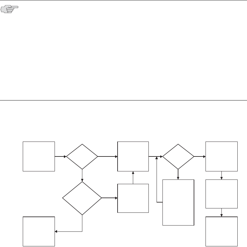
Juniper Networks Secure Access Administration Guide
522
You can ensure that other hosts in a remote user’s LAN cannot reach internal
corporate resources by denying the user access to the local subnet (configured on
the Users > User Roles > Select Role > Network Connect tab). If you do not
allow access to a local subnet, then an IVE appliance terminates Network Connect
sessions initiated by clients on which static routes are defined. You may also
require clients to run endpoint security solutions, such as a personal firewall, before
launching a network-level remote access session. Host Checker, which performs
endpoint security checks on hosts that connect to an IVE appliance, can verify that
clients use endpoint security software. See “Host Checker” on page 223 for more
information.
Figure 40 illustrates the general steps involved in establishing a Network Connect
tunnel.
Figure 40: Establishing a Network Connect tunnel
This section contains the following information about Network Connect:
“Licensing: Network Connect availability” on page 523
“Task Summary: Configuring Network Connect” on page 523
“Network Connect overview” on page 524
NOTE: A Hosts file entry is added by Network Connect to support the following
case:
If, when NC connects, split tunneling is disabled and the original externally
resolved hostname (the hostname the user initially connected to prior to the
NC launch) resolves to another IP address against the internal DNS, the
browser will redirect to a Server not found page, because no route is defined
within the client system.
At a graceful termination (sign-out or timeout) of the NC client connection, the
Hosts file is restored. If the Hosts file was not restored in a prior case due to
an ungraceful termination, the Hosts file will be restored the next time the
user launches Network Connect.
No
User signs in to
Windows and
enters
authentication
credentials
Network Connect
client launches in
embedded
browser displaying
IVE sign-in
User enters
credentials into
IVE sign-in page
of specified URL/
Realm on client
Credentials
correct?
Repeat user
credential
verification twice.
If unable to
authenticate,
display error
message and
connect to LAN
only
Yes
Network Connect
access options
displayed in the
“Available Role
Mappings” page
User selects
access type from
list of available
options
Is GINA
installed on
client?
Yes
No
Does user
choose to launch
Network
Connect?
No
Yes
User signs in to
Windows using
cached credentials
and connected to
LAN only
Network Connect
tunnel established
between remote
client and IVE

Licensing: Network Connect availability 523
Chapter 21: Network Connect
“Defining role settings: Network Connect” on page 534
“Defining resource policies: Network Connect” on page 536
“Defining system settings: Network Connect” on page 547
Licensing: Network Connect availability
In order to use Network Connect an any Secure Access appliance, you must install a
special license. This feature is not available with the baseline version of any Secure
Access product.
Task Summary: Configuring Network Connect
This section provides high-level Network Connect configuration steps. These steps
do not account for preliminary IVE configuration steps such as specifying the IVE’s
network identity or adding user IDs to the IVE.
To configure the IVE for Network Connect:
1. Enable access to Network Connect at the role-level using settings in the Users
> User Roles > Role > General > Overview page of the admin console. For
instructions, see “Defining default options for user roles” on page 64.
2. Create Network Connect resource policies using the settings in the Users >
Resource Policies > Network Connect tabs:
a. Specify general access settings and detailed access rules for Network
Connect in the Network Connect Access Control tab of the admin
console. For details, see “Defining Network Connect access control
policies” on page 537.
b. Specify Network Connect Connection Profiles to assign to remote users in
the Network Connect Connection Profiles tab of the admin console. For
details, see “Creating Network Connect connection profiles” on page 539.
c. (Optional) Specify Network Connect resource policies for filtering packet
information in the Network Connect Logging tab of the admin console.
For details, see “Defining Network Connect logging policies” on page 538.
d. (Optional) Specify split tunneling behavior for Network Connect in the
Network Connect Split Tunneling tab of the admin console. For details,
see “Defining Network Connect split tunneling policies” on page 544.
Juniper Networks Secure Access Administration Guide
524 Network Connect overview
3. Specify whether or not to enable GINA installation, employ split tunneling,
and/or auto-launch behavior for Network Connect in the Users > User Roles
> Role > Network Connect page of the admin console. For instructions, see
“Task Summary: Configuring Network Connect” on page 523.
4. Specify an IP address for the Network Connect server-side process to use for all
Network Connect user sessions on the System > Network > Network
Connect page in the admin console. For details, see “Provisioning your
network for Network Connect” on page 531.
5. Ensure that an appropriate version of Network Connect is available to remote
clients following the instructions on the “Downloading application installers”
on page 577.
6. (Optional) Specify whether or not the IVE compiles Network Connect packet
logs for specific Network Connect users in the System > Log/Monitoring >
NC Packet page on the admin console. For instructions, see “Configuring
events, user access, admin access, IDP sensor, and NC packet logs” on
page 668.
7. If you want to enable or disable client-side logging for Network Connect,
configure the appropriate options in the System > Configuration > Security
> Client-side Logs tab of the admin console. For instructions, see “Enabling
client-side logs” on page 679.
Network Connect overview
This section contains the following information about Network Connect:
“Network Connect execution” on page 525
NOTE: If you choose to activate split tunneling behavior for Network Connect in
this page, you must first create at least one Network Connect split-tunneling
resource profile, as described above.
NOTE: You must enable Network Connect for a given role if you want a user
mapped to that role to be able to use GINA during Windows logon.
NOTE: To install Network Connect, users must have appropriate privileges, as
described in the Client-side Changes Guide on the Juniper Customer Support
Center. If the user does not have these privileges, use the Juniper Installer Service
available from the Maintenance > System > Installers page of the admin
console to bypass this requirement.
NOTE: Network Connect requires signed ActiveX or signed Java applets to be
enabled within the browser to download, install, and launch the client
applications.

Network Connect overview 525
Chapter 21: Network Connect
“Network Connect Connection Profiles with support for multiple DNS settings”
on page 530
“Provisioning your network for Network Connect” on page 531
“Client-side logging” on page 532
“Network Connect proxy support” on page 532
“Network Connect Quality of Service” on page 533
“Network Connect Multicast Support” on page 533
Network Connect execution
The Network Connect agent executes as follows:
1. If Graphical Identification and Authorization (GINA) is installed and registered
on the remote client, the client automatically initiates a Network Connect
tunnel to the IVE when the user signs into Windows; otherwise, the user needs
to sign into an IVE appliance and click on the Network Connect link on the IVE
appliance end-user home page (if you have not configured Network Connect to
launch automatically). For more information, see “Automatically signing into
Network Connect using GINA” on page 527.
2. If the user does not have the latest version of the Network Connect installer, the
IVE appliance attempts to download an ActiveX control (Windows) or a Java
applet (Macintosh and Linux) to the client machine that then downloads the
Network Connect software and performs installation functions. If the IVE
appliance fails to download or upgrade the ActiveX control to a Windows client
due to restricted access privileges or browser restrictions, the IVE appliance
uses a Java applet to deliver the Network Connect software to the client.
For information on removing the Juniper ActiveX control, see “Removing the
Juniper ActiveX Control” on page 265.
Whether the IVE downloads an ActiveX control or a Java applet, both
components attempt to identify the presence and version of existing Network
Connect software on the client before determining which of the following
installation functions to perform:
a. If the client machine has no Network Connect software, install the latest
version.
NOTE: If Microsoft Vista is running on the user’s system, the user must click the
setup link that appears during the installation process to continue installing the
setup client and Network Connect. On all other Microsoft operating systems, the
setup client and Network Connect install automatically.
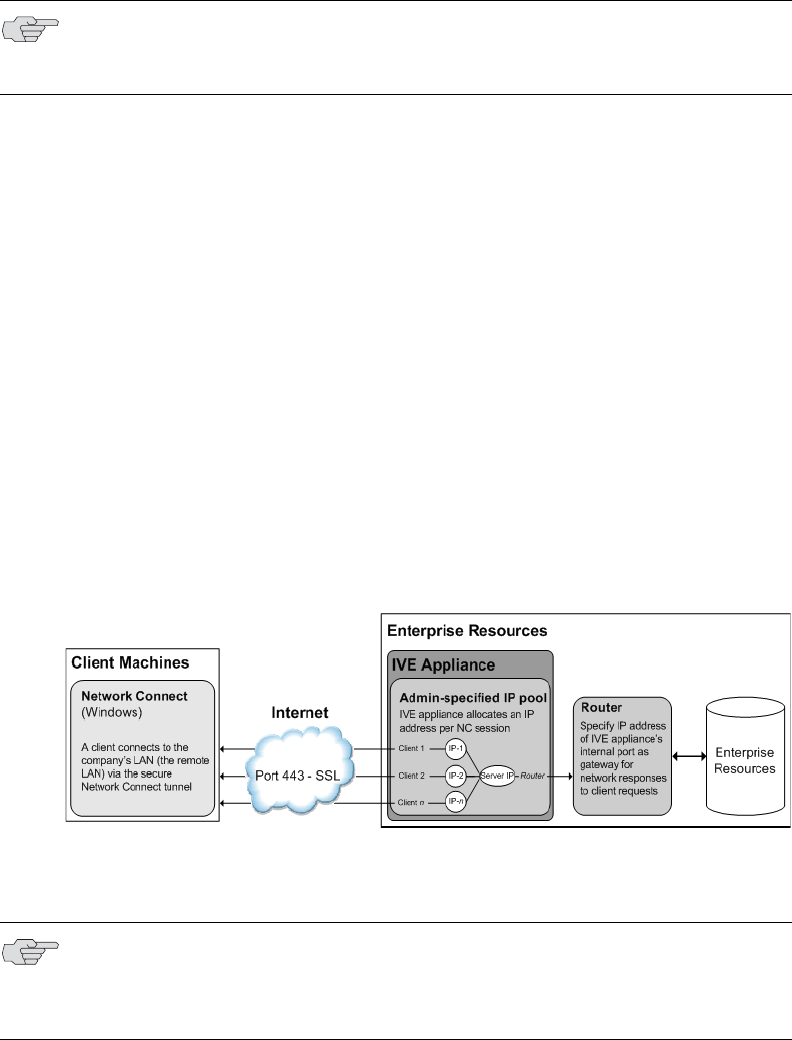
Juniper Networks Secure Access Administration Guide
526 Network Connect overview
b. If the client machine has an earlier version of Network Connect software,
uninstall the older version and install the most current version from the
IVE.
3. Once installed, the Network Connect agent sends a request to the IVE
appliance to initialize the connection with an IP address from the pre-
provisioned IP pool (as defined by the Network Connect Connection Profiles
resource policies applicable to the user’s role).
4. The Network Connect system tray icon starts running in the taskbar on a
Windows client or in the Dock on a Mac client.
5. The IVE appliance allocates an IP address (from a Network Connect Connection
Profiles resource policy) and assigns a unique IP to the Network Connect
service running on the client.
6. The client-side Network Connect service uses the assigned IP address to
communicate with the Network Connect process running on the IVE appliance.
7. After the IVE allocates an IP address to the client, the IVE opens a direct
channel of communication between the client and all enterprise resources to
which the user’s resource policy allows access. The internal application server
sees the source IP as the client’s IP address.
Figure 41: Network Connect client/server communication
The client-side Network Connect agent communicates with the IVE appliance,
which, in turn, forwards client requests to enterprise resources.
NOTE: For information about valid Java applets, installation files and logs, and the
operating system directories in which delivery mechanisms run, see the Client-
side Changes Guide on the Juniper Networks Customer Support Center.
NOTE: If you use Host Checker to validate the presence of client-side security
components based on policies you define on the IVE and the client cannot
conform to the security policies at any point during a Network Connect session,
Host Checker terminates the session.
Network Connect overview 527
Chapter 21: Network Connect
Automatically signing into Network Connect using GINA
The Graphical Identification and Authorization (GINA) sign-in function is an
automated sign-in method you can install and enable on Windows clients signing in
to a Windows NT domain. You can require Network Connect to install GINA on the
client machine, or you can allow users to decide whether or not to install GINA
when they launch Network Connect.
If GINA is installed on the client, it automatically prompts the user to choose
whether or not to launch Network Connect each time he/she signs in to Windows. If
you choose to make GINA installation optional, the user can activate GINA using the
Auto connect when login to Windows option in the Network Connect window.
This option is only available during an open Network Connect session.
The option to enable GINA installation on client systems is available when you
define role attributes in the Users > User Roles > Role > Network Connect page.
For details, see “Task Summary: Configuring Network Connect” on page 523.
Figure 42 illustrates the general steps involved in the GINA installation process.
Figure 42: GINA installation process
The GINA installation process takes place one time and requires the user to perform
a system reboot in order to enable GINA sign-in capability. From that session
forward, GINA prompts the user to decide whether or not to launch Network
Connect at each Windows sign-in. When the user signs in to Network connect,
unless otherwise specified, GINA passes the user’s Windows sign-in credentials to
the IVE for authentication before establishing the Network Connect tunnel.
NOTE: You cannot install more than one GINA automatic sign-in function on a
client’s system. If another application on the client’s system uses a GINA function,
Network Connect cannot install and activate the GINA component.
User signs in to
IVE via Network
Connect
Network Connect
installed without
GINA capability
GINA automatic
sign-in
service installed
Does user choose
to enable GINA?
GINA installation
completed and
user asked
whether or not to
reboot at this time
Yes
No
No
Yes
Is GINA enabled on
the user’s IVE role?
No

Juniper Networks Secure Access Administration Guide
528 Network Connect overview
Figure 43 illustrates the general steps involved in the automated GINA tunnel
establishment process.
Figure 43: GINA automated sign-in process
Using GINA Chaining
Network Connect supports GINA chaining. GINA chaining means that one GinaDLL
calls another GinaDLL. By default, enabling NC GINA also enables NC GINA
chaining. The Network Connect client detects any currently installed GINA
component on top of the existing GINA chain. If the GINA component is
compatible, NC GINA is placed in front of the current GINA components. Currently,
Network Connect supports the following GINA components:
Cisco VPN client (CSGina.dll)
Microsoft GINA (msgina.dll)
Nortel Networks VPN client (nngina.dll)
RSA SecurID (AceGina.dll)
Novell GINA (NWGINA.dll)
If an installed GINA component is not supported (that is, not in the above list), a
warning message appears and the NC GINA is not installed.
User launches
Windows on client
Windows
credentials
presented to IVE
for authentication
User signs in to
Windows using
cached credentials, no
GINA sign-in
displayed, and no
network connectivity
established
Attempt user
credential
verification three
times only.
If unable to
authenticate,
display error
message and
connect to LAN
User connected
to network
User signs in to
Windows using
cached credentials
and connected to
LAN only
No
Yes
Yes
No
GINA
sign-in appears.
Does user want to
launch Network
Connect?
Does client have
network connectivity?
Was the tunnel
established?
No
Yes
Yes
Is user signed in to
Windows NT domain?
Yes
No

Network Connect overview 529
Chapter 21: Network Connect
If you uninstall a GINA component after Network Connect adds its information to
the GINA chain, the NC GINA removes the saved GINA information and does not
call the removed GINA component the next time it goes through GINA chaining.
Launching Network Connect during a Windows Secure Application
Manager session
Users can launch Network Connect while signed in to the IVE via Windows Secure
Application Manager (WSAM). When a user launches Network Connect in this
scenario, however, the Network Connect installer automatically terminates the
WSAM session prior to launching Network Connect.
During the process, the user is prompted with a warning message informing them
that they are about to terminate their WSAM session in favor of launching Network
Connect. We recommend that you configure users’ Network Connect resource
policies to feature as much access to network resources as they would have in their
WSAM sessions. This way, when users choose to launch Network Connect
(simultaneously terminating WSAM) they will sill be able to access the same
network resources.
Logging In To Windows Through a Secure Tunnel
Use the Logoff On Connect feature for users to log in to their Windows
environment through an existing Network Connect secure tunnel. This feature lets
them authenticate against a Windows Domain server in real time, as opposed to
authenticating with the locally cached credentials. When this feature is enabled,
they are automatically logged off Windows after the Network Connect session
starts. The standard Windows login screen re-appears and they log in using their
Windows credentials. Their Windows environment is now established through the
Network Connect tunnel.
To use the Logoff On Connect feature:
NOTE: If the NC GINA is installed at the top of the GINA chain (meaning, it is the
last one installed), the NC GINA is uninstalled when you uninstall the Network
Connect client. However, if the NC GINA is in the middle of the chain, you must
remove all GINAs higher in the chain than the Network Connect GINA prior to
removing the NC GINA.
NOTE: If users choose not to launch Network Connect, the Network Connect
installer still automatically installs the client application on their computer, but
does not launch Network Connect. After the client application has been installed,
users can choose uninstall it manually via their secure gateway home page or the
folder options available in the Windows Start menu.
You
NOTE: Users must log in to Windows within 5 minutes of the login screen re-
appearing or before the Host Checker policy evaluate period ends, whichever is
shorter. If they do not, their Network Connect connection may time out and they
will not be logged in to Windows through a secure tunnel. An error appears if the
Network Connect connection times out.

Juniper Networks Secure Access Administration Guide
530 Network Connect overview
1. Users log on to their local machine using their domain cached credentials.
Their machine must be part of a Windows domain.
2. Users launch Network Connect and click Tools from the Network Connect login
page.
3. Select the Logoff on Connect option and click OK.
4. Users enter their username and password credentials in the Network Connect
login page.
Network Connect establishes a tunnel and logs them off of their local machine.
The Windows login page appears.
5. Users enter their username and password credentials to sign-in to their
Windows Domain using the Network Connect tunnel.
Network Connect Connection Profiles with support for multiple DNS settings
To ensure remote users are able to perform DNS searches as efficiently or as
securely as possible, you can configure the IVE to allow multiple DNS settings
during Network Connect sessions, based on a user’s role membership.
When the IVE launches a user’s Network Connect session, the IVE uses a matching
profile based on the user’s role membership containing IP address, DNS, and WINS
settings.
If you enable split-tunneling, the DNS search order setting allows you to define
which DNS setting takes precedence—for example, search for a DNS server on the
client’s LAN before the IVE’s DNS server, or vice-versa. Network Connect makes a
backup of the client’s DNS settings/search order preference before establishing a
Network Connect connection. After the session terminates, Network Connect
restores the client to the original DNS settings. If you disable split-tunneling, all DNS
requests go to the IVE’s DNS server and your setting for the DNS search order
preference does not apply.
NOTE: After stopping and restarting a DNS client, the client may not pick up the
search order of multiple DNS addresses in a timely manner, resulting in an
incorrect lookup order when launching Network Connect. The rules governing
DNS name resolution and failover are complex and often specific to the particular
client operating system. You or the end-user can attempt to run the ipconfig
/registerdns commands from a command window on the client machine. This
may reset the search order to the correct order. To understand the search
resolution order for DNS servers, refer to the appropriate Microsoft DNS
documentation for your operating system platform.
Network Connect overview 531
Chapter 21: Network Connect
When employing a multi-site cluster of IVEs, the IP pool and DNS settings may be
unique to each IVE residing at a different site. For this reason, the IVE allows the
Network Connect Connection Profile policy to be node-specific. That is, the
resource policy enables the client to connect to the same IVE in the cluster each
time a new session is established.
Provisioning your network for Network Connect
Network Connect incompatibility with other VPN client applications
Third-party vendor VPN client applications may be incompatible with Network
Connect. Table 39 lists known VPN client vendors and Network Connect’s relative
compatibility with those vendors’ VPN client applications.
If you want to install Network Connect on a client featuring an incompatible VPN
client application, you must uninstall the incompatible application before you
install or launch Network Connect on the client.
Linux client requirements
Linux clients signing in to Network Connect via Mozilla Firefox version 1.6 must
ensure that the OpenSSL libraries are installed on the client. Most Linux versions
come pre-packaged with OpenSSL. If you encounter a Linux user that does not have
the required OpenSSL libraries, you can direct them to the following resource
where they can be obtained and installed for free:
See http://www.openssl.org/related/binaries.html for details. (You can also
advise users to compile their own version by directing them to the source at
http://www.openssl.org/source/.) The required version is libssl.so.0.9.6b.
NOTE: If you run Network Connect on a system with an IVS license, see
“Configuring DNS for the IVS” on page 774 and “Configuring Network Connect for
use on a virtualized IVE” on page 777.
Table 39: Network Connect compatibility with third-party VPN clients
Vendor Compatible?
Cisco Yes
Nortel Yes
NS Remote Yes
Intel Yes
Checkpoint Yes

Juniper Networks Secure Access Administration Guide
532 Network Connect overview
Client-side logging
Network Connect client-side logs are files that reside on the remote client
containing sign-in, debug, and other statistical information you can use to
troubleshoot potential issues with Network Connect. When you enable client-side
logging for Network Connect users, the client records Network Connect events in a
series of log files, continually appending entries each time a feature is invoked
during subsequent user sessions. The resulting log files are useful when working
with the support team to debug problems with Network Connect. For more
information, see “Enabling client-side logs” on page 679.
Network Connect proxy support
Network Connect provides support for remote clients using a proxy server to access
the Internet (and the IVE via the Internet), as well as clients who do not need a
proxy to access the Internet, but who access resources on an internal network
through a proxy. Network Connect also provides support for clients accessing a
Proxy Automatic Configuration (PAC) file that specifies client and IVE proxy
settings enabling access to Web applications.
To address these varying methods of proxy implementation, Network Connect
temporarily changes the proxy settings of the browser so that only traffic intended
for the Network Connect session uses the temporary proxy settings. All traffic not
intended for the Network Connect session uses the existing proxy settings.
Whether split-tunneling is enabled or disabled, the IVE supports the following proxy
scenarios:
Using an explicit proxy to access the IVE
Using an explicit proxy to access internal Web applications
Using a PAC file to access the IVE
Using a PAC file to access internal Web applications
NOTE: If Network Connect users turn client-side logging off, (even if logging is
enabled on the IVE) the client does not record any new client-side log information.
If the user turns on the logging function and the IVE is then configured to disable
client-side logging, the client does not record any new client-side log information.
NOTE: The Network Connect client does not support the use of the MS Winsock
proxy client. Please disable the MS Winsock proxy client before running the
Network Connect client. For more information, see
http://www.microsoft.com/windowsxp/using/mobility/expert/vpns.mspx.
NOTE: The Network Connect client does not support the option to automatically
detect proxy settings. You must choose to use either an automatic configuration
script (PAC) or specify a proxy server. You cannot use both a proxy server and an
automatic configuration script, together. You can define one or the other at Users
> Resource Policies > Network Connect > NC Connection Profiles > Select
Profile > Proxy.

Network Connect overview 533
Chapter 21: Network Connect
When split-tunneling is enabled on the IVE, Network Connect manages proxy
settings in one of the following ways, depending on the method with which the
proxy is implemented:
For remote clients using a proxy server to access the Internet, all HTTP
requests generated by the browser and intended for the IVE (including NCP
transport traffic) go through either an explicit proxy or a PAC file accessed by
the remote client. Because the presence of an explicit proxy or access to a PAC
file is already provisioned on the client-side, the client sets up the local,
temporary proxy before attempting to establish a Network Connect session.
For remote clients using a proxy to access corporate resources on a corporate
network, yet still able to connect directly to the Internet without a proxy,
Network Connect identifies the proxy settings on the client even though the
proxy server is not reachable until Network Connect establishes a connection.
Once Network Connect establishes a connection, it then creates the local,
temporary proxy.
When a remote client accesses a pre-configured HTTP-based PAC file, the client
cannot access the PAC file until after Network Connect establishes a session
connection. After Network Connect establishes a connection, the client
accesses the PAC file, includes the PAC file contents in the local, temporary
proxy, and then refreshes the browser proxy setting.
Network Connect Quality of Service
To support Quality of Service (QoS) on your internal network via Network Connect,
the IVE translates the “inner” IP packet header (for Application-layer packet
encapsulation, for example) to the “outer” packet header, thus enabling Network
layer-level packet prioritization. Routers in the network are then able to identify,
prioritize, and appropriately forward Network Connect IPSec packets across the
network. This feature helps ensure that you are able to support time-sensitive IP
packet transmission and reception like IP video streams, for example.
Network Connect Multicast Support
To enable streaming IP video broadcasts over the internal network, Network
Connect features Internet Group Management Protocol (IGMP) gateway multicast
proxy support.
NOTE: Network Connect QoS applies to UDP (IPSec) packets only. SSL packet
encapsulation and forwarding behavior remains unchanged when you employ the
Network Connect QoS feature.
NOTE: If you are using NC multicast support, and you are using L2 switches, make
sure the switches support IGMP v3.

Juniper Networks Secure Access Administration Guide
534 Defining role settings: Network Connect
When users initiate a request to join a multicast group, the IVE initiates an IGMP
join message to the local multicast router or switch on the client’s behalf. In
addition, the IVE stores the IGMP group request queries in its cache so that
whenever a multicast router in the network polls the IVE for IGMP group
information, the IVE responds with its current collection of multicast user and
group requests. If a router or switch does not receive a response from the IVE, the
multicast group information for the IVE is removed from the router or switch’s
forwarding table.
Defining role settings: Network Connect
Use role-level settings to specify split-tunneling, auto-launch, auto-uninstall, and
Graphical Identification and Authentication (GINA) options. For more information
on GINA, see “Automatically signing into Network Connect using GINA” on
page 527.
To specify Network Connect split-tunneling, auto-launch, auto-uninstall, and GINA
installation options:
1. In the admin console, choose Users > User Roles > Role > Network
Connect.
2. Under Split Tunneling Options, select one of the following options:
Disable Split Tunneling—All network traffic from the client goes through
the Network Connect tunnel. When Network Connect successfully
establishes a connection to the IVE, the IVE removes any predefined local
subnet and host-to-host routes that might cause split-tunneling behavior. If
any changes are made to the local route table during an active Network
Connect session, the IVE terminates the session.
Allow access to local subnet—The IVE preserves the local subnet route on
the client, retaining access to local resources such as printers. The local
route table may be modified during the Network Connect session.
Enable Split Tunneling—This option activates split-tunneling and requires
you to specify the network IP address/netmask combinations for which the
IVE handles traffic passed between the remote client and the corporate
intranet according to the instructions in “Defining Network Connect split
tunneling policies” on page 544.
When split-tunneling is used, Network Connect modifies routes on clients
so that traffic meant for the corporate intranet networks to Network
Connect and all other traffic goes through the local physical adapter. The
IVE tries to resolve all DNS requests through the physical adapter first and
then routes those that fail to the Network Connect adapter.
NOTE: Network Connect supports streaming media at up to 2 MB per second on a
single tunnel.

Defining role settings: Network Connect 535
Chapter 21: Network Connect
Enable Split Tunneling with route change monitor—Once a Network
Connect session starts, changes to the local route table terminate the
session. This option retains access to local resources such as printers.
3. Under Auto Launch Options, specify whether or not Network Connect
automatically launches when an authenticated user maps to one or more roles
that enable Network Connect sessions.
4. Under Auto Uninstall Options, specify whether or not Network Connect un-
installs itself from the remote client when a user signs-out of the Network
Connect session.
5. Under TOS Options, specify whether or not you want to enable the IP TOS bit-
copying quality of service (QoS) feature by activating or deactivating this
option. When this option is enabled, Network Connect copies IP TOS bits from
inner IP packet header to outer IP packet header.
6. Under Multicast Option, specify whether or not you want Network Connect to
operate in multicast mode.
7. Under GINA Options, specify whether or not to enable GINA installation for a
role and specify the GINA sign-in behavior by selecting one of the following
options:
Require NC to start when logging into Windows—After GINA is installed,
this option automatically launches the Network Connect sign-in function at
every Windows user sign-in.
Allow user to decide whether to start NC when logging into Windows—
After GINA is installed, this option allows the user to determine, at each
Windows startup, whether or not to launch Network Connect after GINA
installation.
8. Under Session Scripts, specify the following:
a. The location of Network Connect start and end scripts for Windows,
Macintosh, and/or Linux clients. If you do not specify any start or end
scripts, Network Connect does not execute any scripts to start or end the
session.
NOTE:
Enabling this option may require the user to reboot their computer when
Network Connect is installed for the first time on a Windows OS.
If you enable this option on the IVE, ensure that you have disabled the Repeat
Protection option, as described in “Creating Network Connect connection
profiles” on page 539.
NOTE: You must enable Network Connect for a given role if you want a user
mapped to that role to be able to use GINA during Windows logon.

Juniper Networks Secure Access Administration Guide
536 Defining resource policies: Network Connect
When Network Connect launches, start and end scripts are copied to the
client and, upon session termination, are removed from the client. Scripts
can be accessed locally or remotely via file share or other permanently-
available local network resource.
b. Turn on the Skip if GINA enabled option to bypass the specified Windows
session start script.
If the client signs in to their Windows Domain via the GINA automatic sign-
in function, a script is executed by the Windows client. In this case, the
sign-in script may be identical to the specified Network Connect start
script. You can use this option, therefore, as a way to avoid executing the
same script twice.
9. Click Save Changes.
Defining resource policies: Network Connect
Network Connect resource policies specify a variety of Network Connect session
parameters you can use to determine the method of access for remote clients. You
can configure the following types of resource policies on the IVE and apply them to
one or more user roles:
Access resource policies—This policy type specifies which resources users
may access when using Network Connect, such as Web, file, and server
machines on the corporate intranet. For more information, see “Defining
Network Connect access control policies” on page 537.
Packet logging resource policies—This policy type allows you to compile
client-side Network Connect packet logs on the IVE to help diagnose and
resolve connection issues. For more information, see “Defining Network
Connect logging policies” on page 538.
NOTE:
The client should be a member of the same domain as the remote server to
allow NC to copy start and end scripts. If the client credentials are unknown to
the server, the script copy fails, and NC does not prompt the user to enter
username and password.
Windows only supports scripts with the .bat, .cmd, or .exe extension. To run a
.vbs script, the user must have a batch file to call the .vbs script.
The Network Connect client makes a copy of the end script after the tunnel
has been set up and stores the script in a temporary directory to ensure that,
if the network connection were to fail, the end script can still be used to
terminate the Network Connect session.
Defining resource policies: Network Connect 537
Chapter 21: Network Connect
Connection profiles resource policies—This policy type specifies which
option (DHCP or IVE-managed IP address pool) the IVE uses to assign an IP
address to the client-side Network Connect agent. You can also use this feature
to specify the transport protocol and encryption method for the Network
Connect session. For more information, see “Creating Network Connect
connection profiles” on page 539.
Split Tunneling resource policies—This policy type enables you to specify one
or more network IP address/netmask combinations for which the IVE handles
traffic passed between the remote client and the corporate intranet. For more
information, see “Defining Network Connect split tunneling policies” on
page 544.
Defining Network Connect access control policies
Use the Network Connect Access Control tab to write a Network Connect resource
policy that controls resources users can connect to when using Network Connect.
To write a Network Connect access resource policy:
1. In the admin console, choose Users > Resource Policies > Network Connect
> Network Connect Access Control.
2. On the Network Connect Network Connect Access Control page, click New
Policy.
3. On the New Policy page, enter:
a. A name to label this policy.
b. A description of the policy. (optional)
4. In the Resources section, specify the resources to which this policy applies. See
“Resource policy components” on page 82 for more information.
5. In the Roles section, specify:
Policy applies to ALL roles—To apply this policy to all users.
Policy applies to SELECTED roles—To apply this policy only to users who
are mapped to roles in the Selected roles list. Make sure to add roles to this
list from the Available roles list.
Policy applies to all roles OTHER THAN those selected below—To apply
this policy to all users except for those who map to the roles in the Selected
roles list. Make sure to add roles to this list from the Available roles list.
6. In the Action section, specify:
Allow access—Select this option to grant access to the resources specified
in the Resources list.
Deny access—Select this option to deny access to the resources specified
in the Resources list.
Juniper Networks Secure Access Administration Guide
538 Defining resource policies: Network Connect
Use Detailed Rules—Select this option to define resource policy rules that
put additional restrictions on the specified resources. See “Writing a
detailed rule” on page 88 for more information.
7. Click Save Changes.
8. On the Network Connect Access Policies page, order the policies according to
how you want the IVE to evaluate them. Keep in mind that once the IVE
matches the resource requested by the user to a resource in a policy’s (or a
detailed rule’s) Resource list, it performs the specified action and stops
processing policies.
Defining Network Connect logging policies
Use the Network Connect Logging tab to compile and display packet information
for one or more Network Connect users. Compiling client-side Network Connect
packet information can help you better support and troubleshoot Network Connect
issues like session failure or users experiencing periodic packet loss. You can log
and even search for specific types of packets based on the users’ authentication,
authorization, and IP allocation information, source and destination IP addresses,
source and destination port assignments, and session transport protocol(s).
To write a Network Connect logging policy:
1. In the admin console, choose Users > Resource Policies > Network Connect
> Network Connect Logging.
2. On the Network Connect Logging page, click New Policy.
3. On the New Policy page, enter:
a. A name to label this policy.
b. A description of the policy (optional).
4. In the Resources section, specify the resources to which this policy applies. See
“Specifying resources for a resource policy” on page 83 for more information.
5. In the Roles section, specify:
Policy applies to ALL roles—To apply this policy to all users.
Policy applies to SELECTED roles—To apply this policy only to users who
are mapped to roles in the Selected roles list. Make sure to add roles to this
list from the Available roles list.
Policy applies to all roles OTHER THAN those selected below—To apply
this policy to all users except for those who map to the roles in the Selected
roles list. Make sure to add roles to this list from the Available roles list.
6. In the Action section, select on of the following options:
Log Packets—Select this option to instruct the IVE to automatically log
packets for all connections fitting the criteria specified in the logging policy.
Defining resource policies: Network Connect 539
Chapter 21: Network Connect
Use Detailed Rules—Select this option to define resource policy rules that
put additional restrictions on the specified resources. See “Writing a
detailed rule” on page 88 for more information.
7. Click Save Changes.
Creating Network Connect connection profiles
Use the Network Connect Connection Profiles tab to create a Network Connect
resource profile. When an IVE receives a client request to start a Network Connect
session, the IVE assigns an IP address to the client-side Network Connect agent.
The IVE assigns this IP address based on the IP Address Pool policies that apply to a
user’s role. In addition, this feature allows you to specify the transport protocol,
encryption method, and whether or not to employ data compression for the
Network Connect session.
Nodes in a multi-site cluster share configuration information, which means that
IVEs in different networks share an IP address pool. Since any IVE node may
receive the client request to start the Network Connect session, you need to specify
an IP filter for that node that filters out only those network addresses available to
that node. When the cluster node receives a request to create a Network Connect
session, it assigns the IP address for the session from the filtered IP address pool.
To write a Network Connect connection profile:
1. In the admin console, choose Users > Resource Policies > Network Connect
> NC Connection Profiles.
2. On the Network Connect Connection Profiles page, click New Profile.
3. On the New Profile page, enter the following information:
a. A name to label this policy.
b. A description of the policy (optional).
4. In the IP address assignment section, specify the method of client-side IP
address assignment by choosing one of the following:
DHCP server—This option allows you to specify the host name or IP
address of a network Dynamic Host Configuration Protocol (DHCP) server
responsible for handling client-side IP address assignment.
IP address pool—This option allows you to specify IP addresses or a range
of IP addresses for the IVE to assign to clients that run the Network
Connect service. Use the canonical format: ip_range

Juniper Networks Secure Access Administration Guide
540 Defining resource policies: Network Connect
The ip_range can be specified as “a.b.c.d-e” where the last component of
the IP address is a range delimited by a hyphen (-). No special characters
are allowed. For example: 10.10.10.1-100.
NOTE: We recommend that you set up your network so that the Network Connect
client-side IP address pool, or the DHCP server specified in the Network Connect
connection profile, resides on the same subnet as the IVE.
If your network topology dictates that the IVE internal IP interface and the IP
address pool or DHCP server reside on different subnets, you need to add static
routes to your intranet’s gateway router(s) to ensure that your Enterprise
resources and the IVE can see each other on the internal network.
NOTE:
If you are running a multi-unit cluster across a LAN or WAN, make sure that
the IP address pool contains addresses that are valid for each node in the
cluster. Then, configure an IP filter for each node to apply to this IP address
pool.
The IVE does not support a common IP address pool for Network Connect for
an Active/Active cluster. In A/A NC deployments, we recommend that you
split the NC IP pool into node-specific subpools. Furthermore, you are advised
to perform static route configuration on the backend router infrastructure in a
coordinated fashion, with static routes to each subpool pointing to the internal
IP address of the hosting cluster node as the next-hop gateway.

Defining resource policies: Network Connect 541
Chapter 21: Network Connect
5. In the Connection settings section, specify transport, encryption, and
compression settings for this connection profile:
a. Specify the encapsulation and transport method by choosing one of the
following:
ESP (maximize performance)—Select this option to use a UDP
encapsulated ESP transfer method to securely transfer data between
the client and the IVE. You can further customize the date transfer
parameters by defining the UDP port, ESP-to-NCP fallback time-out
value, and ESP encryption key lifetime values.
oNCP/NCP (maximize compatibility)—Select this option to use the
standard oNCP/NCP transport method for this connection profile. For
background information on oNCP and NCP and options for NCP usage
on the IVE, refer to “Configuring licensing, security, and NCP” on
page 580.
b. If you want to accept the IVE’s default values for the ESP transport method,
proceed to the next step. Otherwise, you can also provide the following
values:
UDP port—Provide the IVE port through which you intend to direct
UDP connection traffic. The default port number is 4500.
ESP to NCP fallback timeout—Provide a period of time (in seconds)
the IVE will wait before it will automatically establish a standard
oNCP/NCP connection following UDP connection failure. The default
time period is 15 seconds.
NOTE: The oNCP transport protocol offers increased flexibility over NCP because it
accommodates Macintosh and Linux clients. (The traditional NCP transport
protocol functions in an exclusively Windows client environment.) If you disable
the oNCP/NCP auto-selection feature on the System > Configuration > NCP
page of the admin console and a UDP-to-oNCP/NCP fail-over occurs, the IVE
disconnects Macintosh and Linux clients because the IVE fails over from UDP to
NCP (instead of oNCP), which does not support these users.
NOTE: Whether you specify a custom port number or choose to use the default
port number (4500) configured on the IVE, you must also ensure that other
devices along the encrypted tunnel allow UDP traffic to pass between the IVE and
Network Connect clients. For example, if you employ an edge router and a
firewall between the Internet and your corporate intranet, you must ensure that
port 4500 is enabled on both the router and the firewall and that port 4500 is
configured to pass UDP traffic.

Juniper Networks Secure Access Administration Guide
542 Defining resource policies: Network Connect
Key lifetime—Provide the period of time (in minutes) the IVE
continues to employ the same ESP encryption key for this connection
profile. Both the local and remote sides of the encrypted transmission
tunnel use the same encryption key only for a limited period of time to
help prevent unauthorized access. The default time period is 20
minutes.
Replay Protection—Enable this option to activate replay protection on
the IVE. When enabled, this option helps protect against hostile
“repeat attacks” from the network. When packets arrive from the
client, the IVE checks the IP header information to verify that a packet
featuring the same IP header information has not already been
received. If one has been received, the packet is rejected. This option is
enabled on Network Connect resource policies by default.
If you activate the Enable TOS Bits Copy option, as described in “Task
Summary: Configuring Network Connect” on page 523, IP packets
with different TOS bits may be reordered when passing through
gateway routers on your network. To ensure that any packets received
out of order are not automatically dropped when they reach the IVE,
you can disable the Replay Protection option for this resource policy.
c. Specify the encryption method by choosing one of the following:
AES/SHA1 (maximize security)—This option instructs the IVE to
employ Advanced Encryption Standard (AES)1 encryption on the data
channel and the SHA12 authentication method during Network
Connect sessions.
AES/MD5 (maximize performance)—This option instructs the IVE to
employ AES1 encryption on the data channel and the MD53
authentication method for Network Connect sessions.
d. Specify whether or not to employ compression for the secure connection.
NOTE: Frequently changing the encryption key can increase CPU overhead on the
IVE.
NOTE: We recommend that you leave replay protection enabled if you are not
expecting more than one source of packets from the client (e.g. if only one
application is transmitting and receiving traffic over the Network Connect tunnel).
1. The AES encryption method protects IP packets by encoding them with a cryptographic algorithm featuring a
128-bit encryption key.
2. The SHA1 authentication method is easy to use and efficient when encoding user ID and password information.
The SHA1 algorithm translates the characters comprising a user ID or password string into unreadable text
before it is transmitted to or from the IVE. The same algorithm is then used to reverse the translation before it is
presented to the authentication server.
3. The MD5 authentication algorithm creates digital signatures. The MD5 authentication method translates an
input string (like a user’s ID or sign-in password, for example) into a fixed- 128-bit fingerprint (also called a
“message digest”) before it is transmitted to or from the IVE.
Defining resource policies: Network Connect 543
Chapter 21: Network Connect
6. In the Roles section, specify:
Policy applies to ALL roles—To apply this policy to all users.
Policy applies to SELECTED roles—To apply this policy only to users who
are mapped to roles in the Selected roles list. Make sure to add roles to this
list from the Available roles list.
Policy applies to all roles OTHER THAN those selected below—To apply
this policy to all users except for those who map to the roles in the Selected
roles list. Make sure to add roles to this list from the Available roles list.
7. On the New Profile page, click on the DNS tab.
8. Select the Custom DNS Settings checkbox to override standard DNS settings
with the settings you provide:
a. Primary DNS—Provide the IP address for the primary DNS.
b. Secondary DNS—Provide the IP address for the secondary DNS.
c. DNS Domain(s)—Provide the DNS domain(s), such as “yourcompany.com,
yourcompany.net”.
d. WINS—Provide the WINS resolution name or IP address.
9. Select the Auto-allow IP's in DNS/WINS settings (only for split-tunnel
enabled mode) option if you want to create an allow rule for the DNS server,
For example, if you have defined policies to allow requests from IP address
10.0.0.0 but your DNS server has an address of 172.125.125.125 the DNS
server requests will be dropped. If you select this option, the appliance creates
a rule to allow the DNS requests.
10. In the DNS search order section, select the DNS server search order only if split
tunneling is enabled:
Search client DNS first, then the device
Search the device’s DNS servers first, then the client
11. On the New Profile page, click on the Proxy tab.
12. In the Network Connect proxy server configuration section, select one of the
following options:
No proxy server—Specifies that the new profile requires no proxy server.
Automatic (URL for PAC file on another server)—Specify the URL of the
server on which the PAC file resides, and the frequency (in minutes) with
which Network Connect polls the server for an updated version of the PAC
file. You can configure Network Connect to check for an updated PAC files
as often as every minute. The default update period is five minutes. If you
specify a value of 0 minutes, Network Connect never polls the server for an
updated PAC file. The PAC file should reside on a Web server, not on the
local PC.

Juniper Networks Secure Access Administration Guide
544 Defining resource policies: Network Connect
Manual configuration—Specify the IP address or the hostname of the
server and provide the port assignment.
13. Click Save Changes.
14. On the NC Connection Profiles page, order the profiles according to how you
want the IVE to evaluate them. Keep in mind that once the IVE matches the
resource requested by the user to a resource in a profile’s (or a detailed rule’s)
Resource list, it performs the specified action and stops processing profiles.
Defining Network Connect split tunneling policies
Use the Network Connect Split Tunneling tab to write a Network Connect
resource policy that specifies one or more network IP address/netmask
combinations for which the IVE handles traffic passed between the remote client
and the corporate intranet.
When split-tunneling is used, Network Connect modifies routes on clients so that
traffic meant for the corporate intranet networks to Network Connect and all other
traffic goes through the local physical adapter. The IVE tries to resolve all DNS
requests through the physical adapter first and then routes those that fail to the
Network Connect adapter.
To write a Network Connect split-tunneling networks resource policy:
1. In the admin console, choose Users > Resource Policies > Network Connect
> Network Connect Split Tunneling.
2. On the Network Connect Network Connect Split Tunneling page, click New
Policy.
3. On the New Policy page, enter:
a. A name to label this policy.
b. A description of the policy (optional).
4. In the Resources section, specify one or more network IP address/netmask
combinations for which the IVE handles traffic passed between the remote
client and the corporate intranet. You may also use the ‘/’ (slash) notation to
specify these networks.
5. In the Roles section, specify:
Policy applies to ALL roles—To apply this policy to all users.
NOTE: Network Connect limits the size of internal (server side) PAC files to 30K.
NOTE: If you are running Network Connect on a system with an IVS license, see
“Configuring Network Connect for use on a virtualized IVE” on page 777.
Defining resource policies: Network Connect 545
Chapter 21: Network Connect
Policy applies to SELECTED roles—To apply this policy only to users who
are mapped to roles in the Selected roles list. Make sure to add roles to this
list from the Available roles list.
Policy applies to all roles OTHER THAN those selected below—To apply
this policy to all users except for those who map to the roles in the Selected
roles list. Make sure to add roles to this list from the Available roles list.
6. In the Action section, specify:
Allow access—Select this option to grant access to the resources specified
in the Resources list.
Use Detailed Rules (available after you click ‘Save Changes’)—Select this
option to define resource policy rules that put additional restrictions on the
specified resources. See “Writing a detailed rule” on page 88 for more
information.
7. Click Save Changes.
8. On the Network Connect Split Tunneling Policies page, order the policies
according to how you want the IVE to evaluate them. Keep in mind that once
the IVE matches the resource requested by the user to a resource in a policy’s
(or a detailed rule’s) Resource list, it performs the specified action and stops
processing policies.
Juniper Networks Secure Access Administration Guide
546 Defining resource policies: Network Connect
Use case: Network Connect resource policy configuration
This section describes a real-world Network Connect application and the steps
necessary to configure the appropriate resource policy providing access to remote
users on the network.
Large financial institutions (also called “Fortune Companies”) require a robust client
sign-in application like Network Connect to help provide remote employees
seamless network connection to a large range of enterprise resources at the
corporate headquarters. Often, remote users need to be able to access multiple
applications on their laptops/client machines beyond simple Email or meeting
scheduling applications. These remote “super users” or “power users” require
secure, encrypted access to powerful server applications like Microsoft OutlookTM,
OracleTM databases, and the RemedyTM case management system.
For this scenario, let’s assume the following:
There is a small collection of remote users who will all access their financial
institution’s enterprise resources via the same IVE
All the users have the same “user_role_remote” role assigned to their user ID
Host Checker and Cache Cleaner are configured and verifying the users’
machines upon logging into the IVE and launching their Network Connect
sessions
All users require access to three large servers at the corporate headquarters
with the following attributes:
“outlook.acme.com” at IP address 10.2.3.201
“oracle.financial.acme.com” at IP address 10.2.3.202
“case.remedy.acme.com” at IP address 10.2.3.99
Because the Company wants to manage their IP address pool very strictly, each
IVE provides IP addresses to remote users (our particular IVE controls the IP
addresses between 10.2.3.128 and 10.2.3.192)
The company is interested in the most secure access possible, simultaneously
accepting only the least possible amount of client down-time
To configure a Network Connect resource policy providing appropriate access to
the Fortune Company remote users:
1. Create a new Network Connect resource policy where you specify the three
servers to which you want to grant remote users access following the
instructions described in “Defining Network Connect access control policies”
on page 537:

Defining system settings: Network Connect 547
Chapter 21: Network Connect
a. In the Resources section, specify the IP address ranges necessary to allow
access to the three servers (“outlook.acme.com,”
“oracle.financial.acme.com,” and “case.remedy.acme.com”) separated by
carriage returns.
udp://10.2.3.64-127:80,443
udp://10.2.3.192-255:80,443
b. In the Roles section, select the Policy applies to SELECTED roles option
and ensure that only the “user_role_remote” role appears in the Selected
roles list.
c. In the Action section, select the Allow access option.
2. Create a new Network Connect connection profile where you define the
transport and encryption method for the data tunnel between the client(s) and
the IVE following the instructions described in “Creating Network Connect
connection profiles” on page 539:
a. In the IP address assignment section, select the IP address pool option
and enter 10.2.3.128-192 in the associated text field.
b. In the Connection Settings section, select the ESP transport option and the
AES/SHA1 encryption option.
c. In the Roles section, select the Policy applies to SELECTED roles option
and ensure that only the “user_role_remote” role appears in the Selected
roles list.
Defining system settings: Network Connect
This section contains the following information about configuring system-level
settings for Network Connect:
“Specifying IP filters” on page 547
“Downloading the Network Connect installer” on page 548
Specifying IP filters
You can specify IP filters for the IVE to apply to Network Connect IP pools from the
System > Network > Network Connect tab in the admin console. An IP pool is a
specific range of IP addresses available for Network Connect requests, (as
explained in “Network Connect” on page 521).
Specifying IP filters to apply to Network Connect IP pools
To add an IP address to the Network Connect filter list:
1. In the admin console, choose System > Network > Network Connect.
Juniper Networks Secure Access Administration Guide
548 Defining system settings: Network Connect
2. Specify an IP address/netmask combination and then click Add. The IVE
applies the filters specified on this page to the Network Connect IP Pool
resource policies that apply to a user’s request.
Specifying the Network Connect Server IP Address
The server-side Network Connect process uses the server IP address to
communicate with enterprise resources. Although the IVE pre-populates this field,
you can change the address to one of your choosing so long as it is not a part of a IP
address pool specified as a part of a NC Connection Profile (see “Network Connect
Connection Profiles with support for multiple DNS settings” on page 530).
Downloading the Network Connect installer
To download the Network Connect application as a Windows executable file, go to
Maintenance > System > Installers. See “Downloading application installers” on
page 577 for more information.
Defining system settings: Network Connect 549
Chapter 21: Network Connect
Network Connect Installation Process Dependencies
During installation, Network Connect interacts with a number of system
components, performing checks and validations along the way. The following list
provides the order of execution during installation, which may be helpful if you
need to debug a Network Connect installation process. For information about the
un-installation process, see “Network Connect Un-installation Process
Dependencies” on page 551.
1. Start Pre-Installation Process:
a. Parse command line arguments.
b. Set appropriate variables via command line.
c. Process commands, as necessary.
d. If the command line entry responds with help or version information, the
Network Connect installation program quits, following the command line
processing. Typically occurs when you run the Network Connect installer
as a standalone installer.
2. Validate System:
a. Check OS. Network Connect support for Windows 98, Windows 2K, and
Windows XP only. If OS is 95, ME or NT 4.0, display error and abort
validation process.
b. Check Administrator privileges.
c. 3rd-party GINA component – if GINA is to be registered, check whether
there is any existing registered GINA component. If yes, abort installation.
3. If there is an existing Network Connect installation, trigger the uninstall in
upgrade mode of the existing Network Connect. The un-installation process is
described in “Network Connect Un-installation Process Dependencies” on
page 551.
4. Wait until the existing Network Connect un-installation process completes (in
upgrade mode).
5. If the un-installation process times-out, display error message and abort the
Network Connect installation, otherwise, continue the Network Connect
installation.
6. Write logging registry keys for Network Connect components.
7. Start Network Connect installation.
8. Shared component installation:
a. Check sharedDll registry value of the shared components to see if this is the
first instance of shared component installation.
b. Check if Neo_CleanInst flag is set.
Juniper Networks Secure Access Administration Guide
550 Defining system settings: Network Connect
c. If steps a or b are true, ensure the sharedDll registry value is clean.
d. Stop service if still running.
e. Check installation and driver
i. If driver is installed and it is a clean installation, uninstall the driver.
ii. If driver is installed and it is not a clean installation, compare driver
versions.
iii. If it is an upgrade, set the driver install flag, otherwise, do not install
the driver (keep the current higher version driver).
9. Network Connect component installation:
a. If the driver install flag is set or if it is a clean install, install the driver.
b. Call the shared component installation macro for the Network Connect
service and GINA component. This macro performs a version comparison,
ensures a proper upgrade, and increments the sharedDll registry key value.
c. Copy other Network Connect binary files.
d. Call the NCCopyFile macro for the files that might be locked by msGINA.
This macro takes care of renaming old files and mark them delete on
reboot.
e. Register GINA if GINA flag is set.
10. Save locale and GINA settings in user’s config.ini file.
11. Start the NCService.
12. Create program shortcut.
13. Create Uninstall registry keys.
14. Start Network Connect user interface.
15. End Network Connect installation process.
16. Start Post-Installation Process:
a. Print product version and append the install log to admin log file
b. Reboot, if the reboot flag was set.

Defining system settings: Network Connect 551
Chapter 21: Network Connect
Network Connect Un-installation Process Dependencies
During un-installation, Network Connect interacts with a number of system
components, performing checks and validations along the way. The following list
provides the order of execution during un-installation, which may be helpful if you
need to debug a Network Connect un-installation process. For information about
the installation process, see “Network Connect Installation Process Dependencies”
on page 549.
1. Start Pre-Uninstall Process:
a. Parse command line inputs, including:
i. Locale
ii. Clean uninstall flag
iii. Upgrade flag
2. Start uninstall operation.
3. Check Administrator privileges.
4. Un-register GINA if already registered.
5. If un-installing in upgrade mode, stop the Network Connect service.
6. If the un-installation is not in upgrade mode, check the current sharedDll
registry key value. If the value is 1, this is the only instance using the shared
components, so:
a. Uninstall the driver.
b. Delete the driver file.
c. Stop and un-register the Network Connect service.
7. Call the shared components macro to uninstall shared components. This macro
decrements the SharedDLL registry key value and removes the source file.
8. Delete other Network Connect files, including:
a. dsNcAdmin.dll
b. dsNcDiag.dll
c. versioninfo.ini
NOTE: If the uninstall process is in upgrade mode, this step is not executed
because the uninstall is triggered from a Network Connect installation process and
the shared component macro in the installation process will handle the shared
component upgrade operations.
Juniper Networks Secure Access Administration Guide
552 Using the Network Connect Launcher (NC Launcher)
9. Call the NCDeleteFile macro to delete the files that may be locked by msGINA.
10. Delete Network Connect registry keys.
11. Remove Network Connect program file directories.
12. End the uninstall process.
13. Print the product version and append the Network Connect installation log to
the Admin log.
14. Reboot, if the reboot flag was set.
Using the Network Connect Launcher (NC Launcher)
The Network Connect Launcher is a client-side command-line utility that maintains
a very small footprint. You can bundle NC Launcher with other applications that
need an operational Network Connect client. Bundling the NC Launcher with other
applications allows you to be confident that the end-user can access these
applications without difficulty. The NC Launcher allows you to initiate an NC
session with a script, batch file, service, or a call from an application, without using
a graphical user interface.
To use the NC Launcher:
1. Write a script, batch file, service or application to call the NC Launcher.
2. Include a call to the NC Launcher executable.
The NC Launcher command syntax follows:
nclauncher.exe [-version|-help|-stop] -user <user> -pass <password> -url <url> -
realm <realm>
NOTE: The NC Launcher does not support the role mapping option Users must
select from assigned Roles when more than one role is assigned to a user. If you
use NC Launcher and more than one role can be assigned to a user, you must
choose to either Merge settings for all assigned roles or you must choose the
option that forces the User to select the sets of merged roles assigned by each
rule.
Table 40: Network Connect Launcher Command Syntax
Argument Action
-version Displays the NC Launcher version information, then exits.
-help Displays available arguments information.
-user <username> Specifies the username.
-pass <password> Specifies the password for authentication.
-url <IVE URL> Specifies the IVE URL information.
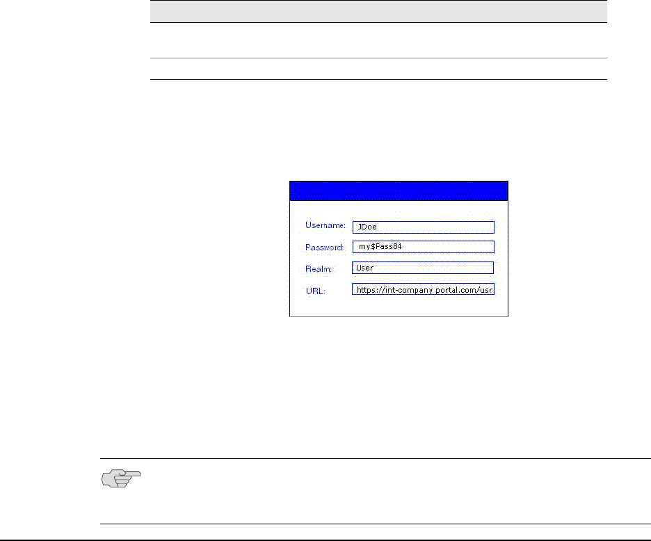
Troubleshooting Network Connect errors 553
Chapter 21: Network Connect
For example, you might distribute a simple login application to your end-users. The
application might capture the end-user's username and password, the IVE resource
they are trying to reach, and the realm to which they are assigned.
In this example, you need to write a script or add logic to your application to
capture the credentials the end-user enters, and pass the credentials as the
arguments to the nclauncher.exe, as follows:
nclauncher.exe -user JDoe -pass my$Pass84 -url https://int-
company.portal.com/usr -realm User
Troubleshooting Network Connect errors
Your end-users may be unable to resolve some of the errors they might encounter,
without your intervention. The following topics may correspond to errors listed in
the end-user help.
nc.windows.app.23792
If your end-user encounters this error (or nc.windows.app.1023), they have been
unable to connect to the IVE.
Check items on both the client machine and on the IVE.
On the client
The error may indicate a faulty Java installation on the client. Have the client
uninstall and reinstall the JRE.
-realm <realm> Specifies the realm to which the IVE submits the user’s
credentials.
-stop Terminates NC tunnel, and sign out current user.
Table 40: Network Connect Launcher Command Syntax
Argument Action
NOTE: If you are using Windows Vista, open the command window as an
administrator user. Standard output from the nclauncher.exe does not display if
the command window is opened by a user without administrator privileges.
Juniper Networks Secure Access Administration Guide
554 Troubleshooting Network Connect errors
One or more of the 3rd-party clients on your end-user’s computer may be
faulty or interrupting the connection. You will need to check or have your user
check clients such as VPN clients, Anti-Virus, Personal Firewalls, Spyware, and
other types of endpoint security clients.
The \Documents and Settings folder on the end-user’s computer might be
encrypted. Network Connect cannot install itself to an encrypted directory.
On the IVE
Ensure that the DNS name lookup for the IVE does not resolve to its
public/private IP address.
If the NC profile is configured to use an external DHCP server, ensure that the
DHCP server is responding to the IVE.
Ensure that you have set the Auto Enable option for NCP.
Select System > Network > Overview and make sure that you have
configured DNS for the IVE.
Version conflict on downgrade
When you downgrade to a prior release, your end-users might receive a version
conflict error when Network Connect initiates. The problem may occur because the
client contains a newer version of certain files which the older version cannot use
properly.
To resolve this problem, delete the following files:
<user_home>/.juniper_networks/ncLinuxApp.jar
<user_home>/.juniper_networks/network_connect/*.*
If this solution does not solve the version conflict problem, contact your system
administrator.
555
Part 5
System management
This section contains the following information about managing your IVE system:
“General system management” on page 557
“Certificates” on page 599
“System archiving” on page 627
“Logging and monitoring” on page 663
“Troubleshooting” on page 689
“Clustering” on page 705
“Delegating administrator roles” on page 733
“Instant Virtual System (IVS)” on page 747
“IVE and IDP Interoperability” on page 801
Juniper Networks Secure Access Administration Guide
556

Licensing: System management availability 557
Chapter 22
General system management
The IVE provides a number of features that allow you to maintain your system
easily. You can define, modify, and monitor system management capabilities, such
as:
“Licensing: System management availability” on page 557
“Task summary: Configuring management capabilities” on page 558
“Configuring network settings” on page 558
“Using central management features” on page 571
“Configuring system utilities” on page 574
“Configuring licensing, security, and NCP” on page 580
“Configuring and using the Management Port” on page 591
Licensing: System management availability
System management features are an integral part of all Secure Access products—
you do not need a special license to manage your Secure Access appliance.
However, note that the following advanced management features are not available
on the SA 700 and are only available on all other Secure Access products by special
license:
Bonding ports
SFP ports
Management ports
VLANs
Central management features
Clustering features
SSL acceleration
WSAM installers

Juniper Networks Secure Access Administration Guide
558 Task summary: Configuring management capabilities
Task summary: Configuring management capabilities
Generally, you can perform the following tasks in order, although to configure your
system settings, it is not always necessary to perform all of the tasks at once.
1. Configure your license settings.
2. Optionally upgrade or downgrade your system software.
3. Configure network settings.
4. Configure security options.
5. Configure internal, external, management, and SFP ports.
6. Optionally configure hosts and static routes.
7. Optionally configure VLANs.
8. Optionally configure Network Connect IP filters.
9. Optionally configure NCP.
10. Optionally configure Central Manager and customize dashboard graphs.
Additionally, you may need to perform more specific tasks that span multiple
topics. In those cases, you can find direction in the task summaries:
“Task Summary: Associating certificates with virtual ports” on page 569
“Configuring network settings” on page 558
Configuring network settings
The IVE enables you to modify the network settings that you enter through the
serial console during your initial IVE configuration as well as configure additional
network settings such IP filters in order to enable other IVE features. This section
provides the following overviews of network settings that you can set through the
admin console:
“Bonding ports” on page 559
“Configuring general network settings” on page 559
“Configuring internal and external ports” on page 561
“Configuring SFP ports” on page 563
“Configuring the Management Port” on page 564
“Configuring VLANs” on page 565
Configuring network settings 559
Chapter 22: General system management
“Configuring virtual ports” on page 566
“Configuring static routes for network traffic” on page 569
“Creating ARP caches” on page 570
“Specifying host names for the IVE to resolve locally” on page 571
“Specifying IP filters” on page 571
Bonding ports
By default, on the SA 6000 only, the IVE uses bonding of the multiple ports to
provide failover protection. Bonding describes a technology for aggregating two
physical ports into one logical group. Bonding two ports on the IVE increases the
failover capabilities by automatically shifting traffic to the secondary port when the
primary port fails.
The SA 6000 appliance bonds ports as follows:
Internal port = Port 0+Port 2
External port = Port 1+Port 3
The IVE indicates in a message on the System > Network > Overview page
whether or not the failover functionality is enabled.
Configuring general network settings
The IVE enables you to view the status of the system ports, to specify a host name
for the IVE, and to configure DNS name resolution, Windows Internet Naming
Service (WINS) server, and master browser settings for the IVE through settings in
the System > Network > Overview page in the admin console. You may also use
settings in this page to view the DNS and WINS settings that you entered through
the serial console during initial configuration.
When you remove a Windows workgroup, it might continue to appear in the IVE
workgroup list for several hours before finally being removed from the list. This
situation occurs because the IVE collects workgroup information from all of the
systems it can contact. The workgroup name might be cached on one or more
Windows systems for several hours and when the IVE interrogates the systems, it
still finds the workgroup names. This is a common occurrence on systems other
than the IVE as well, and poses no integrity problems.
Use settings in this tab to configure general network settings. The Status area
displays read-only status of the following items:
Node Name—Name of the current node, if running a cluster.
Failover Message—Indicates whether or not the failover functionality is
enabled (only on an SA 6000 appliance).
Internal Port—The status and speed of the internal port.
Port 1—The status and speed of the external port, if used.

Juniper Networks Secure Access Administration Guide
560 Configuring network settings
Management Port—The status of the Management Port, if used.
To configure general network settings:
1. In the admin console, choose System > Network > Overview.
2. Under Network Identity, enter the fully-qualified host name of the IVE.
3. Under DNS Name Resolution, update the primary DNS address, secondary
DNS address, and default DNS domain name for the individual IVE appliance.
You may enter a comma delimited list of DNS domains in these fields; the IVE
searches for them in the order that they are listed.
4. Under Windows Networking:
Enter the name or IP address of a local or remote the Windows Internet
Naming Service (WINS) server that you use to associate workstation names
and locations with IP addresses (if applicable).
Click Master Browser(s) to select a WINS server, domain controller, or
other server within the IVE domain that responds to NETBIOS calls and
associates workstation names and locations with IP addresses (if
applicable). Add the master browser through the Windows Networking –
Specify Master Browser page.
5. Select the Enable network discovery check box to enable the IVE to discover
shared Windows folders.
6. Click Save Changes.
NOTE:
The host name that you enter in this field cannot exceed 30 characters.
Secure Meeting uses the specified host name when making SMTP calls and
when populating notification emails with meeting URLs. For more
information, see “Secure Meeting” on page 493.
Pass Through Proxy uses the specified host name as an alias for the
application server host name. For more information, see “Task summary:
Configuring pass-through proxy” on page 287.
If your IVE appliances are clustered, the network identity host name that you
specify is synchronized across the cluster. In multi-site clusters, however, we
recommend that you override this setting and specify different host names
for the individual nodes in the cluster using options in the System >
Clustering page.

Configuring network settings 561
Chapter 22: General system management
Configuring internal and external ports
The internal port, also known as the internal interface, handles all WAN and LAN
requests to resources, listening for Web browsing, file browsing, authentication,
and outbound mail requests. You configure the internal port by providing IP
address, gateway, DNS server and domain, and MTU settings during the initial
setup of the IVE. You can also change them on the System > Network > Internal
Port > Settings tab. For more information, see “Configuring the Management
Port” on page 564. Alternatively, you can deploy the appliance in dual-port mode to
listen for incoming Web and mail proxy SSL connections on an external port.
The external port, also known as the external interface, handles all requests from
users signed into the IVE from outside the customer LAN, for example, from the
Internet. Before sending a packet, the IVE determines if the packet is associated
with a TCP connection that was initiated by a user through the external interface. If
that is the case, the IVE sends the packet to the external interface. All other packets
go to the internal interface.
The routes that you specify for each interface apply after the IVE has determined
whether to use the internal or external interface. No requests are initiated by the
IVE from the external interface, and this interface does not accept any other
connections (except ping and traceroute connections). All requests to any resource
are issued from the internal interface. (For more information, see “Configuring
general network settings” on page 559.)
To modify network settings for the internal port (LAN interface):
1. In the admin console, choose System > Network > Internal Port > Settings.
2. In the Port Information section, update the IP address, netmask, and default
gateway settings for the individual IVE appliance. By default, these fields are
populated with the settings entered during initial IVE setup.
3. In the Link Speed field, specify the speed and duplex combination you want to
use for the internal port.
NOTE: If you enable the external port, then, by default, administrators may no
longer sign in from an external location. You can open the external port for
administrators on the Administrators > Admin Realms > RealmName >
Authentication Policy > Source IP tab. For more information, see “Specifying
source IP access restrictions” on page 43.
NOTE: Most fields on this page are pre-populated with the settings specified during
IVE installation.
Juniper Networks Secure Access Administration Guide
562 Configuring network settings
4. In the ARP Ping Timeout field, specify how long the IVE should wait for
responses to Address Resolution Protocol (ARP) requests before timing out.
Clustered IVE appliances send ARP requests1 to the gateways of other IVE
appliances in order to determine if they are properly communicating with one
another.
5. In the MTU field, specify a maximum transmission unit for the IVE’s internal
interface.
6. Click Save Changes.
To enable the external port:
1. In the admin console, choose System > Network > Port 1 > Settings.
2. Under Use Port, select Enable.
3. In the Port Information section, enter the IP address, netmask, and default
gateway information for the external port of the IVE. Typically, you should to
use the settings from the Internal Port > Settings page and then change the
internal port information to a local IP address, netmask, and gateway.
4. In the Link Speed field, specify the speed and duplex combination you want to
use for the external port.
5. In the ARP Ping Timeout field, specify how long the IVE should wait for
responses to Address Resolution Protocol (ARP) requests before timing out.
Clustered IVE appliances send ARP requests2 to the gateways of other IVE
appliances in order to determine if they are properly communicating with one
another.
1. The IVE makes two ARP requests—one to the gateway on the internal port and another to the gateway on the
external port—when trying to establish communications in the cluster.
NOTE: If you are not running the IVE in a clustered environment, the IVE does not
use this setting. If your IVE systems are clustered, the timeout interval that you
specify is synchronized across the cluster. In multi-site clusters, you can override
this setting for the individual nodes in the cluster using options in the System >
Clustering page. Use caution when changing this setting in active/passive clusters,
however, because the IVE also uses the ARP Ping Timeout setting on the Internal
tab as a failover timer for the VIP.
NOTE: Use the default MTU setting (1500) unless you must change the setting for
troubleshooting purposes.
2. The IVE makes two ARP requests—one to the gateway on the internal port and another to the gateway on the
external port—when trying to establish communications in the cluster.
NOTE: If your IVEs are clustered, the timeout interval that you specify is
synchronized across the cluster. In multi-site clusters, however, you can override
this setting for the individual nodes in the cluster using options in the System >
Clustering page. If you are not running the IVE in a clustered environment, the
IVE does not use the ARP Ping Timeout setting.

Configuring network settings 563
Chapter 22: General system management
6. In the MTU field, specify a maximum transmission unit for the IVE’s external
interface.
7. Click Save Changes.
Configuring SFP ports
The SA 6000 includes two Small Form-factor Pluggable (SFP) Gigabit Ethernet ports
(designated ports 2 and 3 on the front of the SA 6000) that offer you the ability to
further increase your connectivity to internal network components.
When you enable the SFP ports, you can configure them just as you configure the
internal port. For each SFP port that is available on your system, the admin console
provides a separate configuration tab in System > Network > Port [#] where [#]
is the specific number of the port.
To modify network settings for an SFP port:
1. Select the SFP Port [#] > Settings tab.
2. Under Use Port? select Enabled to activate the Management Port.
3. In the admin console, choose System > Network > Port [#]> Settings.
4. In the Port Information section, update the IP address, netmask, gateway, and
link speed settings.
5. In the ARP Ping Timeout field, specify how long the IVE should wait for
responses to Address Resolution Protocol (ARP) requests before timing out.
Clustered IVE appliances send ARP requests1 to the gateways of other IVE
appliances in order to determine if they are properly communicating with one
another.
NOTE: Use the default MTU setting (1500) unless you must change the setting for
troubleshooting purposes.
NOTE: Most fields on this page are pre-populated with the settings specified during
IVE installation.
1. The IVE makes two ARP requests—one to the gateway on the internal port and another to the gateway on the
external port—when trying to establish communications in the cluster.
NOTE: If you are not running the IVE in a clustered environment, the IVE does not
use this setting. If your IVEs are clustered, the timeout interval that you specify is
synchronized across the cluster. In multi-site clusters, you can override this setting
for the individual nodes in the cluster using options in the System > Clustering
page. Use caution when changing this setting in active/passive clusters, however,
because the IVE also uses the ARP Ping Timeout setting on the Port [#] tab as a
failover timer for the VIP.

Juniper Networks Secure Access Administration Guide
564 Configuring network settings
6. In the MTU field, specify a maximum transmission unit for the IVE’s SFP port.
7. Click Save Changes.
Configuring the Management Port
The SA 6000 provides a Management Port that enables seamless integration into a
dedicated Management Network, provides continuously available management
access to the IVE, and enables you to perform management activities without
impacting user traffic and vice versa.
You can configure the Management Port just as you configure the internal port. The
admin console provides a separate configuration tab in System > Network >
Management Port, where you can specify port settings and advanced settings,
such as IP address, netmask, MTU, ARP cache, and others.
To modify network settings for the Management Port:
1. Select the Management Port > Settings tab.
2. Under Use Port? select Enabled to activate the Management Port.
3. In the admin console, choose System > Network > Management Port >
Settings.
4. In the Port Information section, update the IP address, netmask, gateway, and
link speed settings.
5. In the ARP Ping Timeout field, specify how long the IVE should wait for
responses to Address Resolution Protocol (ARP) requests before timing out.
Clustered IVE appliances send ARP requests1 to the gateways of other IVE
appliances in order to determine if they are properly communicating with one
another.
NOTE: Use the default MTU setting (1500) unless you must change the setting for
troubleshooting purposes.
NOTE: Most fields on this page are pre-populated with the settings specified during
IVE installation.
1. The IVE makes two ARP requests—one to the gateway on the internal port and another to the gateway on the
external port—when trying to establish communications in the cluster.
NOTE: If you are not running the IVE in a clustered environment, the IVE does not
use this setting. If your IVE systems are clustered, the timeout interval that you
specify is synchronized across the cluster. In multi-site clusters, you can override
this setting for the individual nodes in the cluster using options in the System >
Clustering page. Use caution when changing this setting in active/passive clusters,
however, because the IVE also uses the ARP Ping Timeout setting on the
Management Port tab as a failover timer for the VIP.

Configuring network settings 565
Chapter 22: General system management
6. In the ARP Ping Timeout field, specify how long the IVE should wait for
responses to Address Resolution Protocol (ARP) requests before timing out.
7. In the MTU field, specify a maximum transmission unit for the IVE’s internal
interface.
8. Click Save Changes.
Configuring VLANs
The IVE enables you to create VLANs for your enterprise. VLANs are used
extensively in the virtual systems, as described in “Configuring a Virtual Local Area
Network (VLAN)” on page 762. However, you can also create a VLAN for use in an
environment in which you have deployed an IVE for use by all of your enterprise
end-users.
The VLAN enables you to take advantage of VLAN tagging, by which the IVE tags
traffic with 802.1Q VLAN IDs before transmitting the traffic over the backend. The
infrastructure uses the VLAN tag to direct the packets to your appropriate
VLANs/subnets.
Traffic coming in over the front-end—that is, inbound traffic—does not have VLAN
tags. The IVE adds the tag to a message upon its arrival over one of the IVE ports.
Each VLAN is assigned a VLAN ID which is part of an IEEE 802.1Q-compliant tag
that is added to each outgoing Ethernet frame. The VLAN ID uniquely identifies all
inbound traffic. This tagging allows the system to direct all traffic to the appropriate
VLAN and to apply respective policies to that traffic.
The VLAN termination point is any device on which VLAN-tagged traffic is identified,
stripped of the VLAN tag, and forwarded to the appropriate tunnel to the backend.
The VLAN termination point can be a CE router, CPE router, L2 switch, firewall, or
other device capable of VLAN routing.
You must define a VLAN port for each VLAN. You assign the specific VLAN ID when
defining the VLAN port.
For each VLAN you configure, the virtualized IVE provisions a unique, logical VLAN
interface, or port, on the internal interface. There is no relationship between the
internal port IP address and any VLAN port IP address. Each VLAN port has its own
route table.
Each VLAN port definition consists of:
Port Name. Must be unique across all VLAN ports that you define on the
system or cluster.
VLAN ID. An integer in the range from 1 to 4094 that uniquely identifies the
VLAN.
NOTE: Use the default MTU setting (1500) unless you must change the setting for
troubleshooting purposes.

Juniper Networks Secure Access Administration Guide
566 Configuring network settings
IP Address/Netmask. Must be an IP address or netmask from the same
network as the VLAN termination point, because the IVE connects to the VLAN
termination point on a Layer 2 network connection. VLAN IP addresses must
be unique. You cannot configure a VLAN to have the same network as the
internal port. For example, if the internal port is 10.64.4.30/16 and you
configure a VLAN as 10.64.3.30/16, you may get unpredictable results and
errors.
Default gateway. The IP address of the default router, typically the CE or CPE
router. The default gateway could act as the VLAN termination point, or could
reside behind the VLAN termination point.
Other network settings. Inherited from the internal port.
When you create a new VLAN port, the system creates two static routes, by default:
The default route for the VLAN, pointing to the default gateway.
The interface route to the directly connected network.
To create a VLAN port, perform the following steps:
1. Select System > Network > VLANs to open the VLAN Network Settings tab.
2. Click New Port. If you are running a cluster, you must create the VLAN for the
entire cluster, not just for a single node.
3. Under VLAN settings, enter a name for the VLAN port.
4. Enter a VLAN ID.
5. Enter the IP address for the VLAN.
6. Enter a netmask for the VLAN.
7. Enter a default gateway for the VLAN.
8. Click Save Changes.
Configuring virtual ports
The IVE enables you to create virtual ports for users such as employees who are
signing into the IVE from inside your internal network. A virtual port activates an IP
alias on a physical port and shares all of the network settings (except IP address)
with the port that hosts the virtual port. An IP alias is an IP address that is bound to
a virtual port. (Note that an IP alias is different from the IVE system’s primary IP
address, which is a required IVE setting that you configure during the IVE
initialization process.)
NOTE: The VLAN ID must be between 1 and 4094 and must be unique on the
system.

Configuring network settings 567
Chapter 22: General system management
You can also specify virtual ports as role-based source IP aliases. These aliases can
correspond to source IP addresses that you specify on a backend network device as
valid addresses originating from the IVE system’s internal interface. For example,
you might want to use a firewall behind the IVE to direct end-user traffic to
particular departments based on source IP addresses. You can define a role-based
source IP alias for each departmental site. Each end-user is then directed to a
specific location based on their role through the use of the source IP alias. For more
information on setting up role-based source IP aliases, see “Specifying role-based
source IP aliases” on page 57.
You can use virtual ports in conjunction with the multiple device certificates feature
to provide users access to the same IVE through different IP aliases.
You use virtual ports when using an IVE configured with an IVS license.
In summary, you can use virtual ports for different purposes, depending on the
physical port on which you base the virtual port:
Configure virtual ports on the internal port to support subnetting in the
backend network and role-based source IP aliasing. Also, if you have an IVS
license, you can use virtual ports to direct traffic to different virtual systems.
Configure virtual ports on the external port to support clustering and external
sign-ins.
Configure virtual ports on the Management Port to support redirection of
administrative traffic.
Configure virtual ports on the SFP ports to support redirection of traffic to and
from those ports.
To create a virtual port for a stand-alone IVE:
1. In the admin console, choose System > Network > Port Tab > Virtual Ports.
The Port Tab could be for any one of ports 1, 2, 3, 4, the internal or external
ports, or the Management Port.
2. Click New Port.
3. Enter a unique name for the virtual port.
4. Enter a unique IP alias to associate with the virtual port—do not use an IP
address that is already associated with another virtual port.
5. Click Save Changes.
NOTE: If you do not enter an IP address, the IVE does not activate the virtual port.

Juniper Networks Secure Access Administration Guide
568 Configuring network settings
To create a virtual port on a cluster node:
1. In the admin console, choose System > Network > Port Tab > Virtual Ports.
The Port Tab could be for any one of ports 1, 2, 3, 4, the internal or external
ports, or the Management Port.
2. From the Settings for drop-down list, select Entire cluster and then click
Update.
3. Click New Port.
4. Enter a unique name for the virtual port and then click Save Changes. The IVE
adds the virtual port name to the Virtual Ports list and provides access to each
node in the cluster.
5. Click the link to a node to access the IP address configuration page. Enter a
unique IP alias to associate with the virtual port—do not use an IP address that
is already associated with another virtual port.
6. Click Save Changes. The Virtual Ports page returns to the virtual port tab. If
necessary, re-select Entire cluster from the Settings for drop-down list and
then repeat the last 2 steps of this procedure.
For more information about using virtual ports in clusters, see “Deploying two
nodes in an Active/Passive cluster” on page 712.
Task Summary: Defining Subnet Destinations Based on Roles
This section provides a high-level overview of the tasks required to direct users to
specific subnets based on their roles. To set up a role-based mapping, you need to
create role-based source IP aliases.
To define subnet destinations based on roles:
1. Create virtual ports in the Network > Internal Port > Virtual Ports page of
the admin console, as described in “Configuring virtual ports” on page 566.
2. Modify one or more roles to point to the virtual ports, in the Users > Roles >
RoleName > General > Source IP page of the admin console, as described in
“Specifying role-based source IP aliases” on page 57.
NOTE: If you need to associate the virtual port with a device certificate, use
settings in the System > Configuration > Certificates > Device Certificates
tab. For more information, see “Associating a certificate with a virtual port” on
page 606.
NOTE: If you do not enter an IP address, the IVE does not activate the virtual port.
Configuring network settings 569
Chapter 22: General system management
3. Map your users to specific roles based on the subnet indicated by the source IP
of the role, in the Authentication > RealmName > Role Mapping page of the
admin console, as described in “Creating administrator roles” on page 735.
Task Summary: Associating certificates with virtual ports
To associate certificates with virtual ports:
1. Use settings in the System > Network > Internal Port tab to create virtual
ports. For instructions, see “Configuring virtual ports” on page 566.
2. Use settings in the System > Configuration > Certificates > Device
Certificates page of the admin console to import the server certificates that
you want to use to validate user certificates. Also use this tab to specify which
ports the IVE should associate with the certificates. For instructions, see
“Associating a certificate with a virtual port” on page 606.
Configuring static routes for network traffic
The IVE enables you to add routing table entries using settings in the System >
Network > Routes tab. All connection requests to internal resources come from
the IVE internal port regardless of route settings. The route settings on the external
port are used only to route packets associated with connections that are initiated by
a remote client.
You can add static routes, if you want to indicate a specific route that the IVE
should use when routing requests. You need to specify a valid IP address, gateway,
and DNS address. The metric is a way of comparing multiple routes to establish
precedence. Generally, the lower the number, from 1 to 15, the higher the
precedence. So, a route with a metric of 2 would be chosen over a route with a
metric of 14. The metric value of zero (0) identifies the route as one that should not
be used.
On the SA6000, you can configure two additional ports, port 2 and port 3. Although
ports 2 and 3 appear to be equivalent to the Internal port, they are not, and by
default, the IVE directs traffic to the Internal port when establishing an outbound
connection. Therefore, if one of these two ports is connected to a network that the
Internal port cannot reach, you need a static route for rewrites to access the
unreachable network. Otherwise, the rewrites might fail.
As a consequence, you need to configure static routes to those ports. The ports
appear in the drop down port menu as Port 2 and Port 3. For more information
about configuring static routes, see “Configuring static routes for network traffic”
on page 569.
To specify static routes for network traffic:
1. In the admin console, choose System > Network > Routes.
2. Select a destination route table from the View route table for: drop down
menu.
3. Click New Route.
4. Enter the required information.

Juniper Networks Secure Access Administration Guide
570 Configuring network settings
5. Click Add to [destination] route table.
Destination route tables may be available for the Internal port, External port,
Management port, Port 2, and Port 3, depending on which hardware platform
you are configuring, or for any VLANs you have defined.
Creating ARP caches
You can use ARP caching to determine the physical (MAC) address of a network
device such as a router or backend application server that connects to the IVE. Use
the System > Network > Internal Port > ARP Cache tab to manage the
following types of ARP (address resolution protocol) entries:
Static entries—You can add a static ARP entry to the cache associated with the
IP and MAC address. The IVE stores static entries during reboots and re-
activates them after re-booting. Static entries are always present on the IVE.
Dynamic entries—The network “learns” dynamic ARP entries during normal
use and interaction with other network devices. The IVE caches dynamic
entries for up to 20 minutes and deletes them during a reboot or when you
manually delete them.
You can view and delete static and dynamic entries from the ARP cache as well as
add static entries. If you have a cluster of IVEs, note that ARP cache information is
node-specific. The IVE only synchronizes ARP cache information across non-multi-
site clusters.
To add a static entry to the ARP Cache:
1. In the admin console, choose System > Network > Port Tab > ARP Cache.
The Port Tab could be for any one of ports 1, 2, 3, 4, the internal or external
ports, or the Management Port.
2. Enter the IP Address and the Physical Address in their respective fields at the
top of the table.
3. Click Add.
NOTE: Port 2 and Port 3 are available only on the SA 6000.
NOTE: If you add an entry containing an existing IP address, the IVE overwrites
the existing entry with your new entry. Also note that the IVE does not verify the
validity of MAC addresses.

Using central management features 571
Chapter 22: General system management
Specifying host names for the IVE to resolve locally
Specify host names that the IVE can resolve to IP addresses locally by using the
Hosts tab. This feature is useful when:
Your DNS server is not accessible to the IVE.
You use WINS to access servers within the LAN.
Your corporate security policy does not allow internal servers to be listed on an
external DNS or requires that internal host names are masked.
To specify host names for the IVE to resolve locally:
1. In the admin console, choose the System > Network > Hosts tab.
2. Enter an IP address, a comma delimited list of host names that resolve to the IP
address, a comment of 200 words or less (optional), and then click Add.
Specifying IP filters
You can specify IP filters for the IVE to apply to Network Connect IP pools from the
System > Network > Network Connect tab. An IP pool is a specific range of IP
addresses available for Network Connect requests (as explained in “Network
Connect” on page 521). For configuration instructions, see “Specifying IP filters” on
page 547.
Using central management features
The Central Manager package is available as part of the Advanced license. Central
management features consist of a two-tier (client/server) system that enables you
to manage multiple IVEs, regardless of whether or not they are clustered. Central
management features include:
System dashboard—The system dashboard feature displays system capacity
graphs and alarms that allow you to easily monitor the system. You can access
the system dashboard from the System > Status page of the admin console.
Improved logging and monitoring—The logging feature enables you to create
custom filters so that you may view and save only those log messages that you
choose in the format of your choice. You can access the logging feature from
the System > Log/Monitoring page of the admin console.
Push configuration feature—The push configuration feature enables you to
easily push settings from one IVE to another for convenient centralized
management.You can access the push configuration feature from the
Maintenance > Push Config page of the admin console.
Minimal downtime upgrades—The minimal downtime upgrade feature
enables you to expedite upgrades across a cluster, ensuring that one cluster
member is always functional during the upgrade process. You can access the
upgrade feature from the Maintenance > System > Upgrade/Downgrade
page of the admin console.
Juniper Networks Secure Access Administration Guide
572 Using central management features
Deterministic cluster recovery—The deterministic cluster recovery feature
enables you to assign ranks to various nodes in a cluster such that when a
cluster recovers from “split-brain” situation, the node with the highest rank
propagates the correct cluster state.
Improved user interface—The admin console for Central Manager includes an
enhanced appearance over the standard admin console for appliances with a
user license.
Improved SNMP MIB—The enhanced SNMP MIB feature provides you with
capacity utilization metrics. You can download the improved MIB from the
System > Log/Monitoring > SNMP page of the admin console.
Saving local backups—The local backups feature enables you to save up to 10
local backups of system and user configuration files on the IVE. You can access
this feature through the Maintenance > Archiving > Local Backups page of
the admin console.
Modifying Central Management dashboard graphs
If you have installed the Central Manager upgrade on your Secure Access appliance,
the system dashboard appears when you open the administrator console. The
dashboard displays system capacity graphs that allow you to easily monitor your
system.
If you want to analyze or display the information from these graphs using your own
tools, you may use the graph download feature. From the system dashboard, you
may download the data from each of the graphs into an XML file. Then, you may
use your own tools to reformat or analyze the data in the XML files.
Central Management dashboard graphs XML schemas
The XML files for all of the system dashboard graphs contain the same basic XML
elements:
<xport>—Top level element.
<meta>—Second level element.
<start>—Time that the system collected the first data point for the graph, in
UTC format.
<step>—Interval at which the system collected data points for the graph, in
seconds. For example, the following XML entry indicates that the system
collects data every minute: <step>60</step>
<end>—Time that the system collected the last data point for the graph, in UTC
format.
<rows>—Number of data points collected for the graph.
<columns>—Number of metrics collected for the graph. (Corresponds to the
number of lines displayed in the graph in the administrator console.)
Using central management features 573
Chapter 22: General system management
<legend>—Contains a list of <entry> sub-elements that define the names of
each of the metrics collected for the graphs. For example, sub-elements for the
Concurrent Users graph may include:
<legend>
<entry>Local users</entry>
<entry>Concurrent users</entry>
</legend>
<data>—Contains a list of <row> sub-elements that include the periodic data
collected for each entry. Each <row> element contains a <t> sub-element that
includes the time that the system collected the data and <v> sub-elements for
each piece of data. For example, a row within the Concurrent Users graph
may include:
<data>
<row>
<t>1089748980</t><v>2.1000000000e+01</v><v>2.1000000000e+01</v>
</row>
Sample XML Schema
The following sample shows the XML output for a Concurrent Users graph. (Note
that for the purposes of brevity, some of the original <row> elements have been
deleted from the sample.)
<xport>
<meta>
<start>1089748980</start>
<step>60</step>
<end>1089763440</end>
<rows>242</rows>
<columns>2</columns>
<legend>
<entry>Local users</entry>
<entry>Concurrent users</entry>
</legend>
</meta>
<data>
<row>
<t>1089748980</t><v>2.1000000000e+01</v><v>2.1000000000e+01</v>
</row>
<row>
<t>1089749040</t><v>2.1000000000e+01</v><v>2.1000000000e+01</v>
</row>
<row>
<t>1089749100</t><v>2.1000000000e+01</v><v>2.1000000000e+01</v>
</row>
...
<row>
<t>1089763440</t><v>NaN</v><v>NaN</v>

Juniper Networks Secure Access Administration Guide
574 Configuring system utilities
</row>
</data>
</xport>
Configuring system utilities
The IVE system utilities enable you to manage your server, upgrade or downgrade
system software, enable version monitoring, and to download client applications
and services. For more information refer to the following topics:
“Reviewing system data” on page 574
“Upgrading or downgrading the IVE” on page 575
“Setting system options” on page 575
“Downloading application installers” on page 577
Reviewing system data
The Maintenance > System > Platform page in the admin console lists IVE
system data and contains controls for restarting, rebooting, or shutting down an
IVE. It also contains a control to test server connectivity. When the IVE is a member
of a cluster, this page lists additional, cluster-specific, system data and the controls
operate on a cluster-wide basis.
Restarting, rebooting, shutting down, or testing server connectivity
The Maintenance > System > Platform page lists the following system data for
an IVE:
Model—Displays the model of the IVE
Version—Displays the IVE’s software version
Rollback—Displays the software version to which the IVE reverts when you roll
back the installed image
Last Reboot—Displays amount of time since the IVE’s last reboot
When the IVE is a member of a cluster, the Platform page lists the following
additional system data:
Cluster—Displays the name of the cluster to which the IVE belongs
Member—Displays the IVE’s cluster member name
The Platform page contains the following controls:
Restart Services/Cluster—Kills all processes and restarts the IVE. When the
IVE is a member of a cluster, this control kills all processes and restarts all
members of a cluster.

Configuring system utilities 575
Chapter 22: General system management
Reboot—Power cycles and reboots the IVE. When the IVE is a member of a
cluster, this control power cycles and reboots all members of the cluster.
Shut down—Shuts down the IVE, requiring you to press the reset button on the
appliance to restart the server. When the IVE is a member of a cluster, this
control shuts down all members of a cluster, requiring you to press the reset
button on all clustered appliances to restart the cluster. Note that the machine
power remains on after a server shutdown.
Rollback—Rolls back the software image and reboots the IVE. After the IVE
reboots, the image on the IVE is automatically rolled back to the image
displayed in the Rollback field, above.
Test Connectivity—Sends an ICMP ping from the IVE to all the servers the IVE
is configured to use and report their connectivity. Each server’s status is
reported under Server Connectivity Results.
Upgrading or downgrading the IVE
You can install a different service package by first obtaining the software from the
Juniper Support Web site and then uploading it through the admin console.
Package files are encrypted and signed so that the IVE server accepts only valid
packages issued by Juniper Networks. This measure prevents the IVE server from
accepting Trojan horse programs.
This feature is typically used to upgrade to newer versions of the system software,
but you can also use this process to downgrade to a previous version or to delete all
your current configuration settings and start from a “clean slate.” You may also roll
back to a previous system state through the serial console, as described in “Rolling
back to a previous system state” on page 812.
You can upgrade or downgrade the IVE from the Maintenance > System >
Upgrade/Downgrade page of the admin console.
Setting system options
You can set a number of system options, such as:
NOTE: If you want to restart, reboot, or shut down, or upgrade one IVE in a cluster,
you first disable the IVE using the controls on the System > Clustering > Status
page, and then return to the Platform page to employ the control of your choice.
NOTE: If you are looking for information on performing a factory reset or rolling
the system back to the previous state, please see “IVE serial console” on
page 811.
NOTE: Installing a service package can take several minutes and requires the IVE
to reboot. Because existing system data is backed up during this process, you can
decrease installation time by clearing your system log before trying to install a
service package.

Juniper Networks Secure Access Administration Guide
576 Configuring system utilities
Version monitoring—Keep your system current and secure by having the IVE
notify you about critical software patches and updates. To do this, it reports to
Juniper Networks the following data: your company name, an MD5 hash of
your license settings, and information describing the current software version.
gzip compression—Reduce download speeds when using HTTP compression-
enabled browsers.
Java instrumentation caching—Improve the performance of downloading
Java applications.
SSL acceleration—Offload the encryption and decryption of SSL handshakes if
you have installed an accelerator card.
Show auto-allow—Copy bookmarks for roles to corresponding access control
policies when using resource policies.
End-user localization—Set the language for the end-user browser, or accept
the browser default.
To set system options:
1. In the admin console, choose Maintenance > System > Options.
2. Select the Automatic Version Monitoring checkbox to automatically receive
notifications of critical software patches and updates.
3. Select the Enable gzip compression checkbox to reduce the amount of data
sent to browsers that support HTTP compression.
4. Select the Enable Java instrumentation caching checkbox to improve the
performance of downloading Java applications. With Java instrumentation
caching enabled, the IVE caches Java applets accessed by end users and serves
the cached applets to subsequent requests for the same applets.
5. Select the Enable SSL acceleration checkbox to off-load the encryption and
decryption of SSL handshakes from the appliance to the accelerator card.
6. If the Show Auto-allow checkbox is checked, deselect the checkbox if you
want to hide the auto-allow option from yourself or other administrators who
create new bookmarks for roles.
NOTE: For your protection, we strongly recommend that you enable this
automatic service, but if necessary, you can disable it.
NOTE: The IVE only displays this option if you have purchased an IVE appliance
equipped with the corresponding accelerator card.
Configuring system utilities 577
Chapter 22: General system management
The auto-allow option provides the means to automatically add bookmarks for
a given role to an access control policy, for example, Web bookmarks with
auto-allow set are added to the Web access control policy. You only use this
feature if you also use Resource Policies. We recommend that you use
Resource Profiles instead. For more information on resource profiles, see
“Resource profile components” on page 72.
7. Under the Show Auto-allow option, choose either:
Only this URL—This option restricts the bookmarks to be added to the
access control policy to the primary URL. For example, the URL
http://www.company.com would be added to the access control policy.
Everything under this URL—This option enables bookmarks to other
paths under the primary URL to be added to the access control policy. If
you define additional Web sites by role, you might want to include these in
the access control policy. For example, the following URLs are both added
when you select this option:
http://www.company.com/sales
http://www.company.com/engineering
8. Select the language for the end-user browser from the End-user Localization
drop down menu.
9. Click Save Changes.
Downloading application installers
You can download an application or service as a Windows executable file, which
enables you to:
Distribute the file to client machines using software distribution tools. This
option enables you to install an application or service on client machines
whose users do not have Administrator privileges, which are required to install
the application or service.
Post the executable in a secure repository so that users with the proper
administrator right may download and install the appropriate version.
Download and execute a script that automatically retrieves the proper version
of the installer from an FTP server.
These options allow you to control which version of an application or service runs
on client machines.

Juniper Networks Secure Access Administration Guide
578 Configuring system utilities
The Installers page contains the following controls:
Juniper Installer Service—The Juniper Installer Service allows users to
download, install, upgrade, and run client-side applications without
administrator privileges. In order to perform these tasks (which require
administrator privileges), the Juniper Installer Service runs under the client’s
Local System account (a powerful account with full access to the system) and
registers itself with Windows’ Service Control Manager (SCM). An Active-X
control or a Java applet running inside the user’s Web browser communicates
the details of the installation processes to be performed through a secure
channel between the IVE and the client system.
Host Checker—This installer (HCInst.exe) installs Host Checker on users’
systems. Host Checker is a client-side agent that performs endpoint security
checks on hosts that connect to the IVE.
Windows Secure Application Manager for Windows 9x platforms—This
installer (WSAMInst.exe) includes the basic version of WSAM. Use this version
to install WSAM on Windows 9x.
NOTE: When installing the Juniper Installer Service on client systems, note that:
You need administrator privileges to install the Juniper Installer Service. For
additional information, see the Client-side Changes Guide on the Juniper
Networks Customer Support Center.
You should ensure that the Microsoft Windows Installer exists on the client
system prior to installing the Juniper Installer Service.
Your end-users’ client systems must contain either a valid and enabled Java
Runtime Engine (JRE) or a current IVE ActiveX control. If the client systems do
not contain either of these software components, the end-users will be unable
to connect to the gateway.
You should ensure that a valid JRE is enabled on your end-users’ client
systems.
If there is no JRE on your end-users’ client systems, you should download
an appropriate installer package from Maintenance > System >
Installers.
The service appears in the Windows Services (Local) list as Neoteris Setup
Service.
The service starts automatically on install and during client system start up.
NOTE: If you decide to distribute Host Checker, make sure to uncheck the Auto-
upgrade Host Checker option on the Authentication > Endpoint Security >
Host Checker page (see “Specifying general Host Checker options” on page 262).
Otherwise the IVE downloads the Host Checker application to a user’s machine,
which may not be the same version as the distributed version.

Configuring system utilities 579
Chapter 22: General system management
Windows Secure Application Manager for Windows 2000/XP platforms—
This installer (WSAMInstNt.exe) includes the NetBIOS version of W-SAM, which
enables users to map drives to Windows resources. Use this version to install
WSAM on Windows 2000 and Windows XP systems.
Scriptable W-SAM—This installer (Samlauncher.exe) enables you to launch
WSAM manually from a command line or automatically from a batch file, an
application that performs a shell call, or a Win32 service. See “Using the
W-SAM launcher” on page 413 for information about command-line
arguments, return codes, errors, and examples.
Windows Secure Application Manager for PocketPC 2003SE—This installer
(wsam.ppc2003_arm.cab) includes the PDA version of WSAM. Use this version
to install WSAM on Pocket PC systems.
Network Connect for Windows—This installer (NcInst.exe) installs Network
Connect on Windows systems. Network Connect is a remote access
mechanism that provides a clientless VPN user experience.
Network Connect for Mac OS X—This installer (NetworkConnect.dmg) installs
Network Connect on Macintosh OS X systems. Network Connect is a remote
access mechanism that provides a clientless VPN user experience.
Network Connect for Linux—This installer (ncui-1.2-1.i386.rpm) installs
Network Connect on Linux systems. Network Connect is a remote access
mechanism that provides a clientless VPN user experience.
To download an application or service:
1. In the admin console, choose Maintenance > System > Installers.
2. Click on the Download link to the right of the application or service you want
to download. The File Download dialog box appears.
3. Click the Save button on the File Download dialog box. The Save As dialog box
appears.
4. Choose an appropriate location in the Save As dialog box.
5. Click the Save button on the Save As dialog box.
NOTE: If you decide to distribute W-SAM, we recommend that you disable the
Auto-upgrade Secure Application Manager option on the Users > User Roles >
RoleName > SAM > Options page (see “Specifying role-level WSAM options” on
page 408) and save your changes. If enabled, the IVE automatically downloads a
newer version of W-SAM to the client, resulting in different users running
inconsistent versions of W-SAM. Furthermore, if a user does not have
administrator privileges, the upgrade fails and W-SAM may no longer function.

Juniper Networks Secure Access Administration Guide
580 Configuring licensing, security, and NCP
Configuring licensing, security, and NCP
Use the System > Configuration pages to apply your initial license or upgrade
your license, to set default security options, to configure NCP or JCP
communication protocols, as described in the following topics:
“Entering or upgrading IVE licenses” on page 580—Use this feature to enter a
new license, to add options to your existing license, or to upgrade a license to a
new release.
“Activating and deactivating emergency mode” on page 586—Use this feature
to activate or deactive “In Case of Emergency” (ICE) mode.
“Setting security options” on page 587—Use this feature to set all security
options, including system-wide options, cookies, intermediation, and more.
“Configuring NCP and JCP” on page 589—Use this feature to set
communication protocols.
“Installing a Juniper software service package” on page 590—Use this feature
to install a new service package to the IVE.
Entering or upgrading IVE licenses
The IVE appliance ships with a license that allows you basic access to the IVE1. To
take full advantage of your appliance, however, you must access the Juniper
Networks License Management System, provide your Licensing Hardware ID and
Authorization Code(s) to obtain your license keys, and sign in to the admin console
to enter the license keys you receive from Juniper Networks.
A Licensing Hardware ID is a unique 16-character code Juniper Networks uses to
identify your particular IVE when generating license keys. You can find the IVE’s
Licensing Hardware ID above the menu options in the serial console and at the
bottom of the admin console.
An Authorization Code is a pass key required to generate and activate license keys
you or your company have purchased for your IVE. You receive your Authorization
Code(s) separate from the IVE after you purchase your IVE and associated product
and feature licenses.
1. The basic IVE
license allows you to create 5 local user accounts, enables 2 users to sign in concurrently, and
provides basic Web, Windows, and UNIX/NFS file browsing capabilities.
Configuring licensing, security, and NCP 581
Chapter 22: General system management
Figure 44: License key generation and activation
Sign in to Juniper Networks
License Management System
at
http://www.juniper.net/
generate_license
Supply your Juniper
Networks Secure
Access Appliance
Serial Number
(when upgrading
SA 1000, SA 3000,
and SA 5000 license
keys only)
Receive Juniper
Networks
Secure Access
license keys
Enter Juniper
Networks Secure
Access license keys
in Secure Access
administrator Web
console
Obtain your Juniper
Networks Secure
Access Authorization
Code
Obtain your Juniper
Networks Secure
Access Licensing
Hardware ID

Juniper Networks Secure Access Administration Guide
582 Configuring licensing, security, and NCP
The package you download from the Juniper Networks License Management
System or the email message you receive from Juniper Networks may contain
different types of licenses:
IVE user license keys—The IVE user license key enables you to host as many
users as are specified in the license key code. IVE user license keys are additive,
meaning that you can expand the number of users that can access the IVE by
simply acquiring an additional user license key and adding it to your
configuration. For example, if you initially purchase an SA4000-ADD-100U
license and then purchase another SA4000-ADD-100U license in the future,
your IVE could accommodate up to 200 users.
IVE access feature license keys—IVE access feature license keys allow you to
enable access methods on the IVE. Access feature license keys are available for
a variety of access methods including Network Connect and Secure Application
Manager, Secure Meeting, and Advanced access feature licenses.
IVE cluster license keys—IVE cluster license keys enable clustering behavior
among IVEs. You can purchase IVE cluster license keys in conjunction with IVE
user license keys, but the number of users that can access the IVEs in the
cluster is restricted to the maximum number of users allowed by the IVE
cluster license key. Like IVE user license keys, IVE cluster license keys are
additive in that you can increase the number of users who are able to access the
cluster by purchasing additional license keys in the future. For example, if you
initially purchase an SA4000-CL-100U cluster license and then purchase
another SA4000-CL-100U cluster license in the future, your IVE could
accommodate up to 200 users. If you purchase an additional SA4000-ADD-
100U IVE user license key instead of an additional cluster license key, however,
despite being able to accommodate up to 200 users via your user license keys,
you can still only accommodate 100 users in the cluster of IVEs. For more
information on clustering IVEs, refer to “Clustering” on page 705.
IVE lab license keys—Lab license keys allow you to deploy new IVE
functionality in a “test” or “laboratory” environment before deciding whether
or not to purchase and roll out the up-to-date functionality in your live network.
Lab license keys are valid for 52 weeks and grant access to a limited number of
users. Although you can purchase multiple lab license keys, it does not increase
the number of users to whom you can provide access. Instead, you can
increase the duration of the license by multiples of 52 weeks (104 weeks, 156
weeks, and so forth). For example, if you purchase two SA4000-LAB licenses,
you can grant 10 users access for 104 weeks, rather than just 52.
NOTE: All nodes in a cluster must feature the same license key as on the primary
cluster IVE to enable cluster operation. You cannot add an ADD and a CL license
to the same machine at the same time. For a node to be able to join a cluster, you
must add a CL license to the node.

Configuring licensing, security, and NCP 583
Chapter 22: General system management
IVE In Case of Emergency (ICE) license keys—In Case of Emergency (ICE)
license keys allow you to activate the IVE emergency mode, which temporarily
enables the IVE for a large number of users. For instance, you may want to
activate this mode if one of your offices shuts down due to severe weather
conditions. When you do, your employees can use the IVE to work from home
instead of coming to the office. Valid ICE licenses support a full set of features,
but limits usage to 2 users when emergency mode is dectivated. You can
operate the IVE in emergency mode for up to 8 weeks. For more information,
see “Activating and deactivating emergency mode” on page 586.
IVE evaluation license keys—Evaluation license keys allow you to enable and
roll out the latest IVE functionality for a limited time before deciding whether or
not to purchase license keys and enable the new IVE functionality on a
permanent basis. Evaluation license keys are valid for one, two, or four weeks.
Use the System > Configuration > Licensing tab to enter the license keys for
your site, view their expiration dates, and delete them (if required).
Entering new IVE license keys
To create and enter new IVE license keys or transfer license keys to a replacement
IVE:
1. Ensure that you have your Licensing Hardware ID and Authorization Code(s)
readily available.
You can find the IVE’s Licensing Hardware ID above the menu options in the
serial console and at the bottom of the admin console.
You receive your Authorization Code(s) separate from the IVE after you
purchase your IVE and associated product and feature licenses.
2. Navigate to the Juniper Networks License Management System at
https://www.juniper.net/generate_license.
3. Click the Secure Access SSL VPN link to generate new IVE license keys or click
Generate Replacement License for RMA Device to create a license key based
on an existing license for an IVE that you are replacing.
NOTE: Make sure that you read the license agreement, which is accessible from
the Licensing tab, before submitting your license key. The license agreement
available from the Licensing tab is the same text displayed in the serial console
during the initial setup.
NOTE: The Juniper Networks License Management System offers you an access
point where you can obtain detailed information about Juniper Networks licenses,
including all licenses registered to you and your company, as well as licenses
currently associated with specific Licensing Hardware IDs.
You must have a valid Juniper Networks Customer Support Center user ID and
password to access the information at this location. To obtain a Juniper Networks
Customer Support Center user ID and password, access the Customer Support
Center.

Juniper Networks Secure Access Administration Guide
584 Configuring licensing, security, and NCP
4. On the Generate Licenses page:
If you are creating a license key for only one IVE, enter the Licensing
Hardware ID and one or more Authorization Codes in the appropriate
fields.
If you want to create license keys for multiple IVEs at the same time, click
Generate License Keys for Multiple SSL VPN Devices and follow the on-
screen procedure to create the Excel file necessary to generate your license
keys.
5. Click Generate.
The Confirm License Information page appears, displaying a summary of the
information you submitted to the License Management System.
6. Review the information to ensure everything is correct and then click Generate
License.
The Generate License SSL VPN page appears, displaying a summary of your
license keys, including a link that displays the details of your new license keys.
7. Click Download/Email and specify the file format and delivery method you
want to use to obtain your new license keys.
After you download or receive your license keys by using email:
1. In the admin console, choose System > Configuration > Licensing.
2. Click on the license agreement link. Read the license agreement and, if you
agree to the terms, continue to the next step.
3. Enter your license key(s) and click Add.
Upgrading IVE license keys
If you are using a Secure Access 700, Secure Access 1000, Secure Access 3000,
Secure Access 5000, or Secure Access FIPS appliance and you want to upgrade
your license keys after upgrading the image on your IVE to 5.1 or later, you must go
through the following procedure to create and enter your new license keys. Since
the IVE retains existing license information when upgrading, you are only required
to validate and create new license keys for any license upgrades you purchase.
Figure 44 on page 581 outlines the major steps in the license-generation process.
NOTE: The Generate Replacement License for RMA Device option is designed to
accommodate RMA hardware-replacement scenarios only. It cannot be used to
replace a license key that was created in error (for example, using an
Authorization Code to create a license key for an IVE other than the IVE for which
the license was originally purchased).

Configuring licensing, security, and NCP 585
Chapter 22: General system management
To upgrade your IVE license keys:
1. Ensure that you have your Licensing Hardware ID and Authorization Code(s)
readily available.
You can find the IVE’s Licensing Hardware ID above the menu options in the
serial console and at the bottom of the admin console.
If you are upgrading your IVE’s software and license keys, you receive your
Authorization Code(s) for your additional feature licenses from the vendor from
whom you originally purchased your IVE.
2. Navigate to the Juniper Networks License Management System at
https://www.juniper.net/generate_license.
3. Click the Secure Access SSL VPN link to generate new IVE license keys or click
Generate Replacement License for RMA Device to create a license based on
an existing license for an IVE that you are replacing.
NOTE: When you upgrade your license keys on an older IVE, the Juniper Networks
License Management System retains information about the new license keys you
create as well as any future license keys you purchase and enter in your IVE.
Older license key details are not accessible. Juniper Networks cannot verify
license key information for software versions older than 5.1. If you accidentally
delete your license information, please contact Juniper Customer Care via the
Customer Support Center Case Manager:
1-800-638-8296 (US and Canada)
1-408-745-9500 (International)
Juniper Customer Care will open a case on your behalf and provide you with a
record of your lost license key(s).
NOTE: The Juniper Networks License Management System offers you an access
point where you can obtain detailed information about Juniper Networks licenses,
including all licenses registered to you and your company, as well as licenses
currently associated with specific Licensing Hardware IDs.
You must have a valid Juniper Networks Customer Support Center user ID and
password to access the information at this location. To obtain a Juniper Networks
Customer Support Center user ID and password, access the Customer Support
Center.
NOTE: The Generate Replacement License for RMA Device option is designed to
accommodate RMA hardware-replacement scenarios only. It cannot be used to
replace a license key that was created in error (for example, using an
Authorization Code to create a license key for an IVE other than the IVE for which
the license was originally purchased).
Juniper Networks Secure Access Administration Guide
586 Configuring licensing, security, and NCP
4. On the Generate Licenses page:
If you are creating a license key for only one IVE, enter the Licensing
Hardware ID and one or more Authorization Codes in the appropriate
fields.
If you want to create license keys for multiple IVEs at the same time, click
Generate License Keys for Multiple SSL VPN Devices and follow the on-
screen procedure to create the Excel file necessary to generate your license
keys.
5. Click Generate.
6. Enter the IVE’s serial number in the Serial Number field. If you do not enter
the IVE’s serial number when prompted, the license-generation portal
automatically uses the Licensing Hardware ID you entered above.
7. Click Generate again.
The Confirm License Information page appears, displaying a summary of the
information you submitted to the License Management System.
8. Review the information to ensure everything is correct and then click Generate
License.
The Generate License SSL VPN page appears, displaying a summary of your
license keys, including a link that displays the details of your new license keys.
9. Click Download/Email and specify the file format and delivery method you
want to use to obtain your new license keys.
After you download or receive your license key upgrades via email:
1. In the admin console, choose System > Configuration > Licensing.
2. Click on the license agreement link. Read the license agreement and, if you
agree to the terms, continue to the next step.
3. Enter license keys and click Save Changes.
Activating and deactivating emergency mode
The IVE emergency mode feature allows you to temporarily enable the IVE for a
large number of users, as explained in “Entering or upgrading IVE licenses” on
page 580.

Configuring licensing, security, and NCP 587
Chapter 22: General system management
In order to activate the IVE in emergency mode, you must first install an In Case of
Emergency (ICE) license using the standard IVE license installation procedure.
Then, when the emergency occurs, you can easily activate emergency mode
through the IVE Web console. When your emergency has passed, you should then
deactivate the emergency mode.
To activate or deactivate emergency mode:
1. In the Web console, choose System > Configuration > Licensing.
2. Find the In Case of Emergency License entry in the license list. Sample ICE
license names include:
SA4000-ICE
SA4000-ICE-CL
SA6000-ICE
SA6000-ICE-CL
3. Click the Enable link in the right side of the license column to activate
emergency mode or click Disable to deactivate it.
Setting security options
Use the System > Configuration > Security page to change the default security
settings for your IVE. We recommend that you use the default security settings,
which provide maximum security, but you may need to modify these settings if
your users cannot use certain browsers or access certain Web pages. You can also
configure lockout options for protecting the IVE and back-end systems from
DOS/DDOS/Password Guessing attacks from the same IP address.
Setting system-wide security options
If any of your users experience browser problems when accessing certain Web
pages, consider adjusting the following settings:
Allowed SSL and TLS Version—Specify encryption requirements for IVE users.
The IVE honors this setting for all Web server traffic, including oNCP and
Secure Email client, and all types of clients, including Pocket PC and iMode.
(The IVE requires SSL version 3 and TLS by default.) You can require users who
have older browsers that use SSL version 2 to update their browsers or change
the IVE setting to allow SSL version 2, SSL version 3, and TLS.
NOTE: The ICE license is permanent until you activate emergency mode.
Activating emergency mode switches the ICE license to a temporary license and
only enables you to operate in emergency mode for 8 weeks. Once the ICE license
expires, all features disappear and your users can no longer access the IVE using
the emergency mode.
NOTE: When you enable and disable emergency mode, the IVE decrements the
corresponding license in 5 minute intervals.

Juniper Networks Secure Access Administration Guide
588 Configuring licensing, security, and NCP
Allowed Encryption Strength—The IVE requires 128-bit encryption by default,
and you can also specify that the IVE requires 168-bit encryption. Older
browsers, which pre-date the 2000 change in the U.S. export law that required
40-bit cipher encryption for international export, may still use 40-bit
encryption. You can either require users to update to a browser with 128-bit
cipher encryption or change the required encryption strength to also allow 40-
bit ciphers.
Encryption Strength option—Normally, the allowed encryption strength is
enforced after an SSL session is established, so that a user connecting with a
disallowed encryption strength receives a Web page describing the problem.
This option prevents a browser with a weak cipher from establishing a
connection.
Delete all cookies at session termination—For convenience, the IVE sets
persistent cookies on the user’s machine to support functions such as multiple
sign-in, last associated realm, and the last sign-in URL. If you desire additional
security or privacy, you may choose to not set them.
Include IVE session cookie in URL—Mozilla 1.6 and Safari may not pass
cookies to the Java Virtual Machine, preventing users from running JSAM and
Java applets. To support these browsers, the IVE can include the user session
cookie in the URL that launches JSAM or a Java applet. By default, this option is
enabled, but if you have concerns about exposing the cookie in the URL, you
can disable this feature.
Configuring Lockout options
You can configure the following Lockout options to protect the IVE and other
systems from Denial of Service (DoS), Distributed Denial of Service (DDoS), and
password-guessing attacks from the same IP address:
Rate—Specify the number of failed sign-in attempts to allow per minute.
Attempts—Specify the maximum number of failed sign-in attempts to allow
before triggering the initial lockout. The IVE determines the maximum initial
period of time (in minutes) to allow the failed sign-in attempts to occur by
dividing the specified number of attempts by the rate. For example,
180 attempts divided by a rate of 3 results in a initial period of 60 minutes. If
180 or more failed sign-in attempts occur within 60 minutes or less, the IVE
locks out the IP address being used for the failed sign-in attempt.
Lockout period—Specify the number of minutes you want the IVE to lock out
the IP address.
NOTE: When using 168-bit encryption on the IVE, some Web browsers may still
show 128-bit encryption (the gold lock on the browser status bar) even though the
connection is 168-bit. This may be a limitation of the browser's capability.
NOTE: Lockout options are not available to IVS systems. All other security options
are available to IVS systems.
Configuring licensing, security, and NCP 589
Chapter 22: General system management
The IVE reacts quickly to an attack that persists, and then gradually becomes less
restrictive when the attack subsides. After a lockout occurs, the IVE gradually
recovers by maintaining the Rate. If the current failure rate since the last lockout
exceeds the specified Rate, the IVE locks out the IP address again. If the failure rate
is less than the specified Rate for the period of Attempts/Rate, the IVE returns to
the initial monitoring state.
For example, if you use the following settings for the Lockout options, the IVE
locks out the IP address for the time periods in the following scenario.
Rate=3 failed sign-in attempts/minute
Attempts=180 maximum allowed in initial period of 60 minutes (180/3)
Lockout period=2 minutes
1. During a period of three minutes, 180 failed sign-in attempts occur from the
same IP address. Because the specified value for Attempts occurs in less than
the allowed initial period of 60 minutes (180/3), the IVE locks out the IP
address for 2 minutes (4th and 5th minutes).
2. In the 6th minute, the IVE removes the lock on the IP address and begins
maintaining the rate of 3 failed sign-in attempts/minute. In the 6th and 7th
minutes, the number of failed sign-in attempts is 2 per minute, so the IVE does
not lock the IP address. However, when the number of failed sign-in attempts
increases to 5 in the 8th minute, which is a total of 9 failed sign-in attempts
within 3 minutes, the IVE locks out the IP address for 2 minutes again (9th and
10th minutes).
3. In the 11th minute, the IVE removes the lock on the IP address and begins
maintaining the rate of 3 failed sign-in attempts/minute again. When the rate
remains below an average of 3/minute for 60 minutes, the IVE returns to its
initial monitoring state.
Configuring NCP and JCP
The Instant Virtual Extranet uses the following types of internal protocols to
communicate between the IVE server and client applications:
Network Communications Protocol (NCP)—The IVE uses NCP to
communicate over SSL with Windows client applications, including the Secure
Meeting Windows client, WSAM, and Network Connect.
Optimized NCP (oNCP)—Optimized NCP (oNCP) significantly improves the
throughput performance of the client applications over NCP because it contains
improvements to protocol efficiency, connection handling, and data
compression.
Java Communications Protocol (JCP)—The IVE uses JCP to communicate with
Java client applications, including the Secure Meeting Java client, JSAM, and the
Java Content Intermediation Engine.
To set NCP options:
1. In the admin console, choose System > Configuration > NCP.

Juniper Networks Secure Access Administration Guide
590 Configuring licensing, security, and NCP
2. (Windows clients) Under NCP Auto-Select, select:
Auto-select Enabled (recommended) Use the oNCP by default. If you
select this option, the IVE uses oNCP for most client/server
communications and then switches to standard NCP when necessary. The
IVE reverts to NCP if the user is running an unsupported operating system,
browser type, or combination thereof, or if the client application fails to
open a direct TCP connection to the IVE for any reason (for instance, the
presence of a proxy, timeout, disconnect).
Auto-select Disabled Always use standard NCP. This option is primarily
provided for backwards compatibility.
3. (Java clients) Under Read Connection Timeout, set the timeout interval for
Java clients (15-120 seconds). If client-side secure access methods do not
receive data from the IVE for the specified interval, they try to reestablish a
connection to the IVE. Note that this value does not apply to user inactivity in
client applications.
4. (Windows clients) Under Idle Connection Timeout, set the idle connection
interval. This timeout interval determines how long the IVE maintains idle
connections for client-side Windows secure access methods.
5. Click Save Changes.
Installing a Juniper software service package
Before installing a new service package, please export your current system
configuration, local user accounts, customized user settings, and role and policy
information using instructions in “Importing and exporting IVE configuration files”
on page 632.
To install a service package:
1. Browse to the Juniper Networks Customer Support Center and obtain the desired
service package.
2. In the admin console, choose Maintenance > System >
Upgrade/Downgrade.
3. Click Browse to find the service package on your hard drive that you obtained
from the Juniper Networks Customer Support Center. If you want to delete your
current configuration settings but continue to use the same IVE version, choose
the service package that is currently installed on your appliance.
NOTE: If you are using Network Connect to provide client access, we recommend
that you exercise caution when employing the Auto-select Disabled option, as
Mac and Linux clients cannot connect using the traditional NCP protocol. If you
disable the oNCP/NCP auto-selection feature and a UDP-to-oNCP/NCP fail-over
occurs, the IVE disconnects Macintosh and Linux clients because the IVE fails over
from UDP to NCP (instead of oNCP), which does not support these users.

Configuring and using the Management Port 591
Chapter 22: General system management
4. If you are rolling back to an older service package or deleting your
configuration settings, select Delete all system and user data.
5. Select the service package file and click Install Now.
Configuring and using the Management Port
The Juniper Networks SA 6000 includes a physical Management Port that you can
use to connect to dedicated management networks. You can use the Management
Port to separate business traffic from device management traffic, which can
improve reliability and failure recovery.
The typical deployment scenario takes advantage of the internal port for access to
company business systems, the external port for access to and from the Internet,
and the Management Port for access to the management network, consisting of
dedicated devices such as syslog servers and SNMP servers.
Once you enable the Management Port capabilities, specific types of management
traffic are sent over the management port:
Syslog traffic
SNMP traps
SNMP queries
NTP traffic
FTP/SCP archive traffic
You can also use the Management Port to copy selected configuration settings from
one IVE to another using the Push Configuration feature.
Related information
“Configuring Management Port network settings” on page 592
“Troubleshooting the Management Port” on page 596
“Pushing configurations from one IVE to another” on page 656
NOTE: If you choose to revert to delete all system and user data from the
appliance using this option, you will have to reestablish network connectivity
before re-configuring the system. Also note that you cannot roll back to an IVE
version lower than 3.1.
NOTE: If you apply an IVS license, you cannot use the Management Port to capture
IVS administrative and management traffic. Also, you cannot use the IVS path-
based URL prefix to sign in on the Management Port.
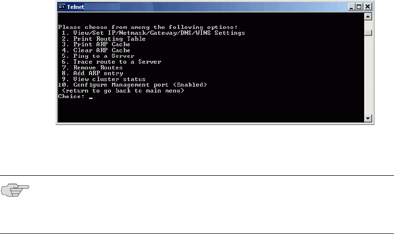
Juniper Networks Secure Access Administration Guide
592 Configuring and using the Management Port
Configuring Management Port network settings
You can configure Management Port network settings in the admin console or in
the serial console.
You can:
“Configuring network settings from the serial console” on page 592
“Configuring network settings from the admin console” on page 593
“Adding static routes to the management route table” on page 593
“Assigning certificate to Management Port” on page 593
“Controlling administrator sign-in access” on page 594
“Signing in over the Management Port” on page 595
“Setting role-mapping rules using custom expressions” on page 595
Configuring network settings from the serial console
To configure your Management Port network settings from the serial console
1. Start a serial console session, as described in “Connecting to an IVE appliance’s
serial console” on page 811.
2. Select item 1, System Settings and Tools.
3. Select item 10, Configure Management port. The text indicates if the option is
enabled or disabled.
4. Enter the network settings for the Management Port, as prompted.
NOTE: If you enable the Management Port but neglect to configure the IP address
and netmask, the port reverts to a disabled state. Also, you cannot clear
Management Port settings from the serial console when the port is disabled,
though you can clear them from within the admin console.

Configuring and using the Management Port 593
Chapter 22: General system management
5. When prompted to accept the changes, if they are correct, enter y. Otherwise,
repeat the process to correct the settings.
6. Close the serial console.
Related information
“Configuring network settings from the admin console” on page 593
Configuring network settings from the admin console
To configure your Management Port network settings from the admin console:
1. Make sure your backend management network is already configured.
2. Connect your management network gateway to the SA 6000 by way of the
Management Port.
3. In the admin console, choose System > Network > Management Port.
4. Select Enabled.
5. Enter your port information, including IP address, netmask, and default
gateway.
6. Click Save Changes.
Related information
“Configuring network settings from the serial console” on page 592
Adding static routes to the management route table
You can also add static routes to the management route table. This is easily
accomplished by following the procedure for adding static routes to route tables as
described in “Configuring static routes for network traffic” on page 569. When you
enable the Management Port, the New Route page includes a new interface
selection for the management route table.
Assigning certificate to Management Port
You can assign only one device certificate to the Management Port. If you assign a
certificate other than the default device certificate to the Management Port, the
default device certificate is automatically deselected as the default. If you do not
select a device certificate for the Management Port, then the IVE uses the default
device certificate that is presented on the Internal port.
NOTE: You cannot assign certificates to Management Port VIPs.
Juniper Networks Secure Access Administration Guide
594 Configuring and using the Management Port
Controlling administrator sign-in access
You can control administrator access to the ports on the IVE. When you enable the
Management Port, access to it is controllable through the configuration of your
Admin realms.
To control administrator access to the Management Port
1. Enable the Management Port following the instructions in “Configuring
Management Port network settings” on page 592.
2. Perform one of the following steps:
Choose Administrators > Admin Realms > Admin Users if you intend to
modify the default admin users realm.
Choose Administrators > Admin Realms, then click New, if you intend to
create a new admin realm.
3. Perform one of the following steps:
If you chose to create a new admin realm, follow the instructions for
configuring the realm as described in “Creating an authentication realm”
on page 166, then continue to the next step.
If you chose to modify the default admin users realm, continue to the next
step.
4. Click the Authentication Policy tab.
5. Scroll to the bottom of the Source IP tab. You should see a message stating that
the Management Port is enabled, along with a link to the Network Settings
page.
6. Select the available options to allow administrators to sign in to all available
ports, to the management port or the internal port only, or to restrict them
from signing in to any of the ports. In some cases you may inadvertently limit
administrative access completely. If this occurs, you can reconfigure the ports
by way of the serial console.

Configuring and using the Management Port 595
Chapter 22: General system management
7. Click Save Changes.
Signing in over the Management Port
If you sign in to an appliance directly via the Management Port IP address, you will
be unable to access the end-user sign-in page, as you normally can with the default
IVE configuration over the internal port. You are only allowed to sign in to the
realm defined for the administrative access to the Management Port. If you want to
access the end-user sign-in page, you need to sign in over either the internal port or
the external port.
However, if you have restricted access within the realm, so that administrators
must sign in over the Management Port, access to the other ports is effectively
blocked when signing in to the Management Port IP address.
Setting role-mapping rules using custom expressions
When you have enabled the Management Port, you can use a new value for the
network interface (networkIF) variable in custom expressions to assign roles to the
port.
To use the new variable:
1. After completing the steps described in “Controlling administrator sign-in
access” on page 594, click the Role Mapping tab.
2. Select Custom Expressions from the Rule based on drop down menu.
3. Click Update.
4. Under the Rule section, click Expressions.
5. On the Expressions tab of the Server Catalog dialog, enter a name for your new
rule.
NOTE:
If you limit administrative access to the Management Port, then export
configuration and import the configuration to an SA 2000 or an SA 4000
appliance, the import operation may fail or the Management Port
configuration will be ignored, possibly stranding your administrator access.
This could occur because only the SA 6000 supports the Management Port.
The other appliance models do not recognize the Management Port
configuration.
If you enable administrators to sign in to the Management Port or to the
Internal Port but you neglect to enable the Management Port itself, the IVE
considers the option to be set to allow administrators to sign in to the Internal
port only. If you then enable the Management Port, the setting for
administrator access to the Management Port will be restored, assuming you
have left the Management Port option selected on the Authentication Policy
tab.

Juniper Networks Secure Access Administration Guide
596 Configuring and using the Management Port
6. Enter the expression as:
networkIF = “management”
Make sure you enclose the value in double quotes. Unlike the values for internal
and external ports, you must delimit the Management Port value with double
quotes.
7. Click Save Changes. Your named expression appears in the Available
Expressions text box.
8. Select the expression and click Add to move the expression to the Selected
Expressions text box.
9. Select the appropriate role, for example, .Administrators, then click Add to
move the role to the Selected Roles text box.
10. Click Save Changes.
This procedure assigns the selected role or roles to the Management Port.
Troubleshooting the Management Port
The IVE provides a number of troubleshooting features to help you identify and
resolve problems, if necessary. Some potential problems can occur if you do not
configure your management network and if you allow management devices, such
as syslog servers to send traffic over the IVE internal port.
For example, if you configure management devices to send traffic over the internal
port, you may be unable to retrieve that information. For example, if you configure
an SNMP trap to send results over the internal port when the Management Port is
enabled, the IVE drops the data.
Management Port traffic is captured in the admin log.
You can:
“Using TCPDump to troubleshoot the Management Port” on page 596
“Using network utilities to test connectivity” on page 597
“Using the Management Port on a cluster” on page 597
Using TCPDump to troubleshoot the Management Port
You can use the TCPDump utility to troubleshoot the Management Port.
1. Choose Maintenance > Troubleshooting > TCP Dump.
2. Select Management Port.
NOTE: The IVE ignores SNMP queries that occur on any port other than the
Management Port, when the Management Port is enabled.
Configuring and using the Management Port 597
Chapter 22: General system management
3. Configure the other available options as described in “Creating TCP dump files”
on page 696.
4. Click Start Sniffing.
Using network utilities to test connectivity
The IVE provides a number of network utilities that you can use to test connectivity
to the Management Port, including ARP, ping, traceroute, and NSlookup.
1. Choose Maintenance > Troubleshooting > Commands.
2. Select the command type from the Command drop down menu.
3. Configure the specific utility, as described in “Testing IVE network
connectivity” on page 697.
4. Select Management Port.
5. Click Ok.
Using the Management Port on a cluster
The Management Port uses node-specific network settings, including the
enable/disable settings. In effect, this means that you can combine different models
of IVE appliance in a cluster, but doing so may limit the use of the Management
Port for the entire cluster.
The Management Port is not available on any appliance other than the SA 6000. If
you enable the Management Port on a node that is an SA 6000, management traffic
from that node travels over the Management Port. Traffic from non-SA 6000 nodes,
however, travels over the internal port.
Importing configurations to a system with the Management Port enabled
If you import a configuration from a system that does not support a management
port into a system that has an enabled management port and you import
everything, including licenses, the management port on the target system will
appear to be removed. The management port actually continues to be operational
and will reappear along with its original configuration when you reapply the
management port license for the target system. If you import to the target but
specify the Import everything except network settings and licenses option, the
management port and its configuration persist on the target system and the port is
operational.
Juniper Networks Secure Access Administration Guide
598 Configuring and using the Management Port
599
Chapter 23
Certificates
An IVE uses PKI to secure the data that it sends to clients over the Internet. PKI
(public key infrastructure) is a security method that uses public and private keys to
encrypt and decrypt information. These keys are enabled and stored through digital
certificates. A digital certificate is an encrypted electronic file issued that establishes
a Web server’s or user’s credentials for client-server transactions.
An IVE uses the following types of digital certificates to establish credentials and
secure IVE session transactions:
Device certificates—A device certificate helps to secure network traffic to and
from an IVE appliance using elements such as your company name, a copy of
your company’s public key, the digital signature of the certificate authority (CA)
who issued the certificate, a serial number, and expiration date. For more
information, see “Using device certificates” on page 600.
Trusted client CAs—A trusted client CA is a client-side certificate issued by a
certificate authority (CA) that allows you to control access to realms, roles, and
resource policies based on certificates or certificate attributes. For example,
you may specify that users must present a valid client-side certificate with the
OU attribute set to “yourcompany.com” in order to sign into the “Users”
authentication realm. For more information, see “Using trusted client CAs” on
page 607.
Trusted server CAs—A trusted server CA is the certificate of a Web server that
you trust. If you have a Web browsing license, you may install a trusted server
CA on the IVE in order to validate the credentials of the Web sites that users
access through the IVE appliance. For more information, see “Using trusted
server CAs” on page 621.
Code-signing certificates—A code-signing certificate (also called an applet
certificate) is a type of server-side certificate that re-signs Java applets
intermediated by the IVE. You may use the self-signed code-signing certificate
that comes pre-loaded on an IVE appliance, or you may install your own code-
signing certificate. For more information, see “Using code-signing certificates”
on page 623.
In a basic IVE setup, the only required certificates are a device certificate and a
code-signing certificate. The IVE appliance can use a single code-signing certificate
to resign all Java applets and a single device certificate to intermediate all other PKI-
based interactions. If the basic certificates do not meet your needs, however, you
may install multiple device and applet certificates on an IVE appliance or use
trusted CA certificates to validate users.

Juniper Networks Secure Access Administration Guide
600 Licensing: Certificate availability
This section contains the following information about certificates:
“Licensing: Certificate availability” on page 600
“Using device certificates” on page 600
“Using trusted client CAs” on page 607
“Using trusted server CAs” on page 621
“Using code-signing certificates” on page 623
Licensing: Certificate availability
Certificate management features are an integral part of the IVE management
framework—All Secure Access products include some certificate management
features. If you are an SA 700 administrator, however, note that trusted server CA
and code-signing certificate administration features are only available if you have a
Core Clientless Access upgrade license.
Using device certificates
A device certificate helps to secure network traffic to and from an IVE appliance
using elements such as your company name, a copy of your company’s public key,
the digital signature of the certificate authority (CA) who issued the certificate, a
serial number, and expiration date.
When receiving encrypted data from an IVE, the client’s browser first checks
whether the IVE’s certificate is valid and whether the user trusts the CA that issued
the IVE’s certificate. If the user has not already indicated that he trusts the IVE’s
certificate issuer, the Web browser prompts the user to accept or install the IVE’s
certificate.
When you initialize an IVE, it creates a temporary self-signed digital certificate
locally that enables users to immediately begin using your IVE. Note that the
encryption for the self-signed certificate created during initialization is perfectly
safe, but users are prompted with a security alert each time they sign in to an IVE
because the certificate is not issued by a trusted certificate authority (CA). For
production purposes, we recommend that you obtain a digital certificate from a
trusted CA.
The IVE supports X.509 device certificates in DER and PEM encode formats (file
extensions include .cer, .crt, .der, and .pem) as well as PKCS #12 (file extensions
include .pfx and .p12). The IVE also supports using the following additional features
with device certificates:
Intermediate device CA certificates—Within a certificate hierarchy, one or
more intermediate certificates are branched off of a single root certificate.

Using device certificates 601
Chapter 23: Certificates
Multiple device certificates—When using multiple device certificates, each
certificate handles validation for a separate host name or fully-qualified domain
name (FQDN) and may be issued by a different CA.
This section contains the following instructions for working with device certificates:
“Importing certificates into the IVE” on page 601
“Downloading a device certificate from the IVE” on page 603
“Creating a certificate signing request (CSR) for a new certificate” on page 604
“Using intermediate server CA certificates” on page 605
“Using multiple IVE device certificates” on page 605
Importing certificates into the IVE
This section contains the following import instructions:
“Importing an existing root certificate and private key” on page 601
“Importing a renewed certificate that uses the existing private key” on
page 602
Importing an existing root certificate and private key
You can create Web server certificates from servers such as Apache, IIS, Sun ONE
(formerly iPlanet), or Netscape, and then import the certificate into the IVE. To
export a digital server certificate and key, please follow your Web server's
instructions for exporting certificates. Then, use the Device Certificates tab to
import these files.
To import an existing root server certificate and private key:
1. In the admin console, choose System > Configuration > Certificates >
Device Certificates.
2. Click Import Certificate & Key.
NOTE:
When exporting a certificate from another Web server, note that it must be
encrypted and you must export the password with the certificate.
You cannot import a Web server certificate’s private key into an Secure
Access FIPS machine, since the key is created in a non-FIPS compliant
environment. You may, however, import a certificate key from another IVE
along with its security world. For more information, see “Importing and
exporting IVE configuration files” on page 632.

Juniper Networks Secure Access Administration Guide
602 Using device certificates
3. Choose the appropriate form to import the certificate:
If the certificate and key are contained in one file, use the If certificate file
includes private key form.
If the certificate and key are separate files, use the If certificate and
private key are separate files form.
If the certificate and key are contained in a system configuration file, use
the Import via System Configuration file form. When you choose this
option, the IVE imports all of the certificates specified in the configuration
file into the Device Certificates page (including private keys and pending
CSRs, but not the corresponding port mappings).
4. In the appropriate form, browse to the certificate and key file. If the file is
encrypted, enter the password key.
5. Click Import.
Importing a renewed certificate that uses the existing private key
You can renew a device certificate in two ways:
Submit a new CSR to a CA—This process of renewing a certificate is more
secure, because the CA generates a new certificate and private key, retiring the
older private key. To use this renewal method, you must first create a CSR
through the admin console. For more information, see “Creating a certificate
signing request (CSR) for a new certificate” on page 604.
Request renewal based on the CSR previously submitted to the CA—This
process of renewing a certificate is less secure, because the CA generates a
certificate that uses the existing private key.
NOTE: You cannot import a device certificate into a FIPS system. You can only
create a CSR and then import a signed certificate from the CSR.
NOTE: You cannot import a Web server certificate’s private key into an Secure
Access FIPS machine, since the key is created in a non-FIPS compliant
environment.
NOTE: When ordering a renewed certificate, you must resubmit your original CSR
or ensure that the CA has a record of the CSR that you submitted for your current
certificate.

Using device certificates 603
Chapter 23: Certificates
To import a renewed device certificate that uses the existing private key:
1. Follow your CA’s instructions for renewing a certificate that you previously
purchased through them.
2. In the admin console, choose System > Configuration > Certificates >
Device Certificates.
3. If you want to renew an intermediate certificate, click the Intermediate Device
CAs link at the top of the page.
4. Click the link that corresponds to the certificate that you want to renew.
5. Click Renew Certificate.
6. In the Renew the Certificate form, browse to the renewed certificate file, enter
the password for the certificate key, and click Import.
Downloading a device certificate from the IVE
If you create a SAML resource policy, for example, you must create a trust
relationship between the IVE and your access management system. (Trust
relationships ensure that SAML-enabled systems are only passing information to
and from trusted sources.) If you choose to create a SAML SSO resource policy
using a POST profile, part of creating a trust relationship involves installing the
IVE’s device certificate on the access management system. The Device Certificates
page enables you to easily download the IVE appliance’s certificate so you can
install it on your access management system.
To download a device certificate from the IVE:
1. In the admin console, choose System > Configuration > Certificates >
Device Certificates.
2. Click the link that corresponds to the certificate that you want to save.
3. Click Download.
4. Browse to the location where you want to save the certificate and click Save.
NOTE: Ensure you specify the same information you used in the original CSR.
Your CA uses this information to create a new certificate that corresponds to the
existing key.
Even though you specify the same information used in the original CSR, your
rootCA may have different serial numbers and keys from the original. You may
need to support both new client and old client certificates during the transition
period, which means that you will need to maintain two rootCA certificates (your
existing cert and the renewed cert), at least temporarily. To support multiple
rootCA certificates, you must have an Advanced license. Please contact your
Juniper Networks Support representative, if you need to procure an Advanced
license.

Juniper Networks Secure Access Administration Guide
604 Using device certificates
Creating a certificate signing request (CSR) for a new certificate
If your company does not own a digital certificate for its Web servers, or if you are
running an Secure Access FIPS system, you can create a CSR (certificate signing
request) through the admin console and then send the request to a CA for
processing. When you create a CSR through the admin console, a private key is
created locally that corresponds to the CSR. If you delete the CSR at any point, this
file is deleted, too, prohibiting you from installing a signed certificate generated
from the CSR.
To create a certificate signing request:
1. In the admin console, choose System > Configuration > Certificates >
Device Certificates.
2. Click New CSR.
3. Enter the required information and click Create CSR.
4. Follow the instructions on-screen, which explain what information to send to
the CA and how to send it.
5. When you receive the signed certificate from the CA, import the certificate file
using the instructions that follow.
Importing a signed certificate created from a CSR
If you create a CSR through the admin console, the IVE displays a Pending CSR link
for the CSR in the Device Certificates tab until you import the signed device
certificate distributed by the certificate authority (CA).
To import a signed device certificate created from a CSR:
1. In the admin console, choose System > Configuration > Certificates >
Device Certificates.
2. Under Certificate Signing Requests, click the Pending CSR link that
corresponds to the signed certificate.
3. Under Import signed certificate, browse to the certificate file you received
from the CA and then click Import.
NOTE: Do not send more than one CSR to a CA at one time. Doing so may result in
duplicate charges. You may view details of any pending requests that you
previously submitted by clicking the Certificate Signing Request Details link in
the Device Certificates tab.
NOTE: When submitting a CSR to a CA authority, you may be asked to specify
either the type of Web server on which the certificate was created or the type of
Web server the certificate is for. Select apache (if more than one option with
apache is available, choose any). Also, if prompted for the certificate format to
download, select the standard format.
Using device certificates 605
Chapter 23: Certificates
Using intermediate server CA certificates
Within a certificate hierarchy, one or more intermediate certificates are branched
off of a single root certificate. The root certificate is issued by a root certificate
authority (CA) and is self-signed. Each intermediate certificates is issued by the
certificate above it in the chain.
If you are securing traffic using chained certificates, you must ensure that the IVE
and Web browser together contain the entire certificate chain. For example, you
may choose to secure traffic using a chain that stems from a Verisign root
certificate. Assuming your users’ browsers come pre-loaded with Verisign root
certificates, you only need to install the lower-level certificates in the chain on the
IVE. Then, when your users browse to the IVE, the IVE presents any required
certificates within the chain to the browser in order to secure the transaction. (The
IVE creates the proper links in the chain using the root certificate’s IssuerDN.) If the
IVE and browser together do not contain the entire chain, the user’s browser will
not recognize or trust the IVE’s device certificate since it is issued by another
certificate instead of a trusted CA.
For information about chained client certificates, see “Enabling client CA
hierarchies” on page 614.
When installing certificates through the IVE, you may install certificates in any
order. The IVE supports uploading one or more intermediate CAs in a PEM file.
To import an intermediate device certificate and private key:
1. In the admin console, choose System > Configuration > Certificates >
Device Certificates.
2. Click the Intermediate Device CAs link at the top of the page.
3. Click Import CA certificate.
4. Browse to the CA certificate that you want to upload to the IVE and click
Import Certificate.
Using multiple IVE device certificates
When using multiple IVE device certificates, each certificate handles validation for a
separate host name or fully qualified domain name (FQDN) and may be issued by a
different CA. You can use multiple root certificates in conjunction with multiple
sign-in URLs. With the multiple sign-in URLs feature, you can provide access to the
IVE from multiple host names by creating a different sign-in URL for each host
name or FQDN. Then, you can create separate sign-in pages and authentication
requirements for each sign-in URL. For more information, see “Sign-in policies” on
page 181. With the multiple device certificates feature, you can use different
certificates to validate users signing into each of those host names or FQDNs. For
example, you can associate one certificate with the partners.yourcompany.com site
and another with the employees.yourcompany.com site.
Juniper Networks Secure Access Administration Guide
606 Using device certificates
Task Summary: Enabling multiple device certificates
To enable multiple device certificates, you must:
1. Specify the IP addresses from which users may access the IVE and then create
a virtual port for each. A virtual port activates an IP alias on a physical port. To
create virtual ports for:
Internal users—Use settings in the System > Network > Internal Port >
Virtual Ports tab to create virtual ports for users such as employees who
are signing into the IVE from inside your internal network. For instructions,
see “Configuring virtual ports” on page 566.
External users—Use settings in the System > Network > Port 1 >
Virtual Ports tab to create virtual ports for users such as customers and
partners who are signing into the IVE from outside of your internal
network. For instructions, see “Configuring virtual ports” on page 566.
2. Upload your device certificates to the IVE. You can import certificates from the
System > Configuration > Certificates > Device Certificates page of the
admin console or the Maintenance > Import/Export > System
Configuration page of the admin console. Upload one device certificate for
each domain (host name) that you want to host on the IVE. For instructions,
see “Importing an existing root certificate and private key” on page 601.
3. Specify which virtual ports the IVE should associate with the certificates using
settings in the System > Configuration > Certificates > Device Certificates
tab. When a user tries to sign into the IVE using the IP address defined in a
virtual port, the IVE uses the certificate associated with the virtual port to
initiate the SSL transaction. For instructions, see “Associating a certificate with
a virtual port” on page 606.
Associating a certificate with a virtual port
If you choose to associate multiple host names with a single IVE, you must specify
which certificates the IVE should use to validate users signing in to the different
host names. Options include:
Associate all host names with a single wildcard certificate—With this
method, you use a single wildcard certificate to validate all users, regardless of
which host name they use to sign into the IVE. A wildcard certificate includes a
variable element in the domain name, making it possible for users signing in
from multiple hosts to map to the “same” domain. For example, if you create a
wildcard certificate for *.yourcompany.com, the IVE uses the same certificate to
authenticate users who sign into employees.yourcompany.com as it does to
authenticate users who sign into partners.yourcompany.com.

Using trusted client CAs 607
Chapter 23: Certificates
Associate each host name with its own certificate—With this method, you
associate different host names with different certificates. Since the IVE does
not know the host name that the end-user uses to sign into the IVE, however,
you must create a virtual port for each host name and then associate your
certificates with the virtual ports. A virtual port activates an IP alias on a
physical port. For example, you may choose to create two virtual ports on a
single appliance, mapping the first virtual port to the IP address 10.10.10.1
(sales.yourcompany.com) and the second virtual port to the IP address
10.10.10.2 (partners.yourcompany.com). Then, you can associate each of these
virtual ports with its own certificate, ensuring that the IVE authenticates
different users through different certificates.
To associate different certificates with different virtual ports:
1. In the admin console, navigate to the System > Network > Internal Port tab
or Port 1 tab. Then, create your virtual ports using settings in the Virtual Ports
page.
2. Import the device certificates that you want to use to validate user certificates.
You can import certificates from the System > Configuration > Certificates
> Device Certificates page of the admin console or the Maintenance >
Import/Export > System Configuration page of the admin console.
3. On the System > Configuration > Certificates > Device Certificates page,
click the link that corresponds to a certificate that you want to use to validate
user certificates.
4. Under Present certificate on these ports, specify the port(s) that the IVE
should associate with the certificate—you can choose internal or external ports
and primary or virtual ports, but you cannot choose a port that is already
associated with another certificate.
5. Click Save Changes.
6. Repeat steps 3-6 for each of the certificates that you want to use to authenticate
users.
Using trusted client CAs
A trusted client CA is a client-side certificate issued by a certificate authority (CA). To
use client CA certificates, you must install and enable the proper certificates on the
IVE as well as install the corresponding client-side certificates in the Web browsers
of your end-users. When validating users with CA certificates, the IVE checks that
the certificate is not expired or corrupt and that the certificate is signed by a CA
that the IVE recognizes. If the CA certificate is chained (described below) the IVE
also follows the chain of issuers until it reaches the root CA, checking the validity of
each issuer as it goes. The IVE supports X.509 CA certificates in DER and PEM
encode formats.

Juniper Networks Secure Access Administration Guide
608 Using trusted client CAs
The IVE supports using the following additional features with CA certificates:
Certificate servers—A certificate server is a type of local authentication server
that allows you to authenticate IVE users based solely on their certificate
attributes rather than authenticating them against a standard authentication
server (such as LDAP or RADIUS), as well as requiring specific certificates or
certificate attributes. For more information, see “Configuring a certificate
server instance” on page 105.
Certificate hierarchies—Within a certificate hierarchy, one or more
subordinate certificates (called intermediate certificates) are branched off of a
root certificate creating a certificate chain. Each intermediate certificate (also
called a chained certificate) handles requests for a part of the root CA’s domain.
For example, you may create a root certificate that handles all requests to the
yourcompany.com domain and then branch off intermediate certificates that
handle requests to partners.yourcompany.com and employees.yourcompany.com.
When you install a chained certificate on the IVE, the appliance confirms that
the chain is valid and allows users to authenticate using the leaf certificate (that
is, the lowest certificate in the chain). For more information, see “Enabling
client CA hierarchies” on page 614.
Certificate revocation lists—Certificate revocation is a mechanism by which a
CA invalidates a certificate before its expiration date. A certificate revocation list
(CRL) is a list of revoked certificates published by a CA. Within CRLs, each entry
contains the serial number of the revoked certificate, the date that the
certificate was revoked, and the reason that the certificate was revoked. The
CA may invalidate a certificate for various reasons such as the employee to
whom the certificate is issued has left the company, the certificate’s private key
is compromised, or the client-side certificate is lost or stolen. Once the CA
revokes a certificate, the IVE can appropriately deny access to users who
present a revoked certificate. For more information, see “Enabling CRLs” on
page 615.
Enabling trusted client CAs
If you require users to provide a client-side certificate to sign in to the IVE, you must
upload the corresponding CA certificate into the IVE. You can upload CA certificates
manually or configure the IVE to upload CA certificates automatically. The IVE uses
the uploaded certificate to verify that the browser-submitted certificate is valid. In
addition, you can specify whether or not to automatically import CA certificates for
validation and the CRL/OCSP retrieval method the IVE uses when automatically
importing the CA certificates.
NOTE: If you have a user license, you can only install one root CA certificate on the
IVE and validate users using one corresponding client-side CA certificate.

Using trusted client CAs 609
Chapter 23: Certificates
This section contains the following CA certificate instructions:
“Automatically import a CA certificate” on page 609
“Manually upload CA certificates” on page 610
“Specifying attributes for the trusted client CA certificate” on page 611
“Specifying client-side certificate restrictions” on page 613
Automatically import a CA certificate
To automatically import and specify options for a trusted client CA certificate on
the IVE:
1. In the admin console, choose System > Configuration > Certificates >
Trusted Client CAs.
2. Click Auto-import options. The Auto-import options page appears.
3. Click Auto-import Trusted CAs.
NOTE:
When using client-side certificates, we strongly recommend that you advise
your users to close their Web browsers after signing out of the IVE. If they do
not, other users may be able to use their open browser sessions to access
certificate-protected resources on the IVE without re-authentication. After
loading a client-side certificate, both Internet Explorer and Netscape cache the
certificate’s credentials and private key. The browsers keep this information
cached until the user closes the browser (or in some cases, until the user
reboots the workstation). For details, see:
http://support.microsoft.com/?kbid=290345.) To remind users to close their
browsers, you may modify the sign out message in the Authentication >
Signing In > Sign-in Pages tab.
Uploading a CA certificate to the IVE does not enable client-side SSL
authentication. You must either use a certificate server or enable certificate
restrictions in the Administrators > Admin Realm > Select Realm >
Authentication Policy > Certificate page or the Users > User Realms >
Select Realm > Authentication Policy > Certificate page of the admin
console in order to enable client-side SSL authentication.
If you have just a standard IVE user license, you can only import one CA
certificate to the IVE.
When uploading a certificate chain to the IVE, you must either install the
certificates one at a time in descending order starting with the root certificate
(DER or PEM files), or you must upload a single file to the IVE that contains
the entire certificate chain (PEM files only). By using one of these methods,
you ensure that the IVE can link the certificates together in the correct order.
Juniper Networks Secure Access Administration Guide
610 Using trusted client CAs
4. Under Client certificate status checking, specify the method the IVE uses to
verify client certificate status:
None—Specifies that the IVE should not validate this trusted client
certificate.
Use OCSP—Specifies that the IVE should use the OCSP method, validating
the client certificate in real-time, as needed. After you select this option,
you can specify options for OCSP as described in “Specifying client-side
certificate restrictions” on page 613.
Use CRLs—Specifies that the IVE should use CRLs to validate the client
certificate. After you select this option, you can specify options for OCSP as
described in “Specifying CDP options” on page 617.
Use OCSP with CRL fallback—Specifies that the IVE should use the OCSP
validation method when possible, but attempt to validate client certificates
using CRLs should the OCSP method fail (for example, if the link to the
OCSP Responder were to fail). After you select this option, you can specify
options for OCSP as described in “Specifying client-side certificate
restrictions” on page 613 and for CDP as described in “Specifying CDP
options” on page 617.
5. Under CDP(s)/OCSP responder, specify the CRL/OCSP retrieval method from
the associated drop-down list:
None—Specifies that the IVE does not to use a CRL/OCSP retrieval method.
From client certificate—Specifies that the IVE use a CRL/OCSP retrieval
method found in the client certificate.
From trusted CA certificates—Specifies that the IVE use a CRL/OCSP
retrieval method found in the trusted client CA certificate.
6. Enable the Verify imported CA certificates option if you want the IVE to
validate the CRL from which the certificate is issued.
7. Click Save.
Manually upload CA certificates
To manually upload CA certificates to the IVE:
1. Install a client-side certificate through the user’s browser. For help, see the
instructions provided with the browser.
2. In the admin console, choose System > Configuration > Certificates >
Trusted Client CAs.
3. Click Import CA Certificate. The Import Trusted Client CA page appears.
Using trusted client CAs 611
Chapter 23: Certificates
4. Browse to the CA certificate that you want to upload to the IVE and click
Import Certificate. The Trusted Client CA page appears, displaying the
certificate attributes, including the type of certificate status checking enabled
for the certificate and an indication of whether or not the IVE is configured to
verify trusted client CAs.
5. Click Save.
After you have manually imported the CA certificate, you can specify CA
certificate attributes as described in “Specifying attributes for the trusted client
CA certificate” on page 611.
Specifying attributes for the trusted client CA certificate
To specify attributes for the trusted client CA certificate:
1. In the admin console, choose System > Configuration > Certificates >
Trusted Client CAs.
2. Click the certificate that you want to view. The Trusted Client CA page appears
displaying all of the information about the certificate you selected.
3. Under Certificate, use the arrow next to the following field names to view
certificate details:
Issued To—Name and attributes of the entity to whom the certificate is
issued.
Issued By—Name and attributes of the entity that issued the certificate.
Note that the value of this field should either match the Issued To field (for
root certificates) or the Issued To field of the next certificate up in the
chain (for intermediate certificates).
Valid Dates—Time range that the certificate is valid. If your certificate is
expired, see the instructions in “Importing a renewed certificate that uses
the existing private key” on page 602.
Details—Includes various certificate details, including its version, serial
number, signature algorithm, CRL distribution points, public key algorithm
type, and the public key. Note that although the IVE may display a CRL
distribution point in the Details field, it does not check the CDP unless you
enable it. For more information, see “Enabling CRLs” on page 615.
4. If you want to renew the certificate:
a. Click Renew Certificate.
b. Browse to the renewed CA certificate that you want to upload to the IVE
and click Import Certificate.
5. Under CRL checking for client certificates, view details about the CRL(s) that
are enabled for this certificate:
Enable—Displays a check mark if the IVE is configured to use the CRL
from this CDP.
Juniper Networks Secure Access Administration Guide
612 Using trusted client CAs
CRL Distribution Points—Location of the CRL distribution point against
which the client certificates are validated. This field also indicates whether
or not the last attempt to download the CRL from the CDP was successful
or not.
Status—Indicates the status of the CRL (OK, No CRL, Expired, Download in
progress), the CRL size, and the number of revocations contained in the
CRL.
Last Updated—Indicates the last time the IVE downloaded a CRL from the
specified CRL distribution point. Also contains a link that allows you to save
the IVE’s current version of the CRL.
Next Update—Indicates the next download time based on the interval
specified in the CRL distribution point. Note that a download interval is
specified both in the CRL and in the IVE CRL configuration page (as the
CRL Download Frequency)—the actual download time is the shorter of the
two intervals, regardless of what is displayed in the Next Update column.
6. In the Client Certificate Status Checking section, specify the method the IVE
uses to validate the client certificate:
None—Specifies that the IVE should not validate this trusted client
certificate.
Use OCSP—Specifies that the IVE should use the OCSP method, validating
the client certificate in real-time, as needed. After you select this option,
you can specify options for OCSP as described in “Specifying client-side
certificate restrictions” on page 613.
Use CRLs—Specifies that the IVE should use CRLs to validate the client
certificate. After you select this option, you can specify options for OCSP as
described in “Specifying CDP options” on page 617.
Use OCSP with CRL fallback—Specifies that the IVE should use the OCSP
validation method when possible, but attempt to validate client certificates
using CRLs should the OCSP method fail (for example, if the link to the
OCSP Responder were to fail). After you select this option, you can specify
options for OCSP as described in “Specifying client-side certificate
restrictions” on page 613 and for CDP as described in “Specifying CDP
options” on page 617.
7. Enable the Verify Trusted Client CA option to instruct the IVE to validate the
trusted client CA.
8. Click Save Changes.
Using trusted client CAs 613
Chapter 23: Certificates
Specifying client-side certificate restrictions
Use a certificate restriction to require client machines to possess a valid client-side
certificate in order to access an IVE sign-in page, be mapped to a role, or access a
resource. If you use this feature, make sure that you import a CA certificate to
verify the client-side certificate. To maximize the security of this feature, make sure
that a user’s client settings are set to require the user to enter a password each time
the user signs in. The default setting for some browser versions is to remember the
certificate password, which means the user won’t be prompted for this additional
sign-in information after installing the certificate.
To specify certificate restrictions:
1. Navigate to: System > Configuration > Certificates > Trusted Client CAs
and specify the root certificate authority that you want to use to validate the
client-side certificate restrictions that you enable at the realm, role, and
resource policy levels.
2. Select the level at which you want to implement certificate restrictions:
Realm level—Navigate to:
Administrators > Admin Realms > Select Realm > Authentication
Policy > Certificate
Users > User Realms > Select Realm > Authentication Policy >
Certificate
Role level—Navigate to:
Administrators > Admin Roles > Select Role > General >
Restrictions > Certificate
Users > User Realms > Select Realm > Role Mapping >
Select|Create Rule > Custom Expression
Users > User Roles > Select Role > General > Restrictions >
Certificate
Resource policy level—Navigate to: Users > Resource Policies > Select
Resource > Select Policy > Detailed Rules > Select|Create Rule >
Condition Field
3. Choose one of the following options:
Allow all users (no client-side certificate required) — Does not require a
user’s client to have a client-side certificate.
Allow all users and remember certificate information while user is
signed in — Does not require a user’s client to have a client-side
certificate, but if the client does have a certificate, the IVE remembers the
certificate information during the entire user session.

Juniper Networks Secure Access Administration Guide
614 Using trusted client CAs
Only allow users with a client-side certificate signed by Trusted Client
CAs to sign in — Requires a user’s client to have a client-side certificate in
order to satisfy the access management requirement. To restrict access
even further, you can define unique certificate attribute-value pairs. Note
that the user’s certificate must have all the attributes you define.
4. Add a certificate field name and an expected value to optionally require specific
values in the client certificate. You can specify variables in the Expected Value
field. For example, you can add the value uid to the Certificate field and
<userAttr.uid> to the Expected Value field.
5. Click Save Changes to save your settings.
Enabling client CA hierarchies
Within a certificate hierarchy, one or more intermediate certificates are branched
off of a single root certificate. The root certificate is issued by a root certificate
authority (CA) and is self-signed. Each intermediate certificate is issued by the
certificate above it in the chain.
To enable authentication in a chained certificate environment, you must install the
appropriate client-side certificates in each user’s Web browser and then upload the
corresponding CA certificates to the IVE.
NOTE: The user attribute can come from any authentication server that supports
attributes. Any attribute name specified in a certificate restriction must be
included in the server catalog so the values are collected during authentication
and added to the session context data.
NOTE:
The IVE supports all X.509 Distinguished Name (DN) attributes (such as C,
CN, L, O, OU).
The attribute and value fields are not case-sensitive.
Define only one value for each attribute. If you specify multiple values,
the client-side certificate may not authenticate correctly against the CA
certificate.
The IVE currently recognizes an e-mail address in the subjectAltName
attribute in a certificate.
The IVE can extract the User Principal Name (UPN) from the
subjectAltName attribute. The IVE locates a specific UPN Object Identifier
(OID) in the certificate and decodes the value. To represent the UPN in the
subjectAltName attribute, use the token <certAttr.altName.UPN>.

Using trusted client CAs 615
Chapter 23: Certificates
For information about chained device certificates, see “Using intermediate server
CA certificates” on page 605.
You can install client CAs through the System > Configuration > Certificates >
Trusted Client CAs page of the admin console. When uploading the certificate
chain to the IVE, you must use one of the following methods:
Import the entire certificate chain at once—When installing a chain of
certificates contained in a single file, the IVE imports the root certificate and
any sub-certificates whose parents are in the file or on the IVE. You can include
certificates in any order in the import file.
Import the certificates one at a time in descending order—When installing a
chain of certificates contained in multiple files, the IVE requires that you install
the root certificate first, and then install the remaining chained certificates in
descending order.
When you install chained certificates using one of these methods, the IVE
automatically chains the certificates together in the correct order and displays them
hierarchically in the admin console.
Enabling CRLs
A certificate revocation list (CRL) is a mechanism for cancelling a client-side
certificate. As the name implies, a CRL is a list of revoked certificates published by
a CA or delegated CRL issuer. The IVE supports base CRLs, which include all of the
company’s revoked certificates in a single, unified list.
The IVE knows which CRL to use by checking the client’s certificate. (When issuing
a certificate, the CA includes CRL information for the certificate in the certificate
itself.) To ensure that it receives the most up-to-date CRL information, the IVE
periodically contacts a CRL distribution point to get an updated list of revoked
certificates. A CRL distribution point (CDP) is a location on an LDAP directory server
or Web server where a CA publishes CRLs. The IVE downloads CRL information
from the CDP at the interval specified in the CRL, at the interval that you specify
during CRL configuration, and when you choose to manually download the CRL.
The IVE also supports CRL partitioning. CRL partitioning enables you to verify
portions of very large CRLs without having to spend the time and bandwidth
necessary to access and validate a very large CRL or collection of large CRLs. CRL
partitioning is only enabled on the IVE when you employ the Specify the CDP(s) in
the client certificates method (described below). In this case, the IVE validates the
user by verifying only the CRL specified in the client certificate.
NOTE: With a user license, you cannot install a chain whose certificates are issued
by different CAs. The CA that signs the lowest-level certificate in the chain must
also sign all other certificates in the chain.
NOTE: If you install multiple certificates in a user’s Web browser, the browser
prompts the user to choose which certificate to use whenever he signs into the
IVE.

Juniper Networks Secure Access Administration Guide
616 Using trusted client CAs
Although CAs include CRL information in client-side certificates, they do not always
include CDP information, as well. A CA may use any of the following methods to
notify the IVE of a certificate’s CDP location:
Specify the CDP(s) in the CA certificate—When the CA issues a CA certificate,
it may include an attribute specifying the location of the CDP(s) that the IVE
should contact. If more than one CDP is specified, the IVE chooses the first one
listed in the certificate and then fails over to subsequent CDPs, if necessary.
Specify the CDP(s) in the client certificates—When the CA issues client-side
certificates, it may include an attribute specifying the location of the CDP(s)
that the IVE should contact. If more than one CDP is specified, the IVE chooses
the first one listed in the certificate and then fails over to subsequent CDPs, if
necessary. When the IVE employs CRL partitioning and the client certificate
specifies only one CRL, the IVE performs verification using only that CRL.
Require the administrator to manually enter the CDP location—If the CA
does not include the CDP location in the client or CA certificates, you must
manually specify how to download the entire CRL object when configuring the
IVE. You may specify a primary and backup CDP. (Manually entering the CDP
location provides the greatest flexibility because you do not need to reissue
certificates if you change your CDP location.)
The IVE checks the user’s certificate against the appropriate CRL during
authentication. If it determines that the user’s certificate is valid, the IVE caches the
certificate attributes and applies them if necessary during role and resource policy
checks. If it determines that the user’s certificate is invalid, if it cannot contact the
appropriate CRL, or if the CRL is expired, the IVE denies the user access.
You can configure CRL checking through the System > Configuration >
Certificates > Trusted Client CAs page of the admin console.
NOTE: If you choose this method, the user receives an error the first time he tries
to sign into the IVE because no CRL information is available. Once the IVE
recognizes the client’s certificate and extracts the CRL location, it can start
downloading the CRL and subsequently validate the user’s certificate. In order to
successfully sign into the IVE, the user must try to reconnect after a few seconds.
NOTE:
The IVE only supports CRLs that are in a PEM or DER format and that are
signed by the CA for which the revocations apply.
The IVE only saves the first CRL in a PEM file.
The IVE does not support the Issuing Distribution Point (IDP) CRL extension.

Using trusted client CAs 617
Chapter 23: Certificates
Specifying CDP options
If you selected either Use CRLs or Use OCSP with CRL fallback in the procedures
outlined in “Specifying attributes for the trusted client CA certificate” on page 611,
you can enable and periodically download certificate revocation lists (CRL) from
CRL distribution points (CDPs) in order to verify the ongoing validity of client-side
certificates.
1. In the admin console, choose System > Configuration > Certificates >
Trusted Client CAs.
2. Click the link that corresponds to the certificate for which you want to enable
CRL checking.
3. Click CRL Checking Options. The CRL Checking Options page appears.
4. Under CRL Distribution Points, specify where the IVE should find access
information for the CDP. Options include:
No CDP (no CRL Checking)—When you select this option, the IVE does
not check CRLs issued by the CA, so you do not need to enter any
parameters to access the CDP that issued the CRL.
CDP(s) specified in the Trusted Client CA —When you select this option,
the IVE checks the CRL distribution point attribute in the certificate and
displays the URIs of the CDPs that it finds in the CRL Checking Options
page. If the CA certificate does not include all of the information required
to access the CDP, specify the additional required information:
CDP Server: (LDAP only)—Enter the location of the CDP server. When
using LDAP protocol, enter the IP address or host name (for example,
ldap.domain.com).
CRL Attribute: (LDAP only)—Enter the LDAP attribute on the object
that contains the CRL (for example, CertificateRevocationList).
Admin DN, Password: (LDAP only)—If the CDP server does not allow
anonymous searches of the CRL, enter the admin DN and password
that are required to authenticate into the CDP server.
CDP(s) specified in client certificates—If the client certificate does not
include all of the information required to access the CDP, specify the
additional required information:
CDP Server (LDAP only)—Enter the location of the CDP server. When
using LDAP protocol, enter the IP address or host name (for example,
ldap.domain.com).
CRL Attribute (LDAP only)—Enter the LDAP attribute on the object
that contains the CRL (for example, CertificateRevocationList).
NOTE: Since the IVE supports CRL partitioning, you may see multiple CRLs
displayed under CRL distribution points. This is because the partitioned portions
of a revocation list are not identified individually, but referred to as the CDP from
which they are derived.

Juniper Networks Secure Access Administration Guide
618 Using trusted client CAs
Admin DN, Password (LDAP only)—If the CDP server does not allow
anonymous searches of the CRL, enter the admin DN and password
that are required to authenticate into the CDP server.
Manually configured CDP—When you select this option, the IVE accesses
the CDP that you specify. Enter the URL of the primary CDP and optionally
of a backup CDP. For an LDAP server, use the syntax:
ldap://Server/BaseDN?attribute?Scope?Filter. For a Web server, enter the
complete path to the CRL object. For example:
http://domain.com/CertEnroll/CompanyName%20CA%20Server.crl
Additionally, if the CDP server does not allow anonymous searches of the
CRL, enter the admin DN and password that are required to authenticate
into the CDP server. (LDAP only)
5. In the CRL Download Frequency field, specify how often the IVE should
download the CRL from the CDP. The allowable range is from 1 to 9999 hours.
6. Click Save Changes.
7. If you want to check the validity of your CA certificate (in addition to client-side
certificates) against the CRL specified in the previous steps, select Verify
Trusted Client CA on the Trusted Client CA page.
8. Click Save Changes. The IVE downloads the CRL using the method you
specified (if applicable) and displays CRL checking details (described in the
following section).
9. Click Update Now in the Trusted Client CA page to manually download the
CRL from the CDP (optional).
NOTE: If you choose to download CDPs using one method and then select a
different method, the IVE deletes any CDPs from disk that were downloaded
using the previous method.
NOTE:
When you choose to verify an intermediate certificate, make sure that CRLs
are available for all of the CA certificates that are above the intermediate
certificate in the chain—when verifying a CA certificate, the IVE also verifies
all issuing CAs above the certificate in the chain.
If you select this option but do not enable CRL checking, the IVE checks the
CA certificate against the CDP for the CA’s issuer. If no CRL is enabled for the
issuer, user authentication fails.
Using trusted client CAs 619
Chapter 23: Certificates
Enabling OCSP
The Online Certification Status Protocol (OCSP) offers you the ability to verify client
certificates in real-time. Using OCSP, the IVE becomes a client of an OCSP
responder and forwards validation requests for users, based on client certificates.
The OCSP responder maintains a store of CA-published CRLs and maintains an up-
to-date list of valid and invalid client certificates. Once the OCSP responder receives
a validation request from the IVE (which is commonly an HTTP or HTTPS
transmission), the OCSP responder either validates the status of the certificate
using its own authentication database or calls upon the OCSP responder that
originally issued the certificate to validate the request. After formulating a response,
the OCSP responder returns the signed response to the IVE and the original
certificate is either approved or rejected, based on whether or not the OCSP
responder validates the certificate.
This section contains the following OCSP instructions:
“Specifying OCSP options” on page 619
“Specifying OCSP responder options” on page 620
Specifying OCSP options
If you selected either Use OCSP or Use OCSP with CRL fallback in the procedures
specified in “Specifying attributes for the trusted client CA certificate” on page 611,
the IVE displays a list of known OCSP responders and enables you to configure
OCSP responder options:
1. Delete, enable, or disable OCSP Responder configuration using the Delete,
Enable, or Disable buttons, respectively.
2. If you want to configure OCSP options, click OCSP Options. The OCSP Options
page appears.
3. Specify the type of OCSP responder the IVE uses to validate trusted client CAs
in the Use drop-down list:
None—The IVE does not use OCSP to verify the status of certificates issued
by this CA.
Responder(s) specified in the CA certificate—The IVE uses OCSP
responders specified in the imported client CA to perform verification.
When you select this option, the IVE displays a list of OCSP responders
specified in the imported CA (if any) and the last time they were used.
Responder(s) specified in the client certificates—The IVE uses
responders specified during client authentication to perform verification.
When you select this option, the IVE displays a list of known OCSP
responders (if any) and the last time they were used.
Manually configured responders—The IVE uses primary and secondary
OCSP responders at the addresses you specify.

Juniper Networks Secure Access Administration Guide
620 Using trusted client CAs
4. Under the Options section, specify whether or not the IVE signs the certificate
validation request with an identifier and whether or not the IVE uses Nonce
during verification.
5. Click Save Changes.
Specifying OCSP responder options
To specify OCSP Responder Signer Certificate options for one or more OCSP
responders:
1. Click the name of the OCSP responder you want to configure in the OCSP
responders list. The option specification page for the OCSP responder appears.
2. Browse to the network path or local directory location of a Responder Signer
Certificate. This is the certificate the OCSP responder uses to sign the
response. You must specify the Responder Signer Certificate if the signer
certificate is not included in the response.
3. If you want to allow an OCSP responder certificate that matches the responder
signer certificate, activate the Trust Responder Certificate checkbox.
4. Enable the Revocation Checking option to ensure that the certificate the IVE
and OCSP responder are using has not recently been revoked. This option only
has any implications if you specified the Use OCSP with CRL fallback option in
the procedures outlined in “Specifying attributes for the trusted client CA
certificate” on page 611.
5. Specify a clock discrepancy value in the Allow clock discrepancy field to
account for possible mismatches in timestamps between the IVE and the OCSP
responder. If the mismatch is significant enough, the IVE simply disregards the
response from the OCSP responder as out-of-date or expired.
6. Click Save Changes.
NOTE: A nonce is random data the IVE includes in an OCSP request and the OCSP
Responder returns in the OCSP response. The IVE compares the nonce in the
request and response to ensure that the response is generated by the OCSP
responder. If the two do not match, the IVE disregards the response and sends a
new request. Nonces are a common way of prevent replay attacks.

Using trusted server CAs 621
Chapter 23: Certificates
Using trusted server CAs
If you have a Web browsing license, you may validate the credentials of the Web
sites that users access through the IVE appliance. You must simply install the CA
certificate of the Web servers that you trust on the IVE appliance.
Then, whenever a user visits an SSL-enabled Web site, the IVE appliance verifies
that:
The Web site’s certificate is issued by one of the trusted root CA chains
installed on the IVE appliance.
The Web site’s certificate is not expired.
The Web site’s certificate Subject CN value matches the actual host name of the
accessed URL. (Note that the IVE appliance allows the Subject CN value to
contain wildcards in the format: *.company.com.)
If any of these conditions are not met, the IVE appliance logs a major event to the
user access log and allows or denies the user access to the Web site based on role-
level settings that you have configured through the Users > User Roles > Select
Role > Web > Options tab of the admin console. (If you do not configure these
settings, the IVE appliance warns the user that the Web site’s certificate is invalid,
but still allows him to access the site.)
This section contains the following trusted server CA instructions:
“Uploading trusted server CA certificates” on page 621
“Renewing a trusted server CA certificate” on page 622
“Deleting a trusted server CA certificate” on page 622
“Viewing trusted server CA certificate details” on page 623
Uploading trusted server CA certificates
Use the System > Configuration > Certificates > Trusted Server CAs tab to
import the CA certificates of trusted Web sites into the IVE.
The IVE supports X.509 CA certificates in PEM (Base 64) and DER (binary) encode
formats. Note that you should also specify what the IVE should do in cases where a
user tries to access an untrusted Web site. For more information, see “Specifying
certificate access restrictions” on page 47.
NOTE: All of the trusted root CAs for the Web certificates installed in Internet
Explorer 6.0 and Windows XP service pack 2 are pre-installed on the IVE
appliance.

Juniper Networks Secure Access Administration Guide
622 Using trusted server CAs
To upload CA certificates to the IVE:
1. In the admin console, choose System > Configuration > Certificates >
Trusted Server CAs.
2. Click Import Trusted Server CA.
3. Browse to the CA certificate that you want to upload to the IVE and click
Import Certificate.
Renewing a trusted server CA certificate
If one of your trusted Web sites renews its certificate, you must upload the renewed
certificate to the IVE as well.
To import a renewed CA certificate into the IVE:
1. In the admin console, choose System > Configuration > Certificates >
Trusted Server CAs.
2. Click the link that corresponds to the certificate that you want to renew.
3. Click Renew Certificate.
4. Browse to the renewed CA certificate that you want to upload to the IVE and
click Import Certificate.
Deleting a trusted server CA certificate
You can delete any trusted server CA certificate that is installed on the IVE,
including the pre-installed certificates for Internet Explorer 6 and Windows XP
service pack 2.
To delete a trusted server CA certificate from the IVE:
1. In the admin console, choose System > Configuration > Certificates >
Trusted Server CAs.
2. Select the checkbox next to the certificate you want to delete.
3. Click Delete and then confirm that you want to delete the certificate.
NOTE:
When uploading a certificate chain to the IVE, you must either install the
certificates one at a time in descending order starting with the root certificate
(DER or PEM files), or you must upload a single file to the IVE that contains
the entire certificate chain (PEM files only). By using one of these methods,
you ensure that the IVE can link the certificates together in the correct order.
The IVE does not support CRL revocation checks for trusted server CA
certificates.

Using code-signing certificates 623
Chapter 23: Certificates
Viewing trusted server CA certificate details
You can view a variety of details about each of the CA certificates installed on the
IVE.
To view trusted server CA certificate details:
1. In the admin console, choose System > Configuration > Certificates >
Trusted Server CAs.
2. Click the certificate that you want to view.
3. Under Certificate, use the arrow next to the following field names to view
certificate details:
Issued To—Name and attributes of the entity to whom the certificate is
issued.
Issued By—Name and attributes of the entity that issued the certificate.
Note that the value of this field should either match the Issued To field (for
root certificates) or the Issued To field of the next certificate up in the
chain (for intermediate certificates).
Valid Dates—Time range that the certificate is valid. If your certificate is
expired, see the instructions in “Importing a renewed certificate that uses
the existing private key” on page 602.
Details—Includes various certificate details, including its version, serial
number, signature algorithm, CRL distribution points, public key algorithm
type, and the public key. (Note that the IVE does not support CRL checking
for trusted server CA certificates.)
Using code-signing certificates
When the IVE intermediates a signed Java applet, the IVE re-signs the applet with a
self-signed certificate by default. This certificate is issued by a non-standard trusted
root CA. As a result, if a user requests a potentially high-risk applet (such as an
applet that accesses network servers), the user’s Web browser alerts him that the
root is untrusted.
If you import a code-signing certificate to the IVE, the IVE uses the imported
certificate to re-sign applets instead of the default self-signed certificate. As a result,
if a user requests a potentially high-risk applet, the user’s Web browser displays an
informational message instead of a warning. The message informs the user that the
applet is signed by a trusted authority.

Juniper Networks Secure Access Administration Guide
624 Using code-signing certificates
The IVE supports the following types of code-signing certificates:
Microsoft Authenticode Certificate— The IVE uses this certificate to sign
applets that run on either MS JVM or SUN JVM. Note that we only support
Microsoft Authenticode Certificates issued by Verisign. You may purchase
Microsoft Authenticode Certificates at the following location:
http://www.verisign.com/products-services/security-services/code-
signing/index.html
JavaSoft Certificate—The IVE uses this certificate to sign applets that run on
SUN JVM. Note that we only support JavaSoft Certificates issued by Verisign
and Thawte.
When deciding which code-signing certificate to import, consider the following
browser dependencies:
Internet Explorer—Internet Explorer running on new computers shipped with
Windows XP pre-installed typically runs the SUN JVM, which means that the
IVE needs to re-sign applets using the JavaSoft certificate.
Internet Explorer running on a Windows 98 or Windows 2000 PC, or a PC that
has been upgraded to Windows XP, typically runs the MS JVM, which means
that the IVE needs to re-sign applets using the Authenticode certificate.
Netscape, Firefox, and Safari—These browsers only support the SUN JVM,
which means that the IVE needs to re-sign applets using the JavaSoft certificate.
This section contains the following information about code-signing certificates:
“Additional considerations for SUN JVM users” on page 625
“Task Summary: Configuring the IVE to sign or re-sign java applets” on
page 625
“Importing a code-signing certificate” on page 626
NOTE: If you create IVS systems, you can also import code-signing certificates for
each IVS. You must navigate to each IVS system, using the IVS system drop down
menu in the admin console header, then import the code-signing certificate for
each IVS on the System > Configuration > Certificates > Code-signing
Certificates page.

Using code-signing certificates 625
Chapter 23: Certificates
Additional considerations for SUN JVM users
By default, the Java Plug-in caches an applet along with the code-signing
certificate presented when a user accesses the applet. This behavior means that
even after importing a code-signing certificate to the IVE, the browser
continues to present applets with the original certificate. To ensure that SUN
JVM users are not prompted with an untrusted certificate for applets accessed
prior to importing a code-signing certificate, users need to flush the Java Plug-in
cache. Alternatively, users can disable the cache, but this option may impact
performance since the applet needs to be fetched each time the user accesses
it.
The Java Plug-in maintains its own list of trusted Web server certificates that is
different from the browser’s list of trusted certificates. When a user accesses an
applet, the SUN JVM makes its own connection (in addition to the browser) to
the Web server on which the applet resides. The user is then presented with
the option to accept the Web server certificate in addition to the code-signing
certificate. In these cases, the user needs to select the “Always Trust” button for
the Web server certificate. Due to a built-in timeout in the Java Plug-in, if the
user waits too long to select this button for the Web server certificate, the
applet does not load.
Task Summary: Configuring the IVE to sign or re-sign java applets
To configure the IVE to re-sign applets using code-signing certificates, you must:
1. Install the Java code-signing certificates through the System > Configuration
> Certificates > Code-Signing Certificates page of the admin console. For
instructions, see “Importing a code-signing certificate” on page 626.
Table 41: Certificates used to sign .cab and .jar files on the IVE
Object Certificate
MSJVM JSAM New Juniper Verisign cert (bought 3/31/2005;
expired 3/31/2006)
SunJVM JSAM New Juniper Verisign cert (bought 3/31/2005;
expired 3/31/2006)
ActiveX and Windows Clients New Juniper Verisign cert (bought 3/31/2005;
expired 3/31/2006)
Java clients like Secure Meeting, NC, Host
Checker (uses SunJVM)
New Juniper Verisign cert (bought 3/31/2005;
expired 3/31/2006)
Java Installer (SunJVM) New Juniper Verisign cert (bought 3/31/2005;
expired 3/31/2006)
Firefox New Juniper Verisign cert converted to Firefox
format (bought 3/31/2005; expired 3/31/2006)
Juniper Networks Secure Access Administration Guide
626 Using code-signing certificates
2. Do one of the following:
Create code-signing policies specifying which applets the IVE should re-sign
through the Users > Resource Policies > Web > Java > Code Signing
page of the admin console or the Users > Resource Profiles > Web
Application Resource Profiles > Profile page. The policies should specify
the host names from which the applets originate. For instructions, see
“Writing a Java code signing resource policy” on page 338.
Upload your own java applets to the IVE and configure the IVE to sign or re-
sign them, as explained in “Task Summary: Hosting Java applets” on
page 357.
Importing a code-signing certificate
To import a code-signing certificate:
1. In the admin console, choose System > Configuration > Certificates >
Code-Signing Certificates.
2. Under Applet Signing Certificates, click Import Certificates.
3. On the Import Certificates page, browse to the appropriate code-signing
certificate files, enter the password key information, and then click Import.
4. When you have successfully imported a certificate, a Sign Juniper Web
Controls With dialog pane appears where you can specify the IVE’s signing
option:
Default Juniper Certificate—Select this option to specify that the IVE
should sign all ActiveX and Java applets originating from the IVE using the
default Juniper Networks certificate. If you have previously selected an
imported code-signing certificate and are reverting back to this option,
after you click Save, a process icon appears indicating that the IVE is
processing the request and re-signing all of the relevant code. This process
can take several minutes to complete.
Imported Certificate—Select this option to specify that the IVE signs all
ActiveX and Java applets using the certificate or certificates imported in the
previous step. When you click Save, a process icon appears indicating that
the IVE is processing the request and signing all of the relevant code. This
process can take several minutes to complete.
5. Use settings in the following tabs to specify which resources are signed or re-
signed by the applet certificate:
Users > Resource Policies > Web > Java > Code Signing
Users > Resource Policies > Web > Java > Applets

Licensing: System archiving availability 627
Chapter 24
System archiving
The IVE provides different ways to backup and restore configuration files
containing user and system data. The IVE utilities you can use to backup and
restore data preserve the configuration data in two different formats: binary and
XML. The method you choose to use depends on your requirements.
Using IVE configuration file management features, you can import, export, save,
archive, and push configuration files as described in the sections that follow:
“Licensing: System archiving availability” on page 627
“Archiving IVE binary configuration files” on page 628
“Creating local backups of IVE configuration files” on page 630
“Importing and exporting IVE configuration files” on page 632
“Importing and exporting XML configuration files” on page 635
“Strategies for working with XML instances” on page 646
“Pushing configurations from one IVE to another” on page 656
Licensing: System archiving availability
System archiving capabilities are available on all Secure Access products—you do
not need a special license to use them. However, the following archiving tools may
are not available on the SA 700 appliance and are only available on other Secure
Access appliances by special license:
Archiving local backups
Push Configuration

Juniper Networks Secure Access Administration Guide
628 Archiving IVE binary configuration files
Archiving IVE binary configuration files
The IVE enables you to use SCP (Secure Copy) or FTP to automatically archive a
binary copy of your system logs, configuration files, and user accounts on a daily or
weekly basis. The IVE encrypts the configuration files and user accounts to ensure
secure transmission and secure storage on other servers, and then archives the files
to the server and directory you specify on the chosen day(s) and time.
SCP is a file transfer utility similar to FTP. SCP encrypts all data during transfer.
When the data reaches its destination, it is rendered in its original format. SCP is
included in most SSH distributions, and is available on all major operating system
platforms.
The name of archive files includes the archive date and time, as follows:
System events: JuniperAccessLog-hostname-date-time
User events: JuniperEventsLog-hostname-date-time
Administrator events: JuniperAdminLog-hostname-date-time
System configuration files: JuniperConf-hostname-date-time
User accounts: JuniperUserAccounts-hostname-date-time
To specify archive parameters:
1. In the admin console, choose Maintenance > Archiving > Archiving Servers.
2. Under Archive Settings, specify the destination server, a directory, and your
credentials for that server. Do not include a drive specification for the
destination directory, such as: juniper/log.
For UNIX computers, although you can specify an absolute or relative path,
depending on the user’s home directory, we recommend using a full path
instead.
For Windows computers, specify a path that is relative to the ftproot
directory. We recommend using a full path to the directory.
3. For Method, specify SCP or FTP. SCP is the default method.
4. Under Archive Schedule, specify one or more of the following components to
archive by enabling its associated checkbox:
Archive events log (For more information, see “Logging and Monitoring
overview” on page 664.)
Archive user access log (For more information, see “Logging and
Monitoring overview” on page 664.)
Archive admin access log (For more information, see “Logging and
Monitoring overview” on page 664.)

Archiving IVE binary configuration files 629
Chapter 24: System archiving
Archive NC packet log (For more information, see “Logging and
Monitoring overview” on page 664.)
Archive Sensors log (For more information, see “Logging and Monitoring
overview” on page 664.)
Archive client-side log uploads (For more information, see “Logging and
Monitoring overview” on page 664.)
Archive system configuration (For more information, see “Archiving IVE
binary configuration files” on page 628.)
Archive user accounts (For more information, see “Exporting local user
accounts or resource policies” on page 634.)
Archive IVS (For more information, see “Performing export and import of
IVS configuration files” on page 785.)
Archive XML configuration (For more information, see “Importing and
exporting XML configuration files” on page 635.)
5. Specify an archive schedule for each selected component. Through the options
for each component, schedule archives on any combination of weekdays
including weekends.
6. Define a specific time when you want the IVE to archive data or elect to archive
data every hour, which produces twenty-four files with unique timestamps.
7. Select a log filter from the drop-down list. See “Custom filter log files” on
page 666 for information about the filter types.
8. Specify to clear system events, access, and administrator log files after
archiving (optional).
9. Provide a password if you want to encrypt system configuration or user
account archives with a password (optional).
10. Click Save Changes.
NOTE: If you schedule an archival operation to occur during the hour that your
system switches to Daylight Savings Time (DST) the operation may not occur as
scheduled. For example, if your system is set to change to DST at 1:00 a.m. and
you have scheduled an archival operation to occur at anytime between 1:01 a.m.
and 1:59 a.m., the operation is not accomplished, because at 1:00 a.m. the
system clock is moved forward to 2:00 a.m. and the system never reaches your
archival time for that date.

Juniper Networks Secure Access Administration Guide
630 Creating local backups of IVE configuration files
Creating local backups of IVE configuration files
IVE appliances equipped with the Advanced license enable you to save backups of
your current system configuration and user accounts directly to the IVE in binary
format. You may then use these configurations to restore the IVE or a cluster of
IVEs to the state contained in the encrypted file. Note that these files only contain
configuration information—they do not include logs.
You may save up to 5 system configuration backups and 5 user account backups on
the IVE. If you try to exceed this limit, the IVE overwrites the oldest backup with the
new backup. If you do not want to overwrite the oldest backup, choose another
backup to delete instead, before saving the most current one.
To save your current system configuration:
1. In the admin console, choose Maintenance > Archiving > Local Backups.
2. Click Save Configuration or Save User Accounts. The IVE adds a new backup
to the list, naming it with the current date and time.
You may use system and user backups to update a single IVE or a cluster. If you
choose to restore an IVE that is enabled as part of a cluster, that IVE automatically
pushes the configuration to all other cluster members. The cluster is disabled until
all cluster members have updated their settings using the backup configuration.
Then, they restart and re-enable the cluster.
You can save a backup of your current configuration or to restore your system or
user account state from a backup, as explained in “Creating local backups of IVE
configuration files” on page 630.
To override your configuration with settings from a backup file:
1. In the admin console, choose Maintenance > Archiving > Local Backups.
2. Select the checkbox next to the system configuration or user account backup
file that you want to use to restore your system.
NOTE: During an import operation to a cluster node, the sync rank of the node
may change temporarily to allow the propagation of the imported data to all
nodes. The sync rank will be returned to its original value after the import
operation is complete.

Creating local backups of IVE configuration files 631
Chapter 24: System archiving
3. If you are restoring from a system configuration, indicate whether or not you
want to use the certificate, IP address, and network settings contained in the
configuration file.
4. Click Restore. The IVE must restart before changes can take effect. After the
IVE restarts, you must sign back in to the IVE in order to access the admin
console.
To save a local backup of your IVS configuration files:
1. In the admin console, choose Maintenance > Archiving > Local Backups.
2. Click Save IVS.
The resulting backup includes:
IVS Profiles
IVS System
IVS Authentication
IVS Administrators
IVS Users
IVS Resource Policies
IVS Maintenance
3. When restoring, if you want to include IVS network settings, select IVS Profile
Network Settings, then click Restore.
By selecting the IVS Profile Network Settings you can import references to
VLAN ports and virtual ports in the imported IVS profiles. For more information
on IVS export and import, see “Performing export and import of IVS
configuration files” on page 785.
NOTE:
If you are upgrading an entire cluster, you should use caution when including
network settings. Since IP addresses and other settings may not apply to all
members of the cluster, cluster members may not be able to communicate
with one another if the settings are pushed out to all members.
If you are upgrading an Secure Access FIPS system, you must choose a
certificate that uses a FIPS-compliant private key if you choose to import a
certificate. To ensure FIPS-compliance, select a certificate and corresponding
security world private keys were generated on an Secure Access FIPS system.
Juniper Networks Secure Access Administration Guide
632 Importing and exporting IVE configuration files
Importing and exporting IVE configuration files
The IVE enables you to import and export IVE system and network settings using
binary IVE configuration files. When importing a system configuration file, you can
exclude the device certificate and the IVE server’s IP address or network settings
from the imported information. For example, to set up multiple IVEs behind a load
balancer, import everything except for the IP address. To set up an IVE as a backup
server, import everything except for the digital certificate and the network settings.
The IVE also enables you to import and export all local user accounts you have
defined for any local authentication servers.
Exporting a system configuration file
Export the system configuration file if you want to export:
Network settings
NOTE:
When importing a configuration file that contains licenses, the IVE gives
precedence to any existing licenses that are currently installed on the IVE.
Archived licenses are only imported if no licenses currently exist on the IVE.
You may import an Secure Access FIPS configuration file into a non-Secure
Access FIPS machine and vice versa provided that you do not include the
certificate and security world in the import process.
When importing certificates, note that the IVE only imports device
certificates—not the chains corresponding to the device certificates or trusted
client CAs.
NOTE:
If you want to export resource policies, you must export user accounts, not
the system settings. You can export resource policies on the Maintenance >
Import/Export > Import/Export Users tab. For more information, see
“Exporting local user accounts or resource policies” on page 634.
To export or import client-side logs, export or import both the system and
user configuration files.
Sensor configurations are included the system configuration file while sensor
event policies are included in the user configuration file. To export or import
sensor-related configuration to an IVE, export or import both the system and
user configuration files.
The user configuration file, not the system configuration file, includes
resource profiles, resource policies, and the local user database. To perform a
complete backup, export both the system and user configuration files.

Importing and exporting IVE configuration files 633
Chapter 24: System archiving
Cluster configuration
Licenses
SNMP settings
To export a system configuration file:
1. In the admin console, choose Maintenance > Import/Export >
Configuration.
2. Under Export, enter a password if you’d like to password-protect the
configuration file.
3. Click Save Config As to save the file.
Importing a system configuration file
To import a configuration file:
1. Choose Maintenance > Import/Export > Configuration in the admin
console.
2. Specify whether you want to import the IVE device certificate. The certificate is
not imported unless you check the Import Device Certificate(s)? checkbox.
3. Choose one of the following import options.
Import everything (except Device Certificate(s))—This option imports all
configuration setting except IVE device certificates.
NOTE: When exporting an Secure Access FIPS configuration file, note that
information about the machine’s security world is included in the file. Therefore,
you need an administrator card that is associated with the security world in order
to successfully import the configuration file into another machine.
NOTE: When importing a device certificate in to an Secure Access FIPS system,
note that you must choose a certificate that uses a FIPS-compliant private key. To
ensure FIPS-compliance, select a certificate and corresponding security world
private keys were generated on an Secure Access FIPS system.

Juniper Networks Secure Access Administration Guide
634 Importing and exporting IVE configuration files
Import everything but the IP address—This option excludes only the IP
address from the imported configuration file. If you exclude the IP address,
the server’s IP address does not change when you import the file. When
you select this option, the IVE also imports any SNMP settings that you
have defined. In other words, choosing this option preserves the IP
address, netmask, and default gateway of the network interfaces on the
target device.
Import everything except network settings and licenses—This option
imports all configuration settings except the network settings. If you
exclude the network settings, the information on the System > Network
page (internal port, external port, and static route settings) does not change
when you import the file. When you select this option, network
configurations, licenses, cluster configurations, certificates, defined SNMP
settings and syslog configurations are not imported.
Import only Device Certificate(s)—This option imports only the IVE server
certificates. Be sure to enable the Import Device Certificate(s)? checkbox
when using this option.
4. Browse to the configuration file, which is named system.cfg by default.
5. Enter the password you specified for the file. If you did not specify a password
before exporting the file, then leave this field blank.
6. Click Import Config.
Exporting local user accounts or resource policies
Export the user accounts if you want to export:
Sign in settings (includes sign in policies, sign in pages, all authentication
servers)
Authentication realms
Roles
NOTE: Imported values overwrite the VIPs associated with the internal, external
and managment ports. If the imported VIPs are in different IP subnets relative to
the underlying network interfaces, you must reconfigure the VIPs after the import.
Imported values overwrite the static routes in the route tables associated with the
internal, external and management ports. Since the imported routes correspond
to a different backend network, you must update the static routes in the route
tables after importing the data.
NOTE: When importing a device certificate and corresponding security world in to
an Secure Access FIPS machine, you must finish initializing the security world
using the serial console and an administrator card that is associated with the new,
imported security world. For more information, see “Creating a new security
world” on page 832.

Importing and exporting XML configuration files 635
Chapter 24: System archiving
Resource profiles/resource policies
User accounts
Meeting configurations
To export local user accounts or resource policies:
1. In the admin console, choose Maintenance > Import/Export > User
Accounts.
2. Under Export, enter a password if you’d like to password-protect the
configuration file.
3. Click Save Config As to save the file.
Importing local user accounts or resource policies
To import local user accounts or resource policies:
1. In the admin console, choose Maintenance > Import/Export > User
Accounts.
2. Browse to the configuration file, which is named user.cfg by default.
3. Enter the password you specified for the file. If you did not specify a password
before exporting the file, then leave this field blank.
4. Click Import Config.
Importing and exporting XML configuration files
The XML Import/Export feature enables you to make significant changes to your
system configuration and provides a number of benefits, particularly when it
comes to making a large number of repetitive changes, or when you want to add,
update, and delete configuration data all at once.
Some of the tasks you might want to perform using exported XML configuration
files include:
Adding a large number of users.
Deleting all or many of your auth servers, users, or other IVE objects.
Tracking configuration changes by performing a diff on weekly exports.
Modifying multiple instances of a single setting, for example, an auth server
name.
Creating a configuration template to use when setting up new IVE appliances.

Juniper Networks Secure Access Administration Guide
636 Importing and exporting XML configuration files
The IVE enables you to export several types of configuration data, including some
network settings, sign-in settings, auth servers, realms, roles, resource policies, and
users. You can then import those settings into the same or another IVE.
You can export XML configuration files containing settings in the following list.
Additional settings may also be available.
Network Settings—Network Connect server IP address, nodes, node
identifiers, DNS servers, DNS domains, hosts, NICs, NIC identifiers, virtual port
addresses, source IP aliases, ARP cache, ARP ping timeout, default gateway, IP
address, MTU, NIC name, net mask, static routes, link speed, NIC type, host
name, licenses, and WINS address.
Sign-in Settings—Authentication servers, password options, password
management options, standard sign-in pages, custom text, header options,
custom error messages, help options, page name, sign-in URLs, and page type.
Authentication Realms—User and admin realms, realm names, realm types,
primary and secondary server settings, dynamic policy evaluation settings,
authentication policies, limits, password policies, role mapping settings, and
role processing option.
NOTE: You can only export and import XML instance files between IVEs that have
the same version of the IVE system software. You cannot use the XML
Import/Export feature to upgrade an older product release from configuration
files exported from a new product release. You also cannot downgrade a newer
product release using configuration files exported from an older release of the
product.
NOTE: If you are running the IVE with an IVS license, XML Import/Export is not
supported. For more information on how to export and import on an IVS, see
“Performing export and import of IVS configuration files” on page 785.
NOTE: You must never modify the two NIC identifiers in the XML instance file. The
IVE relies on knowing that each appliance has two interface cards, known as NIC0
and NIC1.
The identifiers appear in the NIC elements <NICIdentifier>0</NICIdentifier> and
<NICIdentifier>1</NICIdentifier>.
NOTE: You can only export standard sign-in pages. You cannot export custom
sign-in pages.

Importing and exporting XML configuration files 637
Chapter 24: System archiving
Roles—User roles, admin roles, role names, enabled features, restrictions,
session options, UI options, VLAN source IP, Windows and UNIX file settings,
WSAM and JSAM settings, Web options, Secure Meeting options, Network
Connect options, Telnet options, terminal server options, Admin system
options, and resource policy settings.
Resource Policies—Web policies, file access policy lists, Telnet/SSH, Network
Connect, Terminal Connect, and SAM policies.
Local User Accounts—Users, auth server name, email address, full name,
login name, password, change password option, user status, and user type.
Log/Monitoring—SNMP settings, including trap settings and limits.
Meeting Policy—Meeting policy settings.
The basic process for exporting and importing an XML configuration file is as
follows:
1. Choose the configuration settings you want to modify.
2. Export the file from the IVE.
3. Open the file and edit configuration data in a text editor.
4. Save and close the file.
5. Import the file to the IVE.
You can learn more about XML configuration files and how to use them in the
sections that follow:
“Creating and modifying XML instances” on page 637
“Strategies for working with XML instances” on page 646
“Strategies for working with XML instances” on page 646
“XML import modes” on page 643
“XML Import/Export use cases” on page 650
“Importing to a system with the Management Port” on page 656
Creating and modifying XML instances
When you export your configuration file, the IVE saves the file as an XML instance.
The instance is the file you will modify.
NOTE: These lists may not be a complete listing of available settings. For a
complete list of supported settings, consult the XML Import/Export page and the
Push Config page on the admin console.
Juniper Networks Secure Access Administration Guide
638 Importing and exporting XML configuration files
The XML instance
Upon export, the instance file shows you the current state of the IVE configuration.
The XML instance is based on an XML schema. The schema is a separate file that
defines the metadata, and which serves as a model or a template for the instance
file. You will only use the schema file for reference purposes, if at all.
The data in the instance file is based on the selections you make on the XML
Import/Export tab in the admin console when you perform the export operation.
Instance files usually end with the .xml file extension.
Creating an instance file
You can create an instance file by exporting an XML configuration file from the IVE.
Even if you want to replace all of your existing configuration settings for a given
object, you should start with an exported instance file. The exported instance file
contains all of the required XML processing instructions and namespace
declarations, which must be included exactly as defined.
To export an XML configuration file, see “Strategies for working with XML
instances” on page 646.
Editing the instance file
All of the IVE’s XML instance files share a similar structure. Once you become
familiar with the basic structure, you should be able to navigate the files easily. The
files can become large, so you might find it more efficient to use a commercial or
open source XML editor. XML editors often separate the editable data from the
structural display. This separation reduces or eliminates the chance of accidentally
modifying an XML element rather than its data, which is possible when editing in a
simple text editor.
Despite the potential advantages of using an XML editor, you can do an adequate
job of editing your configuration data using a simple text editor.
Instance elements
An element is a discrete XML unit that defines an IVE object or part of an object.
The element typically consists of a pair of tags that may or may not surround string
data. Tags are delimited by angle brackets (< >). You can find several examples of
tags in the following discussion.
Every tag fits into one of four tag types:
XML processing instruction—A special form of tag that starts with an angle
bracket and a question mark (<?) and occurs at the beginning of each XML
document. You should never modify the XML processing instruction.
Start tag—Defines the beginning of an element. The start tag consists of an
open angle bracket (<), a name, zero or more attributes, and a close angle
bracket (>). Every start tag must be followed by an end tag at some point in
the document.
Importing and exporting XML configuration files 639
Chapter 24: System archiving
End tag—Defines the end of an element. The end tag consists of an open angle
bracket and a forward slash (</), followed by the same name defined in its
corresponding start tag, and ends with a close angle bracket (>).
Empty tag—The empty tag is denoted in two forms. If a tag pair has no data
between them, the tag pair is considered an empty tag. Officially, according to
the XML specification, an empty tag looks something like this:
<empty tag example/>
In this form, the empty tag consists of an open angle bracket (<), followed by
an element name, a slash and a close angle bracket (/>). When you see an
empty tag in your configuration files, it signifies an element that the schema
requires to be included in the instance file, but whose data is optional.
Start tags can contain attributes, and tag pairs (elements) can contain additional
elements. The following example shows an XML instance file for the Users object.
In this example, you see only the IVE Platform Administrator configuration settings.
Bolded comments in the example describe the tag details. Italicized items signify
user data.
<!-- The file starts with the XML processing instruction. The next line is an
example of namespace declarations. You should never delete or modify the XML
processing instruction or namespace declarations. -->
<?xml version="1.0" encoding="UTF-8" standalone="no" ?>
<IVE xmlns="http://xml.juniper.net/iveos/5.1R1/ive">
<AAA> <!-- Start tag -->
<Users>
<User>
<AuthServerName>Administrators</AuthServerName>
<Email /> <!-- Empty tag -->
<FullName>IVE Platform Administrator</FullName>
<LoginName>admin</LoginName>
<Password
PasswordFormat="Encrypted"> jiqYRG5GAgABA==
</Password> <!-- Attribute defined in start tag -->
<ChangePasswordAtNextLogin>false
</ChangePasswordAtNextLogin>
<QuarantineRoleList />
<UserStatus>Enabled</UserStatus>
<UserType>NormalUser</UserType>
</User>
</Users> <!-- End tag -->
</AAA>
</IVE> <!-- End tag for namespace declaration -->
You make your changes to the string data that appears between start and end tags.
For example, from the preceding example, you can add to or change the following
elements:
<AuthServerName>Administrators</AuthServerName>
<Email />
<FullName>IVE Platform Administrator</FullName>

Juniper Networks Secure Access Administration Guide
640 Importing and exporting XML configuration files
<LoginName>admin</LoginName>
<Password PasswordFormat="Plaintext">password</Password>
<ChangePasswordAtNextLogin>false</ChangePasswordAtNextLogin>
The Email element is blank, which means that although the schema requires the
inclusion of the Email element in the instance file, its value is optional. You can add
an email address or leave it blank.
The instance file in the preceding sample displays the Password element’s data as
encrypted data, with the PasswordFormat set to Encrypted, indicating that you
cannot change the password value. By default, the XML export operation provides
encrypted passwords with a PasswordFormat set to Encrypted. You can modify the
password, if you change the PasswordFormat to Plaintext. If you modify the
password in the instance file, the password value is visible until it is imported back
into the IVE. Once imported, the IVE encrypts the password.
If you enter passwords for new users in plaintext format, the passwords are visible
in the instance file, therefore, you might consider setting the Change Password at
Next Login option to true.
Attributes
Attributes are pieces of information that refine an element definition. The
element’s start tag can include attributes. Attribute values are delimited by double
quotes. The following example shows the password element from the Users
instance file. The password format is defined as an attribute of the element:
<Password PasswordFormat="Encrypted">fEm3Qs6qBwBQ==</Password>
You can change the value “Encrypted” to one of the other allowable values.
Although you can often find allowable values for an attribute on the admin console,
for this example, you need to review the users.xsd schema file to identify the
allowable values as Plaintext, Encrypted, and Base64.
NOTE: If you change a user for a given auth server or an auth server for a given
user, you are creating a different user, not updating an existing user or auth
server. User and auth server together logically define a unique user.
NOTE:
Because passwords are encrypted by default, they are fully portable from one
system to another.
You should never attempt to encrypt a password manually in the XML file.
The IVE rejects any attempt to do so. Use the plaintext PasswordFormat and
enter a plaintext password when changing passwords through the XML file.
NOTE: You can download the schema (.xsd) files from the XML Import/Export
pages. For more information, see “Downloading the schema file” on page 645.
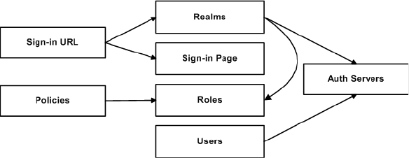
Importing and exporting XML configuration files 641
Chapter 24: System archiving
Namespaces
Namespaces allow you to use the same words or labels in your code from different
contexts or XML vocabularies. Prefixing elements with namespace qualifiers allows
an instance file to include references to different objects that originate in different
XML vocabularies and that share the same name. If you do not prefix elements
with namespace qualifiers, the namespace is the default XML namespace and you
refer to element type names in that namespace without a prefix.
A namespace declaration looks like:
<IVE xmlns="http://xml.juniper.net/iveos/5.0R1">
When you see namespace identifiers in your instance files, you do not need to be
concerned about them, as long as you do not delete or modify the identifiers.
Element sequence
You should avoid changing the sequence of elements in the instance file, whenever
possible. Although the schema does not enforce sequence in all cases, you gain no
benefit from changing the order of elements from the order in which they appear in
the exported instance file, and, in some cases, you might invalidate an instance
document by changing element sequence.
Referential integrity constraints
IVE configuration objects are part of a data model that is enforced through the use
of referential integrity constraints. You cannot change these constraints, but you
should understand them before you attempt to delete objects that maintain
dependencies to other objects.
If you violate the IVE referential integrity constraints, your import operation fails.
The following diagram illustrates the relationships among several IVE objects.
Figure 45: IVE object referential integrity constraints
In Figure 45 the boxes represent IVE object types and the arrows represent
dependent relationships between the object types. Arrows point from dependent
objects to objects.
The system does not allow you to delete an object upon which another object
depends. Conversely, when you add an object, you must add any other objects
upon which that object depends.
Juniper Networks Secure Access Administration Guide
642 Importing and exporting XML configuration files
In Figure 45, sign-in URLs depend upon realms and sign-in pages. Realms depend
upon both auth servers and roles. Policies depend upon roles. Users depend upon
auth servers.
Consider the following scenarios based on Figure 45:
If you add sign-in URLs, you must add realms, sign-in pages, roles, and auth
servers. You need to add an auth server and at least one role to support the
realm, and you need to add the realm and the sign-in page to support the new
sign-in URL.
If you add a user, you must be able to assign it to an auth server. If there is no
auth server on the target IVE yet, you must add one in the instance file.
If you add a policy, you must be able to assign it to a role. If there is no role on
the target IVE yet, you must add one in the instance file.
If you delete an auth server, you might strand realms and users, therefore, you
need to make sure no realms or users depend on the auth server before you
attempt to delete it.
If you delete a role, you might strand policies and realms. To delete a role, you
must first delete any policy that depends upon the role, or reassign associated
policies to another role. Also, to delete a role, you must first delete or reassign
any realm that depends upon that role.
If you delete a sign-in page, you might strand one or more sign-in URLs. To
delete a sign-in page, you must first delete any associated sign-in URLs or
reassign them to other sign-in pages.
Mapping the XML instance to UI components
The elements in the XML instance are closely related to the objects and their
options as you see them in the admin console. The element names in the XML
instance file correlate closely with the displayed object and option names.
For example, go to Users > User Roles > [Role] > General > Session Options in
the admin console. The admin console renders the possible values for a roaming
session as a radio button group, consisting of the values:
Enabled
Limit to subnet
Disabled
The following excerpt, from the exported configuration file for roles, shows the
session options for the Users role. On the bolded line, the roaming session option is
set to Enable:
<SessionOptions>
<MaxTimeout>60</MaxTimeout>
<RoamingNetmask />
<Roaming>Enable</Roaming>
<IdleTimeout>10</IdleTimeout>
Importing and exporting XML configuration files 643
Chapter 24: System archiving
<ReminderTime>5</ReminderTime>
<PersistentPassword>false</PersistentPassword>
<RequestFollowThrough>false</RequestFollowThrough>
<PersistentSession>false</PersistentSession>
<SessionTimeoutWarning>false</SessionTimeoutWarning>
<SessionTimeoutRelogin>true</SessionTimeoutRelogin>
<IgnoreApplicationActivity>false</IgnoreApplicationActivity>
<UploadLog>false</UploadLog>
</SessionOptions>
In the schema.xsd schema file, you can locate the allowable values for the roaming
session option:
<xs:simpleType name="EnableRoamingType">
<xs:restriction base="xs:token">
<xs:enumeration value="Enable"/>
<xs:enumeration value="Limited"/>
<xs:enumeration value="Disable"/>
</xs:restriction>
</xs:simpleType>
If you want to change the value for the roaming session from enabled to limit to
subnet, replace Enable with Limited.
This example shows you that the admin console often provides all of the allowable
values, displayed either in a radio button group, as checkboxes, as drop down
listboxes, or as other types of user interface components. The instance file displays
only the current state of your IVE configuration. The schema file displays all of the
actual values for the configuration options that are supported in the XML
Import/Export feature.
For more information about specific elements, review the schema files directly.
XML import modes
The IVE provides three different import modes to use when importing XML
configuration files. Each mode enables you to perform progressively more complex
tasks during the import operation.
Quick Import
If you want to add objects to your configuration, use the quick import mode. Quick
import mode does not allow you to make changes to any of the existing settings.
Even if you modify the data in your XML instance file, the IVE does not apply those
modifications to the configuration.
Standard Import
If you want to change or add objects to your configuration without affecting any of
the other data in your configuration, use the standard import mode. Standard
import mode enables you to add new objects to your configuration, and to update
existing objects. If you delete an object from the instance file, then use standard
import mode, the IVE ignores the deletion. The IVE sets the default import mode to
standard import.

Juniper Networks Secure Access Administration Guide
644 Importing and exporting XML configuration files
Full Import
Full import mode is the most powerful import operation you can perform using the
XML instance file. A full import consists of a complete replacement of the IVE
configuration. Using full import mode, you can add, modify, and delete objects
from the IVE.
Because you can make significant changes to your configuration, both purposely
and inadvertently, it is important for you to understand the implications of using
full import mode.
During a full import, you completely replace your existing configuration with
whatever is in your instance file. You can effectively delete a large number of
objects from your existing configuration with this mode. The IVE performs the
deletion by exclusion. On comparing the instance file with the existing
configuration, the IVE deletes anything in the existing configuration that does not
appear in the instance file.
The following scenarios illustrate the incorrect and the correct usage of full import
mode when attempting to delete some users from an IVE configuration.
Using Full Import mode incorrectly
You want to remove a few users from the IVE.
You perform the following steps:
1. Export the local users who are associated with one of your auth servers.
2. Delete a few of the users from the XML instance file.
3. Select Full Import and import the remaining users back into the IVE.
You have now deleted all users except those that were left in the XML instance file.
Your mistake was in exporting only users associated with a specific auth server.
Because the full import mode results in a complete replacement of the
configuration, the contents of the imported file overwrite all corresponding IVE
configuration data.
Using Full Import mode correctly
You want to remove a few users from the IVE. You perform the following steps:
1. Export all local users from all auth servers defined on the IVE.
2. Delete some of the users from the XML instance file.
NOTE: You can delete much or all of your configuration inadvertently, if you
implement the full import operation incorrectly. The exported instance file
contains the current state of the top-level components in the IVE.
NOTE: DO NOT perform this procedure. It is included as an example of the
incorrect use of the Full Import mode and is meant strictly for training purposes.

Importing and exporting XML configuration files 645
Chapter 24: System archiving
3. Select Full Import and import the remaining users back into the IVE.
You have now deleted only the selected users from your IVE and left the other users
intact.
Validating the instance file
An XML schema defines the structure of an application as well as allowable values,
defaults, data types, ranges, list values, required and optional values, syntax, and
other data structures. The XML instance is validated against the schema when you
attempt to import the instance into the IVE, ensuring that the instance conforms to
the requirements for a valid IVE configuration.
If you have made changes or additions to the instance file that somehow violate the
rules set forth in the schema, whether those are referential integrity rules, allowable
values, ranges, or other types of constraints, the IVE does not complete the import
operation and provides error messages.
You can download the schema (.xsd) file for the IVE objects whose data are
available for export and import. You might find the schema file useful for
determining the rules that apply to the IVE objects, as they relate to exporting,
modifying, and importing those objects.
Downloading the schema file
You can download the schema (.xsd) file for the IVE objects, if you want to review
the structure and rules that apply to the objects.
You can download the schema file in two ways:
From the XML Import/Export pages, by clicking a hyperlink.
Directly, by accessing the URL where the files are stored on the system.
To access the .xsd file, access the following URL, either directly or by way of a
script:
https://<IP-or-hostname>/dana-na/xml/schema.xsd
where IP-or-hostname is the IVE's IP address or hostname. Using this method, you
do not need to sign in to the IVE.
NOTE: This feature might change in the future. Be aware of this if you use scripts
to access the zip file by way of the URL. The items that might change are:
The URL.
The filename.
The file extension. The format could be changed to .xsd, for example.
Juniper Networks Secure Access Administration Guide
646 Importing and exporting XML configuration files
Strategies for working with XML instances
The following strategies might be useful to you when exporting and importing XML
instance files:
Define your goal for a given XML Import/Export operation.
What IVE object or objects do you need to add, update, or delete?
Do you need to complete all modifications in one operation, or can you
modify the configuration in separate operations?
Will your process be a one-time operation, or will you need to perform the
same operation multiple times?
Are you updating an existing IVE, or are you using one IVE configuration as
a template for configuring other IVEs?
Document the changes to the IVE objects you intend to modify.
Make a list of objects to be added, updated, or deleted.
For objects to add or update, list specific attribute data.
List pages or tabs from the admin console that correspond to the objects
and attributes you intend to change.
Make a binary system snapshot or a binary configuration backup immediately
before performing the import.
Make sure you understand the implications of the import modes, as described
in “XML import modes” on page 643.
Make a plan to verify that the completed configuration meets your goals.
Check the Admin Access log to make sure the export and import
operations succeeded.
Perform a random check of the modified items. Make sure items were
added, updated, or deleted as you expected.
You will almost always need to use the XML instance file and the admin console in
combination, particularly when you first begin modifying the XML instance files.
You may also need to view the XML schema files.
Use the XML instance file to:
Identify the configuration objects, expressed as XML elements.
Locate and modify the configuration data.
Use the admin console to:
Correlate visual components to XML schema and instance elements.
Confirm the accuracy of modifications to specific objects.

Importing and exporting XML configuration files 647
Chapter 24: System archiving
Use the XML schema file to:
Identify the structure and sequence of configuration objects.
Identify optional and required elements, allowable values, default values, and
other attributes of the configuration objects.
Importing XML configuration data
To import XML configuration data:
1. Choose Maintenance > Import/Export > XML Import/Export > Import in
the admin console.
2. Under Schema Files, click the link to download the XML Schema (.xsd) files
that describe the IVE objects (Optional). For more information about schema
files, see “Downloading the schema file” on page 645.
3. Browse to, and select, the XML data file that you want to import. You can
import a valid XML fragment file if you want to import only a partial
configuration.
4. Select the Import mode:
Full Import (Add, Update, and Delete)—Adds any new data elements that
appear in the imported XML file to the IVE configuration, updates any
existing elements whose values are changed in the imported XML file, and
deletes any existing elements that are not defined in the imported XML
file.
Standard Import (Add and Update)—Adds any new data elements that
appear in the imported XML file to the IVE configuration and updates any
existing elements whose values are changed in the imported XML file. No
elements are deleted.
NOTE: Importing and exporting XML configuration files can take several minutes
to complete. Do not perform any operations that might modify or remove data
currently being imported or exported.
NOTE: If you import an XML configuration file into a cluster, all members of a
cluster are disabled and all end-user sessions are terminated during the import
process. After the import process completes, the cluster members are
automatically enabled but users must sign-in again.
NOTE: CAUTION. Using Full Import mode is a potentially dangerous operation.
You can inadvertently delete much or all of your IVE configuration if you are not
careful. When set to Full Import, the IVE replaces the configuration on the IVE
appliance with whatever is in the instance file. Anything that is not defined in the
instance file is deleted from the IVE appliance.

Juniper Networks Secure Access Administration Guide
648 Importing and exporting XML configuration files
Quick Import (Add)—Adds any new data elements that appear in the
imported XML file to the IVE configuration. Any changes to existing
elements are ignored.
5. Click Import. The Import XML Results page displays containing information
about the imported network settings, roles, resource policies, and other
settings.
If there are errors in the XML, the import operation stops and rolls back the
configuration to the previous state. Error messages are displayed on the Import
XML Results page.
6. Click OK to return to the Import page.
Exporting XML configuration data
To export XML configuration data:
1. Choose Maintenance > Import/Export > XML Import/Export > Export in
the admin console.
2. Under Schema Files, click the link to download the XML Schema (.xsd) file that
describe the IVE objects (Optional). For more information about schema files,
see “Downloading the schema file” on page 645.
3. Click the Select All button to export all of the settings identified on the page.
Otherwise, select the specific information you want to export:
Select the Network Settings and Licenses checkbox to export network
settings, including internal port settings, external port settings, and
licensing information. For a more detailed list, see “Importing and
exporting XML configuration files” on page 635.
NOTE: The following rules apply to exported and imported licenses:
You cannot edit the license data that is exported, as it is encrypted.
An XML import of licenses is only valid if the machine importing the license
does not currently have a license installed. If there is a license installed
already, any imported licenses are dropped. If you still intend to import a
license, you must perform a factory reset on the IVE, then perform the import
operation.
If you import a license after deleting a temporary license from the IVE, the
imported license will be dropped, because you might still be able to reactivate
the deleted license and the import operation attempts to preserve any
licensing data currently on the IVE.

Importing and exporting XML configuration files 649
Chapter 24: System archiving
Select the Sign-in Settings checkbox to export Authentication servers,
password options, password management options, standard sign-in pages,
custom text, header options, custom error messages, help options, page
name, sign-in URLs, and page type.
From Sign-in URLs, select one of the following options:
Choose ALL sign-in URLs to export all sign-in URLs.
Choose SELECTED sign-in URLs, select URLs from the Available Sign-
in URLs list, and click Add to export only those URLs.
From Sign-in Pages, select one of the following options:
Choose ALL Pages to export all sign-in pages.
Choose ONLY pages used by URLs selected above to restrict the
exported pages to those that are valid for the sign-in URLs you have
chosen.
Choose SELECTED pages..., select pages from the Available Pages list,
and click Add to export only those pages.
From Authentication servers, select one of the following options:
Choose ALL auth servers to export all authentication servers.
Choose SELECTED auth servers..., select servers from the Available
Servers list, and click Add to export only those servers.
Select the Authentication Realms checkbox to export authentication
realms.
From Administrator Realms, select one of the following options:
Choose ALL admin realms to export all administrator realms.
Choose SELECTED admin realms..., select realms from the Available
Realms list, and click Add to export only those realms.
From User Realms, select one of the following options:
Choose ALL user realms to export all user realms.
Choose SELECTED user realms..., select realms from the Available
Realms list, and click Add to export only those realms.
Select the Roles checkbox to export admin and user roles.
From Delegated Admin Roles, select one of the following options:
NOTE: You can only export standard sign-in pages. You cannot export custom
sign-in pages.
Juniper Networks Secure Access Administration Guide
650 Importing and exporting XML configuration files
Choose ALL delegated admin roles to export roles from all
authentication realms.
Choose SELECTED delegated admin roles..., select roles from the
Available Roles list, and click Add to export only those roles.
From User Roles, select one of the following options:
Choose ALL user roles to export all local user roles.
Choose SELECTED user roles..., select roles from the Available Roles
list, and click Add to export the selected user roles.
Select the Resource Policies checkbox to export resource policies. Next,
select the checkboxes that correspond to the types of resource policies that
you want to export.
Select the Local User Accounts checkbox to export all local user accounts.
Next, select one of the following options:
Choose From ALL local auth servers to export all local user accounts
from all of the local authentication servers.
Choose From SELECTED local auth servers..., select authentication
servers from the Available Servers list, and click Add to export local
users from only those authentication servers.
Select the Log/Monitoring Settings checkbox to export some
log/monitoring data.
Select SNMP Settings to export SNMP data, including trap settings and
limits.
Select Meeting Policy to export meeting policy settings, including idle
time-out settings, maximum session time-out settings, SMTP server
configurations for email notifications, 32-bit color settings, and daylight
savings time settings.
4. Click Export... to save the information in an XML file.
XML Import/Export use cases
The following use cases illustrate common examples of how you can use the XML
Import/Export feature. Each use case consists of a brief description and a
procedure for accomplishing the use case. These use cases are abbreviated and do
not cover all of the intricacies and details of performing a full set of procedures. The
use cases are included solely as illustrations of the potential uses for the XML
Import/Export feature.

Importing and exporting XML configuration files 651
Chapter 24: System archiving
Use Case: Adding multiple new users to an IVE
You have just added a new IVE appliance to your network, and you want to add
your two thousand users to the system. You do not want to add them one at a time
in the admin console, but would like to perform a mass import and force the users
to change their passwords the first time they log in to the system. You can export
the user accounts, extract the relevant XML that defines users, replicate each
element as needed, then import them to the IVE.
In this procedure, you only see examples for User 1, User 2, and User 2000. All
other users are assumed as being included in your import file. You set the
passwords to numbered instances of the word password, such as password1,
password2, and so on. All users in this example are assigned to the same auth
server, although you can specify any combination of auth servers that are valid on
your system.
To add multiple new users to an IVE:
1. In the admin console, go to Maintenance > Import/Export > XML
Import/Export > Export XML.
2. Follow the instructions to export local user accounts as described in “Strategies
for working with XML instances” on page 646.
3. Save the exported file as users.xml.
4. Open the users.xml file.
5. Copy and paste the User container element until you have added the necessary
number of users. Although the example shows only three new users, you might
add hundreds of new users to the file.
6. Update the appropriate data in each User container element, as shown in the
following example:
<?xml version="1.0" encoding="UTF-8" standalone="no" ?>
<IVE xmlns="http://xml.juniper.net/iveos/5.4R1/ive">
<AAA>
<Users>
<User>
<AuthServerName>System Local</AuthServerName>
<Email>user1@company.com</Email>
<FullName>User1</FullName>
<LoginName>user1</LoginName>
<Password PasswordFormat="Plaintext">password1
</Password>
<ChangePasswordAtNextLogin>true
NOTE:
The formatting in the following example has been modified from the original
to improve readability. The actual XML code may appear differently.
You must set the PasswordFormat to Plaintext, otherwise the IVE assumes a
default of Encrypted.
Juniper Networks Secure Access Administration Guide
652 Importing and exporting XML configuration files
</ChangePasswordAtNextLogin>
<QuarantineRoleList />
<userStatus>Enabled</UserStatus>
<UserType>NormalUser</UserType>
</User>
<User>
<AuthServerName>System Local</AuthServerName>
<Email>user2@company.com</Email>
<FullName>User2</FullName>
<LoginName>user2</LoginName>
<Password PasswordFormat="Plaintext">password2
</Password>
<ChangePasswordAtNextLogin>true
</ChangePasswordAtNextLogin>
<QuarantineRoleList />
<userStatus>Enabled</UserStatus>
<UserType>NormalUser</UserType>
</User>
<User>
<AuthServerName>System Local</AuthServerName>
<Email>user2000@company.com</Email>
<FullName>User 2000</FullName>
<LoginName>user2000</LoginName>
<Password PasswordFormat="Plaintext">password2000
</Password>
<ChangePasswordAtNextLogin>true
</ChangePasswordAtNextLogin>
<QuarantineRoleList />
<userStatus>Enabled</UserStatus>
<UserType>NormalUser</UserType>
</User>
</Users>
</AAA>
</IVE>
7. Save the users.xml file.
8. In the admin console, go to Maintenance > Import/Export > XML
Import/Export > Import.
9. Choose either Standard Import or Quick Import.
10. Import the file, as described in “Importing and exporting XML configuration
files” on page 635.
Use Case: Updating policies
You want to change all ActiveX rewriting policies from an action of
RewriteURLResponseForDynamicStaticHTML to another action, but you do not want
to enter each policy separately in the admin console. Instead, you can export an
instance file, make your changes, then import the file back to the IVE.
To update policies on an IVE:

Importing and exporting XML configuration files 653
Chapter 24: System archiving
In the admin console, go to Maintenance > Import/Export > XML Import/Export
> Export.
1. Follow the instructions to export local user accounts as described in “Strategies
for working with XML instances” on page 646.
2. Save the exported file as policy.xml.
3. Open the exported file.
4. Open the policy.xsd schema file on your system, using either a text editor or an
XML editor. In the schema file, search for the action value
RewriteURLResponseForDynamicStaticHTML. The schema definition for the
ActiveXActionType includes the current policy action value, as well as the other
possible values, as shown in the following example:
<xs:simpleType name="ActiveXActionType">
<xs:restriction base="xs:token">
<xs:enumeration value="RewriteURLResponseForStaticHTML"/>
<xs:enumeration
value="RewriteURLResponseForDynamicStaticHTML"/>
<xs:enumeration value="RewriteURLForStaticHTML"/>
<xs:enumeration value="RewriteURLForDynamicStaticHTML"/>
<xs:enumeration value="RewriteHostForStaticHTML"/>
<xs:enumeration value="RewriteHostForDynamicStaticHTML"/>
<xs:enumeration value="RewriteURLInsertHostname"/>
<xs:enumeration value="RewriteDataAsListOfURLs"/>
<xs:enumeration value="DoNotRewrite"/>
</xs:restriction>
</xs:simpleType>
5. In the exported policy.xml file, search and replace
RewriteURLResponseForDynamicStaticHTML with the action value of
RewriteURLForDynamicStaticHTML.
<!-- DO NOT MODIFY OR DELETE THE FIRST LINE -->
<IVE xmlns="http://xml.juniper.net/iveos/5.4R1/ive">
<AAA>
<ResourcePolicyList>
<WebActiveXRewritingPolicyList>
<ActiveXRewritingPolicy>
<ParameterList>
<Parameter>
<Name>URL</Name>
<!-- Change the following data -->
<Action>RewriteURLResponseForDynamicStaticHTML
</Action>
</Parameter>
</ParameterList>
<Description>OrgPlus Orgviewer</Description>
NOTE: The following example shows only a fragment of the actual policy.xml file.
Also, the formatting has been modified from the original to improve readability.
The actual XML code may appear differently.

Juniper Networks Secure Access Administration Guide
654 Importing and exporting XML configuration files
<ClassID>DCB98BE9-88EE-4AD0-9790-2B169E8D5BBB
</ClassID>
</ActiveXRewritingPolicy>
</WebActiveXRewritingPolicyList>
</ResourcePolicyList>
<!-- DO NOT MODIFY OR DELETE THE LAST THREE LINES -->
</AAA>
<SYS xmlns:sys="http://xml.juniper.net/iveos/5.4R1/sys"/>
</IVE>
6. Save the policy.xml file.
7. In the admin console, go to Maintenance > Import/Export > XML
Import/Export > Import.
8. Choose Standard Import. By selecting this import mode, you will update data
on the IVE that has been modified in the XML instance file.
9. Import the file, as described in “Importing XML configuration data” on
page 647.
Use Case: Deleting users from an IVE
Every month you purge users who are no longer with the company from the IVE.
Because you work in a very large organization, you often must delete dozens or
even hundreds of users every month. This can be a tedious process and you would
like to find an easier way to perform this task.
To delete users from an IVE:
1. In the admin console, go to Maintenance > Import/Export > XML
Import/Export > Export.
2. Follow the instructions to export local user accounts as described in “Strategies
for working with XML instances” on page 646.
3. Save the exported file as remusers.xml.
4. Open the remusers.xml file.
5. If you have a list of users you want to delete, search the file for each username,
then remove the entire User container element that contains that username.
The following example shows the User container and its child elements:
<User>
<AuthServerName>System Local</AuthServerName>
<Email>deleteuser@company.com</Email>
<FullName>DeleteUser</FullName>
NOTE: CAUTION. Using Full Import mode is a potentially dangerous operation.
You can inadvertently delete much or all of your IVE configuration if you are not
careful. When set to Full Import, the IVE replaces the configuration on the IVE
appliance with whatever is in the instance file. Anything that is not defined in the
instance file is deleted from the IVE appliance.

Importing and exporting XML configuration files 655
Chapter 24: System archiving
<LoginName>deleteuser</LoginName>
<Password
PasswordFormat="Encrypted">oU63QjnZCgABAAAA91aVaD==
</Password>
<ChangePasswordAtNextLogin>false
</ChangePasswordAtNextLogin>
</User>
6. Save the remusers.xml file.
7. In the admin console, go to Maintenance > Import/Export > XML
Import/Export > Import.
8. Choose Full Import. By selecting this import mode, you replace all of the user
data on the IVE with the user data in the XML instance file.
9. Import the file, as described in “Importing and exporting XML configuration
files” on page 635.
Use Case: Using XML Import/Export in a clustered environment
You can use the XML Import/Export feature in a clustered environment. You must,
however, adhere to certain rules and you must follow a particular procedure to
complete the operation successfully.
The XML instance you want to import must contain the same set of nodes as
the original cluster. The signature used to synchronize the cluster when the
nodes are re-enabled is derived from the IP addresses of the cluster nodes, so
the remaining nodes cannot rejoin the cluster if the imported configuration
yields a different signature.
Do not modify node name, IP address, or IP netmask in the instance file.
Do not use Full Import mode. Use only Standard Import mode.
Do not change any network settings in the instance file that render the primary
node unreachable. For example, do not change the default gateway
configuration for a multi-site cluster.
On import, the instance file overwrites the node-specific cluster configuration
network settings of the remaining nodes. If you change these node-specific
network settings, make sure you do not make the remaining nodes
unreachable.
Do not modify existing virtual port settings or add new virtual port settings in
the instance file.
NOTE: You should never attempt to encrypt a password manually in the XML file.
The IVE rejects any attempt to do so. Use the plaintext PasswordFormat and enter a
plaintext password when changing passwords through the XML file.

Juniper Networks Secure Access Administration Guide
656 Pushing configurations from one IVE to another
When performing an import operation on a cluster, all of the cluster nodes
should be enabled and running. If you attempt to import a configuration into a
cluster in which a node is not running, the import operation may hang or your
import results may be unpredictable.
Importing to a system with the Management Port
If you import a configuration from a system that does not support a management
port into a system that has an enabled management port and you import
everything, including licenses, the management port on the target system will
appear to be removed. The management port actually continues to be operational
and will reappear along with its original configuration when you reapply the
management port license for the target system. If you import to the target but
specify the option Import everything except network settings and licenses, the
management port and its configuration persist on the target system and the port is
operational.
Pushing configurations from one IVE to another
IVE appliances enabled with the Advanced license enable you to copy all
configuration settings or selected configuration settings from one IVE to another
using the Push Configuration feature. This feature provides simple configuration
management across an enterprise without requiring you to cluster IVE appliances.
With the Push Configuration feature, you can decide exactly which settings you do
and do not want to copy across the enterprise. The interface for selecting the
settings is similar to the XML Import/Export feature.
You can push to a single IVE or to multiple IVEs. For example, if you install several
new IVEs, you can push to set their initial configuration. You can also push to an
IVE that is a member of a cluster as long as the target IVE is not a member of the
same cluster as the source. Target IVEs have the option of not accepting pushed
configuration settings. For instructions, see “Defining the target IVEs” on page 657.
If a push to a target IVE fails, Push Configuration continues to the next target until
all identified targets are updated. The results page displays the status and any
problems encountered during the process.
Note the following when pushing configurations:
After the IVE updates the configuration on a target IVE, the target IVE appliance
restarts its services. Brief interrupts may occur while the service restarts. We
recommend you push to target IVEs when they are idle or when you can
accommodate brief interruptions.
Target IVEs display no warning message when receiving pushed
configurations. Push Configuration updates the Administrator Access log file
with the push results.
The target IVE automatically logs out administrators during the push process.
The source and target IVEs must have the same build version and number.
If either the source or target IVEs has an IVS license, you must push all
configuration settings. You cannot select which settings to push.
Pushing configurations from one IVE to another 657
Chapter 24: System archiving
The source IVE pushes data only over the internal port or the Management Port
(on the Juniper Networks SA 6000, if configured.) If the source IVE’s internal
port or Management Port cannot talk to the target IVE’s external port, the push
operation fails.
The source IVE pushes data only over the internal port. If the source IVE’s
internal port cannot talk to the target IVE’s external port, the push operation
fails.
You can push up to 8 targets per push operation; up to 25 push operations can
be run simultaneously. The maximum number of targets the IVE pushes to at
any time is 200.
The source IVE saves and displays up to 25 push configuration results in the
Results tab. If 25 results are currently displayed, the IVE removes the oldest
result data when push configuration runs again.
For Push Configuration to work, the administrator account on the source IVE must
sign in to the target IVE without any human interaction. For example, you cannot
have dynamic credentials or multiple roles that are not merged as these both
require manual interaction.
Prior to using Push Configuration, you must configure your system following
specific conditions:
You must map to the .Administrators role, thereby creating a “super
administrator” with full administration privileges. Use settings in the
Authentication > Auth Servers >[Administrator Server] > Users tab to add
yourself to the .Administrators role.
The target IVE administrator account must use static password authentication
or two-factor tokens that do not use challenge-response type authentication.
For example, certificates, Soft ID, and Defender Authentication are not
supported. Use settings in the Administrators > Admin Realms >
[Administrator Realm] > General tab to select the proper authentication server
for the administrator realm.
You must not configure the administrator account in a way that requires the
administrator to select a role to sign in to the target IVE. For example, you must
not map a single user to multiple roles, including the push configuration
administrator role, and then fail to permissively merge those roles. We
recommend creating an account exclusively for push configuration
administrators to guarantee that the administrator does not need to choose a
role during the sign-in process and to clearly distinguish the actions of push
configuration administrators in your log files. Use settings in the
Administrators > Admin Realms > [Administrator Realm] > Role Mapping
tab to set the appropriate role-mapping rules.
Defining the target IVEs
If the target IVE is part of a cluster, you can push to any member of the cluster as
long as the target is not a member of the source cluster. You must enable the Allow
this IVE to be a target setting on all cluster members. This setting is important
when specifying the virtual IP (VIP) in the sign-in URL of a destination as it ensures
that the push succeeds regardless of which node is hosting the VIP.
Juniper Networks Secure Access Administration Guide
658 Pushing configurations from one IVE to another
Note the following about target IVEs.
Target names and target sign-in URLs cannot be edited once they are created.
You cannot edit or delete a target IVE while the push operation is pushing
configuration data to that target IVE.
When deleting a target IVE, all push configuration results associated with that
target IVE are also deleted.
To define target IVEs:
1. Create administrator accounts on both IVEs. For instructions, see “Creating
administrator roles” on page 735. (See restrictions in “Pushing configurations
from one IVE to another” on page 656.)
2. In the admin console, choose Maintenance > Push Config > Targets.
3. If you do not want this IVE to accept pushed configuration settings, uncheck
the Allow this IVE to be a target checkbox.
4. To create a new target IVE, click New Target. On the New Target page:
a. In the Name field, enter a name for the target IVE.
b. In the Sign-in URL field, enter the sign-in URL defined in the
Authentication > Signing In > Sign-In Policies page.
c. Enter the username, password, and authentication realm of an
administrator account on the target IVE that provides full administration
privileges.
d. Click Save Changes.
5. To delete a target IVE:
a. Select the checkbox next to the target IVE you want to delete.
b. Click Delete and then confirm that you want to delete the IVE.
6. Click Save Changes.
Pushing the configuration settings
To push selected roles, resources, sign-in settings, auth servers, and local users
from one IVE to another:
1. In the admin console, choose Maintenance > Push Config.
2. If you have not set up your target IVEs, click the Targets tab and follow the
instructions in “Defining the target IVEs” on page 657.
3. Select one of the following options from the What to push list:

Pushing configurations from one IVE to another 659
Chapter 24: System archiving
Entire configuration to push all configuration settings, except for the
following:
Network configurations
Licenses
Cluster configurations
Certificates
SNMP settings
Syslog server settings
Push configuration targets configured on the source IVE
Selected configuration to choose specific settings to push.
4. If you chose Selected Configuration:
Select the Sign-in Settings checkbox to export sign-in URLs, standard sign-
in pages, and authentication servers.
From Sign-in URLs, select one of the following options:
Choose ALL sign-in URLs to export all sign-in URLs.
Choose SELECTED sign-in URLs, select URLs from the Available Sign-
in URLs list, and click Add to export only those URLs.
From Sign-in Pages, select one of the following options:
Choose ALL Pages to export all sign-in pages.
Choose ONLY pages used by URLs selected above to restrict the
exported pages to those that are valid for the sign-in URLs you have
chosen.
Choose SELECTED pages..., select pages from the Available Pages list,
and click Add to export only those pages.
From Authentication servers, select one of the following options:
NOTE: User bookmarks and preferences from the source IVE are pushed to all
target IVEs with this option. Any bookmarks and preferences already set on the
target IVEs are overwritten.
NOTE: You cannot copy network settings to another IVE using the Push
Configuration feature. You can use the XML Import/Export feature to export
selected network settings and then to import those settings to another IVE. For
more information, see “Importing and exporting XML configuration files” on
page 635.
Juniper Networks Secure Access Administration Guide
660 Pushing configurations from one IVE to another
Choose ALL auth servers to export all authentication servers.
Choose SELECTED auth servers..., select servers from the Available
Servers list, and click Add to export only those servers.
Select the Authentication Realms checkbox to export authentication
realms.
From Administrator Realms, select one of the following options:
Choose ALL admin realms to export all administrator realms.
Choose SELECTED admin realms..., select realms from the Available
Realms list, and click Add to export only those realms.
From User Realms, select one of the following options:
Choose ALL user realms to export all user realms.
Choose SELECTED user realms..., select realms from the Available
Realms list, and click Add to export only those realms.
Select the Roles checkbox to export role mapping rules.
From Delegated Admin Roles, select one of the following options:
Choose ALL delegated admin roles to export role mapping rules from
all authentication realms.
Choose SELECTED delegated admin roles..., select roles from the
Available Roles list, and click Add to export only those roles.
From User Roles, select one of the following options:
Choose ALL user roles to export all local user roles.
Choose SELECTED user roles..., select roles from the Available Roles
list, and click Add to export the selected user roles.
Select the Resource Policies checkbox to export resource policies. Next,
select the checkboxes that correspond to the types of resource policies that
you want to export.
Select the Local User Accounts checkbox to export all local user accounts.
Next, select one of the following options:
Choose From ALL local auth servers to export all local user accounts
from all of the local authentication servers.
Choose From SELECTED local auth servers..., select authentication
servers from the Available Servers list, and click Add to export local
users from only those authentication servers.
Select the Log/Monitoring checkbox to export some log/monitoring data.

Pushing configurations from one IVE to another 661
Chapter 24: System archiving
Select SNMP to export SNMP data, including trap settings and limits.
Select Export Meeting Policy to export meeting policy settings.
5. Select the target IVEs from the Available Targets list and click Add to move
them to the Selected Targets list.
6. Select the Overwrite duplicate settings checkbox if you want to overwrite
settings on the target IVE that have the same name as settings on the source
IVE.
7. Click Push Configuration to copy the selected settings to the target IVEs. The
IVE displays the push status in the Results tab.
If there are errors during the push process, the operation stops and rolls back
the configuration to the previous state. Error messages are displayed on the
Results page.
8. Correct the problems described by the error messages and push to the failed
target IVE again.
NOTE:
If Overwrite duplicate settings is off, and if the name of any setting in the
imported file matches the name of a corresponding setting on the target IVE,
then Push Configuration does not copy the values for that setting to the target
IVE. Push Configuration only copies new objects to the target IVE.
If Overwrite duplicate settings is on, Push Configuration copies all new and
updated objects to the target IVE.
NOTE: Once you click Push Configuration, you cannot halt the process or change
the target IVEs until the entire push configuration process completes.
Juniper Networks Secure Access Administration Guide
662 Pushing configurations from one IVE to another

Licensing: Logging and monitoring availability 663
Chapter 25
Logging and monitoring
The IVE provides logging and monitoring capabilities to help you track events and
user activities. This chapter describes the various logging and monitoring features
included with the IVE.
This section contains the following information about logging and monitoring
features:
“Licensing: Logging and monitoring availability” on page 663
“Logging and Monitoring overview” on page 664
“Configuring the Log Monitoring features” on page 668
“Configuring events, user access, admin access, IDP sensor, and NC packet
logs” on page 668
“Monitoring the IVE as an SNMP agent” on page 673
“Viewing system statistics” on page 679
“Enabling client-side logs” on page 679
“Viewing general status” on page 683
“Monitoring active users” on page 686
“Viewing and cancelling scheduled meetings” on page 687
Licensing: Logging and monitoring availability
Logging and monitoring capabilities are available on all Secure Access products—
you do not need a special license to use them. However, the following advanced
logging and monitoring tools are not available on the SA 700 appliance and are
only available on other Secure Access appliances by special license:
Sensors log
Custom & dynamic log filters
System capacity and critical events dashboard graphs

Juniper Networks Secure Access Administration Guide
664 Logging and Monitoring overview
Secure Meeting logging and monitoring
Logging and Monitoring overview
IVE log files are text files stored on an IVE appliance that track system events. An
IVE appliance produces the following types of log files:
Events log—This log file contains a variety of system events, such as session
timeouts (including idle and maximum length session timeouts), system errors
and warnings, requests to check server connectivity, and IVE service restart
notifications. (The IVE Watchdog process periodically checks the IVE server
and restarts it if the IVE does not respond.)
User Access log—This log file contains information about when users access
the appliance, including the number of simultaneous users at each one hour
interval (logged on the hour), user sign-ins and sign-outs, user file requests, and
Web requests.
Administrator Access log—This log file contains administration information,
including administrator changes to user, system, and network settings, such as
changes to session timeouts, the option to enable/disable URL browsing and
user-created bookmarks, and machine and server information. It also creates a
log entry whenever an administrator signs in, signs out, or changes licenses on
the appliance.
Sensors log—This log file contains informational and attack alert messages
generated by an associated IDP device monitoring client traffic for possible
network intrusion.
Network Connect Packet log—This log file contains all of the information
featured in the User Access log plus additional information like the source and
destination IP addresses, source and destination ports, UDP encapsulated ESP
transport protocol negotiation events, and the destination protocol used when
applications are accessed via the Network Connect client-to-IVE tunnel.
Client upload log—This log file contains session initiation, connection, and
termination log information that you can use to help diagnose and troubleshoot
problems users may have connection to the IVE.
The System > Log/Monitoring pages lets you specify which events are logged, the
maximum file size for the system log, and whether to log events to the syslog
server in addition to logging them locally. The System > Log/Monitoring pages
also let you view the specified number of events, save the log files to a network,
and clear the logs.
NOTE: Because client-side Network Connect packet logging is policy-driven, packet
information will only be logged for user profiles meeting all the criteria necessary
to automatically engage the logging function.

Logging and Monitoring overview 665
Chapter 25: Logging and monitoring
When one of the logs reaches the configured maximum log file size (200MB by
default), the current data is rolled over to a backup log file. A new, empty, file is
then created for all subsequent (new) log messages. Using the log viewer, the
administrator can see the most recent 5000 log messages (the viewer's display
limit). If the current log file contains less than 5000 log messages, older log
messages from the backup log file are displayed, up to a total of 5000 log
messages. This makes the log files appear as one, even though they are stored
separately, according to the configured maximum log file size.
Additionally, you can use a network management tool such as HP OpenView to
monitor an IVE appliance as an SNMP agent. The IVE platform supports SNMP v2,
implements a private MIB (management information base), and defines its own
traps. To enable your network management station to process these traps, you
need to download the Juniper Networks MIB file and specify the appropriate
information to receive the traps. You can configure some of the traps to suit your
needs. For more information on setting trap thresholds, see “Monitoring the IVE as
an SNMP agent” on page 673.
Log file severity levels
The events, user access, and administrator access log files rank events according to
these guidelines:
Critical (severity level 10)—When the IVE cannot serve user and administrator
requests or loses functionality to a majority of subsystems, it writes a critical
event to the log.
Major (severity levels 8-9)—When the IVE loses functionality in one or more
subsystems, but users can still access the appliance for other access
mechanisms, the IVE writes a major event to the log.
Minor (severity levels 5-7)—When the IVE encounters an error that does not
correspond to a major failure in a subsystem, it writes a minor event to the log.
Minor events generally correspond to individual request failures.
Info (severity levels 1-4)—When the IVE displays a notification message,
when an end-user makes a request, or when an administrator makes a
modification, the IVE writes an informational event to the log.
NOTE: When you choose to save the log messages or use the FTP archive function
on the Maintenance > Archiving page, the backup log file is appended to the
current log file, and is then downloaded as one log file. If the log files are not
archived or saved by the time they are rolled over once again, the oldest log
messages (saved in the backup log file) are lost.
NOTE: To monitor vital system statistics, such as CPU utilization, load the UC-
Davis MIB file into your SNMP manager application. You can obtain the MIB file
from: http://net-snmp.sourceforge.net/docs/mibs/UCD-SNMP-MIB.txt.

Juniper Networks Secure Access Administration Guide
666 Logging and Monitoring overview
Custom filter log files
The Central Manager package allows you to filter and format the data in your
events, user access, and administrator access log files.
When you filter log files, the IVE appliance only saves those messages specified
within the filter query. For example, you may create a query that only logs entries
for a particular range of IP addresses or for users who are signed into a specific
realm. To create a query, use the IVE custom expression language.
When you format log files, the IVE appliance simply changes the “look” of the log
messages based on your specifications. Log formats do not affect which data the
appliance saves; formats only affect how the appliance displays the data. An IVE
appliance includes standard, WELF, and W3C log formats, but you may also choose
to create your own custom format. To create a custom format, use log fields.
For configuration instructions, see “Configuring the Log Monitoring features” on
page 668.
Dynamic log filters
The Central Manager package provides administrators with the ability to quickly
change the log view by clicking on any data log variable link in the currently viewed
log. For instance, if you want to temporarily view the User Access Log based on a
particular IP address, create a “quick filter” by clicking on any occurrence of that IP
address in the current log and the IVE immediately redraws the log to show all
entries containing the specified IP address. Furthermore, clicking on additional data
log variable links expands the quick filter and updates the current view of the log.
Although quick filters act as temporary filter agents, the IVE gives you the option of
saving the temporary query strings as new custom filters.
For configuration instructions, see “Dynamic log filters” on page 666. For more
information on Central Manager, see “Using central management features” on
page 571.
Viewing and deleting user sessions
The configuration page for most IVE authentication servers contain a Users tab that
you can use to view and delete active IVE user sessions. Authentication server types
that do not display this tab include:
Anonymous server—The IVE cannot display individual session data about
users who sign in through an anonymous server, because it does not collect
usernames or other credentials for users signing in through an anonymous
server.
NOTE: As with custom log filters, dynamic log filters change only the current view
of the log — not the data that the IVE saves.

Logging and Monitoring overview 667
Chapter 25: Logging and monitoring
Local authentication server—The IVE displays a Local Users tab instead of a
Users tab for local authentication servers, allowing you to add and delete user
accounts instead of user sessions.
For all other types of authentication servers, you may view and delete active user
sessions using the instructions below.
To view or delete an active user session:
1. In the admin console, choose Authentication > Auth. Servers.
2. Click the appropriate link in the Authentication/Authorization Servers list.
3. Select the Users tab.
4. Perform any of the following tasks:
Enter a username in the Show users named field and click Update to
search for a specific user.
Or, you can use an * character as a wildcard, where an * represents any
number of zero or more characters. For example, if you want to search for
all usernames that contain the letters jo, enter *jo* in the Show users
named field. The search is case-sensitive. To display the entire list of
accounts again, either enter an * character, or delete the field’s contents
and click Update.
Enter a number in the Show N users field and click Update to control the
number of users displayed on the page.
Click the checkbox next to individual users and click Delete to terminate
their IVE sessions.
NOTE: You can find several access statistics for any user account on the Users tab
in the Last Access Statistics columns. These columns appear on any of the Users
tabs anywhere they appear in the admin console. The statistics include the last
sign-in date and time a user successfully signed in and the browser type and
version.

Juniper Networks Secure Access Administration Guide
668 Configuring the Log Monitoring features
Configuring the Log Monitoring features
Log Monitoring features on the IVE enable you to monitor events, user access,
administrator access, Network Connect packets using pre-defined logs which you
can filter and save for later review. Additionally, the IVE allows you to use SNMP to
monitor its activities, and provides statistics, client-side logs for applications such as
Host Checker, Cache Cleaner, Secure Meeting, WSAM, JSAM, Terminal Services,
and Network Connect.
For more information, refer to the following topics:
“Configuring events, user access, admin access, IDP sensor, and NC packet
logs” on page 668
“Monitoring the IVE as an SNMP agent” on page 673
“Viewing system statistics” on page 679
“Enabling client-side logs” on page 679
“Viewing general status” on page 683
“Monitoring active users” on page 686
“Viewing and cancelling scheduled meetings” on page 687
For information about IVE logs and monitoring capabilities, see “Logging and
monitoring” on page 663.
Configuring events, user access, admin access, IDP sensor, and NC
packet logs
Use the System > Log/Monitoring > Events, User Access, Admin Access,
Sensor, and NC Packet pages to save log files, create dynamic log queries, specify
which events to save in the log files, and create custom filters and formats.
To save, view, or clear the events log file:
1. In the admin console, choose System > Log/Monitoring.
2. Select either the Events, User Access, Admin Access, Sensors, or NC Packet
tab, and then choose Log.
NOTE: The events, user access, and admin access logs are three distinct files.
Although the basic configuration instructions for each is the same, modifying the
settings for one does not affect settings for another. For more information about
the contents of each file, see “Logging and monitoring” on page 663.

Configuring events, user access, admin access, IDP sensor, and NC packet logs 669
Chapter 25: Logging and monitoring
3. (Central Management only) From the View by filter list, choose the custom
filter that the IVE should use to filter data.
4. Enter a number in the Show field and click Update if you want to change the
number of log entries that the IVE displays at one time.
5. Click Save Log As, navigate to the desired network location, enter a file name,
and then click Save to manually save the log file.
6. Click Clear Log to clear the local log and log.old file.
Creating, resetting, or saving a dynamic log query
To create, reset, or save a dynamic log filter query:
1. Choose System > Log/Monitoring in the admin console.
2. Select the Events, User Access, Admin Access, Sensors, or NC Packet tab, and
then choose Log.
3. Click on any data log variable link in the current log. The log immediately
redraws based on the chosen variable.
4. Continue adding variables in the same manner (optional). Each data log
variable link you select adds an additional variable to the Edit Query text field
and the log updates with each added variable.
(NC Packet page only) You can also enter filter arguments specific to Network
Connect Packet logging to help refine the display in the bottom portion of this
window. The Network Connect-specific options available are:
port number—This option displays all Network Connect packets directed to
the specified remote application port number.
srcport number—This option displays all Network Connect packets
originating from the specified source application port number.
remoteip IP address—This option displays all Network Connect packets
being sent to specified IP address.
sourceip IP address—This option displays all Network Connect packets
originating from the specified IP address.
NOTE: To save all log files—Events Log, User Access Log, Admin Access Log, NC
Packet Log, and Sensors Log—click Save All Logs and the IVE prompts you for a
location where it saves the log files in one compressed file. You can access the
Save All Logs button from any one of the appropriate log tabs.
NOTE: When you clear the local log, events recorded by the syslog server are not
affected. Subsequent events are recorded in a new local log file.

Juniper Networks Secure Access Administration Guide
670 Configuring events, user access, admin access, IDP sensor, and NC packet logs
protocol TCP | ICMP | UDP—This option will display all Network Connect
packet logs that are being transmitted over the TCP, ICMP, or UDP
transport protocol, respectively.
You can also define a combination of the above options to even more
definitively refine the log entries displayed in the bottom portion of this
window. For example, the entry (remoteip 10.1.2.3) and (protocol UDP) would
display only Network Connect UDP packets destined for IP address 10.1.2.3.
5. Click the Reset Query button to clear the Edit Query text field and reset the log
to the view determined by the filter specified in the View by filter field
(optional).
6. Click the Save Query button to save the dynamic log query as a custom filter
(optional). The Filters tab displays with the Query field pre-populated with the
variables you selected from the log. Next:
a. Enter a name for the filter.
b. Make the new filter the default filter by selecting Make default (optional).
c. Set the start and end dates for the filter:
In the Start Date section, click Earliest Date to write all logs from the
first available date stored in the log file. Or, manually enter a start date.
In the End Date section, click Latest Date to write all logs up to the last
available date stored in the log file. Or, manually enter a end date.
7. Choose a format in the Export Format section. For more information about the
available formats, see “Custom filter log files” on page 666.
8. Select the Save button to save the new filter.
Specifying which events to save in the log file
Use options in the Settings tab to specify what the IVE writes to the log file, which
syslog servers it uses to store the log files, and the maximum file size.
To specify events log settings:
1. In the admin console, choose System > Log/Monitoring.
NOTE: NC Packet Logging could significantly degrade performance, and should
only be used for Troubleshooting.
NOTE: You may also use the Archiving page to automatically save the logs to an
FTP accessible location. For more information, see “Archiving IVE binary
configuration files” on page 628.

Configuring events, user access, admin access, IDP sensor, and NC packet logs 671
Chapter 25: Logging and monitoring
2. Select the Events Log, User Access Log, Admin Access Log, Sensors Log, or
NC Packet Log tab, and then choose Settings.
3. In the Maximum Log Size field, specify the maximum file size for the local log
file. (The limit is 500 MB.) The system log displays data up to the amount
specified.
4. Under Select Events to Log, select the checkbox for each type of event that
you want to capture in the local log file.
5. Under Syslog Servers, enter information about the syslog servers where you
want to store your log files (optional):
a. Enter the name or IP address of the syslog server.
b. Enter a facility for the server. The IVE provides 8 facilities (LOCAL0-
LOCAL7) which you can map to facilities on your syslog server.
c. (Central Manager only) Choose which filter you want to apply to the log file.
d. Click Add.
e. Repeat for multiple servers if desired, using different formats and filters for
different servers and facilities.
6. Click Save Changes.
NOTE: Enabling NC packet logging can impact your system performance and
stability.
NOTE: Maximum Log Size is an internal setting that most closely corresponds
with the size of logs formatted with the Standard format. If you choose to use a
more verbose format such as WELF, your log files may exceed the limit that you
specify here.
NOTE: If you disable the Statistics checkbox in the Events Log tab, the IVE does
not write statistics to the log file, but continues to display them in the System >
Log/Monitoring > Statistics tab. For more information, see “Viewing system
statistics” on page 679.
NOTE: The Select Events to Log portion of the Settings tab does not apply to the
NC Packet page or the Sensors page, as Network Connect packet logging focuses
on client-side packet activity, rather than Administratively-oriented logging, and
attack alert messages from the IDP are first logged on the IDP device and then
passed to the IVE.
NOTE: Make sure your syslog server accepts messages with the following settings:
facility = LOG_USER and level = LOG_INFO.

Juniper Networks Secure Access Administration Guide
672 Configuring events, user access, admin access, IDP sensor, and NC packet logs
Creating, editing, or deleting log filters
Use the controls on the Filters tab to create custom log filters, or to edit or delete
the following set of pre-defined log filters:
Standard (default)—This log filter format logs the date, time, node, source
IP address, user, realm, and the IVE event ID and message.
WELF—This customized WebTrends Enhanced Log Format (WELF) filter
combines the standard WELF format with information about the IVE
appliance’s realms, roles, and messages.
WELF-SRC-2.0-Access Report—This filter adds access queries to our
customized WELF filter. You can easily use this filter with NetIQ’s SRC to
generate reports on user access methods.
W3C—The World Wide Web Consortium’s extended log file format is a
customizable ASCII format with a variety of different fields. Visit
http://www.w3.org for more information about this format. Only the User
Access log offers this filter as an option.
Creating custom filters and formats for your log files
Use options in the Filters tab to specify which data is written to your log files as
well as its format. This option is only available with the Central Manager package.
1. In the admin console, choose System > Log/Monitoring.
2. Select the Events, User Access, Admin Access, or NC Packet tab, and then
choose Filters.
3. Do one of the following:
To modify an existing filter, click its name.
To create a new filter, click New Filter.
4. Enter a name for the filter.
5. Click Make Default to define the selected filter as the default for the log file
type. You may set different default filters for the events, user access, and
administrator access logs.
6. Use options in the Query section to control which subset of data the IVE writes
to the log:
a. In the Start Date section, click Earliest Date to write all logs from the first
available date stored in the log file. Or, manually enter a start date.
NOTE: If you select a format and then create a new name for it in the Filter Name
field, the IVE does not create a new custom filter format that is based on the
existing format. Instead, it overwrites the existing format with the changes you
make.

Monitoring the IVE as an SNMP agent 673
Chapter 25: Logging and monitoring
b. In the End Date section, click Latest Date to write all logs up to the last
available date stored in the log file. Or, manually enter a end date.
c. In the Query section, use the IVE custom expression language to control
which subset of data the IVE writes to the log. For instructions, see
“Writing custom expressions” on page 855.
7. Use one of the options the Export Format section to control the format of the
data in the log:
Select the Standard, WELF, or W3C option to format the log entries using
one of these standardized formats. For more information, see “Dynamic
log filters” on page 666.
Select the Custom option and enter the format you want to use in the
Format field. When entering a format, surround variables with percentage
symbols (for example %user%). All other characters in the field are treated
as literals.
8. Click Save.
Monitoring the IVE as an SNMP agent
You can use a network management tool such as HP OpenView to monitor the IVE
as an SNMP agent. The IVE supports SNMP (Simple Network Management Protocol)
v2, implements a private MIB (management information base), and defines its own
traps. To enable your network management station to process these traps, you
need to download the Juniper Networks MIB file and specify the appropriate
information to receive the traps.
To specify SNMP settings:
1. In the admin console, choose System > Log/Monitoring > SNMP.
NOTE: Any string (including a * wildcard character) you manually enter in a query,
must be enclosed in double-quotes. For example, the query protocol="UDP" AND
sourceip=172.27.0.0/16 AND port=* must be presented as protocol="UDP" AND
sourceip=172.27.0.0/16 AND port=”*” or the logging component returns an error.
NOTE:
To monitor IVE vital system statistics, such as CPU utilization, load the UC-
Davis MIB file into your SNMP manager application. You can obtain the MIB
file from: http://net-snmp.sourceforge.net/docs/mibs/UCD-SNMP-MIB.txt.
The IVE supports standard MIB objects, including the system uptime
(sysUpTime) object.
The system uptime (sysUpTime) object returns the time elapsed (in
hundredths of a second) since the SNMP agent was started.

Juniper Networks Secure Access Administration Guide
674 Monitoring the IVE as an SNMP agent
2. Click the Juniper Networks MIB file link to access the MIB file, and then save
the file from your browser to a network location. For descriptions of the Get
and Trap objects in the MIB file, see “Monitoring the IVE as an SNMP agent” on
page 673.
3. Under Agent Properties enter information in the following fields, and then
click Save Changes:
Enter information in the System Name, System Location, and System
Contact fields that describes the IVE agent (optional).
Enter a string in the Community field (required).
4. Under Trap Thresholds, set the values for the following traps (optional):
Check Frequency
Log Capacity
Users
Memory
Swap Memory
Disk
Meeting Users
CPU
For information about trap thresholds, see “Monitoring the IVE as an SNMP
agent” on page 673.
5. Under Optional traps, select one or both of the following (optional):
Critical Log Events
Major Log Events
For more information about these event types, see “Logging and Monitoring
overview” on page 664.
6. Under SNMP Servers, specify servers to which you want the IVE to send the
traps that it generates by entering information in the following fields, and then
clicking Add:
NOTE:
In order to query the IVE, your network management station must send the
Community string to the IVE.
To stop the SNMP system, clear the Community field.

Monitoring the IVE as an SNMP agent 675
Chapter 25: Logging and monitoring
The server’s host name or IP address
The port on which the server listens (typically port 162)
The community string required by the network management station (if
applicable)
7. Click Save Changes.
8. At your network management station:
a. Download the Juniper Networks MIB file.
b. Specify the community string required when querying the IVE (see step 3).
c. Configure the network management software to receive IVE traps.
Table 42: Configuration objects
Object Description
logFullPercent Returns the percentage of the available file size filled by
the current log as a parameter of the logNearlyFull trap.
signedInWebUsers Returns the number of users signed in to the IVE through
a Web browser.
signedInMailUsers Returns the number of users signed in to the Email client.
blockedIP Returns the IP address—blocked due to consecutive
failed login attempts—sent by the
iveToomanyFailedLoginAttempts trap. The system adds the
blocked IP address to the blockedIPList table.
authServerName Returns the name of an external authentication server
sent by the externalAuthServerUnreachable trap.
productName Returns the IVE licensed product name.
productVersion Returns the IVE system software version.
fileName Returns the file name sent by the archiveFileTransferFailed
trap.
meetingUserCount Returns the number of concurrent meeting users sent by
the meetingUserLimit trap.
iveCpuUtil Returns the percentage of CPU used during the interval
between two SNMP polls. This value is calculated by
dividing the amount of CPU used by the amount of CPU
available during the current and previous SNMP polls. If
no previous poll is available, the calculation is based on
the interval between the current poll and system boot.
iveMemoryUtil Returns the percentage of memory utilized by the IVE at
the time of an SNMP poll. The system calculates this
value by dividing the number of used memory pages by
the number of available memory pages.
iveConcurrentUsers Returns the total number of users logged in for the IVE
node.
clusterConcurrentUsers Returns the total number of users logged in for the
cluster.

Juniper Networks Secure Access Administration Guide
676 Monitoring the IVE as an SNMP agent
iveTotalHits Returns the total number of hits to the IVE since last
reboot.
iveFileHits Returns the total number of file hits to the IVE since last
reboot.
iveWebHits Returns the total number of hits by means of the Web
interface since last reboot.
iveAppletHits Returns the total number of applet hits to the IVE since
last reboot.
ivetermHits Returns the total number of terminal hits to the IVE since
last reboot.
iveSAMHits Returns the total number of Secure Application Manager
hits to the IVE since last reboot.
iveNCHits Returns the total number of Network Connect hits to the
IVE since last reboot.
meetingHits Returns the total number of meeting hits to the IVE since
last reboot.
meetingCount Returns the number of concurrent meetings sent by the
meetingLimit trap.
logName Returns the name of the log (admin/user/event) for the
logNearlyFull and iveLogFull traps.
iveSwapUtil Returns the percentage of swap memory pages used by
the IVE at the time of an SNMP poll. The system
calculates this value by dividing the number of swap
memory pages used, by the number of available swap
memory pages.
diskFullPercent Returns the percentage of disk space used in the IVE for
the iveDiskNearlyFull trap. The system calculates this value
by dividing the number of used disk space blocks by the
number of total disk space blocks.
blockedIPList Returns a table with the 10 most recently blocked IP
addresses. The blockedIP MIB adds blocked IP addresses
to this table
ipEntry An entry in the blockedListIP table containing a blocked IP
address and its index (see IPEntry).
IPEntry The index (ipIndex) and IP address (ipValue) for an entry
in the blockedIPList table.
ipIndex Returns the index for the blockedIPList table.
ipValue A blocked IP address entry in the blockedIPList table.
logID Returns the unique ID of the log message sent by the
logMessageTrap trap.
logType Returns a string sent by the logMessageTrap trap stating
whether a log message is major or critical.
logDescription Returns a string sent by the logMessageTrap trap stating
whether a log message is major or critical.
ivsName Returns the name of a virtual system.
ocspResponderURL Returns the name of an OCSP responder.
fanDescription Returns the status of the IVE fans.
Table 42: Configuration objects (Continued)
Object Description

Monitoring the IVE as an SNMP agent 677
Chapter 25: Logging and monitoring
psDescription Returns the status of the IVE power supplies.
raidDescription Returns the status of the IVE RAID device.
Table 42: Configuration objects (Continued)
Object Description
NOTE: The options for sending SNMP traps for critical and major events are set to
OFF by default, for security purposes.
Table 43: Status/error objects
Object Description
iveLogNearlyFull The log file (system, user access, or administrator access)
specified by the logName parameter is nearly full. When
this trap is sent, the logFullPercent (%of log file full)
parameter is also sent. You can configure this trap to be
sent at any percentage. To disable the trap, set
iveLogNearlyFull to 0%. The trap’s default value is 90%.
iveLogFull The log file (system, user access, or administrator access)
specified by the logName parameter is completely full.
iveMaxConcurrentUsersSignedIn Maximum number or allowed concurrent users are
currently signed in. You can configure this trap to be sent
at any percentage. To disable the trap, set
iveMaxConcurrentUsersSignedIn to 0%. The trap’s default
value is 100%.
iveTooManyFailedLoginAttempts A user with a specific IP address has too many failed
sign-in attempts. Triggered when a user fails to
authenticate according to the settings for the Lockout
options on the Security Options tab. (See “Configuring
Lockout options” on page 588.)
When the system triggers this trap, the system also
triggers the blockedIP (source IP of login attempts)
parameter.
externalAuthServerUnreachable An external authentication server is not responding to
authentication requests.
When the system sends this trap, it also sends the
authServerName (%of log file full) (name of unreachable
server) parameter.
iveStart IVE has just been turned on.
iveShutdown IVE has just been shut down.
iveReboot IVE has just been rebooted.
archiveServerUnreachable IVE is unable to reach configured FTP or SCP Archive
server.
archiveServerLoginFailed IVE is unable to log into configured FTP or SCP Archive
server.
archiveFileTransferFailed IVE is unable to successfully transfer archive to
configured FTP or SCP Archive server. When the system
sends this trap, it also sends the fileName parameter.

Juniper Networks Secure Access Administration Guide
678 Monitoring the IVE as an SNMP agent
meetingUserLimit Supplies notification that the user count is over the
license limit. When the system sends this trap, it also
sends the meetingUserCount parameter.
iveRestart Supplies notification that the IVE has restarted according
to the administrator’s instruction.
meetingLimit Supplies notification that the concurrent meeting count is
over the licensed limit. When the system sends this trap,
it also sends the meetingCount parameter. You can
configure this trap to be sent at any percentage. To
disable the trap, set meetingLimit to 0%. The trap’s
default value is 100%.
iveDiskNearlyFull Supplies notification that the IVE’s disk drive is nearly
full. When the system sends this trap, it also sends the
diskFullPercent parameter. You can configure this trap to
be sent at any percentage. To disable the trap, set
iveDiskNearlyFull to 0%. This trap’s default value is 80%.
iveDiskFull Supplies notification that the IVE’s disk drive is full.
logMessageTrap The trap generated from a log message. When the
system sends this trap, it also sends the logID, logType,
and logDescription parameters.
memUtilNotify Supplies notification that the system has met the
configured threshold for memory utilization. To disable
the trap, set memUtilNotify to 0. The threshold is 0%, by
default.
cpuUtilNotify Supplies notification that the system has met the
configured threshold for CPU utilization. To disable the
trap, set cpuUtilNotify to 0. The threshold is 0%, by
default.
swapUtilNotify Supplies notification that the system has met the
configured threshold for swap file memory utilization. To
disable the trap, set swapUtilNotify to 0. The threshold is
0%, by default.
iveMaxConcurrentUsersVirtualSystem Supplies notification that the maximum number of
concurrent virtual system users have signed in to the IVS.
ocspResponderUnreachable Supplies notification that the OCSP Responder is not
responding.
iveFanNotify Supplied notification that the status of the fans has
changed.
ivePowerSupplyNotify Supplies notification that the status of the power supplies
has changed.
iveRaidNotify Supplies notification that the status of the RAID device
has changed.
iveNetExternalInterfaceDownTrap
(nicEvent)
Supplies the type of event that brought down the external
interface. The nicEvent parameter can contain values of
“external” for an external event and “admin” for an
administrative action.
iveNetInternalInterfaceDownTrap
(nicEvent)
Supplies the type of event that brought down the internal
interface. The nicEvent parameter can contain values of
“external” for an external event and “admin” for an
administrative action.
Table 43: Status/error objects (Continued)
Object Description
Viewing system statistics 679
Chapter 25: Logging and monitoring
Viewing system statistics
Every hour, the IVE logs the following data:
Peak load of Web users
Peak load of Mail users
Number of URLs accessed
Number of files accessed
The Statistics page displays that information for the past seven days. The IVE
writes that information to the system log once a week. Note that upgrading the IVE
clears all statistics. If you configure the system to log statistics hourly, however, old
statistics are still available in the log file after an upgrade.
To view system statistics:
1. In the admin console, choose System > Log/Monitoring > Statistics.
2. Scroll the page to view all four categories of data.
Enabling client-side logs
The IVE includes the following options for enabling and viewing client-side logs:
Logging activity for individual features—You can use options in the System
> Log/Monitoring > Client Logs > Settings page of the admin console to
enable client-side logging for individual IVE client applications such as Host
Checker and Network Connect, to set log limit sizes, and to enable log alerts.
You must enable client-side logs on this page in order to use other client-side
options described here. For more information, see “Enabling client-side logging
and global options” on page 680.
iveClusterDisableNodeTrap
(clusterName,nodeList)
Supplies the name of the cluster that contains disabled
nodes, as well as a string containing the names of all
disabled nodes. Node names are separated by white
space in the string.
iveClusterChangedVIPTrap(vipType,
currentVIP, newVIP)
Supplies the status of a virtual IP for the cluster. The
vipType indicates whether the changed VIP was external
or internal. The currentVIP contains the VIP prior to the
change, and newVIP contains the VIP after the change.
iveClusterDelete(nodeName) Supplies the name of the node on which the cluster
delete event was initiated.
Table 43: Status/error objects (Continued)
Object Description

Juniper Networks Secure Access Administration Guide
680 Enabling client-side logs
Uploading log files to the IVE—You can use options in the Users > User
Roles > Select Role > General > Session Options page of the admin console
to configure the IVE to upload log files to the admin console when initiated by
an end-user. For more information, see “Enabling client-side log uploads” on
page 681.
Viewing uploaded logs—You can use options in the System >
Log/Monitoring > Client Logs > Uploaded Logs page of the admin console to
view the logs that end-users push to the IVE. For more information, see
“Viewing uploaded client-side logs” on page 682.
Enabling client-side logging and global options
Client-side logging is useful when working with the Juniper Networks Support team
to debug problems with an IVE client-side feature. When you enable logging for a
feature, the IVE writes a log to any client computer that uses the feature. (These
settings are global, which means that the IVE writes a log file to all clients that use
the enabled feature.) The IVE then appends to the log file each time the feature is
invoked during subsequent user sessions. Once the IVE has written a log file to a
user’s computer, it does not remove it. If users want to remove the log files, they
must manually delete them from their computers.
You can enable client-side logging for the Host Checker, Cache Cleaner, Secure
Meeting, WSAM, JSAM and Java Applet Rewriter, Network Connect, and Terminal
Services features. For information about where the IVE installs log files for each of
these features, see the Client-side Changes Guide on the Juniper Networks Customer
Support Center.
When you use the IVE as an Instant Virtual System (IVS) appliance, keep the
following guidelines in mind:
The options available in the tabs on the System > Log/Monitoring > Client
Logs page on an IVE featuring one or more IVS systems can only be configured
by the root administrator—this right includes disk space allocation and alert
settings on the IVE, which are shared among all IVS systems on the IVE.
Each IVS administrator has rights to enable client-side logging for the roles
associated with the IVS system’s user roles.
IVS administrators can only manipulate (save, delete) log files within their
respective IVS systems.
Root administrators can save and delete log files from all IVS systems.
An IVS administrator can configure the system to receive a User Access Event
when their IVS log uploads.
For more information, see “Instant Virtual System (IVS)” on page 747.
NOTE: The IVE only logs information for the Network Connect feature if you
enable logging through the admin console using the procedure that follows and
the end-user enables logging through the end-user’s Network Connect status
window.

Enabling client-side logs 681
Chapter 25: Logging and monitoring
To specify global client-side logging settings:
1. In the admin console, choose System > Log/Monitoring > Client Logs >
Settings.
2. Select the desired features for which the IVE writes client-side logs.
3. Under Upload Logs, configure the following:
a. Specify the amount of disk space (in Megabytes) you want to allocate for
uploaded client log files in the Uploaded logs disk space field. You can
allocate from 0 to 200 MB.
b. Enable or disable the Alert when log uploaded option to specify whether
or not you want the IVE to display an alert message when an end-user
pushes a log file up to the IVE. (For more information, see “Enabling client-
side log uploads” on page 681.)
4. Click Save Changes to save these settings globally.
Enabling client-side log uploads
If you enable client-side logging for IVE features (as described in “Enabling client-
side logging and global options” on page 680), you can also enable automatic
upload of those logs at the role level. When you do, IVE end-users and Secure
Meeting attendees who are members of the enabled roles can choose to push their
log files up to the IVE at will. Then, you can view the uploaded files through the
System > Log/Monitoring > Client Logs > Uploaded Logs page of the admin
console (as described in “Viewing uploaded client-side logs” on page 682).
When you upload log files to an IVE that is a node in a cluster, keep the following
guidelines in mind:
You can use the Log Node column on the System > Log/Monitoring > Client
Logs > Uploaded Logs tab to view the location of existing log files collected by
nodes in the cluster. This is specific to a cluster setup and does not apply to a
single IVE deployment.
The user uploads logs to the cluster node to which he is connected.
You can view upload log entries across all nodes in a cluster. You can save and
unzip your uploaded log files from the respective nodes in the cluster where the
user uploaded the logs.
You can only manipulate (save, delete) uploaded log files on a cluster node
from the IVE to which they have been uploaded.
When a node is removed from a cluster, the IVE deletes the logs of that node
from the Uploaded Log List in the cluster and from the node.
NOTE: For new IVE 5.x systems, all options are disabled by default. If you upgrade
your IVE from a 3.x configuration, all log options are enabled by default.

Juniper Networks Secure Access Administration Guide
682 Enabling client-side logs
For more information, see “Clustering” on page 705.
To enable end-users to upload logs to the IVE:
1. Navigate to the Users > User Roles > Select Role > General > Session
Options of the admin console.
2. In the Upload logs section, select the Enable Upload Logs checkbox.
3. Click Save Changes.
Viewing uploaded client-side logs
If you enable end-users to push log files up to the IVE (as described in “Enabling
client-side log uploads” on page 681), you can view the uploaded logs through the
System > Log/Monitoring > Client Logs > Uploaded Logs page of the admin
console. This page displays a list of uploaded log files from clients, featuring
information such as the file name, date, associated user and/or realm, client access
component type, and the log node.
To view client log upload details:
1. In the admin console, choose System > Log/Monitoring > Client Logs >
Uploaded Logs.
2. (Optional) Refresh uploaded client log details by clicking the Refresh Logs
button.
3. (Optional) View or save an uploaded log by clicking on its respective link.
4. (Optional) Delete an uploaded log by clicking the trash can icon in the right side
of the log’s column. Note that once you delete a log from a node, those logs are
lost.
NOTE: The IVE does not preserve uploaded logs when you upgrade the IVE. To
preserve the logs, you may archive them using options in the Maintenance >
Archiving > Archiving Servers page of the admin console. (For more
information, see “Creating local backups of IVE configuration files” on page 630.)
You can also set the log-related SNMP traps to capture log events during the log
upload using options in the System > Log/Monitoring > SNMP page of the
admin console. (For more information, see “Monitoring the IVE as an SNMP
agent” on page 673.)
Viewing general status 683
Chapter 25: Logging and monitoring
Viewing general status
When you sign in to the admin console, the IVE displays the System > Status
page, showing the Overview tab. This tab summarizes details about the IVE server
and system users. When you make changes on other admin console pages, the IVE
updates corresponding information on the Overview tab.
Viewing system capacity utilization
The Central Manager dashboard for Secure Access appliances provides system
capacity utilization graphs that allow you to easily view and understand how much
of your system capacity you are using on a regular basis.
To use this information for data reporting elsewhere, export it as an XML file using
options on the Maintenance > Import/Export > Configuration page.
These graphs are displayed in the System > Status > Overview tab when you
open the admin console, and allow you to easily view:
Concurrent Users—This graph shows the number of users signed into the IVE.
In clustered environments, the graph includes two lines. The first line displays
the number of local users signed into the node selected from the drop-down list
and the second line displays the number concurrent users signed into the
entire cluster.
Concurrent Meetings—This graph shows the number of meetings that are
currently in progress. In clustered environments, the graph includes two lines.
The first line displays the number of meetings running on the node selected
from the drop-down list and the second line displays the number meetings
running on the entire cluster.
Hits Per Second—This graph shows the number of hits currently being
processed by the IVE. In a clustered environment, you may choose an IVE from
the drop-down list to determine which node’s data is displayed in the graph.
The graph includes four lines: number of hits, number of Web hits, number of
file hits, and number of client/server hits.
CPU and Virtual (Swap) Memory Utilization—This graph shows the
percentage of the CPU and available memory currently being used. In a
clustered environment, you may choose an IVE from the drop-down list to
determine which node’s data is displayed in the graph.
NOTE: This tab is the home page for all administrators, including delegated
administrators without read or write access to the System > Status tabs.
NOTE: The IVE averages the numbers it displays in the concurrent meeting graph,
which means it may show fractional numbers in the display. Also note that the
IVE sometimes displays numbers in thousandths (or “millis” represented by an
“m”). For example, in order to represent that an average of .5 meetings ran
simultaneously during a given time frame, the IVE displays “500 m” in the
concurrent meetings graph.
Juniper Networks Secure Access Administration Guide
684 Viewing general status
Throughput—This graph shows the amount of data (in KB) currently being
processed. In a clustered environment, you may choose an IVE from the drop-
down list to determine which node’s data is displayed in the graph. The graph
includes four lines: external in, external out, internal in, and internal out.
You may also use the Page Settings window to configure which graphs the IVE
displays in the dashboard and the period of time that the IVE tracks.
To download the graph data to an XML file:
1. In the admin console, choose System > Status > Overview.
2. Click the Download link that corresponds to the graph that you want to
download.
3. Click Save, specify the directory where you want to save the XML file, and click
Save.
Specifying time range and data to display in graphs
You can also specify the time range and other data to display in the graphs.
To specify the time range and data displayed in the graphs:
1. In the admin console, choose System > Status > Overview.
2. Click Page Settings.
3. Select which utilization graphs to display.
4. Select the range of time that you want to plot in the graphs. Graphing intervals
range from 1 hour to 1 year.
5. Indicate how often you want to refresh the graphs.
6. Click Save Changes.
Configuring graph appearance
You can also specify colors and line weights, to change the appearance of the
graphs on the Status page.
To specify the colors and line weights displayed in the graphs:
1. In the admin console, choose System > Status > Overview.
2. Click the Edit link that corresponds to the graph that you want to modify.
3. Use settings in the Graph Settings dialog box to edit the background color,
graph line colors, text color, line color, and line width displayed in the graph.
4. Click Save Changes.
Viewing general status 685
Chapter 25: Logging and monitoring
Viewing critical system events
The Central Manager dashboard allows you to easily view the last 10 critical system
events. Using the Event Monitor window, you can quickly access and address any
critical system problems. Once you have opened the Event Monitor window, you
may keep it open and continually monitor system events while navigating through
the admin console to perform standard maintenance and configuration tasks.
To quickly review critical system events:
1. In the admin console, choose System > Status > Overview.
2. Click Critical Events. The Event Monitor window displays the severity and
message of any critical events recorded in the system’s log file.
3. Click Refresh to view the most up-to-date events (optional).
4. Click See All to navigate to the System > Log/Monitoring > Events > Log
tab, where all events—ranging from informational to critical—are displayed
(optional). For more information, see “Configuring the Log Monitoring
features” on page 668.
Downloading the current service package
You can download the service package currently installed on the IVE for backup
and to install it onto another IVE.
To download your current service package:
1. In the admin console, choose System > Status > Overview.
2. Click Download Package (Central Manager versions) or the link next to System
Software Pkg Version.
3. Click Save.
4. Specify a name and location for the service package.
5. Click Save.
Editing the system date and time
You need to set the server time in order to accurately record system events and
user file transfers. You may use a Network Time Protocol (NTP) server to sync the
IVE with a series of computers, or you may set the IVE time manually.
To edit the system date and time:
1. In the admin console, choose System > Status > Overview.
2. In the System Date & Time section, click Edit.
3. Select a time zone from the Time Zone menu. The IVE automatically adjusts
the time for Daylight Saving Time.

Juniper Networks Secure Access Administration Guide
686 Monitoring active users
4. Set the system time using one of these methods:
Use NTP server—Select the Use NTP Server option, enter the server’s IP
address or name, and specify an update interval.
Set Time Manually—Select the Set Time Manually option and enter
values for the date and time. You can also click Get from Browser to
populate the Date and Time fields.
5. Click Save Changes.
Monitoring active users
You can monitor users signed in to the IVE. Each user’s name, authentication
realm, role, and sign-in time are listed on the Active Users page.
To monitor users signed in to the IVE:
1. In the admin console, choose System > Status > Active Users.
2. Perform these tasks (optional):
Sign users out of their IVE sessions:
To forcibly sign out one or more end-users or administrators, select the
checkbox next to the appropriate names and then click Delete
Session.
To forcibly sign out all end-users who are currently signed-in, click
Delete All Sessions.
NOTE:
Non-IVE users who are signed into a secure meeting are listed as members of
the “Secure Meeting User Role” role.
The IVE displays “N/A” in the Realm and Role columns for non-IVE users who
are signed in to the IVE to attend a Secure Meeting.
NOTE: If you want to sign out administrators, you must choose them individually
and use the Delete Session button.

Viewing and cancelling scheduled meetings 687
Chapter 25: Logging and monitoring
Perform a dynamic policy evaluation of all signed-in users:
To manually evaluate all authentication policies, role mapping rules,
role restrictions, user roles, and resource policies for all currently
signed-in users, click Refresh Roles. Use this button if you make
changes to an authentication policy, role mapping rules, role
restrictions, or resource policies and you want to immediately refresh
the roles of all users. For more information, see “Dynamic policy
evaluation” on page 40.
Configure which data is shown and its order:
To display a specific user, enter his username in the Show Users
Named field and click Update. If you do not know the user’s exact
username, use the * wildcard character. For example, if you have a
user named “Joseph Jones,” but you do not remember if his username
is “Joe” or “Joseph,” enter Jo* in the Show Users Named field. The IVE
returns a list of all users whose usernames start with the letters jo.
To control how many users and administrators are displayed in the
Active Users page, enter a number in the Show N users field and click
Update.
To sort the table of currently signed-in users and administrators, click a
column header.
To refresh the page’s content, click Update.
Link to related tabs:
To edit a user’s authentication realm, click the Realm link next to his
name and follow the instructions in “Creating an authentication realm”
on page 166.
To edit a user’s role, click the Role link next to his name and follow the
instructions in “Creating administrator roles” on page 735 (if he is an
administrator) or “Configuring user roles” on page 54 (if he is an end-
user).
Viewing and cancelling scheduled meetings
You can view all of the meetings currently scheduled on the IVE or cancel meetings.
(For a description of the Secure Meeting option, see “Secure Meeting” on
page 493.)
To view and cancel scheduled meetings:
1. In the admin console, choose System > Status > Meeting Schedule. The IVE
displays real-time information about all of the meetings that are currently
running or scheduled, including:

Juniper Networks Secure Access Administration Guide
688 Viewing and cancelling scheduled meetings
Time and Status—Displays the time and duration that the meeting is
scheduled to run, as well as the current status of the meeting.
Meeting Details—Displays the meeting name, ID, and password
requirements. This column also includes a Details link that you can use to
view information about the meeting and to join the meeting.
Meeting Role—Displays the role of the meeting creator. If the creator was
signed into multiple roles when he created the meeting (i.e., he is a
member of multiple roles and the appliance is configured for a permissive
merge), Secure Meeting chooses a role using the guidelines described in
“Permissive merge guidelines for Secure Meeting” on page 506.
Attendee Roles—Displays the roles of the attendees who are signed into
the meeting, the number of attendees signed into each role, and each
role’s meeting attendee limit. Note that non-IVE attendees are displayed
under the meeting creator’s user role. For information about how
attendees are assigned to roles and how to set per-role limits, see “Defining
role settings: Secure Meeting” on page 503.
2. Use any of the following methods to change the meeting view (optional):
Select a time frame (Daily, Weekly, In Progress, Scheduled) from the
drop-down list to control which meetings are displayed.
Click on any of the underlined column headers to control the order in
which currently displayed meetings are sorted.
3. Click the Details link under a meeting to view information about the meeting
and optionally to join the meeting (optional).
4. Click the delete icon in the right column to cancel a meeting (optional).
NOTE: Cancelling a meeting permanently deletes from the IVE. You cannot restore
a meeting after cancelling it.

Licensing: Troubleshooting availability 689
Chapter 26
Troubleshooting
The IVE provides several troubleshooting utilities that enable you to monitor the
state of your system, including clusters, if you use them. This section provides an
overview of the various troubleshooting tasks that are available by using the IVE:
“Licensing: Troubleshooting availability” on page 689
“Simulating or tracking events” on page 690
“Recording sessions” on page 694
“Creating snapshots of the IVE system state” on page 695
“Creating TCP dump files” on page 696
“Testing IVE network connectivity” on page 697
“Running debugging tools remotely” on page 699
“Creating debugging logs” on page 699
“Monitoring cluster nodes” on page 700
“Configuring group communication monitoring on a cluster” on page 701
“Configuring network connectivity monitoring on a cluster” on page 702
Licensing: Troubleshooting availability
Troubleshooting capabilities are available on all Secure Access products—you do
not need a special license to use them. Note, however, that the following advanced
features are not available on the SA 700 appliance and are only available on other
Secure Access appliances by special license:
Session recording
Monitoring and configuring clusters

Juniper Networks Secure Access Administration Guide
690 Simulating or tracking events
Simulating or tracking events
You can determine why your IVE does not allow you to accomplish a task that you
desire by simulating and tracking problematic IVE events using settings in the
Maintenance > Troubleshooting > User Sessions > Policy Tracing page of the
admin console. This page guides you through all the realms, roles, and policies that
are currently configured in the IVE and print log messages at various steps of the
authentication, authorization, and access process.
The events in question are related to authentication, authorization, and access for a
particular user. They are entirely driven by what happens during a user session.
This applies to both simulation and policy tracing.
Simulating events that cause a problem
The IVE allows you to troubleshoot problems by simulating the events causing the
problem. Using the Maintenance > Troubleshooting > User Sessions>
Simulation page, you can create virtual user sessions without requiring actual end-
users to sign in to the IVE and recreate their problems. In addition, you can also use
the Simulation tab to test new authentication and authorization policies before
using them in a production environment.
To use the simulator, you must specify which events you want to simulate (for
example, you can create a virtual session in which “John Doe” signs into the
“Users” realm at 6:00 AM from an Internet Explorer browser). Then, you must
specify which events you want to record and log in the simulation. You can log
three major types of events to the simulation log:
Pre-Authentication—The IVE events that are captured will not include any
other system related events. Events are merely used as a filtering mechanism
to reduce the number of logs and highlight the problem.
Role Mapping—The IVE events that are captured will not include any other
system related events. Events are merely used as a filtering mechanism to
reduce the number of logs and highlight the problem.
Resource Policies—The IVE events that are captured will not include any other
system related events. Events are merely used as a filtering mechanism to
reduce the number of logs and highlight the problem.
To simulate a user session:
1. In the admin console, choose Maintenance > Troubleshooting > User
Sessions> Simulation.
2. In the Query Name field, enter a name for the query.
NOTE: The events that are captured do not include any other system related
events. The IVE merely uses the events as a filtering mechanism to reduce the
number of logs and highlight the problem.

Simulating or tracking events 691
Chapter 26: Troubleshooting
3. In the Username field, enter the username of the IVE user whose experience
you want to simulate. Note that you may use a wildcard character (*) in place
of a username. For example, if your users are signing into an anonymous
server, you may want to use the wildcard character (*) since you cannot know
the internal username that the IVE will assign to the user.
4. From the Realm drop down menu, select the realm of the IVE user whose
experience you want to simulate.
5. If you want to determine whether the IVE applies a specific type of resource
policy to a user’s session, enter the specific resource you want to simulate in
the Resource field and select a policy type from the Resource drop-down list.
Then:
If you want to determine whether a user can successfully sign in to the IVE,
select the Pre-Authentication checkbox.
If you want to determine whether a user can successfully map to a specific
role, select the Role Mapping checkbox. Note that this option controls
whether role mapping results are logged to the simulator log, not whether
the IVE runs role mapping rules. The IVE always runs role mapping rules,
even if you do not select this checkbox.
Specify the types of policies you want to log using the checkboxes in the
Events to Log section.
For example, if you want to test whether a user can access the Yahoo Web site,
enter “http://www.yahoo.com” in the Resource field, select Web from the
drop-down list, and select the Access checkbox in the Events to Log section.
6. In the Variables section, use a combination of text and variables to create a
custom expression that reflects the exact same values as in the real session of
the user who is facing a problem. For example, if you want to create a session
in which the user signs in to the IVE at 6:00 AM, enter “time = 6:00 AM” in the
Variables field. For complete instructions on how to create a custom
expression, see “Writing custom expressions” on page 855. You may also view
the syntax for a given variable by clicking the arrow next to it in the Variables
Dictionary.
7. Choose one of the following options:
Run Simulation—Runs the specified simulation and creates an on-screen
log file.
Save Query—Saves the query.
Save Query and Run Simulation—Runs the specified simulation and also
saves it for later use.
NOTE: If you fail to create a custom expression that includes the virtual user’s IP
address, the IVE uses your current IP address instead. Also note that if you use the
role variable to specify the role of the virtual user (for example, role=”Users”), the
IVE ignores results from role mapping rules and assigns the virtual user to the
role(s) you specify.

Juniper Networks Secure Access Administration Guide
692 Simulating or tracking events
8. After running the simulation, choose Save Log As to save the simulation results
to a text file.
Tracking events using policy tracing
The IVE allows you to troubleshoot problems by tracking events when a user signs
into a realm. The Maintenance > Troubleshooting > User Sessions > Policy
Tracing page allows you record a policy trace file for an individual user, the IVE
displays log entries that list the user’s actions and indicates why he is allowed or
denied access to various functions such as accessing the Web or a file server.
For example, you may create a “Human Resources” realm and create two role-
mapping rules within the realm:
All Employees—Within this role, you only enable web browsing. You map
users to the role using the rule: if username = *, map to “All Employees.” In
other words, any user who is allowed to sign into the realm automatically maps
to the “All Employees” role.
Human Resources Staff—Within this role, you enable web, file, and meeting
functionality. You map users to the role using the rule: if LDAP group=human
resources, map to “Human Resources Staff.” In other words, a user must
belong to the “humanresources” group on the LDAP authentication server in
order to map to the role.
You may think that Joe should be a member of both roles, but when he signs into
the IVE, he cannot access the file browsing or Secure Meeting functionality enabled
in the “Human Resources Staff” role. When you turn on policy tracing to determine
why Joe cannot access all of expected functionality, you may see log entries similar
to those displayed in Figure 46.
NOTE: User access logs are only reported for policies that are checked under
Events to Log.
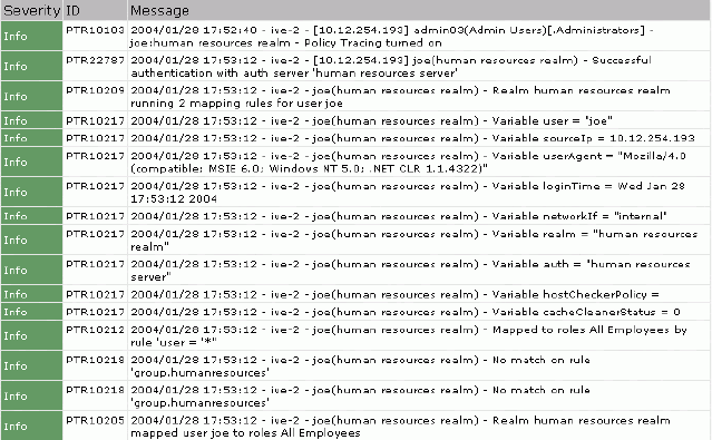
Simulating or tracking events 693
Chapter 26: Troubleshooting
Figure 46: Maintenance > Troubleshooting > User Session > Policy Tracing> Policy Trace
File
By reviewing the trace file, you can determine the problem in entry PTR10218:
joe(human resources realm)-No match on rule ‘group.humanresources’
This entry shows that the IVE did not map Joe to the “Human Resource Staff” role
because he is not a member of the “humanresources” group on the LDAP server.
Use this tab if your users are having problems accessing functions they expect to
use in their roles. The events logged in the policy trace file may help you diagnose
these problems. Note that
To create a policy trace file:
1. In the admin console, choose Maintenance > Troubleshooting > User
Sessions > Policy Tracing.
2. In the User field, enter the IVE username of the user you want to trace. Note
that you may use a wildcard character (*) in place of a username. For example,
if your users are signing into an anonymous server, you may want to use the
wildcard character (*) since you cannot know the internal username that the
IVE will assign to the user.
3. In the Realm field, select the user’s realm. Note that the IVE does not allow you
to select a realm that maps to an anonymous authentication server.
4. Under Events to log, select the types of events you want to write to the policy
tracing log file.
5. Click Start Recording. Ask the user to sign into the IVE after you have started
recording.
6. Click View Log to see the log entries.
7. Click Stop Recording when you have obtained enough information.

Juniper Networks Secure Access Administration Guide
694 Recording sessions
8. Review messages in the log file to determine what is causing the unexpected
behavior. If you cannot determine and fix the problem, click Save Log As to
save a copy of the log file to a location on your network. Then, send the file to
Juniper Networks Support for review.
9. Click Clear Log to clear the contents of the log file, or click Delete Trace to
clear the contents of the log file and to remove the default entries from the
username and realm fields.
Recording sessions
When a Web site does not display properly through the IVE, the Maintenance >
Troubleshooting > Session Recording tab allows you to record a trace file that
lists a user’s actions. In addition, you can use this tab when connecting to a
client/server application that does not behave as expected through the IVE.
When you start recording a trace file, the IVE signs out the specified user and then
starts recording all user actions after the user signs in again and is authenticated.
Note that the IVE notifies the user after authentication that user actions are being
recorded.
To record a trace file:
1. In the admin console, choose Maintenance > Troubleshooting > Session
Recording.
2. Enter the username of the user whose session you want to record.
3. Select the Web (DSRecord) checkbox to record the user’s web session and then
select the Ignore browser cache checkbox if you want to ignore cached copies
of the problem Web site, which the IVE would not otherwise record as a part of
the trace file (optional).
4. Select the Client/Server (JCP+NCP) checkbox to record Java Communication
Protocol and Network Communication Protocol client/server application
sessions (optional).
5. Click Start Recording. The IVE signs out the user.
6. Instruct the user to sign in again and browse to the problem Web site or
connect to the client/server application through the IVE.
7. Click Stop Recording.
8. Download the trace file(s) from the Current Trace File section:
a. Click the DSRecord Log link to download the Web trace file.
b. Click the JCP or NCP Client-Side Log link to download the client/server
application trace file.
9. Email the file(s) to Juniper Networks Support for review.

Creating snapshots of the IVE system state 695
Chapter 26: Troubleshooting
10. Select the Delete button to remove the trace file(s) you just created (optional).
Creating snapshots of the IVE system state
The Maintenance > Troubleshooting > System Snapshot tab allows you to
create a snapshot of the IVE system state. When you use this option, the IVE runs
various utilities to gather details on the IVE system state, such as the amount of
memory in use, paging performance, the number of processes running, system
uptime, the number of open file descriptors, ports in use, and Secure Access FIPS
log messages. You can choose to include or exclude system configuration and
debug logs. However debug logs are particularly important in the event of a
problem. You will need to set the debug log at a certain level and add the events list
as directed by your Support representative. Recreate the problem or event. Then
take a snapshot and send it to Support. The debug log is encrypted. You cannot
view it. The IVE stores up to ten snapshots, which are packaged into an encrypted
“dump” file that you can download to a network machine and then email to Juniper
Networks Support.
If you take more than ten snapshots, the IVE overwrites the oldest snapshot file
with the new snapshot.
To take a snapshot of the IVE system state:
1. In the admin console, choose Maintenance > Troubleshooting > System
Snapshot.
2. Select the Include system config checkbox to include system configuration
information in your snapshot (optional).
3. Select the Include debug log checkbox to include log file created through the
Debug Log tab in your system snapshot. For more information, see “Creating
debugging logs” on page 699.
4. Select Schedule automatic snapshots to automatically take a snapshot at
regular intervals. Enter how often you want to take a snapshot (in hours) and
the maximum file size of each snapshot (in MB).
5. Click Take Snapshot.
6. When the IVE finishes taking the snapshot, click Download to download the
file to a network machine.
7. Email the file to Juniper Networks Support for review.
8. When you are finished, click Delete to delete the snapshot.
NOTE: You can also take a system snapshot from the serial console. This method
is useful if you cannot get to the admin console and need to save the system
configuration. For more information, see “Performing common recovery tasks”
on page 817.

Juniper Networks Secure Access Administration Guide
696 Creating TCP dump files
Creating TCP dump files
The Maintenance > Troubleshooting > TCP Dump tab allows you to sniff
network packet headers and save the results in an encrypted “dump” file that you
can download to a network machine and then email to Juniper Networks Support.
This feature uses the TCP/IP network stack to capture packets at the TCP layer. It
captures all communication that passes through the IVE. However, certain
encrypted higher level protocols cannot be decrypted. This feature is useful for
troubleshooting common customer problems. A TCP dump file helps the Juniper
Networks Support team observe the communication protocols used between IVE
and any other intranet server and how the intranet server responded to requests
from the IVE.
On the admin console, you can select which interface you want to capture packets
from, whether internal or external, you can select promiscuous mode, which
increases the level of detail in the dump file, and you can specify a filter.
To sniff network packet headers:
1. In the admin console, choose Maintenance > Troubleshooting > TCP Dump.
2. Select the IVE port on which you want to sniff network packet headers.
3. If you are operating with an IVS license, you can also select a VLAN port to sniff
packet headers for a subscriber intranet. For more information, see
“Troubleshooting VLANs” on page 788.
4. Turn off Promiscuous mode to sniff only for packets intended for the IVE.
5. Create a custom filter using TCPDump Filter Expressions (optional). This option
provides the ability to filter the sniffed network packets so that the resulting
dump file contains only the information you require. See Table 44 below for
examples.
6. Click Start Sniffing.
7. Click Stop Sniffing to stop the sniffing process and create an encrypted file.
8. Click Download to download the file to a network machine.
9. Email the file to Juniper Networks Support for review.
Table 44: Examples of TCPDump Filter Expressions
Example Result
tcp port 80 Sniffs packets on TCP port 80.
port 80 Sniffs packets on TCP or UDP port 80.
ip Sniffs the IP protocol.
tcp Sniffs the TCP protocol.
Testing IVE network connectivity 697
Chapter 26: Troubleshooting
For more information on using TCP Dump, see “Creating TCP dump files” on
page 696.
Testing IVE network connectivity
The Maintenance > Troubleshooting > Commands tab allows you to run UNIX
commands such as arp, ping, traceroute, and NSlookup to test IVE network
connectivity. You can use these connectivity tools to see the network path from the
IVE to a specified server. If you can ping or traceroute to the IVE and the IVE can
ping the target server, any remote users should be able to access the server through
the IVE.
Address Resolution Protocol (ARP)
Use the arp command to map IP network addresses to the hardware addresses.
The Address Resolution Protocol (ARP) allows you to resolve hardware addresses.
To resolve the address of a server in your network, a client process on the IVE
sends information about its unique identify to a server process executed on a
server in the intranet. The server process then returns the required address to the
client process.
Ping
Use the ping command to verify that the IVE can connect to other systems on the
network. In the event of a network failure between the local and remote nodes, you
will not receive a reply from a pinged device. In that case, contact your LAN
administrator for help.
The ping command sends packets to a server and returns the server response,
typically a set of statistics including the target server’s IP address, the time spent
sending packets and receiving the response, and other data. You can ping unicast
or multicast addresses, and you must include the target server name in the request.
dst #.#.#.# Sniffs the destination IP address specified, where
#.#.#.# is a valid IP address.
src #.#.#.# Sniffs the source IP address specified, where
#.#.#.# is a valid IP address.
port 80 or port 443 Sniffs on port 80 or port 443.
src #.#.#.# and dst #.#.#.# Sniffs the source and destination IP addresses or
hosts specified, where each #.#.#.# represents a
valid IP address.
tcp port 80 or port 443 and dst #.#.#.# and
src #.#.#.#
This example shows how to specify multiple
parameters to create a filter that sniffs on TCP port
80, or on TCP or UDP port 443, and on the
destination and source ports, where each #.#.#.#
represents a valid IP address.
For more information about TCPDump Filter Expressions, visit the following Web site:
http://www.tcpdump.org/tcpdump_man.html
Table 44: Examples of TCPDump Filter Expressions (Continued)
Example Result
Juniper Networks Secure Access Administration Guide
698 Testing IVE network connectivity
Traceroute
Use the traceroute command to discover the path that a packet takes from the IVE
to another host. Traceroute sends a packet to a destination server and receives an
ICMP TIME_EXCEEDED response from each gateway along its path. The
TIME_EXCEEDED responses and other data are recorded and displayed in the
output, showing the path of the packet round-trip.
To run a UNIX command to test IVE network connectivity:
1. In the admin console, choose Maintenance > Troubleshooting >
Commands.
2. From the Command list, select the command to run.
3. In the Target Server field, enter the IP address of the target server.
4. If you are operating on an IVS license, you can select a VLAN port, to test
connectivity to a subscriber intranet. For more information, see
“Troubleshooting VLANs” on page 788.
5. Enter other arguments or options.
6. Click OK to run the command.
NSlookup
Use NSlookup to get detailed information about a name server on the network. You
can query on several different types of information, including a server’s IP address,
alias IP address, start-of-authority record, mail exchange record, user information,
well-known services information, and other types of information.
To run NSLookup to test name server connectivity:
1. In the admin console, choose Maintenance > Troubleshooting >
Commands.
2. From the Command list, select NSLookup.
3. Select the Query Type from the drop down menu.
4. Enter the query, which is a host name, an IP address, or other information,
depending on your selection of query type.
5. Enter the DNS server name or IP address.
6. If you are operating on an IVS license, you can select a VLAN port, to test
connectivity to a subscriber intranet. For more information, see
“Troubleshooting VLANs” on page 788.
7. Enter other options.
8. Click OK to run the command.

Running debugging tools remotely 699
Chapter 26: Troubleshooting
Running debugging tools remotely
The Juniper Networks Support team can run debugging tools on your production
IVE if you configure it to do so through the Maintenance > Troubleshooting >
Remote Debugging page. To enable this option, you must work with Juniper
Networks Support to obtain a debugging code and host to which your IVE connects.
To enable remote debugging:
1. Contact Juniper Networks Support to set up the terms of a remote debugging
session.
2. In the admin console, choose Maintenance > Troubleshooting > Remote
Debugging.
3. Enter the debugging code provided by Juniper Networks Support.
4. Enter the host name provided by Juniper Networks Support.
5. Click Enable Debugging to allow the Juniper Networks Support team to access
the IVE.
6. Notify Juniper Networks Support that your IVE is accessible.
7. Click Disable Debugging when Juniper Networks Support notifies you that the
remote debugging session is over.
Creating debugging logs
If you have a problem, a Juniper Networks Support representative may ask you to
create debugging logs to assist with debugging IVE internal issues. When you
enable logging, the IVE records certain events and messages based on event codes
you enter into admin console on the Maintenance > Troubleshooting > Debug
Log tab. Using the debug log that results, the support team can identify the code
flow for any discrepancies. Your support representative gives you all of the
information you need to create the log file, including the debug detail log level and
the event codes.
To enable the debug log:
1. In the admin console, choose Maintenance > Troubleshooting > Debug Log.
2. Select the Debug Logging On checkbox.
3. Enter the log size, detail level, and event code specified by Juniper Networks
Support.
NOTE: Running debug logging can impact your system performance and stability.
You should only generate debug logs when directed by your Juniper Networks
Support representative.

Juniper Networks Secure Access Administration Guide
700 Monitoring cluster nodes
4. Click Save Changes.
5. Choose the Maintenance > Troubleshooting > System Snapshot tab.
6. Check the Include debug log checkbox.
7. Click Take snapshot to create a file that contains the debug log.
8. Click Download.
9. Attach the snapshot file an email message and sent it to Juniper Networks
Support.
Monitoring cluster nodes
If you have a problem with a cluster, a Juniper Networks Support representative
may ask you to create a snapshot that includes node monitoring statistics to assist
with debugging the cluster problem. When you enable the node monitor on the
Maintenance > Troubleshooting > Node Monitor tab, the IVE captures certain
statistics specific to the cluster nodes on your system. Using the snapshot that
results, the support team can identify important data, such as network statistics
and CPU usage statistics.
To enable node monitoring:
1. Enter the maximum size for the node monitor log.
2. Enter the interval, in seconds, at which node statistics are to be captured.
3. Select the Node monitoring enabled checkbox to start monitoring cluster
nodes.
4. Click Save Changes.
5. If you want to include the node monitoring results in the system snapshot,
choose Maintenance > Troubleshooting > System Snapshot, and select the
Include debug log checkbox.
6. Take a system snapshot to retrieve the results. For more information, see
“Creating snapshots of the IVE system state” on page 695.

Configuring group communication monitoring on a cluster 701
Chapter 26: Troubleshooting
Configuring group communication monitoring on a cluster
If you have a problem with a cluster, a Juniper Networks Support representative
may ask you to create a snapshot that includes group communication statistics to
assist with debugging the cluster problem. When you enable the group
communication monitor on the Maintenance > Troubleshooting > Clustering
Group Communication tab, the IVE records statistics related to all of the cluster
nodes on your system. As the local node communicates with other nodes in the
cluster, the IVE captures statistics related to intra-cluster communication. The
Maintenance > Troubleshooting > Clustering Group Communication tab
appears only when you enable clustering on your system. On a standalone IVE, you
do not have access to the Maintenance > Troubleshooting > Clustering Group
Communication tab.
You can also enable the cluster networking troubleshooting server on the
Maintenance > Troubleshooting > Clustering Network Connectivity page. For
more information, see “Configuring network connectivity monitoring on a cluster”
on page 702.
To enable group communication monitoring:
1. Enter the maximum size for the statistics log.
2. Enter the interval, in seconds, at which events are to be logged.
3. If you want to monitor all cluster nodes from the current local node, select the
Monitor all cluster nodes from this node checkbox. If you do not check this
option, the group communication monitor gathers statistics only for the local
node.
4. Select the Enable group communication monitoring checkbox to start the
monitoring tool.
5. Click Save Changes.
NOTE:
Performing excessive node monitoring can impact your system performance
and stability. You should only perform extensive monitoring when directed
by your Juniper Networks Support representative.
Performing log synchronization across cluster nodes can impact your system
performance and stability.
We recommend a minimum 2 Mbit connection for cluster node
communication.
NOTE: If you select the Monitor all cluster nodes from this node option, the
cluster nodes must be able to communicate over UDP port 6543.

Juniper Networks Secure Access Administration Guide
702 Configuring network connectivity monitoring on a cluster
6. If you want to include the node monitoring results in the system snapshot,
choose Maintenance > Troubleshooting > System Snapshot, and select the
Include debug log checkbox.
7. Take a system snapshot to retrieve the results. For more information, see
“Creating snapshots of the IVE system state” on page 695.
Configuring network connectivity monitoring on a cluster
If you have a problem with a cluster, a Juniper Networks Support representative
may ask you to enable the cluster node troubleshooting server. When you enable
the server on the Maintenance > Troubleshooting > Clustering Network
Connectivity tab, the IVE attempts to establish connectivity between the node on
which the server resides and another node you specify. As the nodes communicate,
the IVE displays network connectivity statistics on the page. The Maintenance >
Troubleshooting > Clustering Network Connectivity tab appears only when you
enable clustering on your system. On a standalone IVE, you do not have access to
the Maintenance > Troubleshooting > Clustering Network Connectivity tab.
Use the Network Connectivity page to enable the cluster node troubleshooting
server and to select a node on which to perform troubleshooting tasks. The
troubleshooting tool allows you to determine the network connectivity between
cluster nodes.
The server component of this tool runs on the node to which connectivity is being
tested. The client component runs on the node from which connectivity is being
tested. The basic scenario for testing connectivity is this:
The administrator starts the server component on the passive node.
The administrator then tests the connectivity to the server node from the
Active node, by starting the client component on the Active node and
contacting the Passive node running the server component.
1. Select the Enable cluster network troubleshooting server checkbox to enable
the server component.
2. Click Save Changes.
3. On another machine, select Troubleshooting > Clustering Network
Connectivity.
4. Perform one of the following steps:
Select a node from the drop down menu.
Enter the IP address of the server node.
NOTE: The server component must be run on nodes that are configured as either
standalone, or in a cluster but disabled. Cluster services cannot be running on the
same node as the server component.
Configuring network connectivity monitoring on a cluster 703
Chapter 26: Troubleshooting
5. Click Go to begin troubleshooting the machine on which the server component
is running.
6. Click the Details link that appears on the page below the fields, to view the
results.
Juniper Networks Secure Access Administration Guide
704 Configuring network connectivity monitoring on a cluster
705
Chapter 27
Clustering
You can purchase a clustering license to deploy two or more Secure Access or
Secure Access FIPS appliances as a cluster. These appliances support Active/Passive
or Active/Active configurations across a LAN or a WAN to provide high availability,
increased scalability, and load balancing capabilities.
You define a cluster on one IVE by specifying three pieces of data:
1. A name for the cluster
2. A password for the cluster members to share
3. A name to identify the machine in the cluster
Entering this information enables you to initiate the first member of your cluster.
You then need to specify which IVEs you want to add to the cluster. After an IVE is
identified as an intended member, you may add it to the cluster through its:
Admin console—If a configured IVE is running as a stand-alone machine, you
can add it to a cluster through its admin console.
Serial console—If an IVE is in its factory-state, you can add it to a cluster
through its serial console by entering minimal information during initial setup.
When an IVE joins a cluster, it initializes its state from the existing member that
you specify. The new member sends a message to the existing member requesting
synchronization. The existing member sends the system state to the new member,
overwriting all system data on that machine. After that point, the cluster members
synchronize data when there is a state change on any member. Cluster member
communication is encrypted to prevent attacks from inside the corporate firewall.
Each IVE uses the shared password to decrypt communication from another cluster
member. For security reasons, the cluster password is not synchronized across
IVEs.
Note that during synchronization, the new node receives the service package,
which upgrades the node if it is equipped with a Central Manager license and is
running an older service package.
This section contains the following information about clustering:
“Licensing: Clustering availability” on page 706
“Task summary: Deploying a cluster” on page 706

Juniper Networks Secure Access Administration Guide
706 Licensing: Clustering availability
“Creating and configuring a cluster” on page 707
“Configuring cluster properties” on page 712
“Managing and configuring clusters” on page 720
Licensing: Clustering availability
The clustering feature is not available on the SA 700 appliance and is only available
on all other Secure Access products by special license.
You can run an IVE with an IVS license in a cluster. For more information, see
“Clustering a virtualized IVE” on page 773.
Task summary: Deploying a cluster
To create an IVE cluster:
1. Make sure that all intended IVE nodes are the same hardware platform (for
example, all Secure Access 3000 machines).
2. Make sure all intended IVE nodes have been initially configured (IVE host name
specified and internal and external IP addresses assigned, for example), and
are running the same service package version.
3. Enable the clustering feature by entering your clustering license through the
System > Configuration > Licensing page of the admin console.
4. Initialize the IVE cluster through the System > Clustering > Create Cluster
page of the admin console by defining the cluster name and adding the
first/primary IVE to the cluster. For instructions, see “Defining and initializing a
cluster” on page 708.
5. Add the names and IP addresses of future cluster IVEs to the primary IVE
through the System > Clustering > Status page of the admin console. For
instructions, see “Joining an existing cluster” on page 710.
6. Populate the cluster with additional IVEs as necessary through the System >
Clustering > Join Cluster page of the admin console. For instructions, see
“Adding an IVE to a cluster through its admin console” on page 711 or, in the
case of a pre-configured/factory-set IVE, “Joining an IVE to a cluster through its
serial console” on page 728.
7. If you are running Network Connect on a multi-site cluster where nodes reside
on different subnets:
NOTE: All IVEs in a cluster must feature the same cluster license. You cannot add
an ADD and a CL license to the same machine at the same time. For a node to be
able to join a cluster, you must add a CL license to the node.

Creating and configuring a cluster 707
Chapter 27: Clustering
a. Configure an IP address pool policy on the Users > Resource Policies >
Network Connect > Network Connect Connection Profiles > New
Profile page that accounts for the different network addresses used by
each node in the cluster.
b. For each node in the cluster, use settings in the System > Network >
Network Connect page of the admin console to specify an IP filter that
filters out only those network addresses available to that node.
c. Create a static route on your gateway router that indicates the IP address of
the internal port of each cluster node. Each IP address specified on the
router needs to be in the same subnetwork as the corresponding cluster
node.
8. If you are creating a cluster of Secure Access FIPS appliances, manually update
the security world on each of the machines, as explained in “Deploying a
cluster in an Secure Access FIPS environment” on page 830.
Creating and configuring a cluster
If an IVE is not part of a cluster (i.e., stand-alone mode), its Clustering page
displays the Create tab. The Create tab allows you create the configurations for
cluster nodes, even if you have no physical devices available to join the cluster.
After you add a clustering license to the IVE, its Clustering page displays the Join
tab. The Join tab enables you to join an initialized IVE to an existing cluster, as
explained in “Joining an existing cluster” on page 710.
NOTE:
When running Network Connect on an Active/Active cluster, you must split
the IP address pool across the nodes to ensure proper routing from the back
end to the NC end-user. This is a requirement whether the IP address pool is
provisioned statically on the IVE or dynamically by way of DHCP. Refer to
“Creating Network Connect connection profiles” on page 539 for more
details.
The client IP pool configuration is synchronized among all nodes in a cluster;
however, administrators may configure each IVE to use a certain subset of the
global IP pool. Configure the client IP pool in the Network Settings >
Network Connect tab, using an IP filter match.
We recommend that you deploy a cluster first in a staging environment and
then move to a production environment after testing authentication realm,
user role, and resource policy configurations, as well as any applications your
end-users may access.

Juniper Networks Secure Access Administration Guide
708 Creating and configuring a cluster
After creating the cluster, the Clustering page shows Status and Properties tabs,
which replace the original Join and Create tabs. Use the Status tab to specify an
IVE to add to a cluster, manage network settings for cluster nodes, and upgrade the
cluster service package. Use the Properties tab to specify active/passive,
active/active, and other cluster settings. You can also use this tab to delete a cluster.
This section contains the following information about clustering:
“Defining and initializing a cluster” on page 708
“Joining an existing cluster” on page 710
“Deploying a cluster in an Secure Access FIPS environment” on page 830
Defining and initializing a cluster
If you are currently running stand-alone IVEs that you want to cluster, we
recommend that before you create a cluster, you first configure system and user
settings on one machine. After doing so, use the same machine to create the
cluster. This machine joins the cluster as part of the creation process. When other
IVEs join the cluster, this machine propagates its configuration to the new cluster
member.
To define and initialize a cluster:
1. Configure one IVE with the appropriate license and system, user, resource, and
application data, as explained in “Task summary: Deploying a cluster” on
page 706.
NOTE:
The Create tab does not appear on an IVE that does not possess the cluster
license key. You cannot create a cluster unless you have entered a cluster
license key.
All nodes in a cluster must feature the same license key as on the primary
cluster IVE to enable cluster operation. You cannot add an ADD and a CL
license to the same machine at the same time. For a node to be able to join a
cluster, you must add a CL license to the node.
NOTE: For information about how to set up a cluster in a:
Service provider network that is operating with an IVS license, see “Clustering
a virtualized IVE” on page 773.
Secure Access FIPS environment, see “Deploying a cluster in an Secure
Access FIPS environment” on page 830
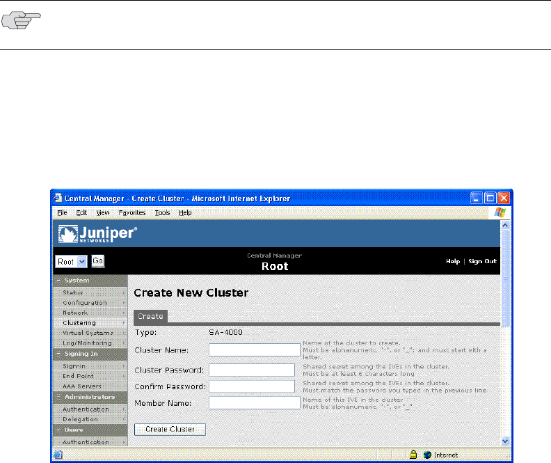
Creating and configuring a cluster 709
Chapter 27: Clustering
2. Choose System > Clustering > Create, enter a name for the cluster, a cluster
password, and a name for this machine, such as Server-1.
3. Click Create Cluster. When prompted to confirm cluster creation, click Create.
After the IVE initializes the cluster, the Clustering page shows the Status and
Properties tabs. Use the Status tab to specify additional cluster members
before trying to add another IVE to the new cluster. For more information, see
“Specifying an IVE to join to a cluster” on page 710.
Figure 47: System > Clustering > Create — Creating a cluster
NOTE: You need to enter the password again when configuring additional IVEs to
join the cluster. All machines in the cluster use this password to communicate.

Juniper Networks Secure Access Administration Guide
710 Creating and configuring a cluster
Joining an existing cluster
Use the Join tab to add an IVE to an existing cluster. The method you use to add an
IVE to a cluster depends on whether or not the IVE is configured or un-initialized
(still in its factory state). For an IVE in its factory state, we recommend that you use
the serial console procedure because it requires you to enter minimal information
in order for the machine to join a cluster. For more information, see “Joining an IVE
to a cluster through its serial console” on page 728.
In an Secure Access FIPS environment, you must use the admin console to add an
IVE to a cluster. You also must have physical access to:
The cryptographic modules installed in the front panels of the cluster
members’ IVE appliances
A smart card reader
An administrator card that is pre-initialized to the active cluster member’s
security world
Specifying an IVE to join to a cluster
Before an IVE can join a cluster, you need to specify its network identity on an
active cluster member.
To specify an IVE that you intend to join to an existing cluster:
1. In the admin console of an active cluster member, choose the System >
Clustering > Status tab.
2. Click Add Member to specify an IVE that will join the cluster:
a. Enter a name for the member.
NOTE:
If you purchased the Juniper Networks SA Central Manager, you can create a
cluster using the IVE running the latest OS version and then add additional
nodes using the “upgrade and join” functionality. When you add a node to a
cluster using this feature, the first IVE node upgrades the joining node with
the more current service package. This functionality works only when all the
IVEs are running version 4.0 or later of the OS.
If you want to add an IVE currently running as a stand-alone machine to a
cluster through its admin console, and you do not have Central Manager, it
must be running the same or a more recent version service package on the
same hardware platform as the other members.
If you add an IVE running a previous version service package to a cluster, the
IVE automatically detects the mismatch, gets the newer package from the
cluster, and joins the cluster. If the new node has no license, it is added with
cluster status set to Enabled, Unqualified until you apply a valid CL license
using the new node’s machine ID. For more information, see “Entering or
upgrading IVE licenses” on page 580.
Creating and configuring a cluster 711
Chapter 27: Clustering
b. Enter the machine’s internal IP address.
c. Enter the machine’s external IP address if necessary. Note that the
External IP address field does not appear if you have not enabled the
external port on the System > Network > Port 1 tab.
d. Change the netmask and gateway settings for the node if necessary.
e. Click Add Node.
f. When prompted to confirm adding the new member, click Add.
g. Repeat this procedure for each IVE you intend to add to a cluster.
Adding an IVE to a cluster through its admin console
Before you can add an IVE to a cluster (either through the Web or serial console),
you need to make its identity known to the cluster. To specify an IVE that you
intend to add to a cluster, see “Specifying an IVE to join to a cluster” on page 710.
Note that if an IVE does not have a cluster license key, it has only a Clustering >
Join tab.
To add an IVE to a cluster through its admin console:
1. In the admin console of an existing cluster member, choose the System >
Clustering > Status tab and specify the IVE you want to add to the cluster. See
“Specifying an IVE to join to a cluster” on page 710.
2. In the admin console of the IVE you want to add to a cluster:
a. Choose the System > Configuration > Licensing tab and enter the
correct license key (containing the machine type, the initials CL to indicate
a cluster, and the number of user licenses—for example, SA6000-CL-
1000U) to enable the clustering feature.
b. Choose the System > Clustering > Join tab and enter:
The name of the cluster to join
The cluster password you specified when defining the cluster
The IP address of an active cluster member
3. Click Join Cluster. When prompted to confirm joining the cluster, click Join.
After the IVE joins the cluster, you may need to sign in again.
4. (Secure Access FIPS environments only) Initialize the node with the active
cluster member’s security world, as explained in “Deploying a cluster in an
Secure Access FIPS environment” on page 830.
While the new node synchronizes its state with the existing cluster member, each
node’s status indicates “Enabled,” “Enabled, Transitioning,” or “Enabled,
Unreachable.”
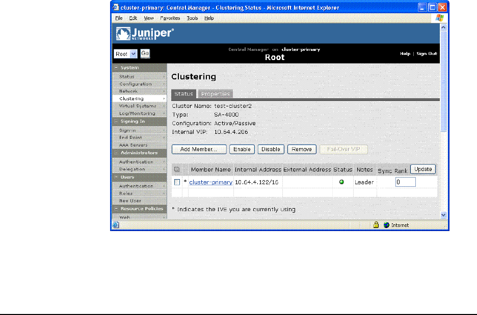
Juniper Networks Secure Access Administration Guide
712 Configuring cluster properties
Figure 48: System > Clustering > Status — After node transition completes
When the new node finishes joining the cluster, its Clustering page shows the
Status and Properties tabs. The original cluster member’s state data, including
system, user, and licensing data, exists on the new cluster member. In this
example, the original member’s user interface coloring is reflected on the new
node.
Configuring cluster properties
This section contains the following information about managing clustering
properties:
“Deploying two nodes in an Active/Passive cluster” on page 712
“Deploying two or more units in an Active/Active cluster” on page 714
“Synchronizing the cluster state” on page 715
“Configuring cluster properties” on page 718
Deploying two nodes in an Active/Passive cluster
You can deploy IVEs as a cluster pair in Active/Passive mode. In this mode, one IVE
actively serves user requests while the other IVE runs passively in the background
to synchronize state data, including system state, user profile, and log messages.
User requests to the cluster VIP (virtual IP address) are passed to the active IVE. If
the active IVE goes off-line, the standby IVE automatically starts servicing user
requests. Users do not need to sign in again, however some IVE session
information entered a few seconds before the active machine went off-line, such as
cookies and passwords, may not have been synchronized on the current IVE box,
in which case users may need to sign in to back-end Web servers again.
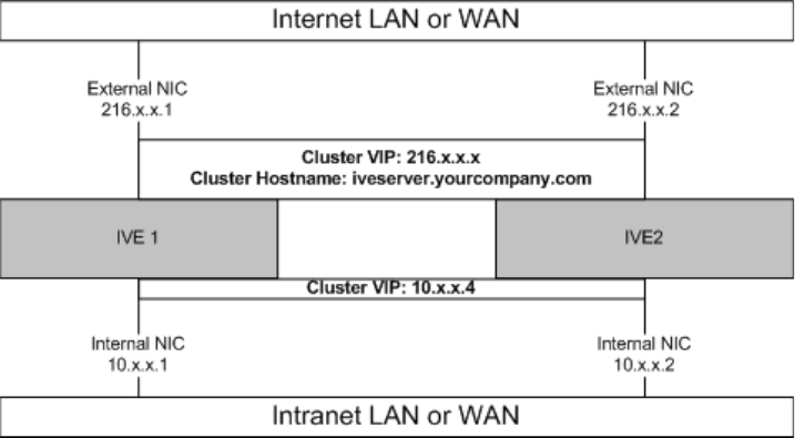
Configuring cluster properties 713
Chapter 27: Clustering
You might need to fail-over the cluster VIP to the other node, manually. You can
perform a manual fail-over by using the Fail-Over VIP button on the Clustering
Status page. For more information, see “Failing-over the VIP to another node” on
page 713.
The following diagram illustrates an Active/Passive IVE cluster configuration using
two IVEs that have enabled external ports. Note that this mode does not increase
throughput or user capacity, but provides redundancy to handle unexpected
system failure.
Figure 49: Active/Passive Cluster Pair
Figure 49 illustrates an Active/Passive cluster deployed within the network. IVE user
requests are directed to the cluster VIP, which then routes them to the currently
active machine.
Failing-over the VIP to another node
In an active/passive cluster, you might need to fail-over the VIP to the other node,
regardless of which node you are currently using.
To fail-over the VIP:
1. Choose System > Clustering > Status.
2. Click the Fail-Over VIP button to move to the other node. The Fail-Over VIP
button is a toggle button, so you can move from one node to the other,
regardless of which is the leader.
The fail-over occurs immediately.

Juniper Networks Secure Access Administration Guide
714 Configuring cluster properties
Deploying two or more units in an Active/Active cluster
In Active/Active mode, all the machines in the cluster actively handle user requests
sent by an external load balancer or Round-Robin DNS. The load balancer hosts the
cluster VIP and routes user requests to an IVE defined in its cluster group based on
source-IP routing. If an IVE goes off-line, the load balancer adjusts the load on the
active IVEs. Users do not need to sign in again, however some IVE session
information entered a few seconds before the active machine went off-line, such as
cookies and passwords, may not have been synchronized on the current IVE box,
in which case users may need to sign in to back-end Web servers again.
The IVE cluster itself does not perform any automatic fail-over or load-balancing
operations, but it does synchronize state data (system, user, and log data) among
cluster members. When an off-line IVE comes back online, the load balancer
adjusts the load again to distribute it among all active members. This mode
provides increased throughput and performance during peak load but does not
increase scalability beyond the total number of licensed users.
The IVE hosts an HTML page that provides service status for each IVE in a cluster.
External load balancers can check this resource to determine how to effectively
distribute the load among all the cluster nodes.
To perform the L7 Health Check for a node:
From a browser—Enter the URL:
https://<IVE-Hostname>/dana-na/healthcheck/healthcheck.cgi
Using an external load balancer—Configure a Health Check policy that sends
the following request to cluster nodes:
GET /dana-na/healthcheck/healthcheck.cgi HTTP/1.1\nHost: localhost
The node returns one of two values:
“Cluster Enabled” string—This value means the node is active.
NOTE: When choosing and configuring a load balancer for your cluster, we
recommend that you ensure the load balancer:
Supports IPSec
Listens for traffic on multiple ports
Can be configured to manage traffic using assigned source and destination IP
addresses (not destination port)
NOTE: The IVE synchronizes state data on all nodes if you add or delete the host
entry by using the Network Settings pages. If you add or delete the host entry
using the Clustering tab for a cluster member, the state data only affects the node
and the IVE does not synchronize the data across the entire cluster.
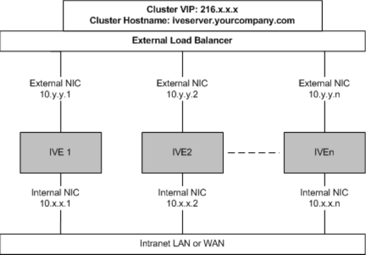
Configuring cluster properties 715
Chapter 27: Clustering
500—This value denotes an error and cluster IVEs stop forwarding user
requests to the node.
The following diagram illustrates an Active/Active IVE cluster configuration in which
the IVEs have enabled external ports.
Figure 50: Active/Active Configuration
Figure 50 illustrates an Active/Active cluster configuration deployed behind an
external load balancer. You can deploy a cluster pair or multi-unit cluster in
Active/Active mode. IVE user requests are directed to the cluster VIP defined on the
load balancer, which routes them to the appropriate machine.
Synchronizing the cluster state
IVE state synchronization occurs only by means of the internal network interface
cards (NICs), and each cluster member is required to possess the cluster password
in order to communicate with other members. Cluster members synchronize data
when there is a state change on any member. IVE cluster state data is either
persistent—permanently stored on the IVE—or transient—stored on the IVE only
for the user’s session. IVE state data is divided into the following major categories:
System state—This state is persistent and does not change often.
Network settings
Authentication server configurations
Authorization group configurations, such as access control list, bookmark,
messaging, and application data

Juniper Networks Secure Access Administration Guide
716 Configuring cluster properties
User profile—This data can be either persistent or transient, depending on
whether or not you have enabled persistent cookies and persistent password
caching. If you have not enabled these features, then the data is transient and
falls into the next category.
User bookmarks—persistent
Persistent user cookies—if the persistent cookies feature is enabled, the
IVE stores user cookies for Web sites that issue persistent cookies
Persistent user passwords—if the password caching feature is enabled,
the user can choose to store her credentials for applications and Web sites
User session—This state is transient and dynamic. User session data consists
of:
The user IVE session cookie
Transient user profile information, which includes cookies and passwords
stored only for during the user’s session
Monitoring state—This persistent information consists of log messages1.
Whether you deploy a cluster in Active/Passive or Active/Active mode, the IVE
is responsible for synchronizing data between cluster members. The IVE
synchronizes all system data, user profile data, and the IVE user session
cookies immediately, so if one cluster member goes off-line, users do not need
to sign in to the IVE again. A small amount of latency occurs when the IVE
synchronizes user session profile and monitoring state data, so if a member
goes off-line, the user may need to sign in to some back-end Web applications
again and administrators may not have access to the logs on the failed
machine.
If you notice too much latency occurring on one or more nodes, you might
need to change the Clustering Timeouts Settings. For more information, see
“Configuring cluster properties” on page 718.
1. When you add an IVE to a cluster, the cluster leader does not send log messages to the new member. Log
messages are also not synchronized between cluster members when one member restarts its services or when
an off-line machine comes back online. Once all machines are online, however, log messages are synchronized.
NOTE: If you are running an Active/Active cluster, you must not allow the cluster
to switch to Active/Passive mode unless the Active/Active and Active/Passive
clusters share compatible spread timeout settings.

Configuring cluster properties 717
Chapter 27: Clustering
You may also configure synchronization settings to improve performance:
Specify the synchronization protocol—When running three or more IVEs in a
multi-unit or multi-site cluster, you can choose to use the synchronization
protocol (Unicast, Multicast, or Broadcast) that best suits your network
topology.
Synchronize log messages—Log messages may create a huge payload on the
network and affect cluster performance. This option is disabled by default.
Synchronize user sessions—Synchronizes all user session information
(instances of access to intranet services, for example) among all IVEs in the
cluster.
Synchronize last access time for user sessions—This option allows you to
propagate user access information in the cluster. If this option is the sole
synchronization item among the cluster nodes, you can significantly reduce
CPU impact among the cluster IVEs.
NOTE: See “Specifying active/passive, active/active, and other cluster settings” on
page 718 for a description of the synchronization settings.
NOTE:
If you configure your cluster to Active/Passive, the Synchronize user sessions
and Synchronize last access time for user sessions options are automatically
checked. The options are also disabled to prevent you from modifying them
for an Active/Passive cluster.
If you enable both Synchronize log messages and Synchronize user sessions
options, everything is replicated on the cluster nodes, including networking
information. Even though networking information, including Syslog and
SNMP settings, can be configured per-node or per-cluster, all of the
networking information is synchronized between nodes when these two
options are set.
In the case in which your cluster node configurations have diverged due to
changes made to one node while another is disabled or unavailable, the IVE
manages the re-merging of the configurations automatically, for up to 16
updates. Beyond the maximum number of allowable updates, you may need
to intervene and re-merge the configurations manually. In some instances,
the IVE may be unable to re-merge the configurations if there is not enough
overlapping configuration information between two nodes to manage the
inter-node communication.
For example, given a two node cluster in which the two nodes are partitioned
from each other due to a network outage, if the internal network IP address of
one of the nodes gets changed in one of the partitions, the two partitions are
unable to rejoin, even when the network is repaired. In such a case, you must
manually re-merge the configurations.

Juniper Networks Secure Access Administration Guide
718 Configuring cluster properties
Configuring cluster properties
Use the Properties tab to specify active/passive, active/active, and other cluster
settings. You can also use this tab to delete a cluster.
Specifying active/passive, active/active, and other cluster settings
Use the Properties tab to change the name of a cluster, specify in which
configuration to run a cluster (active/passive or active/active), specify
synchronization and network healthcheck settings, or delete a cluster.
To modify cluster properties:
1. In the admin console of an active cluster member, choose the System >
Clustering > Properties tab.
2. Edit the Cluster Name field to change the cluster’s name (optional).
3. Under Configuration Settings, select:
Active/Passive to run a cluster pair in active/passive mode. Then, specify
an internal VIP (virtual IP address) and an external VIP if the external port
is enabled.
Active/Active to run a cluster of two or more nodes in active/active mode
using an external load balancer.
4. Under Synchronization Settings, specify the synchronization protocol and one
or more types of data to synchronize using the following options:
a. Specify the synchronization protocol to use when synchronizing data
among cluster nodes by selecting one of the following:
Unicast—Select this option to direct synchronization data
transmissions to other nodes in the cluster, one after the other.
Multicast—Select this option to distribute data to the other nodes in
the cluster, simultaneously. We recommend this method for large
networks where cluster IVEs may reside on subnets with other
machines (routers, switches, and authentication servers, for example)
to prevent simply broadcasting synchronization data all over the
network when it’s really only intended for a small audience of cluster
nodes.
NOTE: To run a two-unit cluster in active/passive mode, the IVEs need to be reside
on the same subnet.
NOTE: To change a two-unit active/passive cluster to an active/active cluster with
more than two nodes, first change the configuration of the two-unit cluster to
active/active and then add the additional nodes.

Configuring cluster properties 719
Chapter 27: Clustering
Broadcast—Select this option to automatically broadcast
synchronization data to all machines on the subnet.
b. Select one or more types of data to synchronize (this option is disabled by
default):
Synchronize log messages—Select this option to propagate all log
messages among all of the IVEs in the cluster.1
Synchronize user sessions—Select this option to synchronize all user
session information (instances of access to intranet services, for
example) among all IVEs in the cluster.
Synchronize last access time for user sessions—Select this option to
propagate the latest user access information across the cluster.
NOTE: Only cluster members residing on the same subnet use anything other than
the Unicast transport setting you specify on the Properties tab. For example, you
can use the Multicast synchronization method among the cluster members in a
four-node cluster residing on the same subnet, but nodes on that subnet can only
communicate with nodes on other subnets using Unicast.
1. When you add an IVE to a cluster, the cluster leader does not send log messages to the new member. Log
messages are also not synchronized between cluster members when one member restarts its services or when
an off-line machine comes back online. Once all machines are online, however, log messages are synchronized.
NOTE:
If you enable both Synchronize log messages and Synchronize user sessions
options, everything is replicated on the cluster nodes, including networking
information. Even though networking information, including Syslog and
SNMP settings, can be configured per-node or per-cluster, all of the
networking information is synchronized between nodes when these two
options are set.
If you are using a load balancer in conjunction with the IVE, we recommend
you disable the Synchronize last access time for user sessions option.
While turning the Synchronize last access time for user sessions option off
can greatly improve cluster synchronization performance, disabling this
option while users are connected to the IVE can result in client-side warnings
informing the user that the session is about to expire. These warnings are
automatically generated due to time-stamp mismatches and the user sessions
do not actually disconnect.
Do not run session synchronization over a WAN connection. Once the
operation applies a medium load across the WAN, the synchronization
activity between nodes will consume significant resources, the activity will
appear to hang, and the resource degradation can trigger a restart. We
recommend that any cluster node communication be operated on a
connection with speed of 2 Mbits or more.

Juniper Networks Secure Access Administration Guide
720 Managing and configuring clusters
5. Under Network Healthcheck Settings, specify the number of ARP ping failures
allowed before the IVE’s internal interface is disabled and whether or not to
disable the IVE’s external interface if the internal interface fails.
6. Under Clustering Timeouts Settings, select the network type to control the
timeouts for the underlying cluster system. Use this option if you note network
delays or significant loads during cluster node operations.
Although modifying this value may improve performance, we do not
recommend that you change the value unless you are experiencing cluster
partitioning problems. The default value is preset based on what Juniper
Networks has determined is most appropriate for your configuration. The
values, from which you can select, have been determined as appropriate for
LAN configurations or, if the nodes configured in the cluster are in different
subnets, for WAN configurations.
7. Click Save Changes.
Managing and configuring clusters
This section contains the following instructions:
“Managing network settings for cluster nodes” on page 721
“Upgrading clustered nodes” on page 721
“Upgrading the cluster service package” on page 722
“Deleting a cluster” on page 723
“Restarting or rebooting clustered nodes” on page 723
“Admin console procedures” on page 724
“Monitoring clusters” on page 725
“Troubleshooting clusters” on page 726
“Serial console procedures” on page 728
Adding multiple cluster nodes
You can add multiple cluster nodes at one time. You can configure all of the nodes
before saving and enabling the multiple node configuration.
To add multiple nodes to a cluster:
1. Select System > Clustering > Cluster Status.
NOTE: Changing the Clustering Timeouts Settings value causes IVE cluster
services to restart.
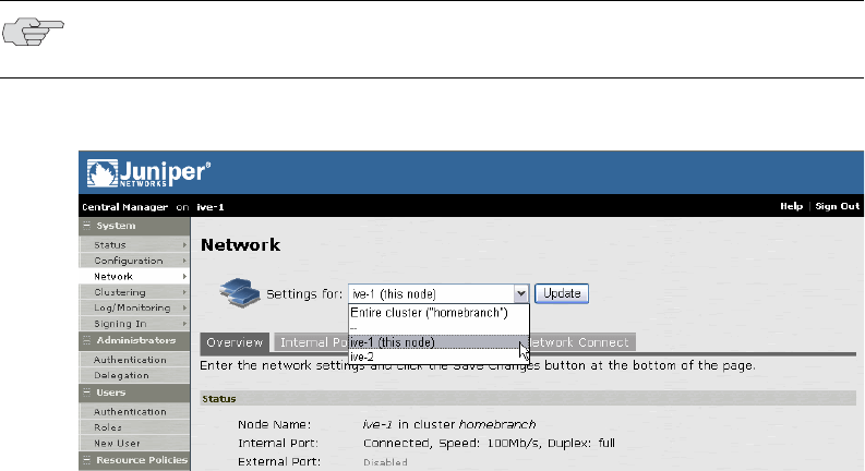
Managing and configuring clusters 721
Chapter 27: Clustering
2. Click Add Members.
3. Enter the node name and internal IP address.
4. Modify or add the default internal netmask and internal gateway addresses, if
necessary.
5. Click Add.
6. Repeat the process until you have added all of the nodes.
7. Click Save Changes to save the node configurations.
The IVE automatically enables the added clusters, even if they are unreachable.
Managing network settings for cluster nodes
To modify the network settings for a cluster or each individual node in a cluster,
you need to use the System > Network pages. After you create a cluster, these
pages provide a drop-down list from which you can select the entire cluster or a
specific node to modify. When you save changes on a Network page, the settings
are saved for the specified cluster or cluster node. If you change network settings
for an entire cluster, they propagate to every node in the cluster.
Figure 51: System > Network pages
Upgrading clustered nodes
The Juniper Networks SA Central Manager offers the ability to easily upgrade every
node in a cluster. You simply install a newer service package on one node and,
once the installation completes and the node reboots, the node pushes the service
package to all nodes in the cluster.
If you have not purchased the Juniper Networks SA Central Manager you can still
upgrade clustered nodes, but the process requires you to disable nodes within the
cluster, upgrade them individually, and then enable them within the cluster again.
NOTE: You can access a node-specific Network page by clicking on the node’s
name in the Member Name column of the Clustering > Status tab.

Juniper Networks Secure Access Administration Guide
722 Managing and configuring clusters
For more information about disabling nodes to upgrade the service package, see
“Upgrading the cluster service package” on page 722.
Upgrading the cluster service package
If you purchased the Juniper Networks SA Central Manager, you simply need to
install a newer service package on one cluster node. When the installation process
completes and the cluster node reboots, it instructs the other nodes to upgrade. See
“Upgrading or downgrading the IVE” on page 575 for more information about
installing a service package.
If you are not running the Juniper Networks SA Central Manager, you need to follow
different procedures for upgrading clustered nodes. Furthermore, the procedures
for upgrading nodes in an active/active cluster differ from the procedures for
upgrading nodes in an active/passive cluster.
To upgrade nodes in an active/active cluster:
1. Disable all nodes:
a. Sign in to the admin console of one the nodes you want to upgrade.
b. Choose System > Clustering > Status, select the checkbox next to all
node names, then click Disable.
2. Upgrade all nodes individually using the instructions in “Upgrading or
downgrading the IVE” on page 575.
3. Enable all nodes:
a. Browse to the System > Clustering > Status page in the admin console of
one of the nodes.
b. Select the checkbox next to all node names, then click Enable.
To upgrade all nodes in an active/passive cluster:
1. Disable the passive node:
a. Sign in to the admin console of the passive node you want to upgrade.
NOTE: If you import an XML configuration file into a cluster, all members of a
cluster are disabled and all end-user sessions are terminated during the import
process. After the import process completes, the cluster members are
automatically enabled but users must sign-in again. For more information, see
“Importing XML configuration data” on page 647.
NOTE: Disabling all nodes in a cluster renders the entire cluster unusable and only
administrators can sign in.

Managing and configuring clusters 723
Chapter 27: Clustering
b. Choose System > Clustering > Status, select the checkbox next to one or
more node names, then click Disable.
2. Upgrade the passive node using the instructions in “Upgrading or downgrading
the IVE” on page 575.
3. Repeat steps 1 and 2 for other passive nodes.
4. Disable the active node by choosing System > Clustering > Status, select the
checkbox next to the active node name, then click Disable.
5. Enable a passive node:
a. Browse to the System > Clustering > Status page in the admin console of
one of the nodes.
b. Select the checkbox next to all passive node names, then click Enable.
6. Upgrade the active node using the instructions in “Upgrading or downgrading
the IVE” on page 575.
7. Enable the active node:
a. Browse to the System > Clustering > Status page in the admin console of
one of the nodes.
b. Select the checkbox next to the active node name, then click Enable.
Deleting a cluster
If you delete a cluster, all of the nodes begin running as stand-alone IVE systems.
To delete a cluster:
1. In the admin console of an active cluster member, choose the System >
Clustering > Cluster Status tab.
2. Select the checkbox next to each cluster node you want to delete.
3. Select Remove Cluster.
4. When prompted, click Remove.
When the operation completes, all cluster nodes begin running as stand-alone
IVE systems.
Restarting or rebooting clustered nodes
When you create a cluster of two or more IVEs, the clustered IVEs act as a logical
entity. As such, when you restart or reboot one of the clustered IVEs using either
the serial console or the admin console, all IVEs in the cluster restart or reboot.
NOTE: Disabling only the passive node leaves the active node enabled to continue
serving users.

Juniper Networks Secure Access Administration Guide
724 Managing and configuring clusters
If you want to restart or reboot only one IVE in a cluster, first use the controls on
the System > Clustering > Status page to disable the IVE you want to restart or
reboot within the cluster. Next, use the controls on the Maintenance > System >
Platform page, or the serial console’s Reboot this IVE, Shutdown this IVE, or
Restart Services in this IVE menu items under System Operations, to restart or
reboot the IVE. After the IVE restarts or reboots, enable the IVE within the cluster
again.
Admin console procedures
Table 45 describes the information displayed on the Status tab and the various
management tasks you can perform, including disabling, enabling, and removing
an IVE node from a cluster. Procedures for performing tasks on the Status tab
follow the table.
Table 45: Clustering > Status tab
User Interface Element Description
Status Information labels Screen displays the cluster name, type, configuration, internal VIP,
and external VIP for an active/passive cluster.
Add Members button Click this button to specify an IVE that will join the cluster. You must
perform this step for IVE systems you intend to add to the cluster.
By clicking this button, you can add multiple nodes at the same
time.
Enable button Click this button to add a node that was previously disabled. When
you add a node, all state information is synchronized on the node.
Disable button Click this button to disable a node within the cluster. The node
retains awareness of the cluster, but does not participate in state
synchronizations or receive user requests unless members sign in to
the node, directly.
Remove button Click this button to remove the selected node or nodes from the
cluster. Once removed, the node runs in stand-alone mode.
Fail-Over VIP button Click this button to fail-over the VIP to the other node in the
active/passive cluster. Only available if cluster is configured as
active/passive.
Member Name column Lists all nodes belonging to the cluster. You can click on a node’s
name to modify its name and network settings.
Internal Address column Shows the internal IP address of the cluster member using Classless
Inter Domain Routing (CIDR) notation.
External Address column Shows the external IP address of the cluster member using CIDR
notation. Note that this column only shows the external IP address
of the cluster leader unless you specify a different address for the
node on its individual network settings page, which is accessible by
clicking on its name in the Member Name column. If you change
the external IP address on the Network > Network Settings page,
the change affects all cluster nodes.

Managing and configuring clusters 725
Chapter 27: Clustering
Monitoring clusters
You can monitor clusters using the standard logging tools provided by the IVE. In
particular, you can use several cluster-specific SNMP traps to monitor events that
occur on your cluster nodes, such as:
External interface down
Internal interface down
Disabled node
Changed virtual IP (VIP)
Deleted cluster node (cluster stop)
Status column Shows the current state of the node:
Green light/enabled—The node is handling user requests and
participating in cluster synchronization.
Yellow light/transitioning—The node is joining cluster.
Red light/disabled—The node is not handling user requests or
participating in cluster synchronization.
Red light/enabled, unreachable—The node is enabled, but due
to a network issue, it cannot be reached.
Note: A node’s state is considered “stand-alone” when it is deployed
outside of a cluster or after being removed from a cluster.
Notes column Shows the status of the node’s connection to the cluster:
OK—The node is actively participating in the cluster.
Transitioning—The node is switching from the stand-alone state
to the enabled state.
Unreachable—The node is not aware of the cluster. A cluster
member may be “unreachable” even when it’s online and can be
pinged. Possible reasons include: its password is incorrect, it
doesn’t know about all cluster nodes, it’s configured with a
different group communication mode, it’s running a different
service package version, or the machine is turned off.
Sync Rank column Specifies the synchronization order for nodes when rejoining a
cluster. Accepts sync ranks from 0 (lowest rank) to 255 (highest
rank). The highest rank takes precedence. Where two nodes have
identical sync ranks, the alpha-numeric rank of the member name is
used to determine precedence.
Note: This option is available only with a Central Manager license.
Update button Updates the sync rank after you change the precedence of the nodes
in the Sync Rank column.
Table 45: Clustering > Status tab (Continued)
User Interface Element Description

Juniper Networks Secure Access Administration Guide
726 Managing and configuring clusters
You can use SNMP traps that are included in the Juniper Standard MIB to monitor
these events. These traps include:
iveNetExternalInterfaceDownTrap—Supplies type of event that brought down
the external interface.
iveNetInternalInterfaceDownTrap—Supplies type of event that brought down
the internal interface.
iveClusterDisableNodeTrap—Supplies the cluster name on which nodes have
been disabled, along with a space separated list of disabled node names.
iveClusterChangedVIPTrap—Supplies the type of the VIP, whether external or
internal, and its value before and after the change.
iveClusterDelete—Supplies the name of the cluster node on which the cluster
delete event was initiated.
These traps are always enabled and available in the MIB. You cannot disable the
traps. For more information about the specific traps, see “Status/error objects” on
page 677.
Troubleshooting clusters
When you have problems with cluster communication, you may be directed by
your Juniper Support representative to use the cluster node troubleshooting tools,
as provided in Maintenance > Troubleshooting > Node Monitor, in
Maintenance > Troubleshooting > Clustering Network Connectivity, and in
Maintenance > Troubleshooting > Clustering Group Communication. For more
information, see “Monitoring cluster nodes” on page 700.
You can use a built-in feature on the clustering Status page to identify the status of
each cluster node. Hover the mouse pointer over the Status light icon and the
system displays a tool tip containing a hexadecimal number. The hexadecimal
number is a snapshot of the status of the IVE. It is a bit mask indicating a number
of states as shown in Table 46.
NOTE: Generally, it is desirable to configure your SNMP traps on a cluster-wide
basis, so that any given cluster node can send its generated traps to the right
target. Setting up cluster-wide configuration for the traps is particularly important
when you also use a load balancer, because you may not know which node is
responsible for a specific operation. In that case, the load balancer may
independently determine which cluster node can manage an administrative
session.
Table 46: Cluster Status
Value Meaning
0x000001 IVE is in standalone mode.
0x000002 IVE is in cluster disabled state.
0x000004 IVE is in cluster enabled state.

Managing and configuring clusters 727
Chapter 27: Clustering
Each code, as you see it in the IVE, may relate specifically to one state. However,
each code may represent a combination of states, and so the actual code does not
appear in Table 46. Instead, the code you see in the IVE is the sum of several of the
hex numbers shown in Table 46. You will need to factor out the codes, as in the
following example:
0x38004—The right-most digit (4) in this hex number corresponds to:
0x000004 IVE is in cluster enabled state.
0x38004—The digit in the 4th position from the right (8) corresponds to:
0x008000 This IVE is the leader of the cluster.
0x38004—The left-most digit (3) in this hex number does not exist in the table,
which indicates that corresponds to the sum of two other digits, in this case, 1
and 2, as shown in the following codes:
0x020000 The gateway on int0 is unreachable for ARP pings (see log file).
0x010000 The spread daemon is running and the cache server is
connected to it.
0x000008 IVE is unreachable (because it is offline, has wrong password, has different
cluster definition, different version, or a related problem).
0x000100 IVE is syncing state from another IVE (initial syncing phase).
0x000200 IVE is transitioning from one state to another.
0x000800 IVE int0 appears disconnected (no carrier).
0x001000 IVE int1 appears disconnected (no carrier).
0x002000 IVE is syncing its state to another IVE that is joining.
0x004000 Initial Synchronization as master or slave is taking place.
0x008000 This IVE is the leader of the cluster.
0x010000 The spread daemon is running and the cache server is connected to it.
0x020000 The gateway on int0 is unreachable for ARP pings (see log file).
0x040000 The gateway on int1 is unreachable for ARP pings (see log file).
0x080000 Leader election is taking place.
0x100000 Server life cycle process (dsmon) is busy.
0x200000 System performs post state synchronization activities.
0x30004 The spread daemon is running and the cache server is connected to it.
The gateway on int0 is unreachable for ARP pings (see log file).
IVE is in cluster enabled state.
0x38004 The spread daemon is running and the cache server is connected to it.
The gateway on int0 is unreachable for ARP pings (see log file).
This IVE is the leader of the cluster.
IVE is in cluster enabled state.
Table 46: Cluster Status
Value Meaning

Juniper Networks Secure Access Administration Guide
728 Serial console procedures
Serial console procedures
You can add an IVE to a cluster through its serial console, except when running an
Secure Access FIPS environment, which requires that you add each IVE through its
admin console.
If you are adding a factory-set IVE to a cluster, we recommend that you use the
serial console, which enables you to join an existing cluster during the initialization
process by entering minimal information. When an IVE joins a cluster, it receives
the cluster state settings, which overwrites all settings on a machine with an
existing configuration and provides new machines with the required preliminary
information.
You can also use an IVE’s serial console to disable an IVE within a cluster. If an IVE
is in synchronization state, you cannot access its admin console. Therefore, if you
need to upgrade or reboot the IVE, for example, you need to first disable the IVE
from a cluster through its serial console.
Joining an IVE to a cluster through its serial console
Before a configured or factory-set IVE can join a cluster, you need to make its
identity known to the cluster. For instructions, see “Specifying an IVE to join to a
cluster” on page 710.
To add an IVE to a cluster through its serial console:
1. In the admin console of an existing cluster member, choose the System >
Clustering > Status tab and specify the IVE you want to add to the cluster. See
“Specifying an IVE to join to a cluster” on page 710.
2. Connect to the serial console of the machine you want to add to the cluster. For
more information, see “IVE serial console” on page 811.
3. Cycle the power to reboot the machine and watch its serial console. After the
system software starts, a message displays stating that the machine is about to
boot as a stand-alone IVE and to hit Tab for clustering options. Press the Tab
key as soon as you see this option.
NOTE:
If you want to add an IVE currently running as a stand-alone machine to a
cluster through its admin console, it must be running the same or a more
recent version service package on the same hardware platform as the other
members.
If you add an IVE running a previous version service package to a cluster, the
IVE automatically detects the mismatch, gets the newer package from the
cluster, and joins the cluster.
NOTE: The interval to press the Tab key is five seconds. If the machine begins to
boot in stand-alone mode, wait for it to finish and then reboot again.
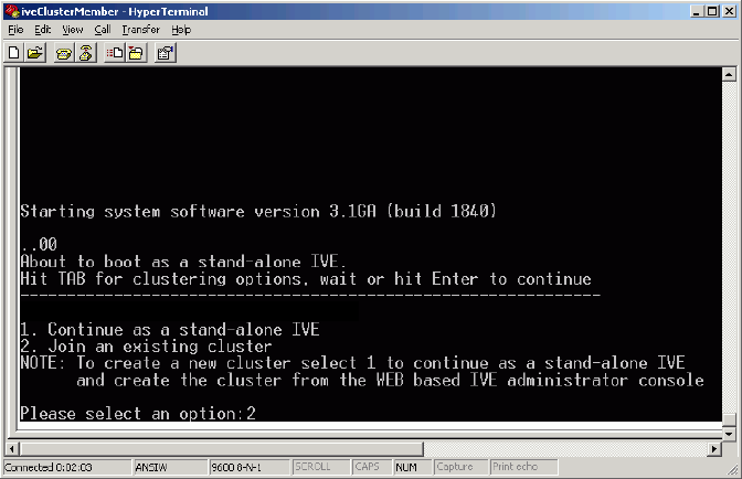
Serial console procedures 729
Chapter 27: Clustering
Figure 52: Serial Console — Join cluster option
4. Enter the number instructing the IVE to join an existing cluster.
5. Enter the requested information, including:
The internal IP address of an active member in the cluster
The cluster password, which is the password you entered when defining
the cluster
The name of the machine you wish to add (in this example, the machine
name is ive-2)
The internal IP address of the machine you wish to add
The netmask of the machine you wish to add
The gateway of the machine you wish to add
The active cluster member verifies the cluster password and that the new
machine’s name and IP address match what you specified in the admin
console on the System > Clustering > Add Cluster Member page. If the
credentials are valid, the active member copies all of its state data to the new
cluster member, including license key, certificate, user, and system data.
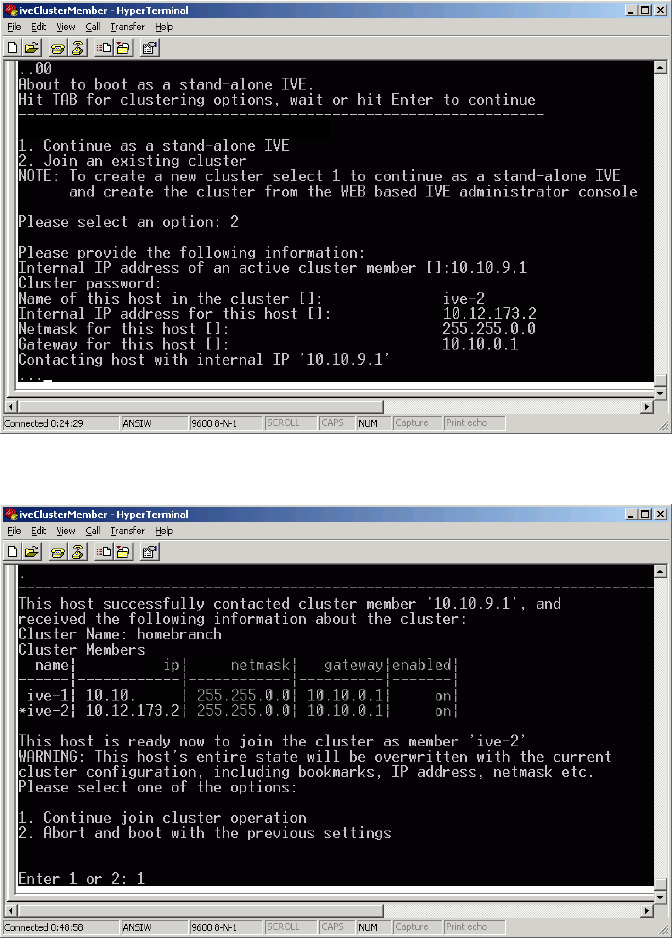
Juniper Networks Secure Access Administration Guide
730 Serial console procedures
Figure 53: Serial Console — Specifying new cluster member
Figure 54: Serial Console — Confirm join cluster
6. Enter the number instructing the IVE to continue the join cluster operation.
When you see the message confirming that the machine has joined the cluster,
check the System > Clustering > Status tab in the admin console of any
active cluster member to confirm that the new member’s Status is a green
light, indicating that the IVE is an enabled node of the cluster.
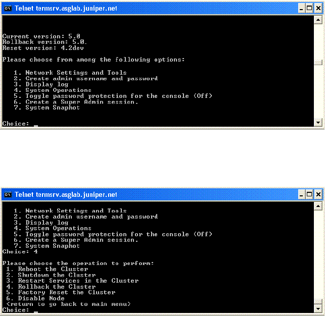
Serial console procedures 731
Chapter 27: Clustering
Disabling a clustered IVE by using its serial console
To disable an IVE within a cluster using its serial console:
1. Connect to the serial console of the machine you want to disable within the
cluster. For more information, see “IVE serial console” on page 811.
2. Enter the number corresponding to the IVE’s System Operations option.
Figure 55: Serial Console — System Operations option
3. Enter the number corresponding to the Disable Node option.
Figure 56: Serial Console — Disable Node option
4. Enter y when the serial console asks you if you are sure you want to disable the
node.
5. Verify that the IVE has been disabled within the cluster by checking the System
> Clustering > Status tab in the admin console of any active cluster member
to confirm that the disabled member’s Status is a red light.
Changing the IP address of a cluster node
To change the IP address of a cluster node:
1. Select System > Clustering > Cluster status.
2. Select the checkbox next to the name of the node whose IP address you want
to change.
3. Click Remove.

Juniper Networks Secure Access Administration Guide
732 Serial console procedures
4. When the node is removed, sign in to the node and change its IP address.
5. Click Save Changes.
6. Rejoin the node to the cluster.
NOTE: If you attempt to change the IP address of a node while it belongs to a
cluster, you may experience unpredictable results.

733
Chapter 28
Delegating administrator roles
The IVE access management system enables you to delegate various IVE
management tasks to different administrators through system administrator roles
and security administrator roles. System and security administrator roles are defined
entities that specify IVE management functions and session properties for
administrators who are mapped to those roles. You can customize an administrator
role by selecting the IVE feature sets, user roles, authentication realms, resource
policies, and resource profiles that members of the administrator role are allowed
to view and manage. Note that system administrators may only manage user roles,
realms, and resource policies; only security administrators can manage
administrator components.
For example, you can create a system administrator role called “Help Desk
Administrators” and assign users to this role who are responsible for fielding tier 1
support calls, such as helping users understand why they cannot access a Web
application or IVE page. In order to help with troubleshooting, you may configure
settings for the “Help Desk Administrators” role as follows:
Allow the help desk administrators Write access to the System >
Log/Monitoring page so they can view and filter the IVE logs, tracking down
critical events in individual users’ session histories, as well as the Maintenance
> Troubleshooting page so they can trace problems on individual users’
systems.
Allow the help desk administrators Read access to the Users > User Roles
pages so they can understand which bookmarks, shares, and applications are
available to individual users’ roles, as well as the Resource Policy or Resource
Profile pages so they can view the policies that may be denying individual
users access to their bookmarks, shares, and applications.
Deny the help desk administrators any access to the remaining System pages
and Maintenance pages, which are primarily used for configuring system-wide
settings—such as installing licenses and service packages—not for
troubleshooting individual users’ problems.
NOTE: In addition to any delegated administrator roles that you may create, the
IVE also includes two basic types of administrators: super administrators
(.Administrators role), who can perform any administration task through the
admin console and read-only administrators (.Read-only Administrators role),
who can view—but not change—the entire IVE configuration through the admin
console.

Juniper Networks Secure Access Administration Guide
734 Licensing: Delegated administration role availability
You can also create a security administrator role called “Help Desk Manager” and
assign users to this role who are responsible for managing the Help Desk
Administrators. You might configure settings for the “Help Desk Manager” role to
allow the Help Desk Manager to create and delete administrator roles on his own.
The Help Desk Manager might create administrator roles that segment
responsibilities by functional areas of the IVE. For example, one administrator role
might be responsible for all log monitoring issues. Another might be responsible for
all Network Connect problems.
This section contains the following information about delegated administration:
“Licensing: Delegated administration role availability” on page 734
“Creating and configuring administrator roles” on page 734
“Specifying management tasks to delegate” on page 736
“Defining general system administrator role settings” on page 743
Licensing: Delegated administration role availability
The delegated administration feature is not available on the SA 700 appliance and
is only available on all other Secure Access products with the Advanced license.
Note, however, that all Secure Access appliances allow members of the
.Administrators role to configure general role settings, access management
options, and session options for the .Administrators and .Read-Only
Administrators roles.
Creating and configuring administrator roles
When you navigate to Administrators > Admin Roles, you can find the
Administrators page. From this page, you can set default session and user
interface options for delegated administrator roles.
This section contains the following information about creating and configuring
delegated administrator roles:
“Creating administrator roles” on page 735
“Modifying administrator roles” on page 735

Creating and configuring administrator roles 735
Chapter 28: Delegating administrator roles
“Deleting administrator roles” on page 736
Creating administrator roles
To create an administrator role:
1. In the admin console, choose Administrators > Admin Roles.
2. Do one of the following:
Click New Role to create a new administrator role with the default settings.
Select the checkbox next to an existing administrator role and click
Duplicate to copy the role and its custom permissions. Note that you
cannot duplicate the system default roles (.Administrators and .Read-
Only Administrators).
3. Enter a Name (required) and Description (optional) for the new role and click
Save Changes.
4. Modify settings for the role using instructions in:
“Managing general role settings and options” on page 743
“Delegating user and role management” on page 737
“Delegating user realm management” on page 738
“Delegating administrative management” on page 739
“Delegating resource policy management” on page 741
“Delegating resource profile management” on page 742
“Delegating access to IVS systems” on page 746
Modifying administrator roles
To modify an existing administrative role:
1. In the admin console, choose Administrators > Admin Roles.
2. Click the name of the administrator role that you want to modify.
NOTE: To create individual administrator accounts, you must add the users
through the appropriate authentication server (not the role). For example, to
create an individual administrator account, you may use settings in the
Authentication > Auth. Servers > Administrators > Users page of the admin
console. For detailed instructions on how to create users on the Administrators
server and other local authentication servers, see “Creating user accounts on a
local authentication server” on page 117. For instructions on how to create users
on third-party servers, see the documentation that comes with that product.

Juniper Networks Secure Access Administration Guide
736 Specifying management tasks to delegate
3. Modify settings for the role using instructions in:
“Managing general role settings and options” on page 743
“Delegating user and role management” on page 737
“Delegating user realm management” on page 738
“Delegating administrative management” on page 739
“Delegating resource policy management” on page 741
“Delegating resource profile management” on page 742
“Delegating access to IVS systems” on page 746
Deleting administrator roles
To delete an existing administrative role:
1. In the admin console, choose Administrators > Admin Roles.
2. Click the checkbox next to the administrator role that you want to delete and
click Delete.
3. Click Delete to confirm that you want to remove the selected role.
Specifying management tasks to delegate
This section contains the following information about delegating management
tasks to various delegated administrator roles:
“Delegating system management tasks” on page 737
“Delegating user and role management” on page 737
“Delegating user realm management” on page 738
“Delegating administrative management” on page 739
NOTE: If you select one of the IVE’s default administrator roles (.Administrators
or .Read-Only Administrators), you can only modify settings in the General tab
(since the default IVE administrators roles always have access to the functions
defined through the System, Users, Administrators, Resource Policies. Resource
Profiles, and IVS tabs).
NOTE: You cannot delete the.Administrators and.Read Only Administrators
roles since they are default roles defined on the IVE.
Specifying management tasks to delegate 737
Chapter 28: Delegating administrator roles
“Delegating resource policy management” on page 741
“Delegating resource profile management” on page 742
“Delegating access to IVS systems” on page 746
Delegating system management tasks
Use the Administrators > Admin Roles > Select Role > System tab to delegate
various IVE system management tasks to different administrator roles. When
delegating privileges, note that:
The IVE allows all administrators read-access (at minimum) to the admin
console home page (System > Status > Overview), regardless of the privilege
level you choose.
The IVE does not allow delegated administrators write-access to pages where
they can change their own privileges. Only those administrator roles that come
with the system (.Administrators and.Read-Only Administrators) may access
these pages:
Maintenance > Import/Export (Within this page,.Read-Only
Administrators can export settings, but cannot import them.)
Maintenance > Push Config
Maintenance > Archiving > Local Backups
Delegation access to the Meeting Schedule page is controlled through the
Meetings option on the Administrators > Admin Roles > Select Role >
Resource Policies page.
Delegating user and role management
Use the Administrators > Admin Roles > Select Role > Users > Roles sub-tab to
specify which user roles the administrator role can manage. When delegating role
management privileges, note that:
Delegated administrators can only manage user roles.
Delegated administrators cannot create new user roles, copy existing roles, or
delete existing roles.
If you allow the delegated administrator to read or write to any feature within a
user role, the IVE also grants the delegated administrator read-access to the
Users > User Roles > Select Role > General > Overview page for that role.
If you grant a delegated administrator write access to a resource policy through
the Administrators > Admin Roles > Select Administrator Role > Resource
Policies page, he may create a resource policy that applies to any user role,
even if you do not grant him read access to the role.
To define role management privileges for an administrative role:
1. In the admin console, choose Administrators > Admin Roles.

Juniper Networks Secure Access Administration Guide
738 Specifying management tasks to delegate
2. Select the administrator role that you want to modify.
3. Select the Users > Roles tab.
4. Under Delegate user roles, specify whether the administrator can manage all
roles or only selected roles. If you only want to allow the administrator role to
manage selected user roles, select those roles in the Available roles list and
click Add.
5. Specify which user role pages the delegated administrator can manage by
selecting one of the following options:
Write All—Specifies that members of the administrator role can modify all
user role pages.
Custom Settings—Allows you to pick and choose administrator privileges
(Deny, Read, or Write) for the individual user role pages.
6. Under Delegate as read-only roles, select the user roles that you want to allow
the administrator to view, but not manage.
7. Click Save Changes.
Delegating user realm management
Use the Administrators > Admin Roles > Select Role > Users > Authentication
Realms tab to specify which user authentication realms the administrator role can
manage. When delegating realm management privileges, note that:
System administrators can only manage user realms.
System administrators cannot create new user realms, copy existing realms, or
delete existing realms.
If you allow the system administrator to read or write to any user realm page,
the IVE also grants the system administrator read-access to the Users > User
Realms > Select Realm > General page for that role.
To define realm management privileges for an administrative role:
1. In the admin console, choose Administrators > Admin Roles.
2. Select the administrator role that you want to modify.
3. Select the Users > Authentication Realms tab.
NOTE: If you specify both write access and read-only access for a feature, the IVE
grants the most permissive access. For example, if you choose Administrators
can manage ALL roles under Delegated user roles, and then select the “Users”
role in the Delegate as read-only roles section, the IVE allows the delegated
administrator role full management privileges to the “Users” role.

Specifying management tasks to delegate 739
Chapter 28: Delegating administrator roles
4. Under Delegate user realms, specify whether the administrator can manage all
user authentication realms or only selected user authentication realms. If you
only want to allow the administrator role to manage selected realms, select
those realms in the Available realms list and click Add.
5. Specify which user authentication realms pages the delegated administrator
can manage by selecting one of the following options:
Write All—Specifies that members of the administrator role can modify all
user authentication realm pages.
Custom Settings—Allows you to pick and choose administrator privileges
(Deny, Read, or Write) for the individual user authentication realm pages.
6. Under Delegate as read-only realms, select the user authentication realms that
you want to allow the administrator to view, but not modify.
7. Click Save Changes.
Delegating administrative management
Use the Administrators > Admin Roles > Select Roles > Administrators tab to
specify which system administrator roles and realms the security administrator role
can manage. When delegating security administrative privileges, note that:
The security administrator role provides control over all administrative roles
and realms.
You can give a security administrator control exclusively over administrator
roles, over administrator realms, or over both.
You can restrict or grant the security administrator the permission to add and
delete administrator roles and administrator realms.
To define security administrator privileges:
1. In the admin console, choose Administrators > Admin Roles > Select Role >
Administrators.
2. Select the Manage ALL admin roles checkbox.
3. If you want to allow the security administrator to add and delete admin roles,
check the Allow Add/Delete admin roles checkbox. This allows the security
administrator the ability to create administrator roles, even if the security
administrator is not part of the .Administrators role.
NOTE: If you specify both write access and read-only access for an authentication
realm page, the IVE grants the most permissive access. For example, if you
choose Administrators can manage ALL realms under Delegated user realms,
and then select the “Users” role in the Delegate as read-only realms section, the
IVE allows the delegated administrator role full management privileges to the
“Users” realm.

Juniper Networks Secure Access Administration Guide
740 Specifying management tasks to delegate
4. Indicate the level of access that you want to allow the security administrator
role to set for system administrators for each major set of admin console pages
(General, System tasks, Users, Administrators, Resource Policies, Resource
Profiles, and IVS) by choosing one of the following options:
Deny All—Specifies that members of the security administrator role
cannot see or modify any settings in the category.
Read All—Specifies that members of the security administrator role can
view, but not modify, all settings in the category.
Write All—Specifies that members of the security administrator role can
modify all settings in the category.
Custom Settings—Allows you to pick and choose security administrator
privileges (Deny, Read, or Write) for the individual features within the
category.
5. Select the Manage ALL admin realms checkbox.
6. If you want to allow the security administrator to add and delete admin realms,
check the Allow Add/Delete admin realms checkbox. This allows the security
administrator the ability to create and delete administrator realms, even if the
security administrator is not part of the .Administrators role.
7. Indicate the level of realm access that you want to allow the security
administrator role to set for system administrators for each major set of admin
console pages (General, Authentication Policy, and Role Mapping) by
choosing one of the following options:
Deny All—Specifies that members of the security administrator role
cannot see or modify any settings in the category.
Read All—Specifies that members of the security administrator role can
view, but not modify, all settings in the category.
Write All—Specifies that members of the security administrator role can
modify all settings in the category.
Custom Settings—Allows you to pick and choose security administrator
privileges (Deny, Read, or Write) for the individual features within the
category.
8. Click Save Changes.
NOTE: All administrators that can manage admin roles and realms have at least
read-only access to the admin role’s Name and Description and to the realm's
Name and Description, as displayed on the General page.
Specifying management tasks to delegate 741
Chapter 28: Delegating administrator roles
Delegating resource policy management
Use the Administrators > Admin Roles > Resource Policies tab to specify which
user resource policies the administrator role can manage. When delegating
resource policy management privileges, note that delegated system administrators
cannot modify the following characteristics of resource policies:
The resource itself (that is, the IP address or host name)
The order in which the IVE evaluates the resource policies.
To delegate administrator privileges for resource policies:
1. In the admin console, choose Administrators > Admin Roles.
2. Select the administrator role that you want to modify.
3. Select the Resource Policies tab.
4. Indicate the level of access that you want to allow the administrator role for
each Resource Policies sub-menu by choosing one of the following options:
Deny All—Specifies that members of the administrator role cannot see or
modify any resource policies.
Read All—Specifies that members of the administrator role can view, but
not modify, all resource policies.
Write All—Specifies that members of the administrator role can modify all
resource policies.
Custom Settings—Allows you to pick and choose administrator privileges
(Deny, Read, or Write) for each type of resource policy or for individual
resource policies.
5. If you want to set custom access levels for an individual policy:
a. Select Custom Settings (above).
b. Click the Additional Access Policies link next to the appropriate category.
(For example, if you want to control access to a resource policy that
controls access to www.google.com, select the Additional Access Policies
link next to Web.)
c. Choose the access level for the policy (Deny, Read, or Write).
d. Under Access Policies, select the resource policy for which you want to
provide a custom access level and click Add.
6. Click Save Changes.
Juniper Networks Secure Access Administration Guide
742 Specifying management tasks to delegate
Delegating resource profile management
Use the Administrators > Admin Roles > Resource Profiles tab to specify which
user resource profiles the administrator role can manage. When delegating
resource profile management privileges, note that delegated system administrators
cannot modify the following characteristics of resource profiles:
The resource itself (that is, the IP address or host name)
The order in which the IVE evaluates the resource policies.
To delegate administrator privileges for resource profiles:
1. In the admin console, choose Administrators > Admin Roles.
2. Select the administrator role that you want to modify.
3. Select the Resource Profiles tab.
4. Indicate the level of access that you want to allow the administrator role for
each Resource Profiles sub-menu by choosing one of the following options:
Deny All—Specifies that members of the administrator role cannot see or
modify any resource profiles.
Read All—Specifies that members of the administrator role can view, but
not modify, all resource profiles.
Write All—Specifies that members of the administrator role can modify all
resource profiles.
Custom Settings—Allows you to pick and choose administrator privileges
(Deny, Read, or Write) for each type of resource profile or for individual
resource profiles.
5. If you want to set custom access levels for an individual profile:
a. Select Custom Settings (above).
b. Click the Additional Access Profiles link next to the appropriate category.
(For example, if you want to control access to a resource policy that
controls access to www.google.com, select the Additional Access Profiles
link next to Web.)
c. Click the Additional Access Policies link next to the appropriate category.
d. Choose the access level for the profile (Deny, Read, or Write).
e. Under Access Profiles, select the resource profile for which you want to
provide a custom access level and click Add.
6. Click Save Changes.

Defining general system administrator role settings 743
Chapter 28: Delegating administrator roles
Defining general system administrator role settings
This section contains the following information about configuring general options
for delegated system administrator roles:
“Defining default options for administrator roles” on page 743
“Managing general role settings and options” on page 743
“Specifying access management options for the role” on page 744
“Specifying general session options” on page 744
“Specifying UI options” on page 745
Defining default options for administrator roles
To define the default options for all delegated administrator roles:
1. In the admin console, choose Administrators > Admin Roles.
2. Click Default Options.
3. Modify settings in the Session Options and UI Options tabs using instructions
in “Managing general role settings and options” on page 743 and click Save
Changes. These become the new defaults for all new delegated administrator
roles.
Managing general role settings and options
To manage general role settings and options:
1. In the admin console, choose Administrators > Admin Roles > Select Role >
General > Overview.
2. Create a label for the delegated administrator role using the Name and
Description fields (optional).
3. Under Options, check:
Session Options to apply the settings configured in the General > Session
Options tab to the role.
UI Options to apply the settings configured in the General > UI Options
tab to the role.
4. Click Save Changes to apply the settings to the role.
Juniper Networks Secure Access Administration Guide
744 Defining general system administrator role settings
Specifying access management options for the role
Use the Administrators > Admin Roles> General > Restrictions tab to specify
access management options for the role. The IVE does not map administrators to
this role unless they meet the specified restrictions. For more information, see
“Access management framework” on page 33.
To specify access management options for the role:
1. In the admin console, choose Administrators > Admin Roles> Select Role >
General> Restrictions.
2. Click the tab corresponding to the option you want to configure for the role,
and then configure it using the instructions in the following sections:
“Specifying source IP access restrictions” on page 43
“Specifying browser access restrictions” on page 44
“Specifying certificate access restrictions” on page 47
“Specifying Host Checker access restrictions” on page 49
You may configure any number of access management options for the role. If
an administrator does not conform to all of the restrictions, then the IVE does
not map the delegated administrator to the role.
3. Click Save Changes to apply the settings to the role.
Specifying general session options
To specify general session options:
1. In the admin console, choose Administrators > Admin Roles > Select Role >
General > Session Options.
2. Under Session Lifetime, specify values for:
Idle Timeout—Specify the number of minutes an administrator session
may remain idle before ending. The minimum is 5 minutes. The default
idle session limit is ten minutes, which means that if an administrator’s
session is inactive for ten minutes, the IVE ends the session and logs the
event in the system log (unless you enable session timeout warnings
described below).
Max. Session Length—Specify the number of minutes an active
administrator session may remain open before ending. The minimum is 6
minutes. The default time limit for an administrator session is sixty
minutes, after which the IVE ends the session and logs the event in the
system log.

Defining general system administrator role settings 745
Chapter 28: Delegating administrator roles
3. Under Roaming session, specify:
Enabled—To enable roaming user sessions for users mapped to this group.
A roaming user session works across source IP addresses, which allows
mobile administrators (laptop users) with dynamic IP addresses to sign in
to the IVE from one location and continue working from another. However,
some browsers may have vulnerabilities that can allow malicious code to
steal user cookies. A malicious user could then use a stolen IVE session
cookie to sign in to the IVE.
Limit to subnet—To limit the roaming session to the local subnet specified
in the Netmask field. Administrators may sign in from one IP address and
continue using their sessions with another IP address as long as the new IP
address is within the same subnet.
Disabled—To disable roaming sessions for administrators mapped to this
role. Administrators who sign in from one IP address may not continue an
active IVE session from another IP address; administrator sessions are tied
to the initial source IP address.
4. Click Save Changes to apply the settings to the role.
Specifying UI options
Use the Administrators > Admin Roles > Select Role > General > UI Options
tab to customize admin console settings for the administrators mapped to this role,
including console colors, logos, and hierarchical navigation menus. (For
information about customizing the logo and colors in the admin console sign-in
page, see “Configuring standard sign-in pages” on page 188.)
Hierarchical navigation menus are dynamic menus that appear when you mouse
over one of the menus in the left panel of the admin console. For example, if you
enable hierarchical navigation menus and then hover over the Authentication >
Signing In menu in the admin console, the Sign-In Policies, and Sign-In Pages sub-
menus appear. You can use these menus to quickly navigate through the system
without having to click through the whole menu hierarchy.
NOTE:
For information about the environments in which hierarchical menus are
supported, see the Supported Platforms Guide on the Juniper Networks
Customer Support Center.
If you have upgraded your system from version 4.0, you must clear your
browser cache or start a new browser in order to use the hierarchical menus.
If you have defined over 10 authentication realms or roles under
Administrators or Users, the admin console only displays the 10 most
recently accessed roles or realms in the hierarchical navigation menus. Note
that the IVE does not display the 10 roles and realms most recently accessed
by the current administrator—instead it displays the 10 roles and realms
accessed by all administrators who have signed in to this IVE.

Juniper Networks Secure Access Administration Guide
746 Defining general system administrator role settings
To customize the IVE welcome page for role users:
1. In the admin console, choose Administrators > Admin Roles > Select Role.
2. Select the UI Options checkbox on the General > Overview tab to enable
settings for the role.
3. Choose General > UI Options to customize settings for the role.
4. In the Header section, specify a custom logo image file for the header and a
different header color.
5. In the Navigation Menus section, choose whether you wish to display
hierarchical navigation menus. Options include:
Auto-enabled—The IVE determines whether the administrator is signed in
from a supported platform and enables or disables the hierarchical menus
accordingly.
Enabled—The IVE enables hierarchical menus, regardless of your
platform. If the administrator is signed in from an unsupported platform,
they may not be able to use the hierarchical menus, even though they are
enabled.
Disabled—The IVE disables hierarchical menus for all members of the role.
6. In the Other section, select the Show copyright notice and “Secured by
Juniper Networks” label in footers checkbox to display the Juniper logo.
7. Click Save Changes. The changes take effect immediately, but current user
browser sessions may need to be refreshed to see the changes. Or click
Restore Factory Defaults to reset the admin console appearance to the default
settings.
Delegating access to IVS systems
If you are running an IVS license, you can also delegate administrative access and
responsibilities to specific IVS systems. You can delegate read/write access or read-
only access to all IVS systems, or to selected IVS systems. For more information,
see “Delegating administrative access to IVS systems” on page 784.
NOTE: If you do not want user roles to see the copyright notice, you can also
deselect the option in the Default Settings for user roles, in general. That way, all
subsequent roles you create do not allow the notice to appear on the end-user UI.
747
Chapter 29
Instant Virtual System (IVS)
The Instant Virtual System (IVS) gives managed service providers (MSPs) the
opportunity to offer cost-effective secure remote access, disaster recovery and
managed extranet services to small and medium sized companies. To meet this
opportunity, MSPs can deliver managed security solutions from equipment that is
located on the subscriber company’s premises (Customer Premises Edge router-
based) or within the MSP network (Carrier Edge router-based or network-based).
Network-based managed security solutions centralize the security gateway
equipment in the MSP network. A virtualized IVE allows the MSP to provide
managed, network-based SSL VPN services to multiple customers from the same
equipment. The basic business model might work something like this:
The MSP manages the SSL VPN equipment at the MSP site.
Small and medium-sized companies subscribe to monthly services from the
MSP.
The MSP is responsible for the management of the equipment, but delegates
portal administration to an IVS administrator designated by each subscriber
company.
The virtual system supports and enforces an architectural and administrative
separation between subscriber companies, providing a completely secure and
individualized view for each subscriber.
This system provides a number of benefits to service providers:
Expand market share—The ability to provide secure SSL VPN capabilities to as
many as 255 subscriber companies from one IVE offers the MSP economies of
scale and the opportunity to expand market share with services targeting small
and medium sized businesses.
Simplify administration—Each subscriber administrator can manage their
company’s IVS instance with no visibility into another subscriber company’s
administrative interface. The MSP root administrator can manage all hosted
companies and can easily monitor or configure hosted company systems.
Enhance subscriber security—Each subscriber company maintains complete
separation from other subscriber companies. As far as the subscriber
administrator or subscriber users are concerned, they are operating on a
completely independent and protected SSL VPN system.
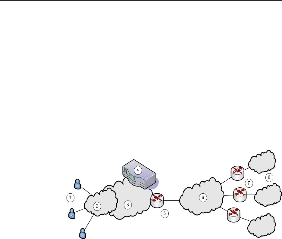
Juniper Networks Secure Access Administration Guide
748 Licensing: IVS availability
Optimize traffic management—Traffic from end-users or corporate intranet
servers stays within each company’s VLAN. Subscriber end-users never see
services located on another subscriber’s intranet.
See the following topics for more information:
“Licensing: IVS availability” on page 748
“Virtualized IVE architecture” on page 750
“Clustering a virtualized IVE” on page 773
“IVS use cases” on page 789
Licensing: IVS availability
You must have an IVS license to create IVS systems. (Note that IVS licenses are
not available for SA 700 or SA 2000 appliances.)
You must have both an IVS license and a Network Connect license to provide
centralized DHCP support to your subscribers.
Deploying an IVS
For each subscriber company, the virtualized IVE provides a secure portal for the
company’s end-users (mobile employees, customers, or partners) to access its
internal resources. Authentication servers that reside either on the subscriber’s
premises or in the MSP network, authenticate end-users who sign in to the IVS.
Once authenticated, end-users establish secure sessions through the IVS to their
respective company’s back-end servers.
Figure 57: MSP deployment scenario
The following numbered list items correspond to the labeled objects in Figure 57
1. End-users sign in to different subscriber company intranets on specified IP
addresses.
Deploying an IVS 749
Chapter 29: Instant Virtual System (IVS)
2. End-users sign-in over an Internet connection using a standard SSL-enabled
Web browser.
3. All traffic is directed into the Managed Service Provider’s (MSP) network. The
MSP is the customer who holds the license to the virtualized IVE hardware and
software.
4. All traffic is directed to the virtualized IVE. Each message is evaluated based on
its sign-in IP address and, by the virtualized IVE, is assigned a VLAN tag
containing a VLAN ID that corresponds to a subscriber company. The IVE
supports up to 250 IVS systems, each one representing a single subscriber
company IVE. The subscriber is any company that subscribes to hosted SSL
VPN services from the MSP.
5. The MSP carrier-edge (CE) router or other Layer 2 device acts as a VLAN
termination point, and routes traffic over a secure tunnel to a customer
premises edge (CPE) router. Based on the VLAN ID, the router directs the traffic
to the appropriate subscriber intranet. During this part of the process, the CE
router removes the VLAN tag containing the VLAN ID, as once the message is
correctly destined for the appropriate intranet, the ID and tag are no longer
needed. The term subscriber intranet is interchangeable with the term
company intranet.
6. The CE router routes messages over the service provider backbone to the
appropriate customers’ premises edge routers through encrypted tunnels, such
as IPSec, GRE, PPP, and MPLS tunnels. Untagged traffic is sent over these
tunnels to the customer intranet.
7. The CPE routers within the customer intranet on the customer premises can
act as a VLAN termination point and routes traffic from the secure tunnel
connected to the CE Router, to the customer intranet.
8. The end-user traffic reaches the correct subscriber company’s backend
resources. The IVE processes any return messages to the end-users from the
subscriber intranets following a similar set of steps.
In a typical MSP deployment, firewalls are present in front of the IVE in the MSP's
DMZ, behind the IVE, in the MSP network or in the customer's intranet DMZ, or
both. Note that a virtualized firewall could potentially exist behind the IVE (a Vsys
cluster, for example), in which case it should have the ability to accept VLAN tagged
traffic from the IVE and forward it to the proper customer VLAN (and vice versa).
Also, most, if not all deployments have Domain Name Server (DNS) or Application
servers located either in the MSP network or on the customer intranet.
In a virtualized IVE deployment, the front-end is considered the external interface
and is the end-user or Internet-facing interface. The back-end is considered the
internal interface and is the subscriber company intranet-facing interface.
The IVE tags inbound traffic sent by end-users and destined for a server in the
subscriber intranet or MSP network, with VLAN tags containing the VLAN ID.
Inbound traffic can arrive over the IVE appliance’s internal interface or external
interface.
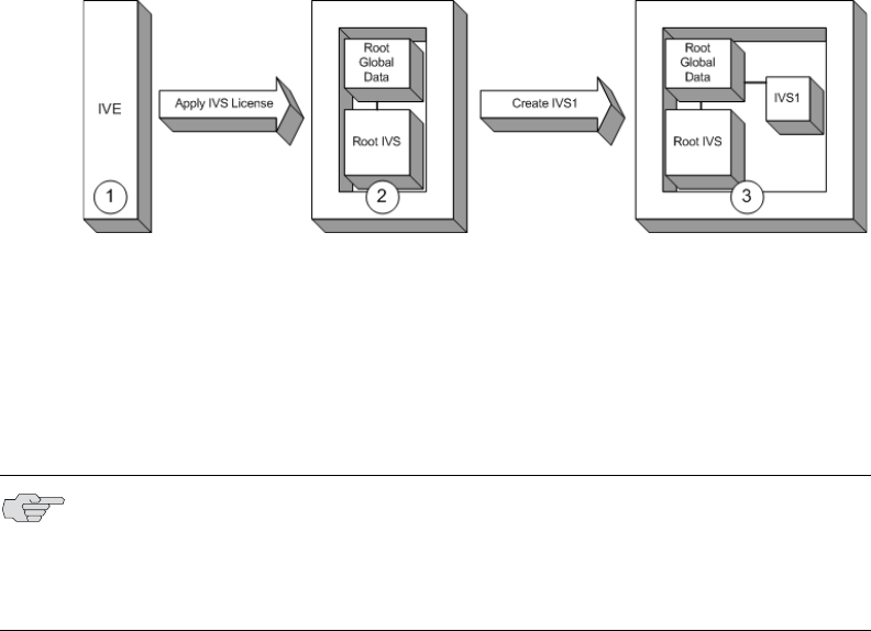
Juniper Networks Secure Access Administration Guide
750 Deploying an IVS
Outbound traffic, which is traffic transmitted over the IVE backend and destined for
servers located on MSP network or subscriber intranet, can be sourced by the IVE
itself. For example, traffic destined for authentication, DNS, or application servers,
is outbound traffic, as is traffic forwarded by the IVE, such as Network Connect
traffic.
If the traffic arrives as inbound traffic to an IP address that has been designated for
an IVS system that uses a VLAN, that traffic is tagged with the VLAN tag on arrival.
When it has been identified and directed to the proper backend destination, the
VLAN termination device strips the VLAN tag from the Ethernet frame and forwards
the traffic to the backend destination.
Virtualized IVE architecture
The virtualized IVE framework consists of a root system and any subscriber IVS
systems the MSP root administrator creates subsequently. Subscriber IVS
administrators can only manage resources on their particular IVS system. The root
administrator can manage resources on all IVS systems on the appliance.
The IVS license converts the IVE system to a root system that is functionally
identical to the IVE, with the added capability of provisioning virtual systems. The
root system consists of system-level global data and a single default root IVS, which
encompasses the access management subsystem.
Figure 58: IVS architecture
The root administrator (root administrator) is the super-administrator of the root
system. Often, the root administrator is the same thing as the IVE administrator.
The root administrator has administrative control over the root system and all
subscriber IVS systems. The root administrator can provision IVS systems on the
root system, create IVS administrators, edit IVS configuration. The root
administrator can override configuration changes made by any IVS administrator.
As shown in Figure 58:
1. The IVE administrator applies an IVS license to an IVE appliance containing a
Secure Access license.
T
NOTE: The instructions for configuring the root and IVS systems are meant to be
read by a root administrator. The pronoun you, in these sections, denotes the root
administrator. If a task can be performed by someone in a role other than the
root administrator, the text makes a distinct reference to the role in the task
description.

Signing in to the root system or the IVS 751
Chapter 29: Instant Virtual System (IVS)
2. The resulting system contains the root global data and a root IVS, in effect, a
virtualized IVE.
3. From the root IVS, the root administrator can create multiple subscriber IVS
systems, each IVS completely separate from any other IVS.
The root system contains a superset of all capabilities of the system. You, as the
root administrator, define all global network settings and root administrator
settings on the root system. For each subscriber, you provision one or more IVS
systems and manage them from the root system.
The subscriber IVS contains a unique instance of the access management
framework. When you create an IVS for each subscriber company, you also create
an IVS administrator (IVS administrator) account. The IVS administrator has
complete administrative control over the IVS. The IVS administrator uses an
administrative admin console that contains a subset of the root administrator
capabilities.
Signing in to the root system or the IVS
You can configure sign-in URLs using different methods:
Sign-in URL prefix per IVS
Virtual ports
VLAN ports
You can use both of these methods on the same IVS.
Signing-in using the sign-in URL prefix
This feature enables end-users to access an IVS by way of a single hostname and
and IVS-specific sign-in URL prefix. By using this method, administrators can
ensure that users can access multiple IVS systems by way of a single IP address on
the IVE.
Additionally, the use of path-based URLs results in:
Savings in certificate costs—You need only supply one device certificate.
Fewer DNS entries—You need only one DNS entry across all IVS systems
hosted on a single IVE.
Administrators and end-users can sign into an IVS system using sign-in URLs
similar to the following (assuming the managed service provider URL is
www.msp.com):
Company A sign-in URL: www.msp.com/companyA
Company B sign-in URL: www.msp.com/companyB
Company A IVS administrator sign-in URL: www.msp.com/companyA/admin
Juniper Networks Secure Access Administration Guide
752 Signing in to the root system or the IVS
Company B IVS administrator sign-in URL: www.msp.com/companyB/admin
You can continue to restrict access by implementing additional sign-in URLs that
are segregated by certain criteria, as follows:
www.msp.com/companyA/sales
www.msp.com/companyA/finance
www.msp.com/companyA/hr
If you do not specify a URL prefix, the IVE defaults to sign-in over virtual ports. If
you do specify a path-based sign-in URL prefix, the following rules apply:
You cannot specify a multilevel path for the URL prefix, by using the /
character.
End-users can sign in to an IVS on the internal port, external port, VLAN
interface, or virtual port that has not already been assigned to an IVS using the
selected URL prefix, in other words, where the hostname is the DNS name
assigned to one of the interface IP addresses.
For example, assume that your IVE ports are assigned to specific DNS names, as
follows:
Internal Port = MSP-internal
External Port = MSP-external
VLAN Port 10 = MSP-vlan10
Virtual Port X = MSP-virtualx
Now, consider that VLAN Port 10 and Virtual Port X are not assigned to an IVS. If
you host the Company A IVS, and the Company A sign-in URL prefix is specified as
companyA in the IVS profile, then end-users can sign-in to the Company A IVS
using any of the following URLs:
MSP-internal/companyA
MSP-external/companyA
MSP-vlan10/companyA
MSP-virtualx/companyA
The path-based URL feature carries a few restrictions, as follows:
An end-user or administrator can sign into only one IVS from a given browser
instance. If you attempt to sign in to another IVS from a new browser window
of the same browser instance, your sign in attempt is rejected. You must create
a new browser instance to sign in to multiple IVS systems.
You cannot establish multiple concurrent sessions, with all sessions using Host
Checker, from the same end-point to different IVE systems. You cannot
establish multiple concurrent sessions from the same end-point to multiple IVS
systems, regardless of the sign-in method.
Signing in to the root system or the IVS 753
Chapter 29: Instant Virtual System (IVS)
If you configure an IVS with a path-based sign-in URL prefix, you cannot use
the persistent session cookie (DSID) and maintain the ability to sign in to
multiple IVS systems from the same browser using the URL prefix. The
limitation does not apply to users signing in to the IVS with a sign-in IP address,
because the system creates a different DSID per target IVS in that case.
Pass-through proxy based on port numbers is supported. However, you cannot
specify a pass-through proxy policy when using virtual hosts, unless the virtual
host DNS entry maps to the IVS sign-in IP address. If the virtual host DNS entry
points to the IVE, when the user signs in he will sign-in to the root IVS sign-in
page.
When using Secure Meeting, if a user is not already signed in to their IVS and
you have enabled the option require IVE users, all meeting invitation emails
will contain a link to the root IVS sign-in page.
If an IVS user bookmarks pages while using web rewriting, signs out, then
reopens the browser and selects the bookmark, he will display the root IVS
sign-in page.
Signing-in over virtual ports
You may have reasons for configuring virtual ports for sign in. Virtual ports provide
significant segregation of traffic. If you choose to use virtual ports, keep in mind
that:
Must provide multiple certificates—You need to supply one device certificate
per virtual port address.
Must configure multiple DNS entries—You need to supply DNS entries for
each IVS system hosted on a single IVE.
The sign-in request’s target IP address drives the sign-in to the root system or IVS.
To sign in to the root system or an IVS, users browse to a hostname-based URL.
You map the URL, by way of external DNS, to the IP address or to an IP alias of the
IVE system’s external interface.
For example, consider an MSP with host name msp.com, that provides SSL VPN
gateway services to two subscribers: s1 and s2.
Root administrator sign-in URL: http://www.msp.com
S1 sign-in URL: http://www.s1.com
S2 sign-in URL: http://www.s2.com
External DNS must map these URLs to unique IP addresses, which must
correspond to IP addresses or aliases hosted on the IVE, typically a virtual port
defined on either the internal or external port.
To summarize signing-in, IVS users can sign in on:
A virtual port configured on the external interface of the IVE.
A virtual port configured on the internal interface of the IVE (untagged).

Juniper Networks Secure Access Administration Guide
754 Determining the subscriber profile
A VLAN interface configured on the internal interface (tagged).
Root system users can also sign in directly over the internal or external interface.
For more information about signing in, see “Configuring sign-in policies” on
page 183 and “Configuring sign-in pages” on page 187.
Signing-in over a VLAN interface
In addition to the sign-in capabilities provided over the external interface (or the
internal interface, if configured) by the root administrator, end-users can sign in
over any VLAN interface the root administrator assigns to their IVS. In other words,
the IVS administrator can provide the VLAN port IP address to end-users for sign-in.
Navigating to the IVS
Only root administrators can navigate to an IVS from the root system. On the
virtualized IVE, the admin console navigation for the root system includes an
additional drop-down menu listing the configured IVS systems, on all page headers.
You can navigate to an IVS and administer it by selecting an IVS from the drop-
down menu. IVS administrators must sign-in directly to the IVS through a standard
administrative sign-in page.
The root administrator creates the initial IVS administrator account. An IVS
administrator can create additional IVS administrator accounts, using the standard
procedure for creating administrator accounts, as described in “Creating and
configuring administrator roles” on page 734.
Determining the subscriber profile
In order to configure the system to properly steer inbound traffic to the correct
subscriber IVS, and outbound traffic to the correct VLAN, the MSP root
administrator needs to compile a profile for each subscriber company.
IVS Configuration Worksheet
When creating a new virtual system, you must create a number of other system
objects, and specify several pieces of data, including IP addresses, VLAN IDs, virtual
ports, and DNS settings. You can use this worksheet to plan and keep track of the
system data while creating each IVS. The worksheet presents data in the general
order in which you should define the IVS.
NOTE: You cannot map an explicit device certificate to any IP addresses mapped
to a VLAN. When signing in over a VLAN interface, the system chooses the device
certificate that is already assigned to the IVS. If there is no certificate associated
with the IVS, the system assigns the certificate from the top of the IVE device
certificate list. This list can be re-ordered when a certificate is added or removed,
which can result in an unpredictable certificate during configuration. Once an IVS
is in a production state, this should not present a problem, as the IVS VIP is
mapped to a specific certificate.

Determining the subscriber profile 755
Chapter 29: Instant Virtual System (IVS)
Depending on the specific topology of the subscribers' networks, you may need to
collect additional information, or may not use all of the information listed on the
form.
Date: Created by:
Subscriber:
Account #:
Comment:
Subscriber VLAN (System > Network > VLANs)
VLAN Settings
VLAN Port Name:
VLAN ID (1-4095):
VLAN Port Information
IP Address:
Netmask:
Default Gateway:
Subscriber Sign-in Virtual Port Configuration
(System > Network > Port 1 > Virtual Ports > New Virtual Port)
External Virtual Port
Name (for sign-in):
IP Address:
Internal Virtual Port
Name (optional):
IP Address:
Install Device Certificate for IVS hostname
IVS Hostname:
Internal Port:
External Port:
Subscriber IVS (System > Virtual Systems > New Virtual System)
Name (Subscriber):
Description:
Administrator
Username:
Password (at least 6
characters in length):
Properties
Max Concurrent Users:
Default VLAN:

Juniper Networks Secure Access Administration Guide
756 Determining the subscriber profile
Administering the root system
Once you apply the IVS license to the IVE, the new Virtual Systems tab appears in
the administrator UI. After you apply the IVS license, you can see an explicit display
of the root system in the drop down menu that appears in the admin console
header area.
Setting up the system requires a series of basic procedures. Once the hardware is
connected:
1. Boot the system.
2. Apply the IVS license through the Maintenance > System >
Upgrade/Downgrade page of the admin console.
3. Configure the root system from the admin console, as described in
“Provisioning an IVS” on page 757.
Regardless of how many subscriber administrators you define on the subscriber IVS
systems, you always maintain control over the entire system and have visibility
into the settings on all IVS systems.
Selected Virtual Ports:
(Internal Interface)
Selected Virtual Ports:
(External Interface)
Network Connect IP Pool:
Static Routes (System > Network > Routes > New Routes)
Destination Network/IP:
Netmask:
Gateway:
Interface:
Metric:
DNS Settings (Subscriber IVS > System > Network > Overview)
Hostname:
Primary DNS:
Secondary DNS:
DNS Domain(s):
WINS:

Provisioning an IVS 757
Chapter 29: Instant Virtual System (IVS)
Configuring the root administrator
Configuring the root administrator is similar to the task of creating a new
administrator on a standalone IVE. You can create an administrator account
through the Authentication > Auth. Servers > Administrators > Users page of
the admin console, or by using the serial console, as described in “Connecting to an
IVE appliance’s serial console” on page 811.
If you upgrade from an earlier IVE version to the 5.1 version software or later, the
system considers any administrator in the root system who maps to the
.Administrators role to be a root administrator for the IVE. If you re-image the IVE
appliance or install a brand new piece of hardware, you create a primary
administrator during the initial configuration steps, in the serial console. For more
information about setting up the system from the serial console, see “Connecting to
an IVE appliance’s serial console” on page 811.
Provisioning an IVS
This section describes the tasks involved in provisioning an IVS, including:
“Understanding the provisioning process” on page 758
“Configuring sign-in ports” on page 760
“Configuring a Virtual Local Area Network (VLAN)” on page 762
“Loading the certificates server” on page 766
“Creating a virtual system (IVS profile)” on page 766
“Configuring role-based source IP aliasing” on page 769
“Configuring policy routing rules on the IVS” on page 771
“Clustering a virtualized IVE” on page 773
“Configuring DNS for the IVS” on page 774
“Configuring Network Connect for use on a virtualized IVE” on page 777
“Configuring authentication servers” on page 782
“Accessing standalone installers” on page 784
“Performing export and import of IVS configuration files” on page 785
“Monitoring subscribers” on page 787
“Troubleshooting VLANs” on page 788
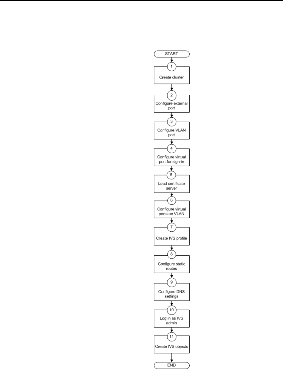
Juniper Networks Secure Access Administration Guide
758 Understanding the provisioning process
Understanding the provisioning process
Figure 59 illustrates the basic tasks required to provision an IVS.
Figure 59: Basic process of provisioning an IVS
Understanding the provisioning process 759
Chapter 29: Instant Virtual System (IVS)
Provisioning an IVS consists of the following steps, as illustrated in Figure 59:
1. Configure one or more clusters, if needed, through the System > Clustering >
Create Cluster page.
2. Configure and enable external port. The external port is in a disabled state, by
default. You must enable the port and configure it, to provide sign-in
capabilities from outside the network.
3. Create at least one VLAN port for each subscriber company. You must define a
unique ID for each VLAN. A subscriber company can have multiple VLANs on
the IVE.
4. Configure at least one virtual port on the external port to enable end-users to
sign in. You can also configure virtual ports on the internal port, for signing in
from behind the firewall, if needed.
5. Load one certificate server per subscriber company.
6. If you intend to use virtual ports, for example, to support IP sourcing, create
them at this point in the process.
7. Create an IVS profile for each subscriber company. The IVS profile establishes
the connection between the company, the VLAN, and the available virtual
ports.
8. Configure static routes to backend servers. If you intend to provide shared
access to resources on the MSP network, you add static routes to the VLAN
route tables that point to those resources.
9. Configure DNS settings, so that any traffic destined for resources on the MSP
network first goes through the MSP’s DNS server.
10. Log in as the IVS administrator.
11. Configure users, roles, realms, and resource policies for the IVS.
When you create the IVS, the IVS name appears in the drop down menu located in
the header of the admin console. You can perform operations on each IVS by
selecting the IVS name in the drop down menu and clicking the Go button.
Task Summary: Provisioning an IVS
To provision an IVS system, you must:
1. Create a cluster, if necessary. For instructions, see “Clustering” on page 705.
2. Configure an external port, which consists of enabling the port and configuring
virtual ports to allow end-users to sign-in from outside the MSP network. For
instructions, see “Configuring sign-in ports” on page 760.
3. Configure a VLAN, which includes defining the VLAN port and specifying a
VLAN ID. For instructions, see “Configuring a Virtual Local Area Network
(VLAN)” on page 762.

Juniper Networks Secure Access Administration Guide
760 Configuring sign-in ports
4. Load the certificates server, which allows the MSP and subscriber companies to
certify traffic. For instructions, see “Loading the certificates server” on
page 766.
5. Configure virtual ports on the VLAN for IP sourcing or for clustering. For
instructions, see “Configuring a virtual port for sign-in on the internal port” on
page 761.
6. Create the IVS profile, which defines the subscriber company’s environment on
the virtualized IVE. For instructions, see “Creating a new IVS profile” on
page 766.
7. Configure static routes to support backend servers, Network Connect users,
and to provide shared services on the MSP network. For instructions, see
“Adding static routes to the VLAN route table” on page 764.
8. Configure DNS settings, to force traffic to go through the MSP DNS server. If
you are running Network Connect, you must configure DNS. For instructions,
see “Configuring DNS for the IVS” on page 774.
9. Configure Network Connect, if necessary. For instructions, see “Configuring
Network Connect for use on a virtualized IVE” on page 777.
Configuring sign-in ports
You must configure virtual ports by which end-users can sign in to the subscriber
company intranet. A virtual port activates an IP alias on a physical port and shares
all of the network settings of that port. For more information about virtual ports in
general, see “Configuring virtual ports” on page 566.
This section contains the following topics:
“Configuring the external port” on page 760
“Configuring a virtual port for sign-in on the external port” on page 761
“Configuring a virtual port for sign-in on the internal port” on page 761
Configuring the external port
You need to enable and configure the external port to allow IVS end-users to sign in
from outside the network.
To enable and configure the external port:
1. Make sure you are in the root context. If the IVS drop down menu in the admin
console header bar displays something other than Root, select Root from the
menu and click Go.
2. Select System > Network > Port 1 > Settings.
3. Select Enabled.
Configuring sign-in ports 761
Chapter 29: Instant Virtual System (IVS)
4. Enter a valid IP address for the external port.
5. Enter a valid netmask for the IP address.
6. Enter the default gateway address.
7. Click Save Changes.
The system enables the port.
Configuring a virtual port for sign-in on the external port
You need to configure a virtual port to enable IVS end-users to sign-in from outside
the network over the external port. For example, if users sign in over the Internet,
they use the virtual port defined on the external port.
To configure the virtual port for sign-in:
1. Make sure you are in the root context. If the IVS drop down menu in the admin
console header bar displays something other than Root, select Root from the
menu and click Go.
2. Select System > Network > Port 1 > Virtual Ports.
3. Click New Port.
4. Enter a unique name for the virtual port.
5. Enter a valid IP address, provisioned by the subscriber company’s network
administrator.
6. Click Save Changes.
The system adds the port, displays the Virtual Ports tab, and restarts the network
services. This virtual port is available for use during the process described in
“Creating a virtual system (IVS profile)” on page 766. Define as many virtual ports
as needed for sign-in.
Configuring a virtual port for sign-in on the internal port
You need to enable and configure the internal port to allow IVS end-users to sign in
from inside the network.
To configure the virtual port for sign-in:
1. Make sure you are in the root context. If the IVS drop down menu in the admin
console header bar displays something other than Root, select Root from the
menu and click Go.
2. Select System > Network > Internal Port > Virtual Ports.
3. Click New Port.
4. Enter a unique name for the virtual port.

Juniper Networks Secure Access Administration Guide
762 Configuring a Virtual Local Area Network (VLAN)
5. Enter a valid IP address, provisioned by the subscriber company’s network
administrator.
6. Click Save Changes.
The system adds the port, displays the Virtual Ports tab, and restarts the network
services. You can assign this virtual port to an IVS profile as described in “Creating
a virtual system (IVS profile)” on page 766. Define as many virtual ports as needed
for sign-in.
Task Summary: Configuring IVS sign-in ports
To configure IVS sign-in ports, you must:
1. Configure the external port. For instructions, see “Configuring the external
port” on page 760.
2. Configure a virtual port for sign-in on the external port. For instructions, see
“Configuring a virtual port for sign-in on the external port” on page 761.
3. Configure a virtual port for sign-in on the internal port (optional). For
instructions, see “Configuring a virtual port for sign-in on the internal port” on
page 761.
Configuring a Virtual Local Area Network (VLAN)
By defining at least one Virtual Local Area Network (VLAN) on each subscriber IVS,
the MSP can take advantage of VLAN tagging, by which the virtualized IVE tags
traffic with 802.1Q VLAN IDs before transmitting the traffic over the backend. The
carrier infrastructure uses the VLAN tag to direct the packets to the appropriate
subscriber intranet.
VLAN tagging provides separation of the traffic the IVE transmits over the backend,
destined for subscriber intranets. Traffic coming in over the front-end—that is,
inbound traffic—does not have VLAN tags. The IVS adds the tag to a message upon
its arrival over one of the IVE ports.
Each VLAN is assigned a VLAN ID which is part of an IEEE 802.1Q-compliant tag
that is added to each outgoing Ethernet frame. The VLAN ID uniquely identifies
each subscriber and all subscriber traffic. This tagging allows the system to direct all
traffic to the appropriate VLAN and to apply respective policies to that traffic.
The VLAN termination point is any device on which VLAN-tagged traffic is identified,
stripped of the VLAN tag, and forwarded to the appropriate tunnel to the backend.
The VLAN termination point can be a CE router, CPE router, L2 switch, firewall, or
other device capable of VLAN routing.
You must define a VLAN port for each VLAN. The root administrator assigns the
specific VLAN ID when defining the VLAN port.

Configuring a Virtual Local Area Network (VLAN) 763
Chapter 29: Instant Virtual System (IVS)
For each VLAN you configure, the virtualized IVE provisions a unique, logical VLAN
interface, or port, on the internal interface. There is no relationship between the
internal port IP address and any VLAN port IP address. Each VLAN port has its own
route table.
Each VLAN port definition consists of:
Port Name. Must be unique across all VLAN ports that you define on the
virtualized IVE or cluster.
VLAN ID. An integer in the range from 1 to 4095 that uniquely identifies the
subscriber/customer VLAN.
IP Address/Netmask. Must be an IP address or netmask from the same
network as the VLAN termination point, because the virtualized IVE connects to
the VLAN termination point on a Layer 2 network connection. VLAN IP
addresses must be unique. You cannot configure a VLAN to have the same
network as the internal port. For example, if the internal port is 10.64.4.30/16
and you configure a VLAN as 10.64.3.30/16, you may get unpredictable results
and errors.
Default gateway. The IP address of the default router, typically the CE or CPE
router. The default gateway could act as the VLAN termination point, or could
reside behind the VLAN termination point.
Other network settings. Inherited from the internal port.
Configuring VLANs on the virtualized IVE
The relationship between a VLAN and a given IVS allows the root system to
separate and direct traffic to different subscribers, as described in “Licensing: IVS
availability” on page 748. You can define multiple VLANs for a subscriber IVS.
Configuring a VLAN port
Before creating a new virtual system, create a VLAN port to identify the specific
subscriber traffic.
To create a VLAN port, perform the following steps:
1. Make sure you are in the root context. If the IVS drop down menu in the admin
console header bar displays something other than Root, select Root from the
menu and click Go.
2. Select System > Network > VLANs to open the VLAN Network Settings tab.
3. Click New Port.
4. Under VLAN settings, enter a name for the VLAN port.
NOTE: If you do not specify a VLAN for the subscriber company, you must
configure the IVS to transmit traffic over the internal interface by selecting it as
the default VLAN.

Juniper Networks Secure Access Administration Guide
764 Configuring a Virtual Local Area Network (VLAN)
5. Enter a VLAN ID.
6. Enter the IP address for the VLAN.
7. Enter a netmask for the VLAN.
8. Enter a default gateway for the VLAN.
9. Click Save Changes.
Assigning a VLAN to the root IVS
In order to assign a VLAN to a role, you must assign the VLAN to the root IVS, first.
If you have not assigned a VLAN to the root IVS, the VLAN is not available in the
VLAN drop down menu in the Users > User Roles > Select Role > VLAN/Source
IP page.
To assign a VLAN to the root IVS
1. Select System > Virtual Systems > Root.
2. Under Properties, select the VLAN from the Available VLANs list.
3. Click Add -> to move the VLAN name to the Selected VLANs list.
4. Click Save Changes.
Adding static routes to the VLAN route table
When you create a new VLAN port, the system creates two static routes, by default:
The default route for the VLAN, pointing to the default gateway.
The interface route to the directly connected network.
In addition, you can static routes to shared servers in the MSP network.
To add static routes to a VLAN route table:
1. Make sure you are in the root context. If the IVS drop down menu in the admin
console header bar displays something other than Root, select Root from the
menu and click Go.
2. Select System > Network > VLANs.
3. Either click New Port or select an existing VLAN for which to add a static route.
4. At the bottom of the VLAN port page, click the Static Routes link.
5. From the drop-down menu, select the VLAN for which to create static routes, if
not already selected.
NOTE: The VLAN ID must be between 1 and 4095 and must be unique on the
system. The root system uses untagged traffic and cannot be changed.

Configuring a Virtual Local Area Network (VLAN) 765
Chapter 29: Instant Virtual System (IVS)
6. Click New Route.
7. On the New Route page, enter the destination network/IP address.
8. Enter the destination netmask.
9. Enter the destination gateway.
10. Select the interface from the Interface drop down menu.
11. Enter the metric.
The metric is a number between 0 and 15, and usually signifies the number of
hops that traffic can make between hosts. You can set the metric of each route
to specify precedence. The lower the number, the higher the precedence.
Therefore, the device chooses a route with a metric of 1 over a route with a
metric of 2. A router that uses metrics compares a dynamic route metric with
the static route metric and chooses the route with the lowest metric.
12. If you want to add static routes to shared services, for example, you should
perform one of the following steps:
Click Add to [VLAN] route table, where [VLAN] is the name of an available
VLAN, to add the route to a selected VLAN. This action adds the static route
to a particular subscriber company’s VLAN route table and excludes access
from all other VLANs, including from users of the MSP network.
Click Add to all VLAN route tables to add the route to all VLANs defined
on the system. For example, if the root administrator wants to share some
service among all end-users of all subscriber company’s, select this option.
Deleting a VLAN
You cannot delete a VLAN that is associated with an IVS. First, you must either
delete the IVS or remove the relationship between the IVS and the VLAN port.
To delete a VLAN:
1. Select System > Network > VLANs.
2. Select the checkbox next to the name of the VLAN to delete.
3. Click Delete.
NOTE: You can also use static routes if you want to configure shared services on
the MSP network. To accomplish this:
1. Add a static route to the shared resource in either your own VLAN route table,
if the root system has a VLAN, or in the main IVE route table, if the root
system uses the internal interface.
2. Click Add to all VLAN route tables, which populates all VLAN route tables
with the static route. When you add the static route to all VLAN route tables,
all IVS profiles can access the shared services.
Juniper Networks Secure Access Administration Guide
766 Loading the certificates server
Loading the certificates server
On the root system, you can load certificates using the procedure described in
“Importing certificates into the IVE” on page 601.
You must associate the virtual ports that you have defined as sign-in ports for IVS
end-users with the device certificate. You can specify virtual ports on the
Certificate Details page, as described in “Associating a certificate with a virtual
port” on page 606.
On an IVS, you can only import Trusted Client CAs and Trusted Server CAs, as
described in “Using trusted client CAs” on page 607 and in “Using trusted server
CAs” on page 621.
You can only configure the root IVS to re-sign IVE applets/controls in the admin
console. The admin consoles for subscriber IVS systems do not show the re-signing
option. You should take note of the following information:
All root and subscriber end-users see the same applets/controls: either all of the
default Juniper controls, or all of the controls signed by the root IVS.
If you do not want subscriber IVS systems to see controls signed by the
certificate from the root IVS, then you should not re-sign the controls. If you re-
sign the controls, the subscriber IVS systems have access to them.
Creating a virtual system (IVS profile)
After creating a VLAN port, proceed with the task of creating the new virtual system
(IVS profile) for the subscriber company.
This section contains the following topics:
“Creating a new IVS profile” on page 766
“To define the IVS profile:” on page 767
“To define sign-in properties, VLAN, and port settings:” on page 767
Creating a new IVS profile
The IVS profile defines the subscriber IVS and any elements required to reach the
subscriber’s intranet, such as DNS settings and authentication servers. You must
specify a default VLAN for each IVS. The significance of the default VLAN for a given
IVS is that when an end-user attempts to sign into a particular realm within that
IVS, the IVS sends traffic to the authentication server for that realm over the default
VLAN interface.
NOTE: You cannot share certificates across IVS systems. You must have a unique
IP and certificate for each IVS.

Creating a virtual system (IVS profile) 767
Chapter 29: Instant Virtual System (IVS)
To define the IVS profile:
1. Make sure you are in the root context. If the IVS drop down menu in the admin
console header bar displays something other than Root, select Root from the
menu and click Go.
2. Select System > Virtual Systems.
3. Click New Virtual System to display the IVS - Instant Virtual System page.
4. Enter the name of the subscriber company.
5. Enter a description (optional).
6. Select Enabled, if it is not already selected.
7. Under Administrator, create a username for the IVS administrator.
8. Create a password for the IVS administrator.
9. Specify the sign-in properties, VLAN, and port settings for the IVS.
To define sign-in properties, VLAN, and port settings:
1. Enter the maximum number of concurrent end-users allowed on the IVS.
2. Select a VLAN from the Available list box and click Add -> to move the name
of the VLAN to the Selected VLANs list box. You can add multiple VLANs to an
IVS. You can select the internal port as a VLAN even if you have added other
VLANs to the Selected VLANs list. Unlike other VLAN interfaces, you can add
the internal port to multiple IVS profiles. If you have not defined a VLAN, you
must select the internal interface instead.
NOTE: If you ever need to prohibit a subscriber and the subscriber’s end-users
from accessing the IVS due to billing or other problems, disable their account
here. By disabling the account, you can resolve any customer issues and then
enable access without having to delete the subscriber account and lose all the
configuration data.
NOTE: The IVS administrator username and password are available in the IVS
profile the first time you create the IVS. Subsequently, if you edit the IVS, these
fields are not available, for security purposes. However, if you need to access the
IVS administrator username and password, you can do so through the IVS
configuration page, by going to the Administrators authentication server.
NOTE: The number of concurrent end-users must be fewer than the number of
assigned users on the entire system.

Juniper Networks Secure Access Administration Guide
768 Signing in directly to the IVS as an IVS administrator
3. To specify the default VLAN for the IVS, select the VLAN name in the Selected
VLANs list box, then click Set Default VLAN. The IVS marks the VLAN name
with an asterisk (*). The virtualized IVE uses the default VLAN to provide
authentication server access. The IVE consults the default VLAN’s route table to
look up the route to authentication servers for a given IVS.
4. If you want to define a sign-in URL prefix that your end-users can sign in over
rather than over a virtual port, add the prefix to the Sign-in URL Prefix field.
The prefix is the equivalent of the first node in the URL, for example,
companyA in the following URL:
http://www.mycompany.com/companyA
For more information about using the prefix, see “Signing-in using the sign-in
URL prefix” on page 751.
5. If you have defined virtual ports for either the internal interface or the external
interface, you can select them in the Available list boxes and click Add -> to
move them to the Selected Virtual Ports list boxes for the respective
interfaces. For more information about virtual ports, see “Configuring virtual
ports” on page 566.
6. Enter the address or range of IP addresses that are available for Network
Connect clients (end-users). If you intend to configure a DNS server on the IVS,
for a server located on the subscriber intranet, you must add the available
Network Connect IP address pool values here. For more information, refer to
“Specifying IP filters” on page 547.
7. Click Save Changes.
For information on how to sign in to the IVS as an IVS administrator, see “Signing
in directly to the IVS as an IVS administrator” on page 768.
Signing in directly to the IVS as an IVS administrator
Signing in directly to the IVS as an IVS administrator is different than picking the
IVS from the virtual system drop down menu in the Web-based administrator UI
console. If you, as the root administrator, want to sign in the same way that all IVS
administrators must sign in to the IVS, perform the following steps:
1. Sign-out of the root IVE.
2. Enter the sign-in URL in the address bar of a valid browser, using either the
hostname or the IP address. For example:
https://www.company.com/admin
or
NOTE: You must specify the internal port as the default VLAN for the root IVS.

Configuring role-based source IP aliasing 769
Chapter 29: Instant Virtual System (IVS)
https://10.9.0.1/admin
This example assumes that you assigned the IP address 10.9.0.1 as a virtual
port for sign-in. The format depends on whether or not you defined a DNS
entry for the sign-in host name. When logging in, the administrator can enter
the host name or the IP address defined as the virtual port for sign-in. If the
administrator signs in from within the network, he should use the IP address
you configured for signing in over the internal port. If the administrator signs in
from outside the network, he should use the IP address you configured for
signing in over the external port.
3. Press Enter.
4. Enter the IVS administrator username.
5. Enter the IVS password.
6. Click the Sign in button.
Assuming the credentials are valid, the System Status page for the IVS appears.
When either the root or an IVS administrator exits the IVS, the appliance
immediately severs the connection.
Configuring role-based source IP aliasing
If the subscriber company employs policy evaluation devices/firewalls in their
network for the purpose of separating traffic based on the source IP address as it
enters the intranet from the IVS, you, the root administrator, must configure the
IVS to generate traffic with different source IP addresses. The role-based source IP
aliasing feature, also known as VIP sourcing, provides the capability to map end-
user roles to VLANs and specific source IP addresses (the IP address of any one of
the virtual ports hosted on the VLAN interface). All traffic generated by the IVS over
the back-end on behalf of the end-user carries the source IP address configured for
the end-user's role.
For example, assume that the traffic to a particular subscriber intranet needs to be
differentiated based on whether it originates from customers, partners, or
employees. There are two ways to accomplish this:
Provision three different VLANs for the subscriber, create three roles
corresponding to customers, partners and employees, and map each role to a
different VLAN.
Provision a single VLAN for the subscriber, configure three virtual ports with
unique IP addresses, and map customers, partners and employee roles to the
same VLAN but to different source IP addresses.
This section contains the following topics:
“Associating roles with VLANs and the source IP address” on page 770
“Configuring virtual ports for a VLAN” on page 770
Juniper Networks Secure Access Administration Guide
770 Configuring role-based source IP aliasing
Associating roles with VLANs and the source IP address
You can use role-based source IP aliasing whether or not you have defined a VLAN.
In the case of a non-VLAN configuration, you define a virtual port, then assign that
port to a role’s source IP. For more information, see “Configuring virtual ports” on
page 566.
When using a VLAN, you can set the source IP address of a role to either the VLAN
port IP address or to an IP alias configured on a VLAN port.
Configuring virtual ports for a VLAN
To configure virtual ports for a VLAN, perform the following steps:
1. Make sure you are in the root context. If the IVS drop down menu in the admin
console header bar displays something other than Root, select Root from the
menu and click Go.
2. Select System > Network > VLANs.
3. Click on the VLAN name of the VLAN to which to add virtual ports.
4. Select the Virtual Ports tab.
5. Click New Port.
6. Enter a name for the new virtual port.
7. Enter a valid IP address.
If defining the port to provide subnetting and traffic separation capabilities to
the subscriber, you need to get the IP address from the subscriber. You define
the virtual port with the IP address that the subscriber’s policy evaluation
devices validate in order to separate traffic to different locations on the
subscriber intranet. You can specify any the virtual port IP as any IP from a
VLAN defined on the IVS.
8. Click Save Changes.
The virtualized IVE restarts certain services on the appliance.
The IVS administrator can then create users and assign them to roles which are
associated with the source IP addresses you have defined.
Associating roles with source IP addresses in an IVS
Assuming that the root administrator has already configured a VLAN, virtual ports
for the VLAN, and the IVS, the IVS administrator can associate roles with the virtual
ports as follows:
1. Log in to the IVS as the IVS administrator.
2. Choose Users > User Roles.
3. Click New Role.

Configuring policy routing rules on the IVS 771
Chapter 29: Instant Virtual System (IVS)
4. Name the role.
5. Select the Source IP checkbox.
6. Select any other options and the features you want a user with this role to be
able to access (Optional).
7. Click Save Changes.
The page refreshes and a set of tabs now appears.
8. Select the VLAN/Source IP tab.
9. Select the VLAN, if the root administrator has defined more than one VLAN for
this IVS.
10. Select the source IP from the Select Source IP drop down menu.
11. Click Save Changes.
12. Repeat the process for each new role.
When creating new users, the IVS administrator can then assign each user to one of
the roles, which determines what source IP address each user can access.
Configuring policy routing rules on the IVS
The virtualized IVE uses a policy routing framework that depends on rules, route
tables, and route entries that are configured on the system.
When you create a VLAN, the system provisions a new route table for that VLAN.
VLAN route tables exist in addition to the main route table for the IVE. Only the
root administrator can manage VLAN route tables. IVS administrators cannot view
or access the route tables.
Each VLAN route table contains the following route entries:
Automatically-created route entries
Manually-created route entries
Automatically-created route entries
Default route 0.0.0.0. Points to the default gateway you have configured for
the VLAN interface. The IVE creates this route internally when it creates the
VLAN interface. End-users can reach most of their company’s resources
through the default route.
Interface route. Network route corresponding to the VLAN interface IP
address.

Juniper Networks Secure Access Administration Guide
772 Configuring policy routing rules on the IVS
Manually-created route entries
Static routes to servers within the same VLAN that are accessible through
routers other than the default gateway.
Static routes to server IP addresses on other VLAN ports within the same
subscriber company intranet, or VLAN ports within the MSP network. For
example, you might define in a VLAN route table static routes to DNS or
authentication servers in either a subscriber company intranet or in the MSP
network.
Static routes to server IP addresses accessible through the internal interface.
These are usually required if your MSP network is connected to the internal
interface.
This section contains the following topics:
“Routing Rules” on page 772
“Overlapping IP address spaces” on page 773
“Define Resource policies” on page 773
Routing Rules
A number of rules have been built into the system to enable the correct routing of
traffic to the appropriate subscriber intranets. For example, rules exist to map:
The Network Connect IP pool address for each Network Connect end-user
session to a corresponding VLAN route table.
To construct this rule, the system determines an end-user’s role when the user
establishes an Network Connect session. The system can then search the role
for the associated VLAN.
A configured source IP address to a corresponding VLAN route table.
The system creates this rule whenever you configure a virtual port or source IP
alias on a VLAN port.
NOTE:
There are no explicit rules governing the flow of traffic between the
subscriber or MSP networks and end-users. Traffic arriving at the IVE over the
backend has a destination IP address set to the configured IP address of one
of the network interfaces, either the external interface, VLAN interface, or a
Network Connect tunnel interface. An IVE application automatically handles
the processing.
You cannot access the rules table. This section includes a description of the
rules table and how rules are constructed to help you understand how the
system operates.

Clustering a virtualized IVE 773
Chapter 29: Instant Virtual System (IVS)
For details about rules regarding authentication server access, see “Rules governing
access to authentication servers” on page 782.
For an example of how policy routing might be applied, see “Policy routing rules
resolution use case for IVS” on page 789.
Overlapping IP address spaces
The virtualized IVE supports overlapping IP addresses in subscriber intranets, and
overlapping source IP addresses for Network Connect. At this time, the virtualized
IVE does not support multiple VLAN interfaces with identical IP addresses.
The virtualized IVE supports overlapping IP addresses among customer networks
that are tied to VLANs in different IVS systems, because IVS systems do not share
route tables.
Assume that Company 1 and Company 2 both have internal networks that use IP
addresses 10.64.0.0/16. Because these addresses are internal to each company’s
network, and because each company has a completely separate IVS, identified by a
unique VLAN ID, the MSP can support them, even though, technically, they overlap.
Define Resource policies
Both you, as the root administrator, and the IVS administrator can create policies
for end-users. For more information on resource policies, refer to “Resource policy
components” on page 82.
You can also customize which policies are visible to IVS administrators. However,
you must customize each IVS independently. Also, if you are in the root IVS context
and you customize the admin console, you are only customizing the console as it
appears to you or other administrators who are permitted to view the root IVS
console. To customize any IVS admin console, you must be in the context of that
IVS. For more information, see “Customizable admin console elements overview”
on page 819
Clustering a virtualized IVE
You can cluster the entire IVE, including all IVS systems. You cannot cluster an
individual IVS system. The clustering rules and conditions in a standard IVE
network also apply to clusters in an IVS network, with the following exceptions:
Virtual port replication—Any virtual port you define on the Active node is
replicated to the Passive node. The virtual port’s name and address is the same
on both Active and Passive nodes.
Virtual port source IP—Given an end-user who maps to a particular role, and a
backend connection from any node on behalf of that end-user, the source IP of
the backend connection is the same as the source IP of the virtual port
configured for the end-user’s role.
VLAN port replication—When you create or delete a VLAN port on an Active
cluster node, the IVE system automatically adds or deletes the VLAN port on
the Passive node.

Juniper Networks Secure Access Administration Guide
774 Configuring DNS for the IVS
VLAN definition—For any given VLAN port, the slot, logical name, VLAN ID,
netmask, and default gateway are the same across all cluster nodes.
VLAN port IP address—The IP address for each VLAN port is node-specific.
Corresponding VLAN ports on an Active/Passive cluster are configured on the
same IP network. You can only configure an IP address/netmask combination
for a VLAN port on the standby node if the resulting network corresponds to
the VLAN port in the Active cluster node. VLAN IP addresses must be unique.
You cannot configure a VLAN to have the same network as the internal port.
For example, if the internal port is 10.64.4.30/16 and you configure a VLAN as
10.64.3.30/16, unpredictable behavior and errors can occur.
Policy routing—You can configure route settings per node and per interface,
either physical or VLAN, however, those route settings are synchronized across
the cluster when you edit them.
IVS profiles—IVS profiles are replicated across cluster nodes, and are not
partitioned across cluster nodes.
Network Connect—If you deploy the virtualized IVE as an Active/Passive
cluster, the Network Connect connection profile that you or an IVS
administrator configures within each IVS is propagated to the standby node.
Network Connect in Active/Active cluster—In an Active/Active cluster, the
Network Connect IP address pool for each IVS is split across individual cluster
nodes by way of role-level settings.
Role-based source IP aliasing—The association of a role to a virtual port name
is cluster-wide, but the association of a virtual port name to an IP address is
node specific. As such, different cluster nodes can issue backend IP traffic with
different source IP addresses even if the respective end-users map to the same
role.
Failover behavior—In the event of a failover, the VLAN interface does not
disappear. Both Active and Passive nodes should contain the VLAN interface.
For more information on clustering, see “Clustering” on page 705.
Configuring DNS for the IVS
This section contains the following topics:
“Accessing a DNS server on the MSP network” on page 775
NOTE: When using Network Connect, you should always define virtual ports for
each VLAN port you create. If you have defined a Network Connect IP address
pool, and you are running in Active/Passive cluster mode, you must configure
your routers to direct traffic to one of the VLAN’s virtual ports as the next-hop
gateway. Otherwise, Network Connect sessions may not recover gracefully from a
failover.
Configuring DNS for the IVS 775
Chapter 29: Instant Virtual System (IVS)
“Accessing a DNS server on a subscriber company intranet” on page 775
Accessing a DNS server on the MSP network
In the root system, you can configure access so that any traffic destined for
resources on the MSP network goes through the DNS server on the MSP network.
To access a DNS server on the MSP network:
1. In the admin console, choose System > Network > Overview.
2. Under DNS name resolution, provide the primary DNS address, secondary DNS
address, and the DNS domains.
When you add the DNS addresses, each one is added to the resolv.conf file on
the IVE, in a nameserver directive.
3. If you are using WINS, provide the WINS server address.
4. Click Save Changes.
5. Follow the instructions in “Configuring the Network Connect connection
profile” on page 777.
You can provide DNS services to non-Network Connect users by specifying a global
DNS/WINS server in the MSP network. The global DNS/WINS server hosts DNS for
all participating subscriber companies. As an alternative, you can configure a
HOSTS file on the IVE with DNS entries for all participating subscriber companies.
When you configure a global DNS/WINS server in this way, it provides DNS services
to any requesting entity, including from Network Connect users of participating
subscriber companies that do not have DNS servers in their intranets.
Accessing a DNS server on a subscriber company intranet
In each IVS system, you can configure access so that any traffic destined for
resources on the IVS subscriber’s network goes through the DNS server on their
internal company network.
Accessing a DNS server on a subscriber intranet
To access a DNS server on a subscriber intranet:
1. If you did not add a valid Network Connect IP address pool to the IVS profile
when you created the virtual system, modify the IVS profile to include the
Network Connect IP addresses. For more information, see “Provisioning an
IVS” on page 757.
2. In the admin console, select the name of the subscriber IVS from the drop
down menu in the console header bar.
3. Click Go.
4. On the subscriber IVS admin console page, choose System > Network >
Overview.

Juniper Networks Secure Access Administration Guide
776 Configuring DNS for the IVS
5. Under DNS name resolution, provide the primary DNS address, secondary DNS
address, and the DNS domains.
6. If you are using WINS, provide the WINS server address.
7. Click Save Changes.
8. Configure the Network Connect Connection Profiles as described in
“Configuring the Network Connect connection profile” on page 777.
Configuring Network Connect Connection Profiles
To configure the Network Connect Connection Profiles:
1. Choose Users > Resource Policies > Network Connect > Network Connect
Connection Profiles.
2. Click New Profile.
3. Provide a name for the Connection Profile.
4. In the IP Address Pool field, enter the range of IP addresses available for use by
Network Connect users.
5. Select any other connection settings, or take the defaults.
6. Choose a role to which to apply the settings, if necessary. By default, if you do
not choose a role, the policy applies to all roles.
7. Click Save Changes.
8. Click the DNS tab.
9. Select the Use Custom Settings checkbox.
10. Add the Primary DNS, Secondary DNS (optional), the DNS domain name, and
WINS server IP addresses.
11. Select the DNS search order. When you enter custom settings for the IVS, the
root system searches the subscriber DNS server first, then the MSP DNS server,
by default.
12. Click Save Changes.
NOTE: You must perform this task for every IVS.

Configuring Network Connect for use on a virtualized IVE 777
Chapter 29: Instant Virtual System (IVS)
Configuring Network Connect for use on a virtualized IVE
You, as the root administrator, must work with the IVS administrator to configure
Network Connect so that end-users can send traffic to the subscriber intranet and
receive traffic back from the subscriber intranet.
Configuring the Network Connect connection profile
Configure the Network Connect connection profile using the IP addresses from the
range specified in the Network Connect IP pool in the IVS profile.
1. Select Users > Resource Policies > Network Connect > Network Connect
Connection Profiles.
2. Click New Profile.
3. Enter the IP addresses in the IP Address Pool text box, one address per line.
The Help text in the admin console shows examples of valid ranges.
4. Change the transport, encryption, and compression settings from the defaults,
if necessary.
5. Add the appropriate role from the Available roles listbox to the Selected roles
listbox.
6. Click Save changes.
Configuring Network Connect on backend routers
Both you, as the root administrator, and the IVS administrator must configure static
routes on the backend to ensure that each Network Connect end-user can be
reached from the subscriber intranet, and if needed, the MSP network.
If you want Network Connect users to be able to access the MSP network’s DNS
server, configure a static route in the route table of each application server or DNS
server to the end-user’s Network Connect IP pool address. Set the next-hop
gateway to the IP address of the root system’s internal interface. Figure 60
illustrates this operation.
NOTE: If you want to use Network Connect on a subscriber company’s IVS (rather
than just by way of Network Connect running on the MSP network) you must
configure a DNS server on the IVS.
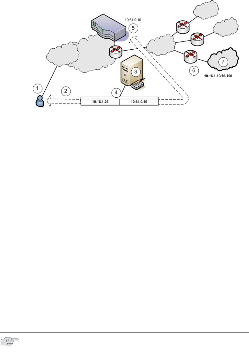
Juniper Networks Secure Access Administration Guide
778 Configuring Network Connect for use on a virtualized IVE
Figure 60: Setting a static route in MSP network DNS or application servers
1. End-users sign in over an Internet connection, using an IP address from a
Network Connect IP address pool, to reach the DNS server on the MSP
network.
2. The root administrator specifies a static route in the DNS server route table to
point to an IP address from the Network Connect IP address pool. The
subscriber company must define the Network Connect IP address pool in its
intranet.
3. The DNS server resides on the MSP network and serves all end-users of all
subscriber companies.
4. The DNS server’s route table contains a static route to the Network Connect IP
address pool and the next-hop gateway IP address.
5. The IVE appliance’s internal interface is the DNS server’s next-hop gateway
address.
6. The subscribers’ CPE routers perform the proper traffic routing to the
subscriber company intranets.
7. Each subscriber company that intends its users to pass through the MSP DNS
or application servers must define a corresponding Network Connect IP
address pool.
As shown in Figure 61, the IVS administrator can configure the subscriber CPE
router with a static route to the end-user’s IP address, with the next-hop gateway
set to the IP address of the corresponding CE router on the MSP network.
NOTE: Alternately, the subscriber can configure a default route on the CPE router
to point to the MSP CE router as the next-hop gateway. In this case, you do not
need to add individual static routes to the Network Connect IP pool addresses.
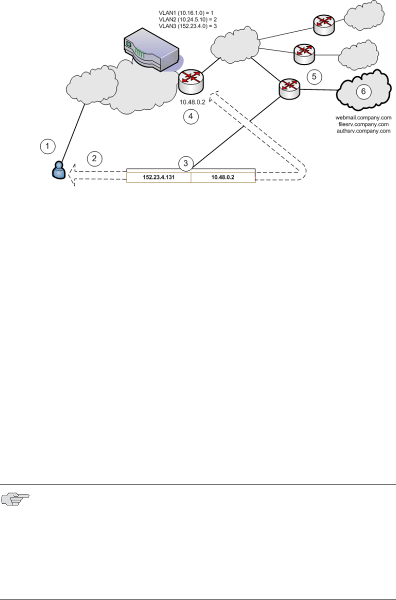
Configuring Network Connect for use on a virtualized IVE 779
Chapter 29: Instant Virtual System (IVS)
Figure 61: Setting a static route to Network Connect end-user IP address in CPE router
1. End-users sign in over an Internet connection using an IP address agreed upon
by the MSP and the subscriber company.
2. Specify a static route in the subscriber company’s CPE router’s route table to
point to the end-user sign-in IP addresses.
3. You must also specify the next-hop gateway in the CPE router’s route table.
4. You use the MSP CE router’s IP address as the next-hop IP in the CPE router’s
route table.
5. The CPE router resides on the subscriber company’s intranet. Using this
arrangement, each subscriber company must specify the static route to their
own end-user sign-in address and must specify the MSP’s CE router IP as the
next-hop gateway in the CPE route table.
6. Once the MSP VLAN termination point (in this example, a CE router)
determines the intended subscriber intranet, the termination point directs the
traffic to the appropriate CPE router, which sends the traffic to the proper
resource in the subscriber intranet.
As shown in Figure 62, you can configure a static route in the CE router to point to
the end-user’s IP address, with the next-hop gateway set to the IP address of the
subscriber’s VLAN port.
NOTE:
Alternately, you can configure a default route on the CE router with the next-
hope gateway set to the IP address of the subscriber VLAN port. In this case,
you do not need to add individual static routes to the Network Connect IP
pool addresses.
You can also allocate an entire network to an Network Connect IP address
pool.
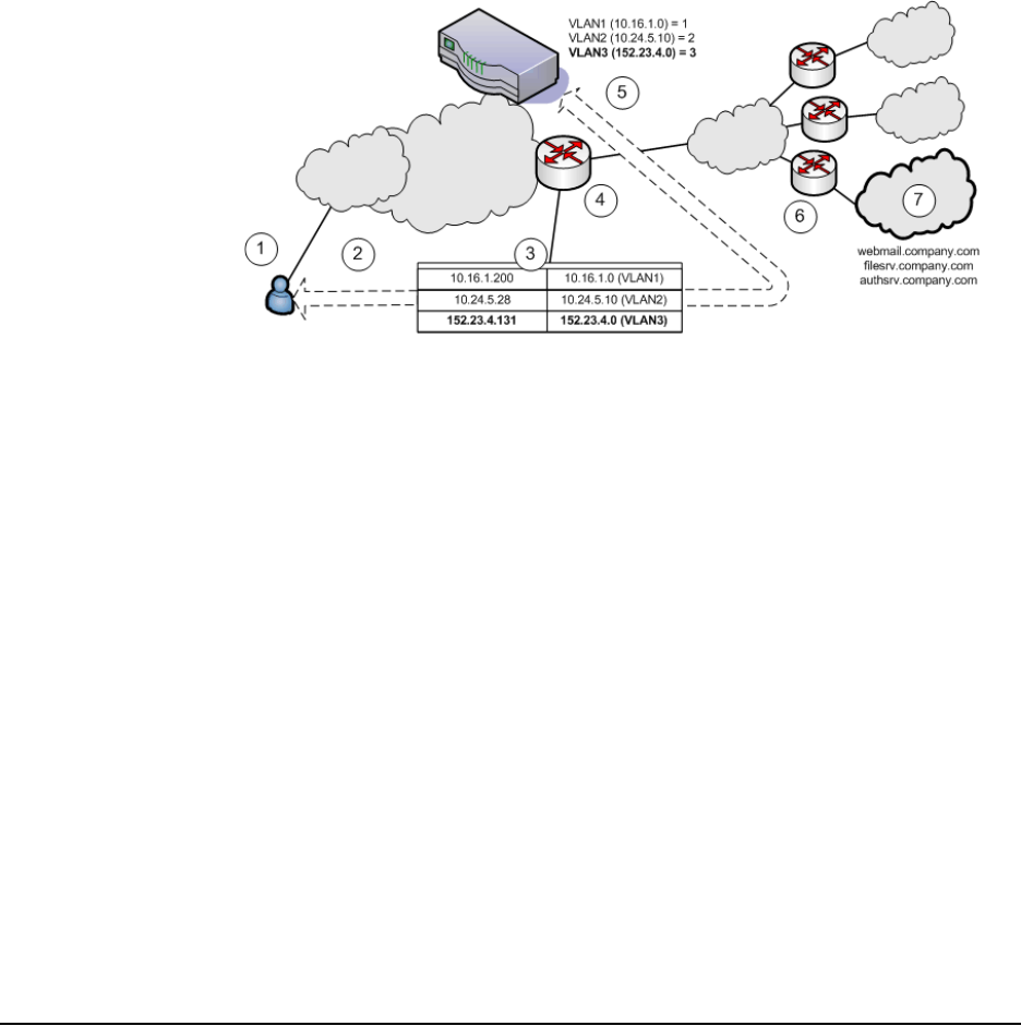
Juniper Networks Secure Access Administration Guide
780 Configuring a centralized DHCP server
Figure 62: Setting a static route to Network Connect end-user’s IP address in CE router
1. End-users sign in over an Internet connection using an IP address agreed upon
by the MSP and the subscriber company.
2. Specify a static route in the MSP’s VLAN termination point (in this example, a
CE router) route table to point to the end-user sign-in IP addresses for each
subscriber company.
3. You must also specify the next-hop gateway in the CE router’s route table.
4. In the CE route table, specify all end-user sign-in IP addresses as static routes,
and all corresponding VLAN port IP addresses as defined in the virtualized IVE.
5. Define at least one unique VLAN ID for each subscriber company. Use the IP
addresses of each VLAN as the next-hop gateway addresses in the CE router’s
route table.
6. The subscribers’ CPE routers perform the proper traffic routing to the
subscriber company intranets.
7. Each subscriber company must provide sign-in pages for the IP addresses
defined as static routes for end-user sign-in.
Once the MSP VLAN termination point (in this example, a CE router) determines
the intended subscriber intranet, the termination point directs the traffic to the
appropriate CPE router, which sends the traffic to the proper resource in the
subscriber intranet.
Configuring a centralized DHCP server
You can configure one or more centralized DHCP servers if you want to provide
Network Connect IVS users with dynamic IP addressing, without requiring each IVS
subscriber to support an IVS-specific DHCP server.
The DHCP server maintains separate IP address pools for each IVS, using the IVS
name property, defined in the IVS profile, to uniquely identify the IVS-specific
pools.

Configuring a centralized DHCP server 781
Chapter 29: Instant Virtual System (IVS)
Upon receiving a request from an IVS, the DHCP server selects an IP address based
on the IVS name and the IP address of the node from which the request originated,
which is delivered in the giaddr field of the request. Using this combination of data
points, the DHCP server picks an available IP address from the appropriate pool
and returns the address in the DHCP offer.
To configure your system to support a centralized DHCP server
1. Configure the DHCP server entry in the Network Connect Connection Profile,
for each Network Connect role that will acquire IP addresses by way of DHCP.
2. Configure the DHCP server itself, by configuring classes and subclasses on the
DHCP server to distinguish between requests from different IVS systems and to
provide IP addresses from IVS-specific IP address pools.
To configure the DHCP server entry in the Network Connect Connection Profile
1. In the Root context, choose Users > Resource Policies > Network Connect.
2. Click the NC Connection Profiles tab.
3. Click New Profile.
4. Enter a name for the profile.
5. Under IP address assignment, select the DHCP Server radio button.
6. Enter the DHCP server name or IP address.
7. Under Roles, select the applicable roles in the Available roles list box and click
Add to move them to the Selected roles list box.
8. Click Save Changes.
9. Repeat the procedure for each IVS that should use the DHCP server., making
sure to enter the same DHCP server name or IP address that you entered for
the Root.
NOTE: The following notes apply to the use of a centralized DHCP server in an IVS
configuration:
You can configure the same DHCP server IP address for Network Connect
roles in multiple IVS systems.
Within a Network Connect role, if you configure both an NC IP pool and a
DHCP server for the same role, the DHCP server takes precedence.
DHCP IP address assignment can co-exist with IP address assignment by way
of NC IP pools within an IVS.
You can employ multiple DHCP servers in the service provider network, with
different groups of IVS systems pointing to different central servers.

Juniper Networks Secure Access Administration Guide
782 Configuring authentication servers
Configuring authentication servers
You can configure authentication servers, such as RADIUS and Active Directory, on
both the MSP network and the subscriber company intranets. The authentication
server authenticates the incoming traffic differently depending on whether the
traffic is authenticated when it comes into the MSP network or when it reaches the
customer intranet.
The following authentication servers are supported on a subscriber IVS:
Local Authentication
LDAP Server
RADIUS Server
Active Directory/Windows NT
Anonymous Server
Certificate Server
The following authentication servers are supported on the root system:
Local Authentication
LDAP Server
NIS Server
ACE Server
RADIUS Server
Active Directory/Windows NT
Anonymous Server
SiteMinder Server
Certificate Server
Rules governing access to authentication servers
The following rules apply to the access of authentication servers on the MSP
network or on the subscriber company network. Each IVS profile must include
settings for:
NOTE: If you connect an authentication server to the internal port, you must set
the default VLAN to the internal port when configuring the IVS.

Configuring authentication servers 783
Chapter 29: Instant Virtual System (IVS)
The default VLAN, which can also be the internal port, if provisioned as the
default VLAN.
The default VLAN interface IP is the source IP address used to contact the
authentication server.
Static routes in the VLAN that point to the appropriate authentication servers,
which can reside in the MSP network (with an assigned VLAN ID or untagged
on the internal port), or on the subscriber company network.
Configuring authentication on a RADIUS server
You must configure the RADIUS server in each IVS. If you have a RADIUS server on
the MSP network as well, all of the IVS RADIUS servers can point to the same MSP
RADIUS IP address.
To configure the RADIUS server:
1. Select the context:
If you are in an IVS context, and you want to define a RADIUS server on
the MSP network, select Root from the context drop down menu in the
admin console header bar and click Go.
If you are in the root context, and you want to define a RADIUS server on a
subscriber intranet, select the IVS name from the context drop down menu
in the admin console header bar and click Go.
2. Refer to the instructions in “Configuring a RADIUS server instance” on
page 120.
Configuring authentication on Active Directory
You must configure the AD/NT server in each IVS. If you have an AD/NT server on
the MSP network as well, all of the IVS AD/NT servers can point to the same MSP
AD/NT IP address.
To configure the Active Directory server:
1. Select the context:
If you are in an IVS context, and you want to define an AD/NT server on
the MSP network, select Root from the context drop down menu in the
admin console header bar and click Go.
If you are in the root context, and you want to define an AD/NT server on a
subscriber intranet, select the IVS name from the context drop down menu
in the admin console header bar and click Go.
NOTE: In the current release, ACE authentication is not available for individual IVS
systems. If you want to use RSA 2 factor token-based authentication, you should
use RADIUS from the IVS to access RSA ACE.

Juniper Networks Secure Access Administration Guide
784 Delegating administrative access to IVS systems
2. Refer to the instructions in “Configuring an Active Directory or NT Domain
instance” on page 99.
Delegating administrative access to IVS systems
As the root administrator, you can delegate administrative access and
responsibilities to specific IVS systems. You can delegate read/write access or read-
only access to all IVS systems, or to selected IVS systems.
To delegate administrative access to IVS systems
1. Select Administrators > Admin Roles > SelectRole where SelectRole indicates
one of the listed administrator roles. You can also create a new administrator
role, if you prefer.
2. Click the IVS tab.
3. If you want to give the administrator read/write access to the IVS, select one of
the following:
If you want to give the administrator read/write access to all IVS systems,
select the Administrator can manage ALL IVSs checkbox.
If you want to limit the administrator’s access to specific IVS systems,
select the Administrator can manage SELECTED IVSs checkbox, then
select the IVS systems from the Available IVSs list and click Add to move
them to the Selected IVSs list.
4. If you want to give the administrator read only access to the IVS, select one of
the following:
If you want to give the administrator read only access to all IVS systems,
select the Administrator can view (but not modify) ALL IVSs checkbox.
If you want to limit the administrator’s access to specific IVS systems,
select the Administrator can view (but not modify) SELECTED IVSs
checkbox, then select the IVS systems from the Available IVSs list and
click Add to move them to the Selected IVSs list.
5. Click Save Changes.
By adding these access rights to a given role, you can exercise different levels of
control over different MSP administrators.
Accessing standalone installers
The IVS administrator might need to access the Host Checker, WSAM, or other
standalone installers. To give IVS administrators access to the installers, which are
located on the Maintenance > System > Installers page, you can delegate the
access to them by way of the Administrators > Admin Roles > SelectRole > IVS
page. Once you have delegated access, the IVS administrator can see the Installers
page from within the context of the IVS admin console.

Performing export and import of IVS configuration files 785
Chapter 29: Instant Virtual System (IVS)
For more information about the installers, see “Downloading application installers”
on page 577.
Performing export and import of IVS configuration files
Use the IVE binary import/export feature to export and import root system and
user settings, and also to export and import subscriber IVS settings and profiles.
The two types of operations are mutually exclusive: if exporting IVS settings, the
exported configuration file does not contain root system settings; if exporting root
system settings, the exported configuration file does not contain subscriber IVS
settings.
You perform export and import operations from the context of the root system. On
the Maintenance > Import/Export > Import/Export Configuration page and on
the Maintenance > Import/Export > Import/Export Users page, you can find the
standard controls for exporting root system and user configuration. A subscriber
IVS administrator cannot export or import data from or to a subscriber IVS. Only
you, as the root administrator, can perform these tasks.
Exporting and importing the root system configuration
To export and import the root system configuration, navigate to the Maintenance
> Import/Export > Import/Export Configuration page, and refer to the
instructions in “Importing and exporting IVE configuration files” on page 632.
Exporting IVS configurations
To export IVS configurations, perform the following steps:
1. Select the Maintenance > Import/Export > Import/Export IVS page.
2. To password protect the configuration file, enter a password in the Password
for configuration file: text box.
3. Click Save Config As.
4. Click Save.
5. Provide a file name and target location for the file.
6. Click Save and Close, if necessary.
The saved configuration file contains the following settings for all IVS systems:
NOTE:
You can only import/export all IVS systems in a single operation. You cannot
import/export an individual IVS system’s configuration.
You can also use the IVE binary archiving feature to perform local backups of
your IVS system. For more information, see “Archiving IVE binary
configuration files” on page 628.

Juniper Networks Secure Access Administration Guide
786 Performing export and import of IVS configuration files
IVS Profiles
IVS System Settings
IVS Signing In Settings
IVS Administrators
IVS Users
IVS Resource Policies
IVS Maintenance Settings
Importing IVS configurations
To import IVS configurations, perform the following steps:
1. Select the Maintenance > Import/Export > Import/Export IVS page.
2. Click Browse.
3. Locate and select the file and click Open.
4. If you password protected the configuration file, enter the password in the
Password: text box.
5. To import the network settings in the IVS profile, such as VLAN ports and
virtual ports, select the Import IVS Profile Network Settings checkbox.
6. Click Import Config.
NOTE:
Importing network settings as described in above only works if you export the
system and IVS configurations from the same system.
The network settings themselves do not get imported; only the references to
the network settings get imported. Network settings are only
imported/exported when importing/exporting the root system settings.

Monitoring subscribers 787
Chapter 29: Instant Virtual System (IVS)
The IVS provides a confirmation message if the import operation succeeds. The IVS
then restarts certain services, which may require several minutes.
Monitoring subscribers
Log files contain detailed information about events, user access, administrator
access and more. The log entries specify the context of each entry, whether the
entry was caused by a root action or an action on one of the IVS systems. The root
entries contain the word Root. For example, the following entries show access by
two administrators, the first being Root and the second, an administrator called
Test:
ADM20716 2005-05-10 10:52:19 - ive - [10.11.254.160]
Root::administrator(administrator Users)[.Administrators] - User Accounts
modified. Added Unspecified Name with username testuser1 to authentication
server System Local.
Info ADM20716 2005-05-10 10:35:26 - ive - [10.11.254.160]
Test::administrator(administrator Users)[.Administrators]!Root - User Accounts
modified. Added IVE Platform Administrator with username omiadmin to
authentication server Administrators.
Suspending subscriber access to the IVS
To suspend subscriber access to the IVS:
1. Select System > Virtual Systems.
2. Click the Disabled radio button.
By performing this step, you make the IVS unavailable to any user of the IVS,
including the IVS administrator. To provide access to the IVS, set the radio button to
the Enabled state.
NOTE:
You can use the XML Import/Export feature to export and import XML-based
configuration files on the root IVS. You cannot use the XML Import/Export
feature for subscriber IVS systems. Instead, use the binary configuration file
import/export.
You can use Push Config to copy one root IVS configuration to another root
IVS. You cannot use Push Config to copy configuration data between
subscriber IVS systems or from a root IVS to a subscriber IVS.

Juniper Networks Secure Access Administration Guide
788 Troubleshooting VLANs
Troubleshooting VLANs
In addition to the standard troubleshooting features provided by the IVE, the
virtualized IVE provides several enhancements, specifically for managing IVS
systems. You can use the following troubleshooting features on either the root
system or each IVS, separately:
Policy simulation
Policy tracing
Session recording
Functionally, these utilities are the same as the standard IVE capabilities. The key
difference is a matter of context. If you initiate one of these three utilities from the
root system context, you get results for users, policies, and sessions on the root
system or from the MSP network. If you initiate the utilities from a subscriber IVS
context, you get results for users, policies, and sessions on the IVS or the subscriber
intranet. For more information about user sessions, policy tracing, and session
recording, see “Troubleshooting” on page 689.
The TCPDump, Ping, Traceroute, NSLookup, and ARP commands are enhanced for
use in virtualized IVE systems. You can initiate these commands on the internal
and external ports, as well as on selected VLAN ports, which you might do if you
want to troubleshoot traffic on a subscriber VLAN. The basic functionality of the
commands is unchanged, except for the ability to specify a VLAN port
Performing TCPDump on a VLAN
1. If you are not in the root system context, select Root from the IVS drop down
menu in the admin console header, and then click Go.
2. Choose Troubleshooting > TCP Dump.
3. With Internal Port selected, select the VLAN from the VLAN Port drop down
menu.
4. Add a filter to the Filter text box (Optional).
5. Click Start Sniffing.
6. To retrieve the results, click Stop Sniffing.
7. Choose the type of Dump file from the Dump File drop down menu.
8. Click Get.
9. Open the file with the appropriate editor.
For more information on using TCP Dump, see “Creating TCP dump files” on
page 696.

IVS use cases 789
Chapter 29: Instant Virtual System (IVS)
Using commands on a VLAN (Ping, traceroute, NSLookup, ARP)
1. If you are not in the root system context, select Root from the IVS drop down
menu in the admin console header, and then click Go.
2. Choose Troubleshooting > Commands.
3. Select a command from the Command drop down menu.
4. Enter the target server.
5. Select the VLAN from the VLAN Port drop down menu.
6. Enter the other settings, depending on the command you choose.
7. Click OK.
For more information on using TCP Dump, see “Creating TCP dump files” on
page 696.
IVS use cases
The following use cases illustrate some common tasks you might want to perform
while configuring your IVS system.
“Policy routing rules resolution use case for IVS” on page 789
“Configuring a global authentication server for multiple subscribers” on
page 795
“Configuring a DNS/WINS server IP address per subscriber” on page 795
“Configuring access to Web applications and Web browsing for each
subscriber” on page 796
“Configuring file browsing access for each subscriber” on page 797
“Setting up multiple subnet IP addresses for a subscriber’s end-users” on
page 798
“Configuring multiple IVS systems to allow access to shared server” on
page 799.
“Configuring Network Connect for use on a virtualized IVE” on page 777
Policy routing rules resolution use case for IVS
This use case illustrates how policy routing takes place in an MSP deployment. The
first part of the use case details two subscriber company configurations and how
end-users access their respective subscriber company networks. The second part of
the use case describes what happens when you create a VLAN on the MSP network
to provide shared services to the subscriber companies’ end-users.
Juniper Networks Secure Access Administration Guide
790 IVS use cases
Company 1 and Company 2 are hosted companies on the MSP network. Table 47
shows the VLANs, VLAN IDs, interfaces and roles defined for each company.
Company 1 has defined two VLANs, one for Sales and one for Human Resources.
Each company has an associated role defined for each VLAN. The root
administrator creates each VLAN, providing a unique VLAN ID for each, and
indicating a given port. In this case, the root administrator has created all four
VLANs on the internal interface.
Figure 63 illustrates the MSP and subscriber company deployments.
Table 47: Deployments in MSP and subscriber company networks
VLAN VLAN ID Interface Role
Company 1 Sales 1 int0.1 SALES
HR 2 int0.2 HR
Company 2 Employee 3 int0.3 EMPLOYEE
Partner 4 int0.4 PARTNER
NOTE:
The labels for ports have been changed. The port name eth0 (internal port) is
now called int0 and eth1 (external port) is now ext0.
You can only see the route table device names (such as int0.1) from the serial
console. You can view the route table by selecting menu item 1, then menu
item 2 from the serial console.
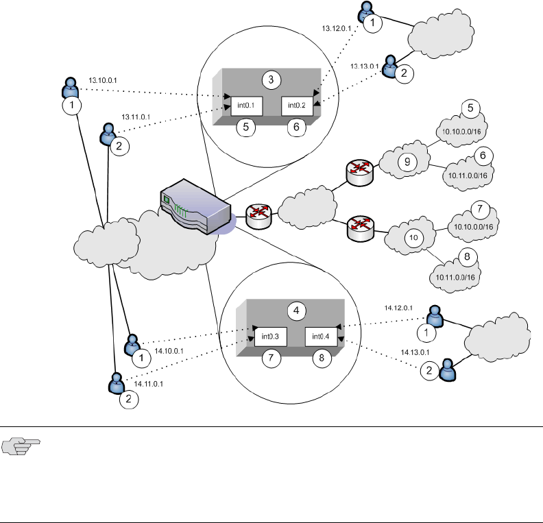
IVS use cases 791
Chapter 29: Instant Virtual System (IVS)
Figure 63: MSP and subscriber company deployment
In Figure 63, Network Connect end-users get their source IP addresses from
configured Network Connect IP address pools that the root administrator has
defined for the IVS. Also, in the figure, non-Network Connect users can still access
specified realms based on their roles and on role-based source IP (VIP sourcing)
addresses that you define as virtual ports on the VLAN.
The following list describes each item that is marked with a numbered label in
Figure 63.
1. Network Connect end-users get IP addresses from Network Connect IP pools.
Traffic from these users is routed through the appropriate subscriber VLAN,
which you define on the internal port.
2. Non-Network Connect end-users get IP addresses from virtual IP (VIP) pools.
Traffic from these users is sourced through the appropriate subscriber VLAN.
3. In Figure 63, this numbered box represents a subscriber IVS, which contains
two VLANs that are defined on ports int0.1 and int0.2.
NOTE: IVS VLANs are not explicitly tied to subscriber intranets by configuration on
the IVE. The association of a VLAN to a subscriber intranet is accomplished by
mapping VLAN interfaces to private tunnels in the subscriber intranet within the
CE->CPE router framework. For more information, refer to the discussion on
static routes in “Adding static routes to the VLAN route table” on page 764.
Juniper Networks Secure Access Administration Guide
792 IVS use cases
4. In Figure 63, this numbered box represents a second subscriber IVS, which
contains two VLANs that are defined on ports int0.3 and int0.4.
5. The subscriber defines a role for “Sales” on VLAN1. End-users signing in to IP
13.10.0.1 over the Internet are routed to the Company 1 intranet, to the
appropriate backend resources located in the “Sales” realm at 10.10.0.0/16.
End-users signing in on IP 13.11.0.1 are VIP sourced to the Company 1
intranet, also to the appropriate backend resources located in the “Sales” realm
at 10.10.0.0/16.
6. The subscriber defines a role for “HR” on VLAN2. End-users signing in on IP
13.12.0.1 over the Internet are routed to the Company 1 intranet, to the
appropriate backend resources located in the “HR” realm at 10.11.0.0/16. End-
users signing in on IP 13.13.0.1 are VIP sourced to the Company 1 intranet,
also to the appropriate backend resources located in the “HR” realm at
10.11.0.0/16.
7. The subscriber defines a role for “Employee” on VLAN3. End-users signing in
on IP 14.10.0.1 over the Internet are routed to the Company 2 intranet, to the
appropriate backend resources located in the “Employee” realm at
10.10.0.0/16. End-users signing in on IP 14.11.0.1 are VIP sourced to the
Company 2 intranet, also to the appropriate backend resources located in the
“Employee” realm at 10.10.0.0/16.
8. The subscriber defines a role for “Partner” on VLAN4. End-users signing in on
IP 14.12.0.1 over the Internet are routed to the Company 2 intranet, to the
appropriate backend resources located in the “Partner” realm at 10.11.0.0/16.
End-users signing in on IP 14.13.0.1 are VIP sourced to the Company 2
intranet, also to the appropriate backend resources located in the “Partner”
realm at 10.11.0.0/16.
9. The Company 1 intranet supports two realms: “Sales” at 10.10.0.0/16 and
“HR” at 10.11.0.0/16. These realms correspond to the roles defined on VLAN1
and VLAN2/
10. The Company 2 intranet supports two realms: “Employee” at 10.10.0.0/16 and
“Partner” at 10.11.0.0/16.
The route tables for each VLAN appear as follows:
NOTE: The realms are valid even though they contain overlapping IP addresses.
Because the roles are defined for different VLANs, the VLAN IDs provide the
separation that allows them to overlap without danger of mixed traffic.
Table 48: VLAN1 route table
Destination IP Gateway Output port
0.0.0.0 Default gateway on VLAN1 int0.1
10.10.0.0/16 0.0.0.0 int0.1
IVS use cases 793
Chapter 29: Instant Virtual System (IVS)
Now consider the situation in which the MSP decides to provide shared services to
end-users of Company 1 and Company 2. Assume the MSP network is also on a
VLAN (VLAN5). If you want to provide services on 10.64.0.0/16 to both Company 1
and Company 2, and services on 10.65.0.0/16 to Company 2 only, you can
configure either Network Connect pools or virtual ports for those addresses.
Figure 64 illustrates this situation.
Table 49: VLAN2 route table
Destination IP Gateway Output port
0.0.0.0 Default gateway on VLAN2 int0.2
10.10.0.0/16 0.0.0.0 int0.2
Table 50: VLAN3 route table
Destination IP Gateway Output port
0.0.0.0 Default gateway on VLAN3 int0.3
10.10.0.0/16 0.0.0.0 int0.3
Table 51: VLAN4 route table
Destination IP Gateway Output port
0.0.0.0 Default gateway on VLAN4 int0.4
10.10.0.0/16 0.0.0.0 int0.4
NOTE: Some details from Figure have been removed or greyed out to improve
readability of Figure 64.
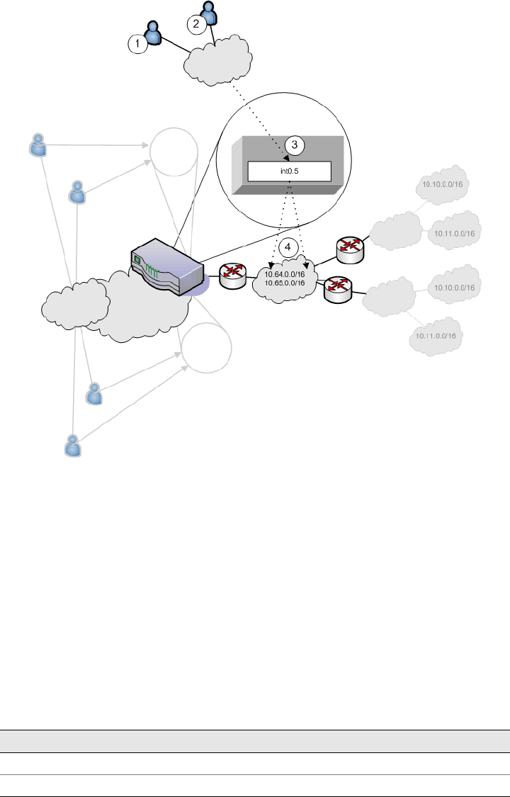
Juniper Networks Secure Access Administration Guide
794 IVS use cases
Figure 64: MSP VLAN providing shared services
1. Company 1 end-users sign-in over the Internet to the MSP network and the
MSP VLAN, VLAN5 (represented as number 3 in the illustration).
2. Company 2 end-users sign-in over the Internet to the MSP network and the
MSP VLAN, VLAN5 (represented as number 3 in the illustration).
3. The MSP VLAN5 provides access to shared services on the MSP network.
4. You must define separate IP addresses for each subscriber company’s end-
users, even though they share MSP services.
Once you configure routes to support users who have access to shared services on
the MSP network and to support users who also have access to restricted MSP
network services, the VLAN route tables appear as follows:
Table 52: VLAN1 route table
Destination IP Gateway Output port
0.0.0.0 Default gateway on VLAN1 int0.1
10.64.0.0 Router on VLAN5 int0.5

IVS use cases 795
Chapter 29: Instant Virtual System (IVS)
Configuring a global authentication server for multiple subscribers
If your subscriber companies prefer to lease or purchase authentication services
from you, the service provider, you can configure a global authentication server on
your network. In that case, you must perform several tasks:
1. Configure one or more authentication servers on your MSP network.
2. Configure path-based URLs or virtual ports for sign-in on your MSP network.
3. Configure VLANs and IVS systems to map to the authentication servers on the
MSP network.
For more information, see “Configuring authentication servers” on page 782.
Configuring a DNS/WINS server IP address per subscriber
If you want to configure a particular DNS/WINS server IP address per subscriber,
you can do so from within each IVS.
To configure a DNS/WINS server IP address:
1. Configure your IVS systems.
2. Select an IVS from the system drop down menu in the admin console header
area and then click Go. Within the IVS context, the header color changes and
displays the name of the subscriber.
Table 53: VLAN2 route table
Destination IP Gateway Output port
0.0.0.0 Default gateway on VLAN2 int0.2
10.64.0.0 Router on VLAN5 int0.5
Table 54: VLAN3 route table
Destination IP Gateway Output port
0.0.0.0 Default gateway on VLAN3 int0.1
10.64.0.0 Router on VLAN5 int0.5
10.65.0.0 Router on VLAN5 int0.5
Table 55: VLAN4 route table
Destination IP Gateway Output port
0.0.0.0 Default gateway on VLAN4 int0.2
10.64.0.0 Router on VLAN5 int0.5
10.65.0.0 Router on VLAN5 int0.5
NOTE: If the MSP network is connected to the untagged port (internal), the route
entries are similar, but the output port is int0 only.
Juniper Networks Secure Access Administration Guide
796 IVS use cases
3. Select System > Network > Overview.
4. Enter the DNS/WINS settings that correspond to the DNS/WINS server on the
subscriber intranet.
5. Click Save Changes.
For more information, see “Configuring DNS for the IVS” on page 774. For an
example of how to set up a global DNS/WINS server, see “Configuring Network
Connect for use on a virtualized IVE” on page 777.
Configuring access to Web applications and Web browsing for each subscriber
The IVS administrator may want to configure specific Web browsing policies for the
IVS end-users.
To configure Web browsing access, the IVS administrator needs to configure the
following pages:
Users > User Roles > RoleName > Web
Users > Resource Policies > Web
Configuring Web browsing access
To configure Web browsing access:
1. Choose Users > User Roles > RoleName > Web.
2. Select the Bookmarks tab.
3. Click New Bookmark.
4. Supply settings to configure the bookmark to a given Web URL.
5. Click Save Changes or Save + New if you want to add multiple bookmarks.
The bookmarks you define here appear in the Secure Access Web bookmarks
section to which end-users have access.
6. Select the Options tab.
7. Select the Web browsing privileges you want to provide to your end-users.
8. Choose the other options you want, including setting the timeout value for the
HTTP connection.
9. Click Save Changes.
Configuring Web browsing access policies
To configure Web browsing access policies:
1. Choose Users > Resource Policies > Web.
2. Supply the appropriate settings on each of the tabs.
IVS use cases 797
Chapter 29: Instant Virtual System (IVS)
For information on resource policies and how to configure Web resource policies,
see both “Web rewriting” on page 281 and “Defining resource policies: Overview”
on page 322.
Configuring file browsing access for each subscriber
The IVS administrator may want to configure specific file-browsing access policies
for the IVS end-users. The IVS administrator can perform this type of operation
based on roles.
To configure file browsing, the IVS administrator needs to configure the following
pages:
Users > User Roles > RoleName > General
Users > User Roles > RoleName > Files
Users > Resource Policies > Files
Configuring file browsing access
To configure file browsing access:
1. Choose Users > User Roles > RoleName > General.
2. Under Access Features, select the Files checkbox (for Windows).
3. Click Save Changes.
4. Select the Files tab.
5. Select the Options page.
6. Depending on the file system type, select the options that apply to the IVS end-
user access.
7. Click Save Changes.
Configuring file system bookmarks
To configure file system bookmarks:
1. Make sure you are in the IVS context. If the IVS drop down menu in the admin
console header bar displays Root, select the IVS name from the menu and click
Go.
2. Select Users > User Roles > RoleName > General > Files.
3. Select either the Windows Bookmarks or the UNIX Bookmarks page.
4. Click New Bookmark.
5. Supply the appropriate settings.
6. Click Save Changes.
Juniper Networks Secure Access Administration Guide
798 IVS use cases
For more information on setting up bookmarks to file systems, see “File rewriting”
on page 371.
Configuring file system access policies
To configure file system access policies:
1. Make sure you are in the IVS context. If the IVS drop down menu in the admin
console header bar displays Root, select the IVS name from the menu and click
Go.
2. Select Users > Resource Policies > Files > Access > Windows.
3. Choose the role from the Show policies that apply to drop down menu, and
click Update.
4. Click New Policy.
5. Supply the appropriate settings.
6. Click Save Changes.
7. Select the Credentials tab.
8. Supply the appropriate settings.
9. Click Save Changes.
10. Repeat these steps for each role.
11. Select the Encoding tab to select the language encoding and click Save
Changes.
12. Select the Options tab to set options, such as IP based matching for Hostname
based policy resources and click Save Changes.
For more information on file policies, see “Defining resource policies: UNIX/NFS file
resources” on page 389. For more information on encoding, see “Multi-language
support” on page 843. For more information on access options, see “Writing
UNIX/NFS resource policies” on page 391.
Setting up multiple subnet IP addresses for a subscriber’s end-users
Assume that the subscriber wants to create subnets within the intranet to support
traffic separation between subscriber end-users from three different departments:
Marketing, Finance, and Engineering. The procedures needed to accomplish this
task are divided between those performed by the root administrator and those
performed by the IVS administrator.
Tasks performed by the root administrator
1. Create subscriber VLAN. See“Configuring a Virtual Local Area Network (VLAN)”
on page 762.
2. Create subscriber IVS. See “Creating a virtual system (IVS profile)” on
page 766.
IVS use cases 799
Chapter 29: Instant Virtual System (IVS)
3. Create path-based URLs or virtual ports for sign-in. See“Signing-in using the
sign-in URL prefix” on page 751 or “Configuring a virtual port for sign-in on the
internal port” on page 761.
4. Create virtual ports for role-based source IP aliasing. See “Configuring role-
based source IP aliasing” on page 769.
Tasks performed by the IVS administrator
1. Create users. Create roles for Marketing, Finance, and Engineering. See
“Configuring user roles” on page 54.
2. Assign roles to VLAN/Source IP. See “Associating roles with source IP addresses
in an IVS” on page 770.
3. Assign users to roles. See “Creating user accounts on a local authentication
server” on page 117.
Configuring multiple IVS systems to allow access to shared server
There may be cases in which you want to provide end-users of multiple subscriber
companies to access a shared server on the MSP network. For more information
about accessing shared servers, see “Configuring Network Connect for use on a
virtualized IVE” on page 777 and “Policy routing rules resolution use case for IVS”
on page 789.
The following steps describe a simple use case and solutions.
Solution #1
To configure access to a shared server, assuming two IVS systems for two
subscribers:
1. Add the internal port to the IVS1 list of selected VLANs.
2. Add the internal port to the IVS2 list of selected VLANs. For instructions on
adding ports to the IVS system’s selected VLAN field, see “Provisioning an IVS”
on page 757.
3. Edit the internal port’s route table and configure a static route pointing to the
shared server, with the internal interface as the output port.
Solution #2
To configure access to a shared server, assuming two IVS systems for two
subscribers:
1. Add VLAN1 to the IVS1 selected VLAN list and set it as the default VLAN.
2. Add VLAN2 to the IVS2 selected VLAN list and set it as the default VLAN. For
instructions on adding VLANs to the IVS system’s selected VLAN field, see
“Provisioning an IVS” on page 757.
3. Edit the route tables for both VLAN1 and VLAN2 and configure a static route in
each that points to the shared server, with the internal interface as the output
port.
Juniper Networks Secure Access Administration Guide
800 IVS use cases

801
Chapter 30
IVE and IDP Interoperability
Securing intranet work application and resource traffic is vital to protecting your
network from hostile outside intrusion. You can add levels of application security to
your remote access network by integrating a Juniper Networks Secure Access
appliance with a Juniper Networks Intrusion Detection and Prevention (IDP) Sensor.
The IDP device may provide the following types of protection in this solution (some
forms of protection depend upon the specific configuration):
Protects against attacks from user to application and from application to user
(from a server-side endpoint)
Detects and blocks most network worms based on software vulnerabilities
Detects and blocks non-file-based Trojan Horses.
Detects and blocks effects of Spyware. Adware, and Key Loggers
Detects and blocks many types of malware
Detects and blocks zero day attacks through the use of anomaly detection
You do not need a special license from Juniper Networks to enable interaction
between the IVE and the IDP, you just need to posses and have enabled a valid
“Advanced” IVE license.
Using the IVE’s Admin console, you can configure and manage interaction
attributes between the IVE and an IDP including the following:
Global configuration parameters like the IDP hostname or IP address, the TCP
port over which the sensor monitors the intranet for possible intrusion, and the
one-time password the IVE and IDP use to authenticate with one another
Dynamically changing the IDP configuration from the IVE and alerting the IDP
of changes in the IP address pool available to remote users
Various levels of attack severity warnings
NOTE: An IDP Sensor can send logs to one IVE appliance only. However, an IVE
appliance can receive logs from more than one IDP Sensor.

Juniper Networks Secure Access Administration Guide
802 Licensing: IDP availability
The IDP sits behind the IVE on your internal network and monitors traffic flowing
from the IVE into the LAN. Any abnormal events detected by the IDP Sensor are
reported to the IVE, which you configure to take appropriate action based on the
severity level of the reported events. The IDP Sensor performs reporting functions
in addition to any normal logging the IDP has been configured to undertake.
Licensing: IDP availability
The IDP integration feature is not available on the SA 700 and is only available on
all other Secure Access products that have an “Advanced” IVE license.
Deployment scenarios
The two most likely deployment scenarios are as follows:
Customer use of IVE for extended enterprise access and IDP for security of all
perimeter traffic including but not limited to traffic from the IVE. Figure 65
illustrates this scenario, in which the IVE is deployed in the DMZ or on the LAN
and the IDP is deployed in-line behind the firewall and in front of the LAN.
Figure 65: IVE and IDP topology scenario 1
In the second deployment scenario, IDP is only used to protect traffic that
comes through the IVE but not in-line with other perimeter traffic. Figure 66
illustrates this deployment scenario.
NOTE: You can use an IDP Sensor on an IVE cluster, if the cluster is configured
with a virtual IP (VIP) address.
InternetMobile Users IVE Attack message LAN
IDP
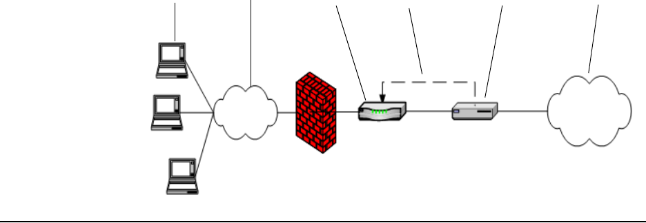
Configuring the IVE to Interoperate with an IDP 803
Chapter 30: IVE and IDP Interoperability
Figure 66: IVE and IDP topology scenario 2
Configuring the IVE to Interoperate with an IDP
The IDP Sensor can be a powerful tool to counter users who perform attacks. The
integration with the IVE allows you to configure automatic responses as well as to
manually monitor and manage users.
To configure the IVE to interoperate with an associated IDP Sensor, you must first
ensure the IDP has been configured according to the instructions described in the
“IVE Signaling Setup” appendix of the Intrusion Detection and Prevention Concepts &
Examples Guide. Once the IDP Sensor has been set up, you can specify the events
you want the IDP to watch for and the actions that the IVE takes once a particular
event has been noted and reported.
There are two locations on the IVE where you can specify actions to be taken in
response to users that perform attacks:
Sensor Event policies page—Define the policy on this page to generate an
automatic response to users who perform attacks.
Users page—Manually identify and quarantine or disable users on the System >
Status > Active Users page, which lists users who have performed attacks. For
more details, see “Identifying and managing quarantined users manually” on
page 807.
Configuring IDP connections
The Sensors tabs allow you to specify the system settings the IVE uses to establish a
connection to a Juniper Network’s Intrusion Detection and Prevention (IDP) device.
Use the System > Configuration > Sensors > Sensors tab to perform a number
of tasks related to configuring and managing interaction between the IVE and an
IDP Sensor. This section contains the following topics:
“Creating a new IDP Sensor entry” on page 804
“Enabling or disabling the connection to an existing IDP Sensor” on page 804
Mobile Users Internet LAN
IVE Attack message IDP

Juniper Networks Secure Access Administration Guide
804 Configuring the IVE to Interoperate with an IDP
“Deleting an IDP Sensor entry” on page 805
“Reconnecting to an IDP and refreshing IDP connection status” on page 805
Creating a new IDP Sensor entry
You can enable and disable IDP connection entries on the IVE.
To enable or disable existing IDP Sensor entries on the IVE:
1. In the admin console, choose System > Configuration > Sensors.
2. Click New Sensor. The admin console displays the New Sensor page.
3. Under Sensor Properties, specify the following information:
Name—A name the IVE uses to identify the new connection entry
Hostname—The hostname or IP address of the IDP Sensor to which the
IVE connects in order to receive application and resource attack alert
messages
Port—The TCP port on the IDP Sensor that the IVE listens to when
receiving application and resource attack alert messages
One-time Password—The encrypted password the IVE uses when
conducting the initial Transport Layer Security (TLS) handshake with the
IDP Sensor. You must enter the encrypted IVE OTP password as displayed
on the IDP ACM configuration summary screen.
4. Under Monitoring Options, specify IP addresses to monitor and the minimum
alert severity level the IDP Sensor will record and submit to the IVE:
a. In the Addresses to monitor field, specify individual IP addresses and/or IP
address ranges the IDP Sensor monitors for potentially hostile attacks, one
entry per line.
b. Select one of the options available in the Severity filter drop down list. The
severity level range is gradient along a scale from 1 to 5, where 1 is
informational and 5 is critical.
5. Click Save Changes.
Enabling or disabling the connection to an existing IDP Sensor
You can enable and disable IDP connection entries on the IVE.
To enable or disable existing IDP Sensor entries on the IVE:
1. In the admin console, choose System > Configuration > Sensors.
NOTE: The hostname, TCP port, and one-time password must already be
configured on the IDP Sensor before this configuration can be successful.
Configuring the IVE to Interoperate with an IDP 805
Chapter 30: IVE and IDP Interoperability
2. Select the checkbox next to one or more IDP Sensor entries you want to enable
or disable.
3. Click Enable or Disable to enable or disable the specified IDP Sensor entries,
respectively.
Deleting an IDP Sensor entry
You can delete existing IDP Sensor entries that define a connection between the
IVE and an IDP Sensor.
To delete one or more existing IDP Sensor entries from the IVE:
1. In the admin console, choose System > Configuration > Sensors.
2. Select the checkbox next to the IDP Sensor entry or entries you want to delete.
3. Click Delete and then confirm that you want to delete the sensor entry or
entries.
Reconnecting to an IDP and refreshing IDP connection status
When the connection to an IDP Sensor is down, you can use the admin console on
the IVE to try and re-establish the connection. You can also use the admin console
to refresh the status of existing connections between the IVE and the IDP Sensor.
If you need to re-establish communication with an IDP Sensor, you must generate a
new One-time Password, as described in “Creating a new IDP Sensor entry” on
page 804.
To reconnect to an associated IDP Sensor:
1. In the admin console, choose System > Configuration > Sensors.
2. Select the checkbox next to the IDP Sensor to which you want to reconnect.
3. Click Reconnect.
The admin console displays a message informing you that the IVE is currently
attempting to re-establish connection to the specified IDP Sensor. This page
automatically refreshes each second during the reconnection process.
Otherwise, the connection status page automatically refreshes once every
thirty seconds.
To refresh and display the connection status for the specified IDP Sensor:
1. In the admin console, choose System > Configuration > Sensors.
2. Select the checkbox next to one or more IDP Sensor entries for which you want
to display current connection status.
3. Click Refresh.
Juniper Networks Secure Access Administration Guide
806 Configuring the IVE to Interoperate with an IDP
Defining automatic response sensor event policies
Use the System > Configuration > Sensors > Sensor Event Policies tab to
specify one or more rules that specify the action(s) the IVE takes when it receives
attack alert messages from an IDP Sensor.
To create a new IDP rule:
1. In the admin console, choose System > Configuration > Sensors > Sensor
Event Policies.
2. On the Sensors page, click New Rules.
3. On the Juniper IDP Rule page, in the Rule: On Receiving... section:
Select an existing event from the Event drop-down list
Click Events to edit an existing event or create a new type of event and add
it to the options in the Events drop-down list:
i. Specify a name for the event.
ii. Populate the Expressions field by manually entering expressions or by
selecting one or more clauses from the Expressions Dictionary and
clicking Insert Expression.
For example, to check for all critical/highest severity level attacks,
enter the following expression:
idp.severity >= 4
To check for all critical/highest severity level attacks for HTTP traffic,
enter the following expression:
idp.severity >= 4 AND idp.attackStr = “*HTTP*”
For more information on building IDP policies, refer to:
Juniper Networks TechNote IDP Policy Building Primer,
Part Number 552035-001, available at
http://www.juniper.net/solutions/literature/tech_note/552035.pdf.
iii. When you have finished entering the expressions you want to apply to
this event, click Add Expression.
iv. Click Close.
4. In the ...then perform this action section, specify one of the following actions:
Ignore (just log the event)—Specifies that the IVE should log the event, but
take no further action against the user profile to which this rule applies.
This option is best used to deal with very minor “informational” attack
alert messages that come from the IDP Sensor.
Terminate User Session—Specifies that the IVE should immediately
terminate the user session and require them to sign in to the IVE again.
Configuring the IVE to Interoperate with an IDP 807
Chapter 30: IVE and IDP Interoperability
Disable user account—Specifies that the IVE should disable the user
profile associated with this attack alert message, thus rendering the client
unable to sign in to the IVE until the administrator re-enables the user
account. (This option is only applicable for users who have a local IVE user
account.)
Replace users role with this one—Specifies that the role applied to this
user’s profile should change to the role you select from the associated
drop-down list. This new role remains assigned to the user profile until the
session terminates. This feature allows you to relegate a user to a specific
controlled role of your choice, based on specific IDP events. For example,
if the user performs attacks, you might assign the user to a restrictive role
that limits the user’s access and activities.
Choose to make this role assignment:
Permanent—User remains in the quarantined state across subsequent
logins until the administrator releases the user from the quarantined
state.
For this session only—Default. User can login to another session.
5. In the Roles section, specify:
Policy applies to ALL roles—To apply this policy to all users.
Policy applies to SELECTED roles—To apply this policy only to users who
are mapped to roles in the Selected roles list. Make sure to add roles to this
list from the Available roles list.
Policy applies to all roles OTHER THAN those selected below—To apply
this policy to all users except for those who map to the roles in the Selected
roles list. Make sure to add roles to this list from the Available roles list.
6. Click Save Changes.
Identifying and managing quarantined users manually
When the IVE quarantines a user based on an attack, you can display and manage
the states by locating the user link in the System > Status > Active Users page.
You can identify quarantined users based on several elements:
A small warning icon displayed in front of the user name.
The hyperlinked user name.
An enabled Quarantined radio button on the specific user’s page. If the user is
not quarantined, the radio button is disabled.
To manage quarantined users:
1. Identify quarantined users at System > Status > Active Users.

Juniper Networks Secure Access Administration Guide
808 Configuring the IVE to Interoperate with an IDP
2. Locate the quarantined user and click on the username link. The user page
displays, showing a number of options.
3. Click Disabled to disallow a user from authenticating.
4. Click Quarantined to leave a user in a quarantined state. The Quarantined
option is only enabled if the user is already quarantined.
5. Click Save Changes.
6. To re-enable previously quarantined or disabled users, select Authentication
> Auth. Servers > Select Server > Users and click the link for the given user.
7. Click Enabled to release the user from quarantine.
8. Click Save Changes.
If you want to isolate quarantined users automatically, follow the steps as described
in “Defining automatic response sensor event policies” on page 806.
NOTE: The IVE assigns quarantined users to the quarantined role, regardless of
their login realm.
NOTE: You can also disable users from this location.
NOTE: All Sensor events are logged at System > Log/Monitoring > Sensors >
Log. For more information, see “Configuring events, user access, admin access,
IDP sensor, and NC packet logs” on page 668.
809
Part 6
System services
This section contains the following information about IVE system services:
“IVE serial console” on page 811
“Customizable admin and end-user UIs” on page 819
“Secure Access 6000” on page 823
“Secure Access FIPS” on page 827
“Compression” on page 839
“Multi-language support” on page 843
“Handheld devices and PDAs” on page 847
Juniper Networks Secure Access Administration Guide
810

Licensing: Serial console availability 811
Chapter 31
IVE serial console
The serial console provides a limited set of powerful capabilities to help you
manage your IVE, and is available through your operating system’s command
window. This section describes serial console tasks, such as:
“Licensing: Serial console availability” on page 811
“Connecting to an IVE appliance’s serial console” on page 811
“Rolling back to a previous system state” on page 812
“Resetting an IVE appliance to the factory setting” on page 814
“Performing common recovery tasks” on page 817
Licensing: Serial console availability
Serial console capabilities are available on all Secure Access products—you do not
need a special license to use them.
Connecting to an IVE appliance’s serial console
Before performing any tasks through an IVE appliance’s serial console, you need to
connect to the console using a terminal console or laptop.
To connect to an IVE appliance’s serial console:
1. Plug a null modem crossover cable from a console terminal or laptop into the
IVE appliance. This cable is provided in the product box. Do not use a straight
serial cable.
NOTE: For information about creating Secure Access FIPS administrator cards,
security worlds, and clusters through the serial console, see “Secure Access FIPS”
on page 827.
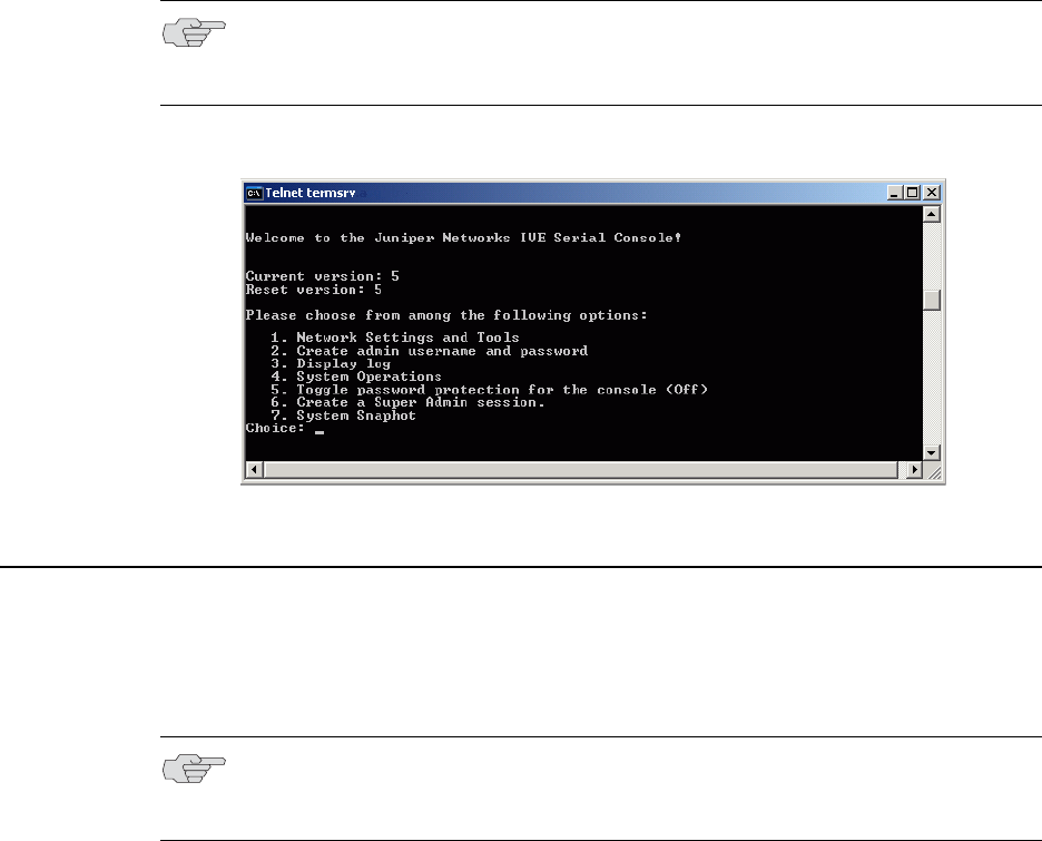
Juniper Networks Secure Access Administration Guide
812 Rolling back to a previous system state
2. Configure a terminal emulation utility, such as HyperTerminal, to use these
serial connection parameters:
9600 bits per second
8-bit No Parity (8N1)
1 Stop Bit
No flow control
3. Press Enter until the IVE serial console appears.
Figure 67: IVE Serial Console
Rolling back to a previous system state
An IVE appliance stores current system configuration information and that of the
previous state.
NOTE: If you are running an Secure Access FIPS machine and are connecting to
the serial console for the first time, you must also set the mode switch on the
cryptographic module to I (initialization mode).
NOTE: You may also roll back to a previous system state through the admin
console, as described in “Installing a Juniper software service package” on
page 590.

Rolling back to a previous system state 813
Chapter 31: IVE serial console
Rolling back to a previous system state through the admin console
If you upgrade your server package and decide you would like to revert to the
previous state of your machine, we recommend that you perform the following
steps from within the admin console:
1. Locate previously exported system and user configuration files that store the
desired state data. (This step presumes that you backed up your system and
user data by exporting files through the admin console’s Maintenance >
Import/Export menu.)
2. Download the desired IVE OS service package from the Juniper Networks
Support Customer Support Center.
3. Import the chosen IVE OS service package through the admin console’s
Maintenance > System > Upgrade/Downgrade menu.
4. Import the system and user configuration files you locate in the beginning of
this section.
Rolling back to a previous system state through the serial console
If you cannot access the admin console, connect to the serial console to perform a
system rollback to the previous system state.
To roll back to the previous IVE OS service package:
1. Connect to your IVE appliance’s serial console. For instructions, see
“Connecting to an IVE appliance’s serial console” on page 811.
2. In a browser window, sign in to the admin console.
3. Choose Maintenance > System > Platform.
4. Click Reboot Now and then go back to the console utility window. The window
displays a message that the system is restarting.
5. After several moments, you are prompted to hit the Tab key for options. Press
the Tab key, and when prompted for the configuration to load, type rollback
and then press the Enter key.
NOTE: If you have not yet performed an IVE OS service package upgrade, there is
no previous state to roll back to and this option is not available. If you have
performed an IVE OS service package upgrade, any system and user configuration
data created after the upgrade is lost unless you export the most current
configuration files before rolling back the system and then import them
afterwards.
NOTE: If you are running an Secure Access FIPS machine and want to roll back to
a previous security world, use instructions in “Recovering an archived security
world” on page 835.
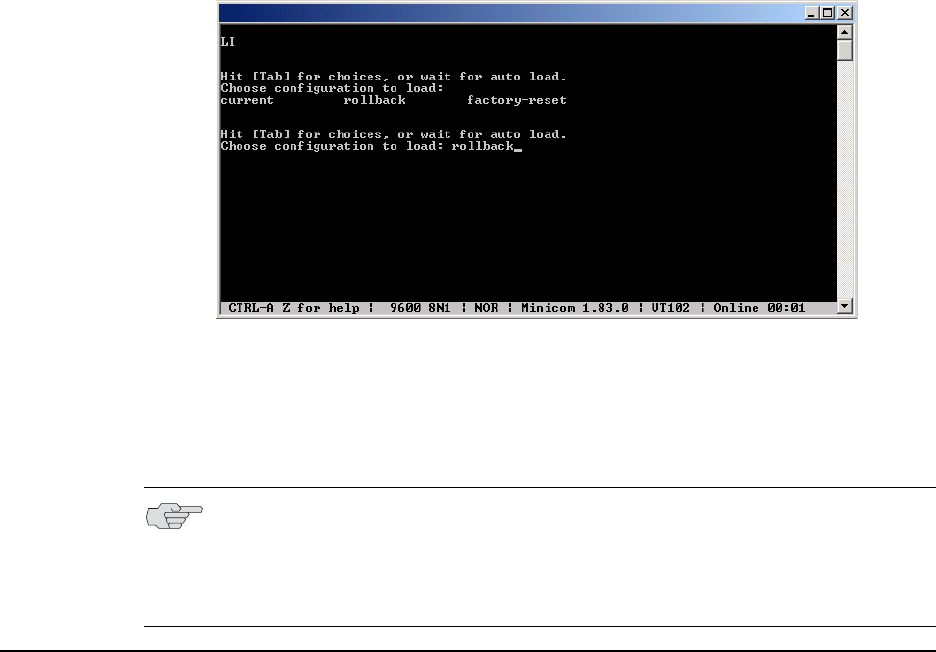
Juniper Networks Secure Access Administration Guide
814 Resetting an IVE appliance to the factory setting
Figure 68: IVE Serial Console
After clicking Reboot Now on the Maintenance > System > Platform page, the
server’s rollback status is output to the screen, and when complete, you are
prompted to hit the Return key (Enter) to modify system settings, which returns
you to the initial setup options. When you are finished entering data, simply close
the utility window.
Resetting an IVE appliance to the factory setting
In rare cases, you may need to reset your IVE appliance to its original factory
settings. Before performing this advanced system recovery option, please contact
Juniper (http://www.juniper.net/support/). If possible, export the most current
system and user configuration data before performing a factory reset.
To perform a factory-reset:
1. Connect to the serial console. For instructions, see “Connecting to an IVE
appliance’s serial console” on page 811.
2. In a browser window, sign in to the admin console.
3. Choose Maintenance > System > Platform.
4. Click Reboot and then go back to the console utility window. The window
displays a message that the system is restarting.
5. After several moments, you are prompted to hit the Tab key for options. Press
the Tab key, and when prompted for the configuration to load, type factory-
reset and then press the Enter key.
NOTE: If you wait more than 5 seconds to enter your choice, the current system
configuration is automatically loaded and you’ll need to go back to the admin
console and click Reboot Now to start the process again. If you have already
performed a system rollback, the rollback option is not available again until you
upgrade the IVE OS service package again.
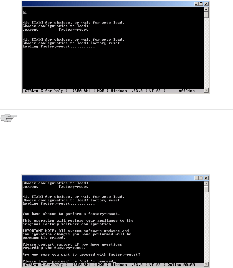
Resetting an IVE appliance to the factory setting 815
Chapter 31: IVE serial console
Figure 69: IVE Serial Console after clicking Reboot IVE on the Maintenance > System >
Platform page
6. When you are prompted to confirm performing a factory-reset, type proceed
and then press Enter.
Figure 70: IVE Serial Console after choosing to perform a factory-reset.
The system begins the process of resetting the machine to its original settings
and outputs several screens of data. After several minutes, you are prompted to
hit the Tab key to choose configuration choices.
NOTE: If you wait more than 5 seconds to enter your choice, the current system
configuration is automatically loaded and you’ll need to go back to the admin
console and click Reboot Now to start the process again.
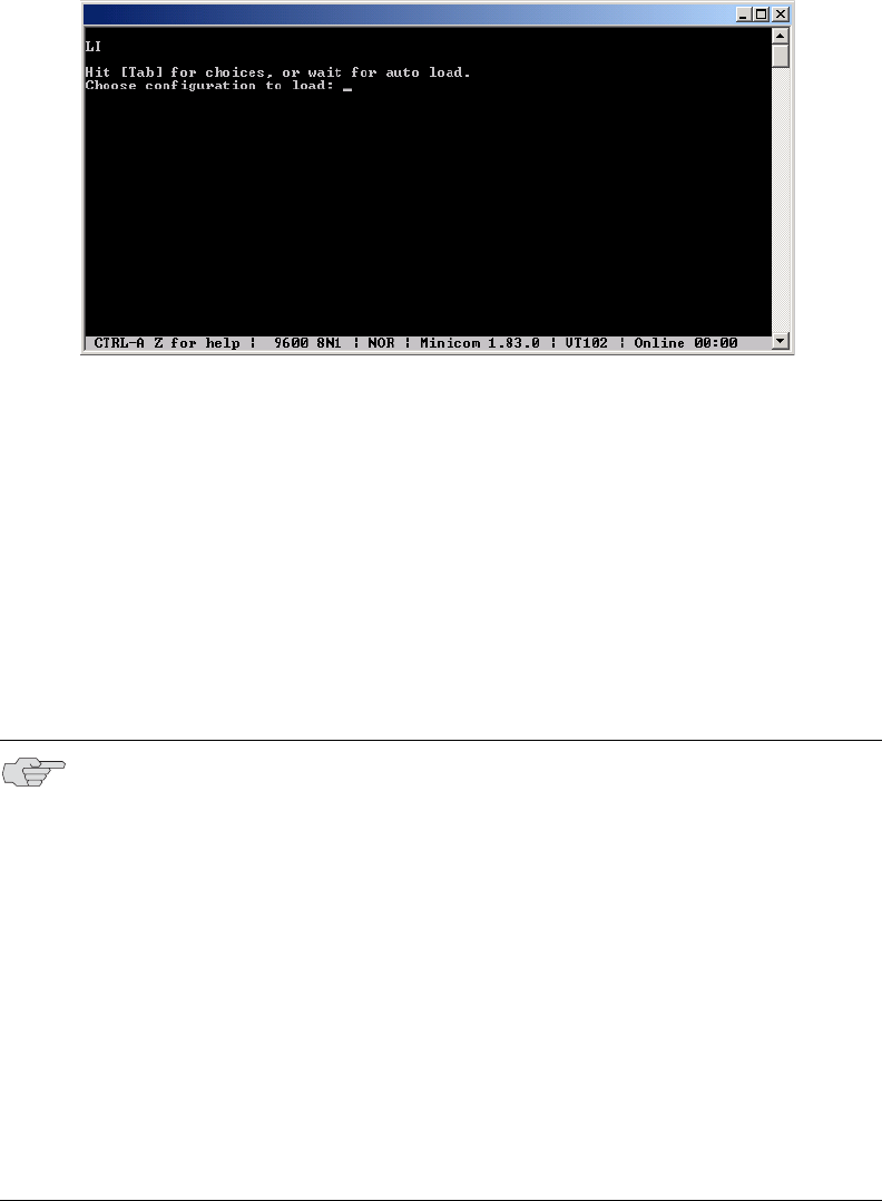
Juniper Networks Secure Access Administration Guide
816 Resetting an IVE appliance to the factory setting
Figure 71: IVE Serial Console after performing the factory-reset.
7. When prompted to hit the Tab key, either:
Wait for the default selection (current) to automatically start, or
Press Tab, type current, and then press Enter.
You are then prompted to enter the initial machine configuration settings. For
details on how to proceed, please consult the Quick Start Guide on the Juniper
Networks Customer Support Center.
After completing the initialization process, you may upgrade to the latest IVE
OS service package and import saved system and user configuration files to
return to the last good working state of your machine.
NOTE: You might receive errors from the IVE during the initial setup or on a
factory reset. Before the IVE starts services it monitors the network port for a
maximum of 120 seconds. The IVE checks the link status and performs an ARPing
on the default gateway. If there is a problem, after 5 seconds, the IVE displays a
message on the serial console that starts with NIC:...... If the link recovers within
120 seconds, the startup process continues. If the link does not recover, the
following message appears:
Internal NIC: ................[Down code=0x1]
Two codes can appear:
0x1 means that the interface link status reported by the NIC remains off (for
example, a disconnected cable or a cable in the wrong port).
0x2 means that the gateway is unreachable. The IVE boots but is not
reachable from IP addresses bound to that network port.

Performing common recovery tasks 817
Chapter 31: IVE serial console
Performing common recovery tasks
If you forget your IVE administrator username and/or password, lock yourself out
of your machine due to configuration errors, or change the IVE appliance IP
address and can no longer reach the machine, you can modify the machine settings
through the serial console. Follow the instructions under “Connecting to an IVE
appliance’s serial console” on page 811 and then choose the appropriate
configuration task.
Network Settings and Tools—Enables you to change standard network
settings; print a routing table; print or clear an ARP cache; ping another server,
trace a route to a server, remove static routes, and add an ARP entry.
Create admin username and password—Enables you to create a new super-
administrator account.
Display log—Enables you to display system configuration, user logs, or
administrator access logs through the serial console. Note that must enter “q”
to return to serial console options after viewing the logs.
System Operations—Enables you to reboot, shutdown, restart, rollback, or
factory reset the IVE appliance without using the admin console.
Toggle password protection for the console—Enables you to password
protect the serial console. When you toggle this option to “on,” only super-
administrators are allowed access.
Create a Super Admin session—Enables you to create a recovery session to
the admin console, even if you have configured the IVE appliance to block
access to all administrators. When you select this option, the appliance
generates a temporary token that is valid for 3 minutes. Enter the following
URL into a browser window:
https://<ive-host>/dana-na/auth/recover.cgi
Then, enter the temporary token when prompted in order to sign into the
admin console.
NOTE: When you choose this option, the IVE appliance blocks any additional
administrators from signing in to the admin console until you sign in to the
specified URL and initiate a session using your token. The appliance blocks
additional sign-in attempts so that you can fix any configuration problems that the
IVE may have encountered without conflicting with another session.

Juniper Networks Secure Access Administration Guide
818 Performing common recovery tasks
System Snapshot—Enables you to take a system snapshot without using the
admin console. When you choose this option, the IVE takes the snapshot
immediately. You can then send the snapshot file, by way of SCP, to a remote
system. The system prompts you for the destination server port, user ID,
password, and the destination path to the remote directory.
Replace Administrator Card Set (Secure Access FIPS only)—Enables you to
create additional administrator cards for a security world. See the following
section for details.
NOTE: If you choose not to send the snapshot file to a remote system, the IVE
saves the file locally. The next time you log in to the admin console, the System
Snapshot tab contains a link to the snapshot file. For more information about
taking a snapshot from the admin console, see “Creating snapshots of the IVE
system state” on page 695.
NOTE: If you are running an Secure Access FIPS system and you press the clear
switch on the cryptographic module, set the cryptographic module’s mode switch
to O (operational mode) and restart the system. You do not need to access the
serial console for recovery.

Licensing: Customizable UI availability 819
Chapter 32
Customizable admin and end-user UIs
The IVE enables you to customize a variety of elements in both the admin console
and the end-user interface. This section contains the following information about
which elements you can customize and where you can find the appropriate
configuration options:
“Licensing: Customizable UI availability” on page 819
“Customizable admin console elements overview” on page 819
“Customizable end-user interface elements overview” on page 821
Licensing: Customizable UI availability
All Secure Access appliances enable you to customize parts of the administrator
and end-user consoles. However, note that the following customizable UI features
are not available on the SA 700 appliance and are only available on all other Secure
Access products by special license:
Customized sign-in pages that you upload to the IVE
Customizable graphs that display system usage statistics
Customizable admin console elements overview
The IVE enables you to customize the look and feel of the following user interface
elements in the admin console:
Sign-in pages (default and custom)—You can customize the page that
administrators see when they sign into the admin console using settings in the
Authentication > Signing In > Sign-in Pages page. Using settings in this
page, you can create welcome messages, sign out messages and other
instructions; control page headers; customize select error messages; and create
a link to a custom help page within the default IVE sign-in page. For
instructions, see “Configuring standard sign-in pages” on page 188. Or, you
can upload your own custom sign-in page to the IVE. For more information, see
the Custom Sign-In Pages Solution Guide.
Juniper Networks Secure Access Administration Guide
820 Customizable admin console elements overview
UI look and feel—You can customize the header, background color, and logo
displayed in the admin console using settings in the Administrators > Admin
Roles > Select Role > General > UI Options page. You can also use settings
in this page to enable or disable the “fly out” hierarchical menus that appear
when you mouse over one of the menus in the left panel of the admin console.
For instructions, see “Specifying UI options” on page 745.
System utilization graphs—You can choose which system utilization graphs
the IVE displays on the opening page of the admin console using settings in the
System > Status > Overview page. You can also use settings in this page to
fine-tune the look and data within each of the graphs. For instructions, see
“Viewing general status” on page 683.
Show auto-allow options—You can show or hide the auto-allow option from
yourself or other administrators who create new bookmarks for roles using
settings in the Maintenance > System > Options page. For instructions, see
“Setting system options” on page 575.
User role views—You can use customization options on the Users > User
Roles page to quickly view the settings that are associated with a specific role
or set of roles. For instructions, see “Customizing user roles UI views” on
page 66.
User realm views—You can use customization options on the Users > User
Realms page to quickly view the settings that are associated with a specific
user realm or set of user realms. For instructions, see “Customizing user realm
UI views” on page 178.
Resource policy views—You can limit which resource policies the IVE displays
on any given resource policy page based on user roles. For instance, you can
configure the Users > Resource Policies > Web page of the admin console to
only display those resource policies that are assigned to the “Sales” user role.
You can customize these using settings in the Users > Resource Policies >
Select Policy Type page of the admin console. For instructions, see
“Customizing resource policy UI views” on page 89.
Web resource policy views—You can limit which Web resource policy
configuration pages the IVE displays using settings in Users > Resource
Policies > Web > Policy Type of the admin console. For configuration
instructions, see “Managing resource policies: Customizing UI views” on
page 356.
Administrator roles—You can delegate select responsibilities to other
administrators using settings in the Administrators > Admin Roles section of
the admin console. In doing so, you can restrict the visibility of certain options
and capabilities to those other administrators. For instructions, see “Creating
and configuring administrator roles” on page 734.

Customizable end-user interface elements overview 821
Chapter 32: Customizable admin and end-user UIs
Customizable end-user interface elements overview
The IVE enables you to customize the look and feel of the following elements in the
end-user interface:
Sign-in pages (default and custom)—You can customize the page that users see
when they sign into the admin console using settings in the Authentication >
Signing In > Sign-in Pages page. Using settings in this page, you can create
welcome messages, sign out messages and other instructions; control page
headers; customize select error messages; and create a link to a custom help page
within the default IVE sign-in page. For instructions, see “Configuring standard sign-
in pages” on page 188. Or, you can upload your own custom sign-in page to the
IVE. For instructions, see the Custom Sign-In Pages Solution Guide.
UI look and feel—You can customize the header, background color, and logo
displayed in the admin console using settings in the Users > User Roles >
Select Role > General > UI Options page. You can also use settings in this
page to specify the first page the users see after they sign into the IVE, the
order in which the IVE displays bookmarks, the help system that the IVE
displays to users, and various toolbar settings. For instructions, see “Specifying
customized UI settings” on page 60.
Default messages and UI look and feel—You can specify what the default look
and feel should be for all user roles using settings in Users > User Roles >
[Default Options] pages of the admin console. You can also use settings in
these pages to define the default errors that users see when they try to access a
blocked site, SSO fails, or SSL is disabled. For instructions, see “Defining
default options for user roles” on page 64.
Juniper Networks Secure Access Administration Guide
822 Customizable end-user interface elements overview

Standard hardware 823
Chapter 33
Secure Access 6000
The Juniper Networks Secure Access 6000 is a next-generation IVE appliance
featuring a number of notable hardware design upgrades relative to the other
members of the Secure Access family.
Standard hardware
The SA 6000 chassis features the following hardware components:
Console port—You can use the console port to initially set up the SA 6000
before you fully integrate it as the secure gateway to your internal network.
You can also use the console port to perform certain configuration and
clustering tasks after the IVE begins operating as the secure gateway.
Port 0 (internal) and Port 1 (external) Ethernet ports—The SA 6000’s
primary connections to the corporate network and the outside world are the
internal and external Ethernet ports, respectively. You can configure the
internal and external interfaces via the System > Network page of the admin
console.
Management port—The SA 6000’s management port is now available and:
Enables seamless integration into a dedicated Management Network.
Provides continuously available management access to the IVE.
Enables you to perform management activities without impacting user
traffic.
Allows you to separate administrative access from user access between the
IVE and Enterprise devices on the internal network.
You can configure the Management port information and advanced settings via
the admin console, just as you would configure the internal port. For more
information, see “Configuring the Management Port” on page 564.
Dual SFP ports (reserved for future use)—The SA 6000 includes two Small
Form-factor Pluggable (SFP) Gigabit Ethernet ports (designated ports 2 and 3 on
the front of the SA 6000) that will offer you the ability to further increase your
connectivity to internal network components in a future release.

Juniper Networks Secure Access Administration Guide
824 Secure Access 6000 field-replaceable units
Status LEDs—The front of the SA 6000 chassis features the following LEDs:
PWR (green)—Indicates that the appliance has power and is turned on
HD (amber)—Indicates that the hard disk is in use (writing or reading data)
TEMP (red)—A blinking LED indicates that one of the fans has failed or is
not seated properly in its port, or that a fan has failed and needs to be
replaced. A solid LED indicates a high internal temperature reading that
may result in system failure if not addressed.
PS FAIL (red)—Indicates that one of the power supplies is faulty, has been
unplugged, or has experienced an outright failure
Port 0 1000 and Port 1 1000 (green)—Indicates that the link speed of the
INT 0 (internal) or INT 1 (external) Ethernet interfaces is a Gigabit Ethernet
connection
Port 0 100 and Port 1 100 (green)—Indicates that the link speed of the
INT 0 (internal) or INT 1 (external) Ethernet interfaces is a 100BaseT
Ethernet connection
Internal and external Ethernet LINK TX/RX (green)—Indicates that the
internal or external Ethernet interface is currently transmitting or receiving
data
SFP port 2 and 3 LINK (green) (reserved for future use)—Indicates that SFP
port 2 or 3 is enabled.
SFP port 2 and 3 TX/RX (green) (reserved for future use)—Indicates that
SFP port 2 or 3 is sending or receiving traffic.
Secure Access 6000 field-replaceable units
The SA 6000 chassis features three types of field-replaceable units (FRUs) that you
can add or replace. The FRUs are “hot-swappable,” meaning you do not have to
first shut down the SA 6000 before adding or replacing any of the FRUs.
NOTE: If both the Port 0 1000 and Port 0 100 (internal) or Port 1 1000 and Port 1
100 (external) LEDs are active, the link speed for that interface is 10BaseT.

Secure Access 6000 field-replaceable units 825
Chapter 33: Secure Access 6000
Hard disks—The SA 6000 ships with one hard disk, however, you can add an
optional second hard disk to the SA 6000 chassis to offer component
redundancy and help minimize IVE down time. When a second (redundant)
hard disk is installed, it maintains an exact copy of the software image and
configuration information on the working hard disk. Therefore, if the working
hard disk fails, the redundant hard disk immediately assumes responsibility for
all IVE operations. This function is referred to as the Redundant Array of
Independent Disks (RAID) mirroring process.
Power supplies—The SA 6000 ships with one AC power supply installed in the
back of the chassis. You can add an optional second power supply to support
redundancy and load-sharing features. In addition, if you need to replace one
of the power supplies, you can “swap” the faulty power supply for a
replacement while the optional second power supply assumes responsibility for
the entire power load, thus avoiding a situation where you have to power off
the IVE before replacing the removable unit.
Cooling fans—The SA 6000 ships with two cooling fans installed in the back of
the chassis. If you need to replace one of the cooling fans, you can “swap” the
faulty fan for a replacement during operation in a matter of moments. You can
purchase additional cooling fans from your vendor when you order your
SA 6000, or you can purchase them in the future to replace faulty or failed
cooling fans, as necessary, in the future. Juniper strongly recommends that you
run the SA 6000 with two cooling fans.
For information about installing or replacing any of the hardware mentioned here,
see the Secure Access 6000 Field Replaceable Units Removal and Installation Guide on
the Juniper Networks Customer Support Center.
NOTE: The SA 6000 hard disk modules are hot-swappable. You must make sure
that the IVE finishes booting and is operating correctly before removing,
replacing, or upgrading a hard disk module. Once a new hard disk module is
inserted, you must wait until the RAID mirroring process is completely finished—
which takes approximately 40 minutes—before rebooting or turning off the IVE.
Juniper Networks Secure Access Administration Guide
826 Secure Access 6000 field-replaceable units

Licensing: Secure Access FIPS availability 827
Chapter 34
Secure Access FIPS
FIPS, or Federal Information Processing Standards, are National Institute of
Standards and Technology regulations for handling keys and encrypting data.
Juniper Networks Secure Access FIPS is a standard SA3000, SA4000, SA5000, or
SA6000 NetScreen Instant Virtual Extranet equipped with a FIPS-certified
cryptographic module. The tamper-proof hardware security module installed on an
Secure Access FIPS system is certified to meet the FIPS 140-2 level 3 security
benchmark. The module handles private cryptographic key management and SSL
handshakes, simultaneously, ensuring FIPS compliance and off-loading CPU-
intensive public key infrastructure (PKI) tasks from the IVE to a dedicated module.
The configuration process for Secure Access FIPS administrators is almost exactly
the same as for the non-FIPS Secure Access administrators, requiring only minor
configuration changes during the initialization, clustering, and certificate generation
processes. In the few cases where administration tasks are different, this guide
includes the appropriate instructions for both Secure Access and Secure Access
FIPS administrators. For end-users, Secure Access FIPS is exactly the same as a
standard Secure Access system.
For more information, see:
“Licensing: Secure Access FIPS availability” on page 827
“Secure Access FIPS execution” on page 828
“Creating administrator cards” on page 829
“Creating a new security world” on page 832
“Recovering an archived security world” on page 835
Licensing: Secure Access FIPS availability
Secure Access FIPS is a hardware feature that is built into selected Secure Access
appliances. It is not available on SA 700 appliances.

Juniper Networks Secure Access Administration Guide
828 Secure Access FIPS execution
Secure Access FIPS execution
When you first install an Secure Access FIPS system, the IVE serial console walks
you through the process of creating a security world through the serial console. A
security world is a key management system used by Secure Access FIPS consisting
of the following elements:
Cryptographic module—The cryptographic module (also sometimes called the
hardware security module, or HSM) included with Secure Access FIPS includes
hardware and firmware installed directly on the appliance. A security world
may contain a single cryptographic module (standard environment) or multiple
modules (clustered environment). However, a single Secure Access FIPS
appliance is always equipped with a single cryptographic module.
Security world key—A security world key is a unique Triple DES encrypted key
that protects all other application keys within a security world. As required by
the Federal Information Processing Standards, you cannot import this key into
a security world—you must directly create it from a cryptographic module. In a
clustered environment, all of the modules within the security world share the
same security world key. (For more information, see “Deploying a cluster in an
Secure Access FIPS environment” on page 830.)
Smart cards—A smart card is a removable key device that looks like a credit
card. A smart card authenticates users, allowing them access to various data
and processes controlled by the cryptographic hardware module. During the
initialization process, you must insert one of your smart cards into the reader
(built-in or external, depending upon which device model you own). As part of
the initialization process, the smart card is transformed into an administrator
card that allows the card holder access to the security world. (For more
information, see “Replacing administrator cards” on page 834.)
Encrypted data—Encrypted host data in a Secure Access FIPS environment
includes keys and other data required to share information in a secure manner.
These elements interlock to create a comprehensive security world. When you start
the appliance, it confirms that the security world is valid and that the cryptographic
module is in operational mode before starting normal operations.
You can set the cryptographic module into operational mode using a hardware
switch on the outside of the module. The switch’s settings include:
I—Initialization mode. Use this setting when initializing the cryptographic
module with a new security world or when adding a module to an existing
security world in an IVE cluster. Note that once you set the switch to I and
begin initialization, you must complete the process. Otherwise, your security
world is only partially initialized, making it unusable.
O—Operational mode. Use this setting to place the cryptographic module into
operational mode after initialization. Note that you must set the switch to O
before the module powers up in order to alert the unit that you want to begin
day-to-day processing. Otherwise, the module prompts you through the serial
console to join the existing security world or initialize a new one.

Creating administrator cards 829
Chapter 34: Secure Access FIPS
M—Maintenance mode. In future releases, this setting will be used to upgrade
the firmware on the cryptographic module. (Not yet supported.)
For more information about initializing the module and creating a new security
world, see the Juniper Networks Netscreen Secure Access FIPS Getting Started Guide
included with the product packaging.
Creating administrator cards
When you receive your Secure Access FIPS product, you receive 6 smart cards as
part of the package. A smart card is a removable key device that you must use in
order to gain access to some of the critical data and processes controlled by the
cryptographic module. Secure Access FIPS first requires you to use one of your
smart cards while initializing the cryptographic module through the serial console.
During this process, Secure Access FIPS creates a security world and transforms the
smart card into an administrator card that gives the holder access only to that
security world.
Once the module is initialized, you do not need the administrator card for normal
IVE operations. However, you are required to use the administrator card whenever
you want to:
Add another Secure Access FIPS machine to a cluster. For more information,
see “Deploying a cluster in an Secure Access FIPS environment” on page 830.
Reinitialize a module with a new or different security world. For more
information, see “Recovering an archived security world” on page 835.
Replace administrator cards. For more information, see “Replacing
administrator cards” on page 834.
As a rule-of-thumb, any Secure Access FIPS operation that you must execute
through the IVE serial console requires an administrator card.
NOTE: Whenever you change your security world, you must determine how to
handle your existing administrator cards. Your choices include:
Reset your existing administrator cards to the new security world.
Use administrator cards that are pre-initialized to the new security world and
leave your existing administrator cards unchanged. Note that if you choose
this option, however, you cannot use the old, unchanged cards to access the
new security world.

Juniper Networks Secure Access Administration Guide
830 Deploying a cluster in an Secure Access FIPS environment
Administrator card precautions
Since administrator cards are so critical to Secure Access FIPS operations and the
security of the keys within your security world, we strongly recommend that you
take the following precautions:
Create multiple administrator cards—You cannot replace an administrator
card unless you have another valid card and the pass phrase for that card; the
cryptographic module does not store administrator card recovery data.
Therefore, we strongly recommend that you create at least one administrator
card for standard administrative operations and another for backup purposes.
Otherwise, you run the risk of losing your only administrator card and
subsequently losing access to your security world and all the data it stores. You
can only create a set of administrator cards, all at once. You cannot add
additional cards to an existing set.
Store a backup administrator card in a secure location—Always keep your
backup administrator card(s) in a secure location separate from the card you
use for standard administrative operations to ensure that you do not lose all of
your administrator cards to the same event (such as a fire or theft).
Overwrite all remaining administrator cards if one gets lost—If you lose or
damage an administrator card, immediately create a new security world and
overwrite all remaining cards from the old security world. Otherwise, an
attacker with an old administrator card may be able to access old host data
stored on a backup tape or another host. With the old host data and an old
card, the attacker may then be able to re-create your keys.
Protect the administrator card’s pass phrase—For maximum security, you
should never write down your pass phrase, tell it to untrusted users, or use a
pass phrase that is easy to guess. Protecting your pass phrase adds an extra
level of security to your operations.
Only use your administrator card with known, trusted sources—Always
obtain smart cards from a trusted source, never insert a smart card into an
untrusted smart card reader, and never insert untrusted smart cards into your
smart reader.
Deploying a cluster in an Secure Access FIPS environment
In addition to sharing state, user profile, user session, and monitoring state data,
the members of an Secure Access FIPS cluster also share security world data. All
cluster members share the same private key and are accessible using the same
administrator cards. Since changing a security world requires physical access to a
cryptographic module, however, Secure Access FIPS cluster members cannot share
all of their data using the standard IVE synchronization process. Instead, to create
an Secure Access FIPS cluster, you must:
1. Create a cluster of Secure Access FIPS machines through the admin
console—As with a standard IVE cluster, each cluster node in an Secure Access
FIPS cluster is initialized using system state data from the specified cluster
member, overwriting all existing data on the node machine.

Deploying a cluster in an Secure Access FIPS environment 831
Chapter 34: Secure Access FIPS
2. Manually update the security world on each of the machines—After creating
a cluster, you must initialize each cluster node with the specified member’s
security world using an administrator card that is pre-initialized to the security
world and the serial console. Prior to joining a cluster, each node is in its own
security world. As a consequence, after a node joins the cluster, the
administrator card from the joining node will be invalid. Only the administrator
card set from the cluster will be valid.
Similarly, if you want to modify an existing security world on a cluster, you must
individually update each cluster member’s cryptographic module using an
administrator card and the IVE serial console. For instructions, see “IVE serial
console” on page 811.
The basic process for creating a cluster follows these high-level steps:
1. Initialize one IVE from the serial console, creating administrator cards.
2. Initialize the second IVE from the serial console, creating one administrator
card.
3. Create the cluster from the admin console.
4. Add the node to the cluster.
5. Reboot the node from the serial console.
6. When prompted, supply the cluster details, including IP address, netmask, and
domain.
7. When prompted, insert an administrator card from the cluster’s set of cards.
The node’s administrator card will become invalid, as the node joins the
security world of the cluster.
To initialize a FIPS cluster member’s security world via the serial console:
1. If you use an SA 3000 or SA 5000 FIPS appliance, plug the smart card reader
cable into the cryptographic module’s reader port on the SA 3000/SA 5000
IVE’s front panel. Otherwise, if you use an SA 4000 or SA 6000 FIPS appliance,
skip this step.
2. Insert an administrator card that is pre-initialized with the active cluster
member’s security world into the smart card slot with the contacts facing up.
3. Switch the cryptographic module’s mode switch to I (initialization mode) if it is
not already in that position.
4. Connect to the machine’s serial console. For more information, see “IVE serial
console” on page 811.
NOTE: If you have already performed the procedures required to configure the
FIPS appliance, as described in the Quick Start Guide, you might be able to skip
this step.

Juniper Networks Secure Access Administration Guide
832 Creating a new security world
5. Cycle the power to reboot the machine and watch its serial console. After the
system software starts, you will see a message that the machine is about to
boot as a stand-alone IVE and to hit Tab for clustering options. Press the Tab
key as soon as you see this option.
6. Enter the number 2 to join the existing cluster or 1 to continue as a standalone
IVE.
7. Enter the initialization information as prompted, including:
Cluster name
Cluster password
IP address of a node in the cluster
IP address of the node you are adding
Netmask
Gateway IP address
8. Select 1 to continue joining the cluster.
9. After the FIPS appliance initializes the card, switch the cryptographic module’s
mode switch to O (operational mode).
Creating a new security world
You cannot begin using an Secure Access FIPS machine until you create a security
world on it. However, in some case you may need to overwrite that security world
with a new one. For example, if you lose an administrator card, we recommend
that you create a brand new security world to prevent an untrusted source from
finding the card and accessing your security world. You may also need to create a
new security world if you cannot remember your original administrator cards pass
phrases.
In order to create a new security world, you must have physical access to:
The cryptographic module(s) that belong to the security world
NOTE: The interval to press the Tab key is five seconds. If the machine begins to
boot in stand-alone mode, wait for it to finish and then reboot again.
NOTE: After you initialize members of an Secure Access FIPS cluster with the same
security world, you may disable and re-enable the cluster through the admin
console. You are no longer required to use the serial console once the cluster
members are all members of the same security world.

Creating a new security world 833
Chapter 34: Secure Access FIPS
A smart card reader (if you use an older model IVE that does not contain a
built-in card reader)
One or more unformatted smart cards or administrator cards containing data
that you can safely overwrite
For information about overwriting a security world with an existing security world,
see “Recovering an archived security world” on page 835.
Creating a security world on a stand-alone IVE
To create a new security world on a stand-alone IVE:
1. If you use an SA 3000 or SA 5000 FIPS appliance, plug the smart card reader
cable into the cryptographic module’s reader port on the SA 3000/SA 5000
IVE’s front panel. Otherwise, if you use an SA 4000 or SA 6000 FIPS appliance,
skip this step.
2. Insert an un-formatted smart card or an administrator card containing data
that you can safely overwrite into the card slot with the card contacts facing up.
3. Set the mode switch on the cryptographic module to I (initialization mode).
4. Access the IVE’s serial console and reboot the IVE. For instructions, see
“Connecting to an IVE appliance’s serial console”
on page 811. After the IVE
reboots, you are prompted on the serial console with the following question:
Do you want to use the currently installed security world (y/n)?
5. Perform one of the following:
If you want to create a new security world, then:
i. Enter n and press Enter.
ii. Enter the number of administrator cards you want to create and press
Enter.
iii. Enter y and press Enter to confirm the number of cards you want to
create.
NOTE: Your old administrator cards will not work with the new security world until
you reformat them with the new security world’s data. Also note that once you set
the switch to I and begin initialization, you must complete the process. Otherwise,
your security world is only partially initialized, making it unusable.
NOTE: WARNING—You must obtain one or more new device certificates from
your CA whenever you create a new security world.

Juniper Networks Secure Access Administration Guide
834 Creating a new security world
If you want to use the currently installed security world, then:
i. Enter y and press Enter.
ii. Proceed to the next numbered step in this procedure.
6. Reset the cryptographic module’s mode switch to O (operational mode).
7. Add the common name and company name when prompted. The system uses
the existing self-signed certificate temporarily.
8. Create a new device certificate that shares the new security world’s private key.
For more information, see “Creating a certificate signing request (CSR) for a
new certificate” on page 604.
Creating a security world in a clustered environment
To create a new security world in a clustered environment:
1. Sign in to the admin console of a cluster node that you want to reformat with a
new security world. To access a node’s admin console, enter its internal IP
address followed by “/admin” in a browser. For example:
https://x.x.x.x/admin
2. On the System > Clustering > Status tab, select the checkbox next to the
node’s name in the Cluster Members column and then click Disable.
3. Initialize the cluster member with a security world. If this is the first node in the
cluster, create a new security world, as explained in “Creating a new security
world” on page 832.
4. Return to the node’s System > Clustering > Status tab, select the checkbox
next to the node’s name in the Cluster Members column, and then click
Enable.
5. Perform these steps for each node in the cluster.
Replacing administrator cards
You can replace an administrator card by selecting the Replace Administrator
Card Set option from the serial console. You cannot increase the number of
administrator cards in an existing set, but you can create a new security world to
replace all of the cards in a set and initialize a larger set of cards than you originally
had.
If you need to replace administrator cards for a security world, you must have
physical access to:
A cryptographic module that belongs to the security world
NOTE: WARNING—You must obtain one or more new server certificates from
your CA whenever you create a new security world.
Recovering an archived security world 835
Chapter 34: Secure Access FIPS
A smart card reader (if you use an older model IVE that does not contain a
built-in card reader)
An administrator card that is pre-initialized with the security world
An un-formatted smart card or administrator card containing data that you can
safely overwrite.
To replace all administrator cards or to create a larger number of cards for a
security world:
1. Follow the steps to create a new security world, as described in “Creating a
security world on a stand-alone IVE” on page 833.
2. Choose Replace Administrator Card Set from the list of configuration tasks.
3. Enter the pass phrase for the security world.
4. When prompted, insert an un-formatted smart card or an administrator card
whose data you can safely overwrite into the smart card reader with the
contacts facing up.
5. Enter the additional initialization information for which you are prompted.
6. Repeat steps 4 and 5 for as many cards as you want to create.
7. Store at least one of the administrator cards in a secure location.
Recovering an archived security world
In rare cases, you may need to recover your system using an archived security
world. The archived security world may be an older version of the security world
that already exists on your system or the same version. In order to recover your
system, you must have access to the system configuration file (by default,
system.cfg) that holds the archived security world and its corresponding certificate.
In addition, if you are overwriting your security world with a different security
world, you must have physical access to:
All of the cryptographic modules that belong to the security world
A smart card reader (if you use an older model IVE that does not contain a
built-in card reader)
NOTE: If you need to replace administrator cards, you must replace the same
number of cards that you first initialized for the security world. You cannot
replace a subset of the cards.
NOTE: If you require additional smart cards, please contact your IVE Reseller.

Juniper Networks Secure Access Administration Guide
836 Recovering an archived security world
An administrator card that is pre-initialized with the security world and
administrator passphrase that you want to import
Importing a security world into a stand-alone IVE
To import an existing security world into a stand-alone IVE:
1. Import the system configuration file that contains the archived security world
and its corresponding certificate into the IVE (as explained in “Importing a
system configuration file” on page 633), and then initialize the security world if
necessary. If the configuration file contains an archive of:
The same security world that was already present on the machine, no
further configuration is required.
A different security world than was already present on the machine, you
must initialize the new security world.
1. If you use an SA 3000 or SA 5000 FIPS appliance, plug the smart card reader
cable into the cryptographic module’s reader port on the SA 3000/SA 5000
IVE’s front panel. Otherwise, if you use an SA 4000 or SA 6000 FIPS appliance,
skip this step.
2. Insert an administrator card that is pre-initialized with the imported security
world into the smart card reader slot with the contacts facing up.
3. Set the mode switch on the cryptographic module to I (initialization mode).
4. Access the IVE’s serial console and reboot the IVE. For more information, see
“Connecting to an IVE appliance’s serial console”
on page 811.
5. Enter the initialization information for which you are prompted, including:
Administrator username
Password
IP address
Netmask
Gateway IP address
6. Reset the cryptographic module’s mode switch to O (operational mode) when
prompted.
NOTE: If you import a configuration file containing a different security world, note
that your existing administrator cards will not work with the imported security
world until you reformat them with the new security world’s data. Also note that
once you set the switch to I and begin initialization, you must complete the
process. Otherwise, your security world is only partially initialized, making it
unusable.
Recovering an archived security world 837
Chapter 34: Secure Access FIPS
Importing a security world into a cluster
To import an existing security world into a cluster:
1. Sign in to the admin console of the cluster node that you want to reformat with
a new security world. To access a node’s admin console, enter its internal IP
address followed by “/admin” in a browser. For example:
https://x.x.x.x/admin
2. On the System > Clustering > Status tab, select the checkbox next to the
node’s name in the Cluster Members column and then click Disable.
3. Import an archived security world in to the cluster member, as described in the
previous section.
4. When the installation process completes, return to the node’s System >
Clustering > Status tab, select the checkbox next to the node’s name in the
Cluster Members column, and then click Enable.
Perform these steps for each node in the cluster.
Juniper Networks Secure Access Administration Guide
838 Recovering an archived security world

Licensing: Compression availability 839
Chapter 35
Compression
IVE improves performance by compressing common types of Web and file data
such as HTML files, Word documents, and images. This section contains the
following information about compression:
“Licensing: Compression availability” on page 839
“Compression execution” on page 839
“Supported data types” on page 840
“Enabling compression at the system level” on page 841
“Creating compression resource profiles and policies” on page 842
Licensing: Compression availability
Gzip compression is available on all Secure Access appliances.
Compression execution
The IVE determines whether it should compress the data accessed by users by
using the following process:
1. The IVE verifies that the accessed data is a compressible type. The IVE supports
compressing many common data types such as such as HTML files, and Word
documents. For a complete list, see “Supported data types” on page 840.
2. If the user is accessing Web data, the IVE verifies that the user’s browser
supports compression of the selected data type.
The IVE determines compression supportability based on the browser’s user-
agent and the accept-encoding header. The IVE supports the compression of all
of the standard Web data types if it determines that the user-agent is
compatible with Mozilla 5, Internet Explorer 5, or Internet Explorer 6. The IVE
only supports compressing HTML data, however, if it determines that the
browser’s user-agent is only compatible with Mozilla 4.
Juniper Networks Secure Access Administration Guide
840 Supported data types
3. The IVE verifies that compression is enabled at the system level. You can
enable system-level compression through the Maintenance > System >
Options page of the admin console, as explained in “Enabling compression at
the system level” on page 841.
4. The IVE verifies that compression resource policies or autopolicies are enabled
for the selected data type. The IVE comes with resource policies that compress
data. You may enable these policies or create your own through the following
pages of the admin console:
Users > Resource Policies > Web > Compression.
Users > Resource Policies > Files > Compression.
For instructions, see “Defining resource policies: Web compression” on
page 349.
You may also create resource profile compression autopolices through the
Users > Resource Profiles > Web > Web Applications/Pages page of the
admin console. For instructions, see “Defining a Web compression autopolicy”
on page 304.
If all of these conditions are met, the IVE runs the appropriate resource policy
either compresses or does not compress the data accessed by the user based on the
configured action.
Upgrading from a previous version
The IVE comes pre-equipped with three resource policies that compress Web and
file data. If you are upgrading from a pre-4.2 version of the IVE and you previously
had compression enabled, these policies are enabled. Otherwise, if you previously
had compression disabled, these policies are disabled.
The Web and file resource policies created during the upgrade process specify that
the IVE should compress all supported types of Web and File data, including types
that were not compressed by previous versions of the appliance. All data types that
were not compressed by previous product versions are marked with an asterisk (*)
in the supported data types list below.
Supported data types
The IVE supports compressing the following types of Web and file data:
text/plain (.txt)
text/ascii (.txt)*
text/html (.html, .htm)
NOTE: If all of these conditions are not met, the IVE does not run the appropriate
resource policy and no resource policy items appear in the IVE log files.

Enabling compression at the system level 841
Chapter 35: Compression
text/css (.css)
text/rtf (.rtf)
text/javascript (.js)
text/xml (.xml)*
application/x-javascript (.js)
application/msword (.doc)
application/ms-word (.doc)*
application/vnd.ms-word (.doc)*
application/msexcel (.xls)*
application/ms-excel (.xls)*
application/x-excel (.xls)*
application/vnd.ms-excel (.xls)*
application/ms-powerpoint (.ppt)*
application/vnd.ms-powerpoint (.ppt)*
Additionally, the IVE supports compressing the following types of IVE files:
text/html (.html, .htm)
application/x-javascript (.js)
text/javascript (.js)
text/css (.css)
application/perl (.cgi)
Enabling compression at the system level
To enable system-level compression:
1. In the admin console, choose Maintenance > System > Options.
NOTE: The data types denoted by an asterisk * were not compressed by pre-4.2
versions of the IVE appliance.
Also note that the IVE does not compress files that you upload to the IVE—only
files that you download from the IVE.

Juniper Networks Secure Access Administration Guide
842 Creating compression resource profiles and policies
2. Select the Enable gzip compression checkbox to reduce the amount of data
sent to browsers that support HTTP compression. Note that after you enable
this option, you must also configure Web and file resource policies specifying
which types of data the IVE should compress. For more information, see
“Compression” on page 839.
3. Click Save Changes.
Creating compression resource profiles and policies
For information about enabling compression at the resource level, see instructions
in sections listed below.
Recommended methods:
“Defining a Web compression autopolicy” on page 304)
“Defining a file compression autopolicy” on page 374
“Defining a file compression autopolicy” on page 374
Alternate methods:
“Defining resource policies: Web compression” on page 349
“Writing a Windows compression resource policy” on page 386
“Writing a Unix/NFS compression resource policy” on page 392

843
Chapter 36
Multi-language support
SSL VPN appliances provide multi-language support for file encoding, end-user
interface display, and customized sign-in and system pages. The SSL VPN
appliances support the following languages:
English (US)
Chinese (Simplified)
Chinese (Traditional)
French
German
Japanese
Korean
Spanish
This section provides information about:
“Licensing: Multi-language support availability” on page 844
“Encoding files” on page 844
“Localizing the user interface” on page 844
“Localizing custom sign-in and system pages” on page 845
NOTE: Juniper Networks translates the IVE end-user console and help systems into
the languages listed above. Note, however, that the translated end-user help is not
available in the first release of the product. Juniper Networks makes a translated
version of the help available in the first maintenance release after the general
availability release.

Juniper Networks Secure Access Administration Guide
844 Licensing: Multi-language support availability
Licensing: Multi-language support availability
Multiple languages are supported on all Secure Access appliances. Note, however,
that the localized customized sign-in pages feature is not available on the SA 700
appliance and is only available on other appliances by special license.
Encoding files
Character encoding is a mapping of characters and symbols used in written
language into a binary format used by computers. Character encoding affects how
you store and transmit data. The encoding option in Users > Resource Policies >
Files > Encoding allows you to tune the rewriter to support localized pages during
rewrite and file browsing. The encoding option does not affect the end-user
language environment.
To specify the internationalization encoding for IVE traffic:
1. In the admin console, choose Users > Resource Policies > Files > Encoding.
2. Select the appropriate option:
Western European (ISO-8859-1) (default) (Includes English, French,
German, Spanish)
Simplified Chinese (CP936)
Simplified Chinese (GB2312)
Traditional Chinese (CP950)
Traditional Chinese (Big5)
Japanese (Shift-JIS)
Korean
3. Click Save Changes.
Localizing the user interface
The IVE provides a means to display the end-user interface in one of the supported
languages. Combining this feature with (custom) sign-in and system pages and a
localized operating system provides a fully localized user experience.
When you specify a language, the IVE displays the user interface, including all
menu items, dialogs generated by the IVE, and the help file in the chosen language
for all users regardless of which realm they sign in to.

Localizing custom sign-in and system pages 845
Chapter 36: Multi-language support
To configure localization options:
1. In the admin console, choose Maintenance > System > Options.
2. Use the End-user Localization drop-down list to specify the language in which
to display the end-user interface (optional). If you do not specify a language,
the end-user interface displays based on the settings of the browser.
3. Click Save Changes.
Localizing custom sign-in and system pages
The IVE provides several zip files that contain different sets of sample template files
for various pages that may appear during the sign-in process. Use these template
files along with the template toolkit language to create localized custom sign-in and
system pages for your end-users. For more information about the zip files and the
template files they contain, as well as information about the template toolkit
language, see Custom Sign-In Pages Solution Guide.
NOTE: The Whole Security Confidence Online feature supported by Host Checker
cannot be localized currently. For more information about Whole Security
features, see “Enabling advanced malware protection policies” on page 228.
NOTE: Editing the default sign-in page using text in the language of your choice is
a quick way to provide your users with a localized sign-in page. For information
about customizing the default sign-in page, see “Configuring sign-in pages” on
page 187.Use settings in the System > Authentication > Signing In Pages tab
to create customized, localized sign-in pages. For instructions, see the Custom
Sign-In Pages Solution Guide.
Juniper Networks Secure Access Administration Guide
846 Localizing custom sign-in and system pages
847
Chapter 37
Handheld devices and PDAs
In addition to allowing users to access the IVE from standard workstations and
kiosks, the IVE also allows end-users to access the IVE from connected PDAs,
handhelds and smart phones such as i-mode and Pocket PC. When a user connects
from a PDA or handheld device, the IVE determines which IVE pages and
functionality to display based on settings in the System > Configuration > Client
Types page of the admin console. By default, settings in this page specify that when
accessing the IVE using a(n):
i-mode device—The IVE displays compact HTML (cHMTL) pages without
tables, images, JavaScript, Java, or frames to the user. Depending on which
features you enable through the admin console, the end-user may browse the
Web, link to Web bookmarks, single sign-on to other applications, and edit
their preferences (including clearing their cache and editing their IVE/LDAP
password). The IVE allows i-mode users to access supported features using
access keys on their phone’s keypad as well as through standard browse-and-
select navigation.
Pocket PC device—The IVE displays mobile HTML pages with tables, images,
JavaScript and frames, but does not process Java. Depending on which features
you enable through the admin console, the end-user may access Mobile Notes,
browse the Web, link to Web bookmarks, single sign-on to other applications,
and edit their preferences (including clearing their cache and editing their
IVE/LDAP password).
PDA and handheld users cannot access the admin console or most of the IVE’s
advanced options, including file browsing, Network Connect, Secure Meeting,
Telnet/SSH, Email Client, Host Checker, and Cache Cleaner, since PDA and
handheld devices do not generally support the ActiveX, Java, or JavaScript controls
on which these features depend.
Also note that i-mode users cannot access cookie-based options, including session
cookies and SiteMinder authentication and authorization, since most i-mode
browsers do not support HTTP cookies. The IVE rewrites hyperlinks to include the
session ID in the URL instead of using cookies. The IVE reads the session ID when
the user accesses the URL.
This section contains the following information about handheld devices and PDAs:
“Licensing: Handheld and PDA support availability” on page 848
“Task summary: Configuring the IVE for PDAs and handhelds” on page 848

Juniper Networks Secure Access Administration Guide
848 Licensing: Handheld and PDA support availability
“Defining client types” on page 849
“Enabling WSAM on PDAs” on page 851
Licensing: Handheld and PDA support availability
Handheld devices and PDAs are only supported on SA 700 appliances that are
licensed for Web browsing.
Task summary: Configuring the IVE for PDAs and handhelds
To properly configure the IVE to work with PDAs and handheld devices, you must:
1. Enable access at the system level—If you want to support browsers other
than the defaults provided with the IVE, you must enter the user agent strings
of the PDA and handheld operating systems that you want to support in the
System > Configuration > Client Types tab. For more information, see
“Defining client types” on page 849. For a complete list of PDA and handheld
browsers that are supported with the IVE, see the Supported Platforms
document posted on the Support website.
2. Evaluate your user roles and resource policies—Depending on which IVE
features you have enabled, you may need to either modify your existing roles
and resource policies for PDA and handheld users or create new ones. Note
that:
Mobile device users cannot access roles or policies that require Host
Checker or Cache Cleaner since handheld devices do not generally support
the ActiveX, Java, or JavaScript controls on which these features depend.
You can disable these options through the following tabs:
Users > User Roles > Role > General > Restrictions
Resource Policies > Web > Access > Web ACL> Policy > Detailed
Rules
Mobile device users may have trouble reading long role names on their
small screens. If you require users to pick from a list of roles when they
sign in, you may want to shorten role names in the Users > User Roles >
Role > General > Overview tab.
Mobile device users may have trouble reading long bookmark names on
their small screens. You can edit Web bookmarks in the following tabs:
Users > Resource Profiles > Web Application Resource Profiles >
Profile > Bookmarks
Users > User Roles > Role > Web > Bookmarks
Resource Policies > Web > Access > Web ACL> Policy > General

Defining client types 849
Chapter 37: Handheld devices and PDAs
Although advanced features such as file browsing are not supported for
PDAs and handhelds, you do not need to disable them in the roles and
resource policies used by mobile device users. The IVE simply does not
display these options to mobile device users.
3. Evaluate your authentication and authorization servers—The IVE supports
all of the same authentication and authorization servers for PDA and handheld
users as standard users, except the eTrust SiteMinder policy server. SiteMinder
is dependent on cookies, which are not supported with i-mode browsers.
4. Evaluate your realms—Depending on which IVE features you have enabled,
you may need to either modify your existing realms for PDA and handheld
users or create new ones. Note that:
Mobile device users cannot access the IVE when they try to sign into a
realm that requires Host Checker or Cache Cleaner since handheld devices
do not generally support the ActiveX, Java, or JavaScript controls on which
these features depend. You can disable these options through sub-tabs in
the System > Configuration > Security page.
Mobile device users cannot authenticate against an eTrust SiteMinder
server. You can choose a different authentication server for the realm in
the Users > User Realms > Realm > General tab.
Mobile device users may have trouble reading long realm names on their
small screens. If you require users to pick from a list of realms when they
sign in, you may want to shorten realm names in the Users > User
Realms > Realm > General tab.
5. Evaluate your sign-in policy to use—If you want to use a different sign-in
page for Pocket PC users, you can define it in the Authentication > Signing In
> Sign-in Pages tab and then create a sign-in policy that references the page
using options in the Authentication > Signing In > Sign-in Policies tab. Or,
if you have the Advanced license, you can create a custom sign-in page using
the Pocket PC template files that are available in sample.zip.
6. Specify allowed encryption strength—Different types of devices allow
different encryption strengths. You should specify the encryption strength in
the IVE to match the requirement of your devices. For example, mobile phones
often only accept 40-bit encryption. Review your end-users’ device
requirements and specify the allowed encryption strength on the System >
Configuration > Security tab.
Defining client types
The Client Types tab allows you to specify the types of systems your users may
sign in from and the type of HTML pages the IVE displays when they do. For more
information, see “Handheld devices and PDAs” on page 847.
To manage user agents:
1. In the admin console, choose System > Configuration > Client Types.

Juniper Networks Secure Access Administration Guide
850 Defining client types
2. Enter the user agent string that corresponds to the operating system(s) that you
want to support. You may be as broad or specific as you want. For example,
you can use the IVE’s default setting of *DoCoMo* to apply to all DoCoMo
operating systems, or you can create a string such as DoCoMo/1.0/P502i/c10
to apply to a single type of DoCoMo operating system. You may use the * and ?
wildcard characters in your string. Note that user agent strings on the IVE are
case-insensitive.
3. Specify which type of HTML the IVE should display to users who sign in from
the operating system specified in the previous step. Options include:
Standard HTML—The IVE displays all standard HTML functions, including
tables, full-size graphics, ActiveX components, JavaScript, Java, frames,
and cookies. Ideal for standard browsers, such as Firefox, Mozilla, and
Internet Explorer.
Compact HTML (imode)—The IVE displays small-screen HTML-compatible
pages. This mode does not support cookies or the rendering of tables,
graphics, ActiveX components, JavaScript, Java, VB script, or frames. (The
only difference between this option and the Smart Phone HTML Basic
option is the user interface.)Ideal for iMode browsers.
Mobile HTML (Pocket PC)—The IVE displays small-screen HTML-
compatible pages that may contain tables, small graphics, JavaScript,
frames, and cookies, but this mode does not facilitate the rendering of java
applets or ActiveX components. Ideal for Pocket PC browsers.
Smart Phone HTML Advanced—The IVE displays small-screen HTML-
compatible pages that may contain tables, small graphics, frames, cookies,
and some JavaScript, but this mode does not facilitate the rendering of java
applets, ActiveX components, or VB scripts. Ideal for Treo and Blazer
browsers.
Smart Phone HTML Basic—The IVE displays small-screen HTML-
compatible pages. This mode does not support cookies or the rendering of
tables, graphics, ActiveX components, JavaScript, Java, VB script, or
frames. (The only difference between this option and the Compact HTML
option is the user interface.) Ideal for Opera browsers on Symbian.
4. Specify the order that you want the IVE to evaluate the user agents. The IVE
applies the first rule in the list that matches the user’s system. For example,
you may create the following user agent string/HTML type mappings in the
following order:
a. User Agent String: *DoCoMo* Maps to: Compact HTML
b. User Agent String: DoCoMo/1.0/P502i/c10 Maps to: Mobile HTML
If a user signs in from the operating system specified in the second line, the IVE
will display compact HTML pages to him, not the more robust mobile HTML,
since his user agent string matches the first item in the list.
NOTE: The IVE rewrites hyperlinks to include the session ID in the URL instead of
using cookies.

Enabling WSAM on PDAs 851
Chapter 37: Handheld devices and PDAs
To order mappings in the list, select the checkbox next to an item and then use
the up and down arrows to move it to the correct place in the list.
5. Select the Enable password masking for Compact HTML checkbox if you
want to mask passwords entered in iMode and other devices that use compact
HTML. (Devices that do not use compact HTML mask passwords regardless of
whether or not you select this checkbox.) Note that if your iMode users’
passwords contain non-numeric characters, you must disable password
masking because iMode devices only allow numeric data in standard password
fields. If you disable masking, passwords are still transmitted securely, but are
not concealed on the user's display.
6. Click Save Changes.
Enabling WSAM on PDAs
When defining client/server applications to secure through Windows Secure
Application Manager (WSAM) on PDA devices, you should define PDA-specific
applications through the Users > User Roles > Select Role > SAM > Applications
> Add Application page.
Listed below are some PDA-specific executable files that you might want to enable
for PSA devices:
tmail.exe—Specifies the Pocket Outlook application
The IVE supports the following modes through Pocket Outlook:
S-IMAP/S-POP and S-SMTP
ActiveSync—If the supported PDAs to which you are providing Pocket
Outlook access are using ActiveSync, you must ensure that the IP address
of the Exchange Server appears in the list of destination hosts defined
within the user role.
mstsc40.exe—Specifies the Windows Terminal Services application
iexplore.exe—Specifies the Pocket Internet Explorer application
NOTE: When using an existing WSAM role configuration originally set up for
Windows PC users to provide secure access PDA users, ensure that the list of
destination hosts defined within the user role is no larger than 1500 bytes. Very
large lists of destination hosts can lock up the WSAM launcher on PDA devices
due to memory buffer constraints.
Juniper Networks Secure Access Administration Guide
852 Enabling WSAM on PDAs
853
Part 7
Supplemental information
This section contains the following supplemental topics:
“Writing custom expressions” on page 855
You can also find supplemental information about the IVE on the Juniper Networks
Customer Support Center. Supplemental documents on the support center include:
Client-side Changes Guide—Describes the changes that the Juniper Installer
Service, Host Checker, Cache Cleaner, Secure Meeting, WSAM, JSAM, Network
Connect, GINA, Windows Terminal Services, and Citrix Terminal Services
components make to client computers. Changes described in this document
include the names and locations of the files that the components install,
registry changes made by the components, and files that remain after an
uninstall. This document also lists the privileges that users must have to install
various versions of the IVE client-side components.
IVE Content Intermediation Engine Best Practices—Lists the content types that
the IVE supports through its Content Intermediation Engine, such as HTML,
JavaScript, VBScript, and Java. This document also includes guidelines on how
to create Web pages and applications that the Content Intermediation Engine
can effectively rewrite.
J.E.D.I. Solution Guide—Describes how to configure Host Checker at a high-level
and how to interface with Host Checker using Juniper Endpoint Defense
Initiative (J.E.D.I.) APIs. This document also includes sample configurations
describing how to implement various solutions such as Microsoft hotfix
installation checks and Sygate Security Agents using Host Checker policies.
Network Connect and WSAM Error Messages—Lists the error messages that end-
users may see during a Network Connect or WSAM session. This document
also includes each error’s unique ID, the cause of the error, and the
corresponding action that the user should take.
Secure Access 6000 Field Replaceable Units Guide—Describes how to remove
and install hard disks, power drives, and cooling fans from a Secure Access
6000 chassis. Translated versions of this document are available.
Juniper Networks Secure Access Administration Guide
854
Secure Access Quick Start Guide—Describes how to setup the Secure Access
700, Secure Access 2000, Secure Access 4000, Secure Access FIPS 4000,
Secure Access 6000, and Secure Access FIPS 6000 appliances. Setup
instructions include how to install the hardware on your network, initialize the
IVE software through the serial console, and access the admin console.
Translated versions of this document are available.
Secure Meeting Error Messages—Lists the error messages that IVE
administrators may see while configuring Secure Meeting, error messages that
IVE end-users may see while creating a meeting, and error messages the
meeting client users may see while attending a meeting. This document also
includes each error’s unique ID, the cause of the error, and the corresponding
action that the user should take.
You can also download a PDF version of this administration guide from the Juniper
Networks Customer Support Center. Translated versions are also available.

Licensing: Custom expressions availability 855
Appendix A
Writing custom expressions
This section contains the following topics:
“Licensing: Custom expressions availability” on page 855
“Custom expressions” on page 855
“System variables and examples” on page 860
“Using system variables in realms, roles, and resource policies” on page 869
Licensing: Custom expressions availability
The custom expressions feature is an advanced feature that is not available on the
SA 700 appliance.
Custom expressions
The IVE enables you to write custom expressions that are evaluated in role
mapping rules, resource policies, and log filter queries. A custom expression is a
combination of variables that the IVE evaluates as a boolean object to true, false, or
error. Custom expressions enable you to better manage resource access control by
providing a means to specify complex statements for policy evaluation and log
queries.
You can write custom expressions in the following formats. Note that elements of
these formats are described in greater detail in the table that follows:
variable comparisonOperator variable
variable comparisonOperator simpleValue
variable comparisonOperator (simpleValue)
variable comparisonOperator (OR Values)
variable comparisonOperator (AND Values)
variable comparisonOperator (time TO time)

Juniper Networks Secure Access Administration Guide
856 Custom expressions
variable comparisonOperator (day TO day)
isEmpty (variable)
isUnknown (variable)
(customExpr)
NOT customExpr
! customExpr
customExpr OR customExpr
customExpr || customExpr
customExpr AND customExpr
customExpr && customExpr
The elements used in these custom expression formats are described in the
following table:
Table 56: Custom expression elements
variable Represents a system variable. A variable name is a dot-separated string,
and each component can contain characters from the set [a-z A-Z 0-9_ ]
but cannot start with a digit [0-9]. Variable names are case-insensitive.
For system variables that you may use in role mapping rules and
resource policies, see “System variables and examples” on page 860.
When writing a custom expression in a log query field, you need to use
system log variables. These variables are described in the Filter
Variables Dictionary on the Filter page (System > Log/Monitoring >
Events | User Access | Admin Access > Filters > Select Filter tab).
Quoting syntax for variables:
The IVE supports a quoting syntax for custom expression variables that
allows you to use any character except '.' (period) in a user attribute
name. To escape characters in an attribute name, quote some or all of
the variable name using { } (curly-braces). For example, these
expressions are equivalent:
userAttr.{Login-Name} = 'xyz'
userAttr.Login{-}Name = 'xyz'
{userAttr.Login-Name} = 'xyz'
userA{ttr.L}{ogin-}Name = 'xyz'
Escape characters supported within quotes:
\\ represents a \ (backslash)
\{ represents a { (left curly-brace)
\} represents a } (right curly-brace)
\hh represents a hexadecimal value
where hh is two characters from
[0-9A-Fa-f]

Custom expressions 857
Appendix A: Writing custom expressions
Examples:
userAttr.{Tree Frog} = 'kermit'
userAttr.{Tree\20Frog} = 'kermit'
Notes:
There is no limit to the number of quotes you can use in a variable
name.
You can use the quoting syntax with any variable—not just userAttr.*
variables.
You need to use curly-brace quotes only when writing custom
expressions.
comparisonOperator is one of the following:
=equal to — Use with strings,
numbers, and DNs. See “DN
variables and functions” on
page 859 for more information.
!= not equal to — Use with strings,
numbers, and DNs. See “DN
variables and functions” on
page 859 for more information.
<less than — Use with numbers
<= less than or equal to — Use with
numbers
>greater than — Use with numbers
>= greater than or equal to — Use
with numbers
Table 56: Custom expression elements (Continued)

Juniper Networks Secure Access Administration Guide
858 Custom expressions
simpleValue is one of the following:
string — quoted string that may contain wildcards. See “Wildcard
matching” on page 859 for more information.
IP Address — a.b.c.d
subnet — a.b.c.d/subnetBitCount or a.b.c.d/netmask
number — positive or negative integer
day — SUN MON TUE WED THU FRI SAT
Notes about strings:
A string may contain all characters except <nl> (newline) and <cr>
(carriage return).
Strings can be any length.
String comparisons are case-insensitive.
Strings can be quoted with single- or double-quotes. A quoted string
may contain wildcards, including star(*), question mark (?), and
square brackets ([ ]). See “Wildcard matching” on page 859 for more
information.
variable comparisonOperator variable comparisons are evaluated
without wildcard matching.
Use a backslash to escape these characters:
single-quote (') — \'
double-quote (") — \"
backslash (\) — \\
hexadecimal — \hh [0-9a-fA-F]
Note about day:
Day and time comparisons are evaluated in the IVE’s time zone. Day
range (day TO day) calculations start with the first day and step forward
until the second day is reached. In time range (time TO time)
calculations, the first value must be earlier than the second value. Only
time variables can be compared to day and time values. The time
variables are: time.* and loginTime.*.
time is the time of day in one of the following formats:
HH:MM — 24-hour
HH:MMam — 12-hour
HH:MMpm — 12-hour
H:MM — 24-hour
H:MMam — 12-hour
H:MMpm — 12-hour
Day and time comparisons are evaluated in the IVE’s time zone. Day
range (day TO day) calculations start with the first day and step forward
until the second day is reached. In time range (time TO time)
calculations, the first value must be earlier than the second value. Only
time variables can be compared to day and time values. The time
variables are: time.* and loginTime.*.
OR Value is a string containing one or more OR comparisons:
variable comparisonOperator (number OR number ...)
variable comparisonOperator (string OR string ...)
AND Value is a string containing one or more AND comparisons
variable comparisonOperator (number AND number ...)
variable comparisonOperator (string AND string ...)
Table 56: Custom expression elements (Continued)

Custom expressions 859
Appendix A: Writing custom expressions
Wildcard matching
You may use wildcards within a quoted string. Supported wildcards include:
star (*)—A star matches any sequence of zero or more characters.
question mark (?)—A question mark matches any single character.
square brackets ([ ])—Square brackets match one character from a range of
possible characters specified between the brackets. Two characters separated
by a dash (-) match the two characters in the specified range and the lexically
intervening characters. For example, ‘dept[0-9]’ matches strings "dept0",
"dept1", and up to "dept9".
To escape wildcard characters, place them inside square brackets. For example, the
expression ' userAttr.x = "value[*]" ' evaluates to true if attribute x is exactly
"value*".
DN variables and functions
You can compare a distinguished name (DN) to another DN or to a string, but the
IVE ignores wildcards, white space, and case. Note, however, that the IVE takes the
order of DN keys into consideration.
When the IVE compares an expression to a DN to a string, it converts the string to a
distinguished name before evaluating the expression. If the IVE cannot convert the
string due to bad syntax, the comparison fails. The DN variables are:
userDN
certDN
isEmpty is a function that takes a single variable name (variable) argument and
returns a boolean value. isEmpty() is true if the variable is unknown or
has a zero-length value, zero-length strings, and empty lists.
Example: isEmpty(userAttr.terminationDate)
isUnknown is a function that takes a single variable name (variable) argument and
returns a boolean value. isUnknown() is true if the variable is not defined.
User attributes (userAttr.* variables) are unknown if the attribute is not
defined in LDAP or if the attribute lookup failed (such as if the LDAP
server is down).
Example: isUnknown(userAttr.bonusProgram)
NOT, ! is the logical negation comparisonOperator. The negated expression
evaluates to true if the customExpr is false and evaluates to false if the
customExpr is true.
The operators
NOT
,
AND
, and
OR
are evaluated from highest
to lowest precedence in this order:
NOT
(from right),
AND
(from left),
OR
(from left).
OR, || is the logical operator OR or ||, which are equivalent.
The operators
NOT
,
AND
, and
OR
are evaluated from highest to lowest precedence in this order:
NOT
(
from right),
AND
(from left),
OR
(from left).
AND, && is the logical AND or &&, which are equivalent.
The operators
NOT
,
AND
,
and
OR
are evaluated from highest to lowest precedence in this order:
NOT
(from
right),
AND
(from left),
OR
(from left).
customExpr is an expression written in the Custom Expression Syntax (see above).
Table 56: Custom expression elements (Continued)
Juniper Networks Secure Access Administration Guide
860 System variables and examples
certIssuerDN
The IVE also supports DN suffix comparisons using the matchDNSuffix function. For
example:
matchDNSuffix( certDn, "dc=danastreet,dc=net")
Within the parenthesis, the first parameter is the “full” DN and the second is the
suffix DN. You can use a variable or string for each parameter. Note that this first
parameter should have more keys than the second (suffix parameter). Otherwise, if
they are equal, it is the same as <firstparam> = <secondparam>. If the second
parameter has more keys, matchDNsuffix returns false.
System variables and examples
The following table lists and defines system variables, gives an example for each
system variable, and provides a guide as to where you may use system variables.
NOTE: This list does not include variables used in a filter query or an export format
for a system log. These variables are described in the Filter Variables Dictionary
on the Filter page (System > Log/Monitoring > Events | User Access | Admin
Access > Filters > Select Filter tab).
Table 57: System variables and examples
Variable Description Examples
authMethod
Available in:
role mapping rules
resource policy rules
role mapping rules
Type of authentication method used to
authenticates a user.
authMethod = ‘ACE Server’
cacheCleanerStatus
Available in:
role mapping rules
resource policy rules
role mapping rules
The status of Cache Cleaner. Possible values:
1 - if it is running
0 - if otherwise
cacheCleanerStatus = 1
cacheCleanerStatus = 0

System variables and examples 861
Appendix A: Writing custom expressions
certAttr.<cert-attr>
Available in:
role mapping rules
resource policy rules
SSO parameter fields
LDAP configuration
Attributes from a client-side certificate.
Examples of certAttr attributes include:
C - country
CN - common name
description - description
emailAddress - email address
GN - given name
initials - initials
L - locality name
O - organization
OU - organizational unit
SN - surname
serialNumber- serial number
ST - state or province
title - title
UI - unique identifier
Use this variable to check that the user’s client
has a client-side certificate with the value(s)
specified.
certAttr.OU = 'Retail Products Group'
certAttr.altName.<Alt-attr>
Available in:
role mapping rules
resource policy rules
SSO parameter fields
LDAP configuration
Subject alternative name value from a client-
side certificate where <Alt-attr> may be:
Email
directoryName
DNS
URI
UPN
ipAddress
registeredId
certAttr.altName.email =
"joe@company.com"
certAttr.altName.dirNameText =
"cn=joe, ou=company, o=com"
certAttr.altName.ipAddress =
10.10.83.2
certAttr.serialNumber
Available in:
role mapping rules
resource policy rules
SSO parameter fields
LDAP configuration
Client certificate serial number.
Note that all characters other than [0-9 a-f A-F]
are stripped out of a string before comparison
with certAttr.SN. Wildcards are not supported.
certAttr.SerialNumber =
userAttr.certSerial
certAttr.SerialNumber =
"6f:05:45:ab"
certDN
Available in:
role mapping rules
resource policy rules
role mapping rules
Client certificate subject DN. Wildcards are not
permitted.
certDN = 'cn=John
Harding,ou=eng,c=Company'
certDN = userDN (match the
certificate subject DN with the LDAP
user DN)
certDN = userAttr.x509SubjectName
certDN = ('cn=John
Harding,ou=eng,c=Company' or
'cn=Julia
Yount,ou=eng,c=Company')
Table 57: System variables and examples (Continued)
Variable Description Examples

Juniper Networks Secure Access Administration Guide
862 System variables and examples
certDN.<subject-attr>
Available in:
role mapping rules
resource policy rules
SSO parameter fields
LDAP configuration
Any variable from the client certificate subject
DN, where subject-attr is the name of the RDN
key.
Use to test the various subject DN attributes in a
standard x.509 certificate.
certDN.OU = 'company'
certDN.E = 'joe@company.com'
certDN.ST = 'CA'
certDNText
Available in:
role mapping rules
resource policy rules
SSO parameter fields
role mapping rules
Client certificate user DN stored as a string.
Only string comparisons to this value are
allowed.
certDNText = 'cn=John
Harding,ou=eng,c=Company'
certIssuerDN
Available in:
role mapping rules
resource policy rules
role mapping rules
Client certificate-issuer subject DN. This
variable works like a standard DN attribute
such as CertDN. Wildcards are not permitted.
certIssuerDN = 'cn=John
Harding,ou=eng,c=Company'
certIssuerDN = userAttr.x509Issuer
certIssuerDN =
('ou=eng,c=Company' or
'ou=operations,c=Company')
certIssuerDN.<issuer-attr>
Available in:
role mapping rules
resource policy rules
SSO parameter fields
role mapping rules
Any variable from the client certificate-issuer
subject DN, where issuer-attr is the name of the
RDN key.
certIssuerDN.OU = 'company'
certIssuerDN.ST = 'CA'
certIssuerDNText
Available in:
role mapping rules
resource policy rules
SSO parameter fields
role mapping rules
Client certificate-issuer subject DN stored as a
string. Only string comparisons to this value
are allowed.
certIssuerDNText = 'cn=John
Harding,ou=eng,c=Company'
defaultNTDomain
Available in:
role mapping rules
resource policy rules
SSO parameter fields
role mapping rules
Contains the Domain value set in the IVE
authentication server configuration when you
use AD/NT authentication.
defaultNTDomain=”CORP”
Table 57: System variables and examples (Continued)
Variable Description Examples

System variables and examples 863
Appendix A: Writing custom expressions
group.<group-name>
Available in:
role mapping rules
resource policy rules
role mapping rules
Note: Only those groups evaluated
for role mapping rules are available
in the detailed rules (conditions) in
the resource policies. We
recommend that you use the groups
variable instead of group.<group-
name>, which is supported only for
backwards compatibility.
User’s group membership as provided by the
realm authentication or directory server.
group.preferredPartner
group.goldPartner or
group.silverPartner
group.employees and time.month =
9
Combination examples:
Allow all partners with active status
from Monday to Friday but preferred
partners Monday through Saturday:
((group.partners and time = (Mon to
Fri)) or
(group.preferredPartners and time =
(Mon to Sat))) and
userAttr.partnerStatus = 'active'
Note: Spaces are not supported, such
as, group.sales managers
groups
Available in:
role mapping rules
resource policy rules
SSO parameter fields
role mapping rules
List of groups as provided by the realm
authentication or directory server.
NOTE: You can enter any characters in the
groupname, although wildcard characters are
not supported.
groups=('sales managers')
hostCheckerPolicy
Available in:
role mapping rules
resource policy rules
SSO parameter fields
role mapping rules
Host Checker polices that the client has met. hostCheckerPolicy = ('Norton' and
'Sygate') and cacheCleanerStatus = 1
loginHost
Available in:
role mapping rules
resource policy rules
SSO parameter fields
LDAP configuration
Host name or IP address that the browser uses
to contact the IVE.
loginHost = 10.10.10.10
loginTime
Available in:
role mapping rules
resource policy rules
SSO parameter fields
role mapping rules
The time of day at which the user submits his
credentials to the IVE. The time is based on the
IVE time.
NOTE: When using this variable in an SSO
parameter field, the variable returns the UNIX
string time.
loginTime = (8:00am)
loginTime= (Mon to Fri)
loginTime.day
Available in:
role mapping rules
resource policy rules
role mapping rules
The day of month on which the user submits
his credentials to the IVE, where day is 1-31.
The time is based on the IVE time.
Note: You cannot use the TO operator with this
variable.
loginTime.day = 3
Table 57: System variables and examples (Continued)
Variable Description Examples

Juniper Networks Secure Access Administration Guide
864 System variables and examples
loginTime.dayOfWeek
Available in:
role mapping rules
resource policy rules
role mapping rules
The day of the week on which the user submits
his credentials to the IVE, where dayOfWeek is
in the range [0-6] where 0 = Sunday.
Note: The IVE do not support the TO operator
with time.dayOfWeek expressions if you use
numbers instead of strings. In other words,
“loginTime.dayOfWeek = (2 TO 6)” does not
work, but “loginTime.dayOfWeek = (mon to fri)”
does work.
loginTime.dayOfWeek = (0 OR 6)
loginTime.dayOfWeek = (mon TO fri)
loginTime.dayOfWeek = (1)
loginTime.dayOfWeek = 5
loginTime.dayOfYear
Available in:
role mapping rules
resource policy rules
role mapping rules
The numeric day of the year on which the user
submits his credentials to the IVE, where
dayOfYear can be set to [0-365].
Note: You cannot use the TO operator with this
variable.
loginTime.dayOfYear = 100
loginTime.month
Available in:
role mapping rules
resource policy rules
role mapping rules
The month in which the user submits his
credentials to the IVE, where month can be set
to [1-12] where
1 = January.
Note: You cannot use the TO operator with this
variable.
loginTime.month >= 4 AND
loginTime.month <=9
loginTime.year
Available in:
role mapping rules
resource policy rules
role mapping rules
The year in which the user submits his
credentials to the IVE, where year can be set to
[1900-2999].
Note: You cannot use the TO operator with this
variable.
loginTime.year = 2005
loginURL
Available in:
role mapping rules
resource policy rules
SSO parameter fields
LDAP configuration
URL of the page that the user accessed to sign
in to the IVE. The IVE gets this value from the
Administrator URLs|User URLs column on the
Authentication > Signing In > Sign-in
Policies page of the admin console.
loginURL = */admin
networkIf
Available in:
role mapping rules
resource policy rules
SSO parameter fields
role mapping rules
The network interface on which the user
request is received. Possible values: internal,
external
sourceIp = 192.168.1.0/24 and
networkIf = internal
ntdomain
Available in:
role mapping rules
SSO parameter fields
role mapping rules
The NetBIOS NT domain used in NT4 and
Active Directory authentication.
ntdomain = jnpr
Table 57: System variables and examples (Continued)
Variable Description Examples

System variables and examples 865
Appendix A: Writing custom expressions
ntuser
Available in:
role mapping rules
SSO parameter fields
role mapping rules
The NT username used in Active Directory
authentication
ntuser = jdoe
password
password[1]
password[2]
Available in:
role mapping rules
resource policy rules
SSO parameter fields
role mapping rules
The password entered by the user for the
primary authentication server (password and
password[1]) or the secondary authentication
server (password[2]).
password = A1defo2z
realm
Available in:
role mapping rules
resource policy rules
SSO parameter fields
role mapping rules
The name of the authentication realm to which
the user is signed in.
Realm = ('GoldPartners' or
'SilverPartners')
Note: AND condition will always fail
as a user is only allowed to sign in to
a single realm in a session.
role
Available in:
resource policy rules
SSO parameter fields
List of all the user roles for the session.
In SSO, if you want to send all the roles to
back-end applications, use <role sep = ";"> -
where sep is the separator string for multiple
values. The IVE supports all separators except “
and >.
Role = ('sales' or 'engineering')
Role = ('Sales' AND 'Support')
sourceIP
Available in:
role mapping rules
resource policy rules
SSO parameter fields
role mapping rules
The IP address of the machine on which the
user authenticates. You can specify the
netmask using the bit number or in the
netmask format: '255.255.0.0'. Note that you
can evaluate the sourceIP expression against a
string variable such as an LDAP attribute.
sourceIP = 192.168.10.20
sourceIP = 192.168.1.0/24 and
networkIf internal
userAttr.dept = ('eng' or 'it') and
sourceIP = 10.11.0.0/16
sourceIP = 192.168.10.0/24 (Class
C)
is the same as:
sourceIP =
192.168.10.0/255.255.255.0
sourceIP=userAttr.sourceip
Table 57: System variables and examples (Continued)
Variable Description Examples

Juniper Networks Secure Access Administration Guide
866 System variables and examples
time
Available in:
role mapping rules
resource policy rules
role mapping rules
The time of day at which the role mapping rule
or resource policy rule is evaluated. The time of
the day can be in 12-hour or 24-hour format.
time = (9:00am to 5:00pm)
time = (09:00 to 17:00)
time = (Mon to Fri)
Combination examples:
Allow executive managers and their
assistants access from Monday to
Friday:
userAttr.employeeType = ('*manager*'
or '*assistant*') and
group.executiveStaff and
time = (Mon to Fri)
time.day
Available in:
role mapping rules
resource policy rules
role mapping rules
The day of month on which the user submits
his credentials to the IVE, where day is 1-31.
The time is based on the IVE time.
loginTime.day = 3
time.dayOfWeek
Available in:
role mapping rules
resource policy rules
role mapping rules
The day of the week on which the role
mapping rule or resource policy rule is
evaluated, where dayOfWeek is in the range [0-
6] where 0 = Sunday.
loginTime.dayOfWeek = (0 OR 6)
loginTime.dayOfWeek = (1 to 5)
loginTime.dayOfWeek = 5
time.dayOfYear
Available in:
role mapping rules
resource policy rules
role mapping rules
The day of the year on which the role mapping
rule or resource policy rule is evaluated.
Possible values include: 1-365.
time.dayOfYear = 100
time.month
Available in:
role mapping rules
resource policy rules
role mapping rules
The month in which the role mapping rule or
resource policy rule is evaluated. Possible
values include: 1-12
time.month >= 9 and time.month <=
12 and time.year = 2004
group.employees and time.month =
9
time.year
Available in:
role mapping rules
resource policy rules
role mapping rules
The year in which the role mapping rule or
resource policy rule is evaluated, where year
can be set to [1900-2999].
time.year = 2005
Table 57: System variables and examples (Continued)
Variable Description Examples

System variables and examples 867
Appendix A: Writing custom expressions
user
user[1]
user[2]
Available in:
role mapping rules
resource policy rules
SSO parameter fields
role mapping rules
IVE username for the user’s primary
authentication server (user and user[1]) or
secondary authentication server (user[2]). Use
when authenticating against an Active
Directory server, domain and username.
NOTE: When including a domain as part of a
username, you must include two slashes
between the domain and user. For example:
user=’yourcompany.net\\joeuser’.
user = 'steve'
user = 'domain\\steve'
username
username[1]
username[2]
Available in:
role mapping rules
resource policy rules
SSO parameter fields
role mapping rules
IVE username for the user’s primary
authentication server (username and
username[1]) or secondary authentication
server (username[2]). If the user is signing in to
a certificate authentication server, then the
user’s IVE username is the same as CertDN.cn.
username = 'steve' and time = mon
username = 'steve'
username = 'steve*'
username = ('steve' or '*jankowski')
userAgent
Available in:
role mapping rules
resource policy rules
SSO parameter fields
role mapping rules
The browser’s user agent string. The browser’s user agent string.
Table 57: System variables and examples (Continued)
Variable Description Examples

Juniper Networks Secure Access Administration Guide
868 System variables and examples
userAttr.<auth-attr>
Available in:
role mapping rules
resource policy rules
SSO parameter fields
role mapping rules
User attributes retrieved from an LDAP,
RADIUS, or SiteMinder authentication or
directory server.
userAttr.building = ('HQ*' or
'MtView[1-3]')
userAttr.dept = ('sales' and 'eng')
userAttr.dept = ('eng' or 'it' or
'custsupport')
userAttr.division = 'sales'
userAttr.employeeType !=
'contractor'
userAttr.salaryGrade > 10
userAttr.salesConfirmed >=
userAttr.salesQuota
Negative examples:
userAttr.company != "Acme Inc" or
not group.contractors
not (user = 'guest' or group.demo)
Combination examples:
Allow executive managers and their
assistants access from Monday to
Friday:
userAttr.employeeType = ('*manager*'
or '*assistant*') and
group.executiveStaff and
time = (Mon to Fri)
Allow all partners with active status
from Monday to Friday but preferred
partners Monday through Saturday:
((group.partners and time = (Mon to
Fri)) or
(group.preferredPartners and time =
(Mon to Sat))) and
userAttr.partnerStatus = 'active'
userDN
Available in:
resource policy rules
role mapping rules
The user DN from an LDAP server. If the user is
authenticated by the LDAP server, then this DN
is from the authentication server; otherwise,
the DN comes from the realm's
Directory/Attribute server. Wildcards are not
permitted.
userDN = 'cn=John
Harding,ou=eng,c=Company'
userDN = certDN
userDN.<user-attr>
Available in:
role mapping rules
resource policy rules
SSO parameter fields
role mapping rules
Any variable from the user DN, where user-attr
is the name of the RDN key.
Any variable from the user DN, where
user-attr is the name of the RDN key.
Table 57: System variables and examples (Continued)
Variable Description Examples
Using system variables in realms, roles, and resource policies 869
Appendix A: Writing custom expressions
Using system variables in realms, roles, and resource policies
You can use system variables to define user realm attributes, role settings, and
resource policies. Using system variables in this way allows you the flexibility to
configure certain parameters dynamically based on LDAP attributes or other
information available for the user.
When specifying variables, use the standard variable syntax <variable> as in
<user> and <time>. (For a list of system variables, see “System variables and
examples” on page 860.) When adding an attribute to a variable, use the syntax
<variable.attribute> as in <userAttr.SourceIP> and <group.sales>.
The IVE allows the use of system variables when configuring the following user
roles settings:
Web bookmarks—Bookmarked resource (actual URL)
Windows/NFS File bookmarks—File resource (server, share or path)
Telnet/SSH—host name
JSAM—Exchange Servers, Custom Client-server host names
WSAM—host names and IP/Netmasks
Terminal Services—Application hosts
UI Options\Custom Welcome Text—The greeting message can contain any
system variables
This section contains the following information about using system variables in
realms, roles, and resource policies:
“Using multi-valued attributes” on page 870
“Specifying fetch attributes in a realm” on page 871
userDNText
Available in:
role mapping rules
resource policy rules
SSO parameter fields
role mapping rules
User DN stored as a string. Only string
comparisons to this value are allowed.
userDNText = 'cn=John
Harding,ou=eng,c=Company'
Table 57: System variables and examples (Continued)
Variable Description Examples
NOTE: You can use the <USER> substitution variable in ACLs for web pages, telnet,
files, SAM. You cannot use the variable in Network Connect ACLs.
Juniper Networks Secure Access Administration Guide
870 Using system variables in realms, roles, and resource policies
“Specifying the homeDirectory attribute for LDAP” on page 872
Using multi-valued attributes
Multi-valued attributes—attributes that contain two or more values—provide you
with a convenient method for defining resources that expand into multiple
individual bookmarks on the users’ bookmarks page.
For example, assume that the user’s LDAP directory contains the multi-valued
attribute HomeShares: \\Srv1\Sales;\\Srv2\Marketing. When you configure the
Windows File share resource definition using the HomeShares multi-valued
attribute, \\<userAttr.HomeShares>, the user sees two bookmarks:
\\Srv1\Sales
\\Srv2\Marketing
Now let’s assume the user’s LDAP directory contains a second multi-valued
attribute defined as HomeFolders: Folder1;Folder2;Folder3. When you configure the
Windows File share resource using both of the multi-valued attributes,
\\<userAttr.HomeShares>\<userAttr.HomeFolders>, the user sees the following six
bookmarks:
\\Srv1\Sales\Folder1
\\Srv1\Sales\Folder2
\\Srv1\Sales\Folder3
\\Srv2\Marketing\Folder1
\\Srv2\Marketing\Folder2
\\Srv2\Marketing\Folder3
The only exception to this functionality is when the variable includes an explicit
separator string. In this case, only one bookmark containing multiple resources
displays on the users’ bookmark page.
You specify the separator string in the variable definition using the syntax
sep=’string’ where string equals the separator you want to use. For example, to
specify a semi-colon as the separator, use the syntax <variable.Attr sep=';'>.
Use the following syntax for multi-valued attributes handling. Note that <variable>
refers to a session variable such as <userAttr.name> or <CertAttr.name>:
<variable[Index]>—You specify indexes in a variety of ways. If, for example,
the total number of values for a given index is 5, and you want to specify the
entire range of values you use <variable[ALL]>. If you want to specify only the
fourth value, you use <variable[4]>.
<variable> is the same as <variable[ALL]>
<variable sep='str'> and <variable[All] sep='str'> — These variable definitions
always refer to a single string value with all the tokens expanded out with
separator strings between the values.

Using system variables in realms, roles, and resource policies 871
Appendix A: Writing custom expressions
Specifying multi-valued attributes in a bookmark name
Another common case of using multi-valued attributes occurs when you include a
variable in a bookmark name and in a URL or file server/share field.
For example, again assume that the user’s LDAP directory contains the multi-
valued attribute HomeShares: \\Srv1\Sales;\\Srv2\Marketing. When you configure
the Windows File share resource definition using the HomeShares multi-valued
attribute, \\<userAttr.HomeShares>, and you use the same attribute in the
bookmark name field, <userAttr.HomeShares>, the IVE creates two bookmarks:
Srv1\Sales bookmark pointing to \\Srv1\Sales
Srv2\Marketing bookmark pointing to \\Srv2\Marketing
This does not create a situation in which you end up with the following set of
conditions:
Srv1\Sales bookmark pointing to \\Srv1\Sales
Srv1\Marketing bookmark pointing to \\Srv1\Marketing (error)
Srv2\Sales bookmark pointing to \\Srv1\Sales (error)
Srv2\Marketing bookmark pointing to \\Srv2\Marketing
Specifying fetch attributes in a realm
To facilitate the support for various parameterized settings in user roles and
resource policies, you have the ability to specify additional "fetch attributes.” The
IVE stores the fetch attributes when users log in so that you can use them in
parameterized role or resource policy definitions.
The IVE pulls all the attributes that are currently stored in the Sever Catalog for the
user's authentication or authorization LDAP server. So, make sure to add the LDAP
user attributes that are used in role or resource policy definitions in the LDAP
Server Catalog first.
When a user logs in, the IVE retrieves user attributes that are referenced in the role
mapping rules plus all of the additional attributes referenced in the Server Catalog
and stores all these values. Note that this should not incur a significant performance
overhead because all the user attributes are retrieved in one single LDAP query.
NOTE: Variable names cannot contain spaces.
NOTE: When you substitute variables, such as in IP/Netmasks, host names, etc.,
the values in the session are appropriately converted into the data type that is
required by the particular application definition.
Juniper Networks Secure Access Administration Guide
872 Using system variables in realms, roles, and resource policies
Specifying the homeDirectory attribute for LDAP
You can create a bookmark that automatically maps to a user’s LDAP home
directory. You can accomplish this using the LDAP attribute homeDirectory. You
need to configure a realm that specifies the LDAP server instance as its auth server,
and you need to configure role-mapping rules and a bookmark that points to the
LDAP homeDirectory attribute. For more details, see “Creating Windows bookmarks
that map to LDAP servers” on page 380.
Index 873
Index
Symbols
.Administrators role........................................................737
.Read-Only Administrators role ......................................737
Numerics
128-bit encryption..........................................................588
168-bit encryption..........................................................588
16-bit applications ..........................................................245
5250 terminal emulators, intermediating traffic to .........359
A
accelerator card
gzip .........................................................................842
SSL ..........................................................................576
access control list (ACL), exporting .................................636
access control polices, See resource profiles, autopolicies
access management, restrictions, specifying ....................56
Access Series FIPS
supplemental documentation ..................................854
Access Series FIPS, See Secure Access FIPS
access tunnel, See pre-authentication access tunnel
Access-Accept RADIUS attribute .....................................127
Access-Accept RADIUS authentication ............................121
Access-Challenge RADIUS attribute.................................127
Access-Challenge RADIUS authentication........................121
Access-Reject RADIUS attribute ......................................127
Access-Reject RADIUS authentication .............................121
Access-Request RADIUS attribute ...................................127
Access-Request RADIUS authentication ..........................121
accounting server, See authentication server, RADIUS
Accounting-Request RADIUS attribute ............................127
Accounting-Response RADIUS attribute..........................127
Acct-Authentic RADIUS attribute.............................126, 128
Acct-Delay-Time RADIUS attribute..................................128
Acct-Input-Gigawords RADIUS attribute ..........................128
Acct-Input-Octets RADIUS attribute ........................126, 128
Acct-Input-Packets RADIUS attribute ..............................128
Acct-Interim-Interval RADIUS attribute ...........................128
Acct-Link-Count RADIUS attribute...........................126, 128
Acct-Multi-Session-Id RADIUS attribute...................126, 128
Acct-Output-Gigawords RADIUS attribute .......................128
Acct-Output-Octets RADIUS attribute......................126, 128
Acct-Output-Packets RADIUS attribute............................128
Acct-Session-Id RADIUS attribute............................126, 128
Acct-Session-Time RADIUS attribute.......................126, 128
Acct-Status-Type RADIUS attribute .........................126, 128
Acct-Terminate-Cause RADIUS attribute .................126, 128
Acct-Tunnel-Connection RADIUS attribute......................128
Acct-Tunnel-Packets-Lost RADIUS attribute.....................128
ACE/Server, See authentication server, ACE/Server
ACLs, See resource profiles, autopolicies
ACS, See assertion consumer service
action, resource policy component ...................................82
Active Directory, See authentication server, Active Directory
active/active cluster, See cluster, active/active
active/passive cluster, See cluster, active/passive
ActiveX rewriting
creating resource policies ........................................346
restoring resource policies.......................................348
address bar, displaying to end-users ...............................307
administrator
card, See Secure Access FIPS, administrator card
privileges .................................................................245
realms .............................................................649, 739
See also realms
roles ........................................................................739
defined.......................................................51, 733
See also roles
super administrator account, creating .....................817
user account, creating..............................................735
user administrator
See user, user administrators
Adobe PDF files, See PDF files
AES encryption
key ..........................................................................249
support......................................................................97
aliasing source IP addresses, See source IP, address, aliasing
allowed clock skew option ......................................161, 162
AND custom expression comparison operator855, 856, 858,
859
anonymous server, See authentication server, anonymous
server
anti-virus software
checking using Host Checker.....................................29
specifying requirements ..........................................221
WSAM support.........................................................400
applets, See Java applets
application
caches, clearing ...............................................222, 269
securing access to..............................................25, 279
See also Secure Application Manager
Applications to deny option ............................................248
ARAP-Challenge-Response RADIUS attribute ..................127
ARAP-Features RADIUS attribute ....................................127
ARAP-Password RADIUS attribute...................................127
ARAP-Security RADIUS attribute.....................................127
ARAP-Security-Data RADIUS attribute.............................127
ARAP-Zone-Access RADIUS attribute ..............................127
Juniper Networks Secure Access Administration Guide
874 Index
archive, defining.............................................................665
archiveFileTransferFailed MIB object..............................677
archiveServerLoginFailed MIB object ..............................677
archiveServerUnreachable MIB object ............................677
ARP
cache, configuring...................................................570
command................................................................817
Ping Timeout, configuring ...............562, 563, 564, 565
artifact............................................................................159
profiles............................................................157, 162
See also authentication server, SAML
See also SAML, artifact
asserting party, See SAML authority
assertion consumer service ............................................160
defined............................................................157, 202
sending SAML response to ......................................158
AssertionHandle .............................................................159
assertions .......................................................................159
attribute statements, restrictions....................................203
attributes
configuring..............................................................170
XML ........................................................................640
authentication policies
configuring..............................................................168
defined..............................................................36, 165
authentication realms, See realms
authentication server
ACE/Server
Agent configuration file......................................98
configuring.........................................................97
overview ............................................................96
RADIUS protocol support .................................121
resolving host names .........................................93
restrictions.........................................................97
SecurID authentication.............................133, 136
supported modes and features...........................97
Active Directory
configuring.................................................93, 100
group lookup support.......................................104
multi-domain configuration..............................102
overview ............................................................99
password management....................................112
restrictions.......................................................100
supported server features.................................100
anonymous server
configuring.................................................95, 666
overview ............................................................94
restrictions.........................................................95
certificate server
configuring.......................................................105
defined.............................................................608
LDAP, authenticating against ...........................106
overview ..........................................................105
restrictions.......................................................105
custom expressions variable ...................................860
defined..............................................................36, 165
directory server, defined ...........................................36
general
configuration................................................92, 94
licensing.............................................................92
overview ......................................................91, 93
LDAP
configuring.................................................93, 107
configuring attributes .......................................170
group lookup....................................................108
licensing...........................................................111
overview ..........................................................106
password management....................................111
referral chasing ................................................110
restrictions .......................................................108
retreiving attributes............................................91
Secure Meeting configuration...........................110
using with Secure Meeting, See Secure Meeting
local authentication
accounting .......................................................126
configuring.........................................94, 115, 667
creating users...................................................117
managing user accounts...................................118
overview ..........................................................115
password management............................115, 118
restrictions .......................................................116
user administrators ..........................................119
mapping to realm....................................................166
NIS server................................................................120
RADIUS ...................................................................120
accounting ...............................................123, 125
ACE/Server protocol ...........................................97
attributes..........................................................127
CASQUE authentication............................122, 124
cluster considerations...............................125, 133
configuring.......................................................122
configuring attributes .......................................170
multiple sessions..............................................126
NAS..................................................................123
overview ..........................................................120
PassGo Defender..............................................121
password management....................................123
retrieving attributes............................................91
role-mapping attributes....................................127
SSO ..................................................................123
start attributes..........................................125, 126
stop attributes ..........................................125, 126
supported server features.................................121
user experience................................................121
SAML
allowed clock skew option........................161, 162
artifact profiles.........................................157, 162
artifacts............................................................159
assertion consumer service..............157, 158, 160
AssertionHandle...............................................159
assertions.........................................................159
configuring.......................................................161
Email Address format.......................................161
HTML FORM ....................................................158
HTTP POST ......................................................158
inter-site transfer service..........................157, 159
issuer value ......................................................161
overview ..........................................................156
POST profiles ...................................157, 158, 162
relying party.....................................................157
Index 875
Index
SAML assertion.................................................158
SAML consumer ...............................................161
SOAP Client Authentication..............................162
source ID..................................................159, 162
source site........................................................158
Source Site Inter-Site Transfer Service URL ......161
Source SOAP Responder Service URL...............162
status code 302................................................160
TARGET URL ....................................................158
TypeCode.........................................................159
Unspecified format...........................................161
user name template .................................161, 162
Windows Domain Qualified Name format........161
X.509 Subject Name format .............................161
See also SAML
SiteMinder
ACE SecurID authentication .............................136
agents ..............................................139, 149, 151
authentication schemes............................136, 139
automatic sign-in..............................134, 148, 155
certificate authentication..................................136
configuration (general) .....................................144
configuring the SiteMinder policy server ..........138
cookie domain .................................................148
cookie provider domain ...................................148
custom sign-in pages........................................136
debugging ........................................................156
failover mode...................................................147
overview ..................................................133, 134
password management....................................140
policies.............................................................144
policy domains.................................................141
protected resources..........................142, 145, 147
protection levels...............................137, 140, 145
realms......................................................141, 149
re-authenticating users.............................137, 140
response ..........................................................142
restrictions .........................................93, 135, 847
retrieving attributes............................................91
role-mapping....................................................154
rules.................................................................142
single sign-on ...................................................192
SMSESSION cookie...........................................134
SSO ..................................134, 135, 137, 148, 155
supported versions...........................................135
user attributes ..........................................143, 146
usernames, determining ..................................137
authentication settings, for users ............................253, 275
authentication statement, defined ..................................202
authMethod custom expression variable.........................860
authorization decision statement, defined ......................203
authServerName MIB object ...........................................675
auto-allow
application servers (JSAM) .......................................442
application servers (WSAM).....................................409
bookmarks
file....................................................................380
Web .................................................................318
Telnet/SSH sessions.........................................455, 456
auto-launch
JSAM........................................................................284
Network Connect.....................................................535
autopolicies, See resource profiles, autopolicies
auto-upgrade, WSAM ......................................................409
B
base CRL
defined ....................................................................615
See also CRL
basic authentication
autopolicies .............................................................293
overview..................................................................284
resource policies......................................................326
See also SSO
blockedIP MIB object ......................................................675
blockedIPList MIB object.................................................676
bmname parameter........................................................486
bookmarks
Citrix
creating through resource profiles ....................311
default properties .....................................310, 314
See also Citrix
custom expressions in .............................................869
exporting.................................................................636
file
creating through resource profiles ............373, 376
creating through roles...............378, 379, 387, 388
restrictions .......................................................376
hosted Java applets
configuration overview.....................................358
defining....................................................318, 363
linking from IVE console ..................................361
overview ..........................................................361
required attributes............................................365
required parameters.........................................367
restrictions .......................................................362
Lotus Notes
creating through resource profiles ....................314
See also Lotus Notes
Microsoft OWA
creating through resource profiles ....................312
default properties .............................................312
See also Microsoft OWA
passthrough proxy...................................................287
Sharepoint
creating through resource profiles ....................316
See also Sharepoint
Telnet/SSH...............................................................454
configuration overview.............................450, 454
creating through resource profiles ....................452
creating through roles.......................................454
Web
configuration overview.....................................282
creating through resource profiles ....289, 305, 317
creating through roles...............................317, 318
default properties .............................................289
enabling for end-users......................283, 307, 319
overview ..................................................305, 316
restrictions ...............................................305, 306
Juniper Networks Secure Access Administration Guide
876 Index
SSO..................................................................326
broadcasting synchronization data.................................719
browser
address bar, displaying to end-users........................307
request follow-through, configuring...........................60
restrictions, configuring.............................................45
sign-in restrictions, user ............................................45
SiteMinder security settings.....................................148
toolbar, displaying...................................................307
browsing
configuring end-user options...................................319
options, specifying file.....................................381, 389
C
CA certificate, See certificate, CA certificate
CAB files, intermediating through the IVE.......................360
cache
clearing ...........................................................222, 269
Java Plug-in .............................................................625
Cache Cleaner
custom expression variable.....................................860
logging, disabling .................................... 267, 278, 680
overview .................................................................269
registry key changes................................................853
restrictions ..............................................................847
SiteMinder security settings.....................................148
cacheCleanerStatus custom expression variable.............860
cache-control, See caching, configuration
caching
Citrix ICA files .........................................................297
configuration
autopolicies......................................................296
general options ................................................335
overview ..........................................................284
resource policies ..............................................332
credentials
See SSO
headers ...................................................................297
images ....................................................................335
Lotus iNotes files .....................................................335
media files ..............................................................296
OWA files........................................................335, 351
PDF files..................................................................297
Power Point files .....................................................297
preventing...............................................................297
QuickPlace files.......................................................297
streaming media files..............................................297
temporary caching ..................................................297
Web proxy ..............................................................353
zip files....................................................................296
Callback-Id RADIUS attribute..........................................128
Callback-Number RADIUS attribute ................................128
Called-Station-Id RADIUS attribute..................................128
Calling-Station-Id RADIUS attribute.................................129
canonical format
file configuration .............................................382, 390
overview ...................................................83, 382, 390
Telnet/SSH...............................................................457
Web configuration...................................................323
CASQUE authentication support, See authentication server,
RADIUS
CDP, See CRL distribution point
Central Managerment features overview ........................571
centralized DHCP ...........................................................780
certAttr.altName.Alt-attr custom expression variable......861
certAttr.cert-attr custom expression variable ..................861
certAttr.serialNumber custom expression variable .........861
certDN custom expression variable ................................861
certDN.subject-attr custom expression variable..............862
certDNText custom expression variable .........................862
certificate
applet certificate
defined.............................................................599
importing .........................................................626
attributes, configuring .............................................171
CA certificate
defined.............................................................599
enabling CRL checking .....................................617
renewing..........................................................611
uploading to the IVE.........................................608
verifying...........................................................618
viewing details .................................................623
client-side certificate
defined.............................................................599
SiteMinder........................................................136
code-signing certificate
See certificate, applet certificate
CRLs
enabling ...........................................................617
viewing details .................................................611
custom expression variables....................................861
device certificate
associating with virtual port .............................606
creating CSR.....................................................604
defined.............................................................599
downloading ....................................................603
exporting existing ............................................601
importing CSR..................................................604
importing existing....................................601, 605
importing renewed...........................................602
multiple certificates, enabling...................601, 605
hierarchy
defined.............................................................608
discussed..................................................605, 614
intermediate certificate, defined..............................608
JavaSoft ...................................................................624
key
exporting existing ............................................601
import existing.................................................601
importing existing............................................605
MS Authenticode .....................................................624
restrictions, configuring.......................................36, 37
revocation list
defined.............................................................608
discussed..........................................................615
revocation, defined..................................................608
SAML.......................................................................215
Secure Meeting recommendation............................511
security requirements, defining.................................47
Index 877
Index
self-signed ...............................................................600
server certificate, defined........................................599
server See authentication server, certificate server
signing request
creating............................................................604
importing .........................................................604
importing certificate from ................................604
SiteMinder security settings.....................................148
supported formats...................................600, 607, 621
warnings, displaying................................................321
wildcard certificate, defined ....................................606
certificate revocation list, See certificate, revocation list
certIssuerDN custom expression variable .......................862
certIssuerDN.issuer-attr custom expression variable.......862
certIssuerDNText custom expression variable ................862
chained certificate, See certificate, intermediate certificate
CHAP-Challenge RADIUS attribute ..................................128
CHAP-Password RADIUS attribute ..................................128
chat window, See Secure Meeting, text messaging
cHTML
overview..................................................................847
pages, enabling .......................................................850
passwords, masking ................................................851
CIE
See
Content Intermediation Engine
Web, rewriting
Citrix
bookmarks, configuring...........................................311
configuration mechanisms, compared.....................307
CSG support ............................................................469
files, caching ...........................................................297
NFuse support through JSAM...................................430
resource profiles......................................................307
WSAM support ................................................403, 405
See also
Java applets, hosted
Terminal Services
Class RADIUS attribute ...................................................129
cleaning up files......................................................222, 269
client types, See handheld devices
clientless VPN, overview.................................................521
clientPort parameter.......................................................486
client-side logs, See logging, client logs
client-side utility .............................................................552
cluster
ACE/Server support ...................................................97
active/active ............................................................714
deployment overview.......................................714
figure................................................................715
active/passive ..........................................................712
deploying overview..........................................712
figure................................................................713
changing node IP.....................................................731
configuring ......................................................705, 707
deleting ...................................................................723
hostnames...............................................................560
initializing........................................................705, 706
joining .....................................................................710
logging ............................................................716, 717
managing ........................................................710, 721
modifying properties .......................................718, 723
password.................................................................715
RADIUS accounting .................................................125
restart, reboot, shut down .......................................574
Secure Meeting restriction .......................................499
state synchronization...............................................715
status defined ..........................................................724
synchronization...............................................705, 715
system data.............................................................574
upgrading ................................................................722
clusterConcurrentUsers MIB object .................................675
code-signing certificate, See certificate, applet certificate
colorDepth parameter.....................................................486
Command window option ..............................................248
command-line utility.......................................................552
compact HTML pages
enabling ..................................................................850
masking passwords .................................................851
overview..................................................................847
compression
autopolicies
file....................................................................374
Web .................................................................304
GZIP compression, restriction..................................297
resource policies......................................................284
UNIX/NFS .........................................................392
Web .................................................................350
Windows ..........................................................386
system settings........................................................304
concurrent users, SiteMinder security settings ................148
conferencing, See Secure Meeting
configuration file
ACLs and bookmarks, exporting..............................636
local user accounts, exporting .................................634
local user accounts, importing.................................635
system, exporting....................................................632
system, importing ...................................................633
configuration, upgrading system....................................xxiv
Configuration-Token RADIUS attribute............................129
connectDrives parameter................................................486
Connect-Info RADIUS attribute .......................................129
Connection Control policy, selecting as Host Checker option
228
connectivity, testing........................................................574
connectPrinters parameter .............................................487
console, serial, See serial console
Content Intermediation Engine
overview....................................................25, 279, 281
supplemental documentation ..................................853
See also Web, rewriting
Control panel option.......................................................248
conventions defined
icons....................................................................... xxiv
text......................................................................... xxiv
cookies
blocking...........................................................302, 344
deleting at session termination................................588
including in URL ......................................................588
persistent
Juniper Networks Secure Access Administration Guide
878 Index
enabling...........................................................321
restriction ........................................................400
sending to applications............................285, 295, 330
corporate images, specifying requirements ....................221
CPU usage, viewing ........................................................683
cpuUtilNotify MIB object.................................................678
credentials
passing to another application See SSO
verifying See authentication server
critical log messages, defined .........................................665
CRL distribution point
discussed.................................................................615
downloading CRLs from..........................................617
CRL, See certificate, revocation list
cryptographic module
defined....................................................................828
See Secure Access FIPS
CSR
creating...................................................................604
importing ................................................................604
importing certificate from .......................................604
CSS, rewriting.................................................................341
Custom applications option ............................................248
custom expressions
comparison operators
AND.........................................855, 856, 858, 859
defined.............................................................857
NOT .........................................................856, 859
OR ...........................................855, 856, 858, 859
TO....................................................................855
DN variables and functions .....................................859
formats ...................................................................855
functions
isEmpty....................................................856, 859
isUnknown...............................................856, 859
matchDNSuffix.................................................860
licensing..................................................................855
overview .................................................................855
using
general.............................................................171
in JSAM hostnames ..........................................869
in LDAP configurations ....................................861
in log filters......................................................856
in realms..........................................................869
in resource policies ..................................860, 869
in role mapping rules .......................................860
in roles.............................................................869
in SSO parameter fields ...................................861
in Telnet/SSH hostnames .................................869
in Terminal Services bookmarks ......................869
in UI options & custom text .............................869
in Web bookmarks...........................................869
in Windows bookmarks ...................................869
in WSAM hostnames........................................869
values, defined........................................................858
variables
authMethod......................................................860
cacheCleanerStatus ..........................................860
certAttr.altName.Alt-attr...................................861
certAttr.cert-attr ...............................................861
certAttr.serialNumber.......................................861
certDN......................................................859, 861
certDN.subject-attr ...........................................862
certDNText.......................................................862
certIssuerDN ............................................860, 862
certIssuerDN.issuer-attr....................................862
certIssuerDNText .............................................862
defaultNTDomain.............................................862
group.group-name............................................863
groups..............................................................863
hostCheckerPolicy............................................863
loginHost..........................................................863
loginTime.........................................................863
loginTime.day ..................................................863
loginTime.dayOfWeek......................................864
loginTime.dayOfYear .......................................864
loginTime.month..............................................864
loginTime.year .................................................864
loginURL ..........................................................864
networkIf .........................................................864
ntdomain .........................................................864
ntuser...............................................................865
overview ..........................................................856
password..........................................................865
quoting syntax .................................................856
realm ...............................................................865
role...................................................................865
sourceIP ...........................................................865
time .........................................................858, 866
time.day...........................................................866
time.dayOfWeek ..............................................866
time.dayOfYear................................................866
time.month ......................................................866
time.year..........................................................866
user..................................................................867
userAgent.........................................................867
userAttr.auth-attr..............................................868
userDN.....................................................859, 868
userDN.user-attr...............................................868
userDNText......................................................869
username.........................................................867
wildcard matching...................................................859
custom Web application resource profile, See Web rewriting,
resource profiles
customer support ........................................................... xxv
customizable UI
admin console, resource policy settings ..................356
Secure Meeting
configuring.......................................................494
restriction.........................................................499
uploading ................................................................188
using with SiteMinder..............................................136
D
dashboard
configuring ..............................................................683
overview..................................................................571
XML output..............................................................572
database, authentication, See authentication server
Index 879
Index
date and time, setting.....................................................685
daylight savings time, observing.....................................510
defaultNTDomain custom expression variables ..............862
Defender support, See authentication server, RADIUS
delegated administration
exporting admin roles .............................................649
overview..................................................................733
deleting, configuration....................................................644
DES/SDI encryption support .............................................97
Desktop Persistence option ............................................247
detailed rules, See rule
dfs servers, browsing......................................................379
DHCP
configuring support .................................................780
giaddr......................................................................781
server support, Network Connect ............................539
digital certificate
defined....................................................................599
See also certificate
directory server
defined......................................................................91
See also authentication server
disaster recovery license
See emergency mode
diskFullPercent MIB object..............................................676
DLL requirements, Host Checker
See Host Checker, client interface
See Host Checker, server integration interface
DMZ, interface................................................561, 563, 564
DNS
application server....................................................749
configuring for passthrough proxy...................286, 288
for external port ......................................561, 563, 564
hostname, defining in resource policies.....................84
name resolution, configuring...................................560
doc files, caching ............................................................335
DoD 5220.M...................................................................244
domain custom expression variables......................862, 864
Domino Web Access 6.5, restriction...............................297
drive mapping, enabling.................................................303
DST, observing ...............................................................510
DTD, rewriting................................................................341
dynamic policy evaluation ................................40, 167, 264
E
EAP-Message RADIUS attribute.......................................129
elements, instance..........................................................638
eligible roles, defined......................................................170
Email Client
configuring ..............................................................518
MIB object ...............................................................675
overview..................................................................513
resource policies........................................................82
restrictions ..............................................................847
emails, Secure Meeting, See Secure Meeting, emails
emergency mode
activating.................................................................586
deactivating.............................................................586
overview..................................................................583
empty tag, XML ..............................................................639
Enable Custom Instructions option .................................250
Enable Java instrumentation caching ..............................576
encryption
described...................................................................24
passwords ...............................................................640
strength ...................................................................588
Encryption Strength option.............................................588
end tag, XML ..................................................................639
endpoint defense
overview..................................................................221
See also Cache Cleaner
See also Host Checker
supplemental documentation ..................................853
Endpoint Security Assessment Plug-In, upgrading ..........235
error messages
modifying................................................................189
Secure Meeting........................................................511
etc/hosts file
changes to
made by Host Checker .....................................474
made by JSAM..................................................470
made by Terminal Services ......................470, 474
restrictions...............................................................474
eTrust, See authentication server, SiteMinder
Evaluate Other Policies option ........................................250
event monitor, viewing...................................................685
Excel files, caching..........................................................335
Exchange Server support ................................................517
export.............................................................................785
export network settings ..................................................648
external ports .................................................................561
externalAuthServerUnreachable MIB object....................677
F
Fail-over..........................................................................713
fail-over operations.........................................................714
fanDescription MIB object...............................................676
FAT16.............................................................................247
FAT32.............................................................................247
Federal Information Processing Standards, See Secure Access
FIPS
file
access statistics........................................................679
check, configuring ...................................................239
URLs, rewriting........................................................322
file rewriting
autopolicies
access control...................................................374
compression.....................................................374
SSO ..................................................................375
bookmarks
UNIX/NFS .........................................................388
Windows ..........................................................379
general options
UNIX/NFS .................................................389, 393
Windows ..................................................381, 387
licensing ..................................................................371
resource policies
Juniper Networks Secure Access Administration Guide
880 Index
defining resources............................................373
overview ............................................................81
UNIX/NFS.................................................389, 391
Windows..........................................................381
fileName MIB object .......................................................675
Filter-Id RADIUS attribute ...............................................129
FIPS, See Secure Access FIPS
firewall
requiring .................................................................221
using with Cache Cleaner ........................................275
WSAM support ........................................................401
Flash
allowing ..................................................................320
rewriting .................................................................341
form POSTs
enabling ..................................................................294
overview .................................................................285
resource policies......................................................328
See also remote SSO
Framed-AppleTalk-Link RADIUS attribute.......................129
Framed-AppleTalk-Network RADIUS attribute ................129
Framed-AppleTalk-Zone RADIUS attribute......................129
Framed-Compression RADIUS attribute..........................129
Framed-IP-Address RADIUS attribute .....................126, 129
Framed-IP-Netmask RADIUS attribute ............................129
Framed-IPv6-Pool RADIUS attribute ...............................129
Framed-IPv6-Route RADIUS attribute.............................129
Framed-IPX-Network RADIUS attribute ..........................129
Framed-MTU RADIUS attribute.......................................129
Framed-Pool RADIUS attribute .......................................129
Framed-Protocol RADIUS attribute .................................129
Framed-Route RADIUS attribute.....................................129
Framed-Routing RADIUS attribute..................................129
FTP archive, defining......................................................665
full import mode ............................................................644
G
gateway
configuring......................................561, 562, 563, 564
for external port......................................561, 563, 564
giaddr field .....................................................................781
GINA
See Network Connect
graphs
configuring..............................................................683
XML output .............................................................572
GreenBow personal firewall, WSAM support...................401
group membership
custom expression variables ...................................863
LDAP.......................................................................171
retreiving...................................................................91
group.groupname custom expression variable ...............863
groups custom expression variable.................................863
guaranteed maximum users per realm.............................49
guaranteed minimum users per realm..............................49
gzip accelerator ..............................................................842
GZIP compression, See compression, GZIP
H
handheld devices
enabling ..........................................................848, 849
overview..................................................................847
restrictions ..............................................................848
WSAM support ................................397, 407, 579, 851
hardware security module, See Secure Access FIPS
hardware token, using to sign in.......................................96
Headers/Cookies policies
configuration...........................................................330
overview..................................................................285
health check URL............................................................714
help, contacting support ................................................ xxiv
help, modifying ..............................................................189
HKLM registry.................................................................245
home page, customize......................................................60
Host Checker
API, See Host Checker, server integration interface
auto-upgrade ...........................................................266
client interface
overview ..........................................................221
Connection Control policy .......................................228
custom expression variables....................................863
execution ........................................................252, 273
frequency check......................................................262
installer
directory ..................................................253, 275
enabling ...........................................................254
overview ..................................................264, 277
logging, disabling.....................................267, 278, 680
overview..................................................................223
policies....................................................................226
registry key changes................................................853
remediation
configuring.......................................................257
overview ..........................................................255
restrictions ..............................................................847
server integration interface
enabling ...........................................................242
overview ..........................................................221
supplemental documentation...........................853
SiteMinder security settings.....................................148
specifying restrictions
overview ..........................................................226
realm level ...............................................251, 253
resource policy level...................................88, 251
role level ..................................................251, 254
uninstalling......................................................253, 275
host parameter ...............................................................486
host, defining in resource policies.....................................84
hostCheckerPolicy custom expression variable...............863
hosted Java applets
See Java applets, hosted
hostname
configuring ..............................................498, 510, 560
defining in resource policies..............83, 373, 382, 390
masking ..................................................................319
resolving..................................................................571
hosts file, See etc/hosts file
HP OpenView support ....................................................665
Index 881
Index
HSM, See Secure Access FIPS
HTC, rewriting ................................................................341
HTML
caching....................................................................335
rewriting..................................................................341
HTTP
connection timeout, configuring..............................322
protocol resource policies........................................354
resource policies......................................................284
I
IBM AS/400 system, intermediating traffic to .................359
ICA client, See Terminal Services, ICA client
ICA files, caching ............................................................297
ICE license
See emergency mode
icons defined, notice ..................................................... xxiv
idle timeouts, Secure Meeting.........................................509
Idle-Timeout RADIUS attribute........................................129
IDP interaction, enabling ................................................803
IE Explorer, running a JVM .............................................624
IE/Outlook extensions to allow option ............................249
images, caching..............................................................335
IMAP
mail server ..............................................................518
support....................................................513, 515, 517
iMode devices, See handheld devices
import ............................................................................785
import mode ..................................................................647
Full Import ......................................................644, 647
Quick Import...................................................643, 648
Standard Import..............................................643, 647
In Case of Emergency license
See emergency mode
Independent Computing Architecture client, See Terminal
Services, ICA client
info log messages, defined .............................................665
initialization mode, Secure Access FIPS ..........................828
in-network user, defined.................................................496
iNotes, See Lotus Notes
installation, contacting support for help......................... xxiv
installer service
See Juniper Installer Service
installers, downloading...................................................578
instant meeting, See Secure Meeting, instant meeting
Instant Virtual Extranet, See IVE
Instant Virtual System ....................................................747
See also IVS
intermediate certificate, See certificate, intermediate
certificate
intermediation
defined......................................................................23
See also Web, rewriting
internal port, configuring................................561, 563, 564
Internet Explorer, See IE Explorer
Internet Mail Application Protocol support......................513
Intersite Transfer Service URL, See authentication server,
SAML
IP address
configuring ......................................561, 562, 563, 564
defining in resource policies ........83, 84, 373, 382, 390
for external port ......................................561, 563, 564
Network Connect allocation.....................................526
node ........................................................................731
resolving..................................................................571
restrictions.............................43, 45, 48, 253, 275, 613
SiteMinder security settings.....................................148
specifying user requirements.....................................43
user sign-in restrictions............................................275
IP alias
activating, See virtual port
defined ....................................................................566
ipEntry MIB object ..........................................................676
ipIndex MIB object..........................................................676
ipValue MIB object..........................................................676
isEmpty custom expression function ......................856, 859
isUnknown custom expression function .................856, 859
IVE certificates, See certificates, device certificates
IVE, defined......................................................................23
iveAppletHits MIB object.................................................676
iveClusterChangedVIPTrap..............................................679
iveClusterDelete..............................................................679
iveClusterDisableNodeTrap.............................................679
iveConcurrentUsers MIB object.......................................675
iveCpuUtil MIB object......................................................675
iveDiskFull MIB object.....................................................678
iveDiskNearlyFull MIB object ..........................................678
iveFanNotify SNMP trap..................................................678
iveFileHits MIB object .....................................................676
iveLogFull MIB object......................................................677
iveLogNearlyFull MIB object............................................677
iveMaxConcurrentUsersSignedIn MIB object...................677
iveMaxConcurrentUsersVirtualSystem SNMP trap...........678
iveMemoryUtil MIB object...............................................675
iveNCHits MIB object ......................................................676
iveNetExternalInterfaceDownTrap..................................678
iveNetInternalInterfaceDownTrap...................................678
ivePowerSupplyNotify SNMP trap...................................678
iveRaidNotify SNMP trap ................................................678
iveReboot MIB object......................................................677
iveRestart MIB object......................................................678
iveSAMHits MIB object....................................................676
iveShutdown MIB object .................................................677
iveStart MIB object..........................................................677
iveSwapUtil MIB object ...................................................676
ivetermHits MIB object ...................................................676
iveTooManyFailedLoginAttempts MIB object ..................677
iveTotalHits MIB object ...................................................676
iveWebHits MIB object....................................................676
IVS..................................................................................747
archiving..................................................................631
provisioning.............................................................757
signing in.................................................................768
virtual system..........................................................766
IVS Configuration Worksheet..........................................754
IVS configurations
export......................................................................785
import .....................................................................785
ivsName MIB object........................................................676
Juniper Networks Secure Access Administration Guide
882 Index
J
J.E.D.I. See endpoint defense
JAR files, intermediating through the IVE........................360
Java access control policies
autopolicies .............................................................298
overview .................................................................284
resource policies......................................................336
Java applets
Citrix applet, delivering to users..............................307
enabling
through passthrough proxy ..............................287
through Web options .......................................320
See also Java access control policies
hosted
automatically signing .......................................360
Citrix JICA 8.0 use case ....................................368
configuration overview.....................................357
creating web page............................................361
improving performance ...................................358
licensing...........................................................357
linking from external server.............................361
overview ..................................................357, 358
resource profiles ..............................................362
restrictions.......................................360, 362, 367
uploading to the IVE.........................................359
See also bookmarks, hosted Java applets
signed
configuration....................................298, 309, 338
overview ..........................................................338
rewriting recommendation ..............................342
Java Communications Protocol, enabling........................589
Java Plug-in caches .........................................................625
Java Virtual Machine, See JVM
Javascript, rewriting........................................................341
JavaSoft Certificate .........................................................624
JCP, enabling ..................................................................589
JEDI See endpoint defense
JSAM
auto-launching.........................................................284
autopolicies.....................................................300, 303
overview .........................................................395, 418
registry key changes................................................853
resource policies......................................................284
restrictions ..............................................................310
start/stop accounting messages.......................125, 126
using custom expressions in hostnames .................869
using to configure Citrix ..........................................309
See also Secure Application Manager
Juniper Endpoint Defense Initiative, See endpoint defense
Juniper Installer Service
registry key changes................................................853
Juniper Installer Service, described.................................578
Juniper Networks Support.............................................. xxiv
JVM
certificate requirements ..........................................338
requirements, JSAM.................................................428
signing applets ........................................................624
supporting Sun and Microsoft..................................360
working with unsupported versions ........................287
K
Keep-Alives RADIUS attribute .........................................129
key .................................................................................601
private, See private key
security world, See Secure Access FIPS, security world
key
Kill Processes option.......................................................250
L
L7 Health Check URL......................................................714
LAN, modifying network settings....................561, 563, 564
LDAP
mapping Windows bookmarks to............................380
LDAP server, See authentication server, LDAP
licenses
creating ...................................................................583
overview..................................................................580
updating..................................................................585
upgrading................................................................584
limits, restrictions.............................................................49
link speed, configuring ...........................561, 562, 563, 564
Linux
Secure Meeting restriction.......................................499
support through JSAM..............................................424
load balancer, using in a cluster......................................714
local authentication server, See authentication server, local
authentication
local server, See authentication server, local authentication
localhost, resolving remote server ..................................419
logDescription MIB object...............................................676
logFullPercent MIB object ...............................................675
logging
client logs
Cache Cleaner ..................................................275
disabling...........................................267, 278, 680
Secure Meeting.................................................495
clusters............................................................716, 717
critical events ..........................................................685
filters
configuring.......................................................672
overview ..........................................................666
formats
configuring.......................................................672
overview ..........................................................666
installation logs, Secure Meeting..............................495
policy tracing...........................................................693
saving log files.........................................................668
severity levels..........................................................665
specifying events to log ...........................................670
logging subscriber events ...............................................787
logID MIB object .............................................................676
loginHost custom expression variable.............................863
Login-IP-Host RADIUS attribute ......................................129
Login-LAT-Group RADIUS attribute .................................130
Login-LAT-Node RADIUS attribute ..................................130
Login-LAT-Port RADIUS attribute ....................................130
Login-LAT-Service RADIUS attribute ...............................130
Login-Service RADIUS attribute.......................................130
Login-TCP-Port RADIUS attribute ....................................130
Index 883
Index
loginTime custom expression variable............................863
loginTime.day custom expression variable .....................863
loginTime.dayOfWeek custom expression variable ........864
loginTime.dayOfYear custom expression variable ..........864
loginTime.month custom expression variable ................864
loginTime.year custom expression variable....................864
loginURL custom expression variable .............................864
logMessageTrap MIB object ............................................678
logName MIB object .......................................................676
logType MIB object .........................................................676
loopback addresses, JSAM ..............303, 421, 422, 436, 441
Lotus Notes
bookmarks, configuring...........................................314
files, caching ...........................................................335
overview..................................................................428
resource profiles......................................................313
support............................................................513, 517
WSAM support ................................................403, 405
LSP driver, See WSAM, LSP driver
M
Macintosh
JSAM support...........................................................424
Secure Meeting restriction.......................................499
mail
peak usage statistics ................................................679
servers, configuring.................................................518
maintenance
mode, Secure Access FIPS.......................................829
tasks, delegating......................................................737
major log messages, defined ..........................................665
malware detectors, specifying requirements ..................221
management information base overview........................665
MAPI support..........................................................513, 515
masking
hostnames...............................................................319
passwords in compact HTML...................................851
maximum concurrent users..............................................49
maximum transmission unit, configuring562, 563, 564, 565
McAfee, WSAM support..................................................400
media files, caching........................................................296
meeting creator, See Secure Meeting, roles
Meeting Series, See Secure Meeting
meetingCount MIB object ...............................................676
meetingHits MIB object ..................................................676
meetingLimit MIB object.................................................678
meetingUserCount MIB object ........................................675
meetingUserLimit MIB object..........................................678
memory usage, viewing..................................................683
memUtilNotify MIB object ..............................................678
Metaframe server, See Citrix
metric.............................................................................765
MIB overview..................................................................665
Microsoft Authenticode Certificate..................................624
Microsoft hotfix checks, enabling through Host Checker.853
Microsoft JVM, See JVM
Microsoft Outlook
See Microsoft OWA
See Outlook
See Pocket Outlook
See Secure Meeting, Outlook plug-in
Microsoft OWA
bookmarks, configuring...........................................312
caching OWA files ...........................................335, 351
resource profiles......................................................311
support information.................................................517
Microsoft Sharepoint, resource profiles...........................315
minimum concurrent users...............................................49
minor log messages, defined ..........................................665
mobile HMTL pages
enabling ..................................................................850
overview..................................................................847
Mobile Notes, accessing..................................................847
monitoring subscribers ...................................................787
Mozilla, supporting, Safari, supporting............................588
MS Exchange
protocol support ......................................................513
support....................................................................515
MS-Acct-Auth-Type RADIUS attribute..............................130
MS-Acct-EAP-Type RADIUS attribute...............................130
MS-ARAP-Challenge RADIUS attribute.............................130
MS-ARAP-Password-Change-Reason RADIUS attribute....130
MS-BAP-Usage RADIUS attribute.....................................130
MS-CHAP2-CPW RADIUS attribute..................................130
MS-CHAP2-Response RADIUS attribute...........................130
MS-CHAP2-Success RADIUS attribute..............................130
MS-CHAP-Challenge RADIUS attribute ............................130
MS-CHAP-CPW-1 RADIUS attribute.................................130
MS-CHAP-CPW-2 RADIUS attribute.................................130
MS-CHAP-Domain RADIUS attribute ...............................130
MS-CHAP-Error RADIUS attribute....................................130
MS-CHAP-LM-Enc-PW RADIUS attribute..........................130
MS-CHAP-MPPE-Keys RADIUS attribute..........................130
MS-CHAP-NT-Enc-PW RADIUS attribute..........................130
MS-CHAP-Response RADIUS attribute.............................130
MS-Filter RADIUS attribute..............................................130
MS-Link-Drop-Time-Limit RADIUS attribute ....................131
MS-Link-Utilization-Threshold RADIUS attribute..............131
MS-MPPE-Encryption-Policy RADIUS attribute ................131
MS-MPPE-Encryption-Types RADIUS attribute ................131
MS-MPPE-Recv-Key RADIUS attribute.............................131
MS-MPPE-Send-Key RADIUS attribute.............................131
MS-New-ARAP-Password RADIUS attribute.....................131
MS-Old-ARAP-Password RADIUS attribute ......................131
MS-Primary-DNS-Server RADIUS attribute ......................131
MS-Primary-NBNS-Server RADIUS attribute ....................131
MS-RAS-Vendor RADIUS attribute...................................131
MS-RAS-Version RADIUS attribute ..................................131
MS-Secondary-DNS-Server RADIUS attribute...................131
MS-Secondary-NBNS-Server RADIUS attribute ................131
MTU, configuring ....................................562, 563, 564, 565
Multicast .........................................................................718
N
name locking support .......................................................97
namespaces, XML...........................................................641
NAS , See authentication server, RADIUS, NAS
NAS-Identifier RADIUS attribute..............................126, 131
Juniper Networks Secure Access Administration Guide
884 Index
NAS-IP-Address RADIUS attribute...........................125, 131
NAS-Port RADIUS attribute .....................................126, 131
NAS-Port-Id RADIUS attribute.........................................131
NAS-Port-Type RADIUS attribute ....................................131
Native Host Check, See Host Checker
nclauncher.exe...............................................................552
NCP, enabling.................................................................589
NetBIOS file browsing, WSAM support ...................403, 406
netmask
configuring......................................561, 562, 563, 564
defining in resource policies......................................84
defining user requirements .......................................43
for external port......................................561, 563, 564
Netscape
mail support............................................................516
Messenger support..................................................514
running a JVM .........................................................624
web server ..............................................................601
Network Access Server, See authentication server, RADIUS,
NAS
Network Communications Protocol, enabling.................589
Network Connect............................................................780
bundling..................................................................552
calling from application...........................................552
DHCP server support...............................................539
error messages........................................................853
figure.......................................................................526
launcher ..................................................................552
options, specifying ..................................................534
overview .........................................................201, 521
registry key changes................................................853
resource policies................................................81, 521
restrictions ..............................................................847
start/stop accounting messages.......................125, 126
using .......................................................................525
using with WSAM....................................................401
Network Healthcheck Settings........................................720
network settings
configuring......................................561, 563, 564, 817
initial.......................................................................558
Network Share Access option .........................................247
Network Time Protocol, using ........................................685
networkIf custom expression variable............................864
New PIN mode support ....................................................96
Next Token mode support................................................96
Nfuse server, See Citrix
NIS authentication server, See authentication server, NIS
nodes, cluster .........................................................710, 721
Norton AntiVirus support, WSAM ...................................400
NOT custom expression comparison operator........ 856, 859
Notes application, See Lotus Notes
notice icons defined ...................................................... xxiv
notification emails, Secure Meeting, See Secure Meeting,
emails
NT Domain, See authentication server, Active Directory
ntdomain custom expression variable............................864
NTFS ..............................................................................247
NTLM configuration
See also SSO
Active Directory server..............................................93
autopolicies .............................................................293
overview..................................................................284
resource policies......................................................326
NTP, using......................................................................685
ntuser custom expression variable .................................865
null server, See authentication server, anonymous server
O
obscuring hostnames......................................................319
ocspResponderUnreachable SNMP trap..........................678
ocspResponderURL MIB object .......................................676
online meetings, See Secure Meeting
operational mode, Secure Access FIPS............................828
Optical Responder tokens, See authentication server,
RADIUS, CASQUE
Optimized NCP, enabling ...............................................589
OR custom expression comparison operator .855, 856, 858,
859
Oracle, configuring through passthrough proxy......287, 288
Outlook
using with Secure Meeting
See Secure Meeting, Outlook plug-in
WSAM support ................................................403, 405
Outlook Express support ................................................514
Outlook support..............................................514, 515, 516
Outlook Web Access, See Microsoft OWA
out-of-network user, defined...........................................496
OWA, See Microsoft OWA
P
PassGo Defender support, See authentication server, RADIUS
passthrough applications, See WSAM, role settings,
bypassing applications
passthrough proxy
autopolicies .............................................................300
certificate recommendation ............................286, 288
configuration overview............................................287
DNS settings....................................................286, 288
examples.................................................................288
overview..................................................................286
resource policies......................................................342
resource profiles......................................................301
restrictions ......................................................286, 287
system settings................................................286, 288
password
caching, configuring ..................................................60
custom expression variable .....................................865
encrypted................................................................640
for new users...........................................................640
in XML file...............................................................640
management
LDAP................................................................111
local authentication server .......................115, 118
RADIUS ............................................................123
SiteMinder........................................................140
parameter ...............................................................486
passing to another application
See SSO
plaintext..................................................................640
Index 885
Index
security requirements, defining.................................48
SiteMinder security settings.....................................148
verifying See authentication server
Password-Retry RADIUS attribute...................................131
path, defining in resource policies ..................373, 383, 390
PDAs, See handheld devices
PDF files
caching............................................................297, 335
rewriting links .........................................................322
permissive merge
overview....................................................................53
Secure Meeting........................................................506
persistent data, defined ..................................................715
personal firewall
using with Cache Cleaner ........................................275
See alsofirewall
ping command ...............................................................817
PKI, defined....................................................................599
platform, upgrading........................................................575
Pocket Internet Explorer, WSAM support .......................851
Pocket Outlook, WSAM support......................................851
Pocket PC devices
See alsohandheld devices
policies
See also authentication policies
See also sign-in policies
See resource policies
policy decision point, See SAML authority
Policy Tracing subtab......................................................692
policy, tracing.................................................................692
POP
clients......................................................................516
mail server ..............................................................518
support....................................................513, 515, 517
port
defining in resource policies......................................85
external...................................................................561
internal....................................................................561
modifying external ..................................561, 563, 564
requirements, configuring .......................................238
settings....................................................................767
See also virtual port
port-forwarding channel, See WSAM, port-forwarding
channel
Port-Limit RADIUS attribute............................................131
Post Office Protocol, See POP
POST profile ...................................................157, 158, 162
See alsoauthentication server, SAML
See alsoSAML, POST profile
POST, See form POSTs
Power Point files, caching.......................................297, 335
PPT files, caching....................................................297, 335
pragma no-cache, See caching, configuration
pre-authentication access tunnel
described.................................................................258
specifying................................................................259
preferences, See user ,preferences
Printers option................................................................246
private key
importing ........................................................601, 605
management ...........................................................827
process check, configuring..............................................238
productName MIB object ................................................675
productVersion MIB object..............................................675
profile, defined ...............................................................204
Prompt RADIUS attribute................................................131
protocol
defining in resource policies ..............................84, 323
resource policies......................................................284
specifying ................................................................354
proxy
Secure Meeting restriction .......................................499
See also passthrough proxy
See alsoWeb proxy
Proxy-State RADIUS attribute..........................................132
psDescription MIB object ................................................677
PTP, See passthrough proxy
public key infrastructure, defined ...................................599
Q
quick import ...................................................................643
QuickPlace files, caching.................................................297
R
RADIUS, See authentication server, RADIUS
raidDescription MIB object..............................................677
RDP client, See Terminal Services, RDP client
realm
administrator...........................................................739
custom expression variable .....................................865
defined ................................................................33, 36
exporting.................................................................649
managing ........................................................738, 739
mapping to sign-in policy ........................................184
security requirements................................................36
rebooting the IVE............................................................574
recording user sessions...................................................693
redundancy, Active/Passive mode...................................713
referential integrity .........................................................641
referral chasing support..................................................110
Registry editor option .....................................................248
registry key changes .......................................................853
registry setting checks, configuring.................................240
relying party ...........................................................157, 201
Remediate option ...........................................................250
remediation
configuring ..............................................................257
overview..................................................................255
Remote Authentication Dial-In User Service, See
authentication server, RADIUS
Remote Desktop Protocol client, See Terminal Services, RDP
client
remote SSO
configuration
autopolicies ..............................................293, 294
form POST policies...........................................328
Headers/Cookies policy ....................................330
licensing ..................................................................282
restrictions.......................................................285, 294
Juniper Networks Secure Access Administration Guide
886 Index
See also SSO
Removable Drives option ...............................................247
Reply-Message RADIUS attribute .................................... 132
reporting ........................................................................787
resource policies
defined................................................................33, 37
Email Client...............................................................82
evaluating..................................................................86
exporting.........................................................648, 650
file
compression ....................................................392
overview ............................................................81
UNIX/NFS.........................................................389
Windows..........................................................381
Windows access control...................................383
Windows compression.....................................386
Windows SSO ..................................................384
importing ................................................................647
managing ........................................................741, 742
Network Connect ..............................................81, 521
overview ...................................................................81
Secure Application Manager......................................81
Secure Meeting..........................................................81
server........................................................................84
Telnet/SSH.................................................................81
configuration overview.....................................450
defining............................................................457
general options ................................................458
overview ..........................................................456
Terminal Services......................................................81
Web ..................................................81, 282, 322, 323
ActiveX parameters..........................................346
basic authentication.........................................326
caching ....................................................284, 332
customizing views............................................356
general options ........................................285, 355
HTTP 1.1 protocol............................................354
Java access.......................................................284
Java access controls .........................................336
Java code signing .............................................338
launch JSAM.....................................................284
NTLM ...............................................................326
passthrough proxy ...........................................342
protocol ...........................................................284
remote SSO......................................................328
rewriting ..........................................................284
selective rewriting............................................340
SSO..........................................................284, 325
Web access control ..................................284, 324
Web compression ....................................284, 350
Web proxy...............................................284, 351
Windows files..........................................................382
resource profiles
autopolicies
file access control.............................................372
hosted Java applets ..........................................362
Java access controls .........................................298
JSAM ................................................................303
passthrough proxy ...........................................301
selective rewriting............................................301
SSO ..................................................................292
Telnet/SSH........................................................451
Web access control ..................................289, 290
Web caching ....................................................296
Web compression ............................................304
Web rewriting ..................................................300
WSAM..............................................................302
file...........................................................................371
hosted Java applets..................................................358
Telnet/SSH
configuration overview.....................................450
defining............................................................450
URLs, defining.........................................................290
Web ........................................................................282
resources, resource policy component..............................82
restarting the IVE............................................................574
Restricted View of Files option .......................................246
reverse proxy, compared to passthrough proxy..............286
rewriting
resource policies......................................................284
See also passthrough proxy
See also Web, rewriting
role
administrator...........................................................739
configuring ................................................................55
custom expression variable .....................................865
defined..........................................................33, 37, 51
evaluating..................................................................52
exporting.................................................................648
importing ................................................................647
mapping......................................36, 53, 165, 169, 170
merging.....................................................................53
options, managing.....................................................55
resource policy component .......................................82
restrictions ................................................................56
settings, managing ....................................................55
sign-in restrictions
by Host Checker policy.....................................253
by IP ................................................................275
user session options, specifying ................................58
role-based source IP aliasing...........................................769
root admin, configuring..................................................757
route
static route ..............................................................764
table, VLAN .............................................................764
Routes tab ......................................................................569
RSA
ACE/Server, See authentication server, ACE/Server
RADIUS support, See authentication server, RADIUS
rule
configuring ........................................................87, 171
resource policy component .......................................83
Run menu option............................................................248
S
SA 700 licensing
authentication servers ...............................................92
SA-700 appliance licensing
file rewriting............................................................371
Index 887
Index
SA-700 licensing
hosted Java applets..................................................357
Telnet/SSH...............................................................450
Web rewriting .........................................................282
SAM, See Secure Application Manager
SAML
access control
authorization, defined ......................................203
policy, defined .................................................211
transaction, configuring ...................................215
artifact profile
configuring...............................................205, 215
defined.............................................................204
assertion..................................................................158
authority, defined....................................................201
certificate, configuring.............................................215
consumer ................................................................161
creating a trust relationship.....................................603
Issuer, configuring...................................................215
overview..........................................................192, 201
POST profile
configuring.......................................................215
defined.............................................................208
receiver, See relying party
responder, See SAML authority
restrictions ......................................................203, 214
server, See authentication server, SAML
SSO
defined.............................................................202
profile, configuring...........................................215
transaction, configuring ...................................215
trust relationship, creating.......................................214
URL, configuring......................................................215
sanitization standard ......................................................244
SCP, system snapshot.....................................................818
screenSize parameter .....................................................486
scriptable installer, See WSAM, installers ........................399
sdconf.rec, generating ......................................................98
Secure Access 2000 appliance, supplemental documentation
854
Secure Access 4000 appliance, supplemental documentation
854
Secure Access 6000 appliance, supplemental documentation
853, 854
Secure Access 700 appliance, supplemental documentation.
854
Secure Access FIPS
administrator card
described .........................................................828
managing .........................................................829
overview ..........................................................829
security ............................................................830
clustering.........................................................710, 830
initialization mode...................................................828
maintenance mode .................................................829
operational mode ....................................................828
overview..................................................................827
recovery tasks .........................................................818
security world
creating............................................................832
managing .........................................................829
overview ..........................................................828
recovering ........................................................835
security world key, defined......................................828
Secure Application Manager
overview..................................................................395
resource policies........................................................81
See also JSAM
See also WSAM
Secure Email Client, See Email Client
Secure Meeting
annotations
overview ..........................................................501
restriction.........................................................501
attendee names, displaying .....................................505
attending .................................................................500
authenticating
configuration....................................................504
overview ..........................................................499
servers .....................................................494, 507
availability
See Secure Meeting, licensing
certificate recommendation.....................................511
chatting, See Secure Meeting, text messaging
client
installing...........................................................499
uninstalling.......................................................511
clustering, restriction...............................................499
color-depth, configuring...........................................510
compatibility
testing ......................................................497, 511
conducting...............................................................500
configuration overview............................................494
creating ...................................................................503
custom sign-in pages
configuring .......................................................494
restriction.........................................................499
daylight savings time, observing..............................510
emails
configuring .......................................................504
enabling ...........................................................560
overview ..........................................................497
specifying email address ..................................498
error messages ................................................511, 854
hostname, configuring.....................................498, 510
installing..................................................................499
instant meeting .......................................................502
joining
configuration....................................................503
overview ..................................................498, 499
LDAP server
configuring .......................................110, 494, 507
overview ..........................................................498
licensing
number of meetings.........................................506
SA 700 appliance..............................................493
limits, enabling........................................................506
linking to .................................................................498
Linux, restriction .....................................................499
logging, disabling.....................................................680
Juniper Networks Secure Access Administration Guide
888 Index
logs
allowing clients to upload.........................495, 509
enabling...........................................................495
viewing ............................................................495
Macintosh, restriction..............................................499
meeting viewer .......................................................499
notification email
See Secure Meeting, emails
Outlook plug-in
email addresses, obtaining...............................498
enabling...........................................................505
installing ..........................................................497
overview ..........................................................496
restrictions.......................................................497
scheduling meetings ........................................497
overview .................................................................493
PAC files, restriction................................................499
permissive merge guidelines...................................506
preferences, configuring..........................................498
presenting ...............................................................501
proxies, restriction ..................................................499
registry key changes................................................853
remote controlling
enabling...........................................................505
overview ..........................................................501
restriction ........................................................501
resource policy..................................................81, 508
restrictions ..............................................................847
role-level settings, configuring.........................494, 503
roles
attendee...........................................................499
conductor.........................................................500
creator .............................................................496
presenter .................................................500, 501
remote controller .....................................501, 505
schedules
creating............................................................496
viewing ............................................................512
session limits...........................................................509
sign-in policies, configuring.....................................494
SMTP server
email addresses, obtaining...............................498
enabling...................................................498, 509
overview ..........................................................496
streaming media, restriction ...................................511
support meeting
enabling...........................................................506
overview ..........................................................501
restriction ........................................................506
system capacity, viewing.........................................512
system-level settings, configuring............................495
text messaging
enabling...........................................................505
overview ..................................................499, 500
timeouts..................................................................509
troubleshooting
overview ..........................................................511
uninstalling .............................................................511
URL ......................................................................... 498
viewing activity .......................................................683
Secure Virtual Workspace...............................................244
SecurID tokens, See authentication server, ACE/Server,
SecurID
security administrator.....................................................739
Security Assertion Markup Language, See SAML
security options, configuring...........................................587
security world
overview..................................................................828
See Secure Access FIPS, security world
selective rewriting
autopolicies .............................................................301
overview..................................................................340
resource policies......................................................340
sequence elements .........................................................641
serial console
initializing an Secure Access FIPS machine .............828
using for system tasks.............................................811
server
authentication, See authentication server
catalog, configuring .................................................172
defining in resource policies....................373, 382, 390
DHCP ......................................................................780
resource policies........................................................84
securing access to..............................................25, 279
serverPort parameter......................................................486
service package
installing..........................................................575, 590
installing in a cluster................................................722
Service-Type RADIUS attribute .......................................132
session
ending.....................................................................686
options, specifying ....................................................58
persistent, configuring...............................................59
roaming, configuring.................................................59
role, defined..............................................................52
timeout
configuring.........................................................37
effect on Cache Cleaner ...................................275
idle...............................................................58, 60
maximum length................................................58
reminder............................................................58
Secure Meeting.................................................509
warning..............................................................58
Session-Timeout RADIUS attribute..................................132
share, defining in resource policies.........................373, 382
Sharepoint, bookmarks, configuring...............................316
shutting down the IVE ....................................................574
signedInMailUsers MIB object.........................................675
signedInWebUsers MIB object ........................................675
sign-in
management tasks, delegating ................................737
options, user restrictions ...........................45, 253, 275
pages
custom .............................................................188
defining............................................................187
exporting..........................................................649
mapping to sign-in policies.......................184, 186
pushing ............................................................659
standard...........................................................188
policies
Index 889
Index
changing order.................................................187
configuring...............................................184, 185
defined.....................................................181, 183
disabling...........................................................186
enabling ...........................................................186
evaluating.........................................................187
properties................................................................767
URLs................................................................649, 659
signing into an IVS..........................................................768
Simple Mail Transfer Protocol, See SMTP
single sign-on
See SAML
See SSO
SiteMinder, See authentication server, SiteMinder
slave ACE/Server support..................................................97
smart
caching, See caching, configuration
card, See Secure Access FIPS, administrator card
phones, See handheld devices
SMSESSION cookie, See authentication server, SiteMinder
SMTP mail server
enabling ..................................................................518
support....................................................................513
using with Secure Meeting
See Secure Meeting, SMTP server
snapshots, creating.................................................630, 818
SNMP
monitoring IVE as agent ..........................................673
settings, specifying..................................................673
support....................................................................665
traps
iveClusterChangedVIPTrap ...............................679
iveClusterDelete ...............................................679
iveClusterDisableNodeTrap ..............................679
iveNetExternalInterfaceDownTrap ...................678
iveNetInternalInterfaceDownTrap ....................678
SOAP Client Authentication ............................................162
SoftID tokens, See authentication server, ACE/Server
software
installing..................................................................590
installing in a cluster................................................722
token, using to sign in ...............................................96
source IP
address....................................................................770
address, aliasing........................................................57
aliases .......................................................................57
restrictions, configuring.......................................36, 37
role-based..................................................................57
Source Site Inter-Site Transfer Service URL.....................161
Source SOAP Responder Service URL .............................162
sourceIP custom expression variable..............................865
split-tunneling options ....................................................534
spyware, specifying requirements ..................................222
SSH session configuration, See Telnet/SSH
SSL
accelerator...............................................................576
encryption strength allowed....................................588
handshakes
management....................................................827
offloading.........................................................576
version allowed .......................................................587
SSL VPN, See IVE
SSO
requiring..................................................................295
resource policies......................................................284
See also authentication server, SiteMinder
See also basic authentication
See also NTLM
See also Remote SSO
See also SAML
standard import mode....................................................643
Standard log file format ..................................................673
start tag, XML .................................................................638
startApp parameter.........................................................486
startDir parameter ..........................................................486
State RADIUS attribute....................................................132
state synchronization......................................................715
static routes ............................................................569, 764
statistics, viewing............................................................679
Steelbelted-RADIUS support, See authentication server,
RADIUS
streaming media
files, caching............................................................297
restriction ................................................................511
subscribers
monitoring...............................................................787
prohibit from access................................................767
suspending access ...................................................787
topology ..................................................................754
Sun JVM, See JVM
super administrator account, creating.............................817
support meetings, See Secure Meeting, support meetings
swapUtilNotify MIB object...............................................678
Switch to Real Desktop option ........................................247
Sygate Security Agents, enabling through Host Checker .853
Synchronization Settings.................................................718
Synchronize last access time for user sessions........717, 719
Synchronize log messages ......................................717, 719
Synchronize user sessions ......................................717, 719
syslog servers, configuring..............................................671
system
administrator...........................................................739
capacity, viewing.....................................................683
configuration ...........................................................574
configuration, exporting ..........................................632
configuration, importing..........................................633
data .........................................................................574
management tasks, delegating ................................737
snapshot..........................................................700, 702
software, installing ..................................................590
state data described.................................................715
statistics, viewing ....................................................679
T
tabs, Routes....................................................................569
TAR files, intermediating through the IVE.......................360
Task manager option ......................................................248
TCP traffic, securing, See WSAM, TCP traffic
TCPBrowserAddress parameter ......................................465
Juniper Networks Secure Access Administration Guide
890 Index
TDI driver, See WSAM, TDI driver
Telephone-number RADIUS attribute..............................132
Telnet session configuration, See Telnet/SSH
Telnet/SSH
bookmarks
custom expressions in......................................869
bookmarks, See bookmarks, Telnet/SSH
configuration overview............................................450
general options .......................................................455
licensing..................................................................450
options, specifying ..................................................456
overview .........................................................449, 456
resource policies........................................................81
defining............................................................457
general options ................................................458
overview ..........................................................456
resource profiles......................................................450
restrictions ..............................................449, 452, 847
supported protocols ................................................449
supported security mechanisms..............................449
supported terminal settings.....................................449
templates, customizable UI.............................................188
temporary files, removing ......................................222, 269
Terminal Services
availability...............................................................461
bookmarks
auto-launching .........................463, 474, 479, 482
configuring.......................................472, 477, 480
overview ..........................................................463
using custom expressions in ............................869
Citrix
bookmarks...............................................472, 477
comparison to JSAM.........................................469
installation procedure ......................................465
overview ..........................................................464
registry key changes ........................................853
resource policies ..............................................489
resource profiles ......................................470, 476
roles.................................................................480
Citrix server farm
connecting to ...........................464, 465, 468, 483
overview ..........................................................467
restrictions.......................................466, 467, 476
configuration overview............................................461
execution ................................................................464
files installed by ......................................................464
hostname/IP matching ............................................490
ICA client
checking in registry..........................................466
downloading ....................................................488
hosting on IVE..................................................469
installation procedure ......................................465
overview ..........................................................464
testing with ICA file..........................................488
ICA configuration file
custom vs. default............................................470
customizing ..................... 465, 471, 473, 476, 483
downloading ....................................................487
overview ..........................................................464
testing with ICA client ......................................488
version number................................................488
viewing default settings....................471, 473, 483
licensing..................................................................461
links from other sites
configuring.......................................................485
overview ..........................................................464
load balancing
See Terminal Services, Citrix server farm
overview..................................................................463
parameters..............................................................486
rdp and ica commands............................................464
RDP client
installation procedure.......................................465
overview ..........................................................464
required rights to install and use .....................464, 470
resource policies, configuring ............................81, 489
resource profiles, configuring ..........................470, 476
roles, configuring.....................................................480
SSO .........................................................................463
configuring.......................................474, 479, 483
required clients ........................................465, 466
restrictions ...............................................465, 466
support.............................................................466
user experience.......................................................463
Windows Terminal Services
bookmarks.......................................................472
installation procedure.......................................465
overview ..........................................................464
registry key changes.........................................853
resource policies ..............................................489
resource profiles...............................................470
roles.................................................................480
WSAM/Pocket PC support ................................851
Termination-Action RADIUS attribute.............................132
text conventions defined ............................................... xxiv
text messaging, See Secure Meeting, text messaging
THMTL, using to create custom pages ............................188
throughput usage, viewing..............................................684
time and date, setting.....................................................685
time custom expression variable ....................................866
time.day custom expression variable..............................866
time.dayOfWeek custom expression variable.................866
time.dayOfYear custom expression variable...................866
time.month custom expression variable.........................866
time.year custom expression variable ............................866
timeout
idle session................................................................58
idle session, application activity ................................60
maximum session .....................................................58
reminder, setting.......................................................58
Secure Meeting........................................................509
warning, setting.........................................................58
See alsosession time-outs
TLS, version allowed.......................................................587
TO custom expression comparison operators.................855
token, using to sign in ......................................................96
toolbar, displaying to end-users......................................307
traceroute command ......................................................817
transient data, defined....................................................715
traps
Index 891
Index
configuring ..............................................................674
defining...................................................................665
Trend Micro, WSAM support...........................................401
troubleshooting, policy tracing........................................692
Tunnel-Assignment-ID RADIUS attribute.........................132
Tunnel-Client-Auth-ID RADIUS attribute..........................132
Tunnel-Client-Endpoint RADIUS attribute .......................132
Tunnel-Link-Reject RADIUS attribute ..............................132
Tunnel-Link-Start RADIUS attribute.................................132
Tunnel-Link-Stop RADIUS attribute.................................132
Tunnel-Medium-Type RADIUS attribute ..........................132
Tunnel-Password RADIUS attribute.................................132
Tunnel-Preference RADIUS attribute...............................132
Tunnel-Private-Group-ID RADIUS attribute......................132
Tunnel-Reject RADIUS attribute ......................................132
Tunnel-Server-Auth-ID RADIUS attribute.........................132
Tunnel-Server-Endpoint RADIUS attribute ......................132
Tunnel-Start RADIUS attribute ........................................133
Tunnel-Stop RADIUS attribute.........................................133
Tunnel-Type RADIUS attribute........................................133
txt files, caching .............................................................335
type parameter...............................................................486
U
UDP
port 6543 ................................................................701
traffic, securing, See WSAM, UDP traffic
Unicast ...........................................................................718
UNIX
authentication server, See authentication server, NIS
bookmarks ..............................................................388
resource policies, defining.......................................390
resource profiles, See resource profiles, file
upgrading
Endpoint Security Assessment Plug-In.....................235
service package .......................................................575
uploading Java applets, See Java applets, hosted
URLs
access statistics .......................................................679
displaying to users
See bookmarks, Web
masking ..................................................................319
sign-in URLs, defining..............................................185
URLs sign-in URLs, defining............................................184
user
accounts
creating......................................................55, 117
exporting..................................................634, 650
importing .........................................................635
local .................................................................650
attributes, configuring .............................................170
creating ...................................................................117
custom expression variable .....................................867
data
importing .........................................................636
forcing to exit..........................................................686
managing accounts .................................................118
parameter ...............................................................486
preferences
configuring .......................................................321
specifying credentials...............................285, 294
storing credentials............................................285
profile data ..............................................................716
realms
exporting
See also realms
role
defined...............................................................51
See also role
session data.............................................................716
sign-in restrictions
by browser .........................................................45
user administrators
authenticating ....................................................93
defining............................................................119
overview ..........................................................119
viewing activity........................................................683
USER variable
in UNIX bookmarks .................................................388
in Web bookmarks ..................................................318
in Windows bookmarks...........................................379
userAgent custom expression variable............................867
userAttr.auth-attr custom expression variable.................868
userDN custom expression variable................................868
userDN.user-attr custom expression variable..................868
userDNText custom expression variable.........................869
username
custom expression variable .....................................867
passing to another application, See SSO
verifying, See authentication server
User-Name RADIUS attribute ..................................125, 133
User-Password RADIUS attribute ....................................133
V
valid roles, defined ...................................................53, 170
validation........................................................................645
VBScript, rewriting..........................................................341
version monitoring virus signatures on client .................234
virtual
environments, specifying requirements...................221
hostname
configuring .......................................301, 343, 560
See alsohostname
port .........................................................................770
associating with a certificate.............................607
defined.............................................................606
enabling ...........................................................566
system, IVS..............................................................766
virus signatures
checking age............................................................239
version monitoring on client....................................234
VLAN ......................................................................762, 767
deleting ...................................................................765
port definition..................................................565, 763
route table ...............................................................764
W
W3C log file format.........................................................673
Juniper Networks Secure Access Administration Guide
892 Index
Web
access control policies
autopolicies..............................................289, 290
resource policies ......................................284, 324
bookmarks
See bookmarks
compression
See compression
peak usage statistics................................................679
proxy
intermediating requests to ...............................327
resource policies ......................................284, 351
resource policies........................................................81
rewriting
autopolicies......................................................300
bookmarks.......................................................316
Citrix................................................................307
configuration overview.....................................282
default configuration........................................300
general options ................................................319
licensing...........................................................282
Lotus Notes ......................................................313
Microsoft OWA ................................................311
Microsoft Sharepoint........................................315
overview ..........................................................283
resource policies ..............................................322
resource profiles ..............................................288
Web console, homepage ................................................571
WELF log file format.......................................................673
wildcard certificate, defined ...........................................606
Windows 2000 ...............................................................244
Windows files, resource policies.....................................382
Windows Internet Naming Service server, configuring ...560
Windows Mobile devices, See handheld devices
Windows NT authentication, See authentication server,
Active Directory
Windows resource profiles, See resource profiles, file
windows resource, bookmark.........................................379
Windows support
certificates...............................................................624
JSAM .......................................................................424
Windows Terminal Services, See Terminal Services
Windows XP...................................................................244
WINS
for external port......................................561, 563, 564
server, configuring ..................................................560
Word files, caching.........................................................335
WSAM
auto-allow application servers .................................409
auto-launch .............................................................409
autopolicies.....................................................300, 302
configuration overview............................................396
debugging ...............................................................401
error messages........................................................853
installers
downloading ....................................................578
overview ..........................................................398
See also WSAM, scripts
internet zone settings..............................................409
IP/hostname matching ............................................412
licensing..................................................................396
LSP driver, overview................................................399
overview..........................................................395, 397
PDA support
See handheld devices, WSAM support
port-forwarding channel, overview..........................400
registry key changes................................................853
resource policies
general options ................................................412
overview ..........................................................410
specifying servers.............................................410
resource profiles
autopolicies..............................................403, 404
bookmarks.......................................................402
client application profiles .................................402
destination network profiles.............................403
overview ..........................................................401
restrictions ..............................................................310
role settings
bypassing applications .....................................407
configuring applications ...................................405
configuring servers...........................................406
general options ................................................408
overview ..........................................................404
scriptable installer
See WSAM, installers ........................................399
scripts
enabling ...........................................................410
example ...........................................................415
running ....................................................414, 415
writing..............................................................413
start/stop accounting messages .......................125, 126
supported applications
Citrix........................................................403, 405
GreenBow personal firewall..............................401
Lotus Notes ..............................................403, 405
McAfee.............................................................400
Microsoft Outlook.....................................403, 405
NetBIOS file browsing ..............................403, 406
Norton AntiVirus ..............................................400
PDAs ................................................................851
Pocket Internet Explorer ..................................851
Pocket Outlook.................................................851
Trend Micro .....................................................401
Windows Terminal Services .............................851
TCP traffic, securing ................................................399
TDI driver, overview................................................399
UDP traffic, securing ...............................................399
uninstalling..............................................................409
upgrading................................................................409
user experience.......................................................399
user preferences......................................................398
using custom expressions in hostnames..................869
using to configure Citrix ..........................................309
using with Network Connect ...................................401
X
xls files, caching .............................................................335
XML
Index 893
Index
attributes.................................................................640
code sample ............................................................639
Import/Export
delegated admin roles ......................................649
import mode....................................................647
local user accounts...........................................650
network settings...............................................648
realms..............................................................649
resource policies ..............................................650
sign-in pages ............................................649, 659
user roles .........................................................649
import/export
element sequence ............................................641
empty tag.........................................................639
end tag.............................................................639
instance elements ............................................638
instance file......................................................638
mapping XML instance to UI ............................642
processing instruction ......................................638
referential integrity ..........................................641
start tag............................................................638
instance file, validating............................................645
namespaces ............................................................641
passwords ...............................................................640
rewriting..........................................................341, 343
XSLT, rewriting...............................................................341
Z
zero downtime upgrade overview...................................571
zip files, caching .....................................................296, 335
ZIP files, intermediating through the IVE ........................360
Juniper Networks Secure Access Administration Guide
894 Index
