5730A High Performance Multifunction Calibrator Data Sheet Brochure
User Manual: 5730A-High-Performance-Multifunction-Calibrator-Data-Sheet-Brochure
Open the PDF directly: View PDF ![]() .
.
Page Count: 22
Extended Specifications
5730A High Performance
Multifunction Calibrator
Extended specications

2 Fluke Calibration Fluke 5730A Extended Specifications
General Specifications
Warm-Up Time
................................................... Twice the time since last warmed up, to a maximum of 30 minutes.
System Installation
............................................ Rack mount kits available.
Standard Interfaces
........................................... IEEE-488, RS-232, USB 2.0 device, Ethernet, 5725A, 52120A,
phase lock in (BNC), phase reference out (BNC).
Temperature Performance
Operating ........................................................ 0 °C to 50 °C
Calibration ...................................................... 15 °C to 35 °C
Storage ............................................................ -40 °C to 75 °C
Relative Humidity
Operating ........................................................ <80 % to 30 °C, <70 % to 40 °C, <40 % to 50 °C
Storage ............................................................ <95 %, non-condensing. A power stabilization period of four days
may be required after extended storage at high temperature and
humidity.
Safety
................................................................. IEC 61010-1: Overvoltage Category II, Pollution Degree 2
Operating Altitude
............................................. 2000 m maximum
Guard Isolation
.................................................. 20 V
Electromagnetic Compatibility (EMC)
IEC 61326-1 (Controlled EM environment) ..... IEC 61326-2-1; CISPR 11: Group 1, Class A
Group 1: Eequipment has intentionally generated and/or use
conductively coupled radio-frequency energy which is necessary
for the internal functioning of the equipment itself.
Class A equipment is equipment suitable for use in all
establishments other than domestic and those directly connected
to a low voltage power supply network which supplies buildings
used for domestic purposes.
Emissions which exceed the levels required by CISPR 11 can occur
when the equipment is connected to a test object. The equipment
may not meet the immunity requirements of 61326-1 when test
leads and/or test probes are connected.
USA (FCC) ........................................................ 47 CFR 15 subpart B, this product is considered an exempt device
per clause 15.103
Korea (KCC) ..................................................... Class A Equipment (Industrial Broadcasting & Communication
Equipment)
This product meets requirements for industrial (Class A)
electromagnetic wave equipment and the seller or user should
take notice of it. This equipment is intended for use in business
environments and not to be used in homes.
Line Power
Line Voltage
5730A ......................................................... 100 V-120 V, 220 V- 240 V ±10 %
5725A ......................................................... 100 V, 110 V, 115 V, 120 V, 200 V, 220 V, 230 V, 240 V, ±10 %
Line Frequency ........................................... 47 Hz-63 Hz
Maximum Power
5730A.......................................................... 300 VA
5725A.......................................................... 750 VA
Weight
5730A ............................................................. 27 kg (62 lb)
5725A ............................................................. 32 kg (70 lb)
Size
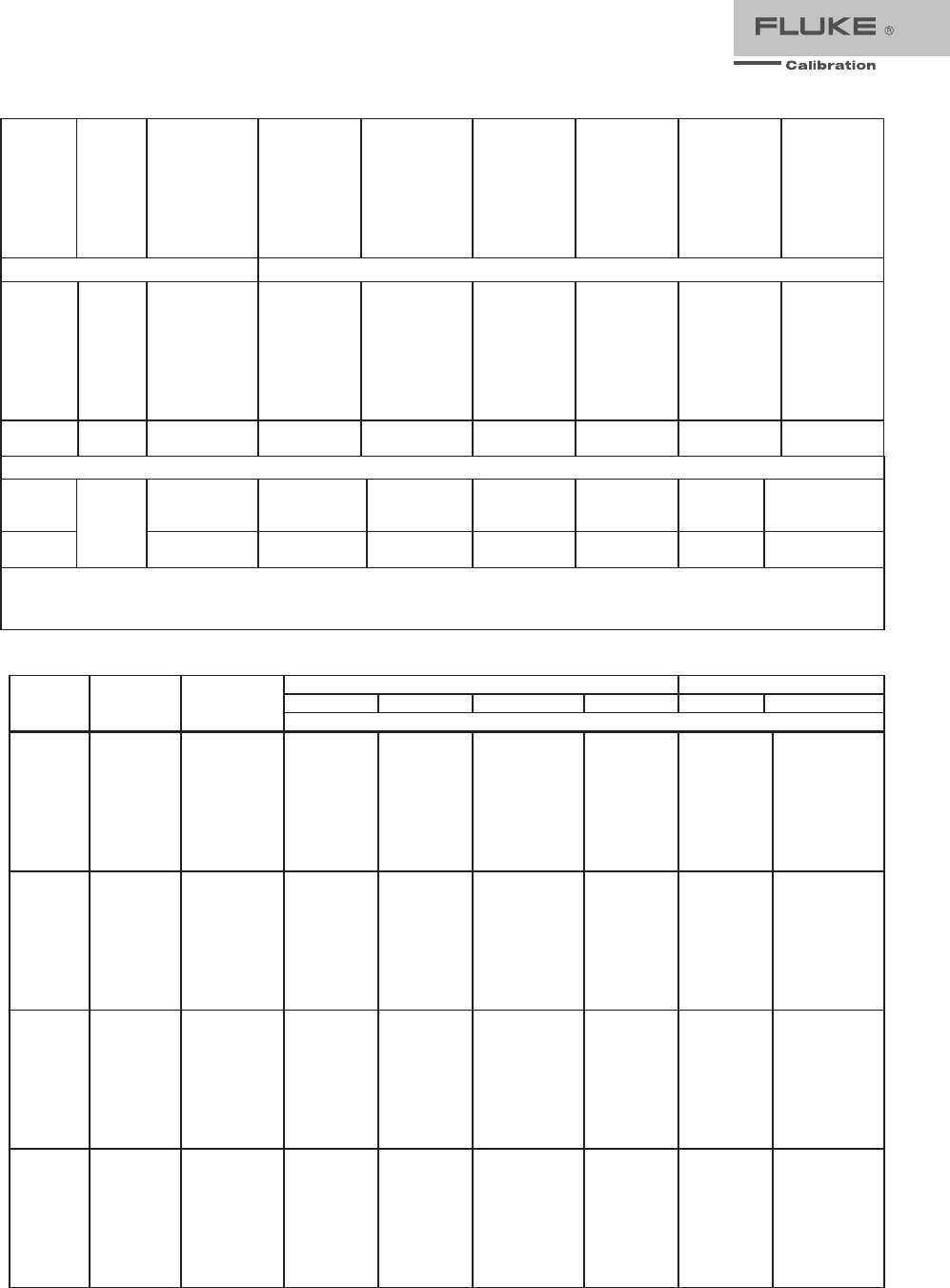
5730A
Height .......................................................... 17.8 cm (7 in), standard rack increment, plus 1.5 cm (0.6 in) for
feet
Width ........................................................... 43.2 cm (17 in), standard rack width
Depth ........................................................... 64.8 cm (25.5 in), overall; 59.4 cm (23.4 in), rack depth
5725A
Height .......................................................... 13.3 cm (5.25 in)
Width and Depth ......................................... Both units project 5.1 cm (2 in) from rack front.
3 Fluke Calibration Fluke 5730A Extended Specifications
hhp002.eps
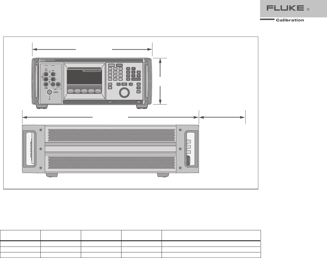
Figure 1-1. Product Dimensions
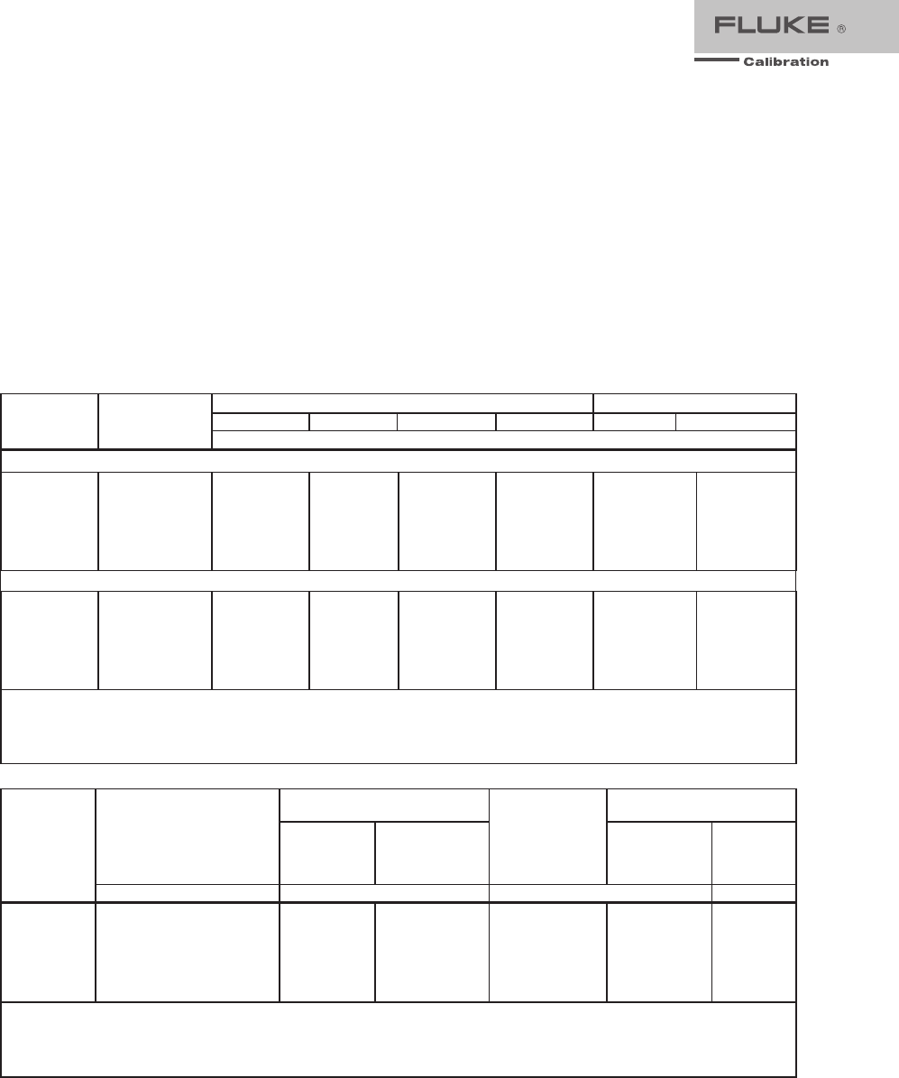
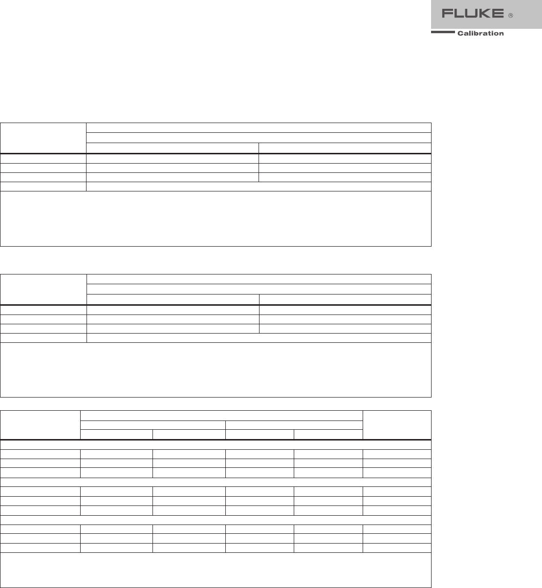
Artifact Calibration Standards Requirements
The following external standards are necessary to calibrate the 5730A to the listed specification. Each
external standard used must have an uncertainty equal to or less than the listed uncertainty limit.
Fluke Standard Traceable
Quantit
y
Nominal Value Uncertainty
Limit 5730A Specifications Susceptible to
Uncertaint
y
Limit
732B Volta
g
e 10 V 1.5
pp
m dc volts, ac volts, dc current, ac current
742A-1 Resistance 1 Ω 10
pp
m1Ω, 1.9 Ω
742A-10k Resistance 10 kΩ 2
pp
m ac current, dc current 10 Ω to 100 MΩ
43.2 cm (17 in)
17.8 cm (7 in)
64.8 cm (25.5 in)
6.35 cm (2.5 in)
For cable
access
4 Fluke Calibration Fluke 5730A Extended Specifications
Electrical Specifications
The product specifications describe the Absolute Instrumental Uncertainty of the Product. The product specifications
include stability, temperature, and humidity; within specified limits, linearity, line and load regulation, and the reference
standard measurement uncertainty. The product specifications are provided at a 99 %, k=2.58, normally distributed and a
95 %, k=2, normally distributed level of confidence. Fluke Calibration guarantees product performance to the 99 % level
of confidence.
The relative specifications are provided for enhanced accuracy applications. The specifications apply when range
constants are adjusted (see "Range Calibration"). To Calculate an enhanced absolute specification from the relative
accuracy specification, it is necessary to combine the uncertainty of your external standards with the pertinent relative
specifications.
Specifications are valid after allowing a warm-up period of 30 minutes, or twice the time the Product has been turned off.
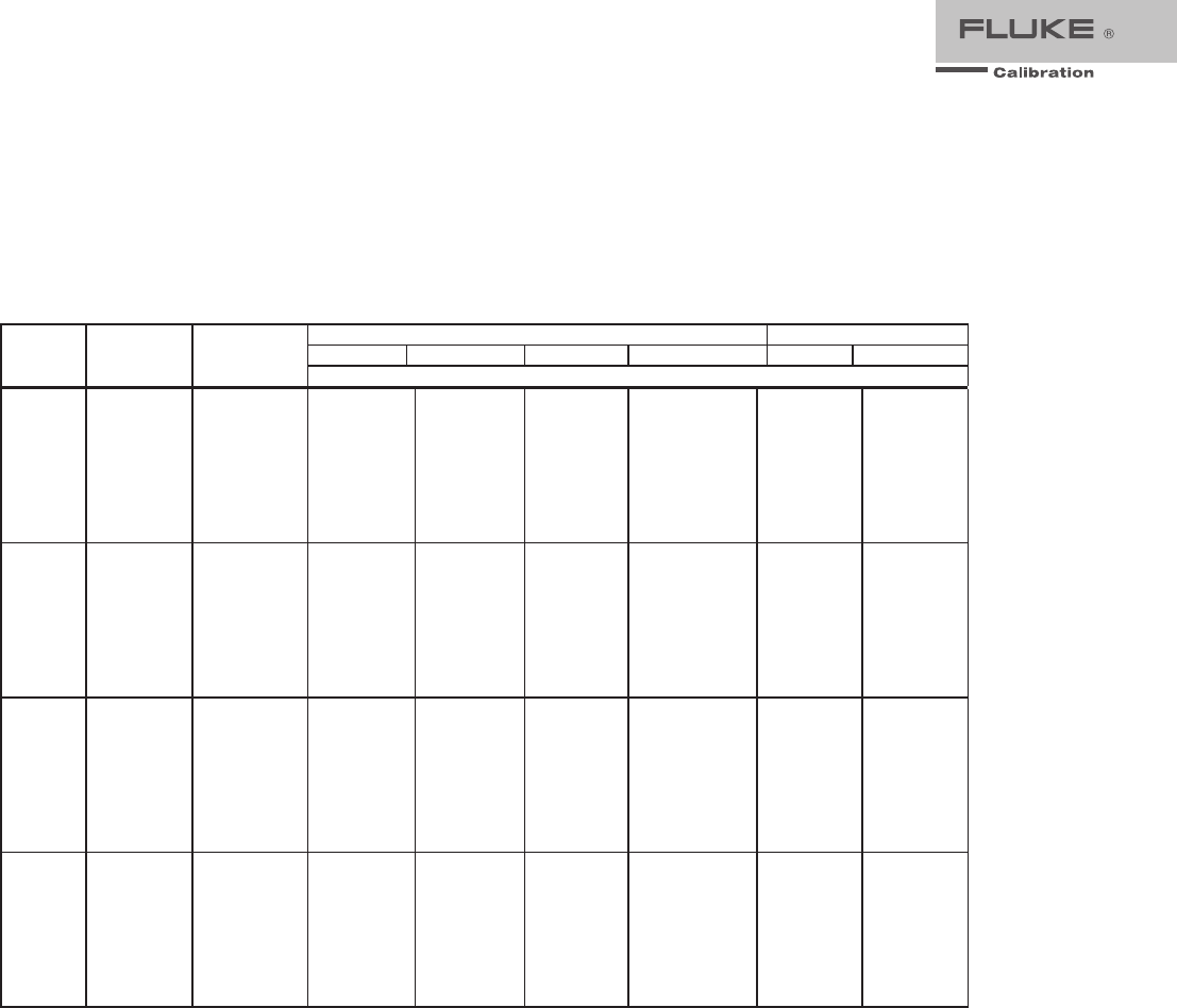
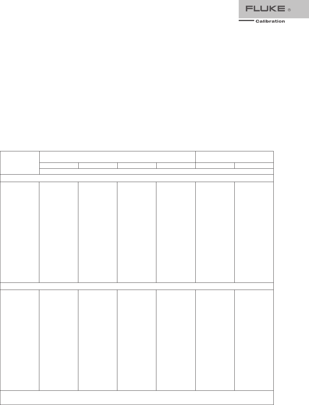
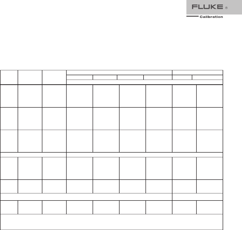
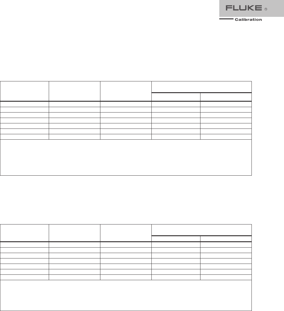
DC Voltage Specifications
5730A DC Voltage Specifications
Range Resolution
Absolute / ±5°C from calibration tem
p
erature Relative ±1 °C
24 Hours 90 Da
y
s 180 Da
y
s 1 Year 24 Hours 90 Da
y
s
±(
pp
m out
p
ut
[1]
+
μ
V)
99 % Confidence Level
220 mV 10 nV 5 + 0.5 7 + 0.5 8 + 0.5 9 + 0.5 2 + 0.4 2.5 + 0.4
2.2 V 100 nV 3.5 + 0.8 4 + 0.8 4.5 + 0.8 6 + 0.8 2 + 0.8 2.5 + 0.8
11 V 1
μ
V 2.5 + 3 3 + 3 3.5 + 3 4 + 3 1 + 3 1.5 + 3
22 V 1
μ
V 2.5 + 5 3 + 5 3.5 + 5 4 + 5 1 + 5 1.5 + 5
220 V 10
μ
V 3.5 + 50 4 + 50 5 + 50 6 + 50 2 + 50 2.5 + 50
1100 V 100
μ
V 5 + 500 6 + 500 7 + 500 8 + 500 2.5 + 400 3 + 400
95 % Confidence Level
220 mV 10 nV 4 + 0.4 6 + 0.4 6.5 + 0.4 7.5 + 0.4 1.6 + 0.4 2 + 0.4
2.2 V 100 nV 3 + 0.7 3.5 + 0.7 4 + 0.7 5 + 0.7 1.6 + 0.7 2 + 0.7
11 V 1
μ
V 2 + 2.5 2.5 + 2.5 3 + 2.5 3.5 + 2.5 0.8 + 2.5 1.2 + 2.5
22 V 1
μ
V 2 + 4 2.5 + 4 3 + 4 3.5 + 4 0.8 + 4 1.2 + 4
220 V 10
μ
V 3 + 40 3.5 + 40 4 + 40 5 + 40 1.6 + 40 2 + 40
1100 V 100
μ
V 4 + 400 4.5 + 400 6 + 400 6.5 + 400 2 + 400 2.4 + 400
Notes:
Perform the DC Zero calibration every 30 days. In addition, perform the DC Zero calibration after powering up the unit the first time after
unpacking following a shipment or if exposed to an environmental change of greater than 5 °C.
1. For radiated EMI fields >400 MHz and <500 MHz, add 1 ppm.
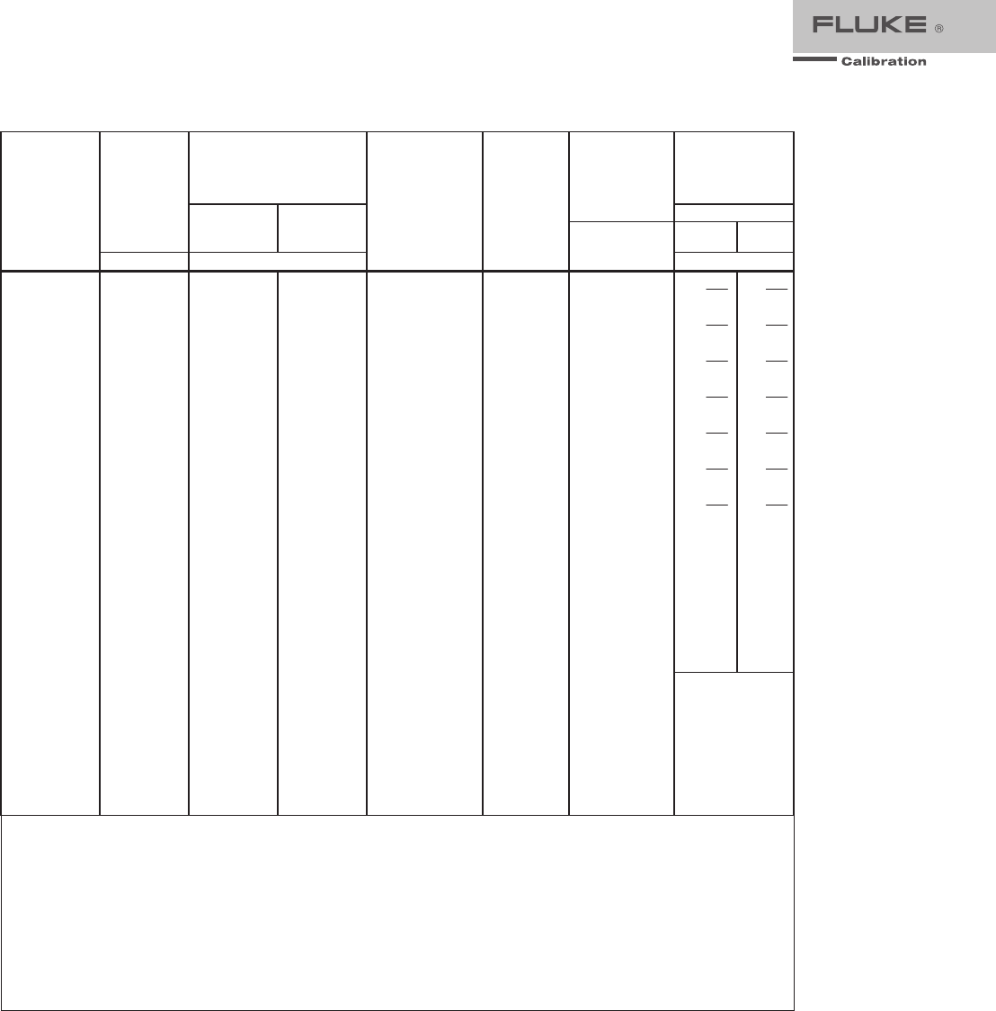
DC Voltage Secondary Performance Specifications and Operating Characteristics
Range
Stability
[1]
±1 °C
24 Hours
Temperature Coefficient
Adder
[2]
Linearity ±1 °C
Noise
10 - 40 °C
0 - 10 °C and
40 - 50 °C
Bandwidth
0.1 - 10 Hz
pk-pk
Bandwidth
10 -
10 kHz
RMS
±(
pp
m out
p
ut +
μ
V) ±(
pp
m out
p
ut +
μ
V) / °C±(
pp
m out
p
ut +
μ
V)
μ
V
220 mV
2.2 V
11 V
22 V
220 V
1100 V
0.3 + 0.3
0.3 + 1
0.3 + 2.5
0.4 + 5
0.5 + 40
0.5 + 200
0.4 + 0.1
0.3 + 0.1
0.15 + 0.2
0.2 + 0.4
0.3 + 5
0.5 + 10
1.5 + 0.5
1.5 + 2
1 + 1.5
1.5 + 3
1.5 + 40
3 + 200
1 + 0.2
1 + 0.6
0.3 + 2
0.3 + 4
1 + 40
1 + 200
0.15 + 0.1
0.15 + 0.4
0.15 + 2
0.15 + 4
0.15 + 60
0.15 + 300
5
15
50
50
150
500
Notes:
1. Stability specifications are included in the absolute specification values in the primary specification tables.
2. Temperature coefficient is an adder to accuracy specifications that does not apply unless operating more than ±5 °C from
calibration temperature.
Minimum Output
............................................... 0 V for all ranges, except 100 V for 1100 V range
Maximum Load
................................................. 50 mA for 2.2 V through 220 V ranges; 20 mA for 1100 V range;
50 Ω output impedance on 220 mV range; all ranges <1000 pF,
>25 Ω
Load Regulation
................................................ <(0.2 ppm of output + 0.1 ppm of range), full load to no load
Line Regulation
................................................ <0.1 ppm change, ±10 % of selected nominal line
Settling Time
.................................................... 3 seconds to full specification; + 1 second for range or polarity
change; + 1 second for 1100 V range
5 Fluke Calibration Fluke 5730A Extended Specifications
Overshoot
..........................................................<5 %
Common Mode Rejection
..................................140 dB, DC to 400 Hz
Remote Sensing
...............................................Available 0 V to ±1100 V, on 2.2 V through 1100 V ranges
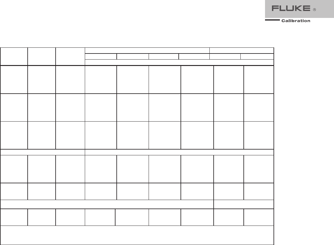
AC Voltage Specifications
5730A AC Voltage Specifications: 99 % Confidence Level
Range Resolution Frequency
(Hz)
Absolute / ±5 °C from calibration tem
p
erature Relative ±1 °C
24 Hours 90 Da
y
s 180 Da
y
s 1 Year 24 Hours 90 Da
y
s
±(
pp
m out
p
ut +
μ
V)
2.2 mV 1 nV
10 - 20
20 - 40
40 - 20 k
20 k - 50 k
50 k - 100 k
100 k - 300 k
300 k - 500 k
500 k - 1 M
250 + 5
100 + 5
85 + 5
220 + 5
500 + 6
1000 + 12
1400 + 25
2900 + 25
270 + 5
105 + 5
90 + 5
230 + 5
540 + 6
1200 + 12
1500 + 25
3100 + 25
290 + 5
110 + 5
95 + 5
240 + 5
570 + 6
1250 + 12
1600 + 25
3250 + 25
300 + 5
115 + 5
100 + 5
250 + 5
600 + 6
1300 + 12
1700 + 25
3400 + 25
250 + 5
100 + 5
60 + 5
85 + 5
200 + 6
350 + 12
800 + 25
2700 + 25
270 + 5
105 + 5
65 + 5
95 + 5
220 + 6
400 + 12
1000 + 25
3000 + 25
22 mV 10 nV
10 - 20
20 - 40
40 - 20 k
20 k - 50 k
50 k - 100 k
100 k - 300 k
300 k - 500 k
500 k - 1 M
250 + 5
100 + 5
85 + 5
220 + 5
500 + 6
1000 + 12
1400 + 25
2900 + 25
270 + 5
105 + 5
90 + 5
230 + 5
540 + 6
1200 + 12
1500 + 25
3100 + 25
290 + 5
110 + 5
95 + 5
240 + 5
570 + 6
1250 + 12
1600 + 25
3250 + 25
300 + 5
115 + 5
100 + 5
250 + 5
600 + 6
1300 + 12
1700 + 25
3400 + 25
250 + 5
100 + 5
60 + 5
85 + 5
200 + 6
350 + 12
800 + 25
2700 + 25
270 + 5
105 + 5
65 + 5
95 + 5
220 + 6
400 + 12
1000 + 25
3000 + 25
220 mV 100 nV
10 - 20
20 - 40
40 - 20 k
20 k - 50 k
50 k - 100 k
100 k - 300 k
300 k - 500 k
500 k - 1 M
250 + 15
100 + 8
65 + 8
135 + 8
370 + 20
650 + 25
1400 + 30
2700 + 60
270 + 15
105 + 8
66 + 8
140 + 8
380 + 20
700 + 25
1500 + 30
2900 + 60
290 + 15
110 + 8
67 + 8
145 + 8
390 + 20
750 + 25
1600 + 30
3100 + 60
300 + 15
115 + 8
70 + 8
150 + 8
400 + 20
800 + 25
1700 + 30
3300 + 60
250 + 15
100 + 8
60 + 8
85 + 8
200 + 20
350 + 25
800 + 30
2600 + 60
270 + 15
105 + 8
65 + 8
95 + 8
220 + 20
400 + 25
1000 + 30
2800 + 60
2.2 V 1 μV
10 - 20
20 - 40
40 - 20 k
20 k - 50 k
50 k - 100 k
100 k - 300 k
300 k - 500 k
500 k - 1 M
250 + 50
95 + 20
45 + 10
75 + 12
95 + 40
350 + 100
1000 + 250
1600 + 400
270 + 50
100 + 20
46 + 10
77 + 12
97 + 40
370 + 100
1100 + 250
1800 + 400
290 + 50
105 + 20
47 + 10
78 + 12
98 + 40
380 + 100
1150 + 250
1900 + 400
300 + 50
110 + 20
48 + 10
80 + 12
100 + 40
400 + 100
1200 + 250
2000 + 400
250 + 50
95 + 20
30 + 10
70 + 12
100 + 40
270 + 100
900 + 250
1200 + 400
270 + 50
100 + 20
40 + 10
75 + 12
105 + 40
290 + 100
1000 + 250
1300 + 400
6 Fluke Calibration Fluke 5730A Extended Specifications
22 V 10 μV
10 - 20
20 - 40
40 - 20 k
20 k - 50 k
50 k - 100 k
100 k - 300 k
300 k - 500 k
500 k - 1 M
250 + 500
95 + 200
45 + 70
75 + 120
95 + 250
285 + 800
1000 + 2500
1500 + 4000
270 + 500
100 + 200
46 + 70
77 + 120
97 + 250
290 + 800
1100 + 2500
1600 + 4000
290 + 500
105 + 200
47 + 70
78 + 120
98 + 250
295 + 800
1150 + 2500
1700 + 4000
300 + 500
110 + 200
48 + 70
80 + 120
100 + 250
300 + 800
1200 + 2500
1800 + 4000
250 + 500
95 + 200
30 + 70
70 + 120
100 + 250
270 + 800
900 + 2500
1300 + 4000
270 + 500
100 + 200
40 + 70
75 + 120
105 + 250
290 + 800
1000 + 2500
1400 + 4000
±
(ppm output + mV)
220 V [2] 100 μV
10 - 20
20 - 40
40 - 20 k
20 k - 50 k
50 k - 100 k
100 k - 300 k
300 k - 500 k
500 k - 1 M
250 + 5
95 + 2
57 + 0.7
90 + 1.2
160 + 3
900 + 20
5000 + 50
8000 + 100
270 + 5
100 + 2
60 + 0.7
95 + 1.2
170 + 3
1000 + 20
5200 + 50
9000 + 100
290 + 5
105 + 2
62 + 0.7
97 + 1.2
175 + 3
1050 + 20
5300 + 50
9500 + 100
300 + 5
110 + 2
65 + 0.7
100 + 1.2
180 + 3
1100 + 20
5400 + 50
10,000 + 100
250 + 5
95 + 2
45 + 0.7
75 + 1.2
140 + 3
600 + 20
4500 + 50
8000 + 100
270 + 5
100 + 2
50 + 0.7
80 + 1.2
150 + 3
700 + 20
4700 + 50
8500 + 100
1100 V [1] 1 mV 15 - 50
50 - 1 k
300 + 20
70 + 4
320 + 20
75 + 4
340 + 20
80 + 4
360 + 20
85 + 4
300 + 20
50 + 4
320 + 20
55 + 4
5725A Amplifier:
1100 V
1 mV
40 - 1 k
1 k - 20 k
20 k - 30 k
75 + 4
105 + 6
230 + 11
80 + 4
125 + 6
360 + 11
85 + 4
135 + 6
440 + 11
90 + 4
165 + 6
600 + 11
50 + 4
85 + 6
160 + 11
55 + 4
105 + 6
320 + 11
750 V 30 k - 50 k
50 k - 100 k
230 + 11
600 + 45
360 + 11
1300 + 45
440 + 11
1600 + 45
600 + 11
2300 + 45
160 + 11
380 + 45
320 + 11
1200 + 45
Notes:
1. Maximum output 250 V from 15-50 Hz.
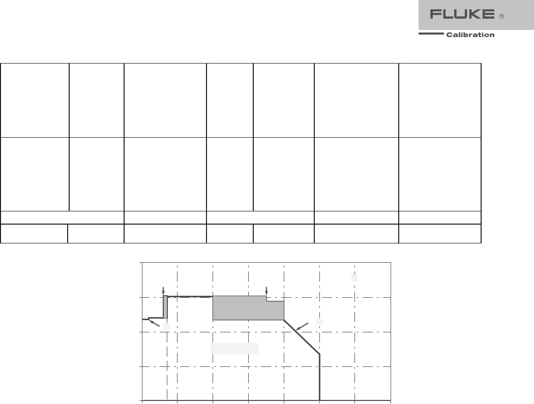
2. See Volt-Hertz capability in Figure A.
5730A AC Voltage Specifications: 95 % Confidence Level
Range Resolution Frequency
(Hz)
Absolute / ±5°C from calibration tem
p
erature Relative ±1°C
24 Hours 90 Da
y
s 180 Da
y
s 1 Year 24 Hours 90 Da
y
s
±(
pp
m out
p
ut +
μ
V)
2.2 mV 1 nV
10 - 20
20 - 40
40 - 20 k
20 k - 50 k
50 k - 100 k
100 k - 300 k
300 k - 500 k
500 k - 1 M
200 + 4
80 + 4
70 + 4
170 + 4
400 + 5
800 + 10
1100 + 20
2400 + 20
220 + 4
85 + 4
75 + 4
180 + 4
460 + 5
900 + 10
1200 + 20
2500 + 20
230 + 4
87 + 4
77 + 4
190 + 4
480 + 5
1000 + 10
1300 + 20
2600 + 20
240 + 4
90 + 4
80 + 4
200 + 4
500 + 5
1050 + 10
1400 + 20
2700 + 20
200 + 4
80 + 4
50 + 4
70 + 4
160 + 5
280 + 10
650 + 20
2100 + 20
220 + 4
85 + 4
55 + 4
80 + 4
180 + 5
320 + 10
800 + 20
2400 + 20
22 mV 10 nV
10 - 20
20 - 40
40 - 20 k
20 k - 50 k
50 k - 100 k
100 k - 300 k
300 k - 500 k
500 k - 1 M
200 + 4
80 + 4
70 + 4
170 + 4
400 + 5
800 + 10
1100 + 20
2400 + 20
220 + 4
85 + 4
75 + 4
180 + 4
460 + 5
900 + 10
1200 + 20
2500 + 20
230 + 4
87 + 4
77 + 4
190 + 4
480 + 5
1000 + 10
1300 + 20
2600 + 20
240 + 4
90 + 4
80 + 4
200 + 4
500 + 5
1050 + 10
1400 + 20
2700 + 20
200 + 4
80 + 4
50 + 4
70 + 4
160 + 5
280 + 10
650 + 20
2100 + 20
220 + 4
85 + 4
55 + 4
80 + 4
180 + 5
320 + 10
800 + 20
2400 + 20
220 mV 100 nV
10 - 20
20 - 40
40 - 20 k
20 k - 50 k
50 k - 100 k
100 k - 300 k
300 k - 500 k
500 k - 1 M
200 + 12
80 + 7
54 + 7
105 + 7
296 + 17
535 + 20
1100 + 25
2400 + 45
220 + 12
85 + 7
55 + 7
110 + 7
298 + 17
583 + 20
1200 +25
2500 + 45
230 + 12
87 + 7
56 + 7
115 + 7
303 + 17
600 + 20
1300 + 25
2600 + 45
240 + 12
90 + 7
57 + 7
120 + 7
310 + 17
655 + 20
1400 + 25
2700 + 45
200 + 12
80 + 7
50 + 7
70 + 7
160 + 17
280 + 20
650 + 25
2100 + 45
220 + 12
85 + 7
55 + 7
80 + 7
180 + 17
320 + 20
800 + 25
2400 + 45
2.2 V 1 μV
10 - 20
20 - 40
40 - 20 k
20 k - 50 k
50 k - 100 k
100 k - 300 k
300 k - 500 k
500 k - 1 M
200 + 40
75 + 15
37 + 8
61 + 10
79 + 30
276 + 80
800 + 200
1300 + 300
220 + 40
80 + 15
39 + 8
63 + 10
81 + 30
300 + 80
900 + 200
1500 + 300
230 + 40
85 + 15
40 + 8
65 + 10
82 + 30
314 + 80
950 + 200
1600 + 300
240 + 40
90 + 15
42 + 8
67 + 10
85 + 30
336 + 80
1000 + 200
1700 + 300
200 + 40
75 + 15
25 + 8
55 + 10
80 + 30
230 + 80
700 + 200
1000 + 300
220 + 40
80 + 15
35 + 8
60 + 10
85 + 30
250 + 80
800 + 200
1100 + 300
7 Fluke Calibration Fluke 5730A Extended Specifications
22 V 10 μV
10 - 20
20 - 40
40 - 20k
20k - 50k
50k - 100k
100k - 300k
300k - 500k
500k - 1M
200 + 400
75 + 150
37 + 50
61 + 100
78 + 200
238 + 600
800 + 2000
1200 + 3200
220 + 400
80 + 150
39 + 50
63 + 100
80 + 200
243 + 600
900 + 2000
1300 + 3200
230 + 400
85 + 150
40 + 50
65 + 100
81 + 200
249 + 600
900 + 2000
1400 + 3200
240 + 400
90 + 150
42 + 50
67 + 100
83 + 200
254 + 600
1000 + 2000
1500 + 3200
200 + 400
75 + 150
25 + 50
55 + 100
80 + 200
250 + 600
700 + 2000
1100 + 3200
220 + 400
80 + 150
35 + 50
60 + 100
85 + 200
270 + 600
800 + 2000
1200 + 3200
±
(ppm output + mV)
220 V [2] 100 μV
10 - 20
20 - 40
40 - 20 k
20 k - 50 k
50 k - 100 k
100 k - 300 k
300 k - 500 k
500 k - 1 M
200 +4
75 + 1.5
45 + 0.6
70 + 1
120 + 2.5
700 + 16
4000 + 40
6000 + 80
220 + 4
80 + 1.5
47 + 0.6
75 + 1
130 + 2.5
800 + 16
4200 + 40
7000 + 80
230 + 4
85 + 1.5
50 + 0.6
77 + 1
140 + 2.5
850 + 16
4300 + 40
7500 + 80
240 + 4
90 + 1.5
52 + 0.6
80 + 1
150 + 2.5
900 + 16
4400 + 40
8000 + 80
200 + 4
75 + 1.5
35 + 0.6
60 + 1
110 + 2.5
500 + 16
3600 + 40
6500 + 80
220 + 4
80 + 1.5
40 + 0.6
65 + 1
120 + 2.5
600 + 16
3800 + 40
7000 + 80
1100 V [1] 1 mV 15 - 50
50 - 1 k
240 + 16
55 + 3.5
260 + 16
60 + 3.5
280 + 16
65 + 3.5
300 + 16
70 + 3.5
240 + 16
40 + 3.5
260 + 16
45 + 3.5
5725A Amplifier:
1100 V
1 mV
40 - 1 k
1 k - 20 k
20 k - 30 k
75 + 4
105 + 6
230 + 11
80 + 4
125 + 6
360 + 11
85 + 4
135 + 6
440 + 11
90 + 4
165 + 6
600 + 11
50 + 4
85 + 6
160 + 11
55 + 4
105 + 6
320 + 11
750 V 30 k - 50 k
50 k - 100 k
230 + 11
600 + 45
360 + 11
1300 + 45
440 + 11
1600 + 45
600 + 11
2300 + 45
160 + 11
380 + 45
320 + 11
1200 + 45
Notes:
1. Maximum output 250 V from 15-50 Hz.
2. See Volt-Hertz capability in Figure A.
AC Voltage Secondary Performance Specifications and Operating Characteristics
Range Frequency
(Hz)
Stability ±1 °C
[1]
24 Hours
Tem
p
erature Coefficient
Output Impedance
(Ω)
Maximum Distortion
Bandwidth 10 Hz-10 MHz
10 - 40 °C0 - 10 °C
and 40 - 50
°C
±
μ
V ±
μ
V / °C±(% out
p
ut +
μ
V)
2.2 mV
10 - 20
20 - 40
40 - 20 k
20 k - 50 k
50 k - 100 k
100 k - 300 k
300 k - 500 k
500 k - 1 M
5
5
2
2
3
3
5
5
0.05
0.05
0.05
0.1
0.2
0.3
0.4
0.5
0.05
0.05
0.05
0.1
0.2
0.3
0.4
0.5
50
0.05 + 10
0.035 + 10
0.035 + 10
0.035 + 10
0.035 + 30
0.3 + 30
0.3 + 30
2 + 50
22 mV
10 - 20
20 - 40
40 - 20 k
20 k - 50 k
50 k - 100 k
100 k - 300 k
300 k - 500 k
500 k - 1 M
5
5
2
2
3
5
10
15
0.2
0.2
0.2
0.4
0.5
0.6
1
1
0.3
0.3
0.3
0.5
0.5
0.6
1
1
50
0.05 + 11
0.035 + 11
0.035 + 11
0.035 + 11
0.035 + 30
0.3 + 30
0.3 + 30
2 + 30
±
(ppm output +
μ
V
)
±
(ppm output
μ
V
) /
°
C
220 m
V
10 - 20
20 - 40
40 - 20 k
20 k - 50 k
50 k - 100 k
100 k - 300 k
300 k - 500 k
500 k - 1 M
150 + 20
80 + 15
12 + 2
10 + 2
10 + 2
20 + 4
100 + 10
200 + 20
2 + 1
2 + 1
2 + 1
15 + 2
15 + 4
80 + 5
80 + 5
80 + 5
2 + 1
2 + 1
2 + 1
15 + 2
15 + 4
80 + 5
80 + 5
80 + 5
50
0.05 + 16
0.035 + 16
0.035 + 16
0.035 + 16
0.035 + 30
0.3 + 30
0.3 + 30
1 + 30
Load Regulation
±
(ppm output +
μ
V)
2.2 V
10 - 20
20 - 40
40 - 20 k
20 k - 50 k
50 k - 100 k
100 k - 300 k
300 k - 500 k
500 k - 1 M
150 + 20
80 + 15
12 + 4
15 + 5
15 + 5
30 + 10
70 + 20
150 + 50
50 + 10
15 + 5
2 + 1
10 + 2
10 + 4
80 + 15
80 + 40
80 + 100
50 + 10
15 + 5
5 + 2
15 + 4
20 + 4
80 + 15
80 + 40
80 + 100
10 + 2
10 + 2
10 + 4
30 + 10
120 + 16
300 ppm
600 ppm
1200 ppm
0.05 + 80
0.035 + 80
0.035 + 80
0.035 + 80
0.035 + 110
0.3 + 110
0.5 + 110
1 + 110
8 Fluke Calibration Fluke 5730A Extended Specifications
22 V
10 - 20
20 - 40
40 - 20 k
20 k - 50 k
50 k - 100 k
100 k - 300 k
300 k - 500 k
500 k - 1 M
150 + 20
80 + 15
12 + 8
15 + 10
15 + 10
30 + 15
70 + 100
150 + 100
50 + 100
15 + 30
2 + 10
10 + 20
10 + 40
80 + 150
80 + 300
80 + 500
50 + 100
15 + 40
4 + 15
20 + 20
20 + 40
80 + 150
80 + 300
80 + 500
10 + 20
10 + 20
10 + 30
30 + 50
80 + 80
100 + 700
200 + 1100
600 + 3000
0.05 + 700
0.035 + 700
0.035 + 700
0.035 + 700
0.05 + 800
0.3 + 800
0.3 + 800
2 + 800
220 V
10 - 20
20 - 40
40 - 20 k
20 k - 50 k
50 k - 100 k
100 k - 300 k
300 k - 500 k
500 k - 1 M
150 + 200
80 + 150
12 + 80
15 + 100
15 + 100
30 + 400
100 + 10,000
200 + 20,000
50 + 1000
15 + 300
2 + 80
10 + 100
10 + 500
80 + 600
80 + 800
80 + 1000
50 + 1000
15 + 300
4 + 80
20 + 100
20 + 500
80 + 600
80 + 800
80 + 1000
10 + 200
10 + 200
10 + 300
30 + .600
80 + 3,000
250 + 25,000
500 + 50,000
1000 + 110,000
0.05 + 10,000
0.05 + 10,000
0.05 + 10,000
0.05 + 10,000
0.2 + 50,000
1.5 + 50,000
1.5 + 50,000
3.5 + 100,000
±
(ppm output + mV)
±
(ppm output) /
°
C
±
(ppm output + mV)
±
(% output)
1100 V 15 - 50
50 - 1 k
150 + 0.5
20 + 0.5
50
2
50
5
10 + 2
10 + 1
0.15
0.07
Figure A.
1000
100
10
0
3.5 V
10000
50 Hz10 Hz 1 kHz 100 kHz 1 MHz 30 MHz
Voltage
Frequency
40 Hz 30 Hz
2.2 x 10
7
V-Hz
15 Hz
Volt-Hertz Capability
9 Fluke Calibration Fluke 5730A Extended Specifications
5725A Amplifier:
Range
Frequency
(Hz)
Stability
±1 °C
[1]
24 Hours
Temperature Coefficient
Adder
Load Regulation
[2]
Distortion
Bandwidth
10 Hz -10 MHz
±(% output)
10 - 40 °C 0 - 10 °C
and
40 - 50 °C
±(ppm output +
mV) ±(ppm output) / °C±(ppm output + mV) 150 pF 1000 pF
1100 V
40 - 1 k
1 k - 20 k
20 k - 50 k
50 k - 100
k
10 + .5
15 + 2
40 + 2
130 + 2
5
5
10
30
5
5
10
30
10 + 1
90 + 6
275 + 11
500 + 30
0.10
0.10
0.30
0.40
0.10
0.15
0.30
0.40
Notes:
1. Stability specifications are included in Absolute specification values for the primary specifications.
2. The 5725A will drive up to 1000 pF of load capacitance. Absolute specifications include loads to 300 pF and 150 pF as shown
under "Load Limits." For capacitances up to the maximum of 1000 pF, add "Load Regulation."
Volta
g
e Ran
g
e Maximum Current Limits Load Limits
2.2 V [2]
22 V
220 V
50 mA, 0 °C-40 °C
20 mA, 40 °C-50 °C
>50 Ω,
1000 pF
1100 V 6 mA 600
p
F
5725A Amplifier:
40 Hz-5 kHz 50 mA 1000
p
F [1]
1100 V 5 kHz-30 kHz 70 mA 300
p
F
30 kHz-100 kHz
70 mA [3] 150 pF
Notes:
1. The 5725A will drive up to 1000 pF of load capacitance. Absolute specifications include loads to 300 pF and 150 pF as shown
under "Load Limits." For capacitances up to the maximum of 1000 pF, add "Load Regulation."
2. 2.2 V Range, 100 kHz-1.2 MHz only: Absolute specifications cover loads to 10 mA or 1000 pF. For higher loads, load regulation
is added.
3. Applies from 0 °C to 40 °C.
Output Display Formats
.....................................Voltage or dBm, dBm reference 600 Ω.
Minimum Output
................................................10 % on each range
External Sense
...................................................Applicable for 2.2 V, 22 V, 220 V, and 1100 V ranges; 5730A
<100 kHz, 5725A <30 kHz. Specifications are the same as
internal sense.
Settling Time to Published Specifications
Fre
q
uenc
y
(Hz) Settlin
g
Time (seconds)
10-120 7
>120 5
Notes:
Plus 1 second for amplitude or frequency range change
Plus 2 seconds for 5730A 1100 V range
Plus 4 seconds for 5725A 1100 V range
Overshoot
............................................................<10 %
Common Mode Rejection
....................................... 140 dB, dc to 400 Hz
Frequency
Ranges (Hz) .....................................................10.000 - 119.99
0.1200 k - 1.1999 k
1.200 k - 11.999 k
12.00 k - 119.99 k
120.0 k - 1.1999 M
Absolute Specification .....................................±0.0025 %
Resolution ........................................................11.999 counts
10 Fluke Calibration Fluke 5730A Extended Specifications
Phase Lock
(Selectable Rear Panel BNC Input)
Phase Specification (except 1100 V range) .... >30 Hz: ±1 ° + 0.05 °/kHz), <30 Hz: ±3 °
Input Voltage .................................................. 1 V to 10 V rms sine wave (do not exceed 1 V for mV ranges)
Frequency Range ............................................ 10 Hz to 1.1999 MHz
Lock Range ..................................................... ±2 % of frequency
Lock-In Time ................................................... Larger of 10/frequency or 10 msec
Phase Reference
(Selectable Rear Panel BNC Output)
Range .............................................................. ±180 °
Phase Absolute Specification .......................... (except 1100 V range) ±1 ° at quadrature points (0 °, ±90 °, ±180 °)
elsewhere ±2 °
Stability ........................................................... ±0.1 °
Resolution ....................................................... 1 °
Output Level .................................................... 2.5 V rms ±0.2 V
Frequency Range ............................................ 50 Hz to 1 kHz, usable 10 Hz to 1.1999 MHz
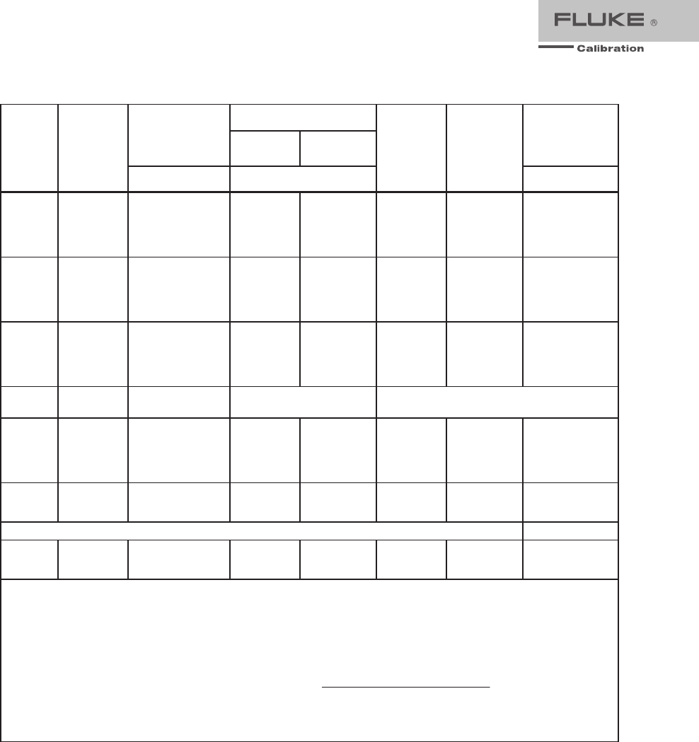
Resistance Specifications
5730A Resistance Specifications
Nominal Value
(Ω)
Absolute Specification of Characterized Value
±5 °C from calibration tem
p
erature
[1]
Relative ±1 °C
24 Hours 90 Da
y
s 180 Da
y
s 1 Year 24 Hours 90 Da
y
s
±
pp
m
99 % Confidence Level
0
1
1.9
10
19
100
190
1 k
1.9 k
10 k
19 k
100 k
190 k
1 M
1.9 M
10 M
19 M
100 M
50
μ
Ω
85
85
23
23
10
10
7
7
6
6
7
8
13
15
33
43
100
50
μ
Ω
95
95
25
25
11
11
7.2
7.2
7
7
8
10
14
17
37
47
110
50
μ
Ω
100
100
26
26
11.5
11.5
7.5
7.5
7.5
7.5
9
11
14.5
19
40
50
115
50
μ
Ω
110
110
27
27
12
12
8
8
8
8
10
12
15
21
46
55
120
50
μ
Ω
32
25
5
4
2
2
2
2
2
2
2
2
2.5
3
10
20
50
50
μ
Ω
40
33
8
7
4
4
3
3
3
3
3
3
5
6
14
24
60
95 % Confidence Level
0
1
1.9
10
19
100
190
1 k
1.9 k
10 k
19 k
100 k
190 k
1 M
1.9 M
10 M
19 M
100 M
40
μ
Ω
70
70
20
20
8
8
5.5
5.5
5
5
5.5
6
10
12
27
35
85
40
μ
Ω
80
80
21
21
9
9
5.7
5.7
5.5
5.5
7.5
7
11
13.5
31
39
95
40
μ
Ω
85
85
22
22
9.5
9.5
6
6
6
6
8
8
12
15
34
42
100
40
μ
Ω
95
95
23
23
10
10
6.5
6.5
6.5
6.5
8.5
8.5
13
18
40
47
100
40
μ
Ω
27
20
4
3.5
1.6
1.6
1.6
1.6
1.6
1.6
1.6
1.6
2
2.5
8
16
40
40
μ
Ω
35
26
7
6
3.5
3.5
2.5
2.5
2.5
2.5
2.5
2.5
4
4
12
20
50
Note:
1. Specifications apply to displayed value. 4-wire connections, except 100 MΩ.
11 Fluke Calibration Fluke 5730A Extended Specifications
Resistance Secondary Performance Specifications and Operating Characteristics
Nominal
Value
(Ω)
Stability
±1 °C
[1]
24 Hours
Temperature Coefficient
Adder
[2]
Full Spec Load
Range
[3]
I
L -
I
U (mA)
Maximum
Peak
Current
IMAX
(mA)
Maximum
Difference of
Characterized
to Nominal
Value
Two-Wire
Adder Active
Compensation
[4]
10 - 40 °C
0 - 10 °C
and
40 - 50 °C
Lead Resistance
±ppm 0.1 Ω 1 Ω
±
pp
m ±
pp
m/°C ±mΩ
0 ⎯ ⎯ ⎯ 8 - 500 500 ⎯ 2 + m
I
ȝV 4 4 + m
I
ȝV 4
1 32 4 5 8 - 100 700 500 2 + m
I
ȝV 4 4 + m
I
ȝV 4
1.9 25 6 7 8 - 100 500 500 2 + m
I
ȝV 4 4 + m
I
ȝV 4
10 5 2 3 8 - 11 220 300
2 + m
I
ȝV 4 4 + m
I
ȝV 4
19 4 2 3 8 - 11 160 300
2 + m
I
ȝV 4 4 + m
I
ȝV 4
100 2 2 3 8 - 11 70 150
2 + m
I
ȝV 4 4 + m
I
ȝV 4
190 2 2 3 8 - 11 50 150
2 + m
I
ȝV 4 4 + m
I
ȝV 4
1 k 2 2 3 1 - 2 22 150 10 15
1.9 k 2 2 3 1 - 1.5 16 150 10 15
10 k 2 2 3 100 - 500 μA 7 150 50 60
19 k 2 2 3 50 - 250 μA 5 150 100 120
100 k 2 2 3 10 - 100 μA 1 150 Im= Current
produced by
Ohmmeter (A)
190 k 2 2 3 5 - 100
μ
A500
μ
A150
1 M 2.5 2.5 6 5 - 20
μ
A100
μ
A200
1.9 M 3.5 3 10 2.5 - 10
μ
A50
μ
A200
10 M 10 5 20 0.5 - 2
μ
A10
μ
A300
19 M 20 8 40 0.25 - 1
μ
A5
μ
A300
100 M 50 12 100 50 - 200 nA 1
μ
A500
Notes:
1. Stability specifications are included in the Absolute specification values in the primary specification tables.
2. Temperature coefficient is an adder to Absolute specifications that does not apply unless operated more than 5 °C from calibration
temperature, or calibrated outside the range 19 °C to 24 °C. Two examples:
- Calibrate at 20 °C: Temperature coefficient adder is not required unless operated below 15 °C or above 25 °C.
- Calibrate at 26 °C: Add 2 °C temperature coefficient adder. Additional temperature coefficient adder is not required unless
operated below 21 °C or above 31 °C.
3. Refer to current derating factors table for loads outside of this range.
4. Active two-wire compensation may be selected for values less than 100 kΩ, with either the front panel or the meter input terminals
as reference plane. Active compensation is limited to 11 mA load, and to 2 V burden. Two-wire compensation can be used only
with Ω-meters that source continuous (not pulsed) dc current.
12 Fluke Calibration Fluke 5730A Extended Specifications
Current Derating Factors
Nominal Value
(Ω)
Value of Deratin
g
Factor K for Over or Under Current
Two-Wire Comp
I
<
I
L
[1]
Four-Wire
I
<
I
L
[1]
Four-Wire
I
U <
I
<
I
MAX
[2]
SHORT
1
1.9
10
19
100
190
1 k
1.9 k
10 k
19 k
100 k
190 k
1 M
1.9 M
10 M
19 M
100 M
4.4
4.4
4.4
4.4
4.4
4.4
4.4
4.4
4.4
5000
5000
⎯
⎯
⎯
⎯
⎯
⎯
0.3
300
160
30
16
3.5
2.5
0.4
0.4
50
50
7.5
4.0
1.0
0.53
0.2
0.53
0.1
⎯
4 x10⁻⁵
1.5 x 10⁻⁴
1.6 x 10⁻³
3 x 10⁻³
1 x 10⁻²
1.9 x 10⁻²
0.1
0.19
2.0
3.8
2 x 10⁻⁵
3.8 x 10⁻⁵
1.5 x 10⁻⁴
2.9 x 10⁻⁴
1 x 10⁻³
1.9 x 10⁻³
⎯
Notes:
1. For I < I L, errors occur due to thermally generated voltages within the 5730A. Use the following equation to determine the error,
and add this error to the corresponding specifications.
Error = K(I L - I)/( I L x I)
Where: Error is in mΩ for all two-wire comp values and four-wire short, and in ppm for the remaining four-wire values.
K is the constant from the above table;
I and IL are expressed in mA for short to 1.9 kΩ;
I and IL are expressed in μA for 10 kΩ to 100 MΩ
2. For IU < I < IMAX errors occur due to self-heating of the resistors in the calibrator. Use the following equation to determine the error
in ppm and add this error to the corresponding specifications.
Error in ppm = K(I2-IU2)
Where: K is the constant from the above table;
I and IU are expressed in mA for short to 19 kΩ;
I and IU are expressed in μA for 100 kΩ to 100 MΩ
13 Fluke Calibration Fluke 5730A Extended Specifications
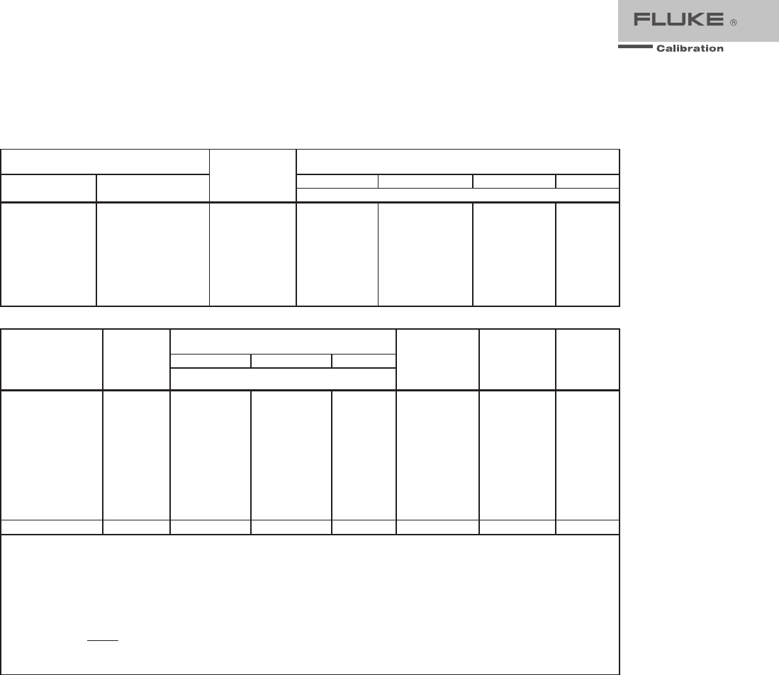
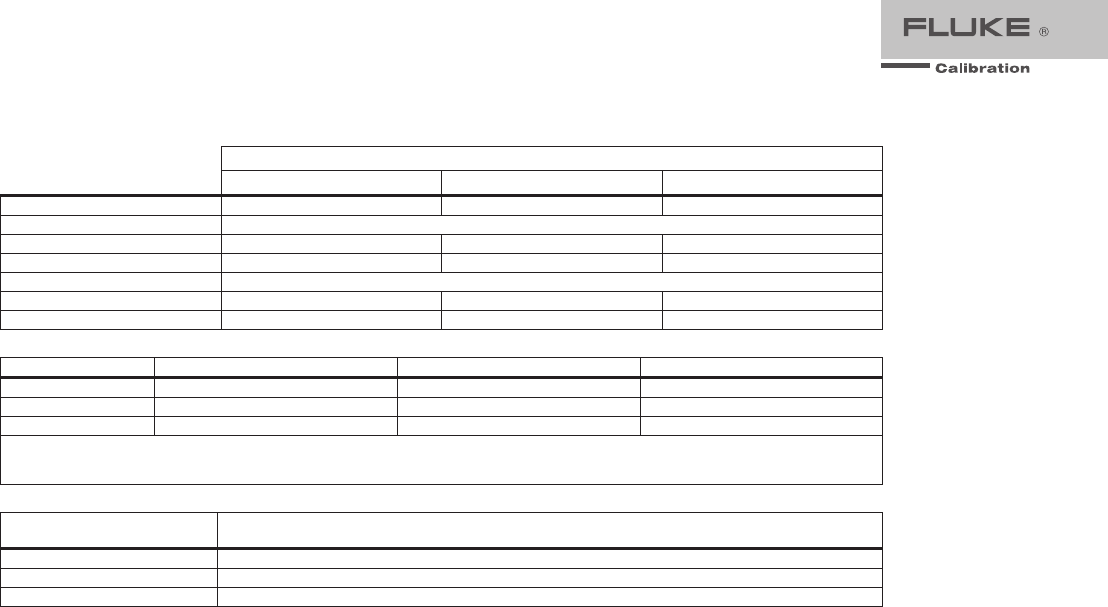
DC Current Specifications
5730A DC Current Specifications
Range Resolution Absolute / ±5 °C from calibration tem
p
erature Relative ±1 °C
24 Hours 90 Da
y
s 180 Da
y
s 1 Year 24 Hours 90 Da
y
s
nA ±(
pp
m out
p
ut + nA)
99 %
Confidence Le
v
el
220
μ
A
2.2 mA
22 mA
0.1
1
10
40 + 7
30 + 8
30 + 50
42 + 7
35 + 8
35 + 50
45 + 7
37 + 8
37 + 50
50 + 7
40 + 8
40 + 50
24 + 2
24 + 5
24 + 50
26 + 2
26 + 5
26 + 50
μ
A ±(
pp
m out
p
ut +
μ
A)
220 mA
[1]
2.2 A [1]
0.1
1
40 + 0.8
60 + 15
45 + 0.8
70 + 15
47 + 0.8
80 + 15
50 + 0.8
90 + 15
26 + 0.3
40 + 7
30 + 0.3
45 + 7
5725A Amplifier:
11 A 10 330 + 470 340 + 480 350 + 480 360 + 480 100 + 130 110 + 130
95 % Confidence Level
nA ±(
pp
m out
p
ut + nA)
220
μ
A
2.2 mA
22 mA
0.1
1
10
32 + 6
25 + 7
25 + 40
35 + 6
30 + 7
30 + 40
37 + 6
33 + 7
33 + 40
40 + 6
35 + 7
35 + 40
20 + 1.6
20 + 4
20 + 40
22 + 1.6
22 + 4
22 + 40
μ
A ±(
pp
m out
p
ut +
μ
A)
220 mA
[1]
2.2 A [1]
0.1
1
35 + 0.7
50 + 12
40 + 0.7
60 + 12
42 + 0.7
70 + 12
45 + 0.7
80 + 12
22 + 0.25
32 + 6
25 + 0.25
40 + 6
5725A Amplifier:
11 A 10 330 + 470 340 + 480 350 + 480 360 + 480 100 + 130 110 + 130
Note:
Maximum output from the calibrator’s terminals is 2.2 A. Specifications for 220 μA and 2.2 mA ranges are increased by a factor of 1.3
when supplied through 5725A terminals.
Specifications are otherwise identical for all output locations.
1. Add to specifications:
±200 x I2 ppm for >100 mA on 220 mA range
±10 x I2 ppm for >1 A on 2.2 A range
DC Current Secondary Performance Specifications and Operating Characteristics
Range
Stability
±1 °C
[1]
24 Hours
Temperature
Coefficient
[2]
Complianc
e Limits
Burden
Voltage
Adder
[3]
(±nA/V)
Maximum
Load for
Published
Specification
[4]
(Ω)
Noise
10 - 40
°C
0 - 10 °C
and
40 - 50 °C
Bandwidth
0.1-10 Hz
Bandwidth
10 Hz-10 kHz
p
k-
p
k RMS
±(ppm
out
p
ut + nA) ±(ppm output + nA) /
°C ppm output
+ nA nA
220
μ
A
2.2 mA
22 mA
220 mA
2.2 A
5 + 1
5 + 5
5 + 50
8 + 300
9 + 7
μ
A
1 + 0.40
1 + 2
1 + 20
1 + 200
1 + 2.5
μ
A
3 + 1
3 + 10
3 + 100
3 + 1 μA
3 + 10
μ
A
10
10
10
10
3 [5]
0.2
0.2
10
100
2
μ
A
20k
2k
200
20
2
6 + .9
6 + 5
6 + 50
9 + 300
12 + 1.5
μ
A
10
10
50
500
20
μ
A
5725A ±(ppm
out
p
ut +
μ
A) ±(ppm output +
μ
A)/
°C ppm output
+
μ
AμA
11 A 25 + 100 20 + 75 30 + 120 4 0 4 15 + 70 175
Notes:
Maximum output from the calibrator’s terminals is 2.2 A. Specifications for 220 μA and 2.2 mA ranges are increased by a factor of 1.3
when supplied through 5725A terminals.
1. Stability specifications are included in the Absolute specification values for the primary specifications.
2. Temperature coefficient is an adder to Absolute specifications. It does not apply unless operating more than ±5 °C from
calibration temperature.
3. Burden voltage adder is an adder to Absolute specifications that does not apply unless burden voltage is greater than 0.5 V.
4. For higher loads, multiply Absolute specification by:
ionspecificat publishedfor load maximum
load actualx 0.1
1+
5. The calibrator’s compliance limit is 2 V for outputs from 1 A to 2.2 A. 5725A Amplifier may be used in range-lock mode down to
0 A.
14 Fluke Calibration Fluke 5730A Extended Specifications
Minimum Output
.................................................. 0 for all ranges, including 5725A.
Settling Time
....................................................... 1 second for μA and mA ranges; 3 seconds for 2.2 A range; 6
seconds for 11 range; + 1 second for range or polarity change
Overshoot
............................................................. <5 %
AC Current Specifications
5730A AC Current Specifications: 99 % Confidence Level
Range Resolution Frequency
(Hz)
Absolute / ±5°C from calibration tem
p
erature Relative ±1°C
24 Hours 90 Da
y
s 180 Da
y
s 1 Year 24 Hours 90 Da
y
s
±(
pp
m out
p
ut + nA)
220 μA 1 nA
10 - 20
20 - 40
40 - 1 k
1 k - 5 k
5 k - 10 k
260 + 20
170 + 12
115 + 10
300 + 15
1000 + 80
280 + 20
180 + 12
117 + 10
320 + 15
1100 + 80
290 + 20
190 + 12
118 + 10
340 + 15
1200 + 80
300 + 20
200 + 12
120 + 10
350 + 15
1300 + 80
260 + 20
130 + 12
100 + 10
250 + 15
900 + 80
280 + 20
150 + 12
110 + 10
280 + 15
1000 + 80
2.2 mA 10 nA
10 - 20
20 - 40
40 - 1 k
1 k - 5 k
5 k - 10 k
260 + 50
170 + 40
115 + 40
210 + 130
1000 + 800
280 + 50
180 + 40
117 + 40
220 + 130
1100 + 800
290 + 50
190 + 40
118 + 40
230 + 130
1200 + 800
300 + 50
200 + 40
120 + 40
240 + 130
1300 + 800
260 + 50
130 + 40
100 + 40
190 + 130
900 + 800
280 + 50
150 + 40
110 + 40
220 + 130
1000 + 800
22 mA 100 nA
10 - 20
20 - 40
40 - 1 k
1 k - 5 k
5 k - 10 k
260 + 500
170 + 400
115 + 400
210 + 700
1000 + 6000
280 + 500
180 + 400
117 + 400
220 + 700
1100 + 6000
290 + 500
190 + 400
118 + 400
230 + 700
1200 + 6000
300 + 500
200 + 400
120 + 400
240 + 700
1300 + 6000
260 + 500
130 + 400
100 + 400
190 + 700
900 + 6000
280 + 500
150 + 400
110 + 400
220 + 700
1000 + 6000
±(
pp
m out
p
ut +
μ
A)
2
20 mA 1 μA
10 - 20
20 - 40
40 - 1 k
1 k - 5 k
5 k - 10 k
260 + 5
170 + 4
115 + 3
210 + 4
1000 + 12
280 + 5
180 + 4
117 + 3
220 + 4
1100 + 12
290 + 5
190 + 4
118 + 3
230 + 4
1200 + 12
300 + 5
200 + 4
120 + 3
240 + 4
1300 + 12
260 + 5
130 + 4
100 + 3
190 + 4
900 + 12
280 + 5
150 + 4
110 + 3
220 + 4
1000 + 12
2.2 A 10 μA
20 - 1 k
1 k - 5 k
5 k - 10 k
270 + 40
440 + 100
6000 + 200
280 + 40
460 + 100
7000 + 200
290 + 40
480 + 100
7500 + 200
300 + 40
500 + 100
8000 + 200
260 + 40
420 + 100
6000 + 200
280 + 40
440 + 100
7000 + 200
5725A Amplifier:
11 A 100 μA
40 - 1 k
1 k - 5 k
5 k - 10 k
370 + 170
800 + 380
3000 + 750
400 + 170
850 + 380
3300 + 750
440 + 170
900 + 380
3500 + 750
460 + 170
950 + 380
3600 + 750
300 + 170
700 + 380
2800 + 750
330 + 170
800 + 380
3200 + 750
Note:
Maximum output from the calibrator’s terminals is 2.2 A. Specifications for 220 μA and 2.2 mA ranges are increased by a factor of 1.3 plus 2
μA when supplied through 5725A terminals.
15 Fluke Calibration Fluke 5730A Extended Specifications
5730A AC Current Specifications: 95 % Confidence Level
Range Resolution Frequency
(Hz)
Absolute / ±5 °C from calibration tem
p
erature Relative ±1 °C
24 Hours 90 Da
y
s 180 Da
y
s 1 Year 24 Hours 90 Da
y
s
±(
pp
m out
p
ut + nA)
220 μA 1 nA
10 - 20
20 - 40
40 - 1 k
1 k - 5 k
5 k - 10 k
210 + 16
130 + 10
96 + 8
240 + 12
800 + 65
230 + 16
140 + 10
99 + 8
250 + 12
900 + 65
240 + 16
150 + 10
101 + 8
270 + 12
1000 + 65
250 + 16
160 + 10
103 + 8
280 + 12
1100 + 65
210 + 16
110 + 10
80 + 8
200 + 12
700 + 65
230 + 16
130 + 10
90 + 8
230 + 12
800 + 65
2.2 mA 10 nA
10 - 20
20 - 40
40 - 1 k
1 k - 5 k
5 k - 10 k
210 + 40
130 + 35
96 + 35
170 + 110
800 + 650
230 + 40
140 + 35
99 + 35
180 + 110
900 + 650
240 + 40
150 + 35
101 + 35
190 + 110
1000 + 650
250 + 40
160 + 35
103 + 35
200 + 110
1100 + 650
210 + 40
110 + 35
80 + 35
160 + 110
700 + 650
230 + 40
130 + 35
90 + 35
170 + 110
800 + 650
22 mA 100 nA
10 - 20
20 - 40
40 - 1 k
1 k - 5 k
5 k - 10 k
210 + 400
130 + 350
96 + 350
170 + 550
800 + 5000
230 + 400
140 + 350
99 + 350
180 + 550
900 + 5000
240 + 400
150 + 350
101 + 350
190 + 550
1000 + 5000
250 + 400
160 + 350
103 + 350
200 + 550
1100 + 5000
210 + 400
110 + 350
80 + 350
160 + 550
700 + 5000
230 + 400
130 + 350
90 + 350
170 + 550
800 + 5000
±(
pp
m out
p
ut +
μ
A)
220 mA 1 μA
10 - 20
20 - 40
40 - 1 k
1 k - 5 k
5 k - 10 k
210 + 4
130 + 3.5
96 + 2.5
170 + 3.5
800 + 10
230 + 4
140 + 3.5
99 + 2.5
180 + 3.5
900 + 10
240 + 4
150 + 3.5
101 + 2.5
190 + 3.5
1000 + 10
250 + 4
160 + 3.5
103 + 2.5
200 + 3.5
1100 + 10
210 + 4
110 + 3.5
80 + 2.5
160 + 3.5
700 + 10
230 + 4
130 + 3.5
90 + 2.5
170 + 3.5
800 + 10
2.2 A 10 μA
20 - 1 k
1 k - 5 k
5 k - 10 k
214 + 35
350 + 80
5000 + 160
224 + 35
390 + 80
6000 + 160
234 + 35
420 + 80
6500 + 160
244 + 35
450 + 80
7000 + 160
200 + 35
300 + 80
5000 + 160
230 + 35
350 + 80
6000 + 160
5725A Amplifier:
11 A 100 μA
40 - 1 k
1 k - 5 k
5 k - 10 k
370 + 170
800 + 380
3000 + 750
400 + 170
850 + 380
3300 + 750
440 + 170
900 + 380
3500 + 750
460 + 170
950 + 380
3600 + 750
300 + 170
700 + 380
2800 + 750
330 + 170
800 + 38
3200 + 750
Note:
Maximum output from the calibrator’s terminals is 2.2 A. Specifications for 220 μA and 2.2 mA ranges are increased by 1.3 plus 2 μA when
supplied through 5725A terminals.
16 Fluke Calibration Fluke 5730A Extended Specifications
AC Current Secondary Performance Specifications and Operating Characteristics
Range Frequency
(Hz)
Stability ±1 °C
[1]
24 Hours
Temperature
Coefficient
[2]
Compliance
Limits
(V rms)
Maximum
Resistive
Load
For
Published
Specification
[3]
(Ω)
Noise and
Distortion
(Bandwidth
10 Hz - 50 kHz
<0.5V Burden)
10 - 40 °C0 - 10 °C and
40 - 50 °C
±(ppm output +
nA) ±(ppm output + nA)/ °C ±(% output +
μ
A)
220 μA
10 - 20
20 - 40
40 - 1 k
1 k - 5 k
5 k - 10 k
150 + 5
80 + 5
30 + 3
50 + 20
400 + 100
50 + 5
20 + 5
4 + 0.5
10 + 1
20 + 100
50 + 5
20 + 5
10 + 0.5
20 + 1
20 + 100
7 2 k
0.05 + 0.1
0.05 + 0.1
0.05 + 0.1
0.25 + 0.5
00.5 + 1
2.2 mA
10 - 20
20 - 40
40 - 1 k
1 k - 5 k
5 k - 10 k
150 + 5
80 + 5
30 + 3
50 + 20
400 + 100
50 + 5
20 + 4
4 + 1
10 + 100
50 + 400
50 + 5
20 + 4
10 + 2
20 + 100
50 + 400
7 800
0.05 + 0.1
0.05 + 0.1
0.05 + 0.1
0.25 + 0.5
00.5 + 1
22 mA
10 - 20
20 - 40
40 - 1 k
1 k - 5 k
5 k - 10 k
150 + 50
80 + 50
30 + 30
50 + 500
400 + 1000
50 + 10
20 + 10
4 + 10
10 + 500
50 + 1000
50 + 10
20 + 10
10 + 20
20 + 400
50 + 1000
7 80
0.05 + 0.1
0.05 + 0.1
0.05 + 0.1
0.25 + 0.5
00.5 + 1
Hz
±
(ppm output +
μ
A)
±
(ppm output +
μ
A)/
°
C
220 mA
10 - 20
20 - 40
40 - 1 k
1 k - 5 k
5 k - 10 k
150 + 0.5
80 + 0.5
30 + 0.3
50 + 3
400 + 5
50 + 0.05
20 + 0.05
4 + 0.1
10 + 2
50 + 5
50 + 0.05
20 + 0.05
10 + 0.1
20 + 2
50 + 5
7 8
0.05 + 10
0.05 + 10
0.05 + 10
0.25 + 50
00.5 + 100
2.2 A
20 - 1 k
1 k - 5 k
5 k - 10 k
50 + 5
80 + 20
800 + 50
4 + 1
10 + 5
50 + 10
10 + 1
20 + 5
50 + 10
1.4 [4] 0.8
0.5 + 100
0.3 + 500
1 + 1 mA
5725A Amplifier:
±
(% output)
11 A
40 - 1 k
1 k - 5 k
5 k - 10 k
75 + 100
100 + 150
200 + 300
20 + 75
40 + 75
100 + 75
30 + 75
50 + 75
100 + 75
3 3
0.05
[5]
0.12 [5]
0.5 [5]
Notes:
Maximum output from 5730A terminals is 2.2 A. Specifications for 220 μA and 2.2 mA ranges are increased by a factor of 1.3, plus
2 μA when supplied through 5725A terminals. Specifications are otherwise identical for all output locations.
1. Stability specifications are included in the Absolute values for the primary specifications.
2. Temperature coefficient is an adder to specifications that does not apply unless operating more than ±5 °C from calibration
temperature.
3. For larger resistive loads multiply accuracy specifications by: (
ionspecificat publishedfor load maximum
load actual )
2
4. 1.5 V compliance limit above 1 A. 5725A Amplifier may be used in range-lock mode down to 1 A.
5. For resistive loads within rated compliance voltage limits.
Minimum Output
.................................................9 μA for 220 μA range, 10 % on all other ranges. 1 A minimum for
5725A.
Inductive Load Limits
.........................................400 μH (5730A, or 5725A). 20 μH for 5730A output >1 A.
Power Factors
.....................................................5730A, 0.9 to 1; 5725A, 0.1 to 1. Subject to compliance voltage
limits.
Frequency
Range (Hz)
......................................................10.000 - 11.999, 12.00 - 119.99, 120.0 - 1199.9, 1.200 k -
10.000 k
Specification ..............................................±0.01 % of output
Resolution ..................................................11,999 counts
Settling Time
..................................................5 seconds for 5730A ranges; 6 seconds for 5725A 11 A range;
+1 second for amplitude or frequency range change.
Overshoot
........................................................<10 %
17 Fluke Calibration Fluke 5730A Extended Specifications
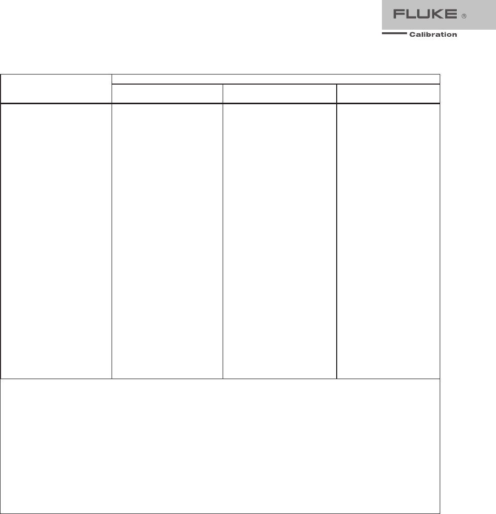
Wideband AC Voltage (Option 5730A/03 and 5730A/05) Specifications (99 %
Confidence Level)
Specifications apply to the end of the cable and 50 Ω termination used for calibration.
Range
Resolution
Absolute / ±5 °C from calibration temperature
30 Hz - 500 kHz
Volts dBm 24 Hours 90 Da
y
s 180 Da
y
s 1 Year
±(% out
p
ut +
μ
V)
1.1 mV -46 10 nV 0.4 + 0.4 0.5 + 0.4 0.6 + 0.4 0.8 + 2
3.3 mV -37 10 nV 0.4 + 1 0.45 + 1 0.5 + 1 0.7 + 3
11 mV -26 100 nV 0.2 + 4 0.35 + 4 0.5 + 4 0.7 + 8
33 mV -17 100 nV 0.2 + 10 0.3 + 10 0.45 + 10 0.6 + 16
110 mV -6.2 1
μ
V 0.2 + 40 0.3 + 40 0.45 + 40 0.6 + 40
330 mV +3.4 1
μ
V 0.2 + 100 0.25 + 100 0.35 + 100 0.5 + 100
1.1 V +14 10
μ
V 0.2 + 400 0.25 + 400 0.35 + 400 0.5 + 400
3.5 V +24 10
μ
V 0.15 + 500 0.2 + 500 0.3 + 500 0.4 + 500
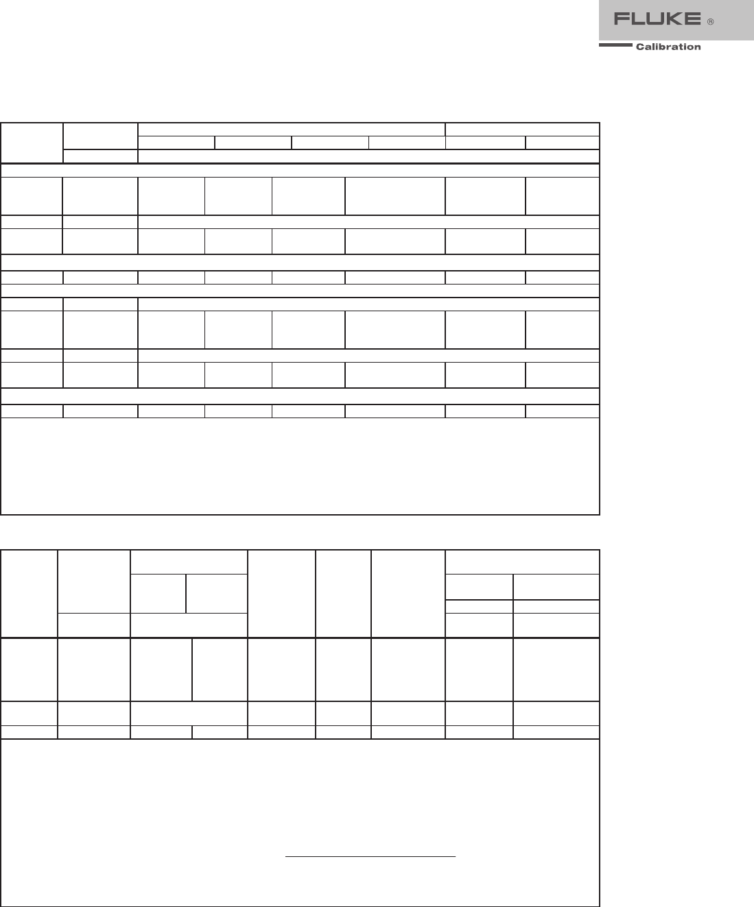
Frequency
(Hz)
Frequency
Resolution
(Hz)
Amplitude Flatness, 1 kHz Reference
Volta
g
e Ran
g
e Temperature
Coefficient
±ppm/°C
Settling
Time To
Published
Specification
(Seconds)
Harmonic
Distortion
(dB)
1.1 mV 3.3 mV >3.3 mV
±(% output + floor indicated)
10 - 30 0.01 0.3 0.3 0.3 100 7 -40
30 - 119.99 0.01 0.1 0.1 0.1 100 7 -40
120 - 1.1999 k 0.1 0.1 0.1 0.1 100 5 -40
1.2 k - 11.999 k 1 0.1 0.1 0.1 100 5 -40
12 k - 119.99 k 10 0.1 0.1 0.1 100 5 -40
120 k - 1.1999 M 100 0.2 + 3
μ
V 0.1 + 3
μ
V 0.1 + 3
μ
V 100 5 -40
1.2 M - 2 M [1] 1 k 0.2 + 3
μ
V 0.1 + 3
μ
V 0.1 + 3
μ
V 100 0.5 -40
2 M - 11.9 M 1 k 0.4 + 3
μ
V 0.3 + 3
μ
V 0.2 + 3
μ
V 100 0.5 -40
12 M - 20 M 10 k 0.6 + 3
μ
V 0.5 + 3
μ
V 0.4 + 3
μ
V 150 0.5 -34
20 M - 30 M 10 k 1.5 + 15
μ
V 1.5 + 3
μ
V1 + 3
μ
V 300 0.5 -34
30 M -50 M [2] 10 k 3.0 + 15
μ
V 3.0 + 3
μ
V 2.0 + 3
μ
V 600 0.5 -34
Note:
1. For output voltages <50 % of full range in the 33 mV, 110 mV, 330 mV, 1.1 V , and 3.5 V ranges, add 0.1 % to the amplitude
flatness specification.
Additional Operating Information:
dBm reference = 50 Ω
Range boundaries are at voltage points, dBm levels are approximate.
dBm = 10 log ( mW 1
Power ) ; 0.22361 V across 50 Ω = 1 mW or 0 dBm
2. Applies to Option 5730A/05 only.
Minimum Output
.................................................300 μV (-57 dBm)
VSWR at Output Terminal
..................................<1.1 Typical
Frequency Specification
....................................±0.01 % of output
Frequency Resolution
........................................11,999 counts to 1.1999 MHz, 10799 counts to 11.999 MHz, 3800
counts to 50 MHz
Overload Protection
...........................................A short circuit on the wideband output will not result in damage.
After settling time, normal operation is restored upon removal.

18 Fluke Calibration Fluke 5730A Extended Specifications
52120A Specifications when Operated with the 5730A
Line Power
Voltage range ................................................. 100 V to 240 V
Frequency ....................................................... 47 to 63 Hz
Voltage variations ........................................... ±10 % about line voltage
Power consumption ........................................ <1500 VA
Dimensions
(HxWxL)
With feet ......................................................... 192 mm x 432 mm x 645 mm (7.6 in x 17.0 in x 25.5 in)
Without feet .................................................... 178 mm x 432 mm x 645 mm (7.0 in x 17.0 in x 25.5 in)
Weight
................................................................ 25 kg (54 lb)
Temperature
Operating ........................................................ 5 °C to 35 °C (41 °F to 95 °F)
Calibration (tcal) ............................................. 16 °C to 30 °C (61 °F to 86 °F)
Storage ............................................................ 0 °C to 50 °C (32 °F to 122 °F)
Transit ............................................................ -20 °C to +60 °C (-4 °F to +140 °F) <100 hours
Warmup Time
.................................................... Twice the time since last warmed up, to a maximum of 1 hour.
Humidity
(non-condensing)
Operating ........................................................ <80 %, 5 °C to 31 °C (41 °F to 88 °F) ramping linearly down to
50 % at 35 °C (95 °F)
Storage ............................................................ <95 %, 0 to 50 °C (32 °F to 122 °F)
Altitude
Operating ........................................................ 2,500 m (8,200 ft) maximum
Non-Operating ................................................ 12,000 m (39,400 ft) maximum
Shock and Vibration
.......................................... MIL-PRF-28800F Class 3
Safety
................................................................. EN/IEC 61010-1, 300 V CAT II, Pollution Degree 2
Electromagnetic Environment
.......................... IEC 61326-1, Industrial
Electromagnetic Compatibility
......................... FCC Rules part 15 sub part B
Applies to use in Korea only. Class A Equipment (Industrial Broadcasting & Communication Equipment)
This product meets requirements for industrial (Class A)
electromagnetic wave equipment and the seller or user should
take notice of it. This equipment is intended for use in business
environments and is not to be used in homes.
Indoor use only
.................................................. IP20
52120A Electrical Performance Limits
Voltage compliance developed across inductive loads may prevent range maximum current output being achieved
at higher frequencies. The appropriate maximum frequency (Fmax) for a given load inductance and current is
given by:
Fmax = 4.5 I = Current
2•π•I•L L = Total inductance
The maximum frequency calculated with this equation is only approximate. Series resistance and parallel
capacitance also affect the maximum achievable frequency.
Input Common Mode Rejection
......................... 80 dB @ DC decreasing linearly to 40 dB at 10 kHz
Input Impedance
Voltage input .................................................. >1 MΩ
Current input................................................... 10 Ω
Maximum Output Compliance Voltage
............. 4.5 V rms (6.4 V pk), 6.4 V dc. 120 A range maximum compliance
voltage decreases from 4.5 V at 1 kHz to about 3 V at 10 kHz
DC Offset
............................................................ Magnetic remanence that follows abrupt changes in output current
level may cause small changes to DC current offset. It is good
practice to correct for offsets in DC measurements and techniques
such as DC reversal measurement will result in best accuracy.
19 Fluke Calibration Fluke 5730A Extended Specifications
Operated within 5730A Control Loop (all current ranges)
The current specification of the 52120A, when controlled by a single 5730A, applies to the parallel output of up to
three 52120As connected as slaves.
Coverage factor k=2.58 (99 % confidence level)
Current Specification
Frequency
1-
y
ear, tcal
[1]
±5°C ±(% of out
p
ut + % of ran
g
e)
5730A
% of out
p
ut % of ran
g
e
DC 0.015 0.010
10 Hz to 850 Hz 0.011 0.003
850 Hz to 6 kHz 0.052 0.005
6 kHz to 10 kHz See O
p
erated Stand Alone current s
p
ecification table in the 52120A Users Manual.
Notes:
1. tcal is the temperature at which calibration adjustment took place.
Maximum inductance for stability LCOMP OFF is 100 μH. Maximum inductance for stability LCOMP ON is 400 μH for 2 A and 20 A
ranges. 100 μH on the 120 A range.
With LCOMP ON, the output is limited to 7.2e3 A-Hz. For example, a 100 A output is limited to 72 Hz.
Coverage factor k=2.00 (95 % confidence level)
Current Specification
Frequency
1-
y
ear, tcal
[1]
±5°C ±(% of out
p
ut + % of ran
g
e)
5730A
% of out
p
ut % of ran
g
e
DC 0.012 0.008
10 Hz to 850 Hz 0.009 0.002
850 Hz to 6 kHz 0.040 0.004
6 kHz to 10 kHz See O
p
erated Stand Alone current s
p
ecification table in the 52120A Users Manual.
Notes:
1. tcal is the temperature at which calibration adjustment took place.
Maximum inductance for stability LCOMP OFF is 100 μH. Maximum inductance for stability LCOMP ON is 400 μH for 2 A and 20 A
ranges. 100 μH on the 120 A range.
With LCOMP ON, the output is limited to 7.2e3 A-Hz. For example, a 100 A output is limited to 72 Hz.
Maximum Distortion and Noise
Frequency
Distortion
[1]
Noise
16 Hz to 10 MHz
LCOMP OFF LCOMP ON
dBc Current dBc Current
2 Am
p
Ran
g
e
16 Hz to 850 Hz -76 42
μ
A -70 83
μ
A -60 dB
850 Hz to 6 kHz -52 662
μ
A -46 1.3 mA -60 dB
6 kHz to 10 kHz [2] -40 2.6 mA -35 4.7 mA -60 dB
20 Am
p
Ran
g
e
16 Hz to 850 Hz -76 418
μ
A -60 2.6 mA -70 dB
850 Hz to 6 kHz -52 6.6 mA -42 20.9 mA -70 dB
6 kHz to 10 kHz [2] -40 26.4 mA -35 46.9 mA -70 dB
120 Am
p
Ran
g
e
16 Hz to 850 Hz -76 2.5 mA -60 15.8 mA -70 dB
850 Hz to 6 kHz -52 39.7 mA -42 125.7 mA -70 dB
6 kHz to 10 kHz [2] -40 158.2 ma -35 281.3 mA -70 dB
Notes:
1. Use dB or Current. Whichever is larger.
2. Interharmonics only above 6 kHz.
20 Fluke Calibration Fluke 5730A Extended Specifications
52120A/COIL 3 kA 25-Turn Coil
Number of Turns
................................................ 25
Minimum internal jaw dimension to clear wires
26 mm (width) x 36 mm (length)
Maximum Input Current
.................................... 120 A continuous with built-in 12 V fan on
Maximum Voltage
.............................................. 4.5 V rms
Specification
Input Current
[1]
Frequency Effective Current
Amp-turns
52120A + Coil Specification
[2]
±(% of Am
p
-turns + % of 52120A ran
g
e)
% of Amp-turns % of 52120A Range
0 A to 100 A DC 0 to 2500 0.7 % 0.7 %
0 A to 120 A 10 Hz to 65 Hz 0 to 3000 0.7 % 0.7 %
0 A to 120 A 65 Hz to 300 Hz 0 to 3000 0.7 % 0.7 %
0 A to 40 A 300 Hz to 1 kHz 0 to 1000 0.7 % 0.7 %
0 A to 12 A 1 kHz to 3 kHz 0 to 300 0.8 % 1.0 %
0 A to 3 A 3 kHz to 6 kHz 0 to 75 1.5 % 1.0 %
0 A to 1 A 6 kHz to 10 kHz 0 to 25 5.0 % 1.0 %
Notes:
1. The inductance and mutual inductance of the 25 turn coil and clamp that is measured causes a frequency dependent
compliance voltage across the coil. The length and configuration of the cables that connect the current to the coil also have
an effect. Maximum input current is 120 A input at approximately 100 Hz. Maximum current input decreases to
approximately 0.8 A at 10 kHz.
2. Includes coil/clamp interaction.
52120A/COIL 6 kA 50-Turn Coil
Number of Turns
................................................ 50
Minimum Flexible Probe Length
....................... 500 mm
Maximum Input Current
.................................... 120 A continuous with built-in 12 V fan on
Maximum Voltage
.............................................. 4.5 V rms
Specification
Input Current
[1]
Frequency Effective Current
Amp-turns
52120A + Coil Specification
[2]
±(% of Am
p
-turns + % of 52120A ran
g
e)
% of Am
p
-turns % of 52120A Ran
g
e
0 A to 100 A DC 0 to 5000 0.7 % 0.7 %
0 A to 120 A 10 Hz to 65 Hz 0 to 6000 0.7 % 0.7 %
0 A to 120 A 65 Hz to 300 Hz 0 to 6000 0.7 % 0.7 %
0 A to 120 A 300 Hz to 1 kHz 0 to 6000 0.7 % 0.7 %
0 A to 120 A 1 kHz to 3 kHz 0 to 6000 0.8 % 1.0 %
0 A to 25 A 3 kHz to 6 kHz 0 to 1250 1.5 % 1.0 %
0 A to 13 A 6 kHz to 10 kHz 0 to 650 5.0 % 1.0 %
Notes:
1. The inductance and mutual inductance of the 50 turn coil causes a frequency dependent compliance voltage across the
coil. Maximum frequency for 120 A input current is approximately 600 Hz. Maximum current input decreases to
approximately 13 A at 10 kHz.
2. Includes coil/probe interaction.
Note
The specifications for these coils are at 99 % confidence level and are the
combined specification of the coil and a 52120A. If the coils are used with
other current sources the calibration specification of the coils alone is 0.65 %
(99 % confidence level) from 0 Hz to 10 kHz.
21 Fluke Calibration Fluke 5730A Extended Specifications
Operating Limits
Output Current Range
2 A 20 A 120 A
Current Out
p
ut (Max.) 2 A rms 20 A rms 120 A rms
C
Current In
p
ut
In
p
ut Current (Max.) 200 mA rms 200 mA rms 120 mA rms
Current
g
ain 10 100 1,000
V
Volta
g
e In
p
ut
In
p
ut Volta
g
e (Max.) 2 V rms 2 V rms 1.2 V rms
Transconductance 1 Siemen 10 Siemens 100 Siemens
120 A Range Current/Frequency Limits
Fre
q
uenc
y
Maximum Out
p
ut Current Maximum Current In
p
ut Maximum Volta
g
e In
p
ut
DC ±100 A ±100 mA ±1.0 V
<10 Hz 100 A
p
k (70 A rms) 100 mA
p
k (70 mA rms) 1.0 V
p
k (0.7 V rms)
10 Hz to 10 kHz 170 A
p
k (120 A rms) 170 mA
p
k(120mA rms) 1.7V
p
k (1.2 V rms)
Note:
The 2 A and 20 A ranges operate at full output current from DC to 10 kHz.
Output Isolation
Frequency Maximum Voltage Signal Applied to any Output Current Terminal with respect to
Earth
DC to 850 Hz 600 V rms, 850 V
p
k, limited 2 A rms, no transient overvolta
g
es
850 Hz to 3 kHz 100 V rms, 142 V
p
k, limited 2 A rms, no transient overvolta
g
es
3 kHz to 10 kHz 33 V rms, 47 V
p
k, limited 2 A rms, no transient overvolta
g
es
22 Fluke Calibration Fluke 5730A Extended Specifications
Fluke Calibration
PO Box 9090,
Everett, WA 98206 U.S.A.
Fluke Europe B.V.
PO Box 1186, 5602 BD
Eindhoven, The Netherlands
Web access: http://www.flukecal.en
For more information call:
In the U.S.A. (877) 355-3225 or Fax (425) 446-5116
In Europe/M-East/Africa +31 (0) 40 2675 200 or Fax +31 (0) 40 2675 222
In Canada (800)-36-FLUKE or Fax (905) 890-6866
From other countries +1 (425) 446-5500 or Fax +1 (425) 446-5116
Web access: http://www.flukecal.com
©2015 Fluke Calibration. Specifications subject to change without notice.
Printed in U.S.A. 6/2015 4265329b_EN
Pub-ID: 12117-eng
Modification of this document is not permitted without written permission
from Fluke Calibration.
Fluke Calibration. Precision, performance, confidence.™
Ordering Information
Model
5730A Multifunction Calibrator
5730A/03 Multifunction Calibrator with 30 MHz Wideband AC Voltage Option
5730A/05 Multifunction Calibrator with 50 MHz Wideband AC Voltage Option
5730A/S Multifunction Calibrator with no front panel USB port
Accessories
52120A Transconductance Amplifier
5725A Amplifier
5730A-7002 Low Thermal EMF Cables with Banana Plugs
5730A-7003 Low Thermal EMF Cables with Spade Connectors
Y5737 5730A Rack Mount Kit
Y5738 5730A Rack Ear Kit
57XX/CASE 5730A Durable Travel Case
Additional standards
5790B AC Measurement Standard
734A Voltage Reference and
DC Voltage Standard
732B Direct Voltage Standard
742A Resistance Standards
792A AC/DC Transfer Standard
Software
MET/CAL MET/CAL Plus Calibration Management Software
MET/TEAM MET/TEAM Test Equipment Asset Management Software
