151137 5820XL Installation Manual
User Manual: 5820XL Installation Manual AlarmHow.net Library
Open the PDF directly: View PDF ![]() .
.
Page Count: 198 [warning: Documents this large are best viewed by clicking the View PDF Link!]

151137 i
Content
Section 1
Introduction .............................................................................................................................................. 1-1
1.1 Overview of Basic System ....................................................................................................................... 1-1
1.1.1 Hardware Features ............................................................................................................................ 1-1
1.1.2 Software Features ............................................................................................................................. 1-2
1.2 About this Manual .................................................................................................................................... 1-2
1.2.1 Terms Used in this Manual ............................................................................................................... 1-2
1.3 Compatible Products ................................................................................................................................ 1-3
1.4 How to Contact Silent Knight .................................................................................................................. 1-4
Section 2
Agency Listings, Approvals, and Requirements ................................... 2-1
2.1 Federal Communications Commission (FCC) ......................................................................................... 2-1
2.2 Underwriters Laboratories (UL) .............................................................................................................. 2-2
2.2.1 Requirements for All Installations .................................................................................................... 2-2
2.2.2 Requirements for Central Station Fire Alarm Systems .................................................................... 2-2
2.2.3 Requirements for Local Protected Fire Alarm Systems ................................................................... 2-2
2.2.4 Requirements for Remote Station Protected Fire Alarm Systems - Digital Alarm Communicator
Transmitter (DACT) 2-2
Section 3
Before You Begin Installing ............................................................................................... 3-1
3.1 What’s in the Box? ................................................................................................................................... 3-1
3.2 Environmental Specifications .................................................................................................................. 3-1
3.3 Electrical Specifications ........................................................................................................................... 3-2
3.4 Wiring Specifications ............................................................................................................................... 3-3
3.5 Board Assembly Diagram ........................................................................................................................ 3-5
3.6 Calculating Current Draw and Standby Battery ...................................................................................... 3-6
3.6.1 Worksheet Requirements .................................................................................................................. 3-6
Filling in the Current Draw Worksheet, Table 3-2 (Section 3.6.2) ....................................... 3-6
3.6.2 Current Draw Worksheet .................................................................................................................. 3-7
3.6.2.1 Maximum Battery Standby Load ........................................................................................... 3-8
3.7 Installation Tasks Overview ..................................................................................................................... 3-9
Section 4
Control Panel Installation ...................................................................................................... 4-1
4.1 Mounting the Control Panel Cabinet ....................................................................................................... 4-1
4.1.1 Removing the 5820XL Assembly from the Housing ....................................................................... 4-1
4.2 AC Connection ......................................................................................................................................... 4-2
4.3 Battery Connection .................................................................................................................................. 4-3

151137 ii
4.3.1 AB-33 Accessory Cabinet ................................................................................................................ 4-4
4.3.1.1 Installing the AB-33 Accessory Cabinet and Batteries .......................................................... 4-4
4.4 SBUS Wiring ........................................................................................................................................... 4-6
4.4.1 Calculating Wiring distance for SBUS modules ..............................................................................4-6
Wiring Distance calculation example: ................................................................................... 4-8
4.4.2 Wiring Configurations ...................................................................................................................... 4-9
4.5 Remote Annunciator 5860 Installation .................................................................................................. 4-10
4.5.1 Mounting the 5860 .......................................................................................................................... 4-11
4.5.1.1 Flush Mounting .................................................................................................................... 4-12
Flush Mounting with an Electrical Box ............................................................................... 4-13
Flush Mounting Steps .......................................................................................................... 4-13
4.5.1.2 Surface Mounting ................................................................................................................. 4-14
4.5.2 Model 5860 Connection to the Panel .............................................................................................. 4-15
4.6 5815XL Installation ............................................................................................................................... 4-16
4.6.1 5815XL Connection to the Panel .................................................................................................... 4-17
4.7 5824 Serial/Parallel Interface Installation .............................................................................................. 4-18
4.7.1 Selecting 5824 Options ................................................................................................................... 4-19
Printer and Output Port Options ........................................................................................... 4-20
4.8 5880 LED Driver Module ...................................................................................................................... 4-21
4.8.1 5880 Board Layout ......................................................................................................................... 4-21
4.8.2 FACP Connection ........................................................................................................................... 4-22
4.8.3 LED Wiring .................................................................................................................................... 4-23
4.8.4 Dry Contact Wiring ........................................................................................................................ 4-24
4.9 5865-3 / 5865-4 LED Annunciator Installation ..................................................................................... 4-25
4.9.1 FACP Connection ........................................................................................................................... 4-26
4.9.2 5865 Mounting ................................................................................................................................ 4-27
4.10 Configuring Modules ............................................................................................................................. 4-28
4.10.1 Assigning Module IDs .................................................................................................................... 4-28
4.11 Telephone Connection ........................................................................................................................... 4-29
4.11.1 Ground Start Relay (Model 5211) .................................................................................................. 4-29
4.12 Flexputs™ I/O Circuits ........................................................................................................................... 4-30
4.12.1 Conventional Notification Appliance ............................................................................................. 4-30
4.12.1.1 Class B Notification Wiring ................................................................................................. 4-30
4.12.1.2 Class A Notification Wiring ................................................................................................ 4-31
4.12.2 Conventional Input Switch Circuits ................................................................................................ 4-32
4.12.2.1 Class B Inputs ...................................................................................................................... 4-32
4.12.2.2 Class A Inputs ...................................................................................................................... 4-33
4.12.3 Installing 2-Wire Smoke Detectors ................................................................................................. 4-34
4.12.3.1 Installing 2-Wire Class B Smoke Detectors ........................................................................ 4-34
4.12.3.2 Installing 2-Wire Class A Smoke Detector .......................................................................... 4-35
4.12.4 Installing 4-Wire Smoke Detectors ................................................................................................. 4-36
4.12.4.1 Installing a Class B 4-Wire Smoke Detector ....................................................................... 4-36
4.12.4.2 Installing 4-Wire Class A Smoke Detectors ........................................................................ 4-37
4.12.5 Auxiliary Power Installation ........................................................................................................... 4-38
4.12.5.1 Door Holder Power .............................................................................................................. 4-38
4.12.5.2 Constant Power .................................................................................................................... 4-38
4.12.5.3 Resettable Power .................................................................................................................. 4-39
4.13 On-Board Relays (Conventional) ........................................................................................................... 4-39
4.13.1 Trouble Relay ................................................................................................................................. 4-39
4.13.2 Programmable Relays ..................................................................................................................... 4-39
4.14 Keltron Model 3158 Installation ............................................................................................................ 4-40
4.15 Model 5220 Direct Connect Module ..................................................................................................... 4-41
4.15.1 5220 Electrical Specifications ........................................................................................................ 4-41
4.15.2 City Box Connection ...................................................................................................................... 4-42
4.15.3 NFPA 72 Polarity Reversal ............................................................................................................. 4-43

151137 iii
Section 5
SLC Device Installation ............................................................................................................ 5-1
5.1 Types of SLC Devices ............................................................................................................................. 5-1
5.2 Maximum Number of Devices ................................................................................................................. 5-1
5.3 Wiring Requirements for SLC Devices ................................................................................................... 5-2
5.3.1 Wiring 5815XL in Style 4 (Class B) Configuration ......................................................................... 5-2
5.3.2 Wiring 5815XL in Style 6 (Class A) Configuration ......................................................................... 5-3
5.4 Heat and Smoke Detector Installation ..................................................................................................... 5-4
5.4.1 Wiring ............................................................................................................................................... 5-4
5.5 Duct Detector Installation ........................................................................................................................ 5-5
5.6 Input Monitor Module (SD500-AIM) ...................................................................................................... 5-6
5.7 Mini Input Module (SD500-MIM) .......................................................................................................... 5-7
5.8 Relay Module Installation ........................................................................................................................ 5-8
5.8.1 Electrical Specifications ................................................................................................................... 5-8
Relay Ratings ......................................................................................................................... 5-8
5.8.2 Wiring ............................................................................................................................................... 5-8
5.9 SD500-ANM Installation Instructions ..................................................................................................... 5-9
5.9.1 SD500-ANM Specification ............................................................................................................... 5-9
5.9.2 Wiring the SD500-ANM ................................................................................................................ 5-10
5.9.2.1 Wiring the SD500-ANM to the 5815XL ............................................................................. 5-10
5.9.3 Class B Notification Configuration ................................................................................................ 5-10
5.9.4 Class A Notification Configuration ................................................................................................ 5-11
5.9.5 Configuring Flexput™ Circuits for Auxiliary Power ..................................................................... 5-11
5.10 SLC Device Addressing ......................................................................................................................... 5-12
5.10.1 EEPROM Addressing ..................................................................................................................... 5-12
5.10.2 Dipswitch Addressing ..................................................................................................................... 5-13
Section 6
Programming Overview ........................................................................................................... 6-1
6.1 JumpStart Autoprogramming ................................................................................................................... 6-1
6.1.1 Input Points ....................................................................................................................................... 6-2
6.1.2 Output Points .................................................................................................................................... 6-2
6.1.3 Running JumpStart ........................................................................................................................... 6-2
6.2 Mapping Overview .................................................................................................................................. 6-4
6.2.1 Input Point Mapping ......................................................................................................................... 6-5
6.2.2 Output Circuit Mapping .................................................................................................................... 6-6
6.2.3 Zone Event Mapping ........................................................................................................................ 6-7
6.2.4 Mapping LED Points ........................................................................................................................ 6-9
6.3 SK Analog Fire System Editor 5590 ...................................................................................................... 6-10
6.4 Annunciator Programming ..................................................................................................................... 6-10
6.4.1 Entering / Exiting the Program Menu ............................................................................................. 6-11
To enter the Program Mode: ................................................................................................ 6-11
To Exit Program Mode: ....................................................................................................... 6-11
6.4.2 Moving through the Menus ............................................................................................................. 6-12
6.4.3 Selecting Options and Entering Data .............................................................................................. 6-12
6.4.4 Editing Keys ................................................................................................................................... 6-13
6.5 Programming Menu Quick Reference ................................................................................................... 6-14

151137 iv
Section 7
Programming ......................................................................................................................................... 7-1
7.1 Modules .................................................................................................................................................... 7-1
7.1.1 Edit Modules ..................................................................................................................................... 7-1
7.1.1.1 Naming Modules .................................................................................................................... 7-2
7.1.1.2 Module, Wiring Class ............................................................................................................ 7-2
7.1.2 Adding a Module .............................................................................................................................. 7-2
7.1.3 Deleting a Module ............................................................................................................................ 7-3
7.2 Zone ......................................................................................................................................................... 7-4
7.2.1 Edit Zone ........................................................................................................................................... 7-4
7.2.1.1 Edit Zone Name ..................................................................................................................... 7-5
7.2.1.2 Edit Zone Properties ............................................................................................................... 7-5
Alarm Delay Characteristics .................................................................................................. 7-6
Heat Detector Sensitivity ....................................................................................................... 7-7
Smoke Detector Sensitivity .................................................................................................... 7-7
7.2.1.3 Zone Outputs .......................................................................................................................... 7-8
Mapping to Zone Events ........................................................................................................ 7-8
Example or Zone Mapping: ................................................................................................... 7-9
7.2.1.4 Cadence Patterns .................................................................................................................. 7-10
7.2.2 Add Zone ........................................................................................................................................ 7-11
7.2.3 Delete Zone ..................................................................................................................................... 7-11
7.2.4 View Zone Points ............................................................................................................................ 7-12
7.3 Group ..................................................................................................................................................... 7-13
7.3.1 Edit Group ....................................................................................................................................... 7-13
7.3.1.1 Edit Group Name ................................................................................................................. 7-13
Example of Group Name: .................................................................................................... 7-14
7.3.1.2 Edit Group Properties ........................................................................................................... 7-14
Latching / Non-latching Outputs .......................................................................................... 7-14
Silencing Options ................................................................................................................. 7-15
Response with System-Wide Conditions ............................................................................. 7-15
7.3.2 Add Group ...................................................................................................................................... 7-16
7.3.3 Delete Group ................................................................................................................................... 7-16
7.3.4 View Group Points .......................................................................................................................... 7-17
7.3.5 Edit Output Group Templates ......................................................................................................... 7-18
7.4 Point ....................................................................................................................................................... 7-19
7.4.1 Point Programming For 5815XL Module .......................................................................................7-19
7.4.2 Point Programming For Internal
or External Power Module (5895XL) 7-22
7.4.3 Point Programming For 5880 and 5865 Modules ........................................................................... 7-24
7.4.3.1 Assigning a Name to a Points .............................................................................................. 7-25
7.5 System Options ...................................................................................................................................... 7-26
7.5.1 Reporting Account .......................................................................................................................... 7-26
7.5.1.1 Edit Accounts ....................................................................................................................... 7-27
Select Account (ID) ............................................................................................................. 7-27
Edit Account Number .......................................................................................................... 7-27
Select Reporting Format ...................................................................................................... 7-28
Events to Report ................................................................................................................... 7-28
Switch Attempts ................................................................................................................... 7-28
Fail Attempts ........................................................................................................................ 7-29
Selecting Primary and Secondary Phone Lines ................................................................... 7-29
Telephone Number ...............................................................................................................7-29
7.5.1.2 Auto Test Time .................................................................................................................... 7-30
7.5.2 Phone Lines ..................................................................................................................................... 7-30

151137 v
7.5.2.1 Dialing Prefix ....................................................................................................................... 7-31
7.5.2.2 Number of Answer Rings .................................................................................................... 7-31
7.5.2.3 Dial Option (TouchTone or Pulse) ....................................................................................... 7-32
7.5.2.4 Rotary Format ...................................................................................................................... 7-32
7.5.2.5 Line Monitor ........................................................................................................................ 7-32
7.5.2.6 Ground Start Relay ............................................................................................................... 7-32
7.5.2.7 Answering Machine Bypass ................................................................................................. 7-33
7.5.3 Sys. Event Outputs .......................................................................................................................... 7-33
7.5.3.1 Trouble Events ..................................................................................................................... 7-33
7.5.3.2 System Alarm Cadence ........................................................................................................ 7-34
7.5.4 Day/Night Sensitivity Time ............................................................................................................ 7-35
7.5.5 Holiday Days .................................................................................................................................. 7-36
7.5.6 Miscellaneous Options .................................................................................................................... 7-37
7.5.6.1 Water Flow Delay ................................................................................................................ 7-37
7.5.6.2 Low AC Report Delay ......................................................................................................... 7-38
7.5.6.3 Automatic Daylight Savings Adjustment ............................................................................ 7-38
7.5.6.4 Clock Display Format (AM/PM or Military) ....................................................................... 7-38
7.5.6.5 Change AC Line Frequency ................................................................................................. 7-39
7.5.7 Edit Library Name .......................................................................................................................... 7-39
7.5.8 Edit Banner Message ...................................................................................................................... 7-40
7.6 JumpStart Autoprogramming ................................................................................................................. 7-41
7.7 Computer Account ................................................................................................................................. 7-42
7.8 Access Codes ......................................................................................................................................... 7-43
Section 8
System Operation ............................................................................................................................ 8-1
8.1 Annunciator Description .......................................................................................................................... 8-1
8.1.1 LCD Displays ................................................................................................................................... 8-1
8.1.2 Banner ............................................................................................................................................... 8-2
8.2 Key Operation .......................................................................................................................................... 8-2
8.3 Menu System ............................................................................................................................................ 8-2
8.3.1 User Menu ......................................................................................................................................... 8-3
8.3.2 Installer Menu ................................................................................................................................... 8-3
8.3.3 Main Menu Overview (User and Installer) ....................................................................................... 8-3
8.3.4 Using the Menus ............................................................................................................................... 8-4
8.4 Basic Operation ........................................................................................................................................ 8-4
8.4.1 Setting Time and Date ...................................................................................................................... 8-4
8.4.2 Disable / Enable a Point .................................................................................................................... 8-4
8.4.3 View Event History .......................................................................................................................... 8-4
8.4.4 Conduct a Fire Drill .......................................................................................................................... 8-5
8.4.5 Conduct an Indicator Test ................................................................................................................. 8-5
8.4.6 Conduct a Walk Test ......................................................................................................................... 8-6
8.4.7 Conduct a Dialer Test ....................................................................................................................... 8-6
8.4.8 Silence alarms or troubles ................................................................................................................. 8-6
8.4.9 Reset alarms ...................................................................................................................................... 8-7
8.4.10 Check Detector Sensitivity Through Point Status ............................................................................ 8-7
8.4.11 Change User or Installer Code .......................................................................................................... 8-8
8.4.12 View Status of a Point ...................................................................................................................... 8-8
8.4.13 View Alarms or Troubles ................................................................................................................. 8-8
8.4.14 View System Information ................................................................................................................. 8-8
8.4.15 Reset dialer ....................................................................................................................................... 8-8
8.4.16 Communicating with a Remote Computer ....................................................................................... 8-9
8.4.17 Working with a Printer ................................................................................................................... 8-10
8.5 Operation Mode Behavior ...................................................................................................................... 8-11

151137 vi
Section 9
Reporting ..................................................................................................................................................... 9-1
9.1 Receivers Compatible with the Control Panel ......................................................................................... 9-1
9.2 Ademco Contact ID Dialer Output ......................................................................................................... 9-2
9.3 SIA Dialer Output ................................................................................................................................... 9-6
Section 10
Testing and Troubleshooting ......................................................................................... 10-1
10.1 Troubleshooting ..................................................................................................................................... 10-1
10.2 Common Problems ................................................................................................................................. 10-1
10.2.1 Event History .................................................................................................................................. 10-2
10.3 Built-in Troubleshooting and Testing Tools .......................................................................................... 10-3
10.3.1 SLC Device Locator ....................................................................................................................... 10-3
10.3.2 SLC Multi Locator .......................................................................................................................... 10-4
10.3.3 I/O Point Control ............................................................................................................................ 10-5
Section 11
Installation Records .................................................................................................................... 11-1
11.1 SLC Point Record .................................................................................................................................. 11-1
11.2 Conventional Output Point Record ........................................................................................................ 11-6
Appendix A
Compatible Devices ..................................................................................................................... A-1
A.1 Two-Wire Smoke Detectors .................................................................................................................... A-1
A.2 Four-Wire Smoke Detectors ................................................................................................................... A-2
A.3 Notification Appliances .......................................................................................................................... A-3
A.4 Door Holder Device .............................................................................................................................. A-10
Appendix B
Word and Special Characters Lists .........................................................................B-1
B.1 Name Library ...........................................................................................................................................B-1
B.2 Characters For Customized Textual Descriptions ...................................................................................B-2

151137 1-1
Section 1
Introduction
The IntelliKnight 5820XL Fire Alarm Control / Communicator is an analog addressable fire
control system that meets the requirements of UL 864.
1.1 Overview of Basic System
The IntelliKnight 5820XL base system is packaged as an assembled stack of 3 circuit boards
mounted to an aluminum housing.
1.1.1 Hardware Features
• The basic IntelliKnight 5820XL panel contains one SLC (Signaling Line Circuit) which
supports 127 analog addressable devices (points). Additional loops can be added using the
Model 5815XL SLC Expander to increase overall point capacity to 381 points (127 points
per 5815XL).
• 5.0A of output power is available through 6 sets of terminals for notification and auxiliary
applications. Each circuit is power limited per UL 864 and can source up to 3.0A (total
output power for all 6 circuits must not exceed 5.0A).
• Built-in dual phone line, digital alarm communicator/transmitter (DACT).
• Dedicated Form C trouble relay.
• Two general purpose Form C programmable relays.
• Basic system operation can be performed using a key or a user code.
• Can be used with up to 8 Model 5860 Remote Annunciators (sold separately).
• Can be used with Model 5865-3, 5865-4, and 5880 in any combination for a total of eight
devices on one control panel. See Sections 4.8 and 4.9 for additional information on these
models.
• Printing of detector status, event history, and real time event log available through the
Model 5824 Serial / Parallel Interface (sold separately).
• Supports conventional 2-wire & 4-wire detectors using the 6 Flexput™ circuits.
• Add 6 Flexput™ circuits with each 5895 Intelligent Power Module (up to 8 5895s per
system).
• 125 software zones, 250 output groups.

IntelliKnight 5820XL Installation Manual
1-2 151137
1.1.2 Software Features
• Advanced analog smoke detector features:
Three sensitivity settings (high, medium, low)
Automatic drift compensation
Maintenance alert region
Point status eliminates calibrated smoke test requirements for NFPA 72
Automatic day/night sensitivity adjustment
• “JumpStart” feature for easy programming
• Non-volatile event history stores 1000 events
• A choice of output patterns available for notification outputs, including ANSI 3.41
temporal signal
1.2 About this Manual
This manual is intended to be a complete reference for all installation and operation tasks.
Please let us know if the manual does not meet your needs in any way. We value your
feedback!
1.2.1 Terms Used in this Manual
The following terminology is used with the IntelliKnight 5820XL system:
Term Description
SLC Signaling Line Circuit
Module The term module is used for all hardware devices except for
SLC addressable devices and notification appliances. This
includes the 5820XL panel itself and the built-in 5897 power
supply. It also refers to any (optional) 5815XL SLC expansion
modules.
Input Point An addressable sensing device, such as a smoke or heat detector
or a contact monitor device.
Input Zone A protected area made up of input points.
Output Point
(or Output Circuit)
A notification point or circuit for notification appliances. Relay
circuits and auxiliary power circuits are also considered output
points.
Group (or “Output Group”) A group of output points. Operating characteristics are common
to all output points in the group.
Output (or “Cadence”) Pattern The pattern that the output will use, for example, Constant,
March Code, ANSI 3.41. Applies to zones and special system
events. See Section 7.5.3.2 for additional information.
Mapping Mapping is the process of specifying which outputs are
activated when certain events occur in the system. Section 6.2
explains mapping in detail.

Introduction
151137 1-3
1.3 Compatible Products
The chart below lists the products available from Silent Knight for use with the IntelliKnight
5820XL.
Note: Models SD500-FRCM, SD500-FRCM-4 and SD505-ARM are no longer manufactured, but they are still
compatible with the IntelliKnight system. Contact Silent Knight if you need information about these
modules.
5865-3, 5865-4, and 5880 can be used in any combination, up to a total of eight devices on one panel.
Model Description
SLC Devices
SD500-AIM Contact Monitor Module (switch input). Standard size. (This device replaces Model
SD500-FRCM-4. See Note below.)
SD500-MIM Mini Contact Monitor Module (switch input). Small size. (This device replaces Model
SD500-FRCM. See Note below.)
SD500-ARM Relay Module (This device replaces Model SD505-ARM. See Note below.)
SD505-AHS Heat Sensor
SD505-AIS Ionization Smoke Detector
SD505-APS Photoelectric Smoke Detector
SD505-ADH
Duct housing is shipped with a detector
base only. Detector head must be
ordered separately.
Duct Housing for use with SD505-AIS ionization smoke detector or SD505-APS
photoelectric smoke detector head.
Intake tubing for duct available in 3 lengths:
STS-2.5: Duct widths 1.0’ to 2.5’
STS-2.5: Duct widths 2.5’ to 5.0’
STS-2.5: Duct widths 5.0’ to 10.0’
When ordering SD505-ADH, specify intake tubing size and order the appropriate
smoke detector, if needed.
SD500-ANM Addressable Notification Module
Other Modules
5815XL SLC Expander Allows an additional 127 SLC devices to be added to the system. Up to two 5815XLs
per system.
5211 Ground Start Relay For use with ground start telephone network. (Do not use in UL installations.)
5824 Serial/Parallel Interface Allows a printer to be attached for the system for on-site event logging, detector status
and event history reports. Two maximum per system.
5895 Intelligent Power Module Provides additional power, six Flexput™ circuits, and two Form C relays. Max. 8 per
system see Model 5895 Installation Instructions P/N 151024.
5860 and 5860R Remote Fire Alarm
Annunciator
Same operation, similar appearance as on-board annunciator. Up to 8 5860s per system.
5860 is gray; 5860R is red.
5860TG and 5860TR Trim Ring Kit Trim ring kits for surface mounting the 5860 annunciator. 5860TG is gray; 5860TR is
red.
5865-3 and 5865-4 LED Annunciator LED annunciator can display up to 30 LEDs (15 red and 15 yellow). 5865-4 has key
switches for silence and reset, and a system trouble LED.
5880 LED Driver Module Driver for up to 40 LEDs. Interfaces with customized annunciator boards. In addition
the 5880 has eight generic switch input points.
7860 Telephone Cord RJ31X cord for connecting phone line to the 5820XL.
SK Analog Fire System Editor 5590 For communication and panel programming with a Windows-based computer and
*modem (not sold by Silent Knight, see Table 1-1 for compatible modems). Enables
remote viewing of detector status and event history.
IntelliView Software For remote viewing of detector status and event history. Requires a modem (not sold by
Silent Knight).

IntelliKnight 5820XL Installation Manual
1-4 151137
The following modems have been tested by Silent Knight for compatibility with the 5820XL
and the 5590/IntelliView communication software packages:
1.4 How to Contact Silent Knight
If you have a question or encounter a problem not covered in this manual, contact Silent
Knight Technical Support at 800-328-0103 (or 612-493-6455). To order parts, contact Silent
Knight Sales at 800-446-6444 (or 612-493-6435).
IntelliKnight® is a registered trademarks of Silent Knight.
Flexput™ is a trademark of Silent Knight.
Table 1-1: Compatible Modems
Manufacturer Model
US Robotics 28.8
Motorola
LifeStyle
28.8, 3400 series
Premier 33.6
MultiTech MT19321ZDX

151137 2-1
Section 2
A
g
enc
y
Listin
g
s, Approvals, and Requirements
2.1 Federal Communications Commission (FCC)
1. The following information must be provided to the telephone company before the
IntelliKnight 5820XL can be connected to the phone lines:
2. This device may not be directly connected to coin telephone or party line services.
3. This device cannot be adjusted or repaired in the field. In case of trouble with the device,
notify the installing company or return to:
Silent Knight Security Systems
7550 Meridian Circle
Maple Grove, MN 55369-4927
612-493-6455
800-328-0103
4. If the 5820XL causes harm to the telephone network, the telephone company will notify
the user in advance that temporary discontinuance of service may be required. If advance
notice is not practical, the telephone company will notify the user as soon as possible.
Users have the right to file complaints, if necessary, with the Federal Communications
Commission.
5. The telephone company may make changes in its facilities, equipment, operations, or pro-
cedures that could affect the operation of the equipment. If this happens, the telephone
company will provide advance notice to allow you to make the necessary modifications to
maintain uninterrupted service.
A Manufacturer: Silent Knight Security Systems
B Model Number: IntelliKnight 5820XL
C FCC registration number: AC6USA-23901-AL-E
Ringer equivalence: 0.8B
D Type of jack: RJ31X
E Facility Interface Codes: Loop Start: 02LS2
Ground Start: 02GS2
F Service Order Code: 9.0F
Warning
This device has been verified to comply with FCC Rules Part 15. Operation is subject to the following conditions:
(1) This device may not cause radio interference, and (2) This device must accept any interference received,
including interference that may cause undesired operation.

IntelliKnight 5820XL Installation Manual
2-2 151137
2.2 Underwriters Laboratories (UL)
2.2.1 Requirements for All Installations
General requirements are described in this section. When installing an individual device,
refer to the specific section of the manual for additional requirements. The following
subsections list specific requirements for each type of installation (for example, Central
Station Fire Alarm systems, Local Protected Fire Alarm systems, and so on).
1. All field wiring must be installed in accordance with NFPA 70 National Electric Code.
2. Use the addressable smoke detectors specified in Section 5.1 of this manual and or con-
ventional detectors listed in the compatability chart. (See Appendix A.)
3. Use UL listed notification appliances compatible with the 5820XL from those specified in
the Appendix at the back of this manual.
4. A full system checkout must be performed any time the panel is programmed.
2.2.2 Requirements for Central Station Fire Alarm
Systems
1. Use both phone lines. Enable phone line monitors for both lines.
2. You must program a phone number and a test time so that the 5820XL sends an automatic
daily test to the central station.
3. Do not use the ground start option.
4. The AC Loss Hours option must be set from 6-12 hours.
5. The Attempts to Report option must be set for 5.
2.2.3 Requirements for Local Protected Fire Alarm
Systems
At least one UL listed supervised notification appliance must be used.
2.2.4 Requirements for Remote Station Protected Fire
Alarm Systems - Digital Alarm Communicator
Transmitter (DACT)
1. Do not exceed the current load restrictions shown in Section 3.6.
2. The AC Loss Hours option must be set from 15-30 hours.

151137 3-1
Section 3
Before You Be
g
in Installin
g
This section of the manual is intended to help you plan your tasks to facilitate a smooth
installation. Please read this section thoroughly, especially if you are installing a 5820XL
panel for the first time.
3.1 What’s in the Box?
The IntelliKnight 5820XL ships with the following hardware:
• A cabinet with all hardware assembled
• Two keys for the front door
• Two keys for user operation of the on-board annunciator (installer operations require the
Installer’s Code)
• Ten 4.7K ohm end-of-line resistors
• A battery cable for batteries wired in series
• Programming adapter cable used for setting SLC device addresses
3.2 Environmental Specifications
It is important to protect the 5820XL control panel from water. To prevent water damage, the
following conditions should be AVOIDED when installing the units:
• Do not mount directly on exterior walls, especially masonry walls (condensation)
• Do not mount directly on exterior walls below grade (condensation)
• Protect from plumbing leaks
• Protect from splash caused by sprinkler system inspection ports
• Do not mount in areas with humidity-generating equipment (such as dryers, production
machinery)
When selecting a location to mount the 5820XL control panel, the unit should be mounted
where it will NOT be exposed to temperatures outside the range of 0°C-49°C (32°F-120°F) or
humidity outside the range of 10%-85% at 30°C (86°F) noncondensing.

IntelliKnight 5820XL Installation Manual
3-2 151137
3.3 Electrical Specifications
Table 3-1: Terminal Strip Description and Electrical Rating
Terminal # and Label Description Rating
Voltage Current
1 L AC input (hot) 120 VAC, 60 Hz 2.5 A
2 Earth ground N/A N/A
3 N AC input (neutral) 120 VAC 60 Hz 2.5 A
4X I/O 6 Flexput™ Circuits 24 VDC
3.0 Amp Notification and
Aux power Circuits
5 O 100 mA for initiation circuits
6 X I/O 5 Flexput™ Circuits 24 VDC
3.0 Amp Notification and
Aux power Circuits
7 O 100 mA for initiation circuits
8X I/O 4 Flexput™ Circuits 24 VDC
3.0 Amp Notification and
Aux power Circuits
9 O 100 mA for initiation circuits
10 X I/O 3 Flexput™ Circuits 24 VDC
3.0 Amp Notification and
Aux power Circuits
11 O 100 mA for initiation circuits
12 X I/O 2 Flexput™ Circuits 24 VDC
3.0 Amp Notification and
Aux power Circuits
13 O 100 mA for initiation circuits
14 X I/O 1 Flexput™ Circuits 24 VDC
3.0 Amp Notification and
Aux power Circuits
15 O 100 mA for initiation circuits
16 B
SBUS OUT
SBUS communication 5 VDC 100 mA
17 A
18 + SBUS power 24 VDC 1.0 A
19 -
20 B
SBUS IN Used for Class A installations
21 A
22 +
23 -
24 N.C.
RELAY 2 General Purpose Relay 2 24 VDC 2.5 A25 C
26 N.O.
27 N.C.
RELAY 1 General Purpose Relay 1 24 VDC 2.5 A28 C
29 N.O.
30 N.C.
TROUBLE Trouble Relay 24 VDC 2.5 A31 C
32 N.O.
Before You Begin Installing
151137 3-3
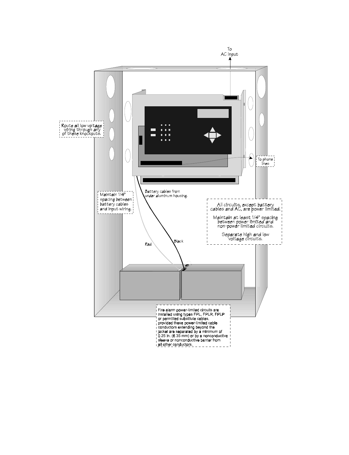
3.4 Wiring Specifications
Induced noise (transfer of electrical energy from one wire to another) can interfere with
telephone communication or cause false alarms. To avoid induced noise, follow these
guidelines:
• Isolate input wiring from high current output and power wiring. Do not pull one multi-
conductor cable for the entire panel. Instead, separate the wiring as follows:
• Do not pull wires from different groups through the same conduit. If you must run them
together, do so for as short a distance as possible or use shielded cable. Connect the shield
to earth ground at the panel. You must route high and low voltages separately.
• Route the wiring around the inside perimeter of the cabinet. It should not cross the circuit
board where it could induce noise into the sensitive microelectronics or pick up unwanted
RF noise from the high speed circuits. See Figure 3-1 for an example.
• High frequency noise, such as that produced by the inductive reactance of a speaker or
bell, can also be reduced by running the wire through ferrite shield beads or by wrapping it
around a ferrite toroid.
33 SC- L1
SLC OUT SLC terminals 32 VDC 150 mA
34 SC+
35 SC- L2
SLC IN Used for Class A installations
36 SC+
37 Ring Phone Line 1 Telco Ring
N/A
38 Tip Phone Line 1 Telco Tip
39 Ring Phone Line 1 Premises Ring
40 Tip Phone Line 1 Premises Tip
41 Ring Phone Line 2 Telco Ring
N/A
42 Tip Phone Line 2 Telco Tip
43 Ring Phone Line 2 Premises Ring
44 Tip Phone Line 2 Premises Tip
45 SC- SLC Programming Terminal
( - ) 32 VDC 150 mA
46 SC+ SLC Programming Terminal
( + ) 32 VDC 150 mA
High voltage AC power, Terminals 1-3
SLC loops Terminals 33-36
Audio input/output Phone line circuits, Terminals
37-44
Notification circuits Terminals 4-15
SBUS Terminals 16-23
Relay circuits Terminals 24-32
Table 3-1: Terminal Strip Description and Electrical Rating
Terminal # and Label Description Rating
Voltage Current
IntelliKnight 5820XL Installation Manual
3-4 151137
Figure 3-1 Wire Routing Example
151137 3-5
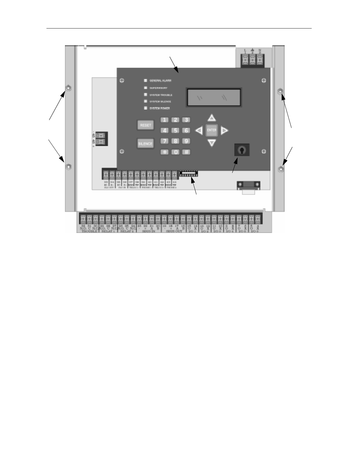
3.5 Board Assembly Diagram
Figure 3-2 Model 5820XL Assembly
Figure 3-2 shows the circuit boards, metal housing and annunciator that attach the 5820XL
assembly to the cabinet. If you should need to remove the board assembly for repair, remove
the four mounting nuts which hold the assembly in the cabinet. Then lift the entire assembly
out of the cabinet. Do not attempt to remove the circuit boards from the metal bracket.
Ground Start
Relay Socket
Chassis
Mounting
Nuts
Chassis
Mounting
Nuts
To AC
On-board Annunciator
Key Switch
Input

IntelliKnight 5820XL Installation Manual
3-6 151137
3.6 Calculating Current Draw and Standby Battery
This section is for helping you determine the current draw and standby battery needs for your
installation.
3.6.1 Worksheet Requirements
The following steps must be taken when determining 5820XL current draw and standby
battery requirements.
Filling in the Current Draw Worksheet, Table 3-2 (Section 3.6.2)
1. For the 5820XL, the worst case current draw is listed for the panel, addressable devices,
and all SBUS expanders. Fill in the number of addressable devices and expanders that will
be used in the system and compute the current draw requirements for alarm and standby.
Record this information in Table 3-2 at Line A.
2. Add up the current draw for all auxiliary devices and record in the table at Line B.
3. Add up all notification appliance loads and record in the table at Line C.
4. For notification appliances and auxiliary devices not mentioned in the manual, refer to the
device manual for the current ratings.
5. Make sure that the total alarm current you calculated, including current for the panel itself,
does not exceed 5.0 A. This is the maximum alarm current for the 5820XL control panel.
If the current is above 5.0 A you will need to use a notification power expander(s) such as
the Silent Knight 5395 or the 5895XL intelligent power expander, to distribute the power
loads so that the 5820XL or the power expanders do not exceed their power rating. Refer
to the current draw worksheets provided with the 5395 or 5895XL manuals so you do not
exceed their power requirements.
6. Complete the remaining instructions in Table 3-2 for determining battery size
requirements.
Before You Begin Installing
151137 3-7
3.6.2 Current Draw Worksheet
Use the worksheet beginning on the next page to determine current requirements during
alarm/battery standby operation. (Copy the page if additional space is required.)
* If you are using door holders, you do not need to consider door holder current for alarm/battery standby,
because power is removed during that time. However, during normal operation, door holders draw current
and must be included in the 5.0 A total current that can be drawn from the panel.
** Use next size battery with capacity greater than required.
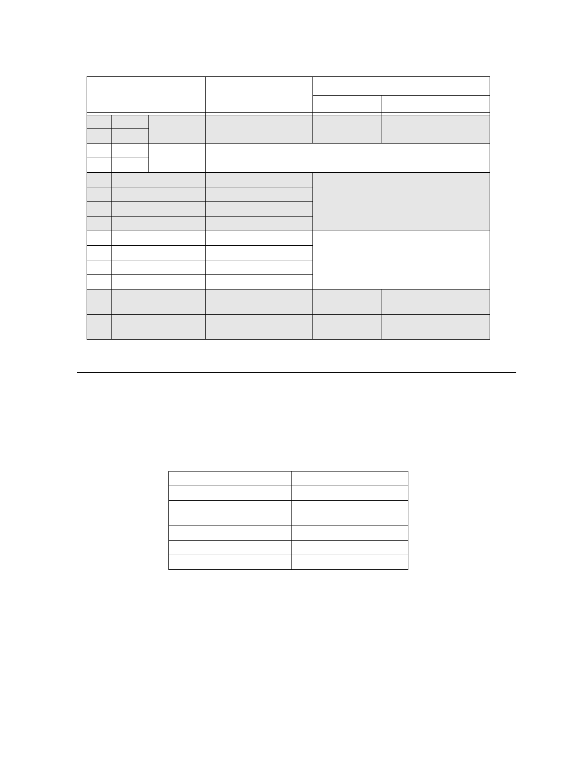
Table 3-2: Current Draw Calculations
Device # of
Devices Current per Device Standby
Current Alarm
Current
For each device use this formula: This column X This column = Current per number of devices.
IntelliKnight 5820XL Fire Panel
(Current draw from battery) 1Standby: 140 mA 140 mA
Alarm: 260 mA 260 mA
Addressable SLC Devices (381 max.) Standby: 0.55 mA mA
Alarm: 0.55 mA mA
5815XL SLC Expander (2 max.) Standby: 55 mA mA
Alarm: 55 mA mA
5860 Remote Fire Alarm
Annunciator (8 max.) Standby: 20 mA mA
Alarm: 25 mA mA
5824 Serial / Parallel Module (2 max.) Standby: 45 mA mA
Alarm: 45 mA mA
5895XL IntelliKnight Power
Expander (8 max.) Standby: 10 mA mA
Alarm: 10 mA mA
5865-4 LED Annunciator
(with reset and silence switches)
(8 max.)
Standby: 35 mA mA
Alarm: 145 mA mA
5865-3 LED Annunciator Standby: 35 mA mA
Alarm: 145 mA mA
5880 Generic LED Driver Module Standby: 35 mA mA
Alarm: 200 mA mA
ATotal System Current
*Auxiliary Devices Refer to devices manual for current rating.
Alarm/Standby: mA mA mA
Alarm/Standby: mA mA mA
Alarm/Standby: mA mA mA
Alarm/Standby: mA mA mA
BAuxiliary Devices Current
Alarm: mA mA
Alarm: mA mA
Alarm: mA mA
Alarm: mA mA
CNotification Appliances Current mA
D Total current ratings of all devices in system (line A + line B + C) mA mA
E Total current ratings converted to amperes (line D x .001): A A
F Number of standby hours (24 or 60 for NFPA 72, chapter 1, 1-5.2.5): H
G Multiply lines E and F. Total standby AH AH
H Alarm sounding period in hours. (For example, 5 minutes = .0833 hours) H
I Multiply lines E and H. Total alarm AH AH
J **Add lines G and I. Total ampere hours required AH

IntelliKnight 5820XL Installation Manual
3-8 151137
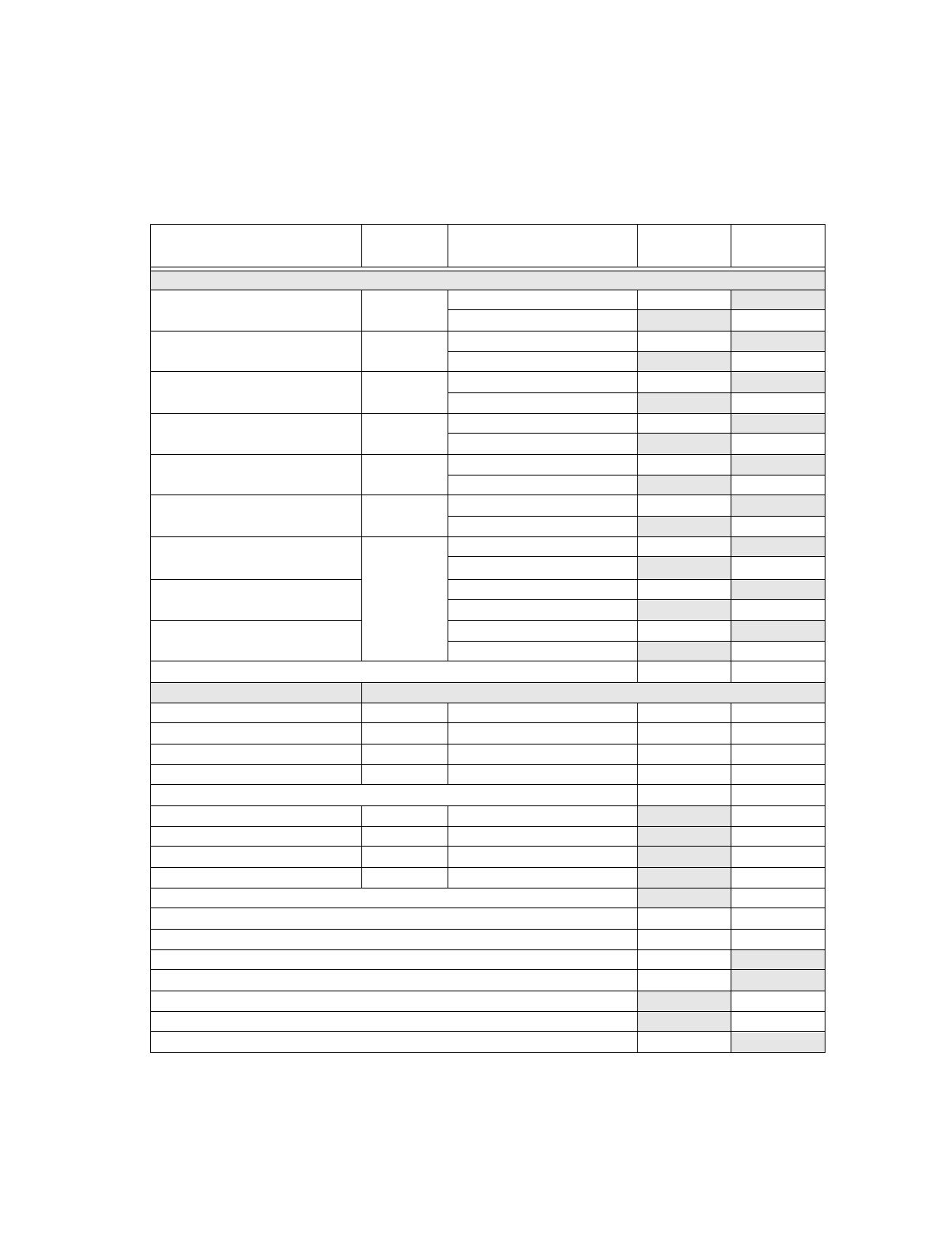
3.6.2.1 Maximum Battery Standby Load
Table 3-3 shows the maximum battery standby load for the 5820XL based on 24 and 60 hours
of standby. The standby load calculations of line D in the Current Draw Calculation
Worksheet (Table 3-2) must be less than the number shown in Table 3-3 for the battery size
used and standby hours required.
* Required for NFPA 72 Auxiliary Protected Fire Alarm systems for Fire Alarm Service (City Box) and Remote
Station Protected Fire Alarm systems (Polarity Reversal) and Digital Alarm Communicator/Transmitter
(DACT).
Table 3-3: Maximum Battery Standby Load
Rechargeable Battery Size Max. Load for 24 hrs.
Standby, 5 mins. Alarm *Max. Load for 60 hrs.
Standby, 5 mins. Alarm
7 AH 270 mA 105 mA
12 AH 475 mA 190 mA
17 AH 685 mA 270 mA
33 AH 1.3 A 540 mA
Warning!
Silent Knight does not support the use of batteries smaller than those listed in Table 3-3. If you use a battery too
small for the installation, the system could overload the battery resulting in the installation having less than the
required 24 hours standby power. Use Table 3-2 to calculate the correct battery amperes/hour rating needed for
your installation.
Before You Begin Installing
151137 3-9
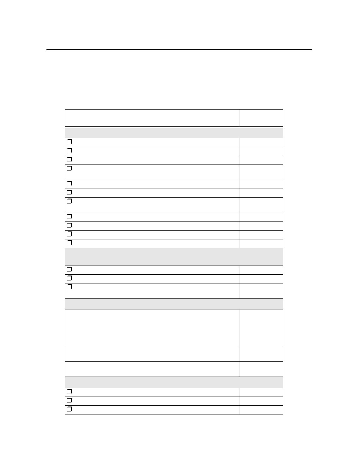
3.7 Installation Tasks Overview
This section of the manual is a chart listing tasks that need to be performed when installing the
IntelliKnight 5820XL system. The chart is intended to be a handy way for you to make sure
you have completed all necessary tasks. Unless noted, these tasks do not have to be performed
in the order they are listed here.
Important: Connect and address SLC devices before running JumpStart.
Task See Sec.
(for more info.)
Main Panel Hardware Installation
Mount the control panel cabinet. 4.1
Connect AC. 4.2
Connect phone lines. 4.11
Install 5815XL SLC Expander modules (if needed). Required if more than
127 SLC devices are used.
4.6
Install 5860 Remote Fire Alarm Annunciator modules if used. 4.5
Install 5865 or LED Annunciator modules if used. 4.9
Install 5880 LED Driver Module if customized LED annunciation will be
used.
4.8
Install notification appliances. 4.12
Install auxiliary power devices (if used). 4.12.5
If using a printer, install Model 5824 Serial/Parallel Interface. 4.7
Connect batteries (typically last step). 4.3
SLC Device Hardware Installation
Perform these steps before running JumpStart.
Connect device bases to the loop. 5.3
Set device addresses. 5.10
Physically connect detectors to their bases. Connect relay and contact
monitor modules.
5.8.2
JumpStart
JumpStart is for initial system programming. JumpStart automatically selects
some options for SLC devices. See “Input Point Configuration” section of this
chart for other options.
JumpStart makes selections for the following options. You can customize
options, if necessary.
See Section 6.1
and 7.6
Device type (detector or switch) configured by JumpStart. To change, see
Sec. 7.4
Program type of detector (heat, photoelectric, or ionization) selected by
JumpStart.
To change, see
Sec. 7.4
System Software Configuration
Select low AC hours report time (6 hours by default). 7.5.6.2
Select Auto Test Time (2:00 AM by default). 7.5.1.2
Enable/disable automatic DST adjustment feature (enabled by default). 7.5.6.3

IntelliKnight 5820XL Installation Manual
3-10 151137
Change clock display format (12-hour with AM/PM by default). 7.5.6.4
Enable/disable day/night sensitivity (disabled by default). 7.5.4
Select holiday schedule (up to 18 days) if installation is using day/night
sensitivity.
7.5.5
Set up reporting accounts. 7.5.1
Select options for phone lines. 7.5.2
Select system-wide response to trouble conditions, if desired. 7.5.3
Select system-wide cadence patterns for special conditions (fire drill, Aux1
and Aux2 alarms) if desired.
7.5.3
Customize banner message (message that displays on LCD in normal
mode) if desired.
7.5.8
Input Point (SLC Device) Configuration
JumpStart automatically selects some options for SLC devices (see “JumpStart” section of this chart).
You can change options selected by JumpStart, if necessary and further customize input point
options.
Program type of switch (manual pull, fire drill, and so on), if necessary.
(JumpStart assigns all switches as Manual Pull type.)
7.4
If the installation includes duct detectors, program detector type.
(JumpStart does not distinguish duct detectors from ordinary smoke
detectors.)
7.4
Assign a name (or description) to the point. 7.4.3.1
Assign input points to zones, if necessary. (JumpStart assigns all input
points to Zone 1.)
7.4
Zone Configuration
Add the zone to the system if it does not already exist. (Zone 1 created by
JumpStart.)
7.2.2
Program a name (or description) for the zone. 7.2.1.1
Select alarm delay options (detection characteristics) for zone. 7.2.1.2
Select heat detector trip temperature and/or smoke sensitivity level for
photoelectric smoke detectors. (JumpStart selects 150(F for heat detectors
and Low sensitivity for smoke detectors.)
7.2.1.2
Output Point Configuration
Conventional notification circuits (circuits 1-6):
Enable circuits used for notification appliances through programming, if
necessary. (JumpStart enables circuits 1-6 as Notification.)
7.3.1
Conventional relay circuits (circuits 7-8):
Select options for relay circuits, if desired. Note: Relay circuits will always
output continuously (constant pattern), even if assigned to an Output Group
that uses a different output pattern.
7.3.1
Auxiliary power circuits (circuits 1-6):
Enable any circuit used for auxiliary power devices through programming. 7.4
Select type of power (door holder, constant, or resettable) 7.4
Task See Sec.
(for more info.)

Before You Begin Installing
151137 3-11
Addressable relay modules
Assign addressable relay modules to output groups through programming.
(JumpStart assigns all relay modules to Group 1.)
7.4
LED output points (from the 5880 LED Driver or 5865/66 LED Annunciator)
Assign LED modules to output groups through programming. 7.4.3
All output circuits (1-8):
Disable (set to UNUSED) any unused circuits. If you do not disable unused
output circuits, they will cause a trouble condition (unless an EOL resistor
is used).
7.4
Select a name for the point, if desired. 7.4
Output Group Configuration
Add the group to the system if it does not already exist. 7.3.2
Assign output points to the group. 7.4
Program a name (or description) for the group, if desired. 7.3.1.1
Select “group properties” (see below).
Latching / non-latching 7.3.1
Silencing option 7.3.1
Select options for activation with system switches. 7.3.1
Map zones to output groups that will activate when zone goes into alarm. 7.2.1.3
Select a cadence pattern for outputs in the zone. 7.2.1.3
Task See Sec.
(for more info.)

IntelliKnight 5820XL Installation Manual
3-12 151137

151137 4-1
Section 4
Control Panel Installation
4.1 Mounting the Control Panel Cabinet
Read the environmental specifications in Section 3.2 before mounting the control panel
cabinet. This will ensure that you select a suitable location.
The panel should be accessible to main drop wiring runs. It should be mounted as close to the
center of the building as possible and located within a secured area, but should be accessible
for testing and service.
Mount the control panel cabinet so it is firmly secured to the wall surface. When mounting on
concrete, especially when moisture is expected, attach a piece of 3/4-inch plywood to the
concrete surface and then attach the cabinet to the plywood. Also mount any other modules to
the plywood.
The cabinet can be surface- or flush-mounted. If you will be flush-mounting the cabinet, the
hole for the enclosure should be 14.75" W x 25" H x 4" D. Do NOT flush-mount in a wall
designated as a fire break.
4.1.1 Removing the 5820XL Assembly from the Housing
If it should ever be necessary to remove the control panel assembly from the cabinet for
repair, do so by unscrewing the nuts that connect the control panel assembly to the cabinet. Do
not attempt to disassemble the circuit boards. See Section 3.5 for location of the nuts.
Caution!
To avoid the risk of electrical shock and damage to the unit, power should be OFF at the control panel while
installing or servicing.
IntelliKnight 5820XL Installation Manual
4-2 151137
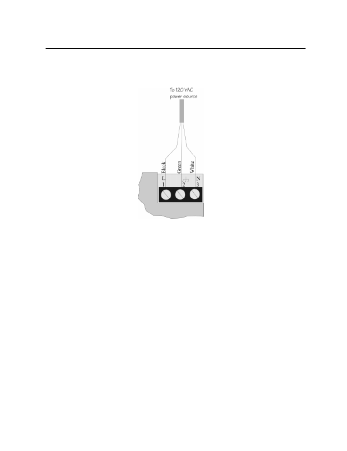
4.2 AC Connection
At installation, connect the AC terminals to 120 VAC source as shown in Figure 4-1. It may
be necessary for a professional electrician to make this connection.
The AC terminals are rated at 120 VAC, 60 Hz, 2.5A.
Figure 4-1 AC Power Connection
Control Panel Installation
151137 4-3
4.3 Battery Connection
The control panel battery charge capacity is 7.0 to 33.0 AH. Use 12V batteries of the same AH
rating. Determine the correct AH rating as per your current load calculation (see Section 3.6).
Wire batteries in series to produce a 24-volt equivalent. Do not parallel batteries to increase
the AH rating.
Figure 4-2 Battery Connection
To Control Panel
Red Black
Battery Jumper
(P/N 140694)
Shipped With Panel
UL Listed 12V Battery
UL Listed 12V Battery

IntelliKnight 5820XL Installation Manual
4-4 151137
4.3.1 AB-33 Accessory Cabinet
The AB-33 Accessory cabinet can be used when your backup batteries requirements use
backup batteries that are too large to fit into the main control panel cabinet. The AB-33
cabinet holds batteries up to the 33 AH size.
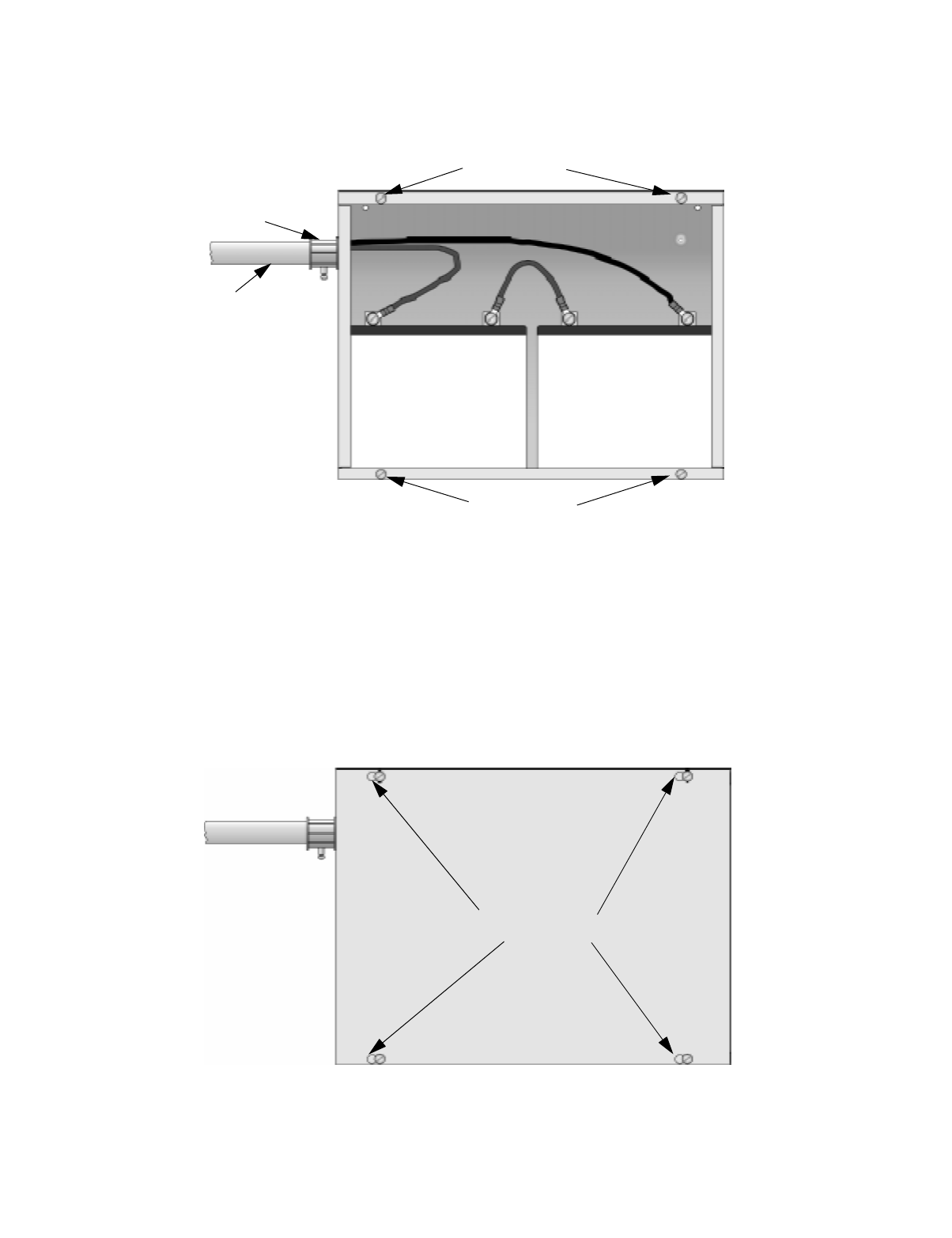
4.3.1.1 Installing the AB-33 Accessory Cabinet and Batteries
To properly install the accessory cabinet and backup batteries, follow these steps:
1. Mount the accessory cabinet. See figure Figure 4-3 for the four cabinet mounting holes.
• If mounting onto drywall the accessory cabinet must be mounted onto 3/4-inch ply-
wood. This is necessary because the weight of the batteries inside the accessory cabi-
net could cause the cabinet to pull away from the drywall.
• When mounting on concrete, especially when moisture is expected, attach a piece of
3/4-inch plywood to the concrete surface and then attach the AB-33 cabinet to the ply-
wood.
• If using the battery cable extenders provided (P/N 140643), mount the AB-33 cabinet
no more than 18" away from the main control panel cabinet. This will ensure that the
battery cables reach the battery terminals.
Figure 4-3 AB-33 Cabinet Mounting Holes
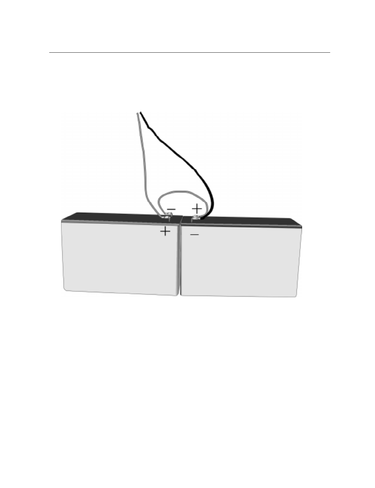
2. Connect the main control panel battery cables to the battery cable extenders as shown in
Figure 4-4.
Figure 4-4 Splicing Control panel Battery Cable to AB-33 Battery Cable Extenders
Cabinet
Mounting Holes
Control Panel Installation
151137 4-5
3. Run extended battery cable from control panel cabinet through conduit to AB-33 cabinet.
See Figure 4-5.
Figure 4-5 Battery Connections in the AB-33 Cabinet
Note: Any one of the cabinet knock-outs (on either the main control panel or the AB-33 cabinet), that are not pre-
viously being used may be utilized to connect conduit between the two cabinets.
4. Connect battery leads to the backup battery terminals. See Figure 4-5.
Observe the proper polarity to prevent damage to the batteries or the control panel.
5. Insert the AB-33 cover screws into the cover mounting holes (see Figure 4-5).
Screw the cover screw 3/4 of the way into the cover mounting hole.
6. Align the cover plate mounting keyhole over the cover mounting screws. See Figure 4-6.
Figure 4-6 Cover Plate Mounting Keyholes and Cover Mounting Screws Alignment
7. Slide the cover into place and tighten the cover mounting screws. See Figure 4-6.
Conduit
Conduit
Coupler
++
--
AB-33 Cabinet
Cover Screws
AB-33 Cabinet
Cover Screws
Cover Plate
Mounting Keyholes

IntelliKnight 5820XL Installation Manual
4-6 151137
4.4 SBUS Wiring
This section contains information on calculating SBUS wire distances and the types of wiring
configurations (Class A and B).
4.4.1 Calculating Wiring distance for SBUS modules
The following instructions will guide you in determining the type of wire and the maximum
wiring distance that can be used with control panel SBUS accessory modules.
To calculate the wire gauge that must be used to connect SBUS modules to the control panel,
it is necessary to calculate the total worst case current draw for all modules on a single 4-
conductor bus. The total worst case current draw is calculated by adding the individual worst
case currents for each module. The individual worst case values are shown in the table below.
Note: Total worst case current draw on a single SBUS cannot exceed 1 amp. If a large number of accessory mod-
ules are required, and the worst case current draw will exceed the 1 amp limit, then the current draw must
be distributed using 5895XL Power Expanders. Each 5895XL Power Expander provides an additional
SBUS, with an additional 1 amp of SBUS current. Wiring distance calculations are done separately for
each 5895XL, and separately for the control panel itself.
After calculating the total worst case current draw, Table 4-1 specifies the maximum distance
the modules can be located from the panel on a single wire run. The table insures 6.0 volts of
line drop maximum. In general, the wire length is limited by resistance, but for heavier wire
gauges, capacitance is the limiting factor.
Model Number Worst Case Current Draw
5860 Fire Annunciator .100 amps
5824 Parallel/Serial Interface .040 amps
5880 LED Driver Module .250 amps
5865 LED Fire Annunciator .200 amps
5895XL Intelligent Power Supply .010 amps

Control Panel Installation
151137 4-7
These cases are marked in the chart with an asterisk (*). Maximum length can never be more
than 6,000 feet, regardless of gauge used. (The formula used to generate this chart is shown in
the note below).
Note: The following formulas were used to generate the wire distance chart:
Table 4-1: Wire Distances Per Wire Gauge
Wiring Distance: SBUS Modules to Panel
Total Worst Case
Current Draw (amps) 22 Gauge 18 Gauge 16 Gauge 14 Gauge
0.100 1852 ft. 4688 ft. * 6000 ft. * 6000 ft.
0.200 926 ft. 2344 ft. 3731 ft. 5906 ft.
0.300 617 ft. 1563 ft. 2488 ft. 3937 ft.
0.400 463 ft. 1172 ft. 1866 ft. 2953 ft.
0.500 370 ft. 938 ft. 1493 ft. 2362 ft.
0.600 309 ft. 781 ft. 1244 ft. 1969 ft.
0.700 265 ft. 670 ft. 1066 ft. 1687 ft.
0.800 231 ft. 586 ft. 933 ft. 1476 ft.
0.900 206 ft. 521 ft. 829 ft. 1312 ft.
1.000 (Max) 185 ft. 469 ft. 746 ft. 1181 ft.
Maximum Resistance (Ohms) = 6.0 Volts
Total Worst Case Current Draw (amps)
Maximum Wire Length (Feet) =
(6000 feet maximum)
Maximum Resistance (Ohms) * 500
Rpu
where: Rpu = Ohms per 1000 feet for various Wire Gauges (see table below)
Table 4-2: Typical Wire Resistance Per 1000 ft.
Wire Gauge Ohms per 1000 feet (Rpu)
22 16.2
18 6.4
16 4.02
14 2.54

IntelliKnight 5820XL Installation Manual
4-8 151137
Wiring Distance calculation example:
Suppose a system is configured with the following SBUS modules:
2 - Module 5860 Fire Annunciator
1 - 5895XL Intelligent Power Expander
1 - 5865 LED Fire Annunciator
1 - 5824 Parallel/Serial Interface
The total worst case current is calculated as follows:
Using this value, and referring to the Wiring Distance table, it can be found that the available
options are:
370 feet maximum using 22 Gauge wire
938 feet maximum using 18 Gauge wire
1493 feet maximum using 16 Gauge wire
2362 feet maximum using 14 Gauge wire
5860 Current Draw = 2 x .100 amps = .200 amps
5895XL Current Draw = 1 x .010 amps = .010 amps
5865 Current Draw = 1 x .200 amps = .200 amps
5824 Current Draw = 1 x .040 amps = .040 amps
Total Worst Case Current Draw = .450 amps
Control Panel Installation
151137 4-9
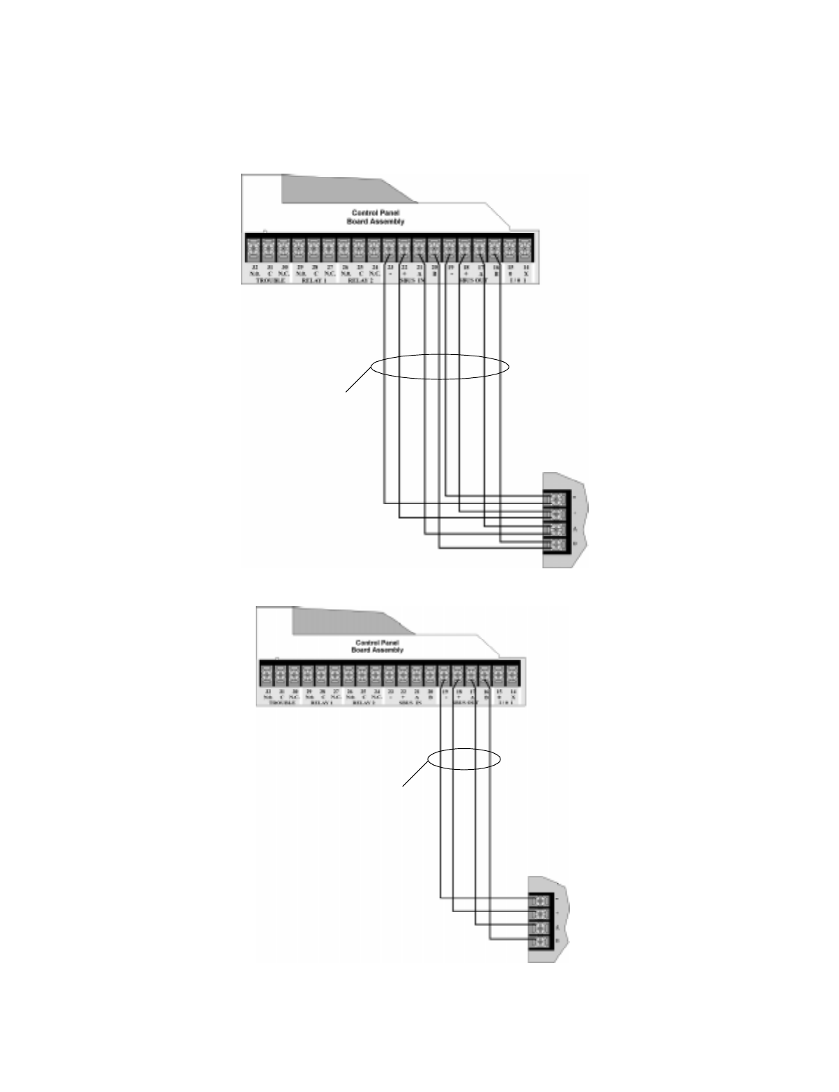
4.4.2 Wiring Configurations
Figure 4-7 illustrates Class A wiring configuration and Figure 4-8 illustrates Class B
configuration.
Figure 4-7 SBUS Class A Wiring
Figure 4-8 SBUS Class B Wiring
Supervised
Power Limited
Supervised
Power Limited
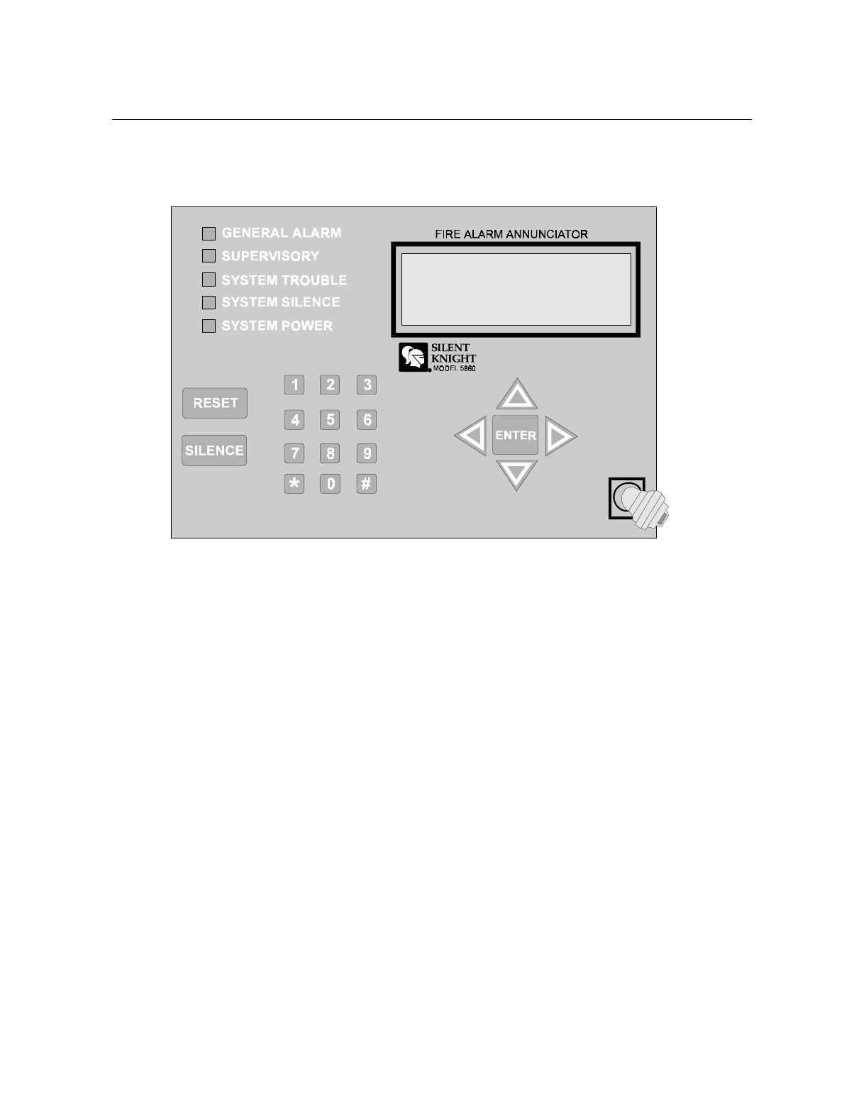
IntelliKnight 5820XL Installation Manual
4-10 151137
4.5 Remote Annunciator 5860 Installation
The optional Model 5860 Remote Annunciator, shown in Figure 4-9, performs the same
functions as the on-board annunciator. Operation is identical. Up to 8 annunciators can be
added to the IntelliKnight 5820XL system.
Figure 4-9 Model 5860 Remote Annunciator, Front View
5860 installation involves the following steps:
1. Make sure power is off at the panel.
2. Mount the 5860 in the desired location (see Section 4.5.1).
3. Connect the 5860 to the panel (see Section 4.5.2).
4. Use the dipswitches on the back of the 5860 to assign an ID# to the 5860 (see Section
4.10.1).
5. The new 5860 module must be added to the system through programming. JumpStart will
add the module automatically (see Section 6.1). You can also add it manually (see Section
7.1.2). Select a name, if desired (see Section 7.1.1.1).
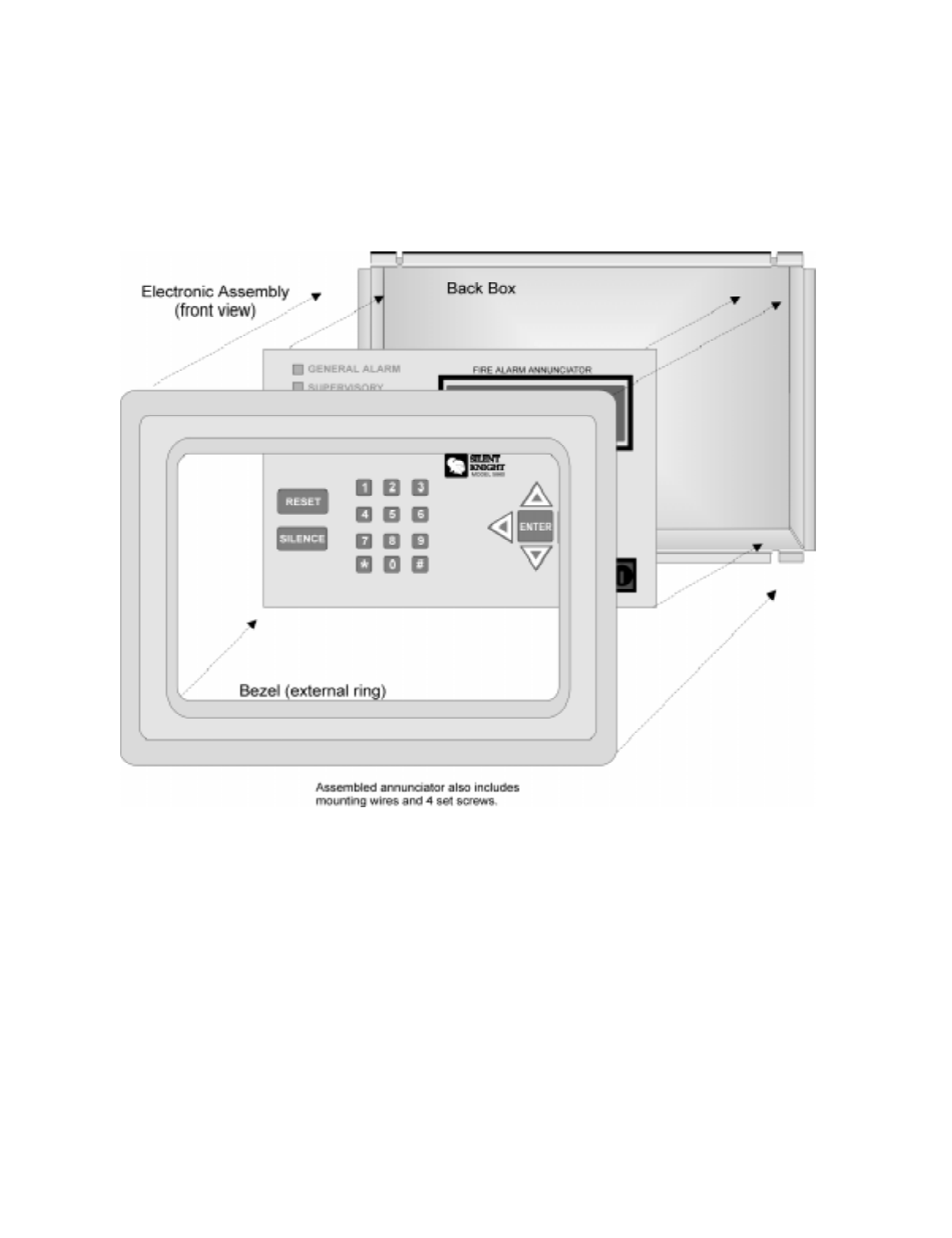
Control Panel Installation
151137 4-11
4.5.1 Mounting the 5860
This section of the manual describes mounting the remote annunciator. The annunciator can
be flush- or surface-mounted.
Figure 4-10 shows the parts of the annunciator. Instructions for disassembling and mounting
appear on the following pages.
Figure 4-10 Annunciator Parts
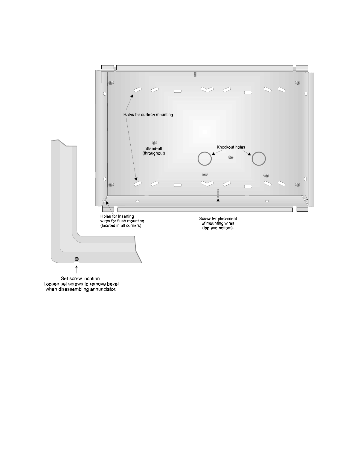
IntelliKnight 5820XL Installation Manual
4-12 151137
The 5860 comes from the factory fully assembled. You must disassemble it for mounting. To
disassemble the annunciator, use a 5/64 hex wrench to remove the set screws, located on the
bottom of the annunciator bezel. (See Figure 4-11 for location of the set screws.)
Figure 4-11 Annunciator Back Box and Bezel Details
4.5.1.1 Flush Mounting
This section of the manual describes flush mounting. You can flush-mount with or without an
electrical box.
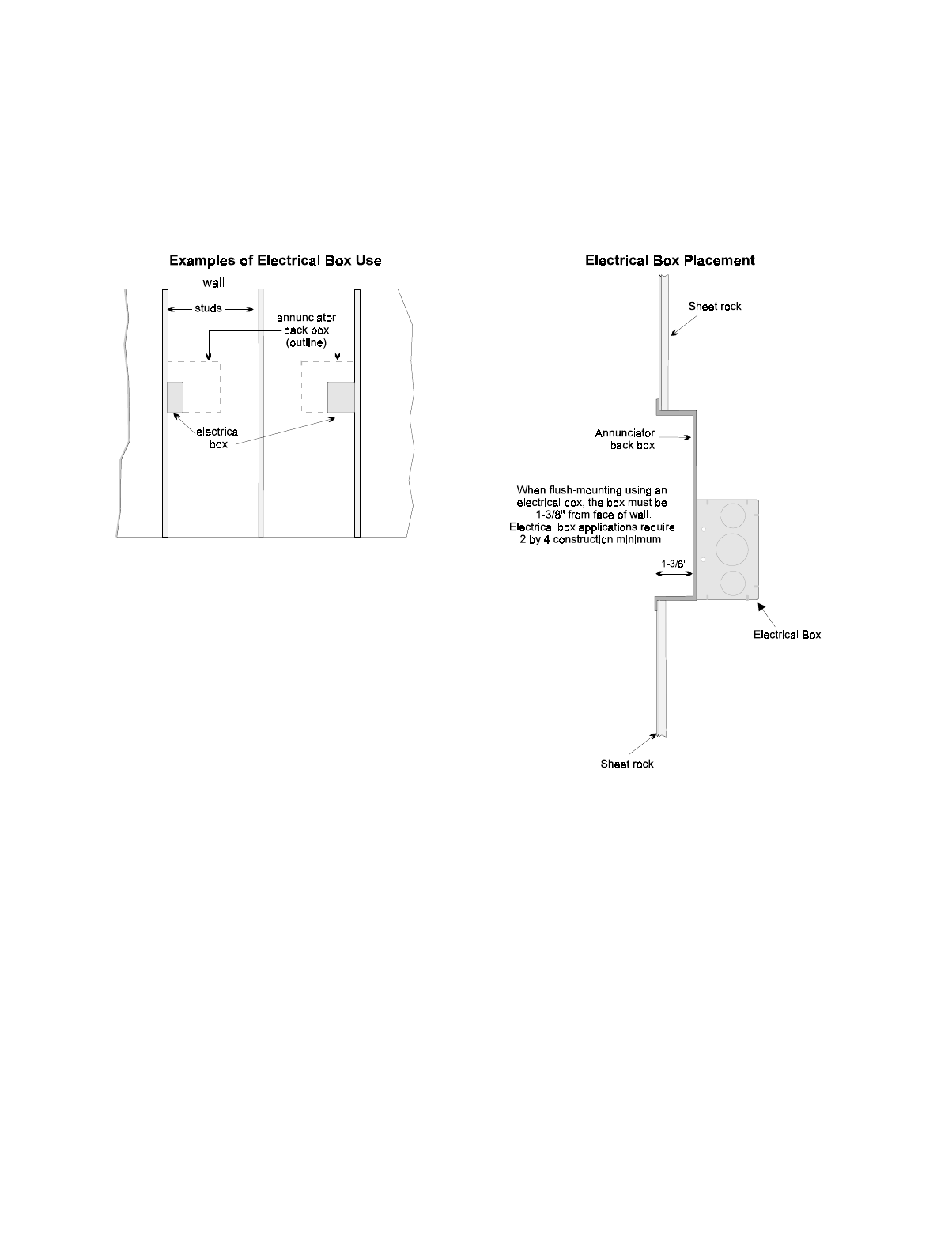
Control Panel Installation
151137 4-13
Flush Mounting with an Electrical Box
The 5860 annunciator can be used with the following types of electrical boxes: 4S, single-
gang, and double-gang.
If an electrical box is used, the box must be 1-3/8” back from the face of the wall to
accommodate the annunciator. Studs used with an electrical box must be two by fours (or
larger).
Figure 4-12 Placement of Electrical Box for Flush Mounting
Flush Mounting Steps
1. Cut a hole in the sheet rock to the following dimensions: 8-1/4” w x 6-5/8” h. If an electri-
cal box is used, the box must be 1-3/8” back from face of wall to accommodate the annun-
ciator (see Figure 4-12).
2. Remove knockout holes as needed for wires.
3. Fit the annunciator back box into the hole and stabilize with mounting wires. Angle the
mounting wires into the first hole past the sheet rock. Secure the wires behind the screws
as shown in Figure 4-13. When all four wires are in place, the back box should fit snugly
into the hole in the sheet rock.
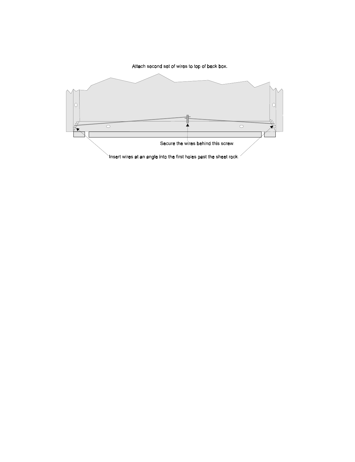
IntelliKnight 5820XL Installation Manual
4-14 151137
4. After the annunciator wiring to the panel has been completed (described in Section 4.5.2),
replace the electronic assembly in the back box. Place the bezel over the back box and
tighten the set screws on the bezel.
Figure 4-13 Flush Mounting the Back Box
4.5.1.2 Surface Mounting
The 5860 can be mounted directly to a surface or can be attached to a single, double, or four-
square electrical box. The Model 5860TG/TR trim ring kit is available for use when surface
mounting.
1. Drill holes in the surface to match the screw holes on the back box.
2. Fit the trim ring over the back box.
3. Attach the back box to the surface using screws provided.
4. After the annunciator wiring to the panel has been completed (described in Section 4.5.2),
replace the electronic assembly in the back box. Place the bezel over the back box and
tighten the set screws on the bezel.
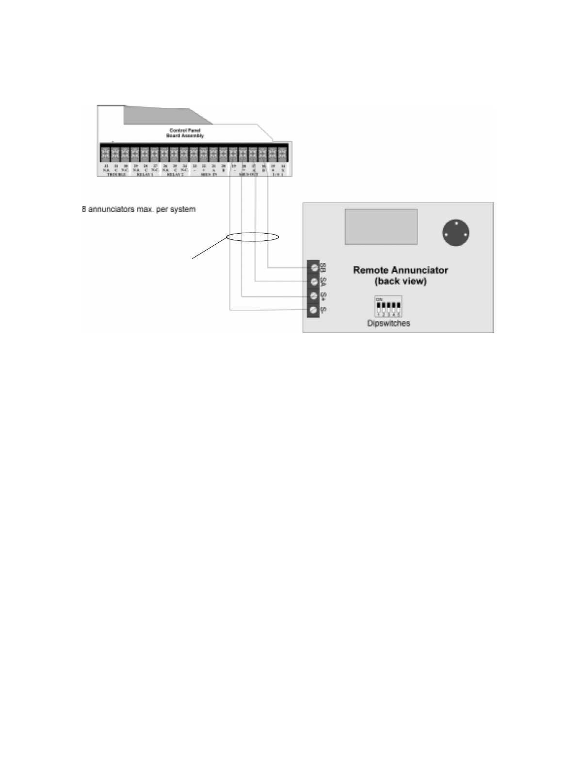
Control Panel Installation
151137 4-15
4.5.2 Model 5860 Connection to the Panel
Connect the 5860 to the panel as shown in Figure 4-14.
Figure 4-14 Model 5860 Connection to the Panel
Supervised
Power Limited
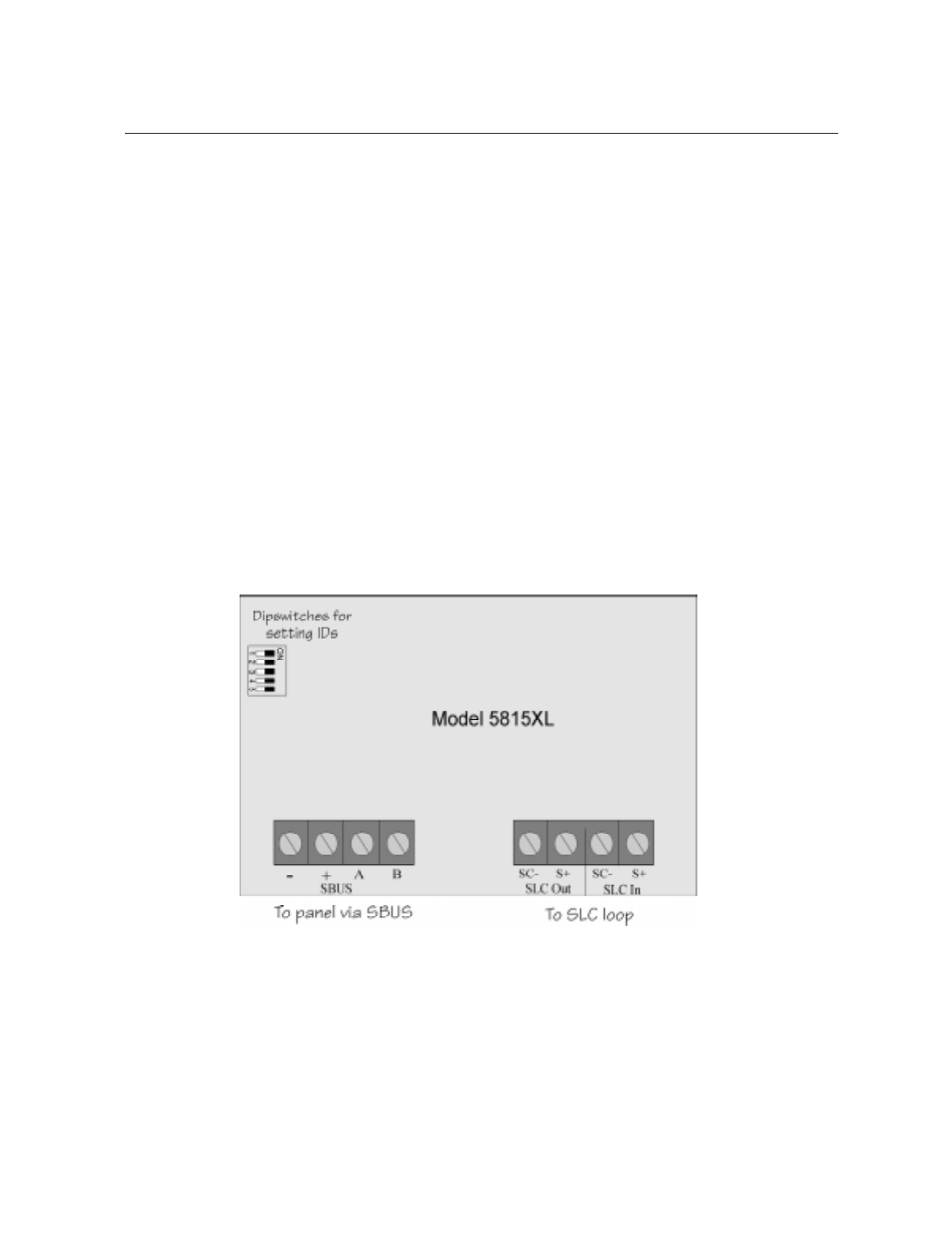
IntelliKnight 5820XL Installation Manual
4-16 151137
4.6 5815XL Installation
The Model 5815XL SLC Expander allows you to add 127 analog addressable devices. Up to
two 5815XLs (adding 254 SLC devices) can be used with the system.
5815XL installation involves the following steps.
1. Make sure power is off at the panel.
2. Mount the 5815XL in the 5820XL or 5895XL cabinet. Use the standoffs located under the
control panel board assembly and secure with screws provided with the 5815XL. See also
Model 5895XL Installation Instructions P/N 151142.
3. Connect the 5815XL to the control panel. (See Section 4.6.1.)
4. Use on-board dipswitches to select an ID#. (See Section 4.10.1.)
5. The new 5815XL module must be added to the system through programming. JumpStart
will add the module automatically (see Section 6.1). You can also add it manually (see
Section 4.10). Select a name, if desired (see Section ).
6. You are now ready to connect SLC devices to the 5815XL (see Section 5.3).
Figure 4-15 is a drawing of the 5815XL board, showing the location of terminals and
dipswitches.
Figure 4-15 5815XL Board
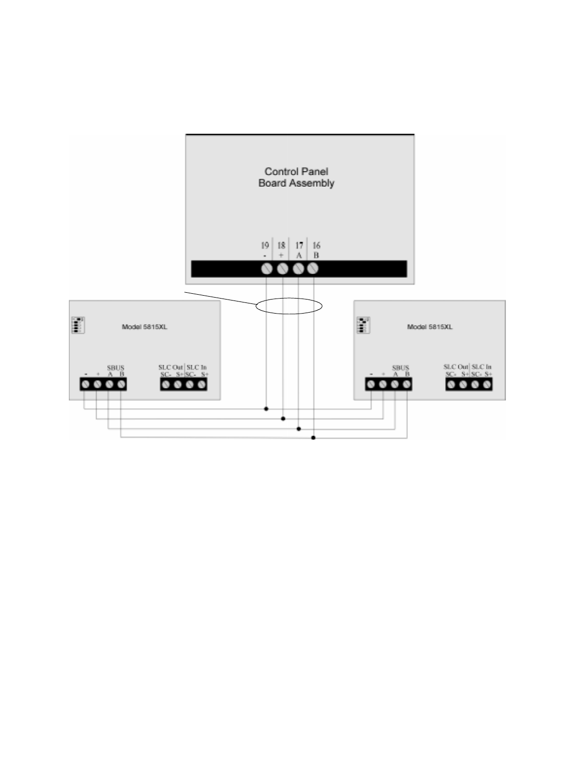
Control Panel Installation
151137 4-17
4.6.1 5815XL Connection to the Panel
Connect the 5815XL to the control panel as shown in Figure 4-16. After the 5815XL is
connected to the panel, it must be added to the system. This programming step is described in
Section 4.10.
Figure 4-16 5815XL Connection to Main Panel Assembly
Supervised
Power Limited
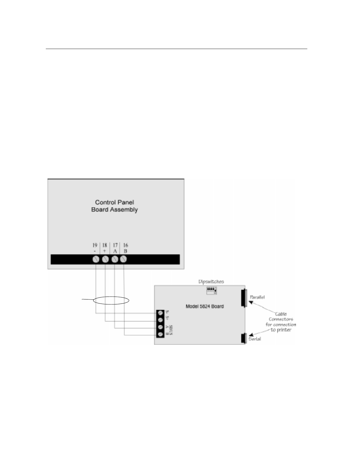
IntelliKnight 5820XL Installation Manual
4-18 151137
4.7 5824 Serial/Parallel Interface Installation
The 5824 Serial / Parallel Interface allows you to connect a printer to the panel, so you can
print a real-time log of system events, a report of detector status, and event history.
Instructions for installing the 5824 appear below.
5824 installation involves the following steps:
1. Make sure power is off at the panel.
2. Connect the 5824 to the panel as shown in Figure 4-17.
Note: Two 5824s per panel maximum.
3. Use the dipswitches on the back of the 5824 board to assign an ID# to the 5824 (see Sec-
tion 4.10.1).
4. Configure the 5824 device through programming. See Section 4.7.1.
5. Connect a printer to the 5824 as shown in Figure 4-18.
Figure 4-17 5824 Connection to the Panel
Supervised
Power Limited

Control Panel Installation
151137 4-19
Figure 4-18 Printer Connection
4.7.1 Selecting 5824 Options
Configuring the 5824 includes the following steps:
• Add the module to the system. JumpStart will add the module automatically (see Section
6.1). You can also add it manually (see Section 4.10).
• Select a name, if desired (see Section ).
• Select options for the printer and the output port. See below.
M
o
d
e
l
5824
(
w
i
t
h
h
ous
i
ng
)
To Parallel Printer
To Serial Printer
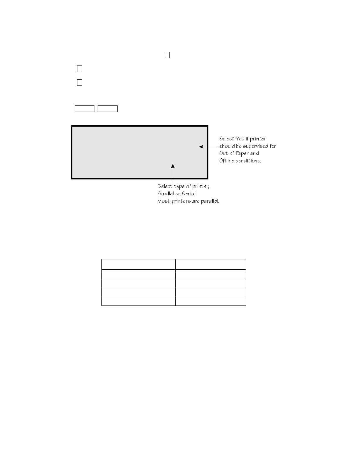
IntelliKnight 5820XL Installation Manual
4-20 151137
Printer and Output Port Options
1. From the Installer Main Menu, select for Program Menu.
2. Select for Module.
3. Select for Edit Module.
4. From the list that displays, select the 5824 module you want to configure.
5. Press to bypass the next two screens. A screen similar to the one shown in
Figure 4-19 will display.
Figure 4-19 Selecting Printer and Output Port Options
6. Select options for the printer as needed for your installation. Most printers are parallel.
7. If you are using a serial printer, use the next screen to select serial port options as required
for your printer. Refer to your printer manual if you need more information.
Option Choices
Baud Rate: 75 - 19200
Data Bits: 5 - 8
Stop Bits: .5, 1, 2
Parity: None, Even, Odd
7
1
2
ENTER ENTER
M06 5824 06
Monitor Printer=YES
Output Port=PARALLEL

Control Panel Installation
151137 4-21
4.8 5880 LED Driver Module
The 5880 is an LED driver board that can be used in a wide variety of applications, including
as an interface with most customized floor plan annunciator boards. The 5880 can drive up to
40 LEDs and has one PZT controller. The 5880 also has eight inputs for dry contact
monitoring. The following sub-sections describe hardware installation. Refer to Section 6 for
programming information.
4.8.1 5880 Board Layout
Figure 4-20 is a picture of the 5880 board showing locations of screw terminals for connection
to the panel and contact monitor wiring; pin connectors for connecting LEDs; and the
dipswitch for selecting an SBUS ID number.
Figure 4-20 5880 Board Layout
SBUS Connection
SBUS Address
DIPs
Dry Contact Inputs
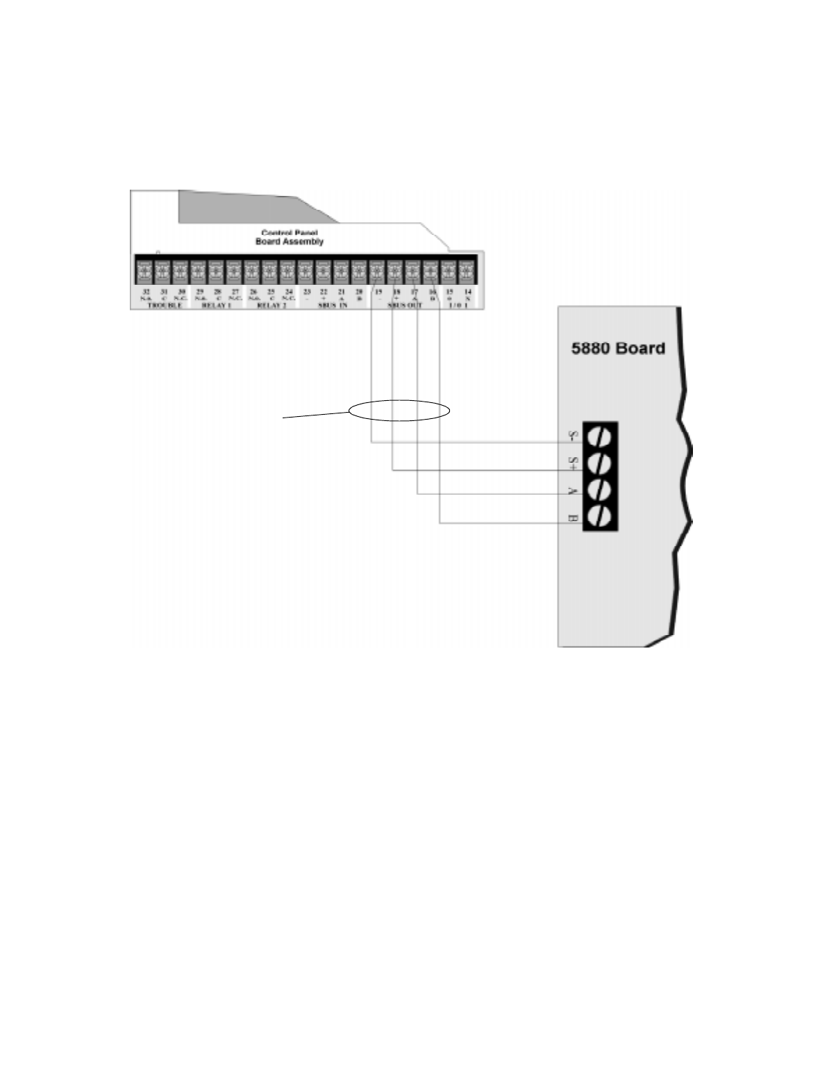
IntelliKnight 5820XL Installation Manual
4-22 151137
4.8.2 FACP Connection
The 5880 connects to the panel via the SBUS. Make connections as shown in Figure 4-21.
After the 5880 is connected to the panel, it must be added to the system. This programming
step is described in Section 4.10.
Figure 4-21 5880 Connection to Main Control Panel Assembly
Supervised
Power Limited

Control Panel Installation
151137 4-23
4.8.3 LED Wiring
There are four 12-pin connectors on the 5880 board for connecting LEDs. Each LED gets its
power from Pin 11. Internal resistors are sized so that there is approximately 10 mA of current
for each LED, no series resistors are required. LED outputs can be mapped to output circuits.
See Section 6 for programming details.
Wire the LEDs as shown in Figure 4-22.
On connector P1, Pin 12 is an open collector output for controlling a PZT. If used, the 5880
PZT will match the PZT pattern of the on-board (or 5860) annunciator.
Note: The circuit connected to “Open Collector Output” (last pin on P1) must be current limited so that no more
than 100 mA of current is allowed to flow into the open collector transistor.
Figure 4-22 5880 Board Layout
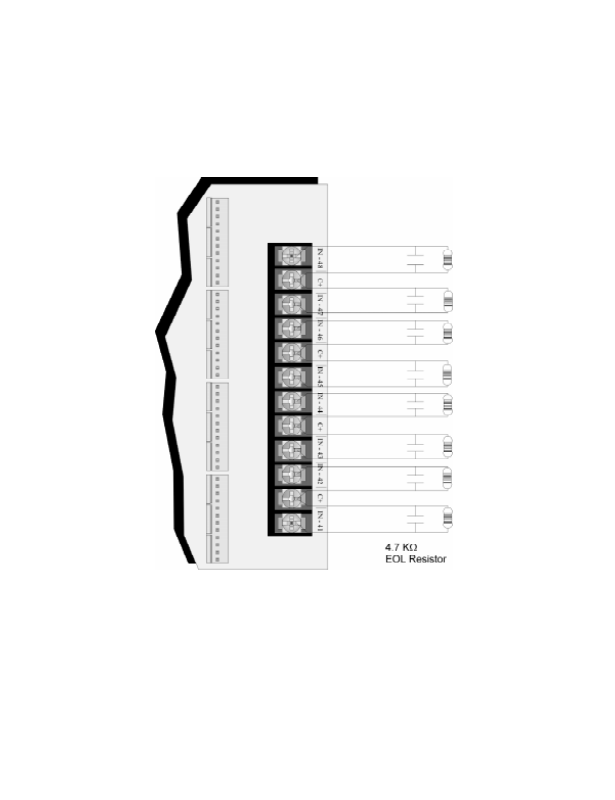
IntelliKnight 5820XL Installation Manual
4-24 151137
4.8.4 Dry Contact Wiring
The 8 input circuits on the 5880 board are for monitoring switch inputs-any type of switch
supported by the control panel can be used with the 5880. For example, you can use a 5880 to
monitor pull stations, water flow, tamper, reset, or silence switches.
Wire dry contacts as shown in Figure 4-23. Notice grouping of terminals; power terminals are
shared by two inputs.
Figure 4-23 Dry Contact Wiring
Model 7628
Supervised
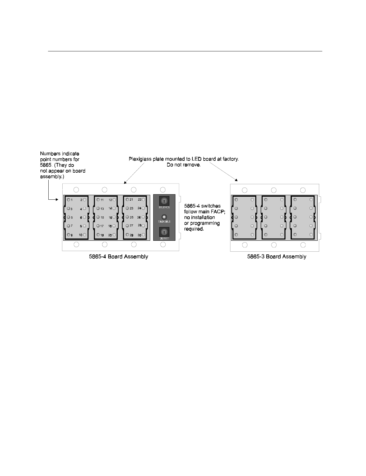
Control Panel Installation
151137 4-25
4.9 5865-3 / 5865-4 LED Annunciator Installation
The 5865-3 and 5865-4 are LED annunciators. The 5865-4 has 30 mappable LEDs, remote
silence and reset key switches, and a general system trouble LED. The 5865-3 has 30
mappable LEDs only. These are arranged as 15 pairs of red (typically used for alarm) and
yellow (typically used for trouble) LEDs.
Installation of the 5865-5 and 5865-4 is identical. The key switches and the trouble LED
follow the behavior of other system annunciators and do not require any installation steps. The
following sub-sections describe how to install the 5865-3 and 5865-4 hardware. Refer to
Section 6 for programming information.
Note: This manual uses “5865” when referring to aspects of the 5865-3 and 5865-4 that are common to both
models.
Figure 4-24 5865-3 and 5865-4 Assembly (front view)
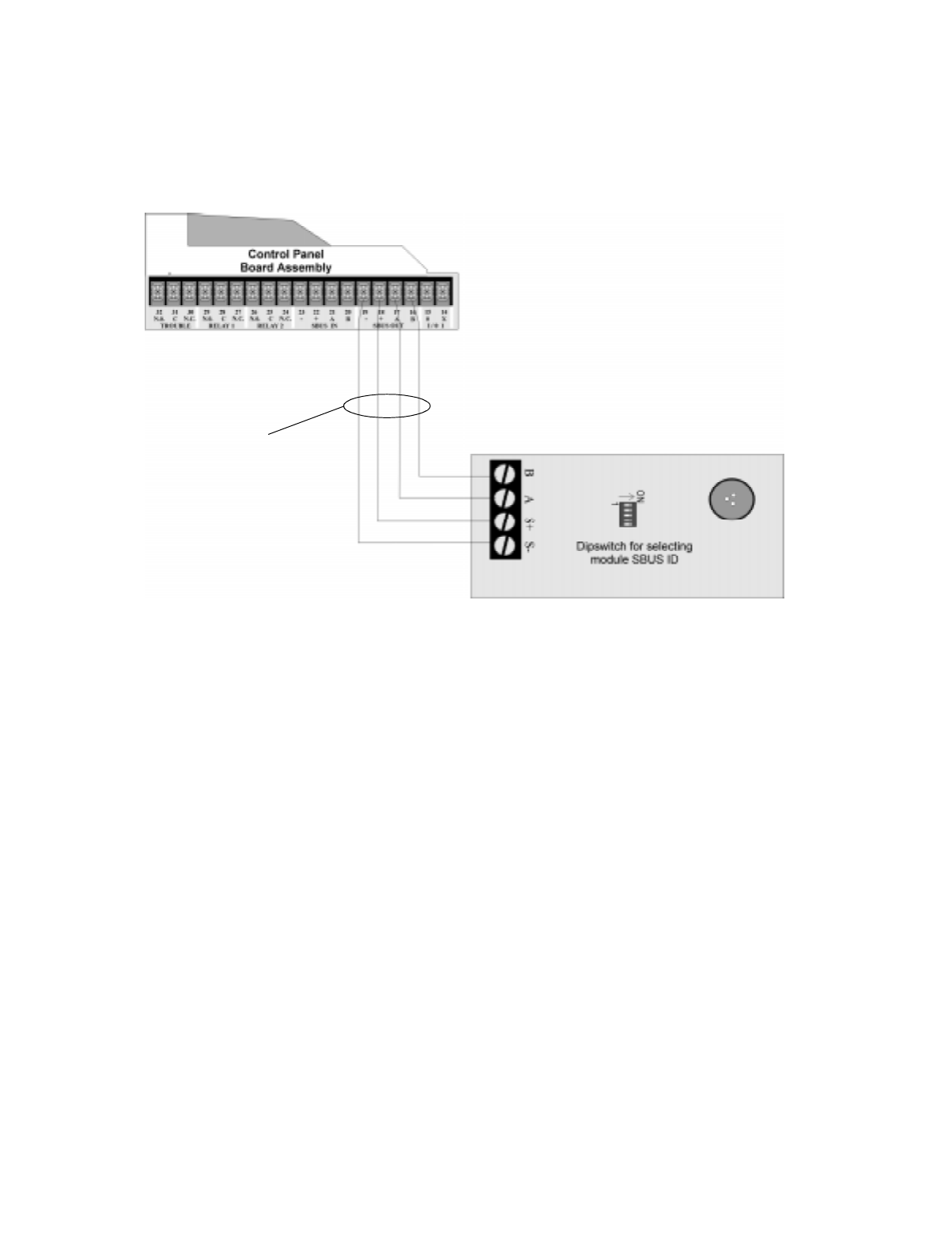
IntelliKnight 5820XL Installation Manual
4-26 151137
4.9.1 FACP Connection
The 5865 connects to the panel via the SBUS. Make connections as shown in Figure 4-25.
After the 5865 is connected to the panel, it must be added to the system. This programming
step is described in Section 4.10.
Figure 4-25 5865 Connection to the FACP
Supervised
Power Limited
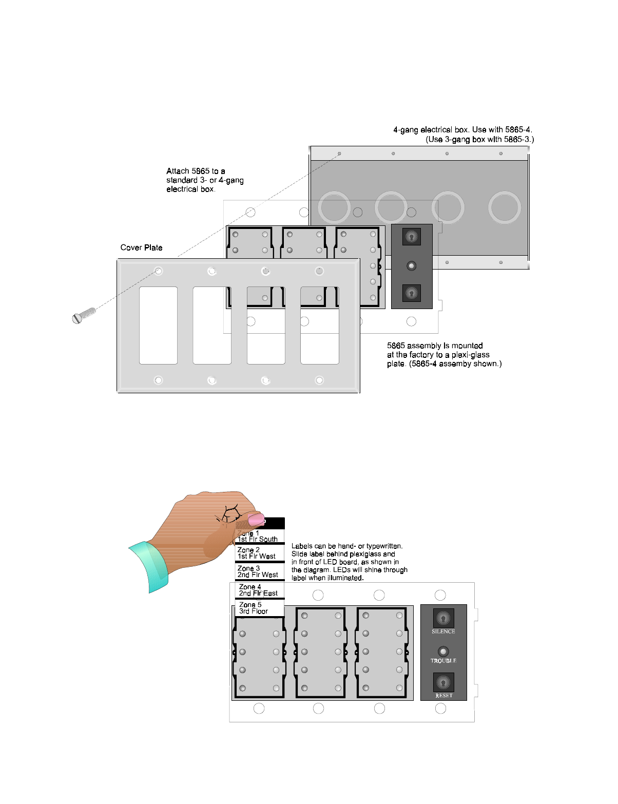
Control Panel Installation
151137 4-27
4.9.2 5865 Mounting
Mount the 5865-4 to a standard 4-gang electrical box. Mount the 5865-3 to a standard 3-gang
electrical box. In Figure 4-26, the 5865-4 attached to a 4-gang box is used as an example.
Figure 4-26 5865 Mounting Example
The 5865 ships with a set of zone description labels that can be inserted into the 5865 board
assembly. These labels can be used in a typewriter or can be written on by hand.
Slide the labels under the plexiglass as shown in Figure 4-27. The LEDs will show through the
label when illuminated.
Figure 4-27 Inserting Zone Description Labels
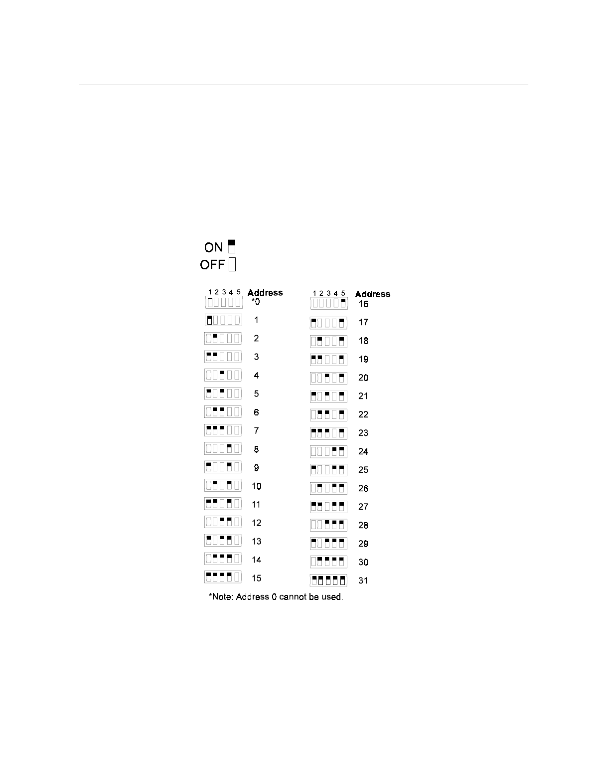
IntelliKnight 5820XL Installation Manual
4-28 151137
4.10 Configuring Modules
This section describes how to configure any system hardware modules that have been added
to the system.
4.10.1 Assigning Module IDs
When installing a hardware module (such as, 5815XL, 5824, 5860, 5895XL, 5865-3 or 5865-
4), you must use the dipswitches on the module to assign an ID# to the module.
Figure 4-28 shows all possible dipswitch positions and their correlation to a numerical ID. For
example, to select ID 2, place dipswitch 2 in the up position.
Figure 4-28 Possible module addresses
Refer to Section 7.1 to edit, add, delete, and view module list.
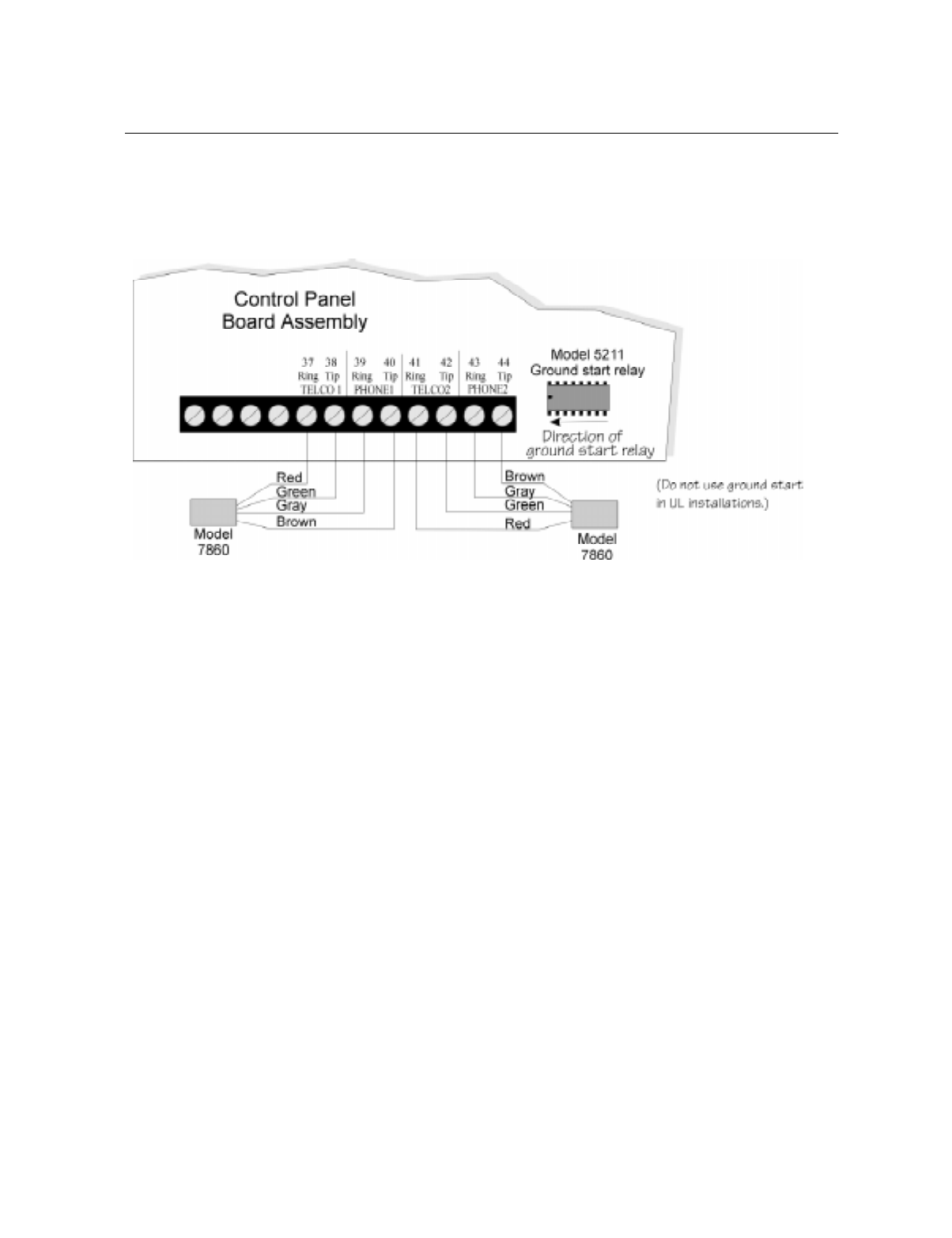
Control Panel Installation
151137 4-29
4.11 Telephone Connection
Connect the telephone lines as shown in Figure 4-29. The Model 7860 phone cord is available
from Silent Knight for this purpose.
A number of programmable options are available for customizing telephone lines. These
options are described in Section 7.5.
Figure 4-29 Connection of Telephone Lines
4.11.1 Ground Start Relay (Model 5211)
Note: Do not use ground start in UL installations.
If you are using the ground start telephone network, you must use the Model 5211 Ground
Start Relay (ordered separately).
1. Install the relay as shown in Figure 4-29.
2. Enable ground start through programming. See Section 7.5.2.6 for instructions.
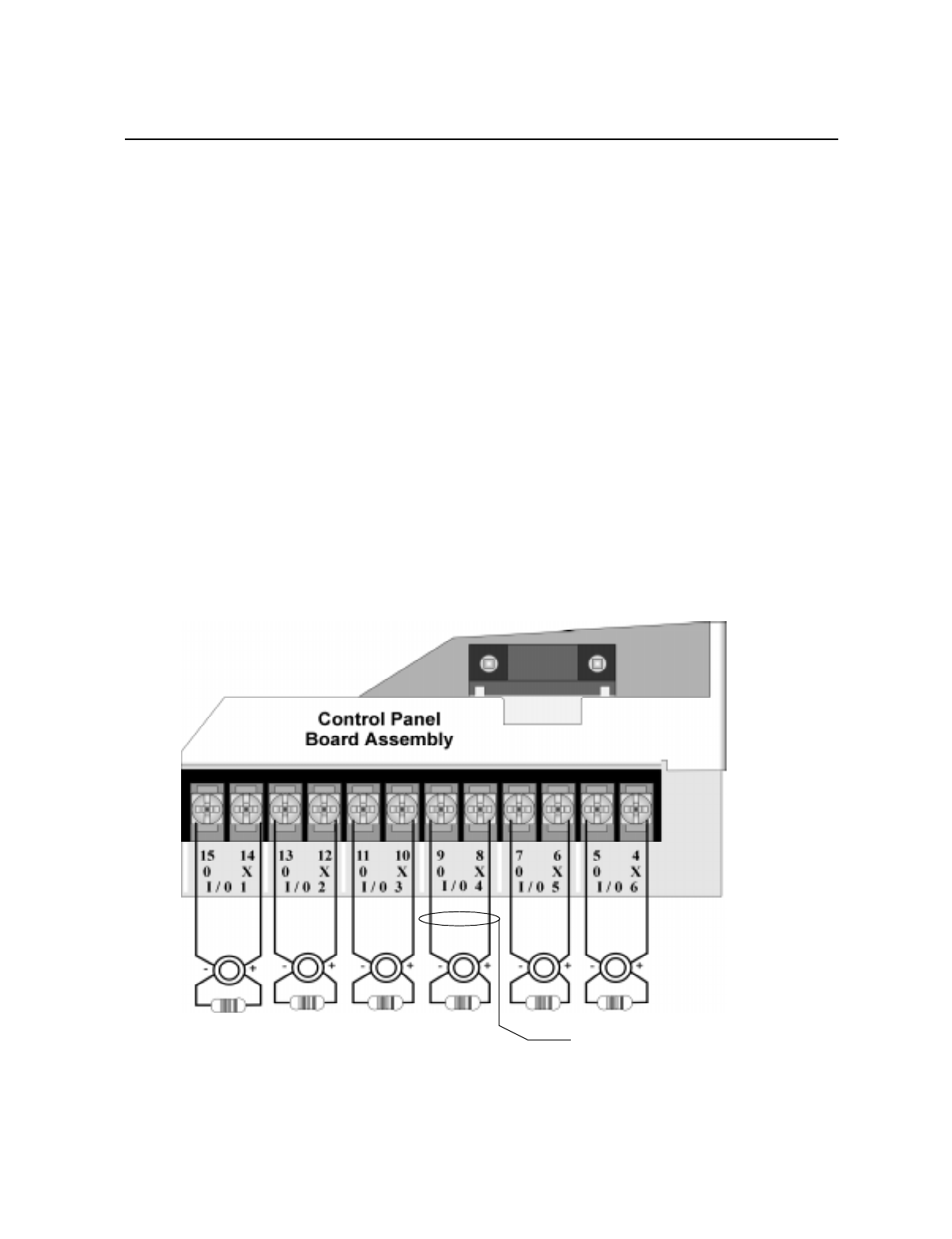
IntelliKnight 5820XL Installation Manual
4-30 151137
4.12 Flexputs™ I/O Circuits
The six Flexput™ circuits are an innovative and versatile feature of the control panel. They
can be used as: Class A or B notification circuits, Class A or B initiation circuits (either 2 or 4
wire detectors), or as auxiliary power (resettable, continuous, or door holder).
This section of the manual explains how to install conventional notification appliances and
initiating devices to be used with the system.
4.12.1 Conventional Notification Appliance
This sub-section of the manual explains how to install conventional notification appliances for
Class A (Style Z) and Class B (Style Y) configurations.
4.12.1.1 Class B Notification Wiring
You must use an appliance from the list of compatible appliances in the Appendix A at the
back of this manual.
To install a Class B notification appliance circuit:
1. Wire Class B Notification appliances as shown in Figure 4-30.
2. Configure the circuit through programming (see Section 7.4).
Figure 4-30 Class B Notification Appliance Circuit Wiring
Alarm Polarity
Shown.
UL Listed EOL
Model 7628
4.7 kΩ
Supervised
Power Limited
Notification Wiring
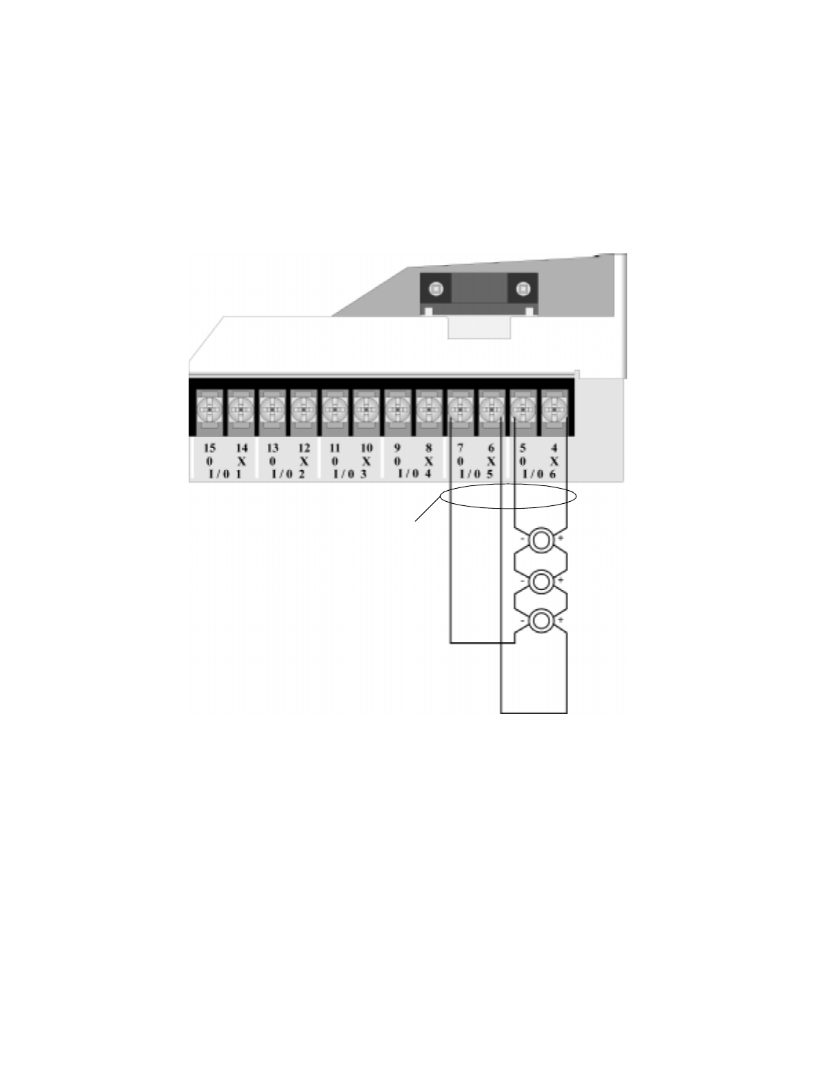
Control Panel Installation
151137 4-31
4.12.1.2 Class A Notification Wiring
You must use an appliance from the list of compatible appliances in the Appendix at the back
of this manual.
To install a Class A notification appliance circuit:
1. Wire the Class A notification appliances as shown in Figure 4-31.
2. Configure the circuit for Class A in programming (see Section 7.4).
Figure 4-31 Class A Notification Appliance Circuit Configuration
Note: In programming any point that uses multiple Flexput circuits, the lowest Flexput circuit number is used to
refer to the circuit pair. For example, Figure 4-31 uses both Flexput circuit 5 and 6, so in programming it
would be referred to as point 5.
Supervised
Power Limited
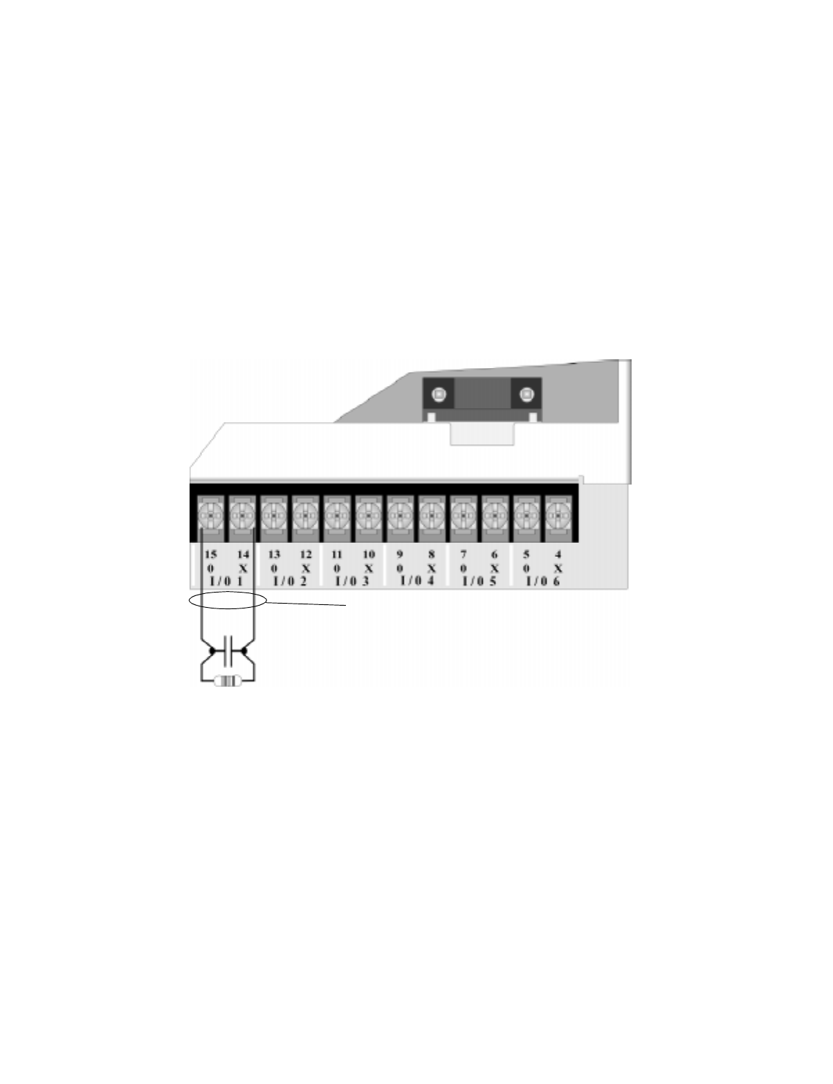
IntelliKnight 5820XL Installation Manual
4-32 151137
4.12.2 Conventional Input Switch Circuits
This section of the manual explains how to install conventional initiating devices for Class A
(Style D) or Class B (Style B) configurations.
4.12.2.1 Class B Inputs
You can connect conventional Class B switches, such as waterflow switches and pull stations,
directly to the Flexput circuits of the control panel.
To install a Class B switch:
1. Wire the Class B switch as shown in Figure 4-32.
2. Configure the circuit through programming (see Section 7.4).
Figure 4-32 Class B Input Switches
UL Listed EOL
Model 7628
4.7 kΩ
Supervised
Power Limited
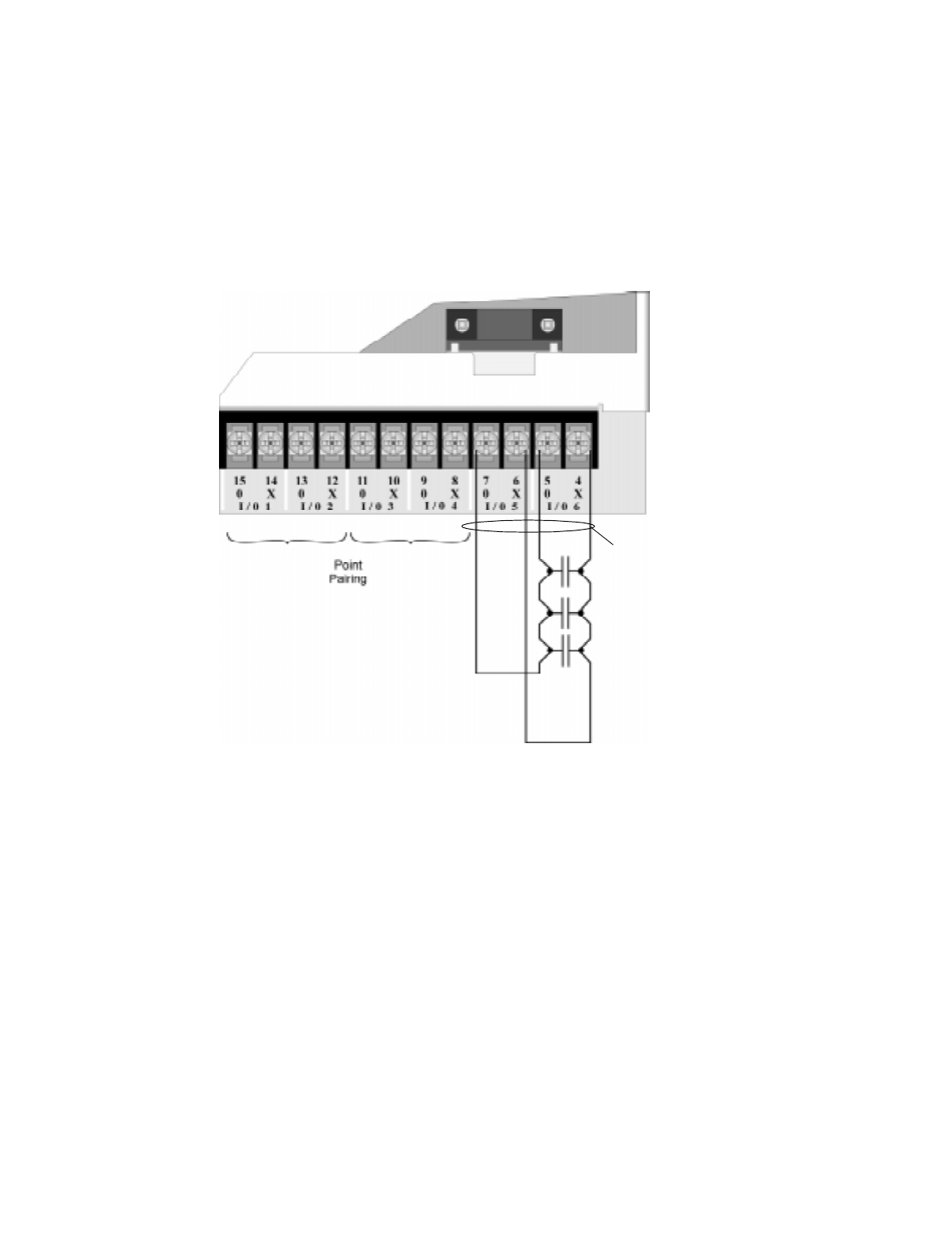
Control Panel Installation
151137 4-33
4.12.2.2 Class A Inputs
You can connect conventional Class A switches, such as waterflow switches and pull stations,
directly to the Flexput circuits of the control panel.
To install a Class A switch:
1. Wire the Class A switch as shown in Figure 4-33.
2. Configure the circuit through programming (see Section 7.4).
Figure 4-33 Class A initiating Switches
Note: In programming any point that uses multiple Flexput circuits, the lowest Flexput circuit number is used to
refer to the circuit pair. For example, Figure 4-33 uses both Flexput circuit 5 and 6, so in programming it
would be referred to as point 5.
Note:
Flexput circuit 5 and 6
used as an example.
Any Flexput point pairing
could be used.
Supervised
Power Limited
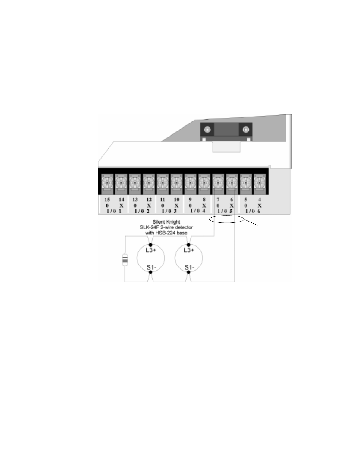
IntelliKnight 5820XL Installation Manual
4-34 151137
4.12.3 Installing 2-Wire Smoke Detectors
Any compatible U.L. listed two-wire smoke detector can be used with the control panel (see
Appendix A for list of compatible smoke detectors). Figure 4-34 and Figure 4-35 illustrate
how to connect a UL listed 2-wire detector to the control panel.
4.12.3.1 Installing 2-Wire Class B Smoke Detectors
To install a Class B two-wire smoke detector, wire as shown in Figure 4-34.
Figure 4-34 Two-Wire Class B Smoke Detector
Note:
Flexput circuit 5
used as an example.
Any Flexput circuit
could be used.
UL Listed EOL
Model 7628
4.7 kΩ
Supervised
Power Limited
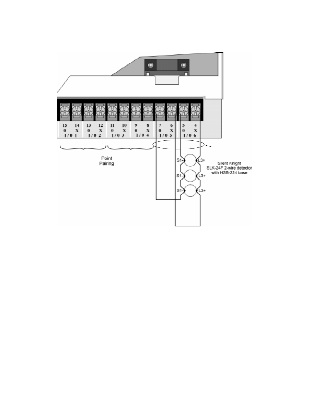
Control Panel Installation
151137 4-35
4.12.3.2 Installing 2-Wire Class A Smoke Detector
To install a Class A two-wire smoke detector, wire as shown in Figure 4-35.
Figure 4-35 Two-Wire Class A Smoke Detector Connections
Note: In programming any point that uses multiple Flexput circuits, the lowest Flexput circuit number is used to
refer to the circuit pair. For example, Figure 4-35 uses both Flexput circuit 5 and 6, so in programming it
would be referred to as point 5.
Note:
Flexput circuit 5 and 6
used as an example.
Any Flexput point pairing
could be used.
Supervised
Power Limited
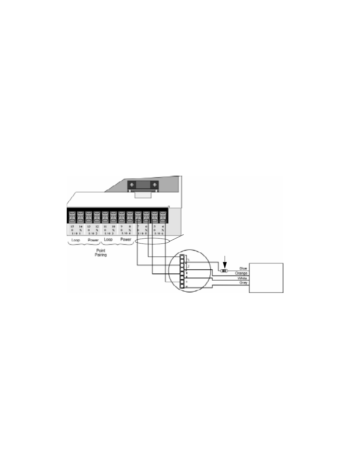
IntelliKnight 5820XL Installation Manual
4-36 151137
4.12.4 Installing 4-Wire Smoke Detectors
Any compatible U.L. listed four-wire smoke detector can be used with the control panel (see
Appendix A for list of compatible smoke detectors). Figure 4-34 and Figure 4-35 illustrate
how to connect a UL listed four-wire detector to the control panel.
4.12.4.1 Installing a Class B 4-Wire Smoke Detector
Figure 4-36 illustrates how to install a 4-wire Class B smoke detector.
Conventions used for wiring 4-wire Class B loops:
1. Up to three Class B 4-wire smoke detector loops can be connected to the control panel at
once.
2. Each Class B loop input is paired with a unique power source as shown in Figure 4-36.
3. Each loop gets smoke power from the even numbered Flexput circuit and the contact input
is connected to the odd numbered Flexput circuit.
Figure 4-36 Class B 4-Wire Smoke Detector Connections
Note: In programming any point that uses multiple Flexput circuits, the lowest Flexput circuit number is used to
refer to the circuit pair. For example, Figure 4-36 uses both Flexput circuit 5 and 6, so in programming it
would be referred to as point 5.
Air Products
PAM-2
Model 160150
Su
p
ervision
Module
UL Listed
EOL Resistor
Model 7628
ESL 449CT
Note:
Flexput circuit 5 and 6
used as an example.
Any Flexput point pairing
could be used.
Supervised
Power Limited
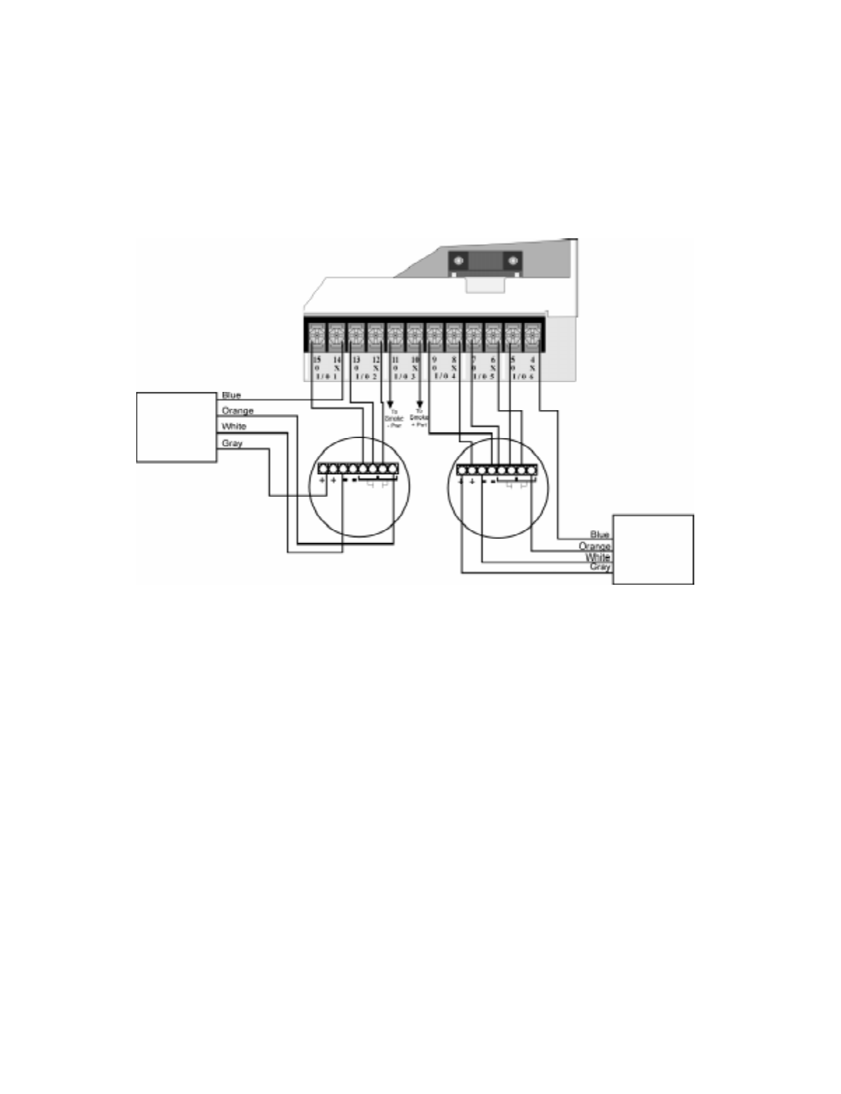
Control Panel Installation
151137 4-37
4.12.4.2 Installing 4-Wire Class A Smoke Detectors
Figure 4-37 illustrates how to install 4-wire Class A detectors.
Conventions used for wiring 4-wire Class A loops:
1. Up to two Class A 4-wire loops can be connected to the control panel at once.
2. Smoke power is supplied to each Class A loop as shown in Figure 4-37.
Figure 4-37 Class A 4-Wire Smoke Detector Connections
Note: In programming any point that uses multiple Flexput circuits are always referred to as the lowest Flexput
circuit number used. For example, Figure 4-37 uses Flexput circuits 1, 2, 3 together and 4, 5, 6 together.
In programming (1, 2, 3) would be referred to as point 1, and (4, 5, 6) would be referred to as point 4.
Air Products
PAM-2
Model 160150
Supervision
Module
Air Products
PAM-2
Model 160150
Supervision
Module
Supervised
Power Limited
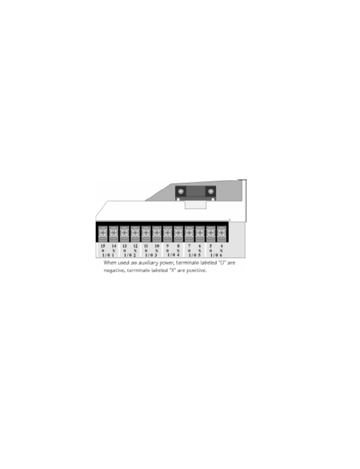
IntelliKnight 5820XL Installation Manual
4-38 151137
4.12.5 Auxiliary Power Installation
Flexput Circuits 1-6 on the control panel can be used as auxiliary power circuits (see also
Section 5.9.5). The three types of auxiliary power available are:
• Door Holder (see section 4.12.5.1)
• Constant (see section 4.12.5.2)
• Resettable Power (see section 4.12.5.3)
Auxiliary power circuits are power limited. Each circuit can source up to 3A (total current for
all Flexput circuits must not exceed 5A).
To install an auxiliary power circuit:
1. Wire the Flexput circuit(s) that will be used for auxiliary power. See Figure 4-38 for loca-
tion of Flexput circuits.
2. Configure the auxiliary power output through programming (see section 7.4).
Figure 4-38 Flexput Circuit Location
4.12.5.1 Door Holder Power
Door holder power is intended for fire door applications. When there are no alarms in the
system and the panel has AC power, door holder circuits have 24-volt power present at their
terminals. Any alarm will cause power to disconnect. Power will be re-applied when the
system is reset. If AC power is off for more than 15 seconds, the auxiliary door holder power
will be disconnected to conserve the battery backup. When AC power is restored, power is
immediately restored to the door holder circuits.
Use a UL listed door holder ESL DHX-1224, for this application.
4.12.5.2 Constant Power
Use constant power for applications that require a constant auxiliary power source. Power is
always present at Constant circuits.

Control Panel Installation
151137 4-39
4.12.5.3 Resettable Power
Resettable power is typically used to power beam detectors, flame detectors and conventional
4-wire smoke detectors. For circuits selected as Resettable, 24-volt power is always present at
the terminals unless a system reset occurs. If a system reset occurs, power is disconnected
from the terminals for 30 seconds, then re-applied.
4.13 On-Board Relays (Conventional)
The control panel has two built-in programmable relays and a built-in trouble relay. All relays
are Form C rated at 2.5 A @ 24 VDC.
Figure 4-39 Location of Conventional Relay Circuits
4.13.1 Trouble Relay
The control panel has a dedicated Form C trouble relay built into terminals 30-32. The relay
provides a normally open and a normally closed contact. The trouble relay will deactivate
under any trouble condition.
Note: The N.C. contact is the relay contact that is closed when the panel has power and there are no trouble con-
ditions.
4.13.2 Programmable Relays
The control panel has two Form C programmable relays built into terminals 24-29. Each relay
provides a normally open and a normally closed contact.
To install one or two programmable relays, follow these steps.
1. Wire Relay 1 and/or Relay 2 as needed for your application. See Figure 4-39 for the loca-
tion of the relay terminals.
2. Configure the relay through programming (see section 7.4).
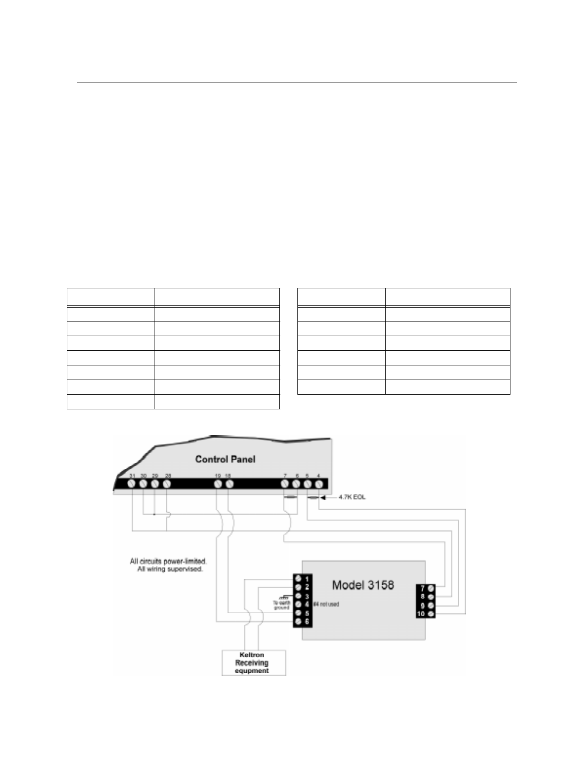
IntelliKnight 5820XL Installation Manual
4-40 151137
4.14 Keltron Model 3158 Installation
The control panel is compatible with Keltron Model 3158, used for direct connection to a
Keltron receiver. The 3158 reports alarms, supervisories, and troubles.
The steps for connecting the 3158 to the control panel. Refer to the 3158 installation
instructions for complete information.
1. Wire the 3158 to the control panel as shown in the connection list and Figure 4-40.
2. Wire the 3158 within 20 feet of the control panel. Wiring must be enclosed in conduit.
3. Program control panel Relay 1 for alarm.
4. Program Flexput circuit 5 for alarm.
5. Program Flexput circuit 6 for supervisory.
Figure 4-40 Keltron 3158 Connection to Control Panel
Table 4-3: Keltron 3158 to Control Panel Connections
Terminal # Connects To Terminal # Connects To
3158 Term. 1 To Keltron receiving equipment 3158 Term. 8 Control panel Term. 28
3158 Term. 2 To Keltron receiving equipment 3158 Term. 9 Control panel Term. 5
3158 Term. 3 Earth ground 3158 Term. 10 Control panel Term. 4
3158 Term. 4 Not used; no connection. Control panel Term. 6 Control panel Term. 29
3158 Term. 5 Control panel Term. 18 Control panel Term. 28 Control panel Term. 31
3158 Term. 6 Control panel Term. 19 Control panel Term. 29 Control panel Term. 30
3158 Term. 7 Control panel Term. 7
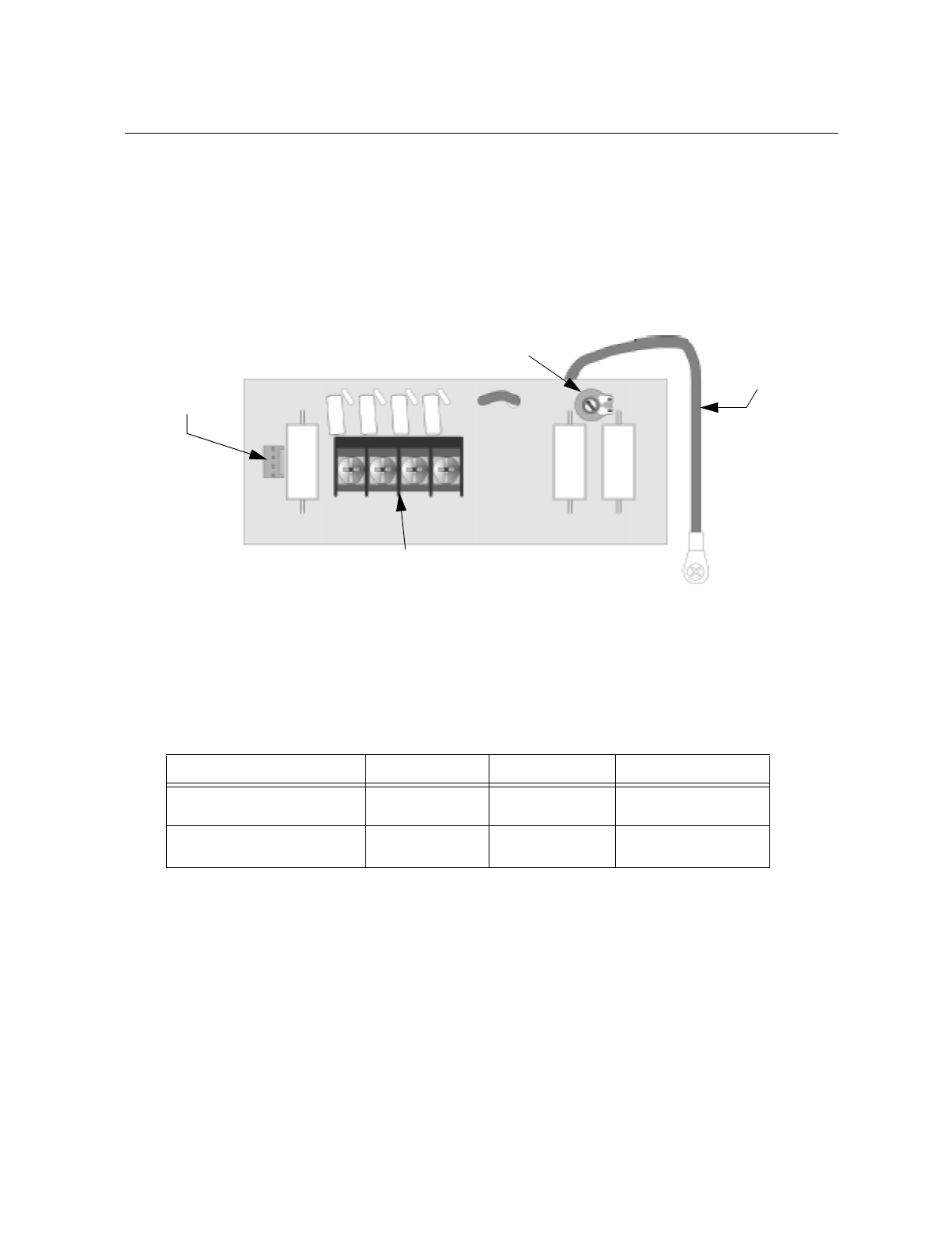
Control Panel Installation
151137 4-41
4.15 Model 5220 Direct Connect Module
The 5220 Direct Connect Module can be used with the control panel to meet NFPA 72
standards. The 5220 requires four connections to the control panel and provides outputs for
city box and polarity reversal applications. The 5220 cannot be used for sprinkler supervisory.
The 5220 provides a current that reverses polarity during an alarm or removes current during a
trouble condition.
Figure 4-41 Shows the specific components of the 5220 module which will be used for
installation.
Figure 4-41 5220 Components
4.15.1 5220 Electrical Specifications
T shows the electrical specifications for the 5220 for different wiring configurations.
* Notification supervision current accounted for in control panel draw.
Table 4-4: 5220 Electrical Specifications
Wiring Configuration Standby Current Alarm Current Comment
City Box *0 1 Amp for 1 second See Section 4.15.2 for
wiring diagram.
Polarity Reversal 100 mA 100 mA See Section 4.15.3 for
wiring diagram.
R10 Earth
Ground
4-Pin
Connector
For Cable
(P/N 130294)
Terminal Block
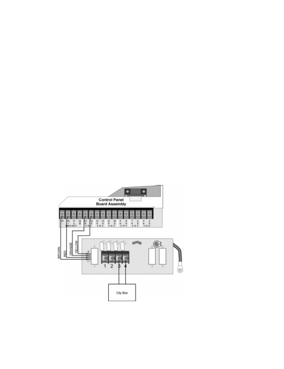
IntelliKnight 5820XL Installation Manual
4-42 151137
4.15.2 City Box Connection
This section describes how to connect the control panel to a municipal fire alarm box or “city
box” as required by NFPA 72 Auxiliary Protected Fire Alarm systems for fire alarm service.
The city (master) box is an enclosure that contains a manually operated transmitter used to
send an alarm to the municipal communication center which houses the central operating part
of the fire alarm system.
The maximum coil and wire resistance (combined) must not exceed 30 ohms.
To install the 5220 for city box connection:
1. Use one of the knockouts on the right side of the control panel to connect the 5220 using a
short piece of conduit (must not exceed 20 feet in length).
2. Wire the 5220 to the control panel as shown in Figure 4-42. This drawing also shows how
to connect the city box coil to terminals 3 and 4 on the 5220. Do not install an EOL resis-
tor in the terminals of the Flexput circuit used for this application.
3. Connect earth ground wire to the 5220 chassis with mounting screw.
4. Program the Flexput circuit used as a notification circuit, continuous and non-silencing.
Refer to Section 7.4.1 for zone grouping and mapping.
It is not possible to reset the remote indication until you clear the condition and reset the
control panel.
Figure 4-42 City Box Connection
Note:
Flexput Circuit 1 Used
as an example.
Any Flexput circuit
could be used.
All circuits power-limited.
All wiring supervised.
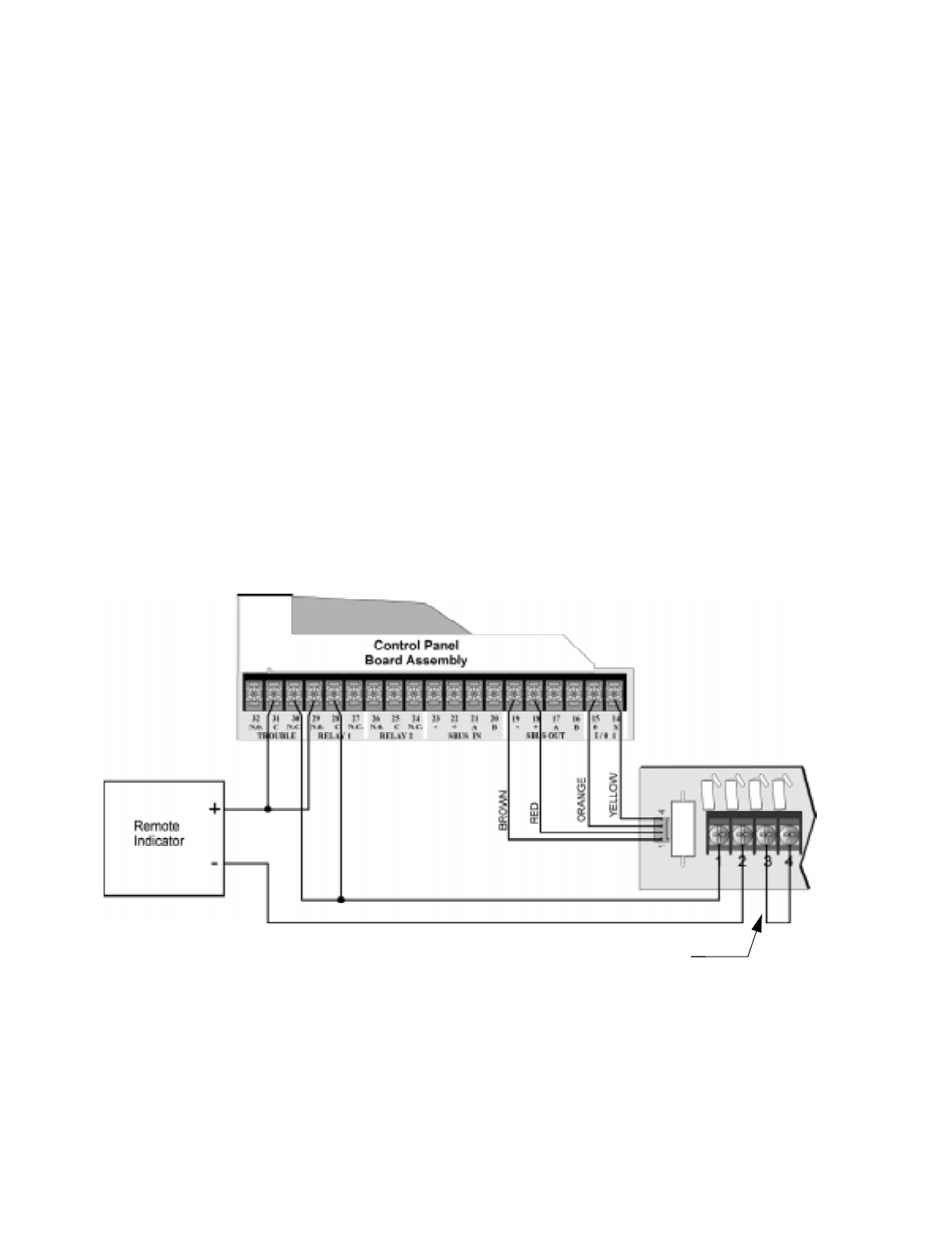
Control Panel Installation
151137 4-43
4.15.3 NFPA 72 Polarity Reversal
When the 5220 is wired and programmed for polarity reversal, it reports alarm and trouble
events to a remote site. Alarms will override trouble conditions and it will not be possible to
reset the remote indicator until the condition is cleared and the control panel is reset.
If an alarm condition occurs, the alarm relay will close, overriding the trouble condition.
To install the 5220 for polarity reversal, follow the steps below:
1. Locate the knockout on the right side of the control panel cabinet to connect the 5220
using a short piece of conduit (must not exceed 20 feet in length).
2. Wire the 5220 to the control panel using the four-wire pigtail provided as shown in Figure
4-43. This diagram also shows how to connect the 5220 to the remote indicator. Do not
install an EOL resistor in the terminals of the Flexput circuit used for this application.
3. Connect earth ground wire to the 5220 chassis with mounting screw.
4. Program the Flexput circuit used as a notification circuit, continuous and non-silencing.
Refer to Section 7.4.1 for zone grouping and mapping.
5. If necessary, adjust loop current using the potentiometer (R10) on the 5220 board (see Fig-
ure 4-41). Normal loop current is 2-to-8 mA with a 1k ohm remote station receiving unit.
Maximum loop resistance is 3k ohm.
Figure 4-43 Polarity Reversal Connection
All circuits power-limited.
All wiring supervised.
Note:
Flexput circuit 1 and Relay 1
used as examples. Any
Flexput circuit and either
relay 1 or relay 2 could
be used.
Jumper these terminals
when City Box is not used.

IntelliKnight 5820XL Installation Manual
4-44 151137

151137 5-1
Section 5
SLC Device Installation
5.1 Types of SLC Devices
The following types of SLC devices can be used with the system.
• *Model SD500-AIM Input Module (switch input), standard size, dipswitch configurable
• *Model SD500-MIM Mini Input Monitor Module (switch input), small size, dipswitch
configurable. Fits in single-gang box with manual pull station switch.
• *Model SD500ARM Addressable Relay Module, dipswitch configurable
• Model SD505-AHS Heat Sensor
• Model SD505-AIS Ionization Smoke Detector
• Model SD505-APS Photoelectric Smoke Detector
• Model SD505-ADH Duct Housing (used with SD505-AIS or SD505-APS smoke detec-
tors)
• Model SD500-ANM Addressable Notification Module
* Indicates replacement for earlier model. SD500-AIM replaces SD500-FRCM-4; SD500-MIM replaces
SD500-FRCM; SD500-ARM replaces SD505-ARM. Earlier models are compatible with the panel but are no
longer manufactured by Silent Knight. Contact Silent Knight if you need information about these models.
5.2 Maximum Number of Devices
A total of 381 analog addressable devices can be used with the system. 127 devices can be
attached to the main system. The optional Model 5815XL SLC Expander can add another 127
devices. Up to two 5815XLs can be added to the main system to achieve the 381 point
capacity.
Caution
To avoid the risk of electrical shock and damage to the unit, power should be OFF at the control panel while
installing or servicing.
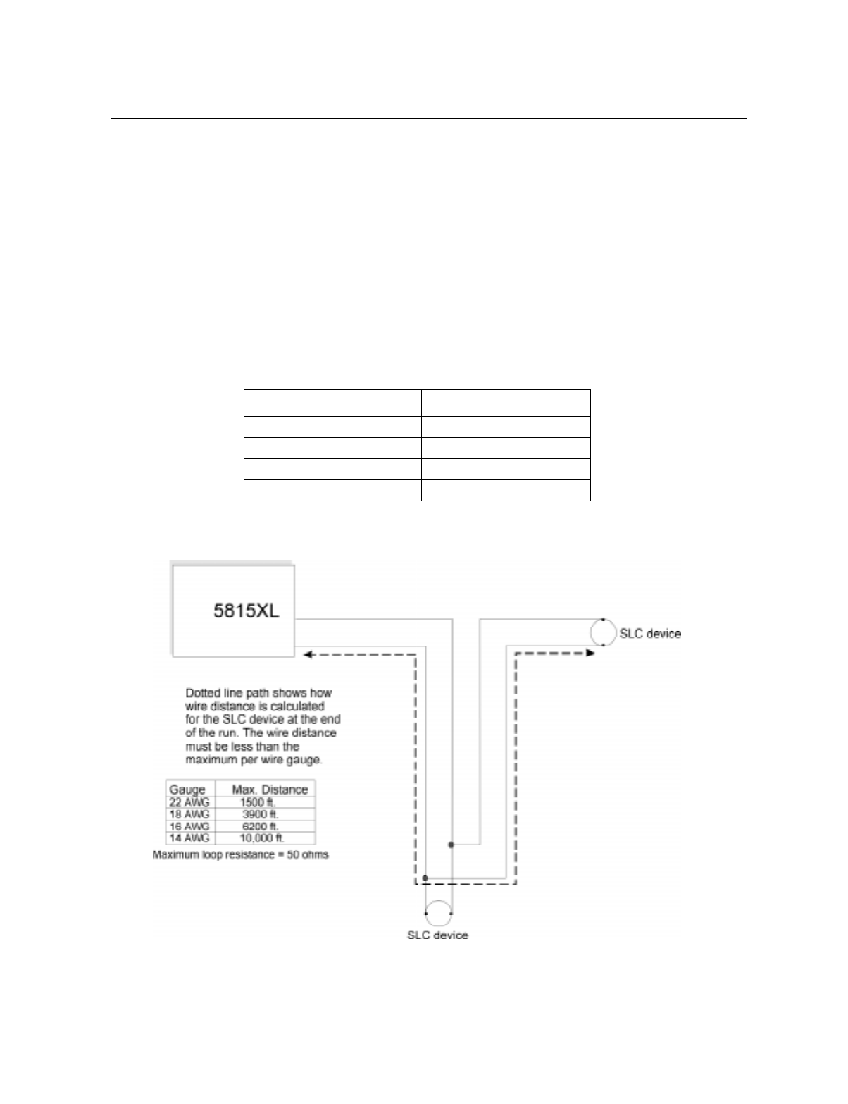
IntelliKnight 5820XL Installation Manual
5-2 151137
5.3 Wiring Requirements for SLC Devices
The following information applies to all SLC devices. Refer to the section that describes the
type of device you are installing for details.
5.3.1 Wiring 5815XL in Style 4 (Class B) Configuration
No special wire is required for addressable loops. The wire can be untwisted, unshielded, solid
or stranded as long as it meets the National Electric Code 760-51 requirements for power
limited fire protective signaling cables.
Maximum wiring resistance is 50 ohms.
Maximum loop length depends on the wire gauge.
Figure 5-1 and Figure 5-2 show how wire length is determined for out-and-back tap and T-tap
style wiring.
Figure 5-1 Calculating wire run length for a simple out and back tap
Wire Gauge Max. Distance
22 AWG 1500 feet
18 AWG 3900 feet
16 AWG 6200 feet
14 AWG 10,000 feet
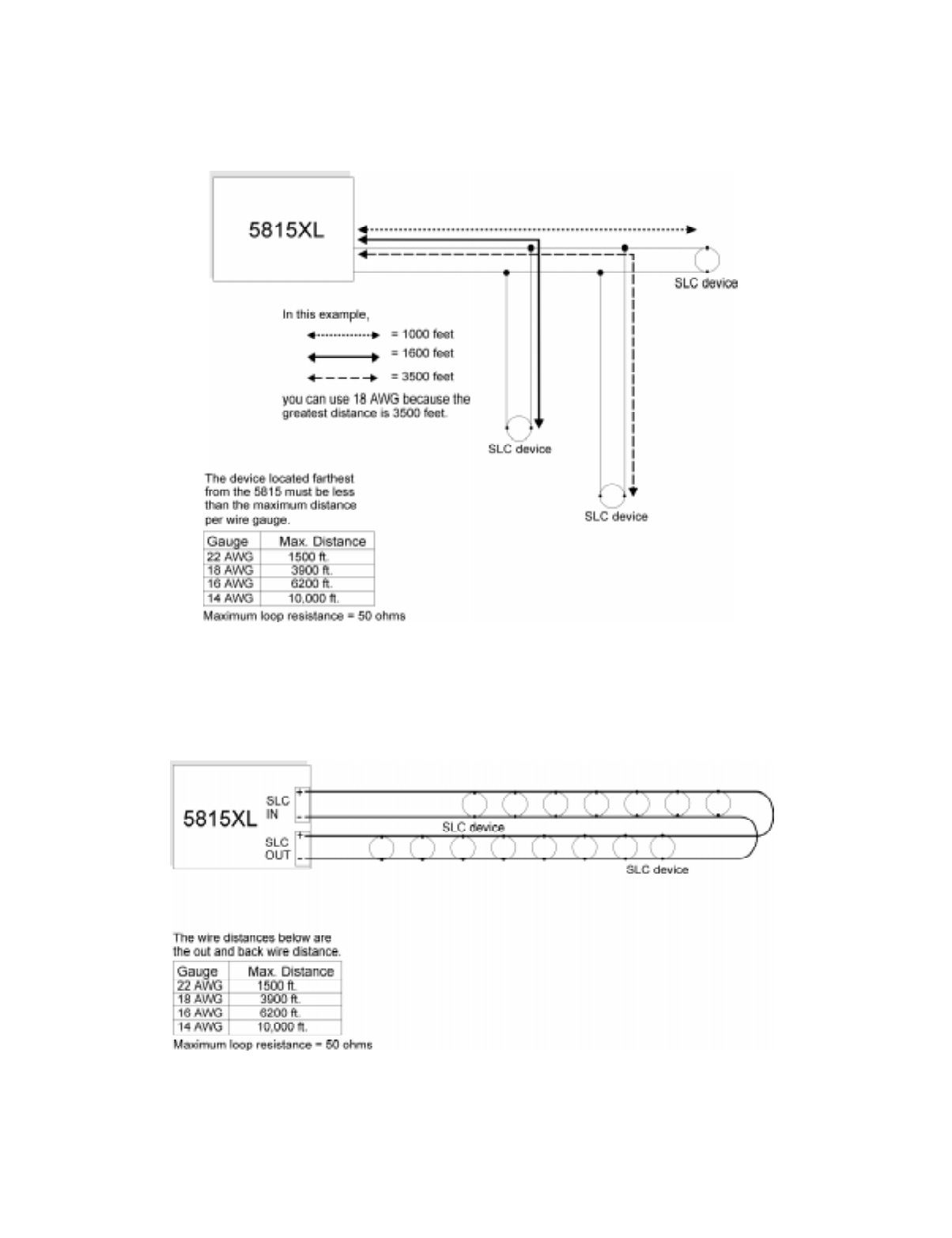
SLC Device Installation
151137 5-3
When using T-taps, the total length of all taps and the main bus must not exceed 40,000 feet.
This requirement must be met in addition to the maximum distance requirements for the
various wire gauges.
Figure 5-2 Calculating Wire Run Length for a T-tap
5.3.2 Wiring 5815XL in Style 6 (Class A) Configuration
F illustrates how to wire the SLC loop for class A installations.
Figure 5-3 Class A SLC Configuration
Note: No t-taps allowed on class A SLC loops.
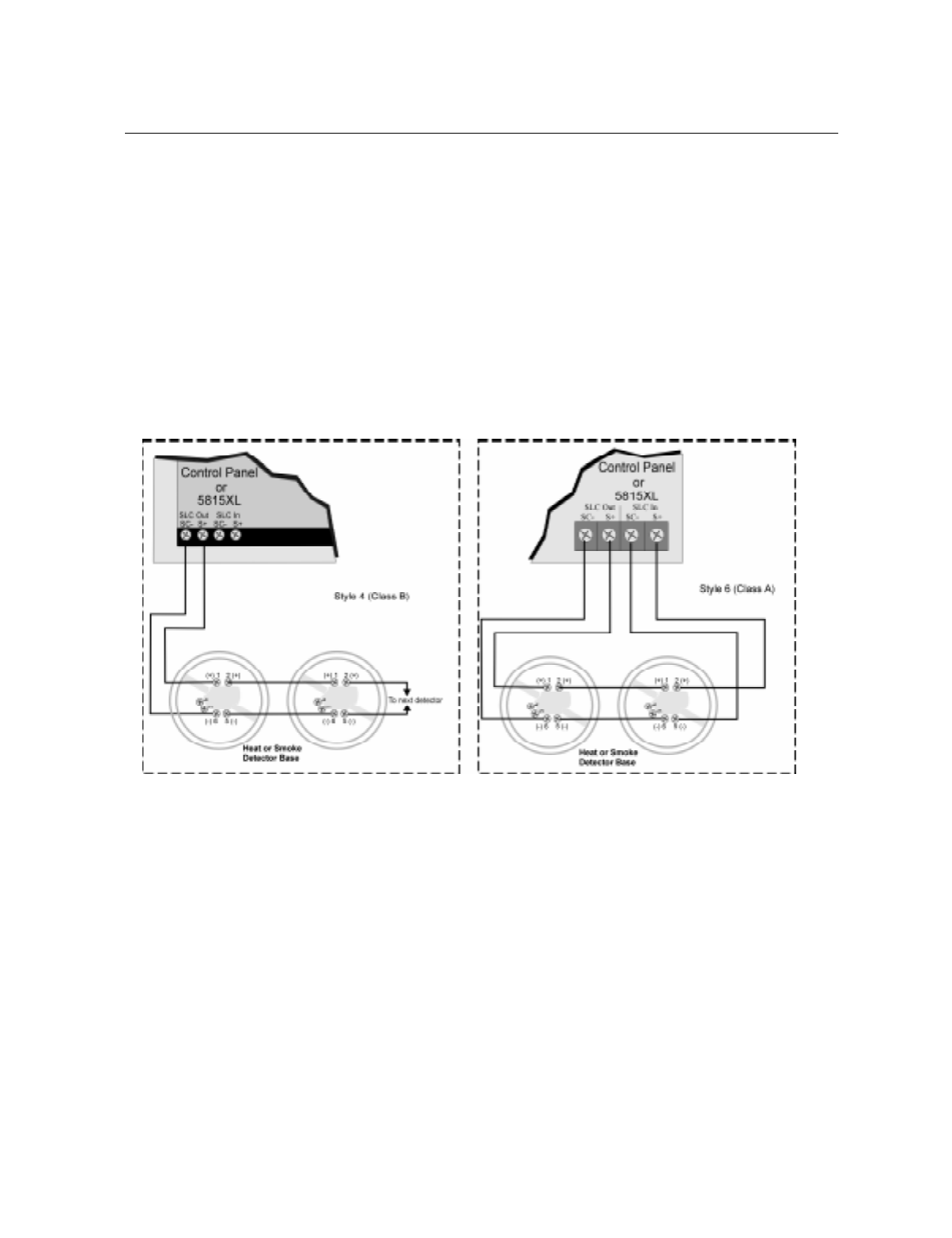
IntelliKnight 5820XL Installation Manual
5-4 151137
5.4 Heat and Smoke Detector Installation
The information in this section applies to the following models: SD505-AHS Heat Detector,
SD505-AIS Ionization Smoke Detector, and SD505-APS Photoelectric Smoke Detector.
See also Section 5.10 for information on how to address the detectors.
5.4.1 Wiring
1. Wire device bases as shown in Figure 5-4.
2. Set the address for each device as described in Section 5.10.
3. If you are connecting to the main panel, do not connect any devices to terminals 35 and
36. If you are connecting to a 5815XL, do not connect any devices to “SLC IN”.
Figure 5-4 Heat or Smoke Detector Connection to the FACP (Class B)
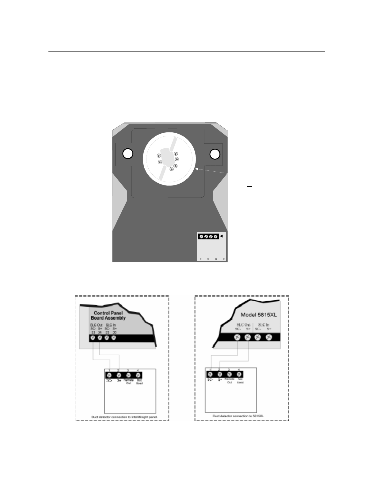
SLC Device Installation
151137 5-5
5.5 Duct Detector Installation
Figure 5-5 shows the layout of the SD505-ADH duct housing with a detector base in place,
including location of the terminals for connection to the FACP. Figure 5-6 shows wiring in
detail.
Address the detector head before attaching it to the base. This procedure is explained in
Section 5.10.
Figure 5-5 Model SD505-ADH Internal View Showing Connector Locations
Figure 5-6 Duct Detector Connection to the Control Panel
Terminals on detector
base are for SLC loop
connection. Make loop
connections below.
not
Exhaust Tube Inlet Tube
Connect tubes at back of housing.
1
2
5
6
3
4
Connect to
SLC loop.
See Fig. 5
for wiring details.
Pre-wired connections
t
o
duc
t
de
t
ec
t
o
r
base
.
1234
Detector Base
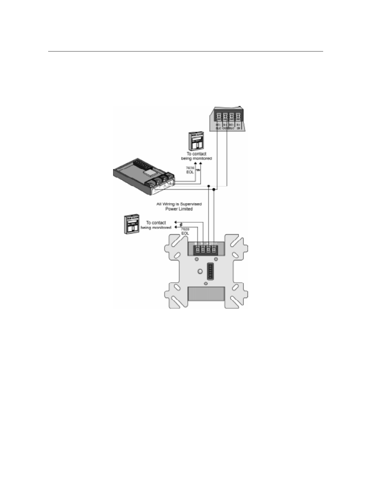
IntelliKnight 5820XL Installation Manual
5-6 151137
5.6 Input Monitor Module (SD500-AIM)
Wire and mount the SD500-AIM full-size input module as described in this section (see
Figure 5-7 and Figure 5-8). See Section 5.10.2 for information on how to use the on-board
dipswitch to select an address for the module.
Wire the monitor modules to the panel or to the 5815XL as shown in Figure 5-7.
Figure 5-7 SD500-AIM/MIM Input Module Connection to the FACP (Class B)
Control
or
5815XL
SD500-AIM
SD500-MIM
Panel
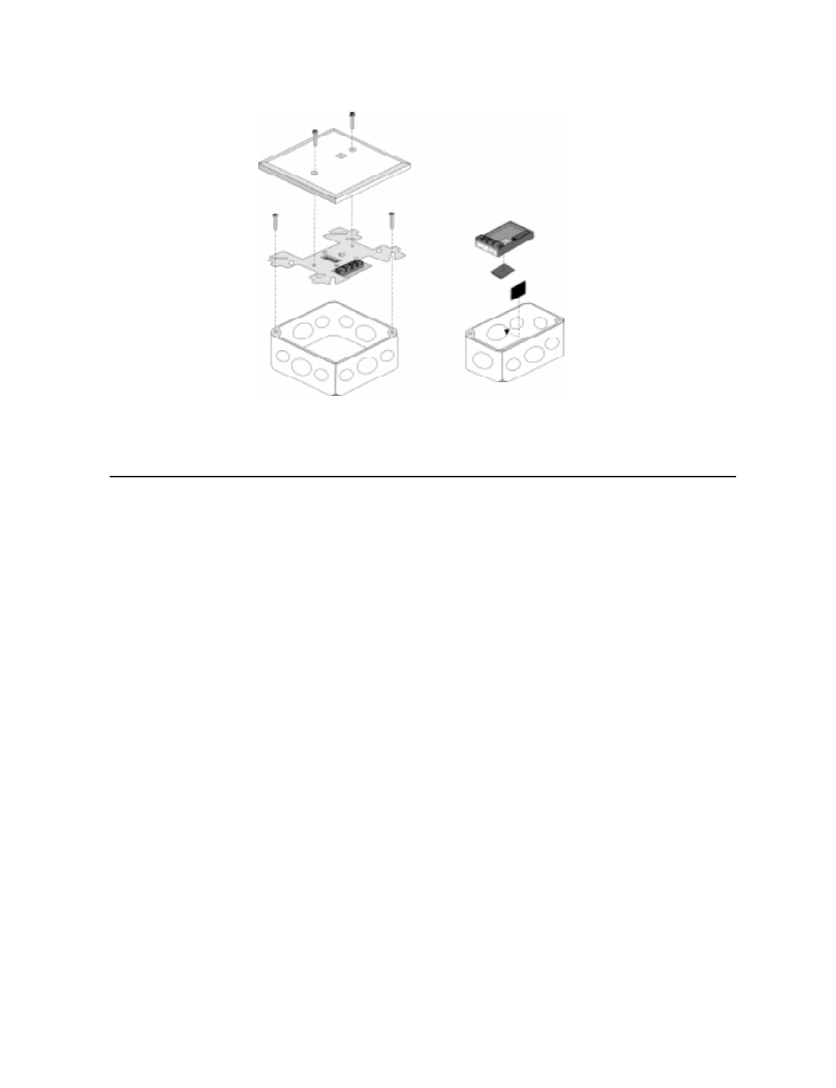
SLC Device Installation
151137 5-7
Figure 5-8 SD500-AIM/MIM Input Module Mounting Example
5.7 Mini Input Module (SD500-MIM)
Wire the SD500-MIM Mini Input Module as shown in this section (see Figure 5-7 and Figure
5-8). The SD500-MIM fits inside a single-gang electrical box. See Section 5.10.2 for
information on using the on-board dipswitch to select an address for the module.
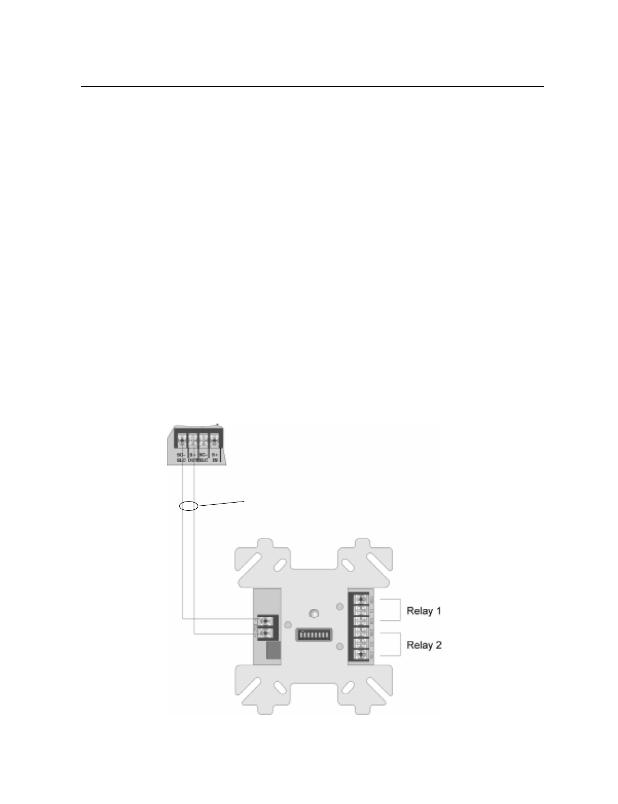
IntelliKnight 5820XL Installation Manual
5-8 151137
5.8 Relay Module Installation
The information in this section applies to Model SD500-ARM Relay Modules. See Section
5.10.2 for information on how to use the on-board dipswitch to select an address for the
module.
5.8.1 Electrical Specifications
The following is electrical rating information for SD500-ARM relay modules.
Relay Ratings
30 VDC @ 2.0 A Resistive
30 VDC @ 1.0 A Inductive (.6PF)
30 VDC @ 0.6 A (0.35PF) Pilot Duty—Light duty low voltage S.W.
120 VAC @ 0.6 A (0.35PF) Pilot Duty
Connect to power limited sources only.
Note: PF = Power Factor.
5.8.2 Wiring
Wire relay modules to the panel or to the 5815XL as shown in Figure 5-9.
Figure 5-9 Relay Module Connection to the FACP (Class B)
Control Panel
or
5815XL
SD500-ARM
Supervised
Power Limited

SLC Device Installation
151137 5-9
5.9 SD500-ANM Installation Instructions
The SD500-ANM (Addressable Notification Module) is an output accessory module for the
Control Panel, which provides one reverse polarity supervised notification appliance circuit.
The notification circuit can be configured in either Class A (Style Z) or Class B (Style Y).
5.9.1 SD500-ANM Specification
Table 5-1 list the electrical, physical and environmental specifications of the SD500-ANM.
Note: When calculating standby and alarm current with SD500-ANMs there are three components to the current
draw work sheet of Table 3-2. The first component is that each SD500-ANM counts as one SLC addressable
device for standby and alarm (0.55 mA). The second component is that each SD500-ANM has a 6 mA stand-
by and 56 mA alarm current draw to be included under the auxiliary devices category. The third component
is that all notification appliances used with the SD500-ANM must be included under the notification appli-
ances category.
Table 5-1: SD500-ANM Specs
Specification Parameter Rating
Operating Temperature: 32° - 120° F
(0° - 49° C)
Dimensions:
Length: 4-7/8”
Width: 4-7/8”
Depth: 7/8”
Operating Voltage: 24 VDC
Auxiliary Power
Circuit Current:
Alarm: 56 mA
Standby: 6 mA
Notification Appliance Current: 2 A max.
SLC Current: .55 mA
Max. SLC Loop Resistance: 50 Ω
For indoor use only

IntelliKnight 5820XL Installation Manual
5-10 151137
5.9.2 Wiring the SD500-ANM
Note: Installation and wiring of this device must be done in accordance with NFPA 72 and local ordinances.
5.9.2.1 Wiring the SD500-ANM to the 5815XL
The SD500-ANM connection for the 5815XL internal and external are the same. Wire as
shown in Figure 5-10.
Figure 5-10 : SD500-ANM Connections to the 5815XL
5.9.3 Class B Notification Configuration
Wire Class B notification appliance circuits to the SD500-ANM as shown in Figure 5-11.
Figure 5-11 : SD500-ANM Class B Notification Wiring
Supervised
Power Limited
Supervised
Power Limited
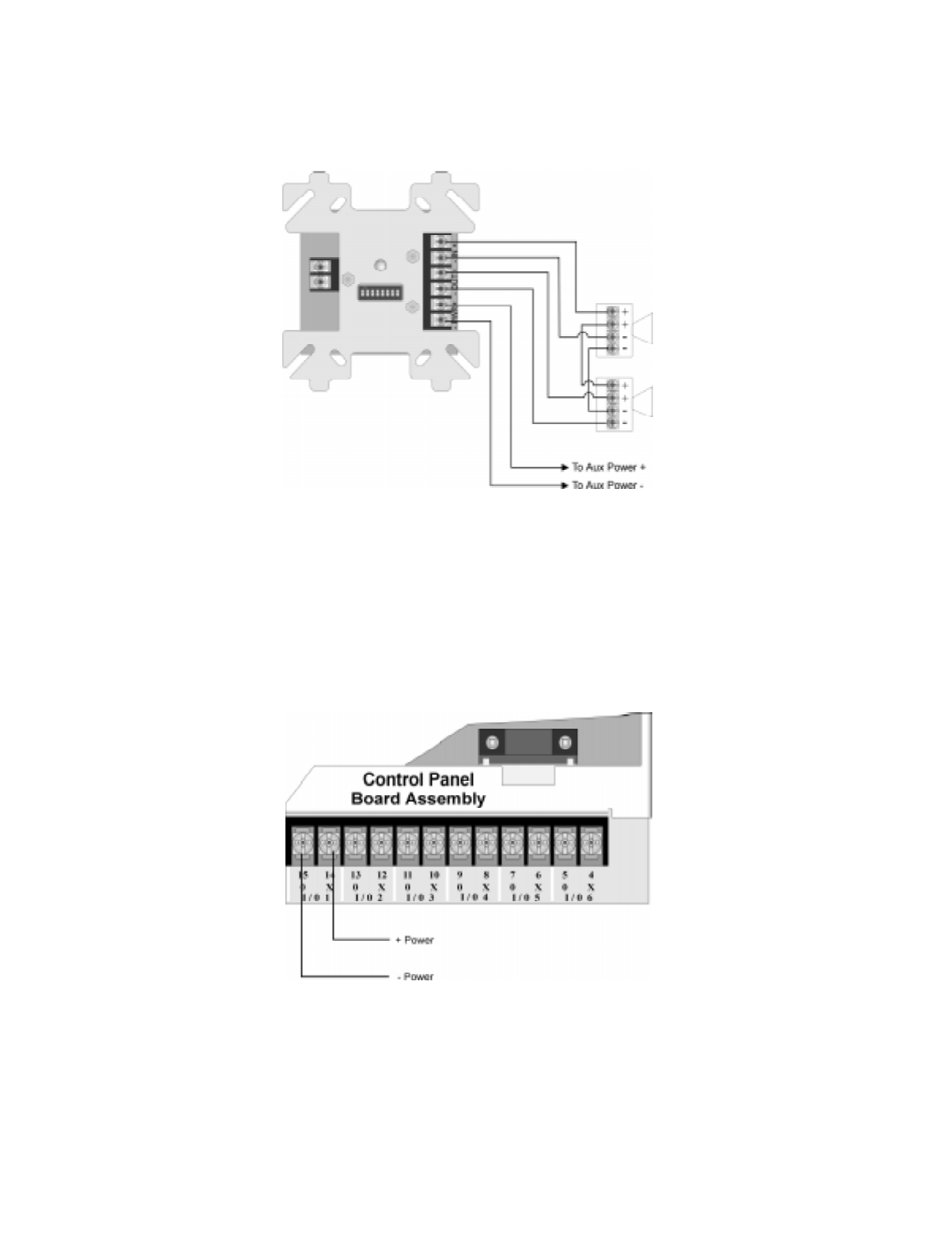
SLC Device Installation
151137 5-11
5.9.4 Class A Notification Configuration
Wire Class A notification appliance circuits to the SD500-ANM as shown in Figure 5-12.
Figure 5-12 : SD500-ANM Class A Notification Wiring
5.9.5 Configuring Flexput™ Circuits for Auxiliary Power
Follow these steps to configure an Flexput circuit for aux power to be used with the
SD500-ANM:
1. Wire the PWR terminals of the SD500-ANM to the Flexput terminals using “X” terminals
as positive and “O” terminals as negative power. See Figure 5-13.
Figure 5-13 : Flexput Auxiliary Power Output
2. Configure the auxiliary power output for constant output through programming (see Sec-
tion 7.4).
Supervised
Power Limited
Power Limited
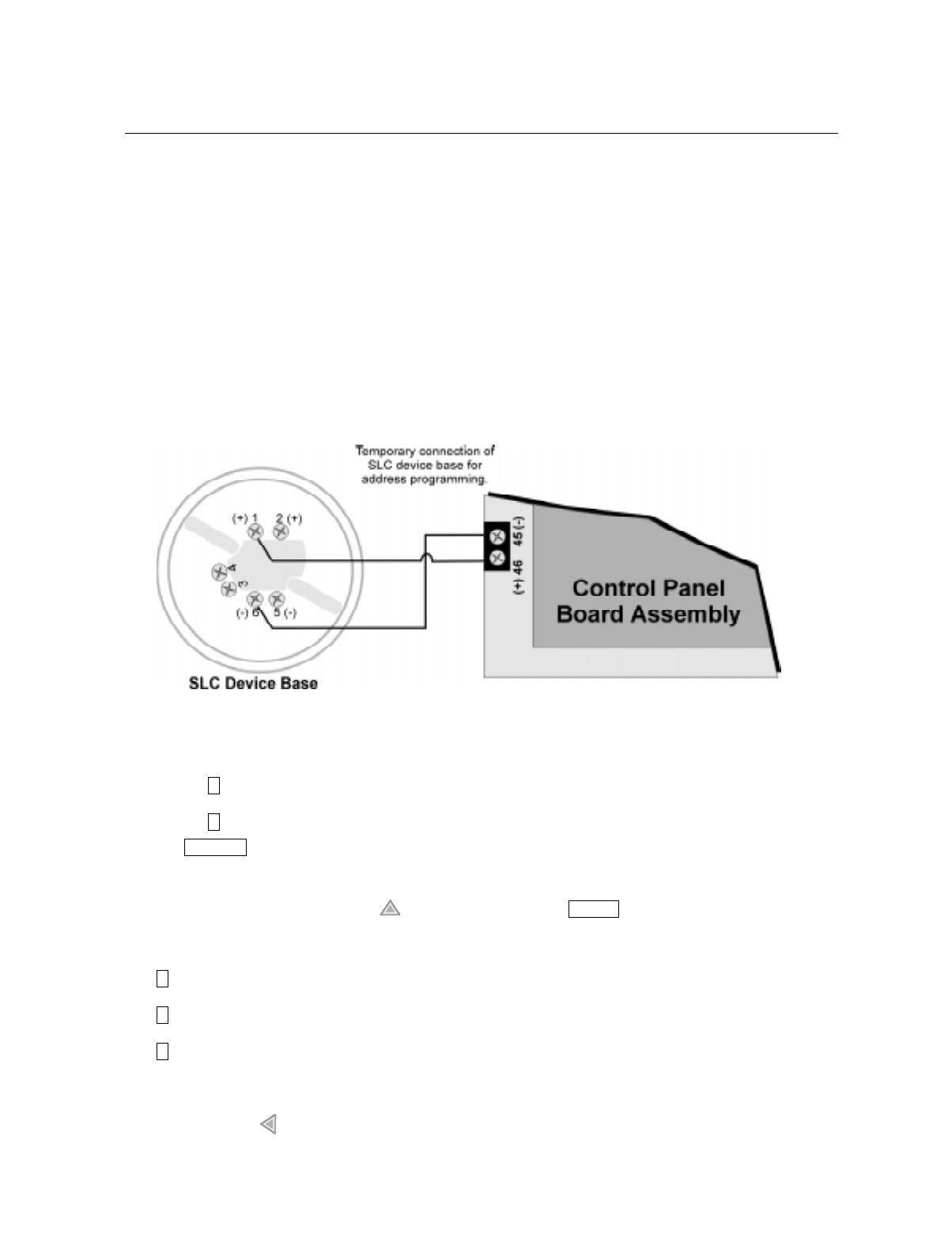
IntelliKnight 5820XL Installation Manual
5-12 151137
5.10 SLC Device Addressing
5.10.1 EEPROM Addressing
Select addresses for the following models through software as described here:
• Model SD505-AHS Heat Detector
• Model SD505-APS Photoelectric Smoke Detector
• Model SD505-AIS Ionization Smoke Sensor
You must use the Installer Code to perform this task. Here are the steps.
1. Connect a detector base temporarily to the programming terminals as shown in Figure
5-14. (You can use the same base for each detector.)
Figure 5-14 Temporary of Detector Base to Panel for Addressing
2. Enter the Installer code.
3. Select for Point Functions.
4. Select for Set SLC Dev Addr. (The panel will go into trouble at this point. You can use
the key to stop the PZT. The trouble will clear automatically when the panel rein-
itializes when you finish programming.)
5. Select “Yes” by pressing the up arrow, then press .
6. When the wait message clears, the following options display:
for Read Address. Use to read (or check) a single detector’s address.
for Write Address. Use to program a single detector’s address.
for Seq. Programming. Use to program more than one detector in sequential order.
7. If you are changing addresses, write the programmed address on the back of the device.
8. To exit press left arrow until fully exited.
2
3
SILENCE
ENTER
1
2
3
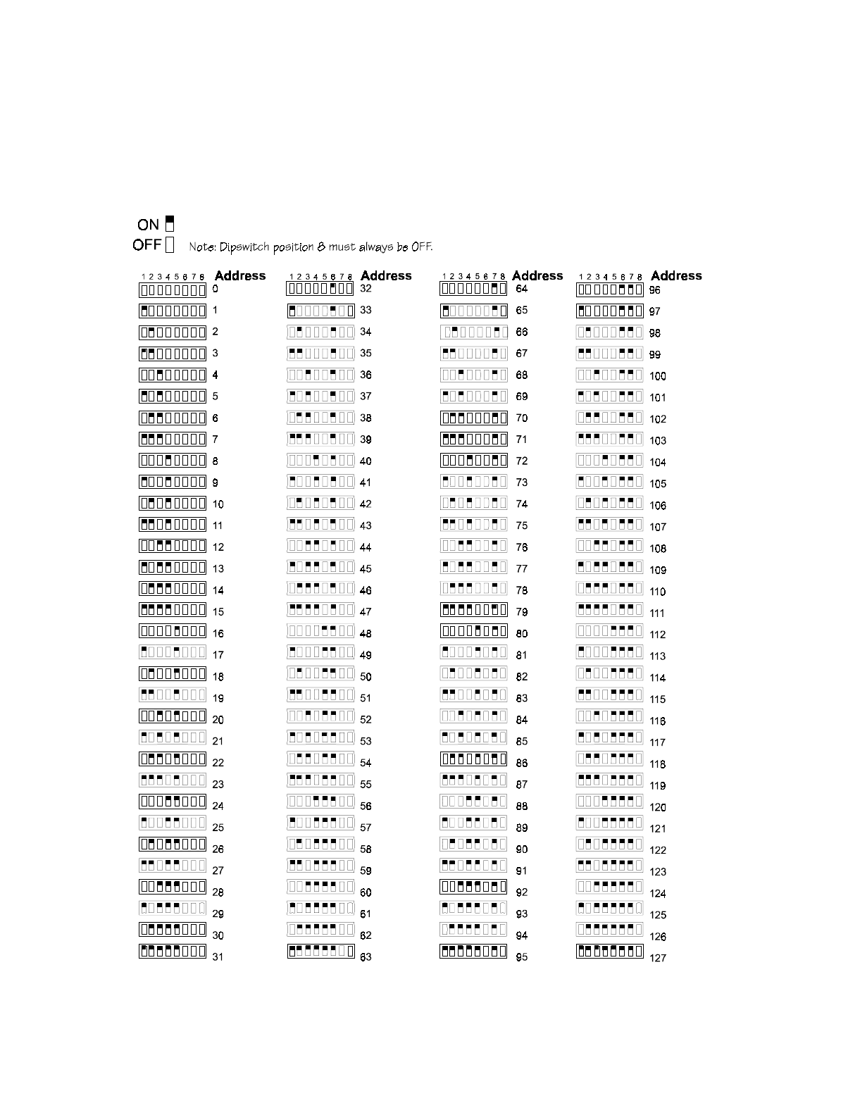
SLC Device Installation
151137 5-13
5.10.2 Dipswitch Addressing
Input and relay module addresses are set using the dipswitch that appears on the module
board. The chart below shows the available addresses. For example, to select address 3, place
dipswitches 1 and 2 in the up position. The range of valid addresses is 1-127 (0 is an invalid
address).
Figure 5-15 SLC Device Addressing Using Dipswitches

IntelliKnight 5820XL Installation Manual
5-14 151137

151137 6-1
Section 6
Pro
g
rammin
g
Overview
This section of the manual is intended to give you an overview of the programming process.
Please read this section of the manual carefully, especially if you are programming the control
panel for the first time.
The JumpStart feature automates many programming tasks and selects default options for the
system. You will run JumpStart at least once when you are installing the system. See Section
6.1 for details. After you run JumpStart, you may need to do some additional programming
depending on your installation. Section 7 of this manual cover manual programmable options
in detail.
Programming the panel can be thought of as a three part process. You must program:
• System options. These are options that affect general operation of the panel (see Section
7.5 for details).
• Options for input points and zones. These are primarily options that control detection
behavior of devices (see Section 7.4 for details).
• Options for output points and groups. This includes selecting characteristics for output
groups and mapping output circuits to output groups (see Section 7.4 for details).
6.1 JumpStart Autoprogramming
The JumpStart feature allows for faster system setup. When you run JumpStart (immediately
after addressing SLC devices), the system scans devices on all SLC loops and determines
device type (for example, ionization smoke detector or heat sensor) and selects some system
options based on the device type. This saves the installer from having to program options for
each device. Depending on the application, the installer may need to make some changes after
JumpStart completes.
See Section 6.1.3 for complete details about running JumpStart.
IMPORTANT
JumpStart is intended to be run one time only, immediately after SLC devices have been addressed and connected.
JumpStart will reset manually all programmed options to default settings. Do not run JumpStart after you have
configured the system.

IntelliKnight 5820XL Installation Manual
6-2 151137
6.1.1 Input Points
JumpStart will determine the number and type of input points (detectors or contact monitor
modules) on each SLC loop. JumpStart assigns the correct detector type (heat, ionization or
photoelectric), so the installer does not need to edit device type for detectors. Any contact
monitor modules on the system will be assigned type "Manual Pull." The installer will need to
manually change the switch type if manual pull is not correct.
JumpStart creates one zone (Zone 1) and assigns all input points to Zone 1. Zone 1 is mapped
to Output Group 1. After JumpStart completes, you can re-map to configure a multiple zone/
output group system (see Section 7.2.1.3). For a general explanation of mapping, see Section
6.2.
6.1.2 Output Points
JumpStart creates three output groups and assigns output circuits as follows:
Circuits 1-6:
Configured as Notification and assigned to Group 1. JumpStart automatically programs Zone
1 to activate Group 1 using constant on output.
Circuit 7 (Relay 1):
Assigned to Group 249. JumpStart automatically programs Zone 1 to activate Group 249
using constant on output when a supervisory condition occurs.
Circuit 8 (Relay 2):
Assigned to Group 250. JumpStart automatically programs Zone 1 to activate Group 250
using constant on output when an alarm occurs.
Addressable output points (Relay modules):
All addressable relay devices will be configured as "Output Pt" (general purpose output point)
and assigned to Group 1.
Note: Relay output is constant even if the zone activating the relay is programmed with an output pattern.
6.1.3 Running JumpStart
Run JumpStart immediately after you have addressed and connected all input devices
(detectors, pull stations, and so on) and output devices (notification appliances, relays, and so
on).
Note: If you need to install a few devices after you have run JumpStart, you can install them manually. Follow
instructions in Section 8 for configuration.
To run JumpStart, follow these steps.
1. You must be in the Installer Menu to run JumpStart. If you are not, enter the Installer
Code.
2. Press to enable the keypad.
Programming Overview
151137 6-3
3. Select for Program Menu.
4. From the next menu, select for JumpStart.
5. The message "WARNING Will reset all system options" displays on the LCD. Select Yes
to continue. A series of messages displays for the next several seconds. JumpStart scans
the SLC loops for devices. This can take several minutes, depending on the number of
devices attached.
6. When the message "Configure System Done" displays on the LCD, press any key to con-
tinue.
7. Select one of the following options from the menu that displays.
- Review System Press if you need to review the JumpStart configuration.
- Repeat JumpStart Press if you need to rerun JumpStart for any reason.
- Accept Configuration 1. If you are ready to make the JumpStart configuration permanent, select .
2. The system will ask you if the installation contains duct detectors. If there
are none, select for No and skip to Step 8. If the system contains duct
detectors, select for Yes and continue with Step 3.
3. From the list that displays, select the 5815XL device that contains the duct
detectors.
4. The first photoelectric or ionization detector on the system will display.
Select for DUCT and for NonDUCT.
5. Press to select the next detector. Select for DUCT and for Non-
DUCT. Continue until all duct detectors have been selected. (Note: You can
move backwards through the list with .)
6. When you reach the last detector on this device, press .
7. The system will ask you if there are more duct detectors in the system. If
there are, select for Yes and repeat from Step 3. If there are no more
duct detectors, select for No and continue with Step 8.
8. The system will restart in 10 seconds. You can press to restart immedi-
ately. Do not select for System Diagnostics. (This feature is for use in
testing at the factory.)
9. After the system resets, it will use the new JumpStart configuration.
7
6
1 1
2 2
3 3
2
1
1 2
1 2
1
2
1
2
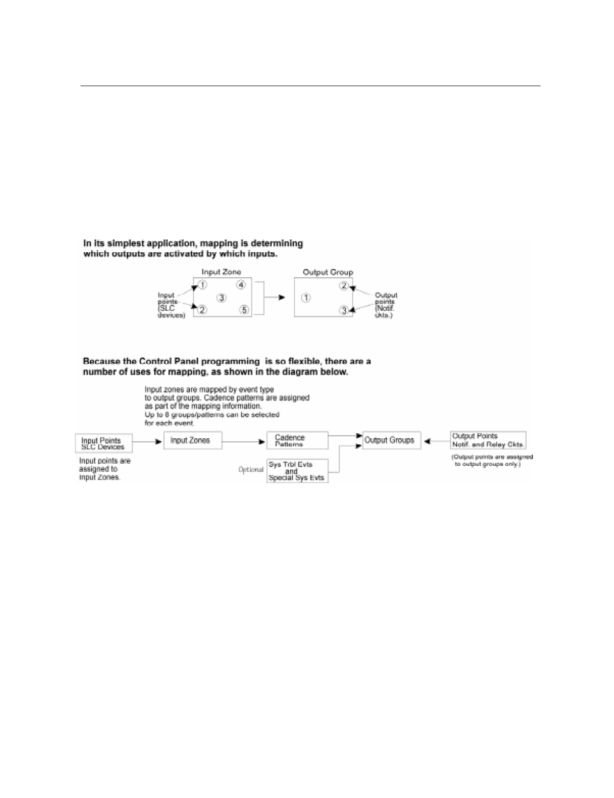
IntelliKnight 5820XL Installation Manual
6-4 151137
6.2 Mapping Overview
This section of the manual is an overview of mapping. Details about how to select mapping
options appear in the appropriate subsections in Section 7.
Mapping is an important concept with the control panel. In general terms, mapping is
assigning or linking events to outputs that should activate when events occur. You do this by
assigning input points to input zones, output points to output groups and then linking or
mapping zones and output groups.
Figure 6-1 is a brief overview of the concept of mapping. The next several pages of the
manual show these subjects in detail.
Figure 6-1 Mapping Overview
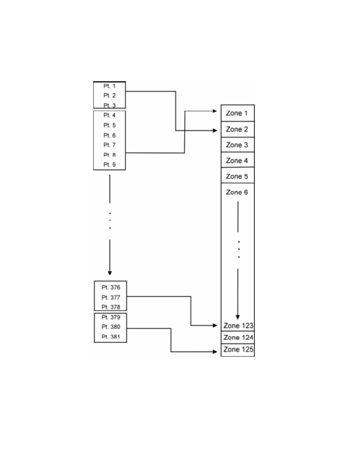
Programming Overview
151137 6-5
6.2.1 Input Point Mapping
Input points are assigned to input zones. Any input point can be assigned to any input zone.
(Input points can be assigned to one zone only. An input point can be designated as "Unused,"
which means it has not been assigned to a zone.)
Figure 6-2 Input Point Assignment Example
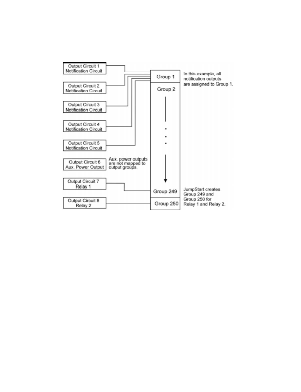
IntelliKnight 5820XL Installation Manual
6-6 151137
6.2.2 Output Circuit Mapping
Figure 6-3 is a simple example showing how to assign notification and relay output circuits to
groups. For an example of a simple floor above/floor below application, see Figure 6-5.
Figure 6-3 Assigning Output Circuits to Groups (Example)
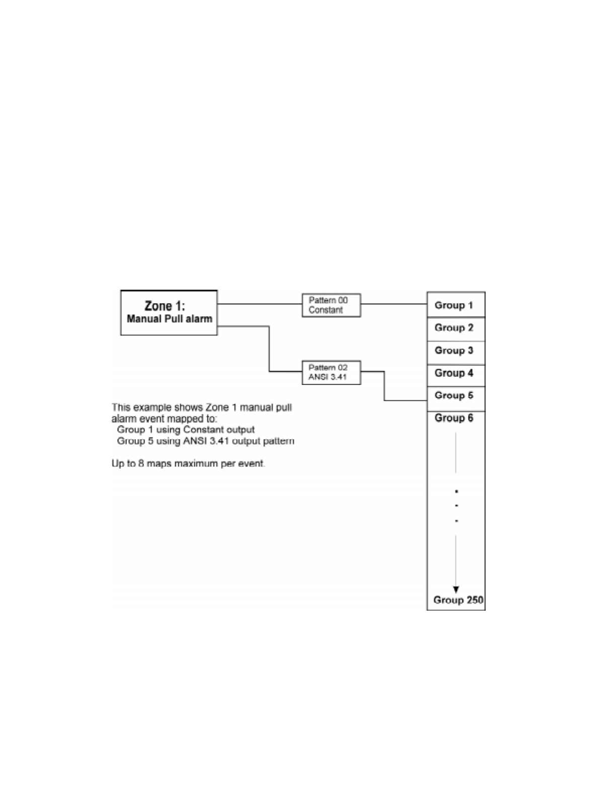
Programming Overview
151137 6-7
6.2.3 Zone Event Mapping
There are 8 types of events that can occur in zones (see below). For each event type, you can
activate up to 8 output groups and patterns. If it is necessary to map to more than 8 output
groups, an output group template may be used (see Section 7.3.5 for information on output
group templates). Event types are:
• Manual Pull Alarm
• Water Flow Alarm
• Detector Alarm (heat or smoke detectors)
• Aux 1 and Aux 2 Alarm (user-specified alarm types)
• Pre-alarm
• Supervisory
• Trouble
Figure 6-4 Example of Zone Events Mapped to Output Groups and Patterns
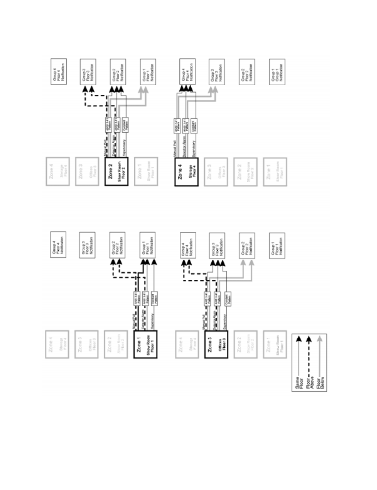
IntelliKnight 5820XL Installation Manual
6-8 151137
Figure 6-5 Example of Zone Events Mapped to Output Groups and Patterns
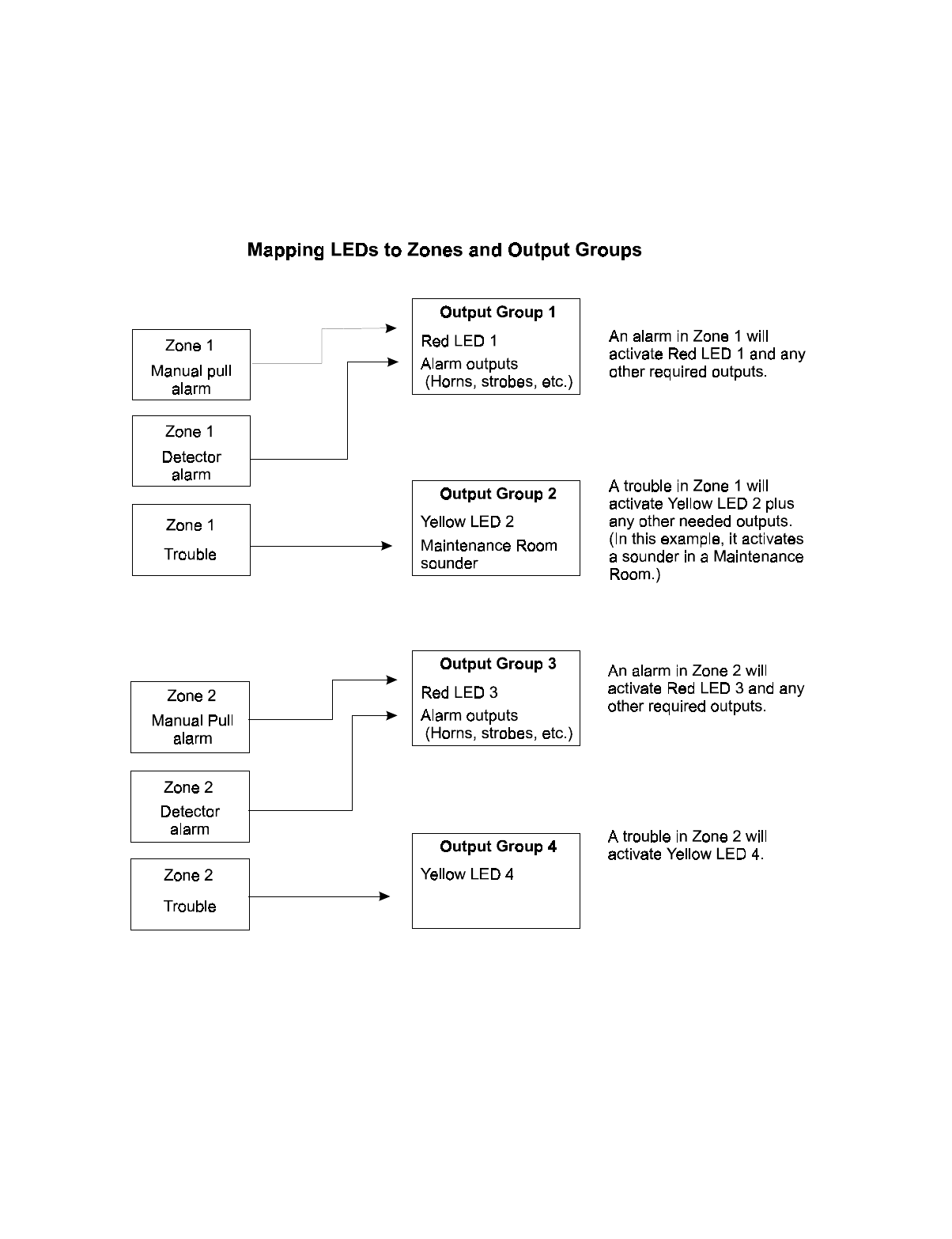
Programming Overview
151137 6-9
6.2.4 Mapping LED Points
Figure 6-6 is a simple example showing how LED points are mapped to zones and output
groups. Typically you would create two output groups for each zone, one for alarms and one
for troubles. (LED points are available when Models 5865-3/4 and/or 5880 are used with the
system.)
Figure 6-6 Example of LED Points Mapped to Output Groups
(applies to Models 5865-3/4 and 5880)

IntelliKnight 5820XL Installation Manual
6-10 151137
6.3 SK Analog Fire System Editor 5590
There are two ways to program the control panel. One way is to program directly from an
annunciator, either the on-board annunciator or a Model 5860 Remote Annunciator.
Annunciator programming is explained in Section 6.4.
The other method for programming is through the SK Analog Fire System Editor 5590. The
5590 is an optional software package that allows you to easily program the control panel using
a Windows-based computer and a *modem (not sold by Silent Knight). The software works in
the following way. First you use the software to program options for the panel, saving the
options in a file. You can then download the file to the panel. The software includes an on-line
help system and a manual. See the manual (P/N 151004) for more information.
* See Section 1.3 for a list of modems that have been tested for compatibility with the control panel and the SK
Analog Fire System Editor 5590.
6.4 Annunciator Programming
There are two ways to program a control panel. One way is through the SK Analog Fire
System Editor 5590 (see Section 6.3).
The other method is to program directly from an annunciator, using either the on-board
annunciator or a Model 5860 Remote Annunciator.
The following subsections describe programming basics, including a description of editing
keys available for programming and how to move through programming menus. Section 7
contain specific information about individual programming options.
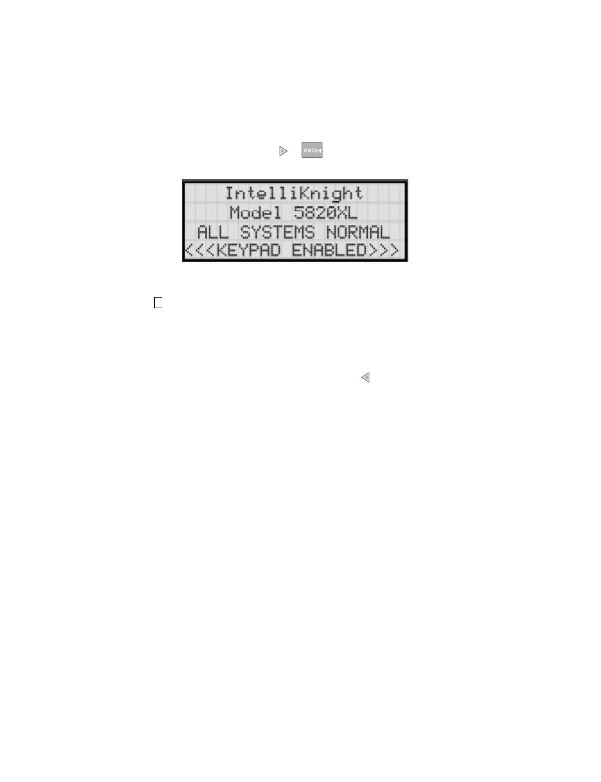
Programming Overview
151137 6-11
6.4.1 Entering / Exiting the Program Menu
To enter the Program Mode:
1. Enter the Installer Code (factory programmed default code is 5820).
2. The display prompts you to press the or key to bring up the Installer Main Menu
(see Figure 6-7).
Figure 6-7 Keypad Enabled Screen
3. Then press . The menus described in Section 7 of this manual will display. Section 6.5
of this manual is a quick reference listing all programmable options and JumpStart
defaults.
To Exit Program Mode:
When you have completed working with the menus, press (left arrow) several times until
you are exited from programming mode. Two prompts will display. The first prompt is to
make sure you intended to leave the Program Menu (select Yes or No as appropriate). The
second prompt is for accepting all changes. If you select No, any changes you have made
since you entered the Program Menu will have no effect.
7
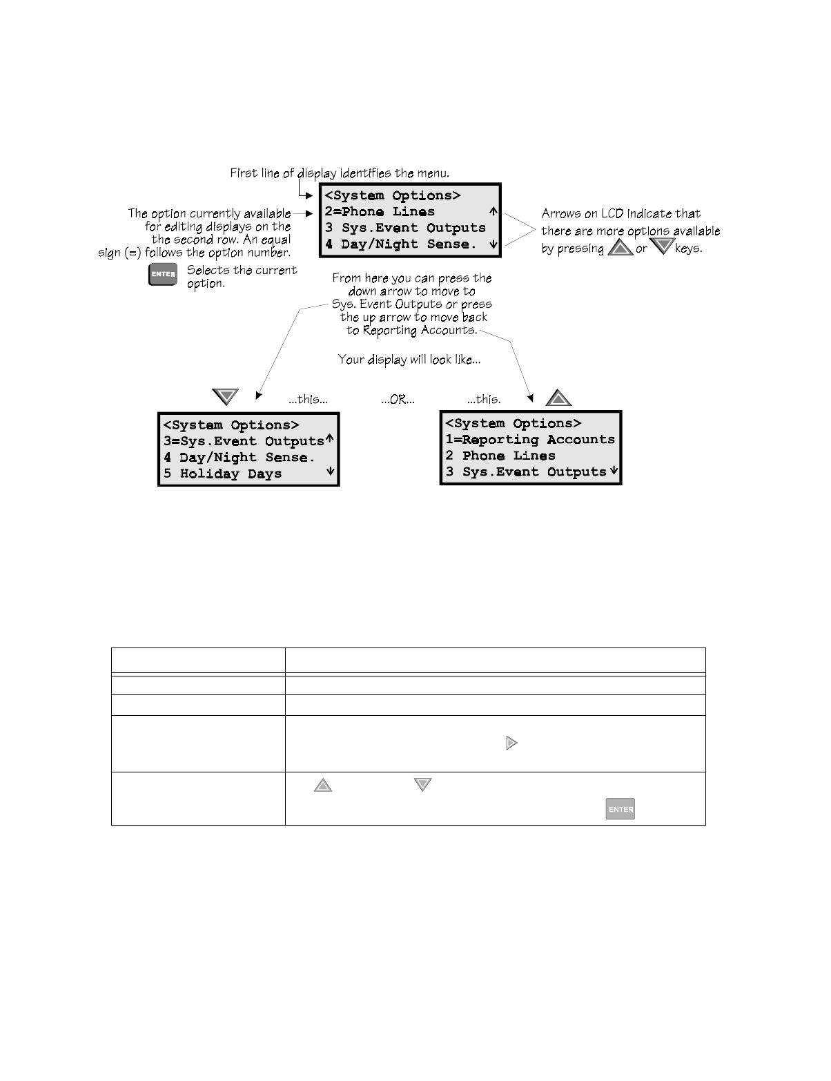
IntelliKnight 5820XL Installation Manual
6-12 151137
6.4.2 Moving through the Menus
Figure 6-8 shows how to move through Program Menu screens, using the System Options
screen as an example.
Figure 6-8 Moving through Program Menu
(System Options Sub-Menu Used as an Example)
6.4.3 Selecting Options and Entering Data
There are several ways to make programming selections using the control panel depending on
which screen you are currently using. The chart below is a generic explanation.
To Press
Select from a menu. Enter the number of the option.
Enter numeric data. Press the appropriate number on the annunciator.
Enter text (alphanumeric data). Enter each letter individually by pressing and holding any numeric key until the
one you wish to select displays. Then press (right arrow) to select the letter. See
Section 6.4 for complete information.
Select from a scrolling list. Use (up arrow) and (down arrow) to move through a list of available
options. When the option you want to select is displayed, press .
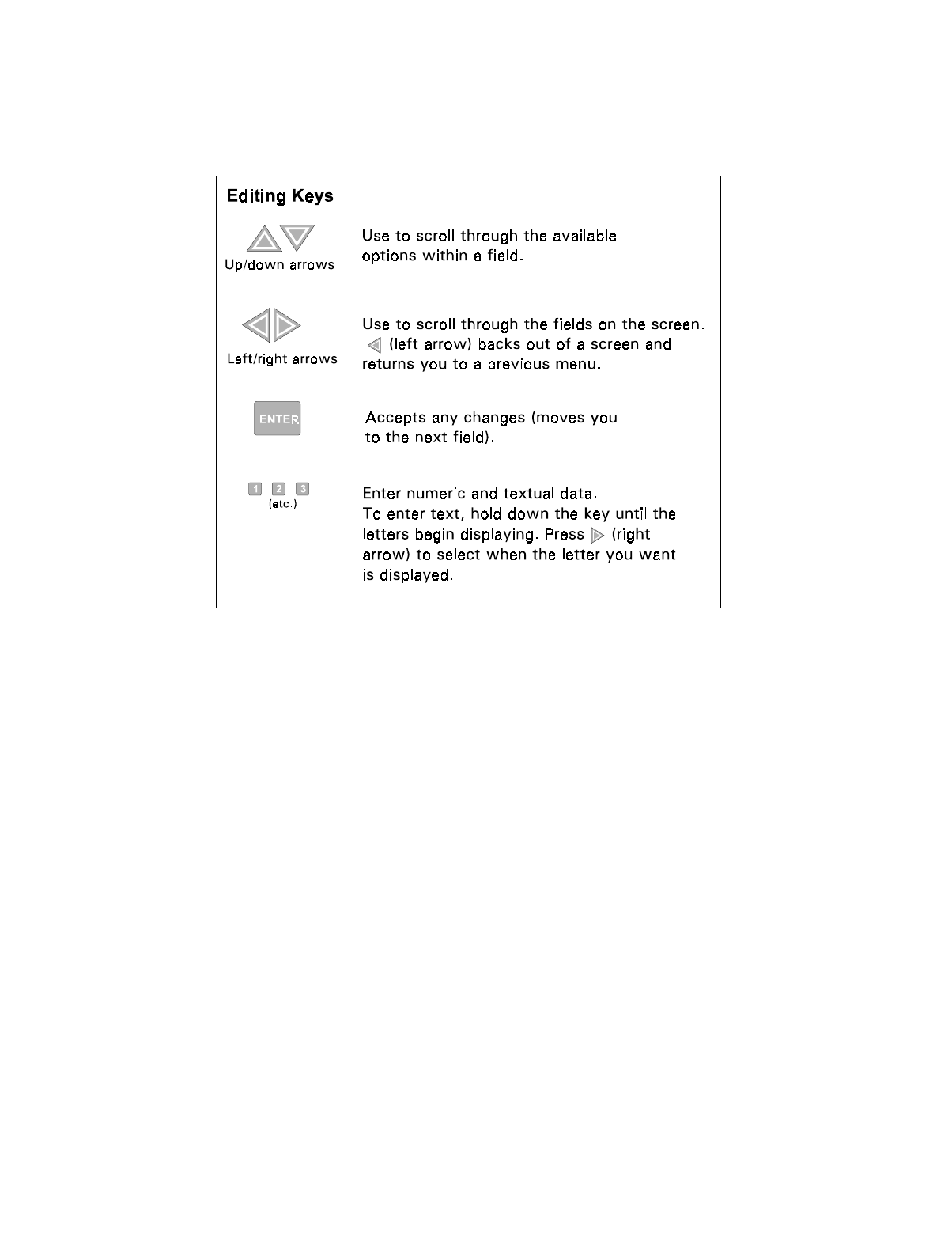
Programming Overview
151137 6-13
6.4.4 Editing Keys
The keys shown in Figure 6-9 are available for use when you are in the Program Menu.
Figure 6-9 Editing Keys Available from Program Menu

IntelliKnight 5820XL Installation Manual
6-14 151137
6.5 Programming Menu Quick Reference
This section of the manual lists all Program Menu options in the order they appear on the sub-
menus. Default settings are indicated in text or marked with an asterisk. The comments
column provide quick information and a reference to a section (if applicable) which has more
detailed information.
Menu Options/Defaults Comments
Module
Edit Module
Internal 5815 Enter Module Name Select Class
See Section 4.10
Internal Pwr Enter Module Name Select Class
Internal Annu Enter Module Name
5897 Enter Module Name
5865 Enter Module Name
5880 Enter Module Name
5824 Enter Module Name
5860 Enter Module Name
5815XL Enter Module Name
Add Module
5815XL-SLC
See Section 7.1.2
5860-Keystation
5824-Ser/Par/IO
5895XL-io/Pwr Sup
5880-LED/IO Dev
5865-LED Annunc
Delete Module List of Modules See Section 7.1.3
View Module List List of Modules

Programming Overview
151137 6-15
Zone
Edit Zone Select Zone to Edit
Edit Zone Name
Enter Name1
Enter Number1
Enter Name2
Enter Number2
Zone Properties
Verification Type
*1 Count
2 Count
Alarm Ver.
PAS
Heat Sensitivity 135° to 150°F
Smoke
Sensitivity
*Low 3.5% obscurity
Sec 7.2.1.2
Medium 2.5 obscurity
Sec 7.2.1.2
High 1.5% obscurity
Sec 7.2.1.2
Zone Outputs
Manual Pull
(MP) (Groups 01 &
250, Pattern
00)
Sec. 7.2
Water Flow
(WF)
Detector Alarm
Aux 1
no groupAux 2
Pre-alarm (PRE)
Supervisory
(SUP)
(Group 249,
Pattern 00)
Trouble (TRB) no group
Add Zone Adds next available zone number. Sec. 7.2.2
Delete Zone Select Zone to be
Deleted
Sec. 7.2.3
View Zone Points List of all points in
selected zone.
Sec. 7.2.4
Menu Options/Defaults Comments

IntelliKnight 5820XL Installation Manual
6-16 151137
Group
Edit Group Select Group
Group Name
Enter Name1
See Section
7.3.1.1. Sec. 7.3.1.1
Enter Number1
Enter Name2
Enter Number2
Group Properties
Latching
Options
*Non-
Latching
Latching
Silencing
Options
*SILENCE Silenceable
NON-SIL Non-Silenceable
Sec. 7.3.1
Auto
Unsilence
Auto Un-silenced
Sec. 7.3.1
SIL-INHIB Silence after inhib
delay. Sec. 7.3.1
SHUT-
DOWN
Automatic
Shutdown Sec.
7.3.1
Group Active
With:
Group
Activates for
all Man. Pull
*No
Group
Activates for
Fire Drill
*Yes
Group
Activates for
Aux 1
*No
Group
Activates for
Aux 2
*No
Ignore Global
Cadence
*No
Add Group
Sec. 7.3.3
Delete Group Select Group to
Delete
View Group Points Select Group
Edit OPG Template Select Template
Number
Select Group
Include in template Yes
No
Select Pattern 0-16 0 = Constant. Refer to Figure 7-5
Menu Options/Defaults Comments

Programming Overview
151137 6-17
Point Internal and
External 5815XL Enter Pt
UNUSED
DETECTOR
PHOTO
Select zone See Section 7.4.
ION
HEAT
PHOT DUCT
ION DUCT
SWITCH
MAN_PULL
See Section 7.4.
WATERFLOW LATCH
NLATCH
SUPERVSY LATCH
NLATCH
FIREDRILL
SILENCE
RESET
PAS_ACK
ZN_AUX1 LATCH
NLATCH
ZN_AUX2 LATCH
NLATCH
SYS_AUX1 LATCH
NLATCH
SYS_AUX2 LATCH
NLATCH
DETECT SW
TAMPER
NOTIF
OUTPUT PT Select Group
See Section 7.4.
AUX CONST
AUX RESET
AUX DOOR
RELAY
OUTPUT PT Select Group
See Section 7.4.
AUX CONST
AUX RESET
AUX DOOR
Menu Options/Defaults Comments

IntelliKnight 5820XL Installation Manual
6-18 151137
Point
(Cont.)
Internal Pwr and
External Power
Enter Pt Input Point Type
(detector/switch)
Select Function Per JumpStart
Select Type
UNUSED
B NOTIF Select Group
A NOTIF
AUX PWR
CONSTANT
RESETABLE
DOOR
B SWITCH
MAN PULL Select zone Latch and Non-
latch feature only
appears for
waterflow,
supervisory,
tamper, zone
aux1, zone aux2,
system aux1, and
system aux2.
WATERFLOW Select zone
SUPERVSY Select zone
TAMPER Select zone
FIREDRILL
SILENCE
RESET
PAS_ACK Select zone
ZN_AUX1 Select zone
ZN_AUX2 Select zone
SYS_AUX1
SYS_AUX2
A SWITCH Same as B SWITCH
B DETECTOR 2-WIRE SMK
4-WIRE SMK
A DETECTOR 2-WIRE SMK
4-WIRE SMK
Select Group or
Zone Number
Group or Zone selection will
appear depending on the type is
selected
Edit Name
Enter Name1
See Section 7.4
Enter Number1
Enter Name2
Enter Number2
5880
Enter Point # NOTIF
UNUSED
Select Group #
Edit Name
Enter Name1
Enter Number1
Enter Name2
Enter Number2
5865
Enter Point # NOTIF
UNUSED
Select Group #
Edit Name
Enter Name1
See 7.4
Enter Number1
Enter Name2
Enter Number2
Menu Options/Defaults Comments

Programming Overview
151137 6-19
System
Options
Reporting
Accounts
Edit Acct.
For each account (1-4), select:
Edit Account # *123456 Account # (6-digit
number, identifies
account to central
station)
Sec. 7.5.1
Edit Format *Contact ID Reporting Format
(SIA, S20,
Contact ID)
Sec. 7.5.1
Report Alarms
Y (Yes) *No Sec. 7.5.1
N (No)
M (Must)
Rep. Alarm Restore
Y (Yes)
N (No)
M (Must)
Report Troubles
Y (Yes)
N (No)
M (Must)
Report Ena/Disable
Y (Yes)
N (No)
M (Must)
Report Test
Y (Yes)
N (No)
M (Must)
Report Resets
Y (Yes)
N (No)
M (Must)
Switch attempts 1 - 15 *5 Sec. 7.5.2
Fail attempts 1 - 15 *10 Sec. 7.5.2
Primary Phone Line 1 or 2 *Line 1 Sec. 7.5.2
Secondary Phone
Line
1 or 2 *Line 2 Sec. 7.5.2
Edit Phone #1 up to 40 digits blank Sec. 7.5.2
Auto Test Time
Set the Hour
*02:00 AM Sec. 7.5.1.2Set the Minutes
Select AM/PM
Menu Options/Defaults Comments

IntelliKnight 5820XL Installation Manual
6-20 151137
System
Option
(cont.)
Phone Lines Select Phone Line
For each phone line (1 & 2), select:
Dialing Prefix Up to 9 digits none Sec. 7.5.2.1
# of Answer Rings Range: 00-15 06 Number of rings
before panel
answers a call
from a computer
Sec. 7.5.2.2
Select Dialing
Option
TT
TouchTone
Touch Tone
TT/PL TouchTone
alternating with
pulse see Section
7.5.2.3
PULSE Pulse dialing
Rotary Pulse Format U = 60/40 *U Sec. 7.5.2.4
E = 66/34
Line Monitor Yes *No Sec. 7.5.2.5
No
Enable Ground Start Yes = enabled *N = Disabled Sec. 7.5.2.6
No = disabled
Answering Machine
Bypass
Yes = enabled *Y = Enabled Sec. 7.5.2.7
No = disabled
System Event
Outputs
Trouble Events
System Trouble Select Group None selected Sec. 7.5.3.1
Select Cadence Sec. 7.5.3.1
Alarm Silence Select Group None selected
Select Cadence
Trbl Silence Select Group None selected
Select Cadence
User Selected
Group Tr
Select Group
SBUS Com
SBUS Pwr
SLC Loop
AC Loss
Battery
Gnd Flt
Select
Cadence
Phone Ln
Account
Printer
Aux Pwr
Sys Sw
Sys Alarm Cadence
Fire Drill
Select Cadence ConstantSystem Aux1 Sec.7.5.3.2
System Aux2
Menu Options/Defaults Comments

Programming Overview
151137 6-21
System
Option
(cont.)
Day/Night
Sensitivity
Enable Day/Night
Sensitivity
Y (Enabled) *Disabled Sec.7.5.4
N (Disabled)
Day Start
Select Hour
*06:00 AM
Select Time Day
Begins
Select Minutes
Select AM/PM
Night Start
Select Hour
*06:00 PM
Select Time Night Begins
Select Minutes
Select AM/PM
Days of Week Sunday through
Saturday
*Mon- Fri Select Days of Week for Day/
Night Sensitivity
Holiday Days Holidays 1 to 9 *Jan 1, July 4, Dec
24, Dec 25
Select up to 18 days that the
system will use the Night
sensitivity only. Sec.7.5.5
Holidays 10 to 18 None
Misc. Options
Water Flow Delay
0 - 90 Seconds *30 sec Water Flow delay is the number
of sec before water flow alarm is
generated. Sec. 7.5.6.1
Low AC Delay
6 - 30 hours *6 hrs Low AC Report
Delay. Sec.
7.5.6.2
DST Y (Enabled) *Enabled Automatic daylight Savings
enable or disable. Sec. 7.5.6.3
N (Disabled)
CLK AM/PM *AM/PM System Clock Format (AM/PM or
military). Sec. 7.5.6.4
MIL
AC Freq: 50 Hz
60 Hz
Neither
Edit Library Name
Select Word
Number
120 to 255 This option is for adding words to
the library. Sec. 7.5.7
Edit Word
This option is for changing the
normal mode display on the
system LCD. See Sec. 7.5.7
Edit Banner
Internal Message See Section 7.5.8
Custom Message Edit Line 1
Edit Line 2
JumpStart
AutoPrg
No See Section 7.6
Yes
Computer
Account
Computer Account
#*5820
See also Section 7.7
Computer Access
Code *0
Computer Phone # Up to 40 digits See Section 7.7 for programming
phone number.
Access
Codes
User Code *1111 4 to 7 digits See Section 8.4.11.
Installer Code *5820
Menu Options/Defaults Comments

IntelliKnight 5820XL Installation Manual
6-22 151137

151137 7-1
Section 7
Pro
g
rammin
g
This section of the manual manually program the control panel. Each subsection discusses
these menu options in detail. All options described in this section can be performed using the
SK Analog Fire System Editor 5590.
7.1 Modules
This section lists the options available under the module option in the program menu. The
types of modules available for the control panel are, 5815XL (SLC), 5860 (Keystation), 5824
(Serial/Parallel input/output), 5895XL (Input/output Power Supply), 5880 (LED Input/Output
module), and a 5865 (LED Annunciator).
7.1.1 Edit Modules
The features that can be edited when this option is selected are, module name, and class of
wiring (Class A or Class B).
To edit an existing module, follow these steps:
1. Enter the installer code.
2. Press or to display the installer menu.
3. Select for Program Menu.
Display reads: ,QLWLDOL]LQJ
3OHDVHZDLW
4. Press to enter module menu.
5. Press to edit a module.
6. Use the or arrow to select the module you wish to edit.
Important!
Before any customized programming is done, JumpStart should be run first. After
JumpStart is run, thoroughly test the system. The reason the system should be tested
after JumpStart is because Jumpstart automatically programs the system, searching for
and configuring all SLC and SBUS devices it finds. JumpStart allows you to confirm
the integrity of the installation prior to performing any custom programming. After
determining that the hardware is properly installed, custom programming can be
performed. Refer to Section 6.
7
1
1
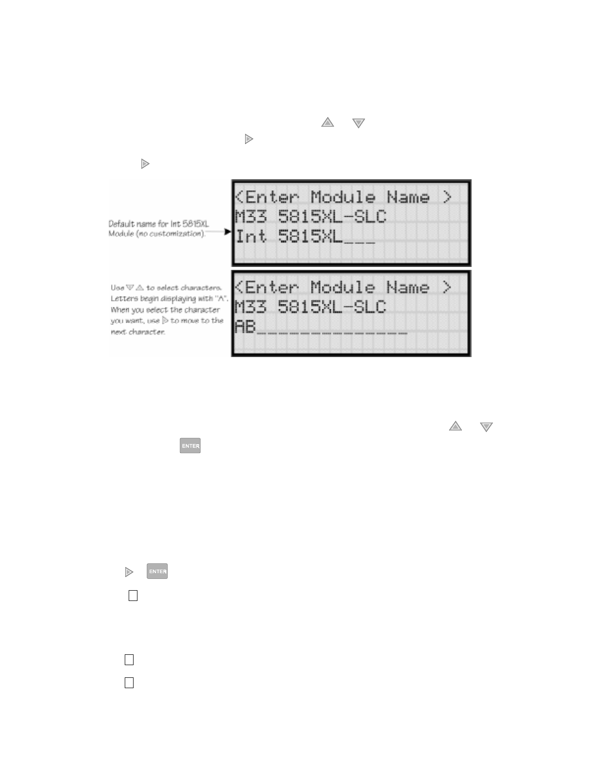
IntelliKnight 5820XL Installation Manual
7-2 151137
7.1.1.1 Naming Modules
You can assign an English name to a system hardware module to make it easier to recognize
on a display.
7. If you wish to edit the modules name press the or arrow to select each character
for the modules name (or press to bypass name edit).
Press the to move to the next character.
Figure 7-1 Edit module Name Programming Screen Example
7.1.1.2 Module, Wiring Class
8. Choose the class of wiring you wish to use for this module by pressing the or
arrow, then press .
7.1.2 Adding a Module
If you need to add a new hardware module to the system, follow these steps.
You must be in the Installer Menu to perform this task. If necessary, enter the Installer Code.
1. Enter the installer code.
2. Press or to display the installer menu.
3. Select for Program Menu.
Display reads: ,QLWLDOL]LQJ
3OHDVHZDLW
4. Press to enter module menu.
5. Press to add a module.
7
1
2

Programming
151137 7-3
6. From the next screen, select the number that corresponds to the type of module you are
adding from the <New Module Type> screen.
The screen will display “Adding module [#]...” for a few moments. You will be returned
to the <Module Programming> screen where you can select a name for the module if
desired (see Section 7.1.1.1).
You must save changes when you exit the Program Menu or the new module will not be
added.
Note: If you Add a Module that has not been physically connected, the panel will go into trouble after it
reinitializes (when you exit the Program Menu). When the new module is attached, the trouble will correct
itself automatically the next time you power up the system.
7.1.3 Deleting a Module
If you ever need to delete a module, follow these steps.
You must be in the Installer Menu to perform this task. If necessary, enter the Installer Code.
1. Enter the installer code.
2. Press or to display the installer menu.
3. Select for Program Menu.
Display reads: ,QLWLDOL]LQJ
3OHDVHZDLW
4. Press to enter module menu.
5. Press to delete a module.
6. A warning screen will display. If you want to proceed with deleting the module, select
Yes. To cancel, select No.
7
1
3

IntelliKnight 5820XL Installation Manual
7-4 151137
7.2 Zone
Through the zone option in the program menu you can edit, add, delete, and view zone points.
Selections made here affect all detectors and switches in the zone. Up to 125 zones can be
used in the system.
7.2.1 Edit Zone
Features that can be edited through the edit zone option are, edit zone name, zone properties
(which includes, zone type, and detector sensitivity), and zone output mapping.
To edit a zone, follow these steps:
1. Enter the installer code.
2. Press or to display the installer menu.
3. Select for Program Menu.
Display reads: ,QLWLDOL]LQJ
3OHDVHZDLW
4. Press to enter zone menu.
5. Press to edit a zone.
6. Enter the zone number, then press .
7
2
1
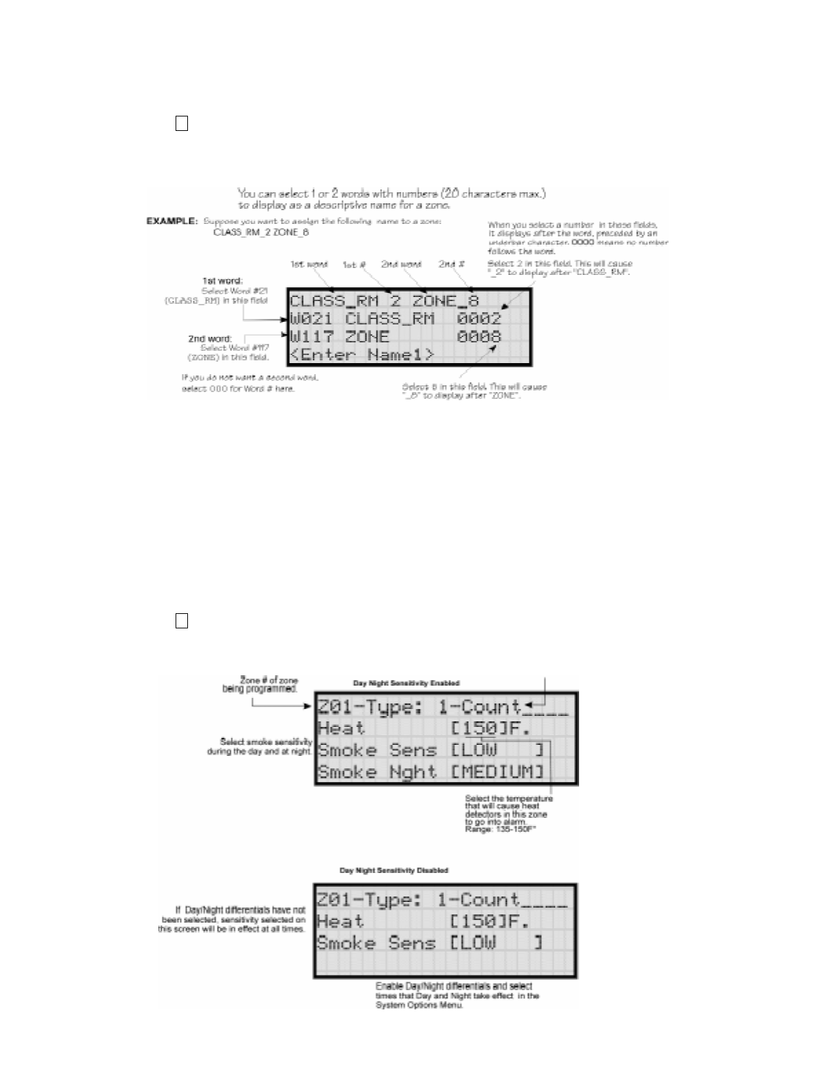
Programming
151137 7-5
7.2.1.1 Edit Zone Name
7. Press to edit the selected zone’s name.
A screen similar to the one shown in Figure 7-2 displays. Select a one- or two-word
descriptive name as shown in the diagram.
Figure 7-2 Selecting a Name for a Zone
See Appendix B Table B-1 of this manual for a list of available words. If you want to use a
word not in the list, you can add the word the "library" (or list) of words that is available to be
used with the control panel.
7.2.1.2 Edit Zone Properties
Zone properties consist of, alarm delay characteristics, heat detector sensitivity, and smoke
detector sensitivity.
1. Do steps 1 through 6 of Section 7.2.1.
2. Press to edit the properties of the selected zone.
1
2
Detection type also selected from
this screen (see Table 7-1).
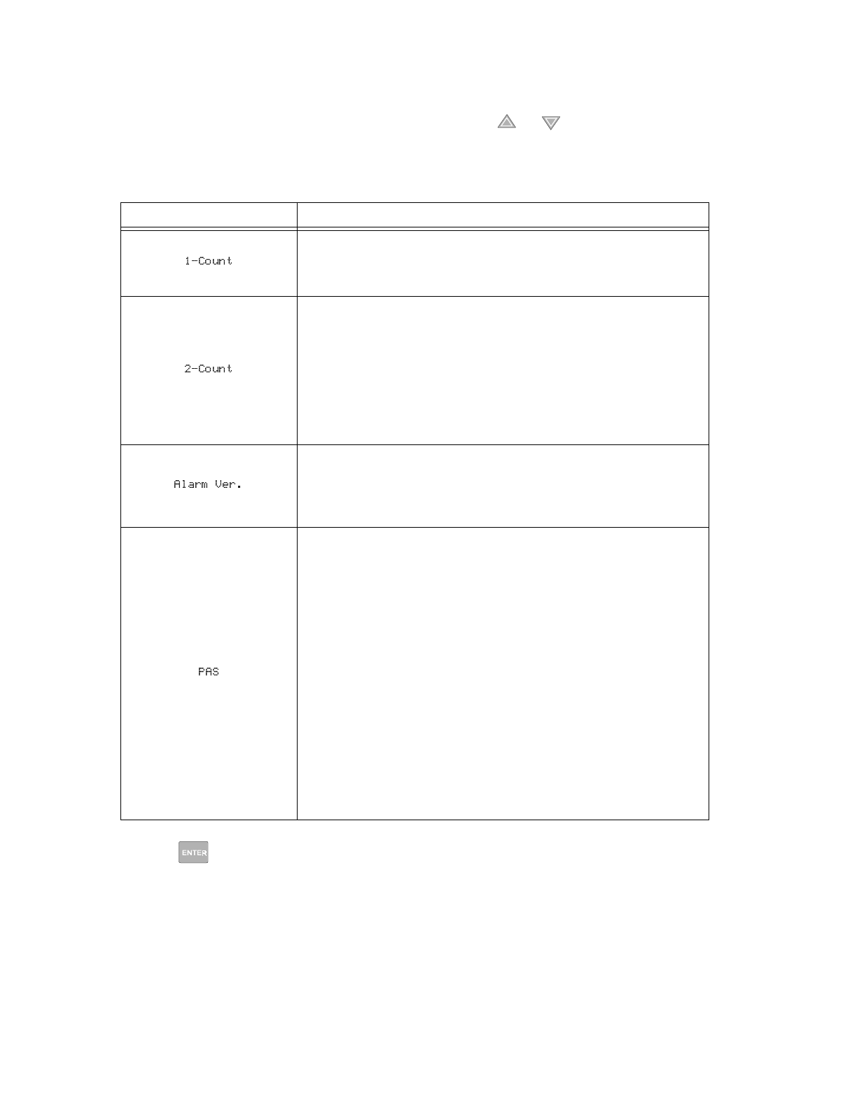
IntelliKnight 5820XL Installation Manual
7-6 151137
Alarm Delay Characteristics
3. Select the alarm delay characteristics by pressing the or arrow.
Table 7-1 list the delay choices and a description of each.
4. Press .
Table 7-1: Alarm Delay Characteristics
Type of Delay Description
One Count (No Delay). When this option is enabled, an alarm occurs
immediately when a single device of any of the following types goes into alarm:
detector, manual pull, water flow, Aux1 or Aux2. This is considered the most
typical operation and is the default for all zones.
When this type of alarm delay is used, two or more detectors within the zone
must go into alarm in order for the zone to report an alarm. Switches of type
manual pull, water flow, Aux1 and Aux2 are an exception; they will cause an
alarm when only one switch is in alarm.
When a single detector is in alarm in a 2-Count zone, the system enters a
prealarm condition. In a prealarm condition, the touchpad PZT beeps and the
annunciator display indicates that a prealarm has occurred. If the zone has been
mapped to an output group for the prealarm event, the output group will
activate. The prealarm will not be reported to the central station.
Alarm verification is an optional false alarm prevention feature that verifies an
alarm condition by resetting the smoke detector. If the alarm condition still
exists by the time the reset cycle has completed, the detector will go into alarm.
If the detector is no longer in alarm, no report will go to the central station. The
alarm verification sequence is ignored if the zone is already in alarm.
This option is intended to be used with an acknowledge switch. An alarm is
delayed for 15 seconds, giving on-site personnel a chance to investigate the
alarm. If the acknowledge switch is not activated within 15 seconds, an alarm
occurs automatically.
If this option is enabled for a zone, the zone will respond to an alarm condition
as follows:
• The zone will not go into alarm for 15 seconds to allow an on-site operator
to activate the acknowledge switch.
• If the operator does not press the acknowledge switch within 15 seconds,
the zone will go into alarm.
• If the operator presses the acknowledge switch within 15 seconds, a 180-
second time-frame will begin counting down. This time-frame allows the
operator to investigate the cause of the alarm.
If the operator performs a reset within 180 seconds, the alarm will not
occur.
If the operator does not perform a reset within 180 seconds, an alarm will
occur automatically.
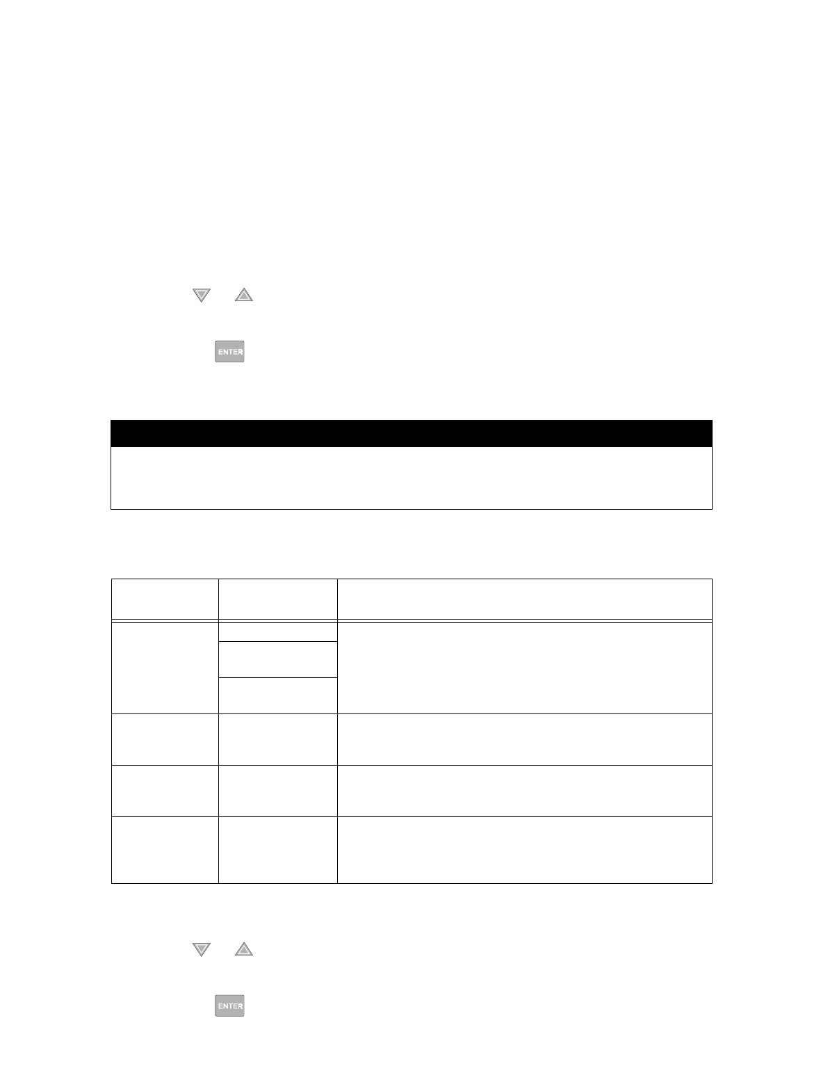
Programming
151137 7-7
Heat Detector Sensitivity
Use this feature to set the temperature that heat detectors will respond. The range is 135° to
150° F. All detectors in the zone will respond in the same way.
The Model SD505-AHS Heat Detector is an absolute temperature device. This means that it
responds to an alarm immediately if the temperature in the zone goes above the programmed
temperature.
5. Enter the temperature that the heat detector will respond.
Or
Use the or keys to scroll through the range or enter directly from the number keys
on the annunciator.
Then press .
Smoke Detector Sensitivity
All detectors in the zone will respond as programmed in this menu location.
Note: Automatic drift compensation is always in effect for all detectors. See Section 8.4.10 for information about
how to check if a detector is in compliance.
6. Use the or keys to scroll through the range or enter directly from the number keys
on the annunciator.
7. Then press .
IMPORTANT!
Drift compensation is automatic for all smoke detectors (photoelectric and
ionization). The feature is always in effect, no programming is required. See Section
8.4.10 for information about how to check if a detector is in UL compliance.
Table 7-2: Detector Sensitivity Choices
Type of Smoke
Detector Choices Comments
Photoelectric
Smoke Detector
Low (3.5% obscurity) If the day/night sensitivity option is selected, you can have different
sensitivity settings during the day and at night. You can determine the
days of the week that Day/Night Sensitivity will automatically adjust.
You can also designate specific days as Holidays. Holiday and weekend
days will use night sensitivity for the entire day
Medium
(2.5% obscurity)
High
(1.5% obscurity)
Photoelectric duct
Detector
See Note. Low, Medium and High settings have no effect for photoelectric duct
detectors. Photoelectric duct detector sensitivity is always 1.1% per foot.
Day and night settings also have no effect on these detectors.
Ionization Smoke
Detector
See Note. Sensitivity for ionization detectors is always 64 MIC (1.1% obscurity per
foot) regardless of Low, Medium or High setting. Day and night settings
also have no effect on these detectors.
Ionization Duct
Detector
See Note. Low, Medium, or High settings have no effect for ionization duct
detectors. Ionization duct detector sensitivity is always 75 MIC (0.8%)
regardless of Low, Medium or High setting. Day and night settings also
have no effect on these detectors.
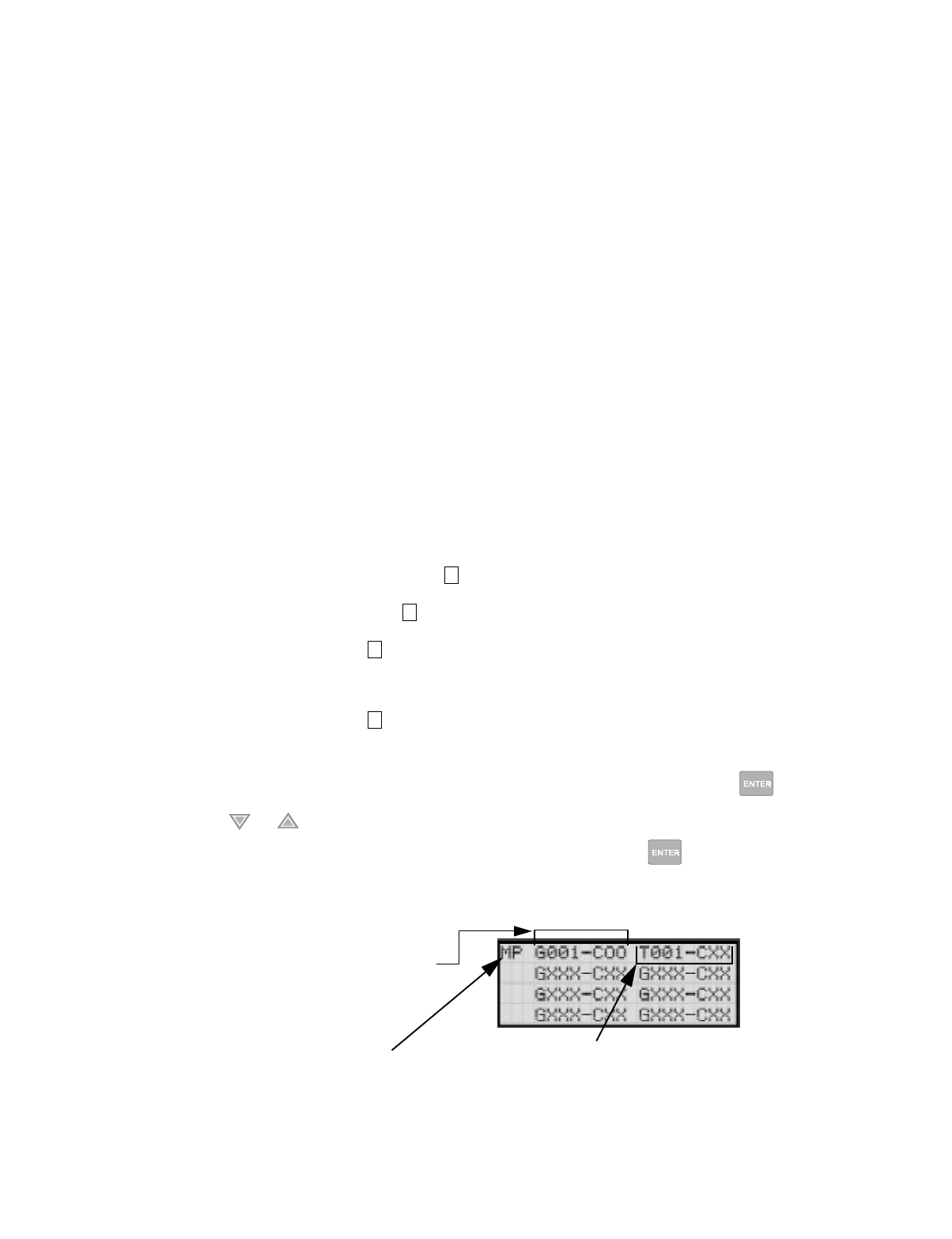
IntelliKnight 5820XL Installation Manual
7-8 151137
7.2.1.3 Zone Outputs
Output groups and cadence patterns are mapped to events. They can be programmed to output
when an event occurs in a zone. Some system trouble events can be mapped for the entire
system. Section 6.2 of this manual contains a general explanation of mapping. The following
sections explain how to select mapping options.
Mapping to Zone Events
Eight types of events can occur in zones. For each event type, you can activate up to 8 output
groups or output group template, specifying a pattern for each.
Event types are:
• Manual Pull Alarm
• Water Flow Alarm
• Detector Alarm (heat or smoke detectors)
• Aux 1 and Aux 2 Alarm (user-specified alarm types)
• Pre-alarm
• Supervisory
• Trouble
To map zone events to outputs, follow these steps:
1. From the Installer Main Menu, select for Program Menu.
2. From the Program Menu, select for Zone.
3. From the next menu, select for Edit Zone.
4. Enter the zone number you wish to edit.
5. From the next menu, select for Zone Outputs.
6. From the next screen, a list of 8 event types will display. Select the event type you want to
program. A screen similar to the one shown in Figure 7-3 will display. Press .
7. Press the or key to toggle the the group letter to either G = Group or T = output
group template depending on want you need for this zone. Press .
8. Select options for each event that could occur in this zone. Figure 7-3 is a complete
example of how you might map a zone.
Figure 7-3 Selecting Output Groups/templates and Cadence Patterns for a Zone Event
7
2
1
3
Indicates type of event (in
this case, Manual Pull alarm).
See Section 6.5 for choices.
Indicates output group 1, cadence
pattern 00 has been selected. 00 is
a constant output cadence.
"T" Indicates output group
template 1. See Section 7.3.5 for
more information on output group
templates.
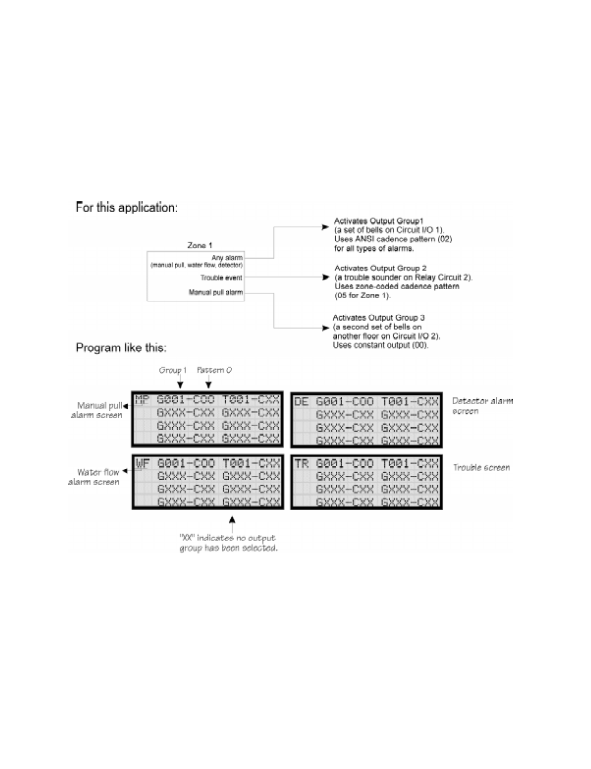
Programming
151137 7-9
Example or Zone Mapping:
Suppose you want to program Zone 1 so that:
• Any alarm (detector, water flow or manual pull) would activate Output Group 1 using the
ANSI cadence pattern.
• Manual pull alarm would activate Output Group 3 using constant output.
• Troubles would activate Output Group 2 using the zone-coded cadence pattern.
To accomplish this you need to access the screen for each event and then select your output
groups. Figure 7-4 shows how you would program this application.
Figure 7-4 Zone Mapping Example
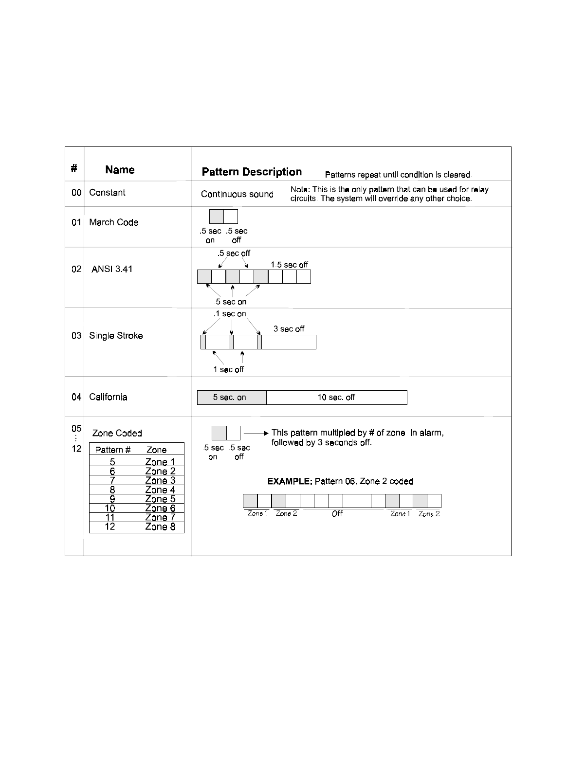
IntelliKnight 5820XL Installation Manual
7-10 151137
7.2.1.4 Cadence Patterns
The cadence patterns shown in Figure 7-5 are available for use with the control panel.
Cadence patterns can be selected by event type for each zone or for the entire system. Special
cadence patterns can be selected for fire drills and any auxiliary system switches used with the
system..
Figure 7-5 Cadence Patterns Available with the Control Panel

Programming
151137 7-11
7.2.2 Add Zone
To add a zone, follow these steps:
1. Enter the installer code.
2. Press or to display the installer menu.
3. Select for Program Menu.
Display reads: ,QLWLDOL]LQJ
3OHDVHZDLW
4. Press to enter zone menu.
5. Press to add a zone.
A zone will be added. The system will assign the next available zone number. Options for
this zone can now be programmed through the Zone Edit sub-menu. Up to 125 zones can
be used.
7.2.3 Delete Zone
To delete a zone, follow these steps:
1. Enter the installer code.
2. Press or to display the installer menu.
3. Select for Program Menu.
Display reads: ,QLWLDOL]LQJ
3OHDVHZDLW
4. Press to enter zone menu.
5. Press to delete a zone.
A warning screen will display. If you want to proceed with deleting the zone, select Yes.
To cancel, select No.
7
2
2
7
2
3
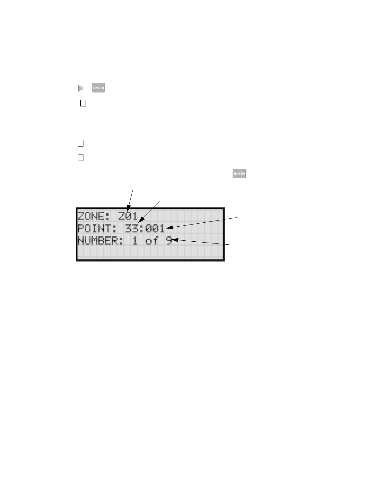
IntelliKnight 5820XL Installation Manual
7-12 151137
7.2.4 View Zone Points
To view the points in a zone, follow these steps:
1. Enter the installer code.
2. Press or to display the installer menu.
3. Select for Program Menu.
Display reads: ,QLWLDOL]LQJ
3OHDVHZDLW
4. Press to enter zone menu.
5. Press to view zone points.
6. Enter the number of the zone you wish to view, then press .
Figure 7-6 View Zone Points Screen
7
2
4
Zone Number
Module or
Device Address
Point Number
Total Number of
Points in the Zone

Programming
151137 7-13
7.3 Group
An output group is made up of output points that have been programmed to respond in the
same way. Output groups simplify programming because you do not have to program each
individual point. Once you have defined the characteristics of output groups, you can assign
each point to the appropriate group. Up to 250 output groups can be defined.
7.3.1 Edit Group
In the edit group option you can program the name of an output group (Section 7.3.1.1) and
change the properties (Section 7.3.1.2) of that group.
To edit a group, follow these steps:
1. Enter the installer code.
2. Press or to display the installer menu.
3. Select for Program Menu.
Display reads: ,QLWLDOL]LQJ
3OHDVHZDLW
4. Press to enter group menu.
5. Press to edit group.
6. Enter the number of the group you wish to edit, then press .
7.3.1.1 Edit Group Name
7. To edit the group name, press .
A screen similar to the one in Figure 7-7 will display. Select a one- or two-word
descriptive name as shown in the diagram. Refer to Appendix B Section B.1 for a list of
available words.
7
3
1
1
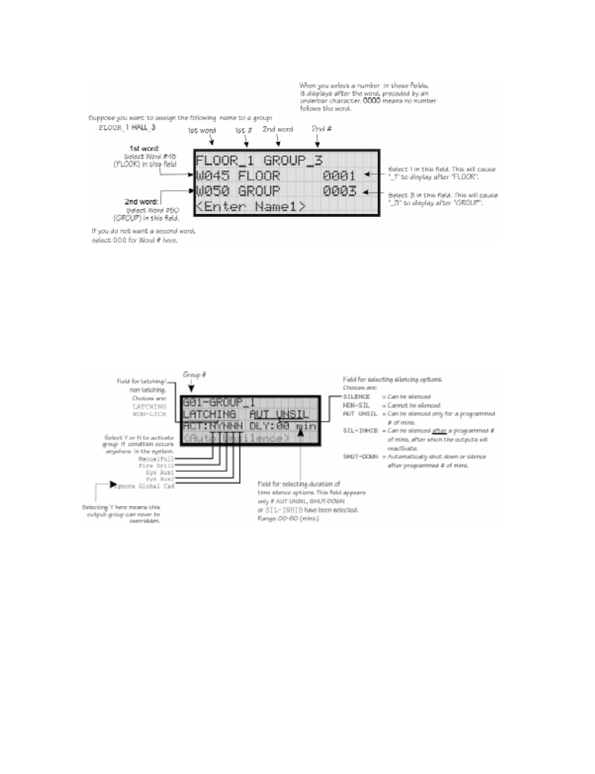
IntelliKnight 5820XL Installation Manual
7-14 151137
Example of Group Name:
Figure 7-7 Editing Group Name Example
7.3.1.2 Edit Group Properties
The Edit Group Menu allows you to select options for each group for the following items:
• Latching or non-latching outputs.
• Silencing operation.
• Operation with system switches.
Figure 7-8 Group Properties Screen Programming Options
Latching / Non-latching Outputs
Outputs that are programmed as Latching remain active until the system has been manually
reset. Non-latching outputs stop activating automatically when the condition clears.

Programming
151137 7-15
Silencing Options
The following silencing options are available for each output group.
Response with System-Wide Conditions
You can select whether an output group will respond to various system-wide occurrences.
(See Figure 7-8 for location of this field.)
8. To get to this menu item repeat steps 1 through 6 of section 7.3.1.
9. To edit group properties, press .
Table 7-3: Silencing Options
Option Description
SILENCE Silenceable. The output group can be silenced through the key.
NON-SIL Not silenceable. The output group cannot be silenced. Activation of the key will be
ignored for this output group.
AUT UNSIL Auto Unsilenced. If this option is selected, the output group can be silenced for a programmed time-
frame. If the condition that caused the output to activate has not cleared during the time-frame, the
output reactivates. If you select this option, select the time-frame in the DLY: field. Range is 00-60
minutes. (See Figure 7-8 for location of field.)
SIL-INHIB Timed Silence after Inhibit. If this option is selected, the output group must be audible for a
programmed number of minutes before it can be silenced. If the condition that caused the output to
activate has not cleared during the time-frame, the output can be silenced. If you select this option,
select the timeframe in the DLY: field. Range is 00-60 minutes. (See Figure 7-8 for location of
field.)
SHUT-DOWN If this option is selected, the output group will automatically silence (shut down) after the
programmed time period. If you select this option, select the timeframe in the DLY: field. Range is
00-60 minutes. (See Figure 7-8 for location of field.)
Table 7-4: Output Group Response Choices
Option Description
ManPull Manual Pull Activation. Select Yes if you want this group to activate for all manual pull
alarms that occur in the system.
Note: Even though manual pull switches are assigned to zones, activation selected
here for manual pull will override zone-programmed activation.
Fire Drill Fire Drill Activation. Select Yes if you want this group to activate for fire drills.
Sys Aux1 and Sys Aux2 Select Yes if you want this output group to activate for system-wide Aux1 and Aux2
alarms.
(Aux 1 and Aux 2 alarm types are for auxiliary alarm conditions. For example, you
might want to use Aux 1 to provide a unique alarm type and sound for a severe weather
condition like a tornado.)
Ignore Global Cad Ignore Global Cadence. If you want to create an output group that can never be
overridden, you can select Yes for this option. Selecting No means that system-wide
events that have been assigned an output pattern could override the pattern for the
output group.
For example, suppose you had assigned a set of strobes to Output Group 3. You would
never want these strobes to output in a pattern under any circumstances. To make sure
this happens, select Yes for Ignore Global Cadence for Output Group 3.
SILENCE
SILENCE
2

IntelliKnight 5820XL Installation Manual
7-16 151137
10. Press the or arrows to select the desired latching option.
11. Press .
12. Press the or arrows to select the desired silencing option. Refer to Table 7-3.
13. Press .
14. Enable group activation for a condition (see Table 7-4) by pressing the or arrows to
select Y (yes) or N (no).
15. Press .
16. Repeat steps 14 and 15 for all the activation options.
7.3.2 Add Group
To add a group, follow these steps:
1. Enter the installer code.
2. Press or to display the installer menu.
3. Select for Program Menu.
Display reads: ,QLWLDOL]LQJ
3OHDVHZDLW
4. Press to enter group menu.
5. Press to add a group.
The system will assign the next available group number. Properties for the new group can
now be edited if desired (see Section 7.3.1.2). A total of 250 output groups can be defined.
7.3.3 Delete Group
1. Enter the installer code.
2. Press or to display the installer menu.
3. Select for Program Menu.
Display reads: ,QLWLDOL]LQJ
3OHDVHZDLW
4. Press to enter group menu.
5. Press to delete a group.
A warning screen will display. If you want to proceed with deleting the group, select Yes.
To cancel, select No.
7
3
2
7
3
3
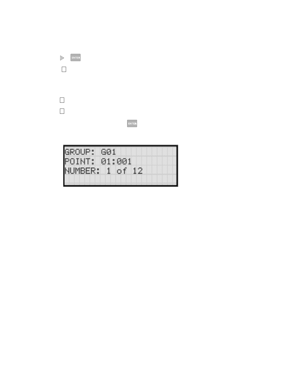
Programming
151137 7-17
7.3.4 View Group Points
1. Enter the installer code.
2. Press or to display the installer menu.
3. Select for Program Menu.
Display reads: ,QLWLDOL]LQJ
3OHDVHZDLW
4. Press to enter group menu.
5. Press to view group points.
6. Enter the group number, then press .
7
3
4
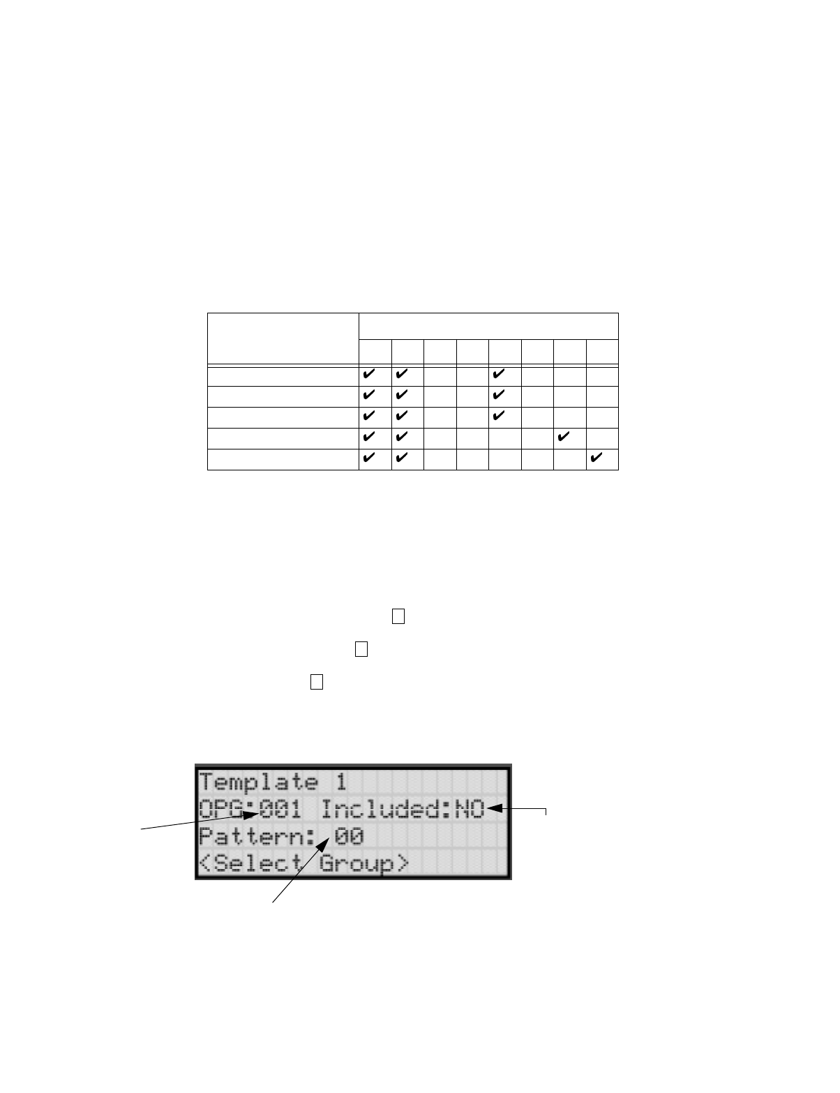
IntelliKnight 5820XL Installation Manual
7-18 151137
7.3.5 Edit Output Group Templates
Some installations may require that zones be mapped to more than 8 output groups. With
output group templates you can combine one or all output groups into one template, which can
be used when the same combination of outputs are used for several zones.
For example, lets say an installation has five zones (See Table 7-5). The check mark indicates
what output groups are mapped to each zone. You will notice that every zone is mapped to
outputs 1 and 2. As an alternative you can create a template that combines output group 1 and
2 as one choice.
This can be done by creating a template which includes output groups 1 and 2. Then you can
map all the zones to the template you created. This will free up output group assignments that
are common to several zones. This is very useful when you need to map zones to more than
eight output groups.
To create Output Group Templates:
1. From the Installer Main Menu, select for Program Menu.
2. From the Program Menu, select for Group.
3. At the next screen, select for Edit OPG Template.
4. Select the template number (01 - 08).
5. Select output group number. See Figure 7-9.
Figure 7-9 Output Group Template Programming Screen
Table 7-5: Zone Group Example
Zone Group Number
12345678
1st Floor Smoke Detectors
2nd Floor Smoke Detectors
3rd Floor smoke Detectors
Manual Fire Pull Stations
Water Flow Switches
7
3
5
Output
Group #
Yes = Include the selected
output group in this
template
No = Do Not include output
group in this template
Select the
Cadence Pattern

Programming
151137 7-19
7.4 Point
You may need to change characteristics of individual input points (detectors and switches)
even after using JumpStart. This section explains how to change options for: type of input
point; latching/non-latching status (switches); and name and zone assignment of a point.
7.4.1 Point Programming For 5815XL Module
To program for an 5815XL Module points, follow these steps:
1. Enter the installer code.
2. Press or to display the installer menu.
3. Select for Program Menu.
Display reads: ,QLWLDOL]LQJ
3OHDVHZDLW
4. Press to enter point menu.
5. Press the or arrows to select the desired module. refer to Section 6.5 Quick
Reference Table for available choices.
6. Press .
7. Enter the number of the point you wish to edit.
8. Press .
7
4

IntelliKnight 5820XL Installation Manual
7-20 151137
9. Select the type of device by pressing the or arrows. Refer to Table 7-6 under
column heading "Type Selection" for a list of choices.
Table 7-6: Point Programming Options for 5815XL Modules
Module Type Type
Selection Function Latching
Option Comments
Internal and
External
5815XL
UNUSED
DETECTOR
PHOTO
ION
HEAT
PHOT DUCT
ION DUCT
SWITCH
MAN_PULL
Use this switch type for manual pull stations. This input
is always latched. The switch can clear only when an
alarm is reset. This switch type has the highest priority;
it overrides any other type of alarm.
WATERFLOW
Latching Use this switch type for monitoring water flow in a
sprinkler system. Switch closure will cause a sprinkler
alarm. Water flow switches can be programmed as
latching or non-latching.
You can program a delay of up to 90 seconds to be used
with a water flow switch. The delay allows for normal,
brief changes in sprinkler system water pressure. The
water flow alarm will not activate unless the switch is
active for the programmed delay time.
If a delay is used, the system begins counting down
when the switch closes. If the switch opens (restores)
before the timer expires, a water flow alarm is not
generated. If the water flow switch remains closed after
the timer expires, a water flow alarm will be generated.
Non Latching
SUPERVISY
Latching Use this switch type for tamper monitoring of sprinklers
and other fire protection devices. If a contact closes, a
sprinkler supervisory event will be generated.
Supervisory switches can be latching or non-latching.
Non Latching
FIREDRILL
System-level, non latching switch. This switch is an
alternative way of causing a fire drill. It has the same
operation as the fire drill option available from the
annunciator. When the switch is activated, a fire drill
begins; when the switch is de-activated, the fire drill
ends.
SILENCE
This system-level switch is an alternative way to silence
the system. It has the same effect as pressing the
key.
RESET
This system-level switch is an alternative way to reset
the system. It has the same effect as pressing the
key.
SILENCE
RESET

Programming
151137 7-21
Internal and
External
5815XL
(Continued)
SWITCH
(Continued)
PAS_ACK
Positive acknowledge switch. This switch must be used
in zones programmed as Positive Alarm Sequence (see
Table 7-2).
If an acknowledge switch closes when an alarm or
trouble condition is not already in progress, a trouble
will occur.
You must use a UL listed normally open, momentary
switch type. The switch must be rated at 5V, 100 mA
(minimum) and be used with an EOL resistor for
supervision.
ZN_AUX1 Latching Use these switch types if you want to monitor special
zone-level conditions (such as operation of a fan or
damper).
Non Latching
ZN_AUX2 Latching
Non Latching
SYS_AUX1 Latching Use these switch types if you want to monitor special
system-wide conditions (such as operation of a fan or
damper).
Non Latching
SYS_AUX2 Latching
Non Latching
DETECT SW Used to monitor conventional 4-wire detectors, a
contact closure will generate a detector alarm event.
TAMPER Latching Performs identically to a supervisory switch, but will be
indicated as a tamper switch on the LCD annunciator.
Non Latching
NOTIF
OUTPUT PT Select Group Output Point, a general use notification type. Use for
driving standard notification appliances.
AUX CONST Select Group
Use constant power for applications that require a
constant auxiliary power source. Power is always
present at Constant circuits.
AUX RESET Select Group
Use for auxiliary power, resettable applications. See
Section 4.12.5.3 for a description of how this option
operates.
AUX DOOR Select Group
Use for auxiliary power, door holder applications. For
example, if you were using an auxiliary power supply
for door holders, you would use this option. See Section
4.12.5.1 for a description of how this option operates.
RELAY
OUTPUT PT Select Group
Output Point, a general use relay type. Use for
applications requiring a relay, such as fan shutdown,
elevator recall, and so on.
AUX RESET Select Group
Use for auxiliary power, resettable applications. See
Section 4.12.5.3 for a description of how this option
operates.
AUX DOOR Select Group
Use for auxiliary power, door holder applications. For
example, if you were using an auxiliary power supply
for door holders, you would use this option. See Section
4.12.5.1 for a description of how this option operates.
Table 7-6: Point Programming Options for 5815XL Modules
Module Type Type
Selection Function Latching
Option Comments

IntelliKnight 5820XL Installation Manual
7-22 151137
7.4.2 Point Programming For Internal
or External Power Module (5895XL)
To program for an internal or external power module points, follow these steps:
1. Enter the installer code.
2. Press or to display the installer menu.
3. Select for Program Menu.
Display reads: ,QLWLDOL]LQJ
3OHDVHZDLW
4. Press to enter point menu.
5. Press the or arrows to select the desired module. Refer to Section 6.5 for available
choices.
6. Press .
7. Enter the number of the circuit or point you wish to edit. Refer to Table 7-7 for available
selections.
8. Press .
9. Select the type by pressing the or arrows.
10. Press .
11. Select the function by pressing the or arrows.
12. Press .
7
4

Programming
151137 7-23
13. Select the zone by pressing the or arrows.
14. Press .
15. Edit point name. See Section 7.4.3.1.
Or
Press to skip point name edit.
16. Repeat Steps 1 through 15 for all circuits.
Table 7-7: Menu choices for Internal/External Power Module
Choices Type Selections Function
Selections for
each Type Comments
Enter Point or Circuit
Select Type
UNUSED
B NOTIF
A NOTIF
AUX PWR
CONSTANT Constant auxiliary power.
RESETTABLE Resettable auxiliary power.
DOOR Door holder auxiliary power.
B SWITCH
MAN PULL Refer to comments column of
Table 7-6 for description of these
options.
Latch or Non-latching feature only
appears for waterflow, supervisory,
tamper, zone aux1, zone aux2, system
aux1, and system aux2.
WATERFLOW
SUPERVSY
TAMPER
FIREDRILL
SILENCE
RESET
PAS_ACK
ZN_AUX1
ZN_AUX2
SYS_AUX1
SYS_AUX2
A SWITCH Same as B SWITCH Used for
B DETECTOR 2-WIRE SMK Used for Class B, 2-wire detectors.
4-WIRE SMK Used for Class B, 4-wire detectors.
A DETECTOR 2-WIRE SMK Used for Class A, 2-wire detectors.
4-WIRE SMK Used for Class A, 4-wire detectors.
UNUSED
B NOTIF
A NOTIF
Select Zone/Group Group or Zone selection will appear
depending on the type selected.
Edit Name See Section 7.1.1.1.
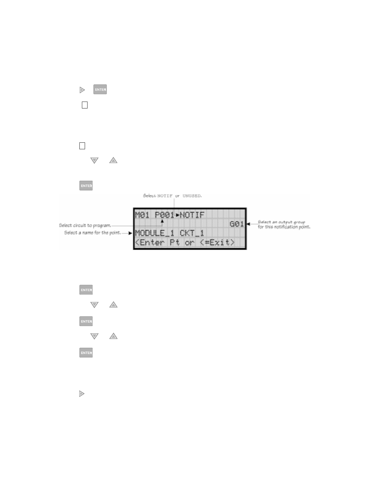
IntelliKnight 5820XL Installation Manual
7-24 151137
7.4.3 Point Programming For 5880 and 5865 Modules
To program for a 5880 or 5865 module points, follow these steps:
1. Enter the installer code.
2. Press or to display the installer menu.
3. Select for Program Menu.
Display reads: ,QLWLDOL]LQJ
3OHDVHZDLW
4. Press to enter point menu.
5. Press the or arrows to select the desired module. Refer to Section 6.5 for available
choices.
6. Press .
Figure 7-10 Programming Points Screen for 5880 and 5865 Modules
7. Enter the point number.
8. Press .
9. Press the or arrows to select the type (Notification or unused).
10. Press .
11. Press the or arrows to select the desired Group.
12. Press .
13. Edit module name. See Section 7.4.3.1.
Or
Press to skip module name edit.
14. Repeat Steps 1 through 13 for all points.
7
4

Programming
151137 7-25
7.4.3.1 Assigning a Name to a Points
You can assign a name to a point to make it easier to recognize on a display.
If you wish to edit the name of a point, follow these instructions:
1. When the Display is flashing on the Edit Name field press .
2. Enter the number for the Name1or press the or arrow to select Name1. Refer to
Appendix B Table B-1.
3. Press .
4. Enter Number1 or press the or arrow to select Number1.
5. Press .
6. Enter the number for the Name2 or press the or arrow to select Name2. Refer to
Appendix B Table B-1.
7. Press .
8. Enter Number2 or press the or arrow to select Number2.
9. Press .
If you wish to bypass the Edit Name field press .

IntelliKnight 5820XL Installation Manual
7-26 151137
7.5 System Options
This section of the manual explains how to customize software options that affect general
operation of the system. This includes such items as: AC loss hours, system clock options,
holidays schedule, telephone and reporting account options. Refer to each individual
subsection for complete instructions.
7.5.1 Reporting Account
Up to four reporting accounts can be used with the control panel. Events in accounts are
reported by zone.
Each account is assigned an up-to-6-digit account number. Each account is also assigned a
unique ID (1-4) which determines the priority for reporting ("1" has the highest priority; "4"
has the lowest).
Disable any unused accounts by selecting "N" for all events (see Figure 7-11, next page). If
the system is local only (does not connect to a central station), disable all events for all four
reporting accounts.
Options for each account can be customized. These options appear on the Reporting Accounts
screen. Some related options appear on the Phone Lines screen (see Section 7.5.2).
To access the Reporting Accounts screen:
1. Enter the installer code.
2. Press or to display the installer menu.
3. Select for Program Menu.
Display reads: ,QLWLDOL]LQJ
3OHDVHZDLW
4. From the Program Menu, select for System Options.
5. From the next menu, select for Reporting Accounts.
7
5
1
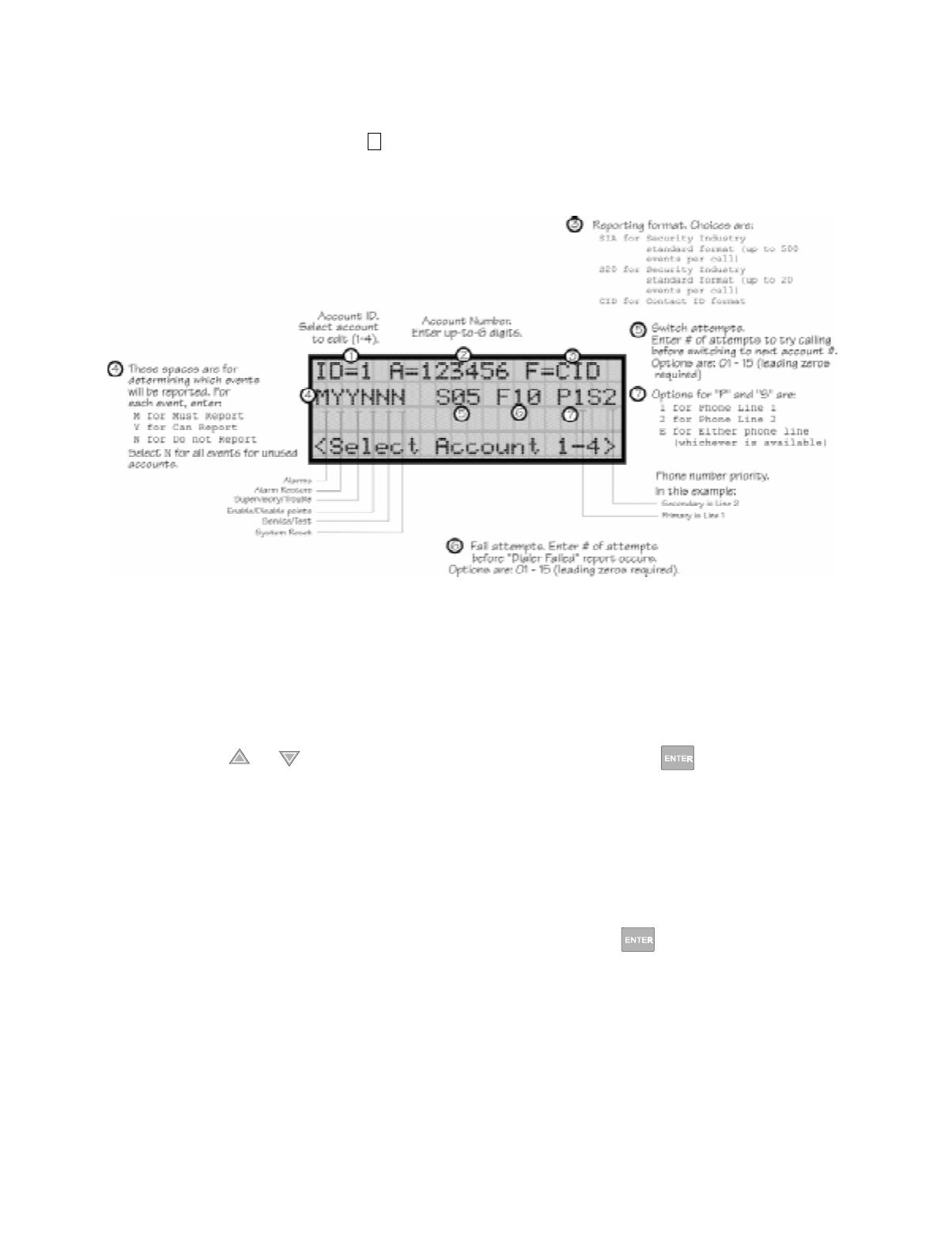
Programming
151137 7-27
7.5.1.1 Edit Accounts
6. From the next menu, select for Edit Account.
A screen similar to one shown in Figure 7-11 will display. The following subsections
describe the options on each field.
Figure 7-11 Reporting Account Editing Screen
Select Account (ID)
The control panel provides up to 4 reporting accounts. The priority of an account is based on
its account ID. Account 1 is highest priority; Account 4 is lowest. Use Account 1 to report the
highest priority events.
7. Press the or arrow to select account ID number, then press .
Edit Account Number
Enter an up-to-6-digit number for each account to identify the account to the central station.
See Figure 7-11 for location of this option on the screen. The account number should be
compatible with the reporting format used. For example, the Contact ID format transmits up
to four digits only.
8. Enter the desired account number (up to 6-digits), then press .
1

IntelliKnight 5820XL Installation Manual
7-28 151137
Select Reporting Format
Select a reporting format for each account. Options are:
9. Press the or arrow to select the reporting format, then press .
Events to Report
The next six options select which types of events (or event families) will be reported to this
account. (See Figure 7-11 for location of these options on the screen.) Events are reported by
zone.
10. Press the or arrow to select Must, Yes, or No (see Table below), then press .
11. Repeat step 10 for all six event report options.
For each event family, select M, Y, or N.
Switch Attempts
Specify the number of times the dialer should attempt to report to this account before
switching to the next account. Range is 01-15.
12. Enter the number of switch attempts (or press the or arrow), then press .
SIA SIA format. 500 events per call.
CID Ademco’s Contact ID format
S20 Same as SIA but limits events reported to 20 events per phone call.
Event Family Events Included in this Family
Alarms All alarms (Water Flow, Manual Pull, Detectors, Auxiliary Switches)
Alarm Restore All alarm restores.
Supervisory/Trouble All trouble and supervisory conditions and trouble and supervisory restores.
Enable/Disable Point Enabling and disabling of input and output points.
Service/Test Fire drill, walk test, dialer test, automatic test, all programming sessions.
System Reset All system resets.
M(ust) Must Report. Selecting "M" makes this a primary reporting account for this family of events. The dialer
MUST report events in this family to this account.
Selecting Must makes an account a primary reporting account. The dialer will try to report the event to
the primary account until it exceeds the "Switch Attempts" value. When the dialer has exceeded the
Switch Attempt retry limit, it will switch to a backup account (a "Can Report" or "Yes" account, see
below). If the dialer cannot report the event to any of the backup accounts, it will return to the primary
account and repeat the process until it exceeds the "Fail Attempts" value. If the Fail Attempts limit is
exceeded, an Account Trouble condition is generated and a local trouble will sound.
Y(es) Can Report. Selecting Y makes this a backup account for this event family. The dialer will report to this
account only if it was previously unable to report the event to a Must account.
N(o) No events in this family will ever be reported to this account.
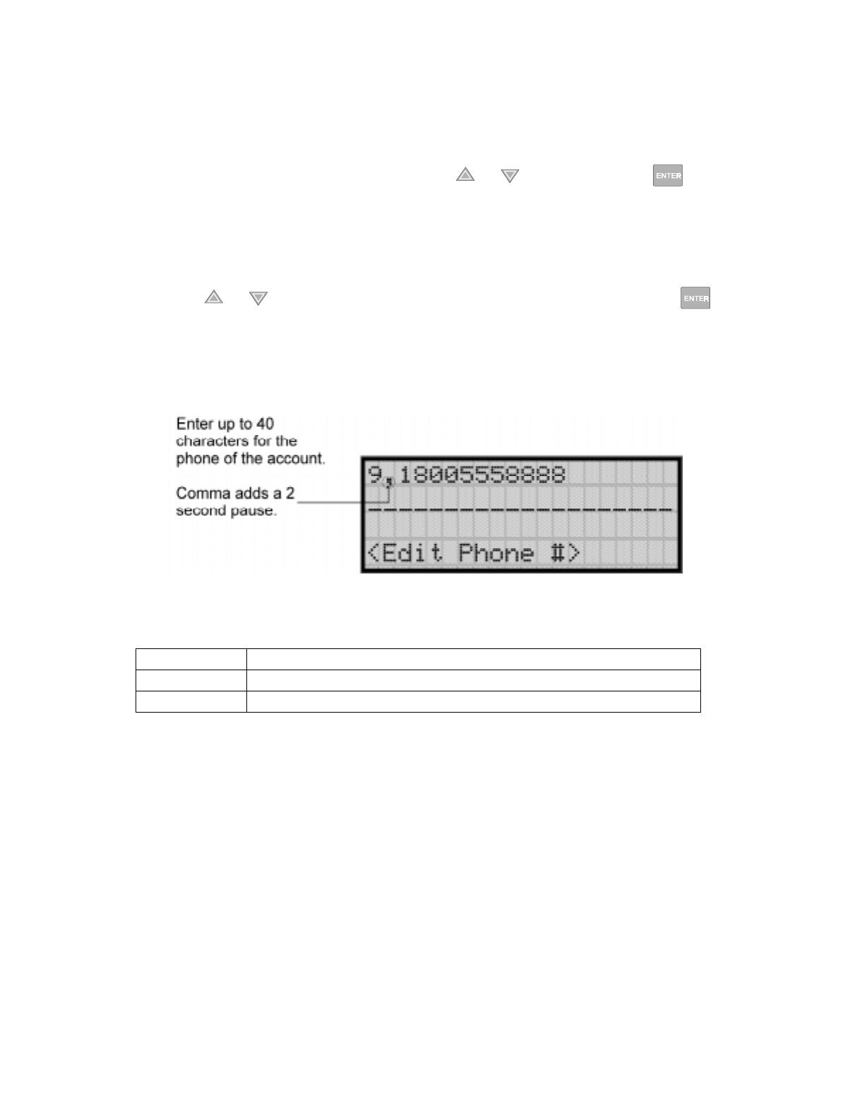
Programming
151137 7-29
Fail Attempts
This feature specifies the number of times the dialer should attempt to perform the dial/switch
sequence before issuing an account trouble condition. Range is 01 - 15 (Default = 10).
13. Enter the number of fail attempts (or press the or arrow), then press .
Selecting Primary and Secondary Phone Lines
For each account, select which phone line (Line 1 or Line 2) is primary. See Figure 7-11 for
an example of how to make this selection.
14. Press the or arrow to select line 1 or 2 as primary phone line, then press .
15. Repeat step 14 for the secondary phone line.
Telephone Number
Enter up to 40 characters for phone number for this account.
The following special characters are available:
Use the number buttons on the annunciator or the up- and down-arrow keys to select special
characters. Characters begin displaying after "9". See Figure 7-11 for an example.
Table 7-8: Special Character for Dialing
# Pound (or number) key on the telephone
* Star key on the telephone
, Comma (character for 2-second pause)

IntelliKnight 5820XL Installation Manual
7-30 151137
7.5.1.2 Auto Test Time
To access the automatic dialer test time screen:
1. Enter the installer code.
2. Press or to display the installer menu.
3. Select for Program Menu.
Display reads: ,QLWLDOL]LQJ
3OHDVHZDLW
4. From the Program Menu, select for System Options.
5. From the next menu, select for auto test time.
6. Enter the hour you desire the control panel to send an automatic test report (or press the
or arrow), then press .
7. Enter the minutes (or press the or arrow), then press .
8. Select AM or PM by pressing the or arrow, then press .
7.5.2 Phone Lines
To access the phone lines screen:
1. Enter the installer code.
2. Press or to display the installer menu.
3. Select for Program Menu.
Display reads: ,QLWLDOL]LQJ
3OHDVHZDLW
4. From the Program Menu, select for System Options.
5. Select for the phone lines menu.
7
5
2
7
5
2
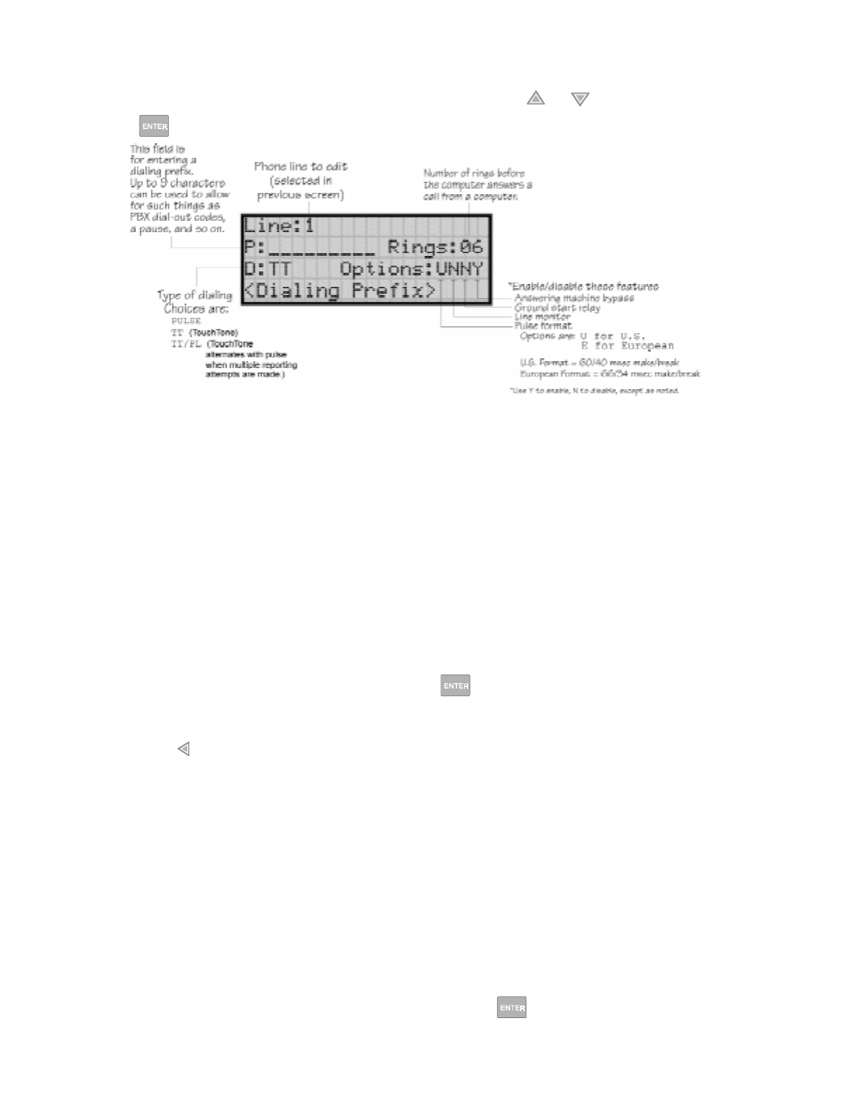
Programming
151137 7-31
6. Select the phone line to be edited (1 or 2) by pressing the or arrow, then press
.
Figure 7-12 Phone Lines Editing Screen
7.5.2.1 Dialing Prefix
Enter up to 8 characters to be used for such things as PBX dial-out codes, a pause, and so on.
The following special characters are available:
Use the number buttons on the annunciator or the up- and down-arrow keys to select special
characters. Characters begin displaying after "9". See Figure 7-12 for an example.
7. Enter a dialing prefix (if needed), then press .
Or
Press to bypass the dialing prefix option.
7.5.2.2 Number of Answer Rings
This option is used in conjunction with the SK Analog Fire System Editor 5590. Use the
option to determine the number of rings before the panel answers a call from the computer.
Range is 00-15 rings. This option is factory-programmed as 06 rings, which should be
compatible for most installations where the answering machine bypass feature is used. You
may need to adjust it depending on the installation’s telephone system.
The selection made here must match the programming for this option in the Communication
Configuration dialog box of the 5590 software. See the manual for the software (p/n 151004)
if you need more information.
8. Enter the desired number of answer rings, then press .
# Pound (or number) key on the telephone
* Star key on the telephone
, Comma (character for 2-second pause)
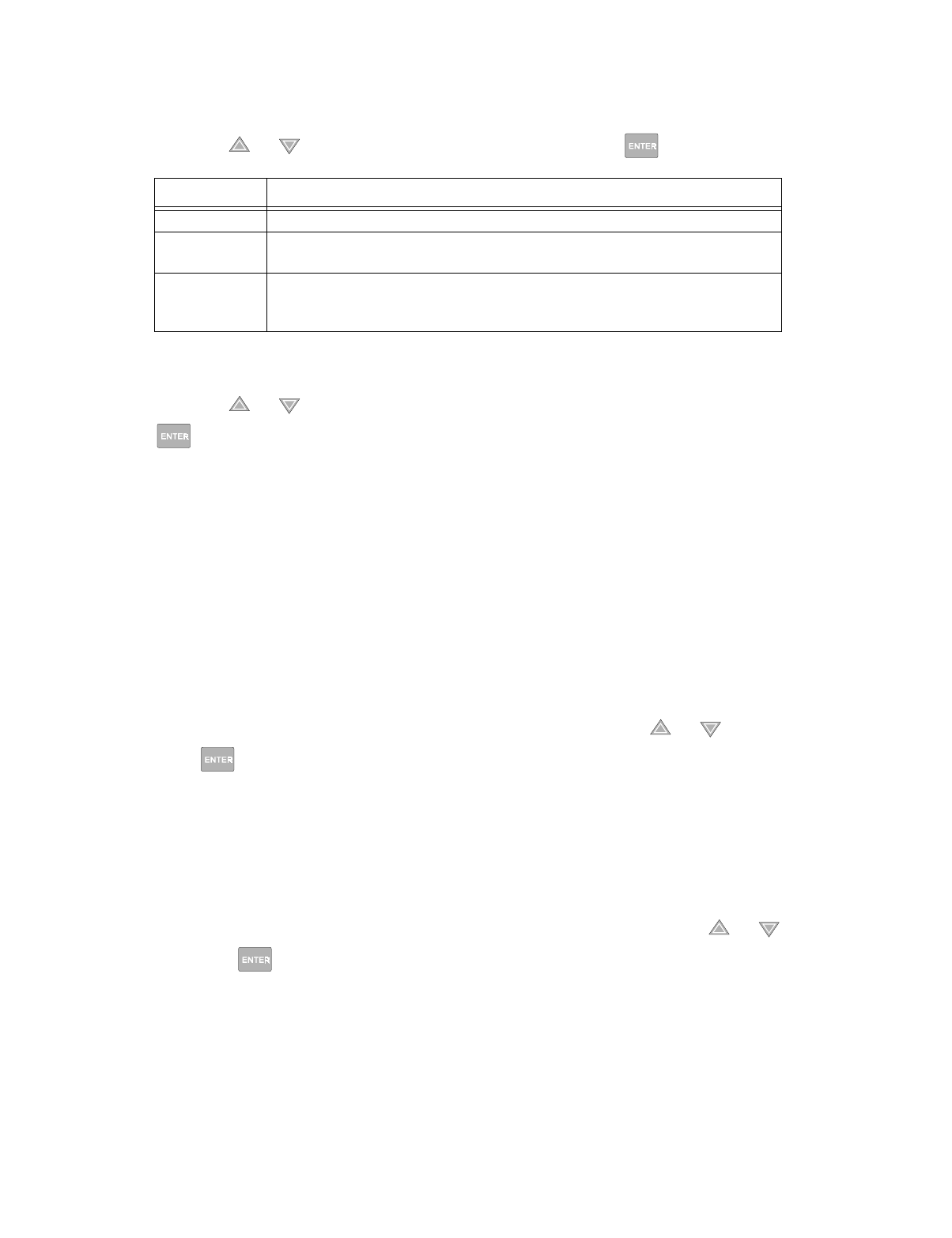
IntelliKnight 5820XL Installation Manual
7-32 151137
7.5.2.3 Dial Option (TouchTone or Pulse)
9. Press the or arrow to select the dial option, then press .
7.5.2.4 Rotary Format
10. Press the or arrow to select the pulse ratio for rotary dialing option, then press
.
Options are:
7.5.2.5 Line Monitor
Enable the line monitor for each phone line that will be used. See Figure 7-12 for location of
this field on the phone lines screen. When the phone line monitor has been enabled for a
phone line, a trouble condition will occur if the line is not connected. If a phone line will not
be used, it must be disabled.
11. Select Y (monitor line) or N (don’t monitor line) by pressing the or arrow, then
press .
7.5.2.6 Ground Start Relay
If the ground start relay (Model 5211) is used, use this option to enable it. See Figure 7-12 for
location of this field on the phone lines screen. This option is disabled by default.
Note: Ground start cannot be used in UL installations.
12. Select Y (ground start used) or N (ground start not used) by pressing the or arrow,
then press .
Dial Option Description
PULSE If this option is selected, only pulse dialing will be used for this phone line.
TT TouchTone dialing. If this option is selected, only TouchTone dialing will be used for
this phone line.
TT/PL
TouchTone alternating with pulse. If this option is selected, the dialer will first attempt to
use TouchTone. It will switch to pulse if TouchTone is not successful on the first
attempt. It will continue to alternate between TT and pulse for additional attempts.
U U.S. standard format. Uses the 60 msec / 40 msec make/break ratio.
E European format. Uses the 66 msec / 34 msec make/break ratio.

Programming
151137 7-33
7.5.2.7 Answering Machine Bypass
This option is used in conjunction with the SK Analog Fire System Editor 5590. This feature
ensures that an answering machine will not interfere with communication between the panel
and the computer. If an answering machine is used at the panel site, enable this feature; if an
answering machine is not used, disable the feature.
This option is factory-programmed as Yes (enabled).
The selection made here must match the programming for this option in the Communication
Configuration dialog box of the 5590 software. See the manual for the software (p/n 151004)
if you need more information.
13. Select Y (answering machine bypass enabled) or N (answering machine bypass disabled)
by pressing the or arrow, then press .
7.5.3 Sys. Event Outputs
1. Enter the installer code.
2. Press or to display the installer menu.
3. Select for Program Menu.
Display reads: ,QLWLDOL]LQJ
3OHDVHZDLW
4. From the Program Menu, select for System Options.
5. From the System Options Menu, select for Sys. Event Outputs.
7.5.3.1 Trouble Events
You can map certain system trouble events to an output group. To access the screen for
selecting output groups and cadence patterns for system trouble events.
6. Press for Trouble Events. A screen similar to the one in Figure 7-13 will display. Select
a group and a cadence pattern for each event as needed for your application. The U: field
is for a user-specified trouble condition. You can program an output group and cadence
pattern for any of the following events:
Battery Low battery condition.
Gnd Flt Ground fault.
Phone Ln Phone Line 1 or 2 trouble.
Account Account trouble; cannot report to account.
Printer Printer trouble. (Currently not supported; do not select.)
Aux Pwr Auxiliary power trouble.
Sys Sw Trouble with a system switch.
Group Tr Trouble with an output group.
SBUS Com SBUS communication trouble.
SBUS Pwr SBUS power trouble.
SLC Loop Trouble on the SLC loop.
AC Loss AC power lost.
7
5
3
1
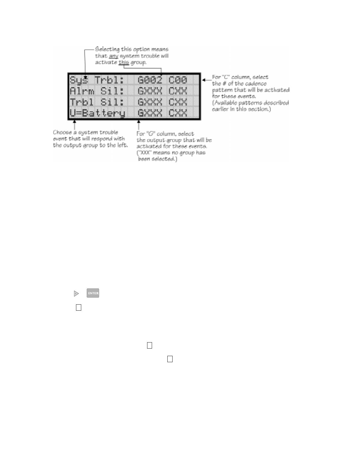
IntelliKnight 5820XL Installation Manual
7-34 151137
Figure 7-13 System Trouble Event Mapping Example
7.5.3.2 System Alarm Cadence
Fire drill and system auxiliary alarm events can have special cadence patterns to distinguish
them from other types of alarms. See Section 7.2.1.4 for available cadence patterns.
A typical use of the System Aux1 and Aux2 patterns is to distinguish fire emergencies from
other types of emergencies (such as a tornado or other weather condition). For example, you
could use one pattern for fire drills and a different pattern for a tornado condition. The System
Aux1 and Aux2 alarms would be triggered by a system-wide switch.
To access the screen for selecting output groups and cadence patterns for system trouble
events:
1. Enter the installer code.
2. Press or to display the installer menu.
3. Select for Program Menu.
Display reads: ,QLWLDOL]LQJ
3OHDVHZDLW
4. From the Program Menu, select for System Options.
5. From the System Options Menu, select for Sys. Event Outputs.
7
5
3
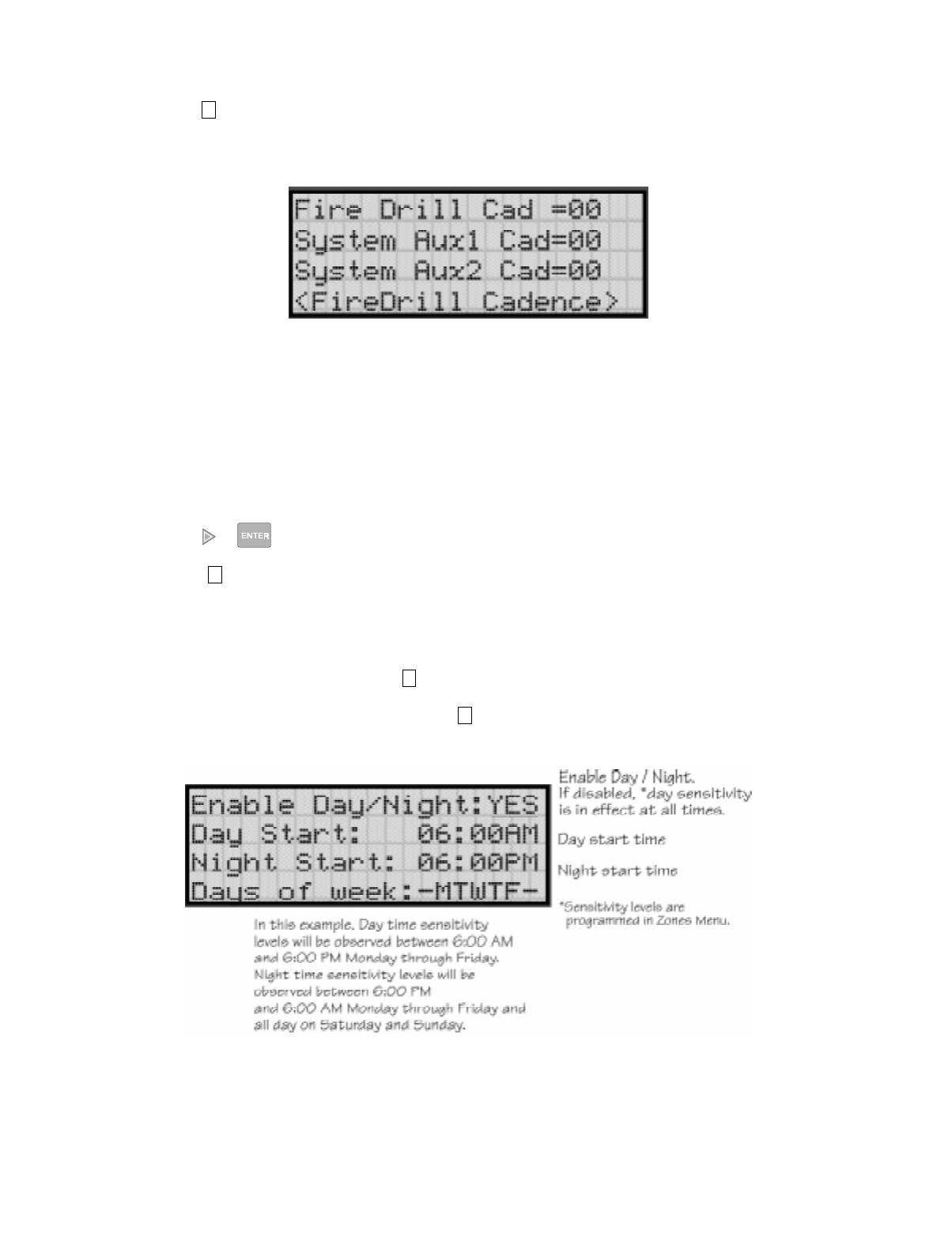
Programming
151137 7-35
6. Press for System Alarm Cadence.
A screen similar to the one in Figure 7-14 will display. Select a cadence pattern for these
special events if required for your application.
Figure 7-14 Special Cadence Patterns for Fire Drill and Auxiliary Alarm Events
7.5.4 Day/Night Sensitivity Time
If you need to change the time that sensitivity levels take effect (that is, the time that "Day"
and "Night" begin), follow these steps.
1. Enter the installer code.
2. Press or to display the installer menu.
3. Select for Program Menu.
Display reads: ,QLWLDOL]LQJ
3OHDVHZDLW
4. From the Program Menu, select for System Options.
5. From the System Options Menu, select for Day/Night Sense.
A screen similar to the one shown in Figure 7-15 will display.
Figure 7-15 Changing Day/Night Sensitivity Time
2
7
5
4
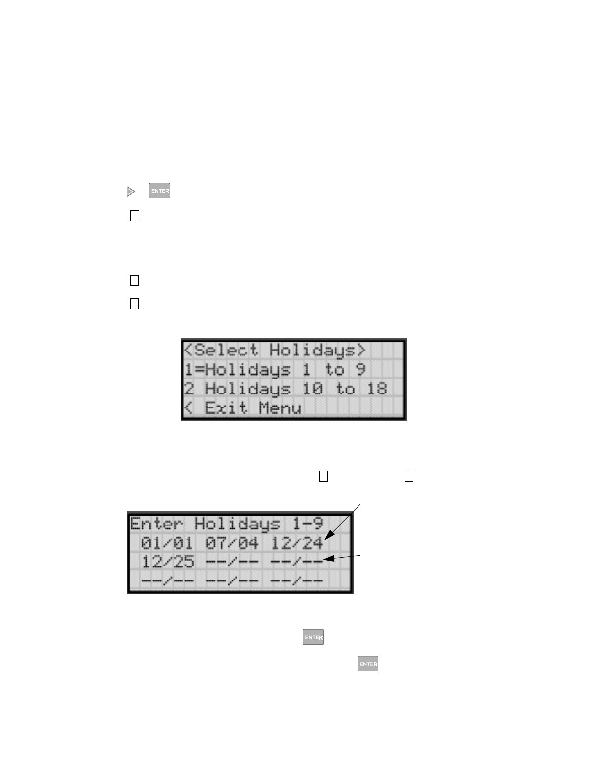
IntelliKnight 5820XL Installation Manual
7-36 151137
7.5.5 Holiday Days
Up to 18 dates can be designated as holidays. When day/night sensitivity is enabled, all
photoelectric smoke detectors in the system will use night sensitivity for the entire day on
days designated as holidays (see Section 7.5.4).
To add or change a holiday, follow these steps.
1. Enter the installer code.
2. Press or to display the installer menu.
3. Select for Program Menu.
Display reads: ,QLWLDOL]LQJ
3OHDVHZDLW
4. Select for System Options.
5. Select for Holiday Days.
A screen similar to that shown in Figure 7-16 will display.
Figure 7-16 Select Holidays
Note: For most installations, holiday programming will need to be performed each year to ensure correct dates.
6. Select the holiday schedules you wish to edit ( holidays 1 - 9, holidays 10 - 18).
Figure 7-17 Edit Holidays Screen
7. Enter the month of the Holiday, then press .
8. Enter the day of the month for the Holiday, then press .
9. Repeat steps 7 and 8 for any remaining holidays you wish to program.
7
5
5
1 2
Pre-programmed
Holidays
Programmable
Holiday locations
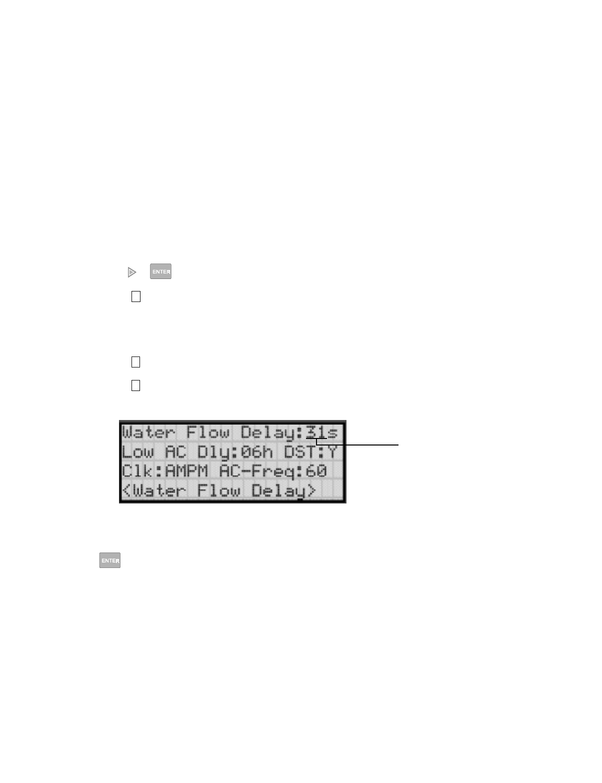
Programming
151137 7-37
7.5.6 Miscellaneous Options
Through this programming option you can set the water flow delay time, low AC report delay,
enable or disable automatic daylight savings time adjustment, clock format, and AC clock
frequency.
7.5.6.1 Water Flow Delay
You can program a delay of 0-90 seconds (zero means no delay) to be used in conjunction
with a water flow switch. The delay is system-wide. All water flow switches on the system
will use the same delay period.
To access the screen for programming water flow delay, follow these steps:
1. Enter the installer code.
2. Press or to display the installer menu.
3. Select for Program Menu.
Display reads: ,QLWLDOL]LQJ
3OHDVHZDLW
4. Select for System Options.
5. Select for Miscellaneous Options.
A screen similar to the one shown in Figure 7-18 will display.
Figure 7-18 Water Flow Delay Programming Screen
6. Enter the number of seconds (0 to 90 ) to delay an a water flow switch alarm, then press
.
7
5
6
Delay in seconds
before waterflow
alarm occurs.
(00 - 90)
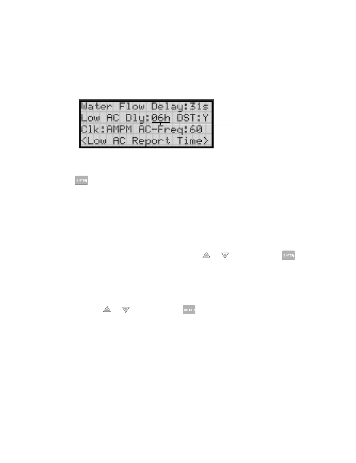
IntelliKnight 5820XL Installation Manual
7-38 151137
7.5.6.2 Low AC Report Delay
Note: You must select 6-12 hours in UL central station installations or 15-30 in UL remote signaling installa-
tions.
You can adjust the number of hours before a Low AC report will be sent to the central station.
To program low AC report delay, follow these steps:
Note: Steps continued from step 6 of Section 7.5.6.1.
Figure 7-19 Low AC Report Delay Programming Screen
7. Enter the number of hours before a low AC report will be sent to the central station, then
press . Refer to Figure 7-19.
7.5.6.3 Automatic Daylight Savings Adjustment
The control panel has an automatic DST (daylight savings time) adjustment feature. If this
feature is enabled, the system clock will switch to DST on the first Sunday in April at 2:00
a.m. The system clock will revert to standard time on the last Sunday in October at 2:00 a.m.
To enable or disable DST adjustment continue programming form step 7 above:
8. Select Y (enabled) or N (disabled) by pressing the or arrow, then press .
7.5.6.4 Clock Display Format (AM/PM or Military)
To change the system clock display format, continue programming from step 8 above:
9. Select AMPM (for AM/Pm display format) or MIL (for military or 24 hr display format)
by pressing the or arrow, then press .
Low AC Report
Delay in Hours
(06 - 30)

Programming
151137 7-39
7.5.6.5 Change AC Line Frequency
The panel’s AC line frequency is selectable for 50, 60 Hz, or Neither. AC Frequency feature
dictates how the control panel will calculate time based on the AC line frequency used in the
installation site. The "Neither" option can be used in areas where the AC line frequency is not
dependable and you want the panel to calculate time from the internal crystal. The internal
crystal is not as accurate as the AC power source and either 60 Hz or 50 Hz should normally
selected. The panel defaults to the 60 Hz. selection
To change the AC line frequency, continue programming from step 9 above:
10. Select 50, 60 or Neither, by pressing the or arrow, then press .
7.5.7 Edit Library Name
The control panel has a built-in library (or list) of 120 9-character words that are available for
you to select for naming points, zones, and groups. You can add up to 136 of your own 9-
character words to the library which will then be available to select.
Note: Customized words are available to be selected as descriptions of zones, groups and points. If you change
a word that is used in more than one location, all descriptions using the word will be changed.
To add word to the built-in library, follow these steps:
1. Enter the installer code.
2. Press or to display the installer menu.
3. Select for Program Menu.
Display reads: ,QLWLDOL]LQJ
3OHDVHZDLW
4. Select for System Options.
5. Select for Miscellaneous Options.
Figure 7-20 Edit Library Word Screen
6. Enter the word number you wish to edit or add, then press .
7. Select each character of a word by pressing the or arrow, then press to move to
the next character.
8. When word is complete press . repeat steps 1 through 8 for any additional word.
7
5
7
Use or arrow to select
character, then press to
move to next character.
Word Number
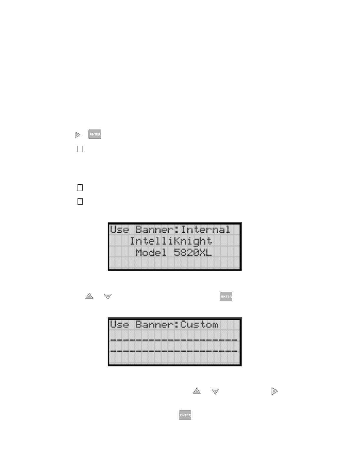
IntelliKnight 5820XL Installation Manual
7-40 151137
7.5.8 Edit Banner Message
The banner is the message that displays on the panel LCD when the system is normal, that is,
when no alarms or troubles exist and no one is currently using system menus. You can create
a customized message, which can be up to 40 characters, two lines of 20 characters each.
If you do not create a customized message, the system will use the internal banner. You
cannot change the internal banner.
To customizing the banner display message:
1. Enter the installer code.
2. Press or to display the installer menu.
3. Select for Program Menu.
Display reads: ,QLWLDOL]LQJ
3OHDVHZDLW
4. Select for System Options.
5. Select for Miscellaneous Options.
A screen similar to the one shown in Figure 7-21 will display.
Figure 7-21 Internal Banner Message
6. Press the or arrow to select "Custom", then press .
A screen similar to the one shown in Figure 7-22 will display.
Figure 7-22 Custom Banner Edit Screen
7. Select each character of a word by pressing the or arrow, then press to move to
the next character.
8. When word or sentence is complete press to move to line two of the custom banner.
Repeat step 7 and 8.
7
5
8

Programming
151137 7-41
7.6 JumpStart Autoprogramming
To run JumpStart:
1. Enter the installer code.
2. Press or to display the installer menu.
3. Select for Program Menu.
Display reads: ,QLWLDOL]LQJ
3OHDVHZDLW
4. Select for System Options.
5. Press the or arrow to select "Yes" from the warning screen.
6. Press .
IMPORTANT!
JumpStart is intended to be used prior to performing any custom programming. Each time
JumpStart is executed, all options will be reset to their default values. Do not run
JumpStart after you have configured the system through programming.
7
6

IntelliKnight 5820XL Installation Manual
7-42 151137
7.7 Computer Account
An installer at the panel site can initiate communications between the panel and a computer
running the SK Analog Fire System Editor 5590 (see also Section 8.4.16). In order for this
communication to function properly both the computer (running the software) and the control
panel must have matching computer account numbers and computer access codes.
Before you program in this location you should know how your control panel will
communicate with the downloading computer, either through direct connect (RS232) or via
the phone lines (Internal Modem).
If the computer initiates the call to a downloading computer, a phone number must be
programmed in the computer accounts area. If the computer initiates the call then answering
machine bypass (see Section 7.5.2.7) may need to be selected.
To program computer account information:
1. Enter the installer code.
2. Press or to display the installer menu.
3. Select for Program Menu.
Display reads: ,QLWLDOL]LQJ
3OHDVHZDLW
4. Select for System Options.
5. Enter the computer account number, then press .
6. Enter the computer code (up to 7-digits), then press .
7. Enter the phone number the panel will dial to connect to a downloading computer (up to
40-digits), then press . See Table 7-8 for special dialing characters.
7
7

Programming
151137 7-43
7.8 Access Codes
You can edit the default User and Installer codes through this programming option.
To change a access code:
1. Enter the installer code.
2. Press or to display the installer menu.
3. Select for Program Menu.
Display reads: ,QLWLDOL]LQJ
3OHDVHZDLW
4. Select for System Options.
5. Select the access code you wish to edit by pressing either (for User code) or
(Installer code).
6. Enter the new code (4 to 7-digits), then press .
7. Re-enter the same code, then press again to verify your original entry.
7
8
1 2

IntelliKnight 5820XL Installation Manual
7-44 151137
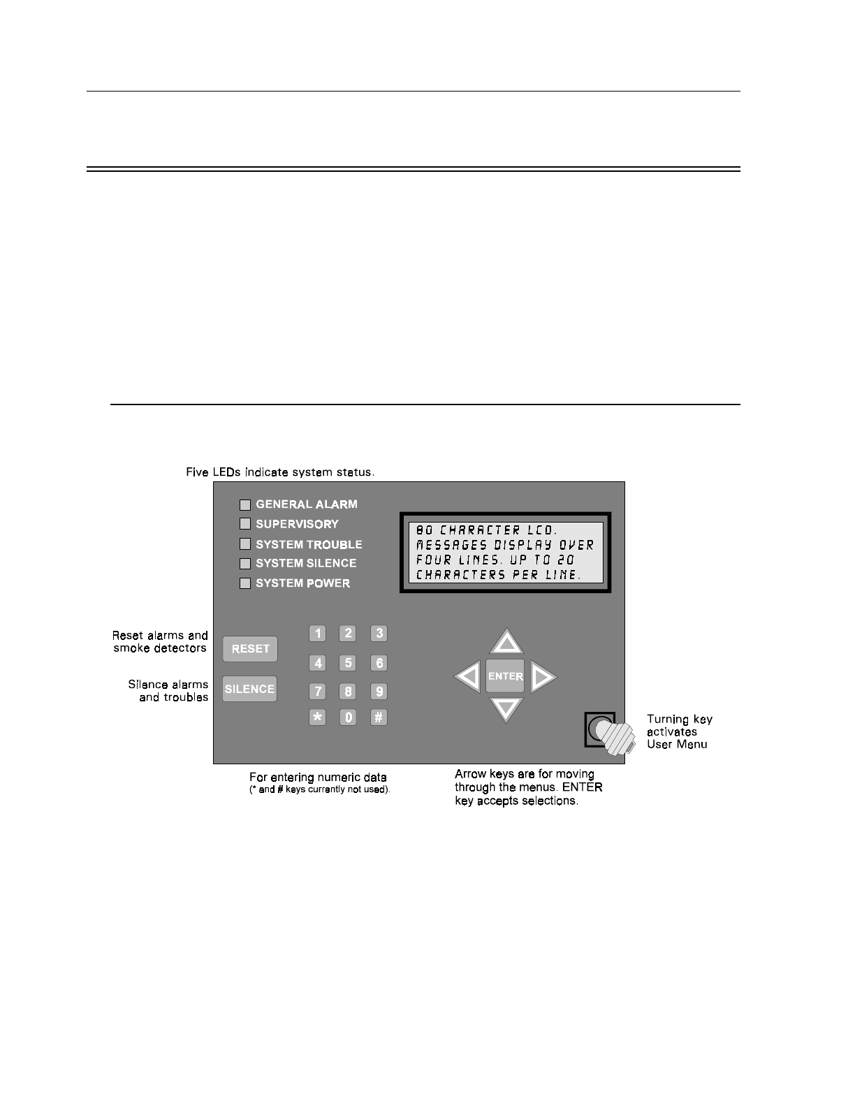
151137 8-1
Section 8
S
y
stem Operation
Operation of the control panel is simple. Menus guide you step-by-step through operations.
This section of the manual is an overview of the operation menus. Please read this entire
section carefully before operating the panel.
User Menu (basic operation) access: Rotate the key on the annunciator or enter the User Code
(factory-programmed as 1111).
Installer Menu (access to menu that allows for programming and all operations), enter the
Installer Code (factory-programmed as 5820).
8.1 Annunciator Description
Figure 10-1 shows the annunciator that is part of the control panel board assembly.
Figure 8-1 Control Panel Annunciator
8.1.1 LCD Displays
The control panel LCD displays system messages, annunciates alarms, supervisories and
troubles; provides status information; and prompts for input. These messages can be up to 80
characters, displaying over four lines of 20 characters each. Annunciator keys beep when they
are pressed.
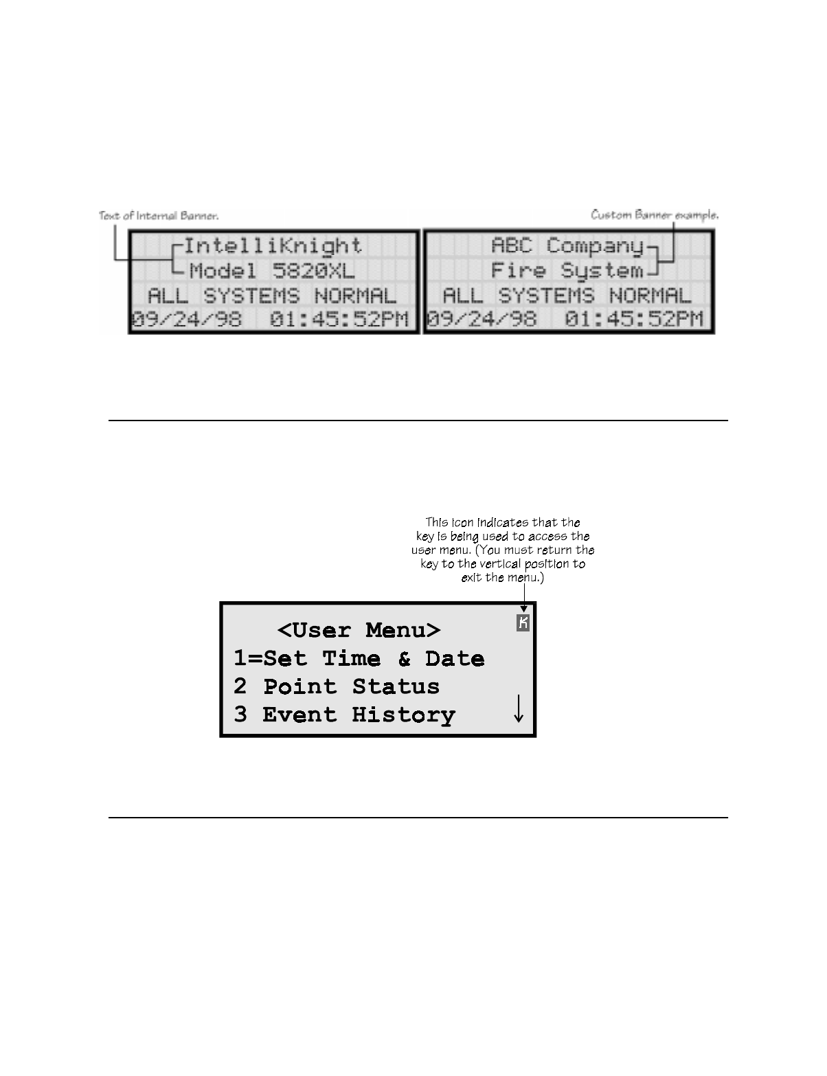
IntelliKnight 5820XL Installation Manual
8-2 151137
8.1.2 Banner
The banner is the message that displays on the control panel when the system is in normal
mode (no alarm or trouble condition exists and menus are not in use). You can create a
customized message that will display instead of the internal (default) message. See Section
7.5.8 for information on customizing the banner.
Figure 8-2 Banner Display Examples
8.2 Key Operation
The key on the control panel board assembly is for accessing the User Menu for basic system
operation. The key is activated when it is turned once to the right (clockwise). If the key has
been used to activate the menu, it must be turned counter-clockwise to exit the menu.
Figure 8-3 Using a Key to Access the User Menu
8.3 Menu System
The contol panel is easy to operate from menus that display when you activate the key or enter
an access code. The available options will be different depending on how you access the
system. If you use the key on the annunciator or the User Code, the User Main Menu will
display. If you use the Installer Code, the Installer Main Menu will display.

System Operation
151137 8-3
8.3.1 User Menu
The User Menu is actually a set of menus for basic system operation. It allows you to perform
such operations as setting the date and time, disabling points, and silencing and resetting
alarms. This menu displays whenever the User Code is entered or the key is activated. (The
User Code is factory-programmed as 1111.)
8.3.2 Installer Menu
The Installer Menu is a set of menus for performing all system operation, maintenance,
troubleshooting and programming. It includes all functions of the User Menu and many
others. This menu displays whenever the Installer Code is entered. (The Installer Code is
factory-programmed as 5820.)
8.3.3 Main Menu Overview (User and Installer)
The chart below is a brief overview of the User and Installer Main Menus. These options are
described in greater detail throughout this section of the manual.
User Menu Installer Menu Description
System Tests System Tests From here both menus can access Fire Drill and Indicator Test. The Installer
Menu can access all system tests.
Point Functions Point Functions From here both menus can enable / disable points. The Installer Menu can
access the menu for setting SLC device addresses.
Event History Event History Display event history on the LCD. See Section 8.4.3 for more information.
Set Time and Date Set Time and Date Set time and date for the system.
Printer Options Options for controlling a printer if attached to the system. If a printer is used,
the Model 5824 Serial/Parallel Interface must be used.
Reset Dialer Cancel any attempt to call the central station. Any calls awaiting additional
attempts will be aborted.
Program Menu Brings up a set of menus for programming the panel, including changing
access codes. These options are described in detail in Section 7.
System Info View system information, including model and serial numbers and revision
number and date.
Up/Download Initiate communication from the panel site between the panel and a
computer running the SK Analog Fire System Editor 5590.
1 1
2 2
3 3
4 4
5
6
7
8
9
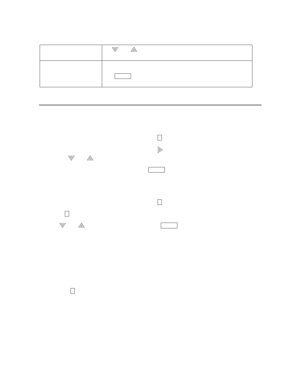
IntelliKnight 5820XL Installation Manual
8-4 151137
8.3.4 Using the Menus
8.4 Basic Operation
8.4.1 Setting Time and Date
1. From the User or Installer Main Menu, select for Set Date and Time.
2. Make changes in the fields on the screen. Use (right arrow) to move through the fields.
Use the and to select options in the fields.
3. When the date and time are correct, press .
8.4.2 Disable / Enable a Point
1. From the User or Installer Main Menu, select for Point Functions.
2. Select for Disable/Enable Point. A list of modules displays.
3. Use and to move through the list. Press to select the module where the
point you want to disable/enable is located. A description of the point should display. The
fourth line of the screen should show "NORMAL" (meaning that the point is currently
enabled) or "DISABLED" (the point is currently disabled). Press to toggle between NOR-
MAL and DISABLE.
8.4.3 View Event History
Use the View Event History feature to display events on LCD. From the User or Installer
Menu, press to select Event History. Events will begin displaying with most recent events
first.
The panel can store up to 1000 events. When it reaches its 1000-event capacity, it begins
deleting, starting with the oldest events.
If a printer is attached to the system (via a Module 5824 Serial/Parallel Interface), you can
print event history (see Section 8.4.17).
The SK Analog Fire System Editor 5590 or IntelliView Software can be used to retain more
than 1000 events and to create event history reports.
To move through the menus: Use and to move through the options in a menu. Use to move to a
previous menu.
To select an option: Enter the number of the option.
–OR–
Press (Enter key) if the option appears at the top of the menu (= symbol
displays after the option number in this case).
ENTER
4
ENTER
2
1
ENTER
4

System Operation
151137 8-5
8.4.4 Conduct a Fire Drill
1. From the User or Installer Menu, press for System Tests.
2. Press for Fire Drill. You will be prompted to press .
3. The drill will begin immediately after you press .
4. Press any key to end the drill. (If you do not press any key to end the fire drill manually, it
will time out automatically after one hour.)
If a fire drill switch has been installed, activating the switch one time will begin the drill;
activating a second time will end the drill.
8.4.5 Conduct an Indicator Test
The indicator test checks the annunciator LEDs, PZT, and LCD display.
1. From the Installer Main Menu, press for System Tests.
2. Press for Indicator Test. The system turns on each LED several times, beeping the PZT
as it does so. At the same time it scrolls each available character across the LCD. A prob-
lem is indicated if any of the following occurs:
• An LED does not turn on;
• You do not hear a beep;
• All four lines of the LCD are not full.
This test takes approximately 15 seconds to complete. You can press any key to end manually
while the test is still in progress. When the test ends, you will be returned to the <Test Menu>.
1
1
ENTER
ENTER
1
2

IntelliKnight 5820XL Installation Manual
8-6 151137
8.4.6 Conduct a Walk Test
1. From the Installer Main Menu, press for System Tests.
2. Select for Walk Test-No Rpt. The LCD will display "WALK TEST STOPPED" on
Line 1 and "ENTER = start test" on Line 2. If you select this option, central station report-
ing will be disabled while the test is in progress.
Select for Walk Test-with Rpt. The LCD will display "WALK TEST STOPPED" on
Line 1 and "ENTER = start test" on Line 2. If you select this option, central station report-
ing will occur as normal during the walk test.
The panel generates a TEST report to the central station when the walk test begins. During
a walk test, the panel’s normal fire alarm function is completely disabled, placing the
panel in a local trouble condition. All zones respond as 1-Count zones (respond when a
single detector is in alarm) during a walk test. Each alarm initiated during the walk test
will be reported and stored in the event history buffer.
3. Press to end the walk test. The system will reset. The panel will send a "TEST
RESTORE" report to the central station.
If you do not end the walk test manually within 60 minutes, it will end automatically.
If an alarm or pre-alarm condition is occurring in the system, you will not be able to enter the
walk test.
Note: the panel does not do a full 30 second reset on resettable power outputs. As soon as the device is back to
normal, the panel is ready to go to the next device.
8.4.7 Conduct a Dialer Test
1. From the Installer Main Menu, press for System Tests.
2. Select for Dialer Test. The screen will display “Manual dialer test started”. When the
test is completed, you will be returned to the <Test Menu>.
8.4.8 Silence alarms or troubles
Press and enter your code or rotate the key at the prompt. If an external silence
switch has been installed, activating the switch will silence alarms or troubles. If you are
already using system menus when you press , you will not need to enter your code or
rotate the key.
IMPORTANT!
If any alarm verification zones are being used, the user will be asked if they wish to
disable alarm verification during walk test. This occurs for either walk test option.
1
3
4
ENTER
1
5
SILENCE
SILENCE
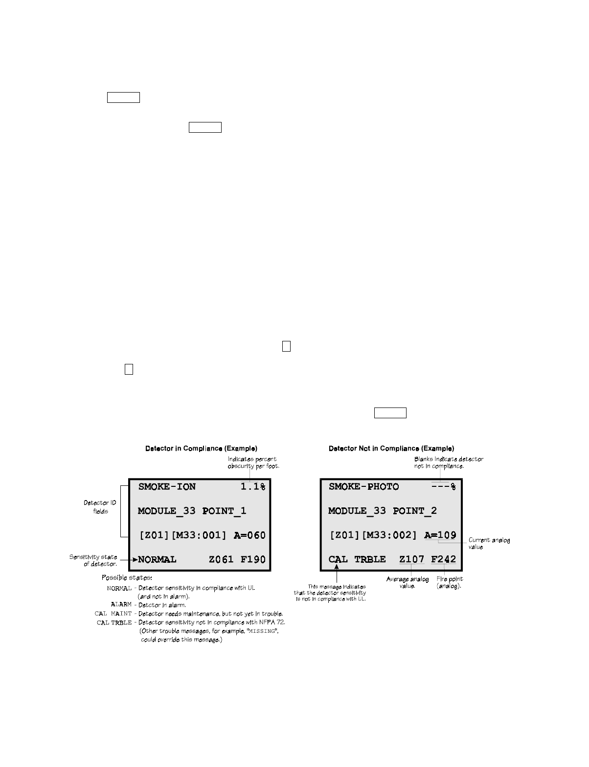
System Operation
151137 8-7
8.4.9 Reset alarms
Press and enter your code or rotate the key at the prompt. If an external reset switch
has been installed, activating the switch will reset alarms. If you are already using system
menus when you press , you will not need to enter your code or rotate the key.
8.4.10 Check Detector Sensitivity Through Point Status
The control panel constantly monitors smoke detectors to ensure that sensitivity levels are in
compliance with NFPA 72.
If sensitivity for a detector is not in compliance, the panel goes into trouble, generating a CAL
TRBLE condition. A detector enters a CAL MAINT state to indicate that it is approaching an
out of compliance condition (but is currently still in compliance).
When a CAL TRBLE condition occurs, the central station receives a detector trouble report
(“373” + Zone # for Contact ID format; “FT” + Zone # in SIA format).
To check sensitivity for an individual detector, follow the steps below. Section 8.4.17
provides instructions for printing the status of all detectors in the system.
1. From the User or Installer Menu, press for Point Functions.
2. Press for Point Status.
3. Select the module where the point you want to check is located.
4. Enter the number of the point you want to check and press .
5. A screen similar to those shown in Figure 8-4 will display.
Figure 8-4 Checking Detector Sensitivity Compliance
If a printer is attached to the system (via a Module 5824 Serial/Parallel Interface), you can
print detector status (see Section 8.4.17).
RESET
RESET
2
2
ENTER

IntelliKnight 5820XL Installation Manual
8-8 151137
8.4.11 Change User or Installer Code
You must be in the Program Menu to perform this step.
1. From the Installer Main Menu, press to enter the Program Menu.
2. From the Program Menu, press for Access Codes.
3. At the prompt, press to change the User Code or to change the Installer Code.
4. At the next prompt, enter a 4-to-7-digit number for the new code and press .
5. At the <Verify> prompt, enter the code a second time.
6. You will be prompted to save your changes before moving to a new menu. Use the or
to select Yes or No, if needed, then press .
8.4.12 View Status of a Point
1. From the User or Installer Main Menu, select for Point Status.
2. From the list that displays, press to select the module where this point is located.
The screen that displays will show you if the point has a trouble and will provide sensitiv-
ity compliance information. (See Section 8.4.10 for complete information about detector
sensitivity compliance.)
8.4.13 View Alarms or Troubles
When the system is in alarm or trouble, you can press to view the location of an alarm or
trouble. See Section 8.4.13 for more information.
8.4.14 View System Information
Press from the Installer Main Menu to view the panel model and serial number and system
version number and date. The information displays for several seconds then returns to the
main menu.
8.4.15 Reset dialer
From the Installer Main Menu, select . The LCD will display “Dialer reset in progress...”
You will be returned to the Installer Main Menu when the reset is completed.
7
8
1 2
ENTER
ENTER
2
ENTER
8
6

System Operation
151137 8-9
8.4.16 Communicating with a Remote Computer
An installer at the panel site can initiate communications between the panel and a computer
running the SK Analog Fire System Editor 5590. You can use this feature to upload a panel
configuration. For example, if you have made programming changes to an installation on site
using an annunciator, you can send your changes to the computer, so that the central station
will have the latest data about the installation. Refer to the 5590 manual (P/N 151004) for
complete details about communication hardware set-up. To initiate communication, follow
the steps below.
1. From the Installer Main Menu, select for Up/Download.
2. From the next screen that displays, select the communication device. Options are:
3. If you are using the panel’s internal modem to communicate, you will be prompted to
enter a phone number. If you are communicating via the RS232 connection, a phone num-
ber is not needed and this step will be skipped.
If the phone number you will be calling is already displayed, press . Continue with
Step 4.
If the phone number you will be calling is not already displayed, enter the number and press
. The number you enter will become the default phone number. A phone number can
be up to 40 digits long and can contain the following special characters.
Use the number buttons on the annunciator or the up- and down-arrow keys to select special
characters. Characters begin displaying after “9”.
4. You will be prompted to enter an account number. If the account number you want to use
is already displayed, just press to begin communication.
If the account number displayed is not the correct one, enter the account number and press
to begin communication. The number you enter will become the default account
number.
5. The panel will attempt to communicate with the computer. If communication was estab-
lished, the upload task you created will be placed on the 5590 job queue, awaiting process-
ing. When processing is completed, an “Unsolicited Upload” task will appear in the
queue.
Important!
To ensure proper downloading, make sure that the SK Analog Fire System Editor’s revision is equal to or
greater than the software revision of the control panel. See Section 8.4.14.
= Internal Modem If you select this option, you will use the panel’s built-in modem to call
the panel.
= RS232 connection If you select this option, the panel and a computer are both on-site
connected via a 9-pin straight-through serial cable.
# Pound (or number) key on the telephone
* Star key on the telephone
, Comma (character for 2-second pause)
9
1
2
ENTER
ENTER
ENTER
ENTER
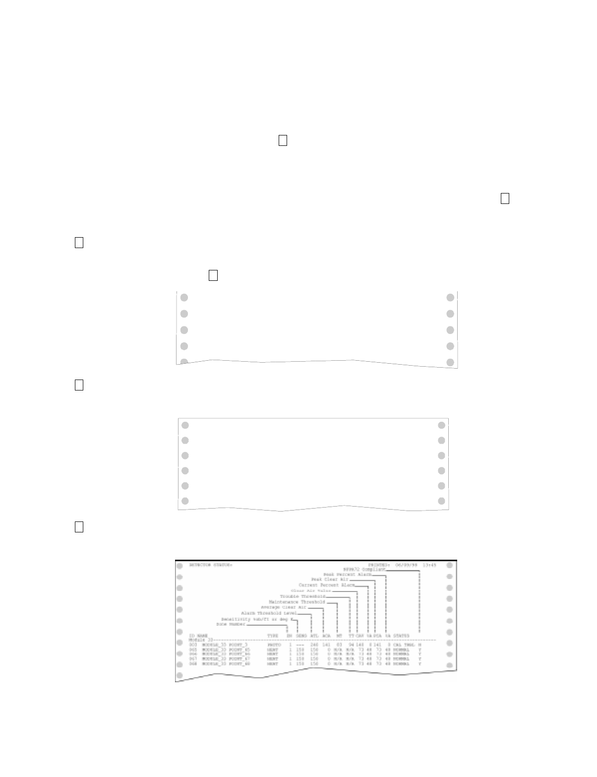
IntelliKnight 5820XL Installation Manual
8-10 151137
8.4.17 Working with a Printer
If you are using the Model 5824 Serial/Parallel Interface, several printing options are
available. See Section 4.7 for information about installing the 5824.
1. From the Installer Main Menu, select Printer Options.
2. From the next screen, select the 5824 module where the printer is connected.
3. If the printer is not currently busy printing another report, a screen with the following
options will be available. If the printer is busy, a message will display. You can press to
cancel the current print job. These options will then display.
Note: Detector status can also be viewed and printed using the 5590 SK Analog Fire System Editor or IntelliView
Software.
= Event Logging Enables event logging, which causes the printer to continuously print events as they occur. The
date/time will print in 24-hour military format. Once event logging is enabled, it will remain
enabled until canceled by the installer. If you need to disable event logging, return to this option
and press to disable.
Sample Event Log
= Print Event History Prints the up-to-1000 events currently stored in the panel’s event history buffer. Events print
starting with the newest. The date and time printed will be when the event actually occurred and
will print in 24-hour military format.
Sample Event
History Print-Out
= Print Detector
Status
Prints the current status of all detectors in the system. This is a method for finding out if any
detectors are out of NFPA compliance or any detectors need maintenance (are approaching an
out of compliance condition).
Sample Detector
Status Print-Out
5
1
1
1
EVENT LOG:
EVENT LOG:
STARTED: 02/17/97 02:23
STOPPED: 02/17/97 15:02
02/17/97 11:23 Event: System Silenced
02/17/97 11:24 Event: System Reset
02/17/97 14:30 Event: Local Programming Begin
02/17/97 15:01 Event: Local Programming Ended Successfully
2
EVENT HISTORY: PRINTED: 02/28/97 13:35
02/20/97 09:05 Event 2 of 10: System Reset
02/28/97 13:31 Event 2 of 10: Walk Test End
02/20/97 09:02 Event 3 of 10: System Silenced
02/22/97 08:47 Event 4 of 10: Printer Off Line 4
02/22/97 08:52 Event 4 of 10: Printer On Line 4
02/25/97 15:54 Event 5 of 10: Local Programming Begin
02/25/97 16:10 Event 5 of 10: Local Programming Ended Successfully
02/28/97 12:50 Event 6 of 10: Walk Test Begin
.
.
.
3

System Operation
151137 8-11
8.5 Operation Mode Behavior
The control panel panel can be in one of seven conditions at any given moment: Normal,
Alarm, Prealarm, Supervisory, Trouble, Silenced, and Reset. Table 10-1 describes the
behavior of the panel in each of these modes.
Table 8-1: Operation Mode Behavior
Operation
Mode Occurs When System Behavior In This Mode You Can
Normal No alarm or
trouble con-
dition exists and
menus are not in
use.
SYSTEM POWER LED is on.
The All Systems Normal display indicates
that the system is in normal mode.
The current date and time display on the
last line of the LCD.
Enter the appropriate code to activate the User or
Installer Menu, or rotate the key to activate the User
Menu.
Alarm A smoke
detector goes
into alarm or a
pull station is
activated.
The dialer seizes control of the phone line
and calls the central station.
The on-board annunciator sounds a loud,
steady beep (any notification devices
attached to the system will also sound).
GENERAL ALARM LED flashes.
The LCD displays a screen similar to this
one.
Press the down arrow to view the alarm. A screen
similar to this one displays.
Press and enter an access code (or
activate the key) to silence the annunciator (and any
notification devices attached to the system).
When the alarm condition clears, press
and enter a code (or activate the key) to restore the
panel to normal.
SILENCE
RESET
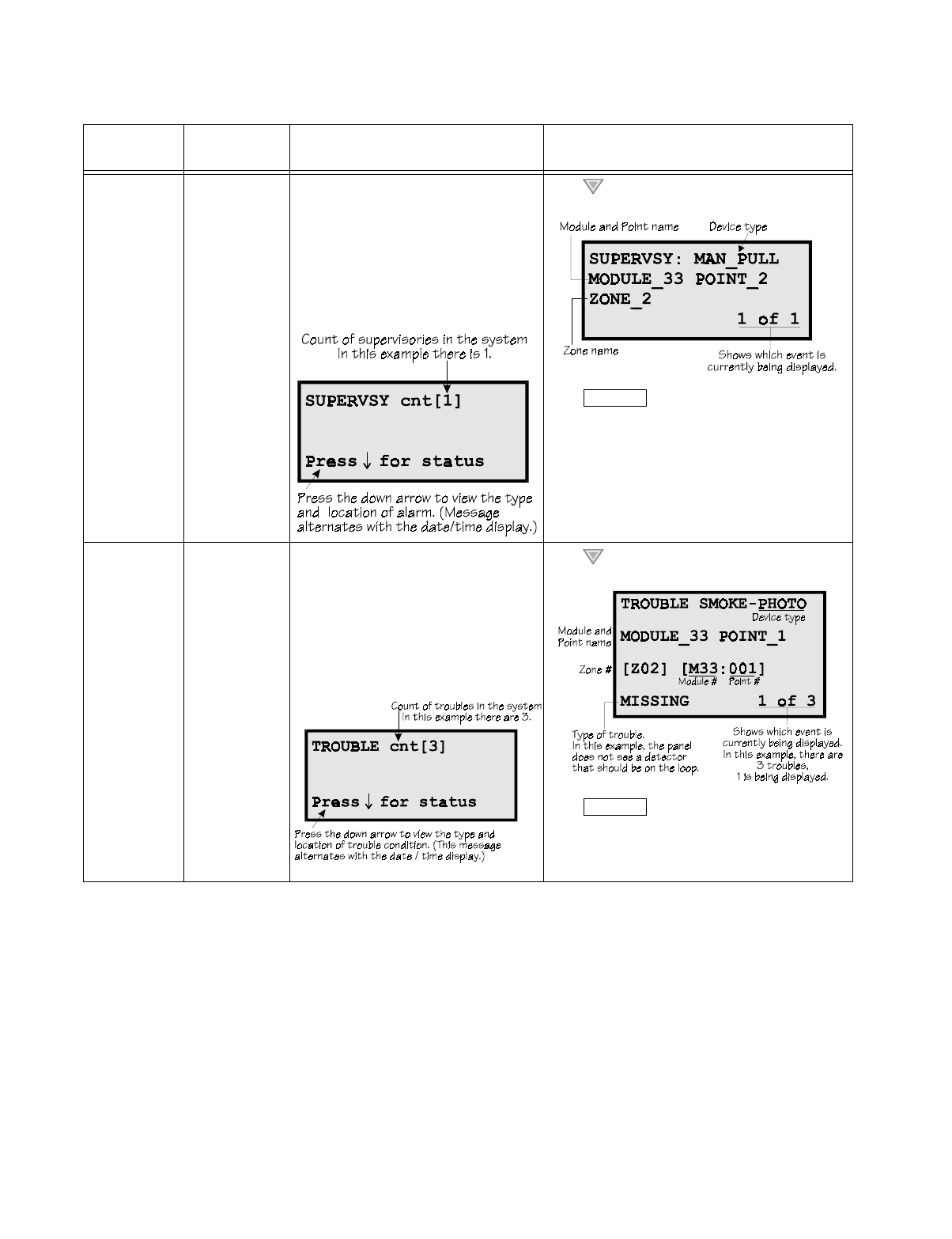
IntelliKnight 5820XL Installation Manual
8-12 151137
Supervisory The system
detects a
supervisory
condition.
The dialer seizes control of the phone line
and calls the central station.
The on-board annunciator sounds a loud,
pulsing beep in the sequence one second
on, one second off.
SUPERVISORY LED flashes.
The LCD displays a screen similar to this
one.
Press (down arrow) to view the supervisory
condition. A screen similar to this one displays.
Press and enter an access code (or
activate the key) to silence the annunciator.
Once the supervisory condition has been corrected,
the system will restore itself automatically.
Trouble A system trouble
condition
occurs.
The dialer seizes control of the phone line
and calls the central station.
The on-board annunciator sounds a loud,
pulsing beep in the sequence one second
on, nine seconds off.
SYSTEM TROUBLE LED flashes.
The LCD displays a screen similar to this
one.
Press (down arrow) to view the trouble. A
screen similar to this one displays.
Press and enter an access code (or
activate the key) to silence the annunciator.
Once the trouble condition has been fixed, the
system will restore itself automatically.
Table 8-1: Operation Mode Behavior
Operation
Mode Occurs When System Behavior In This Mode You Can
SILENCE
SILENCE
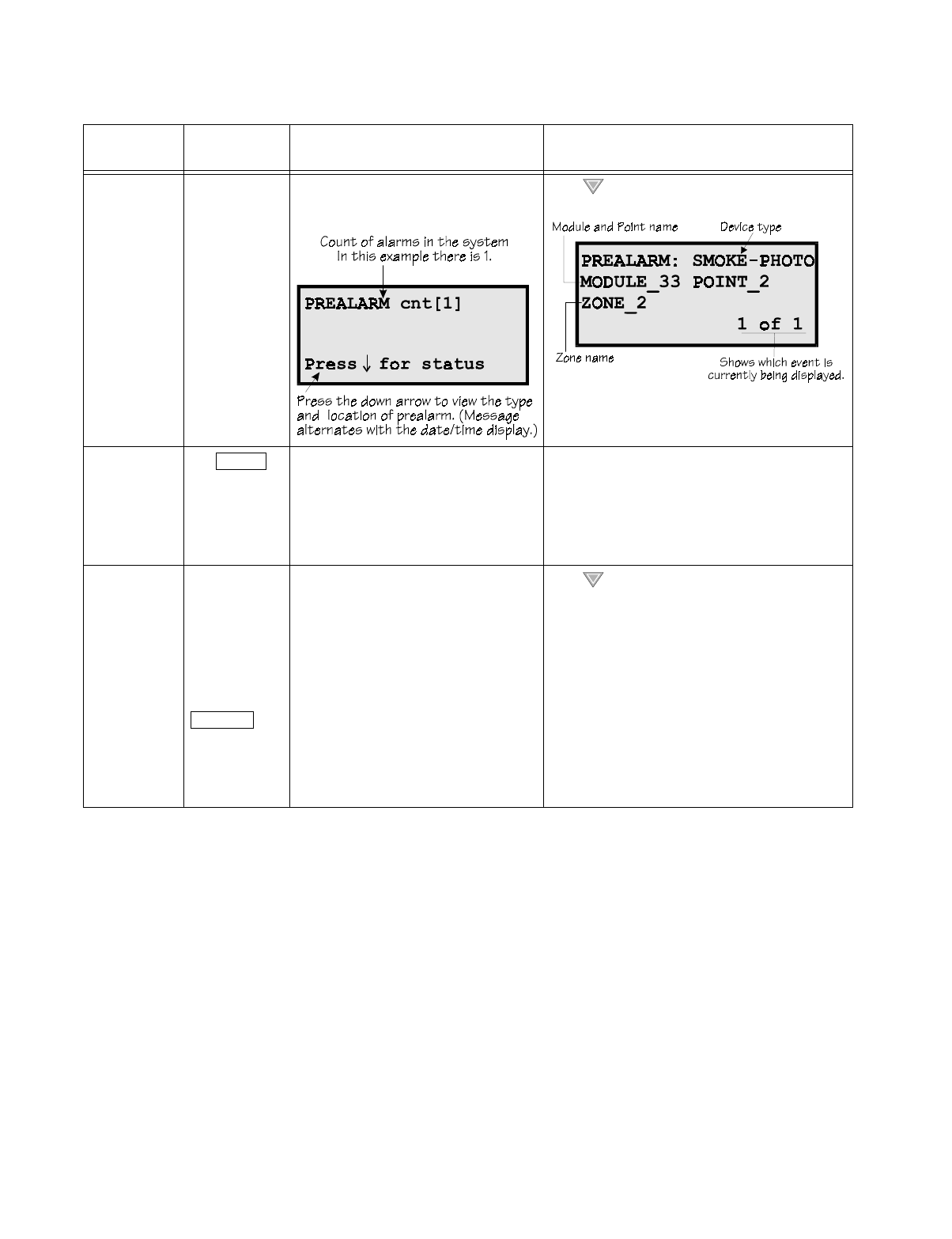
System Operation
151137 8-13
Prealarm A single detector
trips in a 2-
Count zone. (2-
Count means
two detectors
must trip before
an alarm is
reported.)
Touchpad PZT beeps.
The LCD displays a screen similar to this
one.
Press (down arrow) to view the prealarm. A
screen similar to this one displays.
All system operations are available in this mode.
Reset The
button is pressed
followed by a
valid code or
rotation of the
key.
All LEDs are on briefly then the LCD
displays "ALARM RESET IN
PROGRESS". If the reset process
completes normally, the date and time
normal mode screen displays.
Menus are not available during the reset process.
Silenced An alarm or
trouble
condition has
been silenced
but still exists.
To silence
alarms and
troubles, press
followed by the
Installer or User
Code or rotate
the key.
SYSTEM SILENCE LED is on. SYSTEM
TROUBLE, SUPERVISORY or
GENERAL ALARM LED (depending on
condition) is on. The annunciator (and any
notification devices attached to the
system) will be silenced.
Press (down arrow) to view the location of the
alarm or trouble. When the condition no longer
exists, the SYSTEM SILENCED and SYSTEM
TROUBLE LED, SUPERVISORY or GENERAL
ALARM LEDs turn off.
Table 8-1: Operation Mode Behavior
Operation
Mode Occurs When System Behavior In This Mode You Can
RESET
SILENCE

IntelliKnight 5820XL Installation Manual
8-14 151137

151137 9-1
Section 9
Reportin
g
This section lists receivers that are compatible with this control panel, and the reporting codes
sent by the control panel for SIA and Contact ID formats.
9.1 Receivers Compatible with the Control Panel
Table 11-1 shows receivers compatible with the control panel.
Table 9-1: Receivers Compatible with the Control Panel
Manufacturer Model Format
Silent Knight Model 9800 SIA and Contact ID
Model 9000 (SIA formats) SIA
Ademco Model 685 (Contact ID ) Contact ID
Sur-Gard SG-MLR2-DG (V. 1.64 or higher) SIA and Contact ID
Osborne Hoffman Quickalert SIA and Contact ID

IntelliKnight 5820XL Installation Manual
9-2 151137
9.2 Ademco Contact ID Dialer Output
Table 9-2: Ademco Contact ID Output
Event Description Event Family
Event
Qualifier
1=New,
3= Restore
Event Code Group # Zone /
Contact ID #
Detector alarm. Alarm 1 110 00 Zone
Detector alarm restore Restore/Reset 3 110 00 Zone
Water flow switch alarm. Alarm 1 113 00 Zone
Water flow switch alarm restore Restore/Reset 3 113 00 Zone
Manual pull switch alarm. Alarm 1 115 00 Zone
Manual pull switch alarm restore Restore/Reset 3 115 00 Zone
Zone based, AUX1 switch alarm Alarm 1 140 01 Zone
Zone based, AUX2 switch alarm Alarm 1 140 02 Zone
Zone based, AUX1 switch alarm restore Restore/Reset 3 140 01 Zone
Zone based, AUX2 switch alarm restore Restore/Reset 3 140 02 Zone
System-based AUX1 switch alarm. Alarm 1 140 01 000
System-based AUX2 switch alarm. Alarm 1 140 02 000
System-based AUX1 switch alarm restore Restore/Reset 3 140 01 000
System-based AUX2 switch alarm restore Restore/Reset 3 140 02 000
Supervisory condition Trouble 1 203 00 Zone
Supervisory restore Trouble 3 203 00 Zone
Checksum error. Trouble 1 300 00 000
AC power lost Trouble 1 301 00 000
AC power restore Trouble 3 301 00 000
Battery voltage low Trouble 1 302 Exp ID 000
Battery voltage restore Trouble 3 302 Exp ID 000
Initial Power Up. Trouble 1 305 00 000
Ground fault condition detected Trouble 1 310 Exp ID 000
Ground fault condition restore Trouble 3 310 Exp ID 000
Aux Power Trouble Trouble 1 320 00 000
Aux Power Trouble Restore Trouble 3 320 00 000
Notification output trouble Trouble 1 320 00 Group #
Notification output trouble restore Trouble 3 320 00 Group #
SLC Class A supervision lost Trouble 1 331 Exp ID 000
SLC Class A supervision restored Trouble 3 331 Exp ID 000
Short detected on SLC communication loop Trouble 1 332 Exp ID 000
Short removed from SLC communication loop Trouble 3 332 Exp ID 000
SBUS expander trouble Trouble 1 333 Exp ID 000
SBUS expander trouble restore Trouble 3 333 Exp ID 000
SBUS Class A supervision lost Trouble 1 333 Exp ID 000

Reporting
151137 9-3
SBUS Class A supervision restore Trouble 3 333 Exp ID 000
Printer is out of paper. Trouble 1 335 Exp ID 000
Printer paper restored. Trouble 3 335 Exp ID 000
Printer offline. Trouble 1 336 Exp ID 000
Printer back online. Trouble 3 336 Exp ID 000
Auto Dialer Test Communication Trouble Trouble 1 350 0 Line #
Auto Dialer Test Communication Trouble Restore Trouble 3 350 0 Line #
Phone line 1 trouble detected Trouble 1 351 00 000
Phone line 1 trouble restore Trouble 3 351 00 000
Phone line 2 trouble detected Trouble 1 352 00 000
Phone line 2 trouble restore Trouble 3 352 00 000
Unable to report to an account Trouble 1 354 Acct # Acct #
Report to an account successful Trouble 3 354 Acct # Acct #
Water flow switch trouble Trouble 1 373 00 Zone
Manual pull switch trouble Trouble 1 373 00 Zone
Detector trouble Trouble 1 373 00 Zone
Zone-based Aux 1 switch trouble Trouble 1 373 01 Zone
Zone-based Aux 2 switch trouble Trouble 1 373 02 Zone
Supervisory switch trouble Trouble 1 373 00 Zone
Water flow switch trouble restore Trouble 3 373 00 Zone
Manual pull switch trouble restore Trouble 3 373 00 Zone
Detector trouble restore Trouble 3 373 00 Zone
Zone based, AUX 1 switch trouble restore Trouble 3 373 01 Zone
Zone based, AUX 2 switch trouble restore Trouble 3 373 02 Zone
Supervisory switch trouble restore Trouble 3 373 00 Zone
System-based AUX1 switch trouble Trouble 1 373 01 000
System based AUX 2 switch trouble Trouble 1 373 02 000
External Reset/Silence/Fire Drill switch trouble Trouble 1 373 00 000
System-based AUX1 switch trouble restore Trouble 3 373 01 000
System-based AUX2 switch trouble restore Trouble 3 373 02 000
External Reset/Silence Fire Drill trouble restore Trouble 3 373 00 000
Positive Alarm Sequence acknowledge switch
trouble
Trouble 1 373 00 Zone
Positive Alarm Sequence acknowledge switch
trouble restore
Trouble 3 373 00 Zone
An unexpected SLC device has been detected. Trouble 1 380 Exp ID Pnt #
An unexpected SLC device has been removed. Trouble 3 380 Exp ID Pnt #
User initiated a system reset Restore/Reset 1 401 00 000
Remote programming ended normally. Trouble 1 412 00 000
Table 9-2: Ademco Contact ID Output
Event Description Event Family
Event
Qualifier
1=New,
3= Restore
Event Code Group # Zone /
Contact ID #

IntelliKnight 5820XL Installation Manual
9-4 151137
Remote programming aborted or ended with
errors.
Trouble 1 413 00 000
Notification output disabled Disable 1 571 Exp ID Pnt #
Manual pull switch disabled Disable 1 571 Exp ID Pnt #
Water flow switch disabled Disable 1 571 Exp ID Pnt #
Conventional detector input has been disabled Disable 1 571 Exp ID Pnt #
Addressable photoelectric detector has been
disabled
Disable 1 571 Exp ID Pnt #
Addressable heat detector has been disabled Disable 1 571 Exp ID Pnt #
Addressable ionization detector has been disabled Disable 1 571 Exp ID Pnt #
Addressable beam detector has been disabled Disable 1 571 Exp ID Pnt #
Supervisory switch input has been disabled Disable 1 571 Exp ID Pnt #
Tamper switch input has been disabled Disable 1 571 Exp ID Pnt #
Zone-based AUX1 switch input has been disabled Disable 1 571 Exp ID Pnt #
Zone-based AUX2 switch input has been disabled Disable 1 571 Exp ID Pnt #
Positive alarm sequence acknowledge switch has
been disabled
Disable 1 571 Exp ID Pnt #
Detection acknowledge switch has been disabled Disable 1 571 Exp ID Pnt #
Fire drill switch has been disabled Disable 1 571 Exp ID Pnt #
Silence switch has been disabled Disable 1 571 Exp ID Pnt #
Reset switch has been disabled Disable 1 571 Exp ID Pnt #
System based AUX 1 switch input disabled Disable 1 571 Exp ID Pnt #
System-based AUX2 switch input disabled Disable 1 571 Exp ID Pnt #
Constant ON Auxiliary power output has been
disabled
Disable 1 571 Exp ID Pnt #
Resettable auxiliary power output has been
disabled
Disable 1 571 Exp ID Pnt #
Door Holder auxiliary power output has been
disabled
Disable 1 571 Exp ID Pnt #
Notification output has been re-enabled Disable 3 571 Exp ID Pnt #
Manual pull switch has been re-enabled Disable 3 571 Exp ID Pnt #
Water flow switch has been re-enabled. Disable 3 571 Exp ID Pnt #
Conventional detector input has been re-enabled Disable 3 571 Exp ID Pnt #
Addressable photoelectric detector has been re-
enabled.
Disable 3 571 Exp ID Pnt #
Addressable heat detector has been re-enabled Disable 3 571 Exp ID Pnt #
Addressable ionization detector has been re-
enabled
Disable 3 571 Exp ID Pnt #
Addressable beam detector has been re-enabled. Disable 3 571 Exp ID Pnt #
Supervisory switch input has been re-enabled. Disable 3 571 Exp ID Pnt #
Table 9-2: Ademco Contact ID Output
Event Description Event Family
Event
Qualifier
1=New,
3= Restore
Event Code Group # Zone /
Contact ID #

Reporting
151137 9-5
Tamper switch input has been re-enabled. Disable 3 571 Exp ID Pnt #
Zone-based AUX 1 switch input has been re-
enabled.
Disable 3 571 Exp ID Pnt #
Zone-based AUX 2 switch input has been re-
enabled.
Disable 3 571 Exp ID Pnt #
Positive alarm sequence acknowledge switch has
been re-enabled.
Disable 3 571 Exp ID Pnt #
A detection acknowledge switch has been re-
enabled.
Disable 3 571 Exp ID Pnt #
A fire drill switch has been re-enabled. Disable 3 571 Exp ID Pnt #
A silence switch has been re-enabled. Disable 3 571 Exp ID Pnt #
A reset switch has been re-enabled Disable 3 571 Exp ID Pnt #
A system-based AUX 1 switch input has been re-
enabled.
Disable 3 571 Exp ID Pnt #
A system-based AUX 2 switch input has been re-
enabled.
Disable 3 571 Exp ID Pnt #
A constant on auxiliary power output has been re-
enabled.
Disable 3 571 Exp ID Pnt #
A resettable auxiliary power output has been re-
enabled.
Disable 3 571 Exp ID Pnt #
A door holder auxiliary power output has been re-
enabled.
Disable 3 571 Exp ID Pnt #
User has initiated dialer test. Test 1 601 00 Channel #
Periodic test event. Test 1 602 00 Channel #
Fire drill has begun. Test 1 604 00 000
Fire drill has ended. Test 3 604 00 000
Walk test begin. Test 1 607 00 000
Walk test end. Test 3 607 00 000
SLC address programming started; system has
been shut down.
Test 1 607
SLC address programming ended; system has been
re-enabled.
Test 3 607
Panel date has been changed. Trouble 1 625 00 000
Panel time has been changed. Trouble 1 625 00 000
Local programming begin. Trouble 1 627 00 000
Remote programming begin. Trouble 1 627 00 000
Local programming ended normally. Trouble 1 628 00 000
Local programming aborted or ended with errors. Trouble 1 628 00 000
Table 9-2: Ademco Contact ID Output
Event Description Event Family
Event
Qualifier
1=New,
3= Restore
Event Code Group # Zone /
Contact ID #

IntelliKnight 5820XL Installation Manual
9-6 151137
9.3 SIA Dialer Output
Table 9-3: SIA Dialer Output
Event Description Event
Family Module ID#
(if any) SIA Event
Code Parameter
(if any)
AC power restore Trouble AR
AC power lost Trouble AT
SBUS expander trouble restore Trouble ER Exp. ID
SBUS Class A supervision restore Trouble ER Exp. ID
Short removed from SLC communication loop Trouble ER Exp. ID
SLC Class A supervision restored Trouble ER Exp. ID
SBUS expander trouble Trouble ET Exp. ID
SBUS Class A supervision lost Trouble ET Exp. ID
Short detected on SLC communication loop Trouble ET Exp. ID
SLC Class A supervision lost Trouble ET Exp. ID
Manual pull switch alarm. Alarm FA Zone
Detector alarm. Alarm FA Zone
Notification output disabled Disable pi Exp. ID FB Pnt #
Manual pull switch disabled Disable pi Exp. ID FB Pnt #
Conventional detector output has been disabled Disable pi Exp. ID FB Pnt #
Addressable photoelectric detector has been disabled Disable pi Exp. ID FB Pnt #
Addressable heat detector has been disabled Disable pi Exp. ID FB Pnt #
Addressable ionization detector has been disabled Disable pi Exp. ID FB Pnt #
Addressable beam detector has been disabled Disable pi Exp. ID FB Pnt #
Positive alarm sequence acknowledge switch disabled Disable pi Exp. ID FB Pnt #
Detection acknowledge switch has been disabled Disable pi Exp. ID FB Pnt #
Fire drill switch has been disabled Disable pi Exp. ID FB Pnt #
Silence switch has been disabled Disable pi Exp. ID FB Pnt #
Reset switch has been disabled Disable pi Exp. ID FB Pnt #
Constant ON Auxiliary power output has been disabled Disable pi Exp. ID FB Pnt #
Resettable auxiliary power output has been disabled Disable pi Exp. ID FB Pnt #
Door Holder auxiliary power output has been disabled Disable pi Exp. ID FB Pnt #
Manual pull switch alarm restore Restore/Reset FH Zone
Detector alarm restore Restore/Reset FH Zone
Fire drill has begun. Test FI
Positive Alarm Sequence acknowledge switch trouble restore Trouble FJ Zone
Manual pull switch trouble restore Trouble FJ Zone
Detector trouble restore Trouble FJ Zone
Fire drill has ended. Test FK
Notification output trouble restore Trouble FR 1000+Grp
Aux Power Trouble Restore Trouble FR 0
Aux Power Trouble Trouble FT 0

Reporting
151137 9-7
Manual pull switch trouble Trouble FT Zone
Detector trouble Trouble FT Zone
Positive Alarm Sequence acknowledge switch trouble Trouble FT Zone
Notification output trouble Trouble FT 1000+Grp
Notification output has been reenabled Disable pi Exp. ID FU Pnt #
Manual pull switch has been reenabled Disable pi Exp. ID FU Pnt #
Conventional detector input has been re-enabled Disable pi Exp. ID FU Pnt #
Addressable photoelectric detector has been re-enabled Disable pi Exp. ID FU Pnt #
Addressable heat detctor has been re-enabled Disable pi Exp. ID FU Pnt #
Addressable ionization detector has been re-enabled Disable pi Exp. ID FU Pnt #
Addressable beam detector has been re-enabled. Disable pi Exp. ID FU Pnt #
Positive alarm sequence acknowledge switch has been re-
enabled.
Disable pi Exp. ID FU Pnt #
A detection acknowledge switch has been re-enabled. Disable pi Exp. ID FU Pnt #
A fire drill switch has been re-enabled. Disable pi Exp. ID FU Pnt #
A silence switch has been re-enabled. Disable pi Exp. ID FU Pnt #
A reset switch has been re-enabled Disable pi Exp. ID FU Pnt #
A constant on auxiliary power output has been re-enabled. Disable pi Exp. ID FU Pnt #
A resettable auxiliary power output has been re-enabled. Disable pi Exp. ID FU Pnt #
A door holder auxiliary power output has been re-enabled. Disable pi Exp. ID FU Pnt #
Panel date has been changed. Trouble JD
Panel time has been changed. Trouble JT
Local programming begin. Trouble LB
Phone line trouble restore Trouble LR Line #
Local programming ended normally. Trouble LS
Phone line trouble detected Trouble LT Line #
Local programming aborted or ended with errors. Trouble LU
User initiated a system reset Restore/Reset OR
Remote programming begin. Trouble RB
Periodic test event. Test RP Channel #
Initial Power Up. Trouble RR
Remote programming ended normally. Trouble RS
Unable to report to an account Trouble RT Acct #
Remote programming aborted or ended with errors. Trouble RU
User has initiated dialer test. Test RX Channel #
Water flow switch alarm. Alarm SA Zone
Water flow switch disabled Disable pi Exp. ID SB Pnt #
Supervisory/Tamper switch input has been disabled Disable pi Exp. ID SB Pnt #
Water flow switch alarm restore Restore/Reset SH Zone
Supervisory/Tamper switch trouble restore Trouble SJ Zone
Table 9-3: SIA Dialer Output
Event Description Event
Family Module ID#
(if any) SIA Event
Code Parameter
(if any)

IntelliKnight 5820XL Installation Manual
9-8 151137
Water flow switch trouble restore Trouble SJ Zone
Supervisory restore Trouble SR Zone
Supervisory condition Trouble SS Zone
Supervisory/Tamper switch trouble Trouble ST Zone
Water flow switch trouble Trouble ST Zone
Water flow switch has been re-enabled. Disable pi Exp. ID SU Pnt #
Supervisory/Tamper switch input has been re-enabled. Disable pi Exp. ID SU Pnt #
Walk test end. Test TE
SLC address programming ended; system has been re-enabled. Test TE
Walk test begin. Test TS
SLC address programming started; system has been shut down. Test TS
Zone based, AUX1 switch alarm. Alarm UA 1000+Zone
Zone based, AUX2 switch alarm. Alarm UA 2000+Zone
System-based AUX1 switch alarm. Alarm UA 1000
System-based AUX2 switch alarm. Alarm UA 2000
Zone-based AUX1 switch input has been disabled Disable pi Exp. ID UB Pnt #
Zone-based AUX2 switch input has been disabled Disable pi Exp. ID UB Pnt #
System based AUX 1 switch input disabled Disable pi Exp. ID UB Pnt #
System-based AUX2 switch input disabled Disable pi Exp. ID UB Pnt #
Zone based, AUX1 switch alarm restore Restore/Reset UH 1000+Zone
Zone based, AUX2 switch alarm restore Restore/Reset UH 2000+Zone
System-based AUX1 switch alarm restore Restore/Reset UH 1000
System-based AUX2 switch alarm restore Restore/Reset UH 2000
Zone based, AUX 1 switch trouble restore Trouble UJ 1000+Zone
Zone based, AUX 2 switch trouble restore Trouble UJ 2000+Zone
System-based AUX1 switch trouble restore Trouble UJ 1000
System-based AUX2 switch trouble restore Trouble UJ 2000
External Reset/Silence Fire Drill trouble restore Trouble UJ 0
Zone-based Aux 1 switch trouble Trouble UT 1000+Zone
Zone-based Aux 2 switch trouble Trouble UT 2000+Zone
System-based AUX1 switch trouble Trouble UT 1000
System based AUX 2 switch trouble Trouble UT 2000
External Reset/Silence/Fire Drill switch trouble Trouble UT 0
Zone-based AUX 1 switch input has been re-enabled. Disable pi Exp. ID UU Pnt #
Zone-based AUX 2 switch input has been re-enabled. Disable pi Exp. ID UU Pnt #
A system-based AUX 1 switch input has been re-enabled. Disable pi Exp. ID UU Pnt #
A system-based AUX 2 switch input has been re-enabled. Disable pi Exp. ID UU Pnt #
Printer paper restored. Trouble VI
Printer is out of paper. Trouble VO
Printer back online. Trouble VY
Table 9-3: SIA Dialer Output
Event Description Event
Family Module ID#
(if any) SIA Event
Code Parameter
(if any)

Reporting
151137 9-9
Printer offline. Trouble VZ
An unexpected SLC device has been detected. Trouble pi Exp. ID XE Pnt #
An unexpected SLC device has been removed. Trouble pi Exp. ID XI Pnt #
Auto Dialer Test Communication Trouble Trouble YC Line #
Checksum error. Trouble YF
Auto dialer Test Communication Trouble Restore Trouble YK Line #
Report to an account successful Trouble YK Acct #
Ground fault condition detected Trouble YP Exp. ID
Ground fault condition restore Trouble YQ Exp. ID
Battery voltage restore Trouble YR Exp. ID
Battery voltage low Trouble YT Exp. ID
Table 9-3: SIA Dialer Output
Event Description Event
Family Module ID#
(if any) SIA Event
Code Parameter
(if any)

IntelliKnight 5820XL Installation Manual
9-10 151137

151137 10-1
Section 10
Testin
g
and Troubleshootin
g
10.1 Troubleshooting
This section of the manual offers suggestions for troubleshooting hardware problems. Please
read this section if you encounter a problem when installing the control panel. If these
suggestions do not solve your problem or if you encounter a problem that is not listed here,
contact Silent Knight Technical Support at 800-328-0103 for assistance.
10.2 Common Problems
Problem Possible Cause / Suggested Actions
Trouble message "DBL ADDR" (Double
Address) displays on LCD.
An address has been assigned to more than one detector. Correct the address
following the procedure described in Section 5.10.
Auxiliary power or notification circuits
have incorrect polarity.
Correct polarity. For notification and auxiliary power circuits: When in alarm
or powered, terminals labeled "X" are positive, terminals labeled "O" are
negative.
SLC devices are not being recognized
(trouble message "Missing" displays).
Check hardware connections.
If devices are physically connected, make sure wiring is correct (see Section
5.3). For the main panel, the positive side of device must be connected to
terminal 34; the negative side must be connected to Terminal 33. For 5815XL
devices, make sure the device connects to the 5815XL via the SLC OUT
terminals.
There can be only one SLC loop on the main panel and on each 5815XL
module. Do not connect devices to terminals labeled SLC IN.
Make sure SLC devices have been addressed properly following the
procedure described in Section 5.10.
For contact monitor modules, which are addressed using dipswitches, the
dipswitch must be set to the correct address before power is applied to the
SLC loop. If this procedure is not followed, the device will have an incorrect
address.
Make sure correct polarity has been observed for SLC device wiring. See
Section 5.3.

IntelliKnight 5820XL Installation Manual
10-2 151137
10.2.1 Event History
The event history can be useful for tracking or recalling a trouble condition.
SLC devices are not being recognized
(trouble message "Missing" displays on
the annunciator).
Check that SLC loop impedance is within the required range.
To measure impedance, use the following procedure.
1. Disconnect both wires from the terminal block at the panel (SLC devices
can remain connected).
2. Measure the impedance from positive to negative and from negative to
positive. Both measurements should be greater than 500 K ohms. If the
installation uses T-taps, test each T-tap individually.
3. Temporarily connect the positive wire to the negative wire of the SLC
loop at the point farthest from the panel (SLC devices can remain con-
nected).
4. Measure the impedance from positive to negative and from negative to
positive. Both measurements must be less than 50 ohms.
The panel indicates a ground fault trouble
condition (trouble message "GROUND
FAULT" displays).
An earth ground fault occurs when the panel senses an unexpected flow of
current from one or more of its terminals to the earth connection (Terminal 2).
Isolate the wiring that is causing the fault by removing wiring connections
one at a time until the earth fault is no longer present. Pause at least five
seconds after removing a wire before removing the next one.
The panel will also go into ground fault if a computer is connected to the
panel via a serial cable attached to the panel’s 9-pin connector. This is a
correct method for on-site communication between a panel and a computer.
Ignore the ground fault message in this case. The trouble will clear
automatically when you disconnect the computer from the cable
5815XL module that has been physically
connected to the panel but is not being
recognized.
Check the status of the 5815XL green LED. If it flashes in the pattern .5 sec
on / .5 sec. off, it is likely that the 5815XL has not been added to the system
through programming. JumpStart will add any 5815XLs connected to the
panel. If you have already run JumpStart, 5815XLs can be added manually
(see Section 4.10).
Check that the correct ID for the 5815XL module has been set through the
dipswitches. Assign ID#1 to the first 5815XL and ID#2 to the second
5815XL. See Section 4.10.1 for complete details.
If the wiring between the 5815XL and the panel is correct, measure the
voltage from 5815XL Terminal (+) to Terminal (-). Voltage should be in the
range 27.2-27.4V when AC power is present.
If the green LED is not flashing, the likely cause is incorrect wiring from
between the 5815XL and the panel. See Section 4.6.1 for wiring details.
Problem Possible Cause / Suggested Actions
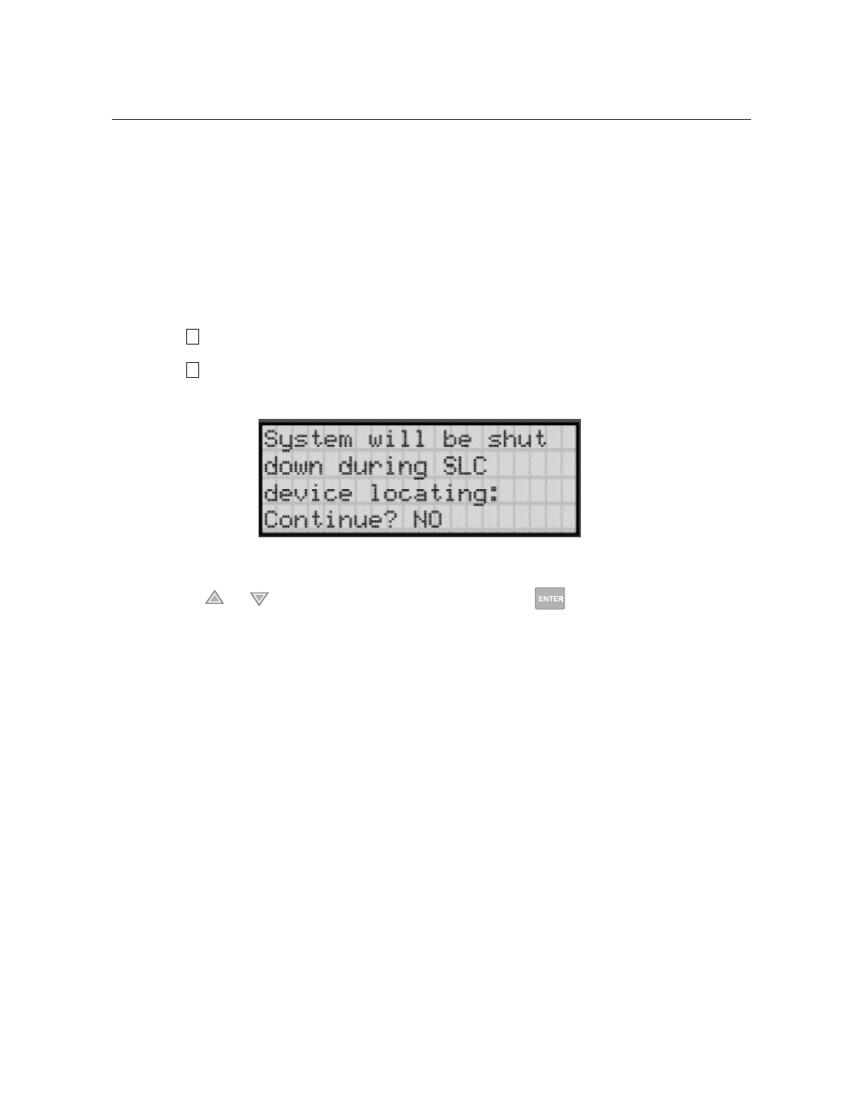
Testing and Troubleshooting
151137 10-3
10.3 Built-in Troubleshooting and Testing Tools
The fire control panel has several built-in testing and troubleshooting tools that can be utilized
to save time while testing and troubleshooting points and SLC devices.
10.3.1 SLC Device Locator
SLC device locator can be used to locate a device on a SLC loop.
Follow these steps to locate a particular SLC device:
1. Select (Point Functions) from the Installer Menu.
2. Select (SLC Dev Locator).
A message similar to the one shown in Figure 10-1 will display.
Figure 10-1 Shut Down Warning
3. Press the or arrow to toggle 12 to <(6then press .
If 12 is chosen you will exit back to the Point Function menu.
If <HV is chosen the system will cease normal operation leaving the premise unprotected.
4. Select the SLC loop.
5. Enter the SLC address of the device you wish to locate.
The LED on the selected device will start flashing.
6. Press any key to exit SLC device locator function.
Note: Once you exit the system will resume normal operation.
2
4

IntelliKnight 5820XL Installation Manual
10-4 151137
10.3.2 SLC Multi Locator
This feature is the same as SLC Device Locator, except you can locate up to 8 devices on a
single search.
Follow these instructions to locate multiple SLC devices:
1. Select (Point Functions) from the Installer Menu.
2. Select (SLC Dev Locator).
A message similar to the one shown in Figure 10-1 will display.
Figure 10-2 Shut Down Warning
3. Press the or arrow to toggle 12 to <(6then press .
If 12 is chosen you will exit back to the Point Function menu.
If <HV is chosen the system will cease normal operation leaving the premise unprotected.
4. Select the SLC loop.
5. Enter up to 8 SLC addresses for the devices you wish to locate.
The LEDs on the selected devices will start flashing.
6. Press the to exit SLC multi-locator function.
Note: Once you exit the system will resume normal operation.
2
5

Testing and Troubleshooting
151137 10-5
10.3.3 I/O Point Control
This feature allows you to toggle any output on or off and trip any input device. This can be
useful to test a point’s output mapping.
Follow these steps to control a I/O point:
1. Select (Point Functions) from the Installer Menu.
2. Select (I/O Point Control).
3. Select the Module the point is on.
4. Enter the zone number , or press the or arrow to select the point you wish to test,
then press .
5. Press to generate an alarm for an input point or activate an output point.
6. To exit press .
2
6

IntelliKnight 5820XL Installation Manual
10-6 151137

151137 11-1
Section 11
Installation Records
This section of the manual is for you to use if you wish to track of how points, zones, and
groups have been programmed.
11.1 SLC Point Record
You can use the chart that begins below to keep track of SLC points.
Default addresses for ID: On-board: = 33
5815-1: = 1
5815-2: = 2
Table 11-1: Installation Record
Module Addr Zone /
Group Description Module Addr Zone/
Group Description
On-board 1 On-board 25
On-board 2 On-board 26
On-board 3 On-board 27
On-board 4 On-board 28
On-board 5 On-board 29
On-board 6 On-board 30
On-board 7 On-board 31
On-board 8 On-board 32
On-board 9 On-board 33
On-board 10 On-board 34
On-board 11 On-board 35
On-board 12 On-board 36
On-board 13 On-board 37
On-board 14 On-board 38
On-board 15 On-board 39
On-board 16 On-board 40
On-board 17 On-board 41
On-board 18 On-board 42
On-board 19 On-board 43
On-board 20 On-board 44
On-board 21 On-board 45
On-board 22 On-board 46
On-board 23 On-board 47
On-board 24 On-board 48

IntelliKnight 5820XL Installation Manual
11-2 151137
On-board 49 On-board 89
On-board 50 On-board 90
On-board 51 On-board 91
On-board 52 On-board 92
On-board 53 On-board 93
On-board 54 On-board 94
On-board 55 On-board 95
On-board 56 On-board 96
On-board 57 On-board 97
On-board 58 On-board 98
On-board 59 On-board 99
On-board 60 On-board 100
On-board 61 On-board 101
On-board 62 On-board 102
On-board 63 On-board 103
On-board 64 On-board 104
On-board 65 On-board 105
On-board 66 On-board 106
On-board 67 On-board 107
On-board 68 On-board 108
On-board 69 On-board 109
On-board 70 On-board 110
On-board 71 On-board 111
On-board 72 On-board 112
On-board 73 On-board 113
On-board 74 On-board 114
On-board 75 On-board 115
On-board 76 On-board 116
On-board 77 On-board 117
On-board 78 On-board 118
On-board 79 On-board 119
On-board 80 On-board 120
On-board 81 On-board 121
On-board 82 On-board 122
On-board 83 On-board 123
On-board 84 On-board 124
On-board 85 On-board 125
On-board 86 On-board 126
On-board 87 On-board 127
On-board 88
Table 11-1: Installation Record
Module Addr Zone /
Group Description Module Addr Zone/
Group Description

Installation Records
151137 11-3
5815-1 1 5815-1 42
5815-1 2 5815-1 43
5815-1 3 5815-1 44
5815-1 4 5815-1 45
5815-1 5 5815-1 46
5815-1 6 5815-1 47
5815-1 7 5815-1 48
5815-1 8 5815-1 49
5815-1 9 5815-1 50
5815-1 10 5815-1 51
5815-1 11 5815-1 52
5815-1 12 5815-1 53
5815-1 13 5815-1 54
5815-1 14 5815-1 55
5815-1 15 5815-1 56
5815-1 16 5815-1 57
5815-1 17 5815-1 58
5815-1 18 5815-1 59
5815-1 19 5815-1 60
5815-1 20 5815-1 61
5815-1 21 5815-1 62
5815-1 22 5815-1 63
5815-1 23 5815-1 64
5815-1 24 5815-1 65
5815-1 25 5815-1 66
5815-1 26 5815-1 67
5815-1 27 5815-1 68
5815-1 28 5815-1 69
5815-1 29 5815-1 70
5815-1 30 5815-1 71
5815-1 31 5815-1 72
5815-1 32 5815-1 73
5815-1 33 5815-1 74
5815-1 34 5815-1 75
5815-1 35 5815-1 76
5815-1 36 5815-1 77
5815-1 37 5815-1 78
5815-1 38 5815-1 79
5815-1 39 5815-1 80
5815-1 40 5815-1 81
5815-1 41 5815-1 82
Table 11-1: Installation Record
Module Addr Zone /
Group Description Module Addr Zone/
Group Description

IntelliKnight 5820XL Installation Manual
11-4 151137
5815-1 83 5815-1 123
5815-1 84 5815-1 124
5815-1 85 5815-1 125
5815-1 86 5815-1 126
5815-1 87 5815-1 127
5815-1 88
5815-1 89 5815-2 1
5815-1 90 5815-2 2
5815-1 91 5815-2 3
5815-1 92 5815-2 4
5815-1 93 5815-2 5
5815-1 94 5815-2 6
5815-1 95 5815-2 7
5815-1 96 5815-2 8
5815-1 97 5815-2 9
5815-1 98 5815-2 10
5815-1 99 5815-2 11
5815-1 100 5815-2 12
5815-1 101 5815-2 13
5815-1 102 5815-2 14
5815-1 103 5815-2 15
5815-1 104 5815-2 16
5815-1 105 5815-2 17
5815-1 106 5815-2 18
5815-1 107 5815-2 19
5815-1 108 5815-2 20
5815-1 109 5815-2 21
5815-1 110 5815-2 22
5815-1 111 5815-2 23
5815-1 112 5815-2 24
5815-1 113 5815-2 25
5815-1 114 5815-2 26
5815-1 115 5815-2 27
5815-1 116 5815-2 28
5815-1 117 5815-2 29
5815-1 118 5815-2 30
5815-1 119 5815-2 31
5815-1 120 5815-2 32
5815-1 121 5815-2 33
5815-1 122 5815-2 34
Table 11-1: Installation Record
Module Addr Zone /
Group Description Module Addr Zone/
Group Description

Installation Records
151137 11-5
5815-2 35 5815-2 75
5815-2 36 5815-2 76
5815-2 37 5815-2 77
5815-2 38 5815-2 78
5815-2 39 5815-2 79
5815-2 40 5815-2 80
5815-2 41 5815-2 81
5815-2 42 5815-2 82
5815-2 43 5815-2 83
5815-2 44 5815-2 84
5815-2 45 5815-2 85
5815-2 46 5815-2 86
5815-2 47 5815-2 87
5815-2 48 5815-2 88
5815-2 49 5815-2 89
5815-2 50 5815-2 90
5815-2 51 5815-2 91
5815-2 52 5815-2 92
5815-2 53 5815-2 93
5815-2 54 5815-2 94
5815-2 55 5815-2 95
5815-2 56 5815-2 96
5815-2 57 5815-2 97
5815-2 58 5815-2 98
5815-2 59 5815-2 99
5815-2 60 5815-2 100
5815-2 61 5815-2 101
5815-2 62 5815-2 102
5815-2 63 5815-2 103
5815-2 64 5815-2 104
5815-2 65 5815-2 105
5815-2 66 5815-2 106
5815-2 67 5815-2 107
5815-2 68 5815-2 108
5815-2 69 5815-2 109
5815-2 70 5815-2 110
5815-2 71 5815-2 111
5815-2 72 5815-2 112
5815-2 73 5815-2 113
5815-2 74 5815-2 114
Table 11-1: Installation Record
Module Addr Zone /
Group Description Module Addr Zone/
Group Description

IntelliKnight 5820XL Installation Manual
11-6 151137
Copy these pages if you additional sheets.
11.2 Conventional Output Point Record
This chart can be used to keep track of how conventional output points (circuits) have been
configured.
5815-2 115 5815-2 122
5815-2 116 5815-2 123
5815-2 117 5815-2 124
5815-2 118 5815-2 125
5815-2 119 5815-2 126
5815-2 120 5815-2 127
5815-2 121
Point/Circuit Group Description
1
2
3
4
5
6
7
8
Table 11-1: Installation Record
Module Addr Zone /
Group Description Module Addr Zone/
Group Description

151137 A-1
Appendix A
Compatible Devices
A.1 Two-Wire Smoke Detectors
The table below lists two-wire smoke detectors that are compatible with the fire control panel.
The table is organized by manufacturer. The columns show the number of detectors per loop
that can be used.
Table A-1: Compatible Two-Wire Smoke Detectors
Manufacturer Model Name or Number
(Base model name or number in
parentheses.)
Compatibility ID # per Loop
Head Base
Apollo 55000-350 (45681-200) 55000-350 45681-200 24 / loop
55000-250 (45681-200) 55000-250 45681-200 24 / loop
ESL
429C (S10A) N/A S10A 30 / loop
429CRT (S11A) N/A S11A 30 / loop
429CST (S11A) N/A S11A 30 / loop
429CT (S10A) N/A S10A 30 / loop
609U01-11 S10 S00 40 / loop
609U02-11 S10 S00/S03 40 / loop
611U (601U or 602U) S10 S00/S03 40 / loop
611UD (601U or 602U) S10 S00/S03 40 / loop
611UT (601U or 602U) S10 S00/S03 40 / loop
612U (601U or 602U) S10 S00/S03 40 / loop
612UD (601U or 602U) S10 S00/S03 40 / loop
711U (701E or 701U) N/A S10A 25 / loop
712U (701E or 701U) N/A S10A 25 / loop
713-5U (702E or 701U) N/A S10A 25 / loop
713-6U (702E or 701U) N/A S10A 25 / loop
721-U (S10A) N/A S10A 30 / loop
721-UT (S10A) N/A S10A 30 / loop
Falcon 525 FDT1 N/A 17 / loop
525T FDT1 N/A 17 / loop
Hochiki
SIH-24F (HS-224D OR HSD-224) HD-3 HB-5 25 / loop
SLK-24F (HS-224D) HD-3 HB-5 25 / loop
SLK-24FH (HS-224D) HD-3 HB-5 25 / loop

IntelliKnight 5820XL Installation Manual
A-2 151137
A.2 Four-Wire Smoke Detectors
System Sensor
1400 A N/A 20 / loop
1451 (B401B) A A 20 / loop
2100 A N/A 20 / loop
2100T A N/A 20 / loop
2300T A N/A 20 / loop
2300 A N/A 20 / loop
2300TB A N/A 20 / loop
2400 A N/A 20 / loop
2400 (DH400) A N/A 20 / loop
2400AIT A N/A 20 / loop
2400AT A N/A 20 / loop
2400TH A N/A 20 / loop
2451 (B401B) A N/A 20 / loop
2451DH (DH 400) A N/A 20 / loop
2451TH (B401B) A N/A 20 / loop
Table A-2: Compatible Four-Wire Smoke Detectors
Manufacturer Model
Silent Knight SD-P24F with SD-B4 base
Detection Systems DS200/DS200HD
MB200 Base
ESL 445 Series
449 Series
Gentex 624
824
2040-24 Power Supervision Unit
Hochiki SIH-24F HS-224D or SHB-224 Base
SLK-24F HS-224D Base
SLK-23FH HS-224D Base
System Sensor 1851B
2851/2851BTH
DH200ADCD
Table A-1: Compatible Two-Wire Smoke Detectors
Manufacturer Model Name or Number
(Base model name or number in
parentheses.)
Compatibility ID # per Loop
Head Base

Compatible Devices
151137 A-3
A.3 Notification Appliances
For proper operation, you must use polarized devices with a Model 7628 4.7k ohm EOL
resistor on each loop. All supervised notification applicances used with the control panel must
be polarized.
The chart below lists notification appliances compatible with the 5395.
Manufacturer Model Type
Faraday 446 Vibrating Bell
Faraday 476 Vibrating Bell
Faraday 477 Single Stroke Bell
Faraday 5333 Multi-Tone Horn)
Faraday 5336 Multi-Tone Horn/Strobe
Faraday 5337 Multi-Tone Horn/Strobe
Faraday 5338 Multi-Tone Horn/Strobe
Faraday 5343 Single Tone Horn/Strobe
Faraday 5346 Electronic Horn with Strobe
Faraday 5347 Electronic Horn with Strobe
Faraday 5348 Single Tone Horn/Strobe
Faraday 5373 8-Tone Horn/Strobe
Faraday 5376 8-Tone Horn/Strobe
Faraday 5377 8-Tone Horn/Strobe
Faraday 5378 8-Tone Horn/Strobe
Faraday 5383 8-Tone Horn/Strobe with Sync Strobe
Faraday 5386 8-Tone Horn/Strobe with Sync Strobe
Faraday 5387 8-Tone Horn/Strobe with Sync Strobe
Faraday 5388 8-Tone Horn/Strobe with Sync Strobe
Faraday 5405 Sync Control Unit
Faraday 5508 Single Gang Sync Strobe
Faraday 5509 Strobe
Faraday 5510 Strobe
Faraday 5511 Strobe
Faraday 5512 Strobe
Faraday 5516 Strobe
Faraday 5517 Strobe
Faraday 5518 Strobe
Faraday 5519 Strobe
Faraday 5521 4” Square Sync Strobe
Faraday 5522 4” Square Sync Strobe
Faraday 6120 Horn
Faraday 6140 Horn

IntelliKnight 5820XL Installation Manual
A-4 151137
Faraday 6223 Horn
Faraday 6226 Horn/Strobe
Faraday 6227 Horn/Strobe
Faraday 6228 Horn/Strobe
Faraday 6243 Electron-Mechanical Horn
Faraday 6244 Electron-Mechanical Horn
Faraday 6245 Electron-Mechanical Horn
Faraday 6246 Electron-Mechanical Horn/Strobe
Faraday 6247 Electron-Mechanical Horn/Strobe
Faraday 6248 Electron-Mechanical Horn/Strobe
Faraday 6300 Mini-Horn
Faraday 6301 Mini-Horn
Faraday 6302 Mini-Horn
Faraday 6310 Mini-Horn/Strobe/Strobe
Faraday 6311 Mini-Horn/Strobe/Strobe
Faraday 6312 Mini-Horn/Strobe/Strobe
Faraday 6320 Sync Mini Horn/Strobe
Faraday 6321 Sync Mini Horn/Strobe
Faraday 6322 Mini Horn/Sync Strobe
Faraday 6380 8-Tone Electronic Signal
Federal Signal 450 Horn
Federal Signal VALS Horn/Strobe
Gentex GOS-24-15-1WR Multi-Tone Horn Strobe
Gentex GOS-24-15-1WW Multi-Tone Horn Strobe
Gentex GOS-24-15-1PWR Multi-Tone Horn Strobe
Gentex GOS-24-15-1PWW Multi-Tone Horn Strobe
Gentex GOS-24-110-1WR Multi-Tone Horn Strobe
Gentex GOS-24-110-1WW Multi-Tone Horn Strobe
Gentex GOS-24-110-PWR Multi-Tone Horn Strobe
Gentex GOS-24-110-PWW Multi-Tone Horn Strobe
Gentex GOS-24-1575WR Multi-Tone Horn Strobe
Gentex GOS-24-1575WW Multi-Tone Horn Strobe
Gentex GOS-24-1575CR Multi-Tone Horn Strobe
Gentex GOS-24-1575CW Multi-Tone Horn Strobe
Gentex GOS-24-1575PWR Multi-Tone Horn Strobe
Gentex GOS-24-1575PWW Multi-Tone Horn Strobe
Gentex GOS-24-1575PCR Multi-Tone Horn Strobe
Gentex GOS-24-1575PCW Multi-Tone Horn Strobe
Gentex GOS-24-3075WR Multi-Tone Horn Strobe
Manufacturer Model Type

Compatible Devices
151137 A-5
Gentex GOS-24-3075WW Multi-Tone Horn Strobe
Gentex GOS-24-3075PWR Multi-Tone Horn Strobe
Gentex GOS-24-3075PWW Multi-Tone Horn Strobe
Gentex GOT-24R Multi-Tone Horn
Gentex GOT-24W Multi-Tone Horn
Gentex GMH24R Electro-Mechanical Horn
Gentex GMS24-110-1WR Electro-Mechanical Horn Strobe
Gentex GMS24-110-PWR Electro-Mechanical Horn Strobe
Gentex GMS24-15-1WR Electro-Mechanical Horn Strobe
Gentex GMS24-1575WR Electro-Mechanical Horn Strobe
Gentex GMS24-1575CR Electro-Mechanical Horn Strobe
Gentex GMS24-1575PWR Electro-Mechanical Horn Strobe
Gentex GMS24-1575PCR Electro-Mechanical Horn Strobe
Gentex GX90-4R Mini Horn
Gentex GX90-4B Mini Horn
Gentex GX90S-4-15-1WR Mini Horn w/Strobe
Gentex GX90S-4-15-1WB Mini Horn w/Strobe
Gentex GX90S-4-15-1PWR Mini Horn w/Strobe
Gentex GX90S-4-15-1PWB Mini Horn w/Strobe
Gentex GX90S-4-110-1WR Mini Horn w/Strobe
Gentex GX90S-4-110-1WB Mini Horn w/Strobe
Gentex GX90S-4-110-1PWR Mini Horn w/Strobe
Gentex GX90S-4-110-1PWB Mini Horn w/Strobe
Gentex GX90S-4-1575-WR Mini Horn w/Strobe
Gentex GX90S-4-1575WB Mini Horn w/Strobe
Gentex GX90S-4-1575CR Mini Horn w/Strobe
Gentex GX90S-4-1575CB Mini Horn w/Strobe
Gentex GX90S-4-1575PWR Mini Horn w/Strobe
Gentex GX90S-4-1575-PWB Mini Horn w/Strobe
Gentex GXS-4-15-1WR Visual Strobe
Gentex GXS-4-15-1WB Visual Strobe
Gentex GXS-4-15-1PWR Visual Strobe
Gentex GXS-4-15-1PWB Visual Strobe
Gentex GXS-4-110-1WR Visual Strobe
Gentex GXS-4-110-1WB Visual Strobe
Gentex GXS-4-110-1PWR Visual Strobe
Gentex GXS-4-110-1PWB Visual Strobe
Gentex GXS-4-1575WR Visual Strobe
Gentex GXS-4-1575WB Visual Strobe
Manufacturer Model Type

IntelliKnight 5820XL Installation Manual
A-6 151137
Gentex GXS-4-1575CR Visual Strobe
Gentex GXS-4-1575CB Visual Strobe
Gentex GXS-4-1575PWR Visual Strobe
Gentex GXS-4-1575PWB Visual Strobe
Gentex HG124R Mini Horn w/Strobe
Gentex HG124B Mini Horn w/Strobe
Gentex SHG24-15-1WR Mini Horn w/Strobe
Gentex SHG24-15-1WB Mini Horn w/Strobe
Gentex SHG24-15-1PWR Mini Horn w/Strobe
Gentex SHG24-15-1PWB Mini Horn w/Strobe
Gentex SHG24-110-1WR Mini Horn w/Strobe
Gentex SHG24-110-1WB Mini Horn w/Strobe
Gentex SHG24-110-1PWR Mini Horn w/Strobe
Gentex SHG24-110-1PWB Mini Horn w/Strobe
Gentex SHG24-1575WR Mini Horn w/Strobe
Gentex SHG24-1575WB Mini Horn w/Strobe
Gentex SHG24-1575CR Mini Horn w/Strobe
Gentex SHG24-1575CB Mini Horn w/Strobe
Gentex SHG24-1575PWR Mini Horn w/Strobe
Gentex SHG24-1575PWB Mini Horn w/Strobe
System Sensor MASS241 Horn/Strobe
System Sensor MASS24110ADA Horn/Strobe
System Sensor MASS2415ADA Horn/Strobe
System Sensor MASS2475ADA Horn/Strobe
System Sensor SS24110ADA Strobe
System Sensor SS2415ADA Strobe
System Sensor SS2475ADA Strobe
System Sensor PS2415ADA Mini-Horn/Strobe
System Sensor PS241575ADA Mini-Horn/Strobe
System Sensor PS24110ADA Mini-Horn/Strobe
System Sensor PS2475ADA Mini-Horn/Strobe
Wheelock 46T-G4-24-R Bell
Wheelock 46T-G6-24-R Bell
Wheelock 46T-G10-24-R Bell
Wheelock 46T-G6-24-WS-24-HF-R Strobe/Bell
Wheelock 46T-G10-24-WS-24-HF-R Strobe/Bell
Wheelock 46T-G6-24-WH-24-HF-R Strobe/Bell
Wheelock 46T-G10-24-WH-24-HF-R Strobe/Bell
Wheelock 7001T-12\24-W-FR Strobe Horn
Manufacturer Model Type

Compatible Devices
151137 A-7
Wheelock 7002T-12\24-W-FR Strobe Horn
Wheelock AES-DL1-R Multitone Horn
Wheelock AES-EL1-R Multitone Horn
Wheelock AES-DL1-WS-24-VF-R Multitone Horn
Wheelock AES-EL1-WS-24-VF-R Multitone Horn
Wheelock AES-DL1-WH-24-VF-R Multitone Horn
Wheelock AES-EL1-WH-24-VF-R Multitone Horn
Wheelock AES-DL1-WM-24-VF-R Multitone Horn
Wheelock AES-EL1-WM-24-VF-R Multitone Horn
Wheelock AH-24-R Horn
Wheelock AMT-12\24-R Strobe Horn
Wheelock AMT-24-LS-VFR Strobe Horn
Wheelock AMT-24-LSM-VFR Strobe Horn
Wheelock AMT-24-IS-VFR Strobe Horn
Wheelock AS-2415-VFR Strobe Horn
Wheelock AS-241575-VFR Strobe Horn
Wheelock AS-2430-VFR Strobe Horn
Wheelock AS-2475-VFR Strobe Horn
Wheelock AS-24110-HFR Strobe Horn
Wheelock SM-12\24-R Strobe Horn Controller
Wheelock DSM-12\24-R Strobe Horn Controller
Wheelock CF-BF1 Chime
Wheelock CF-BF1-R Chime
Wheelock CH-CF1 Chime
Wheelock CH-CF1-R Chime
Wheelock CH-CF1-W Chime
Wheelock CH-DF1 Chime
Wheelock CH-DF1-R Chime
Wheelock CH-BF1-WS-24-HF-R Strobe Chime
Wheelock CH-CF1-LS-24 Strobe Chime
Wheelock CH-CF1-MS-24 Strobe Chime
Wheelock CH-CF1-IS-24 Strobe Chime
Wheelock CH-CF1-LS-24-CFW Strobe Chime
Wheelock CH-CF1-MS-24-CFW Strobe Chime
Wheelock CH-CF1-IS-24-CFW Strobe Chime
Wheelock CH-CF1-WS-24-CF-W Strobe Chime
Wheelock CH-DF1-LS-24 Strobe Chime
Wheelock CH-DF1-MS-24 Strobe Chime
Wheelock CH-DF1-IS-24 Strobe Chime
Manufacturer Model Type

IntelliKnight 5820XL Installation Manual
A-8 151137
Wheelock CH-DF1-LS-24-VFR Strobe Chime
Wheelock CH-DF1-LSM-24-VFR Strobe Chime
Wheelock CH-DF1-MS-24-VFR Strobe Chime
Wheelock CH-DF1-IS-24-VFR Strobe Chime
Wheelock CH-DF1-WM-24-VFR Strobe Chime
Wheelock CH-DF1-WS-24-VF-R Strobe Chime
Wheelock DSM-12/24 Sync Module
Wheelock EH-DL1-R Electronic Horn
Wheelock EH-EL1-R Electronic Horn Electronic Horn
Wheelock EHS-DL1-W-VF-R Strobe Horn (single input)
Wheelock EHS-EL1-W-VF-R Strobe Horn (single input)
Wheelock EH-DL1-WS-24-VF-R Strobe Horn (dual input)
Wheelock EH-EL1-WS-24-VF-R Strobe Horn (dual input)
Wheelock EH-DL1-WH-24-VF-R Strobe Horn (dual input)
Wheelock EH-EL1-WH-24-VF-R Strobe Horn (dual input)
Wheelock EH-DL1-WM-24-VF-R Strobe Horn (dual input)
Wheelock EH-EL1-WM-24-VF-R Strobe Horn (dual input)
Wheelock HSW-24-HFR Remote Strobe
Wheelock HS2W-24-HFR Remote Strobe
Wheelock HSPW-24-HFR Remote Strobe
Wheelock IS-24-VFR Remote Strobe
Wheelock IS1-24-VFR Remote Strobe
Wheelock IS3-24-VFR Remote Strobe
Wheelock ISP-24-HFR Remote Strobe
Wheelock LS-24-VFR Remote Strobe
Wheelock LS1-24-VFR Remote Strobe
Wheelock LS3-24-VFR Remote Strobe
Wheelock LSP-24-HFR Remote Strobe
Wheelock LSM-24-VFR Remote Strobe
Wheelock LS1M-24-VFR Remote Strobe
Wheelock LS3M-24-VFR Remote Strobe
Wheelock LSPM-24-VFR Remote Strobe
Wheelock MS-24-VFR Remote Strobe
Wheelock MS1-24-VFR Remote Strobe
Wheelock MS3-24-VFR Remote Strobe
Wheelock MSP-24-HFR Remote Strobe
Wheelock MB-G6-24-R Motor Bell
Wheelock MB-G10-24-R Motor Bell
Wheelock MBS-G6-24-W-HF-R Motor Bell with Strobe
Manufacturer Model Type

Compatible Devices
151137 A-9
Wheelock MBS-G10-24-W-HF-R Motor Bell with Strobe
Wheelock MIZ-24-R Mini-Horn
Wheelock MIZ-24-W Mini-Horn
Wheelock MIZ-24-LS-VFR Mini-Horn/Strobe
Wheelock MIZ-24-LSM-VFR Mini-Horn/Strobe
Wheelock MIZ-24-MS-VFR Mini-Horn/Strobe
Wheelock MIZ-24-HSW-HFR Mini-Horn/Strobe
Wheelock MIZ-24-IS-VFR Mini-Horn/Strobe
Wheelock MIZ-24-WS-VF-R Mini-Horn/Strobe
Wheelock MIZ-24-WS-VF-W Mini-Horn/Strobe
Wheelock MIZ-24-WH-VF-W Mini-Horn/Strobe
Wheelock MIZ-24-WM-VF-W Mini-Horn/Strobe
Wheelock MT-12/24-R Strobe Horn
Wheelock MT-24-LS-VFR Strobe Horn
Wheelock MT-24-LSM-VFR Strobe Horn
Wheelock MT-24-MS-VFR Strobe Horn
Wheelock MT-24-IS-VFR Strobe Horn
Wheelock MT-24-SL-VFR Strobe Horn
Wheelock MT-24-SLM-VFR Synch. Multitone Strobe
Wheelock MT-24-WM Strobe
Wheelock MT-24-WM-VFR Horn
Wheelock RS-2415-HFR Strobe
Wheelock RSP-2415-VFR Strobe
Wheelock RS-241575-VFR Strobe
Wheelock RSP-241575-VFR Strobe
Wheelock RS-2430-VFR Strobe
Wheelock RS-2430-HFR Strobe
Wheelock RS-2475-VFR Strobe
Wheelock RSP-2475-HFR Strobe
Wheelock RS-24110-HFR Strobe
Wheelock RSP-24110-HFR Strobe
Wheelock SL-24-VFR Synchronized Remote Strobe
Wheelock SL1-24-VFR Synchronized Remote Strobe
Wheelock SL3-24-VFR Synchronized Remote Strobe
Wheelock SLP-24-VFR Synchronized Remote Strobe
Wheelock SLM-24-VFR Synchronized Remote Strobe
Wheelock SL1M-24-VFR Synchronized Remote Strobe
Wheelock SL3M-24-VFR Synchronized Remote Strobe
Wheelock SLPM-24-VFR Synchronized Remote Strobe
Manufacturer Model Type

IntelliKnight 5820XL Installation Manual
A-10 151137
A.4 Door Holder Device
The following UL listed door holder can be used with the control panel: ESL DHS-1224
Wheelock SHW-24-VFR Synchronized Remote Strobe
Wheelock SH2W-24-VFR Synchronized Remote Strobe
Wheelock SHPW-24-VFR Synchronized Remote Strobe
Wheelock SCM-24-R Controller for Synchronized Strobes
Wheelock SM-12/24-R Sync Module
Wheelock SR-2415-VFR Sync Strobe
Wheelock SRP-2415-HFR Sync Strobe
Wheelock SR-241575-VFR Sync Strobe
Wheelock SRP-241575-VFR Sync Strobe
Wheelock SR-2475-VFR Sync Strobe
Wheelock SR-2475-HFR Sync Strobe
Wheelock SR-24110-HFR Sync Strobe
Wheelock SRP-24110-HFR Sync Strobe
Wheelock V7001T-12\24-W-FR Strobe Horn
Wheelock WM3T-24-FR Remote Strobe
Wheelock WM3T-24-VFR Remote Strobe
Wheelock WS1T-24-FR Strobe
Wheelock WS3T-24-FR Strobe
Wheelock WST-24-FR Strobe
Manufacturer Model Type

151137 B-1
Appendix B
Word and Special Characters Lists
This section contains tables of programmable words or special characters that may be used for
device, module, and zone names or phone numbers.
B.1 Name Library
The control panel has a built-in library (or list) of 120 9-character words that are available for
you to select for naming points, zones, and groups. You can add up to 136 of your own 9-
character words to the library which will then be available to select (see Table B-2).
Table B-1: Description Name Library
Word# Text Word# Text Word# Text Word# Text
W000 (blank) W031 DISASTER W062 LOWER W093 SOUNDER
W001 1ST W032 DOCK W063 MAIN W094 SOUTH
W002 2ND W033 DOOR W064 MAN_PULL W095 SPRINKLER
W003 3RD W034 DRILL W065 MANUFACT W096 STAIRWAY
W004 4TH W035 DUCT W066 MIDDLE W097 STORE_RM
W005 ACKNOWLDG W036 EAST W067 MODULE W098 STROBE
W006 ACTIVE W037 ELEC_RM W068 MONITOR W099 SUPERVSY
W007 ALARM W038 ELEVATOR W069 NORTH W100 SWITCH
W008 ALERT W039 EMERGENCY W070 NOTIF W101 SYS_AUX1
W009 AUX_PWR W040 ENTRANCE W071 OFFICE W102 SYS_AUX2
W010 AUXILIARY W041 EVACUATE W072 PAS_ACK W103 SYSTEM
W011 BACK W042 FAULT W073 PATIENT W104 TAMPER
W012 BASEMENT W043 FIRE W074 PHONE W105 TEST
W013 BATTERY W044 FIREDRILL W075 PHOTO W106 TORNADO
W014 BEAM W045 FLOOR W076 POINT W107 TROUBLE
W015 BELL_CKT W046 FLR W077 PREALARM W108 UNIT
W016 BOILER_RM W047 FRONT W078 PULLSTA W109 UNUSED
W017 CAFE W048 GARAGE W079 REAR W110 UPPER
W018 CENTER W049 GAS W080 RELAY W111 VALVE
W019 CIRCUIT W050 GROUP W081 REMOTE W112 WARNING
W020 CKT W051 HALL W082 RESET W113 WATERFLOW
W021 CLASS_RM W052 HAZARD W083 RESTAURNT W114 WEST
W022 COMBO W053 HEAT W084 RESETABLE W115 WHSE
W023 COMPUTER W054 HOOD W085 RESTROOM W116 WING
W024 CONSTANT W055 HORN_CKT W086 RM W117 ZONE
W025 CONFRNCE W056 HVAC W087 ROOM W118 ZN_AUX1
W026 CONTROL W057 ION W088 SAFE W119 ZN_AUX2
W027 CONVENT W058 KITCHEN W089 SECURITY
W028 CORRIDOR W059 LEVEL W090 SHIPPING
W029 DAMPER W060 LOBBY W091 SILENCE
W030 DETECTOR W061 LOCAL W092 SMOKE

IntelliKnight 5820XL Installation Manual
B-2 151137
B.2 Characters For Customized Textual Descriptions
Table B-2: Alphanumeric Characters Used for Textual Descriptions
Character Description
A-Z UPPER-case letters
a-z lower-case letters
[Blank] Blank space to use between words and so on.
0-9 Numbers can also be entered directly from the annunciator.
:colon
-dash
_ underbar, looks like a blank character when it is being selected
.period
,comma
&ersand
*asterisk
# pound or number sign

151137
Silent Knight Fire Product Warranty and Return Policy
General Terms and Conditions
• All new fire products manufactured by Silent Knight after September 1, 1997 have a
limited warranty period of 18 months from the date of manufacture against defects in
materials and workmanship. See limited warranty statement for details.
• This limited warranty does not apply to those products that are damaged due to misuse,
abuse, negligence, or have been modified in any manner whatsoever.
Repair and RA Procedure
• All products that are returned to Silent Knight for credit or repair require a RA (Return
Authorization) number. Call Silent Knight Customer Service at 800-446-6444 or 612-493-
6435 between 8:00 A.M. and 5:00 P.M. CST, Monday through Friday to obtain a return
authorization number. Silent Knight Technical Support is available at 800-328-0103
between 8:00 A.M. and 6:00 P.M. CST, Monday through Friday.
• RA number must be prominently displayed on the outside of the shipping box. See return
address example under Advanced Replacement Policy.
• All products returned to Silent Knight must be sent freight pre-paid. After product is
processed, Silent Knight will pay for shipping product back to customer.
• Return the Silent Knight product circuit board only. Products that are returned in cabinets
will be charged an additional $20 to cover the extra shipping and handling costs over
board only returns. Do not return batteries. Silent Knight has the authority to determine if
a product is repairable. Products that are deemed un-repairable will be returned to the
customer.
• Product that is returned that has a board date code more than 18 months from date of
manufacture will be repaired and the customer will be assessed the standard Silent Knight
repair charge for that model.
• A detailed description of the problem should be included with each return.
Advanced Replacement Policy
• Silent Knight offers an option of advance replacement for fire product printed circuit
boards that fail during the 18 month warranty period.
• For advance replacement of a defective board call Silent Knight at 800-446-6444 or
612-493-6435 to obtain a RA (Return Authorization) number and request advanced
replacement.
• Customers must use a MasterCard or Visa credit card to get an advance replacement.

IntelliKnight 5820XL Installation Manual
151137
• A new or refurbished board will be shipped to the customer. The customer will initially be
billed for the replacement board but a credit will be issued after the repairable board is
received at Silent Knight.
• The defective board must be returned within 30 days of shipment of replacement board for
customer to receive credit. No credit will be issued if the returned board was damaged due
to misuse or abuse.
• Repairs and returns should be sent to:
Silent Knight
Attn: Repair Department
7550 Meridian Circle
Maple Grove, MN 55369-4927
RA Number:___________________
Limited Warranty
Silent Knight warrants that the products of its manufacture shall be free from defects in materials or
workmanship for 18 months from the manufacturing date code on the printed circuit board, if such
goods have been properly installed, are subject to normal proper use, and have not been modified in
any manner whatsoever. Upon return of the defective product, Silent Knight will, at its sole discretion,
either repair or replace, at no cost, such goods as may be of defective material or workmanship.
Customers outside the United States are to return products to their distributor for repair.
SILENT KNIGHT SHALL NOT UNDER ANY CIRCUMSTANCES BE LIABLE FOR ANY
INCIDENTAL OR CONSEQUENTIAL DAMAGES ARISING FROM LOSS OF PROPERTY OR
OTHER DAMAGE OR LOSSES OWING TO THE FAILURE OF SILENT KNIGHT SECURITY
SYSTEMS PRODUCTS BEYOND THE COST OF REPAIR OR REPLACEMENT OF ANY
DEFECTIVE PRODUCTS.
SILENT KNIGHT MAKES NO WARRANTY OF FITNESS OR MERCHANTABILITY AND NO
OTHER WARRANTY, ORAL OR WRITTEN, EXPRESS OR IMPLIED, BEYOND THE 18
MONTH WARRANTY EXPRESSLY SPECIFIED HEREIN.
