[Kleppner] Introduction To Mechanics Solutions Manual
User Manual:
Open the PDF directly: View PDF ![]() .
.
Page Count: 216 [warning: Documents this large are best viewed by clicking the View PDF Link!]
Solutions Manual to accompany
AN
INTRODUCTION
TO
MECHANICS
2nd edition
Version 1 November 2013
KLEPPNER / KOLENKOW
c
Kleppner and Kolenkow 2013
CONTENTS
1 VECTORS AND KINEMATICS 1
2 NEWTON’S LAWS 21
3 FORCES AND EQUATIONS OF MOTION 33
4 MOMENTUM 54
5 ENERGY 72
6 TOPICS IN DYNAMICS 89
7 ANGULAR MOMENTUM AND FIXED AXIS ROTATION 105
8 RIGID BODY MOTION 138
9 NONINERTIAL SYSTEMS AND FICTITIOUS FORCES 147
10 CENTRAL FORCE MOTION 156
11 THE HARMONIC OSCILLATOR 171
12 THE SPECIAL THEORY OF RELATIVITY 182
13 RELATIVISTIC DYNAMICS 196
14 SPACETIME PHYSICS 206
1.1 Vector algebra 1
A=(2 ˆ
i−3ˆ
j+7ˆ
k)B=(5 ˆ
i+ˆ
j+2ˆ
k)
(a) A+B=(2 +5) ˆ
i+(−3+1) ˆ
j+(7 +2) ˆ
k=7ˆ
i−2ˆ
j+9ˆ
k
(b) A−B=(2 −5) ˆ
i+(−3−1) ˆ
j(7 −2) ˆ
k=−3ˆ
i−4ˆ
j+5ˆ
k
(c) A·B=(2)(5) +(−3)(1) +(7)(2) =21
(d) A×B=
ˆ
iˆ
jˆ
k
2−3 7
5 1 2
=−13 ˆ
i+31 ˆ
j+17 ˆ
k
1.2 Vector algebra 2
A=(3 ˆ
i−2ˆ
j+5ˆ
k)B=(6 ˆ
i−7ˆ
j+4ˆ
k)
(a) A2=A·A=32+(−2)2+52=38
(b) B2=B·B=62+(−7)2+42=101
(c) (A·B)2=[(3)(6) +(−2)(−7) +(5)(4)]2=[18 +14 +20]2=522=2704

2VECTORS AND KINEMATICS
1.3 Cosine and sine by vector algebra
A=(3 ˆ
i+ˆ
j+ˆ
k)B=(−2ˆ
i+ˆ
j+ˆ
k)
(a)
A·B=A B cos (A,B)
cos (A,B)=A·B
A B
=(−6+1+1)
√(9 +1+1) √4+1+1) =−4
√11 √6≈0.492
(b) method 1:
|A×B|=A B sin (A,B)
sin (A,B)=|A×B|
A B
A×B=
ˆ
iˆ
jˆ
k
3 1 1
−2 1 1
=(1 −1) ˆ
i−(3 +2) ˆ
j+(3 +2) ˆ
k=−5ˆ
j+5ˆ
k
|A×B|=√52+52=5√2
sin (A,B)=|A×B|
A B =5√2
√11 √6≈0.870
(c) method 2 (simpler) – use:
sin2θ+cos2θ=1
sin (A,B)=p1−cos2(A,B)
=p1−(0.492)2from (a) ≈0.871
1.4 Direction cosines
Note that here α, β, γ stand
for direction cosines, not for
the angles shown in the figure:
θx=cos−1α,
θy=cos−1β,
θz=cos−1γ.
continued next page =⇒
VECTORS AND KINEMATICS 3
A=Axˆ
i+Ayˆ
j+Azˆ
k
Ax=A·ˆ
i=Acos (A,ˆ
i)≡Aα
α=cos (A,ˆ
i)=cos θx.
Similarly,
Ay=Acos (A,ˆ
j)≡Aβ
β=cos (A,ˆ
j)=cos θy
Az=Acos (A,ˆ
k)≡Aγ
γ=cos (A,ˆ
k)=cos θz
Using these results,
A2=A2
x+A2
y+A2
z
=A2(α2+β2+γ2)
from which it follows that
α2+β2+γ2=1
Another way to see this is
A2=ρ2+A2
z=A2
x+A2
y+A2
z=A2(α2+β2+γ2)
and it follows as before that
α2+β2+γ2=1.
1.5 Perpendicular vectors
Given |A−B|=|A+B|with Aand Bnonzero. Evaluate the magnitudes by squaring.
A2−2A·B+B2=A2+2A·B+B2
−2A·B= +2A·B.
A·B=0
and it follows that A⊥B.
4VECTORS AND KINEMATICS
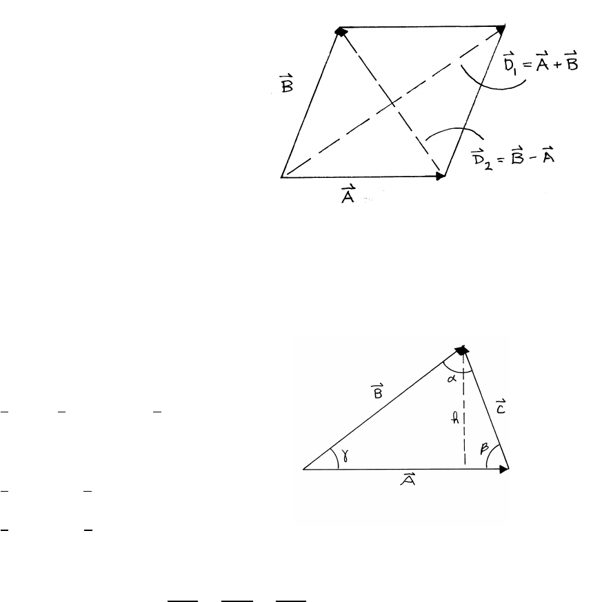
1.6 Diagonals of a parallelogram
The parallelogram is
equilateral, so A=B.
D1=A+B
D2=B−A
D1·D2=(A+B)·(B−A)=A2−B2=0.
Hence D1·D2=0and it follows that D1⊥D2.
1.7 Law of sines
The area Aof the triangle is
A=1
2A h =1
2A B sin γ=1
2|A×B|
Similarly,
A=1
2|B×C|=1
2BC sin α
A=1
2|C×A|=1
2AC sin β.
Hence AB sin γ=BC sin α=AC sin β, from which it follows
sin γ
C=sin α
A=sin β
B
Introducing the cross product makes the notation convenient, and emphasizes the
relation between the cross product and the area of the triangle, but it is not essential
for the proof.
VECTORS AND KINEMATICS 5
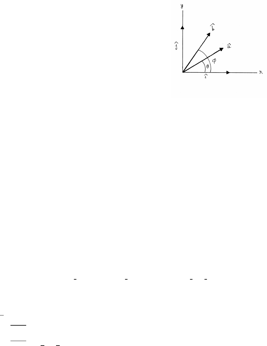
1.8 Vector proof of a trigonometric identity
Given two unit vectors ˆ
a=cos θˆ
i+sin θˆ
jand ˆ
b=cos φˆ
i+sin φˆ
j, with a=1,b=1.
First evaluate their scalar product using components:
a·b=ab cos θcos φ+ab sin θsin φ
=cos θcos φ+sin θsin φ
then evaluate their scalar product geometrically.
a·b=ab cos (a,b)=ab cos (φ−θ)=cos (φ−θ)
Equating the two results,
cos (φ−θ)=cos φcos θ+sin φsin θ
1.9 Perpendicular unit vector
Given A=(ˆ
i+ˆ
j−ˆ
k) and B=(2ˆ
i+ˆ
j−3ˆ
k), find Csuch that A·C=0and B·C=0.
C=Cxˆ
i+Cyˆ
j+Czˆ
k
=Cx(ˆ
i+(Cy/Cx)ˆ
j+(Cz/Cx)ˆ
k)
A·C=Cx(1 +(Cy/Cx)−(Cz/Cx)) =0
B·C=Cx(2 +(Cy/Cx)−3(Cz/Cx)) =0
We have two equations for the two unknowns (Cy/Cx) and (Cz/Cx).
1+(Cy/Cx)−(Cz/Cx)=0
2+(Cy/Cx)−3(Cz/Cx)=0.
The solutions are (Cy/Cx)=−1
2and (Cz/Cx)=1
2, so that C=Cx(ˆ
i−1
2ˆ
j+1
2ˆ
k). To
evaluate Cx, apply the condition that Cis a unit vector.
C2=3
2C2
x=1
Cx=±p(2/3)
ˆ
C=±p(2/3) (ˆ
i−1
2ˆ
j+1
2ˆ
k)
continued next page =⇒
6VECTORS AND KINEMATICS
which can be written
ˆ
C=±1
√6(2 ˆ
i−ˆ
j+ˆ
k)
Geometrically, Ccan be perpendicular to both Aand Bonly if Cis perpendicular
to the plane determined by Aand B. From the standpoint of vector algebra, this
implies that C∝A×B. To prove this, evaluate A×B.
A×B=
ˆ
iˆ
jˆ
k
1 1 −1
2 1 −3
=−2ˆ
i+ˆ
j−ˆ
k
∝C.
1.10 Perpendicular unit vectors
Given A=3ˆ
i+4ˆ
j−4ˆ
k, find a unit vector ˆ
Bperpendicular to A.
(a)
B=Bxˆ
i+Byˆ
j=Bx[ˆ
i+(By/Bx)ˆ
j]
A·B=Bx[3 +4(By/Bx)] =0
By/Bx=−3/4
B=Bx[ˆ
i−3
4ˆ
j]
To evaluate Bx, note that Bis a unit vector, B2=1.
1=B2
x(1)2+ 3
4!2= 25
16!B2
x
which gives
Bx=±(4/5)
ˆ
B=±(4/5)(ˆ
i−(3/4)ˆ
j)=±1
5(4 ˆ
i−3ˆ
j)
continued next page =⇒
VECTORS AND KINEMATICS 7
(b)
C=Cxˆ
i+Cyˆ
j+Czˆ
k
=Cx[ˆ
i+(Cy/Cx)ˆ
j+(Cz/Cx)ˆ
k]
A·C=0⇒Cx[3 +4(Cy/Cx)−4(Cz/Cx)] =0
B·C=0⇒1
5Cx[4 −3(Cy/Cx)] =0
Cy/Cx=4/3Cz/Cx=25/12
To make Ca unit vector,
C2=C2
x(1)2+ 4
3!2
+ 25
12!2=1
Cx≈ ±0.348
(c) The vector B×Cis perpendicular (normal) to the plane defined by Band C, so
we want to prove
A∝B×C
B×C=Cx
ˆ
iˆ
jˆ
k
4
5−3
50
14
3
25
12
=Cx"− 75
60!ˆ
i− 100
60 !ˆ
j+ 25
15!ˆ
k#
= 5
12!Cx(−3ˆ
i−4ˆ
j+4ˆ
k)∝A.
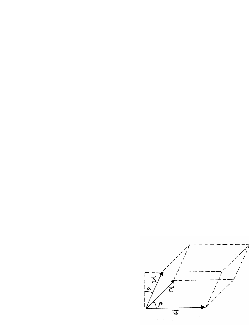
1.11 Volume of a parallelepiped
With reference to the sketch, the height is Acos α,
so the frontal area is AB cos α. The depth is
Csin β, so the volume Vis
V=(AB cos α)(Csin β)=(Acos α)(BC sin β)=A·(B×C)
The same approach can be used starting with a different face.
V=C·(A×B)V=B·(C×A)
Note that A,B,Care arbitrary vectors. This proves the vector identity
A·(B×C)=C·(A×B)=B·(C×A)
8VECTORS AND KINEMATICS
1.12 Constructing a vector to a point
Applying vector addition to the lower triangle
in the sketch,
A=r1+x(r2−r1)
=(1 −x)r1+xr2
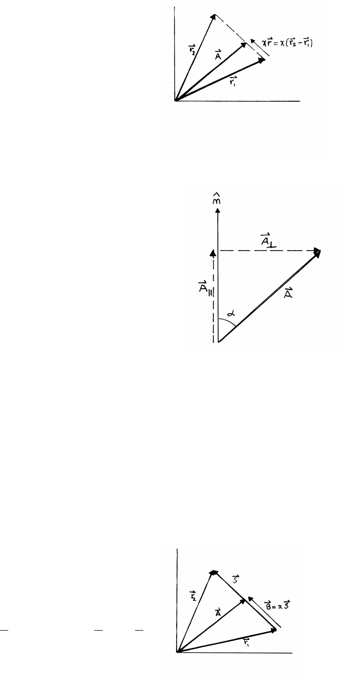
1.13 Expressing one vector in terms of another
We will express vector Ain terms of a unit vector
ˆ
n. As shown in the sketch, we can write
Aas the vector sum of a vector Akparallel to ˆ
n
and a vector A⊥perpendicular to ˆ
n,
so that A=Ak+A⊥.
|Ak|=Acos α
The direction of Akis along ˆ
n, so it follows that
Ak=(A·ˆ
n)ˆ
n.
|A⊥|=Asin α=|ˆ
n×A|
The direction of (ˆ
n×A) is into the paper, so taking its cross product with ˆ
ngives a
vector (ˆ
n×A)׈
nalong A⊥and with the correct magnitude. Hence
A=(A·ˆ
n)ˆ
n+(ˆ
n×A)׈
n
1.14 Two points
S=r2−r1B=xS A =r1+B
x=0 at t=0; x=1 at t=T
so that x=t/T, linear in t
A=r1+xS=r1+t
T(r2−r1)=1−t
Tr1+t
Tr2
VECTORS AND KINEMATICS 9
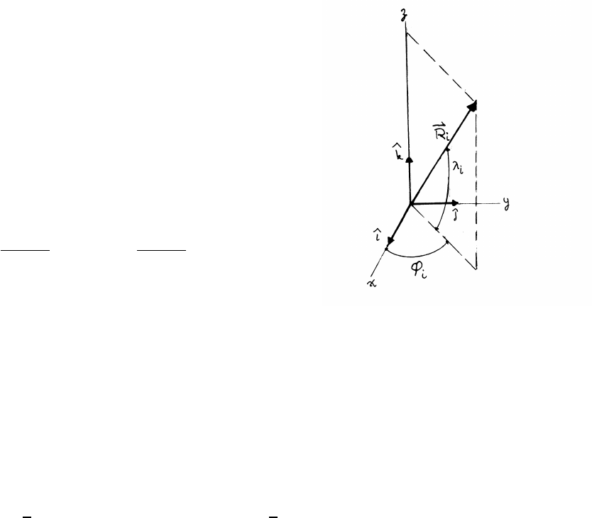
1.15 Great circle
Consider vectors R1and R2from the center
of a sphere of radius Rto points on the surface.
To avoid complications, the sketch shows the geometry
of a generic vector Ri(i=1 or 2) making angles λiand φi.
The magnitude of Riis R, so R1=R2=R.
The coordinates of a point on the surface are
Ri=Rcos λicos φiˆ
i+Rcos λisin φiˆ
j+Rsin λiˆ
k
The angle between two points can be found using the dot product.
θ(1,2) =arccos R1·R2
R1R2!=arccos R1·R2
R2!
Note that θ(1,2) is in radians.
The great circle distance between R1and R2is S=Rθ(1,2).
R1·R2=R2(cos λ1cos φ1cos λ2cos φ2+cos λ1sin φ1cos λ2sin φ2+sin λ1sin λ2)
Hence
S=Rθ(1,2)
=Rarccos [cos λ1cos λ2(cos φ1cos φ2+sin φ1sin φ2)+sin λ1sin λ2]
=Rarccos (1
2cos (λ1+λ2)cos (φ1−φ2)−1+1
2cos (λ1−λ2)cos (φ1−φ2)+1)
10 VECTORS AND KINEMATICS
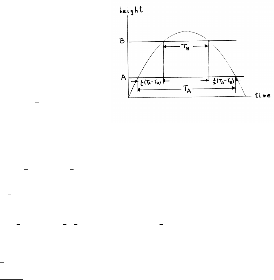
1.16 Measuring g
The motion is free fall with uniform
acceleration, so the trajectory is a
parabola, as shown in the sketch. Take
the initial conditions at T=0 to be
z=zAand v=vA. The height zis then
z=zA+vAT−1
2gT 2
The height is again zAwhen T=TA.
zA=zA+vATA−1
2gT 2
A
so that
0=vATA−1
2gT 2
A⇒vA=1
2gTA
By the symmetry of the trajectory, the body reaches height zBfor the second time
at T=1
2(TA+TB).
h=zB−zA
="zA+1
2vA(TA+TB)−1
2g[1
2(TA+TB)]2#−"zA+vATA−1
2gT 2
A#
= 1
2! 1
2!gTA(TA+TB)−1
8g(TA+TB)2
=1
8g(T2
A−T2
B)
g=8h
T2
A−T2
B
VECTORS AND KINEMATICS 11
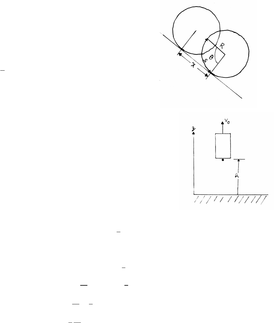
1.17 Rolling drum
The drum rolls without slipping, so that when it has rotated through an angle θ, it
advances down the plane by a distance xequal to the arc length s=Rθlaid down.
x=Rθ
a=¨x=R¨
θ=Rα
so that
α=a
R
1.18 Elevator and falling marble
Starting at t=0, the elevator moves upward
with uniform speed v0, so its height above the ground
at time tis z=v0t.
At time T1,h=v0T1, so that T1=h/v0. At the instant T1
when the marble is released, the marble is at height h
and has an instantaneous speed v0. Its height zat a later time tis then
z=h+v0(t−T1)−1
2g(t−T1)2
The marble hits the ground h=0 at time t=T2.
0=h+v0(T2−T1)−1
2g(T2−T1)2
=h+h
T1
(T2−T1)−1
2g(T2−T1)2
=hT2
T1−1
2g(T2−T1)2
h=1
2
T1
T2
g(T2−T1)2
12 VECTORS AND KINEMATICS
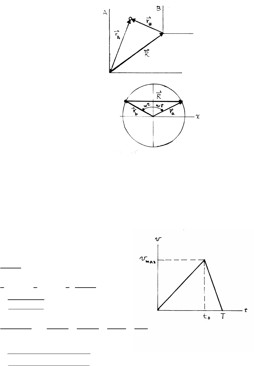
1.19 Relative velocity
(a)
rA=rB+R
˙
rA=˙
rB+˙
R
vB=vA−˙
R
(b)
R=2lsin (ωt)ˆ
i
˙
R=2lωcos (ωt)ˆ
i
From the result of part (a)
va=vb+2lωcos (ωt)ˆ
i
1.20 Sportscar
With reference to the sketch, the distance Dtraveled is the area under the plot of
speed vs. time. The goal is to minimize the time while keeping Dconstant. This
involves accelerating with maximum acceleration aafor time t0and then braking
with maximum (negative) acceleration abto bring the car to rest.
vmax =aat0=ab(T−t0)
t0=abT
aa+ab
D=1
2vmaxT=1
2aat0T=1
2 aaab
aa+ab!T2
T=r2D(aa+ab)
aaab
aa=100 km/hr
3.5 s = 100 km
hr ! 1000 m
1 km ! 1 hr
3600 s! 1
3.5 s!≈7.94m/s2
ab=0.7g=0.7(9.80 m/s2)≈6.86 m/s2
T=s(2000 m)(6.86 +7.94) m/s2
(6.86 m/s2)(7.94 m/s2)≈23.5s
VECTORS AND KINEMATICS 13
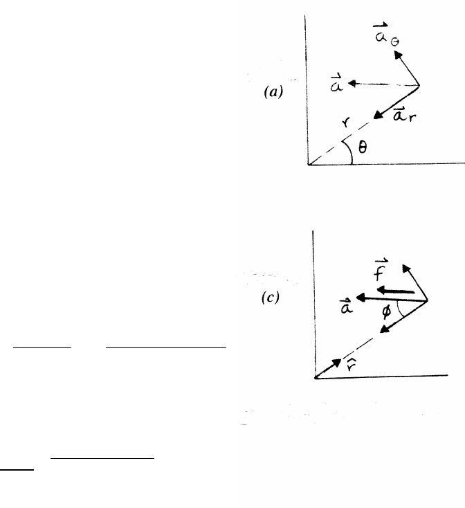
1.21 Particle with constant radial velocity
(a)
v=˙rˆ
r+r˙
θˆ
θ=(4.0 m/s) ˆ
r+(3.0 m)(2.0 rad/s) ˆ
θ
(Note that radians are dimensionless.)
v=(4.0ˆ
r+6.0ˆ
θ) m/s v =pvr2+vθ2=√16.0+36.0≈7.2 m/s
(b)
a=(¨r−r˙
θ2)ˆ
r+(r¨
θ+2˙r˙
θ)ˆ
θ
¨r=0 and ¨
θ=0
ar=−r˙
θ2=−(3.0 m)(2.0 rad/s)2=−12.0 m/s2
aθ=2˙r˙
θ=2(4.0 m/s)(2.0 rad/s) =16.0 m/s2
a=qa2
r+a2
θ=√144.0+256.0=20.0 m/s2
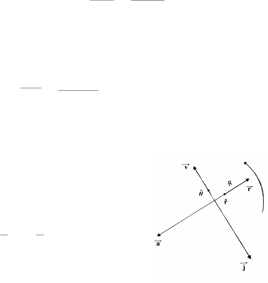
1.22 Jerk
For uniform motion in a circle, θ=ωt,
where the angular speed ωis constant.
r=rˆ
r=Rˆ
r
v=r˙
θˆ
θ=ωRˆ
θ
a=−r˙
θ2ˆ
r=−Rω2ˆ
r
Let j≡jerk.
j=da
dt =−Rω2dr
dt =−Rω2ˆ
θ
The vector diagram (drawn for R=2 and ω=1.5)
rotates rigidly as the point moves around the circle.
14 VECTORS AND KINEMATICS
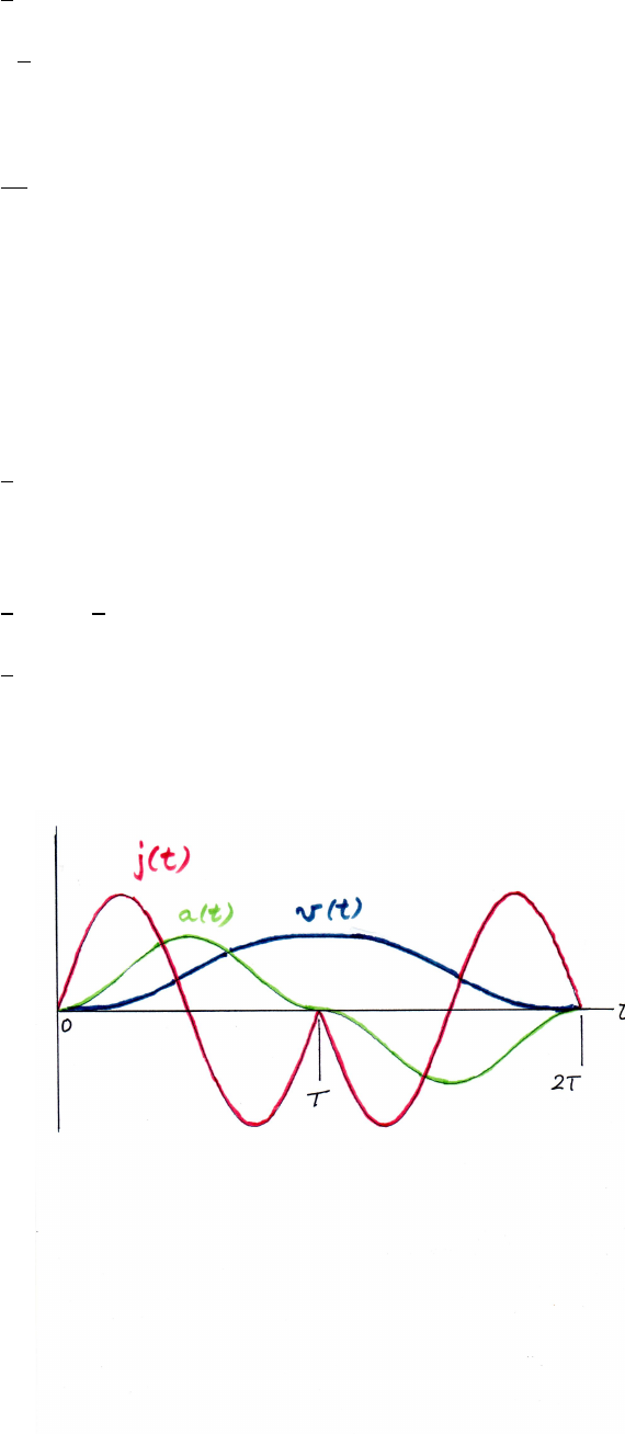
1.23 Smooth elevator ride
(a) Let a(t)≡acceleration
a(t)=1
2am[1 −cos(2πt/T)] 0 ≤t≤T
a(t)=−1
2am[1 −cos(2πt/T)] T≤t≤2T
Let j(t)≡jerk
j(t)=da
dt
j(t)=am(π/T) sin (2πt/T) 0 ≤t≤T
j(t)=−am(π/T) sin (2πt/T)T≤t≤2T
Let v(t)≡speed
v(t)=v(0) +Zt
0
a(t0)dt00≤t≤T
=1
2am[t−(T/2π) sin(2πt/T)]
v(t)=v(T)+Zt
T
a(t0)dt0T≤t≤2T
=1
2amT−1
2am[(t−T)−(T/2π) sin(2πt/T)]
=1
2am[(2T−t)+(T/2π) sin 2πt/T]
The sketch (in color) shows the jerk j(t) (red), the acceleration a(t) (green), and
the speed v(t) (black) versus time t.
continued next page =⇒
VECTORS AND KINEMATICS 15
(b) The speed v(t) is the area under the curve of a(t). As the sketch indicates, v(t)
increases with time up to t=T, and then decreases. The maximum speed vmax
therefore occurs at t=T, so that vmax =v(T).
vmax =v(0) +ZT
0
a(t0)dt0=1
2amZT
0
[1 −cos (2πt0/T)]dt0
=1
2am[t0−(T/2π) sin (2πt0/T)]|T
0=1
2amT
(c) For tT, we can use the small angle approximation:
sin θ=[θ−1
3!θ3+. . .]
v(t)=Zt
0
a(t0)dt0=1
2am[t−(T/2π) sin (2πt/T)]
=am
2{t−(T/2π)[(2πt/T)−1
3!(2πt/T)3+. . .}
≈am
2{1
3!(2π/T)2t3} ≈ am π2
3! t3
T2!
(d) direct method:
Let the distance at time tbe x(t).
x(t)=Zv(t0)dt0
where
v(t)=1
2Zt
0
a(t0)dt00≤t≤T
=am
2[t−(T/2π) sin (2πt/T)] 0 ≤t≤T
v(t)=ZT
0
a(t0)dt0+Zt
T
a(t0)dt0T≤t≤2T
=am
2[T−t+T+(T/2π) sin (2πt/T)] T≤t≤2T
(Note that v(2T)=0.) Then
D=x(2T)
=am
2ZT
0
[t0−(T/2π) sin (2πt0/T)]dt0+am
2Z2T
T
[2T−t0+(T/2π) sin (2πt0/T)]dt0
=am
2T2
continued next page =⇒
16 VECTORS AND KINEMATICS
(e) symmetry method:
By symmetry, the distance from x(0) to x(T) and the distance from x(T) to
x(2T) are equal. The distance from x(0) to x(T) is
x(T)=ZT
0
v(t0)dt0
=am
2ZT
0
[t−(T/2π) sin (2πt0/T)]dt0
=am
2[t02/2+(T/2π)2cos (2πt0/T)]
T
0=am
4T2
By symmetry
D=2x(T)=1
2amT2
as before.
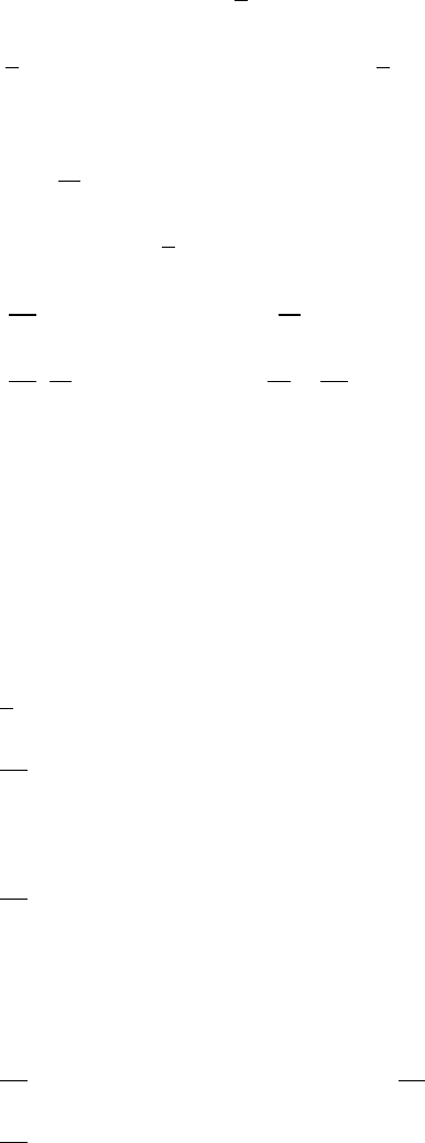
1.24 Rolling tire
Let x,ybe the coordinates of the pebble measured
from the stationary origin. Let ρbe the vector
from the stationary origin to the center of the
rolling tire, and let R0be the vector
from the center of the tire to the pebble.
ρ=Rθˆ
i+Rˆ
j
R0=−Rsin θˆ
i−Rcos θˆ
j
From the diagram, the vector from the origin to the pebble is
xˆ
i+yˆ
j=ρ+R0=Rθˆ
i+Rˆ
j−Rsin θˆ
i−Rcos θˆ
j
x=Rθ−Rsin θ˙x=R˙
θ−Rcos θ˙
θ
y=R−Rcos θ˙y=Rsin θ˙
θ
The tire is rolling at constant speed without slipping: θ=ωt=(V/R)t.
continued next page =⇒
VECTORS AND KINEMATICS 17
˙x=Rω−Rωcos θ¨x=Rω2sin θ
˙y=Rωsin θ¨y=Rω2cos θ
Note that
¨xˆ
i+¨yˆ
j=¨
ρ+¨
R0=¨
R0
The pebble on the tire experiences an inward radial acceleration V2/R, and from
the results for ¨xand ¨y
p¨x2+¨y2=Rω2
=V2
R
as expected.
This result shows that the acceleration measured in the stationary system is the
same as measured in the system moving uniformly along with the tire.
1.25 Spiraling particle
(a)
r=θ
πθ=αt2
2
r=αt2
2π
˙r=αt
π˙
θ=αt
¨r=α
π¨
θ=α
a=(¨r−r˙
θ2)ˆ
r+(r¨
θ+2˙r˙
θ)ˆ
θ= α
π−α3t4
2π!ˆ
r+ 5α2t2
2π!ˆ
θ
(b)
ar=α
π−α3t4
2π=0 at time t’
α
π=α3t04
2π=⇒t02=√2
α
θ(t0)=αt02
2=1
√2rad
continued next page =⇒
18 VECTORS AND KINEMATICS
(c)
a=(¨r−r˙
θ2)ˆ
r+(r¨
θ+2˙r˙
θ)ˆ
θ
Using the expression for θfrom part (a),
a=α
π[(1 −2θ2)ˆ
r+5θˆ
θ]
Setting |ar|=|aθ|, then |1−2θ2|=|5θ|
If θ < 1
√2, then 1 −2θ2=5θ
Because θ≥0, the only allowable root is
θ=−5+√33
4≈0.186 rad ≈10◦
If θ > 1
√2, then 2θ2−1=5θ
θ=5+√33
4≈2.69 rad ≈154◦
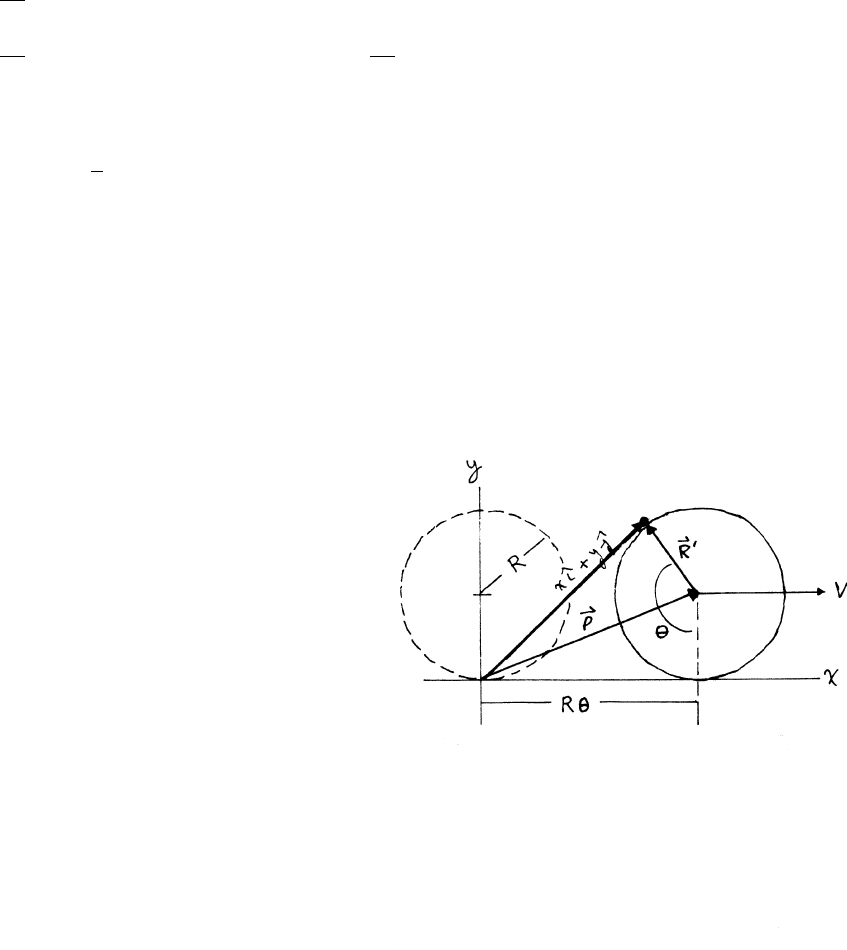
In the sketch, the velocity vectors are in scale to one another, as are the acceleration
vectors.
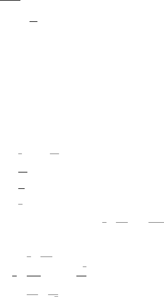
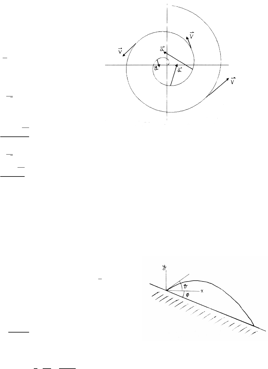
1.26 Range on a hill
The trajectory of the rock is described by coordinates xand y, as shown in the
sketch. Let the initial velocity of the rock be v0at angle θ.
x=(v0cos θ)t y =(v0sin θ)t−1
2g t2
The locus of the hill is y=−xtan φ
Let the rock land on the hill at time t0.
t0=x
v0cos θ
The locus of the hill and the trajectory of the rock intersect at t0.
−xtan φ=xtan θ−1
2 g
v02! x2
cos2θ!
continued next page =⇒
VECTORS AND KINEMATICS 19
Solving for x,
x= 2v2
0
g!hcos θsin θ+(cos2θ) tan φi= 2v2
0
g!"1
2sin 2θ+(cos2θ) tan φ#
The condition for maximum range is dx/dθ=0. Note that φis a constant.
dx
dθ=0=cos 2θ−2 sin θcos θtan φ=cos 2θ−(sin 2θ) tan φ
cot 2θ=tan φ
tan 2θ=tan π
2−φ
θ=π
4−φ
2for maximum range
The sketch is drawn for the case φ=20◦and v0=5.0 m/s.
1.27 Peaked roof
Let the initial speed at t=0 be v0. A straightforward way to solve this problem is
to write the equations of motion in a uniform gravitational field, as follows:
x=−h+v0xt y =v0yt−1
2gt2
vx=v0xvy=v0y−gt
At time T, he ball is at the peak, where y=hand vy=0.
0=v0y−gT ⇒T=v0y
g
h=v0yT −1
2gT 2=
v2
0y
g−1
2
v2
0y
g
v2
0y=2gh
At time T,x=0.
0=−h+v0xT⇒v0x=h
T=pgh
2
We then have
v0=qv2
0x+v2
0y=r2+1
2pgh =r5
2pgh
continued next page =⇒

20 VECTORS AND KINEMATICS
A more physical approach is to note that the vertical speed needed to reach the peak
is the same as the speed v0ya mass acquires falling a distance h:v0y=p2gh. The
time Tto fall that distance is T=v0y/g. The horizontal distance traveled in the
time Tis
h=v0xT=v0x v0y
g!=v0xs2h
g
v0x=rgh
2
The initial speed v0is therefore
v0=qv2
0x+v2
0y=r2+1
2pgh =r5
2pgh
2.1 Time-dependent force
a=F
m=
(4t2ˆ
i−3tˆ
j) N
5 kg
=
(4t2ˆ
i−3tˆ
j) kg ·m/s2
5 kg
= 4
5t2ˆ
i−3
5tˆ
j!m/s2
(a) v(t)−v(0) =Rt
0a(t0)dt0=4
15 t3ˆ
i−3
10 t2ˆ
jm/s
(b) r(t)−r(0) =Rt
0v(t0)dt0=1
15 t4ˆ
i−1
10 t3ˆ
jm
(c) r×v=
ˆ
iˆ
jˆ
k
t4
15 −t3
10 0
4t3
15 −3t2
10 0
=−t6
50 ˆ
i+2t6
75 ˆ
j
22 NEWTON’S LAWS
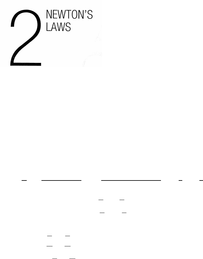
2.2 Two blocks and string
(a) Step 1: draw the force diagram for each block
The force diagrams are shown in the sketch.
The vertical forces on block M1cancel,
because M1is on the table and has no
vertical acceleration. (A constraint.)
The tension Tis the same at both ends
of the string, because the string is massless
so the net force on it must be 0.
(b) Step 2: write the equations of motion for each block
M1¨x1=T M2¨x2=W2−T
(c) Step 3: write the constraint equation(s)
We have already considered the (trivial) constraint condition for the vertical
acceleration of M1. Another constraint is that the length Lof the string is fixed.
L−x1+x2=constant =⇒ −¨x1+¨x2=0=⇒¨x1=¨x2
(d) Step 4: solve
From the string constraint
T=M1¨x1=M1¨x2(1)
From the equation of motion for M2, and using W2=M2g,
M2g−T=M2¨x2(2)
Combining (1) and (2) gives
(M1+M2) ¨x2=M2g=⇒¨x2=M2g
(M1+M2)=¨x1
NEWTON’S LAWS 23
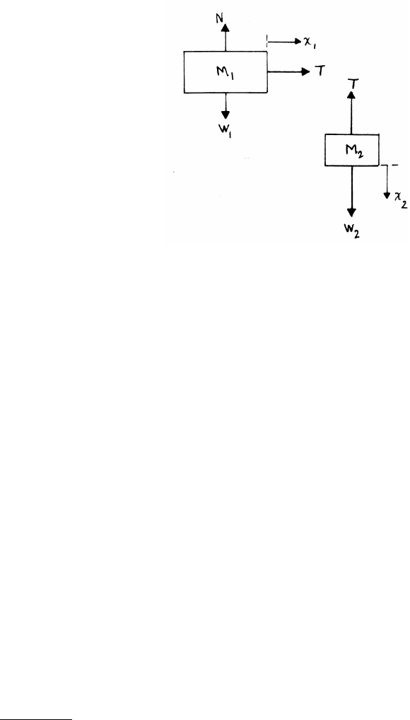
2.3 Two blocks on table
The blocks have zero vertical
acceleration, so the sketch omits
the vertical forces. By Newton’s
third law, the force on m1due
to m2is equal and opposite to
the force on m2due to m1.
m1¨x=F−F0m2¨x=F0
¨x=F
(m1+m2)
This result can be found directly by considering a system with mass (m1+m2) acted
on by the external force F.
F0=m2¨x=m2
(m1+m2)F="1 kg
(2 kg +1 kg) #(3 N) =1 N
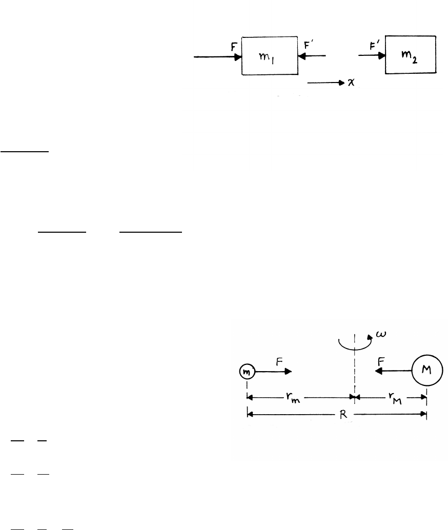
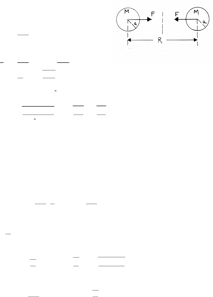
2.4 Circling particle and force
Let ambe the inward radial acceleration
of m, and aMthe inward radial acceleration of M.
mam=mrmω2=F
MaM=MrMω2=F
rm=F
ω2 1
m!
rM=F
ω2 1
M!
R=rM+rM
=F
ω2 1
m+1
M!
24 NEWTON’S LAWS
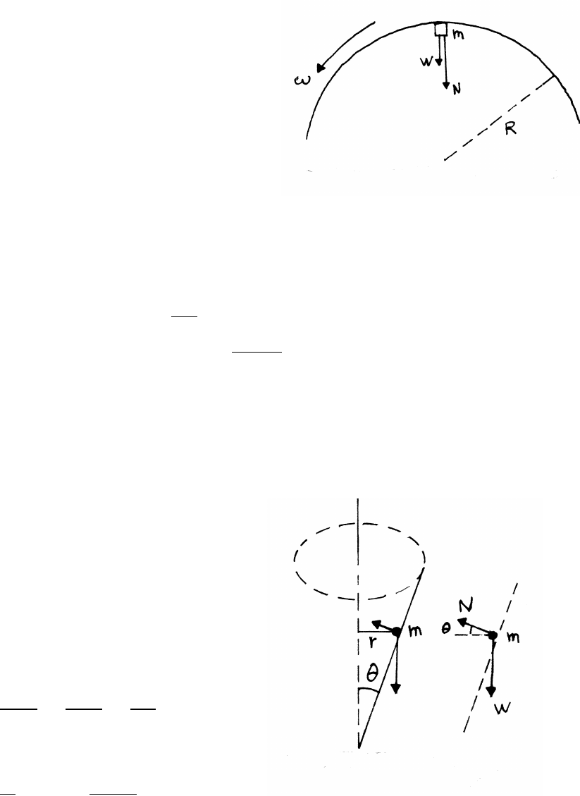
2.5 Concrete mixer
Consider a small mass mof concrete, momentarily
at the top of the rotating drum. Mass mis acted
upon by the downward weight force Wand by the
normal force Nexerted by the wall of the drum.
Mass mfalls away from the drum if N≤0,
when ω≤ωcritical.
W+N=maradial =mRω2
N=mRω2−W=mRω2−mg =m(Rω2−g)
N=0 for ω=ωcritical.
Rω2critical −g=0=⇒ωcritical =pg/R
For R=0.5 m and g=9.8 m/s2,ωcritical =√9.8/0.5=4.43 rad/s, or equivalently
4.43/2πrev/s=⇒=(0.705)(60) =42.3 rpm.
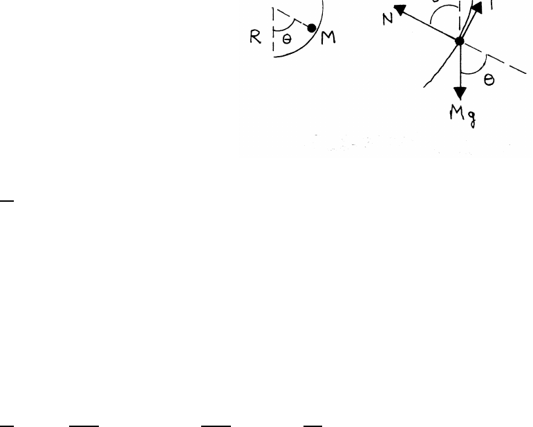
2.6 Mass in a cone
From the force diagram,
Nsin θ=W(1)
Ncos θ=mrω2(2)
Dividing Eq. (1) by Eq. (2) gives
tan θ=W
mrω2=mg
mrω2=g
rω2
The speed v0of maround the cone is v0=rω.
tan θ=gr
v2
0
=⇒r=v2
0tan θ
g
NEWTON’S LAWS 25
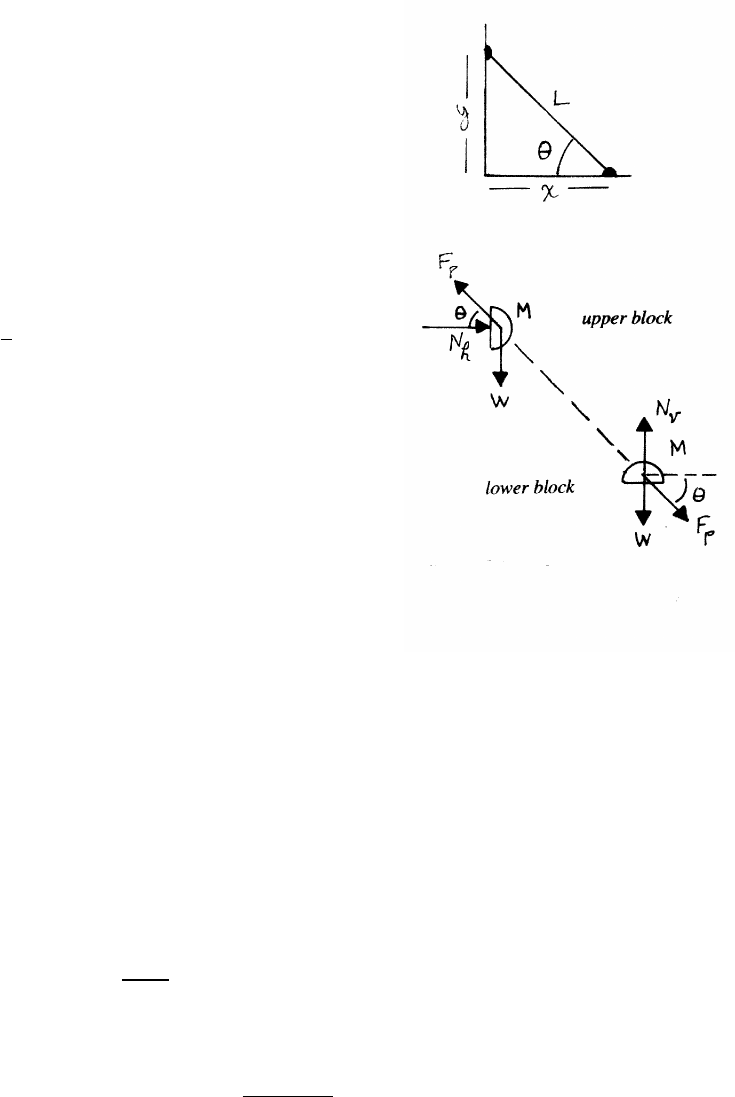
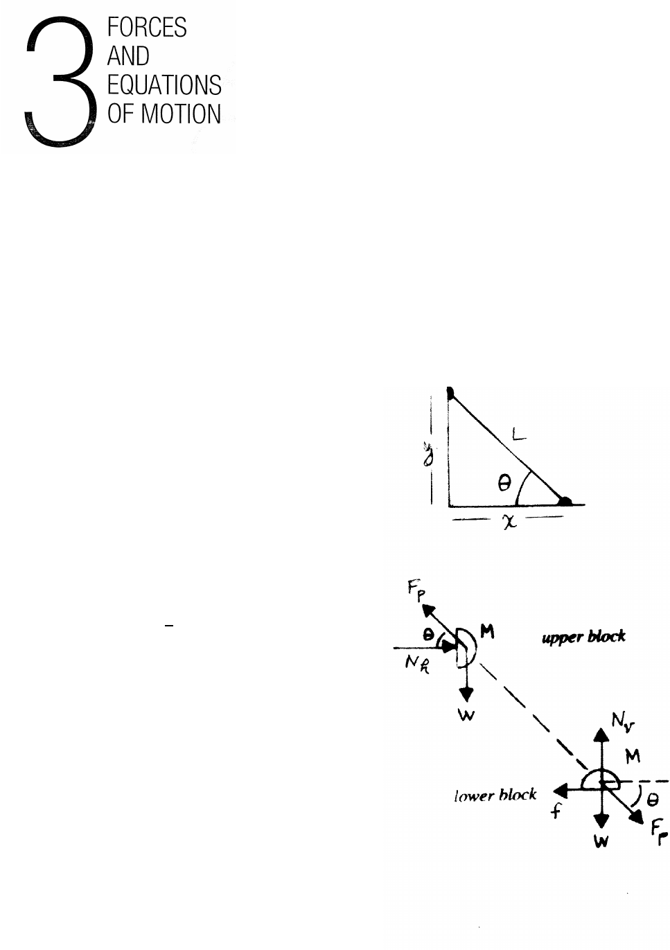
2.7 Leaning pole
(a)
x2+y2=L2
2x˙x+2y˙y=0
˙x2+x¨x+˙y2+y¨y=0
When the pole is at rest, ˙x=0, ˙y=0.
At rest, the condition becomes
x¨x+y¨y=0
¨x=−y
x¨y=−(tan θ)¨y(1)
(b) The pole is taken to be massless, so the net force on the pole must be 0. The
pole therefore exerts equal and opposite force Fpon each block, as indicated in
the force diagrams. Consider only the equations of motion that do not involve
the horizontal normal force Nhexerted on the upper block by the wall, and the
vertical normal force Nvexerted on the lower block by the floor.
upper block: M ¨y=Fpsin θ−W(2)
lower block: M ¨x=Fpsin θ(3)
Solve Eqs.(1), (2), (3) for the three unknowns Fp, ¨xand ¨y. From Eqs. (2) and
(3)
M¨y=M¨x sin θ
cos θ!−W=⇒¨y=(tan θ) ¨x−g.
Combining with Eq. (1) yields
¨y=−(tan2θ)¨y−g=−g
1+tan2θ
Using the identities tan θ=sin θ/ cos θand sin2θ+cos2θ=1 gives
¨y=−gcos2θ¨x=−(tan θ)¨y=gsin θcos θ
26 NEWTON’S LAWS
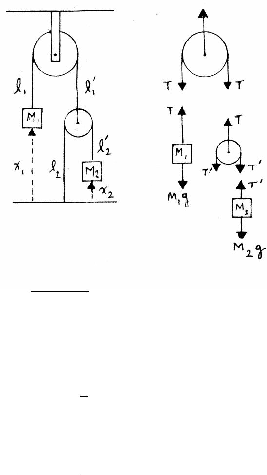
2.8 Two masses and two pulleys
constraint:
The fixed length of the string is a constraint.
x1+l1+l0
1+(x2+l2+l0
2)
2=constant =⇒¨x2=−2 ¨x1
equations of motion:
The vertical force on the upper pulley plays no role in the motion and can be ne-
glected. The lower pulley is taken to be massless, so the net force is 0: 2T0=T.
M1¨x1=T−M1g=⇒T=M1¨x1+M1g
M2¨x2=T0−M2g=T
2−M2g
Solving,
−4M2¨x1=T−2M2g=M1¨x1+M1g−2M2g
¨x1=(2M2−M1)g
(4M2+M1)
The result is reasonable. The weight of M1is counterbalanced by twice the weight
of M2; the acceleration of M2is twice the rate of M1. As special cases, if M1M2,
¨x1≈ −g. If M2M1,¨x1≈g/2 and ¨x2≈ −g.
NEWTON’S LAWS 27
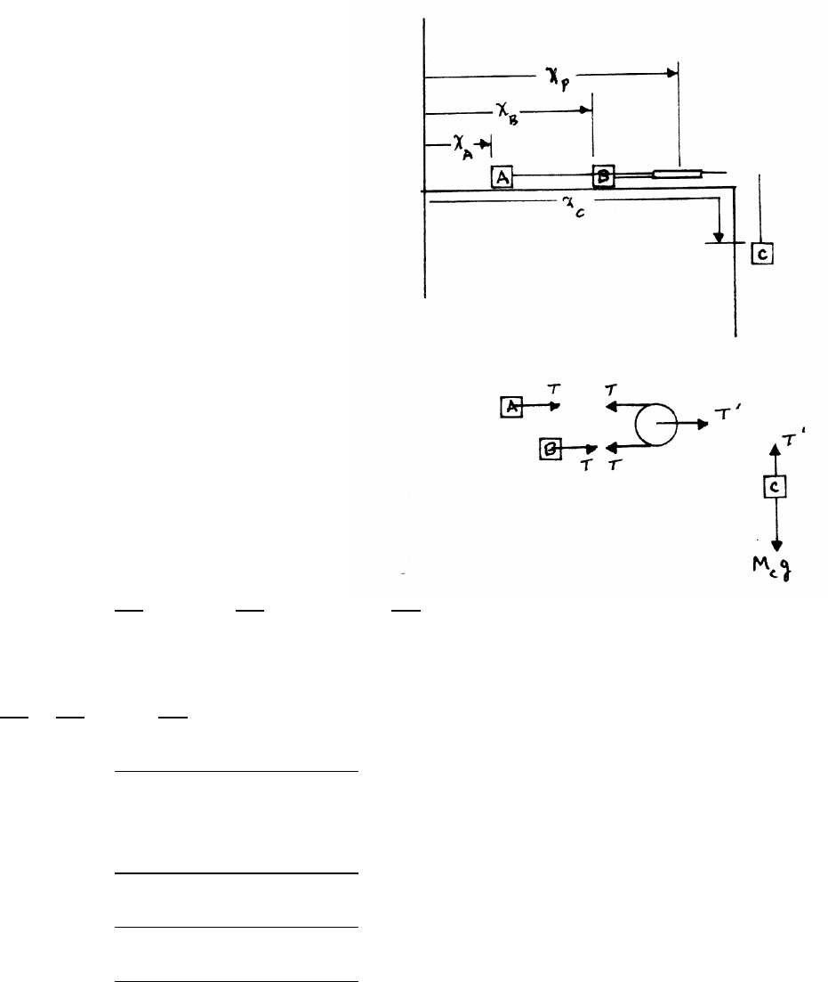
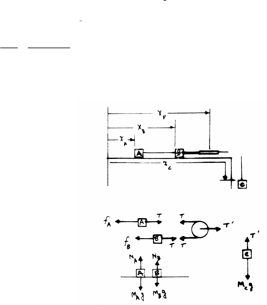
2.9 Masses on table
constraints:
xC−xP=constant
¨xC=¨xP
(xP−xA)+(xP−xB)=constant
¨xA+¨xB=2 ¨xP=2 ¨xC(1)
The lower sketch shows the forces on the
blocks and pulley. The pulley is taken to be
massless, so the net force on the pulley
is 0: 2T−T0=0.
equations of motion:
MA¨xA=T MB¨xB=T MC¨xC=MCg−T0
solving:
¨xA=T
MA
¨xB=T
MB
¨xC=g−2T
MC
Using the constraint Eq. (1),
T
MA
+T
MB
=2g−4T
MC
T=2MAMBMCg
(MAMC+MBMC+4MAMB)
Then
¨xA=2MBMCg
(MAMC+MBMC+4MAMB)
¨xB=2MAMCg
(MAMC+MBMC+4MAMB)
¨xC=(MA+MB)MCg
(MAMC+MBMC+4MAMB)

28 NEWTON’S LAWS
2.10 Three masses
(a) coordinates and force diagrams:
(b) constraint:
x2−x1+2y=length of string =constant
¨x2−¨x1+2¨y=0
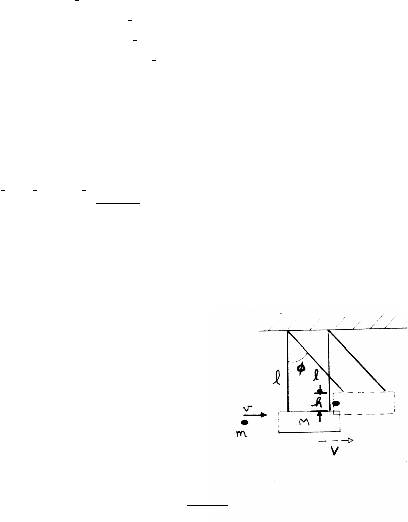
2.11 Block on wedge
constraint:
x−X
h−y=tan (45◦)=1
x−X=h−y
¨x=¨
X−¨y=A−¨y(1)
equations of motion:
Note that cos (45◦)=sin (45◦)=1/√2
m¨x=Ncos (45◦)=N
√2(2)
m¨y=Nsin (45◦)−mg =N
√2−mg (3)
continued next page =⇒
NEWTON’S LAWS 29
solve: From Eqs. (1), (2), and (3),
mA =m¨y+N
√2
=√2N−mg =⇒N=m(A+g)
√2
¨x=A+g
2¨y=A−g
2
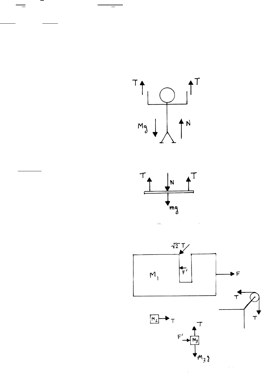
2.12 Painter on scaffold
The constraint is that the painter and the
scaffold both accelerate at the same rate a.
The equations of motion for the painter
and the scaffold are, respectively,
Ma =2T+N−Mg
ma =2T−N−mg
(M+m)a=4T−(M+m)g
a=4T
(M+m)−g
2.13 Pedagogical machine
Because M3is motionless, all three
bodies experience the same horizontal
acceleration a. Two further points:
(1) M1is pushing on M3with force F0to give M3
the acceleration a. By Newton’s third law, M3
exerts an equal and opposite force F0on M1,
as shown in the force diagram.
(2) A subtle point is that the pulley holder exerts
a force on M1, as illustrated in the sketch. This force
has a horizontal component Tdirected opposite to
the applied force F.
continued next page =⇒
30 NEWTON’S LAWS
With reference to the force diagrams, the equations of motion are
M1a=F−F0−T M2a=T M3a=F0M3g−T=0
To find F, eliminate T,a, and F0.
T=M3g=M2a=⇒a= M3
M2!g
F=M1a+F0+T=(M1+M3)a+M2a=(M1+M2+M3)a=(M1+M2+M3) M3
M2!g
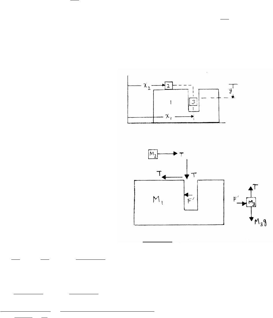
2.14 Pedagogical machine 2
constraints:
With reference to the coordinates
in the upper sketch, the length
of the string is x1−x2+y.
x1−x2+y=constant
¨x1−¨x2+¨y=0 (1)
A second constraint is that M1and M3
have equal horizontal acceleration ¨x1=¨x3.
equations of motion:
M1¨x1=−F0−T M2¨x2=T M3¨x3=F0
To solve, eliminate Tand F0, express ¨x2,¨x3and ¨y
in terms of ¨x1, and use the constraint Eq. (1).
F0=M3¨x3=M3¨x1
T=M2¨x2=−M1¨x1+F0=−(M1+M3) ¨x1=⇒¨x2=(M1+M3)
M2
¨x1
¨y=g−T
M3
=g−M2
M3
¨x2=g+(M1+M3)
M3
¨x1
From Eq. (1)
0=¨x1+(M1+M3)
M2
¨x1+g+(M1+M3)
M3
¨x1
¨x1=−g
2+(M1+M3)
M2+M1
M3=−M2M3g
(2M2M3+M1M3+M1M2+M32)
NEWTON’S LAWS 31
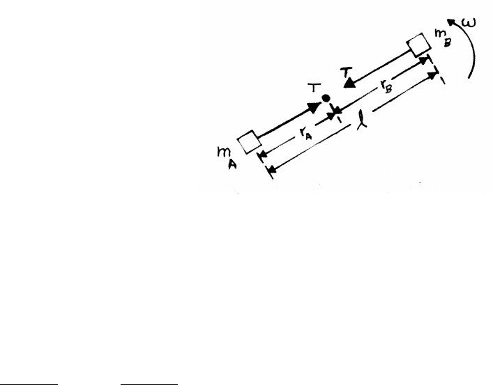
2.15 Disk with catch
constraints:
rA+rB=l
¨rB=−¨rA
equations of motion:
Because the blocks are constrained by the groove, the tangential motion plays no
dynamical role, and is neglected in the force diagram. Note that the force Ton each
mass is radially inward.
−T=mA(¨rA−rAω2)
−T=mB(¨rB−rBω2)
mA(¨rA−rAω2)=mB(¨rB−rBω2)=mBh−¨rA+(l−rA)ω2i
¨rA= mA−mB
mA+mB!rAω2+mBlω2
mA+mB
2.16 Planck units
Using Maxwell’s notation, the dimensions of h,G, and care symbolized as [h],
[G], and [c] respectively.
[h]=ML2T−1[G]=M−1L3T−2[c]=LT −1
(a) The Planck length Lpis
Lp=hαGβcγ
Converting to dimensions,
L=(ML2T−1)α(M−1L3T−2)β(LT −1)γ=M(α−β)L(2α+3β+γ)T−(α+2β+γ)
continued next page =⇒
32 NEWTON’S LAWS
The fundamental dimensions M,L,Tare independent of one another, so the
exponents must agree on both sides, leading to the three equations
α−β=0 2α+3β+γ=1−α−2β−γ=0
α=1/2β=1/2γ=−3/2
Lp=rhG
c3=s(6.6×10⁻³⁴)(6.7×10⁻¹¹)
(3.0×10⁸)3=4.1×10⁻³⁵ m
(b) Proceeding as in (a), with fresh exponents, the Planck mass Mpis
Mp=hαGβcγM=M(α−β)L(2α+3β+γ)T−(α+2β+γ)
α=1/2β=−1/2γ=1/2
Mp=rhc
G=r(6.6×10⁻³⁴)(3.0×10⁸)
6.7×10−11 =5.4×10⁻⁸kg
(c) Proceeding as before, the Planck time Tpis
Tp=hαGβcγT=M(α−β)L(2α+3β+γ)T−(α+2β+γ)
α=1/2β=1/2γ=−5/2
Tp=rhG
c5=s(6.6×10⁻³⁴)(6.7×10⁻¹¹)
(3.0×10⁸)5=1.3×10−43 s
3.1 Leaning pole with friction
constraint:
x2+y2=L2
2x˙x+2y˙y=0
˙x2+x¨x+˙y2+y¨y=0
When the pole is at rest, ˙x=0, ˙y=0 and the condition becomes
x¨x+y¨y=0
¨x=−y
x¨y=−(tan θ)¨y(1)
The net force on the massless pole must be 0.
The pole therefore exerts equal and opposite force
Fpon each block.
continued next page =⇒
34 FORCES AND EQUATIONS OF MOTION
equations of motion:
upper block:
M¨y=Fpsin θ−Mg (2)
lower block:
Nv−Mg =0
M¨x=Fpcos θ−f
=Fpcos θ−µNv
=Fpcos θ−µMg (3)
We have three equations (1), (2), and (3) for the three unknowns Fp, ¨xand ¨y. From
Eq. (2),
Fp=M(¨y+g)
sin θ(4)
From Eq. (3)
Fp=M( ¨x+µg)
cos θ
Using Eqs. (4) and (1)
¨y+g=(tan θ)( ¨x+µg)
=(tan θ)[−(tan θ)¨y+µg]
¨y=(µtan θ−1)g
1+tan2θ
With the identities tan θ=sin θ/ cos θand sin2θ+cos2θ=1
¨y=(µsin θcos θ−cos2θ)g
Then, using Eq. (1),
¨x=−(tan θ)¨y
=(sin θcos θ−µsin2θ)g
The frictionless case is treated in problem 2.7.
FORCES AND EQUATIONS OF MOTION 35
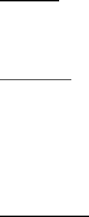
3.2 Sliding blocks with friction
The upper sketch shows the force diagrams for the
first part. The vertical forces on M2play no
dynamical role, and are not shown.
M1¨x1=f=⇒¨x1=f
M1
M2¨x2=F−f=⇒¨x2=F
M2−f
M2
The blocks move together if ¨x1=¨x2.
f
M1
=F
M2−f
M2
f= M1
M1+M2!F= 4 kg
9 kg!27 N =12 N
Incidentally, f=µN1=µM1gso that µ≈0.3
The lower sketch shows the force diagrams
for the second part.
M1¨x1=F0−f=⇒¨x1=F0
M1−f
M1
M2¨x2=f=⇒¨x2=f
M2
The blocks move together if x1=¨x2.
F0
M1−f
M1
=f
M2
F0= M1+M2
M2!f= M1
M2!F=21.6 N

36 FORCES AND EQUATIONS OF MOTION
3.3 Stacked blocks and pulley
The upper sketch shows the coordinates and
the lower sketches show the force diagrams.
constraints:
The massless rope has fixed length la+lb
=constant so that ¨
lb=−¨
la. Also,
xa+la=X=⇒¨xa+¨
la=¨
X=A(1a)
xb+lb=X=⇒¨xb+¨
lb=¨
X=A(1b)
equations of motion:
Vertical forces on Mbare omitted in the sketch,
because they play no dynamical role.
Ma¨xa=T−f=⇒¨xa=1
Ma
(T−f)
Mb¨xb=T+f=⇒¨xb=1
Mb
(T+f)
From Eqs. (1a) and (1b)
A−¨
la=1
Ma
(T−f)
A+¨
la=1
Mb
(T+f)
2A= 1
Ma
+1
Mb!T+ 1
Mb−1
Ma!f
T=2A MaMb
Ma+Mb!+ Mb−Ma
Ma+Mb!f=2A MaMb
Ma+Mb!+ Mb−Ma
Ma+Mb!µNa
=2A MaMb
Ma+Mb!+ Mb−Ma
Ma+Mb!µMag
FORCES AND EQUATIONS OF MOTION 37
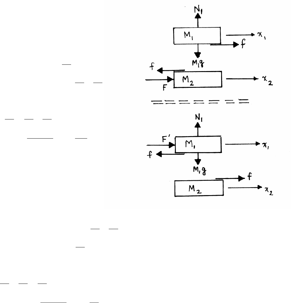
3.4 Synchronous orbit
mRω2=GmMe
R2=⇒R3=GMe
ω2
Usingg=GMe
R2
e
R3
R3
e
=GMeg
GMeReω2
R=Re g
Reω2!1/3
g=9.8 m/s2,Re=6.4×106m, ω=2πrad/day =7.3×10⁻⁵s−1
R=6.6Re=4.2×10⁷m≈26 ×103miles
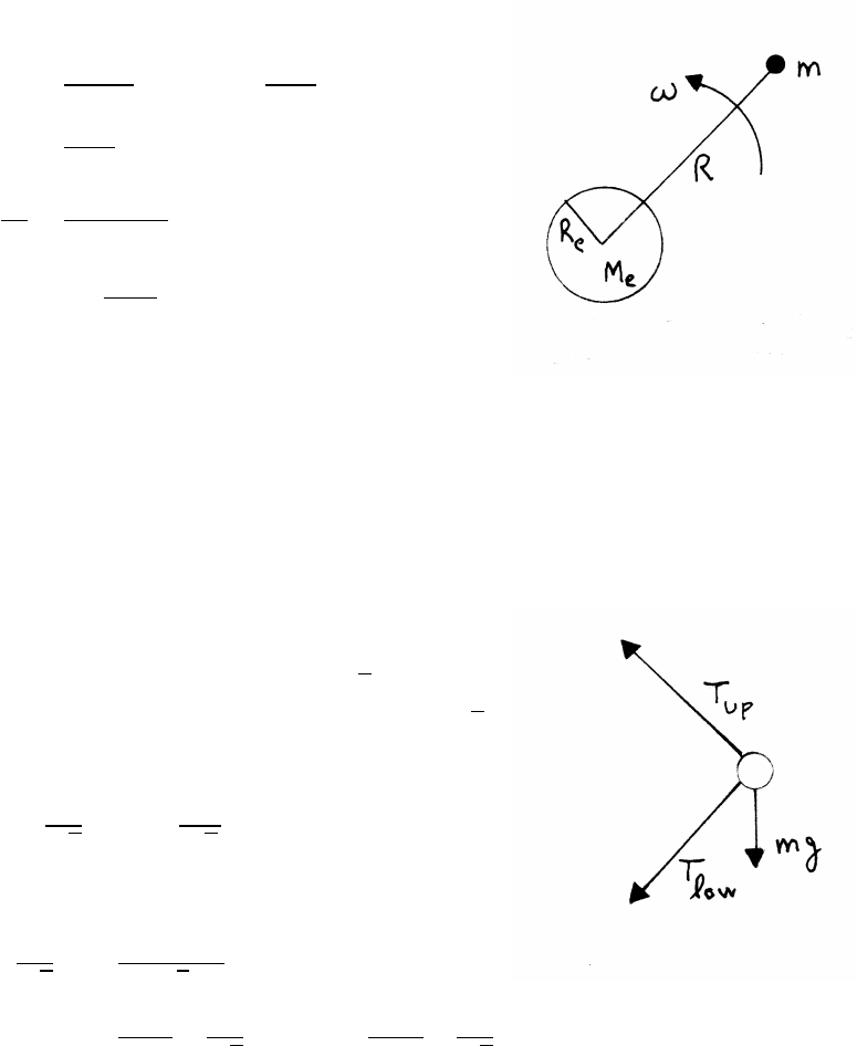
3.5 Mass and axle
(a) The sketch shows the force diagram.
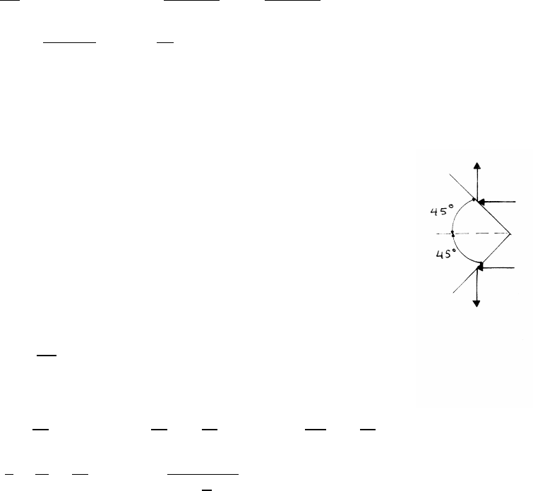
(b) Note that cos 45◦=sin 45◦=1/√2.
The radial distance of mfrom the axle is l/√2.
vertical equation of motion:
Tup
√2
=mg +Tlow
√2
radial equation of motion:
ml
√2ω2=Tup +Tlow
√2
Tlow =mlω2
2−mg
√2Tup =mlω2
2+mg
√2
38 FORCES AND EQUATIONS OF MOTION
3.6 Tablecloth trick
While the tablecloth is being pulled out from under the glass, the glass is accel-
erated at a rate agiven by ma =µmg, or a=µg.If this occurs for time T, the
glass reaches speed v0=µgT , and travels a distance d=1
2µgT 2. The glass is
then sliding on the tabletop, and is retarded by a force µmg. It comes to rest in
time Tafter traveling a distance 1
2µgT 2. The total distance traveled by the glass is
D=2d=µgT 2. We require D≤6 inches ≈15 cm. So
T2≤15 cm
µg=0.15 m
(0.5)(9.8 m/s2)=⇒T≤0.17 s
3.7 Pulleys and rope with friction
(a) constraints:
xC−xP=constant
(xP−xA)+(xP−xB)=constant
(b) accelerations:
¨xC=¨xP
¨xA+¨xB=2 ¨xP=2 ¨xC
(c) equations of motion:
MA¨xA=T−fA
MB¨xB=T−fB
NA−MAg=0NB−MBg=0
fA=µNa=µMAg
fB=µNB=µMBg
The pulley is massless, so T0=2T.
continued next page =⇒
FORCES AND EQUATIONS OF MOTION 39
Solving,
T0 1
Mc
+1
4MA
+1
4MB!=(1 +µ)g
T0= 4(1 +µ)MAMBMC
MAMC+MBMC+4MAMB!g
T=T0
2= 2(1 +µ)MAMBMC
MAMC+MBMC+4MAMB!g
The frictionless case is treated in problem 2.10.
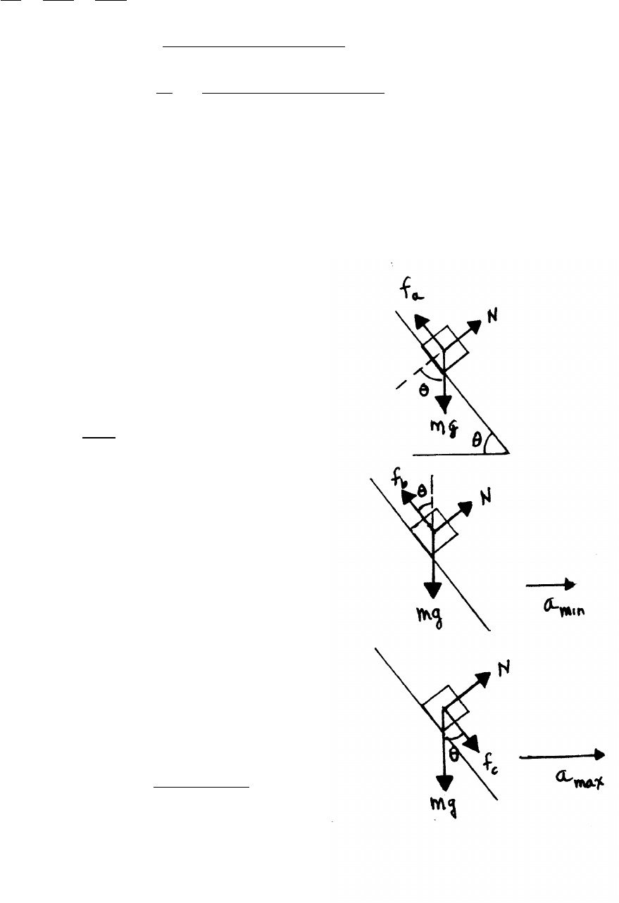
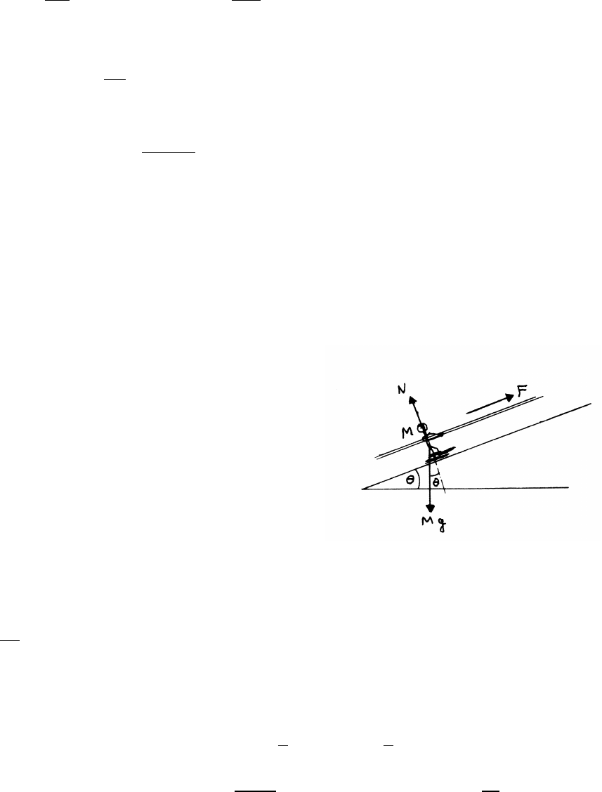
3.8 Block and wedge
(a) The block has 0 acceleration.
N−mg cos θ=0
mg sin θ−fa=0
fa=µN
mg sin θ=µN=µmg cos θ
µ=sin θ
cos θ=tan θ
(b) Minimum acceleration:
The block’s horizontal acceleration is
mamin =Ncos θ−fbsin θ
fb≤µN
In the limit, fb=µN
mamin =N(cos θ−µsin θ) (1)
The block has 0 vertical acceleration.
Nsin θ+fbcos θ−mg =0=⇒N(sin θ+µcos θ)=mg (2)
Dividing Eq. (1) by Eq. (2) gives
amin = cos θ−µsin θ
sin θ+µcos θ!g
continued next page =⇒
40 FORCES AND EQUATIONS OF MOTION
(c) Maximum acceleration:
mamax =Ncos θ+fcsin θ
fc≤µN
In the limit, fc=µN=⇒mamax =N(cos θ+µsin θ) (3)
The block has 0 vertical acceleration.
Nsin θ−fccos θ−mg =0=⇒N(sin θ−µcos θ)=mg (4)
Dividing Eq. (3) by Eq. (4) gives
amax = cos θ+µsin θ
sin θ−µcos θ!g
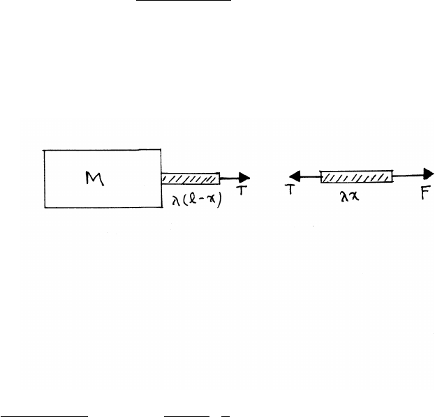
3.9 Tension in a rope
The uniform rope has linear mass density λ=m/lmass per unit length.
The equations of motion are
F−T=(λx)a(1)
T=[M+λ(l−x)] a(2)
Dividing Eq. (1) by Eq. (2),
T="M+λ(l−x)
M+λl#F=1−m
M+mx
lF
FORCES AND EQUATIONS OF MOTION 41
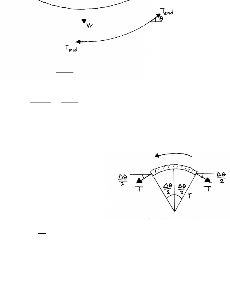
3.10 Rope and trees
(a)
2Tend sin θ=W=⇒Tend =W
2 sin θ
(b)
Tmid =Tend cos θ=Wcos θ
2 sin θ=W
2 tan θ
3.11 Spinning loop
In problems involving small angles, for example
in examining a short arc length ∆S=R∆θ,
it is helpful to keep the small angle approximations
in mind: sin ∆θ≈∆θand cos ∆θ≈1−∆θ2/2.
The radially inward force ∆Fron the arc is
∆Fr=2Tsin (∆θ/2) ≈2T∆θ
2=T∆θ
The mass ∆mof the arc is
∆m=M∆θ
2π
so the radial equation of motion is
(∆m)rω2=T∆θ=M ∆θ
2π! l
2π!ω2=⇒T=Ml ω
2π2
42 FORCES AND EQUATIONS OF MOTION
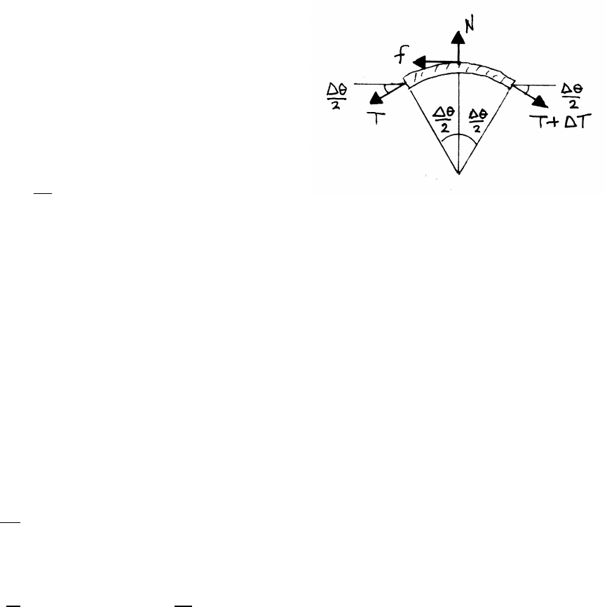
3.12 Capstan
The rope is stationary, so the forces
are in balance. From the sketch, the vertical
equation of motion is
0=N−Tsin (∆θ /2) −(T+ ∆T) sin (∆θ /2)
Because we will be taking the limit, retain only
first order terms.
N≈2T∆θ
2=T∆θ
The horizontal equation of motion is
0=(T+ ∆T) cos (∆θ /2) −f−Tcos (∆θ /2)
Using the small angle approximation cos x≈1−x2/2 and retaining first order terms
f≈∆T
The maximum friction force is
f=µN
∆T≈µT∆θ
In the limit ∆θ→0,
dT
dθ=µT
Integrating,
ZTA
TB
dt
T=µZθ0
0
dθ=⇒ln TA
TB!=µ θ0=⇒TA=TBeµ θ0
FORCES AND EQUATIONS OF MOTION 43
3.13 Incomplete loop-the-loop
This problem assumes r=R=constant,
so that ˙r=0,¨r=0, and
˙
θ=v/R=constant, so that ¨
θ=0.
The radial acceleration is inward, with ¨r=0.
The tangential acceleration is 0.
radial equation of motion:
Mv2
R=N−Mg cos θ(1)
tangential equation of motion:
f−Mg sin θ=0
The car begins to skid when the tangential force f−Mg sin θ≤0. The maximum
value of fis µN. The limiting case is µN=Mg sin θ.
Using Eq. (1),
Mv2
R=Mg sin θ
µ−cos θ!=⇒sin θ
µ−cos θ=v2
Rg (2)
For a flat plane, R→ ∞, slipping occurs when tan θ=µ, as found in problem 3.8.
The direction of fis a possible source of confusion. Formally, the car would have
a tangential acceleration in the reverse direction if fwere opposed to the direction
of motion. Physically, the car’s engine turns the tires, and they exert a friction force
on the road opposed to the direction of motion. The road therefore exerts an equal
and opposite force; the car is propelled forward by the friction force.
What is the condition for the car to barely make a complete loop (θ=πrad =180◦)?
According to the result Eq. (2), v2/R=gwhen θ=πrad. This means that at the
top of the loop, the downward weight force mg in this limiting case is sufficient to
account for the radial acceleration v2/R. It follows that N=0 at the top of the loop,
so the car is just parting company with the loop under this condition. If v2/R>g,
then N>0, and the car is definitely in contact with the track at the top of the loop.
44 FORCES AND EQUATIONS OF MOTION
3.14 Orbiting spheres
Each sphere orbits in a circle of radius R/2, and
each sphere experiences a radial gravitational
attraction F
F=GM2
R2
radial equation of motion:
MR
2ω2=GM2
R2=⇒ω2=2GM
R3
T=2π
ω=2πrR3
2GM
Let ρbe the density, M=4
3πa3ρ. Make Mlarge to make Tsmall, so that ashould
be as large as possible. amax =R/2 (spheres touching). Then
Tmin =2πsR3
2Gρ4
3π(R/2)3=2πs3
πGρ=s12π
Gρ
G=6.67 ×10⁻¹¹ kg−1m3s−2
ρ=21.5g cm−3=21.5(g cm−3)(10−3kg g−1)(106cm3m−3)=21.5×10³kg m−3
Tmin =5130 s
3.15 Tunnel through the Earth
The mass of a sphere of radius r<Rewithin a uniform Earth is M(r)=Me(r/Re)3.
The equation of motion of mass min a tunnel through the center of the Earth is
m¨r=−m Mer3
R3
e!G
r2=⇒¨r=− GMe
R3
e!r
Using GMe/R2
e=g,
¨r+ g
Re!r=0
This is the equation for SHM, with frequency ωtunnel and period T=2π/ω.
ωtunnel =rg
Re
=⇒T=2πsRe
g=2πs6.4×106m
9.8 m/s2=5080 s ≈85 min
For a satellite of mass min circular low Earth orbit, the equation of motion is
mReω2
orbit =mGMe
R2
e
=mg =⇒ωorbit =rg
Re
=ωtunnel
FORCES AND EQUATIONS OF MOTION 45
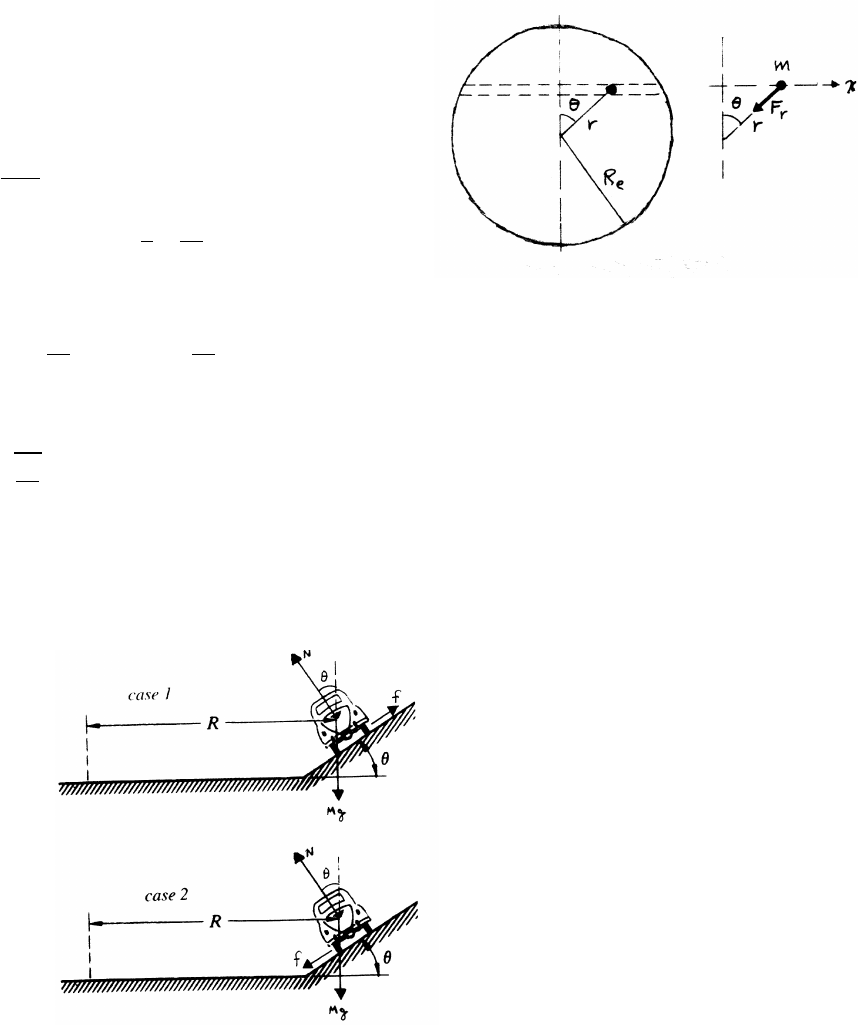
3.16 Off-center tunnel
Mass mis at coordinate xalong the off-center tunnel.
Mass mis gravitationally attracted by the mass
of the Earth within the radius r. As shown in
problem 3.15, the radial force Fron mis
Fr=−mgr
Re
Fx=Frsin θ=−mg x
r r
Re!
equation of motion along x:
m¨x=−mg x
Re!=⇒¨x+ g
Re!x=0
This is the equation for SHM with frequency ωand period T=2π/ω.
ω=rg
Re
=ωtunnel as in problem 3.15
3.17 Turning car
There are two cases, as the sketches indicate. Keep in mind that the friction force
is opposed to the direction of motion. In case 1, the car will tend to slide down the
slope if it is moving too slowly, so the friction force fis outward as shown. In case
2, the car will tend to slide up the slope if it is moving too fast, so fis inward.
continued next page =⇒

46 FORCES AND EQUATIONS OF MOTION
case 1:
horizontal equation of motion:
Mv2
R=Nsin θ−fcos θ
The maximum friction force is µN.
Mv2
R≥N(sin θ−µcos θ)
Mv2min
R=N(sin θ−µcos θ) (1)
There is no vertical acceleration if the car is not sliding, so the vertical equation of
motion is Ncos θ+fsin θ−Mg =0. In the limit where f=µN
Mg =N(cos θ+µsin θ) (2)
Dividing Eq. (1) by Eq. (2),
v2
min
Rg =sin θ−µcos θ
cos θ+µsin θ=⇒vmin =sRg sin θ−µcos θ
cos θ+µsin θ!
case 2:
Proceeding as before,
Mv2
R≤Nsin θ+fcos θ
Mv2
max
R=N(sin θ+µcos θ) (3)
vertical equation of motion:
0=Ncos θ−fsin θ−Mg =N(cos θ−µsin θ) (4)
Dividing Eq. (3) by Eq. (4) leads to
vmax =sRg sin θ+µcos θ
cos θ−µsin θ!
FORCES AND EQUATIONS OF MOTION 47
3.18 Car on rotating platform
(a) Acceleration in polar coordinates:
a=(¨r−r˙
θ2)ˆ
r+(r¨
θ+2˙r˙
θ)ˆ
θ
a=ar+aθ
In this problem,
r=v0t˙r=v0¨r=0
θ=ωt˙
θ=ω¨
θ=0
a=−v0tω2ˆ
r+2v0ωˆ
θ
(b) The car starts to skid when
Ma ≥fmax
=µW=µMg
a=pa2r+a2θ=pv20t2ω4+4v20ω2≥µg
Skidding just starts at t0, where
(µg)2=v20ω4t20+4v20ω2
t0=1
v0ω2p(µg)2−4v20ω2
Note that if the Coriolis term 2v0ωis > µ g, the car always skids.
(c) The friction force fis directed along the acceleration, at angle φ, as shown.
When the car begins to skid. it will move backwards along that line.
48 FORCES AND EQUATIONS OF MOTION
3.19 Mass and springs
(a)
∆x1=F
k1
∆x2=F
k2
∆xtotal = ∆x1+ ∆x2
ke f f =F
∆xtotal
=1
1
k1+1
k2
ωa=rke f f
m=sk1k2
m(k1+k2)
(b)
Both springs stretch the same amount ∆x.
F1=k1∆x F2=k2∆x
Ftotal =F1+F2=(k1+k2)∆x
ke f f =Ftotal
∆x=k1+k2=⇒ωb=r(k1+k2)
m
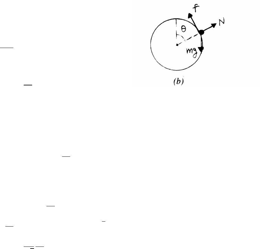
3.20 Wheel and pebble
As long as the pebble is in contact with wheel,
its speed Vpebble =Rω=Vwheel, the speed of the
wheel’s center as it rolls along.
(a)
Vpebble =Vwheel ≡V
From force diagram (a)
mV2
R=mg −N
N≥0 The pebble flies offwhen N=0.
mV2
R>mg =⇒V>pRg
continued next page =⇒
FORCES AND EQUATIONS OF MOTION 49
(b)
While in contact the pebble’s radial equation of motion is
mV2
R=mg cos θ−N
Using the criterion N≥0,
cos θmax =V2
Rg.
There is a more stringent criterion based on f: there is no tangential accelera-
tion, so
0=mg sin θ−f=⇒f=mg sin θ(1)
f≤µN(2)
N=mg cos θ−mV2
R(3)
Combining Eqs. (1), (2), and (3) gives
gsin θ≤µgcos θ−V2/R
sin θ≤cos θ−V2
Rg (for µ=1)
V2
Rg =cos (θmax)−sin (θmax)=√2 cos (θmax +π/4)
cos (θmax +π/4) =1
√2
V2
Rg
3.21 Bead on rod
The radial acceleration is ar=¨r−r˙
θ2=¨r−rω2
Because the rod is frictionless, ar=0, so that ¨r=rω2(1)
Given that r=Ae−γt+Beγt
˙r=−γAe−γt+γBeγt¨r=γ2Ae−γt+γ2Beγt=γ2r
Comparing with Eq. (1) it follows that γ=ω.
50 FORCES AND EQUATIONS OF MOTION
3.22 Mass, string, and ring
(a) V=constant, so that
r=r0−Vt ˙r=−V¨r=0
Ftangential =r¨
θ+2˙r˙
θ=0 (1)
Eq. (1) becomes a differential equation for ω.
rdω
dt +2dr
dt ω=0=⇒dω
ω=−2dr
r
ln(ω)|ω
ω0=−2ln(r)|r
r0
ln ω
ω0!=−2ln r
r0!
ω
ω0
=r0
r2
=⇒ω(t)=ω0
r02
(r0−Vt)2
(b)
Fradial =−T
m(¨r−r˙
θ2)=−T
T=mrω2
Tis a function of time, to keep the end of the string moving at steady rate V.
T=mω2
0 r4
0
r3!=m r0ω2
0r0
r3
=m r0ω2
0 r0
r0−Vt !3
FORCES AND EQUATIONS OF MOTION 51
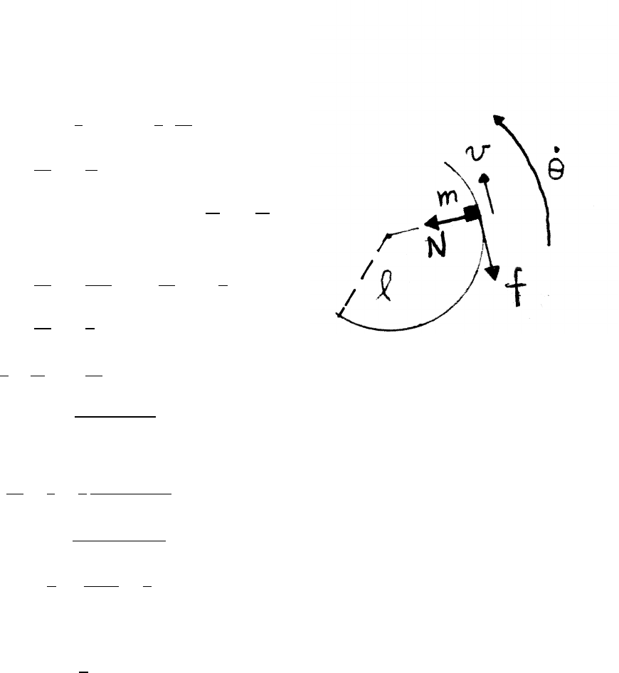
3.23 Mass and ring
(a)
−f=Ftangential =matangential =m(r¨
θ+2˙r˙
θ)
r=l=constant =⇒˙r=0
˙
θ=v
l¨
θ= 1
l!dv
dt
dv
dt =−f
m
N=Fradial =mr ˙
θ2=mlv2
l2=mv2
l
f=µN
dv
dt =−µv2
l=⇒dv
v2=−µ
ldt
Zv
v0
dv
v2=−µ
lZt
0
dt
− 1
v−1
v0!=−µt
l
v=v0
(1+µv0t/l)
(b)
dθ
dt =v
l=1
l
v0
(1+µv0t/l)
Zθ
θ0
dθ=Zt
0
v0
l(1+µv0t0/l)dt0
θ−θ0=1
µZdx
1+x=1
µln(1 +x)
where x=µv0t/l
θ(t)=θ0+1
µln (1+µv0t/l)(1)
What is θ(t) if the ring is frictionless, µ=0? The solution can be found simply
by noting that the block must continue to move with its initial speed v0, so that
˙
θ=v0/l=constant. Then θ(t)−θ0=v0t/l. In the frictionless case, θincreases
without limit as tincreases.
continued next page =⇒
52 FORCES AND EQUATIONS OF MOTION
However, it is worthwhile to describe a general approach to problems of this type.
For µ=0, the result Eq. (1) becomes ln(1)/0=0/0, an indeterminate form. To deal
with this situation, treat µas small, and expand the logarithm in Taylor’s series.
ln(1 +x)≈x+terms of order x2and higher
θ(t)−θ0≈µv0t
µl+terms of order µ2and higher →v0t
lin the limit µ→0.
3.24 Retarding force
mdv
dt =−F=−beαv
e−αvdv
dt =−b
m
Zv
v0
e−αvdv =−b
mZt
0
dt
−1
α(e−αv−e−αv0)=−b
mt
e−αv=αb
mt+e−αv0=⇒v=1
αln 1
αbt/m+e−αv0!
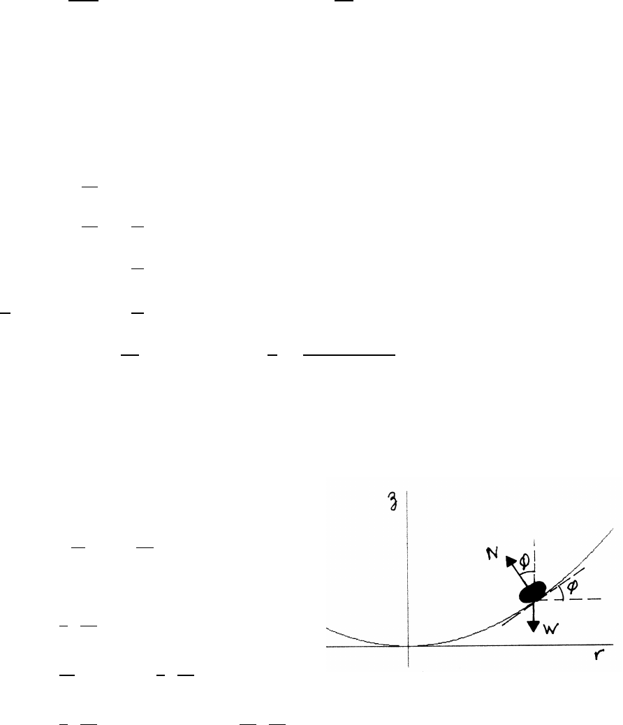
3.25 Hovercraft
For stable circular motion
Nsin φ=mv2
r=mr 2π
T!2
Ncos φ=W=mg
tan φ=r
g 2π
T!2
tan φ=dz
dr =⇒dz =1
g 2π
T!2
r dr
Zz
0
dz =1
g 2π
T!2Zr
0
r dr =⇒z=1
2g 2π
T!2
r2
The bowl is a parabola of revolution.
FORCES AND EQUATIONS OF MOTION 53
3.26 Viscous force
Consider a force F=f(v)ˆ
v.
F
m=a=d(vˆ
v)
dt =dv
dt ˆ
v+vdˆ
v
dt (1)
Because ˆ
vis a unit vector, it cannot change in magnitude, only in direction, as
shown earlier in Sec. 1.10.1. In particular, for any vector Aof constant magnitude,
dA/dt is perpendicular to A. But F=f(v)ˆ
vhas no component perpendicular to v,
so it follows from the equation of motion that dˆ
v/dt =0; for a force Falong v,ˆ
v
cannot change either in magnitude or in direction. Hence the force Fcannot alter
the direction of motion.
Another approach is to take the dot product of Eq. (1) with ˆ
v. to give
F·ˆ
v
m=dv
dt ˆ
v·ˆ
v+vˆ
v·dˆ
v
dt
ˆ
v·dˆ
v
dt =1
2
d(ˆ
v·ˆ
v)
dt =1
2
d(constant)
dt =0
mdv
dt =F·ˆ
v=f(v)
For the case f(v)=−Cv2, find v(t) by integration.
dv
dt =−C
mv2
Zv
v0
dv
v2=−C
mZt
0
dt =⇒1
v=1
v0
+Ct
m=1
v01+Cv0t
m=1
v01+t
τ
τ=m/(Cv0) is a characteristic time for this system – it sets the time scale. A
second integration gives s(t), the distance traveled in time t.
s=Zv dt =Zt
0 v0
1+t/τ!dt =v0τln(1 +t/τ)
If tτ, use ln(1 +x)≈xfor x1.
s≈v0τt
τ≈v0t

4.1 Center of mass of a nonuniform rod
(a)
M=Zl
0
dm =Zl
0
λdx =AZl
0
cos πx
2ldx
=2l
πA sinπx
2l
l
0
=2l
πA
A=π
2lM
(b)
¯
X=1
MZl
0
x dm =1
MZl
0
xλdx =A
MZl
0
xcos πx
2ldx =π
2lZl
0
xcos πx
2ldx
Using the substitution
u=πx
2l=⇒¯
X= 2l
π!Zπ/2
0
ucos u du and integrate by parts using
ucos u=d
du(usin u)−sin u
Zπ/2
0
ucos u du =usin u|π/2
0−Zπ/2
0
sin u du
=(π/2−0) −(−cos u)|π/2
0=π
2−1
¯
X=2l
ππ
2−1=l 1−2
π!
For a uniform rod, ¯
X=l/2. This nonuniform rod has greater mass near x=0, so
¯
X<l/2 as expected.
MOMENTUM 55
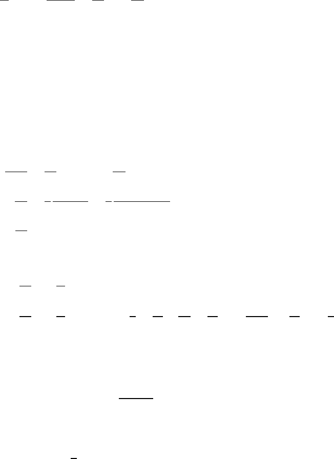
4.2 Center of mass of an equilateral triangle
Method 1: analytical Divide the plate into narrow
strips of length l(y) and width dy, as shown.
The mass dm of a strip is dm =ρltdy,
where ρis the density of the plate and t
is its thickness. The mass Mof the plate is
ρ×area ×t=1
2ρaht.
By symmetry, the center of mass is on the yaxis.
¯
Y=1
MZy dm =2
ρaht Zρtyl(y)dy =2
ah Zh
0
ya 1−y
hdy =2
hZh
0 y−y2
h!dy
=2
h 1
2−1
3!h2=h
3
Method 2: geometrical For any uniform triangle, symmetry requires that the center
of mass lies on the median line from any vertex to the midpoint of the opposite side.
As a simple proof, divide the triangle into strips perpendicular to a median line; the
center of mass of the strip is at its center.
According to a theorem from geometry, the three medians of a triangle meet at a
point 2/3 the distance from each vertex. In this problem, take the median line that
is along the yaxis; then the center of mass is 2/3 the distance from the top vertex,
so that the center of mass lies at a height y=h/3 from the base.
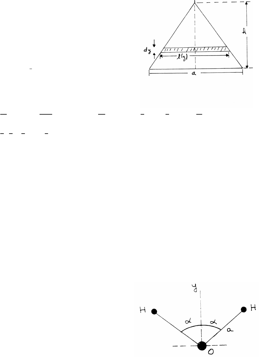
4.3 Center of mass of a water molecule
The center of mass lies on the yaxis, by symmetry.
Take the origin at the oxygen atom, as shown,
so that the ycoordinate of the oxygen atom is yO=0.
The ycoordinate of each hydrogen atom is
yH=acos α=0.097 nm ×cos (52.25◦)=0.059 nm.
continued next page =⇒
56 MOMENTUM
¯
Y=1
Mtotal 2MhydrogenyH+MoxygenyO
where Mtotal =2Mhydrogen +Moxygen.
Mhydrogen =1 amu (atomic mass unit) and Moxygen =16 amu.
¯
Y=2
2+16 [(2)(0.059) +16(0.00)]
=0.0066nm
The center of mass is very near the massive oxygen atom, as expected.
4.4 Failed rocket
As long as the pieces are in flight, the center of mass continues on the parabolic
trajectory. The time to rise is the same as the time to fall, so the center of mass
reaches the ground at x=L. Let the smaller piece have mass ms, and the larger
piece have mass ml, as indicated in the sketch.
continued next page =⇒
MOMENTUM 57
The xcoordinate of the center of mass is Lwhen it reaches the ground, so
¯
X=msxs+mlxl
ms+ml
L=ms(−L)+mlxl
ms+ml
=−Lms+3xlms
ms+3ms
=−L+3xl
4
xl=5
3L
in the coordinate system shown in the sketch, or alternatively, from the launch point,
xl=5
3L+L=8
3L
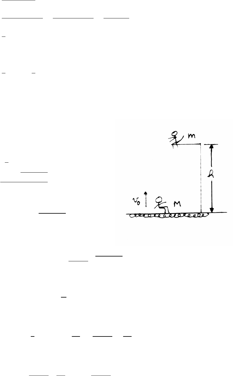
4.5 Acrobat and monkey
The acrobat reaches height hat time t.
h=−1
2gt2+v0t
t=v0−pv02−2gh
g
The acrobat’s speed vat tis
v=−gt +v0=pv02−2gh
Vertical momentum is conserved when the acrobat grabs the monkey. The speed v0
of the pair just after the collision is
(m+M)v0=Mv =⇒v0=M
m+Mpv02−2gh
The pair rises for a time t0until their speed =0.
−gt0+v0=0=⇒t0=v0
g
At the peak, they are a height h0above the perch.
h0=−1
2gt02+v0t0=v02
2g=M
m+M2 v02
2g−h!
The total height h+h0is
h+h0=M
m+M2v02
2g+"1−M
m+M2#h
58 MOMENTUM
4.6 Emergency landing
Let M=mass of plane =2500 lb
gm=mass of sandbag =250 lb
g
v=speed at landing =120 ft/sFretarding =Ff riction +Fbrakes
L=distance traveled before coming to rest
Momentum is conserved at the moment the sandbag is picked up. The system’s
speed then becomes v0.
v0=M
m+Mv
The system slows with uniform acceleration a.
a=Fretarding
(m+M)
L=v02
2a
Ff riction =µmg =(0.4)(250 lb) =100 lb Fbrakes =300 lb
Fretarding =100 lb +300 lb =400 lb
L=v02
2a=v2
2M
m+M2 m+M
Fretarding !=v2
2M
m+M M
Fretarding !
=(120 ft/s)2
2× 2500
2750!× 2500 lb
32 ft/s2!× 1
400 lb!≈1300 ft
4.7 Blocks and compressed spring
While m1is against the wall, m2moves according to SHM with ω=√k/m2.
x2=Asin (ωt)+Bcos (ωt)+C˙x2=ωAcos (ωt)−ωBsin (ωt)
Using the initial conditions x2(0) =l/2 and ˙x2(0) =0, it follows that
x2= 1−1
2cos (ωt)!l
Until m1loses contact with the wall, the coordinate Xof the center of mass is
X=m1x1+m2x2
m1+m2
=m2
m1+m2 1−1
2cos (ωt)!l
continued next page =⇒
MOMENTUM 59
m1loses contact with the wall when ωt=π/2; at this instant, x2=l.
˙x2=ωl
2=constant
From this time on, the system moves as a whole, with ˙x1=˙x2. Thus
˙
X=m1˙x1+m2˙x2
m1+m2
=˙x2=ωl
2
4.8 Jumper
To rise a height h, the initial speed must be v0=p2gh. The initial momentum is
therefore mv0, and the final momentum is 0. The impulse from the ground is then
impulse =mv0−0=(50 kg) q2×9.8 m/s2×0.8 m =198 kg m/s
4.9 Rocket sled
At time t, the system consists of mass Mmoving with speed v, where M(0) =M0.
The momentum P(t) is
P(t)=Mv
At time t+ ∆t, the system (still of total mass M) consists of mass (M−∆M) moving
with speed (v+ ∆v) and mass ∆Mmoving with speed (v−v0). Then
∆P=P(t+ ∆t)−P(t)
=(M−∆M)(v+ ∆v)+ ∆M(v−v0)−Mv
In the limit ∆t→0
dP
dt =Mdv
dt −v0
dM
dt
The friction force on the sled is −µMg.
dP
dt =−µMg
Mdv
dt −v0
dM
dt =−µMg
continued next page =⇒
60 MOMENTUM
The fuel burns at constant rate dM/dt =−γ, so that M(t)=M0−γt.
dv
dt =v0γ
(M0−γt)−µg
Integrating,
v(t)=v0γZt
0
dt0
(M0−γt0)−µgt
=−v0|.ln(M0−γt0)|t
0−µgt
=v0ln M0
(M0−γt)!−µgt
The rocket engine turns offat time tfwhen γtf=M0/2.
v(tf)=v0ln2−µgM0
2γ
The sled begins to slow for t>tf, so v(tf) is the maximum speed.
4.10 Rolling freight car with sand
The system consists of the freight car and its contents, with initial mass M0at
t=0. The bottom is opened at t=0, and the sand runs out at steady rate γ, so
that dm/dt =γand dM/dt =−γ. Then M(t)=M0−γt. To first order, and exact
in the limit ∆t→0, the mass of sand ∆mreleased in time ∆thas at the instant of
release the same speed as the freight car, so it does not contribute to the change of
the system’s momentum. (See Example 4.14.)
P(t)=Mv P(t+ ∆t)=(M−∆m)(v+ ∆v)+ ∆m(v+ ∆v)
∆P≈M∆v
dP
dt =Mdv
dt =Ma =F=⇒dv
dt =F
M=F
M0−γt
The sand is all gone at time tf, so that tf=m/γ.
Zv(tf)
0
dv =Ztf
0
Fdt0
M0−γt0
v(tf)=− F
γ!ln M0−γtf
M0!= F
γ!ln M0
M0−m!
MOMENTUM 61
4.11 Freight car and hopper
The system consists of the freight car of mass Minitially at rest, plus the mass of
sand mthat will fall in by time t;mis also initially at rest, and m=bt. The total
mass of the car and sand at time tis M+bt.
P(0) =0P(t)=(M+bt)v
impulse = ∆P=(M+bt)v=Zt
0
Fdt0=FZt
0
dt0=Ft =⇒v=Ft
(M+bt)
4.12 Two carts and sand
The system consists of cart A, with mass Mand speed v, and the mass ∆mmoving
with speed u. The rate of material flow is b, so that dm/dt =b.
P(t)=Mv +(∆m)u P(t+ ∆t)=(M+ ∆m)(v+ ∆v)
∆P=M∆v+ ∆m(v−u)=⇒dP
dt =Mdv
dt +dm
dt (v−u)
There is no external force on the system, so dP/dt =0. Thus
dv
dt =−dm
dt
(v−u)
M=b(u−v)
M
4.13 Sand sprayer
The system consists of the freight car and load with instantaneous mass Mmoving
with speed v, plus the mass of sand ∆msprayed in during time ∆tat rate γ:∆m=
γ∆t. The speed of ∆mis v+u, because the locomotive and freight car are moving
with the same speed.
P(t)=Mv + ∆m(v+u)P(t+ ∆t)=M(v+ ∆v)+ ∆m(v+ ∆v)
∆P≈M∆v−(∆m)udP
dt =Mdv
dt −udm
dt =Mdv
dt −udM
dt
continued next page =⇒
62 MOMENTUM
Note that ∆mis being added to the freight car, so dM/dt = +dm/dt >0. Because
no external force is acting on the system dP/dt =0. Thus
dv =udM
M=⇒Zv
0
dv0=uZMf
M0
dM0
M0
where M0is the initial mass of the system, and Mfis its mass after 100 s.
v=u ln Mf
M0!
Mf=M0+γt=2000 kg +(10 kg/s)(100 s) =3000 kg
v(100 s) =(5 m/s) ln 3000 kg
2000 kg!=2.03 m/s
Comparing these results with the derivation of rocket motion in Sec. 4.8, the system
in this problem is seen to be a rocket in ”reverse”, where mass is added instead of
being expelled. In Sec. 4.8 dM/dt <0, but in this problem dM/dt >0.
4.14 Ski tow
It is sound practice to solve problems symbolically,
introducing numerical values only toward the end,
to help maintain numerical accuracy.
Let Lbe the length of the tow, and let lbe the
separation between skiers, so that the number
of skiers on the tow is L/l. Let tsbe the time
interval between skiers grasping the tow. The number
of skiers grasping the tow per second is then γ=1/ts.
If Wtot is the total weight of the skiers on the tow,
dP
dt =F−Wtot sin θ=Mvγ
The momentum of the system does not change when a skier leaves the rope, so
F−Wtot sin θ=Mvγ
F=Wtot sin θ+Mvγ=Mg L
lsin θ+Mv 1
ts!
F=(70 kg)(9.8 m/s2) 100 m
7.5 m !sin (20◦)+(70 kg)(1.5 m/s) 1
5 s!
=3128 N +21 N =3149 N

MOMENTUM 63
4.15 Men and flatcar
In each situation, the flatcar does not accelerate
further after the jumper leaves. Just as the jumper
leaves, his speed is the final speed of the flatcar
minus the speed relative to the flatcar.
The flatcar and its load are initially at rest.
(a) N jump at once.
Piniitial =0
Pf inal =Mva+Nm(va−u)=Pinitial =0
va=Nm
Nm +Mu
(b) one jumps at a time. Let the speed of the flatcar
be vjafter jof Nhave jumped.
Pinitial =[(N−j)m+M]vj
Pf inal =[(N−j−1)m+M]vj+1+m(vj+1−u)
∆P=[(N−j−1)m+M]vj+1+m(vj+1−u)−[(N−j)m+M]vj
There are no external forces, so ∆P=0.
0=[(N−j)m+M]vj+1−mu −[(N−j)m+M]vj
vj+1= m
(N−j)m+M!u+vj
vb= m
Nm +M+m
(N−1)m+M+. . . m
m+M!u
(c)
But
va=m
Nm +M+m
Nm +M+. . . m
Nm +Mu<vb
In the trivial special case N=1, case (a) and case (b) are identical.
Note that case (b) is closely analogous to the derivation of rocket motion in Sec.
4.8. In case (b), however, the expelled mass is in finite packets, one man at a time,
while for the rocket the expelled mass is a continuous flow.
continued next page =⇒

64 MOMENTUM
To help understand why the flatcar moves faster in case (b), assume that the mass of
the flatcar is small. In this situation, when the men jump together the flatcar moves
forward at speed slightly less than u, and the men are moving slowly with respect
to the ground. This result is nearly independent of the number of men jumping.
Consider now case (b), when the men jump one at a time. The last jumper by
himself could cause the forward speed of the flatcar to be close to u, but if there are
several jumpers, each previous jumper also contributes to increasing the speed of
the flatcar. In case (b), therefore, the final speed of the flatcar could exceed u.
4.16 Rope on table
The rope has total length land mass M.
At time t=0, the rope is momentarily at rest,
with length x(0) =l0hanging through the hole.
(a)
The mass of the hanging portion is Mx/lwhere
Pinitial =Mv
Pinitial + ∆P=M(v+ ∆v)
Fexternal(t)=Mg
lx
Fexternal(t+ ∆t)=Mg
l(x+ ∆x)
∆P=M∆v=Zt+∆t
t
Fexternal dt ≈Mgx ∆t
l
dv
dt =d2x
dt2=gx
l
The general solution of the differential equation is
x(t)=Ae
g
lt+Be−g
lt
(b)
x(0) =A+B=l0
˙x(0) =g
lA−g
lB=0
A=B=l0/2
x(t)=l0
2e
g
lt+e−g
lt=l0cosh g
lt
MOMENTUM 65
4.17 Solar sail 1
Refer to Example 4.21: the radiation force Frad due to the Sun on area Ais
Frad =2SS un A
c
arad =Frad
m=2SS unA
mc (1)
mis the mass of the craft, and arad is the acceleration due to radiation pressure. For
the solar sail craft to move outward away from the Sun,
arad ≥gS un
2SS unA
mc ≥gS un
A≥gS unmc
2SS un
The IKAROS mass was mostly the sail, m≈1.6 kg. From Example 4.21,
gS un =5.9×10⁻³m/s2SS un/c=4.6×10−6kg/ms2
A≥(5.9×10⁻³m/s2)(1.6 kg)
24.6×10⁻⁶kg/ms2≥103m2
Could such a sail be constructed using the same polyimide film material used for
IKAROS? The desired area is 1000/150 =6.8 times the area of the IKAROS sail,
and because the mass of the sail is density x area x thickness =ρAt, the thickness
would have to be 6.8 times thinner, or 7.5×10⁻⁶m/6.8 =1.1×10⁻⁶m. Constructing
a strong sail so extremely large and thin is beyond the limits of current technology.
For further insight into the design issues, using m≈ρAt in Eq. (1) shows that arad
is essentially independent of the sail area Aand depends mainly on ρt, the ”areal
density” (mass per unit area) of the sail material.
66 MOMENTUM
4.18 Solar sail 2
Assume that the mass mof the craft is essentially the mass of the sail m=ρtA,
where ρis the density of the sail material, tthe sail thickness, and Athe area. With
reference to Example 4.21,
(a)
arad =(2S/c)A
m=(2S/c)A
ρtA =2S/c
ρt
=(2)4.6×10⁻⁶kg/ms2
(1.4×10³kg/m3)(2.5×10−5m) =2.6×10⁻⁴m/s2
(b)
acra f t =arad −aearth =arad −gRe
r2
The craft cannot accelerate outward from the Earth unless it is launched beyond
a radius rmin such that
arad −g Re
rmin !2
≥0=⇒ Re
rmin !2
≤arad
g=2.6×10⁻⁴
9.8=2.7×10⁻⁵
Re
rmin ≤5.2×10−3=⇒rmin ≥194Re
(c) If ris so large that the Earth’s gravitational attraction can be neglected
v=arad T
T=11.2×10³m/s
2.6×10⁻⁴m/s2=4.3×107s≈1.4 years
(d) Neglect gravitational forces. The radiation force on the sail is Frad =2(S/c)A.
Let the mass of the sail be m=ρtA and the mass of the payload be M=1.0
kg. For half the original acceleration,
Frad =(m+M)arad
2
(m+M)arad =(ρtA +1.0)arad =4(S/c)A
A=arad
4(S/c)−ρtarad
=2.6×10⁻⁴
(4)4.6×10⁻⁶−(1.4×10³)(2.5×10⁻⁵)(2.6×10⁻⁶)=28 m2
A simpler method is to note that the acceleration is halved if the mass Mof the
payload doubles the mass of the craft. Hence the mass of the sail should be ρtA =
1.0 kg, so A=1.0/ρt=28 m2as before.
MOMENTUM 67
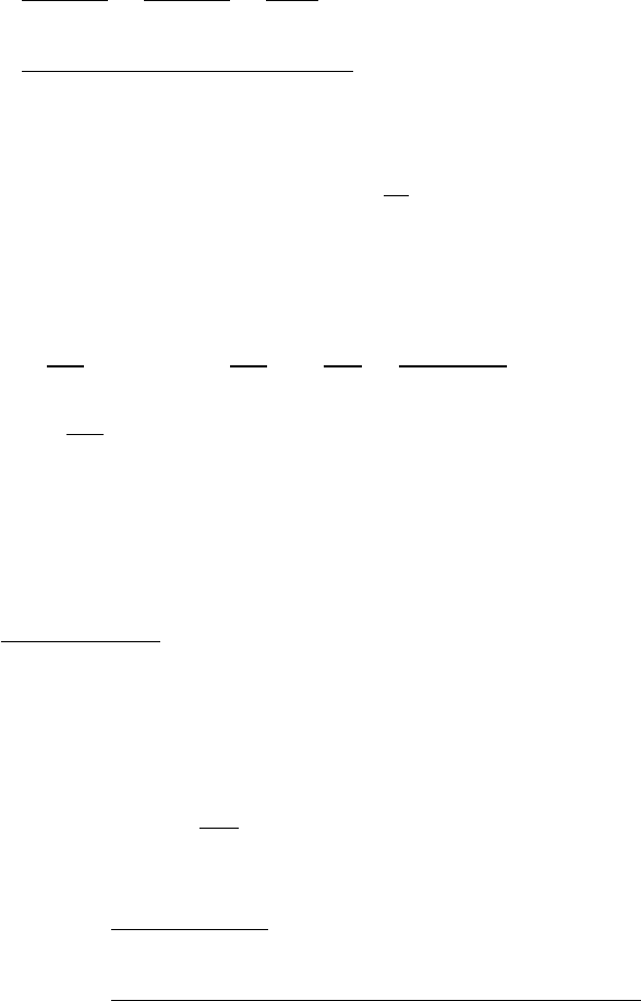
4.19 Tilted mirror
(a) The momentum flow ˙
Pthrough a surface of area Ais
˙
P=J·A, where Jis the momentum flux density. Enclose
the mirror with a hypothetical surface, as shown in the
upper sketch. Taking flow in as positive,
˙
Pnet =˙
Pin −˙
Pout =2JA ˆ
n
F=2JA ˆ
n
F=2JA =9.2×10⁻⁶kg ·m/s2=9.2×10−6N
(b) If the mirror is tilted, the reflected beam leaves
at the same angle αmade by the incident beam, see lower sketch.
Jin ·A=JA cos α
Jout ·A=−JA cos α
F=˙
Pin −˙
Pout =2JA cos αˆ
n=9.2×10⁻⁶cos αˆ
n
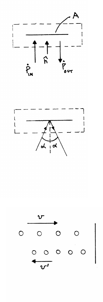
4.20 Reflected particle stream
The rate at which incoming particles strike the surface is
(number of particles per unit length) x (speed) =λv. If each
incoming particle carries momentum mv, the rate ˙
Pat which
momentum arrives at the surface is ˙
Pin =(mv)(λv)=λmv2.
In steady conditions, the rate at which particles leave must equal the rate
at which they arrive. If they leave with speed v0, with λ0particles per
unit length, λ0v0=λv.The reflected particles carry away momentum in the opposite
direction at rate mv0λ0v0=mv0λv. Hence the total force, which is the difference
between the incoming and outgoing rates of momentum, is λm(v2+vv0).
68 MOMENTUM
4.21 Force on a firetruck
A volume of water with mass ∆Mmoving at velocity vcarries momentum ∆P=
v∆M. The rate of momentum flow in the stream is then dP/dt =vdM/dt =Kv.
The vertical component of vis vsin θ. From motion under constant gravity, the wa-
ter ascends to a height vsin θ=p2gh, so that v=p2gh/sin θ.
The recoil force is F=−˙
P=−Kv. The magnitude of the force is |Kv|=Kp2gh/sin θ,
and its direction is opposite to the flow.
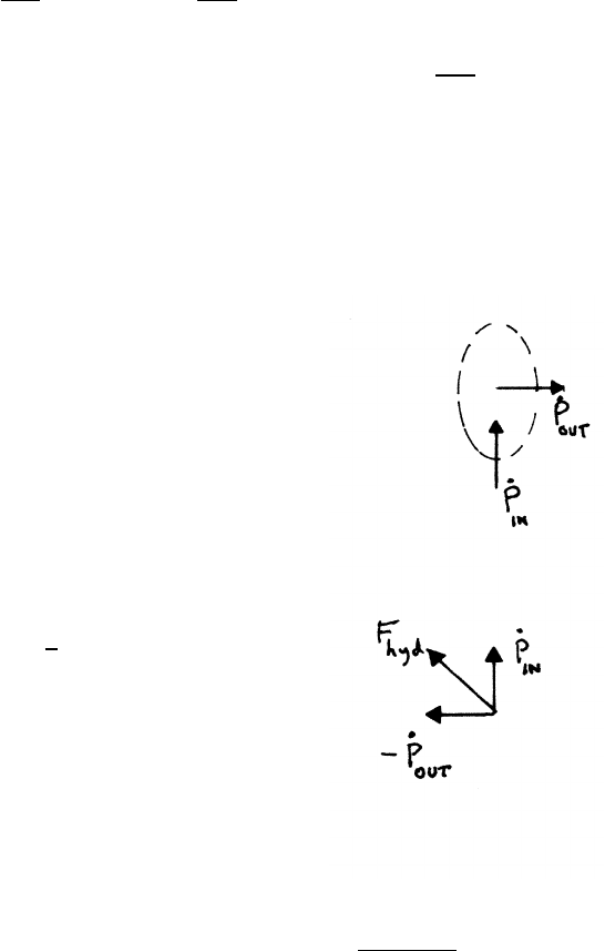
4.22 Fire hydrant
Imagine a hypothetical surface surrounding the hydrant,
as shown. The rate of change of momentum within the surface is
˙
P=˙
Pout −˙
Pin. The force Fwater on the water
due to the hydrant is therefore Fwater =˙
Pout −˙
Pin.
The force Fhydrant on the hydrant due to the water is equal and opposite:
Fhydrant =−Fwater =˙
Pin −˙
Pout.
Let ρbe the density of water. Then |˙
Pin|−|˙
Pout|=ρV02A
where A=πD2/4. Hence Fhydrant =√2ρV02A,
directed upward at 45◦, as shown.
4.23 Suspended garbage can
The stream has initial speed v0, so at height yits speed is v=pv02−2gy. The
stream carries mass at a rate dm/dt ≡K. Under steady conditions the rate of mass
flow is constant, with an equal amount of mass passing through any horizontal
plane per unit time, because water is essentially incompressible. In time interval
∆tmass ∆m=K∆tpasses through a horizontal surface, transporting momentum
∆P=v∆m=vK∆t. The upward momentum flux is then ˙
P=vK. (The momen-
tum flux decreases with height, because the downward gravitational force is acting.)
continued next page =⇒
MOMENTUM 69
The maximum height will be reached if the water rebounds elastically from the
garbage can. In this case the rate of momentum transfer to the can gives a force
2˙
P=2vK, double compared to the inelastic case where the water comes to rest
without rebounding after colliding with the can. In equilibrium, 2vK =Wso that
v=W
2K
pv02−2gh =W
2K
h=1
2g"v02−W
2K2#
Note that v0must be greater than a minimum value v0≥W/2Kto get any lift.
4.24 Growing raindrop
Consider the change in momentum of the drop as it gains mass during the time
interval from tto t+ ∆t.
P(t)=MV P(t+ ∆t)=(M+ ∆M)(V+ ∆V)
∆P≈M∆V+V∆M
dP
dt =MdV
dt +VdM
dt
There is the external gravitational force Mg.
MdV
dt +VdM
dt =Mg
dM
dt =kMV =⇒MdV
dt +kMV2=Mg =⇒dV
dt =g−kV2
The acceleration decreases as the falling drop gains speed, and vanishes at the ter-
minal velocity Vterminal =pg/k.
4.25 Bowl of water
Let dM/dt =σA. The momentum flux is then vσ, so the force Fis vσA. In SI units,
σ=10−3g
cm2·s×1 kg
103g×104cm2
1 m2=10−2kg
m2·s
A=500 cm2=5×10⁻²m2v=5 m/s
F=vσA=(5 m/s) × 10−2kg
m2·s!×(5 ×10⁻²m2)=2.5×10⁻³N
continued next page =⇒
70 MOMENTUM
Another approach to this problem is to model the rain as individual droplets arriv-
ing with speed v. Let Nbe the number of droplets per m3, and let mdbe the mass
of each droplet. Then vmdN ≡ σ. There are vNAdroplets striking the bowl per
second. Each droplet brings in momentum mdv, and runs offwith zero momentum,
so the force Fon the bowl is the change in momentum: F=(droplets arriving per
second)(momentum per droplet) =(vNA)(mdv)=v(vmdN)A=vσA, as found be-
fore.
When the bowl is moving upward at speed v0, the number of droplets striking the
bowl per second is (v+v0)NA. Each droplet now strikes the bowl with speed (v+v0),
so the momentum of each droplet is (v+v0)md. The total momentum delivered per
second is
dP
dt =(v+v0)2mdNA=(v+v0)2
vσA=(v+v0)2
v2(vσA)
Fmoving =(5 +2)2
52Fstatic =49
25 Fstatic =4.9×10⁻³N
4.26 Rocket in interstellar cloud
Because the collisions are elastic, the particles bounce off
the rocket’s nose cone transversely to the motion, Hence
the reflected particles transfer no net momentum to the rocket.
(a) The rate at which particles strike the rocket is ANv
where Ais the projected area A=πR2. The incoming
momentum of each particle is mv, so the force Fon the
rocket equals the momentum flux dP/dt
F=dP
dt =−ANmv2≡ −Av2
(b)
Mdv
dt =−Av2=⇒dv
v2=−A
Mdt =⇒Zv
v0
dv0
v02=−A
MZt
0
dt0
1
v−1
v0
=A
Mt=⇒v=v0
1+A
Mv0t

MOMENTUM 71
4.27 Exoplanet detection
Consider the Sun - Jupiter system. They rotate about their center of mass given by
MS unRS un =MJupiterRJupiter. The distance RS un of the Sun from the C.M. is
RS un =MJupiter
MS un
RJupiter =1.9×1027 kg
1.99 ×1030 kg (7.8×10¹¹ m) =7.5×10⁸m
The speed vS un of the Sun as it orbits about the center of mass is then
vS un = ΩRS un = 2πrad
4330 days ×1 day
8.64 ×10⁴s!RS un =(1.68 ×10⁻⁸rad/s) (7.5×10⁸m) =12.6 m/s
According to current technology, as described in Example 4.6, the effect of Jupiter
would be readily detectable.
5.1 Loop-the-loop
initial energy: Ki=0Ui=mgz
Ei=Ki+Ui=0+mgz
final energy: Kf=1
2mv2Uf=mg(2R)
Ef=Kf+Uf=1
2mv2+mg(2R)=Ei=mgz
v2=2gz −4gR (1)
At the top of the loop the total downward force is N+mg, where Nis the normal
force exerted by the loop. Using Eq. (1)
N+mg =mv2
R=2mgz
R−4mg
If N=mg, then
2mg =2mg z
R−4mg
z=3R
ENERGY 73
5.2 Block, spring, and friction
initial energy: Ki=1
2Mv2
0Ui=0
Ei=Ki+Ui=1
2Mv2
0+0
final energy: Kf=0Uf=1
2kl2
Ef=Kf+Uf=0+1
2kl2
The friction force Ff riction =µN, where N=Mg is the normal force.
Ef−Ei=work on the system
=Zl
0
Ff riction dx0=−Zl
0
µMg dx0=−Mg Zl
0
µdx0=−Mg Zl
0
bx0dx0
=−1
2Mgbl2
1
2kl2−1
2Mv2
0=−1
2Mgbl2=⇒l2(k+Mgb)=Mv2
0
l=v0sM
k+Mgb
5.3 Ballistic pendulum
During this collision, linear momentum is conserved
but mechanical energy is not conserved.
(a)
Momentum just before and just after collision:
Pi=mv Pf=(m+M)V
Before external forces can act significantly
Pi=Pf=⇒mv =(m+M)V=⇒V=m
(m+M)v
continued next page =⇒
74 ENERGY
(b)
After the collision, energy is conserved as the block rises.
Ki=1
2(m+M)V2Ui=0Kf=0Uf=(m+M)gh
Ef=(m+M)gh =Ei=1
2(m+M)V2=1
2
m2
m+Mv2
v2=2m+M
m2
gh
h=l(1 −cos φ)
v=m+M
mp2gl(1 −cos φ)
Knowing m,M, and l, and measuring φgives the speed vof the bullet.
5.4 Sliding on a circular path
There are no dissipative forces (friction), so in this system
both momentum and mechanical energy are conserved.
initial energy: Ki=0Ui=mgh Ei=0+mgh
final energy: Kf=1
2mv2+1
2MV2Uf=mg(h−R)
Ef=1
2mv2+1
2MV2+mg(h−R)=Ei=mgh
1
2mv2+1
2MV2−mgR =0
Pf=mv −MV =Pi=0
v=rM
M+m2gR
ENERGY 75
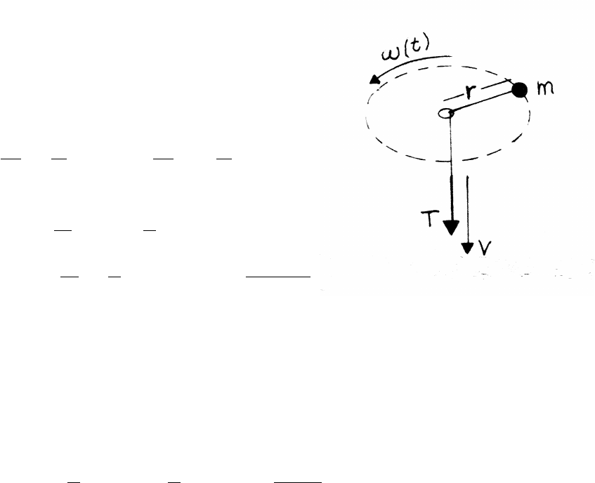
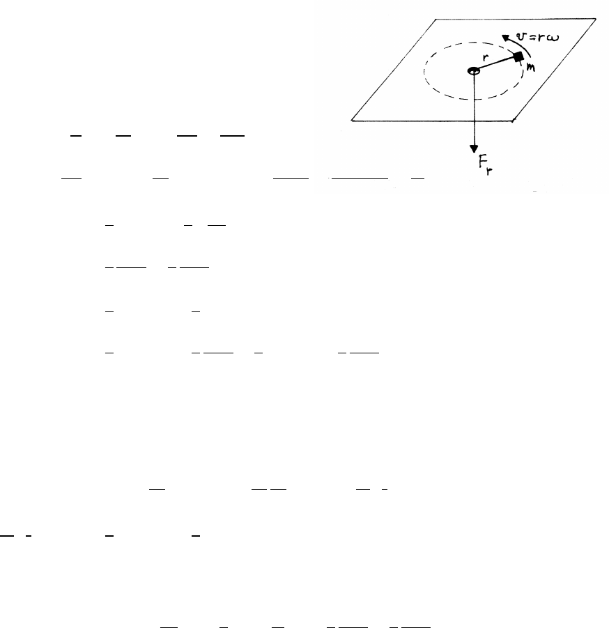
5.5 Work on a whirling mass
Mechanical energy is conserved (no friction). The applied force
Fris radial, so the tangential equation of motion is aθ=0.
aθ=2˙r˙
θ+r¨
θ=0
˙ω
ω=−2˙r
r=⇒dω
ω=2dr
r
Zω
ωi
dω
ω=−2Zr
l1
dr
r=⇒˙
θ=ω=l12ω1
r2=constant
r2≡C
r2(1)
Ktangential =1
2m(rω)2=1
2mC2
r2
Ktangential
f−Ktangential
i=1
2
mC2
l22−1
2
mC2
l12
Kradial
f−Kradial
i=1
2mv2
radial,f−1
2mv2
radial,i
Ef−Ei=1
2mv2
radial,f+1
2
mC2
l22−1
2mv2
radial,i−1
2
mC2
l12
Now find the work Wdone by the radial force Fr.
W=Zl2
l1
Frdr Zl2
l1
mardr =mZl2
l1
(¨r−r˙
θ2)dr
mZl2
l1
¨r dr =mZl2
l1
d˙r
dt dr =mZtf
ti
d˙r
dt
dr
dt dt =Ztf
ti
d
dt 1
2m˙r2dt
Ztf
ti
d
dt 1
2m˙r2dt =1
2mv2
radial,f−1
2mv2
radial,i
equals the change in mechanical energy due to radial motion. Using Eq. (1),
−mZl2
l1
r˙
θ2dr =−mZl2
l1
C2
r3dr =1
2mC2 1
r2!
l2
l1
=1
2
mC2
l22−1
2
mC2
l12
equals the change in mechanical energy due to tangential motion. Hence Ef−Ei=
Was expected.
76 ENERGY
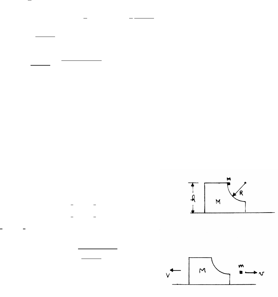
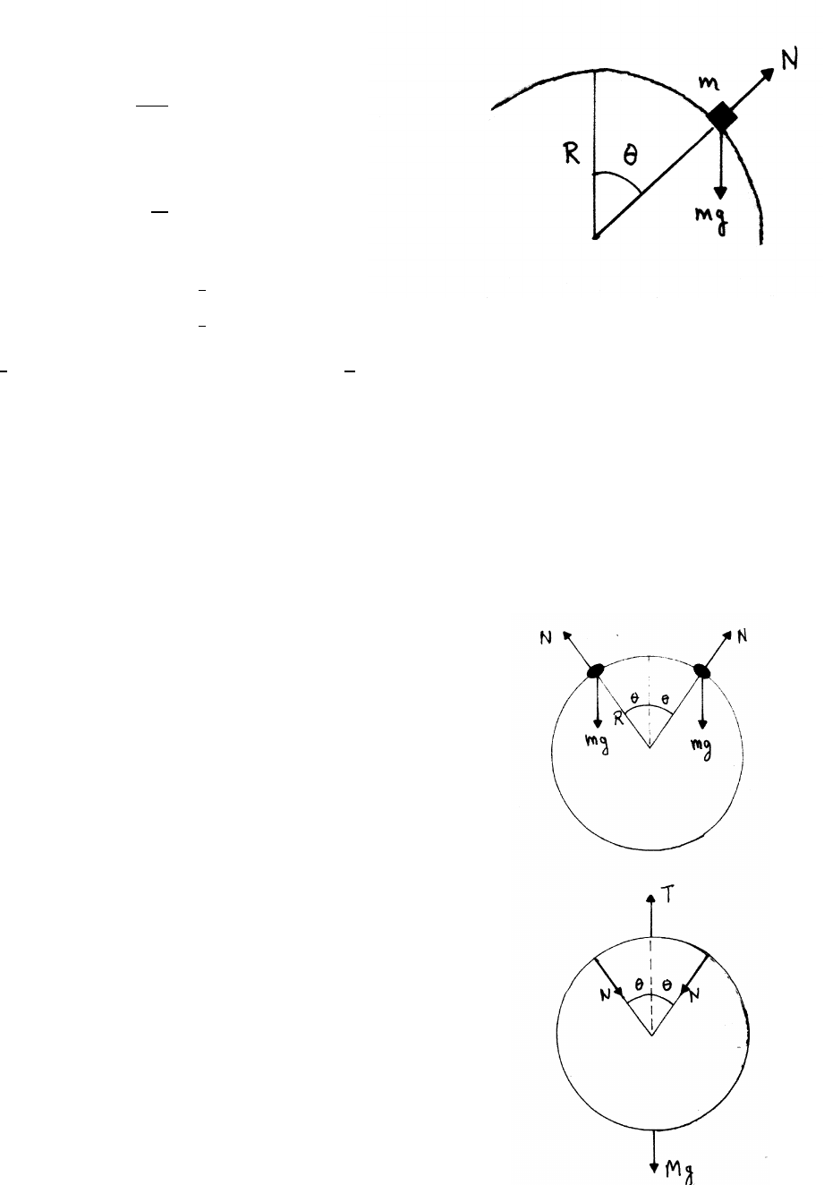
5.6 Block sliding on a sphere
radial equation: mv2
R=mg cos θ−N
Block separates when N=0.
v2
R=gcos θ
Ki=0Ui=mgR
Kf=1
2mv2Uf=mgR cos θ
Ef=1
2mv2+mgR cos θ=Ei=mgR
1
2gR cos θ+gR cos θ=gR =⇒cos θ=2
3
At separation, the block is a distance y=R(1 −cos θ)=R/3 below the top.
5.7 Beads on hanging ring
Mechanical energy is conserved (no friction).
The upper sketch shows the forces on each bead: the
downward weight force mg and the outward radial normal
force Nexerted by the ring.
The lower sketch shows the forces on the ring: the
downward weight force Mg, the upward force Texerted
by the thread, and the inward radial forces Nexerted by the beads.
continued next page =⇒
ENERGY 77
The ring remains stationary if T≥0 (strings can only pull, not push).
ring equation of motion:
T−2Ncos θ−Mg =0
bead equation of motion:
mg cos θ−N=mv2
R
Ki=0Ui=mgR
Kf=1
2mv2Uf=mgR cos θ
Ef=1
2mv2+mgR cos θ=Ei=mgR =⇒mv2
R=2mg(1 −cos θ)
N=mg cos θ−mv2
R=mg(3 cos θ−2)
for T just 0: 2Ncos θmax =−Mg
2m(3 cos θmax −2) cos θmax =−M(1)
cos θmax =1
3≈70◦
From Eq. (1), the ring starts to rise when 2m(3 cos θmax −2) cos θmax =−M
2m"3 1
3!−2# 1
3!=−M=⇒m≥3
2M
To find the angle for any values of mand M, use Eq. (1).
3 cos2θ−2 cos θ+M
2m=0
cos θ=1
3+r1
9−M
6m(2)
The plus sign is chosen because cos θmax =1/3, and θmust be < θmax.
Comment: According to Eq. (2), cos θ < 2/3, or θ >≈48◦, regardless of the value
of M/m. If m<3
2M, the argument in Eq. (2) is <0; the ring will never rise.

78 ENERGY
5.8 Damped oscillation
Consider one complete cycle. Let xibe
the maximum displacement of the block
at the start. It starts from rest, so its
kinetic energy is 0. Its potential energy
is 1
2k(xi−x0)2due to the spring,
where x0is the unstretched length of
the spring. x0is halfway between xi.
as shown. If there is no friction, the block
returns to xiafter one complete cycle, and the mechanical energy is conserved.
With friction present, the block returns only to xi−∆x, so then the potential energy
is 1
2k(xi−∆x−x0)2. Mechanical energy is less by an amount ∆E:
(a)
∆E=1
2k[(xi−∆x−x0)2−(xi−x0)2]≈ −2(1
2)k∆x(xi−x0)
By symmetry of SHM, the block travels (xi−x0) in 1/4 cycle, so distance
traveled per cycle is 4(xi−x0). The work Wfof friction is
Wf=f×distance traveled in one cycle =4f(xi−x0)
By the Work-Energy Theorem, ∆E=−Wf
k∆x(xi−x0)=4f(xi−x0)=⇒∆x=4f
k
so the change in amplitude per cycle is constant, to first order.
continued next page =⇒
ENERGY 79
(b)
The block comes to rest after ncycles. The block loses amplitude ∆x/cycle.
n∆x=(xi−x0)=⇒n=k
4f(xi−x0)
The result is reasonable; the block makes many cycles if the friction force is weak,
or if the spring is stretched quite far at the start.
5.9 Oscillating block
(a) (1) The original period is T0=2π√M/k. The new mass is (m+M), so the new
period is 2π√(m+M)/k=T0√(m+M)/M.
(2) Because the lump msticks at the extreme of the motion, the amplitude is
unchanged. Note that the lump transfers no horizontal momentum to M.
(3) The mechanical energy is E=1
2kA2
0, where A0is the amplitude. Because
the amplitude is unchanged, the mechanical energy is also unchanged.
(b) (1) The mass is (m+M), so the new period is T0√(m+M)/Mas in a(1).
(2) In this case, linear momentum is conserved when the putty sticks, but the
mechanical energy is not conserved. If Vis the speed just before the collision,
the speed V0just after the collision is given by (m+M)V0=MV. Hence the
new mechanical energy E0is
E0=1
2(m+M)V02=1
2MV2M
m+M=1
2kA2
where Ais the new amplitude. Hence
1
2kA2=1
2MV2M
m+M=1
2kA2
0M
m+M=⇒A=A0rM
m+M
continued next page =⇒

80 ENERGY
(3) From part b(2),
E0=1
2MV2M
m+M=EM
m+M
5.10 Falling chain
The links of the chain fall like free bodies. The mass per
unit length of the chain is λ=M/l. In length ∆x,
the mass is ∆m=λ∆x, and if it hits the scale
with speed vit carries momentum ∆p=v∆m=vλ∆x. The rate of
momentum flow to the scale is F=dp/dt =λv2.
When the top of the chain has fallen a distance x,
a length xof the chain is on the pan of the scale,
contributing weight λxg. The total force Fwhile the
chain is falling is therefore F=λv2+λxg.
While the chain is in free fall, v2=2gx. Hence while
the chain is falling, F=3λgx. The chain has
completely fallen in time twhere l=1
2gt2so that after
time t=p2l/g, all the chain is on the scale. The
scale then reads the chain’s full weight λgl, as indicated
in the sketch. The idealized sketch assumes that the scale has a very fast response.
5.11 Dropped soldiers
The bale hits the ground with kinetic energy 1
2Mv2=Mgh, where Mis the mass of
the soldier and his the altitude of the drop. If the soldier comes to rest in distance
s, the average force ¯
F=Mgh/sby the Work-Energy theorem.
continued next page =⇒
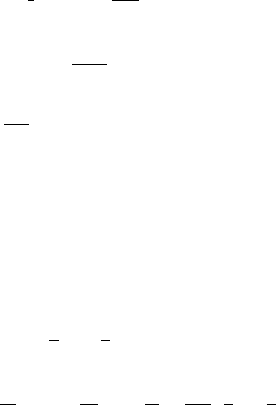
ENERGY 81
¯
Fis the average upward force: ¯
F=¯
Fsnow −Mg.
¯
Fsnow =Mg h
s+1!=180 lb 100 ft
2 ft +1!=9180 lb
The impact area Ais
A=5 ft2=5 ft2×144 in2
1 ft2=720 in2
The force per square inch P(a pressure) is thus
P=9180
720 =12.8 lb/in2
The drop should be safe. This problem could also be solved by calculating the im-
pulse and the acceleration, but the energy method used here is more direct. How-
ever, the result obtained is not entirely convincing. The assumption that the retard-
ing force is constant is not realistic. For instance, if the compression acts more like
a spring force, the peak force would be twice the average force.
5.12 Lennard-Jones potential
U="r0
r12
−2r0
r6#(1)
Differentiating,
dU
dr ="(−12) r012
r13 !+(12) r06
r7!#=−12
r"r0
r12
−r0
r6#
dU/dr =0 for r=r0.
Substituting r=r0in Eq. (1),
U(r0)=−
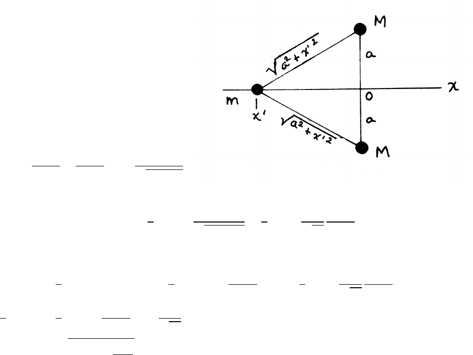
82 ENERGY
5.13 Bead and gravitating masses
mis initially located at x0. Mechanical
energy is conserved. The total gravitational
potential energy is the sum of the potential
energies of mwith each mass M. Using the
convention that U→0 as r→ ∞,
(a)
U=−GmM
r−GmM
r=−2GmM
√a2+x02
(b)
Ei=Ki+U(x0=3a)=1
2mv2
i−2GmM
√a2+9a2=1
2mv2
i−2
√10
GmM
a
Let v(0) be the speed of mas it passes the origin.
Ef=1
2mv2(0) −U(x=0) =1
2mv2(0) −2GmM
a=Ei=1
2mv2
i−2
√10
GmM
a
1
2mv2(0) =1
2mv2
i+2GmM
a 1−1
√10!
v(0) ≈rv2
i+2.74GM
a
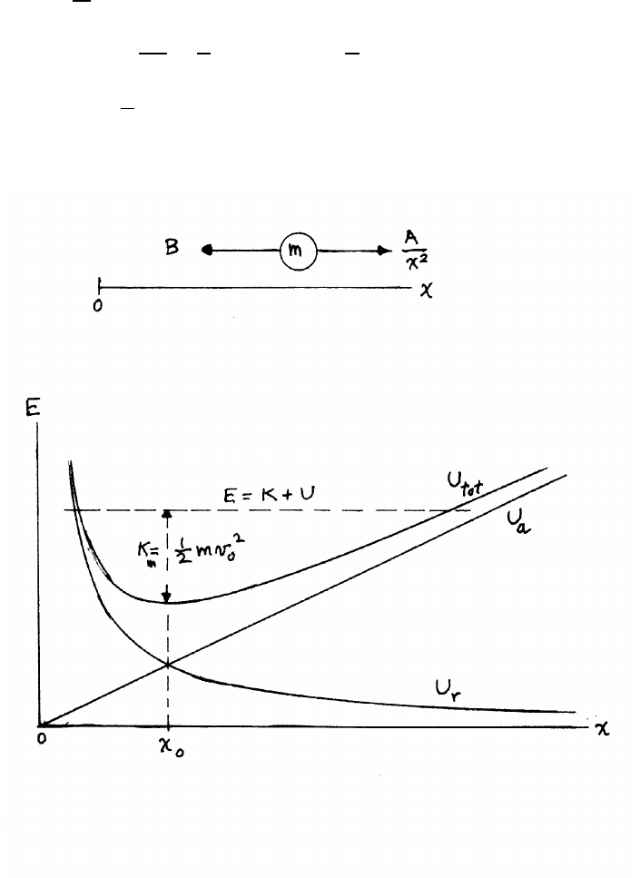
ENERGY 83
5.14 Particle and two forces
(a)
1) attractive force: Fa=−B
Ua(x)−Ua(0) =−Zx
0
Fadx0=Bx0|x
0=⇒Ua(x)=Bx +Ua(0)
2) repulsive force: Fr=A
x2
Ur(x)−Ur(∞)=−Zx
∞
Adx0
x02=A
x=⇒Ur(x)=A
x
Utotal =Bx +A
x
(b)
continued next page =⇒
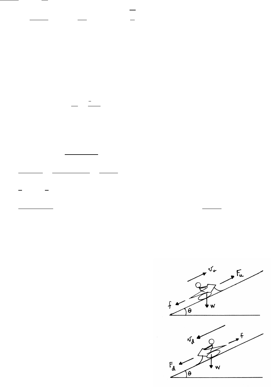
84 ENERGY
(c)
dUtotal
dx =B−A
x2
0=dUtotal
dx x0
=B−A
x02=⇒x0=rA
B
It is easy to prove that for these particular forces, the minimum of Utotal occurs
where Ua(x0)=Ur(x0), as shown in the sketch, for any values of Aand B.
5.15 Sportscar power
The average power ¯
P=∆E
∆T=
1
2Mv2
∆T
The units are mixed. Best practice is to work mainly in SI.
M=1800 lb-mass ×1 kg
2.2 lb-mass =818 kg
v=60 miles
hour ×1.61 ×10³m
1 mile ×1 hour
3600 s =26.8 m/s
∆E=1
2Mv2=1
2×(818 kg) ×(26.8 m/s)2=2.94 ×105kg ·m2/s2=2.94 ×105J
¯
P=2.94 ×10⁵J
3 s =9.80 ×10⁴J/s=.80 ×104W=9.80 ×104W×1 hp
746 W =131 hp
5.16 Snowmobile and hill
The snowmobile moves at constant speed,
which requires the total force to be zero.
The forces parallel to the surface are the
component of gravity along the slope, the
retarding force f, and the propelling force F.
continued next page =⇒
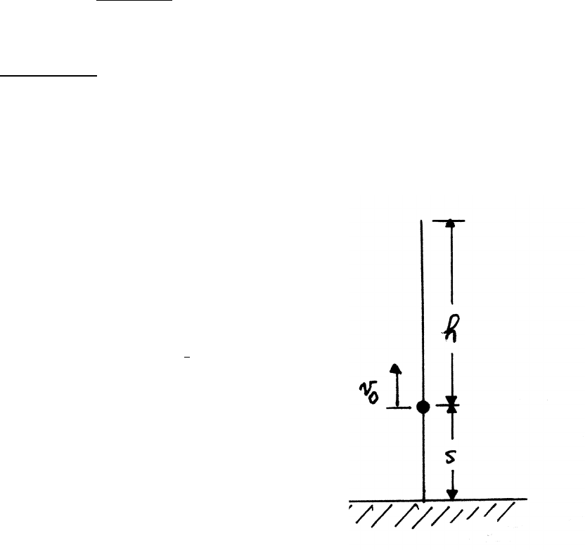
ENERGY 85
Fis the reaction force from the snow to the propelling force on the snow from the
treads. The normal force on the snowmobile has no component along the slope, and
is not shown in the sketches. The sketches are not to scale; according to the stated
conditions, the slope angle θis ≈1.4◦.
The subscript ustands for up, and dfor down. The power Pdelivered by the snow-
mobile is Fv.
Fu=f+Wsin θFd=f−Wsin θ
Pu=(f+Wsin θ)vuPd=(f−Wsin θ)vd
The engine’s power is constant.
Pu=Pd=⇒vd= f+Wsin θ
f−Wsin θ!vu
f=0.05 Wsin θ=sin (arctan 1/40) ≈0.025
vd= (0.05 +0.025)
(0.05 −0.025)!vu=3vu=45 mph
5.17 Leaper
The leaper applies constant force so the acceleration a
is constant. The leaper’s center of mass has risen a height sjust
as the leaper leaves the ground. At this point the speed is v0,
which carries the leaper an additional height h. The mechanical energy
Eat the top of the leap is E=Mg(s+h).
The time Tto reach height sis given by s=1
2aT 2
and the speed at that point is v0=aT , so that T=2s/v0.
continued next page =⇒
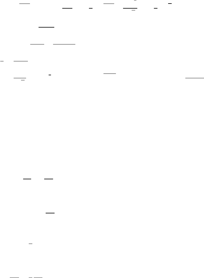
86 ENERGY
The average power ¯
Pis ¯
P=E/T=Mg(s+h)v0/2s.
v0=p2gh =⇒¯
P=Mg
2 1+h
s!p2gh =Mg
3
2
√2 1+h
s!√h
M=160 lb ×1 kg
2.2 lb =72.7 kg
h=3 ft ×12 in
1 ft ×2.54 cm
1 in =91.4 cm =0.91 m
h
s=3 ft
1.5 ft =2.0
¯
P=72.7
√2×(9.8)3
2×(1.0+2.0) ×√0.91 =4510 W =4510 W ×1 hp
746 W =6.0 hp
The world record for the standing high jump is ≈1.6 m. The leaper’s jump in this
problem is evidently within the realm of human capability.
5.18 Sand and conveyor belt
(a) The momentum change of sand mass ∆mis ∆p= ∆mv. The force Fon the belt
F=dp
dt =vdm
dt
The power Pto drive the belt is
P=Fv =v2dm
dt
(b) The kinetic energy Kof mass mon the belt is
K=1
2mv2
so the power needed to increase the kinetic energy is
dK
dt =1
2
dm
dt v2
Half the power to drive the belt goes to giving kinetic energy to the sand.
continued next page =⇒

ENERGY 87
Note that energy is dissipated when the sand is abruptly accelerated as it hits the
belt. To help understand what happens, consider a simple mechanistic model. Sup-
pose that when mass ∆mlands on the belt, it skids a distance dunder a constant fric-
tion force f. The acceleration aof ∆mis a=f/∆mso that v2=2ad =2( f/∆m)d.
The work done by friction is thus f d =1
2∆m v2so the power dissipated by friction
is 1
2(dm/dt)v2, accounting for the other half of the power needed to drive the belt.
5.19 Coil of rope
If a length of rope yis offthe ground at any instant, its mass is m=λy. The total
upward force Ftot =F−mg, where Fis the applied force. The rate of change of the
momentum pis, with dy/dt =v0,
(a)
dp
dt =v0
dm
dt =v0λdy
dt =v2
0λ
F=Ftot +mg =d p
dt +mg =v2
0λ+λyg =λ(v2
0+yg)
(b) The power Pdelivered to the rope is
P=Fv0=λv3
0+λygv0
The rope is uniform, so the raised length yhas mass m=λy. The length has
kinetic energy K.
K=1
2mv2
0=1
2λyv2
0
The center of mass of the raised portion is at y/2, so the potential energy Uis
U=mg y
2=1
2λgy2
The total mechanical energy Eis
E=1
2λyv2
0+1
2λgy2
continued next page =⇒

88 ENERGY
The rate of change of mechanical energy is, using dy/dt =v0,
dE
dt =1
2λv3
0+λygv0
Note that dE/dt <P. The kinetic energy of the rope is increasing at only half
the rate of the first term in the expression for P. The remainder is dissipated in the
sudden acceleration of the rope from rest. Thinking of the rope as a chain, the speed
of each link is changed abruptly, in an inelastic process that conserves momentum
but not mechanical energy.
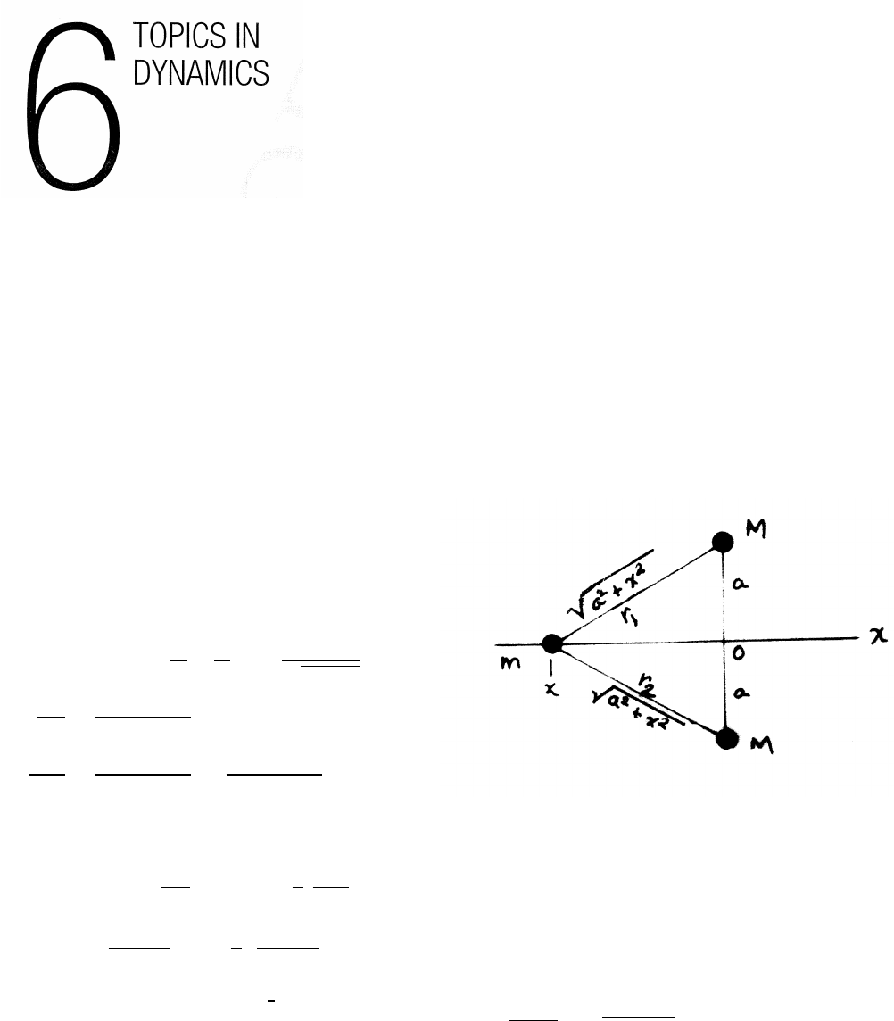
6.1 Oscillation of bead with gravitating masses
The total gravitational potential energy is the
sum of the potential energies of mwith each mass M.
Using the convention that U→0 as r→ ∞,
U(x)=−GmM 1
r1
+1
r2!=−2GmM
√a2+x2
dU
dx =2GmMx
(a2+x2)3/2
d2U
dx2=2GmM
(a2+x2)3/2− 6GmM
(a2+x2)5/2!x2
Use a Taylor’s series expansion around x0=0.
U(x)=U(0) +dU
dx 0
(x−0) +1
2
d2U
dx20
(x−0)2+. . .
≈ −2GmM
a+0+1
2 2GmM
a3!x2
For an ideal spring, U=1
2kx2. The effective spring constant is therefore k=
2GmM/a3. The frequency of small oscillations is ω=√(k/m)=p2GM/a3.
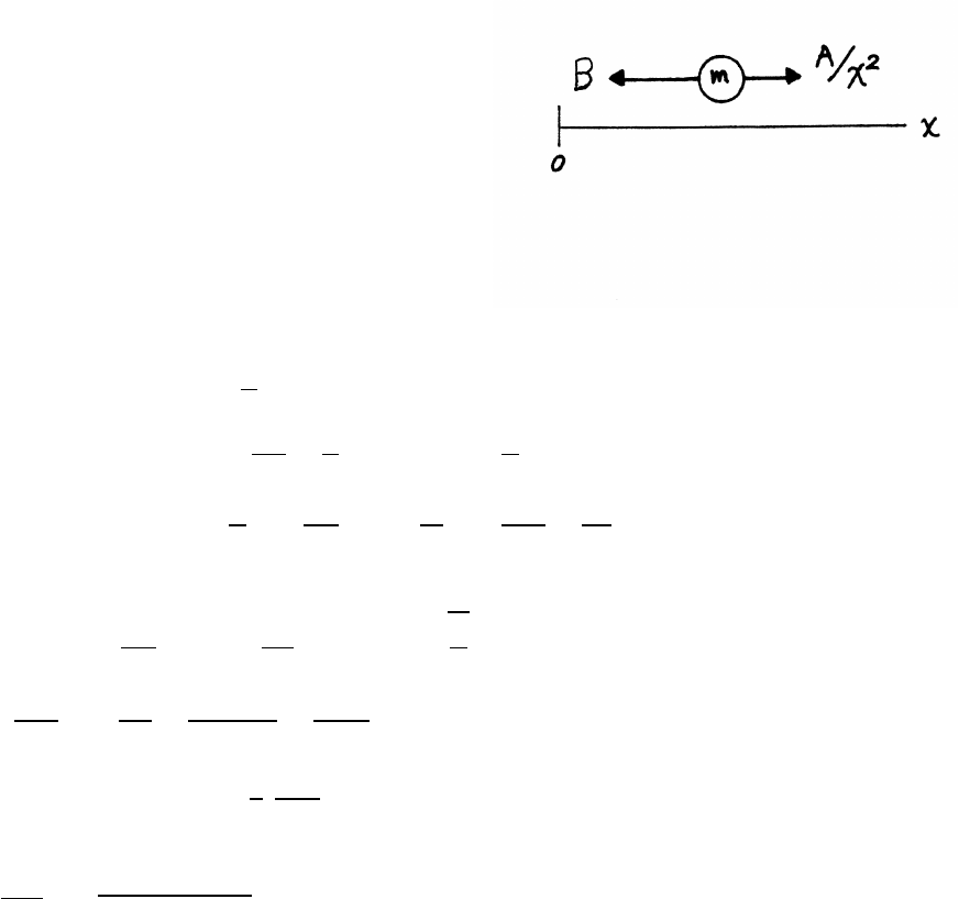
90 TOPICS IN DYNAMICS
6.2 Oscillation of a particle with two forces
Let x0be the location of the potential
minimum, where the total force Ftot =0.
(See the sketch for problem 5.14.)
The total potential energy is the sum of the
potential energies due to each force.
1) attractive force: Fa=−B
Ua(x)−Ua(0) =−Zx
0
Fadx0=Bx0|x
0=⇒Ua(x)=Bx +Ua(0)
2) repulsive force: Fr=A
x2
Ur(x)−Ur(∞)=−Zx
∞
Adx0
x02=A
x=⇒Ur(x)=A
x
Utot =Bx +A
x
dU
dx =B−A
x2
d2U
dx2=2A
x3
The potential is a minimum at x0.
0=dU
dx x0
=B−A
x02=⇒x0=rA
B
d2U
dx2x0
=2A
x03=2A
(A/B)3/2=2B3/2
A1/2
U(x−x0)=U(x0)+0+1
2
d2U
dx2x0
(x−x0)2+. . .
so the effective spring constant is k=(2B3/2)/(A1/2) and the frequency is ω=
√k/m=p(2B3/2)(mA1/2)
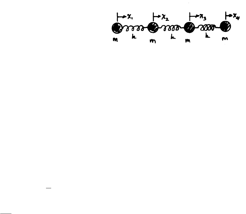
TOPICS IN DYNAMICS 91
6.3 Normal modes and symmetry
As shown in the sketch, four identical masses m
are joined by three identical springs of constant k
and are constrained to move along the xaxis.
In the usual normal mode problem, the coupled
equations of motion are solved for the frequencies,
from which the relative amplitudes of the normal modes can be found. However, in
a problem such as this that has a high degree of symmetry, the normal modes can
be guessed, leading to the normal mode frequencies.
The amplitudes are constrained by symmetry, so that x1=±x4and x2=±x3.
There are no external forces, so the center of mass must be at rest, leading to the
possibilities
(x4=−x1) and (x3=−x2)(mode A)
(x4=x1) and (x3=x2)(mode B)
In a normal mode, all masses undergo simple harmonic motion with the same fre-
quency ω. For the harmonic motion of each mass, ¨xi=ω2xi. The equation of
motion for mass 1 is, for example,
m¨x1=k(x1−x2)=⇒ω2x1=k
m(x1−x2)=ω02(x1−x2)
βx1=(x1−x2)
where ω0=√k/mand β=ω2/ω02. Hence
βx1=(x1−x2)βx2=(x2−x1−x3)
βx3=(x3−x2−x4)βx4=(x4−x3)
continued next page =⇒
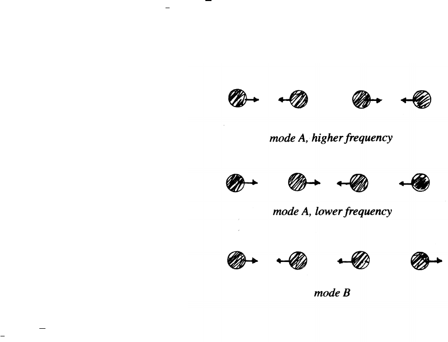
92 TOPICS IN DYNAMICS
Consider the modes Afor which x4=−x1and x3=−x2. The equations of motion
reduce to
βx1=x1−x2(β−1)x1=−x2(1)
βx2=2x2−x1(β−2)x2=−x1(2)
Using Eq. (2) to eliminate x2from Eq. (1) leads to a quadratic equation for β:
β2−3β+1=0, which has roots β=1
2(3 ±√5). The two roots are β≈2.618 and
β≈0.382. The corresponding normal mode frequencies are 1.62ω0and 0.62ω0.
The sketches for modes A show the relative
motion for the higher frequency mode (β > 2)
and for the lower frequency mode (β < 1).
Proceeding similarly for mode B,
where x4=x1and x3=x2,
the equations of motion reduce to
(β−1)x1=−x2(3)
βx2=−x1(4)
Equations (3) and (4) lead to a quadratic equation for β:β2−β−1=0. The roots are
β=1
2(1 ±√5). Because β≥0, take the positive sign. The root is β=1.618, which
gives ω≈1.27ω0. (As discussed in Example 6.6, only three nontrivial frequencies
are expected when there are four equations of motion.)
As the sketch for mode B shows, masses 1 and 4 move together, and 2 and 3 also
move together but in the opposite direction.
All the modes conserve momentum, with the center of mass at rest.
TOPICS IN DYNAMICS 93
6.4 Bouncing ball
The speed after the first collision with the floor is v1=ev0. After ncollisions,
the speed is vn=env0. The time Tto rise to the top of the trajectory is given by
v=gT , so the time between successive bounces is 2T=2v/g. The time Tnfor the
nth bounce is therefore
Tn=2vn
g= 2v0
g!en.
The total time Tn,total for nbounces is
Tn,total =
n
X
j=1
Ti= 2v0
g!n
X
j=1
ej
As n→ ∞, then v→0. The time Tfto finally come to rest is therefore
Tf=lim
j→∞ Tn,total = 2v0
g!∞
X
j
ej=∞
X
k=1
xk−∞
X
k=1
xk+1= 2v0
g!e
1−e
The last step makes use of the identity S=P∞
k=1xk=x
1−x, provided x<1. Proof:
S−xS =∞
X
k=1
xk−∞
X
k=1
xk+1=∞
X
k=1
xk−∞
X
k=2
xk(1)
The second sum cancels all of the first sum except for the very first term, for which
k=1, so the right hand side of Eq. (1) becomes simply x.
S−xS =x=⇒S=x
1−xif x<1
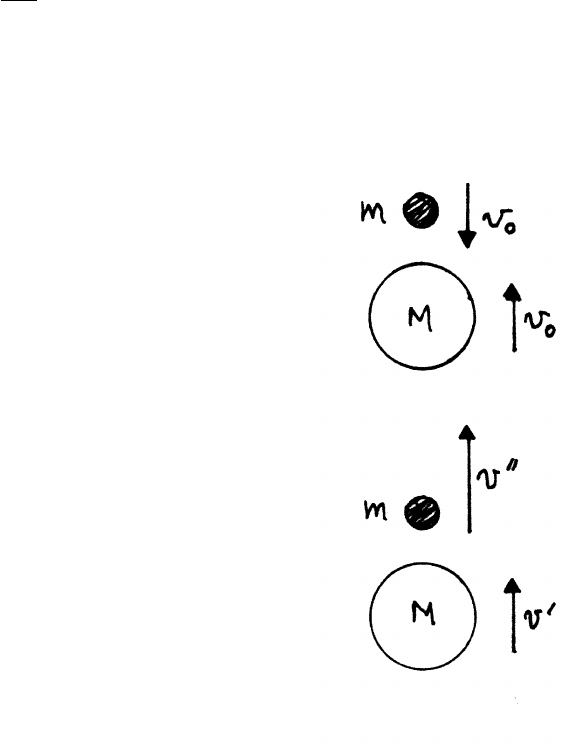
94 TOPICS IN DYNAMICS
6.5 Marble and superball
After falling from height h, a superball of mass Mcarrying a marble of mass mhits
the floor with speed v0=p2gh. After the elastic bounce, Mmoves upward with
speed v0. Here are two methods for finding the upward speed of the marble after
it collides with the superball. (To demonstrate the effect, it may be easier to use a
coin instead of a marble, but a coin may experience greater air resistance.)
Method 1:
This method is algebraic, using the conservation
laws for momentum and for mechanical energy.
The top sketch shows the superball immediately
after it has bounced offthe floor. A gap (greatly exaggerated
in the sketch) is shown between the marble, which is still
moving downward with speed v0, and the superball, which is
moving upward with speed v0.
The lower sketch shows the system immediately after the
marble has collided with the superball. The superball’s speed is
now v0at this instant, and the marble has speed v00 upward.
The initial momentum just before the collision (upper sketch)
is Pi, and the final momentum just after (lower sketch) is Pf.
Pi=Mv0−mv0Pf=Mv0+mv00
The external gravitational force has negligible time to act, so Pf=Pi.
Mv0+mv00 =Mv0−mv0=⇒m(v00 +v0)=M(v0−v0) (1)
continued next page =⇒

TOPICS IN DYNAMICS 95
The collision is assumed to be elastic, so mechanical energy is conserved, The
change in potential energy is negligible during the short time of the collision, so
kinetic energy is the only mechanical energy of interest. Kiis the initial kinetic
energy (upper sketch), and Kfis the kinetic energy just after the collision (lower
sketch).
Kf=−1
2Mv02+1
2mv002=Ki=−1
2Mv20+1
2mv20
m(v002−v2
0)=M(v2
0−v02)=M(v0−v0)(v0+v0)
≈2Mv0(v0−v0) (2)
In the last step, v0≈v0because Mm, so (v0+v0)≈2v0. Using Eq. (1) in Eq, (2)
m(v002−v2
0)=m(v00 −v0)(v00 +v0)=2mv0(v00 +v0)
v00 −v0=2v0=⇒v00 =3v0
After the collision, the marble flies up a height h0=(3v0)2/(2g)=9h.
method 2:
This method is nonalgebraic, and uses simple but sophisticated reasoning.
To an observer on M(moving upward), the marble just before the collision ap-
pears to be approaching with speed 2v0. Because mM, the collision resembles
a collision with a rigid wall, which reverses the direction of the marble’s speed, so
after the collision the marble is moving upward with speed 2v0relative to the su-
perball, or 3v0relative to the floor. After the collision, the marble flies up a height
h0=(3v0)2/(2g)=9h.
6.6 Three car collision
Momentum is conserved in these inelastic collisions, but mechanical energy is not
conserved. Each car has mass M.The initial speed of car A is v0, so its initial kinetic
energy is E0=1
2Mv2
0. After the first collision, cars A and B move together with
speed v1, so conservation of momentum gives Mv0=2Mv1. Therefore v1=v0/2,
so the kinetic energy E1of A and B is E1=1
2(2M)v2
1=(1
2)(1
2)Mv2
0=E0/2.
After the second collision, the speed v2is given by 3Mv2=2Mv1=Mv0, so that
v2=v0/3. The kinetic energy E2is E2=1
2(3M)v2
2=(1
2)(1
3)Mv2
0=E0/3. Hence the
mechanical energy lost in the second collision is E2−E1=(1
2−1
3)E0=E0/6.
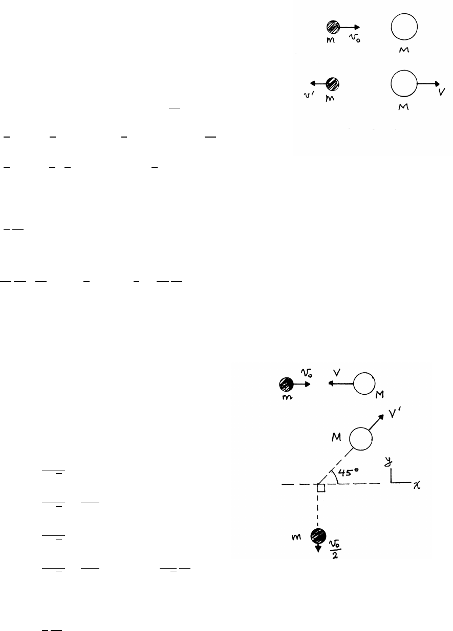
96 TOPICS IN DYNAMICS
6.7 Proton collision
The proton has mass m, and the unknown particle has mass M.
The upper sketch is before the collision, and the lower sketch
is after the collision. Both momentum Pand mechanical energy
(kinetic energy K) are conserved in the elastic collision.
Pf=MV −mv0=Pi=mv0=⇒v0=M
mV−v0(1)
Kf=1
2MV2+1
2mv02=Ki=1
2mv2
0=⇒v2
0=M
mV2+v02(2)
Ef=1
2mv02=4
9 1
2mv2
0!=⇒v0=2
3v0(3)
Using Eqs. (1) and (3),
V=5
3
m
Mv0(4)
Using Eqs. (3) and (4) in Eq. (2),
v2
0=M
m
25
9m
M2
v2
0+4
9v2
0=⇒5
9=25
9
m
M=⇒M=5m
6.8 Collision of mand M
The upper sketch shows the system before the collision,
and the lower sketch after the collision. Both momentum P
and mechanical energy (kinetic energy K) are conserved in
the elastic collision. Phas both xand ycomponents.
Pf x =MV0
√2
=Pix =mv0−MV
Pf y =MV0
√2−mv0
2=Piy =0
mv0−MV =MV0
√2(1)
0=MV0
√2−mv0
2=⇒V0=1
√2
m
Mv0(2)
From Eqs. (1) and (2)
V=1
2
m
Mv0(3)
continued next page =⇒
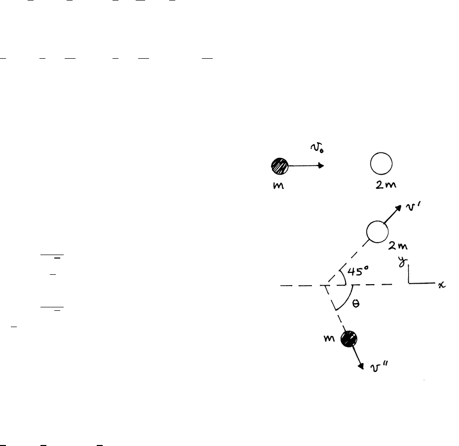
TOPICS IN DYNAMICS 97
Conservation of mechanical energy:
1
2mv2
0+1
2MV2=1
2mv0
22
+1
2MV02
Using Eqs. (2) and (3),
3
4mv2
0+1
4Mm
M2
v2
0=1
2Mm
M2
v2
0=⇒m
M=3
6.9 Collision of mand 2m
The upper sketch shows the system before
the collision, and the lower sketch is after. Both
momentum Pand mechanical energy (kinetic
energy K) are conserved in the elastic collision.
Phas both xand ycomponents.
Pf x =2mv0
√2
+mv00 cos θ=Pix =mv0
v0=√2v0+v00 cos θ(1)
Pf y =2mv0
√2−mv00 sin θ=Piy =0
√2v0=v00 sin θ(2)
From Eqs. (1) and (2),
v0=v00(sin θ+cos θ) (3)
Conservation of mechanical energy:
1
2mv2
0=1
2(2m)v02+1
2mv002=⇒v2
0=2v02+v002(4)
Using Eq. (2), Eq. (4) becomes
v2
0=v002(sin2θ+1) (5)
and from Eqs. (3) and (5),
sin2θ+1=(sin θ+cos θ)2=1+2 sin θcos θ
sin θ=2 cos θ=⇒tan θ=2θ≈63◦
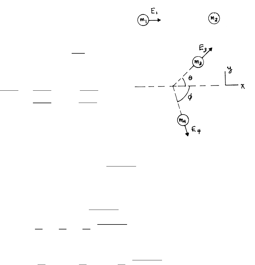
98 TOPICS IN DYNAMICS
6.10 Nuclear collision in the Lsystem
The upper sketch shows the system before
the reaction, and the lower sketch is after.
The collision is inelastic, so momentum P
is conserved, but but mechanical energy Eis not.
Phas both xand ycomponents.
Use the convenient form P=√2mE.
(a) The energy released is Q=E3+E4−E1(1)
(b) conservation of momentum:
p2m1E1=p2m3E3cos θ+p2m4E4cos φ(2)
0=p2m3E3sin θ−p2m4E4sin φ(3)
(c) Now eliminate E4and φ, using Eqs. (2) and (3). Squaring Eqs. (2) and (3),
m4E4cos2θ=m1E1+m3E3cos2θ−2pm1m3E1E3cos θ(4)
m4E4sin2φ=m3E3sinθ(5)
Adding Eqs. (4) and (5),
m4E4=m1E1+m3E3−2pm1m3E1E3cos θ
E4=m1
m4
E1+m3
m4
E3−2
m4pm1m3E1E4cos θ
Inserting this expression for E4in Eq. (1) gives
Q= m3
m4
+1!E3+ m1
m4−1!E1−2
m4pm1m3E1E3cos θ
TOPICS IN DYNAMICS 99
6.11 Uranium fission
The incoming neutron is slow, and the uranium nucleus is essentially at rest, so take
the initial momentum and initial kinetic energy of the neutron and the 235U nucleus
to be zero. After fission, the product 97Sr and 138Xe nuclei move apart back-to-
back, with equal and opposite momentum P. The total kinetic energy of the fission
fragments is Et=170 MeV. Using E=P2/2M,
ES r =P2
2MS r
EXe =P2
2MXe
ES r +EXe =Et
P2 1
2MS r
+1
2MXe !=Et=⇒P2=2Et MS r MXe
MS r +MXe !
ES r =Et MXe
MS r +MXe !=170 MeV ×138
235 =100 MeV
EXe =Et MS r
MS r +MXe !=170 MeV ×97
235 =70 MeV
6.12 Hydrogen fusion
The particles are essentially at rest before the fusion reaction. After fusion, the
products have equal and opposite momentum P. Using E=P2/2M,
EHe =P2
2MHe
En=P2
2Mn
The total energy Etotal released is
Etotal =EHe +En=17.6 MeV
P2 1
2MHe
+1
2Mn!=Et=⇒P2=2Et MHe Mn
MHe +Mn!
EHe =Et Mn
MHe +Mn!=17.6 MeV ×1
5=3.5 MeV
En=Et MHe
MHe +Mn!=17.6 MeV ×4
5=14.1 MeV

100 TOPICS IN DYNAMICS
6.13 Nuclear reaction of αrays with lithium
To high accuracy, the mass of the reactants M=Mα+MLi is equal to the mass of
the products Mn+MB, where M=4+7=1+10 =11 mass units.
Let E0be the kinetic energy of the incident αparticle in the Lsystem. The reaction
collision is inelastic; E0supplies the kinetic energy of the products and the reaction
energy Q=2.8 MeV.
At threshold, the energy in the Csystem is just enough to form the products. At
threshold, the neutron and the boron are at rest in C, so their energies KLin the L
system are due entirely to the motion of the center of mass, moving with speed V,
so KL=(1/2)MV2.
(a)
V=Mα
Mvα=⇒KL=1
2MMα
M2
v2
α=1
2Mαv2
α×Mα
M=Mα
ME0=4
11 E0
E0,threshold =KL+Q=4
11 E0,threshold +Q=11
7×2.8 MeV =4.4 MeV
At threshold, the neutron is moving with speed Vin the Lsystem.
En,L=1
2MnV2=1
2MnMα
Mv2
α=Mn
ME0,threshold =1
11 ×4.4 MeV =0.4 MeV
(b) For the product neutron moving in the forward direction in the Lsystem, its
velocity vn,Cmust be either parallel or antiparallel to the center of mass ve-
locity V. If vn,Cis moving parallel to V, the neutron will always be moving in
the forward direction in L, and its energy is not restricted. However, if vn,Cis
antiparallel to V, the neutron will be moving in the forward direction in Lonly
if vn,C≤V. In this case, the limit for forward motion in Lis vn,C=V. The speed
of the neutron in Cis Vin this case, and it is moving antiparallel to V. Because
total momentum is always 0 in C, the speed of the boron nucleus is (Mn/MB)V,
and it is moving parallel to V. The speeds of the products in the Lsystem, in
the limit of forward motion, are
vn,L=V−V=0
vB,L=Mn
MB
V+V
continued next page =⇒
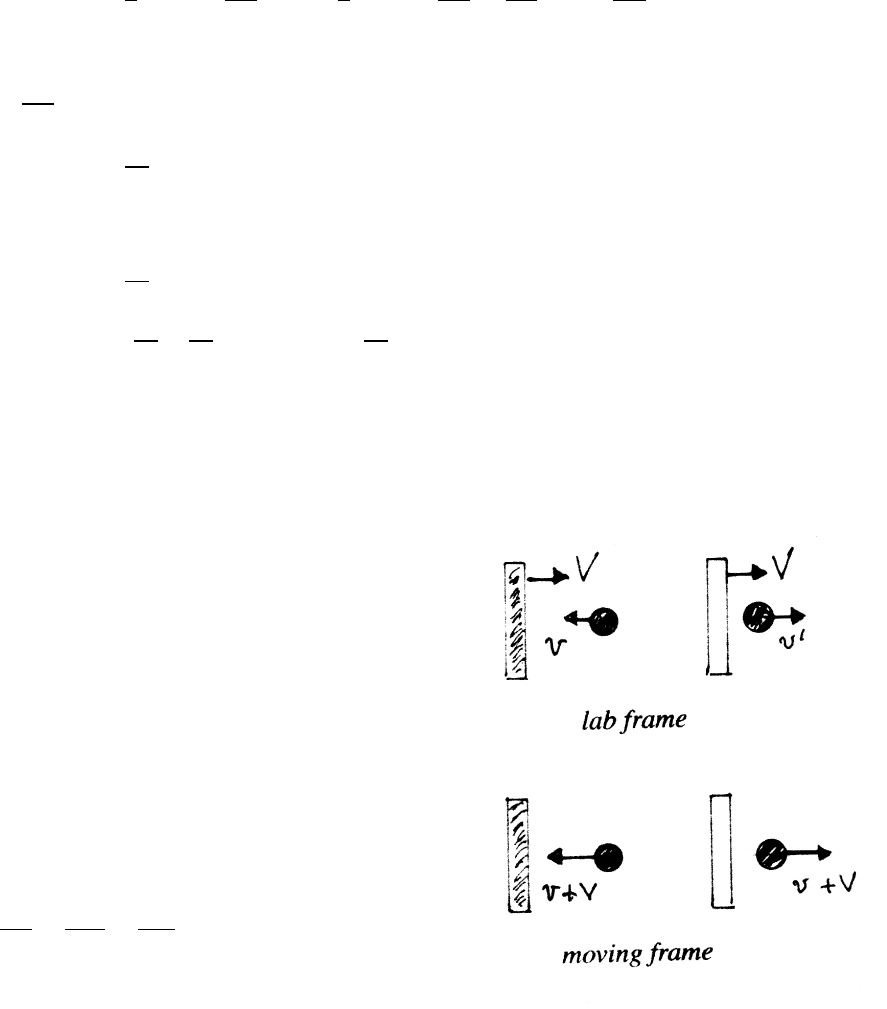
TOPICS IN DYNAMICS 101
The kinetic energy of nin Lis 0, and the kinetic energy of boron is
KB,L=1
2MB 1+Mn
MB!2
V2=1
2MB 1+Mn
MB!2Mα
M2
v2
α=Mα
MB
E0
E0=KB,L+0+Q
1−Mα
MB!E0=Q
E0=10
6×2.8 MeV
At threshold,
E0,threshold =11
7×2.8 MeV
E0−E0,threshold = 10
6−11
7!×2.8 MeV =4
42 ×2.8 MeV =0.27 MeV
6.14 Superball bouncing between walls
This problem is a model for the common observation
that when pumping up a tire with a hand pump, the barrel
of the pump becomes warmer. Pushing the piston down does
work on the gas, raising its temperature by increasing the
average speed of the gas molecules.
(a) The time-average force is the average rate of
momentum transfer to a wall. Consider the situation when
the walls are stationary. In a single collision (elastic),
∆p=2mv. The time between collisions is ∆T=2l/v.
The average force ¯
Fis then
¯
F=∆p
∆T=2mv
2l/v=mv2
l
continued next page =⇒
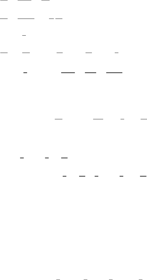
102 TOPICS IN DYNAMICS
(b) Consider now the case when one wall is moving. To an observer moving with
the wall, the superball approaches with speed v+V, and leaves with the same
speed (elastic collision), as shown in the sketch. Then convert back to the lab
frame by adding V.
v0=(v+V)+V=v+2V
∆v=v0−v=2V
The time between collisions is ∆T=2x/v. In the limit ∆T→0,
dv
dt =2V
2x/v=vV
x
dv
dx =dv/dt
dx/dt =−1
V
dv
dt (-) sign because xdecreases with time
=−v
x
dv
v=−dx
x=⇒ln v
v0
=−ln x
x0
=−ln x
l
v=v0
l
x=⇒¯
F=2mv
2x/v=mv2
x=mv2
0l2
x3
(c) The work ∆Wmoving distance ∆xin the direction of Vis
∆W=−F∆x(-) because xis decreasing
W=−mv2
0l2Zx
l
dx
x3=mv2
0l2 1
2x2!
x
l
=1
2mv2
0 x2
l2−1!
The superball’s kinetic energy Kis
K=1
2mv2=1
2mv2
0
x2
l2
∆K=K(x)−K(l)=1
2mv2
0
x2
l2−1
2mv2
0=1
2mv2
0 x2
l2−1!=W
6.15 Center of mass energy
Let M=Ma+Mb. The object of this problem is to prove that for two particles a
and bmoving with velocities Vaand Vb,
1
2MV2+1
2µV2
r=1
2MaV2
a+1
2MbV2
b
where Vis the velocity of the center of mass, Vris the relative velocity of the two
particles, and µis the reduced mass.
continued next page =⇒
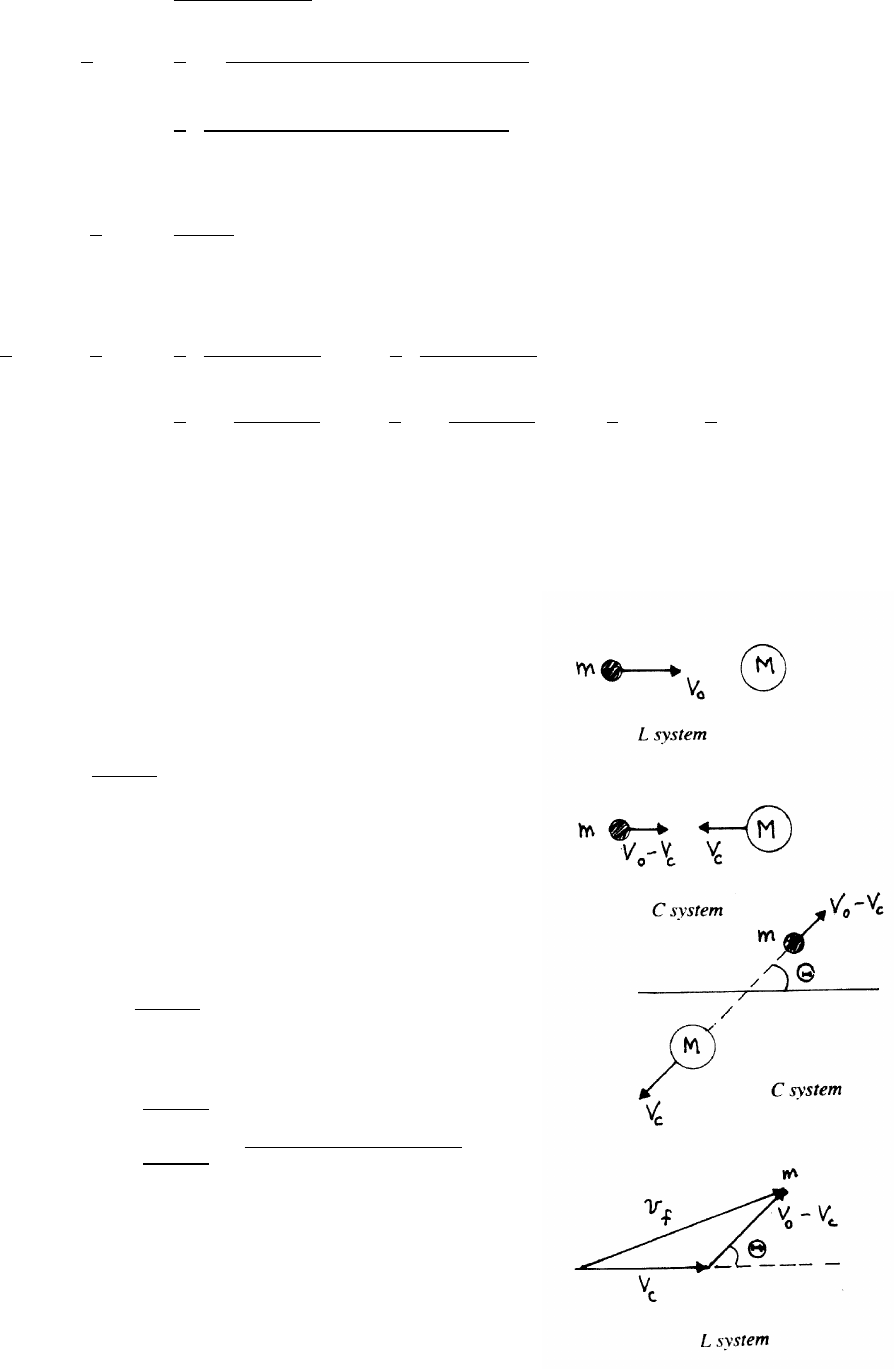
TOPICS IN DYNAMICS 103
V=MaVa+MbVb
M
1
2MV2=1
2M MaV2
a+MbV2
b+2Va·VbMaMb
M2!
=1
2 M2
aV2
a+M2
bV2
b+2Va·VbMaMb
M!(1)
Vr=Va−Vb
1
2µV2
r=MaMb
MV2
a+V2
b−2Va·Vb(2)
Adding Eqs. (1) and (2),
1
2MV2+1
2µV2
r=1
2 M2
a+MaMb
M!V2
a+1
2 M2
b+MaMb
M!V2
b
=1
2Ma Ma+Mb
Ma+Mb!V2
a+1
2Mb Mb+Ma
Ma+Mb!V2
b=1
2MaV2
a+1
2MbV2
b
6.16 Converting between Cand Lsystems
(a) To convert from the Lto C, subtract
the center of mass velocity Vcfrom every
Lsystem velocity vector (upper two sketches).
Vc=mV0
m+M
In an elastic collision, the speeds in Care unchanged,
(third sketch). To convert from Cto L, add Vcto
every velocity vector, as shown for mass m(bottom sketch).
vfis the velocity of min the Lsystem after the collision.
v0−Vc=Mv0
m+M
v2
f=V2
c+(v0−Vc)2−2Vc(v0−Vc) cos (π−Θ)
=v0
m+M2m2+M2+2mM cos Θ
vf=v0
m+M√m2+M2+2mM cos Θ
continued next page =⇒
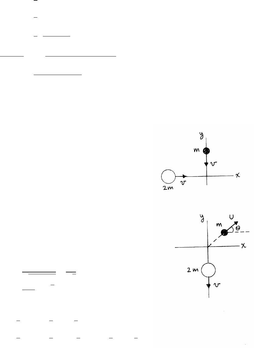
104 TOPICS IN DYNAMICS
(b)
K0=1
2mv2
0
Kf=1
2mv2
f
=1
2 mv2
0
(m+M)2!(m2+M2+2mM cos Θ)
K0−Kf
K0
=1−(m2+M2+2mM cos Θ)
(m+M)2
=2mM(1 −cos Θ)
(m+M)2
6.17 Colliding balls
The upper sketch is before the collision,
and the lower sketch is after the collision.
(a)
By conservation of momentum,
2mv ˆ
i−mv ˆ
j=mU cos θˆ
i+mU sin θˆ
j−2mv ˆ
j
2v=Ucos θ(1)
v=Usin θ(2)
Dividing Eq. (2) by Eq. (1),
tan θ=1/2≈27◦
sin θ=tan θ
√1+tan2θ
=1
√5
U=v
sin θ=√5v≈2.2v
(b)
Ei=1
2(2m)v2+1
2mv2=3
2mv2
Ef=1
2(2m)v2+1
2mU2=1
2(2m)v2+5
2mv2=7
2mv2
>Ei
The collision is superelastic.
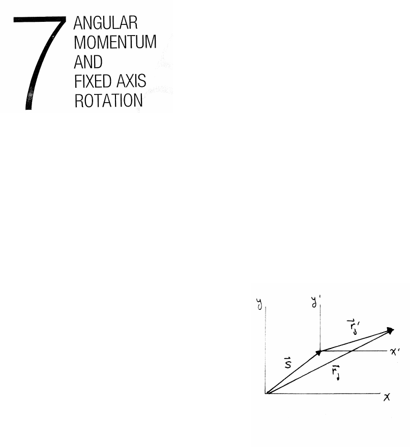
7.1 Origins
(a) L=angular momentum in x−y
L0=angular momentum in x0−y0.
L=Xrj×pj=X(S+r0j)×pj
pj=m˙
rj=m˙
r0j=p0j
L0=Xr0j×p0j=X(rj−S)×pj=Xrj×pj−S×Xpj=L−S×Xpj
It is given that P=Ppj=0, so L0=L, independent of the origin S.
(b)
τ=Prj×Fj. Because forces are independent of the origin, F0j=Fj.
τ0=Xr0j×F0j=X(rj−S)×Fj=τ−S×XFj
It is given that Ftotal =PFj=0 so τ0=τ
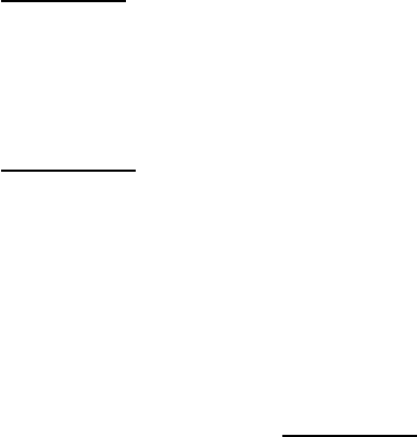
106 ANGULAR MOMENTUM AND FIXED AXIS ROTATION
7.2 Drum and sand
The angular momentum of the system at time t=0 is
L(0) =(MA+Ms)a2ωA(0) (1)
At time t, the angular momentum is
L(t)=(MA+Ms−λt)a2ωA(0) +(MB+λt)b2ωB(t) (2)
Note that ωA(t)=ωA(0) because the sand exerts no torque on drum Aas it leaves.
(To an observer on the drum, the sand appears to fly out radially.) Angular momen-
tum is conserved L(t)=L(0), because the system is isolated – there are no external
torques. Equations (1) and (2) then give
ωB(t)=λa2ωA(0)t
(MB+λt)b2
At time Tgiven by λT=Ms, all of the sand has been transferred from drum Ato
drum B, and ωBis then constant. Thus
ωB(t≥T)=Msa2ωA(0)
(MB+Ms)b2(3)
< ωA(0)
It is easy to show that the angular momentum of the system for t≥Tremains equal
to L(0). Using Eq. (3) gives
L(t≥T)=MAa2ωA(0) +(MB+Ms)b2ωB(t≥T)
=MAa2ωA(0) +(MB+Ms)b2Msa2ωA(0)
(MB+Ms)b2
=(MA+Ms)a2ωA(0)
=L(0)
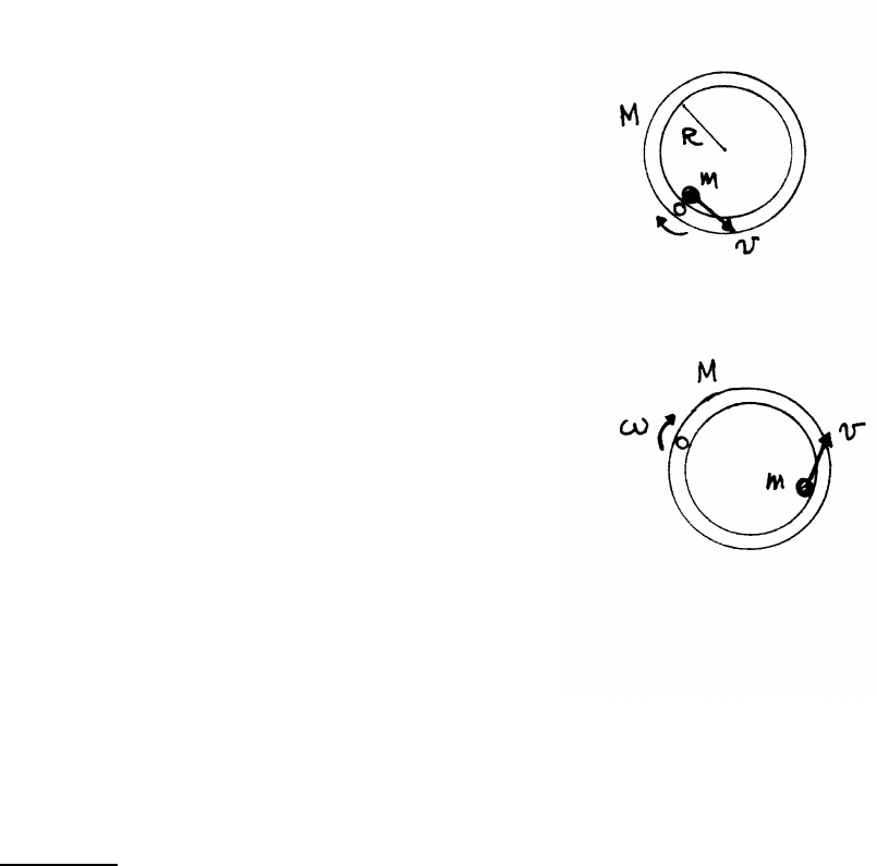
ANGULAR MOMENTUM AND FIXED AXIS ROTATION 107
7.3 Ring and bug
(a) With the bug at the origin and the ring at rest, the initial angular
momentum is L(0) =0. Angular momentum Labout the pivot is
conserved, because no external torques are acting on the system.
Thus, noting that the ring rotates clockwise as the
bug moves counterclockwise,
L=Lbug −Lring
When the bug is halfway around, the ring
is rotating at some angular speed ω. The speed of the
bug is then v−2Rω.
The moment of inertia of the ring Iring about the pivot, is,
by the parallel axis theorem,
Iring =I0+MR2=MR2+MR2
=2MR2
The total angular momentum is
L=−ωIring +m(2R)(v−2Rω)
=[−2MR2−(2R)2m]ω+2mRv
=0
ω=mv
(M+2m)R
(b) When the bug is back at the pivot, Lbug =0,
and therefore Lring =0 so that ω=0. The ring is
then momentarily at rest, but it is not necessarily back
to its initial position.
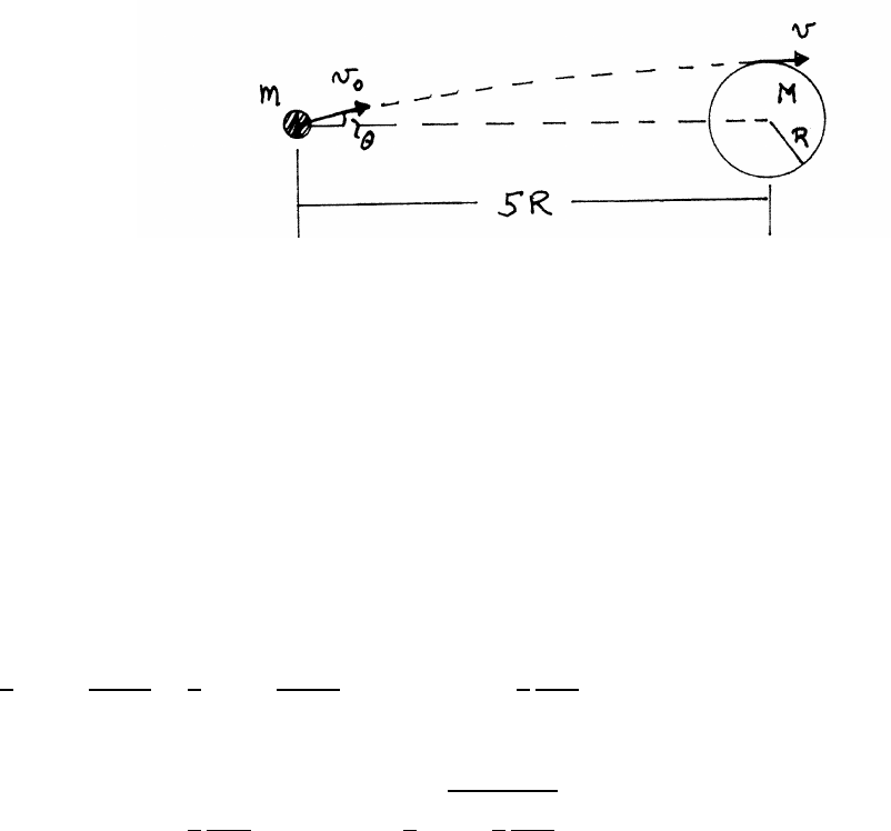
108 ANGULAR MOMENTUM AND FIXED AXIS ROTATION
7.4 Grazing instrument package
Because the gravitational force on mis central, angular momentum about the center
of the planet is conserved. At tangential grazing, mis traveling at speed vand its
trajectory is perpendicular to R. Hence
m(5R)v0sin θ=mvR =⇒v=5v0sin θ(1)
Another expression for the grazing speed vcan be found using conservation of
mechanical energy.
1
2mv2
0−GmM
5R=1
2mv2−GmM
R=⇒v2=v2
0+8
5
GM
R(2)
Combining Eqs. (1) and (2) to eliminate v,
(25 sin2θ−1) =8
5
GM
Rv2
0
=⇒sin θ=1
5s1+8
5
GM
Rv2
0
(3)
It is evident from Eq. (3) that sin θmust be >1/5 (θ > 11.5◦). For example, if θ
is too small, the package does not graze the planet but plows into it. On the other
hand, if 8GM/5Rv2
0>24, then according to Eq. (3), sin θ > 1, an unrealizable
value. In this case, the package does not graze, but sails over the planet.

ANGULAR MOMENTUM AND FIXED AXIS ROTATION 109
7.5 Car on a hill
The car is in stationary equilibrium, so the total force
on the car must be 0, and the total torque about any
point must be 0. (Problem 7.1 shows that in a stationary
system, if the torque is 0 about some point, it is 0
about any point.)
forces:
0=N1+N2−Mg cos θ
0=f1+f2−Mg sin θ(1)
torque (about the center of mass):
0=N1l2+f1l1+f2l1−N2l2(2)
Using Eq. (1), Eq. (2) can be written
0=(N1−N2)l2+Mgl1sin θ
N1=1
2Mg cos θ−l1
l2
sin θ!N2=1
2Mg cos θ+l1
l2
sin θ!
Mg =3000 lb θ=15◦l1=2 ft l2=4 ft
N1=1500 0.966 −2
40.259!=1255 lb
N2=1500 0.966 +2
40.259!=1643 lb
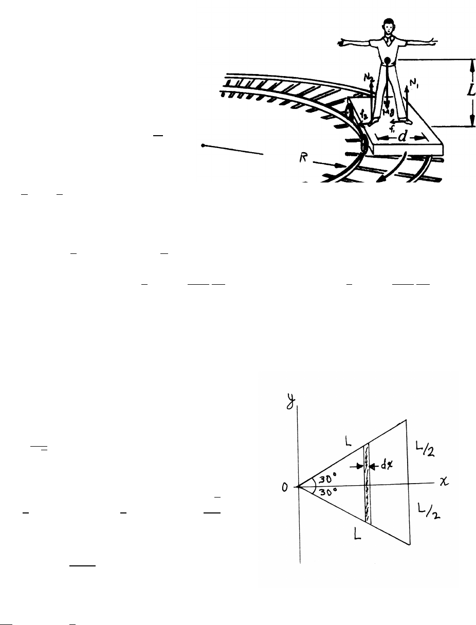
110 ANGULAR MOMENTUM AND FIXED AXIS ROTATION
7.6 Man on a railroad car
vertical equation of motion:
N1+N2−Mg =0
radial equation of motion:
f1+f2=Mv2
R(1)
torque about the center of mass:
−N1
d
2+N2
d
2+(f1+f2)L=0 (2)
Using Eq. (1) in (Eq. (2),
d
2(N1−N2)=mv2L
R
outside foot: N1=1
2 Mg +Mv2
R
2L
d!inside foot: N2=1
2 Mg −Mv2
R
2L
d!
7.7 Moment of inertia of a triangle
The slanted sides obey the relation
y=±x
√3(1)
The area Aof the triangle is
A=1
2(base ×height)=1
2L(Lcos 30◦)=√3
4L2
The shaded strip has length 2y, width dx and mass dm.
dm =2y dx
AM
The moment of inertia of the strip about its center is
1
12dm(2y)2=1
3y2dm
continued next page =⇒
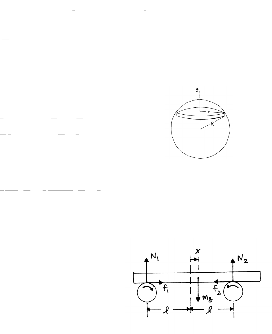
ANGULAR MOMENTUM AND FIXED AXIS ROTATION 111
By the parallel axis theorem, the moment of inertia dIvof the strip about a perpen-
dicular axis through the vertex at the origin is, using Eq. (1),
dIv=x2dm +1
3y2dm =10
9x2dm
Iv=10
9Zx2dm =20
9
M
AZ√3L/2
0
x2y dx =20
9√3
M
AZ√3L/2
0
x3dx =20
9√3
M
(√3/2)L2×1
4
√3
2L
4
=5
12 ML2
7.8 Moment of inertia of a sphere
Consider the sphere to be a stack of solid disks of radius rand
mass dm. The moment of inertia is
dI =1
2r2dm dm =M
VdV =M
V(πr2dz)
=M
V
1
2πr4dz =⇒I=M
VZ1
2πr4dz
With r2=R2−z2,
I=M
VZR
−R
1
2π(R2−z2)2dz =π
2
M
VZR
−R
(R4−2R2z2+z4)dz =π
2
MR5
V 2−4
3+2
5!
=π
2
MR5
V 16
15!=π
2
MR5
(4/3)πR3 16
15!=2
5MR2
7.9 Bar and rollers
The vertical and horizontal equations of motion:
N1+N2−Mg =0 (1)
M¨x=f1−f2(2)
The torque is 0; take torques about the center of mass
−N1(l+x)+N2(l−x)=0 (3)
continued next page =⇒

112 ANGULAR MOMENTUM AND FIXED AXIS ROTATION
The bar is thin, so f1and f2produce negligible torques. Using Eqs. (1) and (3),
N1=1
2Mg 1−x
lN2=1
2Mg 1+x
l
f1−f2=µ(N1−N2)=−µMg
lx
so Eq. (2) becomes
M¨x=−µMg
lx=⇒¨x+µg
lx=0
This is the equation for SHM, with frequency ω=qµg
l
7.10 Cylinder in groove
vertical equation of motion:
0=N1
√2
+N2
√2
+f1
√2−f2
√2−Mg (1)
horizontal equation of motion:
0=N1
√2−N2
√2−f1
√2−f2
√2(2)
Using the law of friction f=µN, Eq. (2) gives
N2=(1 −µ)
(1 +µ)N1(3)
Using Eq. (3) in Eq. (1),
N1=Mg
√2 1+µ
1+µ2!N2=Mg
√2 1−µ
1+µ2!
torques about the center of mass:
τ=(f1+f2)R=µ(N1+N2)R=√2Mg µ
1+µ2!R
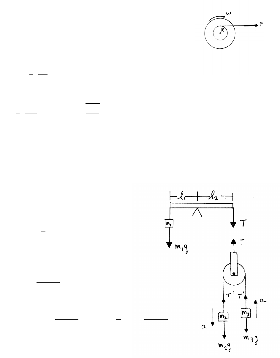
ANGULAR MOMENTUM AND FIXED AXIS ROTATION 113
7.11 Wheel and shaft
This problem concerns angular acceleration under constant torque.
Note the exact analogy with linear acceleration under a constant force.
τ=Ioα=Io
dω
dt
In this system, τ=FR, so dω/dt =FR/I0.Fis constant, so ω=(FR/I0)t.
θ=Zωdt =1
2 FR
I0!t2
Let ω=ω0at t=t0, when all the tape of length Lhas just been unwound.
L=Rθ=1
2 FR2
I0!t2
0=⇒t0=r2LI0
FR2
ω0=FR
I0
t0=r2LF
I0
=⇒I0=2LF
ω2
0
7.12 Beam and Atwood’s machine
The beam is in equilibrium, so the total
torque =0. Taking torques about the fulcrum,
T l2−m1gl1=0
T=m1g l1
l2!
The equations of motion for m2and m3are
m2a=m2g−T0m3a=T0−m3g
T0=2g m2m3
m2+m3!
In equilibrium, the pulley does not accelerate.
T=2T0=4g m2m3
m2+m3!=⇒m1g l1
l2!=4g m2m3
m2+m3!
m1l1=4 m2m3
m2+m3!l2
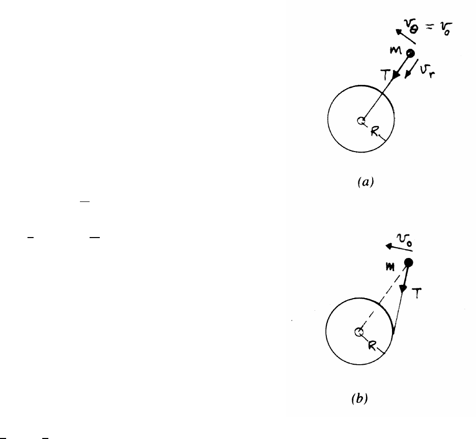
114 ANGULAR MOMENTUM AND FIXED AXIS ROTATION
7.13 Mass and post
(a) Angular momentum about the center of the post
is conserved, because the force is radial and cannot exert
a torque on m. Initially, mis at distance rfrom
the center, and is moving with tangential velocity v0,
so the initial angular momentum is L=mv0r.
At a later time, mis a distance rffrom the
center, and has tangential velocity vf, so that L=mv frf.
Momentum pand mechanical energy Eare not conserved,
because external force is acting on m.
pf=mvf=p0 r
rf!
Ef=1
2mv2
f=E0
r2
r2
f
(b) In this case, the force on mis not central, and angular
momentum is not conserved. The radius vector rfrom the center
to mis not perpendicular to p, so L=r×p,0,
and furthermore the angle between rand pchanges during the
motion. Momentum is not conserved, because RTdt ,0.
Mechanical energy is conserved, because the force Ton mis
perpendicular to v, and hence does no work. Therefore
1
2mv2
f=1
2mv2
0=⇒vf=v0
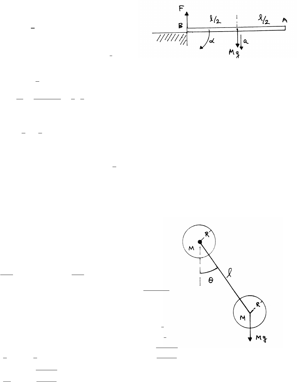
ANGULAR MOMENTUM AND FIXED AXIS ROTATION 115
7.14 Stick on table
(a)
τB=Mg l
2!
(b) The moment of inertia of a thin rod of length l
about one end is, from Example 7.3, 1
3Ml2.
τB=IBα=1
3Ml2α
α=τB
IB
=Mg(l/2)
(1/3)Ml2=3
2g
l
(c)
a=α l
2!=3
4g
(d)
Ma =Mg −F=⇒F=M(g−a)=1
4Mg
7.15 Two-disk pendulum
The upper disk is pivoted about its center.
The torque about the pivot is τ0=−Mgl sin θ.
equation of motion: τ0=I0α
¨
θ+Mgl
I0
sin θ=0=⇒¨
θ+Mgl
I0
θ≈0
This is the equation for SHM with frequency ω=p(Mgl)/I0
The moment of inertia of the upper disk about the pivot is 1
2MR2.
The moment of inertia of the lower disk about the pivot is (1
2MR2+Ml2).
I0=1
2MR2+ 1
2MR2+Ml2!=M(R2+l2)=⇒ω=rgl
R2+l2
T=2π
ω=2πsR2+l2
gl
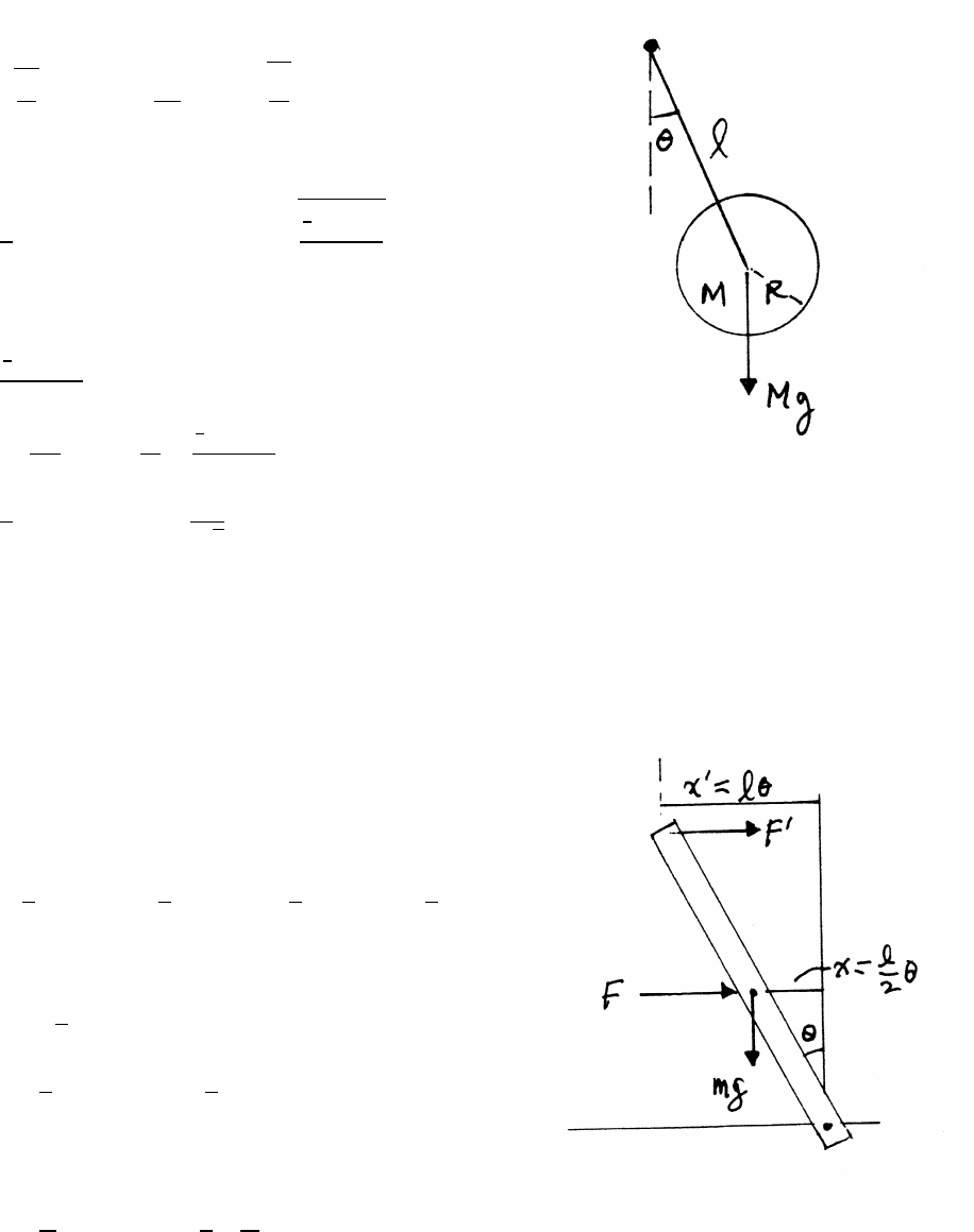
116 ANGULAR MOMENTUM AND FIXED AXIS ROTATION
7.16 Disk pendulum
From the result of problem 7.15, the period is
ω=rgl
I0
=⇒T=2π
ω=2πsI0
gl
where I0is the moment of inertia about the pivot.
I0=1
2MR2+Ml2=⇒T=2πs1
2R2+l2
gl
The minimum period occurs for dT/dl =0.
T2=
1
2R2+l2
gl
0=2TdT
dl =2T
2l
gl −
1
2R2+l2
gl2
2l2=1
2R2+l2=⇒l=R
√2
The pivot point for minimum period lies within the body of the disk.
7.17 Rod and springs
The sketch shows the rod displaced from equilibrium by
angle θ. Both springs act to restore the rod toward equilibrium.
Taking torque τabout the pivot,
τ=−Fl
2−F0l+mg l
2sin θ≈ −Fl
2−F0l+mg l
2θ(1)
The spring forces are, in the directions shown,
F=kx =kl
2θF0=kx0=klθ
τ≈−k l
2!2
−kl2+mg l
2!θ
The equation of motion is τ=I0¨
θ.
¨
θ≈"−k l2
4!−kl2+mg l
2!# θ
I0
continued next page =⇒
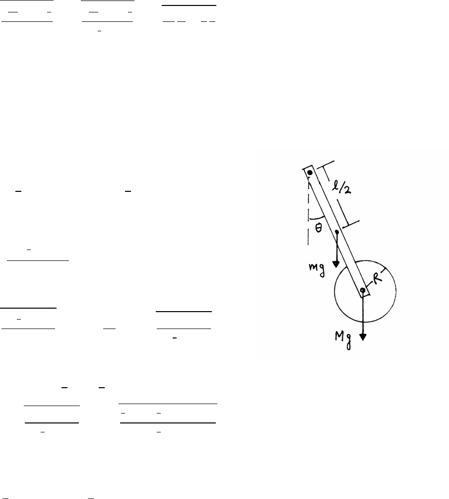
ANGULAR MOMENTUM AND FIXED AXIS ROTATION 117
The rod moves according to SHM with frequency ω.
ω=sk5l2
4−mg l
2
I0
=v
tk5l2
4−mg l
2
1
3ml2=r15
4
k
m−3
2
g
l
As kis decreased, ωalso decreases, and finally becomes 0. At this point, the system
is no longer stable, and the motion ceases to be harmonic.
7.18 Rod and disk pendulum
The torque τabout the pivot is
τ= −mg l
2−Mgl!sin θ≈ −mg l
2−Mgl!θ
The equation of motion is τ=Itotal ¨
θ.
0=¨
θ+mg l
2+Mgl
Itotal
θ
The system moves according to SHM with frequency ωand period T.
ω=smg l
2+Mgl
Itotal
T=2π
ω=2πsItotal
mg l
2+Mgl
The moment of inertia Itotal about the pivot is
Itotal =Irod +Idisk =1
3ml2+1
2MR2+Ml2
T=2πsItotal
mg1
2+Mgl =2πs1
3ml2+1
2MR2+Ml2
mg l
2+Mgl (1)
To help understand how the disk’s mounting affects the period, consider the contri-
butions to the total angular momentum of the system, using Ltotal =Itotalω.
Ltotal =1
3ml2ω+Ml2ω+1
2MR2ω
The first term on the right is the angular momentum of the rod. The second term is
the angular momentum of a mass Mconcentrated at the end of the rod. The third
term is the angular momentum of the disk. All rotate with angular momentum ω.
continued next page =⇒
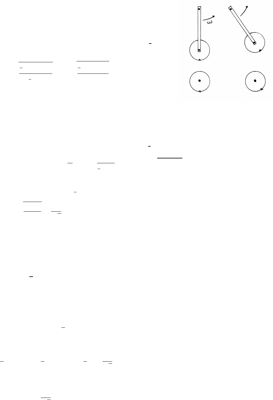
118 ANGULAR MOMENTUM AND FIXED AXIS ROTATION
When the disk is rigidly attached to the rod, the disk rotates, as
indicated for the isolated disk in the sketch by the mark on the
rim for the isolated disk. The period is T, Eq. (1). When the disk
is mounted by a frictionless bearing, it cannot rotate and
contributes no rotational angular momentum. The term 1
2MR2
should then be omitted from Eq. (1) to give the new period T0:
T0=2πs1
3ml2+Ml2
mg l
2+Mgl =2πs2
3ml +2Ml
mg +2Mg
7.19 Disk and coil spring
(a) The restoring torque is τ=−Cθ, so the equation of motion is I¨
θ+Cθ=0, the
equation for SHM. The initial moment of inertia is 1
2MR2, so
0=¨
θ+C
Iθ=¨
θ+C
1
2MR2θ=⇒ω=p2C/MR2
(b) (1) The moment of inertia of the putty ring is MR2, so the moment of inertia of
the disk and putty is now 3
2MR2, and the new frequency ω0is
ω0=r2C
3MR2=ω
√3
(2) At time t1, just before the putty is dropped,
θ=θ0sin ωt1=θ0sin π=0˙
θ=ω θ0cos ωti=ω θ0cos π=−ω θ0
Immediately before the putty is dropped, the angular momentum Lis
L=Iω=1
2MR2ω θ0
The amplitude of the initial motion is ω θ0. The putty ring has angular momen-
tum =0 before it is dropped. Hence the angular momentum of the system is
conserved. The new angular momentum L0equals the initial L.
L0=I0ω0=3
2MR2ω0θ0
0
By conservation of momentum,
1
2MR2ω θ0=3
2MR2ω0θ0
0=3
2MR2ω
√3θ0
0
so the new amplitude is
θ0
0=θ0
√3
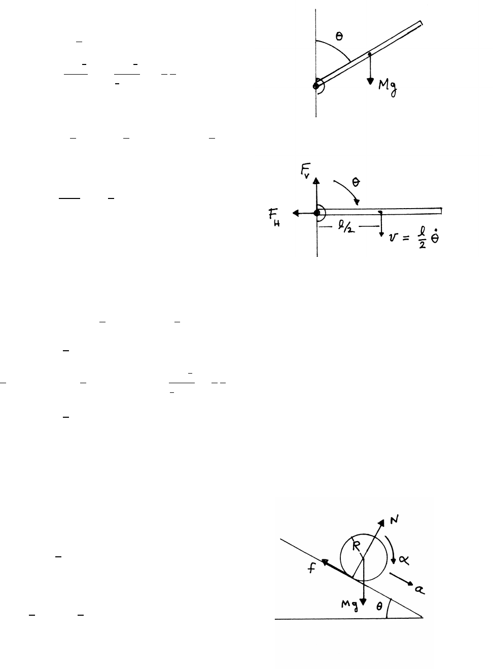
ANGULAR MOMENTUM AND FIXED AXIS ROTATION 119
7.20 Falling plank
For θ=90◦, the torque τabout the pivot is
τ=Mg l
2=I¨
θ(90◦)
¨
θ(90◦)=
Mg l
2
I
=
Mg l
2
1
3Ml2
=3
2
g
l
tangential equation of motion:
Mg −FV=Ml
2¨
θ(90◦)=3
4Mg =⇒FV=1
4Mg
radial equation of motion (at 90◦):
FH=Mv2
l/2=Ml
2˙
θ2(90◦)
Use conservation of mechanical energy to
find ˙
θ2(90◦). Note that FVand FHdo no
work on the system, because the displacement is 0.
Take the gravitational potential energy to be 0 at θ=90◦.
Initially, at θ=60◦, the kinetic energy is 0.
E(60◦)=0+Mg l
2sin 30◦=Mg l
4
E(90◦)=1
2I˙
θ2(90◦)E(90◦)=E(60◦)
1
2I˙
θ2(90◦)=Mg l
4=⇒˙
θ2(90◦)=Mg l
2
1
3Ml2=3
2
g
l
FH=3
4Mg
7.21 Rolling cylinder
Take torques about the center of the
cylinder. Only the friction force fcontributes.
f R =Iα=1
2MR2α
For rolling without slipping, a=Rα, so
f=1
2MRα=1
2Ma
continued next page =⇒
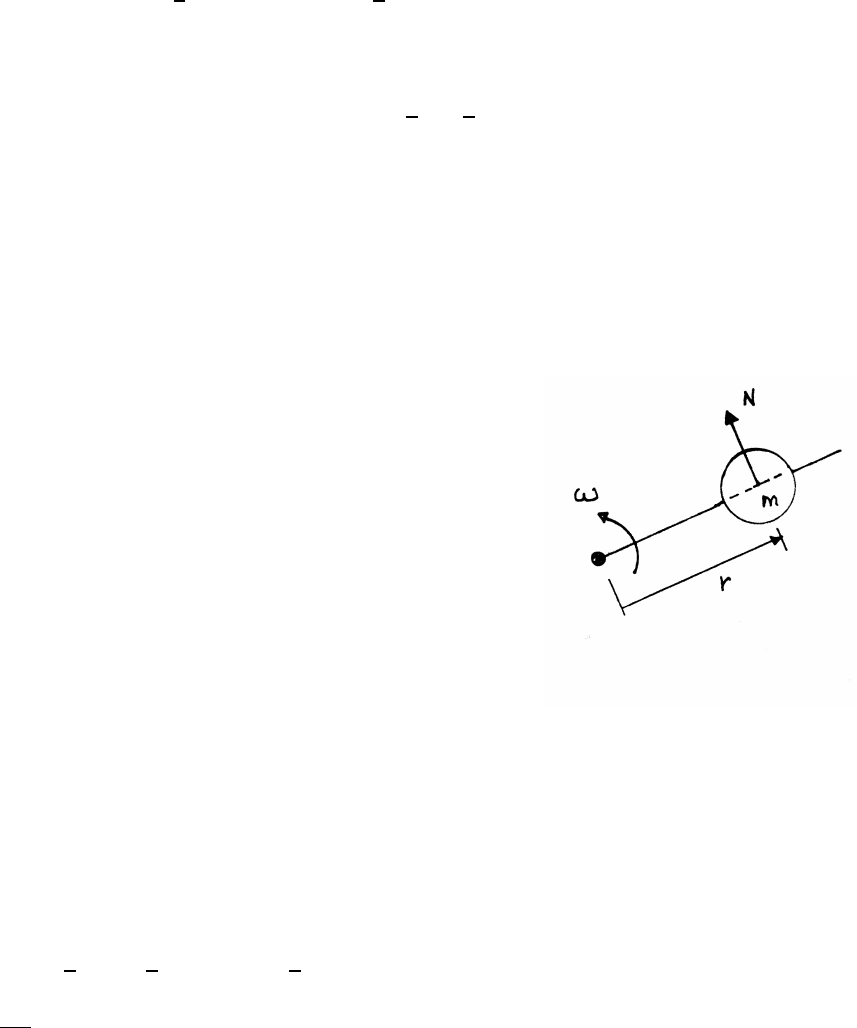
120 ANGULAR MOMENTUM AND FIXED AXIS ROTATION
equation of motion normal to the plane:N−Mg cos θ=0
equation of motion along the plane:Mg sin θ−f=Ma
Mg sin θ=Ma +f=3
2Ma =⇒gsin θ=3
2a
The strength of fis limited.
f≤µN=µMg cos θ=⇒µgcos θ≥1
2a=1
3gsin θ
The condition for rolling without slipping is therefore tan θ≤3µ.
7.22 Bead and rod
(a) radial equation of motion (ω=constant):
0=mar=m¨r−mrω2=⇒¨r−rω2=0 (1)
r=r0eωtsatisfies Eq. (1), with r(0) =r0. Proof:
˙r=ωr0eωt¨r=ω2r0eωt=ω2r
(b) By Newton’s Third Law, the force on the rod
is equal and opposite to N, the force on the bead.
tangential equation of motion:
N=maθ=m(2˙rω)=2mω(r0ωeωt)=2mω2r0eωt
(c) The power P=Fv =τ ω. From parts (a) and (b),
P=τ ω =(Nr)ω=2mω3r2
0e2ωt
The kinetic energy Kof the bead is
K=1
2mv2=1
2m(v2
r+v2
θ)=1
2m˙r2+(rω)2=mr2
0ω2e2ωt
dK
dt =2mr2
0ω3e2ωt=P
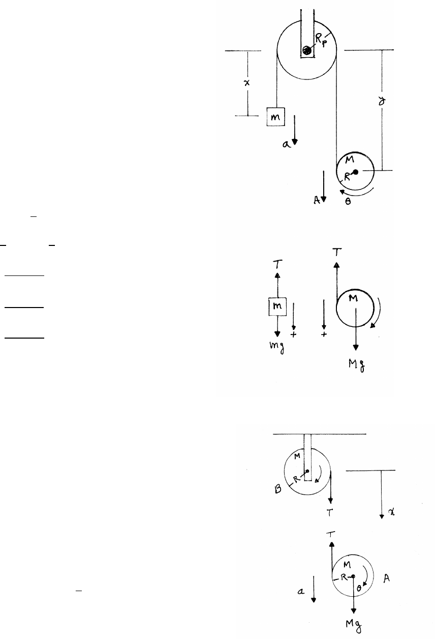
ANGULAR MOMENTUM AND FIXED AXIS ROTATION 121
7.23 Disk, mass, and tape
The tape slips over the stationary pulley.
The length of the tape x+y+πRpincreases
by Rθas the tape unwinds from the disk.
(a) constraint:
x+y=constant +Rθ=⇒¨x+¨y=R¨
θ
Rα=a+A
(b) translational equations of motion:
mg −T=ma Mg −T=MA
rotational equation of motion:
T R =I0α=1
2MR2α
T=1
2MRα=1
2M(a+A)
a= 3m−M
3m+M!g
A=m+M
3m+Mg
Rα= 4m
3m+M!g
7.24 Two drums
The drums are identical, and they experience the
same torque T R. Starting from rest, they consequently
rotate through the same angle θ, causing the tape
to lengthen by 2Rθ. Let l0be the initial length of the tape.
constraint:
x=l0+2Rθ=⇒¨x=a=2Rα
equations of motion for drum A:
Mg −T=Ma T R =1
2MR2α
continued next page =⇒
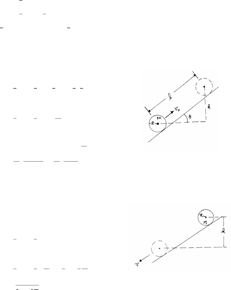
122 ANGULAR MOMENTUM AND FIXED AXIS ROTATION
equation of motion for drum B:
T R =1
2MR2α
T=1
2MRα=1
4Ma
1
4Ma =Mg −Ma =⇒a=4
5g
7.25 Rolling marble
Energy methods are a good approach to this problem.
Ei=1
2Mv2
0+1
2I˙
θ2
0=1
2Mv2
0+1
2 2
5MR2!˙
θ2
0
For rolling without slipping, R˙
θ0=v0,
Ei=1
2Mv2
0+1
5Mv2
0=7
10 Mv2
0
The marble is momentarily stationary at the final height.
Ef=0+Mgh =Mgl sin θ=Ei=7
10 Mv2
0
l=7
10 Mv2
0
Mg sin θ!=7
10 v2
0
gsin θ!
7.26 Sphere and cylinder
Energy methods are a good approach to this problem.
At the start, the object has only gravitational potential energy,
and it gains kinetic energy as it rolls down the plane.
Ef=1
2Mv2+1
2I˙
θ2
0=Ei=Mgh
For rolling without slipping, R˙
θ=v.
Ef=1
2Mv2+1
2I v2
R2!= 1
2M+1
2
I
R2!v2
v2=
Mgh
1
2M+1
2
I
R2
(1)
continued next page =⇒
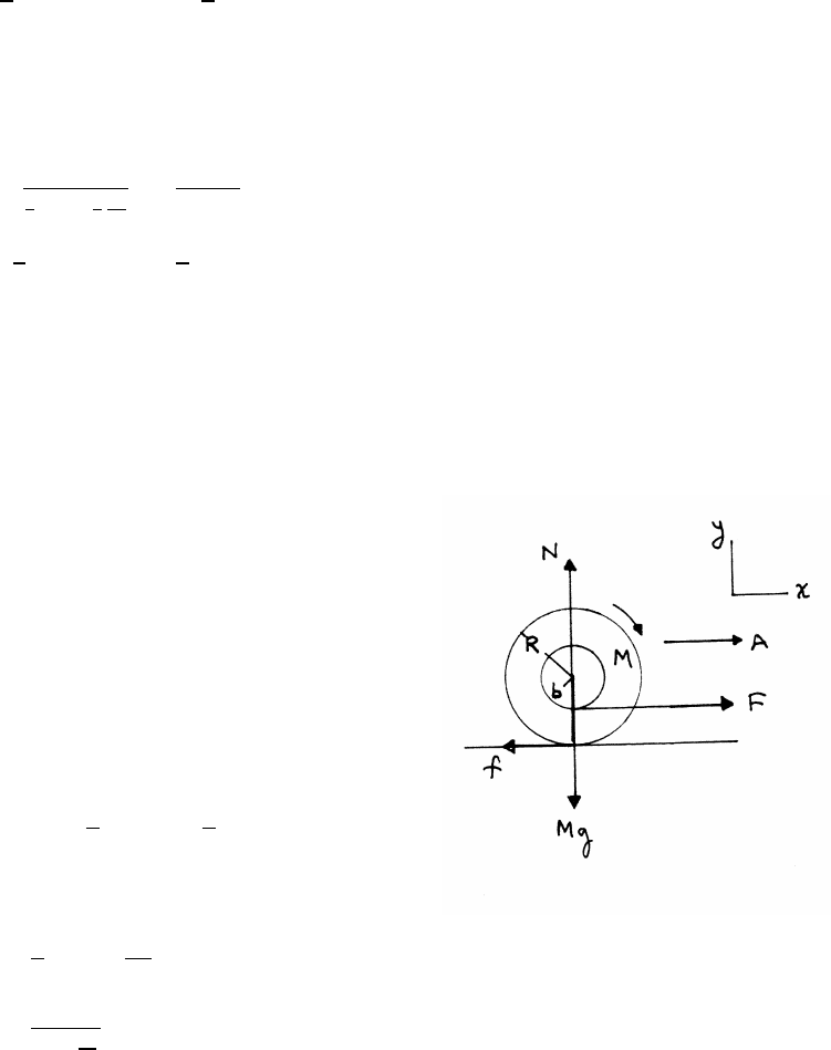
ANGULAR MOMENTUM AND FIXED AXIS ROTATION 123
From Eq. (1), the sphere is faster because it has the smaller moment of inertia.
Isphere =2
5MR2<Icylinder =1
2MR2
Equation (1) can be written more elegantly using the radius of gyration k(Section
7.7.2). The radius of gyration is given by I=k2MR2. Writing Eq. (1) in terms of k,
v2=
Mgh
1
2M+1
2
I
R2
=2gh
1+k2
k2sphere =2
5<k2cylinder =1
2
The sphere is faster, because it has the smaller k.
7.27 Yo-yo on table
translational equation of motion, x:
F−f=M¨x=MA
translational equation of motion, y:
N−Mg =0=⇒N=Mg
rotational equation of motion:
R f −bF =I¨
θ=1
2MR2α=1
2MRA
Using A=Rαfor rolling without slipping.
f=1
3F 1+2b
R!≤µN=µMg
Fmax =3µMg
1+2b
R

124 ANGULAR MOMENTUM AND FIXED AXIS ROTATION
7.28 Yo-yo pulled at angle
The force Fhas a fixed value.
equation of motion, y:
0=N+Fsin θ−Mg =⇒N=Mg −Fsin θ
The torque =0 when
0=R f −bF =⇒f=bF
R
f≤µN=µ(Mg −Fsin θ)
Using this in Eq. (2),
bF
R≤µ(Mg −Fsin θ)
sin θ≤Mg
F−b
µR
sin θmax =Mg
F−b
µR(1)
Comments: According to Eq. (1), |sin θ|>1 for µ→0, an unacceptable result.
However, the solution requires that the Yo-yo be on the verge of slipping. For small
µ, the Yo-yo always slips. Similarly, the result is unacceptable if F→0, but for
small F, the Yo-yo never slips.
7.29 Yo-yo motion
(a) The equations of motion, either descending
or ascending, are, with A=bα,
Mg −T=MA (1)
bT =1
2MR2α=1
2MR2A
b
MA =2b2
R2T
Mg =T+MA =T+2b2
R2T
T= MgR2
2b2+R2!
continued next page =⇒
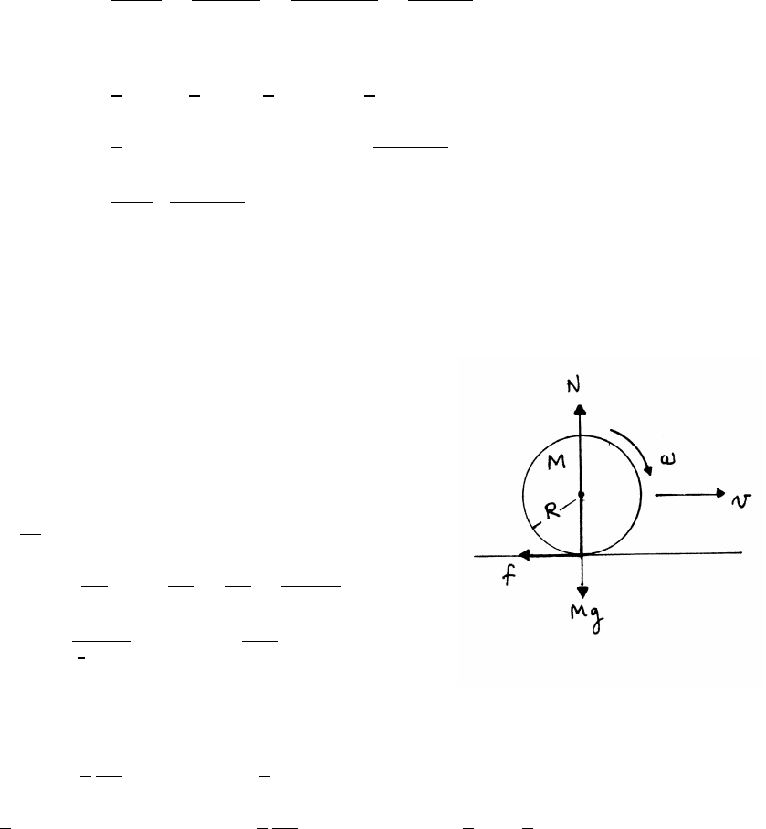
ANGULAR MOMENTUM AND FIXED AXIS ROTATION 125
(b) When the Yo-yo reverses direction at the end of the string, the speed changes
from vfdownward to vfupward. The change in momentum is 2Mvf=the
impulse I=¯
Fstring∆t, where ¯
Fstring is the average force exerted by the string
and ∆tis the time to reverse direction. The Yo-yo is turning at rate ωand it
makes a half turn during the reversal, so that ω∆t=π. Hence
¯
Fstring =2Mvf
∆t=2Mvfω
π=2M(bω)ω
π=2Mbω2
π
Use conservation of mechanical energy to find ω.
Ef=1
2Mv2
f+1
2Iω2=1
2Mb2ω2+1
4MR2ω2=Ei=Mgh
Mgh =1
4M2b2+R2ω2=⇒ω2=4gh
2b2+R2
¯
Fstring =8Mg
π bh
2b2+R2!
7.30 Sliding and rolling bowling ball
Method 1 uses the equations of motion, and
method 2 uses conservation of angular momentum.
Method 1:equations of motion:
N=Mg f =µN=µMg
Mdv
dt =−f=−µMg =⇒v=v0−µgt
R f =Idω
dt =⇒dω
dt =R f
I=µMgR
I
=µMgR
2
5MR2=⇒ω= 5µg
2R!t
Note that vdecreases with time, and ωincreases with time. Rolling begins at tr
when ω(tr)=v(tr)/R.
ω(tr)=5
2
µg
Rtr=⇒v(tr)=5
2µgtr=v0−µgtr
5
2µgtr=v0−µgtr=⇒tr=2
7
v0
µg=⇒v(tr)=v0−2
7v0=5
7v0
continued next page =⇒
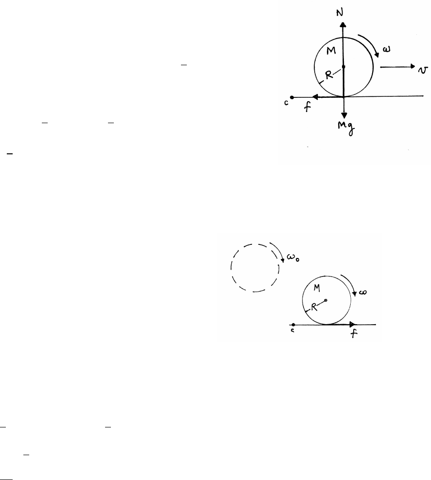
126 ANGULAR MOMENTUM AND FIXED AXIS ROTATION
Method 2: conservation of angular momentum:
Take angular momentum about any point on the alley,
such as cin the sketch.
Li=Mv0R Lf=MvR +Iω=MvR +2
5MR2ω
Rolling starts at t=trwhen ω(tr)=v(tr)/R.
Lf= MR +2
5MR!v(tr)=7
5MRv(tr)=Li=Mv0R
v(tr)=5
7v0
7.31 Skidding and rolling cylinder
The approach to this problem uses
conservation of angular momentum, similar
to Method 2 in problem 7.30.
The friction force fcauses the translational
speed vto increase and the angular speed ωto decrease.
Taking angular momentum about cin the sketch,
Lf=Iωf+MvfR=Li=Iω0
Rolling without skidding begins when vf=Rωf.
Lf=1
2MR2ωf+MR2ωf=3
2MR2ωf
Lf=Li=1
2MR2ω0
ωf=ω0
3

ANGULAR MOMENTUM AND FIXED AXIS ROTATION 127
7.32 Two rubber wheels
As suggested by the lower sketch, the friction force
on each wheel produces a torque. To keep the device
from rotating, the hand must apply an opposite torque.
Thus the angular momentum of the device is not conserved,
so analyze the problem.using equations of motion.
f R =−IAαA(wheel A)
f r =IBαB(wheel B)
ωA=ω0−R
IAZt
0
f dt0ωB=r
IBZt
0
f dt0
ωA=ω0−R
IA
IB
rωB
Sliding continues until the contact points both have the
same linear speed RωA=rωB. This condition gives
ωA=ω0−R2
IA
IB
r2ωA
IA=1
2MR2and IB=1
2mr2. The final angular speed of Ais
ωA=ω0−m
MωA=⇒ωA= ω0
1+m
M!
7.33 Grooved cone and mass
The initial angular momentum of the rotating cone
is along the vertical axis, but there are no external torques,
so the angular momentum of the system remains constant
in magnitude and direction.
(a) The mass gains angular momentum mR2ωas it is
carried around with the cone, so the cone must lose
angular momentum.
Lf=I0ωf+mR2ωf=Li=I0ω0
ωf= I0
I0+mR2!ω0
continued next page =⇒
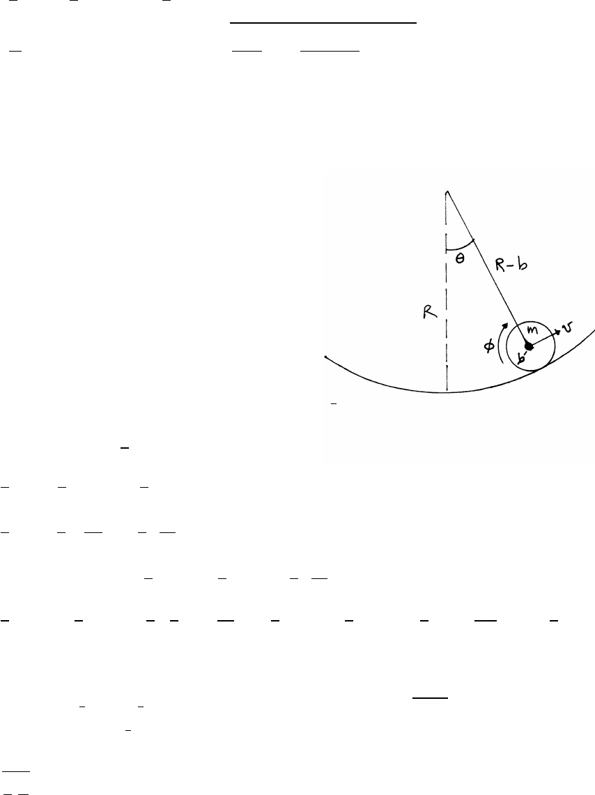
128 ANGULAR MOMENTUM AND FIXED AXIS ROTATION
(b) There are no dissipative forces, so mechanical energy is conserved. The mass
has gravitational potential energy and kinetic energy, and the cone has rota-
tional kinetic energy.
Ef=1
2I0ω2
f+1
2mv2
f=Ei=1
2I0ω2
0+mgh
v2
f=I0
mω2
0−ω2
f+2gh =⇒vf=sI0ω2
0
m 1−I0
I0+mR2!2
+2gh
7.34 Marble in dish
Energy methods are a good way to solve this problem.
One element of this approach is to express all the
energy contributions in terms of a single variable, here θ.
The marble has gravitational potential energy Epot,
translational kinetic energy Etrans, and rotational kinetic
energy Erot. Take the gravitational potential energy
of the marble to be 0 at the bottom of the dish (θ=0).
Epot =mg(R−b)(1 −cos θ)
Taking Rb(the sketch exaggerates b), and cos θ≈1−1
2θ2
Epot ≈mgR(1 −cos θ)≈1
2mgRθ2
Etrans =1
2mv2=1
2m(Rω)2=1
2mR2˙
θ2
Erot =1
2I˙
φ2=1
2I R˙
θ
b!2
=1
2IR2
b2˙
θ2
Etot =Epot +Etrans +Erot =1
2mgRθ2+1
2mR2˙
θ2+1
2IR2
b2˙
θ2
=1
2mgRθ2+1
2mR2˙
θ2+1
2 2
5mb2!R2
b2˙
θ2=1
2mgRθ2+1
2mR2 1+2
5!˙
θ2=mR
2 gθ2+7
5R˙
θ2!(1)
There are several ways to find the angular frequency of small oscillations from Eq.
(1). One way is to note the analogy between Eq. (1) and the mechanical energy of a
harmonic oscillator 1
2m0˙x2+1
2k0x2, which has oscillation frequency √k0/m0. From
Eq. (1), k0∼gand m0∼7
5R, so the corresponding angular frequency ωmof the
marble is
ωm=r5
7
g
R
continued next page =⇒

ANGULAR MOMENTUM AND FIXED AXIS ROTATION 129
Another approach is to note that Eq. (1) is a quadratic energy form (Sec. 6.2.1),
where it is shown that ω=√A/Bfor a quadratic energy form 1
2B˙q2+1
2Aq2, so that
ωm=r5
7
g
R
Finally, by conservation of mechanical energy, Etot is constant, so taking the deriva-
tive of Eq. (1) with respect to θgives
0=dEtot
dθ=7
5R˙
θ¨
θ+gθ˙
θ=7
5R¨
θ+gθ=⇒ωm=r5
7
g
R
7.35 Cube and drum
The cube is rocking, not sliding, on the drum.
At the instant shown in the sketch, the pivot
point is n. Because the cube is always tangential
to the drum, the angle subtended from the
center of the drum is equal to the cube’s
angle of rotation. The cube is stable if
the torque created by a small rotation is
a negative ”restoring” torque tending to
bring the cube back to equilibrium. The horizontal
displacement of the center of mass must be less
than the displacement of n.
The displacement aof the center of mass is
a=L
2sin θ
The displacement bof the contact point is
b=Rsin θ
For stability,
a<b=⇒L<2R
continued next page =⇒
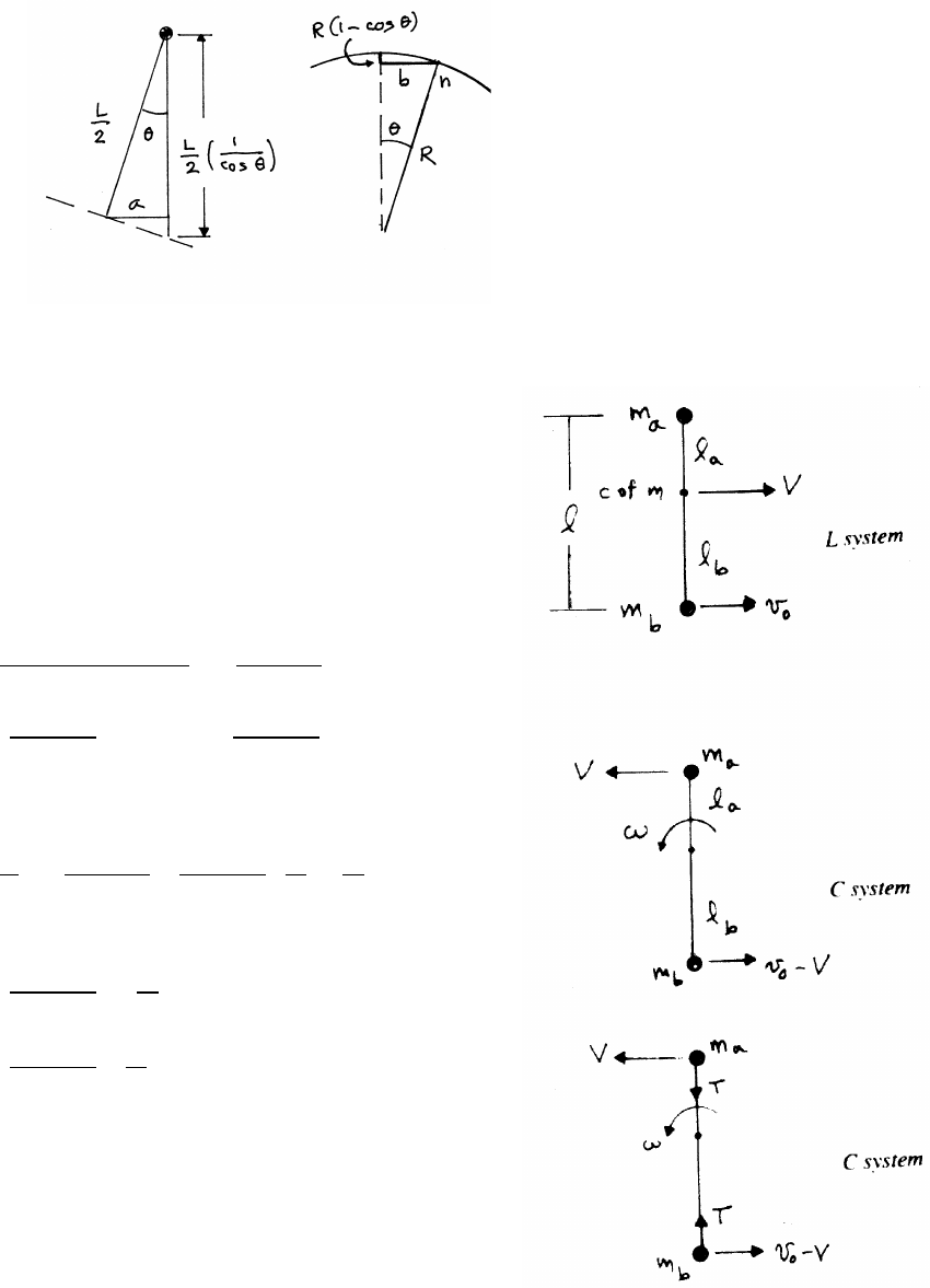
130 ANGULAR MOMENTUM AND FIXED AXIS ROTATION
The cube in the sketch is stable. Put descriptively, the cube is stable if the line of
the weight vector falls within the Rθof the cylinder’s center,
7.36 Two twirling masses
No external forces act horizontally, so the
system is isolated in the horizontal plane.
The motion is described most naturally as a
combination of a uniform translation of the center
of mass and a uniform rotation about the center of mass.
The speed Vof the center of mass is
V=mava(0) +mbvb(0)
ma+mb
= mb
ma+mb!v0
la= mb
ma+mb!l lb= ma
ma+mb!l
The sketches show the speeds in the C system.
ω=V
la
= mb
ma+mb! ma+mb
mb!v0
l=v0
l
T=malaω2
= mamb
ma+mb!lv0
l2
= mamb
ma+mb! v2
0
l!
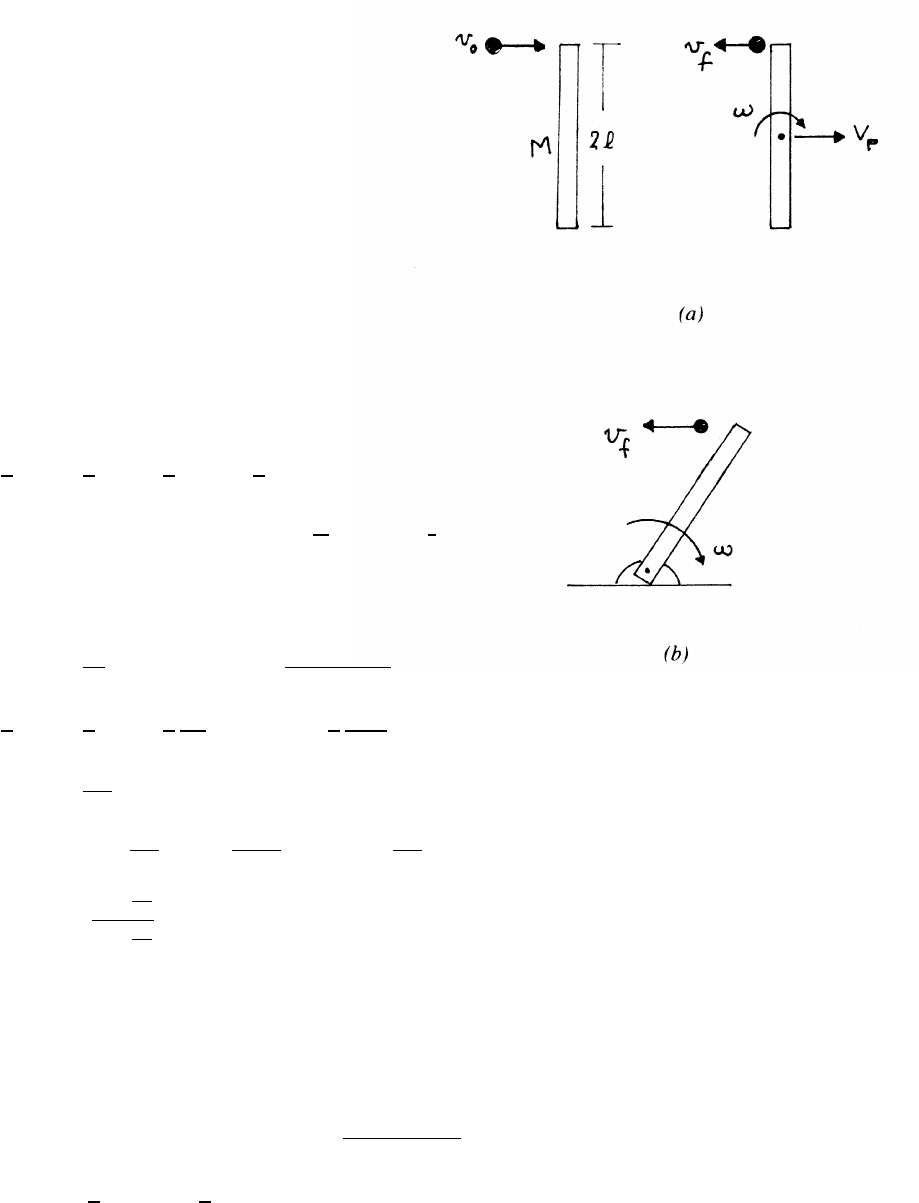
ANGULAR MOMENTUM AND FIXED AXIS ROTATION 131
7.37 Plank and ball
(a) The system is isolated in the horizontal
plane. Linear momentum, angular momentum,
and mechanical energy are conserved.
linear momentum:
mv0=−mvf+MVp
angular momentum:
mv0l=−mvfl+I0ω
mechanical energy:
1
2mv2
0=1
2mv2
f+1
2MV2
p+1
2I0ω2
I0about the plank’s center is I0=1
12 M(2l)2=1
3Ml2.
Solving for the three unknowns vf,Vp, and ω,
Vp=m
M(v0+vf)ω=ml(v0+vf)
I0
1
2mv2
0=1
2mv2
f+1
2
m2
M(v0+vf)2+1
2
m2l2
I0
(v0+vf)2
v2
0−v2
f=4m
M(v0+vf)2
0= 1+4m
M!v2
f+ 8mv0
M!vf− 1−4m
M!v2
0
vf=
1−4m
M
1+4m
M
v0
(b) Because of the forces at the pivot, linear momentum
is not conserved, but angular momentum and mechanical energy are conserved.
angular momentum about the pivot:
mv0(2l)=−mvf(2l)+Ipω=⇒ω=2ml(v0+vf)
Ip
Ip=1
3M(2l)2=4
3Ml2
continued next page =⇒
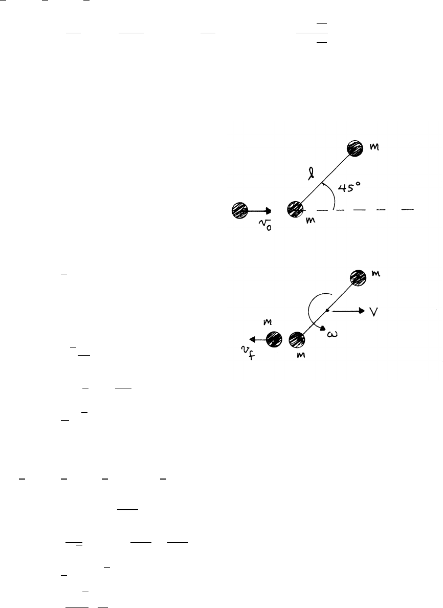
132 ANGULAR MOMENTUM AND FIXED AXIS ROTATION
mechanical energy:
1
2mv2
0=1
2mv2
f+1
2Ipω2
0= 1−3m
M!v2
f+ 6mv0
M!vf− 1−3m
M!v2
0=⇒vf=
1−3m
M
1+3m
M
v0
7.38 Collision on a table
The system is isolated in the horizontal
plane. Linear momentum, angular momentum,
and mechanical energy are conserved.
linear momentum:
mv0=−mvf+2mV
V=1
2(v0+vf)
angular momentum about the rod’s midpoint:
mv0lsin (45◦)=−mvflsin (45◦)+I0ω
v0+vf=√2I0
mlω
I0=2m l
2!2
=ml2
2
v0+vf=l
ω√2
mechanical energy:
1
2mv2
0=1
2mv2
f+1
2(2m)V2+1
2I0ω2
v2
0=v2
f+2V2+l2ω2
2
= lω
√2−v0!2
+l2ω2
4+l2ω2
2
0=5
4lω−√2v0
ω=
4√2
5
v0
l
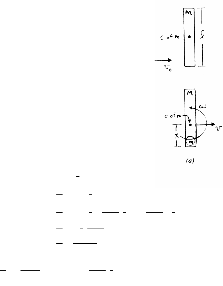
ANGULAR MOMENTUM AND FIXED AXIS ROTATION 133
7.39 Child on ice with plank
(a) Linear momentum and angular momentum are conserved
in the inelastic collision, but mechanical energy is not.
After the inelastic collision, the new center of mass
of the child-plank system translates with velocity v
parallel to the child’s initial velocity, by conservation
of linear momentum. The system rotates about the new
center of mass with angular frequency ω.
The speed vof the new center of mass is given by
v=m
m+Mv0
Angular momentum is best calculated about the
new center of mass, which is located a distance x
from the end of the plank, as indicated in the sketch.
x=M
m+Ml
2
The initial angular momentum about xis Li=mv0x
The final angular momentum is Lf=Ixω.
Ix=I0+M"l
2−x#2
+mx2
=1
12 Ml2+M"l
2−x#2
+mx2
=1
12 Ml2+M"l
2−M
m+Ml
2#2
+mM
m+M2 l
2!2
=1
12 Ml2+1
4mM
m+Ml2
=1
12 Ml2(M+4m)
(m+M)
Lf=Ixω=Li=mv0x
1
12 Ml2 M+4m
m+M!ω=mv0x=mv0M
m+Ml
2
ω=6m
M+4mv0
l
continued next page =⇒
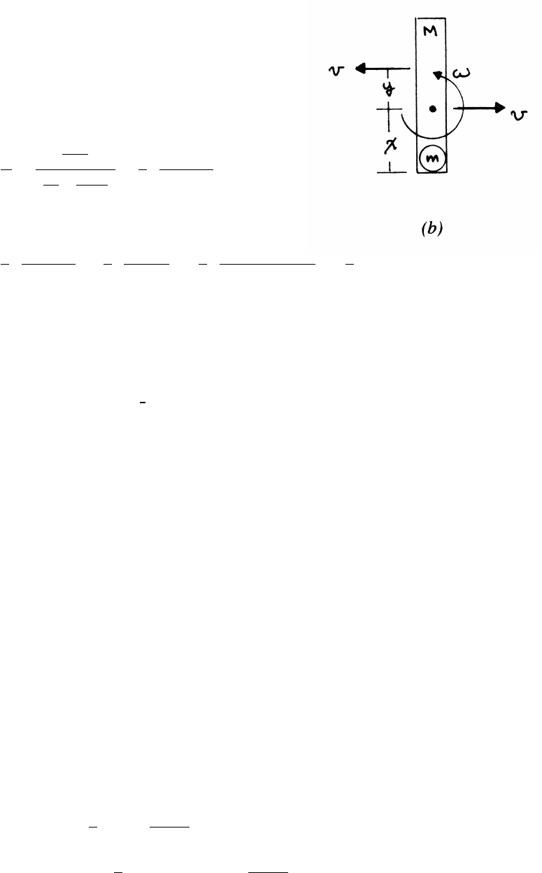
134 ANGULAR MOMENTUM AND FIXED AXIS ROTATION
(b) The point instantaneously at rest is moving with speed v
(due to the rotation) antiparallel to the translation of
the center of mass, as shown in the sketch, so that its
instantaneous speed is v−v=0. Let the point be a
distance yabove the center of mass, so v=yω.
y=v
ω=mv0
m+M
6v0
l m
M+4m=l
6 M+4m
M+m!
The distance from the child is y+x.
y+x=l
6 M+4m
M+m!+l
2M
M+m=l
6 M+4m+3M
M+m!=2
3l
7.40 Toothed wheel and spring
The initial mechanical energy is 1
2kb2. Mechanical energy is conserved until x=l,
but at that point there is an inelastic collision with the track and some mechani-
cal energy is dissipated. Linear momentum is also not conserved in the collision,
because of the force exerted at the point of impact.
The force at the point of impact exerts no torque about that point, but the wheel
has angular momentum of translation. At x=l, the spring force is 0, so the
spring exerts no torque. Hence, angular momentum is conserved in the collision.
When the wheel engages the toothed track, it is constrained to move with v=Rω.
(a) Before the sliding wheel collides with the track, it is not rotating about its center
and therefore has zero angular momentum of rotation. However, it has angular
momentum MvR from translation of the axis (refer to Note 7.2 in the text for
a summary). Sketch (a) shows the system at the start, and at the instant just
before the collision with the track.
Immediately after the collision, the wheel rotates at rate ωfabout the contact
point. The moment of inertia about the center of mass (the wheel’s center)
is I0=MR2, and the moment of inertia Ipabout the contact point is Ip=
I0+MR2=2MR2. Just before and after the collision,
Li=MRviEi=1
2Mv2
i=L2
i
2MR2
Lf=2MR2ωfEf=1
2Ipω2
f=MR2ω2
f=
L2
f
4MR2
continued next page =⇒
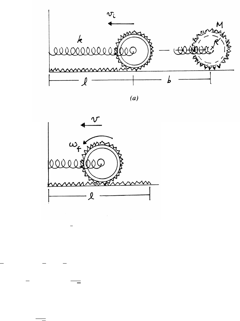
ANGULAR MOMENTUM AND FIXED AXIS ROTATION 135
Because Lf=Li,Ef=1
2Ei.
Mechanical energy Efis conserved following the collision, when the wheel is
on the track. The wheel comes to rest when the spring is compressed to b0.
1
2kb02=Ef=1
2Ei=1
4kb2
b02=1
2b2=⇒b0=1
√2b
The closest approach to the wall is
l−b0=l−1
√2b
continued next page =⇒
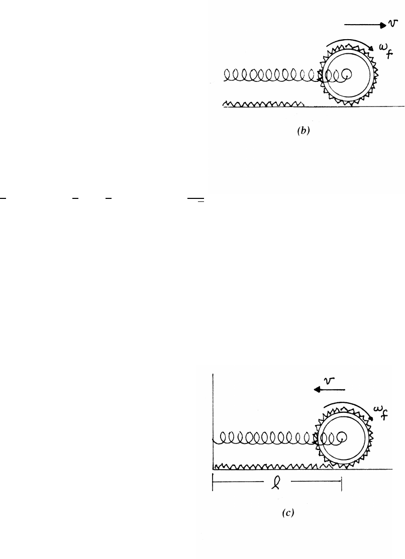
136 ANGULAR MOMENTUM AND FIXED AXIS ROTATION
(b) When the wheel returns to the initial point of contact, its velocity and angular
velocity are reversed, as shown in sketch (b). Mechanical energy Efis con-
served as the wheel moves offthe track onto the smooth surface. The velocity v
changes with time because of the spring force, but the angular velocity remains
constant, because there is no torque on the wheel about its center of mass.
The wheel moves outward away from the wall until the spring is extended be-
yond lby an amount b00, where
1
2kb002=Ef=1
2Ei=1
4kb2=⇒b00 =1
√2b
(c) When the wheel returns to the point of contact for the second time, its angular
momentum of translation is Ltrans =mvfRand its angular momentum of rota-
tion is Lrot =I0ωf=mR2ωf=mv fR. Thus the mechanical energy is equally
divided between translation and rotation. As shown is sketch (c), Lrot has re-
versed its direction, so the total angular momentum is 0, and it remains 0 after
the second collision. The wheel is therefore at rest, v=0. The second collision
has dissipated all the remaining mechanical energy!
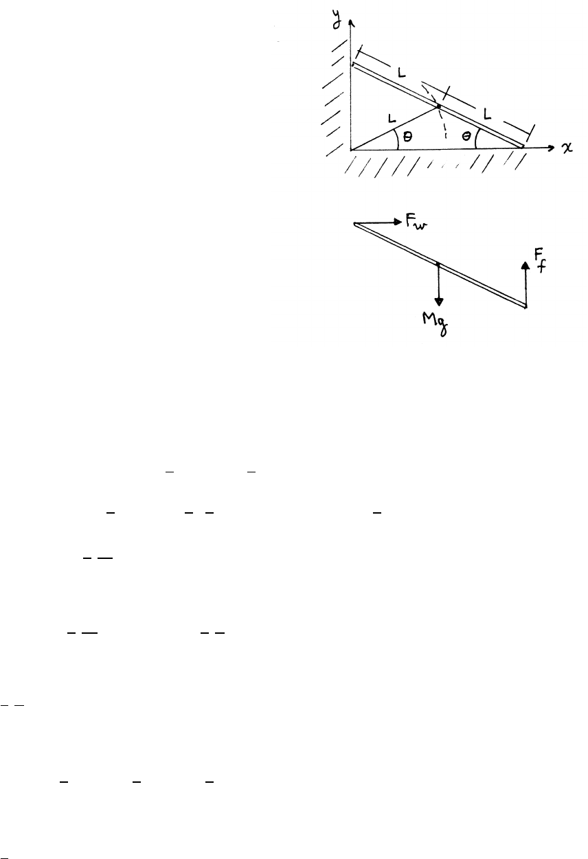
ANGULAR MOMENTUM AND FIXED AXIS ROTATION 137
7.41 Leaning plank
As long as the plank is in contact with the wall,
the coordinates of its center of mass are
x=Lcos θy=Lsin θ
x2+y2=L2(cos2θ+sin2θ)=L2
Until contact with the wall is lost, the center
of mass moves on a circular path of radius L,
as indicated in the upper sketch.
Because the wall and floor are frictionless, the
force Fwexerted by the wall on the plank and
the force Ffexerted by the floor are normal to
the surfaces, as shown in the lower sketch.
The plank loses contact with the wall when
Fw=0, or, equivalently, when ¨x=Fw/M=0.
x=Lcos θ˙x=−Lsin θ˙
θ
¨x=−Lcos θ˙
θ2−Lsin θ¨
θ=0=⇒˙
θ2=−tan θ¨
θ(1)
There are no dissipative forces, so mechanical energy Eis conserved. Let y0be the
initial height of the center of mass above the floor.
Ei=Mgy0=Ef=Mgy +1
2M(L˙
θ)2+1
2I0˙
θ2
Mgy0=MgL sin θ+1
2M(L˙
θ)2+1
2 1
3ML2!˙
θ2=MgL sin θ+2
3ML2˙
θ2
y0=Lsin θ+2
3
L2
g˙
θ2(2)
Differentiating Eq. (2),
0=Lcos θ˙
θ+4
3
L2
g˙
θ¨
θ=⇒¨
θ=−3
4
g
Lcos θ
Using Eq. (1),
˙
θ2=3
4
g
Lsin θ(3)
Substituting Eq. (3) in Eq. (2),
y0=Lsin θ+1
2Lsin θ=3
2Lsin θ=3
2y
so the plank loses contact with the wall at height
y=2
3y0
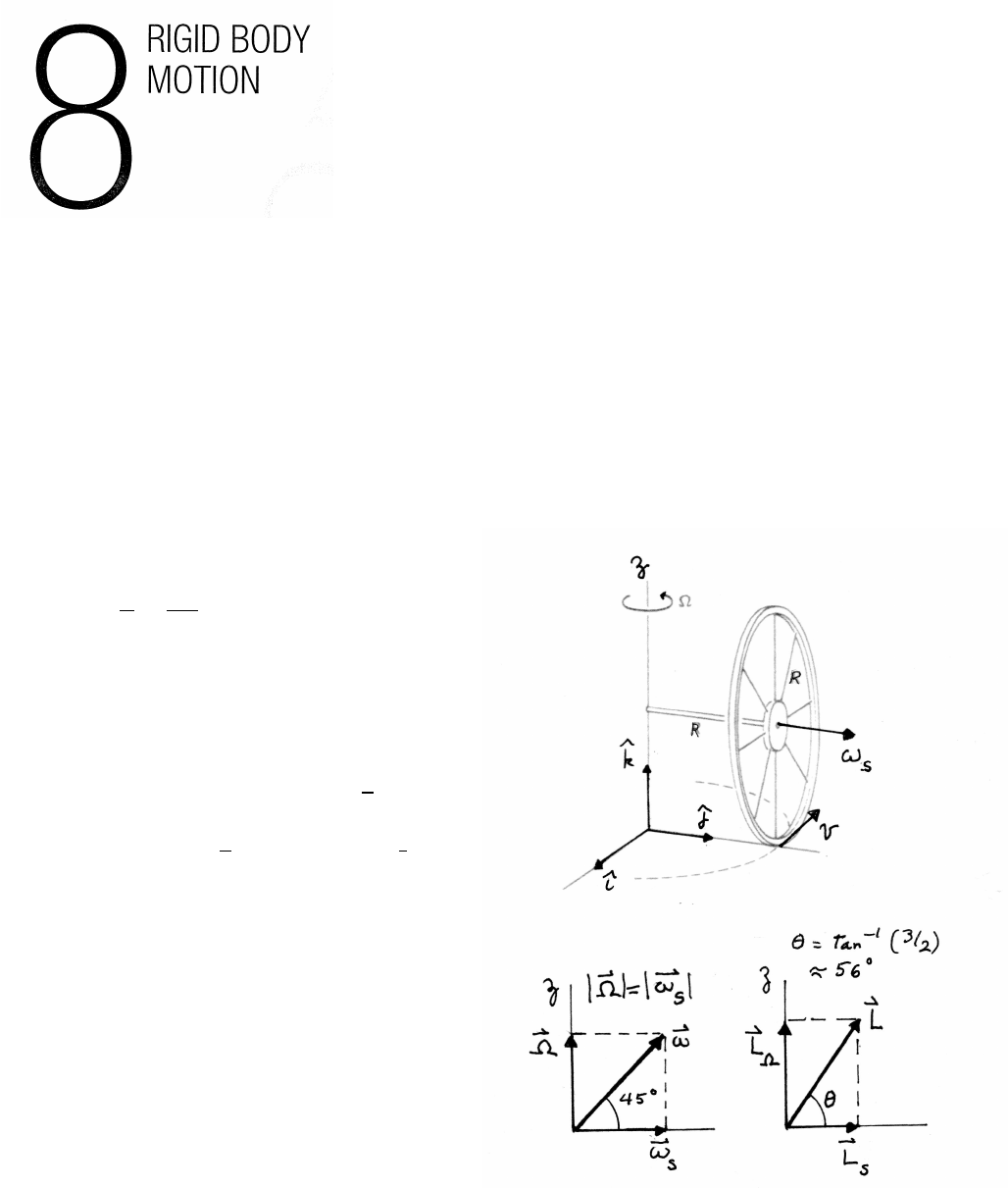
8.1 Rolling hoop
(a)
ωs=v
R=ΩR
R= Ω
ω=ωs+ Ω = Ω(ˆ
j+ˆ
k)
(b)
L=Ls+Lω=Isωs+IzΩ
Is=MR2Iz=I0+MR2=3
2MR2
L=MR2 ωs+3
2Ω!=MR2Ω(ˆ
j+3
2ˆ
k)
The lower sketches show that ωand Lare not parallel.
We treated Las the angular momentum of a body
with moment of inertia from the parallel axis
theorem. Lcan also be viewed as the sum of
orbital angular momentum MR2Ωplus spin
angular momentum (1/2)MR2Ω.
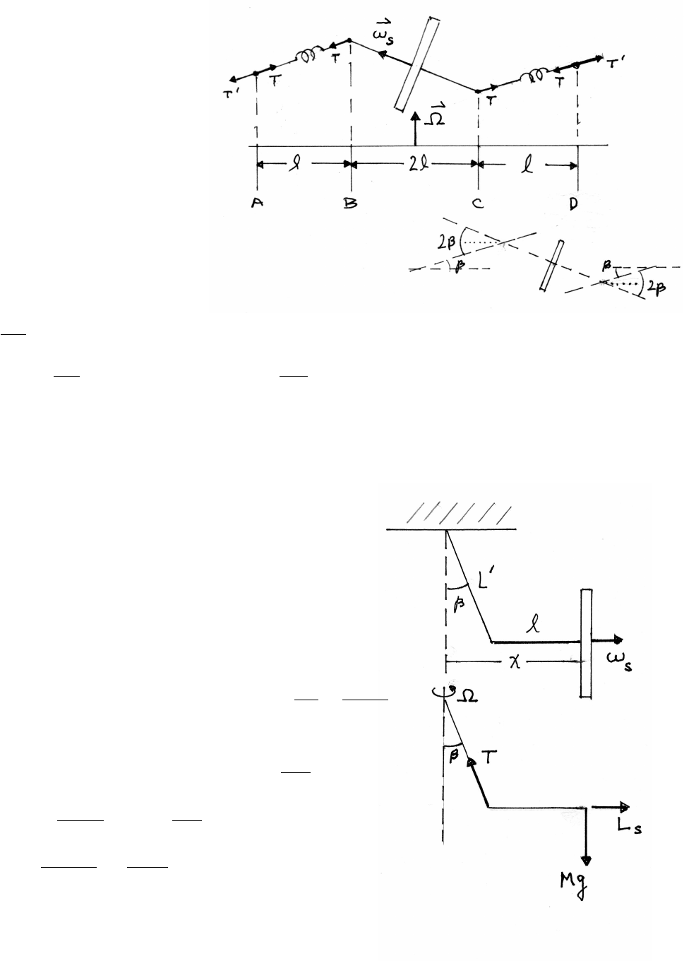
RIGID BODY MOTION 139
8.2 Flywheel on rotating table
The angle of tilt is assumed
to be small so that sin x≈x.
The torque can be calculated
from the forces Tat either
end of the axle (points B, C)
or from the forces T0=Tat
either end of the spring
suspension (points A, D).
τBC =2l(Tsin 2β)≈4lT β
τAD =4l(Tsin β)≈4lT β
The spin angular momentum Ls=I0ωs
is a vector of constant magnitude rotating at angular
speed Ω. From Secs. 1.10.1 and 8.3,
dLs
dt
= ΩLs
τ=dLs
dt =⇒4lT β= ΩLs=⇒β=ΩLs
4lT
8.3 Suspended gyroscope
Note that in this problem, βand Ω
are both unknown quantities,
Assume βis small, so that sin β≈β
and cos β≈1. Hence x=l+L0sin β≈l+L0β.
equations of motion:
Mg =Tcos β≈T
MxΩ2=Tsin β≈Tβ=⇒Ω2=Tβ
Mx =gβ
l+L0β
torque :
T l =˙
Ls= ΩI0ωs=⇒Ω = Mgl
I0ωs
gβ
l+L0β= Ω2= Mgl
I0ωs!2
β 1−M2gl2L0
I2
0ω2
s!=M2gl3
I2
0ω2
s
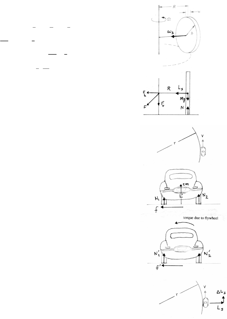
140 RIGID BODY MOTION
8.4 Grain mill
Fis the force exerted by the pivot. The millstone
rolls without slipping, so ωsb= ΩR.
Ls=I0ωs=1
2Mb2R
bΩ=1
2MbRΩ
dLs
dt =ωLs=1
2MbRΩ2
τpivot =(N−Mg)R=dLs
dt =1
2MbRΩ2
N=Mg 1+1
2bΩ2
g!
The millstone exerts a downward force N>Mg
due to the downward force of the pivot: N=Mg +Fv.
8.5 Automobile on a curve
(a) The radial equation of motion is f=MV2/r. Without
the flywheel, the torque due to friction fis balanced by the
torque due to the unequal loading N1and N2. For equal
loading N0
1=N0
2, these forces produce no torque.
The flywheel thus needs to produce a counterclockwise
torque on the car to balance the clockwise torque
from f0. The torque on the flywheel by
the car must therefore be clockwise, so that the
spin angular momentum Lsmust increase
in the forward direction of the car’s motion.
If the car turns in the opposite direction, both the torque and
the direction are reversed, so equal loading remains satisfied.
One can also argue that the torque on the total car-flywheel
system by the friction force f0must cause Lsto increase in
the forward direction by precessing at the rate Ω = V/r,
which can be achieved by mounting the flywheel’s axis
transverse to the car’s motion (parallel to the
car’s axles). For Lsin the horizontal plane,
the flywheel’s disk must be in the vertical plane.
continue next page =⇒
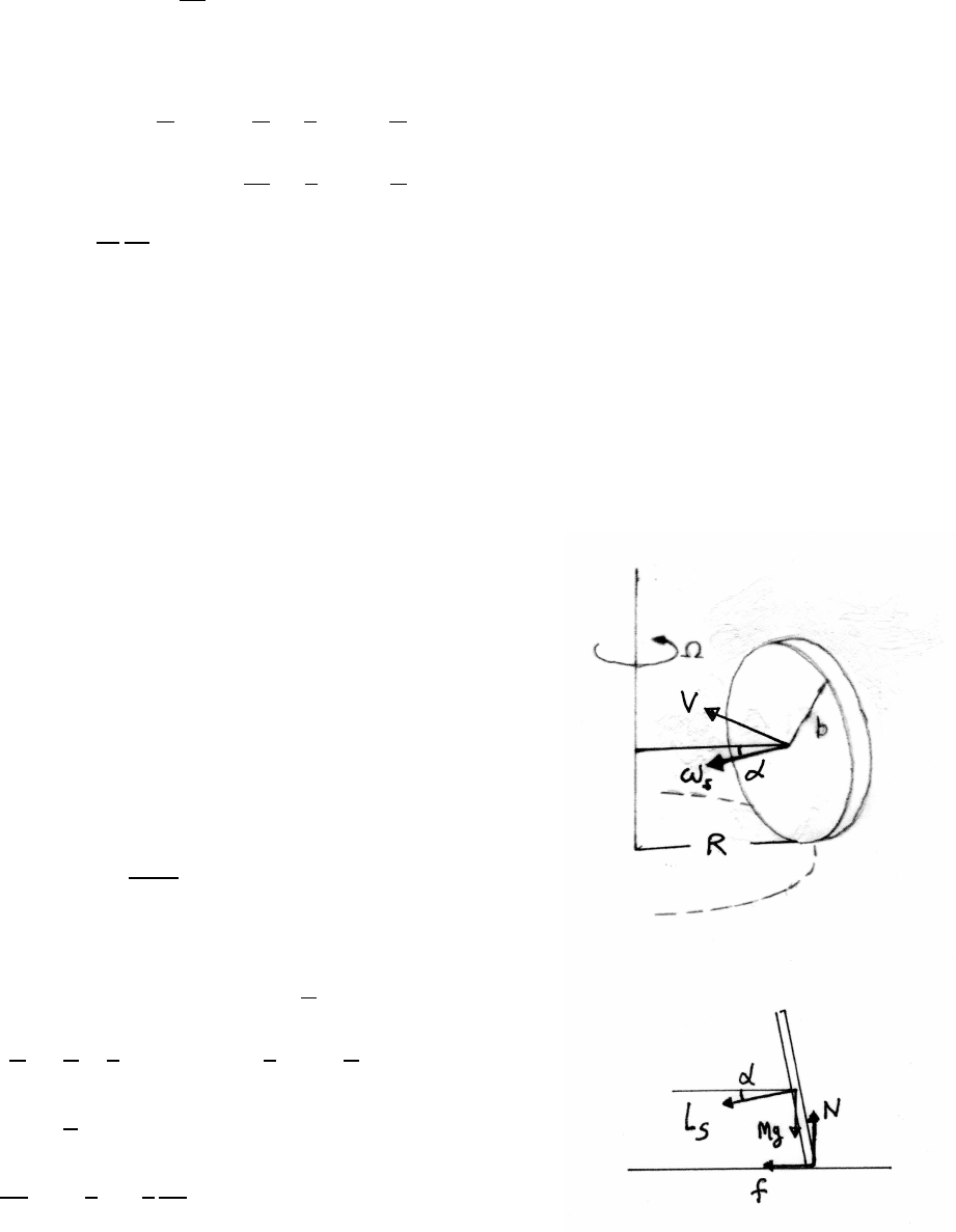
RIGID BODY MOTION 141
(b) The torque τroad due the road’s friction force f0is
τroad =L0f0=L0MV2
r
The torque τf lywheel due to the flywheel is
τf lywheel =LsΩ = Łs
V
r=I0ωs
V
r=1
2mR2ωs
V
r
τroad =τf lywheel =⇒L0MV2
r=1
2mR2ωs
V
r
ωs=2L0M
m
V
R2
The result does not include the radius rof the turn, but ωsmust be kept proportional
to V.
8.6 Rolling coin
As the coin rolls with speed Varound the circle of
radius R, it rotates around the vertical at rate Ω = V/R.
This rotation is caused by precession of of its spin angular
momentum due to the torque induced by the tilt. For rolling
without slipping, V=bωs, so Ω = ωs(b/R).
The coin is accelerating, so take torques about the
center of mass. From the force diagram,
τcm =f b cos α−Nb sin α
N=Mg f =MV2
R
The equation of motion for Lsis
τcm = ΩLscos α= ΩI0ωscos α=ω2
s
b
RI0cos α
=V
b2 b
R! 1
2Mb2!cos α=1
2MV2 b
R!cos α
=MV2 b
R!cos α−Mgb sin α
tan α=V2
Rg 1−1
2!=1
2
V2
Rg

142 RIGID BODY MOTION
8.7 Suspended hoop
(a) The spin angular momentum is Ls=I0ωs=MR2ωs.
The equation of motion for Lsis
τ=ωsLssin β≈ωsLsβ(directed out of the paper)
Ls=I0ωs=MR2ωs
Tcos α=Mg =⇒τ=RT cos α≈MgR
MgR =ωsLsβ=MR2ωs2β=⇒β=g
Rωs2
(b) equation of motion: (the cm moves in a loop of radius r)
Tsin α=Mrωs2=⇒gtan α=rωs2
r=g
ωs2tan α
(c) To gauge the validity of the solution,. compare the torque τcm needed to spin
the center of mass with the torque τhoop needed to spin the hoop.
τcm =Mgr τhoop =MgR =⇒τcm
τhoop
=r
R=gtan α
Rω2
The solution is therefore only valid for large ω, so that τcm can be neglected. The
criterion is equivalent to being able to twirl a lariat vertically as well as horizontally.
8.8 Deflected hoop
(a) The force Fdue to the stick and the friction force fexert a
horizontal torque directed into the paper. The hoop is vertical,
so gravity exerts no torque. The blow by the stick is short,
so the peak of force Fis large; fcan be neglected
during the time of impact. The torque τinto the paper is then Fb.
The spin speed for rolling without slipping is ωs=V/band
the spin angular momentum is Ls=I0ωs=Mb2ωs=MVb.
The equation of motion for Lsis
τ=LsΩ =⇒Fb =MVbΩ
where Ω = dΦ/dt is the angular speed around the vertical axis.
Ω = dΦ
dt =F
MV =⇒∆Φ = ZF
MV dt0=1
MV ZFdt0=I
MV
continued next page =⇒
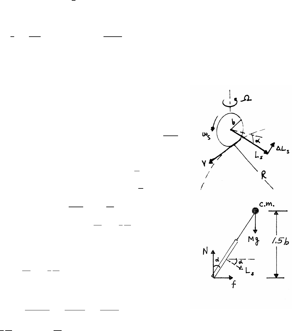
RIGID BODY MOTION 143
(b) The angular momentum around the vertical axis is
Lvertical =IΦΩ = 1
2Mb2Ω
For the solution in (a) to be valid, Lvertical Ls.
1
2Mb2F
MV MVb =⇒F2MV2
b
8.9 Stability of a bicycle
The torque τhabout the center of mass is
into the paper.
τh=N(1.5b) tan α−f(1.5b)
=Mg(1.5b) tan α−(1.5b)MV2
R
The total spin angular momentum (two wheels) is
Ls=2I0ωs=2mb2V
b=2mbV
τh=LhΩ = Lscos αV
R
Mg(1.5b) tan α−(1.5b)MV2
R=2mbV2
Rcos α
tan α=V2
Rg 1+4
3
m
Mcos α!
Because m/M1, the second term in parentheses is
a small correction and it is adequate to take cos α≈1.
tan α≈V2
Rg 1+4
3
m
M!
Converting units, using g=32 ft/s2,
V= 20 miles
hour !× 5280 ft
mile !× 1 hour
3600 s!=29.3 ft/s
4
3
m
M=0.048 V2
Rg =0.268
tan α=(0.268)(1.048) =0.28
α≈16◦
If spin is neglected, the term in m/Mshould be omitted. Then α≈15◦. The spin-
ning wheels increase the tilt angle by only about a degree, not a substantial effect.
Without a rider, Mis smaller and αis larger.

144 RIGID BODY MOTION
8.10 Measuring latitude with a gyro
The gyro’s disk is spinning with angular speed ωs.
(a) If the gyro’s spin angular momentum Lsis parallel
to the Earth’s angular velocity Ωe(upper sketch),
Lsdoes not change direction as the Earth rotates, and the
axis of the gyro remains stationary. Its axis is then at the latitude
angle λwith respect to the local horizontal, which lies along the
meridian in the north-south (N-S) direction.
(b) The magnitude of Lsis constant, but there are two different ways
to change the angular momentum of the gyro disk. Let I0be
the moment of inertia about the gyro’s spin axis, Ls=I0ωs, and let
I⊥be the moment of inertia about the horizontal a−baxis.
Let Φbe the angle between Lsand Ωe, (lower sketch).
(1) rotation of Lsabout Ωe:
The component of Lsperpendicular to Ωeis Lssin Φ, so
rate of change (1) =Lssin ΦΩe≈LsΩeΦ = I0ωsΩeΦ
(2) rotation of the gyro disk about a-b by Φ:
angular momentum about a-b :=I⊥
dΦ
dt
rate of change (2) :=I⊥
d2Φ
dt2
The two contributions are parallel to the a−baxis, and add. There is no applied
torque, so the net rate of change is 0.
I⊥
d2Φ
dt2+(I0ωsΩe)Φ = 0
This is the equation for SHM, with oscillation frequency ωosc and period Tosc.
ωosc =rI0ωsΩe
I⊥
Tosc =2π/ωosc
I⊥=I0/2 for a thin disk =⇒ωosc =p2ωsΩe
ωs=4.0×10⁴rpm = (2π) 4.0×10⁴rad
min !× 1 min
60 s !=4.19 ×10³rad/s
Ωe= 2πrad
day !× 1 day
8.64 ×10⁴s!=7.27 ×10⁻⁵rad/s
ωosc =p(2)(4.19 ×10³)(7.27 ×10⁻⁵)=0.78 rad/sTosc =2π
ωosc
=8.1 s
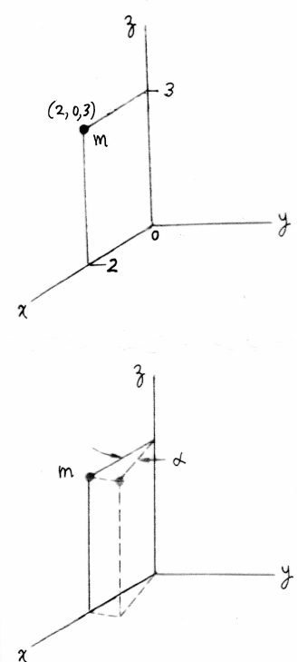
RIGID BODY MOTION 145
8.11 Tensor of inertia
(a)
Ixx =m(y2+z2)=m((0)2+(3)2)=9m
Iyy =m(x2+z2)=m((2)2+(3)2)=13m
Izz =m(x2+y2)=m((2)2+(0)2)=4m
Ixy =Iyx =−m(xy)=−m(2)(0) =0
Iyz =Izy =−m(yz)=−m(0)(3) =0
Ixz =Izx =−m(xz)=−m(2)(3) =6m
In matrix form,
˜
I=m
9 0 −6
0 13 0
−6 0 4
(b) To order α2,
x=2 cos α≈2−α2y=2 sin α≈2αz=3
˜
I0=m
9+4α2−4α−6+3α2
−4α13 −4α2−6α
−6+3α2−6α4
Comparing with part (a), note that the moments of inertia
(along the main diagonal of the matrix) vary only as α2,
but some of the products of inertia (off-diagonal elements)
can vary linearly with α.
When making such approximations, be sure to include all terms
up to the highest order retained. For example,
I0
zz =m[x2+y2]=m[(2 −α2)2+(2α)2]≈m[4 −4α2+4α2]=4m
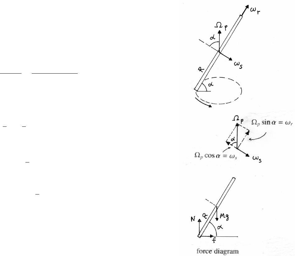
146 RIGID BODY MOTION
8.12 Euler’s disk
The contact point moves on the surface in a circle of radius
Rcos α, with speed V=(Rcos α)(Ωp. The disk is
assumed to roll without slipping, so Rωs=V=(Rcos α)Ωp.
equations of motion:
0=N−Mg =⇒N=Mg
f=MV2
Rcos α=M(Rcos α)2Ω2
p
Rcos α=MR cos αΩ2
p
The total angular velocity is Ωp+ωs=ωr. As shown
in the sketches, ωrlies along the axis from the contact point to
the center of mass. The moment of inertia along this axis is
I⊥=1
2I0=1
4MR2
The spin angular momentum is
Ls=I⊥ωr=1
4MR2Ωpsin α
The horizontal component of the spin angular momentum is
Lh=Lscos α=1
4MR2cos αsin αΩp
torque about the cm (positive is into the paper):
τcm =NR cos α−f R sin α=MgR cos α−MR2cos αsin αΩ2
p
=MR cos αg−Rsin αΩ2
p
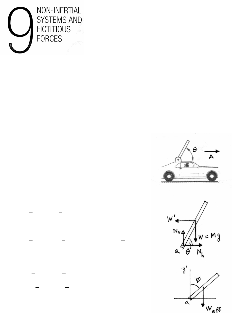
9.1 Pivoted rod on car
The force diagram (middle sketch) is in the
accelerating system. W0is the fictitious
force W0=−MA, so W0is drawn
opposite to A.
equations of motion:
Nv+W=0Nh+W0=0
(a) The torque about the pivot ais
τa=L
2cos θW−L
2sin θW0
For equilibrium in the accelerating system, τa=0.
0=L
2cos θMg −L
2sin θMA =⇒tan θ=g
A
For equilibrium in any system, the torque about any point
must vanish. For example, the torque about the center of mass is
τcm =L
2cos θNv−L
2sin θNh
=−L
2cos θW+L
2sin θW0=0
using the equations of motion.
continued next page =⇒
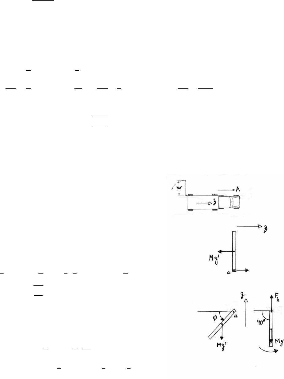
148 NONINERTIAL SYSTEMS AND FICTITIOUS FORCES
(b) Introduce a coordinate system with z0along the equilibrium position of the
board. (z0is drawn vertically in the sketch for clarity.)
The effective acceleration due to gravity is
ge f f =pg2+A2
so the effective weight force is
We f f =Mge f f
For small displacements, the torque is
τ=L
2sin φMge f f ≈l
2Mge f f φ
Ia
d2φ
dt2=L
2Mge f f φ=⇒1
12 ML2d2φ
dt2−L
2Mge f f φ=0=⇒d2φ
dt2−6ge f f
Lφ=0
The motion is exponential:
φ=φ0e±γtwhere γ=r6ge f f
L
9.2 Truck door
Consider the motion of the door in a system accelerating
with the truck. The door effectively ”falls” from rest in a
gravitational field g0=A, in the direction shown
in the sketch. The sketches with zturned 90◦shows
the door ”falling” with weight force Mg0.
(a) Use conservation of mechanical energy. The door’s center
of mass falls a distance w/2 as it gains rotational
kinetic energy.
1
2Ia˙
φ2=Mg0w
2=⇒1
2 1
3Mw2!˙
φ2=MAw
2
˙
φ=r3A
w
(b)
The equation of motion (see force diagram) is
Fh−Mg0=Mw
2˙
φ2=Mw
2 3A
w!
Fh=Mg0+3
2MA =MA +3
2MA =5
2MA
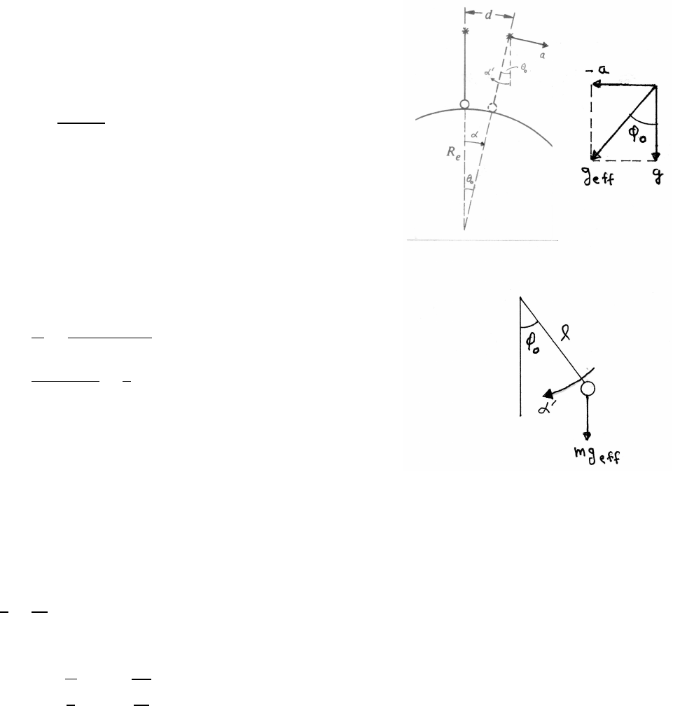
NONINERTIAL SYSTEMS AND FICTITIOUS FORCES 149
9.3 Pendulum on moving pivot
In the sketches, αand α0are angular accelerations
in the earthbound system and in the accelerating
system respectively.
In the accelerating system, the pendulum swings under an
effective gravitational acceleration ge f f , where
ge f f =pg2+a2
The pendulum begins to swing from an initial angular
displacement φ0=arctan a/g, as indicated in the sketch.
Consequently, ”down” in the accelerating system differs
from ”down” in the earthbound system by φ0.
If the simple pendulum has length land mass m, the
torque in the accelerating system is initially
τ0=mge f f lsin φ0
α0=τ0
I0
=mge f f lsin φ0
ml2
=ge f f sin φ0
l=a
l
using ge f f sin φ0=a(see the top right-hand sketch)
In order for the pendulum to point continually down
(toward the center of the Earth), its angular acceleration α0
must be equal and opposite to the angular acceleration αof the
point of support with respect to the center of the Earth, α=a/Re,
α0=α
a
l=a
Re
=⇒l=Re
The period of this pendulum is
T=2πsl
g=2πsRe
g=84 minutes
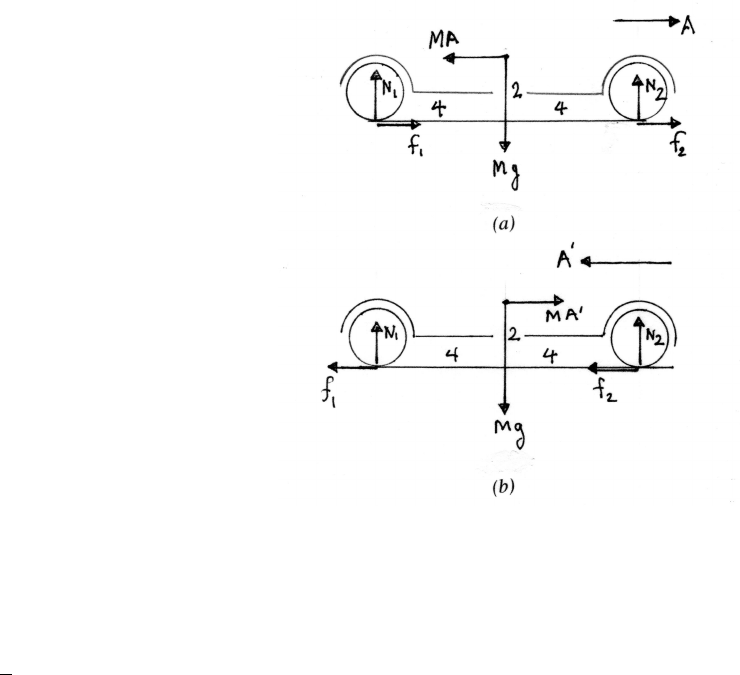
150 NONINERTIAL SYSTEMS AND FICTITIOUS FORCES
9.4 Weight on a car’s wheels
In this problem, the forces on the tires due to
the road are the normal forces N1and N2, and the
friction forces f1and f2. In part (a), MA is the
fictitious force, and in part (b), it is MA0. The
directions of the fictitious forces are shown in the
sketches. English units are used.
In both parts, the approach is to take torques
about the point of contact of the rear tire with
the road. One advantage is that the friction forces
do not appear in the torque equations.
The torques are 0, because the car is in horizontal
equilibrium as long as N1and N2are ≥0.
(a)
τ=8N2+2MA −4Mg =0
For N2just 0,
A=2g=64 ft/s2
(b) For A0=gin the direction shown
τ=8N2−4Mg −2MA0=8N2−4Mg −2Mg =0
N2=3
4Mg =2400 lbs
The vertical acceleration =0, so
N1+N2−Mg =0=⇒N1=Mg −N2=800 lbs
Under positive acceleration, the rear wheels bear more of the car’s weight. Under
braking, the front wheels bear more of the weight; when a car is brought to a sudden
stop, it can ”nose dive”.
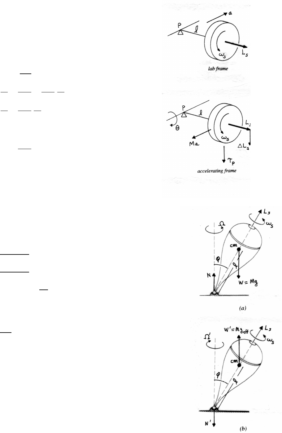
NONINERTIAL SYSTEMS AND FICTITIOUS FORCES 151
9.5 Gyroscope and acceleration
In the accelerating system, the gyroscope experiences
an effective gravitational field -a, so there is
a fictitious force Ma acting in the direction shown.
The torque τPon the gyroscope about the pivot
is downward, so the gyroscope precesses as shown.
τP=Nl =Mal
|τP|=
dLs
dt
=Ls˙
θ=I0ωs˙
θ
dθ
dt =Mal
I0ωs
=Ml
I0ωs
dv
dt
dv
dt =I0ωs
Ml
dθ
dt
Zv
0
dv0=Zθ
0
dθ0
v=I0ωs
Ml θ
9.6 Spinning top in an elevator
(a) elevator at rest
The horizontal component of Lsis
Lhorizontal =Lssin φ
dLhorizontal
dt =τcm =lN sin φ=lW sin φ
dLhorizontal
dt =LhorizontalΩ = LsΩsin φ
Ω = lW
Ls
The direction of precession is shown in sketch (a).
The same result is obtained using the general result Eq. (9.5)
dLs
dt =Ω×Ls
(b) elevator accelerating down at rate 2g
There is a fictitious force M(2g) acting upward
so the effective gravitational acceleration is
ge f f =2g−g=gupward.
continued next page =⇒
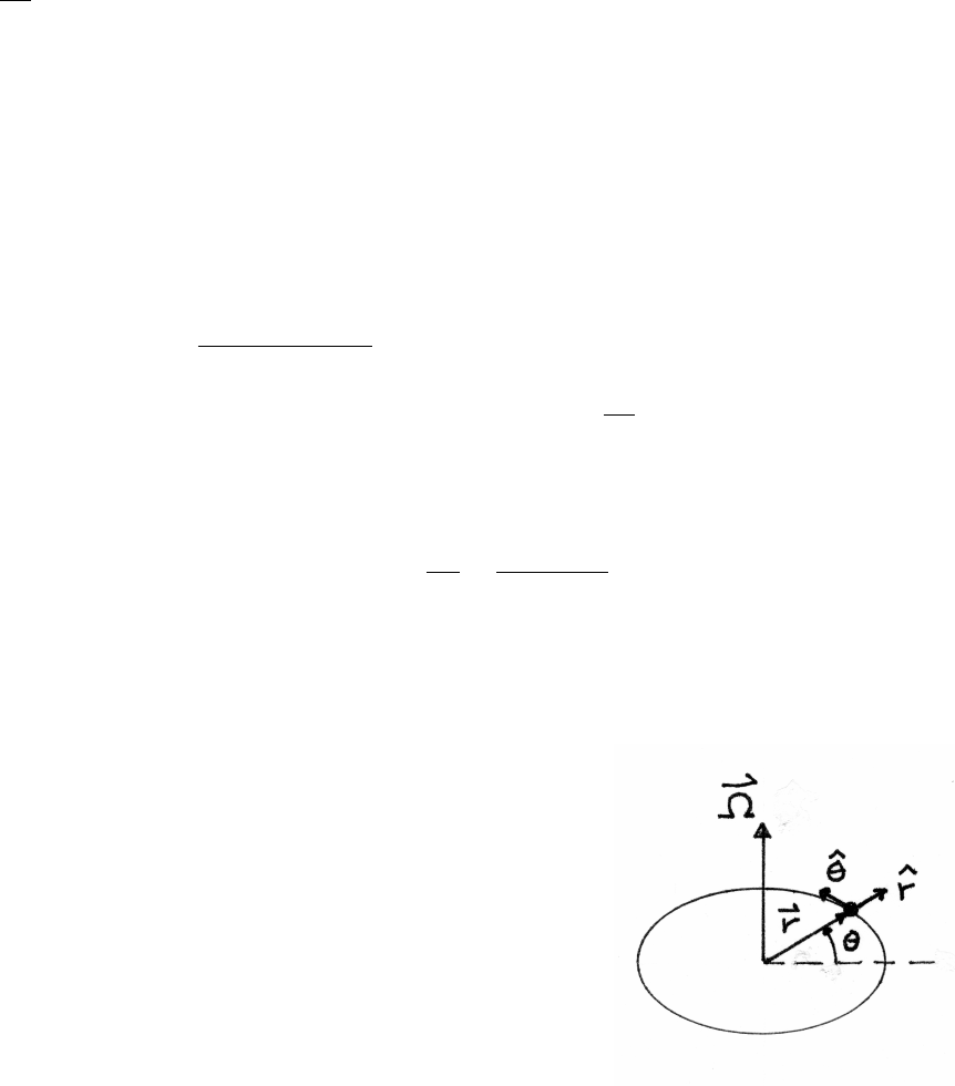
152 NONINERTIAL SYSTEMS AND FICTITIOUS FORCES
In the accelerating system, gravity appears to be reversed, which reverses the
direction of τcm.
Ω0=−lW
Ls
As sketch (b) shows, the top consequently reverses its direction of precession in the
downward accelerating elevator.
9.7 Apparent force of gravity
gequator =g−ReΩ2
egpole =g
∆g=ReΩ2
ewhere Ωe=2πrad/day
8.64 ×10⁴s/day =7.27 ×10⁻⁵rad/s
∆g=(6.37 ×10⁶m)(7.27 ×10⁻⁵rad/s)2=3.37 ×10−2m/s2∆g
g=3.44 ×10⁻³
It is interesting to note that the Earth’s polar and equatorial radii differ fractionally
by nearly the same amount.
Rpol =6.357 ×10⁶mReq =6.378 ×10⁶m∆R
Re
=2.1×10⁴
6.37 ×106=3.30 ×10⁻³
9.8 Velocity in plane polar coordinates
Consider an inertial frame and a frame instantaneously rotating
with the particle. The instantaneous rate of rotation is Ω = ˙
θ.
vinertial =vrot +Ω×r
In the rotating system, the particle has only radial velocity, so
vrot =˙rˆ
r
Ω×r= Ωrˆ
θ=˙
θrˆ
θ
vinertial =˙rˆ
r+r˙
θˆ
θ
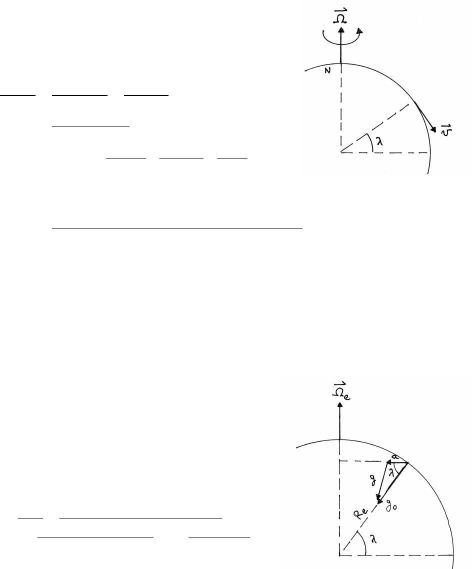
NONINERTIAL SYSTEMS AND FICTITIOUS FORCES 153
9.9 Train on tracks
Let the latitude be λ, for generality.
(a)
FCoriolis =−2MΩ×v
FCoriolis =2MΩvsin λ
FCoriolis
W=2MΩvsin λ
Mg =2Ωvsin λ
g
Ω = 2πrad/day
8.64 ×10⁴s/day =7.27 ×10⁻⁵rad/s
v=60 mph = 60 miles
1 hour ! 5280 feet
1 mile ! 1 hour
3600 s!=88 ft/s
sin (60◦)=0.866
W=(400 tons)(2000 lbs/ton) =8.00 ×10⁵lbs
FCoriolis =(2)(7.27 ×10⁻⁵rad/s)(88 ft/s)(0.866)(8.00 ×105lbs)
32 ft/s2
=277 lbs
(b) From the sketch, Ω×vis directed into the page, toward the east. The Coriolis
force on the train is directed toward the west, so the force on the tracks is toward
the east. The Coriolis force vanishes at the equator, where Ω×v=0.
9.10 Apparent gravity versus latitude
The apparent acceleration of gravity is g=g0+a, where
ais the acceleration of the local reference frame.
For points at rest, ais radial, directed toward the axis,
as shown in the sketch. Using the law of cosines,
g2=g2
0+a2−(2ag0) cos λ
a= Ω2
eRecos λ
g2=g2
0+(Ω2
eRe)2cos2λ−2Ω2
eReg0cos2λ
Let x≡Ω2
eRe
g0
=(7.27 ×10⁻⁵rad/s)2(6.37 ×106m)
9.8 m/s2=3.44 ×10−3
g=g0√1+x2cos2λ−2xcos2λ≈g0√1−2xcos2λ
because x1. (Note that xis dimensionless.)
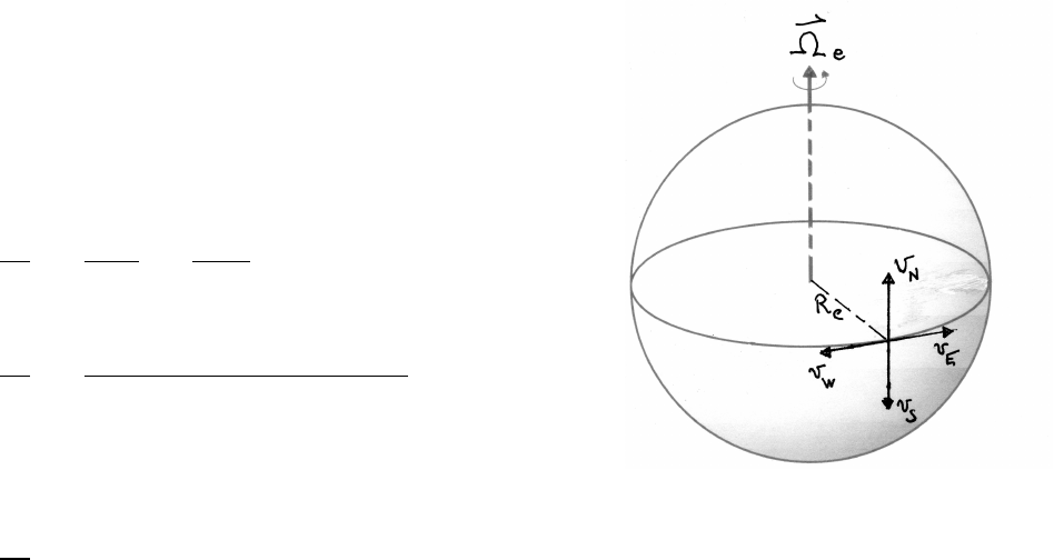
154 NONINERTIAL SYSTEMS AND FICTITIOUS FORCES
9.11 Racing hydrofoil
The velocity dependent fictitious force is Ff ict =−2mΩe×v.
The apparent change in gravity is the component of
Ff ict/mnormal to the surface of the Earth.
(a) East:
Ωe×vEpoints radially inward, so Ff ict/mis
radially outward, decreasing g.
∆g
g=−Ff rict
mg =−2ΩvE
g
Ωe=7.27 ×10⁻⁵rad/sv=200 mph =293 ft/s
∆g
g=−(2)(7.27 ×10⁻⁵rad/s)(293 ft/s)
32 ft/s2=−1.33 ×10−3
(b) West:
The sign is reversed compared to East, so gis increased.
∆g
g= +1.33 ×10⁻³
(c) South:
Ωeand vSare antiparallel, so ∆g=0.
(d) North:
Ωeand vNare parallel, so ∆g=0.
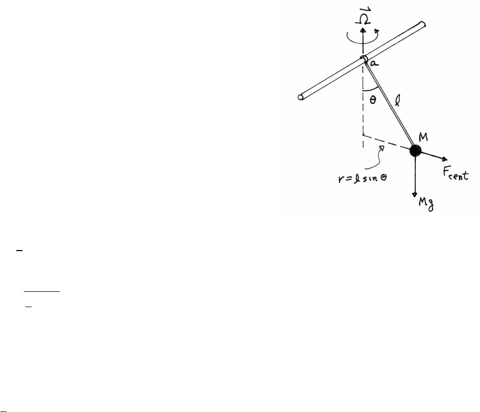
NONINERTIAL SYSTEMS AND FICTITIOUS FORCES 155
9.12 Pendulum on rotating platform
For small amplitude, sin θ≈θand cos θ≈1.
In the rotating system, a fictitious centrifugal force Fcent
acts on M.Fcent is directed radially outward from the
axis of rotation.
Fcent =Mr Ω2=Ml Ω2sin θ≈Ml Ω2θ
The fictitious Coriolis force in the rotating system acts
perpendicular to the plane of swing, and does not play a role
in the dynamics of this problem.
Take torques about the pivot point a.
τa=Mgl sin θ−Fcentlcos θ
≈Mglθ−Fcentl=(Mgl −Ml2Ω2)θ
=−I0¨
θ=−Ml2¨
θ
l2¨
θ+(gl −l2Ω2)θ=0
¨
θ+g
l−Ω2θ=0
This is the equation for SHM, with oscillation frequency
ωosc =rg
l−Ω2
If Ω2>g/l, the motion is no longer harmonic, but exponential – Mcan fly up to a
much larger angle. Consider, however, the torque equation without using the small
angle approximation.
¨
θ+g
l−Ω2cos θsin θ=0
As θincreases, cos θdecreases, so at a sufficiently high angle, the term in parenthe-
ses becomes positive, and Mundergoes oscillatory motion once again, but about a
new equilibrium angle.
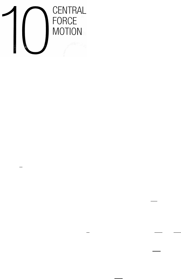
10.1 Equations of motion
L=µr2˙
θ(10.5) (1)
E=1
2µ(˙r2+r2˙
θ2)+U(r) (10.6b) (2)
Angular momentum and mechanical energy are both conserved, so their derivatives
with respect to time vanish.
Differentiating Eq. (1), µ(2r˙r˙
θ+r2¨
θ)=dL
dt =0
which can be written µ(r¨
θ+2˙r˙
θ)=0 (3) =⇒=Eq. (10.4b)
Differentiating Eq. (2), 1
2µ(2˙r¨r+2r˙r˙
θ2+2r2˙
θ¨
θ)+dU
dr ˙r=dE
dt =0
which can be written µ[˙r¨r+r˙
θ(˙r˙
θ+r¨
θ)] +dU
dr ˙r=0
Using Eq. (3) to eliminate r¨
θ=−2˙r˙
θ, and cancelling the common factor ˙r,
µ(¨r−r˙
θ2)+dU
dr =0
Using dU/dr =−f(r), Eq. (10.4a) is obtained.
µ(¨r−r˙
θ2)=f(r)
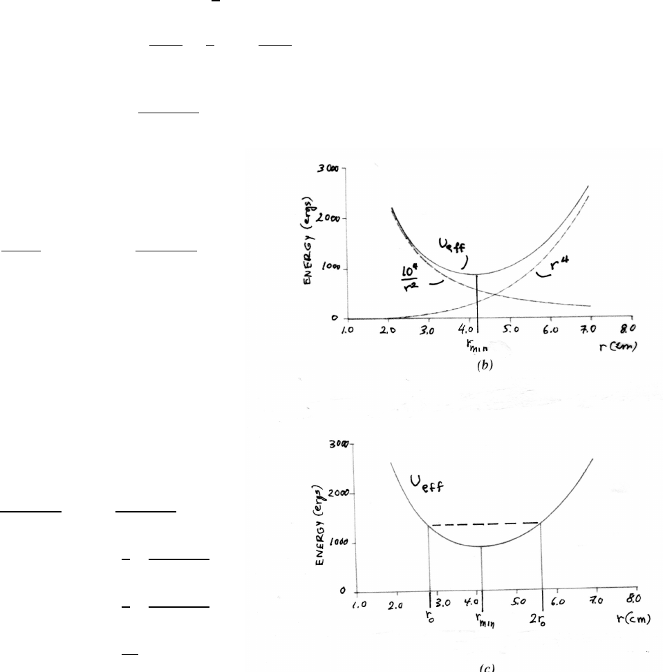
CENTRAL FORCE MOTION 157
10.2 r3central force
(a)
f(r)=−Ar3ˆ
r
U(r)−U(0) =−Zr
0
f(r0)dr0=1
4Ar4taking U(0) =0.
Ue f f (r)=U(r)+L2
2mr2=1
4Ar4+L2
2mr2
A=4.0 dynes/cm3L=103g/cm2·sm=50.0 g
Ue f f = r4+1.0×10⁴
r2!ergs
(b) Circular motion occurs at rmin, the
minimum value of Ue f f , where
dUe f f /dr =0
dUe f f
dr rmin
=4r3
min −2.0×10⁴
r3
min
=0
r6
min =5.0×103cm6
rmin =4.1 cm
(c)
Ue f f (r0)=Ue f f (2r0)
1.0×10⁴
r2
0
+r4
0=1.0×10⁴
(2r0)2+(2r0)4
= 1
4! 1.0×10⁴
r2
0!+16.0r4
0
15.0r4
0= 3
4! 1.0×10⁴
r2
0!
r6
0= 3
60!×104=500
r0=2.8 cm
158 CENTRAL FORCE MOTION
10.3 Motion with 1/r3central force
Write the radial force as
f(r)=−2A
r3where Ais a constant
U(r)−U(∞)=−Zr
∞ −2A
r03!dr0=−A
r2
Take U(∞)=0.
Ue f f =U(r)+L2
2mr2= −A+L2
2m!1
r2
If A=L2/(2m), then Ue f f =0; the radial force is 0, so the radial motion is uniform
(vis constant).
r(t)=r0+vt
For this case,
2mA =L2=(mr2˙
θ)2=⇒˙
θ=r2A
m
1
r2
Zθ(t)
θ0
dθ0=r2A
mZr(t)
r0
dt
r02
=r2A
mZr(t)
r0
dt
dr0
dr0
r02
=r2A
m
1
vZr(t)
r0
dr0
r02
θ(t)=θ0+r2A
m
1
v 1
r0−1
r(t)!
As t→ ∞,r(t)→ ∞, so θ(t)→constant; there is no further rotation.
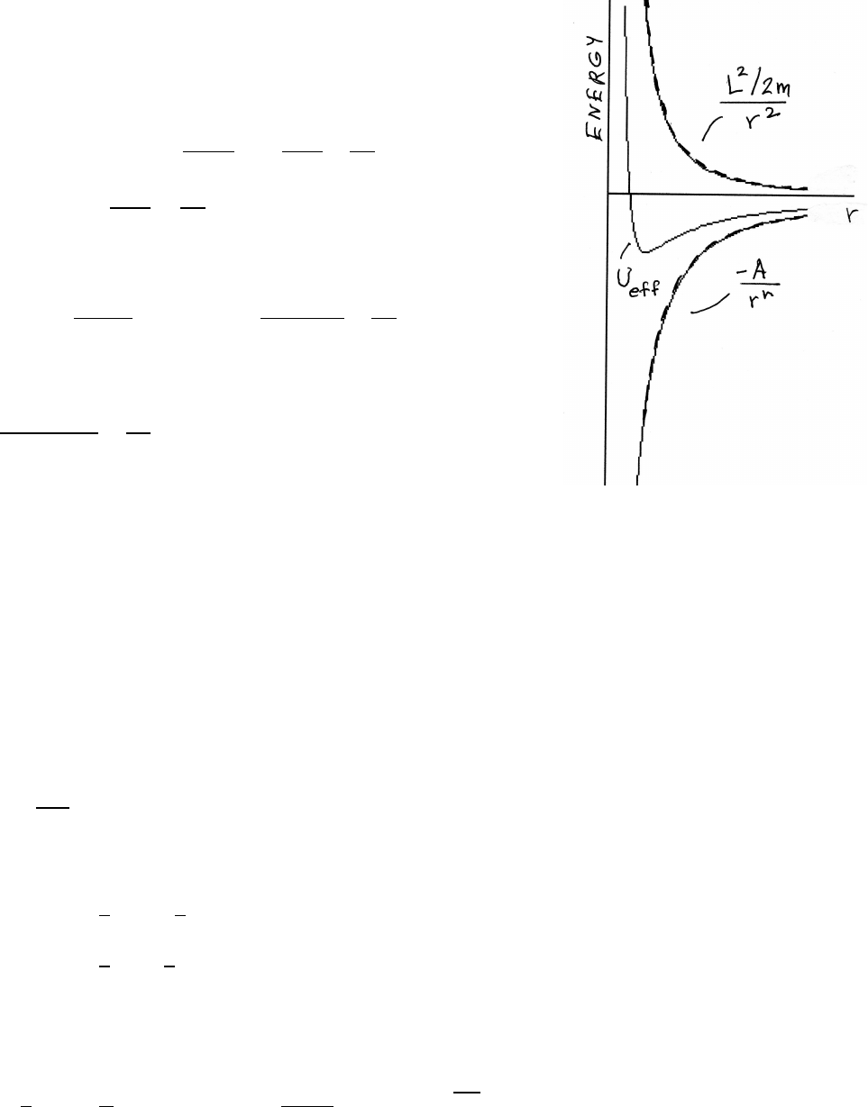
CENTRAL FORCE MOTION 159
10.4 Possible stable circular orbits
Write Ue f f as Ue f f =U(r)+L2/(2mr2)≡ −A/rn+B/r2
where Ais an unspecified force constant and
B=L2/(2m). For a stable circular orbit, Ue f f must
have a minimum at some radius r0.
0=dUe f f
dr r0
=nA
r0n+1−2B
r03
nA
r0n+1=2B
r03(1)
To be a minimum,
d2Ue f f
dr2r0
>0=⇒ −n(n+1)A
r0n+2+6B
r04>0
Using Eq. (1),
−(n+1)(2B)
r04+6B
r04>0
from which follows n+1≤3 or n≤2.
The case n=0 does not work, but n<0 is all right for any n.
See Problem 10.2 for the case U(r)∝r4.
The figure is drawn for A=20, B=12, n=1.5, which gives r0≈0.89.
10.5 Central spring force
(a) radial equation of motion for a circular orbit at r0:
mv2
r0
=kr0
mechanical energy:
E=1
2Mv2
0+1
2kr2
0
=1
2kr2
0+1
2kr2
0=kr2
0
k=3.0N/mand E=12.0J
E=kr2
0=⇒12.0 J =(3.0 N/m) r2
0=⇒r0=2.0 m
1
2Mv2
0=E
2=6.0 J =⇒v2
0=12.0 J
2.0 kg =⇒v0=√6.0≈2.45 m/s
continued next page =⇒
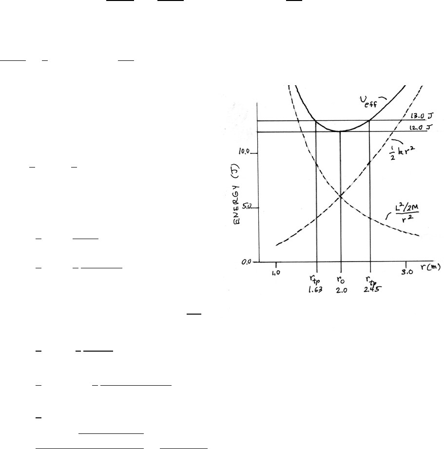
160 CENTRAL FORCE MOTION
For this particular force, r0occurs where the two curves intersect, as shown in
the figure below.
dUe f f
dr =−L2/M
r3
0
+kr0=0=⇒r4
0=L2
kM
The curves intersect at
L2
2Mr2
0
=1
2kr2
0=⇒r4
0=L2
kM
(b)
The radial blow changes the total mechanical
energy but not the angular momentum =Mv0r0,
so Ue f f is unchanged, as indicated in the figure.
The radial blow increases Eby
∆E=1
2M˙r2=1
2(2.0 kg)(1.0 m/s)2=1.0 J
Ef=Ei+ ∆E=12.0+1.0=13.0 J
(c)
Ue f f =1
2kr2+L2
2Mr2
=1
2kr2+1
2
(Mv0r0)2
2Mr2(1)
At the turning points, the kinetic energy is 0,
E=Ue f f , and r=rtp.
With Ue f f =13.0 J, M=2.0 kg, v0=√6.0 m/s, k=3.0 N/m,
Ue f f =1
2kr2
tp +1
2
Mv2
0r2
0
r2
tp
13.0=1
2(3.0) r2
tp +1
2
(2.0)(6.0)(2.0)2
r2
tp
0=3
2r4
tp −13.0r2
tp +24.0
r2
tp =13.0±√169.0−144.0
3.0=13.0±5.0
3.0
rtp =1.63 m,2.45 m
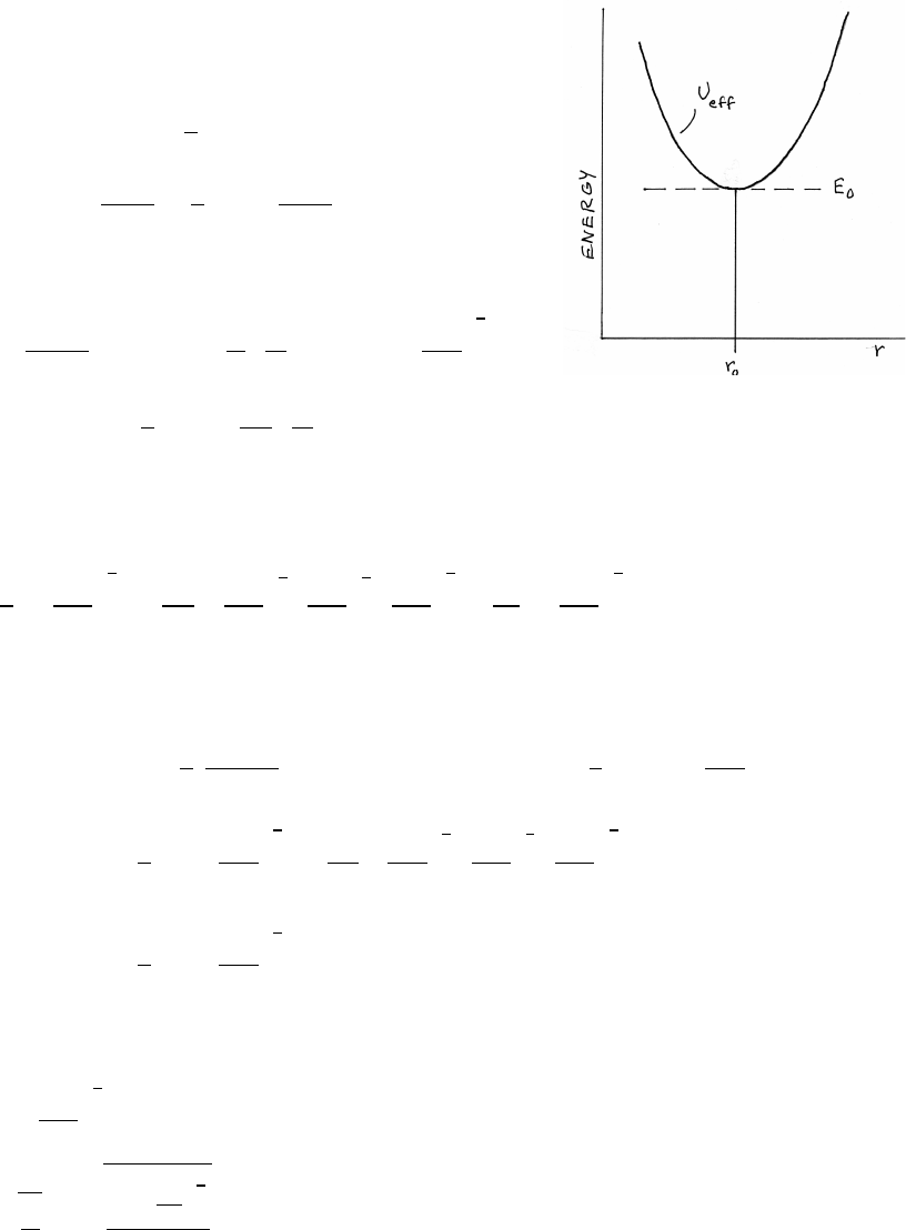
CENTRAL FORCE MOTION 161
10.6 r4central force
F=−Kr4ˆ
r
U(r)=KZr
0
r04dr0=1
5Kr5
Ue f f =U(r)+l2
2mr2=1
5Kr5+l2
2mr2
For circular motion at r=r0,
0=dUe f f
dr r0
=Kr4
0− l2
m!1
r3
0
=⇒r0= l2
Km !
1
7
E0=Ue f f (r0)=1
5Kr5
0+ l2
2m!1
r2
0
From Sec. 10.3.3, Ue f f includes the kinetic energy due to tangential motion; for
circular motion, there is no kinetic energy due to radial motion.
E0=1
5K l2
Km !
5
7
+ l2
2m!Km
l2
2
7Km
l2
5
7 l2
Km !
5
7
=7
10 K l2
Km !
5
7
To find the oscillation frequency ω, follow the approach in Sec. 6.2, and expand
Ue f f about r0. Let rr0be a small displacement.
Ue f f =Ue f f (r0)+0+1
2
d2Ue f f
dr2r0
r2+. . . ≈Ue f f (r0)+1
2 4Kr3
0+3l2
mr4
0!r2
=Ue f f (r0)+1
2
4K l2
Km !
3
7
+ 3l2
m!Km
l2
4
7Km
l2
3
7 l2
Km !
3
7
r2
=Ue f f (r0)+1
2
7K l2
Km !
3
7
r2
The effective spring constant kis therefore
k=7K l2
Km !
3
7
ω=rk
m=v
u
t7Kl2
Km 3
7
m
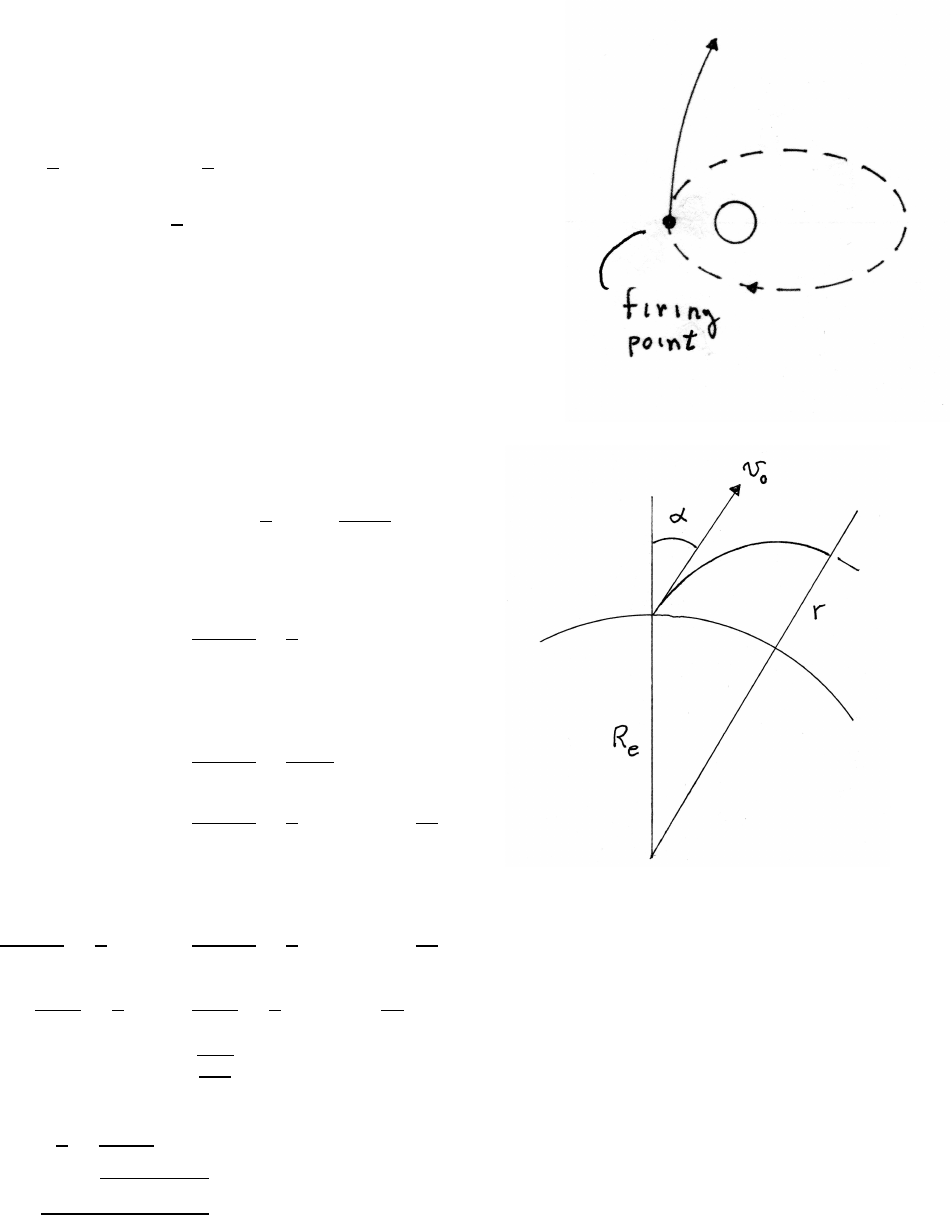
162 CENTRAL FORCE MOTION
10.7 Transfer to escape
The mechanical energy in an elliptic orbit is <0. For escape,
the energy must be increased to ≥0. The satellite does not
move far during the brief firing time, so the potential energy
is essentially unchanged. The change in kinetic energy is
∆K=1
2m(vi+ ∆v)2−1
2mv2
i
=m(vi·∆v)+1
2m∆v2
The change is largest if ∆vkviand when viis largest. These
conditions are satisfied best at the closest point (perigee).
10.8 Projectile rise
Ei=U(Re)+1
2m˙r2+l2
2mRe
where l=mv0sin αRe.
Ei=−GMem
Re
+1
2mv2
0
At the top of the trajectory, ˙r=0.
Ef=−GMem
r+l2
2mr2
=−GMem
r+1
2mv2
0sin2αRe
r2
The rocket is in free flight, so Ei=Ef.
−GMem
Re
+1
2mv2
0=−GMem
r+1
2mv2
0sin2αRe
r2
−GMe
Re
+1
2v2
0=−GMe
r+1
2v2
0sin2αRe
r2
(1)
It is given that v0=qGMe
Reso Eq. (1) becomes, with x≡r/Re,
−1=−2
x+sin2α
x2=⇒0=x2−2x+sin2α
x=2±p4−4 sin2α
2=⇒r=Re(1 ±cos α)
continued next page =⇒
CENTRAL FORCE MOTION 163
Take the +sign, because r>Re. so that r=Re(1 +cos α) The rocket rises to a
height Recos αabove the Earth’s surface.
10.9 Halley’s comet
The period of an elliptic orbit depends only on the major axis Aand the mass of the
attractor. In this problem, the reduced mass µis very nearly the mass of the comet.
Using Eq. (10.31),
U(r)=−C
r=−GMS un µ
r
µ
C=1
GMS un
=⇒A= 2
π2T2GMS un!1
3
T=(76 years) 3.16 ×10⁷s
year !=2.40 ×10⁹s
G=6.67 ×10⁻¹¹ m3·kg−1·s−2MS un =1.99 ×1030 kg
A=5.37 ×10¹² m
For comparison, the diameter of the Earth’s orbit is 2.98 ×10¹¹ m.
From Eq. (10.21), the equation of an elliptic orbit is
r=r0
1−cos θ
rmin ≡rperihelion =r0
1+
rmax ≡raphelion =r0
1−
A=rperihelion +raphelion =r0 1
1++1
1−!=2r0
1−2
r0=1
2A(1 −2)=1
2(5.37 ×10¹² m)(1 −(0.967)2)=1.74 ×10¹¹ m
(a)
rperihelion =1.74 ×10¹¹
1.967 =8.86 ×10¹⁰ m
raphelion =1.74 ×10¹¹
1−0.967 =5.27 ×10¹² m
continued next page =⇒
164 CENTRAL FORCE MOTION
(b) The comet’s maximum speed vmax occurs at perihelion, as it must because of
the law of equal areas. Here are two ways of finding vmax.
method 1: angular momentum L =µvmaxrperihelion
From Eq. (10.19),
L2=roµC=r0µ2GMS un
vmax =L
µrperihelion
=√r0GMS un
rperihelion
=p(1.74 ×10¹¹)(6.67 ×10⁻¹¹)(1.99 ×1030)
8.86 ×1010 =5.42 ×10⁴m/s
method 2: Eq. (10.30)
v2
max =2C
µ 1
rperihelion −1
A!
=(2GMS un) A−rperihelion
Arperihelion !=(2GMS un) raphelion
Arperihelion !
=(2)(6.67 ×10⁻¹¹)(1.99 ×1030) 5.27 ×10¹²
(5.37 ×10¹²)(8.86 ×10¹⁰)!=2.94 ×10⁹
vmax =5.42 ×10⁴m/s
10.10 Satellite with air friction
For min a circular orbit under an attractive force C/r2,
mv2
r=C
r2=⇒K=1
2mv2=1
2
C
r=−1
2U(r)
(a)
E=K+U=−1
2U(r)+U(r)=1
2U(r)=−1
2
C
r=−K
(b) The energy loss per revolution ∆Edue to friction is −2πr f .
∆E= dE
dr !∆r=⇒∆r=∆E
dE/dr =−2πr f
C/(2r2)=−4πr3f
C
The radius of the orbit decreases because of friction.
(c) In the circular orbit, E=−K.
∆K=−∆E= +2πr f
Friction causes the total mechanical energy Eto decrease. Because K=−E, a
decrease in the total energy is accompanied by an increase in the kinetic energy.
Friction causes the satellite’s speed to increase!
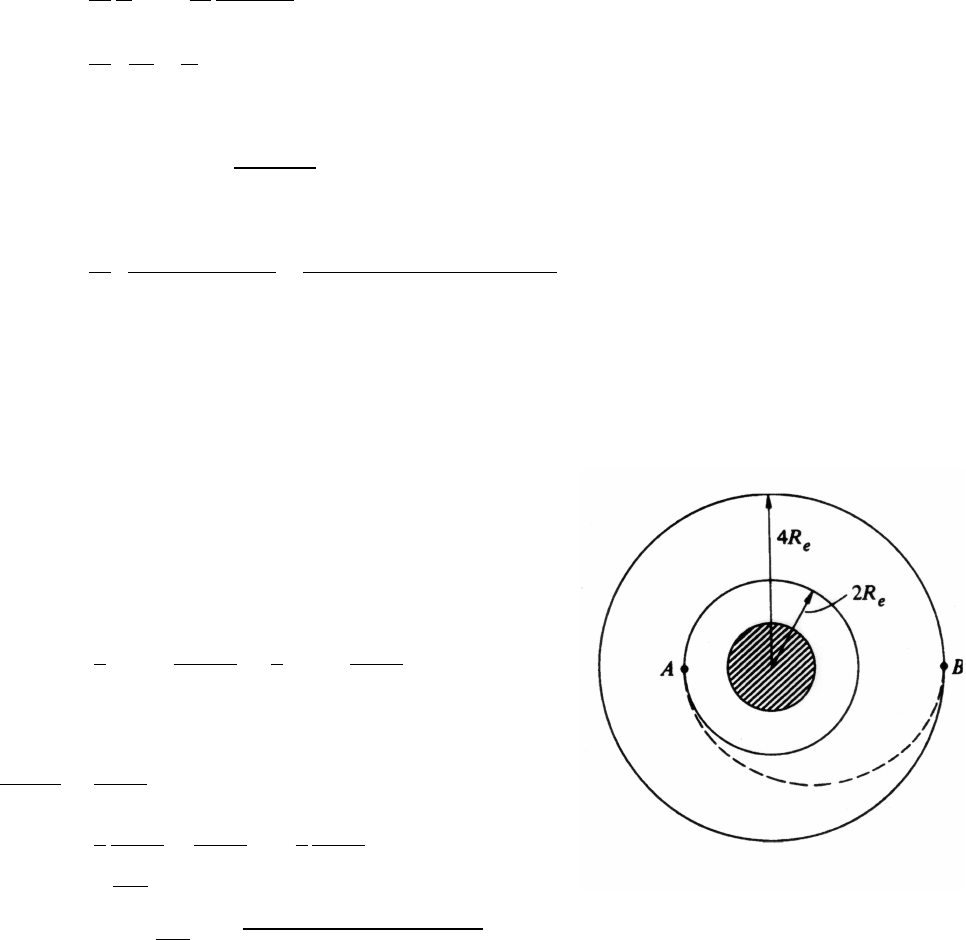
CENTRAL FORCE MOTION 165
10.11 Mass of the Moon
Let the major axis be A, and the period T. Kepler’s Third Law gives
T2=π2
2
µ
CA3=π2
2
1
GMMoon
A3
MMoon =π2
2 A3
T2! 1
G!
A=(1861 +1839) km =3.70 ×10³m
T=(119 minutes) 1 minute
60 s !=7.14 ×10³s
G=6.67 ×10⁻¹¹ m3·kg−1·s−2
MMoon =π2
2"(3.70 ×10⁶m)3
(7.14 ×10³s)2#" 1
6.67 ×10⁻¹¹ m3·kg−1·s−2!]
=7.35 ×10²² kg
10.12 Hohmann transfer orbit
Let vcbe the speed in a circular orbit, and let vebe the
speed in the elliptic transfer orbit.
The total mechanical energy Eof a mass m
moving in the Earth’s gravitational field is
E=1
2mv2−GmMe
r=1
2mv2−mgR2
e
r
The equation of motion in a circular orbit is
m(vc)2
r=mgR2
e
r2
E=1
2
mgR2
e
r−mgR2
e
r=−1
2
mgR2
e
r
Note that √gRehas the dimensions of velocity.
pgRe=q(9.8 m ·s−2)(6.4×10⁶m) =7.92 ×10³m/s
continued next page =⇒
166 CENTRAL FORCE MOTION
(a)
rA=2Re=⇒EA=−1
2 mgR2
e
2Re!=−1
4mgRe
rB=4Re=⇒EB=−1
2 mgR2
e
4Re!=−1
8mgRe
∆E= −1
8+1
4!mgRe=1
8mgRe
=1
8(3 ×10³kg)(7.92 ×10³m/s)2
=2.35 ×10¹⁰ J
(b) The transfer orbit is a semi-ellipse with perigee at Aand apogee at B. The major
axis Aof the ellipse is
A=rA+rB=2Re+4Re=6Re
The energy E0is
E0=−mgR2
e
A=−1
6mgRe
K=−Ein a circular orbit, so
KA=1
2m(vc
A)2=−EA=1
4mgRe
vc
A=rgRe
2
The speed at Afor transfer is
K0
A+UA=E0
1
2m(ve
A)2=−1
6mgRe+1
2mgRe=1
3mgRe
ve
A=r2gRe
3
∆vA=ve
A−vc
A=r2gRe
3−rgRe
2=(0.109)(7.92 ×10³m/s) =864 m/s
continued next page =⇒
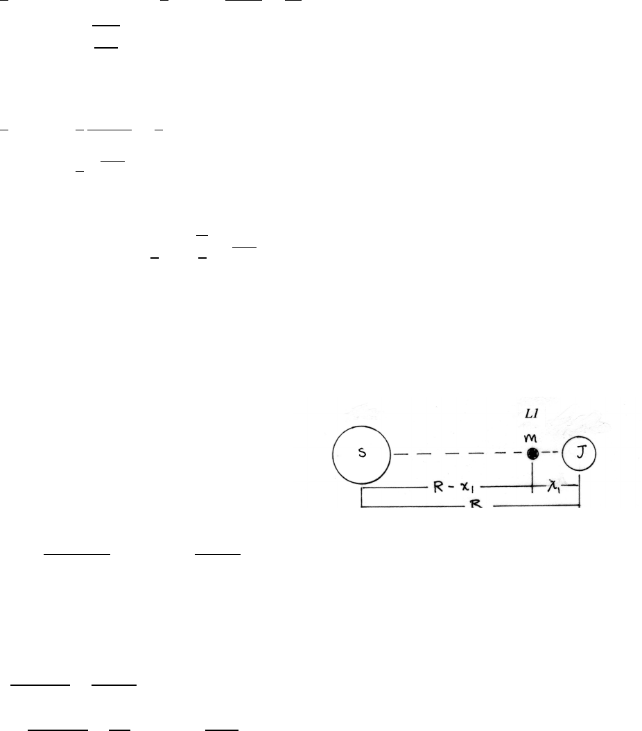
CENTRAL FORCE MOTION 167
The initial speed at Bis
1
2m(ve
B)2=E0−UB=−1
6mgRe+mgR2
e
4Re
=1
12mgRe
ve
B=rgRe
6
The final speed at Bin the new circular orbit is
1
2m(vc
B)2=1
2
GmMe
RB
=1
8mgRe
vc
B=1
2pgRe
The change in speed at Bis
∆vB=vc
B−ve
B=
1
2−r1
6
pgRe=727 m/s
This problem can also be solved readily using Eq. (10.30).
10.13 Lagrange point L1
Take the center of mass at the center of the Sun,
because MS un MJand the asteroid’s mass mis
small. Jupiter rotates about the Sun at angular
speed Ω. The asteroid also rotates about the Sun
at rate Ω, so the three bodies remain in line,
the characteristic behavior at a Lagrange point.
MJRΩ2=GMS un MJ
R2=⇒Ω2=GMS un
R3
(a) In the rotating system, the forces on mare the real gravitational forces of the
Sun and Jupiter, and the fictitious force m(R−x1)Ω2. In equilibrium, the total
force on mis 0.
−GmMS un
(R−x1)2+GmMJ
x2
1
+m(R−x1)Ω2=0
−MS un
(R−x1)2+MJ
x2
1
+(R−x1)MS un
R3=0 (1)
continued next page =⇒

168 CENTRAL FORCE MOTION
(b) data:
R=7.78 ×1011 mx1=5.31 ×10¹⁰ mR−x1=7.25 ×10¹¹ m
MS un =1.99 ×1030 kg MJ=1.90 ×1027 kg
Inserting in Eq. (1),
−1.99 ×1030
(7.25 ×10¹¹)2+1.90 ×1027
(5.31 ×10¹⁰)2+(7.25 ×10¹¹)(1.90 ×1030)
(7.78 ×10¹¹)3
?
=0
−0.02 ×10⁶?
=0
The calculated result is consistent with 0, within the numerical accuracy of the
data and the approximations.
(c) As required for a Lagrange point, all three bodies rotate about their center of
mass at the same angular speed Ω. Neglecting perturbations, the configuration
is therefore unchanging during the rotation.
In the rotating system, mis acted upon by the real gravitational forces of the
Sun and Jupiter, and by the fictitious centrifugal force mr Ω2. The forces are in
balance at equilibrium, with fixed Ω, so a larger gravitational force leads to a
larger orbital radius rfor the asteroid to increase the centrifugal force for bal-
ance.
Lagrange point L2: Both the Sun and Jupiter exert an additive inward gravita-
tional force on m, so the asteroid’s orbit is somewhat outside Ras indicated,
with R+x2>R, or x2>0.
Lagrange point L3: At L3, mis on the Sun-Jupiter line on the opposite side
from Jupiter. If Jupiter were not present, the radius of the asteroid’s orbit would
be R. However, Jupiter adds a moderate gravitational force, so x3>R.
CENTRAL FORCE MOTION 169
10.14 Speed of S2 around Sgr A*
For a body in elliptic orbit about an attractor, the distance of closest approach has
been termed the periapse, and the farthest distance the apoapse.
The orbiting body’s fastest speed occurs at the periapse, as a consequence of the
Law of Equal Areas. Let Abe the major axis.
rperiapse =r0
1+rapoapse =r0
1−
A=rperiapse +rapoapse =2r0
1−2=⇒r0=1
2A(1 −2)
Using Eq. (10.30), the fastest speed of the orbiting star S2 is given by
v2
max =2Cµ 1
rperiapse −1
A!
=2GMS gr A∗ 1+
r0−1
A!=2GMS gr A∗
A 2(1 +)
1−2−1!
=2GMS gr A∗
A 1+
1−!
data:
G=6.67 ×10⁻¹¹ m3·kg−1·s−2≈0.87 A=2.9×10¹⁴ m
MS gr A∗=4×10⁶MS un =8×1036 kg
vmax ≈7300 km/s
which is approximately 250 times the speed of the Earth around the Sun.
With a similar calculation, the minimum speed vmin of S2 (at apoapse) is
v2
min =2GMS gr A∗
A 1−
1+!
vmin ≈500 km/s
also many times faster than the Earth.
170 CENTRAL FORCE MOTION
10.15 Sun-Earth mass ratio
From the statement of Kepler’s third law in Eq. (10.31),
T2=π2µ
2CA3=π2µ
2GmM A3
where mis the mass of the satellite and Mis the mass of the attractor. For the cases
in this problem, where mM,µ=mto good accuracy.
A3
T2=2GM
π2
Taking ratios for M=MS un and M=MEarth,
(A3/T2)S un
(A3/T2)Earth
=MS un
MEarth
From Table 10.1,
A3
T2!S un
=2.69 ×10¹⁰ km3·s−2
From the Earth satellite data in the problem,
A3
T2!Earth
=8.07 ×10⁴km3·s−2
MS un
MEarth
=3.33 ×10⁵
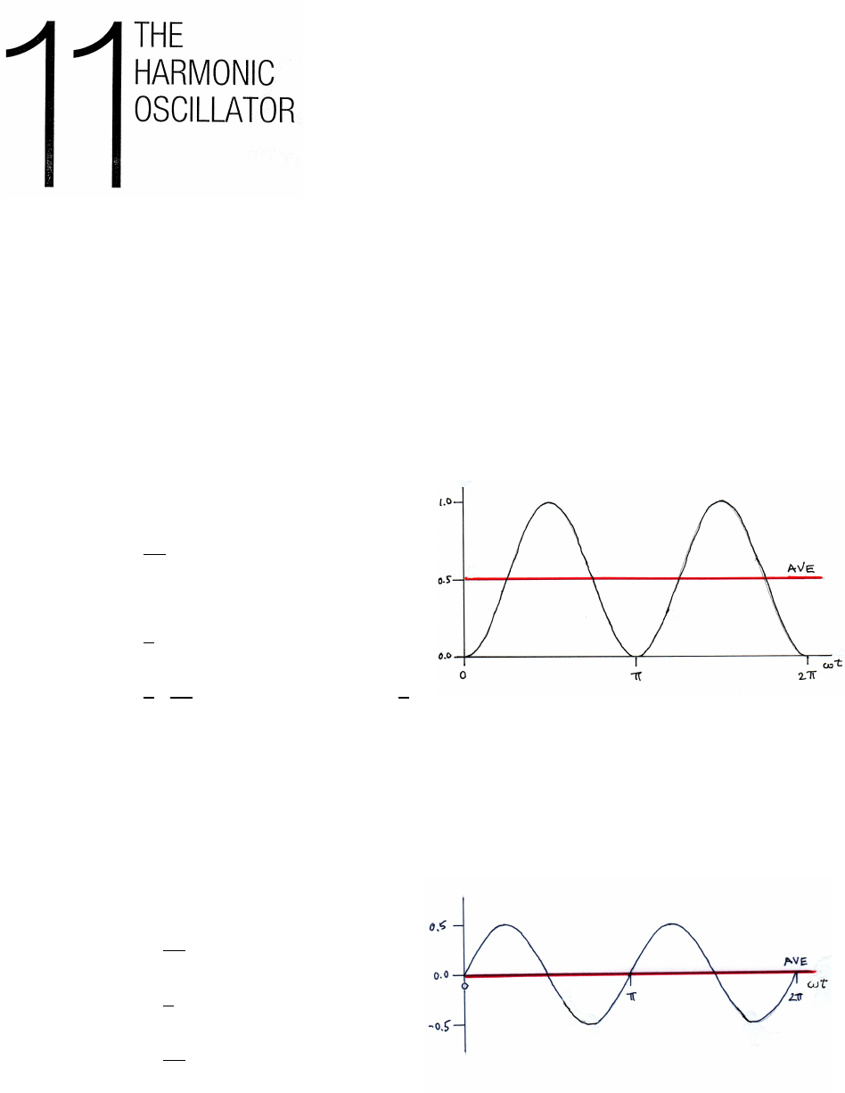
11.1 Time average of sin2
Formally:
hsin2iave =1
2πZ2π
0
sin2u du
cos (u+u)=cos2u−sin2u=1−2 sin2u
sin2u=1
2(1 −cos 2u)
hsin2iave =1
2 1
2πZ2π
0
(1 −cos 2u)du!=1
2
Qualitatively: Note from the sketch that sin2is symmetric about the value 1/2.
11.2 Time average of sin ×cos
Formally:
hsin ×cosiave =1
2πZ2π
0
sin ucos u du
sin ucos u=1
2sin (2u)
hsin ×cosiave =1
4πZ2π
0
sin (2u)du =0
Qualitatively: This is a product of an odd function sin u=−sin (−u) and an even
function cos u= + cos (−u), so the area under the product vanishes for a full period.
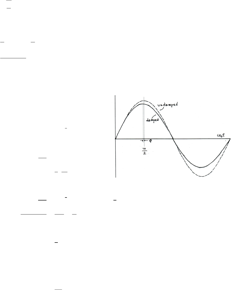
172 THE HARMONIC OSCILLATOR
11.3 Damped mass and spring
ω=rk
m
k=mω2=(0.3 kg) h(2 cycles ·s−1)(2πradians ·cycle−1)i2
=47.4 N ·m−1
Q=ω
γ=⇒γ=ω
Q
=4πrad ·s−1
60 =0.21 s−1
11.4 Phase shift in a damped oscillator
Let xube the coordinate for the
undamped case, and xdfor the damped case.
xu=x0sin (ω0t)
xd=x0e−γ
2tsin (ω0t)
Maximum of xuis at tum:
dxu
dt =ω0x0cos (ω0tum)=0
tum =π
2,3π
2,. . .
Maximum of xdis at tdm:
dxd
dt =x0e−γ
2tω0cos (ω0tdm)−γ
2sin (ω0tdm)=0
cos (ω0tdm)
sin (ω0tdm)=γ
2ω0
=2
Q(1)
For Q1, the condition is satisfied near π/2,3π/2, . . .. For example,
ω0tdm ≈π
2−φ
cos (π/2−φ)=sin φ≈φ
sin (π/2−φ)=cos φ≈1
If Q1 the condition in Eq. (1) is then satisfied for
φ=1
2Q
For clarity, the value of Qin the figure is not very large.
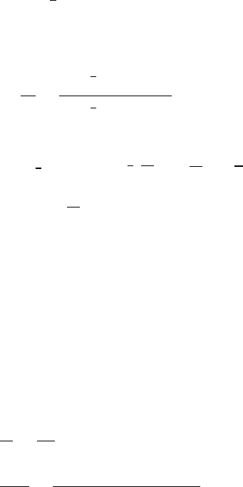
THE HARMONIC OSCILLATOR 173
11.5 Logarithmic decrement
x=x0e−γ
2tsin (ω0t)
Let two successive positive maxima occur at t1and t2. Let Rbe the ratio x1/x2.
R=x1
x2
=x0e−γ
2tsin (ω0t1)
x0e−γ
2tsin (ω0t2)
ω0t2=ω0t1+2π=⇒sin (ω0t2)=sin (ω0t1)
R=e−γ
2(t1−t2)=e
γ
22π
ω0=e
γπ
ω0=e
π
Q
δ=ln R=π
Q
11.6 Logarithmic decrement of a damped oscillator
k=mω2
0=(5 kg) h(0.5 cycles ·s−1)(2πrad ·cycle−1)i2=49.3 N ·m−1
From the preceding problem (problem 11.5),
δ=π
Q=πγ
ω0
γ=δ ω0
π=(0.02)(1.0πrad ·s−1)
π=0.02 s−1
The damping constant b=γmis defined in Sec. 11.3.
b=γm=(0.02 s−1)(5.0 kg) =0.10 kg ·s−1=0.10 N ·s·m−1
11.7 Critically damped oscillator
(a) The equation of motion is
¨x+γ˙x+ω2
0x=0=⇒¨x+2ω0˙x+ω2
0x=0 (1)
x=(A+Bt)e−ω0t˙x=[B−ω0(A+Bt)]e−ω0t¨x=h−2Bω0+ω2
0(A+Bt)ie−ω0t
Substituting in Eq. (1), omitting the common factor e−ω0t,
0?
=−2Bω0+ω2
0(A+Bt)+2ω0[B−ω0(A+Bt)]+ω2
0(A+Bt)=0
continued next page =⇒
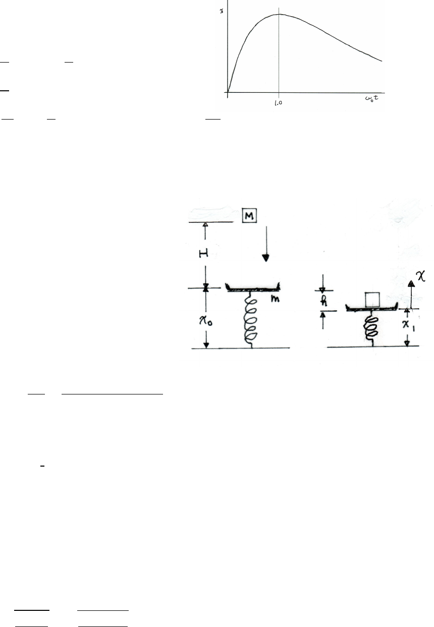
174 THE HARMONIC OSCILLATOR
(b) The initial conditions are
x(0) =0=⇒A=0
˙
x(0) =I
m=⇒B=I
m
x=I
mte−ω0t
0=dx
dt tmax
=I
m(1−ω0tmax)e−ω0t=⇒tmax =1.0
ω0
11.8 Scale spring constant
Let mbe the mass of the empty pan, and let
Mbe the mass of the falling block.
(a)
Before Mlands,
kx0=−mg
After Mlands and is at rest,
kx1=−(m+M)g
k(x1−x0)=−Mg
k=Mg
h=(10.0 kg)(9.8 m ·s−2)
0.10 m =980 N ·m−1
(b) Let x≡x(t) be the coordinate of the pan, measured from final equilibrium x1.
The equation of motion for a critically damped oscillator is given in Eq. (11.43)
in Note 11.2:
x=(A+Bt)te−γ
2t≡(A+Bt)e−ω0t
Qualitatively, the pan moves down below x1after the collision and then moves
upward back to the equilibrium position x1, according to the behavior for a
critically damped oscillator (no oscillations).
The initial conditions are
x|t=0=x0−x1=h=⇒A=h=0.10 m
˙x(0) =v0=B−ω0(A+Bt)e−ω0tt=0=B−ω0A
B=v0+ω0h
ω0=rk
m+M=r980
10.0+2.0=9.04 s−1
continued next page =⇒
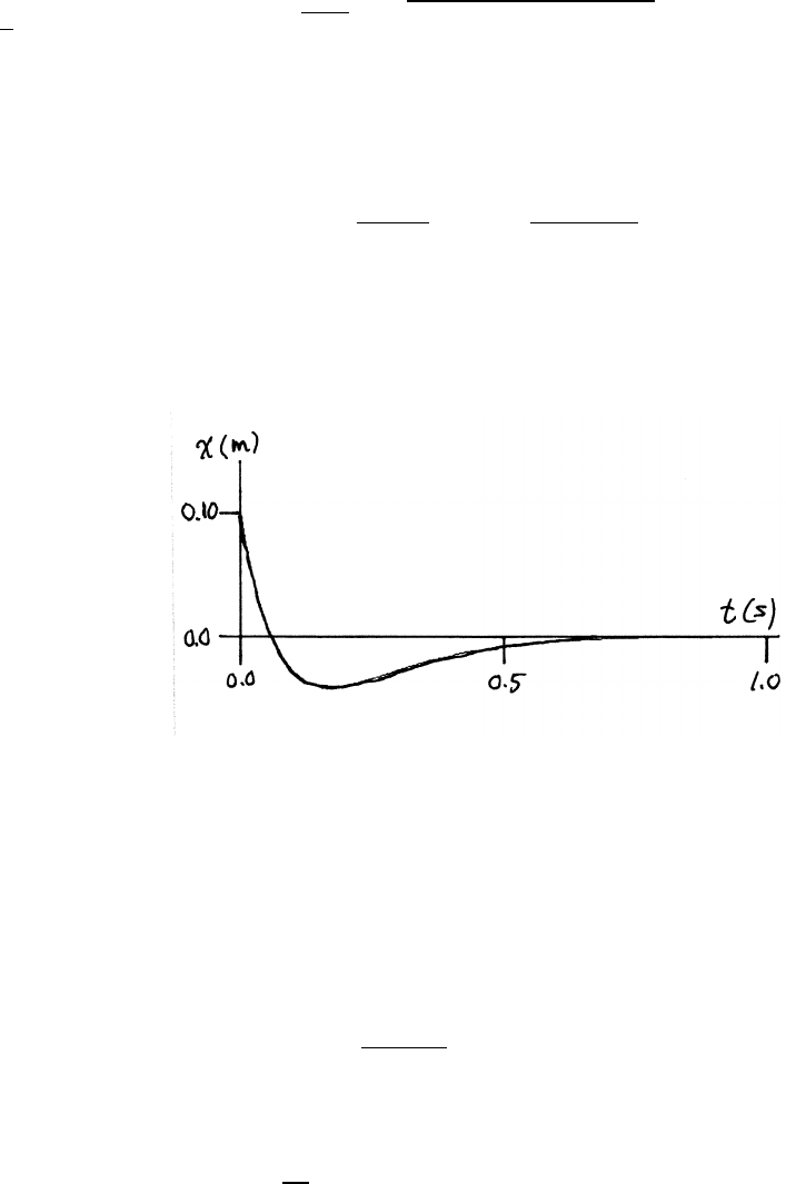
THE HARMONIC OSCILLATOR 175
Mechanical energy of Mis conserved until it strikes the pan, so its speed V
immediately before the collision is
1
2MV2=MgH =⇒V=p2gH =q(2)(9.8 m ·s−2)(0.50 m) =3.13 m/s
To find v0, use conservation of momentum, because mechanical energy is not
conserved in the collision of Mwith the pan.
−MV =(m+M)v0=⇒v0=−M
m+MV=− 10.0
10.0+2.0!(3.13) =−2.61 m/s
B=v0+ω0h=−2.61 +(9.04)(0.10) =−1.71 m/s
x=(0.10 −1.71t)e−9.04 t(1)
The figure is a graph of the result, Eq. (1).
11.9 Velocity and driving force in phase
From Sec. (11.4), the driving force Fdis
Fd=F0cos (ωt) (1)
From Eqs. (11.26) and (11.28), the motion is
x=X0cos (ωt+φ)
φ=arctan γω
ω2
0−ω2!(2)
The velocity is
v=dx
dt =−ωX0sin (ωt+φ) (3)
Comparing Eqs. (1) and (3), the condition for vand Fdto be in phase is
−sin (ωt+φ)=cos (ωt) (4)
Using −sin (ωt+φ)=−sin (ωt) cos φ−cos (ωt) sin φ
condition (4) requires sin φ=−1 and cos φ=0
continued next page =⇒
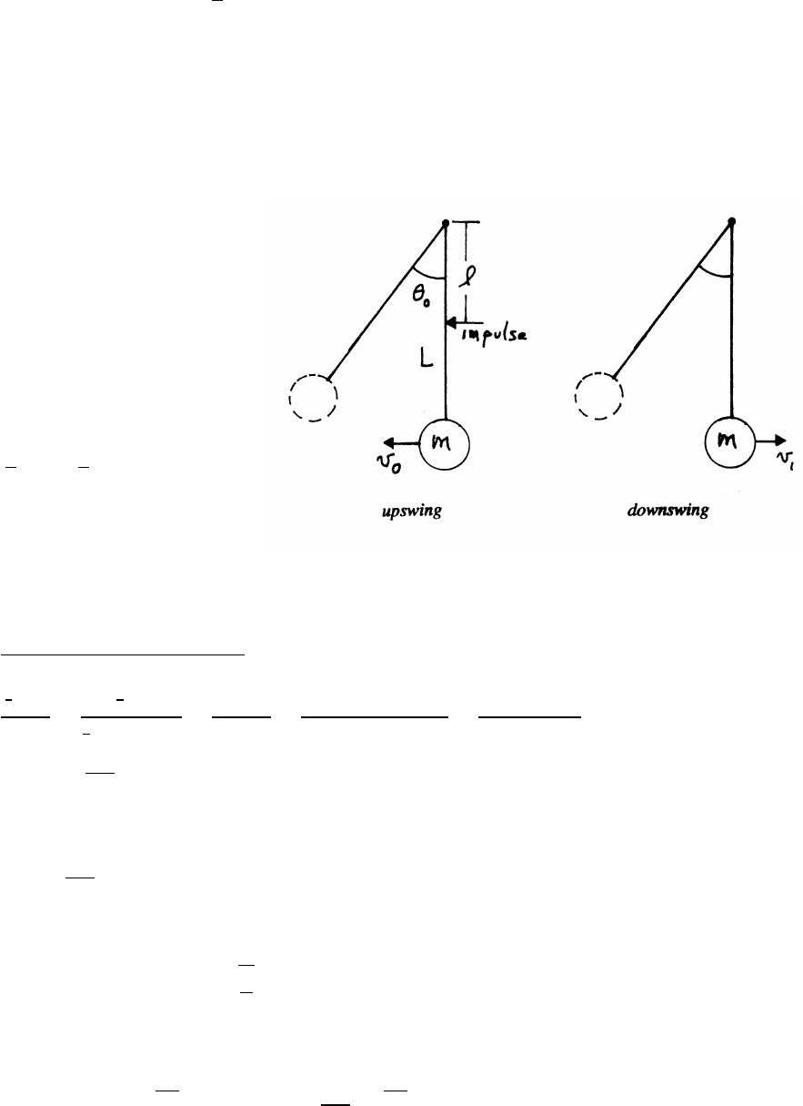
176 THE HARMONIC OSCILLATOR
These requirements are both satisfied for
φ=−π
2=⇒tan φ→ −∞
From Eq. (2), the tangent goes to infinity when ω=ω0, at the resonance frequency
of the undamped oscillator.
11.10 Grandfather clock
The pendulum loses mechanical
energy ∆Eas it swings, due to friction.
As indicated in the sketch, its speed
speed decreases slightly from v0to v1
during a half cycle. The escapement
provides an impulse every period to
make up for the loss.
(a)
∆E=1
2mv2
0−1
2mv2
1
∆Eis the energy lost per half cycle (πradians).
From Eq. (11.23),
Q=energy of the oscillator
energy dissipated per radian
=
1
2mv2
0
∆E/π =π(1
2mv2
0)
1
2m(v2
0−v2
1)=πv2
0
v2
0−v2
1
=πv2
0
(v0−v1)(v0+v1)≈πv2
0
2v0(v0−v1)
∆v=v0−v1=πv0
2Q
The required impulse Iis
I=m∆v=πv0
2Q
The pendulum motion is
θ=θ0sin (ωt) where ω=rg
L
The speed v0at the beginning of the upswing is
v0=L˙
θ=L(ω θ0)=pgL θ0=⇒I=m πθ0
2Q!pgL
continued next page =⇒
THE HARMONIC OSCILLATOR 177
(b) The impulse Iproduces a change in speed ∆v=I/m, so that the energy is
increased by ∆EI.
∆EI=1
2m(v+ ∆v)2−1
2mv2=mv∆v+1
2m(∆v)2=Iv +I2
2m
The point in the cycle where the impulse acts can vary due to mechanical im-
perfections. To minimize this effect, the impulse should be applied when vis
not changing to first order with respect to θ, which is at the bottom of the swing.
Proof: The energy equation is
E=1
2mv2+mgL(1 −cos θ) (1)
To find where dv/dθ=0, differentiate Eq. (1), where E=constant.
0=mvdv
dθ+mgL sin θ=0+mgl sin θ=⇒sin θ=0
so θ=0, that is, at the bottom of the swing.
11.11 Average stored energy
The energy dissipated by a damped driven oscillator is the mechanical energy con-
verted to heat by the viscous retarding force Fv=bv. The motion is
x=Acos (ωt+φ)v=−Aωsin (ωt+φ)
The rate of energy dissipation is the power P. Brackets hi denote time averages.
P=vFv=bv2A2ω2sin2(ωt+φ)=⇒ hPi=1
2bA2ω2
The oscillator traverses 1 radian in time tr=1/ω.∆Edissipated during tris
∆E=hPitr=hPi
ω=1
2ωbA2
For a lightly damped oscillator,
ω≈ω0=rk
m
The average energy hEiof the oscillator is
hEi=1
2khx2i+1
2mhv2i=1
2k 1
2A2!+1
2m 1
2ω2A2!≈1
2k 1
2A2!+1
2m 1
2ω2
0A2!=1
2kA2
hEi
∆E=
1
2kA2
1
2ωbA2=k
ωb≈k
ω0b=k
ω0γm=ω0
γ=Q
using γ=b/m, Eq. (11.9).
178 THE HARMONIC OSCILLATOR
11.12 Cuckoo clock
A cuckoo clock is a pendulum clock with a mechanism that causes a bird model to
pop out to announce the hour.
Let time averages be denoted by brackets hi.
Let lbe the length of the pendulum, and let θ0be the amplitude of swing. The mass
of the pendulum is m, and the mass of the falling weight is M.
The power to the clock by the descending weight compensates the power dissipated
by friction. If the weight descends a distance Lin time Td,
hPi=MgL
Td
The energy dissipated per radian is
h∆Ei=hPi
ω
The gravitational potential energy is mgl(1 −cos θ)≈mgl(θ2/2), so the average
stored energy is
hEi=1
2mhv2i+1
2mglhθ2i
The average kinetic and potential energies are equal.
hEi=1
2mgl θ2
0
Q=hEi
h∆Ei=
1
2mgl θ2
0
hPi
ω=
1
2mgl θ2
0
MgL
ωTd
=1
2m
M l
L!θ2
0ωTd
=1
2 0.01 kg
0.2 kg ! 0.25 m
2.0 m !(0.2 rad)2(2πrad/s)(8.64 ×104s)
=68
The energy Edto run the clock for 24 hours is
Ed=MgL =(0.2 kg)(9.8 m ·s−2)(2 m) =3.9 J
Therefore a 1J battery could run the clock for only a little over 6 hours.
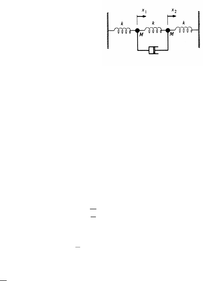
THE HARMONIC OSCILLATOR 179
11.13 Two masses and three springs
(a) equations of motion:
M¨x1=−kx1−k(x1−x2)−b( ˙x1−˙x2) (1)
M¨x2=−kx2−k(x2−x1)−b( ˙x2−˙x1) (2)
(b) Adding Eqs. (1) and (2),
M( ¨x1+¨x2)=−k(x1+x2)
y1=x1+x2=⇒M¨y1+ky1=0 (3)
Subtracting Eq. (2) from Eq. (1),
M( ¨x1−¨x2)=−k(x1−x2)−2k(x1−x2)−2b( ˙x1−˙x2)
y2=x1−x2=⇒M¨y2=−3ky2−2b˙y2(4)
Equations (3) and (4) each have only one dependent variable, y1or y2, so in
principle they can be solved directly (numerically if necessary).
(c) For mode y2Eq. (4), the motion is a damped transient and eventually becomes
negligibly small, so that at long times y2=x1−x2=0 and x1=x2. The
equation of motion for y1Eq. (3) is the equation for free undamped SHM. At
long times, x1and x2move together so that their separation is constant and
there is therefore no damping.
To evaluate the initial conditions, express y1and y2in terms of x1and x2.
y1(0) =x1(0) +x2(0) =0+0=⇒y1(0) =0
˙y1(0) =˙x1(0) +˙x2(0) =v0+0=⇒˙y1(0) =v0
y2(0) =x1(0) −x2(0) =0−0=⇒y2(0) =0
˙y2(0) =˙x1(0) −˙x2(0) =v0−0=⇒˙y2(0) =v0
The solution of Eq. (3) is
y1=Asin (ωt)+Bcos (ωt) where ω=rk
M
y1(0) =B=0
˙y1=ωAcos (ωt)
˙y1(0) =ωA=v0=⇒y1=Asin (ωt)=v0
ωsin (ωt)
At long times, y2→0, so x1−x2→0, hence x1=x2at long times. Then
y1=x1+x2=2x1, so
x1=v0
2ωsin (ωt) at long times
180 THE HARMONIC OSCILLATOR
11.14 Motion of a driven damped oscillator
(a) equation of motion for a forced damped oscillator:
¨xa+γ˙xa+ω2
0xa=F0
mcos (ωt) (1)
The steady-state solution to Eq. (1) is
xa=X0cos (ωt+φ) (1a)
where X0and φare defined in Eqs. (11.29) and (11.30). Note that X0and φhave
defined values, and therefore do not depend on the initial conditions.
equation of motion for a free damped oscillator:
¨xb+γ˙xb+ω2
0xb=0 (2)
Let
x(t)=xa(t)+xb(t)
¨x+γ˙x+ω2
0x=¨xa+γ˙xa+ω2
0xa+¨xb+γ˙xb+ω2
0xb
=F0
mcos (ωt)+0
so x(t) also satisfies Eq. (1). This is a consequence of the linearity of Eqs. (1)
and (2).
(b) From Eqs. (11.12) and (11.13), the motion for the free damped oscillator is
xb=Xbe−γ
2tcos (ω1t+ψ) (2a)
where Eq. (2a) is the solution to Eq. (2), and where Xband ψare to be deter-
mined by the initial conditions.
In Eq. (2a),
ω1=qω2
0−(γ/2)2ω0=rk
m
x=xa+xb=X0cos (ωt+φ)+Xbe−γ
2tcos (ω1t+ψ) (3a)
˙x=−ωX0sin (ωt+φ)+Xbe−γ
2t−γ
2cos (ω1t+ψ)+ω1sin (ω1t+ψ)(3b)
Applying the initial conditions,
x(0) =X0cos φ+Xbcos ψ=0 (4a)
v(0) =˙x(0) =−ωX0sin φ−Xbγ
2cos ψ+ω1sin ψ=0 (4b)
continued next page =⇒
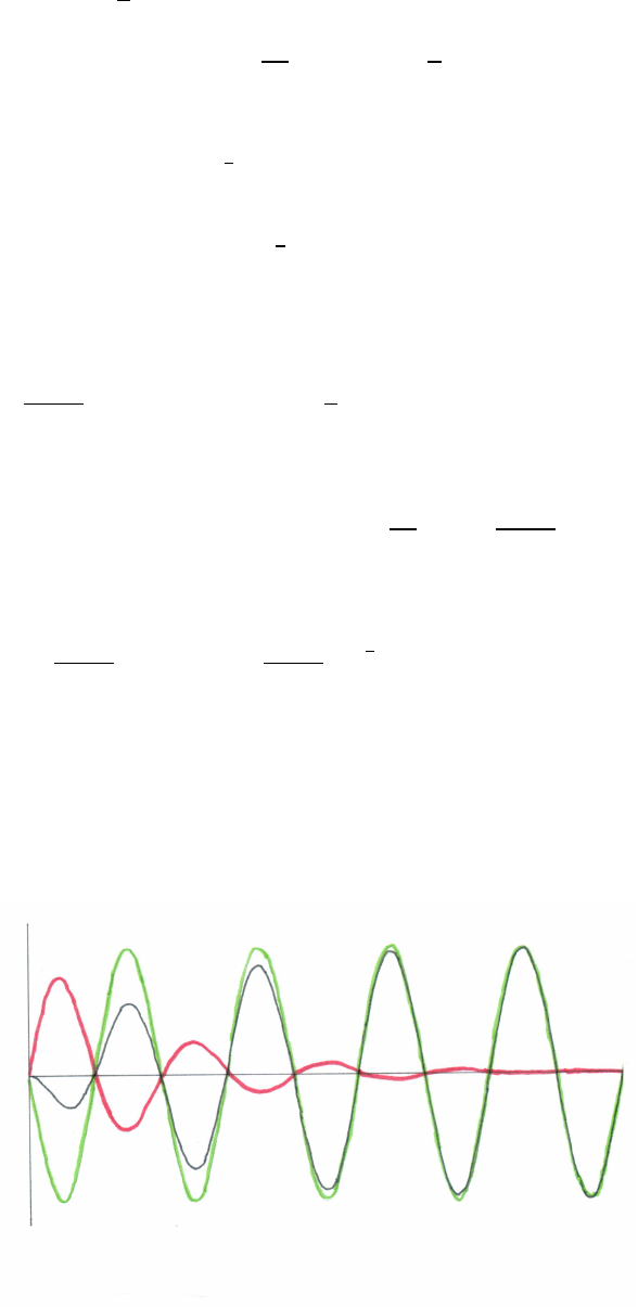
THE HARMONIC OSCILLATOR 181
Solving. To simplify, let
C ≡ Xbcos ψS ≡ Xbsin ψ
Equation (4a) becomes
C=−X0cos φ
Equation (4b) becomes
−ωX0sin φ−γ
2C − ω1S=0
S=X0
ω1−ωsin φ+γ
2cos φ
With this notation, Eqs. (3a) and (3b) can be written
x=X0cos (ωt+φ)+e−γ
2t[Ccos (ω1t)− S sin (ω1t)](5a)
˙x=−ωX0sin (ωt+φ)−e−γ
2t(γ/2)Ccos (ω1t)−(γ/2)Ssin (ω1t)
+ω1Csin (ω1t)+ω1Scos (ω1t)](5b)
(c) At resonance, ω=ω0and from Eqs. (11.29) and (11.30),
X0=F0
mω0γφ=arctan (∞)=π
2
so that
C=−X0cos (π/2) =0 and S=−ω0
ω1
X0=−F0
mω1γ
At resonance, Eq. (5a) becomes
x=− F0
mω0γ!sin (ω0t)+ F0
mω1γ!e−γ
2tsin (ω1t)
The figure shows the response for the steady-state forced damped oscillator
(green), the free damped oscillator transient (red), and the net behavior (black).
The transient eventually becomes negligibly small, leaving only the steady-
state behavior.
The figure is drawn for ω0=2.0 s−1and γ=0.70 s−1, so that ω1=1.97 s−1.
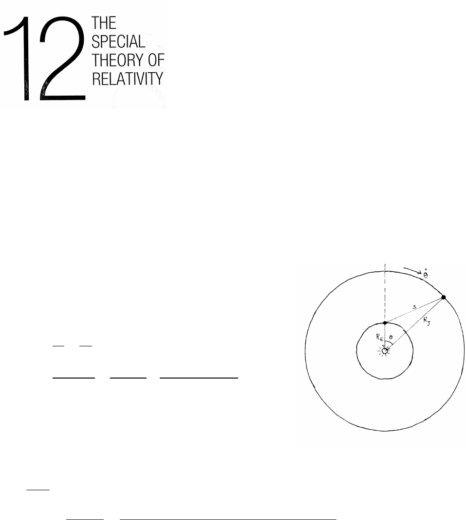
12.1 Maxwell’s proposal
The orbits are essentially circular. The rate of revolution
is ˙
θ=2π/T, where Tis the period. In a coordinate
system rotating with the Earth, the apparent rate of
Jupiter’s revolution is
˙
θ=2π 1
TJ−1
TE!
=2π 1
11.9 year −1
1.0 year! 1
3.15 ×10⁷s/year!
=−1.8×10⁻⁷rad ·s−1
Differentiate the law of cosines to find 2s˙s.
s2=R2
J+R2
E−2RjREcos θ
d(s2)
dt =2s˙s=2RJREsin θ˙
θ
(∆T)max ≈2RJRE˙
θ
c2=(2)(7.8×10¹¹ m)(1.5×10¹¹ m)(1.8×10⁻⁷s−1)
(3.0×10⁸m·s−1)2
≈0.5 s
∆Tis for the extremes of s. Minimum soccurs for θ=0◦, when Jupiter, the Earth,
and the Sun are in line, with the Earth on the side of its orbit nearest Jupiter. Maxi-
mum soccurs a little over 6 months later, for θ=180◦.

THE SPECIAL THEORY OF RELATIVITY 183
12.2 Refined Michelson-Morley interferometer
As derived in Sec. 12.3, the fringe shift Nis
N=2l
λ v2
c2!
The additional factor of 2 arises because the improved interferometer could be ro-
tated to be either with or against the Earth’s motion, doubling the possible observ-
able fringe shift.
The upper limit to vfor a fringe shift no larger than Nis therefore
v≤crNλ
2l
v≤(3.0×10⁸m/s) s(0.01)(590 ×10−9m)
(2)(11.0 m) =4.9×10³m/s
Compared to the speed of the Earth in its orbit, this limit is smaller by a factor of
3.0×10⁴m/s
4.9×10³m/s=6.1
12.3 Skewed Michelson-Morley apparatus
In the upper sketch, the apparatus is moving to the
right with speed v. The time for light to go from
the origin to the end of arm A and return is
τ++τ−=S+
c+S−
c
L±=vτ±
From the lower sketches,
s2
+=l2+L2
+−2lL+cos φ
=l2+L2
+−2lL+cos (π−θ)=l2+L2
++2lL+cos θ
c2τ2
+=l2+v2τ2
++2lvτ+cos θ
0= 1−v2
c2!τ2
+− 2lv cos θ
c2!τ+−l2
c2
τ+=1
21−v2
c2
2lv
c2cos θ±2l
cr1+v2
c2(cos2θ−1)
Take the +root, because τ+=2l/cwhen v=0.
continued next page =⇒
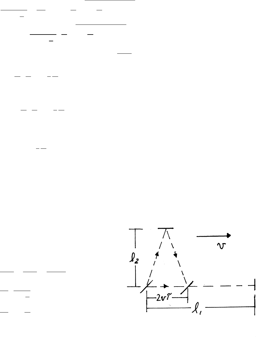
184 THE SPECIAL THEORY OF RELATIVITY
The calculation for τ−follows the same algebra but replacing cos θwith −cos θ.
τ−=1
21−v2
c2−2lv
c2cos θ+2l
cr1+v2
c2(cos2θ−1)
τA≡τ++τ−=1
21−v2
c2
4l
cr1+v2
c2(cos2θ−1)
Retain only terms up to order v2/c2, and use √1+x=1+x/2+. . .
τA≈ 1+v2
c2!2l
c"1+1
2
v2
c2(cos2θ−1)#
The analysis for arm B is similar, but with φ0=π/2+θ, so that cos φ0=−sin θ.
τB≈ 1+v2
c2!2l
c"1+1
2
v2
c2(sin2θ−1)#
The difference in time τdi f f for the two paths is, to order v2/c2,
τdi f f =τA−τB=l
c
v2
c2(cos2θ−sin2θ)
This agrees with the result in Sec. 12.3 when θ=0. It also shows that the fringe
shift changes sign when the apparatus is rotated by 90◦.
12.4 Asymmetric Michelson-Morley interferometer
Assume, as Michelson did, that the speed
of light adds vectorially to the speed
of the interferometer through the ether.
The time τ1for light to travel out
and back along l1parallel to vis
τ1=l1
c+v+l1
c−v=2l1c
c2−v2
=2l1
c
1
1−v2
c2
≈2l1
c 1−v2
c2!
continued next page =⇒
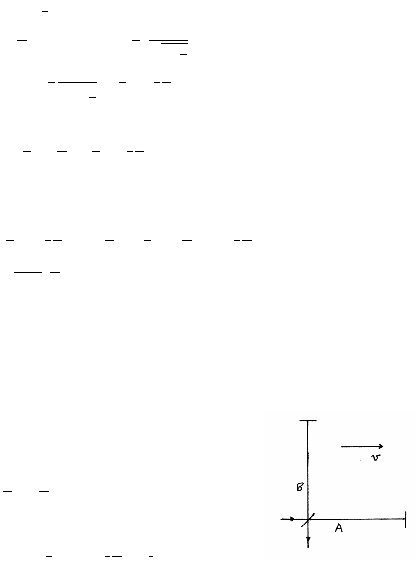
THE SPECIAL THEORY OF RELATIVITY 185
Let τbe the time to travel to the upper mirror. During this time, the lower mirror
advances a distance vτ. The time τ2for the total round trip along arm l2, which is
perpendicular to v, is
τ2=2τ=2
cql2
2+(vτ)2
4τ2=4
c2l2
2+v2τ2=⇒τ= l2
c!1
q1−v2
c2
τ2=2τ=2l2
c
1
q1−v2
c2
≈2l2
c 1+1
2
v2
c2!
The time difference is
τ1−τ2=2l1
c 1+v2
c2!−2l2
c 1+1
2
v2
c2!
If the interferometer is rotated by 90◦, the arms are reversed, so that the change ∆T
in delay is
∆T=(τ0
1−τ0
2)−(τ1−τ2)=(τ0
1−τ1)−(τ0
2−τ2)
=2l1
c" 1+1
2
v2
c2!− 1+v2
c2!#−2l2
c" 1+v2
c2!− 1+1
2
v2
c2!#
=− l1+l2
c!v2
c2
The fringe shift Nis therefore
N=c
λ|∆T|= l1+l2
λ!v2
c2
12.5 Lorentz-FitzGerald contraction
Assume that both arms have the same rest length l0, and
that during the fringe shift measurement, the lengths are
lAand lB.
The times to traverse the arms are
τA=2lA
c 1+v2
c2!
τB=2lB
c 1+1
2
v2
c2!
∆τ=τA−τB=2
c(lA−lB)+2
c
v2
c2(lA−1
2lB)
continued next page =⇒
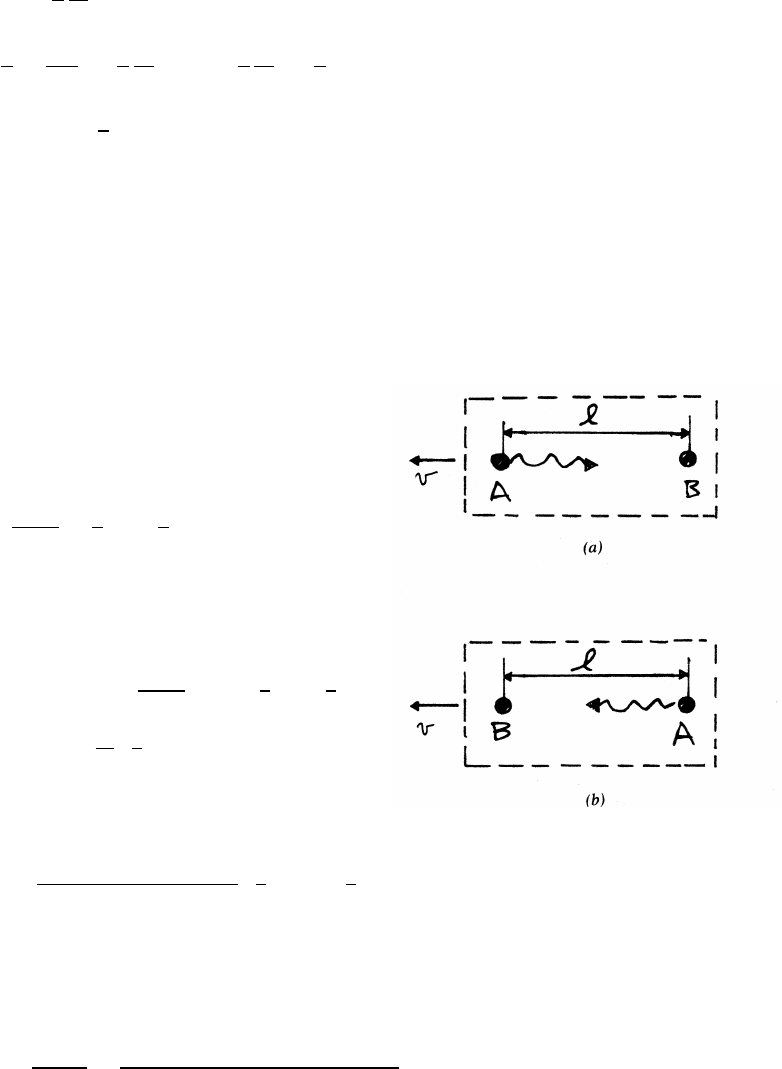
186 THE SPECIAL THEORY OF RELATIVITY
Following Lorentz and FitzGerald, take
lA=l0 1−1
2
v2
c2!and lB=l0
∆τ=−2
cl0 v2
2c2!+2
c
v2
c2"l0 1−1
2
v2
c2!−1
2l0#
≈0 to order v
c4
There is no fringe shift to order v2/c2. For the Earth’s orbital motion v=3.0×10⁴
m/s, (v/c)2=10−8. Terms to order (v/c)4=10−16 were too small to be detected in
the Michelson-Morley interferometer.
12.6 One-way test of the consistency of c
(a) event a:
At t=0, a pulse is sent from A
and arrives at B at time ta.
ta=l
c−v≈l
c1+v
c
event b:
At time T, a pulse is sent from B
and arrives at A at time tb.
tb=T+l
c+v≈T+l
c1−v
c
tb−ta−T=2l
cv
c
(b) Let lbe the distance from the ground to the
satellite, l=5.6Re−Re=4.6Re. Then
∆T= (2)(4.6)(6.4×10⁶m)
3.0×10⁸m/s!v
c=0.17 v
cs
The orientation with respect to the ether would be opposite after 12 hours. With
an accuracy of 1 part in 1016, the clock could detect a change δTof
δT=(12 hours)(3600 s/hour) ×10−16 =4.3×10⁻¹² s in a period of 12 hours.
v≥cδT
0.17 s =(3.0×10⁸m/s)(4.3×10−12 s)
0.17 s
The minimum detectable vwould be
vmin =7.6×10⁻³m/s
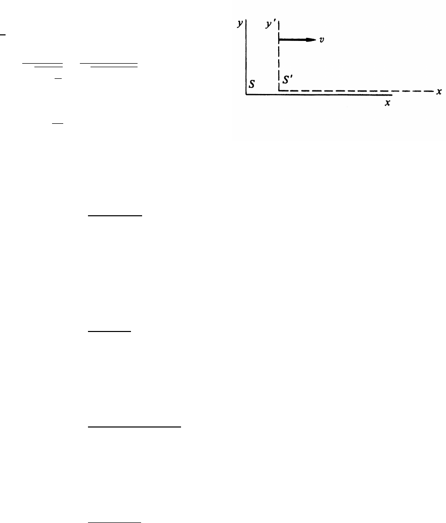
THE SPECIAL THEORY OF RELATIVITY 187
12.7 Four events
v
c=0.6
γ=1
q1−v2
c2
=1
p1−(0.6)2
=1.25
x0=γ(x−vt)
t0=γt−xv
c2
(a)
x=4 m t=0 s
x0=1.25[4 −0] =5 m
t0=1.25 "0−(4 m)(0.6c)
c2#=−1×10⁸s
(b)
x=4 m t=1 s
x0=1.25[4 −(0.6c)(1)] =1.25[4 −(0.6)(3 ×10⁸]≈ −2.25 ×10⁸m
t0=1.25 "1−(4)(0.6c)
c2#≈1.25 s
(c)
x=1.8×10⁸mt=1 s
x0=1.25[1.8×10⁸−(0.6c)(1)] =0 m
t0=1.25 "1−(1.8×10⁸m)(0.6c)
c2#=0.8 s
(d)
x=109mt=2 s
x0=1.25[109−(0.6c)(2)] =8×10⁸m
t0=1.25 "2−(109)(0.6c)
c2#=0 s
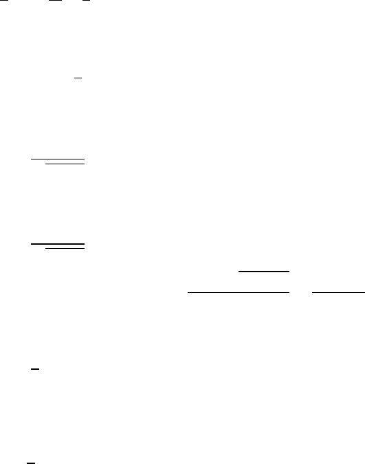
188 THE SPECIAL THEORY OF RELATIVITY
12.8 Relative velocity of Sand S0
Given
x=9×108mx0=3×10⁸mt0=1 s
From Eq. (12.4a)
x=γ(x0+vt0)
It is convenient to express all lengths in units of c.
x
c=γ x0
c+v
ct0!
so that
3=γ1+v
c(1)(1)
Let r≡v2/c2so that
γ=1
√1−r2
and Eq. (1) becomes
3=1
√1−r2(1 +r)=⇒9(1 −r2)=(1 +r)2
0=10r2+2r−8=⇒r=−2±√4+320
20 =−2±18
20
The roots are
r=4
5,−1
The root -1 is rejected, because γis undefined for v2/c2=1, and also because the
relative speed of observers must be less than c. Hence
v=4
5c=2.4×10⁸m/s
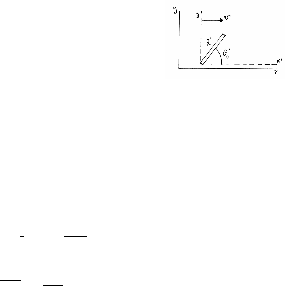
THE SPECIAL THEORY OF RELATIVITY 189
12.9 Rotated rod
In this solution, primed quantities refer to the
moving x0−y0frame, and unprimed quantities
to the stationary x−yframe.
Let x0−y0be the rod’s rest frame, as shown
in the sketch. In its rest frame, the rod makes angle
θ0
0with x0axis. The lower end of the rod is at
the origin of the x0−y0frame, and the upper end is at
x0=l0cos θ0
0y0=l0sin θ0
0
As observed in the x−yframe, the rod is moving to the right with speed v, as
shown. Let the measurements be made at t=t0=0, when the origins coincide. It is
tempting, but wrong, to use x=γx0. The ends must be measured at the same time
in the x−yframe, so it is necessary to use the full transformation x0=γ(x−vt),
and y0=y.
Then at t=0, the lower end is located at
0=x0=γ(x−0) =⇒x=0
0=y0=y=⇒y=0
At t=0, the upper end in x−yis located at
x0=l0cos θ0
0=γ(x−0) =⇒γx=x0=l0cos θ0
0
y0=l0sin θ0
0=y
The angle θ0in the x−yframe is therefore
θ0=arctan y
x=arctan γl0sin θ0
0
l0cos θ0
0!=arctan (γtan θ0
0)
For v→c, then γ→ ∞ so θ0→π/2.
In the x−yframe, the length lof the rod is
l=px2+y2=l0scos2θ0
0
γ2+sin2θ0
0
For v→c, then γ→ ∞ and l=l0sin θ0
0.
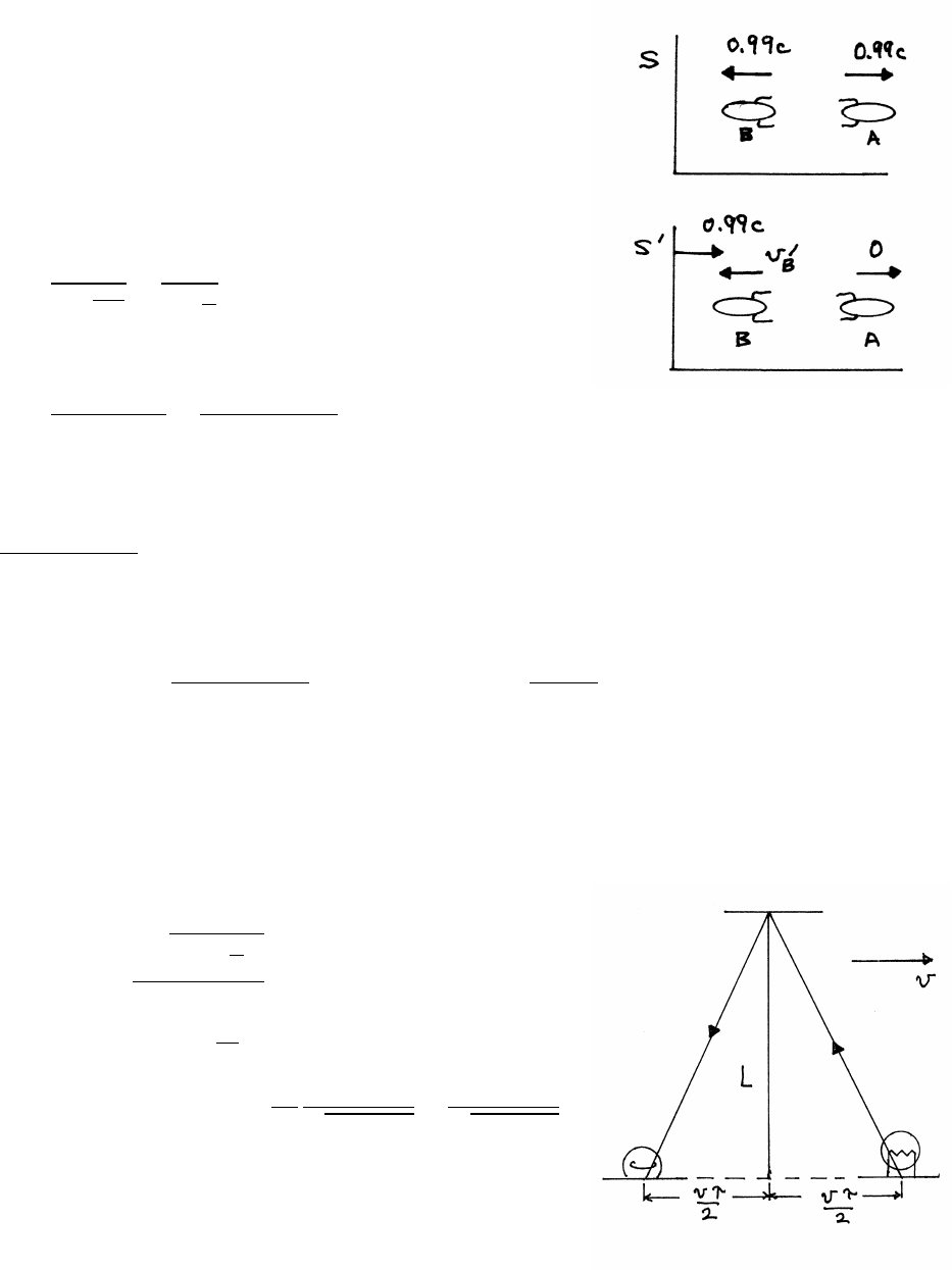
190 THE SPECIAL THEORY OF RELATIVITY
12.10 Relative speed
The sketches show the spaceships in the observer’s
frame S, and in frame S0moving with spaceship A.
In frame S
vA=vB=0.99c≡v
In frame S0moving with A,v0
A=0.
v0
B=vA+vB
1+vAvB
c2
=2v
1+v2
c2
vnearly equals c, so for accuracy let v=(1 −x)cwhere x=0.01.
v0
B=2(1 −x)c
1+(1 −x)2=(1 −x)c
1−(x−x2/2)
The result is exact so far, but because x1, expand in Taylor’s series (1 −u)−1=
1+u+u2+. . .
(1 −x)c
1−(x−x2/2) ≈(1 −x)ch1+(x−x2/2) +(x−x2/2)2+. . .i
Retaining only terms up to x2,
v0
B=(1 −x)c
1−(x−x2/2) ≈(1 −x2/2)c="1−(0.01)2
2#c=(1 −5×10⁻⁵)c=0.99995c
Note the importance of including all terms up to the desired highest order.
12.11 Time dilation
The total time of travel τis
τ=
2qL2+(vτ
2)2
c
c2τ2=4"L2+vτ
22#
τ2(c2−v2)=4L2=⇒τ=2L
c
1
p1−v2/c2
=τ0
p1−v2/c2
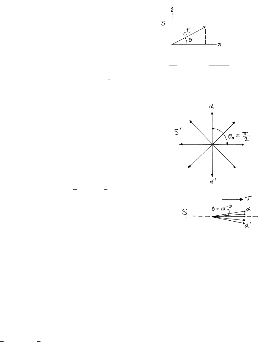
THE SPECIAL THEORY OF RELATIVITY 191
12.12 Headlight effect
(a) In the S0frame, the coordinates x0,y0,t0of the
light pulse after t0=1 s are
x0=ccos θ0y0=csin θ0t0=1 s
In S, the coordinates x,y,tare
x=γ(x0+vt0)=γ(ccos θ0+v)y=y0t=γ t0+vx0
c2!=γ1+vcos θ0
c
cos θ=x
ct =γ(ccos θ0+v)
γ(c+vcos θ0)=cos θ0+v
c
1+v
ccos θ0
(b) In S0, half the radiation is emitted in the forward
hemisphere, limiting θ0to ±π/2 so that cos θ0=0 at the
limits. In S, using the result from (a), θis limited to
cos θ=±0+v/c
1+0=±v
c
v=ccos θ
Let θbe the half-angle of the cone, as shown.
θ1=⇒cos θ≈1−1
2θ2=1−1
2(10−3)2
v=(1 −5×10⁻⁷)c
12.13 Traveling twin
From Sec. 12.11, the difference ∆Tbetween the twins’ ages is
∆T=1
2T0
v2
c2
where T0is the total time for the voyage and where vis the speed of the craft,
assumed constant except at turnaround.
The distance to αCentauri is 4.3 light years. At a speed v=c/5, the craft travels 1
light year in 5 years, so the round trip takes
T0=(2)(4.3)(5) =43 years
∆T=1
2(43 years) 1
5!2
=0.86 year ≈10 months
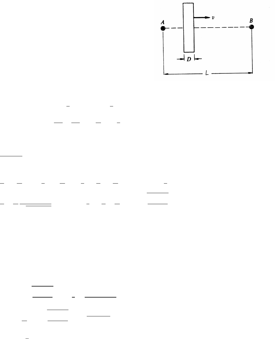
192 THE SPECIAL THEORY OF RELATIVITY
12.14 Moving glass slab
For the trip from Ato B, let t0be the time spent
traveling outside the glass and tgbe the time spent
traveling through the glass. To find tg, consider two
events in the S0rest frame of the slab.
event 1: light enters the slab at t0
1=0,x0
1=0.
event 2: light leaves at t0
2=nD/c,x0
2=D.
In the Slab frame, light enters the slab at x1and time t1,
and leaves at x2at time t2. The Lorentz transformation gives
x1=γ(x0
1+vt0
1)=(0 +0) =0t1=γ(t0
1+vx0
1/c2)=(0 +0) =0
x2=γ(x0
2+vt0
2)=γD+nDv
c=γD1+nv
c
t2=γ(t0
2+vx0
2/c2)=γnD
c+vD
c2=γD
cn+v
c
The distance traveled outside the slab is L−x2, so
t0=(L−x2)
c
T=t0+tg=t0+t2−t1
=L
c−γD
c1+nv
c+γD
cn+v
c=L
c+γD
cn−1+(1 −n)v
c
=L
c+D
c
1
p1−v2/c2(n−1) 1−v
c=L
c+D
c(n−1) s1−v/c
1+v/c
12.15 Doppler shift of a hydrogen spectral line
Light from a receding source is shifted toward the red (longer wavelength), and
light from an approaching source is shifted toward the blue (shorter wavelength).
(a) From Eq. (12.12),
ν0=νs1−v/c
1+v/c=⇒v
c=3×10⁶m/s
3×10⁸m/s=0.01
λ0=c
ν0=λs1+v/c
1−v/c≈λp1+2v/c≈λ(1 +v/c)=1.01λ
λ0−λ=λv
c=0.01λ=6.6×10⁻⁹m
λ0=(656.1+6.6) ×10−9=662.7×10⁻⁹m
continued next page =⇒
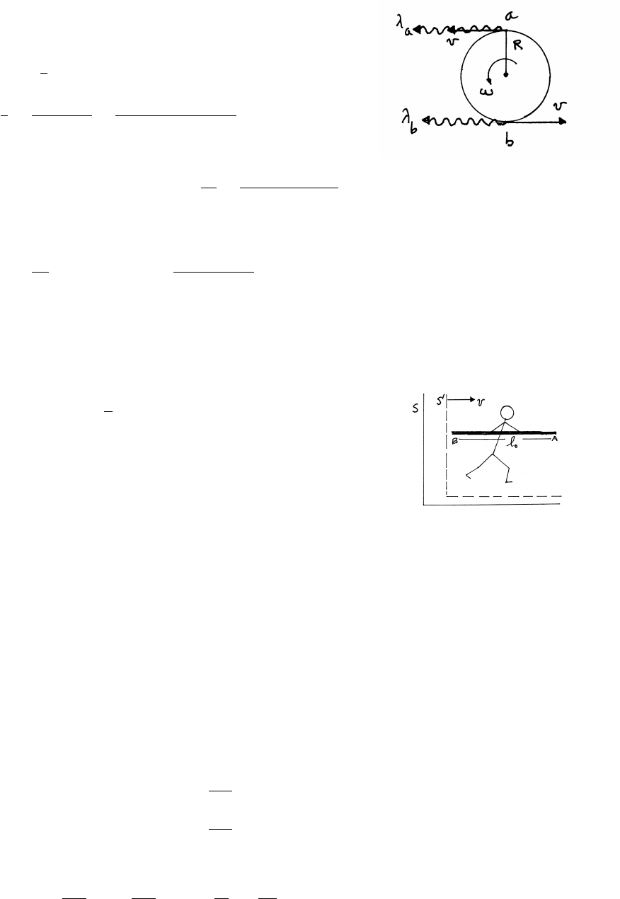
THE SPECIAL THEORY OF RELATIVITY 193
(b)
The difference in observed wavelengths from the
advancing limb aand the receding limb bis, from (a),
λa−λb=2v
cλ
v
c=(λa−λb)
2λ=9.0×10⁻¹² m
(2)(656 ×10−9m) =6.86 ×10⁻⁶
v=(6.86 ×10⁻⁶)(3 ×10⁸m/s) =2.06 ×10³m/s
v=ωR=ω(D/2) =⇒ω=2v
D=4.12 ×10³m/s
1.4×10⁹m=2.94 ×10⁻⁶s−1
The period Tis
T=2π
ω=(2.13 ×10⁶s) 1 day
8.64 ×10⁴s!≈25 days
12.16 Pole-vaulter paradox
Unprimed quantities refer to frame S, and primed quantities
to frame S0. For v/c=√3/2, γ=2.
(a) the farmer’s point of view (frame S ):
Let end Bof the pole be at xBat time t. At the same time t,
the farmer (in frame S) observes end Aat xA. Let lbe the
length of the pole in S, so that l=xA−xB. From the
Lorentz transformation Eq. (12.13),
x0
A−x0
B=l0=γ(xA−vt)−γ(xB−vt)=γ(xA−xB)=γl
l=l0/γ =l0/2, so that the pole easily fits inside the barn.
(b) the runner’s point of view (frame S 0):
The length of the pole in S0is l0, so if end Ais at the rear door, the end Bis
projecting out the front door by l0−(3/4)l0=l0/4.
(c) From the Lorentz transformation Eq. (12.14),
x0
B=γ(xB−vt)t0
B=γt−vxB
c2
x0
A=γ(xA−vt)t0
A=γt−vxA
c2
x0
A−x0
B=l0
t0
A−t0
B=−γvxA
c2+γvxB
c2=−γ vl
c2!=vl0
c2
continued next page =⇒

194 THE SPECIAL THEORY OF RELATIVITY
In the runner’s system S0, the two ends of the pole are not inside the barn at the
same instant. From the runner’s point of view, event Aoccurs before the farmer
shuts the door.
Looked at more closely, at the instant the front door is closed, the runner ob-
serves that end Aof his pole is at x0
A=l0, so that it is already outside the rear
door. How does this event, call it C, look to the farmer in frame S?
xC=γ(x0
A+vt0)−γ(x0
B+vt0)=γl0=2l0
tC=γ t0+vx0
A
c2!−γ t0+vx0
B
c2!=2l0
v
c2
Because tC>0, the farmer observes that event Coccurs after the door is shut.
So the farmer and the pole-vaulter are both correct; the bet can’t be settled until
they agree on whose frame is to be used.
12.17 Transformation of acceleration
Take differentials of the equation for the relativistic addition of velocities, Eq.
(12.8a). Note that v, the relative velocity of the Sand S0frames, is a constant.
u=(u0+v)
1+u0v
c2
du =du0
1+u0v
c2−(u0+v)
1+u0v
c22
v
c2du0=du0
1+u0v
c22"1−v2
c2#=du0
1+u0v
c22
1
γ2(1)
From the Lorentz transformation,
dt =γ dt0+vdx0
c2!=γdt0 1+u0v
c2!(2)
Dividing Eq. (1) by Eq. (2),
a=du
dt =du0
dt0
1
γ3
1
1+u0v
c23
In the rest frame, du0/dt0=a0and u0=0.
a=a0
γ3
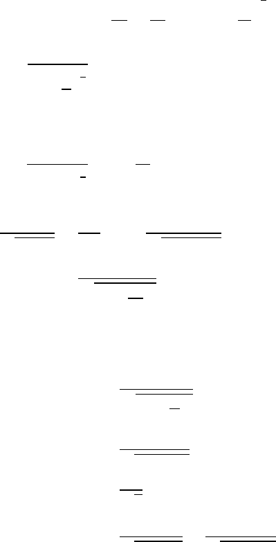
THE SPECIAL THEORY OF RELATIVITY 195
12.18 The consequences of endless acceleration
(a) If the acceleration in S0is a0, the acceleration ain Sis, with reference to prob-
lem 12.17,
a=dv
dt =a0
γ3=a0 1−v2
c2!
3
2
Zdv
1−v2
c23
2
=Za0dt
Let v=xc.
Zx
0
dx
(1 −x2)3
2
=Zt
0
a0
cdt
x
√1−x2=a0t
c=⇒v
p1−v2/c2
=a0t
v=a0t
q1+(a0t
c)2
Note that for t→ ∞,v→c.
(b) Let u0=a0tso that
v=u0
q1+(u0
c)2
u0=10−3c: v=10−3c
√1+10−6≈10−3c
u0=c: v=c
√2≈0.71c
u0=103c: v=103c
√1+106=c
√1+10−6≈(1 −5×10⁻⁷)c
High-energy particle accelerators can accelerate particles to energies far greater
than their rest-mass energies, but the particle’s speed is always less than c, if only
slightly.
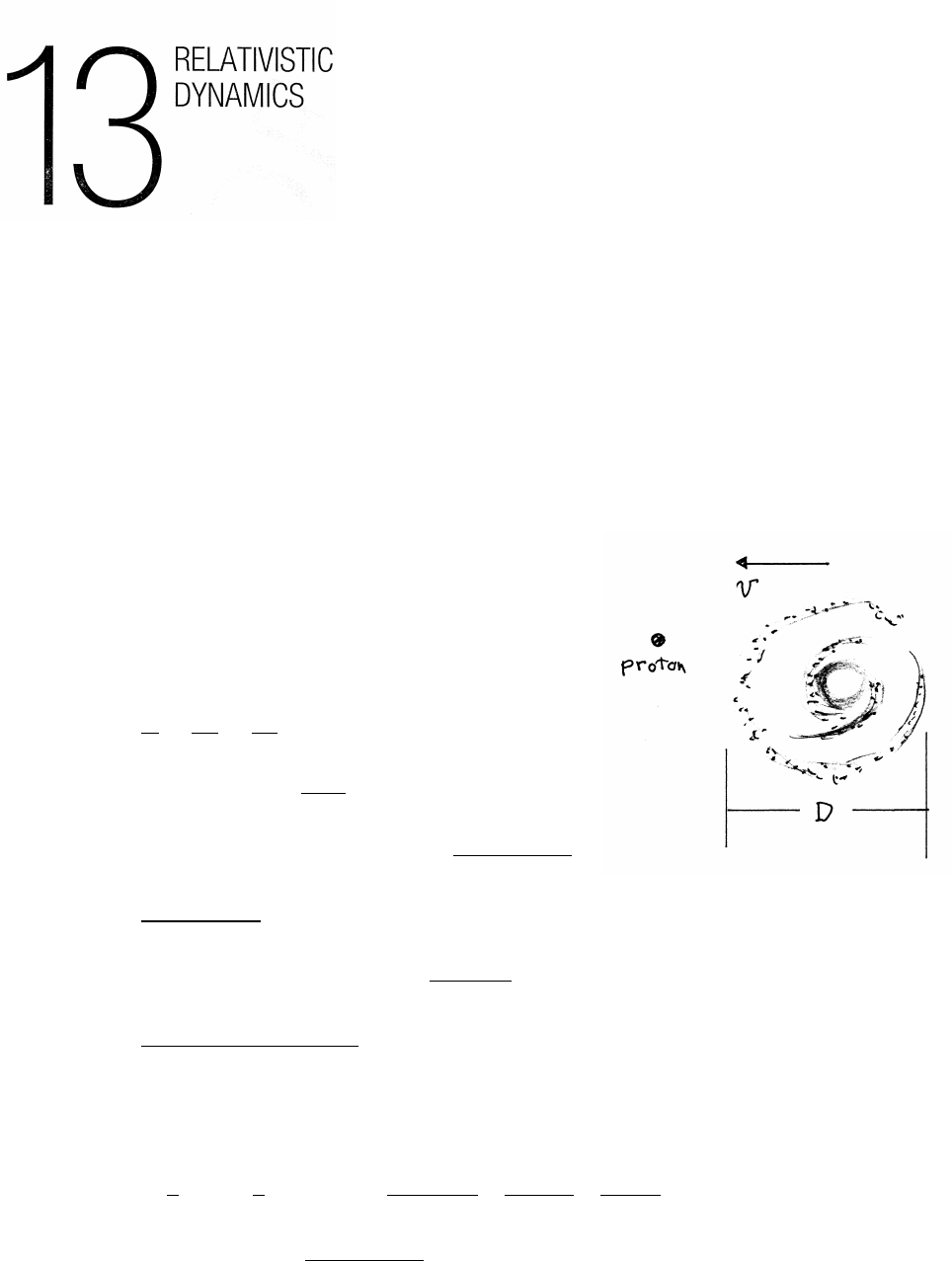
13.1 Energetic proton
(a) In a frame moving with the proton, the galaxy
is approaching at speed vand has thickness D=D0/γ.
The proton has such high energy that vis very
nearly c, to the accuracy of this solution.
The time Tto traverse the galaxy is
T=D
v=D0
γv'D0
γc
E=γm0c2=⇒γ=E
m0c2
m0c2=1.67 ×10⁻²⁷ kg3×108m/s2 1 eV
1.6×10⁻¹⁹ J!=9.4×10⁸eV
γ=3×10²⁰ eV
9.4×10⁸eV =3.2×10¹¹
D0=(105light years)(3 ×10⁸m/s) 3×10⁷s
1 year !=9×10²⁰ m
T=9×10²⁰ m
(3 ×10¹¹)(3 ×10⁸m/s) =10 s
The photon is traveling at the speed of light, so γ→ ∞, and Tphoton =0.
(b)
Ebaseball =1
2Mv2=1
2(0.145 kg) " 100 miles
1 hour ! 1610 m
1 mile ! 1 hour
3600 s!#2
=145 J
Eproton =(3 ×10²⁰ eV) 1.6×10⁻¹⁹ J
1 eV !=48 J
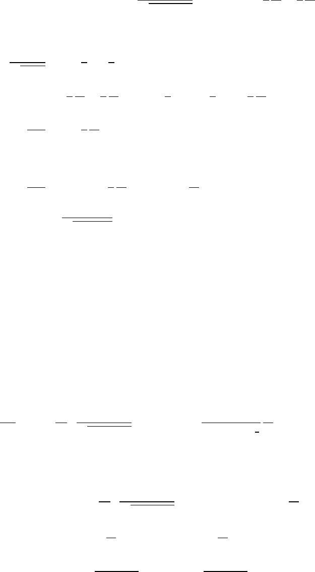
RELATIVISTIC DYNAMICS 197
13.2 Onset of relativistic effects
(a)
Krel =(γ−1)m0c2=
1
p1−v2/c2−1
m0c2≈ 1
2
v2
c2+3
8
v4
c4!m0c2
using
1
√1−x≈1+1
2x+3
8x2
Krel ≈ 1
2
v2
c2+3
8
v4
c4!m0c2=1
2m0v2+1
2m0v2 3
4
v2
c2!
Krel
Kcl ≈1+3
4
v2
c2
For
Krel
Kcl
=1.1=⇒3
4
v2
c2=0.1=⇒v2
c2=0.133
γ=1
√1−.133
=1.074
(b)
(1) Kelectron =(γ−1)m0c2=(0.074)(0.51 MeV) =0.038 MeV =38 keV
(2) Kproton =(γ−1)m0c2=(0.074)(930 MeV) =69 MeV
13.3 Momentum and energy
K=(γ−1)m0c2
dK
dv =m0c2d
dv
1
p1−v2/c2−1
=m0c2
1
1−v2/c23
2
v
c2
dK =m0vγ3dv
p=γm0v
dp=γm0dv+m0vd
dv
1
p1−v2/c2
dv =γm0dv+γ3m0vv
c2dv
v·dp=γm0vdv +γ3m0
v3
c2dv =γm0vdv 1+γ2v2
c2!
=γm0vdv 1+v2/c2
1−v2/c2!=γm0vdv 1
1−v2/c2!
=m0vγ3dv =dK
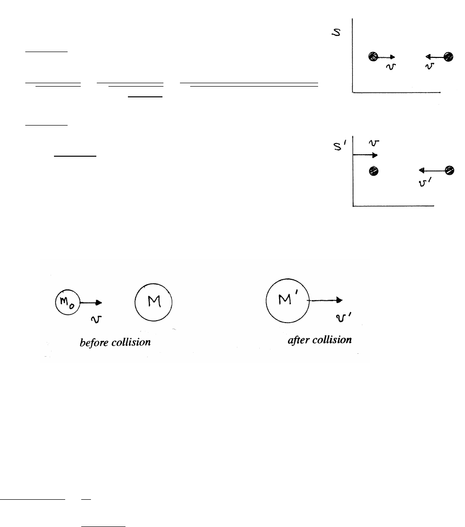
198 RELATIVISTIC DYNAMICS
13.4 Particles approaching head-on
The left-hand particle is at rest in S0. From Eq. (12.9)
for the relativistic addition of velocities,
v0=2v
1+v2/c2E0=γm0c2
γ=1
p1−v02/c2
=1
q1−4v2
(1+v2/c2)2
=1+v2/c2
p1+2v2/c2+v4/c4−4v2/c2
=1+v2/c2
1−v2/c2
E0=m0c2 1+v2/c2
1−v2/c2!
13.5 Speed of a composite particle after an inelastic collision
p=γm0v p0=γ0M v0
E=γm0c2+Mc2E0=γ0M0c2
Momentum and total energy are conserved, so
γm0v=γ0M0v0(1)
γm0c2=γ0M0c2(2)
Dividing Eq. (1) by Eq. (2),
γm0v
γm0c2+Mc2=v0
c2
v0=γm0v
γm0+M
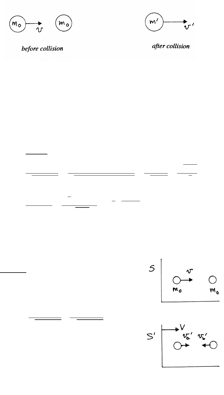
RELATIVISTIC DYNAMICS 199
13.6 Rest mass of a composite particle
pi=γm0v pf=γ0m0
0v0
Ei=γm0c2+m0c2Ef=γ0m0
0c2
K=xm0c2=(γ−1)m0c2=⇒γ=x+1
Momentum and total energy are both conserved.
γm0v=(x+1)m0v=γ0m0
0v0(1)
(γ+1)m0c2=(x+2)m0c2=γ0m0
0c2(2)
Dividing Eq. (1) by Eq. (2),
v0=(x+1)v
(x+2)
γ0=1
p1−v02/c2
=(x+2)
p(x+2)2−(x+1)2+1
=(x+2)
√2x+4
=√x+2
√2
(γ+1)m0c2=γ0m0
0c2
m0
0=(γ+1)m0
γ0=√2(x+2)m0
√x+2
=√2p(x+2) m0
13.7 Zero momentum frame
In S0, the speeds of the particles are
v0
a=v−V
1−vV/c2v0
b=Vto the left, as shown
The corresponding momenta are
p0
a=γ0
am0v0
ap0
b=γ0
bm0v0
b
0=p0
a−p0
b=v0
a
p1−v02
a/c2−v0
b
q1−v02
b/c2
The particles have equal mass, so by symmetry
they must have equal and opposite velocities in S0
to give zero net momentum.
continued next page =⇒
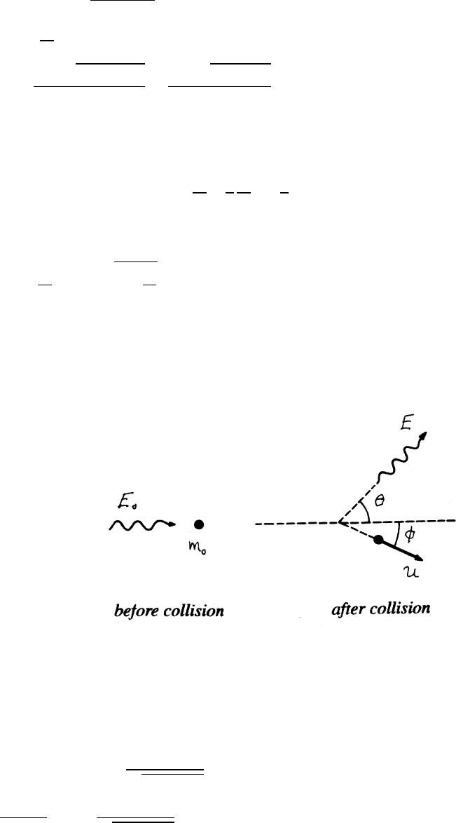
200 RELATIVISTIC DYNAMICS
Because their speeds are equal, it follows that γ0
a=γ0
b, so that the condition for
zero momentum becomes
v0
a=v0
b=⇒v−V
1−vV/c2=V
0=v
c2V2−2V+v
V=2±p4−4v2/c2
2v/c2=1±p1−v2/c2
v/c2
For vc, the negative sign correctly gives
V≈ c2
v! 1
2
v2
c2!=v
2
as expected. Hence
V= c2
v!
1−r1−v2
c2
13.8 Final velocity of a scattered particle
Ei=E0+m0c2Ef=E+γm0c2
There are 3 unknowns, θ,φ, and u. However, if only uis to be found, the most direct
route is to use conservation of total energy, which does not involve the unknown
angles.
E0+m0c2=E+m0c2
p1−u2/c2
E0−E
m0c2+1=1
p1−u2/c2
continued next page =⇒
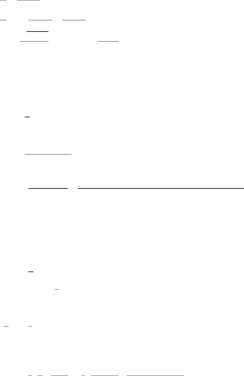
RELATIVISTIC DYNAMICS 201
Let x=(E0−E)/(m0c2).
1−u2
c2=1
(x+1)2
u2
c2=1−1
(x+1)2=x2+2x
(x+1)2
u=
√x2+2x
x+1
cwhere x=E0−E
m0c2
13.9 The force of sunlight
(a) Reis the radius of the Earth. Let Sbe the solar constant.
Fsolar =S
c×πR2
e
As discussed in Example 4.21, the momentum flux density =S/c.
Fsolar =1.4×10³W/m2
3×10⁸m/sπ(6.4×106m)2=6.0×108N
REis the distance from the Sun to the Earth.
Fgravity =GMEarth MS un
R2
E
=(6.7×10⁻¹¹ N·m2·kg−2)(6.0×1024 kg)(2.0×1030 kg)
(1.5×10¹¹)2=3.6×10²² N
Fgravity ≈6×10¹³ Fsolar
(b) Both the pressure of light and the gravitational attraction of the Sun fall offas
the square of the distance, so consider the balance of forces on a particle at the
Earth’s orbit. Let the density of the particle be ρ=5.0×10³kg/m3, its mass m,
and its radius r.
Frad =S
c×πr2
Fgravity =maS un =4
3πr3ρaS un
To escape, Frad >Fgravity.
S
cπr2>4
3πr3ρaS un
The acceleration at the Earth’s orbit due to the Sun is
aS un =6×10⁻³m/s2
r<3
4S
c 1
ρaS un !=3
4 1.4×10³
3×10⁸! 1
(5 ×10³)(6 ×10⁻³)!
r<1.2×10⁻⁷m
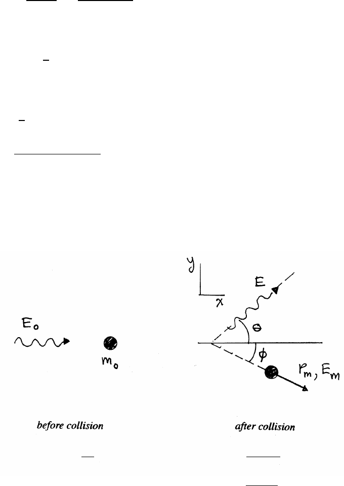
202 RELATIVISTIC DYNAMICS
13.10 Levitation by laser light
Let the density of the particle be ρ=2.7×10³kg/m3, and let rbe its radius.
If the sphere is large compared to the spot of laser light, assume that the light is
reflected, doubling the force.
F=2power
c=2×10³W
3×10⁸m/s=6.7×10−6N
For levitation,
F≥mg =4
3πr3ρg
At equilibrium,
6.7×10⁻⁶N= 4
3πr3m3!(2.7×10³kg ·m−3)(9.8 m ·s2)=1.1×10⁵r3
r3=6.7×10⁻⁶N
1.1×10⁵N·m−3=6.1×10⁻¹¹ m3
r=3.9×10⁻⁴m
13.11 Photon-particle scattering
x direction: (pi)x=E0
c(pf)x=Ecos θ
c+pmcos φ
y direction: (pi)y=0 (pf)y=Esin θ
c−pmsin φ
Ei=E0+m0c2Ef=E+Em
continued next page =⇒
RELATIVISTIC DYNAMICS 203
By conservation of momentum,
E0
c=Ecos θ
c+pmcos φ(1)
Esin θ
c=pmsin φ(2)
Dividing Eq. (1) by Eq. (2),
cot φ=E0
Esin θ−cot θ(3)
By conservation of total energy,
E0+m0c2=E+Em(4)
(E0−E+m0c2)2=E2
m=(pmc)2+(m0c2)2(5)
From Eqs. (1) and (2),
pmccos φ=E0−Ecos θpmcsin φ=Esin θ
Squaring and adding,
(pmc)2=(E0−Ecos θ)2+E2sin2θ=E2
0+E2−2E0Ecos θ
Using this in Eq. (5),
E0E(1 −cos θ)=m0c2(E0−E)=⇒E0
E=E0
m0c2(1 −cos θ)+1
Using this expression for E0/Ein Eq. (4),
cot φ= E0
m0c2!(1 −cos θ)
sin θ+1
sin θ−cot θ= 1+E0
m0c2!(1 −cos θ)
sin θ
= 1+E0
m0c2!tan (θ/2)
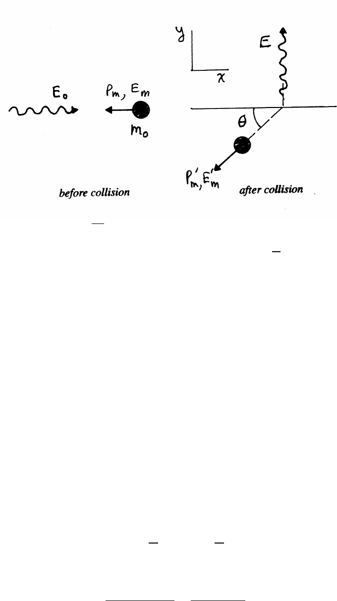
204 RELATIVISTIC DYNAMICS
13.12 Photon-electron collision
x direction: (pi)x=E0
c−pm(pf)x=−p0
mcos θ
y direction: (pi)y=0 (pf)y=E
c−p0
msin θ
Ei=E0+EmEf=E+E0
m
(a) By conservation of momentum,
E0−cpm=−cp0
mcos θ(1)
E=cp0
msin θ(2)
Squaring and adding Eqs. (1)and (2),
E2
0−2E0cpm+(cpm)2+E2=(cp0
m)2(3)
By conservation of total energy, E0
m=E0+Em−E(4)
Use
(cpm)2=E2
m−(m0c2)2and (cp0
m)2=E02
m−(m0c2)2
in Eq. (3) to give, with Eq. (4),
E2
0−2E0cpm+E2
m+E2=E02
m=(E0+Em−E)2=⇒E0(Em+cpm)=E(E0+Em) (5)
pm=γm0v=v
c2γm0c2=v
c2Em
so Eq. (5) becomes
E=E0Em(1 +v/c)
E0+Em
=E0(1 +v/c)
1+E0/Em
continued next page =⇒
RELATIVISTIC DYNAMICS 205
(b) The line broadening ∆λis
∆λ=λ−λ0
Using E=hν=hc/λ,
∆λ=hc
E−hc
E0
=⇒∆λ
hc =1
E−1
E0≈E0−E
E2
0
From the result of part (a),
E0−E
E2
0
=1
E0"1−(1 +v/c)
1+E0/Em#
Em=γm0c2=m0c2
p1−v2/c2≈m0c2
∆λ
hc =λ0
hc "1−(1 +v/c)
1+h/λ0m0c#=λ0
hc "1−(1 +v/c)
1+λC/λ0#
∆λ=0.711 ×10⁻¹⁰ 1−(1 +6×10⁻³)
1+2.426×10⁻¹²
0.711×10−10
=0.711 ×10⁻¹⁰ "1−(1 +6×10⁻³)
(1 +3.4×10⁻²)#
≈0.711 ×10⁻¹⁰ h1−(1 +6×10⁻³)(1 −3.4×10⁻²)i
=(0.711 ×10⁻¹⁰)(−6×10⁻³+3.4×10⁻²)
=2.0×10⁻¹² m=(2.0×10⁻¹² m) 1˚
A
1×10⁻¹⁰ m!
=0.020 ˚
A
consistent with the data plot in Example 13.6.
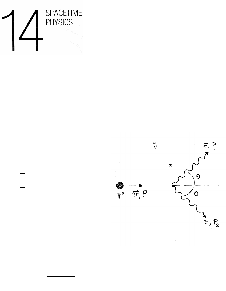
14.1 Pi meson decay
Momentum Pof the π0:
P=γm0(v,0,0,c)
Momentum Piof the photons:
P1=E
c(cos θ, sin θ, 0,1)
P2=E
c(cos θ, −sin θ, 0,1)
(a)
P=P1+P2
Equating the time-like components
γm0c=2E
c
γ=2E
m0c2(1)
=2×100 keV
135 keV =1.48
1
1−v2/c2=(1.48)2=⇒v
c=p1−1/(1.48)2=0.74
continued next page =⇒
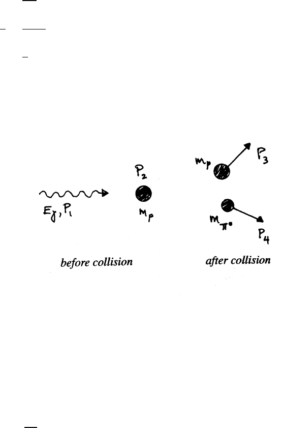
SPACETIME PHYSICS 207
(b) Equating the xcomponents
γm0v=2E
ccos θ
γv
c=2E
m0c2cos θ=γcos θusing Eq. (1)
cos θ=v
c=0.74 =⇒θ=42◦
14.2 Threshold for pi meson production
Eγis the energy of the γray. p3and p4are 3-vectors, and P3and P4are 4-vectors.
Comparing components of vectors requires evaluating them in the same coordinate
system. However, the norms of 4-vectors are scalars, independent of coordinate
system, permitting the 4-vectors to be expressed in any convenient coordinate sys-
tem. In this problem, the center of mass system is convenient.
conservation of 4-momentum:
P1+P2=P3+P4
P1=Eγ
c(1,0,0,1)
P2=mpc(0,0,0,1)
P3+P4=(p3+p4,(mp+mπ0)c)=(0,0,0,(mp+mπ0)c)
Equating norms,
|P1+P2|2=P2
1+2P1·P2+P2
2=0−2mpEγ−(mpc)2
|P3+P4|2=−[(mp+mπ0)c]2
continued next page =⇒
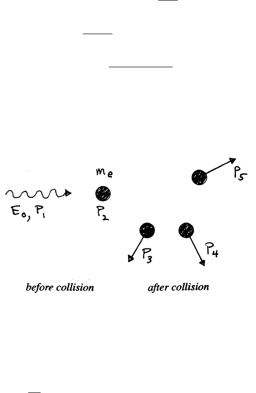
208 SPACETIME PHYSICS
Consequently, the minimum value of Eγsatisfies
2mpEγ+(mpc)2=[(mp+mπ0)c]2=⇒Eγ=1
2mp
(2mpmπ0+m2
π0)c2
Eγ=mπ0c2 1+mπ0c2
2mpc2!
=(135 MeV) 1+135 MeV
2×938 MeV!=145 MeV
14.3 Threshold for pair production by a photon
At threshold, all of the incident photon’s energy goes to promoting the reaction.
Above threshold, there would be a residual photon of lower energy among the re-
action products.
Let mebe the rest mass of each particle.
P1=E0
c(1,0,0,1)
P2=mec(0,0,0,1)
|P1+P2|2=P2
1+2P1·P2+P2
2=0−2meE0−(mec)2
Evaluate the 4-momenta of the three products in the center of mass frame.
|P3+P4+P5|2=−(p3+p4+p5,3mec2)2=−(3mec)2
conservation of 4-momentum:
P1+P2=P3+P4+P5
2meE0+(mec)2=(3mec)2=9(mec)2
E0=4mec2=4×(0.51 MeV)
=2.04 MeV
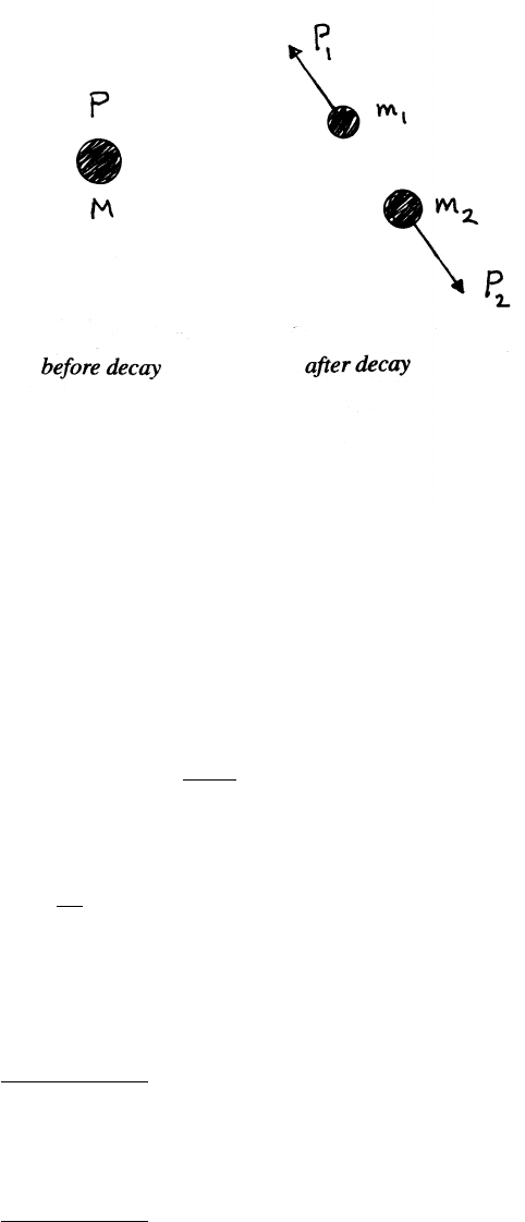
SPACETIME PHYSICS 209
14.4 Particle decay
The mass symbols M,m1, and m2all refer to rest mass.
P=M(0,0,0,c)
P1=(p,E1/c)
P2=(−p,E2/c)
Note that 3-momentum and 4-momentum are both conserved.
P=P1+P2
|P|2=P2
1+2P1·P2+P2
2
−(Mc)2=−(m1c)2−2p2+E1E2
c2−(m2c)2(1)
Use
p2=p2
1=E1
c2
−m1c2and E1+E2=Mc2=⇒E2=Mc2−E1
Equation (1) then becomes
(Mc)2=−(m1c)2+(m2c)2+2E1M
E1= M2+m2
1−m2
2
2M!c2
To find E2, simply interchange the subscripts.
E2= M2+m2
2−m2
1
2M!c2
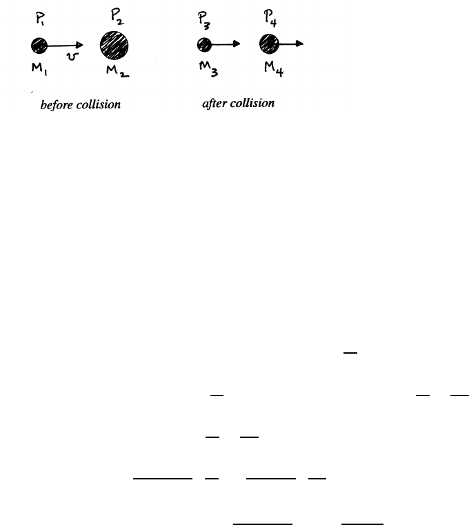
210 SPACETIME PHYSICS
14.5 Threshold for nuclear reaction
The symbols M1,M2,M3, and M4all refer to rest mass.
P1=γM1(v,0,0,c)
P2=M2(0,0,0,c)
In the center of mass system,
|P3+P4|2=−(M3+M4)2c2
Use P1+P2|2=|P3+P4|2and (M3+M4)c2=(M1+M2)c2+Q
P2
1+2P1·P2+P2
2=|P3+P4|2
−M2
1c2−2γM1M2c2−M2
2c2=−(M3+M4)2c2=−M1+M2+Q
c22
c2
M2
1+2γM1M2+M2
2=M1+M2+Q
c22
=M2
1+M2
2+2(M1+M2)Q
c2+Q2
c2
2(γ−1)M1M2=2(M1+M2)Q
c2+Q2
c4
γ−1= M1+M2
M1M2!Q
c2+ 1
2M1M2!Q2
c4
K1=(γ−1)M1c2= M1+M2
M2!Q+ 1
2M2c2!Q2
14.6 Photon-propelled rocket
The initial 4-momentum of the rocket is Pi=M0(0,0,0,c). When the rocket has ac-
clerated to speed vand its rest mass has decreased to Mf, the rocket’s 4-momentum
is Pf=γMf(v,0,0,c).
(a) By conservation of 3-momentum, the momentum pex of the exhaust is
pex =−γMfv
The exhaust consists of photons, for which p=E/c. The 4-momentum of the
exhaust is therefore
Pex =(pex,E/c)=γMf(−v,0,0,v)
continued next page =⇒
SPACETIME PHYSICS 211
(b) By conservation of 4-momentum,
Pi=Pf+Pex
M0(0,0,0,c)=γMf(v,0,0,c)+γMf(−v,0,0,v)
Because all the 4-vectors refer to the same frame (in this case, the laboratory
frame), it is correct to equate corresponding components. The 4th component
gives
M0c=γMfc+γMfv
M0
Mf
=γ1+v
c
Let µ≡M0
Mf
µ2= 1
1−v2/c2!1+v
c2
=1+v/c
1−v/c
v= µ2−1
µ2+1!c
14.7 Four-acceleration
Consider motion only along the x−axis, so that the 4-velocity is
U=γ(u,0,0,c)
A=dU
dτ=γdU
dt =γd
dt [γ(u,0,0,c)]
=γ2(du/dt,0,0,0) +γdγ
dt (u,0,0,c)
where du
dt =aand dγ
dt =d
dt
1
p1−u2/c2
=γ3u
c2
du
dt =γ3au
c2
A=γ2(a,0,0,0) +γ4au
c2(u,0,0,c)
= γ2a+γ4au2
c,0,0, γ4au
c!
="γ2a 1+γ2u2
c2!,0,0, γ4au
c#="γ2a 1+u2/c2
1−u2/c2!,0,0, γ4au
c#
=γ4a1,0,0,u
c
The norm of Ais
|A|2=γ8a2 1−u2
c2!=γ6a2
212 SPACETIME PHYSICS
14.8 A wave in spacetime
Let ube the relative velocity of frames Sand S0, to minimize confusion with the
wave’s frequency ν.
(a) To demonstrate that K=2π(1/λ, 0,0, ν/c) is a 4-vector, show that its dot prod-
uct with a known 4-vector is a scalar, and that its norm is Lorentz invariant.
Take the trial 4-vector to be the displacement X=(x,0,0,ct).
K·X=2πx
λ−νt
This dot product is the phase of the wave. Different observers must agree on the
phase, for instance a point in spacetime where the amplitude vanishes. Because
Xtransforms according to the Lorentz transformation, Kmust also.
The norm is
|K|2=(2π)2"1
λ2−ν
c2#
The norm is a Lorentz invariant, which implies that λ ν =c; in other words, the
wave travels at the speed of light, as postulated.
(b) Using the notation of Section 14.5,
K=(a1,a2,a3,a4)=2π 1
λ,0,0,ν
c!
In the S0system, Eq. (14.13) gives
a0
4=γa4−u
ca1=⇒2πν0
c=γ2π"ν
c−u
c 1
λ!#
ν0=γν−u
λ=γ ν 1−u
c=ν(1 −u/c)
p(1 −u2/c2)
=νs 1−u/c
1+u/c!
ν=ν0s 1+u/c
1−u/c!
in agreement with Eq. (12.12) for the longitudinal Doppler shift.
(c) For propagation along the yaxis,
K=2π 0,1
λ,0,ν
c!
In the S0frame,
ν0
c=γν
c=⇒ν=ν0
γ=ν0p1−u2/c2
in agreement with Eq. (12.13) for the transverse Doppler shift, with θ=π/2.
