5x34AC
User Manual: 5x34AC
Open the PDF directly: View PDF ![]() .
.
Page Count: 12
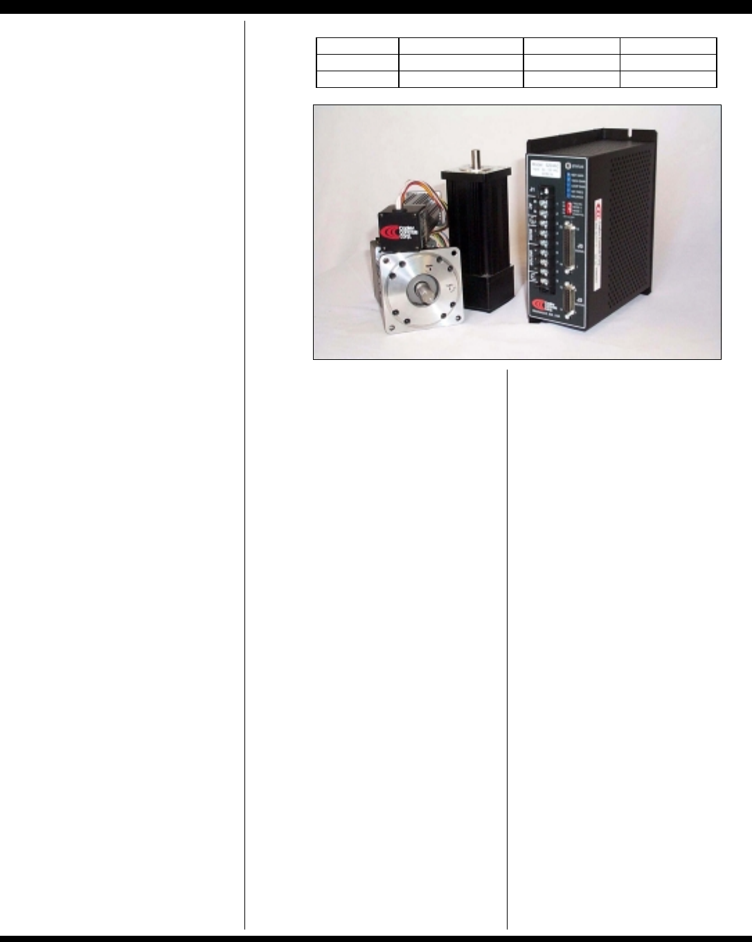
MODELS 5234AC, 5434AC
LINE-POWERED DC BRUSHLESS SERVO AMPLIFIERS
Copley Controls Corp., 20 Dan Road Canton, MA 02021 Tel: 781-828-8090 Fax: 781-828-6547
www.copleycontrols.com
Page 1 of 12
FEATURES
• Operates directly from AC
mains with full optical
isolation between signal and
power stages.
• Drives DC brushless
motors with 60°
°°
° or 120°
°°
° Halls
in six-step (trapezoidal) mode
• Independent settings for
peak and continuous current,
and peak-time.
• External or hardwired
control of peak and
continuous current limits.
• DriveTorque mode
switches from velocity to
torque mode for fastener-
driving, bottle capping, etc.
• Separate motor and
signal Sub-D type connectors
for simpler cabling
• +5V @ 200mA powers
motors with “commutating
encoders”
• FAIL-SAFE ENABLE INPUT
Ground or +5V level select
Pull-up or pull-down select
• Dual Status outputs (amp
NORMAL and amp READY)
• FAULT PROTECTIONS
Short-circuits
output to output
output to gnd
Over / under voltage
Over temperature
Self-reset or latch-off
• 3kHz bandwidth
Wide load inductance range
0.4~40 mH.
THE OEM ADVANTAGE
• Production amplifiers can
be pre-configured at the
factory for volume production
• Built in power supply!
FEATURES
The 5xx4AC models are PWM
servoamplifiers for Hall commutated DC
brushless motors operating in six-step
(trapezoidal) mode. Models operate
from 115 or 230VAC single-phase AC
mains. Signal, logic, Halls, encoder,
and monitor signals are all optically
isolated from the mains.
Built with surface-mount technology,
these amplifiers offer a full complement
of features for DC brushless motor
control. Torque-mode operation is
standard, and there are two modes of
velocity-loop operation. Frequency to
voltage conversion of Hall or encoder
signals gives tachless velocity-loop
operation. Output voltage control gives
velocity loop operation without the use
of encoder or Hall signals.
Torque mode is used typically with
digital controllers that calculate position
and velocity from the motors encoder.
Hall tach operation works well for high
speed applications such as spindles.
Encoder tach velocity loops give a wide
speed range and lower ripple near zero
velocity. Voltage mode is smooth
around zero, and has enough speed
regulation to work well with PLC’s, or
motion control IC’s.
An internal solderless sockets permits
users to configure the various gain and
current limit settings to customize the
amplifiers for a wide range of loads and
applications. Header components
permit compensation over a wide range
of load inductances to maximize
bandwidth with different motors.
Separate current-limits provide
protection for motors while optimizing
acceleration characteristics. Peak
current, continuous current, and peak-
time are individually settable via the
internal header, or by external signals.
DriveTorque mode for fastener driving
applications permits external switching
between velocity and torque mode.
Screws are driven in at constant speed
using voltage-mode feedback until the
external controller senses increased
current. Then, mode is switched to
torque mode to set screw at
programmed torque.
The /Enable input active logic-level is
switch-selectable to ground or +5V to
interface with all types of control cards.
Fail-safe operation in either polarity
results from an internal jumper that
selects the default input level and input
resistor pull-up or pull-down
connections so that the amplifier shuts
down with no input.
IGBT output stages deliver four-
quadrant power for bi-directional
acceleration and deceleration of
motors. For high-inertia loads, an
external regenerative energy dissipater
is available.
All models are protected against output
short circuits (output to output and
output to ground) and heatplate
overtemperature. With the /Reset input
open the amplifier will latch off until
powered-down or the /Reset input is
toggled.The amplifier will reset itself
automatically from faults if the /Reset
input is wired to GND.
MODEL POWER I-CONT
(
A
)
I-PEAK
(
A
)
5234AC 32~132VAC 15 30
5434AC 32~264VAC 15 30

MODELS 5234AC, 5434AC
LINE-POWERED DC BRUSHLESS SERVO AMPLIFIERS
Copley Controls Corp., 20 Dan Road Canton, MA 02021 Tel: 781-828-8090 Fax: 781-828-6547
www.copleycontrols.com
Page 2 of 12
TECHNICAL SPECIFICATIONS
MODEL 5234AC 5434AC
OUTPUT POWER
Peak power 30A @ 100V 30A @ 200V
Peak time 1 sec at peak power or 2 secs. after polarity reversal
Continuous power 15A @ 120V 15A @ 240V
OUTPUT VOLTAGE
On-resistance (Ro, ohms) 0.1 0.15
Max PWM Peak Output Voltage ±Vout = (VAC X 1.41 -2)×(0.97) - (Ro)×(Io)
Maximum effective output voltage at continuous power 120V @ 15A 240V @ 15A
Maximum effective output voltage at peak power 100V @ 30A 200V @ 30A
INPUT POWER
Mains voltage 32~132VAC, 47~63Hz 32~264VAC, 47~63Hz
Mains current @ continuous output rating 16A 16A
Inrush current on startup 37 A max 37 A max
External mains fuse rating 30A/125V 30A/250V
LOAD INDUCTANCE
Minimum inductance 400 µH. 400 µH.
Maximum inductance No maximum. See chart of load inductance values. Bandwidth varies with inductance and header parts.
BANDWIDTH Small signal -3dB @ 3kHz with minimum load at nominal supply voltage. Varies with load inductance and header values
PWM OUTPUTS
PWM frequency 25kHz
Modulation Center-weighted, 50% duty cycle at 0V output
REFERENCE INPUT Differential, 94KΩ between inputs, ±20V maximum
POTENTIOMETERS Ref Gain Default = CW CCW attenuates Reference input from x1 to 0
(15 turn) Tach Gain Default = CCW CW increases speed ( decreases feedback from tachometer ). Note: fully CW = 5% of max
Loop Gain Default = CCW CW increases loop gain in velocity mode, current gain in torque mode
Integ Freq Default = CCW Integrator zero-gain frequency in velocity mode. CW increases stiffness
Balance/Test Default = center Use to set output current or rpm to zero; or use as ±10V test input if RH9 set to 50kΩ
DIP SWITCHES S1: Velocity loop integrator control. ON: Torque mode, integrator disabled. OFF: Velocity mode, integrator enabled.
S2, S3: Feedback mode control. See Applications section for details.
S4: /Enable input active polarity. OFF (default): Gnd enables amplifier, open or +5V inhibits. ON: Gnd inhibits, open enables
LOGIC INPUTS
/Enable Default = GND GND enables amplifier, open or >2.5V inhibits with S1 OFF. If S4 ON then GND inhibits
See following section on Fail-Safe operation for JP4 settings.
Response time: 1 ms. From enable active to amplifier output ON
/POS enable, /NEG enable Default = GND GND enables, open or >2.5V inhibits positive/negative output currents ( S4 has no effect )
/Reset Default = Open GND resets latching fault condition, ground for self-reset every 50 ms.
/Motemp Default = GND Motor temperature sensor. Typically normally closed bimetal sensor. Open = overtemp
/Force Default = Open Velocity to torque mode switching control. Ground disconnects velocity loop
components (Ref Gain, Tach Gain, Loop Gain, Integ Freq, and Balance pots,
and all related header parts). Mode changes to torque, RH10 controls transconductance.
See application section for details.
Input resistance 10kΩ (Jumper J1-A selects connection to +5V or ground), R-C filters on inputs
Logic threshold voltage 2.5V (Schmitt trigger inputs with hysteresis, 74HC14)
Input voltage range 0V to +32VDC
FAIL-SAFE ENABLE INPUT
Internal jumper JP4 selects +5V or GND connection for input pull-up resistors to /Enable input only so that amplifier will default to
disabled condition if inputs are open-circuit, or wires are broken. (See Applications section for details)
LOGIC OUTPUTS
/Normal LO (current sinking) when Normal LED is ON; HI when LED is OFF
HI output voltage +5V (no load). Output is N-channel mosfet drain terminal with10kΩ pullup resistor to +5V
LO output voltage On resistance Ro = 5Ω. Max sink current of 250mA. max off-voltage = 50VDC
Amp OK N-channel opto-isolator is ON when amp is OK:
Buss volts OK AND NOT (output short OR overtemp) AND NOT Motemp switch open.
ON current 4 mA.
Max voltage 32 VDC
STATUS LED
Bicolor LED changes color and flashes to indicate amplifier operating status
Green = Normal Amplifier enabled AND Amp OK (see above)
blinking green = Ready Amplifier OK, will run when enabled
Red = Buss Fault, non-latching Over or under-voltage condition. Amplifier recovers when voltage is in normal range OR Motemp switch open.
Red/blinking = Latching Fault Output overcurrent (short circuit) or overtemp condition. Ground /Reset or power amp off/on to clear condition
MONITOR OUTPUTS
Current Ref Current demand signal to PWM stage: ±10V = ±Ipeak
Current Monitor Motor winding current: ±10V @ ±Ipeak (1kΩ, 33nF R-C filter)
Feedback Monitor signal for Hall/encoder tachometer, voltage feedback. ±5V = 100% of feedback signal normal range
DC POWER OUTPUTS
+5V @ 250 mA max (J2-11, J3-23). Power for Halls and/or encoder.
+10VDC @ 5 mA (J3-24) -10VDC @ 5mA (J3-25)
Note: maximum power from all dc outputs not to exceed 1.4W
MODELS 5234AC, 5434AC
LINE-POWERED DC BRUSHLESS SERVO AMPLIFIERS
Copley Controls Corp., 20 Dan Road Canton, MA 02021 Tel: 781-828-8090 Fax: 781-828-6547
www.copleycontrols.com
Page 3 of 12
PROTECTIVE FEATURES
Short circuit (output to output, output to ground) Latches unit OFF (Power off/on, or ground at /Reset input resets)
OverTemperature Latches unit OFF at 70°C on heatplate ( Power off/on, or ground at /Reset input resets)
Wire /Reset input to ground for automatic reset after latching fault
Undervoltage Shutdown at DC buss < 45VDC
Overvoltage Shutdown at DC buss > 195VDC (5234AC), or DC buss > 390VDC (5434AC)
( Amplifier operation resumes when power is NOT undervoltage or NOT overvoltage )
Current-limiting (foldback) Output current set by header components (peak, continuous, & peak-time)
THERMAL REQUIREMENTS
Storage temperature range -30°C to +85°C
Operating temperature range 0° to 70°C baseplate temperature
Thermal resistance (heatplate to ambient):
No heatsink or fan: 0.92 deg C/W, no heatsink with fan: 0.51 deg C/W
With heatsink: no fan: 0.6 deg C/W; with heatsink and fan: 0.23 deg C/W.
MECHANICAL
Size 7.50 x 7.0 x 2.72 in. (190 x 178 x 69 mm) without optional heatsink
7.5 x 7.0 x 4.72 in. (190 x 178 x 120mm) with optional heatsink
Weight 3.71 lbs (1.69 kg) without optional heatsink. Add 3.2 lb ( 1.47 kg ) for heatsink.
CONNECTORS
J1: Power & motor 9-position terminal strip
J2: Halls / Options 15-position female Sub-D type. #4-40 standoffs for cable shell lock screws
J3: Signal 25-position female Sub-D type. #4-40 standoffs for cable shell lock screws
Connector shells are connected to amplifier chassis for grounding/shielding
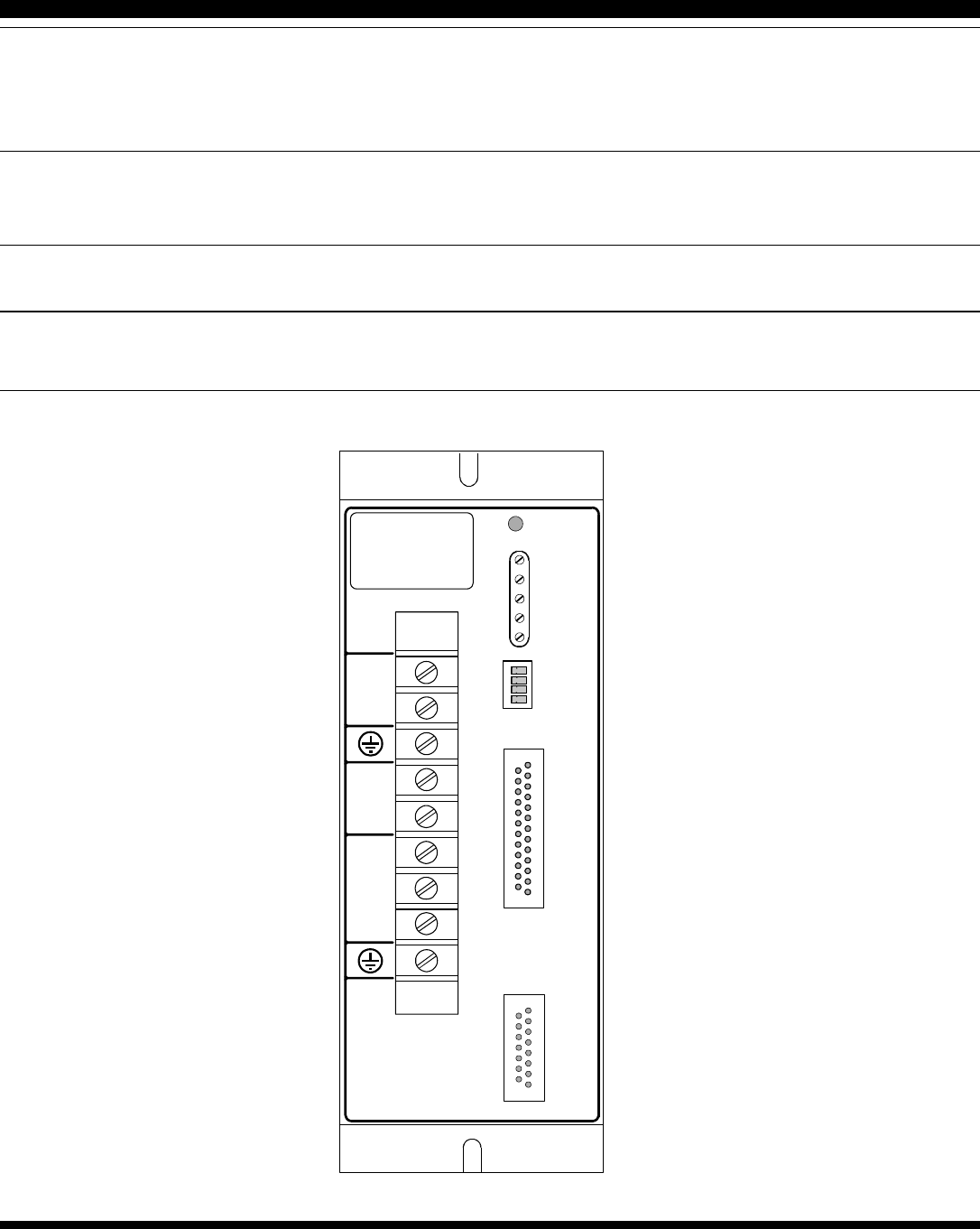
PANEL LAYOUT
REF GAIN
TACH GAIN
LOOP GAIN
INT FREQ
BALANCE
S1
S3
S4
S2 TRQ/VEL
MODE 0
MODE 1
ENAB POL
STATUS
J3
SIGNAL
J2
MOTOR
J1
1
13
14
25
1
8
9
15
H
N
+
U
V
W
-
BUSS
1
2
3
4
5
6
7
8
9
ACMOTOR
Model: 5434AC
Input: 32~264VAC
50/60Hz
MODELS 5234AC, 5434AC
LINE-POWERED DC BRUSHLESS SERVO AMPLIFIERS
Copley Controls Corp., 20 Dan Road Canton, MA 02021 Tel: 781-828-8090 Fax: 781-828-6547
www.copleycontrols.com
Page 4 of 12
J1 POWER AND MOTOR WINDING CONNECTIONS
Connector type: Barrier-block. Screw-terminal connections. #6-32 locking screws with cable clamps.
PIN SIGNAL FUNCTION
1 H AC Power Input Hot (black or brown wire from AC mains)
2 N AC Power Input Neutral (white or blue wire from AC mains)
3 GND Chassis safety ground (green or green/yel wire from AC mains)
4 Buss (+) Positive terminal of internal DC power supply (N.C.)
5 Buss (-) Negative terminal of internal DC power supply (N.C.)
6 Motor U Amplifier output to “U” winding of motor
7 Motor V Amplifier output to “V” winding of motor
8 Motor W Amplifier output to “W” winding of motor
9 GND Chassis safety ground. Also for cable shield of motor cable.
J2 MOTOR HALL AND ENCODER CONNECTIONS
Connector type: Female Sub-D, 15-position, #4-40 standoffs for cable shell
PIN SIGNAL FUNCTION
1 Safety GND Chassis ground. Use to ground cable shield. Not connected to internal signal ground.
2 Hall U Digital Hall inputs for “U”
3 Hall V Digital Hall inputs for “V”
4 Hall W Digital Hall inputs for “W”
5 Analog Tach Brush tachometer input
6 N.C.
7 Encoder B channel
8 Encoder A channel
9 Motemp Note: Must be grounded for amplifier to operate (Connect to J2-12, 14 or 15)
10 N.C.
11 +5V @ 200 mA. DC power for encoders and Halls (Note 1)
12 0V. Signal ground for +5V and Halls.
13 N.C.
14 0V. Signal ground for +5V and Halls.
15 0V. Signal ground for +5V and Halls.
J3 SIGNAL CONNECTIONS
Connector type: Female Sub-D, 25-position, #4-40 standoffs for cable shells
PIN SIGNAL FUNCTION PIN SIGNAL FUNCTION
1 Safety GND Chassis ground. Use to
ground cable shield. Not
connected to internal signal
ground (J3-12,13,15,16).
2 Ref (+) Positive terminal of
differential +/-10V analog
command input
14 Ref (-) Negative terminal of
differential +/-10V analog
command input
3 Analog Tach Brush tachometer input 15 0V. Signal ground.
4 Feedback Hall, encoder, or Vout FB 16 0V. Signal ground.
5 /Enable input Amplifier enable 17 /Pos Enable input
6 /Normal output Mosfet output amp status 18 /Neg Enable input
7 Amp OK (-) output Opto-isolator emitter (NPN) 19 Amp OK (+) output Opto-isolator collector (NPN)
8 Current Ref output 20 Ext Ipeak External setting of peak curr
9 Aux input 21 Ext Icont External setting of cont curr
10 Current Monitor Out 22 /Reset input
11 /DrivTorq Ground enables Drive-
Torque mode. 23 +5V @ 200 mA. Auxiliary DC power for user
devices (Note 1)
12 0V. Signal ground. 24 +10V @ 5 mA Auxiliary DC power
13 0V. Signal ground. 25 -10V @ 5 mA Auxiliary DC power
Notes:
1. +5V @ 200mA connects to both J3-23 and J2-11. Combined current from both pins must not exceed 200mA.
MODELS 5234AC, 5434AC
LINE-POWERED DC BRUSHLESS SERVO AMPLIFIERS
Copley Controls Corp., 20 Dan Road Canton, MA 02021 Tel: 781-828-8090 Fax: 781-828-6547
www.copleycontrols.com
Page 5 of 12
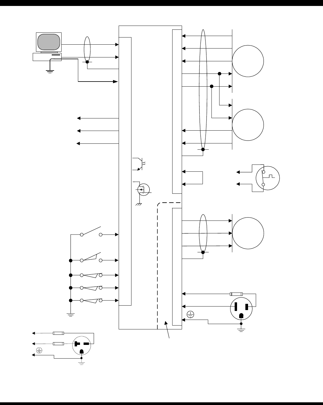
AMPLIFIER CONNECTIONS
1
2
3
J1
2
14
1
Ref(+)
Ref(-)
Shld
5
17
18
/Enable
/Pos enable
/Neg enable
4Feedback
8Current Ref
10Current Mon
J3
Monitor Outputs
V
U
WHalls
2
3
4
+5V
0V
11
12
Encoder
Ch. B
Ch. A
7
8
0V
+5V
1Shld
J2
9
15
/Motemp
Gnd
V
U
W
Motor
6
7
8
9Shld
Note: Circuits within
dashed line are HOT!
(At mains potential)
H
N
Note: /Motemp must be
grounded for amplifier to
operate
L1
L2
Fuses: 30A
time-delay
230VAC Wiring for
5434AC
Blk (Brn)
Grn (Grn/Yel)
22
/Reset
19
7
Amp OK (+)
(-)
6
/Normal
11
Velocity
DriveTorque
Mode switch
4
5
BUSS (+) N.C.
Fuse
BUSS (-) N.C.
13
Signal ground
Note:
Amplifier signal ground
must be connected to
controller ground.
MODELS 5234AC, 5434AC
LINE-POWERED DC BRUSHLESS SERVO AMPLIFIERS
Copley Controls Corp., 20 Dan Road Canton, MA 02021 Tel: 781-828-8090 Fax: 781-828-6547
www.copleycontrols.com
Page 6 of 12
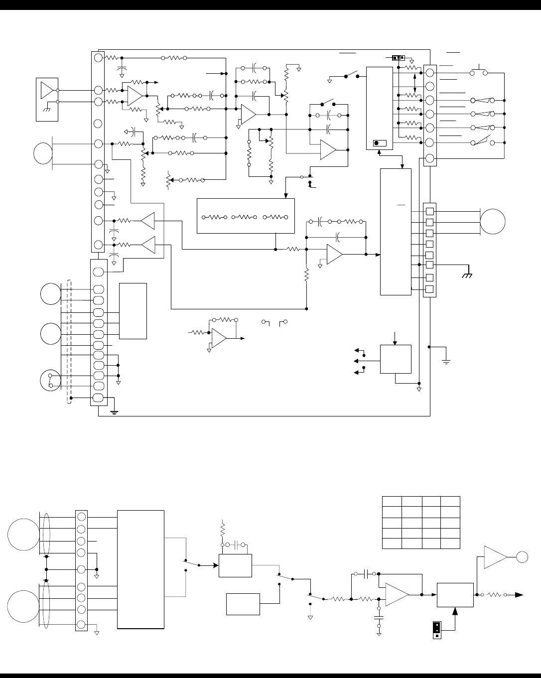
FUNCTIONAL DIAGRAM
-
+
DIFF AMP
CURRENT
LIMIT SECTION
Earth GND
Buss (+)
N.C.
-
+
CH18 RH20
12.1K
12.1K
+HV
DC / DC
CONVERTER
GND
CONTROL
LOGIC
STATUS
&
ENABLE
POS ENABLE
NEG ENABLE
NORMAL
RESET
CURRENT
ERROR
AMP
NORMAL
LED
G
CASE GROUND
NOT CONNECTED
TO CIRCUIT GROUND
GROUND CASE FOR SHIELDING
MOMENTARY SWITCH RESETS FAULT
WIRE RESET TO GROUND FOR SELF-RESET
+5
+15
-15
POWER GROUND AND SIGNAL GROUNDS ARE
COMMON
47K
470 PF
1.5NF 49.9K
+5V @
200mA
HALLS
U
V
W
GND
V
W
U
REF(+)
REF(-) 14 cw -
+
3
15
TACH (-)
GND or TACH(+)
1K
0.1
50K
CW TACH GAIN
50K REF GAIN
RH3
100K
100K
RH7 CH8
1K
+5
-5
50K
BALANCE
C
W
-
+
RH12
100K
50K
C
WLOOP GAIN
1K
SW
1
CH2
33NF
0.22UF
INTEG FREQ
500K
C
W
1 K
RH1
CURRENT REF
RH17
PEAK TIME
301k
CONT
RH14
SEL
PEAK
RH15
SEL
G = X1
TACH
25
-10V @
5mA -10V
24
+10V @
5mA +10V
13
GND
5
4
6
7
8
22
6
18
17
5
12
11 DRVTORQ
60 / 120
DEGREE
SELECTION
IS
AUTOMATIC
10 1K
33NF
8
33NF
CURRENT
REFERENCE
+/-10V @ +/-Ipk
1K
CURRENT
MONITOR
+/-10V @ +/-Ipk
9
AUX
1K
33NF RH11
11
4
3
2
RH6
RH9
RH4 CH5
CH13
10M
RH 10 RH19
+15 -15
19 22
SW
4
JP1-A
+5V 13
2
10k
OFF = ENABLE
ON = ENABLE
100 PF
100K
220 PF
J3 SIGNALS
J3 SIGNALS
J1 MOTOR & POWER
47K
47K
47K
+/-5 mA
max
CONTROL
SYSTEM
2
44
12
SHIELD
HALL
LOGIC
5K
FEEDBACK
14
8
7
CH. A
CH. B
ENCODER
15
1
9
TACH (-)
GND
GND
HOT-MOT
+5V@200mA
5
OUTPUT
CURRENT
SENSE
PWM
MOSFET
"H"
BRIDGE
STAGE
Gv = +HV
10
MOTOR
H
2
1
3
Buss (-)
N.C.
N
SJ From RH22
To Drive Torque Ref
Normal J3-11 Open
IC from drive torque
when J3-11 Grouded
-
+To IC
Drive Torque Ref
TEMP
J2 MOTOR
Inrush
Limiting
Rectifier and
Capacitors
Power Stage
at Line
Potential and
Isolated from
Signal Stage
FEEDBACK MODES FUNCTIONAL DIAGRAM
LOW-PASS FILTER
100K 100K
CH24
CH25
-
+
Ch. A
Ch. B
ENCODER +5V
12
11
7
J2 MOTOR
GND
HALLS
8
2
3
4
HALL U
HALL V
HALL W
14
15
GND
FILTERS &
STATE
DECODER
+5V
4538
+5V
100K CH23
TQ
6 PULSES
PER
HALL CYCLE
4 PULSES
PER
ENCODER
LINE
RH22
POLARITY
SWITCHING
OUTPUT
VOLTAGE
SENSE
K1A
BK2A
BK3A
B
TO SJ
JP1-B
NORM
REV
FEEDBACK POLARITY
SELECTION
K2
K1
K3
DIP SW S3
DIP SW S2 OFF
ON
X
X
B
ON
OFF
X
B
A
TORQUE
VOLTAGE
ON
ON
B
A
A
HALL TACH
OFF
OFF
A
A
A
ENCODER TACH
4
J3
FEEDBACK
MODELS 5234AC, 5434AC
LINE-POWERED DC BRUSHLESS SERVO AMPLIFIERS
Copley Controls Corp., 20 Dan Road Canton, MA 02021 Tel: 781-828-8090 Fax: 781-828-6547
www.copleycontrols.com
Page 7 of 12
DIP SWITCH FUNCTIONS
The default configuration for the amplifier is torque mode (no feedback). To enable the velocity feedback modes described below, set
the DIP switches according to the chart below.
Note: Default positions shown in bold & italics (ON is toward PC board, OFF is away from PC board)
SW NAME SEL DESCRIPTION
S1 INTEG ON Torque Mode (velocity integrator OFF)
OFF Velocity feedback mode (integrator ON)
S2 MODE 0 OFF Amplifier operating mode selection (Default = torque mode)
S3 MODE 1 ON See table below for functions
S4 EN POL ON /Enable input disables amplifier if ground. Open or >2.5V enables.
OFF /Enable input ground-active. Open or >2.5V disables amplifier.
Note: “X” in table below means that switch setting doesn’t matter.
S2 S3 J3-11 FUNCTION DESCRIPTION
OFF ON HI Torque-Mode No internal feedback
ON OFF HI Output voltage feedback Output voltage control
ON ON HI Hall speed control mode Frequency to voltage conversion of Halls
OFF OFF HI Encoder speed control mode Frequency to voltage conversion of encoder
X X LO
DriveTorque mode RH10 sets current-gain. All pots out of circuit.
POTENTIOMETER FUNCTIONS
POT DEFAULT DESCRIPTION
REF GAIN CW Input reference signal attenuation. Controls overall amplifier gain
(amps/volt or rpm/volt) without affecting response.
Full CCW attenuates reference signal to zero.
TACH
GAIN CCW Tachometer feedback control. CCW = maximum feedback (lowest
speed, fastest response), CW = minimum feedback (highest speed,
slowest response). Range = 20:1 (maximum to minimum speed).
LOOP
GAIN CCW Response control for velocity loop: CW increases bandwidth, CCW
decreases. In torque mode: CW increases amps/volt.
INTEG
FREQ CCW DIP switch S1 must be OFF for this pot to function.
In velocity mode, CW increases stiffness, makes loop less stable,
CCW decreases stiffness, makes loop more stable.
Too much CW leads to violent oscillation.
BALANCE Center Sets velocity to zero, or output current to zero with zero input.
LED INDICATOR FUNCTIONS
Color and state of LED indicates amplifier operating conditions:
LED COLOR CONDITION (Note 2) ACTION REQUIRED TO ENABLE
Flashing Green Ready Ground /Enable input (J3-5) (Note 2)
Green Normal None. Normal “RUN” condition.
Red Power Fault Bring AC voltage into range.
Flashing Red Latching Fault Ground /Reset input, or cycle AC power OFF/ON
Notes:
1. Fault = output short circuit or heatplate overtemperature. Amplifier ‘latches’ off and stays off until reset.
Amp OK = Internal buss voltage is within limits AND NOT-Fault
Ready = Amp OK AND NOT-enabled
Normal = Amp OK AND enabled
2. With S4 OFF and jumper J1-A on pins 1-2 (default), grounding /Enable will enable amplifier.
If S4 is ON, grounding J3-5 inhibits the amplifier: voltage must be >2.5V to enable amplifier.
If J1-A is on pins 1-2 (default), amplifier will be enabled whenever J3-5 is open or >2.5V.
With J1-A on pins 2-3, the enable input is pulled to ground via a 10k resistor, disabling the amplifier when J3-
5 is open (Fail-Safe operation). To enable the amplifier, the controller must pull-up the 10k resistor to >2.5V to
enable amplifier.
MODELS 5234AC, 5434AC
LINE-POWERED DC BRUSHLESS SERVO AMPLIFIERS
Copley Controls Corp., 20 Dan Road Canton, MA 02021 Tel: 781-828-8090 Fax: 781-828-6547
www.copleycontrols.com
Page 8 of 12
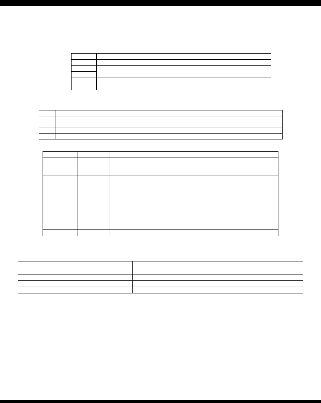
FAIL-SAFE JUMPER FUNCTION
+5V
J3-5
J1-A
1 2 3
/Enable
10k
10k
33nF
1 2 3 OFF
ON
SET FOR DIP
SW S4
Internal jumper J1-A sets the open-pin voltage for the /Enable
input (J3-5). For FAIL-SAFE operation, the amplifier should
shut down if J3 is disconnected, or if the wire to the /Enable
input is broken.
For this to work, J1-A should be set according to the position
of DIP switch S4 as follows:
S4 OFF (default): /Enable input is ground active. J1-A set to
pins 1-2 so that input pulls up to +5V, disabling amplifier.
S4 ON: /Enable input functions as +Enable, /Disable. Set J1-
A to pins 2-3 so that input voltage is pulled-down to ground if
input is open.
AMP-NORMAL OUTPUT
+5V
+NORMAL
J3-6
/NORMAL
10k
N-channel mosfet with 10k ohm resistor connected to +5V.
Maximum voltage: 50VDC. Maximum current 250mA. On-
resistance = 5 ohms.
Output is LO (mosfet ON) whenever amplifier is enabled and
NORMAL (LED green).
Output is HI (mosfet OFF) whenever amplifier is NOT-enabled,
or FAULT occurs.
OPTOISOLATED AMP OK OUTPUT
The Amp OK signal indicates amplifier ready to run status. It is
completely optically isolated from the amplifier. The input of
the optocoupler is driven by the amplifier logic circuits, and the
output is a floating NPN transistor with both terminals brought
to signal connector
J3 as shown below.
/NORMAL
+5V J3-19
J3-7
AMP OK(+)
AMP OK(-)
470
Maximum voltage = 32VDC. ON current = 4mA. minimum
Output transistor ON voltage: 0.4 at 4mA
DRIVETORQUE MODE
This mode is most useful in fastener-drive applications where
the amplifier is operated in a velocity mode to drive the
fastener in at a constant speed until the controller senses that
the current has reached a set value. Then the controller
grounds the /DRVTRQ input switching the amplifier into torque
mode that applies a set current to the fastener to drive it into
position at a constant torque value.
With J3-11 open (default) amplifier operates in velocity mode.
This can be switch-selected to be Hall, encoder, output
voltage, or analog tachometer controlled.
When J3-11 is grounded, DriveTorque mode is enabled, and
amplifier switches to torque mode with transconductance
controlled by RH10. The REF GAIN, LOOP GAIN, INTEG
FREQ, and BALANCE pots have no effect in this mode. The
current gain is controlled by this simple equation:
Gain = RH10
10
(kOhms)
(A/V)
PEAK CURRENT LIMIT SET
Control of the peak current limits can be made externally via
connector pin J3-20. A resistor can be connected between this
pin and signal ground (J3-12, 13, 15, or 16), or the pin can be
driven by a voltage between 0 and +10VDC. Using this
technique, the current limit can be controlled over a range of
100% to 10% of the amplifiers peak rated current. The figure
below shows the circuit. RH15 internal.
J3-20
94k
47k
+15V
+10V = 100%
Ipeak
R
H
15
Rpk
0~10VDC
Amplifier
J3-16
The table below give values of the external control voltage, or
external control resistor for various values of peak current:
Ipeak Rext Vext
30 <out> 10
27 180k 8.8
24 91k 7.7
21 56k 6.6
18 39k 5.6
15 24k 4.6
12 15k 3.5
9 10k 2.5
6 5k 1.4
3 1.2k 0.4
These values are within 10%, typically. For greater accuracy,
measure Current Ref and select parts for exact limit value.

MODELS 5234AC, 5434AC
LINE-POWERED DC BRUSHLESS SERVO AMPLIFIERS
Copley Controls Corp., 20 Dan Road Canton, MA 02021 Tel: 781-828-8090 Fax: 781-828-6547
www.copleycontrols.com
Page 9 of 12
ENCODER TACH OPERATION
HALL TACH VS. ENCODER TACH
Digital Hall or encoder signals are converted into an analog
tachometer signal by f/v (frequency to voltage) conversion.
Encoder tachometer mode gives the widest speed useable
speed range and fastest velocity-loop response. Use Hall-
tachometer mode for high-speed operation where no encoder
feedback exists. Example: a 4-pole brushless motor with a 500
line encoder operating at 1500 rpm. The f/v clock pulse rate is
50,000 Hz for encoder feedback, and 300 Hz for Hall
feedback. As speed drops, ripple will increase. At a standstill,
there will be no feedback between Hall or encoder transitions,
resulting in jitter. This may be acceptably small for an encoder
application, or unacceptably rough for a Hall tach. Use the
/Enable or /Brake inputs to disable the amplifier if zero-output
is required.
MAXIMUM F/V PULSE RATE
An f/v clock signal is generated that is 4X the encoder line
frequency. The maximum f/v clock rate is 600kHz. First check
to make sure that your f/v clock will be in limits.
f/v Encoder =×Lines rpm
15
f/v Hall =×Poles rpm
20
If the rate is greater than 600kHz, then maximum rpm must be
reduced. If the rate is acceptable, select the f/v capacitor
CH23 as follows:
HALL TACHOMETER
Set DIP switches S2 & S3 ON. Choose CH23 based on this
equation:
C=×
1400
Poles rpm ( C = CH23 in µF )
ENCODER TACHOMETER
Set DIP switches S2 and S3 OFF. Choose CH23 based on this
equation:
C=×
×
1109e
Lines rpm (CH23 = pF)
Choose a capacitor with the closest value. This should
produce a tach-voltage of about ±5V at the rpm used in the
equations. With the default value of 49.9k for RH22 (feedback
scaling header resistor), this would correspond to the
maximum reference input of ±10V.
LOW-PASS FILTER
The choice of low-pass filter will determine both the useable
rpm range of the f-v converter and the effective response time
of the velocity-loop ( or effective bandwidth ). For widest speed
range, set the low-pass filter frequency to a lower value. For
faster response times ( higher velocity loop bandwidth ) set the
frequency to a higher value.
Because Hall pulse rates will typically be as much as 100X
less than encoder pulse rates, a low-pass filter frequency that
gives satisfactory results at lower speeds may noticeably slow
down the step response of the motor. The default filter
frequency is 16Hz for Hall tach operation. This gives a
frequency of 159Hz, which is a good starting point for many
motors. CH24 & CH25 may be removed for fastest response
and best stiffness with smaller motors. In general, use the
lowest frequency possible that does not begin to slow down
the response of the loop to a step input. This will give the
widest rpm range.
VELOCITY LOOP TUNING
Begin with S1 ON (integrator disabled), REF GAIN pot fully
CW, TACH GAIN and LOOP GAIN pots fully CCW. Previous
steps must be performed to insure that motor is properly
phased and rotates smoothly in both directions.
STATIC SETUP
Apply a ±10V signal to Ref inputs Measure feedback voltage at
J3-4 This should be about ±5V if CH23 has been chosen
correctly. Motor rpm can be measured by viewing any Hall
signal and calculating as follows:
RPM Th Poles
=×
120
Where Th is the period of one Hall signal (U, V, or W ).
DYNAMIC SETUP
Set switch S1 ON (integrator disabled). Use a function
generator with a square wave output set to a small voltage
(±0.5V). Connect to reference inputs and adjust frequency so
that motor can change direction and settle to a set speed (1
Hz). Connect oscilloscope to J3-4 to monitor voltage. If
possible, also connect to J2-10, current monitor. Adjust Loop
Gain pot for fastest response that does not produce oscillation
or excessive ringing of either tach signal, or current monitor.
When Loop Gain is adjusted, set S1 OFF. Adjust Integ Freq
pot CW until overshoot on tach signal rings and then back off
for stable response. CW adjustment increases stiffness
(speed stability), but too much will produce oscillation. With
Loop Gain and Integ Freq adjusted properly, response to step
inputs will be smooth, and free from oscillation.
FEEDBACK POLARITY
Jumper J1-B switches the polarity of the feedback signal.
Once the amplifier is adjusted in torque mode to compensate
for load inductance, the velocity loop is closed by setting DIP
switches 2 & 3 to one of the three possible choices: Hall,
encoder, or output voltage. If the initial setting produces run-
away (positive feedback), disable the amplifier and set the
jumper to the alternate position. This should produce a stable
velocity loop which can then be ‘tuned’ using the
potentiometers.
VOLTAGE FEEDBACK MODE
Set DIP switches S1 OFF, S2 ON, and S3 OFF. Set Ref Gain
pot fully CW, Tach Gain, Loop Gain, and Integ Freq pots fully
CCW. With the default components, the voltage gain is X40.
Thus, a ±5V input will produce a ±200V-output voltage swing.
MODELS 5234AC, 5434AC
LINE-POWERED DC BRUSHLESS SERVO AMPLIFIERS
Copley Controls Corp., 20 Dan Road Canton, MA 02021 Tel: 781-828-8090 Fax: 781-828-6547
www.copleycontrols.com
Page 10 of 12
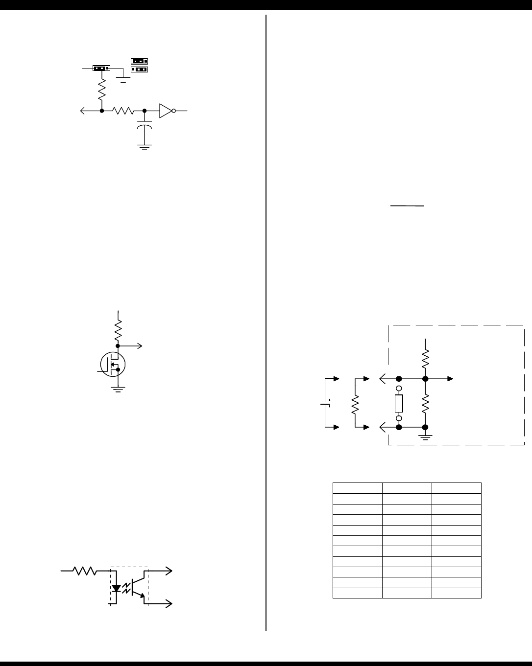
CONTINUOUS CURRENT LIMIT SET
Control of the peak current limits can be made externally via
connector pin J3-21. A resistor can be connected between this
pin and signal ground (J3-12, 13, 15, or 16), or the pin can be
driven by a voltage between 0 and +5VDC. Using this
technique, the current limit can be controlled over a range of
10% TO 100% of the amplifiers rated continuous current. The
figure below shows the circuit. RH14 internal.
J3-21
9.76k
10k
+10V
+5V = 100%
of Icont
RH
14
Rext
Vext
0~5VDC
Amplifier
J3-16
The table below lists values for Vext and Rext to control the
continuous current limit externally.
Icont Rext Vext
15 <out> 4.9
13.5 30k 4.29
12 15k 3.66
10.5 7.5k 3.0
9 4.7k 2.4
7.5 2.7k 1.78
6 1.5k 1.16
4.5 560 0.54
3.1 0 0
These values will give results within 10%, typically. For greater
accuracy, measure Current Ref signal, and select parts for
desired value.
MOTOR INDUCTANCE SETTING
Header components RH20, CH18, and CH16 control the
amplifier compensation for different motors. These set the gain
in the current error amplifier to give the best response for
different winding inductances.
The tables below give values for the header parts for the two
models. If the inductance of your motor is less than ½ of the
value shown in the table, use the values from the next lower
inductance range. E.g., for a 4mH motor, use the values from
the 3 mH row (1/2 of 10mH is 5mH, which is greater than 4mH,
so the value from the next lower row, 3mH, is used).
For all tables, CH18 is 15nF, and CH16 is <out>.
Model 5234AC @ 115VAC
L (mH) RH20 (kΩ)
0.3 10
1 30
3 100
10 300
30 1 Meg
Model 5434AC @ 230VAC
L (mH) RH20 (kΩ)
0.3 4.7
1 15
3 47
10 150
30 470
Model 5434AC @ 115VAC
L (mH) RH20 (kΩ)
0.3 10
1 30
3 100
10 300
30 1 Meg
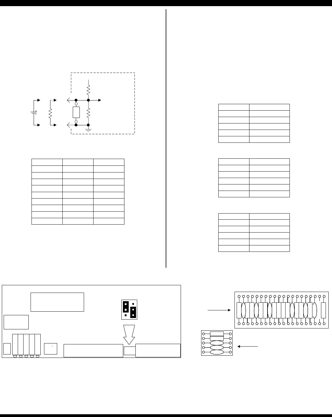
SIGNAL BOARD AND HEADER SOCKET LAYOUT
HEADER "A"
RH1~20
HEADER "B"
RH21~25
DIP
SW
J3 SIGNAL JP1 J2 HALLS
LED
120
21
25
1
2
3
1
2
3
AB
JP-1
} NORM
} REV
GND {
+5V {
FEEDBACK
POLARITY
ENABLE
INPUT
RESISTOR
REF GAIN
TACH GAIN
LOOP GAIN
INTEG FREQ
BALANCE
R
H
3
RH22
RH21
CH23
CH24
CH25
HDR19
"A" Header
"B" Header
R
H
1
C
H
2
R
H
4
C
H
5
R
H
6
R
H
7
C
H
8
R
H
9
R
H
1
0
R
H
1
1
R
H
1
2
C
H
1
3
R
H
1
4
R
H
1
5
C
H
1
6
R
H
1
7
C
H
1
8
R
H
2
0
The A and B header sockets hold the components that determine the amplifiers performance such as operating mode, current limits, and
feedback type. Components are named RHn, CHn as Resistor Header n, Capacitor Header n, etc. The table above lists values that cover a wide
range of motor winding inductances. Note: RH22 is temporally installed in the RH19 position as default from factory. For velocity operation,
after current mode commutation is verified working, install RH22.
MODELS 5234AC, 5434AC
LINE-POWERED DC BRUSHLESS SERVO AMPLIFIERS
Copley Controls Corp., 20 Dan Road Canton, MA 02021 Tel: 781-828-8090 Fax: 781-828-6547
www.copleycontrols.com
Page 11 of 12
SETTING LOAD INDUCTANCE COMPENSATION
Header components RH20, CH18, and CH16 control the frequency response of the current error amplifier. Determining the correct
values for these parts with your motor is called tuning the current loop, or setting the inductance compensation for the amplifier.
This proceeds in two parts: adjustment of the DC gain in the current error amplifier, and adjustment of the integrator frequency. Header
component RH20 controls the DC gain, and is selected with CH18 replaced by a jumper. When this is complete, CH18 is re-installed,
and the best value is then selected. In most applications, CH16 is not needed, but can be added to lower the high-frequency response.
Important: always power-down when changing components in the header socket.
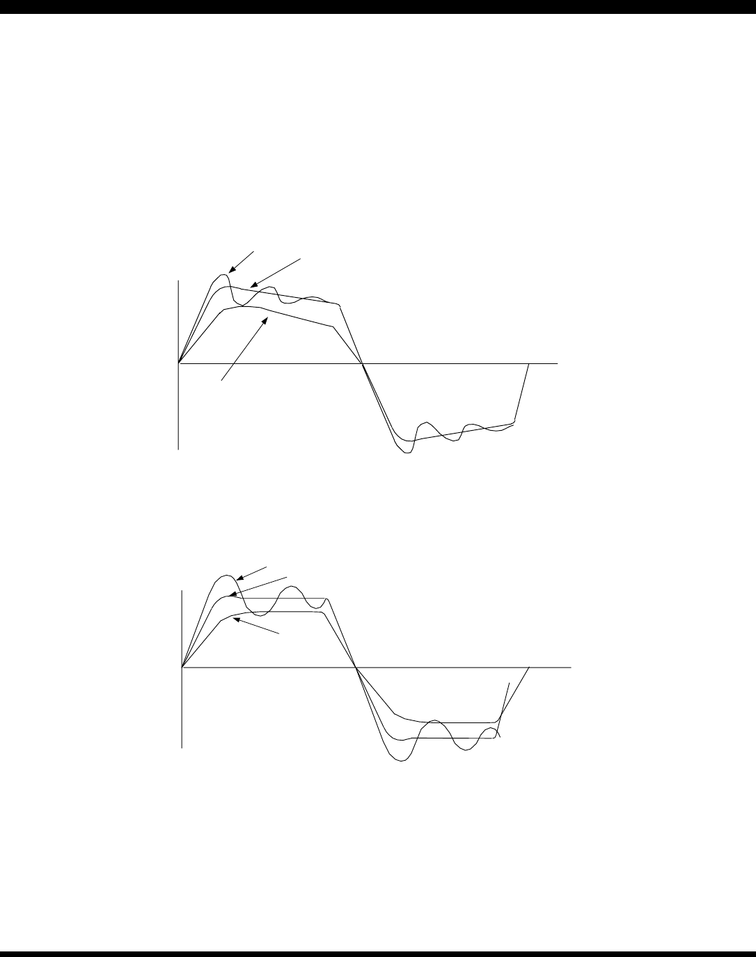
DC GAIN ADJUSTMENT (RH20)
1. Use a square-wave reference signal of ±0.5V, 50Hz.. Set the power supply to the anticipated operating voltage.
2. Replace the compensation capacitor (CH18) with a short ( jumper )
3. Observing the signal at the current monitor, pick a value for RH20 that gives a clean step response. Do not consider the
‘flat-top’ portion of the waveform, the ‘tilt’ will disappear when CH18 is adjusted.
OSCILLATION, RESISTOR VALUE TOO HIGH!
GOOD RESPONSE, BEST RISETIME WITHOUT OSCILLATION
RESISTOR TOO SMALL, POOR RESPONSE
COMPENSATION RESISTO
R
SETTING
( COMPENSATION CAPACITOR = S
H
INTEGRATOR ADJUSTMENT (CH18)
1. Begin with the default value of 15nF. Check step waveform. If overshoot >10% and ringing occur, CH18 is too small. If
response is sluggish, CH18 is too big. When changing CH18, use a factor of 3X (or 1/3) to see significant effect.
Thereafter-smaller changes can be used to converge on best setting.
2. When CH18 is properly chosen, some overshoot (<10%) will occur, but waveform will settle cleanly to a ‘flat-top’ with
little undershoot.
> 10% OVERSHOOT AND/OR OSCILLATION, CAPACITOR TOO SMALL
GOOD RESPONSE, SAME RISETIME WITH <10% OVERSHOOT
CAPACITOR TOO BIG,
SLUGGISH RESPONSE
COMPENSATION CAPACITOR
SETTING
( USE VALUE OF RESISTOR CHOSEN IN PREVIOU
S
BANDWIDTH TESTING
1. Change reference signal to sinusoidal waveform. Begin at 100Hz, adjust amplitude for a 0.35V peak-to-peak waveform at the
current monitor. This should be seven vertical divisions on an oscilloscope that is set to 0.05V/division.
2. Sweep the frequency upward. When the peak-to-peak amplitude drops to 5 divisions this is the –3dB frequency. This method will
permit testing of 10mH loads to 3kHz BW at 120VAC or a 20mH load to 3kHz at 240VAC. For higher inductance values, slew rate
limiting will force p-p current amplitude to be lowered for observation without error.
MODELS 5234AC, 5434AC
LINE-POWERED DC BRUSHLESS SERVO AMPLIFIERS
Copley Controls Corp. Tel: 781-828-8090
www.copleycontrols.com 20 Dan Road Canton, MA 02021 Fax: 781-828-6547
Rev. F 04/01/05
Page 12 of 12
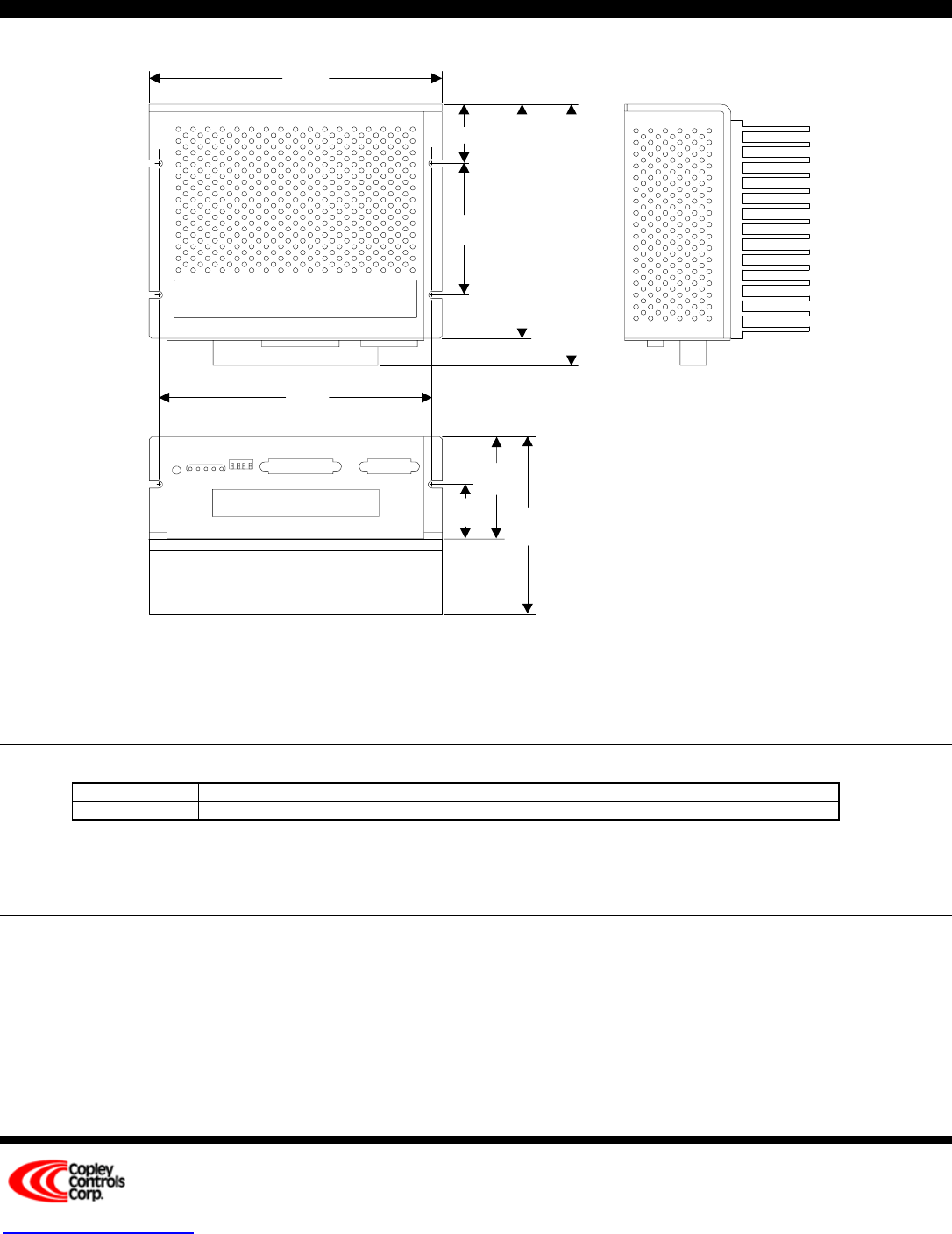
OUTLINE DIMENSIONS
2.72
(69.1)
4.72
(119.9)
7.50
(190.5)
6.94
(176.3)
6.22
(158)
1.46
(37.08)
3.00
(76.2)
0.93 (23.62)
7.00
(177.8)
Optional heat sink
Heat sink option
Dimensions in inches (mm.)
WEIGHT 3.71 lb. (1.69 kg) without optional heatsink. Add 3.2 lb. (1.47 kg) for heatsink.
CONNECTORS J1: Power & motor 9-position barrier strip; #6-32 screws have wire protector washers
J2: Motor signal 15 position female sub-D type; with #4-40 standoffs for cable shell
J3: Control Signal 25 position female sub-D type; with #4-40 standoffs for cable shell
ORDERING GUIDE
Model 5234AC 30A peak, 15A continuous, 115VAC, 50/60Hz nominal input power
Model 5434AC 30A peak, 15A continuous, 115/230VAC, 50/60Hz nominal input power
Notes: 1. Add "H" to model number to specify heatsink option.
Example: Model 5434AC with heatsink would be ordered as a 5434ACH
No user serviceable parts. Contact Copley for service.
OTHER BRUSHLESS AMPLIFIERS
7000 Series Five different model types for driving AC brushless motors with sinusoidal commutation using a variety
of feedback and control card schemes
5xx1 Series Six models operating from +24 to +225VDC, 10~20A peak, 5~15A continuous.
CE compliance available (5xx1CE models), Hall/encoder velocity feedback option
Brushless tachometer option.
Model 503 Torque-mode brushless amplifier. +18 to +55VDC, 5A continuous, 10A peak.
Model 505 Same power output as 503. Adds Hall / Encoder tachometer feature for velocity loop operation.
