F90070EQ Instruction_v3.3 6001 6002 I Explore Manual2
User Manual: 6001
Open the PDF directly: View PDF ![]() .
.
Page Count: 14
900X70 Refractor Telescope
Instruction Manual
For products #6001 & #6002 www.iOptron.com
2
Table of Contents
Table of Contents ............................................................................................................ 2
1. Telescope Assembly.................................................................................................... 3
1.1. 900X70 Assembly Terms....................................................................................... 3
1.2. Telescope Assembly.............................................................................................. 5
2. Understanding Celestial Motion and Coordinates ....................................................... 7
3. Getting Started ............................................................................................................ 8
3.1. Selecting an Eyepiece........................................................................................... 8
3.2. Focusing Telescope............................................................................................... 8
3.3. Aligning Finderscope:............................................................................................ 8
3.4. Balancing the Telescope ....................................................................................... 8
3.5. Polar Alignment of the Equatorial mount ............................................................... 9
4. Using the Telescope .................................................................................................. 10
4.1. Getting familiar with you mount and telescope.................................................... 10
4.2. Star observation .................................................................................................. 10
4.3. Observation Tips ................................................................................................. 10
4.4. How to use setting circles.................................................................................... 10
4.5. Calculating the Power ......................................................................................... 11
5. Maintenance.............................................................................................................. 12
6. Technical Specifications ............................................................................................ 13
IOPTRON ONE YEAR LIMITED WARRANTY.............................................................. 14
3
1. Telescope Assembly
1.1. 900X70 Assembly Terms
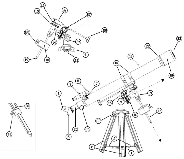
Figure 1. 900X70
(1). Accessory holder tray
(2). Aluminum tripod
(3). Leg lock brackets
(4). Tripod base
(5). Diagonal mirror
(6). Eyepiece
(7). Finderscope bracket
(8). Finderscope
(9). Finderscope collimation screws
(10). Scope mounting ring
(11). Main optical tube
(12). Declination locking knob
(13). Declination setting circle
(14). Right ascension locking knob
(15). Right ascension gear
(16). Right ascension setting circle
(17). Counterweight shaft
(18). Counterweight
(19). Counterweight safety washer
(20). Counterweight locking knob
(21). Equatorial mount head
(22). Lens cell
(23). Azimuth adjustment knob
(24). Latitude adjustment knob
(25). Eyepiece holder tube
(26). Focusing knob
(27). Right ascension control cable
(28). Declination control cable
(29). Sunshade
(30). Sliding inner tripod leg extension
(31). Leg extension locking knob
(32). Tripod leg bolts
(33). Front lens dust cap
DEC Axis
RA Axis
4
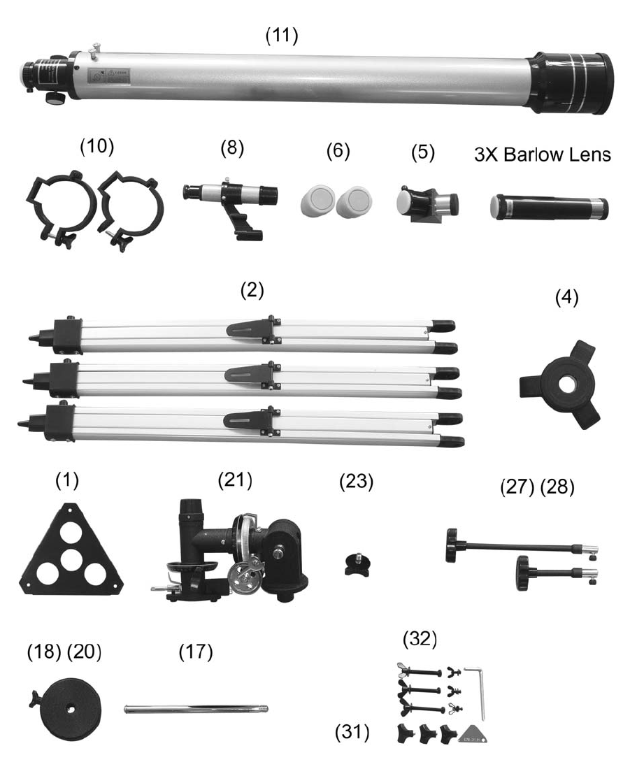
Figure 2. Parts List
5
1.2. Telescope Assembly
The numbers in brackets refer to the keys
shown in Figures 1 & 2.
1. Unpack and identify the components of your
telescope using the list shown in previous page.
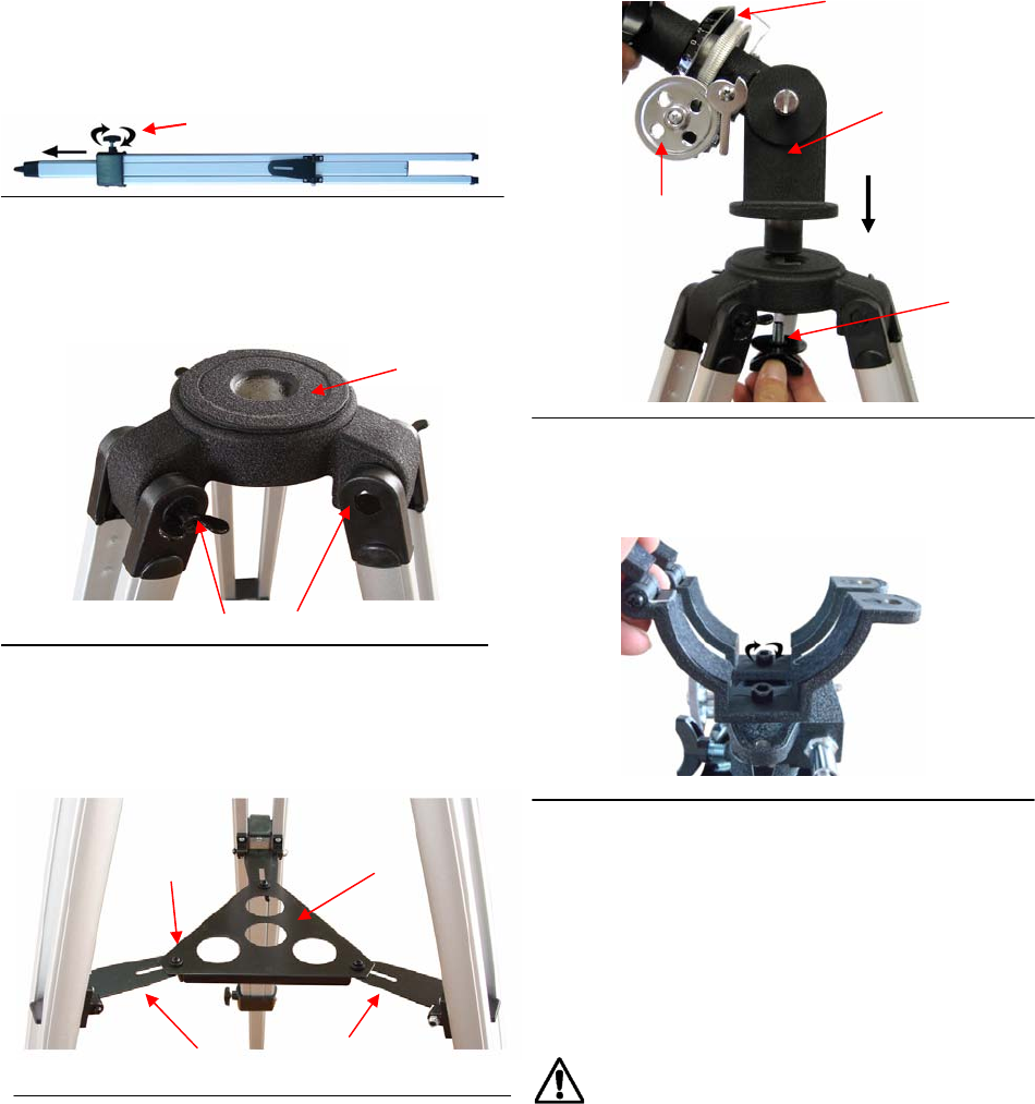
2. Take the tripod legs (2) out of the package.
Make sure the locking knobs (31) are tightened.
3. Mount three tripod's legs (2) to the tripod base
(4) using the three long tripod leg bolts (32) with
their washers and wing nuts. Make sure that the
three hinged leg lock brackets (3) are facing inside
(as shown in figure. 1 )
4. Stand the telescope's tripod mount upright by
spreading the tripod's legs out uniformly. Attach
the accessory holder tray (1) to the leg lock
brackets (3) using the short screws and wing nuts
supplied.
5. Unlock the tripod leg extension locking knob
(31). Extend tripod legs to desired height and lock
the leg locks afterwards.
6. Insert the base of the equatorial mount head
into the hole of the tripod base (4) and secure it
using azimuth adjustment knob (23). Make sure the
right ascension (R.A.) gear (21) is below the R.A.
setting circle (13).
7. Put the optical tube mounting (10) onto the
equatorial mount and secure it using 2 supplied hex
head screws.
8. Slide counterweight (18) onto the
counterweight shaft (17) and secure the
counterweight by tightening the counterweight
locking knob (20). Screw counterweight shaft (17)
onto the base of the declination (Dec) axis on the
equatorial mount. Once this shaft is firmly in place,
release the locking knob (20), adjust the
counterweight up some 50 mm from the end of the
shaft and retightening the locking knob (20).
Counter weight is heavy. Please handle
with care to avoid injury!
(31)
Tripod base (4)
Tripod leg bolts and nuts (32)
Accessory tray (1)
Short screw
Leg lock brackets (3)
R.A.
g
ear
(
21
)
R.A. setting circle (13)
Equatorial mount
Head (15)
Azimuth Adjustment
knob (23)
6
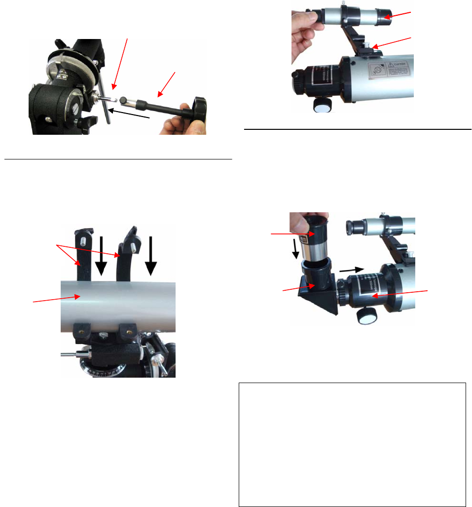
9. Assemble the right ascension (R.A.) control
cable (27, short cable) and declination (Dec) control
cable (28). These cables are locked into position by
firmly tightening the screws at the end of each
cable.
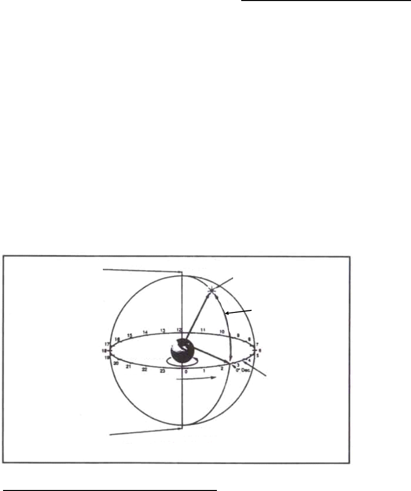
10. Place the optical tube assembly (OTA) (11)
into the scope mounting rings (10) and tighten the
two wing screws on the tube mounting to secure the
OTA.
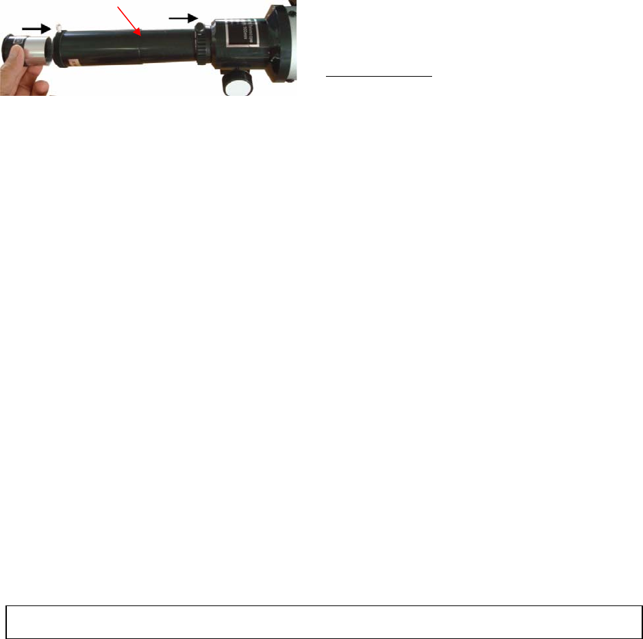
11. Loosen two screws at the end of the OTA.
Mount the finderscope bracket (7) onto the
telescope using these two knurled screws.
12. Insert the diagonal (5) into the eyepiece holder
tube (25) and the eyepiece (6) into the diagonal.
Tighten the thumbscrews to a firm feel only. If the
3X Barlow lens is needed, insert the Barlow into the
eyepiece holder tube first.
The telescope is now fully assembled and ready to
use. You can move the telescope in altitude
direction (up and down) and azimuth direction (left
or right) by slightly release the latitude adjustment
knob (24) and azimuth adjustment knob (23). Or
you can move the telescope along the right
ascension and declination direction by loosen the
right ascension locking knob (14) and declination
locking knob (12).
R.A. control cable (27)
Lock trench Screws to mount
finderscope
Eyepiece (6)
Diagonal (5) Eyepiece holder
tube (25)
Finderscope
OTA
Mounting
Rings
7
2. Understanding Celestial Motion and
Coordinates
Understanding where to locate celestial objects and
how these objects move through the sky is
fundamental to fully appreciating astronomy as a
hobby. Most amateur astronomers use the same
visual path (or star-hopping) method for locating
celestial objects. To do this they use maps of the
sky or an astronomy program that identifies bright
stars and constellations of stars that serve as
"roadmaps" and "markers" in the sky. These visual
reference points guide amateur astronomers in
their search for astronomic objects and although
the visual path method is the preferred
approach—giving thought to whether or not to use
circles of digital coordinates for locating objects is
desirable as your telescope offers this function. Be
warned however, when compared with a visual path
approach, looking for objects using circles of digital
coordinates requires a greater investment in terms
of patience and time in order to achieve a more
precise alignment of the telescope's polar axis on
the celestial pole. This is partially why the visual
path approach is preferred since it’s the simplest
(and quickest) way to get started.
Understanding how astronomic objects move
Given the earth's rotation, celestial bodies (stars)
appear to move from east to west along a curved
trajectory across the sky. The trajectory that they
follow is known as the right ascension line (R.A.).
The angle of the trajectory that they follow is known
as the declination line (Dec.). The right ascension
and the declination form a system that is similar to
the terrestrial system of latitude and longitude.
In the system of R.A. and Dec. coordinates, stars
are projected onto the "celestial sphere", i.e. onto
the imaginary sphere where all of the stars appear
to be located.
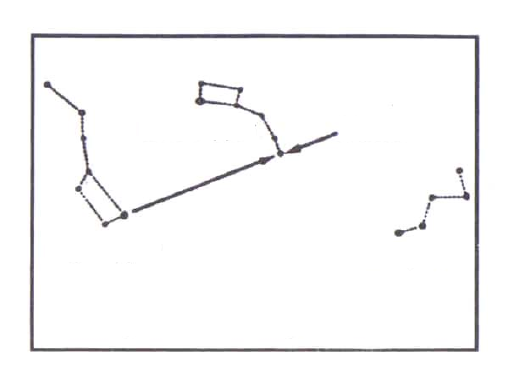
Understanding celestial coordinates
In the system of celestial coordinates, the poles are
defined as being the two points where the earth's
rotation axis, when prolonged infinitely to the north
and to the south, intersects with the celestial
sphere. Consequently, the celestial North Pole is
the point in the sky where the prolongation of the
earth's axis passing through the North Pole
intersects the celestial sphere. In fact this point in
the sky is located close to the North Star or pole
star (Polaris).
So-called "longitude lines" are drawn on the earth's
surface between the north and south poles. In the
same way, "latitude lines" are drawn along an
east-west direction, parallel to the earth's equator.
The celestial equator is simply a projection of the
earth's equator into the celestial sphere. Just like
on the earth's surface, imaginary lines have been
drawn on the celestial sphere to form a grid of
coordinates. The positions of the stars on the
earth's surface are specified by their latitude and
longitude.
The celestial
equivalent to terrestrial
latitude is called
"Declination" or simply
"Dec", expressed in
degrees, minutes, and
seconds north (“+”) or
south ("-") of the
celestial equator.
Consequently any
point located along the
celestial equator (e.g.
passing through the
constellations of Orion,
Virgo and Aquarius) is
specified by its
declination of 0º0’0”.
The declination of the
North Star or pole star located very close to the
North Celestial Pole is +89.2º.
The celestial equivalent to terrestrial longitude is
called "Right Ascension" or "R.A.", expressed in
hours, minutes and seconds from a "zero" R.A. line
defined arbitrarily and which passes through the
constellation of Pegasus. The coordinates of the
Right Ascension range from 0h 0mn 0s to 24h 0mn
0s (not inclusive). Therefore, there are 24 primary
Celestial North Pole
(close to the North Star
(Polaris)) Star
Declination
Earth's rotation
Right ascension Celestial equator
Celestial South Pole
Figure 2: Celestial Sphere
8
R.A. lines located at 15 degree intervals along the
celestial equator. The objets that are further away,
eastwards, from the primary Right Ascension grid
line (0h 0mn 0s) carry rising R.A. coordinates.
Consequently, once it is possible to specify the
position of all of these celestial objects using their
Right Ascension and Declination coordinates the
task of searching for objects (especially low
brightness stars) using the astronomer's telescope
may be simplified. The digital, R.A. (16) and Dec.
(13) setting circles for your telescope can be made
up, in practice to read the object's coordinates, by
positioning it close to the telescope's telescopic
field of view (FOV). The advantage of using these
setting circles is however only justified after first
correctly aligning the telescope with the North
Celestial Pole.
3. Getting Started
Before you can use the telescope effectively, there
are still a few steps to be performed.
3.1. Selecting an Eyepiece
1. Always begin viewing with the lowest power
eyepiece. (Note: a 20 mm focal length eyepiece is
lower power than a 12.5 mm one.) A formula can
be used to determine the power of each eyepiece:
Telescope focal length divided by eyepiece focal
length equals magnification. Ex. 900mm ÷ 20mm =
45X (magnification)
2. Included with this telescope is a 90° Star
Diagonal.
3.2. Focusing Telescope
1. After selecting the desired eyepiece aim the
main telescope tube at a land-based target at least
200 yards away (e.g. A telephone pole or a
building). Fully extend focusing tube by turning the
focus knob.
2. While looking through selected eyepiece, slowly
retract focusing tube by turning focusing knob until
object comes into focus.
3.3. Aligning Finderscope:
The extended field of vision offered by the 5x24
mm finderscope (8) makes it easier to aim at an
object before viewing it through the main telescope
tube with a higher magnification.
1). Remove the front lens cover (33) from the
sunshade (29). Look through Main Telescope Tube
and establish a well-defined target (see focusing
telescope section). Tighten all lock knobs
(Declination, Latitude, Right Ascension, Horizontal
Axis) so that telescope’s aim is not disturbed.
2). Looking through the finderscope, alternate
tightening or loosing each finderscope Adjustment
Screw (9) until the crosshairs of the finderscope
are precisely centered on the same object already
centered in Main Telescope Tube’s field of view.
3). Now, objects located with the finderscope first
will be centered in FOV of the main telescope.
They can be focused by turning the finderscope’s
threaded eyepiece. The image in the finderscope
will be reversed.
3.4. Balancing the Telescope
To insure smooth movement of the telescope on
both axes of the equatorial mount, it is imperative
that the optical tube be properly balanced. We will
first balance the telescope with respect to the right
ascension (R.A.) axis and then in the declination
(Dec.) axis.
1. Keeping one hand on the telescope optical tube
(11), loosen the R.A. lock knob (14). Make sure the
Dec. lock knob (12) is locked. The telescope
should now be able to rotate freely about the R.A.
axis. Rotate it until the counterweight shaft (17) is
parallel to the ground (i.e., horizontal).
2. Now loosen the counterweight lock knob (20)
and slide the weight along the shaft until it exactly
counterbalances the telescope. That’s the point at
which the shaft remains horizontal even when you
let go of the telescope with both hands.
3. Retighten the counterweight lock knob. The
telescope is now balanced on the R.A. axis.
4. To balance the telescope on the Dec. axis, first
tighten the R.A. lock knob (14), with the
counterweight shaft (17) still in the horizontal
position.
5. With one hand on the telescope optical tube (11),
loosen the Dec. lock knob (12). The telescope
should now be able to move freely on the Dec. axis.
Loosen the ring clamps on the tube rings (10) a few
turns, until you can slide the telescope tube forward
and back inside the rings (this can be aided by
using a slight twisting motion on the optical tube
while you push or pull on it).
6. Position the telescope in the tube rings (10) so it
9
remains horizontal when you carefully let go with
both hands. This is the balance point for the optical
tube (11) with respect to the Dec. axis.
7. Retighten the ring clamps.
3.5. Polar Alignment of the Equatorial mount
Objects located in the sky appear to revolve around
the celestial pole. In northern latitudes, the North
Star (Polaris) is close to the pole. (In actual fact,
stars are essentially "fixed" in place and their
apparent motion is caused by the earth rotating
around its own axis.) Over a 24 hour period, stars
will perform a complete revolution around the pole,
generating concentric circles with the pole at their
center. By aligning the telescope's polar axis with
the celestial north pole (or with the celestial south
pole for observers located in the earth's southern
hemisphere), astronomic objects may be followed
(or tracked) by simply moving the telescope around
an axis, the polar axis.
If the telescope is reasonably aligned with the pole,
changing the instrument's declination using its
flexible control cable will consequently be of little
use – almost all the telescope motion required will
take place using the Right Ascension coordinates.
(If the telescope is perfectly aligned with the
pole—no declination change will be required to
follow stellar objects). For occasional visual
observations through the telescope, aligning the
telescope's polar axis by one or two degrees in
relation to the pole is more than enough. With this
level of aiming precision the telescope can achieve
precise tracking if the R.A. flexible control cable is
used while maintaining the objects within the
telescope's FOV for some 20 to 30 minutes.
To polar-align the telescope:
1. Level the equatorial mount by adjusting the
length of the three tripod legs (2).
2. Loosen the latitude adjustment knob (24) and tilt
the mount until the pointer on the latitude scale is
set at the latitude of your observing site. If you don’t
know your latitude, consult a geographical atlas or
search the internet. For example, if your latitude is
35° north, set the pointer to 35. Then retighten the
latitude knob. The latitude setting should not have
to be adjusted again unless you move to a different
viewing location some distance away.
3. Loosen the Dec. lock knob (12) and rotate the
telescope optical tube (11) until it is parallel with the
R.A. axis, as it is in Figure 1. The pointer on the
Dec. setting circle (13) should read 90°. Retighten
the Dec. lock knob.
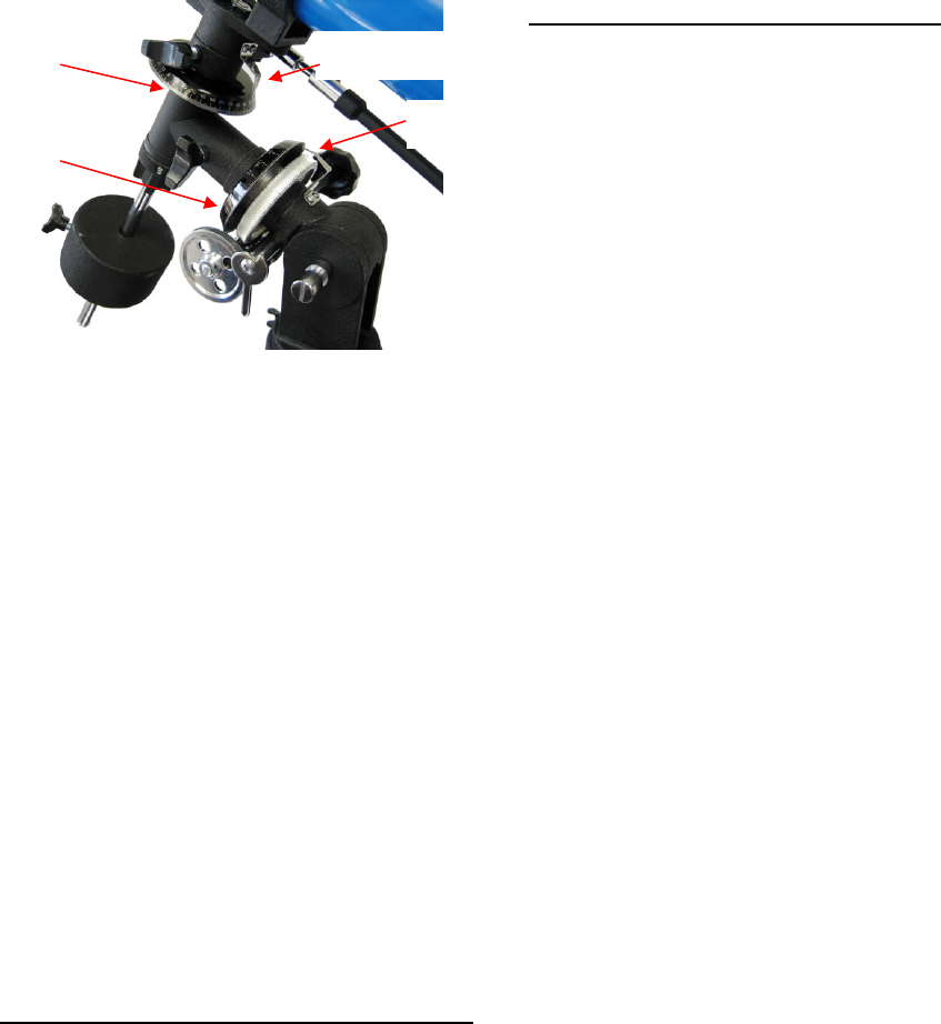
4. Loosen the azimuth adjustment knob (23) on the
mount and rotate the mount so the telescope tube
(and R.A. axis) points roughly at Polaris. If you
cannot see Polaris directly from your observing site,
consult a compass and rotate the mount so the
telescope points north. Retighten the azimuth
adjustment knob.
Ursa minor Polaris
Cassiopeia
Ursa major
Figure 3: Finding Polaris
The equatorial mount is now polar aligned.
From this point on in your observing session, you
should not make any further adjustments in the
azimuth or the latitude of the mount, nor should you
move the tripod. Doing so will undo the polar
alignment. The telescope should be moved only
about its R.A. and Dec. axes.
10
4. Using the Telescope
With the telescope aligned on the pole, you are
now ready to start your observations.
4.1. Getting familiar with you mount and
telescope
Before observing a celestial object, looking at
terrestrial objects during the day provides a good
exercise on how to operate the mount and
telescope.
4.2. Star observation
First of all you will need to choose an object that is
easy to find. The Moon or a bright star is a good
target to start with.
1. Slightly loose the telescope's Right Ascension
locking knob (14) and the Declination locking knob
(12), located close to the Declination adjustment
ring (13). By applying slight pressure by hand, the
telescope should now move freely along its two
axes.
2. Move the telescope along R.A. and Dec axes
and using the aligned finderscope to find the Moon.
With the object centered in the finderscope's cross
hairs, retighten the R.A. and Dec. knobs.
3. The Moon should be visible somewhere within
the FOV of main telescope. Focus the image by
adjusting the focusing knob (26). Center the Moon
by adjusting the mount using RA and DEC control
cable (27, 28).
4. You’ll find that the object immediately starts to
shift across the FOV. This motion is due to the
earth rotation. To "track" the object and keep it in
the FOV, turn the cable that controls R.A. slow
motion (27). Objects will appear to move faster at
higher magnifications. The Declination control
cable (28) is only used for centering the object and
not for tracking.
4.3. Observation Tips
When selecting a location for observing, get as far
away as possible from direct artificial light such as
street lights, porch lights, and automobile
headlights. The glare from these lights will greatly
impair your dark-adapted night vision. Set up on a
grass or dirt surface, not asphalt, because asphalt
radiates more heat, which disturbs the surrounding
air and degrades the images seen through the
telescope. Avoid viewing over rooftops and
chimneys, as they often have warm air currents
rising from them. Avoid observing from indoors
through an open (or closed) window, because the
temperature difference between the indoor and
outdoor air will cause image blurring and distortion.
Furthermore, it is preferable to let your telescope
reach outside ambient (surrounding) temperature
before starting an observation cycle.
Wait a few minutes to allow your eyes to become
used to the darkness before attempting any serious
observations. Use a flashlight with a red filter to
preserve your night vision when looking at star
maps or checking telescope parts.
Avoid touching the eyepiece during observation.
Vibration generated by this contact may cause the
view to move. Also avoid observing from locations
where terrestrial vibrations are significant.
Observing from the upper floors of buildings may
also cause the images vibrating.
Warning! Never attempt to observe the sun
through your telescope without a proper solar filter.
Observing the sun, even for a fraction of a second,
may cause immediate and irreversible harm to your
eye as well as physical damage to the telescope.
Some atmospheres may deform the image that you
are observing. Planets in particular, when observed
low on the horizon, often present a fuzziness – the
same object when observed at a higher altitude in
the sky may benefit from far better definition and a
far higher degree of contrast. Furthermore, air
turbulence in the upper layers of the atmosphere
may cause "trembling" to affect the view observed
through the eyepiece. In this case, reduce the
magnification factor until the picture stabilizes.
Keep in mind that even a small sized but bright and
well defined image will reveal far more interesting
details than a larger, but less bright and slightly
fuzzy, view.
4.4. How to use setting circles
Understanding the Setting Circles
The setting circles on an equatorial mount enable
you to locate celestial objects by their “celestial
coordinates”. The R.A. and Dec. values for
celestial objects can be found in any star atlas or
star catalog.
11
The mount’s R.A. setting circle (16) is scaled in
hours, from 1 through 24, with small marks in
between representing 6-minute increments. The
numbers closest to the R.A. axis gear apply to
viewing in the Southern Hemisphere, while the
numbers above them apply to viewing in the
Northern Hemisphere.
The Dec. setting circle (13) is scaled in degrees,
with each mark representing 2° increments. Values
of Dec. coordinates range from +90° to -90°. The 0°
mark indicates the celestial equator. When the
telescope is pointed north of the celestial equator,
values of the Dec. setting circle are positive, while
when the telescope is pointed south of the celestial
equator, values of the Dec. setting circle are
negative.
Before you can use the setting circles to locate
objects, the mount must be correctly polar aligned,
and the R.A. setting circle must be calibrated. The
Dec. setting circle has been permanently calibrated
at the factory, and should read 90° whenever the
telescope optical tube is parallel with the R.A. axis.
Calibrating the Right Ascension Setting Circle
1. Identify a bright star in the sky near the celestial
equator (Dec. = 0°) and look up its coordinates in a
star atlas.
2. Loosen the R.A. and Dec. lock knobs (14, 12) on
the equatorial mount, so the telescope optical tube
can move freely.
3. Point the telescope at the bright star whose
coordinates you know. Lock the R.A. and Dec. lock
knobs. Center the star in the telescope’s field of
view with the R.A. and Dec control cables.
4. Rotate the setting circle until the metal arrow
indicates the R.A. coordinate listed in the star atlas
for the object
Finding Objects With the Setting Circles
Now that both setting circles are calibrated, look up
in a star atlas the coordinates of an object you wish
to view. Loosen the Dec. lock knob (12) and rotate
the telescope until the Dec. value from the star
atlas matches the reading on the Dec. setting circle
(13). Remember that values of the Dec. setting
circle are positive when the telescope is pointing
north of the celestial equator (Dec. = 0°), and
negative when the telescope is pointing south of
the celestial equator. Retighten the lock knob.
Loosen the R.A. lock knob (14) and rotate the
telescope until the R.A. value from the star atlas
matches the reading on the R.A. setting circle (16).
Remember to use the upper set of numbers on the
R.A. setting circle. Retighten the lock knob.
Most setting circles are not accurate enough to put
an object dead-center in the telescope’s eyepiece,
but they should place the object somewhere within
the field of view of the finderscope, assuming the
equatorial mount is accurately polar aligned. Use
the R.A. and Dec control cables to center the object
in the finderscope, and it should appear in the
telescope’s field of view.
The R.A. setting circle must be re-calibrated every
time you wish to locate a new object. Do so by
calibrating the setting circle for the centered object
before moving on to the next one.
4.5. Calculating the Power
The power or magnification offered by a telescope
is determined by two factors: the optical or focal
length of the telescope's lens and the eyepiece's
focal length. This telescope's focal length is 900
mm. To calculate the magnification factor, divide
the lens' focal length by that of the eyepiece. The
resulting value represents the magnification factor
offered by the telescope when it is used with this
eyepiece. For example, using a 20 mm eyepiece
provides a magnification factor of:
Magnification = 900 mm/20 mm = 45X
Dec. setting circle
R.A. setting circle
Dec. mark
R.A. mark
12
A Barlow lens is used to increase the magnification
of each eyepiece. First insert the Barlow 3X lens in
the telescope’s eyepiece holder, then the diagonal
mirror and the eyepiece itself. Secure the lens
using thumbnail screws. The total magnification will
be 135X when a 20 mm eyepiece (45X) and a 3X
Barlow lens are used together.
Some words of caution on magnification.
Although the theoretical power or magnification of
a telescope is virtually limitless, there are practical
limits, such as he earth's atmosphere. Every
telescope has a useful magnification limit of about
2X per millimeter of aperture. This comes to 140X
for the 900X70. Moderate magnifications are what
give the best views. It is better to view a small, but
bright and detailed image than a dim, unclear,
oversized image.
5. Maintenance
If you give your telescope reasonable care, it will
last a lifetime. Store it in a clean, dry, dust free
place, safe from rapid changes in temperature and
humidity. Do not store the telescope outdoors,
although storage in a garage or shed is OK. Small
components like eyepieces and other accessories
should be kept in a protective box or storage case.
Keep the caps on the front of the telescope and on
the focuser drawtube when not in use.
Your 900X70 telescope requires very little
mechanical maintenance. The optical tube is
aluminum and has a smooth painted finish that is
fairly scratch resistant. If a scratch does appear, it
will not harm the telescope.
Cleaning Lenses
Any quality optical lens cleaning tissue and optical
lens cleaning fluid specifically designed for
multi-coated optics can be used to clean the
objective lens and the exposed lenses of your
eyepieces. Never use regular glass cleaner or
cleaning fluid designed for eyeglasses.
Before cleaning with fluid and tissue, blow any
loose particles off the lens with a blower bulb or
compressed air. Then apply some cleaning fluid to
a tissue, never directly on the optics. Wipe the lens
gently in a circular motion, then remove any excess
fluid with a fresh lens tissue. Oily fingerprints and
smudges may be removed using this method. Use
caution— rubbing too hard may scratch the lens.
For the larger surface of the objective lens, clean
only a small area at a time, using a fresh lens tissue
on each area. Never reuse tissues.
6.
Barlow lens
For further assistance visit www.iOptron.com for FAQ’s, technical support, and other helpful tips.

13
Technical Specifications
Optical tube Aluminum
Optical Design Achromatic Refractor
Objective lens Air-spaced, fully coated
Clear Aperture 70 mm
Focal Length 900mm
Focal Ratio f/12.8
Focuser Rack and pinion, accepts 1.25" eyepieces and
accessories
Eyepiece H12.5mm, H20mm
Diagonal 90º star diagonal, 1.25”
Magnification with
supplied eyepiece 45X (w/ 20mm),
72X (w/12.5mm)
Barlow Lens 3X
Finding Scope 5X24
Mount EQ-2, German equatorial
Tripod Aluminum
Motor drive Optional
Total Weight 20 lbs.

14
IOPTRON ONE YEAR LIMITED WARRANTY
A. iOptron warrants your telescope, mount, or controller to be free from defects in materials and workmanship for one
year. iOptron will repair or replace such product or part which, upon inspection by iOptron, is found to be defective in
materials or workmanship. As a condition to the obligation of iOptron to repair or replace such product, the product must
be returned to iOptron together with proof-of-purchase satisfactory to iOptron.
B. The Proper Return Authorization Number must be obtained from iOptron in advance of return. Call iOptron at
1.866.399.4587 to receive the number to be displayed on the outside of your shipping container.
All returns must be accompanied by a written statement stating the name, address, and daytime telephone number of
the owner, together with a brief description of any claimed defects. Parts or product for which replacement is made shall
become the property of iOptron.
The customer shall be responsible for all costs of transportation and insurance, both to and from the factory of iOptron,
and shall be required to prepay such costs.
iOptron shall use reasonable efforts to repair or replace any telescope, mount, or controller covered by this warranty
within thirty days of receipt. In the event repair or replacement shall require more than thirty days, iOptron shall notify
the customer accordingly. iOptron reserves the right to replace any product which has been discontinued from its
product line with a new product of comparable value and function.
The repairing and replacement carry a 90 day limited labor and/or parts warranty.
This warranty shall be void and of no force of effect in the event a covered product has been modified in design or
function, or subjected to abuse, misuse, mishandling or unauthorized repair. Further, product malfunction or
deterioration due to normal wear is not covered by this warranty.
IOPTRON DISCLAIMS ANY WARRANTIES, EXPRESS OR IMPLIED, WHETHER OF MERCHANTABILITY OF
FITNESS FOR A PARTICULAR USE, EXCEPT AS EXPRESSLY SET FORTH HERE. THE SOLE OBLIGATION OF
IOPTRON UNDER THIS LIMITED WARRANTY SHALL BE TO REPAIR OR REPLACE THE COVERED PRODUCT, IN
ACCORDANCE WITH THE TERMS SET FORTH HERE. IOPTRON EXPRESSLY DISCLAIMS ANY LOST PROFITS,
GENERAL, SPECIAL, INDIRECT OR CONSEQUENTIAL DAMAGES WHICH MAY RESULT FROM BREACH OF ANY
WARRANTY, OR ARISING OUT OF THE USE OR INABILITY TO USE ANY IOPTRON PRODUCT. ANY
WARRANTIES WHICH ARE IMPLIED AND WHICH CANNOT BE DISCLAIMED SHALL BE LIMITED IN DURATION
TO A TERM OF ONE YEARS FROM THE DATE OF ORIGINAL RETAIL PURCHASE.
Some states do not allow the exclusion or limitation of incidental or consequential damages or limitation on how long an
implied warranty lasts, so the above limitations and exclusions may not apply to you.
This warranty gives you specific legal rights, and you may also have other rights which vary from state to state.
iOptron reserves the right to modify or discontinue, without prior notice to you, any model or style telescope.
If warranty problems arise, or if you need assistance in using your telescope, mount, or controller contact:
iOptron Corporation
Customer Service Department
6F Gill Street
Woburn, MA 01801
www.ioptron.com
Tel. (866)399-4597 (Toll Free in US)
Tel: +1 781.569.0200
Fax: +1 781.935.2860
Monday-Friday 9AM-5PM EST
NOTE: This warranty is valid to U.S.A. and Canadian customers who have purchased this product from an authorized
iOptron dealer in the U.S.A. or Canada or directly from iOptron. Warranty outside the U.S.A. and Canada is valid only to
customers who purchased from an iOptron Distributor or Authorized iOptron Dealer in the specific country. Please
contact them for any warranty services.
