Metasys Integrator Liebert Application Note DC12I 6295370
User Manual: DC12I
Open the PDF directly: View PDF ![]() .
.
Page Count: 74
- lntroduction
- Cable Connections
- Metasys Integrator Unit Setup
- Point Mapping Tables
- Deluxe System/3 (MCCI Configuration)
- Small Systems Controller (MCCI Configuration)
- Liebert ECA2 Level 0
- Liebert ECA2 Level 10 and Level 15
- Liebert DCLAN Environmental Unit Level 0 and Level 0 with On
- Liebert DCLAN Environmental Unit Small Systems Control (L0B)
- Liebert DCLAN Environmental Unit Level 2, 3, 10, and 15 (L02
- Liebert DCLAN Chiller - CW1, CW2, and CW3
- Liebert DCLAN Chiller with Econocoil - CE1, CE2, and CE3
- Liebert DCLAN Power Conditioning Unit
- Liebert DCLAN UPS Series 300 and 600
- Liebert DCLAN Series 600 Static Control Cabinet (SCC)
- Liebert DCLAN Contact Closure Module (CCM)
- Liebert SiteLink/NIC CCM Function Block
- Liebert SiteLink/NIC CSE Function Block
- Liebert SiteLink/NIC CSU Function Block
- Liebert SiteLink/NIC EDS Function Block
- Liebert SiteLink/NIC L00 Function Block
- Liebert SiteLink/NIC L0B Function Block
- Liebert SiteLink/NIC L10 Function Block
- Liebert SiteLink/NIC LAM and MM2 Function Blocks
- Liebert SiteLink/NIC LSM Function Block
- Liebert SiteLink/NIC MM4 Function Block
- Liebert SiteLink/NIC MMS Function Block
- Liebert SiteLink/NIC NPower IMP Function Block
- Liebert SiteLink/NIC PMP Function Block
- Liebert SiteLink/NIC RAC Function Block
- Liebert SiteLink/NIC SC4 Function Block
- Liebert SiteLink/NIC SCC Function Block
- Liebert SiteLink/NIC SM3 Function Block
- Liebert SiteLink/NIC SM4 Function Block
- Liebert SiteLink/NIC SMS Function Block
- Liebert SiteLink/NIC THM Function Block
- Liebert SiteLink/NIC VCF Function Block
- Liebert SiteLink/NIC VCM Function Block
- Liebert SiteLink/NIC WDU Function Block
- Metasys Network Setup
- Custom Integration

Application Note
Issue Date May 25, 2004
Metasys Integrator® Liebert® Application
lntroduction 3
Application Details 3
Component Requirements 10
Vendor Contact Information 12
Design Considerations 13
Cable Connections 15
Cable Pinouts 15
Connecting to SiteLink/NIC Modules 17
Connecting the Cable 19
Metasys Integrator Unit Setup 21
Point Mapping Tables 26
Deluxe System/3 (MCCI Configuration) 26
Small Systems Controller (MCCI Configuration) 28
Liebert ECA2 Level 0 29
Liebert ECA2 Level 10 and Level 15 30
Liebert DCLAN Environmental Unit Level 0 and Level 0 with On/Off Control
(L00, L0A, and LSM) 31
Liebert DCLAN Environmental Unit Small Systems Control (L0B) 32
Liebert DCLAN Environmental Unit Level 2, 3, 10, and 15 (L02, L03, L10,
L1A, and LAM) 32
Liebert DCLAN Chiller - CW1, CW2, and CW3 34
Liebert DCLAN Chiller with Econocoil - CE1, CE2, and CE3 35
Liebert DCLAN Power Conditioning Unit 36
Liebert DCLAN UPS Series 300 and 600 37
Liebert DCLAN Series 600 Static Control Cabinet (SCC) 38
Liebert DCLAN Contact Closure Module (CCM) 39
Liebert SiteLink/NIC CCM Function Block 40
© 2004 Johnson Controls, Inc. 1
Code No. LIT-6295370 www.johnsoncontrols.com

Liebert SiteLink/NIC CSE Function Block 41
Liebert SiteLink/NIC CSU Function Block 42
Liebert SiteLink/NIC EDS Function Block 43
Liebert SiteLink/NIC L00 Function Block 45
Liebert SiteLink/NIC L0B Function Block 46
Liebert SiteLink/NIC L10 Function Block 47
Liebert SiteLink/NIC LAM and MM2 Function Blocks 49
Liebert SiteLink/NIC LSM Function Block 51
Liebert SiteLink/NIC MM4 Function Block 52
Liebert SiteLink/NIC MMS Function Block 54
Liebert SiteLink/NIC NPower IMP Function Block 55
Liebert SiteLink/NIC PMP Function Block 57
Liebert SiteLink/NIC RAC Function Block 58
Liebert SiteLink/NIC SC4 Function Block 59
Liebert SiteLink/NIC SCC Function Block 61
Liebert SiteLink/NIC SM3 Function Block 62
Liebert SiteLink/NIC SM4 Function Block 63
Liebert SiteLink/NIC SMS Function Block 65
Liebert SiteLink/NIC THM Function Block 66
Liebert SiteLink/NIC VCF Function Block 67
Liebert SiteLink/NIC VCM Function Block 68
Liebert SiteLink/NIC WDU Function Block 69
Metasys Network Setup 70
Mapping to a CS Object 70
Custom Integration 74
2 Metasys Integrator Liebert Application Application Note

lntroduction
This document explains Metasys Integrator® Liebert® applications.
Use this document with the Metasys Integrator unit technical bulletins on
the Johnson Controls® Product Information site
(http://cgproducts.johnsoncontrols.com System Manuals > Integration >
Metasys Integrator), which provide information on installing and
commissioning the Metasys Integrator unit. For information on
Liebert equipment, see Liebert documentation (obtainable from a
Liebert representative).
Note: If you are using a Universal Packaging Module (UPM) enclosure,
you must install the Metasys Integrator unit 300 Series in a
two high enclosure (EN-EWC25-0) rather than a one high
enclosure (EN-EWC13-0) as shown in the figures for this
application note.
The Metasys Integrator unit allows Liebert equipment to become an
integral part of the Metasys® and Metasys Companion Networks. After a
Liebert Multi-Channel Communications Interface (MCCI), Environmental
Communication Adapter (ECA2), DCLAN BMS, SiteLink™ Module, or
Open Comms Network Interface Card (NIC) is connected to a Metasys or
Companion Network via the Metasys Integrator unit, each of its
Information Gathering Modules (IGMs) has access to the full complement
of Metasys Building Automation System (BAS) features, including
Change-of-State (COS) monitoring, alarm notification, trend, and
totalization.
Application
Details
IGMs maintain Liebert environmental systems to provide precise control
of temperature, humidity, filtration, and distribution for heat generating
equipment.
The Metasys Integrator unit supports applications for many, but not all,
SiteLink function blocks. With a Liebert SiteLink module configured for
Modbus RTU protocol and downloaded with the appropriate SiteLink
function block, the Metasys Integrator unit can communicate with most
Liebert products.
Liebert equipment equipped with a Liebert OpenComms Network
Interface Card use the SiteLink vendor tables.
IMPORTANT: For a complete list of products, controllers, and
function blocks, see the Liebert Web site
(www.liebert.com).
Metasys Integrator Liebert Application Application Note 3

You must verify that the product you want to integrate uses a function
block that is listed in this document. Table 1 lists examples of products
that are supported by the Metasys Integrator unit.
Table 1: Liebert SiteLink Products Supported by Metasys Integrator Unit
Product Names Controller Name or Identification
Environmental Products
CSU3000 Chiller
CSU3000 with Econocoil® Chiller with Econocoil
Deluxe System™ 3 Level 0
Levels 3, 10
Levels 15, Advanced Microprocessor, Advanced with
Graphics
Levels 0 with On/Off Control, and Standard Microprocessor
Challenger 3 Level 0
Challenger 3000 Standard Microprocessor
Advanced Microprocessor, Advanced with Graphics
DataMate Small System Controller
Industrial Cooling Series Standard Microprocessor, Advanced Microprocessor
Level 10
Logicool™ Level 0
Mini-Mate Small System Controller
Mini-Mate 2 MM2
Mini-Mate Plus Small System Controller
Modular Plus Level 1
Level 10
Liebert Monitoring Modules
LDS750 and LDS1000 Water Detection LDS750 and LDS1000
RAC2-8 Autochangeover RAC2-8
CCM200 Contact Closure Module CCM200
VSM100 Voltage Sensing Module VSM100
CSM100 Current Sensing Module CSM100
Temperature/Humidity Module THM100
RCM8 Contact Closure Module RCM8
Continued on next page . . .
4 Metasys Integrator Liebert Application Application Note

Product Names (Cont.) Controller Name or Identification
Power Products
Static Transfer Switch PDU Single Output Breaker, Prior to 1/99
Datawave® Power Monitoring Panel
Voltage Current Frequency Monitoring Panel
Precision Power Center Power Monitoring Panel
Voltage Current Monitoring Panel
MPU4000 Voltage Current Frequency Monitoring Panel
AP301/302 Single Module UPS SM3
Early Series 300/500/600 Single Module
UPS SMS
Early Series 500/600 System Control
Cabinet SCC
Early Series 500/600 Multi-Module UPS MMS
Series 600 Single Module UPS with
Extended Protocol SM4
Series 600 Multi-Module UPS with
Extended Protocol MM4
Series 600 System Control Cabinet
with Extended Protocol SC4
Npower® Single Module UPS IMP
Metasys Integrator Liebert Application Application Note 5

With the Liebert MCCI, the Metasys Integrator unit supports
seven Liebert IGMs:
• Deluxe System 3/Level 0
• Deluxe System 3/Level 1
• Deluxe System 3/Level 2
• Deluxe System 3/Level 3
• Deluxe System 3/Level 10
• Deluxe System 3/Level 15
• Small Systems Controller (SSC)
With the Liebert ECA2, the Metasys Integrator unit supports three IGMs:
• Deluxe System 3/Level 0
• Deluxe System 3/Level 10
• Deluxe System 3/Level 15
With Liebert DCLAN, the Metasys Integrator unit communicates with the
following devices:
• Environmental Unit Level 0
and Level 0 with On/Off
Control (L00, L0A, and LSM)
• Environmental Unit Small
Systems Control (L0B)
• Environmental Unit Level 2,
3, 10, and 15 (L02, L03, L10,
L1A, and LAM)
• Chiller (CW1, CW2, and
CW3)
• Power Conditioning Unit Type
PMP with IGM, VCMP with
IGM
• UPS Series 300* and 600-Type
Single Module System (SMS),
Multi Module System (MMS),
and Static Control Cabinet
(SCC)
• Contact Closure Module
(CCM)
• Chiller with Econocoil
(CE1, CE2, and CE3)
*Series 300 with optional SiteScan® Interface Card.
The MCCI or ECA2 connects to the Metasys Integrator unit through the
RS-232 Bus. Once connected, it is the interface between Liebert
equipment and non Liebert devices (such as the Metasys Integrator unit).
The Metasys Integrator unit allows status information and commands to
be transmitted between the Liebert devices and the Metasys or Companion
Network.
Each Metasys Integrator vendor port can connect to one MCCI or ECA2.
Each MCCI can connect up to 24 Liebert IGMs on 24 individual
RS-422 lines. Each ECA2 can connect to two Liebert IGMs on
two individual RS-422 lines.
6 Metasys Integrator Liebert Application Application Note

The Liebert DC100 can be used in place of the MCCI. The DC100 must
be configured to use the MCCI protocol on Port 2, using SS25 software
Version 1.05B or later. (The DC100 and MCCI are no longer available
from Liebert.)
The DCLAN BMS protocol can be used as an interface to monitor and
control Environmental Units, chillers, power conditioning units,
Uninterruptible Power Supplies (UPSs), and Contact Closure Modules.
Liebert SiteLink modules provide a communication link between
third-party Modbus devices and Liebert manufactured devices. The
Liebert SiteLink-DC12i module has 12 ports. Each port may be connected
to a Liebert device. A SiteLink-DC4i module has 4 ports. The
OpenComms Network Interface Card has one port and is connected to one
Liebert device. The SiteLink module (via downloaded Function Blocks)
polls each device connected to it and stores the information in registers
that a Modbus device can access. SiteLink modules can also be configured
to communicate via DCLAN BMS protocol.
Liebert OpenComms Network Interface Cards communicate with Modbus
devices via their third-party interface port (2-wire RS-485). This port is
connected via an RS-485 converter to a vendor port on the
Metasys Integrator unit. Modbus RTU protocol (9600, N, 8, 1 standard) is
used for communication with the OpenComms NIC.
Figure 1 shows a Metasys Network with the Metasys Integrator unit
connected to one MCCI in a star configuration. Figure 2 shows a
Metasys Network with a Metasys Integrator unit connected to one
DCLAN BMS, which can be connected to 12 control modules such as
DC12-422 and DC12-485. For more information about DCLAN
configurations, see Configuration Guide-Intermediate by Liebert
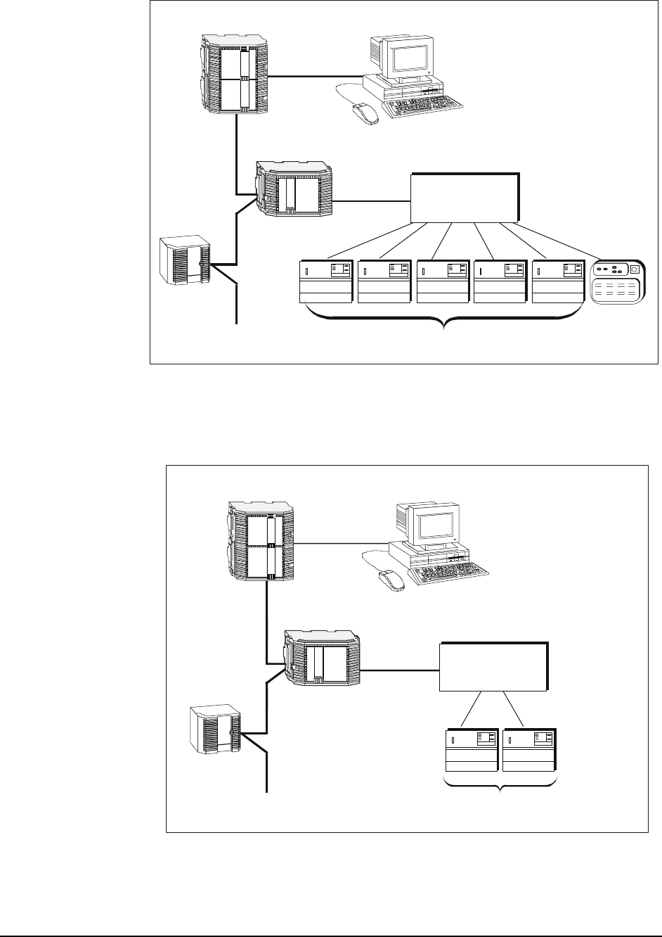
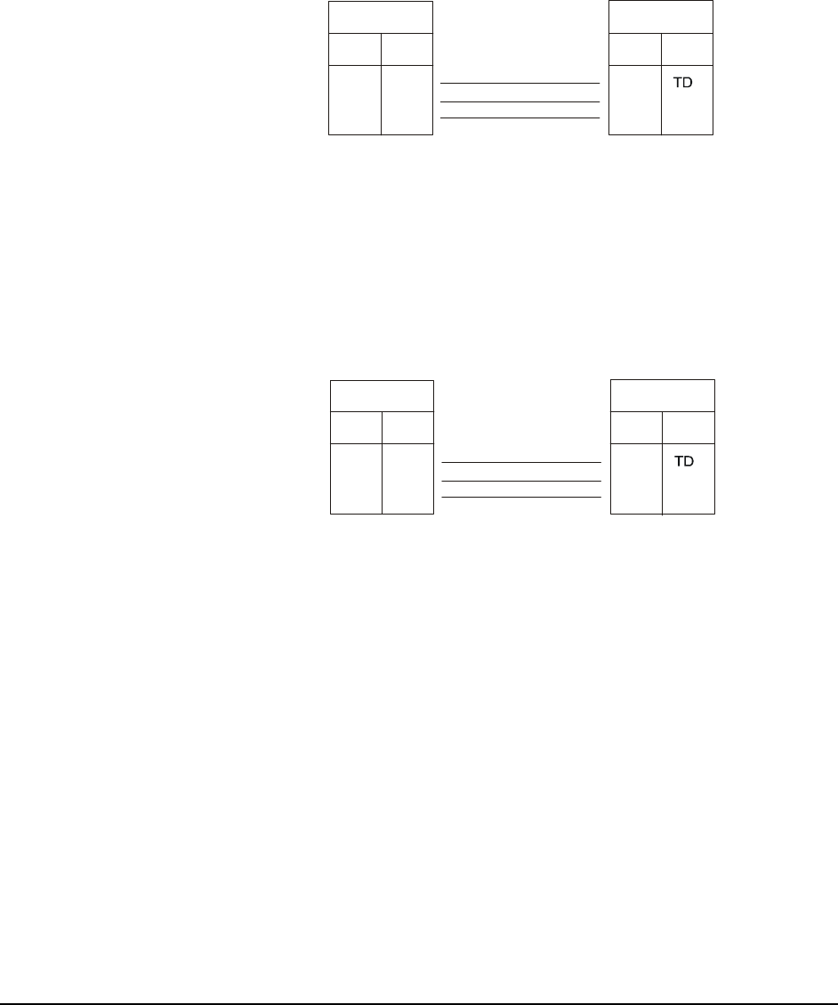
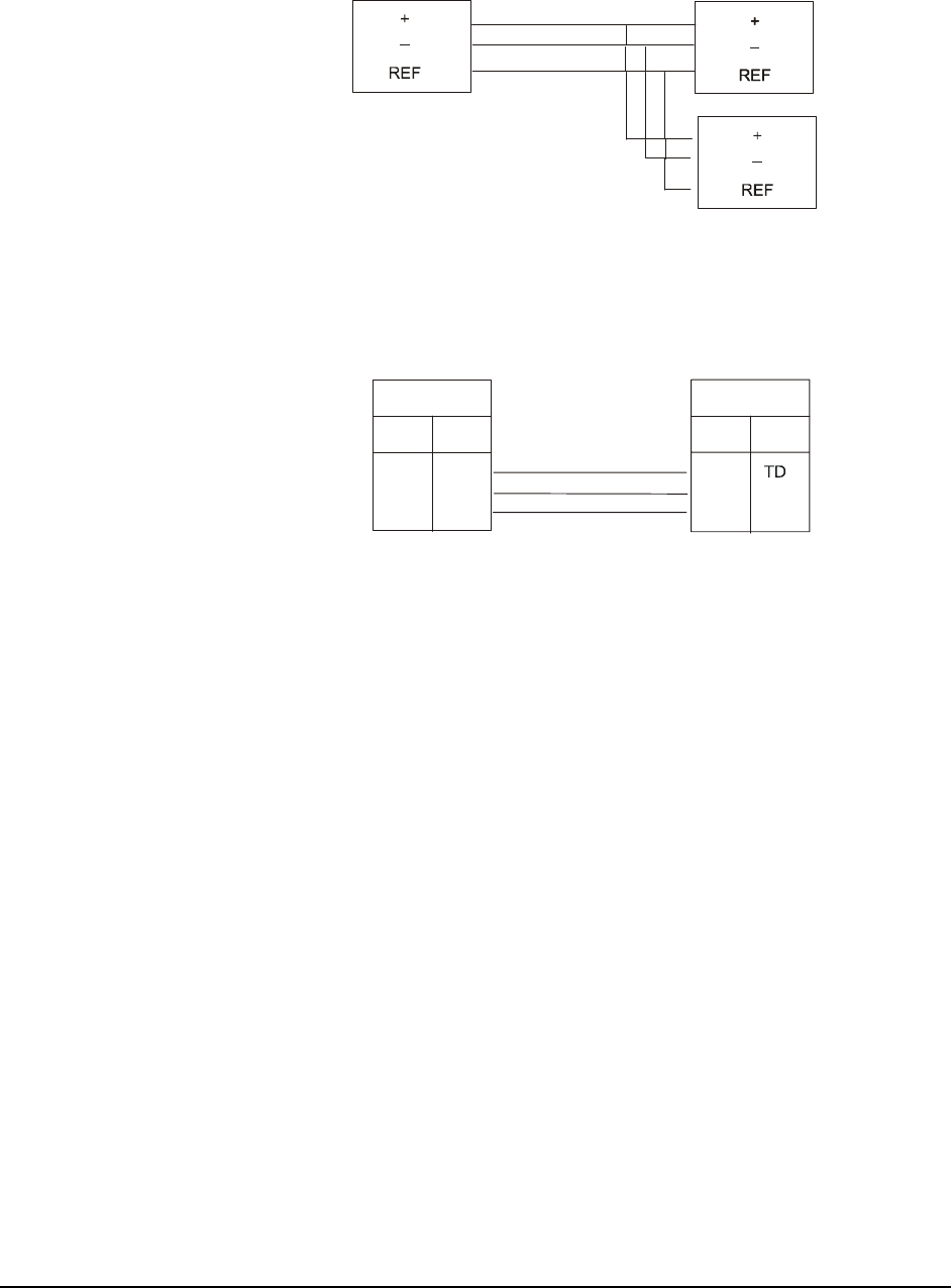
Corporation. Figure 3 and
Figure 4 show Metasys Companion and Liebert integration.
Metasys Integrator Liebert Application Application Note 7
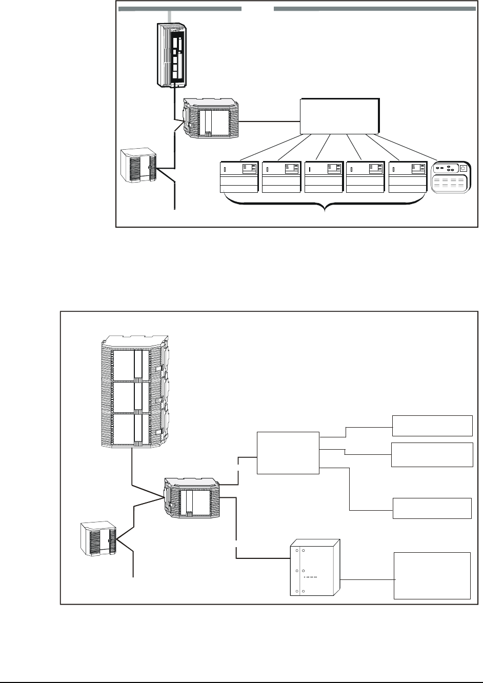
RS-422
(Belden Cable
3280 ft maximum)
N2 Bus
Standard NCU
UNT
RS-232
(50 ft maximum)
N1 LAN
Metasys
Integrator
liebert1
Deluxe System/3 Deluxe System/3 Deluxe System/3 Delux e Sys tem/3 Delux e Sys tem/3
Deluxe System/3
Small System
Controller
MCCI
with 24 RS-422
Ports
Note: If you use a UPM enclosure, you must install the Metasys Integrator unit
300 Series in a two high enclosure (EN-EWC25-0) rather than a one high
enclosure (EN-EWC13-0) as shown in the figures for this application note.
Figure 1: Liebert and Metasys System Integration
RS-232
liebert8
N2 Bus
UNT
NCM300
DCLAN
Liebert
Liebert
SiteLink
DC12I
(or DC4I)
Liebert Device 1
Liebert Device 2
Liebert Device 12
:
:
:
:
RS-232
Metasys
Integrator
(50 ft maximum)
(30 ft maximum)
Liebert
DC12, DC4,
DC12i, or DC4i
Note: If you use a UPM enclosure, you must install the Metasys Integrator unit 300 Series in a
two high enclosure (EN-EWC25-0) rather than a one high enclosure (EN-EWC13-0) as shown
in the figures in this application note.
Figure 2: Liebert DCLAN BMS and Metasys System Integration
8 Metasys Integrator Liebert Application Application Note
N2 Bus
UNT
Metasys
Integrator
RS-422
(Belden Cable
3280 ft maximum)
RS-232
(50 ft maximum)
Deluxe System/3 Deluxe Sys tem/3 Deluxe System/3 Deluxe System/3 Deluxe System/3
Deluxe System/3
Small System
Controller
MCCI
with 24 RS-422
Ports
liebcomp
Panel Unit Workstation
Note: A PC version and converter may be substituted for the Panel unit.
ump
Note: If you use a UPM enclosure, you must install the Metasys Integrator unit
300 Series in a two high enclosure (EN-EWC25-0) rather than a one high
enclosure (EN-EWC13-0) as shown in the figures in this application note.
Figure 3: Liebert MCCI and Metasys Companion Integration
N2 Bus
UNT
Metasys
Integrator
RS-422
(Belden Cable
3280 ft maximum)
RS-232
(50 ft maximum)
Deluxe System/3 Deluxe System/3
Deluxe System/3
ECA2
liebcom2
Panel Unit Workstation
Note: A PC version and converter may be substituted for the Panel unit.
ump
Note: If you use a UPM enclosure, you must install the Metasys Integrator unit 300
Series in a two high enclosure (EN-EWC25-0) rather than a one high enclosure
(EN-EWC13-0) as shown in the figures in this application note.
Figure 4: Liebert ECA2 and Metasys Companion Integration
Metasys Integrator Liebert Application Application Note 9

To integrate Liebert equipment, you need the following components:
Component
Requirements • properly installed Liebert devices
• RS-232 cable (for connecting the MCCI, ECA2, DCLAN, or SiteLink
module to the Metasys Integrator unit)
Note: If connecting a single Metasys Integrator unit to multiple SiteLink
modules via the Modbus RTU protocol interface (that is standalone
SiteLink modules that are not part of a DCLAN Network),
additional RS-232 cables, RS-485 cables, and RS-485/232
converters are needed. See Cable Connections in this document for
more information. Connection to one or more OpenComms
Network Interface Cards also require a RS-485/232 Converter.
• Metasys Integrator unit
• N2 Bus (for connecting the Metasys Integrator unit to the Metasys or
Companion Network)
• portable Personal Computer (PC) for downloading vendor
communication tables (.VCT files) and network setup information into
the Metasys Integrator unit and for running diagnostics
• cable for connecting portable PC to the Metasys Integrator unit
• the correct vendor communication table (.VCT file) to download into
the Metasys Integrator unit (supplied on Metasys Integrator CD-ROM)
This document describes the RS-232 cable and the vendor communication
tables. Liebert documentation describes its equipment. The remaining
components are described in the Metasys Integrator unit technical on the
Johnson Controls Product Information site
(http://cgproducts.johnsoncontrols.com System Manuals > Integration >
Metasys Integrator).
Metasys Release
Requirements To integrate Liebert equipment into the Metasys Network, you need:
• Metasys Operator Workstation (OWS) software Release 6.0 or later
• Metasys Integrator unit software/firmware Release 9.3 or later
Metasys
Companion
Release
Requirements
To integrate Liebert equipment into the Metasys Companion Network,
you need:
• Metasys Companion Release 5.0 or later
• Metasys Integrator unit software/firmware Release 9.3 or later
10 Metasys Integrator Liebert Application Application Note

Vendor
Component
Requirements
Integration between the Metasys Integrator unit and Liebert has been
tested with the equipment listed in Table 2. Changes to this equipment or
integration of Liebert products not discussed in this document requires
additional software development and testing by Systems Products. For
information on integrating other products, refer to the Custom Integration
section of this document.
Table 2: Liebert Part and Software Version Numbers
Liebert Product Part Number Firmware Version
Number
Multi-Channel Communications
Interface 129443G1 Revision 2.08
DC100 DC100BMS MCCI Card, Revision 2.08
Deluxe System 3/Level 0 N/A** Lev0 or Lev0A
Deluxe System 3/Level 1* N/A** Lev1
Deluxe System 3/Level 2 N/A** Lev2 or Lev2A
Deluxe System 3/Level 3 N/A** Lev2 or Lev2A
Deluxe System 3/Level 10 N/A** Lev2 or Lev2A
Deluxe System 3/Level 15 N/A** Lev2A
Single Module NPower UPS N/A*** N/A
Small Systems Controller N/A** Lev0B
Environmental Communication
Adapter (ECA2) 4D14081G1 1
DCLAN BMS Data Concentrator
for Local Area Network (LAN) DCLAN BMS Revision 2.0
DC1 IGM Interface Module DC1 --
DC4-422 IGM Interface Module DC4-422 N/A
DC12-422 IGM Interface Module DC12-422 N/A
SiteLink DC4i-422 IGM Interface
Module SiteLink-DC4i N/A
SiteLink DC12i-422 IGM Interface
Module SiteLink-DC12i N/A
OpenComms Network Interface
Card OpenComms NIC N/A
REPOPT RS-485/232 Converter REPOPT N/A
* The System 3/Level 1 IGM requires a Liebert Retrofit Kit with a Liebert Protocol
Converter (Part Number KIT-0101).
** Part number varies according to the system in which the System/3 controller is
mounted.
*** Requires an OpenComms NIC or SiteScan® Optional Module.
Metasys Integrator Liebert Application Application Note 11

DCLAN
The DCLAN BMS database is factory configured by Liebert. Only
databases configured by a Liebert factory are supported. Obtain the
following information from the Liebert representative:
• the address of each DCLAN BMS, which is configured with units to
be monitored by the Metasys Integrator unit
• the DCLAN BMS database address of each unit, which includes the
unit type (for example: DCLAN BMS Addresses 101 and 102
configured for an environmental unit type LAM)
Note: Every CMnet device uses two sequential DCLAN addresses.
Liebert supports a maximum of fifty devices per DCLAN BMS.
To use SiteLink modules within a DCLAN system, the Liebert
representative must configure SiteLink modules for DCLAN
communication. DCLAN DC4 and DC12 drivers must be Version 4.7 or
later.
SiteLink/OpenComms NIC
The Liebert representative must supply a Liebert Site Survey, which
indicates which function blocks (for example, L00, PMP, EDS, etc.) are
involved in the integration. The function blocks correspond to the
three-character acronym associated with the name of each Metasys
Integrator unit application for Liebert SiteLink.
To communicate directly to SiteLink/NIC modules, the Liebert
representative must configure each SiteLink/NIC module to communicate
via Modbus RTU protocol. The representative must also supply the
Modbus address and port numbers for each Liebert device.
Liebert
P.O. Box 29186
1050 Dearborn Drive
Columbus, OH 43085
Vendor Contact
Information
www.liebert.com
Site Application Engineering:
Phone: 800-222-5877
12 Metasys Integrator Liebert Application Application Note

When integrating Liebert equipment, consider the following:
Design
Considerations • Make sure all Liebert equipment is set up, started, and running
properly before attempting to integrate with the Metasys or
Companion Network. (The Liebert representative is responsible for
operation of Liebert equipment.)
MCCI/ECA2 • If an environmental unit is commanded off at the local controller, it
cannot be turned on remotely.
• The MCCI/ECA2 baud rate is fixed at 9600 baud.
• The RS-232 port jumper settings on the MCCI should be set to DCE.
(The Liebert representative is responsible for setting jumper settings
on the MCCI.)
Note: The DCE jumper pins are on the lower MCCI board and are
labeled DTE/DCE.
• Cable distance between the master MCCI or ECA2 and the last IGM
can be a maximum of 3280 feet. (The Liebert representative is
responsible for proper configuration of Liebert equipment.)
• Set the DIP switches on SW1 of the ECA2 as follows:
1=On, 2=On, 3=Off, 4=On, 5 (not used), 6=Off, 7=Off, 8=Off.
Set SW2 on the ECA2 to Terminal.
DCLAN • Liebert representatives must configure the DCLAN Network correctly.
• The DCLAN BMS must be configured so that echo is off.
• The default baud rate for the Metasys Integrator unit connection to a
DCLAN Network is 9600 baud.
SiteLink Module/
OpenComms
NIC
• Liebert representatives must configure each SiteLink/NIC module
correctly. If the SiteLink module is directly connected to the
Metasys Integrator unit, it must be downloaded with the function
blocks and module drivers configured for Modbus. If connected to a
DCLAN, it must be downloaded with the function blocks and module
drivers configured for DCLAN.
• OpenComms NIC modules must be configured for Modbus RTU
communication and a unique Modbus Slave Address assigned.
• The default baud rate for the Metasys Integrator unit connection to a
SiteLink/NIC module is 9600 baud. The SiteLink module can also be
configured for 38400 baud.
• If the SiteLink module supports automatic alarm reset, the auto-restore
timer must be set as shown in Table 3 to ensure all hardware-latched
alarms are reported.
Metasys Integrator Liebert Application Application Note 13

Table 3: SiteLink Auto-Restore Timer Settings
Number of SiteLink Modules
Connected to One Metasys
Integrator Port
Number of Minutes
Needed for SiteLink
Configuration
Number of Minutes
Needed for DCLAN
Configuration
1 1 2
2 to 6 2 4
7 to 10* 3 6
* We do not recommend more than 10 modules be connected to one port because of
performance considerations.
• The Liebert representative is responsible for configuring the
SiteLink module for setpoints and unit on/off control. If a
SiteScan system is connected to the SiteLink module along with the
Metasys Integrator unit, only one system is allowed to update setpoints
(Analog Outputs [AOs]) and the unit on/off control.
14 Metasys Integrator Liebert Application Application Note

Cable Connections
Cable Pinouts
MCCI Use the following cable pinouts for the RS-232 connection between the
Metasys Integrator unit and the Liebert MCCI:
RS-232 Port
MCCI
(set to DCE)
DB-9 Female
Signal Pin
DB-25 Male
Signal
Pin
3
2
20
7
4
5
RS-232
Vendor Port A or B
on Metasys Integrator
(50 ft maximum)
RD
TD
DTR
GND
RTS
CTS
liebert2
RD
TD
DTR
GND
RTS
CTS
2
3
4
5
7
8
Figure 5: Cable Pinouts (MCCI)
ECA2 Use the following cable pinouts for the RS-232 connection between the
Metasys Integrator unit and the Liebert ECA2:
RS-232 Port
ECA2
DB-9 Female
Signal Pin
DB-25 Female
Signal
Pin
2
3
5
4
7
RS-232
V
endor Port A or B
on Metasys Integrator
(50 ft maximum)
TD
RD
CTS
RTS
GND
liebert6
RD
TD
RTS
CTS
GND
2
3
7
8
5
Figure 6: Cable Pinouts (ECA2)
Metasys Integrator Liebert Application Application Note 15

DC100 Use the following cable pinouts for the RS-232 connection between the
Metasys Integrator unit and the Liebert DC100:
RS-232 Port
DC100 Port 2
(DTE)
DB-9 Female
Signal Pin
DB-25 Female
Signal
Pin
2
3
20
7
4
5
RS-232
Vendor Port A or B
on Metasys Integrator
(50 ft maximum)
TD
RD
DTR
GND
RTS
CTS
liebert5
RD
TD
DTR
GND
RTS
CTS
2
3
4
5
7
8
Figure 7: Cable Pinouts (DC100 Port 2)
DCLAN Use the following cable pinouts for the RS-232 connection between the
Metasys Integrator unit and the Liebert DCLAN Port 1. Use a DB-9
female to DB-9 female null modem to connect the Metasys Integrator unit
to the Liebert DCLAN Port 2.
RS-232 Port 1
DCLAN
DB-9 Female
Signal Pin
DB-25 Female
Signal
Pin
8
2
3
20
7
RS-232
V
endor Port A or B
on Metasys Integrator
(50 ft maximum)
DCD
TD
RD
DTR
GND
liebert7
DCD
RD
TD
DTR
GND
1
2
3
4
5
Figure 8: Cable Pinouts (DCLAN)
16 Metasys Integrator Liebert Application Application Note
Connecting to
SiteLink/NIC
Modules
Direct RS-232
Connection Use the following cable pinout for the RS-232 connection between the
Metasys Integrator unit and a single Liebert SiteLink module:
RS-232 Port
on SiteLink (DTE)
DB-9 Female
Signal Pin
DB-9 Female
Signal
Pin
3
2
5
RS-232
V
endor Port A or B
on Metasys Integrator
(50 ft maximum)
RD
GND
Liebert9
RD
TD
GND
2
3
5
P2 or P3 on Panel Third Party
Interface Port
Figure 9: Cable Pinouts for Single SiteLink Module
RS-485
Connection Use Figures 10 through 12 to wire multiple SiteLink/OpenComms NIC
modules using Liebert REPOPT RS-232 to RS-485 Converters:
DB-9 Female
Signal Pin
DB-9 Female
Signal
Pin
3
2
5
RS-232
(50 ft maximum)
RD
GND
RD
TD
GND
2
3
5
P2 or P3 on Panel RS-232 Connector
Lieb11
Vendor Port A or B
on Metasys Integrator
Liebert REPOPT
RS-232 to RS-485
Converter
Figure 10: Cable Pinout for Liebert REPOPT
RS-232 to RS-485 Converter
Metasys Integrator Liebert Application Application Note 17
RS-485
RS-485
Daisy-chained
REPOPTs
REPOPT
RS-232 to RS-485
Converter
(4000 ft maximum)
Liebert1
2
Figure 11: RS-485 Network of REPOPTs
DB-9 Female
Signal Pin
DB-9 Female
Signal
Pin
3
2
5
RS-232
(50 ft maximum)
RD
GND
RD
TD
GND
2
3
5
RS-232 Connector on
Daisy-chained REPOPT
RS 232 Connector
on SiteLink Module
Liebert13
REPOPT
RS-232 to RS-485
Converter
Figure 12: Null Modem Cable from
Liebert REPOPT to SiteLink Module
18 Metasys Integrator Liebert Application Application Note

Connecting the
Cable Connect the female end of the RS-232 cable to either Vendor Port A or
Vendor Port B on the Metasys Integrator unit. Connect the other end of
the cable to the RS-232 port on the MCCI, DC100, ECA2, DCLAN or
SiteLink module.
Metasys
Integrator
Liebert
MCCI.
ECA2,
DC100,
DCLAN,
or
SiteLink
RS-232 Port
Vendor Port
A or B
RS-232
Liebert3
Figure 13: Port-to-Port Connection
Connection to
Multiple SiteLink
Modules
Metasys
Integrator
RS-232 RS-485
Liebert
REPOPT
Liebert
REPOPT RS-232
Liebert
REPOPT Liebert
SiteLink
RS-232
Liebert
SiteLink
Liebert15
Figure 14: Connecting Metasys Integrator Unit to
Multiple SiteLink Modules
Metasys Integrator Liebert Application Application Note 19

Connecting
Metasys
Integrator Unit to
OpenComms
Network
Interface Cards
Metasys
Integrator
Unit
Liebert
REPOPT
OpenComms
Network
Interface Card
OpenComms
Network
Interface Card
RS-232 RS-485
Liebert15a
Figure 15: Connecting Metasys Integrator Unit to OpenComms
Network Interface Card
20 Metasys Integrator Liebert Application Application Note

Metasys Integrator Unit Setup
To set up the Metasys Integrator unit, use a portable PC connected to
Metasys Integrator Terminal Port. Metasys Integrator unit setup involves:
• downloading the correct vendor communication table (.VCT file)
• setting up the ports
• assigning network addresses to the controllers
Tables 4 through 7 provide setup information specific to Liebert
applications. For detailed procedures, see the Metasys Integrator unit
technical bulletins on the Johnson Controls Product Information site
(http://cgproducts.johnsoncontrols.com System Manuals > Integration >
Metasys Integrator).
Table 4: Metasys Integrator Unit Setup for Liebert MCCI
Applications
Vendor Communication Table (.VCT File)
System 3/Level 0 and 1 LI_LEV0.VCT
System 3/Level 2, 3, 10, and 15 LI_LEV2.VCT
System 3/Level 10 and 15 with On/Off
Control LI_LEV2A.VCT
Small Systems Controller LI_SSC.VCT
Port Setup
Baud Rate 9600
Word Length 8
Stop Bits 1
Parity None
Interface RS-232
Network Setup
Vendor Address Port Number (1-24)
Timeout Value 4000 ms
Poll Delay 0 ms
Performance Guide
System 3/Environmental Units 8 seconds
Small Systems Controller 8 seconds
Metasys Integrator Liebert Application Application Note 21

Table 5: Metasys Integrator Unit Setup for Liebert ECA2
Applications
Vendor Communication Table (.VCT File)
Environmental Communication Adapter
(ECA2) Level 0 LI_ECA2.VCT
Environmental Communication Adapter
(ECA2) Levels 10 and 15 LIECA210.VCT
Port Setup
Baud Rate 9600
Word Length 8
Stop Bits 1
Parity None
Interface RS-232
Network Setup
Vendor Address Channel (1-2)
Timeout Value 4000 ms
Poll Delay 0 ms
Performance Guide
ECA2 Environmental Communication
Adapte
r
8 seconds
22 Metasys Integrator Liebert Application Application Note

Table 6: Metasys Integrator Unit Setup for Liebert DCLAN
Applications
Vendor Communication Table (.VCT File)
Environmental Units
Level 00 (L00) LIDCLL00.VCT
Small Systems Control (L0B) LIDCLL0B.VCT
Level 02 (L02) and Level 03 (L03) LIDCLL02.VCT
Level 0 with On/Off Control (L0A) and
Standard Microprocessor (LSM)
LIDCLL0A.VCT
Level 10 without On/Off Control (L10) LIDCLL10.VCT
Level 10 with On/Off Control (L1A) and
Level 15 with On/Off Control (LAM)
LIDCLL1A.VCT
Chillers
Single Module (CW1) LIDCLCW1.VCT
Two Module (CW2) LIDCLCW2.VCT
Three Module (CW3) LIDCLCW3.VCT
Chillers with Econocoil-Single Module
(CE1) LIDCLCE1.VCT
Chillers with Econocoil-Two Module
(CE2) LIDCLCE2.VCT
Chillers with Econocoil-Three Module
(CE3) LIDCLCE3.VCT
Power Conditioning Units
Power Monitoring Panel (PMP) LIDCLPMP.VCT
UPS
Series 300 and 600 Single Module
System (SMS) LIDCLSMS.VCT
Series 600 Multi Module System (MMS) LIDCLMMS.VCT
Series 600 Static Control Cabinet
(SCC) LIDCLSCC.VCT
Contact Closure Module (CCM) LIDCLCCM.VCT
Port Setup
Baud Rate 9600
Word Length 8
Stop Bits 1
Parity None
Interface RS-232
Continued on next page . . .
Metasys Integrator Liebert Application Application Note 23

Network Setup (Cont.)
Vendor Address D,aaa*
where D is: the address of the
DCLAN (‘1’ - ‘9’, ‘A’ - ‘Z’,
or ‘a’ - ‘y’);
where aaa is: the DCLAN configured
address (101 - 199);
each unit uses two
consecutive DCLAN
addresses**, only the
first address is entered.
For example, to address the first
DCLAN device in DCLAN 1, enter
1,101.
Timeout Value 1000 ms
Poll Delay 0 ms
Performance Guide
DCLAN BMS Units 2 seconds
* The comma (,) between D and aaa of the Vendor Address is a required delimiter,
which must be included in the vendor address.
** For the latest information on obtaining addressing information, please refer to
The Advisor. It may be displayed or printed as needed.
24 Metasys Integrator Liebert Application Application Note

Table 7: Metasys Integrator Unit Setup for Liebert SiteLink/NIC
Applications
Vendor Communication Table (.VCT)
CCM Function Block
CSE Function Block
CSU Function Block
EDS Function Block
IMP Function Block
L00 Function Block
L0B Function Block
L10 Function Block
LAM Function Block
LSM Function Block
MM4 Function Block
MMS Function Block
PMP Function Block
RAC Function Block
SC4 Function Block
SCC Function Block
SM3 Function Block
SM4 Function Block
SMS Function Block
THM Function Block
VCF Function Block
VCM Function Block
WDU Function Block
LiSL_CCM.VCT
LiSL_CSE.VCT
LiSL_CSU.VCT
LiSL_EDS.VCT
LiSL_IMP.VCT
LiSL_L00.VCT
LiSL_L0B.VCT
LiSL_L10.VCT
LiSL_LAM.VCT
LiSL_LSM.VCT
LiSL_MM4.VCT
LiSL_MMS.VCT
LiSL_PMP.VCT
LiSL_RAC.VCT
LiSL_SC4.VCT
LiSL_SCC.VCT
LiSL_SM3.VCT
LiSL_SM4.VCT
LiSL_SMS.VCT
LiSL_THM.VCT
LiSL_VCF.VCT
LiSL_VCM.VCT
LiSL_WDU.VCT
Port Configuration
Baud Rate 9600 (38400 also can be used if the
SiteLink module is configured for it.)
Word Length 8
Stop Bits 1
Parity None
Interface RS-232
Network Configuration
Vendor Address <Modbus Address>, <Port #> (for example,
3, 12)
SiteLink Modbus Address 1-255, Port 1-12
NIC Modbus Address 1-255, Port 1
For example:
If the SiteLink Modbus address is 3,
and the IGM is connected to Port 12,
enter 3,12. If NIC Modbus address is 4,
enter 4, 1
Note: <Modbus Address> defaults to 3.
Timeout Value 500 ms
Poll Delay 50 ms
Retries 3
Approximate Scan Time (for a single Metasys Integrator device)
SiteLink/NIC Modbus 1 second
Metasys Integrator Liebert Application Application Note 25

Point Mapping Tables
Use the following point mapping tables to map Metasys objects to the
Liebert Deluxe System/3 IGMs. Table 8 applies to System/3
Levels 0, 1, 2, 3, 10, and 15.
Deluxe
System/3
(MCCI
Configuration) Table 8: Deluxe System/3 (MCCI Configuration)
To get the hardware
reference for
mapping points to
CS object attributes
(via the software
model), combine
the Network Point
Type (NPT) and
Network Point
Address (NPA). For
example, the
hardware reference
for the Percent
Heating point is AI3.
NPT1NPA2Unit Description
AI
AI
AI
AI
AI
AI
1
2
3
4
5
6
DegF
%RH
%
Step
%
Step
Temperature
Humidity
Percent Heating
Stages Heating
Percent Cooling
Stages Cooling
AO
AO
AO
AO
1
2
3
4
DegF
DegF
%RH
%RH
Temperature Setpoint (40 to 85)
Temperature Tolerance (1 to 5)
Humidity Setpoint (40 to 60)
Humidity Tolerance (1 to 10)
BI
BI
BI
BI
BI
BI
BI
BI
BI
BI
BI
BI
BI
BI
BI
BI
BI
BI
BI
BI
BI
BI
BI
BI
1
2
3
4
5
6
7
8
9
10
11
12
13
14
15
16
17
18
19
20
21
22
23
24
Cooling 0-Heat, 1-Cool
Glycol 0-Off, 1-On
Humidifying 0-Off, 1-On
Dehumidifying 0-Off, 1-On
High Head Pressure Compressor 1 0-Normal, 1-Alarm
High Head Pressure Compressor 2 0-Normal, 1-Alarm
Loss of Airflow 0-Normal, 1-Alarm
Standby Glycol Pump On 0-Normal, 1-Alarm
Water Under Floor 0-Normal, 1-Alarm
Change Filters 0-Normal, 1-Alarm
High Temperature Alarm 0-Normal, 1-Alarm
Low Temperature Alarm 0-Normal, 1-Alarm
High Humidity Alarm 0-Normal, 1-Alarm
Low Humidity Alarm 0-Normal, 1-Alarm
High Water in Humidifier Pan 0-Normal, 1-Alarm
No Water in Humidifier Pan 0-Normal, 1-Alarm
Compressor #1 Overload 0-Normal, 1-Alarm
Compressor #2 Overload 0-Normal, 1-Alarm
Main Fan Overload 0-Normal, 1-Alarm
Manual Override 0-Normal, 1-Alarm
Smoke Detected 0-Normal, 1-Alarm
Loss of Water Flow 0-Normal, 1-Alarm
Standby Unit On 0-Normal, 1-Alarm
Low Suction Pressure 0-Normal, 1-Alarm
1 Network Point Type
2 Network Point Address
Continued on next page . . .
26 Metasys Integrator Liebert Application Application Note

NPT1
(Cont.) NPA2Unit Description
BI
BI
BI
BI
BI
BI
BI
25
26
27
28
29
30
31
Short Cycle Alarm 0-Normal, 1-Alarm
Loss of Power Alarm 0-Normal, 1-Alarm
Local Alarm 1 0-Normal, 1-Alarm
Local Alarm 2 0-Normal, 1-Alarm
User Alarm 1 0-Normal, 1-Alarm
User Alarm 2 0-Normal, 1-Alarm
Alarm Condition Exists 0-Normal, 1-Alarm
BO
BO
1
2
Reset All Alarms3 0-N/A, 1-Reset
Unit Mode4 0-Off, 1-On
BD
BD
1
2
Unit Start Status4 0-Off, 1-On
Local Command Status4 0-Off, 1-On
1 Network Point Type
2 Network Point Address
3 The Reset All Alarms command has no effect on the System/3 Level 10. If you want
to reset alarms on the Level 10, reset them directly on the System/3 controller panel.
Do not map these points to Companion Binary Output (BO) points. If you map these
points to Metasys BO objects, make sure the Auto Restore option in the BO object’s
Definition and Focus window is disabled.
4 Available only on units that include start/stop control.
Metasys Integrator Liebert Application Application Note 27

Table 9: Small Systems Controller (MCCI Configuration) Small Systems
Controller
(MCCI
Configuration)
To get the hardware
reference for
mapping points to
CS object attributes
(via the software
model), combine
the Network Point
Type (NPT) and
Network Point
Address (NPA). For
example, the
hardware reference
for the Percent
Heating point is AI3.
NPT1NPA2Unit Description
AI
AI
AI
AI
AI
AI
1
2
3
4
5
6
DegF
%RH
%
Step
%
Step
Temperature
Humidity
Percent Heating
Stages Heating
Percent Cooling
Stages Cooling
BI
BI
BI
BI
BI
BI
BI
BI
BI
BI
BI
BI
BI
BI
BI
BI
BI
BI
BI
BI
BI
BI
BI
BI
BI
BI
BI
BI
BI
BI
BI
1
2
3
4
5
6
7
8
9
10
11
12
13
14
15
16
17
18
19
20
21
22
23
24
25
26
27
28
29
30
31
Coolon 0-Heat, 1-Cool
Glyavail 0-Off, 1-On
Humidifying 0-Off, 1-On
Dehumidifying 0-Off, 1-On
High Head Pressure Compressor 1 0-Normal, 1-Alarm
High Head Pressure Compressor 2 0-Normal, 1-Alarm
Loss Of Airflow 0-Normal, 1-Alarm
Standby Glycol Pump On 0-Normal, 1-Alarm
Water Under Floor 0-Normal, 1-Alarm
Change Filters 0-Normal, 1-Alarm
High Temperature Alarm 0-Normal, 1-Alarm
Low Temperature Alarm 0-Normal, 1-Alarm
High Humidity Alarm 0-Normal, 1-Alarm
Low Humidity Alarm 0-Normal, 1-Alarm
High Water In Humidifier Pan 0-Normal, 1-Alarm
No Water In Humidifier Pan 0-Normal, 1-Alarm
Compressor 1 Overload 0-Normal, 1-Alarm
Compressor 2 Overload 0-Normal, 1-Alarm
Main Fan Overload 0-Normal, 1-Alarm
Manual Override 0-Normal, 1-Alarm
Smoke Detected 0-Normal, 1-Alarm
Loss Of Water Flow 0-Normal, 1-Alarm
Standby Unit On 0-Normal, 1-Alarm
Low Suction Pressure 0-Normal, 1-Alarm
Short Cycle Alarm 0-Normal, 1-Alarm
Loss Of Power Alarm 0-Normal, 1-Alarm
Local Alarm 1 0-Normal, 1-Alarm
Local Alarm 2 0-Normal, 1-Alarm
User Alarm 1 0-Normal, 1-Alarm
User Alarm 2 0-Normal, 1-Alarm
Alarm Condition Exists 0-Normal, 1-Alarm
BO 1 Reset Alarms3 0-N/A, 1-Reset
1 Network Point Type
2 Network Point Address
3 Do not map these points to Companion BO points. If you map these points to
Metasys BO objects, make sure the Auto Restore option in the BO object’s
Definition and Focus window is disabled.
28 Metasys Integrator Liebert Application Application Note

Table 10: Liebert ECA2 Level 0 Liebert ECA2
Level 0
To get the hardware
reference for
mapping points to
CS object attributes
(via the software
model), combine
the Network Point
Type (NPT) and
Network Point
Address (NPA). For
example, the
hardware reference
for the Humidity
Reading point is
AI2.
NPT1NPA2Unit Description
AI
AI
AI
AI
1
2
3
4
DegF
% RH
%
Step
Temperature Reading
Humidity Reading
Percent Heating/Cooling
Stages Heating/Cooling
AO
AO
AO
AO
1
2
3
4
DegF
DegF
% RH
% RH
Temperature Setpoint 40-85
Temperature Sensitivity 1-5
Humidity Setpoint 40-60
Humidity Sensitivity 1-10
BI
BI
BI
BI
BI
BI
BI
BI
BI
BI
BI
BI
BI
BI
BI
BI
BI
BI
BI
BI
BI
BI
BI
BI
BI
BI
BI
1
2
3
4
5
6
7
8
9
10
11
12
13
14
15
16
17
18
19
20
21
22
23
24
25
26
27
Cooling 0-Heat, 1-Cool
Glycol 0-Off, 1-On
Humidifying 0-Off, 1-On
Dehumidifying 0-Off, 1-On
High Head Pressure Compressor 1 0-Ok, 1-Alarm
High Head Pressure Compressor 2 0-Ok, 1-Alarm
Loss Of Airflow 0-Ok, 1-Alarm
Standby Glycol Pump On 0-Ok, 1-Alarm
Water Under Floor 0-Ok, 1-Alarm
Change Filters 0-Ok, 1-Alarm
High Temperature Alarm 0-Ok, 1-Alarm
Low Temperature Alarm 0-Ok, 1-Alarm
High Humidity Alarm 0-Ok, 1-Alarm
Low Humidity Alarm 0-Ok, 1-Alarm
High Water In Humidifier Pan 0-Ok, 1-Alarm
No Water In Humidifier Pan 0-Ok, 1-Alarm
Compressor 1 Overload 0-Ok, 1-Alarm
Compressor 2 Overload 0-Ok, 1-Alarm
Main Fan Overload 0-Ok, 1-Alarm
Manual Override On 0-Ok, 1-Alarm
Smoke Detected 0-Ok, 1-Alarm
Loss Of Water Flow 0-Ok, 1-Alarm
Standby Unit On 0-Ok, 1-Alarm
Low Suction Pressure 0-Ok, 1-Alarm
Short Cycle Alarm 0-Ok, 1-Alarm
Loss Of Power Alarm 0-Ok, 1-Alarm
Alarm Present 0-Ok, 1-Alarm
BO
BO
1
2
Reset All Alarms3 0-N/A, 1-Reset
Unit Mode 0-Off, 1-On
1 Network Point Type
2 Network Point Address
3 Do not map these points to Companion BO points. If you map these points to
Metasys BO objects, make sure the Auto Restore option in the BO object’s Definition
and Focus window is disabled.
Metasys Integrator Liebert Application Application Note 29

Table 11: Liebert ECA2 Level 10 and Level 15 Liebert ECA2
Level 10 and
Level 15
To get the hardware
reference for
mapping points to
CS object attributes
(via the software
model), combine
the Network Point
Type (NPT) and
Network Point
Address (NPA). For
example, the
hardware reference
for the Humidity
Reading point is
AI2.
NPT1NPA2Unit Description
AI
AI
AI
AI
AI
AI
AI
1
2
3
4
5
6
7
DegF
%RH
%
Step
Hours
Hours
Hours
Temperature Reading
Humidity Reading
Percent Heating/Cooling
Stages Heating/Cooling
Compressor 1 Run Hours
Compressor 2 Run Hours
Glycol Hours
AO
AO
AO
AO
AO
AO
AO
AO
1
2
3
4
5
6
7
8
DegF
DegF
%RH
%RH
DegF
DegF
%RH
%RH
Temperature Setpoint 40-85
Temperature Sensitivity 1-5
Humidity Setpoint 40-60
Humidity Sensitivity 1-10
High Temperature Alarm Setpoint 40-85
Low Temperature Alarm Setpoint 40-85
High Humidity Alarm Setpoint 40-60
Low Humidity Alarm Setpoint 40-60
BI
BI
BI
BI
BI
BI
BI
BI
BI
BI
BI
BI
BI
BI
BI
BI
BI
BI
BI
BI
BI
BI
BI
BI
BI
BI
BI
1
2
3
4
5
6
7
8
9
10
11
12
13
14
15
16
17
18
19
20
21
22
23
24
25
26
27
Cooling 0-Heat, 1-Cool
Glycol 0-Off, 1-On
Humidifying 0-Off, 1-On
Dehumidifying 0-Off, 1-On
High Head Pressure Compressor 1 0-Ok, 1-Alarm
High Head Pressure Compressor 2 0-Ok, 1-Alarm
Loss Of Airflow 0-Ok, 1-Alarm
Standby Glycol Pump On 0-Ok, 1-Alarm
Water Under Floor 0-Ok, 1-Alarm
Change Filters 0-Ok, 1-Alarm
High Temperature Alarm 0-Ok, 1-Alarm
Low Temperature Alarm 0-Ok, 1-Alarm
High Humidity Alarm 0-Ok, 1-Alarm
Low Humidity Alarm 0-Ok, 1-Alarm
High Water In Humidifier Pan 0-Ok, 1-Alarm
No Water In Humidifier Pan 0-Ok, 1-Alarm
Compressor 1 Overload 0-Ok, 1-Alarm
Compressor 2 Overload 0-Ok, 1-Alarm
Main Fan Overload 0-Ok, 1-Alarm
Manual Override On 0-Ok, 1-Alarm
Smoke Detected 0-Ok, 1-Alarm
Loss Of Water Flow 0-Ok, 1-Alarm
Standby Unit On 0-Ok, 1-Alarm
Low Suction Pressure 0-Ok, 1-Alarm
Short Cycle Alarm 0-Ok, 1-Alarm
Loss Of Power Alarm 0-Ok, 1-Alarm
Alarm Present 0-Ok, 1-Alarm
1 Network Point Type
2 Network Point Address
Continued on next page . . .
30 Metasys Integrator Liebert Application Application Note

NPT1
(Cont.) NPA2Unit Description
BO
BO
1
2
Reset All Alarms3 0-N/A, 1-Reset
Unit Mode 0-Off, 1-On
1 Network Point Type
2 Network Point Address
3 Do not map these points to Companion BO points. If you map these points to
Metasys BO objects, make sure the Auto Restore option in the BO object’s
Definition and Focus window is disabled.
Table 12: Liebert DCLAN Environmental Unit Level 0 and
Level 0 with On/Off Control (L00, L0A, and LSM)
Liebert DCLAN
Environmental
Unit Level 0
and Level 0
with On/Off
Control (L00,
L0A, and LSM)
To get the hardware
reference for
mapping points to
CS object attributes
(via the software
model), combine
the Network Point
Type (NPT) and
Network Point
Address (NPA). For
example, the
hardware reference
for the Humidity
Reading point is
AI3.
NPT1NPA2Unit Description
AI
AI
AI
1
2
3
DegF
DegC
%RH
Temperature Reading (F)
Temperature Reading (C)
Humidity Reading
AO
AO
AO
AO
AO
1
2
3
4
5
DegF
DegC
Deg
%RH
%RH
Temperature Setpoint (F) 35-95
Temperature Setpoint (C) 1-35
Temperature Tolerance Setpoint 1-10
Humidity Setpoint 35-65
Humidity Tolerance Setpoint 1-10
BI
BI
BI
BI
BI
1
2
3
4
5
Alarm Present 0-No, 1-Alarm
Humidifying On 0-Off, 1-On
Dehumidifying On 0-Off, 1-On
Cooling On 0-Off, 1-On
Heating On 0-Off, 1-On
BD
BD
BD
BD
BD
BD
BD
BD
1
2
3
4
5
6
7
8
High Temperature 0-Ok, 1-Alarm
Low Temperature 0-Ok, 1-Alarm
High Humidity 0-Ok, 1-Alarm
Low Humidity 0-Ok, 1-Alarm
Loss Of Air Flow 0-Ok, 1-Alarm
Water Under Floor 0-Ok, 1-Alarm
Change Filters 0-Ok, 1-Alarm
High Head Pressure 0-Ok, 1-Alarm
BO 1 Unit Run3 0-Off, 1-On
1 Network Point Type
2 Network Point Address
3 Only for L0A
Metasys Integrator Liebert Application Application Note 31

Table 13: Liebert DCLAN Environmental Unit Small Systems
Control (L0B)
Liebert DCLAN
Environmental
Unit Small
Systems
Control (L0B)
To get the hardware
reference for
mapping points to
CS object attributes
(via the software
model), combine
the Network Point
Type (NPT) and
Network Point
Address (NPA). For
example, the
hardware reference
for the Humidity
point is AI3.
NPT1NPA2Unit Description
AI
AI
AI
1
2
3
DegF
DegC
%RH
Temperature (F)
Temperature (C)
Humidity
BI 1 Alarm Present 0-No, 1-Alarm
BD 1
2
3
4
High Temperature 0-Ok, 1-Alarm
Low Temperature 0-Ok, 1-Alarm
High Humidity 0-Ok, 1-Alarm
Low Humidity 0-Ok, 1-Alarm
BO 1 Unit Run 0-Off, 1-On
1 Network Point Type
2 Network Point Address
Liebert DCLAN
Environmental
Unit Level 2, 3,
10, and 15 (L02,
L03, L10, L1A,
and LAM)
To get the hardware
reference for
mapping points to
CS object attributes
(via the software
model), combine
the Network Point
Type (NPT) and
Network Point
Address (NPA). For
example, the
hardware reference
for the Humidity
point is AI3.
Table 14: Liebert DCLAN Environmental Unit Level 2, 3, 10,
and 15 (L02, L03, L10, L1A, and LAM)
NPT1NPA2Unit Description
AI
AI
AI
1
2
3
Deg
Deg
%RH
Temperature Reading (F)
Temperature Reading (C)
Humidity
AO
AO
AO
AO
AO
AO
AO
AO
AO
AO
AO
AO
AO
1
2
3
4
5
6
7
8
9
10
11
12
13
Deg
Deg
Deg
%RH
%RH
DegF
DegF
DegF
Deg F
%RH
%RH
Min
Min
Temperature Setpoint (F) 35-95
Temperature Setpoint (C) 1-35
Temperature Tolerance Setpoint 1-10
Humidity Setpoint 35-65
Humidity Tolerance Setpoint 1-10
High Temperature Alarm Setpoint (F) 30-90
High Temperature Alarm Setpoint (C) -1-32
Low Temperature Alarm Setpoint (F) 30-90
Low Temperature Alarm Setpoint (C) -1-32
High Humidity Alarm Setpoint 35-65
Low Humidity Alarm Setpoint 30-90
Auto Restart Delay Setpoint 0-99
CW Flush Cycle Setpoint3 0-99
1 Network Point Type
2 Network Point Address
3 Available only for Level 02 and 03.
Continued on next page . . .
32 Metasys Integrator Liebert Application Application Note

NPT1NPA2Unit Description
BI
BI
BI
BI
BI
1
2
3
4
5
Alarm Present 0-No, 1-Alarm
Humidifying On 0-Off, 1-On
Dehumidifying On 0-Off, 1-On
Cooling On 0-Off, 1-On
Heating On 0-Off, 1-On
BD
BD
BD
BD
BD
BD
BD
BD
BD
BD
BD
BD
BD
BD
BD
BD
BD
BD
BD
BD
BD
BD
BD
BD
1
2
3
4
5
6
7
8
9
10
11
12
13
14
15
16
17
18
19
20
21
22
23
24
High Temperature 0-Ok, 1-Alarm
Low Temperature 0-Ok, 1-Alarm
High Humidity 0-Ok, 1-Alarm
Low Humidity 0-Ok, 1-Alarm
Loss Of Air Flow 0-Ok, 1-Alarm
Water Under Floor 0-Ok, 1-Alarm
Change Filters 0-Ok, 1-Alarm
High Head Pressure 1 0-Ok, 1-Alarm
High Head Pressure 2 0-Ok, 1-Alarm
High Water Humidifier Pan 0-Ok, 1-Alarm
Manual Override 0-Ok, 1-Alarm
Customer Alarm 1 0-Ok, 1-Alarm
Customer Alarm 2 0-Ok, 1-Alarm
Standby Glycol Pump On 0-Ok, 1-Alarm
Compressor 1 Overloaded 0-Ok, 1-Alarm
Compressor 2 Overloaded 0-Ok, 1-Alarm
Main Fan Overloaded 0-Ok, 1-Alarm
Smoke Detected 0-Ok, 1-Alarm
Loss Of Water Flow 0-Ok, 1-Alarm
Standby Unit On 0-Ok, 1-Alarm
Low Suction Pressure 0-Ok, 1-Alarm
Short Cycle 0-Ok, 1-Alarm
Loss Of Power 0-Ok, 1-Alarm
Low Water Humidifier Pan3 0-Ok, 1-Alarm
BO
BO
1
2
Alarm Reset5 0-N/A, 1-Reset
Unit Run4 0-Off, 1-On
1 Network Point Type
2 Network Point Address
3 Available only for Level 02 and 03.
4 Available only for devices which have on/off control.
5 Do not map these points to Companion BO points. If you map these points to
Metasys BO objects, make sure the Auto Restore option in the BO object’s
Definition and Focus window is disabled.
Metasys Integrator Liebert Application Application Note 33

Table 15: Liebert DCLAN Chiller - CW1, CW2, and CW3 Liebert DCLAN
Chiller - CW1,
CW2, and CW3
To get the hardware
reference for
mapping points to
CS object attributes
(via the software
model), combine
the Network Point
Type (NPT) and
Network Point
Address (NPA). For
example, the
hardware reference
for the Module 3
Start point is BI8.
NPT1NPA2Unit Description
BI
BI
BI
BI
BI
BI
BI
BI
BI
BI
1
2
3
4
5
6
7
8
9
10
Alarm Present 0-No, 1-Alarm
Module 1 Start 0-Off, 1-On
Module 1 Pump On 0-Off, 1-On
Module 1 Cooling On 0-Off, 1-On
Module 2 Start3 0-Off, 1-On
Module 2 Pump On3 0-Off, 1-On
Module 2 Cooling On3 0-Off, 1-On
Module 3 Start4 0-Off, 1-On
Module 3 Pump On4 0-Off, 1-On
Module 3 Cooling On4 0-Off, 1-On
BD
BD
BD
BD
BD
BD
BD
BD
BD
BD
BD
BD
BD
BD
BD
1
2
3
4
5
6
7
8
9
10
11
12
13
14
15
High Head Pressure Module 1 0-Ok, 1-Alarm
No Water Flow Module 1 0-Ok, 1-Alarm
High Water Temperature Module 1 0-Ok, 1-Alarm
Low Water Temperature Module 1 0-Ok, 1-Alarm
No Power Module 1 0-Ok, 1-Alarm
High Head Pressure Module 23 0-Ok, 1-Alarm
No Water Flow Module 23 0-Ok, 1-Alarm
High Water Temperature Module 23 0-Ok, 1-Alarm
Low Water Temperature Module 23 0-Ok, 1-Alarm
No Power Module 23 0-Ok, 1-Alarm
High Head Pressure Module 34 0-Ok, 1-Alarm
No Water Flow Module 34 0-Ok, 1-Alarm
High Water Temperature Module 34 0-Ok, 1-Alarm
Low Water Temperature Module 34 0-Ok, 1-Alarm
No Power Module 34 0-Ok, 1-Alarm
1 Network Point Type
2 Network Point Address
3 Available for CW2 (two module unit) or CW3 (three module unit).
4 Available for CW3.
34 Metasys Integrator Liebert Application Application Note

Table 16: Liebert DCLAN Chiller with Econocoil CE1, CE2,
and CE3
Liebert DCLAN
Chiller with
Econocoil -
CE1, CE2,
and CE3
To get the hardware
reference for
mapping points to
CS object attributes
(via the software
model), combine
the Network Point
Type (NPT) and
Network Point
Address (NPA). For
example, the
hardware reference
for the Module 2
Start point is BI6.
NPT1NPA2Unit Description
BI
BI
BI
BI
BI
BI
BI
BI
BI
BI
BI
BI
BI
1
2
3
4
5
6
7
8
9
10
11
12
13
Alarm Present 0-No, 1-Alarm
Module 1 Start 0-Off, 1-On
Module 1 Pump On 0-Off, 1-On
Module 1 Cooling On 0-Off, 1-On
Module 1 Econocoil Operating 0-Off, 1-On
Module 2 Start3 0-Off, 1-On
Module 2 Pump On3 0-Off, 1-On
Module 2 Cooling On3 0-Off, 1-On
Module 2 Econocoil Operating 0-Off, 1-On
Module 3 Start4 0-Off, 1-On
Module 3 Pump On4 0-Off, 1-On
Module 3 Cooling On4 0-Off, 1-On
Module 3 Econocoil Operating 0-Off, 1-On
BD
BD
BD
BD
BD
BD
BD
BD
BD
BD
BD
BD
BD
BD
BD
1
2
3
4
5
6
7
8
9
10
11
12
13
14
15
High Head Pressure Module 1 0-Ok, 1-Alarm
No Water Flow Module 1 0-Ok, 1-Alarm
High Water Temperature Module 1 0-Ok, 1-Alarm
Low Water Temperature Module 1 0-Ok, 1-Alarm
No Power Module 1 0-Ok, 1-Alarm
High Head Pressure Module 23 0-Ok, 1-Alarm
No Water Flow Module 23 0-Ok, 1-Alarm
High Water Temperature Module 23 0-Ok, 1-Alarm
Low Water Temperature Module 23 0-Ok, 1-Alarm
No Power Module 23 0-Ok, 1-Alarm
High Head Pressure Module 34 0-Ok, 1-Alarm
No Water Flow Module 34 0-Ok, 1-Alarm
High Water Temperature Module 34 0-Ok, 1-Alarm
Low Water Temperature Module 34 0-Ok, 1-Alarm
No Power Module 34 0-Ok, 1-Alarm
1 Network Point Type
2 Network Point Address
3 Available for CE2 (two-module unit) or CE3 (three-module unit).
4 Available for CE3.
Metasys Integrator Liebert Application Application Note 35

Table 17: Liebert DCLAN Power Conditioning Unit - Type PMP
with IGM, VCMP with IGM
Liebert DCLAN
Power
Conditioning
Unit
To get the hardware
reference for
mapping points to
CS object attributes
(via the software
model), combine
the Network Point
Type (NPT) and
Network Point
Address (NPA). For
example, the
hardware reference
for the Frequency
point is AI14.
NPT1NPA2Unit Description
AI
AI
AI
AI
AI
AI
AI
AI
AI
AI
AI
AI
AI
AI
AI
AI
AI
1
2
3
4
5
6
7
8
9
10
11
12
13
14
15
16
17
Volt
Volt
Volt
Volt
Volt
Volt
Amps
Amps
Amps
Amps
Amps
kV
kW
Hz
%
%
%
Volts Out X-Y
Volts Out Y-Z
Volts Out Z-X
Volts Out X-N
Volts Out Y-N
Volts Out Z-N
Amps Out X
Amps Out Y
Amps Out Z
Ground Current
Neutral Current
kVA
kW
Frequency
% Capacity Phase X
% Capacity Phase Y
% Capacity Phase Z
BI 1 Alarm Present 0-No, 1-Alarm
BD
BD
BD
BD
BD
BD
BD
BD
BD
BD
BD
BD
BD
BD
BD
BD
BD
1
2
3
4
5
6
7
8
9
10
11
12
13
14
15
16
17
Transformer Over Temperature 0-Ok, 1-Alarm
Frequency Deviation 0-Ok, 1-Alarm
Ground Over Current 0-Ok, 1-Alarm
Output Over Current 0-Ok, 1-Alarm
Output Over Voltage 0-Ok, 1-Alarm
Output Under Voltage 0-Ok, 1-Alarm
Ground System Fault 0-Ok, 1-Alarm
Water Under Floor 0-Ok, 1-Alarm
Security Alarm 0-Ok, 1-Alarm
Phase Rotation 0-Ok, 1-Alarm
Datawave Over Temperature 0-Ok, 1-Alarm
Emergency Shutdown 0-Ok, 1-Alarm
Unit In Bypass 0-Ok, 1-Alarm
Customer Alarm 1 0-Ok, 1-Alarm
Customer Alarm 2 0-Ok, 1-Alarm
Local Alarm 0-Ok, 1-Alarm
Ground Failure 0-Ok, 1-Alarm
BO 1 Alarm Reset3 0-N/A, 1-Reset
1 Network Point Type
2 Network Point Address
3 Do not map these points to Companion BO points. If you map these points to
Metasys BO objects, make sure the Auto Restore option in the BO object’s
Definition and Focus window is disabled.
36 Metasys Integrator Liebert Application Application Note

Table 18: Liebert DCLAN UPS Series 300* and 600 - Type
Single Module System (SMS) and Multi Module System (MMS)
Liebert DCLAN
UPS Series 300
and 600
To get the hardware
reference for
mapping points to
CS object attributes
(via the software
model), combine
the Network Point
Type (NPT) and
Network Point
Address (NPA). For
example, the
hardware reference
for the Frequency
point is AI12.
NPT1NPA2Unit Description
AI
AI
AI
AI
AI
AI
AI
AI
AI
AI
AI
AI
AI
AI
AI
AI
AI
AI
AI
AI
1
2
3
4
5
6
7
8
9
10
11
12
13
14
15
16
17
18
19
20
Volt
Volt
Volt
Volt
Volt
Volt
Amps
Amps
Amps
kV
kW
Hz
%
%
%
Amps
Volt
Volt
Volt
Volt
Volts Out A-B
Volts Out B-C
Volts Out C-A
Volts Out A-N
Volts Out B-N
Volts Out C-N
Amps Out A
Amps Out B
Amps Out C
KVA
kW
Frequency
% Capacity Phase A
% Capacity Phase B
% Capacity Phase C
Battery Current
DC Bus Voltage
Input Volts Phase A-B
Input Volts Phase B-C
Input Volts Phase C-A
BI 1 Alarm Present 0-No, 1-Alarm
BD
BD
BD
BD
BD
BD
BD
BD
BD
BD
BD
1
2
3
4
5
6
7
8
9
10
11
Output Overload 0-Ok, 1-Alarm
Load On Bypass 0-Ok, 1-Alarm
Static Switch Disabled 0-Ok, 1-Alarm
Emergency Power Off 0-Ok, 1-Alarm
Module Cooling Failure 0-Ok, 1-Alarm
Ambient Over Temperature 0-Ok, 1-Alarm
Battery Discharging 0-Ok, 1-Alarm
Low Battery Reserve 0-Ok, 1-Alarm
Battery Disconnect 0-Ok, 1-Alarm
Fuse Cleared 0-Ok, 1-Alarm
Control Power Failure4 0-Ok, 1-Alarm
BO 1 Alarm Reset3 0-N/A, 1-Reset
1 Network Point Type
2 Network Point Address
3 Do not map these points to Companion BO points. If you map these points to
Metasys BO objects, make sure the Auto Restore option in the BO object’s
Definition and Focus window is disabled.
4 Not available on MMS.
* Series 300 with optional SiteScan Interface Card
Metasys Integrator Liebert Application Application Note 37

Table 19: Liebert DCLAN Series 600 Static Control Cabinet (SCC) Liebert DCLAN
Series 600
Static Control
Cabinet (SCC)
To get the hardware
reference for
mapping points to
CS object attributes
(via the software
model), combine
the Network Point
Type (NPT) and
Network Point
Address (NPA). For
example, the
hardware reference
for the Frequency
point is AI12.
NPT1NPA2Unit Description
AI
AI
AI
AI
AI
AI
AI
AI
AI
AI
AI
AI
AI
AI
AI
AI
AI
AI
1
2
3
4
5
6
7
8
9
10
11
12
13
14
15
16
17
18
Volt
Volt
Volt
Volt
Volt
Volt
Amp
Amp
Amp
kV
kW
Hz
%
%
%
Volt
Volt
Volt
Volts Out A-B
Volts Out B-C
Volts Out C-A
Volts Out A-N
Volts Out B-N
Volts Out C-N
Amps Out A
Amps Out B
Amps Out C
KVA
kW
Frequency
% Capacity Phase A
% Capacity Phase B
% Capacity Phase C
Bypass Voltage Phase A-B
Bypass Voltage Phase B-C
Bypass Voltage Phase C-A
BI 1 Alarm Present 0-No, 1-Alarm
BD
BD
BD
BD
BD
BD
BD
BD
BD
BD
BD
1
2
3
4
5
6
7
8
9
10
11
Output Overload 0-Ok, 1-Alarm
Emergency Power Off 0-Ok, 1-Alarm
Load on Bypass 0-Ok, 1-Alarm
Static Switch Disabled 0-Ok, 1-Alarm
System Output Out of Limits 0-Ok, 1-Alarm
Module 1 Alarm 0-Ok, 1-Alarm
Module 2 Alarm 0-Ok, 1-Alarm
Module 3 Alarm 0-Ok, 1-Alarm
Module 4 Alarm 0-Ok, 1-Alarm
Module 5 Alarm 0-Ok, 1-Alarm
Module 6 Alarm 0-Ok, 1-Alarm
BO 1 Alarm Reset3 0-N/A, 1-Reset
1 Network Point Type
2 Network Point Address
3 Do not map these points to Companion BO points. If you map these points to
Metasys BO objects, make sure the Auto Restore option in the BO object’s
Definition and Focus window is disabled.
38 Metasys Integrator Liebert Application Application Note

Table 20: Liebert DCLAN Contact Closure Module (CCM) Liebert DCLAN
Contact
Closure Module
(CCM)
To get the hardware
reference for
mapping points to
CS object attributes
(via the software
model), combine
the Network Point
Type (NPT) and
Network Point
Address (NPA). For
example, the
hardware reference
for the Input
Contact 1 point is
BI1.
NPT1NPA2Unit Description
BI
BI
BI
BI
BI
BI
BI
BI
BI
BI
BI
BI
BI
BI
BI
BI
BI
BI
BI
BI
BI
BI
BI
BI
BI
BI
BI
BI
BI
BI
BI
BI
1
2
3
4
5
6
7
8
9
10
11
12
13
14
15
16
17
18
19
20
21
22
23
24
25
26
27
28
29
30
31
32
Input Contact 1 0-Off, 1-On
Input Contact 2 0-Off, 1-On
Input Contact 3 0-Off, 1-On
Input Contact 4 0-Off, 1-On
Input Contact 5 0-Off, 1-On
Input Contact 6 0-Off, 1-On
Input Contact 7 0-Off, 1-On
Input Contact 8 0-Off, 1-On
Input Contact 9 0-Off, 1-On
Input Contact 10 0-Off, 1-On
Input Contact 11 0-Off, 1-On
Input Contact 12 0-Off, 1-On
Input Contact 13 0-Off, 1-On
Input Contact 14 0-Off, 1-On
Input Contact 15 0-Off, 1-On
Input Contact 16 0-Off, 1-On
Input Contact 17 0-Off, 1-On
Input Contact 18 0-Off, 1-On
Input Contact 19 0-Off, 1-On
Input Contact 20 0-Off, 1-On
Input Contact 21 0-Off, 1-On
Input Contact 22 0-Off, 1-On
Input Contact 23 0-Off, 1-On
Input Contact 24 0-Off, 1-On
Input Contact 25 0-Off, 1-On
Input Contact 26 0-Off, 1-On
Input Contact 27 0-Off, 1-On
Input Contact 28 0-Off, 1-On
Input Contact 29 0-Off, 1-On
Input Contact 30 0-Off, 1-On
Input Contact 31 0-Off, 1-On
Input Contact 32 0-Off, 1-On
BD
1
Alarm Flags 0-Ok, 1-Alarm
Loss of Communications
1 Network Point Type
2 Network Point Address
Metasys Integrator Liebert Application Application Note 39

Table 21: Liebert SiteLink/NIC CCM Function Block
Liebert
SiteLink/NIC
CCM Function
Block
To get the hardware
reference for
mapping points to
CS object attributes
(via the software
model), combine
the Network Point
Type (NPT) and
Network Point
Address (NPA). For
example, the
hardware reference
for the
Input Contact 1
point is BI1.
NPT1NPA2Unit Description
BI
BI
BI
BI
BI
BI
BI
BI
BI
BI
BI
BI
BI
BI
BI
BI
BI
BI
BI
BI
BI
BI
BI
BI
BI
BI
BI
BI
BI
BI
BI
BI
1
2
3
4
5
6
7
8
9
10
11
12
13
14
15
16
17
18
19
20
21
22
23
24
25
26
27
28
29
30
31
32
Input Contact 1 0-Open, 1-Closed
Input Contact 2 0-Open, 1-Closed
Input Contact 3 0-Open, 1-Closed
Input Contact 4 0-Open, 1-Closed
Input Contact 5 0-Open, 1-Closed
Input Contact 6 0-Open, 1-Closed
Input Contact 7 0-Open, 1-Closed
Input Contact 8 0-Open, 1-Closed
Input Contact 9 0-Open, 1-Closed
Input Contact 10 0-Open, 1-Closed
Input Contact 11 0-Open, 1-Closed
Input Contact 12 0-Open, 1-Closed
Input Contact 13 0-Open, 1-Closed
Input Contact 14 0-Open, 1-Closed
Input Contact 15 0-Open, 1-Closed
Input Contact 16 0-Open, 1-Closed
Input Contact 17 0-Open, 1-Closed
Input Contact 18 0-Open, 1-Closed
Input Contact 19 0-Open, 1-Closed
Input Contact 20 0-Open, 1-Closed
Input Contact 21 0-Open, 1-Closed
Input Contact 22 0-Open, 1-Closed
Input Contact 23 0-Open, 1-Closed
Input Contact 24 0-Open, 1-Closed
Input Contact 25 0-Open, 1-Closed
Input Contact 26 0-Open, 1-Closed
Input Contact 27 0-Open, 1-Closed
Input Contact 28 0-Open, 1-Closed
Input Contact 29 0-Open, 1-Closed
Input Contact 30 0-Open, 1-Closed
Input Contact 31 0-Open, 1-Closed
Input Contact 32 0-Open, 1-Closed
BD
1
Alarm Flags 0-Ok, 1-Alarm
Loss of Communications
1 Network Point Type
2 Network Point Address
40 Metasys Integrator Liebert Application Application Note

Table 22: Liebert SiteLink/NIC CSE Function Block Liebert
SiteLink/NIC
CSE Function
Block
To get the hardware
reference for
mapping points to
CS object attributes
(via the software
model), combine
the Network Point
Type (NPT) and
Network Point
Address (NPA). For
example, the
hardware reference
for the Module 1
Start/Stop point is
BI1.
NPT1NPA2Unit Description
AI 1 # Number of Modules
BI
BI
BI
BI
BI
BI
BI
BI
BI
BI
BI
BI
BI
BI
BI
BI
BI
BI
BI
BI
BI
BI
BI
BI
BI
BI
BI
BI
BI
BI
BI
1
2
3
4
5
6
7
8
9
10
11
12
13
14
15
16
17
18
19
20
21
22
23
24
25
26
27
28
29
30
31
Module 1 Start/Stop 0-Stop, 1-Start
Module 1 Pump On/Off 0-Off, 1-On
Module 1 Cool On/Off 0-Off, 1-On
Module 2 Start/Stop 0-Stop, 1-Start
Module 2 Pump On/Off 0-Off, 1-On
Module 2 Cool On/Off 0-Off, 1-On
Module 3 Start/Stop 0-Stop, 1-Start
Module 3 Pump On/Off 0-Off, 1-On
Module 3 Cool On/Off 0-Off, 1-On
Module 1 Econocycle On/Off 0-Off, 1-On
Module 2 Econocycle On/Off 0-Off, 1-On
Module 3 Econocycle On/Off 0-Off, 1-On
System Econocycle On/Off 0-Off, 1-On
Alarm Present 0-No, 1-Yes
Alarm Flags 0-Ok, 1-Alarm
Local Alarm 1
Local Alarm 2
Module 1 High Head Pressure
Module 2 High Head Pressure
Module 3 High Head Pressure
Module 1 No Water Flow
Module 2 No Water Flow
Module 3 No Water Flow
Module 1 High Water Temp
Module 2 High Water Temp
Module 3 High Water Temp
Module 1 Low Water Temp
Module 2 Low Water Temp
Module 3 Low Water Temp
Module 1 No Power Other Mod
Module 2 No Power Other Mod
Module 3 No Power Other Mod
BD
1
Alarm Flags 0-Ok, 1-Alarm
Loss of Communication
1 Network Point Type
2 Network Point Address
Metasys Integrator Liebert Application Application Note 41

Table 23: Liebert SiteLink/NIC CSU Function Block Liebert
SiteLink/NIC
CSU Function
Block
To get the hardware
reference for
mapping points to
CS object attributes
(via the software
model), combine
the Network Point
Type (NPT) and
Network Point
Address (NPA). For
example, the
hardware reference
for the Module 1
Start/Stop point is
BI1.
NPT1NPA2Unit Description
AI 1 # Number of Modules
BI
BI
BI
BI
BI
BI
BI
BI
BI
BI
BI
BI
BI
BI
BI
BI
BI
BI
BI
BI
BI
BI
BI
BI
BI
BI
BI
BI
BI
BI
1
2
3
4
5
6
7
8
9
10
11
12
13
14
15
16
17
18
19
20
21
22
23
24
25
26
27
28
29
30
Module 1 Start/Stop 0-Stop, 1-Start
Module 1 Pump On/Off 0-Off, 1-On
Module 1 Cool On/Off 0-Off, 1-On
Module 2 Start/Stop 0-Stop, 1-Start
Module 2 Pump On/Off 0-Off, 1-On
Module 2 Cool On/Off 0-Off, 1-On
Module 3 Start/Stop 0-Stop, 1-Start
Module 3 Pump On/Off 0-Off, 1-On
Module 3 Cool On/Off 0-Off, 1-On
Alarm Present 0-No, 1-Yes
Alarm Flags 0-Ok, 1-Alarm
Local Alarm 1
Local Alarm 2
Module 1 High Head Pressure
Module 2 High Head Pressure
Module 3 High Head Pressure
Module 1 No Water Flow
Module 2 No Water Flow
Module 3 No Water Flow
Module 1 High Water Temp
Module 2 High Water Temp
Module 3 High Water Temp
Module 1 Low Water Temp
Module 2 Low Water Temp
Module 3 Low Water Temp
Module 1 No Power Other Mod
Module 2 No Power Other Mod
Module 3 No Power Other Mod
Module 1 Liquid Detected
Module 2 Liquid Detected
Module 3 Liquid Detected
BD
1
Alarm Flags 0-Ok, 1-Alarm
Loss of Communication
1 Network Point Type
2 Network Point Address
42 Metasys Integrator Liebert Application Application Note

Table 24: Liebert SiteLink/NIC EDS Function Block Liebert
SiteLink/NIC
EDS Function
Block
To get the hardware
reference for
mapping points to
CS object attributes
(via the software
model), combine
the Network Point
Type (NPT) and
Network Point
Address (NPA). For
example, the
hardware reference
for the kW point is
AI17.
NPT1NPA2Unit Description
AI
AI
AI
AI
AI
AI
AI
AI
AI
AI
AI
AI
AI
AI
AI
AI
AI
AI
AI
AI
AI
1
2
3
4
5
6
7
8
9
10
11
12
13
14
15
16
17
18
19
20
21
#
Volt
Volt
Volt
Amps
Amps
Amps
Hz
Volt
Volt
Volt
Amps
Amps
Amps
Hz
kVA
kW
Sec
%
Deg
Hz
Transfer Count
Source 1 Volts A-B
Source 1 Volts B-C
Source 1 Volts C-A
Source 1 Amps A
Source 1 Amps B
Source 1 Amps C
Source 1 Freq
Source 2 Volts A-B
Source 2 Volts B-C
Source 2 Volts C-A
Source 2 Amps A
Source 2 Amps B
Source 2 Amps C
Source 2 Freq
KVA
kW
Auto Transfer Time
Nominal Voltage Deviation
Phase Differential Limit
Frequency Deviation
BI
BI
BI
BI
BI
BI
BI
BI
BI
BI
BI
BI
BI
BI
BI
BI
BI
BI
BI
BI
BI
BI
1
2
3
4
5
6
7
8
9
10
11
12
13
14
15
16
17
18
19
20
21
22
Preferred Source 0-Scr2, 1-Src1
Load On Source 1 or 2 0-Scr2, 1-Src1
Auto-Transfer Enabled 0-Disabl, 1-Enable
Alarm Present 0-No, 1-Yes
Alarm Flags 0-Ok 1-Alarm
Logic Failure
Equip Overtemp
Power Supply 1 Fault
Source 1 Overvoltage
Source 1 Undervoltage
Source 2 Overvoltage
Source 2 Undervoltage
Source 1 Overload
Shorted SCR 1
Shorted SCR 2
Open SCR 1
Open SCR 2
Fan Failure
Source 2 Overload
Power Supply 2 Fault
Freq Deviation
Transfer Inhibit
Auto Retransfer Primed
1 Network Point Type
2 Network Point Address
Continued on next page . . .
Metasys Integrator Liebert Application Application Note 43

NPT1
(Cont.) NPA2Unit Description
BI
BI
BI
BI
BI
BI
BI
BI
BI
BI
BI
BI
BI
BI
BI
BI
BI
BI
BI
BI
23
24
25
26
27
28
29
30
31
32
33
34
35
36
37
38
39
40
41
42
Out of Sync
Source 1 Failure
Source 2 Failure
Retransfer Failure
Overload
Control Fuse 1 Blown
Control Fuse 2 Blown
Source 1 CB 1 Open
Source 2 CB 2 Open
Output CB 3 Open
Custom Alarm 1
Custom Alarm 2
Bypass CB4 Closed
Bypass CB5 Closed
Custom Alarm 3
Custom Alarm 4
Custom Alarm 5
Custom Alarm 6
Custom Alarm 7
Custom Alarm 8
BD
1
Alarm Flags 0-Ok 1-Alarm
Loss of Communication
1 Network Point Type
2 Network Point Address
44 Metasys Integrator Liebert Application Application Note

Table 25: Liebert SiteLink/NIC L00 Function Block Liebert
SiteLink/NIC
L00 Function
Block
To get the hardware
reference for
mapping points to
CS object attributes
(via the software
model), combine
the Network Point
Type (NPT) and
Network Point
Address (NPA). For
example, the
hardware reference
for the Temperature
point is AI1.
NPT1NPA2Unit Description
AI
AI
AI
AI
AI
AI
AI
AI
1
2
3
4
5
6
7
8
Deg
%RH
Step
%
Deg
%RH
Deg
%RH
Temperature
Humidity
Stages
% Capacity
Temperature Tolerance
Humidity Tolerance
Temperature Setpoint
Humidity Setpoint
AO
AO
AO
AO
AO
1
2
3
4
5
DegF
%RH
DegC
DegF
%RH
Temperature Setpoint (40 to 90)
Humidity Setpoint (20 to 80)
Temperature Setpoint DegC (5 to 32)
Temperature Tolerance Setpoint (1 to 10)
Humidity Tolerance Setpoint (1 to 10)
BI
BI
BI
BI
BI
BI
BI
BI
BI
BI
BI
BI
BI
BI
BI
BI
1
2
3
4
5
6
7
8
9
10
11
12
13
14
15
16
Cooling 0-Off, 1-On
Heating 0-Off, 1-On
Humidification 0-Off, 1-On
Dehumidification 0-Off, 1-On
Econ-O-Cycle 0-Off, 1-On
Alarm Present 0-No, 1-Yes
Alarm Flags 0-Ok, 1-Alarm
High Head Pressure 1
High Head Pressure 2
Loss Of Airflow
Liquid Detected
Change Filters
High Temperature
Low Temperature
High Humidity
Low Humidity
Custom Alarm 1
BD
1
Alarm Flags 0-Ok, 1-Alarm
Loss Of Communication
1 Network Point Type
2 Network Point Address
Metasys Integrator Liebert Application Application Note 45

Table 26: Liebert SiteLink/NIC L0B Function Block Liebert
SiteLink/NIC
L0B Function
Block
To get the hardware
reference for
mapping points to
CS object attributes
(via the software
model), combine
the Network Point
Type (NPT) and
Network Point
Address (NPA). For
example, the
hardware reference
for the Temperature
point is AI1.
NPT1NPA2Unit Description
AI
AI
AI
AI
1
2
3
4
Deg
%RH
Step
%
Temperature
Humidity
Stages
% Capacity
BI
BI
BI
BI
BI
BI
BI
BI
BI
BI
BI
BI
BI
BI
1
2
3
4
5
6
7
8
9
10
11
12
13
14
Cooling 0-Off, 1-On
Heating 0-Off, 1-On
Humidification 0-Off, 1-On
Dehumidification 0-Off, 1-On
Econ-O-Cycle 0-Off, 1-On
Alarm Present 0-No, 1-Yes
Unit Run 0-Off, 1-On
Alarm Flags 0-Ok, 1-Alarm
High Temperature
Low Temperature
High Humidity
Low Humidity
Unit Turned Off Locally
Unit Turned Off Remotely
Temperature Scale 0-DegF, 1-DegC
BO 1 Unit Run (Last Command) 0-Off, 1-On
BD
1
Alarm Flags 0-Ok, 1-Alarm
Loss of Communication
1 Network Point Type
2 Network Point Address
46 Metasys Integrator Liebert Application Application Note

Table 27: Liebert SiteLink/NIC L10 Function Block Liebert
SiteLink/NIC
L10 Function
Block
To get the hardware
reference for
mapping points to
CS object attributes
(via the software
model), combine
the Network Point
Type (NPT) and
Network Point
Address (NPA). For
example, the
hardware reference
for the Temperature
point is AI1.
NPT1NPA2Unit Description
AI
AI
AI
AI
AI
AI
AI
AI
1
2
3
4
5
6
7
8
Deg
%RH
Step
%
Deg
%RH
Deg
%RH
Temperature
Humidity
Stages
% Capacity
Temperature Tolerance
Humidity Tolerance
Temperature Setpoint
Humidity Setpoint
AO
AO
AO
AO
AO
1
2
3
4
5
DegF
%RH
DegC
DegF
%RH
Temperature Setpoint (40 to 90)
Humidity Setpoint (20 to 80)
Temperature Setpoint DegC (5 to 32)
Temperature Tolerance Setpoint (1 to 10)
Humidity Tolerance Setpoint (1 to 10)
1 Network Point Type
2 Network Point Address
Continued on next page . . .
Metasys Integrator Liebert Application Application Note 47

NPT1
(Cont.) NPA2Unit Description
BI
BI
BI
BI
BI
BI
BI
BI
BI
BI
BI
BI
BI
BI
BI
BI
BI
BI
BI
BI
BI
BI
BI
BI
BI
BI
BI
BI
BI
BI
BI
BI
BI
1
2
3
4
5
6
7
8
9
10
11
12
13
14
15
16
17
18
19
20
21
22
23
24
25
26
27
28
29
30
31
32
33
Cooling 0-Off, 1-On
Heating 0-Off, 1-On
Humidification 0-Off, 1-On
Dehumidification 0-Off, 1-On
Econ-O-Cycle 0-Off, 1-On
Alarm Present 0-No, 1-Yes
Alarm Flags 0-Ok, 1-Alarm
High Head Pressure 1
High Head Pressure 2
Loss of Airflow
Standby Glycool Unit On
Liquid Detected
Change Filters
High Temperature
Low Temperature
High Humidity
Low Humidity
Humidifier Problem
No Water in Humidifier Pan
Compressor 1 Overload
Compressor 2 Overload
Main Fan Overload
Manual Override
Smoke Detected
Loss of Water
Standby Unit On
Low Suction Pressure
Short Cycle
Loss of Power
Inverter on Bypass
Standby Fan On
Emergency Power Off
Local Alarm 1
Local Alarm 2
BD
1
Alarm Flags 0-Ok, 1-Alarm
Loss of Communications
1 Network Point Type
2 Network Point Address
48 Metasys Integrator Liebert Application Application Note

Table 28: Liebert SiteLink/NIC LAM and MM2 Function Blocks Liebert
SiteLink/NIC
LAM and MM2
Function
Blocks
To get the hardware
reference for
mapping points to
CS object attributes
(via the software
model), combine
the Network Point
Type (NPT) and
Network Point
Address (NPA). For
example, the
hardware reference
for the Temperature
point is AI1.
NPT1NPA2Unit Description
AI
AI
AI
AI
AI
AI
AI
AI
AI
AI
AI
AI
1
2
3
4
5
6
7
8
9
10
11
12
Deg
%RH
Step
%
Deg
%RH
Deg
Deg
%RH
%RH
Deg
%RH
Temperature
Humidity
Stages
% Capacity
Temperature Tolerance
Humidity Tolerance
High Temp Setpoint*
Low Temp Setpoint*
High Humidity Setpoint*
Low Humidity Setpoint*
Temperature Setpoint
Humidity Setpoint
AO
AO
AO
AO
AO
1
2
3
4
5
DegF
%RH
DegC
DegF
%RH
Temperature Setpoint (40 to 90)
Humidity Setpoint (20 to 80)
Temperature Setpoint DegC (5 to 32)
Temperature Tolerance Setpoint (1 to 10)
Humidity Tolerance Setpoint (1 to 30)
1 Network Point Type
2 Network Point Address
* If the corresponding alarm is disabled at the SiteLink/NIC module, the setpoint has a
0 value.
Continued on next page . . .
Metasys Integrator Liebert Application Application Note 49

NPT1
(Cont.) NPA2Unit Description
BI
BI
BI
BI
BI
BI
BI
BI
BI
BI
BI
BI
BI
BI
BI
BI
BI
BI
BI
BI
BI
BI
BI
BI
BI
BI
BI
BI
BI
BI
BI
BI
BI
BI
BI
BI
1
2
3
4
5
6
7
8
9
10
11
12
13
14
15
16
17
18
19
20
21
22
23
24
25
26
27
28
29
30
31
32
33
34
35
36
Cooling 0-Off, 1-On
Heating 0-Off, 1-On
Humidification 0-Off, 1-On
Dehumidification 0-Off, 1-On
Econ-O-Cycle 0-Off, 1-On
Alarm Present 0-No, 1-Yes
Unit Run 0-Off, 1-On
Alarm Flags 0-Ok, 1-Alarm
High Head Pressure 1
High Head Pressure 2
Loss of Airflow
Standby Glycool Unit On
Liquid Detected
Change Filters
High Temperature
Low Temperature
High Humidity
Low Humidity
Humidifier Problem
No Water in Humidifier Pan
Compressor 1 Overload
Compressor 2 Overload
Main Fan Overload
Manual Override
Smoke Detected
Loss of Water
Standby Unit On
Low Suction Pressure
Short Cycle
Loss of Power
Inverter on Bypass
Standby Fan On
Emergency Power Off
Local Alarm 1
Local Alarm 2
Unit Turned Off Locally
Unit Turned Off Remotely
BO 1 Unit Run (Last Commanded) 0-Off, 1-On
BD
1
Alarm Flags 0-Ok, 1-Alarm
Loss of Communications
1 Network Point Type
2 Network Point Address
50 Metasys Integrator Liebert Application Application Note

Table 29: Liebert SiteLink/NIC LSM Function Block Liebert
SiteLink/NIC
LSM Function
Block
To get the hardware
reference for
mapping points to
CS object attributes
(via the software
model), combine
the Network Point
Type (NPT) and
Network Point
Address (NPA). For
example, the
hardware reference
for the Temperature
point is AI1.
NPT1NPA2Unit Description
AI
AI
AI
AI
AI
AI
AI
AI
1
2
3
4
5
6
7
8
Deg
%RH
Step
%
Deg
%RH
Deg
%RH
Temperature
Humidity
Stages
% Capacity
Temperature Tolerance
Humidity Tolerance
Temp Setpoint
Humidity Setpoint
AO
AO
AO
AO
AO
1
2
3
4
5
DegF
%RH
DegC
DegF
%RH
Temperature Setpoint (40 to 90)
Humidity Setpoint (20 to 80)
Temperature Setpoint DegC (5 to 32)
Temperature Tolerance Setpoint (1 to 10)
Humidity Tolerance Setpoint (1 to 10)
BI
BI
BI
BI
BI
BI
BI
BI
BI
BI
BI
BI
BI
BI
BI
BI
BI
BI
BI
1
2
3
4
5
6
7
8
9
10
11
12
13
14
15
16
17
18
19
Cooling 0-Off, 1-On
Heating 0-Off, 1-On
Humidification 0-Off, 1-On
Dehumidification 0-Off, 1-On
Econ-O-Cycle 0-Off, 1-On
Alarm Present 0-No, 1-Yes
Unit Run 0-Off, 1-On
Alarm Flags 0-Ok, 1-Alarm
High Head Pressure 1
High Head Pressure 2
Loss of Airflow
Liquid Detected
Change Filters
High Temperature
Low Temperature
High Humidity
Low Humidity
Custom Alarm 1
Unit Turned Off Locally
Unit Turned Off Remotely
BO 1 Unit Run (Last Commanded) 0-Off, 1-On
BD
1
Alarm Flags 0-Ok, 1-Alarm
Loss of Communications
1 Network Point Type
2 Network Point Address
Metasys Integrator Liebert Application Application Note 51

Table 30: Liebert SiteLink/NIC MM4 Function Block Liebert
SiteLink/NIC
MM4 Function
Block
To get the hardware
reference for
mapping points to
CS object attributes
(via the software
model), combine
the Network Point
Type (NPT) and
Network Point
Address (NPA). For
example, the
hardware reference
for the kW point is
AI13.
NPT1NPA2Unit Description
AI
AI
AI
AI
AI
AI
AI
AI
AI
AI
AI
AI
AI
AI
AI
AI
AI
AI
AI
AI
1
2
3
4
5
6
7
8
9
10
11
12
13
14
15
16
17
18
19
20
Volt
Volt
Volt
Volt
Volt
Volt
Amps
Amps
Amps
Volt
Amps
kVA
kW
Hz
%
%
%
Amps
Amps
Amps
Input Volts A-B
Input Volts B-C
Input Volts C-A
Output Volts A-B
Output Volts B-C
Output Volts C-A
Output Amps A
Output Amps B
Output Amps C
DC Bus Voltage
Battery Current
KVA
kW
Critical Bus Frequency
% Capacity A
% Capacity B
% Capacity C
Input Amps A
Input Amps B
Input Amps C
1 Network Point Type
2 Network Point Address
Continued on next page . . .
52 Metasys Integrator Liebert Application Application Note

NPT1
(Cont.) NPA2Unit Description
BI
BI
BI
BI
BI
BI
BI
BI
BI
BI
BI
BI
BI
BI
BI
BI
BI
BI
BI
BI
BI
BI
BI
BI
BI
BI
1
2
3
4
5
6
7
8
9
10
11
12
13
14
15
16
17
18
19
20
21
22
23
24
25
26
Alarm Present 0-No, 1-Yes
Alarm Flags 0-Ok 1-Alarm
Battery Discharge
Input Failure
Hardware Shutdown
DC Ground Fault
Input CB Open
Output CB Open
DC Cap Fuse Blown
Low Battery Reserve
Output Overload
Rectifier Fuse Blown
Emergency Power Off
Ambient Overtemperature
Battery Disconnected
Control Power Failure
Overload Shutdown
Inverter Fault
Input Current Unbalance
Inverter Out of Sync
Reverse Power
Low Battery Shutdown
DC Overvoltage Shutdown
Battery Cycle Buffer Full
Equipment Overtemperature
Blower/Fan Failure
Overtemperature Shutdown
BD
1
Alarm Flags 0-Ok 1-Alarm
Loss of Communications
1 Network Point Type
2 Network Point Address
Metasys Integrator Liebert Application Application Note 53

Table 31: Liebert SiteLink/NIC MMS Function Block Liebert
SiteLink/NIC
MMS Function
Block
To get the hardware
reference for
mapping points to
CS object attributes
(via the software
model), combine
the Network Point
Type (NPT) and
Network Point
Address (NPA). For
example, the
hardware reference
for the kW point is
AI16.
NPT1NPA2Unit Description
AI
AI
AI
AI
AI
AI
AI
AI
AI
AI
AI
AI
AI
AI
AI
AI
AI
AI
AI
AI
1
2
3
4
5
6
7
8
9
10
11
12
13
14
15
16
17
18
19
20
Volt
Volt
Volt
Volt
Volt
Volt
Volt
Volt
Volt
Amps
Amps
Amps
Volt
Amps
kVA
kW
Hz
%
%
%
Input Volts A-B
Input Volts B-C
Input Volts C-A
Output Volts A-B
Output Volts B-C
Output Volts C-A
Output Volts A-N
Output Volts B-N
Output Volts C-N
Output Amps A
Output Amps B
Output Amps C
DC Bus Voltage
Battery Current
kVA
kW
Output Frequency
% Capacity A
% Capacity B
% Capacity C
BI
BI
BI
BI
BI
BI
BI
BI
BI
BI
BI
1
2
3
4
5
6
7
8
9
10
11
Alarm Present 0-No, 1-Yes
Alarm Flags 0-Ok 1-Alarm
Battery Discharge
Low Battery Reserve
Output Overload
Fuse Cleared
Ambient Overtemperature
Battery Grounded
Battery Disconnected
Module Cooling
Control Power Failure
Overload Shutdown
BD
1
Alarm Flags 0-Ok 1-Alarm
Loss of Communications
1 Network Point Type
2 Network Point Address
54 Metasys Integrator Liebert Application Application Note

Liebert
SiteLink/NIC
NPower IMP
Function Block
To get the hardware
reference for
mapping points to
CS object attributes
(via the software
model), combine
the Network Point
Type (NPT) and
Network Point
Address (NPA). For
example, the
hardware reference
for the Battery
Temperature is AI9.
Table 32: Liebert SiteLink/NIC NPower IMP Function Block
NPT1NPA2Unit Description
AI
AI
AI
AI
AI
AI
AI
AI
AI
AI
AI
AI
AI
AI
AI
AI
AI
AI
AI
AI
AI
AI
AI
AI
1
2
3
4
5
6
7
8
9
10
11
12
13
14
15
16
17
18
19
20
21
22
23
24
Volt
Volt
Volt
Volt
Volt
Volt
Volt
Amps
C
Volt
Volt
Volts
Amps
Amps
Amps
kVA
kVA
kVA
kW
kW
kW
Hz
%max
%max
Input Volts A-B
Input Volts B-C
Input Volts C-A
Bypass Volts A-B
Bypass Volts B-C
Bypass Volts C-A
Battery Volts
Battery Current
Battery Temperature
Output Volts A-B
Output Volts B-C
Output Volts C-A
Output Current A
Output Current B
Output Current C
Output kVA A
Output kVA B
Output kVA C
Output kW A
Output kW B
Output kW C
Output Frequency
Rated kVA Percent
Rated kW Percent
1 Network Point Type
2 Network Point Address
Continued on next page . . .
Metasys Integrator Liebert Application Application Note 55

NPT1
(Cont.) NPA2Unit Description
BI
BI
BI
BI
BI
BI
BI
BI
BI
BI
BI
BI
BI
BI
BI
BI
BI
BI
BI
BI
BI
BI
BI
BI
BI
BI
BI
BI
BI
BI
BI
BI
BI
BI
BI
BI
BI
BI
BI
BI
BI
BI
BI
BI
BI
1
2
3
4
5
6
7
8
9
10
11
12
13
14
15
16
17
18
19
20
21
22
23
24
25
26
27
28
29
30
31
32
33
34
35
36
37
38
39
40
41
42
43
44
45
Communications 0-Ok, 1-Alarm
Battery Fuse Failure 0-Ok, 1-Alarm
Battery Low Transfer 0-Ok, 1-Alarm
DC Overvoltage Transient 0-Ok, 1-Alarm
Input Phase Rotation Error 0-Ok, 1-Alarm
Rectifier Fuse Failure 0-Ok, 1-Alarm
Bypass Frequency Error 0-Ok, 1-Alarm
Bypass Overload Shutdown 0-Ok, 1-Alarm
Bypass Phase Rotation Error 0-Ok, 1-Alarm
Inverter Overload Transfer 0-Ok, 1-Alarm
Inverter Fuse Failure 0-Ok, 1-Alarm
Output Overvolt Transfer 0-Ok, 1-Alarm
Output Undervolt Transfer 0-Ok, 1-Alarm
SBS SCR Open 0-Ok, 1-Alarm
SBS SCR Shorted 0-Ok, 1-Alarm
Inverter Current Limit Transfer 0-Ok, 1-Alarm
Overtemp CB Trip 0-Ok, 1-Alarm
Battery Ground Fault CB Trip 0-Ok, 1-Alarm
Power Supply Fail 0-Ok, 1-Alarm
EPO Shutdown 0-Ok, 1-Alarm
Rectifier Fail 0-Ok, 1-Alarm
Inverter Fail 0-Ok, 1-Alarm
Hardware Shutdown 0-Ok, 1-Alarm
Battery Discharging 0-Ok, 1-Alarm
Input Current Imbalance 0-Ok, 1-Alarm
Input Line Failure 0-Ok, 1-Alarm
Input Undervoltage 0-Ok, 1-Alarm
Input Overvoltage 0-Ok, 1-Alarm
Input Overcurrent 0-Ok, 1-Alarm
Battery CB Open 0-Ok, 1-Alarm
Bypass Sync Error 0-Ok, 1-Alarm
Bypass Volts Out of Tolerance 0-Ok, 1-Alarm
Bypass Line Failure 0-Ok, 1-Alarm
Inverter Current Limit 0-Ok, 1-Alarm
Output Over/Under Frequency 0-Ok, 1-Alarm
Inverter Overload 0-Ok, 1-Alarm
Excessive Auto Re-Transfers 0-Ok, 1-Alarm
Overtemp Warning 0-Ok, 1-Alarm
Fan Failure 0-Ok, 1-Alarm
SBS Unable 0-Ok, 1-Alarm
Inverter Off by User 0-Ok, 1-Alarm
Low Battery Warning 0-Ok, 1-Alarm
Battery Test Fail User Shutdown 0-Ok, 1-Alarm
Load on Bypass 0-Ok, 1-Alarm
Input Contact 0-Ok, 1-Alarm
1 Network Point Type
2 Network Point Address
56 Metasys Integrator Liebert Application Application Note

Table 33: Liebert SiteLink/NIC PMP Function Block Liebert
SiteLink/NIC
PMP Function
Block
To get the hardware
reference for
mapping points to
CS object attributes
(via the software
model), combine
the Network Point
Type (NPT) and
Network Point
Address (NPA). For
example, the
hardware reference
for the kW point is
AI16.
NPT1NPA2Unit Description
AI
AI
AI
AI
AI
AI
AI
AI
AI
AI
AI
AI
AI
AI
AI
AI
AI
AI
AI
AI
1
2
3
4
5
6
7
8
9
10
11
12
13
14
15
16
17
18
19
20
Volt
Volt
Volt
Volt
Volt
Volt
Volt
Volt
Volt
Amps
Amps
Amps
Amps
Amps
kVA
kW
Hz
%
%
%
Input Volts A-B
Input Volts B-C
Input Volts C-A
Output Volts A-B
Output Volts B-C
Output Volts C-A
Output Volts A-N
Output Volts B-N
Output Volts C-N
Output Amps A
Output Amps B
Output Amps C
Ground Current
Neutral Current
kVA
kW
Output Freq
% Capacity A
% Capacity B
% Capacity C
BI
BI
BI
BI
BI
BI
BI
BI
BI
BI
BI
BI
BI
BI
BI
BI
BI
BI
1
2
3
4
5
6
7
8
9
10
11
12
13
14
15
16
17
18
Alarm Present 0-No, 1-Yes
Alarm Flags 0-Ok, 1-Alarm
Output Undervoltage
Output Overvoltage
Output Overcurrent
Frequency Deviation
Ground Overcurrent
Transformer Overtemp
Ground Fault
Ground Failure
Liquid Detected
Security Alarm
Phase Rotation/Loss
Datawave Overtemp
Emergency Shutdown
Load On Bypass
Local Alarm
Custom Alarm 1
Custom Alarm 2
BD
1
Alarm Flags 0-Ok, 1-Alarm
Loss of Communications
1 Network Point Type
2 Network Point Address
Metasys Integrator Liebert Application Application Note 57

Table 34: Liebert SiteLink/NIC RAC Function Block
Liebert
SiteLink/NIC
RAC Function
Block
To get the hardware
reference for
mapping points to
CS object attributes
(via the software
model), combine
the Network Point
Type (NPT) and
Network Point
Address (NPA). For
example, the
hardware reference
for the Unit 1 On/Off
point is BI1.
NPT1NPA2Unit Description
BI
BI
BI
BI
BI
BI
BI
BI
BI
BI
BI
BI
BI
BI
BI
BI
BI
BI
BI
BI
BI
BI
BI
BI
1
2
3
4
5
6
7
8
9
10
11
12
13
14
15
16
17
18
19
20
21
22
23
24
Unit 1 On/Off 0-Off, 1-On
Unit 2 On/Off 0-Off, 1-On
Unit 3 On/Off 0-Off, 1-On
Unit 4 On/Off 0-Off, 1-On
Unit 5 On/Off 0-Off, 1-On
Unit 6 On/Off 0-Off, 1-On
Unit 7 On/Off 0-Off, 1-On
Unit 8 On/Off 0-Off, 1-On
Alarm Present 0-No, 1-Yes
Alarm Flags 0-Ok, 1-Alarm
Unit 1 Common Alarm
Unit 2 Common Alarm
Unit 3 Common Alarm
Unit 4 Common Alarm
Unit 5 Common Alarm
Unit 6 Common Alarm
Unit 7 Common Alarm
Unit 8 Common Alarm
Emergency Power Operation
EPO All Units
High Temperature
Low Temperature
High Humidity
Low Humidity
Manual Override
BD
1
Alarm Flags 0-Ok, 1-Alarm
Loss of Communications
1 Network Point Type
2 Network Point Address
58 Metasys Integrator Liebert Application Application Note

Table 35: Liebert SiteLink/NIC SC4 Function Block Liebert
SiteLink/NIC
SC4 Function
Block
To get the hardware
reference for
mapping points to
CS object attributes
(via the software
model), combine
the Network Point
Type (NPT) and
Network Point
Address (NPA). For
example, the
hardware reference
for the kW point is
AI11.
NPT1NPA2Unit Description
AI
AI
AI
AI
AI
AI
AI
AI
AI
AI
AI
AI
AI
AI
AI
AI
AI
AI
AI
AI
1
2
3
4
5
6
7
8
9
10
11
12
13
14
15
16
17
18
19
20
Volt
Volt
Volt
Volt
Volt
Volt
Amps
Amps
Amps
kVA
kW
Hz
%
%
%
Volt
Volt
Volt
Hz
Hz
Input Volts A-B
Input Volts B-C
Input Volts C-A
Output Volts A-B
Output Volts B-C
Output Bolts C-A
Output Amps A
Output Amps B
Output Amps C
KVA
kW
Critical Bus Frequency
% Capacity A
% Capacity B
% Capacity C
Bypass Volts A-B
Bypass Volts B-C
Bypass Volts C-A
Output Frequency
Bypass Frequency
BI
BI
BI
BI
BI
BI
BI
BI
BI
BI
BI
BI
BI
BI
BI
BI
BI
BI
BI
BI
BI
BI
BI
1
2
3
4
5
6
7
8
9
10
11
12
13
14
15
16
17
18
19
20
21
22
23
Alarm Present 0-No, 1-Yes
Alarm Flags 0-Ok, 1-Alarm
Output Undervoltage
Output Overvoltage
Frequency Deviation
Bypass CB Open
Output CB Open
Static SW Disconnected
Output Overload
Emergency Power Off
Load On Bypass
Static Switch Disabled
Control Power Failure
Module 1Summary Alarm
Module 2 Summary Alarm
Module 3 Summary Alarm
Module 4 Summary Alarm
Module 5 Summary Alarm
Module 6 Summary Alarm
Bypass Not Available
Not OK to Transfer
Bypass Ph. Rotation Error
Manual Reset/Transfer
Auto Retransfer Primed
1 Network Point Type
2 Network Point Address
Continued on next page . . .
Metasys Integrator Liebert Application Application Note 59

NPT1
(Cont.) NPA2Unit Description
BI
BI
BI
BI
BI
BI
BI
BI
BI
BI
BI
BI
BI
BI
BI
24
25
26
27
28
29
30
31
32
33
34
35
36
37
38
Overload Transfer
Module 1 Offline
Module 2 Offline
Module 3 Offline
Module 4 Offline
Module 5 Offline
Module 6 Offline
Custom Alarm 1
Custom Alarm 2
Custom Alarm 3
Custom Alarm 4
Custom Alarm 5
Custom Alarm 6
Custom Alarm 7
Custom Alarm 8
BD
1
Alarm Flags 0-Ok, 1-Alarm
Loss of Communications
1 Network Point Type
2 Network Point Address
60 Metasys Integrator Liebert Application Application Note

Table 36: Liebert SiteLink/NIC SCC Function Block Liebert
SiteLink/NIC
SCC Function
Block
To get the hardware
reference for
mapping points to
CS object attributes
(via the software
model), combine
the Network Point
Type (NPT) and
Network Point
Address (NPA). For
example, the
hardware reference
for the kW point is
AI14.
NPT1NPA2Unit Description
AI
AI
AI
AI
AI
AI
AI
AI
AI
AI
AI
AI
AI
AI
AI
AI
AI
AI
1
2
3
4
5
6
7
8
9
10
11
12
13
14
15
16
17
18
Volt
Volt
Volt
Volt
Volt
Volt
Volt
Volt
Volt
Amps
Amps
Amps
kVA
kW
Hz
%
%
%
Input Volts A-B
Input Volts B-C
Input Volts C-A
Output Volts A-B
Output Volts B-C
Output Volts C-A
Output Volts A-N
Output Volts B-N
Output Volts C-N
Output Amps A
Output Amps B
Output Amps C
KVA
kW
Output Frequency
% Capacity A
% Capacity B
% Capacity C
BI
BI
BI
BI
BI
BI
BI
BI
BI
BI
BI
BI
1
2
3
4
5
6
7
8
9
10
11
12
Alarm Present 0-No, 1-Yes
Alarm Flags 0-Ok, 1-Alarm
Output Overload
Emergency Power Off
Load On Bypass
Static Switch Disabled
Output Out of Limits
Module 1 Summary Alarm
Module 2 Summary Alarm
Module 3 Summary Alarm
Module 4 Summary Alarm
Module 5 Summary Alarm
Module 6 Summary Alarm
BD
1
Alarm Flags 0-Ok, 1-Alarm
Loss of Communications
1 Network Point Type
2 Network Point Address
Metasys Integrator Liebert Application Application Note 61

Table 37: Liebert SiteLink/NIC SM3 Function Block Liebert
SiteLink/NIC
SM3 Function
Block
To get the hardware
reference for
mapping points to
CS object attributes
(via the software
model), combine
the Network Point
Type (NPT) and
Network Point
Address (NPA). For
example, the
hardware reference
for the Output
Frequency point is
AI14.
NPT1NPA2Unit Description
AI
AI
AI
AI
AI
AI
AI
AI
AI
AI
AI
AI
AI
AI
AI
AI
AI
1
2
3
4
5
6
7
8
9
10
11
12
13
14
15
16
17
Volt
Volt
Volt
Volt
Volt
Volt
Amps
Amps
Amps
Volt
Amps
kVA
kW
Hz
%
%
%
Input Volts A-N
Input Volts B-N
Input Volts C-N
Output Volts A-N
Output Volts B-N
Output Volts C-N
Output Amps A
Output Amps B
Output Amps C
DC Bus Voltage
DC Bus Current
kVA
kW
Output Frequency
% Capacity A
% Capacity B
% Capacity C
BI
BI
BI
BI
BI
BI
BI
BI
BI
BI
BI
BI
BI
1
2
3
4
5
6
7
8
9
10
11
12
13
Alarm Present 0-No, 1-Yes
Alarm Flags 0-Ok, 1-Alarm
Battery Discharge
Low Battery Reserve
Output Overload
Fuse Cleared
Emergency Power Off
Ambient Overtemperature
Load On Bypass
Static Switch Disabled
Battery Disconnected
Module Cooling Failure
Control Power Failure
Overload Shutdown
BD
1
Alarm Flags 0-Ok, 1-Alarm
Loss of Communications
1 Network Point Type
2 Network Point Address
62 Metasys Integrator Liebert Application Application Note

Table 38: Liebert SiteLink/NIC SM4 Function Block Liebert
SiteLink/NIC
SM4 Function
Block
To get the hardware
reference for
mapping points to
CS object attributes
(via the software
model), combine
the Network Point
Type (NPT) and
Network Point
Address (NPA). For
example, the
hardware reference
for the
Input Amps A point
is AI21.
NPT1NPA2Unit Description
AI
AI
AI
AI
AI
AI
AI
AI
AI
AI
AI
AI
AI
AI
AI
AI
AI
AI
AI
AI
AI
AI
AI
AI
1
2
3
4
5
6
7
8
9
10
11
12
13
14
15
16
17
18
19
20
21
22
23
24
Volt
Volt
Volt
Volt
Volt
Volt
Amps
Amps
Amps
Volt
Amps
kVA
kW
Hz
%
%
%
Volt
Volt
Volt
Amps
Amps
Amps
Hz
Input Volts A-B
Input Volts B-C
Input Volts C-A
Output Volts A-B
Output Volts B-C
Output Volts C-A
Output Amps A
Output Amps B
Output Amps C
DC Bus Voltage
Battery Current
kVA
kW
Critical Bus Frequency
% Capacity A
% Capacity B
% Capacity C
Bypass Volts A-B
Bypass Volts B-C
Bypass Volts C-A
Input Amps A
Input Amps B
Input Amps C
Bypass Frequency
BI
BI
BI
BI
BI
BI
BI
BI
BI
BI
BI
BI
BI
BI
BI
BI
BI
B
BI
1
2
3
4
5
6
7
8
9
10
11
12
13
14
15
16
17
18
19
Alarm Present 0-No, 1-Yes
Alarm Flags 0-Ok, 1-Alarm
Output Undervoltage
Output Overvoltage
Battery Discharge
Freq Deviation
Input Failure
Hardware Shutdown
DC Ground Fault
Input CB Open
Bypass CB Open
Output CB Open
Static SW Disconnected
DC Cap Fuse Blown
Low Battery Reserve
Output Overload
Rectifier Fuse Blown
Emergency Power Off
Ambient Overtemperature
Load On Bypass
1 Network Point Type
2 Network Point Address
Continued on next page . . .
Metasys Integrator Liebert Application Application Note 63

NPT1
(Cont.) NPA2Unit Description
BI
BI
BI
BI
BI
BI
BI
BI
BI
BI
BI
BI
BI
BI
BI
BI
BI
BI
BI
BI
BI
BI
BI
BI
BI
BI
20
21
22
23
24
25
26
27
28
29
30
31
32
33
34
35
36
37
38
39
40
41
42
43
44
45
Static Switch Disabled
Battery Disconnected
Control Power Failure
Inverter Fault
Input Current Unbalance
Bypass Not Available
Not OK to Transfer
Bypass Ph. Rotation Error
Manual Reset/Transfer
Auto Retransfer Primed
Overload Transfer
Reverse Power
Low Battery Shutdown
DC Overvoltage Shutdown
Battery Cycle Buffer Full
Equip Overtemp
Blower/Fan Failure
Overtemp Shutdown
Custom Alarm 1
Custom Alarm 2
Custom Alarm 3
Custom Alarm 4
Custom Alarm 5
Custom Alarm 6
Custom Alarm 7
Custom Alarm 8
BD
1
Alarm Flags 0-Ok, 1-Alarm
Loss of Communications
1 Network Point Type
2 Network Point Address
64 Metasys Integrator Liebert Application Application Note

Table 39: Liebert SiteLink/NIC SMS Function Block Liebert
SiteLink/NIC
SMS Function
Block
To get the hardware
reference for
mapping points to
CS object attributes
(via the software
model), combine
the Network Point
Type (NPT) and
Network Point
Address (NPA). For
example, the
hardware reference
for the
Output Frequency
point is AI17.
NPT1NPA2Unit Description
AI
AI
AI
AI
AI
AI
AI
AI
AI
AI
AI
AI
AI
AI
AI
AI
AI
AI
AI
AI
1
2
3
4
5
6
7
8
9
10
11
12
13
14
15
16
17
18
19
20
Volt
Volt
Volt
Volt
Volt
Volt
Volt
Volt
Volt
Amps
Amps
Amps
Volt
Amps
kVA
kW
Hz
%
%
%
Bypass Volts A-B
Bypass Volts B-C
Bypass Volts C-A
Output Volts A-B
Output Volts B-C
Output Volts C-A
Output Volts A-N
Output Volts B-N
Output Volts C-N
Output Amps A
Output Amps B
Output Amps C
DC Bus Voltage
DC Bus Current
kVA
kW
Output Frequency
% Capacity A
% Capacity B
% Capacity C
BI
BI
BI
BI
BI
BI
BI
BI
BI
BI
BI
BI
BI
1
2
3
4
5
6
7
8
9
10
11
12
13
Alarm Present 0-No, 1-Yes
Alarm Flags 0-Ok, 1-Alarm
Battery Discharge
Low Battery Reserve
Output Overload
Fuse Cleared
Emergency Power Off
Ambient Overtemperature
Load On Bypass
Static Switch Disabled
Battery Disconnected
Module Cooling Failure
Control Power Failure
Overload Shutdown
BD
1
Alarm Flags 0-Ok, 1-Alarm
Loss of Communications
1 Network Point Type
2 Network Point Address
Metasys Integrator Liebert Application Application Note 65

Table 40: Liebert SiteLink/NIC THM Function Block Liebert
SiteLink/NIC
THM Function
Block
To get the hardware
reference for
mapping points to
CS object attributes
(via the software
model), combine
the Network Point
Type (NPT) and
Network Point
Address (NPA). For
example, the
hardware reference
for the
No. 1 Temperature
point is AI1.
NPT1NPA2Unit Description
AI
AI
AI
AI
AI
AI
AI
AI
AI
AI
AI
AI
AI
AI
AI
AI
1
2
3
4
5
6
7
8
9
10
11
12
13
14
15
16
Deg
%RH
Deg
%RH
Deg
%RH
Deg
%RH
Deg
%RH
Deg
%RH
Deg
%RH
Deg
%RH
#1 - Temperature
#1 - Humidity
#2 - Temperature
#2 - Humidity
#3 - Temperature
#3 - Humidity
#4 - Temperature
#4 - Humidity
#5 - Temperature
#5 - Humidity
#6 - Temperature
#6 - Humidity
#7 - Temperature
#7 - Humidity
#8 - Temperature
#8 - Humidity
BI 1 Alarm Present 0-No, 1-Yes
BD
1
Alarm Flags 0-Ok, 1-Alarm
Loss of Communications
1 Network Point Type
2 Network Point Address
66 Metasys Integrator Liebert Application Application Note

Table 4 : Liebert SiteLink/NIC VCF Function Block 1Liebert
SiteLink/NIC
VCF Function
Block
To get the hardware
reference for
mapping points to
CS object attributes
(via the software
model), combine
the Network Point
Type (NPT) and
Network Point
Address (NPA). For
example, the
hardware reference
for the
Alarm Present point
is BI1.
NPT1NPA2Unit Description
AI
AI
AI
AI
AI
AI
AI
AI
AI
AI
AI
AI
AI
1
2
3
4
5
6
7
8
9
10
11
12
13
Volt
Volt
Volt
Volt
Volt
Volt
Amps
Amps
Amps
Amps
Amps
kVA
Hz
Output Volts X-Y
Output Volts Y-Z
Output Volts Z-X
Output Volts X-N
Output Volts Y-N
Output Volts Z-N
Output Amps A
Output Amps B
Output Amps C
Ground Current
Neutral Current
kVA
Frequency
BI
BI
BI
BI
BI
BI
1
2
3
4
5
6
Alarm Present 0-No, 1-Yes
Alarm Flags 0-Ok, 1-Alarm
Output Undervoltage
Output Overvoltage
Transformer Overtemp
Local Alarm 1
Local Alarm 2
BD
1
Alarm Flags 0-Ok, 1-Alarm
Loss of Communications
1 Network Point Type
2 Network Point Address
Metasys Integrator Liebert Application Application Note 67

Table 4 : Liebert SiteLink/NIC VCM Function Block 2Liebert
SiteLink/NIC
VCM Function
Block
To get the hardware
reference for
mapping points to
CS object attributes
(via the software
model), combine
the Network Point
Type (NPT) and
Network Point
Address (NPA). For
example, the
hardware reference
for the
Alarm Present point
is BI1.
NPT1NPA2Unit Description
AI
AI
AI
AI
AI
AI
AI
AI
AI
AI
AI
AI
1
2
3
4
5
6
7
8
9
10
11
12
Volt
Volt
Volt
Volt
Volt
Volt
Amps
Amps
Amps
Amps
Amps
kVA
Output Volts X-Y
Output Volts Y-Z
Output Volts Z-X
Output Volts X-N
Output Volts Y-N
Output Volts Z-N
Output Amps A
Output Amps B
Output Amps C
Ground Current
Neutral Current
kVA
BI
BI
BI
BI
BI
BI
1
2
3
4
5
6
Alarm Present 0-No, 1-Yes
Alarm Flags 0-Ok, 1-Alarm
Output Undervoltage
Output Overvoltage
Transformer Overtemp
Local Alarm 1
Local Alarm 2
BD
1
Alarm Flags 0-Ok, 1-Alarm
Loss of Communications
1 Network Point Type
2 Network Point Address
68 Metasys Integrator Liebert Application Application Note

Table 4 : Liebert SiteLink/NIC WDU Function Block 3Liebert
SiteLink/NIC
WDU Function
Block
To get the hardware
reference for
mapping points to
CS object attributes
(via the software
model), combine
the Network Point
Type (NPT) and
Network Point
Address (NPA). For
example, the
hardware reference
for the Distance
point is AI1.
NPT1NPA2Unit Description
AI 1 # Distance
BI
BI
BI
BI
1
2
3
4
Units 0-Meters, 1-Feet
Alarm Present 0-No, 1-Yes
Alarm Flags 0-Ok, 1-Alarm
Cable Fault
Liquid Detected
BD
1
Alarm Flags 0-Ok, 1-Alarm
Loss of Communications
1 Network Point Type
2 Network Point Address
Metasys Integrator Liebert Application Application Note 69

Metasys Network Setup
Metasys Network Setup is described in the Metasys Integrator unit
technical bulletins on the Johnson Controls Product Information site
(http://cgproducts.johnsoncontrols.com System Manuals > Integration >
Metasys Integrator). This section contains details specific to Liebert
applications.
Mapping to a
CS Object
Table 44: Software Model and CS Object Definition
Application Software Model
(on Tables and Models
CD-ROM)
Display Attribute
(Recommended) NT Command Attribute
(Recommended)
DC100 or MCCI
System 3
Levels 0, 1, 2, 3, 10, and 15
Small Systems Controller
LI_SYS3.DDL
LI_SSC.DDL
AI1
Temperature
AI1
Temperature
BO1
Reset Alarms
BO1
Reset Alarms
ECA2
Level 0
Levels 10 and 15
LI_ECA2.DDL
LIECA210.DDL
AI1
Temperature
AI1
Temperature
BO1
Reset Alarms
BO1
Reset Alarms
DCLAN
Environmental Units
Level 00 (L00)
Small Systems Control (L0B)
Level 02 (L02) and
Level 03 (L03)
Level 0 with On/Off Control
(L0A) and Standard
Microprocessor (LSM)
Level 10 without On/Off
Control (L10)
Level 10 (L1A) and Level 15
(LAM) with On/Off Control
LIDCLL00.DDL
LIDCLL0B.DDL
LIDCLL02.DDL
LIDCLL0A.DDL
LIDCLL10.DDL
LIDCLL1A.DDL
AI1
Temperature
AI1
Temperature
AI1
Temperature
AI1
Temperature
AI1
Temperature
BO1
Unit Run
BO1
Unit Run
BO1
Reset Alarms
BO1
Reset Alarms
BO1
Reset Alarms
* For the NT Command attribute, use the same attribute as the Display attribute. However, since you cannot
command the points, you will not be able to command the attribute. (This must be defined because the NT
Command attribute cannot be null.)
Continued on next page . . .
70 Metasys Integrator Liebert Application Application Note

Application
(Cont.) Software Model
(on Tables and
Models CD-ROM)
Display Attribute
(Recommended) NT Command Attribute
(Recommended)
Chillers
Single Module (CW1)
Two Module (CW2)
Three Module (CW3)
Chillers with Econocoil
Single Module (CE1)
Two Module (CE2)
Three Module (CE3)
Power Conditioning Unit
Power Monitoring Panel
(PMP)
UPS
Series 300 and 600 – Single
Module System (SMS)
Series 600 – Multi-Module
System (MMS)
Series 600 – Static Control
Cabinet (SCC)
NPower (IMP) UPS
Contact Closure Module (CCM)
LIDCLCW1.DDL
LIDCLCW2.DDL
LIDCLCW3.DDL
LIDCLCE1.DDL
LIDCLCE2.DDL
LIDCLCE3.DDL
LIDCLPMP.DDL
LIDCLSMS.DDL
LIDCLMMS.DDL
LIDCLSCC.DDL
LISL_IMP.DDL
LIDCLCCM.DDL
BI4
Cooling On
BI4
Cooling On
BI4
Cooling On
BI4
Cooling On
BI4
Cooling On
BI4
Cooling On
AI 13
kW
AI16
Battery Current
AI16
Battery Current
AI1
Input Volts A-B
AI8
Battery Current
BI1
Input Contact 1
BI4*
Cooling On
BI4*
Cooling On
BI4*
Cooling On
BI4
Cooling On
BI4
Cooling On
BI4
Cooling On
BO1
Reset Alarms
BO1
Reset Alarms
BO1
Reset Alarms
BO1
Reset Alarms
AI8*
Battery Current
BI1*
Input Contact 1
* For the NT Command attribute, use the same attribute as the Display attribute. However, since you cannot
command the points, you will not be able to command the attribute. (This must be defined because the NT
Command attribute cannot be null.)
Continued on next page . . .
Metasys Integrator Liebert Application Application Note 71

Application
(Cont.) Software Model
(on Tables and
Models CD-ROM)
Display Attribute
(Recommended) NT Command Attribute
(Recommended)
SiteLink/NIC Modbus Function
Blocks
CCM
CSE
CSU
EDS
L00
L0B
L10
LAM
LSM
MM4
MMS
PMP
RAC
SC4
SCC
SM3
SM4
SMS
LiSL_CCM.DDL
LiSL_CSE.DDL
LiSL_CSU.DDL
LiSL_EDS.DDL
LiSL_L00.DDL
LiSL_L0B.DDL
LiSL_L10.DDL
LiSL_LAM.DDL
LiSL_LSM.DDL
LiSL_MM4.DDL
LiSL_MMS.DDL
LiSL_PMP.DDL
LiSL_RAC.DDL
LiSL_SC4.DDL
LiSL.SCC.DDL
LiSL_SM3.DDL
LiSL_SM4.DDL
LiSL_SMS.DDL
BI1
Contact 1
BI1
Module 1 Start/Stop
BI1
Module 1 Start/Stop
AI2
Source 1 Volts A-B
AI1
Temperature
AI1
Temperature
AI1
Temperature
AI1
Temperature
AI1
Temperature
AI1
Input Volts A-B
AI1
Input Volts A-B
AI1
Input Volts A-B
BI1
Unit 1 On/Off
AI1
Input Volts A-B
AI1
Input Volts A-B
AI1
Input Volts A-B
AI1
Input Volts A-B
AI4
Output Volts A-B
BI1*
Contact 1
BI1*
Module 1 Start/Stop
BI1*
Module 1 Start/Stop
AI2*
Source 1 Volts A-B
AO1*
Setpoint
BO1*
Unit Run
AO1*
Setpoint
AO1*
Setpoint
AO1*
Setpoint
AI1*
Input Volts A-B
AI1*
Input Volts A-B
AI1*
Input Volts A-B
BI1*
Unit 1 On/Off
AI1*
Input Volts A-B
AI1*
Input Volts A-B
AI1*
Input Volts A-B
AI1*
Input Volts A-B
AI4*
Output Volts A-B
* For the NT Command attribute, use the same attribute as the Display attribute. However, since you cannot
command the points, you will not be able to command the attribute. (This must be defined because the NT
Command attribute cannot be null.)
Continued on next page . . .
72 Metasys Integrator Liebert Application Application Note

Application
(Cont.) Software Model
(on Tables and
Models CD-ROM)
Display Attribute
(Recommended) NT Command Attribute
(Recommended)
SiteLink/NIC Modbus (Cont.)
THM
VCF
VCM
WDU
LiSL_THM.DDL
LiSL_VCF.DDL
LiSL_VCM.DDL
LiSL_WDU.DDL
AI1
#1 Temp
AI1
Output Volts X-Y
AI1
Output Volts X-Y
AI1
Distance
AI1*
#1 Temp
AI1*
Output Volts X-Y
AI1*
Output Volts X-Y
AI1*
Distance
* For the NT Command attribute, use the same attribute as the Display attribute. However, since you cannot
command the points, you will not be able to command the attribute. (This must be defined because the NT
Command attribute cannot be null.)
Metasys Integrator Liebert Application Application Note 73

Custom Integration
For information on integrating products that are not discussed in this
document, first refer to the Metasys Compatible Products online list of
released connectivity products. If this list does not provide the information
you require, consider using the Systems Integration Services (SIS)
Request Custom Engineered Solutions process to request a custom
contract from System Integration Team.
Access both the Metasys Compatible Products and the Request Custom
Engineered Solutions process from The Advisor by performing the
following steps:
1. Click on the Products Focus link, located at the top of The Advisor
home page.
2. Under Products, click on the Systems Integration Services link.
3. For the searchable database, click on Metasys Compatible Products.
4. Select Metasys Compatible Products Database.
5. Click Online Search Tool.
6. After the search in completed, return to the Systems Integration
Services home page as instructed in Steps 1-2.
7. Select Custom Engineered Solutions to view the process used for
requesting all types of SIS engineered solutions and services.
8. Select Requesting an Engineered Solution or Service.
9. Click Online Request Page.
If you need further assistance, contact the Johnson Controls Field Support
Center.
Controls Group
507 E. Michigan Street
P.O. Box 423 www.johnsoncontrols.com
Milwaukee, WI 53201 Published in U.S.A.
74 Metasys Integrator Liebert Application Application Note
