Manual For The 63770 12000 Lb. Off Road Vehicle Electric Winch With Automatic Load Holding Brake
User Manual: Manual for the 63770 12000 lb. Off-Road Vehicle Electric Winch with Automatic Load-Holding Brake 12000 lb. Off-Road Vehicle Electric Winch with Automatic Load-Holding Brake
Open the PDF directly: View PDF ![]() .
.
Page Count: 16

!"#"$%&'(%)*+#"$*%,$-%.$$/-00)))1.,(+&(2(*"3.$14&5
65,"7%&'(%$*4.8"4,7%#'//&($%,$-%/(&9'4$#'//&($:.,(+&(2(*"3.$14&5
Owner’s Manual & Safety Instructions
Save This Manual%Keep this manual for the safety warnings and precautions, assembly,
operating, inspection, maintenance and cleaning procedures. Write the product’s serial number in the
back of the manual near the assembly diagram (or month and year of purchase if product has no number).
Keep this manual and the receipt in a safe and dry place for future reference. 17j
When unpacking, make sure that the product is intact
and undamaged. If any parts are missing or broken,
please call 1-888-866-5797 as soon as possible.
Copyright© 2017 by Harbor Freight Tools®. All rights reserved.
No portion of this manual or any artwork contained herein may be reproduced in
any shape or form without the express written consent of Harbor Freight Tools.
Diagrams within this manual may not be drawn proportionally. Due to continuing
improvements, actual product may differ slightly from the product described herein.
Tools required for assembly an d se rv ic e may n ot b e in cl uded.
;*,9%$."#%5,$*(",7%+*2&(*%'#"83%$."#%/(&9'4$1%
<,"7'(*%$&%9&%#&%4,8%(*#'7$%"8%#*("&'#%"8='(>1%
?@!6%ABC?%D@EF@G1

Page 2 <&(%$*4.8"4,7%H'*#$"&8#I%/7*,#*%4,77%JKLLLKLMMKNOPO1 Item 63770
A,+7*%&2%Q&8$*8$#
Specifications ............................................. 2
Safety ......................................................... 3
Setup .......................................................... 8
Operation ................................................... 10
Maintenance .............................................. 13
Parts List and Diagram .............................. 15
Warranty .................................................... 16
?/*4"2"4,$"&8#
Rated Single
Line Pull
12,000 lb (5454 kg)
Application Vehicle Recovery /
For Trucks and SUV’s
Motor 12VDC 6 HP Series Wound
Power IN &
Power OUT Yes
Duty Cycle Rating 5% (45 sec at Max Rated Load;
14 min, 15 sec Rest)
Pendant Controller Wired, 12 ft (3.7m) long
Geartrain 3-Stage Planetary
Gear Ratio 265:1
Freespool Sliding Ring Gear
Brake Auto. Load Holding
Drum (Dia. X L) 2.5" X 8.8" (64mm X 224mm)
Clevis Hook 3/8", Replaceable with
Spring-loaded Safety Latch
Fairlead Roller with nylon bushings
Overload Protection In line Circuit Breaker
Sound Rating 90 dB
Wire Rope
Size / Type
Ø0.375" X 65' (Ø9.5mm X 19.8m)
Nominal strength=14,400 lb
7X19 Galvanized Steel
Aircraft Wire Rope
Battery 12VDC Minimum 650 CCA
Battery Cables Min. 2 AWG X 6'
Mounting Bolt
Pattern
10" x 4.5" (254mm x 114.3mm)
Mounting Hardware R"84.-
4x G8, M10-1.50 X 30mm
<,"(7*,9-%
2x G8, M12-1.75 X 25mm
?&7*8&"9%S&T-%
2x G8, ST-M5 X 14mm
Overall Dimensions
(L X D X H)
21" X 6.4" X 10.125″
(533x162x211mm)
Weight 85.8 lb (39 kg)
IP Rating IP 66 - Winch and Controls
(resistant to powerful water jets,
except remote control switch)
Winch Certification CE
G,>*( ;,$*9%G"8*%U'77 R"(*%;&/*%Q,/,4"$>
J 12000 lb (5443 kg) 16.3' (5m)
V 9517 lb (4317 kg) 37' (11m)
W 7885 lb (3577 kg) 60' (18.3m)
<"(#$%G,>*(%&2%R"(*%;&/*%U*(2&(5,84*
J
G"8*%U'77%lb (kg) G"8*%?/**9%fpm (mpm) @5/%X(,)%(@ 12V)
0 (0) 15.5 (4.7) 101
3000 (1361) 9.5 (2.9) 173
6000 (2722) 7.4 (2.3) 244
9000 (4082) 5.7 (1.7) 311
12000 (5443) 4.4 (1.3) 359
Page 3<&(%$*4.8"4,7%H'*#$"&8#I%/7*,#*%4,77%JKLLLKLMMKNOPO1Item 63770
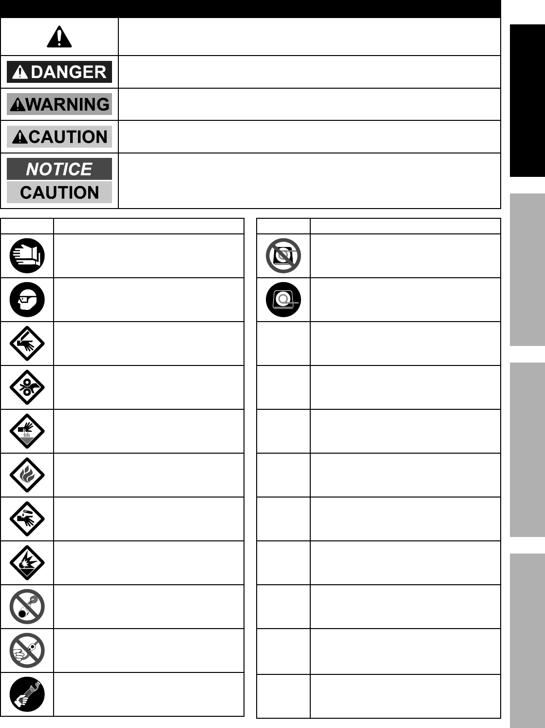
?@<6AYZU6;@ACZED@CEA6E@EQ6 ?6AFU
R@;ECE[%?YDSZG?%@EX%X6<CECACZE?
This is the safety alert symbol. It is used to alert you to potential
personal injury hazards. Obey all safety messages that
follow this symbol to avoid possible injury or death.
Indicates a hazardous situation which, if not avoided,
will result in death or serious injury.
Indicates a hazardous situation which, if not avoided,
could result in death or serious injury.
Indicates a hazardous situation which, if not avoided,
could result in minor or moderate injury.
Addresses practices not related to personal injury.
?>5+&7 U(&/*($>%&(%?$,$*5*8$
R*,(%.*,\>K9'$>I%4'$K%,89%
,+(,#"&8-(*#"#$,8$%7*,$.*(%37&\*#1
R*,(%@E?CK,//(&\*9%#,2*$>%37,##*#1
Q'$%&(%#*\*(%.,],(91
;&77*(%*8$,837*5*8$%.,],(91
B&$%#'(2,4*%+'(8%.,],(91
<"(*%.,],(91
Q,'#$"4%4.*5"4,7%^,4"9_%.,],(91
6T/7&#"&8%.,],(91
X&%8&$%7&&/%$.*%)"(*%(&/*%,(&'89%
&+=*4$%,89%.&&`%&8$&%"$#*721
X&%8&$%/7,4*%2"83*(^#_%$.(&'3.%.&&`1%%
<"83*(#%5,>%+*%4,'3.$%,89%3*$%
/'77*9%"8$&%2,"(7*,9%&(%9('51
U'77%.&&`%'#"83%#$(,/%&87>1
?>5+&7 U(&/*($>%&(%?$,$*5*8$
X&%8&$%'#*%)"84.%"8%
&\*()"89%&("*8$,$"&81%%
^R"(*%(&/*%*8$*(#0*T"$#%,$%$.*%$&/1_
F#*%)"84.%&87>%"8%
'89*()"89%&("*8$,$"&81%%
^R"(*%(&/*%*8$*(#0*T"$#%,$%$.*%+&$$&51_
!XQ Volts Direct Current
@Amperes
QQ@ Cold Cranking Amperes
BU Horsepower
2/5 Feet Per Minute
5/5 Meters Per Minute
;UD Revolutions Per Minute
CU
International Protection rating
Classifies the degrees of protection provided
against the intrusion of solid objects,
dust, accidental contact, and water.
[L Grade 8
A fastener strength rating.

Page 4 <&(%$*4.8"4,7%H'*#$"&8#I%/7*,#*%4,77%JKLLLKLMMKNOPO1 Item 63770
?@<6AY ZU6;@ACZE D@CEA6E@EQ6?6AFU
CDUZ;A@EA%?@<6AY%CE<Z;D@ACZE
% R@;ECE[a%;*,9%,77%"8#$('4$"&8#1 <,"7'(*%$&%2&77&)%,77%"8#$('4$"&8#%7"#$*9%&8%/,3*#%b%$&%O%5,>%
(*#'7$%"8%2"(*I%#*("&'#%"8='(>%,890&(%X6@AB1%
The warnings and precautions discussed in this manual cannot cover all possible conditions and
situations that may occur. It must be understood by the operator that common sense and caution
are factors which cannot be built into this product, but must be supplied by the operator.
C8#$,77,$"&8%U(*4,'$"&8#
1. Do not wear loose clothing or jewelry,
as they can be caught in moving parts.
Non-skid footwear is recommended.
Wear restrictive hair covering to contain long hair.
2. Wear ANSI-approved safety goggles and
heavy-duty leather work gloves during installation.
3. Before installation confirm that area is clear
of fuel lines, brake lines, electrical wires,
gas tanks or any other component which
could be damaged during drilling.
4. Mounting location and hardware
must support winch and load.
5. Use supplied power cords and wire rope listed
in manual only. Do not use thinner/longer
cables or link multiple cables together.
6. Do not route electrical cables near sharp edges
or parts that will move or become hot.
7. Ventilate area well before and while working
on battery. Explosive invisible hydrogen gas
can accumulate and then explode when ignited
by a spark from the battery connection.
8. Only connect to a clean, corrosion free battery.
9. Do not lean over or come in contact with
battery while making connections.
10. Remove all metal jewelry before
working near battery.
11. Connect red wire to positive battery terminal
and black wire to negative battery terminal.
12. Insulate all exposed wiring and
terminals after installation.
13. Install winch and fairlead in underwind
orientation, so that the wire rope enters and
exits the winch at the bottom of the drum.

Page 5<&(%$*4.8"4,7%H'*#$"&8#I%/7*,#*%4,77%JKLLLKLMMKNOPO1Item 63770
?@<6AYZU6;@ACZED@CEA6E@EQ6 ?6AFU
Z/*(,$"&8%U(*4,'$"&8#
1. Do not exceed load capacity. S*%,),(*%&2%
9>8,5"4%7&,9"83a Sudden load movement may
briefly create excess load causing product failure.
2. X&%8&$%5,"8$,"8%/&)*(%$&%$.*%)"84.%"2%$.*%5&$&(%
#$,77#1 Verify load is within rated capacity for
the wire rope layer, see Winch Specifications on
page 2.
Make sure the battery is fully charged.
Use double line rigging whenever possible,
see Double Line Rigging on page 11.
3. Wear ANSI-approved safety goggles and
heavy-duty leather work gloves during operation.
4. Do not disengage clutch under load.
Engage clutch before starting.
5. Keep clear of fairlead when operating.
Do not try to guide wire rope.
6. X&%8&$%/7,4*%2"83*(^#_%$.(&'3.%.&&`1 Fingers may
be caught and get pulled into fairlead or drum.
Use included strap to hold hook instead.
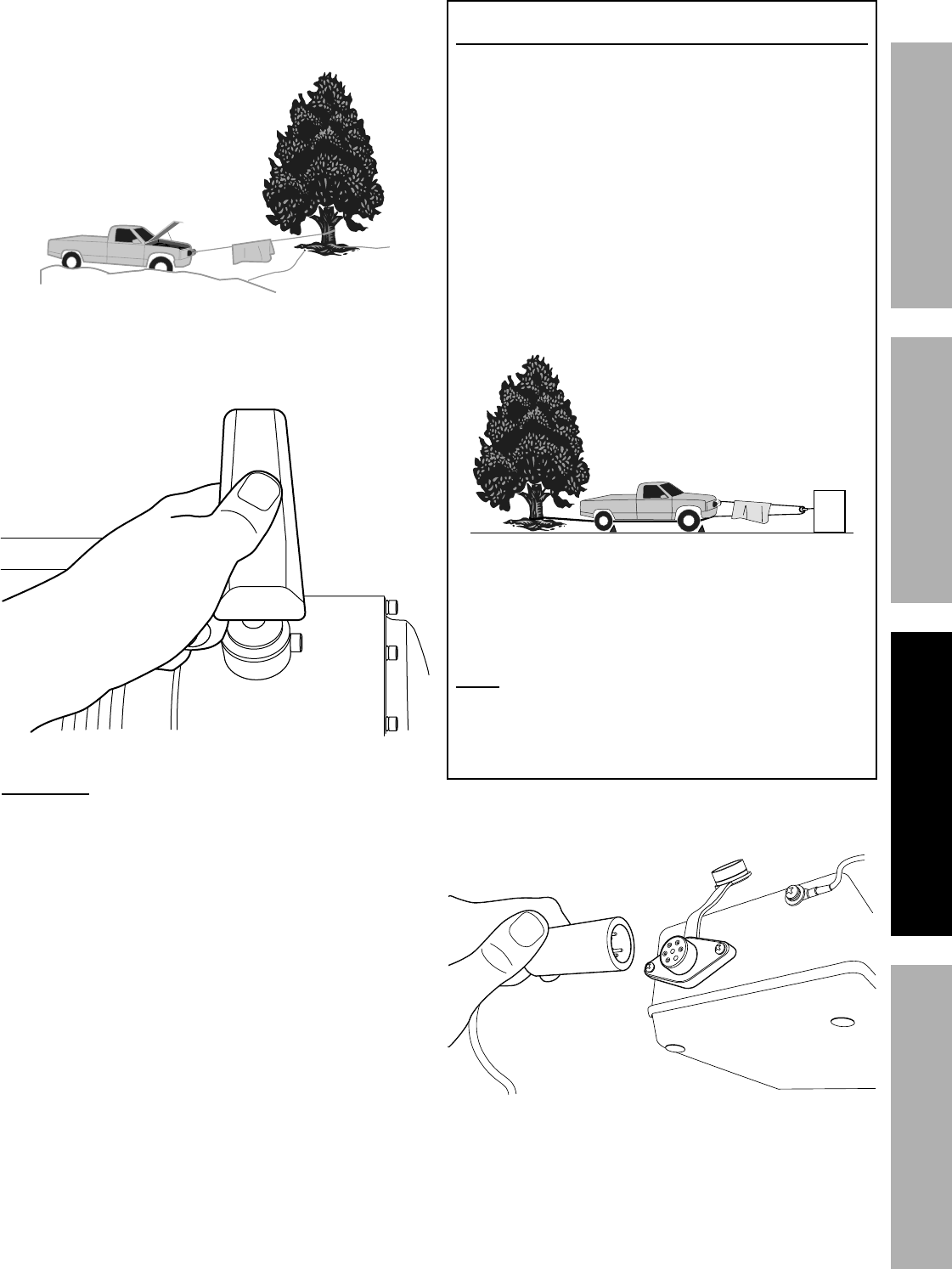
7. Place heavy rag or carpet over wire
rope span 6 feet from hook to help absorb the force
released if the wire rope breaks.%%^?**%<"3'(*%@1_
<"3'(*%@-%%R."/7,#.%X,5/*8"83%S7,8`*$%&(%;'3
8. Stay out of the direct line that the wire
rope is pulling. In case it slips or breaks,
it will “whiplash” along this line.
9. Do not use for lifting or moving people.
10. Use a spotter to assist you in assuring that it is safe
to operate the winch. Make sure the spotter is out of
the way of the vehicle and the wire
rope before activating the winch.
11. Do not use the hand crank, if equipped,
to “assist” the winch.
12. Do not use vehicle to pull on the
Wire Rope and “assist” the winch.
13. Use as intended only. Do not lift items
vertically or use for aircraft purposes.
14. Prevent entanglement. Do not wear loose clothing
or jewelry, as they can be caught in moving
parts. Non-skid footwear is recommended. Wear
restrictive hair covering to contain long hair.
15. Disconnect Pendant Controller before
working near the Wire Rope, drum, fairlead
or load, to prevent accidental starting.
16. Inspect before every use; do not use if damaged or
parts loose. Examine the winch for structural cracks,
bends, damage, frayed or kinked wire rope, and any
other conditions that may affect the safe operation
of the winch. Do not use the winch even if minor
damage appears. A kink permanently weakens the
wire rope, even after it is straightened out; kinked
wire rope can fail suddenly and must not be used.
17. Keep wire rope straight to avoid kinking
the wire rope. The illustrations to the
right show how a kink forms.
a. This illustration shows a kink about
to form. At this point the winch
should be stopped and the wire
rope should be straightened out
to prevent kinking.
b. This wire rope is
kinked. It is too
late to reverse the
damage at this point, the
wire rope must be discarded.
It is permanently damaged
and must not be used.
c. This is a kinked wire rope that has been
straightened out. Even though it has been
pulled straight, some wires in the wire rope
are stretched, and others are severely bent,
if not broken. The unstretched wires will
take more load and can fail suddenly before
the rope reaches its capacity. This wire
rope must be discarded and not be used.
A kink permanently weakens the wire rope,
even after it is straightened out; kinked wire
rope can fail suddenly and must not be used.
18. Keep children and bystanders away while operating.
Distractions can cause you to lose control.

Page 6 <&(%$*4.8"4,7%H'*#$"&8#I%/7*,#*%4,77%JKLLLKLMMKNOPO1 Item 63770
?@<6AY ZU6;@ACZE D@CEA6E@EQ6?6AFU
19. Stay alert, watch what you are doing and
use common sense when operating. Do not
use a winch while you are tired or under the
influence of drugs, alcohol or medication.
A moment of inattention while operating winches
may result in serious personal injury.
20. Do not overreach. Keep proper footing and
balance at all times. This enables better control
of the winch in unexpected situations.
21. Hook onto the object using a pulling point, tow
strap or chain. Do not wrap the wire rope around
the object and hook onto the wire rope itself.
This can cause damage to the object being
pulled, and kink or fray the wire rope.
22. X&%8&$%'#*%,%;*4&\*(>%?$(,/%)."7*%
)"84."831 They are designed to stretch
and can suddenly whip back towards the
operator during a winching operation.
23. Secure load after moving.
NO LOCKING MECHANISM.
24. Keep at least 5 full turns of wire rope on
drum. The wire rope’s connection to the
drum is not intended to sustain a load,
without the added support from the friction
of at least 5 full turns of wire rope.
25. Wrap wire rope under 500 lb. tension before use.
Otherwise, wire rope may bind during operation.
26. Keep clear of wire rope, hook, and load while
winching. Do not step over wire rope.
X&%8&$%/'#.%#"9*),>#%,3,"8#$%)"(*%(&/*%
'89*(%$*8#"&8c%)"(*%(&/*%5"3.$%+(*,`%'89*(%
$."#%7&,9%,89%(*4&"7%+,4`I%#$("`"83%$.*%
/*(#&8%/'#."83%,3,"8#$%"$%&(%,%+>#$,89*(1
27. If wire rope begins to get entangled, stop winch
immediately and release wire rope using switch.
28. Do not submerge winch in water.
If winch gets submerged accidentally, it needs
to be immediately disassembled, cleaned, dried
and re-lubricated by a qualified technician to
prevent permanent damage from corrosion.
29. Only winch with the winching vehicle′s
transmission in neutral. Winching with a vehicle′s
transmission in gear or park may damage
the transmission. A vehicle′s transmission is
not designed to handle that type of load.
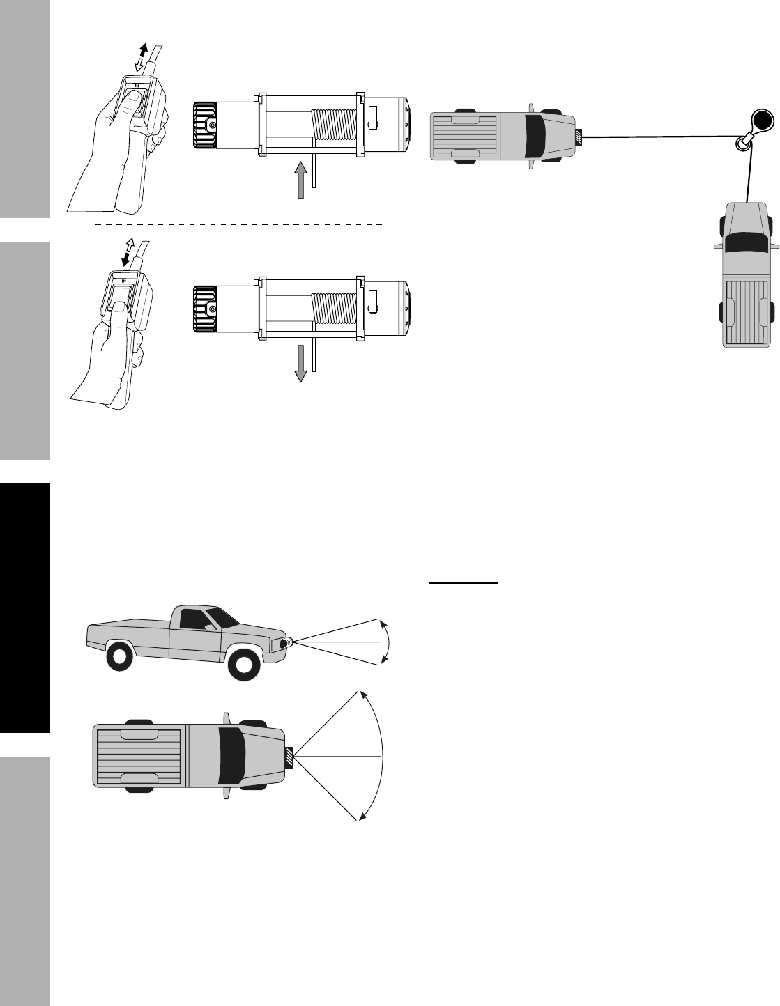
30. Do not operate the winch at extreme angles.
Do not exceed the angles shown in Figure B for
a roller fairlead. For a hawse fairlead, the angle
should be as close to straight as possible.
45°
45°
15°
15°
<"3'(*%S-%%;&77*(%2,"(7*,9%D,T"5'5%R"84."83%@837*#
31. If the object to be pulled must be pulled at an
angle in relation to the winch, use a pulley
(sold separately) and an anchor point directly
in front of the winch, as shown in Figure C,
to keep the Wire Rope pull straight.
<"3'(*%Q-%%U'77*>%,84.&("83
32. Broken strands of wire rope will be sharp.
Wear heavy-duty work gloves when handling
the wire rope. Do not slide wire rope
through hands, even with gloves on.
33. Winch motor will be hot during and after use.
Keep clear.
34. Do not power the hook all the way
into the fairlead or winch.
35. To prevent accidental starting, unplug winch controls
and any RF receivers immediately after extending
or retracting. This is especially important before
rigging, installing, free spooling, or servicing.
36. People with pacemakers should consult their
physician(s) before use. Electromagnetic fields in
close proximity to heart pacemaker could cause
pacemaker interference or pacemaker failure.

Page 7<&(%$*4.8"4,7%H'*#$"&8#I%/7*,#*%4,77%JKLLLKLMMKNOPO1Item 63770
?@<6AYZU6;@ACZED@CEA6E@EQ6 ?6AFU
?*(\"4*%U(*4,'$"&8#
1. Wear ANSI-approved safety goggles and
heavy-duty leather work gloves during service.
2. Disconnect power to winch and allow it
to cool completely before service.
3. Use supplied power cords/wire rope or cables
listed in manual only. Do not use thinner/
longer cables or link multiple cables together.
4. Have the winch serviced by a qualified repair person
using only identical replacement parts. This will
ensure that the safety of the winch is maintained.
5. Maintain labels and nameplates on the winch.
These carry important safety information.
If unreadable or missing, contact
Harbor Freight Tools for a replacement.
%?@!6%AB6?6%CE?A;FQACZE?1

Page 8 <&(%$*4.8"4,7%H'*#$"&8#I%/7*,#*%4,77%JKLLLKLMMKNOPO1 Item 63770
?@<6AY ZU6;@ACZE D@CEA6E@EQ6?6AFU
C8#$,77,$"&8%,89%?*$'/
% ;*,9%$.*%6EAC;6%CDUZ;A@EA%?@<6AY%CE<Z;D@ACZE%#*4$"&8%,$%$.*%+*3"88"83%&2%$."#%
5,8',7%"847'9"83%,77%$*T$%'89*(%#'+.*,9"83#%$.*(*"8%+*2&(*%#*$%'/%&(%'#*%&2%$."#%/(&9'4$1
D&'8$"83%$.*%R"84.
1. The mounting plate must be rated to
at least the winch’s capacity.
2. Align the winch perpendicular to center line of
the vehicle at the desired location, and mark the
locations of the winch base holes. Compare the
dimensions of the marked holes to Figure D.
3. Before drilling, verify that the installation
surface has no hidden components or
structural pieces that will be damaged.
EZA6-%This winch can generate extreme
forces. Select a location that can withstand the
rated capacity without damage or weakening.
Steel reinforcement plates may be needed or a
certified welder may need to weld on additional
bracing depending on the mounting location.
4. Drill holes appropriate for the hardware
at the marked locations.
5. Install the winch using the hardware
specified on the specification chart.
Jd%"81%0%VNb1M55
Vd1Pb%"81%0%NWV55
befd1bW%"81%0%JJ55
M1W%"81%0%JMd55
b1bP%"81%%
0%JJb55
L1L%"81%0%VVW1M55 N1VL%"81%0%JWb55M1LN%"81%0%JOb55
L1NL%"81%0%VJL55
<"3'(*%X-%%R"84.%X"5*8#"&8#
D&'8$"83%$.*%?&7*8&"9%@##*5+7>
1. Place the Solenoid Box in a suitable
place near enough to the winch to allow
the cables to be routed properly.
2. Mark the where the screw holes will be.
3. Verify that the installation surface has no
hidden components or structural pieces
that will be damaged before drilling.
4. Drill pilot holes for the mounting screws.
5. Secure in place with mounting screws.

Page 9<&(%$*4.8"4,7%H'*#$"&8#I%/7*,#*%4,77%JKLLLKLMMKNOPO1Item 63770
?@<6AYZU6;@ACZED@CEA6E@EQ6 ?6AFU
R"("83
AZ%U;6!6EA%?6;CZF?%CEgF;Y%<;ZD%6hUGZ?CZE%%
XF6%AZ%?U@;iCE[%@A%AB6%S@AA6;Y%QZEE6QACZE-%
F8/7'3%$.*%U*89,8$%Q&88*4$&(%,89%9"#4&88*4$%$.*%S,$$*(>%Q,+7*#%%
+*2&(*%5,`"83%&$.*(%)"("83%4&88*4$"&8#1
AZ%U;6!6EA%?6;CZF?%CEgF;Y%<;ZD%G6@iCE[%S@AA6;Y%@QCX-%
X&%8&$%'#*%,%9"($>I%4&((&9*9%&(%7*,`"83%+,$$*(>1%%%
Z87>%'#*%,%JV!%,'$&5&$"\*%^&(%*H'"\,7*8$_%+,$$*(>I%"8%3&&9%4&89"$"&81
1. Plan a route for the wiring from the point of the
vehicle where the winch will be mounted, or used,
to the battery. This route must be secure, out of the
way of moving parts, road debris, or any possibility
of being damaged by operation or maintenance
of the vehicle. For example, you may wish to
route the wires under the vehicle, attaching it to
the frame using suitable fasteners. Do not attach
the wires to the exhaust system, drive shaft,
emergency brake cable, fuel line, or any other
components which may create damage the wiring
through heat or motion, or create a fire hazard.
2. If you drill through the bumper or any part
of the body to route the wires, be sure
to install a rubber grommet in the hole to
prevent fraying of the wires at that point.
3. Route the Cables from the Solenoid to the battery
and from the Solenoid to the Winch, following the
precautions discussed above. See Figure E.
Q"(4'"$%
S(*,`*(
?&7*8&"9%
S&T
R"84.
;*9
S7,4`
S7,4`
Y*77&)%Q,/
S7,4`
;*9
<"3'(*%6-%%R"("83%Q&88*4$"&8#
4. Attach the Red, Black and Yellow
Cables to the terminals on the Winch.
The Winch terminals are color-coded.
5. Attach the Circuit Breaker to the
Positive Terminal on the battery.
6. Attach the red Battery Cable to the Circuit Breaker.
7. Attach the black Battery Cable directly to
the negative terminal of the battery.
8. Lift the Socket Cover exposing the
electrical switch connector. Insert the
Pendant connector into the Socket.
E&$*- The attachment of the Motor Cables determines
the direction of the Pendant Controller’s button.
After the unit is mounted and powered, check the
direction of the Power In and Power Out on the Pendant
Controller button. If you wish to change the direction on
the Pendant Controller, disconnect the Battery Cables
from the battery, switch the Motor Cable connections on
the Motor Assembly, then reconnect the Battery Cables.
9. Disconnect the Pendant Controller when not in use.
U(*/,("83%$.*%R"(*%;&/*
1. The wire rope must be properly coiled under tension
to be able to support a load without damage.
2. Uncoil the wire rope, except for 5 full wraps.
3. Recoil the wire rope back into the winch
under at least 500 lb. of tension.

Page 10 <&(%$*4.8"4,7%H'*#$"&8#I%/7*,#*%4,77%JKLLLKLMMKNOPO1 Item 63770
?@<6AY ZU6;@ACZE D@CEA6E@EQ6?6AFU
Z/*(,$"&8
% ;*,9%$.*%6EAC;6%CDUZ;A@EA%?@<6AY%CE<Z;D@ACZE%#*4$"&8%,$%$.*%+*3"88"83%&2%$."#%5,8',7%
"847'9"83%,77%$*T$%'89*(%#'+.*,9"83#%$.*(*"8%+*2&(*%#*$%'/%&(%'#*%&2%$."#%/(&9'4$1%
A.*%"8#$('4$"&8#%$.,$%2&77&)%,(*%+,#"4%3'"9*7"8*#%&87>%,89%4,88&$%4&\*(%,77%#"$',$"&8#%*84&'8$*(*9%
9'("83%'#*1%%A.*%&/*(,$&(%,89%,##"#$,8$#%5'#$%4,(*2'77>%/7,8%'#,3*%$&%/(*\*8$%,44"9*8$#1
1. Examine the wire rope. Do not use the winch if
the wire rope is frayed, kinked or damaged.
2. Fully charge the vehicle’s battery.
3. Check the Winch’s electrical connections.
All connections must be tight and clean.
4. Put the vehicle’s transmission in Neutral.
5. If the vehicle where the winch is mounted
is not supposed to be moved, engage the
emergency brake and block the wheels
using wheel chocks (sold separately).
6. To pull out the wire rope, move the Clutch Handle to
the Released position, shown in Figure F, slide the
loop of the Hook Strap over the hook, then pull on
the Hook Strap to pull out the wire rope.
R@;ECE[a%%G*,\*%,$%7*,#$%2"\*%2'77%
$'(8#%&2%)"(*%(&/*%&8%$.*%9('51
<"3'(*%<-%%Q7'$4.%(*7*,#*9
7. Hook onto the object using a pulling point, tow
strap, tree strap, or chain. See Figure G.
<"3'(*%[-%%F#"83%,%#$(,/%,84.&(%/&"8$
X&%8&$%)(,/%$.*%)"(*%(&/*%,(&'89%
$.*%&+=*4$%,89%.&&`%&8$&%$.*%
)"(*%(&/*%"$#*721
This can damage the object being
pulled, and kink or fray the wire rope.
8. Attachment point must be centered in
loop of hook and the hook’s safety clasp
must be fully closed. See Figure H.
<"3'(*%B-%%Q&((*4$%,89%"84&((*4$%.&&`%,$$,4.5*8$
9. X&%8&$%'#*%,%;*4&\*(>%?$(,/%)."7*%
)"84."831 They are designed to stretch
and can suddenly whip back towards the
operator during a winching operation.
Page 11<&(%$*4.8"4,7%H'*#$"&8#I%/7*,#*%4,77%JKLLLKLMMKNOPO1Item 63770
?@<6AYZU6;@ACZED@CEA6E@EQ6 ?6AFU
10. Place a heavy rag or carpet (sold separately) over
the wire rope span, 6 feet from the hook to help
absorb the force released if the wire rope breaks.
<C[F;6%@-%RBCUG@?B%X@DU6ECE[%
SG@Ei6A%Z;%;F[
11. Re-engage the clutch by moving the Clutch Handle
to the Engaged position, shown in Figure I.
<"3'(*%C-%%Q7'$4.%683,3*9
R@;ECE[a Do not allow anyone to stand near
the wire rope, or in line with the wire rope behind
the winch while it is under power. If the wire rope
should slip or break, it can suddenly whip back
towards the winch, causing a hazard for anyone in
the area. Stand well to the side while winching.
X&'+7*%G"8*%;"33"83
a. A double line system should be used whenever
possible. It reduces the load on the winch,
allowing it to work longer with less heat buildup.
It reduces load on the winch in two ways:
• It utilizes the lower layers of wire rope
that have higher capacity, and
• It halves the load on the winch
through pulley action.
b. Connect the wire rope for a double line
system as shown in Figure J below.
Use a pulley block (sold separately) properly
rated for the load to be pulled and designed
to be operated with this winch’s wire rope.
?$,$"&8,(>%
R"84."83%!*."47*%%
^Q.&4`%$"(*#I%
#*$%/,(`"83%+(,`*I%
,89%7*,\*%"8%8*'$(,7_ G&,9
Q,(/*$
<"3'(*%g-%%X&'+7*%G"8*%#*$'/
c. Loop the wire rope around the pulley and connect
to another part of the vehicle’s chassis or to
a separate anchor point. X&%8&$%,84.&(%$.*%
R"(*%;&/*%+,4`%$&%$.*%)"84.%&(%)"84.%5&'8$1
E&$*- If anchoring the winching vehicle, only attach
the anchor line to the front of the vehicle.
If the anchor line is attached to the rear of the vehicle,
the vehicle's frame may be damaged by
the forces exerted by winching.
12. Attach the Pendant Controller to the Socket
on the Solenoid Assembly, see Figure K.
<"3'(*%i-%%U*89,8$%4&88*4$"&8
Page 12 <&(%$*4.8"4,7%H'*#$"&8#I%/7*,#*%4,77%JKLLLKLMMKNOPO1 Item 63770
?@<6AY ZU6;@ACZE D@CEA6E@EQ6?6AFU
13. Operate the Pendant controls briefly to ensure
they work properly, see Figure L. If operation is
reversed, the power cables may be connected
backwards. Correct any such issue before use.
<"3'(*%G-%%U*89,8$%4&8$(&7#
14. When it is safe to do so, use the power switch on
the Pendant Controller to retract the wire rope, and
winch the as desired. X&%8&$%/&)*(%$.*%.&&`%,77%
$.*%),>%"8$&%$.*%2,"(7*,9%$&%/(*\*8$%9,5,3*1
15. Do not operate the winch at extreme angles.
Do not exceed the angles shown in Figure B for
a roller fairlead. For a hawse fairlead, the angle
should be as close to straight as possible.
45°
45°
15°
15°
<C[F;6%S-%;ZGG6;%<@C;G6@X%
D@hCDFD%RCEQBCE[%@E[G6?
16. If the object to be pulled must be pulled at an
angle in relation to the winch, use a pulley
(sold separately) and an anchor point directly
in front of the winch, as shown in Figure C,
to keep the Wire Rope pull straight.
<C[F;6%Q-%UFGG6Y%@EQBZ;CE[
17. R@;ECE[a%Stop the winch and release
tension on the wire rope before moving
the rag or carpet placed on it.
18. Do not continue use of the winch until
the battery is completely run down.
19. You may wish to keep the engine running while
using this winch, to continually recharge the battery.
However, exercise extreme caution when
working around a running vehicle and ONLY
operate a vehicle in an outdoor area.
Q@FACZEa X&%8&$%'#*%$.*%)"84.%"8%,%
4&8#$,8$%9'$>%,//7"4,$"&8I%"$%"#%9*#"38*9%2&(%
CEA6;DCAA6EA%F?6%ZEGY1%%i**/%$.*%9'(,$"&8%
&2%$.*%/'77"83%=&+%,#%#.&($%,#%/&##"+7*1%%C2%$.*%
5&$&(%+*4&5*#%\*(>%.&$%$&%$.*%$&'4.I%#$&/%,89%
7*$%"$%4&&7%9&)8%2&(%#*\*(,7%5"8'$*#1%%X&%8&$%/'77%
2&(%5&(*%$.,8%&8*%5"8'$*%,$%&(%8*,(%$.*%(,$*9%
7&,91%%X&%8&$%5,"8$,"8%/&)*(%$&%$.*%R"84.%"2%
$.*%5&$&(%#$,77#1%%X&'+7*%G"8*%;"33"83%)"77%.*7/%
/(*\*8$%&\*(7&,9"83%,89%#.&'79%+*%'#*9%).*8*\*(%
/(,4$"4,7I%#**%X&'+7*%G"8*%;"33"83%&8%/,3*%JJ1
20. When finished pulling the load, reverse the direction
of the winch just enough to release tension on
the Wire Rope so that you can unfasten the
Hook from the load and reel in the Wire Rope.

Page 13<&(%$*4.8"4,7%H'*#$"&8#I%/7*,#*%4,77%JKLLLKLMMKNOPO1Item 63770
?@<6AYZU6;@ACZED@CEA6E@EQ6 ?6AFU
X'$>%Q>47*%^X'(,$"&8%&2%F#*_
,$%7*,#$%
Jb%5"8'$*#I%
JN%#*4&89#%
&2%(*#$
bN%#*4&89#%)"84."83 @\&"9%9,5,3*%$&%$.*%R"84.%+>%8&$%)"84."83%
2&(%5&(*%$.,8%$.*%/(*#4("+*9%9'$>%4>47*%$"5*1%
The Duty Cycle defines the amount of time, within
a 15 minute period, during which a Winch can
operate at its maximum capacity without overheating.
For example, this Winch with a 5% duty cycle at its
maximum load must be allowed to rest for at least
14 minutes, 15 seconds after every 45 seconds of
continuous operation. Failure to carefully observe
duty cycle limitations can easily over-stress a
Winch contributing to premature Winch failure.
D,"8$*8,84*%,89%?*(\"4"83
% U(&4*9'(*#%8&$%#/*4"2"4,77>%*T/7,"8*9%
"8%$."#%5,8',7%5'#$%+*%/*(2&(5*9%
&87>%+>%,%H',7"2"*9%$*4.8"4",81
AZ%U;6!6EA%?6;CZF?%CEgF;Y%<;ZD%@QQCX6EA@G%ZU6;@ACZE-%
F8/7'3%$.*%U*89,8$%4&88*4$&(%,89%9"#4&88*4$%$.*%S,$$*(>%Q,+7*#%+*2&(*%/*(2&(5"83%,8>%
"8#/*4$"&8I%5,"8$*8,84*I%&(%47*,8"83%/(&4*9'(*#1
AZ%U;6!6EA%?6;CZF?%CEgF;Y%<;ZD%RCEQB%<@CGF;6-%
X&%8&$%'#*%9,5,3*9%*H'"/5*8$1%%C2%,+8&(5,7%8&"#*%&(%\"+(,$"&8%
&44'(#I%.,\*%$.*%/(&+7*5%4&((*4$*9%+*2&(*%2'($.*(%'#*1
Q7*,8"83I%D,"8$*8,84*I%,89%G'+("4,$"&8
1. S6<Z;6%6@QB%F?6I inspect the general
condition of the winch. Check for loose hardware,
misalignment or binding of moving parts, cracked
or broken parts, damaged electrical wiring,
corroded or loose terminals, and any other
condition that may affect its safe operation.
Examine the wire rope. Do not use the winch if
the wire rope is frayed, kinked or damaged.
2. @<A6;%F?6I wipe external surfaces
of the winch with clean cloth.
3. Lubricate the wire rope occasionally with a light oil.
4. The winch’s internal mechanism is permanently
lubricated. Do not open the housing.
However, if the winch is submerged, it should be
opened, dried, and re-lubricated by a qualified
technician as soon as possible to prevent corrosion.
R"(*%;&/*%;*/7,4*5*8$
1. Move Clutch Handle to the Released position.
2. Extend the Wire Rope to its full length,
noting how the existing Wire Rope is
connected to the inside of the drum.
3. Remove old Wire Rope and attach new assembly.
Q@FACZEa Do not replace with inferior Wire Rope.
Only use a wire rope rated to the same rating
cited on the specification chart or better.
4. Retract Wire Rope onto Wire Rope
drum being careful not to allow kinking.
Refer to instructions for tensioning the wire rope
under ″Preparing the Wire Rope on page 9.
5. Test Electric Winch for proper operation.

Page 14 <&(%$*4.8"4,7%H'*#$"&8#I%/7*,#*%4,77%JKLLLKLMMKNOPO1 Item 63770
?@<6AY ZU6;@ACZE D@CEA6E@EQ6?6AFU
A(&'+7*#.&&$"83
U(&+7*5 U&##"+7*%Q,'#*# G"`*7>%?&7'$"&8#
Motor overheats. 1. Incorrect power cords.
2. Winch running time too long.
1. Use only supplied power cords.
2. Allow winch to cool down periodically.
Motor does
not turn on.
1. Switch Assembly not
connected properly.
2. Loose battery cable connections.
3. Vehicle battery needs charging.
4. Solenoid malfunctioning.
5. Defective Switch Assembly.
6. Defective motor.
7. Water has entered motor.
8. Internal damage or wear.
1. Insert Switch Assembly all the way into connector.
2. Tighten nuts on all cable connections.
3. Fully charge battery.
4. Tap solenoid to loosen contacts. Apply 12 volts to coil
terminals directly. A clicking indicates proper activation.
5. Replace Switch Assembly.
6. Check for voltage at armature port with Switch
pressed. If voltage is present, replace motor.
7. Allow to drain and dry. Run in short bursts
without load until completely dry.
8. Have technician service winch.
Motor runs but
Wire Rope drum
does not turn.
Clutch not engaged. Move the Clutch Handle to the Engaged position.
If problem persists, a qualified technician
needs to check and repair.
Motor runs
slowly or without
normal power.
1. Insufficient current or voltage.
2. Loose or corroded battery
cable connections.
3. Incorrect power cords.
1. Battery weak, recharge.
Run winch with vehicle motor running.
2. Clean, tighten, or replace.
3. Use only supplied power cords.
Motor runs in one
direction only.
1. Defective or stuck solenoid.
2. Defective Switch Assembly.
1. Tap solenoid to loosen contacts.
Repair or replace solenoid.
2. Replace Switch Assembly.
% <&77&)%,77%#,2*$>%/(*4,'$"&8#%).*8*\*(%9",38&#"83%&(%#*(\"4"83%
$.*%$&&71%%X"#4&88*4$%/&)*(%#'//7>%+*2&(*%#*(\"4*1
UG6@?6%;6@X%AB6%<ZGGZRCE[%Q@;6<FGGY
THE MANUFACTURER AND/OR DISTRIBUTOR HAS PROVIDED THE PARTS LIST AND ASSEMBLY DIAGRAM
IN THIS MANUAL AS A REFERENCE TOOL ONLY. NEITHER THE MANUFACTURER OR DISTRIBUTOR
MAKES ANY REPRESENTATION OR WARRANTY OF ANY KIND TO THE BUYER THAT HE OR SHE IS
QUALIFIED TO MAKE ANY REPAIRS TO THE PRODUCT, OR THAT HE OR SHE IS QUALIFIED TO REPLACE
ANY PARTS OF THE PRODUCT. IN FACT, THE MANUFACTURER AND/OR DISTRIBUTOR EXPRESSLY
STATES THAT ALL REPAIRS AND PARTS REPLACEMENTS SHOULD BE UNDERTAKEN BY CERTIFIED AND
LICENSED TECHNICIANS, AND NOT BY THE BUYER. THE BUYER ASSUMES ALL RISK AND LIABILITY
ARISING OUT OF HIS OR HER REPAIRS TO THE ORIGINAL PRODUCT OR REPLACEMENT PARTS
THERETO, OR ARISING OUT OF HIS OR HER INSTALLATION OF REPLACEMENT PARTS THERETO.
;*4&(9%U(&9'4$j#%?*(",7%E'5+*(%B*(*-%
E&$*- If product has no serial number, record month and year of purchase instead.
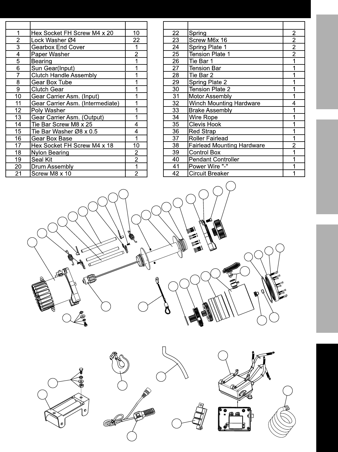
E&$*- Some parts are listed and shown for illustration purposes only,
and are not available individually as replacement parts.
Page 15<&(%$*4.8"4,7%H'*#$"&8#I%/7*,#*%4,77%JKLLLKLMMKNOPO1Item 63770
?@<6AYZU6;@ACZED@CEA6E@EQ6 ?6AFU
U,($#%G"#$%,89%X",3(,5
U,($ X*#4("/$"&8 k$> U,($ X*#4("/$"&8 k$>
38
5
6
7
8
9
10
11
12
13
14
15
16
17
37
35
40
34
36
18
19
20
21
23
1
2
3
4
32
39
41
42
24
25
26
27
28
29
22
30
33
31

WbPJ%D"##"&8%Z,`#%S7\91%%l%%UZ%S&T%MddP%%l%%Q,5,("77&I%Q@%PWdJJ%%l%%JKLLLKLMMKNOPO
G"5"$*9%Pd%X,>%R,((,8$>
Harbor Freight Tools Co. makes every effort to assure that its products meet high quality and durability standards,
and warrants to the original purchaser that this product is free from defects in materials and workmanship for the
period of 90 days from the date of purchase. This warranty does not apply to damage due directly or indirectly,
to misuse, abuse, negligence or accidents, repairs or alterations outside our facilities, criminal activity, improper
installation, normal wear and tear, or to lack of maintenance. We shall in no event be liable for death, injuries
to persons or property, or for incidental, contingent, special or consequential damages arising from the use of
our product. Some states do not allow the exclusion or limitation of incidental or consequential damages, so the
above limitation of exclusion may not apply to you. THIS WARRANTY IS EXPRESSLY IN LIEU OF ALL OTHER
WARRANTIES, EXPRESS OR IMPLIED, INCLUDING THE WARRANTIES OF MERCHANTABILITY AND FITNESS.
To take advantage of this warranty, the product or part must be returned to us with transportation charges
prepaid. Proof of purchase date and an explanation of the complaint must accompany the merchandise.
If our inspection verifies the defect, we will either repair or replace the product at our election or we may
elect to refund the purchase price if we cannot readily and quickly provide you with a replacement. We will
return repaired products at our expense, but if we determine there is no defect, or that the defect resulted
from causes not within the scope of our warranty, then you must bear the cost of returning the product.
This warranty gives you specific legal rights and you may also have other rights which vary from state to state.
