7700 Series Emulator Softkey Interface 64146 97005_7700_Series_Softkey_Feb94 97005 Feb94
User Manual: 64146-97005_7700_Series_Softkey_Feb94
Open the PDF directly: View PDF ![]() .
.
Page Count: 112 [warning: Documents this large are best viewed by clicking the View PDF Link!]

HP 64146
7700 Series Emulator
Softkey Interface
User’s Guide
HP Part No. 64146-97005
Printed in U.S.A.
February 1994
Edition 2

Notice Hewlett-Packard makes no warranty of any kind with regard to this
material, including, but not limited to, the implied warranties of
merchantability and fitness for a particular purpose. Hewlett-Packard
shall not be liable for errors contained herein or for incidental or
consequential damages in connection with the furnishing, performance,
or use of this material.
Hewlett-Packard assumes no responsibility for the use or reliability of
its software on equipment that is not furnished by Hewlett-Packard.
© Copyright 1994, Hewlett-Packard Company.
This document contains proprietary information, which is protected by
copyright. All rights are reserved. No part of this document may be
photocopied, reproduced or translated to another language without the
prior written consent of Hewlett-Packard Company. The information
contained in this document is subject to change without notice.
AdvanceLink, Vectra and HP are trademarks of Hewlett-Packard
Company.
IBM and PC AT are registered trademarks of International Business
Machines Corporation.
MS-DOS is a trademark of Microsoft Corporation.
MELPS is a registered trademark of Mitsubishi Electric Corporation.
Hewlett-Packard Company
P.O.Box 2197
1900 Garden of the Gods Road
Colorado Springs, CO 80901-2197, U.S.A.
RESTRICTED RIGHT LEGEND Use, duplication, or disclosure by
the U.S. Government is subject to restrictions as set forth in
subparagraph (C) (1) (ii) of the Rights in Technical Data and Computer
Software Clause at DFARS 252.227-7013.
Hewlett-Packard Company, 3000 Hanover Street, Palo Alto, CA 94304
U.S.A. Rights for non-DOD U.S.Government Departments and
Agencies are as set forth in FAR 52.227-19(C)(1,2)

Printing History New editions are complete revisions of the manual. The date on the
title page changes only when a new edition is published.
A software code may be printed before the date; this indicates the
version level of the software product at the time the manual was issued.
Many product updates and fixes do not require manual changes, and
manual corrections may be done without accompanying product
changes. Therefore, do not expect a one-to-one correspondence
between product updates and manual revisions.
Edition 1 64146-97002, August 1992
Edition 1 64146-97005, February 1994

Using This Manual
This manual introduces you to the HP 64146A/B 7700 Series Emulator
as used with the Softkey Interface.
This manual:
Shows you how to use emulation commands by executing
them on a sample program and describing their results.
Shows you how to use the emulator in-circuit (connected to a
target system).
Shows you how to configure the emulator for your
development needs. Topics include: restricting the emulator
to real-time execution, selecting a target system clock source.
This manual does not:
Show you how to use every Softkey Interface command and
option; the Softkey Interface is described in the Softkey
Interface Reference.
For the most part, the HP 64146A and HP 64146B emulators all
operate the same way. Differences of between the emulators are
described where they exist. Both the HP 64146A and HP 64146B
emulators will be referred to as the "HP 64146A/B 7700 Series
emulator" or "7700 Series emulator". In the specific instances where
HP 64146B emulator differs from HP 64146A emulator, it will be
described as "HP 64146B emulator".

Organization
Chapter 1 Introduction to the 7700 Series Emulator. This chapter briefly
introduces you to the concept of emulation and lists the basic features
of the 7700 Series emulator.
Chapter 2 Getting Started. This chapter shows you how to use emulation
commands by executing them on a sample program. This chapter
describes the sample program and how to: load programs into the
emulator, map memory, display and modify memory, display registers,
step through programs, run programs, set software breakpoints, search
memory for data, and use the analyzer.
Chapter 3 "In-Circuit" Emulation. This chapter shows you how to install the
emulator probe into a target system and how to use the "in-circuit"
emulation features.
Chapter 4 Configuring the Emulator. This chapter shows you how to restrict the
emulator to real-time execution, select a target system clock source,
allow background cycles to be seen by the target system.
Chapter 5 Using the Emulator. This chapter describes emulation topics which are
not covered in the "Getting Started" chapter.
Appendix A Using the Foreground Monitor. This appendix describes the
advantages and disadvantages of foreground and background monitors
and how to use foreground monitors.
Appendix B Using the Format Converter. This appendix describes the usage of the
file format converter.

Conventions Example commands throughout the manual use the following
conventions:
bold Commands, options, and parts of command syntax.
bold italic Commands, options, and parts of command syntax
which may be entered by pressing softkeys.
normal User specified parts of a command.
$ Represents the HP-UX prompt. Commands which
follow the "$" are entered at the HP-UX prompt.
<RETURN> The carriage return key.

Notes

Contents
1 Introduction to the 7700 Series Emulator
Introduction . . . . . . . . . . . . . . . . . . . . . . . . . . . . . . 1-1
Purpose of the 7700 Series Emulator . . . . . . . . . . . . . . . . . 1-1
Supported Microprocessors . . . . . . . . . . . . . . . . . . . . 1-3
Features of the 7700 Series Emulator . . . . . . . . . . . . . . . . 1-5
Clock Speed . . . . . . . . . . . . . . . . . . . . . . . . . . . . 1-5
Emulation memory . . . . . . . . . . . . . . . . . . . . . . . . 1-5
Analysis . . . . . . . . . . . . . . . . . . . . . . . . . . . . . . 1-6
Foreground or Background Emulation Monitor . . . . . . . . . 1-6
Register Display and Modification . . . . . . . . . . . . . . . . 1-7
Single-Step . . . . . . . . . . . . . . . . . . . . . . . . . . . . 1-7
Breakpoints . . . . . . . . . . . . . . . . . . . . . . . . . . . . 1-7
Real Time Operation . . . . . . . . . . . . . . . . . . . . . . . 1-7
Coverage Measurements . . . . . . . . . . . . . . . . . . . . . 1-8
Reset Support . . . . . . . . . . . . . . . . . . . . . . . . . . . 1-8
Watch Dog Timer . . . . . . . . . . . . . . . . . . . . . . . . . 1-8
Limitations, Restrictions . . . . . . . . . . . . . . . . . . . . . . . 1-9
Access to Internal RAM . . . . . . . . . . . . . . . . . . . . . . 1-9
Trace Internal RAM . . . . . . . . . . . . . . . . . . . . . . . . 1-9
DMA Support . . . . . . . . . . . . . . . . . . . . . . . . . . . 1-9
Watch Dog Timer in Background . . . . . . . . . . . . . . . . . 1-9
Step Command with Foreground Monitor . . . . . . . . . . . . 1-9
Step Command and Interrupts . . . . . . . . . . . . . . . . . . . 1-9
Emulation Commands in Stop/Wait Mode . . . . . . . . . . . 1-10
Stack Address . . . . . . . . . . . . . . . . . . . . . . . . . . 1-10
2 Getting Started
Introduction . . . . . . . . . . . . . . . . . . . . . . . . . . . . . . 2-1
Before You Begin . . . . . . . . . . . . . . . . . . . . . . . . . . 2-2
Prerequisites . . . . . . . . . . . . . . . . . . . . . . . . . . . . 2-2
A Look at the Sample Program . . . . . . . . . . . . . . . . . . 2-3
Sample Program Assembly . . . . . . . . . . . . . . . . . . . . 2-7
Linking the Sample Program . . . . . . . . . . . . . . . . . . . 2-7
Generate HP Absolute file . . . . . . . . . . . . . . . . . . . . 2-7
Contents-1
Entering the Softkey Interface . . . . . . . . . . . . . . . . . . . . 2-8
From the "pmon" User Interface . . . . . . . . . . . . . . . . . 2-8
From the HP-UX Shell . . . . . . . . . . . . . . . . . . . . . . 2-9
On-Line Help . . . . . . . . . . . . . . . . . . . . . . . . . . . . 2-10
Softkey Driven Help . . . . . . . . . . . . . . . . . . . . . . . 2-10
Pod Command Help . . . . . . . . . . . . . . . . . . . . . . . 2-11
Configuring the Emulator . . . . . . . . . . . . . . . . . . . . . 2-12
Loading Absolute Files . . . . . . . . . . . . . . . . . . . . . . . 2-14
Displaying Symbols . . . . . . . . . . . . . . . . . . . . . . . . 2-14
Global . . . . . . . . . . . . . . . . . . . . . . . . . . . . . . 2-14
Local . . . . . . . . . . . . . . . . . . . . . . . . . . . . . . . 2-15
Displaying Memory in Mnemonic Format . . . . . . . . . . . . . 2-16
Displaying Memory with Symbols . . . . . . . . . . . . . . . . . 2-17
Running the Program . . . . . . . . . . . . . . . . . . . . . . . . 2-18
Displaying Memory in Blocked Format . . . . . . . . . . . . . . 2-18
Modifying Memory . . . . . . . . . . . . . . . . . . . . . . . . . 2-19
Breaking into the Monitor . . . . . . . . . . . . . . . . . . . . . 2-20
Using Software Breakpoints . . . . . . . . . . . . . . . . . . . . 2-20
Enabling/Disabling Software Breakpoints . . . . . . . . . . . 2-22
Setting a Software Breakpoint . . . . . . . . . . . . . . . . . 2-22
Clearing a Software Breakpoint . . . . . . . . . . . . . . . . . 2-23
Stepping Through the Program . . . . . . . . . . . . . . . . . . . 2-24
Displaying Registers . . . . . . . . . . . . . . . . . . . . . . . . 2-24
Using the Analyzer . . . . . . . . . . . . . . . . . . . . . . . . . 2-26
Specifying a Simple Trigger . . . . . . . . . . . . . . . . . . 2-26
Displaying the Trace . . . . . . . . . . . . . . . . . . . . . . 2-27
Displaying Trace with Time Count Absolute . . . . . . . . . . 2-28
Changing the Trace Depth . . . . . . . . . . . . . . . . . . . 2-29
Using the Storage Qualifier . . . . . . . . . . . . . . . . . . . 2-29
7700 Series Analysis Status Qualifiers . . . . . . . . . . . . . 2-30
Restriction of the Analyzer . . . . . . . . . . . . . . . . . . . . . 2-31
Trace of Internal RAM . . . . . . . . . . . . . . . . . . . . . 2-31
For a Complete Description . . . . . . . . . . . . . . . . . . . 2-31
Exiting the Softkey Interface . . . . . . . . . . . . . . . . . . . . 2-32
End Release System . . . . . . . . . . . . . . . . . . . . . . . 2-32
Ending to Continue Later . . . . . . . . . . . . . . . . . . . . 2-32
Ending Locked from All Windows . . . . . . . . . . . . . . . 2-32
Selecting the Measurement System Display or Another Module 2-32
3 "In-Circuit" Emulation
Introduction . . . . . . . . . . . . . . . . . . . . . . . . . . . . . . 3-1
2-Contents
Prerequisites . . . . . . . . . . . . . . . . . . . . . . . . . . . . . 3-1
Installing the Target System Probe . . . . . . . . . . . . . . . . . . 3-2
In-Circuit Configuration Options . . . . . . . . . . . . . . . . . . . 3-3
4 Configuring the Emulator
Introduction . . . . . . . . . . . . . . . . . . . . . . . . . . . . . . 4-1
General Emulator Configuration . . . . . . . . . . . . . . . . . . . 4-3
Micro-processor clock source? . . . . . . . . . . . . . . . . . . 4-3
Enter monitor after configuration? . . . . . . . . . . . . . . . . 4-4
Restrict to real-time runs? . . . . . . . . . . . . . . . . . . . . . 4-5
Emulator Reconfiguration . . . . . . . . . . . . . . . . . . . . . . 4-5
Micro-processor group? . . . . . . . . . . . . . . . . . . . . . . 4-6
Processor mode? . . . . . . . . . . . . . . . . . . . . . . . . . . 4-9
Modify value for Stack Pointer (SP)? . . . . . . . . . . . . . . . 4-9
Memory Configuration . . . . . . . . . . . . . . . . . . . . . . . 4-10
Is speed of input clock faster than
16 MHz? . . . . . . . . . . . . . . . . . . . . . . . . . . . . . 4-10
Monitor type? . . . . . . . . . . . . . . . . . . . . . . . . . . 4-11
Mapping memory . . . . . . . . . . . . . . . . . . . . . . . . 4-13
Emulator Pod Configuration . . . . . . . . . . . . . . . . . . . . 4-16
Target memory access size? . . . . . . . . . . . . . . . . . . . 4-16
Respond to target system interrupts? . . . . . . . . . . . . . . 4-17
Enable watchdog timer? . . . . . . . . . . . . . . . . . . . . . 4-17
Debug/Trace Configuration . . . . . . . . . . . . . . . . . . . . 4-18
Break processor on write to ROM? . . . . . . . . . . . . . . . 4-18
Trace background or foreground operation? . . . . . . . . . . 4-18
Trace refresh cycles by emulation analyzer? . . . . . . . . . . 4-19
Trace DMA cycles by emulation analyzer? . . . . . . . . . . . 4-19
Trace HOLD/HLDA cycles by emulation analyzer? . . . . . . 4-19
Replace 16-bit addresses with symbolic references? . . . . . . 4-20
Simulated I/O Configuration . . . . . . . . . . . . . . . . . . . . 4-20
Interactive Measurement Configuration . . . . . . . . . . . . . . 4-20
External Analyzer Configuration . . . . . . . . . . . . . . . . . . 4-21
Saving a Configuration . . . . . . . . . . . . . . . . . . . . . . . 4-21
Loading a Configuration . . . . . . . . . . . . . . . . . . . . . . 4-21
5 Using the Emulator
Introduction . . . . . . . . . . . . . . . . . . . . . . . . . . . . . . 5-1
Sample Program . . . . . . . . . . . . . . . . . . . . . . . . . . . 5-2
Internal RAM and SFR . . . . . . . . . . . . . . . . . . . . . . . . 5-2
Loading the Sample Program . . . . . . . . . . . . . . . . . . . 5-2
Contents-3
Running the Example . . . . . . . . . . . . . . . . . . . . . . . 5-2
Features Available via Pod Commands . . . . . . . . . . . . . . . 5-4
Debugging C Programs . . . . . . . . . . . . . . . . . . . . . . . . 5-5
Displaying Memory with C Sources . . . . . . . . . . . . . . . 5-5
Displaying Trace with C Sources . . . . . . . . . . . . . . . . . 5-5
Stepping C Sources . . . . . . . . . . . . . . . . . . . . . . . . 5-6
Displaying Memory in Various Data Type . . . . . . . . . . . . 5-6
Using a Command File . . . . . . . . . . . . . . . . . . . . . . . . 5-6
Storing Memory Contents to an Absolute File . . . . . . . . . . . . 5-7
Coordinated Measurements . . . . . . . . . . . . . . . . . . . . . . 5-7
Limitations, Restrictions . . . . . . . . . . . . . . . . . . . . . . . 5-8
Access to Internal RAM . . . . . . . . . . . . . . . . . . . . . . 5-8
Trace Internal RAM . . . . . . . . . . . . . . . . . . . . . . . . 5-8
DMA Support . . . . . . . . . . . . . . . . . . . . . . . . . . . 5-8
Watch Dog Timer in Background . . . . . . . . . . . . . . . . . 5-8
Step Command with Foreground Monitor . . . . . . . . . . . . 5-8
Step Command and Interrupts . . . . . . . . . . . . . . . . . . . 5-8
Emulation Commands in Stop/Wait Mode . . . . . . . . . . . . 5-9
Stack Address . . . . . . . . . . . . . . . . . . . . . . . . . . . 5-9
A Using the Foreground Monitor
Introduction . . . . . . . . . . . . . . . . . . . . . . . . . . . . . . A-1
Comparison of Foreground and Background Monitors . . . . . . . A-1
Background Monitors . . . . . . . . . . . . . . . . . . . . . . . A-2
Foreground Monitors . . . . . . . . . . . . . . . . . . . . . . . A-2
An Example Using the Foreground Monitor . . . . . . . . . . . . . A-3
Assemble and Link the Monitor . . . . . . . . . . . . . . . . . . A-3
Modifying Location Declaration Statement . . . . . . . . . . . A-3
Modifying the Emulator Configuration . . . . . . . . . . . . . . A-4
Load the Program Code . . . . . . . . . . . . . . . . . . . . . . A-6
Running User Program . . . . . . . . . . . . . . . . . . . . . . A-6
Limitations of Foreground Monitors . . . . . . . . . . . . . . . . . A-7
Step Command . . . . . . . . . . . . . . . . . . . . . . . . . . A-7
Synchronized Measurement . . . . . . . . . . . . . . . . . . . . A-7
B Using the Format Converter
How to Use the Converter . . . . . . . . . . . . . . . . . . . . . B-1
Specifications . . . . . . . . . . . . . . . . . . . . . . . . . . . B-2
4-Contents

Illustrations
Figure 1-1. HP 64146 Emulator for MELPS 7700 Series . . . . . . 1-2
Figure 2-1. Connecting the Emulation Pod . . . . . . . . . . . . . 2-3
Figure 2-2. Sample Program Listing . . . . . . . . . . . . . . . . . 2-4
Figure 2-3. Linkage Editor Command File . . . . . . . . . . . . . . 2-7
Figure 2-4. Softkey Interface Display . . . . . . . . . . . . . . . . 2-9
Figure 4-1. Chip Group and Type for Configuration . . . . . . . . 4-7
Tables
Table 1-1. Supported Microprocessors . . . . . . . . . . . . . . . . 1-3
Table 2-1. Chip Group and Chip Type for Configuration . . . . . 2-13
Contents-5

Notes
6-Contents

1
Introduction to the 7700 Series Emulator
Introduction The topics in this chapter include:
Purpose of the 7700 Series Emulator
Features of the 7700 Series Emulator
Purpose of the
7700 Series
Emulator
The HP 64146A/B 7700 Series Emulator is designed to replace the
MELPS 7700 Series microprocessor in your target system so you can
control operation of the processor in your application hardware
(usually referred to as the target system). The emulator performs just
like the MELPS 7700 Series microprocessor, but is a device that allows
you to control the MELPS 7700 Series directly. These features allow
you to easily debug software before any hardware is available, and ease
the task of integrating hardware and software.
Note In this manual, MELPS 7700 Series is referred to as 7700 Series.
Introduction 1-1
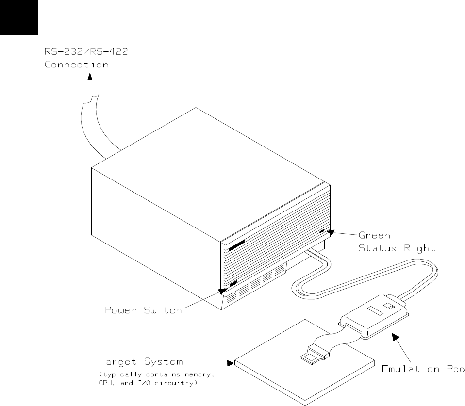
Figure 1-1. HP 64146 Emulator for MELPS 7700 Series
1-2 Introduction

Supported
Microprocessors A list of the supported 7700 Series microprocessors is shown in Table
1-1. You need to purchase appropriate emulation pod and emulation
processor.
Processor Clock Emulation Emulation
Processor Pod
=================================================================
M37700/1 M2-xxxFP/SP | 8 | M37700SAFP | M37700T-HPD
M2AxxxFP/SP | 16 | |
SFP/SP | 8 | |
SAFP/SP | 16 | |
---------------------+---------+----------------|
M37700/1 M4-xxxFP/SP | 8 | M37700S4AFP |
M4AxxxFP/SP | 16 | |
S4FP/SP | 8 | |
S4AFP/SP | 16 | |
---------------------+---------+----------------+----------------
M37702/3 M2-xxxFP/SP | 8 | M37702S1AFP | M37702T-HPD
M2AxxxFP/SP | 16 | |
S1FP/SP | 8 | |
S1AFP/SP | 16 | |
---------------------+---------+----------------+
M37702/3 M4-xxxFP/SP | 8 | M37702S4AFP |
M4AxxxFP/SP | 16 | |
S4FP/SP | 8 | |
S4AFP/SP | 16 | |
---------------------+---------+----------------+----------------
M37702 M6LxxxFP | 8 | M37702S1BFP | M37702TL-HPD
| | | HP 641466-61002
| | | (64146B)
---------------------+---------+----------------+----------------
M37702/3 M2BxxxFP/SP | 25 | M37702S1BFP | M37702TB-HPD
S1BFP/SP | 25 | | HP 64146-61001
---------------------+---------+----------------+ (64146A)
M37702/3 M4BxxxFP/SP | 25 | M37702S4BFP | HP 64146-61002
S4BFP/SP | 25 | | (64146B)
M6BxxxFP | 25 | |
---------------------+---------+----------------+----------------
M37704/5 M2-xxxFP/SP | 8 | M37704S1AFP | M37704T-HPD
M2AxxxFP/SP | 16 | |
S1FP/SP | 8 | |
S1AFP/SP | 16 | |
---------------------+---------+----------------+----------------
M37704 M3BxxxFP | 25 | M37704M4BFP | M37704TB-HPD
M3BxxxFP | 25 | |
---------------------+---------+----------------+----------------
M37710 M4BxxxFP | 25 | M37710M4BFP | M37710TL-HPD
S4BFP | 25 | |
---------------------+---------+----------------+----------------
M37720 S1FP | 8 | M37720S1AFP | M37720T-HPD
S1AFP | 16 | |
---------------------+---------+----------------+----------------
M37730 S2FP/SP | 8 | M37730S2AFP | M37730T-HPD
S2AFP/SP | 16 | |
Table 1-1. Supported Microprocessors
Introduction 1-3

The HP 64146A emulator is provided with the following items.
HP 64146-61001 emulation pod with M37702S1BFP
emulation processor
Adaptor for M37703 processor
The HP 64146B emulator is provided with the following items.
HP 64146-61002 emulation pod with M37702S1BFP
emulation processor
Adaptor for M37703 processor
As you can see from Table 1-1, the HP 64146A/B emulator can
emulate M37702/3M2 and M37702/3S1 processor by default. These
emulation pods can be used with clock up to 25 MHz. Also, HP
64146B emulator can emulate M37702 M6L processor using default
emulation pod, HP 64146-61002.
To emulate other processors of 7700 Series, you need to purchase
appropriate emulation pod and/or emulation processor.
The HP 64146A/B #001 emulator is provided with no emulation pod.
You need to purchase appropriate emulation pod and emulation
processor listed in Table 1-1.
To purchase emulation pod or emulation processor, contact the address
listed in the manual provided with your emulation pod.
---------------------+---------+----------------+----------------
M37732 S4FP/SP | 8 | M37732S4AFP | M37732T-HPD
S4AFP/SP | 16 | |
---------------------+---------+----------------+----------------
M37780 STJ/FP | 16 | M37780STJ | M37780T-HPD
---------------------+---------+----------------+----------------
M37781 M4TxxxJ/FP | 16 | M37781M4TJ | M37781T-HPD
E4TxxxJ/FP | 16 | |
---------------------+---------+----------------+----------------
M37795 SJ | 8 | M37795SJ | M37795T-HPD
STJ | 8 | |
---------------------+---------+----------------+
M37796 E4-xxxJ | 8 | M37796E4J |
E4TxxxJ | 8 | |
=================================================================
Table 1-1. Supported Microprocessors (Cont’d)
1-4 Introduction

The list of supported microprocessors in Table 1-1 is not necessarily
complete. To determine if your microprocessor is supported or not,
contact Hewlett-Packard.
Features of the
7700 Series
Emulator
This section introduces you to the features of the emulator. The
chapters which follow show you how to use these features.
Clock Speed The HP 64146-61001 and HP 64146-61002 emulation pods generate
internal clock of 1 MHz. These emulation pods can be used with target
system clock up to 25 MHz.
The emulator can run with no wait state up to 25 MHz. When clock is
faster than 16 MHz, you can use the emulator with one of the following
methods.
Insert one wait state by the RDY signal. The emulator can be
configured to generate the RDY signal. Also, the emulator
accepts RDY signal from the target system.
Use the high speed access mode of the emulator. The
emulator can run with no wait state. However, there is a
limitation in the mapping of the emulation memory in this
mode. Refer to Chapter 4 of this manual for more detail.
Emulation memory The HP 64146A/B 7700 Series emulator is used with one of the
following Emulation Memory Cards.
HP 64726A 128K byte Emulation Memory Card
HP 64727A 512K byte Emulation Memory Card
HP 64728A 1M byte Emulation Memory Card
HP 64729A 2M byte Emulation Memory Card
The emulation memory can be configured into 256 byte blocks. A
maximum of 16 ranges can be configured as emulation RAM (eram),
emulation ROM(erom), target system RAM (tram), target system ROM
(trom), or guarded memory (grd). The HP 64146A/B 7700 Series
Introduction 1-5

emulator will attempt to break to the emulation monitor upon accessing
guarded memory; additionally, you can configure the emulator to break
to the emulation monitor upon performing a write to ROM (which will
stop a runaway program).
Analysis The HP 64146A/B 7700 Series emulator is used with one of the
following analyzers which allows you to trace code execution and
processor activity.
HP 64704 80-channel Emulation Bus Analyzer
HP 64703 64-channel Emulation Bus Analyzer and
16-channel State/Timing Analyzer
HP 64794A/C/D 80-channel 8K/64K/256K Emulation Bus
Analyzer
The Emulation Bus Analyzer monitors the emulation processor using
an internal analysis bus. The HP 64703 64-channel Emulation Bus
Analyzer and 16-channel State/Timing Analyzer allows you to probe
up to 16 different lines in your target system.
Foreground or
Background
Emulation Monitor
When you power up the emulator, or when you initialize it, the
background monitor is used by default. You can also configure the
emulator to use a foreground monitor. Before the background and
foreground monitors are described, you should understand the function
of the emulation monitor program.
The Function of the Monitor Program
The monitor program is the interface between the emulation system
controller and the target system. The emulation system controller uses
its own microprocessor to accept and execute emulation, system, and
analysis commands. The monitor program is executed by the
emulation processor.
The monitor program makes possible emulation commands which
access target system resources. (The only way to access target system
resource is through the emulation processor.) For example, when you
enter a command to modify target system memory, it is the execution
of monitor program instructions that cause the new values to be written
to target system memory.
1-6 Introduction

The Background Monitor
On emulator power-up, or after initialization, the emulator uses the
background monitor program. The background monitor does not
occupy processor address space.
The Foreground Monitor
You can configure the emulator to use a foreground monitor program.
When a foreground monitor is selected it executes in the foreground
emulator mode. The foreground monitor occupies processor memory
space and executes as if it were part of your program.
Register Display and
Modification You can display or modify the 7700 Series internal register contents.
This includes the ability to modify the program counter (PC) and the
program bank register (PG) values so you can control where the
emulator starts a program run.
Single-Step When you are using the background monitor, you can direct the
emulation processor to execute a single instruction or a specified
number of instructions.
Breakpoints You can set the emulator/analyzer interaction so the emulator will
break to the monitor program when the analyzer finds a specific state
or states, allowing you to perform post-mortem analysis of the program
execution. You can also set software breakpoints in your program.
This feature is realized by inserting BRK instructions into user
program. Refer to the "Using Software Breakpoints" section of
"Getting Started" chapter for more information.
Real Time Operation Real-time signifies continuous execution of your program at full rated
processor speed without interference from the emulator. (Such
interference occurs when the emulator needs to break to the monitor to
perform an action you requested, such as displaying target system
memory.) Emulator features performed in real time include: running
and analyzer tracing. Emulator features not performed in real time
include: display or modify of target system memory; load/dump of
target memory, display or modification of registers, and single step.
Introduction 1-7

Coverage
Measurements Coverage memory is provided for the processor’s external program
memory space. This memory allows you to perform coverage
measurements on programs in emulation memory.
Reset Support The emulator can be reset from the emulation system under your
control; or your target system can reset the emulation processor.
Watch Dog Timer You can configure the emulator to disable the watch dog timer.
1-8 Introduction

Limitations,
Restrictions
Access to Internal
RAM Modifying internal RAM or SFR suspends user program execution.
Trace Internal RAM Read data from the internal RAM or SFR is not traced correctly by the
emulation analyzer.
Note Write data is also not traced correctly, when the following conditions
are met: The emulator is used with the M37795 emulation pod.
The processor is operating in the memory expansion or
microprocessor mode with 8 bit external bus.
DMA Support Direct memory access to emulation memory is not allowed.
Watch Dog Timer in
Background Watch dog timer suspends count down while the emulator is running in
background monitor.
Step Command with
Foreground Monitor Step command is not available when the emulator is used with a
foreground monitor.
Step Command and
Interrupts When an interrupt occurs while the emulator is running in monitor, the
emulator fails to do the first step operation. The emulator will display
the mnemonic of the instruction which should be stepped, but the
instruction is not actually executed. The second step operation will
step the first instruction of the interrupt routine.
Introduction 1-9

Emulation
Commands in
Stop/Wait Mode
When the 7700 microprocessor is in the stop or wait mode, emulation
commands which access memory or registers will fail. You need to
break the emulator into the monitor to use these commands. Once you
break the emulator into the monitor, the stop or wait mode will be
released.
Stack Address In some versions of 7700 microprocessor, the stack can be located in
Bank FF. However, the HP 64146A/B 7700 Series emulator doesn’t
support the feature. The stack must be located in Bank 0.
1-10 Introduction

2
Getting Started
Introduction This chapter will lead you through a basic, step by step tutorial
designed to familiarize you with the use of the HP 64146A/B 7700
Series emulator with the Softkey Interface.
This chapter will:
Tell you what must be done before you can use the emulator
as shown in the tutorial examples.
Describe the sample program used for this chapter’s example.
This chapter will show you how to:
Start up the Softkey Interface.
Load programs into emulation and target system memory.
Enter emulation commands to view execution of the sample
program.
Getting Started 2-1

Before You Begin
Prerequisites Before beginning the tutorial presented in this chapter, you must have
completed the following tasks:
1. Connected the emulator to your computer. The HP 64700
Series Installation/Service manual shows you how to do this.
2. Installed the Softkey Interface software on your computer.
Refer to the HP 64700 Series Installation/Service manual for
instructions on installing software.
3. In addition, you should read and understand the concepts of
emulation presented in the Concepts of Emulation and
Analysis manual. The Installation/Service manual also covers
HP 64700 system architecture. A brief understanding of these
concepts may help avoid questions later.
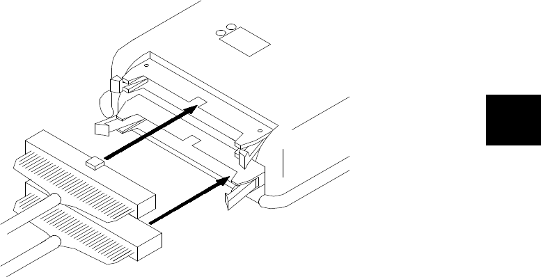
4. Connected the emulator to the emulation probe as shown in
Figure 2-1.
Caution Turn off power of the emulator before inserting the cables to the
emulation pod to avoid circuit damage.
2-2 Getting Started
A Look at the Sample
Program The sample program used in this chapter is listed in Figure 2-2. The
program emulates a primitive command interpreter. The sample
program is shipped with the Softkey Interface and may be copied from
the following location.
/usr/hp64000/demo/emul/hp64146/cmd_rds.a77
Data Declarations
The "TABLE" section defines the messages used by the program to
respond to various command inputs. These messages are labeled
Msg_A,Msg_B, and Msg_I.
Initialization
The program instruction at the Init label initializes the stack pointer.
Figure 2-1. Connecting the Emulation Pod
Getting Started 2-3

.DP 0
.DT 0
.PUB Init
.PUB Msgs
.PUB Cmd_Input
.PUB Msg_Dest
.SECTION BUFFER
;**********************************************************
; Command input byte.
;**********************************************************
Cmd_Input: .BLKB 1
;**********************************************************
; Destination of the command messages.
;**********************************************************
Msg_Dest: .BLKB 20H
.BLKB 100H
Stack:
.SECTION TABLE
Msgs:
Msg_A: .BYTE ’THIS IS MESSAGE A’
Msg_B: .BYTE ’THIS IS MESSAGE B’
Msg_I: .BYTE ’INVALID COMMAND’
.SECTION SAMPPROG
.DATA 8
.INDEX 16
;**********************************************************
; Set up the Stack Pointer.
;**********************************************************
Init: LDX #Stack
TXS
SEM
;**********************************************************
; Clear Previous command.
;**********************************************************
Clear_Input: LDA B,#00H
STA B,DT:Cmd_Input
;**********************************************************
; Read command input byte. If no command has been entered,
; continue to scan for it.
;**********************************************************
Scan: LDA A,DT:Cmd_Input
CMP A,#00H
BEQ Scan
.INDEX 8
;**********************************************************
; A command has been entered. The destination area is
; cleared.
;**********************************************************
SEP X
Clear_Output: LDX #00H
LDY #20H
Clear_Loop: STA B,DT:Msg_Dest,X
INX
DEY
BNE Clear_Loop
Figure 2-2. Sample Program Listing
2-4 Getting Started

Reading Input
The instruction at the Clear_Input label clears any random data or
previous commands from the Cmd_Input byte. The Scan loop
continually reads the Cmd_Input byte to see if a command is entered
(a value other than 0 hex).
.INDEX 16
;**********************************************************
; Check if the command entered is command A, command B,
; or invalid command.
;**********************************************************
CLP X
Process_Cmd: CMP A,#41H
BEQ Cmd_A
CMP A,#42H
BEQ Cmd_B
BRA Cmd_I
;**********************************************************
; Command A is entered. A = the number of bytes in
; message A. X = location of the message. Jump to the
; routine which writes the message.
;**********************************************************
Cmd_A: LDA A,#11H
LDX #Msg_A
BRA Output
;**********************************************************
; Command B is entered.
;**********************************************************
Cmd_B: LDA A,#11H
LDX #Msg_B
BRA Output
;**********************************************************
; An invalid command is entered.
;**********************************************************
Cmd_I: LDA A,#0FH
LDX #Msg_I
;**********************************************************
; Message is written to the destination. Y = location of
; the destination area.
;**********************************************************
Output: LDY #Msg_Dest
MVN 0,0
;**********************************************************
; Go back and scan for next command.
;**********************************************************
BRA Clear_Input
.END
Figure 2-2. Sample Program Listing (Cont’d)
Getting Started 2-5

Processing Commands
When a command is entered, the Clear_Output routine clears the
destination area. Then, the instructions from Process_Cmd to Cmd_A
determine whether the command was "A", "B", or an invalid command.
If the command input byte is "A" (ASCII 41 hex), execution is
transferred to the instructions at Cmd_A.
If the command input byte is "B" (ASCII 42 hex), execution is
transferred to the instructions at Cmd_B.
If the command input byte is neither "A" nor "B", an invalid command
has been entered, and execution is transferred to the instructions at
Cmd_I.
The instructions at Cmd_A, Cmd_B, and Cmd_I each load
accumulator A with the length of the message to be displayed and
index register X with the starting location of the appropriate message.
Then, execution transfers to Output which writes the appropriate
message to the destination location, Msg_Dest.
After the message is written, the program branches back to read the
next command.
The Destination Area
The "BUFFER" section declares memory storage for the command
input byte, the destination area, and the stack area.
2-6 Getting Started

Sample Program
Assembly The sample program is written for and assembled/linked with
Mitsubishi RASM77 Assembler and LINK77 Linkage Editor.
The sample program was assembled with the following command.
$ rasm77 -s cmd_rds.a77
Linking the Sample
Program The sample program can be linked with the following command and
generates the absolute file. The contents of "cmd_rds.lnk" linkage
editor subcommand file is shown in Figure 2-3.
$ link77 @\cmd_rds.lnk
Generate HP
Absolute file To generate HP Absolute file for the Sofktey Interface, you need to use
"m77cnvhp" absolute file format converter program. The m77cnvhp
converter is provided with the Softkey Interface. To generate HP
Absolute file, enter following command:
$ m77cnvhp cmd_rds <RETURN>
You will see that cmd_rds.X, cmd_rds.L, and cmd_rds.A are
generated. These are sufficient throughout this chapter.
Note You must specify -s option when you assemble and link your program.
If this option isn’t speicified, symbol file (.sym file) won’t be
generated, and the format converter cannot convert your program.
cmd_rds
,
,SAMPPROG=C000 TABLE=C100 BUFFER=100
,-s -ms
Figure 2-3. Linkage Editor Command File
Getting Started 2-7

Entering the
Softkey Interface
If you have installed your emulator and Softkey Interface software as
directed in the HP 64700 Series Emulators Softkey Interface
Installation Notice, you are ready to enter the interface. The Softkey
Interface can be entered through the pmon User Interface Software or
from the HP-UX shell.
From the "pmon"
User Interface If /usr/hp64000/bin is specified in your PATH environment variable,
you can enter the pmon User Interface with the following command.
$ pmon <RETURN>
If you have not already created a measurement system for the 7700
Series emulator, you can do so with the following commands. First
you must initialize the measurement system with the following
command.
MEAS_SYS msinit <RETURN>
After the measurement system has been initialized, enter the
configuration interface with the following command.
msconfig <RETURN> To define a measurement system for the 7700 Series emulator, enter:
make_sys emm77 <RETURN> Now, to add the emulator to the measurement system, enter:
add <module_number>
naming_it
m77 <RETURN> Enter the following command to exit the measurement system
configuration interface.
end <RETURN>
If the measurement system and emulation module are named "emm77"
and "m77" as shown above, you can enter the emulation system with
the following command:
emm77 default m77 <RETURN>
If this command is successful, you will see a display similar to Figure
2-4. The status message shows that the default configuration file has
been loaded. If the command is not successful, you will be given an
error message and returned to the pmon User Interface. Error
messages are described in the Softkey Interface Reference manual.
2-8 Getting Started

For more information on creating measurements systems, refer to the
Softkey Interface Reference manual.
From the HP-UX Shell If /usr/hp64000/bin is specified in your PATH environment variable,
you can also enter the Softkey Interface with the following command.
$ emul700 <emul_name> <RETURN>
The "emul_name" in the command above is the logical emulator name
given in the HP 64700 emulator device table
(/usr/hp64000/etc/64700tab).
If this command is successful, you will see a display similar to Figure
2-4. The status message shows that the default configuration file has
been loaded. If the command is not successful, you will be given an
error message and returned to the HP-UX prompt. Error messages are
described in the Softkey Interface Reference manual.
HPB64146-19003 A.04.00 20Aug92
M37700 EMULATION SERIES 64700
A Hewlett-Packard Software Product
Copyright Hewlett-Packard Co. 1992
All Rights Reserved. Reproduction, adaptation, or translationwithout prior
written permission is prohibited, except as allowed undercopyright laws.
RESTRICTED RIGHTS LEGEND
Use , duplication , or disclosure by the Government is subject to
restrictions as set forth in subparagraph (c) (1) (II) ofthe Rights
in Technical Data and Computer Software clause at DFARS52.227-7013.
HEWLETT-PACKARD Company , 3000 Hanover St. , Palo Alto, CA94304-1181
STATUS: Loaded configuration file____________________________________...R....
run trace step display modify break end ---ETC--
Figure 2-4. Softkey Interface Display
Getting Started 2-9

On-Line Help There are two ways to access on-line help in the Softkey Interface. The
first is by using the Softkey Interface help facility. The second method
allows you to access the firmware resident Terminal Interface on-line
help information.
Softkey Driven Help To access the Softkey Interface on-line help information, type either
"help" or "?" on the command line; you will notice a new set of
softkeys. By pressing one of these softkeys and <RETURN>, you can
cause information on that topic to be displayed on your screen. For
example, you can enter the following command to access "system
command" help information.
?
system_commands
<RETURN>
The help information is scrolled on to the screen. If there is more than
a screenful of information, you will have to press the space bar to see
the next screenful, or the <RETURN> key to see the next line, just as
you do with the HP-UX more command. After all the information on
the particular topic has been displayed (or after you press "q" to quit
scrolling through information), you are prompted to press <RETURN>
to return to the Softkey Interface.
---SYSTEM COMMANDS & COMMAND FILES---
? displays the possible help files
help displays the possible help files
! fork a shell (specified by shell variable SH)
!<shell cmd> fork a shell and execute a shell command
cd <directory> change the working directory
pwd print the working directory
cws <SYMB> change the working symbol - the working symbol also
gets updated when displaying local symbols and
displaying memory mnemonic
pws print the working symbol
<FILE> p1 p2 p3 ... execute a command file passing parameters p1, p2, p3
see "COMMAND FILES EXAMPES" below for more detail
log_commands to <FILE> logs the next sequence of commands to file <FILE>
log_commands off discontinue logging commands
name_of_module get the "logical" name of this module (see 64700tab.net)
--More--(20%)
2-10 Getting Started

Pod Command Help To access the emulator’s firmware resident Terminal Interface help
information, you can use the following commands.
display pod_command <RETURN>
pod_command ’help m’ <RETURN>
The command enclosed in string delimiters (", ’, or ^) is any Terminal
Interface command, and the output of that command is seen in the
pod_command display. The Terminal Interface help (or ?) command
may be used to provide information on any Terminal Interface
command or any of the emulator configuration options (as the example
command above shows).
Pod Commands
Time Command
10:00:00 help m
m - display or modify processor memory space
m <addr> - display memory at address
m -d<dtype> <addr> - display memory at address with display option
m <addr>..<addr> - display memory in specified address range
m -dm <addr>..<addr> - display memory mnemonics in specified range
m <addr>.. - display 128 byte block starting at address A
m <addr>=<value> - modify memory at address to <value>
m -d<dtype> <addr>=<value> - modify memory with display option
m <addr>=<value>,<value> - modify memory to data sequence
m <addr>..<addr>=<value>,<value> - fill range with repeating sequence
--- VALID <dtype> MODE OPTIONS ---
b - display size is 1 byte(s)
w - display size is 2 byte(s)
m - display processor mnemonics
STATUS: M37700--Running in monitor____________________________________........
run trace step display modify break end ---ETC--
Getting Started 2-11

Configuring the
Emulator
You need to configure the emulator for this tutorial. To configure the
emulator, type the following command to get into the configuration
session.
modify configuration <RETURN>
Trace the following answer to configure the emulator. Details of each
question will be described later.
Micro-processor clock source? internal
Enter monitor after configuration? yes
Restrict to real-time runs? no
Reconfigure emulator? yes
Micro-processor group? <chip group>
Micro-processor type? <chip type>
Select the chip group and chip type you are going to emulate.
Appropriate chip group and chip type are listed in Table 2-1.
Note If your processor is not listed in Table 2-1, refer to chapter 4 of this
manual for information on configuring the emulator.
Processor node? single
Modify reset value for Stack Pointer? no
Modify memory configuration?
When you are going to emulate a processor which have no internal
RAM, answer "yes" to this question, and map 100 hex through FFF hex
as emulation RAM. Refer to chapter 4 of this manual for information
on memory mapping.
When you are going to emulate a processor which have internal RAM,
answer "no" to this question.
Modify emulator pod configuration? no
Modify debug/trace options? no options? no
Modify simulated I/O configuration? no
Modify interactive measurement specification? no
Configuration file name? cmd_rds
2-12 Getting Started

<chip_name> Processor || <chip_name> Processor
======================================||======================================
7700M2 | M37700M2-xxxFP || 7704M2 | M37704M2-xxxFP
| M2AxxxFP || | M2AxxxFP
| M37701M2-xxxSP || | M37705M2-xxxSP
| M2AxxxSP || | M2AxxxSP
------------------+-------------------||-------------------+------------------
7700M4 | M37700M4-xxxFP || 7704M3 | M37704M3BxxxFP
| M4AxxxFP ||-------------------+--------------------
| M37701M4-xxxSP || 7704M4 | M37704M4BxxxFP
| M4AxxxSP ||-------------------+--------------------
------------------+-------------------|| 7704S1 | M37704S1FP
7700S | M37700SFP || | S1AFP
| SAFP || | M37705S1SP
| M37701SSP || | S1ASP
| SASP ||-------------------+--------------------
------------------+-------------------|| 7710M4 | M37710M4BxxxFP
7700S4 | M37700S4FP ||-------------------+--------------------
| S4AFP || 7710S4 | M37710S4BFP
| M37701S4SP ||-------------------+--------------------
| S4ASP || 7720S1 | M37720S1FP
------------------+-------------------|| | S1AFP
7702M2 | M37702M2-xxxFP ||-------------------+--------------------
| M2AxxxFP || 7730S2 | M37730S2FP
| M2BxxxFP || | S2AFP
| M37703M2-xxxSP || | S2SP
| M2AxxxSP || | S2ASP
| M2BxxxSP ||-------------------+--------------------
------------------+-------------------|| 7732S4 | M37732S4FP
7702M4 | M37702M4-xxxFP || | S4AFP
| M4AxxxFP ||-------------------+--------------------
| M4BxxxFP || 7780S | M37780STJ
| M37703M4-xxxSP || | STFP
| M4AxxxSP ||-------------------+--------------------
| M4BxxxSP || 7781M4 | M37781M4TxxxJ
------------------+-------------------|| | M4TxxxFP
7702M6 | M37702M6BxxxFP ||-------------------+--------------------
| M6LxxxFP || 7781E4 | M37781E4TxxxJ
------------------+-------------------|| | E4TxxxFP
7702S1 | M37702S1FP ||-------------------+--------------------
| S1AFP || 7795S | M37795SJ
| S1BFP || | STJ
| M37703S1SP ||-------------------+--------------------
| S1ASP || 7796E4 | M37796E4-xxxJ
| S1BSP || | E4TxxxJ
------------------+-------------------|| | E4TxxxFP
7702S4 | M37702S4FP ||-------------------+--------------------
| S4AFP ||
| S4BFP ||
| M37703S4SP ||
| S4ASP ||
| S4BSP ||
Table 2-1. Chip Group and Chip Type for Configuration
Getting Started 2-13

Loading Absolute
Files
The "load" command allows you to load absolute files into emulation
or target system memory. If you wish to load only that portion of the
absolute file that resides in memory mapped as emulation RAM or
ROM, use the "load emul_mem" syntax. If you wish to load only the
portion of the absolute file that resides in memory mapped as target
RAM, use the "load user_mem" syntax. If you want both emulation
and target memory to be loaded, do not specify "emul_mem" or
"user_mem". For example:
load cmd_rds <RETURN>
Displaying
Symbols
When you load an absolute file into memory (unless you use the
"nosymbols" option), symbol information is loaded. Both global
symbols and symbols that are local to a source file can be displayed.
Global To display global symbols, enter the following command.
display global_symbols <RETURN> Listed are: address ranges associated with a symbol.
Global symbols in cmd_rds
Static symbols
Symbol name ____________________ Address range __ Segment _____________ Offset
Cmd_Input 000100 0000
Init 00C000 0000
Msg_Dest 000101 0001
Msgs 00C100 0000
Filename symbols
Filename __________________________________________________________________
cmd_rds.a77
STATUS: M37700--Running in monitor____________________________________...R....
display global_symbols
run trace step display modify break end ---ETC--
2-14 Getting Started

Local When displaying local symbols, you must include the name of the
source file in which the symbols are defined. For example,
display local_symbols_in cmd_rds.a77:
<RETURN>
Symbols in cmd_rds.a77:
Static symbols
Symbol name ____________________ Address range __ Segment _____________ Offset
Cear_Input 00C005 0005
Clear_Loop 00C019 0019
Clear_Output 00C015 0015
Cmd_A 00C02D 002D
Cmd_B 00C034 0034
Cmd_I 00C03B 003B
Cmd_Input 000100 0000
Init 00C000 0000
Msg_A 00C100 0000
Msg_B 00C111 0011
Msg_Dest 000101 0001
Msg_I 00C122 0022
Msgs 00C100 0000
Output 00C040 0040
Process_Cmd 00C023 0023
STATUS: M37700--Running in monitor____________________________________...R....
display local_symbols_in cmd_rds.a77:
run trace step display modify break end ---ETC--
Getting Started 2-15

Displaying
Memory in
Mnemonic Format
You can display, in mnemonic format, the absolute code in memory.
To display memory in mnemonic format from the address of label Init,
enter the following command:
display memory Init
mnemonic options m0x0
<RETURN>
You need to specify the values of M flag and X flag at the staring
address of mnemonic memory display. When the inverse-assembler
encounters an instruction which changes M flag and/or X flag (SEM,
CLM, SEP X, etc..), the value set by the instruction is used to continue
disassembling memory contents.
Note When you use <PGUP> or <PREV> key to see the previous lines of
memory display, disassembled mnemonic may not be accurate.
Memory :mnemonic :file = cmd_rds.a77:
address data
00C000 A22102 LDX #0221H
00C003 9A TXS
00C004 F8 SEM
00C005 42A900 LDA B,#00H
00C008 428D0001 STA B,0100H
00C00C AD0001 LDA A,0100H
00C00F C900 CMP A,#00H
00C011 F0F9 BEQ 00C00CH
00C013 E210 SEP #10H
00C015 A200 LDX #00H
00C017 A020 LDY #20H
00C019 429D0101 STA B,0101H,X
00C01D E8 INX
00C01E 88 DEY
00C01F D0F8 BNE 00C019H
00C021 C210 CLP #10H
STATUS: M37700--Running in monitor____________________________________...R....
display memory Init mnemonic options m0x0
run trace step display modify break end ---ETC--
2-16 Getting Started

Displaying
Memory with
Symbols
You can include symbol information in memory display.
set symbols on <RETURN>
Note The "set" command is effective only to the window in which the
command is invoked. You need to use this command at each window.
Memory :mnemonic :file = cmd_rds.a77:
address label data
00C000 :Init A22102 LDX #0221H
00C003 9A TXS
00C004 F8 SEM
00C005 :Clear_Input 42A900 LDA B,#00H
00C008 428D0001 STA B,DT:0100H
00C00C cmd_rds:Scan AD0001 LDA A,DT:0100H
00C00F C900 CMP A,#00H
00C011 F0F9 BEQ cmd_rds.a77:Scan
00C013 E210 SEP #10H
00C015 Clear_Output A200 LDX #00H
00C017 A020 LDY #20H
00C019 c:Clear_Loop 429D0101 STA B,DT:0101H,X
00C01D E8 INX
00C01E 88 DEY
00C01F D0F8 BNE cmd_r:Clear_Loop
00C021 C210 CLP #10H
STATUS: M37700--Running in monitor____________________________________...R....
set symbols on
run trace step display modify break end ---ETC--
Getting Started 2-17

Running the
Program
The "run" command lets you execute a program in memory. Entering
the "run" command by itself causes the emulator to begin executing at
the current program counter address. The "run from" command allows
you to specify an address at which execution is to start. For example to
run the sample program from the address of Init label,
run from Init <RETURN>
Note The run from transfer_address command is not available in the 7700
Series Softkey Interface.
Displaying
Memory in
Blocked Format
You can display memory locations in blocked format. For example, to
display the Msg_Dest locations of the sample program in blocked byte
format, enter the following command.
display memory Msg_Dest
repetitively
blocked
bytes
<RETURN>
2-18 Getting Started

Modifying Memory The sample program simulates a primitive command interpreter.
Commands are sent to the sample program through a byte sized
memory location labeled Cmd_Input. You can use the modify
memory feature to send a command to the sample program. For
example, to enter the command "A" (41 hex), use the following
command.
modify memory Cmd_Input
bytes to
41h <RETURN>
Or:
modify memory Cmd_Input
string to
’A’
<RETURN>
(Single character strings are allowed in expressions.)
As you can see, the memory display is automatically updated, and
shows that the "THIS IS MESSAGE A" message is written to the
destination locations.
Memory :bytes :blocked :update
address data :hex :ascii
000101-08 54 48 49 53 20 49 53 20 T H I S I S
000109-10 4D 45 53 53 41 47 45 20 M E S S A G E
000111-18 41 00 00 00 00 00 00 00 A . . . . . . .
000119-20 00 00 00 00 00 00 00 00 . . . . . . . .
000121-28 00 00 00 00 00 00 00 00 . . . . . . . .
000129-30 00 00 00 00 00 00 00 00 . . . . . . . .
000131-38 00 00 00 00 00 00 00 00 . . . . . . . .
000139-40 00 00 00 00 00 00 00 00 . . . . . . . .
000141-48 00 00 00 00 00 00 00 00 . . . . . . . .
000149-50 00 00 00 00 00 00 00 00 . . . . . . . .
000151-58 00 00 00 00 00 00 00 00 . . . . . . . .
000159-60 00 00 00 00 00 00 00 00 . . . . . . . .
000161-68 00 00 00 00 00 00 00 00 . . . . . . . .
000169-70 00 00 00 00 00 00 00 00 . . . . . . . .
000171-78 00 00 00 00 00 00 00 00 . . . . . . . .
000179-80 00 00 00 00 00 00 00 00 . . . . . . . .
STATUS: M37700--Running user program__________________________________...R....
display memory Cmd_Input bytes to 41h
run trace step display modify break end ---ETC--
Getting Started 2-19

Note Modifying/displaying internal RAM or SFR suspends user program
execution. This is because the emulator uses internal RAM and SFR of
emulation processor to perform emulation. However, you can
configure the emulator so that write cycles are performed to both
internal RAM (or SFR) and emulation memory. If you do this, you can
display the data written to emulation memory without suspending user
program execution. Refer to chapter 4 and chapter 5 of this manual for
more details.
Breaking into the
Monitor
The "break" command allows you to divert emulator execution from
the user program to the monitor. You can continue user program
execution with the "run" command. To break emulator execution from
the sample program to the monitor, enter the following command.
break <RETURN>
Using Software
Breakpoints
Software breakpoints are provided with an 7700 Series BRK
instruction. When you define or enable a software breakpoint, the
emulator will replace the opcode at the software breakpoint address
with a BRK instruction.
Note You must set software breakpoints only at memory locations which
contain instruction opcodes (not operands or data). If a software
breakpoint is set at a memory location which is not an instruction
opcode, the software breakpoint instruction will never be executed and
the break will never occur.
2-20 Getting Started

Note Because software breakpoints are implemented by replacing opcodes
with BRK instructions, you cannot define software breakpoints in
target ROM.
Note Software breakpoints should not be set, cleared, enabled, or disabled
while the emulator is running user code. If any of these commands are
entered while the emulator is running user code, and the emulator is
executing code in the area where the breakpoint is being modified,
program execution may be unreliable.
When software breakpoints are enabled and emulator detects a fetching
the BRK instruction, it generates a break to background request which
as with the "processor break" command. Since the system controller
knows the locations of defined software breakpoints, it can determine
whether the BRK instruction is software breakpoints or opcode in your
target program.
If it is a software breakpoint, execution breaks to the monitor,and the
BRK instruction is replaced by the original opcode. A subsequent run
or step command will execute from this address.
If the BRK instruction is opcode of your target program, execution still
breaks to the monitor, and an "Undefined software breakpoint" status
message is displayed.
When software breakpoints are disabled, the emulator replaces the
special code with the original opcode.
Up to 32 software breakpoints may be defined.
Getting Started 2-21

Enabling/Disabling
Software Breakpoints When you initially enter the Softkey Interface, software breakpoints
are disabled. To enable the software breakpoints feature, enter the
following command.
modify software_breakpoints enable <RETURN>
When software breakpoints are enabled and you set a software
breakpoint, the 7700 BRK instruction will be placed at the address
specified. When the BRK instruction is executed, program execution
will break into the monitor.
Setting a Software
Breakpoint To set a software breakpoint at the address of the Cmd_I label, enter
the following command.
modify software_breakpoints set
cmd_rds.a77:Clear_Output <RETURN>
Notice that when using local symbols in expressions, the source file in
which the local symbol is defined must be included.
After the software breakpoint has been set, enter the following
commands to display memory and see if the software breakpoint was
correctly inserted.
display memory Init
mnemonic options m0x0
<RETURN>
Memory :mnemonic :file = cmd_rds.a77:
address label data
00C000 :Init A22102 LDX #0221H
00C003 9A TXS
00C004 F8 SEM
00C005 :Clear_Input 42A900 LDA B,#00H
00C008 428D0001 STA B,0100H
00C00C cmd_rds:Scan AD0001 LDA A,0100H
00C00F C900 CMP A,#00H
00C011 F0F9 BEQ cmd_rds.a77:Scan
00C013 E210 SEP #10H
* 00C015 Clear_Output 0000 BRK
00C017 A020 LDY #20H
00C019 c:Clear_Loop 429D0101 STA B,0101H,X
00C01D E8 INX
00C01E 88 DEY
00C01F D0F8 BNE cmd_r:Clear_Loop
00C021 C210 CLP #10H
STATUS: M37700--Running in monitor____________________________________...R....
display memory Init mnemonic options m0x0
run trace step display modify break end ---ETC--
2-22 Getting Started

As you can see, the software breakpoint is shown in the memory
display with an asterisk, and the instruction at the address is replaced
with a BRK instruction.
Note When a software breakpoint is inserted, the mnemonic in memory
display may not be accurate.
Enter the following command to run the sample program again.
run
from
Init <RETURN>
Now, modify the command input byte to an invalid command for the
sample program.
modify memory Cmd_Input
bytes to
75h <RETURN>
You will see the address field of a line is inversed. The inversed
address field shows that the Program Counter is now at the address.
A message on the status line shows that the software breakpoint has
been hit. The status line also shows that the emulator is now executing
in the monitor.
When software breakpoints are hit, they become inactivated. To
reactive the breakpoint so that is "pending", you must reenter the
"modify software_breakpoints set" command.
Clearing a Software
Breakpoint To remove software breakpoint defined above, enter the following
command.
modify software_breakpoints clear
cmd_rds.a77:Clear_Output <RETURN>
The breakpoint is removed from the list, and the original opcode is
restored if the breakpoint was pending.
To clear all software breakpoints, you can enter the following
command.
modify software_breakpoints clear <RETURN>
Getting Started 2-23

Stepping Through
the Program
The step command allows you to step through program execution an
instruction or a number of instructions at a time. Also, you can step
from the current program counter or from a specific address. To step
through the example program from the address of the software
breakpoint set earlier, enter the following command.
step <RETURN>, <RETURN>, <RETURN>, ...
You will see the inverse-video moves according to the step execution.
You can continue to step through the program just by pressing the
<RETURN> key; when a command appears on the command line, it
may be entered by pressing <RETURN>.
Note When the emulator performs step execution, all memory access is
performed by byte access.
Displaying
Registers
Enter the following command to display registers. You can display the
basic registers class, or an individual register.
display registers <RETURN>
2-24 Getting Started

Following list shows the register names and class that may be used
with the "display registers" commands.
Register Name Description
PC
PG
DT
SP
PS
A
B
X
Y
DPR
Program Counter
Program Bank Register
Data Bank Register
Stack Pointer
Processor Status Register
Accumulator A
Accumulator B
Index Register X
Index Register Y
Direct Page Register
When you enter the "step" command with registers displayed, the
register display is updated every time you enter the "step" command.
step <RETURN>, <RETURN>, <RETURN>
Registers
Next_PC 00C01D
PC C01D PG 00 DT 00 SP 0221 PS 0031 <..mx...c>
A 0075 B 0000 X 0200 Y 0120 DPR 0000
STATUS: M37700--Stepping complete_____________________________________........
display registers
run trace step display modify break end ---ETC--
Getting Started 2-25

Enter the following command to cause sample program execution to
continue from the current program counter.
run <RETURN>
Using the Analyzer HP 64700 emulators contain an emulation analyzer. The emulation
analyzer monitors the internal emulation lines (address, data, and
status). Optionally, you may have an additional 16 trace signals which
monitor external input lines. The analyzer collects data at each pulse
of a clock signal, and saves the data (a trace state) if it meets a "storage
qualification" condition.
Specifying a Simple
Trigger Suppose you want to trace program execution after the point at which
the sample program execute the Cmd_A routine. To do this The
following command makes this trace specification.
trace after cmd_rds.a77:Cmd_A status
exec<RETURN>
Registers
Next_PC 00C01D
PC C01D PG 00 DT 00 SP 0221 PS 0031 <..mx...c>
A 0075 B 0000 X 0200 Y 0120 DPR 0000
Step_PC 00C01D INX
Next_PC 00C01E
PC C01E PG 00 DT 00 SP 0221 PS 0031 <..mx...c>
A 0075 B 0000 X 0201 Y 0120 DPR 0000
Step_PC 00C01E DEY
Next_PC 00C01F
PC C01F PG 00 DT 00 SP 0221 PS 0031 <..mx...c>
A 0075 B 0000 X 0201 Y 011F DPR 0000
STATUS: M37700--Stepping complete_____________________________________........
step
run trace step display modify break end ---ETC--
2-26 Getting Started

The message "Emulation trace started" will appear on the status line.
Now, modify the command input byte to "A" with the following
command.
modify memory Cmd_Input
bytes to
41h <RETURN>
The status line now shows "Emulation trace complete".
Displaying the Trace The trace listings which follow are of program execution on the 7700
Series emulator. To display the trace, enter:
display trace <RETURN>
Line 0 (labeled "after") in the trace list above shows the state which
triggered the analyzer. The trigger state is always on line 0. To list the
next lines of the trace, press the <PGDN> or <NEXT> key.
Trace List Offset=0
Label: Address Data Opcode or Status time count
Base: symbols hex mnemonic w/symbols relative
after cmd_rds.a7:Cmd_A A9FF INSTRUCTION--opcode unavailable ------------
+001 :cmd_rds:+00002E A211 A211H opcode fetch mx 6.00 uS
+002 :cmd_rds:+00002F A211 LDX #C100H 2.0 uS
+003 :cmd_rds:+000030 C100 C100H opcode fetch 6.00 uS
+004 :cmd_rds:+000032 0C80 0C80H opcode fetch 8.00 uS
+005 :cmd_rds:+000032 0C80 BRA cmd_rds.a:Output 2.0 uS
+006 cmd_rds.a7:Cmd_B 11A9 11A9H opcode fetch 6.00 uS
+007 cmd_rds.a:Output 01A0 01A0H opcode fetch 8.00 uS
+008 cmd_rds.a:Output 01A0 LDY #0101H 2.0 uS
+009 :cmd_rds:+000042 5401 5401H opcode fetch 6.00 uS
+010 :cmd_rds:+000043 5401 MVN 00H,00H 2.0 uS
+011 :cmd_rds:+000044 0000 0000H opcode fetch mx 6.00 uS
+012 :cmd_rds:+000046 BD80 BD80H opcode fetch mx 8.00 uS
+013 :Msgs 4854 4854H data read mx 10.0 uS
+014 :Msg_Dest 5454 54xxH data write mx 8.00 uS
STATUS: M37700--Running user program Emulation trace complete______...R....
display trace
run trace step display modify break end ---ETC--
Getting Started 2-27

The resulting display shows MVN instruction moves the "THIS IS
MESSAGE A" message to the destination locations.
To list the previous lines of the trace, press the <PGUP> or <PREV>
key.
Displaying Trace with
Time Count Absolute Enter the following command to display count information relative to
the trigger state.
display trace count absolute <RETURN>
Trace List Offset=0
Label: Address Data Opcode or Status time count
Base: symbols hex mnemonic w/symbols relative
+015 :cmd_rds:+000002 5448 xx48H data write mx 4.00 uS
+016 :cmd_rds:+000002 5349 5349H data read mx 8.00 uS
+017 :cmd_rds:+000003 4949 49xxH data write mx 8.00 uS
+018 :cmd_rds:+000004 4953 xx53H data write mx 4.00 uS
+019 :cmd_rds:+000004 4920 4920H data read mx 8.00 uS
+020 :cmd_rds:+000005 2020 20xxH data write mx 8.00 uS
+021 :cmd_rds:+000006 2049 xx49H data write mx 4.00 uS
+022 :cmd_rds:+000006 2053 2053H data read mx 8.00 uS
+023 :cmd_rds:+000007 5353 53xxH data write mx 8.00 uS
+024 :cmd_rds:+000008 5320 xx20H data write mx 4.00 uS
+025 :cmd_rds:+000008 454D 454DH data read mx 8.00 uS
+026 :cmd_rds:+000009 4D4D 4DxxH data write mx 8.00 uS
+027 :cmd_rds:+00000A 4D45 xx45H data write mx 4.00 uS
+028 :cmd_rds:+00000A 5353 5353H data read mx 8.00 uS
+029 :cmd_rds:+00000B 5353 53xxH data write mx 8.00 uS
STATUS: M37700--Running user program Emulation trace complete______........
display trace
run trace step display modify break end ---ETC--
2-28 Getting Started

Changing the Trace
Depth The default states displayed in the trace list is 256 states. To change
the number of states, use the "display trace depth" command.
display trace depth 512 <RETURN>
You can see the states more than 256 states by using the above
command.
Using the Storage
Qualifier You can use storage qualifier to trace only states with specific
conditions. Suppose that you would like to trace only states which
write the messages to the Msg_Dest area. To accomplish this, you can
use the "trace only" command like following.
trace after
Msg_Dest status write only range
Msg_Dest
thru
+20h
status
write
<RETURN>
Only accesses to address Msg_Dest through Msg_Dest+20h will be
stored in the trace buffer.
Modify the command input byte with the following command, and
display trace display with time count relative.
modify memory Cmd_Input
bytes to 41h
<RETURN>
display trace count relative <RETURN>
Trace List Offset=0
Label: Address Data Opcode or Status time count
Base: symbols hex mnemonic w/symbols absolute
+015 :cmd_rds:+000002 5448 xx48H data write mx + 84.0 uS
+016 :cmd_rds:+000002 5349 5349H data read mx + 92.0 uS
+017 :cmd_rds:+000003 4949 49xxH data write mx + 100. uS
+018 :cmd_rds:+000004 4953 xx53H data write mx + 104. uS
+019 :cmd_rds:+000004 4920 4920H data read mx + 112. uS
+020 :cmd_rds:+000005 2020 20xxH data write mx + 120. uS
+021 :cmd_rds:+000006 2049 xx49H data write mx + 124. uS
+022 :cmd_rds:+000006 2053 2053H data read mx + 132. uS
+023 :cmd_rds:+000007 5353 53xxH data write mx + 140. uS
+024 :cmd_rds:+000008 5320 xx20H data write mx + 144. uS
+025 :cmd_rds:+000008 454D 454DH data read mx + 152. uS
+026 :cmd_rds:+000009 4D4D 4DxxH data write mx + 160. uS
+027 :cmd_rds:+00000A 4D45 xx45H data write mx + 164. uS
+028 :cmd_rds:+00000A 5353 5353H data read mx + 172. uS
+029 :cmd_rds:+00000B 5353 53xxH data write mx + 180. uS
STATUS: M37700--Running user program Emulation trace complete______...R....
display trace count absolute
run trace step display modify break end ---ETC--
Getting Started 2-29

7700 Series Analysis
Status Qualifiers The status qualifier "write" was used in the example trace command
used above. The following analysis status qualifiers may also be used
with the 7700 Series emulator.
Trace List Offset=0
Label: Address Data Opcode or Status time count
Base: symbols hex mnemonic w/symbols relative
after :Msg_Dest 0088 00xxH data write mx ------------
+001 :cmd_rds:+000002 D000 xx00H data write mx 56.00 uS
+002 :cmd_rds:+000003 0088 00xxH data write mx 56.00 uS
+003 :cmd_rds:+000004 D000 xx00H data write mx 56.00 uS
+004 :cmd_rds:+000005 0088 00xxH data write mx 56.00 uS
+005 :cmd_rds:+000006 D000 xx00H data write mx 56.00 uS
+006 :cmd_rds:+000007 0088 00xxH data write mx 56.00 uS
+007 :cmd_rds:+000008 D000 xx00H data write mx 56.00 uS
+008 :cmd_rds:+000009 0088 00xxH data write mx 56.00 uS
+009 :cmd_rds:+00000A D000 xx00H data write mx 56.00 uS
+010 :cmd_rds:+00000B 0088 00xxH data write mx 56.00 uS
+011 :cmd_rds:+00000C D000 xx00H data write mx 56.00 uS
+012 :cmd_rds:+00000D 0088 00xxH data write mx 56.00 uS
+013 :cmd_rds:+00000E D000 xx00H data write mx 56.00 uS
+014 :cmd_rds:+00000F 0088 00xxH data write mx 56.00 uS
STATUS: M37700--Running user program Emulation trace started_______........
display trace count relative
Qualifier Status bits (40..47) Description
backgrnd x1xx xxxx Background cycle
byte xx1x 1x1x Byte access
cpu xx11 xxxx CPU cycle
data xx1x 10xx Data access
dma xx10 xxxx DMA cycle
exec xx11 01xx Execution Cycle
fetch xx11 11x1 Fetch cycle
foregrnd x0xx xxxx Foreground cycle
hold xx01 xxxx HOLD cycle
mx 1xxx xxxx Value of MX signal
read xx1x 1xx1 Read cycle
ref xx00 xxxx Refresh cycle
2-30 Getting Started

Restriction of the
Analyzer
The following section describes restrictions of the analyzer of the 7700
Series emulator.
Trace of Internal RAM The HP 64146A/B emulator cannot trace data which is read from
internal RAM or SFR. Such data always appears FF hex in the trace
listing. This is because the emulator uses the internal RAM and SFR of
the emulation processor to perform emulation. Data read from internal
RAM or SFR does not appear on the data bus.
As an example, trace the accesses to the Cmd_Input.
trace after cmd_rds.a77:Scan status exec
<RETURN>
As you can see in line 11 of the trace listing, data read from internal
RAM (which should be 00 hex) appears FF hex.
For a Complete
Description For a complete description of using the HP 64700 Series analyzer with
the Softkey Interface, refer to the Analyzer Softkey Interface User’s
Guide.
Trace List Offset=0
Label: Address Data Opcode or Status time count
Base: symbols hex mnemonic w/symbols relative
after cmd_rds.a77:Scan 00AD INSTRUCTION--opcode unavailable ------------
+001 :cmd_rds:+00000E C901 C901H opcode fetch mx 6.00 uS
+002 :Cmd_Input FFFF xxFFH data read mx 4.00 uS
+003 :cmd_rds:+00000F FFFF CMP A,#00H 2.0 uS
+004 :cmd_rds:+000010 F000 F000H opcode fetch mx 6.00 uS
+005 :cmd_rds:+000011 F000 BEQ cmd_rds.a77:Scan 2.0 uS
+006 :cmd_rds:+000012 E2F9 E2F9H opcode fetch 6.00 uS
+007 :cmd_rds:+000014 A210 A210H opcode fetch 8.00 uS
+008 cmd_rds.a77:Scan 00AD 00ADH opcode fetch 8.00 uS
+009 cmd_rds.a77:Scan 00AD LDA A,DT::Cmd_Input 2.0 uS
+010 :cmd_rds:+00000E C901 C901H opcode fetch mx 6.00 uS
+011 :Cmd_Input FFFF xxFFH data read mx 4.00 uS
+012 :cmd_rds:+00000F FFFF CMP A,#00H 2.0 uS
+013 :cmd_rds:+000010 F000 F000H opcode fetch mx 6.00 uS
+014 :cmd_rds:+000011 F000 BEQ cmd_rds.a77:Scan 2.0 uS
STATUS: M37700--Running user program Emulation trace complete______...R....
trace after cmd_rds.a77:Scan
run trace step display modify break end ---ETC--
Getting Started 2-31

Exiting the
Softkey Interface
There are several options available when exiting the Softkey Interface:
exiting and releasing the emulation system, exiting with the intent of
reentering (continuing), exiting locked from multiple emulation
windows, and exiting (locked) and selecting the measurement system
display or another module.
End Release System To exit the Softkey Interface, releasing the emulator so that other users
may use the emulator, enter the following command.
end release_system <RETURN>
Ending to Continue
Later You may also exit the Softkey Interface without specifying any
options; this causes the emulator to be locked. When the emulator is
locked, other users are prevented from using it and the emulator
configuration is saved so that it can be restored the next time you enter
(continue) the Softkey Interface.
end <RETURN>
Ending Locked from
All Windows When using the Softkey Interface from within window systems, the
"end" command with no options causes an exit only in that window.
To end locked from all windows, enter the following command.
end locked <RETURN>
This option only appears when you enter the Softkey Interface via the
emul700 command. When you enter the Softkey Interface via pmon
and MEAS_SYS, only one window is permitted.
Refer to the Softkey Interface Reference manual for more information
on using the Softkey Interface with window systems.
Selecting the
Measurement System
Display or Another
Module
When you enter the Softkey Interface via pmon and MEAS_SYS, you
have the option to select the measurement system display or another
module in the measurement system when exiting the Softkey Interface.
This type of exit is also "locked"; that is, you can continue the
emulation session later. For example, to exit and select the
measurement system display, enter the following command.
end select measurement_system <RETURN>
This option is not available if you have entered the Softkey Interface
via the emul700 command.
2-32 Getting Started

3
"In-Circuit" Emulation
Introduction The emulator is in-circuit when it is plugged into the target system.
This chapter covers topics which relate to in-circuit emulation.
This chapter will:
Describe the issues concerning the installation of the emulator
probe into target systems.
Show you how to install the emulator probe.
Show you how to use features related to in-circuit emulation.
Prerequisites Before performing the tasks described in this chapter, you should be
familiar with how the emulator operates in general. Refer to the HP
64700 Emulators: System Overview manual and the
"Getting Started" chapter of this manual.
In-Circuit Emulation 3-1

Installing the
Target System
Probe
Caution POSSIBLE DAMAGE TO THE EMULATOR PROBE. The
emulation probe contains devices that are susceptible to damage by
static discharge. Therefore, precautionary measures should be taken
before handling the microprocessor connector attached to the end of
the probe cable to avoid damaging the internal components of the
probe by static electricity.
Caution POSSIBLE DAMAGE TO THE EMULATOR. Make sure target
system power is OFF before installing the emulator probe into the
target system. Do not install the emulator probe into the processor
socket with power applied to the target system.
Caution DAMAGE TO THE EMULATOR WILL RESULT IF THE PROBE IS
NOT INSTALLED CORRECTLY. Make sure pin 1 of probe
connector is aligned with pin 1 of the socket. When installing the
emulation probe, be sure that the probe is installed into the processor
socket so that pin 1 of the connector aligns with pin 1 of the socket.
Note When you use the emulator in-circuit, turn ON the target system first,
then turn ON the emulator. Likewise, turn OFF your target system
first, then turn OFF the emulator.
3-2 In-Circuit Emulation

In-Circuit
Configuration
Options
The 7700 Series emulator provides configuration options for the
following in-circuit emulation issues.
Refer to the "Configuring the Emulator" for more information on these
configuration options.
Using the Target System Clock Source
You can configure the emulator to use the external target system clock
source.
Note Your target system must have a clock generation circuit. The
emulation pod cannot generate clock signal using a ceramic (or quartz
crystal) resonator.
Target Memory Access Size
You can configure the emulator to access target system memory by
byte access or word access to perform emulation commands.
Respond to Target System Interrupts
You can configure the emulator whether or not the emulator responds
to interrupt signals from the target system during foreground operation.
Note You may need to set up switches inside the emulation pod to accept
target system interrupt signals. Refer to the manual provided with your
emulation pod.
In-Circuit Emulation 3-3

Notes
3-4 In-Circuit Emulation

4
Configuring the Emulator
Introduction Your 7700 Series emulator can be used in all stages of target system
development. For instance, you can run the emulator out-of-circuit
when developing your target system software, or you can use the
emulator in-circuit when integrating software with target system
hardware. You can use the emulator’s internal clock or the target
system clock. Emulation memory can be used in place of, or along
with, target system memory. You can execute target programs in
real-time or allow emulator execution to be diverted into the monitor
when commands request access of target system resources (target
system memory, register contents, etc).
The emulator is a flexible instrument and may be configured to suit
your needs at any stage of the development process. This chapter
describes the options available when configuring the HP 64146A/B
emulator.
The configuration options are accessed with the following command.
modify configuration <RETURN>
After entering the command above, you will be asked questions
regarding the emulator configuration. The configuration questions are
listed below and grouped into the following classes.
General Emulator Configuration:
–Specifying the emulator clock source (internal/external).
–Selecting monitor entry after configuration.
–Restricting to real-time execution.
Configuring the Emulator 4-1

Emulator Reconfiguration:
–Selecting microprocessor to be emulated.
–Selecting CPU operation mode.
–Defining the reset value of the stack pointer.
Memory Configuration:
–Enabling the high speed access mode
–Selecting the background or foreground emulation
monitor.
–Mapping memory.
Emulator Pod Configuration:
–Selecting target memory access data size.
–Enabling interrupts from the target system.
–Enabling watch dog timer.
Debug/Trace Configuration:
–Enabling breaks on writes to ROM.
–Enabling tracing refresh cycles.
–Enabling tracing DMA cycles.
–Enabling tracing HOLD/HLDA cycles.
–Enabling 16bit symbol display.
–Defining the DT register value for symbol display.
Simulated I/O Configuration: Simulated I/O is described in the
Simulated I/O reference manual.
Interactive Measurement Configuration: See the chapter on
coordinated measurements in the Softkey Interface Reference manual.
4-2 Configuring the Emulator

External Analyzer Configuration: See the Analyzer Softkey
Interface User’s Guide.
General Emulator
Configuration
The configuration questions described in this section involve general
emulator operation.
Micro-processor
clock source? This configuration question allows you to select whether the emulator
will be clocked by the internal clock source or by a target system clock
source.
internal Selects the internal clock oscillator as the emulator
clock source. The internal clock is provided from
the emulation pod. In the case of HP 64146-61001
or HP 64146-61602 emulation pod, the clock speed
is 1 MHz. When you use an emulation pod with
clock faster than 16 MHz, you need to select the
high speed access mode to run the emulator with no
wait state. If the high speed access mode is not
selected, one wait state is inserted by the emulator.
external Selects the clock input to the emulator probe from
the target system. You must use a clock input
conforming to the specifications for the 7700 Series
microprocessor. The HP 64146A/B emulator runs
with no wait state with target system clock up to 16
MHz. When clock is faster than 16 MHz, you need
to select the high speed access mode to run the
emulator with no wait state. If the high speed
access mode is not selected, one wait state is
inserted by the emulator.
Configuring the Emulator 4-3

Note Your target system must have a clock generation circuit. The
emulation pod cannot generate clock signal using a ceramic (or quartz
crystal) resonator.
Note Changing the clock source drives the emulator into the reset state. The
emulator may later break into the monitor depending on how the
following "Enter monitor after configuration?" question is answered.
Enter monitor after
configuration? This question allows you to select whether the emulator will be running
in the monitor or held in the reset state upon completion of the
emulator configuration.
How you answer this configuration question is important in some
situations. For example, when the external clock has been selected and
the target system is turned off, reset to monitor should not be selected;
otherwise, configuration will fail.
When an external clock source is specified, this question becomes
"Enter monitor after configuration (using external clock)?" and the
default answer becomes "no".
yes When reset to monitor is selected, the emulator will
be running in the monitor after configuration is
complete. If the reset to monitor fails, the previous
configuration will be restored.
no After the configuration is complete, the emulator
will be held in the reset state.
4-4 Configuring the Emulator

Restrict to real-time
runs? The "restrict to real-time" question lets you configure the emulator so
that commands which cause the emulator to break to monitor and
return to the user program are refused.
no All commands, regardless of whether or not they
require a break to the emulation monitor, are
accepted by the emulator.
yes When runs are restricted to real-time and the
emulator is running the user program, all
commands that cause a break (except "reset",
"break", "run", and "step") are refused. For
example, the following commands are not allowed
when runs are restricted to real-time:
Display/modify registers.
Display/modify internal RAM or SFR.
Display/modify target system memory.
Load/store target system memory
Caution If your target system circuitry is dependent on constant execution of
program code, you should restrict the emulator to real-time runs. This
will help insure that target system damage does not occur. However,
remember that you can still execute the "reset", "break", and "step"
commands; you should use caution in executing these commands.
Emulator
Reconfiguration
The emulator reconfiguration questions allows you to reconfigure the
emulator for your system. Type of the processor, processor operation
mode and reset value for the stack pointer will be configured here. To
access the emulator reconfiguration questions, you must answer "yes"
to the following question.
Reconfigure emulator?
Configuring the Emulator 4-5

Micro-processor
group? This configuration item allows you to select the processor you are
going to emulate.
7700 When you are going to emulate M37700xx or
M37701xx, select this item.
7702 When you are going to emulate M37702xx or
M37703xx, select this item.
7704 When you are going to emulate M37704xx or
M37705xx, select this item.
7720 When you are going to emulate M37720xx or
M37710xx,select this item.
7730 When you are going to emulate M37730xx or
M37732xx, select this item.
7790 When you are going to emulate M37795xx,
M37796xx, M37780xx or M37781xx, select this
item.
When you select one of these groups, you will see the following
question.
Micro-processor type (xxxx group)?
Select the chip you are going to emulate.
Note If your processor is not included in the above groups, select "other" in
this question and answer to the following questions.
Usually, the previous question set up internal memory addresses
automatically. However, when your processor is not supported by the
previous question, you must configure the following questions by
yourself.
4-6 Configuring the Emulator

<chip_name> Processor || <chip_name> Processor
======================================||======================================
7700M2 | M37700M2-xxxFP || 7704M2 | M37704M2-xxxFP
| M2AxxxFP || | M2AxxxFP
| M37701M2-xxxSP || | M37705M2-xxxSP
| M2AxxxSP || | M2AxxxSP
------------------+-------------------||-------------------+------------------
7700M4 | M37700M4-xxxFP || 7704M3 | M37704M3BxxxFP
| M4AxxxFP ||-------------------+--------------------
| M37701M4-xxxSP || 7704M4 | M37704M4BxxxFP
| M4AxxxSP ||-------------------+--------------------
------------------+-------------------|| 7704S1 | M37704S1FP
7700S | M37700SFP || | S1AFP
| SAFP || | M37705S1SP
| M37701SSP || | S1ASP
| SASP ||-------------------+--------------------
------------------+-------------------|| 7710M4 | M37710M4BxxxFP
7700S4 | M37700S4FP ||-------------------+--------------------
| S4AFP || 7710S4 | M37710S4BFP
| M37701S4SP ||-------------------+--------------------
| S4ASP || 7720S1 | M37720S1FP
------------------+-------------------|| | S1AFP
7702M2 | M37702M2-xxxFP ||-------------------+--------------------
| M2AxxxFP || 7730S2 | M37730S2FP
| M2BxxxFP || | S2AFP
| M37703M2-xxxSP || | S2SP
| M2AxxxSP || | S2ASP
| M2BxxxSP ||-------------------+--------------------
------------------+-------------------|| 7732S4 | M37732S4FP
7702M4 | M37702M4-xxxFP || | S4AFP
| M4AxxxFP ||-------------------+--------------------
| M4BxxxFP || 7780S | M37780STJ
| M37703M4-xxxSP || | STFP
| M4AxxxSP ||-------------------+--------------------
| M4BxxxSP || 7781M4 | M37781M4TxxxJ
------------------+-------------------|| | M4TxxxFP
7702M6 | M37702M6BxxxFP ||-------------------+--------------------
| M6LxxxFP || 7781E4 | M37781E4TxxxJ
------------------+-------------------|| | E4TxxxFP
7702S1 | M37702S1FP ||-------------------+--------------------
| S1AFP || 7795S | M37795SJ
| S1BFP || | STJ
| M37703S1SP ||-------------------+--------------------
| S1ASP || 7796E4 | M37796E4-xxxJ
| S1BSP || | E4TxxxJ
------------------+-------------------|| | E4TxxxFP
7702S4 | M37702S4FP ||-------------------+--------------------
| S4AFP ||
| S4BFP ||
| M37703S4SP ||
| S4ASP ||
| S4BSP ||
Figure 4-1. Chip Group and Type for Configuration
Configuring the Emulator 4-7

SFR area start address?
SFR area end address?
Second SFR area start address?
Second SFR area end address?
Specify the start address and end address of internal SFR of your
processor. These addresses can be defined on 16 byte boundaries.
If your processor has only one SFR area, specify the same value as the
first one for the "Second SFR ..." questions.
Internal RAM area start address?
Internal RAM area end address?
Second internal RAM area start address?
Second internal RAM area end address?
Specify the start address and end address of internal RAM of your
processor. These addresses can be specified on 16 byte boundaries. If
your processor has no internal RAM, enter 0 as start address and end
address of internal RAM area. If your processor has only one SFR
area, specify the same value as the first one for the "Second internal
RAM ..." questions.
Internal ROM area start address?
Internal ROM area end address?
Specify the start address and end address of internal ROM of your
processor. These addresses can be defined on 16 byte boundaries. If
your processor has no internal ROM, enter 0 as start address and end
address of internal ROM area.
Processor mode register address?
Specify the address of processor mode register. This is needed to
manage processor operation modes.
4-8 Configuring the Emulator

Processor mode? This configuration defines operation mode of the processor.
single The emulator will operate in single-chip mode.
expand8 The emulator will operate in memory expansion
mode with 8 bit data width.
expand16 The emulator will operate in memory expansion
mode with 16 bit data width.
proc8 The emulator will operate in microprocessor mode
with 8 bit data width.
proc16 The emulator will operate in microprocessor mode
with 16 bit data width.
Note You may need to set up a switch inside the emulation pod in addition
to this configuration. Refer to the manual provided with your
emulation pod.
Modify value for
Stack Pointer (SP)? Reset value for the stack pointer is automatically set up to the end of
internal RAM area. When the processor you select has no internal
RAM, it is set up to FFF hex. If you would like to change the value,
answer "yes" to this question.
Reset value for Stack Pointer (SP)?
This question allows you to specify the value to which the stack pointer
(SP) will be set on entrance to the emulation monitor initiated RESET
state. The address specified in response to this question must be a
16-bit hexadecimal address.
This address should be defined in RAM area (internal RAM, target
RAM or emulation RAM) which is not used by user program. When
the emulator breaks to the background monitor, the background
monitor uses 5 bytes of stack area.
Configuring the Emulator 4-9

Caution Without a stack pointer, the emulator is unable to make the transition to
the run state, step or perform many other emulation functions.
Memory
Configuration
The memory configuration questions allows you to select the monitor
type and to map memory. To access the memory configuration
questions, you must answer "yes" to the following question.
Modify memory configuration?
Is speed of input
clock faster than
16 MHz?
This question allows you to configure the emulator for clock
(internal/external) faster than 16 MHz.
no When the clock speed is equal or slower than
16 MHz, select this answer. The emulator runs
with no wait state.
yes When the clock speed is faster than 16 MHz, select
this answer. You will be asked the following
question.
Enable high speed access mode for emulation memory?
When clock speed is faster than 16 MHz, the emulator can run with no
wait state by selecting the "high speed access mode." If you don’t
select the high speed access mode, the emulator inserts one wait state.
4-10 Configuring the Emulator

yes Enables the high speed access mode of the
emulator. In the high speed access mode:
The emulator can run with no wait state up to 25 MHz.
you can map the emulation memory only to the
following address ranges.
Memory Monitor Available location
128K Background 000000H-01F7FFH
128K Foreground 000000H-01FFFFH
512K Background 000000H-07F7FFH
512K Foreground 000000H-07FFFFH
1M Background 000000H-0FF7FFH
1M Foreground 000000H-0FFFFFH
2M Background 000000H-1FF7FFH
2M Foreground 000000H-1FFFFFH
no Select the normal mode. In the normal mode:
You can define up to 16 different map terms which
can be placed wherever you like. (Refer to "Mapping
memory" section in this chapter.)
The emulator generates the /RDY signal, and inserts
one wait state for all memory access.
Note Changing this configuration will reset the memory map,
Monitor type? The monitor type configuration question allows you to choose between
a foreground monitor (which is supplied with the emulation software
but must be assembled, linked, converted, and loaded into emulation
memory) or the background monitor (which resides in the emulator).
The emulation monitor is a program that is executed by the emulation
processor. It allows the emulation system controller to access target
Configuring the Emulator 4-11

system resources. For example, when you enter a command that
requires access to target system resources, say a command to display
target system memory, the system controller writes a command code to
the monitor communications area and breaks execution of the
emulation processor from the user program into the monitor program.
The monitor program then reads the command from the
communications area and executes the 7700 Series instructions which
read the contents of the target system memory locations. After the
monitor has completed its task, execution returns to the user program.
The background monitor, resident in the emulator, offers the greatest
degree of transparency to your target system (that is, your target system
should generally be unaffected by monitor execution). However, in
some cases you may require an emulation monitor tailored to the
requirements of your system. In this case, you will need to use a
foreground monitor linked into your program modules. See the "Using
the Foreground Monitor" appendix for more information on foreground
monitors.
background Selects the use of the background monitor. When
you select the background monitor and the current
monitor type is "foreground", you are asked the
following question.
Reset map (change of monitor type requires map reset)?
This question must be answered "yes" to change the monitor type.
foreground Specifies that a foreground monitor will be used.
Foreground monitor programs are shipped with the
Softkey Interface. When you select a foreground
monitor, you will be asked additional questions.
Reset map (change of monitor type requires map reset)?
This question must be answered "yes" or else the foreground monitor
will not be selected.
4-12 Configuring the Emulator

Monitor address?
The default configuration specifies a monitor address of 0b800 hex.
The monitor base address must be located on a 2K byte boundary other
than internal RAM and Special Function Register area; otherwise,
configuration will fail.
Monitor filename?
This question allows you to specify the name of the foreground
monitor program absolute file. Remember that the foreground monitor
must already be assembled and linked starting at the 2K byte boundary
specified for the previous "Monitor address?" question.
The monitor program will be loaded after you have answered all the
configuration questions; therefore, you should not link the foreground
monitor to the user program. If it is important that the symbol database
contain both monitor and user program symbols, you can create a
different absolute file in which the monitor and user program are
linked. Then, you can load this file after configuration.
Mapping memory The emulation memory consists of 128K/512K/1M/2M bytes,
mappable in 256 byte blocks. You can define up to 16 different map
terms.
The memory mapper allows you to characterize memory locations. It
allows you specify whether a certain range of memory is present in the
target system or whether you will be using the emulation memory for
that address range. You can also specify whether the target system
memory is ROM or RAM, and you can specify that emulation memory
be treated as ROM or RAM.
Note You cannot map Internal RAM and SFR as guarded.
Configuring the Emulator 4-13

Note Target system accesses to emulation memory are not allowed. Target
system devices that take control of the bus (for example, external DMA
controller) cannot access emulation memory.
Caution The default emulator configuration maps location C000 hex through
FFFF hex as emulation ROM. This must be needed when you use the
7700 Series internal ROM. You don’t have to map internal RAM area
since the emulator uses internal RAM of the emulation processor.
When you answered "yes" to the
"Reset map (change of monitor type requires map reset)?"
question , you must map again for memory space where internal ROM
is located as emulation ROM.
Blocks of memory can also be characterized as guarded memory.
Guarded memory accesses will generate "break to monitor" requests.
Writes to ROM will generate "break to monitor" requests if the "Enable
breaks on writes to ROM?" configuration item is enabled (see the
"Debug/Trace Configuration" section which follows).
To map memory for the sample program, enter the following mapper
commands:
delete all <RETURN>
0c000h
thru
0ffffh
emulation rom
<RETURN>
end <RETURN>
When mapping memory for your target system programs, you may
wish to characterize emulation memory locations containing programs
and constants (locations which should not be written to) as ROM. This
will prevent programs and constants from being written over
accidentally, and will cause breaks when instructions attempt to do so.
4-14 Configuring the Emulator

Note You should map all memory ranges used by your programs before
loading programs into memory. This helps safeguard against loads
which accidentally overwrite earlier loads if you follow a map/load
procedure for each memory range.
Internal RAM and SFR
The emulator uses internal RAM of emulation processor to emulate
user program. When you direct the emulator to display the contents of
internal RAM or SFR area, the emulator breaks to the monitor and the
monitor program reads the contents of memory. Therefore, execution
of user program is suspended to perform your direction. However, you
can configure the emulator so that write cycles are performed to both
internal RAM (or SFR) and emulation memory. In this case, you can
display the data written to emulation memory without suspending
program execution.
To use this feature, you need to map these area to emulation RAM
(eram). When you do this, you can display the contents of emulation
memory with "display memory" command without suspending user
program execution. You still can display the contents of internal RAM
by specifying "fcode i" syntax in "display memory" command.
For example, to see the contents of address 100 hex in internal RAM,
you can do both of the following:
display memory fcode none 100h
(This command accesses emulation memory)
display memory fcode i 100h
(This command accesses internal RAM of
emulation processor.)
Configuring the Emulator 4-15

Note When you specify "fcode", the "fcode" becomes the new default to
display memory. That is, once you specify "fcode i", you need to
specify "fcode none" to display emulation memory.
When you don’t map the internal RAM and SFR area to emulation
RAM (when you don’t copy the contents to emulation memory), you
can access the internal RAM and SFR without specifying "fcode"
syntax.
Note The contents of emulation memory is updated only when user program
writes data to internal RAM (or SFR). Therefore, the contents of
emulation memory may be different from the actual value of internal
RAM. Especially, you should pay a close attention when seeing flags
of SFR.
Note When you modify memory, the emulator breaks to the monitor, and
writes data to internal RAM or SFR. Therefore, user program is
suspended when modifying internal RAM or SFR.
Emulator Pod
Configuration
To access the emulator pod configuration questions, you must answer
"yes" to the following question.
Modify emulator pod configuration?
Target memory
access size? This question allows you to specify the types of cycles that the
emulation monitor use when accessing target system memory. When
an emulation command requests the monitor to read or write target
4-16 Configuring the Emulator

system memory locations, the monitor will either use byte or word
instructions to accomplish the read/write.
byte Specifies that the emulator will access target system
memory by byte accesses.
word Specifies that the emulator will access target system
memory by word accesses.
Respond to target
system interrupts? This configuration allows you to specify whether or not the emulator
responds to interrupt signals from the target system during foreground
operation.
yes The emulator will respond to interrupt signals from
the target system.
no The emulator will not respond to interrupt signals
from the target system.
Note You may need to set up switches inside the emulation pod to accept
interrupts from the target system. Refer to the manual provided with
your emulation pod.
Enable watchdog
timer? This question allows you to enable/disable the watchdog timer interrupt.
no Disables the watchdog timer interrupt. This may
useful in early stage of your program development.
yes Enables the watchdog timer interrupt.
Configuring the Emulator 4-17

Debug/Trace
Configuration
The debug/trace configuration questions allows you to specify breaks
on writes to ROM, and specify that the analyzer trace
foreground/background execution, and bus release cycles. To access
the trace/debug configuration questions, you must answer "yes" to the
following question.
Modify debug/trace options?
Break processor on
write to ROM? This question allows you to specify that the emulator break to the
monitor upon attempts to write to memory space mapped as ROM.
The emulator will prevent the processor from actually writing to
memory mapped as emulation ROM; however, they cannot prevent
writes to target system RAM locations which are mapped as ROM,
even though the write to ROM break is enabled.
yes Causes the emulator to break into the emulation
monitor whenever the user program attempts to
write to a memory region mapped as ROM.
no The emulator will not break to the monitor upon a
write to ROM. The emulator will not modify the
memory location if it is in emulation ROM.
Trace background or
foreground
operation?
This question allows you to specify whether the analyzer trace only
foreground emulation processor cycles, only background cycles, or
both foreground or background cycles.
foreground Specifies that the analyzer trace only foreground
cycles. This option is specified by the default
emulator configuration.
background Specifies that the analyzer trace only background
cycles. (This is rarely a useful setting.)
both Specifies that the analyzer trace both foreground
and background cycles. You may wish to specify
4-18 Configuring the Emulator

this option so that all emulation processor cycles
may be viewed in the trace display.
Trace refresh cycles
by emulation
analyzer?
This question is asked only when the 7720 processor is selected in
"Micro-processor group?" configuration question.
You can direct the emulator to send refresh cycle data to emulation
analyzer or not to send it.
yes Enables the emulator to trace refresh cycles.
no Refresh cycles will not appear on analysis trace list.
Trace DMA cycles by
emulation analyzer? This question is asked only when the 7720 processor is selected in
"Micro-processor group?" configuration question.
You can direct the emulator to send DMA cycle data to emulation
analyzer or not to send it.
yes When you enable tracing DMA cycles, DMA
cycles will appear as one analysis trace line.
no DMA cycles will not appear on analysis trace list.
Trace HOLD/HLDA
cycles by emulation
analyzer?
You can direct the emulator to send HOLD/HLDA cycle data to
emulation analyzer or not to send it.
yes When you enable tracing HOLD/HLDA cycles,
these cycles will appear as one analysis trace line.
no HOLD/HLDA cycles will not appear on analysis
trace list.
Configuring the Emulator 4-19

Replace 16-bit
addresses with
symbolic references?
You can direct the emulator whether or not to display symbols in 16bit
addresses in mnemonic field of memory and trace display.
no Symbols are displayed only in 24bit addresses of
mnemonic field.
yes Symbols are displayed both in 16 and 24bit
addresses of mnemonic field. When you select this
answer, you are asked the following question.
Data bank register value for symbolic references?
Since symbols have 24bit value, you need to specify the value of the
upper 8bit which will be used to display symbols in 16bit addresses.
The value specified in this question will be combined with the 16bit
value in mnemonic field, and symbols are displayed using the value.
Simulated I/O
Configuration
The simulated I/O feature and configuration options are described in
the Simulated I/O reference manual.
Interactive
Measurement
Configuration
The interactive measurement configuration questions are described in
the chapter on coordinated measurements in the Softkey Interface
Reference manual. Examples of coordinated measurements that can be
performed between the emulator and the emulation analyzer are found
in the
"Using the Emulator" chapter.
4-20 Configuring the Emulator

External Analyzer
Configuration
The external analyzer configuration options are described in the
Analyzer Softkey Interface User’s Guide.
Saving a
Configuration
The last configuration question allows you to save the previous
configuration specifications in a file which can be loaded back into the
emulator at a later time.
Configuration file name? <FILE>
The name of the last configuration file is shown, or no filename is
shown if you are modifying the default emulator configuration.
If you press <RETURN> without specifying a filename, the
configuration is saved to a temporary file. This file is deleted when
you exit the Softkey Interface with the
"end release_system" command.
When you specify a filename, the configuration will be saved to two
files; the filename specified with extensions of ".EA" and ".EB". The
file with the ".EA" extension is the "source" copy of the file, and the
file with the ".EB" extension is the "binary" or loadable copy of the file.
Ending out of emulation (with the "end" command) saves the current
configuration, including the name of the most recently loaded
configuration file, into a "continue" file. The continue file is not
normally accessed.
Loading a
Configuration
Configuration files which have been previously saved may be loaded
with the following Softkey Interface command.
load configuration <FILE> <RETURN>
Configuring the Emulator 4-21

This feature is especially useful after you have exited the Softkey
Interface with the "end release_system" command; it saves you from
having to modify the default configuration and answer all the questions
again. To reload the current configuration, you can enter the following
command.
load configuration <RETURN>
4-22 Configuring the Emulator

5
Using the Emulator
Introduction In the "Getting Started" chapter, you learned how to load code into the
emulator, how to modify memory and view a register, and how to
perform a simple analyzer measurement. In this chapter, we will
discuss in more detail other features of the emulator.
This chapter discusses:
Internal RAM and SFR of 7700 Series.
Features available via "pod_command".
Debugging C Programs
Limitations and restrictions of the emulator.
This chapter shows you how to:
Use sequential trigger feature of the analyzer.
Store the contents of memory into absolute files.
Make coordinated measurements.
Use a command file.
Using the Emulator 5-1

Sample Program In the "Getting Started" chapter, we looked at a sample program which
functioned as a primitive command interpreter. In this section, we will
use the same program.
Internal RAM and
SFR
As described in chapter 2 and chapter 4, the emulator breaks into the
monitor when displaying internal RAM or SFR. However, you can
configure the emulator so that write cycles are performed to both
internal RAM (or SFR) and emulation memory. In this case, you can
display the data written to emulation memory without suspending user
program execution. To perform this, you need to map the internal
RAM area and SFR area to emulation memory. Enter memory
mapping screen with "modify configuration" command, and map 100H
through 27FH to emulation RAM.
100h
thru
27fh
emulation ram
<RETURN>
end
<RETURN>
Loading the Sample
Program The sample program is loaded with the following command.
load cmd_rds <RETURN>
Running the Example Enter the following command to cause the emulator to run the sample
program.
run from Init <RETURN>
Modify the command input byte to "A" to let the program write the
message to the Destination area.
modify memory fcode i Cmd_Input
byte to
41h
<RETURN>
Notice that you need to specify "fcode i" syntax to access internal
RAM. If you specify "fcode none" syntax, the data you entered is
written to emulation memory. In this case, the program will never
write the message, since user program reads data only from internal
RAM.
5-2 Using the Emulator

Now, let’s display the message written to the destination area.
display memory fcode i Msg_Dest
blocked byte
<RETURN>
The above command displays the contents of internal RAM. Sample
program is suspended, and the monitor reads the internal RAM.
To display the data copied to emulation memory, enter the following
command.
display
memory fcode none
Msg_Dest <RETURN>
The above command displays the contents of emulation memory.
When user program writes data to internal RAM or SFR, it is written to
emulation memory simultaneously. You can display this data in
emulation memory without suspending user program execution.
Note The contents of emulation memory is updated only when user program
writes data to internal RAM (or SFR). Therefore, the contents of
emulation memory may be different from the actual value in internal
RAM (or SFR). Especially, you should pay a close attention when
seeing flags of SFR,
Note Notice that user program is still suspended, when you modify internal
RAM or SFR.
Note Once you specify "fcode", it becomes the new default to access
memory.
Using the Emulator 5-3

Features Available
via Pod
Commands
Several emulation features available in the Terminal Interface but not
in the Softkey Interface may be accessed via the following emulation
commands.
display pod_command <RETURN>
pod_command ’<Terminal Interface command>’
<RETURN>
Some of the most notable Terminal Interface features not available in
the softkey Interface are:
Copying memory.
Searching memory for strings or numeric expressions.
Performing coverage analysis.
Refer to your Terminal Interface documentation for information on
how to perform these tasks.
Note Be careful when using the "pod_command". The Softkey Interface,
and the configuration files in particular, assume that the configuration
of the HP 64700 pod is NOT changed except by the Softkey Interface.
Be aware that what you see in
"modify configuration" will NOT reflect the HP 64700 pod’s
configuration if you change the pod’s configuration with this
command. Also, commands which affect the communications channel
should NOT be used at all. Other commands may confuse the protocol
depending upon how they are used. The following commands are not
recommended for use with "pod_command":
stty, po, xp - Do not use, will change channel operation and hang.
echo, mac -Usage may confuse the protocol in use on the channel.
wait -Do not use, will tie up the pod, blocking access.
init, pv -Will reset pod and force end release_system.
t - Do not use, will confuse trace status polling and unload.
5-4 Using the Emulator

Debugging C
Programs
Softkey Interface has following functions to debug C programs.
Including C source lines in memory mnemonic display
Including C source lines in trace listing
Stepping C sources
Display memory in various data type
The following section describes such features.
Displaying Memory
with C Sources You can display memory in mnemonic format with C source lines. For
example, to display memory in mnemonic format from address _main
with source lines, enter the following commands.
display memory _main
mnemonic
<RETURN>
set source on <RETURN>
You can display source lines highlighted with the following command.
set source on inverse_video on <RETURN>
To display only source lines, use the following command.
set source only <RETURN>
Specifying Address with Line Numbers
You can specify addresses with line numbers of C source program. For
example, to set a breakpoint to line 20 of "main.c" program, enter the
following command.
modify software_breakpoints set main.c:
line
20 <RETURN>
Displaying Trace with
C Sources You can include C source information in trace listing. You can use the
same command as the case of memory display. For example, to
display trace listing with source lines highlighted, enter the following
command.
display trace <RETURN>
set source on inverse_video on <RETURN>
Using the Emulator 5-5

Stepping C Sources You can direct the emulator to execute a line or a number of lines at a
time. For example, to step one line from the beginning of function
main, enter the following command.
step source from _main <RETURN>
To step 1 line from the current line, enter the following command.
step source <RETURN>
You can specify the number of lines to be executed. To step 5 lines
from the current line, enter the following command.
step 5 source <RETURN>
Displaying Memory
in Various Data Type You can display the contents of memory in various data types. For
example, to display character type data "strings[0]" through
"strings[20], enter the following command.
display data _strings
thru
+20
char
<RETURN>
To display 16 bit integer data "int_data", enter the following command.
display data _int_data
int_16
<RETURN>
Using a Command
File
You can use a command file to perform many functions for you,
without having to manually type each function. For example, you
might want to create a command file that loads configuration, loads
program into memory and displays memory.
To create such a command file, type "log" and press TAB key. You
will see a command line "log_commands" appears in the command
field. Next, select "to" in the softkey label, and enter the command file
name "sample.cmd". This set up a file to record all commands you
execute. The commands will be logged to the file sample.cmd in the
current directory. You can use this file as a command file to execute
these commands automatically.
Suppose that your configuration file and program are named
"cmd_rds". To load configuration:
load configuration cmd_rds <RETURN>
To load the program into memory:
load cmd_rds <RETURN>
5-6 Using the Emulator

To display memory C000 hex through C020 hex in mnemonic format:
display memory 0c000h
thru
0c020h
mnemonic
Now, to disable logging, type "log" and press TAB key, select "off",
and press Enter. The command file you created looks like this:
load configuration cmd_rds
load cmd_rds
display memory 0c000h thru 0c020h mnemonic
If you would like to modify the command file, you can use any text
editor on your host computer. To execute this command file, type
"sample.cmd", and press Enter.
Storing Memory
Contents to an
Absolute File
The "Getting Started" chapter shows you how to load absolute files
into emulation or target system memory. You can also store emulation
or target system memory to an absolute file with the following
command.
store memory 0c000h
thru
0c047h
to
absfile
<RETURN>
The command above causes the contents of memory locations C000
hex through C047 hex to be stored in the absolute file "absfile.X".
Notice that the ".X" extension is appended to the specified filename.
Coordinated
Measurements
For information on coordinated measurements and how to use them,
refer to the "Coordinated Measurements" chapter in the Softkey
Interface Reference manual.
Using the Emulator 5-7

Limitations,
Restrictions
Access to Internal
RAM Modifying internal RAM or SFR suspends user program execution.
Trace Internal RAM Read data from the internal RAM or SFR is not traced correctly by the
emulation analyzer.
Note Write data is also not traced correctly in the following case:
The emulator is used with the M37795 emulation pod.
And:
The processor is operating in the memory expansion or
microprocessor mode with 8 bit external bus.
DMA Support Direct memory access to emulation memory is not allowed.
Watch Dog Timer in
Background Watch dog timer suspends count up while the emulator is running in
background monitor.
Step Command with
Foreground Monitor Step command is not available when the emulator is used with
foreground monitor.
Step Command and
Interrupts When an interrupt occurs while the emulator is ruuning in monitor, the
emulator fails to do the first step operation. The emulator will display
the mnemonic of the instruction which should be stepped, but the
instruction is not actually executed. The second step operation will
step the first instruction of the interrupt routine.
5-8 Using the Emulator

Emulation
Commands in
Stop/Wait Mode
When the 7700 microprocessor is in the stop or wait mode, emulation
commands which access memory or registers will fail. You need to
break the emulator into the monitor to use these commands. Once you
break the emulator into the monitor, the stop or wait mode will be
released.
Stack Address In some versions of 7700 microprocessor, the stack can be located in
Bank FF. However, the HP 64146A/B emulator doesn’t support the
feature. The stack must be located in Bank 0.
Using the Emulator 5-9

Notes
5-10 Using the Emulator

A
Using the Foreground Monitor
Introduction By using and modifying the optional foreground monitor, you can
provide an emulation environment which is customized to the needs of
a particular target system.
The foreground monitors are supplied with the emulation software and
can be found in the following path:
/usr/hp64000/monitor/*
The monitor programs are named fm7700b.a77.
Comparison of
Foreground and
Background
Monitors
An emulation monitor is required to service certain requests for
information about the target system and the emulation processor. For
example, when you request a register display, the emulation processor
is forced into the monitor. The monitor code has the processor dump
its registers into certain emulation memory locations, which can then
be read by the emulator system controller without further interference.
Using A Foreground Monitor A-1

Background Monitors A background monitor is an emulation monitor which overlays the
processor’s memory space with a separate memory region. Entry into
the monitor is normally accomplished by jamming the monitor
addresses onto the processor’s address bus.
Usually, a background monitor will be easier to work with in starting a
new design. The monitor is immediately available upon powerup, and
you don’t have to worry about linking in the monitor code or allocating
space for the monitor to use the emulator. No assumptions are made
about the target system environment; therefore, you can test and debug
hardware before any target system code has been written. All of the
processor’s address space is available for target system use, since the
monitor memory is overlaid on processor memory, rather than
subtracted from processor memory. Processor resources such as
interrupts are not taken by the background monitor.
However, all background monitors sacrifice some level of support for
the target system. For example, when the emulation processor enters
the monitor code to display registers, it will not respond to target
system interrupt requests. This may pose serious problems for
complex applications that rely on the microprocessor for real-time,
non-intrusive support. Also, the background monitor code resides in
emulator firmware and can’t be modified to handle special conditions.
Foreground Monitors A foreground monitor may be required for more complex debugging
and integration applications. A foreground monitor is a block of code
that runs in the same memory space as your program. Foreground
monitors allow the emulator to service real-time events, such as
interrupts or watchdog timers, while executing in the monitor. For
most multitasking, interrupt intensive applications, you will need to use
a foreground monitor.
You can tailor the foreground monitor to meet your needs, such as
servicing target system interrupts. However, the foreground monitor
does use part of the processor’s address space, which may cause
problems in some target systems. You must also properly configure
the emulator to use a foreground monitor (see the "Configuring the
Emulator" chapter and the examples in this appendix).
A-2 Using A Foreground Monitor

An Example Using
the Foreground
Monitor
In the following example, we will illustrate how to use a foreground
monitor with the sample program from the "Getting Started" chapter.
By using the emulation analyzer, we will also show how the emulator
switches from state to state using a foreground monitor.
For this example, we will locate the monitor at b800 hex; the sample
program will be located at c000 hex with the message table at c100 hex
and the command input, message destination, and stack locations at 27f
hex.
$ cp /usr/hp64000/monitor/fm7700b.a77 .
<RETURN>
Assemble and Link
the Monitor You can assemble, link and convert the foreground monitor program
with the following commands.
$ rasm77 -s fm7700b.a77 <RETURN>
$ link77 fm7700b <RETURN>
Enter -s as command parameter.
$ m77cnvhp fm7700b <RETURN>
If you haven’t already assembled ,linked, and converted the sample
program, do that now. Refer to the "Getting Started" chapter for
instructions on assembling, linking, and converting the sample program.
Modifying Location
Declaration Statement You may need to modify the foreground monitor program to adjust it to
your needs.
Monitor Address
You can load the monitor "fm7700b.a77" at any base address on a 2K
byte boundary except internal RAM and SFR area. To relocate the
monitor, you must modify the "LOCATE_ADRS" label statement near
the top of the monitor listing to point the base address where the
monitor will be loaded. You will see the statement in the monitor
listing as follows:
Using A Foreground Monitor A-3

LOCATE_ADRS .EQU 0B800H ;start monitor on 2k boundary in bank 0
;rather than sfr/iram area
PROCMODEREG .EQU 0005EH ;processor mode register;s address
For example, if you want to locate the monitor at a000 hex, you may
change the address "0B800H" to "0A000H".
Processor Mode Register Address
You may need to modify the .EQU statement at the PROCMODEREG
label. This value defines the location of processor mode register. If
your processor has processor mode register at address other than 5e
hex, modify this value to appropriate value. The following list shows
the address of processor mode register.
Modifying the
Emulator
Configuration
The following assumes you are modifying the default emulator
configuration (that is, the configuration present after initial entry into
the emulator or entry after a previous exit using
"end release_system"). Enter all the default answers except those
shown below.
Modify memory configuration? yes
You must modify the memory configuration so that you can select the
foreground monitor and map memory.
Monitor type? foreground
Specifies that you will be using a foreground monitor program.
=========================================================================
| Processor Mode || | Processor Mode
Processor | Register Address || Processor | Register Address
==================================||=====================================
7700M2 | 5e || 7704M2 | 5e
7700S | 5e || 7704S1 | 5e
7700M4 | 5e || 7720S1 | 5e
7700S4 | 5e || 7730S2 | 5e
7702M2 | 5e || 7732S4 | d8
7702S | 5e || 7795S | d8
7702M4 | 5e || 7796E4 | d8
7702S4 | 5e ||
=========================================================================
A-4 Using A Foreground Monitor

Reset map (change of monitor type requires map reset)? yes
You must answer this question as shown to change the monitor type to
foreground.
Monitor address? 0b800h
Specifies that the monitor will reside in the 2K byte block from b800
hex through bfff hex.
Monitor file name? fm7700b
Enter the name of the foreground monitor absolute file. This file will
be loaded at the end of configuration.
Mapping Memory for the Example
When you specify a foreground monitor and enter the monitor address,
all existing memory mapper terms are deleted and a term for the
monitor block will be added. Add the additional term to map memory
for the sample program and, map other area as target RAM.
0c00h0
thru
0dfffh
emulation rom
<RETURN>
default target ram <RETURN>
end <RETURN>
If your processor has no internal RAM, map 0 hex through 2ff hex as
emulation RAM.
See the "Mapping Memory" section of the "Configuring the Emulator"
chapter for more information.
Modify emulation pod configuration ? yes
You need to modify the emulation pod configuration to select your
processor.
Select chip (group)? <chip group>
Select chip ? <chip type>
Select the processor you are going to emulate.
Using A Foreground Monitor A-5

Configuration file name? fmconfig
If you wish to save the configuration specified above, answer this
question as shown.
Load the Program
Code Now it’s time to load the sample program. You can load the sample
program with the following command:
load cmd_rds <RETURN>
Running User
Program Before running the user program, you should initialize the stack pointer
by breaking the emulator out of reset.
break <RETURN>
To run the sample program from address Init, enter the following
command:
run from Init <RETURN>
Now you can use the emulator with the foreground monitor.
A-6 Using A Foreground Monitor

Limitations of
Foreground
Monitors
Listed below are limitations or restrictions present when using a
foreground monitor.
Step Command Step command is not available when you are using the emulator with a
foreground monitor.
Synchronized
Measurement You cannot perform synchronized measurements over the CMB when
using a foreground monitor. If you need to make such measurements,
select the background monitor type when configuring the emulator.
Using A Foreground Monitor A-7

Notes
A-8 Using A Foreground Monitor

B
Using the Format Converter
How to Use the
Converter The format converter is a program that generates HP format files from
MELPS 7700 Hex format file and its symbol file. This means you can
use available language tools to create MELPS 7700 Hex format file,
then load the file into the emulator using the format converter.
To execute the converter program, use the following command:
$ m77cnvhp [-q] <file_name> <RETURN>
<file_name> is the name of MELPS 7700 Hex format file without
suffix. The converter program will read the MELPS 7700 Hex format
file (with .hex suffix) and the symbol file (with .sym suffix). It will
generate the following HP format files:
HP Absolute file (with .X suffix)
HP Linker symbol file (with .L suffix)
HP Assembler symbol files (with .A suffix)
When the -q option is specified, warning messages are suppressed.
Suppose that you have the following two files:
sample.hex (MELPS 7700 Hex format file)
sample.sym (Symbol file)
You can generate HP format files from these two files with the
following command:
$ m77cnvhp sample <RETURN>
Note The converter uses both .hex file and .sym file. You need to direct
your assembler and linker to generate .sym file.
Using the Converter B-1

Specifications The following are specifications of the format converter.
Label names and Symbol names must be 15 and less
characters in length.
File name must be 14 and less characters in length.
Up to 10000 sections can be handled.
Up to 1000 functions can be handled.
If a label name or symbol name contains "?", it will be
replaced with "_".
Note When you convert files which contain no local symbols, the assembler
symbol files (.A file) won’t be generated. In this case, you will see an
error message when you load the program into the emulator. However,
this error will cause no damage on your operation.
B-2 Using the Converter

Index
Aabsolute file, loading 2-14
absolute files
storing 5-7
analyzer
7700 Series status qualifiers 2-30
configuring the external 4-21
restriction 2-31
storage qualifier 2-29
using the 2-26
assemble
assembling the sample program 2-7
assembling the getting started sample program 2-7
Bbackground cycles
tracing 4-18
background monitor 4-12, A-2
selecting 4-11
blocked byte memory display 2-18
breaks
break command 2-20
guarded memory accesses 4-14
software breakpoints 2-20
write to ROM 4-18
CC program
debugging 5-5
displaying in mnemonic memory display 5-5
displaying in trace listing 5-5
caution statements
emulator cannot run without a stack pointer 4-10
internal memory must be assigned as emulation memory 4-14
pin alignment of emulator probe 3-2
real-time dependent target system circuitry 4-5
static discharge, protect emulator probe from 3-2
target power must be OFF when installing probe 3-2
cautions
turn off the emulator to connect the pod 2-2
Index-1

characterization of memory 4-13
clearing software breakpoints 2-23
clock source
external 4-3
internal 4-3
command file
creating and using 5-6
comparison of foreground/background monitors A-1
configuration
for sample program 2-12
configuration options
enable interrupt inputs 4-17
in-circuit 3-3
processor mode 4-9
configuring the emulator
for sample program 2-12
convert absolute file to HP Absolute 2-7
converter, m77cnvhp 2-7
coordinated measurements 4-20, 5-7
copy memory 5-4
coverage analysis 5-4
DDebugging C programs 5-5
device table file 2-9
display command
data 5-5
memory blocked 2-18
memory mnemonic 2-16
registers 2-24
symbols 2-14
trace 2-27
display data 5-6
displaying 16bit symbols 4-20
DMA controllers
external 4-14
Eemul700, command to enter the Softkey Interface 2-9, 2-32
emulation analyzer 2-26
emulation memory 5-2
loading absolute files 2-14
mapping internal RAM area 4-15
note on target accesses 4-14
2-Index

RAM and ROM characterization 4-13
size of 4-13
emulation monitor 4-11
background 4-12
Emulation pod 1-4
ordering information 1-4
Emulation processor 1-4
ordering information 1-4
Emulator
before using 2-2
configuration 4-1
device table file 2-9
limitations 5-8
prerequisites 2-2
probe installation into target system 3-2
purpose 1-1
emulator configuration
break processor on write to ROM 4-18
clock selection 4-3
enable high speed access mode 4-10
enable watchdog timer 4-17
loading 4-21
monitor entry after 4-4
monitor type selection 4-11
processor mode register address 4-8
respond to target system interrupts 4-17
restrict to real-time runs 4-5
saving 4-21
select chip 4-6
set up internal RAM address 4-8
set up internal ROM address 4-8
set up internal SFR address 4-8
stack pointer 4-9
target memory access size 4-16
trace background/foreground operation 4-18
trace DMA cycles 4-19
trace HOLD/HLDA cycles 4-19
trace refresh cycles 4-19
emulator configuration
display 16bit symbols 4-20
Emulator features 1-5
Index-3

analyzer 1-6
breakpoints 1-7
clock speed 1-5
coverage measurements 1-8
emulation memory 1-5
foreground and background monitor 1-6
high speed access mode 1-5
processor reset control 1-8
register display/modify 1-7
restrict to real-time runs 1-7
single-step processor 1-7
Emulator limitations 1-9
Access to Internal RAM 1-9, 5-8
DMA support 1-9, 5-8
emulation command fails in stop/wait mode 1-10, 5-9
modifying memory 4-16
stack must be in bank 0 1-10, 5-9
step command with foreground monitor 1-9, 5-8
step fails when an interrupt exists 1-9, 5-8
trace internal RAM 1-9, 5-8
watch dog timer 1-9, 5-8
enable high speed access mode
emulator configuration 4-10
enable watchdog timer
emulator configuration 4-17
end command 2-32, 4-21
exit, Softkey Interface 2-32
external analyzer 2-26
configuration 4-21
external clock source 4-3
Ffile extensions
.EA and .EB, configuration files 4-21
foreground monitor A-2
defining processor mode register address A-4
defining the location A-3
example of using A-3
location of shipped files A-1
modify location declaration statement A-3
selecting 4-11
using the foreground monitor A-1
foreground monitor address 4-13
4-Index

foreground operation
tracing 4-18
format converter B-1
Ggetting started 2-1
prerequisites 2-2
global symbols
displaying 2-14
guarded memory accesses 4-14
Hhardware installation 2-2
help
on-line 2-10
pod command information 2-11
softkey driven information 2-10
high speed access mode 1-5, 4-10
Iin-circuit configuration options 3-3
in-circuit emulation 3-1
installation
hardware 2-2
software 2-2
interactive measurements 4-20
internal clock source 4-3
internal RAM 4-15, 5-2
copying to emulation memory 2-20
Llimitations of the emulator 5-8
link
linking the sample program 2-7
linking the getting started sample program 2-7
loading absolute files 2-14
loading emulator configurations 4-21
local symbols 2-22
local symbols, displaying 2-15
locked, end command option 2-32
logging of commands 5-6
MM flag
to display memory in mnemonic format 2-16
m77cnvhp, converter 2-7
mapping memory 4-13
measurement system 2-32
Index-5

creating 2-8
initialization 2-8
memory
blocked display 2-18
characterization 4-13
copying 5-4
mapping 4-13
mnemonic display 2-16
mnemonic display and M flag, X flag 2-16
mnemonic display with C sources 5-5
mnemonic display with symbols 2-17
modifying 2-19
searching for strings or expressions 5-4
memory display
with 16bit symbols 4-20
memory mapping
maximum number of terms 4-13
sequence of map/load commands 4-15
mnemonic memory display 2-16
specify M flag and X flag 2-16
with symbols 2-17
modify command
configuration 4-1
memory 2-19
software breakpoints clear 2-23
software breakpoints set 2-22
module 2-32
module, emulation 2-8
monitor
breaking into 2-20
monitor (emulation) 4-11
background 4-12, A-2
comparison of foreground/background A-1
foreground A-2
monitor program 1-6
background 1-7
foreground 1-7
monitor type, selecting 4-11
monitors
foreground,specifying the filename 4-13
6-Index

Nnosymbols 2-14
notes
.sym file is needed to convert a program 2-7
converting files with no symbols B-2
display memory mnemonic with software breakpoints 2-23
displaying SFR 4-16, 5-3
fcode becomes the default if once specified 4-16
Files needed to convert your program B-1
function code becomes new default when specified 5-3
map memory before loading programs 4-15
memory access with step execution 2-24
modifying internal RAM suspends program execution 2-20
pod commands that should not be executed 5-4
run from transfer address 2-18
select chip 2-12
selecting internal clock forces reset 4-4
set command and its effect 2-17
setting up emulation pod for target interrupts 3-3
Setting up the pod to accept target interrupts 4-17
software breakpoint cmds. while running user code 2-21
software breakpoints not allowed in target ROM 2-21
software breakpoints only at opcode addresses 2-20
target accesses to emulation memory 4-14
target system must have clock circuit 3-3, 4-4
turn on target system before turn on the emulator 3-2
user program suspended when modifying internal RAM 5-3
Oon-line help 2-10
PPATH, HP-UX environment variable 2-8 - 2-9
pmon, User Interface Software 2-8, 2-32
pod_command 2-11
features available with 5-4
help information 2-11
predefining stack pointer 4-9
prerequisites for using the emulator 2-2
probe cable installation 3-2
processor mode register
defining the location A-4
processor operation mode 4-9
Purpose of the Emulator 1-1
Index-7

RRAM
mapping emulation or target 4-13
real-time execution
restricting the emulator to 4-5
register display/modify 2-24
registers
classes 2-24
names 2-25
release_system
end command option 2-32, 4-21 - 4-22
respond to target system interrupts
emulator configuration 4-17
restrict to real-time runs
emulator configuration 4-5
permissible commands 4-5
target system dependency 4-5
ROM
mapping emulation or target 4-13
writes to 4-14
run command 2-18
Ssample program
description 2-3
for chapter 5 5-2
saving the emulator configuration 4-21
select chip
emulator configuration 4-6
set command
symbols on 2-17
set up internal RAM address
emulator configuration 4-8
set up internal ROM address
emulator configuration 4-8
set up internal SFR address
emulator configuration 4-8
set up processor mode register address
emulator configuration 4-8
SFR 4-15, 5-2
copying to emulation memory 2-20
simulated I/O 4-20
softkey driven help information 2-10
Softkey Interface
8-Index

entering 2-8
exiting 2-32
on-line help 2-10
software breakpoints 2-20
clearing 2-23
enabling/disabling 2-22
setting 2-22
software installation 2-2
stack pointer 1-10, 5-9
stack pointer,defining 4-9
static discharge, protect the emulator probe from 3-2
status qualifiers (7700 Series) 2-30
step command 2-24
with C program 5-5
stop mode 1-10
storage qualifier 2-29
string delimiters 2-11
supported microprocessors 1-3
symbol
in memory display 2-17
symbols
display 16bit symbols 4-20
symbols, displaying 2-14
system overview 2-2
Ttarget memory
RAM and ROM characterization 4-13
target memory access size
emulator configuration 4-16
target memory, loading absolute files 2-14
target system
dependency on executing code 4-5
Terminal Interface 2-11
trace
display with C source lines 5-5
trace DMA cycles
emulator configuration 4-19
trace HOLD/HLDA cycles
emulator configuration 4-19
trace listing
with 16bit symbols 4-20
trace refresh cycles
Index-9

emulator configuration 4-19
trace, displaying the 2-27
trace, displaying with time count absolute 2-28
trace, reducing the trace depth 2-29
tracing background operation 4-18
trigger state 2-27
trigger, specifying 2-26
Uundefined software breakpoint 2-21
user (target) memory, loading absolute files 2-14
Wwait mode 1-10
watchdog timer
enable/disable by emulator configuration 4-17
window systems 2-32
write to ROM break 4-18
XX flag
to display memory in mnemonic format 2-16
10-Index
