TLCS 9000 Emulator Terminal Interface 64770 97000_TLCS_9000_Terminal_Interface_Jun95 97000 Jun95
User Manual: 64770-97000_TLCS_9000_Terminal_Interface_Jun95
Open the PDF directly: View PDF ![]() .
.
Page Count: 142 [warning: Documents this large are best viewed by clicking the View PDF Link!]

HP 64770
TLCS-9000 Emulator
Terminal Interface
User’s Guide
HP Part No. 64770-97000
June 1995
Edition 1

Notice Hewlett-Packard makes no warranty of any kind with regard to
this material, including, but not limited to, the implied warranties
of merchant ability and fitness for a particular purpose.
Hewlett-Packard shall not be liable for errors contained herein or for
incidental or consequential damages in connection with the furnishing,
performance, or use of this material.
Hewlett-Packard assumes no responsibility for the use or reliability of
its software on equipment that is not furnished by Hewlett-Packard.
© Copyright 1995, Hewlett-Packard Company.
This document contains proprietary information, which is protected by
copyright. All rights are reserved. No part of this document may be
photocopied, reproduced or translated to another language without the
prior written consent of Hewlett-Packard Company. The information
contained in this document is subject to change without notice.
HP is a trademark of Hewlett-Packard Company.
UNIX is a registered trademark in the United States and other
countries, licenced exclusively through X/Open Company Limited.
TLCS-9000 is trademark of Toshiba Electronics Inc.
Hewlett-Packard Company
P.O. Box 2197
1900 Garden of the Gods Road
Colorado Springs, CO 80901-2197, U.S.A.
RESTRICTED RIGHTS LEGEND Use, duplication,or disclosure
by the U.S. Government is subject to restrictions as set forth in
subparagraph (c)(1)(ii) of the Rights in Technical Data and Computer
Software Clause at DFARS 252.227-7013. Hewlett-Packard Company,
3000 Hanover Street, Palo Alto, CA 94304 U.S.A. Rights for non-DOD
U.S.Government Departments and Agencies are as set forth in FAR
52.227-19(c)(1,2).

Printing History New editions are complete revisions of the manual. The date on the
title page changes only when a new edition is published.
A software code may be printed before the date; this indicates the
version level of the software product at the time the manual was issued.
Many product updates and fixes do not require manual changes and,
manual corrections may be done without accompanying product
changes. Therefore, do not expect a
one-to-one correspondence between product updates and manual
revisions.
Edition 1 64770-97000, June 1995

Using this Manual
This manual will show you how to use HP 64770A/B emulator with the
Terminal Interface.
This manual will:
Show you how to use emulation commands by executing them
on a sample program and describing their results.
Show you how to configure the emulator for your
development needs. Topics include: restricting the emulator to
real-time execution, selecting a target system clock source,
and allowing the target system to insert wait states.
Show you how to use the emulator in-circuit (connected to
target system).
Describe the command syntax which is specific to the
TLCS-9000 emulator.
This manual will not:
Describe every available option to the emulation commands;
this is done in the HP 64700 Emulators Terminal Interface:
User’s Reference.
For the most part, the HP 64770A and HP 64770B emulators all
operate the same way. Differences of between the emulators are
described where they exist. Both the HP 64770A and HP 64770B
emulators will be referred to as the "HP 64770A/B TLCS-9000
emulator" or "TLCS-9000 emulator". In the specific instances where
HP 64770B emulator differs from HP 64770B emulator, it will be
described as "HP 64770A emulator".

Organization
Chapter 1 Introduction to the TLCS-9000 Emulator. This chapter briefly
introduces you to the concept of emulation and lists the basic features
of the TLCS-9000 emulator.
Chapter 2 Getting Started. This chapter shows you how to use emulation
commands by executing them on a sample program. This chapter
describes the sample program and how to: load programs into the
emulator, map memory, display and modify memory, display registers,
step through programs, run programs, use software breakpoints, and
search memory for data.
Chapter 3 Using the Emulator. This chapter shows you how to: restrict the
emulator to real-time execution, use the analyzer, and run the emulator
from target system reset.
Chapter 4 In-Circuit Emulation Topics. This chapter shows you how to: install
the emulator probe into a demo board and target system.
Appendix A TLCS-9000 Emulator Specific Command Syntax. This appendix
describes the command syntax which is specific to the TLCS-9000
emulator. Included are: emulator configuration items, display and
access modes, register class and name.

Contents
1 Introduction to the TLCS-9000 Emulator
Introduction . . . . . . . . . . . . . . . . . . . . . . . . . . . . . . 1-1
Purpose of the Emulator . . . . . . . . . . . . . . . . . . . . . . . 1-1
Features of the TLCS-9000 Emulator . . . . . . . . . . . . . . . . 1-3
Supported Microprocessors . . . . . . . . . . . . . . . . . . . . 1-3
Clock Speeds . . . . . . . . . . . . . . . . . . . . . . . . . . . 1-4
Emulation memory . . . . . . . . . . . . . . . . . . . . . . . . 1-4
Analysis . . . . . . . . . . . . . . . . . . . . . . . . . . . . . . 1-5
Registers . . . . . . . . . . . . . . . . . . . . . . . . . . . . . . 1-5
Emulation Monitor . . . . . . . . . . . . . . . . . . . . . . . . 1-5
Single-Step . . . . . . . . . . . . . . . . . . . . . . . . . . . . 1-5
Breakpoints . . . . . . . . . . . . . . . . . . . . . . . . . . . . 1-5
Reset Support . . . . . . . . . . . . . . . . . . . . . . . . . . . 1-5
Real-Time Operation . . . . . . . . . . . . . . . . . . . . . . . 1-6
Coverage . . . . . . . . . . . . . . . . . . . . . . . . . . . . . . 1-6
Easy Products Upgrades . . . . . . . . . . . . . . . . . . . . . . 1-6
Limitations, Restrictions . . . . . . . . . . . . . . . . . . . . . . . 1-7
Reset While in Monitor . . . . . . . . . . . . . . . . . . . . . . 1-7
User Interrupts While in Monitor . . . . . . . . . . . . . . . . . 1-7
While Executing Step Command . . . . . . . . . . . . . . . . . 1-7
Watch Dog Timer (HP 64770A Only) . . . . . . . . . . . . . . 1-7
Vector Area . . . . . . . . . . . . . . . . . . . . . . . . . . . . 1-7
Register Bank . . . . . . . . . . . . . . . . . . . . . . . . . . . 1-8
Unbreaking into the Monitor . . . . . . . . . . . . . . . . . . . 1-8
Emulation Memory . . . . . . . . . . . . . . . . . . . . . . . . 1-8
Evaluation Chip . . . . . . . . . . . . . . . . . . . . . . . . . . 1-8
2 Getting Started
Introduction . . . . . . . . . . . . . . . . . . . . . . . . . . . . . . 2-1
Before You Begin . . . . . . . . . . . . . . . . . . . . . . . . . . . 2-2
A Look at the Sample Program . . . . . . . . . . . . . . . . . . 2-2
Using the "help" Facility . . . . . . . . . . . . . . . . . . . . . . . 2-6
Becoming Familiar with the System Prompts . . . . . . . . . . . 2-7
Initializing the Emulator . . . . . . . . . . . . . . . . . . . . . . . 2-8
Contents-1
Set Up the Proper Emulation Configuration . . . . . . . . . . . . . 2-9
Set Up Emulation Condition . . . . . . . . . . . . . . . . . . . 2-9
Mapping Memory . . . . . . . . . . . . . . . . . . . . . . . . . . 2-10
Which Memory Locations Should be Mapped? . . . . . . . . 2-11
Getting the Sample Program into Emulation Memory . . . . . . . 2-12
Standalone Configuration . . . . . . . . . . . . . . . . . . . . 2-12
Transparent Configuration . . . . . . . . . . . . . . . . . . . 2-13
Remote Configuration . . . . . . . . . . . . . . . . . . . . . . 2-15
For More Information . . . . . . . . . . . . . . . . . . . . . . 2-15
Displaying Memory In Mnemonic Format . . . . . . . . . . . . . 2-16
Stepping Through the Program . . . . . . . . . . . . . . . . . . . 2-17
Displaying Registers . . . . . . . . . . . . . . . . . . . . . . . . 2-18
Combining Commands . . . . . . . . . . . . . . . . . . . . . 2-18
Using Macros . . . . . . . . . . . . . . . . . . . . . . . . . . 2-18
Command Recall . . . . . . . . . . . . . . . . . . . . . . . . 2-19
Repeating Commands . . . . . . . . . . . . . . . . . . . . . . 2-19
Command Line Editing . . . . . . . . . . . . . . . . . . . . . 2-20
Modifying Memory . . . . . . . . . . . . . . . . . . . . . . . . . 2-21
Specifying the Access and Display Modes . . . . . . . . . . . 2-21
Running the Sample Program . . . . . . . . . . . . . . . . . . . 2-22
Searching Memory for Data . . . . . . . . . . . . . . . . . . . . 2-22
Breaking into the Monitor . . . . . . . . . . . . . . . . . . . . . 2-22
Using Software Breakpoints . . . . . . . . . . . . . . . . . . . . 2-23
Displaying and Modifying the Break Conditions . . . . . . . . 2-24
Defining a Software Breakpoint . . . . . . . . . . . . . . . . . 2-24
Using the Analyzer . . . . . . . . . . . . . . . . . . . . . . . . . 2-26
Predefined Trace Labels . . . . . . . . . . . . . . . . . . . . . 2-26
Predefined Status Equates . . . . . . . . . . . . . . . . . . . . 2-26
Specifying a Simple Trigger . . . . . . . . . . . . . . . . . . 2-26
Trigger Position . . . . . . . . . . . . . . . . . . . . . . . . . 2-28
For a Complete Description . . . . . . . . . . . . . . . . . . . 2-30
Copying Memory . . . . . . . . . . . . . . . . . . . . . . . . . . 2-30
Resetting the Emulator . . . . . . . . . . . . . . . . . . . . . . . 2-31
3 Using the Emulator
Introduction . . . . . . . . . . . . . . . . . . . . . . . . . . . . . . 3-1
Prerequisites . . . . . . . . . . . . . . . . . . . . . . . . . . . . . 3-2
Execution Topics . . . . . . . . . . . . . . . . . . . . . . . . . . . 3-2
Restricting the Emulator to Real-Time Runs . . . . . . . . . . . 3-2
Setting Up to Break on an Analyzer Trigger . . . . . . . . . . . 3-2
Making Coordinated Measurements . . . . . . . . . . . . . . . 3-3
2-Contents
Memory Mapping . . . . . . . . . . . . . . . . . . . . . . . . . . . 3-4
Mapping as Emulation Memory . . . . . . . . . . . . . . . . . . 3-4
Single Chip Mode . . . . . . . . . . . . . . . . . . . . . . . . . 3-6
Vector Area Setting . . . . . . . . . . . . . . . . . . . . . . . . . . 3-7
Single Chip Mode . . . . . . . . . . . . . . . . . . . . . . . . . 3-7
External Bus Mode . . . . . . . . . . . . . . . . . . . . . . . . 3-7
Analyzer Topics . . . . . . . . . . . . . . . . . . . . . . . . . . . 3-9
Analyzer Status Qualifiers . . . . . . . . . . . . . . . . . . . . . 3-9
Specifying Address and Status for Trigger or Store Condition . 3-9
Specifying Data for Trigger or Store Condition . . . . . . . . . 3-9
Specifying Execute Address for Trigger or Store Condition . . 3-10
Specifying Trace Disassembly option . . . . . . . . . . . . . . 3-10
Analyzer Clock Speed . . . . . . . . . . . . . . . . . . . . . . 3-10
Monitor Topics . . . . . . . . . . . . . . . . . . . . . . . . 3-11
4 In-Circuit Emulation Topics
Introduction . . . . . . . . . . . . . . . . . . . . . . . . . . . . . . 4-1
Prerequisites . . . . . . . . . . . . . . . . . . . . . . . . . . . . . 4-1
Installing the Emulation Probe Cable . . . . . . . . . . . . . . . . 4-2
Installing the Emulation Memory Module . . . . . . . . . . . . . . 4-5
Installing into the Demo Target Board . . . . . . . . . . . . . . . . 4-7
Installing into a Target System . . . . . . . . . . . . . . . . . . . . 4-9
Installing into a QFP-PGA Adaptor . . . . . . . . . . . . . . . 4-11
In-Circuit configuration Options . . . . . . . . . . . . . . . . . . 4-12
Execution Topics . . . . . . . . . . . . . . . . . . . . . . . . . . 4-13
Run from Target System Reset . . . . . . . . . . . . . . . . . 4-13
Pin State in Background . . . . . . . . . . . . . . . . . . . . . . 4-14
Electrical Characteristics . . . . . . . . . . . . . . . . . . . . . . 4-15
Target System Interface . . . . . . . . . . . . . . . . . . . . . . 4-35
A TLCS-9000 Emulator Specific Command Syntax
ACCESS_MODE . . . . . . . . . . . . . . . . . . . . . . . . . . . A-2
CONFIG_ITEMS . . . . . . . . . . . . . . . . . . . . . . . . . . . A-3
DISPLAY_MODE . . . . . . . . . . . . . . . . . . . . . . . . . A-12
REGISTER CLASS and NAME . . . . . . . . . . . . . . . . . . A-14
B TLCS-9000 Emulator Specific Error Messages
Contents-3

Illustrations
Figure 1-1 HP 64770A/B Emulator for TLCS-9000 . . . . . . . . . 1-2
Figure 2-1 Sample program source . . . . . . . . . . . . . . . . . . 2-3
FIgure 4-1 Installing cables to the control board . . . . . . . . . . . 4-2
Figure 4-2 Installing cables into cable sockets . . . . . . . . . . . . 4-3
Figure 4-3 Installing cables to the emulation probe . . . . . . . . . 4-4
Figure 4-4 Opening the emulation probe cover . . . . . . . . . . . 4-5
Figure 4-5 Installing the memory module . . . . . . . . . . . . . . 4-6
Figure 4-6 Installing the demo target board . . . . . . . . . . . . . 4-7
Figure 4-7 Installing the power cable . . . . . . . . . . . . . . . . 4-8
Figure 4-8 Installing into a target system board . . . . . . . . . . 4-11
Tables
Table 1-1 Supported Microprocessors(HP 64770A) . . . . . . . . . 1-3
Table 1-2 Supported Microprocessors(HP 64770B) . . . . . . . . . 1-4
Table 4-1 AC Electrical Specifications
(SRAM Mode 00,IO Mode 01) . . . . . . . . . . . . . . . . . 4-15
Table 4-2 AC Electrical Specifications
(DRAM Mode 00) . . . . . . . . . . . . . . . . . . . . . . . . 4-17
Table 4-3 AC Electrical Specifications
(PSRAM Mode 00) . . . . . . . . . . . . . . . . . . . . . . . 4-20
Table 4-4 AC Electrical Specifications
(EPROM Burst Mode) . . . . . . . . . . . . . . . . . . . . . . 4-22
Table 4-5 AC Electrical Specifications
(SCLK Input Mode) . . . . . . . . . . . . . . . . . . . . . . . 4-23
Table 4-6 AC Electrical Specifications
(SCLK Output Mode) . . . . . . . . . . . . . . . . . . . . . . 4-24
Table 4-7 AC Electrical Specifications
(Event Counter) . . . . . . . . . . . . . . . . . . . . . . . . . 4-24
Table 4-8 AC Electrical Specifications
(Interrupt Operation) . . . . . . . . . . . . . . . . . . . . . . . 4-25
4-Contents
Table 4-9 AC Electrical Specifications
(Bus Request/Acknowledge) . . . . . . . . . . . . . . . . . . . 4-25
Table 4-10 AC Electrical Specifications
(SRAM Mode 00,IO Mode 01) . . . . . . . . . . . . . . . . . 4-26
Table 4-11 AC Electrical Specifications
(DRAM Mode 00) . . . . . . . . . . . . . . . . . . . . . . . . 4-28
Table 4-12 AC Electrical Specifications
(PSRAM Mode 00) . . . . . . . . . . . . . . . . . . . . . . . 4-31
Table 4-13 AC Electrical Specifications
(EPROM Burst Mode) . . . . . . . . . . . . . . . . . . . . . . 4-33
Table 4-14 AC Electrical Specifications
(Bus Request/Acknowledge) . . . . . . . . . . . . . . . . . . . 4-34
Contents-5

Notes
6-Contents

1
Introduction to the TLCS-9000 Emulator
Introduction The topics in this chapter include:
Purpose of the emulator
Features of the emulator
Limitations and Restrictions of the emulator
Purpose of the
Emulator
The TLCS-9000 emulator is designed to replace the TLCS-9000
microprocessor series in your target system to help you debug/integrate
target system software and hardware. The emulator performs just like
the processor which it replaces, but at the same time, it gives you
information about the bus cycle operation of the processor. The
emulator gives you control over target system execution and allows you
to view or modify the contents of processor registers, target system
memory, and I/O resources. Refer to "Memory Mapping" section in the
"Using the Emulator" chapter.
Introduction 1-1
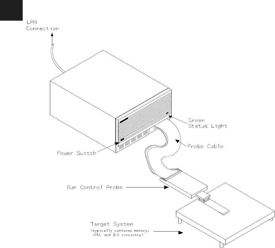
Figure 1-1 HP 64770A/B Emulator for TLCS-9000
1-2 Introduction
Features of the
TLCS-9000
Emulator
This section introduces you to the features of the emulator. The
chapters which follow show you how to use these features.
Supported
Microprocessors The HP 64770A emulator supports the microprocessors listed in Table
1-1. The HP 64770B emulator supports the microprocessors listed in
Table 1-2.
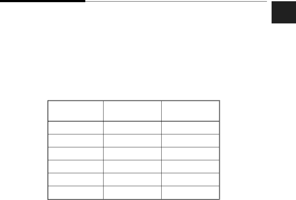
Table 1-1 Supported Microprocessors (HP 64770A)
Supported
Microprocessors Internal ROM size Internal RAM size
TMP97C241F 0 2K byte
TMP97PS40F 64K byte 2K byte
TMP97CS40F 64K byte 2K byte
TMP97CM40F 32K byte 1K byte
TMP97PW40F 128K byte 4K byte
TMP97CW40F 128K byte 4K byte
Introduction 1-3
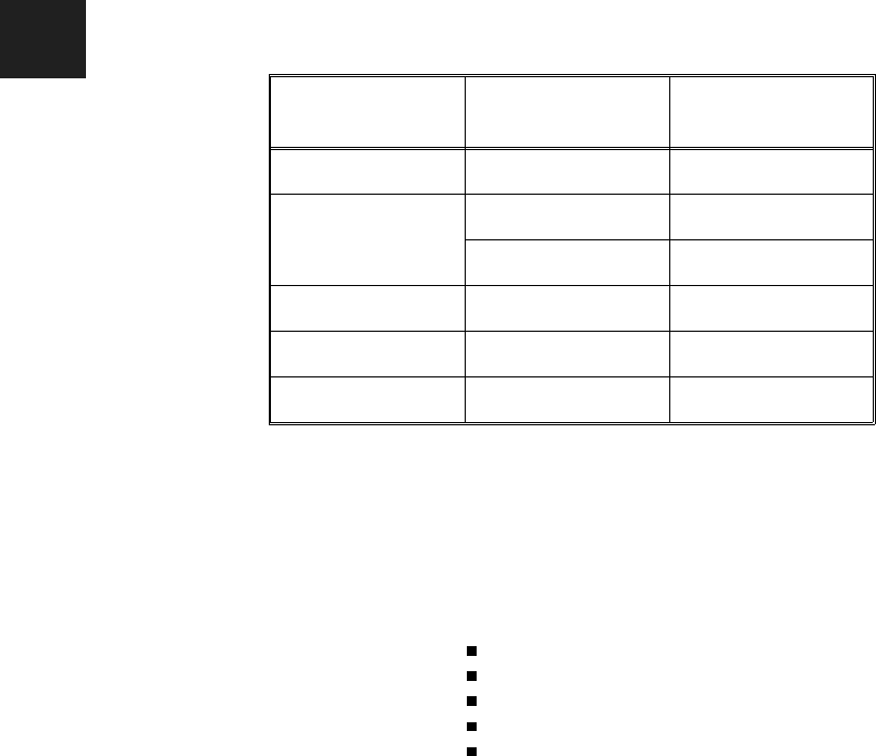
Table 1-2 Supported Microprocessors (HP 64770B)
Supported
Microprocessors Internal ROM size Internal RAM size
TMP97CS42 64K byte 3.5K byte
TMP97PU42 64K byte 3.5K byte
96K byte 5.25K byte
TMP97CU42 96K byte 5.25K byte
TMP97PW42 128K byte 5.25K byte
TMP97CW42 128K byte 5.25K byte
Clock Speeds The HP 64770A emulator runs with a target system clock from 4 to 20
MHz. The HP 64770B emulator runs with a target system clock from 4
to 16 MHz.
Emulation memory The TLCS-9000 emulator can be used with one of the following
Emulation Memory Modules.
HP 64171A 256K byte Emulation Memory Module(35 ns)
HP 64171B 1M byte Emulation Memory Module(35 ns)
HP 64172A 256K byte Emulation Memory Module(20 ns)
HP 64172B 1M byte Emulation Memory Module(20 ns)
HP 64173A 4M byte Emulation Memory Module(25 ns)
You can define up to 7 memory ranges. You can characterize memory
ranges as emulation RAM, emulation ROM, target system RAM, target
system ROM, or guarded memory. The emulator generates an error
message when accesses are made to guarded memory locations. You
can also configure the emulator so that writes to memory defined as
ROM cause emulator execution to break out of target program
execution. Refer to the "Memory Mapping" section in the "Using the
emulator" chapter.
Analysis The TLCS-9000 emulator is used with one of the following analyzers
which allows you to trace code execution and processor activity.
1-4 Introduction

HP64704A 80-channel Emulation Bus Analyzer
HP64794A/C/D Deep Emulation Bus Analyzer
The Emulation Bus Analyzer monitors the emulation processor using
an internal analysis bus.
Registers You can display or modify the TLCS-9000 internal register contents.
Emulation Monitor The emulation monitor is a program that is executed by the emulation
processor. It allows the emulation controller to access target system
resources, and emulation memory. For example, when you display
target system memory, it is monitor program that executes TLCS-9000
instructions which read the target memory locations and send their
contents to the emulation controller.
The emulation monitor takes up 64K bytes of processor’s address space.
Single-Step You can direct the emulation processor to execute a single instruction
or a specified number of instructions.
Breakpoints You can set up the emulator/analyzer interaction so that when the
analyzer finds a specific state, emulator execution will break to the
emulation monitor.
You can also define software breakpoints in your program. The
emulator uses the undefined instruction(7F9Fh) to provide software
breakpoint. When you define a software breakpoint, the emulator
places a this undefined instruction at the specified address; after the
undefined instruction causes emulator execution to break out of your
program, the emulator replaces undefined instruction with the original
opcode.
Reset Support The emulator can be reset from the emulation system under your
control, or your target system can reset the emulation processor.
Real-Time Operation Real-time operation signifies continuous execution of your program
without interference from the emulator. (Such interference occurs when
Introduction 1-5

the emulator temporarily breaks to the monitor so that it can access
register contents or memory.)
You can restrict the emulator to real-time execution. When the
emulator is executing your program under the real-time restriction,
commands which display/modify registers, display/modify memory are
not allowed.
Coverage The TLCS-9000 emulator does not support coverage test.
Easy Products
Upgrades Because the HP 64700 Series development tools (emulator, analyzer,
LAN board) contain programmable parts, it is possible to reprogram
the firmware and some of the hardware without disassembling the HP
64700B Card Cage. This means that you’ll be able to update product
firmware, if desired, without having to call an HP field representative
to your site
1-6 Introduction

Limitations,
Restrictions
Reset While in
Monitor If monitor program is running, RESET signal from target system is
ignored while in monitor.
User Interrupts While
in Monitor If the monitor is running, NMI, INT0-7(edge sense) for HP 64770A,
IREQ for HP 64770B signals from target system are suspended until
the emulator goes into user program operation. Other interrupts are
ignored.
While Executing Step
Command While stepping user program, interrupts are ignored. While single
stepping, BUSRQ from target system is always ignored even if
BUSRQ from target system is enabled.
Note You should not use step command in case the interrupt handler’s
punctuality is critical.
Watch Dog Timer
(HP 64770A Only) When the HP 64770A breaks into the monitor, the watched dog timer is
resets, and disabled until the emulator goes into user program operation.
You must display/modify MDMOD register by "reg" command instead
of "m" command.
Vector Area You need to configure vector entry for the emulator to realize the
following features.
Break
Single-Step
Software Break Point
Refer to the "Vector Area Setting" section in the "Using the Emulator"
Chapter in this manual.
Introduction 1-7

Register Bank When the emulator breaks into the monitor, the PC and PSW are stored
at register bank of "CBP-1" in the same way as the emulator accepts
interrupts.
Unbreaking into the
Monitor The emulator can not break into the monitor when the emulation
processor is the following states.
Standby Mode by HALT instruction
Power Save state(Hardware standby mode) by PS signal
Hold Mode by BUSRQ signal
Reset state by RESET signal from target
Emulation Memory When you use the emulator in single chip mode, you need the
emulation memory because the emulator maps internal ROM/RAM
area as emulation memory.
If you use the emulator in single chip mode or the emulation processor
does burst fetch, the emulation memory module is restricted by clock
speed as following.
HP 64770A
If clock speed is equal to 18MHz or greater 18MHz, you need
HP64712A/B emulation memory module. If clock speed is less than
18MHz, you can use HP64712A/B and HP64713A emulation memory
modules. If clock speed is less than 15MHz, you can use HP64171A/B,
HP64172A/B and HP64713A emulation memory module.
HP 64770B
If clock speed is equal to 16MHz or less than 16MHz, you can use
HP64712A/B and HP64713A emulation memory modules. If clock
speed is less than 15MHz, you can use HP64171A/B, HP64172A/B
and HP64713A emulation memory module.
Evaluation Chip Hewlett-Packard makes no warranty of the problem caused by the
TLCS-9000 Evaluation chip in the emulator.
1-8 Introduction

2
Getting Started
Introduction This chapter will lead you through a basic, step by step tutorial that
shows how to use the HP 64770A/B emulator for the TLCS-9000
microprocessor.
This chapter will:
Describe the sample program used for this chapter’s examples.
Show you how to use the "help" facility.
Show you how to use the memory mapper.
Show you how to enter emulation commands to view
execution of the sample program. The commands described in
this chapter include:
–Displaying and modifying memory
–Stepping
–Displaying registers
–Defining macros
–Searching memory
–Running
–Breaking
–Using software breakpoints
–Using the Analyzer
Getting Started 2-1

Before You Begin Before beginning the tutorial presented in this chapter, you must have
completed the following tasks:
1. Completed hardware installation of the HP64700 emulator in
the configuration you intend to use for your work:
–Standalone configuration
–Transparent configuration
–Remote configuration
–Local Area Network configuration
References: HP 64700 Series Installation/Service manual
2. If you are using the Remote configuration, you must have
completed installation and configuration of a terminal
emulator program which will allow your host to act as a
terminal connected to the emulator. In addition, you must start
the terminal emulator program before you can work the
examples in this chapter.
3. If you have properly completed steps 1 and 2 above, you
should be able to hit <RETURN> (or <ENTER> on some
keyboards) and get one of the following command prompts on
your terminal screen:
U>
R>
M>
If you do not see one of these command prompts, retrace your
steps through the hardware and software installation
procedures outlined in the manuals above, verifying all
connections and procedural steps.
In any case, you must have a command prompt on your
terminal screen before proceeding with the tutorial.
A Look at the Sample
Program The sample program used in this chapter is listed in figure 2-1. The
program emulates a primitive command interpreter.
2-2 Getting Started

.GLOBAL Init,Msgs,Cmd_Input
.GLOBAL Msg_Dest
.SECTION Table,DATA
Msgs
Msg_A .SDATA "THIS IS MESSAGE A"
Msg_B .SDATA "THIS IS MESSAGE B"
Msg_I .SDATA "INVALID COMMAND"
End_Msgs
.SECTION Prog,CODE
;****************************************************
;* Set up the Stack Pointer.
;****************************************************
Init LD.D ISP,00001000h
;****************************************************
;* set register bank size to 4 banks
;****************************************************
LD.D PSW,00000800h
;****************************************************
;* disable Watch Dog Timer (HP 64770A Only)
;****************************************************
LD.B (0fffa60h),00h
LD.B (0fffa61h),0b1h
;****************************************************
;* Clear previous command.
;****************************************************
Clear LD.B (Cmd_Input),00h
;****************************************************
;* Read command input byte. If no command has been
;* entered, continue to scan for it.
;****************************************************
Scan LD.B RB15,(Cmd_Input)
CP.B RB15,00h
JRC Z,Scan
;****************************************************
;* A command has been entered. Check if it is
;* command A, command B, or invalid command.
;****************************************************
Exe_Cmd CP.B RB15,41h
JRC Z,Cmd_A
CP.B RB15,42h
JRC Z,Cmd_B
JR Cmd_I
;****************************************************
;* Command A is entered. RD10 = the number of bytes
;* in message A. RD8 = location of the message.
;* Jump to the routine which writes the message.
;****************************************************
Cmd_A LD.D RD10,Msg_B-Msg_A
LD.D RD8,Msg_A
JR Write_Msg
;****************************************************
Figure 2-1 Sample program source
Getting Started 2-3

Data Declarations
The area at Table section defines the messages used by the program to
respond to various command inputs. These messages are labeled
Msg_A, Msg_B, and Msg_I.
;* Command B is entered.
;****************************************************
Cmd_B LD.D RD10,Msg_I-Msg_B
LD.D RD8,Msg_B
JR Write_Msg
;****************************************************
;* An invalid command is entered.
;****************************************************
Cmd_I LD.D RD10,End_Msgs-Msg_I
LD.D RD8,Msg_I
;****************************************************
;* The destination area is cleared.
;****************************************************
Write_Msg LD.D RD12,Msg_Dest
Clear_Old LD.D RD6,20h
Clear_Loop LD.B (RD12++),20h
SUB.D RD6,01h
JRC NZ,Clear_Loop
;****************************************************
;* Message is written to the destination.
;****************************************************
LD.D RD12,Msg_Dest
Write_Loop LD.B (RD12++),(RD8++)
SUB.D RD10,01h
JRC NZ,Write_Loop
;****************************************************
;* Go back and scan for next command.
;****************************************************
JP (Clear)
.SECTION Data,DATA
;****************************************************
;* Command input byte.
;****************************************************
Cmd_Input .RES.B 1
.RES.B 1
;****************************************************
;* Destination of the command messages.
;****************************************************
Msg_Dest .RES.B 80h
.END Init
Figure 2-1 Sample program source (Cont’d)
2-4 Getting Started

Initialization
The program instructions from the Init label to the Clear label perform
initialization. The segment registers are loaded and the stack pointer is
set up.
Reading Input
The instruction at the Clear label clears any random data or previous
commands from the Cmd_Input byte. The Scan loop continually
reads the Cmd_Input byte to see if a command is entered (a value
other than 0H).
Processing Commands
When a command is entered, the instructions from Exe_Cmd to
Cmd_A determine whether the command was "A", "B", or an invalid
command.
If the command input byte is "A" (ASCII 41H), execution is transferred
to the instructions at Cmd_A.
If the command input byte is "B" (ASCII 42H), execution is transferred
to the instructions at Cmd_B.
If the command input byte is neither "A" nor "B", i.e. an invalid
command has been entered, then execution is transferred to the
instructions at Cmd_I.
The instructions at Cmd_A, Cmd_B, and Cmd_I load register RD10
with the length location of the message to be displayed and register
RD8 with the starting location of the appropriate message. Then,
execution transfers to Write_Msg where the appropriate message is
written to the destination location, Msg_Dest. Then, the program jumps
back to read the next command.
Destination Area
The area at Data section declares memory storage for the command
input byte, and the destination area.
Getting Started 2-5

Using the "help"
Facility
The HP 64700 Series emulator’s Terminal Interface provides an
excellent help facility to provide you with quick information about the
various commands and their options. From any system prompt, you
can enter "help" or "?" as shown below.
R>help
help - display help information
help <group> - print help for desired group
help -s <group> - print short help for desired group
help <command> - print help for desired command
help - print this help screen
--- VALID <group> NAMES ---
gram - system grammar
proc - processor specific grammar
sys - system commands
emul - emulation commands
hl - highlevel commands (hp internal use only)
trc - analyzer trace commands
* - all command groups
Commands are grouped into various classes. To see the commands
grouped into a particular class, you can use the help command with that
group. Viewing the group help information in short form will cause the
commands or the grammar to be listed without any description.
For example, if you want to get some information for group gram, enter
"help gram". Following help information should be displayed.
R>help gram
gram - system grammar
-----------------------------------------------------------------------------
--- SPECIAL CHARACTERS ---
# - comment delimiter ; - command separator Ctl C - abort signal
{} - command grouping "" - ascii string ‘‘ - ascii string
Ctl R - command recall Ctl B - recall backwards
--- EXPRESSION EVALUATOR ---
number bases: t-ten y-binary q-octal o-octal h-hex
repetition and time counts default to decimal - all else default to hex
operators: () ~ * / % + - < << > >> & ^ | &&
--- PARAMETER SUBSTITUTION ---
&token& - pseudo-parameter included in macro definition
- cannot contain any white space between & pairs
- performs positional substitution when macro is invoked
Example
Macro definition: mac getfile={load -hbs"transfer -t &file&"}
Macro invocation: getfile MYFILE.o
Expanded command: load -hbs"transfer -t MYFILE.o"
2-6 Getting Started

Help information exists for each command. Additionally, there is help
information for each of the emulator configuration items.
Becoming Familiar
with the System
Prompts
A number of prompts are used by the HP 64700 Series emulators. Each
of them has a different meaning, and contains information about the
status of the emulator before and after the commands execute. These
prompts may seem cryptic at first, but there are two ways you can find
out what a certain prompt means.
Using "help proc" to View Prompt Description
The first way you can find information on the various system prompts
is to look at the proc help text.
R>help proc
--- Emulation Prompt Status Characters ---
R - emulator in reset state c - no target system clock
U - running user program r - target system reset active
M - running monitor h - halted in user program
b - no bus cycles s - power save
W - waiting for CMB to become ready T - waiting for target system reset
? - unknown state p - no target system power
--- Analyzer STATUS Field Equates ---
exec - valid instruction execution bus - valid bus cycle
fetch - program fetch mem - memory access
read - read halt - halt
write - write intack - interrupt acknowledge
byte - byte user - user program cycles
word - word mon - monitor program cycles
Using the Emulation Status Command (es) for Description
of Current Prompt
When using the emulator, you will notice that the prompt changes after
entering certain commands. If you are not familiar with a new prompt
and would like information about that prompt only, enter the es
(emulation status) command for more information about the current
status.
U>es
T9K40-9000--Running user program
Getting Started 2-7

Initializing the
Emulator
If you plan to follow this tutorial by entering commands on your
emulator as shown in this chapter, verify that no one else is using the
emulator. To initialize the emulator, enter the following command:
R>init
# Limited initialization completed
The init command with no options causes a limited initialization, also
known as a warm start initialization. Warm start initialization does not
affect system configuration. However, the init command will reset
emulator and analyzer configurations. The init command:
Resets the memory map.
Resets the emulator configuration items.
Resets the break conditions.
Clears software breakpoints.
The init command does not:
Clear any macros.
Clear any emulation memory locations; mapper terms are
deleted, but if you respecify the same mapper terms, you will
find that the emulation memory contents are the same.
2-8 Getting Started

Set Up the Proper
Emulation
Configuration
Emulation configuration is needed to adapting to your specific
development. As you have initialized the emulator, the emulation
configuration items have default value.
Set Up Emulation
Condition The emulator allows you to set the emulator’s configuration setting
with the cf command. Enter the help cf to view the information with
the configuration command.
R>help cf
cf - display or set emulation configuration
cf - display current settings for all config items
cf <item> - display current setting for specified <item>
cf <item>=<value> - set new <value> for specified <item>
cf <item> <item>=<value> <item> - set and display can be combined
help cf <item> - display long help for specified <item>
--- VALID CONFIGURATION <item> NAMES ---
breq - en/dis /BUSRQ input from target system
cbp - CBP value on break from reset state
emvbp - en/dis emulation VBP
int - en/dis interrupts
loc - specify monitor location
mode - select operation mode
proc - select processor type
rrt - en/dis restriction to real time runs
trst - en/dis /RESET input from target system
vector - specify vector address
wdt - en/dis watch dog timer on break from reset state
To view the current emulator configuration setting, enter the following
command.
R>cf
cf breq=en
cf cbp=01
cf emvbp=en
cf int=en
cf loc=0f0000
cf mode=ext
cf proc=none
cf rrt=dis
cf trst=en
cf vector=0ff0000
cf wdt=en
The individual configuration items won’t be explained in this section;
refer to the "CONFIG_ITEMS" in the "TLCS-9000 Emulator Specific
Command Syntax" appendix for details.
Getting Started 2-9

Mapping Memory Depending on the memory module, emulation memory consists of
256K, 1M, or 4M bytes.
The memory mapper allows you to characterize memory locations. It
allows you to specify whether a certain range of memory is present in
the target system or whether you will be using emulation memory for
that address range. You can also specify whether the target system
memory is ROM or RAM, and you can specify that emulation memory
be treated as ROM or RAM.
Note Target system devices that take control of the bus (for example,
external DMA controllers), cannot access emulation memory.
Blocks of memory can also be characterized as guarded memory.
Guarded memory accesses will generate "break to monitor" requests.
Writes to ROM will also generate "break to monitor" requests if the
rom break condition is enabled. Memory is mapped with the map
command. To view the memory mapping options, enter:
M>help map
map - display or modify the processor memory map
map - display the current map structure
map <addr>..<addr> <type> - define address range as memory type
map other <type> - define all other ranges as memory type
map -d <term#> - delete specified map term
map -d * - delete all map terms
--- VALID <type> OPTIONS ---
eram - emulation ram
erom - emulation rom
tram - target ram
trom - target rom
grd - guarded memory
Enter the map command with no options to view the default map
structure.
M>map
# remaining number of terms : 7
# remaining emulation memory : 100000h bytes
map other tram
2-10 Getting Started

Which Memory
Locations Should be
Mapped?
Typically, assemblers generate relocatable files and linkers combine
relocatable files to form the absolute file. A linker load map listing will
show what memory locations your program will occupy. One for the
sample program is shown below.
SECTION SUMMARY
---------------
SECTION ATTRIBUTE START END LENGTH ALIGN
Prog NORMAL CODE 00001500 0000157B 0000007C 2 (WORD)
Data NORMAL DATA 00001600 00001681 00000082 2 (WORD)
Table NORMAL DATA 00001700 00001730 00000031 2 (WORD)
From the load map listing, you can see that the sample program
occupies three address ranges. The program area, which contains the
opcodes and operands, occupies locations 1500 through 157B hex. The
data area, which contains the ASCII values of the messages the
program transfers, occupies locations 1700 through 1730 hex. The
destination area, which contains the command input byte and the
locations of the message destination, occupies locations 1600 through
1681 hex.
Before you map memoy, you must specify processor type. If you use
HP 64770A emulator, enter the following commad to specify processor
type.
R>cf proc=97ps40
If you use HP 64770B emulator, enter the following commad to specify
.processor type
R>cf proc=97cu42
Since the program writes to the destination area, the mapper block of
destination area should not be characterized as ROM. Enter the
following commands to map memory for the sample program and
display the memory map.
R>map 1500..15ff erom
R>map 1600..16ff eram
R>map 1700..17ff erom
R>map
# remaining number of terms : 4
# remaining emulation memory : d0000h bytes
map 0001500..00015ff erom # term 1
map 0001600..00016ff eram # term 2
map 0001700..00017ff erom # term 3
map other tram
Getting Started 2-11

When mapping memory for your target system programs, you should
characterize emulation memory locations containing programs and
constants (locations which should not be written) as ROM. This will
prevent programs and constants from being written over accidentally.
Break will occur when instructions or commands attempt to do so(if the
rom break condition is enabled).
Note The defaults number base for address and data values within HP 64700
Terminal Interface is hexadecimal. Other number bases may be
specified. Refer to the "Expressions" chapter or the HP 64700 Terminal
Interface Reference manual for further details.
Getting the
Sample Program
into Emulation
Memory
This section assumes you are using the emulator in one of the following
three configurations:
1. Connected only to a terminal, which is called the standalone
configuration. In the standalone configuration, you must
modify memory to load the sample program.
2. Connected between a terminal and a host computer, which is
called the transparent configuration. In the transparent
configuration, you can load the sample program by
downloading from the "other" port.
3. Connected to a host computer and accessed via a terminal
emulation program. This configurations is called remote
configurations. In the remote configuration, you can load the
sample program by downloading from the same port.
Standalone
Configuration If you are operating the emulator in the standalone configuration, the
only way to load the sample program into emulation memory is by
2-12 Getting Started

modifying emulation memory locations with the m (memory
display/modification) command.
You can enter the sample program into memory with the m command
as shown below.
R>m -dw 1500=0b31,1000,0000,0b39,0800,0000
R>m -dw 150c=7f00,7a60,47b1,8720,0fa61,0d800
R>m -dw 1518=7f00,7600,0d000,798f,7600,5ee0
R>m -dw 1524=13f8,4741,860f,120a,4742,860f
R>m -dw 1530=1210,201a,0c711,870a,0b08,1700
R>m -dw 153c=0000,2018,0c711,870a,0b08,1711
R>m -dw 1548=0000,200c,0c70f,870a,0b08,1722
R>m -dw 1554=0000,0b0c,1602,0000,0c720,8706
R>m -dw 1560=4720,877c,0c671,13fb,0b0c,1602
R>m -dw 156c=0000,4f78,877c,0c6b1,13fb,0d000
R>m -dw 1578=0b460,0f516
R>m -db 1700="THIS IS MESSAGE A"
R>m -db 1711="THIS IS MESSEGE B"
R>m -db 1722="INVALID COMMAND"
After entering the opcodes and operands, you would typically display
memory in mnemonic format to verify that the values entered are
correct (see the example below). If any errors exist, you can modify
individual locations. Also, you can use the cp (copy memory)
command if, for example, a byte has been left out, but the locations
which follow are correct.
Note Be careful about using this method to enter programs from the listings
of relocatable source files. If source files appear in relocatable sections,
the address values of references to locations in other relocatable
sections are not resolved until link-time. The correct values of these
address operands will not appear in the assembler listing.
Transparent
Configuration If your emulator is connected between a terminal and a host computer,
you can download programs into memory using the load command
with the -o (from other port) option. The load command will accept
absolute files in the following formats:
HP absolute.
Getting Started 2-13

Intel hexadecimal.
Tektronix hexadecimal.
Motorola S-records.
The examples which follow will show you the methods used to
download HP absolute files and the other types of absolute files.
HP Absolutes
Downloading HP format absolute files requires the
transfer protocol. The example below assumes that the transfer utility
has been installed on the host computer (HP 64884 for HP 9000 Series
500, or HP 64885 for HP 9000 Series 300).
Note Notice that the transfer command on the host computer is terminated
with the <ESCAPE>g characters; by default, these are the characters
which temporarily suspend the transparent mode to allow the emulator
to receive data or commands.
R>load -hbo <RETURN> <RETURN>
$ transfer -rtb cmd_rds.X <ESCAPE>g
####
R>
Other Supported Absolute Files
The example which follows shows how to download Intel hexadecimal
files by the same method (but different load options) can be used by
load Tektronix hexadecimal and Motorola S-record files as well.
R>load -io <RETURN> <RETURN>
$ cat ihexfile <ESCAPE>g
#####
Data records = 00003 Checksum error = 00000
R>
2-14 Getting Started

Remote Configuration If the emulator is connected to a host computer, and you are accessing
the emulator from the host computer via a terminal emulation program,
you can also download files with the load command. However, in the
remote configuration, files are loaded from the same port that
commands are entered from. For example, if you wish to download a
Tektronix hexadecimal file from a Vectra personal computer, you
would enter the following commands.
R>load -t <RETURN>
After you have entered the load command, exit from the terminal
emulation program to the MS-DOS operating system. Then, copy your
hexadecimal file to the port connected to the emulator, for example:
C:\copy thexfile com1: <RETURN>
Now you can return to the terminal emulation program and verify that
the file was loaded correctly.
For More Information For more information on downloading absolute files, refer to the load
command description in the HP 64700 Emulators Terminal Interface:
User’s Reference manual.
Getting Started 2-15

Displaying
Memory In
Mnemonic Format
Once you have loaded a program into the emulator, you can verify that
the program has indeed been loaded by displaying memory in
mnemonic format.
R>m -dm 1500..157b
0001500 - LD.D:I ISP,00001000
0001506 - LD.D:I PSW,00000800
000150c - LD.B:A (fffa60),0
0001510 - LD.B:G (fffa61),b1
0001516 - LD.B:A (001600),0
000151c - LD.B:A RB15,(001600)
0001522 - CP.B:S RB15,0
0001524 - JRC Z,00151c
0001526 - CP.B:G RB15,41
000152a - JRC Z,001534
000152c - CP.B:G RB15,42
0001530 - JRC Z,001540
0001532 - JR 00154c
0001534 - LD.D:G RD10,11
0001538 - LD.D:I RD8,00001700
000153e - JR 001556
0001540 - LD.D:G RD10,11
0001544 - LD.D:I RD8,00001711
000154a - JR 001556
000154c - LD.D:G RD10,0f
0001550 - LD.D:I RD8,00001722
0001556 - LD.D:I RD12,00001602
000155c - LD.D:G RD6,20
0001560 - LD.B:G (RD12++),20
0001564 - SUB.D:S RD6,1
0001566 - JRC NZ,001560
0001568 - LD.D:I RD12,00001602
000156e - LD.B:G (RD12++),(RD8++)
0001572 - SUB.D:S RD10,1
0001574 - JRC NZ,00156e
0001576 - JP.W (001516)
If you display memory in mnemonic format and do not recognize the
instructions listed or see some illegal instructions or opcodes, go back
and make sure the memory locations you have typed are mapped
properly. If the memory map is not the problem, recheck the linker load
map listing to verify that the absolute addresses of the program match
with the locations you are trying to display.
2-16 Getting Started

Stepping Through
the Program
The emulator allows you to execute one instruction or a number of
instructions with the s (step) command. Enter the help s to view the
options available with the step command.
R>help s
s - step emulation processor
s - step one from current PC
s <count> - step <count> from current PC
s <count> $ - step <count> from current PC
s <count> <addr> - step <count> from <addr>
s -q <count> <addr> - step <count> from <addr>, quiet mode
s -w <count> <addr> - step <count> from <addr>, whisper mode
--- NOTES ---
STEPCOUNT MUST BE SPECIFIED IF ADDRESS IS SPECIFIED!
If <addr> is not specified, default is to step from current PC.
A <count> of 0 implies step forever.
A step count of 0 will cause the stepping to continue "forever" (until
some break condition, such as "write to ROM", is encountered, or until
you enter <CTRL>c). The following command will step from the first
address of the sample program.
R>s 1 1500
0001500 - LD.D:I ISP,00001000
PC = 0001506
Getting Started 2-17

Displaying
Registers
The step command shown above executed the "LD.D:I ISP,00001000"
instruction. Enter the following command to view the contents of the
registers.
M>reg *
reg pc=001506 psw=ac000000 rw0=0000 rw1=0000 rw2=0000 rw3=0000 rw4=0000
reg rw5=0000 rw6=0000 rw7=0000 rw8=0000 rw9=0000 rw10=0000 rw11=0000
reg rw12=0000 rw13=0000 rw14=0000 rw15=0000 isp=00001000 cbp=01 pbp=00
reg usp=00000000 fp=00000000
The register contents are displayed in a "register modify" command
format. This allows you to save the output of the reg command to a
command file which may later be used to restore the register contents.
(Refer to the po (port options) command description in the Terminal
Interface: User’s Reference for more information on command files.)
Refer to the "REGISTER CLASS and NAME" section in the
"TLCS-9000 Emulator Specific Command Syntax" appendix for more
information on the register names and classes.
Combining
Commands More than one command may be entered in a single command line. The
commands must be separated by semicolons (;). For example, you
could execute the next instruction(s) and display the registers by
entering the following.
M>s;reg
0001506 - LD.D:I PSW,00000800
PC = 000150c
reg pc=00150c psw=00000800 rw0=0000 rw1=0000 rw2=0000 rw3=0000 rw4=0000
reg rw5=0000 rw6=0000 rw7=0000 rw8=0000 rw9=0000 rw10=0000 rw11=0000
reg rw12=0000 rw13=0000 rw14=0000 rw15=0000 isp=00001000 cbp=01 pbp=00
reg usp=00000000 fp=00000000
The sample above shows you that "LD.D:I PSW,00000800" is
executed by step command.
Using Macros Suppose you want to continue stepping through the program and
displaying registers after each step. You could continue entering s
command followed by reg command, but you may find this tiresome. It
is easier to use a macro to perform a sequence of commands which will
be entered again and again.
2-18 Getting Started

Macros allow you to combine and store commands. For example, to
define a macro which will display registers after every step, enter the
following command.
M>mac st={s;reg}
Once the st macro has been defined, you can use it as you would use
any other command.
M>st
# s ; reg
000150c - LD.B:A (fffa60),0
PC = 0001510
reg pc=001510 psw=00000800 rw0=0000 rw1=0000 rw2=0000 rw3=0000 rw4=0000
reg rw5=0000 rw6=0000 rw7=0000 rw8=0000 rw9=0000 rw10=0000 rw11=0000
reg rw12=0000 rw13=0000 rw14=0000 rw15=0000 isp=00001000 cbp=01 pbp=00
reg usp=00000000 fp=00000000
Command Recall The command recall feature is yet another, easier way to enter
commands again and again. You can press <CTRL>r to recall the
commands which have just been entered. If you go past the command
of interest, you can press <CTRL>b to move forward through the list of
saved commands. To continue stepping through the sample program,
you could repeatedly press <CTRL>r to recall and <RETURN> to
execute the st macro.
Repeating Commands The rep command is also helpful when entering commands
repetitively. You can repeat the execution of macros as well as normal
commands. For example, you could enter the following command to
cause the st macro to be executed four times.
M>rep 4 st
Getting Started 2-19

# s ; reg
0001510 - LD.B:G (fffa61),b1
PC = 0001516
reg pc=001516 psw=00000800 rw0=0000 rw1=0000 rw2=0000 rw3=0000 rw4=0000
reg rw5=0000 rw6=0000 rw7=0000 rw8=0000 rw9=0000 rw10=0000 rw11=0000
reg rw12=0000 rw13=0000 rw14=0000 rw15=0000 isp=00001000 cbp=01 pbp=00
reg usp=00000000 fp=00000000
# s ; reg
0001516 - LD.B:A (001600),0
PC = 000151c
reg pc=00151c psw=00000800 rw0=0000 rw1=0000 rw2=0000 rw3=0000 rw4=0000
reg rw5=0000 rw6=0000 rw7=0000 rw8=0000 rw9=0000 rw10=0000 rw11=0000
reg rw12=0000 rw13=0000 rw14=0000 rw15=0000 isp=00001000 cbp=01 pbp=00
reg usp=00000000 fp=00000000
# s ; reg
000151c - LD.B:A RB15,(001600)
PC = 0001522
reg pc=001522 psw=00000800 rw0=0000 rw1=0000 rw2=0000 rw3=0000 rw4=0000
reg rw5=0000 rw6=0000 rw7=0000 rw8=0000 rw9=0000 rw10=0000 rw11=0000
reg rw12=0000 rw13=0000 rw14=0000 rw15=0000 isp=00001000 cbp=01 pbp=00
reg usp=00000000 fp=00000000
# s ; reg
0001522 - CP.B:S RB15,0
PC = 0001524
reg pc=001524 psw=00000808 rw0=0000 rw1=0000 rw2=0000 rw3=0000 rw4=0000
reg rw5=0000 rw6=0000 rw7=0000 rw8=0000 rw9=0000 rw10=0000 rw11=0000
reg rw12=0000 rw13=0000 rw14=0000 rw15=0000 isp=00001000 cbp=01 pbp=00
reg usp=00000000 fp=00000000
Command Line
Editing The terminal interface supports the use of HP-UX ksh(1)-like editing
of the command line. The default is for the command line editing
feature to be disabled to be compatible with earlier versions of the
interface. Use the cl command to enable command line editing.
M>cl -e
Refer to "Command Line Editing" in the HP64700-Series Emulators
Terminal Interface Reference for information on using the command
line editing feature.
2-20 Getting Started

Modifying Memory The preceding step and register commands show the sample program is
executing Scan loop, where it continually reads the command input
byte to check if a command had been entered. Use the m (memory)
command to modify the command input byte.
M>m 1600=41
To verify that 41H has been written to 900H, enter the following
command.
M>m -db 1600
0001600..0001600 41
When memory was displayed in byte format earlier, the display mode
was changed to "byte". The display and access modes from previous
commands are saved and they become the defaults.
Specifying the
Access and Display
Modes
There are a couple different ways to modify the display and access
modes. One is to explicitly specify the mode with the command you are
entering, as with the command m -db 1600. The mo (display and
access mode) command is another way to change the default mode. For
example, to display the current modes, define the display mode as
"word", and redisplay 1600H, enter the following commands.
M>mo
mo -ab -db
M>mo -dw
M>m 1600
0001600..0001601 0041
To continue the rest of program.
M>r
U>
Display the Msg_Dest memory locations (destination of the message,
902H) to verify that the program moved the correct ASCII bytes. At
this time you want to see correct byte values, so "-db" option (display
with byte) is used.
U>m -db 1602..1621
0001602..0001611 54 48 49 53 20 49 53 20 4d 45 53 53 41 47 45 20
0001612..0001621 41 20 20 20 20 20 20 20 20 20 20 20 20 20 20 20
Getting Started 2-21

Running the
Sample Program
The emulator allows you to execute a program in memory with the r
command. The r command by itself causes the emulator to begin
executing at the current program counter address. The following
command will begin running the sample program from 800H.
M> r 1500
The r rst command specifies that the emulator begin to executing from
target system reset (see the "Execution Topics" section in the
"In-Circuit Emulation" chapter).
Searching
Memory for Data
The ser (search memory for data) command is another way to verify
that the program did what it was supposed to do.
U>ser 1602..1621="THIS IS MESSAGE A"
pattern match at address: 0001602
If any part of the data specified in the ser command is not found, no
match is displayed (No message displayed).
Breaking into the
Monitor
You can use the break command (b) command to generate a break to
the monitor. While the break will occur as soon as possible, the actual
stopping point may be many cycles after the break request (depending
on the type of instruction being executed and whether the processor is
in a special state).
U>b
M>
2-22 Getting Started

Using Software
Breakpoints
Software breakpoints are handled by the TLCS-9000 undefined
instruction (breakpoint interrupt instruction:7F9Fh). When you define
or enable a software breakpoint(with the bp command), the emulator
will replace the opcode at the software breakpoint address with a
breakpoint interrupt instruction.
Caution Software breakpoints should not be set, enabled, disabled, or removed
while the emulator is running user code. If any of these commands are
entered while the emulator is running user code and the emulator is
executing code in the area where the breakpoint is being modified,
program execution may be unreliable.
Note You must only set software breakpoints at memory locations which
contain instruction opcodes (not operands or data). If a software
breakpoint is set at a memory location which is not an instruction
opcode, the software breakpoint instruction will never be executed.
Further, your program won’t work correctly.
Note NMI will be ignored, when software breakpoint and NMI occur at the
same time.
Note Because software breakpoints are implemented by replacing opcodes
with the breakpoint interrupt instructions, you cannot define software
breakpoints in target ROM.
Getting Started 2-23

When software breakpoints are enabled and the emulator detects the
breakpoint interrupt instruction(7F9Fh), it generates a break into the
monitor.
If the breakpoint interrupt instruction(7F9Fh) was generated by a
software breakpoint, execution breaks to the monitor, and the
breakpoint interrupt instruction is replaced by the original opcode. A
subsequent run or step command will execute from this address.
Displaying and
Modifying the Break
Conditions
Before you can define software breakpoints, you must enable software
breakpoints with the bc (break conditions) command. To view the
default break conditions and change the software breakpoint condition,
enter the bc command with no option. This command displays current
configuration of break conditions.
M>bc
bc -d bp #disable
bc -e rom #enable
bc -d bnct #disable
bc -d cmbt #disable
bc -d trig1 #disable
bc -d trig2 #disable
To enable the software break point feature enter
M>bc -e bp
Defining a Software
Breakpoint Now that the software breakpoint feature is enabled, you can define
software breakpoints. Enter the following command to break on the
address of the Cmd_I (address 154cH) label.
M>bp 154c
M>bp
### BREAKPOINT FEATURE IS ENABLED ###
bp 000154c #enabled
Run the program, and verify that execution broke at the appropriate
address.
M>r 1500
U>m 1600=43
!ASYNC_STAT 615! Software breakpoint: 000154c
M>st
# s ; reg
000154c - LD.D:G RD10,0f
PC = 0001550
reg pc=001550 psw=00000800 rw0=0000 rw1=0000 rw2=0000 rw3=0000 rw4=0000
reg rw5=0000 rw6=0000 rw7=0000 rw8=0000 rw9=0000 rw10=000f rw11=0000
2-24 Getting Started

reg rw12=0000 rw13=0000 rw14=0000 rw15=0043 isp=00001000 cbp=01 pbp=00
reg usp=00000000 fp=00000000
When a breakpoint is hit, it becomes disabled. You can use the -e
option with the bp command to re-enable the software breakpoint.
M>bp
### BREAKPOINT FEATURE IS ENABLED ###
bp 000154c #disabled
M>bp -e 154c
M>bp
### BREAKPOINT FEATURE IS ENABLED ###
bp 000154c #enabled
M>r
U>m 1600=43
!ASYNC_STAT 615! Software breakpoint: 000154c
M>bp
### BREAKPOINT FEATURE IS ENABLED ###
bp 000154c #disabled
Getting Started 2-25

Using the Analyzer
Predefined Trace
Labels Three trace labels are predefined in the TLCS-9000 emulator. You can
view these labels by entering the tlb (trace label) command with no
options.
M>tlb
# #### Emulation trace labels
tlb addr 16..39
tlb data 0..15
tlb eaddr 40..63
tlb extra 40..63
tlb stat 64..76
Predefined Status
Equates Common values for the TLCS-9000 status trace signals have been
predefined. You can view these predefined equates by entering the equ
command with no options.
M>equ
### Equates ###
equ bus=0x0xxxxxxxxxxxy
equ byte=0x010xxxxxx1xxy
equ exec=0xxx1xxxxxxxxy
equ fetch=0x010x1xxxxx1xy
equ halt=0x011xxxxxxxxxy
equ intack=0x000xxxxxxxxxy
equ mon=0x0xxxxxxxxxx0y
equ read=0x010xxxxxxx1xy
equ user=0x0xxxxxxxxxx1y
equ word=0x010xxxxxx0xxy
equ write=0x010x0xxxxx0xy
These equates may be used to specify values for the stat trace label
when qualifying trace conditions.
Specifying a Simple
Trigger The tg analyzer command is a simple way to specify a condition on
which to trigger the analyzer. Suppose you wish to trace the states of
the program after the read of "B"(42H) command from the command
input byte. Enter the following commands to set up the trace, run the
program, issue the trace, and display the trace status.(Note that the
analyzer is to search for a lower byte read of 42H because the address is
even)
M>tg addr=1600 and data=0xx42 and stat=read
and stat=bus
M>t
emulation trace started
2-26 Getting Started

M>r 1500
U>ts
--- Emulation Trace Status ---
New User trace running
Arm ignored
Trigger not in memory
Arm to trigger ?
States ? (8192) ?..?
Sequence term 1
Occurrence left 1
The trace status shows that the trigger condition has not been found.
You would not expect the trigger to be found because no commands
have been entered. Modify the command input byte to "B"(42H) and
display the trace status again.
U>m 1600=42
U>ts
---Emulation Trace Status ---
New User trace complete
Arm ignored
Trigger in memory
Arm to trigger ?
States 8192 (8192) 0..8192
Sequence term 2
Occurrence left 1
The trace status shows that the trigger has been found. Enter the
following command to display the first 15 states of the trace.
U>tl -t 15
Line addr,H T9K40 mnemonic,H count,R
------- ------ ----------------------------------- -------------
0 001600 xx42 read mem byte -------------
1 001524 13f8 fetch 0.34uS
2 =001522 INSTRUCTION--opcode unavailable 0.06uS
3 =001524 JRC Z,00151c 0.06uS
4 001526 4741 fetch 0.20uS
5 =001526 CP.B:G RB15,41 0.06uS
6 001528 860f fetch 0.28uS
7 00152a 120a fetch 0.32uS
8 =00152a JRC Z,001534 0.08uS
9 00152c 4742 fetch 0.26uS
10 =00152c CP.B:G RB15,42 0.08uS
11 00152e 860f fetch 0.26uS
12 001530 1210 fetch 0.32uS
13 =001530 JRC Z,001540 0.08uS
14 001532 201a fetch 0.26uS
Line 0 in the trace list above shows the state which triggered the
analyzer. The trigger state is always on line 0.
To list the next lines of the trace, enter the following command.
Getting Started 2-27

U>tl
Line addr,H T9K40 mnemonic,H count,R
------- ------ ----------------------------------- -------------
15 001540 c711 fetch 0.34uS
16 =001540 LD.D:G RD10,11 0.06uS
17 001542 870a fetch 0.28uS
18 001544 0b08 fetch 0.32uS
19 =001544 LD.D:I RD8,00001711 0.08uS
20 001546 1711 fetch 0.26uS
21 001548 0000 fetch 0.34uS
22 00154a 200c fetch 0.32uS
23 =00154a JR 001556 0.08uS
24 00154c c70f fetch 0.26uS
25 001556 0b0c fetch 0.34uS
26 =001556 LD.D:I RD12,00001602 0.06uS
27 001558 1602 fetch 0.26uS
28 00155a 0000 fetch 0.34uS
29 00155c c720 fetch 0.34uS
Trigger Position You can specify where the trigger state will be positioned with in the
emulation trace list. The following three basical trigger positions are
defined.
s start
ccenter
eend
When s(start) trigger position is selected, the trigger is positioned at the
start of the trace list. You can trace the states after the trigger state.
When c(center) trigger position is selected, the trigger is positioned at
the center of the trace list. You can trace the states around the trigger.
When e(end) trigger position is selected, the trigger is positioned at the
end of the trace list. You can trace the state before the trigger.
In the above section, you have traced the states of the program after a
certain state, because the default trigger position was s(start). If you
want to trace the states of the program around a certain state, you need
to change the trigger position.
For example, if you wish to trace the transition to the command A
process, change the trigger position to "center" and specify the trigger
condition.
To specify the trigger position, enter the following command.
U>tp c
Specify the trigger condition by typing
2-28 Getting Started

U>tg eaddr=1534
Enter the trace command to start the trace.
U>t
Emulation trace started
Modify the command input byte to "A" and display the trace status
again.
U>m 1600=41
U>ts
--- Emulation Trace Status ---
New User trace complete
Arm ignored
Trigger not in memory
Arm to trigger ?
States 8192 (8192) -4096..4095 Sequence term 2
Occurrence left 1
The trace status shows that the trigger has been found. Enter the
following command to display the states about the execution state of
address 1534H.
U>tl -10..9
Line addr,H T9K40 mnemonic,H count,R
------- ------ ----------------------------------- -------------
-10 001524 13f8 fetch 0.34uS
-9 =001522 CP.B:S RB15,0 0.06uS
-8 =001524 JRC Z,00151c 0.08uS
-7 001526 4741 fetch 0.18uS
-6 =001526 CP.B:G RB15,41 0.08uS
-5 001528 860f fetch 0.26uS
-4 00152a 120a fetch 0.34uS
-3 =00152a JRC Z,001534 0.06uS
-2 00152c 4742 fetch 0.26uS
-1 001534 c711 fetch 0.34uS
0 =001534 LD.D:G RD10,11 0.08uS
1 001536 870a fetch 0.26uS
2 001538 0b08 fetch 0.34uS
3 =001538 LD.D:I RD8,00001700 0.06uS
4 00153a 1700 fetch 0.26uS
5 00153c 0000 fetch 0.34uS
6 00153e 2018 fetch 0.34uS
7 =00153e JR 001556 0.06uS
8 001540 c711 fetch 0.26uS
9 001556 0b0c fetch 0.34uS
The transition states to the process for the command A are displayed.
For a Complete
Description For a complete description of the HP 64700 Series analyzer, refer to the
HP 64700 Emulators Terminal Interface: Analyzer User’s Guide.
Getting Started 2-29

Copying Memory The cp (copy memory) command gives you the ability to copy the
contents of one range of memory to another. This is a handy feature to
test things like the relocatability of programs, etc. To test if the sample
program is relocatable within the same segment, enter the following
command to copy the program to an unused, but mapped, area of
emulation memory. After the program is copied, run it from its new
start address to verify that the program is indeed relocatable.
U>cp 2000=1500..157b
U>r 2000
U>
The prompt shows that the emulator is executing user code, so it looks
as if the program is relocatable. You may want to issue a simple trace
to verify that the program works while running from its new location.
U>tg any
U>t
Emulation trace started
U>tl
Line addr,H T9K40 mnemonic,H count,R
------- ------ ----------------------------------- -------------
0 001600 xx00 read mem byte -------------
1 002024 13f8 fetch 0.32uS
2 =002022 INSTRUCTION--opcode unavailable 0.08uS
3 =002024 JRC Z,00201c 0.06uS
4 002026 4741 fetch 0.20uS
5 00201c d000 fetch 0.34uS
6 =00201c LD.B:A RB15,(001600) 0.06uS
7 00201e 798f fetch 0.26uS
8 002020 7600 fetch 0.34uS
9 002022 5ee0 fetch 0.34uS
10 001600 xx00 read mem byte 0.32uS
11 002024 13f8 fetch 0.34uS
12 =002022 CP.B:S RB15,0 0.06uS
13 =002024 JRC Z,00201c 0.06uS
14 002026 4741 fetch 0.20uS
15 00201c d000 fetch 0.34uS
16 =00201c LD.B:A RB15,(001600) 0.06uS
17 00201e 798f fetch 0.28uS
18 002020 7600 fetch 0.32uS
19 002022 5ee0 fetch 0.34uS
Resetting the
Emulator
To reset the emulator, enter the following command.
2-30 Getting Started

U>rst
R>
The emulator is held in a reset state (suspended) until a b (break), r
(run), or s (step) command is entered. A CMB execute signal will also
cause the emulator to run if reset.
The -m option to the rst command specifies that the emulator begin
executing in the monitor after reset instead of remaining in the
suspended state.
R>rst -m
M>
Getting Started 2-31

Notes
2-32 Getting Started

3
Using the Emulator
Introduction Many of the topics described in this chapter involve the commands
which are unique to the TLCS-9000 emulator such as the cf command
which allows you to specify emulator configuration.
A reference-type description of the TLCS-9000 emulator configuration
items can be found in the "CONFIG_ITEMS" section in the
"TLCS-9000 Emulator Specific Command Syntax" appendix.
This chapter will:
Execution Topics
–Restricting the Emulator to Real-Time Runs
–Setting Up to Break on an Analyzer Trigger
–Making Coordinated Measurements
Memory Mapping
Vector Area Setting
Analyzer Topics
–Analyzer Status Qualifiers
–Specifying Address and Status for Trigger or Store
Condition
–Specifying Data for Trigger or Store Condition
–Specifying Execute Address for Trigger or Store Condition
–Analyzer Clock Speed
Monitor Topics
Using the Emulator 3-1

Prerequisites Before performing the tasks described in this chapter, you should be
familiar with how the emulator operates in general. Refer to the
Concepts of Emulation and Analysis manual and the "Getting Started"
chapter of this manual.
Execution Topics The description in this section are of emulation tasks which involve
program execution in general.
Restricting the
Emulator to
Real-Time Runs
By default, the emulator is not restricted to real-time runs. However,
you may wish to restrict runs to real-time to prevent accidental breaks
that might cause target system problems. Use the cf (configuration)
command to enable the rrt configuration item.
R>cf rrt=en
When runs are restricted to real-time and the emulator is running user
code, the system refuses all commands that cause a break except rst
(reset), r (run), s(step), and b (break to monitor).
The following commands are not allowed when runs are restricted to
real-time:
reg (register display/modification).
m (memory display/modification).
The following command will disable the restriction to real-time runs
and allow the system to accept commands normally.
R>cf rrt=dis
Setting Up to Break
on an Analyzer
Trigger
The analyzer may generate a break request to the emulation processor.
To set up to break on an analyzer trigger, follow the steps below.
3-2 Using the Emulator

Specify the Signal Driven when Trigger is Found
Use the tgout (trigger output) command to specify which signal is
driven when the analyzer triggers. Either the "trig1" or the "trig2"
signal can be driven on the trigger.
R>tgout trig1
Enable the Break Condition
Enable the "trig1" break condition.
R>bc -e trig1
After you specify the trigger to drive "trig1" and enable the "trig1"
break condition, set up the trace, enter the t (trace) command, and run
the program.
Making Coordinated
Measurements Coordinated measurements are measurements made between multiple
HP 64700 Series emulators which communicate via the Coordinated
Measurement Bus (CMB). Coordinated measurements can also include
other instruments which communicate via the BNC connector. A
trigger signal from the CMB or BNC can break emulator execution into
the monitor, or it can arm the analyzer. An analyzer can send a signal
out on the CMB or BNC when it is triggered. The emulator can send an
EXECUTE signal out on the CMB when you enter the x (execute)
command.
Coordinated measurements can be used to start or stop multiple
emulators, start multiple trace measurements, or to arm multiple
analyzers.
As with the analyzer generated break, breaks to the monitor on CMB or
BNC trigger signals are interpreted as a "request to break". The
emulator looks at the state of the CMB READY (active high) line to
determine if it should break. It does not interact with the EXECUTE
(active low) or TRIGGER (active low) signals.
For information on how to make coordinated measurements, refer to
the HP 64700 Emulators Terminal Interface: Coordinated
Measurement Bus User’s Guide manual.
Using the Emulator 3-3

Memory Mapping You can define up to 7 memory ranges. You can not map the internal
RAM and internal ROM(single-chip operation) area and I/O area since
the TLCS-9000 emulator maps automatically. You can characterize
memory ranges as emulation RAM, emulation ROM, target RAM,
target ROM, or guarded memory.
Mapping as
Emulation Memory When you characterize memory ranges as emulation memory, note the
following.
When you characterize memory range which does not override
64K byte boundary as emulation memory, 64K byte is used as
following.
R>map
# remaining number of terms : 7
# remaining emulation memory : 100000h bytes
map other tram
R>map 800..8ff eram
R>map
# remaining number of terms : 6
# remaining emulation memory : f0000h bytes
map 0000800..00008ff eram # term 1
map other tram
When you characterize memory range which override N
blocks of 64K byte as emulation memory, 64K x 2M (2M-1 <
N =< 2M) byte is used.
For example, when you characterize memory
range(0ff00..200ff) which overrides 3 block of 64K byte as
emulation RAM, the 64K x 22 (21 < 3 =< 22:M=2) byte is
used as following.
R>map
# remaining number of terms : 7
# remaining emulation memory : 100000h bytes map other tram
R>map 0ff00..200ff eram
R>map
# remaining number of terms : 6
# remaining emulation memory : c0000h bytes
map 000ff00..00200ff eram # term 1
map other tram
For examle, when 192K byte emulation memroy is remained
you can not characterize memory range(80000..0affff), which
3-4 Using the Emulator

is 192K byte and override 3 block of 64K byte, as emulatoin
RAM by one mapper term because the emulator needs 256K
byte to map memory range(80000..0affff).In this case, you can
characterize that memeoy range by two mapper term(the one
is 128K byte mapper term, the another is 64K byte mapper
term) as following.
R>map
# remaining number of terms : 4
# remaining emulation memory : 30000h bytes
map 0100000..01400ff eram # term 1
map 0150000..01700ff eram # term 2
map 0180000..01800ff eram # term 3
map other tram
R>map 80000..0affff eram
!ERROR 21! Insufficient emulation memory
!ERROR 725! Unable to load new memory map; old map reloaded
R>map 80000..9ffff
R>map 0a0000..0affff
R>map
# remaining number of terms : 2
# remaining emulation memory : 0h bytes
map 0080000..009ffff eram # term 1
map 00a0000..00affff eram # term 2
map 0100000..01400ff eram # term 3
map 0150000..01700ff eram # term 4
map 0180000..01800ff eram # term 5
map other tram
Using the Emulator 3-5
Single Chip Mode When user uses the emulator in single chip mode, the emulator maps
internal ROM as emulation memory. The emulation memory is used as
following.
Processor Type Emulation Memory
TMP97PS40F 64K
TMP97CS40F 64K
TMP97CM40F 64K
TMP97PW40F 128K
TMP97CW40F 128K
TMP97CS42 64K
TMP97PU42(64K) 64K
TMP97PU42(96K) 128K
TMP97CU42 128K
TMP97PW42 128K
TMP97CW42 128K
Note When you emulate TMP97CM40 microprocessor insingle chip mode,
you can use 32K bytes internal ROM but the emulator uses 64K
byteemulation memory as internal ROM.
When you emulate TMP97PU42(96K mode) or TMP97CU42
microprocessor insingle chip mode, you can use 96K bytes internal
ROM but the emulator uses 128K byteemulation memory as internal
ROM.
3-6 Using the Emulator

Vector Area
Setting
TLCS-9000 microprocessor has vector area(2K bytes). TLCS-9000
emulator uses three vector entry in vector area to realize the following
emulator features.
Break
Single-Step
Software Break Point
Single Chip Mode If you specify that TLCS-9000 microprocessor operates in single chip
mode ("cf mode=single"), you do not need to set the vector entry since
the emulator automatically sets. The values of PC, PSW, and CBP are
specified by vector entry, when the emulator breaks into the monitor
from reset state.
External Bus Mode If you specify that TLCS-9000 microprocessor operates in external bus
mode ("cf mode=ext"), the way of the emulator’s operations differ
according to setting "cf emvbp" and memory mapping.
"cf emvbp=en"
The emulator reads Vector Base Pointer(VBP) from emulation VBP
instead of target VBP. When the emulator breaks into the monitor from
reset, the value of emulation VBP is specified by "cf vector"
configuration.
If vector area are mapped as emulation memory, the emulator sets the
vector entry when the emulator breaks into the monitor from reset state.
When the emulator breaks into the monitor from reset, the value of PC,
PSW, and CBP are specified by vector entry.
If vector area ara mapped as target memory, the emulator uses copy of
vector area. The emulator copies data of vector ares when the emulator
breaks into the monitor from reset state, and then sets the vector entry.
When the emulator breaks into the monitor from reset, the value of PC,
and PSW are specified by vector entry and the value of CBP is
specified by "cf cbp" configuration.
Using the Emulator 3-7

"cf emvbp=dis"
In this case, the emulator does not set the vector entry. So you must set
up the vector entry to realize the emulator features. If you do not set the
vector entry, the emulator can not operate correctly. Even if you specify
that "cf emvbp=dis", the value of PC, PSW,and CBP are specified in
the same way as you specify that "cf emvbp=en" when the emulator
breaks into the monitor from reset state, Set the vector area as
following.
Vector number Offset value Purpose
12 60H 0000H Break
62H 0202H
64H 00xxH
66H 0000H
14 70H 0000H Step
72H 0204H
74H 00xxH
76H 0000H
31 F8H 0000H Software break
point
FAH 0200H
FCH 00xxH
FEH 0000H
xx: Upper 8 bits of monitor area
3-8 Using the Emulator

Analyzer Topics
Analyzer Status
Qualifiers The following are the analyzer status labels which may be used in the
"tg" and "tsto" analyzer commands.
Qualifier Status bits Description
bus 0x0xxxxxxxxxxxy bus cycle
byte 0x010xxxxxx1xxy byte memory cycle
exec 00xxx1xxxxxxxxy execute instruction
fetch 0x010x1xxxxx1xy program fetch
halt 0x011xxxxxxxxxy halt
intack 0x000xxxxxxxxxy interrupt acknowledge
mon 0x0xxxxxxxxxx0y monitor cycle
read 0x010xxxxxxx1xy read
user 0x0xxxxxxxxxx1y user program cycle
word 0x010xxxxxx0xxy word memory cycle
write 0x010x0xxxxx0xy write
Specifying Address
and Status for
Trigger or Store
Condition
The analyzer captures the actual bus states and execute states. In some
case, bus state and execute state are captured simultaneously. To
specify actual bus status for trigger or store condition by "addr", "stat"
and "data", you should add "stat=bus" condition to trigger/store
condition as following.
M>tg addr=1000 and stat=bus
M>tg stat=write and stat=bus
Specifying Data for
Trigger or Store
Condition
The analyzer captures the actual bus states of the TLCS-9000
microprocessor. When you specify a data in the analyzer trigger or
store condition, the ways of analyzer data specification differ according
to the data size and the address.
To trigger analyzer when the TLCS-9000 microprocessor accesses the
byte data 12h at address 1000h(even address), enter the following,
M>tg addr=1000h and data=0xx12h and stat=bus
and stat=byte
To trigger analyzer when the TLCS-9000 microprocessor accesses the
byte data 12h at address 1001h(odd address), enter the following,
M>tg addr=1001h and data=012xxh and stat=bus
and stat=byte
Using the Emulator 3-9

To trigger analyzer when the TLCS-9000 microprocessor accesses the
word data 1234h at address 1001h(odd address), the data bus activity of
cycles will be as follows.
Sequencer level Address bus Data bus
1 1001 34xx
2 1002 xx12
In this case, you need to use the analyzer sequential trigger capabilities.
We do not describe the detail about the sequential trigger feature. Only
how to trigger the analyzer at this example is described. To specify the
condition of sequencer level 1, enter;
M>tif 1 addr=1001 and data=34xx and stat=bus
To specify the condition of sequencer level 2, enter;
M>tif 2 addr=1002 and data=0xx12 and stat=bus
Specifying Execute
Address for Trigger
or Store Condition
The TLCS-9000 emulator can trace actual bus address and execute
address respectively. You can specify execute address for trigger and
store condition by "eaddr". To specify "eaddr" for trigger or store
condition, you must specify even addresses as execute address. To
trigger analyzer when TLCS-9000 microprocessor executes instruction
at address 2000h, enter the following,
M>tg eaddr=2000h
Specifying Trace
Disassembly option If you do not want to see fetch cycles in trace list, specify the -oc
option. To show all cycles, specify -on option.
Analyzer Clock Speed The emulation analyzer can capture both the execution states and bus
states. The analyzer has a counter which allows to count either time or
occurrence of bus states. If you use 64794A/C/D Deep emulation
analyzer, the trace state and time counter qualifiers can be used
regardless of clock speed. If you use HP 64770A emulator with
64704A emulation analyzer, the trace state and time counter qualifiers
are limited by clock speed as the following.
Table 3-1 Analyzer Counter
Clock Speed Analyzer Speed Setting Valid count qualifier options
3-10 Using the Emulator

clock =< 16MHz S(slow) counting <state>
counting time
16MHz < clock =< 20MHz F(fast) counting <state>
If your target system clock is between 16MHz and 20MHz, you can use
the analyzer state counter. In this case, the analyzer state counter counts
occurrences of the states which you specify. Assume that you would
like to count occurrences of the state which the processor read a data.
M>tcq stat=read
M>tck -s F
If your target system clock is equal to 16MHz or less than 16MHz, you
can use analyzer time and state counter. Assume that you would like to
count time.
M>tck -s S
M>tcq time
Monitor Topics The monitor is a program which is executed by the emulation
processor. It allows the emulation system controller to access target
system resources. For example, when you enter a command that
requires access to target system resources (display target memory, for
example), the system controller writes a command code to a
communications area and breaks the execution of the emulation
processor into the monitor. The monitor program then reads the
command from the communications area and executes the processor
instructions which access the target system. After the monitor has
performed its task, execution returns to the target program.
The monitor take up 64K bytes of processor address space, but the
monitor does not need to be linked to the target program.
Using the Emulator 3-11

3-12 Using the Emulator

4
In-Circuit Emulation Topics
Introduction Many of the topics described in this chapter involve the installation,
and the commands which relate to using the emulator in-circuit, that is,
connected to a target system or demo board.
This chapter will:
Show you how to install the emulation probe cable
Show you how to install the emulation memory module.
Show you how to install the emulation probe to demo board.
Describe the issues concerning the installation of the
emulation probe into target systems.
Describe how to execute program from target reset. This
topics is related to program execution in general.
Prerequisites Before performing the tasks described in this chapter, you should be
familiar with how the emulator operates in general. Refer to the
Concepts of Emulation and Analysis manual and the "Getting Started"
chapter of this manual.
In-Circuit Emulation 4-1
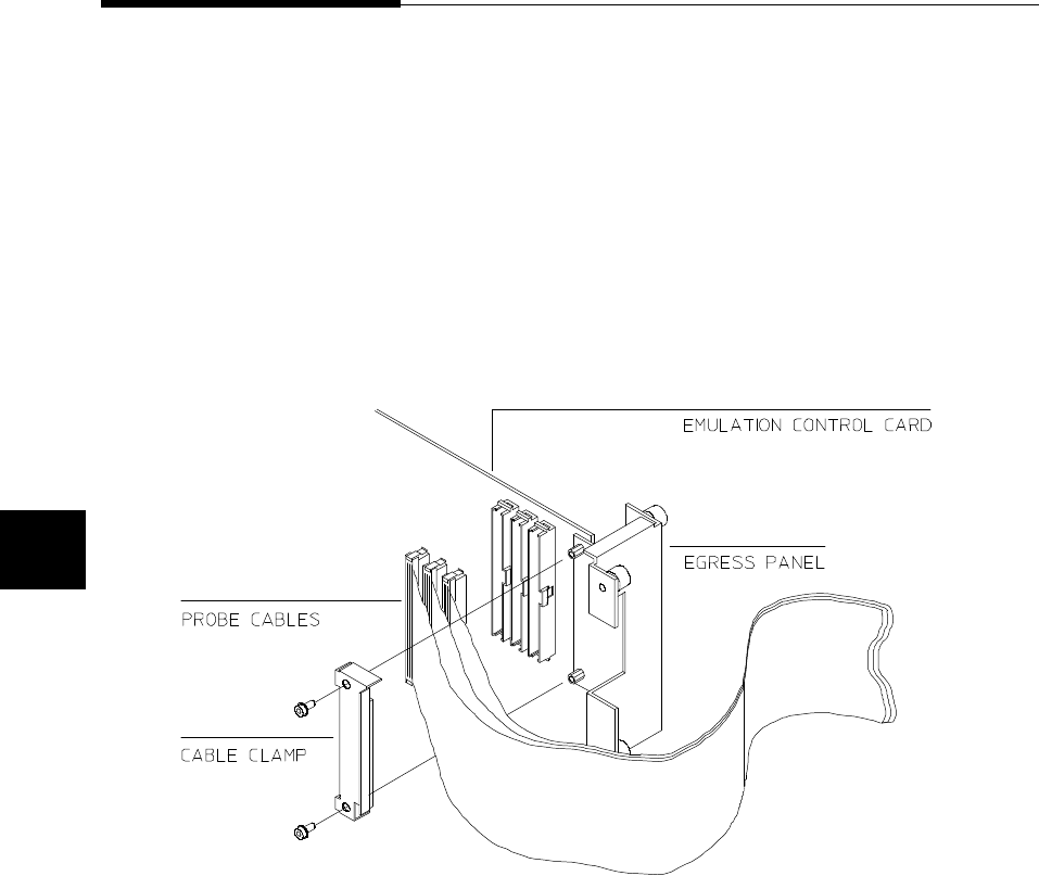
Installing the
Emulation Probe
Cable
The probe cables consist of three ribbon cables. The longest cable
connects to J3 of the emulation control card, and to J3 of the probe. The
shortest cable connects to J1 of the emulation control card and J1 of the
probe. The ribbon cables are held in place on the emulation control card
by a cable clamp attached with two screws. No clamp holds the ribbon
cables in the probe.
1. Secure the cable on the emulation control card with cable
clamp and two screws.
FIgure 4-1 Installing cables to the control board
4-2 In-Circuit Emulation
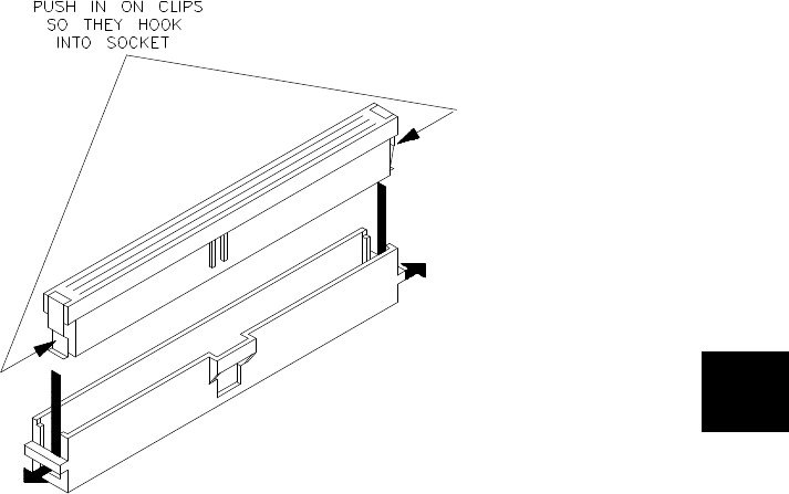
2. When insert the ribbon cables into the appropriate sockets,
press inward on the connector clops so that they into the
sockets as shown.
Figure 4-2 Installing cables into cable sockets
In-Circuit Emulation 4-3
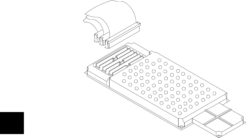
3. Connect the other ends of the cables to the emulation probe.
Figure 4-3 Installing cables to the emulation probe
4-4 In-Circuit Emulation
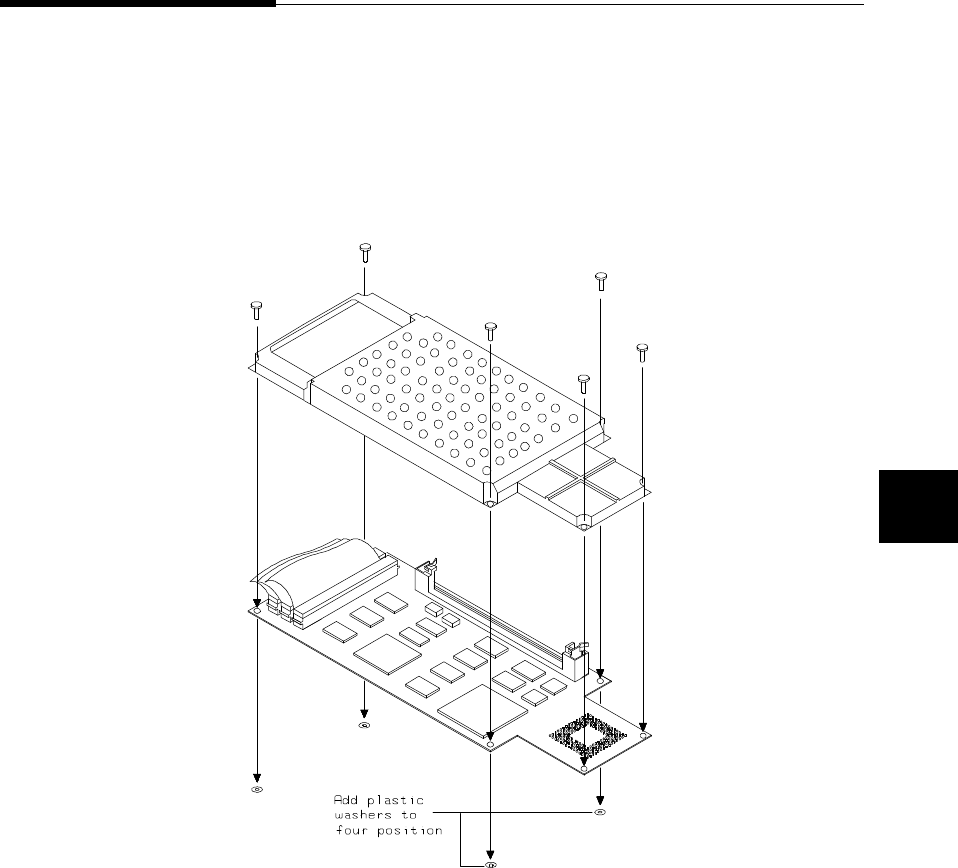
Installing the
Emulation
Memory Module
There are four types of emulation memory modules that can be inserted
into sockets on the probe.
1. Remove plastic rivets that secure the plastic cover on the top
of the emulation probe, and remove the cover. The bottom
cover is only removed when you need to replace a defective
active probe on the exchange program.
Figure 4-4 Opening the emulation probe cover
In-Circuit Emulation 4-5
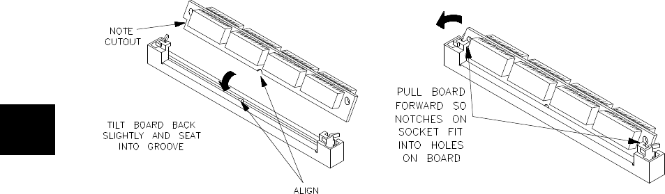
2. Insert emulation memory module on the emulation probe.
There is a cutout on one side of the memory modules so that
they can only be installed one way.
To install memory modules, place the memory module into
the socket groove at an angle. Firmly press the memory
module into the socket to make sure it is completely seated.
Once the memory module is seated in the connector groove,
pull the memory module forward so that the notches on the
socket fit into the holes on the memory module. There are two
latches on the sides of the socket that hold the memory
module in place.
3. Replace the plastic cover, and insert new plastic rivets to
secure the cover.
Figure 4-5 Installing the memory module
4-6 In-Circuit Emulation
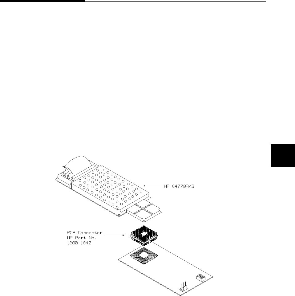
Installing into the
Demo Target
Board
To connect the microprocessor connector to the demo target board,
proceeded with the following instructions.
1. Remove front bezel and connect the power cable to the
connector of the HP 64700B front panel. Refer to the HP
64700 Series Installation/Service manual.
2. With HP 64700B power OFF, connect the emulation probe to
the demo target board. When you install the emulation probe
into the demo target board, be careful not to bend any of the
pins.
After connection the probe to the demo target board, set the
TEST/TARGET MODE and SINGLE CHIP/EXTERNAL BUS
MODE switches. Use TEST MODE position when you run
performance verification test, and use TARGET MODE position when
you run the emulator in "out-of-circuit" mode. You must set SINGLE
CHIP/EXTERNAL BUS switch according to ’cf mode’ configuration.
Figure 4-6 Installing the demo target board
In-Circuit Emulation 4-7
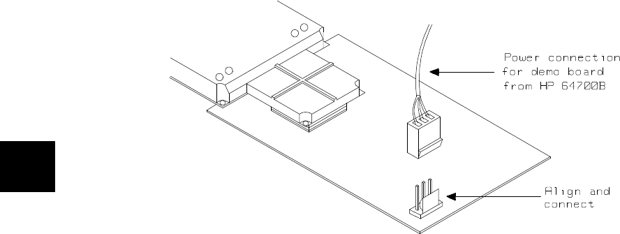
1. Connect the power cable supply wires from the emulator to
demo target board. When attaching the wire cable to the demo
target board, make sure the connector is aligned properly so
that all three pins are connected.
Figure 4-7 Installing the power cable
4-8 In-Circuit Emulation

Installing into a
Target System
The TLCS-9000 emulation probe has a 135-pin PGA connector;
The emulation probe is also provided with a conductive pin protector to
protect the delicate gold-plated pins of the probe connector from
damage due to impact.
Caution Protect against electrostatic discharge. The emulation probe contains
devices that are susceptible to damage by electrostatic discharge.
Therefore, precautionary measures should be taken before handling the
microprocessor connector attached to the end of the probe cable to
avoid damaging the internal components of the probe by electrostatic
electricity.
Caution Make sure target system power is OFF. Do not install the emulation
probe into the target system microprocessor socket with power applied
to the target system. The emulator may be damaged if target system
power is not removed before probe installation.
Caution Make sure pin 1 of probe connector is aligned with pin 1 of the
socket. When installing the emulation probe, be sure that probe is
inserted into the processor socket so that pin 1 of the connector aligns
with pin 1 of the socket. Damage to the emulator probe will result if the
probe is incorrectly installed.
Caution DO NOT use the microprocessor connector without using a pin
protector. The pin protector prevents damage to the prove when
inserting and removing the probe from the flexible adapter.
In-Circuit Emulation 4-9

Caution Compatibility of VOLTAGE/CURRENCY. Please be sure to check
that the voltage/currency of the emulator and target system being
connected are compatible. If there is a discrepancy, damage may result.
Caution Do not apply strong force to PGA-QFP probe. as that might damage
the probe.
Caution Turn ON power. When you start to use the 64770A/B emulator which
is plugged into a target system, you must turn HP 64770A/B power ON
at first, then turn target system power ON.
Caution Turn OFF power Do not turn HP 64770A/B power OFF while the
emulator is plugged into a target system whose power is ON.
4-10 In-Circuit Emulation
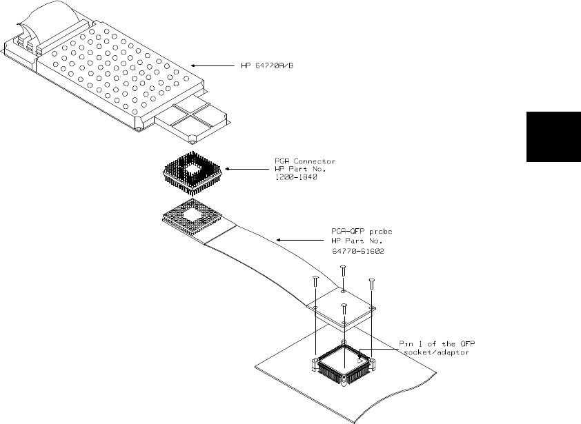
Installing into a
QFP-PGA Adaptor To connect the microprocessor connector to the target system,
proceeded with the following instructions.
1. Attach the QFP socket/adaptor(YAMAICHI
IC149-120K13207-0B) on your target system.
2. Connect the PGA-QFP probe(64770-61602) to the emulation
probe through PGA connector(1200-1840).
3. Install the PGA-QFP probe to the QFP socket/adaptor on your
target system.
Figure 4-8 Installing into a target system board
In-Circuit Emulation 4-11

In-Circuit
configuration
Options
The TLCS-9000 emulator provides configuration options for the
following in-circuit emulation issues. Refer to the "CONFIG_ITEM"
section in the "TLCS-9000 Emulator Specific Command Syntax"
appendix.
Allowing BUSRQ Signal from Target System
You can specify whether the emulator accepts or ignores the BUSRQ
signal from target system. By default, the emulator accepts the BUSRQ
signal from the target system.
The configuration item is "breq"
Allowing Interrupts Requests
You can specify whether the emulator accepts or ignores the Interrupt
requests (NMI, INT0-3 for HP 64770A, IREQ for HP 64770B, internal
interrupt). By default, the emulator accepts the interrupt requests.
The configuration item is "int"
Allowing RESET Signal from Target System
You can specify whether the emulator accepts or ignores the RESET
signal from target system. By default, the emulator accepts the RESET
signal from the target system.
The configuration item is "trst"
4-12 In-Circuit Emulation

Execution Topics The descriptions in this section are of emulation tasks which involve
program execution in general.
Run from Target
System Reset You can use "r rst" command to execute program from target system
reset. You will see "T>" system prompt when you enter "r rst". In this
status, the emulator accept target system reset. Then program starts if
reset signal from target system is released.
Note In the "Awaiting target reset" status(T>), you can not break into the
monitor. If you enter "r rst" in the configuration that emulator ignores
target system reset(cf trst=dis), you must reset the emulator.
Note After you turn on the emulator, you must enter "rst" command and then
"b" command to set the emulation stack pointer.
The TLCS-9000 emulator supports power on reset. If you want
program to be executed by power on reset, execute the following
process.
1) Enter "rst"
2) Enter "b"
3) Enter "r rst"
4) Turn OFF your target system
4-1) If you see the "p>" system prompt, enter "r rst" again.
5) Turn On your target system
In-Circuit Emulation 4-13

Pin State in
Background
While the emulator is running in the monitor, the probe pins of the
emulator are in the following state.
Address Bus Same as running user’s program.
Data Bus Same as running user’s program.
BS R/W Same as running user’s program.
UB/WEH LB/WEL
CAS/OE
RAS0/CE0
RAS1/CE1
RAS2/CE2
RAS3/CE3
Same as running user’s program except accessing
monitor area. When accessing monitor area, High
level.
RFSH/CE Same as running user’s program except accessing
monitor area. When accessing monitor area, Low
level.
4-14 In-Circuit Emulation
Electrical
Characteristics
The AC characteristics of the HP 64770A/B emulator are listed in the
following table
Table 4-1 AC Electrical Specifications(SRAM Mode 00,IO Mode 01)
Characteristic Symbol
TMP97C-
241A
5V
20MHz
HP 64770A
Unit
Worst Case Typical
(*1)
Min Max Min Max
Cycle Time tRC1 100 100 100 ns
Cycle Time (Burst) tRC2 50 50 50 ns
CE Access Time tCE0 60 50 60 ns
OE Access Time tOE1 27 17 30 ns
UB, LB Access Time tOE2 15 515ns
Address Access Time tACC1 60 50 60 ns
Address Access Time(Burst) tACC2 12 215ns
R/W(H) - UB, LB(L) tRWB 20 20 30 ns
Output Disable Time(Output Off) tOD0 15 15 15 ns
Output Hold Time tOH 0 0 0 ns
CE(L) - Write Complete tCW 60 60 79 ns
Address Setup Time tAS 15 15 33 ns
Write Recovery Time tWR 5 5 20 ns
In-Circuit Emulation 4-15

Table 4-1 AC Electrical Specifications(SRAM Mode 00,IO Mode 01)
(Cont’d)
Characteristic Symbol
TMP97C-
241A
5V
20MHz
HP 64770A
Unit
Worst Case Typical
(*1)
Min Max Min Max
Write Pulse Width tWP 30 30 48 ns
UB, LB(H) - Write Data Setup tDS 25 25 35 ns
UB, LB(H) - Write Data Hold tDH 50 0ns
*1 Typical outputs measured with 82pF load
4-16 In-Circuit Emulation

Table 4-2 AC Electrical Specifications(DRAM Mode 00)
Characteristic Symbol
TMP97C-
241A
5V
20MHz
HP 64770A
Unit
Worst Case Typical
(*1)
Min Max Min Max
RAS Cycle Time(Burst) tRC1 150 150 150 ns
RAS Cycle Time(Normal) tRC2 150 150 150 ns
Interleave Cycle Time tPC 90 90 - ns
RAS Access Time tRAC 60 50 60 ns
CAS Access Time tCAC 15 515ns
Access Time Col Address 1 tAA1 30 20 30 ns
Access Time Col Address 2 tAA2 30 20 30 ns
Row Address Setup Time tASR 30 30 42 ns
Row Address Hold Time tRAH 15 15 22 ns
Col Address Setup Time 1 tASC1 10 10 18 ns
Col Address Setup Time 2 tASC2 10 10 - ns
Col Address Hold Time tCAH 15 15 21 ns
RAS - CAS Delay Time tRCD 30 30 - ns
RAS Precharge Time tRP 40 40 50 ns
In-Circuit Emulation 4-17

Table 4-2 AC Electrical Specifications(DRAM Mode 00)
(Cont’d)
Characteristic Symbol
TMP97C-
241A
5V
20MHz
HP 64770A
Unit
Worst Case Typical
(*1)
Min Max Min Max
CAS Precharge Time tCP 30 30 40 ns
CAS - RAS Precharge Time tCRP 30 30 47 ns
RAS Pulse Width tRAS 80 80 100 ns
CAS Pulse Width 1 tCAS1 30 30 48 ns
CAS Pulse Width 2 tCAS2 30 30 41 ns
Write Data Setup Time tDS 40 40 53 ns
Write Data Hold Time tDH 40 40 45 ns
Write Pulse Width tWP1 80 80 98 ns
Write Pulse Width(Page) tWP2 30 30 40 ns
Write Pulse Setup Time tWCS1 50 50 69 ns
Write Pulse Setup Time(Page) tWCS2 55 15ns
Write Pulse Hold Time tWCH1 10 10 30 ns
Write Pulse Hold Time(Page) tWCH2 10 10 25 ns
Output Disable Time tOFF 15 15 15 ns
4-18 In-Circuit Emulation

Table 4-2 AC Electrical Specifications(DRAM Mode 00)
(Cont’d)
Characteristic Symbol
TMP97C-
241A
5V
20MHz
HP 64770A
Unit
Worst Case Typical
(*1)
Min Max Min Max
CAS Precharge Time(Refresh) tCPRF 10 10 - ns
RAS - CAS Precharge Time tPRC 55 -ns
CAS Setup Time tCSR 55 20ns
CAS Hold Time tCHR 80 80 99 ns
*1 Typical outputs measured with 82pF load
In-Circuit Emulation 4-19

Table 4-3 AC Electrical Specifications(PSRAM Mode 00)
Characteristic Symbol
TMP97C-
241A
5V
20MHz
HP 64770A
Unit
Worst Case Typical
(*1)
Min Max Min Max
Random Read, Write Cycle Time tRC 200 200 200 ns
CE Precharge Time tP85 85 85 ns
CE Pulse Width tCE 80 80 98 ns
Address Setup Time for CE tASC 80 80 103 ns
Address Hold Time for CE tAHC 80 80 99 ns
OE Setup Time for CE tOSC 80 80 92 ns
OE Hold Time for CE tOHC 10 10 26 ns
Read Command Setup Time tRCS 80 80 92 ns
Read Command Hold Time tRCH 15 15 45 ns
CE Access Time tCEA 50 40 50 ns
OE Access Time tOEA 25 15 25 ns
OE Output Disable Time tOHZ 15 15 15 ns
CE Output Disable Time tCHZ 15 15 15 ns
Write Command Hold Time tWCH 65 65 80 ns
Write Pulse Width tWP 130 130 148 ns
4-20 In-Circuit Emulation

Table 4-3 AC Electrical Specifications(PSRAM Mode 00)
(Cont’d)
Characteristic Symbol
TMP97C-
241A
5V
20MHz
HP 64770A
Unit
Worst Case Typical
(*1)
Min Max Min Max
Write Command Read Time tCWL 140 140 164 ns
Input Data Setup Time for R/W tDSW 120 120 138 ns
Input Data Hold Time for R/W tDHW 55 5ns
RFSH Delay Time to CE tRFD 55 55 - ns
Auto Refresh Cycle Time tFC 400 400 - ns
RFSH Active CE Delay Time tFCE 205 205 225 ns
RFSH Pulse Width tFAP 105 105 125 ns
RFSH Precharge Time tFP 255 225 265 ns
*1 Typical outputs measured with 82pF load
In-Circuit Emulation 4-21

Table 4-4 AC Electrical Specifications(EPROM Burst Mode)
Characteristic Symbol
TMP97C-
241A
5V
20MHz
HP 64770A
Unit
Worst Case Typical
(*1)
Min Max Min Max
From CE to Output Data Valid tCE 60 50 60 ns
From OE to Output Data Valid tOE 13 315ns
Address Access Time tACC 60 50 60 ns
Output Data Hold Time tOH 00 0ns
From CE to High Impedance Output tDF1 15 15 15 ns
From OE to High Impedance Output tDF2 15 15 15 ns
*1 Typical outputs measured with 82pF load
4-22 In-Circuit Emulation

Table 4-5 AC Electrical Specifications(SCLK Input Mode)
Characteristic Symbol
TMP97C-
241A
5V
20MHz
HP 64770A
Unit
Worst Case Typical
(*1)
Min Max Min Max
SCLK Cycle tSCY 0.8 0.8 - us
Output Data - SCLK Rise tOSS 100 100 - ns
SCLK Rise - Output Data Hold tOHS 150 150 - ns
SCLK Rise - Input Data Hold tHSR 00 -ns
SCLK Rise - Valid Data Input tSRD 450 450 - ns
*1 Typical outputs measured with 82pF load
In-Circuit Emulation 4-23

Table 4-6 AC Electrical Specifications(SCLK Output Mode)
Characteristic Symbol
TMP97C-
241A
5V
20MHz
HP 64770A
Unit
Worst Case Typical
(*1)
Min Max Min Max
SCLK Cycle (Programmable) tSCY 0.8 409.6 0.8 409.6 - us
Output Data - SCLK Rise tOSS 550 550 - ns
SCLK Rise - Output Data Hold tOHS 20 20 - ns
SCLK Rise - Input Data Hold tHSR 00 -ns
SCLK Rise - Valid Data Input tSRD 550 550 - ns
*1 Typical outputs measured with 82pF load
Table 4-7 AC Electrical Specifications(Event Counter)
Characteristic Symbol
TMP97C-
241A
5V
20MHz
HP 64770A
Unit
Worst Case Typical
(*1)
Min Max Min Max
Clock Cycle tVCK 500 500 - ns
Clock Low-level Pulse Width tVCKL 240 240 - ns
Clock High-level Pulse Width tVCKH 240 240 - ns
*1 Typical outputs measured with 82pF load
4-24 In-Circuit Emulation
Table 4-8 AC Electrical Specifications(Interrupt Operation)
Characteristic Symbol
TMP97C-
241A
5V
20MHz
HP 64770A
Unit
Worst Case Typical
(*1)
Min Max Min Max
NMI INT0-3 Low-level Pulse Width tINTAL 200 200 - ns
NMI INT0-3 High-level Pulse Width tINTAH 200 200 - ns
INT4-7 Low-level Pulse Width tINTBL 500 500 - ns
INT4-7 High-level Pulse Width tINTBH 500 500 - ns
*1 Typical outputs measured with 82pF load
Table 4-9 AC Electrical Specifications(Bus Request/Acknowledge)
Characteristic Symbol
TMP97C-
241A
5V
20MHz
HP 64770A
Unit
Worst Case Typical
(*1)
Min Max Min Max
BUSRQ Setup Time for CLK tRBC 30 40 - ns
CLK - BUSAK Fall tCBAL 80 90 - ns
CLK - BUSAK Rise tCBAH 80 90 - ns
Floating Time until BUSAK Fall tABA 0 80 0 85 - ns
Floating Time until BUSAK Rise tABA 0 80 0 85 - ns
*1 Typical outputs measured with 82pF load
In-Circuit Emulation 4-25

Table 4-10 AC Electrical Specifications(SRAM Mode 00,IO Mode 01)
Characteristic Symbol
TMP97CU-
42
5V
16MHz
HP 64770B
Unit
Worst Case Typical
(*1)
Min Max Min Max
Cycle Time tRC1 125 125 100 ns
Cycle Time (Burst) tRC2 62.5 62.5 50 ns
CE Access Time (b16=1) tCE0 65 55 60 ns
CE Access Time (b16=0) tCE0 80 70 60 ns
OE Access Time tOE1 53 43 30 ns
UB, LB Access Time tOE2 43 33 15 ns
Address Access Time tACC1 85 75 60 ns
Address Access Time(Burst) tACC2 27 17 15 ns
R/W(H) - UB, LB(L) tRWB 26 26 30 ns
Output Disable Time(Output Off) tOD0 21 21 15 ns
Output Hold Time tOH 0 0 0 ns
CE(L) - Write Complete tCW 78 78 79 ns
Address Setup Time tAS 26 26 33 ns
Write Recovery Time tWR 11 11 20 ns
4-26 In-Circuit Emulation

Table 4-10 AC Electrical Specifications(SRAM Mode 00,IO Mode 01)
(Cont’d)
Characteristic Symbol
TMP97CU-
42
5V
16MHz
HP 64770B
Unit
Worst Case Typical
(*1)
Min Max Min Max
Write Pulse Width tWP 52 52 48 ns
UB, LB(H) - Write Data Setup tDS 52 52 35 ns
UB, LB(H) - Write Data Hold tDH 11 11 0 ns
*1 Typical outputs measured with 82pF load
In-Circuit Emulation 4-27

Table 4-11 AC Electrical Specifications(DRAM Mode 00)
Characteristic Symbol
TMP97CU-
42
5V
16MHz
HP 64770B
Unit
Worst Case Typical
(*1)
Min Max Min Max
RAS Cycle Time(Burst) tRC1 187 187 150 ns
RAS Cycle Time(Normal) tRC2 187 187 150 ns
Interleave Cycle Time tPC 125 125 - ns
RAS Access Time tRAC 85 75 60 ns
CAS Access Time tCAC 27 17 15 ns
Access Time Col Address 1 tAA1 53 43 30 ns
Access Time Col Address 2 tAA2 38 28 30 ns
Row Address Setup Time tASR 51 51 42 ns
Row Address Hold Time tRAH 21 21 22 ns
Col Address Setup Time 1 tASC1 21 21 18 ns
Col Address Setup Time 2 tASC2 16 16 - ns
Col Address Hold Time tCAH 21 21 21 ns
RAS - CAS Delay Time tRCD 52 52 - ns
RAS Precharge Time tRP 52 52 50 ns
4-28 In-Circuit Emulation

Table 4-11 AC Electrical Specifications(DRAM Mode 00)
(Cont’d)
Characteristic Symbol
TMP97CU-
42
5V
16MHz
HP 64770B
Unit
Worst Case Typical
(*1)
Min Max Min Max
CAS Precharge Time tCP 52 52 40 ns
CAS - RAS Precharge Time tCRP 52 52 47 ns
RAS Pulse Width tRAS 115 115 100 ns
CAS Pulse Width 1 tCAS1 52 52 48 ns
CAS Pulse Width 2 tCAS2 52 52 41 ns
Write Data Setup Time tDS 73 73 53 ns
Write Data Hold Time tDH 52 52 45 ns
Write Pulse Width tWP1 115 115 98 ns
Write Pulse Width(Page) tWP2 52 52 40 ns
Write Pulse Setup Time tWCS1 68 68 69 ns
Write Pulse Setup Time(Page) tWCS2 11 11 15 ns
Write Pulse Hold Time tWCH1 26 26 30 ns
Write Pulse Hold Time(Page) tWCH2 26 26 25 ns
Output Disable Time tOFF 21 21 15 ns
In-Circuit Emulation 4-29

Table 4-11 AC Electrical Specifications(DRAM Mode 00)
(Cont’d)
Characteristic Symbol
TMP97CU-
42
5V
16MHz
HP 64770B
Unit
Worst Case Typical
(*1)
Min Max Min Max
CAS Precharge Time(Refresh) tCPRF 16 16 - ns
RAS - CAS Precharge Time tPRC 11 11 - ns
CAS Setup Time tCSR 11 11 20 ns
CAS Hold Time tCHR 105 105 99 ns
*1 Typical outputs measured with 82pF load
4-30 In-Circuit Emulation

Table 4-12 AC Electrical Specifications(PSRAM Mode 00)
Characteristic Symbol
TMP97CU-
42
5V
16MHz
HP 64770B
Unit
Worst Case Typical
(*1)
Min Max Min Max
Random Read, Write Cycle Time tRC 250 250 200 ns
CE Precharge Time tP110 110 85 ns
CE Pulse Width tCE 115 115 98 ns
Address Setup Time for CE tASC 115 115 103 ns
Address Hold Time for CE tAHC 110 110 99 ns
OE Setup Time for CE tOSC 115 115 92 ns
OE Hold Time for CE tOHC 21 21 26 ns
Read Command Setup Time tRCS 105 105 92 ns
Read Command Hold Time tRCH 26 26 45 ns
CE Access Time tCEA 85 75 50 ns
OE Access Time tOEA 53 43 25 ns
OE Output Disable Time tOHZ 21 21 15 ns
CE Output Disable Time tCHZ 21 21 15 ns
Write Command Hold Time tWCH 88 88 80 ns
Write Pulse Width tWP 177 177 148 ns
In-Circuit Emulation 4-31

Table 4-12 AC Electrical Specifications(PSRAM Mode 00)
(Cont’d)
Characteristic Symbol
TMP97CU-
42
5V
16MHz
HP 64770B
Unit
Worst Case Typical
(*1)
Min Max Min Max
Write Command Read Time tCWL 203 203 164 ns
Input Data Setup Time for R/W tDSW 177 177 138 ns
Input Data Hold Time for R/W tDHW 11 11 5 ns
RFSH Delay Time to CE tRFD 83 83 - ns
Auto Refresh Cycle Time tFC 500 500 - ns
RFSH Active CE Delay Time tFCE 271 271 225 ns
RFSH Pulse Width tFAP 146 146 125 ns
RFSH Precharge Time tFP 333 333 265 ns
*1 Typical outputs measured with 82pF load
4-32 In-Circuit Emulation

Table 4-13 AC Electrical Specifications(EPROM Burst Mode)
Characteristic Symbol
TMP97CU-
42
5V
16MHz
HP 64770B
Unit
Worst Case Typical
(*1)
Min Max Min Max
From CE to Output Data Valid tCE 80 70 60 ns
From OE to Output Data Valid tOE 27 17 15 ns
Address Access Time tACC 85 75 60 ns
Output Data Hold Time tOH 00 0ns
From CE to High Impedance Output tDF1 21 21 15 ns
From OE to High Impedance Output tDF2 21 21 15 ns
*1 Typical outputs measured with 82pF load
In-Circuit Emulation 4-33

Table 4-14 AC Electrical Specifications(Bus Request/Acknowledge)
Characteristic Symbol
TMP97CU-
42
5V
16MHz
HP 64770B
Unit
Worst Case Typical
(*1)
Min Max Min Max
BUSRQ Setup Time for CLK tRBC -- -ns
CLK - BUSAK Fall tCBAL ---ns
CLK - BUSAK Rise tCBAH ---ns
Floating Time until BUSAK Fall tABA 0 80 0 85 - ns
Floating Time until BUSAK Rise tABA 0 80 0 85 - ns
*1 Typical outputs measured with 82pF load
4-34 In-Circuit Emulation
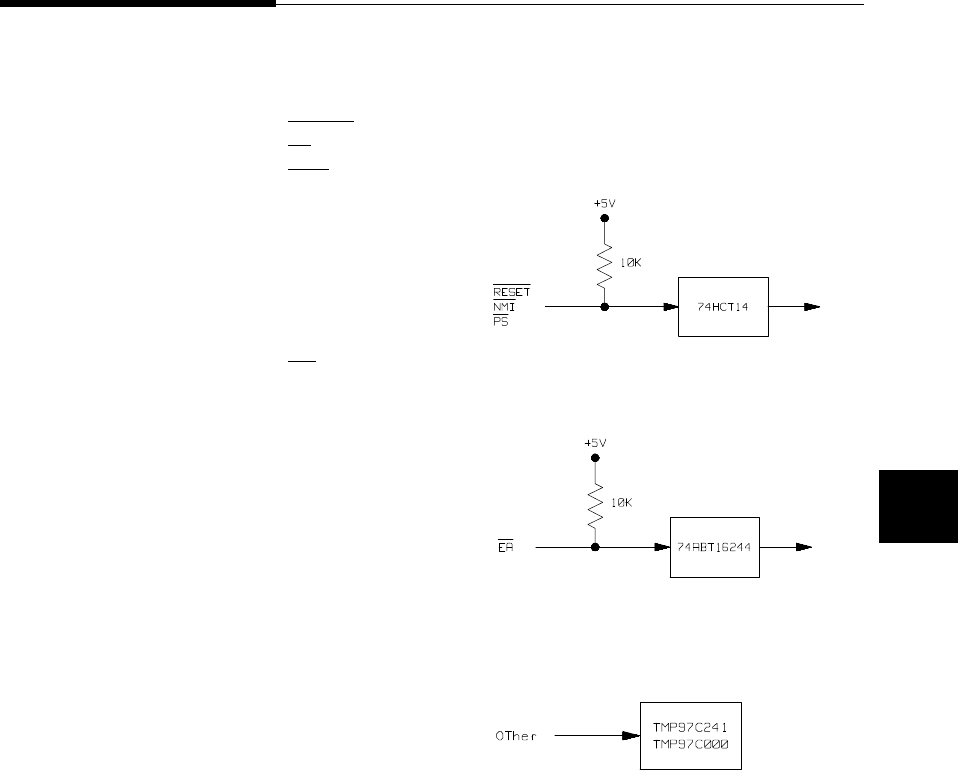
Target System
Interface
RESET
PS
NMI
These signals are connected to 74HC14 through
10K ohm pull-up register.
EA These signals are connected to 74ABT16244
through 10K ohm pull-up register.
Other signals These signals are connected to TLCS-9000
emulation processor.
In-Circuit Emulation 4-35

Notes
4-36 In-Circuit Emulation

A
TLCS-9000 Emulator Specific Command Syntax
The following pages contain descriptions of command syntax specific
to the TLCS-9000 emulator. The following syntax items are included
(several items are parts of other command syntax):
<ACCESS_MODE>. May be specified in the mo (display
and access mode), m (memory) commands. The access mode
is used when the m commands modify target memory or I/O
locations.
<CONFIG_ITEMS>. May be specified in the cf (emulator
configuration) and help cf commands.
<DISPLAY_MODE>. May be specified in the mo (display
and access mode), m (memory), and ser (search memory for
data) commands. The display mode is used when memory
locations are displayed or modified.
<REG_NAME> and <REG_CLASS>. May be specified in
the reg (register) command.
Emulator Specific Command Syntax A-1

ACCESS_MODE
Summary Specify cycles used by monitor when accessing target system memory
or I/O.
Syntax
Function The <ACCESS_MODE> specifies the type of microprocessor cycles
that are used by the monitor program to access target memory or I/O
locations. When a command requests the monitor to read or write to
target system memory or I/O, the monitor program will look at the
access mode setting to determine whether byte or word instructions
should be used.
Parameters
b Byte. Selecting the byte access mode specifies that
the emulator will access target memory using byte
cycles (one byte at a time).
w Word. Selecting the word access mode specifies
that the emulator will access target memory using
word cycles (one word at a time).
Defaults In the TLCS-9000, the <ACCESS_MODE> is b at power up
initialization. Access mode specifications are saved; that is, when a
command changes the access mode, the new access mode becomes the
current default.
Related Commands mo (specify display and access modes)
A-2 Emulator Specific Command Syntax

CONFIG_ITEMS
Summary TLCS-9000 emulator configuration items.
Syntax
Emulator Specific Command Syntax A-3

Function The <CONFIG_ITEMS> are the TLCS-9000 specific configuration
items which can be displayed/modified using the cf (emulator
configuration) command. If the "=" portion of the syntax is not used,
the current value of the configuration item is displayed.
Parameters
proc
(HP 64770A) Processor Type. This configuration item selects the
processor to be emulated.
Setting proc equal to none specifies that any
processor is not selected.
Setting proc equal to 97ps40 specifies that
TMP97PS40F/CS40F and TMP97C241F are
selected. If you emulate TMP97C241F, you must
specify that "cf mode=ext"
Setting proc equal to 97cm40 specifies that
TMP97CM40F is selected.
Setting proc equal to 97pw40 specifies that
TMP97PW40F/CW40F is selected.
proc
(HP 64770B) Processor Type. This configuration item selects the
processor to be emulated.
Setting proc equal to 97cs42 specifies that
TMP97CS42/PU42(64K mode) is selected.
Setting proc equal to 97cu42 specifies that
TMP97CU42/PU42(96K mode) is selected.
Setting proc equal to 97cw42 specifies that
TMP97PW42/CW42 is selected.
A-4 Emulator Specific Command Syntax

Note You must specify processor type before operating the emulator.
Otherwise, you can not operate the emulator correctly.
Note The TLCS-9000 emulator is reset state and the all mapping terms are
deleted after specifying this configuration item. And "loc" and "vector"
items are setting default value.
mode Emulator Processor Operation Mode. This
configuration item selects emulator processor
operation mode.
Setting mode equal to single specifies that single
chip mode is selected.
Selecting single chip mode requires emulation
memory for internal ROM emulation.
Setting mode equal to ext specifies that external
bus mode is selected.
Note The TLCS-9000 emulator operates in accordance with this
configuration instead of EA signal from target system.
But when the emulator breaks into the monitor from reset state, EA
signal must accord with this configuration.
Note The TLCS-9000 emulator is reset state and the all mapping terms are
deleted after specifying this configuration item. And "loc" and "vector"
items are setting default value.
Emulator Specific Command Syntax A-5
vector Address of Vector Table. This configuration item
allows you to specify vector address. The vector
address must be specify on 2K boundary.
If you specify "cf mode=single", this configuration
item is invalid.
If you specify "cf mode=ext", emulator uses the
vector area which is specified by this configuration.
Because this configuration is used whenever the
emulator breaks into the monitor regardless ’cf
emvbp’ configuration, you must specify address
which accord with vector address.
The default value is specified as following.
Processor Type Default Value
none 0ff0000h
97ps40 0ff0000h
97cm40 0f80000h
97pw40 0fe0000h
97cs42 0fef800h
97cu42 0fe7800h
97cw42 0fdf800h
Note The TLCS-9000 emulator is reset state and the all mapping terms are
deleted after specifying this configuration item.
A-6 Emulator Specific Command Syntax

loc Monitor Location This configuration item allows
you specify location of monitor program. The
monitor must be located on a 64K boundary.
The start address of the monitor must be located at a
address 10000h thru EF0000h.
The default value is 0f0000h.
Note The TLCS-9000 emulator is reset state and the all mapping terms are
deleted after specifying this configuration item. And "vector" item is
setting default value.
Emulator Specific Command Syntax A-7

trst Respond to Target Reset. This configuration item
allows you to specify whether or not the emulator
responds target system reset while running in user
program or waiting for target system reset.
While running in monitor, the TLCS-9000 emulator
ignores target system reset completely independent
on this setting.
Setting trst equal to en specifies that the emulator
responds to reset from target system. In this
configuration, emulator will accept reset and
execute from reset vector in the same manner as
actual microprocessor after reset is inactivated.
Setting trst equal to dis specifies that the emulator
ignores reset from target system.
The TLCS-9000 emulator is reset state after
specifying this configuration item.
Note When you use the r rst (run from reset) command in-circuit to run
form processor reset after the target reset input, you must use "cf
trst=en" configuration setting.
emvbp Emulation Vector Base Pointer. This
configuration item allows you to specify whether or
not the emulator uses emulation base pointer.
If you specify "cf mode=single", this configuration
item is invalid.
Setting emvbp equal to en specifies that the
emulator uses emulation base vector pointer (VBP)
and the value for the VBP is calculated from the
A-8 Emulator Specific Command Syntax

value specified by ’cf vector’ configuration item. If
vector area is mapped to target memory, the copy of
vector area is used instead of target memory.
Setting emvbp equal to dis specifies that the
emulator uses target system VBP. You must set
vector entry to realize emulator features(break,
single-step, software breakpoint).
Note The TLCS-9000 emulator is reset state and the all mapping terms are
deleted after specifying this configuration item.
cbp Current Bank Pointer. This configuration item
allows you to specify value of CBP register when
you break from reset state.
This configuration item is invalid when single chip
mode (cf mode=single) is selected, or emulation
VBP is enabled (cf emvbp=en) and vector area is
mapped as emulation memory.
When vector area is mapped as target memory or
emulation VBP is disabled (cf emvbp=dis), value
specified by this configuration is set to the CBP
register when the emulator breaks into the monitor
from reset state.
wdt Enable/Disable Watch-dog Timer. (HP 64770A
only)This configuration item allows you to specify
whether watch-dog timer is enable or disable when
user’s program running.
This configuration item is valid when the emulator
breaks into the monitor from reset state.
Setting wdt equal to en specifies that the watch-dog
timer is enabled when running user’s program.
Emulator Specific Command Syntax A-9

Setting wdt equal to dis specifies that the
watch-dog timer is disabled when running user’s
program.
breq Respond to Bus Request. This configuration item
allows you to specify whether or not the emulator
accepts BUSRQ signal generated by the target
system.
Setting breq equal to en specifies that the emulator
accepts BUSRQ signal. When the hold is accepted,
the emulator will respond as actual microprocessor.
Setting breq equal to dis specifies that the emulator
ignores BUSRQ signal from target system.
int Enable/disable user Interrupts. This
configuration item allows you to specify whether
interrupt from target system,(NMI and INT0-3 for
HP 64770A, and IREQ for 64770B) and an internal
peripheral during user program execution are
accepted or ignored by the emulator.
Setting int equal to en specifies that the emulator
accepts interrupts.
Setting int equal to dis specifies that the emulator
ignores interrupts.
A-10 Emulator Specific Command Syntax

Note When target interrupts signal is enabled , it is in effect while the
emulator is running in the target program. While the emulator is
running monitor, interrupts will be suspended until the monitor is
finished.
rrt Restrict to Real-Time Runs. This configuration
item allows you to specify whether program
execution should take place in real-time or whether
commands should be allowed to cause breaks to the
monitor during program execution.
Setting rrt equal to en specifies that the emulator’s
execution is restricted to real-time. In this setting,
commands which access target system resources
(display/modify registers, display/modify memory
or I/O) are not allowed.
setting rrt equal to dis specifies that the emulator
breaks to the monitor during program execution.
Defaults The default values of TLCS-9000 emulator configuration items are
listed below.
cf proc=none
cf mode=ext
cf vector=0ff0000
cf loc=0f0000
cf trst=en
cf emvbp=en
cf cbp=0
cf wdt=en
cf breq=en
cf int=en
cf rrt=dis
Related Commands help
You can get an on line help information for particular configuration
items by typing:
R>help cf <CONFIG_ITEM>
Emulator Specific Command Syntax A-11

DISPLAY_MODE
Summary Specify the memory display format or the size of memory locations to
be modified.
Syntax
Function The <DISPLAY_MODE> specifies the format of the memory display
or the size of the memory which gets changed when memory is
modified.
Parameters
b Byte. Memory is displayed in a byte format, and
when memory locations are modified, bytes are
changed.
wWord. Memory is displayed in a word format, and
when memory locations are modified, words are
changed.
d Double Word. Memory is displayed in a double
word format, and when memory locations are
modified, double words are changed.
m Mnemonic. Memory is displayed in mnemonic
format; that is, the contents of memory locations are
inverse-assembled into mnemonics and operands.
When memory locations are modified, the last
non-mnemonic display mode specification is used.
A-12 Emulator Specific Command Syntax

You cannot specify this display mode in the ser
(search memory for data) command.
Defaults At power up or after init,in the TLCS-9000 Emulator, the
<ACCESS_MODE> and <DISPLAY_MODE> are b.
Display mode specifications are saved; that is, when a command
changes the display mode, the new display mode becomes the current
default.
Related Commands mo (specify access and display modes)
m (memory display/modify)
ser (search memory for data)
Emulator Specific Command Syntax A-13

REGISTER CLASS
and NAME
Summary TLCS-9000 register designator. All available register class names and
register names are listed below.
<REG_CLASS>
<REG_NAME> Description
*(All basic registers)
pc
rw0
rw1
rw2
rw3
rw4
rw5
rw6
rw7
rw8
rw9
rw10
rw11
rw12
rw13
rw14
rw15
isp
usp
fp
cbp
pbp
psw
BASIC registers.
A-14 Emulator Specific Command Syntax

pbank(Previous bank registers)
ppc
ppsw
ppbp
pr0
pr1
pr2
pr3
pr4
pr5
pr6
pr7
pr8
pr9
pr10
pr11
pr12
pr13
pr14
pr15
Saved PC
Saved PSW
Saved PBP
pw0 on previous bank
pw1 on previous bank
pw2 on previous bank
pw3 on previous bank
pw4 on previous bank
pw5 on previous bank
pw6 on previous bank
pw7 on previous bank
pw8 on previous bank
pw9 on previous bank
pw10 on previous bank
pw11 on previous bank
pw12 on previous bank
pw13 on previous bank
pw14 on previous bank
pw15 on previous bank
sys(System Control registers) (HP64770A Only)
wdmod
wdcr
ch0cr
ch1cr
ch2cr
ch3cr
refhreg
Watch dog timer mode
Watch dog timer control (Write Only)
Memory controller channel 0
Memory controller channel 1
Memory controller channel 2
Memory controller channel 3
Refresh control
sys(System control registers) (HP64770B Only)
omr
pdmr
stbymd
ch0cr
ch1cr
ch2cr
ch3cr
refhreg
Operation mode
Power down mode
Stand-by mode
Memory controller channel 0
Memory controller channel 1
Memory controller channel 2
Memory controller channel 3
Refresh control
Emulator Specific Command Syntax A-15

tmr(Timer registers)(HP 64770A Only)
trun0
trun4
trdc0
trdc4
tffcr0
tffcr4
t01mod
t23mod
t45mod
t67mod
treg0
treg1
treg2
treg3
treg4
treg5
treg6
treg7
tt0run
tt1run
tt0mod
tt1mod
tt0ffcr
tt1ffcr
ttreg0
ttreg1
ttreg2
ttreg3
cap1
cap2
cap3
cap4
Timer control (TRUN0123)
Timer control (TRUN4567)
Double buffer control (TRDC0123)
Double buffer control (TRDC4567)
Timer flip-flop control (TFFCR0123)
Timer flip-flop control (TFFCR4567)
Timer source clk and mode (Write Only)
Timer source clk and mode (Write Only)
Timer source clk and mode (Write Only)
Timer source clk and mode (Write Only)
Timer register 0 (Write Only)
Timer register 1 (Write Only)
Timer register 2 (Write Only)
Timer register 3 (Write Only)
Timer register 4 (Write Only)
Timer register 5 (Write Only)
Timer register 6 (Write Only)
Timer register 7 (Write Only)
Timer control 0
Timer control 1
Timer source clk and mode
Timer source clk and mode
Timer flip-flop control
Timer flip-flop control
Timer register 0 (Write Only)
Timer register 1 (Write Only)
Timer register 2 (Write Only)
Timer register 3 (Write Only)
Capture register 1 (Read Only)
Capture register 2 (Read Only)
Capture register 3 (Read Only)
Capture register 4 (Read Only)
A-16 Emulator Specific Command Syntax

gto(General output timer registers)(HP 64770B Only)
gtr
cprs0
cprs1
cprs2
cprs3
cprs4
cprs5
cprs6
cprs7
cprr0
cprr1
cprr2
cprr3
cprr4
cprr5
cprr6
cprr7
domr1
docr
dor1
lgto
gtoen
General timer
Compare reg for "Set ch0"
Compare reg for "Set ch1"
Compare reg for "Set ch2"
Compare reg for "Set ch3"
Compare reg for "Set ch4"
Compare reg for "Set ch5"
Compare reg for "Set ch6"
Compare reg for "Set ch7"
Compare reg for "Reset ch0"
Compare reg for "Reset ch1"
Compare reg for "Reset ch2"
Compare reg for "Reset ch3"
Compare reg for "Reset ch4"
Compare reg for "Reset ch5"
Compare reg for "Reset ch6"
Compare reg for "Reset ch7"
Digital output mode
Digital output control
Digital out (Read Only)
Output level of GTO
GTO enable
Emulator Specific Command Syntax A-17

gti(General input timer registers)(HP 64770B Only)
cpcl0
cpcl1
cpcl2
cpcl3
gta0p
gta1p
gta2p
gta3p
gta0n
gta1n
gta2n
gta3n
gtb0
gtb1
gtb2
gtb3
Pulse counter latch 0 (Read Only)
Pulse counter latch 1 (Read Only)
Pulse counter latch 2 (Read Only)
Pulse counter latch 3 (Read Only)
GTIA positive edge 0 (Read Only)
GTIA positive edge 1 (Read Only)
GTIA positive edge 2 (Read Only)
GTIA positive edge 3 (Read Only)
GTIA negative edge 0 (Read Only)
GTIA negative edge 1 (Read Only)
GTIA negative edge 2 (Read Only)
GTIA negative edge 3 (Read Only)
GTIB edge 0 (Read Only)
GTIB edge 1 (Read Only)
GTIB edge 2 (Read Only)
GTIB edge 3 (Read Only)
pout(Pulse timer output registers)(HP 64770B Only)
tioc
lpout
domr2
dor2
cprd0
cprd1
cprd2
cprd3
cprd4
cprd5
cprd6
cprd7
TIO control
Output level of POUT (Read Only)
Digital output mode
Digital out
Compare register for Pout 0
Compare register for Pout 1
Compare register for Pout 2
Compare register for Pout 3
Compare register for Pout 4
Compare register for Pout 5
Compare register for Pout 6
Compare register for Pout 7
A-18 Emulator Specific Command Syntax

poc(Pulse output down-counter registers)(HP 64770B Only)
cpoc0
cpoc1
cpoc2
cpoc3
cpoc4
cpoc5
cpoc6
cpoc7
Pulse output counter of ch0
Pulse output counter of ch1
Pulse output counter of ch2
Pulse output counter of ch3
Pulse output counter of ch4
Pulse output counter of ch5
Pulse output counter of ch6
Pulse output counter of ch7
sc(Serial communication registers) (HP 64770A Only)
sc0cr
sc0mod
br0cr
sc0buf
sc1cr
sc1mod
br1cr
sc1buf
sc2cr
sc2mod
br2cr
sc2buf
ode
Serial channel 0 control
Serial channel 0 mode
Serial channel 0 baud rate control
Serial channel 0 buffer
Serial channel 1 control
Serial channel 1 mode
Serial channel 1 baud rate control
Serial channel 1 buffer
Serial channel 2 control
Serial channel 2 mode
Serial channel 2 baud rate control
Serial channel 2 buffer
Port 8 open-drain enable
Emulator Specific Command Syntax A-19

sci(Serial interface registers) (HP 64770B Only)
scatb
scarb
scamr
scasr
scacr
sc2tb
sc2rb
sc2mr
sc2sr
sc2cr
scbtb
scbrb
scbmr
scbsr
scbcr
SCIA transmit buffer (Write Only)
SCIA receive buffer (Read Only)
SCIA mode
SCIA status (Read Only)
SCIA control
SCI2 transmit buffer (Write Only)
SCI2 receive buffer (Read Only)
SCI2 mode
SCI2 status (Read Only)
SCI2 control
SCIB transmit buffer (Write Only)
SCIB receive buffer (Read Only)
SCIB mode
SCIB status (Read Only)
SCIB control
sei(Expansion serial interface registers) (HP 64770B Only)
ascr
asbf
akcr
skbf
se2cr
se3bo
se3bi
se3sfo
se3sfi
se3cr
sesr
secr
Asynchronous mode command (Write Only)
Asynchronous mode buffer (Read Only)
Synchronous mode command (Write Only)
Synchronous mode buffer (Read Only)
SEI2 control & status
SEI3 buffer register out (Write Only)
SEI3 buffer register in (Read Only)
SEI3 shift register out (Write Only)
SEI3 shift register in (Read Only)
SEI3 control
SEI shif register
SEI control & status
smp(Serial monitor port registers) (HP 64770B Only)
smisr
smosr
smfull
SMP input shift register (Read Only)
SMP output shift register (Write Only)
SMP input full register
A-20 Emulator Specific Command Syntax

ad(A/D converter registers) (HP 64770A Only)
admod
adccs
adreg04
adreg15
adreg26
adreg37
A/D converter mode
ADC channel selector
AD result 04 (Read Only)
AD result 15 (Read Only)
AD result 26 (Read Only)
AD result 37 (Read Only)
dma(DMA controller registers) (HP 64770B Only)
mar0
dtcr0
mar1
dtcr1
mar2
dtcr2
mar3
dtcr3
mar4
dtcr4
mar5
dtcr5
chsr0
chsr1
chsr2
Memory address 0
Data transfer count 0
Memory address 1
Data transfer count 1
Memory address 2
Data transfer count 2
Memory address 3
Data transfer count 3
Memory address 4
Data transfer count 4
Memory address 5
Data transfer count 5
Channel status 0 (Read Only)
Channel status 1 (Read Only)
Channel status 2 (Read Only)
Emulator Specific Command Syntax A-21

int(Interrupt control registers) (HP 64770A Only)
inte0
inte1
inte2
inte3
inte4
inte5
inte6
inte7
intet0
intet1
intet2
intet3
intet4
intet5
intet6
intet7
intett0
intett1
intett2
intett3
intes0r
intes0t
intes1r
intes1t
intes2r
intes2t
intead
intetask
inmimc
Interrupt enable 0
Interrupt enable 1
Interrupt enable 2
Interrupt enable 3
Interrupt enable 4
Interrupt enable 5
Interrupt enable 6
Interrupt enable 7
Interrupt enable 8 bit timer 0
Interrupt enable 8 bit timer 1
Interrupt enable 8 bit timer 2
Interrupt enable 8 bit timer 3
Interrupt enable 8 bit timer 4
Interrupt enable 8 bit timer 5
Interrupt enable 8 bit timer 6
Interrupt enable 8 bit timer 7
Interrupt enable 16 bit timer TTREG0
Interrupt enable 16 bit timer TTREG1
Interrupt enable 16 bit timer TTREG2
Interrupt enable 16 bit timer TTREG3
Interrupt enable serial 0 receive
Interrupt enable serial 0 transmit
Interrupt enable serial 1 receive
Interrupt enable serial 1 transmit
Interrupt enable serial 2 receive
Interrupt enable serial 2 transmit
Interrupt enable A/D
Interrupt enable TASK
Interrupt NMI input mode control
A-22 Emulator Specific Command Syntax

pic(Interrupt control registers) (HP 64770B Only)
gticr
tiicr0
tiicr1
tiicr2
toicr0
toicr1
toicr2
toicr3
poicr0
poicr1
sioicr0
dmaicr0
dmaicr1
swicr0
swicr1
swicr2
nmirq
gtirq
tiirq
toisrq
toirrq
poirq
dmairq
swirq
General timer interrupt control
GTI interrupt control 0
GTI interrupt control 1
GTI interrupt control 2
GTO interrupt control 0
GTO interrupt control 1
GTO interrupt control 2
GTO interrupt control 3
POUT interrupt control 0
POUT interrupt control 1
SCI interrupt control
SCI2 interrupt control
SCI3 interrupt control
SOFTWARE interrupt control 0
SOFTWARE interrupt control 1
SOFTWARE interrupt control 2
NMI interrupt request flag
GT interrupt request flag
Timer input interrupt request flag
Timer output set interrupt request
Timer output reset interrupt request
Pout interrupt flag
DMA interrupt flag
SWI interrupt flag
Emulator Specific Command Syntax A-23

prt(Port registers) (HP 64770A Only)
pt0
pt1
pt2
pt3
pt4
pt5
pt6
pt7
pt8
pt9
pta
ptb
ptc
p0cr
p0fc
p1cr
p1fc
p2cr
p2fc
p3cr
p3fc
p4cr
p4fc
p5cr
p5fc
p6cr
p6fc
p7cr
p7fc
p8cr
p8fc
p9cr
p9fc
pacr
pafc
pbcr
pbfc
Port 0
Port 1
Port 2
Port 3
Port 4
Port 5
Port 6
Port 7
Port 8
Port 9
Port A
Port B
Port C (Read Only)
Port 0 control (Write Only)
Port 0 function (Write Only)
Port 1 control (Write Only)
Port 1 function (Write Only)
Port 2 control (Write Only)
Port 2 function (Write Only)
Port 3 control (Write Only)
Port 3 function (Write Only)
Port 4 control (Write Only)
Port 4 function (Write Only)
Port 5 control (Write Only)
Port 5 function (Write Only)
Port 6 control (Write Only)
Port 6 function (Write Only)
Port 7 control (Write Only)
Port 7 function (Write Only)
Port 8 control (Write Only)
Port 8 function (Write Only)
Port 9 control (Write Only)
Port 9 function (Write Only)
Port A control (Write Only)
Port A function (Write Only)
Port B control (Write Only)
Port B function (Write Only)
A-24 Emulator Specific Command Syntax

prt(Port registers) (HP 64770B Only)
p0
p1
p2
p3
p4
p5
p6
p9
pj
pf
pg
pm
ph
ps
p0cr
p0fc
p1cr
p1fc
p2cr
p2fc
p3cr
p3fc
p4cr
p4fc
p5cr
p5fc
p6cr
p6fc
p9cr
pjcr
pfcr
pgcr
pmcr
phcr
pscr
Port 0 data
Port 1 data
Port 2 data
Port 3 data
Port 4 data
Port 5 data
Port 6 data
Port 9 data
Port J data
Port F data
Port G data
Port M data
Port H data
Port S data
Port 0 control
Port 0 function
Port 1 control
Port 1 function
Port 2 control
Port 2 function
Port 3 control
Port 3 function
Port 4 control
Port 4 function
Port 5 control
Port 5 function
Port 6 control
Port 6 function
Port 9 control
Port J control (Write Only)
Port F control
Port G control
Port M control
Port H control
Port S control
Emulator Specific Command Syntax A-25

pfsr0
pfsr1
pfsr2
pfsr3
pfsr4
pfsr5
pfsr6
Port function select 0
Port function select 1
Port function select 2
Port function select 3
Port function select 4 (Write Only)
Port function select 5
Port function select 6
OTHER(Other registers)
rb0
rb1
rb2
rb3
rb4
rb5
rb6
rb7
rb8
rb9
rb10
rb11
rb12
rb13
rb14
rb15
rd0
rd2
rd4
rd6
rd8
rd10
rd12
rd14
uspl
usph
fpl
fph
RB0
RB1
RB2
RB3
RB4
RB5
RB6
RB7
RB8
RB9
RB10
RB11
RB12
RB13
RB14
RB15
RD0
RD2
RD4
RD6
RD8
RD10
RD12
RD14
lower 16 bits of USP
upper 16 bits of USP
lower 16 bits of FP
upper 16 bits of FP
A-26 Emulator Specific Command Syntax

Function The <REG_CLASS> names may be used in the reg(register)
command to display a class of TLCS-9000 registers.
The <REG_NAME> names may be used with the reg command to
either display or modify the contents of TLCS-9000 registers.
Refer to your TLCS-9000 user’s manual for complete details on the use
of the TLCS-9000 registers.
Related Commands reg (register display/modify)
Emulator Specific Command Syntax A-27

Notes
A-28 Emulator Specific Command Syntax

B
TLCS-9000 Emulator Specific Error Messages
The following pages document the error messages which are specific to
the TLCS-9000 emulator. The cause of the error is described, as well as
the action you must take to remedy the situation.
Message 140 : no valid processor selected
Cause
This error occurs when you attempt to break without select the
processor type.
Action
Select the processor type with cf proc command.
Message 141 : Single chip mode requires emulation memory
Cause
This error occurs when you attempt to select single-chip mode without
the emulation memory.
Action
Load the emulation memory when you use the emulator in single-chip
mode.
Specific Error Messages B-1

Message 142 : Map term overlaps to an internal resource
Cause
This error occurs when you attempt to map address range which
overlaps to internal RAM/ROM or I/O area.
Message 143 : Map term overlaps to emulation monitor
Cause
This error occurs when you attempt to map address range which
overlaps to emulation monitor area.
Message 144 : Target operation mode conflicts
Cause
This error occurs when operation mode that you specify with cf mode
disagrees with EA signal from target system.
Message 145 : Monitor and vector address conflicts
Cause
This error occurs when address range that you specify with cf vector
overlaps to emulation monitor area.
Message 146 : Invalid odd address for until breakpoint: XXXX
Cause
This error occurs when you attempt to specify odd address with until
command.
B-2 Specific Error Messages

Action
Specify even address with until command.
Message 147 : Invalid address for run or step
Cause
This error occurs when you attempt to run or step from odd address,
emulation monitor area, or internal I/O area.
Action
Run or step from external address area or internal ROM area.
Message 148 : Invalid CBP value: XX
Cause
This error occurs when you attempt to display/modify PBP in spit of
value of CBP is 0 or FCh-FFh(97ps40/pw40,
97CU42/CS42/CW42),7Ch-FFh(97cm40).
Action
Set up value of CBP 1h thru FBh(97ps40/pw40, 97CU42/CS42/CW42)
or 7Bh(97cm40).
Message 149 : Invalid PBP value: XX
Cause
This error occurs when you attempt to display/modify PBP in spit of
value of PBP is 0 or FCh-FFh(97ps40/pw40,
97CU42/CS42/CW42),7Ch-FFh(97cm40).
Specific Error Messages B-3

Action
Set up value of PBP 1h thru FBh(97ps40/pw40, 97CU42/CS42/CW42)
or 7Bh(97cm40).
Message 150 : Emulator is not in-circuit
Cause
This error occur when you attempt to break without a power supply
Message 155 : Unable to run HP64770 performance verification tests
Cause
This error occurs when you attempt to execute "pv" command without
connecting power cable to demo board.
Message 170 : Copy target image no supported
Cause
This error occurs when you attempt to execute "cim" command. "cim"
command is not supported on HP 64770A/B emulator.
Message 176 : Update HP64700 system firmware to A.04.00 or newer
Cause
This error occurs when firmware of HP64700 system is old.
Action
Update firmware of HP64700 system.
Message 179 : HP64770 TMP97XX40 firmware no compatible with emulation
probe
B-4 Specific Error Messages

Cause
This error occurs when HP64770A/B emulator is not connected or
another emulator is connected.
Specific Error Messages B-5

Notes
B-6 Specific Error Messages

Index
Aabsolute files, downloading, 2-13
access mode, specifying, 2-21
ACCESS_MODE syntax, A-2
adaptor
installing, 4-11
analyzer
clock speed, 3-10
features of, 1-5
status qualifiers, 3-9
analyzer status
predefined equates, 2-26
assemblers, 2-11
Bb (break to monitor) command, 2-22
background monitor
pin state, 4-14
bc (break conditions) command, 2-24
BNC connector, 3-3
break conditions, 2-24
after initialization, 2-8
break on analyzer trigger, 3-2
breakpoints, 2-8
breq,emulator configuration, A-10
bus request
while stepping, 1-7
Ccautions
installing the target system probe, 4-9
cbp,emulator configuration, A-9
cf (emulator configuration) command, 3-1
characterization of memory, 2-10
checksum error count, 2-14
CMB (coordinated measurement bus), 3-3
combining commands on a single command line, 2-18
command files, 2-18
command groups, viewing help for, 2-6
Index -1

command recall, 2-19
command syntax, specific to TLCS-9000 emulator, A-1
commands
combining on a single command line, 2-18
CONFIG_ITEMS syntax, A-3
configuration
breq, A-10
cbp, A-9
emvbp, A-8
hld, 4-12
int, A-10
loc, A-7
mode, A-5
nmi, 4-12
proc, A-4
rrt, A-11
rst, 4-12
trst, A-8
vector, A-6
wdt, A-9
configuration (hardware)
remote, 2-12
standalone, 2-12
transparent, 2-12
coordinated measurements, 3-3
cp (copy memory) command, 2-30
Ddata address
trace, 3-9
data bus
trace, 3-9
demo board
installing, 4-7
display mode, specifying, 2-21
DISPLAY_MODE syntax, A-12
DMA
external, 2-10
downloading absolute files, 2-13
Eelectrical characteristics, 4-15
emulation analyzer, 1-5
emulation memory
2- Index

after initialization, 2-8
burst fetch, 1-8
installing, 4-5
note on target accesses, 2-10
single chip mode, 1-8
size of, 2-10
emulation monitor, 1-5
emulation probe
installing, 4-9
emulation probe cable
installing, 4-2
emulation RAM and ROM, 2-10
emulator
feature list, 1-3
purpose of, 1-1
supported, 1-3
emulator configuration
after initialization, 2-8
on-line help for, 2-7
emulator configuration items
rrt, 3-2
Emulator features
emulation memory, 1-4
emulator specific command syntax, A-1
emvbp,emulator configuration, A-8
equates predefined for analyzer status, 2-26
eram, memory characterization, 2-11
erom, memory characterization, 2-11
es (emulator status) command, 2-7
escape character (default) for the transparent mode, 2-14
evaluation chip, 1-8
EXECUTE (CMB signal), 3-3
execute address
trace, 3-10
Ffile formats, absolute, 2-13
Ggetting started, 2-1
grd, memory characterization, 2-10
guarded memory accesses, 2-10
Index -3

Hhelp facility, using the, 2-6
help information on system prompts, 2-7
HP absolute files, downloading, 2-14
Iin-circuit emulation, 4-1
init (emulator initialization) command, 2-8
initialization, emulator, 2-8
warm start, 2-8
int,emulator configuration, A-10
Intel hexadecimal files, downloading, 2-14
interrupt
during monitor, 1-7
from target system, 1-7
while stepping, 1-7
Llabels (trace), predefined, 2-26
linkers, 2-11
load (load absolute file) command, 2-13
load map, 2-11
loc, emulator configuration, A-7
Mm (memory display/modification) , 2-13
m (memory display/modification) command, 2-21
macros
after initialization, 2-8
using, 2-18
map (memory mapper) command, 2-10
Map command
command syntax, 2-11
mapping
emulation memory, 3-4
single chip mode, 3-6
mapping memory, 2-10
memory
displaying in mnemonic format, 2-16
memory map
after initialization, 2-8
memory, mapping, 2-10
mo (specify display and access modes) command, 2-21
mode,emulator configuration, A-5
monitor program, 3-11
4- Index

monitor program memory, size of, 2-10
Motorola S-record files,downloading, 2-14
Nnotes
target accesses to emulation memory, 2-10
Oon-line help, using the, 2-6
PPin guard
target system probe, 4-9
predefined equates, 2-26
predefined trace labels, 2-26
proc,emulator configuration, A-4
prompts, 2-7
help information on, 2-7
using "es" command to describe, 2-7
RRAM
mapping emulation or target, 2-10
READY (CMB signal), 3-3
real-time runs
commands not allowed during, 3-2
commands which will cause break, 3-2
restricting the emulator to, 3-2
recalling commands, 2-19
reg (register display/modification) command, 2-18
regiser bank
breaking into the monitor, 1-8
register commands, 1-5
relocatable files, 2-11
remote configuration, 2-12
rep (repeat) command, 2-19
reset
commands which cause exit from, 2-31
during monitor, 1-7
target system, 4-1
ROM
mapping emulation or target, 2-10
writes to, 2-10
rrt (restrict to real-time) configuration item, 3-2
rrt, emulator configuration, A-11
rst (reset emulator) command, 2-31
run from reset, 4-1, 4-13
Index -5

Ss (step) command, 2-17
sample program
description, 2-2
loading the, 2-12
ser (search memory) command, 2-22
simple trigger, specifying, 2-26
software breakpoints, 2-23
after initialization, 2-8
and NMI, 2-23
defining, 2-24
standalone configuration, 2-12
stat (emulation analyzer status) trace label, 2-26
status
trace, 3-9
syntax (command), specific to TLCS-9000 emulator, A-1
Ttarget reset
run form reset, A-8
target system
interface, 4-35
Target system probe
pin guard, 4-9
target system RAM and ROM, 2-11
target system reset
run from reset, 4-13
Tektronix hexadecimal files, downloading, 2-14
tg (specify simple trigger) command, 2-26
tgout (trigger output) command, 3-3
tl (trace list) command, 2-27
tlb (display/modify trace labels) command, 2-26
tp(specify trigger position) command, 2-28
trace
disassembly option, 3-10
trace labels, predefined, 2-26
tram, memory characterization, 2-11
transfer utility, 2-14
transparent configuration, 2-12
transparent mode, 2-14
trig1 and trig2 internal signals, 3-3
trigger
break on, 3-2
specifying a simple, 2-26
6- Index

TRIGGER (CMB signal), 3-3
trigger position, 2-28
trom, memory characterization, 2-11
trst, emulator configuration, A-8
ts (trace status) command, 2-26
Vvector area, 1-7, 3-7
external bus mode, 3-7
single chip mode, 3-7
vector,emulator configuration, A-6
Wwarm start initialization, 2-8
watched dog timer
during monitor, 1-7
wdt,emulator configuration, A-9
Xx (execute) command, 3-3
Index -7

Notes
8- Index
