6800 A2 GK64 00
6800-A2-GK64-00 6800-A2-GK64-00
User Manual: 6800-A2-GK64-00
Open the PDF directly: View PDF ![]() .
.
Page Count: 88
- Overview
- Content Summary
- COMSPHERE 6800 Series Network Management System Communications Products Support Command Reference Manual
- Call Statistics Application
- Call Fault Criteria (cfc)
- Call Test (ct) Command
- Change Options/Display Options (cho/dso) Commands
- Change/Display Thresholds (cht/dst)
- Circuit Quality (cq)
- Clear Call Directory (clcd) Command
- Device Health and Status (dhs)
- Dial (dial)
- Download Device Firmware (dndf)
- EIA Status (eias)
- Identity (id)
- Loopback (lo) Command
- Reset (reset)
- COMSPHERE 6800 Series Network Management System Communications Products Support Configuration Guide (6800-A2-BG20-10)
- COMSPHERE 6800 Series Network Management System Core Command Reference Manual (6800-A2-GD32-10)
- Create Device Profile (crdp)/Delete Device Profile(dldp)/Display Device Profile (dsdp)/Edit Device Profile (eddp)
- Display System Poll List (dsspl)
- Edit ATR Phone Directory (edatrpd)
- Edit External System Configuration (edesc)
- Edit Port Configurations (edpc)
- Detailed Alert Report (dar)
- COMSPHERE 6800 Series Network Management System User's/System Administrator's Guide (6800-A2-GE26-10)
- Changes to Chapter 1
- Changes to Chapter 2
- Sun Workstation/X Workstation Support
- COMSPHERE 6800 Series Network Management System Reports and Trouble Tracking Customization Guide (6800-A2-GE27-10)
- Changes to Chapter 2
- COMSPHERE 6800 Series Network Management System Installation and Maintenance Guide (6800-A2-GN22-20)
- Chapter 2
- Using Workstations with AT&T Globalyst Hardware
- Using the Globalyst 575 As a Basic-Feature Workstation
- Using the Globalyst 520 As a Basic-Feature Workstation
- Using the Globalyst 575 As a Full-Feature Workstation Running Whitepine Exodus Software
- Configuring the Intel EtherExpress Card
- Configuring the ATI Graphics Ultra+ Video Card for 14" and 17" Monitors
- Switching Off the Cache on Globalyst 575
- Installing Whitepine Exodus Software with Intel EtherExpress Card and a 14" or 17" Monitor
- Installing the NMS Full-Feature Workstation Application Software with Intel EtherExpress Card
- Using the Globalyst 520 and 575 As a Full-Feature Workstation Running eXceed 4 Software
- Configuring the Globalyst 520 and 575 As a Full-Feature Workstation to Run eXceed 4
- Changing the Globalyst 575 Display Option for Windows
- Switching Off the Cache on Globalyst 575
- Configuring the EtherExpress Card
- Configuring the Globalyst 520 As a Full-Feature Workstation to Run eXceed 4
- Changing the Globalyst 520 Display Option for Windows
- Configuring the EtherExpress Card
- Installing SuperTCP Version 4.0
- Installing eXceed 4
- Configuring SuperTCP/eXceed 4
- Preinstallation Checks for Paradise Video Card
- Chapter 5
- Using Whitepine Exodus with Existing Hardware
- Installing the Whitepine Exodus Software Package with EtherLink II Card
- Installing the NMS Full-Feature Workstation Application Software with EtherLink II Card
- Installing Whitepine Exodus Software Package with a StarLAN 10 NAU
- Installing the NMS Full-Feature Workstation Application Software with StarLAN 10 NAU
- Network Configuration of Full-Feature Workstation
- Using Whitepine Exodus with Existing Hardware
- Token Ring Installation When Using Either X-One or Exodus Software

You have accessed an older version of a
Paradyne product document.
Paradyne is no longer a subsidiary of
AT&T. Any reference to AT&T Paradyne is
amended to read Paradyne Corporation.

P
a
r
a
dyn
e
1
COMSPHERE 6800 Series Network Management System
General Release Notes for 6800 Series NMS
Release 4.2 Documentation
Document Number 6800-A2-GK64-00
September 1995
Overview
This document consolidates the following COMSPHERE 6800 Series Network Management System Release
Notes documents:
•DualFlow DSUs and the TDM/Flex or MCMP/Flex Option (for Firmware Update Release 6.28) Release
Notes (6800-A2-GK50-00). (The DualFlow DSU product release and the product release of the TDM/Flex
or MCMP/Flex options are mutually exclusive. You cannot order or install the TDM/Flex or MCMP/Flex
option in a DualFlow DSU.)
•3900 Series Modems Release Notes Firmware Update for Release 2.6 (6800-A2-GK60-00)
•3800 Series Modems Release Notes Firmware Update for Release 4.5 (6800-A2-GK61-00)
•3800Plus Modems Release Notes Firmware Update for Release 4.32 (6800-A2-GK62-00)
(The software release reference on the cover of this document should not read Release 4.32. Instead, it
should read Release 1.22.)
•392xPlus Modems Release Notes Firmware Update for Release 2.0 (6800-A2-GK63-00)
This general release notes document also includes revisions to any NMS documents since the release of the
6800 Series NMS R4.2 documentation set. Procedures are included to support the replacement hardware for
basic-feature and full-feature workstations, support information on the Paradise Video card, and the software
change from GraphPoint X-One to Whitepine Exodus and eXceed 4 software.

2
Content Summary
Six books in the COMSPHERE 6800 Series NMS R4.2 documentation set are affected by this document. The
following list identifies these books and briefly describes the information added or changed.
•COMSPHERE 6800 Series Network Management System Communications Products Support Command
Reference Manual (6800-A2-GB31-10). Several commands were modified to accommodate new devices or
device enhancements. Support information for the DualFlow DSU includes both the standalone Model
3615 and the carrier-mounted Model 3616. Support information for the TDM/Flex and MCMP/Flex
options includes both the 2-port and 6-port versions of the Models 3610/3611 TDM/DSD (Time Division
Multiplexing/Digital Sharing Device) and MCMP/DSD (Multichannel Multipoint/Digital Sharing Device).
•COMSPHERE 6800 Series Network Management System Communications Products Support Configuration
Guide (6800-A2-GB20-10). Table added to Chapter 2 which provides a list of supported device commands
for the 3615/3616 DualFlow DSU products.
•COMSPHERE 6800 Series Network Management System Core Command Reference Manual
(6800-A2-GD32-10). Several commands were modified to accommodate new devices or existing device
enhancements.
•COMSPHERE 6800 Series Network Management System User’s/System Administrator’s Guide
(6800-A2-GE26-10). Table 5-2 in Chapter 5 is changed to reflect the new alerts in support of 3900 Series
modems. Table A-1 in Appendix A is changed to reflect the new device numbers. Instructions are included
for PC X servers.
•COMSPHERE 6800 Series Network Management System Reports and Trouble Tracking Customization
Guide (6800-A2-GE27-10). The cpio command was edited.
•COMSPHERE 6800 Series Network Management System Installation and Maintenance Guide
(6800-A2-GN22-20). Additions to Chapter 2 for replacement hardware support and Paradise Video card
jumper settings, and additions to Chapter 5 to support the X-One to Exodus software change as well as the
change to eXceed 4 software.

3
COMSPHERE 6800 Series Network Management System
Communications Products Support Command Reference
Manual (6800-A2-GB31-00, -01, and -10)
The following commands were modified or changed for this manual:
•Call Detail Display (cded) (see Call Statistics Application)
•Call Duration Distribution (cdud) (see Call Statistics Application)
•Call Fault Criteria (cfc)
•Call Occurrence Distribution (cod) (see Call Statistics Application)
•Call Test (ct)
•Change External Interface Leads (chels)
•Change Options(cho)
•Change Thresholds (cht)
•Circuit Quality (cq)
•Clear Call Directory (clcd)
•Daily Historical Utilization (dhu) (see Call Statistics Application)
•Device Health and Status (dhs)
•Dial (dial)
•Display External Interface Leads (dsels)
•Display Options (dso)
•Display Thresholds (dst)
•Download Device Firmware (dndf)
•EIA Status (eias)
•Identity (id)
•Loopback (lo)
•Manage Call Statistics (mcs) (see Call Statistics Application)
•Reset (reset)

4
Call Statistics Application
The Call Statistics Application functionality now supports 3900 Series modems in the same
capacity provided for the 3800 Series modems. This affects the following commands:
•Call Detail Display (cded)
•Call Duration Distribution (cdud)
•Call Occurrence Distribution (cod)
•Daily Historical Utilization (dhu)
•Manage Call Statistics (mcs)

5
Call Fault Criteria (cfc)
The Call Fault Criteria (cfc) input form, page 2 is changed as follows:
Action upon exceeding minimum average
changes to
Action upon not meeting minimum average
6
Call Test (ct) Command
For a 3900 Series modem, three different requests can be performed to initiate a call test. These
tests are invoked by using a new field which appears on the input form when 3900 Series device
addresses are specified in the device field. This field is defined as follows.
Test type
Enter the call test to be performed. Valid selections are as follows:
clear counter – Resets the call attempts counter within the device. The modem will
attempt to dial backup for a maximum of 10 times. At this point, the modem must be
manually commanded to dial or reset before another dial backup attempt can be executed.
dial tone – Causes the modem to go offline and recognize a dial tone. Once a valid dial
tone is recognized, the test completes by releasing the dial line. Leased-line operation is
interrupted by this test.
ring detect – Causes the modem to look for a ring tone for a maximum of 30 seconds
and terminates the test when a ring tone is detected. The modem does not answer the
inbound call while running the test, but aborts immediately. Leased-line operation is not
interrupted by this test.
NOTE
The PSTN Test fail alert is reported upon failure of the dial tone or
ring tone detect test.
Call Test Results Form
The Call Test results form displays the following possible result messages:
•Call test passed
•no dial tone
•no ringing tone
The no dial tone and no ringing tone messages are displayed if the call test failed.

7
Change External Interface Leads (chels)
This command is not executable for 3980, 3981, and 3982 modems. A warning box with the
message Test not sent. Test-device mismatch. appears.
Display External Interface Leads (dsels)
This command is not executable for 3980, 3981, and 3982 modems. The message Test not sent.
Test-device mismatch. appears on the results form.

8
Change Options/Display Options (cho/dso) Commands
The following changes and additions apply to both the Change Options (cho) and Display Options
(dso) commands.
For the DualFlow DSU and the TDM/Flex or MCMP/Flex options for a DSU:
•The Port n Configuration Set for DSUs with TDM/MCMP and the General Configuration
Set for DSUs with the ASPEN application module, but no TDM/MCMP, input forms have
the following new field: Overspeed. A pop-up menu is available listing valid selections.
•The DBM Configuration Set input form has the following valid selections for the DTR call
control field: disable, originate and answer.
•The Port Speed Configuration Set input form has the following new selections for the DDS
rate (Kbps) and DDD rate (Kbps) fields: 4.4, 9.2, and 18.8 (Kbps).
•The Port Configuration Set input form has the following new selections for the DSU port
rate selection (Kbps) and DBM port rate selection (Kbps) fields: 4.4, 9.2, and
18.8 (Kbps).
•The Configuration Set input form has new pages to support both the DualFlow DSU and the
DualFlow DBM.
— For the DualFlow DSUs: DSU Configuration Set screen, Diagnostic Configuration Set
screen, and DSU port Configuration Set screen. On all three screens, a pop-up menu is
available listing valid selections.
— For the DualFlow DBMs: DBM Configuration Set screen, Backup Configuration Set
screen, Diagnostic Configuration Set screen, and DBM port Configuration Set screen.
On all three screens, a pop-up menu is available listing valid selections.
For the 3900 Series modems:
•The DTE INTERFACE Configuration Set input form has one new selection for the DTR
action field:
—CntrlsTxMute
•This screen also has two new fields: Extend Main ch. and Upstream port.
•The DIAL LINE Configuration Set input form has the following new field: V32bis
override.
•The LEASED LINE Configuration Set input form has six new fields. A pop-up menu is
available listing valid selections.
—V32bis override
—Special standby
—Dial standby time
—Lease lookback
—Dual lease line
—Backup line check

9
•MISC Configuration Set input form has three new fields. A pop-up menu is available listing
valid selections.
—Diag connection
—Link delay (sec)
—Network delay (sec)
For the 3800 Series modems:
•The DTE INTERFACE Configuration Set input form has new selections for the DTR
action, DSR control and the LSD control fields. The new selections for DTR action are
Off=ReldStrp and Off=CmdMode; for DSR control it is DialBkToggle; for LSD control
it is BridgeRetran.
•The DTE DIALER Configuration Set input form has the new selection DTR=Dirs for the
DTE dialer type field.
•This DTE DIALER Configuration Set screen contains one new field: DTR cont repeat. A
pop-up menu is available listing valid selections.
•This DIAL LINE Configuration Set screen has two new selections for the Dial transmit
level field. The new selections are ETC1.0_Cell and ETC1.1_Cell.
•The LEASED LINE Configuration Set screen has the new selection a value between
60 seconds and 600 seconds in 30 second increments for the Auto dial backup field.
•The LEASED LINE Configuration Set screen contains two new fields: Rate auto origin
and Auto redial. A pop-up menu is available listing valid selections.
•The MISC Configuration Set screen contains one new field: Cellular RJ11 adapt. The new
selections are disable and enable.
•The SECURITY Configuration Set screen has two new display only selections for the
Answer security field. The new selections are VF&DTE and VFw/DTE.
For the 3980, 3981, and 3982 modems:
•The DTE INTERFACE Configuration Set input form has new selections for the DTR
action, DSR control and the LSD control fields. The new selections for DTR action are
Off=ReldStrp, Off=CmdMode; for DSR control it is DialBkToggle; for LSD control it is
BridgeRetran.
•This DIAL LINE Configuration Set screen has new selections for the Dial line rate and
Dial transmit level field. The new selections for the Dial line rate field are 33600, 31200,
28800(V34), 26400(V34), 24000(V34), 21600(V34), 19200(V34), 16800(V34),
12000(V34), 9600(V34), 7200(V34), 4800(V34), 2400(V34). The new selections for the
Dial transmit level field are ETC1.0_Cell, ETC1.1_Cell. The new field Asymmetrical
rate is added with the valid selections of enable and disable. The fields V323bis
automode, V32bis autorate (dial) and V32bis train are changed to Automode, Autorate
and Train time.
•The LEASED LINE Configuration Set screen has new selections for the Leased line rate
and Auto dial backup field. The new selections for the Leased line rate field are 33600,
31200, 28800(V34), 26400(V34), 24000(V34), 21600(V34), 19200(V34), 16800(V34),
12000(V34), 9600(V34), 7200(V34), 4800(V34), 2400(V34). The new selections for the
Auto dial backup field are a value between 60 seconds and 600 seconds in 30 second
increments. The new field Autorate with the valid selections of enable and disable
replaces the V32bis autorate (leased) field. Two new fields are added, Rate auto origin
and Auto redial. A pop-up menu is available listing valid selections.

10
•The MISC Configuration Set screen contains one new field: Cellular RJ11 adapt. The new
selections are disable and enable.
•The SECURITY Configuration Set screen has one new display-only selection for the
Answer security field. The new selection is VFw/DTE.
For the 392xPlus modems:
•The first page of the added PORT n (n = 1 to 4) Configuration Set screen displays the
following fields: Async/Sync mode, Async DTE rate, Async #data bits, Async #stop bits,
Async overspeed, DTR action, DSR control, RTS action, RTS antistreaming, CTS
control, RTS/CTS delay (x 10msec)m, and LSD control. A pop-up is available listing
valid selections.
•The second page of the added PORT n (n = 1 to 4) Configuration Set screen displays the
following fields: XTXC clamps TXC, CT111 control, DTE RL(CT140), DTE
LL(CT141), Extend main ch., Upstream port, Port transmit clock, Receive remote
loopback, and Modem MSD. A pop-up is available listing valid selections.
•The third page of the added PORT n (n = 1 to 4) Configuration Set screen displays the
following fields: Rate at 33.6, Rate at 28.8, Rate at 24.0, Rate at 19.2, Rate at 16.8, Rate
at 14.4, Rate at 12.0, Rate at 9600, Rate at 7200, Rate at 4800, and Rate at 2400. A
pop-up is available listing valid selections.
•The DTE INTERFACE Configuration Set screen contains two new fields: MUX mode and
MSD control. A pop-up menu is available listing valid selections. The Transmit clock
source and the Backup TX clock src fields have the new values port1, port2, port3, and
port4.
•This DIAL LINE Configuration Set screen contains one new field: Asymmetrical rate. A
pop-up menu is available listing valid selections. The Dial line rate field contains the new
values 33600, 31200, 28800(V34), 26400(V34), 24000(V34), 21600(V34), 19200(V34),
16800(V34), 14400(V34), 12000(V34), 9600(V34), 7200(V34), 4800(v34), 2400(V34).
•The LEASED LINE Configuration Set screen contains four new fields: Asymmetrical rate,
Lease lookback, Dual lease line, and Backup line check. A pop-up menu is available
listing valid selections. The Leased line rate field contains the new values 33600, 31200,
28800(V34), 26400(V34), 24000(V34), 21600(V34), 19200(V34), 16800(V34),
14400(V34), 12000(V34), 9600(V34), 7200(V34), 4800(v34), 2400(V34).

11
Change/Display Thresholds (cht/dst)
The following fields and their possible values display for the 3910, 3911, 3920Plus and 3921Plus
modems:
•Retrains: 1–255, computed for the last 15 minutes.
•Gain hits: 1–255, computed for the last 15 minutes.
•Phase hits: 1–255, computed for the last 15 minutes.
•Impulse hits: 1–255, computed for the last 15 minutes.
•Dropouts: 1–255, computed for the last 15 minutes.
•Receive level (high): Receive level in –dBms. Possible range: 15 to 0.
•Receive level (low): Receive level in –dBms. Possible range: 50 to 16.
•Signal/noise: Signal/noise ratio in dB. Possible range: 5 to 40.
•Phase jitter 20–300 Hz: In degrees (deg). Possible range: 1 to 45.
•Freq offset: Frequency offset in Hertz (Hz). Possible range: 1 to 15.
•Non-linear distortion: Non-linear distortion in –dB. Possible range: 50 to 15.
•Signal quality threshold: An alarm is generated if the measured signal quality is less than
the signal quality threshold. Possible values: excellent, good, fair, poor and no signal.
•Near echo: Near echo threshold in –dBm. Possible range: 38 to 0.
•Far echo: Far echo threshold in –dBm. Possible range: 38 to 0.

12
Circuit Quality (cq)
The following fields their possible values display for the 3910, 3911, 3920Plus and 3921Plus
modems:
•Receive level: Possible range: –204.7 to +204.7 dBm.
•Signal/noise: Possible range: <0.0 to >102.3 dB.
•Phase jitter 20–300 Hz: Possible range <0.0 to >99 degrees.
•Freq offset: 1–10 Hz.
•Non-linear distortion: Possible range: >0.0 to <-102.3 dB.
•Retrains: 0–255, computed for the last 15 minutes.
•Gain hits: 0–255, computed for the last 15 minutes.
•Phase hits: 0–255, computed for the last 15 minutes.
•Impulse hits: 0–255, computed for the last 15 minutes.
•Dropouts: 0–255, computed for the last 15 minutes.
•Signal quality: Possible values: excellent, good, fair, poor and no signal.
•Near end echo: Possible range: >0.0 to <-102.3 dBm.
•Far end echo: Possible range: >0.0 to <-102.3 dBm.
•Far end delay: Far end delay in milliseconds (msec).
•Echo freq offset: Possible range: <-51.1 to 51.1 Hz.

13
Clear Call Directory (clcd) Command
This command now supports 3900 Series modems.

14
Device Health and Status (dhs)
The Device Health and Status results form supports the following three new alerts in the STATUS
field in support of 3900 Series modems:
•blbad
•ptf
•ehscn
The EXPANDED STATUS field has the following new status message: Call test.
The Device Health and Status results form displays the following possible Modem VF Line Speeds
for 3980, 3981, and 3982 modems.
•300
•600
•1200
•2400
•4800
•7200
•9600
•12000
•14400
•16800
•19200
•21600
•24000
•26400
•28800
•31200
•33600
•38400
•57600
•76800
•115750

15
In support of 392xPlus the Modem DTE speed for Port 1 field under the EXPANDED STATUS
section is changed to Modem DTE speed for Port n, where n = 1 to 4. The Port Alarms field is
expanded to include Port 2, 3, and 4. The following are possible Port Alarm messages:
•Port n receive data alarm
•Port n transmit data alarm
•Port n DTR alarm
•Port n CTS alarm
•Port n RTS alarm
•Port n DSR alarm
•Port n LCD alarm
•Port n TX clock alarm
•Port n RX clock alarm
•Port n auto stream disabled
•Port n disabled

16
Dial (dial)
When the dial connection has been successfully completed, the results form displays the speed at
which the connection was made. The possible speeds (in bps) for 3980, 3981, and 3982 modems
are as follows:
•300
•600
•1200
•2400
•4800
•7200
•9600
•12000
•14400
•16800
•19200
•21600
•24000
•26400
•28800
•31200
•33600

17
Download Device Firmware (dndf)
The value 3900 dc is added to the Type of download field for Broadcast Download Clone over the
Diagnostic Channel in support of 3900 Series modems.
The input form that appears when 3900 dc download is specified contains the following fields:
Device
Enter the address of the extended tributary device to which this command will be sent.
Link participation
Enter the type of diagnostic channel clone to remote download to be performed. Valid
entries are all and partial. Selecting all allows the download to be performed when all of
the Poll List Active link-attached remote modems are participating in the download
process. Selecting partial allows the download even if there are non-participating
modems in the Active Poll List. Selecting partial runs the risk of having modems with
different firmware versions in different tributaries being on the same line. A confirm
message will display asking you to continue or cancel.
Since diagnostic channel firmware download depends on the active poll list, the accuracy
of the active poll list is critical to the success of the download. Another confirm message
will display, asking you to verify the correctness of the active poll list before executing
the download.
This command supports the 3980, 3981, and 3982 modems with the same functionality as the
3800 Series modems.
The dndf command supports 3800Plus modems. This will require a different set of firmware
download files (with initial P) than those provided for 3800 Series modems (with initial A).
This command also supports 392xPlus modems. This will require a different set of firmware
download files (with initial M) than those provided for 391x modems (with initial G).

18
EIA Status (eias)
The results form displays only the RS232 Status screens for 3980, 3981, and 3982 modems.

19
Identity (id)
For 3900 Series modems the Identity command results form supports the following additional
country codes in the Modem Strapping field:
•Germany
•Belgium
•Australia
•New Zealand
•France
•Switzerland
•Netherlands
•Spain
•Austria
•Denmark
•Sweden
•Norway
•Finland
•Cyprus
•Portugal
•Singapore
•Malaysia
•Turkey
The Installed features field on the results form is enhanced with the following new values:
•Proprietary 28.8
•Proprietary 1200
•Dual Leased Line
The following selection is added to the Installed Features field of this command in support of
3800 Series modems.
•FAX Class 2 (Classic)
The following selections are added to the Installed Features field of this command for 3980,
3981, and 3982 modems.
•V.34
•2-Wire

20
The results form now displays 3920 and or 3921 in the Model field in support of 392xPlus
modems.
The following selection is added to the Installed Features field.
•V.34

21
Loopback (lo)
Command
On Page 1 of the Loopback input form, the Test type or state field contains a new selection,
3600-remote-digital.

22
Reset (reset)
The Reset command is used to reset one or more downstream 3900 Series modems. The command
contains the following field in support of the 3900 Series modems:
•Device(s) – Enter the address(es) of device(s) to be reset.
The Reset results form lists the device information for each device specified. A message appears
indicating whether or not the device has a Breakdown in Communication during Selection or
Incomplete message received from device if addressed to a local device as a result of the reset
operation being executed.

23
COMSPHERE 6800 Series Network Management System
Communications Products Support Configuration Guide
(6800-A2-GB20-10)
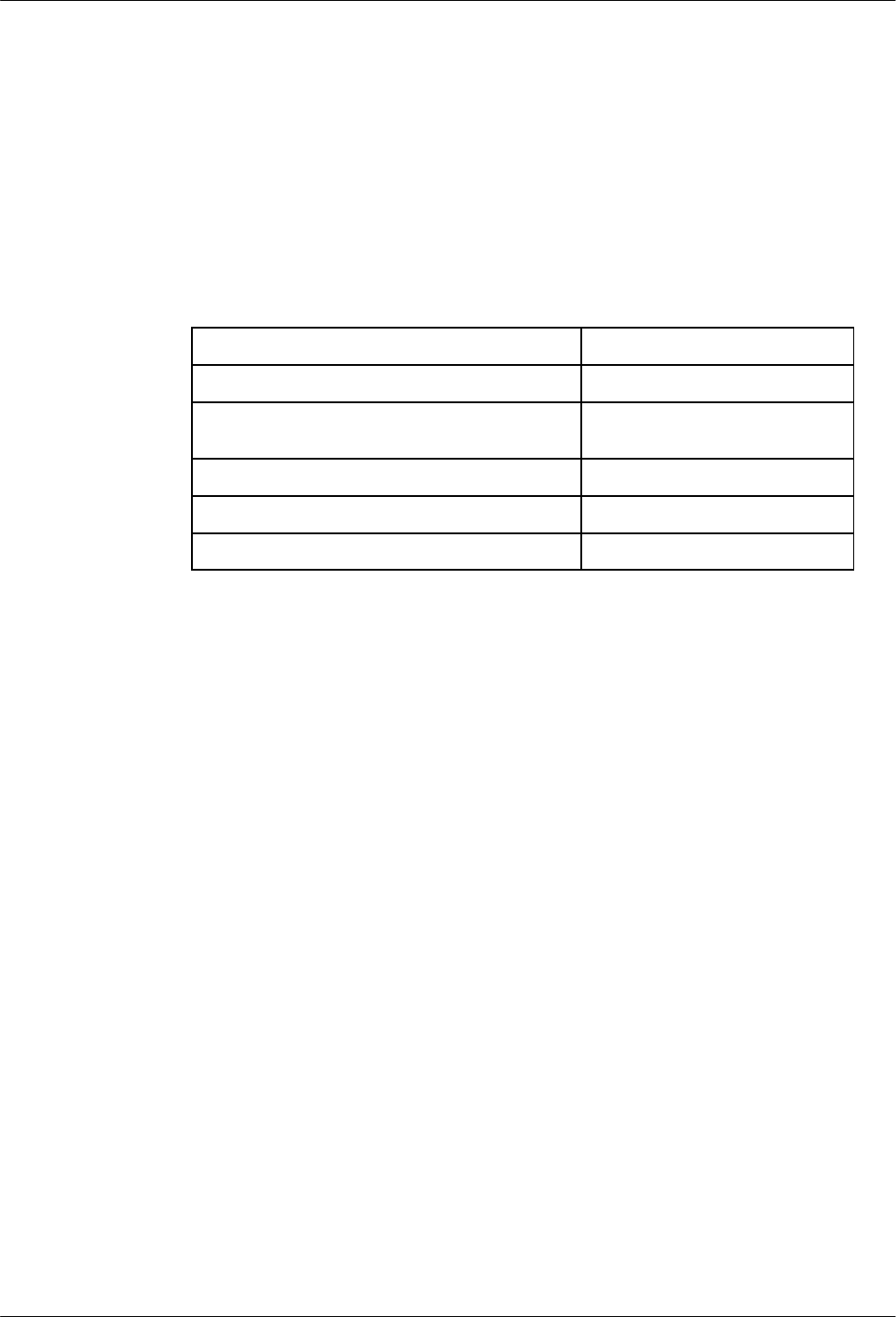
The following table is added to Chapter 2.
Supported Device Commands
For the 3615/3616 DualFlow DSUs, the following table lists the commands and the product
configurations that each command supports.
Command Supported Product Configurations
Abort (abt) Control DSU, Control DBM, Tributary DSU, Tributary DBM
Acquire [Device] Poll List (acpl) Control DBM
Configuration Change Notification (ccn) Control DSU, Tributary DSU
Configuration Change Notification Enable/
Disable (ccned) Control DSU, Tributary DSU
Change Address (cha) Control DSU, Control DBM, Tributary DSU, Tributary DBM
Change Call Directory (chcd) Control DBM, Tributary DBM
Change External Leads States (chels) Control DSU, Control DBM, Tributary DSU, Tributary DBM
Change Telephone Number(s) (chtn) Control DBM, Tributary DBM
Change Options (cho) Control DSU, Control DBM, Tributary DSU, Tributary DBM
Change [Device] Poll List (chpl) Control DBM
Circuit Quality (cq) Control DBM, Tributary DBM
Disable/Enable (de) Control DSU, Control DBM, Tributary DSU, Tributary DBM
Device test (det) Control DSU, Control DBM, Tributary DSU, Tributary DBM
Device Health and Status (dhs) Control DSU, Control DBM, Tributary DSU, Tributary DBM
Dial (dial) Control DBM
Digital Test (dit) Control DBM
Dial Mode (dm) Control DSU, Control DBM, Tributary DSU, Tributary DBM
Dial Standby (ds) Control DSU, Control DBM, Tributary DSU, Tributary DBM
Display Address (dsa) Control DSU, Control DBM, Tributary DSU, Tributary DBM
Display Call Directory (dscd) Control DBM, Tributary DBM
Display External Leads States (dsels) Control DSU, Control DBM, Tributary DSU, Tributary DBM
Display Options (dso) Control DSU, Control DBM, Tributary DSU, Tributary DBM
Display [Device] Poll List (dspl) Control DBM
Display Telephone Number(s) (dstn) Control DBM, Tributary DBM
End-To-End Test (eet) Control DBM
EIA Status (eia) Control DSU, Control DBM, Tributary DSU, Tributary DBM
Identity (id)Control DSU, Control DBM, Tributary DSU, Tributary DBM
Loopback (lo) Control DSU, Control DBM, Tributary DSU, Tributary DBM

24
Command Supported Product Configurations
Modem Bit Error Rate Test (mbert) Control DSU, Control DBM
Report Terminal Power (rtp) Control DSU, Control DBM, Tributary DSU, Tributary DBM
Standby Facility (sf) Control DBM
Send Message (snm) Control DSU, Control DBM, Tributary DBM
Transmit Test Pattern (ttp) Control DSU, Control DBM, Tributary DSU, Tributary DBM

25
COMSPHERE 6800 Series Network Management System Core
Command Reference Manual (6800-A2-GD32-10)
The following commands in Chapter 2 of this manual were modified or changed:
•Create Device Profile (crdp)
•Delete Device Profile (dldp)
•Display Device Profile (dsdp)
•Display System Pool List (dsspl)
•Edit ATR Phone Directory (edatrpd)
•Edit External System Configuration (edesc)
•Edit Device Profile (eddp)
•Edit Port Configurations (edpc)
The command description was modified for the following command in Chapter 3 of this manual:
•Detailed Alert Report (dar)

26
Create Device Profile (crdp)/Delete Device Profile(dldp)/Display
Device Profile (dsdp)/Edit Device Profile (eddp)
The Create Device Profile (crdp), Delete Device Profile (dldp), Display Device Profile (dsdp), and
Edit Device Profile (eddp) commands accept the following additional device types in the Model
number field:
•3980, 3981, and 3982 for 3800Plus modems
•3920 and 3921 for 392xPlus modems.
•3615 and 3616 for 3600 Series DSUs
For the 3610/3611 2-port and 6-port TDM/Flex or MCMP/Flex option, the following new
information is added to the Create Device Profile (crdp) command’s Access module id field:
n port Flex TDM
CCA: TDM – Time Division Multiplexer Circuit Card Assembly/Time Division
Multiplexer.
n port Flex TDM
CCA: MCMP – Time Division Multiplexer Circuit Card Assembly/Multichannel
Multipoint.
n port Flex TDM
CCA: Bridge – Time Division Multiplexer Circuit Card Assembly/Bridge.
n port Flex TDM
CCA: Dual Bridge – Time Division Multiplexer Circuit Card Assembly/Dual Bridge.
n port Flex TDM
CCA: Extended
Bridge
– Time Division Multiplexer Circuit Card Assembly/Extended
Bridge.
n port Flex TDM
CCA: TDM (V.35) – Time Division Multiplexer Circuit Card Assembly/Time Division
Multiplexer V.35.
n port Flex TDM
CCA: MCMP (V.35) – Time Division Multiplexer Circuit Card Assembly/Multichannel
Multipoint V.35.
n port Flex TDM
CCA: ASPEN – Time Division Multiplexer Circuit Card and ASPEN application
present.
n port Flex TDM
CCA:
CBRIDGE-ASPEN
– Time Division Multiplexer Circuit Card, Central Site Digital
Bridge, and ASPEN application present.
n port Flex TDM
CCA: No Application – Time Division Multiplexer Circuit Card Assembly/No application.
n port Flex MCMP
CCA: TDM – Multichannel Multipoint Circuit Card Assembly/Time Division
Multiplexer.
n port Flex MCMP
CCA: MCMP – Multichannel Multipoint Circuit Card Assembly/Multichannel
Multipoint.
n port Flex MCMP
CCA: Bridge – Multichannel Multipoint Circuit Card Assembly/Bridge.
n port Flex MCMP
CCA: Dual Bridge – Multichannel Multipoint Circuit Card Assembly/Dual Bridge.
n port Flex MCMP
CCA: Extended
Bridge
– Multichannel Multipoint Circuit Card Assembly/Extended Bridge.

27
n port Flex MCMP
CCA: TDM (V.35) – Multichannel Multipoint Circuit Card Assembly/Time Division
Multiplexer V.35.
n port Flex MCMP
CCA: MCMP (V.35) – Multichannel Multipoint Circuit Card Assembly/Multichannel
Multipoint V.35.
n port Flex MCMP
CCA: ASPEN – Multichannel Multipoint Circuit Card and ASPEN application
present.
n port Flex MCMP
CCA:
CBRIDGE-ASPEN
– Multichannel Multipoint Circuit Card, Central Site Digital Bridge,
and ASPEN application present.
n port Flex MCMP
CCA: No Application – Multichannel Multipoint Circuit Card Assembly/No application.
28
Display System Poll List (dsspl)
The Control Channel(s) field for this command is changed to read as follows.
Control Channel(s)
Identifies the control channels whose poll lists are to be displayed. Control channel values
are defined in the following table.
Control Channel Value Connection
1–16 DCE devices
a1–a6 Devices managed by
ANALYSIS 6510 systems
b1 SNMP and brouter devices
e1 Bytex devices
m2 ACCULINK multiplexer network

29
Edit ATR Phone Directory (edatrpd)
For the ATR destination field, the list of special characters is limited to the following:
•–
•*
•#

30
Edit External System Configuration (edesc)
For the Parameter field, the list of special characters is limited to the following:
•–
•*
•#

31
Edit Port Configurations (edpc)
The following note is added to the State field of this command.
NOTE
Prior to deleting a printer port, be sure that all the queued jobs are
cancelled. Refer to Chapter 9,
Printer Functions,
of the
COMSPHERE 6800 Series Network Management System
User’s/System Administrator’s Guide
(6800-A2-GE26-10
)
for more
details.

32
Detailed Alert Report (dar)
The following note should be added to the Alert duration field of this command.
NOTE
Events may have a duration less than one second. Therefore, to
retrieve all records from the database, there may be an occasion to
change the default Alert duration interval from 00:00:01 to
00:00:00.

33
COMSPHERE 6800 Series Network Management System
User’s/System Administrator’s Guide (6800-A2-GE26-10)
The changes or modifications to the commands in this manual involve Chapters 1, 2, and 5.
Changes to Chapter 1
The heading Sun Workstations/Generic X-Terminal Support changes to Sun
Workstation/X Workstation Support. The subsequent description changes to the following:
Sun workstations or X workstations from a variety of vendors can be used as full-feature
workstations. Sun workstations must either use OpenWindows or an X server that is compatible
with X Version 11 Release 4 or later. X workstations from other vendors must use an X server
that is compatible with X Version 11 Release 4 or later.
Table 1-1 in the guide changes to reflect new values in the SYSTEM CAPACITY column for the
following features:
FEATURE SYSTEM CAPACITY
User Profiles 150
Total Facility Profiles 15,000
Total Site Profiles 15,001
Total Device Profiles (managed and
unmanaged) 15,001
Historic Alert Records 75,000

34
Changes to Chapter 2
The following sections are added in support of X servers.
Sun Workstation/X Workstation Support
Sun workstations or X workstations from a variety of vendors can be used as full-feature
workstations. Sun workstations must either use OpenWindows or an X server that is compatible
with X Version 11 Release 4 or later. X workstations from other vendors must use an X server that
is compatible with X Version 11 Release 4 or later.
The following sections describe how to configure Sun workstations running OpenWindows and
UNIX workstations running an X server based on MIT’s X Version11 Release 4 sample server. The
tools as described in the following paragraphs should be provided by your software or workstation
vendor. If they are not, the following section provides ideas on what to look for in vendor-specific
documentation.
Network Configuration
Any time a new workstation is added to the network, the workstation’s IP address and name must
be added to the /etc/hosts files on both the NMS host and UIP. Also, the IP address and name of
both the NMS host and UIP must be added to the workstation’s /etc/hosts file. The workstation
name and user IDs on the workstation must be added to the file /usr/ffw/.rhosts on both the NMS
host and UIP. This gives users on the workstation permission to remotely execute commands on
the NMS host and UIP, while using the ffw user ID. Refer to the hosts and rhosts man pages for
more information.
To verify the changes on the workstation, type the following commands:
rcmd -l ffw <NMS-host> echo hello
rcmd -l ffw <NMS-host> echo hello
Where: <NMS-host> is the NMS host name.
If the command rcmd does not exist, try rsh or remsh.

35
Installing 6800 Fonts
The 6800 full-feature tasks, including the Map, require that the workstation have 6800-specific
fonts installed. These fonts are distributed with the 6800 product software and can be found in the
directory /usr/nms/RNMS/fonts on the NMS host. Fonts are distributed in Bitmap Distribution
Format, an X Consortium standard for font interchange and are in files with the suffix .bdf. Copy
and install these files to the workstation using tools provided with the workstation software. You
can use the following steps to install fonts on Sun OpenWindows workstations or on MIT-based
X11R4 workstations.
1. Choose a directory for the fonts.
It is recommended that you add a 6800-specific sub-directory to the font directory supplied
by your workstation’s vendor:
•On a Sun OpenWindows workstation, try /usr/openwin/lib/fonts.
•On an MIT-based X workstation, try /usr/lib/X11/fonts.
2. Create a sub-directory called nms and make it your current directory using the cd
command.
3. Copy fonts from the NMS host to the workstation.
4. TYPE: rcp ffw@<NMS-host>:/usr/nms/RNMS/fonts/*.bdf .
Where: <NMS-host> is the NMS host name.
5. Convert from BDF to workstation format:
•On a Sun OpenWindows workstation, enter the commands:
convertfont *.bdf
bldfamily –d .
•On a Sun OpenWIndows workstation, enter the commands:
for i in *.bdf
do
/usr/bin/X11/bdftosnf $i > ‘basename $i .bdf‘ .snf
done
mkfontdir
Note that later releases of X11 have replaced bdftosnf with bdftopcf and may use a font
server. Refer to your workstation documentation for more information.

36
Start-Up Shell Script
The following shell script will start up the 6800 full-feature application on a Sun OpenWindows
workstation. It is recommended that the script be placed in a file called /usr/bin/StartNMS. When
setting up an X workstation, you may use the same script with minor modifications. All users must
have read and execute permission to this file (To do this, use the command chmod 755
/usr/bin/StartNMS). The following line numbers provide a convenient way to subsequently
discuss the script and must not be included in an actual shell script file.
1 for i in $*
2do
3 xhost + $i
4 done
5 xset –fp /usr/openwin/lib/fonts/nms
6 xset +fp /usr/openwin/lib/fonts/nms
7 xset fp rehash
8 xmodmap –e ’keycode 16 = F11’ \
9 -e ’keycode 18 = F12’ \
10 –e ’keycode 77 =Prior F29 KP_9’ \
11 –e ’keycode 121 = Next F35 KP_3’ \
12 –e ’keycode 75 = Home F27 KP_7’ \
13 –e ’keycode 119 = End R13 KP_1’ \
14 WRKSTN=‘uname -n‘
15 rsh -l ffw $1 “StartNMSd $WRKSTN:0 hires”
The script requires at least one argument, which is the name of the NMS host or the UIP on which
the full-feature application will run.
Lines 1 through 4 give the UIP and/or NMS host permission to connect to the workstation. If you
have a UIP, its name should be the first argument followed by the name of the NMS host. The
NMS host needs permission to support the Manage Routing Tables task for multiplexer
applications.
Lines 5 through 7 tell the workstation where to find the 6800-specific fonts. For an MIT-based X
workstation, replace /usr/openwin/lib/fonts/nms with /usr/lib/X11/fonts/nms.
Lines 8 through 13 map some of the Sun keycodes to PC-compatible key symbols required to fully
support the 6800 full-feature tasks. The keycode to keysym mappings are appropriate for a Sun-4
keyboard. Other keyboards may require different mappings. See Keyboard Mappings in this
section for more information.
Line 15 uses the rsh commands to remotely execute the shell script, StartNMSd, on the UIP
or NMS host. StartNMSd is installed in /usr/bin on both UIP and the NMS host. Depending on
the workstation’s operating system, you may need to replace the rsh command with rcmd or
remsh. The StartNMSd script takes two arguments:
•workstation’s display name
•vga for 800 x 600 (or less) screen resolution or hires for higher screen resolution

37
The StartNMSd script is appropriate when your workstation has a window manager running. If
your workstation is a low-end X terminal that does not provide window management, or if the
workstation’s window manager does not interact well with the 6800 application, you should
disable the window manager and replace line 15 with the following:
rsh -l ffw $1 “DISPLAY=$WRKSTN:0; startx -t”
This command starts up the Motif window manager on the UIP or NMS host as well as the 6800
application.
Keyboard Mappings
Full functionality of 6800 full-feature tasks require that a workstation emulate a typical PC
keyboard. Specifically, there must be keys equivalent to the PC keys:
•F1 through F12
•PgUp and PgDn (X keysym names are Prior and Next)
•Home and End
If your workstation does not have similar keys, or the keys do not function as expected, use the
xev command to determine keycode associations. The xev command can be executed from the
UNIX or UIP task, as long as the DISPLAY environment variable is set to workstation-name:0.
Experiment with keycode to keysym mappings, using the xmodmap command. Once the
mappings are established, modify lines 8 though 13 of the StartNMS script. See man pages for
xev and xmodmap for more information.

38
Changes to Chapter 5
In support of 3900 Series modems, four new alert types are added to Table 5-2. These alert types
describe the reason for a dial failure or disconnect from a 3900 Series device. Alert types blbad,
ptf, and ehscn are status alerts. The alerts are described as follows.
DEVICE TYPE AND
DESCRIPTION ALERT GROUP ALERT
TYPE PRIORITY ALERT’S TEXTUAL DISPLAY
APL – COMSPHERE,
DATAPHONE II and
Paradyne Analog
Private Line Modems
apl-cnnd-msg
apl-backup
apl-service
apl-message
dial
blbad
ptf
ehscn
3
2
3
3
Dial fail, invalid number
Dial fail, DTR off
Dial fail, no dial tone
Dial fail, number busy
Dial fail, trunk busy
Dial fail, no answer
Dial fail, no remote tone
Disconnect, loss of carrier
Disconnect, received long space
Disconnect, no data time out
Disconnect, received V.32 cleardown
Disconnect, DTR dropped
Disconnect, CD dropped
Disconnect, error control failed
Disconnect, VF password timeout
Disconnect, unknown VF password
Disconnect, user ID timeout
Disconnect, DTE password timeout
Disconnect, unknown DTE password
Disconnect, missing originate
password
Disconnect, invalid originate
password
Disconnect, DTR dial blocked
Backup line bad
PSTN test failure
Expanded health and status change

39
Changes to Appendix A
Table A-1 in Appendix A has the following additions.
New device numbers for the COMSPHERE DDD Modems and DSUs listing:
•3615 and 3616 to support the DualFlow DSUs
•3980, 3981, and 3982 to support 3800Plus modems
New device numbers for the COMSPHERE 3900 APL Modems listing:
•3920 and 3921 to support the 392xPlus modems

40
COMSPHERE 6800 Series Network Management System Reports
and Trouble Tracking Customization Guide (6800-A2-GE27-10)
The changes in this manual occur in Chapter 2.
Changes to Chapter 2
Under the heading Installing the Customized Database Report Package, the following command
changes from
cpio -icvdmk </dev/rfd0135ds9
to
cpio -icvdmku </dev/rfd0135ds9

41
COMSPHERE 6800 Series Network Management System
Installation and Maintenance Guide (6800-A2-GN22-20)
The changes or modifications in this manual occur in Chapters 2 and 5. Highlights of these
changes are as follows:
•For the AT&T Globalyst 575 hardware used as the full-feature and basic-feature
workstations, these release notes contain the description of the hardware and installation,
configuration and cache disable instructions for workstations running Whitepine Exodus
software. Instructions are also included for 575 full-feature workstations running
eXceed 4 software.
•For the AT&T Globalyst 520 hardware used as the full-feature and basic-feature
workstations, these release notes contain the description of the hardware and configuration
instructions for 520 full-feature workstations running eXceed 4 software.
•Included are instructions for installing Whitepine Exodus software. Revised procedures are
provided in these release notes for using Exodus with the existing Altos 486 hardware.
•Added are instructions for installing and configuring both SuperTCP Version 4 software
and eXceed 4 software.
•Included are preinstallation checks for the Paradise Video Card.
•Changed for existing X-One users is the current procedure in the Installing the Token Ring
Software on the Full-Feature Workstation section. The revised procedure is the same for
both X-One and Exodus users and is provided on page 80.
Chapter 2
Using Workstations with AT&T Globalyst Hardware
Both the AT&T Globalyst 575 and the AT&T Globalyst 520 are used as basic-feature and
full-feature workstations for the COMSPHERE 6800 Series NMS. The Globalyst hardware
includes the Intel i486 DX2 66 MHz CPU with 8 Mb RAM and is configured with the
following:
•One 348 Mb DTE hard disk and one 3.5 1.44 Mb diskette drive.
•17 high resolution monitor.
•1 Mb video DRAM (upgradable to 2 Mb), S3 Vision 864 Graphic chip with a maximum
resolution of 1280 * 1024 (for some Globalyst 575 full-feature workstation configurations,
the ATI Graphics Ultra+ video card is pre-installed).
•Connectors for two serial devices, one parallel device, PS/2 keyboard and PS/2 two-button
mouse.
ATI and Graphics Ultra+ are a trademarks of ATI Technologies, Inc.
eXceed is a trademark of Hummingbird Communications Ltd.
i486 and Intel are registered trademarks and EtherExpress is a trademark of Intel Corporation.
Paradise is a registered trademark of Western Digital Corporation.
SuperTCP is a trademark of Frontier Technologies Corporation.
Whitepine is a registered trademark of White Pine Software, Inc.

42
•Intel EtherExpress 16 network interface card (pre-installed on full-feature workstations)
Token Ring card may be configured depending on user requirements.
•MS-DOS 6.22 and MS-Windows 3.11.
Some Globalyst 575 configurations run the Whitepine Exodus software. For information on these
workstations, refer to the Using the Globalyst 575 Running Whitepine Exodus Software section.
Some Globalyst 575 configurations and all of the Globalyst 520 configurations run the eXceed 4
software. For information on these workstations, refer to the Using the Globalyst 520 and 575
Running eXceed 4 Software
section.
Check for the eXceed or EXODUS directory on your Globalyst machine to verify which software
is loaded on your system.
Using the Globalyst 575 As a Basic-Feature Workstation
There are no on-site configuration or user modifications required on the Globalyst 575 when used
as a basic-feature workstation. However, you may verify that procedures in the following sections
were performed to switch off cache and properly configure the factory-installed ATI Graphics
Ultra+ Video card:
•Configuring the ATI Graphics ULTRA+ Card
•Switching off Cache on the Globalyst 575
Refer to the Using the Globalyst 575 As a Full-Feature Workstation Running Whitepine Exodus
Software
section for these procedures
.
For a complete description of the PC hardware or
instructions on connecting PC components, refer to the manufacturer’s user’s guide that
accompanies the hardware.
Using the Globalyst 520 As a Basic-Feature Workstation
There are no on-site configuration or user modifications required on the Globalyst 520 when used
as a basic-feature workstation.
For a complete description of the PC hardware or instructions on connecting PC components, refer
to the manufacturer’s user’s guide that accompanies the hardware.
43
Using the Globalyst 575 As a Full-Feature Workstation Running
Whitepine Exodus Software
This section discusses using Globalyst 575 as a full-feature workstation. It also provides
installation instructions and configuration information for using the Globalyst 575 running Exodus
software.
To configure the Globalyst 575, perform the following steps:
1. Verify that procedures in the following sections were performed to switch off cache and
configure the factory-installed Intel EtherExpress Card and ATI Graphics Ultra+ Video
card.
•Configuring the Intel EtherExpress Card
•Configuring the ATI Graphics ULTRA+ Card
•Switching off Cache on the Globalyst 575
2. Perform procedures in the following sections to load software.
•Installing Whitepine Exodus Software with Intel EtherExpress Card and a 14 or 17
Monitor
•
For a complete description of the PC hardware or instructions on connecting PC components, and
replacing boards and internal hardware, refer to the manufacturer’s user’s guide that accompanies
the hardware.
Configuring the Intel EtherExpress Card
There are no preinstallation requirements and are no user-configurable switches on the card. You
must, however, configure the card via software for use as a full-feature workstation on the NMS.
To configure the Intel EtherExpress card, perform the following steps:
1. Insert the Intel EtherExpress LAN Adapter Driver and Option diskette into the a: drive.
2. At the C: prompt:
TYPE: a:softset
PRESS: Enter
The Softset Introduction screen appears and prompts:
Press spacebar to continue
3. Press the spacebar. The main menu appears.
4. Using the ↑↓ keys,
SELECT: Manual Setup
PRESS: Enter
The Manual Setup menu appears.

44
5. Using the ↑↓ keys,
SELECT: Interrupt
PRESS: Enter
6. Using the ↑↓ keys on the pop-up menu,
SELECT: IRQ5
PRESS: Enter
The system returns to the Manual Setup menu.
7. Using the ↑↓ keys,
SELECT: Connector Type
PRESS: Enter
8. Using the ↑↓ keys on the pop-up menu,
SELECT: RJ-45 connector
PRESS: Enter
9. To accept the settings,
PRESS: F10
10. To exit Softset, use the ↑↓ keys and
SELECT: Exit
PRESS: Enter
11. To confirm your intention to exit,
SELECT: Yes
PRESS: Enter
12. Remove the diskette from the a: drive and reboot the system.

45
Configuring the ATI Graphics Ultra+ Video Card for 14 and 17 Monitors
There are no preinstallation requirements for this card and there are no user-configurable switches
on the board. You must, however, configure the card via software for use as a full-feature
workstation on the NMS.
To configure the ATI Graphics Ultra+ Video card, perform the following steps:
1. Insert the GRAPHICS ULTRA+ Disk 1 of 3 diskette into the a: drive and at the C: prompt:
TYPE: a:install
PRESS: Enter
2. Using the ↑↓ keys at the Main menu,
SELECT: Set Power-Up Configuration
PRESS: Enter
3. Using the ↑↓ keys at the Main menu,
SELECT: Monitor Type
PRESS: Enter
4. Using the ↑↓ keys at the pop-up menu,
SELECT: Custom
PRESS: Enter
5. Using the ↑↓ keys at the pop-up menu,
SELECT: 1024 * 768
PRESS: Enter
6. Ignore the warning message,
PRESS: Any key (to continue)
7. Using the ↑↓ keys at the pop-up menu,
SELECT: x
Where: x is 60 Hz Non-interlaced for 14-inch monitor and 72 Hz Non-interlaced
for 17-inch monitor
PRESS: Enter
A display appears with a user-adjustable boundary.
8. Using the ↑→↓← keys, adjust the position of the boundary to accommodate your display
size requirements.
PRESS: Enter
PRESS: Esc

46
9. At the following prompt:
Is your Custom Monitor Configuration now complete?
PRESS: Y (for Yes)
10. To save your settings,
PRESS: F10
11. Remove and store the diskette.
12. Reboot the system. (Shut power off, wait 10 seconds, then turn power on.)
Switching Off the Cache on Globalyst 575
The Globalyst 575 may be switched off using the SurePath BIOS Setup Utility which is resident in
the workstation’s firmware. Starting the Globalyst 575 powered off, perform the following steps:
1. Power on the workstation and when a box containing tildes appears in the upper right
corner of the screen:
PRESS: F1
The SurePath BIOS Setup Main menu appears.
2. Using the ↑↓ keys,
SELECT: Advanced System Setup
PRESS: Enter
3. Using the ↑↓ keys on the pop-up menu,
SELECT: Cache Control
PRESS: Enter
The Cache Control screen appears for the BIOS and Video setup.
4. For the BIOS setup, use the ←→ keys to toggle ROM Cacheable to non-cacheable.
5. For the Video setup, use the ←→ keys to toggle ROM Cacheable to non-cacheable.
6. While in the Cache Control screen,
PRESS: Esc (twice)
7. At the SurePath BIOS Setup Main menu,
SELECT: Save Settings
PRESS: Enter
8. To confirm the save,
PRESS: Enter

47
9. Using the ↑↓ keys at the SurePath BIOS Setup Main menu,
SELECT: Exit Setup
PRESS: Enter
10. To confirm your intention to exit,
PRESS: Enter
11. The system automatically reboots. Follow the standard procedure for starting up a
full-feature workstation.
Installing Whitepine Exodus Software with Intel EtherExpress Card and a 14 or 17 Monitor
To install the Whitepine Exodus software when an Intel EtherExpress card is used, perform the
following steps:
1. Insert the Whitepine eXodus Installation disk into the drive and
TYPE: A:install
PRESS: Enter
2. The system prompts:
Enter the floppy drive to use [A:]:
PRESS: Enter
3. The system prompts:
Enter the destination drive to use [C:]:
PRESS: Enter
4. The system prompts:
Enter the destination directory to use [\EXODUS]:
PRESS: Enter
If the directory, C:\EXODUS, does not exist the system prompts:
The directory C:\EXODUS does not exist. OK to create it? (y/n) [y]
TYPE: y
PRESS: Enter
5. The system prompts:
Do you wish to install the fonts (y/n)? [n]
TYPE: y
PRESS: Enter

48
Do you wish to install the standard set of fonts
including “MISC” and “75DPI” (y/n): [y]
PRESS: Enter
Do you wish to install the 100DPI fonts (y/n)? [n]
TYPE: y
PRESS: Enter
Do you wish to install the OpenWindows fonts: (y/n)? [n]
TYPE: y
PRESS: Enter
Do you wish to install the DecWindows fonts: (y/n)? [n]
TYPE: y
PRESS: Enter
Do you wish to install the TGRAF fonts: (y/n)? [n]
TYPE: y
PRESS: Enter
Do you wish to install the Kanji fonts: (y/n)? [n]
TYPE: y
PRESS: Enter
Make sure the EXODUS disk labeled “Install” is in the floppy drive
Press ENTER to continue or ‘q’ to Quit
PRESS: Enter
6. After some time marked by a line of dots on the screen, the system prompts:
Insert the EXODUS disk labeled ‘Fonts Disk 1’
Press ENTER to continue or ‘q’ to Quit
Remove the Exodus Install disk, insert the requested disk, and
PRESS: Enter
7. After some time marked by a line of dots on the screen, the system prompts:
Insert the EXODUS disk labeled ‘Fonts Disk 2’
Press ENTER to continue or ‘q’ to Quit
Remove the Fonts Disk 1, insert the requested disk, and
PRESS: Enter

49
8. After another period marked by the line of dots on the screen, the following messages
appear:
All files successfully installed.
The following should be placed in your autoexec.bat file
SET EXODUSDIR=C:\EXODUS
SET DOS4G=quiet
Would you like eXodus to add this to your autoexec.bat file (y/n)? [y]:
PRESS: Enter
9. The system prompts:
Ready to execute setup
Press any key to continue
PRESS: Enter
10. The system prompts:
Exodus Setup Utility
Press any key to continue
PRESS: Enter
11. The system prompts:
Select Mouse type
1. Mouse type device (pre-loaded driver)
2. Microsoft serial mouse
3. Logitech serial mouse
4. Mouse Systems serial mouse
Enter selection or ‘q’ to Quit [1]:
TYPE: 1
PRESS: Enter
12. The system prompts:
Would you like to use the graphics board configuration detected by
Xsetup (y/n): [y]:
TYPE: n
PRESS: Enter
The system prompts (with options):
Select Graphics Card
4. ATI Ultra Pro
TYPE: 4

50
Enter selection or ‘q’ to Quit [1]:
PRESS: Enter
Select video memory
4. 2 MB
Enter selection or ‘q’ to Quit [1]:
TYPE: 4
PRESS: Enter
Select graphics mode
3. 1024x768, 256 colors
Enter selection or ‘q’ to Quit [1]:
TYPE: 3
PRESS: Enter
Select Monitor Size
2. 14 inch
5. 17 inch
Enter selection or ‘q’ to Quit [1]:
TYPE: x
Where: x is 2 for 14-inch monitor or 5 for 17-inch monitor
PRESS: Enter
13. The system then prompts:
Please verify settings:
Mouse settings . . .
Graphics Info . . .
Graphics board settings . . .
Monitor settings . . .
Are these settings correct (y/n/q)? [y]:
14. If these settings are not correct,
TYPE: n
PRESS: Enter
The system starts again at Step 10.
15. If the settings are correct,
PRESS: Enter

51
16. The system responds:
Settings saved in file “C:\EXODUS\hardware.cfg”.
Press any key to continue
PRESS: Enter
17. The system prompts:
Xsetup will need to copy the graphics driver ‘vga.dvr’
from the Exodus diskette to the C:\EXODUS directory
Insert the disk labeled ‘Install’ in drive A:
Press ENTER to continue or ‘q’ to Quit
18. Insert the proper disk and
PRESS: Enter
19. The system responds:
1 file extracted from archive
Press any key to continue
PRESS: Enter
20. The system prompts:
Select Network configuration
1. Whitepine’s own builtin TCP/IP
2. FTP Software’s PC/TCP
3. Sun Microsystem’s PC/NFS ver’s 3.5-3.9
4. Beame and Whiteside BW-TCP
5. Woolongong’s Pathway TCP
Enter selection or ‘q’ to Quit [1]:
PRESS: Enter
21. The system prompts:
Select Network Interface
9. Packet Driver
Enter selection or ‘q’ to Quit [1]:
TYPE: 9
PRESS: Enter
Will you be using more than one Network board in your machine
with more than one packet driver loaded (y/n/q)? [n]:
PRESS: Enter

52
NOTE
If using basic network configuration, use the IP address in Table 5-1.
Otherwise, ask your System Administrator for the correct IP
address.
Enter this system’s IP address:
TYPE: IP address in the format “xxx.xxx.xxx.xxx”
Where: xxx is a number from 1 to 255 inclusive
PRESS: Enter
NOTE
Ask your Network Administrator for the correct subnet mask.
Enter a subnet mask[255.0.0.0]
PRESS: Enter
22. The system prompts:
Would you like to specify your gateway entries now (y/n/q)? [n]:
PRESS: Enter
Would you like to add a name server (y/n)? [n]:
PRESS: Enter
If a HOSTS file does not exist, please specify the path where it will reside:
(Default: C:\EXODUS\HOSTS)
PRESS: Enter
23. The system prompts:
Please verify settings:
Transport:
Interface:
Connector:
I/O Address:
IP Address:
Subnet mask:
Hosts file path:
Are these settings correct (y/n/q)? [y]:
24. If the settings are correct,
PRESS: Enter

53
25. If the settings are not correct,
TYPE: n
PRESS: Enter
The system returns to Step 21.
26. The system responds:
Xsetup will need to copy the network driver “tcpnet.exe”
from the EXODUS diskette to the C:EXODUS directory
Insert the disk labeled ‘Install’ in drive A:
Press ENTER to continue or ‘q’ to Quit
Insert the diskette labeled Install and
PRESS: Enter
The system displays various messages including:
file extracted from archive
Press any key to continue
PRESS: Enter
Xsetup will need to copy some additional files to go with your network files
Press any key to continue
PRESS: Enter
The system displays various messages including:
5 files extracted
Press any key to continue
PRESS: Enter
The following message appears:
eXodus Install Complete
Press any key to continue
PRESS: Enter

54
Installing the NMS Full-Feature Workstation Application Software
with Intel EtherExpress Card
A diskette is provided to install the full-feature workstation application software on your
Globalyst 575. To install the software, perform the following steps:
1. Turn on your system. Insert your disk labeled 6800 FFW Application Volume 1 into the
a: drive.
2. At the C: prompt,
TYPE: cd C:\EXODUS
PRESS: Enter
TYPE: a:install
PRESS: Enter
The current directory should be “\xone” if you have installed XONE
or “\exodus” if you have installed EXODUS.
If current directory is not “\xone” or “\exodus”
Please break out of the installation by typing
Ctrl-C
Press any key to continue
PRESS: Enter
3. The system displays many message including the following significant ones:
Loading fonts
Loading configuration script
Loading packet driver
For further information on installation and startup –
Please refer to the C:\XONE\README or C:\EXODUS\README file.
Installation Completed
NOTE
For the 15000 platform, the division of full-feature workstations
among the three processors should be:
Host Uip-1 Uip-2
7 3 14
Configurations with fewer full-feature workstations should retain
equivalent ratios among the processors for best performance.
4. If the workstation is connected to an NMS host and while still in the \EXODUS directory:
TYPE: COPY HOST.CFG EXODUS.CFG
PRESS: Enter

55
5. If the workstation is connected to a UIP and while still in the \EXODUS directory:
TYPE: COPY UIP.CFG EXODUS.CFG
PRESS: Enter
6. TYPE: edit EXODUS.CFG
PRESS: Enter
The DOS editor displays the CFG file. Find the line which starts with
CONN_COMMAND and change WSNAME to the name of the workstation. Find the line
beginning with CONN_HOST and change NMSHOST to the name of the NMS host or
the UIP if this workstation will connect to the UIP. Save the file and exit the editor.
7. Insert the EtherExpress diskette labeled Intel EtherExpress LAN Adapter Driver and
Option Diskette into the a: drive.
8. At the C:\EXODUS prompt,
TYPE: Copy a:\packet\exp16.com c:\exodus
PRESS: Enter
TYPE: cd ..
PRESS: Enter
TYPE: edit autoexec.bat
PRESS: Enter
The DOS editor displays the file. At the end of the file, add the following line:
c:\exodus\exp16 0x60 0x300
9. Reboot the processor so that all changed parameters are properly loaded.

56
Using the Globalyst 520 and 575 As a Full-Feature Workstation
Running eXceed 4 Software
This section discusses using the Globalyst 520 as a full-feature workstation. It also provides
installation instructions and configuration information for using the Globalyst 520 and the
Globalyst 575 running eXceed 4 software. Load and configure the Globalyst machines for eXceed
4 software using the procedures in the following order.
1. Perform the procedures in one of the following sections depending on the Globalyst
hardware being used:
•Configuring the Globalyst 575 as a Full-Feature Workstation to Run eXceed 4
•Configuring the Globalyst 520 as a Full-Feature Workstation to Run eXceed 4
2. Install the SuperTCP Version 4.0 software.
3. Install the eXceed 4 software.
4. Configure the SuperTCP and eXceed 4 software.
Configuring the Globalyst 575 As a Full-Feature Workstation to Run eXceed 4
To configure a Globalyst 575, perform procedures in the following sections in the order shown:
1. Changing the Globalyst 575 Display Option for Windows.
NOTE
After changing the display option, you should exit windows and edit
your
Autoexec.bat
file to remove the win entry. This will allow the
system to boot up at the DOS prompt instead of automatically
invoking Windows.
2. Switching Off Cache on the Globalyst 575.
3. Configuring the EtherExpress Card; for Token Ring networks, refer to the Changing the
Token Ring Configuration section in your COMSPHERE 6800 Series Network
Management System Installation and Maintenance Guide.
Changing the Globalyst 575 Display Option for Windows
To change the display option, perform the following steps:
1. Insert the diskette labeled Miro High Speed Drivers for Windows 1 of 2 into the a: drive.
2. Select Run from the Program Manager’s File menu.
3. Type a:\install in the Run Dialog box and click on OK.
4. Select English from the list of language selections in the welcome dialog box and click on
OK.

57
5. Select AT&T System Graphics [1MB] from the list of board selections in the next dialog
box and click on OK.
6. Select Windows 3.1 driver software from the list of software selections in the following
dialog box and click on OK.
7. Remove the diskette from the a: drive, when instructed, and insert the diskette labeled
Miro High Speed Drivers for Windows 2 of 2.
8. Click on OK.
9. Double click on the miro MONITOR SELECT icon from the miroWINTOOLS program
group window.
10. Select 64 kHz multi frequency for the Monitor option in the miro MONITOR SELECT
dialog box and click on OK.
11. Select 800 x 600 for the Resolution option in the miro SUPERSCREEN Desktop
Configuration dialog box and click on OK.
After you exit the miroWINTOOLS program, confirm that the Display option for Windows is set
to AT&T System 3264 (800 x 600 256 colors):
1. Select Main from the Program Manager’s Window menu.
2. Double click on Windows Setup. The dialog box shows the current display setting.
For the display setting to take effect, you must exit and restart Windows.
Switching Off the Cache on Globalyst 575
The Globalyst 575 may be switched off using the SurePath BIOS Setup Utility which is resident in
the workstation’s firmware. Starting the Globalyst 575 powered off, perform the following steps:
1. Power on the workstation and when a box containing tildes appears in the upper right
corner of the screen:
PRESS: F1
The SurePath BIOS Setup Main menu appears.
2. Using the ↑↓ keys,
SELECT: Advanced System Setup
PRESS: Enter
3. Using the ↑↓ keys on the pop-up menu,
SELECT: Cache Control
PRESS: Enter
The Cache Control screen appears for the BIOS and Video setup.
4. For the BIOS setup, use the ←→ keys to toggle ROM Cacheable to non-cacheable.

58
5. For the Video setup, use the ←→ keys to toggle ROM Cacheable to non-cacheable.
6. While in the Cache Control screen,
PRESS: Esc (twice)
7. At the SurePath BIOS Setup Main menu,
SELECT: Save Settings
PRESS: Enter
8. To confirm the save,
PRESS: Enter
9. Using the ↑↓ keys at the SurePath BIOS Setup Main menu,
SELECT: Exit Setup
PRESS: Enter
10. To confirm your intention to exit,
PRESS: Enter
11. The system automatically reboots. Follow the standard procedure for starting up a
full-feature workstation.
Configuring the EtherExpress Card
There are no preinstallation requirements and are no user-configurable switches on the card. You
must, however, configure the card via software for use as a full-feature workstation on the NMS.
To configure the Intel EtherExpress card, perform the following steps:
1. Insert the Intel EtherExpress LAN Adapter Driver and Option diskette into the a: drive.
2. At the C: prompt:
TYPE: a:softset
PRESS: Enter
The Softset Introduction screen appears and prompts:
Press spacebar to continue
3. Press the spacebar. The main menu appears.
4. Using the ↑↓ keys,
SELECT: Manual Setup
PRESS: Enter
The Manual Setup menu appears.

59
5. Using the ↑↓ keys,
SELECT: Interrupt
PRESS: Enter
6. Using the ↑↓ keys on the pop-up menu,
SELECT: IRQ5
PRESS: Enter
The system returns to the Manual Setup menu.
7. Using the ↑↓ keys,
SELECT: Connector Type
PRESS: Enter
8. Using the ↑↓ keys on the pop-up menu,
SELECT: RJ-45 connector
PRESS: Enter
9. To accept the settings,
PRESS: F10
10. To exit Softset, use the ↑↓ keys and
SELECT: Exit
PRESS: Enter
11. To confirm your intention to exit,
SELECT: Yes
PRESS: Enter
12. Remove the diskette from the a: drive and reboot the system.

60
Configuring the Globalyst 520 As a Full-Feature Workstation to Run eXceed 4
To configure a Globalyst 520, perform the procedures in the following sections in the order shown:
1. Changing the Globalyst 520 Display Option for Windows.
NOTE
After changing the display option, you should exit windows and edit
your
Autoexec.bat
file to remove the win entry. This will allow the
system to boot up at the DOS prompt instead of automatically
invoking Windows.
2. Configuring the EtherExpress Card; for Token Ring networks, refer to the Changing the
Token Ring Configuration section in your COMSPHERE 6800 Series Network
Management System Installation and Maintenance Guide.
Changing the Globalyst 520 Display Option for Windows
To change the display option, perform the following steps:
1. Select Main from the Program Manager’s Window menu.
2. Double click on Windows Setup. The dialog box shows the current display setting.
3. Select Change System Settings... from the Options menu.
4. Click on the current display setting and continue to hold down the mouse button. Scroll the
expanded display selection list and choose S3 764 1.3B8 800x600 256 colors SF.
5. Click on OK.
For the display setting to take effect, exit and restart Windows.
Configuring the EtherExpress Card
There are no preinstallation requirements and are no user-configurable switches on the card. You
must, however, configure the card via software for use as a full-feature workstation on the NMS.
To configure the Intel EtherExpress card, perform the following steps:
1. Insert the Intel EtherExpress LAN Adapter Driver and Option diskette into the a: drive.
2. At the C: prompt:
TYPE: a:softset
PRESS: Enter
The Softset Introduction screen appears and prompts:
Press spacebar to continue
3. Press the spacebar. The main menu appears.

61
4. Using the ↑↓ keys,
SELECT: Manual Setup
PRESS: Enter
The Manual Setup menu appears.
5. Using the ↑↓ keys,
SELECT: Interrupt
PRESS: Enter
6. Using the ↑↓ keys on the pop-up menu,
SELECT: IRQ5
PRESS: Enter
The system returns to the Manual Setup menu.
7. Using the ↑↓ keys,
SELECT: Connector Type
PRESS: Enter
8. Using the ↑↓ keys on the pop-up menu,
SELECT: RJ-45 connector
PRESS: Enter
9. To accept the settings,
PRESS: F10
10. To exit Softset, use the ↑↓ keys and
SELECT: Exit
PRESS: Enter
11. To confirm your intent to exit,
SELECT: Yes
PRESS: Enter
12. Remove the diskette from the a: drive and reboot the system.

62
Installing SuperTCP Version 4.0
Before installing this software, verify that the hardware was configured properly to run eXceed 4
software. To install SuperTCP Version 4.0, perform the following steps:
1. If Windows is not running, type win at the DOS prompt.
2. Insert the diskette labeled SuperTCP Installation Disk into the a: drive.
3. Select Run from the Program Manager’s File menu.
4. Type a:\install in the Run Dialog box. Click on OK. The Package Authentication dialog
box appears.
5. Enter the Serial Number and Authentication Key. (These unique numbers come in your
software package.) Click on OK. A dialog box for Default or Custom Installation selection
appears.
6. Select Default. The Batch Setup dialog box appears.
7. Select Yes in response to the question “Do you want your C:\AUTOEXEC.BAT file
modified so that super–TCP can automatically start?” The Time Zone dialog box appears.
8. Click on OK. The SuperTCP Minimal Configuration dialog box appears.
9. Enter ffw_name for “This Machine Name” and 1.1.1.3 for the IP Address. Do not change
any other values. Click on OK. The Insert Disk dialog box appears.
10. Insert the diskette labeled SuperTCP NDIS/Packet Drivers into the a: drive and click on
OK. The Network Adapters dialog box appears.
11. Select Intel EtherExpress 16 Family of Adapters if the Intel EtherExpress card is
configured or select Proteon ProNET–4/16 p1390 v2.07 if the Proteon Token ring card is
configured and click on OK. The NDIS Configuration dialog box appears.
12. Click on OK in response to the message “CONFIG.SYS has been modified...” The
Interface 1 dialog box appears.
13. Click on OK. The SuperTCP Kernel for Windows Version 4.00 R2 dialog box appears.
14. Click on Close. A notice box appears indicating that ‘‘Devices were changed in the
SYSTEM.INI file..”
15. Click on OK. A dialog box labeled IMPORTANT appears indicating that ‘‘You must
reboot your computer...”
16. Click on OK.
17. Exit Windows.

63
18. Do one of the following:
•For Intel EtherExpress card configurations, reboot the system and continue with the
Installing eXceed 4 procedure.
•For Token Ring card configurations:
Insert the diskette labeled 6800 Token Ring FFW Application into the
a: drive.
At the DOS prompt, type
copy /y a:\*.* c:\supertcp.
With a text editor, edit the c:\config.sys file changing the line:
Device=c:\supertcp\NDIS139.DOS
to
Device=c:\supertcp\NDIS39XR.DOS.
Reboot the system and and continue with the Installing eXceed 4 procedure.
Installing eXceed 4
Before installing this software, verify that the hardware was configured properly to run eXceed 4
software. Verify that SuperTCP is properly installed. To install eXceed 4, perform the following
steps:
1. If Windows is not running, type win at the DOS prompt.
2. Insert the diskette labeled eXceed 4 DISK 1/11 into the a: drive.
3. Select Run from the Program Manager’s File menu.
4. Type a:\setup in the Run Dialog box and click on OK. The eXceed 4 - Setup dialog box
appears.
5. Click on OK. A dialog box appears with Setup Type defaulted to Personal and Method
defaulted to Express.
6. Click on OK. A dialog box appears requesting your home directory. The default is
C:\EXCEED.
7. Click on OK. A dialog box appears requesting your user directory. The default is
C:\EXCEED\USER.
8. Click on OK. A dialog box appears saying “Winsock was detected. Would you like to
install additional transport interfaces?”
9. Click on No. A dialog box appears with all setup options selected properly.
10. Click on Start. A dialog box appears requesting distribution diskette #2.

64
11. Insert the diskette labeled eXceed 4 DISK 2/11 into the a: drive and click on Continue.
After all files are copied from this diskette, a dialog box appears requesting the distribution
diskette #3. Continue to provide the diskettes when requested in their sequential order and
click on Continue until all diskettes are loaded.
After eXceed 4 DISK 11/11 is copied, a dialog box appears asking for the transport
interface to be used.
12. Select Windows Sockets API and click on OK. A dialog box appears asking for the type
of video system to be used with the default other selected.
13. Click on OK. A dialog box appears asking for the keyboard file to be used with the default
us.kbd selected.
14. Click on OK. A dialog box appears asking for Password and Confirmation for Xconfig.
15. Click on OK. A dialog box appears asking you to specify a password.
16. Click on No. A dialog box appears asking to create a Program Manager group for
eXceed 4.
17. Click on Yes. A dialog box appears asking to create a Program Manager group for Local X
clients.
18. Click on Yes. A dialog box appears asking to tune the X Server for optimal graphics
performance now.
19. Click on Yes. When tuning is completed, a dialog box appear with the message
Installation for eXceed 4 is now complete...
20. Click on OK.
21. Exit Windows.
22. Insert the diskette labeled 6800 FFW Application into the a: drive.
23. At the DOS prompt, type a:install.
24. Remove the diskette when the message Installation Complete appears.
25. At the DOS prompt, type win to start Windows.
26. Double click on the XConfig icon from the eXceed program group.
27. Double click on the Font icon from the Xconfig dialog box. A Font Settings dialog box
appears.
28. Click on Compile Fonts. A Compile Fonts dialog box appears.
29. Select C:\EXCEED\FONT\NMS for Directories and *.bdf for File Name.
30. Select the default C:\EXCEED\USER for Output Font Directory.

65
31. Click on Select All.
32. Click on Compile. A dialog box appears saying ‘‘The output font directory c:\exceed\user
is not in the font database. Do you wish to add it to the font database...”
33. Click on Done after all fonts are compiled. A dialog box appears saying ‘‘The output font
directory c:\exceed\usr is not in the font database. Do you wish to add it to the font
database...’’
34. Click on Yes. The Add Font Directory dialog box appears.
35. Type nms for File Name[*.fdb] and change State from Load to Keep.
36. Click on OK. A dialog box appears saying ‘‘Font directory c:\exceed\user has been added.
37. Click on OK.
38. Close the Compile Fonts dialog box.
39. Close the Font Settings dialog box.
40. Double click on the Window Mode icon. A Window Mode dialog box appears.
41. Change the Window Mode option from Multiple to Single.
42. Click on OK.
43. Close the Window Mode dialog box.
44. Double click on Xstart icon from the eXceed program group. An Xstart – (Untitled) dialog
box appears.
45. Select the File option and click on Open from File menu.
46. Select
the 6800.xs file in Open dialog box and click on OK. An Xstart – (6800.XS) dialog
box appears with following:
Start Method: RSH (TCP/IP)
Program Type: X Window
User ID : root
Password:
Host : 1.1 1.1
Command: export DISPLAY=ffw_name:0; startx –t
47. Click on Install.
48. Select eXceed for the Program Group Description in Install dialog box and click on OK.
An icon ‘‘6800” is created in the eXceed program group.
49. Close the Xstart dialog box.

66
Configuring SuperTCP/eXceed 4
To configure SuperTCP and eXceed 4, perform the following steps:
1. If Windows is not running, type win at the DOS prompt.
2. Double click on SetupTCP icon in the superTCP program group. A dialog box
‘‘SuperTCP Kernel for Windows, Version 4.00 R2” appears.
3. Click on the Names icon and replace ffw_name with the name of the workstation.
4. Click on the interface icon and enter the appropriate IP Address and IP Address Mask.
5. Click on the IP Setup icon and enter the appropriate Default Gateway.
6. Click on Close.
7. Exit Windows.
8. With a text editor, edit the file c:\exceed\user\6800.xs in section [Xstart] as follows:
•Replace ffw_name in line
Command=export DISPLAY=ffw_name; startx –t
with the name of the workstation
•Replace 1.1.1.1 in the line
Host=1.1.1.1
with the IP address of the host/uip machine which connects to the workstation
9. Save the file.
10. Restart Windows.
11. Double click on the 6800 icon in the eXceed program group to start a 6800 session.
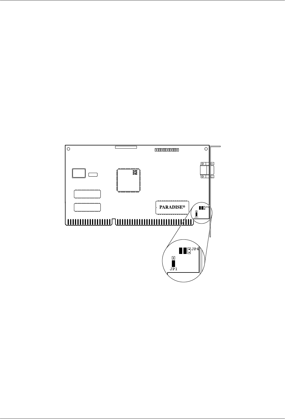
67
Preinstallation Checks for the Paradise Video Card
The Paradise Video card is installed at the factory for the Altos full-feature workstations. However,
if you do not have a video display on power-up, verify that the settings on the card were properly
configured as described below. If replacing a video card on the Altos 386 full-feature workstations
with a Paradise Video card, the default strapped by the manufacturer may not be compatible with
the workstation, also resulting in no video display. For either case, if the identifications on the card
have the WDC Chip number as WD90C33-ZZ, ’94 appears on the Paradise chip, and 833124
appears on the label on the back of the board, the following jumper settings apply (see Figure 1
below):
•The jumper at location JP1 is set on Pins 2 and 3.
•The jumpers at location JP4 remains at the factory setting. Jumpers are set on Pins (left to
right) 1, 2, 3, and 4 with 5 and 6 open.
495-14681
62-003318-800
©WDC'94
WDC
WD90C33-ZZ
xx-xx xxxx x
xxxxxx-xxxx
Figure 1. Paradise Video Card

68
Chapter 5
Using Whitepine Exodus with Existing Hardware
The following procedures should be amended to Chapter 5 of the installation manual:
•Installing the Whitepine Exodus software package with EtherLink II Card
•Installing the NMS Full-Feature Workstation Application software with EtherLink II Card
•Installing Whitepine Exodus software package with a StarLAN 10 NAU
•Installing the NMS Full-Feature Workstation Application software with
StarLAN 10 NAU
•Network configuration of full-feature workstation
For installing the Token Ring software on the Full-Feature Workstation, see Token Ring
Installation When Using Either X-One or Exodus Software at the end of this section.
Installing the Whitepine Exodus Software Package with EtherLink II Card
To install the Whitepine Exodus software package, perform the following steps:
1. Insert the Whitepine Exodus installation disk into the drive and
TYPE: A:install
PRESS: Enter
2. The system prompts:
Enter the floppy drive to use [A:]:
PRESS: Enter
3. The system prompts:
Enter the destination drive to use [C:]:
PRESS: Enter
4. The system prompts:
Enter the destination directory to use [\EXODUS]:
PRESS: Enter
If the directory, C:\EXODUS, does not exist the system prompts:
The directory C:\EXODUS does not exist. OK to create it? (y/n) [y]
TYPE: y
PRESS: Enter

69
5. The system prompts:
Do you wish to install the fonts (y/n)? [n]
TYPE: y
PRESS: Enter
Do you wish to install the standard set of fonts
including “MISC” and “75DPI” (y/n): [y]
PRESS: Enter
Do you wish to install the 100DPI fonts (y/n)? [n]
TYPE: y
PRESS: Enter
Do you wish to install the OpenWindows fonts: (y/n)? [n]
TYPE: y
PRESS: Enter
Do you wish to install the DecWindows fonts: (y/n)? [n]
TYPE: y
PRESS: Enter
Do you wish to install the TGRAF fonts: (y/n)? [n]
TYPE: y
PRESS: Enter
Do you wish to install the Kanji fonts: (y/n)? [n]
TYPE: y
PRESS: Enter
Make sure the EXODUS disk labeled ‘‘Install” is in the floppy drive
Press ENTER to continue or ‘q’ to Quit
PRESS: Enter
6. After some time marked by a line of dots on the screen, the system prompts:
Insert the EXODUS disk labeled ‘Fonts Disk 1’
Press ENTER to continue or ‘q’ to Quit
Remove the Exodus Install disk, insert the requested disk, and
PRESS: Enter
7. After some time marked by a line of dots on the screen, the system prompts:
Insert the EXODUS disk labeled ‘Fonts Disk 2’
Press ENTER to continue or ‘q’ to Quit
Remove the Fonts Disk 1, insert the requested disk, and
PRESS: Enter

70
8. After another period marked by the line of dots on the screen, the following messages
appear:
All files successfully installed.
The following should be placed in your autoexec.bat file
SET EXODUSDIR=C:\EXODUS
SET DOS4G=quiet
Would you like eXodus to add this to your autoexec.bat file (y/n)? [y]:
PRESS: Enter
9. The system prompts:
Ready to execute setup
Press any key to continue
PRESS: Enter
10. The system prompts:
Exodus Setup Utility
Press any key to continue
PRESS: Enter
11. The system prompts:
Select Mouse type
1. Mouse type device (pre-loaded driver)
2. Microsoft serial mouse
3. Logitech serial mouse
4. Mouse Systems serial mouse
Enter selection or ‘q’ to Quit [1]:
TYPE: 1
PRESS: Enter

71
12. The system prompts:
Would you like to use the graphics board configuration detected by
Xsetup (y/n): [y]:
TYPE: n
PRESS: Enter
Select Graphics Card
1. 640x480 displayed in 816x640 virtual space 16 colors
2. 640x480 16 colors
3. 640x480 displayed in 640x816 virtual space 16 colors
4. 640x480 displayed in 1088x480 virtual space 16 colors
5. 800x600 16 colors
6. 640x480 256 colors
7. 800x600 1256 colors
8.
Enter selection or ‘q’ to Quit [1]:
TYPE: 7
PRESS: Enter
Select Monitor Size
1. 11 inch
2. 14 inch
3. 15 inch
4. 16 inch
5. 17 inch
6. 19 inch
7. 21 inch
8. other
Enter selection or ‘q’ to Quit [1]:
TYPE: appropriate number
PRESS: Enter
13. The system then prompts:
Please verify settings:
Mouse settings . . .
Graphics settings . . .
Monitor settings . . .
Are these settings correct (y/n/q)? [y]:
14. If these settings are not correct,
TYPE: n
PRESS: Enter
The system starts again at Step 10.

72
15. If the settings are correct,
PRESS: Enter
16. The system responds:
Settings saved in file “C:\EXODUS\hardware.cfg”.
Press any key to continue
PRESS: Enter
17. The system prompts:
Xsetup will need to copy the graphics driver ‘vga256.dvr’
from the Exodus diskette to the C:\EXODUS directory
Insert the disk labeled ‘Install’ in drive A:
Press ENTER to continue or ‘q’ to Quit
18. Insert the proper disk and
PRESS: Enter
19. The system responds:
1 file extracted from archive
Press any key to continue
PRESS: Enter
20. The system prompts:
Select Network configuration
1. Whitepine’s own builtin TCP/IP
2. Beame and Whiteside BW-TCP
3. FTP Software’s PC/TCP version 2.05
4. FTP Software’s PC/TCP version 2.1 or later
5. Sun Microsystem’s PC/NFS ver’s 3.5-3.9
6. Sun Microsystem’s PC/NFS ver. 4.0 or later
7. Woolongong’s Pathway TCP
Enter selection or ‘q’ to Quit [1]:
PRESS: Enter

73
21. The system prompts:
Select Network Interface
4. 3COM 3C503 (Etherlink II)
Enter selection or ‘q’ to Quit [1]:
TYPE: 4
PRESS: Enter
Select connector type
1. Thin net
2. External Transceiver (thick net)
Enter selection or ‘q’ to Quit [1]:
TYPE: 1
PRESS: Enter
Enter I/O Address in hex [300]:
TYPE: 300
PRESS: Enter
NOTE
If you are using basic network configuration, use the IP address in
Table 5-1. Otherwise, ask your System Administrator for the correct
IP address.
Enter this system’s IP address:
TYPE: IP address in format “xxx.xxx.xxx.xxx” where xxx is a number from
1 to 255 inclusive
PRESS: Enter
NOTE
Ask your Network Administrator for correct subnet mask.
Enter a subnet mask[255.0.0.0]
PRESS: Enter

74
22. The system prompts:
Would you like to specify your gateway entries now (y/n/q)? [n]:
PRESS: Enter
Would you like to add a name server (y/n)? [n]:
PRESS: Enter
If a HOSTS file does not exist, please specify the path where it will reside:
(Default: C:\EXODUS\HOSTS)
PRESS: Enter
23. The system prompts:
Please verify settings:
Transport:
Interface:
Connector:
I/O Address:
IP Address:
Subnet mask:
Hosts file path:
Are these settings correct (y/n/q)? [y]:
24. If the settings are correct,
PRESS: Enter
25. If the settings are not correct,
TYPE: n
PRESS: Enter
The system returns to Step 21.
26. The system responds:
Settings saved in file “C:\EXODUS\tcp.cfg”.
Press any key to continue
PRESS: Enter
27. The system prompts:
Xsetup will need to copy the network driver “tcpnet.exe” from the EXODUS
diskette to the C:EXODUS directory
Insert the disk labeled ‘Install’ in drive A:
Press ENTER to continue or ‘q’ to Quit
PRESS: Enter

75
28. The system prompts:
Xsetup will need to copy some additional files to go with your network files
Press any key to continue
PRESS: Enter
Searching archive for files. Please wait . . .
Press any key to continue
PRESS: Enter
eXodus Setup is now finished
Create a HOSTS file that has the same name as the one you specified, before you
start eXodus.
See the Installation & Operation Guide for more details
eXodus Install Complete
Press any key to continue
PRESS: Enter
Installing the NMS Full-Feature Workstation Application Software with EtherLink II Card
A diskette is provided to install the full-feature workstation application software on your Altos
486DX/33, Altos SX/20, or a 386-based processor. To install the software, perform the following
steps:
1. Turn on your system. Insert the disk labeled 6800 FFW Application Volume 1 into the
a: drive.
2. At the C: prompt,
TYPE: cd C:\EXODUS
PRESS: Enter
TYPE: a:install
PRESS: Enter
The current directory should be “\xone” if you have installed XONE
or “\exodus” if you have installed EXODUS.
If current directory is not “\xone” or “\exodus”
Please break out of the installation by typing
Ctrl-C
Press any key to continue
PRESS: Enter

76
3. The system displays many message including the following significant ones:
Loading fonts
Loading configuration script
Loading packet driver
For further information on installation and startup –
Please refer to the C:\XONE\README or C:\EXODUS\README file.
Installation Completed
4. Determine if the workstation connects to the host or a UIP (either uip-1 or uip-2).
NOTE
For the 15000 platform, the division of full-feature workstations
among the three processors should be:
Host Uip-1 Uip-2
7 3 14
Configurations with fewer full-feature workstations should retain
equivalent ratios among the processors for best performance.
5. If the workstation is connected to a UIP and while still in the \EXODUS directory:
TYPE: COPY UIP.CFG EXODUS.CFG
PRESS: Enter
TYPE: edit EXODUS.CFG
PRESS: Enter
The DOS editor displays the CFG file. Find the line which starts with
CONN_COMMAND and change WSNAME to the name of the workstation. Find
the line beginning with CONN_HOST and change NMSUIP to the name of the UIP.
6. If the workstation is connected to an NMS host and while still in the \EXODUS directory:
TYPE: COPY HOST.CFG EXODUS.CFG
PRESS: Enter
TYPE: edit EXODUS.CFG
PRESS: Enter
The DOS editor displays the CFG file. Find the line which starts with
CONN_COMMAND and change WSNAME to the name of the workstation. Find
the line beginning with CONN_HOST and change NMSHOST to the name of the NMS
host.
7. Reboot the processor to ensure that all changed parameters are properly loaded.

77
Installing Whitepine Exodus Software Package with a StarLAN 10 NAU
To install the Whitepine eXodus Server when a StarLan NAU card is used, perform the following
steps:
1. Insert the Whitepine eXodus installation disk into the drive and
TYPE: A:install
PRESS: Enter
2. The system prompts:
Enter the floppy drive to use [A:]:
PRESS: Enter
3. The system prompts:
Enter the destination drive to use [C:]:
PRESS: Enter
4. The system prompts:
Enter the destination directory to use [\EXODUS]:
PRESS: Enter
If the directory, C:\EXODUS, does not exist the system prompts:
The directory C:\EXODUS does not exist. OK to create it? (y/n) [y]
TYPE: y
PRESS: Enter
5. The system prompts:
Do you wish to install the fonts (y/n)? [n]
TYPE: y
PRESS: Enter
Do you wish to install the standard set of fonts
including “MISC” and “75DPI” (y/n): [y]
PRESS: Enter
Do you wish to install the 100DPI fonts (y/n)? [n]
TYPE: y
PRESS: Enter
Do you wish to install the OpenWindows fonts: (y/n)? [n]
TYPE: y
PRESS: Enter

78
Do you wish to install the DecWindows fonts: (y/n)? [n]
TYPE: y
PRESS: Enter
Do you wish to install the TGRAF fonts: (y/n)? [n]
TYPE: y
PRESS: Enter
Do you wish to install the Kanji fonts: (y/n)? [n]
TYPE: y
PRESS: Enter
Make sure the EXODUS disk labeled ‘Install’ is in the floppy drive
Press ENTER to continue or ‘q’ to Quit
PRESS: Enter
6. After some time marked by a line of dots on the screen, the system prompts:
Insert the EXODUS disk labeled ‘Fonts Disk 1’
Press ENTER to continue or ‘q’ to Quit
Remove the Exodus Install disk, insert the requested disk, and
PRESS: Enter
7. After some time marked by a line of dots on the screen, the system prompts:
Insert the EXODUS disk labeled ‘Fonts Disk 2’
Press ENTER to continue or ‘q’ to Quit
Remove the Fonts Disk 1, insert the requested disk, and
PRESS: Enter
8. After another period marked by the line of dots on the screen, the following messages
appear:
All files successfully installed.
The following should be placed in your autoexec.bat file
SET EXODUSDIR=C:\EXODUS
SET DOS4G=quiet
Would you like eXodus to add this to your autoexec.bat file (y/n)? [y]:
PRESS: Enter
9. The system prompts:
Ready to execute setup
Press any key to continue
PRESS: Enter

79
10. The system prompts:
Exodus Setup Utility
Press any key to continue
PRESS: Enter
11. The system prompts:
Select Mouse type
1. Mouse type device (pre-loaded driver)
2. Microsoft serial mouse
3. Logitech serial mouse
4. Mouse Systems serial mouse
Enter selection or ‘q’ to Quit [1]:
TYPE: 1
PRESS: Enter
12. The system prompts:
Would you like to use the graphics board configuration detected by
Xsetup (y/n): [y]:
TYPE: n
PRESS: Enter
Select Graphics Card
1. 640x480 displayed in 816x640 virtual space 16 colors
2. 640x480 16 colors
3. 640x480 displayed in 640x816 virtual space 16 colors
4. 640x480 displayed in 1088x480 virtual space 16 colors
5. 800x600 16 colors
6. 640x480 256 colors
7. 800x600 1256 colors
8.
Enter selection or ‘q’ to Quit [1]:
TYPE: 7
PRESS: Enter
Select Monitor Size
1. 11 inch
2. 14 inch
3. 15 inch
4. 16 inch
5. 17 inch
6. 19 inch
7. 21 inch
8. other

80
Enter selection or ‘q’ to Quit [1]:
TYPE: appropriate number
PRESS: Enter
13. The system prompts:
Please verify settings:
Mouse settings . . .
Graphics Info . . .
Graphics board settings . . .
Monitor settings . . .
Are these settings correct (y/n/q)? [y]:
14. If these settings are not correct,
TYPE: n
PRESS: Enter
The system starts again at Step 10
15. If the settings are correct,
PRESS: Enter
16. The system responds:
Settings saved in file “C:\EXODUS\hardware.cfg”.
Press any key to continue
PRESS: Enter
17. The system prompts:
Xsetup will need to copy the graphics driver ‘vga.dvr’
from the Exodus diskette to the C:\EXODUS directory
Insert the disk labeled ‘Install’ in drive A:
Press ENTER to continue or ‘q’ to Quit
18. Insert the proper disk and
PRESS: Enter
19. The system responds:
1 file extracted from archive
Press any key to continue
PRESS: Enter
81
20. The system prompts:
Select Network configuration
1. Whitepine’s own builtin TCP/IP
2. FTP Software’s PC/TCP
3. Sun Microsystem’s PC/NFS ver’s 3.5-3.9
4. Beame and Whiteside BW-TCP
5. Woolongong’s Pathway TCP
Enter selection or ‘q’ to Quit [1]:
PRESS: Enter
21. The system prompts:
Select Network Interface
9. Packet Driver
Enter selection or ‘q’ to Quit [1]:
TYPE: 9
PRESS: Enter
Will you be using more than one Network board in your machine
with more than one packet driver loaded (y/n/q)? [n]:
PRESS: Enter
NOTE
For the basic network configuration, use the IP address in Table 5-1.
Otherwise, ask your System Administrator for the correct IP
address.
Enter this system’s IP address:
TYPE: IP address in the format “xxx.xxx.xxx.xxx”
Where: xxx is a number from 1 to 255 inclusive
PRESS: Enter
NOTE
Ask your Network Administrator for the correct subnet mask.
Enter a subnet mask[255.0.0.0]
PRESS: Enter

82
22. The system prompts:
Would you like to specify your gateway entries now (y/n/q)? [n]:
PRESS: Enter
Would you like to add a name server (y/n)? [n]:
PRESS: Enter
If a HOSTS file does not exist, please specify the path where it will reside:
(Default: C:\EXODUS\HOSTS)
PRESS: Enter
23. The system prompts:
Please verify settings:
Transport:
Interface:
Connector:
I/O Address:
IP Address:
Subnet mask:
Hosts file path:
Are these settings correct (y/n/q)? [y]:
24. If the settings are correct,
PRESS: Enter
25. If the settings are not correct,
TYPE: n
PRESS: Enter
The system returns to Step 20.
26. The system responds:
Xsetup will need to copy the network driver “tcpnet.exe”
from the EXODUS diskette to the C:EXODUS directory
Insert the disk labeled ‘Install’ in drive A:
Press ENTER to continue or ‘q’ to Quit
Insert the diskette labeled Install and
PRESS: Enter
The system displays various messages including:
file extracted from archive
Press any key to continue
PRESS: Enter
Xsetup will need to copy some additional files to go with your network files

83
Press any key to continue
PRESS: Enter
The system displays various messages including:
5 files extracted
Press any key to continue
PRESS: Enter
The following message appears:
eXodus Install Complete
Press any key to continue
PRESS: Enter
Installing the NMS Full-Feature Workstation Application Software with StarLAN 10 NAU
A diskette is provided to install the full-feature workstation application software on your Altos
486DX/33, Altos SX/20, or a 386-based processor. To install the software, perform the following
steps:
1. Turn on your system. Insert the disk labeled 6800 FFW Application Volume 1 into the
a: drive.
2. At the C: prompt,
TYPE: cd C:\EXODUS
PRESS: Enter
TYPE: a:install
PRESS: Enter
The current directory should be “\xone” if you have installed XONE
or “\exodus” if you have installed EXODUS.
If current directory is not “\xone” or “\exodus”
Please break out of the installation by typing
Ctrl-C
Press any key to continue
PRESS: Enter

84
3. The system displays many message including the following significant ones:
Loading fonts
Loading configuration script
Loading packet driver
For further information on installation and startup –
Please refer to the C:\XONE\README or C:\EXODUS\README file.
Installation Completed
NOTE
For the 15000 platform, the division of full-feature workstations
among the three processors should be:
Host Uip-1 Uip-2
7 3 14
Configurations with fewer full-feature workstations should retain
equivalent ratios among the processors for best performance.
4. If the workstation is connected to an NMS host and while still in \EXODUS directory:
TYPE: COPY HOST.CFG EXODUS.CFG
PRESS: Enter
5. If the workstation is connected to a UIP and while still in the \EXODUS directory:
TYPE: COPY UIP.CFG EXODUS.CFG
PRESS: Enter
6. TYPE: edit EXODUS.CFG
PRESS: Enter
The DOS editor displays the CFG file. Find the line which starts with
CONN_COMMAND and change WSNAME to the name of the workstation. Find the line
beginning with CONN_HOST and change NMSHOST to the name of the NMS host or
the UIP if this workstation will connect to the UIP. Save the file and exit the editor.

85
7. If not installing the Token Ring package, do the following steps. If installing the Token
Ring package, continue with the procedure, Installing the Token Ring Software on the
Full-Feature Workstation.
TYPE: cd . .
PRESS: Enter
TYPE: edit autoexec.bat
PRESS: Enter
The DOS editor displays the file. At the end of the file add the following line:
C:\EXODUS\PACKET\STARTPKT
Save the file and exit the editor program.
8. Reboot the processor to ensure that all changed parameters are properly loaded.
Network Configuration of Full-Feature Workstation
The NMS full-feature workstation needs to know about the other processors on the network that it
communicates with. This information is stored in a file \EXODUS\HOSTS, which must contain the
name of each processor and its associated IP address. To configure the full-feature workstation for
proper communication on the LAN, you must perform the following:
1. If using the basic network configuration for the Altos 5000 platform supplied with the
NMS:
TYPE: COPY \EXODUS\WS.BAS \EXODUS\HOSTS
PRESS: Enter
Stop here. There are no further steps in the basic network configuration process.
2. If configuring any Altos 15000 or customizing your network configuration for an Altos
5000, or connecting to an existing LAN, consult your Network Administrator for valid IP
address information and perform the following steps:
TYPE: EDIT \EXODUS\HOSTS
PRESS: Enter
3. Add the IP address and NMS host processor name to the \EXODUS\HOSTS file in the
format:
nnn.nnn.nnn.nnn host-name
Where: nnn is a number from 1 to 255 inclusive, and
host-name is the name of the NMS host processor

86
4. If the full-feature workstation is to communicate with a UIP, add the IP address and UIP
name to the \EXODUS\HOSTS file in the format:
nnn.nnn.nnn.nnn uip-name
Where: nnn is a number from 1 to 255 inclusive, and
uip-name is the name of the NMS UIP
NOTE
For the 15000 platform, the division of full-feature workstations
among the three processors should be:
Host Uip-1 Uip-2
7 3 14
Configurations with fewer full-feature workstations should retain
equivalent ratios among the processors for best performance.
Token Ring Installation When Using Either X-One or
Exodus Software
The following procedure replaces the existing Installing the Token Ring Software on the
Full-Feature Workstation procedure in Chapter 5. You use this procedure regardless of whether
you have installed X-One or Exodus software.
Installing the Token Ring Software on the Full-Feature Workstation
The Whitepine Exodus server software or the GraphPoint X-One software must be installed prior
to the installation of any Token Ring software on the full-feature workstation. The Exodus or
X-One software must be configured for use with a packet driver. For more information, please
refer to the section Installing the Whitepine eXodus Software Package with a StarLAN 10 NAU.
Follow Steps 1 through 22 listed in Chapter 5 of the installation guide for the Installing the Token
Ring Software on the Full-Feature Workstation procedure. Replace the remaining steps with the
following instructions.
23. Insert the diskette labeled “Token Ring FFW Application” into the a: drive.
24. At the C: prompt,
TYPE: cd c:xxxxx
Where: xxxxx is \ xone or \exodus
PRESS: Enter
TYPE: a:install
PRESS: Enter

87
25. The following message appears,
Before installing “TOKEN RING FFW APPLICATION
REL. 4.2.1” you must install XONE or EXODUS
and “6800 FFW APPLICATION REL 4.2.1” on your
system.
Installation begins.
The current directory should be “\xone” if you have
installed XONE or “\exodus” if you have installed
EXODUS. If current directory is not “\xone” or
“\exodus” Please break out of the installation by typing Ctrl-C
Press any key to continue...
PRESS: Enter
26. The following message appears,
Loading IBMTOKEN.COM file
Please remove the diskette,
add following line to your autoexec.bat file
c:\xone\packet\ibmtoken.com 0x60 0 if XONE is
installed or c:\exodus\packet\ibmtoken.com 0x60 0
if EXODUS is installed and reboot the system.
Token Ring Packet Driver installation completed.
Remove the diskette and add proper line to your
autoexec.bat file.
27. Remove and store the diskette.
28. Edit your autoexec.bat file per the text message instructions in Step 26.
29. Reboot your system.
