HARLEY 95 UP 692 1600 1600AT
User Manual: HARLEY-95 UP 692-1600
Open the PDF directly: View PDF ![]() .
.
Page Count: 2
®
23801 E. La Palma Ave., Yorba Linda, Ca 92887 Ph. 714.692.8180, Fax. 714.692.5016
www.fi2000r.com
04/11
* Cobra® recommends you always wear a helmet while riding. Please never operate your motorcycle while under
the influence of alcohol and/or drugs. Enjoy the new look of your motorcycle and please ride safely.
Items Supplied >
1 – Fi2000AT Fuel Injection Module
2 – Zip Ties
1 – Velcro Strip
Application(s) >
HARLEY 95-05 FLH
W/Fuel Injection FLHT
FLHS
FLTR
ROADKING
Instruction Manual >
Read all instructions carefully and completely before installing your new Fi2000AT module.
It is recommended that a qualified mechanic or technician install this product.
1. Remove the seat and air cleaner assembly. Remove both front and rear gas tank mounting bolts.
2. Prop the rear of the gas tank up approximately 2”.
3. Locate the factory connector on each fuel injector. Depress the wire clip on the injector and pull the
connector free and move out of way. Note: A pair of needle nose pliers and a long flat blade
screwdriver helps with this job. If you have a 2002 or newer Harley see the additional instructions on
sheet 2.
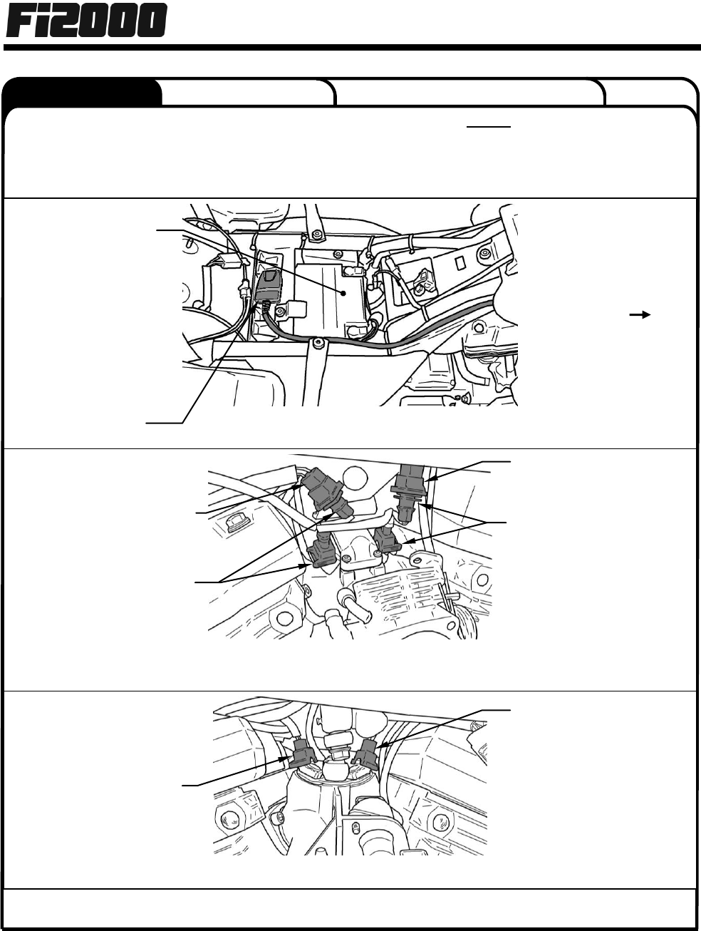
4. Lay the Fi2000 module in place, but do not attach it to the motorcycle, and run the wiring harness up to
the manifold area behind the other wiring of the throttle body (See figure 1). Attach one pair of the
Fi2000 module’s injector plugs to the front injector. Take the original HD connector and insert the
corresponding Fi2000 connector into it. (For model years 02’ and Up refer to figure 2, for model years
95-01 refer to figure 3)
5. Attach the Fi2000 module’s remaining pair of connectors to the rear injector. Then take the original HD
connector and insert the corresponding Fi2000 connector into it. (For model years 02’ and Up refer to
figure 2, for model years 95-01 refer to figure 3). Use one of the supplied zip-ties to secure the
Fi2000 wire harness to the upper motor mount before it is routed back towards the seat area.
6. Route the BLACK wire from the Cobra® module to the negative post of the battery as shown in figure 1.
7. Verify the wire connections; turn on the ignition and watch the Fi2000 LED logo, confirm that the LED
blinks several times then turns off. If you do not see any blinking, it may be necessary to wait for the
alarm to reset (if applicable) and try again. Also confirm the side stand is up, bike is in neutral, clutch is
in and handle bar engine switch is set to run (where applicable). Start the bike and the Fi2000 logo
should remain solid red, which confirm the unit is fully functioning. If it flashes while the bike is running,
turn off the bike and recheck that all harness connections (injectors, ground wire, and O2 sensors when
applicable) have been properly made. Re-verify by turning ignition on while watching for flashing LED,
prior to starting. Start and confirm LED remains ON solid red. NOTE: Make sure ignition is turned off
before attempting to change any Fi2000 harness connections.
8. Route the Fi2000 wiring harness along side the factory harness using the supplied zip ties, keeping it
off the cylinder head or getting it pinched under the gas tank. Lower and re-attach the fuel tank.
9. Remove the backing from the Velcro and attach the Fi2000 next to the battery as shown in fig 1.
10. Re-install the seat and air cleaner assembly.
692-1600AT
Page 1 of 2
DOCUMENT NO. 0017 REV. A
®
23801 E. La Palma Ave., Yorba Linda, Ca 92887 Ph. 714.692.8180, Fax. 714.692.5016
www.fi2000r.com
04/11
Instruction Manual >
692-1600AT
Page 2 of 2
The following instructions apply to the 02 - 05
1. If you need additional access to the fuel injector connectors, you can remove the Idle Air
solenoid by removing the two 5/16’’ bolts holding it on and loosening the Torx #20 screw on
throttle cable bracket. Make sure to use locktite when refitting the two 5/16” bolts and correctly
position the o-ring when reattaching.
DOCUMENT NO. 0018 REV. A
BATTERY
NEGATIVE POST
(GROUND)
FIGURE 1
(02-05 shown, 95’ – 01’ similar)
FIGURE 2
(02 – 05 W/Fi2000 installed and Air Injector Solenoid removed)
FIGURE 3 (95 – 01 W/O Fi2000 installed)
Fi2000 MODULE
FRONT Fi2000 INJECTOR
CONNECTORS
ORGINAL FRONT HD
INJECTOR CONNECTOR
REAR Fi2000 INJECTOR
CONNECTORS
ORGINAL REAR HD
INJECTOR CONNECTOR
FRONT
BATTERY
ORGINAL REAR HD
INJECTOR CONNECTOR
ORGINAL FRONT HD
INJECTOR CONNECTOR
NOTE: For California riders we offer Air Resources Board approved Fi2000R ARB units. (ARB E.O. No. D-633-1). All
other Fi2000 models are not legal for street use in California.
