Manual For The 69783 9 Gal. 212cc 135 PSI Wheelbarrow Air Compressor EPA III
User Manual: Manual for the 69783 9 gal. 212cc 135 PSI Wheelbarrow Air Compressor EPA III 9 gal. 212cc 135 PSI Wheelbarrow Air Compressor EPA III
Open the PDF directly: View PDF ![]() .
.
Page Count: 48
Visit our website at: http://www.harborfreight.com
Email our technical support at: productsupport@harborfreight.com
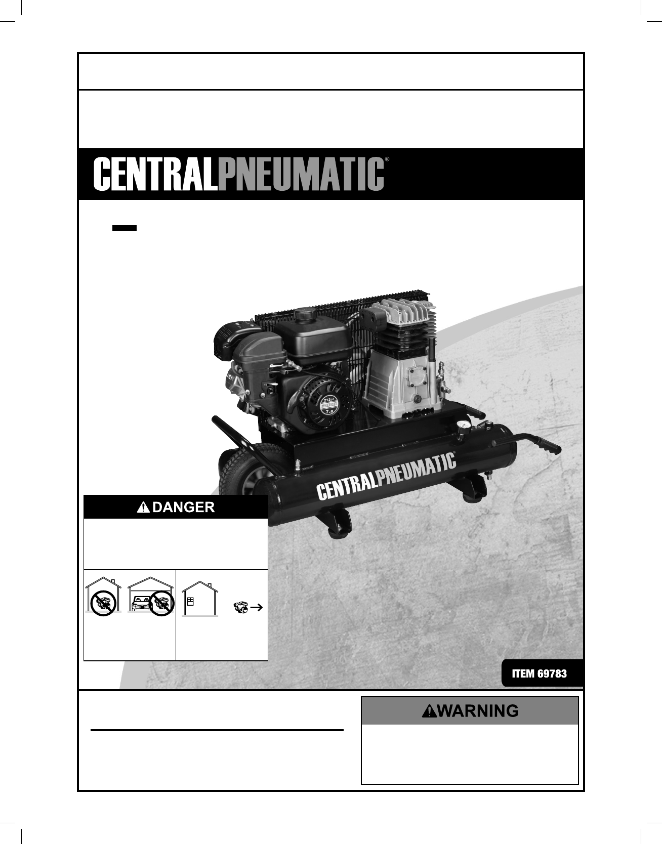
9 GAL wheelbarrow oil lubricated
air compressor
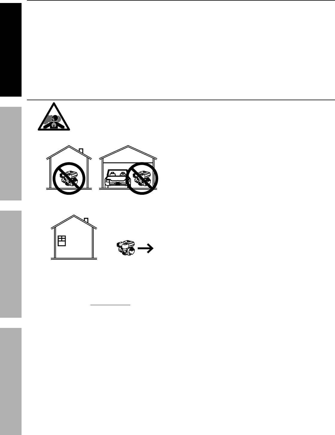
Using an engine indoors
CAN KILL YOU IN MINUTES.
Engine exhaust contains carbon monoxide.
This is a poison you cannot see or smell.
NEVER use inside
a home or garage,
EVEN IF doors and
windows are open.
Only use OUTSIDE
and far away from
windows, doors,
and vents.
Owner’s Manual & Safety Instructions
Save This Manual Keep this manual for the safety warnings and precautions, assembly,
operating, inspection, maintenance and cleaning procedures. Write the product’s serial number in the
back of the manual near the assembly diagram (or month and year of purchase if product has no number).
Keep this manual and the receipt in a safe and dry place for future reference.
When unpacking, make sure that the product is intact
and undamaged. If any parts are missing or broken,
please call 1-888-866-5797 as soon as possible.
Copyright© 2012 by Harbor Freight Tools®. All rights reserved.
No portion of this manual or any artwork contained herein may be reproduced in
any shape or form without the express written consent of Harbor Freight Tools.
Diagrams within this manual may not be drawn proportionally. Due to continuing
improvements, actual product may differ slightly from the product described herein.
Tools required for assembly and service may not be included.
Read this material before using this product.
Failure to do so can result in serious injury.
SAVE THIS MANUAL.
REV 16e
2
This unit was fully tested and inspected prior to shipment and will operate properly when instructions are followed. Refer to your owner’s manual for basic
troubleshooting. To avoid unnecessary return to the store, simply call Compressor Support toll free for additional assistance.
DO NOT RETURN TO STORE
IMPORTANT
STOP STOP
Compressor Support: 1-800-444-3353
•
Air Compressor will automatically shut off when maximum PSI is reached. When the tank pressure drops to the cut
in pressure (low pressure) and the on/off switch
is in the ON position, the unit will automatically restart.
• On occasion, maximum pressure in tank will remain until next use thus resulting in a sense of no power (See bullet above).
• To avoid power loss, overheating and ensure power, use additional air hose rather than extension cords.
• It is the consumer’s responsibility to drain oil lubed units prior to shipment to meet ICC, state and local fire regulations.
Please have your model number and serial number available. These can be found on the data label on your product. Retain a copy of your receipt with purchase
date for reference.
NOTICE
(%2+)6
8LMWGSQTVIWWSVTYQTMWRSXIUYMTTIHERHWLSYPHRSXFIYWIHXSWYTTP]FVIEXLMRKUYEPMX]EMV%HHMXMSREPIUYMT
QIRX[SYPHFIRIGIWWEV]XSTVSTIVP]JMPXIVERHTYVMJ]XLIEMVXSQIIXQMRMQEPWTIGMJMGEXMSRWJSV+VEHI(FVIEXLMRK
EWHIWGVMFIHMR'SQTVIWWIH+EW%WWSGMEXMSR'SQQSHMX]7TIGMJMGEXMSR+37,%'*6
'SQTVIWWIH+EW%WWSGMEXMSR;EPRI]6SEH*MJXL*PSSV'LERXMPP]:%
[[[GKERIXGSQ%R]WYGLEHHMXMSREPIUYMTQIRXLEWRSXFIIRI\EQMRIHERHRSMQTPMGEXMSRSJTVSTIVYWIJSVFVIEXL
MRKEMVMWMRXIRHIHSVMQTPMIH
-JXLMWGSQTVIWWSVMWEPXIVIHMRER][E]I\MWXMRK[EVVERXMIWWLEPPFIZSMHIH,YWO]!!&"!%"!$
JSVER]PSWWTIVWSREPMRNYV]SVHEQEKI
This tool has many features for making its use more pleasant and enjoyable. Safety, performance, and dependability
have been given top priority in the design of this product making it easy to mantain and operate.
Introduction ......................................................................................................................................................................2
General Safety Rules ....................................................................................................................................................3-4
Specific Safety Rules ....................................................................................................................................................4-5
Symbols .........................................................................................................................................................................6-7
Glossary of Terms ............................................................................................................................................................8
Tools Needed ...................................................................................................................................................................8
Features ......................................................................................................................................................................9-11
Assembly ...................................................................................................................................................................11-12
Operation ...................................................................................................................................................................13-15
Maintenance ..............................................................................................................................................................16-20
Troubleshooting .........................................................................................................................................................21-23
Warranty .........................................................................................................................................................................24
TABLE OF CONTENTS
INTRODUCTION
If this compressor is altered in any way, existing warranties shall be voided. Harbor Freight Tools disclaims any
liabilities whatsoever for any loss, personal injury, or damage.
3
WARNING:
Read and understand all instructions. Failure to
follow all instructions listed below may result in electric
shock, fire, and/or serious personal injury.
SAVE THESE INSTRUCTIONS
WORK AREA
Keep your work area clean and well lit. Cluttered
benches and dark areas invite accidents. Floor must
not be slippery from wax or dust.
Do not operate power tools in explosive atmo-
spheres, such as in the presence of flammable
liquids, gases, or dust. Power tools create sparks
which may ignite the dust or fumes.
Keep bystanders, children, and visitors away while
operating tools. Distractions can cause you to lose
control.
Operate air compressor in an open area at least 18
in. away from any wall or object that could restrict
the flow of fresh air to ventilation openings.
ELECTRICAL SAFETY
Avoid body contact with grounded surfaces such as
pipes, radiators, ranges, and refrigerators. There is an
increased risk of electric shock if your body is grounded.
Don’t expose power tools to rain or wet conditions.
Water entering a power tool will increase the risk of
electric shock.
Do not abuse the cord. Never use the cord to carry
the tool or pull the plug from an outlet. Keep cord
away from heat, oil, sharp edges, or moving parts.
Replace damaged cords immediately. Damaged
cords increase the risk of electric shock.
When operating a power tool outside, use an
outdoor extension cord marked “W-A” or “W”.
These cords are rated for outdoor use and reduce the
risk of electric shock.
PERSONAL SAFETY
Eye protection which conforms to ANSI specifica-
tions and provides protection against flying
particles both from the FRONT and SIDE should
ALWAYS be worn by the operator and others in the
work area when loading, operating, or servicing
this tool. Eye protection is required to guard against
flying fasteners and debris, which could cause severe
eye injury.
The employer and/or user must ensure that proper
eye protection is worn. We recommend a Wide Vision
Safety Mask for use over eyeglasses or standard safety
glasses that provide protection against flying particles
both from the front and side. Always use eye protection
which is marked to comply with ANSI Z87.1.
Additional safety protection will be required in
some environments. For example, the working area
may include exposure to a noise level which can lead to
hearing damage. The employer and user must ensure
that any necessary hearing protection is provided
and used by the operator and others in the work
area. Some environments will require the use of head
protection equipment. When required, the employer
and user must ensure that head protection marked to
comply with ANSI Z89.1 is used.
Stay alert, watch what you are doing, and use
common sense when operating a power tool. Do
not use tool while tired or under the influence
of drugs, alcohol, or medication. A moment of
inattention while operating power tools may result in
serious personal injury.
Dress properly. Do not wear loose clothing or
jewelry. Contain long hair. Keep your hair, clothing,
and gloves away from moving parts. Loose clothes,
jewelry, or long hair can be caught in moving parts.
Do not overreach. Keep proper footing and balance
at all times. Proper footing and balance enables better
control of the tool in unexpected situations.
Use safety equipment. Always wear eye protection.
Dust mask, nonskid safety shoes, hard hat, or hearing
protection must be used for appropriate conditions.
Do not use on a ladder or unstable support. Stable
footing on a solid surface enables better control of the
tool in unexpected situations.
TOOL USE AND CARE
Do not exceed the pressure rating of any
component in the system.
Never use this compressor to inflate low pressure
objects (i.e. toys, footballs, etc.).
Protect material lines and air lines from damage or
puncture. Keep hose and power cord away from sharp
objects, chemical spills, oil, solvents, and wet floors.
Check hoses for weak or worn condition before
GENERAL SAFETY RULES
WARNING:
This instruction manual, and any instructions supplied
by manufacturers of supporting equipment, should be
read and understood prior to starting the compressor.
Failure to comply with safety precautions and
procedures outlined in this manual may void your
warranty. Before contacting your distributor or the
factory, check the maintenance requirements and the
troubleshooting guide for your compressor.
Most warranty issues can be taken care of by following
proper maintenance procedures.

4
each use, making certain all connections are
secure. Do not use if defect is found. Purchase a
new hose or notify an authorized service center for
examination or repair.
Release all pressures within the system slowly.
Dust and debris may be harmful.
Store idle tools out of the reach of children and
other untrained persons. Tools are dangerous in the
hands of untrained users.
Maintain tools with care. Follow maintenance
instructions. Properly maintained tools are easier to
control.
Check for misalignment or binding of moving parts,
breakage of parts, and any other condition that
may affect the tool’s operation. If damaged, have
the tool serviced before using. Many accidents are
caused by poorly maintained tools.
Never point any tool toward yourself or others.
Keep the exterior of the air compressor dry, clean,
and free from oil and grease. Always use a clean
cloth when cleaning. Never use brake fluids, gasoline,
petroleum-based products, or any strong solvents to
clean the unit. Following this rule will reduce the risk of
deterioration of the enclosure plastic.
GENERAL SAFETY RULES
SERVICE
Tool service must be performed only by qualified
repair personnel. Service or maintenance performed
by unqualified personnel may result in a risk of injury.
Disconnect power supply, open drain valve to
decompress tank and allow water to drain, and
allow air compressor to become cool to the touch
before servicing. Turn pressure regulator knob fully
counter clockwise after shutting off compressor.
When servicing a tool, use only identical
replacement parts. Follow instructions in the
Maintenance section of this manual. Use of
unauthorized parts or failure to follow Maintenance
instructions may create a risk of injury.
GENERAL
Do not remove or paint over any DANGER!,
WARNING!, CAUTION!, or instructional materials
attached to the compressor.
If for any reason any part of the manual becomes
illegible or the manual is lost, have it replaced
immediately. The instruction manual should be read
periodically to refresh one’s memory.
SPECIFIC SAFETY RULES
Disconnect electrical compressor units from their
power source or shut down gas engine powered
compressor units & relieve the system of all
pressure before servicing any part of the unit or
attaching tools or accessories.
Allow ample time for the compressor unit to
cool before performing service procedures.
Some surface temperatures exceed 350°F when the
compressor is operating.
Do not change the pressure setting of the safety
valve, restrict the function of the safety valve, or
replace the safety valve with a plug.
Do not install a shutoff valve in the compressor
discharge line without first installing a safety valve of
proper size and design between the shutoff valve and
the compressor.
Periodically check all safety valves for proper
operation.

5
Know your power tool. Read operator’s manual
carefully. Learn its applications and limitations, as well
as the specific potential hazards related to this tool.
Following this rule will reduce the risk of electric shock,
fire, or serious injury.
Drain tank of moisture after each day’s use.
If unit will not be used for a while, it is best to leave drain
valve open until such time as it is to be used. This will
allow moisture to completely drain out and help prevent
corrosion on the inside of tank.
Risk of Fire or Explosion. Do not spray flammable
liquid in a confined area. Spray area must be well
ventilated. Do not smoke while spraying or spray where
spark or flame is present. Keep compressors as far from
the spraying area as possible, at least 15 feet from the
spraying area and all explosive vapors.
Risk of Bursting. Do not adjust regulator to result
in output pressure greater than marked maximum
pressure of attachment. Do not use at pressure greater
than the rated maximum pressure of this compressor.
If connected to a circuit protected by fuses, use
time-delay fuses with this product.
To reduce the risk of electric shock, do not expose to
rain. Store indoors.
Inspect tank yearly for rust, pin holes, or other
imperfections that could cause it to become unsafe.
Never weld or drill holes in the air tank.
Make sure the hose is free of obstructions or snags.
Entangled or snarled hoses can cause loss of balance
or footing and may become damaged.
Use the air compressor only for its intended use. Do
not alter or modify the unit from the original design
or function.
Always be aware that misuse and improper handling
of this tool can cause injury to yourself and others.
Never leave a tool unattended with the air hose
attached.
Do not operate this tool if it does not contain a
legible warning label.
Do not continue to use a tool or hose that leaks air
or does not function properly.
Always disconnect the air supply and power supply
before making adjustments, servicing a tool, or when a
tool is not in use.
Do not attempt to pull or carry the air compressor
by the hose.
Your tool may require more air consumption than
this air compressor is capable of providing.
Never use the compressor without guards (belt
guard) and never touch moving parts.
SPECIFIC SAFETY RULES
Always follow all safety rules recommended by the
manufacturer of your tool, in addition to all safety
rules for the air compressor. Following this rule will
reduce the risk of serious personal injury.
Never direct a jet of compressed air toward people
or animals. Take care not to blow dust and dirt
towards yourself or others. Following this rule will
reduce the risk of serious injury.
Protect your lungs. Wear a face or dust mask if the
operation is dusty. Following this rule will reduce the
risk of serious personal injury.
Do not use this air compressor to spray chemicals.
Your lungs can be damaged by inhaling toxic fumes. A
respirator may be necessary in dusty environments or
when spraying paint. Do not carry while painting.
Inspect tool cords and hoses periodically and, if
damaged, have repaired at your nearest Authorized
Service Center. Constantly stay aware of cord
location. Following this rule will reduce the risk of
electric shock or fire.
Never use an electrical adaptor with this grounded
plug.
Check damaged parts. Before further use of the
air compressor or air tool, a guard or other part
that is damaged should be carefully checked to
determine that it will operate properly and perform
its intended function. Check for alignment of
moving parts, binding of moving parts, breakage of
parts, mounting, and any other conditions that may
affect its operation. A guard or other part that is
damaged should be properly repaired or replaced
by an authorized service center. Following this rule
will reduce the risk of shock, fire or serious injury.
Make sure your extension cord is in good
condition. When using an extension cord, be sure
to use one heavy enough to carry the current your
product will draw. A wire gauge size (A.W.G.) of at
least 14 is recommended for an extension cord 50
feet or less in length. A cord exceeding 100 feet is
not recommended. If in doubt, use the next heavier
gauge. The smaller the gauge number, the heavier
the cord. An undersized cord will cause a drop in line
voltage resulting in loss of power and overheating.
Save these instructions. Refer to them frequently
and use them to instruct others who may use this air
compressor. If you loan someone this tool, load them
these instructions also.
6
Do not adjust regulator to result in output pressure greater than
marked maximum pressure of attachment. Do not use at pressure
greater than the rated maximum pressure of this compressor.
7
7=1&307
7)6:-')
7IVZMGMRKVIUYMVIWI\XVIQIGEVIERHORS[PIHKIERH
WLSYPHFITIVJSVQIHSRP]F]EUYEPMJMIHWIVZMGIXIGL
RMGMER*SVWIVZMGI[IWYKKIWX]SYVIXYVRXLITVSHYGXXS
XLIRIEVIWX%98,36->)(7)6:-')')28)6JSVVITEMV
;LIRWIVZMGMRKYWISRP]MHIRXMGEPVITPEGIQIRXTEVXW
;%62-2+
8SEZSMHWIVMSYWTIVWSREPMRNYV]HSRSXEXXIQTXXSYWI
XLMWTVSHYGXYRXMP]SYVIEHXLSVSYKLP]ERHYRHIVWXERH
GSQTPIXIP]XLISTIVEXSVWQERYEP7EZIXLMWSTIVEXSVW
QERYEPERHVIZMI[JVIUYIRXP]JSVGSRXMRYMRKWEJISTIV
EXMSRERHMRWXVYGXMRKSXLIVW[LSQE]YWIXLMWTVSHYGX
8LISTIVEXMSRSJER]TS[IVXSSPGERVIWYPXMRJSVIMKRSFNIGXWFIMRKXLVS[RMRXS]SYVI]IW[LMGLGERVI
WYPXMRWIZIVII]IHEQEKI&IJSVIFIKMRRMRKTS[IVXSSPSTIVEXMSREP[E]W[IEVWEJIX]KSKKPIWWEJIX]
KPEWWIW[MXLWMHIWLMIPHWSVEJYPPJEGIWLMIPH[LIRRIIHIH;IVIGSQQIRH;MHI:MWMSR7EJIX]1EWO
JSVYWISZIVI]IKPEWWIWSVWXERHEVHWEJIX]KPEWWIW[MXLWMHIWLMIPHW%P[E]WYWII]ITVSXIGXMSR[LMGL
MWQEVOIHXSGSQTP][MXL%27->
;%62-2+
7%:)8,)7)-27869'8-327
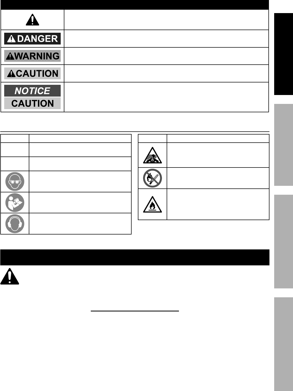
8LIJSPPS[MRKWMKREP[SVHWERHQIERMRKWEVIMRXIRHIHXSI\TPEMRXLIPIZIPWSJVMWOEWWSGMEXIH[MXLXLMWTVSHYGX
7=1&30 7-+2%0 1)%2-2+
(%2+)6
;%62-2+
'%98-32
'%98-32
-RHMGEXIWERMQQMRIRXP]LE^EVHSYWWMXYEXMSR[LMGLMJRSXEZSMHIH[MPP
VIWYPXMRHIEXLSVWIVMSYWMRNYV]
-RHMGEXIWETSXIRXMEPP]LE^EVHSYWWMXYEXMSR[LMGLMJRSXEZSMHIHGSYPH
VIWYPXMRHIEXLSVWIVMSYWMRNYV]
-RHMGEXIWETSXIRXMEPP]LE^EVHSYWWMXYEXMSR[LMGLMJRSXEZSMHIHQE]
VIWYPXMRQMRSVSVQSHIVEXIMRNYV]
;MXLSYX7EJIX]%PIVX7]QFSP-RHMGEXIWEWMXYEXMSRXLEXQE]VIWYPXMR
TVSTIVX]HEQEKI
8
0RESSURE3WITCH
!UTOMATICALLYCONTROLSTHEONOFFCYCLINGOFTHECOMPRES
SOR)TSTOPSTHECOMPRESSORWHENTHECUTOFFPRESSUREIN
THETANKISREACHEDANDSTARTSTHECOMPRESSORWHENTHE
AIRPRESSUREDROPSBELOWTHECUTINPRESSURE
03)0OUNDS0ER3QUARE)NCH
-EASUREMENTOFTHEPRESSUREEXERTEDBYTHEFORCEOFTHE
AIR4HEACTUALPSIISMEASUREDBYAPRESSUREGAUGEONTHE
COMPRESSOR
0UMP
0RODUCESTHECOMPRESSEDAIRWITHARECIPROCATINGPISTON
CONTAINEDWITHINTHECYLINDER
2EGULATOR0RESSURE'AUGE
$ISPLAYSTHECURRENTLINEPRESSURE,INEPRESSUREISADJUST
EDBYROTATINGTHEPRESSUREREGULATORKNOB
3AFETY6ALVE
0REVENTSAIRPRESSUREINTHEAIRTANKFROMRISINGOVERA
PREDETERMINEDLIMIT
3#&-3TANDARD#UBIC&EET0ER-INUTE
!UNITOFMEASUREOFAIRDELIVERY
4ANK0RESSURE'AUGE
)NDICATESTHEPRESSUREINTHEAIRTANK
4HERMAL/VERLOAD3WITCH
!UTOMATICALLYSHUTSOFFTHECOMPRESSORIFTHETEMPERATURE
OFTHEELECTRICMOTOREXCEEDSAPREDETERMINEDLIMIT
',/33!29/&4%2-3
!IR&ILTER
0OROUSELEMENTCONTAINEDWITHINAMETALORPLASTICHOUS
INGATTACHEDTOTHECOMPRESSORCYLINDERHEADWHICH
REMOVESIMPURITYFROMTHEINTAKEAIROFTHECOMPRESSOR
!IR4ANK
#YLINDRICALCOMPONENTWHICHCONTAINSTHECOMPRESSEDAIR
#HECK6ALVE
$EVICETHATPREVENTSCOMPRESSEDAIRFROMFLOWINGBACK
FROMTHEAIRTANKTOTHECOMPRESSORPUMP
#UT)N0RESSURE
4HELOWPRESSUREATWHICHTHEMOTORWILLAUTOMATICALLY
RESTART
#UT/FF0RESSURE
4HEHIGHPRESSUREATWHICHTHEMOTORWILLAUTOMATICALLY
SHUTOFF
%LECTRIC-OTOR
$EVICEWHICHPROVIDESTHEROTATIONALFORCENECESSARYTO
OPERATETHECOMPRESSORPUMP
-ANUAL/N/FF3WITCH
#ONTROLWHICHTURNSTHEAIRCOMPRESSORONOROFF4HE
PRESSURESWITCHWILLNOTAUTOMATICALLYSTARTANDCONTROLTHE
COMPRESSORUNLESSTHEMANUAL/N/FF3WITCHISINTHE/.
LPOSITION
.04.ATIONAL0IPE4HREAD
.ATIONAL0IPE4HREADISA53STANDARDFORTAPERED.04
ORSTRAIGHT.03THREADSUSEDTOJOINPIPESANDFITTINGS
!THREADSEALINGTAPEMUSTBEUSEDTOPROVIDEALEAKFREE
SEALONPIPETHREADEDCONNECTIONS
0RESSURE2EGULATOR+NOB
2EGULATESTHEOUTGOINGPRESSUREFROMTHEAIROUTLETTOTHE
TOOL)TISPOSSIBLETOINCREASEORDECREASETHEPRESSUREAT
THEOUTLETBYADJUSTINGTHISCONTROLKNOB
TOOLS NEEDED
The following tools are needed in order to assemble the rubber foot kit.
47/!$*534!",%72%.#(%3
TWO ADJUSTABLE WRENCHES
9
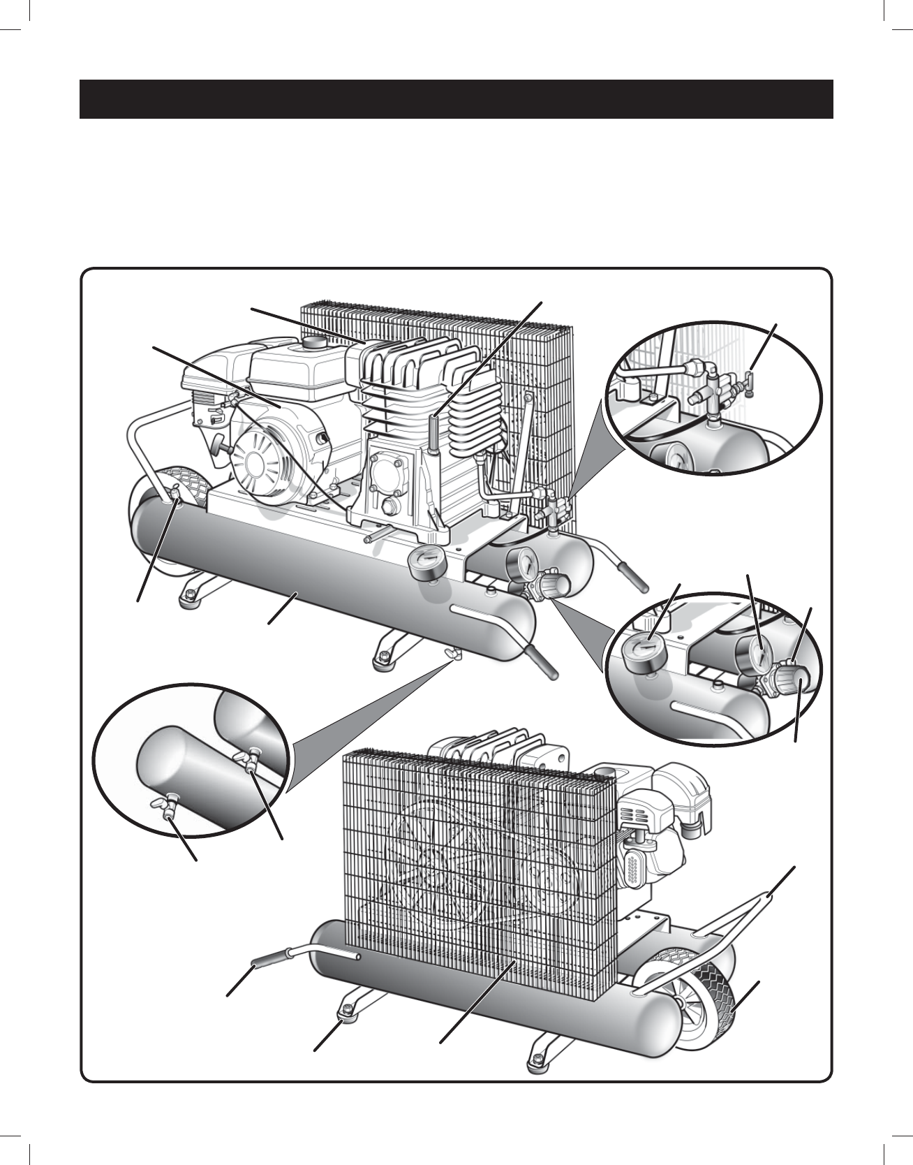
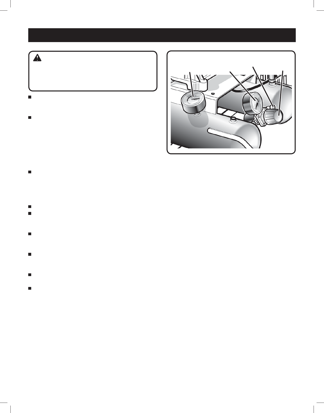
FEATURES
Fig. 1 AIR INTAKE
FILTER
REAR
HANDLE
FRONT
HANDLE
DRAIN
VALVE
PRESSURE
REGULATOR
KNOB
RUBBER
FOOT
PILOT
VALVE
DRAIN
VALVE
SAFETY
VALVE
WHEEL
TANK
PRESSURE
GAUGE
REGULATOR
PRESSURE
GAUGE
AIR
OUTLET
PRODUCT SPECIFICATIONS
Engine Displacement.................................................212 cc
Air Tank Capacity ........................................................ 9 gal.
Air Pressure ....................................................135 PSI max.
Air Delivery ...........................................11 SCFM @ 40 PSI
............................................................ 9.5 SCFM @ 90 PSI
Lubrication .......................................................................Oil
Gauges ....................................................... 1.5 in. diameter
Net Weight ...............................................................150 lbs.
TANK
GASOLINE
ENGINE
SAFETY GUARD
FOR THE V-BELT
OIL FILL
PLUG
10
FEATURES
KNOW YOUR AIR COMPRESSOR
See Figure 1.
Before attempting to use this product, familiarize yourself
with all operating features and safety rules.
DESCRIPTION
Your air compressor is aircooled, splash lubricated, belt-
driven, single stage.
DRIVE PULLEYS / FLYWHEELS
Drive pulleys and compressor flywheels must be properly
aligned and tensioned to specifications. (Refer to Belt
Alignment & Adjustment).
GUARDS
They must provide protection from moving parts while still
allowing full air flow for cooling purposes.
CHECK VALVES
Check valves are designed to allow air to flow freely in
one direction only. A properly sized check valve must be
provided in the discharge line. Do not rely on a check
valve to isolate a compressor from a pressurized tank
or compressed air delivery system during maintenance
procedures.
PRESSURE REGULATOR KNOB
The pressure regulator knob allows the operator to
control the amount of air pressure being supplied to a tool
(through the hose). A gauge is provided to indicate the air
pressure. To adjust the amount of air pressure supplied:
Pull up on the regulator knob to unlock it.
Turn the knob clockwise to increase pressure -
counterclockwise to decrease pressure.
Push the knob down to lock it into position.
REGULATOR PRESSURE GAUGE
The current line pressure is displayed on the regulator
pressure gauge. This pressure can be adjusted by rotating
the pressure regulator knob.
SAFETY VALVES
Safety valves aid in preventing system failures by relieving
system pressure when compressed air reaches a pre-determined
pressure level. All air receivers must be equipped with an
adequately sized safety valve. This type of valve is preset by the
manufacturer and must not be modified in any way.
Safety valves are to be placed ahead of any potential
blockage point which includes, but not limited to, shutoff
valves, heat exchangers, pulsation dampeners, and
discharge silencers. Ideally the safety valve should be
threaded directly into the pressure point it is sensing, not
connected with tubing or pipe, and always pointed away
from any chance bystander. All tubing or piping added must
be the same size as the safety valve opening or larger.
COMPRESSOR CONTROLS
Gasoline engine driven compressors are equipped with
constant run controls and operate continuously until they
are manually shut-off. During operation, air is compressed
and delivered to the tanks for use. Once the demand for
compressed air is satisfied, the in-line unloader (located
in the compressor discharge line) is activated, causing the
air delivered by the compressor to be discharged to the
atmosphere, and allowing the engine to run at a lower speed.
In this state, the system is considered to be “unloaded”.
As the air stored in the tanks is used and the demand for
compressed air returns, the unloader is deactivated, the
engine runs at a higher speed, and the compressed air is
once again delivered to the tanks for use.
When starting an engine driven unit with air pressure in the
tank, flip the toggle on side of the pilot valve to the horizontal
position. This will unload the compressor and allow the
engine to start easier.
When the engine has run for a few minutes, flip the toggle
back to its original position.
AIR FILTER
This compressor is equipped with an air filter to provide a
clean air supply, an essential component to the satisfactory
operation of your compressor.
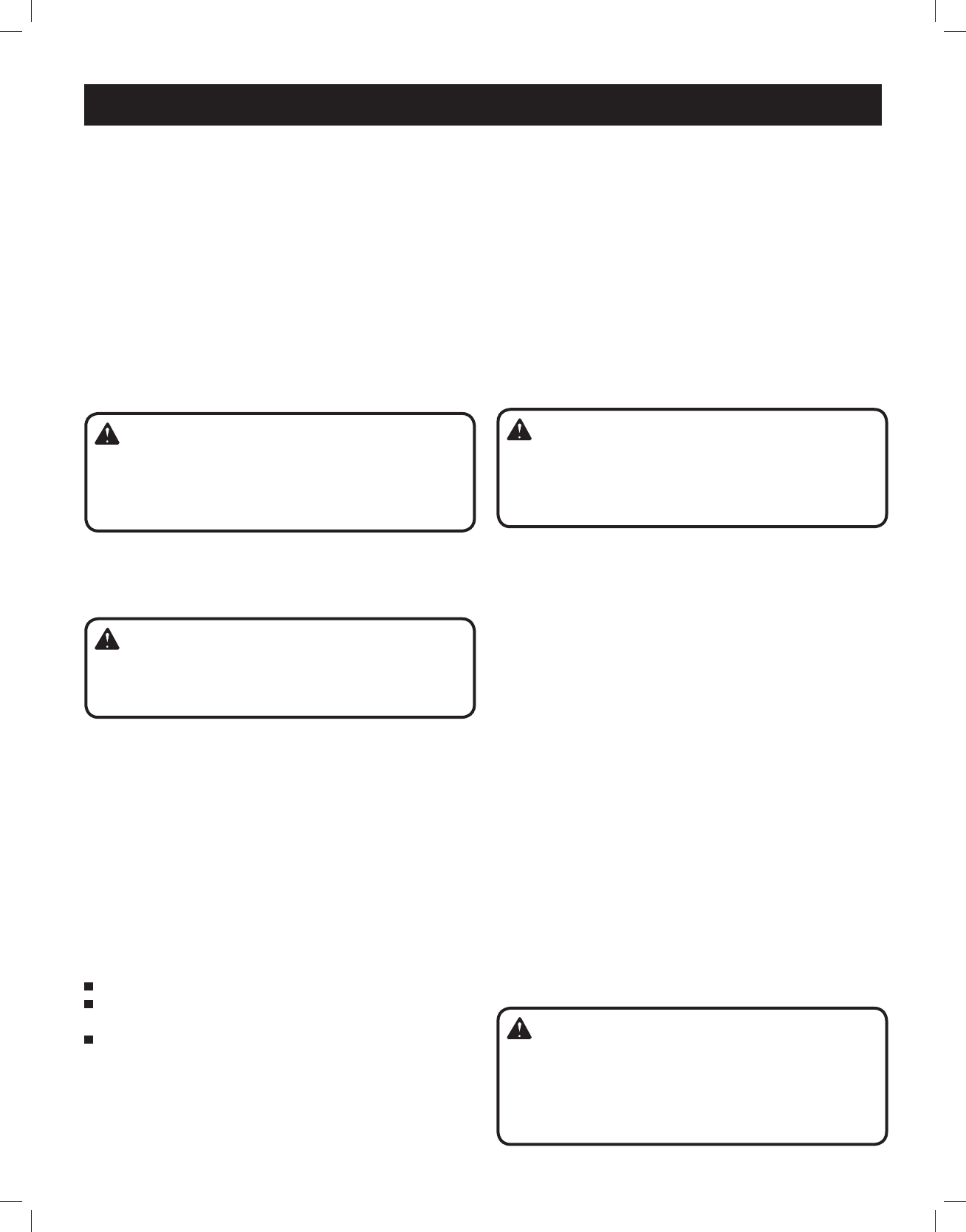
WARNING!
Excessive compressor RPM’s could cause a pulley or
flywheel to shatter, possibly causing bodily harm or death.
Do not operate the compressor above the recommended
RPM as supplied by the factory.
WARNING!
Guards must be fastened in place before starting the
compressor. Always stop the unit before removing the
guard.
WARNING!
Safety valves must be provided to protect compressed
air systems. Failure to provide properly sized pressure
safety valves may cause property damage, severe
personal injury or even death.
WARNING!
Never locate the compressor where toxic, volatile or
corrosive vapors, air temperatures exceeding 104°F,
water, or extremely dirty air could be ingested. The
compressor could be damaged by these atmospheres
and result in injury or death.
11
PRESSURE VESSELS
Air receiver tanks and other pressure containing vessels
must be equipped with a properly sized pressure relief
valve, pressure gauge, and a tank drain. The drain valve
must be located in the bottom of the air tank(s) to provide
for moisture removal.
TANK PRESSURE GAUGE
The tank pressure gauge indicates the pressure of the air
in the tank.
FEATURES
When using the compressor for spray painting, isolate the
compressor as far away from the work area as practical,
employing extra air hose rather than an extension cord.
Warranty will be void if a failure is determined to be caused
by dust, dirt or other contaminants.
COMPRESSED AIR DISCHARGE SYSTEM
WARNING!
Discharge piping can exceed 350°F when compressor
is operating. Do not use plastic pipe or lead tin soldered
joints for a discharge line. Do not modify the discharge
line.
WARNING!
Pressure vessels must not be modified, welded on, or
repaired. Such actions may cause property damage,
severe injury, or even death.
ASSEMBLY
UNPACKING
This product has been shipped completely assembled,
except the four rubber feet.
Carefully remove the compressor from the box. Make
sure that all items listed in the packing list are included.
I
nspect the compressor carefully to make
sure no
breakage or damage occurred during shipping.
Do not discard the packing material until you have
carefully inspected and satisfactorily operated the tool.
If any parts are damaged or missing, please call
1-800-444-3353 for assistance.
PACKING LIST
Air Compressor (1)
Operator’s Manual (1)
Replacement Parts List (1)
INSTALLATION
Air compressors should be located in an area that is dry,
clean, well lighted, and adequately ventilated.
Air supplied to the inlet filter must be clean. The compressor
belt guard must not be located closer than 12 inches to a
wall, or 24 inches to another compressor. Additional safety
can be achieved by locating the pulley drive system, with
the guard, next to the wall.
The compressor may only be operated in temperatures
under 104°F and over 32°F. In cold climates, the compressor
should be installed in a heated building.
Proper mounting of the compressor unit is crucial to the safe
operation and longevity of the equipment. The installation
requires a stable, flat and level surface. Satisfactory results
can usually be obtained by mounting the compressor
unit on rubber feet supplied with the unit. Refer to Fig. 2.
Uneven feet drawn tightly to a concrete floor or truck bed
will cause severe vibrations resulting in cracked welds or
fatigue failure. If the unit is mounted to a concrete floor
or truck bed or similar foundation, loosen the lock nut
several turns & lock it with a back-up nut! The customer
WARNING:
If any parts are missing do not operate the compressor
or air tools until the missing parts are replaced. Failure
to do so could result in possible serious personal injury.
WARNING:
Do not attempt to modify this tool or create accessories
not recommended for use with this tool. Any such
alteration or modification is misuse and could result
in a hazardous condition leading to possible serious
personal injury.
DANGER!
A gas engine will produce carbon monoxide; always
provide adequate ventilation! Do not operate engine
in an enclosed area..
12
ASSEMBLY
is responsible for providing a suitable foundation & rubber
foot mounting where necessary.
HIGH ALTITUDE APPLICATIONS
Refer to the engine manufacturer’s recommendations for
operation of engines at high altitudes.
DANGER!
Under no circumstances should a compressor be
used in an area where toxic, volatile, or corrosive
agents are used or stored near the compressor.
CAUTION!
Unusual noise or vibration indicates a problem. Do
not operate the compressor until the source has been
identified and corrected by a qualified technician.
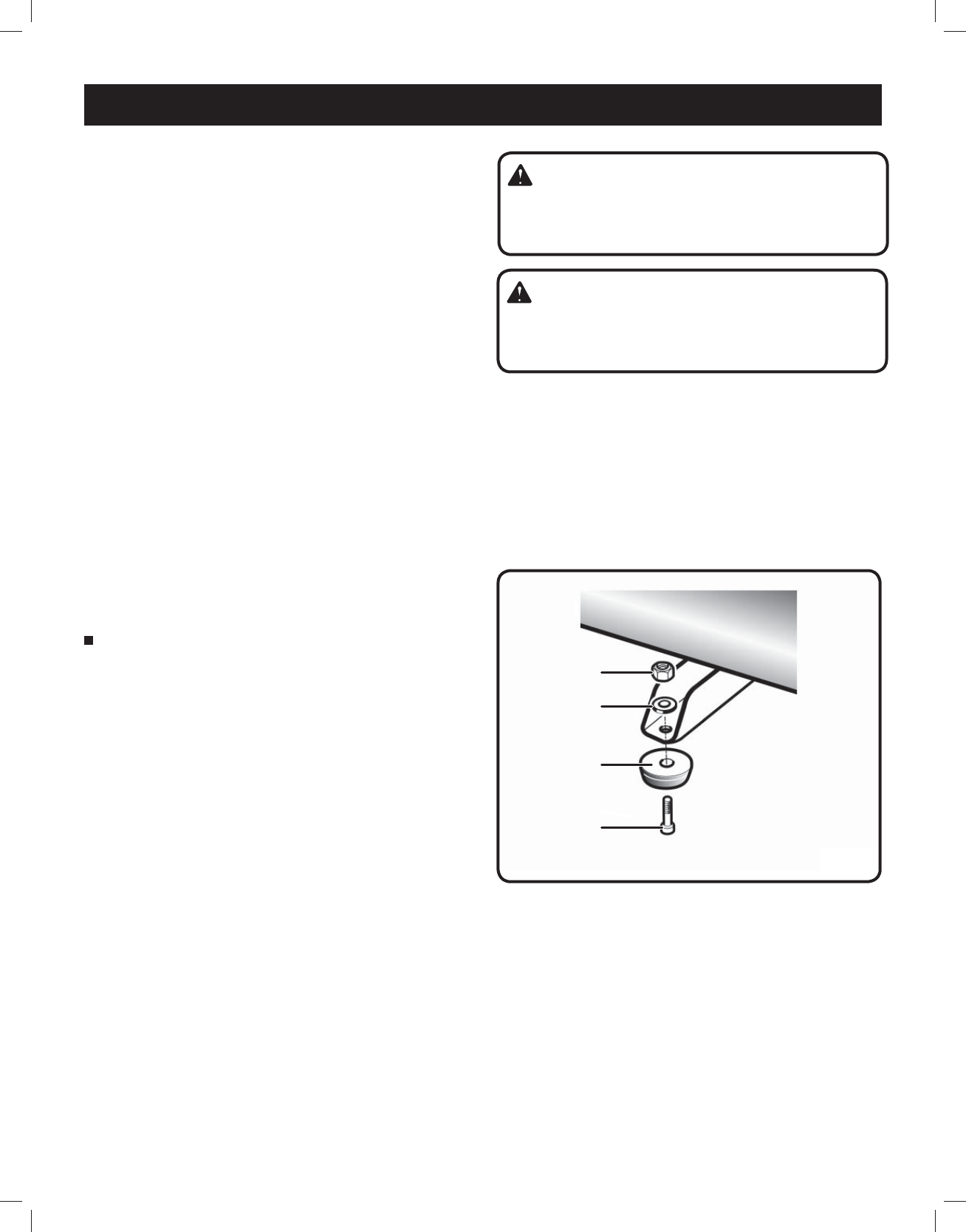
Fig. 2
WASHER
SCREW
RUBBER FOOT
NUT
ASSEMBLING THE RUBBER FOOT
See Figure 2.
Mount the rubber foot as shown in figure.
Tighten firmly with an open-end wrench (not included)
to secure it in position.
13
Turn off drain valve until completely closed.
CHECKING THE SAFETY VALVE
See Figure 4.
The safety valve will automatically release air if the air receiver
pressure exceeds the preset maximum. The valve should be
checked before each day of use by pulling the ring by hand.
Turn the air compressor on and allow the tank to
fill. The compressor will shut off when the pressure
reaches the preset maximum.
Turn the air compressor off.
Pull the ring on the safety valve to release air for twenty
seconds.
Release the ring. Air must immediately stop escaping
when the ring is released. Any continued loss of air
after releasing the safety valve ring indicates a problem
with the safety valve. Discontinue use and seek service
before continued use of the air compressor.
WARNING:
If air leaks after the ring has been released, or if the
valve is stuck and cannot be actuated by the ring,
Do Not use the air compressor until the safety valve
has been replaced. Use of the air compressor in this
condition could result in serious personal injury.
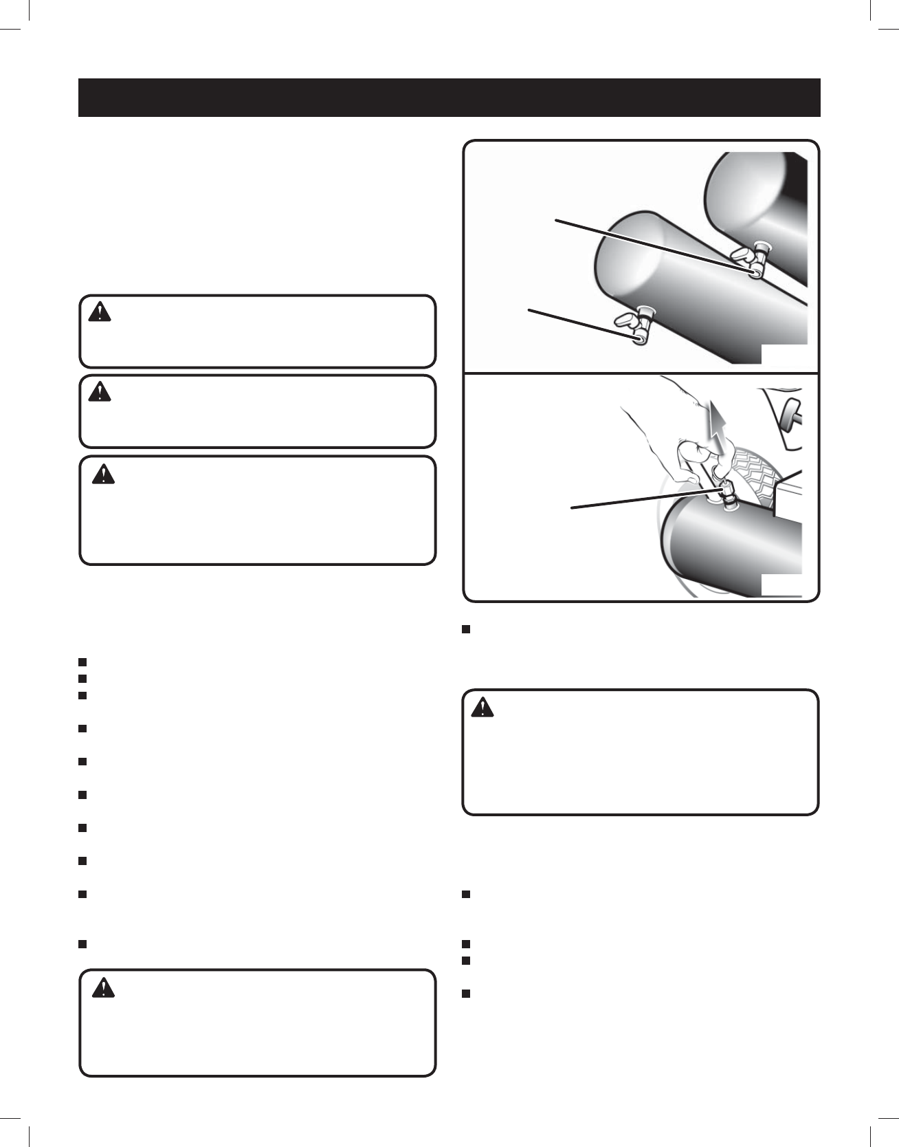
DRAINING THE TANK
See Figure 3.
The drain valve is located on the underside of each air
tank(s). The compressor can be tilted in the direction of the
drain valve in order to allow removal of tank moisture.
To help prevent tank(s) corrosion and keep moisture out
of the air used, the tank(s) of the compressor should be
drained daily.
Tank(s) subjected to freezing temperatures may contain
ice. Store the compressor in a heated area before
attempting to drain moisture from the tank(s).
A correct use of the drain valve:
Verify that the compressor is turned off.
Disconnect the spark plug wire from the spark plug.
Reduce the air pressure in the tank to 30 PSI by pulling
the safety valve ring (Fig. 4).
Position yourself so that the moisture and air to be
expelled can not cause you harm.
Holding the handle, tilt the compressor toward the drain
valve so that it’s set in a lower position.
Open the drain valve completely, allowing the moisture
and air mixture to drain from the tank.
Keep the compressor tilted until all moisture has been
removed.
Once the moisture has been completely drained, close
the drain valve.
Drain moisture from tank into a suitable container.
NOTE: Condensate is a polluting material and should
be disposed of in compliance with local regulations.
If drain valve is clogged, release all air pressure by pulling
the safety valve. Remove and clean valve, then reinstall.
OPERATION
WARNING:
Unplug the air compressor and release all air from
the tank before servicing. Failure to depressurize tank
before attempting to remove valve may cause serious
personal injury.
WARNING:
Do not attempt to tamper with safety valve. Anything
loosened from this device could fly up and hit you.
Failure to heed this warning could result in death or
serious personal injury.
Fig. 4
Fig. 3
WARNING!
Do not open a drain valve on any air tank containing
more than 30 PSI of air pressure!
WARNING!
Never attempt to relieve air pressure in an air tank by
removing a pipe plug or any other system component!
DRAIN
VALVE
DRAIN
VALVE
SAFETY
VALVE
(Rotate drain valve right to open)
14
Drain moisture from the air tank(s). Never attempt
to drain the tank(s) without first relieving the system
pressure (using the instruction found in Draining the
Tank).
STARTING & STOPPING THE COMPRESSOR
Connect the air line to the quick coupler.
Rotate regulator knob fully counterclockwise in order to
close the air flow.
Ensure both drain valves are closed.
Fill the engine with oil through oil fill hole.
Fill the compressor pump with oil. Do not overfill.
Fill the fuel tank with fuel.
Open the petcock on the unloader valve for cold starts
(turn clockwise or in).
Flip the toggle on the pilot valve to the “MANUAL
UNLOAD” position (see Pilot Valve Adjustments).
Start the gas engine (refer to gas engine owner’s
manual for more detailed start-up procedures):
– Adjust choke and open fuel valve.
– Pull the cord.
– Move choke to run.
Watch and listen for excessive vibration and unusual
noises. If either exist, stop the compressor and refer to
Troubleshooting.
Allow the compressor to run for a few minutes.
Close the petcock (turn counterclockwise or out).
Flip the toggle on the pilot valve to the “RUN” position.
The compressor should pump up the tank to 135
PSI, then unload. If pressure exceeds 135 PSI, see
Troubleshooting.
New compressors should be run with approximately
80 PSI of air pressure in the tank for 1 hour to break-in
(use regulator to control tank pressure). This will allow
the compressor time to warm up and seat the rings.
To stop the compressor, shut the engine off.
USING THE AIR COMPRESSOR
See Figure 5.
Rotate pressure regulator knob to desired line
pressure. Turning the knob clockwise increases
air pressure at the outlet; turning counterclockwise
reduces air pressure at the outlet.
APPLICATIONS
Air compressors are utilized in a variety of air system
applications. Match hoses, connectors, air tools, and
accessories to the capabilities of the air compressor.
You may use this tool for purposes listed below:
Operating some air-powered tools.
Inflating tires, air beds, sports equipment, etc.
PRE-STARTING CHECKLIST
The following steps should be performed prior to operating
the unit. If any condition of the checklist is not satisfied,
make the necessary adjustments or corrections before
starting the compressor.
WARNING:
Always wear safety goggles or safety glasses with
side shields when operating power tools. Failure to do
so could result in objects being thrown into your eyes
resulting in possible serious injury.
WARNING:
Do not allow familiarity with tools to make you careless.
Remember that a careless fraction of a second is
sufficient to inflict serious injury.
CAUTION:
Do not use in an environment that is dusty or otherwise
contaminated. Using the air compressor in this type of
environment may cause damage to the unit.
OPERATION
WARNING:
Always ensure the regulator pressure gauge read
zero before changing air tools or disconnecting the
hose from the air outlet. Failure to do so could result in
possible serious personal injury.
The compressor is shipped with lubricant in the
crankcase. Check lubricant level per specifications
(using the instruction found in Lubrication).
Make sure all safety valves are correctly installed.
(using the instruction found in Features).
Be sure all guards are in place and securely mounted
(using the instruction found in Features).
WARNING!
Failure to perform the PRE-STARTING CHECKLIST may
result in mechanical failure, property damage, serious
injury or even death.
WARNING!
Never assume a compressor is safe to work on just because
it is not operating. It could restart at any time. Follow all
safety precautions outlined in MAINTENANCE.
15
OPERATION
Following all safety precautions in this manual and the
manufacturer’s instructions in the air tool manual, you
may now proceed to use your air-powered tool.
If using an inflation accessory, control the amount of air
flow with the pressure regulator knob. Turning the knob
fully counterclockwise will completely stop the flow of
air.
NOTE: Always use the minimum amount of pressure
necessary for your application. Using a higher pressure
than needed will drain air from the tank more rapidly
and cause the unit to cycle on more frequently.
When finished, always drain the tank and stop
the compressor. Never leave the unit in running
unattended.
END OF OPERATION/STORAGE
Shut off the engine.
Disconnect the spark plug wire from the spark plug and
wrap around handle area to prevent damage when not
in use.
Wearing safety glasses drain tank of air by pulling the
ring on the safety valve. Use other hand to deflect fast
moving air from being directed toward your face.
Drain tank of condensation by opening both drain
valves on bottom of tank. Tank pressure should be
below 10 psi when draining tank.
Air hose should be disconnected from compressor and
hung open ends down to allow any moisture to drain.
Compressor and hose should be stored in a cool, dry
place.
WARNING:
Your tool may require more air consumption than this
air compressor is capable of providing. Check the tool
manual to avoid damage to the tool or risk of personal
injury.
Fig. 5
PRESSURE
REGULATOR
KNOB
TANK
PRESSURE
GAUGE
REGULATOR
PRESSURE
GAUGE
AIR
OUTLET
16
WARNING:
When servicing, use only identical Harbor Freight Tools
replacement parts. Use of any other parts may create a
hazard or cause product damage.
WARNING:
Always wear safety goggles or safety glasses with side
shields during power tool operation or when blowing
dust. If operation is dusty, also wear a dust mask.
MAINTENANCE
MAINTENANCE SCHEDULE
Refer to the gas engine owner’s manual for maintenance
procedures to be performed on the engine. If the unit is
used in an excessively dirty or dusty environment, check
and perform all maintenance procedures more often.
After First 100 Hours or First Month of Operation
(whichever occurs first)
Replace break-in lubricant with SAE 40W oil (refer to
Lubrication).
Daily
Maintain lubricant level at the halfway point on the
sightglass. Discolored lubricant or a higher lubricant
level reading may indicate the presence of condensed
liquids (refer to Troubleshooting).
Humidity in the air causes condensate to form in the air
tank. Drain moisture from air tank(s) (refer to Draining
the Tank). Tank(s) subjected to freezing temperatures
may contain ice. Store the compressor in a heated area
before attempting to drain moisture from the tank(s).
Give compressor overall visual inspection and be sure
safety guards are in place.
Check for any unusual noise or vibration.
Check for leaks.
Weekly
The safety valve automatically releases air if the air
receiver pressure exceeds the preset maximum.
Check the safety valve before each use, following the
instructions found in Checking the Safety Valve. Pull
on the ring of the safety valves to make sure they are
operating correctly. Air pressure should escape when
the ring is pulled (refer to Fig. 4).
Check all pressurized components for rust, cracking or
leaking. Immediately discontinue use of the equipment
and relieve all system pressure if any of these problems
are discovered. Do not use the equipment until it has
been inspected and repaired by a qualified mechanic.
Clean the exterior surfaces of the compressor.
Check the air filter and replace if necessary.
Monthly
Check belt tension.
Check pulley retaining screws.
Check system for air leaks.
Every 3 Months or Every 300 hrs. of Operation
(whichever occurs first)
Change lubricant.
WARNING:
Prior to performing any maintenance or repair, always
shut off the engine and remove the plug wire from the
spark plug.
WARNING:
Completely relieve the system of air pressure by pulling
the ring on the safety valve. Continue to pull the ring
until all air pressure escapes (Fig. 4).
WARNING:
Wait for the unit to cool before starting to service. Some
surface temperatures exceed 350°F when the unit is
operating.
WARNING:
Do not at any time let brake fluids, gasoline, petroleum-
based products, penetrating oils, etc., come in contact
with plastic parts. Chemical can damage, weaken or
destroy plastic which may result in serious personal
injury. Electric tools used on fiberglass material, wall-
board, spackling compounds, or plaster are subject
to accelerated wear and possible premature failure
because the fiberglass chips and grindings are highly
abrasive to bearings, brushes, commutators, etc.
Consequently, we do not recommend using this tool for
extended work on these type of materials. However, if
you do work with any of these materials, it is extremely
important to clean the tool using compressed air.
17
MAINTENANCE
Yearly
Inspect the tank yearly for rust, pin holes, or other
imperfections that could cause it to become unsafe.
Avoid using solvents when cleaning plastic parts. Most
plastics are susceptible to damage from various types of
commercial solvents and may be damaged by their use.
Use clean cloths to remove dirt, dust, oil, grease, etc.
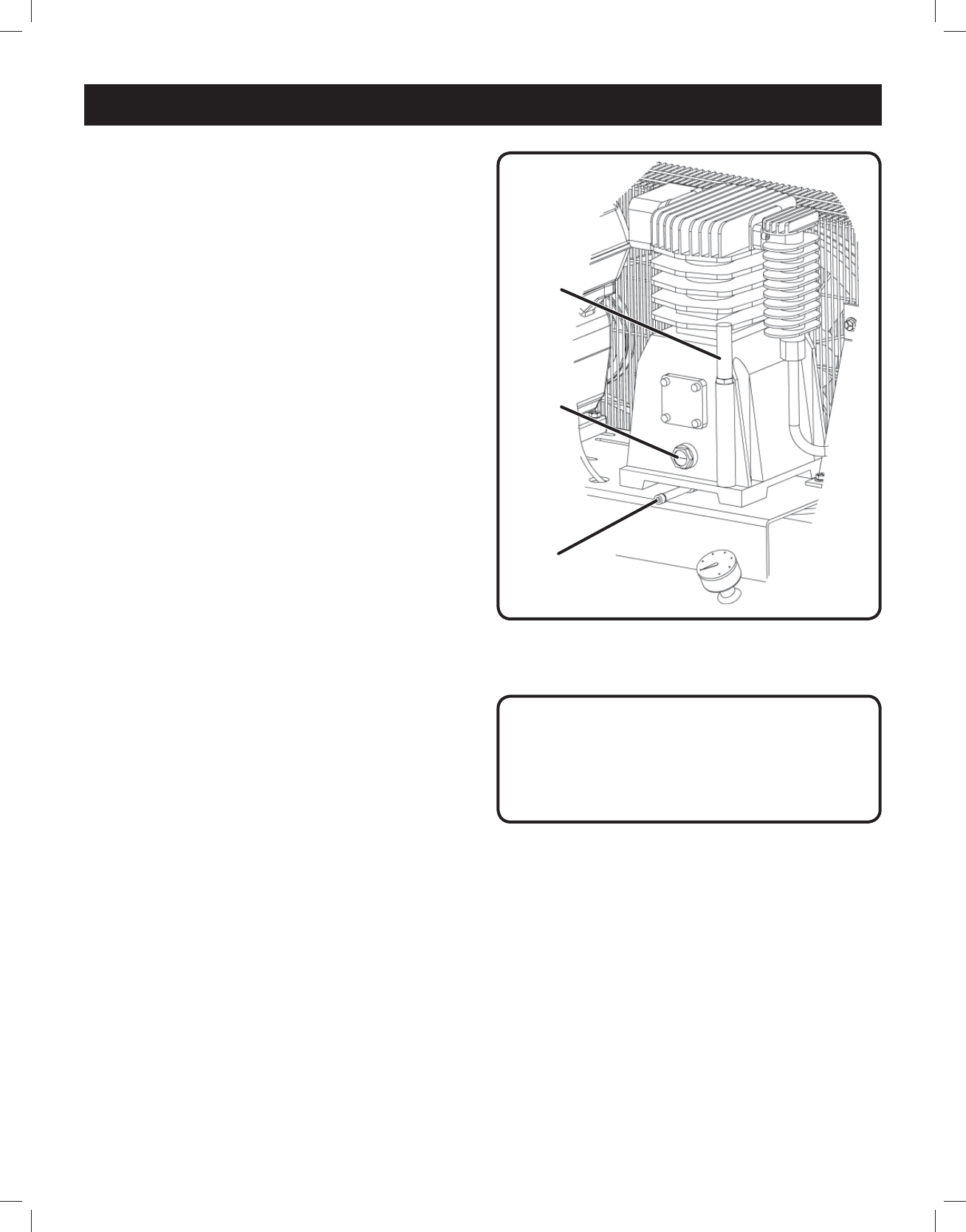
LUBRICATION
See Figure 6.
Before starting this compressor, check the lubricant level.
Place the compressor on a level and straight surface.
The oil level should register at the halfway point on the
sightglass. Remove the oil fill plug to add lubricant. Do not
overfill.
Ambient Temperature SAE Viscosity
30-104°F SAE 40
Below 30°F SAE 30
Do not use petroleum based automotive oils because
specific types have a tendency to foam and leave carbon
deposits when used in compressors.
How to change the oil
See Figures 13.
Shut off the engine. After releasing any air pressure you
can unscrew the oil fill plug from the compressor pump. To
prevent the oil from running out in an uncontrolled manner,
hold a small metal chute under the opening and collect the
oil in a vessel. If the oil does not drain out completely, we
recommend tilting the compressor slightly.
Dispose of the old oil at a drop-off point for old oil.
When the oil has drained out, re-fit the oil fill plug. Fill new
oil through the oil filler opening (ref. 14) until it comes up to
the required level. Then replace the oil drain plug.
Condensation
Rust can form inside the crankcase and on internal
components as a result of condensation. A compressor
must operate long enough during each run cycle to reach
full operating temperature in order to reduce the risk of
condensation.
Fig. 6
OIL
SIGHT
GLASS
OIL
DRAIN
PLUG
OIL
FILL
PLUG
Condensation can also form in the air tank of your
compressor. When this happens, a mixture of air and
moisture will be expelled through the service valve and
into whatever is connected to the valve (e.g. air hoses,
metal air lines, pneumatic tools, spray guns). An in-line
filter, may be required to eliminate the moisture.
Condensation in the air tank can be kept to a minimum by
draining the tank on a daily basis. This also reduces the
risk of rust developing and weakening the tank.
CAUTION:
Lubricant that appears milky may have mixed with
condensate. Failure to replace contaminated lubricant
will result in damage to the compressor and may void
warranty.
18
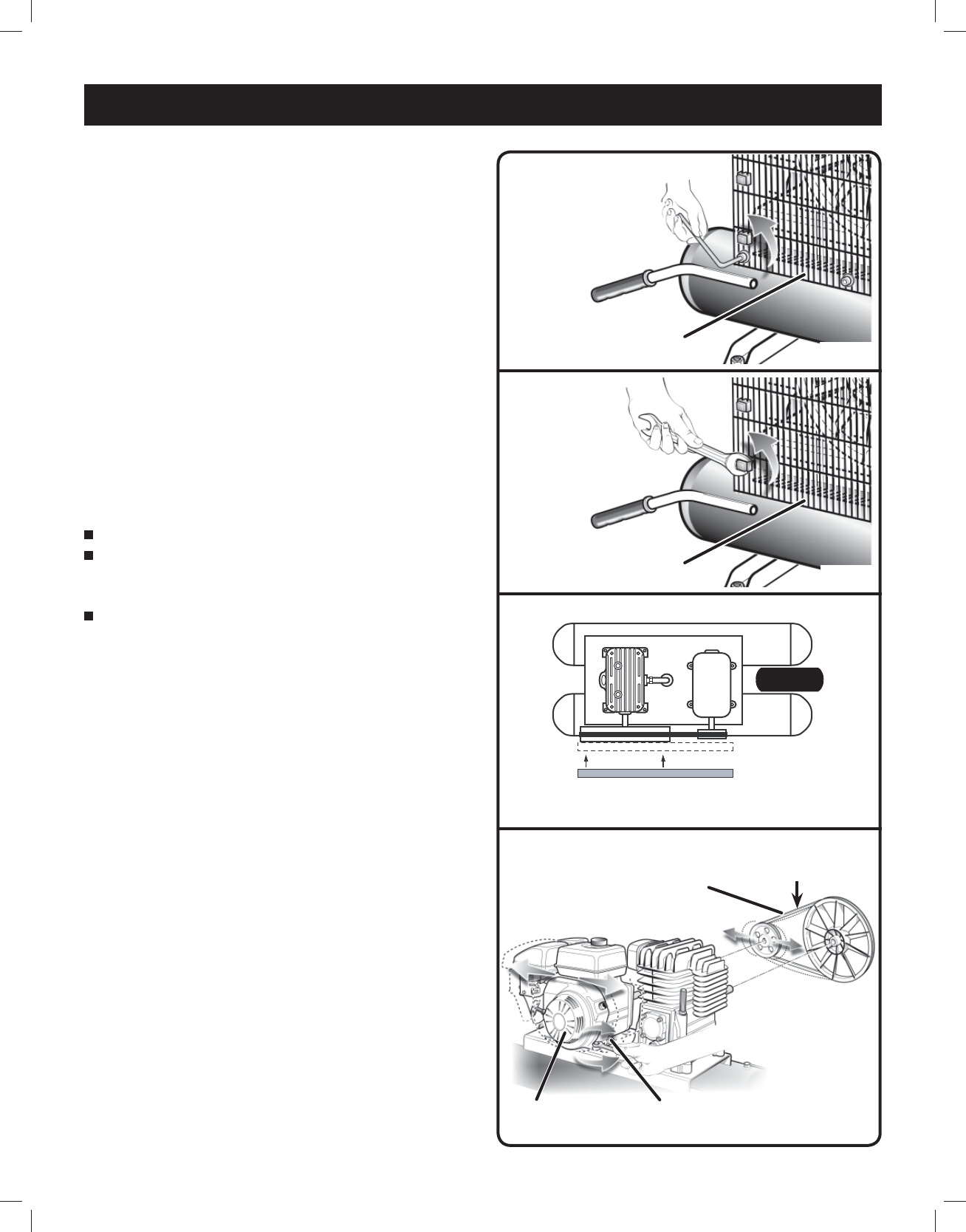
Fig. 10
ENGINE
UNIT
1/4 in.
(6 mm)
ENGINE MOUNTING
SCREW
BELT ALIGNMENT & ADJUSTMENT
See Figures 7 - 8 - 9 - 10.
Drive belts tend to stretch with normal use and require
adjustment periodically (check monthly). In order to adjust
the drive belt, the belt guard must be removed.
In order to remove the belt guard, follow the instructions
shown in figures 7 - 8.
Check the belt alignment by placing a straightedge against
the face of the flywheel, touching its rim at two places
(refer to Fig. 9). Adjust the flywheel or motor pulley so that
the belt runs parallel to the straightedge. Use a puller to
move the motor pulley on the shaft.
Properly adjusted, a 3 pound pressure applied to the belt
between the motor pulley and the compressor flywheel will
deflect the belt about 1/4” (6mm). Refer to Fig. 10.
To adjust the belt tension, perform the following
operations:
Loosen the four engine mounting screws.
Slide the engine in the proper direction, until the belt is
tensioned to the point where it can still be depressed by
approx. 1/4” (6mm) at the longest free position.
Re-tighten the engine mounting screws and refit the
safety guard for the belt.
MAINTENANCE
Fig. 7
Fig. 8
Fig. 9
TOP VIEW OF COMPRESSOR UNIT
Edge of straightedge should touch outer rim of flywheel
at two places; belt should run parallel to straightedge
SAFETY GUARD
FOR THE BELT
SAFETY GUARD
FOR THE BELT
BELT
19
MAINTENANCE
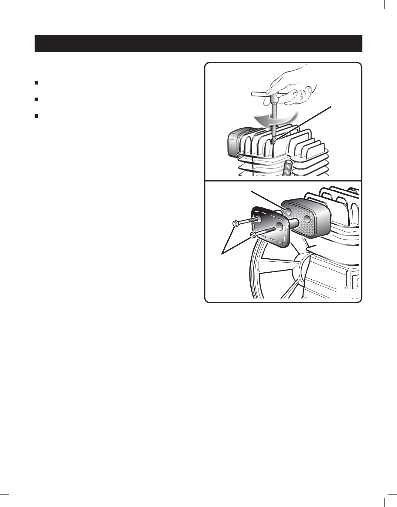
Fig. 12
ALLEN
SCREWS
AIR FILTER
TIGHTENING OF HEAD TENSION RODS
See Figure 11.
Check that all screws (in particular those of the head of
the unit) are tightly drawn up.
The check must be carried out prior to the first
compressor starting. And after the first hour of work.
Tightening values for the tension rods of the head:
Nm min. torque = 22
Nm max. torque = 27
CLEANING THE INTAKE FILTER
See Figure 12.
The intake filter prevents dust and dirt being drawn in.
It is essential to clean this filter after at least every 100
hours in service. A clogged intake filter will decrease the
compressor’s performance dramatically. Undo the two
allen screws (Figure 18). You can then remove the filter
from the two halves of the plastic housing, tap it to remove
the dirt, blast it down with low-pressure compressed air
(approx. 3 bar) and re-insert it (Figure 12).
Fig. 11
HEAD
TENSION
ROD
20
Fig. 14
MAINTENANCE
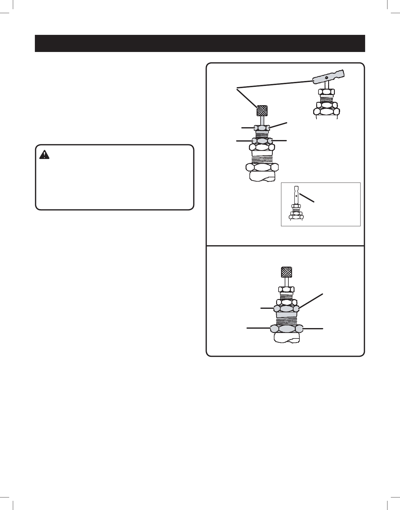
PILOT VALVE ADJUSTMENTS
See Figures 13 - 14.
All adjustments made to the pilot valve must be performed
by a qualified technician. The adjustments must be made
while the unit is operating, therefore, extreme caution must
be taken while working on the unit.
Observe all necessary precautions. Always use a back-
up wrench and make all differential and unload pressure
adjustments in very small increments (1/8 turn).
Setting Unload Pressure (Fig. 13)
Step 1. Flip the toggle to the “RUN” position as shown,
or turn the knurled knob (if so equipped)
counterclockwise until it stops.
Step 2. Loosen locknut (counterclockwise).
* Stabilize with back-up wrench!
Step 3. Turn clockwise to increase unload pressure, turn
counterclockwise to decrease unload pressure.
Hold position with wrench and proceed to Step 4.
Step 4. Tighten locknut (clockwise) with wrench.
* Stabilize with back-up wrench!
Setting Differential Pressure (Fig. 14)
Step 5. Loosen locknut (counterclockwise).
* Stabilize with back-up wrench!
Step 6. Turn clockwise to decrease the differential
pressure and counterclockwise to increase the
differential pressure. Hold position with wrench
and proceed to Step 7.
Step 7. Tighten locknut (clockwise) with wrench.
* Stabilize with back-up wrench!
WARNING!
The pilot valve are set at the factory for maximum
efficiency. Adjustments to either component must be
performed by a qualified technician. Exceeding the
factory recommended maximum pressure will void the
warranty and may cause personal injury.
Step 1.
Step 2.
Step 3.
Step 4.
*
Step 5.
Step 6.
Step 7.
*
“Manual Unload”
position (Ref.)
Fig. 13

21
TROUBLESHOOTING
Problem Possible Cause Solution
Motor hums or runs slowly when first
turned on, but compressor does not
start.
Motor then stops humming.
- Fuses blow
- Circuit breakers trip
- Motor thermal overload trips
Lubricant being used is too heavy. Use a lighter weight lubricant (refer to
LUBRICATION).
Too many lights or appliances being
operated on the same circuit as the
compressor (circuit overloaded).
Try another circuit or remove other
appliances from circuit being used.
Defective check valve or unloader. Replace check valve or unloader.
Freezing temperature. Warm the compressor or use a lighter
weight lubricant (refer to LUBRICATION).
Motor sized incorrectly. Replace with correctly sized motor.
Drive belt too tight. Re-adjust belt (refer to BELT
ALIGNMENT & ADJUSTMENT).
Incorrect size fuse or circuit breaker. Check for proper size fuse.
Lack of proper ventilation room
temperature too high.
Move the compressor to a well
ventilated area.
Compressor won’t operate. Defective engine. Replace or repair engine.
Lack of lubricant in compressor (can
cause serious damage to compressor).
Add lubricant (refer to LUBRICATION).
Belt too tight or too loose. Adjust belt (refer to BELT ALIGNMENT &
ADJUSTMENT).
Noisy operation. Lack of lubricant in crankcase. Check for possible damage to
bearings. Add lubricant (refer to
LUBRICATION).
Loose pulley, flywheel, belt,
compressor or motor fasteners,
beltguard, clamps or accessories.
Tighten where necessary.
Carbon deposits on piston or valves. Remove the cylinder head and inspect
for foreign matter on top of the piston.
Clean.
Worn main bearings, broken piston,
worn wrist pins, wrist pin bearings, or
loose connecting rod bolt.
Take compressor to Service Center.
Excessive vibrations. Pulley & flywheel misaligned or loose. Re-align or tighten pulley and flywheel.
Bent crankshaft. Take compressor to Service Center.
Belt loose. Tighten belt (refer to BELT ALIGNMENT
& ADJUSTMENT).
Read and understand all the safety rules listed in this manual and follow all procedures listed in MAINTENANCE before
making repairs. Refer to the gas engine owner’s manual for troubleshooting the gas engine.

22
TROUBLESHOOTING
Problem Possible Cause Solution
Excessive lubricant consumption and/
or excessive lubricant in hose.
Crankcase overfilled with lubricant. Drain lubricant. Refill to proper
level with proper lubricant (refer to
LUBRICATION).
Lubricant leaks. Tighten bolts on compressor to proper
torque or replace gaskets.
Worn piston rings. Take compressor to Service Center.
Wrong lubricant viscosity. Drain lubricant & refill with proper
lubricant (refer to LUBRICATION).
Compressor on unlevel surface. Level compressor.
Scored cylinder. Take compressor to Service Center.
Plugged crankcase breather. Clean or replace crankcase breather.
Air blowing from inlet filter. Damaged inlet (reed) valve. Take compressor to Service Center.
Insufficient pressure at tool or
accessory.
Leaks or restrictions. Check for leaks or restrictions in hose
or piping. Repair.
Restricted air intake (filter plugged). Replace air filter.
Slipping belt. Tighten belt (refer to BELT ALIGNMENT
& ADJUSTMENT).
Hose or hose connectors too small. Replace with larger hose or
connectors.
Compressor incorrectly sized. Either use a smaller tool or a larger
compressor.
Regulator not turned up to high enough
pressure / faulty regulator.
Turn the regulator to the proper setting
/ replace faulty regulator.
Leaking valves in compressor. Take compressor to Service Center.
Tank loses pressure rapidly when
compressor shuts off.
Loose connection or leak (pipe, tank
drain valve, tubing, fitting or hose).
Turn unit off, unplug it, & tighten or
replace fittings or components.
Faulty check valve. Replace faulty check valve.
Moisture in discharge air. Condensation in tank, caused by
high level of atmospheric humidity or
compressor is not run long enough.
Drain tank after every use. Drain tank
more frequently in humid weather &
use an air line filter.
Pressure in tank exceeds 135 PSI. Defective pilot valve. Replace defective pilot valve.
Incorrectly adjusted pilot valve. Readjust pilot valve (see PILOT VALVE
ADJUSTMENT)
Crankcase lubricant is milky. Water in lubricant due to humidity or
condensation.
Change lubricant. Move compressor to
less humid atmosphere.
Compressor runs backwards. Reversed wiring polarity. Contact qualified electrician.
Belt roll over. Misaligned belts. Align belts (Refer to BELT ALIGNMENT &
ADJUSTMENT).
Loose belt. Tighten belts (Refer to BELT ALIGNMENT
& ADJUSTMENT).

23
TROUBLESHOOTING
Problem Possible Cause Solution
Compressor overheats. High ambient temperature, poor
ventilation.
Increase ventilation with cooler air.
Dirty cylinder and head cooling fins. Clean all outer surfaces of the
compressor.
Unit is undersized for application. Re-evaluate application requirements;
re-size compressor unit if necessary.
Insufficient lubrication. Inspect for proper lubricant and
amount (refer to LUBRICATION)
Compressor runs backward. Contact qualified electrician.
One or more head valves failing to seat
properly.
Take compressor to Service Center.
Damaged cylinder head gasket. Take compressor to Service Center.
Restriction in head or check valve. Inspect, clean or replace.

Limited 90 Day Warranty
Harbor Freight Tools Co. makes every effort to assure that its products meet high quality and durability standards, and
warrants to the original purchaser that this product is free from defects in materials and workmanship for the period
of 90 days from the date of purchase. This warranty does not apply to damage due directly or indirectly, to misuse,
abuse, negligence or accidents, repairs or alterations outside our facilities, criminal activity, improper installation,
normal wear and tear, or to lack of maintenance. We shall in no event be liable for death, injuries to persons or
property, or for incidental, contingent, special or consequential damages arising from the use of our product. Some
states do not allow the exclusion or limitation of incidental or consequential damages, so the above limitation of
exclusion may not apply to you. THIS WARRANTY IS EXPRESSLY IN LIEU OF ALL OTHER WARRANTIES,
EXPRESS OR IMPLIED, INCLUDING THE WARRANTIES OF MERCHANTABILITY AND FITNESS.
To take advantage of this warranty, the product or part must be returned to us with transportation charges prepaid.
Proof of purchase date and an explanation of the complaint must accompany the merchandise. If our inspection
verifies the defect, we will either repair or replace the product at our election or we may elect to refund the purchase
price if we cannot readily and quickly provide you with a replacement. We will return repaired products at our expense,
but if we determine there is no defect, or that the defect resulted from causes not within the scope of our warranty,
then you must bear the cost of returning the product.
This warranty gives you specific legal rights and you may also have other rights which vary from state to state.
WARNING: The brass components of this product
contain lead, a chemical known to the State of
California to cause cancer and birth defects or other
reproductive harm. (California Health & Safety Code
§ 25249.5, et seq.)
3491 Mission Oaks Blvd. • PO Box 6009 • Camarillo, CA 93011 • 1-888-866-5797
!"#"$%&'(%)*+#"$*%,$-%.$$/-00)))1.,(+&(2(*"3.$14&5
%65,"7%&'(%$*4.8"4,7%#'//&($%,$-%/(*9,$&(:.,(+&(2(*"3.$14&5
;#"83%,8%*83"8*%"89&&(#%
<=>%?@AA%BC;%@>%D@>;E6F1
683"8*%*G.,'#$%4&8$,"8#%4,(+&8%5&8&G"9*1%%
E."#%"#%,%/&"#&8%H&'%4,88&$%#**%&(%#5*771
>6!6I%'#*%"8#"9*%
,%.&5*%&(%3,(,3*J%
6!6>%@K%9&&(#%,89%
)"89&)#%,(*%&/*81
C87H%'#*%C;EF@L6%
,89%2,(%,),H%2(&5%
)"89&)#J%9&&(#J%
,89%M*8$#1
;#"83%,8%*83"8*%"89&&(#%
<=>%?@AA%BC;%@>%D@>;E6F1
683"8*%*G.,'#$%4&8$,"8#%4,(+&8%5&8&G"9*1%%
E."#%"#%,%/&"#&8%H&'%4,88&$%#**%&(%#5*771
>6!6I%'#*%"8#"9*%
,%.&5*%&(%3,(,3*J%
6!6>%@K%9&&(#%,89%
)"89&)#%,(*%&/*81
C87H%'#*%C;EF@L6%
,89%2,(%,),H%2(&5%
)"89&)#J%9&&(#J%
,89%M*8$#1
Owner’s Manual & Safety Instructions
Save This Manual%Keep this manual for the safety warnings and precautions, assembly,
operating, inspection, maintenance and cleaning procedures. Write the product’s serial number in the
back of the manual near the assembly diagram (or month and year of purchase if product has no number).
Keep this manual and the receipt in a safe and dry place for future reference. 17f
When unpacking, make sure that the product is intact
and undamaged. If any parts are missing or broken,
please call 1-888-866-5797 as soon as possible.
Copyright© 2012 by Harbor Freight Tools®. All rights reserved.
No portion of this manual or any artwork contained herein may be reproduced in
any shape or form without the express written consent of Harbor Freight Tools.
Diagrams within this manual may not be drawn proportionally. Due to continuing
improvements, actual product may differ slightly from the product described herein.
Too ls r eq ui re d f or a ss em bl y a nd s er vi ce ma y no t be i ncl ud ed .
I*,9%$."#%5,$*(",7%+*2&(*%'#"83%$."#%/(&9'4$1%
K,"7'(*%$&%9&%#&%4,8%(*#'7$%"8%#*("&'#%"8N'(H1%
F=!6%EO@F%D=>;=A1
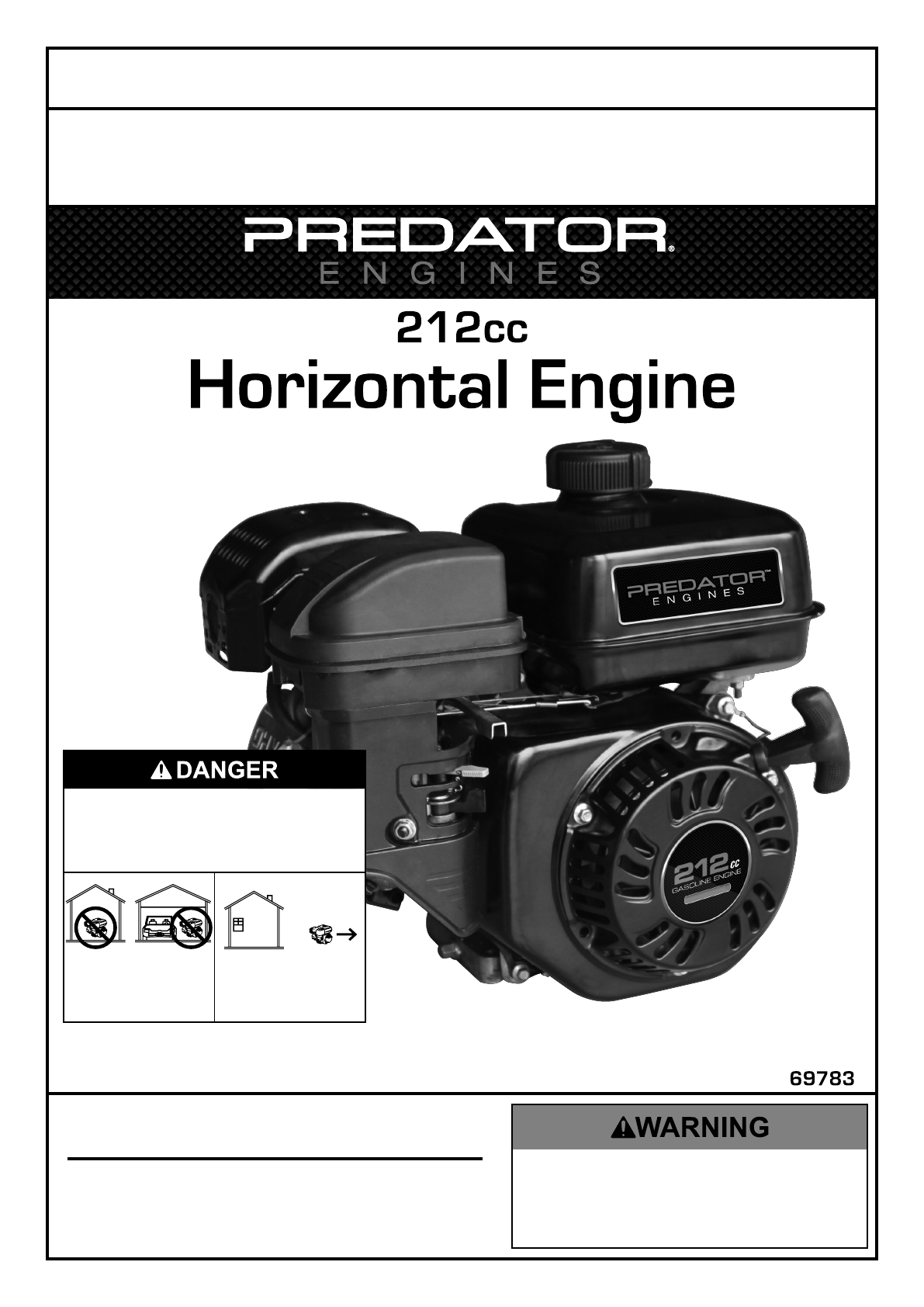
Page 2 K&(%$*4.8"4,7%P'*#$"&8#J%/7*,#*%4,77%QRSSSRSTTRUVWV1 Engine for 69783
E,+7*%&2%<&8$*8$#
Specifications ............................................. 2
Safety ......................................................... 3
Setup .......................................................... 6
Operation .................................................... 8
Maintenance .............................................. 12
Troubleshooting ......................................... 16
Warranties ................................................. 18
Parts Lists and Diagrams .......................... 21
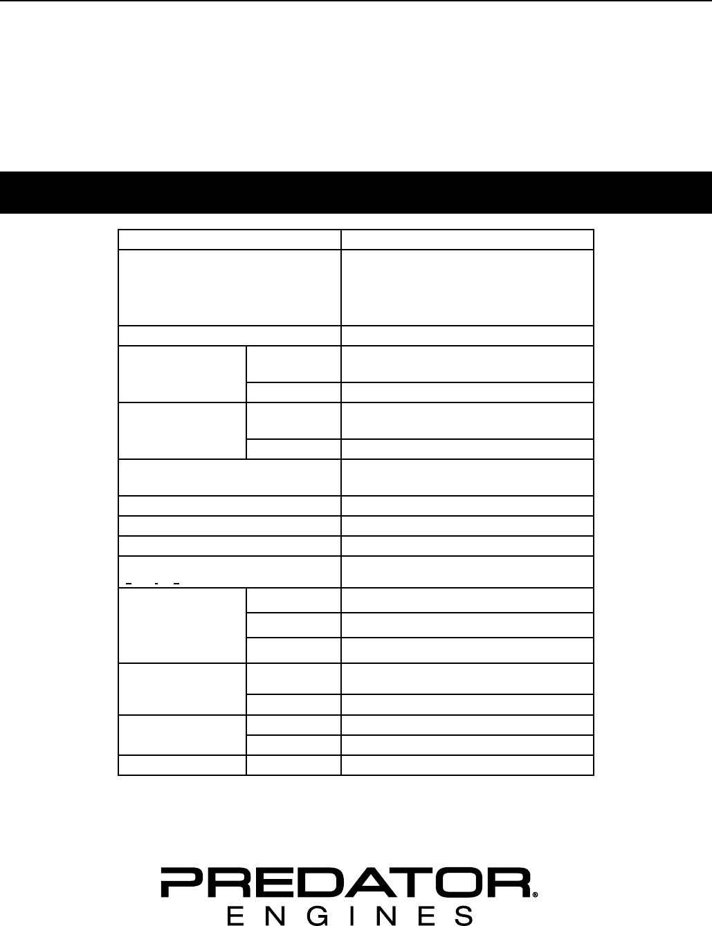
F/*4"2"4,$"&8#
Displacement 212cc
Engine Type
Horizontal Single Cylinder
4 stroke OHV
Meets EPA phase III and CARB
emissions standards
Cooling System Forced air cooled
Fuel Type 87+ octane stabilizer treated
unleaded gasoline
Capacity 0.9 Gallon (3.6 Liter)
Engine Oil Type SAE 10W-30 above 32° F
5W-30 at 32° F or below
Capacity 0.5 Quart
Run Time @ 50% Load
with full tank 3 hr.
Sound Level at 22 feet 104 dB
Bore x Stroke 70 mm x 55 mm
Compression Ratio 8.5:1
Rotation viewed from PTO
(power takeoff - the output shaft) Counterclockwise
Shaft
Shaft 3/4″ x 2.43″
Keyway 3/16″ (4.76 mm)
End Tapped 5/16″ - 24 UNF
Spark Plug Type NGK® BP-6ES
NHSP® / Torch® F6TC
Gap 0.027" - 0.031"
Valve Clearance Intake 0.004" - 0.006"
Exhaust 0.006" - 0.008"
Speed Idle 1,800 ± 50 RPM
The emissions control system for this Engine is warranted for standards set by the
U.S. Environmental Protection Agency and by the California Air Resources Board (also known as CARB).
For warranty information, refer to the last pages of this manual.
Page 3K&(%$*4.8"4,7%P'*#$"&8#J%/7*,#*%4,77%QRSSSRSTTRUVWV1Engine for 69783
F=K6EBCX6I=E@C>D=@>E6>=><6 F6E;X
Y=I>@>Z%FBD[CAF%=>L%L6K@>@E@C>F
This is the safety alert symbol. It is used to alert you to potential
personal injury hazards. Obey all safety messages that
follow this symbol to avoid possible injury or death.
Indicates a hazardous situation which, if not avoided,
will result in death or serious injury.
Indicates a hazardous situation which, if not avoided,
could result in death or serious injury.
Indicates a hazardous situation which, if not avoided,
could result in minor or moderate injury.
Addresses practices not related to personal injury.
FH5+&7%L*2"8"$"&8#
FH5+&7 X(&/*($H%&(%F$,$*5*8$
IXD Revolutions Per Minute
OX Horsepower
WARNING marking concerning
Risk of Eye Injury. Wear ANSI-approved
safety goggles with side shields.
Read the manual before
set-up and/or use.
WARNING marking concerning
Risk of Hearing Loss.
Wear hearing protection.
FH5+&7 X(&/*($H%&(%F$,$*5*8$
WARNING marking concerning
Risk of Respiratory Injury.
Operate engine OUTSIDE and far away
from windows, doors, and vents.
WARNING marking concerning
Risk of Fire while handling fuel.
Do not smoke while handling fuel.
WARNING marking concerning
Risk of Fire.
Do not refuel while operating.
Keep flammable objects
away from engine.
F,2*$H%Y,(8"83#
% Y=I>@>Z\%I*,9%,77%"8#$('4$"&8#1
K,"7'(*%$&%2&77&)%,77%"8#$('4$"&8#%7"#$*9%+*7&)%5,H%(*#'7$%"8%2"(*J%#*("&'#%"8N'(H%,890&(%L6=EO1%
The warnings and precautions discussed in this manual cannot cover all possible conditions and
situations that may occur. It must be understood by the operator that common sense and caution
are factors which cannot be built into this product, but must be supplied by the operator.
F=!6%EO6F6%@>FEI;<E@C>F
Page 4 K&(%$*4.8"4,7%P'*#$"&8#J%/7*,#*%4,77%QRSSSRSTTRUVWV1 Engine for 69783
F=K6EB CX6I=E@C> D=@>E6>=><6F6E;X
F*$%'/%X(*4,'$"&8#
1. Gasoline fuel and fumes are flammable, and
potentially explosive. Use proper fuel storage
and handling procedures. Do not store fuel
or other flammable materials nearby.
2. Have multiple ABC class fire extinguishers nearby.
3. Operation of this equipment may create sparks
that can start fires around dry vegetation. A spark
arrestor may be required. The operator should
contact local fire agencies for laws or regulations
relating to fire prevention requirements.
4. Set up and use only on a flat, level,
well-ventilated surface.
5. Wear ANSI-approved safety goggles, heavy-duty
work gloves, and dust mask/respirator during set up.
6. Use only lubricants and fuel recommended
in the Specifications chart of this manual.
C/*(,$"83%X(*4,'$"&8#
1. <=I[C>%DC>C]@L6%O=^=IL%
;#"83%,8%*83"8*%"89&&(#%<=>%?@AA%
BC;%@>%D@>;E6F1%
Engine exhaust contains carbon
monoxide. This is a poison you cannot
see or smell.
NEVER use inside a home or garage,
EVEN IF doors and windows are open.
Only use OUTSIDE and far away from windows,
doors, and vents.
2. Keep children away from the equipment,
especially while it is operating.
3. Keep all spectators at least six feet
from the Engine during operation.
4. Fire Hazard! Do not fill gas tank while engine is
running. Do not operate if gasoline has been spilled.
Clean spilled gasoline before starting engine.
Do not operate near pilot light or open flame.
5. Do not touch engine during use.
Let engine cool down after use.
6. Never store fuel or other flammable
materials near the engine.
7. Only use a suitable means of transport and
lifting devices with sufficient weight bearing
capacity when transporting the Engine.
8. Secure the Engine on transport vehicles to
prevent the tool from rolling, slipping, and tilting.
9. Industrial applications must follow
OSHA requirements.
10. Do not leave the equipment unattended when it is
running. Turn off the equipment (and remove safety
keys, if available) before leaving the work area.
11. Engine can produce high noise levels.
Prolonged exposure to noise levels
above 85 dBA is hazardous to hearing.
Always wear ear protection when operating or
working around the gas engine while it is operating.
12. Wear ANSI-approved safety glasses, hearing
protection, and NIOSH-approved dust mask/
respirator under a full face shield along
with steel-toed work boots during use.
13. People with pacemakers should consult their
physician(s) before use. Electromagnetic fields in
close proximity to a heart pacemaker could cause
pacemaker interference or pacemaker failure.
Caution is necessary when near the
engine’s magneto or recoil starter.
14. Use only accessories that are recommended
by Harbor Freight Tools for your model.
Accessories that may be suitable for one
piece of equipment may become hazardous
when used on another piece of equipment.
15. Do not operate in explosive atmospheres,
such as in the presence of flammable
liquids, gases, or dust. Gasoline-powered
engines may ignite the dust or fumes.
16. Stay alert, watch what you are doing and
use common sense when operating this
piece of equipment. Do not use this piece
of equipment while tired or under the
influence of drugs, alcohol or medication.
17. Do not overreach. Keep proper footing and
balance at all times. This enables better control
of the equipment in unexpected situations.
18. Use this equipment with both hands
only. Using equipment with only one hand
can easily result in loss of control.
19. Dress properly. Do not wear loose clothing or
jewelry. Keep hair, clothing and gloves away
from moving parts. Loose clothes, jewelry or
long hair can be caught in moving parts.
Page 5K&(%$*4.8"4,7%P'*#$"&8#J%/7*,#*%4,77%QRSSSRSTTRUVWV1Engine for 69783
F=K6EBCX6I=E@C>D=@>E6>=><6 F6E;X
20. Parts, especially exhaust system components,
get very hot during use. Stay clear of hot parts.
21. Do not cover the engine or
equipment during operation.
22. Keep the equipment, engine, and
surrounding area clean at all times.
23. Do not smoke, or allow sparks, flames,
or other sources of ignition around the
equipment, especially when refuelling.
24. Use the equipment, accessories, etc., in
accordance with these instructions and in the
manner intended for the particular type of
equipment, taking into account the working
conditions and the work to be performed. Use of
the equipment for operations different from those
intended could result in a hazardous situation.
25. Do not operate the equipment with known
leaks in the engine’s fuel system.
26. When spills of fuel or oil occur, they must be
cleaned up immediately. Dispose of fluids and
cleaning materials as per any local, state, or
federal codes and regulations. Store oil rags in
a bottom-ventilated, covered, metal container.
27. Keep hands and feet away from moving parts. Do
not reach over or across equipment while operating.
28. Before use, check for misalignment or binding of
moving parts, breakage of parts, and any other
condition that may affect the equipment’s operation.
@2%9,5,3*9J%.,M*%$.*%*P'"/5*8$%#*(M"4*9%
+*2&(*%'#"831 Many accidents are caused
by poorly maintained equipment.
29. Use the correct equipment for the application.
Do not modify the equipment and do not use the
equipment for a purpose for which it is not intended.
F*(M"4*%X(*4,'$"&8#
1. [*2&(*%#*(M"4*J%5,"8$*8,84*J%&(%47*,8"83-
a. E'(8%$.*%*83"8*%#)"$4.%$&%"$#%_CKK`%/&#"$"&81
b. =77&)%$.*%*83"8*%$&%4&5/7*$*7H%4&&71
c. E.*8J%(*5&M*%$.*%#/,(a%/7'3%
4,/%2(&5%$.*%#/,(a%/7'31
2. Keep all safety guards in place and in
proper working order. Safety guards include
muffler, air cleaner, mechanical guards,
and heat shields, among other guards.
3. L&%8&$%,7$*(%&(%,9N'#$%,8H%/,($%&2%$.*%
*P'"/5*8$%&(%"$#%*83"8*%$.,$%"#%#*,7*9%+H%$.*%
5,8'2,4$'(*(%&(%9"#$("+'$&(1%%C87H%,%P',7"2"*9%
#*(M"4*%$*4.8"4",8%5,H%,9N'#$%/,($#%$.,$%5,H%
"84(*,#*%&(%9*4(*,#*%3&M*(8*9%*83"8*%#/**91
4. Wear ANSI-approved safety goggles,
heavy-duty work gloves, and dust
mask/respirator during service.
5. Maintain labels and nameplates on the equipment.
These carry important information.
If unreadable or missing, contact
Harbor Freight Tools for a replacement.
6. Have the equipment serviced by a qualified repair
person using only identical replacement parts.
This will ensure that the safety of the equipment
is maintained. Do not attempt any service or
maintenance procedures not explained in this
manual or any procedures that you are uncertain
about your ability to perform safely or correctly.
7. Store equipment out of the reach of children.
8. Follow scheduled engine and
equipment maintenance.
I*2'*7"83-
1. Do not refill the fuel tank while the
engine is running or hot.
2. Do not smoke, or allow sparks, flames,
or other sources of ignition around the
equipment, especially when refuelling.
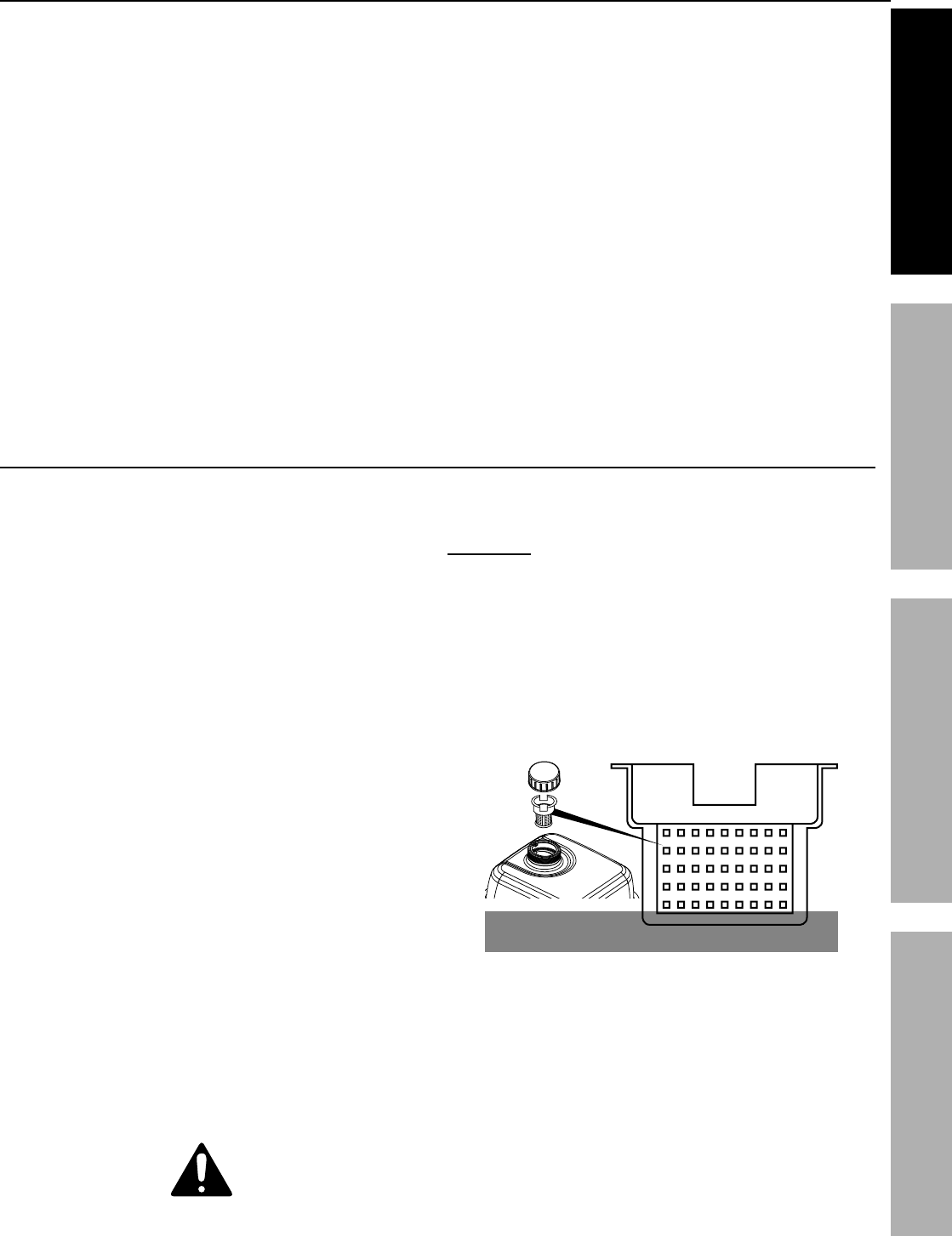
3. EC%XI6!6>E%K;6A%A6=?=Z6%=>L%
K@I6%O=^=ILJ%9&%8&$%2"77%2'*7%,+&M*%
$.*%+&$$&5%&2%2'*7%#$(,"8*(1
D,G%K'*7
LC%>CE%C!6IK@AA\
4. Do not fill fuel tank to the top. Leave a little
room for the fuel to expand as needed.
5. Refuel in a well-ventilated area only.
6. Wipe up any spilled fuel and allow excess
to evaporate before starting engine.
E&%/(*M*8$%K@I6J%9&%8&$%#$,($%$.*%*83"8*%
)."7*%$.*%#5*77%&2%2'*7%.,83#%"8%$.*%,"(1
%F=!6%EO6F6%@>FEI;<E@C>F1
C/*(,$"83%X(*4,'$"&8#%b4&8$1c
Page 6 K&(%$*4.8"4,7%P'*#$"&8#J%/7*,#*%4,77%QRSSSRSTTRUVWV1 Engine for 69783
F=K6EB CX6I=E@C> D=@>E6>=><6F6E;X
F*$%;/
I*,9%$.*%6>E@I6%@DXCIE=>E%F=K6EB%@>KCID=E@C>%#*4$"&8%,$%$.*%+*3"88"83%&2%$."#%5,8',7%
"847'9"83%,77%$*G$%'89*(%#'+.*,9"83#%$.*(*"8%+*2&(*%#*$%'/%&(%'#*%&2%$."#%/(&9'4$1
EC%XI6!6>E%F6I@C;F%@>d;IB-%
C/*(,$*%&87H%)"$.%/(&/*(%#/,(a%,((*#$&(%"8#$,77*91
C/*(,$"&8%&2%$."#%*P'"/5*8$%5,H%4(*,$*%#/,(a#%$.,$%
4,8%#$,($%2"(*#%,(&'89%9(H%M*3*$,$"&81%
=%#/,(a%,((*#$&(%5,H%+*%(*P'"(*91%
E.*%&/*(,$&(%#.&'79%4&8$,4$%7&4,7%2"(*%
,3*84"*#%2&(%7,)#%&(%(*3'7,$"&8#%(*7,$"83%
$&%2"(*%/(*M*8$"&8%(*P'"(*5*8$#1
At high altitudes, the engine’s carburetor, governor
(if so equipped), and any other parts that control the
fuel-air ratio will need to be adjusted by a qualified
mechanic to allow efficient high-altitude use and to
prevent damage to the engine and any other devices
used with this product.
The emission control system for this Engine is warranted
for standards set by the U.S. Environmental Protection
Agency and by the California Air Resources Board
(also known as CARB). For warranty information, refer
to the last pages of this manual.
Y=I>@>Z\%%LC%>CE%@>FE=AA%EO@F%6>Z@>6%C>%=%!6O@<A61
683"8*%<&8$(&7#
683"8*%
F)"$4.
F$,($*(%
O,897*
C"7%L(,"8%X7'3
="(%K"7$*(
K'*7%!,7M*
<.&a*
K'*7%<,/
E.(&$$7*
D'227*(
L"/#$"4a
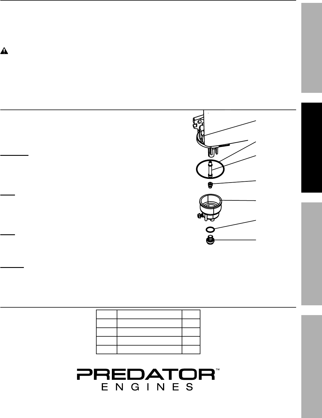
Page 7K&(%$*4.8"4,7%P'*#$"&8#J%/7*,#*%4,77%QRSSSRSTTRUVWV1Engine for 69783
F=K6EBCX6I=E@C>D=@>E6>=><6 F6E;X
O"3.%=7$"$'9*%C/*(,$"&8%=+&M*%efff%2**$
The fuel system on this engine may be influenced by operation at higher altitudes.
Proper operation can be ensured by installing an altitude kit at altitudes higher than 3000 ft. above sea level.
At elevations above 8000 ft, the engine may experience decreased performance, even with the proper main jet.
Operating this engine without the proper altitude kit installed may increase the engine’s emissions and
decrease fuel economy and performance. The kit should be installed by a qualified mechanic.
Y=I>@>Z\ EC%XI6!6>E%F6I@C;F%@>d;IB%KICD%K@I6-
Follow kit procedures in a well-ventilated area away from ignition sources.
If the engine is hot from use, shut the engine off and wait for it to cool before proceeding. Do not smoke.
>CE@<6 Warranty void if necessary adjustments are not made for high altitude use.
O"3.%=7$"$'9*%?"$%@8#$,77,$"&8%@8#$('4$"&8#
1. Turn off the engine.
2. Close the fuel valve.
3. Place a bowl under the fuel cup to catch any spilled fuel.
4. Unthread the bolt holding the fuel cup.
<=;E@C>\ Carburetor bowl may have gas in it
which will leak upon removing the bolt.
5. Remove the bolt, bolt seal, fuel cup, fuel cup seal and main jet
from the body of the carburetor assembly. A carburetor screwdriver
(not included) is needed to remove and install the Main Jet.
>&$*- The mixing tube is held in place by the main jet and
might fall out when it is removed. If it falls out, replace it in
the same orientation before replacing the main jet.
6. Replace the main jet with the replacement jet
needed for your altitude range (part 1 or 2).
>&$*- The Fuel cup seal and bolt seal may be damaged during
removal and should be replaced with the new ones from the kit.
7. Replace the Fuel Cup Seal
(4), fuel cup, Bolt Seal (3) and bolt. Tighten in place.
>CE@<6- Do not cross thread Bolt when tightening. Finger tighten first and
then use a wrench to make sure the Bolt is properly threaded.
8. Wipe up any spilled fuel and allow excess to evaporate before starting engine.
To prevent FIRE, do not start the engine while the smell of fuel hangs in the air.
=7$"$'9*%?"$%X,($#%A"#$
X,($ L*#4("/$"&8 g$H
1 Main Jet 3000-6000 ft. 1
2 Main Jet 6000-8000 ft. 1
3 Bolt Seal 1
4 Fuel Cup Seal 1
<,(+'(*$&(%
=##*5+7H
D,"8%d*$
K'*7%<'/%F*,7
D"G"83%E'+*
b5"3.$%(*5,"8%
"8#"9*%4,(+'(*$&(c
K'*7%<'/
[&7$%F*,7
[&7$
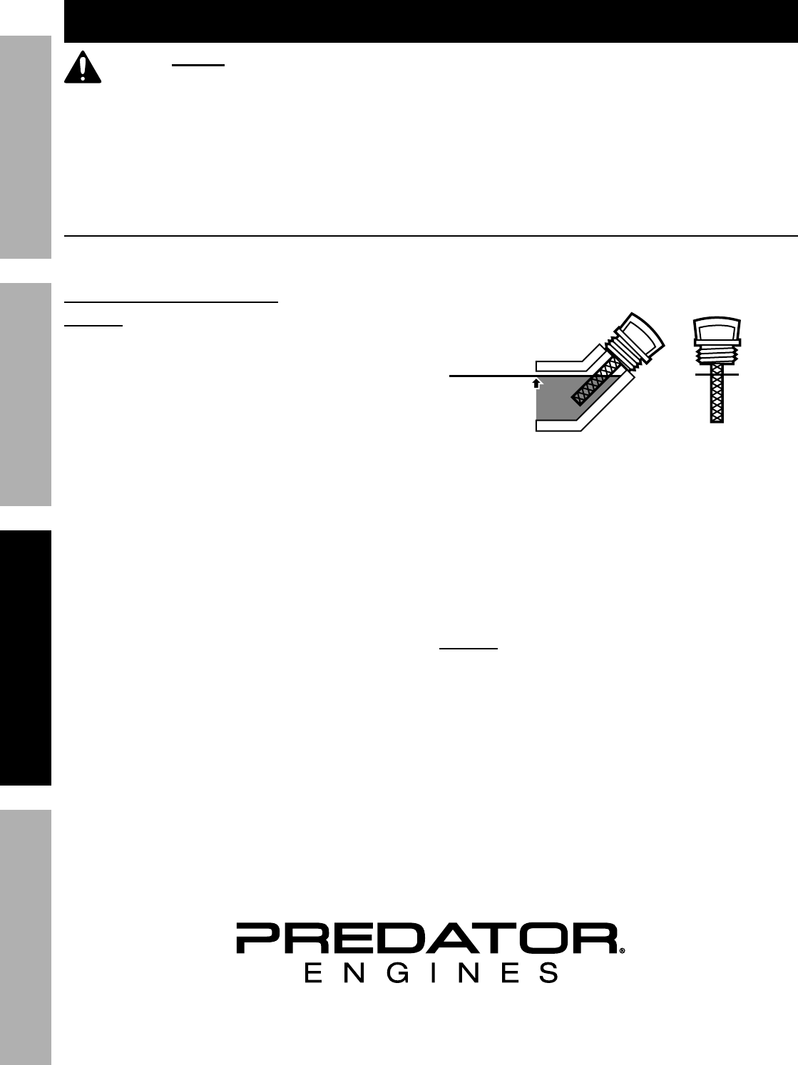
Page 8 K&(%$*4.8"4,7%P'*#$"&8#J%/7*,#*%4,77%QRSSSRSTTRUVWV1 Engine for 69783
F=K6EB CX6I=E@C> D=@>E6>=><6F6E;X
C/*(,$"&8%
I*,9%$.*%6>E@I6%@DXCIE=>E%F=K6EB%@>KCID=E@C>%#*4$"&8%,$%$.*%+*3"88"83%&2%$."#%5,8',7%
"847'9"83%,77%$*G$%'89*(%#'+.*,9"83#%$.*(*"8%+*2&(*%#*$%'/%&(%'#*%&2%$."#%/(&9'4$1
X(*RF$,($%<.*4a#
Inspect engine and equipment looking for damaged, loose, and missing parts before set up and starting. If any
problems are found, do not use equipment until fixed properly.
<.*4a"83%,89%K"77"83%683"8*%C"7
>CE@<6-%%B&'(%Y,((,8$H%"#%!C@L%"2%$.*%*83"8*h#%
4(,8a4,#*%"#%8&$%/(&/*(7H%2"77*9%)"$.%&"7%+*2&(*%
*,4.%'#*1%%[*2&(*%*,4.%'#*J%4.*4a%$.*%&"7%7*M*71
Engine%)"77%8&$%#$,($%)"$.%7&)%&(%8&%*83"8*%&"71
1. Make sure the engine is stopped and is level.
2. Close the Fuel Valve.
3. Clean the top of the Dipstick and the area around it.
Remove the Dipstick by turning it counterclockwise,
and wipe it off with a clean, lint free rag.
4.
Full level
Full level
Reinsert the Dipstick without threading it in and
remove it to check the oil level. The oil level
should be up to the full level as shown above.
5. If the oil level is at or below the low mark add the
appropriate type of oil until the oil level is at the
proper level. SAE 10W-30 oil is recommended for
general use. (The SAE Viscosity Grade chart on
page 13 in the Maintenance section shows other
viscosities to use in different average temperatures.)
6. Thread the dipstick back in clockwise.
>CE@<6-%%L&%8&$%('8%$.*%*83"8*%)"$.%$&&%7"$$7*%&"71
Engine%)"77%#.'$%&22%"2%*83"8*%&"7%7*M*7%"#%$&&%7&)1

Page 9K&(%$*4.8"4,7%P'*#$"&8#J%/7*,#*%4,77%QRSSSRSTTRUVWV1Engine for 69783
F=K6EBCX6I=E@C>D=@>E6>=><6 F6E;X
<.*4a"83%,89%K"77"83%K'*7
Y=I>@>Z\ EC%XI6!6>E%F6I@C;F%
@>d;IB%KICD%K@I6-
Fill the fuel tank in a well-ventilated area
away from ignition sources. If the engine
is hot from use, shut the engine off and
wait for it to cool before adding fuel. Do not smoke.
1. Clean the Fuel Cap and the area around it.
2. Unscrew and remove the Fuel Cap.
3. Remove the Strainer and remove any dirt
and debris. Then replace the Strainer.
>&$*-%%L&%8&$%'#*%3,#&7"8*%4&8$,"8"83%5&(*%$.,8%
Qfi%*$.,8&7%b6Qfc1%%L&%8&$%'#*%6SU%*$.,8&71%%=99%2'*7%
#$,+"7"j*(%$&%$.*%3,#&7"8*%&(%$.*%Y,((,8$H%"#%!C@L1
>&$*-%%L&%8&$%'#*%3,#&7"8*%$.,$%.,#%+**8%#$&(*9%"8%,%
5*$,7%2'*7%4&8$,"8*(%&(%,%9"($H%2'*7%4&8$,"8*(1%%@$%4,8%
4,'#*%/,($"47*#%$&%*8$*(%$.*%4,(+'(*$&(J%,22*4$"83%
*83"8*%/*(2&(5,84*%,890&(%4,'#"83%9,5,3*1
4. If needed, fill the Fuel Tank to about 1 inch under
the fill neck of the Fuel Tank with 87 octane or
higher unleaded gasoline that has been treated
with a fuel stabilizer additive. Follow fuel stabilizer
manufacturer’s recommendations for use.
5. Then replace the Fuel Cap.
6. Wipe up any spilled fuel and allow excess
to evaporate before starting engine.
To prevent FIRE, do not start the engine
while the smell of fuel hangs in the air.
F$,($"83%$.*%683"8*
[*2&(*%F$,($"83%$.*%683"8*
[*2&(*%#$,($"83%$.*%*83"8*-
a. K&77&)%$.*%F*$%;/%@8#$('4$"&8#%"8%$.*%*P'"/5*8$%5,8',7%$&%/(*/,(*%$.*%*P'"/5*8$1
b. @8#/*4$%$.*%*P'"/5*8$%,89%*83"8*1
c. K"77%$.*%*83"8*%)"$.%$.*%/(&/*(%,5&'8$%,89%$H/*%&2%
+&$.%#$,+"7"j*(R$(*,$*9%'87*,9*9%3,#&7"8*%,89%&"71
d. I*,9%$.*%6P'"/5*8$%C/*(,$"&8%#*4$"&8%"8%$.*%*P'"/5*8$%5,8',71
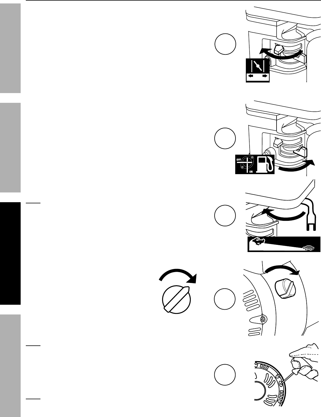
Page 10 K&(%$*4.8"4,7%P'*#$"&8#J%/7*,#*%4,77%QRSSSRSTTRUVWV1 Engine for 69783
F=K6EB CX6I=E@C> D=@>E6>=><6F6E;X
D,8',7%F$,($
1. To start a cold engine, move the Choke to the
START position.
To restart a warm engine, leave the
Choke in the RUN position.
2. Open the Fuel Valve.
3. Slide the Throttle or Speed Control Lever to 1/3
away from the SLOW position (the “turtle”).
>&$*- Some tools have a Speed Control Lever located
elsewhere on the tool which functions the same as
the Throttle. Use the Speed Control Lever in place
of the Throttle when the tool is so equipped.
4. Turn the Engine Switch on.
>&$*- If engine does not start, check engine oil level.
Engine will not start with low or no engine oil.
5. Grip the Starter Handle of the Engine loosely and pull
it slowly several times to allow the gasoline to flow into
the Engine’s carburetor. Then pull the Starter Handle
gently until resistance is felt. Allow Cable to retract fully
and then pull it quickly. Repeat until the engine starts.
>&$*- Do not let the Starter Handle snap back against the engine.
Hold it as it recoils so it doesn't hit the engine.
FE=IE% I;>
1
2
3
C>
CKK
C@
C>
4
5
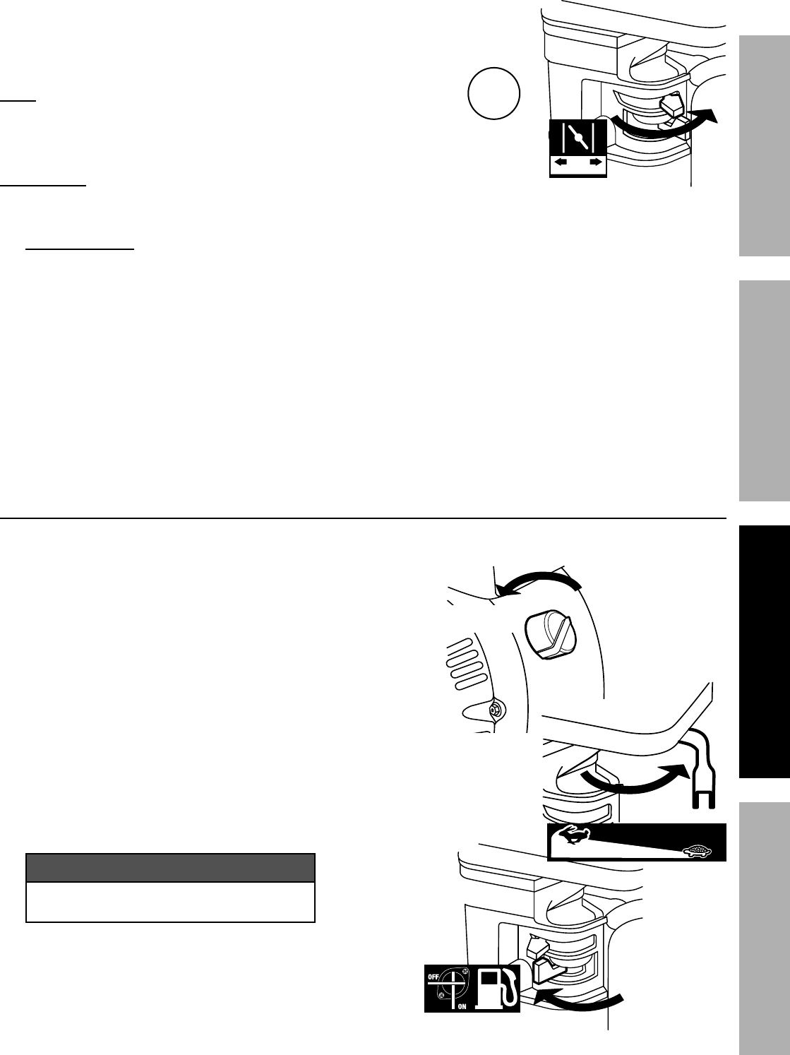
Page 11K&(%$*4.8"4,7%P'*#$"&8#J%/7*,#*%4,77%QRSSSRSTTRUVWV1Engine for 69783
F=K6EBCX6I=E@C>D=@>E6>=><6 F6E;X
6. Allow the Engine to run for several seconds.
Then, if the Choke lever is in the START position,
move the Choke Lever very slowly to its RUN position.
>&$*- Moving the Choke Lever too
fast could stall the engine.
@DXCIE=>E- Allow the engine to run at no load for five minutes with no
load after each start-up so that the engine can stabilize.
7. Adjust the Throttle as needed.
8. [(*,aR"8%X*("&9-
a. Breaking-in the engine will help to ensure proper equipment and engine operation.
b. The operational break-in period will last about 3 hours of use. During this period:
• Do not apply a heavy load to the equipment.
• Do not operate the engine at its maximum speed.
c. The maintenance break-in period will last about 20 hours of use. After this period:
• Change the engine oil.
Under normal operating conditions subsequent maintenance follows the schedule
explained in the MAINTENANCE AND SERVICING section.
F$&//"83%$.*%683"8*
1. To stop the engine in an emergency,
turn the Engine Switch off.
2. Under normal conditions, use the following procedure:
a. Slide the Throttle or Speed Control
Lever to SLOW (the “turtle”).
b. Turn the Engine Switch off.
c. Close the Fuel Valve.
NOTICE
See “Long Term Storage” on page 15
for complete storage instructions.
FE=IE% I;>
6
C@
CKK
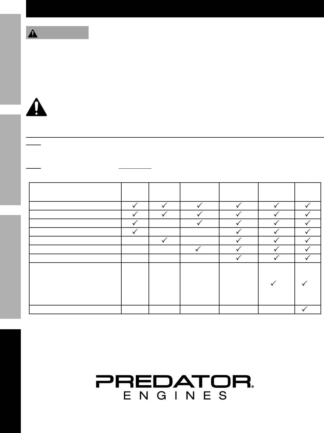
Page 12 K&(%$*4.8"4,7%P'*#$"&8#J%/7*,#*%4,77%QRSSSRSTTRUVWV1 Engine for 69783
F=K6EB CX6I=E@C> D=@>E6>=><6F6E;X
D,"8$*8,84*
Y=I>@>Z
EC%XI6!6>E%F6I@C;F%@>d;IB%KICD%=<<@L6>E=A%FE=IE@>Z-%
E'(8%$.*%X&)*(%F)"$4.%&2%$.*%*P'"/5*8$%$&%"$#%_CKK`%/&#"$"&8J%),"$%2&(%$.*%*83"8*%$&%4&&7J%,89%9"#4&88*4$%
$.*%#/,(a%/7'3%4,/%+*2&(*%/*(2&(5"83%,8H%"8#/*4$"&8J%5,"8$*8,84*J%&(%47*,8"83%/(&4*9'(*#1
EC%XI6!6>E%F6I@C;F%@>d;IB%KICD%6g;@XD6>E%K=@A;I6-%
L&%8&$%'#*%9,5,3*9%*P'"/5*8$1%%@2%,+8&(5,7%8&"#*J%M"+(,$"&8J%&(%*G4*##%
#5&a"83%&44'(#J%.,M*%$.*%/(&+7*5%4&((*4$*9%+*2&(*%2'($.*(%'#*1
K&77&)%,77%#*(M"4*%"8#$('4$"&8#%"8%$."#%5,8',71%%E.*%*83"8*%5,H%2,"7%4("$"4,77H%"2%8&$%#*(M"4*9%/(&/*(7H1
D,8H%5,"8$*8,84*%/(&4*9'(*#J%"847'9"83%,8H%8&$%9*$,"7*9%"8%$."#%5,8',7J%)"77%8**9%$&%+*%
/*(2&(5*9%+H%,%P',7"2"*9%$*4.8"4",8%2&(%#,2*$H1%%@2%H&'%.,M*%,8H%9&'+$#%,+&'$%H&'(%,+"7"$H%$&%#,2*7H%
#*(M"4*%$.*%*P'"/5*8$%&(%*83"8*J%.,M*%,%P',7"2"*9%$*4.8"4",8%#*(M"4*%$.*%*P'"/5*8$%"8#$*,91
<7*,8"83J%D,"8$*8,84*J%,89%A'+("4,$"&8%F4.*9'7*
>&$*- This maintenance schedule is intended solely as a general guide. If performance decreases or if
equipment operates unusually, check systems immediately. The maintenance needs of each piece of equipment
will differ depending on factors such as duty cycle, temperature, air quality, fuel quality, and other factors.
>&$*- The following procedures are in addition to the regular checks and maintenance
explained as part of the regular operation of the engine and equipment.
X(&4*9'(* [*2&(*%
6,4.%;#*
D&8$.7H%&(%
*M*(H%kf%
.(1%&2%'#*
6M*(H%e%5&1%&(%
Uf%.(1%&2%'#*
6M*(H%T%5&1%&(%
Qff%.(1%&2%'#*%
B*,(7H%&(%%
*M*(H%eff%
.(1%&2%'#*
6M*(H%
k%B*,(#
Brush off outside of engine
Check engine oil level
Check air cleaner
Check deposit cup
Change engine oil
Clean/replace air cleaner *
Check and clean spark plug
1. Check/adjust idle speed
2. Check/adjust valve clearance
3. Clean fuel tank, strainer
and carburetor
4. Clean carbon build-up from
combustion chamber
** **
Replace fuel line if necessary **
*Service more frequently when used in dusty areas.
**These items should be serviced by a qualified technician.
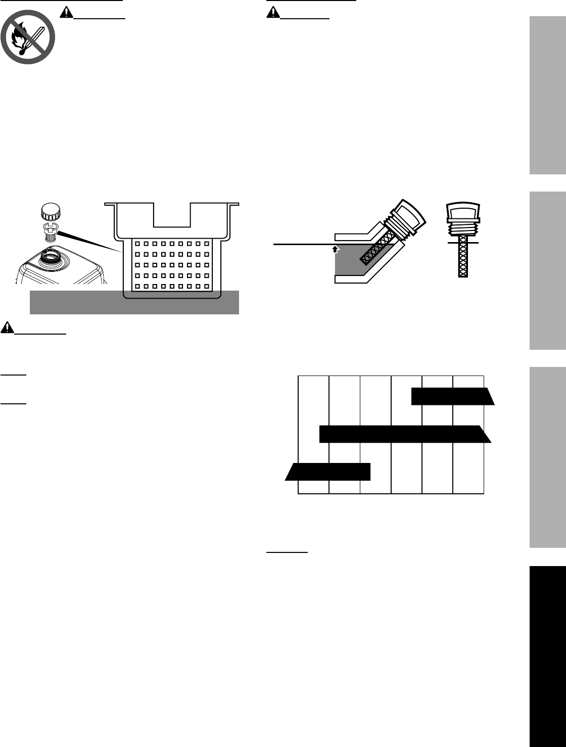
Page 13K&(%$*4.8"4,7%P'*#$"&8#J%/7*,#*%4,77%QRSSSRSTTRUVWV1Engine for 69783
F=K6EBCX6I=E@C>D=@>E6>=><6 F6E;X
<.*4a"83%,89%K"77"83%K'*7
Y=I>@>Z\ EC%XI6!6>E%F6I@C;F%
@>d;IB%KICD%K@I6-
Fill the fuel tank in a well-ventilated area
away from ignition sources. If the engine is
hot from use, shut the engine off and wait
for it to cool before adding fuel.
Do not smoke.
1. Clean the Fuel Cap and the area around it.
2. Unscrew and remove the Fuel Cap.
3. If needed, fill the Fuel Tank to about 1 inch under
the fill neck of the Fuel Tank with 87 octane or
higher unleaded gasoline that has been treated
with a fuel stabilizer additive. Follow fuel stabilizer
manufacturer’s recommendations for use.
D,G%K'*7
LC%>CE%C!6IK@AA\
Y=I>@>Z\%%EC%XI6!6>E%K;6A%
A6=?=Z6%=>L%K@I6%O=^=ILJ%9&%8&$%2"77%
2'*7%,+&M*%$.*%+&$$&5%&2%2'*7%#$(,"8*(1
>&$*-%L&%8&$%'#*%3,#&7"8*%4&8$,"8"83%5&(*%$.,8%
Qfi%*$.,8&7%b6Qfc1%%L&%8&$%'#*%6SU%*$.,8&71
>&$*-%L&%8&$%'#*%3,#&7"8*%$.,$%.,#%+**8%#$&(*9%"8%,%
5*$,7%2'*7%4&8$,"8*(%&(%,%9"($H%2'*7%4&8$,"8*(1%%@$%4,8%
4,'#*%/,($"47*#%$&%*8$*(%$.*%4,(+'(*$&(J%,22*4$"83%
*83"8*%/*(2&(5,84*%,890&(%4,'#"83%9,5,3*1
4. Then replace the Fuel Cap.
5. Wipe up any spilled fuel and allow excess
to evaporate before starting engine.
To prevent FIRE, do not start the engine
while the smell of fuel hangs in the air.
683"8*%C"7%<.,83*
<=;E@C>\ Oil is very hot during operation and can
cause burns. Wait for engine to cool before changing oil.
1. Make sure the engine is stopped and is level.
2. Close the Fuel Valve.
3. Place a drain pan (not included) underneath
the crankcase’s drain plug.
4. Remove the drain plug and, if possible,
tilt the crankcase slightly to help drain
the oil out. Recycle used oil.
5. Replace the drain plug and tighten it.
6. Clean the top of the Dipstick and the area around it.
Remove the Dipstick by turning it counterclockwise,
and wipe it off with a clean, lint free rag.
7.
Full level
Full level
Add the appropriate type of oil until the oil level is at
the full level. SAE 10W-30 oil is recommended for
general use.
The SAE Viscosity Grade chart shows other
viscosities to use in different average temperatures.
QfYRef
ef
UYRef
-20 0 20 40 60 80 100°F
F=6%!"#4&#"$H%Z(,9*#
=M*(,3*%&'$9&&(%$*5/*(,$'(*
8. Thread the dipstick back in clockwise.
>CE@<6-%%L&%8&$%('8%$.*%*83"8*%)"$.%$&&%7"$$7*%&"71
Engine%)"77%8&$%#$,($%)"$.%7&)%&(%8&%*83"8*%&"71
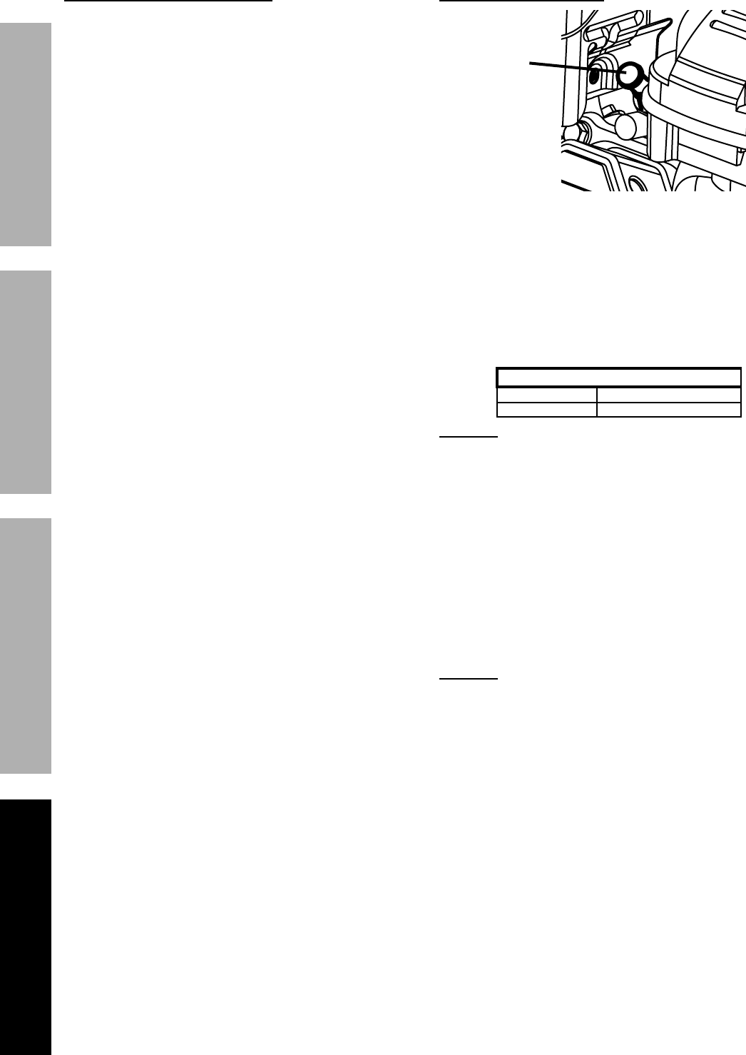
Page 14 K&(%$*4.8"4,7%P'*#$"&8#J%/7*,#*%4,77%QRSSSRSTTRUVWV1 Engine for 69783
F=K6EB CX6I=E@C> D=@>E6>=><6F6E;X
="(%K"7$*(%67*5*8$%D,"8$*8,84*
1. Remove the air filter cover and the air filter elements
and check for dirt. Clean as described below.
2. <7*,8"83-
• For “paper” filter elements:
To prevent injury from dust and debris,
wear ANSI-approved safety goggles,
NIOSH-approved dust mask/respirator, and
heavy-duty work gloves. In a well-ventilated
area away from bystanders, use pressurized
air to blow dust out of the air filter.
• For foam filter elements:
Wash the element in warm water and
mild detergent several times. Rinse.
Squeeze out excess water and allow it to dry
completely. Soak the filter in lightweight oil
briefly, then squeeze out the excess oil.
3. Install the cleaned filter. Secure the
Air Cleaner Cover before use.
F/,(a%X7'3%D,"8$*8,84*
1.
F/,(a%
X7'3%
<,/
Disconnect spark plug cap from end of plug.
Clean out debris from around spark plug.
2. Using a spark plug wrench, remove the spark plug.
3. Inspect the spark plug:
If the electrode is oily, clean it using a clean, dry rag.
If the electrode has deposits on it, polish it using
emery paper. If the white insulator is cracked or
chipped, the spark plug needs to be replaced.
I*4&55*89*9%F/,(a%X7'3#
NGK®BP-6ES
NHSP® / TORCH®F6TC
>CE@<6- Using an incorrect spark
plug may damage the engine.
4. When installing a new spark plug, adjust the
plug’s gap to the specification on the Technical
Specifications chart. Do not pry against the
electrode, the spark plug can be damaged.
5. Install the new spark plug or the cleaned spark plug
into the engine. Gasket-style: Finger-tighten until
the gasket contacts the cylinder head, then tighten
about 1/2-2/3 turn more.
Non-gasket-style: Finger-tighten until
the plug contacts the head, then
tighten about 1/16 turn more.
>CE@<6- Tighten the spark plug properly.
If loose, the spark plug will cause the engine to
overheat.
If overtightened, the threads in the
engine block will be damaged.
6. Apply dielectric spark plug boot protector
(not included) to the end of the spark
plug and reattach the wire securely.
Page 15K&(%$*4.8"4,7%P'*#$"&8#J%/7*,#*%4,77%QRSSSRSTTRUVWV1Engine for 69783
F=K6EBCX6I=E@C>D=@>E6>=><6 F6E;X
A&83%E*(5%F$&(,3*
When the equipment is to remain idle for longer than 20
days, prepare the Engine for storage as follows:
1. <A6=>@>Z:
Wait for Engine to cool, then clean Engine with
dry cloth. >CE@<6- L&%8&$%47*,8%'#"83%),$*(1
The water will gradually enter the Engine
and cause rust damage. Apply a thin coat
of rust preventive oil to all metal parts.
2. K;6A-
To protect the fuel tank during storage, fill the
tank with gasoline that has been treated with
a fuel stabilizer additive. Follow fuel stabilizer
manufacturer’s recommendations for use. Refer
to Checking and Filling Fuel on page 1.
Y=I>@>Z\ EC%XI6!6>E%F6I@C;F%
@>d;IB%KICD%K@I6-
Fill tank in a well-ventilated area away from
ignition sources. If the engine is hot from
use, shut the engine off and wait for it to
cool before adding fuel. Do not smoke.
3. A;[I@<=E@C>-
a. Change engine oil.
b. Clean out area around spark plug.
Remove spark plug and pour one tablespoon of
engine oil into cylinder through spark plug hole.
c. Replace spark plug, but leave
spark plug cap disconnected.
d. Pull Starter Handle to distribute oil in cylinder.
Stop after one or two revolutions when you
feel the piston start the compression stroke
(when you start to feel resistance).
4. FECI=Z6%=I6=-%
Cover and store in a dry, level, well-ventilated
area out of reach of children. Storage area should
also be away from ignition sources, such as
water heaters, clothes dryers, and furnaces.
>CE@<6- During extended storage periods the
Engine must be started every 3 months and allowed
to run for 15 – 20 minutes or the Warranty is VOID.
5. =KE6I%FECI=Z6-%
Before starting the Engine during or after
storage, keep in mind that untreated gasoline
will deteriorate quickly. Drain the fuel
tank and change to fresh fuel if untreated
gasoline has been sitting for a month, if
treated gasoline has been sitting beyond the
fuel stabilizer’s recommended time period,
or if the Engine does not start.

Page 16 K&(%$*4.8"4,7%P'*#$"&8#J%/7*,#*%4,77%QRSSSRSTTRUVWV1 Engine for 69783
F=K6EB CX6I=E@C> D=@>E6>=><6F6E;X
E(&'+7*#.&&$"83
X(&+7*5 X&##"+7*%<,'#*# X(&+,+7*%F&7'$"&8#
Engine will not start FUEL RELATED:
1. No fuel in tank or fuel valve closed.
2. Choke not in START position, cold engine.
3. Gasoline with more than 10% ethanol used.
(E15, E20, E85, etc.)
4. Low quality or deteriorated, old gasoline.
5. Carburetor not primed.
6. Dirty fuel passageways.
7. Carburetor needle stuck.
Fuel can be smelled in the air.
8. Too much fuel in chamber. This can be caused
by the carburetor needle sticking.
9. Clogged Fuel Filter.
FUEL RELATED:
1. Fill fuel tank with fresh 87+ octane stabilizer-
treated unleaded gasoline and open fuel
valve.%
L&%8&$%'#*%3,#&7"8*%)"$.%5&(*%$.,8%
Qfi%*$.,8&7%b6QUJ%6kfJ%6SUJ%*$41c1
2. Move Choke to START position.
3. Clean out ethanol rich gasoline from fuel
system. Replace components damaged by
ethanol. Use fresh 87+ octane stabilizer-
treated unleaded gasoline only. %%
L&%8&$%'#*%3,#&7"8*%)"$.%5&(*%$.,8%
Qfi%*$.,8&7%b6QUJ%6kfJ%6SUJ%*$41c1
4. Use fresh 87+ octane stabilizer-treated
unleaded gasoline.%
L&%8&$%'#*%3,#&7"8*%)"$.%5&(*%$.,8%
Qfi%*$.,8&7%b6QUJ%6kfJ%6SUJ%*$41c1
5. Pull on Starter Handle to prime.
6. Clean out passageways using fuel additive.
Heavy deposits may require further cleaning.
7. Z*8$7H tap side of carburetor float
chamber with screwdriver handle.
8. Turn Choke to RUN position. Remove
spark plug and pull the start handle several
times to air out the chamber. Reinstall
spark plug and set Choke to START position.
9. Replace Fuel Filter.
IGNITION (SPARK) RELATED:
1. Spark plug cap not connected securely.
2. Spark plug electrode wet or dirty.
3. Incorrect spark plug gap.
4. Spark plug cap broken.
5. Incorrect spark timing or faulty ignition system.
IGNITION (SPARK) RELATED:
1. Connect spark plug cap properly.
2. Clean spark plug.
3. Correct spark plug gap.
4. Replace spark plug cap.
5. Have qualified technician diagnose/
repair ignition system.
COMPRESSION RELATED:
1. Cylinder not lubricated.
Problem after long storage periods.
2. Loose or broken spark plug.
(Hissing noise will occur
when trying to start.)
3. Loose cylinder head or damaged head gasket.
(Hissing noise will occur when trying to start.)
4. Engine valves or tappets mis-adjusted or stuck.
ENGINE OIL RELATED:
1. Low engine oil.
2. Engine mounted on slope,
triggering low oil shutdown.
COMPRESSION RELATED:
1. Pour tablespoon of oil into spark plug
hole. Crank engine a few times
and try to start again.
2. Tighten spark plug.
If that does not work, replace spark plug.
If problem persists, may have head
gasket problem, see #3.
3. Tighten head.
If that does not remedy problem,
replace head gasket.
4. Have qualified technician adjust/
repair valves and tappets.
ENGINE OIL RELATED:
1. Fill engine oil to proper level.
Check engine oil before EVERY use.
2. Operate engine on level surface.
Check engine oil level.
K&77&)%,77%#,2*$H%/(*4,'$"&8#%).*8*M*(%9",38&#"83%&(%#*(M"4"83%$.*%*P'"/5*8$%&(%*83"8*1

Page 17K&(%$*4.8"4,7%P'*#$"&8#J%/7*,#*%4,77%QRSSSRSTTRUVWV1Engine for 69783
F=K6EBCX6I=E@C>D=@>E6>=><6 F6E;X
X(&+7*5 X&##"+7*%<,'#*# X(&+,+7*%F&7'$"&8#
Engine misfires 1. Spark plug cap loose.
2. Incorrect spark plug gap or
damaged spark plug.
3. Defective spark plug cap.
4. Old or low quality gasoline.
5. Incorrect compression.
1. Check cap and wire connections.
2. Re-gap or replace spark plug.
3. Replace spark plug cap.
4. Use only fresh 87+ octane stabilizer-treated
unleaded gasoline.%
L&%8&$%'#*%3,#&7"8*%)"$.%5&(*%$.,8%
Qfi%*$.,8&7%b6QUJ%6kfJ%6SUJ%*$41c1
5. Diagnose and repair compression.
(Use 683"8*%)"77%8&$%#$,($-%
<CDXI6FF@C>%I6A=E6L section.)
Engine stops
suddenly
1. Fuel tank empty or full of impure or low quality
gasoline.
2. Low oil shutdown.
3. Defective fuel tank cap creating vacuum,
preventing proper fuel flow.
4. Faulty magneto.
5. Disconnected or improperly
connected spark plug cap.
1. Fill fuel tank with fresh 87+ octane stabilizer-
treated unleaded gasoline.%
L&%8&$%'#*%3,#&7"8*%)"$.%5&(*%$.,8%
Qfi%*$.,8&7%b6QUJ%6kfJ%6SUJ%*$41c1
2. Fill engine oil to proper level.
Check engine oil before EVERY use.
3. Test/replace fuel tank cap.
4. Have qualified technician service magneto.
5. Secure spark plug cap.
Engine stops when
under heavy load
1. Dirty air filter
2. Engine running cold.
1. Clean element.
2. Allow engine to warm up prior
to operating equipment.
Engine knocks 1. Old or low quality gasoline.
2. Engine overloaded.
3. Incorrect spark timing, deposit buildup,
worn engine, or other mechanical problems.
1. Fill fuel tank with fresh 87+ octane stabilizer-
treated unleaded gasoline. %%
L&%8&$%'#*%3,#&7"8*%)"$.%5&(*%$.,8%
Qfi%*$.,8&7%b6QUJ%6kfJ%6SUJ%*$41c1
2. Do not exceed equipment’s load rating.
3. Have qualified technician diagnose
and service engine.
Engine backfires 1. Impure or low quality gasoline.
2. Engine too cold.
3. Intake valve stuck or overheated engine.
4. Incorrect timing.
1. Fill fuel tank with fresh 87+ octane stabilizer-
treated unleaded gasoline. %%
L&%8&$%'#*%3,#&7"8*%)"$.%5&(*%$.,8%
Qfi%*$.,8&7%b6QUJ%6kfJ%6SUJ%*$41c1
2. Use cold weather fuel and oil additives
to prevent backfiring.
3. Have qualified technician diagnose
and service engine.
4. Check engine timing.
After sudden
impact, engine will
run, but equipment
will not operate
Shaft key or other shear pin
broken by impact to disconnect
engine and limit damage.
Have qualified technician check and replace
broken shaft key or other shear pins.
K&77&)%,77%#,2*$H%/(*4,'$"&8#%).*8*M*(%9",38&#"83%&(%#*(M"4"83%$.*%*P'"/5*8$%&(%*83"8*1

Page 18 K&(%$*4.8"4,7%P'*#$"&8#J%/7*,#*%4,77%QRSSSRSTTRUVWV1 Engine for 69783
F=K6EB CX6I=E@C> D=@>E6>=><6F6E;X
Y,((,8$"*#
A"5"$*9%Wf%L,H%Y,((,8$H%bI*$,"7c
Harbor Freight Tools Co. makes every effort to assure that its products meet high quality and durability standards,
and warrants to the original purchaser that this product is free from defects in materials and workmanship for the
period of 90 days from the date of purchase. This warranty does not apply to damage due directly or indirectly,
to misuse, abuse, negligence or accidents, repairs or alterations outside our facilities, criminal activity, improper
installation, normal wear and tear, or to lack of maintenance. We shall in no event be liable for death, injuries
to persons or property, or for incidental, contingent, special or consequential damages arising from the use of
our product. Some states do not allow the exclusion or limitation of incidental or consequential damages, so the
above limitation of exclusion may not apply to you. THIS WARRANTY IS EXPRESSLY IN LIEU OF ALL OTHER
WARRANTIES, EXPRESS OR IMPLIED, INCLUDING THE WARRANTIES OF MERCHANTABILITY AND
FITNESS, EXCEPT FOR THE EMISSIONS CONTROL SYSTEM WARRANTY BELOW.
To take advantage of this warranty, the product or part must be returned to us with transportation charges prepaid.
Proof of purchase date and an explanation of the complaint must accompany the merchandise. If our inspection
verifies the defect, we will either repair or replace the product at our election or we may elect to refund the purchase
price if we cannot readily and quickly provide you with a replacement. We will return repaired products at our
expense, but if we determine there is no defect, or that the defect resulted from causes not within the scope of our
warranty, then you must bear the cost of returning the product.
This warranty gives you specific legal rights and you may also have other rights which vary from state to state.
65"##"&8#%<&8$(&7%FH#$*5%Y,((,8$H
The California Air Resources Board and Harbor Freight Tools (HFT) are pleased to explain the emissions control
system warranty on your 2017 Small Off-Road Engine, in addition to the Retail Warranty above. In California, new
equipment that uses small off-road engines must be designed, built, and equipped to meet the State’s stringent anti-smog
standards. HFT must warrant that the emissions control system on your engine will be free from defects in material and
workmanship for two (2) years, provided there has been no abuse, neglect, or improper maintenance of your engine.
Your emissions control system may include parts such as the carburetor or fuel-injection system, the ignition
system, catalytic converter, fuel tanks, fuel lines, fuel caps, valves, canisters, vapor hoses, clamps, connectors, and
other emissions-related assemblies.
Where a warrantable condition exists, HFT will repair or replace, at our option, your engine if at no cost to you,
including diagnosis, parts and labor.
D=>;K=<E;I6IhF%Y=II=>EB%<C!6I=Z6
This emissions control system is warranted for two years. If any emission-related part on your engine is defective,
the part will be repaired or replaced by HFT.
CY>6IhF%Y=II=>EB%I6FXC>F@[@A@E@6F
As the engine owner, you are responsible for the performance of the required maintenance listed in your
Owner’s Manual.
As the engine owner, you should however be aware that HFT may deny you warranty coverage if your engine or
a part has failed due to abuse (including failure to follow the fuel use instructions contained in this manual), neglect,
improper maintenance, or unapproved modifications.
You are responsible for contacting HFT as soon as the problem exists in order to obtain warranty repair or replacement,
by doing either of the following: (a) contact HFT product support at 1-888-866-5797 or predator@harborfreight.com;
or (b) bring the to your nearest Harbor Freight Tools retail store. The nearest Harbor Freight Tools retail store can
be found on the internet at http://www.harborfreight.com. The warranty repairs or replacement should be completed
in a reasonable amount of time, not to exceed 30 days. If you have a question regarding your warranty coverage,
you should contact HFT product support at 1-888-866-5797 or predator@harborfreight.com.

Page 19K&(%$*4.8"4,7%P'*#$"&8#J%/7*,#*%4,77%QRSSSRSTTRUVWV1Engine for 69783
F=K6EBCX6I=E@C>D=@>E6>=><6 F6E;X
Z6>6I=A%6D@FF@C>F%Y=II=>EB%<C!6I=Z6
a) The warranty period begins on the date the engine or equipment is delivered to an ultimate purchaser. The warranty
period is two years.
b) HFT warrants to the initial owner and each subsequent owner that the engine is:
1. Designed, built, and equipped so as to conform with all applicable regulations adopted by the Air Resources
Board; and
2. Free from defects in materials and workmanship that causes the failure of a warranted part for a period of two
years.
c) The warranty on emissions-related parts is as follows:
1. Any warranted part that is not scheduled for replacement as required maintenance in the written instructions
provided, is warranted for the warranty period stated above. If any such part fails during the period of warranty
coverage, it will be repaired or replaced HFT. Any such part repaired or replaced under the warranty will be
warranted for the remaining warranty period.
2. Any warranted part that is scheduled only for regular inspection in the written instructions is warranted for
the warranty period stated above. A statement in the written instructions to the effect of “repair or replace as
necessary” does not reduce the period of warranty coverage. Any such part repaired or replaced under warranty
will be warranted for the remaining warranty period.
3. Any warranted part that is scheduled for replacement as required maintenance in the written instructions will
be warranted for the period of time prior to the first scheduled replacement point for that part. If the part fails
prior to the first scheduled replacement, the part will be repaired or replaced by HFT. Any such part repaired or
replaced under warranty will be warranted for the remainder of the period prior to the first scheduled replacement
point for the part.
4. Repair or replacement of any warranted part under the warranty will be performed at no charge to the owner
at a retail store or by HFT paying for shipping the product for repair.
5. Notwithstanding the provisions herein, warranty services or repairs will be provided at all retail stores or by
contacting HFT product support at 1-888-866-5797 or predator@harborfreight.com.
6. The owner will not be charged for diagnostic labor that leads to the determination that a warranted part is in
fact defective, provided that such diagnostic work is performed at a retail store.
7. HFT is liable for damages to other engine components proximately caused by a failure under warranty of any
warranted part.
8. Throughout the emissions warranty period stated above, HFT will maintain a supply of warranted parts sufficient
to meet the expected demand for such parts.
9. Any replacement part may be used in the performance of any warranty maintenance or repairs and will be
provided without charge to the owner. Such use will not reduce the warranty obligations of HFT.
10. Add-on or modified parts that are not approved by HFT may not be used. The use of any non-exempted add-
on or modified parts will be grounds for disallowing a warranty claim. HFT is not liable to warrant failures of
warranted parts caused by the use of a non-exempted add-on or modified part.
d) Emission Warranty Parts List.
1. Fuel Metering System
a. Carburetor and its internal parts (and/or pressure
regulator or fuel injection system).
b. Fuel tank.
c. Cold start enrichment system.
d. Air/fuel ratio feedback and control system.
2. Air Induction System
a. Controlled hot air intake system.
b. Intake manifold.
c. Air filter.
3. Ignition System
a. Spark plugs.
b. Magneto ignition system.
c. Spark advance/retard system.
4. Catalyst System (if so equipped)
a. Exhaust pipe stud/exhaust manifold.
b. Thermal reactor.
c. Catalytic converter (if so equipped).
5. Particulate Controls
a. Traps, filters, precipitators, and any other device
used to capture particulate emissions.
6. Miscellaneous Items Used in Above Systems
a. Vacuum, temperature and time sensitive valves
and switches.
b. Hoses, belts, connectors, and assemblies.
7. Evaporative Emission Control System
a. Fuel tank.
b. Fuel caps, valves, canisters, filters, vapor hoses,
clamps, connectors, belts, and assemblies.
HFT provides with each product written instructions for the maintenance and use of the product by the owner.

Page 20 K&(%$*4.8"4,7%P'*#$"&8#J%/7*,#*%4,77%QRSSSRSTTRUVWV1 Engine for 69783
F=K6EB CX6I=E@C> D=@>E6>=><6F6E;X
XA6=F6%I6=L%EO6%KCAACY@>Z%<=I6K;AAB
THE MANUFACTURER AND/OR DISTRIBUTOR HAS PROVIDED THE PARTS LIST AND ASSEMBLY DIAGRAM
IN THIS MANUAL AS A REFERENCE TOOL ONLY. NEITHER THE MANUFACTURER OR DISTRIBUTOR
MAKES ANY REPRESENTATION OR WARRANTY OF ANY KIND TO THE BUYER THAT HE OR SHE IS
QUALIFIED TO MAKE ANY REPAIRS TO THE PRODUCT, OR THAT HE OR SHE IS QUALIFIED TO REPLACE
ANY PARTS OF THE PRODUCT. IN FACT, THE MANUFACTURER AND/OR DISTRIBUTOR EXPRESSLY
STATES THAT ALL REPAIRS AND PARTS REPLACEMENTS SHOULD BE UNDERTAKEN BY CERTIFIED AND
LICENSED TECHNICIANS, AND NOT BY THE BUYER. THE BUYER ASSUMES ALL RISK AND LIABILITY
ARISING OUT OF HIS OR HER REPAIRS TO THE ORIGINAL PRODUCT OR REPLACEMENT PARTS
THERETO, OR ARISING OUT OF HIS OR HER INSTALLATION OF REPLACEMENT PARTS THERETO.
I*4&(9%X(&9'4$h#%F*(",7%>'5+*(%O*(*-%
>&$*-%@2%/(&9'4$%.,#%8&%#*(",7%8'5+*(J%(*4&(9%5&8$.%,89%H*,(%&2%/'(4.,#*%"8#$*,91
>&$*- Some parts are listed and shown for illustration purposes only,
and are not available individually as replacement parts.
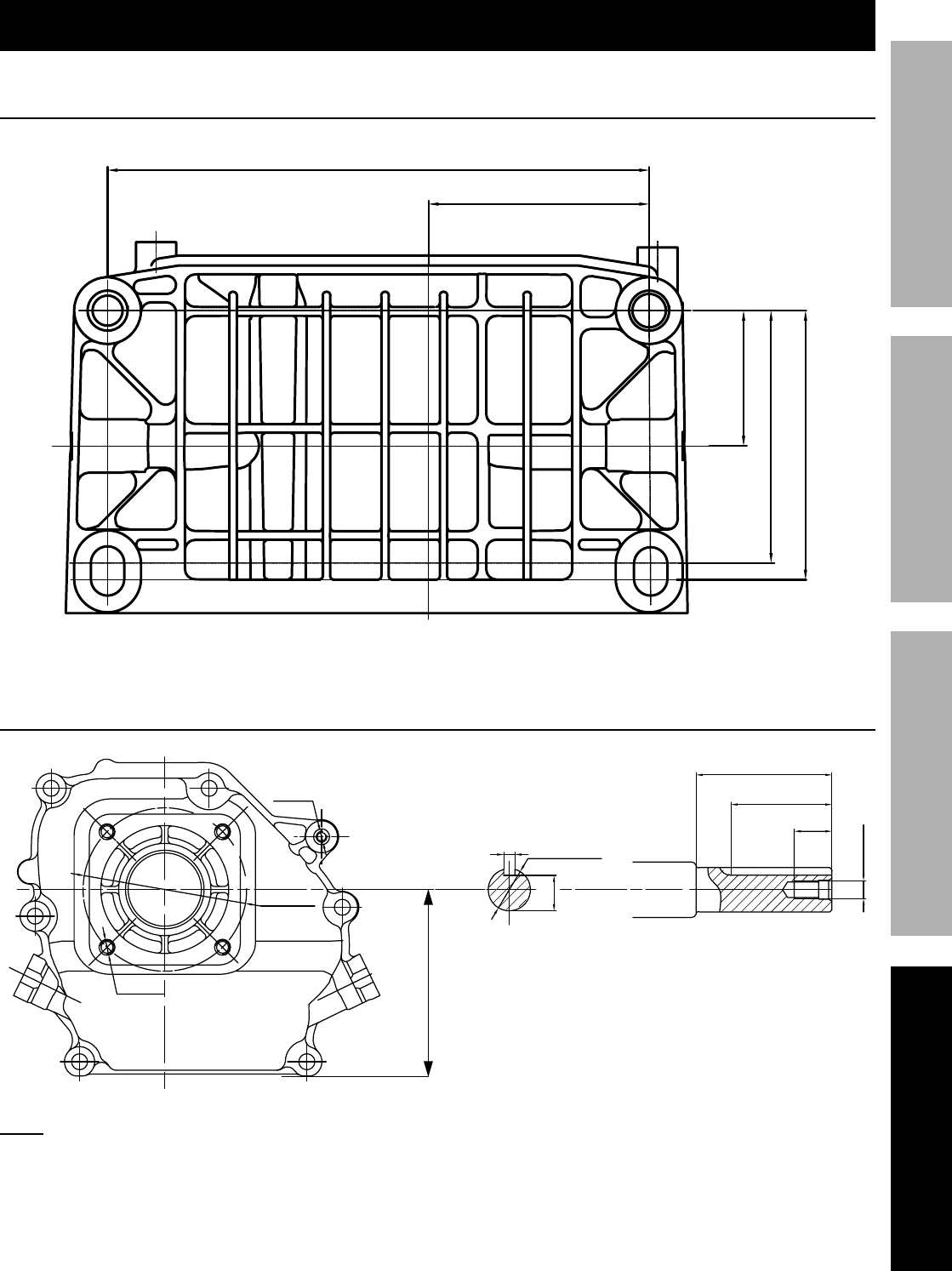
Page 21K&(%$*4.8"4,7%P'*#$"&8#J%/7*,#*%4,77%QRSSSRSTTRUVWV1Engine for 69783
F=K6EBCX6I=E@C>D=@>E6>=><6 F6E;X
X,($#%A"#$#%,89%L",3(,5#
D&'8$"83%O&7*%L",3(,5
T1eS%"81%0%QTk55
k1T%"81%0%TT55
Q1T%"81%0%lf1U55
k1WV%"81%0%VU1U55
e1QV%"81%0%Sf1U55
X&)*(%E,a*RC22%L",3(,5
k1le%"81%0%TQ1V55
Q1VW%"81%0%lU1U55
f1TV%"81%%
0%QV55
5/16-24UNF
mf1VU%"81%0%QW1fU55
f1Tl%"81%%
0%QT1eT55
f1QSVU%"81%0%l1VS55
4x5/16-24UNF
5/16-24UNF
l1QV%"81%0%QfT55
me1TkU%"81%0%Wk55
>&$*- Not to scale.

Page 22 K&(%$*4.8"4,7%P'*#$"&8#J%/7*,#*%4,77%QRSSSRSTTRUVWV1 Engine for 69783
F=K6EB CX6I=E@C> D=@>E6>=><6F6E;X
X,($#%A"#$
X,($ L*#4("/$"&8 g$H
1 Gasket, Cylinder Head 1
2 Cover Subassembly, Cylinder Head 1
3 Gasket, Cylinder Head Cover 1
4 Tube, Breather 1
5 Bolt 4
6 Stud 2
7 Stud 2
8 Pin 2
9 Bolt, Cylinder Head 4
10 Plug, Spark 1
11 Head Subassembly, Cylinder 1
12 Crankcase Subassembly 1
13 Sensor, Engine Oil 1
14 Gear Asm, Governor 1
15 Arm, Governor 1
16 Bolt, Drain Plug 2
17 Washer, Flat 2
18 Bearing, Deep Groove Ball 2
19 Seal, Oil 1
20 Washer, Flat 1
21 Cotter 1
22 Bolt 2
23 Cover, Crankcase 1
24 Gasket, Crankcase 1
25 Pin 2
26 Dipstick Subassembly, Oil 1
27 Plug Subassembly, Engine Oil 1
28 Seal, Oil 1
29 Bolt 6
30 Crankshaft Asm. 1
31 Clip, Piston Pin 2
32 Piston 1
33 Pin, Piston 1
34 Rod, Connecting 1
35 Primary Ring 1
36 Secondary Ring 1
37 Ring Set, Oil 1
38 Camshaft Asm. 1
39 Valve, Exhaust 1
40 Valve, Intake 1
41 Seat, Valve Spring 2
42 Clamp, Valve Lock 4
43 Guide, Seal 2
44 Spring, Valve 2
45 Plate Subassembly, Lifter Stopper 1
46 Bolt, Rocker Shaft 2
47 Rocker, Valve 2
X,($ L*#4("/$"&8 g$H
48 Nut, Valve Adjusting 2
49 Nut, Valve Lock 2
50 Tappet, Valve 2
51 Lifter, Valve 2
52 Starter Asm, Recoil 1
53 Bolt 1
54 Shroud 1
55 Bolt 4
56 Shroud, Cylinder Body 1
57 Bolt 2
58 Shield,Lower 1
59 Bolt 1
60 Protector, Oil 1
61 Collar 1
62 Switch Subassembly, Stop Engine 1
63 Gasket, Carburetor Insulator 1
64 Plate, Carburetor Insulator 1
65 Gasket, Carburetor 1
66 Gasket, Air Cleaner 1
67 Nut 2
68 Cleaner, Air 1
69 Gasket, Exhaust Outlet 1
70 Nut 2
71 Muffler Asm. 1
72 Tank, Fuel 1
73 Strainer, Fuel 1
74 Cover, Fuel Tank 1
75 Outlet Subassembly, Fuel Tank Oil 1
76 Collar 1
77 Tube, Fuel 1
78 Jacket, Rubber 1
79 Nut 2
80 Nut, Flywheel 1
81 Pulley, Starter 1
82 Impeller 1
83 Flywheel Subassembly 1
84 Bolt 2
85 Coil, Ignition 1
86 Support Subassembly, Governor 1
87 Nut 1
88 Bolt, Governor Support 1
89 Spring, Governor 1
90 Rod, Governor 1
91 Spring, Throttle Valve Returning 1
92 Control Asm, Throttle 1
93 Bolt 2
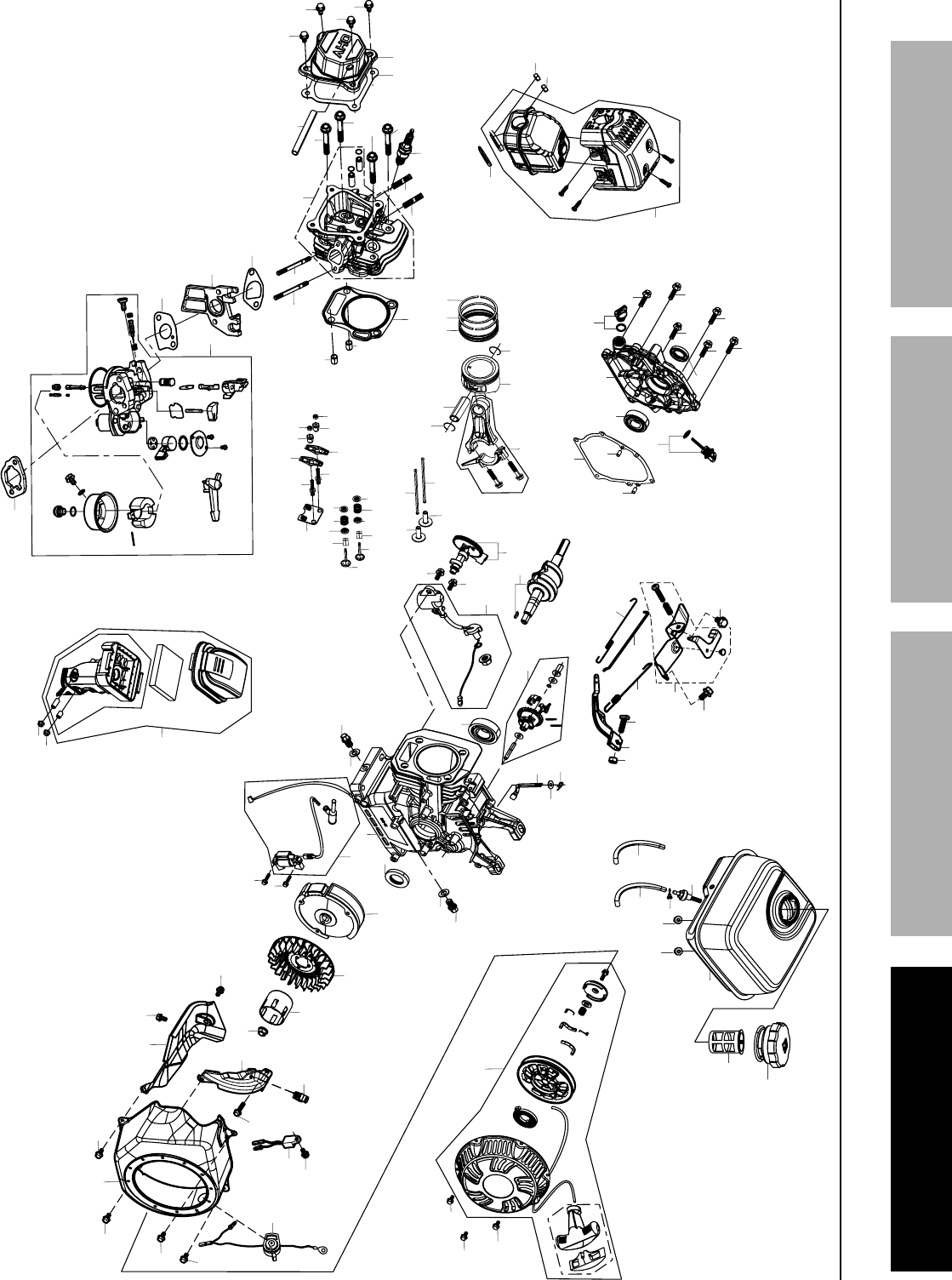
Page 23K&(%$*4.8"4,7%P'*#$"&8#J%/7*,#*%4,77%QRSSSRSTTRUVWV1Engine for 69783
F=K6EBCX6I=E@C>D=@>E6>=><6 F6E;X
=##*5+7H%L",3(,5
48
4
2
4
5
46
46
43
4
144
44
39
4
0
47
48
49
49
37
31 32
33
34
31
35 36
50
51
50
51
47
15
20
21
14
13
16
17
17
16
19
22
22
18
12
30
53
53
53
52
0
1
1
4
23
5
6
7
9
9
9
9
7
6
8
8
5
5
1
1
38
80
82
84
84
581
83
85
54
55
55
55
55
56
57
57
59
55
60
58
66
5
6
4
6
3
6
7
6
4
3
86
89
90
91
92
93
93
87
88
25
25
24
4
2
27
29
29
29 29
29
29
23
26
28
18
4
1
62
61
67
67
68
69
71
70
70
76
77
75
79 79
73
72
78
4
7

elWQ%D"##"&8%C,a#%[7M91%%n%%XC%[&G%TffW%%n%%<,5,("77&J%<=%WefQQ%%n%%QRSSSRSTTRUVWV
