700220_An_Instruction_Set_For_The_18 Bit_PDP K 700220 An Instruction Set For The 18 Bit PDP
User Manual: 700220_An_Instruction_Set_For_The_18-bit_PDP-K
Open the PDF directly: View PDF ![]() .
.
Page Count: 33
J).l. s
tr
i.bu
ti
or;.
K~ys:
R\~vigion
~
Obsolete:
Date:
An
Instruction
Set
for
the
i8-bit
PDP-K
Instruction
Set
Op
C()d~
Data,
~.ry·p~~s
None
Ncne
February
20,
1970
~
.•
0 i
';
.
~r:
( " ,J
c:
t 1
:'
, n
An
instruction
set
for
an
IB~bit
computer~
is
proposri].
It
cJmbines
the
best
features
of
the
F~P-llts
archltec-
tnre
.:ind
the
PDP-olD
~
s
instruct~ion
set
For
::~t~"e:ral
.r'ed50ns
f
an
lB-'bi
t
(:omput!;;r
was
considered
s
u:>e
~<.('jr;
i t
solves
both
t.he
Of:)
code
:tnd
addr€-!ss
spac.
...
~
prob~ernB
of:
a
16·-bit
computer.
In
addit.~6.on"it:
i;:: a
better
data
base
in
two
important
aredls.
Pulse
Height
A:lalysis
(PHA)
programs
have
proven
the
need
for
18
bits.
1\.1so,
thE:
36-bit
floating-point
rt;prt~sentation
has
much
wider
acceptance,
due
to
its
superio~ity
of
32-bit
for~
mats·
..
1 r
"e
..
, a
computer
wi
th
a
'word
len1Jth
of
18
bi
t~'
"
2.0
.
L~'
~:~ructi()n
_f~rmat
a!?
..
d
T.e~rminology
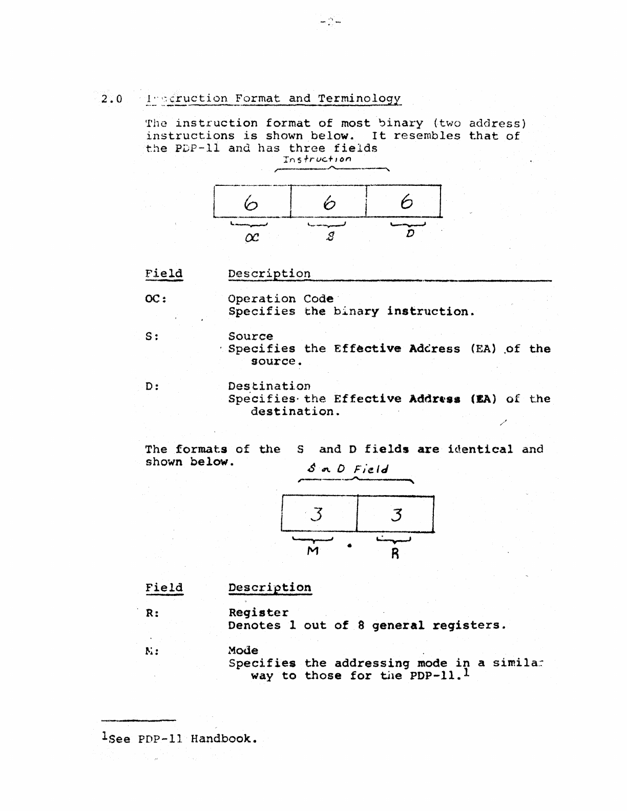
'!'hc
ins
tr'uction
format
of
most
~inary
(two
address)
instruct.ions
is
shown
below.
It
resembles
that
of
the
PDP-II
and
has
three
fields
Field
oc:
s:
D:
In
s
fruG+
Ion
~.~ription
Operation
Code·
Wi
.J
D
Specifies
the
binary
instruction.
Source
.
Specifies
the
Effective
AdC:ress
(EA)
,of
the
source.
Destination
Specifies-
the
Effective
Addr...
(EA)
of
the
destination
..
The
formats
of
the
Sand
D
fields
are
identical
and
shown
below.
~
.r\,
0
F'/eIJ
Field
R:
"..--._._"""
L3
..
M
Description
Reqister
I
.,
•
,
3
:::J
,,'
...
R
Denotes
lout
of
8
general
reqisters.
Mode
Specifies
the
addressinq
mode
in
a
simila::-
way
to
those
for
tile
PDP-li.l
lSee
PDP-II
Handbook.
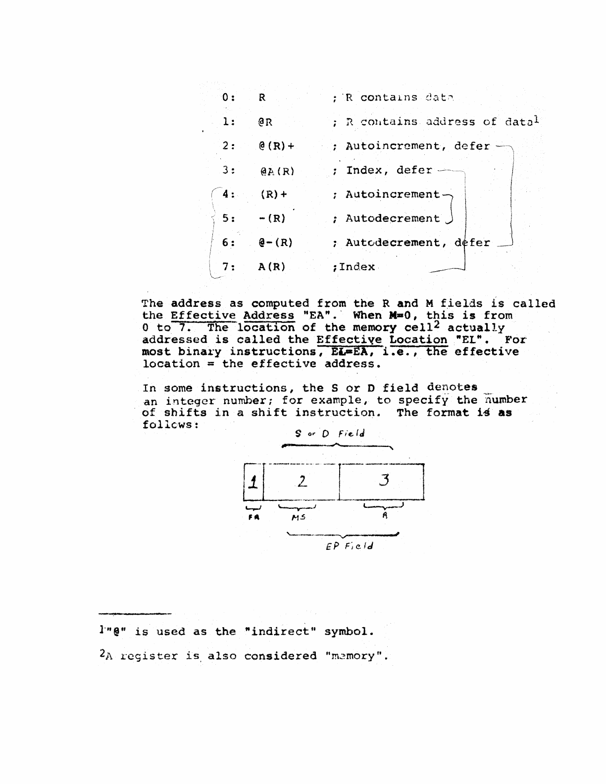
0:
1:
2 :
5 :
6:
7:
R
@R
@(R)+
@J>~CR)
(R)+
-
(R)
@-
(R)
A(R)
:
'R
conta~ns
dat~
~
COl1tains
o.ddress
of
datu
l
Autoincrcment,
defer
Index,
defer
Autoincrement
J
;
Autodecrement
Aut0decrement,
d
fer
;Index·
r:['he
address
as
computed
from
the
Rand
M
f,ields
is
called
the
Effective
Address
'tEA".'
When
M-O,
this
is
from
o
to
7.
The
-tocatio·n
of
the
memory
cel1
2
actually
addressed
is
called
the
Effective
Location
"ELM.
For
most
binary
instructions,
EL-EA,
i.e.,
the
effective
location
=
the
effective
address.
In
some
instructions,
the
S
or
D
field
denotes
an
integer
number;
for
example,
to
specify
the
number
of
shifts
in
a
shift
instruction"
The
format
i4
as
follcws:
'---.
__
-."
l'
EP
,:;
e
fJ
-,---
l"@·'
is
used
as
the
"indirect"
symbol.
2/\
register
is
also
considered
"m~moryu.
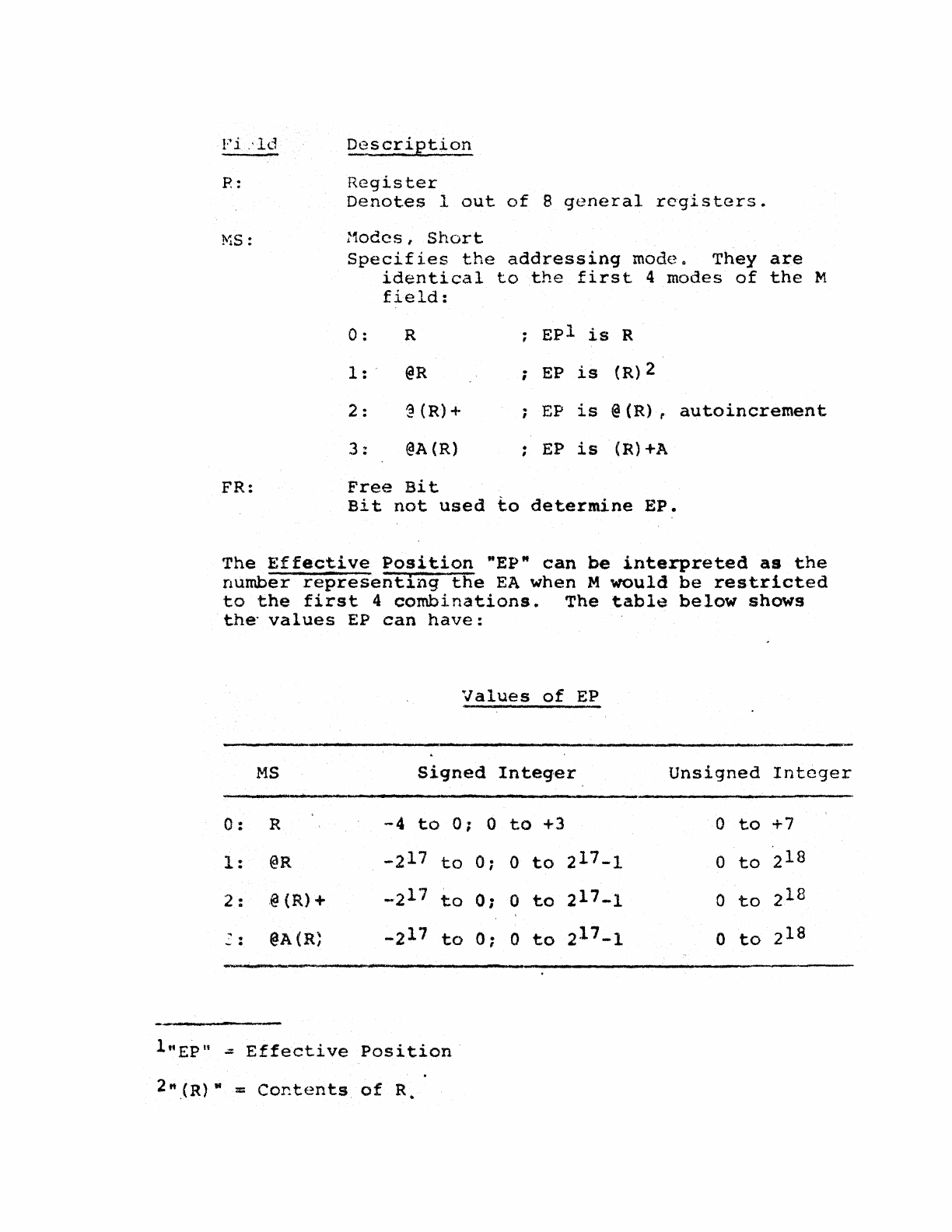
Fi.'ld
P:
FR:
DescriJ(tion
Register
Denotes
lout
of
8
general
rcgistars.
:1odcs I
Short
Specifies
the
addressing
rnodco
They
are
identical
to
the
first
4 modes
of
the
M
field:
o : R
Epl
is
R
1:
.
@R
;
EP
is
(R)2
2 :
~
(R)+
EP
is
@
(R)
f
autoincrement
3:
@A{R)
EP
is
(R)+A
Free
Bit
Bit
not
used
to
determine
EP.
The
Effective
Position
"EP"
can
be
interpreted
as
the
number
representing
the
EA
when M
would
be
restricted
to
the
first
4
combinations.
The
table
below
shows
the"
values
EP
can
have:
Values
of
EP
MS
Signed
Integer
Unsigned
Integer
0:
R
-4
to
0;
0
to
+3
0
to
+7
1:
@R
-2
17
to
0;
0
to
217_1
0
to
2
18
2 :
.@
(R)
+
...
2
17
to
0;
0
to
217_1
0
to
2
18
. .
@A(R~
-2
17
to
0;
0
to
217_1
0
to
2
18
-.
lttEpn
..::
Effective
Position
3.0
('1,Hupatibili·ty_
Introducing
a
different
word
length
will
cause
some
compatibility
problems.
3.1
Peripheral
COffipatibilit:i
A
separate
memorandum
will
be
devoted
to
this
problem.
The
incompatibility
can
be
reduced
by
r.aving
the
same
bus
st~ucture
for
the
PDP-K
as
the
PDP-Il.
This
is
be-
ing
consider~dc
3.2
P~ogram
Compatibility
Two
aspects
have
to
be
considered.
3.2*1
Word
Length
Compatibilit:t
This
can
be
done
,by
hardware
by
having
a
16-
and
an
IS-bit
mode;
by
software;!
through
a
conversion
pr)grarn
simi
lar
to
that
for
converting
PDP-8
to
~DP-9/l5
?rograms
leaving
certain
portions
to
be
recoded
"by
hand"
'e.g.,
shift
and
rotate
instruct-ions).
3.2.2
Instruction
Set
compatibilitl
This
can
be
accomplished
through
microproJramming.
,
Because
of
the
PDP-Res
lS-bit
word
lenqth,
microprogram-
ming
becomes
very
attractive
,because
the
lOP-IO
can
be
emulated.
-(j-
4.
a
Propos~~d
I?DP-K
Instructio,!l
Sc
t
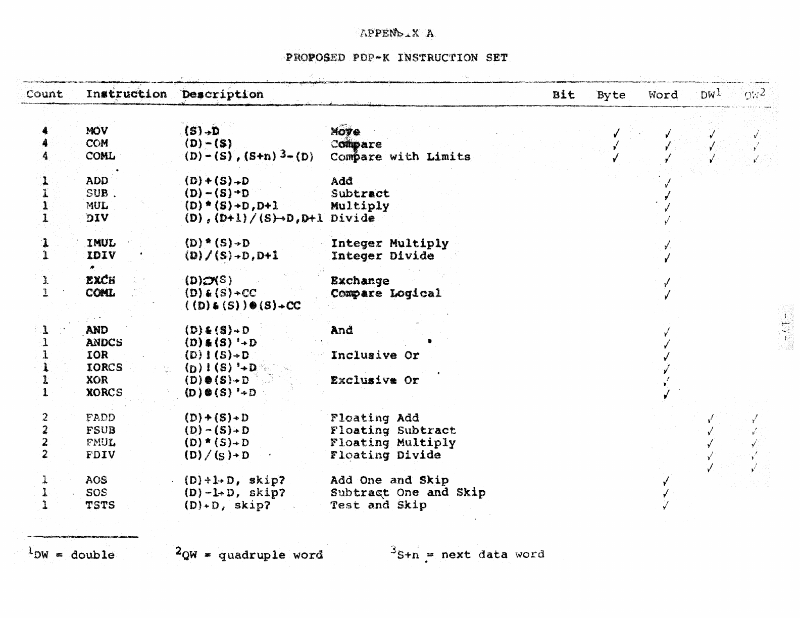
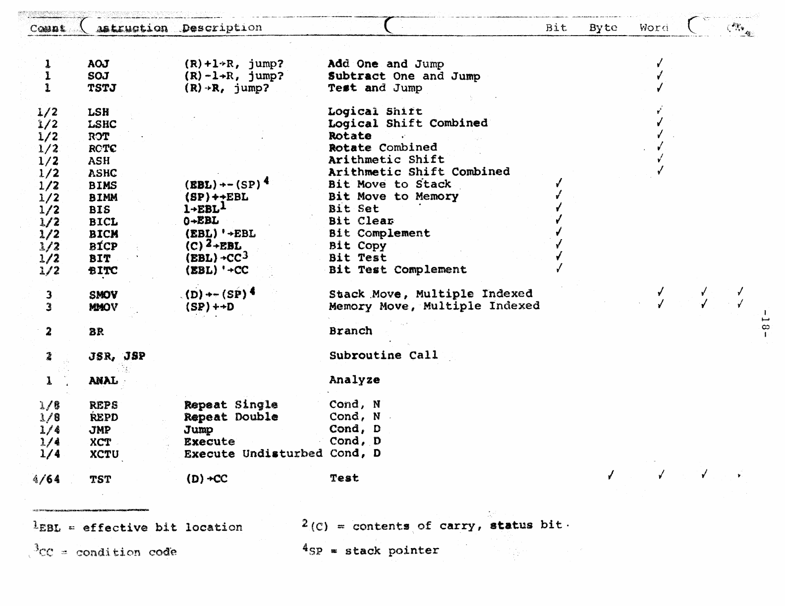
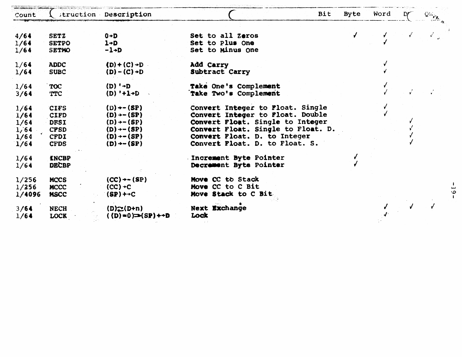
The
proposed
instruction
~et
is
shown
in
Appendix
A.
Only
tte
major
instructions
ar~
shown.
These
are
the
essential
ones
or
thos~
requiring
lots
of
op
code
'space.
It
is
.;\ssur"".cd
that
the
reader
has
some
knowledge
of
the
PDP-II
instruction
set.
The
instructions
operate
on
5
data
types.
4.1
Bit,
"En~
A
bit
is
a
Boolean
quantity
which
is
true
itT"
or
false
'F".
4 • 2
Byte,·
.::1.:
A
byte
is
a
character
..
4.
3
Word,
.
..:!!.:.
A wore
is:
I
.....
2.
3.
A
Boolean
Array
with
18
elements
A
signed
integer
(2's
comple~ent)
A~
unsigned
integer
4.
4
~Jle
Word,
"0"
A
double
word
is
a
single
precision,
floating-point
num.)er.
4.5
Qu<,druple
Word,
"0"
A
'~uadruple
word
"is
a
double-precision,
floating-point
number.
lDenotes
abbreviat~.6n
for
the
particular
data
type.
By
tC$
are
handled
in
a
\vay
simi
lar
t.o
th,(~
PDP
-1
0 ,
as
described
in
Appendix
B. Few
instructions
operd
tf~
on
byte
because
bytes
~re
considered
a
riata
~ormat
for
characters
only.
Most
instructions
operate
on
words
as
the
word
is
con-
sidered
the
data
format
for
program
control
ani
integer
numbers.
It
is
felt
that
higher
level
languages
(FORTRAN, ALGOL,
etc.)
use
integers
T.rtostly
for
subscript-
ing
and
program
control
an~,
therefo:e,
a
singlt.
IS-bi
t
integer
is
considered
sufficient.
The
condition·
code
"ce"
is
handled
in
a
way
as
described
in
Appendix
c.
-
-8-
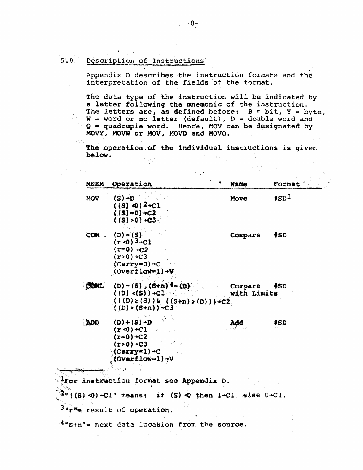
5.0
!?Et.scr!I?tion
of
InstructiQns'
Appendix
D
d~scribes
the
instruction
formats
and
the
interpretation
of
the
fields
'of
the
format.
The
data
ty.pe
of
the
instruction
will
be
indicated
by
a
letter
following.
the
mnemonic
of
the
instruction
..
The
letters
are,
as
defined
before:
B~;
bi
t,
Y
:;:
byte
I
W =
word
or
no
letter
(default)
I 0 =
double
word
and
Q -
quadrupl.e
word.
Henc'e,
MOV
can
be
designated
by
MOVY
I
MOW
or
MaV,
MOVD
and
MOVO
•
.
The
,operation.
of
the
individual
instl'uct.ions
is
qiven
below.
MNEM
Operation
• H·Ule
Format
,"
------
..
-------~------------------
-----------------
MOV
.CQM
.
(8)+0
(
(S),~)2+Cl
(tS)
.0)
'+«:2
({S»O).t.c3,
(D)
~'(S)
.'
(r
<0)
3-+<:1
(r=O)
-+<:2
(r>O)+C3
~carry-O)
"C
(Overflow-l)·Y
Move
ISOl
-Compare
.so
(D)
-
(S)
,
(8+1.)4_(1»'
Com.pare
'SD
«D)
«&»
+Cl..
,. . wi.th.
Limits
«(D)~(S»'
«S+n»)(D»)~2
«O)-(S+n»..c3
(D)+(S)+D
(r
<o)-+el
(r==O)-+C2
(r>O)+C3·
,:(
Carr:y-l
)
-+c
~
(OVerfl()W=ll)
~V
'SD
"~FO~
in.t~ction
format
see
Appendix
0 *
:,t:.
'.
~,:~.=:".(
(5)
<Ol-+cl"
means:'
if
(5)
<fo()
~en
l+Cl
j
else
O-+Cl,.
, 3
..
!-,_.
~'esult
of
operation.
4·S+
n
-=
next
data
loca~ion
from
the
source,
....
9-
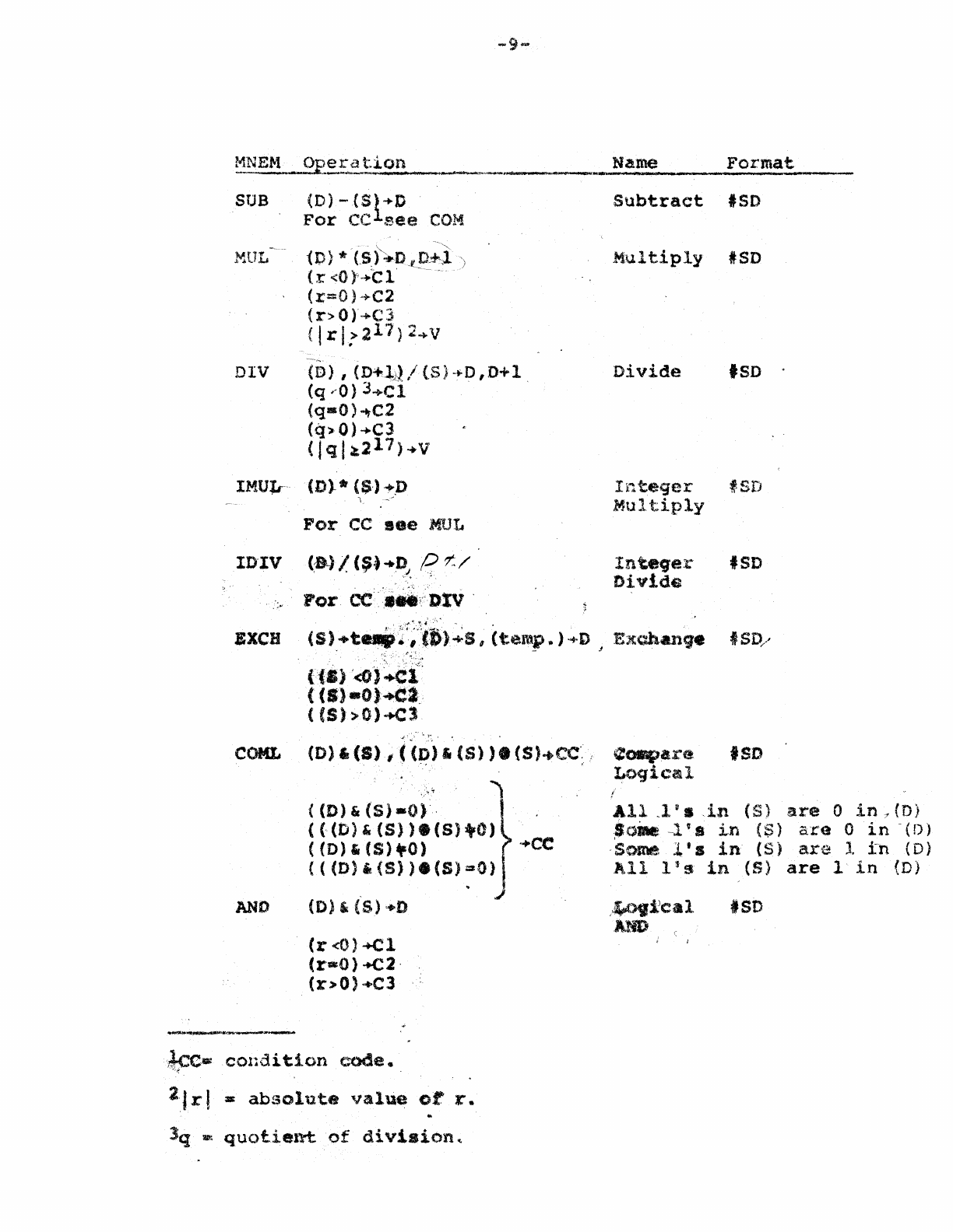
~NEM
_J?1?=.E.~
......
·.~_o_n
__
.
__
..
__
"
____
e_
..
__
...
IJ_!1_me
____
F_O_r_.
m_a_t.
____
_
SUB
MUL~""'"
DIV
(D)
-
C.sl
.....
D
For
CC
see
COM
10)
*-csj'~D.t:o-~l
(r
<Or~-ct'
(:r=O)
'~C2
(r>O)+C3
( I r
i?
211)
:2
..
V
(D)
,
(D+~j)
/
(S)
-~
D ,
D+
1
(q
--0)
3-+Cl
(q-O)...,C2
(q>
0)
-+C3
(Jql~217)
.. v
IMUlr
(D). *
($.)
-
•.
D
I.
~>
For
CC
flee
MDl",
ID'IV
(B.)
I
(~
...
~),
q
tf:/
"_"
Por
CC·:
....
:,;·DIV
.
Subtract
'SD
Multiply
ISD
Divide
'SD
.
Integer
f.SD
Multiply
Integ-er
Divide
ISD
'".
.,
J
.,:-,.,."<,~.
'.,
''''.
".
•
BXCH
(S)+t"':';]J»~S,
(temp.)·,.i)
Exchange
ISD/
.
.'
,~'.':
.~;.!.
~
~
.
[fa)
'<O)~:l::
(
(I)
-0
).ea.
«(S»O)+el
" .
COML
(D)'
(8)
,«p>'
(S)
).
(S)~cc>
¢ospare
'SD
Loqical
AND
«D)
&
(5)-0)
.
«((D)&(S».(S)+O)
(
(D)"
(S)
.0)
'+CC
«(D)'(S».(S)~O)
(D)
,
{S)
·
...
D
(r<O)+Cl
(rcO)
+C2·
(7:>0)
+C3
2Jrl
at
absolute
value
or:
r.
lq
lIlI\
quotient.
of
divi.aion~
All
,1
11
••
in
(S)
are
0
in
7
(D)
SON
-l
's
in
( S )
are
0
in
-( D )
Some
l's
in
(S)
are
1.
:in
(D)
All
lis
in
(S)
are
1
in
(D)
.'~>9i:eal
AND
'SD
10-
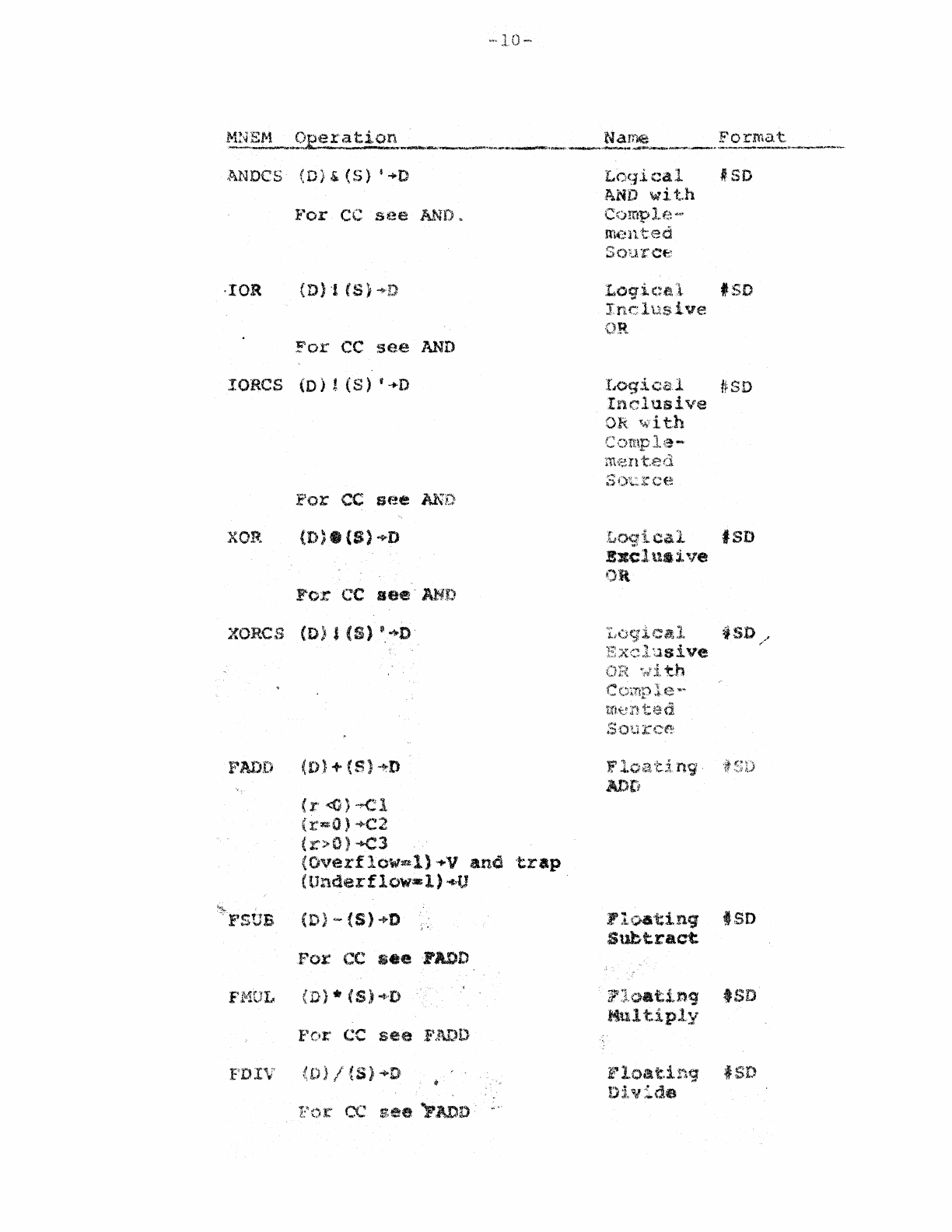
ANDes
(0)&(5)
$.0
l'''or
CC s
((~e
AND
~
·IOR
For
CC
see
AND
lORes
(D)!
(S)
v
-.0
XOP.
{D)8(S)+D
For
CC
see'AND
XORCS
(D),
(5)
'.+D
FADD
(I)} +
(5)
-~D
(x-
<0)
~'::l
(r-O)
-+C2
(r>O)
~~3
(Overflow-i)
,..,..v
ana
'trap
(Underflow-l)
..
U
~~40.
F'SUB
(D)
<-
(S)"D
.For
CC
.ee
FADD
F~'10L
( D ) ., (S»
-t;·,D
POI"
CC
see
FJ\DD
F'D!V
)/{S)~D
CC
..
'
see
«PAnD'
LOC,li
cal
I
SO
~.ND
wit.h
Comple-
m.:-:nted
Source
Logical
.SO
Inclusive
OR
LO'g i c
Z/.l#
S D
Inclusive
OR
with
cal
'SD
Bxcl
ua
l. ·"e
OR
Ex<:,l'Jsive
th
F
n9'~
AOti
Floating'
ISD
Subtract
?l·oatlng
tso
Mult.iply
~"1.oat.in9
t
Dl~lide
-1:-
ftU~Elw1
Operation
Name
:F'ol~mat
-.---..-.
....
~~-
__
.-..-~~""_
.....
_,
__
-.-.t~~
___
.''''''''''JW~;~~
__
Q~1f.9
_______
~
__
''-~~,,
__
~._
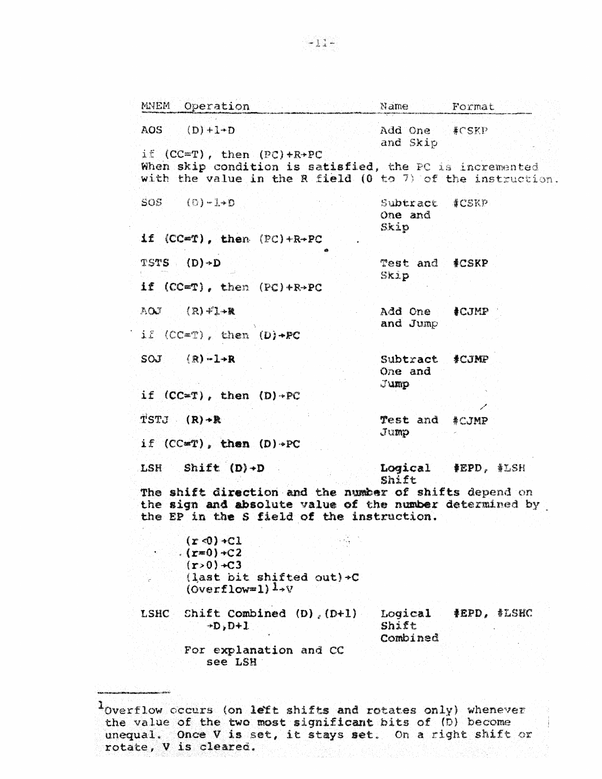
AOS
(D)
+l~'D
Add
One
#CSKI'
and
Skip
1.
f
(CC=T),
then
(PC)
+R·~PC
When
skip
condition
is
satisfi.ed#
the
PC
wi
th
th(~
va.lue
in
the
R
field
(0
t;.., 7
if
(CC=T),
then-
(PC)
+R
..
PC
if
(CC=T),
then
(PC)+R+PC
~
i.£
SOJ
if
(CC:.:T),
then
(D)
-+PC
1f
STJ
(R)+J\
if
(CC-T)~
then
(D)·.PC
Slmtract
tCSl(P
One
and
Skip
Test
and
fCSKP
Skip
Add
One
'C,JblP
and
Jump
subtract
fCJMP
One
and
Jump
Test
and
tCJMP
(;Jutnp
.
LSH
Shift
. (D)
+0
Loqical
fEPD f
iLSH
Shift
The
shif't
direction·
and
the
nu.raber
of
shifts
depend
on
the
siqn
and
absolute
value
of
the
number
determined
by
~
the
EP
in
the
S
field
of
the
instruction.
(r
<0)
· ..
·Cl
.
(r-O)
+C2
(r.>O)
-+C3
(last
bit
shifted
out)+C
(OvE.~rflow=l)
l .. v
LSHC
Shif
t
Combined
(O)
i!
(D-+
1)
·,.D
,D+1
For
explanation
and
CC
see
LSH'
Logical
fEPD, 'LSHC
Shift
Combined.
lOverflow
c,'ccurs
(on
le"ft
shifts
and
rotat,es
onl~{)
wheneveI;':
the
value
of
the
two
most
significant
bit.s
of
(D)
become
unequal..
Once
V
is
set,
it
stays
set.~
On a
rlqh.t
shift
()l'
rotate,
V
is
cleared
..
M}iEt"'l.
Operatior:..
Nan1€~
F;'o:emrtt
-~"'~.>eto_"''''''~~''''-~''''Ar~~_~~_'l'''''·',)Y''>l!I...,.,..,_-.._.~_~
...
.w;..'~·~'_'':'l.>"""~'_"_'''''W'''''''''~'_·'''~''''·-''_.'.<II\_''''':-_'
__
~'>#_'''''_':l;'''_,
__
.
__
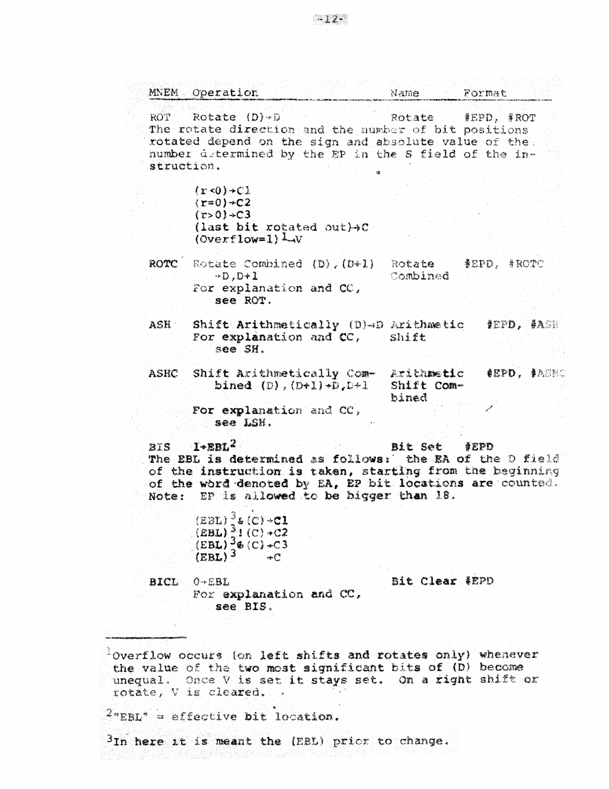
Rotate
{D)~D
Rotate
fEPO,
tROT
The
rotate
direction
r
bit
ons
'rotated
depend
on
the
sign
and
absolute
the.
number
{l,;:termined
by
t:he
E;P
t.h.t; S
str'Uction
..
(r<O)-+Cl
(r=O)+C2
(r>O)-+C3
(last
bit
rotated
out)~C
(Overflow=l)l-1V
ROTC
Hota.te
Camhi
(n~+"l)
t:e
ASHe
-~
D
,D+
1
Combint:~d
FCir
explanation
and
CC;f
see
Rt)T
..
Shift
Arithmetically
(,0)'''4D
For
explanatit)n
and
CC
I'
see
SH
..
Shift
A.t'itJunetici"lly
C<)m-'
bined
(D),
(r,+
1)
-+t~
i
D+l
J."or
explana.t.ion
a.n.d.
CC
i'
see
LSH.
tnllle;
t.!
c
Shi.ft
IA.:::
i
t.tlmE:
ti
C'
Shift
Com
..
.,
bine.d
BIS
1+EBL2.
Bit
Set
tEPD
The
EBL
is
determined
lUS
follt)w8;'
t.he
EA
of
the
instructic)ft.
is
t.aken,
starti.'!l9
from
the
of
the
wbrd
-denoted
by' EA,
EP
bit.
locations
Note:
EP
allowed
,to
be
b,:tqqer
thAn
18"
SIeL
~,
.
)
..:~,
)
~l>Cl
(BaL)')!
(C)
....
C2
(EBL)
3f;
(C)..c3
"
(EBL)
J
~C
j{or
explarLation
andCC"
see
SIS<\>
Bit
Clear
tEPD
Overflow
occ\..u:~
t
..
he
value
of
left
shifts
and
rotates
only)
whenever
two
most
significant
bi
ts
of
(D) hecolr.e
llnequal
is
set
it
stays
set.
On
it
.tight
oX:'
.
t'otat:e
t
'l
ared
..
'"
bi
t.
loc<ttion,
#I
meant
the
1
--
l ,.,-'
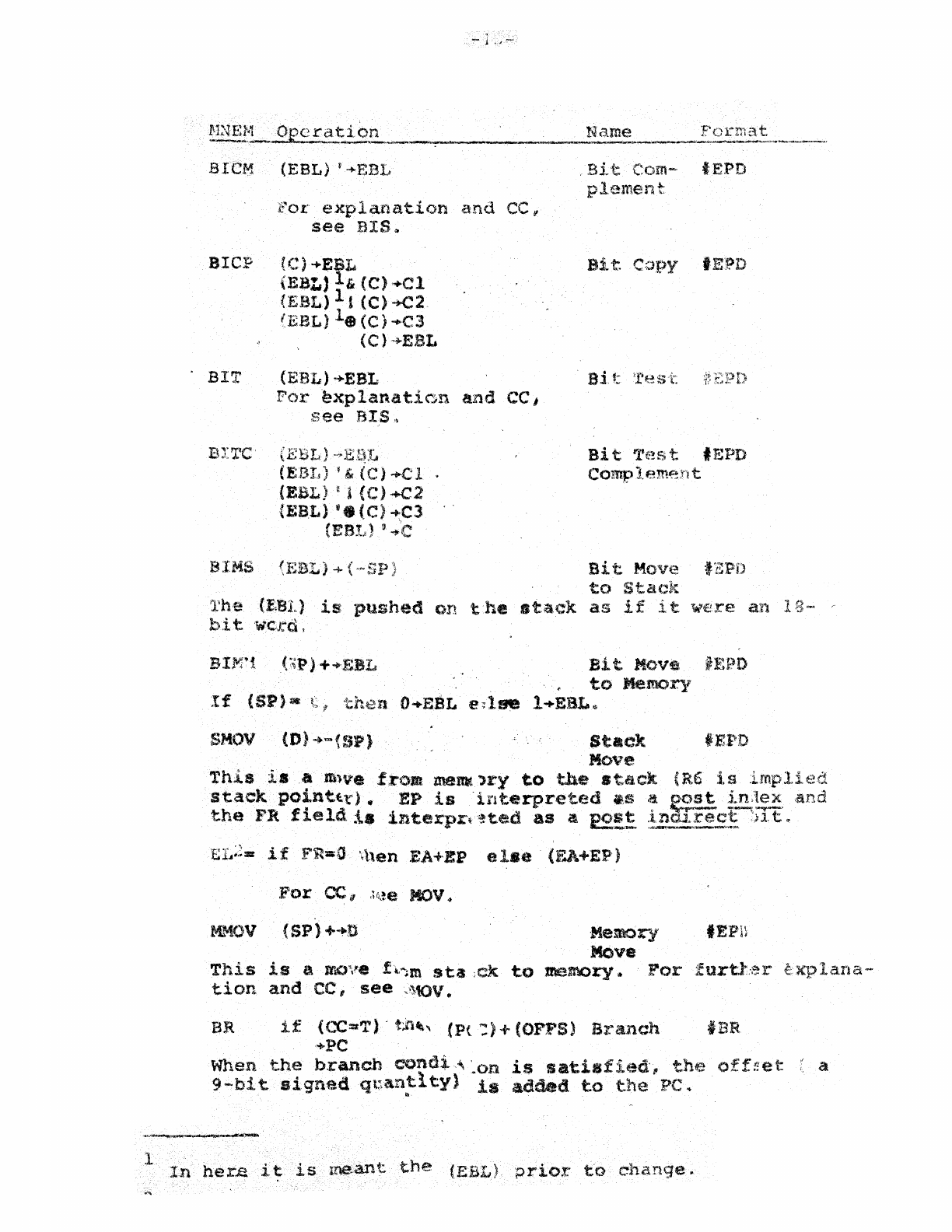
aICH (EBL)
'.EBL
c"or
expla:nation
and
CC
~
see
BIS~
arcp
{C)
....
EBL
(EBL)
1&
(C).Cl
CE.BL)
11
(C)-t-C2
(EeL)
1.
(C)
..,.C3
.
BIT
(C)..;..EBL
(EI:lI.)
....
EBL
For
~xplan.aticn
lUld
CC
I
see
SIS"
BITe'
(EElI)
(EBIt)
~,
)
-+C
1 .
(EBL)
~1(C)+C2
(EB,L)
'.
(C)
~C3
(ESl;)
'
...
c
,Bit
COIn-
tEPD
p1.ement:
B1 t.
Copy
tE:PD
Bi
t T&:!st tF';PD
compleme:nt
BIMS
<EBL)+{-SP
Bit
Move 'EPD
to
Sta(~l{
l'h,e (f,fn.,)
is
pushed
on
t.he
stack
as
if
it
were
an
18--
c-
bi
tWCJ:d,
BIJVt1
(:,P)
+
..
F;SL
Bi
t
Move
iEPD
.
to
Memory
If
(SP)·
t,
then
O+EBL
e~lse
l
....
EBL~
SMOV
(D)+-{SP)
Stack
tEPD
Move
This
isa
ft'nve
from
memt
,ry
to
the
stack
(R6 i.a
impli
staekpo~ntt,l:)
.,
EP
is
'interpreted
.,S
~
~
t.n:!;.~,and
the
FR
fl.eld
:ls
interpr~·~ted
as
a 2£.!t
::!E....'!:~!';;.~!
.)l,t"-
El~~'~-
if
FRa;,a
\hen
EA+EP e
18e
(EA+EP)
MMOV
(Sp)
+
....
n
Memory
tEPH
Move
This
is
a
JrD;"efl,"~m
sta
;ck
to
memory,. .
For
furt.t:er
tion
and
CC,
see
,\~,tOv
..
BR
if
(CC=T)-
t;iu~.,
(Pt::)
+ COFPS)
Branch
IBR
+PC
lana~·
When
the
b.ranch
cond:.l"
~on
is
satisfied',
the
off!:et
;~
a
9-bi
t
signed
qt~,antl.ty)
is
added
to
t.he
PC
..
..
In
her..e
it
is
,meant
the
(EBL)
prior
t'o
change
..
NNEf.1
Operation
"
Name
_,,_-
_~
___
".,.,_.
___
...
_"_
........
,
....
~""""""'*.,..
__
....
_~~_.
____
........
,
.....
h_,
Format
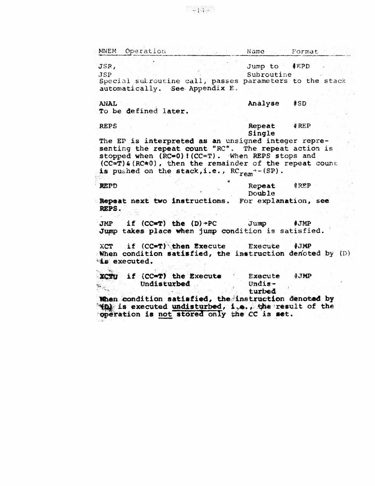
JSR,
Jump
to
tBPD
JSP
Subroutine
Specia.l
suLroutine
call,
passes
parameters
to
the
stack
automatically.
~ee·
Appendix
E.
ANAL
To
be
defined
later.
Analyse
#SD
REPS
Repeat
:#
REP
Sinqle
The
EP
is
interpreted
as
an
unsigned
integer
repre-
senting
the
repeat.
count
·'Re"..
The
repeat
action
is
stopped
when
(Re-O)!
(CC=T)..
'When REPS
stops
and
(CC=T)'
(RC~O),
then
the
remaind.er
of
the
repeat
c:ount:
is
pushed
on
the
st,ack,
i
..
e
..
I
RCre-"m
-1>
.....
(8P)
..
'
:
BPD
Repeat
tREP
Dcnlble
,
Repeat
next
two
instructiOlu;.
f~()r
explanation,
see
UPS.
'
JMP
if
(Cc-T)
the
(D)
"PC
Jump
'JMP
'J~
takes
place
when
jump
condition
,is
satisfied
..
~
XCT
if
(CC-Tf,<,then
Execute
Execut.e
fJMP
:When
condition
satisfied,
the
instruction
denoted
by (
~~!:ta·.
executed.
"'.'.'
-''\!''\'.,
xc:ru.
if
(CC~')
the
Execute
Execute
JJMP
Undisturbed
'
Undis-
,
turbe4,
.
·1Iben:condi
tfon
aati.fied,
the;iinst~uctt.on
denoted
by
1~~
is
executed
undisturbed,
l~.~i·"',~tre.ult
of
the
"Qpe:ration
i8
not
st.ore3
only
~.,
,CC'
is
aet.
-
-15-
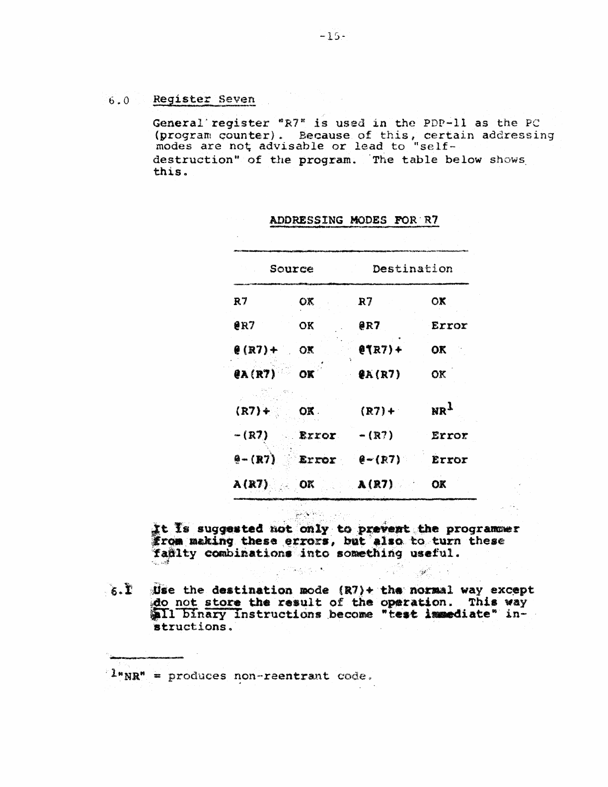
6"
0
Registe£._~eV~!!
General'register
"R7"
is
used
in
the
PDP-li
as
the
PC
(program
Gounter)*
Because
of
this,
certain
addressing
modes
are
no~
advisable
or
lead
to
"self-
destruction"
of
the
program.
'The
table
below
shows,
this.
ADDRESSING
MODES
FOR'
R7
WI,.,
r
............
.... .
...........
------------~-.---,.
Source
Destination
----~~~-~-~.-.---------------------
R7 OK
@R7
OK
,eR7)+
OK
fA
(It?)'
OK
(R7)+
OK.
--
(It"
Error
@-
(lti)
.Error
At.')
" -Oft
-J a
.....
..
r"<.''-·
Of'.
~
R1
@R7
,,:a7) +
'A(R7)
eR7)+
-(R1)
@-'(R7)
A (1t7)
J lilt ;
OK
Error
OK
OK
Error
Error
OJ(
~tt.
suq
...
tedllOt"cmlY" to.p:.;."eJrt
~,fJle
proqrattmter
!J
r
9l'
,
-&king
these
,~~ror.,
ba~,.l.oto,turn
these
'~~lty
com.biJl-atione
into
.ome~in9
useful.
'.'';'. :...ff
;.Use
the
destination
mode
.("')+
tn.'
nOhlal
way
exc~pt
i40
not
store
the
result
of
the
operation.
This
way
~l-ornary
instructions
.become
-te.t
iaaediate"
in-
'structions
~
6
..
2
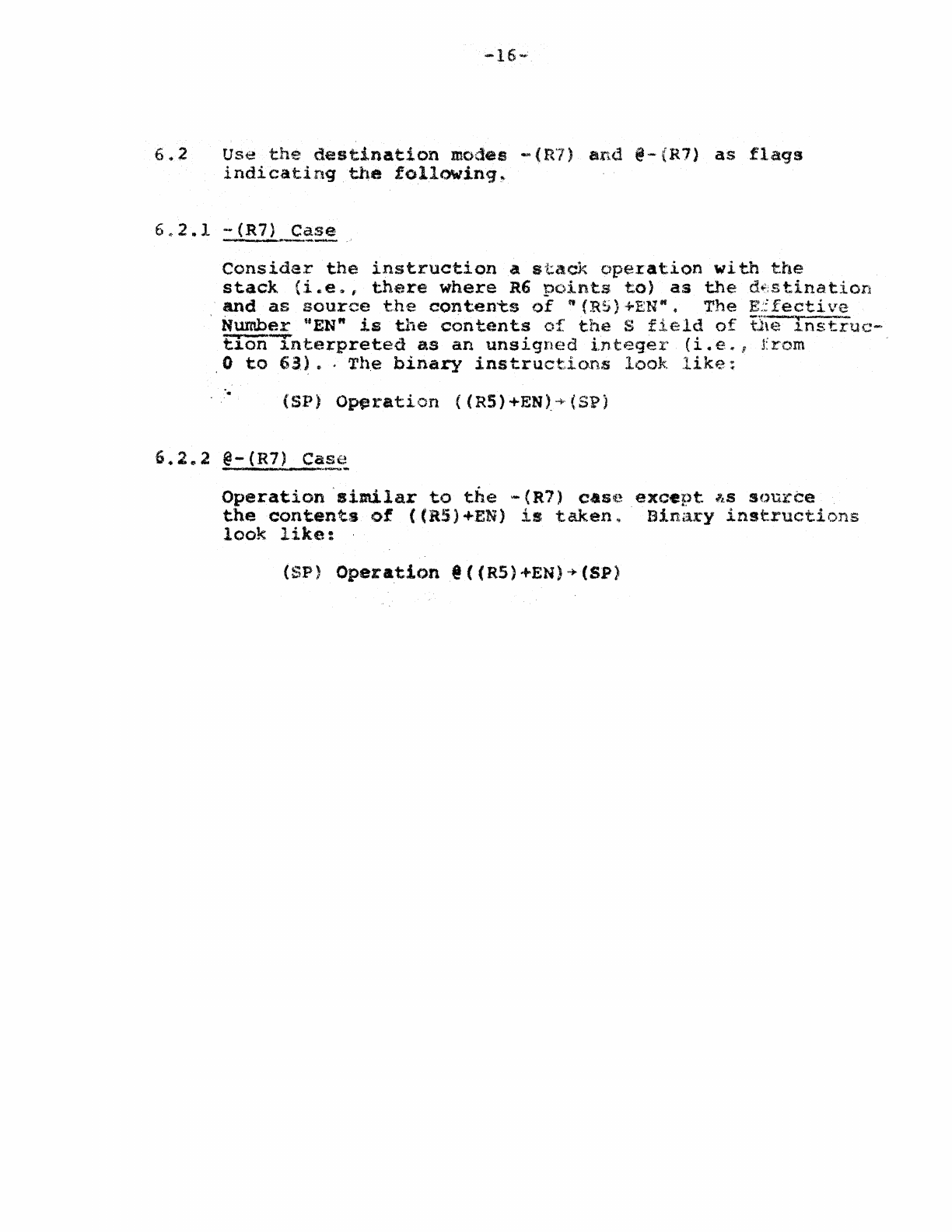
Use
the
dest.inat.ion
modes
-(R7)
and
@-(R7)
as
flags
indicating
the
follO\riin9~
Consider
the
instruction
a
st.ack
operation
with
the
stack
(i
..
e,. f
there
where
R6
o(;)in'ts
to)
as
the
d~;stination
and
as
source
the
contents
of
"(R5)
+EN"
•
The
E:.:
fecti
ve
,
Number
"EN"
is
the
contents
of
the
S
field
of
tI\€
Instruc
....
Elan
-rnterpreted
as
an
unsigned
integex
(i.
e,,;
fr'om
o
to
63.)
...
The
binary
instructions
look
like:
...
(SP)
Operation
«R5)+EN).-+
(SP)
6.2.2
@-(R?)
C~.~~
Operation
'similar
to
the
-(R7)
cas(~
excent
ILS
source
the
contents
of
«(RS)
+EN)
is
taken..
Bin~iry
instructions
look
like:
(SP)
Operation@«R5}+EN)-+(SP)
lOW
c
double
20W
..
quadruple
word
':ot
}
-S+n
=
next
data
word
~'c~~-·_.ct
_._.~c;.
___
...
____
•
___
•.
___
._____
.
.--
--
..
---
....
--.-------
...
---
c
--
-
..
--
.-.
-
.-----.-
---.--.-.>
...
--...-.
-----~--.~-
-~
....
---.-
c~·-
,SG\UD~~.a.atJ;>uction
J;tescription
Bit
Byte
\'Jord
,irl~
\
....
.
~
__
~'L
1
AOJ
(R)
+l-;.R,
jump?
Add One
and
Jump
.;
1
SOJ
(R)-l+R,
jump?
Subtract
One
and
Jump
.:
1 TSTJ
(R)-..R,
jump?
Te.t
and
Jump
"
1/2
LSD
Logical
Shitt
,:
1/2
LSHC
Logical
Shift
Combined "
1/2
ROT
Rotate
.
.;
1/2
RCT£
Rotate
Combined
I
1/2
ASH
Arithmetic
Shift
I
...
1/2
ASHe
Arithmetic
Shift
Combined
I
1/2
BIMS
(BBL)
....
-(SP)
4
Bit
Move
to
S'tack
I
1/2
BIMM
(SP)++EBL
Bit
Move
to
Memory I
'I
1/2
BIS 1
...
£81,1
B.lt
Set
"
1/2
BIeL
O+IBL
Bit
Cleat;
I
1/2
BIeN (EBL)
'+EBL
Bit
Complement ,
1/2
step
(C)2-+EBL
Bit
Copy "
1/2
BIT
(BBL)
+ce
l
Bit
Test
.;
1/2
tlI'l'C
(BBL)
'-+CC
Bit
Test
Complement
I
3
SHOY
.
(0)
+-
(SP)
4
Stack.Move,
Multiple
Indexed
.;
.;
./
3
MMOV
(SP)++D
Memory
Move,
.
Multiple
Indexed
.; .;
,I ,
~
2
Bit
Branch
OJ
I
Z
JSR,
JSP
Subroutine
Call
1 ANAL '
Analyze
1/8
REPS
Repeat
Single
Cond,
N
l/8
REPD
Repeat
Double Cond, N
1/4
JMP
Jump Cond, D
1/4
XCT
Execute
Cond, D
1/4
XCTU
Execute
Undiaturbed
Cond,
D
4/64
TST
(D)+CC
Teat
.;
.;
.;
.,""'!>:;1I!'C'<f~~
.""
lEBL
~
effective
bit
location
2(C)
:::::;'
content.s
of
carry,
status
bit·
,
'l
,~CC
-~.
condition
code
4sp
=
stack
pointer
/;';;'~:~:"~.'::':~";C;:;:L>;:.;._...;;.~._
."
........
__
._.
_____
-----_.
'--_'
._--_
.
.-
-:
Count
;truction
.
Description
C
Bit
Byte
Word
~C
Q\.'
-
-"
-'
.,
....
,.,
.t!!k.!.t
..•....
,,,.
.~.
$",
'---'
---.--
..
...
I:~~
..
_,
~
4/64
SETZ
O+D
Set
to
all
Zeros
I I l I
t'
1/64
SETPO l
....
D
Set
to
plus
One
I
1/64
SETMO
-l+D
set
to
Minus one
1/64
ADDe
(D)+(C)
....
D Add
Carry
.I
1/64
suac
(D)-(C)+D
Subtract
Carry
i
1/64
roc
(D)
t .... D Take
One's
Complement
.;
3/64
'rrc
(D)
'+l+D "Take
Two'.
Complement I v .
1/64
CIFS
(0)+-(8P)
convert
InteCjer
to
Float.
Single
.;
1/64
CIFD
(D)+-(SP)
Convert
Intec}er
to
Ploat.
Double
/
1/64
.
Df:SI
(D)+~(SP)
Convert
Float.
Single
to
Integer
.;
1/64
CPSD
(D)+-(SP)
Convert
Float.
Sin91e
to
Float.
D. I
t
1/64
..
CFOI
(D)+-(SP)
Convert
Float.
D.
to
Integer
I
'1/64
C!o'DS
(D)"-(SP)
Convert
Float.
D •
to
Float.
s.
I
. .
1/64
!NCBP
.Inore.nt
Byte
Pointer
I
1/64
DEtSP
Dec:r_nt
Byte
Pointer
I
1/256
MCCS
(CC)+-(SP)
Move
CC
tb
Stack
1/256
MCCC
(ee)
+C
Move
CC
to
C
Bit
I
~
1/4096
MSCC
.
(S,)+
...
C
Move
Stack
to
C
Bit·
,.!)
I
(D)~(D+n)
"'.
. I I
3/64
NEeH
Next
••
change
1/64
LOCK
(
(D)
-0
)::a.( 81')
++D
Lock
J~
APPENDIX
B
PDP-K
Byte
Handlin~
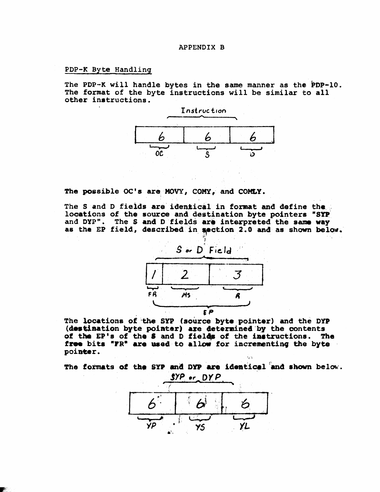
The PDP-K
will
handle
bytes
in
the
same
manner
as
the
PDP-lO.
The
format
of
the
byte
instructions
will
be
similar
to
all
other
instructions.
I
nst
roc
t.on
..--~
[ b b 6 ]
."---r-J .I..-....,-J J
•
OC.
S "
'rhe
possible
oct.
areiMOVY,
COMY,'
and
COMLY.
The
Sand
locations
a.nd DYP".
as
the
EP
D
fieids
are'identical
in
format
and
define
the.;,
of
the
source
and.
destination
byte
pointers
"sn
The
Sand
Dfields
art
interpreted
the
same way
field,
described
in.¥ction
2.0
and
a8
shown
belOfl.·
if,'
~.
,.
1>1
.....,..,
FA
,
s
",
2
•
IfS
~
0
..a
........
~
F,e;Id
; .
.f
[ \ 3
t.
",
II
~~
________
~*~
______ J
.
JP
I
The
locations
of
"the
SYP
(source
byte
pointer)
and
the
DD
(d
..
t.laation
byte
pointer)
.~e
4eter.mine4)~
tbecontents
of
the
EP'
s
of
th.
•
and
D
fiel~
of
the
i
••
tructions.
The
fzwe
bi
t.s
"Fa-
are
..
ad·
to
alloW
for
iacrementinq
the
byte
poinur.
'the
formats
of
til.
sn
ana
ow'
.....
id
••
ti~l
fMl4
shown
bel~'.
jYP.,
Oyp
.,.
~.....
'
..
r
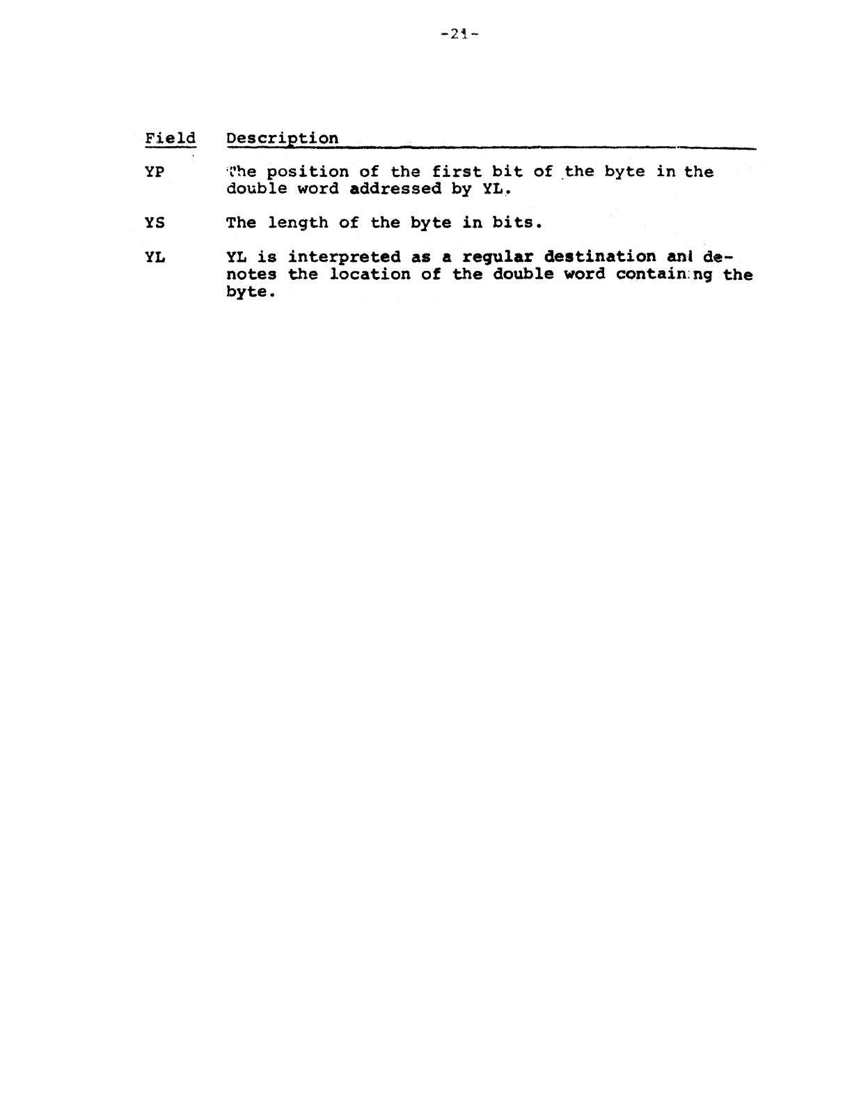
Field
yp
YS
YL
-2~.-
Description
;t'he
position
of
the
first
bit
of
.the
byte
in
the
double
word
addressed
by
YL.
The
length
of
the
byte
in
bits.
YL
is
interpreted
as
a
reqular
destination
ani
de-
notes
the
location
of
the
double
word
contain:ng
the
byte.
-22-
APPENDIX
C
Condition
Codes
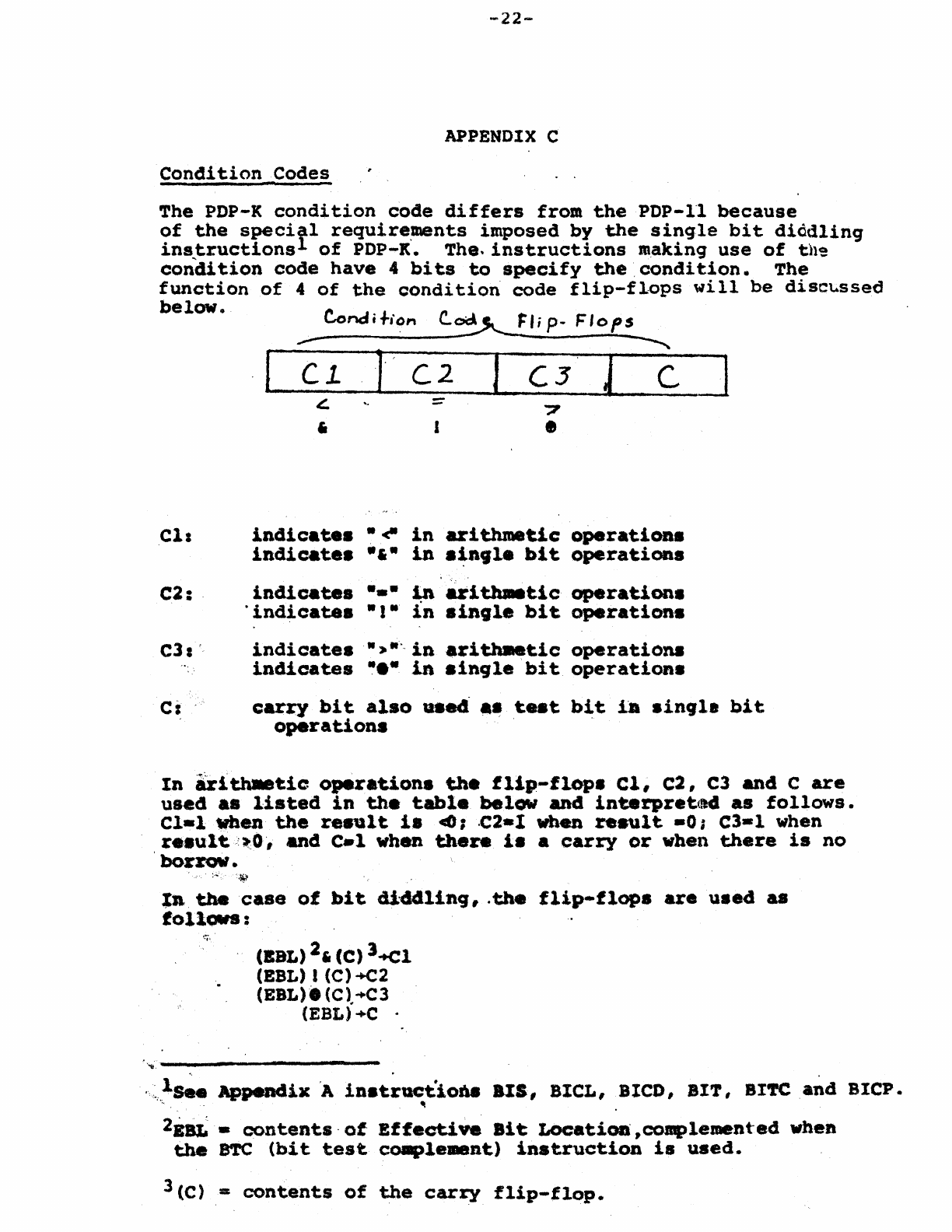
The
PDP-K
condition
code
differs
from
the
PDP-ll
because
of
the
specitl
require~nts
imposed
by
the
single
bit
diddling
ins,tructions
of
POP-It.
The.
instructions
making
use
of
th~
condition
code
have
4
bits
to
specify
the
,condition.
The
function
of
4
of
the
condition
code
flip-flops
will
be
disct.ssed
below.
Condi·h'on
c.~
FI;
p-
Flops
ell
C2:
.
,.-
~
I
(1
1·
C2
I
C3
J C ]
£
,
indicate.
indicate.
indicates
"indicates
"til!"
-6-
-.-
"I"
J ?
•
in
arithmetic:
in
.~ft,le
bit
operations
operatioas
~
arl~tlc
operations
in
sinlle
bit
operations
e31'
indicates
..
,.
....
in
.r1~tic
operations
indicates
•••
in
8ingle
bit
operation.
Ci
.
carq
bit
also
"sed
.~
.t.eat
bit
iA
single
bit
operation.
In
hlthMt:ic
operations
the
flip-flops
el,
e2,
C3
and
C
are
used. a8
listed
in
the
table
below
and
interpretttd
as
follows.
Cl-1
'When
the
renlt
i.
4();
.C2-1 when
result
-0#
C3-1
when
r
••
ult.,i1!':O,
and
C.l
when
there
i.
a
carry
or
when
there
is
no
borrow.
Xatbeca.e
of
bit
diddling,
.the
flip-flops
are
used
&8
follOWS:
!:;.'
(BBL)
2,
(C)
J+Cl
(EBL) I (C)
+c2
(EBL).(C)..-C3
(EBL)"-C .
. ,
'''Ii
---------
.
ls.e
Appendix
'A
iDatructio68
alS,
BIeL,
BleD,
BIT,
BltfC
and
BICP.
't
2EaL
-
cont.ents·
of
EffectiVe
Bit
Locatioa
,complemente.c! wheD
the
8TC
(bit
test
ca.plement)
instruction
ia
used.
3(C)
,=
contents
of
the
carry
flip-flop.
-23-
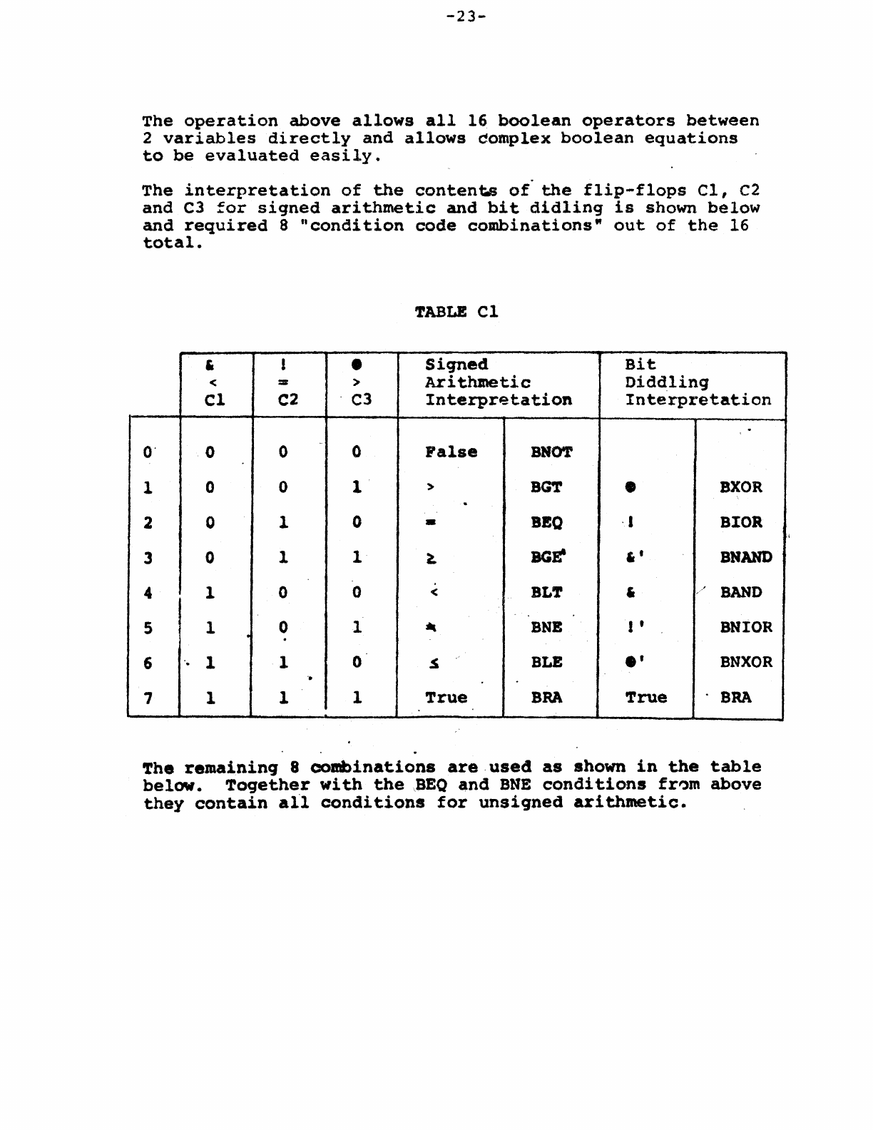
The
operation
above
allows
all
16
boolean
operators
between
2
variables
directly
and
allows
domplex
boolean
equations
to
be
evaluated
easily.
The
interpretation
of
the
contents
of"
the
flip-flops
el,
c2
and
C3
for
signed
arithmetic
and
bit
didlinq
is
shown
below
and
required
8
"condition
code
combinations"
out
of
the
16
total.
TABLE
Cl
, 1 •
Siqned
Bit
< = >
Arithmetic
Diddling
CI
C2
C3
Interpretation
Interpretation
.
O·
0 0 0
PaIse
BHOT
1 0 0 1 > BG'l' •
BXOR
.
2 0 1 0 •
BEO
.,
BIOR
3 0 1 1
~
BGE'
"
SHAND
4 1 0 0 <
BLT
, BAND
5 1 0 1 -
BNB
I •
BHIOR
.
6 . 1 I 0
.s
BLE
.'
BNXOR
'.
7 1 1 1
True
BRA
True
BRA
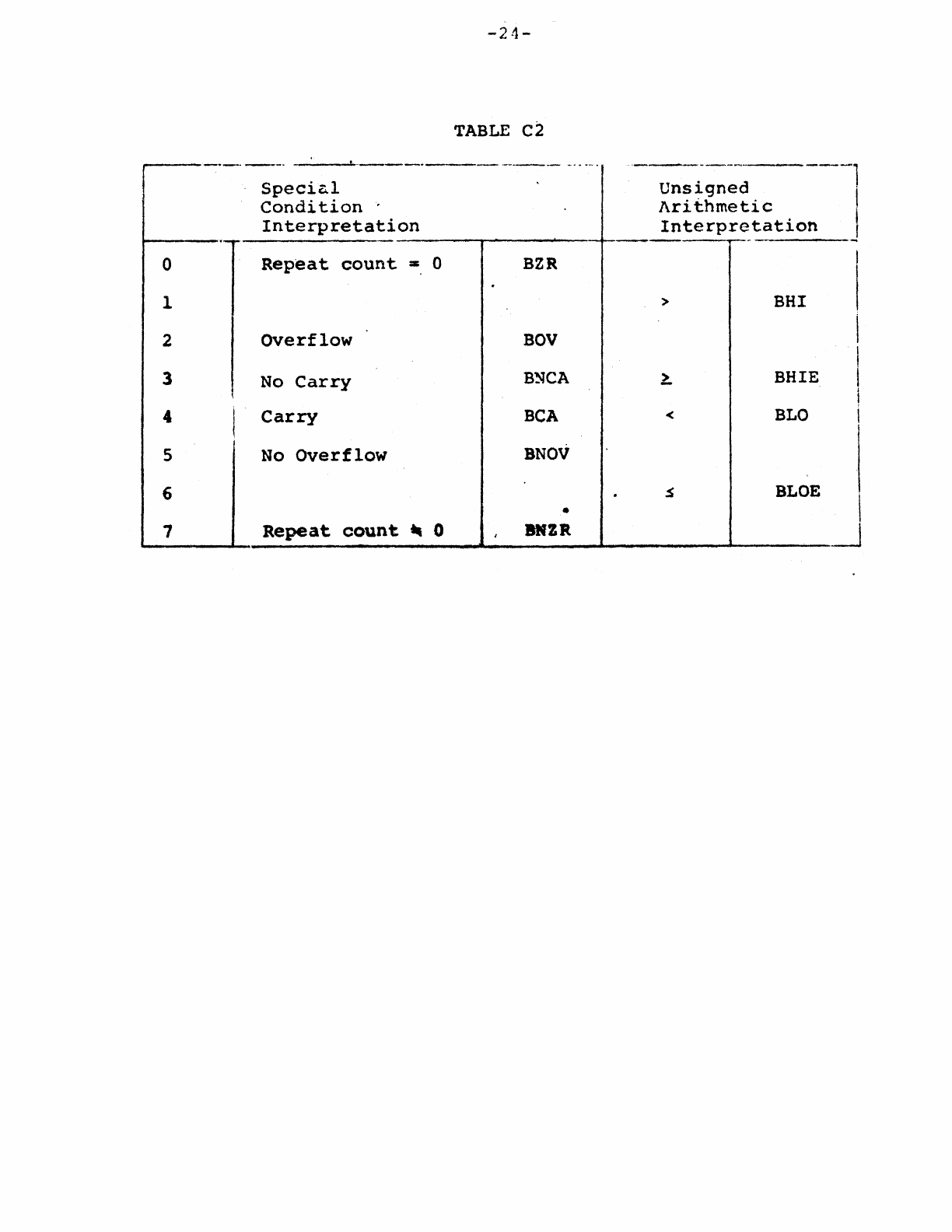
The
remaining
8
combinations
are
used
as
shown
in
the
table
below.
Toqether
with
the
\BEO
and
BHE
conditions
fr~m
above
they
contain
all
conditions
for
unsigned
arithmetic.
;
-24-
TABLE
C2
..
--.---
--
---~-
-.~~
..
-.
._-----_
...
_
.......
-
Speciz..l
Unsigned
Condition
Arithmetic
Interpretation
Interpretation
r--'-
1
_J
0
Repeat
count
:::I:
0
BZR
1 >
BHI
2
OVerflow
BOV
3
No
Carry
BSCA
~
BHIE
4 I
Carry
BCA
<
BLO
5
No
Overflow
BNOV
6 .
~
BLOE
•
1
Repeat
count
~
0 I BNZR J
-25-
APPENDIX
D
Instruction
Formats
..
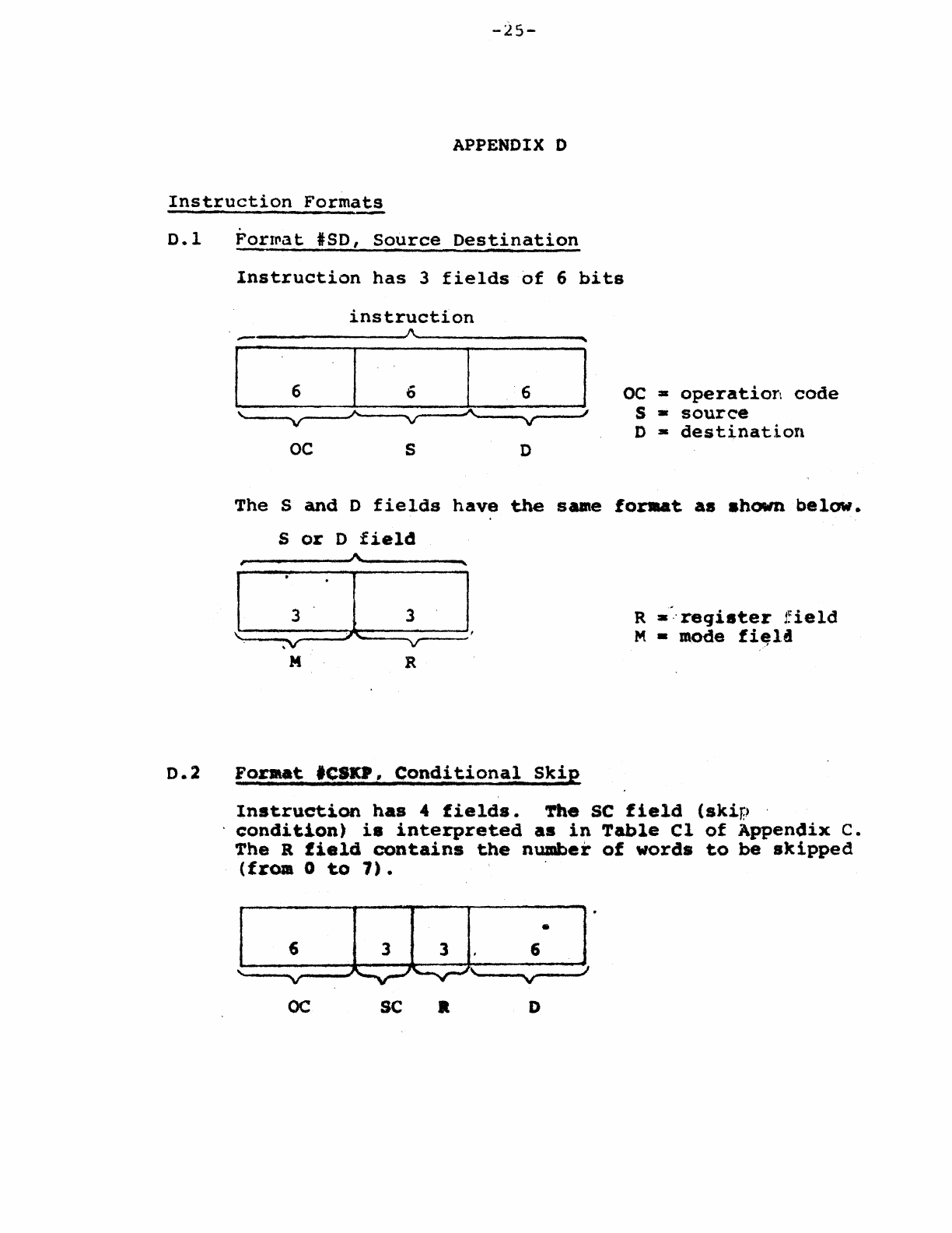
0.1
~ormat
lSD,
Source
Destination
Instruction
has
3
fields
of
6
bits
instruction
1\
"
I 6 6 I 6 I
OC
a
operatior~
code
"
""
A.
I 5 -
source
'v
v v D -
destination
OC
S 0
The
S
and
D
fields
have
the
SUle
forsu.t
as
ahown
below.
S
or
D
field
,
I\,
"
I 3 I 3
I.
R
a'"
reqi8ter
j:ield
V M • mode
fi~la
.V
M R
0.2
For.a.~
'CSKP,
Conditional
Skip
Instruction
has
4
fields.
'!'he
SC
field
(skip
,
.
condition)
i8
interpreted
as
in
Table
Cl
of
Appendix
c.
The R
field
contains
the
number
of
words
to
be
skipped
(from
0
to
7).
] UJ • r
6 6
v
\.
v
OC
sc
• D
-
26~-
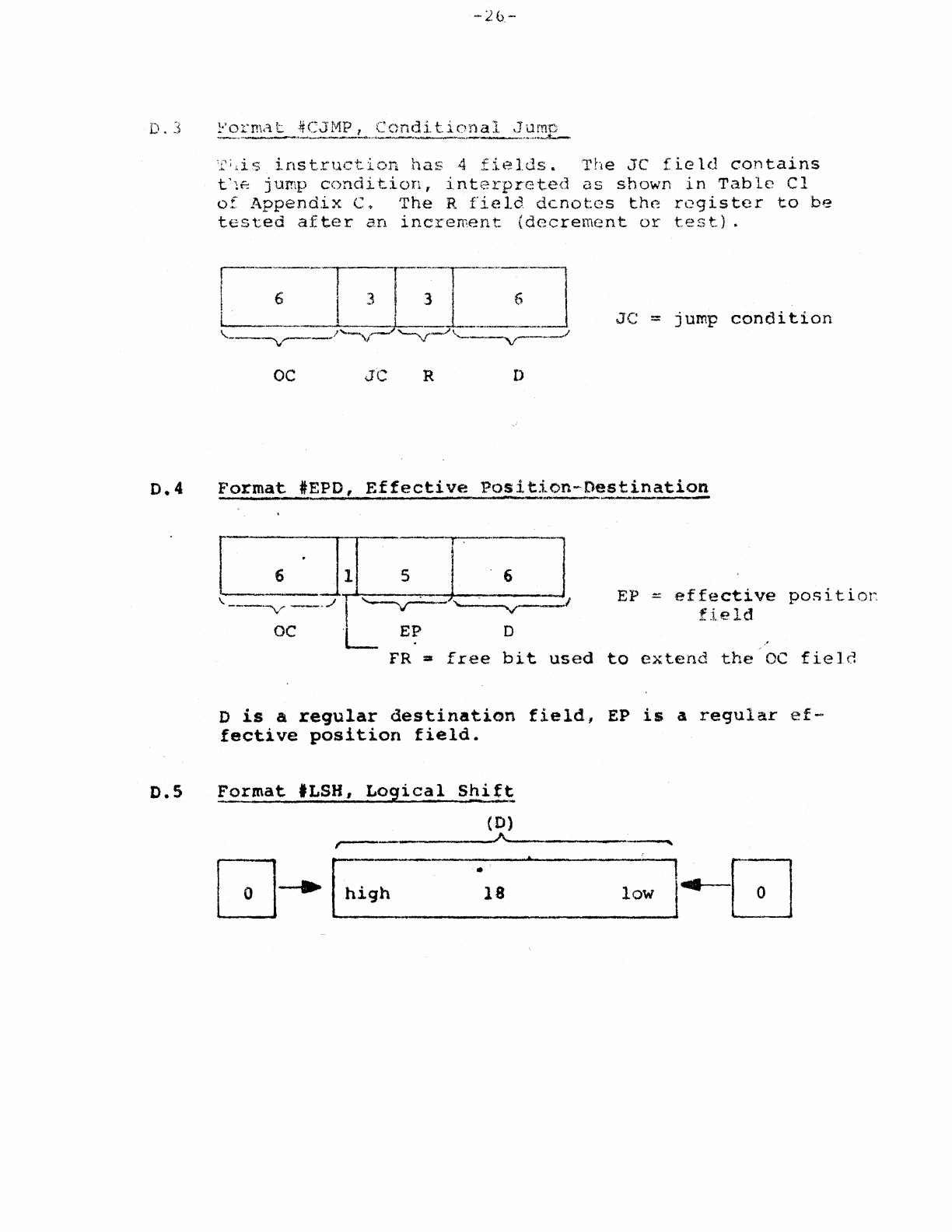
D.3
Porm~t
#CJMP,
Conditional
Jumc
_.-'_~I'f
__
...
_____
~",.'4
________
'
____
"_'
••
"-,,,.......L.-,
D.5
'1'
i
i.
i
sin
s t r
11
C'
t.
ion
has
4
fie
1.
d 5 •
'1"
h e J C
fie
1 d
con
t a
ins
t'1f::
jump
condition,
interprete,d
as
shown
in
Table
Cl
of
Appendix
c~
The
R
field
denotes
the
register
to
be
tested
after
an
increment
(decrement
or
test).
oc
JC
R D
[
6"JLGJ
-_.---v".- - .
...1
I
~~
"----v--
I
OC
'L
E~
D
JC
= jump
condition
EP
=
effective
positior
field
FR •
free
bit
used
to
extend
the
OC
field
D
is
a
regular
destination
field,
EP
is
a
regular
ef-
fective
position
field.
Format
'LSH,
L02ical
Sh.i.t~
(D)
,---
A
------""
Q~[hi9h
II
:
lOW:
""1--
-Q
18
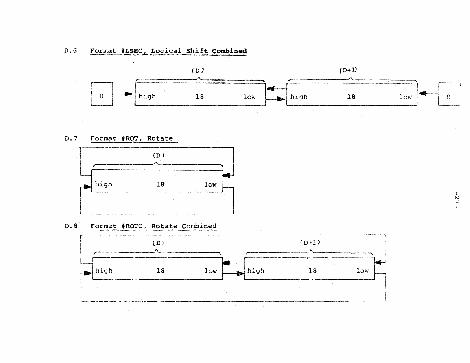
D06
Format
tLSHC
A
Logical
Shi~~
~ombine~
(D)
,..-
A.
f-:l--
r
! 0
.~igh
L_-1
18
low
D.
7
Format
*
¥<?T,
I
Rotate
l---'--
(D)
I
LF---------;~-
r~~h
________
~
___
19-
_____ ._.o-l_o_w_
I
I
L-..
_________
..
__
.
____
.
______
,---.J
0.8
Format
'ROTC,
Rotate
Combin~d
,-------.-----
--------------
----
j
(0)
(D+l)
"
--
1\
18
J~I
high
l
,--;
low
14--1
0
'---
___
~
___
~
_____
,J
l-.~
___
~
(
D+1)
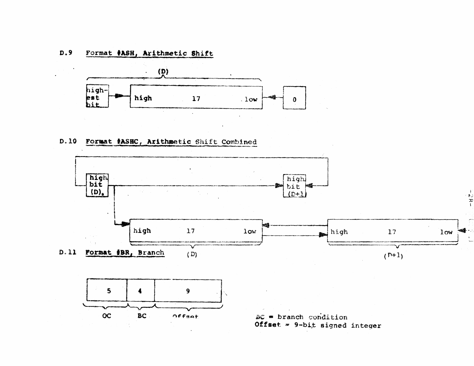
D.9
Format
'ASH,
Ax!~met:ic
Shift
.
(D)
r-------------~-------------~----,
[ 5 I 4 -I
'-
" "--v--"'-
OC
BC
9 I I '
v
.)
!'\F"~At-
-"_.
-------·1
r:~-'
I
!
highJ
J
~
bit
r--
Ut:tJJ
ac -
branch
cOlldi
tion
Offset
=
9-bit
signed
integer
i
f";
:c
I
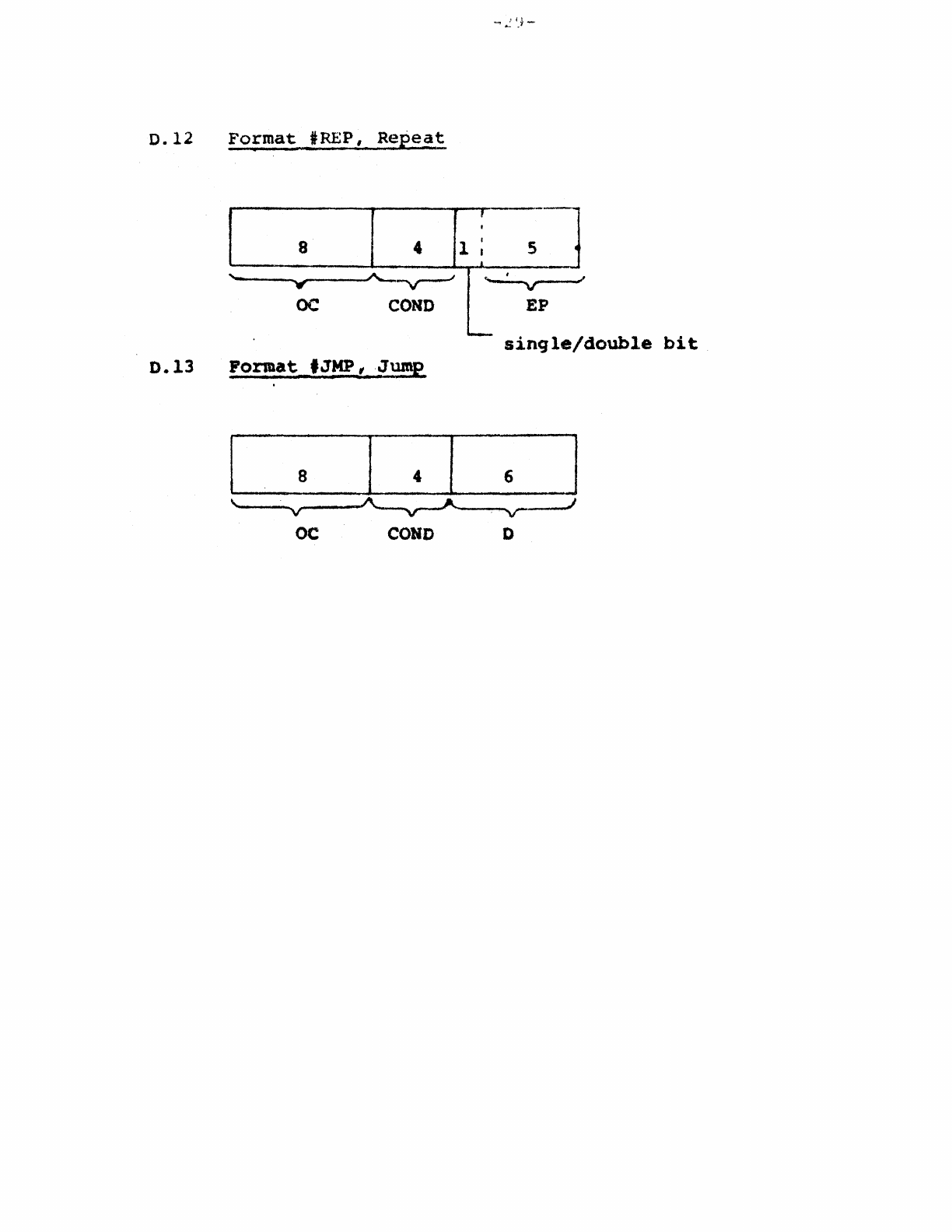
0.12
Format
'REP,
Repeat
r ----
,
8 4 1 I 5
I •
.
'=
A-~
,
'W"
oc
COHD
EP
-
single/double
bit
D.13
Pormat
fJMP
tJump
oc
COHO
D
APPENDIX
E
Subroutine
Calls
Besides
the
standard
PDP-II
JSR,
the
PDP-K
will
have
a
ncre
powerful
subroutine
call.
'rhis
new
call
"JSP"
(Jump
to
Subroutine
with
Parameters)
automatically
passes
paramet:ers
to
t.he
stack
a.nd
does
"stack
house-keeping"
in
such
a way
that
subroutine
returns
can
be
done
ift
a
trivial
way
while
the
stack
is
ucleaned
up"
automatically
..
The
format
of
the
call
is
iEPD
where
the
EP
field
is
in-
terpreted
as
the
number
of
parameters
to
be
pushed
on
th,!
stack.
Register
R5
is
used
to
point
to
the
first
passed
parameter
after
it
has
been
pushed
on
the
stack..
The
ex,lmple
below
~hows
how
th.e
JSP
could
be
implemented..
Note
that
in
addi
ti0n
to
t.he
par-arneters
themse
1
ves,
three
other
quant.j.
ties
have;:.o
bE:;
pushed
on
the
stack
to
allow
for
automatic
up·'
dating
upon
return
from
the
subroutine.
1.
The
number
of
parameters
wNp·
2 •
/J.
..
link
to
'the
previous
call
"LNKIlt
3.
The
return
address
"RAft
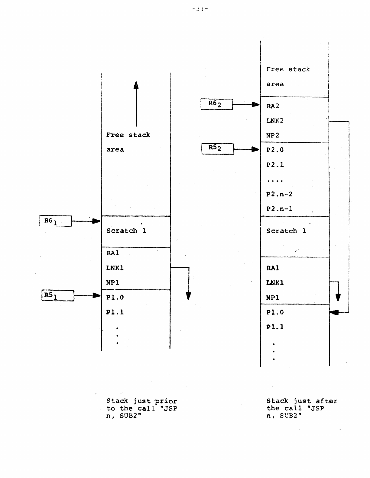
Below
is
shown how
the
JSP
actually
operatese
The
left
stack
shows
the
situation
jus~t
p.rior
to
the
call
of
subro'ttine
2,
the
right
stac.k,
shows
tht~
si
tuation
just
after
the
cal:.
I
...
J
~
~.
Free
stack
area
.
Scratch
1
RAl
I
LNKl
NPl
-
..
Pl
..
O
Pl.l
..
.
•
Stack
just
prior
to
the
call
"JSP
n,
SUB2"
.-
3 1 -
I
I
...
~
I
Free
stack
area
-
RA2
LNK2
NP2
P2.0
p2.1
. . . .
P2.n-2
P2.n-l
Scratch
RAl
LNKl
NPI
Pl.O
Pl.l
1
I
I
i
.,
I
l
stack
just
after
the
call
MJSP
n,
SUB2"
-32-
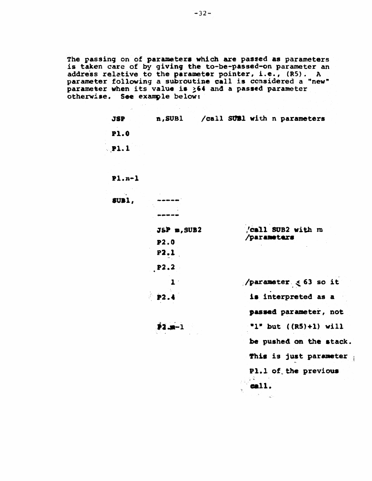
The
passing
on
of
para.meter.
which
are
pasted
.s
pa,rameters
is
taken
care
of
by
givin9
the
to-be-passed,-on
parameter
an
address
relative
to
the
parameter
pointer,
i.e.,
(RS). A
parameter
following
a
subroutine
call
is
considered
a "new"
parametlerwhen
its
value
is
~'4
and.
a
passed
parameter
otherwise.
See
ex~le
below:
JSP
Pl.0
'
..
Pl.1
Pl.n-l
"
..
n,SUSl
Js,p
.,9UI2
.2.0
P2.1
'2.2
leall
SU8l
Wi1~
n
parameters
/eall
SUB2
with
m
/par
...
tu.
,/par8lD8ter.,
~
63
so
it
.
1.
interpreted
as
a
.....
4
parameter,
not
-1-
but
«R5)+1)
will
be
pushed
on
the
stack.
~hi.
is
just
parameter
Pl.l
of.tbe
previou8
