4513 630, 63W, 6EW 34S0259 7014 Sm
User Manual: 34S0259
Open the PDF directly: View PDF ![]() .
.
Page Count: 310 [warning: Documents this large are best viewed by clicking the View PDF Link!]
- Table of contents
- Notices and safety information
- Preface
- 1. General information
- 2. Diagnostics information
- Start
- Symptom tables
- Overview of the operator panel and menus
- Understanding the home screen
- Using the touch-screen buttons
- Messages and error codes
- Service checks
- Controller board service check
- Engine board service check
- Cooling fan service check
- Cover interlock switch service check
- Dead machine service check
- Fuser service check
- LVPS/HVPS service check
- Main motor service check
- Media feed clutch service check
- Networking service check
- Operator panel service check
- Paper feed service checks
- Option card service check
- USB port service check
- Print quality service checks
- Printhead service check
- Transfer roll service check
- Tray 2 service check
- 840.xx service check
- Black or blank page copy service check
- CCD service check
- Flatbed motor service check
- Flatbed home position service check
- ADF cover open service check
- ADF streak service check
- ADF paper jam service check
- ADF feed errors service check
- ADF Duplex service check
- Modem / fax card service check
- Fax transmission service check
- Fax reception service check
- Escalating a fax issue to second-level support
- 3. Diagnostic aids
- Accessing service menus
- Configuration menu (CONFIG MENU)
- Available menus
- Maintenance Count Value (Maint Cnt Value)
- Reset Maintenance Counter
- Reset Photoconductor Maintenance Counter (Reset PC Cnt)
- USB Scan to Local
- Print Quality Pages
- Panel Menus
- PPDS Emulation
- Download Emuls
- Factory Defaults
- Energy Conserve
- Min Copy Memory
- Num Pad Job Assist
- Format Fax Storage
- Fax Storage Location
- ADF Edge Erase
- FB Edge Erase
- Scanner Manual Registration
- Disable Scanner
- Paper Prompts
- Envelope Prompts
- Action For Prompts
- Jobs on Disk
- Disk Encryptyion
- Wipe Disk
- Font Sharpening
- Require Standby
- LES Applications
- Key Repeat Initial Delay
- Key Repeat Rate
- Wiper Message
- Clear Custom Status
- USB Speed
- USB PnP
- Exit Configuration Menu (Exit Config Menu)
- Diagnostics menu
- Printhead assembly electronic adjustment
- Printhead assembly mechanical adjustment
- SE Menu
- Paper jams
- 4. Repair information
- Handling ESD-sensitive parts
- Removal procedures
- ACM pick tire roller removal
- Card reader removal
- Upper and lower card reader cover removal
- Card reader cable removal
- Controller board removal
- Controller board shield
- Controller board cage
- Controller board fan
- Engine board removal
- Cover open sensor
- Door mount removal
- Duplex removal
- Duplex/main motor gear drive interface removal
- Fan removal
- Front access door removal
- Fuser removal
- Scanner front cover removal
- Left side cover removal
- Front door access cover removal
- Lower front cover removal
- LVPS/HVPS removal
- Main motor gear drive removal
- Manual feed clutch removal
- Manual feed solenoid removal
- Media ACM ASM feeder removal
- Media feed clutch removal
- Media manual input sensor
- Multipurpose feeder removal
- Multipurpose feeder (MPF) feed clutch removal
- Nameplate cover removal
- Operator panel keypad removal
- Operator panel display removal
- Display bezel
- UICC cable removal
- USB cable mount bracket removal
- Operator panel support removal
- Display rotation support removal
- Left rear frame assembly removal
- Right rear frame assembly removal
- Tub assembly removal
- Paper input and duplex sensor assembly removal
- Printhead removal
- Mid rear cover removal
- Rear door and lower rear cover removal
- Rear exit guide assembly with sensor and reversing solenoid removal
- Right side cover removal
- Toner level sensor removal
- Top cover assembly removal
- Transfer roll removal
- Upper front guide assembly removal
- Wear strip (tray 1 and 250-sheet tray 2) removal
- Wear strip (550-sheet tray 2) removal
- Imaging component removals
- Option board installs and removals
- 5. Locations and connections
- 6. Preventive maintenance
- 7. Parts Catalog
- Index
- Part number index

Lexmark™ X46x series
7014-431
7014-636
7014-637
7014-63d
7014-63w
• Table of contents
• Start diagnostics
• Safety and notices
• Trademarks
• Index
Lexmark and Lexmark with diamond design are
trademarks of Lexmark International, Inc., registered
in the United States and/or other countries.
Revision: August 20, 2015
Edition: August 20, 2015
The following paragraph does not apply to any country where such provisions are inconsistent with local law:
LEXMARK INTERNATIONAL, INC. PROVIDES THIS PUBLICATION “AS IS” WITHOUT WARRANTY OF ANY KIND,
EITHER EXPRESS OR IMPLIED, INCLUDING, BUT NOT LIMITED TO, THE IMPLIED WARRANTIES OF
MERCHANTABILITY OR FITNESS FOR A PARTICULAR PURPOSE. Some states do not allow disclaimer of express or
implied warranties in certain transactions; therefore, this statement may not apply to you.
This publication could include technical inaccuracies or typographical errors. Changes are periodically made to the
information herein; these changes will be incorporated in later editions. Improvements or changes in the products or the
programs described may be made at any time.
Comments may be addressed to Lexmark International, Inc., Department D22X/002-1, 740 West New Circle Road,
Lexington, Kentucky 40550, U.S.A or e-mail at ServiceInfoAndTraining@Lexmark.com. Lexmark may use or distribute any
of the information you supply in any way it believes appropriate without incurring any obligation to you.
References in this publication to products, programs, or services do not imply that the manufacturer intends to make these
available in all countries in which it operates. Any reference to a product, program, or service is not intended to state or
imply that only that product, program, or service may be used. Any functionally equivalent product, program, or service that
does not infringe any existing intellectual property right may be used instead. Evaluation and verification of operation in
conjunction with other products, programs, or services, except those expressly designated by the manufacturer, are the
user’s responsibility.
Lexmark, Lexmark with diamond design and MarkVision are trademarks of Lexmark International, Inc., registered in the
United States and/or other countries.
PCL® is a registered trademark of the Hewlett-Packard Company.
All other trademarks are the property of their respective owners.
© 2009 Lexmark International, Inc.
All rights reserved.
UNITED STATES GOVERNMENT RIGHTS
This software and any accompanying documentation provided under this agreement are commercial computer software
and documentation developed exclusively at private expense.
P/N 12G9813
7014-xxx

Table of contents iii
7014-xxx
Table of contents
Table of contents. . . . . . . . . . . . . . . . . . . . . . . . . . . . . . . . . . . . . . . . . . . . . . . . . . . . . . .iii
Notices and safety information . . . . . . . . . . . . . . . . . . . . . . . . . . . . . . . . . . . . . . . . . . . xi
Laser notice . . . . . . . . . . . . . . . . . . . . . . . . . . . . . . . . . . . . . . . . . . . . . . . . . . . . . . . . . . . . . . . . . . . . . . . . . . xi
Lithium warning. . . . . . . . . . . . . . . . . . . . . . . . . . . . . . . . . . . . . . . . . . . . . . . . . . . . . . . . . . . . . . . . . . . . . xvii
Safety information. . . . . . . . . . . . . . . . . . . . . . . . . . . . . . . . . . . . . . . . . . . . . . . . . . . . . . . . . . . . . . . . . . . xvii
Preface . . . . . . . . . . . . . . . . . . . . . . . . . . . . . . . . . . . . . . . . . . . . . . . . . . . . . . . . . . . . . . xx
Change history . . . . . . . . . . . . . . . . . . . . . . . . . . . . . . . . . . . . . . . . . . . . . . . . . . . . . . . . . . . . . . . . . . . . . v-xx
Conventions. . . . . . . . . . . . . . . . . . . . . . . . . . . . . . . . . . . . . . . . . . . . . . . . . . . . . . . . . . . . . . . . . . . . . . . . . xxi
General information . . . . . . . . . . . . . . . . . . . . . . . . . . . . . . . . . . . . . . . . . . . . . . . . . . . . . . . . . . . . . . . . . . . . 1-1
Maintenance approach . . . . . . . . . . . . . . . . . . . . . . . . . . . . . . . . . . . . . . . . . . . . . . . . . . . . . . . . . . . . . . . 1-1
Print engine specifications . . . . . . . . . . . . . . . . . . . . . . . . . . . . . . . . . . . . . . . . . . . . . . . . . . . . . . . . . . . . 1-2
Memory . . . . . . . . . . . . . . . . . . . . . . . . . . . . . . . . . . . . . . . . . . . . . . . . . . . . . . . . . . . . . . . . . . . . . . . . 1-2
Print quality settings . . . . . . . . . . . . . . . . . . . . . . . . . . . . . . . . . . . . . . . . . . . . . . . . . . . . . . . . . . . . . 1-2
Environment . . . . . . . . . . . . . . . . . . . . . . . . . . . . . . . . . . . . . . . . . . . . . . . . . . . . . . . . . . . . . . . . . . . . 1-3
Specified operating environment . . . . . . . . . . . . . . . . . . . . . . . . . . . . . . . . . . . . . . . . . . . . . . . . . 1-3
Dimensions . . . . . . . . . . . . . . . . . . . . . . . . . . . . . . . . . . . . . . . . . . . . . . . . . . . . . . . . . . . . . . . . . . . . 1-3
Connectivity and compatibility . . . . . . . . . . . . . . . . . . . . . . . . . . . . . . . . . . . . . . . . . . . . . . . . . . . . . 1-3
Media trays and supply capacity . . . . . . . . . . . . . . . . . . . . . . . . . . . . . . . . . . . . . . . . . . . . . . . . . . . 1-4
Types of print media . . . . . . . . . . . . . . . . . . . . . . . . . . . . . . . . . . . . . . . . . . . . . . . . . . . . . . . . . . . . . 1-5
Media guidelines . . . . . . . . . . . . . . . . . . . . . . . . . . . . . . . . . . . . . . . . . . . . . . . . . . . . . . . . . . . . . . . . 1-6
Paper characteristics . . . . . . . . . . . . . . . . . . . . . . . . . . . . . . . . . . . . . . . . . . . . . . . . . . . . . . . . . . 1-6
Unacceptable paper . . . . . . . . . . . . . . . . . . . . . . . . . . . . . . . . . . . . . . . . . . . . . . . . . . . . . . . . . . 1-6
Selecting paper . . . . . . . . . . . . . . . . . . . . . . . . . . . . . . . . . . . . . . . . . . . . . . . . . . . . . . . . . . . . . . 1-7
Selecting preprinted forms and letterhead . . . . . . . . . . . . . . . . . . . . . . . . . . . . . . . . . . . . . . . . . 1-7
Storing paper . . . . . . . . . . . . . . . . . . . . . . . . . . . . . . . . . . . . . . . . . . . . . . . . . . . . . . . . . . . . . . . . 1-7
Using recycled paper and other office papers . . . . . . . . . . . . . . . . . . . . . . . . . . . . . . . . . . . . . . . 1-7
Digital imaging specifications . . . . . . . . . . . . . . . . . . . . . . . . . . . . . . . . . . . . . . . . . . . . . . . . . . . . . . . . . . 1-9
General specifications . . . . . . . . . . . . . . . . . . . . . . . . . . . . . . . . . . . . . . . . . . . . . . . . . . . . . . . . . . . 1-9
ADF Scan speed . . . . . . . . . . . . . . . . . . . . . . . . . . . . . . . . . . . . . . . . . . . . . . . . . . . . . . . . . . . . . 1-9
ADF Document handling . . . . . . . . . . . . . . . . . . . . . . . . . . . . . . . . . . . . . . . . . . . . . . . . . . . . . . . 1-9
Resolution and color depth . . . . . . . . . . . . . . . . . . . . . . . . . . . . . . . . . . . . . . . . . . . . . . . . . . . . . 1-9
Flatbed document specifications . . . . . . . . . . . . . . . . . . . . . . . . . . . . . . . . . . . . . . . . . . . . . . . . . 1-9
Flatbed speed . . . . . . . . . . . . . . . . . . . . . . . . . . . . . . . . . . . . . . . . . . . . . . . . . . . . . . . . . . . . . . . 1-9
Scanner operating environments . . . . . . . . . . . . . . . . . . . . . . . . . . . . . . . . . . . . . . . . . . . . . . . . 1-9
Scan Preview . . . . . . . . . . . . . . . . . . . . . . . . . . . . . . . . . . . . . . . . . . . . . . . . . . . . . . . . . . . . . . . 1-9
Storage environments (packed) . . . . . . . . . . . . . . . . . . . . . . . . . . . . . . . . . . . . . . . . . . . . . . . . . 1-9
Storage environments (unpacked) . . . . . . . . . . . . . . . . . . . . . . . . . . . . . . . . . . . . . . . . . . . . . . 1-10
Tilt . . . . . . . . . . . . . . . . . . . . . . . . . . . . . . . . . . . . . . . . . . . . . . . . . . . . . . . . . . . . . . . . . . . . . . . 1-10
Scan and copy specific specifications . . . . . . . . . . . . . . . . . . . . . . . . . . . . . . . . . . . . . . . . . . . . . 1-11
Scan Resolutions . . . . . . . . . . . . . . . . . . . . . . . . . . . . . . . . . . . . . . . . . . . . . . . . . . . . . . . . . . . 1-11
Output resolutions . . . . . . . . . . . . . . . . . . . . . . . . . . . . . . . . . . . . . . . . . . . . . . . . . . . . . . . . . . . 1-11
Duplex scan . . . . . . . . . . . . . . . . . . . . . . . . . . . . . . . . . . . . . . . . . . . . . . . . . . . . . . . . . . . . . . . 1-11
Scan file output formats . . . . . . . . . . . . . . . . . . . . . . . . . . . . . . . . . . . . . . . . . . . . . . . . . . . . . . 1-11
Supported compressions . . . . . . . . . . . . . . . . . . . . . . . . . . . . . . . . . . . . . . . . . . . . . . . . . . . . . 1-11
Supported scan destinations . . . . . . . . . . . . . . . . . . . . . . . . . . . . . . . . . . . . . . . . . . . . . . . . . . . 1-11
Multiple copies . . . . . . . . . . . . . . . . . . . . . . . . . . . . . . . . . . . . . . . . . . . . . . . . . . . . . . . . . . . . . 1-11
Reduce / Enlarge . . . . . . . . . . . . . . . . . . . . . . . . . . . . . . . . . . . . . . . . . . . . . . . . . . . . . . . . . . . 1-11
Fax specifications . . . . . . . . . . . . . . . . . . . . . . . . . . . . . . . . . . . . . . . . . . . . . . . . . . . . . . . . . . . . . . . . . . 1-12
Phone network connectivity . . . . . . . . . . . . . . . . . . . . . . . . . . . . . . . . . . . . . . . . . . . . . . . . . . . 1-12
Fax resolutions . . . . . . . . . . . . . . . . . . . . . . . . . . . . . . . . . . . . . . . . . . . . . . . . . . . . . . . . . . . . . 1-12
Miscellaneous FAX specifications . . . . . . . . . . . . . . . . . . . . . . . . . . . . . . . . . . . . . . . . . . . . . . . 1-12
Tools . . . . . . . . . . . . . . . . . . . . . . . . . . . . . . . . . . . . . . . . . . . . . . . . . . . . . . . . . . . . . . . . . . . . . . . . . . . . . 1-13
iv Service Manual
7014-xxx
Acronyms . . . . . . . . . . . . . . . . . . . . . . . . . . . . . . . . . . . . . . . . . . . . . . . . . . . . . . . . . . . . . . . . . . . . . . . . . .1-14
Diagnostics information . . . . . . . . . . . . . . . . . . . . . . . . . . . . . . . . . . . . . . . . . . . . . . . . . . . . . . . . . . . . . . . 2-1
Start . . . . . . . . . . . . . . . . . . . . . . . . . . . . . . . . . . . . . . . . . . . . . . . . . . . . . . . . . . . . . . . . . . . . . . . . . . . . . . .2-1
Symptom tables . . . . . . . . . . . . . . . . . . . . . . . . . . . . . . . . . . . . . . . . . . . . . . . . . . . . . . . . . . . . . .2-1
Service errors (8xx.xx / 9xx.xx’s) . . . . . . . . . . . . . . . . . . . . . . . . . . . . . . . . . . . . . . . . . . . . . . . . .2-1
User status and attendance messages . . . . . . . . . . . . . . . . . . . . . . . . . . . . . . . . . . . . . . . . . . . .2-1
Symptom tables . . . . . . . . . . . . . . . . . . . . . . . . . . . . . . . . . . . . . . . . . . . . . . . . . . . . . . . . . . . . . . . . . . . . . .2-2
POST symptom table . . . . . . . . . . . . . . . . . . . . . . . . . . . . . . . . . . . . . . . . . . . . . . . . . . . . . . . . . . . . .2-2
Printer symptom table . . . . . . . . . . . . . . . . . . . . . . . . . . . . . . . . . . . . . . . . . . . . . . . . . . . . . . . . . . . .2-3
Scan / fax / copy symptom table . . . . . . . . . . . . . . . . . . . . . . . . . . . . . . . . . . . . . . . . . . . . . . . . . . . .2-4
Overview of the operator panel and menus . . . . . . . . . . . . . . . . . . . . . . . . . . . . . . . . . . . . . . . . . . . . . . .2-5
Understanding the home screen . . . . . . . . . . . . . . . . . . . . . . . . . . . . . . . . . . . . . . . . . . . . . . . . . . . . . . . .2-7
Using the touch-screen buttons . . . . . . . . . . . . . . . . . . . . . . . . . . . . . . . . . . . . . . . . . . . . . . . . . . . . . . . .2-9
Sample touch screen . . . . . . . . . . . . . . . . . . . . . . . . . . . . . . . . . . . . . . . . . . . . . . . . . . . . . . . . . . . . .2-9
Other touch-screen buttons . . . . . . . . . . . . . . . . . . . . . . . . . . . . . . . . . . . . . . . . . . . . . . . . . . . . . . .2-10
Diagram of the printer menus . . . . . . . . . . . . . . . . . . . . . . . . . . . . . . . . . . . . . . . . . . . . . . . . . . . . .2-12
Messages and error codes . . . . . . . . . . . . . . . . . . . . . . . . . . . . . . . . . . . . . . . . . . . . . . . . . . . . . . . . . . . .2-13
User attendance messages . . . . . . . . . . . . . . . . . . . . . . . . . . . . . . . . . . . . . . . . . . . . . . . . . . . . . . .2-13
Cartridge error messages . . . . . . . . . . . . . . . . . . . . . . . . . . . . . . . . . . . . . . . . . . . . . . . . . . . . . . . .2-20
Paper jam error codes (200-series) . . . . . . . . . . . . . . . . . . . . . . . . . . . . . . . . . . . . . . . . . . . . . . . . .2-20
Service error codes . . . . . . . . . . . . . . . . . . . . . . . . . . . . . . . . . . . . . . . . . . . . . . . . . . . . . . . . . . . . .2-26
Fax error codes . . . . . . . . . . . . . . . . . . . . . . . . . . . . . . . . . . . . . . . . . . . . . . . . . . . . . . . . . . . . . . . . .2-31
Service checks . . . . . . . . . . . . . . . . . . . . . . . . . . . . . . . . . . . . . . . . . . . . . . . . . . . . . . . . . . . . . . . . . . . . . .2-35
Controller board service check . . . . . . . . . . . . . . . . . . . . . . . . . . . . . . . . . . . . . . . . . . . . . . . . . . .2-35
Engine board service check . . . . . . . . . . . . . . . . . . . . . . . . . . . . . . . . . . . . . . . . . . . . . . . . . . . . . .2-36
Cooling fan service check . . . . . . . . . . . . . . . . . . . . . . . . . . . . . . . . . . . . . . . . . . . . . . . . . . . . . . . .2-37
Cover interlock switch service check . . . . . . . . . . . . . . . . . . . . . . . . . . . . . . . . . . . . . . . . . . . . . . .2-37
Dead machine service check . . . . . . . . . . . . . . . . . . . . . . . . . . . . . . . . . . . . . . . . . . . . . . . . . . . . . .2-38
Fuser service check . . . . . . . . . . . . . . . . . . . . . . . . . . . . . . . . . . . . . . . . . . . . . . . . . . . . . . . . . . . . .2-39
LVPS/HVPS service check . . . . . . . . . . . . . . . . . . . . . . . . . . . . . . . . . . . . . . . . . . . . . . . . . . . . . . . .2-39
Main motor service check . . . . . . . . . . . . . . . . . . . . . . . . . . . . . . . . . . . . . . . . . . . . . . . . . . . . . . . .2-40
Media feed clutch service check . . . . . . . . . . . . . . . . . . . . . . . . . . . . . . . . . . . . . . . . . . . . . . . . . . .2-40
Networking service check . . . . . . . . . . . . . . . . . . . . . . . . . . . . . . . . . . . . . . . . . . . . . . . . . . . . . . . .2-41
Operator panel service check . . . . . . . . . . . . . . . . . . . . . . . . . . . . . . . . . . . . . . . . . . . . . . . . . . . . .2-43
Paper feed service checks . . . . . . . . . . . . . . . . . . . . . . . . . . . . . . . . . . . . . . . . . . . . . . . . . . . . . . . .2-43
Paper jam error indication during POST . . . . . . . . . . . . . . . . . . . . . . . . . . . . . . . . . . . . . . . . . .2-43
Media picks but stops halfway through the printer . . . . . . . . . . . . . . . . . . . . . . . . . . . . . . . . . .2-44
Media never picks . . . . . . . . . . . . . . . . . . . . . . . . . . . . . . . . . . . . . . . . . . . . . . . . . . . . . . . . . . .2-44
Media occasionally mispicks or picks multiple sheets at once . . . . . . . . . . . . . . . . . . . . . . . . .2-44
Media skews . . . . . . . . . . . . . . . . . . . . . . . . . . . . . . . . . . . . . . . . . . . . . . . . . . . . . . . . . . . . . . . .2-45
Media “trees,” wrinkles, stacks poorly, or curls . . . . . . . . . . . . . . . . . . . . . . . . . . . . . . . . . . . . .2-45
Option card service check . . . . . . . . . . . . . . . . . . . . . . . . . . . . . . . . . . . . . . . . . . . . . . . . . . . . . . .2-46
USB port service check . . . . . . . . . . . . . . . . . . . . . . . . . . . . . . . . . . . . . . . . . . . . . . . . . . . . . . . . . .2-46
Print quality service checks . . . . . . . . . . . . . . . . . . . . . . . . . . . . . . . . . . . . . . . . . . . . . . . . . . . . . . .2-47
Blank page . . . . . . . . . . . . . . . . . . . . . . . . . . . . . . . . . . . . . . . . . . . . . . . . . . . . . . . . . . . . . . . .2-47
Black page . . . . . . . . . . . . . . . . . . . . . . . . . . . . . . . . . . . . . . . . . . . . . . . . . . . . . . . . . . . . . . . . .2-48
Heavy background . . . . . . . . . . . . . . . . . . . . . . . . . . . . . . . . . . . . . . . . . . . . . . . . . . . . . . . . . . .2-48
Partial blank image/white spots (no repeating pattern) . . . . . . . . . . . . . . . . . . . . . . . . . . . . . . .2-49
Variation in image density horizontally across page . . . . . . . . . . . . . . . . . . . . . . . . . . . . . . . . .2-49
Poor fusing of image . . . . . . . . . . . . . . . . . . . . . . . . . . . . . . . . . . . . . . . . . . . . . . . . . . . . . . . . .2-49
Light print . . . . . . . . . . . . . . . . . . . . . . . . . . . . . . . . . . . . . . . . . . . . . . . . . . . . . . . . . . . . . . . . . .2-50
White or black lines or bands . . . . . . . . . . . . . . . . . . . . . . . . . . . . . . . . . . . . . . . . . . . . . . . . . .2-50
Toner on back of page . . . . . . . . . . . . . . . . . . . . . . . . . . . . . . . . . . . . . . . . . . . . . . . . . . . . . . .2-50
Solving print quality problems . . . . . . . . . . . . . . . . . . . . . . . . . . . . . . . . . . . . . . . . . . . . . . . . . .2-51
Printhead service check . . . . . . . . . . . . . . . . . . . . . . . . . . . . . . . . . . . . . . . . . . . . . . . . . . . . . . . . . .2-54
Transfer roll service check . . . . . . . . . . . . . . . . . . . . . . . . . . . . . . . . . . . . . . . . . . . . . . . . . . . . . . .2-54
Tray 2 service check . . . . . . . . . . . . . . . . . . . . . . . . . . . . . . . . . . . . . . . . . . . . . . . . . . . . . . . . . . . . .2-55
840.xx service check . . . . . . . . . . . . . . . . . . . . . . . . . . . . . . . . . . . . . . . . . . . . . . . . . . . . . . . . . . . .2-55
Table of contents v
7014-xxx
Black or blank page copy service check . . . . . . . . . . . . . . . . . . . . . . . . . . . . . . . . . . . . . . . . . . . . 2-57
CCD service check . . . . . . . . . . . . . . . . . . . . . . . . . . . . . . . . . . . . . . . . . . . . . . . . . . . . . . . . . . . . . 2-57
Flatbed motor service check . . . . . . . . . . . . . . . . . . . . . . . . . . . . . . . . . . . . . . . . . . . . . . . . . . . . . 2-57
Flatbed home position service check . . . . . . . . . . . . . . . . . . . . . . . . . . . . . . . . . . . . . . . . . . . . . . 2-58
ADF cover open service check . . . . . . . . . . . . . . . . . . . . . . . . . . . . . . . . . . . . . . . . . . . . . . . . . . . . 2-59
ADF streak service check . . . . . . . . . . . . . . . . . . . . . . . . . . . . . . . . . . . . . . . . . . . . . . . . . . . . . . . . 2-59
ADF paper jam service check . . . . . . . . . . . . . . . . . . . . . . . . . . . . . . . . . . . . . . . . . . . . . . . . . . . . . 2-60
ADF feed errors service check . . . . . . . . . . . . . . . . . . . . . . . . . . . . . . . . . . . . . . . . . . . . . . . . . . . . 2-60
ADF Duplex service check . . . . . . . . . . . . . . . . . . . . . . . . . . . . . . . . . . . . . . . . . . . . . . . . . . . . . . . 2-62
Modem / fax card service check . . . . . . . . . . . . . . . . . . . . . . . . . . . . . . . . . . . . . . . . . . . . . . . . . . . 2-63
Fax transmission service check . . . . . . . . . . . . . . . . . . . . . . . . . . . . . . . . . . . . . . . . . . . . . . . . . . . 2-64
Fax reception service check . . . . . . . . . . . . . . . . . . . . . . . . . . . . . . . . . . . . . . . . . . . . . . . . . . . . . . 2-66
Escalating a fax issue to second-level support . . . . . . . . . . . . . . . . . . . . . . . . . . . . . . . . . . . . . . 2-68
Diagnostic aids . . . . . . . . . . . . . . . . . . . . . . . . . . . . . . . . . . . . . . . . . . . . . . . . . . . . . . . . . . . . . . . . . . . . . . . . . 3-1
Accessing service menus . . . . . . . . . . . . . . . . . . . . . . . . . . . . . . . . . . . . . . . . . . . . . . . . . . . . . . . . . . . . . 3-1
Configuration menu (CONFIG MENU) . . . . . . . . . . . . . . . . . . . . . . . . . . . . . . . . . . . . . . . . . . . . . . . . . . . 3-2
Available menus . . . . . . . . . . . . . . . . . . . . . . . . . . . . . . . . . . . . . . . . . . . . . . . . . . . . . . . . . . . . . . . . 3-2
Maintenance Count Value (Maint Cnt Value) . . . . . . . . . . . . . . . . . . . . . . . . . . . . . . . . . . . . . . . . . . 3-3
Reset Maintenance Counter . . . . . . . . . . . . . . . . . . . . . . . . . . . . . . . . . . . . . . . . . . . . . . . . . . . . . . . 3-3
Reset Photoconductor Maintenance Counter (Reset PC Cnt) . . . . . . . . . . . . . . . . . . . . . . . . . . . 3-4
USB Scan to Local . . . . . . . . . . . . . . . . . . . . . . . . . . . . . . . . . . . . . . . . . . . . . . . . . . . . . . . . . . . . . . . 3-4
Print Quality Pages . . . . . . . . . . . . . . . . . . . . . . . . . . . . . . . . . . . . . . . . . . . . . . . . . . . . . . . . . . . . . . 3-4
Menu Settings Page . . . . . . . . . . . . . . . . . . . . . . . . . . . . . . . . . . . . . . . . . . . . . . . . . . . . . . . . . . 3-4
Event Log . . . . . . . . . . . . . . . . . . . . . . . . . . . . . . . . . . . . . . . . . . . . . . . . . . . . . . . . . . . . . . . . . . 3-4
Panel Menus . . . . . . . . . . . . . . . . . . . . . . . . . . . . . . . . . . . . . . . . . . . . . . . . . . . . . . . . . . . . . . . . . . . . 3-4
PPDS Emulation . . . . . . . . . . . . . . . . . . . . . . . . . . . . . . . . . . . . . . . . . . . . . . . . . . . . . . . . . . . . . . . . . 3-5
Download Emuls . . . . . . . . . . . . . . . . . . . . . . . . . . . . . . . . . . . . . . . . . . . . . . . . . . . . . . . . . . . . . . . . 3-5
Factory Defaults . . . . . . . . . . . . . . . . . . . . . . . . . . . . . . . . . . . . . . . . . . . . . . . . . . . . . . . . . . . . . . . . . 3-6
Energy Conserve . . . . . . . . . . . . . . . . . . . . . . . . . . . . . . . . . . . . . . . . . . . . . . . . . . . . . . . . . . . . . . . . 3-6
Min Copy Memory . . . . . . . . . . . . . . . . . . . . . . . . . . . . . . . . . . . . . . . . . . . . . . . . . . . . . . . . . . . . . . . 3-6
Num Pad Job Assist . . . . . . . . . . . . . . . . . . . . . . . . . . . . . . . . . . . . . . . . . . . . . . . . . . . . . . . . . . . . . 3-7
Format Fax Storage . . . . . . . . . . . . . . . . . . . . . . . . . . . . . . . . . . . . . . . . . . . . . . . . . . . . . . . . . . . . . . 3-7
Fax Storage Location . . . . . . . . . . . . . . . . . . . . . . . . . . . . . . . . . . . . . . . . . . . . . . . . . . . . . . . . . . . . 3-7
ADF Edge Erase . . . . . . . . . . . . . . . . . . . . . . . . . . . . . . . . . . . . . . . . . . . . . . . . . . . . . . . . . . . . . . . . . 3-7
FB Edge Erase . . . . . . . . . . . . . . . . . . . . . . . . . . . . . . . . . . . . . . . . . . . . . . . . . . . . . . . . . . . . . . . . . . 3-7
Scanner Manual Registration . . . . . . . . . . . . . . . . . . . . . . . . . . . . . . . . . . . . . . . . . . . . . . . . . . . . . . 3-8
Disable Scanner . . . . . . . . . . . . . . . . . . . . . . . . . . . . . . . . . . . . . . . . . . . . . . . . . . . . . . . . . . . . . . . . . 3-9
Paper Prompts . . . . . . . . . . . . . . . . . . . . . . . . . . . . . . . . . . . . . . . . . . . . . . . . . . . . . . . . . . . . . . . . . . 3-9
Envelope Prompts . . . . . . . . . . . . . . . . . . . . . . . . . . . . . . . . . . . . . . . . . . . . . . . . . . . . . . . . . . . . . . . 3-9
Action For Prompts . . . . . . . . . . . . . . . . . . . . . . . . . . . . . . . . . . . . . . . . . . . . . . . . . . . . . . . . . . . . . . 3-9
Jobs on Disk . . . . . . . . . . . . . . . . . . . . . . . . . . . . . . . . . . . . . . . . . . . . . . . . . . . . . . . . . . . . . . . . . . 3-10
Disk Encryptyion . . . . . . . . . . . . . . . . . . . . . . . . . . . . . . . . . . . . . . . . . . . . . . . . . . . . . . . . . . . . . . . 3-10
Wipe Disk . . . . . . . . . . . . . . . . . . . . . . . . . . . . . . . . . . . . . . . . . . . . . . . . . . . . . . . . . . . . . . . . . . . . . 3-13
Font Sharpening . . . . . . . . . . . . . . . . . . . . . . . . . . . . . . . . . . . . . . . . . . . . . . . . . . . . . . . . . . . . . . . 3-14
Require Standby . . . . . . . . . . . . . . . . . . . . . . . . . . . . . . . . . . . . . . . . . . . . . . . . . . . . . . . . . . . . . . . 3-14
LES Applications . . . . . . . . . . . . . . . . . . . . . . . . . . . . . . . . . . . . . . . . . . . . . . . . . . . . . . . . . . . . . . . 3-15
Key Repeat Initial Delay . . . . . . . . . . . . . . . . . . . . . . . . . . . . . . . . . . . . . . . . . . . . . . . . . . . . . . . . . 3-15
Key Repeat Rate . . . . . . . . . . . . . . . . . . . . . . . . . . . . . . . . . . . . . . . . . . . . . . . . . . . . . . . . . . . . . . . 3-15
Wiper Message . . . . . . . . . . . . . . . . . . . . . . . . . . . . . . . . . . . . . . . . . . . . . . . . . . . . . . . . . . . . . . . . . 3-15
Clear Custom Status . . . . . . . . . . . . . . . . . . . . . . . . . . . . . . . . . . . . . . . . . . . . . . . . . . . . . . . . . . . . 3-16
USB Speed . . . . . . . . . . . . . . . . . . . . . . . . . . . . . . . . . . . . . . . . . . . . . . . . . . . . . . . . . . . . . . . . . . . . 3-16
USB PnP . . . . . . . . . . . . . . . . . . . . . . . . . . . . . . . . . . . . . . . . . . . . . . . . . . . . . . . . . . . . . . . . . . . . . . 3-16
Exit Configuration Menu (Exit Config Menu) . . . . . . . . . . . . . . . . . . . . . . . . . . . . . . . . . . . . . . . . 3-16
Diagnostics menu . . . . . . . . . . . . . . . . . . . . . . . . . . . . . . . . . . . . . . . . . . . . . . . . . . . . . . . . . . . . . . . . . . 3-17
Entering Diagnostics menu . . . . . . . . . . . . . . . . . . . . . . . . . . . . . . . . . . . . . . . . . . . . . . . . . . . . . . 3-17
Registration (printer) . . . . . . . . . . . . . . . . . . . . . . . . . . . . . . . . . . . . . . . . . . . . . . . . . . . . . . . . . . . . 3-18
Quick Test page . . . . . . . . . . . . . . . . . . . . . . . . . . . . . . . . . . . . . . . . . . . . . . . . . . . . . . . . . . . . 3-19
Print Tests . . . . . . . . . . . . . . . . . . . . . . . . . . . . . . . . . . . . . . . . . . . . . . . . . . . . . . . . . . . . . . . . . . . . 3-20
vi Service Manual
7014-xxx
Input sources . . . . . . . . . . . . . . . . . . . . . . . . . . . . . . . . . . . . . . . . . . . . . . . . . . . . . . . . . . . . . . .3-20
Print Quality Pages (Prt Quality Pgs) . . . . . . . . . . . . . . . . . . . . . . . . . . . . . . . . . . . . . . . . . . . . .3-20
Hardware Tests . . . . . . . . . . . . . . . . . . . . . . . . . . . . . . . . . . . . . . . . . . . . . . . . . . . . . . . . . . . . . . . . .3-21
Panel Test . . . . . . . . . . . . . . . . . . . . . . . . . . . . . . . . . . . . . . . . . . . . . . . . . . . . . . . . . . . . . . . . .3-21
Button Test . . . . . . . . . . . . . . . . . . . . . . . . . . . . . . . . . . . . . . . . . . . . . . . . . . . . . . . . . . . . . . . . .3-21
DRAM Test . . . . . . . . . . . . . . . . . . . . . . . . . . . . . . . . . . . . . . . . . . . . . . . . . . . . . . . . . . . . . . . . .3-22
Serial 1 Wrap . . . . . . . . . . . . . . . . . . . . . . . . . . . . . . . . . . . . . . . . . . . . . . . . . . . . . . . . . . . . . . .3-22
USB HS Test Mode . . . . . . . . . . . . . . . . . . . . . . . . . . . . . . . . . . . . . . . . . . . . . . . . . . . . . . . . . .3-23
Duplex Tests . . . . . . . . . . . . . . . . . . . . . . . . . . . . . . . . . . . . . . . . . . . . . . . . . . . . . . . . . . . . . . . . . . .3-24
Quick Test (duplex) . . . . . . . . . . . . . . . . . . . . . . . . . . . . . . . . . . . . . . . . . . . . . . . . . . . . . . . . . .3-24
Top Margin (duplex) . . . . . . . . . . . . . . . . . . . . . . . . . . . . . . . . . . . . . . . . . . . . . . . . . . . . . . . . . .3-25
Sensor Test (duplex) . . . . . . . . . . . . . . . . . . . . . . . . . . . . . . . . . . . . . . . . . . . . . . . . . . . . . . . . .3-25
Motor Test (duplex) . . . . . . . . . . . . . . . . . . . . . . . . . . . . . . . . . . . . . . . . . . . . . . . . . . . . . . . . . .3-25
Duplex Feed 1 . . . . . . . . . . . . . . . . . . . . . . . . . . . . . . . . . . . . . . . . . . . . . . . . . . . . . . . . . . . . . .3-26
Duplex Feed 2 . . . . . . . . . . . . . . . . . . . . . . . . . . . . . . . . . . . . . . . . . . . . . . . . . . . . . . . . . . . . . .3-26
Input Tray Tests . . . . . . . . . . . . . . . . . . . . . . . . . . . . . . . . . . . . . . . . . . . . . . . . . . . . . . . . . . . . . . . .3-26
Feed Tests (input tray) . . . . . . . . . . . . . . . . . . . . . . . . . . . . . . . . . . . . . . . . . . . . . . . . . . . . . . . .3-26
Sensor Test (input tray) . . . . . . . . . . . . . . . . . . . . . . . . . . . . . . . . . . . . . . . . . . . . . . . . . . . . . . .3-26
Output bin tests . . . . . . . . . . . . . . . . . . . . . . . . . . . . . . . . . . . . . . . . . . . . . . . . . . . . . . . . . . . . . . . .3-27
Feed Tests (output bins) . . . . . . . . . . . . . . . . . . . . . . . . . . . . . . . . . . . . . . . . . . . . . . . . . . . . . .3-27
Sensor Test (standard output bin) . . . . . . . . . . . . . . . . . . . . . . . . . . . . . . . . . . . . . . . . . . . . . . .3-27
. . . . . . . . . . . . . . . . . . . . . . . . . . . . . . . . . . . . . . . . . . . . . . . . . . . . . . . . . . . . . . . . . . . . . . . . . . . . . .3-27
Base Sensor Test . . . . . . . . . . . . . . . . . . . . . . . . . . . . . . . . . . . . . . . . . . . . . . . . . . . . . . . . . . . . . . .3-28
DEVICE TESTS . . . . . . . . . . . . . . . . . . . . . . . . . . . . . . . . . . . . . . . . . . . . . . . . . . . . . . . . . . . . . . . . .3-28
Quick Disk Test . . . . . . . . . . . . . . . . . . . . . . . . . . . . . . . . . . . . . . . . . . . . . . . . . . . . . . . . . . . . .3-28
Disk Test/Clean . . . . . . . . . . . . . . . . . . . . . . . . . . . . . . . . . . . . . . . . . . . . . . . . . . . . . . . . . . . . .3-28
PRINTER SETUP . . . . . . . . . . . . . . . . . . . . . . . . . . . . . . . . . . . . . . . . . . . . . . . . . . . . . . . . . . . . . . . .3-29
Defaults . . . . . . . . . . . . . . . . . . . . . . . . . . . . . . . . . . . . . . . . . . . . . . . . . . . . . . . . . . . . . . . . . . .3-29
Printed Page Count . . . . . . . . . . . . . . . . . . . . . . . . . . . . . . . . . . . . . . . . . . . . . . . . . . . . . . . . . .3-29
Permanent Page Count . . . . . . . . . . . . . . . . . . . . . . . . . . . . . . . . . . . . . . . . . . . . . . . . . . . . . . .3-29
Serial Number . . . . . . . . . . . . . . . . . . . . . . . . . . . . . . . . . . . . . . . . . . . . . . . . . . . . . . . . . . . . . .3-29
Engine Settings 1 through 4 . . . . . . . . . . . . . . . . . . . . . . . . . . . . . . . . . . . . . . . . . . . . . . . . . . . .3-29
Model Name . . . . . . . . . . . . . . . . . . . . . . . . . . . . . . . . . . . . . . . . . . . . . . . . . . . . . . . . . . . . . . . .3-29
Configuration ID . . . . . . . . . . . . . . . . . . . . . . . . . . . . . . . . . . . . . . . . . . . . . . . . . . . . . . . . . . . . .3-30
Edge to Edge . . . . . . . . . . . . . . . . . . . . . . . . . . . . . . . . . . . . . . . . . . . . . . . . . . . . . . . . . . . . . . .3-30
Enable Edge to Edge Copy . . . . . . . . . . . . . . . . . . . . . . . . . . . . . . . . . . . . . . . . . . . . . . . . . . . .3-30
EP SETUP . . . . . . . . . . . . . . . . . . . . . . . . . . . . . . . . . . . . . . . . . . . . . . . . . . . . . . . . . . . . . . . . . . . . .3-31
. . . . . . . . . . . . . . . . . . . . . . . . . . . . . . . . . . . . . . . . . . . . . . . . . . . . . . . . . . . . . . . . . . . . . . . . . . . . . .3-31
EP Defaults . . . . . . . . . . . . . . . . . . . . . . . . . . . . . . . . . . . . . . . . . . . . . . . . . . . . . . . . . . . . . . . .3-31
Fuser Temperature (Fuser Temp) . . . . . . . . . . . . . . . . . . . . . . . . . . . . . . . . . . . . . . . . . . . . . . .3-31
Fuser Page Count . . . . . . . . . . . . . . . . . . . . . . . . . . . . . . . . . . . . . . . . . . . . . . . . . . . . . . . . . . .3-31
Warm Up Time . . . . . . . . . . . . . . . . . . . . . . . . . . . . . . . . . . . . . . . . . . . . . . . . . . . . . . . . . . . . . .3-31
Transfer . . . . . . . . . . . . . . . . . . . . . . . . . . . . . . . . . . . . . . . . . . . . . . . . . . . . . . . . . . . . . . . . . . .3-32
Print Contrast . . . . . . . . . . . . . . . . . . . . . . . . . . . . . . . . . . . . . . . . . . . . . . . . . . . . . . . . . . . . . . .3-32
Charge Roll . . . . . . . . . . . . . . . . . . . . . . . . . . . . . . . . . . . . . . . . . . . . . . . . . . . . . . . . . . . . . . . .3-32
Gap Adjust . . . . . . . . . . . . . . . . . . . . . . . . . . . . . . . . . . . . . . . . . . . . . . . . . . . . . . . . . . . . . . . . .3-32
Auto Dark Adjust . . . . . . . . . . . . . . . . . . . . . . . . . . . . . . . . . . . . . . . . . . . . . . . . . . . . . . . . . . . .3-32
Reports . . . . . . . . . . . . . . . . . . . . . . . . . . . . . . . . . . . . . . . . . . . . . . . . . . . . . . . . . . . . . . . . . . . . . . .3-32
Menu Settings Page . . . . . . . . . . . . . . . . . . . . . . . . . . . . . . . . . . . . . . . . . . . . . . . . . . . . . . . . . .3-32
EVENT LOG . . . . . . . . . . . . . . . . . . . . . . . . . . . . . . . . . . . . . . . . . . . . . . . . . . . . . . . . . . . . . . . . . . . .3-32
Display Log . . . . . . . . . . . . . . . . . . . . . . . . . . . . . . . . . . . . . . . . . . . . . . . . . . . . . . . . . . . . . . . . .3-32
Print Log . . . . . . . . . . . . . . . . . . . . . . . . . . . . . . . . . . . . . . . . . . . . . . . . . . . . . . . . . . . . . . . . . . .3-33
Clear Log . . . . . . . . . . . . . . . . . . . . . . . . . . . . . . . . . . . . . . . . . . . . . . . . . . . . . . . . . . . . . . . . . .3-33
Scanner Tests . . . . . . . . . . . . . . . . . . . . . . . . . . . . . . . . . . . . . . . . . . . . . . . . . . . . . . . . . . . . . . . . . .3-34
ASIC Test . . . . . . . . . . . . . . . . . . . . . . . . . . . . . . . . . . . . . . . . . . . . . . . . . . . . . . . . . . . . . . . . . .3-34
Feed Test . . . . . . . . . . . . . . . . . . . . . . . . . . . . . . . . . . . . . . . . . . . . . . . . . . . . . . . . . . . . . . . . . .3-34
Sensor Tests . . . . . . . . . . . . . . . . . . . . . . . . . . . . . . . . . . . . . . . . . . . . . . . . . . . . . . . . . . . . . . .3-34
Exit Diagnostics . . . . . . . . . . . . . . . . . . . . . . . . . . . . . . . . . . . . . . . . . . . . . . . . . . . . . . . . . . . . . . . .3-37
Printhead assembly electronic adjustment . . . . . . . . . . . . . . . . . . . . . . . . . . . . . . . . . . . . . . . . . . . . . .3-38
Table of contents vii
7014-xxx
Printhead assembly mechanical adjustment . . . . . . . . . . . . . . . . . . . . . . . . . . . . . . . . . . . . . . . . . . . . . 3-39
SE Menu . . . . . . . . . . . . . . . . . . . . . . . . . . . . . . . . . . . . . . . . . . . . . . . . . . . . . . . . . . . . . . . . . . . . . . . . . . 3-41
Print SE Menus . . . . . . . . . . . . . . . . . . . . . . . . . . . . . . . . . . . . . . . . . . . . . . . . . . . . . . . . . . . . . 3-41
General . . . . . . . . . . . . . . . . . . . . . . . . . . . . . . . . . . . . . . . . . . . . . . . . . . . . . . . . . . . . . . . . . . . 3-41
Code Revision Info . . . . . . . . . . . . . . . . . . . . . . . . . . . . . . . . . . . . . . . . . . . . . . . . . . . . . . . . . . 3-41
History . . . . . . . . . . . . . . . . . . . . . . . . . . . . . . . . . . . . . . . . . . . . . . . . . . . . . . . . . . . . . . . . . . . . 3-41
MAC . . . . . . . . . . . . . . . . . . . . . . . . . . . . . . . . . . . . . . . . . . . . . . . . . . . . . . . . . . . . . . . . . . . . . 3-41
NVRAM . . . . . . . . . . . . . . . . . . . . . . . . . . . . . . . . . . . . . . . . . . . . . . . . . . . . . . . . . . . . . . . . . . . 3-41
NPAP . . . . . . . . . . . . . . . . . . . . . . . . . . . . . . . . . . . . . . . . . . . . . . . . . . . . . . . . . . . . . . . . . . . . 3-41
TCP/IP . . . . . . . . . . . . . . . . . . . . . . . . . . . . . . . . . . . . . . . . . . . . . . . . . . . . . . . . . . . . . . . . . . . . 3-41
Paper jams . . . . . . . . . . . . . . . . . . . . . . . . . . . . . . . . . . . . . . . . . . . . . . . . . . . . . . . . . . . . . . . . . . . . . . . . 3-42
Avoiding jams . . . . . . . . . . . . . . . . . . . . . . . . . . . . . . . . . . . . . . . . . . . . . . . . . . . . . . . . . . . . . . . . . 3-42
Understanding jam numbers and locations . . . . . . . . . . . . . . . . . . . . . . . . . . . . . . . . . . . . . . . . . 3-43
Jam messages and their locations . . . . . . . . . . . . . . . . . . . . . . . . . . . . . . . . . . . . . . . . . . . . . . . . 3-44
200 and 201 paper jams . . . . . . . . . . . . . . . . . . . . . . . . . . . . . . . . . . . . . . . . . . . . . . . . . . . . . . 3-44
202 paper jam . . . . . . . . . . . . . . . . . . . . . . . . . . . . . . . . . . . . . . . . . . . . . . . . . . . . . . . . . . . . . . 3-46
231 paper jam . . . . . . . . . . . . . . . . . . . . . . . . . . . . . . . . . . . . . . . . . . . . . . . . . . . . . . . . . . . . . . 3-46
233 paper jam . . . . . . . . . . . . . . . . . . . . . . . . . . . . . . . . . . . . . . . . . . . . . . . . . . . . . . . . . . . . . . 3-48
234 paper jam . . . . . . . . . . . . . . . . . . . . . . . . . . . . . . . . . . . . . . . . . . . . . . . . . . . . . . . . . . . . . . 3-48
235 paper jam . . . . . . . . . . . . . . . . . . . . . . . . . . . . . . . . . . . . . . . . . . . . . . . . . . . . . . . . . . . . . . 3-49
240 - 249 paper jams . . . . . . . . . . . . . . . . . . . . . . . . . . . . . . . . . . . . . . . . . . . . . . . . . . . . . . . . 3-49
250 paper jam . . . . . . . . . . . . . . . . . . . . . . . . . . . . . . . . . . . . . . . . . . . . . . . . . . . . . . . . . . . . . . 3-50
251 paper jam . . . . . . . . . . . . . . . . . . . . . . . . . . . . . . . . . . . . . . . . . . . . . . . . . . . . . . . . . . . . . . 3-51
290-294 paper jams . . . . . . . . . . . . . . . . . . . . . . . . . . . . . . . . . . . . . . . . . . . . . . . . . . . . . . . . . 3-52
Repair information. . . . . . . . . . . . . . . . . . . . . . . . . . . . . . . . . . . . . . . . . . . . . . . . . . . . . . . . . . . . . . . . . . . . . . 4-1
Handling ESD-sensitive parts . . . . . . . . . . . . . . . . . . . . . . . . . . . . . . . . . . . . . . . . . . . . . . . . . . . . . . . . . . 4-1
Removal procedures . . . . . . . . . . . . . . . . . . . . . . . . . . . . . . . . . . . . . . . . . . . . . . . . . . . . . . . . . . . . . . . . . 4-2
ACM pick tire roller removal . . . . . . . . . . . . . . . . . . . . . . . . . . . . . . . . . . . . . . . . . . . . . . . . . . . . . . . 4-3
Card reader removal . . . . . . . . . . . . . . . . . . . . . . . . . . . . . . . . . . . . . . . . . . . . . . . . . . . . . . . . . . . . . 4-5
Upper and lower card reader cover removal . . . . . . . . . . . . . . . . . . . . . . . . . . . . . . . . . . . . . . . . . . 4-6
Card reader cable removal . . . . . . . . . . . . . . . . . . . . . . . . . . . . . . . . . . . . . . . . . . . . . . . . . . . . . . . . 4-7
Controller board removal . . . . . . . . . . . . . . . . . . . . . . . . . . . . . . . . . . . . . . . . . . . . . . . . . . . . . . . . . 4-8
Controller board shield . . . . . . . . . . . . . . . . . . . . . . . . . . . . . . . . . . . . . . . . . . . . . . . . . . . . . . . . . . 4-11
Controller board cage . . . . . . . . . . . . . . . . . . . . . . . . . . . . . . . . . . . . . . . . . . . . . . . . . . . . . . . . . . . 4-14
Controller board fan . . . . . . . . . . . . . . . . . . . . . . . . . . . . . . . . . . . . . . . . . . . . . . . . . . . . . . . . . . . . 4-14
Engine board removal . . . . . . . . . . . . . . . . . . . . . . . . . . . . . . . . . . . . . . . . . . . . . . . . . . . . . . . . . . . 4-15
Cover open sensor . . . . . . . . . . . . . . . . . . . . . . . . . . . . . . . . . . . . . . . . . . . . . . . . . . . . . . . . . . . . . 4-16
Door mount removal . . . . . . . . . . . . . . . . . . . . . . . . . . . . . . . . . . . . . . . . . . . . . . . . . . . . . . . . . . . . 4-17
Duplex removal . . . . . . . . . . . . . . . . . . . . . . . . . . . . . . . . . . . . . . . . . . . . . . . . . . . . . . . . . . . . . . . . 4-19
Duplex/main motor gear drive interface removal . . . . . . . . . . . . . . . . . . . . . . . . . . . . . . . . . . . . . 4-21
Fan removal . . . . . . . . . . . . . . . . . . . . . . . . . . . . . . . . . . . . . . . . . . . . . . . . . . . . . . . . . . . . . . . . . . . 4-24
Front access door removal . . . . . . . . . . . . . . . . . . . . . . . . . . . . . . . . . . . . . . . . . . . . . . . . . . . . . . . 4-25
Fuser removal . . . . . . . . . . . . . . . . . . . . . . . . . . . . . . . . . . . . . . . . . . . . . . . . . . . . . . . . . . . . . . . . . 4-28
Scanner front cover removal . . . . . . . . . . . . . . . . . . . . . . . . . . . . . . . . . . . . . . . . . . . . . . . . . . . . . 4-31
Left side cover removal . . . . . . . . . . . . . . . . . . . . . . . . . . . . . . . . . . . . . . . . . . . . . . . . . . . . . . . . . . 4-33
Front door access cover removal . . . . . . . . . . . . . . . . . . . . . . . . . . . . . . . . . . . . . . . . . . . . . . . . . 4-34
Lower front cover removal . . . . . . . . . . . . . . . . . . . . . . . . . . . . . . . . . . . . . . . . . . . . . . . . . . . . . . . 4-35
LVPS/HVPS removal . . . . . . . . . . . . . . . . . . . . . . . . . . . . . . . . . . . . . . . . . . . . . . . . . . . . . . . . . . . . 4-37
Main motor gear drive removal . . . . . . . . . . . . . . . . . . . . . . . . . . . . . . . . . . . . . . . . . . . . . . . . . . . 4-40
Manual feed clutch removal . . . . . . . . . . . . . . . . . . . . . . . . . . . . . . . . . . . . . . . . . . . . . . . . . . . . . . 4-42
Manual feed solenoid removal . . . . . . . . . . . . . . . . . . . . . . . . . . . . . . . . . . . . . . . . . . . . . . . . . . . . 4-44
Media ACM ASM feeder removal . . . . . . . . . . . . . . . . . . . . . . . . . . . . . . . . . . . . . . . . . . . . . . . . . . 4-47
Media feed clutch removal . . . . . . . . . . . . . . . . . . . . . . . . . . . . . . . . . . . . . . . . . . . . . . . . . . . . . . . 4-50
Media manual input sensor . . . . . . . . . . . . . . . . . . . . . . . . . . . . . . . . . . . . . . . . . . . . . . . . . . . . . . 4-54
Multipurpose feeder removal . . . . . . . . . . . . . . . . . . . . . . . . . . . . . . . . . . . . . . . . . . . . . . . . . . . . . 4-57
Multipurpose feeder (MPF) feed clutch removal . . . . . . . . . . . . . . . . . . . . . . . . . . . . . . . . . . . . . . 4-60
Nameplate cover removal . . . . . . . . . . . . . . . . . . . . . . . . . . . . . . . . . . . . . . . . . . . . . . . . . . . . . . . . 4-63
Operator panel keypad removal . . . . . . . . . . . . . . . . . . . . . . . . . . . . . . . . . . . . . . . . . . . . . . . . . . . 4-64
viii Service Manual
7014-xxx
Operator panel display removal . . . . . . . . . . . . . . . . . . . . . . . . . . . . . . . . . . . . . . . . . . . . . . . . . . .4-65
Display bezel . . . . . . . . . . . . . . . . . . . . . . . . . . . . . . . . . . . . . . . . . . . . . . . . . . . . . . . . . . . . . . . . . . .4-66
UICC cable removal . . . . . . . . . . . . . . . . . . . . . . . . . . . . . . . . . . . . . . . . . . . . . . . . . . . . . . . . . . . . .4-67
USB cable mount bracket removal . . . . . . . . . . . . . . . . . . . . . . . . . . . . . . . . . . . . . . . . . . . . . . . . .4-68
Operator panel support removal . . . . . . . . . . . . . . . . . . . . . . . . . . . . . . . . . . . . . . . . . . . . . . . . . . .4-68
Display rotation support removal . . . . . . . . . . . . . . . . . . . . . . . . . . . . . . . . . . . . . . . . . . . . . . . . . .4-69
Left rear frame assembly removal . . . . . . . . . . . . . . . . . . . . . . . . . . . . . . . . . . . . . . . . . . . . . . . . . .4-70
Right rear frame assembly removal . . . . . . . . . . . . . . . . . . . . . . . . . . . . . . . . . . . . . . . . . . . . . . . .4-71
Tub assembly removal . . . . . . . . . . . . . . . . . . . . . . . . . . . . . . . . . . . . . . . . . . . . . . . . . . . . . . . . . . .4-72
. . . . . . . . . . . . . . . . . . . . . . . . . . . . . . . . . . . . . . . . . . . . . . . . . . . . . . . . . . . . . . . . . . . . . . . . . . . . . .4-72
Paper input and duplex sensor assembly removal . . . . . . . . . . . . . . . . . . . . . . . . . . . . . . . . . . . .4-73
Printhead removal . . . . . . . . . . . . . . . . . . . . . . . . . . . . . . . . . . . . . . . . . . . . . . . . . . . . . . . . . . . . . . .4-74
Mid rear cover removal . . . . . . . . . . . . . . . . . . . . . . . . . . . . . . . . . . . . . . . . . . . . . . . . . . . . . . . . . . .4-76
Rear door and lower rear cover removal . . . . . . . . . . . . . . . . . . . . . . . . . . . . . . . . . . . . . . . . . . . .4-77
Rear exit guide assembly with sensor and reversing solenoid removal . . . . . . . . . . . . . . . . . . .4-78
Right side cover removal . . . . . . . . . . . . . . . . . . . . . . . . . . . . . . . . . . . . . . . . . . . . . . . . . . . . . . . . .4-80
Toner level sensor removal . . . . . . . . . . . . . . . . . . . . . . . . . . . . . . . . . . . . . . . . . . . . . . . . . . . . . . .4-82
Top cover assembly removal . . . . . . . . . . . . . . . . . . . . . . . . . . . . . . . . . . . . . . . . . . . . . . . . . . . . . .4-83
Transfer roll removal . . . . . . . . . . . . . . . . . . . . . . . . . . . . . . . . . . . . . . . . . . . . . . . . . . . . . . . . . . . .4-84
Upper front guide assembly removal . . . . . . . . . . . . . . . . . . . . . . . . . . . . . . . . . . . . . . . . . . . . . . .4-85
Wear strip (tray 1 and 250-sheet tray 2) removal . . . . . . . . . . . . . . . . . . . . . . . . . . . . . . . . . . . . . .4-86
Wear strip (550-sheet tray 2) removal . . . . . . . . . . . . . . . . . . . . . . . . . . . . . . . . . . . . . . . . . . . . . . .4-87
Imaging component removals . . . . . . . . . . . . . . . . . . . . . . . . . . . . . . . . . . . . . . . . . . . . . . . . . . . . . . . . .4-88
ADF unit removal . . . . . . . . . . . . . . . . . . . . . . . . . . . . . . . . . . . . . . . . . . . . . . . . . . . . . . . . . . . . . . .4-88
Flatbed removal . . . . . . . . . . . . . . . . . . . . . . . . . . . . . . . . . . . . . . . . . . . . . . . . . . . . . . . . . . . . . . . .4-89
Scanner assembly removal . . . . . . . . . . . . . . . . . . . . . . . . . . . . . . . . . . . . . . . . . . . . . . . . . . . . . . .4-91
ADF separator pad . . . . . . . . . . . . . . . . . . . . . . . . . . . . . . . . . . . . . . . . . . . . . . . . . . . . . . . . . . . . . .4-98
ADF separator roll assembly . . . . . . . . . . . . . . . . . . . . . . . . . . . . . . . . . . . . . . . . . . . . . . . . . . . . . .4-99
Kickstand removal . . . . . . . . . . . . . . . . . . . . . . . . . . . . . . . . . . . . . . . . . . . . . . . . . . . . . . . . . . . . .4-100
Output bin LED and lens removal . . . . . . . . . . . . . . . . . . . . . . . . . . . . . . . . . . . . . . . . . . . . . . . . .4-101
ADF cable removal . . . . . . . . . . . . . . . . . . . . . . . . . . . . . . . . . . . . . . . . . . . . . . . . . . . . . . . . . . . . .4-102
Left scanner cover removal . . . . . . . . . . . . . . . . . . . . . . . . . . . . . . . . . . . . . . . . . . . . . . . . . . . . . .4-103
Right scanner cover removal . . . . . . . . . . . . . . . . . . . . . . . . . . . . . . . . . . . . . . . . . . . . . . . . . . . . .4-104
Option board installs and removals . . . . . . . . . . . . . . . . . . . . . . . . . . . . . . . . . . . . . . . . . . . . . . . . . . .4-105
Lifting the Scanner to the up position . . . . . . . . . . . . . . . . . . . . . . . . . . . . . . . . . . . . . . . . . . . . .4-105
Installing an Internal Solutions Port (ISP) . . . . . . . . . . . . . . . . . . . . . . . . . . . . . . . . . . . . . . . . . .4-106
Printer hard disk removal . . . . . . . . . . . . . . . . . . . . . . . . . . . . . . . . . . . . . . . . . . . . . . . . . . . . . . . .4-109
Printer hard disk installation on an ISP . . . . . . . . . . . . . . . . . . . . . . . . . . . . . . . . . . . . . . . . . . . .4-110
Printer hard disk installation directly on the controller board . . . . . . . . . . . . . . . . . . . . . . . . . .4-112
Fax card installation . . . . . . . . . . . . . . . . . . . . . . . . . . . . . . . . . . . . . . . . . . . . . . . . . . . . . . . . . . . .4-113
Locations and connections. . . . . . . . . . . . . . . . . . . . . . . . . . . . . . . . . . . . . . . . . . . . . . . . . . . . . . . . . . . . 5-1
Locations . . . . . . . . . . . . . . . . . . . . . . . . . . . . . . . . . . . . . . . . . . . . . . . . . . . . . . . . . . . . . . . . . . . . . . . . . . .5-1
Front view . . . . . . . . . . . . . . . . . . . . . . . . . . . . . . . . . . . . . . . . . . . . . . . . . . . . . . . . . . . . . . . . . . . . . .5-1
Rear view . . . . . . . . . . . . . . . . . . . . . . . . . . . . . . . . . . . . . . . . . . . . . . . . . . . . . . . . . . . . . . . . . . . . . . .5-2
Print engine paperpath . . . . . . . . . . . . . . . . . . . . . . . . . . . . . . . . . . . . . . . . . . . . . . . . . . . . . . . . . . . . . . . .5-3
Main boards . . . . . . . . . . . . . . . . . . . . . . . . . . . . . . . . . . . . . . . . . . . . . . . . . . . . . . . . . . . . . . . . . . . . . . . . .5-4
Lexmark X46x series controller board . . . . . . . . . . . . . . . . . . . . . . . . . . . . . . . . . . . . . . . . . . . . . . .5-4
Lexmark X46x series engine board . . . . . . . . . . . . . . . . . . . . . . . . . . . . . . . . . . . . . . . . . . . . . . . . . .5-5
Lexmark X46x controller and engine board connector pin values . . . . . . . . . . . . . . . . . . . . . . . .5-6
Preventive maintenance . . . . . . . . . . . . . . . . . . . . . . . . . . . . . . . . . . . . . . . . . . . . . . . . . . . . . . . . . . . . . . . 6-1
Safety inspection guide . . . . . . . . . . . . . . . . . . . . . . . . . . . . . . . . . . . . . . . . . . . . . . . . . . . . . . . . . . . . . . .6-1
Lubrication specifications . . . . . . . . . . . . . . . . . . . . . . . . . . . . . . . . . . . . . . . . . . . . . . . . . . . . . . . . . . . . .6-1
Scanner glass cleaning . . . . . . . . . . . . . . . . . . . . . . . . . . . . . . . . . . . . . . . . . . . . . . . . . . . . . . . . . . . . . . . .6-1
Maintenance kits . . . . . . . . . . . . . . . . . . . . . . . . . . . . . . . . . . . . . . . . . . . . . . . . . . . . . . . . . . . . . . . . . . . . .6-1
Parts Catalog . . . . . . . . . . . . . . . . . . . . . . . . . . . . . . . . . . . . . . . . . . . . . . . . . . . . . . . . . . . . . . . . . . . . . . . . . . . 7-1
Table of contents ix
7014-xxx
How to use this parts catalog . . . . . . . . . . . . . . . . . . . . . . . . . . . . . . . . . . . . . . . . . . . . . . . . . . . . . . . . . . 7-1
Assembly 1: Covers . . . . . . . . . . . . . . . . . . . . . . . . . . . . . . . . . . . . . . . . . . . . . . . . . . . . . . . . . . . . . . . . . 7-2
Assembly 2: Imaging . . . . . . . . . . . . . . . . . . . . . . . . . . . . . . . . . . . . . . . . . . . . . . . . . . . . . . . . . . . . . . . . 7-4
Assembly 3: Tray assemblies . . . . . . . . . . . . . . . . . . . . . . . . . . . . . . . . . . . . . . . . . . . . . . . . . . . . . . . . . 7-6
Assembly 4: Electronics 2 . . . . . . . . . . . . . . . . . . . . . . . . . . . . . . . . . . . . . . . . . . . . . . . . . . . . . . . . . . . . 7-8
Assembly 5: Frame. . . . . . . . . . . . . . . . . . . . . . . . . . . . . . . . . . . . . . . . . . . . . . . . . . . . . . . . . . . . . . . . . 7-10
Assembly 6: Options . . . . . . . . . . . . . . . . . . . . . . . . . . . . . . . . . . . . . . . . . . . . . . . . . . . . . . . . . . . . . . . 7-12
Assembly 7: Power cords . . . . . . . . . . . . . . . . . . . . . . . . . . . . . . . . . . . . . . . . . . . . . . . . . . . . . . . . . . . 7-13
Index . . . . . . . . . . . . . . . . . . . . . . . . . . . . . . . . . . . . . . . . . . . . . . . . . . . . . . . . . . . . . . . . I-1
Part number index . . . . . . . . . . . . . . . . . . . . . . . . . . . . . . . . . . . . . . . . . . . . . . . . . . . . . I-5
x Service Manual
7014-xxx

Notices and safety information xi
7014-xxx
Notices and safety information
The following laser notice labels may be affixed to this printer.
Laser notice
The printer is certified in the U.S. to conform to the requirements of DHHS 21 CFR Subchapter J for Class I (1)
laser products, and elsewhere is certified as a Class I laser product conforming to the requirements of IEC
60825-1.
Class I laser products are not considered to be hazardous. The printer contains internally a Class IIIb (3b) laser
that is nominally a 7 milliwatt gallium arsenide laser operating in the wavelength region of 655-675 nanometers.
The laser system and printer are designed so there is never any human access to laser radiation above a Class
I level during normal operation, user maintenance, or prescribed service condition.
Laser
Der Drucker erfüllt gemäß amtlicher Bestätigung der USA die Anforderungen der Bestimmung DHHS
(Department of Health and Human Services) 21 CFR Teil J für Laserprodukte der Klasse I (1). In anderen
Ländern gilt der Drucker als Laserprodukt der Klasse I, der die Anforderungen der IEC (International
Electrotechnical Commission) 60825-1 gemäß amtlicher Bestätigung erfüllt.
Laserprodukte der Klasse I gelten als unschädlich. Im Inneren des Druckers befindet sich ein Laser der Klasse
IIIb (3b), bei dem es sich um einen Galliumarsenlaser mit 7 Milliwatt handelt, der Wellen der Länge 655-675
Nanometer ausstrahlt. Das Lasersystem und der Drucker sind so konzipiert, daß im Normalbetrieb, bei der
Wartung durch den Benutzer oder bei ordnungsgemäßer Wartung durch den Kundendienst Laserbestrahlung,
die Klasse I übersteigen würde, Menschen keinesfalls erreicht.
Avis relatif à l’utilisation de laser
Pour les Etats-Unis : cette imprimante est certifiée conforme aux provisions DHHS 21 CFR alinéa J concernant
les produits laser de Classe I (1). Pour les autres pays : cette imprimante répond aux normes IEC 60825-1
relatives aux produits laser de Classe I.
Les produits laser de Classe I sont considérés comme des produits non dangereux. Cette imprimante est
équipée d’un laser de Classe IIIb (3b) (arséniure de gallium d’une puissance nominale de 7 milliwatts) émettant
sur des longueurs d’onde comprises entre 655 et 675 nanomètres. L’imprimante et son système laser sont
conçus pour impossible, dans des conditions normales d’utilisation, d’entretien par l’utilisateur ou de révision,
l’exposition à des rayonnements laser supérieurs à des rayonnements de Classe I .
Avvertenze sui prodotti laser
Questa stampante è certificata negli Stati Uniti per essere conforme ai requisiti del DHHS 21 CFR Sottocapitolo
J per i prodotti laser di classe 1 ed è certificata negli altri Paesi come prodotto laser di classe 1 conforme ai
requisiti della norma CEI 60825-1.
I prodotti laser di classe non sono considerati pericolosi. La stampante contiene al suo interno un laser di classe
IIIb (3b) all’arseniuro di gallio della potenza di 7mW che opera sulla lunghezza d’onda compresa tra 655 e 675
nanometri. Il sistema laser e la stampante sono stati progettati in modo tale che le persone a contatto con la
stampante, durante il normale funzionamento, le operazioni di servizio o quelle di assistenza tecnica, non
ricevano radiazioni laser superiori al livello della classe 1.

xii Service Manual
7014-xxx
Avisos sobre el láser
Se certifica que, en los EE.UU., esta impresora cumple los requisitos para los productos láser de Clase I (1)
establecidos en el subcapítulo J de la norma CFR 21 del DHHS (Departamento de Sanidad y Servicios) y, en
los demás países, reúne todas las condiciones expuestas en la norma IEC 60825-1 para productos láser de
Clase I (1).
Los productos láser de Clase I no se consideran peligrosos. La impresora contiene en su interior un láser de
Clase IIIb (3b) de arseniuro de galio de funcionamiento nominal a 7 milivatios en una longitud de onda de 655 a
675 nanómetros. El sistema láser y la impresora están diseñados de forma que ninguna persona pueda verse
afectada por ningún tipo de radiación láser superior al nivel de la Clase I durante su uso normal, el
mantenimiento realizado por el usuario o cualquier otra situación de servicio técnico.
Declaração sobre Laser
A impressora está certificada nos E.U.A. em conformidade com os requisitos da regulamentação DHHS 21 CFR
Subcapítulo J para a Classe I (1) de produtos laser. Em outros locais, está certificada como um produto laser da
Classe I, em conformidade com os requisitos da norma IEC 60825-1.
Os produtos laser da Classe I não são considerados perigosos. Internamente, a impressora contém um produto
laser da Classe IIIb (3b), designado laser de arseneto de potássio, de 7 milliwatts ,operando numa faixa de
comprimento de onda entre 655 e 675 nanómetros. O sistema e a impressora laser foram concebidos de forma
a nunca existir qualquer possiblidade de acesso humano a radiação laser superior a um nível de Classe I
durante a operação normal, a manutenção feita pelo utilizador ou condições de assistência prescritas.
Laserinformatie
De printer voldoet aan de eisen die gesteld worden aan een laserprodukt van klasse I. Voor de Verenigde
Staten zijn deze eisen vastgelegd in DHHS 21 CFR Subchapter J, voor andere landen in IEC 60825-1.
Laserprodukten van klasse I worden niet als ongevaarlijk aangemerkt. De printer is voorzien van een laser van
klasse IIIb (3b), dat wil zeggen een gallium arsenide-laser van 7 milliwatt met een golflengte van 655-675
nanometer. Het lasergedeelte en de printer zijn zo ontworpen dat bij normaal gebruik, bij onderhoud of reparatie
conform de voorschriften, nooit blootstelling mogelijk is aan laserstraling boven een niveau zoals
voorgeschreven is voor klasse 1.
Lasermeddelelse
Printeren er godkendt som et Klasse I-laserprodukt, i overenstemmelse med kravene i IEC 60825-1.
Klasse I-laserprodukter betragtes ikke som farlige. Printeren indeholder internt en Klasse IIIB (3b)-laser, der
nominelt er en 7 milliwatt galliumarsenid laser, som arbejder på bølgelængdeområdet 655-675 nanometer.
Lasersystemet og printeren er udformet således, at mennesker aldrig udsættes for en laserstråling over Klasse
I-niveau ved normal drift, brugervedligeholdelse eller obligatoriske servicebetingelser.

Notices and safety information xiii
7014-xxx
Laserilmoitus
Tämä tulostin on sertifioitu Yhdysvalloissa DHHS 21 CFR Subchapter J -standardin mukaiseksi luokan I (1) -
lasertuotteeksi ja muualla IEC 60825-1 -standardin mukaiseksi luokan I lasertuotteeksi.
Luokan I lasertuotteita ei pidetä haitallisina. Tulostimen sisällä on luokan IIIb (3b) laser, joka on nimellisteholtaan
7 mW:n galliumarsenidilaser ja toimii 655 - 675 nanometrin aallonpituuksilla. Laserjärjestelmä ja tulostin ovat
rakenteeltaan sellaisia, että käyttäjä ei joudu alttiiksi luokkaa 1 suuremmalle säteilylle normaalin käytön,
ylläpidon tai huollon aikana.
Huomautus laserlaitteesta
Tämä kirjoitin on Yhdysvalloissa luokan I (1) laserlaitteiden DHHS 21 CFR Subchapter J -määrityksen mukainen
ja muualla luokan I laserlaitteiden IEC 60825-1 -määrityksen mukainen.
Luokan I laserlaitteiden ei katsota olevan vaarallisia käyttäjälle. Kirjoittimessa on sisäinen luokan IIIb (3b) 7
milliwatin galliumarsenidilaser, joka toimii aaltoalueella 655 - 675 nanometriä. Laserjärjestelmä ja kirjoitin on
suunniteltu siten, että käyttäjä ei altistu luokan I määrityksiä voimakkaammalle säteilylle kirjoittimen normaalin
toiminnan, käyttäjän tekemien huoltotoimien tai muiden huoltotoimien yhteydessä.
VARO! Avattaessa ja suojalukitus ohitettaessa olet alttiina näkymättömälle lasersäteilylle. Älä katso
säteeseen.
VARNING! Osynlig laserstrålning när denna del är öppnad och spärren är urkopplad. Betrakta ej strålen.
Laser-notis
Denna skrivare är i USA certifierad att motsvara kraven i DHHS 21 CFR, underparagraf J för laserprodukter av
Klass I (1). I andra länder uppfyller skrivaren kraven för laserprodukter av Klass I enligt kraven i IEC 60825-1.
Laserprodukter i Klass I anses ej hälsovådliga. Skrivaren har en inbyggd laser av Klass IIIb (3b) som består av
en laserenhet av gallium-arsenid på 7 milliwatt som arbetar i våglängdsområdet 655-675 nanometer.
Lasersystemet och skrivaren är utformade så att det aldrig finns risk för att någon person utsätts för
laserstrålning över Klass I-nivå vid normal användning, underhåll som utförs av användaren eller annan
föreskriven serviceåtgärd.
Laser-melding
Skriveren er godkjent i USA etter kravene i DHHS 21 CFR, underkapittel J, for klasse I (1) laserprodukter, og er
i andre land godkjent som et Klasse I-laserprodukt i samsvar med kravene i IEC 60825-1.
Klasse I-laserprodukter er ikke å betrakte som farlige. Skriveren inneholder internt en klasse IIIb (3b)-laser, som
består av en gallium-arsenlaserenhet som avgir stråling i bølgelengdeområdet 655-675 nanometer.
Lasersystemet og skriveren er utformet slik at personer aldri utsettes for laserstråling ut over klasse I-nivå under
vanlig bruk, vedlikehold som utføres av brukeren, eller foreskrevne serviceoperasjoner.
xiv Service Manual
7014-xxx
Avís sobre el Làser
Segons ha estat certificat als Estats Units, aquesta impressora compleix els requisits de DHHS 21 CFR, apartat
J, pels productes làser de classe I (1), i segons ha estat certificat en altres llocs, és un producte làser de classe
I que compleix els requisits d’IEC 60825-1.
Els productes làser de classe I no es consideren perillosos. Aquesta impressora conté un làser de classe IIIb
(3b) d’arseniür de gal.li, nominalment de 7 mil.liwats, i funciona a la regió de longitud d’ona de 655-675
nanòmetres. El sistema làser i la impressora han sigut concebuts de manera que mai hi hagi exposició a la
radiació làser per sobre d’un nivell de classe I durant una operació normal, durant les tasques de manteniment
d’usuari ni durant els serveis que satisfacin les condicions prescrites.
Notices and safety information xv
7014-xxx
xvi Service Manual
7014-xxx
Lithium warning -xvii
7014-xxx
Lithium warning
Safety information
•The safety of this product is based on testing and approvals of the original design and specific
components. The manufacturer is not responsible for safety in the event of use of unauthorized
replacement parts.
•The maintenance information for this product has been prepared for use by a professional service person
and is not intended to be used by others.
•There may be an increased risk of electric shock and personal injury during disassembly and servicing of
this product. Professional service personnel should understand this and take necessary precautions.
•CAUTION: When you see this symbol, there is a danger from hazardous voltage in the area of the
product where you are working. Unplug the product before you begin, or use caution if the product
must receive power in order to perform the task.
Consignes de sécurité
•La sécurité de ce produit repose sur des tests et des
agréations portant sur sa conception d'origine et sur des composants particuliers. Le fabricant n'assume
aucune responsabilité concernant la sécurité en cas d'utilisation de pièces de rechange non agréées.
•Les consignes d'entretien et de réparation de ce produit s'adressent uniquement à un personnel de
maintenance qualifié.
•Le démontage et l'entretien de ce produit pouvant présenter certains risques électriques, le personnel
d'entretien qualifié devra prendre toutes les précautions nécessaires.
•ATTENTION : Ce symbole indique la présence d'une tension dangereuse dans la partie du
produit sur laquelle vous travaillez. Débranchez le produit avant de commencer ou faites preuve
de vigilance si l'exécution de la tâche exige que le produit reste sous tension.
Norme di sicurezza
•La sicurezza del prodotto si basa sui test e sull'approvazione del progetto originale e dei componenti
specifici. Il produttore non è responsabile per la sicurezza in caso di sostituzione non autorizzata delle
parti.
•Le informazioni riguardanti la manutenzione di questo prodotto sono indirizzate soltanto al personale di
assistenza autorizzato.
•Durante lo smontaggio e la manutenzione di questo prodotto,
il rischio di subire scosse elettriche e danni alla persona è più elevato. Il personale di assistenza
autorizzato deve, quindi, adottare le precauzioni necessarie.
•ATTENZIONE: Questo simbolo indica la presenza di tensione pericolosa nell'area del prodotto.
Scollegare il prodotto prima di iniziare o usare cautela se il prodotto deve essere alimentato per
eseguire l'intervento.
CAUTION
This product contains a lithium battery. THERE IS A RISK OF EXPLOSION IF THE BATTERY
IS REPLACED BY AN INCORRECT TYPE. Discard used batteries according to the battery
manufacturer’s instructions and local regulations.
-xviii Service Manual
7014-xxx
Sicherheitshinweise
•Die Sicherheit dieses Produkts basiert auf Tests und Zulassungen des ursprünglichen Modells und
bestimmter Bauteile. Bei Verwendung nicht genehmigter Ersatzteile wird vom Hersteller keine
Verantwortung oder Haftung für die Sicherheit übernommen.
•Die Wartungsinformationen für dieses Produkt sind ausschließlich für die Verwendung durch einen
Wartungsfachmann bestimmt.
•Während des Auseinandernehmens und der Wartung des Geräts besteht ein zusätzliches Risiko eines
elektrischen Schlags und körperlicher Verletzung. Das zuständige Fachpersonal sollte entsprechende
Vorsichtsmaßnahmen treffen.
•ACHTUNG: Dieses Symbol weist auf eine gefährliche elektrische Spannung hin, die in diesem
Bereich des Produkts auftreten kann. Ziehen Sie vor den Arbeiten am Gerät den Netzstecker des
Geräts, bzw. arbeiten Sie mit großer Vorsicht, wenn das Produkt für die Ausführung der Arbeiten
an den Strom angeschlossen sein muß.
Pautas de Seguridad
•La seguridad de este producto se basa en pruebas y aprobaciones del diseño original y componentes
específicos. El fabricante no es responsable de la seguridad en caso de uso de piezas de repuesto no
autorizadas.
•La información sobre el mantenimiento de este producto está dirigida exclusivamente al personal
cualificado de mantenimiento.
•Existe mayor riesgo de descarga eléctrica y de daños personales durante el desmontaje y la reparación de
la máquina. El personal cualificado debe ser consciente de este peligro y tomar las precauciones
necesarias.
•PRECAUCIÓN: este símbolo indica que el voltaje de la parte del equipo con la que está
trabajando es peligroso. Antes de empezar, desenchufe el equipo o tenga cuidado si, para
trabajar con él, debe conectarlo.
Informações de Segurança
•A segurança deste produto baseia-se em testes e aprovações do modelo original e de componentes
específicos. O fabricante não é responsável pela segunrança, no caso de uso de peças de substituição
não autorizadas.
•As informações de segurança relativas a este produto destinam-se a profissionais destes serviços e não
devem ser utilizadas por outras pessoas.
•Risco de choques eléctricos e ferimentos graves durante a desmontagem e manutenção deste produto.
Os profissionais destes serviços devem estar avisados deste facto e tomar os cuidados necessários.
•CUIDADO: Quando vir este símbolo, existe a possível presença de uma potencial tensão
perigosa na zona do produto em que está a trabalhar. Antes de começar, desligue o produto da
tomada eléctrica ou seja cuidadoso caso o produto tenha de estar ligado à corrente eléctrica para
realizar a tarefa necessária.
Safety information -xix
7014-xxx
Informació de Seguretat
•La seguretat d'aquest producte es basa en l'avaluació i aprovació del disseny original i els components
específics.
El fabricant no es fa responsable de les qüestions de
seguretat si s'utilitzen peces de recanvi no autoritzades.
•La informació pel manteniment d’aquest producte està orientada exclusivament a professionals i no està
destinada
a ningú que no ho sigui.
•El risc de xoc elèctric i de danys personals pot augmentar durant el procés de desmuntatge i de servei
d’aquest producte. El personal professional ha d’estar-ne assabentat i prendre
les mesures convenients.
•PRECAUCIÓ: aquest símbol indica que el voltatge de la part de l'equip amb la qual esteu
treballant és perillós. Abans de començar, desendolleu l'equip o extremeu les precaucions si, per
treballar amb l'equip, l'heu de connectar.

-xx Service Manual
7014-xxx
Preface
This manual contains maintenance procedures for service personnel. It is divided into the following chapters:
1. General information contains a general description of the printer and the maintenance approach used to
repair it. Special tools and test equipment, as well as general environmental and safety instructions, are
discussed.
2. Diagnostic information contains an error indicator table, symptom tables, and service checks used to
isolate failing field replaceable units (FRUs).
3. Diagnostic aids contains tests and checks used to locate or repeat symptoms of printer problems.
4. Repair information provides instructions for making printer adjustments and removing and installing
FRUs.
5. Connector locations uses illustrations to identify the connector locations and test points on the printer.
6. Preventive maintenance contains the lubrication specifications and recommendations to prevent
problems.
7. Parts catalog contains illustrations and part numbers for individual FRUs.
Change history
Revision date Updates
2015/08/20 Parts catalog (Assembly 5: Frame)—Added PN 40X0016.
2013/11/11 Deleted all instances of 40X5057.
2013/07/16 Updated the Media ACM ASM feeder removal—The media feed clutch should only be
loosened.
2013/07/01 Replaced 40X5836 with 40x5743 (Assembly 2: Imaging).
2012/09/24 Deleted reference to wiring diagram on page 5-6.
2012/09/19 Changed ADF separator pad PN from 40X5472 to 40X8419.
2012/07/10 Updated the description for the “80 Routine Maintenance” on page 2-18.
2012/05/02 Replaced all references to 40X5471 to 40X7545 for the ADF separator roll in “Imaging” on
page 7-5 and in “Maintenance kits” on page 6-1.
2012/02/08 Added the following part numbers in “Imaging” on page 7-5:
• 40X7546 for the ADF hinge, right
• 40X7547 for the ADF hinge, left
2011/10/28 Added this warning: “Warning: Do not strip the insulation off the red and black wires. The
connectors will not work if the insulation is removed,” in step 8 of “Media feed clutch
removal” on page 4-50.
2011/9/14 Revised the media feed clutch assembly removal procedure in “Media feed clutch
removal” on page 4-50.
2011/07/28 • Updated the “Printhead removal” on page 4-74.
• Updated the “Scanner assembly removal” on page 4-91.

Conventions -xxi
7014-xxx
Conventions
Note: A note provides additional information.
Warning: A warning identifies something that might damage the product hardware or software.
There are several types of caution statements:
CAUTION
A caution identifies something that might cause a servicer harm.
CAUTION
This type of caution indicates there is a danger from hazardous voltage in the area of the
product where you are working. Unplug the product before you begin, or use caution if the
product must receive power in order to perform the task.
CAUTION
This type of caution indicates a hot surface.
CAUTION
This type of caution indicates a tipping hazard.
-xxii Service Manual
7014-xxx
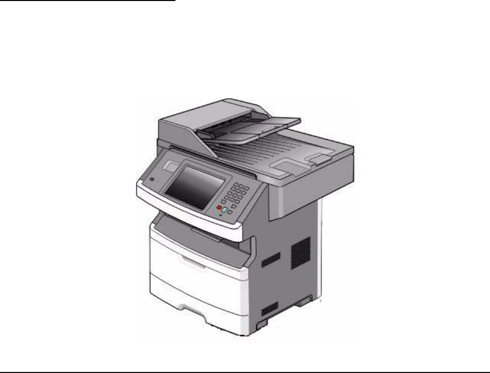
General information 1-1
7014-xxx
1. General information
The Lexmark™ X46x series MFPs are monochrome multifunction laser printers designed for single
users or small workgroups. The X46x MFPs allow users to print, copy, scan, and fax documents.
This book contains information on X46x series MFPs. n A4, 25ppm on legal).
Maintenance approach
The diagnostic information in this manual leads to the correct field replaceable unit (FRU) or part. Use the error
code charts, symptom index, and service checks to determine the symptom and repair the failure. See
“Diagnostics information” on page 2-1 for more information. See “Repair information” on page 4-1 to help
identify parts. After completing the repair, perform tests as needed to verify the repair.

1-2 Service Manual
7014-xxx
Print engine specifications
Memory
Print quality settings
Item Lexmark X463, X464 Lexmark X466
Standard memory 128MB 128MB
Maximum memory 640MB 640MB
Optional memory
128MB DDR SDRAM unbuffered DIMMS ✔ ✔
256MB DDR SDRAM unbuffered DIMMS ✔ ✔
512MB DDR SDRAM unbuffered DIMMS ✔ ✔
Optional flash memory
256 MB via flash memory card ✔ ✔
Optional font cards (DBCS) ✔ ✔
Option slots
ISP (INA) slot 1 1
Memory slots 1 1
Flash memory/option card 2¹ 2¹
¹ Both slots are active for either a 256MB Flash memory card, a font card, or a DLE. Multiple Flash, font, or DLE cards
are not supported.
Item Lexmark X463, X464 LexmarkX466
Print resolution
1200 Image quality¹ ✔ ✔
2400 Image quality² ✔ ✔
600 X 600 dpi ✔ ✔
1200 X 1200 dpi³ ✔ ✔
¹ 1200 Image quality is defined as 600 dpi with 2 bit IET (Image Technology) default mode for all models.
² 2400 Image quality is defined as 600 dpi with 4 bit IET.
³ True 1200 dpi at 1/2 the rated speed

General information 1-3
7014-xxx
Environment
Specified operating environment
Operating temperature range - 16 to 32 degrees C (60 to 90 degrees F
Humidity - 8 to 80% Relative humidity
Altitude 0 to 3048 meters (10,000 ft)
Dimensions
Height - 23.3 in (297mm)
Width - 20.87 in (530 mm)
Depth - 15.5 in (394 mm) w/ input tray set to letter, 16.14 in (410 mm) w/ input tray set to legal.
Connectivity and compatibility
Item Lexmark X463, X464 LexmarkX466
Data stream emulations
Host based printing ✔ ✔
PCL 5e and PCL 6 ✔ ✔
PostScript 3 ✔ ✔
PPDS migration tool ✔ ✔
PDF v1.6 ✔ ✔
XPS¹ ✔ ✔
HTML (including DBCS) ✔ ✔
Direct image ✔ ✔
Compatibility Windows/Macintosh/Linux Windows/Macintosh/Linux
Standard local connections
USB* ✔ ✔
Standard network connections
Ethernet (10/100 Base Tx) ✔ ✔
Wireless ethernet 802.11b/g/n x✔
Optional local connections
Optional network connections:
external print server support
✔ ✔
*All models are USB 2.0 Certified devices supporting Hi-Speed data transfer.
¹ Includes the HD photo image format
² Includes support for the following graphics formats: TIFF, TIF, JPG, GIF, PNG, BMP, PCX, AND DCX

1-4 Service Manual
7014-xxx
Media trays and supply capacity
Item Lexmark X463, X464 Lexmark X466
Available input trays
Integrated 250-sheet tray ✔ ✔
50-sheet MP feeder ✔ ✔
1-sheet manual feed slot x x
Optional input sources
250-sheet drawer ✔ ✔
550-sheet drawer ✔ ✔
Maximum input sheet capacity 850
(excluding envelopes)
850
(excluding envelopes)
Manual/integrated print duplex Integrated Integrated
Envelope conditioning x x
Available output trays
Standard 150-sheet sensing bin ✔ ✔
Toner and photoconductor
Toner cartridge 1,500 standard pages SWE¹
3,500 standard pages SWE¹ 7,000 standard pages SWE¹
High toner cartridge 9,000 standard pages¹ 9,000 standard pages¹
15,000 standard pages¹
Photoconductor kit Up to 30,000 ² Up to 30,000 ²
¹ Declared value in accordance with ISO/IEC 19752
² Up to 30,000 pages, based on an average of 3 pages per job and approximately 5% coverage per page. Yields may
vary based on customer usage.

General information 1-5
7014-xxx
Types of print media
Note: Ensure trays are properly loaded. Never mix media types within a tray.
Source Sizes Types Weight Input capacity* (sheets)
Input tray 1
(250-sheet tray)
A4, A5, A6,JIS¹-B5,
letter, legal, executive,
oficio (Mexico)², folio²,
statement
Plain paper,
recycled, labels,
bond, letterhead,
preprinted, colored
paper, light paper,
heavy paper,
rough/cotton,
custom type [x]
60-90 g/m²
(16-24 lb)
• 250 paper
• 50 labels**
2nd Drawer option
(250/550-sheet
drawer)
A4, A5, JIS¹-B5, letter,
legal, executive, oficio
(Mexico)², folio²,
statement
Plain paper,
recycled, labels,
bond, letterhead,
preprinted, colored
paper, light paper,
heavy paper,
rough/cotton,
custom type [x]
60-90 g/m²
(16-24 lb)
• 250 paper
• 550 paper
• 50 labels**
Multipurpose
feeder A4, A5, A6,JIS¹-B5,
letter, legal, executive,
oficio (Mexico)², folio²,
statement
Plain paper,
transparency,
recycled, labels,
bond, letterhead,
preprinted, colored
paper, light paper,
heavy paper,
rough/cotton,
custom type [x]
60-163 g/m²
(16-43 lb)
• 50 paper
• 15 lables**
• 10 transparencies
Card stock*** • 120-163 g/m²
(16-43 lb)
Index Bristol
• 75-163 g/m²
(46-100 lb)
Tag
20
7 ¾, 9, 10, DL, C5, B5,
other Envelopes
Rough envelopes 75 g/m² (20 lb) 7
Duplex A4, letter, legal, oficio
(Mexico)², folio² Plain paper,
recycled, bond,
letterhead,
preprinted, colored
paper, light paper,
heavy paper,
custom type [x]
60-90 g/m²
(16-24 lb)
* Capacity for 20 lb print media, unless otherwise noted.
** Use for occasional printing only.
¹Japanese Industry Standard
² If a source supports size sensing and is activated, then neither the “oficio” value nor the “folio” value appears in that
source’s list of supported media sizes. These values only appear in a source’s list of supported media sizes either when
the source is non-size sensing or when the source’s size sensing hardware is deactivated and then the device is power
cycled.
1-6 Service Manual
7014-xxx
Media guidelines
Paper characteristics
The following paper characteristics affect print quality and reliability. Consider these characteristics when
evaluating new paper stock.
•Weight—The printer can automatically feed paper weights from 60 to 176 g/m2 (16 to 47 lb bond) grain
long. Paper lighter than 75 g/m2 (20 lb) might not be stiff enough to feed properly, causing jams. For best
performance, use 80 g/m2 (21 lb bond) grain long paper. For paper smaller than 182 x 257 mm (7.2 x 10.1
in.), we recommend 90 g/m2 or heavier paper.
•Curl—Curl is the tendency for paper to curl at its edges. Excessive curl can cause paper feeding
problems. Curl can occur after the paper passes through the printer, where it is exposed to high
temperatures. Storing paper unwrapped in hot, humid, cold, or dry conditions, even in the trays, can
contribute to paper curling prior to printing and can cause feeding problems.
•Smoothness—Paper smoothness directly affects print quality. If paper is too rough, toner cannot fuse to it
properly. If paper is too smooth, it can cause paper feeding or print quality issues. Always use paper
between 100 and 300 Sheffield points; however, smoothness between 150 and 200 Sheffield points
produces the best print quality.
•Moisture content—The amount of moisture in paper affects both print quality and the ability of the printer
to feed the paper correctly. Leave paper in its original wrapper until it is time to use it. This limits the
exposure of paper to moisture changes that can degrade its performance. Condition paper before printing
by storing it in its original wrapper in the same environment as the printer for 24 to 48 hours before printing.
Extend the time several days if the storage or transportation environment is very different from the printer
environment. Thick paper may also require a longer conditioning period.
•Grain direction—Grain refers to the alignment of the paper fibers in a sheet of paper. Grain is either grain
long, running the length of the paper, or grain short, running the width of the paper. For 60 to 176 g/m2 (16
to 47 lb bond) paper, use grain long fibers.
•Fiber content—Most high-quality xerographic paper is made from 100% chemically treated pulped wood.
This content provides the paper with a high degree of stability resulting in fewer paper feeding problems
and better print quality. Paper containing fibers such as cotton possesses characteristics that can
negatively affect paper handling.
Unacceptable paper
The following paper types are not recommended for use with the printer:
•Preprinted papers with chemicals that may contaminate the printer
•Preprinted papers that can be affected by the temperature in the printer fuser
•Coated papers (erasable bond), synthetic papers, thermal papers
•Rough-edged, rough or heavily textured surface papers, or curled papers
•Recycled papers containing more than 25% post-consumer waste, and weighing more than 80 g/m2
•Paper weighing less than 60 g/m2 (16 lb)
•Multiple-part forms or documents
General information 1-7
7014-xxx
Selecting paper
Using appropriate paper prevents jams and helps ensure trouble-free printing. To help avoid jams and poor print
quality:
•Always use new, undamaged paper.
•Before loading paper, know the recommended print side of the paper. This information is usually indicated
on the paper package.
•Do not use paper that has been cut or trimmed by hand.
•Do not mix paper sizes, types, or weights in the same source; mixing results in jams.
•Do not use coated papers unless they are specifically designed for electrophotographic printing.
Selecting preprinted forms and letterhead
Use these guidelines when selecting preprinted forms and letterhead:
•Use grain long for 60 to 176 g/m2 weight paper.
•Use only forms and letterhead printed using an offset lithographic or engraved printing process.
•Avoid papers with rough or heavily textured surfaces.
Use papers printed with heat-resistant inks designed for use in xerographic copiers. The ink must be able to
withstand temperatures up to 200°C (392°F) without melting or releasing hazardous emissions. Use inks that
are not affected by the resin in toner. Inks that are oxidation-set or oil-based generally meet these requirements;
latex inks might not. When in doubt, contact the paper supplier.
Preprinted papers such as letterhead must be able to withstand temperatures up to 200°C (392°F) without
melting or releasing hazardous emissions.
Storing paper
Use these paper storage guidelines to help avoid jams and uneven print quality:
•For best results, store paper where the temperature is 21°C (70°F) and the relative humidity is 40%. Most
label manufacturers recommend printing in a temperature range of 18 to 24°C (65 to 75°F) with relative
humidity between 40 and 60%.
•Store paper in cartons when possible, on a pallet or shelf, rather than on the floor.
•Store individual packages on a flat surface.
•Do not store anything on top of individual paper packages.
Using recycled paper and other office papers
As an environmentally conscious company, Lexmark supports the use of recycled office paper produced
specifically for use in laser (electrophotographic) printers. In 1998, Lexmark presented to the US government a
study demonstrating that recycled paper produced by major mills in the US fed as well as non-recycled paper.
However, no blanket statement can be made that all recycled paper will feed well. Lexmark consistently tests its
printers with recycled paper (20–100% post-consumer waste) and a variety of test paper from around the world,
using chamber tests for different temperature and humidity conditions. Lexmark has found no reason to
discourage the use of today's recycled office papers, but generally the following property guidelines apply to
recycled paper.
•Low moisture content (4–5%)
•Suitable smoothness (100–200 Sheffield units, or 140–350 Bendtsen units, European)
Note: Some much smoother papers (such as premium 24 lb laser papers, 50–90 Sheffield units) and
much rougher papers (such as premium cotton papers, 200–300 Sheffield units) have been engineered to
work very well in laser printers, despite surface texture. Before using these types of paper, consult your
paper supplier.
•Suitable sheet-to-sheet coefficient of friction (0.4–0.6)
•Sufficient bending resistance in the direction of feed
1-8 Service Manual
7014-xxx
Recycled paper, paper of lower weight (<60 g/m2 [16 lb bond]) and/or lower caliper (<3.8 mils [0.1 mm]), and
paper that is cut grain-short for portrait (or short-edge) fed printers may have lower bending resistance than is
required for reliable paper feeding. Before using these types of paper for laser (electrophotographic) printing,
consult your paper supplier. Remember that these are general guidelines only and that paper meeting these
guidelines may still cause paper feeding problems in any laser printer (for example, if the paper curls
excessively under normal printing conditions).

General information 1-9
7014-xxx
Digital imaging specifications
General specifications
ADF Scan speed
Simplex ADF - Up to 25 ppm
Duplex ADF - Up to 35 ppm (page sides)
ADF Document handling
ADF input capacity - 50 sheets.
ADF output capacity - 50 sheets.
ADF document width - 4.9’’ (125mm) to 8.5’’ (216mm)
ADF document length - 5’’ (127mm) to 14.0” (356mm)
Resolution and color depth
•Flatbed maximum optical resolution - 600 x 600 dpi (Mono), 600 x 300 dpi (Color), with final resolution of
300 x 300 dpi
•CDD 1200 dpi, and 600 dpi. Selectable through electronics
•Color depth - 48 bit RGB output. 16 bit / channel
•Mono ADF optical resolution - Max 600 x 600 dpi
•Color ADF resolution - Max. 600 x 300 dpi (final resolution of 300 x 300 dpi)
Flatbed document specifications
•Flatbed scan area - Max. 8.5” x 14” (216mm x 355.6mm)
•Document size- Up to A4 and legal
•4.5’’ x 5.5’’ to 8.5’’x14’’ (SEF)
Flatbed speed
3 seconds to scan, 3 seconds to return.
Scanner operating environments
•Temperature - 16°C to 32°C (60° to 90° farenheit)
•Humidity - 8% RH to 80% RH
•Altitude 0 to 3048M (10000 feet)
Scan Preview
•Available on disk equipped models.
Storage environments (packed)
•Temperature - -40°C to 43.3°C (-40° to 110° farenheit)
•Humidity - 5% RH to 95% RH
•Altitude max - .25 atmosheric pressure
1-10 Service Manual
7014-xxx
Storage environments (unpacked)
•Temperature - 0° to 40°C
•Humidity - 5 to 80% relative humidity
Tilt
This device should operate within the stated parameters when it is level within 10mm from front to back and
10mm side to side.
General information 1-11
7014-xxx
Scan and copy specific specifications
Scan Resolutions
•Optical - 600 dpi (Local Twain only)
•Enhanced (vial Lexmark Scan Center) - 1200 X 1200 dpi, 2400 X 2400 dpi, 4800 X 4800 dpi, 9600 X 9600
dpi, 19200 X 19200 dpi
Output resolutions
•Mono - 600 X 600 dpi
•Color - 300 X 300 dpi
Duplex scan
Duplex and copy is available on all X46x series models.
Scan file output formats
•TIFF
•JPEG
•PDF and secure PDF
•XPS
Supported compressions
•PDF - (1 bit,- JBIG2 CCIT G4, Flate), (8/24 bit - Flate JPEG)
•TIFF - (1 bit - CCITT G4), (8/24 bit - Packbits, LZW)
•JPG - (8/24 bit-JPG)
Supported scan destinations
•Temporary profile from a user’s PC
•FTP
•Scan to PC via network TWAIN
•Scan to PC using Web applet
•Scan to E-Mail
•Scan to USB
•Windows network folder (requires installing embedded scan to folder application)
Multiple copies
999 copies maximum
Reduce / Enlarge
-25% to 400%
1-12 Service Manual
7014-xxx
Fax specifications
Phone network connectivity
Fax resolutions
Miscellaneous FAX specifications
Phone networks types supported PSTN or analog PABX (RJ-11)
ITU COMPATIBILITY
Standard Resolution
Fine
Superfine
Ultrafine
Coding
Group 3/ECM
8 x 3.85 pels/mm (200X100dpi) (204x98)
8 x 7.7 pels/mm (200X200dpi) (204x196)
11.8 x 11.8 pels/mm (300x300 dpi) (204x391)
15.7 x 15.7 pels/mm (600x600 dpi) (612x587)
ITU T.4 and T.6 (MH, MR, MMR, JPEG)
Modem speed V.34 2,400-33,600 BPS,
V.17 7,200-14,400 BPS,
V.27 2,400-4,800 BPS,
V.29 7,200-9,600 BPS
Compression MH, MR, MMR, JPEG
Error correction ITU T.30
Line interface selection
Modular Plug
Out Band Signal Level Dual RJ-11C
Guaranteed North American and Europe PTT standard
Input Level Range
Ring Detection -16dBm ~ -59dBm
Complies with all regulatory requirements
Receive 200x100 dpi, 200x200 dpi, 300x300 dpi,
400x400 dpi, 204x98 dpi, 204x196 dpi,
204x391 dpi, 408x391 dpi
Send 200x100dpi, 200x200 dpi, 300x300 dpi
Fax memory 4 MB Flash (More than 320 pages based on ITU chart #1)
User selectable parameters are stored in NVRAM.
Speed dial Non hard drive model - 500
Hard drive - >1800
Transmission Approximately 3 seconds per page
Fax Storage X464e-12mb (.5mb Fax logs + 11.5mb Fax Storage) 900
pgs
X466e-80GB Hard disk space 4096 fax jobs
Color fax Yes
Fax from PC Yes. Supported using PostScript driver for both local and
network attach modes.
Caller ID Yes
Junk FAX blocking Yes - based on caller ID and remote station ID
Tone/Pulse Tone: Default, Pulse: Yes
Fax forward Yes
Broadcasting Yes. 46 destinations
External phone interface Yes
Manual mode Yes
Fax shortcuts Yes.
Fax content Text, text/photo, photo
Fax perseveration Yes
Halftoning Yes

General information 1-13
7014-xxx
Tools
The removal and adjustment procedures require the following tools and equipment:
•Spring hook
•Needle nose pliers
•Volt-ohmmeter
•#1 and #2 Phillips screwdriver
•Slotted screwdriver

1-14 Service Manual
7014-xxx
Acronyms
ac Alternating Current
ACM Autocompensator Mechanism (or paper feed)
ADF Automatic document feeder
AFE Analog front end
AIO All-In-One
APS Automatic Paper Size
ASIC Application Specific Integrated Circuit
BLDC Brushless DC Motor
BOR Black Only Retract
CCD Charge-Couple Device
CCFL Cold Cathode Fluorescent Lamp
CCW Counter clockwise
CDB Command Descriptor Blocks
CMYK Cyan yellow magenta black
CPU Central processing unit
CRC Cyclic redundancy check
CRU Customer Replaceable Unit
CSU Customer Setup
CW Clockwise
DBCS Double byte character set
dc Direct Current
DIMM Dual Inline Memory Module
DLE Downloadable emulator
DRAM Dynamic random access memory
DVM Digital multimeter
ECC Error correcting code
ECM Error correction mode
EDO Enhanced Data Out
EEPROM Electrical Erasable Programmable Read-Only Memory
ENA External Network Adapter
EOL End of line
EP Electrophotographic process
EPROM Erasable programmable read-only memory
ESD Electrostatic Discharge
FB Flatbed
FD Facedown
FRU Field replaceable unit
FU Face up
GB Gigabyte
GFI Ground Fault Interrupter
GHz Gigahertz
HBP Host Based Printing
HCF High-capacity feeder
HCIT High-capacity Input Tray
HCOF High-Capacity Output Finisher
HCPF High-capacity feeder
HTML Hypertext markup language
HV High Voltage
HVPS High voltage power supply
HVU High voltage unit
Hz Hertz
General information 1-15
7014-xxx
INTL International
ITC Internal Tray Card
ITU Image Transfer Unit
KBlack (Key)
LAN Local area network
LASER Light amplification by stimulated emission of radiation
LCD Liquid crystal display
LCM Liquid Crystal Module
LD Laser Diode
LED Light emitting diode
LEF Long edge feed
LES Lexmark Embedded Solution (applications)
LSU Laser Scanning Unit
LV Low Voltage
LVPS Low voltage power supply
MB Megabyte
MDC Motor Driver Control
MFD Multifunction Device
MFP Multifunction Printer
MH Message handling
MIF Motor interface
mm millimeter
MMR Modified modified read
MPF Multipurpose feeder
MR Modem ready
MROM Masked Read Only Memory
MS Microswitch
NAND NAND (usage: NAND gate)
NVM Nonvolatile Memory
NVRAM Nonvolatile Random Access Memory
OCF Operator correctable failure
OEM Original Equipment Manufacturer
OHP Overhead projector
OPC Optical photo conductor
OPT Optical Sensor
PC Photoconductor
PDF Portable Document Format
PICS Problem isolation charts
PIN Personal identification number
PIXEL Picture element
PJL Printer Job Language
POR Power-on reset
POST Power-on self test
PPDS Personal Printer Data Stream
ppm Pages per minute
PQET Print Quality Enhancement Technology
PRC Peoples' Republic of China
PSC Parallel Synchronous Communications
PSD Position Sensing Device
PSO Participating Standards Organization
PWM Pulse Width Modulation
RAM Random access memory
RFID Radio frequency identification
RH Relative humidity
1-16 Service Manual
7014-xxx
RIP Raster image processor
ROM Read-only memory
ROS Read-only storage
RPM Revolutions Per Minute
SCC Scanner Control Card
SDRAM Synchronous Dynamic Random Access Memory
SEF Short edge feed
SIMM Single Inline Memory Module
SOL Solenoid
SOS Start of scan
SRAM Static random access memory
TAR Toner Add Roll
TPS Toner Patch Sensing
TTM Tandem Tray Module
TVOC Total Volatile Organic Compound
UAT Universally Adjustable Tray
UPR Used Parts Return
USB Universal Serial Bus
VVolts
V ac Volts alternating current
V dc Volts direct current
VOIP Voice over internet protocol
VOM Volt Ohmmeter
VTB Vacuum Transport Belt
XPS XML Paper Specification
Diagnostics information 2-1
7014-xxx
2. Diagnostics information
Start
Use the service error code, user status message, user error message, symptom table, service checks, and
diagnostic aids in this chapter to determine the corrective action necessary to repair a malfunctioning printer.
They will lead you to solutions or service checks, including use of various tests.
Symptom tables
If your machine completes the “Power–On Self Test (POST) sequence” on page 2-1 without an error and you
have a symptom, then go to “Service error codes” on page 2-26. Locate your symptom, and take the
appropriate action.
Service errors (8xx.xx / 9xx.xx’s)
If a service error code appears while you are working on the machine, then go to “Service error codes” on
page 2-26, and take the indicated action for that error.
Service error codes are indicated by a three-digit error code followed by a period and additional numbers in the
format XXX.YY. In most cases, five digits are shown.
User status and attendance messages
•User status messages provide the user with information on the current status of the printer. Ready displays
on the first line of the display unless invoked, and then Power Saver displays. If a user status message is
displayed, then go to “Service error codes” on page 2-26.
•User attendance messages are indicated by a two- or three-digit error code that provides the user with
information that explains a problem with a print cartridge, paper jam, option, port, and so on. If a user error
message displays, then go to “User attendance messages” on page 2-13 and “Paper jam error codes
(200-series)” on page 2-20.
Power–On Self Test (POST) sequence
The following is an example of the events that occur during the POR sequence when the printer is turned on.
1. Display screen illuminates and the memory test is initiated.
2. The Lexmark splash screen is displayed with a progress bar. The firmware revision is displayed in the
lower left of the screen.
3. Scanner calibration and testing initiates when the progress bar is two thirds finished.
4. Not Ready will be displayed if the cover is open.
5. Any cartridge errors, such as Defective Cartridge, are displayed in the message are at the bottom of the
screen.
6. Applicable maintenance messages are displayed.
7. Applicable toner low messages are displayed.
8. The red indicator light will flash if there are errors.
9. The printer displays Ready.
CAUTION
Unplug power from the printer before connecting or disconnecting any cable, assembly, or
electronic card. This is a precaution for personal safety and to prevent damage to the printer.

2-2 Service Manual
7014-xxx
Symptom tables
POST symptom table
Note: Investigate any displayed codes before proceeding with these symptoms. For example, a missing toner cartridge will
prevent POST from completing.
Symptom Action
The main motor, cooling fan, and fuser do not come
on. See “Cover interlock switch service check” on page 2-37.
POST completes, but the display does not come
on. See “Operator panel service check” on page 2-43.
Main motor does not come on. See “Main motor service check” on page 2-40.
Fan does not come on. See “Cooling fan service check” on page 2-37.
Fuser does not cycle. See “Fuser service check” on page 2-39.
Fuser does not turn on and off. See “Fuser service check” on page 2-39.
The paper feed picks and tries to feed media. See “Paper feed service checks” on page 2-43.

Diagnostics information 2-3
7014-xxx
Printer symptom table
Symptom Action
Touchscreen displays upside down
Fan noisy or fan not working. See “Cooling fan service check” on page 2-37.
Fuser parts melted. See “LVPS/HVPS service check” on page 2-39.
Toner not fused to the media. See“Fuser service check” on page 2-39 or “Solving print
quality problems” on page 2-51.
Paper jams. See “Paper feed service checks” on page 2-43.
Main motor noisy or not moving. See “Main motor service check” on page 2-40.
Media skew. See “Paper feed service checks” on page 2-43.
Printer not communicating with host. See “USB port service check” on page 2-46.
Front access door will not close. See “Cover interlock switch service check” on page 2-37.
Operator panel button not responding. See “Operator panel service check” on page 2-43.
Operator panel lights are off or very dim. See “Operator panel service check” on page 2-43.
Blank page. See “Blank page” on page 2-47.
Black page. See “Black page” on page 2-48.
Heavy background. See “Heavy background” on page 2-48.
Light print. See “Light print” on page 2-50.
White or black lines or bands. See “White or black lines or bands” on page 2-50.
Toner on back of page. See “Toner on back of page” on page 2-50.
Media never picks. See “Media never picks” on page 2-44.
Media feeds continuously. See “Media occasionally mispicks or picks multiple sheets
at once” on page 2-44.
Media wrinkled or bent. See “Media “trees,” wrinkles, stacks poorly, or curls” on
page 2-45.
Dead machine (no power). See “Dead machine service check” on page 2-38.
Print quality problems
• Light print
• Blurred characters
• Toner on both sides of media
• Toner not fused
• Streaks
• Blank pages
See “Solving print quality problems” on page 2-51.

2-4 Service Manual
7014-xxx
Scan / fax / copy symptom table
Symptom Action
840.xx scanner error Go to “840.xx service check” on page 2-55.
ADF won’t duplex (Duplex ADF only) Go to “ADF Duplex service check” on page 2-62.
ADF skew Go to “ADF feed errors service check” on page 2-60.
Multiple pages feed into ADF
Documents wont feed into ADF
Printer picks letter size paper on a legal
size scan This is a symptom of a failed paper legnth sensor.
Scanner makes buzzing noise on startup or
during a scan. Go to “Flatbed home position service check” on page 2-58.
Document feeds, but jams in ADF. Go to “ADF paper jam service check” on page 2-60.
Black streaks on scans Go to “ADF streak service check” on page 2-59.
Blank page Go to “Black or blank page copy service check” on
page 2-57.
Black page
No dial tone Go to “Modem / fax card service check” on page 2-63.
Machine dials a number but fails to make a
connection with another fax machine. The other fax machine may be turned off. Ask the fax recipient to
check their machine.
Incoming fax has blank spaces or poor
quality. 1. The sending fax machine may be faulty.
2. The sending fax machine may have a dirty document glass.
3. A noisy phone line can cause errors.
4. Check the MFP print quality by making a copy.
5. The print cartridge may be empty. Replace as necessary.
Invalid fax partition, or fax partition too
small. See Go to “Format Fax Storage” on page 3-7.
Some words on an incoming fax are
stretched. The sending fax machine had a temporary jam.
Faxes fail to transmit. Go to “Fax transmission service check” on page 2-64.
Fax reception fails. Go to “Fax reception service check” on page 2-66.
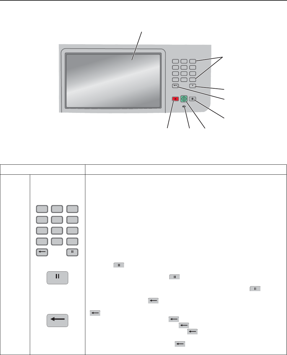
Diagnostics information 2-5
7014-xxx
Overview of the operator panel and menus
The use of the buttons and the layout of the display panel are described in the following table.
Item Description
1Display View scanning, copying, faxing, and printing options as well as status and error
messages.
2Keypad Enter numbers or symbols on the display.
3Dial Pause • Press to cause a two- or three-second dial pause in a fax number. In the
Fax To field, a Dial Pause is represented by a comma (,).
• From the home screen, press to redial a fax number.
• The button functions only within the Fax menu or with fax functions. When
outside of the Fax menu, fax function, or home screen, pressing causes
an error beep.
4Back In the Copy menu, press to delete the right-most digit of the value in the Copy
Count.The default value of 1 appears if the entire number is deleted by pressing
numerous times.
In the Fax Destination List, press to delete the right-most digit of a number
entered manually. You can also press to delete an entire shortcut entry. Once
an entire line is deleted, another press of causes the cursor to move up one
line.
In the E-mail Destination List, press to delete the character to the left of the
cursor. If the character is in a shortcut, then the shortcut is deleted.
12
ABC
3
DEF
6
MNO
5
JKL
4
GHI
9
WXYZ
8
TUV
7
PQRS
#0
*
1
2
4
5
6
7
8
3
12
ABC
3
DEF
6
MNO
5
JKL
4
GHI
9
WXYZ
8
TUV
7
PQRS
#0
*
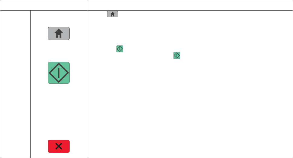
2-6 Service Manual
7014-xxx
5Home Press to return to the home screen.
6Start • Press to initiate the current job indicated on the display.
• From the home screen, press to start a copy job with the default settings.
• If pressed while a job is scanning, the button has no effect.
7Indicator light Indicates the printer status:
• Off—The power is off.
• Blinking green—The printer is warming up, processing data, or printing.
• Solid green—The printer is on, but idle.
• Blinking red—Operator intervention is needed.
8Stop Stops all printer activity
A list of options is offered once Stopped appears on the display.
Item Description
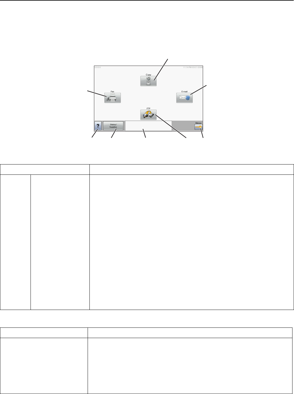
Diagnostics information 2-7
7014-xxx
Understanding the home screen
After the printer is turned on and a short warm-up period occurs, the display shows the following basic screen
which is referred to as the home screen. Use the home screen buttons to initiate an action such as copying,
faxing, or scanning; to open the menu screen; or to respond to messages.
Other buttons that may appear on the home screen:
Display item Description
1Copy Opens the Copy menus
Note: From the home screen, you can also access the Copy menus by pressing
a number on the keypad.
2E-mail Opens the E-mail menu
3Menus Opens the menus
These menus are available only when the printer is in the Ready state.
4FTP Opens the File Transfer Protocol (FTP) menus
Note: This function must be set up by your system support person. Once it is set
up, it appears as a display item.
5Status message bar • Shows the current printer status such as Ready or Busy.
• Shows printer conditions such as Toner Low.
• Shows intervention messages to give instructions on what you should do so
the printer can continue processing, such as Close door or Insert print
cartridge.
6Status/Supplies Appears on the display whenever the printer status includes a message requiring
intervention. Touch it to access the messages screen for more information on the
message, including how to clear it.
7Tips All menus have a Tips button. Tips is a context-sensitive Help feature within the
display touch screens.
8Fax Opens the Fax menus
Display item Description
Release Held Faxes If this button is shown, then there are held faxes with a scheduled hold time
previously set. To access the list of held faxes, touch this button.
Search Held Jobs Searches on any of the following items and returns search results:
• User names for held or confidential print jobs
• Job names for held jobs, excluding confidential print jobs
• Profile names
• Bookmark container or job names
• USB container or job names for supported extensions only
1
2
34567
8
Ready
Touch any button to begin.

2-8 Service Manual
7014-xxx
Held Jobs Opens a screen containing all the held jobs
Lock Device This button appears on the screen when the printer is unlocked and Device Lock-
out Personal Identification Number (PIN) has been set.
Touching this button opens a PIN entry screen. Entering the correct PIN locks the
printer control panel (touch screen and hard buttons).
Unlock Device This button appears on the screen when the printer is locked. The printer control
panel buttons and shortcuts cannot be used while it appears.
Touching this button opens a PIN entry screen. Entering the correct PIN unlocks
the printer control panel (touch screen and hard buttons).
Cancel Jobs Opens the Cancel Jobs screen. The Cancel Jobs screen shows three headings:
Print, Fax, and Network.
The following items are available under the Print, Fax, and Network headings:
•Print job
•Copy job
• Fax profile
•FTP
• E-mail send
Each heading has a list of jobs shown in a column under it which can show only
three jobs per screen. Each job appears as a button which you can touch to
access information about the job. If more than three jobs exist in a column, then
an arrow appears enabling you to scroll through the jobs.
Display item Description

Diagnostics information 2-9
7014-xxx
Using the touch-screen buttons
Note: Depending on your options and administrative setup, your screens and buttons may vary from those
shown.
Sample touch screen
Button Function
Home Returns to the home screen
Scroll down Opens a drop-down list
Left scroll decrease Scrolls to another value in decreasing order
Right scroll increase Scrolls to another value in increasing order
Left arrow Scrolls left
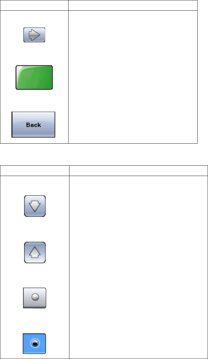
2-10 Service Manual
7014-xxx
Other touch-screen buttons
Right arrow Scrolls right
Submit Saves a value as the new user default setting
Back Navigates back to the previous screen
Button Function
Down arrow Moves down to the next screen
Up arrow Moves up to the next screen
Unselected radio button This is an unselected radio button. The radio button
is gray to show it is unselected.
Selected radio button This is a selected radio button. The radio button is
blue to show it is selected.
Button Function
Submit
Diagnostics information 2-11
7014-xxx
Cancel Jobs Opens the Cancel Jobs screen. The Cancel Jobs
screen shows three headings: Print, Fax, and
Network.
The following items are available under the Print,
Fax, and Network headings:
•Print job
• Copy job
• Fax profile
• FTP
• E-mail send
Each heading has a list of jobs shown in a column
under it which can show only three jobs per screen.
Each job appears as a button which you can touch to
access information about the job. If more than three
jobs exist in a column, then an arrow appears
enabling you to scroll through the jobs.
Continue Touch this button when more changes need to be
made for a job or after clearing a paper jam.
Cancel • Cancels an action or a selection
• Cancels out of a screen and returns to the
previous screen
Select Selects a menu or menu item
Button Function
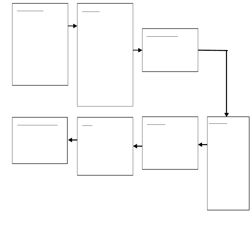
2-12 Service Manual
7014-xxx
Diagram of the printer menus
The diagram shows the menu index on the operator panel and the menus and items available under each menu.
Not all menus or selections will be available in all situations. These are accessed through the driver.
Paper Menu
Default Source
Paper Size/Type
Paper Type
Configure MP
Substitute Size
Paper Texture
Paper Weight
Paper Loading
Custom Types
Custom Names
Custom Scan Sizes
Universal Setup
Option Card Menu
Print PS Error
Font Priority
Reports
Menu Settings Page
Device Stats
Network Setup
Shortcuts
Fax Job Log
Fax Call Log
Copy Shortcuts
E-Mail Shortcuts
Fax Shortcuts
FTP Shortcuts
Profiles Setup List
Print Fonts
Print Directory
Demo
Asset Report
Network Ports
Active NIC
Standard Network
SMTP Setup
Standard USB
Security
Edit Security Setup
Misc Settings
Confidential Print
Disk Wiping
Security Audit Log
Set Date and Time
Settings
General
Copy
Fax
E-Mail
FTP
Flash Drive
Print
Help
Print All Guides
Copy Guide
E-Mail Guide
Fax Guide
FTP Guide
Print Defects Guide
Information Guide
Supplies Guide

Diagnostics information 2-13
7014-xxx
Messages and error codes
User attendance messages
The printer control panel displays messages describing the current state of the printer and indicates possible
printer problems that must be resolved. This topic provides a list of all printer messages, explains what they
mean, and tells how to clear the messages.
The following table lists the messages in alphanumerical order. A message can also be located using the index.
User status and attendance messages
User primary message Explanation
Change <src><Custom
type name> This IR allows a user to override the source for the remainder of a job. The page
will be printed as it is formatted on the paper installed in the tray. This may cause
clipping. No further Change prompts will be posted for the remainder of the current
job.
The following actions can be taken:
• Change the paper source to a custom type / custome string /source and size/
source, type, size.
• Continue the print job.
• Request more information.
• Use the current source.
• Reset the active.
• Wait fir supplies.
Change <src><Custom
String>
Change <src><size>
Change
<src><type><size>
Close Door Message clears when front doors is closed.
Disk Corrupted.
Reformat? This message appears if there is a corrupted hard disk. Reformat the drive. If the
message remains, replace the disk.
Weblink server not setup.
Contact system
administrator
Web Link is being used for e-mail, and either the 'Server' or 'Web Link' fields are
NULL in the Web Link Setup.
• The system administrator needs to configure the server.
SMTP server not setup.
Contact system
administrator
The devices primary and secondary SMTP fields are blank. This needs to be
configured by the system administrator.
No Analog Phone Line An analog line is not detected as being plugged into the modem. If the device is in
Analog mode, this has a source of Fax. If the device is in Fax Server mode, and
the 'Enable analog receive' Fax Server setting is set to 'On', this has a source of
Fax Receive. If the device is in Fax Server mode and the 'Enable analog receive'
Fax Server setting is set to 'Off', then this IR is not generated.
Memory Full, cannot print
faxes Attempted print is automatically canceled. The Fax code will recognize that the
print job has been canceled and will not delete pages in the fax job that have not
printed. Fax will not attempt to reprint the fax that generated the out of memory
error until a POR is performed.
Memory Full, cannot
send faxes After a start, there is no memory to do the fax job. Attempted fax is cancelled.
Fax server ‘To Format’
not set up Device is in Fax Server mode. The To format for the Fax Server setup is null.
Analog receive still possible.
Fax Station number not
set up.
Held jobs may not be
restored This message is only posted once after the firmware has tried to restore all of the
jobs on disk, regardless of the number of held jobs that were not restored. There
are three versions of this IR, depending upon cause. IRHeldA occurs when any
other condition occurs which stops the printer from restoring jobs from disk. These
might include disk failure, user abort, etc.

2-14 Service Manual
7014-xxx
Held jobs may not be
restored (Insufficient
Memory 37)
This message is only posted once after the firmware has tried to restore all of the
jobs on disk, regardless of the number of held jobs that were not restored. There
are three versions of this IR, depending upon cause. IRHeldB occurs when the
printer runs out of memory while attempting to restore jobs from disk.
Held jobs may not be
restored (Config Change
57)
This message is only posted once after the firmware has tried to restore all of the
jobs on disk, regardless of the number of held jobs that were not restored.
There are three versions of this IR, depending upon cause. IRHeldC occurs when
the printer could not restore jobs from the disk because the configuration of the
printer has changed. Some of these said configuration changes are code version
changes, paper handling option(s) removed, or the disk was moved from a
different model or speed of printer.
Load <source> <custom
string>Printer does not detect media meeting the description <custom string> in
<source>, where <source> is Tray 1, Tray 2, Multi-Page Feeder (MP feeder), or
Envelope Feeder.
• Load the input source with the correct type and size media.
• Cancel the current job.
Load <source>
<custom type>Printer does not detect media meeting the description <custom type> in <source>,
where <source> is Tray 1 or Tray 2.
• Load the input source with the correct type and size media.
• Cancel the current job.
Load <source>
<size>Printer does not detect media meeting the size requested in the source indicated.
• Load the input source with the correct type and size media.
• Cancel the current job.
Load <source>
<type> <size>Printer does not detect media meeting the size or type requested in the source
indicated.
• Load the input source with the correct type and size media.
• Cancel the current job.
Load Manual
<custom type>Printer does not detect media meeting the description <custom type> in the single
sheet feeder (manual feeder).
The following actions can be taken:
• Load paper, and the job continues.
•press Select ( ), and choose an alternate source for media.
• Cancel the current job.
Load Manual
<custom string>Printer does not detect media meeting the description <custom string> in the
single sheet feeder (manual feeder).
The following actions can be taken:
• Load paper and the job continues.
•press Select ( ), and choose an alternate source for media.
• Cancel the current job.
Load Manual
<size>Printer does not detect media meeting the description <size> in the single sheet
feeder (manual feeder).
The following actions can be taken:
• Load paper and the job continues.
•press Select ( ), and choose an alternate source for media.
• Cancel the current job.
User status and attendance messages (Continued)
User primary message Explanation

Diagnostics information 2-15
7014-xxx
Load Manual
<type> <size>Printer does not detect media meeting the description <type> and <size> in the
single sheet feeder (manual feeder).
The following actions can be taken:
• Load paper and the job continues.
•press Select ( ), and choose an alternate source for media.
• Cancel the current job.
Paper Changes Needed Change or load new media.
PJL OP Message
PJL Seed Message
PJL ST Message Try one or more of the following:
•press Select ( ) to clear the message, and continue printing.
• Wait for the message to clear.
Remove Paper ADF This posts when there is paper detected in the ADF upon POR or when the cover
is closed (or any other situation that re-inits the scanner). Message clears when
paper is removed.
Remove Paper
Standard Bin The standard output bin is full or nearly full. Remove the media from the bin.
Restore Held Jobs. Go/
Stop? Held jobs were found on disk after a power on/off reset. Restoring will make these
jobs available. Jobs may also be restored at a later time by turning off and
restarting the printer.
The following actions can be taken:
•Restore
• Do not restore
• More information
Securly Clearing Disk
Space This message appears when all blocks of the disk are cleared.
Unsupported USB
Device, Please Remove Remove the unrecognized device from the USB port on the front of the printer.
Unsupported USB Hub,
please remove Remove the unrecognized USB hub/device from the USB port on the front of the
printer.
Unsupported Disk Remove the unsupported disk before continuing.
34 Short Paper • press Select ( ) to clear the message and continue printing.
The printer does not automatically reprint the page that prompted the
message.
• Check tray length and width guides to ensure paper is properly fitted in the
tray.
• Make sure the print job is requesting the correct size of paper.
• Adjust the Paper Size setting for the size paper you are using.
If MP Feeder Size is set to Universal, make sure the paper is large enough for
the formatted data.
• Cancel the current job.
User status and attendance messages (Continued)
User primary message Explanation

2-16 Service Manual
7014-xxx
35 RES Save Off
Deficient Memory This message displays when the printer lacks sufficient memory to enable
Resource Save. This message usually indicates the user has allocated too much
memory for one or more of the printer link buffers; however, modification of other
printer settings which affect the amount of available memory may also create this
condition. If restoration of Resource Save is required after this message is
received, the customer should install additional memory or set each link buffer to
Auto. Once all link buffers are returned to Auto, you should exit the menu to
activate the link buffer changes. Once the printer returns to the Ready state, you
can enable Resource Save and go back and modify the link buffers again. Note
the reduction of available memory to the link buffers when Resource Save has
been enabled, and compare it to the memory available when Resource Save is
disabled.
•press
Select ( ) to disable Resource Save and continue printing.
To enable Resource Save after you get this message:
- Make sure the link buffers are set to Auto, then exit the menus to activate
the link buffer changes.
- When Ready is displayed, enable Resource Save.
• Install additional memory.
37 Insufficient Collation
Area This message is displayed when the printer memory used to store pages is too full
to collate the print job.
The following actions can be taken:
•press Select ( ) to print the portion of the job already stored, and begin
collating the rest of the job.
•press Menus ( ) to access the Busy/Waiting Menu.
The following functions are available.
- Cancel Job
Note: Menu Lockout does NOT prevent access to the Busy/Waiting Menu.
37 Insufficient memory
for flash defragment
operation
This message is displayed when insufficient printer memory is available to perform
Flash Memory Defragment operation.
This message appears prior to the actual start of the defragment operation.
press Select ( ) to stop the defragment operation.
To perform the defragment operation, you can:
• Delete fonts, macros, and other data in RAM.
• Install additional printer memory.
•press Menus ( ) to access the Busy/Waiting Menu.
The following functions are available using the Busy/Waiting Menu:
- Cancel Job
- Reset Printer
Note: Menu Lockout does NOT prevent access to the Busy/Waiting Menu.
38 Memory Full This message is displayed when the printer is processing an incoming job and
there is not enough memory available to continue processing the job.
The following actions can be taken:
• Determine how to make more memory available to your print job by:
- Deleting fonts, macros and other data in RAM.
- Simplify your print job.
- Install additional memory
•press Select ( ) to clear the message and continue printing.
The job may not print correctly.
•press Menus ( ) to access the Busy/Waiting Menu.
The following functions may be available:
- Cancel Job
User status and attendance messages (Continued)
User primary message Explanation
Diagnostics information 2-17
7014-xxx
39 Complex Page This message is displayed when a page is too complex to print.
The following actions can be taken:
•press
Select ( ) to clear the message and continue printing.
The job may not print correctly.
• Simplify the print job.
•press Menus ( ) to access the Busy/Waiting Menu.
The following functions may be available:
- Cancel Job
- Reset Printer
Note: Menu Lockout does NOT prevent access to the Busy/Waiting Menu.
50 PPDS Font Error This error only occurs when a printer is formatting PPDS print data.
The PPDS interpreter has detected a font error. When a specific font, which is not
installed, is requested based on a PPDS mode Set Font Global command, a
Select Code Page command, or a Comprehensive Font Selection command, and
the printer Best Fit setting is off. If Best Fit is on, the printer performs a best fit
search to find a similar font, and this error does not occur.
This error also displays when the printer receives invalid PPDS download font
data.
The following actions can be taken while this message is displayed:
•press Select ( ) to clear the message and continue printing.
The job may not print correctly.
•press Menus ( ) to access the Busy/Waiting Menu.
The following functions may be available:
- Cancel Job
51 Defective Flash
Detected press Select ( ) to clear the message and continue printing.
You must install different flash memory before you can download any resources to
flash.
52 Flash Full • press Select ( ) to clear the message and continue printing.
• Delete fonts, macros, and other data stored on the flash memory.
• Install a larger capacity flash memory card.
53 Unformatted Flash press Select ( ) to clear the message and continue printing.
You must format the flash memory before you can store any resources on it. If the
error message remains, the flash memory may be defective and require replacing.
54 Standard Network
Software Error This message is displayed when the RIP software detects that a network port is
installed but cannot establish communications with it.
•press
Select ( ) to clear the message and continue printing.
The job may not print correctly.
• Program new firmware for the network interface.
• Turn the printer power off and then back on to reset the printer.
54 Network <x> Software
Error The printer disables all communications to the associated network interface. No
data may be received or sent from or to the associated interface. The user can
program new firmware in the network using the parallel port after this message
clears.
•press
Select ( ) to clear the message and continue printing.
The job may not print correctly.
• Program new firmware for the network interface.
• Turn the printer power off and then back on to reset the printer.
55 Unsupported Option in
Slot <x> An unsupported option is installed in the specified solutions port. Power off the
printer and remove the unsupported option in the specified slot.
Remove the unsupported option.
56 Parallel Port <x>
disabled This error displays when data is sent to the printer across an optional parallel port,
but the port has been disabled. Once this message displays, reporting of further
errors is suppressed until the menus are entered, or the printer is reset.
User status and attendance messages (Continued)
User primary message Explanation

2-18 Service Manual
7014-xxx
56 Serial Port <x>
disabled This error displays when data is sent to the printer across an serial port, but the
port has been disabled. Once this message displays, reporting of further errors is
suppressed until the menus are entered, or the printer is reset.
56 Standard USB
Port Disabled This message may appear when data is sent to the printer across a USB port, but
the port is disabled.
Note: Once the error is displayed the first time, reporting of further errors is
suppressed until the printer is reset or menus are entered.
The following actions can be taken:
•press
Select ( ) to clear the message.
Any data received on the USB port is discarded.
•press Menus ( ) to access the Busy/Waiting Menu.
The following functions may be available:
- Turn the printer power off and then back on to reset the printer.
- Reset Active Bin
- Check Supply Levels
Make sure the USB Buffer menu item is not set to Disabled. (press Menus to
access the Administrative Menus, select Network/Ports, USB Menu, and
USB Buffer.)
58 Too many Flash
Options Installed 1. Turn off and unplug the printer.
2. Remove the excess flash memory.
3. Plug in the printer, and turn it on.
58 Too Many
Trays Attached 1. Turn off and unplug the printer.
2. Remove the additional trays.
3. Plug in the printer, and turn it on.
59 Incompatible Tray <x> An incompatible tray is installed. For Tray x, x= 2, 3, 4, or 5.
Remove the incompatible tray and press to clear the message.
If the user installed the incompatible device to satisfy a Check Device
Connections/reattach message, the user should reinstall an associated
compatible option or hot unplug the option.
1. Turn off and unplug the printer.
2. Remove the incompatible trays.
3. Plug in the printer, and turn it on.
61 Defective Disk This error code displays when the printer detects a defective disk. This error may
occur at power on or during disk format and write operations. While this message
displays.
Press to clear the message. The disk is marked defective and normal printer
operations continue. Disk operations are not allowed with a defective disk. The
Format Disk menu is not shown.
62 Disk Full This error code displays when there is not enough free space on the disk to hold
the resources that have been requested to be written to the disk. This message
displays for both resource and PostScript Disk operators when the disk is full.
63 Unformatted Disk The optional disk is not formatted.
Format the disk. If the error remains after formatting, the disk may be defective.
80 Routine Maintenance The operator panel displays this message at each 300K page count interval. It is
necessary to replace the fuser assembly, transfer roller, charge roll, and pick rolls
at this interval to maintain the print quality and reliability of the printer. The parts
are available as a maintenance kit. See “Maintenance kits” on page 6-1.
84 PC Kit Life Warning Replace the PC kit to ensure print quality.
84 Replace PC Kit
88 Cartridge Low This warning is displayed when the cartridge is low. Press Check to continue.
88 Cartridge Early Life
Warning
User status and attendance messages (Continued)
User primary message Explanation

Diagnostics information 2-19
7014-xxx
1565 Emul Error Load
Emul Option This message is displayed when the DLE's version contained in the firmware card
will not function with the printer code. The message will automatically clear in 30
seconds, and the DLE will be disabled. Other printer functions are not affected.
The correct version of the DLE must be downloaded. Contact the second level
support for the correct DLE version.
Scanner ADF cover open The cover to the ADF is open.
• Close the ADF cover. If this doesn’t remedy the problem, Go to “ADF cover
open service check” on page 2-59”.
Scan job too long The scan job exceeds the maximum number of pages
• Break the scan job into multiple small jobs.
• Cancel the scan job.
Scan Paper cleared Paper is cleared from ADF
• Cancel job
• Restart job - This can only be performed if job recovery is enabled and the job
can be restarted. A new job with the same parameters is started.
User status and attendance messages (Continued)
User primary message Explanation

2-20 Service Manual
7014-xxx
Cartridge error messages
Paper jam error codes (200-series)
Note: The Event log (See “EVENT LOG” on page 3-32) will list any of these errors that have occurred.
Repeating jams or jam messages can be caused by any of the following:
•Faulty/contaminated pick solenoids or worn cams of the solenoids.
•Faulty/contaminated flags or springs.
•Debris in the paper path.
•Media not of the specified length.
•Faulty media feed clutch. See “Media feed clutch service check” on page 2-40.
Error Description Action
30 Invalid refill Replace the cartridge.
31 Missing or defective cartridge
32 Unsupported print cartridge
Error Description Action
200.00 Paper jam around input sensor. Remove the PC kit and paper or debris at the input
sensor.
200.01 Classic input jam. The media is too long over the input
sensor. Possible causes include multi-sheet feed, tray
size sensing problem, and media slippage.
First, remove the PC kit and paper or debric at the
input sensor. Then, inspect the flag on the input
sensor. It should rotate freely. Replace the sensor if
necessary. Finally, check the paper size settings in
the printer and the driver.
200.02 The main input sensor never became uncovered from
the sheet ahead.
200.03 The video never started on the page at the input
sensor within two inches after hitting the input sensor Check the printhead. See “Printhead service
check” on page 2-54.
200.04 The media at the input sensor before interrupt
occurred–not enough time elapsed since the printhead
started to expect the printhead mirror motor lock.
Possible causes include bouncy sensor or
exceptionally fast pick– perhaps due to media pre-
staged in the source tray.
Carefully remove the tray and notice if the leading
edge of the media is pointed upward and out of the
tray. If so, then inspect the tray wear strips and
replace if necessary.
Inspect the input sensor flag and replace it if it does
not rotate freely or is too loose.
200.06 Imaged page not expected page (bouncy passthru
sensor) Remove the toner cartridge/PC kit. At the front,
remove the upper front guide, and inspect the flag on
the manual input sensor. If the flag is loose, then
replace it. See “Media manual input sensor” on
page 2-54.
200.08 Media reached the input sensor before the EP was
ready Inspect the tray for prestaging. Verify the proper
media and inspect the tray wear strips. Replace the
wear strips if necessary.
200.09 Transfer servo never started Inspect the LVPS/HVPS. See “Engine board
service check” on page 2-36.

Diagnostics information 2-21
7014-xxx
200.12 Media detected at manual feeder sensor when not
expected. Possible causes include user insert of media
when motor is running or pre-staged media in the tray.
Carefully remove the tray and notice if the leading
edge of the media is pointed upward and out of the
tray. If so, then inspect the tray wear strips and
replace if necessary.
Inspect the input sensor flag and replace it if it does
not rotate freely or is too loose.
200.13 The input sensor is covered when the media is not
expected (media in machine during warm-up) Remove the toner cartridge/PC kit and inspect the
input sensor flag. Replace the flag if necessary.
200.14 Trailing edge cleared manual feed, but did not
successfully debounce the sensor. Potential causes
are a small gap or a bouncy manual feed sensor.
Remove the toner cartridge/PC kit. At the front,
remove the upper front guide, and inspect the flag on
the manual input sensor. If the flag is loose, then
replace it. See “Media manual input sensor” on
page 2-54.
200.15 UNRECOVERABLE NO GAP JAM. Engine detected
no gap at the manual feeder sensor, attempted to
open the gap by stopping the feed rolls, but no trailing
edge was ever seen at the input sensor.
Remove the toner cartridge/PC kit. At the front,
remove the upper front guide, and inspect the flag on
the manual input sensor. If the flag is loose, then
replace it. See “Media manual input sensor” on
page 2-54.
Verify that the media is approved. Inspect the wear
strips in the input tray, and replace if necessary.
200.16 Transport motor error detected Inspect the main motor. See “Main motor service
check” on page 2-40.
200.17 Took too long to ramp up transport motor
200.18 Manual feeder sensor never became uncovered from
the sheet ahead. Remove the toner cartridge/PC kit. At the front,
remove the upper front guide, and inspect the flag on
the manual input sensor. If the flag is loose, then
replace it. See “Media manual input sensor” on
page 2-54.
200.19 The media never reached the input sensor, but was
detected at manual feeder sensor. Remove the toner cartridge/PC kit, and inspect for
debris in the paper path. Check the bottom of the PC
kit for any obstructions. Remove the upper front
guide, and inspect the pinch rollers.
200.20 The media is too long over the manual feeder sensor.
Possible causes include multi-sheet feed, media size
(length) problem, pre-staged media in the tray.
Verify that the media is approved. Inspect the wear
strips in the tray, and replace if they are worn.
200.22 FAILED SMALL GAP OR NO GAP JAM RECOVERY.
Engine detected small gap or no gap at the manual
feeder sensor, opened the gap by stopping the feed
rolls, but never saw the leading edge of the second
page at the input sensor.
200.23 Laser Servo never started due to potential conflict with
the transfer servo. Possible causes: slow or missing
transport motor positional feedback, or the media is
transferred too quickly to the input sensor.
Verify that the media is approved. Inspect the wear
strips in the tray, and replace if they are worn.
Check the main motor. See “Main motor service
check” on page 2-40.
200.24 The measured gap at the input sensor is too small to
meet the video delivery requirements. (There is not
enough time since prior image finished to start new
image)
Verify that the media is approved. Inspect the wear
strips in the tray, and replace if they are worn.
200.26 The trailing edge never cleared the input sensor when
feeding out the media that was detected during warm-
up.
Error Description Action

2-22 Service Manual
7014-xxx
200.27 Printhead Driver: Mirror motor fell out of lock condition
after the media at the input sensor–more time elapsed
since the printhead than the expected stable lock time,
but less than the printhead jitter-stable specification.
Check the printhead. See “Printhead service
check” on page 2-54.
Mirror motor fell out of lock condition after media at the
input sensor–more time elapsed since the printhead
than expected stable lock time, but less than the
printhead jitter-stable specification.
200.28 First writing line of a page at the developer nip, but
laser servo cleanup is not complete. Likely pre staged
media or a fast paper feed.
Verify that the media is approved. Inspect the wear
strips in the tray, and replace if they are worn.
200.29 Printhead drive control out of range due to an external
event beyond what the control is designed to handle.
Probable causes: ESD or noise on hsync signal.
Check the cable routing for the printhead. See
“Printhead service check” on page 2-54.
200.30 Narrow media sensor covered during warm-up. Check that the narrow media flag rotates freely and
securely. If it is dislodged or broken, then repalce the
rear exit guide. See “Rear exit guide assembly
with sensor and reversing solenoid removal” on
page 4-78.
200.32 Media more than 14 inches too long over the manual
feeder sensor. Possible causes include multi-sheet
feed or pre-staged media in the tray.
Verify that the media is approved. Inspect the wear
strips in the tray, and replace if they are worn.
200.33 Page from tray 1 did not reach the input sensor after
multiple attempts. Page did make it out of the tray at
least as far as the manual feeder sensor. Possible
cause is that the page stalled at the alignment gate.
Verify that the pick tires are clean, not worn, or filled
with paper dust. Replace the pick tires if necessary.
See “ACM pick tire roller removal” on page 4-3.
The alignment roller may be binding. Call the next
level of support.
200.34 Timed out waiting for page from tray 1 to reach the
input sensor after multiple pick attempts, but the page
was later detected at the input sensor while waiting for
any page(s) ahead to clear the paper path. Possible
cause is that the page is delayed at the alignment
gate.
200.35 Failed to create hsync during auto alignment Check the printhead. See “Printhead service
check” on page 2-54.
200.36 Lost hsyncs during auto alignment
200.37 Timeout on data collection during auto alignment
200.38 Interpage servo gap is smaller than expected for
printhead offset target evaluation
200.42 Rogue sheet is at the manual feed sensor while
flushing the paper path prior to declaring MPF source
empty.
Retry alignment.
200.43 The media is at the input sensor before interruption
occurs. Possible causes include bouncy sensor or an
exceptionally small gap, perhaps due to the media
being pre-staged in the source tray.
Remove the media, realign the stock, and re-insert.
Do not let the top sheets to go beyond the wear
strips.
201.00 Paper jam between input and exit sensor Remove the toner cartridge/PC kit and check for
obstructions between the input sensor and the fuser.
if the media continues to stop at the entrance or in
the fuser, then replace the fuser. See “Fuser
removal” on page 4-28.
201.01 Transport motor identification failed to identify either
motor after two tries. Check the main motor. See “Main motor service
check” on page 2-40.
Error Description Action

Diagnostics information 2-23
7014-xxx
201.02 Exit sensor never made by leading edge of page. Also
known as internal jam. Remove the PC kit and paper or debris at the input
sensor.
201.03 Video never started on the page at the input sensor
within two inches after hitting the input sensor Check the printhead. See “Printhead service
check” on page 2-54.
201.05 Restart attempted after an internal jam without the
cover open/close event. It is likely that the jam was
never cleared.
Check the paper path and remove any media in the
path.
201.25 Exit sensor never made by leading edge of media
when feeding out the media that was detected during
warm-up.
Remove the toner cartridge/PC kit and check for
obstructions between the input sensor and the fuser.
if the media continues to stop at the entrance or in
the fuser, then replace the fuser. See “Fuser
removal” on page 4-28.
201.26 Page at fuser nip before fuser started ramping toward
desired temperature. Indicates code may be receiving
more interrupts than intended
201.27 Page at fuser nip before fuser reached acceptable
operating temperature. Page arrived at fuser earlier
than expected, so it was probably staged prematurely.
202.00 Paper jam around exit sensor. Open the rear cover and look for obstructions in the
path way. If there are none, then inspect for damage
at the fuser, rear door, exit guide, and top cover.
Often, the leading edge of the media will indicate the
vacinity of damage. If damage is found, then replace
the damaged part.
Note: Print a page with the rear door open to isolate
the fuser from the other parts.
202.01 Exit sensor never broke on the trailing edge of the
sheet at the exit sensor. Open the rear door, and inspect the flag on the exit
sensor. The flag is located behind the fuser exit
rollers, about mid printer. If the flag does not rotate
freely or has no spring action, then replace the fuser.
See “Fuser removal” on page 4-28.
202.02 Exit sensor never broke from sheet ahead of page
heading toward the exit sensor.
202.06 Exit sensor bounced
202.13 Exit sensor covered, media not expected (media not in
machine during warm-up)
202.25 Exit sensor never broke from the sheet ahead of the
page heading toward the exit sensor when feeding out
the media detected during warm-up.
202.26 Trailing edge never cleared exit sensor when feeding
out media that was detected during warm-up. Open the rear door, and inspect the flag on the exit
sensor. The flag is located behind the fuser exit
rollers, about mid printer. If the flag does not rotate
freely or has no spring action, then replace the fuser.
See “Fuser removal” on page 4-28.
202.32 Long media or shingled multi feed stopped before
sending to duplex. Check the paper setting and correct if needed. While
feeding along the media, and immediately after it
enters the output bin, open the reat door and
obscure the trailing edge and the sensor flag. If there
is slippage in the exit guide, then replace the exit
guide. See Go to “Rear exit guide assembly with
sensor and reversing solenoid removal” on
page 4-78.
Error Description Action

2-24 Service Manual
7014-xxx
231.00 Duplex jam while reversing into the device Open the rear cover and look for obstructions
between the rear cover ribs, the fuser exit rollers,
and below. The media entering the duplex passes
outside the exit roller while the media exiting the
fuser passes above and inside the exit rollers.
Remove the tray, open the duplex door, and remove
the obstructions. If there are no obstructions and the
problem persists, then disconnect all of the cables,
tilt the printer onto its back (be sure to protect the
antenna on a wireless unit), and inspect the flag of
the duplex sensor. If the flag does not rotate freely,
then replace the paper input and duplex sensor. See
“Paper input and duplex sensor assembly
removal” on page 4-73.
Check the belt and drive of the duplex unit. Replace
it if necessary.
231.01 Duplex sensor never made by leading edge reversing
into the duplex.
231.02 Bouncy duplex sensor never made.
233.00 Duplex jam while picking from the device
233.01 Page in duplex never picked.
233.02 Feed error picking from the duplex.
233.03 Paper never reached the input sensor, but was
detected at the manual feed sensor.
234.01 Duplex sensor covered during warm-up.
235.01 Invalid duplex media (Unsupported size) Check the media. Duplex supports A4, letter, legal,
oficio, and folio media sizes.
241.00 Paper jam near tray 1. Remove the tray and inspect the media path for
obstructions. Check the pick rollers. Replace the pick
rollers if they are worn or clogged with dust. See
“ACM pick tire roller removal” on page 4-3. Also
check the wear strips, and replace if necessary.
241.10 Second pick attempt failed from Tray 1
241.12 Second pick from manual feeder, tray 1, or feeder
failed when the media was in the source while other
sheets were committed to the paper path.
Remove the tray and inspect the media path for
obstructions. Check the pick rollers. Replace the pick
rollers if they are worn or clogged with dust. See
“ACM pick tire roller removal” on page 4-3. Also
check the wear strips and the manual feeder, and
replace if necessary.
241.16 Failed to feed from tray 1. Pages in the paper path
have been flushed to the output bin.
241.17 MISIDENTIFIED SMALL GAP JAM. Engine detected
small gap at the manual feeder sensor, attempted to
open the gap by stopping the feed rolls, trailing edge
was seen at the input sensor, manual feeder sensor is
no longer covered.
241.19 Second pick attempted failed from Tray 1, no pages
printed since calling a 241.10 or a prior 241.19.
242.00 Paper jam near tray 2. Remove Tray 2 and inspect for obstruction in the
paper path. Check the pick tires for wear or paper
dust. Replace if necessary. Check the wear strips
and replace if necessary.
242.01 Took too long to ramp up dc feed motor Check the connection with Tray 2. (Lift the printer
and re-set it on Tray 2.) If the error persists, then
replace Tray 2.
242.08 Received lots of dc feed interrupts before losing them
242.10 Second pick attempt failed from Tray 2 Remove Tray 2 and inspect for obstruction in the
paper path. Check the pick tires for wear or paper
dust. Replace if necessary. Check the wear strips
and replace if necessary.
242.12 Second pick from manual feeder, tray 1, or feeder
failed when media was in the source, other sheets
were committed to the paper path.
Check the wear strips and replace them if worn.
242.16 Failed to feed from tray 2. Pages in the paper path
have been flushed to the output bin. Remove Tray 2 and inspect for obstruction in the
paper path. Check the pick tires for wear or paper
dust. Replace if necessary. Check the wear strips
and replace if necessary.
Error Description Action

Diagnostics information 2-25
7014-xxx
251.00 Paper jam near the manual feeder. Inspect the pick roller on the MPF or the rollers on
the manual feed. If the MPF pick roller is damaged or
worn, then replace the MPF. For a printer with a
manual feed only (no MPF), clean the roller.
251.10 Second pick attempt failed from manual feeder.
251.11 Failed to feed from manual feeder. Pages in the paper
path have been flushed to the output bin.
251.12 Second pick from manual feeder, tray 1, or feeder
failed when media was in the source while the other
sheets were committed to the paper path.
251.19 Media never reached the input sensor from the manual
feeder.
251.20 The media in the MPF has been pushed in too far. Remove the media, realign the stock, and re-insert.
Do not let the top sheets to go beyond the wear
strips.
251.21 The media in the MPF has been pushed in too far.
290.02 Scanner ADF Feed Jam. The scanner ADF has failed
to feed a page to the ADF interval sensor. Remove the sheet of paper rom the ADF. Retry the
job. If the error recurs, Go to “ADF paper jam
service check” on page 2-60.
290.10 Scanner Static Jam - 1st scanner sensor. Scanner
ADF detects paper at the first scanner sensor while the
ADF is in an idle state.
Remove all paper from the ADF. Retry the job. If the
error recurs, Go to “ADF paper jam service check”
on page 2-60.
.
291.00 Scanner Static Jam - 2nd scanner sensor. Scanner
ADF detects paper at thesecond scanner sensor while
the ADF is in an idle state.
292 Scanner jam, remove all originals from the scanner.
This message appears if the ADF cover is open while
paper is fed through the ADF.
Remove the paper from the ADF, and close the ADF
cover. If the error recurs, Go to “ADF cover open
service check” on page 2-59.
293.02 Flatbed cover open. The MFP senses that the flatbed
cover is open. Close the flatbed cover. See “ADF cover open
service check” on page 2-59.
294.04 Scanner jam, remove all originals from the scanner.
Jam at the ADF exit sensor. 294.06Remove all paper from the ADF. If the error
recurs, “ADF paper jam service check” on
page 2-60.
294.05 Scanner jam, remove all originals from the scanner. A
jam is detected at the ADF exit sensor.
294.06 ADF Backfeed Jam. A jam is detected at the ADF exit
sensor.
295.01 Scanner Disable Page at CCD ADF page gap is too small. Not enough to re initialize
the image processing unit.
Remove paper from the ADF.
295.02 Scanner Disable Page at CCD The ADF page gap is too small, not enough room to
accelerate after pausing.
Remove paper from the ADF.
Error Description Action

2-26 Service Manual
7014-xxx
Service error codes
Service error codes are generally non-recoverable except in an intermittent condition when the printer can be
put into POR to temporarily recover from the error condition.
Error Description Action
8XX Scanner service errors
840.01
Scanner
disabled
The scanner is disabled and can’t be used. Enter the configuration menu, and re-enable the
scanner module. Go to “840.xx service check”
on page 2-55
840.02
Scanner
auto
disabled
The scanner is disabled and can’t be used. This message is posted when the MFP PORs.
Enter the configuration menu, and re-enable the
scanner module. Go to “840.xx service check”
on page 2-55
841 Image Pipeline Image pipeline ASIC. Go to “CCD service
check” on page 2-57. Also,Go to “Flatbed
home position service check” on page 2-58.
841.96 SIZAR out of band interrupt
842 Communication Failure Communication failure. Go to “CCD service
check” on page 2-57
843 Scanner Failure - Carriage failed to move to Home of
desired position Carriage mechanical failure.Go to “Flatbed
motor service check” on page 2-57
843.01 Scanner Failure ADF mechanical failure. Go to “ADF paper jam
service check” on page 2-60
843.02 Scanner Failure General mechanical failure
843.03 Scanner Failure Pick Roller engage failure
843.04 Scanner Failure Pick roller disengage failure
844.yy Scanner Failure Lamp failure. Go to “CCD service check” on
page 2-57
844 Front scan module output level error Go to “CCD service check” on page 2-57
844.01 Rear scan module output level error
844.02
Front scan module lamp level too low Front Mono channel, Front Color channels, Front
Red channel, Front Green channel, and/or Front
Blue channel is detected to have low lamp level.
Go to “CCD service check” on page 2-57
844.03
Rear scan module lamp level too low Rear Mono channel, Rear Color channels, Rear
Red channel, Rear Green channel, and/or Rear
Blue channel is detected to have low lamp level.
Go to “CCD service check” on page 2-57
845.yy Scanner Failure CCD failure
Go to “CCD service check” on page 2-57
845
Front scan module cable failure or SCC card failure CCD channel failure. Check each channel(mono,
R, G, B) for identical values indicating bad cable
and/or SCC card. Excessive noise test for the
dark data indicating some sort of CCD or analog
electronics issue on that channel or channels.
Go to “CCD service check” on page 2-57

Diagnostics information 2-27
7014-xxx
845.01
Rear scan module cable failure or SCC card failure CCD channel failure. Check each channel(mono,
R, G, B) for identical values indicating bad cable
and/or SCC card. Excessive noise test for the
dark data indicating some sort of CCD or analog
electronics issue on that channel or channels.
Go to “CCD service check” on page 2-57
845.02 Cable / SCC Failure Front scan module connector or cable failure
Go to “CCD service check” on page 2-57
845.03 Cable / SCC Failure Rear scan module connector or cable failure
Go to “CCD service check” on page 2-57
845.yy CCD Failure The CCD is defective.
Go to “CCD service check” on page 2-57.
846 Front calibration strip unusable Go to “CCD service check” on page 2-57
846.01 Rear calibration strip unusable
846.02 Front calibration strip too far left The font calibration strip is placed to high or to
low. Go to “CCD service check” on page 2-57
846.03 Front calibration strip too far right Go to “CCD service check” on page 2-57.
846.04 Front calibration strip has excessive skew
846.05 Front calibration strip has excessive bow
846.06 Front calibration strip has excessive dark area Front excessive variability for Mono, Red, Green,
or Blue. Go to “CCD service check” on
page 2-57
846.07 Front magnification exceeds limits Rear excessive variability for Mono, Red, Green,
or Blue. Go to “CCD service check” on
page 2-57
847 Modem Failure The Configuration ID bit that describes the
device’s modem doesn’t match the actual modem
installed in the device.
847.01
Fax Storage The amount of flash storage available on the
device is too small. Note: The NAND Flash
partition can shrink as bit failures cause blocks to
be invalidated. Go to “Format Fax Storage” on
page 3-7. If the issue is not fixed, replace the
controller board. Go to “Controller board
removal” on page 4-8.
847.02
Fax Storage The devices’ flash partition is invalid or
unavailable. Go to “Format Fax Storage” on
page 3-7. If the issue is not fixed, replace the
controller board. Go to “Controller board
removal” on page 4-8.
848.01 Modem/Config ID Mismatch A device has a modem installed, but its
Configuration ID indicates that a modem
shouldn’t be present.
849 HD/Config ID Mismatch A device doesn’t have a hard drive installed, even
though its Configuration ID indicates that a hard
drive should be present.
Error Description Action

2-28 Service Manual
7014-xxx
849.01 HD/Config ID Mismatch A device has a hard drive installed, but its
Configuration ID indicates that a hard drive
shouldn’t be present.
Engine software service errors
900.xx RIP software error Turn off MFP for 10 seconds and restart. If error
re-occurs, replace controller board.
902.xx Engine software error Replace the controller board. See Go to
“Controller board removal” on page 4-8
903.xx Paperport link driver error
904.xx Interface violation by RIP
905.xx Interface violation by paperport device
906.xx RIP interface drive error
DC pick motor errors
910.xx DC pick motor stall
911.xx DC pick motor excessive PWM
912.xx DC pick motor below speed
913.xx DC pick motor over speed
914.00 DC pick motor error
914.01 Lost encoder feedback
Transfer service errors
917.xx Transfer service error Replace the transfer roll. See “Transfer roll
service check” on page 2-54.
Fuser service errors
920.00 Under temperature during steady state control. Replace the fuser. See “Fuser service check”
on page 2-39.
921.00 Under temperature during standby control.
922.00 Fuser failed to ramp to target temperature
923.00 Fuser is over temperature.
924.00 Open thermistor check.
925.xx Wrong fuser installed. The fuser type stored in the
cartridge ID does not match the actual fuser installed in
the printer.
Fan service errors
927.00 Service fan error Replace the fan. See “Cooling fan service
check” on page 2-37.
Toner service errors
Error Description Action

Diagnostics information 2-29
7014-xxx
929.00 Toner sensor error Remove the toner cartridge, and shake it Try a
different toner cartridge, if possible. If the error
persists, then replace the toner level sensor. See
“Toner level sensor removal” on page 4-82.
929.01 No home window
929.02 No sensor transition (closed)
929.03 No sensor transition (open)
Printhead service errors
930.xx Wrong printhead installed Replace the printhead. See “Printhead service
check” on page 2-54.
931.xx No first hsync
Replace the printhead. See “Printhead service
check” on page 2-54.
932.xx Lost hsyncs
933.xx Mirror motor locked: No hsync received
935.xx Motor unable to reach operating speed
Transport motor service errors
936.xx Transport motor initial lock failure Replace the main motor gear drive. See “Main
motor service check” on page 2-40
937.00 Main transport motor lost lock Replace the main motor gear drive. See “Main
motor service check” on page 2-40
Power supply service errors
940.00 LVPS service error Replace the LVPS/HVPS. See “LVPS/HVPS
service check” on page 2-39.
Controller board and operator panel service errors
948.xx Failed engine board Replace the controller board. See “Engine
board service check” on page 2-36.
949.xx
950.xx Mismatch between EEPROM and mirror memory
Note: A new controller board or operator panel has been
installed, and has not been properly prepared for this
use. Install a new note. Do not install both the controller
board and the operator panel at the same time without a
POR in between.
Install a new controller bored or operator panel.
See “Engine board service check” on
page 2-36 or “Operator panel service check”
on page 2-43.
951.xx Error with secure NVRAM on the controller board Replace the controller board. See “Engine
board service check” on page 2-36.
952.xx A recoverable MVRAM Cyclic Redundancy Check error
occurred. Performing POR will clear this error.
953.xx NVRAM chip failure with mirror Replace the engine board. See “Engine board
service check” on page 2-36.
Error Description Action

2-30 Service Manual
7014-xxx
954.xx NVRAM chip failure with system part. Replace the controller board. See “Controller
board service check” on page 2-35.
955.xx The code ROM or NAND flash failed the Cyclic
Redundancy Check or the NAND experienced an
uncorrectible multi-bit failure.
956.00 RIP card failure: processor failure
956.01 Processor overtemp
957.xx RIP card failure: ASIC failure
958.xx Printer has performed more than 100 “shift and reflash”
operations as a result of ECC bit corrections
Firmware or controller board errors
959.01 Controller verification failure of pensive boot code Call the next level of support to update the
firmware, or replace the controller board. See
“Controller board service check” on
page 2-35.
959.02 Failure to authenticate Signature Verification Code
959.03 Signature Verification Code failed to authenticate a code
partition. Update firmware and call the next level of
support, or replace the controller board. See
“Controller board service check” on
page 2-35.
959.04 Jump to unverified address
959.05 Unknown boot failure Update firmware and call the next level of
support, or replace the controller board. See
“Controller board service check” on
page 2-35
959.20 Controller hardware failure Replace the controller board. See “Controller
board service check” on page 2-35.
959.21 Code did not respond to command request.
959.22 Challenge secret failure
959.23 Self test failed during initialization. Replace the controller board. See “Controller
board service check” on page 2-35.
959.24 EEPROM retention error
959.25 Insufficient device space during HW prog
959.26 Incremental counter reset exceeds maximum value
959.27 Increment count failed due to max value limit
959.28 Invalid SP memory configuration
Memory and emulation errors
960.xx RAM memory error: RAM soldered on the controller
board is bad Replace the controller board. See “Controller
board service check” on page 2-35.
961.xx RAM memory error: memory card in slot is bad. Replace the memory card.
964.xx Download Emulation Cyclic Redundancy Check Error:
checksum failure detected in the emulation header or
emulation file.
Disable the Download Emulation. Program the
download emulation into the firmware card again.
If this does not resolve the problem, then replace
the firmware card and download the emulation
again.
Network errors
Error Description Action

Diagnostics information 2-31
7014-xxx
Fax error codes
975.xx Unrecognizable network Call the next level of support.
976.xx Unrecoverable software error in network port
978.xx Bad checksum while programming network port
979.xx Flash parts failed while programing network port
Other errors
980.xx Engine experiencing unreliable communication with the
specified device Call the next level of support.
981.xx Engine protocol violation detected by the specified
device
982.xx Communications error detected by the specified device
983.xx Invalid command received by the specified device
984.xx Invalid command parameter received by the specidied
device Call the next level of support.
990.xx An equipment check condition has occurred in the
specified device, but the device is unable to identify the
exact component failure.
991.xx The specified device has detected an equipment check
in its system card.
Fax error log codes
Error code Description Action
000 No error occurred during fax
transmission
No action needed
200 Error occurred when transmitting
training.
• Check line quality.
• Select a lower ‘Max Speed’.
• value under Fax Send settings
• Adjust the transmit level.
3XX Error occurred when receiving
image data.
• Check line quality.
• Adjust ‘Receive Threshold’.
• Select a lower ‘Max Speed’ value
under Fax Receive settings.
4XX Error occurred when sending
image data.
• Check line quality.
• Adjust ‘Transmit Level’.
• Select a lower ‘Max Speed’ value
under Fax Receive settings.
5XX Received unknown response from
remote fax device.
No action needed. Issue is with the other
device.
6XX Error occurred when receiving a frame. • Check line quality.
• Adjust ‘Receive Threshold’.
Error Description Action

2-32 Service Manual
7014-xxx
7XX Error occurred when sending a frame. • Check line quality.
• Adjust ‘Transmit Level’.
• Select a lower ‘Max Speed’ value
under Fax Send settings.
800 Received EOT unexpectedly from
the modem in V34 mode.
• If error persists disable V34 modulation
scheme.
802 Too many timeouts occurred
during ECM reception.
• If error persists disable ECM mode.
803 Fax cancelled by user No action needed.
804 Unexpectedly received a disconnect
command from the remote end. • Check line quality.
• Adjust Transmit Level/Receive
Threshold values.
• Remote device could be requesting an
unsupported feature.
805 Remote fax device failed to respond to
the DCS command. • Adjust Transmit Level/Receive
Threshold values.
• Remote device could be
malfunctioning.
808 T1 timeout occurred when trying to
establish a connection with a remote
fax device.
• Adjust Transmit Level/Receive
Threshold values.
809 T2 Timeout occurred due to loss of
command/response synchronization. • Adjust Transmit Level/Receive
Threshold values.
80A T5 Timeout occurred when transmitting
image data to remote fax device. • Check line quality.
• Adjust ‘Transmit Level’.
• Select a lower ‘Max Speed’value under
Fax Send settings.
80B Too many errors when transmitting in
ECM mode. • Check line quality.
• Adjust ‘Transmit Level’.
• Select a lower ‘Max Speed’value under
Fax Send settings.
80C Remote device failed to respond to the
CTC command. • Select a lower ‘Max Speed’ value
under Fax Send settings.
• Adjust ‘Transmit Level’.
80D Received too many requests from
remote end to repeat the previous
command sent.
• Check line quality.
• Adjust ‘Transmit Level’.
• Check if line conditions on remote end
will facilitate a good connection.
80E Functional limitation- Remote fax
device does not support G3 receive
capability.
No action needed. Issue with the remote
device.
811 Failed to detect a fax device at the
remote end. • Verify MFD is answering to fax call and
not a voice call.
• Decrease value of ‘Rings To Answer’
setting.
812 No more data rates available in V34
modulation scheme. • Adjust to a lower modulation scheme.
Fax error log codes (Continued)
Error code Description Action

Diagnostics information 2-33
7014-xxx
813 Timeout occurred after waiting too long
to receive a good frame. • Adjust “Receive Threshold”.
814 Tried too many times at selected speed
using V34 modulation scheme. • Adjust ‘Transmit Level’.
• Adjust to a lower modulation scheme.
815 Fax transmission was interrupted due
to power failure. • Troubleshoot MFP if error persists. See
“Modem / fax card service check”
on page 2-63.
818 Fax transmission failed due to
insufficient memory to store scanned
image.
Adjust ‘Memory Use’ setting to allocate
more memory for send jobs.
819 Fax transmission failed due to
insufficient memory to store received
image.
Adjust ‘Memory Use’ setting to allocate
more memory for receive jobs.
81A A timeout occurred during transmission
of a page in ECM mode. Select a lower ‘Max Speed’ value under
Fax Send settings.
880 Failure to transmit training successfully
in V17, V29, V27 terminal modulation
schemes.
• Select a lower “Max Speed” under Fax
Send settings.
• Adjust the “Transmit Level”.
• Check line quality.
881 Failure to transmit training successfully
in V33, V29, V27 terminal modulation
schemes.
• Select a lower “Max Speed” under Fax
Send settings.
• Adjust the “Transmit Level”.
• Check line quality.
882 Failure to transmit training successfully
in V17, V29 terminal modulation
schemes.
• Select a lower “Max Speed” under Fax
Send settings.
• Adjust the “Transmit Level”.
• Check line quality.
883 Failure to transmit training successfully
in V17,V27 terminal modulation
schemes.
• Select a lower “Max Speed” under Fax
Send settings.
• Adjust the “Transmit Level”.
• Check line quality.
884 Failure to transmit training successfully
in V29, V27 terminal modulation
schemes.
• Select a lower “Max Speed” under Fax
Send settings.
• Adjust the “Transmit Level”.
• Check line quality.
885 Failure to transmit training successfully
in V17terminal modulation scheme. • Select a lower “Max Speed” under Fax
Send settings.
• Adjust the “Transmit Level”.
• Check line quality.
886 Failure to transmit training successfully
in V29 terminal modulation scheme. • Select a lower “Max Speed” under Fax
Send settings.
• Adjust the “Transmit Level”.
• Check line quality.
887 Failure to transmit training successfully
in V27 terminal modulation scheme. • Select a lower “Max Speed” under Fax
Send settings.
• Adjust the “Transmit Level”.
• Check line quality.
Fax error log codes (Continued)
Error code Description Action

2-34 Service Manual
7014-xxx
888 Failure to transmit training successfully
at 2400 bps in V27 terminal modulation
scheme.
• Adjust “Transmit Level”.
• Check line quality.
889 Failed to connect at the minimum
speed supported by the MFP. • Adjust “Transmit Level”.
• Incompatible connection.
88A Failed to connect using V.34
modulation scheme. • Check line quality.
• Adjust to a lower modulation scheme.
• Adjust Transmit Level Receive
Threshold values.
901 No fax tones detected from remote
end. • Verify destination phone number.
• Verify that the remote fax is authorized
to receive faxes.
902 No dial tone detected. • Check by enabling ‘Behind a PABX’
setting.
• Check phone line.
• Check MFD modem hardware.
903 Busy tone detected. Check with remote end if successive
attempts fail.
904 Hardware error detected. See “Modem / fax card service check”
on page 2-63.
905 A timeout occurred after dialing the
number and waiting for a response. Check with remote end if successive
attempts fail.
906 Fax cancelled by user. No action needed.
907 Modem detected a digital line
connection. Verify the MFP is connected to an analog
line. See“Fax transmission service
check” on page 2-64.
908 Phone line was disconnected Restore phone line connection.
A00 Received request for unsupported
function from remote fax device. No action needed.
A01 Received request for unsupported
image width from remote fax device. No action needed.
A02 Received request for unsupported
image resolution from remote fax
device.
No action needed.
A03 Received request for unsupported
compression type from remote fax
device.
No action needed.
A04 Received request for unsupported
image length from remote fax device. No action needed.
F00 Unknown error occurred. No action needed.
Fax error log codes (Continued)
Error code Description Action
Diagnostics information 2-35
7014-xxx
Service checks
Service checks which involve measuring voltages on the LVPS/HVPS (low voltage power supply/
high voltage power supply board) should be performed with the printer positioned on its back side.
Note: When making voltage readings, always use frame ground unless another ground is
specified. See the wiring diagram in the back of the book for more information.
Note: The controller board is located beneath the flatbed. To access the controller board, see “ADF unit
removal” on page 4-88.
Controller board service check
Controller board service check
FRU Action
Controller board
assembly POST (Power-On Self Test)
Note: The printer should complete POST in approximately 45 seconds.
If the printer fails to display lights or activate the drive motor, fuser, or fan, then check the
following order:
1. Power to the LVPS/HVPS.
2. Power from the LVPS/HVPS to the engine board. See “Engine board service check”
on page 2-36.
3. Power from the engine board to the controller board.
4. Cables are plugged in correctly, especially for the operator panel. The printer will not
power-up without a functioning operator panel.
5. The operator panel. See “Operator panel service check” on page 2-43.
Verify +24 V dc and +5V dc input from the engine board.
1. Turn the printer off.
2. Disconnect the controller board power cable from the engine board at J503.
3. Turn the printer on.
4. Verify +24 V dc on positions 17, and 19 of the cable connector (J503).
5. Verify +5 V dc on positions 11, 13, 15 on J503.
6. If voltages are correct on the engine board, then check the continuity in the other
conductors of the cable. If the cable is good, then turn the printer off, and check the
connectors on the controller board. If the cable isn’t good, replace the cantroller board
cable.
7. Verify that pins 10, 12, 14, 16, and 18 on both the cable and the engine board connector
are grounded.
8. If grounds are not correct on the cable, but the cable passes continuity otherwise, then
check the controller board.
9. If the grounds are not correct on the controller board, then replace the controller board.
(Check with one probe on the connector pin and the other on the card’s ground plane
found at each screw head.)

2-36 Service Manual
7014-xxx
Engine board service check
Engine board service check
FRU Action
Engine board
assembly POST (Power-On Self Test)
Note: The printer should complete POST in approximately 45 seconds.
If the printer fails to display lights or activate the drive motor, fuser, or fan, then check the
following order:
1. Power to the LVPS/HVPS
2. Power from the LVPS/HVPS to the engine board.
3. Cables are plugged in correctly, especially for the operator panel. The printer will not
power-up without a functioning operator panel.
4. The operator panel. See “Operator panel service check” on page 2-43.
Verify +24 V dc input from the LVPS/HVPS.
1. Turn the printer off.
2. Disconnect the LVPS/HVPS cable from the engine board at J502.
3. Turn the printer on.
4. Verify +24 V dc on positions 6, 17, and 19 of the cable connector (LVPS/HVPS).
5. If voltage is correct, then check the continuity in the other conductors of the cable. If the
cable is good, then turn the printer off, and check the connectors to the controller board.
6. Verify that pins 10, 12, 14, 16, and 18 on both the cable and the card connector are
grounded.
7. If grounds are not correct on the cable, but the cable passes continuity otherwise, then
check the LVPS/HVPS.
8. If the grounds are not correct on the engine board, then replace the engine board.
(Check with one probe on the connector pin and the other on the card’s ground plane
found at each screw head.)
Engine board voltage outputs
Turn the printer off, and plug the LVPS/HVPS cable into J502 of the engine board. See the
wiring diagram at the end of the manual which identifies the output voltages and grounds
for a good engine board.
Turn the printer off before plugging or unplugging any connectors.
LVPS/HVPS Verify main power to engine board
With the printer off, unplug the LPS/HVPS cable at J502 on the controller board. Verify
grounds on pins 10, 12, 14, 16 and 18 for both the cable and the engine board. If any of
these grounds are incorrect, then check the cable for continuity. If the cable fails continuity,
then call the next level of support.
Turn the printer on with the cable still unplugged, and verify the following on the cable
(engine board will not be powered):
If any of the voltages are incorrect, then replace the LVPS/HVPS. See “Dead machine
service check” on page 2-38.
Pins Voltage
6, 17, 19 +24 V dc
1, 3-5, 7, 11,
13, 15 +5 V dc

Diagnostics information 2-37
7014-xxx
Cooling fan service check
Cover interlock switch service check
Note: Make sure a print cartridge assembly is installed and the cover closes all the way, engaging the cover
open switch lever.
FRU Action
Cooling fan Make sure the fan cable plug is properly seated at J36 (engine board).
Turn the printer on. Within a few seconds, the engine board assembly should apply
+24 V dc to pin 2.
• If voltage is not present, then check or replace the engine board. See “Engine board
removal” on page 2-15.
• If voltage is present, then check pin 1 for 24 V dc as well. If it is close to 24 V dc while
the fan is still idle, then replace the fan. See “Fan removal” on page 2-24.
FRU Action
Cover interlock switch Disconnect the cover interlock cable from the controller board at J11.
With the printer turned off:
1. Verify continuity between cable pin 1 and pin 2 with the door closed and discontinuity
with the door open.
2. Verify continuity between cable pin 1 and pin 3 with the door open and discontinuity with
the door closed.
3. Verify discontinuity between cable pins 2 and 3 whether the door is open or closed.
• If any fail, then replace the cover interlock switch.
• If both pass continuity, then turn the printer on, and measure +5 V dc on pin 2 at J11 on
the controller board.
• Verify pin 3 at J6 is ground.
• If voltage or ground is not present, then see “Engine board service check” on
page 2-36 for more information.
2-38 Service Manual
7014-xxx
Dead machine service check
CAUTION: Check the AC line voltage. The voltage should be within the following limits:
• 100 V ac (volts alternating current)-127 V ac for the 110 V printer
• 200 V ac-240 V ac for the 220 V printer
FRU Action
LVPS/HVPS
Unplug the printer. Remove the LVPS/HVPS, and check the fuses for continuity.
• If open, then replace the LVPS/HVPS.
• If not open, then check the switch continuity across its conductors with the switch on.
Turn the switch off. Plug the AC line into the LVPS/HVPS and switch unit on.
Note: Voltages are exposed at several places on the board. Do these verifications, and
then unplug the AC cord from the power supply:
• If voltages are not correct, then replace the LVPS/HVPS.
• If voltages are correct, then check the engine board. See “Engine board service
check” on page 2-36.
• If the engine board checks out ok, perform the controller board service check.
Pins Voltage
CN201-6, 17,
19 +24 V dc
CN201-10, 12,
14, 16, 18 Ground
CN201-1,3, 5,
11,13, 15 +5 V dc
Diagnostics information 2-39
7014-xxx
Fuser service check
When toner is partially fused to the media, it is usually caused by low fuser temperature.
The line voltage to the printer must be within the following limits:
•100 V ac-127 V ac for the 110 V model printer
•200 V ac-240 V ac for the 220 V model printer
This printer uses a belt fuser and therefore does not have a lamp.
LVPS/HVPS service check
Fuser service check
FRU Action
Fuser power cable
LVPS/HVPS
Fuser
Unplug the printer, and disconnect the fuser cable plug from the LVPS/HVPS board
connector at CN102.
Check for continuity across the fuser by checking across the connector pins.
• If there is continuity, then check the LVPS/HVPS. See “LVPS/HVPS service check”
on page 2-39.
• If there is no continuity, then disconnect the fuser power cable at both ends and check
each conductor for continuity. Replace cable if necessary.
• If the cable tests good, then replace the fuser.
Reconnect the cables, turn the printer on, and at &12, check for approximately +5 V dc on
pin 1 and ground on pin 2. If line voltage is incorrect on pin 1, then see “Engine board
service check” on page 2-36 for more information.
Fuser
Disconnect the thermistor cable from J12 on the engine board.
Measure the resistance across the ends of the thermistor cable.
Replace the fuser assembly if the resistance is lower than 1K ohm or shorted.
Note: Resistance measures approximately 400K ohms when cool and 1K ohms hot.
FRU Action
LVPS/HVPS
LVPS portion of board
Fuses that open typically indicate a faulty LVPS/HVPS.
Disconnect the power cable, and open the LVPS/HVPS enough to test the switch. The
switch will show continuity across the conductors with a meter when the switch is on. If the
switch is good, then see “Dead machine service check” on page 2-38 for more
diagnostics.
HVPS portion of board
Problems with the HVPS are exhibited in the print quality. See “Print quality service
checks” on page 2-47 for more information.
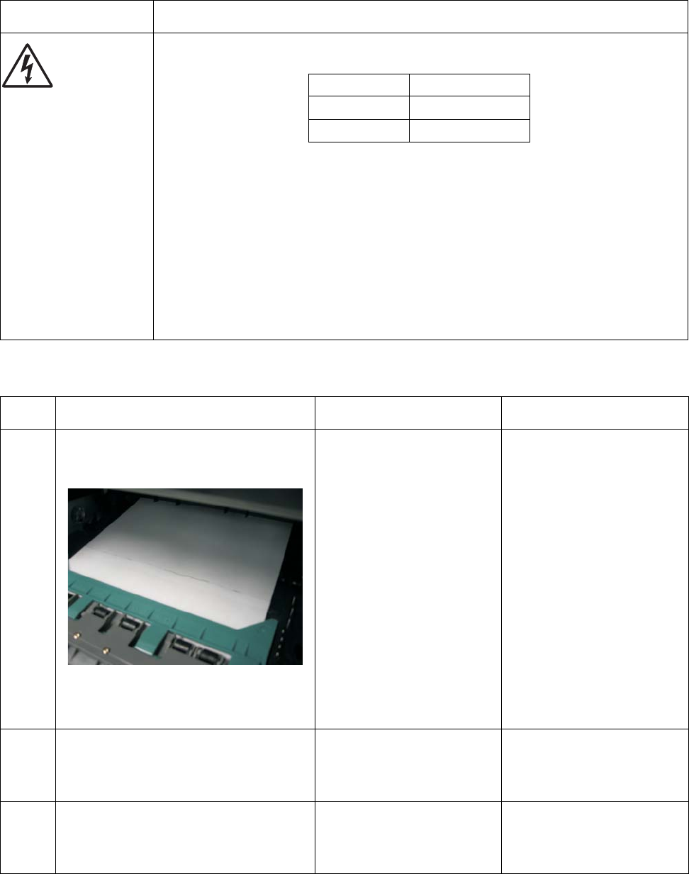
2-40 Service Manual
7014-xxx
Main motor service check
Media feed clutch service check
FRU Action
Main motor gear drive
Main motor cable
LVPS/HVPS
Engine board
Warning: Do not
replace the engine
board and controller
board at the same
time. Each board
contains the printer
settings. When either
of these boards is new,
it obtains the settings
from the other board.
Settings are lost when
both are new and
replaced at the same
time.
Turn off the printer, and unplug the main motor cable at J17 on the engine board. Turn on
the printer, and check for the following voltages at J17:
Verify ground at pin 5 for both the card and cable.
• If these voltages are correct, then check the main motor cable for continuity.
- Remove the left side cover to access the connector on the motor.
- If continuity exists on each wire, then replace the main motor gear drive which
includes the motor.
- If continuity does not exist on one or more of the wires, then call the next level of
support.
• If these voltages are not correct, then see “Lexmark X46x controller and engine
board connector pin values” on page 2-6, or replace the engine board. See “Engine
board removal” on page 2-15.
Step Action and questions Yes No
1Clear the paper path of all sheets of
paper. Turn on the printer. Open the front
door of the printer.
Is the paper overlapping with no space
between the trailing edge of the first
sheet and leading edge of the second?
Go to step 3. Go to step 2.
2Check the paper path sensors for any dirt,
dust or paper that might be obstructing
the sensors.
Does this solve the problem?
Problem resolved Go to step 3.
3Replace the media feed clutch. See
“Media feed clutch removal” on
page 4-50.
Does this solve the problem?
Problem resolved Contact your next level of
support.
J17 pins Voltages
Pins 1-4, 6 Approx. 5 V dc
Pins 7-9 18 V dc-24 V dc

Diagnostics information 2-41
7014-xxx
Networking service check
Note: Before starting this service check, print out the network setup page. This page is found under Menu -
Reports - Network Setup Page. Consult the network administrator to verify that the physical and wireless
network settings displayed on the network settings page for the device are properly configured. If a wireless
network is used, verify that the printer is in range of the host computer or wireless access point, and there is no
electronic interference. Have the network administrator verify that the device is using the correct SSID, and
wireless security protocols. For more network troubleshooting information, consult the Lexmark Network Setup
Guide.
Step Questions / actions Yes No
1If the device is physically connected to the
network, verify that the ethernet cable is
properly connected on both ends.
Is the cable properly connected?
Go to step 3.
If the network is wireless,
got to step 3.
Go to step 2.
2Connect the ethernet cable.
Did this fix the problem?
Problem resolved Go to step 3.
3Check the printer’s online status under Printers
and Faxes on the host computer. Delete all
print jobs in the print queue.
Is the printer online and in a Ready state.
Go to step 5. Go to step 4.
4Change the printer status to online.
Did this fix the issue?
Problem resolved. Go to step 5.
5Does the IP address displayed on the network
settings page match the IP address in the port
of the drivers using the printer?
Go to step 10. Go to step 6.
6Does the LAN use DHCP?
Note: A printer should use a static IP
address on a network.
Go to step 7. Go to step 9.
7Are the first two segments if the IP address
169.254? Go to step 8. Go to step 9
8POR the printer.
Is the problem resolved
Problem resolved Go to step 10.
9Reset the address on the printer to match the
IP address on the driver.
Did this resolve the issue?
Problem fixed. Go to step 10.
10 Have the network admin verify that the printer
and PC’s IP address have identical subnet
addresses.
Are the subnet addresses the same?
Go to step 12. Go to step 11.
11 Using the subnet address supplied by the
network admin, assign a unique IP address to
the printer.
Note: The printer IP address should match
the IP address on the printer driver.
Did this fix the problem?
Problem resolved. Go to step 12.
12 Is the device physically connected (ethernet
cable) to the network? Go to step 13. Go to step15.

2-42 Service Manual
7014-xxx
13 Try using a different ethernet cable.
Did this remedy the situation?
Problem resolved Go to step 14.
14 Have the network administrator check the
network drop for activity.
Is the drop functioning properly?
Replace the controller
board. Go to “Controller
board removal” on
page 4-8
Contact the network
administrator.
15 Is the printer on the same wireless network as
the other devices? Go to step 17. Go to step 16.
16 Assign the correct wireless network to the
printer.
Did this fix the problem?
Problem resolved Go to step 17.
17 Are the other devices on the wireless network
communicating properly? Go to step 18. Contact the network
administrator.
18 Verify that the ISP wireless card cable and any
other ISP cables are properly seated in their
connectors.
Are the cables connected correctly?
Go to step 20. Go to step 19.
19 Properly reseat the ISP cables.
Did this fix the problem?
Problem resolved. Go to step 20.
20 Perform the option card service check. See
“Option card service check” on page 2-46.
Was there another faulty ISP option?
Replace the faulty ISP
option. See “Installing an
Internal Solutions Port
(ISP)” on page 2-106.
Go to step 21.
21 Replace the ISP wireless card? See
“Installing an Internal Solutions Port (ISP)”
on page 2-106.
Did this fix the problem
Problem resolved. Replace the controller
board. Go to “Controller
board removal” on
page 4-8.
Step Questions / actions Yes No

Diagnostics information 2-43
7014-xxx
Operator panel service check
Inspect the operator panel cable for damage. Make sure the cable is plugged in securely. Run POST, and check
each light for proper operation. See “Power–On Self Test (POST) sequence” on page 2-1.
Paper feed service checks
Paper jam error indication during POST
Touch screen operator panel service check
FRU Action
Operator panel Display
Operator panel
keyboard
Controller board
Warning: Do not
replace the engine
board and controller
board at the same
time. Each board
contains the printer
settings. When either
of these boards is new,
it obtains the settings
from the other board.
Settings are lost when
both are new and
replaced at the same
time.
Touchscreen display
If the touchscreen display does not come on or indicator LED on the keyboard doesn’t
illuminate, then open the controller board cage and locate the operator panel connector at
J34. Make sure the cable is properly connected to the controller board and the controller
board has input voltage to it.
With the printer on, verify the following on connector J34:
• Pins 1, 3, 5, and 6: 3.3 v
• Pin 10, 16, 17, and 18: 5 v
• Pins 2, 9, and 15: GND
If any are incorrect, then see “Controller board service check” on page 2-35.
If these are approximately correct and the operator panel is not functioning:
1. Turn the printer off.
2. Remove the left and right covers,
3. Tilt the operator panel keyoboard and verify the UICC cable is properly connected to the
keyboard at connector J10.
4. If the cable is properly connected at both ends, check the cable for continuity. If the
cable fails, replace the UICC cable.
5. Reconnect the UICC cable, and verify the display ribbone cables are properly
connected to J3 and J12 on the keyboard.
6. Restart the printer. If the eight LEDs on the bottom of the keyboard card illuminate, but
the display fails to illuminate, replace the touchscreen display.
7. If the eight LEDs fail to illuminate, replace the keyboard.
Button keypad
If the touchscreen is ok, POR into Diagnostic mode, and perform the Button test under the
Hardware tests. If the buttons do not respond, then replace the keyboard .
FRU Action
Fuser (exit sensor) If the exit sensor flag, which is visible at the back of the fuser, is in any position other than
vertical, then the printer will display a paper jam. Make sure the flag is operating freely.
Replace the fuser if the sensor is damaged.
Input/duplex sensor
Manual feed sensor Make sure the input paper feed sensors are working properly. A stuck or incorrectly installed
sensor causes a paper jam indication.

2-44 Service Manual
7014-xxx
Media picks but stops halfway through the printer
Media never picks
Media occasionally mispicks or picks multiple sheets at once
FRU Action
Input/duplex sensors
(under print cartridge assembly)
Input sensor (manual)
Stairway cables
Check the stairway cables to verify they are properly connected to the engine
board at connectors J500 and J501, and on the controller board at connectors J26
and J27.
If they are prperly connected verify continuity on both cables. If this fails replace
the cables.
Make sure the input sensors are working properly.
Check for a broken or stuck flag on the input sensors. Clear anything that keeps
the flags from rotating freely.
Make sure the cables are seated on the engine board at J27 (input/duplex sensor)
and J23 (manual input).
Check for +5 V dc on pin 2 and 5 at J27 on the engine board (input/duplex
sensors) and pin 2 at J23 ont he engine board (Input sensor). Voltages on pins 1
and 4 at J27 , and pin 1 at J23 should change as the flags intersect with the
sensor.
• If correct, then replace the input paper feed sensor.
• If these voltages are not correct, then replace the controller board.
• Check the pick tires. Clean or replace as necessary.
FRU Action
Paper feed (pick tires) tray 1
Paper feed (pick tires) tray 2
Media drive ASM
Media feed clutch ASM
Manual feed clutch ASM
P/U and manual feed solenoid
ACM drive shaft
Open the left cover, and verify that the solenoids and clutches are functioning
when an attempt is made to feed the media.
Make sure the rubber tires on the ACM are installed and clean.
Replace the tires, ACM drive, clutch assemblies, solenoids, or drive shaft as
necessary.
FRU Action
Tray 1
Tray 2 (option) Check tray for media catch points.
If the sheet being fed stops momentarily, then the ACM applies additional vertical force,
causing additional sheets to feed.
Do not mix media types in one tray.
Paper pick tires
(Tray 1 or tray 2) Check the tires in the ACM assembly for signs of wear or damage.
Replace the tires as necessary.
ACM clutch
Manual feed clutch
Media feed clutch ASM
(tray 1 only)
Manual feed clutch
solenoid
Open left cover, and observe the solenoid and clutch actions at the ACM and manual
feed shafts as a print job is attempted.
Replace the faulty part.

Diagnostics information 2-45
7014-xxx
Media skews
Media “trees,” wrinkles, stacks poorly, or curls
Engine board
P/U and manual feed
solenoid ASM
Check the stairway cables to verify they are properly connected to the engine board at
connectors J500 and J501, and on the controller board at connectors J26 and J27.
If they are prperly connected verify continuity on both cables. If this fails replace the
cables.
Disconnect the solenoid cable at J25 on the engine board and measure the resistance
across cable pins 1 and 2.
• The resistance should be approximately 70 ohms.
• If it is not, then replace the solenoid.
• If the resistance is approximately 70 ohms, then check the controller board. Pin 1 at
J25 on the engine board should be +24 V dc. See Engine Board SVC Check for
more information.
Replace engine board as necessary.
FRU Action
Paper feed (pick tires) tray 1
Paper feed (pick tires) tray 2
Tray 1
Tray 2 (option)
Check tires for debris. If tires are new, then try reversing each on its hub.
Check side guides on Tray 1 and Tray 2. Guides set for a full stack of media may
be too wide when the stack is short.
FRU Action
Fuser This problem is most likely due to a worn backup roll. It causes the printer to run hotter than
required for the media being printed. Excessive heat can cause media treeing problems,
poor stacking, or curl.
Print the menu sheet found under Utilities.
Look at the media settings. Some, such as card stock or rough texture, may require a
higher fuser temperature, which leads to more of these problems (except stacking) in plain
paper.
• Change settings using the printer driver.
• Use the local printer setup utility (included on the CD) to change the NVRAM
settings.
Try a different ream of paper. Moist media has a higher tendency to crease (treeing) and
curl.
FRU Action

2-46 Service Manual
7014-xxx
Option card service check
USB port service check
1. Perform a print test to make sure the printer prints correctly. Verify that the indicator light is on, then print
the menu settings by Menu Settings Page from the Reports Menu in the menus.
2. Be sure the printer usb cable is designed for bidirectional printing.
3. Be sure the user’s application is set up correctly.
4. If the internal print test page prints correctly, the user’s application/printer driver is set up correctly, and the
USB cable is installed, but the printer still fails to print on command from the host computer, then replace
the controller board.
5. Check the USB cable for continuity.
Option card service check
FRU Action
Option cards
Controller board
Option card connection
cable
Warning: Do not
replace the engine
board and controller
board at the same
time. Each board
contains the printer
settings. When either
of these boards is new,
it obtains the settings
from the other board.
Settings are lost when
both are new and
replaced at the same
time.
Card
Remove all the option cards from the device.
Install each card individually. Restart the MFP after each card is installed.
Remove the card and repeat the previous step with a different card till all cards are
checked.
When a faulty card is found, replace the card. See “Option board installs and removals”
on page 4-105. If the error persists after replacing the option card, replace the controller
board. See “Controller board removal” on page 4-8.
If there are no errors found testing the cards individually, install the cards on at a time.
Restart the MFP after each card is installed.
Cables
If the cards do not trigger an error, check the option card connection cables for continuity.

Diagnostics information 2-47
7014-xxx
Print quality service checks
Note: Ensure the cover closes tightly. A gap in the opening may allow light to expose the photoconductor,
resulting in a ‘dirty’ print. Extreme environmental conditions, temperatures, and humidity will affect the print
quality.
Using print quality test pages
To help isolate print quality problems, like streaking, print test pages using the print quality test pages. To print
the print quality test pages:
1. Enter Configuration Menu.
a. Turn off the printer.
b. Turn on the printer while pressing and holding 2 and 6.
c. Release the buttons after 10 seconds.
d. Touch Print Quality Pages to print out the quality pages.
Four pages print to help evaluate print quality. The first page has various fonts and a graphic, the
second page is gray with graphics, the third page is black, and the last page is blank.
2. Use the test pages to isolate problems such as light or toner streaks. See “POST symptom table” on
page 2-2 for solutions to these problems.
3. Scroll down to Exit Config Menu and touch the menu item on the screen. The machine will POR.
Note: Refer to the print defects guide at the end of the manual for repeating defects.
Blank page
FRU Action
Toner cartridge (not a
FRU) Remove the toner cartridge, and gently shake it to evenly distribute the toner.
Check for cartridge damage.
Printhead
LVPS/HVPS
Controller board
Blank pages can be caused by a defective printhead assembly,
LVPS/HVPS, or controller board.
• Printhead errors typically result in printer service errors unless there is blockage of the
beam or dust on the lens. Check the lens and opening for blockage.
• Blank pages typically are caused by the PC roll not being properly charged. Try a
different PC kit.
• With the cartridge out, check the spring loaded contacts on the right side for free motion.
None should be ground except for #4 contact from the front.
Unplug the printer, and check the cable continuity between the LVPS/HVPS connector
marked OPC (at CN202) and the corresponding wire form (spring) found about 14 mm
above and to the right of the transfer roll gear.
• If there is not continuity, then call the next level of service.
Try a different toner cartridge and PC kit.
• If those fail, then replace the LVPS/HVPS, controller board, or the printhead in that
order.
Also, see “Solving print quality problems” on page 2-51.

2-48 Service Manual
7014-xxx
Black page
Note: Incorrect laser exposure or incorrect charging of the photoconductor causes an all black page. Always
verify the same results from a different print cartridge assembly and developer before proceeding.
Heavy background
Poor development or poorly charged toner particles cause excessive background. This is more noticeable as
the toner cartridge nears end-of-life.
FRU Action
Toner electrodes (not
a FRU) Check the three rearward electrodes below the toner cartridge assembly for contamination,
damage, or a short to ground. Correct as necessary.
Check continuity between the cable (DEV, TAR, and doctor blade) connection PCN3 and
on the contact tips below the toner cartridge assembly.
• If continuity fails, then call the next level of service.
LVPS/HVPS board
Controller board
Miscellaneous cables
With the printer off, disconnect the LVPS/HVPS cable from J502 on the engine board.
Turn the printer on, and verify +24 V dc on pins 17 and 19 of the cable.
Verify +5 V dc on pins 1, 3-5, 11, 13, and 15.
Verify ground on pins 10, 12,14, 16, and 18.
• If any of the values are incorrect, then replace LVPS/HVPS board.
• If the grounds are incorrect, then check ground paths.
• Check continuity in the cable. If the cable is bad, then call the next level of support.
• If the values are correct and the toner electrodes are good, then replace the controller
board.
• See the “LVPS/HVPS service check” on page 2-39 and the “Engine board service
check” on page 2-36, if necessary.
FRU Action
Toner cartridge (not a
FRU)
PC Kit (not a FRU)
Check the toner darkness setting in the driver. Try a lower setting.
Make sure the toner cartridge and PC Kit are correctly installed and the high voltage
contacts are clean.
If the toner cartridge and PC Kit are installed correctly, then try a new PC Kit first and then
toner cartridge.
LVPS/HVPS
Engine board
Check the contacts for correct installation and contamination where contact is made
between the print cartridge assembly and spring contacts which connect to the LVPS/HVPS
board at CN203. Clean as necessary.
If this does not correct the problem, then replace the following FRUs one at a time in the
order shown:
• LVPS/HVPS board (See “Black page” on page 2-48 for pin values.)
• Engine board

Diagnostics information 2-49
7014-xxx
Partial blank image/white spots (no repeating pattern)
Variation in image density horizontally across page
Poor fusing of image
FRU Action
Toner cartridge (not a
FRU) Remove the toner cartridge assembly, and gently shake the assembly to evenly distribute
the toner.
Check to make sure that the laser light path is not blocked.
If toner cartridge is low, then try a new one.
Paper (not a FRU) Make sure recommended media is being used.
Check the media settings in the printer driver. A heavier media may require higher heat to
properly fuse.
FRU Action
PC Kit (not a FRU) The charge roll may have an unbalanced force against the PC (photoconductor) drum.
Try a new PC Kit.
Transfer roll Note: Do not touch the transfer roll except at its ends. Place a sheet of paper over the roll to
prevent damage from finger oils or hand lotion.
Check the springs in the left and right transfer roll bearings. The bearing assemblies should
support the transfer roll, applying evenly distributed forces to the PC drum.
Replace the transfer roll assembly if the springs or bearings show signs of damage, or
fatigue.
Inspect the transfer roll for signs of wear, damage or contamination.
Replace as necessary.
FRU Action
Fuser The fuser may not be operating at the proper temperature to fuse the toner to the paper.
See“LVPS/HVPS service check” on page 2-39 for more information. Try changing the
setting to heavier paper or even card stock.
Media (not a FRU) Make sure recommended media is being used.
Check the media settings in the printer driver.
2-50 Service Manual
7014-xxx
Light print
White or black lines or bands
Toner on back of page
FRU Action
Toner cartridge (not a
FRU) Make sure the toner cartridge and PC Kit are installed correctly and that the toner cartridge
is not low on toner.
If the problem continues, then install a new toner cartridge.
Recheck condition before replacing PC Kit, if necessary.
Transfer roll
LVPS/HVPS card
Check the transfer roll for signs of toner buildup and contamination.
Inspect the HVPS contact (transfer roll) for contamination.
Verify the high voltage cable is plugged into the LVPS/HVPS.
If all components appear free of contamination, then replace the following FRUs one at a
time in the order shown:
• Transfer roll
• LVPS/HVPS card
FRU Action
Print cartridge
assembly (not a FRU)
Developer drive
coupling assembly
Main motor gear drive
Banding appears as light or dark horizontal lines on a uniformly gray page or on a page with
a large area of graphics. Banding is primarily due to a variation in the speed of the media as
it feeds through the printer, especially in the developer and transfer process. It may also be
a result of overly dry or moist environments.
With the printer off, check to make sure that the laser beam is not blocked.
Inspect the toner cartridge and paper feed components, especially the drive coupler and
drive gears for debris, binds, or damage.
FRU Action
Photoconductor kit (not
a FRU) Print a menu page from the Menu Settings Page in the Reports menu.
Inspect the overall paper path for signs of spilled toner.
Gently clean the contaminated areas with a soft cloth.
Fuser Inspect the fuser for signs of contamination.
Replace the fuser as necessary.
Transfer roll A transfer roll contaminated with toner can cause toner to transfer to the back of pages.
Inspect the transfer roll for contamination and its cable for continuity.
HVPS or engine board Loss of the proper high voltages can cause excessive toner to contaminate the transfer
roller. None of these voltages can be measured, but the contacts and continuities can be
checked. To check the lower voltage, see J502 on the wiring diagram. Replace the LVPS/
HVPS or controller board as necessary.
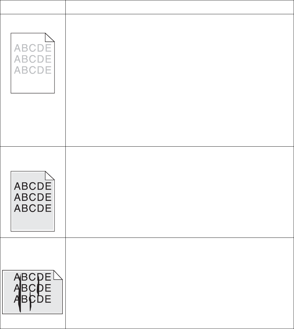
Diagnostics information 2-51
7014-xxx
Solving print quality problems
Note: Refer to the print defects guide at the end of the manual for repeating defects.
Print quality problems
Problem Cause / action
Light or blurred
characters. Light print
See “Light print” on page 2-50.
The toner cartridge may be getting low on toner:
• Remove the toner cartridge and print cartridge assembly.
• Shake it from side to side to redistribute the toner.
• Reinstall it, and recheck for condition.
• Make sure to use the recommended print media (see media types and sizes in the
User’s Guide).
• Use MarkVision™ Professional to define the custom type setting for media type, media
texture, or media weight.
• The toner cartridge or PC Kit may be defective. Replace the PC Kit first, and recheck.
Blurred characters
Blurred images, including characters, are usually caused by a defective printhead.
Vertical white lines
See “Vertical streaks below.
Vertical white lines may be caused by the laser beam, which may be partially blocked. With
the printer off, clear the path or clean the lens. The toner cartridge or fuser may be
defective. Try a different toner cartridge. Inspect the fuser at its entry for debris.
Toner smudges
appear on the front or
back of the page.
• Make sure the media is straight and unwrinkled.
• Replace the PC Kit, and recheck before replacing the toner cartridge. See “Toner on
back of page” on page 2-50 for more information.
Vertical or horizontal
streaks appear on the
page
Vertical streaks
Something could be caught between the PC kit and the fuser. Check the paper path around
the fuser entry. Try a different toner cartridge.
Vertical white lines may be caused by the laser beam, which may be partially blocked. With
the printer off, clear the path or clean the lens. The toner cartridge or fuser may be
defective. Try a different toner cartridge. Inspect the fuser at its entry for debris.
Horizontal streaks
The toner cartridge or the fuser may be the cause due to excessive page count or defect.
Replace as needed.
If the lines are parallel and match the two intended ghost images, then the Form Type may
be incorrectly set. Check those settings.
The PC cleaner sump may be full. Replace the PC kit.
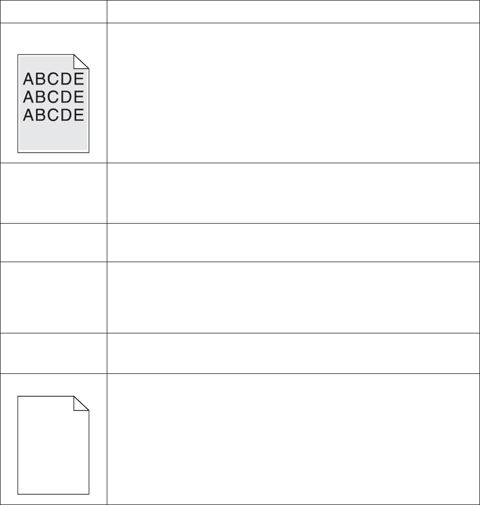
2-52 Service Manual
7014-xxx
Toner smears or rubs
off the page. • Toner is not being fused to the paper. Replace the fuser.
• Change the media texture setting in the driver. If special media is being used, such as
card stock or labels, then be sure to select the correct media type.
• Try a different kind of paper. Paper designed for copiers gives the best quality fusing.
The print is getting
light, but the printer
has not indicated it is
low on toner.
• Toner is becoming low in the cartridge.
• The Toner Low message does not display if the 1,500-page toner cartridge is installed.
• Remove the toner cartridge, and gently shake it from side to side to redistribute the
toner.
• Replace the toner cartridge.
The Toner Low
message displays. • Remove the toner cartridge, and gently shake it from side to side to redistribute the
toner.
• Replace the toner cartridge.
Solid black areas on
transparencies • There is a mismatch in the transparency and what the software is expecting.
• Choose a different fill pattern in the software program.
• Remove the toner cartridge, and gently shake it from side to side to redistribute the
toner.
• Try a different type of transparency.
• Replace the toner cartridge.
Faint images or
repetitive spots appear
on the page.
• Select a different media type or form type setting from the printer driver.
• Try a different type of paper. Media designed for copiers gives the best quality.
• Replace the toner cartridge.
Pages are blank. • The print cartridge may be out of toner or defective. Replace the cartridge.
• There may be a software error. Re-initialize the printer by turning it off and back on.
• With the printer off, check the printhead beam path. If clear, then check for a printhead
error on POR. See “Printhead service check” on page 2-54.
• Also, see “Blank page” on page 2-47.
Print quality problems (Continued)
Problem Cause / action

Diagnostics information 2-53
7014-xxx
The printer is on and
indicates ready, but
nothing prints.
• Make sure the parallel or USB cable is not damaged and is firmly plugged into the
connector on the back of the printer.
• Make sure the toner cartridge assembly is installed properly.
• Print the menu page using the Menu Settings Page in the Reports Menu.
- If a menu settings page cannot be printed, then contact the next level of support.
- If a menu settings page can be printed, then the problem is one of the following:
•Computer
•Software program
•Cable
•(USB only) A failed controller board. Replace card.
Note: Test by unplugging USB and plugging it with the printer on. If the computer indicates
“unknown device,” then replace the controller board.
Toner Low light is on
and printing stops. If a 3.5K or more page toner cartridge is being used and the Toner Low alarm is set to on,
then the printer stops printing until the toner cartridge is replaced.
The Error light alone is
on. Make sure the front printer cover is closed.
The Toner Low light is
blinking, and the Error
light is on.
• Make sure the toner cartridge is installed correctly.
• Install a new toner cartridge.
The media skews or
buckles. • Tray is overfilled or media is too loose.
• Don’t overfill Tray 1 or the optional Tray 2 (see media capacities in the media types and
sizes table in the User’s Guide).
• Make sure the paper guides are flush against the edges of the media.
The media sticks
together, resulting in
the printer feeding
multiple sheets.
• The friction between sheets is too high.
• Remove the media from Tray 1 or Tray 2, and fan it.
• Don’t overfill Tray 1 or the optional Tray 2 (see media capacities in the media types and
sizes chart in the User’s Reference).
The media fails to feed
from Tray 1. • Frictional force between tires and media is less than resisting force.
• Remove the media from Tray 1, and fan it.
• Make sure Tray 1 is selected from the printer driver. Do not overfill the tray.
• Check the condition of the rubber on the paper feed rolls. Replace if worn or
contaminated.
• Verify that the ACM clutch is functioning correctly.
The media fails to feed
from the optional
Tray 2.
• Incorrect tray selection or inadequate picking force by tires.
• Make sure the correct tray and media type are selected from the driver.
• Make sure the tray is pushed all the way in.
• Remove the media from the optional Tray 2, fan it, and reload.
• Check the rubber on the paper feed tires for dirt or any other debris. Replace as
necessary.
• Check the paper path in the tray for burrs or debris that may hinder media movement.
• Make sure the media does not exceed the stack height indicator.
Load Paper displays
even though there is
media loaded in the
optional Tray 2.
• The input sensor does not sense media after picking.
• Make sure the tray is pushed all the way in.
•Press .
• Check the feed tires. (See two preceding actions.)
The printer does not
print after a paper jam
has been cleared.
• The printer is waiting on the next command.
• Clear all jams.
• Press and release , or open and close the printer cover to restart the printer.
• Make sure the print cartridge assembly is installed properly.
Print quality problems (Continued)
Problem Cause / action
2-54 Service Manual
7014-xxx
Printhead service check
Transfer roll service check
Unexpected
characters print, or
characters are
missing.
• Ensure correct printer driver is being used.
• Select hex trace mode to determine what the problem is.
• Restore factory defaults.
• Make sure the parallel cable or USB cable is firmly plugged in at the back of the printer.
Jobs are not printing,
and an error message
is displayed.
• The printer is waiting for an appropriate command.
• Make sure the print cartridge assembly is installed properly.
• Make sure the printer front cover is closed.
While in PostScript 3
emulation, the printer
is flushing data (an
error message is
displayed).
• Ensure the correct PostScript driver is being used.
• The printer doesn’t have enough memory to print the job. Install more memory.
FRU Action
Printhead
Note: New printhead
must be aligned. See
“Printhead assembly
electronic
adjustment” on
page 3-38
Turn the printer off.
Disconnect the printhead cables from J9 and J6 on the controller board.
Turn the printer on with the front door closed.
On the controller board, verify +5 V dc on pins 2 and 3 at J6 and +5 V dc on pins 1,and 10
at J9.
Verify grounds on pins 4, 5, 6, and 7 at J6 and on pin 4 at J9.
• If voltages or grounds are incorrect, then check the controller board. See “Controller
board service check” on page 2-35 for more information.
• If voltages are correct, then replace the printhead.
• If the printhead cables are faulty, order cable parts 40X5816 (HSYNC cable) and
40X5817 (LSU diode cable).
FRU Action
Transfer roll
Note: Do not touch the transfer roll except at its ends. Place a sheet of paper over the roll to
prevent damage from finger oils or hand lotion.
Check the springs in the left and right transfer roll bearings. Do not try to move the left
spring. The bearing assemblies should support the transfer roll, applying evenly distributed
forces to the PC drum.
Replace the transfer roll assembly if the springs or bearings show signs of damage, or
fatigue.
Inspect the transfer roll for signs of wear, damage or contamination.
Replace as necessary.
Print quality problems (Continued)
Problem Cause / action

Diagnostics information 2-55
7014-xxx
Tray 2 service check
840.xx service check
FRU Action
Tray 2 Turn the printer off.
Separate the printer from Tray 2.
Turn the printer on and check the voltages on connector J28 on the engine board.
Pins 1, 4: 3.3 V
Pin 2: 24 V
Pin 6: Ground
If the voltages are incorrent, then replace the engine board. If the voltages are correct, then
try using Tray 2 again. If the printer error persists, then replace Tray 2.
Step Questions / actions Yes No
1POR the machine into configuration mode.
Go to the disable scanner menu item. See
“Disable Scanner” on page 3-9. Touch
“Enable ADF/FB -Enabled and press
Submit to save the change. POR the MFP
to operating mode. Try running a copy from
the ADF and flatbed.
Did the 840.xx error recur?
Go to step 2. Stop. Problem resolved.
2Re-enter Configuration mode, scroll to and
select the Disable Scanner menu item.
Does the screen display ADF Disabled or
Auto Disabled?
Go to step 3. Go to step 8.
3Check the ADF cable connections on the
ADF relay card and connector J17 on the
controller board. Also inspect the cable
connections on J28, J12, 13 and J30 on the
controller board.
Are the connections properly connected?
Go to step 5. Go to step 4.
4Properly connect the connections on the
ADF relay card and controller board. POR
the machine into configuration mode. Go to
the disable scanner menu item. See
“Disable Scanner” on page 3-9. Touch
“Enable ADF/FB -Enabled and press
Submit to save the change. POR the MFP
to operating mode. Try running a copy from
the ADF and flatbed.
Did the 840.xx error recur?
Go to step 5. Stop. Problem solved.
5Check the continuity on the ADF cable.
Is there continuity?
Go to step 7 Go to step 6.

2-56 Service Manual
7014-xxx
6Replace the ADF cable. POR the machine
into configuration mode. Go to the disable
scanner menu item. See “Disable
Scanner” on page 3-9. Touch “Enable
ADF/FB -Enabled and press Submit to
save the change. POR the MFP to operating
mode. Try running a copy from the ADF and
flatbed.
Did the 840.xx error recur?
Go to step 7. Stop. Problem solved.
7Replace the ADF unit. See “ADF unit
removal” on page 4-88. POR the machine
into configuration mode. Go to the disable
scanner menu item. See “Disable
Scanner” on page 3-9. Touch “Enable
ADF/FB -Enabled and press Submit to
save the change. POR the MFP to operating
mode. Run a copy from the ADF.
Did the 840.xx error recur?
Go to step 8. Stop. Problem solved.
8Inspect J17, J12, 13 and J30 on the
controller board.
Are the connections properly connected?
Go to step 10. Go to step 9.
9Properly connect all the connections.
Did the 840.xx error recur?
Go to step 10. Stop Problem solved.
10 Replace the flatbed unit. See “Flatbed
removal” on page 4-89. POR the machine
into configuration mode. Go to the disable
scanner menu item. See “Disable
Scanner” on page 3-9. Touch “Enable
ADF/FB -Enabled and press Submit to
save the change. POR the MFP to operating
mode. Run a copy from the flatbed.
Did the 840.xx error recur?
Go to step 11 Stop. Problem solved.
11 Replace the controller board. See
“Controller board removal” on page 4-8.
Did this fix the problem?
Problem solved. Contact second-level
support.
Step Questions / actions Yes No

Diagnostics information 2-57
7014-xxx
Black or blank page copy service check
CCD service check
Flatbed motor service check
Step Questions / actions Yes No
1Print a menu page, or a page from the host.
Is the page black?
See “Black page” on
page 2-48 Go to step 2.
2Is the copy an ADF scan? Go to step 4. Go to step 3.
3Run a flat bed copy.
Is it blank or black?
Go to step 5 Go to step 4
4Did the sheet feed into the ADF? Go to step 6. Go to step 5.
5Is the CCD ribbon cable properly connected
to J30 on the controller board? Go to step 6. Properly connect the ribbon
cable to J30.
6Check for +14VDC on Pin 3 and 4 on
connector J30. Pin 4 is +5VDC. Are the
voltages present?
Replace the flatbed unit.
See “Flatbed removal” on
page 4-89.
Replace the controller
board. See “Controller
board removal” on
page 4-8.
Step Questions / actions Yes No
1Restart the device, and retry the scan / copy
job. Repeat this step with a few copy jobs.
Does the error return?
Go to step 2. No issue.
2Is the CCD ribbon cable properly connected
to J30 on the controller board? Go to step 3. Properly connect the ribbon
cable to J30.
3Replace the flatbed unit. See “Flatbed
removal” on page 4-89.
Did this resolve the issue?
Problem resolved. Replace the controller
board. See “Controller
board removal” on
page 4-8.
Step Questions / actions Yes No
1Ensure that the flatbed motor cable (J28) is
connected to the controller board. Is the
cable connected?
Go to step 2. Properly connect the cable.
2Check pin 1 in J28 for voltage. The voltage
is only present when a flatbed copy job is
running. The voltage should measure +24V
AC. Is voltage present?
Replace the flatbed unit.
See “Flatbed removal” on
page 4-89.
Replace the controller
board. “Controller board
removal” on page 4-8.

2-58 Service Manual
7014-xxx
Flatbed home position service check
Step Questions / actions Yes No
1POR the MFP. Does the CCD move and
return to the home position? Problem solved. Go to step 2.
2Perform the home position sensor test. Go
to “Scanner Tests” on page 3-34.
Is the sensor working properly?
Go to step 3. Go to step 5.
3Check J28 on the controller board for proper
connection.
Is it connected properly?
Go to step 4. Properly connect the cable.
4Check pin 1 in J28 for voltage. The voltage
is only present when a flatbed copy job is
running. The voltage should measure +24V
AC. Is voltage present?
Go to step 5. Replace the controller
board. “Controller board
removal” on page 4-8
5Ensure that the home position cable (J13) is
connected. Is the cable connected? Go to step 6. Properly connect the cable.
6Check pin 1 in J13 for voltage. The voltage
should measure +5V DC. Pin 2 should be
GND. Is voltage present and is it correct?
Replace the flatbed unit.
See “Flatbed removal” on
page 4-89.
Replace the controller
board. “Controller board
removal” on page 4-8.

Diagnostics information 2-59
7014-xxx
ADF cover open service check
ADF streak service check
Step Questions / actions Yes No
1Is the ADF cover properly closed Go to step 3. Go to step 2.
2Close the ADF cover.
Does the problem go away?
Issue resolved Go to step 3.
3Perform the ADF cover open sensor test.
Go to “Scanner Tests” on page 3-34.
Does the sensor work properly.
Go to step 4 Go to step 8.
4On the bottom of the ADF cover, inspect the
ADF cover closed sensor actuator. Does it
move freely?
Go to step 6. Go to step 5.
5Fix the actuator so it moves freely.
Does this fix the problem?
Issue resolved. Go to step 6.
6Remove the ADF rear cover and inspect the
ADF cover closed sensor for dirt and debris.
Is there dirt and debris present?
Go to step 7. Go to step 8.
7Remove the ADF rear cover, and clean the
dirt and debris from the sensor.
Does this fix the issue?
Issue resolved. Go to step 8.
8Inspect the connections on the ADF relay
card in the ADF. Are all the connections
properly connected?
Go to step 9. Secure all the connections.
9Check the ADF cable for continuity. Is there
continuity? Go to step 10. Replace the ADF cable.See
“ADF cable removal” on
page 4-102.
10 Check for signals or voltages from J17 on
the controller board. Pin 11 and 12 should
measure +24VDC. Pin 14 should measure
+5VDC. Are there signals or voltages
present?
Replace the ADF. See
“ADF unit removal” on
page 4-88.
Replace the controller
board. See “Controller
board removal” on
page 4-8.
Step Questions / actions Yes No
1Do streaks appear on the middle of
scans when using the ADF? Clean the ADF glass on the
flatbed using a lint-free cloth.
Kit 40X0392 is available for
cleaning the glass on the
flatbed.
Also, clean the separator roll
and pad with a damp cloth.
No issue to fix.

2-60 Service Manual
7014-xxx
ADF paper jam service check
Note: This service check should be used if the paper feeds and jams in the ADF. If the paper is not feeding into
the ADF see “ADF feed errors service check” on page 2-60.
ADF feed errors service check
Step Questions / actions Yes No
1If the ADF is multi-feeding, check for dirt on
the ADF separator pad and ADF separator
rollers. Are they dirty?
Clean them with a lint free
cloth and isopropyl alcohol.
Replace the separator pad
and ADF pick roll.
2If the paper is skewing when it is fed into the
ADF, check the paper guide width. Is it set
correctly?
Go to step 3. Set the paper guides so
they contact the edges of
the paper.
3If paper is skewing when fed or jamming
check to see if the top cover is open or ajar.
Is the ADF top cover open or ajar?
Properly close the top
cover.
If the paper is jamming in
the ADF, go to step 6
4Is paper failing to feed into the ADF? Go to step 5. There is no issue.
Perform the ADF paper present, scan 1st
and scan 2nd sensor tests. Go to “Scanner
Tests” on page 3-34.
Are the sensors working properly.
Go to step 6 Go to step 9.
6Check the leading edge of the paper to
ensure the paper is not curled or bent in a
way that would keep it from contacting the
paper present sensor actuator. Is the paper
damaged?
Bad media. Go to step 7.
7Is there dirt in the sensors, or is the paper
present actuator stuck?
Clean the sensors, or
remove debris from the
actuators.
Go to step 8.
8Are the sensor actuators on the ADF
mechanism cover damaged? Replace the ADF. Go to step 9.
9Is the ADF connector properly connected to
J17 on the system board? Go to step 10. Properly connect the cable
to the system board.
10 Inspect the connections on the ADF relay
card in the ADF. Are all the connections
properly connected?
Go to step 11. Secure all the connections.
11 Check the ADF cable for continuity. Is there
continuity? Go to step 11. Replace the ADF cable.
11 Check for signals or voltages from J17 on
the controller board. Pin 11 and 12 should
measure +24VDC. Pin 14 should measure
+5VDC. Are there signals or voltages
present?
Replace the ADF unit. See
“ADF unit removal” on
page 4-88.
Replace the controller
board. See “Controller
board removal” on
page 4-8.
Step Questions / actions Yes No

Diagnostics information 2-61
7014-xxx
1If the ADF is multi-feeding, check for
dirt on the ADF separator pad and
ADF separator rollers. Are they dirty?
Clean them with a lint free
cloth and isopropyl alcohol.
Replace the separator pad and
ADF pick roll.
2If the paper is skewing when it is fed
into the ADF, check the paper guide
width. Is it set correctly?
Go to step 3. Set the paper guides so they
contact the edges of the paper.
3If paper is skewing when fed or
jamming check to see if the top cover
is open or ajar. Is the ADF top cover
open or ajar?
Properly close the top cover. If the paper is jamming in the
ADF, See “ADF paper jam
service check” on page 2-60
4Is paper failing to feed into the ADF? Go to step 5. There is no issue.
5Is the leading edge of the paper
wrinkled or torn?
Use different media. Go to step 6
6Perform the ADF paper present
sensor test. Go to “Scanner Tests”
on page 3-34.
Is the sensor working properly?
Go to step 7. Properly connect all the
connections in the ADF relay
card.
7Check the actuators to see if they are
jammed, or damaged.
Are they jammed or damaged?
Replace the ADF. See “ADF
unit removal” on
page 4-88.
Go to step 8.
8Properly connect all the connections
in the ADF relay card and controller
board.
Did this fix the situation?
Problem resolved Go to step 9.
9Check the ADF cable for continuity. Go to step 6. Replace the ADF cable. Go to
“ADF cable removal” on
page 4-102
10 Replace the ADF. See “ADF unit
removal” on page 4-88.
Does this fix the situation?
Problem solved Replace the controller board. Go
to “Controller board removal”
on page 4-8.

2-62 Service Manual
7014-xxx
ADF Duplex service check
Step Questions / actions Yes No
1Perform sensor 1, and sensor 2
sensor tests. Go to “Scanner Tests”
on page 3-34.
Are the sensors working properly?
Go to step 2. Go to step 3.
2Check the ADF sensor actuators to
see if they are dirty or jamming.
Are the actuators ok?
Go to step 3. Clean the actuators. If any
actuators on the ADF are
broken, replace the ADF unit. Go
to “ADF unit removal” on
page 4-88.
3Check all the connections on the ADF
relay card. Are they properly
connected?
Go to step 4 Properly connect all the
connections.
4Check the ADF cable to ensure it is
properly connected to CN 15 on the
ADF relay card, and main controller
board at J17. Is the ADF cable
properly connected?
Go to step 5. Properly connect the ADF cable
to its connections.
5Check the ADF cable for continuity.
Make sure pin 22 has continuity. Is
there continuity on pin 22?
Go to step 6. Replace the ADF cable.Go to
“ADF cable removal” on
page 4-102.
6Replace the ADF. Go to “ADF unit
removal” on page 4-88. Does this fix
the situation?
Problem solved Replace the controller board. Go
to “Controller board removal”
on page 4-8.

Diagnostics information 2-63
7014-xxx
Modem / fax card service check
Step Questions / actions Yes No
1Is the phone line properly connected to the
modem card and the wall jack?
Go to step 3. Go to step 2.
2Properly connect the phone line to the
modem card and wall jack.
Did this fix the problem?
Problem resolved. Go to step 3.
3Test the phone line’s ability to send and
receive calls.
Did the phone line work properly?
Go to step 5. Go to step 4.
4Use the MFP on a properly functioning
phone jack.
Did this fix the problem?
Problem resolved. Go to step 5.
5Is the modem card cable properly
connected to the system board at J8 and the
modem card?
Go to step 7. Go to step 6.
6Properly connect the modem card cable to
the modem card and system board.
Did this fix the problem?
Problem resolved. Go to step 7.
7Check the modem card cable for continuity.
Is there continuity? Go to step 8. Replace the modem card
cable.
8Check the voltages from connector J8 on
the controller board. Check Pin 12 and 13
for +3.3VDC, Pin 10 for +5VDC. 2, 4, 6, and
8 are grounds. Are the signals or voltages
present?
Replace the modem card. Replace the controller
board. See “Controller
board removal” on
page 4-8.

2-64 Service Manual
7014-xxx
Fax transmission service check
Note: Before performing this service check, verify that the correct country code for the MFP is selected. This
setting must match the country in which the MFP is used to transmit and receive faxes. If the setting is wrong,
the modem settings can be changed in the Fax/SE menu. See step 14. These settings should only be performed
with guidance from your second-level support.
Step Questions / actions Yes No
1Is the phone line properly connected to the
modem card and the wall jack?
Go to step 3. Go to step 2.
2Properly connect the phone line to the
modem card and wall jack.
Did this fix the problem?
Problem resolved Go to step 3.
3Test the phone line’s ability to send and
receive calls.
Did the phone line work properly?
Go to step 5. Go to step 4.
4Use the MFP on a properly functioning
phone jack.
Did this fix the problem?
Problem resolved. Go to step 5.
5Is the phone line being used by the MFP an
analog line? Go to step 8. Go to step 6.
6Is the line being used a VOIP line? Go to step 7. Go to step 8.
7Have the system administrator verify that
the VOIP server is configured to receive
faxes.
Is the server properly configured?
Go to step 8. Stop here. The issue is
VOIP related. The VOIP
provider needs to change
the server configuration.
8Is the MFP on a PABX? Go to step 9. Go to step 10.
9Enable Behind a PABX under fax settings
in the Administration menu.
Did this fix the issue?
Problem fixed. Disable Behind a PABX,
and go to step10.
10 Is a dial prefix needed to get an outside
line? Go to step 11. Go to step 12.
11 Try sending a fax using a dial prefix.
Did the fax transmit?
Problem fixed. Go to step 12.
12 Is the fax failing to send to one specific
destination? Go to step 13. Go to step 14.
13 Check the device that cannot receive a fax.
Can it send a fax? Go to step 14. Stop here. The issue is with
the other device.
14 Press **411 to enter the Fax/SE Menu.
Select “Print Logs”.
Print the T30 transmission log. Check the
error being reported with the fax error code
table. See “Fax error codes” on
page 2-31. Perform the suggested
resolution for the error.
Did this fix the problem?
Problem resolved. Go to step 15.

Diagnostics information 2-65
7014-xxx
15 Adjust the “Transmit Level” setting in the SE
menu. Press **411 to enter the SE menu,
enter Modem settings, and select “Transmit
Level”.
Test by adjusting the transmitted signal
strength by decreasing/increasing the
‘Transmit Level’ setting in steps of 1db. For
example, if default value is -11 db, changing
it to -12db will decrease the signal strength
by 1db, and changing it to -10db will
increase the signal strength by 1db.
Recommended adjustment range is ±5 db
(in 1db steps) from the default value.
Did this fix the problem?
Stop. Problem resolved. Go to your second-level of
support. See “Escalating a
fax issue to second-level
support” on page 2-68.
Step Questions / actions Yes No

2-66 Service Manual
7014-xxx
Fax reception service check
Step Questions / actions Yes No
1Is the phone line properly connected to the
modem card and the wall jack?
Go to step 3. Go to step 2.
2Properly connect the phone line to the
modem card and wall jack.
Did this fix the problem?
Problem resolved. Go to step 3.
3Check for a dial tone.
Is there a dial tone?
Go to step 4. Go to step 6.
4Use a telephone to test the phone line’s
ability to send and receive calls.
Did the phone line work properly?
Go to 7. Go to step 5.
5Use a telephone handset to verify the phone
line is free of static or external noise.
Is the phone line noise-free?
Go to step 7. Go to step 6.
6Use the MFP on a properly functioning
phone jack.
Did this fix the problem?
Problem resolved. Go to step 7.
7In <diags / config menu>, verify that the
Enable Fax Receive setting is on.
Is the setting set to on?
Go to step 9. Go to step 8.
8Set “Enable Fax Receive” to On.
Did this fix the problem?
Problem resolved. Go to step 9.
9Is Distinctive Ring enabled? Go to step 11. Go to step 10.
10 Turn on Distinctive ring.
Did this fix the problem?
Problem resolved. Go to step 11.
11 Is the phone line analog? Go to step 13. Go to step 12.
12 Is the VOIP server configured to support
fax? Go to step13. Stop here. This is an issue
with the VOIP provider.
13 Does the MFP have reception issues with
only a certain remote device? Go to step 14. Go to step 15.
14 Verify communications with a different
remote device.
Can the other device receive faxes?
The issue is with the other
device.
Go to step 15.
15 Go to the Administrator menu. Enter the Fax
settings - Analog Fax Settings submenu.
Verify the Block No Name Fax user setting.
Is it enabled?
Go to step 16. Go to step 17.
16 Disable Block No Name Fax user setting.
Did this fix the issue?
Problem resolved. Go to step 17.

Diagnostics information 2-67
7014-xxx
17 Go to the Administrator menu. Enter the Fax
settings - Analog Fax Settings submenu.
Verify the remote device number is not in
the Banned Fax List user setting.
Is the remote device number in the banned
fax list?
Go to step 18. Go to step 19.
18 Remove the remote number from the
banned fax list.
Did this fix the problem?
Problem resolved. Go to step 19.
19 Adjust the “Receive Threshold” setting in the
SE menu. press **411 to enter the SE
menu, enter Modem settings, and select
“Receive Threshold”.
Test by adjusting the received signal level
by decreasing/increasing the”Receive
Threshold” setting in steps of 2db. For
example, if default value is -43 db, changing
it to -45db will decrease the received signal
level by 2db, and changing it to -41db will
increase the received signal level by 2db.
Recommended adjustment range is
between -33db and -48db (in 2db steps).
Did this fix the problem?
Problem resolved Go to step 20.
20 Press **411 to enter the SE Menu. Select
“Print Logs”.
Print the T30 transmission/ job log. Check
the error code being reported. See “Fax
error codes” on page 2-31. Perform the
suggested resolution for the error.
Did this fix the problem?
Problem resolved. Contact your second-level
of support. See
“Escalating a fax issue to
second-level support” on
page 2-68.
Step Questions / actions Yes No
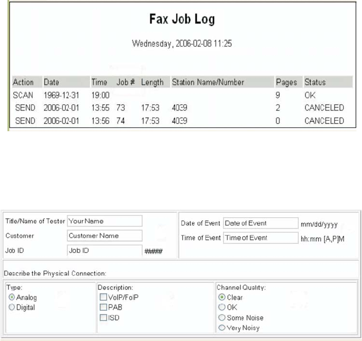
2-68 Service Manual
7014-xxx
Escalating a fax issue to second-level support
Before contacting the second-level support, go to the SE menu on the MFP.and generate a Fax error file. This
file contains machine settings information and debug information that will help second-level support determine
the cause of a failure.
To generate the fax error file, perform the following steps:
1. In a Web browser, type http://MFP ip address/se.
2. The MFP’s SE menu page will display. Click the “Dump Job History” link. The following displays:
3. Write down the type of connection, the type of error, and the job in which the error occurred.
4. In the Web browser address bar, type http://MFP ipaddress/se.
5. Click Report a Fax Problem (A). The fax check list displays.
6. Fill in the requested information. This is where you will type in the information you retrieved in step 3.
Second-level support can assist you if you have questions about the information requested on the page.
Note: The fields requesting the code levels, model number, type of problem are auto-filled. If the information is
not in the fields, it can be retrieved from the SE menu. The SE menu can be accessed by pressing **411 on the
keypad or typing http://MFP ipaddress/se in a Web browser.
7. After all the requested information is entered into the Fax Checklist Web page, press the Submit button on
the bottom of the page. A dialogue asking you to save the file will appear.
Note: The file generated by the MFP is not automatically transmitted to second-level support. It is placed
on the computer desktop.
8. Enter a name for the file, and indicate where you want to save the file.
9. press OK. The file appears on the desktop.
10. E-mail the file to second-level support.

Diagnostic aids 3-1
7014-xxx
3. Diagnostic aids
This chapter explains the tests and procedures to identify printer failures and verify repairs have corrected the
problem.
Accessing service menus
There are different test menus that can be accessed during POR to identify problems with the printer.
To run the printer diagnostic tests described in this chapter, the printer must be in Diagnostic Mode.
Note: If you have installed a controller board, engine board, or operator panel as part of a troubleshooting
procedure, start the machine into diagnostic mode to test the repair.
Configuration Menu 1. Turn off the printer.
2. Press and hold 2 and 6.
3. Turn on the printer.
4. Release the buttons after 10
seconds.
The Configuration Menu group contains a set of
menus, settings, and operations which are
infrequently required by a user. Generally, the
options made available in this menu group are
used to configure a printer for operation.
See “Configuration menu (CONFIG MENU)” on
page 3-2 for more information.
Diagnostics Mode 1. Turn off the printer.
2. Press and hold 3 and 6.
3. Turn on the printer.
4. Release the buttons after 10
seconds.
The Diagnostics Mode group contains the settings
and operations used while manufacturing and
servicing the printer.
See “Diagnostics menu” on page 3-17 for more
information.

3-2 Service Manual
7014-xxx
Configuration menu (CONFIG MENU)
Available menus
Note: Menus may vary depending on the features and options of the printer.
Maintenance Count Value See “Maintenance Count Value (Maint Cnt Value)” on page 3-3.
Reset Maintenance Count See “Reset Maintenance Counter” on page 3-3.
Reset Photoconductor Maintenance
Count See “Reset Photoconductor Maintenance Counter (Reset PC
Cnt)” on page 3-4.
USB Scan to Local See “USB Scan to Local” on page 3-4.
Print Quality Pages See “Print Quality Pages” on page 3-4.
Reports See “Reports” on page 3-32.
Panel Menus See “Panel Menus” on page 3-4.
PPDS Emulation See “PPDS Emulation” on page 3-5.
Download Emuls See “Download Emuls” on page 3-5.
Factory Defaults See “Factory Defaults” on page 3-6.
Energy Conserve See “Jobs on Disk” on page 3-10.
Min Copy Memory See “Min Copy Memory” on page 3-6.
Num Pad Job Assist See “Num Pad Job Assist” on page 3-7.
Format Fax Storage See “Format Fax Storage” on page 3-7.
Fax Storage Location See “Fax Storage Location” on page 3-7.
ADF Edge Erase See “ADF Edge Erase” on page 3-7.
FB Edge Erase See “FB Edge Erase” on page 3-7.
Scanner Manual Registration See “Scanner Manual Registration” on page 3-8.
Disable Scanner See “Disable Scanner” on page 3-9.
Paper Prompts See “Paper Prompts” on page 3-9.
Envelope Prompts See “Envelope Prompts” on page 3-9.
Action for Prompts See “Action For Prompts” on page 3-9.
Jobs On Disk See “Jobs on Disk” on page 3-10.
Disk Encryption See “Disk Encryptyion” on page 3-10.
Wipe Disk See “Wipe Disk” on page 3-13.
Font Sharpening See “Jobs on Disk” on page 3-10.
Require Standby See “Require Standby” on page 3-14.
LES Applications See “LES Applications” on page 3-15.
Key Repeat Initial Delay See “Key Repeat Initial Delay” on page 3-15.
Key Repeat Rate See “Key Repeat Rate” on page 3-15.
Wiper Message See “Wiper Message” on page 3-15.
Clear Custom Status See “Clear Custom Status” on page 3-16.
USB Speed See “USB Speed” on page 3-16.
USB PnP See “USB PnP” on page 3-16.
Exit Config Menu See “Require Standby” on page 3-14.
Diagnostic aids 3-3
7014-xxx
Maintenance Count Value (Maint Cnt Value)
This setting enables you to view the current maintenance count value of each maintenance kit. After selecting
this item, you can choose a specific kit in order to view its current maintenance count value. To return to the
Configuration Menu, press Back. All other control panel keys are ignored.
When a kit’s maintenance count value equals its kit size (150K for the ADF Kit), the device posts the appropriate
“80 Scheduled Maintenance” IR and a status indicator to notify the user to schedule the appropriate
maintenance on the device.
To view the Maintenance Counter Value, touch Maintenance Counter Value from the Configuration Menu.
The panel displays the current value of the maintenance counter as illustrated below:
Touch Back to return to the Configuration Menu.
After installing the required maintenance kit, reset this count to zero.
Reset Maintenance Counter
After scheduled maintenance, reset the Maintenance Counter.
To reset the maintenance page counter to zero:
1. Touch Reset Maintenance Counter from the Configuration Menu.
2. Reset Maintenance Counter appears in the header.
3. Touch 100K Kit or 600K Kit. Yes and No appear in a menu.
4. To cancel the reset operation, touch Back or No. All other button presses are ignored.
5. To initiate the reset operation, touch Yes.
vga
Maintenance Counter Value: 20
?
Back

3-4 Service Manual
7014-xxx
Reset Photoconductor Maintenance Counter (Reset PC Cnt)
This setting resets the photoconductor kit page counter and clears any warnings or photoconductor exhausted
messages. This operation should be performed only after a new photoconductor unit has been installed.
USB Scan to Local
USB Scan to Local enumerates a USB simple device or USB composite device. In the off position the simple
USB device is enumerated: in the on position, the composite USB device is enumerated.
To change this setting:
1. Touch USB Scan to Local from the Configuration Menu. [setting's current value] appears on the
touch-screen.
2. Touch or to scroll through the setting's possible values.
3. Touch Back to cancel and return to the Configuration Menu.
4. Touch Submit to save the change.
Print Quality Pages
This setting is a limited version of the Print Quality Pages setting that appears in the Diagnostics menu. This
setting reports the values of a broad range of printer settings and tests the printer’s ability to generate
acceptable printed output.
To print the Print Quality Pages:
1. Touch Print Quality Pages from the Configuration Menu. Printing Quality Test Pages... appears on
the LCD.
Touch Back to return to the Configuration Menu.
The Reports menu contains two selections: Menu Settings Page and Event Log.
Menu Settings Page
To print the Menu Settings page, press . Press to return to the Configuration menu.
Event Log
The event log provides a history of printer errors. The event log can only be printed in the Configuration
menu. Additional options are available in the Diagnostics menu. See “Reports” on page 3-32.
To print the event log:
1. Select Print Event Log from the Event Log menu.
2. Press to return to the Configuration menu.
Note: An event log printed from the CONFIG MENU will not contain debug information or secondary
codes for 900 service errors. However, the event log printed from DIAGNOSTICS mode does include this
information.
Panel Menus
Lets the system support person enable or disable the operator panel menus. Selecting On (the default) allows
users to change values for the printer. Off disables the users’ access to menus. If a user presses Menu ( ),
they receive a message that the panel menus are locked. When set to Off, this setting restricts all menu access,
even to menus or items set for PIN access. However, when set to On, all PIN restrictions are restored.

Diagnostic aids 3-5
7014-xxx
To change the value of this setting:
1. Touch Panel Menus from the Configuration Menu. [setting's current value] appears on the touch-
screen.
2. Touch or to scroll through the setting's other possible values.
3. Touch Back to cancel and return to the Configuration Menu.
4. Touch Submit to save the change.
PPDS Emulation
The value of the PPDS Emulation menu item determines if a device can recognize and use the PPDS
datastream. The current value of this setting appears in parentheses to the right of the setting on the
Configuration Menu screen.
The following table indicates how the value of this setting affects the user default value for the SmartSwitch and
Printer Language settings:
To change the value of this setting:
1. Touch PPDS Emulation from the Configuration Menu. [setting's current value] appears on the
touch-screen.
2. Touch or to scroll through the setting's possible values.
3. Touch Back to cancel and return to the Configuration Menu.
4. Touch Submit to save the change.
Download Emuls
This setting enables you to disable a Downloadable emulator (DLE) that is installed on the MFP. The setting for
this menu settng is disabled.
Note: The DLE is re-enabled automatically after two PORs.
To change the value of this setting:
1. Touch Download Emuls from the Configuration Menu. [setting's current value] appears on the
touch-screen.
2. Touch or to scroll through the setting's possible values.
3. Touch Back to cancel and return to the Configuration Menu.
4. Touch Submit to save the change.
Value of
PPDS
Emulation
setting
Resulting value of
SmartSwitch setting
(all ports) Resulting value for Printer Language settings
Activate Off PPDS Emulation
Note: You can still switch languages on the operator panel or through
the PJL ENTER LANGUAGE command.
Deactivate On Printer's factory default value

3-6 Service Manual
7014-xxx
Factory Defaults
Warning: This operation cannot be undone.
This setting enables you to restore all of the printer’s settings to the base printer settings, the network settings,
or to remove all Lexmark Embedded Solutions (LES) applications.
To restore the Factory Default settings:
1. Touch Factory Defaults from the Configuration Menu.
2. Touch Restore Base to restore all non-critical base printer NVRAM settings.
3. Touch Restore Network to restore all network NVRAM settings.
4. Touch Restore LES to remove all Lexmark Embedded Solution applications.
When you select either value, the LCD displays Restoring Factory Defaults and then Resetting the Device.
The device immediately performs a POR and restores the appropriate settings to their factory default values.
The following settings are not changed:
•Display Language (general settings)
•Network/Ports Menu
•Standard USB, USB (x) Menus (if an ENA is installed)
Energy Conserve
This menu controls what values appear on the Power Saver menu. If Off is selected in the Energy Conserve
menu, then Disabled appears in the Power Saver menu, and Power Saver can be turned off. If On is set in the
Energy Conserve menu, the Power Saver feature cannot be disabled.
To change this setting:
1. Touch Energy Conserve from the Configuration Menu. [setting's current value] appears on the
touch-screen.
2. Touch or to scroll through the setting's possible values.
3. Touch Back to cancel and return to the Configuration Menu.
4. Touch Submit to save the change.
Min Copy Memory
Values will only be displayed if the amount of installed DRAM is at least twice the amount of the value, that is, at
least 200 MB of installed DRAM is required to display the 100 MB selection.
To change this setting:
1. Touch Min Copy Memory from the Configuration Menu. [setting's current value] appears on the
touch-screen.
2. Touch to decrease the setting's value; touch to increase the setting's value.
3. Touch Back to cancel and return to the Configuration Menu.
4. Touch Submit to save the change.

Diagnostic aids 3-7
7014-xxx
Num Pad Job Assist
This setting determines if a user can configure and initiate a job using the panels hard buttons.
To change this setting:
1. Touch Num Pad Job Assist from the Configuration Menu. [setting's current value] appears on the
touch-screen.
2. Touch or . The settings are On or Off.
3. Touch Submit to save the change.
Format Fax Storage
This setting enables you to format the non-volatile storage used for storing faxes.
To change this setting:
1. Touch Format Fax Storage from the Configuration Menu.
Note: If an advanced password has been established, you must enter this password in order to change the
setting. If no advanced password exists, you can establish one by using the keyboard that appears on the LCD.
2. Touch Submit to save the change.
3. Touch Back to cancel and return to the Configuration Menu.
Formatting Fax Flash DO NOT POWER OFF appears on the LCD while the format operation is active.
Fax Storage Location
To change this setting:
1. Touch Fax Storage Location from the Configuration Menu. [setting's current value] appears on
the touch-screen.
2. Touch or . The settings are Disk and NAND.
3. Touch Submit to save the change.
ADF Edge Erase
This menu item sets the size, in millimeters, of the no-print area around an ADF scan job.All copy jobs have a
minimum of a two millimeter border. Copy jobs will use the setting or two millimeters, whichever is larger.
To adjust the ADF edge erase setting, perform the following steps:
1. Touch ADF Edge Erase from the Configuration Menu. [setting's current value] appears on the
touch-screen.
2. Touch to increase the value or to decrease the value.
3. Touch Submit to save the change.
4. Touch Back to cancel and return to the Configuration Menu.
FB Edge Erase
This menu item sets the size, in millimeters, of the no print area around a flatbed scan job. Copy jobs will use the
setting or two millimeters, whichever is larger.

3-8 Service Manual
7014-xxx
To adjust the flatbed edge erase setting, perform the following steps:
1. Touch FB Edge Erase from the Configuration Menu. [setting's current value] appears on the
touch-screen.
2. Touch to increase the value or to decrease the value.
3. Touch Submit to save the change.
4. Touch Back to cancel and return to the Configuration Menu.
Scanner Manual Registration
This item is used to manually register the flatbed and ADF on the MFP’s scanner unit. Registration should be
performed whenever the ADF unit, flatbed unit, or controller card are replaced.
To manually register a Duplex ADF, perform the following steps:
1. In the Configuration Menu, scroll to the Scanner Manual Registration menu item.
2. Touch Scanner Manual Registration.
3. Touch the Print Quick Test Page menu item.
4. To view and adjust the duplex ADF front side registration, place the quick test page face up into the ADF.
5. Touch Copy Quick Test.
6. After the quick test page copies, touch ADF Front.
7. Use the or to increase or decrease the settings value for horizontal adjust and top margin.
Note: Each button press moves the margin values one pixel in the respective direction.
8. Press Submit to accept the value.
9. Verify the changes by placing the print quick test page face up and touching Copy Quick Test.
10. Repeat steps 6, 7 ,and 8 as needed.
11. To view and adjust the duplex ADF backside registration, place the quick test page face down up into the
ADF, and touch Copy Quick Test.
12. After the quick test page copies, touch ADF Back.
13. Use the or to increase or decrease the settings value for horizontal adjust and top margin.
Note: Each button press moves the margin values one pixel in the respective direction.
14. Press Submit to accept the value.
15. Verify the changes by placing the print quick test page face down and touching Copy Quick Test.
16. Repeat steps 13, 14 ,and 15 as needed.
To manually register the flatbed, perform the following steps:
1. In the Configuration Menu, touch the Scanner Manual Registration menu item.
2. Touch the Print Quick Test Page menu item.
3. To view and adjust the flatbed registration, place the quick test page into the flatbed.
4. Touch the Copy Quick Test Page item.
5. After the quick test page copies, touch Flatbed.
6. Use the or to increase or decrease the settings value for the left or top margin.
Note: Each button press moves the margin values one pixel in the respective direction.
7. Touch Submit to accept the value.
8. Place the print quick test page on the flatbed and touch Copy Quick Test.
9. Repeat steps 5 and 6 as needed.
To exit RESGISTRATION press BACK or STOP .

Diagnostic aids 3-9
7014-xxx
Disable Scanner
This menu item is used to disable the MFP scanner if it is malfunctioning. The MFP must be powered off and on
for the new settings to take effect.
To change this setting:
1. Touch Disable Scanner from the Configuration Menu.
2. Touch or to scroll through the setting's other possible values. The settings are Enable, Disable, ADF
disable.
3. To save the setting's new value, touch Submit.
Paper Prompts
When a tray is out of the indicated paper size, a prompt is sent to the user to load paper in a tray. This setting
controls the tray the user is directed to fill. Selections are Auto (default), MP Feeder, and Manual Paper.
To change this setting:
1. Touch Paper Prompts from the Configuration Menu. [setting's current value] appears on the
touch-screen.
2. Touch or to scroll through the setting's other possible values.
3. To exit this screen without changing the setting's value, touch Back.
4. To save the setting's new value, touch Submit.
Envelope Prompts
This setting controls the tray the user is directed to refill when a specific envelope size is out. The selections are
Auto (default), MP Feeder, and Manual Env.
To change the value of this setting:
1. Touch Env Prompts from the Configuration Menu. [setting's current value] appears on the touch-
screen.
2. Touch or to scroll through the setting's possible values.
3. To exit this screen without changing the setting's value, touch Back.
4. To save the setting's new value, touch Submit.
Action For Prompts
This setting determines which input source receives paper-related or envelope-related change prompts when
they occur.
To change the value of this setting:
1. Touch Action for Prompts from the Configuration Menu. [setting's current value] appears on the
touch-screen.
2. Touch or to change the setting’s value. The values are Prompt user, Continue, and Use current.
3. To save the setting's new value, touch Submit.

3-10 Service Manual
7014-xxx
Jobs on Disk
Jobs On Disk allows you to delete buffered jobs saved on the disk.
To delete jobs saved on the disk:
1. Touch Jobs On Disk from the Configuration Menu.
2. Touch to decrease the setting's value; touch to increase the setting's value.
3. Touch Back to cancel and return to the Configuration Menu.
Disk Encryptyion
This setting determines if the printer encrypts the information that it writes to the hard disk. The values are
Disable and Enable.
Warning: If the value is changed from Enable to Disable or from Disable to Enable, then the printer
completely formats the hard disk. All information on the disk will be unrecoverable.
To change this setting:
1. Touch Disk Encryption from the Configuration Menu.
Note: If an advanced password has been established, you must enter this password in order to change the
setting. If no advanced password exists, you can establish one by using the keyboard that appears on the LCD.
2. Touch Submit to save the change.
3. Touch Back to cancel and return to the Configuration Menu.
If you remove an encrypted disk from a device and then try to install another disk, Disk Corrupted. Reformat?
appears on the LCD. You can format the newly installed disk or remove it from the device.
When you touch Enable (encryption) or Disable (formatting), Contents will be lost. Continue? appears on
the LCD. Touch No to cancel or Yes to proceed. If you touch Yes, the printer performs the selected action on
the hard disk. The following graphic appears when the encryption process is selected:
Encrypting Disk
1/2 0%
DO NOT
POWER OFF

Diagnostic aids 3-11
7014-xxx
The following graphic appears when the formatting process is selected:
The panel provides many progress indicators during the two-stage process.
•1/2 indicates that the process is currently in the first stage.
•0% indicates the progress of the current stage of the process.
•The progress bar indicates the overall completion of the entire process by filling in throughout each
separate stage.
Formatting Disk
1/2 0%
DO NOT
POWER OFF
3-12 Service Manual
7014-xxx
When the first stage of either process completes, the printer displays either of the following graphics depending
on the process selected and then begins the second stage of the process:
The entire process is complete when the progress bar appears completely shaded and the percentage indicator
shows 100%. After completion, the panel returns to Disk Encryption.
Encrypting Disk
2/2 0%
DO NOT
POWER OFF
Formatting Disk
2/2 0%
DO NOT
POWER OFF
Diagnostic aids 3-13
7014-xxx
Wipe Disk
This setting provides you with a tool for erasing the contents of a disk.
Warning: Wipe Disk removes a disk's data in such a way that it cannot be recovered.
To change this setting:
1. Touch Wipe Disk from the Configuration Menu.
Note: If an advanced password has been established, you must enter this password in order to change the
setting. If no advanced password exists, you can establish one by using the keyboard that appears on the LCD.
2. Touch Wipe disk now. Contents will be lost. Continue? appears on the LCD.
3. Touch Back to cancel and return to the Configuration Menu.
If you touch No, the device cancels the Wipe Disk process and returns to the Configuration Menu. If you touch
Yes, the following screen appears:
The panel provides the following progress indicators during the execution of this process:
1. 1/2 indicates that the process is currently in the first stage.
2. 0% indicates the progress of the current stage of the process.
3. The progress bar indicates the overall completion of the entire process by filling in throughout each
separate stage.
Wiping Disk
½0%
DO NOT
POWER OFF
3-14 Service Manual
7014-xxx
When the first stage of the process completes, the printer displays the following graphic and then begins the
second stage of the process:
The entire process is complete when the progress bar appears completely shaded and the percentage indicator
shows 100%. The panel returns to the screen that shows the values for the Wipe Disk setting.
Font Sharpening
This setting allows you to set a text point size below which the high-frequency screens are used when printing
font data. For example, at the default 24, all text in font sizes 24 and less will use the high frequency screens.
The values for this setting range from 0 to 150.
To change this setting:
1. Touch Font Sharpening from the Configuration Menu.
2. Touch to increase the value or to decrease the value.
3. Touch Back to cancel and return to the Configuration Menu.
4. Touch Submit to save the change.
This setting affects the PostScript, PCL, PDF, and XL emulators.
This function is not supported when the device generates output at 600 dpi resolution.
Require Standby
This setting determines if the Standby Mode is On or Off. The default is On.
To change this setting:
1. Touch Require Standby from the Configuration Menu.
2. Touch Back to cancel and return to the Configuration Menu.
3. Touch Submit to save the change.
Wiping Disk
2/2 0%
DO NOT
POWER OFF

Diagnostic aids 3-15
7014-xxx
If Standby Mode is on, the printer begins functioning in Standby Mode when it remains idle for an amount of
time. The Standby Mode enables the printer:
•To consume less energy than when operating in normal mode but not as little as when operating in Power
Saver
•To return to the Ready state more quickly than when operating in Power Saver
LES Applications
This disables all installed Lexmark Embedded Solution applications. The default is Enabled.
To change this setting:
1. Touch LES Applications from the Configuration Menu.
Note: If an advanced password has been established, you must enter this password in order to change the
setting. If no advanced password exists, you can establish one by using the keyboard that appears on the LCD.
2. Touch Back to cancel and return to the Configuration Menu.
3. Touch Submit to save the change.
Key Repeat Initial Delay
When a key is touched repeatedly, this is the delay before the key begins repeating. The delay ranges from .25
seconds to 5 seconds. The default is 1 second. Values are given in increments of .25 seconds.
To change this setting:
1. Touch Key Repeat Initial Delay from the Configuration Menu.
2. Touch to increase the value or to decrease the value.
3. Touch Submit to save the change.
4. Touch Back to cancel and return to the Configuration Menu.
Key Repeat Rate
This is the number of times per second that a repeating key will repeat. The range is 1–100, with a default of 15
times per second.
To change this setting:
1. Touch to select Key Repeat Initial Delay from the Configuration Menu.
2. Touch to increase the value or to decrease the value.
3. Touch Submit to save the change.
Touch Back to cancel and return to the Configuration Menu.
Wiper Message
To change this setting:
1. Touch to select Wiper Message from the Configuration Menu.
2. Touch or to change the value. The values are On (default) and Off.
3. Touch Submit to save the change.
Touch Back to cancel and return to the Configuration Menu.

3-16 Service Manual
7014-xxx
Clear Custom Status
No values exist for this operation. Pressing initiates this operation.
Touch to select Clear Custom Status from the Configuration Menu.
Note: Executing this operation erases any strings that have been defined by the user for the default or
alternate custom messages.
USB Speed
USB PnP
This setting is used to improve the MFP’s compatibility with the host PC.
Note: Some PCs contain chipsets that may be incompatible with this MFP.
To change this setting:
1. Touch to select USB PnP from the Configuration Menu.
2. Touch or to change the value. The values are 1 (default) and 2.
3. Touch Submit to save the change.
Touch Back to cancel and return to the Configuration Menu.
Exit Configuration Menu (Exit Config Menu)
Press to exit the Configuration menu. The printer performs a POR and restarts in normal mode.

Diagnostic aids 3-17
7014-xxx
Diagnostics menu
Entering Diagnostics menu
1. Turn off the printer.
2. Press and hold 3 and 6.
3. Turn on the printer.
4. Release the buttons after ten seconds.
Available tests
The tests display on the operator panel in the order shown:
Note: Menus may vary depending on the features and options of the printer.
Registration See “Registration (printer)” on page 3-18.
Print tests See “Print Tests” on page 3-20.
Hardware tests See “Hardware Tests” on page 3-21.
Duplex tests See “Duplex Tests” on page 3-24.
Input Tray Tests See “Input Tray Tests” on page 3-26.
Output Bin Tests See “Output bin tests” on page 3-27.
Base Sensor Test See “Base Sensor Test” on page 3-28.
Device Tests See “DEVICE TESTS” on page 3-28
Printer setup See “PRINTER SETUP” on page 3-29.
EP Setup See “EP SETUP” on page 3-31.
Reports See “Reports” on page 3-32.
Event Log See “Reports” on page 3-32.
Scanner Tests See “Scanner Tests” on page 3-34
Exit Diagnostics See “Exit Diagnostics” on page 3-37.
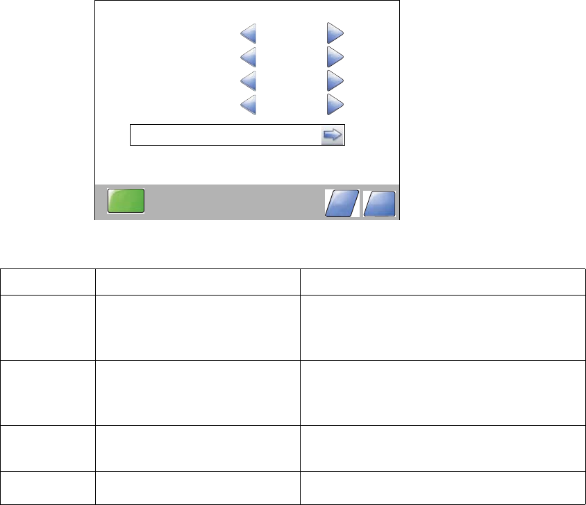
3-18 Service Manual
7014-xxx
Registration (printer)
Print registration makes sure the printing is properly aligned on the page.
The settings available are:
Description Value Direction of change
Top Margin -25 to +25
Each increment causes
approximately 4 pels shift (at
600 dpi).
A positive change moves the image down the
page and increases the top margin. A negative
change moves the image up and decreases the
top margin.
Bottom Margin -20 to +20
Each increment causes
approximately 0.55 mm shift in the
bottom margin.
A positive change compresses the image so it
appears to move down the page, and a negative
change moves the image up.
Left Margin -25 to +25 A positive change moves the image right, and a
negative change moves the image left. No
compression occurs.
Right Margin -10 to +10 A positive change moves the image right, and a
negative change moves the image left.
REGISTRATION
Top Margin
Bottom Margin
Left Margin
Right Margin
0
0
0
0
Quick Test
Submit Back
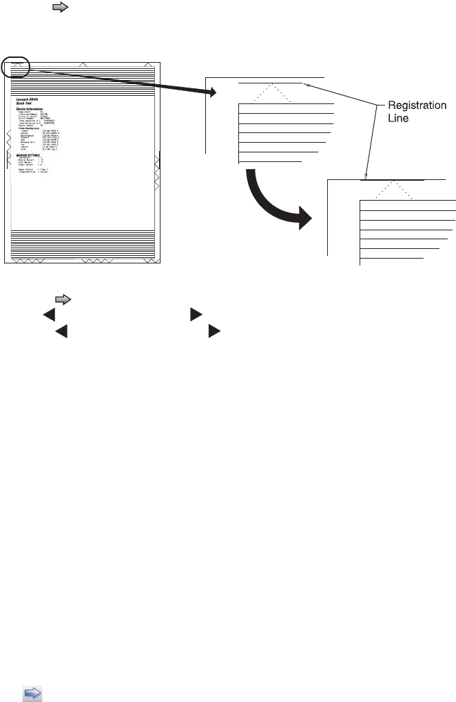
Diagnostic aids 3-19
7014-xxx
To set print registration:
1. Print the Quick Test page.
a. Touch REGISTRATION from the Diagnostics Menu.
b. Touch to select Quick Test. You may need to scroll to the next page.
Retain this page to determine the changes you need to make to the margins settings. The diamonds in the
margins should touch the margins of the page.
2. To change the value of any of the margin settings:
• Touch to the right of the appropriate margin setting. The panel displays the setting's name in the
header and [setting's current value] in a menu below the header row.
• Touch to decrease the value or to increase the value.
• Touch Submit to save the change, or Touch Back to cancel and return to the Diagnostics Menu.
• Touch Submit to save all changed values.
The device prints a Quick Test page from the appropriate paper tray. While the Quick Test page prints,
Printing Alignment Page appears on the LCD.
Quick Test page
The Quick Test contains the following information:
•Device information
•Printer margin settings
•Scanner margin settings
•Alignment diamonds at the top, bottom, and each side.
•Horizontal lines for skew adjustment
•General printer information, including current page count, installed memory, processor speed, serial
number, Engine ID, and system card ID.
To print the Quick Test page:
Note: Print the Quick Test Page on letter or A4 paper.
1. Touch REGISTRATION from the Diagnostics Menu.
2. Touch to select Quick Test.
The message Quick Test Printing… appears on the display.
Once the Quick Test Page completes printing, the Registration screen displays again.
3. Touch Back to return to the Diagnostics Menu.

3-20 Service Manual
7014-xxx
Print Tests
This setting tests the printer’s ability to generate printed output from each of its installed input sources and to
test the printer’s current print quality.
Input sources
The purpose of the diagnostic Print Tests is to verify that the printer can print on media from each of the
installed input options. The contents of the Print Test Page varies depending on the media installed in the
selected input source.
Check each Test Page from each source to assist in print quality and paper feed problems.
To run the Print Test Page:
1. Select PRINT TESTS from the Diagnostics menu.
2. Select the media source to test:
Tray 1
Tray 2 (if installed)
MP Feeder
Envelope Feeder/MP Feeder
3. Select Single or Continuous.
• If Single is selected, a single page is printed.
• If Continuous is selected, printing continues until Stop is pressed to cancel the test.
If a source is selected that contains envelopes, an envelope test pattern is printed. If Continuous is
selected, the test pattern is printed only on the first envelope.
Note: The Print Test Page always prints on one side of the paper, regardless of the duplex setting or the
presence of a duplex option.
Touch Back to return to PRINT TESTS.
Print Quality Pages (Prt Quality Pgs)
The purpose of this diagnostic function is to allow printing of the print quality test pages with the toner cartridge
lockout function disabled. The print quality pages consist of four pages. Page one contains a mixture of
graphics and text. Page two is gray with two one-inch black squares located on the bottom right. Page three is
a solid black page, and page four is blank. If duplex is turned on, the pages are duplexed. The Print Quality
Test pages are printed in English and must always be printed on letter, legal, or A4 paper.
To run the Print Quality Test Pages, touch beside Printing Quality Test Pages from PRINT TESTS. The
message Printing Quality Test Pages is displayed.
Note: The print quality test pages can also be printed from the Configuration menu (CONFIG MENU),
however, a cartridge must be installed with a machine class ID matching the machine class ID stored in
NVRAM. Additional diagnostic information may be printed on the pages when printing from DIAGNOSTICS.
The following is included in the DIAGNOSTICS version of the print quality pages:
•Values from EP SETUP in DIAGNOSTICS, including:
Fuser temperature, warm-up time, transfer, print contrast, charge roll settings and gap adjust.
•Contents of the EVENT LOG from DIAGNOSTICS.
•Configuration information, including printer serial number, controller code level, engine code level, operator
panel code level, font versions, and cartridge information.
•Default values for the QUALITY MENU settings used to print the pages.
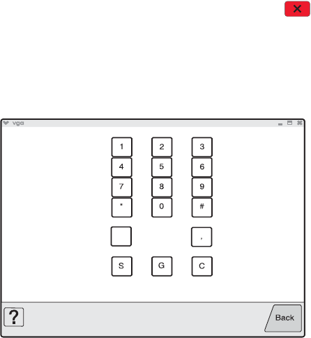
Diagnostic aids 3-21
7014-xxx
Hardware Tests
Select the following Hardware Tests from this menu:
•Panel Test
•Button Test
•DRAM Test
•USB HS Test Mode
Panel Test
This test automatically toggles each pixel of the touchscreen through every contrast level beginning with the
darkest and on to the brightest. This test continues until you press Stop .
Button Test
The Button Test verifies the operation of the buttons on the operator panel. When you select Button Test, a
diagram of the operator panel appears on the panel. When you press a button on the operator panel, the
corresponding touchscreen key is emphasized. Touch Back to cancel the test.

3-22 Service Manual
7014-xxx
DRAM Test
The purpose of this test is to check the validity of DRAM memory, both standard and optional. The test writes
patterns of data to DRAM to verify that each bit in memory can be set and read correctly.
To run the DRAM Test:
1. Touch to select DRAM Test from the menu.
The message DRAM Test Testing… displays. Then the message Resetting Printer appears, and
the power indicator light blinks red.
2. Turn the printer off and on. While the DRAM test executes, the power indicator blinks green.
The following type of message appears:
• xxx represents the installed DRAM size.
• P:###### represents the number of times the memory test has passed and finished successfully.
Initially 000000 displays with the maximum pass count being 999,999.
• F:##### represents the number of times the memory test has failed and finished with errors. Initially
0000 displays with the maximum fail count being 99,999. Initially only four digits appear, but additional digits
appear as needed.
Each time a test is completed, the number of pass and failures increments. If the test fails, the message
Failure displays for approximately three seconds, and the failure count increases by one.
The test continues until all standard and optional DRAM is tested. Once the maximum pass count or fail count
is reached, the test is stopped, the power indicator is turned on solid, and the final results display.
To stop the test before completion, turn the MFP off.
Serial 1 Wrap
This test is used to the serial port option card.. It only apears if the card is installed in the PCI slot.
To run the SERIAL 1 WRAP Test:
1. Touch to select Serial 1 Wrap from HARDWARE TESTS.
The message Serial 1 Wrap Test Testing… displays. Then the message Resetting Printer
appears.
2. The printer automatically performs a Power On Reset (POR). While the CACHE test executes, the power
indicator blinks green.
The following type of message appears:
3. To stop this test before completion, turn the MFP off.
DRAM Test <### P:###### F:####

Diagnostic aids 3-23
7014-xxx
USB HS Test Mode
1. Select USB HS Test Mode from HARDWARE TESTS.
2. Press until the appears next to the Port to be tested, and then press .
3. Select the desired Test, and then press .
To stop testing before completion, turn the printer off.
Port Test Appears on the display
Port 0 Test J
Test K
Test SEO NAK
Test Packet
Test Force Enabled
USB High Speed
Certification Testing...
Port 1 Test J
Test K
Test SEO NAK
Test Packet
Test Force Enabled
USB High Speed
Certification Testing...
Port 2 Test J
Test K
Test SEO NAK
Test Packet
Test Force Enabled
USB High Speed
Certification Testing...
Port 3 Test J
Test K
Test SEO NAK
Test Packet
Test Force Enabled
USB High Speed
Certification Testing...
3-24 Service Manual
7014-xxx
Duplex Tests
Quick Test (duplex)
This test prints a duplex version of the Quick Test that can be used to verify that the correct placement of the
top margin on the back side of a duplex page. You can run one duplexed page (Single), or continue printing
duplexed pages (Continuous) until Stop is pressed. For information about changing the margin, see
“Top Margin (duplex)” on page 3-25.
Note: Before you set the duplex top margin, be sure to set the registration. See “Registration (printer)” on
page 3-18.
The paper you choose to print the page on should be either Letter or A4.
To run the Quick Test (duplex):
1. Touch to select Quick Test from DUPLEX TESTS.
2. Touch to select Single or Continuous.
• The single Duplex Quick test cannot be canceled.
• The printer attempts to print the Quick Test Page from the default paper source. If the default paper
source only supports envelopes, then the page is printed from Tray 1.
• Check the Quick Test Page for the correct offset between the placement of the first scan line on the
front and back side of a duplexed sheet.
The single test stops automatically when a single duplex sheet is printed, and the continuous test continues
until you press Stop .

Diagnostic aids 3-25
7014-xxx
Top Margin (duplex)
This setting controls the offset between the first scan line on the front of the duplex page and the first scan line
on the back of the page. Therefore, be sure to set the top margin in REGISTRATION before setting the duplex
top margin. See “Registration (printer)” on page 3-18.
To set the Top Margin (duplex):
1. Print the Quick Test (duplex):
a. Touch to select Quick Test from DUPLEX TESTS.
b. Select Single.
c. Hold the page to the light to see the whether the top margin of the backside aligns with the
top margin of the front side.
2. Select Top Margin from DUPLEX TESTS.
3. Use the arrows to increase or decrease the current setting displayed on the touchscreen to select the
margin setting:
[setting's current value] .
• Each increment shifts the duplex top margin by 1/100 of an inch.
• The Top Margin (duplex) range is -25 to +25, and the default value is 0.
• An increase moves the top margin down and widens the top margin. A decrease moves the top
margin upward and narrows the top margin.
4. Touch Submit.
5. Print the Quick Test (duplex) again to verify the adjustment. Repeat if necessary.
Sensor Test (duplex)
This test is used to determine whether or not the duplex sensors and switches are working correctly. The test
allows you to actuate the duplex input sensor located in the back part of the duplex unit and the duplex exit
sensor located in the return paper path.
1. Select Sensor Test from DUPLEX TESTS.
The message Sensor Test Testing displays.
2. Manually actuate each of the duplex sensors. When the sensor/switch is closed, CL (closed) displays, and
when the sensor/switch is open, OP (open) displays.
• Duplex input sensor
• Duplex exit sensor
3. Press Stop to exit the test.
Motor Test (duplex)
This test lets you test the duplex option paper feed drive system, and verify that the power and velocity values
are acceptable. The duplex runs the DC motor at high speed and low speed, taking an average of the power
(PWM) required for each speed and calculating the KE value.
To run the Motor Test (duplex):
1. Select Motor Test from DUPLEX TESTS.
The power indicator light blinks, and the message Motor Test Testing displays.
2. When the motor stops, the results are displayed. Listed below is an example of such results:
Duplex Motor Test Test Passed
Avg. PWM of High-Speed Test: 1d
Avg. PWM of Low-Speed Test: Oe
Max. PWM of Low-Speed Test: 00
Min. PWM of Low-Speed Test: 0b
Motor KE Value: 2d
Motor Test Results: 00

3-26 Service Manual
7014-xxx
3. Touch Back or press Stop to exit the test.
Duplex Feed 1
This test feeds a blank sheet of paper to the duplex paper stop position 1. This test can be run using any of the
supported paper sizes.
To run the Duplex Feed 1 Test:
1. Touch to select Duplex Feed 1 from DUPLEX TESTS.
The power indicator blinks while the paper is feeding, and the message Duplex Feed 1 Feeding…
displays.
The message Duplex Feed 1 Clear Paper displays when the paper reaches paper stop position 1,
and the power indicator turns on solid.
2. Remove the media from the duplex unit, and clear the message on the operator panel by pressing
Stop .
Duplex Feed 2
This test feeds a blank sheet of paper to the duplex paper stop position 2. This test can be run using any of the
supported paper sizes.
To run the Duplex Feed 2 Test:
1. Touch to select Duplex Feed 2 from DUPLEX TESTS.
The power indicator blinks while the paper is feeding, and the message Duplex Feed 2 Feeding…
displays.
The message Duplex Feed 2 Clear Paper displays when the paper reaches the duplex paper stop
position 2, and the power indicator turns on solid.
2. Remove the media from the duplex unit, and clear the message on the operator panel by touching Back or
pressing Stop .
Input Tray Tests
Feed Tests (input tray)
This test lets the servicer observe the paper path as media is feeding through the printer. A blank sheet of
paper feeds through the printer as the laser turns off during this test. The only way to observe the paper path is
to open the lower front door that is used to access the envelope or multipurpose feeder. The paper is placed in
the output bin.
To run the Input Tray Feed Tests:
1. Touch to select Feed Tests from INPUT TRAY TESTS.
2. Touch to select the input source from the sources displayed on the Feed Tests menu. All installed
sources are listed.
3. Touch to select either Single or Continuous.
• Single—feeds one sheet of media from the selected source.
• Continuous—media continues feeding from the selected source until Stop is pressed.
Sensor Test (input tray)
This test is used to determine if the input tray sensors are working correctly. To run the Input Tray Sensor Test:
1. Touch to select the Sensor Test from INPUT TRAY TESTS.
2. Touch to select the input source from the sources displayed on the Sensor Test menu. All installed
sources are listed.
Diagnostic aids 3-27
7014-xxx
3. Select the sensor to test. Various sources have different combinations of sensors. See the table below:
[sensor selected]=Open displays.
• Empty—Input tray empty sensor
• Low—Input tray paper low sensor
• passThru—Input tray pass thru sensor
4. Once this message displays, the servicer can manually actuate each sensor. The tray empty sensor can be
actuated by hand, however a sheet of paper can be used to cover the pass thru sensor. When the sensor
is closed, Closed displays; when the sensor is open, Open displays.
5. Press Stop to exit the test.
Output bin tests
Feed Tests (output bins)
Use these tests to verify that media can be fed to the standard output bin. No information is printed on the
media fed to the output bin, because the printhead is not engaged during this test. These tests can use any
media size or envelope supported by the printer.
To run the Feed Tests for the output bins:
1. Touch to select Feed Tests from the OUTPUT BIN TESTS.
2. Touch to select the output bin you want the paper to exit into.
3. Touch to select either Single or Continuous.
• Single—feeds one sheet of media from the selected source.
• Continuous—media continues feeding from the selected source until Stop is pressed.
Touch Back to return to OUTPUT BIN TESTS.
Sensor Test (standard output bin)
This test is used to verify if the standard bin sensor is working correctly.
To run the Sensor Test for the standard bin:
1. Touch to select Sensor Test from OUTPUT BIN TESTS.
2. Touch to select Standard Bin from Sensor Tests.
3. Manually actuate the bin sensor by moving the flag in and out of the sensor, and the display changes.
The following screen is displayed:
Bin Empty: empty or Bin Empty: full.
4. Press Stop to exit the test.
Tray sensor support by source
Source Empty
(Input tray empty
sensor)
Low
(Input tray paper low
sensor)
passThru
(Input tray pass thru
sensor)
Tray 1 X X
Tray 2 XXX
Multipurpose tray X
Envelope feeder X

3-28 Service Manual
7014-xxx
Base Sensor Test
This test is used to determine if the sensors located inside the printer are working correctly.
To run the Base Sensor Test:
1. Select BASE SENSOR TEST from the DIAGNOSTICS menu.
The following sensors are listed:
•Toner Level—Toner level sensor (remove the cartridge and replace to actuate the sensor)
•Input—Input sensor
•Output—Output (exit) sensor
•NarrowMedia—Output (exit) sensor
•Front Door—Front door sensor
2. Manually actuate the sensors to verify that each sensor switches from Open to Closed.
3. Press Stop to exit the test.
DEVICE TESTS
Quick Disk Test
This test performs a non-destructive read/write on one block per track on the disk. The test reads one block on
each track, saves the data, and proceeds to write and read four test patterns to the bytes in the block. If the
block is good, the saved data is written back to the disk.
To run the Quick Disk Test:
1. Touch to select Quick Disk Test from DEVICE TESTS.
The power indicator blinks while the test is in progress, and quick Disk Test Testing… displays.
• Quick Disk Test/Test Passed message displays if the test passes, and the power indicator
turns on solid.
• Quick Disk Test/Test Failed message displays if the test failed, and the power indicator
turns on solid.
2. Press Stop to return to the Device Tests menu.
Disk Test/Clean
Warning: This test destroys all data on the disk and should not be attempted on a good disk. Also note that
this test may run approximately 1½ hours depending on the disk size.
To run the Disk Test/Clean Test:
1. Touch to select Disk Test/Clean from the Device Tests menu.
Contents will be lost. Continue? message displays to warn the user that all contents on the disk
will be lost.
2. Touch Yes to continue and No to exit.
If Yes is selected, the following screen displays and updates periodically, indicating the percentage of test
completed.
The power indicator blinks during the test.
Note: The test can NOT be canceled.
Formatting Disk
1/1 0%
DO NOT POWER OFF
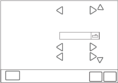
Diagnostic aids 3-29
7014-xxx
3. Once the test is complete, the power indicator turns on solid, and either the message Disk Test/Clean
Test Passed or Disk Test/Clean Failed appears. If the message indicates failure, the disk is
unusable.
PRINTER SETUP
The triangles pointing up or down indicate whether there are additional menus. Touch the up or down arrows to
display these additional menus.
Note: If you make changes, touch Submit to make the change effective.
Defaults
US/Non-US defaults changes whether the printer uses the US factory defaults or the non-US factory defaults.
The settings affected include paper size, envelope size, PCL symbol set, code pages, and units of measure.
Warning: Changing this setting resets the printer to factory defaults, and data may be lost. It cannot be
undone.
Printed Page Count
The page count can only be viewed and cannot be changed.
Touch Back to return to Diagnostics Menu.
Permanent Page Count
The permanent page count can only be viewed and cannot be changed.
Touch Back to return to Diagnostics Menu.
Serial Number
The serial number can only be viewed and cannot be changed.
Touch Back to return to Diagnostics Menu.
Engine Settings 1 through 4
Do not change these settings unless requested to do so by your next level of support.
Model Name
PRINTER SETUP
Defaults
Printed Page Count
Permanent Page Count
Serial Number
US
127
127
xxxxxxx
Submit
Back
Engine Setting 2 0
Engine Setting 1 0

3-30 Service Manual
7014-xxx
The model name can only be viewed and cannot be changed.
Configuration ID
The two configuration IDs are used to communicate information about certain areas of the printer that cannot
be determined using hardware sensors. The configuration IDs are originally set at the factory when the printer
is manufactured, however, the servicer may need to reset Configuration ID 1 or Configuration ID 2 whenever
you replace the system board. The IDs consist of eight hexadecimal characters, including 0 through 9 and A
through F.
Note: When the printer detects a Configuration ID that is not defined or invalid, the following occurs:
•The default standard model Configuration ID is used instead.
•Configuration ID is the only function available in DIAGNOSTICS.
•Unless the menu is in DIAGNOSTICS, Check Config ID displays.
To set the configuration ID:
1. Touch to select PRINTER SETUP from the Diagnostics Menu.
2. Touch to select Configuration ID.
3. Touch the keyboard icon to display a keyboard with 1 through 0 and a through f. The current values for
Configuration ID 1 and Configuration ID 2 are displayed.
• Use keys to type the numbers for the two configuration IDs.
• Use the left arrow to move over a digit from the right of the number toward the left.
• When the numbers are correct, touch Submit.
• If you have a question, touch the question mark icon.
• To exit without changing the numbers, touch Back.
Note: Be sure to touch Submit, or the number will not be changed.
Submitting Selection displays, followed by the value for Configuration ID 1.
Note: If Invalid ID appears, the entry is discarded, and the previous Configuration ID 1 is displayed on
the screen.
If the process is successful, Submitting Selection appears on the display, followed by the current
value for Configuration ID 2.
4. Restart the printer.
Edge to Edge
When this setting is On, the text and graphics are shifted to the physical edges of the paper for all margins.
When the setting is Off, the normal margins are restored.
Enable Edge to Edge Copy
The settings are ON and OFF.
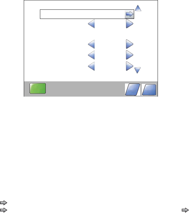
Diagnostic aids 3-31
7014-xxx
EP SETUP
The triangles pointing up or down indicate whether there are additional menus. Touch the up or down arrows to
display these additional menus.
Note: If you make changes, touch Submit to make the change effective.
EP Defaults
This setting is used to restore each printer setting listed in EP SETUP to its factory default value. Sometimes
this is used to help correct print quality problems.
To restore EP Defaults:
1. Touch to select EP Defaults from EP SETUP.
2. Touch to select Restore to reset the values to the factory settings, and touch to select Do Not
Restore to exit without changing the settings.
Touch Back to exit without changing the settings.
Fuser Temperature (Fuser Temp)
This adjustment can be used to help solve some customer problems with paper curl on low-grade papers and
problems with letterheads on some types of media.
The fuser temperature can be adjusted to: Normal, Lower, Lowest. The default is Normal.
Touch Back to return to Diagnostics Menu.
Fuser Page Count
The fuser page count can only be viewed and cannot be changed.
Touch Back to return to Diagnostics Menu.
Warm Up Time
You can change the amount of time the printer warms up before allowing pages to print by changing this
setting from 0 to 5. The factory sets the warm up at 0 or no warm up time. This time period lets the backup roll
heat up and helps reduce curl in some environments.
EP SETUP
EP Defaults
Fuser Temp
Fuser Page Count
Warm Up Time
127
Normal
Submit
Back
Print Contrast Medium
Transfer Medium

3-32 Service Manual
7014-xxx
Touch Back to return to Diagnostics Menu.
Transfer
The transfer can be adjusted to Low, Medium, or High. The default setting is Medium.
Touch Back to return to Diagnostics Menu.
Print Contrast
The print contrast setting controls the developer voltage offset.
The print contrast can be adjusted to Low, Medium, or High. The default setting is Medium.
Touch Back to return to Diagnostics Menu.
Charge Roll
The charge roll can be adjusted to Low, Medium, or High. The default setting is Medium.
Touch Back to return to Diagnostics Menu.
Gap Adjust
The setting adjusts the minimum gap between sheets. Increasing this value may reduce curl of some printed
media and eliminate some output bin stacking problems. However, increasing this value also results in slower
overall performance, measured in pages per minute. The range of values is 0 to 255, and the default value is 0.
Touch Back to return to Diagnostics Menu.
Auto Dark Adjust
The settings are Enable and Disable.
Reports
Menu Settings Page
This enables you to print the Menu Settings Page. The report prints the Diag Menu to include Registration,
Print Tests, Hardware Tests, Duplex Tests, Input Tray Tests, Output Bin Tests, Device Tests, Printer Setup,
EP Setup, Reports, Event Log, Development Menu, and Scanner Tests.
EVENT LOG
Display Log
The event log provides a history of printer errors. It contains the 12 most recent errors that have occurred on
the printer. The most recent error displays in position 1, and the oldest error displays in position 12 (if 12 errors
have occurred). If an error occurs after the log is full, the oldest error is discarded. Identical errors in
consecutive positions in the log are entered, so there may be repetitions. All 2xx and 9xx error messages are
stored in the event log.
To view the event log:
1. Touch to select Display Log from EVENT LOG.
Up to three error codes display at a time. Touch to display additional information, if available.
2. Touch Back to return to the EVENT LOG menu.
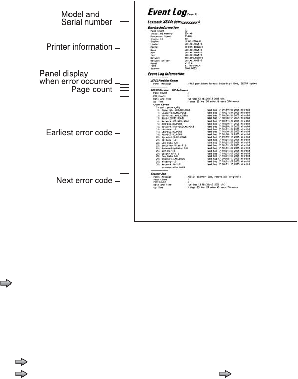
Diagnostic aids 3-33
7014-xxx
Print Log
Additional diagnostic information is available when you print the event log from Diagnostics Menu rather than
Configuration Menu.
The Event Log printed from Diagnostics Menu includes:
•Detailed printer information, including code versions
•Time and date stamps
•Page counts for most errors
•Additional debug information in some cases
The printed event log can be faxed to Lexmark or your next level of support for verification or diagnosis.
To print the event log:
Touch to select Print Log from EVENT LOG.
Clear Log
Use Clear Log to remove the current information in the Event Log. This affects both the viewed log and the
printed log information.
1. Touch to select Clear Log from the Event Log menu.
2. Touch to select Yes to clear the Event Log, or touch to select NO to exit the Clear Log menu. If
YES is selected, Deleting EVENT LOG displays on the screen.

3-34 Service Manual
7014-xxx
Scanner Tests
ASIC Test
A pattern appears and ASIC Test Passed displays. If xxxxxx displays, the test was unsuccessful.
Press Stop to return to the SCANNER TESTS menu.
Feed Test
To run the Scanner Feed test:
1. Touch to select Feed Test from the SCANNER TESTS menu.
2. The panel displays the setting's current value [setting's current value] . Use the arrows to select from
Letter, Legal, or A4.
3. Touch START to begin.
Running Flatbed… displays.
Press 4 to exit the test.
4. Touch Back to return to the Diagnostics Menu.
Sensor Tests
The following tests are available:
P - Sensor (ADF Paper Present)
A - Sensor (ADF cover closed interlock)
F -Sensor (FB scanner cover interlock)
1 - Sensor (ADF sensor 1)
2 - Sensor (ADF sensor 2)
H - Sensor (FB Home position)
1. Touch to select Sensor Test from the SCANNER TESTS menu.
2. The display will show P, F, H, A, 1, 2 in a vertical column.
Note: Every scanner sensor does not need to be tested when Scanner Tests is selected.
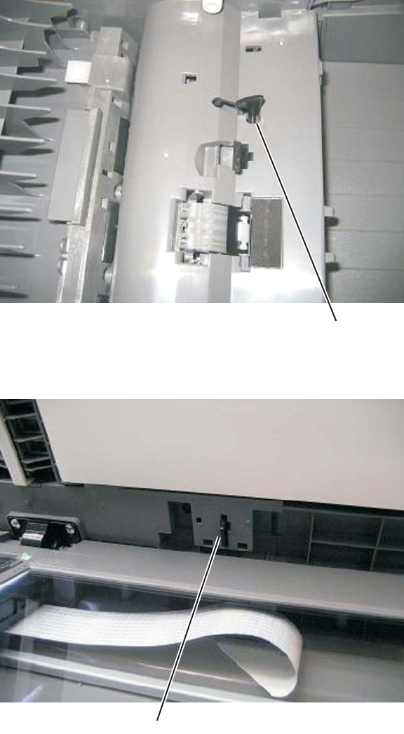
Diagnostic aids 3-35
7014-xxx
3. To test the paper present sensor, push back on the actuator (A). If the sensor is functioning, the 0 next to
the P on the display will change to 1.
4. To test the flatbed cover closed sensor, lift the flatbed cover. The 0 next to the F will change to 1. Also
check the actuator (B) to ensure it is functiong properly.
A
A
B
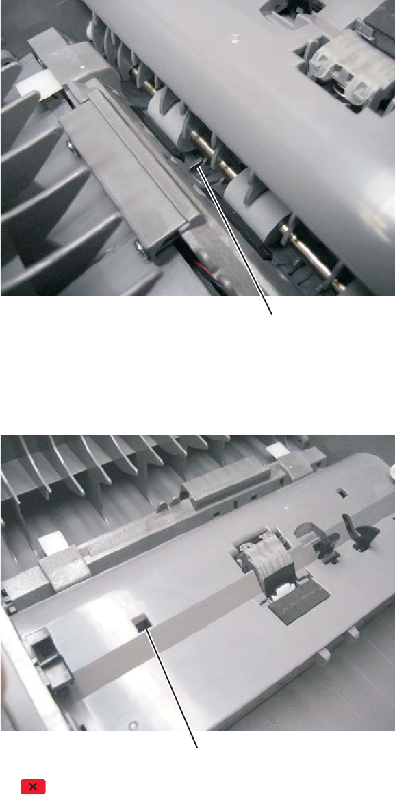
3-36 Service Manual
7014-xxx
5. To test scanner sensor 1 press on the tab (C). The 0 next to the 1 will change to 1 if the sensor is working
properly.
6. To test scanner sensor 2 press on the tab (D). The 0 next to the 2 will change to 1 if the sensor is working
properly.
7. To test the ADF cover opent sensor, open the ADF top cover. Id the sensor is functioning properly the 0
next to the A will change to 1.
8. Press Stop to return to the SCANNER TESTS menu.
B
C
B
D
Diagnostic aids 3-37
7014-xxx
Exit Diagnostics
Selecting EXIT DIAGNOSTICS exits the Diagnostics menu, and Resetting the Printer displays. The printer
performs a POR, and the printer returns to normal mode.
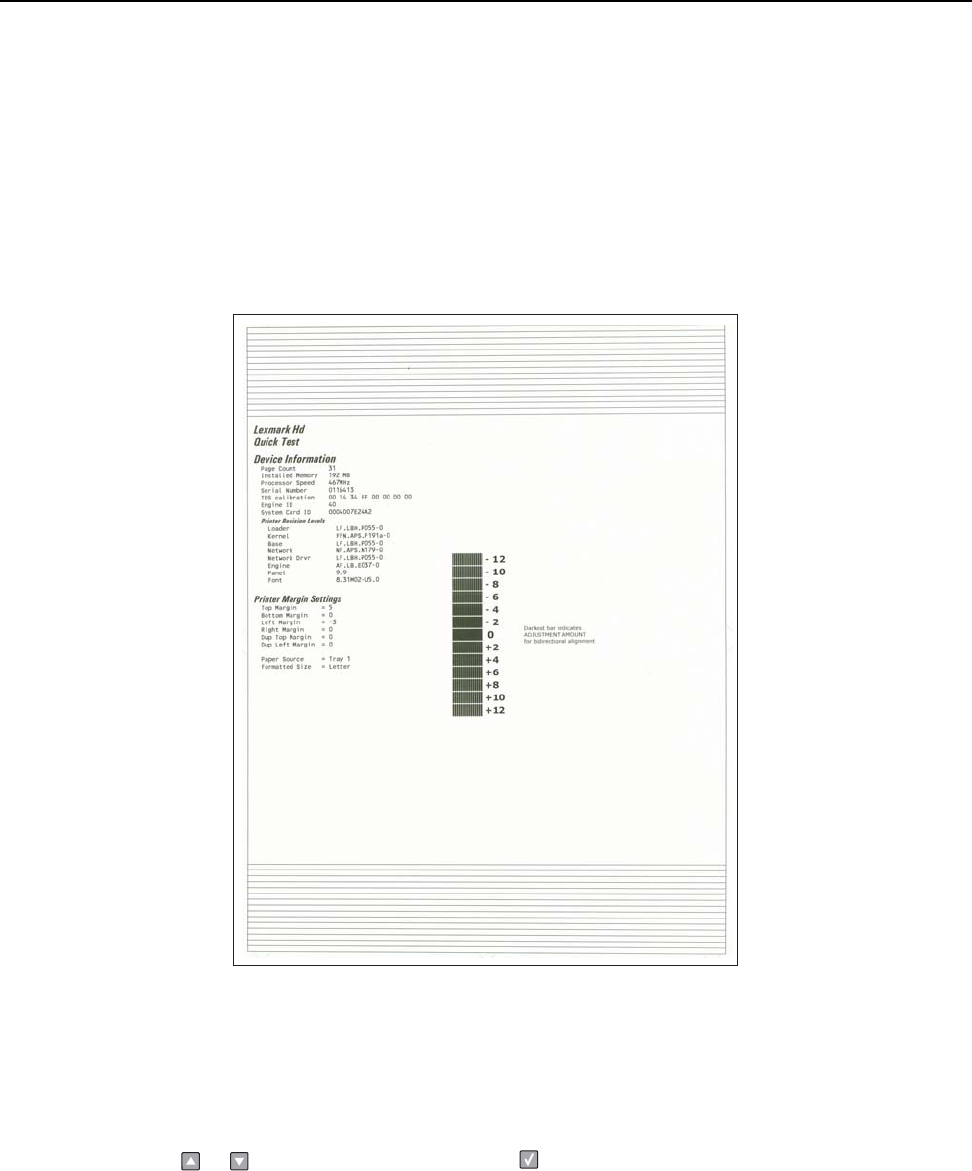
3-38 Service Manual
7014-xxx
Printhead assembly electronic adjustment
Note: Before aligning the printhead electronically, first align the printhead mechanically, if needed. See
“Printhead assembly mechanical adjustment” on page 3-39.
1. Enter the Diagnostics menu. See “Entering Diagnostics menu” on page 3-17.
2. Touch Registration to enter the Registration menu.
3. Touch Quick test to print the Quick test page.
Quick Test page
(sample only; use actual sheet)
4. In the Registration menu, select the right margin setting.
5. To determine the margin setting, choose the value that is closest to the darkest bar on the center graph of
the margin page. Add that value to the current right margin setting printed on the left hand side of the
margin page. (The right margin setting will also appear on the operator panel display.) For example, if the
right margin setting on the page is -2, and the number that is closest to the darkest line on the graph is 3
(-2+3), then the right margin setting will be equal to +1.
6. Press or to the desired setting, and press .

Diagnostic aids 3-39
7014-xxx
7. Print the Quick Test page again and check that the darkest line in the center graph is equal to zero. If it is,
then check to see if the left, top, and bottom margins are detected. If it is not, then repeat step 5.
Note: The alignment of the left margin positions the black plane to the right or left. The alignment of the right
margin does not alter the margins and should only be used to adjust the printhead.
Printhead assembly mechanical adjustment
A printhead needs to be correctly positioned after it has been removed. Use a pencil to mark the screw locations
of the old printhead on the metal frame. Align the new printhead relative to the location of the old printhead.
Note: Skew is caused by a sheet being fed through the printer while misaligned. The entire image is rotated
relative to the sheet edges. However, a mechanically misaligned printhead causes the horizontal lines to appear
skewed, while the vertical lines remain parallel to the vertical edges. There are no adjustments for skew. Check
the pick roll (paper pick assembly) for wear, the paper path for obstructions, the fuser for proper setting, and the
tray paper guides for fit to the media.
To adjust the printhead:
1. Enter the Diagnostics Menu. See “Entering Diagnostics menu” on page 3-17.
2. Select PRINT TESTS.
3. Select Tray 1.
4. Select Single.
5. Fold the printed test page on the left side so that a few millimeters of grid lines wrap around the outside of
the fold. See photo below.
6. Fold a second vertical fold near the center so that the left side top edge aligns with the right side top edge.
Printhead
misalignment
Paper feed
skew
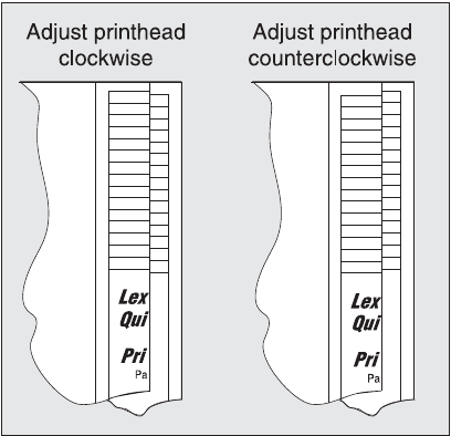
3-40 Service Manual
7014-xxx
7. If the grid lines of the right flap align below the corresponding lines on the left flap, then adjust the printhead
clockwise relative to the printer, and recheck. (See the left side of the figure below.) If the grid lines of the
left flap align below the corresponding lines of the right side, then adjust the printhead counterclockwise.
(See the right side of the figure below.)
8. After obtaining a properly adjusted image on the paper, tighten all three screws.
Note: The printhead must be aligned electronically. See “Printhead assembly electronic adjustment” on
page 3-38.

Diagnostic aids 3-41
7014-xxx
SE Menu
Note: This is not the Fax SE menu. To enter the Fax SE menu, press **411 from the Ready screen.
Note: This menu should be used as directed by second-level support.
Print SE Menus
General
Copyright - Displays copyright information.
Optra Forms mode - On or off
Code Revision Info
Network Code Level - Displays network code level
Network Compile Info - Displays compile information
Printer Code Level - Displays printer code information
Printer Compile Info - Displays compile information
History
Print History
Mark History
History Mode
MAC
Set Card Speed
LAA
Keep Alive
NVRAM
Dump NVRAM
Re-init NVRAM
NPAP
Print Alerts
TCP/IP
netstat -r
arp -a
Allow SNMP Set
MTU
Meditech Mode
Raw LPR Mode
Gather Debug
Enable Debug
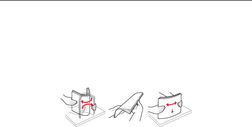
3-42 Service Manual
7014-xxx
Paper jams
Avoiding jams
Most paper jams can be avoided by correctly loading paper and specialty media in the printer.
The following hints can help prevent paper jams:
•Use only the recommended print media.
•Do not overload the print media sources. Make sure the stack height does not exceed the maximum height
indicated by the stack line on the labels in the sources.
•Do not load wrinkled, creased, damp, or curled print media.
•Flex, fan, and straighten print media before loading it. If jams do occur with the print media, then try feeding
one sheet at a time through the manual feeder.
•Do not mix print media sizes, weights, or types in the same print media source.
•Push all trays in firmly after loading them.
Note: Make sure the media stack is below the maximum media fill indicators on the 250-sheet tray before
pushing the tray into the printer.
•Make sure paper guides are positioned before loading the paper or specialty media.
•Do not remove trays while a job is printing.
•Before loading transparencies, fan the stack to prevent sheets from sticking together.
•Do not use envelopes that:
–Have excessive curl
–Are stuck together
–Are damaged in any way
–Contain windows, holes, perforations, cutouts, or embossments
–Have metal clasps, string ties, or metal folding bars
–Have postage stamps attached
–Have any exposed adhesive when the flap is in the sealed position
•Use only recommended media. Refer to the Card Stock & Label Guide available on the Lexmark Web site
at www.lexmark.com for more information about which media provides optimum results for the current
printing environment.
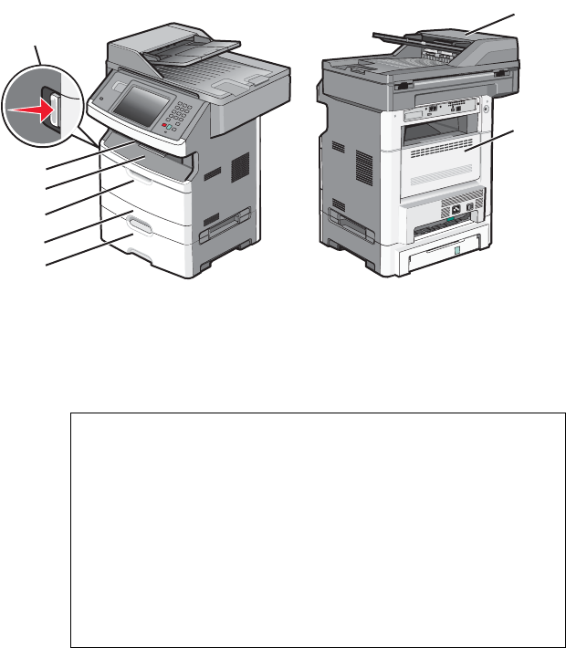
Diagnostic aids 3-43
7014-xxx
Understanding jam numbers and locations
The following illustration shows the areas of the MFP where jams occur. When paper jams occur, follw the
instructions in this section.
Jam area
number Description
1 Opened front door
2 Paper output bin
3 Front door
4 Multi purpose feeder
5Tray 1
6Tray 2
7 Rear door
8 Automatic document feeder (ADF)
3
1
4
5
6
2
7
8
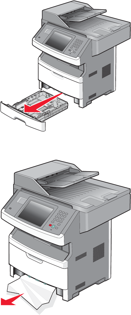
3-44 Service Manual
7014-xxx
Jam messages and their locations
200 and 201 paper jams
CAUTION: Hot surface. The inside of the printer may be hot. To reduce the risk of injury from a hot component,
allow the surface to cool before touching it.
1. Pull the tray completely out.
2. Remove the paper jam.
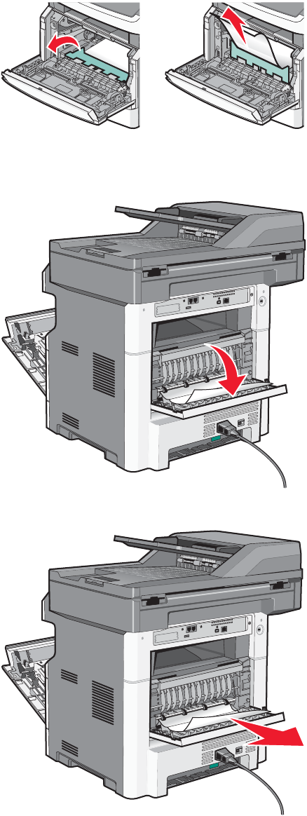
Diagnostic aids 3-45
7014-xxx
3. If the paper is not visible, open the front door and remove the photoconductor kit and toner cartridge.
4. Remove the jam.
5. If the paper is still not visible, open the rear door.
6. Remove the jam.
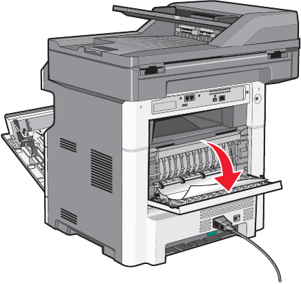
3-46 Service Manual
7014-xxx
7. Close the rear door.
8. Reinsert the photoconductor kit and toner cartridge.
9. Close the front door.
10. Touch Continue.
202 paper jam
Touch Status/Supplies to identify the location of the jam. If the paper is exiting the MFP into the exit bin, pull the
paper out and touch Coninue.
If the paper is still in the paper path:
1. Open the rear door.
2. Remove the jammed paper.
3. Close the rear door.
4. Touch Continue.
231 paper jam
CAUTION: Hot surface. The inside of the printer may be hot. To reduce the risk of injury from a hot component,
allow the surface to cool before touching it.
1. Open the front door.
2. Open the rear door.
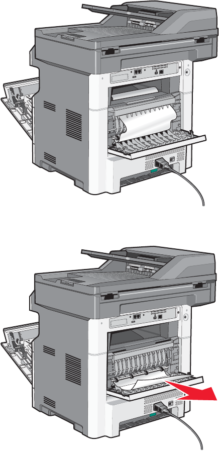
Diagnostic aids 3-47
7014-xxx
3. Remove the jam.
4. Close the rear door.
5. Close the front door.
6. Touch Continue.
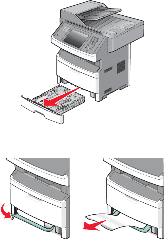
3-48 Service Manual
7014-xxx
233 paper jam
1. Remove the tray from the printer.
2. Locate the duplex release lever and pull it down to release the paper.
3. Insert the tray.
4. Touch Continue.
If this does not clear the jam, perform the steps found in 231 paper jam. See “231 paper jam” on page 3-46.
234 paper jam
This jam error indicates single or multiple jams in the duplex are of the MFP. Perform the steps in the following
jam removal procedures:
231 paper jam. See “231 paper jam” on page 3-46.
233 paper jam. See “233 paper jam” on page 3-48.
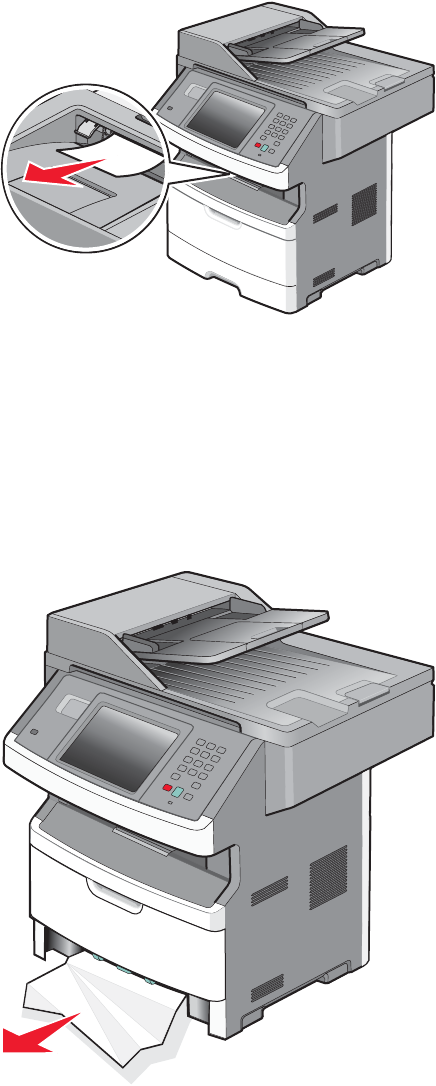
Diagnostic aids 3-49
7014-xxx
235 paper jam
1. Gently pull the jammed media from the fuser.
2. Touch Continue.
240 - 249 paper jams
1. Touch Supplie/Status to identify the jam location.
2. Remove the standard tray.
3. Remove any jammed paper.
4. Reinsert the tray, and touch Continue.
5. If the jam message remains, remove the optional tray.
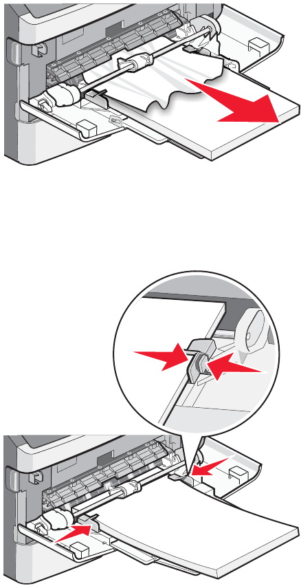
3-50 Service Manual
7014-xxx
6. Remove any jammed paper.
7. Reinsert the option tray, and touch Continue.
250 paper jam
1. Touch Supplies/Status to find the jam location.
2. Remove the media from the multipurpose feeder.
3. Remove the jammed media from the multipurpose feeder.
4. Flex and fan the media.
5. Reload the media into the multipupose feeder.
6. Adjust the guides if needed.
7. Touch Continue.
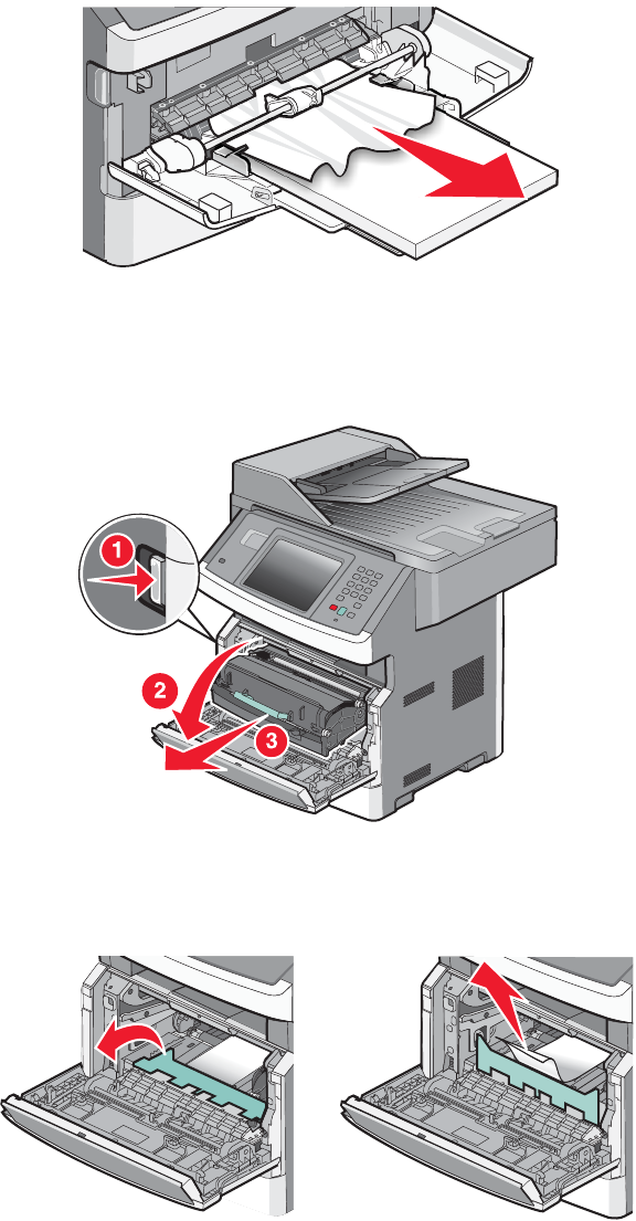
Diagnostic aids 3-51
7014-xxx
251 paper jam
If the media is visible from the front of the MFP, gently pull the media out of the multipurpose feeder.
If the media is not visible, perform the following steps to clear the jam:
1. Open the front door, and remove the photoconductor kit and toner cartridge.
2. Lift the flap at the front of the MFP, and remove any jams.
3. Reinsert the photoconductor kit and toner cartridge.
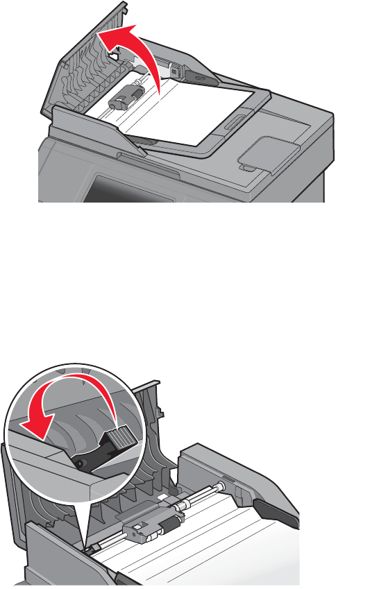
3-52 Service Manual
7014-xxx
4. Close the front door.
5. Touch Continue.
290-294 paper jams
Clearing jams under the ADF cover
1. Remove all original documents from the ADF input tray.
2. Open the ADF cover.
3. Unlock the ADF separator roll.
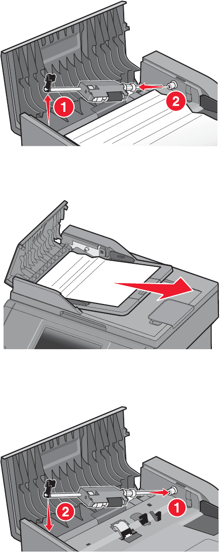
Diagnostic aids 3-53
7014-xxx
4. Remove the ADF separator roll.
5. Remove the jammed media.
6. Reinstall the ADF separator roll.
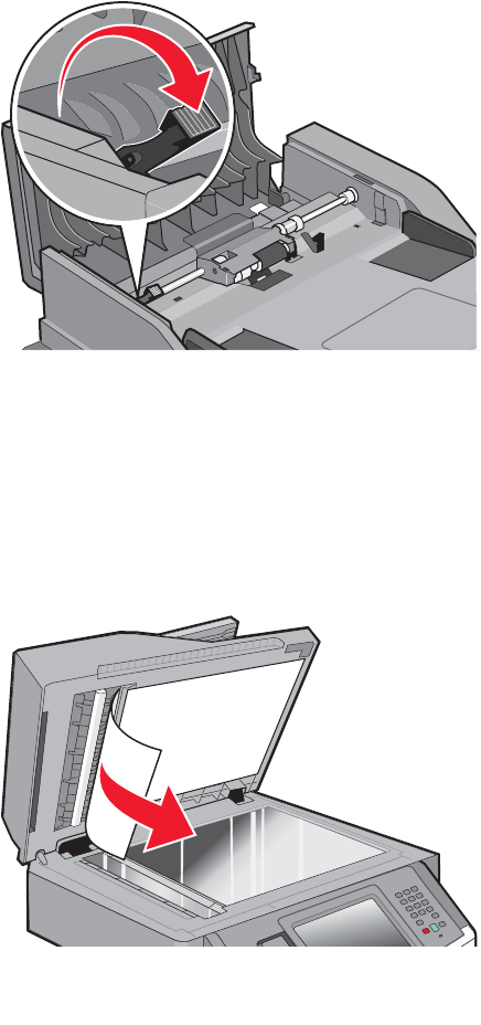
3-54 Service Manual
7014-xxx
7. Lock the ADF separator roll.
8. Close the ADF top cover.
Clearing ADF jams under the flatbed cover.
1. Lift the flatbed cover, and remove the jammed media from the ADF.
2. Touch Continue.
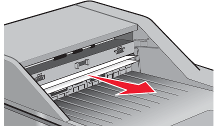
Diagnostic aids 3-55
7014-xxx
Clearing jams in the duplex ADF
1. Remove the ADF input tray.
2. Pull out the jammed media by pulling on the bottom sheet.
3. Reinstall the ADF input tray.
4. Touch Continue.
3-56 Service Manual
7014-xxx

Repair information 4-1
7014-xxx
4. Repair information
Warning: Read the following before handling electronic parts.
Handling ESD-sensitive parts
Many electronic products use parts that are known to be sensitive to electrostatic discharge (ESD). To prevent
damage to ESD-sensitive parts, follow the instructions below in addition to all the usual precautions, such as
turning off power before removing logic cards:
•Keep the ESD-sensitive part in its original shipping container (a special “ESD bag”) until the part is ready to
be installed into the printer.
•Make the least-possible body movements to prevent an increase of static electricity from clothing fibers,
carpets, and furniture.
•Put the ESD wrist strap on your wrist. Connect the wrist band to the system ground point. This discharges
any static electricity in your body to the printer.
•Hold the ESD-sensitive part by its edge connector shroud (cover); do not touch its pins. If a pluggable
module is being removed, then use the correct tool.
•Do not place the ESD-sensitive part on the MFP cover or on a metal table; if the ESD-sensitive part needs
to be put down for any reason, then first put it into its special bag.
•Machine covers and metal tables are electrical grounds. They increase the risk of damage, because they
make a discharge path from your body through the ESD-sensitive part. (Large metal objects can be
discharge paths without being grounded.)
•Prevent ESD-sensitive parts from being accidentally touched by other personnel. Install machine covers
when the machine is not being worked on, and do not put unprotected ESD-sensitive parts on a table.
•If possible, keep all ESD-sensitive parts in a grounded metal cabinet (case).
•Be extra careful in working with ESD-sensitive parts when cold-weather heating is used, because low
humidity increases static electricity.
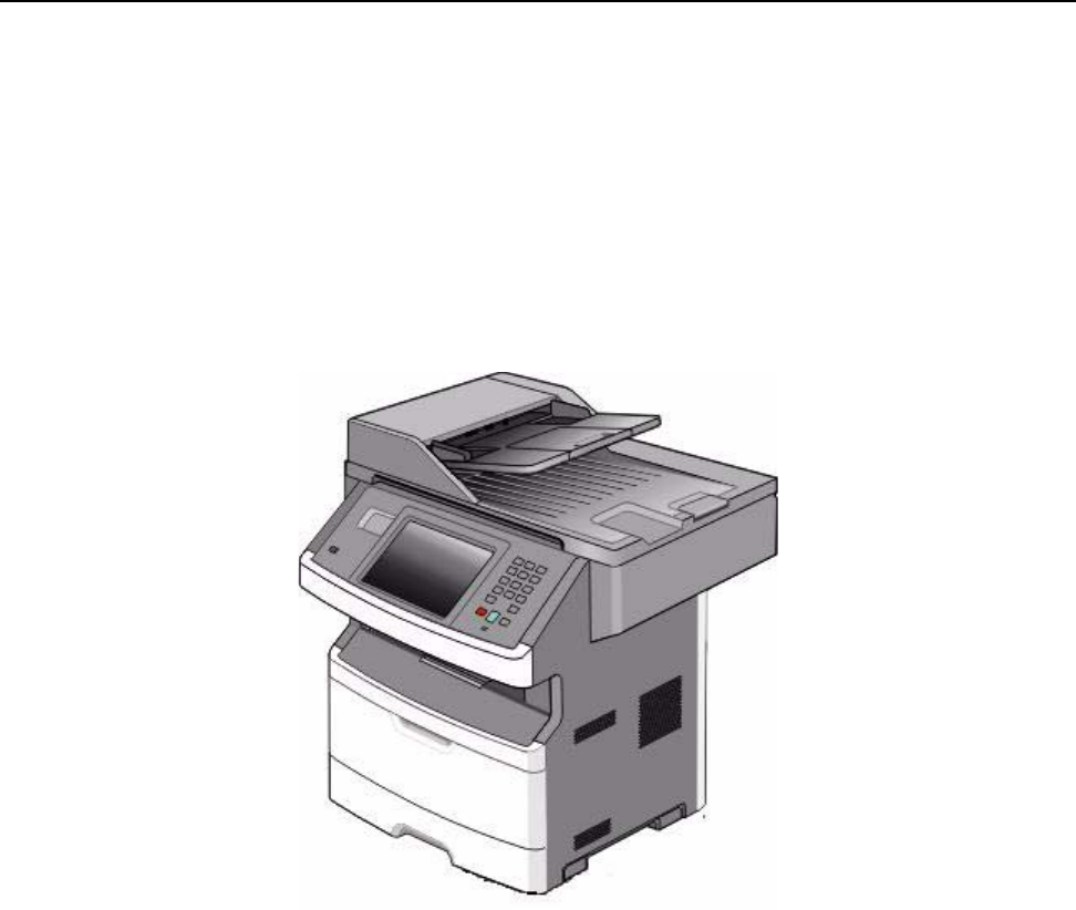
4-2
7014-xxx
Removal procedures
•Remove the toner cartridge and media tray before removing other printer parts. The toner cartridge should
be protected from light while out of the printer.
•We recommend disconnecting all external cables from the printer to prevent damage during service.
•Unless otherwise stated, reinstall the parts in reverse order of removal.
•When reinstalling a part held with several screws, start all screws before final tightening.
•Remove the paper tray and print cartridge before proceeding with a removal.
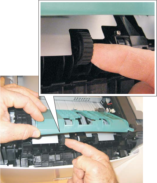
Repair information 4-3
7014-xxx
ACM pick tire roller removal
1. Place the printer on its side.
Note: Be careful to not mar the finish of the printer.
2. Open the duplex jam door just far enough to pull out the ACM pick tires.
Warning: Open the duplex door only far enough to remove the ACM pick tires. If the door is opened too
far, then it can become disengaged and interfere with the paper tray. The tray may go in but will not come
out, and will render the printer non-serviceable.
3. After the ACM pick tires have been pulled out, close the duplex door.
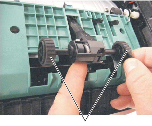
4-4
7014-xxx
4. Remove the ACM pick tire roller (A).
•If the left hub is gray, then disconnect the old right and left tire/hub assemblies from the ACM, and replace
with the new right and left tire/hub assemblies.
•If the left hub is black, then remove the old right and left tires from the ACM hubs, and replace with the new
tires. Do not attempt to remove the hubs.
A
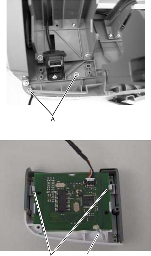
Repair information 4-5
7014-xxx
Card reader removal
1. Remove the scanner front cover. See “Scanner front cover removal” on page 3-31.
2. Remove the operator panel keypad assembly. See “Operator panel keypad removal” on page 4-64
3. Release the tabs on the rear of the operator panel display and tilt it upright.
4. Remove the two screws (A) securing the card reader housing to the tub assembly.
5. Disconnect the card reader cable from the card reader.
6. Remove the LED light tube (B) from the upper card reader cover.
7. Pull the two tabs (C) back and remove the card from the card reader housing.
Note: When replacing the light tube, cover the tube with a small piece of black electrical tape if possible.
B
C
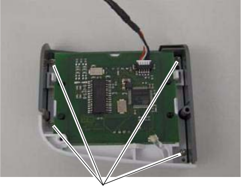
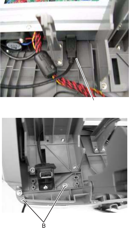
Repair information 4-7
7014-xxx
Card reader cable removal
1. Remove the scanner front cover. See “Scanner front cover removal” on page 3-31.
2. Remove the operator panel keypad assembly. See “Operator panel keypad removal” on page 4-64
3. Release the tabs on the rear of the operator panel display and tilt it upright.
4. Disconnect the card reader cable (A) from the J2 USB port on the controller board.
5. Remove the two screws (B) securing the card reader housing to the tub assembly.
6. Disconnect the cable from the card reader card.
A
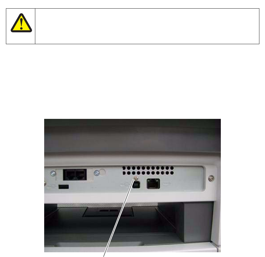
4-8
7014-xxx
Controller board removal
Warning:
•Always touch a ground before touching the board.
•Handle the board carefully by the edges.
•Never replace the operator panel and controller board without a successful POR in between.
•Never replace the operator panel and the controller board at the same time. Each card contains the printer
settings. When either of these cards is new, it obtains its settings from the other card. Critical factory
settings are lost when both cards are new and are replaced at the same time.
1. Remove the screw (A) from the USB port.
2. Lift the scanner assembly to the raised position.
3. Remove any option cards from the controller board.
CAUTION
This product contains a lithium battery. THERE IS A RISK OF EXPLOSION IF THE BATTERY
IS REPLACED BY AN INCORRECT TYPE. Discard used batteries according to the battery
manufacturer’s instructions and local regulations.
A
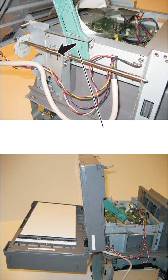
Repair information 4-9
7014-xxx
4. Using a flatblade screwdriver, depress the kickstand release tab (B).
5. While depresing the tab,lift the scanner assembly until it is fully vertical.
6. Carefully tilt the ADF down as shown.
Warning: To avoid damage to the rear frame assemblies, hold the ADF while raising the flatbed to the
upright position, then lower the ADF ,slowly a shown above.
7. Remove the controller board shield. See “Controller board shield” on page 4-11.
8. Disconnect all the cables from the controller board.
9. Tilt the operator panel display to the up position.
10. Route the UICC cable, the front USB cable, and the display panel cables through the hole in the front of the
controller board cage.
B
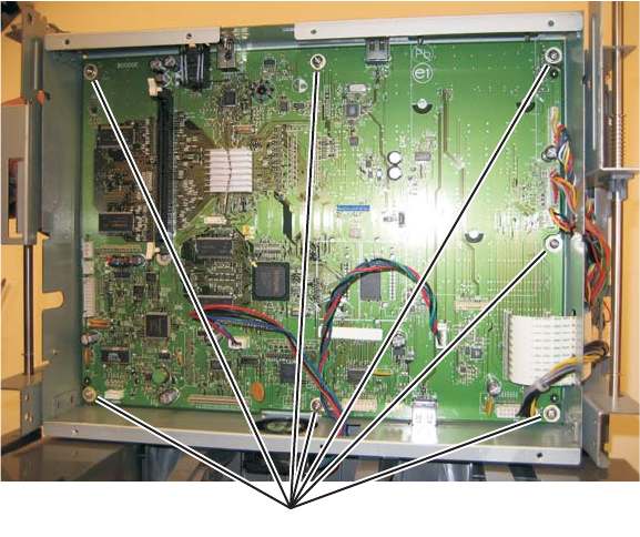
4-10
7014-xxx
11. Remove the seven screws (C) securing the controller board to the controller board cage.
12. Lift the controller board, and remove.
Note: When installing the controller board, place the USB port screw first, and then place the controller
board screws.
A
C
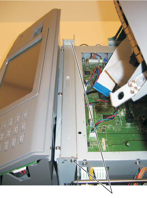
Repair information 4-11
7014-xxx
Controller board shield
1. Remove the two screws (A) securing the controller shield bracket to the controller board cage.
A
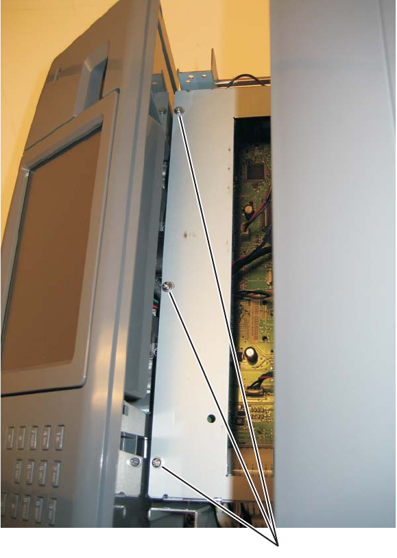
4-12
7014-xxx
2. Remove the three screws (B) securing the top of the controller shield.
B
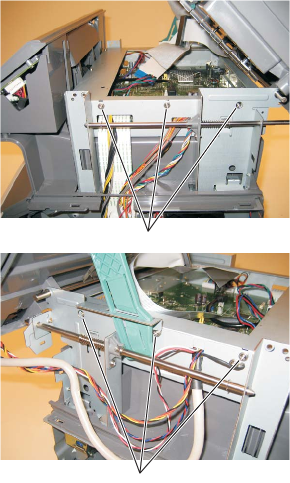
Repair information 4-13
7014-xxx
3. Loosen the three screws (C) on each side of the controller board cage.
4. Remove the controller board shield.
C
C
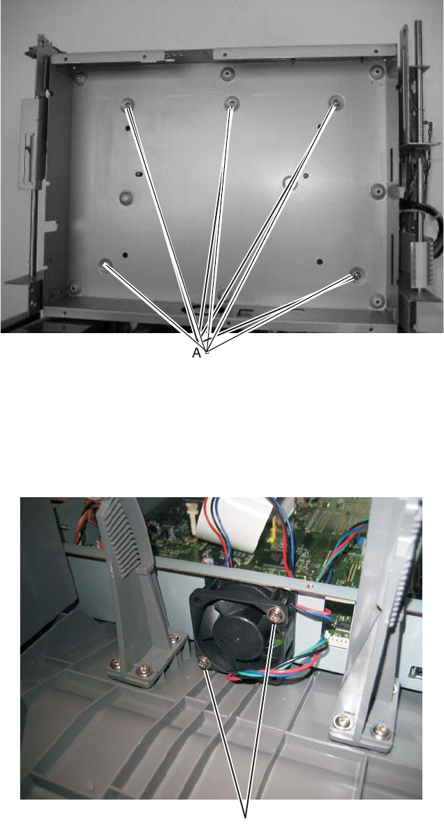
4-14
7014-xxx
Controller board cage
1. Remove the controller board. See Go to “Controller board removal” on page 4-8.
2. Remove the five screws (A) which secure the controller board cage to the tub assembly.
3. Tilt the front of the cage up and remove it from the MFP.
Controller board fan
1. Remove the operator panel display. See Go to “Operator panel display removal” on page 4-65.
2. Disconnect the controller board fan cable from J99 on the controller board.
3. Remove the two screws (A) which secure the controller board fan to the controller board cage.
A
A
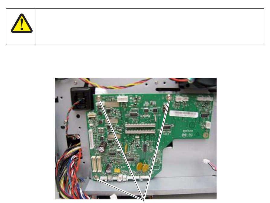
Repair information 4-15
7014-xxx
Engine board removal
1. Remove the right side cover. See Go to “Right side cover removal” on page 4-80.
2. Disconnect all the cables from the engine board.
3. Remove the three screws (A securing the engine board to the print engine frame.
4. Remove the engine board.
CAUTION
This product contains a lithium battery. THERE IS A RISK OF EXPLOSION IF THE BATTERY
IS REPLACED BY AN INCORRECT TYPE. Discard used batteries according to the battery
manufacturer’s instructions and local regulations.
A
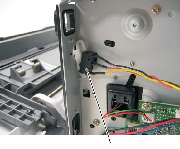
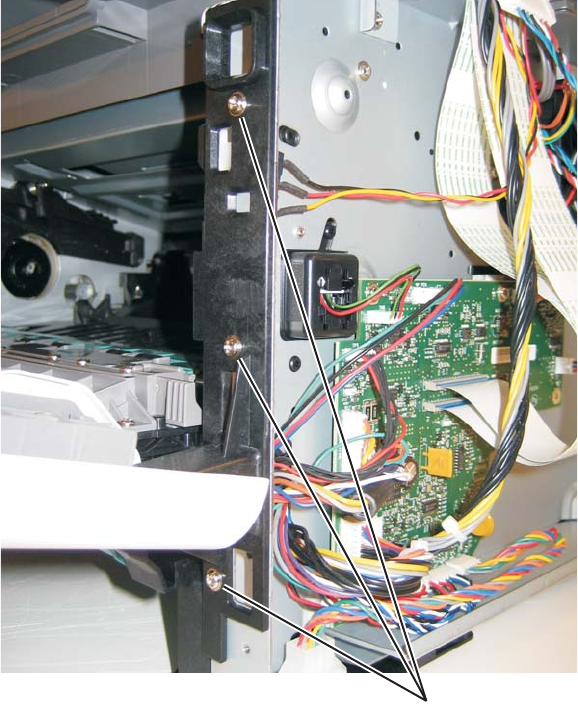
Repair information 4-17
7014-xxx
Door mount removal
1. Open the front cover.
2. Remove the lower front cover. See “Lower front cover removal” on page 4-35.
3. Remove the left side cover. See “Left side cover removal” on page 4-33.
4. Remove the right side cover. See “Right side cover removal” on page 4-80.
5. Remove the cable through the opening.
6. Remove the three screws (A) from the right side of the printer.
A
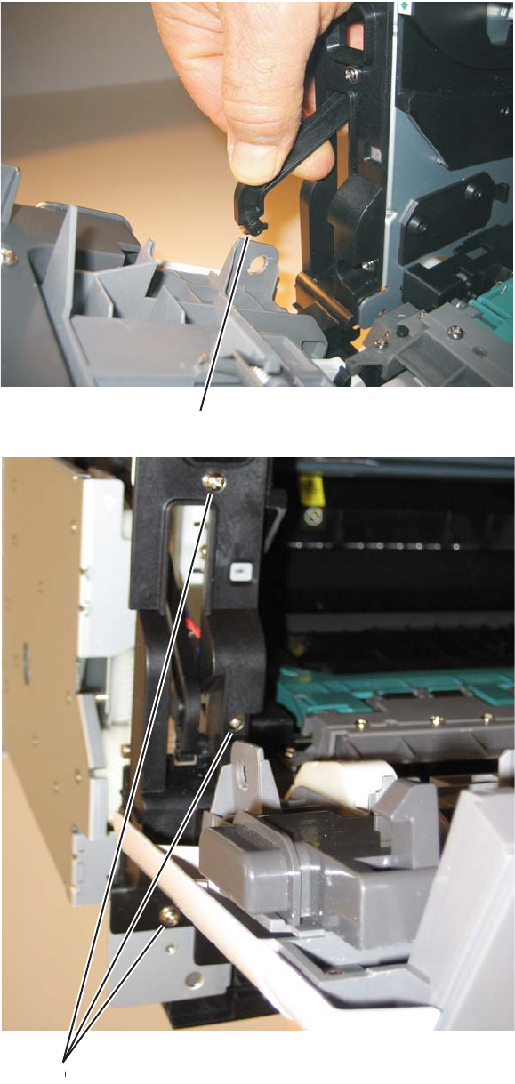
4-18
7014-xxx
7. Disconnect the fuser link (B).
8. Remove the three screws (C) from the left side of the printer.
9. Remove the door mounts.
C
B
C
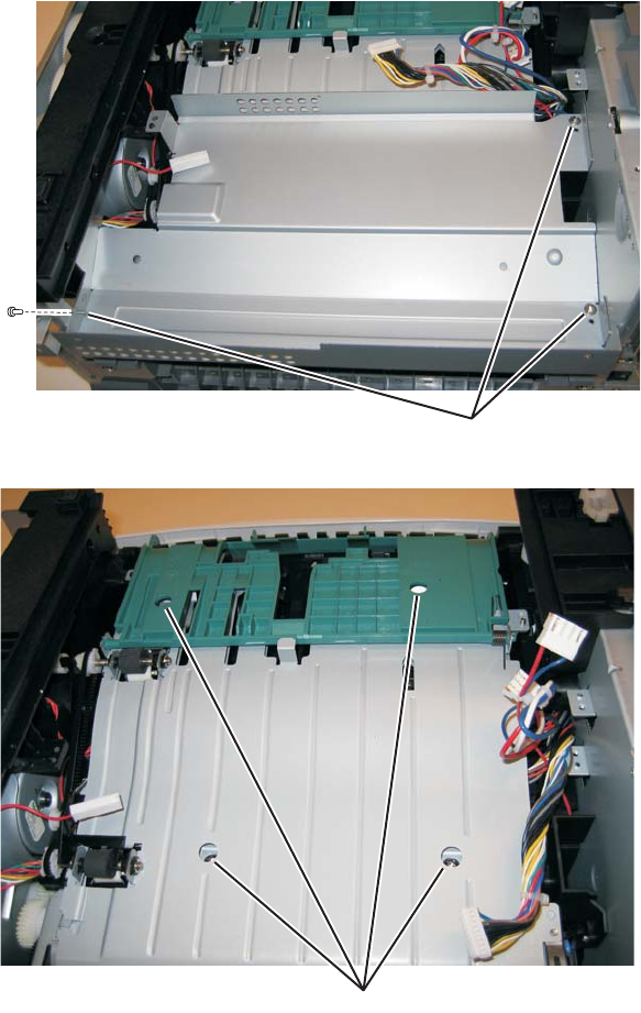
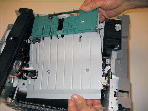
4-20
7014-xxx
5. Lift the duplex slightly, push to the left, and tilt to clear the right side of the printer.
6. Remove the duplex.
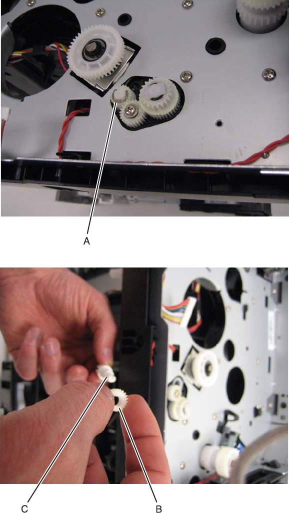
Repair information 4-21
7014-xxx
Duplex/main motor gear drive interface removal
1. Remove the LVPS/HVPS. See “LVPS/HVPS removal” on page 4-37.
2. Remove the duplex. See “Duplex removal” on page 4-19.
3. Remove the main motor gear drive. See “Main motor gear drive removal” on page 4-40.
4. Remove the e-clip (A) from the gear.
5. Remove the gear (B) and gear shaft (C).
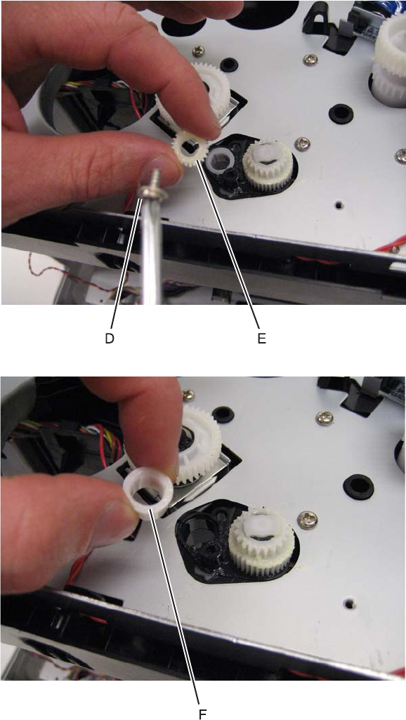
4-22
7014-xxx
6. Remove the screw (D) from the gear (E).
7. Remove the plastic bushing (F).
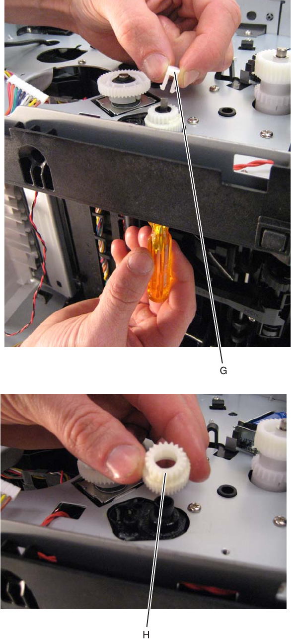
Repair information 4-23
7014-xxx
8. Use a screwdriver to pop the retainer clip (G) loose from the gear.
9. Remove the gear (H).
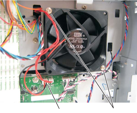
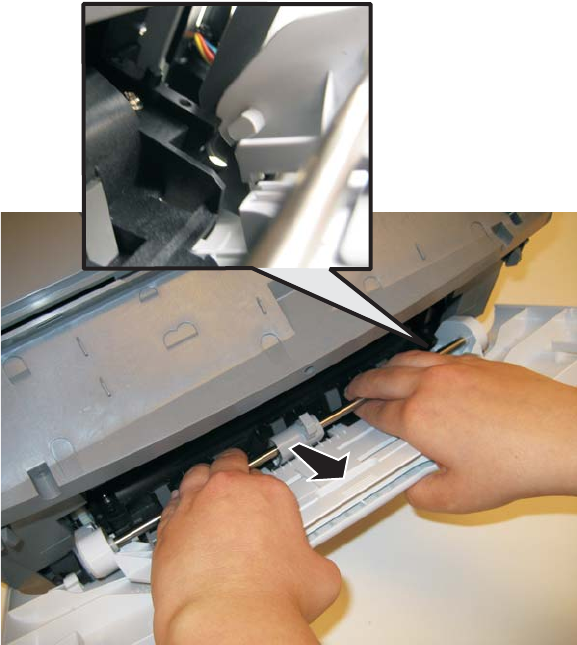
Repair information 4-25
7014-xxx
Front access door removal
1. Remove the front door access cover. See “Front door access cover removal” on page 4-34.
2. Remove the left side cover. See “Left side cover removal” on page 4-33.
3. Remove the upper front guide assembly. See “Upper front guide assembly removal” on page 4-85,
steps 1-3.
4. Close the front access door.
5. While closing the MPF cover, pull up on the MPF by the steel shaft until the MPF lifts from its hinges.
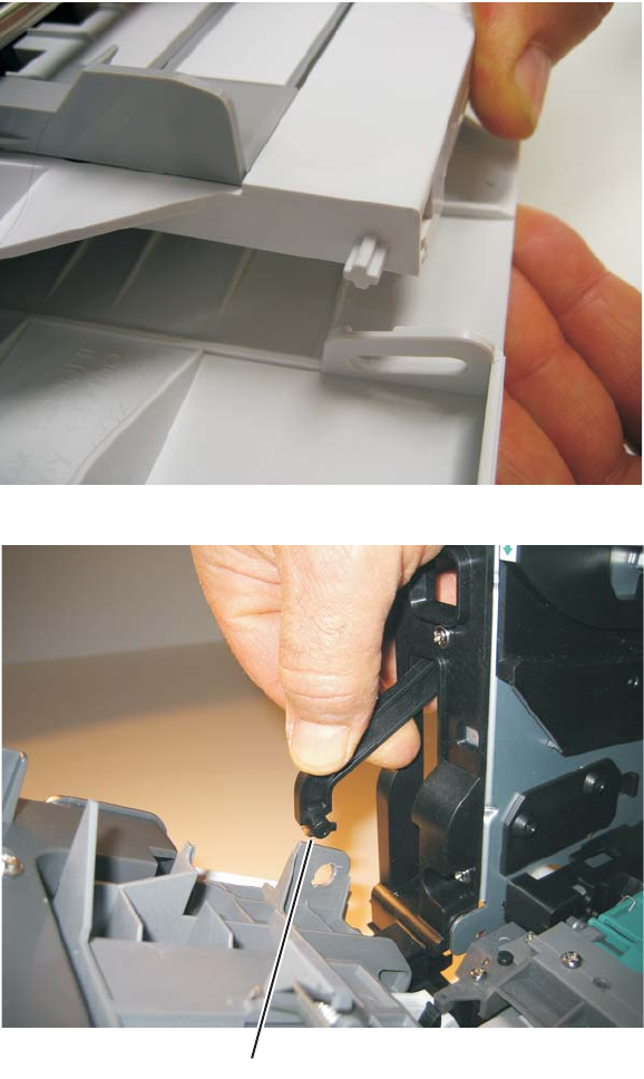
4-26
7014-xxx
6. Disconnect the MPF from the lower front cover.
7. Disconnect the fuser link (A) from the front access door.
A
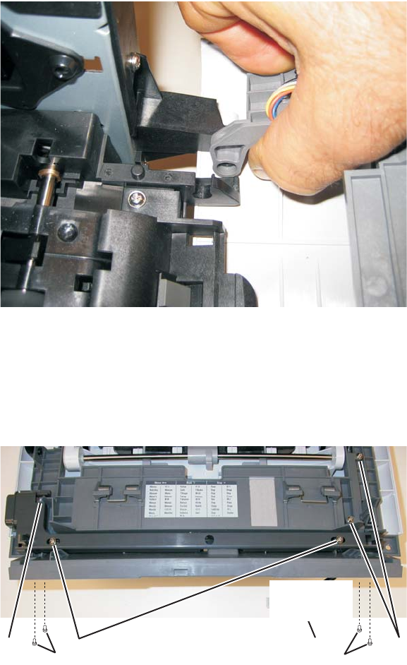
Repair information 4-27
7014-xxx
8. Disconnect the front access door from its hinges, and remove.
Installation note:
a. Install a new front access door at its hinges.
b. Connect the fuser link.
c. Remove the two screws (D).
d. Slide the latch to the left to free it, and then rest it on the door. Keep the spring in place.
e. Finish tightening the screws (F), and reinstall the remaining parts.
D ECG
FF
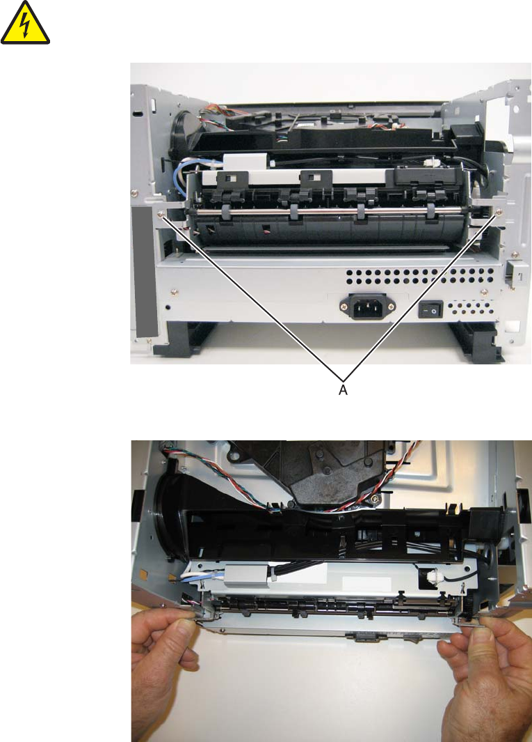
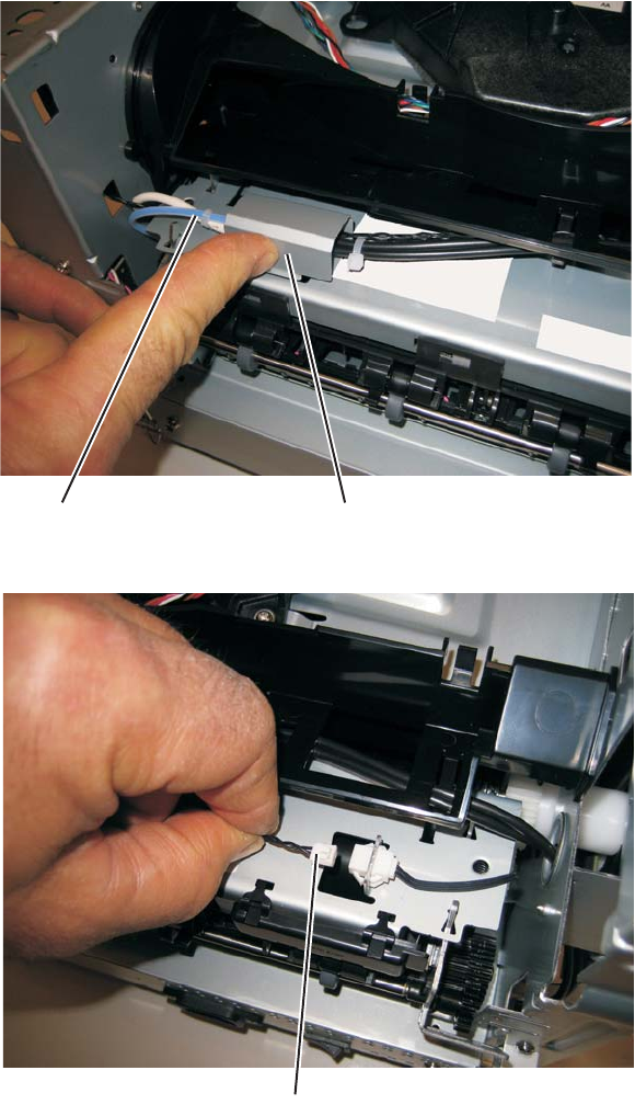
Repair information 4-29
7014-xxx
5. Disconnect the AC cable (C).
6. Disconnect the thermistor cable (D).
CB
D
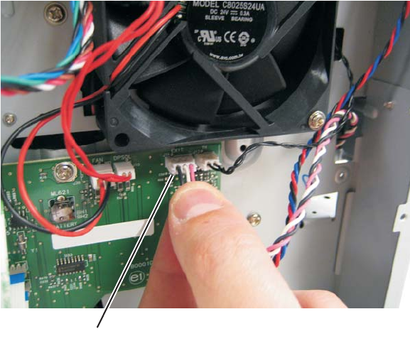
4-30
7014-xxx
7. Disconnect the exit sensor cable (E) from the engine board.
8. Remove the fuser.
Note:
•Be careful to not damage the gears during the fuser installation.
•Be sure to reinstall the AC cable during the fuser installation.
F
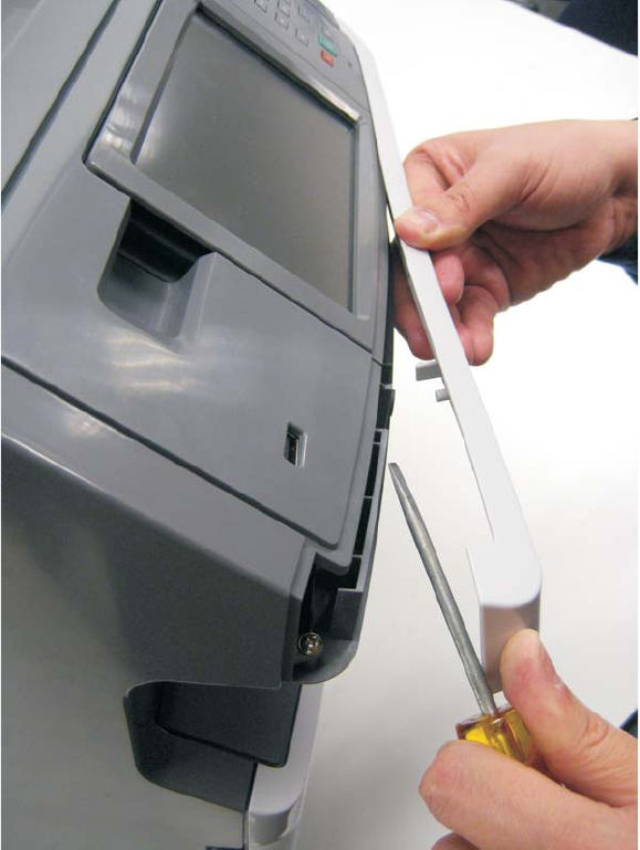
Repair information 4-31
7014-xxx
Scanner front cover removal
1. Use a flatblade screwdriver to pry the scanner front cover away from the side cover. Be careful to avoid
marring the finish.
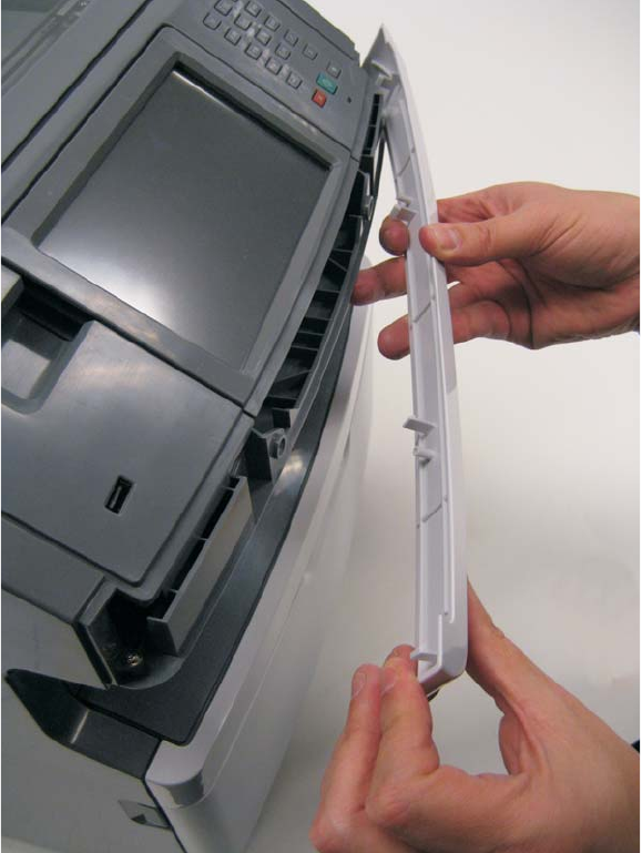
4-32
7014-xxx
2. Carefully pull the scanner front cover away from the tub assembly.
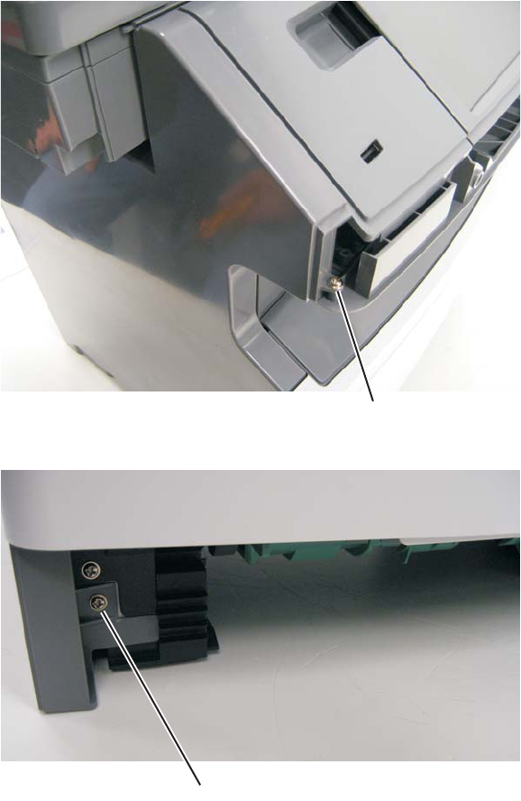
Repair information 4-33
7014-xxx
Left side cover removal
Note:
•Leave the front door closed when removing the left side cover.
•Make sure that the fuser cables are out of the way when removing the left side cover.
1. Remove the scanner front cover. See “Scanner front cover removal” on page 4-31.
2. Move the scanner assembly to the up position.
3. Remove the plastic screw (A) that secures the left cover to the tub assembly.
4. Remove the metal scerw (B) that secures the left cover to the front of the print engine frame.
5. Move the MFP to the edge of the table.
A
B
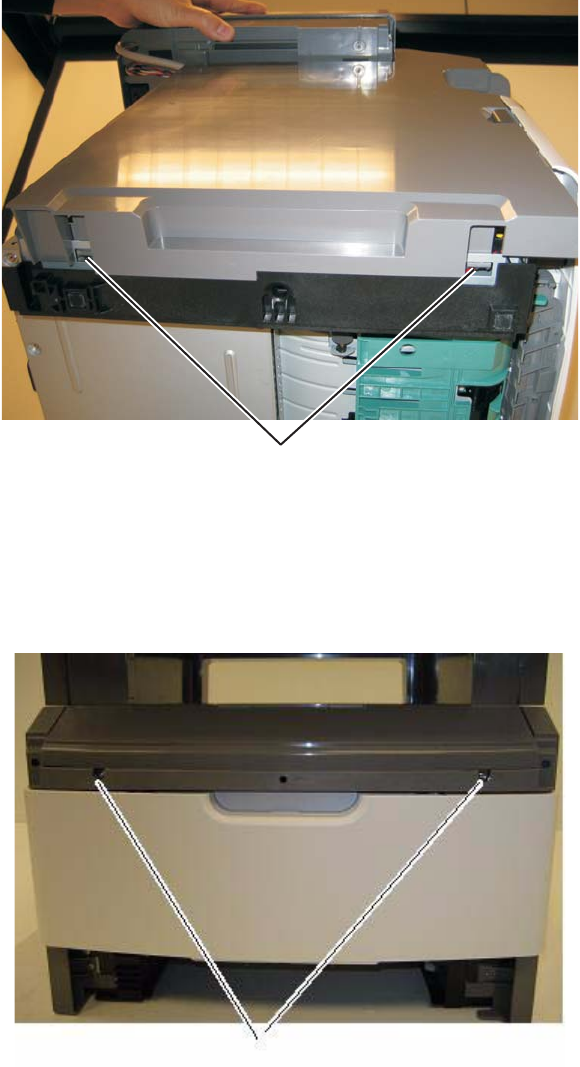
4-34
7014-xxx
6. Depress the two tabs (C) on the underside of the MFP.
7. Lift the left cover up and pull the botom of the cover away from the MFP.
Front door access cover removal
1. Remove bumper. See “Nameplate cover removal” on page 4-63.
2. Remove the two screws (A) securing the front door access cover to the front door assembly.
C
A
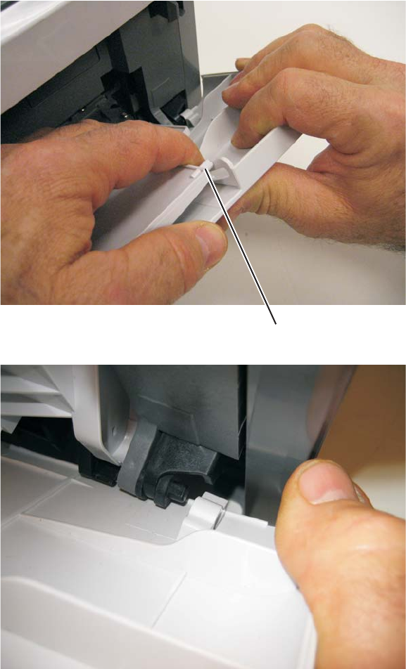
Repair information 4-35
7014-xxx
Lower front cover removal
1. Open the lower front cover.
2. Disconnect the MPF pins (A) from the right and left sides of the lower front cover.
3. Flex the lower front cover, and disconnect it first from its right hinge and then from its left hinge.
Note: An alternative to step 3 is to remove the front access door, and remove the three screws from the right
door mount. See “Front access door removal” on page 4-25 and “Door mount removal” on page 4-17.
A
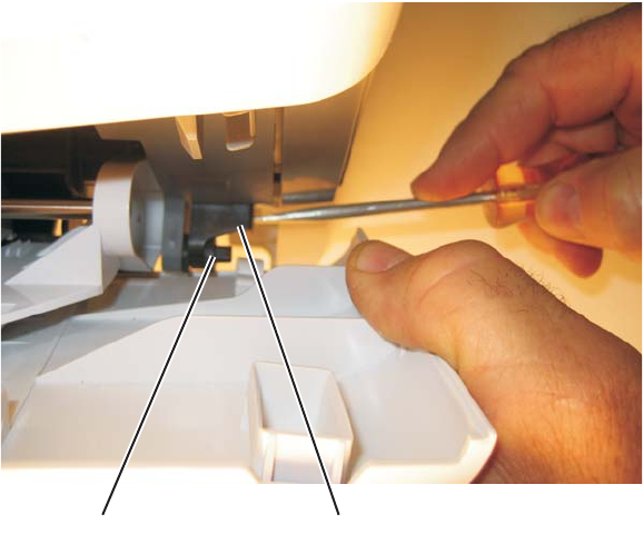
4-36
7014-xxx
Installation note: Use a flathead screw driver to press in on the door mount (B) while pulling on the front access
door to connect the cover to the hinge (C).
BC
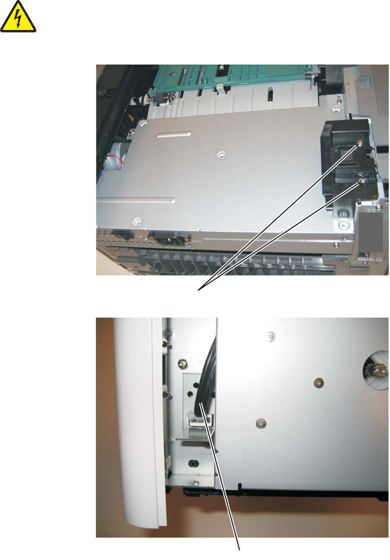
Repair information 4-37
7014-xxx
LVPS/HVPS removal
1. Remove the rear cover. See “Rear door and lower rear cover removal” on page 4-77.
2. Remove the left side cover. See “Left side cover removal” on page 4-33.
3. Place the printer on its top with the rear facing you.
Note: Be careful to not mar the finish of the printer.
4. Remove the two screws (A) from the right rear foot assembly.
5. Disconnect the fuser power cable (B).
A
B
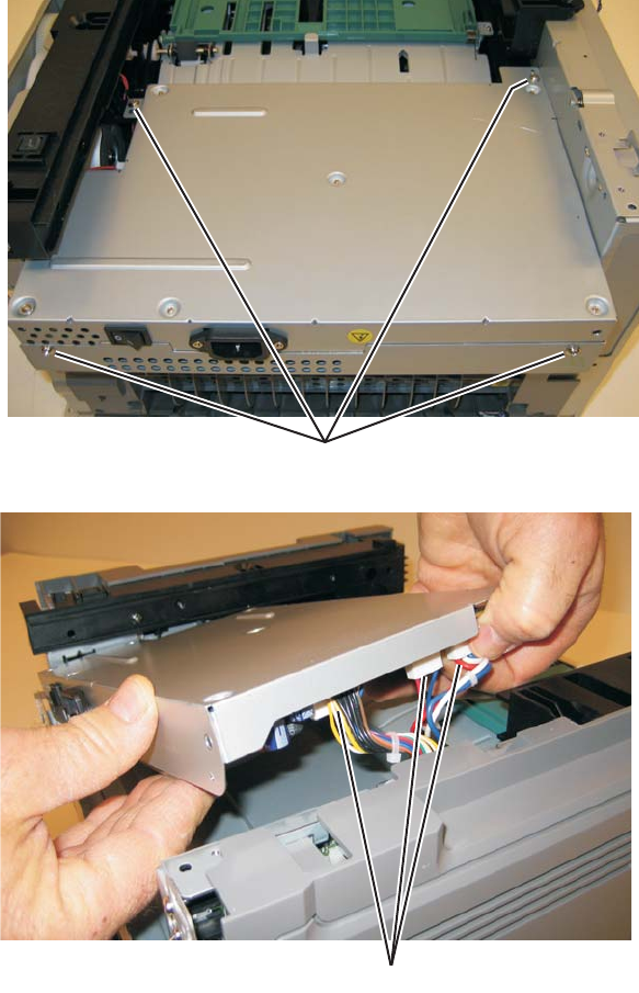
4-38
7014-xxx
6. Remove the four screws (C) from the LVPS/HVPS shield.
7. Lift the LVPS/HVPS, and disconnect the three cables (D).
A
C
E
D
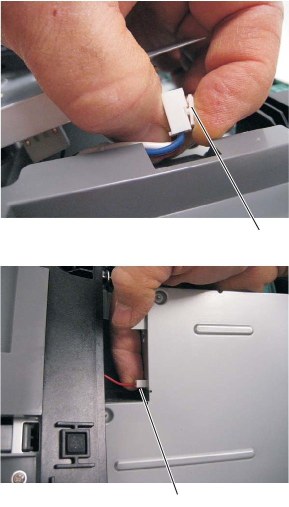
Repair information 4-39
7014-xxx
Note: Squeeze the clip to remove the cables from their connectors (E).
8. Disconnect the transfer roll cable (F).
9. Lift and remove the LVPS/HVPS.
F
E
G
F
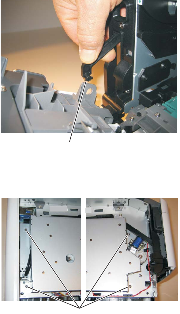
4-40
7014-xxx
Main motor gear drive removal
1. Remove the left side cover. See “Left side cover removal” on page 4-33.
2. Disconnect the fuser link (A) from the front access door.
3. Place the printer on its right side.
Note: Be careful to not mar the finish of the printer.
4. Remove the four screws (B) from the main motor gear drive.
A
B
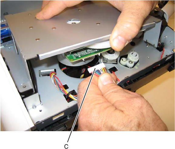
Repair information 4-41
7014-xxx
5. Lift the gear drive, and disconnect the main motor gear drive cable (C).
6. Remove the main motor gear drive.

4-42
7014-xxx
Manual feed clutch removal
1. Remove the left side cover. See “Left side cover removal” on page 4-33.
2. Open the front access door, and disconnect the fuser link (A).
3. Place the printer on its right side.
Note: Be careful to not mar the finish of the printer.
4. Remove the four screws (B) from the main motor gear drive.
5. Rotate the main motor gear drive enough to access the manual feed solenoid.
A
B
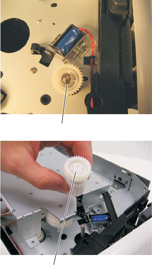
Repair information 4-43
7014-xxx
6. Use a screwdriver to remove the e-clip (C) from the manual feed clutch.
7. Remove the manual feed clutch (D).
C
D
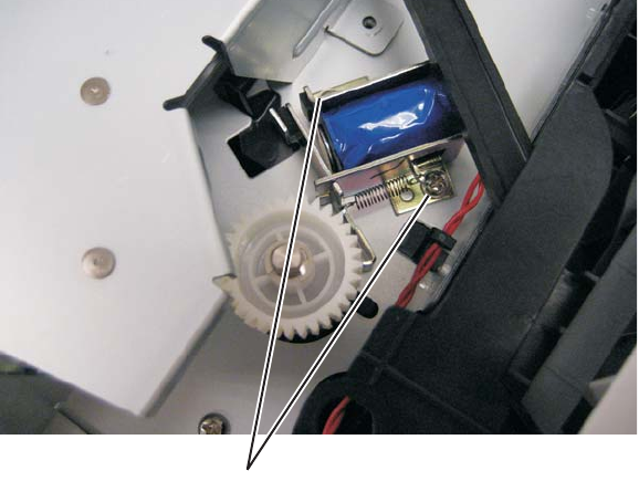
4-44
7014-xxx
Manual feed solenoid removal
1. Remove the left side cover. See “Left side cover removal” on page 4-33.
2. Remove the duplex. See “Duplex removal” on page 4-19.
3. Open the front access door, and place the printer on its right side.
Note: Be careful to not mar the finish of the printer.
4. Remove the two screws (A).
A
A
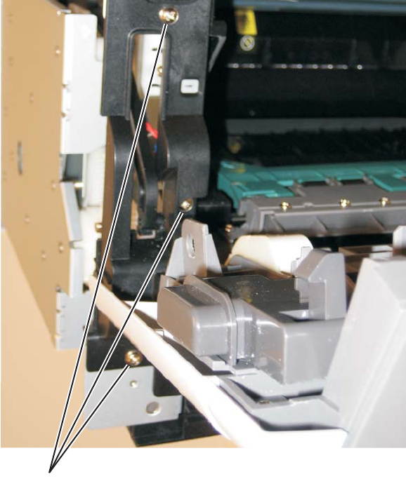
Repair information 4-45
7014-xxx
5. Remove the three screws (B) from the left door mount.
B
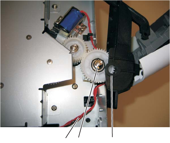
4-46
7014-xxx
6. Lift and remove the left door mount (C) away from the side frame, and unroute the cable (D) with a spring
hook.
7. Reinstall the left door mount, and place the printer on its top.
Note: Be careful to not mar the finish of the printer.
8. Disconnect the cable (D) from J25 on the engine board.
Installation note:
•Install the two screws holding the new solenoid in place, and route the cable (D) behind the MPF clutch
(E).
•After disconnecting the old solenoid cable, connect the new solenoid cable to J25 on the engine board.
EC
D
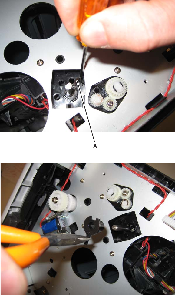
Repair information 4-47
7014-xxx
Media ACM ASM feeder removal
1. Remove the left side cover. See “Left side cover removal” on page 4-33.
2. Remove the LVPS/HVPS. See “LVPS/HVPS removal” on page 4-37.
3. Remove the duplex. See “Duplex removal” on page 4-19.
4. Remove the main motor gear drive. See “Main motor gear drive removal” on page 4-40.
5. Loosen the media feed clutch. See “Media feed clutch removal” on page 4-50.
Warning: Do not cut the media feed clutch cable (leave the media feed clutch hanging).
6. Use a screwdriver to pop the shaft retainer tab (A) loose from the ACM feed shaft.
7. Use a small pair of pliers to remove the shaft retainer tab.
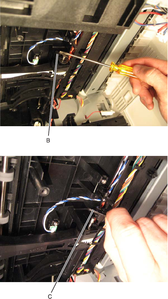
4-48
7014-xxx
8. Use a screwdriver to pop the inner shaft lock (B) loose.
9. Remove the inner shaft lock (C).
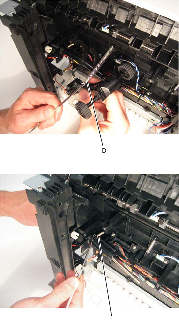
Repair information 4-49
7014-xxx
10. Pull out the auto compensator shaft, and remove the spring (D).
11. Remove the auto compensator shaft.
12. Disconnect the spring (E) from the cylinder.
13. Remove the media ACM ASM feeder.
E
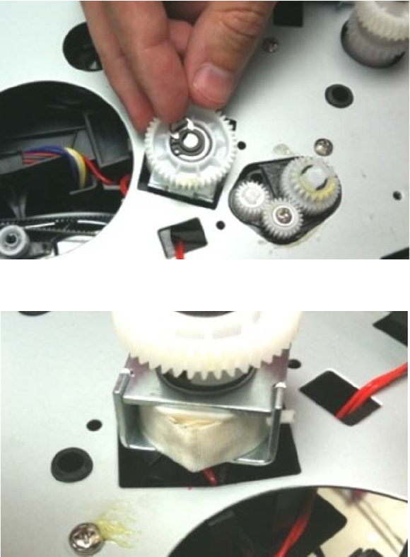
4-50
7014-xxx
Media feed clutch removal
1. Remove theleft cover. See “Left side cover removal” on page 4-33.
2. Remove the main motor gear drive. See “Main motor gear drive removal” on page 4-40.
3. Carefully remove the e-clipthat secures the clutch to the ACM shaft.
4. Pull up the clutch from the cavity, exposingthe white tape.
5. Cut the tape to expose the wire connectionto the clutch, and cut the cables at the copper leads.
6. Clean any adhesive residue from the wires.
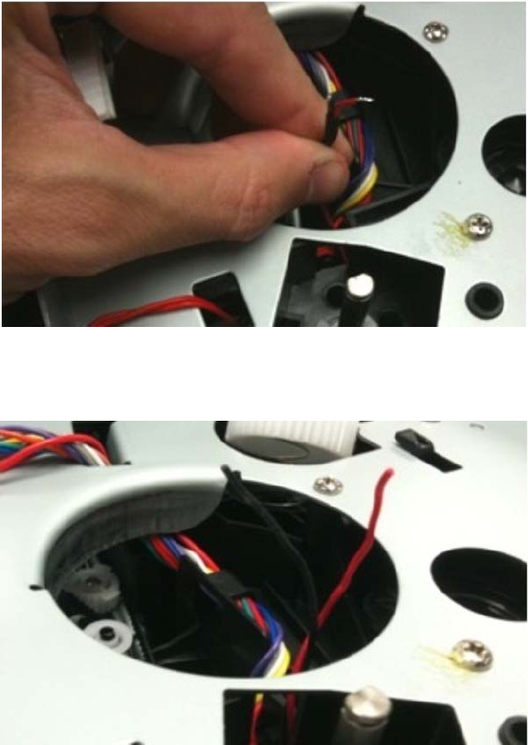
Repair information 4-51
7014-xxx
7. Pull the clutch cable into the motor cavity. Pull up the cable to remove any slack.
8. Remove any shrink tubing that is holding the wires together.
Warning: Do not strip the insulation off the red and black wires. The connectors will not work if the insulation is
removed.
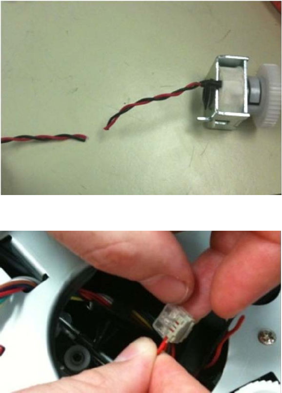
4-52
7014-xxx
Installation notes:
1. Remove the new clutch from its packaging.
2. Measure 4 inches (100 mm) from the clutch, and cut the clutch cable.
3. Install the new media clutch on the ACM drive shaft.
4. Insert the red wire from the printer into the wire splice connector.
5. Insert the red wire from the clutch into the wire splice connector.
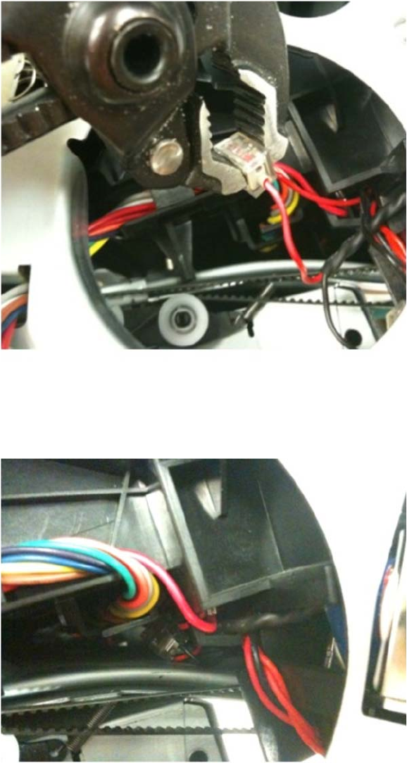
Repair information 4-53
7014-xxx
6. Using a pair of pliers, squeeze the connector to secure the red wires in place.
Note: Check the connector to make sure that the gray connector is pressed flush to the bottom of the wire
splice.
7. Repeat steps four through six for the black wires on the clutch and printer.
8. Tuck the connectors securely above the duplex guide.
Note: If needed, use a wire tie to secure the cable in place. Make sure the tie does not interfere with the
paper path.
9. Reinstall the gear drive.
10. Print the menu pages to test the printer.
11. Reinstall the left cover.
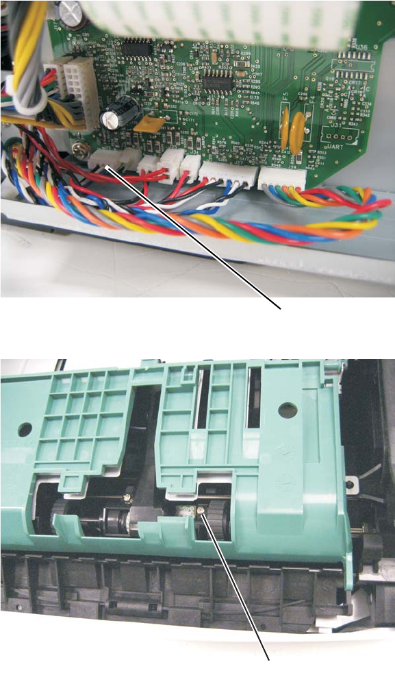
4-54
7014-xxx
Media manual input sensor
1. Remove the right side cover. See “Right side cover removal” on page 4-80.
2. Remove scanner assembly.
3. Place the machine on its side.
Note: Be careful to not mar the finish of the printer.
4. Disconnect the sensor cable (A) from J23 (MPFS) on the engine board.
5. Remove the screw (B) holding the sensor.
6. Free the cable from its retainers, and pull it through the opening toward the sensor mount.
A
B
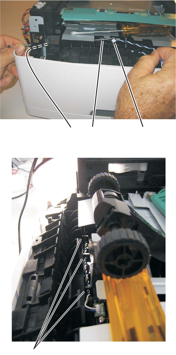
Repair information 4-55
7014-xxx
Re-installation note:
•Prop open the duplex door, and insert the hook end of the spring hook through the frame opening (C) from
the controller board side. Extend the hook until the sensor connector can be hooked.
•Hook the spring hook (D) to the connector (E), and pull it through the opening.
•Place the sensor into position, and reconnect the cable on the controller board.
•Using the spring hook, be sure to reroute the cable through the three retainers (F) between the sensor and
side frame.
Note: If the cable is not properly installed in its retainers, then the loose cable will obstruct the paper path.
EDC
F
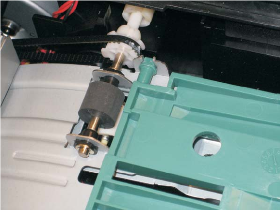
4-56
7014-xxx
Warning: Check to make sure the duplex paper jam door is in its proper position. If it is not, then the paper tray
will become lodged and the printer will need to be replaced.
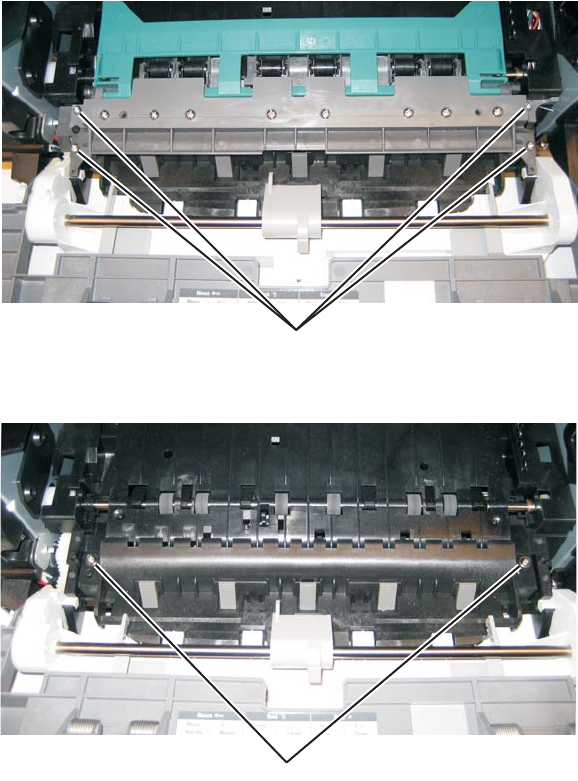
Repair information 4-57
7014-xxx
Multipurpose feeder removal
1. Open the front access door.
2. Remove the four screws (A) from the upper front guide.
3. Remove the upper front guide.
4. Remove the two screws (B).
A
B
B
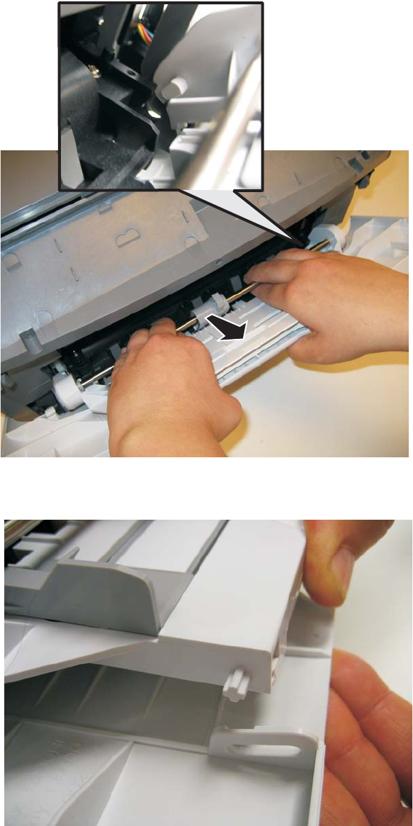
4-58
7014-xxx
5. Close the front access door, and pull up on the MPF by the steel shaft until the MPF lifts from its hinges.
6. Disconnect the MPF from the lower front cover.
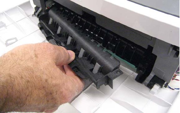
Repair information 4-59
7014-xxx
7. Open the front access door, and remove the lower paper guide.
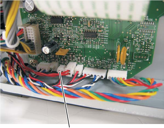
4-60
7014-xxx
Multipurpose feeder (MPF) feed clutch removal
1. Remove the left side cover. See “Left side cover removal” on page 4-33.
2. Remove the duplex. See “Duplex removal” on page 4-19.
3. Disconnect the cable (A) from J24 on the engine board.
4. Place the printer on its right side.
Note: Be careful to not damage any cables or mar the finish of the printer.
A
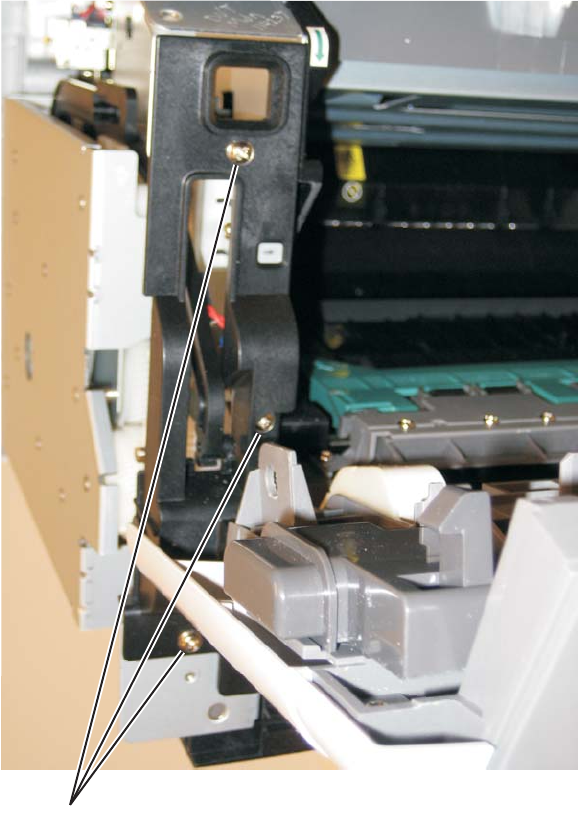
Repair information 4-61
7014-xxx
5. Remove the three screws (B) from the left side of the printer.
B
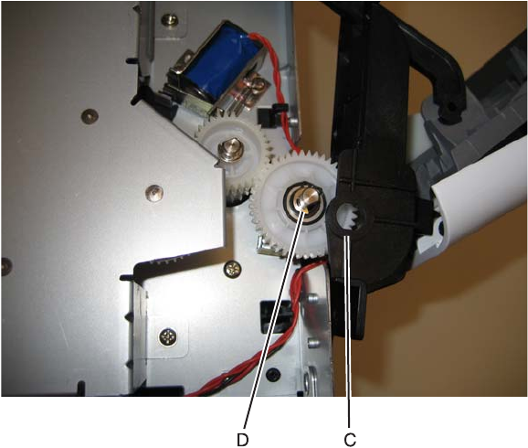
4-62
7014-xxx
6. Disconnect the left hinge (C) from the feed clutch, and remove the e-clip (D).
7. Lift and remove the multipurpose feeder (MPF) feed clutch.
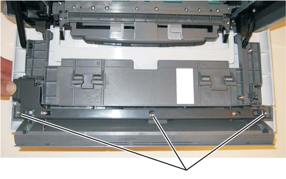
Repair information 4-63
7014-xxx
Nameplate cover removal
1. Open the front access door.
2. Remove the three screws (A).
3. Remove the nameplate.
A
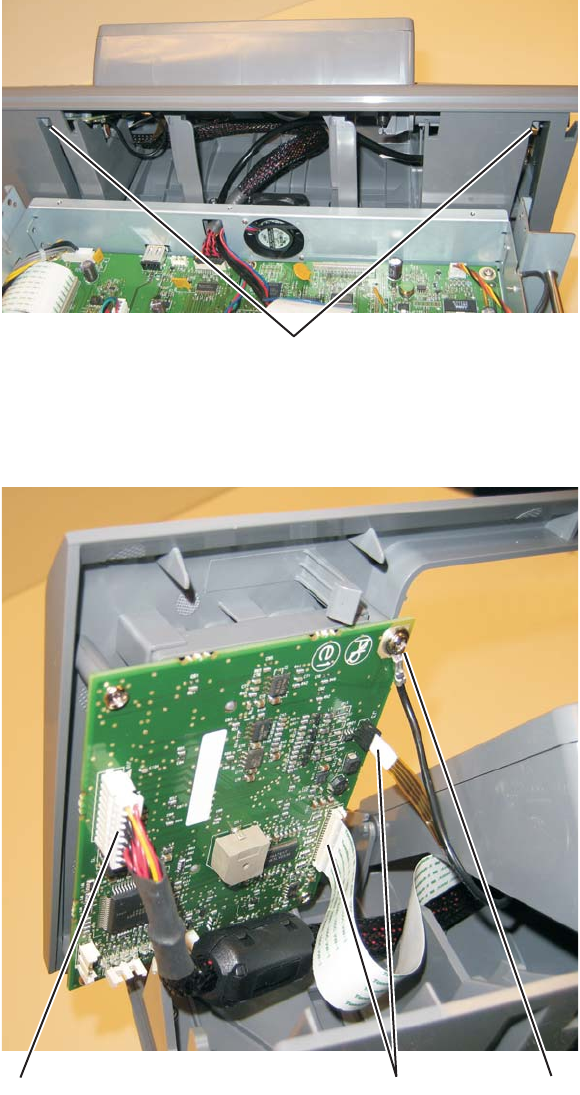
4-64
7014-xxx
Operator panel keypad removal
1. Lift the scanner assembly to the up position.
2. Release the two tabs (A) securing the keypad to the keypad to the tub assembly.
3. Disconnect the UICC cable (B) from the operator panel PCB assembly.
4. Disconnect the two ribbon cables (C) from the operator panel PCB assembly.
5. Disconnect the ground (D) on the operator panel PCB assembly.
6. Tilt the operator panel keypad up and remove it from the MFP.
A
C DB
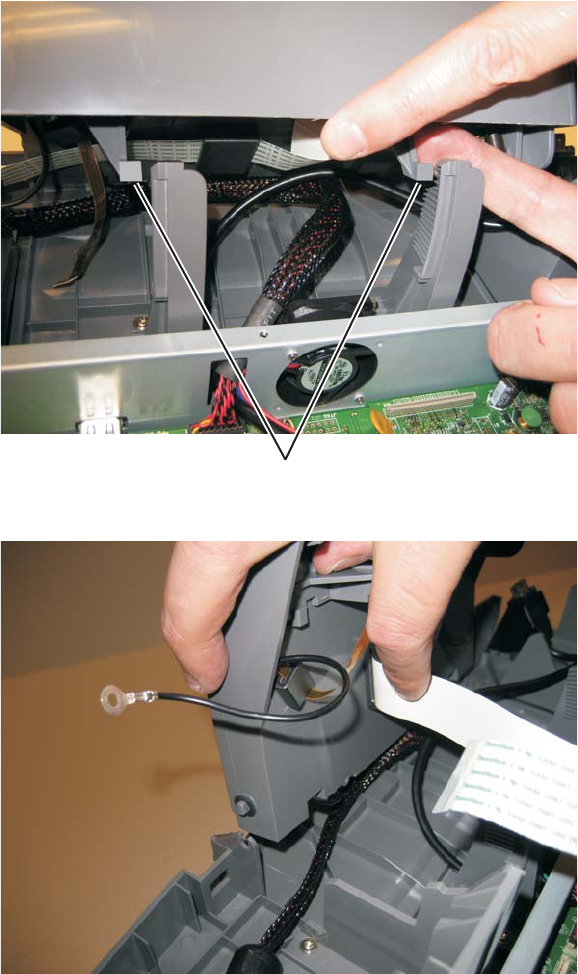
Repair information 4-65
7014-xxx
Operator panel display removal
1. Remove the operator panel keypad.
2. Press the tab on the left side of the operator panel display and raise the operator panel display to the up
position.
3. Press the tabs (A) which fasten the operator panel display to the display rotation supports to the left to
release the operator panel display from the display rotation supports.
4. Disengage the operator panel display from the right display support and remove it from the MFP.
A
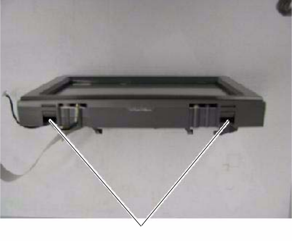
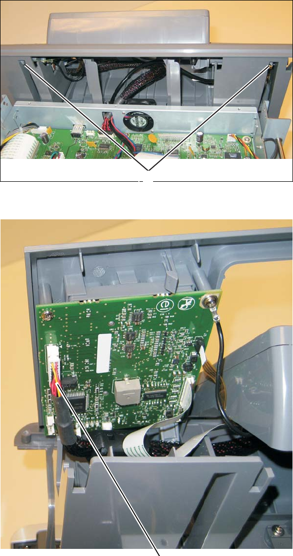
Repair information 4-67
7014-xxx
UICC cable removal
1. Lift the scanner assembly to the up position.
2. Disconnect the UICC cable from the controller board.
3. Feed the cable through the hole in the front of the controller card cage.
4. Release the two tabs (A) securing the keypad to the keypad to the tub assembly.
5. Disconnect the UICC cable B) from the operator panel PCB assembly.
A
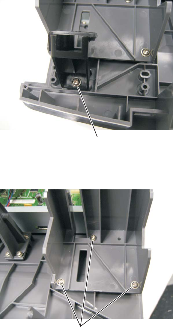
4-68
7014-xxx
USB cable mount bracket removal
1. Remove the operator panel keypad.
2. Open the USB cable clamp and remove the USB cable.
3. Remove the screw (A) securing the USB cable mount bracket to the tub assembly.
Operator panel support removal
1. Remove the operator panel keypad.
2. Remove the three screws (A) securing the operator panel support to the tub assembly.
Note: The same steps are performed for both supports.
B
A
A
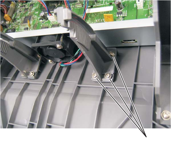
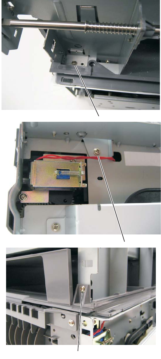
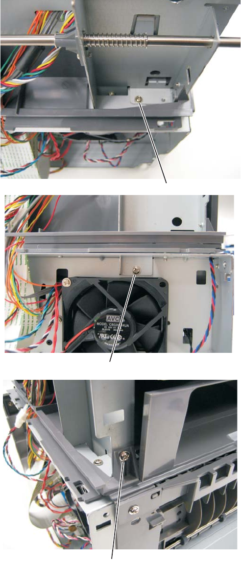
4-72
7014-xxx
Tub assembly removal
1. Remove the flatbed assembly. See “Flatbed removal” on page 4-89.
2. Disconnect the the remaining cables from the controller board.
3. Thread the cables through the tub assembly and top cover.
4. Remove the controller board cage. See “Controller board cage” on page 4-14.
5. Remove the operator panel keyboard. See “Operator panel keypad removal” on page 4-64.
6. Remove the operator panel display. See “Operator panel display removal” on page 4-65.
7. Remove the left rear frame assembly. See “Left rear frame assembly removal” on page 4-70.
8. Remove the right rear frame assembly. See “Right rear frame assembly removal” on page 4-71.
9. Remove the USB cable mount bracket. See “USB cable mount bracket removal” on page 4-68.
10. Remove the operator panel support. See “Operator panel support removal” on page 4-68.
11. Remove the operator panel display rotation support. See “Display rotation support removal” on
page 4-69.
12. Remove the top and side screws securing the left flatbed support.
13. Remove the left flatbed support.
14. Remove the top and side screws securing the right flatbed support.
15. Remove the right flatbed support.
16. Lift the tub assembly off of the MFP.
Note: After removing the tub assembly, remove the output binLED and LED cover. See “Output bin LED and
lens removal” on page 4-101. These will be used on the new tub assembly.
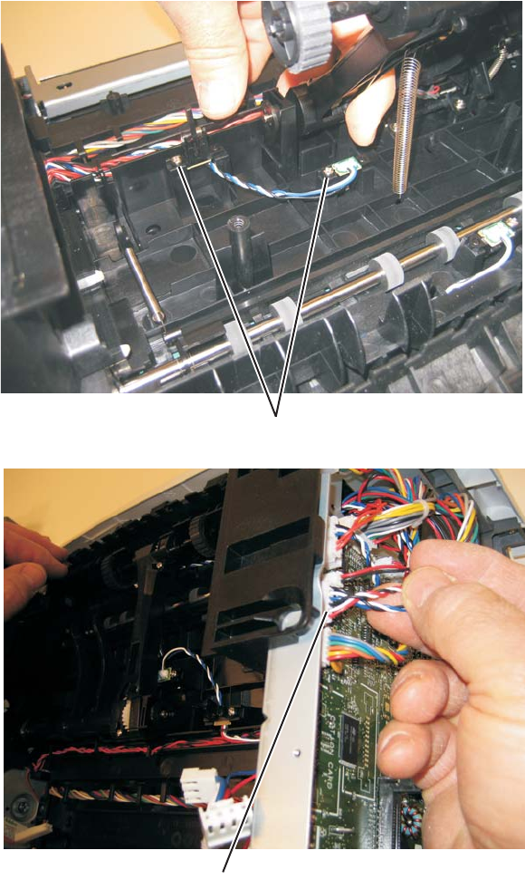
Repair information 4-73
7014-xxx
Paper input and duplex sensor assembly removal
1. Remove the right side cover. See “Right side cover removal” on page 4-80.
2. Remove the duplex. See “Duplex removal” on page 4-19.
3. Remove the two screws (A) from the sensors.
4. Disconnect the sensor cable (B) from the controller board.
5. Remove the paper input and duplex sensor assembly.
A
B
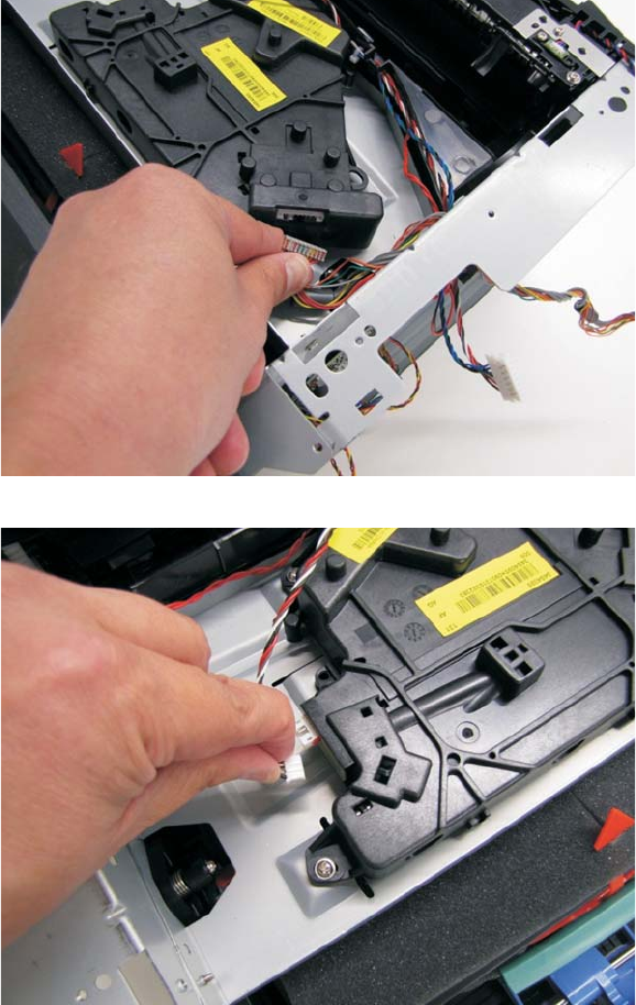
4-74
7014-xxx
Printhead removal
1. Remove the scanner assembly. See “Scanner assembly removal” on page 4-91.
2. Remove the top cover. See “Top cover assembly removal” on page 4-83.
3. Remove the right side cover. See “Right side cover removal” on page 4-80.
4. Disconnect the LSU cable. Use this cable with the new printhead.
5. Disconnect the HSYNC cable. Use this cable with the new printhead.
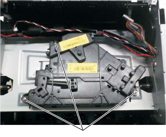
Repair information 4-75
7014-xxx
6. Remove the three screws (A).
Note: Use a pencil to mark the screw locations of the printhead on the metal frame. Align the new printhead
relative to the location of the old printhead. See “Printhead assembly mechanical adjustment” on page 3-39.
7. Remove the printhead.
Note: If the problem is caused by faulty cables, order cable parts 40X5816 and 40X5817.
A
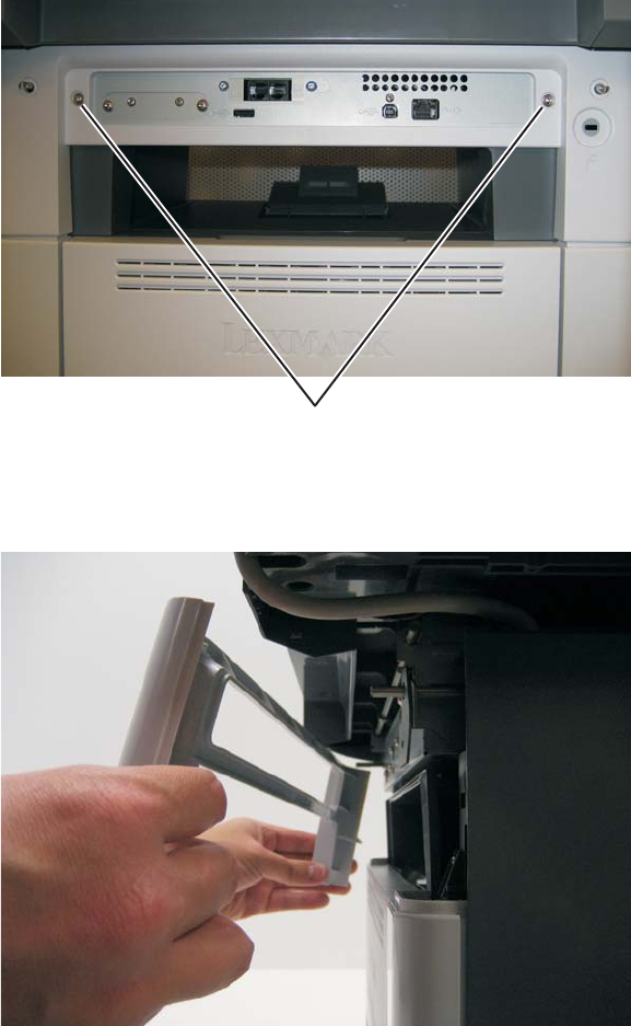
4-76
7014-xxx
Mid rear cover removal
1. Remove the two metal screws (A).
2. Pull the upper rear cover back.
3. Carefully disengage that snaps and remove the cover.
A
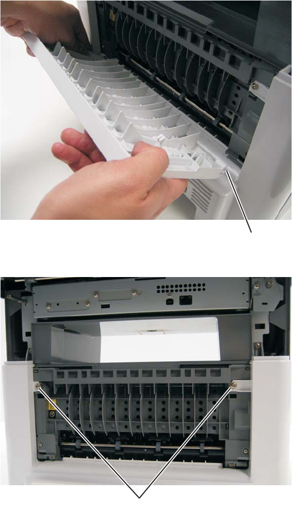
Repair information 4-77
7014-xxx
Rear door and lower rear cover removal
1. Remove the mid rear cover. See “Mid rear cover removal” on page 4-76.
2. Open the rear door.
3. Pull the rear door up at an angle, disconnect the door from the notch (A), and remove.
4. Remove the two screws (B) from the top of the rear cover.
5. Tilt the lower rear cover, and remove.
A
B
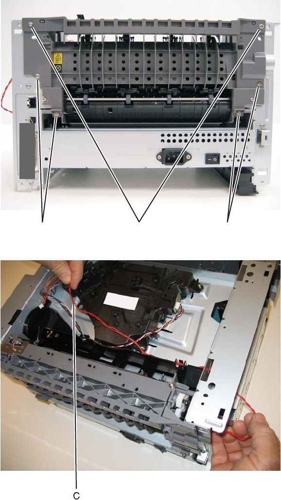
4-78
7014-xxx
Rear exit guide assembly with sensor and reversing solenoid removal
1. Remove the top cover. See “Top cover assembly removal” on page 4-83.
2. Disconnect the narrow media sensor cable from J35 on the engine board.
3. Remove the reversing solenoid cable from J10 on the engine board.
4. Remove the six screws (B) from the rear exit guide assembly.
5. Remove the solenoid cable (C) through the opening.
BBB
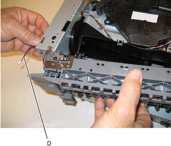
Repair information 4-79
7014-xxx
6. Remove the narrow media sensor cable (D) through the opening.
7. Remove the rear exit guide assembly.
Note: Be careful to not damage the gears during the rear exit guide assembly removal and reinstallation.
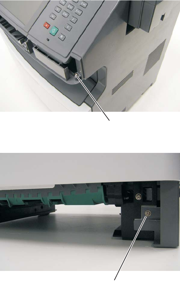
4-80
7014-xxx
Right side cover removal
Note: Leave the front cover closed when removing the right side cover assembly.
1. Remove the scanner front cover. See “Scanner front cover removal” on page 4-31.
2. Remove the plastic screw (A) securing the cover to the tub assembly.
3. Remove the screw (B) from the bottom right side of the printer.
A
B
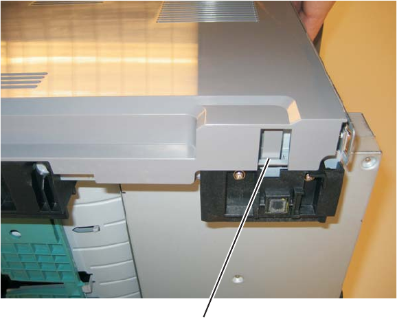
Repair information 4-81
7014-xxx
4. Depress the tab (C) on the bottom of the printer.
5. Rotate the right side cover assembly slightly to the left, and pull out.
C
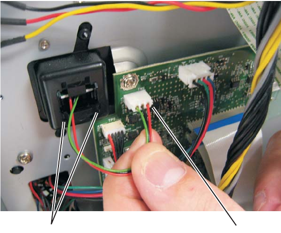
4-82
7014-xxx
Toner level sensor removal
1. Open the front access door.
2. Remove the right side cover. See “Right side cover removal” on page 4-80.
3. Disconnect the toner level sensor cable (A) from the engine board.
4. Squeeze the lower tabs (B) of the toner level sensor, and push it from its holder.
5. Remove the toner level sensor through the inside of the printer.
Note: The toner level sensor must be installed properly, or the printer will not function.
AB
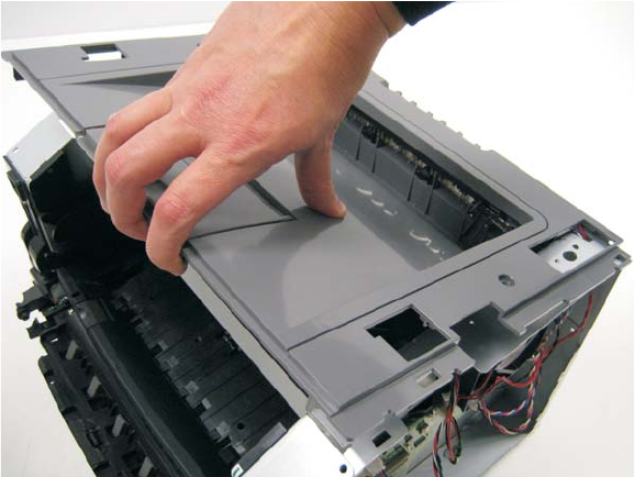
Repair information 4-83
7014-xxx
Top cover assembly removal
1. Remove the scanner assembly. See “Scanner assembly removal” on page 4-91.
2. Lift the top cover, and remove.
Note:
•Be sure to lift the top cover assembly from the front to remove.
•During reinstallation, be sure the exit guide and the paper bin align correctly. A mismatch can cause paper
jams.
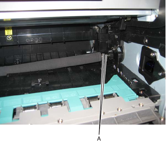
4-84
7014-xxx
Transfer roll removal
Note: A flashlight may be required to remove the transfer roll.
1. Open the front access door.
2. At the right side of the transfer roll, squeeze the holder arms (A) with the left hand while lifting. Stop when
the holder is unlatched.
3. At the left side of the transfer roll, squeeze the holder arms with the right hand while lifting with the left
hand. Stop when the left holder is unlatched.
4. With a hand at each end, lift the transfer roll out.
Note: Do not try removing the spring on the left; it is not removeable but can be dislodged. The spring included
with the FRU is to be used only if the old right-side spring is damaged or lost. Both springs must be positioned
on posts that cannot be seen. If the old springs are moved, then feel the base of the springs to assure that they
are on the posts. The top of the springs must be captured in the bearings of the transfer roll.
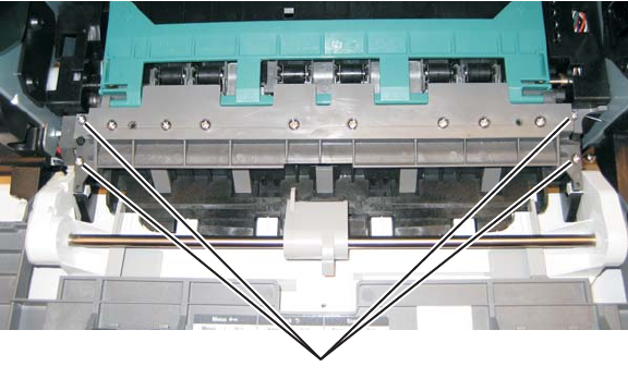
Repair information 4-85
7014-xxx
Upper front guide assembly removal
1. Open the front access door.
2. Remove the four screws (A) from the upper front guide.
3. Remove the upper front guide.
A
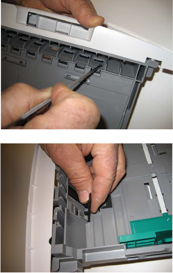
4-86
7014-xxx
Wear strip (tray 1 and 250-sheet tray 2) removal
1. Hold the tray with the bottom up.
2. Use a spring hook to disconnect the strip from the top of the tray.
3. Remove the strip from inside the tray.
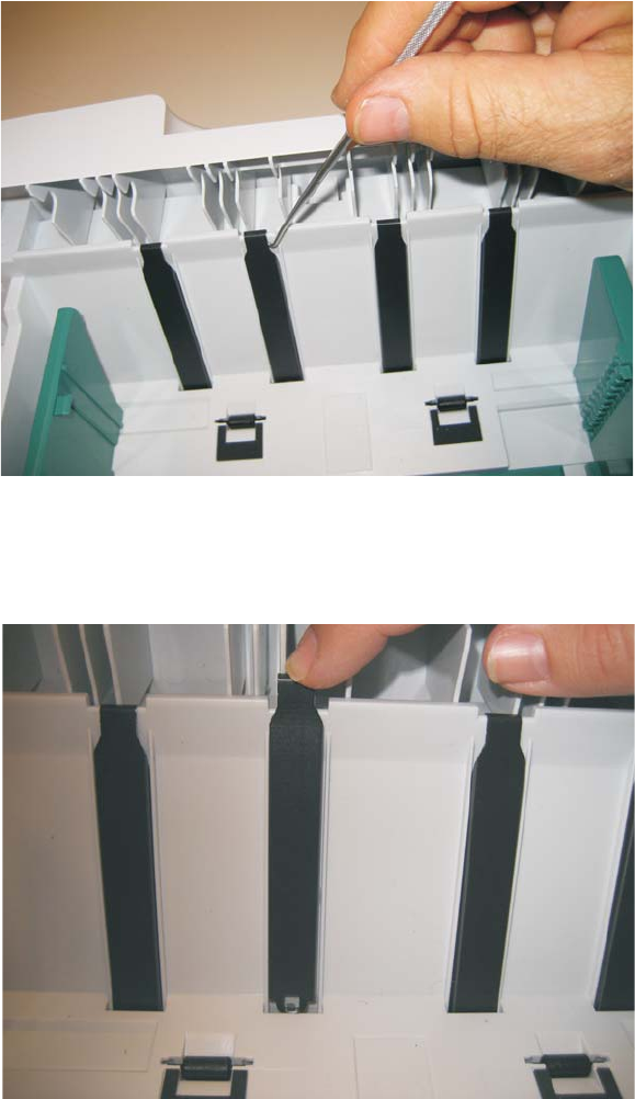
Repair information 4-87
7014-xxx
Wear strip (550-sheet tray 2) removal
1. Use a spring hook to disconnect the strip from the top of the tray.
2. Life the strip, and remove.
Note: When replacing the strip (for all trays):
•Carefully insert the strip from the top of the tray, and push it down through the opening until it snaps
into place.
•Turn the tray over to view the bottom of the strip. Using the spring hook, check to make sure that the
end of the strip is fastened tightly.
•Be sure that the drafted edge of the strip is installed toward the bottom of the tray.
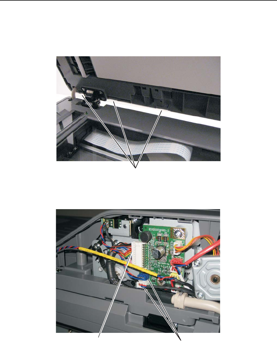
4-88
7014-xxx
Imaging component removals
ADF unit removal
1. Remove the ADF rear cover by by releasing the three tabs (A) which fasten the ADF rear cover to the ADF
unit.
2. Disconnect the ADF cable (B) and two sensor connections (C) on the relay card above the ADF relay
cable.
3. Lift the ADF unit up and depress the tabs located on the bottom of the ADF hinges to release the ADF from
the flatbed.
A
B
BC
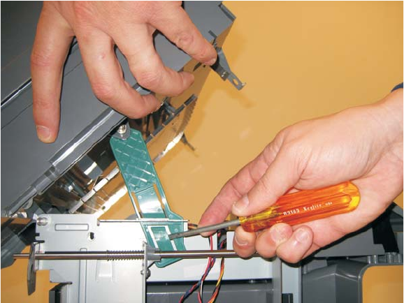
Repair information 4-89
7014-xxx
Flatbed removal
1. Remove the left side cover. See “Left side cover removal” on page 4-33.
2. Remove the left scanner cover. See “Left scanner cover removal” on page 4-103.
3. Remove the right scanner cover. See “Right scanner cover removal” on page 4-104.
4. Remove the right side cover. See “Right side cover removal” on page 4-80.
5. Remove the ADF unit. See “ADF unit removal” on page 4-88.
6. Raise the flatbed unit to the up position.
7. Remove the controller board shield. See “Controller board shield” on page 4-11.
8. Disconnect FBmtr from connector J28, FB home from connector J13, CCD from connector J30, and
Plegnth sensor cables from connector J12 on the controller board.
9. Using a flatbed screwdriver, depress the lower tab on the kickstand, and lift the kickstand out of the left
rear frame assembly.
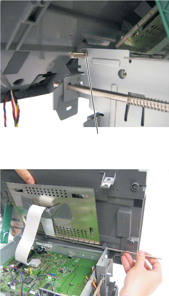
4-90
7014-xxx
10. Remove the e-clip (A) from the flatbed hinge rod.
11. While holding the front of the flatbed with one hand, pull the flatbed hinge rod out.
12. Lift and remove the flatbed unit from the MFP.
B
A
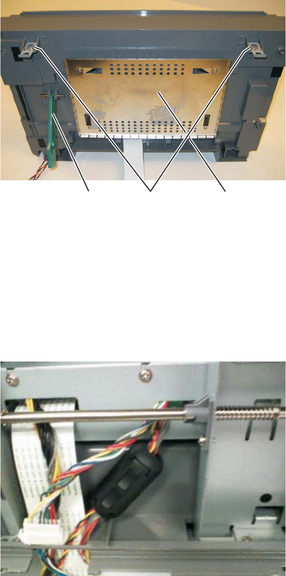
Repair information 4-91
7014-xxx
13. Remove the kickstand (B).
14. Remove the two flatbed supports (C). These will be used on the new flatbed.
15. Remove the controller shield (D). This will be used on the new flatbed.
Scanner assembly removal
1. Remove the left scanner cover. See “Left scanner cover removal” on page 4-103.
2. Remove the right scanner cover. See “Right scanner cover removal” on page 4-104.
3. Remove the left side cover. See “Left side cover removal” on page 4-33.
4. Remove the right side cover. See “Right side cover removal” on page 4-80.
5. Lift the flatbed and ADF assemblies to the up position.
6. Remove the controller board shield. See “Controller board shield” on page 4-11.
7. Remove the toroid from the printhead cable and door interlock switch cable.
8. Disconnect the HVPS cable from connector J37 on the controller board.
9. Disconnect the front cover interlock switch cable from connector J11 on the controller board.
10. Discronnect the stairway cables from J500 and J501 on the engine board.
CB D
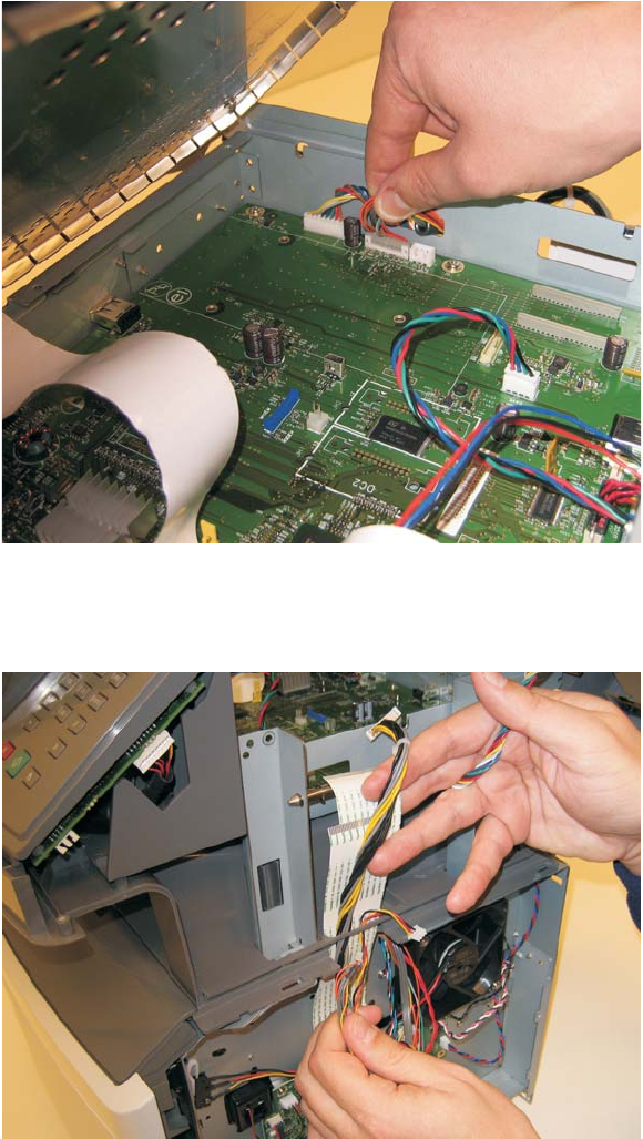
4-92
7014-xxx
11. Disconnect the LSU laser diode cable from the controller board.
12. Thread the LSU diode cabe, the cover interlock cable, the stairway cables, and the controller board power
supply cable through the side of the printer away from the scanner assembly.
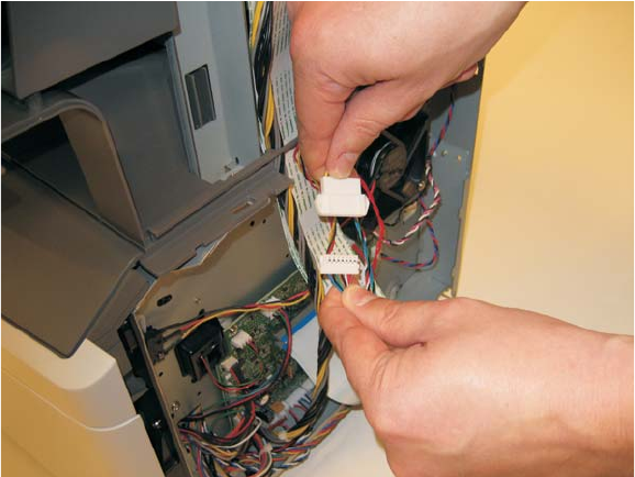
Repair information 4-93
7014-xxx
13. Disconnect LSU HSYNC extension cable at the connector in the middle of the cable.
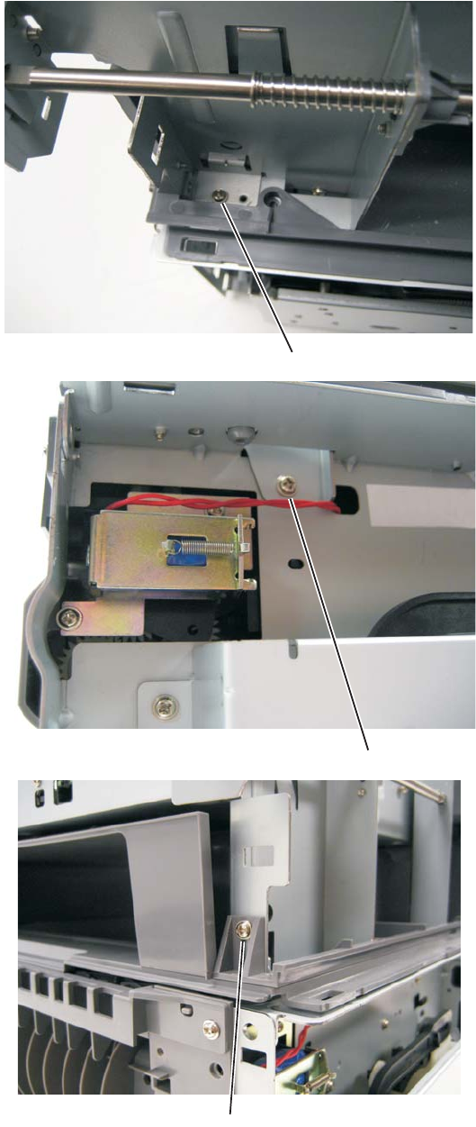
4-94
7014-xxx
14. Remove the three screws (A) from the left rear frame assembly.
A
A
A
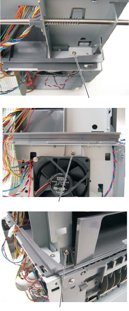
Repair information 4-95
7014-xxx
15. Remove the three screws (B) from the right rear frame assembly.
B
B
B
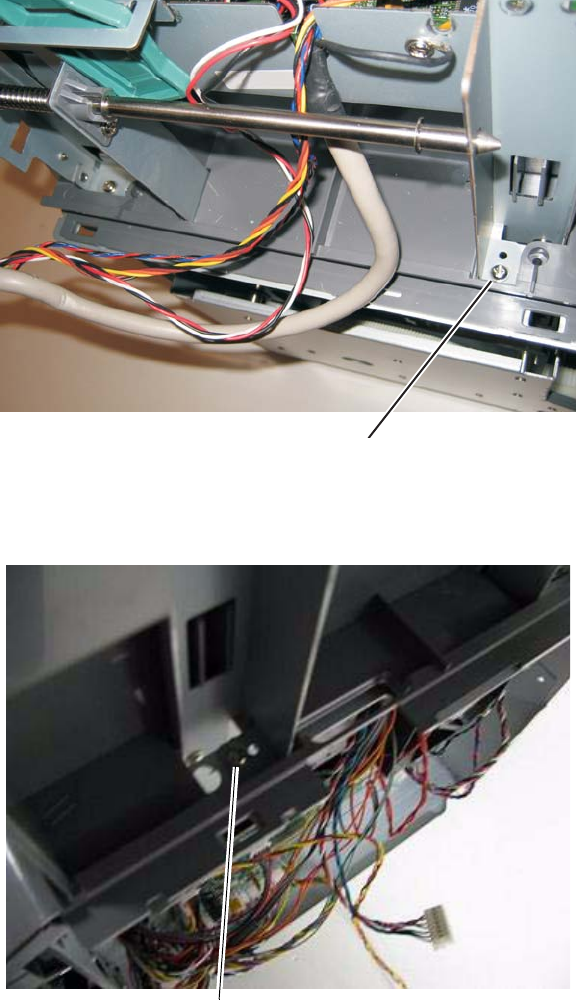
4-96
7014-xxx
16. Remove the screw (C) securing the left flatbed stop to the top of the print engine frame.
17. Remove the screw (D) securing the right flatbed stop to the top of the print engine frame.
18. Lower the flatbed and ADF to the down position.
B
C
D
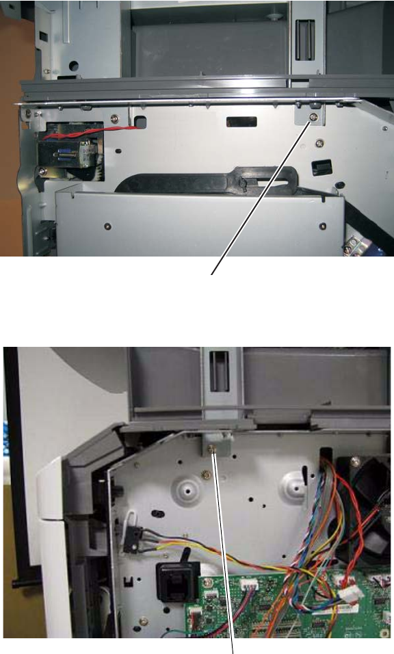
Repair information 4-97
7014-xxx
19. Remove the side screw (E) securing the left flatbed stop to the print engine frame.
20. Remove the side screw (F) securing the right flatbed stop to the print engine frame.
21. Lift and remove the scanner assembly from the MFP.
C
E
F
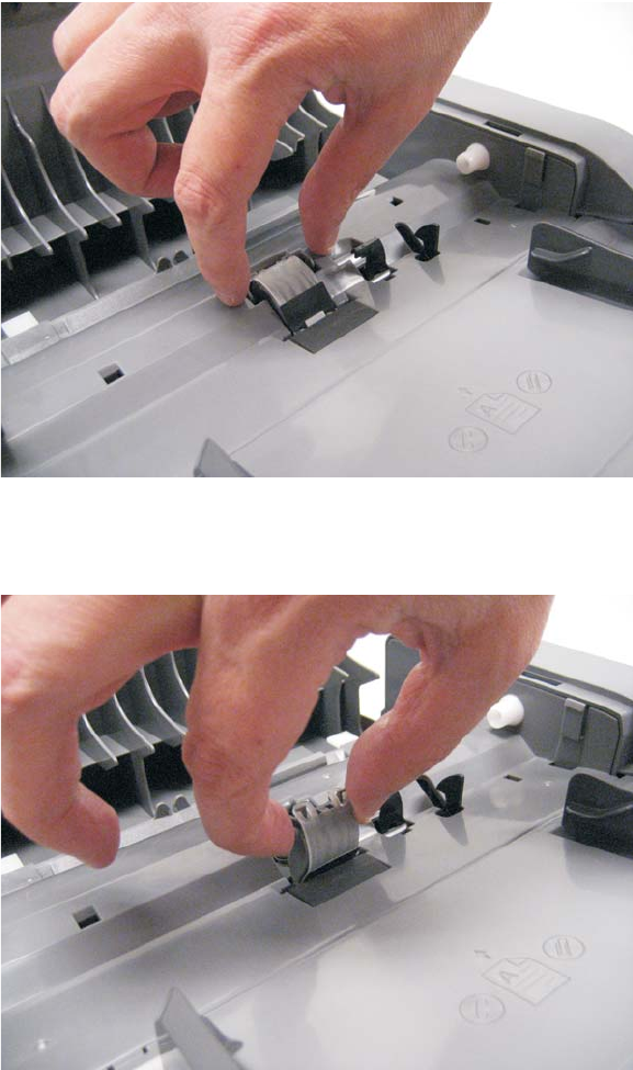
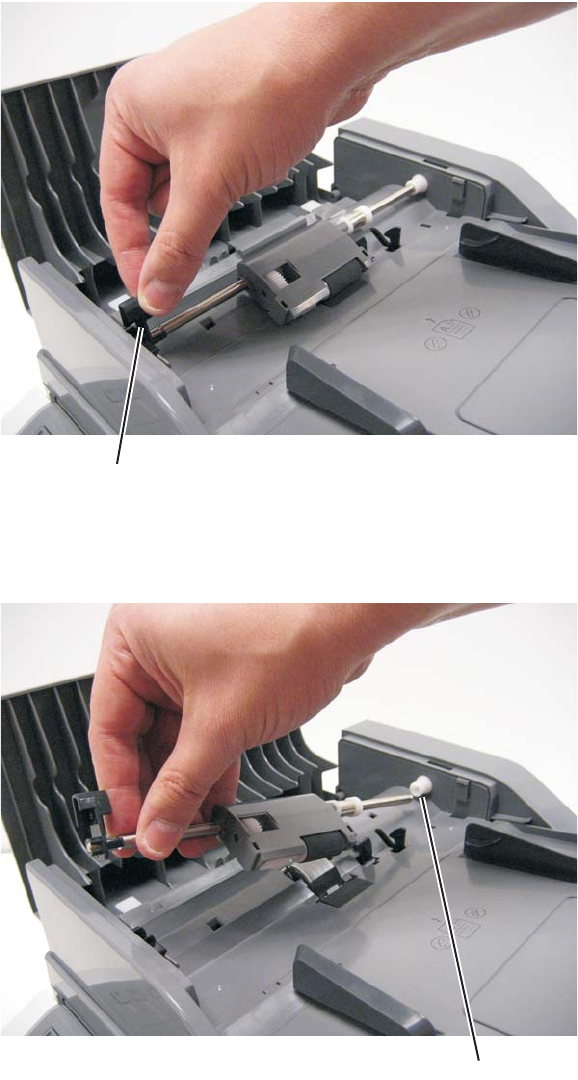
Repair information 4-99
7014-xxx
ADF separator roll assembly
1. Lift the locking lever (A).
2. Slightly lift the separator roll assembly, and pull it out of the mount (B) on the opposite side.
A
B
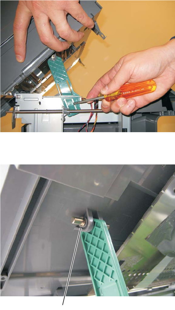
4-100
7014-xxx
Kickstand removal
1. Lift the flatbed assembly to the up position.
2. Release the kickstand from the left rear frame assembly by depressing the tab holding the kickstand in
place.
3. Remove the e-clip (A) securing the kickstand rod to the flatbed.
4. Slide the rod out and remove the kickstand from the flatbed.
A
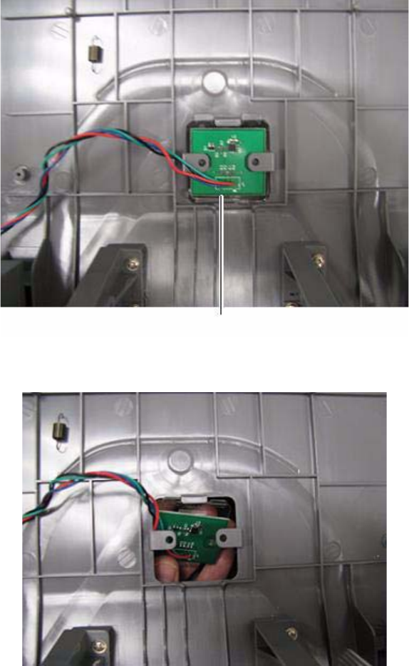
Repair information 4-101
7014-xxx
Output bin LED and lens removal
1. Disconnect the output LED cable from the controller board.
2. Remove the controller board cage. See “Controller board cage” on page 4-14.
3. Press the tab (A) securing the lens to the tub assembly.
4. Pull down on the lens and LED and remove it from the tub.
A
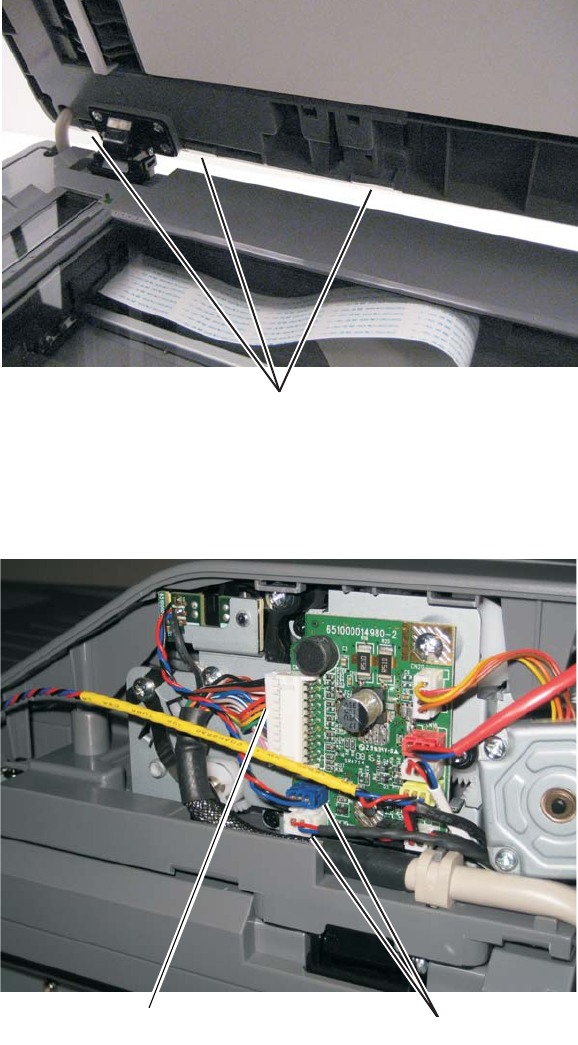
4-102
7014-xxx
ADF cable removal
1. Remove the left scanner cover. See “Left scanner cover removal” on page 4-103.
2. Remove the left cover. See “Left side cover removal” on page 4-33.
3. Remove the controller board shield. See “Controller board shield” on page 4-11.
4. Lift the flatbed cover and unsnap the three tabs (A) securing the ADF rear cover to the ADF.
5. Remove the rear ADF cover.
6. Disconnect the ADF cable (B) and two sensor connections (C) on the relay card above the ADF relay
cable.
7. Disconnect the ADF cable from connector J17 on the controller board.
8. Disconnect the ADF cable ground from the controller cage.
A
B
BC
BC
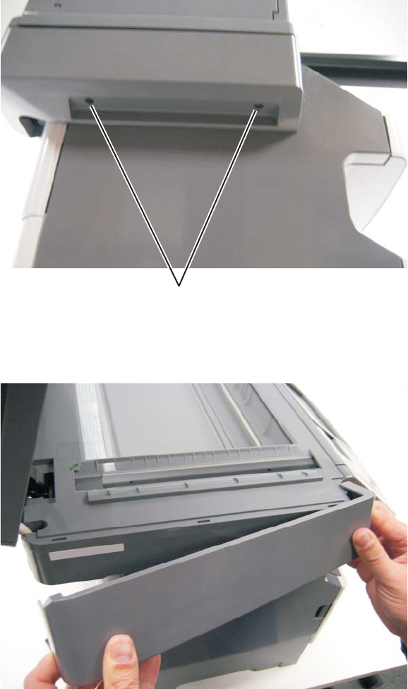
Repair information 4-103
7014-xxx
9. Remove the ADF cable from the MFP.
Left scanner cover removal
1. Lift the ADF to the up position.
2. Remove the two screws (A) securing the left scanner cover to the flatbed unit.
3. Lift and carefully pull the left scanner cover up and away from the rear of the flatbed.
A
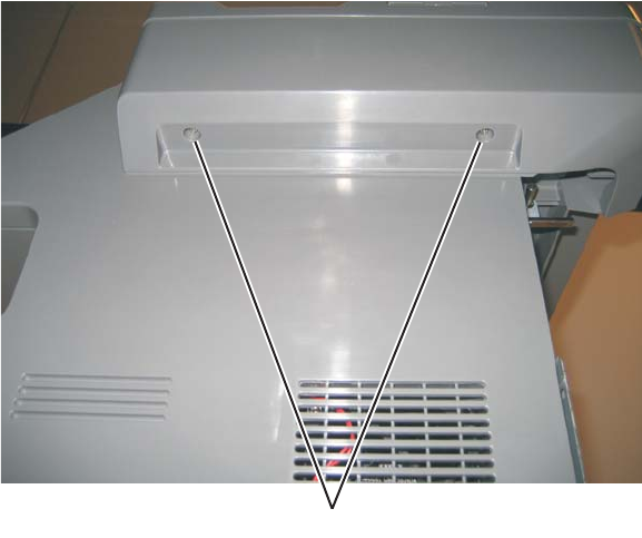
4-104
7014-xxx
Right scanner cover removal
1. Lift the ADF to the up position.
2. Remove the two screws (A) securing the right scanner cover to the flatbed unit.
3. Lift and carefully pull the right scanner cover up and away from the rear of the flatbed.
X
A
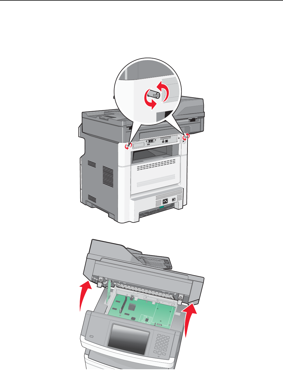
Repair information 4-105
7014-xxx
Option board installs and removals
Note: This information is also available in the X 46x series user guide.
Lifting the Scanner to the up position
1. Turn the two rear frame assembly locks counter-clockwise to the unlock position.
2. Lift the scanner assembly to the up position. The kickstand will lock into place.
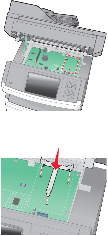
4-106
7014-xxx
Installing an Internal Solutions Port (ISP)
1. Access the controller board. See “Lifting the Scanner to the up position” on page 4-105.
2. Unpack the ISP and tee.
Note: Avoid touching components on the card.
3. Locate the standoff location on the controller board.
Note: If an optional printer hard disk is currently installed, then the printer hard disk must first be removed.
See “Printer hard disk removal” on page 4-109.
4. Remove the metal cover from the ISP opening in the rear of the controller board cage.
5. Align the posts of the mounting tee, and press down to secure it to the controller board.
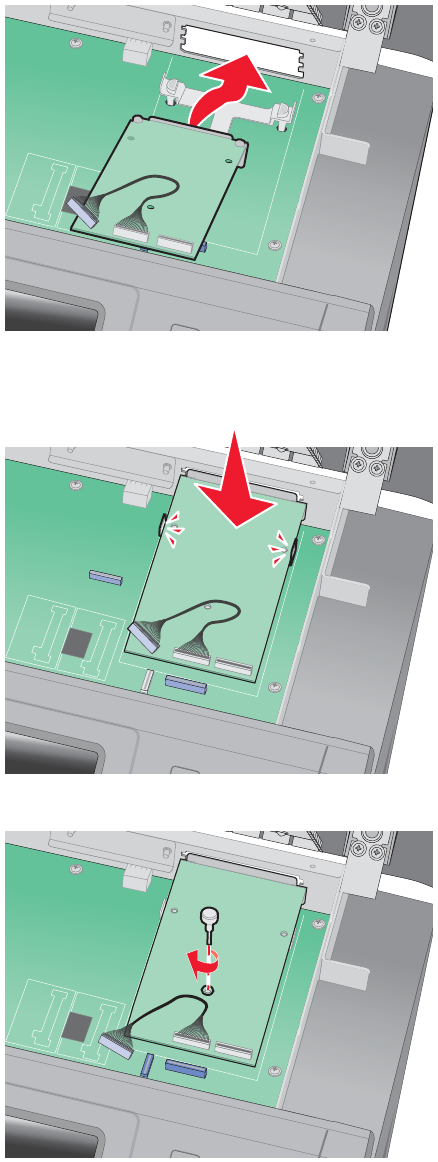
Repair information 4-107
7014-xxx
6. Install the ISP onto the plastic tee.
Note: Make sure the ISP card is properly aligned with the rear of the contoller board cage.
7. Press down on the ISP to seat it in the tee.
8. Insert the thumbscrew.
Note: Do not tighten the thumbscrew at this time.
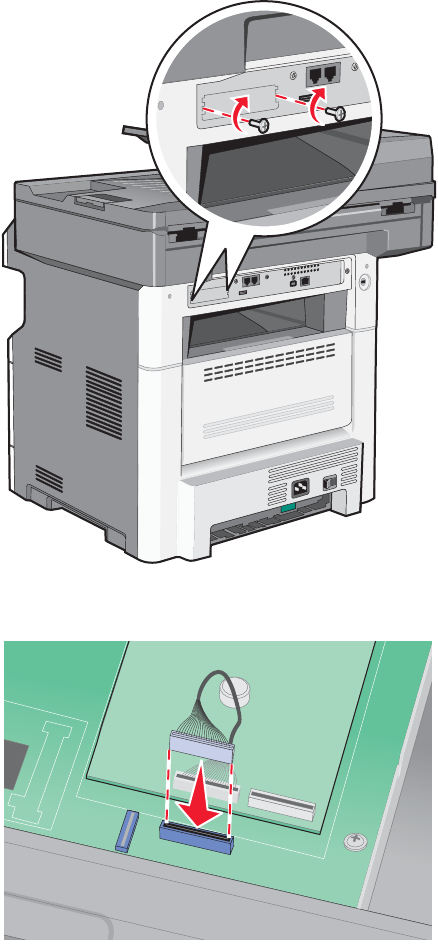
4-108
7014-xxx
9. Attach the two screws that came with the ISP to secure the ISP to the controller board cage.
10. Tighten the thumbscrew from step 8.
11. Insert the cable’s ISP connector into the ISP connector on the controller board.
Note: If a printer hard disk was previously attached, reinstall it at this time.
12. Lower the scanner assembly and lock it.
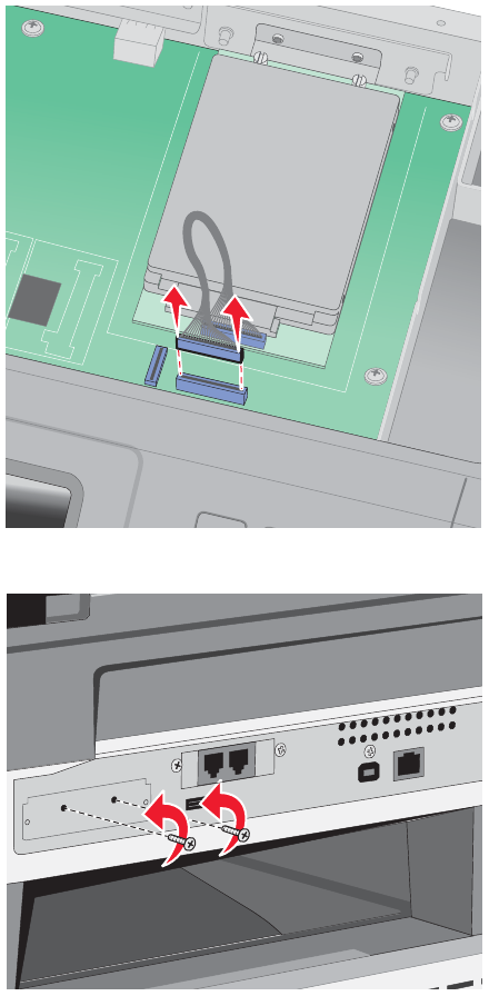
Repair information 4-109
7014-xxx
Printer hard disk removal
1. Unplug the printer hard disk interface cable from the system board.
2. Remove the screws holding the printer hard disk in place.
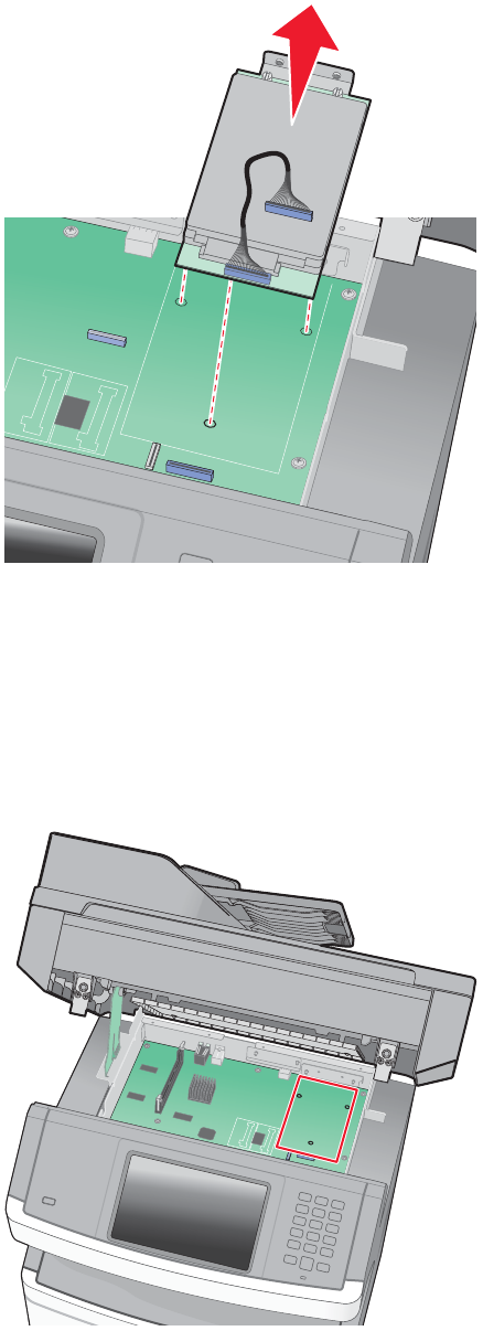
4-110
7014-xxx
3. Remove the printer hard disk by pulling it upwards from the standoffs.
4. Remove the thumbscrews that attach the printer hard disk mounting bracket to the printer hard disk if the
drive is going to be installed on top of an ISP.
Printer hard disk installation on an ISP
1. Access the controller board. See “Lifting the Scanner to the up position” on page 4-105.
2. Unpack the printer hard disk.
3. Locate the standoff location on the controller board.
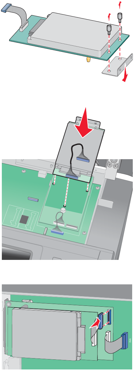
Repair information 4-111
7014-xxx
4. Use a flatblade screwdriver to remove the screws attaching the mounting bracket.
5. Place the hard disk on top of the ISP, making sure the standoff on the hard drive line up with the holes on
the ISP.
6. Gently press down on the hard drive until it locks into place.
7. Fasten the hard dive connector into the connector on the ISP card.
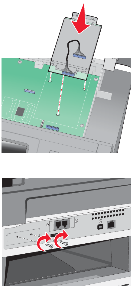
4-112
7014-xxx
Printer hard disk installation directly on the controller board
Note: Perform steps 1, 2, and 3 from above. before doing the rest of the installation.
1. Align the printer hard disk standoffs with the holes on the system board.
2. Press the hard disk down until it locks into place.
3. Attach the hard disk to the controller board cage using the screws that came with the hard disk.
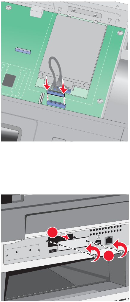
Repair information 4-113
7014-xxx
4. Connect the hard disk interface cable to the connector on the controller board.
Fax card installation
1. Access the controller board.
2. Unpack the fax card,
3. Remove the fax card cover on the controller board cage.
1
2
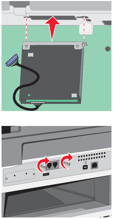
4-114
7014-xxx
4. Insert the fax card into the controller board cage.
5. Tighten the two screws to secure it to the controller board cage.
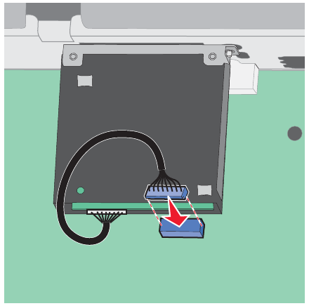
Repair information 4-115
7014-xxx
6. Insert the fax card interface cable into the system board connector.
7. Lower and lock the scanner assembly.
4-116
7014-xxx
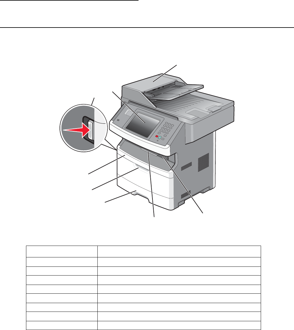
Locations and connections 5-1
7014-xxx
5. Locations and connections
Locations
Front view
Callout number Item name
1Front door release button
2E-Task display / Operator panel
3ADF unit
4Output bin / cave
5Output bin extension
6Standard input tray
7MFP input tray
8Front cover access
3
4
5
6
7
8
12
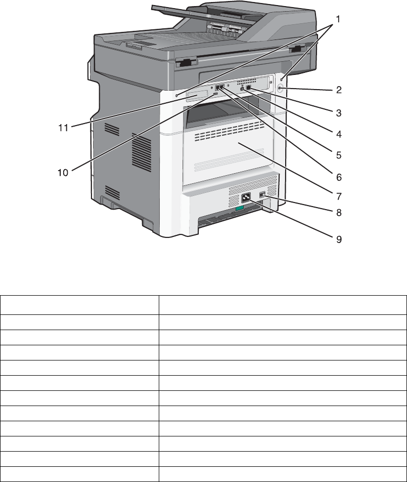
5-2 Service Manual
7014-xxx
Rear view
Callout number Item name
1Scanner locks
2Kensington lock
3Ethernet port
4Host USB port
5Fax /
6Fax /
7Rear door
8Power switch
9Power
10 Rear USB
11 ISP / Options cover
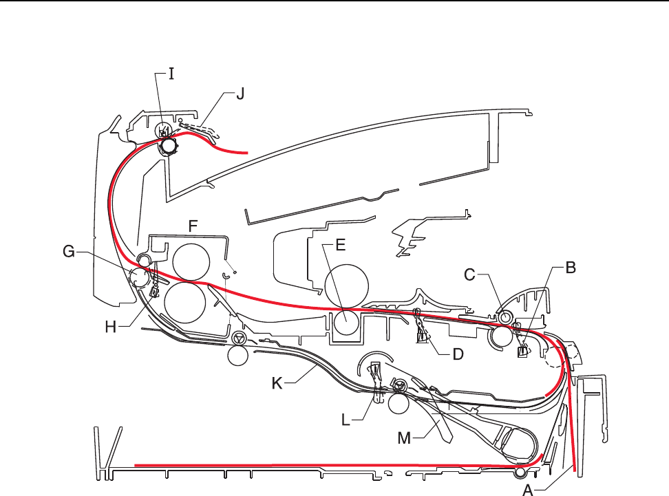
Locations and connections 5-3
7014-xxx
Print engine paperpath
A Paper path A – B 125.3
B Manual feed sensor B – C 9.0
C Upper end feed rolls C – D 59.8
D Input sensor D – E 44.9
E Transfer roll E – F 112.7
F Fuser F – G 21.4
G Fuser exit rolls G – H 114.8
H Fuser exit sensor H – I 7.5
I Exit rolls I – J 17.0
J Exit sensor/narrow media sensor I – K 211.7
K Duplex unit K – L 93.4
L Duplex sensor L – M 8.4
M Auto compensator M – B 177.2
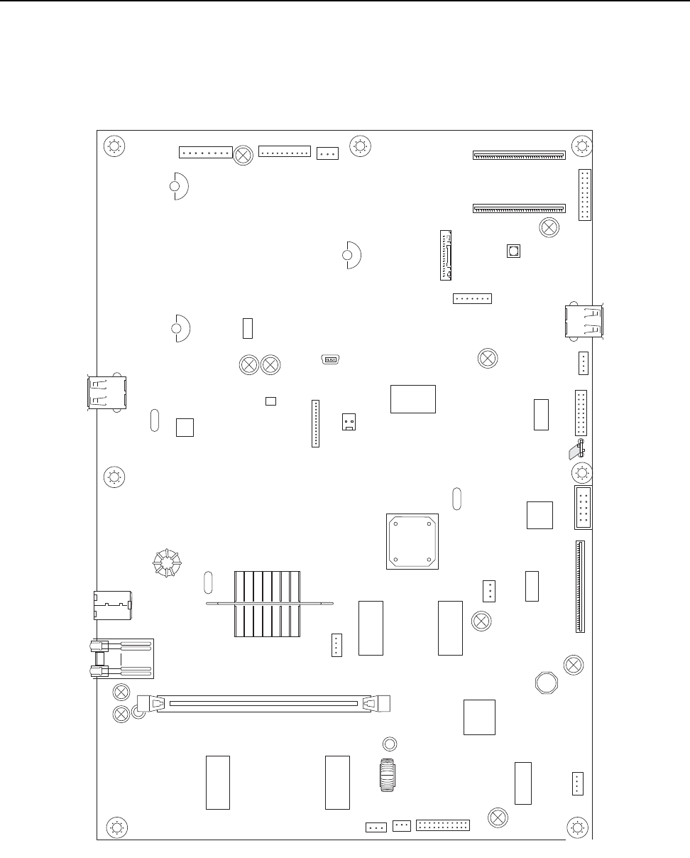
5-4 Service Manual
7014-xxx
Main boards
Lexmark X46x series controller board
J6 J6 J11
1
1
1
J26
J27
1
1
J16
1
J3
1
J3
1
J28
J13
1
J12 J17
1
1
J5
1
J4
1
J1
J8
1
J25
1
J7
1
J2
1
J35
1
J37
1
J34
J33
1
J10
J99
J30
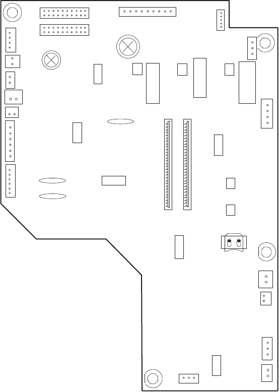
Locations and connections 5-5
7014-xxx
Lexmark X46x series engine board
1
1
J500 J501
J502
J503
1
1
1
J4
1
J13
J504
1
J23
1
J24
J50
1
J25
J34
J27
1
1
1
J28
1
J10
1
J14
J12
1
1
J35
1
J17
1
J36
1
1

5-6 Service Manual
7014-xxx
Lexmark X46x controller and engine board connector pin values
Note: The connections listed below are located on the controller board or the engine board. The comments
column lists which board the connection appears on.
These values were measured with all connections made (plugged) or with only one connector at a time
unplugged to expose the pins. Always disconnect and connect with the printer power off. Otherwise, the values
below may not match.
Connector Pin # Value
cable plugged Value
cable unplugged
(if different)
Comments
J8 1, 3, 5, 7, 9,
11, 14 Signals Modem - Controller Board
10 5 V dc
12, 13 3.3 V dc
2, 4, 6, 8 Ground
J16 10, 12, 14 +5V ISP - Controller Board
1, 4 7 Ground
J7 1 +5V Cave light - Controller board
4 Ground
J99 3 +3.3V Controller cooling fan - Controller board
1 Ground
J4 1 Ground Cartridge - Engine Board
(The front access door must be closed.)
21.7 V dc
3, 4 3.3 V dc
J34 1, 3, 5, 6 3.3 V dc Operator panel (UICC) - Controller Board
10, 16 ,17, 18 5.0 V dc
2, 9, 15 Ground
J6 1 > 0 V dc 5 V dc Printhead - Controller Board
2, 3 5 V dc
4, 5, 6, 7 Ground
J11 1 5 V dc (door closed) Cover open - Controller Board
0 V dc (door open)
25 V dc
3 Ground
J9 1, 10 5 V dc LSU - Controller Board
92.9 V dc
J36 1 24 V dc 0 V dc Cooling fan - Engine Board
2 24 V dc
J10 1 24 V dc 24 V dc Duplex solenoid - Engine Board
2 24 V dc 0 V dc
J35 1 5 V dc Narrow media sensor - Engine Board
2 5 V dc 5 V dc
3 Ground

Locations and connections 5-7
7014-xxx
J12 1 5 V dc Thermistor - Engine Board
2 Ground
J13 1 0.6 V dc Toner level sensor - Engine Board
2 Ground
30 V dc
J14 1 > 0 V dc 5 V dc Fuser exit sensor - Engine Board
25 V dc
3 Ground
J17 1, 4 0.1 V dc 5 V dc Main gear drive motor - Engine Board
2, 3, 6 5 V dc
5 Ground
7, 8, 9 24 V dc
J19 USB port - Controller Board
J23 1 1.1 V dc 5 V dc Manual feed sensor - Engine Board
25 V dc
3 Ground
J24 1 24 V dc MPF clutch - Engine Board
2 24 V dc 0 V dc
J25 1 24 V dc Manual feed solenoid - Engine Board
2 24 V dc 0 V dc
J34 1 24 V dc Media feed clutch - Engine Board
2 24 V dc 0 V dc
J27 1, 4 1.1 V dc 5 V dc Input and duplex sensor - Engine Board
2, 5 5 V dc
3, 6 Ground
J28 1, 4 3.3 V dc Tray 2 - Engine Board
2 24 V dc
6 Ground
J504 1 5 V dc Toner patch (density) sensor - Engine Board
3 1 V dc 0 V dc
4 Ground
5 5 V dc 0V dc
J502 1, 3, 5, 7, 11,
13, 15 5V dc LVPS - Engine Board
45 V dc
6 24 V dc
17, 19 24 V dc
Other 0 V dc
Connector Pin # Value
cable plugged Value
cable unplugged
(if different)
Comments

5-8 Service Manual
7014-xxx
J503 11, 13 15 5V dc HVPS - Engine Board
17, 19 24V dc
10,12,14,16,18 Ground
J37 11, 13 15 5V dc PS (LVPS/HVPS) - Controller Board
17, 19 24V dc
10,12,14,16,18 Ground
J30 3, 4 +14V AFE (CCD Ribbon) - Controller Board
6, 7 +5V
1,5,13,15,18,
21,24,27,30,
31-36
GND
J28 1 V12_A- FB Motor - Controller Board
2 V12_A
3 V12_B-
4 V12_B
J17 14 +5V ADF - Controller Board
11, 12 +24V
3,5,8,10,13 GND
J13 1 +5V Home Sensor - Controller Board
2GND
3HOME
J12 1 GND Paper Legnth (FB) - Controller Board
2 P_LENGTH
3+5V
Connector Pin # Value
cable plugged Value
cable unplugged
(if different)
Comments

Preventive maintenance 6-1
7014-xxx
6. Preventive maintenance
This chapter describes procedures for printer preventive maintenance. Follow these recommendations to help
prevent problems and maintain optimum performance.
Safety inspection guide
The purpose of this inspection guide is to aid you in identifying unsafe conditions.
If any unsafe conditions exist, then find out how serious the hazard could be and if you can continue before you
correct the hazard.
Check the following items:
•Damaged, missing, or altered parts, especially in the area of the On/Off switch and the power supply
•Damaged, missing, or altered covers, especially in the area of the top cover and the power supply cover
•Possible safety exposure from any non-Lexmark attachments
Lubrication specifications
FRUs are typically lubricated as needed from the factory. If not, then lubricate only when parts are replaced or
as needed, not on a scheduled basis. Use of lubricants other than those specified can cause premature failure.
Some unauthorized lubricants may chemically attack parts. Use P/N 99A0394 (Nyogel 744) to lubricate
appropriate areas. Lubricate gears that were lubricated in the original part.
Scanner glass cleaning
Kit 40X0392 is available for cleaning the scanner glass on the flatbed. Included are instructions for cleaning the
ADF glass if streaks should appear on copies from the ADF.
Maintenance kits
Maintenance kits
Description Part number
Low voltage (110 V) maintenance kit
Note: The fuser maintenance kit installation is
recommended every 120,000 pages.
Note: The kit includes:
• Fuser (P/N 40X5344)
• Tray 1 ACM feed tires (P/N 40X5451)
• Transfer roll (P/N 40X5364)
40X5400
High voltage (220 V) maintenance kit
Note: The fuser maintenance kit installation is
recommended every 120,000 pages.
Note: The kit includes:
• Fuser (P/N 40X5345)
• Tray 1 ACM feed tires (P/N 40X5451)
Transfer roll (P/N 40X5364)
40X5401

6-2 Service Manual
7014-xxx
100 V maintenance kit
Note: The fuser maintenance kit installation is
recommended every 120,000 pages.
Note: The kit includes:
• Fuser (P/N 40X5346)
• Tray 1 ACM feed tires (P/N 40X5451)
Transfer roll (P/N 40X5364)
40X5402
ADF Maintenance kit 40X5807
ADF separator roll 40X7545
ADF separator pad 40X8419
Exit guide 40X5372
Maintenance kits
Description Part number
Parts Catalog 7-1
7014-xxx
7. Parts Catalog
How to use this parts catalog
The following legend is used in the parts catalog:
•Asm-index: identifies the assembly and the item in the diagram. For example, 3-1 indicates assembly 3
and the item number 1.
•Part number: identifies the unique number that identifies this FRU.
•Units/mach: refers to the number of units actually used in the machine or product.
•Units/FRU: refers to the number of units packaged together and identified by the part number.
•NS: (Not shown) in the Asm-Index column indicates that the part is procurable but is not pictured in the
illustration.
•PP: (Parts Packet) in the parts description column indicates the part is contained in a parts packet.
•Model information used in the parts catalog.
Asm-
Index Part
number Units/
mach Units/
FRU Description
Machine type
and model Description
7014-431 Lexmark X463de
7014-636 Lexmark X464de
7014-637 Lexmark X466de and X466dte
7014-63w Lexmark X466dwe
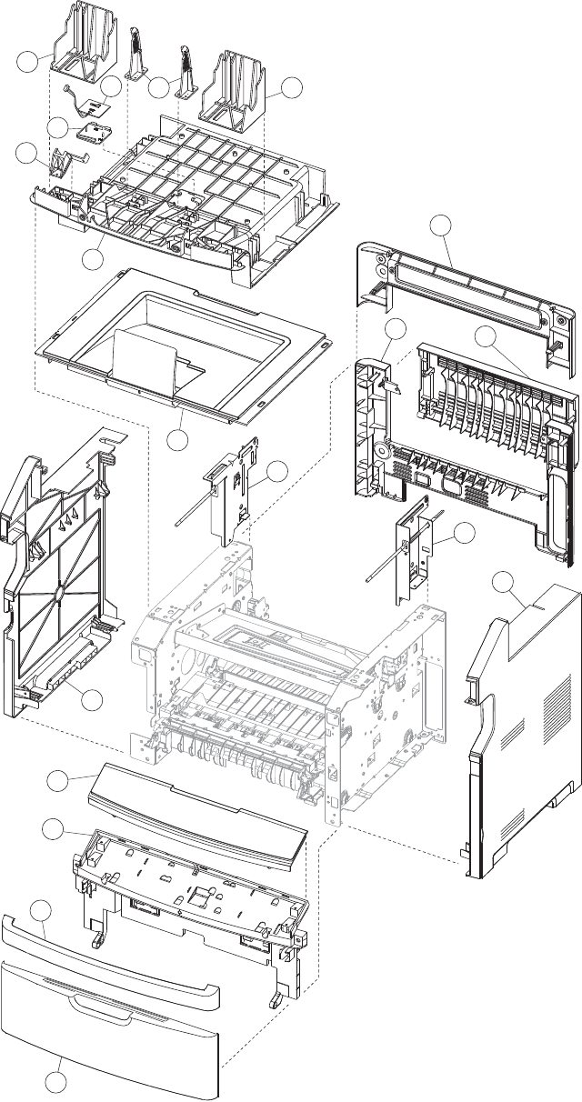
7-2 Service Manual
7014-xxx
Assembly 1: Covers
3
11
7
13
5
16
9
15
2
10
6
17
4
12
8
14
1
1718

Parts Catalog 7-3
7014-xxx
Assembly 1: Covers
Asm-
Index Part
number Units/
mach Units/
FRU Description
1-1 40X5827 1 1 Mid rear cover
2 40X5839 1 1 Rear door
3 40X5838 1 1 Rear cover
4 40X5820 1 1 Rear left frame assembly
5 40X5821 1 1 Rear right frame assembly
6 40X5822 1 1 Right side cover
7 40X5379 1 1 Front door cover
8 40X5359 1 1 Nameplate cover
9 40X5806 1 1 Lower AIO access assembly
10 40X5778 1 1 Front access door cover
11 40X5823 1 1 Left side cover
12 40X5614 1 1 Top cover assembly
13 40X5811 1 1 Tub cover assembly
14 40X5809 1 1 USB cable mount bracket
15 40X5834 1 1 Output bin LED lens
16 40X5835 1 1 Output bin LED
17 40X5815 2 1 Op panel support
18 40X5814 2 1 Display rotation support
NS 40X5381 1 1 Primary tray
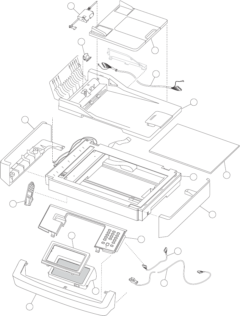
7-4 Service Manual
7014-xxx
Assembly 2: Imaging
3
11
7
13
5
16
9
15
2
10
6
4
12
8
14
1

Parts Catalog 7-5
7014-xxx
Assembly 2: Imaging
Asm-
Index Part
number Units/
mach Units/
FRU Description
1 40X7545 1 1 ADF Separator roll
2 40X8419 1 1 ADF Separator pad
3 40X5470 1 1 ADF input tray
4 40X5540 1 1 ADF cable
5 40X5824 1 1 Duplex ADF unit
6 40X5804 1 1 Flatbed cushion
7 40X5825 1 1 Flatbed module
8 40X5818 1 1 Right scanner cover
9 40X5743 1 1 Operator panel button assembly
10 40X5810 1 1 UICC Cable (Operator panel cable)
11 40X5831 1 1 Operator panel USB cable
12 40X5826 1 1 Scanner front cover
13 40X5837 1 1 Op panel display
14 40X0399 1 1 Op panel display bezel X463
14 40X0400 1 1 Op panel display bezel X464
14 40X0401 1 1 Op panel display bezel X466
15 40X5813 1 1 Kickstand support
16 40X5819 1 1 Left scanner cover
NS 40X5807 1 1 ADF maintenance kit
NS 40X7546 1 1 ADF hinge, right
NS 40X7547 1 1 ADF hinge, left
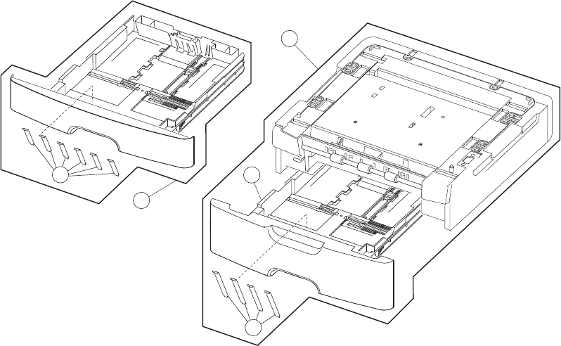
7-6 Service Manual
7014-xxx
Assembly 3: Tray assemblies
3
2
1
5
4

Parts Catalog 7-7
7014-xxx
Assembly 3: Tray assemblies
Asm-
Index Part
number Units/
mach Units/
FRU Description
3-1 40X5398 1 1 Optional 250-sheet tray (new asm)
1 40X5399 1 1 Optional 550-sheet tray(new asm)
2 40X5394 1 1 250-sheet (Tray 2) assembly (new asm)
2 40X5395 1 1 550-sheet (Tray 2) assembly (new asm)
3 40X2855 1 4 Tray 2 wear strips (550-sheet tray only) (new asm)
4 40X5381 1 1 Primary tray
5 40X5382 1 6 Wear strips (250-sheet trays, optional and primary) (new asm)
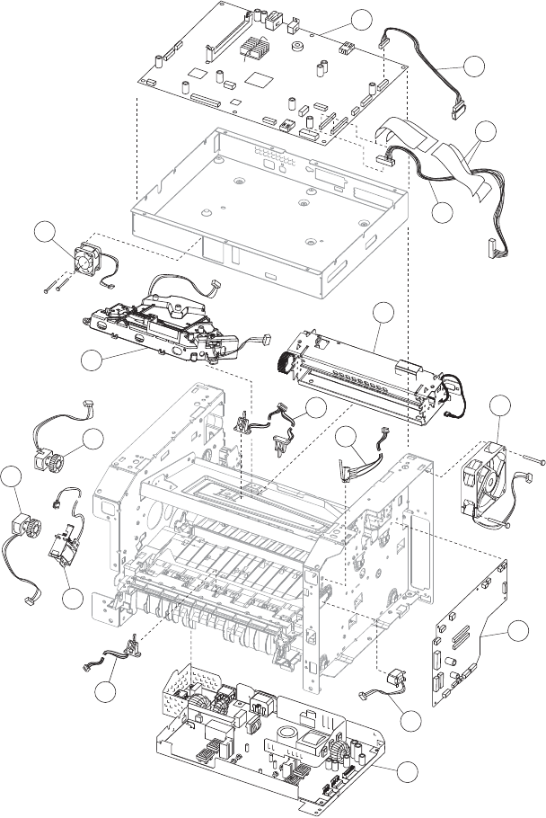
7-8 Service Manual
7014-xxx
Assembly 4: Electronics 2
1
10
11
12
7
13
9
6
14
2
5
8
3
4
16
15
17

Parts Catalog 7-9
7014-xxx
Assembly 4: Electronics 2
Asm-
Index Part
number Units/
mach Units/
FRU Description
4-1 40X5829 1 1 Controller board
2 40X5816 1 1 LSU hsync extension cable
3 40X5832 1 2 Stairway cable
4 40X5833 1 1 Controller board cable
5 40X5344 1 1 Fuser assembly, 115 V
5 40X5345 1 1 Fuser assembly, 230 V
5 40X5346 1 1 Fuser assembly, 100 V
6 40X5365 1 1 Duplex and media sensor assembly
7 40X5360 1 1 Access door open sensor assembly
8 40X5392 1 1 Cooling fan (screws included)
9 40X5830 1 1 Engine board,
10 40X5385 1 1 Toner low sensor
11 40X5842 1 1 LVPS/HVPS card assembly, 110 V
11 40X5841 1 1 LVPS/HVPS card assembly, 220 V
12 40X5366 1 1 Manual input sensor assembly
13 40X5369 1 1 Manual feed solenoid
14 40X5371 1 1 MPF feed clutch
15 40X5370 1 1 Media feed (ACM) clutch
16 40X5387 1 1 LSU, (printhead)
17 40X5805 1 1 Controller board fan
NS 40X5817 1 1 LSU laser diode cable
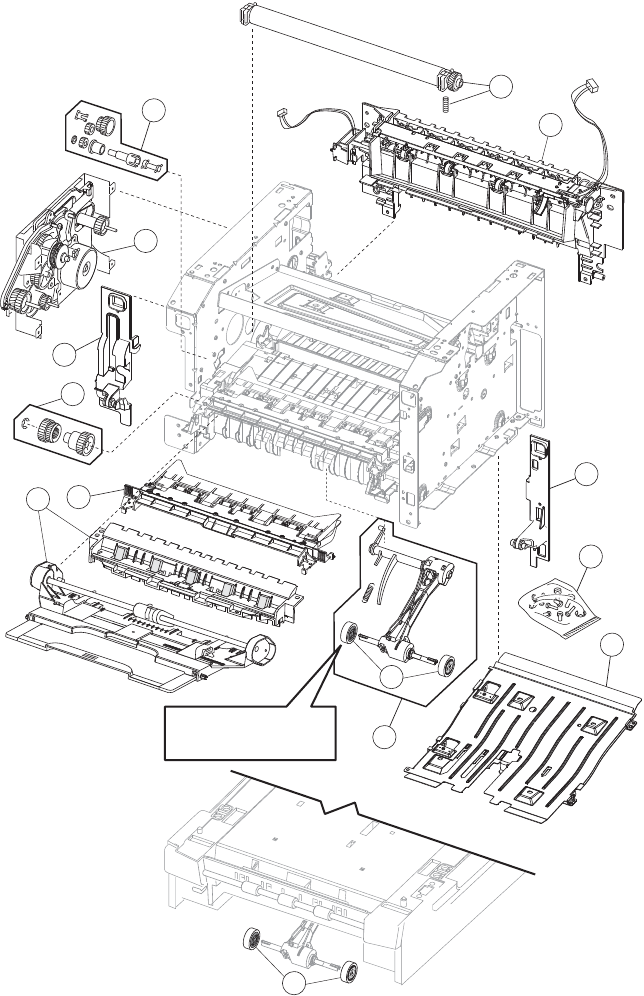
7-10 Service Manual
7014-xxx
Assembly 5: Frame
7
1
2
5
6
7
12
8
See instruction
sheet in the FRU.
9
10
11
3
4
3

Parts Catalog 7-11
7014-xxx
Assembly 5: Frame
Asm-
Index Part
number Units/
mach Units/
FRU Description
5–1 40X5364 1 Transfer roll, bearings, gear, spring (CBM)
2 40X5372 1 Media exit guide assembly (redrive)
3 40X5397 1 1 Front mounts
4 40X5396 N/A
4
4
4
2
2
Screws, miscellaneous
TP2NCX3X6PF-Ni
TP2C-4.0+8PF-Ni
M3.0*0.5+6PF-Ni
M3.0*0.5+4PF-Ni
M3.5*0.6+6P-Ni
5 40X5380 1 1 Complete duplex assembly
6 40X5453 1 1 Media (ACM) drive assembly
7 40X5451 2 2 Paper feed, ACM tires
7 40X5440 1 2 Tray 2 paper feed tires
8 40X5358 1 1 MPF tray assembly
9 40X5383 1 1 Upper front frame assembly
10 40X5368 1 1 Manual feed clutch CBM
11 40X5367 1 1 Main drive gearbox (in motor)
12 40X5363 1 1 Duplex gear drive CBM
NS 40X5400 1 1 110 V maintenance kit
NS 40X5401 1 1 220 V maintenance kit
NS 40X5402 1 1 100 V maintenance kit
Note: Kit contains the following:
Fuser (40X5344, 40X5345, or 40X2802)
Exit guide (40X5372)
Tray 1 ACM feed tires (40X5451)
Transfer roll CBM (40X5364)
NS 40X0016 1 1 Motor spacer washer kit

7-12 Service Manual
7014-xxx
Assembly 6: Options
Asm-
Index Part
number Units/
mach Units/
FRU Description
NS 40X5972 1 1 Japanese font card assembly
NS 40X5970 1 1 Simplified Chinese font card assembly
NS 40X5971 1 1 Traditional Chinese font card assembly
NS 40X5969 1 1 Korean font card assembly
NS 40X5952 1 1 Print cryption card assembly
NS 40X5951 1 1 Korean KS/KSSM/KSP
NS 40X5940 1 1 Bar code and forms
NS 40X5937 1 1 128MB DIMM
NS 40X5938 1 1 256MB DIMM
NS 40X5939 1 1 512MB DIMM
NS 40X5704 1 1 256MB flash
NS 40X1367 1 1 Parallel cable, packaged (3 m)
NS 40X1368 1 1 USB cable, packaged (2 m)
NS 40X4822 1 1 80 GB Hard Disk Drive
NS 40X5038 1 1 Wireless ISP Adapter (US)
NS 40X5039 1 1 Wireless ISP Adapter (EMEA)
NS 40X5318 1 2 Thumbscrews
NS 40X4821 1 1 N.8110 V.34 Fax
NS 40X5606 1 1 14 Pin JST for Fax Cable
NS 56P0558 1 1 RJ11 Cable w/Toroids
NS 40X4819 1 1 RS 232 Serial adapter
NS 40X4826 1 1 N8120 Gigabit INA
NS 40X5315 1 2 ISP screw
NS 40X5316 14 Pin JST for ISP Cable
NS 40X5317 1 1 Standoff Tee w/thumbscrew
NS 40X4823 1 1 Parallel 1284-B thick adapter
NS 40X4827 1 1 N8130 10/100 Fiber adapter
NS 7377732 1 1 Relocation Kit

Parts Catalog 7-13
7014-xxx
Assembly 7: Power cords
Asm-
Index Part
number Units/
mach Units/
FRU Description
NS 40X0297 1 1 Power cord, 1.8M (straight)—USA, Canada
NS 40X0278 1 1 Power cord, 6 foot (straight)—Europe and others
NS 40X0288 1 1 Power cord, 8 foot (straight)—Argentina
NS 40X0286 1 1 Power cord, 8 foot (straight)—United Kingdom
NS 40X0275 1 1 Power cord, 6 foot (straight)—Israel
NS 40X0274 1 1 Power cord, 6 foot (straight)—Switzerland
NS 40X0276 1 1 Power cord, 6 foot (straight)—South Africa
NS 40X0287 1 1 Power cord, 6 foot (straight)—Traditional Italy
NS 40X0279 1 1 Power cord, 6 foot (straight)—Denmark
NS 40X0277 1 1 Power cord, 6 foot (straight)—Brazil
NS 40X0282 1 1 Power cord, 1.8M (straight)—PRC
NS 40X0270 1 1 Power cord, 2.5M (straight)—Japan
NS 40X0280 1 1 Power cord, 1.8M (straight)—Korea
NS 40X0281 1 1 Power cord, 1.8M (straight)—Taiwan
NS 40X0296 1 1 Power cord, 1.8M (straight)—Australia
7-14 Service Manual
7014-xxx

Index I-1
7014-xxx
Index
Numerics
840.xx service check 2-55
A
abbreviations 1-14
acronyms 1-14
ADF cover open service check 2-59
ADF duplex service check 2-62
ADF feed errors service check 2-60
ADF paper jam service check 2-60
ADF separator pad
removal 4-98
ADF separator roll
removal 4-99
ADF streak service check 2-59
ASIC Test 3-34
B
Button Test 3-21
buttons
accessing service menus 3-1
Button Test 3-21
C
CCD service check 2-57
compatibility 1-3
Configuration ID 3-30
Configuration Menu
Reset Maintenance Counter 3-3
configuration menu
accessing 3-1
available menus 3-2
Factory Defaults 3-6
Panel Menus 3-4
PPDS Emulation 3-5
D
defaults
EP defaults 3-31
factory defaults 3-6
US/Non-US defaults 3-29
diagnostics menu
DEVICE TESTS
Disk Test/Clean 3-28
Quick Disk Test 3-28
DUPLEX TESTS
Duplex Feed 1 3-26
Duplex Feed 2 3-26
Motor Test 3-25
Quick Test 3-24
Sensor Test 3-25
Top Margin 3-25
EP SETUP
Charge Roll 3-32
EP Defaults 3-31
Fuser Page Count 3-31
Fuser Temp 3-31
Gap Adjust 3-32
Print Contrast 3-32
Transfer 3-32
Warm Up Time 3-31
EVENT LOG
Clear Log 3-33
Display Log 3-32
Print Log 3-33
HARDWARE TESTS
Button Test 3-21
DRAM Test 3-22
Panel Test 3-21
INPUT TRAY TESTS
Feed Test 3-26
Sensor Test 3-26
OUTPUT BIN TESTS
Feed Test 3-27
Sensor Tests 3-27
PRINTER SETUP
Configuration ID 3-30
Defaults 3-29
Edge to Edge 3-30
engine settings 3-29
Model Name 3-29
Page Count 3-29
Perm Page Count 3-29
Serial Number 3-29
SCANNER TESTS
ASIC Test 3-34
Feed Test 3-34
Sensor Tests 3-34
diagnostics mode 3-17
accessing 3-1
available tests 3-17
diagnostics mode—
Registration 3-18
didital imaging specifications 1-9
DRAM Test 3-22
duplex tests
Duplex Feed 1 3-26
Duplex Feed 2 3-26
Motor Test 3-25
Quick Test 3-24
Sensor Test 3-25
Top Margin 3-25
E
Edge to Edge 3-30
Engine Setting 3-29
error messages
service error codes 2-26
user attendance messages 2-13
ESD-sensitive parts 4-1
I-2 Service Manual
7014-xxx
event log
clear log (diagnostics menu) 3-33
display log (diagnostics mode) 3-32
print log (diagnostics menu) 3-33
F
fan parts catalog 7-9
service check 2-37
fax reception service check 2-66
fax specifications 1-12
miscellaneous 1-12
phone network connectivity 1-12
scan resolutions 1-12
fax transmission service check 2-64
Feed Test (scanner) 3-34
flatbed home position service check 2-58
flatbed motor service check 2-57
frame, parts catalog 7-10
fuser
parts catalog 7-9
service check 2-39
G
gap adjustment 3-32
H
handling ESD-sensitive parts 4-1
I
input sensor tray tests 3-26
input tray feed test 3-26
L
lithium battery v-xvii, 4-8, 4-15
locations
front views 5-1
rear views 5-2
lubrication specifications 6-1
LVPS/HVPS
parts catalog 7-9
service check 2-39
M
maintenance approach 1-1
maintenance kits 6-1
manually register a duplex ADF 3-8
manually register the flatbed 3-8
media
guidelines 1-6
recycled 1-7
unacceptable media 1-6
menus
accessing service menus 3-1
messages
service error codes 2-26
user attendance messages 2-13
Model Name 3-29
models
diagrams 5-1, 5-2
trays available 1-4
modem - fax card service check 2-63
O
operator panel
Button Test 3-21
LCD— 2-5
LED—
service check 2-43
Panel Test 3-21
output bin sensor tests 3-27
P
page count
Fuser Page Count 3-31
Page Count 3-29
permanent page count 3-29
Panel Test 3-21
paper
guidelines 1-6
recycled 1-7
unacceptable paper 1-6
parts catalog
covers 7-2
electronics 7-8
frame 7-10
options 7-12
power-on self test (POST) 2-1
symptoms 2-2
print media
trays by model 1-4
types and sizes 1-5
print quality pages
using 2-47
print quality problems
service check 2-47
solving 2-51
printer symptom table 2-3
printhead
service check 2-54
Q
Quick Disk Test 3-28
Quick Test 3-24
R
registration 3-18
removals
ADF separator pad 4-98
ADF separator roll 4-99
covers
front access cover 4-8
procedures 4-2
S
safety information v-xvii
safety inspection guide 6-1
scan and copy specifications 1-11
scan fax and copy symptoms 2-4
SE Menu 3-41
serial number 3-29
Index I-3
7014-xxx
service checks 2-35
ADF paperfeed 2-60
ADF streak 2-59
black page 2-57
cooling fan 2-37
cover interlock switch 2-37
dead machine 2-38
flatbed 2-58
flatbed motor 2-57
fuser 2-39
LVPS/HVPS 2-39
main motor 2-40
modem / fax card 2-63
networking 2-41
operator panel 2-43
paper feed 2-43
paper jam during POST 2-43
paper never picks 2-44
paper picks but stops 2-44
paper picks sheets 2-44
paper trees, curls 2-45
print quality 2-47
black page 2-48
blank page 2-47
heavy background 2-48
image density 2-49
light print 2-50
partial blank image 2-49
poor fusing of image 2-49
toner on back of page 2-50
white or black lines 2-50
printhead 2-54
scanner, fax, copy
840xx error check 2-55
ADF cover open 2-59
ADF duplex service check 2-62
ADF feed errors 2-60
ADF paper am 2-60
black page or blank page 2-57
CCD service check 2-57
escalating a fax issue to second-level support 2-68
fax reception service check 2-66
fax transmission service check 2-64
flatbed home position 2-58
flatbed motor 2-57
modem service check 2-63
transfer roll 2-54
service error codes 2-26
special tools 1-13
specifications
connectivity 1-3
digital imaging 1-9
fax 1-12
input trays 1-4
memory 1-2
operating systems 1-3
photoconductor capacity 1-4
print media 1-5
scan and copy 1-11
toner capacity 1-4
start 2-1
symptom tables 2-2
POST 2-2
printer 2-3
symptoms
scan fax and copy 2-4
T
tools 1-13
Top Margin 3-18
duplex 3-25
transfer roll
parts catalog 7-11
service check 2-54
U
user attendance messages 2-13
W
warm up time 3-31
I-4 Service Manual
7014-xxx

Part number index I-5
7014-xxx
Part number index
P/N Description Page
40X0016 Motor spacer washer kit - - - - - - - - - - - - - - - - - - - - - - - - - - - - - - - - - - - - - - - - - - - - - - - - - - - - - - - - - 7-11
40X0270 Power cord, 1.77M (straight)—Japan - - - - - - - - - - - - - - - - - - - - - - - - - - - - - - - - - - - - - - - - - - - - - - - 7-13
40X0274 Power cord, 6 foot—Switzerland - - - - - - - - - - - - - - - - - - - - - - - - - - - - - - - - - - - - - - - - - - - - - - - - - - - 7-13
40X0275 Power cord, 6 foot (straight)—Israel - - - - - - - - - - - - - - - - - - - - - - - - - - - - - - - - - - - - - - - - - - - - - - - - 7-13
40X0276 Power cord, 6 foot—South Africa - - - - - - - - - - - - - - - - - - - - - - - - - - - - - - - - - - - - - - - - - - - - - - - - - - 7-13
40X0277 Power cord, 6 foot (straight)—Brazil - - - - - - - - - - - - - - - - - - - - - - - - - - - - - - - - - - - - - - - - - - - - - - - - 7-13
40X0278 Power cord, 6 foot (straight)—Europe and others - - - - - - - - - - - - - - - - - - - - - - - - - - - - - - - - - - - - - - - 7-13
40X0279 Power cord, 6 foot (straight)—Denmark - - - - - - - - - - - - - - - - - - - - - - - - - - - - - - - - - - - - - - - - - - - - - - 7-13
40X0280 Power cord, 1.77M (straight)—Korea - - - - - - - - - - - - - - - - - - - - - - - - - - - - - - - - - - - - - - - - - - - - - - - 7-13
40X0281 Power cord, 1.77M (straight)—Taiwan - - - - - - - - - - - - - - - - - - - - - - - - - - - - - - - - - - - - - - - - - - - - - - 7-13
40X0282 Power cord, 1.77M (straight)—PRC - - - - - - - - - - - - - - - - - - - - - - - - - - - - - - - - - - - - - - - - - - - - - - - - 7-13
40X0286 Power cord, 6 foot—United Kingdom - - - - - - - - - - - - - - - - - - - - - - - - - - - - - - - - - - - - - - - - - - - - - - - 7-13
40X0287 Power cord, 6 foot (straight)—Traditional Italy - - - - - - - - - - - - - - - - - - - - - - - - - - - - - - - - - - - - - - - - - 7-13
40X0288 Power cord, 6 foot—Argentina - - - - - - - - - - - - - - - - - - - - - - - - - - - - - - - - - - - - - - - - - - - - - - - - - - - - 7-13
40X0296 Power cord, 1.8M (straight)—Australia - - - - - - - - - - - - - - - - - - - - - - - - - - - - - - - - - - - - - - - - - - - - - - 7-13
40X0297 Power cord, 1.77M (straight)—USA, Canada - - - - - - - - - - - - - - - - - - - - - - - - - - - - - - - - - - - - - - - - - - 7-13
40X0399 Op panel display bezel X463 - - - - - - - - - - - - - - - - - - - - - - - - - - - - - - - - - - - - - - - - - - - - - - - - - - - - - - 7-5
40X0400 Op panel display bezel X464 - - - - - - - - - - - - - - - - - - - - - - - - - - - - - - - - - - - - - - - - - - - - - - - - - - - - - - 7-5
40X0401 Op panel display bezel X466 - - - - - - - - - - - - - - - - - - - - - - - - - - - - - - - - - - - - - - - - - - - - - - - - - - - - - - 7-5
40X1367 Parallel cable, packaged (3 m) (E460dn only) - - - - - - - - - - - - - - - - - - - - - - - - - - - - - - - - - - - - - - - - - 7-12
40X1368 USB cable, packaged (2 m) - - - - - - - - - - - - - - - - - - - - - - - - - - - - - - - - - - - - - - - - - - - - - - - - - - - - - - 7-12
40X2855 Tray 2 wear strips (550-sheet tray only) - - - - - - - - - - - - - - - - - - - - - - - - - - - - - - - - - - - - - - - - - - - - - - - 7-7
40X4819 RS 232 Serial adapter - - - - - - - - - - - - - - - - - - - - - - - - - - - - - - - - - - - - - - - - - - - - - - - - - - - - - - - - - - 7-12
40X4821 N.8110 V.34 Fax - - - - - - - - - - - - - - - - - - - - - - - - - - - - - - - - - - - - - - - - - - - - - - - - - - - - - - - - - - - - - - 7-12
40X4822 80 GB Hard Disk Drive - - - - - - - - - - - - - - - - - - - - - - - - - - - - - - - - - - - - - - - - - - - - - - - - - - - - - - - - - 7-12
40X4823 Parallel 1284-B thick adapter - - - - - - - - - - - - - - - - - - - - - - - - - - - - - - - - - - - - - - - - - - - - - - - - - - - - - 7-12
40X4826 N8120 Gigabit INA - - - - - - - - - - - - - - - - - - - - - - - - - - - - - - - - - - - - - - - - - - - - - - - - - - - - - - - - - - - - 7-12
40X4827 N8130 10/100 Fiber adapter - - - - - - - - - - - - - - - - - - - - - - - - - - - - - - - - - - - - - - - - - - - - - - - - - - - - - - 7-12
40X5038 Wireless ISP Adapter (US) - - - - - - - - - - - - - - - - - - - - - - - - - - - - - - - - - - - - - - - - - - - - - - - - - - - - - - - 7-12
40X5039 Wireless ISP Adapter (EMEA) - - - - - - - - - - - - - - - - - - - - - - - - - - - - - - - - - - - - - - - - - - - - - - - - - - - - 7-12
40X5315 ISP screw - - - - - - - - - - - - - - - - - - - - - - - - - - - - - - - - - - - - - - - - - - - - - - - - - - - - - - - - - - - - - - - - - - - 7-12
40X5316 14 Pin JST for ISP Cable - - - - - - - - - - - - - - - - - - - - - - - - - - - - - - - - - - - - - - - - - - - - - - - - - - - - - - - - 7-12
40X5317 Standoff Tee w/thumbscrew - - - - - - - - - - - - - - - - - - - - - - - - - - - - - - - - - - - - - - - - - - - - - - - - - - - - - - 7-12
40X5318 Thumbscrews - - - - - - - - - - - - - - - - - - - - - - - - - - - - - - - - - - - - - - - - - - - - - - - - - - - - - - - - - - - - - - - - 7-12
40X5344 Fuser assembly, 115 V - - - - - - - - - - - - - - - - - - - - - - - - - - - - - - - - - - - - - - - - - - - - - - - - - - - - - - - - - - 7-9
40X5345 Fuser assembly, 230 V - - - - - - - - - - - - - - - - - - - - - - - - - - - - - - - - - - - - - - - - - - - - - - - - - - - - - - - - - - 7-9
40X5346 Fuser assembly, 100 V - - - - - - - - - - - - - - - - - - - - - - - - - - - - - - - - - - - - - - - - - - - - - - - - - - - - - - - - - - 7-9
40X5358 MPF tray assembly - - - - - - - - - - - - - - - - - - - - - - - - - - - - - - - - - - - - - - - - - - - - - - - - - - - - - - - - - - - - 7-11
40X5359 Nameplate cover - - - - - - - - - - - - - - - - - - - - - - - - - - - - - - - - - - - - - - - - - - - - - - - - - - - - - - - - - - - - - - - 7-3
40X5360 Access door open sensor assembly - - - - - - - - - - - - - - - - - - - - - - - - - - - - - - - - - - - - - - - - - - - - - - - - - 7-9
40X5363 Duplex gear drive CBM - - - - - - - - - - - - - - - - - - - - - - - - - - - - - - - - - - - - - - - - - - - - - - - - - - - - - - - - - 7-11
40X5364 Transfer roll, bearings, gear, spring (CBM) - - - - - - - - - - - - - - - - - - - - - - - - - - - - - - - - - - - - - - - - - - - 7-11
40X5365 Duplex and media sensor assembly - - - - - - - - - - - - - - - - - - - - - - - - - - - - - - - - - - - - - - - - - - - - - - - - - 7-9
40X5366 Manual input sensor assembly - - - - - - - - - - - - - - - - - - - - - - - - - - - - - - - - - - - - - - - - - - - - - - - - - - - - - 7-9
40X5367 Main drive gearbox (in motor) - - - - - - - - - - - - - - - - - - - - - - - - - - - - - - - - - - - - - - - - - - - - - - - - - - - - - 7-11
40X5368 Manual feed clutch CBM - - - - - - - - - - - - - - - - - - - - - - - - - - - - - - - - - - - - - - - - - - - - - - - - - - - - - - - - 7-11
40X5369 Manual feed solenoid - - - - - - - - - - - - - - - - - - - - - - - - - - - - - - - - - - - - - - - - - - - - - - - - - - - - - - - - - - - 7-9
40X5370 Media feed (ACM) clutch - - - - - - - - - - - - - - - - - - - - - - - - - - - - - - - - - - - - - - - - - - - - - - - - - - - - - - - - - 7-9
40X5371 MPF feed clutch - - - - - - - - - - - - - - - - - - - - - - - - - - - - - - - - - - - - - - - - - - - - - - - - - - - - - - - - - - - - - - - 7-9
40X5372 Exit guide - - - - - - - - - - - - - - - - - - - - - - - - - - - - - - - - - - - - - - - - - - - - - - - - - - - - - - - - - - - - - - - - - - - - 6-2
40X5372 Media exit guide assembly (redrive) - - - - - - - - - - - - - - - - - - - - - - - - - - - - - - - - - - - - - - - - - - - - - - - - 7-11
40X5379 Front door cover - - - - - - - - - - - - - - - - - - - - - - - - - - - - - - - - - - - - - - - - - - - - - - - - - - - - - - - - - - - - - - - 7-3
40X5380 Complete duplex assembly - - - - - - - - - - - - - - - - - - - - - - - - - - - - - - - - - - - - - - - - - - - - - - - - - - - - - - 7-11
40X5381 Primary tray - - - - - - - - - - - - - - - - - - - - - - - - - - - - - - - - - - - - - - - - - - - - - - - - - - - - - - - - - - - - - - 7-3, 7-7
I-6 Service Manual
7014-xxx
40X5382 Wear strips (250-sheet trays, optional and primary) - - - - - - - - - - - - - - - - - - - - - - - - - - - - - - - - - - - - - 7-7
40X5383 Upper front frame assembly - - - - - - - - - - - - - - - - - - - - - - - - - - - - - - - - - - - - - - - - - - - - - - - - - - - - - 7-11
40X5385 Toner low sensor - - - - - - - - - - - - - - - - - - - - - - - - - - - - - - - - - - - - - - - - - - - - - - - - - - - - - - - - - - - - - - 7-9
40X5387 LSU, E460dn/E460dw (printhead) - - - - - - - - - - - - - - - - - - - - - - - - - - - - - - - - - - - - - - - - - - - - - - - - - - 7-9
40X5392 Cooling fan (screws included) - - - - - - - - - - - - - - - - - - - - - - - - - - - - - - - - - - - - - - - - - - - - - - - - - - - - - 7-9
40X5394 Tray 2 assembly - - - - - - - - - - - - - - - - - - - - - - - - - - - - - - - - - - - - - - - - - - - - - - - - - - - - - - - - - - - - - - 7-7
40X5395 550-sheet (Tray 2) assembly - - - - - - - - - - - - - - - - - - - - - - - - - - - - - - - - - - - - - - - - - - - - - - - - - - - - - 7-7
40X5396 Screws, miscellaneous - - - - - - - - - - - - - - - - - - - - - - - - - - - - - - - - - - - - - - - - - - - - - - - - - - - - - - - - - 7-11
40X5397 Front mounts - - - - - - - - - - - - - - - - - - - - - - - - - - - - - - - - - - - - - - - - - - - - - - - - - - - - - - - - - - - - - - - - 7-11
40X5398 Optional 250-sheet tray - - - - - - - - - - - - - - - - - - - - - - - - - - - - - - - - - - - - - - - - - - - - - - - - - - - - - - - - - 7-7
40X5399 Optional 550-sheet tray - - - - - - - - - - - - - - - - - - - - - - - - - - - - - - - - - - - - - - - - - - - - - - - - - - - - - - - - - 7-7
40X5400 110 V maintenance kit - - - - - - - - - - - - - - - - - - - - - - - - - - - - - - - - - - - - - - - - - - - - - - - - - - - - - - - - - 7-11
40X5400 Low voltage (110 V) maintenance kit - - - - - - - - - - - - - - - - - - - - - - - - - - - - - - - - - - - - - - - - - - - - - - - - 6-1
40X5401 220 V maintenance kit - - - - - - - - - - - - - - - - - - - - - - - - - - - - - - - - - - - - - - - - - - - - - - - - - - - - - - - - - 7-11
40X5401 High voltage (220 V) maintenance kit - - - - - - - - - - - - - - - - - - - - - - - - - - - - - - - - - - - - - - - - - - - - - - - 6-1
40X5402 100 V maintenance kit - - - - - - - - - - - - - - - - - - - - - - - - - - - - - - - - - - - - - - - - - - - - - - - - - - - - - - 6-2, 7-11
40X5440 Tray 2 paper feed tires - - - - - - - - - - - - - - - - - - - - - - - - - - - - - - - - - - - - - - - - - - - - - - - - - - - - - - - - - 7-11
40X5451 Paper feed, ACM tires - - - - - - - - - - - - - - - - - - - - - - - - - - - - - - - - - - - - - - - - - - - - - - - - - - - - - - - - - 7-11
40X5453 Media (ACM) drive assembly - - - - - - - - - - - - - - - - - - - - - - - - - - - - - - - - - - - - - - - - - - - - - - - - - - - - 7-11
40X5470 ADF input tray - - - - - - - - - - - - - - - - - - - - - - - - - - - - - - - - - - - - - - - - - - - - - - - - - - - - - - - - - - - - - - - - 7-5
40X5540 ADF cable - - - - - - - - - - - - - - - - - - - - - - - - - - - - - - - - - - - - - - - - - - - - - - - - - - - - - - - - - - - - - - - - - - - 7-5
40X5606 14 Pin JST for Fax Cable - - - - - - - - - - - - - - - - - - - - - - - - - - - - - - - - - - - - - - - - - - - - - - - - - - - - - - - 7-12
40X5704 256MB flash - - - - - - - - - - - - - - - - - - - - - - - - - - - - - - - - - - - - - - - - - - - - - - - - - - - - - - - - - - - - - - - - 7-12
40X5743 Operator panel button assembly - - - - - - - - - - - - - - - - - - - - - - - - - - - - - - - - - - - - - - - - - - - - - - - - - - - 7-5
40X5804 Flatbed cushion - - - - - - - - - - - - - - - - - - - - - - - - - - - - - - - - - - - - - - - - - - - - - - - - - - - - - - - - - - - - - - - 7-5
40X5805 Controller board fan - - - - - - - - - - - - - - - - - - - - - - - - - - - - - - - - - - - - - - - - - - - - - - - - - - - - - - - - - - - - 7-9
40X5807 ADF maintenance kit - - - - - - - - - - - - - - - - - - - - - - - - - - - - - - - - - - - - - - - - - - - - - - - - - - - - - - - 6-2, 7-5
40X5810 UICC Cable (Operator panel cable) - - - - - - - - - - - - - - - - - - - - - - - - - - - - - - - - - - - - - - - - - - - - - - - - - 7-5
40X5813 Kickstand support - - - - - - - - - - - - - - - - - - - - - - - - - - - - - - - - - - - - - - - - - - - - - - - - - - - - - - - - - - - - - 7-5
40X5816 LSU hsync extension cable - - - - - - - - - - - - - - - - - - - - - - - - - - - - - - - - - - - - - - - - - - - - - - - - - - - - - - - 7-9
40X5817 LSU laser diode cable - - - - - - - - - - - - - - - - - - - - - - - - - - - - - - - - - - - - - - - - - - - - - - - - - - - - - - - - - - 7-9
40X5818 Right scanner cover - - - - - - - - - - - - - - - - - - - - - - - - - - - - - - - - - - - - - - - - - - - - - - - - - - - - - - - - - - - - 7-5
40X5819 Left scanner cover - - - - - - - - - - - - - - - - - - - - - - - - - - - - - - - - - - - - - - - - - - - - - - - - - - - - - - - - - - - - - 7-5
40X5824 Duplex ADF unit - - - - - - - - - - - - - - - - - - - - - - - - - - - - - - - - - - - - - - - - - - - - - - - - - - - - - - - - - - - - - - 7-5
40X5825 Flatbed module - - - - - - - - - - - - - - - - - - - - - - - - - - - - - - - - - - - - - - - - - - - - - - - - - - - - - - - - - - - - - - - 7-5
40X5826 Scanner front cover - - - - - - - - - - - - - - - - - - - - - - - - - - - - - - - - - - - - - - - - - - - - - - - - - - - - - - - - - - - - 7-5
40X5829 Controller board - - - - - - - - - - - - - - - - - - - - - - - - - - - - - - - - - - - - - - - - - - - - - - - - - - - - - - - - - - - - - - - 7-9
40X5830 Engine board - - - - - - - - - - - - - - - - - - - - - - - - - - - - - - - - - - - - - - - - - - - - - - - - - - - - - - - - - - - - - - - - - 7-9
40X5831 Operator panel USB cable - - - - - - - - - - - - - - - - - - - - - - - - - - - - - - - - - - - - - - - - - - - - - - - - - - - - - - - 7-5
40X5832 Stairway cable - - - - - - - - - - - - - - - - - - - - - - - - - - - - - - - - - - - - - - - - - - - - - - - - - - - - - - - - - - - - - - - - 7-9
40X5833 Controller board cable - - - - - - - - - - - - - - - - - - - - - - - - - - - - - - - - - - - - - - - - - - - - - - - - - - - - - - - - - - 7-9
40X5837 Op panel display - - - - - - - - - - - - - - - - - - - - - - - - - - - - - - - - - - - - - - - - - - - - - - - - - - - - - - - - - - - - - - 7-5
40X5841 LVPS/HVPS card assembly, 220 V - - - - - - - - - - - - - - - - - - - - - - - - - - - - - - - - - - - - - - - - - - - - - - - - - 7-9
40X5842 LVPS/HVPS card assembly, 110 V - - - - - - - - - - - - - - - - - - - - - - - - - - - - - - - - - - - - - - - - - - - - - - - - - 7-9
40X5937 128MB DIMM - - - - - - - - - - - - - - - - - - - - - - - - - - - - - - - - - - - - - - - - - - - - - - - - - - - - - - - - - - - - - - - 7-12
40X5938 256MB DIMM - - - - - - - - - - - - - - - - - - - - - - - - - - - - - - - - - - - - - - - - - - - - - - - - - - - - - - - - - - - - - - - 7-12
40X5939 512MB DIMM - - - - - - - - - - - - - - - - - - - - - - - - - - - - - - - - - - - - - - - - - - - - - - - - - - - - - - - - - - - - - - - 7-12
40X5940 Bar code and forms - - - - - - - - - - - - - - - - - - - - - - - - - - - - - - - - - - - - - - - - - - - - - - - - - - - - - - - - - - - 7-12
40X5951 Korean KS/KSSM/KSP - - - - - - - - - - - - - - - - - - - - - - - - - - - - - - - - - - - - - - - - - - - - - - - - - - - - - - - - - 7-12
40X5952 Print cryption card assembly - - - - - - - - - - - - - - - - - - - - - - - - - - - - - - - - - - - - - - - - - - - - - - - - - - - - - 7-12
40X5969 Korean font card assembly - - - - - - - - - - - - - - - - - - - - - - - - - - - - - - - - - - - - - - - - - - - - - - - - - - - - - - 7-12
40X5970 Simplified Chinese font card assembly - - - - - - - - - - - - - - - - - - - - - - - - - - - - - - - - - - - - - - - - - - - - - - 7-12
40X5971 Traditional Chinese font card assembly - - - - - - - - - - - - - - - - - - - - - - - - - - - - - - - - - - - - - - - - - - - - - 7-12
40X5972 Japanese font card assembly - - - - - - - - - - - - - - - - - - - - - - - - - - - - - - - - - - - - - - - - - - - - - - - - - - - - 7-12
40X7545 ADF Separatorl roll - - - - - - - - - - - - - - - - - - - - - - - - - - - - - - - - - - - - - - - - - - - - - - - - - - - - - - - - 6-2, 7-5
40X7546 ADF hinge, right - - - - - - - - - - - - - - - - - - - - - - - - - - - - - - - - - - - - - - - - - - - - - - - - - - - - - - - - - - - - - - 7-5
40X7547 ADF hinge, left - - - - - - - - - - - - - - - - - - - - - - - - - - - - - - - - - - - - - - - - - - - - - - - - - - - - - - - - - - - - - - - 7-5
40X8419 ADF Separator pad - - - - - - - - - - - - - - - - - - - - - - - - - - - - - - - - - - - - - - - - - - - - - - - - - - - - - - - - - - - - 7-5
40X8419 ADF separator pad - - - - - - - - - - - - - - - - - - - - - - - - - - - - - - - - - - - - - - - - - - - - - - - - - - - - - - - - - - - - 6-2
Part number index I-7
7014-xxx
56P0558 RJ11 Cable w/Toroids - - - - - - - - - - - - - - - - - - - - - - - - - - - - - - - - - - - - - - - - - - - - - - - - - - - - - - - - - - 7-12
7377732 Relocation Kit - - - - - - - - - - - - - - - - - - - - - - - - - - - - - - - - - - - - - - - - - - - - - - - - - - - - - - - - - - - - - - - - 7-12
I-8 Service Manual
7014-xxx
