Empower GC Getting Started Guide AOEX 55000 640 71500044403ra
User Manual: AOEX-55000-640
Open the PDF directly: View PDF ![]() .
.
Page Count: 52
- Empower Gas Chromatography Getting Started Guide
- Table of Contents
- List of Figures
- List of Tables
- Preface
- Chapter 1 Empower GC Basics
- Chapter 2 Connecting and Configuring GC Hardware
- Chapter 3 Developing Methods Using Wizards
- Chapter 4 Troubleshooting the GC System
- Index

Empower Gas
Chromatography
Getting Started Guide
34 Maple Street
Milford, MA 01757
71500044403, Revision A

NOTICE
The information in this document is subject to change without notice and should not be
construed as a commitment by Waters Corporation. Waters Corporation assumes no
responsibility for any errors that may appear in this document. This document is believed
to be complete and accurate at the time of publication. In no event shall Waters
Corporation be liable for incidental or consequential damages in connection with, or
arising from, the use of this document.
© 2002 WATERS CORPORATION. PRINTED IN THE UNITED STATES OF AMERICA.
ALL RIGHTS RESERVED. THIS DOCUMENT OR PARTS THEREOF MAY NOT BE
REPRODUCED IN ANY FORM WITHOUT THE WRITTEN PERMISSION OF THE
PUBLISHER.
PowerStation, and Waters are registered trademarks, and Empower, LAC/E, and SAT/IN
are trademarks of Waters Corporation.
Microsoft, Windows, and Windows NT are registered trademarks of Microsoft Corporation.
Pentium is a registered trademark of Intel Corporation.
All other trademarks or registered trademarks are the sole property of their respective
owners.

Table of Contents 3
Preface ......................................................................................... 7
Chapter 1
Empower GC Basics ........................................................................ 12
1.1 GC Instrument Control.......................................................... 12
1.2 General Steps ....................................................................... 13
Chapter 2
Connecting and Configuring GC Hardware ..................................... 15
2.1 Digital Output Configuration.................................................. 15
2.1.1 5890 GC, 7673 Controller, and busLAC/E Card ........ 15
2.1.2 5890 GC, 7673 Controller, and 8-Port Serial
Card........................................................................... 16
2.1.3 6890 GC, G1512A Controller, and 8-Port Serial
Card........................................................................... 19
2.1.4 6890 Plus GC or 6890N GC and 8-Port Serial
Card........................................................................... 19
2.1.5 Additional 6890 Configuration.................................... 20
2.2 Analog Output Configuration................................................. 21
2.3 Alternative Setup for a 5890 GC ........................................... 23
Chapter 3
Developing Methods Using Wizards ................................................ 24
3.1 Creating an Instrument Method ............................................ 24
3.1.1 Setting Instrument Properties.................................... 27
3.1.2 Saving the Instrument Method................................... 35
Table of Contents
Table of Contents 4
3.1.3 Injection Volume in Run Samples .............................. 38
3.1.4 Stop Flow Button (5890 and 6890 GCs).................... 40
3.1.5 Vial Capacity and Open Access (6890 GC)............... 40
3.2 Running the GC in Dual Tower Mode.................................... 40
3.2.1 Using Dual Tower Mode............................................. 40
3.2.2 Creating a Dual Tower Sample Set Method
(5890 GC).................................................................. 41
3.2.3 Creating Dual Tower Sample Set Methods for
Simultaneous Sample Injections
(5890 and 6890 GCs)................................................ 41
3.3 Making Manual Injections ..................................................... 41
Chapter 4
Troubleshooting the GC System ...................................................... 43
4.1 Gas System Troubleshooting ................................................ 44
4.2 GC-Specific Troubleshooting................................................. 45
Index ....................................................................................... 49

List of Figures 5
1-1 Setting Up Your GC System........................................................... 14
2-1 Connecting a 5890 GC and 7673 Controller to a busLAC/E
Card............................................................................................... 16
2-2 Connecting a 5890 GC and 7673 Controller to the Serial
Card............................................................................................... 17
2-3 Connecting a 6890 GC and G1512A Controller to the Serial
Card............................................................................................... 19
2-4 Connecting a 6890 Plus GC or 6890N GC to the Serial Card....... 20
2-5 Connecting a 5890 GC, 7673 Controller, and busSAT/IN to a
busLAC/E Card.............................................................................. 22
2-6 Connecting a 5890 GC and G1512A Controller ............................ 23
3-1 Run Samples, Single Tab, Run Only Mode.................................... 25
3-2 New Method Set : Select Instrument Method Page....................... 25
3-3 Instrument Method Editor, 6890, General Tab............................... 26
3-4 Instrument Method Editor, 6890, Oven Tab ................................... 28
3-5 Instrument Method Editor, 6890, Front Injector Tab....................... 29
3-6 Instrument Method Editor, 6890, Column 1 Tab ............................ 30
3-7 Instrument Method Editor, 6890, Front Inlet Tab............................ 31
3-8 Instrument Method Editor, 6890, Front Detector Tab..................... 33
3-9 Instrument Method Editor, 6890, Channel 1 Tab ........................... 34
3-10 Save Current Instrument Method Dialog Box ................................ 35
3-11 New Method Set : Select Instrument Method Page....................... 36
3-12 New Method Set Wizard, Select Default Methods Page................ 36
3-13 New Method Set Wizard, Name Method Set Page........................ 37
3-14 Method Set Editor.......................................................................... 38
3-15 GC Syringe Size Parameters Window........................................... 39
List of Figures


7
Preface
The Empower Gas Chromatography Getting Started Guide describes the basics of how to
set up GC instruments with your Empower™ system, how to develop a GC instrument
method, and how to use custom fields to enhance your GC data. This guide also covers
basic information for troubleshooting your GC systems.
Organization
This guide contains the following:
Chapter 1 briefly describes the GC instruments you control using Empower software.
It also contains a suggested reading path, with relevant sections for GC users.
Chapter 2 describes how to connect GC hardware to the Empower system.
Chapter 3 describes how to create a GC instrument method and how to make manual
injections.
Chapter 4 contains information to help you troubleshoot your GC system.
Related Documentation
Waters Licenses, Warranties, and Support: Provides software license and
warranty information, describes training and extended support, and tells how Waters
handles shipments, damages, claims, and returns.
Online Documentation
Empower Help: Describes all Empower windows, menus, menu selections, and
dialog boxes for the base software and software options. Also includes reference
information and procedures for performing all tasks required to use Empower software.
Included as part of the Empower software.
Empower Read Me File: Describes product features and enhancements, helpful tips,
installation and/or configuration considerations, and changes since the previous
version.
Empower LIMS Help: Describes how to use the Empower LIMS Interface to export
results and import worklists.
Empower Toolkit Professional Help: Describes how to use the common-object-
model, message-based protocol to communicate with the Empower software from a
third-party application.
8
Printed Documentation for Base Product
Empower Software Getting Started Guide: Provides an introduction to the Empower
software. Describes the basics of how to use Empower software to acquire data,
develop a processing method, review results, and print a report. Also covers basic
information for managing projects and configuring systems.
Empower Software Data Acquisition and Processing Theory Guide: Provides
theories pertaining to data acquisition, peak detection and integration, and quantitation
of sample components.
Empower System Installation and Configuration Guide: Describes Empower
software installation, including the stand-alone Personal workstation, Workgroup
configuration, and the Enterprise client/server system. Discusses how to configure the
computer and chromatographic instruments as part of the Empower System. Also
covers the installation, configuration, and use of acquisition servers such as the
LAC/E32 module, the busLAC/E™ card, and interface cards used to communicate with
serial instruments.
Empower System Upgrade and Configuration Guide: Describes how to add
hardware and upgrade the Empower software using an import-and-export upgrade
method.
Empower Software System Administrator’s Guide: Describes how to administer
the Empower Enterprise client/server system and Workgroup configuration.
Empower Software Release Notes: Contains last-minute information about the
product. Also provides supplementary information about specific Empower software
releases.
Printed Documentation for Software Options
Empower System Suitability Quick Reference Guide: Describes the basics of
the Empower System Suitability option and describes the equations used by the
System Suitability software.
Empower PDA Software Getting Started Guide: Describes the basics of how to
use the Empower PDA option to develop a PDA processing method and to review PDA
results.
Empower GPC Software Getting Started Guide: Describes how to use the
Empower GPC option to develop a GPC processing method and to review GPC results.
Empower GPCV Software Getting Started Guide: Describes how to use the
Empower GPCV option to develop a GPCV processing method and to review GPCV
results.

9
Empower Light Scattering Software Getting Started Guide: Describes how to
use the Empower Light Scattering option to develop a light scattering processing
method and to review light scattering results.
Empower ZQ Mass Detector Software Getting Started Guide: Describes
installation, configuration, calibration, and tuning methods, as well as how to operate
the ZQ Mass Detector with Empower software.
Empower Chromatographic Pattern Matching Software Getting Started
Guide: Describes how to use the Chromatographic Pattern Matching option to develop
a pattern matching processing method and to review pattern matching results.
Empower Dissolution System Software Quick Start Guide: Describes how to
operate the Alliance® Dissolution System using Empower software.
Empower Toolkit Programmer’s Reference Guide: Describes how to use the
common-object-model, message-based protocol to communicate with Empower
software from a third-party application.
Waters Integrity System Getting Started Guide: Describes features of the Waters
Integrity® System and provides step-by-step tutorials that guide a user through the use
of the Empower Mass Spectrometry (MS) option.
Empower AutoArchive Software Installation and Configuration Guide:
Describes how to install and configure the Empower AutoArchive option.
Documentation on the Web
Related product information and documentation can be found on the World Wide Web.
Our address is http://www.waters.com.
Related Adobe Acrobat Reader Documentation
For detailed information about using Adobe® Acrobat® Reader, see the Adobe Acrobat
Reader Online Guide. This guide covers procedures such as viewing, navigating, and
printing electronic documentation from Adobe Acrobat Reader.
Printing This Electronic Document
Adobe Acrobat Reader lets you easily print pages, page ranges, or the entire document by
selecting File > Print. For optimum print quantity, Waters recommends that you specify a
PostScript® printer driver for your printer. Ideally, use a printer that supports 600 dpi print
resolution.

10
Documentation Conventions
The following conventions can be used in this guide:
Notes
Notes call out information that is helpful to the operator. For example:
Note: Record your result before you proceed to the next step.
Convention Usage
Purple Purple text indicates user action such as keys to press, menu selec-
tions, and commands. For example, “Click Next to go to the next
page.”
Italic Italic indicates information that you supply such as variables. It also
indicates emphasis and document titles. For example, “Replace
file_name with the actual name of your file.”
Courier Courier indicates examples of source code and system output. For
example, “The SVRMGR> prompt appears.”
Courier Bold Courier bold indicates characters that you type or keys you press in
examples of source code. For example, “At the LSNRCTL> prompt,
enter set password oracle to access Oracle.”
Underlined Blue Indicates hypertext cross-references to a specific chapter, section,
subsection, or sidehead. Clicking this topic using the hand symbol
brings you to this topic within the document. Right-clicking and
selecting Go Back from the shortcut menu returns you to the origi-
nating topic. For example, “Empower software communicates with
the GC through an RS-232 card in the GC as described in
Section 2.1, Digital Output Configuration.”
Keys The word key refers to a computer key on the keypad or keyboard.
Screen keys refer to the keys on the instrument located immedi-
ately below the screen. For example, “The A/B screen key on the
2414 Detector displays the selected channel.”
…Three periods indicate that more of the same type of item can
optionally follow. For example, “You can store filename1,
filename2, … in each folder.”
>A right arrow between menu options indicates you should choose
each option in sequence. For example, “Select File > Exit” means
you should select File from the menu bar, then select Exit from the
File menu.

11
Attentions
Attentions provide information about preventing damage to the system or equipment. For
example:
Cautions
Cautions provide information essential to the safety of the operator. For example:
STOP
Attention: To avoid damaging the detector flow cell, do not touch the flow cell
window.
Caution: To avoid burns, turn off the lamp at least 30 minutes before removing it for
replacement or adjustment.
Caution: To avoid electrical shock and injury, turn off the detector and unplug the
power cord before performing maintenance procedures.
Caution: To avoid chemical or electrical hazards, observe safe laboratory practices
when operating the system.

GC Instrument Control 12
1
Chapter 1
Empower GC Basics
The Empower™ system is a single- or multisystem computer, linked to a set of
chromatographic instruments, that performs acquisition, processing, and management of
chromatographic information.
This guide explains how to start using the Empower gas chromatography (GC) option,
which works with the Empower system and your GC hardware.
You should be familiar with your GC hardware and the basics of Empower software before
you begin to use the system. The documentation set you received with the software
contains extensive information about the system.
1.1 GC Instrument Control
You can control the following GC instruments with Empower software using the serial
interface:
•Agilent 5890 GC
•Agilent 6890 GC with G1512A Controller
•Agilent 6890 Plus GC
•Agilent 6890N GC
•Agilent 7673 GC Controller or G1512A Controller
These instruments constitute a GC system when connected to Empower software through
one of the following devices:
•8-port serial control card
•I/O distribution box (busLAC/E control; 5890/7673 only)
•busSAT/IN Module (no control; data collection only)
Note: For specific communications information, see the operator’s guides for the GC
instruments.
5890 GC Control
You can control the 5890 GC with Empower software. However, in some cases, the 5890
GC is shipped with a serial card that is not compatible with Empower software.

Empower GC Basics 13
1
The 5890 GC contains one of these serial cards:
•HP 3365 ChemStation Interface HP-IB/RS232, part number 19257A
•Serial RS-232-C interface board, part number 19254A
Only 5890 GCs with part number 19254A are compatible with Empower software. If your
5890 GC contains part number 19257A, there are two options:
•Purchase a new 19254A board (part number 19242-60030) and RS-232 cable (part
number 19242-60500) from Agilent.
•Connect the 5890 GC to Empower using only SAT/IN modules.
6890N GC Control
You can control the 6890N GC with Empower software. The GC itself and the injector(s)
are controllable from within Empower. Empower control of the instrument requires Agilent
firmware version N04.08.
Using a Headspace Analyzer as an Injector
Although headspace analyzers are not directly controlled by Empower, you can use a
headspace analyzer as a stand-alone instrument in a Empower system, or you can use a
headspace analyzer controlled by its own software running with Empower. In either
configuration, the headspace analyzer should run its own method and trigger the start of
the run when the sample is introduced.
1.2 General Steps
Figure 1-1 shows the general steps for setting up your GC system, installing Empower,
software and making a run. It also shows where you can find detailed information for each
step of the process.

General Steps 14
1
Figure 1-1 Setting Up Your GC System
Load Empower on Your Computer
See Empower Installation and Configuration Guide
Connect GC Instruments to the Empower Data System
See Chapter 2 in this guide
Start
Set Up Your GC Hardware
See the Documentation for Your GC Hardware
Create a Empower Instrument Method
See Chapter 3 in this guide and Empower Help
Start a Run
See Empower Help
Acquire Data
See Empower Data Acquisition and Theory Guide
Process Data
See Empower Getting Started Guide and Empower Help
Archive and Backup Data
See Empower Getting Started Guide and Empower Help

Digital Output Configuration 15
2
Chapter 2
Connecting and Configuring
GC Hardware
This chapter describes how to connect gas chromatography hardware for use with
Empower software. For information about connecting other hardware components, see the
Empower System Installation and Configuration Guide.
The gas chromatograph (GC) generates both digital and analog data. When controlled
through Empower software, the digital data is collected (see Section 2.1, Digital Output
Configuration). You can also collect the analog data using a SAT/IN module with control of
the GC through Empower software (see Section 2.2, Analog Output Configuration).
2.1 Digital Output Configuration
Empower software communicates with the GC through an RS-232 card in the GC. One
communication port (busLAC/E card for the 5890/7673 or 8-port serial card for all
supported GCs) both sends control information to the GC and receives data back from the
GC.
The following sections describe these digital output configurations:
•5890 GC, 7673 Controller, and busLAC/E card
•5890 GC, 7673 Controller, and 8-port serial card
•5890 GC, G1512A Controller, and 8-port serial card
•6890 GC, G1512A Controller, and 8-port serial card
•6890 Plus GC or 6890N GC and 8-port serial card
2.1.1 5890 GC, 7673 Controller, and busLAC/E Card
You can connect a GC system consisting of a 5890 GC and 7673 Controller. Each GC
system uses two serial ports on the I/O distribution box (one for each device) to
communicate with the busLAC/E card.
To connect the 5890 GC and 7673 Controller to the Empower system:
1. Using RS-232 cables, connect each GC device (5890 and 7673) to separate serial
ports in the I/O distribution box (Figure 2-1). In this configuration, two 5890/7673
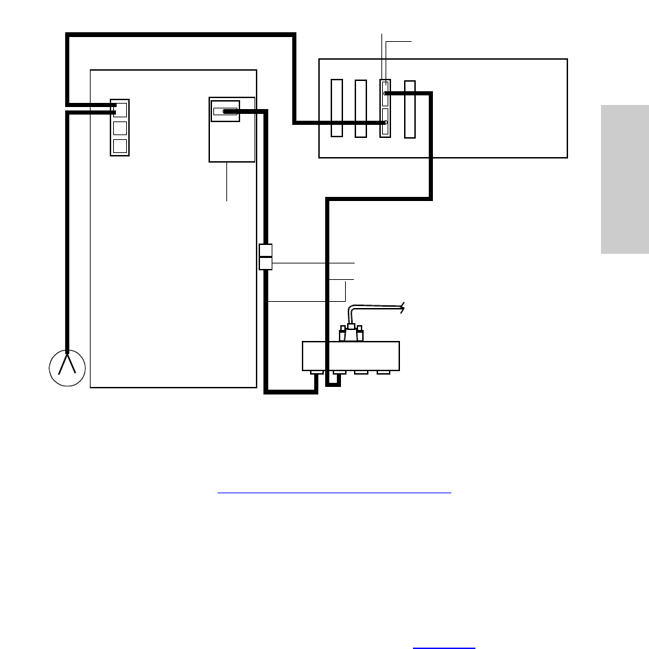
Connecting and Configuring GC Hardware 16
2
systems can be supported because each GC and each controller occupies its own
I/O distribution box port.
Figure 2-1 Connecting a 5890 GC and 7673 Controller to a busLAC/E Card
2. Follow the instructions in “Configuring the 5890 GC” on page 18 to configure the
5890 GC.
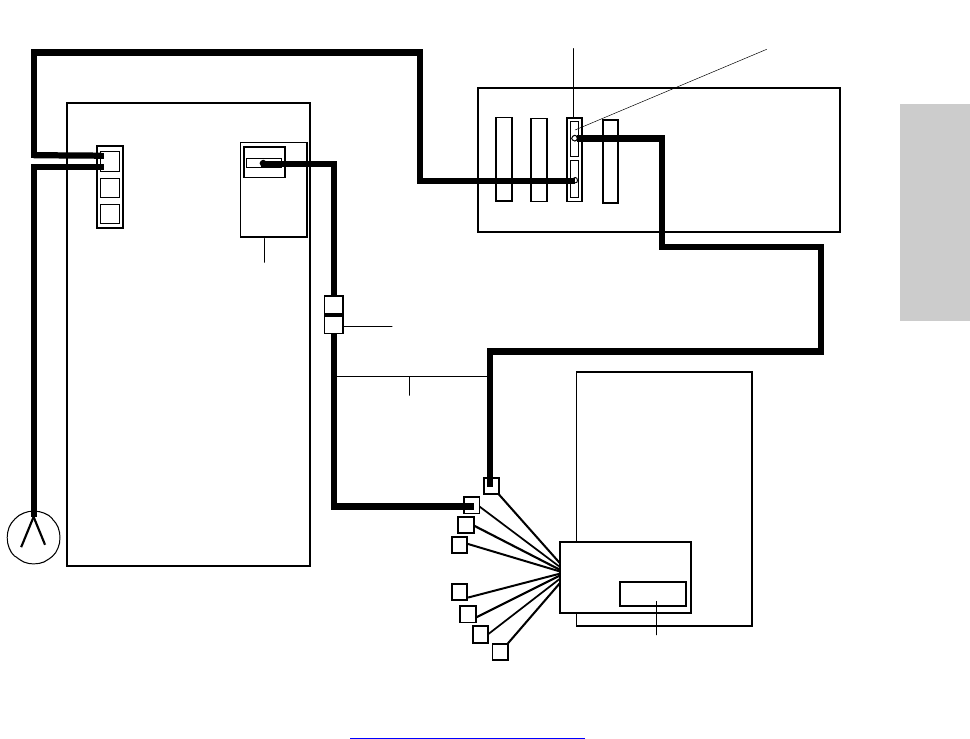
2.1.2 5890 GC, 7673 Controller, and 8-Port Serial Card
You can also connect a GC system consisting of a 5890 GC and 7673 Controller through
an 8-port serial interface card. To connect the 5890 GC and 7673 Controller to the
Empower system:
1. Using RS-232 cables, connect each GC device (5890 and 7673) to separate serial
ports on the cables extending from the 8-port serial card (Figure 2-2). Each serial
card cable is labeled with the corresponding port (1 – 8).
To busLAC/ E Ca rd
Remote
Sig 2
Sig1
I/O Distribution Box
7673
Autosampler
Controller
Note: Do not allow these leads to
directly contact each other.
COMM
Remote Cable (WAT200431)
Adapter (WAT011845)
25-Pin MMJ Adapter (WAT011845)
RS-232 Cable (Agilent
19242-60500)
Cables (WAT011964)
RS-232
Interface
Board
(Agilent
19242-
60030)
5890 GC
Motherboard
(Requires a Jumper
on P15)
RS-232 Board
(Agilent 18594-60080)
Digital Output Configuration 17
2
2. When the 5890 and 7673 are controlled through the 8-port serial card, they are
referred to as 5890S and 7673S, respectively. Install the 8-port serial card starting at
COM address 3 on the computer, so physical port 1 on the serial card gives a
Empower instrument address of 3, port 2 gives 4, and so on.
Figure 2-2 Connecting a 5890 GC and 7673 Controller to the Serial Card
3. Follow the instructions in “Configuring the 5890 GC” to configure the 5890 GC.
Remote
Sig 2
Sig1
7673
Autosampler
Controller
Note: Do not allow these leads to
directly contact each other.
COMM
Remote Cable (WAT200431)
25-Pin RJ45 Adapter (668000141)
RS-232
Cable
(Agilent
19242-
60500)
RJ45 Cables
(WAT280130)
RS-232
Interface
Board
(Agilent
19242-
60030)
5890 GC
Motherboard
(Requires a Jumper
on P15)
RS-232 Board
(Agilent 18594-60080)
8-Port Serial Card
Empower Personal
Workstation
Or
LAC/E32
Acquisition
Server
25-Pin RJ45 Adapter
(668000141)

Connecting and Configuring GC Hardware 18
2
Configuring the 5890 GC
When you have conneceted the 5890 GC to your Empower system, you must configure
the instrument.
1. Power down the 5890 GC and unplug the power cord from the power source.
2. Locate the 5890 motherboard.
3. Enable the emulation mode by placing a jumper (part number WAT072940 or
equilvalent) on the P15 pins on the 5890 motherboard.
Note: If the INET board was previously used, you must provide a jumper to place on
the P15 pins.
4. Power on the 5890 GC and ensure the “Emulation Mode OK” message appears on
the front panel.
5. Set the 5890 GC to Local mode by pressing the following on the 5890 keypad:
a. Press Clear.
b. Press the . key.
c. Press 3.
d. Press Enter and record the address setting (9, 17 or 9, 31) that appears on the
front panel.
e. Press Off. The display should change from Global to Local.
f. Press Clear.
6. If the address recorded in the previous step was X, 17 (where X is any integer) the
5890 GC is properly configured. Otherwise, set the address using this key sequence
on the 5890 GC keypad:
a. Press Clear.
b. Press the . key.
c. Press 3.
d. Press Enter.
e. Press 1.
f. Press 7.
g. Press Enter.
h. Press Clear.
Attention: To avoid possible electric shock, ensure that the 5890 is
powered down and the power cord is disconnected from the power source
before proceeding.
Digital Output Configuration 19
2
7. Repeat the above sequence to ensure that the changes were accepted. When you
press Enter, Local Address 9, 17 should appear on the display.
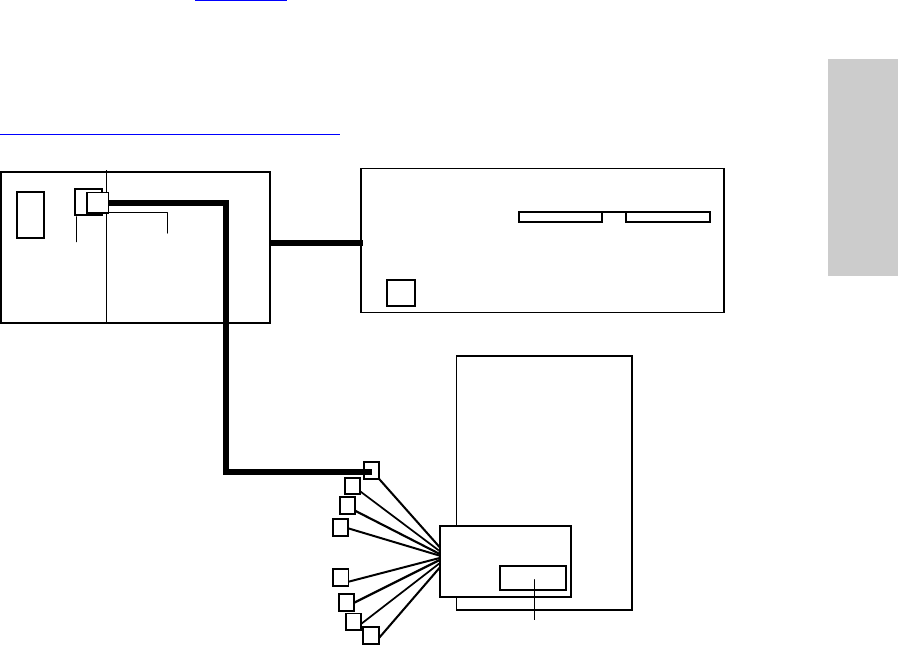
2.1.3 6890 GC, G1512A Controller, and 8-Port Serial Card
The Empower system can communicate with a 6890 GC and a G1512A Controller through
the 8-port serial card (Figure 2-3). Each GC system uses one serial port to both send and
receive control data.
To connect the 6890 GC to the Empower system, use the RJ45 cable from the 8-port
serial card in the LAC/E32 Acquisition Server or the Empower Personal workstation to
connect to the modem port (9-pin) at the back of the 6890 GC. Follow the instructions in
“Configuring the 6890 GC” on page 20 to configure the 6890 GC.
Figure 2-3 Connecting a 6890 GC and G1512A Controller to the Serial Card
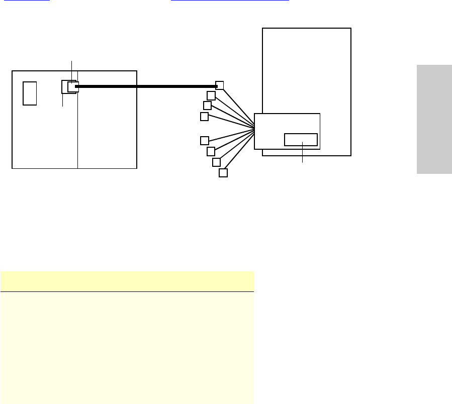
2.1.4 6890 Plus GC or 6890N GC and 8-Port Serial Card
The Empower system can communicate with a 6890 Plus GC or a 6890N GC through an
8-port serial card. Each GC system uses one serial port to both send and receive control
data.
G1512A
Autosampler
Controller
RJ45 Cable
(WAT280130)
6890 GC
8-Port Serial Card
Empower Personal
Workstation
Or
LAC/E32
Acquisition
Server
DIP Switches
11000000 _ 00001010
RJ45 9-Pin
Adapter
(WAT280128)
Modem
Connecting and Configuring GC Hardware 20
2
To connect the 6890 Plus GC or the 6890N GC to the Empower system, use the RJ45
cable from the 8-port serial card in the LAC/E32 Acquisition Server or the Empower
Personal workstation to connect to the modem port (9-pin) at the back of the 6890 GC
(Figure 2-4). Follow the instructions in “Configuring the 6890 GC” to configure the 6890
GC.
Figure 2-4 Connecting a 6890 Plus GC or 6890N GC to the Serial Card
Configuring the 6890 GC
To complete the 6890 setup, ensure the parameters in the 6890 Communications menu
are set as follows:
2.1.5 Additional 6890 Configuration
When you have connected the 6890 GC to your Empower system, you must configure the
instrument.
Parameter Setting
HPIB 0
Baud Rate 19200
Parity None
Handshake None
Data Bits 8
Stop Bits 1
End of Command Carriage return (Enter)
RJ45 Cable
(WAT280130)
6890 Plus or 6890N GC 8-Port Serial Card
Empower Personal
Workstation
Or
LAC/E32
Acquisition
Server
RJ45 9-Pin
Adapter
(WAT280128)
Modem

Analog Output Configuration 21
2
Configuring a GC Column
For a 6890 GC with more than one inlet or detector, a GC column can be installed by
connecting it to either the front or back inlet and the front or back detector. After installing a
GC column, specify the location of the inlet and detector to which the column is
connected. Using the front panel of the 6890 GC, enter this key sequence for column 1:
1. On the 6890 front panel, press Config.
2. Press the arrow key until the Column 1 selection is highlighted, then press Enter.
3. Press the arrow key until the Detector selection is highlighted, then press Enter.
4. Ensure that the detector settings are correct. If not, press Front or Back to specify
the appropriate location.
5. Press Enter.
Follow the same procedure to configure column 2.
Enabling Auto Prep Run
Auto Prep Run must be enabled for the 6890 GC to run under software control. To enable
the Auto Prep Run feature:
1. On the 6890 front panel, press Config.
2. Press the arrow key until the Instrument selection is highlighted, then press Enter.
The panel displays the instrument serial number on line 1 and the Auto Prep Run
parameter on line 2.
3. Ensure that the Auto Prep Run parameter is on. If not, press On.
4. Press Enter.
2.2 Analog Output Configuration
You can use the busSAT/IN Module to convert analog output from the GC detector to
digital data for processing by the Empower system. The busSAT/IN Module can reside on
the busLAC/E or an 8-port serial card. Figure 2-5 shows a busLAC/E 5890 set up for
control through Empower software (digital data) as well as collection of the GC analog
data.
The busSAT/IN Module, when used, occupies an additional (third) port on the I/O
distribution box. In this configuration, each Empower Personal workstation can support
one GC system. As an example, this section describes the 5890/7673 with a SAT/IN
through a busLAC/E.
Note: A SAT/IN can also be used to collect analog data from a 5890 GC or a 6890 GC
configured on an 8-port serial card.
Connecting and Configuring GC Hardware 22
2
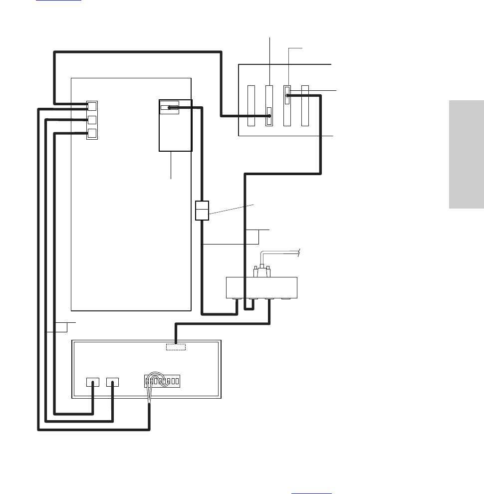
Figure 2-5 shows the cable connections for a 5890 GC and a 7673 Controller with analog
data acquisition through a busSAT/IN Module.
Figure 2-5 Connecting a 5890 GC, 7673 Controller, and busSAT/IN to a busLAC/E Card
Connect inject start trigger cables and analog output cables as follows:
•Connect the inject start trigger cables as indicated in Table 2-1. Both the GC and the
busSAT/IN Module require an inject start signal. The controller provides the inject
start trigger signal over the remote cable. The GC trigger cable connects to the
injector input terminals on the busSAT/IN Module.
HP 5890 GC
HP 7673 Autosampler Controller
Remote
Sig 2
Sig 1
busSAT/IN Module
I/O Distribution Box
to busLAC/E Card
AUX COMM
Analog Cables
(WAT200432)
Remote Cable (WAT200431)
BCD Board (Agilent 18594-60040)
Adapter
(WAT011845)
25-Pin MMJ Adapter (WAT011845)
RS-232 Cable (Agilent
19242-60500)
Cable (WAT011964)
RS-232
Interface
Board
(Agilent
19242-
60030)
5890 GC
Motherboard
(Requires a Jumper
on P15)
busLAC/E
Remote Cable (WAT200431)
RS-232 Board
(Agilent 18594-60080)
Alternative Setup for a 5890 GC 23
2
•If you are using the analog data output of the GC, connect the analog cables between
the GC and the busSAT/IN Module as specified in Table 2-1.
Note: The jumper wires shown on the busSAT/IN Module events connector block are
required to allow data collection on both analog channels using one trigger input (see
Figure 2-5). Connect the black wire on the trigger cable to the positive (+) terminal on the
busSAT/IN Module, and connect the red wire to the negative (–) terminal on the busSAT/IN
Module.
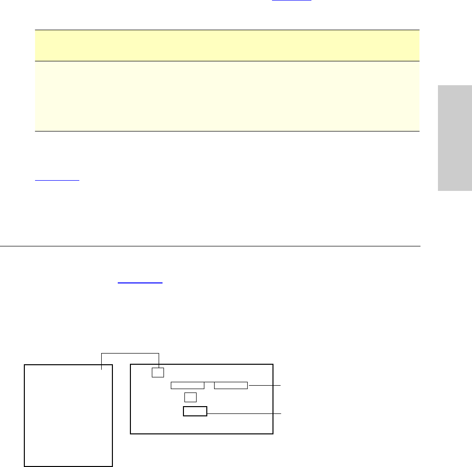
2.3 Alternative Setup for a 5890 GC
To interface a 5890 GC and a G1512A Controller to the Empower system, connect the
cables as shown in Figure 2-6. This configuration allows the G1512A Controller to emulate
a 7673 Controller.
Note: This configuration requires the use of an 8-port serial card.
Figure 2-6 Connecting a 5890 GC and G1512A Controller
Table 2-1 Analog Data Output Connections
busSAT/IN Module
Connection 5890 GC 7673 Controller
CHAN 1 and COM (–)Signal 1 N/A
CHAN 2 and COM (–)Signal 2 (if optional board is
installed) N/A
EVENTS CH 1 IN (trigger
signal) REMOTE Y-cable from REMOTE TTL
board
5890 GC
Host Comm RS-232 (9-Pin)
Connect with Adapter
(WAT280128) to 8-Port Serial Card
APG Remote Port Remote Cable
(Agilent G1512-60530)
DIP Switches in 7673 Mode
00111101 _ 11111111
G1512A Controller

Creating an Instrument Method 24
3
Chapter 3
Developing Methods Using
Wizards
This chapter guides you through acquiring and processing data from a single injection
using the Run Samples and wizard features of Empower software.
Before creating a GC instrument method, you must:
•Set up your GC hardware.
•Load Empower on your computer.
•Connect your GC instruments to the Empower data system.
•Create a Empower chromatographic system that includes your GC instruments.
Note: You should be in Run Samples before you begin the tutorial in this chapter. If you
are not, see Section 3.2, Accessing Run Samples, in the Empower Software Getting
Started Guide for additional instructions.
3.1 Creating an Instrument Method
The instrument method instructs Empower software on how to control your
chromatographic instrumentation. This method contains parameters such as flow rate,
solvent composition, and detector type.
Note: This section is intended to provide an overview of the Instrument Method Editor and
tips for creating a GC instrument method. It does not include specific instructions for each
parameter displayed in the Instrument Method Editor. For specific instructions and field
descriptions, see the Empower Help.
Developing Methods Using Wizards 25
3
To create an instrument method:
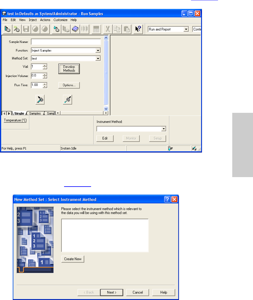
1. In Run Samples with the Single tab displayed, click Develop Methods (Figure 3-1).
Figure 3-1 Run Samples, Single Tab, Run Only Mode
This activates the New Method Set wizard. The New Method Set : Select Instrument
Method page appears (Figure 3-2).
Figure 3-2 New Method Set : Select Instrument Method Page
Creating an Instrument Method 26
3
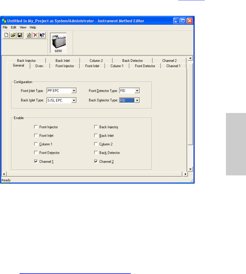
2. Click Create New to create an instrument method. The Instrument Method Editor
window appears. Click the General tab, if it is not already displayed (Figure 3-3,
shown for the 6890 GC).
Figure 3-3 Instrument Method Editor, 6890, General Tab
The Instrument Method Editor is one of the few windows that contains property tabs
(as opposed to window tabs). These tabs reflect parameter settings for the
instrument you select in the Instruments and Active Channels tree pane and differ
depending upon the instrument.
Note: The following procedures assume that the chromatographic system you are
using for this tutorial includes a 6890 GC. If not, the property tabs that appear will
differ from those shown here. Enter the parameter values appropriate to your
instrumentation.
3. Go to Section 3.1.1, Setting Instrument Properties to set the instrument properties.

Developing Methods Using Wizards 27
3
3.1.1 Setting Instrument Properties
1. The Instrument Method Editor lists the instruments in your selected Empower
chromatographic system (Figure 3-3). Click the icon for GC (the 6890 in Figure 3-3),
then click the General tab. The General tab appears.
Note these considerations in the General tab:
•The inlets and detectors displayed are scanned from your GC and are
informational; do not change them.
•When creating an instrument method for dual tower operation, you must enable
both injectors/inlets (enable injectors A and B in the HP 7673S property tabs),
columns, detectors, and channels.
•Enable the front and/or back detector before you specify detector parameters in
the corresponding detector tab. If you specify detector parameters in the detector
tab without first enabling the detector, the parameter settings do not take effect.
•You can simultaneously transmit digital data (RS-232 port on the 5890 GC or
6890 GC) and analog data (Signal 1 and Signal 2 terminals on the 5890 GC or
6890 GC) to an Empower Personal workstation. You need not enable the analog
outputs; they are always active. Analog outputs must be converted to digital
signals by an A/D converter [typically a busSAT/IN Module or busSAT/IN Module
(SAT/IN 2)] before they are transmitted to the Empower Personal workstation.
See Chapter 2 for information on connecting your 6890 GC to an Empower
Personal workstation through a busSAT/IN Module or busSAT/IN Module (SAT/IN
2).
•Set the sampling rate for GC data collected through the analog channels in the
busSAT/IN Module or the busSAT/IN Module (SAT/IN 2) property tabs, depending
on which module is connected to the GC.
Creating an Instrument Method 28
3
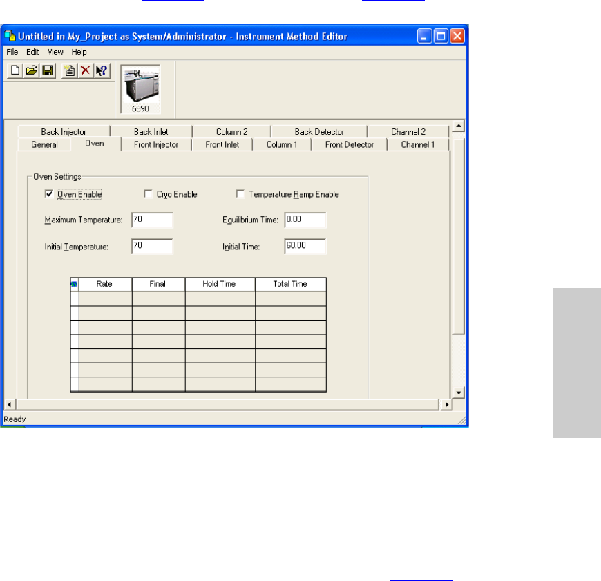
2. Click the Oven tab (Figure 3-4). The Oven tab appears (Figure 3-4).
Figure 3-4 Instrument Method Editor, 6890, Oven Tab
3. Enter the oven settings appropriate for your selected system. The run time is
derived from the oven time values. No data is acquired after the oven time expires.
Note: The Temperature Ramp Enable check box must be selected to enter ramp
values in the table.
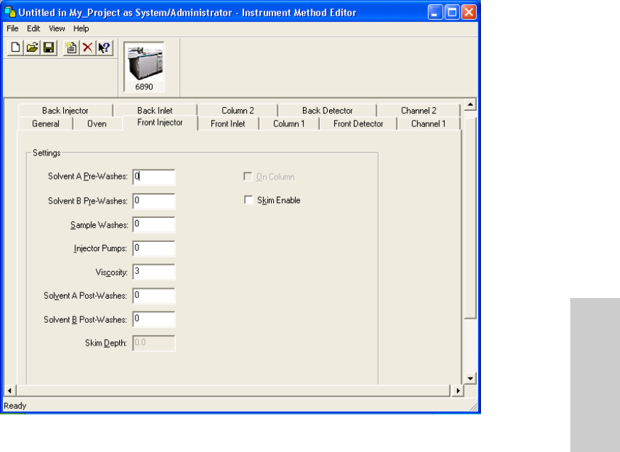
4. Click the Front Injector tab. The Front Injector tab appears (Figure 3-5).
Note: The Back Injector tab is similar. Only the Front Injector properties are
discussed here.
Developing Methods Using Wizards 29
3
Figure 3-5 Instrument Method Editor, 6890, Front Injector Tab
Note these considerations in the Injector tabs:
•The Skim Enable option is available only for the 6890 Plus GC and the 6890N
GC. It is not available for the 6890 GC.
•If your system includes a 6890 GC with these capabilities, you must control them
directly from the instrument:
Waste bottle location
Slow plunger
Pre- and post-dwell time
•If you are using a 7673-style injector tower with a 6890 series controller box, you
might not be able to use all of the advanced injector functions on this tab, such as
pre-washes or skim depth.
•If your 6890 Plus GC or 6890N GC has an installed on-column inlet, all injections
are made on-column.
Creating an Instrument Method 30
3
•If your 6890 GC does not have an installed on-column inlet, clear the On-column
check box to avoid damaging the column by excessive lowering of the needle.
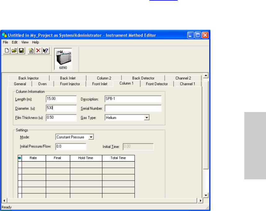
5. Click the Column 1 tab. The Column 1 tab appears (Figure 3-6).
Note: The Column 2 tab is similar. Only the Column 1 properties are discussed
here.
Figure 3-6 Instrument Method Editor, 6890, Column 1 Tab
The Column 1 tab specifies the column mode in which the carrier gas is to be
applied during a run. Select one column mode and complete the ramp parameters if
necessary.
Note: In the Ramp table, if a flow or pressure program ends before the analytical
run ends, the flow or pressure remains at the final value.
Note these considerations in the Column tabs:
•You must define the column dimensions.
•Configure the correct inlet with the correct detector.
Developing Methods Using Wizards 31
3
•If you are using a capillary column, ensure the make-up gas is on.
•Ensure that the inlets and detectors to be used are present in the instrument and
enabled in Empower software.
•If you are using packed columns, the column parameters should be undefined. To
do this, enter 0 for the column length or column diameter.
•Ensure the column configurations specify separate inlets. If you are only using
one column, the unused column must be configured for a different inlet, even if it
is undefined. Failure to do this can produce unusual flow calculations.
•It is possible, and sometimes appropriate, to configure both installed columns to
the same inlet.
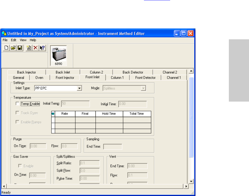
6. Click the Front Inlet tab. The Front Inlet tab appears (Figure 3-7).
Note: The Back Inlet tab is similar. Only the Front Inlet properties are discussed
here.
Figure 3-7 Instrument Method Editor, 6890, Front Inlet Tab

Creating an Instrument Method 32
3
7. The inlet type is automatically detected and should not be changed. Choose the
appropriate mode for the inlet.
Note: If the Split option is selected in the Inlet Type field, you can enter a value for
either the Split Ratio or the Split Flow, but not both. Empower software automatically
calculates the value not entered.
If the Splitless option is selected, the purge valve options become available. You can
enter values for the purge on time (how long after the injection was made) and the
flow desired.
The Gas Saver option reduces the flow of carrier gas into the inlet and out of the
split vent after an injection. The Gas Saver option does not alter column head
pressure or flow through the column.
Note these considerations in the Inlet tabs:
•To avoid an unstable inlet temperature, set the inlet Initial Temp parameter at least
6°C higher or lower than the Oven Initial Temperature.
•If an inlet temperature program ends before an oven temperature program ends, the
inlet temperature remains at the Final value until the oven program and run end.
•Configure your column before setting the Purge Flow parameter or the Split Ratio or
Split Flow parameter.
•If you are using the Gas Saver option, ensure the Gas Saver On Time value is greater
than the Purge On Time value.
•Set Gas Saver Flow at least 15 mL/min greater than the maximum column flow.
•Split Ratio and Split Flow parameters relate to each other and the column flow. Split
Ratio = Split Flow/Column Flow. When one parameter is specified, Empower
automatically calculates the second parameter.
Note: If you are using a split inlet and have selected Constant Pressure mode on
the Column tab, you cannot specify a Split Flow value. You can specify only the Split
Ratio value.
Developing Methods Using Wizards 33
3
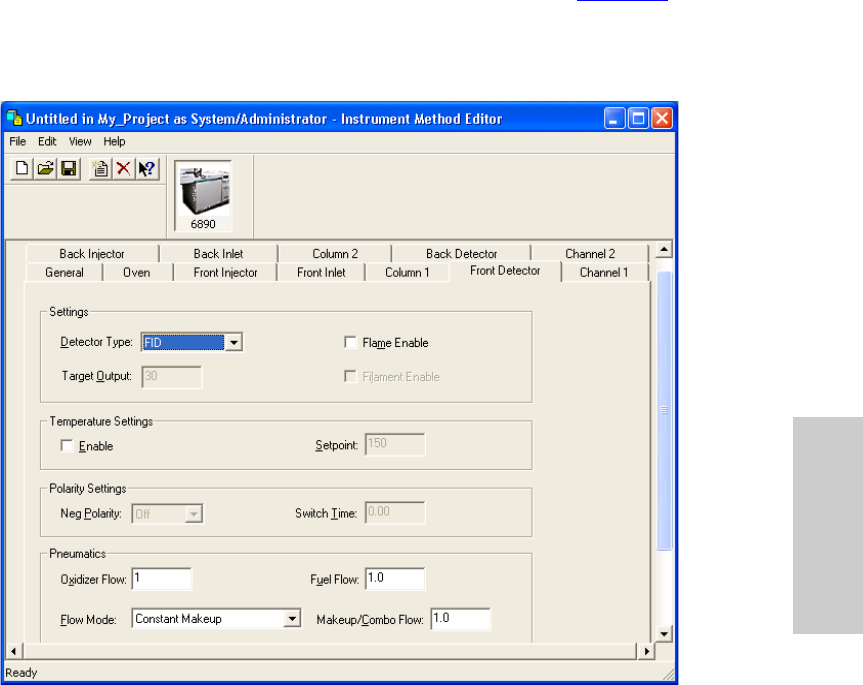
8. Click the Front Detector tab. The Front Detector tab appears (Figure 3-8).
Note: The Back Detector tab is similar. Only the Front Detector properties are
discussed here.
Figure 3-8 Instrument Method Editor, 6890, Front Detector Tab
9. The detector type is automatically detected and should not be changed. Select the
appropriate parameters for the detector.
Creating an Instrument Method 34
3
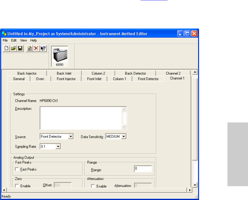
10. Click the Channel 1 tab. The Channel 1 tab appears (Figure 3-9).
Note: Only the Channel 1 properties are discussed here. The Channel 2 tab is
similar.
Figure 3-9 Instrument Method Editor, 6890, Channel 1 Tab
Note these considerations in the Channel 1 tab:
•If you are transmitting analog data through a busSAT/IN Module or busSAT/IN
Module (SAT/IN 2), you must define all Channel 2 tab parameters. If you enabled
the Ch 2 Enable parameter to transmit digital data through the RS-232 port, you
must define the Units and Source parameters.
You set the sampling rate for GC data collected through the analog channels in
the busSAT/IN Module or the busSAT/IN Module (SAT/IN 2) property tabs,
depending on which module is connected to the GC.
Developing Methods Using Wizards 35
3
•If your system is configured for dual tower operation, you must specify Front
Detector as the Source for Channel 1 (the front detector must be connected to
the front injector), and Back Detector as the Source for Channel 2 (the back
detector must be connected to the back injector).
•Select a Sampling Rate of 200 points per second for single-channel acquisition
only.
•To minimize error, set Range to the lowest possible value, making sure that the
peaks of interest do not exceed 1 V. For the analog output of the 6890 GC there
is an internal Range setting within the 6890 GC, but it does not affect the signal
collected by Empower.
•When choosing a data sensitivity level, remember that higher data sensitivity
provides better definition of small features in the chromatogram, but limits the
size of large features.
•Go to section Section 3.1.2, Saving the Instrument Method to save the
instrument method.
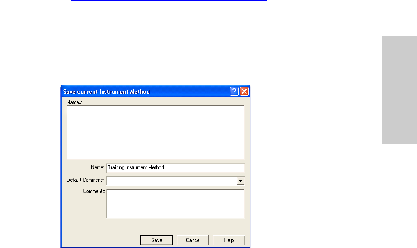
3.1.2 Saving the Instrument Method
1. Click the Save tool. The Save current Instrument Method dialog box appears
(Figure 3-10).
Figure 3-10 Save Current Instrument Method Dialog Box
2. Enter an instrument method name, then click Save. The Instrument Method Editor
reappears.
Creating an Instrument Method 36
3
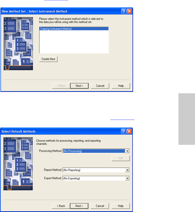
3. Close the Instrument Method Editor. The New Method Set : Select Instrument
Method page appears (Figure 3-11).
Figure 3-11 New Method Set : Select Instrument Method Page
4. Select the instrument method you created from the Instrument Method list, then
click Next. The Select Default Methods page appears (Figure 3-12).
Figure 3-12 New Method Set Wizard, Select Default Methods Page
Developing Methods Using Wizards 37
3
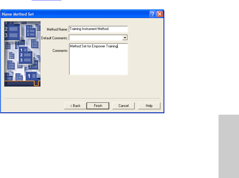
5. Accept the default settings (no methods), then click Next. The Name Method Set
page appears (Figure 3-13).
Figure 3-13 New Method Set Wizard, Name Method Set Page
6. Enter a name for the method set, add any comments describing the method set,
then click Finish to exit.
Note: The Method Name field cannot be blank, and the name cannot be the same
as an existing method set.
Creating an Instrument Method 38
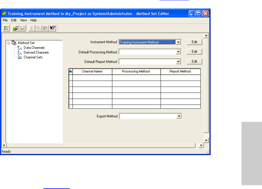
3
The Method Set Editor displays the method set entries (Figure 3-14).
Figure 3-14 Method Set Editor
7. Click the Close button. Run Samples reappears with the Single window tab
displayed (Figure 3-1).
3.1.3 Injection Volume in Run Samples
The injection volume displayed in Run Samples can be expressed as an actual volume or
as the number of plunger steps injected by the GC.
You can specify the syringe size and presence of the nanoliter adapter for the front and
back injectors. When you set these parameters, Empower software calculates the actual
injection volume. Otherwise, the injection volume shown in the Run Samples window is
expressed as a raw value of the number of plunger steps injected.
The actual injection volume for a given number of plunger steps can vary significantly
based on your injector configuration. We recommend specifying the injector parameters
for your system so that the actual injection volume is displayed in Run Samples. You can
set these parameters as defaults or as independant values for samples or single
injections.
Developing Methods Using Wizards 39
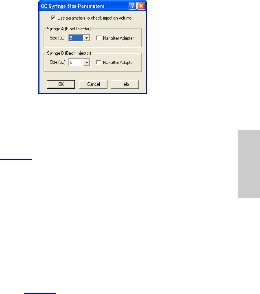
3
Figure 3-15 GC Syringe Size Parameters Window
To set default syringe size parameters:
1. In Run Samples, select Customize > Defaults. The Run Samples Defaults window
appears.
2. Click GC Syringe Info Define. The GC Syringe Size Parameters window appears
(Figure 3-15).
3. Select Use parameters to check injection volume. The syringe fields are
activated.
4. For each syringe (front and back injector):
•Select the syringe size from the Size list.
•If the injector is equipped with a nanoliter adapter, select the Nanoliter Adapter
check box.
5. Click OK to close the GC Syringe Size Parameters window.
6. Click OK to close the Run Samples Defaults window.
You can also set syringe size parameters for a sample set or for a single injection. The
sample set and single injection syringe parameters are independant.
To set the syringe size parameters for a sample set or single injection:
1. In Run Samples, click the appropriate tab (Single or Samples).
2. Select Edit > GC Sample Set Info. The GC Syringe Size Parameters window
appears (Figure 3-15).
3. Select Use parameters to check injection volume. The syringe fields are
activated.
4. For each syringe (front and back injector):

Running the GC in Dual Tower Mode 40
3
•Select the syringe size from the Size list.
•If the injector is equipped with a nanoliter adapter, select the Nanoliter Adapter
check box.
5. Click OK.
3.1.4 Stop Flow Button (5890 and 6890 GCs)
The Stop Flow button in the Run Samples window does not stop the gas flow in the 5890
or 6890 GC. For details on stopping gas flow, see the applicable Agilent documentation.
3.1.5 Vial Capacity and Open Access (6890 GC)
Open Access automatically detects the maximum vial capacity number of the autosampler
for an Agilent 6890 GC (100) and uses this value to determine when Open Access must
restart the Starting Vial number at 1, as different users submit more samples than the
autosampler can handle. Management of the open well position is critical. You must
determine when samples have run and either remove them from the carousel or free up
well positions.
3.2 Running the GC in Dual Tower Mode
3.2.1 Using Dual Tower Mode
If your Empower system is connected to a 5890/7673 or 6890 GC in a dual tower
configuration, each row in the vial column specifies both the carousel vial number and the
tower location (front or back) from which the injection is to be made. For example, an
injection from vial number 2 on the front tower appears as F:2 in the vial column row; an
injection from vial number 6 on the back tower appears as B:6 in the vial column row.
6890 GC
When sample sets are acquired using a dual tower sample set method, the Empower
database stores two channel, two injection, and two vial records for each GC injection.
One channel, injection, and vial are stored for the front tower; a second channel, injection,
and vial are stored for the back tower.
5890 GC
For dual tower operation, the 5890 GC must be connected to an Empower Personal
workstation by a serial card, and must be configured as a 5890S GC. Dual tower operation
is not supported if the 5890 GC is connected to an Empower Personal workstation by a
busLAC/E interface card.

Developing Methods Using Wizards 41
3
3.2.2 Creating a Dual Tower Sample Set Method (5890 GC)
To run control samples (which require that Inject Controls functions be added to your
sample set method), manually add the desired Inject Controls functions after you finish the
Sample Set Method wizard.
3.2.3 Creating Dual Tower Sample Set Methods for Simultaneous
Sample Injections (5890 and 6890 GCs)
When creating a dual tower sample set method for a 6890 GC or a 5890/7673, all of the
following criteria must be met to simultaneously inject samples from a pair of rows in the
sample set method (one row specified from the front tower, and a second row specified
from the back tower).
For two rows in the Samples table to be simultaneously injected, they must specify:
•The same method set
•Different vial numbers
•An F: vial designator (for the front tower) and a B: vial designator (for the back tower)
•The same # of Injections (for the two rows only; you do not need to specify the same
total number of front and back injections for the sample set method)
•The same Run Time
•The same Data Start time
•The same Next Inject Delay time
3.3 Making Manual Injections
You can use the Empower system to make manual injections with your 6890 GC or 5890
GC.
1. When injecting manually, leave the vial field in Run Samples set to its default value.
2. If you are making a manual injection on a 5890 GC, disconnect the remote cable
from its port on the GC.
3. To monitor the baseline and equilibrate, click Monitor in the instrument control pane
to activate baseline monitoring and equilibrate the system.
Note: If you are making a manual injection using a 5890 GC, you must click Start
after you click Monitor.
The steps for making manual injections are identical for 6890, 6890 Plus, and 6890N GC
systems.
1. Remove the autoinjector tower.

Making Manual Injections 42
3
2. If the Not Ready light on the 6890 front panel is lit, adjust the gas flow and
temperature to put the instrument in a ready state. If the light remains lit, press the
Status key for further information on the system status.
3. In Empower software, close the Run Samples window.
4. Access Configuration Manager and take the system offline.
5. In the Acquisition Server Properties window, click the Instruments tab and click
Scan for Instruments.
Note: Complete this step even if there is no busLAC/E installed in the acquisition
server. Scanning the acquisition server captures the configuration of attached
instruments.
If your connection to the 6890 GC and configuration of the Equinox serial board are
correct, YES appears in the OK? field for instrument type 6890 when you click Scan
for Instruments in Acquisition Server Properties.
6. In the Acquisition Server Properties window, scroll to the right to see the instrument
firmware revision and other configurations such as inlets, oven, tray, and detectors.
Do not proceed until the OK? field for the 6890 says YES and the configuration
reported in the Details field matches the actual 6890 configuration. The system is
now ready to accept a manual injection.
7. Click OK to close the Acquisition Server Properties window.
8. Bring the system online.
9. Open the Run Samples window and enter your sample information in the Single
Injection window.
10. In Run Samples, click Inject. The 6890 front panel displays the “Ready for Injection”
message, then the “Waiting for Injection” message.
11. When the 6890 front panel displays the “Waiting for Injection” message, make the
injection at the 6890 system and press Start on the 6890 front panel.

43
4
Chapter 4
Troubleshooting the GC
System
This chapter provides basic troubleshooting information for your GC system. It focuses on
problems between Empower and your GC instruments. See the appropriate operator’s
guides for information about error messages, diagnostics, and troubleshooting other
instruments in your GC system.
Before You Begin
If you work in a validated environment, consult your standard operating procedures before
troubleshooting the system.
Rely on your instrument service provider to make internal adjustments to your GC
instruments.
Contacting Waters
Most problems are relatively easy to correct. If you are unable to correct a problem or a
failed condition, call Waters Technical Service at 800 252-4752, U.S. and Canadian
customers only. Other customers, call your local Waters subsidiary or your local Waters
Technical Service Representative, or call Waters corporate headquarters in Milford,
Massachusetts (U.S.).
To expedite your request for service or technical support, have the following information
available when you call Waters Technical Service:
•System configuration (front inlet, back inlet, front detector, back detector, injectors)
•Detector type
•Problem symptom(s)
STOP
Attention: To avoid problems caused by power surges, line spikes, and/or transient
energy fluctuations, use a power supply that is properly grounded and free from power
supply variations.
Caution: Use caution when touching the GC instruments. They could contain hot
surfaces.

Troubleshooting the GC System 44
4
•Method parameters
•Column type
•Operating pressure
•Carrier gas
You might also be asked to provide the firmware versions of your GC instruments.
To check the firmware version on the 5890, 6890, 6890 Plus or the 6890N GC, power on
the instrument. The firmware version is displayed on the LCD.
To check the firmware version on the injector towers and controllers:
1. On the instrument keypad, press Options.
2. Scroll down to Instrument Status and press Enter.
3. Scroll down. The instruments are shown as follows:
•Smplr:model&firmware
•F inj:model&firmware
•B inj:model&firmware
4.1 Gas System Troubleshooting
A poorly functioning gas system can cause problems in your Empower GC system. Before
proceeding to Section 4.2, check these gas system components.
Regulators
To check the regulators, set the instrument for a constant pressure of 8 psi. Then use the
manifold pressure (on the regulator, not the tank) to adjust the pressure to a constant flow
at 8 psi.
Tanks
Ensure there is adequate pressure in the tanks. The lower the pressure in the tank, the
more erratic the pressure and flow readings. As a rule, the tank should be replaced when
its pressure falls below 100 psi. Follow your standard operating procedure for replacing the
tank.
If you are using a split/splitless inlet, consider using the 6890 Gas Saver option, which
reduces carrier gas consumption and allows you to reach pressures that may otherwise be
difficult to achieve.

GC-Specific Troubleshooting 45
4
Clogs
Visually inspect the inlet liner and septum and the column for clogs. If necessary, have the
person responsible for instrument maintenance remove and reinstall the column. Capillary
columns occasionally become clogged with broken pieces. If this is the case, cut off the
clogged portion of the column and reinstall it.
Fittings
Check the entire copper assembly to ensure all connections are tight. Do not overtighten
the copper connections. If you have to adjust the fittings, tighten them no more than a
quarter turn past tight.
Determine the age and condition of the gas scrubbers and the Teflon® tape inside the
fittings. If there is no Teflon tape inside the fittings, remake all connections using Teflon
tape.
4.2 GC-Specific Troubleshooting
Ta b l e 4 - 1 contains troubleshooting information for Empower controlled GC systems.
Table 4-1 GC Troubleshooting
Symptom Possible Cause Corrective Action
Instrument status – “No”System rescanned before
it was taken offline. Reboot the instrument and the
Empower system computer. Take the
system offline, then rescan.
Columns or instruments
reconfigured without
reconfiguring the
Empower system.
Take the system offline, then rescan.
Instrument fail – Inlet not
enabled Two colums configured for
same inlet. Ensure the column configurations
specify separate inlets. For single
column configurations, the unused
column must be configured for an inlet
different than that of the used column.
Instrument fail – Bad
Method Instrument method/GC
configuration mismatch Check your Empower instrument
method and the instrument configura-
tion to ensure they match.

Troubleshooting the GC System 46
4
Channel collects wrong
data. Cross-configured systems
Note: You can only collect
two channels of data from
one injection if your
system is configured for a
single tower or for a single
injection using dual
towers.
Ensure channel 1 is configured with
inlet 1 and channel 2 is configured with
inlet 2.
Communication failure. Incorrect adapter address. Ensure the Equinox card adapter is
configured so that its first port is COM
3.
Note: Close Run Samples and take
the system offline before you rescan
the busLAC/E or reconfigure the ports
used for the system.
Instrument status –
Always “No”Incorrect communications
parameters. Reset communication parameters.
Incorrect 5890 network
configuration parameters. Reset network configuration
parameters.
Incorrect firmware/driver
versions. Check firmware and driver versions
and reload if necessary.
Note: Reloading firmware clears the
instrument memory. You must reenter
the instrument communication
parameters after loading the firmware.
Instrument status –
Always “No” (continued)Incorrect connectors used
to connect the Equinox
card to the GC.
Ensure the correct connectors (RJ45 -
DB9) are used. See the connection
diagrams in Chapter 2 for connector
uses and part numbers.
Instrument fail – Injector Injector errors. Check the injector needle.
Check the fault lights.
Reboot the instrument and the
Empower system computer.
Data buffer overflow Serial communication
limitation. Ensure that no more than four GCs are
connected to one computer and that
data is not sampled at more than 200
points per second for any one
instrument.
Table 4-1 GC Troubleshooting (Continued)
Symptom Possible Cause Corrective Action

GC-Specific Troubleshooting 47
4
Instrument failure when
setting up the 6890 Plus Incorrect column
dimensions. Ensure the correct column dimensions
are entered in the system.
Oven temperature not at
specified set point. Ensure the oven temperature has
reached the set point. If the error
persists, test the conditions on the
instrument before running from
Empower.
Inlet or detector not at
specified temperature. Ensure the inlets and detectors have
reached the set temperature. If the
error persists, test the conditions on
the instrument before running from
Empower.
Incorrect instrument
method configuration. Check the instrument method. If you
are using a dual tower method, ensure
both injectors are configured properly.
If you are using a single tower method,
uncheck the unused inlet and injector.
Unused detector enabled. If you are using only one detector,
ensure the unused detector is not
enabled.
Instrument failure when
setting up the 6890 Plus
(continued)
Equinox card configured
incorrectly. Check the Devices applet in Control
Panel. The Equinox card should be
listed as Started, and the startup
option should be set to Automatic.
If the card is not listed, the driver was
not loaded.
If the card is listed but fails to start,
start it manually by clicking Start, then
set the startup parameter to
Automatic.
Incorrect cable connec-
tion (6890 with a G1512A
injector controller).
Check the cables that connect the
controller to the respective front and
back injectors to ensure they are
connected correctly.
6890 Plus does not start
until the Prep Run button
is pressed.
The Auto Prep Run feature
is disabled (off). See the instructions on the front panel
and the HP configuration manuals on
how to enable the Auto Prep Run
feature. This starts the 6890 without
pressing the Prep Run button.
Table 4-1 GC Troubleshooting (Continued)
Symptom Possible Cause Corrective Action

Troubleshooting the GC System 48
4
6890 does not start. Remote cable connected
to 6890 (other than from
the G1512).
Disconnect the remote cable to the
6890 GC (other than from the G1512).
Specified parameters
cannot be reached by the
instrument.
Enter parameters in the instrument
front panel to verify that they work.
Table 4-1 GC Troubleshooting (Continued)
Symptom Possible Cause Corrective Action

Index 49
I
N
D
E
X
Numerics
5890 GC
connecting 15, 16
control 12
firmware 44
RS-232 board 12
5890 GC instrument 12, 15, 16, 22, 23
5890S GC instrument 17
6890 GC
connecting 19
control 13
firmware 44
6890 GC instrument 12, 19
6890 Plus GC
connecting 19
instrument failures 47
7673 Controller 12, 15, 16, 22
7673S Controller 17
8-port serial card 12, 16, 19, 20, 21, 23
A
Acquisition 42
Agilent firmware 13
Analog output
configuration 21
connections 23
Auto Prep Run button 47
B
busLAC/E
card 15
scanning 42
busSAT/IN Module 12, 22
analog output 21
C
Cables
GC instrument 19, 20
RJ45 19, 20
RS-232 15, 16
Capillary columns 31, 45
Cards
8-port serial 12, 16, 19, 20, 21
busLAC/E 15
RS-232 10, 15
Channel properties, setting 34
Checking firmware version 44
Clogs, troubleshooting 45
Column properties, setting 30
Communication failures 46
Communication parameters 20
Configurations
analog output 21
digital output 15
Connecting hardware 15
Connections
gas system 45
GC instruments 19, 20
hardware 15
Contact closure signal 22
Contacting Waters 43
Controller firmware 44
Conventions, documentation 10
D
Data
overview 15
simultaneous transmission of analog and
digital 27
Default methods, selecting 36
Detector parameter settings 28
Detector properties, setting 33
Index

Index 50
I
I
N
D
E
X
Digital output configuration 15
Dip switch settings 19, 23
Documentation
conventions 10
related 7
Dual tower operation
Channel tab considerations 35
General tab considerations 27
overview 40
Dual tower sample set method 41
E
Empower
documentation 12
GC instrument control 12, 15
instrument method 24, 35
F
Firmware version 13, 44, 46
Fittings, troubleshooting 45
Flow, stopping 40
G
G1512A Controller 12, 19, 23
Gas flow, stopping 40
Gas pressure 44
Gas Saver option 32, 44
Gas system troubleshooting 44
GC data overview 15
GC instrument
connections 19, 20
control 12, 15
General properties, setting 27
General tab 26
H
Hardware connections 15
Headspace analyzer 13
I
I/O distribution box 12, 15
Inject start signal 22
Injections
manual 41
simultaneous 41
Injector properties, setting 28
Injector tower firmware 44
Injector, headspace analyzer as 13
Inlet properties, setting 31
Instrument control 12, 15
Instrument method
creating 25
saving 35
Instrument Method Editor
Channel 1 tab 31
Degas tab 28
detector settings 28
General tab 27
Instruments and Active Channels tree
pane 26
overview 26
parameter settings 35
J
Jumper wires 23
Jumper, on 5890 motherboard 16, 17

Index 51
I
I
N
D
E
X
M
Manual injections 41
Methods
instrument 25
name 37
selecting default 36
N
New Method Set wizard 25
O
On-column parameter 30
Open Access 40
Output configurations
analog 21
digital 15
Oven properties, setting 28
Overview
of dual tower operation 40
of GC data 15
of Instrument Method Editor 26
P
Packed columns 31
Post-dwell time, 6890 29
Power supply 43
Pre-dwell time, 6890 29
Pressure ramp 30
Pressure, gas 44
Properties
channel 34
column 30
detector 33
general 27
injector 28
inlet 31
oven 28
R
Ramp table
Column tab 30
Inlet tab 32
Oven tab 28
Range, setting 35
Regulators, troubleshooting 44
Related documentation 7
RJ45 cable 19, 20
RS-232 card 10, 15
Run Samples 42
developing methods from 24, 25
vial field in 41
S
Sample set method, dual tower 41
Sampling rate, setting 27, 34, 35
Saving instrument method 35
Scanning busLAC/E 42
Selecting default methods 36
Serial cards
8-port 15, 16, 19, 23
RS-232 10, 12, 15
Setting
channel properties 34
column properties 30
detector properties 33
general properties 27
injector properties 28
inlet properties 31
oven properties 28
range 35
sampling rate 27, 35
Settings
dip switch 19, 23
Instrument Method Editor parameter 35
Simultaneous injections 41
Simultaneous transmission of analog and
digital data 27
Skim enable option, 6890 29

Index 52
I
I
N
D
E
X
Slow plunger, 6890 29
Split option 32
Splitless option 32
Stop Flow button 40
T
Tanks, troubleshooting 44
Temperature ramp
Inlet tab 32
oven 28
Trigger signal 22
Troubleshooting
gas system 44
GC-specific 45
V
Vial capacity 40
Vial field, in Run Samples 41
W
Waste bottle location, 6890 29
Waters Technical Service, contacting 43
Wizards,New Method Set 25
