71T0251_TDC_Quick_Sheet_Apr93 71T0251 TDC Quick Sheet Apr93
71T0251_TDC_Quick_Sheet_Apr93 71T0251_TDC_Quick_Sheet_Apr93
71T0251_TDC_Quick_Sheet_Apr93 The Eye | File Listing
User Manual: 71T0251_TDC_Quick_Sheet_Apr93
Open the PDF directly: View PDF ![]() .
.
Page Count: 2

TANDBERG
DATA
MODEL:
TDC-36101l0 TDC-3630/40 TDC-3650/60 TDC-3810 TDC-4110 TDC-4110
MAX.
CAPACITY:
100MB 200MB 250MB 525MB 1.2GB
2.
5GB
INTERFACE:
QIC-02 or
SCSI-lor
2 QIC-02 or
SCSI·
I or 2 QIC.Q2 or SCSI· I or 2
SCSI-lor2
SCSI-lor
2 SCSI· I or 2
Depending on part no. Depending
on
part no. Depending
on
part no Depending
on
part no.
Depending
on part
no.
Dependina
on
part
no.
BUFFER
SIZE: 64KB wlParity 64KB wlParity 64KB wlParity 256KB wlParity 256KB wlParity 256KB wlParity
DIMENSIONS:
44x
150x218mrn
44x
150x218mrn
44 x 150 x 218mrn
44x
150 x 218mrn
44x
150x218mm
44x
150x218mm
1.732 x 5.905 x 8.583in 1.732 x 5.905 x 8.583in 1.732 x 5.905 x 8.583in 1.732 x 5.905 x 8.583in 1.732 x 5.905 x 8.583in 1.732 x 5.905 x 8.583in
MOUNTING
SCREWS:
3 x IOmm
3x
IOmm
3x
IOmm
3x
IOmm
3x
IOmm 3 x IOmm
WEIGHT:
LI
kg/2.4Ibs
LI
kg/2.4Ibs
LI
kg/2.4lbs
LI
kg/2.4Ibs
1.1
kaI2.4lbs
1.1
kg/2.4Ibs
POWER
DISSIPATION
(TYPICAL):
15WRunning 15WRunning
15WRunning 15WRunning
15WRunnina
15WRunning
2.25W Standby 2.25W Standby 2.25W Standby
3.IWStandby
3.5W Standby 3.5W Standby
(PEAK):
3.9A Motor Startup 3.9A Motor Startup 3.9A Motor Startup 3.3A Motor Startup 3.3A Motor Startup 3.3A Motor Startup
SUSTAIN
XFER
RATE:
9OKB/Sec 9OKB/Sec 90KB/Sec 200KB/Sec 200KB/Sec (Default) 300KB/Sec
• 300KBlSec
BURST
XFER
RATE:
1.4MB/Sec 1.4MB/Sec 1.4MB/Sec 3MB/Sec 3MB/Sec 3MB/Sec
RECORDING
FORMAT
(NATIVE): QIC-24 QIC-120 QIC-150 QIC-525
QIC-IOOO
QIC-2GB
TAPE
TYPFJ:
DC6250 (lPOMB) DC6250 (250MB) DC6250 (250MB) DC6525 (525MB) DC9120 (1.2GB) DC9200 XL(2.5GB)
CAPACITY
DC600A
(60MB)
DC600A(125MB)
DC6150 (150MB) DC6320 (320MB) DC9100 (1.0GB) DC9200 (2GB)
WRITES: QIC-24 QIC-120 QIC-150 QIC-525
QIC.
I 000 QIC-2GB
QIC-II
QIC-120 QIC-150 QIC·525
QIC-lOOO
QIC-120 QIC-150 QIC-525
QIC-120 QIC-150
QIC-120
READS:
QIC-24 QIC-120 QIC-150 QIC-525
QIC-IOOO
QIC-2GB
QIC-II
QIC-24 QIC-120 QIC-150 QIC-525
QIC-IOOO
QIC-II
QIC-24 QIC-120 QIC-150 QIC-525
QIC-II
QIC-24 QIC-120 QIC-150
QIC-24 QIC-120
QIC-24
#
TRACKS:
9
15 18
26
30
42
FLUX
DENSITY
(FRPI)
10,000 12,500 12,500 20,000 45,000 50,800
RECORDING
DENSITY
(BPI):
8000 10,000 10,000 16,000 36,000 40,640
BWCKSIZE:
512KBFixed
512KBFixed
512KB Fixed 512KB,1024KB, 512KB, I024KB, 512KB, 1024KB.
Variable Variable Variable
ERROR
CORRECTION
None
None
None Reed-Solomon Reed-Solomon Reed-Solomon
(ECC):
Level-2 Level-2 Level-2
FRAME:
None None
None
Yes;
14+
2
Yes;
14+2
Yes;
14+
2
ENCODING:
GCRO,2 GCRO,2 GCRO.2 GCRO.2 GCRO,2 GCRO.2
NON-RECOVERABLE
ERRORS:
<or=
I in IOEII
<or=
I
in
IOElI
<or=linIOEII
<or=
I in IOEI4
<or=
I in IOEI5
<or=
I
in
IOEI5
AUDmLE
NOISE:
55dB 55dB 55dB 55dB 55dB 55dB
HEAD:
Brass Brass Brass Ferrite Ferrite Ferrite
HEAD
UFE
100"10
Duty:
>2,OOOPOH >2,OOOPOH >2,OOOPOH >5,OOOPOH >5,OOOPOH >5,OOOPOH
FIRMWARE:
EPROM EPROM
EPROM
EPROM
Flash Memory Flash Memory
MTBF
10"10
DUTY:
>30.000POH
>30.000POH
>30,OOOPOH >120,OOOPOH >150,OOOPOH >200,000
POH
MTTR:
< 0.5 HRS
<0.5HRS
<0.5
HRS
<0.5
HRS
<O.5HRS
<0.5HRS
APPROVALS:
FCClVDElCISPR
FCCNDEICISPR
FCCNDEICISPR
FCCNDEICISPR
FCClVDElCISPR FCClVDE/CISPR
ClassB ClassB
Class B
ClassB
ClassB
ClassB
UL/CSAITUV UL/CSAITUV
ULlCSAmN
UL/CSAfIUV UL/CSAfIUV
UL/CSAITUV
WARRANTY:
2 YEAR 2 YEAR 2 YEAR 2 YEAR 2 YEAR 2 YEAR
•
If
supported by apphcatlon.
Tandbe!g
Data
Inc. QK_ MTRX4.DOC
02116194
REV.4 QUICK SHEET
PIN
71T0251
TANDBERG DATA -
-
INSTALLATION NOTES:
1.
WARNING!
Exposure to
hazardous
voltages
may
occur! Refer installation
to
qualified personnel only. Before
you
begin installation, position the system unit
and
any
external option power switches
to
OFF,
then
unplug
the system unit and all other options from the wall outlet.
2.
CAtITION!
Prior
to
handling
any
printed circuit boards, practice proper electrostatic discharge techniques
by
wearing a ground strap
or
by
touching a metal
part
of
a
plugged·in 3-prong appliance.
3.
Mounting
drive top
or
bottom-flush against a flat surface will impede
air
flow
and
cause overheating
of
the
capstan
motor. Allow
at
least
10mm
(0.4") clearance.
Recommended mounting position is either horizontal with
the
indicator
to
the left,
or
vertical with
the
indicator down. Drive
must
NOT
be
mounted with the cartridge
operating upside down.
4.
The
mounting screws provided are
3mm
in diameter and
lOmm
(.40") in length. A serrated washer is also provided.
To
ensure proper securing
of
the
drive
only
3mm
diameter screws should
be
used
and
the thread engagement into
the
drive chassis
must
be a minimum
of5mm
(.20") and a
maximum
of7.5mm
(.30").
Do
NOT
bend
or
twist
aluminum
chassis when tightening
the
mounting screws.
5. For internal tape installation,
the
computer power supply
must
be
able
to
provide sufficient amperage for all installed equipment including
the
tape
drive.
When
adding
up
power
requirements
of
devices,
be
sure
to
use start-up values for motorized devices
such
as disk drives
and
the
tape
drive.
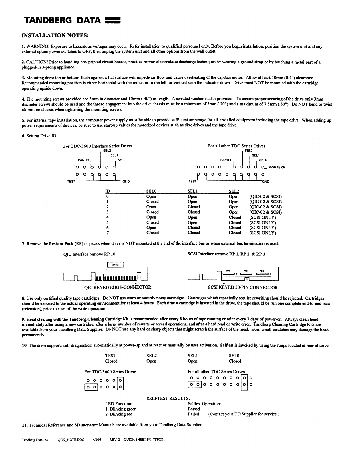
6. Setting Drive ID:
For
TDC-3600
Interface Series Drives For all other
TDC
Series Drives
;AA~~
b J
7:;'~"
O 0 0 O
PARITY
b J
SE~2SEL1SELO
d d CL
PWRTERM
f 9 0 o 0 9 9 9 9 0
TEST
GND
TESl
9 J 9 9 9 GND
ID SELO
SEll
SEL2
o
Open Open Open
(QIC-02
& SCSI)
1 Closed
Open
Open
(QIC-02 &
SCSI)
2
Open
Closed
Open
(QIC-02 & SCSI)
3 Closed Closed
Open
(QIC-02
&;
SCSI)
4
Open
Open Closed
(SCSIONLY)
5 Closed
Open
Closed
(SCSI
ONLy)
6
Open
Closed Closed
(SCSI
ONLY)
7 Closed Closed Closed
(SCSI
ONLY)
7. Remove the Resistor
Pack
(RP)
or
packs
when
drive is
NOT
mounted
at
the
end
of
the interface bus
or
when
external bus termination
is
used:
QIC
Interface remove
RP
10
SCSI
Interface remove
RP
I,
RP
2, &
RP
3
I
r1
n_=
....
"",.;;;..;O-'
-'.~,..,="_,....:::
....
=:::..."
L-J
L-..J
I ITn'--
__
...L-.-'
,
.. ..
,
QIC
KEYED
EDGE-CONNECTOR
SCSI
KEYED
50-PIN
CONNECTOR
8.
Use only certified
quality
tape
cartridges.
Do
NOT
use worn
or
audibly noisy cartridges. Cartridges which repeatedly require rewriting should
be
rejected. Cartridges
should be exposed to
the
actual operating environment for
at
least
4 hours.
Each
time
a cartridge is inserted in
the
drive, the
tape
should
be
run
one complete end-to-end
pass
(retension), prior
to
start
of
the write operation.
9.
Head
cleaning
with
the
Tandberg
Cleaning Cartridge Kit is recommended after every 8 hours
of
tape running
or
after every 7 days
of
power
-on. Always clean
head
immediately after
using
a
new
cartridge, after a large
number
of
rewrite
Of
reread
operations, and after a
hard
read
Of
write errOf.
Tandberg
Cleaning Cartridge Kits are
available from
your
Tandberg
Data
Supplier.
Do
NOT
use
any
hard
or
sharp objed.l
that
might
scratch
the
surface
of
the
head. Even small scratches
may
damage
the
head
permanently.
10.
The
drive supports
self
diagnostics: automatically
at
power-up
and
at
reset
or
manually
by
user
activation. Selftest is invoked
by
using
the
straps located
at
rear
of
drive:
TEST
Closed
For
TDC-3600
Series Drives
00000101
~o
0
o~
LED
Function:
I. Blinking green
2. Blinking red
SEL2
Open
SEll
Open
SELO
Closed
For
all other
TDC
Series Drives
o 0 0 0 0 0 0
01010
~o
0 0 0 0
o~o
SELFTEST
RESULTS:
Selftest Operation:
Passed
Failed (Contact
your
TD
Supplier for service.)
11. Technical Reference
and
Maintenance
Manuals
are available from
your
Tandberg
Data
Supplier.
Tandberg Data Inc.
418193
REV
2 QUICK SHEET
PIN
71T0251
