DI 720, 722, 730, And 75B Data Acquisition Hardware Manual Di720 720 730
User Manual: di720
Open the PDF directly: View PDF ![]() .
.
Page Count: 108 [warning: Documents this large are best viewed by clicking the View PDF Link!]
- Warranty and Service Policy
- CAUTION
- Table of Contents
- 1. Introduction
- 2. Specifications
- 3. Getting Started
- Unpacking
- Applying Power to the DI-7xx Series Instrument
- Printer Port Instrument Installation
- USB Instrument Installation
- Ethernet Instrument Installation
- Installing an Ethernet Device Directly Connected to your PC or Connected via a Hub/Switch where ONLY DI-72x, DI-730, or DI-78x Products are Installed
- Installing an Ethernet device via a distributed network without a DHCP server where one or more DATAQ Instruments devices will coexist with other Ethernet devices, and where static IP address are individually assigned
- Installing an Ethernet device via a distributed network with a DHCP server
- Connecting your Ethernet Instrument to your PC or Network
- Installing WinDaq software for Ethernet Products
- Daisy-Chaining Multiple Ethernet Products
- TCP/IP Manager (Ethernet Models Only)
- WinDaq Waveform Navigator (Ethernet models only)
- 4. Instrument Controls, Indicators, and Connectors
- 5. Calibration Verification
- Required Equipment
- A/D Calibration Verification (DI-720, DI-722, and DI-730 Series Instruments)
- D/A Calibration (DI-720 Series Only)
- Offset Calibration Verification (DI-720 and DI-722 Instruments Only)
- Full Scale (Span) Calibration Verification (DI-720 and DI-722 Instruments Only)
- Offset Calibration Verification (DI-730 Instruments only)
- Full Scale (Span) Calibration Verification (DI-730 Instruments Only)
- 6. Block Diagram
- 7. Accessories
- The DI-705: Signal Input/Output Option
- The DI-205: Signal Input/Output Panel
- DI-725(E) Channel Expansion Unit
- DI-78B 8B Module Channel Expander
- DI-8B Modules
- DI-8B30/31 Analog Voltage Input Modules, 3Hz Bandwidth
- DI-8B32 Analog Current Input Modules
- DI-8B34 Linearized 2- or 3-Wire RTD Input Modules
- DI-8B35 Linearized 4-Wire RTD Input Modules
- DI-8B36 Potentiometer Input Modules
- DI-8B38 Strain Gage Input Modules, Narrow & Wide Bandwidth
- DI-8B40/41 Analog Voltage Input Modules, 1kHz Bandwidth
- DI-8B42 2-Wire Transmitter Interface Modules
- DI-8B45 Frequency Input Modules
- DI-8B47 Linearized Thermocouple Input Modules
- DI-8B50/51 Analog Voltage Input Modules, 20kHz Bandwidth
- DI-75B 5B Module Channel Expander
- DI-5B Modules
- DI-5B30/31 Analog Voltage Input Modules, Narrow Bandwidth
- DI-5B32 Analog Current Input Modules
- DI-5B33 Isolated True RMS Input Modules
- DI-5B34 Linearized 2- or 3-Wire RTD Input Modules
- DI-5B35 Linearized 4-Wire RTD Input Modules
- DI-5B36 Potentiometer Input Modules
- DI-5B38 Strain Gage Input Modules, Narrow & Wide Bandwidth
- DI-5B40/41 Analog Voltage Input Modules, Wide Bandwidth
- DI-5B42 2-Wire Transmitter Interface Modules
- DI-5B43 Isolated DC Transducer Amplifier Input Module
- DI-5B45 Frequency Input Modules
- DI-5B47 Linearized Thermocouple Input Modules
- DI-5B48 Accelerometer Input Modules

The way PC-based instrumentation should be
DI-720 Series
32 Channel USB, Ethernet, or Printer Port Data Acquisition System
DI-722 Series
Extended Measurement Range Data Acquisition System
DI-730 Series
High Voltage Range Data Acquisition System
DI-725/E
Channel Expander
DI-78B
8B Module Channel Expander
DI-75B
5B Module Channel Expander
User's Manual
Manual Revision AO
Copyright © 2014 by DATAQ Instruments, Inc. The Information contained herein is the exclusive property of
DATAQ Instruments, Inc., except as otherwise indicated and shall not be reproduced, transmitted, transcribed, stored
in a retrieval system, or translated into any human or computer language, in any form or by any means, electronic,
mechanical, magnetic, optical, chemical, manual, or otherwise without expressed written authorization from the com-
pany. The distribution of this material outside the company may occur only as authorized by the company in writing.
DATAQ Instruments' hardware and software products are not designed to be used in the diagnosis and treatment of
humans, nor are they to be used as critical components in any life-support systems whose failure to perform can rea-
sonably be expected to cause significant injury to humans.
DATAQ, the DATAQ logo, and WINDAQ are registered trademarks of DATAQ Instruments, Inc. All rights reserved.
241 Springside Dr.
Akron, Ohio 44333 U.S.A.
Telephone: 330-668-1444
Fax: 330-666-5434
Designed and manufactured in the
United States of America
M-100763
Warranty and Service Policy
Product Warranty
DATAQ Instruments, Inc. warrants that this hardware will be free from defects in materials and workmanship under
normal use and service for a period of one year from the date of shipment. DATAQ Instruments' obligations under
this warranty shall not arise until the defective material is shipped freight prepaid to DATAQ Instruments. The only
responsibility of DATAQ Instruments under this warranty is to repair or replace, at its discretion and on a free of
charge basis, the defective material.
This warranty does not extend to products that have been repaired or altered by persons other than DATAQ Instru-
ments employees, or products that have been subjected to misuse, neglect, improper installation, or accident.
DATAQ Instruments shall have no liability for incidental or consequential damages of any kind arising out of the sale,
installation, or use of its products.
Service Policy
1. All products returned to DATAQ Instruments for service, regardless of warranty status, must be on a freight-pre-
paid basis.
2. DATAQ Instruments will repair or replace any defective product within 5 days of its receipt.
3. For in-warranty repairs, DATAQ Instruments will return repaired items to the buyer freight prepaid. Out of war-
ranty repairs will be returned with freight prepaid and added to the service invoice.
v
CAUTION
READ BEFORE CONNECTING INPUT SIGNALS
The data acquisition device you have purchased and are about to use contains input channels that are NOT ISO-
LATED (all channels on DI-72x products are not isolated; only the expansion channels of DI-730 instruments are not
isolated). This means that it is susceptible to common mode voltages that could cause damage to the device. SUCH
DAMAGE IS NOT COVERED BY THE PRODUCT’S WARRANTY. Please read the following carefully before
deploying the product. Contact DATAQ Instruments Support at 330-668-1444 for all questions.
This product can tolerate a maximum applied voltage of only ±20V peak without damage. Although you may be cer-
tain that the signal you want to measure is lower than this level, a common mode voltage (CMV) with an unknown
value may combine with your signal of interest to exceed this ±20V limit. In such instances, the product will be dam-
aged. Verify a CMV does not exist before connecting signals and acquiring data with your device. Use the following
procedure to check for CMV:
1. DO NOT connect your data acquisition device to the device under test. If the device under test is connected to
your data acquisition device, disconnect it.
2. Connect your data acquisition device to the appropriate interface on your PC (USB, Ethernet, RS-232 Serial, or
Parallel Printer Port).
3. Apply power to your data acquisition device, your PC, and the device under test.
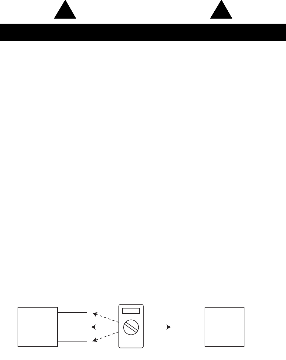
4. Use a digital voltmeter to make the following measurements:
a. Measure the voltage (both the AC and DC range) between the ground terminal of your data acquisition
device and Signal+ of the device under test. This measurement should not exceed the Full Scale Range of
your data acquisition device.
b. Measure the voltage (both the AC and DC range) between the ground terminal of your data acquisition
device and Signal- of the device under test. This measurement should be at or very near 0 Volts.
c. Measure the voltage (both the AC and DC range) between the ground terminal of your data acquisition
device and Common of the device under test. This measurement should be at or very near 0 Volts.
5. Should ANY of these measurements exceed their recommendation DO NOT CONNECT SIGNALS to the data
acquisition device. A common mode voltage may exist that could destroy the instrument. You MUST determine
the source of the CMV and eliminate it before taking any measurements.
1Measured signal is not to exceed the Full Scale Range of your data acquisition device.
2Measured signal must be at or very near 0 volts.
3Measured signal must be at or very near 0 volts.
4Connect to AGD (Analog Ground) port on DI-72x (all input channels), and DI-730 (expansion channels only) instruments.
!
!
Device
Under
Test
Signal + 1
Signal - 2
Common3
Digital Voltmeter
Data
Acquisition
Device
To PC
Ground4

DI–720/DI–722/DI–730 Series User Manual
Table of Contents
vii
Table of Contents
Warranty and Service Policy ................................................................................................................ iii
CAUTION ........................................................................................................................................... v
Table of Contents ................................................................................................................................... vii
1. Introduction ........................................................................................................................................ 1
Features .............................................................................................................................................. 1
Analog Input ...................................................................................................................................... 1
Analog Output ................................................................................................................................... 2
Digital Input and Output (DI-720 Series Only) ................................................................................. 2
2. Specifications ...................................................................................................................................... 3
3. Getting Started ................................................................................................................................... 7
Unpacking .......................................................................................................................................... 7
Applying Power to the DI-7xx Series Instrument ............................................................................. 7
Printer Port Instrument Installation ................................................................................................... 8
USB Instrument Installation .............................................................................................................. 10
Ethernet Instrument Installation ........................................................................................................ 12
Installing an Ethernet Device Directly Connected to your PC or Connected via a Hub/Switch where
ONLY DI-72x, DI-730, or DI-78x Products are Installed .......................................................... 12
Installing an Ethernet device via a distributed network without a DHCP server where one or more
DATAQ Instruments devices will coexist with other Ethernet devices, and where static IP address
are individually assigned ............................................................................................................. 15
Installing an Ethernet device via a distributed network with a DHCP server ............................. 16
Connecting your Ethernet Instrument to your PC or Network ................................................... 17
Installing WinDaq software for Ethernet Products ..................................................................... 17
Daisy-Chaining Multiple Ethernet Products ............................................................................... 18
TCP/IP Manager (Ethernet Models Only) .................................................................................. 19
WinDaq Waveform Navigator (Ethernet models only) .............................................................. 20
4. Instrument Controls, Indicators, and Connectors .......................................................................... 23
DI-720 Series Instrument Front Panel ............................................................................................... 23
DI-722 Series Instrument Front Panel ............................................................................................... 25
DI-730 Series Instrument Front Panel ............................................................................................... 27
DI-720, DI-722, and DI-730 Series Instrument Rear Panel .............................................................. 28
5. Calibration Verification ..................................................................................................................... 31
Required Equipment .......................................................................................................................... 31
A/D Calibration (For DI-720, DI-722, and DI-730 Series Instruments) .................................... 31
D/A Calibration (DI-720 Instruments Only) ............................................................................... 31
A/D Calibration Verification (DI-720, DI-722, and DI-730 Series Instruments) ............................. 31
D/A Calibration (DI-720 Series Only) .............................................................................................. 32
Offset Calibration Verification (DI-720 and DI-722 Instruments Only) .......................................... 33
Full Scale (Span) Calibration Verification (DI-720 and DI-722 Instruments Only) ......................... 33
Offset Calibration Verification (DI-730 Instruments only) ............................................................... 34
Full Scale (Span) Calibration Verification (DI-730 Instruments Only) ............................................ 34
6. Block Diagram .................................................................................................................................... 35
DI-720 Series ..................................................................................................................................... 35
DI-722 Series ..................................................................................................................................... 36
DI-730 Series (Analog Input) ............................................................................................................ 37

DI–720/DI–722/DI–730 Series User Manual
Table of Contents
viii
Ethernet Instruments .......................................................................................................................... 38
7. Accessories .......................................................................................................................................... 39
The DI-705: Signal Input/Output Option .......................................................................................... 40
General ........................................................................................................................................ 40
Input Signal Configuration .......................................................................................................... 40
The DI-205: Signal Input/Output Panel ............................................................................................. 41
General ........................................................................................................................................ 41
DI-205 Input/Output Panel Interconnections .............................................................................. 41
Input Signal Configuration .......................................................................................................... 41
Connecting a Single-ended Amplifier .................................................................................. 42
Connecting a Differential Amplifier ..................................................................................... 42
DI-725(E) Channel Expansion Unit .................................................................................................. 46
Connecting the DI-725 to the Host Instrument ........................................................................... 46
Features, Controls, and Indicators ............................................................................................... 46
DI-725 Front Panel ............................................................................................................... 46
DI-725 Rear Panel ................................................................................................................ 47
Configuring Channels with the DI-725 ....................................................................................... 48
DI-400 Host Instruments ...................................................................................................... 49
DI-720 Host Instruments ...................................................................................................... 50
DI-730 Host Instruments ...................................................................................................... 51
DI-78B 8B Module Channel Expander ............................................................................................. 52
Connecting the DI-78B to the Host Instrument .......................................................................... 52
Applying Power to the DI-78B ................................................................................................... 52
Features, Controls, and Indicators ............................................................................................... 53
DI-78B Front Panel .............................................................................................................. 53
DI-78B Rear Panel ................................................................................................................ 54
Installing DI-8B Modules ........................................................................................................... 54
Enabling CJC for Thermocouple Modules ................................................................................. 56
Configuring DI-78B Channels in WinDaq ................................................................................. 56
DI-720 Host Instruments ...................................................................................................... 57
DI-730 Host Instruments ...................................................................................................... 58
Configuring DI-78B Channel Gain (you MUST configure gain for proper readings) ......... 58
DI-8B Modules .................................................................................................................................. 60
DI-8B30/31 Analog Voltage Input Modules, 3Hz Bandwidth ................................................... 60
DI-8B32 Analog Current Input Modules .................................................................................... 61
DI-8B34 Linearized 2- or 3-Wire RTD Input Modules .............................................................. 62
DI-8B35 Linearized 4-Wire RTD Input Modules ....................................................................... 63
DI-8B36 Potentiometer Input Modules ....................................................................................... 64
DI-8B38 Strain Gage Input Modules, Narrow & Wide Bandwidth ............................................ 65
DI-8B40/41 Analog Voltage Input Modules, 1kHz Bandwidth ................................................. 66
DI-8B42 2-Wire Transmitter Interface Modules ........................................................................ 67
DI-8B45 Frequency Input Modules ............................................................................................ 68
DI-8B47 Linearized Thermocouple Input Modules .................................................................... 69
DI-8B50/51 Analog Voltage Input Modules, 20kHz Bandwidth ............................................... 70
DI-75B 5B Module Channel Expander ............................................................................................. 71
Connecting the DI-75B to the Host Instrument .......................................................................... 71
Applying Power to the DI-75B ................................................................................................... 71
Features, Controls, and Indicators ............................................................................................... 72
DI-75B Front Panel .............................................................................................................. 72
DI-75B Rear Panel ................................................................................................................ 73

DI–720/DI–722/DI–730 Series User Manual
Table of Contents
ix
Configuring Channels with the DI-75B ...................................................................................... 74
DI-72x Host Instruments ...................................................................................................... 75
DI-730 Host Instruments ...................................................................................................... 76
Configuring Host Instrument Channel Gain ............................................................................... 77
DI-5B Modules .................................................................................................................................. 78
DI-5B30/31 Analog Voltage Input Modules, Narrow Bandwidth .............................................. 78
DI-5B32 Analog Current Input Modules .................................................................................... 79
DI-5B33 Isolated True RMS Input Modules .............................................................................. 80
DI-5B34 Linearized 2- or 3-Wire RTD Input Modules .............................................................. 81
DI-5B35 Linearized 4-Wire RTD Input Modules ....................................................................... 83
DI-5B36 Potentiometer Input Modules ....................................................................................... 85
DI-5B38 Strain Gage Input Modules, Narrow & Wide Bandwidth ........................................... 86
DI-5B40/41 Analog Voltage Input Modules, Wide Bandwidth ................................................. 88
DI-5B42 2-Wire Transmitter Interface Modules ........................................................................ 89
DI-5B43 Isolated DC Transducer Amplifier Input Module ........................................................ 90
DI-5B45 Frequency Input Modules ............................................................................................ 92
DI-5B47 Linearized Thermocouple Input Modules .................................................................... 93
DI-5B48 Accelerometer Input Modules ..................................................................................... 95

DI–720/DI–722/DI–730 Series User Manual
Introduction
1
1. Introduction
Congratulations on your purchase of a DI-720, DI-722, or DI-730 Series data acquisition instrument. This manual
describes how to connect and use all of the instruments in the DI-720, DI-722, and DI-730 Series plus the available
accessories and expanders. Throughout the majority of this manual, enough similarity exists to describe all instru-
ments with the same procedure. The convention used to annotate this similarity is “DI-7xx Series.” In cases where the
resemblance is not the same, separate procedures/descriptions exist for each instrument.
Features
The DI-7xx Series has the following features:
• All instruments connect to the printer port of any PC-compatible computer. Most communicate in standard,
bi-directional or EPP mode. Models DI-720-EN, DI-722-EN, and DI-730-EN add optional Ethernet commu-
nication. DI-720-USB, DI-722-USB, and DI-730-USB add optional USB communication.
• Per channel software-configurable settings including input gain, sample rate, intelligent oversampling
modes (signal averaging, maximum value, minimum value, and last point), and single-ended or differential
input.
• DI-720 Series Instruments offer 32 single-ended/16 differential (software selectable per channel) general
purpose inputs (±10V Full Scale).
• DI-722-16 Series Instruments offer 16 fixed differential extended measurement range (±20V Full Scale)
inputs and 16 single-ended/8 differential (software selectable per channel) general purpose (±10V Full
Scale) inputs.
• DI-722-32 Series Instruments offer 32 extended measurement range differential inputs (±20V Full Scale).
• DI-730 Series Instruments offer 8 fixed isolated high voltage range (±1000V Full Scale) differential inputs
and 16 general-purpose (±10V Full Scale) non-isolated inputs (available through the EXPANSION (USB
and PP models) or Channel Expansion (EN models) connector on the rear of the instrument). General pur-
pose inputs are connected directly to a multiplexer. Each channel can be configured for single-ended or dif-
ferential operation on a channel-by-channel basis. General-purpose inputs can have gain factors of 1, 2, 4 or
8 applied on a channel-by-channel basis.
• Ethernet Instruments provide synchronous distributed data acquisition through CAT-5 Ethernet cables (con-
nected through the Expansion port).
• Flexible power requirements. All instruments operate from any standard 60Hz, 120V AC wall outlet with
the supplied power adapter. Alternately, you may power the instrument from any +9 to +36 volt DC source.
• High sample throughput rates. The DI-720 can record at up to 200KHz throughput. The DI-722 Series can
record at up to 50KHz throughput. The DI-730 Series can record at up to 150KHz throughput. See “Analog
Inputs” on page 3 for full sample rate specifications.
• Analog-to-Digital converters. DI-720 and DI-722 Series provide 16-bit A/D converters for high-resolution
measurement accuracy (14 bits maximum resolution using WINDAQ software). DI-730 Series provide a 14-
bit A/D converter.
• Supports analog pre- and post-triggering of data acquisition based on the level and slope of a specified chan-
nel.
Analog Input
32 single-ended/16 differential analog inputs (on DI-720 Series instruments), 16 singled-ended/24 differential analog
inputs (on DI-722-16 Series instruments), 32 differential analog inputs (on DI-722-32 Series instruments) or 8 fixed

DI–720/DI–722/DI–730 Series User Manual
Introduction
2
differential analog inputs plus 16 general purpose non isolated inputs (on DI-730 Series instruments) allow your ana-
log signals to be converted into 14-to-16-bit digital data via the on board A/D converter.
DI-720 Series Instruments feature software-programmable input measurement ranges of ±10V, ±5V, ±2.5V, and
±1.25V full scale with gain ranges of 1, 2, 4, and 8 for all channels.
DI-722 Series Instruments feature software programmable input measurement ranges of ±20V, ±10V, ±5V, and ±2.5V
full scale with gain ranges of 1, 2, 4, and 8 for all fixed differential extended measurement range inputs. General-pur-
pose inputs feature software-programmable input measurement ranges of ±10V, ±5V, ±2.5V, and ±1.25V full scale
with gain ranges of 1, 2, 4, and 8.
DI-730 Series Instruments feature software programmable input measurement ranges of ±10mV, ±100mV, ±1V,
±10V, ±100V and ±1000V full scale with gain ranges of 1, 10, 100, 1000, 10000, and 100000 for the 8 fixed isolated
high voltage range differential inputs. General-purpose inputs feature software-programmable input measurement
ranges of ±10V, ±5V, ±2.5V, and ±1.25V full scale with gain ranges of 1, 2, 4, and 8.
Analog Output
On DI-720 and DI-722 instruments, the D/A subsystem features two buffered, 12-bit D/A converters for outputting
analog data. DI-730 instruments have one 12-bit D/A converter. DI-7xx Series instruments feature a software-pro-
grammable output range of ±10V and feature an on-board 16-entry output counter list that allows you to write analog
or digital output at the maximum conversion rate of the instrument.
Note: Analog output is not available in DI-7xx Ethernet and USB modules while Analog Input is being used.
Digital Input and Output (DI-720 Series Only)
The DI-720-P contains 8 digital input and 8 digital output lines for input/output operations. These lines provide an
interface for the transfer of data between user memory and a peripheral device connected to the instrument. Digital
inputs can monitor alarms or sensors with TTL outputs, while digital outputs can drive TTL inputs on control or mea-
surement equipment. The DI-720-EN and DI-720-USB have 8 digital input and 4 digital output lines available.

DI–720/DI–722/DI–730 Series User Manual
Specifications
3
2. Specifications
Signal Connections
Make signal connections to the two 37-pin, D-type connectors on the front panel of DI-720/722 Series instruments
or to the banana jacks on the front panel of DI-730 Series instruments. On DI-720 Series instruments, signal connec-
tions can also be made with the DI-205 (optional) general purpose signal interface providing convenient banana
jacks for analog input signals. See “The DI-205: Signal Input/Output Panel” on page 41 for more information. Note:
the DI-205 is an extra-cost option and is not included with the purchase of a DI-720 Series instrument.
Interface Characteristics
Compatible computer architecture: Any PC architecture. Connects to computer via the parallel (or printer)
port. Supports standard, bi-directional, or EPP communication modes.
Optional communication interfaces include Ethernet and Universal
Serial Bus (USB).
Analog Inputs
Number of input channels:
DI-720 Series 32 single-ended/16 differential (software selectable per channel)
DI-722-16 Series 24 differential, 16 single-ended (software selectable on channels 17-32)
DI-722-32 Series 32 differential
DI-730 Series 8 isolated fixed differential plus 16 non-isolated general purpose inputs
(16 single ended or 8 differential)
Converter resolution: DI-72x: 16-bit; 14-bit when used with WINDAQ software
DI-730: 14-bit
Common mode rejection ratio: DI-72x: 80 dB minimum @ Av=1
DI-730: 120 dB minimum @ DC to 60Hz
Accuracy: Vin <= 800V ±(0.25% of full-scale range ±100µv)
Vin > 800V ±(0.5% of full-scale range)
Crosstalk: -75 dB @100kHz (50 KHz for DI-722) into 100 unbalanced
Sample throughput rate (max samples/second; software selectable per channel):
Standard Printer Port DI-720, DI-722, and DI-730: 40,000 samples/second max
Bi-directional Printer Port DI-720: 80,000 samples/second max
DI-722: 50,000 samples/second max
DI-730: 80,000 samples/second max
EPP Printer Port DI-720: 200,000 samples/second max
DI-722: 50,000 samples/second max
DI-730: 150,000 samples/second max
USB DI-720: 200,000 samples/second max
DI-722: 50,000 samples/second max
DI-730: 150,000 samples/second max
Ethernet DI-720: 180,000 samples/second max
DI-722: 50,000 samples/second max
DI-730: 150,000 samples/second max

DI–720/DI–722/DI–730 Series User Manual
Specifications
4
Maximum analog measurement range (software selectable per channel):
DI-720 Series and DI-722/DI-730 gen-
eral purpose channels
±10V full scale at a gain of 1
±5V full scale at a gain of 2
±2.5V full scale at a gain of 4
±1.25V full scale at a gain of 8
DI-722 Series Amplified ±20 V full scale at a gain of 1
±10 V full scale at a gain of 2
±5 V full scale at a gain of 4
±2.5 V full scale at a gain of 8
DI-730 Series ±10mV full scale
±100mV full scale
±1V full scale
±10V full scale
±100V full scale
±1000V full scale
Maximum Input without Damage (either input to ground):
DI-720: ±30VDC or Peak AC
DI-722: 120V RMS
DI-730: ±1500VDC or Peak AC (8 high voltage channels only)
Gain error: 1 bit max @ 1kHz sample rate
Input offset voltage: 1 bit max @ 1kHz sample rate
Input settling time: 4µs to 0.01% at all gains
Input impedance: DI-720: 1 M resistor tied to GND on the input channel
DI-722: 1 M
DI-730: 10 M
Maximum jitter between synchronized units: 5 microseconds
Analog Outputs
Number of channels: DI-720: Two buffered analog outputs
DI-722: None
DI-730: One analog output
Resolution: 12-bit; 1 part in 4,096 @ 250kHz
Output voltage range: ±10V full scale
Output impedance: 0.1 - output current should not exceed 1mA (10K load or lighter)
Maximum Sample rate (samples/second):
(software selectable per channel)
standard port: 40,000
bi-directional port: 80,000
EPP: 150,000
Output offset voltage: 1 bit max @ 1kHz sample rate
Digital Input/Output (DI-720 Series Only)
Capacity: 8 input and 8 output
Compatibility: TTL compatible
Max source current: 0.4mA @ 2.4V
Max sink current: 8mA @ 0.5V
Digital input termination: 4.7k pull-up to +5VDC

DI–720/DI–722/DI–730 Series User Manual
Specifications
5
Timing Input/Output
Number of counters: 240 input, 16 output
Resolution: 1 part in 32,768
Base clock accuracy: 0.005% or 50ppm
Counter input frequency: 16 MHz
Scan Lists
Input Scan List: USB: Capacity—128 elements
Printer Port and Ethernet: Capacity—240 elements
Output Scan List: Capacity—16 elements
Triggering
Pre-trigger length and Post-trigger length: Printer Port and Ethernet products: (Pre-trigger points + Post-trigger
points) × the number of enabled channels must be less than or equal to
64,000
USB products: (Pre-trigger points + Post-trigger points) × the number
of enabled channels must be less than or equal to 15,000
Trigger channel: Any channel
Trigger level hysteresis: 8-bit (256 counts)
On-board DSP
Type: Analog Devices ADSP2181, 32 MIPS
Clock frequency: 16 MHz external, 64 MHz internal
Data memory: 16k words
Program memory: 16k words
Physical/Environmental
Box dimensions: 7.29"W × 9"L × 1.52"H
I/O connector: DI-720: 37-pin male D-type
DI-722: 37-pin male D-type
DI-730: Banana jacks
Weight: approx. 3 lbs.
Operating environment:
Component temperature 0º to 70º C
Relative humidity 0% to 90% non-condensing
Storage environment:
Temperature -40º to 100º C
Relative humidity 0% to 90% non-condensing
Power Supply Voltage and Power Consumption
Vo l t a g e : 9 - 3 6 V D C

DI–720/DI–722/DI–730 Series User Manual
Specifications
6
Power: DI-720: 4.5 Watts
DI-722: 10 Watts
DI-730: 14 Watts
DI–720/DI–722/DI–730 Series User Manual
Getting Started
7
3. Getting Started
Unpacking
The following items are included with each DI-720, DI-722, or DI-730 Series instrument. Verify that you have the
following:
• Your DI-720, DI-722, or DI-730 Series Instrument.
• One USB, ethernet or printer port communications cable to connect the DI-7xx Series instrument to your
computer (depending on your model).
• The DATAQ Instruments Software CD. The DATAQ Instruments Software CD contains all software
required to run your instrument. If you ordered an unlock code (WINDAQ/Pro or WINDAQ/Pro+), there will
be a sticker with a password on the sleeve of your CD-ROM.
If an item is missing or damaged, call DATAQ Instruments at 330-668-1444. DATAQ support will guide you through
the appropriate steps for replacing missing or damaged items. Save the original packing material in the unlikely event
that your unit must, for any reason, be sent back to DATAQ Instruments.
Applying Power to the DI-7xx Series Instrument
Use the following procedure to apply power to your DI-7xx Series instrument:
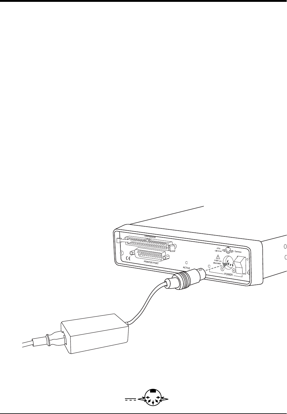
1. Plug the five-pin DIN end of the power adapter cable into the five-pin jack labeled POWER on the rear panel of
the instrument.
2. Plug the appropriate end of the supplied power cord into the power adapter and the other end into any standard
120VAC, 60Hz, single-phase outlet. If an alternate power source is to be used, refer to the following pin-out dia-
gram for power requirements:
Power Adapter
To power supply (outlet)
Rear Panel
Power Adapter Cable
DI-720 or DI-730 Series Instrument
+9 to +36 V Common
DI–720/DI–722/DI–730 Series User Manual
Getting Started
8
3. Turn the POWER switch on.
Printer Port Instrument Installation
All DI-7xx Series instruments can use your computer's parallel (or printer) port to interface digital and analog signals
to your computer. Ethernet/USB models provide Ethernet or USB communication ports (cannot be used concurrently
with the printer port).
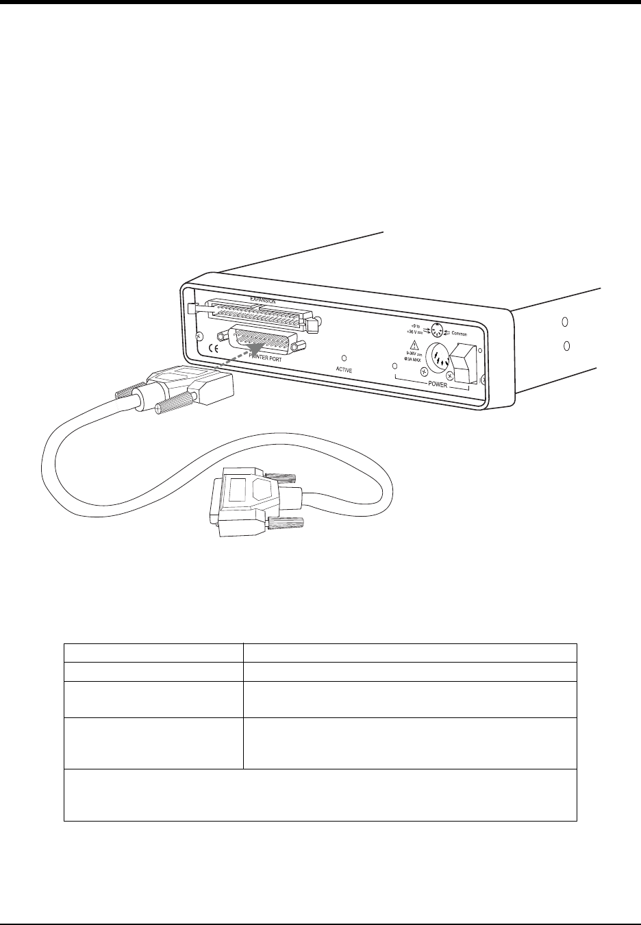
1. Plug the appropriate end of the supplied parallel communications cable to the 25-pin male connector labeled
PRINTER PORT on the rear panel of the DI-7xx Series instrument.
2. Connect the other end of this cable to your computer's parallel (printer) port. Note the LPT port number to which
you connected your device (LPT1, LPT2, etc.).
3. Set up your computer’s Printer Port operating mode. The parallel port may be set up in Standard, Bi-directional,
or EPP mode to communicate with your instrument. Choose a parallel port mode based on the desired sample
rate:
For example, if you will record five channels at 20 Hz each, then the Standard mode will be more than adequate
(5 channels @ 20 Hz = 100 Hz throughput, which is well within the DI-7xx Series 40KHz standard mode
throughput). If, however, you plan to record at a much higher sample rate (for example, five channels at 10KHz
each) the Standard mode will not reliably record your data gap-free — this throughput rate exceeds the DI-7xx's
Parallel Port Mode Maximum Data Throughput*
Standard DI-720, DI-722, and DI-730: 40,000 samples/second
Bi-directional (PS/2) DI-720 and DI-730: 80,000 samples/second
DI-722: 50,000 samples/second
EPP
DI-720: 200,000 samples/second
DI-722: 50,000 samples/second
DI-730: 150,000 samples/second
*Maximum stream-to-disk rate using WINDAQ software on a 350 MHz Pentium II machine
running Windows 98. Triggered storage rates will be faster. Contact DATAQ Instruments to
determine expected maximum sample rates for other machine speeds and operating systems.
To printer port on PC
Rear Panel
Printer Port Cable
DI-720 or DI-730 Series Instrument

DI–720/DI–722/DI–730 Series User Manual
Getting Started
9
standard mode maximum throughput (5 channels @ 10KHz = 50KHz). To reliably record data gap-free at this
sample rate, your computer's parallel port must be operated in something other than standard mode.
Access your computer's CMOS setup routine to change the printer port operating mode. This usually can be
accomplished by pressing a certain key (or keys) on your keyboard at the beginning of your computer's boot-up
process. A message telling you which key to press is usually displayed on your monitor at the beginning of the
boot-up process. If you do not see such a message, consult your computer documentation for CMOS setup infor-
mation.
4. Apply power to the DI-7xx instrument. Windows must be running. Close all other applications.
5. Install WINDAQ Software. All software is included in The DATAQ Instruments Software CD.
a. Insert the The DATAQ Instruments Software CD into your CD-ROM drive. The Windows auto run feature
should start the installation program. If the Windows auto run feature is not enabled on your PC, run the
setup.exe program located on the root of the CD directory.
b. In the “What do you want to do?” dialog box select the Install Software radio button and click OK.
c. In the “Installing Software” dialog box select the Install Software for all other products radio button and
click OK.
d. In the “Specify the product” dialog box you must choose the version of WINDAQ you would like to install. If
you purchased an unlock code (WINDAQ/Pro or Pro+), select the appropriate option and click OK. If you did
not purchase an unlock code, choose the WINDAQ/Lite option and click OK.
e. In the “Specify the Instrument” dialog box select the DI-720/740/730HV Portable Instruments radio but-
ton and click OK.
f. In the “Specify the Instrument” dialog box select the Parallel Port (Printer Port) radio button and click
OK.
g. Read the warning information and follow any instructions relevant to your situation in the “Welcome” dia-
log box. Click OK to continue the installation.
h. Read through the Software License agreement carefully and either Accept and Continue or Cancel to exit
the installation.
i. Enter your Registration Information in the appropriate text boxes and click OK.
j. Select the destination directory where you would like all folders and files to reside on your hard drive. We
recommend you accept the default path, but you can name this new directory anything you like. Simply sub-
stitute the desired drive and directory in the Destination Directory text box. Once you have chosen the direc-
tory click OK.
k. The “Make Backups?” dialog box provides the option of creating backup copies of any files that may be
replaced during installation. This is a safety courtesy; backup copies are not required. Click on No if you
don't want to make backups. Click on Yes to create backups. If you decide to create backups, you will be
prompted to specify a backup file directory.
l. Specify the instrument you are installing. If you are installing a DI-720 or DI-722 select the DI-720/DI-740/
DI-722/DI-5001 Portable Unit radio button. If you are installing a DI-730 select the DI-730HV Portable
Unit radio button. Click OK to continue.
m. Choose the Printer Port you connected your instrument to (LPT1, LTP2, or LPT3). Click OK to continue.
DI–720/DI–722/DI–730 Series User Manual
Getting Started
10
n. Select the program manager group you would like to place the program shortcuts in your Windows pro-
grams. The default is recommended, but you can specify any program group or create a new one. Click OK
to continue.
o. The “Installation Option” dialog box allows you to specify access to WINDAQ for multiple users on the same
PC. If you are the only user or you would like to allow access to all users click Yes. If there are multiple
users and you would like to be the only one able to access WINDAQ click No. Click Cancel to abort the
installation.
p. Select the desired options for installation of WINDAQ/XL and Advanced CODAS.
q. Installation is complete. Re-start your PC to enable WINDAQ device drivers for the printer port.
6. Run WinDaq software from the program group designated in Step 5n above (default is Start > Programs >
WINDAQ > WinDaq Pro(version of the software installed - Lite/Pro/Pro+) Data Acq DI-7xx(model number)
LPT. For help running WinDaq Acquisition and Playback software please see the help files inside the application
(F1 for context-sensitive help or use the Help menu).
USB Instrument Installation
USB instruments require driver installation before they can communicate with your PC. Your USB device may be
installed and run as a Printer Port device if desired (see “Printer Port Instrument Installation” on page 8 to install and
run as a Printer Port device). The USB and Printer Port communications interfaces cannot be used concurrently.
1. Disconnect all DATAQ Instruments USB devices from your PC before continuing with installation.
2. Install WINDAQ Software. All software and drivers are included in The DATAQ Instruments Software CD.
a. Insert the The DATAQ Instruments Software CD into your CD-ROM drive. The Windows auto run feature
should start the installation program. If the Windows auto run feature is not enabled on your PC, run the
setup.exe program located on the root of the CD directory.
b. In the “What do you want to do?” dialog box select the Install Software radio button and click OK.

DI–720/DI–722/DI–730 Series User Manual
Getting Started
11
c. In the “Installing Software” dialog box select the Install Software for all other products radio button and
click OK.
d. In the “Specify the product” dialog box you must choose the version of WINDAQ you would like to install. If
you purchased and unlock code (WINDAQ/Pro or Pro+), select the appropriate option and click OK. If you
did not purchase an unlock code, choose the WINDAQ/Lite option and click OK.
e. In the “Specify the Instrument” dialog box select the DI-720/740/730HV Portable Instruments radio but-
ton and click OK.
f. In the “Specify the Instrument” dialog box select the Universal Serial Bus (USB) radio button and click
OK.
g. The “Welcome!” dialog box allows you to cancel the installation. Click OK to continue installation or Can-
cel to abort.
h. Read through the Software License agreement carefully and either Accept and Continue or Cancel to exit
the installation.
i. Enter your Registration Information in the appropriate text boxes and click OK.
j. Select the destination directory where you would like all folders and files to reside on your hard drive. We
recommend you accept the default path, but you can name this new directory anything you like. Simply sub-
stitute the desired drive and directory in the Destination Directory text box. Once you have chosen the direc-
tory click OK.
k. The “Make Backups?” dialog box provides the option of creating backup copies of any files that may be
replaced during installation. This is a safety courtesy; backup copies are not required. Click on No if you
don't want to make backups. Click on Yes to create backups. If you decide to create backups, you will be
prompted to specify a backup file directory.
l. Select the program manager group you would like to place the program shortcuts in your Windows pro-
grams. The default is recommended, but you can specify any program group or create a new one. Click OK
to continue.
m. Enter the ID address of your instrument. Every DI-720-USB, DI-722-USB or DI-730-USB is initially
assigned an ID address of 0. If you are adding only one DI-720-USB, DI-722-USB or DI-730-USB to your
system or if this is the first USB instrument you are installing, do not change the ID address. If this is not the
first DI-720, DI-722 or DI-730 USB device, change the ID address. The second device installed should have
an ID address of 1, the third device installed should have an ID address of 2, etc. Click OK to continue
installation.
n. The “Installation Option” dialog box allows you to specify access to WINDAQ for multiple users on the same
PC. If you are the only user or you would like to allow access to all users click Yes. If there are multiple
users and you would like to be the only one able to access WINDAQ click No. Click Cancel to abort the
installation.
o. Select the desired options for installation of WINDAQ/XL and Advanced CODAS.
p. Installation is complete. If you are installing multiple devices, run through the installation for each device
making sure to change the ID address in step m above. This does not install multiple versions of the soft-
ware.
DI–720/DI–722/DI–730 Series User Manual
Getting Started
12
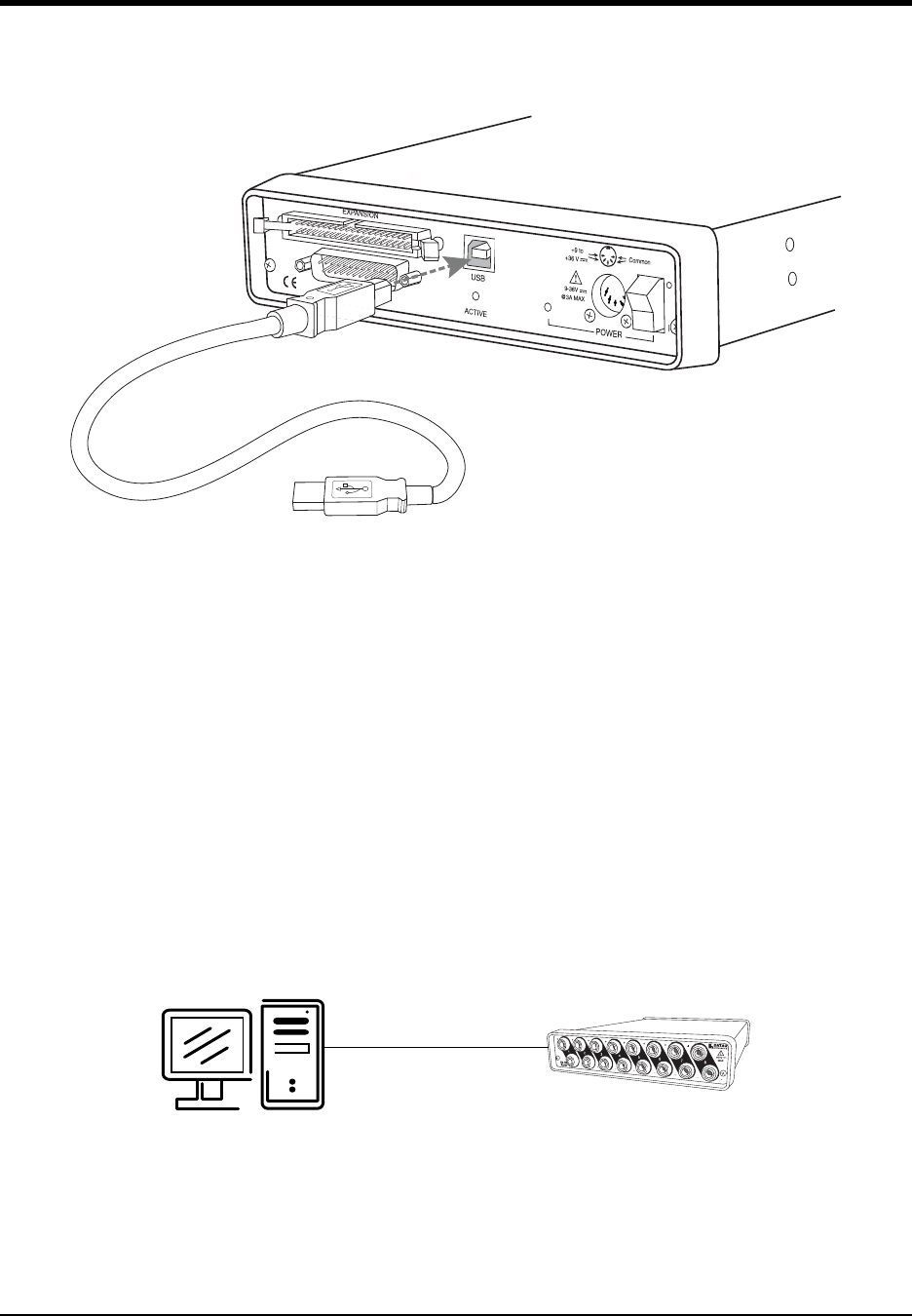
3. You may now connect your USB instrument to your PC. Plug the appropriate end of the supplied USB communi-
cations cable into the USB port (labeled USB) on the rear panel of the instrument. Connect the other end of this
cable to your computer's USB port.
4. Run WinDaq software from the program group designated in Step 7n above (default is Start > Programs >
WINDAQ > WinDaq Pro(version of the software installed - Lite/Pro/Pro+) Data Acq DI-7xx(model number)
USBx(ID address - usually 0). For help running WinDaq Acquisition and Playback software please see the help
files inside the application (F1 for context-sensitive help or use the Help menu).
Ethernet Instrument Installation
Your Ethernet device may be installed and run as a Printer Port device if desired (see “Printer Port Instrument Instal-
lation” on page 8 to install and run as a Printer Port device). The Ethernet and Printer Port communications interfaces
cannot be used concurrently. If you are installing multiple devices in a daisy chain for the purpose of synchronous
distributed data acquisition please see “Daisy-Chaining Multiple Ethernet Products” on page 18 before installing the
software. You may only access one device per network outside your subnet.
Installing an Ethernet Device Directly Connected to your PC or Connected via a
Hub/Switch where ONLY DI-72x, DI-730, or DI-78x Products are Installed
Installation of an Ethernet device directly connected to the network card on your computer requires you to change the
IP address of your network card.
To USB port on PC
Rear Panel
USB Cable
DI-720 or DI-730 Series Instrument
Standard CAT-5 Cable
100M Max
Your PC DI-720/722/730/785/788
DI–720/DI–722/DI–730 Series User Manual
Getting Started
13
Installation of an Ethernet device via a hub/switch containing ONLY DI-720/722/730/785/788 products also requires
you to change the IP address of your network card.
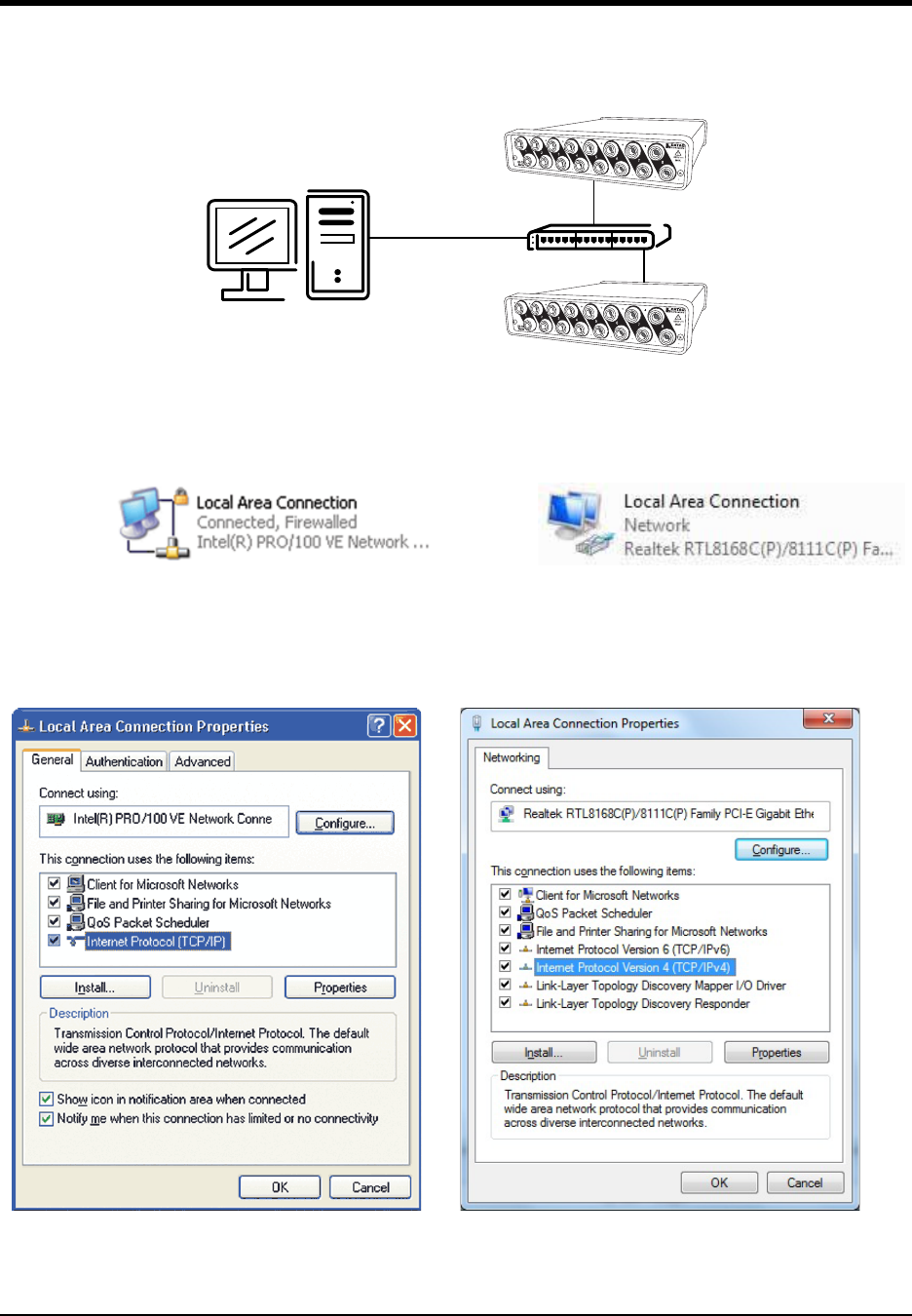
1. Find the Network Connections on your computer (usually in the Control Panel).
2. Double-click on the Local Area Connection icon.
3. Click on the Properties button.
4. Select Internet Protocol (TCP/IP) in Windows XP or Internet Protocol Version 4 (TCP/IPv4) in Windows 7
in the “This connection uses the following items” window and click on the Properties button.
5. Click on the General tab.
Windows XP Windows 7
Windows XP Windows 7
CAT-5 Cable
100M Max
Your PC
Hub
DI-720/722/730/785/788
DI-720/722/730/785/788
DI–720/DI–722/DI–730 Series User Manual
Getting Started
14
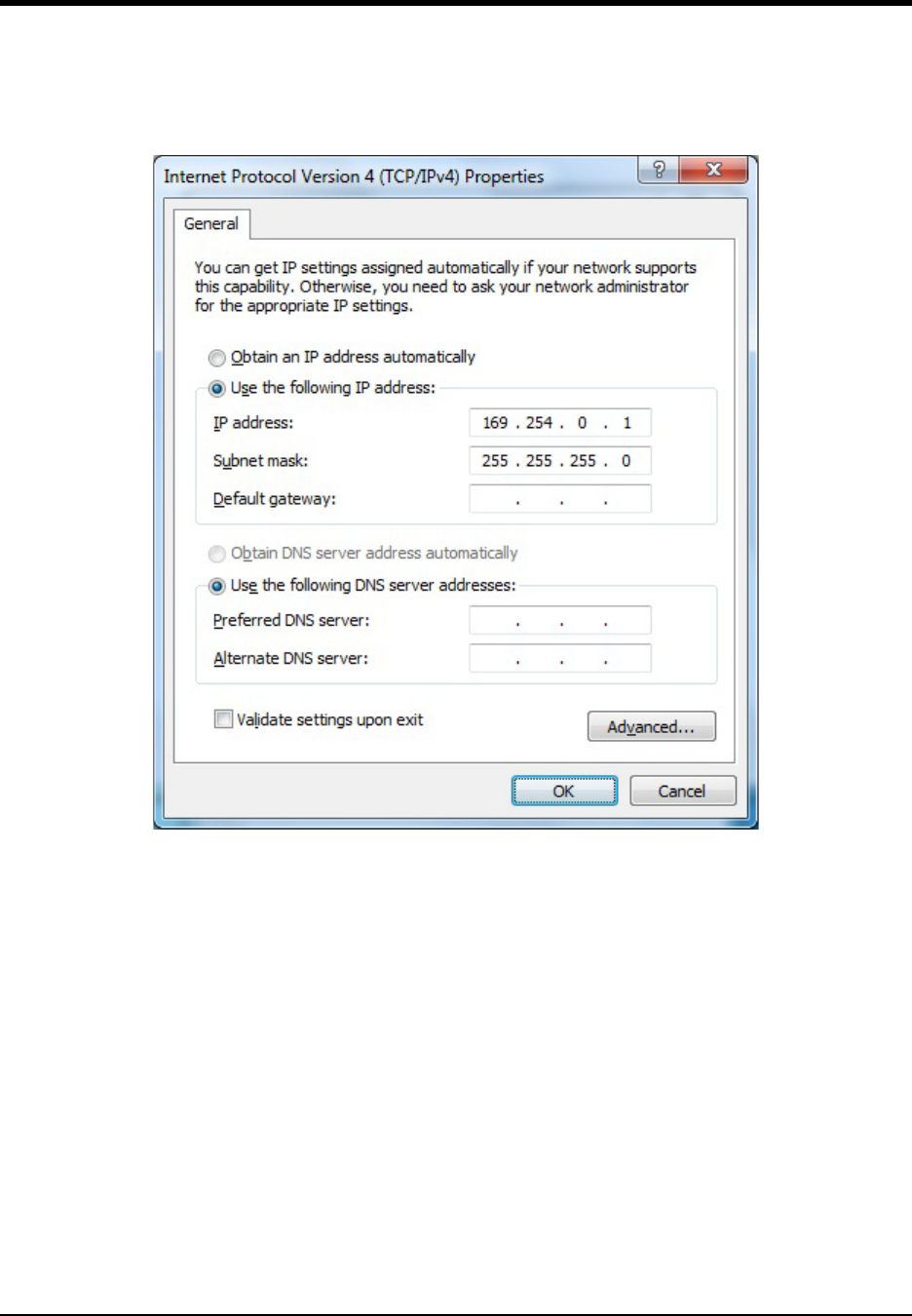
6. Select the radio button Use the following IP address.
7. Enter 169.254.0.1 in the space provided for the IP address.
8. Enter 255.255.0.0 in the space provided for the Subnet mask.
9. Click on the OK button to close the Internet Protocol (TCP/IP) Properties dialog box then click on the OK but-
ton in the Local Area Connection Properties dialog box for the changes to take effect.
Note: If you unplug your device and connect your PC to a network or router you should change the TCP/IP proper-
ties back to their original state.
10. Install WINDAQ software (see “Installing WinDaq software for Ethernet Products” on page 17).
11. Run the TCP/IP Manager software (default location is Start > Programs > WINDAQ > IP Manager).
12. Connect the device (see “Connecting your Ethernet Instrument to your PC or Network” on page 17) to your PC
or hub.
13. Apply power the device (see “Applying Power to the DI-7xx Series Instrument” on page 7).
Note: Always start the TCP/IP Manager software BEFORE powering the device to avoid extended delays resolving
IP addresses.
DI–720/DI–722/DI–730 Series User Manual
Getting Started
15
Installing an Ethernet device via a distributed network without a DHCP server
where one or more DATAQ Instruments devices will coexist with other Ethernet
devices, and where static IP address are individually assigned
Installation of an Ethernet device connected to a distributed network that does not have a DHCP server or where the
DHCP server is turned off requires you to set a static IP to the device after installation to drastically reduce the
amount of time it takes for the TCP/IP Manager to find the device.
Note: In the illustration above, the Hubs could instead be routers with DHCP turned off (i.e., a static IP assigned net-
work). Contact your system administrator for details about your network.
1. Have the system administrator designate an IP address for your device.
2. Install WINDAQ software (see “Installing WinDaq software for Ethernet Products” on page 17) entering the
device’s MAC address at Step 14.
3. Run the TCP/IP Manager software (default location is Start > Programs > WINDAQ > IP Manager).
4. Connect the device to your network (see “Connecting your Ethernet Instrument to your PC or Network” on
page 17).
5. Power the device (see “Applying Power to the DI-7xx Series Instrument” on page 7).
6. In the TCP/IP Manager main window, select the device you have installed.
7. Select the Change IP Address drop down command.
CAT-5 Cable
100M Max
Your PC
Hub
CAT-5 Cable
100M Max
Hub
PC
PC
More Nodes
As Needed
DI-720/722/730/785/788
DI-720/722/730/785/788
DI-720/722/730/785/788
DI–720/DI–722/DI–730 Series User Manual
Getting Started
16
8. Select the Set a static IP Address radio button.
9. Enter the IP address provided by your system administrator in Step 1 above. Do not check the Remote Device
checkbox.
10. Click on the OK button for the change to take effect.
Note: These instructions change the settings inside the device. If you move the device to a DHCP-enabled network
(i.e., where IP addresses are assigned automatically by a DHCP server or router) you will need to change the device
settings using the Dataq TCP/IP Manager. See the Dataq Instruments TCP/IP Manager help file for complete details.
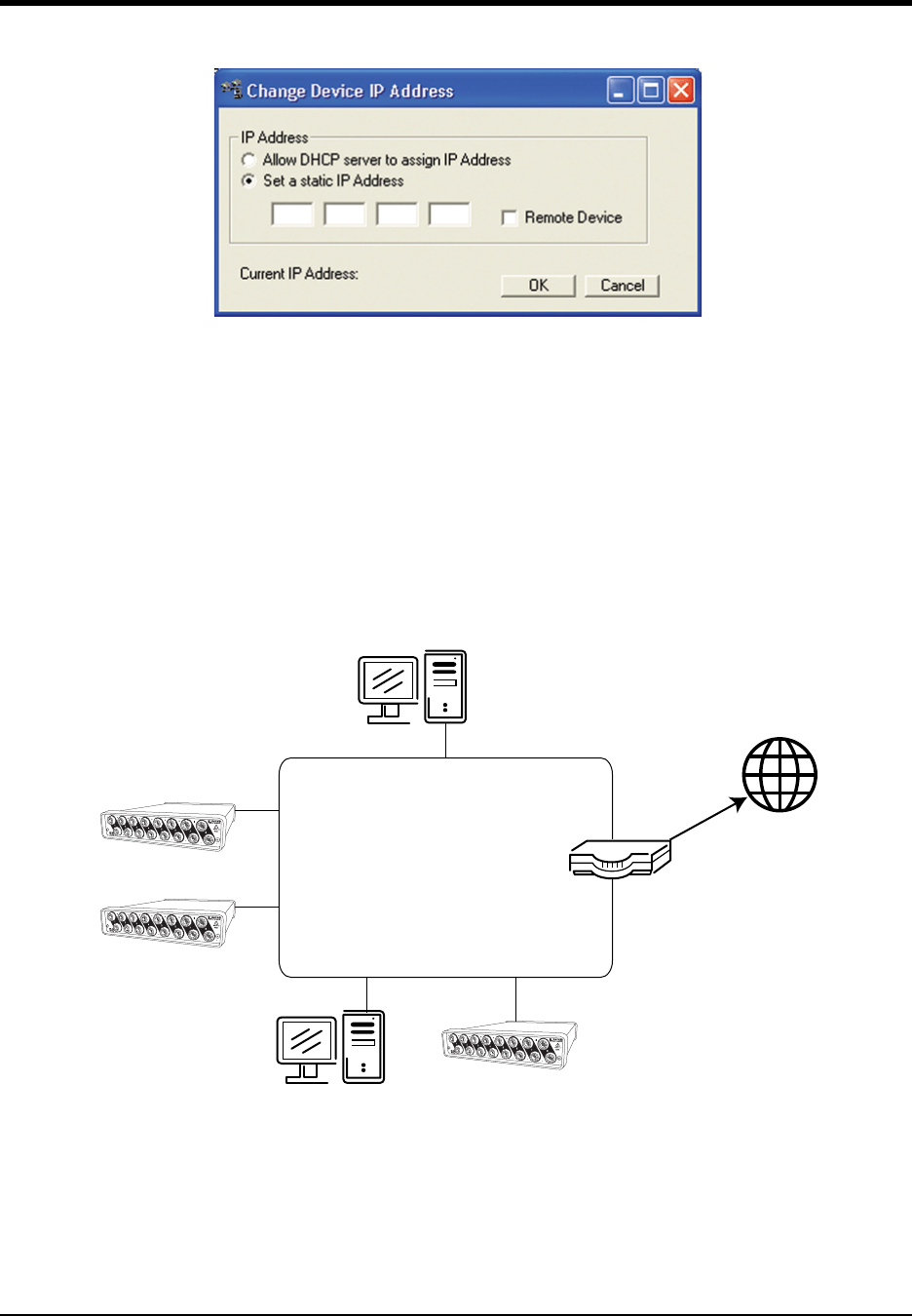
Installing an Ethernet device via a distributed network with a DHCP server
Installation of an Ethernet device connected to a distributed network that has a DHCP server (i.e., a DHCP router
automatically assigns IP addresses to each device connected to the network) requires no extra setup.
Note: If you are unsure whether your network is DHCP-enabled or not, check with your system administrator before
installing WINDAQ.
1. Install WINDAQ software (see “Installing WinDaq software for Ethernet Products” on page 17).
2. Connect your Ethernet device to your Local Area Network (see “Connecting your Ethernet Instrument to your
PC or Network” on page 17).
Your PC
PC
Local Area Network
(LAN)
World Wide
Web
DHCP Router
DI-720/722/730/785/788
DI-720/722/730/785/788
DI-720/722/730/785/788
DI–720/DI–722/DI–730 Series User Manual
Getting Started
17
3. Run the TCP/IP Manager software (default location is Start > Programs > WINDAQ > IP Manager).
4. Apply power to the device (see “Applying Power to the DI-7xx Series Instrument” on page 7).
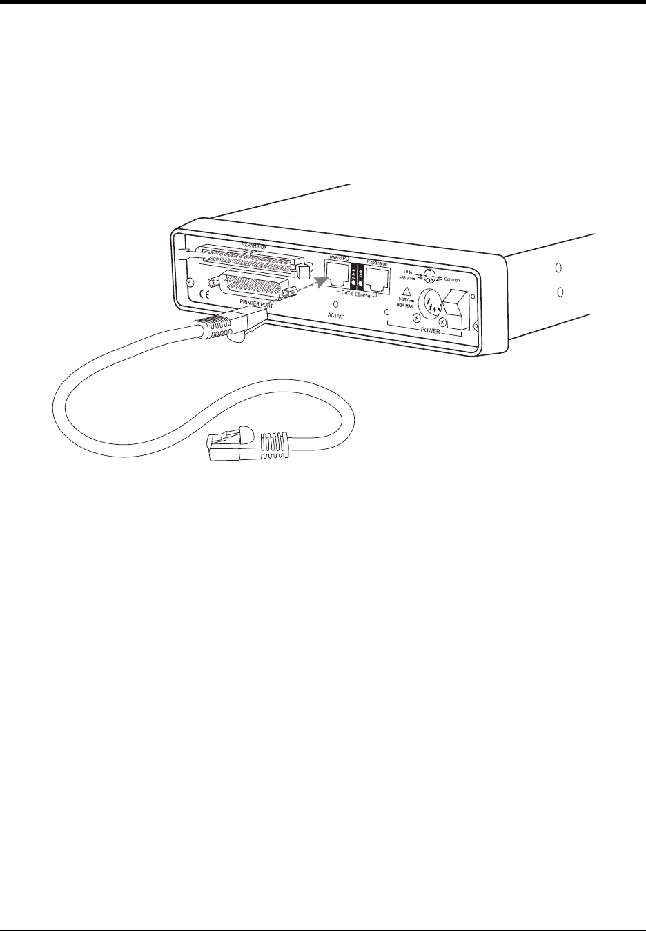
Connecting your Ethernet Instrument to your PC or Network
1. Connect one end of a CAT-5 Ethernet cable to the Toward PC port on the rear of the instrument.
2. Connect the other end of the CAT-5 Ethernet cable to an Ethernet port on your PC or to a port on an accessible
network.
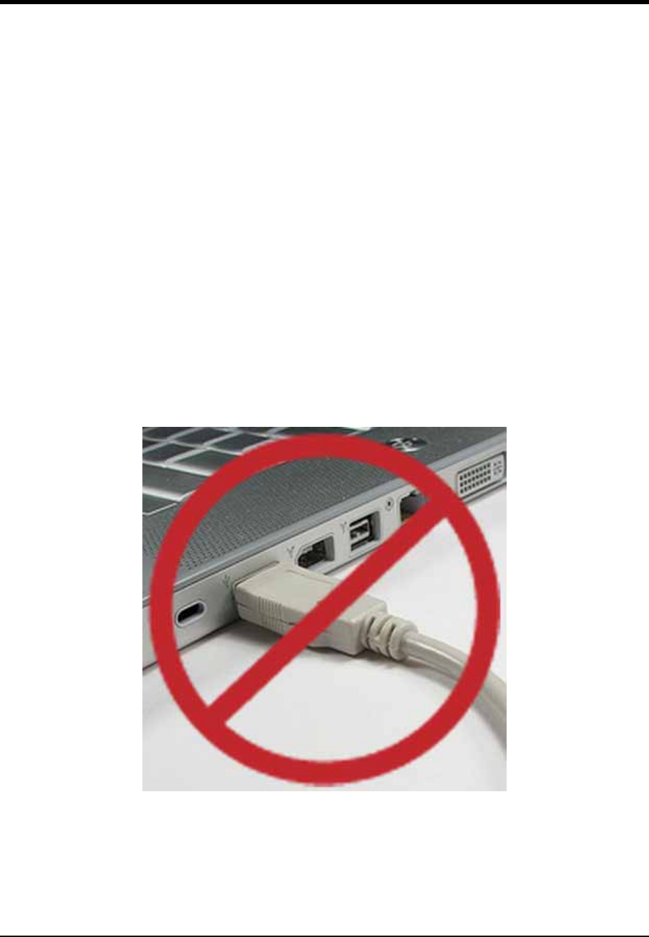
Note: DO NOT connect the Expansion port back to your network or PC. These Ethernet products use an Ethernet
switch. Looping any Ethernet switch will cause your network or PC to crash.
Installing WINDAQ software for Ethernet Products
All software is included in The DATAQ Instruments Software CD.
1. Insert the The DATAQ Instruments Software CD into your CD-ROM drive. The Windows auto run feature should
start the installation program. If the Windows auto run feature is not enabled on your PC, run the setup.exe pro-
gram located on the root of the CD directory.
2. In the “What do you want to do?” dialog box select the Install Software radio button and click OK.
3. In the “Installing Software” dialog box select the Install Software for all other products radio button and click
OK.
4. In the “Specify the product” dialog box you must choose the version of WINDAQ you would like to install. If you
purchased and unlock code (WINDAQ/Pro or Pro+), select the appropriate option and click OK. If you did not
purchase an unlock code, choose the WINDAQ/Lite option and click OK.
5. In the “Specify the Instrument” dialog box select the DI-720/740/730HV Portable Instruments radio button
and click OK.
6. In the “Specify the Instrument” dialog box select the Ethernet radio button and click OK.
7. Check the sticker located on the bottom of your instrument and note the model number. In the “Select a device”
dialog select the model number of your device and click OK.
To Ethernet port on PC or Network
DI-720 or DI-730 Series Instrument
Rear Panel
CAT-5 Ethernet Cable
(up to 100 meters)
To Toward PC port on device

DI–720/DI–722/DI–730 Series User Manual
Getting Started
18
8. The “Welcome!” dialog box allows you to cancel the installation. Click OK to continue installation or Cancel to
abort.
9. Read through the Software License agreement carefully and either Accept and Continue or Cancel to exit the
installation.
10. Enter your Registration Information in the appropriate text boxes and click OK.
11. Select the destination directory where you would like all folders and files to reside on your hard drive. We rec-
ommend you accept the default path, but you can name this new directory anything you like. Simply substitute
the desired drive and directory in the Destination Directory text box. Once you have chosen the directory click
OK.
12. The “Make Backups?” dialog box provides the option of creating backup copies of any files that may be replaced
during installation. This is a safety courtesy; backup copies are not required. Click on No if you don't want to
make backups. Click on Ye s to create backups. If you decide to create backups, you will be prompted to specify
a backup file directory.
13. Select the program manager group you would like to place the program shortcuts in your Windows programs.
The default is recommended, but you can specify any program group or create a new one. Click OK to continue.
14. You must know either the MAC address or the IP address of the device to continue. The MAC address is located
on the sticker on the bottom of your device. IP addresses must be retrieved from the system administrator. Enter
the MAC address or IP address in the text box provided in the “MAC or IP address of the device” dialog box. If
you are installing a device that is not connected to your Local Area Network, you should enter the IP address
here. The software will go to that IP address and retrieve the MAC address for you. This will save further setup
in the TCP/IP Manager. Click OK to continue. Note: If you enter the wrong MAC address you will have to re-run
this installation program with the correct MAC address to access the device.
15. Click Ye s in the “More ethernet devices to install” dialog box if you are installing multiple Ethernet devices.
16. Repeat Steps 14 and 15 until all Ethernet devices’ MAC addresses have been entered. Click No to continue
installation.
17. The “Installation Option” dialog box allows you to specify access to WINDAQ for multiple users on the same PC.
If you are the only user or you would like to allow access to all users click Ye s. If there are multiple users and
you would like to be the only one able to access WINDAQ click No. Click Cancel to abort the installation.
18. Select the desired options for installation of WINDAQ/XL and Advanced CODAS.
19. Installation is complete. Run the TCP/IP Manager via the Windows program group specified during WINDAQ
Software installation (default is Start > Programs > WINDAQ > IP Manager) to access the device and run
WINDAQ Acquisition Software
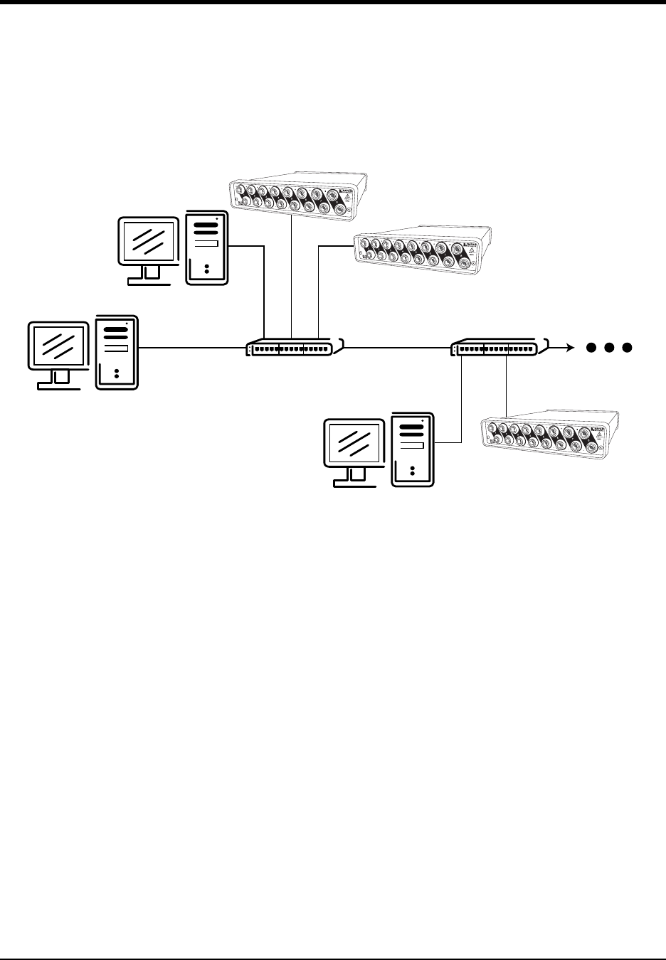
Daisy-Chaining Multiple Ethernet Products
Multiple Ethernet products may be daisy-chained together to allow for one synchronous distributed data acquisition
system. Multiple DI-720, DI-722, and/or DI-730 instruments may be placed in the same daisy chain. To maintain syn-
chronicity, Ethernet hubs and switches cannot be used between units. Make sure to enter each MAC address during
installation. Daisy-chains must be installed to your Local Area Network (LAN) — you cannot access more than one
device per IP address outside of your subnet. If you are not sure whether or not the devices are in your subnet see your
system administrator before installation. You may acquire data from only one daisy chain at a time (i.e., the same PC
cannot access two daisy chained groups at the same time).
Note: If you are installing a daisy-chained group of instruments for the purpose of synchronous distributed data
acquisition, do not allow any other units or daisy chains to be installed to your subnet. Running other devices on the
same subnet will cause the synced units to become unsynced.
DI–720/DI–722/DI–730 Series User Manual
Getting Started
19
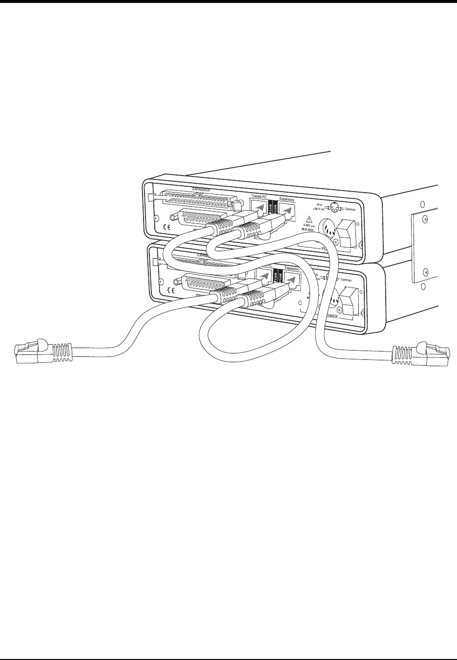
1. Connect one end of a CAT-5 Ethernet cable to the Toward PC port of the first Ethernet device.
2. Connect the other end of the same CAT-5 Ethernet cable to the Ethernet port on your PC or LAN.
3. Connect one end of another CAT-5 Ethernet Cable to the Expansion port on the rear of the first Ethernet device.
4. Connect the other end of the same CAT-5 Ethernet cable to the Towa rd PC port on the second Ethernet device.
5. Continue installing more Ethernet devices by connecting a CAT-5 Ethernet cable to the Expansion port of the
last device in the chain and the Tow ard PC port on the next device you are adding to the chain. Up to 32 devices
may be installed in a single daisy chain. Each device may be 100 meters apart. Use the illustration below for ref-
erence.
Note: DO NOT connect the Expansion port on the last product in the chain back to your network or PC. These Ether-
net products use an Ethernet switch. Looping any Ethernet switch will cause your network or PC to crash.
Use the TCP/IP Manager to run WINDAQ Acquisition Software (see “TCP/IP Manager (Ethernet Models Only)” on
page 19). WINDAQ Acquisition Software provides data acquisition and recording capabilities. Daisy-chained units
record separate files synchronously (one file for each unit) and place them in a user-defined Session folder. The user
may define which units to use in a daisy-chain so not all units have to be used for a recording session.
Use the WWB Navigator to playback and analyze multiple data files in a Session folder (see “WinDaq Waveform
Navigator (Ethernet models only)” on page 20) synchronously. The user may choose which files to view and analyze
so not all data files in a session have to be viewed at the same time. Individual files may be independently opened
using WINDAQ Playback Software (WINDAQ Waveform Browser).
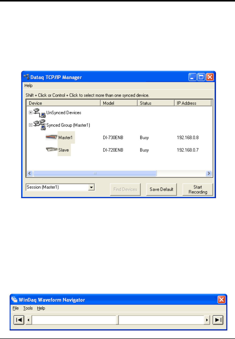
TCP/IP Manager (Ethernet Models Only)
The TCP/IP Manager allows you to easily manage all DI-720, DI-722 and DI-730 Ethernet Instruments installed on
your PC. The TCP/IP manager is installed when installing WINDAQ Software. Access the TCP/IP Manager via the
Windows program group specified during WINDAQ Software installation (default is Start > Programs > WINDAQ >
IP Manager). For help with TCP/IP settings and the TCP/IP Manager see the help files accessible in the application
(press F1 to access context-sensitive help or use the Help menu).
First DI-720 or DI-730
Second DI-720 or DI-730
Connect to Ethernet port on PC or
Network (up to 100 meters)
Connect to Toward PC port on next
DI-720 or DI-730 (up to 100 meters)
CAT-5 Ethernet Cables
(each cable can be up
to 100 meters long)
DI–720/DI–722/DI–730 Series User Manual
Getting Started
20
The main TCP/IP window shows all Ethernet devices installed on your PC. Devices could be busy or unavailable if
there are multiple users. If you entered the wrong MAC address during installation, the status of the device will be
“Off Line.” “UnSynced” devices are all single units installed to your network (units that are not daisy-chained).
Synced Groups are daisy-chained instruments. There is one Synced Group for each daisy chain. Each Synced Group
is named using the first device in the chain (in parentheses).
Use the drop down command menu to change the description of a device. All commands are performed by first
selecting a device, then using the drop down command menu. Multiple devices in the same Synced Group may be
selected for a recording session by using the Shift or Control key. Multiple Synced Groups cannot be accessed by the
same PC at the same time.
WINDAQ Acquisition software must be initiated from the TCP/IP Manager for all DI-720, DI-722, and DI-730 instru-
ments. To begin a recording session select a single device or a group of daisy-chained devices (using the Control or
Shift key) and click the Start WINDAQ button. Each device will open an instance of WINDAQ Acquisition software.
Change channel settings, calibration, and display options independently for each device using each instance of
WINDAQ. Most WINDAQ menu items are available when recording synced devices with the following exceptions:
The Open and Record menu items in the File Menu are not available; The Triggered Mode, Triggered Storage, and
Remote Storage menu items in the Options Menu are not available.
WINDAQ Waveform Navigator (Ethernet models only)
The WINDAQ Waveform Browser Navigator allows you to display and scroll through data recorded synchronously
using multiple daisy-chained DI-720, DI-722, and/or DI-730 Ethernet instruments.Access the application via the
Windows program group specified during WINDAQ Software installation (default is Start > Programs > WINDAQ >
WWB Navigator). Select multiple files from a Session folder to open them in the WINDAQ Waveform Navigator. Use
the scroll bar to navigate through all the data files synchronously.

DI–720/DI–722/DI–730 Series User Manual
Getting Started
21
For help with the WINDAQ Waveform Navigator see the help files accessible in the application (press F1 to access
context-sensitive help or use the Help menu).
DI–720/DI–722/DI–730 Series User Manual
Getting Started
23
4. Instrument Controls,
Indicators, and Connectors
Connect most signal leads to the front panel of DI-720, DI-722, and DI-730 Series instruments. Power, communica-
tions, and expansion connectors can be found on the rear of the instrument.
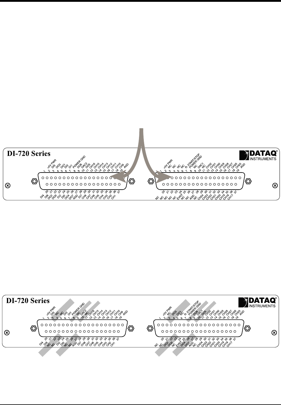
DI-720 Series Instrument Front Panel
The 37-pin male “D” connector on the left is used to interface analog input channels 1 through 16, digital inputs 1-8,
and digital outputs 1-8. The analog inputs are labeled CH1 through CH16, the digital inputs are labeled DI0 through
DI7, and the digital outputs are labeled DO0 through DO7. Other items include DAC2, which is a digital to analog
converter that serves as a general-purpose analog output accessible through WINDAQ and SDK software, and two
analog grounds labeled AGD.
Note: When using your DI-720-USB as a printer port device, Digital Output ports DO1, DO2, and DO3 are unavail-
able. If you have an expander (excluding the DI-78B and DI-75B) connected via the rear panel of the DI-720-USB,
Digital Output is not available. When using your DI-720-USB as a USB device the digital outputs are moved to the
second 37 pin D-sub connector (on the right hand side of the instrument).
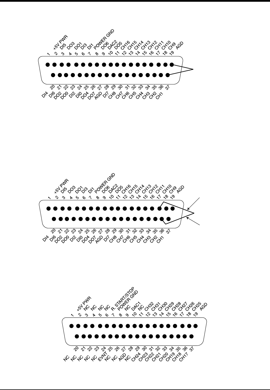
Read “CAUTION” on page v before connecting input signals. DI-720 Series instruments can accept 32 high-level
or preconditioned analog inputs in single-ended configuration or 16 high-level or preconditioned analog inputs in a
differential configuration. High-level inputs are typically low impedance, no-conditioning-required signals in the
Connect 16 single-ended or 8 differential
inputs directly to each of these connectors.
DI–720/DI–722/DI–730 Series User Manual
Getting Started
24
range of ±1.25 to ±10 volts full scale. Single-ended inputs are configured by connecting one signal lead to the desired
channel and the other signal lead to analog ground (AGD).
Differential inputs occupy two channels (e.g., these channel pairs constitute a differential input: 1 and 9, 2 and 10, 3
and 11, 4 and 12, 5 and 13, 6 and 14, 7 and 15, 8 and 16, etc.), with the lowest numbered channel in the pair assuming
the positive (+) input and the channel number. For example, say we have channels 2 and 10 configured as a differen-
tial input. Channel 2 is the positive (+) input, channel 10 is the negative (-) input, and the pair is referred to as “chan-
nel 2 differential.”
The 37-pin male “D” connector on the right provides access to analog input channels 17 through 32
This connector also includes DAC1, which is a second digital-to-analog converter that serves as a general purpose
analog output; R. START/STOP, which allows you to remotely start and stop data storage to disk with a switch or
Signal Leads
Channel 1 configured for single-ended operation
Signal Leads
Channel 2 configured for differential operation
+ input
- input
DI–720/DI–722/DI–730 Series User Manual
Getting Started
25
TTL level signal; EVNT, which allows you to remotely trigger event markers with a switch or TTL level signal; and
two analog grounds labeled AGD.
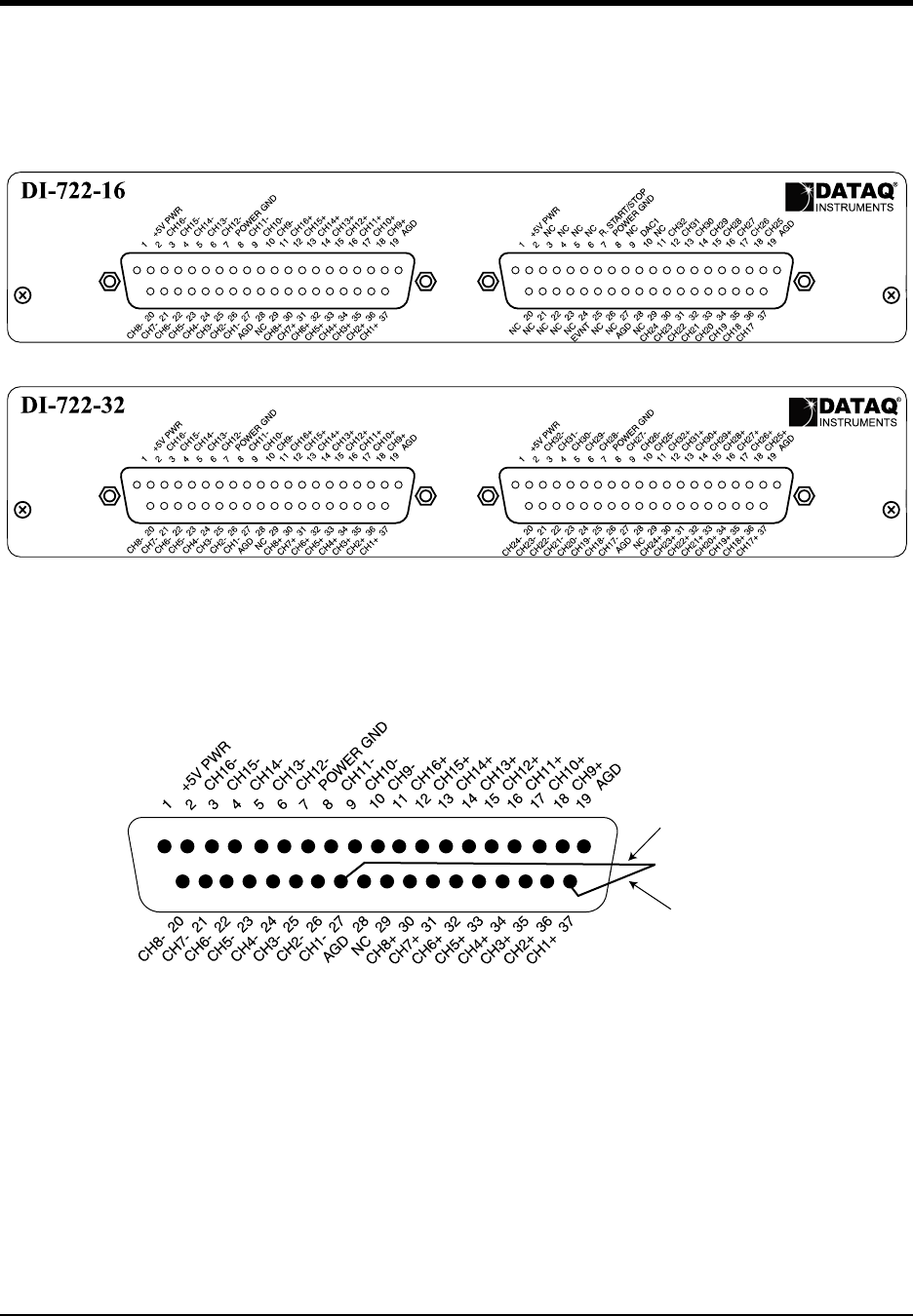
DI-722 Series Instrument Front Panel
The 37-pin male “D” connectors on the DI-722-32 (labeled C and D) and the one on the left of the DI-722-16 (labeled
A) are used to interface analog input channels to the DI-722 Series instrument. The analog inputs are labeled CH1+,
CH1- through CH16+, CH16- for the DI-722-16 and CH1+, CH1- through CH32+, CH32- for the DI-722-32. The
analog grounds are labeled AGD.
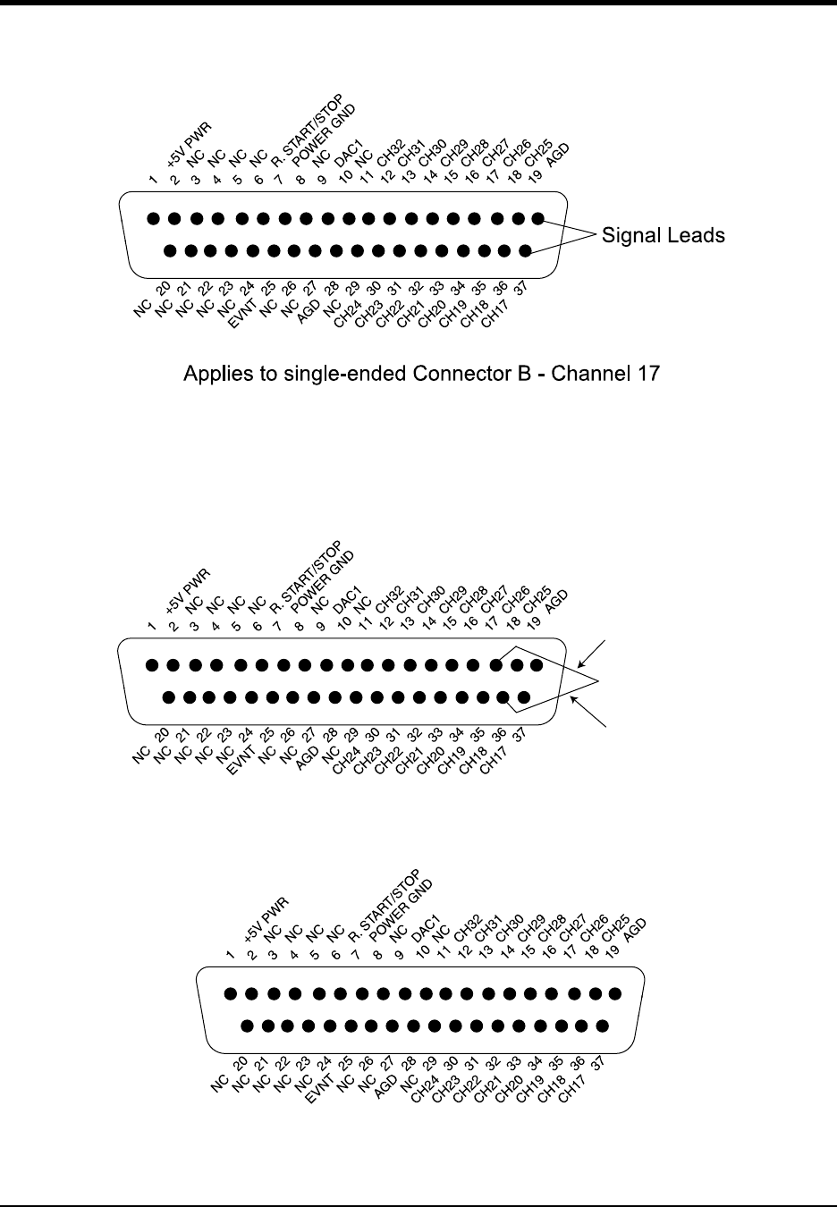
Read “CAUTION” on page v before connecting input signals. The DI-722-16 can accept 16 high-level or precon-
ditioned analog inputs in single-ended configuration or 16 high-level or preconditioned analog inputs in differential
configuration (through the 37-pin D connector labeled B above). High-level inputs are typically low impedance, no-
A B
C D
Signal Leads
+ input
- input
Applies to differential connectors A, C, and D - Channel 1
DI–720/DI–722/DI–730 Series User Manual
Getting Started
26
conditioning-required signals in the range of ±1.25 to ±10 volts full scale. Single-ended inputs are configured by con-
necting one signal lead to the desired channel and the other signal lead to analog ground (AGD):
Differential inputs occupy two channels (e.g., these channel pairs constitute a differential input: 17 and 25, 18 and 26,
19 and 27, 20 and 28, 21 and 29, 22 and 30, 23 and 31, 24 and 32), with the lowest numbered channel in the pair
assuming the positive (+) input and the channel number. For example, say we have channels 18 and 26 configured as
a differential input. Channel 18 is the positive (+) input, channel 26 is the negative (-) input, and the pair is referred to
as “channel 18 differential.”
The 37-pin male “D” connector on the DI-722-16 (labeled B in the graphic of the front panel) provides access to ana-
log input channels 17 through 32
This connector also includes DAC1, which is a second digital-to-analog converter that serves as a general purpose
analog output; R. START/STOP, which allows you to remotely start and stop data storage to disk with a switch or
Signal Leads
+ input
- input
DI–720/DI–722/DI–730 Series User Manual
Getting Started
27
TTL level signal; EVNT, which allows you to remotely trigger event markers with a switch or TTL level signal; and
two analog grounds labeled AGD.
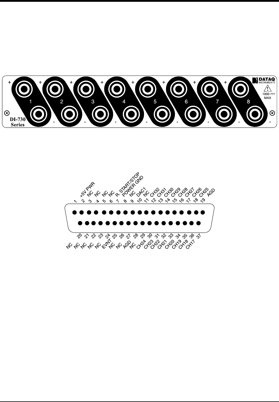
DI-730 Series Instrument Front Panel
DI-730 Series instruments can accept any eight differential analog inputs within a range of ±10mV to ±1000VDC (or
peak AC). Its ±1000V of channel-to-channel and input-to-output isolation protects delicate control circuits, computer
equipment, and personnel from high common mode voltages.
Use the EXPANSION (USB and PP devices) or Channel Expansion (EN devices) port on the rear of the instrument
with optional CABL-7 (part number 100679) to access the 16 general-purpose (±10V Full Scale) analog inputs. Use
the following diagram for pinout (see also “DI-720, DI-722, and DI-730 Series Instrument Rear Panel” on page 28).
Be sure to read “CAUTION” on page v before connecting signals to the Expansion port of your DI-730 device.
DI–720/DI–722/DI–730 Series User Manual
Getting Started
28
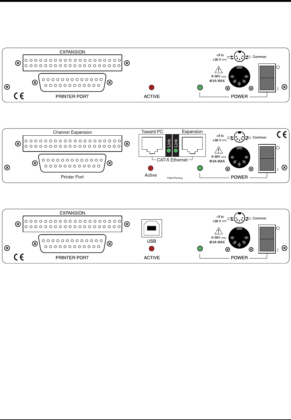
DI-720, DI-722, and DI-730 Series Instrument Rear Panel
The rear panel options are the same for DI-720, DI-722, and DI-730 Series instruments:
PRINTER PORT—Connects your instrument to the Printer Port of your PC using the supplied Printer Port Cable. All
DI-720, DI-722, and DI-730 Series instruments support standard, bi-directional and enhanced (EPP) printer port
communication modes (Ethernet and USB models only support bi-directional and EPP modes).
ACTIVE—DI-7xx-P instruments: Glows red when the instrument is streaming data. This includes all digital input/
output (where applicable), analog output and analog input functions. DI-7xx-EN instruments: Glows red
whenever data is sent back to the host computer. DI-7xx-USB instruments: Glows when the USB control-
ler is enabled.
POWER—This indicator glows green when power is applied to the DI-720, DI-722, or DI-730 Series instrument.
POWER INPUT JACK—Allows you to apply power to the instrument. Power can be applied with the included
power adapter or you can use an alternate source, as long as it is suitable (+9 to +36VDC @ 3A maximum).
POWER SWITCH—Controls power to the DI-720, DI-722, or DI-730 Series instrument. 1 is on, 0 is off.
CAT-5 Ethernet (EN models)—In addition to printer port communications, models DI-720-EN, DI-722-EN, and DI-
730-EN add Ethernet communication capability with this 10baseT port. Connect the Toward PC port to an Ethernet
port on your PC or Network. Use the Expansion port to daisy-chain multiple units together (see “Daisy-Chaining
Multiple Ethernet Products” on page 18). Note that the Ethernet communication interface cannot be used concur-
rently with the printer port.
Instrument Rear Panel
Instrument Rear Panel with Ethernet Option
Instrument Rear Panel with USB Option

DI–720/DI–722/DI–730 Series User Manual
Getting Started
29
USB (USB models)—In addition to printer port communications, models DI-720-USB, DI-722-USB, and DI-730-
USB add Universal Serial Bus (USB) communication capability. Note that the USB communication interface cannot
be used concurrently with the printer port.
EXPANSION (USB and PP models) or Channel Expansion (EN models) —When being used for expansion, models
DI-78B, DI-75B, DI-725 and DI-725E are plugged directly into this connector. The input signals are then connected
to the DI-78B, DI-75B, DI-725 or DI-725B expansion instrument. Use the following diagram for pinout.
1 +5V PWR
3 Reserved
5 Reserved
7 Reserved
9 Reserved
11 R. Start/Stop
13 PWR GND
15 Reserved
17 DAC1
19 Reserved
21 CH32
23 CH31
25 CH30
27 CH29
29 CH28
31 CH27
33 CH26
35 CH25
37 AGND
39 Reserved
Reserved 2
Reserved 4
Reserved 10
Reserved 8
Reserved 6
R. Events 12
Reserved 14
Reserved 16
AGND 18
Reserved 20
CH24 22
CH23 24
CH22 26
CH21 28
CH20 30
CH19 32
CH18 34
CH17 36
Reserved 38
Reserved 40

DI–720/DI–722/DI–730 Series User Manual
Calibration Verification
31
5. Calibration Verification
This section provides calibration verification procedures for the A/D and D/A subsystems of the DI-7xx unit. Your
instrument is calibrated before it is shipped and, therefore, does not need immediate calibration. Should your unit not
comply with the calibration guidelines presented below, arrange to have DATAQ Instruments recalibrate your instru-
ment.
Required Equipment
A/D Calibration (For DI-720, DI-722, and DI-730 Series Instruments)
• A precision DVM with resolution as a function of the input range being calibrated:
minimum DVM resolution = Instrument FSR x 0.1%
For example, suppose we have a DI-720-P and we want to calibrate the ±10 volt range (the DI-720 delivers ±10
volts at a gain of 1):
10V x 0.1% = 10mV
So we would need a DVM with a resolution of 10V or more to calibrate the ±10 volt range.
• A stable voltage source with a stability specification equal to or greater than the minimum DVM resolution,
as calculated above, required to calibrate the instrument at the highest desired gain.
OR
• An alternative is to use a voltage calibrator with enough resolution, as calculated above, to calibrate the
instrument at the highest desired gain.
D/A Calibration (DI-720 Instruments Only)
• A precision DVM with resolution of at least 1mV.
A/D Calibration Verification (DI-720, DI-722, and DI-730 Series Instruments)
Calibration verification of DI-720 Series instruments' A/D subsystem is performed on channel 1, with all other chan-
nels returned to analog common. Calibration of DI-730 Series instrument's A/D subsystem is performed on a chan-
nel-by-channel basis for the 8 wide range inputs and on channel 17 for the general-purpose channels. The following
figures illustrate the necessary connections:
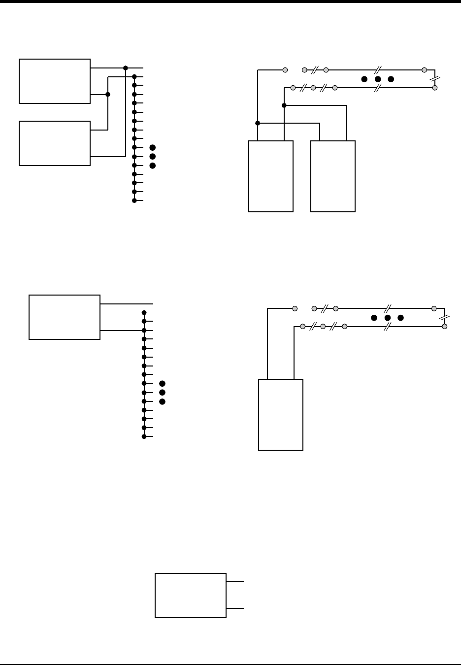
DI–720/DI–722/DI–730 Series User Manual
Calibration Verification
32
Or if you are using the alternative voltage calibrator, the following figure illustrates the necessary connections:
D/A Calibration (DI-720 Series Only)
D/A calibration involves adjusting the analog outputs to the correct full-scale range using the analog data value. The
following figure illustrates the necessary connections:
When the above circuit is connected, the calibration program can be initiated by typing “DI720CAL” at the DOS
prompt. D/A calibration is accomplished by following the on screen prompts.
DI-720 Series Instruments And
16 DI-730 General-Purpose Channels
DI-722 and DI-730 Series 8 Wide-Range Channels (accessi-
ble from the front panel). Channels should be measured in
isolation and not in groups with the shortest lead possible.
DI-720 Series Instruments
16 DI-730 General-Purpose Channels
DI-722 and DI-730 Series 8 Wide-Range Channels (accessible
from the front panel). Channels should be measured in isola-
tion and not in groups with the shortest lead possible.
CH1
CH2
CH3
CH4
CH5
CH6
CH7
CH8
CH9
CH30
CH31
CH32
S.GND
(signal ground)
Voltage
Source
+
+
-
-
DVM
DVM Voltage
Source
++--
CH1 CH2 CH3 CH8
++++
-- - -
+
-
CH1
CH2
CH3
CH4
CH5
CH6
CH7
CH8
CH9
CH30
CH31
CH32
S.GND
(signal ground)
Voltage
Calibrator
Voltage
Calibrator
+-
CH1 CH2 CH3 CH8
++
++
-- - -
+
-
DVM
DAC1/DAC2
SGND
(signal ground)

DI–720/DI–722/DI–730 Series User Manual
Calibration Verification
33
Offset Calibration Verification (DI-720 and DI-722 Instruments Only)
1. Connect your voltage calibrator, or combination DVM and voltage source to your DI-7XX instrument as shown
above. Apply zero volts to the instrument (or short the instrument's analog channel input to ground).
2. Open the WINDAQ/Lite/Pro/Pro+ data acquisition screen. Enable the channel you will use to quantify offset.
Since all channels are adjusted together, any channel may be selected. Enable a maximum burst sample rate of
50,000 Hz by selecting EDIT-PREFERENCES-MAX SAMPLE RATE. Enable a WINDAQ sample rate of 50 Hz.
Set the Acquisition Mode to AVERAGE and the gain factor to 1 through WINDAQ’s CHANNEL SETTINGS
menu for the selected channel.
3. Referring to WINDAQ software's voltage display for the channel you're evaluating, compare this value to that
given in the OFFSET column of TABLE (1) for the selected gain factor.
4. Repeat steps 2 and 3 using a gain of 2, 4 and 8 for the selected channel.
5. If any readings are out of the acceptable ranges described in TABLE (1) arrange to have your instrument recali-
brated by DATAQ Instruments.
Full Scale (Span) Calibration Verification (DI-720 and DI-722 Instruments
Only)
1. Referring again to TABLE (1) set the instrument's gain to 1 and apply the voltage indicated by the SPAN VOLT-
AGE column of TABLE (1) to the selected channel. Note that since all channels are calibrated together, any
channel may be selected. **NOTE: For DI-722 general purpose channels, refer to TABLE 1. For DI-722 differ-
ential channels, refer to TABLE 2.
2. Verify the reading by comparing the value displayed by WINDAQ software with the value of TABLE (1) in the
SPAN ACCURACY column.
3. Repeat for gain selections of 2, 4, and 8.
4. If any readings are out of the acceptable ranges described in TABLE (1) arrange to have your instrument recali-
brated by DATAQ Instruments.
TABLE 1
Gain Factor Offset @ 0V Span Voltage Span Accuracy*
1 0V ±20mV 9.800V 9.800V ±25mV
2 0V ±10mV 4.900V 4.900V ±12.5mV
4 0V ±5mV 2.400V 2.400V ±6.25mV
8 0V ±5mV 1.200V 1.200 ±3.125mV
* Excludes offset errors.
TABLE 2 (Only applicable for DI-722 differential channels)
Gain Factor Offset @ 0V Span Voltage Span Accuracy*
1 0V ±40mV 19.600V 19.600V ±50mV
2 0V ±20mV 9.800V 9.800V ±25mV
4 0V ±10mV 4.800V 4.800V ±12.5mV
8 0V ±10mV 2.400V 2.400 ±6.25mV
* Excludes offset errors

DI–720/DI–722/DI–730 Series User Manual
Calibration Verification
34
Offset Calibration Verification (DI-730 Instruments only)
1. Connect your voltage calibrator, or combination DVM and voltage source to your DI-730 instrument as shown
above. Apply zero volts to the instrument (or short the instrument's analog channel input to ground).
2. Open the WINDAQ/Lite/Pro/Pro+ data acquisition screen. Enable the channel you want to verify. Enable a maxi-
mum burst sample rate of 50,000 Hz by selecting EDIT-PREFERENCES-MAX SAMPLE RATE. Enable a
WINDAQ sample rate of 50 Hz. Set the Acquisition Mode to AVERAGE select the 10mV range through
WINDAQ's CHANNEL SETTINGS menu for the selected channel.
3. Referring to WINDAQ software's voltage display for the channel you're evaluating, compare this value to that
given in the OFFSET column of TABLE (2) for the selected range.
4. Repeat steps 2 and 3 using for each measurement range.
5. Select the next channel, and repeat steps 2 through 4.
6. If any readings are out of the acceptable ranges described in TABLE (2) arrange to have your instrument recali-
brated by DATAQ Instruments.
Full Scale (Span) Calibration Verification (DI-730 Instruments Only)
1. Referring again to TABLE (2) select the 10mV range and apply the voltage indicated by the SPAN VOLTAGE
column of TABLE (2) to the selected channel.
2. Verify the reading by comparing the value displayed by WINDAQ software with the value of TABLE (2) in the
SPAN ACCURACY column.
3. Repeat steps 1 and 2 for all ranges.
4. Repeat steps 1 through 3 for all channels.
5. If any readings are out of the acceptable ranges described in TABLE (1) arrange to have your instrument recali-
brated by DATAQ Instruments.
TABLE (2)
Channel Group Range Offset @ 0V Span Voltage Span Accuracy
1 through 8 10mV 0 ±0.04mV 9mV 9mV ±125µV*
100mV 0 ±0.4mV 90mV 90mV ±350µV*
1V 0 ±4mV 900mV 900mV ±2.6mV
10V 0 ±10mV 9V 9V ±25.1mV
100V 0 ±100mV 90V 90V ±0.2501V
1000V 0 ±1V 700V 700V ±2.5V
17 through 32 10V 0 ±5mV 9V 9V ±25mV
5V 0 ±3mV 4.5V 4.5V ±12.5mV
2.5V 0 ±2mV 2V 2V ±6.25mV
1.25V 0 ±1mV 1V 1V ±3.125mV
* These low-level measurements require an environment free from electrical noise.
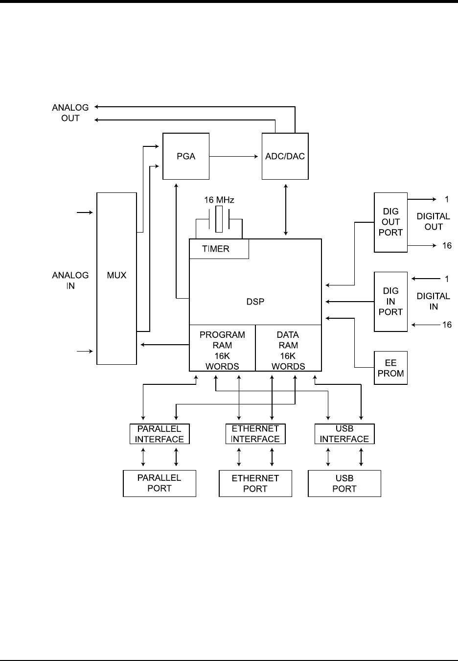
DI–720/DI–722/DI–730 Series User Manual
Block Diagram
35
6. Block Diagram
DI-720 Series
1
32
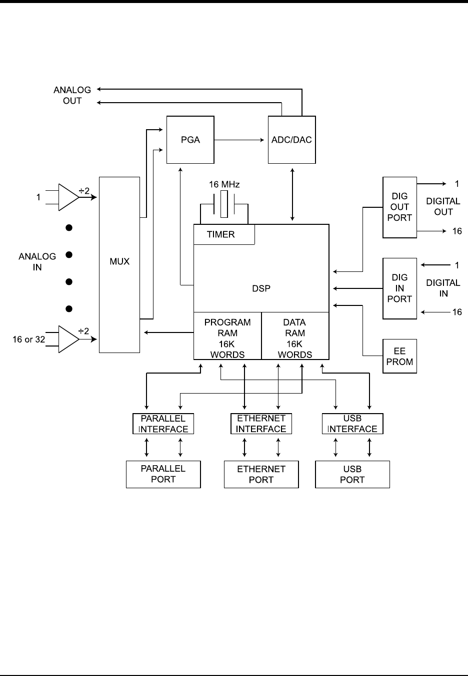
DI–720/DI–722/DI–730 Series User Manual
Block Diagram
36
DI-722 Series
+
+
-
-
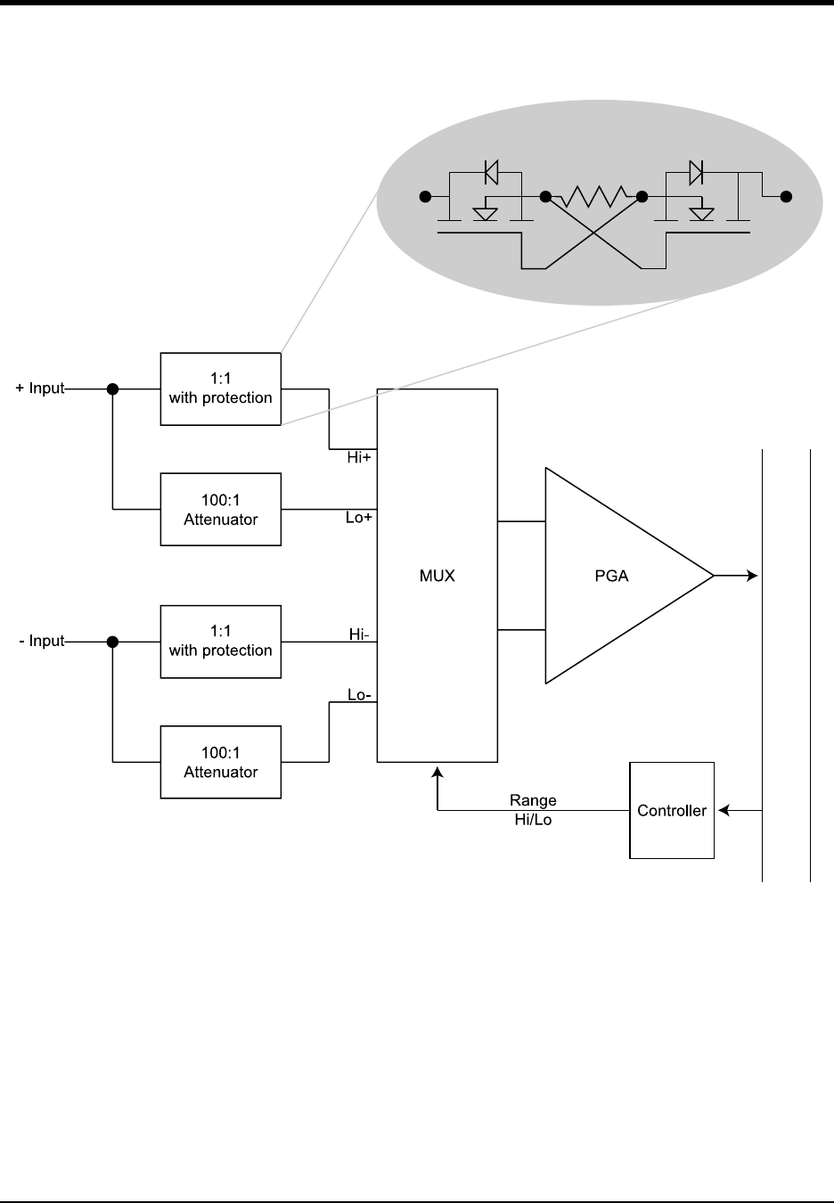
DI–720/DI–722/DI–730 Series User Manual
Block Diagram
37
DI-730 Series (Analog Input)
,
6
2
/
$
7
,
2
1
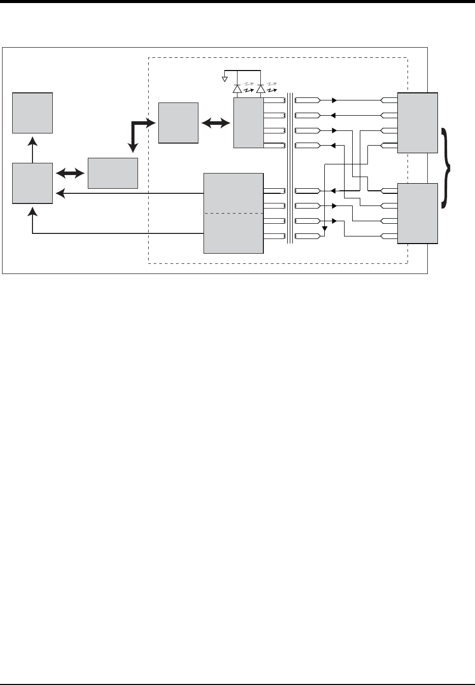
DI–720/DI–722/DI–730 Series User Manual
Block Diagram
38
Ethernet Instruments
RX
TX
Clock In
Clock Out
Sync In
Sync Out
Clock In
10/100
BaseT
RX
TX
RX
TX
Sync Out
Sync In
Clock Out
RX
TX
Interrupt
Synchronous Clock
Synced
ADC
Clock
Command,
Status,
Data,
Address
Link
RJ45
Toward PC
RJ45
Expansion
Sync Start
Encoder/Decoder
PLL Clock
Reconstruction
Ethernet
Controller
Ethernet
Switch
Interface
Controller
DSP
ADC
Ethernet Interface
DI-720 or DI-730
Link

DI–720/DI–722/DI–730 Series User Manual
Accessories
39
7. Accessories
This section describes hardware products that may be used with DI-720, DI-722, and DI-730 Series instruments.
The DI-705: Signal Input/Output Option .......................................................................................... 40
The DI-205: Signal Input/Output Panel ............................................................................................. 41
DI-725(E) Channel Expansion Unit .................................................................................................. 46
DI-78B 8B Module Channel Expander ............................................................................................. 52
DI-8B Modules .................................................................................................................................. 60
DI-8B30/31 Analog Voltage Input Modules, 3Hz Bandwidth ................................................... 60
DI-8B32 Analog Current Input Modules .................................................................................... 61
DI-8B34 Linearized 2- or 3-Wire RTD Input Modules .............................................................. 62
DI-8B35 Linearized 4-Wire RTD Input Modules ....................................................................... 63
DI-8B36 Potentiometer Input Modules ....................................................................................... 64
DI-8B38 Strain Gage Input Modules, Narrow & Wide Bandwidth ........................................... 65
DI-8B40/41 Analog Voltage Input Modules, 1kHz Bandwidth ................................................. 66
DI-8B42 2-Wire Transmitter Interface Modules ........................................................................ 67
DI-8B45 Frequency Input Modules ............................................................................................ 68
DI-8B47 Linearized Thermocouple Input Modules .................................................................... 69
DI-8B50/51 Analog Voltage Input Modules, 20kHz Bandwidth ............................................... 70
DI-75B 5B Module Channel Expander ............................................................................................. 71
DI-5B Modules .................................................................................................................................. 78
DI-5B30/31 Analog Voltage Input Modules, Narrow Bandwidth .............................................. 78
DI-5B32 Analog Current Input Modules .................................................................................... 79
DI-5B33 Isolated True RMS Input Modules .............................................................................. 80
DI-5B34 Linearized 2- or 3-Wire RTD Input Modules .............................................................. 81
DI-5B35 Linearized 4-Wire RTD Input Modules ....................................................................... 83
DI-5B36 Potentiometer Input Modules ....................................................................................... 85
DI-5B38 Strain Gage Input Modules, Narrow & Wide Bandwidth ........................................... 86
DI-5B40/41 Analog Voltage Input Modules, Wide Bandwidth ................................................. 88
DI-5B42 2-Wire Transmitter Interface Modules ........................................................................ 89
DI-5B43 Isolated DC Transducer Amplifier Input Module ........................................................ 90
DI-5B45 Frequency Input Modules ............................................................................................ 92
DI-5B47 Linearized Thermocouple Input Modules .................................................................... 93
DI-5B48 Accelerometer Input Modules ..................................................................................... 95
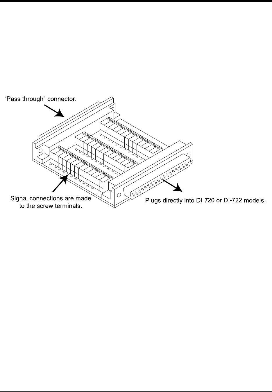
DI–720/DI–722/DI–730 Series User Manual
Accessories
40
The DI-705: Signal Input/Output Option
General
The DI-705 plugs into either 37-pin male “D” connector on the front panel of DI-72x Series instruments and provides
convenient screw terminal access to analog inputs, analog outputs, and digital inputs and/or outputs. The screw termi-
nals accept 16-22 gauge wire and each is silk-screened with the corresponding “D” connector pin number. The DI-
705 also features a 37-pin male “pass-through” connector, which allows you to connect our BNC cable (model num-
ber CABL-4), or our 5B back plane cable (model number CABLE-1), or any 37-pin DAS-16 compatible cable to the
DI-720 while still allowing screw terminal access.
Input Signal Configuration
Any combination of single-ended or differential channels may be connected to the DI-705, but keep in mind a differ-
ential channel uses two analog inputs. Configure single-ended and differential channels on the DI-705 the same way
as on the DI-72x. Refer to the heading titled “DI-720 Series Instrument Front Panel” or “DI-722 Series Instrument
Front Panel” in the Getting Started section of this manual for single-ended/differential configuration details.
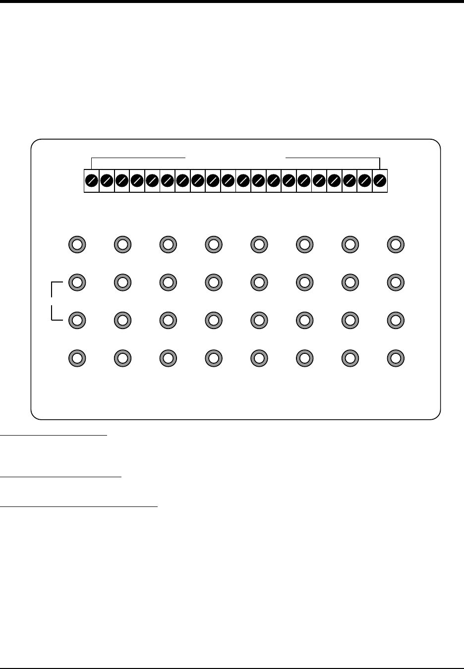
DI–720/DI–722/DI–730 Series User Manual
Accessories
41
The DI-205: Signal Input/Output Panel
General
The DI-205 is a termination panel for general purpose input and output. The DI-205 along with the supplied cable
provides a convenient way to interface digital input/output, analog output and analog input signals to DI-720 Series
instruments. Signal connection is via terminal strip for digital and analog output signals, or 5-way binding posts
(banana jacks) for analog input signals.
DI-205 Input/Output Panel Interconnections
Digital Inputs (DI0 to DI7)
The left end of the 20-connector screw terminal labeled “DGND” and “DI0” through “DI7” indicates the digital input
ports of the DI-205.
Digital Outputs (DO0 to DO7)
The 8 digital output lines labeled “DO0” through “DO7” indicate the digital output ports of the DI-205.
Analog Output (DAC1, DAC2, VOUT)
The digital-to-analog converter (DAC) outputs have two applications: As a general purpose analog output accessible
through WINDAQ or Programmer’s SDK software or as a variable signal suppression voltage automatically enabled
and multiplexed to all channels through Programmer’s SDK software.
Input Signal Configuration
Each DI-205 may be configured to connect to 16 single-ended or 8 differential channels. In addition, any combination
of single-ended or differential channels may be applied. A differential channel is configured by using two single-
ended inputs according to the following illustration:
-ODEL$)
CHAN. 1 CHAN. 2 CHAN. 3 CHAN. 4 CHAN. 5 CHAN. 6 CHAN. 7 CHAN. 8
S. GND S. GND S. GND S. GND S. GND S. GND S. GND S. GND
S. GND S. GND S. GND S. GND S. GND S. GND S. GND S. GND
CHAN.9(1) CHAN.10(2) CHAN.11(3) CHAN.12(4) CHAN.13(5) CHAN.14(6) CHAN.15(7) CHAN.16(8)
DGND
DI0
DI1
DI2
DI3
DI4
DI5
DI6
DI7
DO0
DO1
DO2
DO3
DO4
DO5
DO6
DO7
DAC1
DAC2
VOUT
Digital I/O - Analog Output
Dif.
-
+
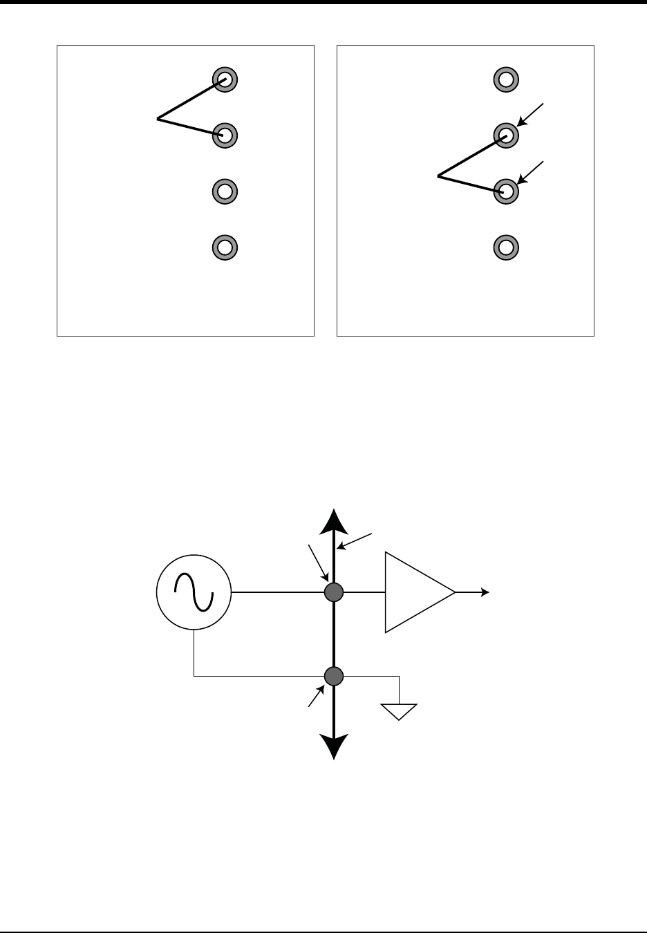
DI–720/DI–722/DI–730 Series User Manual
Accessories
42
Note that when an input channel is configured for differential operation, the binding post associated with that chan-
nel's high (+) input assumes the channel number.
Connecting a Single-ended Amplifier
A single-ended amplifier is the most straightforward approach to connecting signals to the DI-205. However, to
derive adequate performance, the use of a single-ended amplifier requires that the signal to be measured is relatively
high level (greater than or equal to 1V full scale), and the distance from the signal source to the DI-205 is relatively
short (less than 15 feet). Assuming these conditions exist, a single-ended amplifier may be connected to your signal
source as follows:
Connecting a Differential Amplifier
A differential channel configuration is a special case approach to signal measurement that should be used with all
low-level measurements (less than 1v) or when the signal to be measured is located far away from the DI-205 (greater
than 15 feet). When in a differential operating mode, the amplifier sees the difference in voltage between the high (+)
and low (-) inputs. Differential amplifiers have the advantage of reducing common mode voltages (those appearing
simultaneously and in phase on both inputs). This capability may be leveraged to great advantage to reduce noise rid-
ing on a signal of interest.
CHAN. 1
S. GND
S. GND
CHAN.9(1)
Signal Leads
Channel 1 configured
for single-ended input
CHAN. 1
S. GND
S. GND
CHAN.9(1)
Signal Leads
Channel 1 configured
for differential input
+ input
- input
(-)
(+)
1 of 16 analog grounds
1 of 16 analog inputs
Signal
Source
DI-205
Terminal Strip
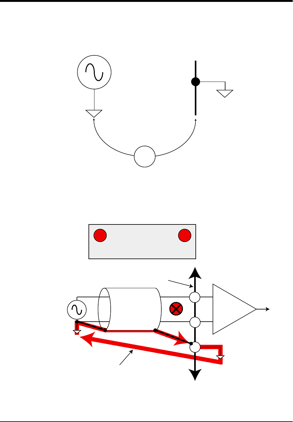
DI–720/DI–722/DI–730 Series User Manual
Accessories
43
Two signal measurement conditions govern your configuration of a differential channel input: The signal to be mea-
sured is ground-referenced; or the signal to be measured is isolated from ground.
Ground-referenced Signal Sources—A ground-referenced signal source is one with a local ground that may not be
(and probably is not) at the same potential as the computer's ground. This potential difference between signal ground
and computer ground is referred to as a common mode voltage and is caused by a number of different factors.
The most common of these is different physical locations of the computer and signal ground points. Since wire is not
a perfect conductor (exhibiting zero resistance regardless of length) a voltage drop, however small, will always be
present. The differential amplifier is unique in its ability to measure signals originating from sources with different
ground potentials relative to the computer provided it is connected properly.
V
Signal
Source
Computer
Ground
Ground Potential Difference
(Common Mode Voltage)
+
Signal
Source
Differential
Amplifier
-
gnd
Signal
Lead
Shield
Ground loop caused by circulating currents.
DI-205 terminal strip
WRONG APPROACH
Circulating currents in signal shield
induce noise on signal of interest.
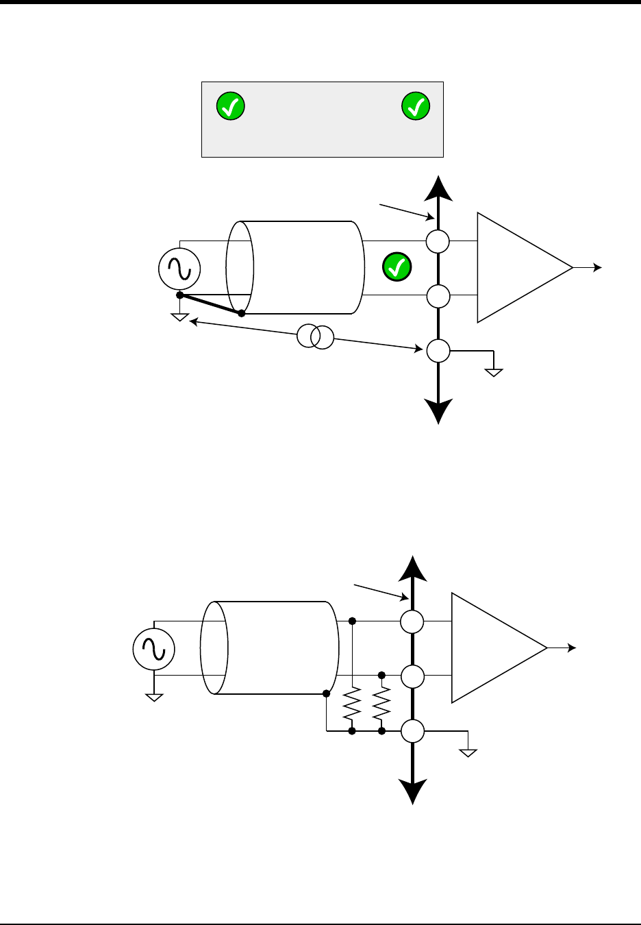
DI–720/DI–722/DI–730 Series User Manual
Accessories
44
The most common error made in connecting differential amplifiers is the tendency to ground both ends of a signal
shield. This causes current to flow through the shield and induces noise on the signal to be measured. Ensuring that
only one ground exists on the signal circuit eliminates this problem.
Isolated Signal Sources—There are two considerations when connecting a differential amplifier to an isolated signal
source: The elimination of ground loops as described above, and the use of bias resistors to provide bias current for
the differential amplifier's positive and negative inputs.
The bias resistors should be chosen to be as low as possible, but the value you use is dependent upon the output
impedance of your signal source. Generally, the value of the bias resistor should be 10 times the output impedance of
your signal source or higher. Bias resistors greater than 1M are not recommended.
Signal Cable and the Differential Amplifier
Quick rule-of-thumb: Any application requiring a differential amplifier also defines a need for quality signal cable.
Four elements combine to ensure adequate quality signal cable: a twisted signal pair with low resistance stranded
+
Signal
Source
Differential
Amplifier
-
gnd
Signal
Lead
Shield
Potential difference
(no path for current to circulate)
DI-205 terminal strip
RIGHT APPROACH
One ground on the signal circuit eliminates
noise-inducing ground loops.
+
Floating
Signal
Source
Differential
Amplifier
-
gnd
Signal
Lead
Shield
DI-205 terminal strip
Locate bias resistors as close
to amplifier as possible

DI–720/DI–722/DI–730 Series User Manual
Accessories
45
copper conductors; surrounded by a multiple-folded foil shield; with a copper stranded drain wire; all contained
within an insulated outer jacket.
In applications where such signal cable is used, a dramatic decrease in noise pickup will be experienced. The drain
wire should be considered as the shield and should be connected as described in the Connecting a Differential Ampli-
fier section above. Signal cable meeting all four criteria for quality is Belden No. 8641.
Insulated Outer Jacket Foil Shield Drain Wire
Twisted Signal Pair
Stranded Copper Conductors
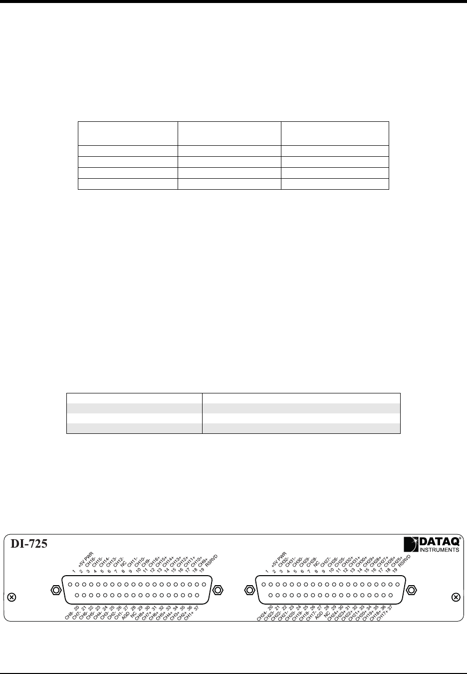
DI–720/DI–722/DI–730 Series User Manual
Accessories
46
DI-725(E) Channel Expansion Unit
The DI-725 is a 32-channel analog expansion device for DI-400, DI-720, and DI-730 instruments. The DI-725 fea-
tures 32 differential analog inputs. The DI-725 is powered by the host DI-400, DI-720, or DI-730 instrument and in
most cases will not need an additional power supply. However, when several DI-725s are linked together, an addi-
tional power source may be required (indicated by a glowing POWER LOW lamp). The DI-725E requires an addi-
tional power source connected via the power input jacks located on the rear panel of the instrument.
Input signal ranges are as follows:
* For the DI-725, overvoltage protection is ±30V powered on and off.
** For the DI-725E, overvoltage protection is ±120V powered on and off.
In return for the 32 expansion channels it provides, each DI-725 consumes two channels from its host instrument.
When a single DI-725 is connected to a DI-400, the combination provides 46 total channels (14 channels are still
available on the host DI-400). When connected to a DI-720, the combination delivers 62 total channels (30 are still
available on the host DI-720). When connected to a DI-730, the DI-725 adds 32 high level differential inputs to the
host’s 8 wide measurement range inputs for a diverse blend of 40 total channels. A maximum of 240 channels may be
configured using multiple DI-725s.
Connecting the DI-725 to the Host Instrument
NOTE: The included expansion signal cable and dual-ended power cable are sized to fit when the DI-725 is stacked
on top of (or below) the host DI-720 or DI-730 instrument. If you are using these instruments and they are not in a
stacked configuration, do so before proceeding.
1. Connect the appropriate end of the included expansion signal cable to the host instrument:
2. Connect the other end of the expansion cable to EXPANSION IN on the rear panel of the DI-725. Power for the
DI-725 is obtained from the host instrument through this cable. Power for the DI-725E must be supplied via the
power input jacks.
Features, Controls, and Indicators
DI-725 Front Panel
The two, 37-pin, male “D” connectors are used to connect your analog input signals to the DI-725. It can accept 32
high-level or preconditioned analog inputs in a differential configuration (one positive (+) and one negative (-) signal
Gain
(Software Selectable)
Measurement Range
(DI-725*)
Measurement Range
(DI-725E**)
1 ±10V ±20V
2±5V±10V
4 ±2.5V ±5V
8 ±1.25V ±2.5V
If you have this instrument: Then connect the expansion cable to:
DI-400 The DI-400’s 37-pin “D” connector
DI-720 EXPANSION on the rear panel of the DI-720
DI-730 EXPANSION on the rear panel of the DI-730
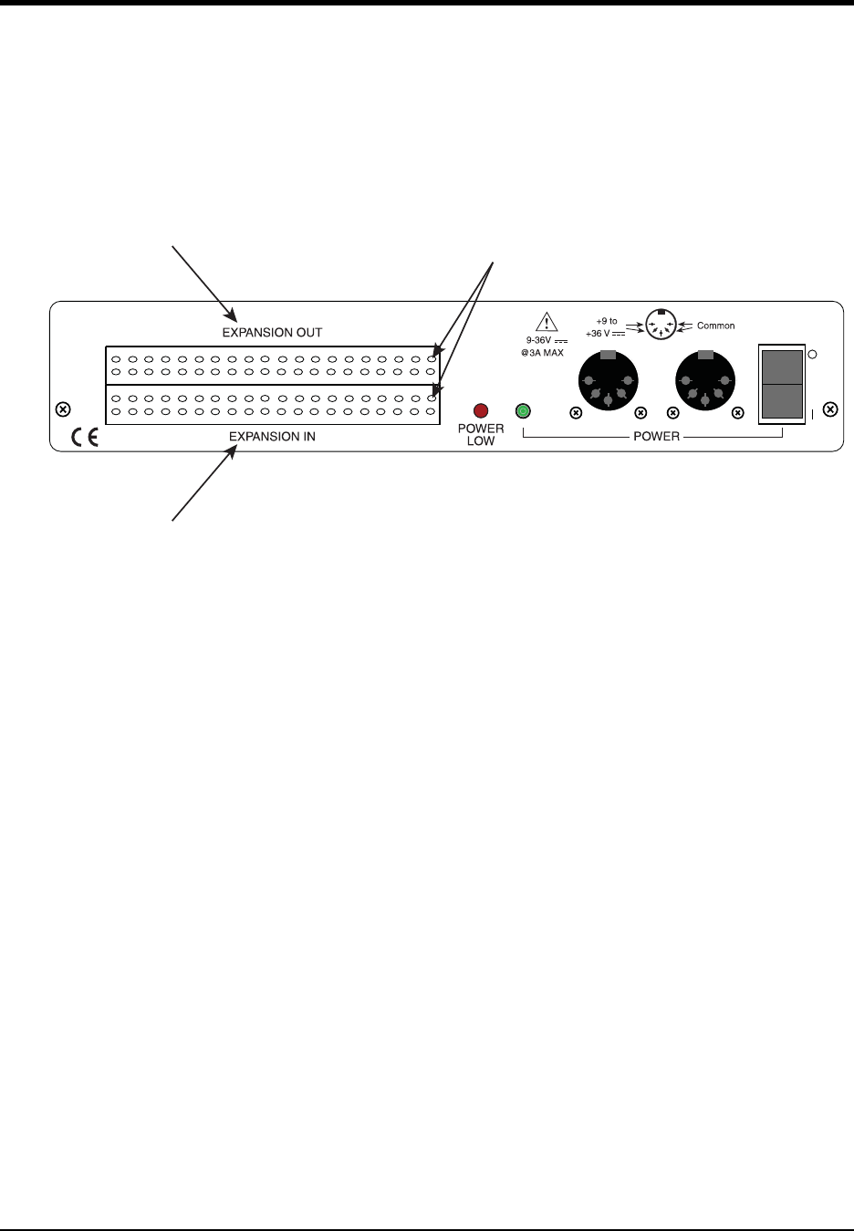
DI–720/DI–722/DI–730 Series User Manual
Accessories
47
lead per channel). High-level inputs are typically low impedance, no-conditioning-required signals in the range of
±1.25 to ±10 volts full scale.
DI-725 Rear Panel
POWER switch — Controls power to the DI-725 instrument. 1 is on, 0 is off.
POWER input jacks — Allows you to apply an alternate power source to the instrument, if necessary. The DI-725 is
powered by its host DI-400, DI-720, or DI-730 instrument and in most cases will not need an additional power sup-
ply. However, many factors can influence how much power is available to the DI-725 from its host instrument. When
the DI-725 cannot derive adequate power from its host instrument, the POWER LOW indicator will glow red. This
indicates that an alternate power source is necessary. Any suitable power source (+9 to +36 volts DC at 3A maxi-
mum) may be connected to either jack to provide the necessary power. When an alternate power source is connected,
the remaining jack can be used as an additional power outlet.
POWER status lamp — Glows green when the POWER switch is in the 1 position, indicating power is applied.
POWER LOW lamp — Glows red when the DI-725 cannot derive adequate power from its host instrument. In this
case, an alternate power source is required.
If the POWER LOW lamp comes on and you are using the DI-725 with a DI-720 or DI-730, the power supply that is
powering these host instruments can be used to power the DI-725 as well. Simply unplug the five-pin DIN end of the
power adapter cable that is currently supplying power to your DI-720 or DI-730, and plug it into one of the DI-725’s
power input jacks. Now plug one end of the supplied dual-ended power cable into the remaining power jack on the
DI-725 and plug the other end into the host instrument power input jack.
EXPANSION OUT connector — Used to connect multiple DI-725’s together. Connect one end of an expansion
cable to this connector and connect the other end of the cable to EXPANSION IN on the next DI-725.
Pin 1
EXPANSION OUT is used to connect several DI-725s
together. A total of 240 channels may be configured
using multiple DI-725s. Simply connect one end of the
cable here, and the other end of the cable to
EXPANSION IN on the next DI-725.
Connect the appropriate end of the expansion cable to
the host instrument, then connect the other end of the
cable to EXPANSION IN.

DI–720/DI–722/DI–730 Series User Manual
Accessories
48
EXPANSION IN connector — Connects the DI-725 to its host DI-400, DI-720, or DI-730 instrument.
Configuring Channels with the DI-725
In WINDAQ/Pro or WINDAQ/Pro+ data acquisition software, channels are enabled or configured for acquisition with
the channel selection grid. The channel selection grid is accessed by selecting Channels… from the Edit menu (in the
SET-UP operating mode of WINDAQ software).
Each box in this grid potentially represents an input channel. An input channel is enabled by clicking the desired box.
Which box you click, which mouse button you click with, and how many times you click the mouse button deter-
mines whether the input channel is enabled for single-ended operation, differential operation, or digital input opera-
tion.
The following pages show how to enable channels when using the DI-725 with a DI-400, DI-720, and DI-730 host
instrument.
Description
+5V
Ch 16
Ch 15
Ch 14
Ch 13
Ch 12
Ch 11
Ch 10
Ch 9
Analog Gnd
Analog Gnd
Ch 8
Ch 7
Ch 6
Ch 5
Ch 4
Ch 3
Ch 2
Ch 1
Pin
1
11
12
13
14
15
16
17
18
19
28
30
31
32
33
34
35
36
37
All other pins have no
connection.
EXPANSION IN and EXPANSION OUT Pinout
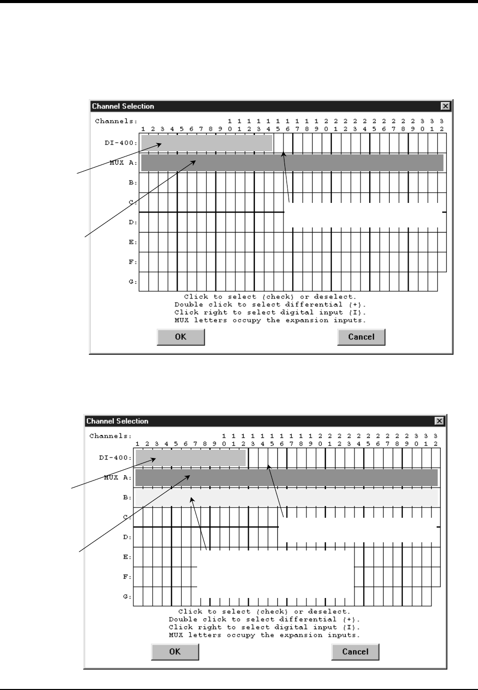
DI–720/DI–722/DI–730 Series User Manual
Accessories
49
DI-400 Host Instruments
The following channel selection grid is typical when a single DI-725 is used with a DI-400. Note that the DI-400
channels are enabled on the top row of the grid and the DI-725 channels are enabled on the row labeled “MUX A”.
The shaded area on the top row shows the channels that are still available on the host DI-400 instrument when the DI-
725 is added.
The following grid is typical of two DI-725’s used with a DI-400. Note the pattern. Each DI-725 consumes the two
highest-numbered channels on the host DI-400, and the expansion channels are enabled on the next MUX row down.
The result is similar when more DI-725’s are added to the system.
When a Single DI-725 is Used.
These 14
channels are
still available on
the host DI-400.
A A
These are the
32 DI-725
expansion
channels
(enable them
on this row).
These 2 channels are consumed by
the DI-725 (therefore unavailable).
When Two DI-725’s are Used.
These 12
channels are
still available on
the host DI-400.
A A
These are the
32 expansion
channels on
the first DI-
725 (the one
directly
connected to
the DI-400).
Enable them
on this row).
These 4 channels are consumed by
the DI-725’s (therefore unavailable).
B B
These are the next 32 expansion
channels on the second DI-725 (the
one not directly connected to the DI-
400). Enable them on this row.
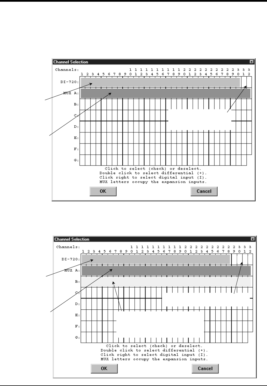
DI–720/DI–722/DI–730 Series User Manual
Accessories
50
DI-720 Host Instruments
The following channel selection grid is typical when a single DI-725 is used with a DI-720. Note that the DI-720
channels are enabled on the top row of the grid and the DI-725 channels are enabled on the row labeled “MUX A”.
The shaded area on the top row shows the channels that are still available on the host DI-720 instrument when the DI-
725 is added.
The following grid is typical of two DI-725’s used with a DI-720. Note the pattern. Each DI-725 consumes the two
highest-numbered channels on the host DI-720, and the expansion channels are enabled on the next MUX row down.
The result is similar when more DI-725’s are added to the system.
When a Single DI-725 is Used.
These 30
channels are
still available on
the host DI-720.
A A
These are the
32 DI-725
expansion
channels
(enable them
on this row).
These 2 channels are
consumed by the DI-725
(therefore unavailable).
When Two DI-725’s are Used.
These 28
channels are
still available on
the host DI-720.
A A
These are the
32 expansion
channels on the
first DI-725
(the one directly
connected to
the DI-720).
Enable them on
this row).
These 4 channels are consumed by
the DI-725’s (therefore unavailable).
B B
These are the next 32 expansion
channels on the second DI-725 (the
one not directly connected to the DI-
720). Enable them on this row.
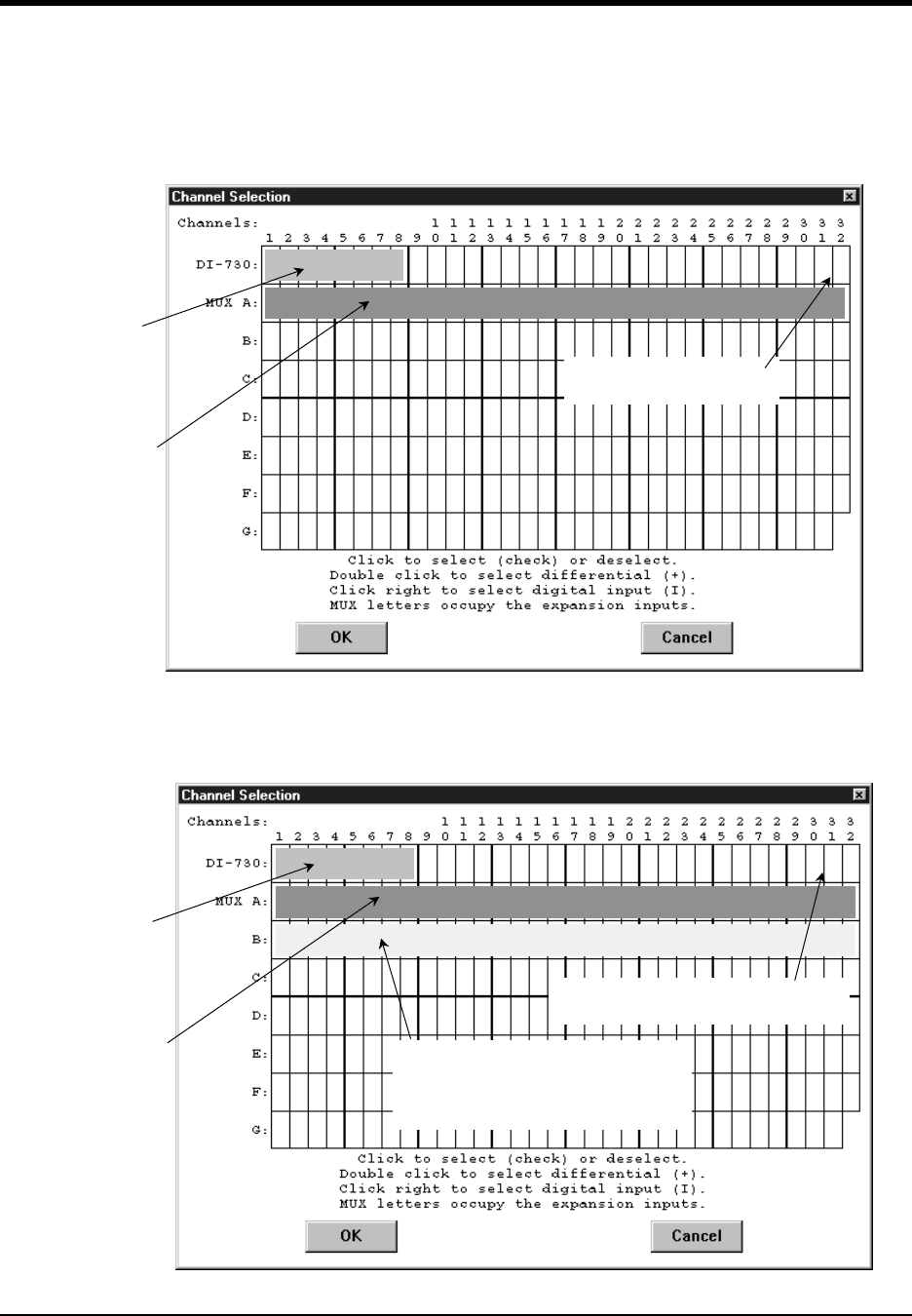
DI–720/DI–722/DI–730 Series User Manual
Accessories
51
DI-730 Host Instruments
The following channel selection grid is typical when a single DI-725 is used with a DI-730. Note that the DI-730
channels are enabled on the top row of the grid and the DI-725 channels are enabled on the row labeled “MUX A”.
The shaded area on the top row of the grid shows the channels that are still available on the host DI-730 instrument
when the DI-725 is added.
The following grid is typical of two DI-725’ s used with a DI-730. Note the pattern. Each DI-725 consumes the two
highest-numbered channels on the host DI-730, and the expansion channels are enabled on the next MUX row down.
The result is similar when more DI-725’s are added to the system.
When a Single DI-725 is Used.
These 8
channels are
still available on
the host DI-730.
A A
These are the
32 DI-725
expansion
channels
(enable them
on this row).
These 2 channels are
consumed by the DI-725.
When Two DI-725’s are Used.
These 8
channels are
still available on
the host DI-730.
A A
These are the
32 expansion
channels on the
first DI-725
(the one directly
connected to
the DI-730).
Enable them on
this row.
These 4 channels are consumed by
the DI-725’s.
B B
These are the next 32 expansion
channels on the second DI-725 (the
one not directly connected to the DI-
730). Enable them on this row.
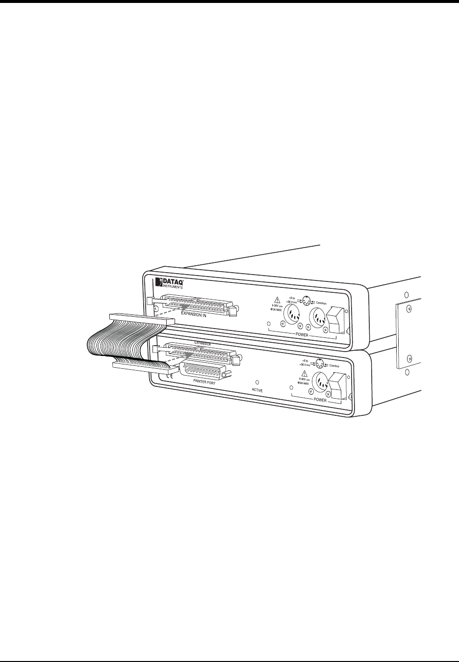
DI–720/DI–722/DI–730 Series User Manual
Accessories
52
DI-78B 8B Module Channel Expander
The DI-78B is a sixteen-channel, 8B-module expansion device for DI-720, DI-722, and DI-730 instruments. Each
DI-78B accepts up to sixteen high performance, plug-in signal conditioning modules, expanding the measurement
capability of DI-720 and DI-730 instruments to include virtually any isolated, industrial-type signal. Each DI-78B is
provided with the appropriate cable to connect it to its host instrument.
Each DI-78B channel consumes one channel from its host instrument in return for the isolated, signal-conditioned
input it provides. One DI-78B instrument may be connected to any DI-720 or DI-730 instrument. Signal connections
are made to the DI-78B through four removable screw terminal blocks. Power is obtained from the host DI-720 or
DI-730 instrument through the supplied, dual-ended power cable.
Connecting the DI-78B to the Host Instrument
Note: The included expansion signal cable and the dual ended power cable are sized to fit when the DI-78B is
stacked on top of (or under) the host instrument. If the instruments are not in a stacked configuration, do so before
proceeding.
1. Connect one end of the included expansion signal cable to EXPANSION on the rear panel of the host instrument.
2. Connect the other end of the expansion signal cable to EXPANSION IN on the rear panel of the DI-78B.
Applying Power to the DI-78B
A separate power supply is not required. Power is obtained from the host DI-720 or DI-730 instrument through the
dual-ended power cable supplied with the DI-78B. Modules should be installed before power is applied to the instru-
ment. See “Installing DI-8B Modules” on page 54 for instructions on installing 8B modules.
1. Unplug the five-pin DIN end of the power adapter cable that is currently supplying power to your DI-720 or DI-
730 and plug it into one of the DI-78B’s power jacks.
2. Plug one end of the dual -ended power cable into the remaining power jack in the DI-78B and plug the other end
into the host instrument power jack.
DI-78B
DI-720 or DI-730
end to EXPANSION on the host instrument.
Expansion Cable
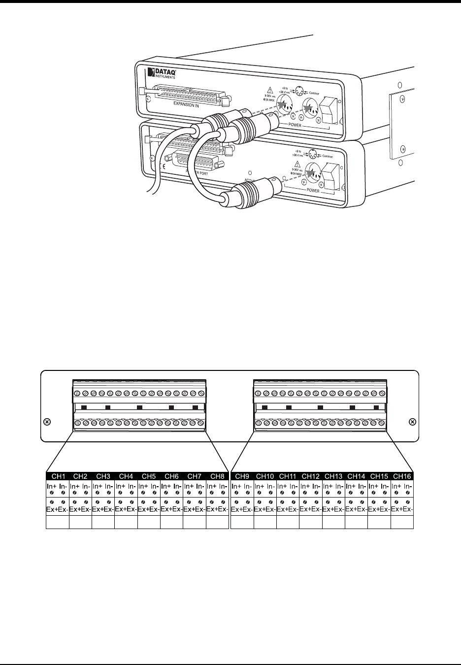
DI–720/DI–722/DI–730 Series User Manual
Accessories
53
3. Plug the appropriate end of the power cord to a 120V source (wall outlet).
Features, Controls, and Indicators
The DI-78 front panel contains four removable sixteen position screw terminal blocks for quick and easy connection
of all analog in signal leads. The rear panel provides connections for power and expansion in.
DI-78B Front Panel
The four 16-port screw terminals on the front of the DI-78B are used to interface analog input channels 1 through 16
(channels 17 through 32 of the host DI-720 or DI-730 instrument). Each channel has four terminals: In+, In-, Ex+,
and Ex- for input signals and excitation (if required). Use the sticker located on the top of your instrument for quick
reference to terminal access port designations.
DI-78B
DI-720 or DI-730
and the other end to the DI 78B. Connect the
power adapter (provided with the host instrument)
to the DI-78B and plug into power source.
Dual-Ended
Power Cable
To Power Adaptor
DI-78B
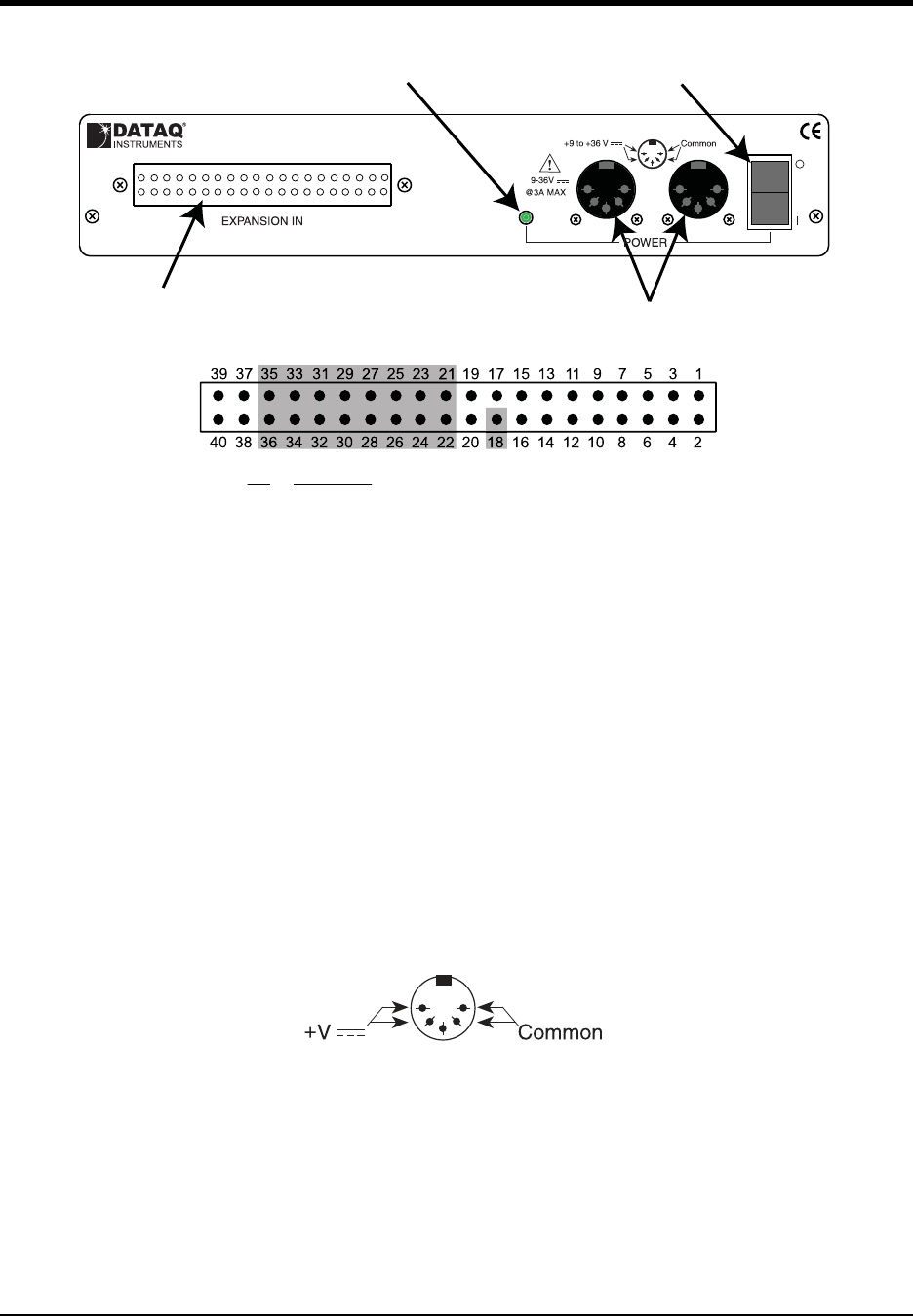
DI–720/DI–722/DI–730 Series User Manual
Accessories
54
DI-78B Rear Panel
EXPANSION IN connector — Connects the DI-78B to the host instrument. Use the following diagram for pinout.
Power LED — Glows green when power is applied.
Power Connectors — Input jacks to provide power to the instrument. Allows you to apply an alternate power source
to the instrument, if necessary. Power may be applied to the host instrument using the provided dual-ended power
cable. See “Connecting the DI-78B to the Host Instrument” on page 52. Output capacity of the power supply is 2.5A.
Power switch — Controls power to the DI-78B. 1 position is on, 0 is off.
Installing DI-8B Modules
DI-78B instruments accept up to 16 signal conditioned analog inputs. All DI-8B modules must be installed onto the
DI-8B backplane (located on the instrument circuit board).
1. Unplug the device and make sure there is no power to the instrument.
Power LED Power Switch
EXPANSION IN Power Connectors
Description
Analog Ground
Channel 16
Channel 8
Channel 15
Channel 7
Channel 14
Channel 6
Channel 13
Channel 5
Channel 12
Channel 4
Channel 11
Channel 3
Channel 10
Channel 2
Channel 9
Channel 1
Pin
18
21
22
23
24
25
26
27
28
29
30
31
32
33
34
35
36
Power Connectors Pinout
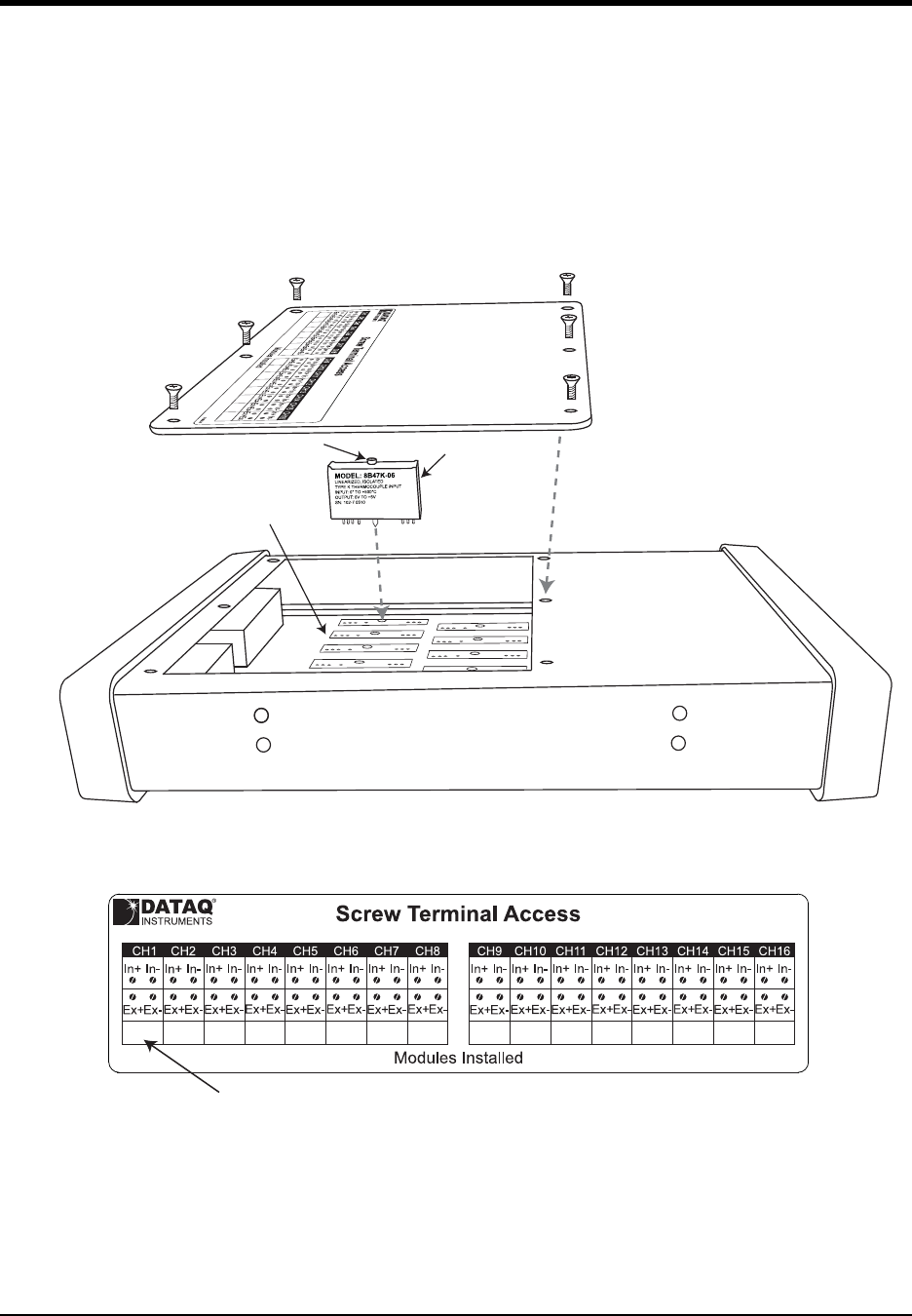
DI–720/DI–722/DI–730 Series User Manual
Accessories
55
2. Unscrew the six screws on the top of the instrument and remove the top hatch cover to reveal the DI-8B back-
plane.
3. Plug the DI-8B module firmly into one of the channel positions clearly labelled on the backplane and secure with
the set screw. Note: Be sure to completely screw the module into place or vibrations could short the system. DI-
8B modules are installed on (or removed from) the socketed DI-8B backplane (located on the circuit board) and
are secured with a non-removable mounting screw. Each channel position is labeled “CHANNEL 1,” “CHAN-
NEL 2,” etc. on the socketed backplane. The DI-8B modules can be mixed or matched in any combination suit-
able for the application and are identical in pinout and size, so it doesn't matter which module gets plugged into
which channel position.
4. Using an erasable pencil write the module number of each DI-8B module installed on the sticker located on the
top hatch to indicate which module is installed at each channel position.
5. After all modules are installed and indicated on the sticker reassemble the instrument. Note: If your are installing
a thermocouple module you must enable the Cold Junction Compensation jumper for that channel (see
“Enabling CJC for Thermocouple Modules” below).
DI-8B Module
Front
Rear
Top Hatch
DI-8B Backplane and Circuit Board
Set Screw
101058-B
Write Installed Modules
in the spaces provided
with an erasable pencil.
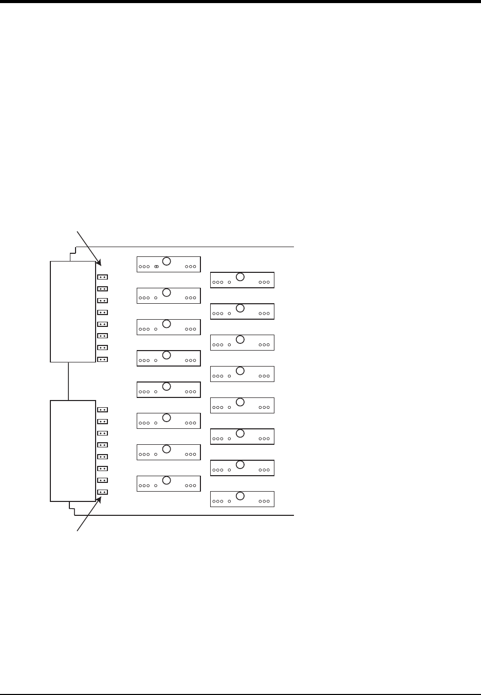
DI–720/DI–722/DI–730 Series User Manual
Accessories
56
Enabling CJC for Thermocouple Modules
If you are installing a Thermocouple Input Module (see “DI-8B47 Linearized Thermocouple Input Modules” on
page 69) you must enable the Cold Junction Compensation jumper. Each channel has its own CJC enable jumper
located towards the front of the instrument on the instrument circuit board (see also “Installing DI-8B Modules” on
page 54 for disassembly). Tip: Install all unused jumpers onto one pin of each channel so they cannot be accidentally
misplaced.
1. Unplug the device and make sure there is no power to the instrument.
2. Unscrew the six screws on the top of the instrument and remove the top hatch cover to reveal the DI-8B back-
plane and the CJC Enable Jumpers.
3. Install a jumper onto the board for each channel that uses a thermocouple module. Each jumper is labelled on the
circuit board as “TC CH#” where # is the channel number. Sixteen jumpers are provided with the DI-78B for this
purpose.
Note: If you are not using a Thermocouple Input Module on that channel be sure the jumper is disabled (removed
or installed on only one pin) because this will affect the input signal.
4. After all necessary jumpers are installed reassemble the instrument.
Configuring DI-78B Channels in WINDAQ
Channels are enabled in the channel selection grid (select Channels... from the Edit menu) in WINDAQ Data Acqui-
sition software. Each box in the grid represents an input channel. Click on the desired channel box to enable a chan-
nel.
CHANNEL 1
CHANNEL 2
CHANNEL 3
CHANNEL 4
CHANNEL 5
CHANNEL 6
CHANNEL 7
CHANNEL 8
CHANNEL 9
CHANNEL 10
CHANNEL 11
CHANNEL 12
CHANNEL 13
CHANNEL 14
CHANNEL 15
CHANNEL 16
TC CH1
TC CH8
TC CH7
TC CH6
TC CH5
TC CH4
TC CH3
TC CH2
TC CH9
TC CH16
TC CH15
TC CH14
TC CH13
TC CH12
TC CH11
TC CH10
CJC Enable Jumpers
Circuit Board with
DI-8B Backplane
ont of DI-78B
CJC Enable Jumpers
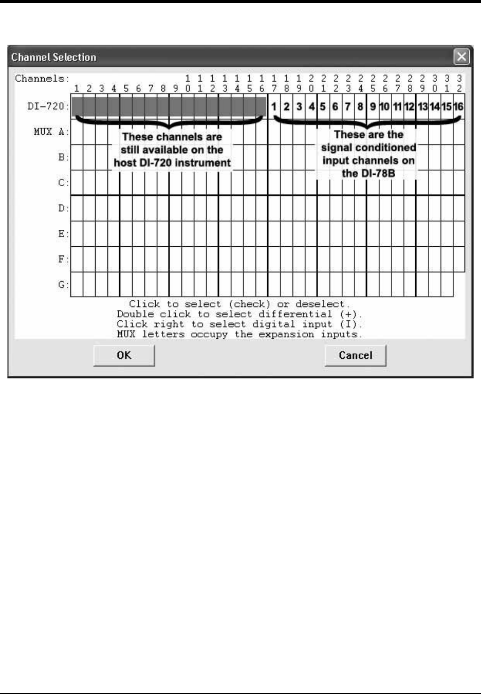
DI–720/DI–722/DI–730 Series User Manual
Accessories
57
DI-720 Host Instruments
Typical channel selection grid showing a DI-78B with a host DI-720
All channels (on both the DI-720 and the DI-78B) are enabled on the top row of the Channel Selection grid. The
shaded areas show the channels that are still available on the host DI-720 instrument when the DI-78B is added.
These channels can be enabled as single-ended or differential, the same as before the DI-78B was added. Channels 17
through 32 (channels 1 through 16 on the DI-78B) are defined by DI-8B modules and are enabled by clicking once
with the left mouse button. Note that if a DI-8B module is not plugged into a slot on the DI-78B, then that channel is
available on the host DI-720 instrument.
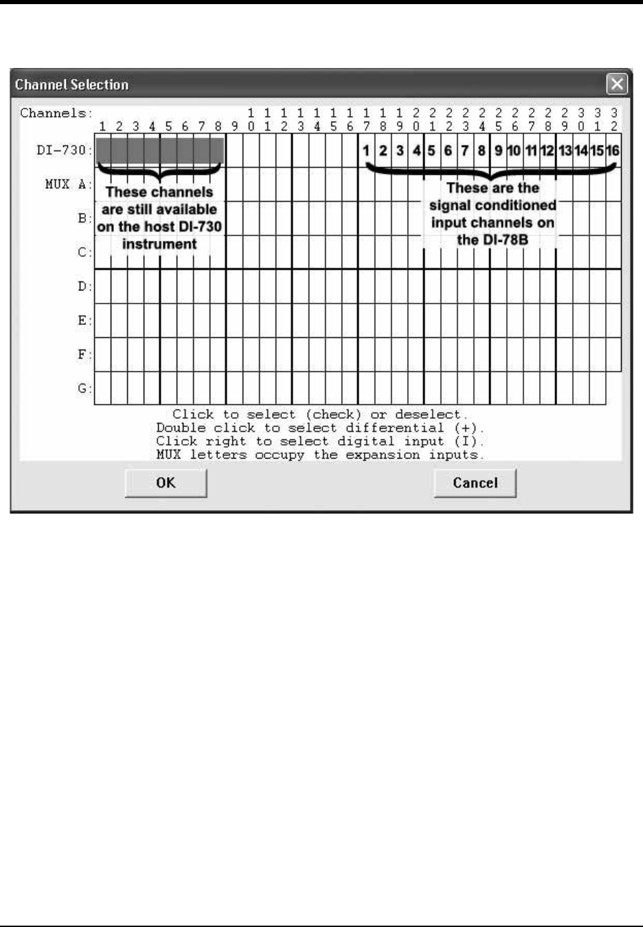
DI–720/DI–722/DI–730 Series User Manual
Accessories
58
DI-730 Host Instruments
Typical channel selection grid showing a DI-78B with a host DI-730
All channels (on both the DI-730 and the DI-78B) are enabled on the top row of the Channel Selection grid. The
shaded areas show the channels that are still available on the host DI-730 instrument when the DI-78B is added.
Channels 17 through 32 (channels 1 through 16 on the DI-78B) are defined by DI-8B modules and are enabled by
clicking once with the left mouse button. The isolated differential inputs on the front panel of the DI-730 are still
available.
Configuring DI-78B Channel Gain (you MUST configure gain for proper readings)
The signal conditioned (or DI-8B module) channels on the DI-78B output ±5 volts to the host instrument. Since the
DI-78B connections to the DI-720 Series and DI-730 Series (available through the EXPANSION connector) host
instruments are ±10 volt input devices, each DI-78B signal conditioned channel in use MUST be set to a gain of 2, so
they have a full scale measurement range of ±5 volts.
1. After you have enabled channels, click on Channel Settings… in the Edit menu.
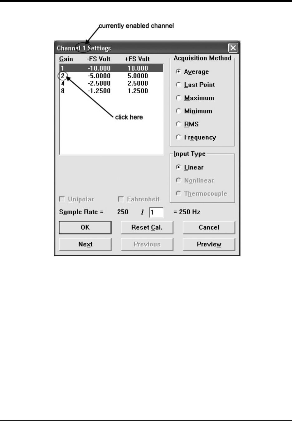
DI–720/DI–722/DI–730 Series User Manual
Accessories
59
This displays the Channel X Settings dialog box (where X represents the currently enabled channel).
2. In the upper left corner of the dialog box, click the gain factor 2 to get a ± full scale range of 5 volts.
3. Click the Next (or Previous) command button at the bottom of the dialog box to step to the next (or previously)
enabled channel. Note that when either the Next or Previous button is activated, the channel number in the title
bar of the dialog box changes to indicate the channel you are currently working on.
4. Repeat steps 2 and 3 for each DI-78B signal conditioned channel in use.
5. Click the OK command button to close the Channel Settings dialog box.
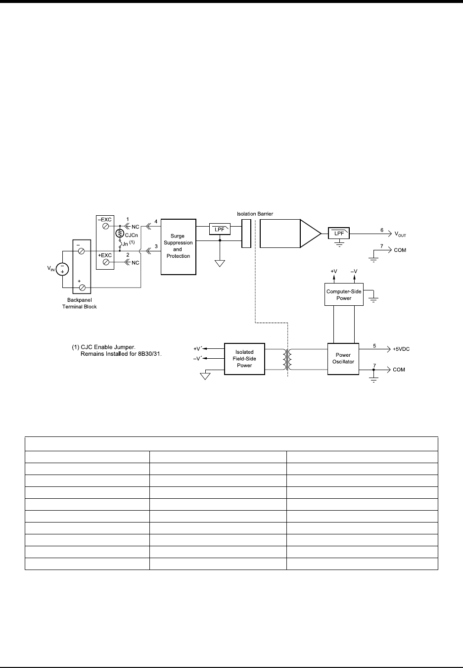
DI–720/DI–722/DI–730 Series User Manual
Accessories
60
DI-8B Modules
DI-8B30/31 Analog Voltage Input Modules, 3Hz Bandwidth
Each DI-8B30 or DI-8B31 module isolates, filters and amplifies a voltage input signal and provides an analog voltage
output.
Signal filtering is accomplished with a three-pole filter optimized for time and frequency response which provides
70dB of normal-mode-rejection at 60Hz. One pole of this filter is on the field side of the isolation barrier for anti-
aliasing, and the other two are on the system side.
A special input circuit on the DI-8B30 and DI-8B31 modules provides protection against accidental connection of
power-line voltages up to 240VAC.
Isolation is provided by optical coupling to suppress transmission of common mode spikes or surges. The module is
powered from +5VDC, ±5%.
:
Ordering Information
MODEL INPUT RANGE OUTPUT RANGE
DI-8B30-01 -10mV to +10mV -5V to +5V
DI-8B30-02 -50mV to +50mV -5V to +5V
DI-8B30-03 -100mV to +100mV -5V to +5V
DI-8B31-01 -1V to +1V -5V to +5V
DI-8B31-02 -5V to +5V -5V to +5V
DI-8B31-03 -10V to +10V -5V to +5V
DI-8B31-07 -20V to +20V -5V to +5V
DI-8B31-09 -40V to +40V -5V to +5V
DI-8B31-12 -60V to +60V -5V to +5V
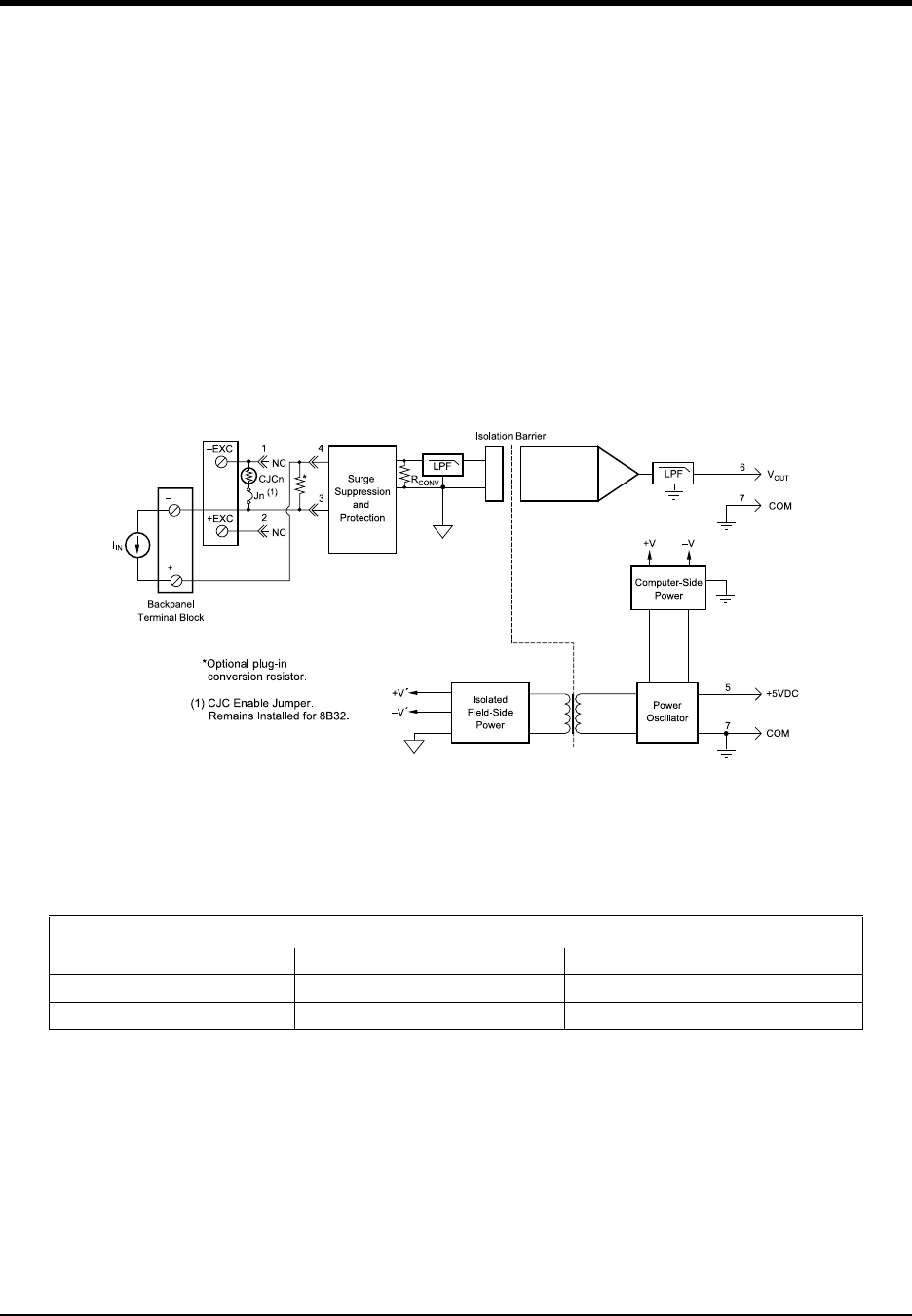
DI–720/DI–722/DI–730 Series User Manual
Accessories
61
DI-8B32 Analog Current Input Modules
Each DI-8B32 module isolates, filters and amplifies a process current input signal and provides an analog voltage
output.
Current to voltage conversion is accomplished internal to the module to ensure high accuracy.
Signal filtering is accomplished with a three-pole filter optimized for time and frequency response which provides
70dB of normal-mode-rejection at 60Hz. One pole of this filter is on the field side of the isolation barrier for anti-
aliasing, and the other two are on the system side.
A special input circuit on the 8B32 module provides protection against accidental connection of power-line voltages
up to 30VAC. Isolation is provided by optical coupling to suppress transmission of common mode spikes or surges.
The module is powered from +5VDC, ±5%.
Ordering Information
MODEL INPUT RANGE OUTPUT RANGE
DI-8B32-01 4mA to 20mA 0V to +5V
DI-8B32-02 0mA to 20mA 0V to +5V
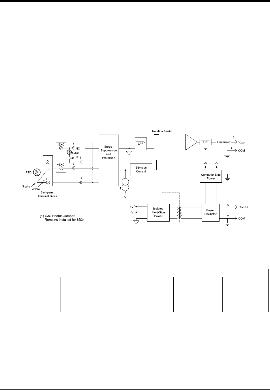
DI–720/DI–722/DI–730 Series User Manual
Accessories
62
DI-8B34 Linearized 2- or 3-Wire RTD Input Modules
Each DI-8B34 module isolates, filters, amplifies, and linearizes a single channel of temperature input from an RTD
and provides an analog voltage output.
RTD excitation is provided from the module using two matched current sources. When using a 3-wire connection,
this method allows equal currents to flow through the sensor leads, cancelling the effects of lead resistances. The
excitation currents are small (0.25mA) which minimizes the self-heating of the RTD.
Signal filtering is accomplished with a three-pole filter optimized for time and frequency response which provides
70dB of normal-mode-rejection at 60Hz. One pole of this filter is on the field side of the isolation barrier for anti-
aliasing, and the other two are on the system side.
A special input circuit on the DI-8B34 module provides protection against accidental connection of power-line volt-
ages up to 240VAC. Clamp circuits on the I/O and power terminals protect against harmful transients.
Ordering Information
MODEL INPUT RANGE OUTPUT RANGE ACCURACY*
DI-8B34-01 -100°C to +100°C (-148°F to +212°F) 0V to +5V ±0.20°C
DI-8B34-02 0°C to +100°C (+32°F to +212°F) 0V to +5V ±0.15°C
DI-8B34-03 0°C to +200°C (+32°F to +392°F) 0V to +5V ±0.20°C
DI-8B34-04 0°C to +600°C (+32°F to +1112°F) 0V to +5V ±0.45°C
* Includes conformity, hysteresis and repeatability.
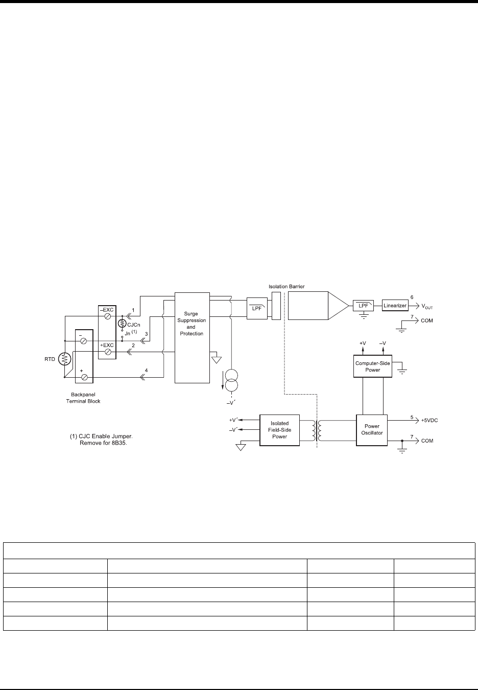
DI–720/DI–722/DI–730 Series User Manual
Accessories
63
DI-8B35 Linearized 4-Wire RTD Input Modules
In RTD temperature measurement applications requiring a very high level of accuracy, the DI-8B35 4-Wire RTD
input module offers a significant advantage over 3-wire measurement techniques (see block diagram). The DI-8B35
measures only the voltage dropped across the RTD and almost completely ignores the resistance or length of the RTD
lead wires. The DI-8B34 3-Wire RTD module provides lead resistance compensation, but requires equal lead resis-
tances, while the DI-8B35 does not require matched lead resistances.
Each DI-8B35 module isolates, filters, amplifies, and linearizes a single channel of temperature input from an RTD
and provides an analog voltage output.
RTD excitation is provided from the module using a precision current source. Excitation current does not flow in the
input signal leads, which allows RTD measurements to be made independent of lead resistance. The excitation cur-
rents are small (0.25mA) which minimizes self-heating of the RTD.
Signal filtering is accomplished with a three-pole filter optimized for time and frequency response which provides
70dB of normal-mode-rejection at 60Hz. One pole of this filter is on the field side of the isolation barrier for anti-
aliasing, and the other two are on the system side.
A special input circuit on the DI-8B35 module provides protection against accidental connection of power-line volt-
ages up to 240VAC. Clamp circuits on the I/O and power terminals protect against harmful transients.
Ordering Information
MODEL INPUT RANGE OUTPUT RANGE ACCURACY*
DI-8B35-01 -100°C to +100°C (-148°F to +212°F) 0V to +5V ±0.20°C
DI-8B35-02 0°C to +100°C (+32°F to +212°F) 0V to +5V ±0.15°C
DI-8B35-03 0°C to +200°C (+32°F to +392°F) 0V to +5V ±0.20°C
DI-8B35-04 0°C to +600°C (+32°F to +1112°F) 0V to +5V ±0.45°C
* Includes conformity, hysteresis and repeatability.
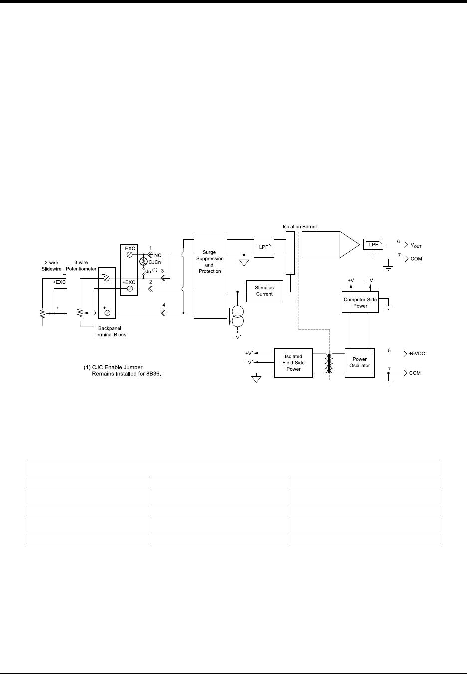
DI–720/DI–722/DI–730 Series User Manual
Accessories
64
DI-8B36 Potentiometer Input Modules
Each DI-8B36 module isolates, filters and amplifies a single channel of potentiometer input and provides an analog
voltage output.
Excitation for the potentiometer is provided by using two matched current sources. When using a 3-wire connection,
this method allows equal currents to flow through the sensor leads, cancelling the effects of lead resistances. The
excitation currents are small (0.25mA) which minimizes the self-heating of the potentiometer.
Signal filtering is accomplished with a three-pole filter optimized for time and frequency response which provides
70dB of normal-mode-rejection at 60Hz. One pole of this filter is on the field side of the isolation barrier for anti-
aliasing, and the other two are on the system side.
A special input circuit on the DI-8B36 module provides protection against accidental connection of power-line volt-
ages up to 240VAC. Clamp circuits on the I/O and power terminals protect against harmful transients.
Ordering Information
MODEL INPUT RANGE OUTPUT RANGE
DI-8B36-01 0 to 1000V to +5V
DI-8B36-02 0 to 5000V to +5V
DI-8B36-03 0 to 1k0V to +5V
DI-8B36-04 0 to 10k0V to +5V
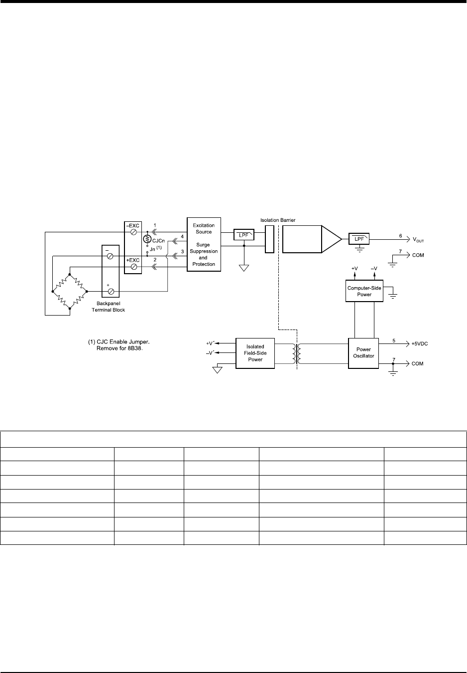
DI–720/DI–722/DI–730 Series User Manual
Accessories
65
DI-8B38 Strain Gage Input Modules, Narrow & Wide Bandwidth
Each DI-8B38 module isolates, filters and amplifies a full-bridge strain gage input signal and provides an analog volt-
age output.
The 8B38 can interface to transducers with a nominal resistance of 100 to 10k. Bridge excitation is provided from the
module with a stable 10.00V or 3.33V source. Full scale sensitivities of 2mV/V and 3mV/V are offered as standard.
Signal filtering is accomplished with a five-pole filter optimized for time and frequency response which provides
100dB per decade of normal-mode rejection above the filter cutoff frequency. One pole of this filter is on the field
side of the isolation barrier for anti-aliasing, and the other four are on the system side.
A special input circuit on the DI-8B38 module provides protection against accidental connection of power-line volt-
ages up to 240VAC. Clamp circuits on the I/O and power terminals protect against harmful transients.
Isolation is provided by optical coupling to suppress transmission of common mode spikes or surges. The module is
powered from +5VDC, ±5%.
Ordering Information
MODEL BANDWIDTH INPUT RANGE EXCITATION OUTPUT RANGE
DI-8B38-01 3kHz -10mV to +10mV 3.333V at 3mV/V Sensitivity -5V to +5V
DI-8B38-02 3kHz -30mV to +30mV 10.0V at 3mV/V Sensitivity -5V to +5V
DI-8B38-05 3kHz -20mV to +20mV 10.0V at 2mV/V Sensitivity -5V to +5V
DI-8B38-31 3Hz -10mV to +10mV 3.333V at 3mV/V Sensitivity -5V to +5V
DI-8B38-32 3Hz -30mV to +30mV 10.0V at 2mV/V Sensitivity -5V to +5V
DI-8B38-35 3Hz -20mV to +20mV 10.0V at 2mV/V Sensitivity -5V to +5V
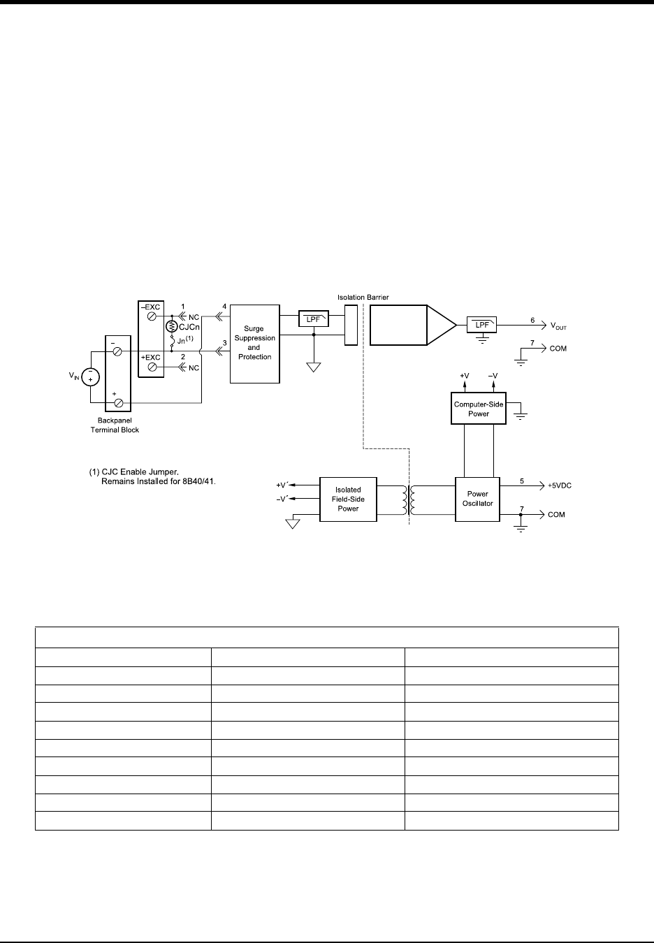
DI–720/DI–722/DI–730 Series User Manual
Accessories
66
DI-8B40/41 Analog Voltage Input Modules, 1kHz Bandwidth
Each DI-8B40 and DI-8B41 module isolates, filters, and amplifies a voltage input signal and provides an analog volt-
age output.
Signal filtering is accomplished with a multiple pole filter optimized for time and frequency response which provides
70dB of normal-mode-rejection at 60Hz. One pole of this filter is on the field side of the isolation barrier for anti-
aliasing, and the remaining poles are on the system side.
A special input circuit on the DI-8B40 and DI-8B41 modules provides protection against accidental connection of
power-line voltages up to 240VAC. Clamp Circuits on the I/O and power terminals protect against harmful transients.
Isolation is provided by optical coupling to suppress transmission of common mode spikes or surges. The module is
powered from +5VDC, ±5%.
Ordering Information
MODEL INPUT RANGE OUTPUT RANGE
DI-8B40-01 -10mV to +10mV -5V to +5V
DI-8B40-02 -50mV to +50mV -5V to +5V
DI-8B40-03 -100mV to +100mV -5V to +5V
DI-8B41-01 -1V to +1V -5V to +5V
DI-8B41-02 -5V to +5V -5V to +5V
DI-8B41-03 -10V to +10V -5V to +5V
DI-8B41-07 -20V to +20V -5V to +5V
DI-8B41-09 -40V to +40V -5V to +5V
DI-8B41-12 -60V to +60V -5V to +5V
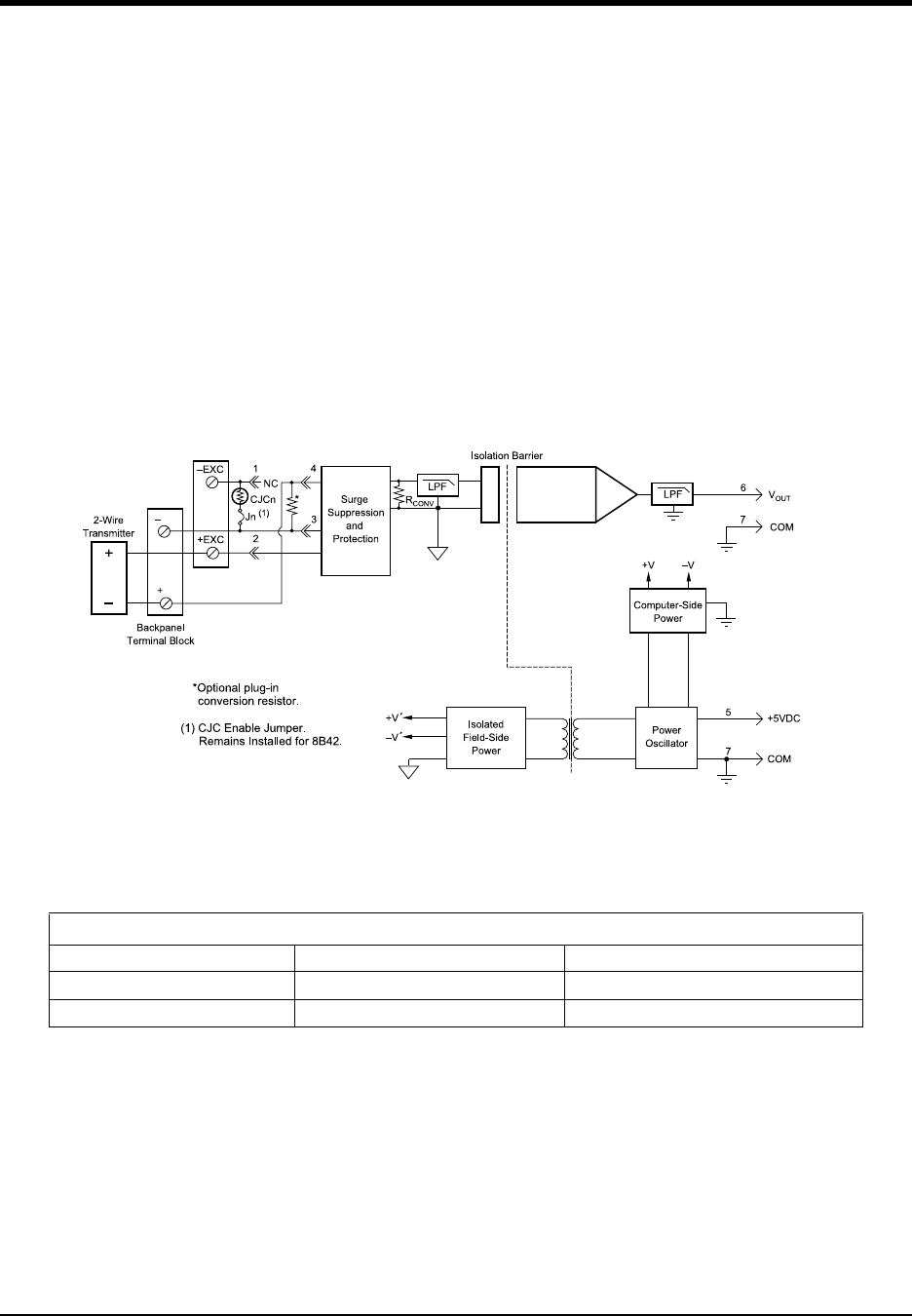
DI–720/DI–722/DI–730 Series User Manual
Accessories
67
DI-8B42 2-Wire Transmitter Interface Modules
Each DI-8B42 module provides power to a current transmitter, then isolates, filters and amplifies the resulting pro-
cess current input signal and provides an analog voltage output.
Current to voltage conversion is accomplished internal to the module to ensure high accuracy.
Signal filtering is accomplished with a three-pole filter optimized for time and frequency response which provides
60dB per decade of normal-mode rejection above 100Hz. One pole of this filter is on the field side of the isolation
barrier for anti-aliasing, and the other two are on the system side.
A special input circuit on the DI-8B42 module provides protection against accidental connection of power-line volt-
ages up to 40VAC. Clamp circuits on the I/O and power terminals protect against harmful transients.
Isolation is provided by optical coupling to suppress transmission of common mode spikes or surges. The module is
powered from +5VDC, ±5%.
Ordering Information
MODEL INPUT RANGE OUTPUT RANGE
DI-8B42-01 4mA to 20mA 0V to +5V
DI-8B42-02 4mA to 20mA +1V to +5V
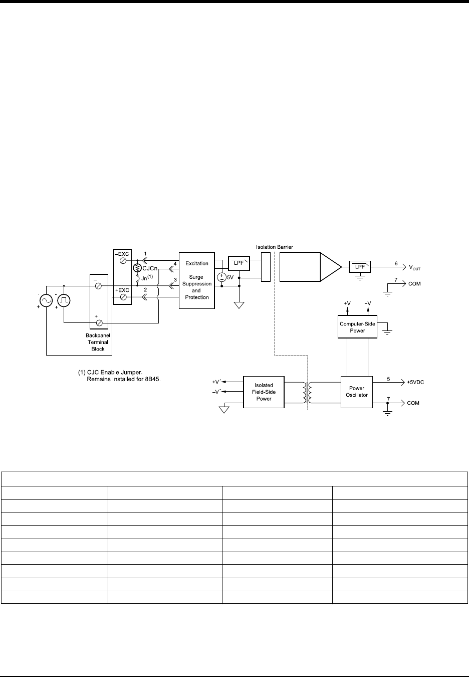
DI–720/DI–722/DI–730 Series User Manual
Accessories
68
DI-8B45 Frequency Input Modules
Each DI-8B45 module isolates and conditions a frequency input signal and provides an analog voltage output.
The frequency input signal can be either a TTL level or zero crossing with as little as ±100mV amplitude. Input cir-
cuitry for each signal type has built-in hysteresis to prevent spurious noise from corrupting the module output. TTL
signals are applied to the + and - terminals while zero crossing signals are applied to the +EXC and - terminals. Ref-
erence the block diagram.
A 5V excitation is available for use with magnetic pick-up or contact closure type sensors. The excitation is available
on the -EXC terminal with return on the - terminal.
A special input circuit on the DI-8B45 modules provides protection against accidental connection of power-line volt-
ages up to 240VAC. Clamp circuits on the I/O and power terminals protect against harmful transients.
Isolation is provided by optical coupling to suppress transmission of common mode spikes or surges. The module is
powered from +5VDC, ±5%.
Ordering Information
MODEL INPUT RANGE OUTPUT RANGE EXCITATION
DI-8B45-01 0 to 500Hz 0 to +5V +5V at 8mA max
DI-8B45-02 0 to 1kHz 0 to +5V +5V at 8mA max
DI-8B45-03 0 to 2.5kHz 0 to +5V +5V at 8mA max
DI-8B45-04 0 to 5kHz 0 to +5V +5V at 8mA max
DI-8B45-05 0 to 10kHz 0 to +5V +5V at 8mA max
DI-8B45-06 0 to 25kHz 0 to +5V +5V at 8mA max
DI-8B45-07 0 to 50kHz 0 to +5V +5V at 8mA max
DI-8B45-08 0 to 100kHz 0 to +5V +5V at 8mA max
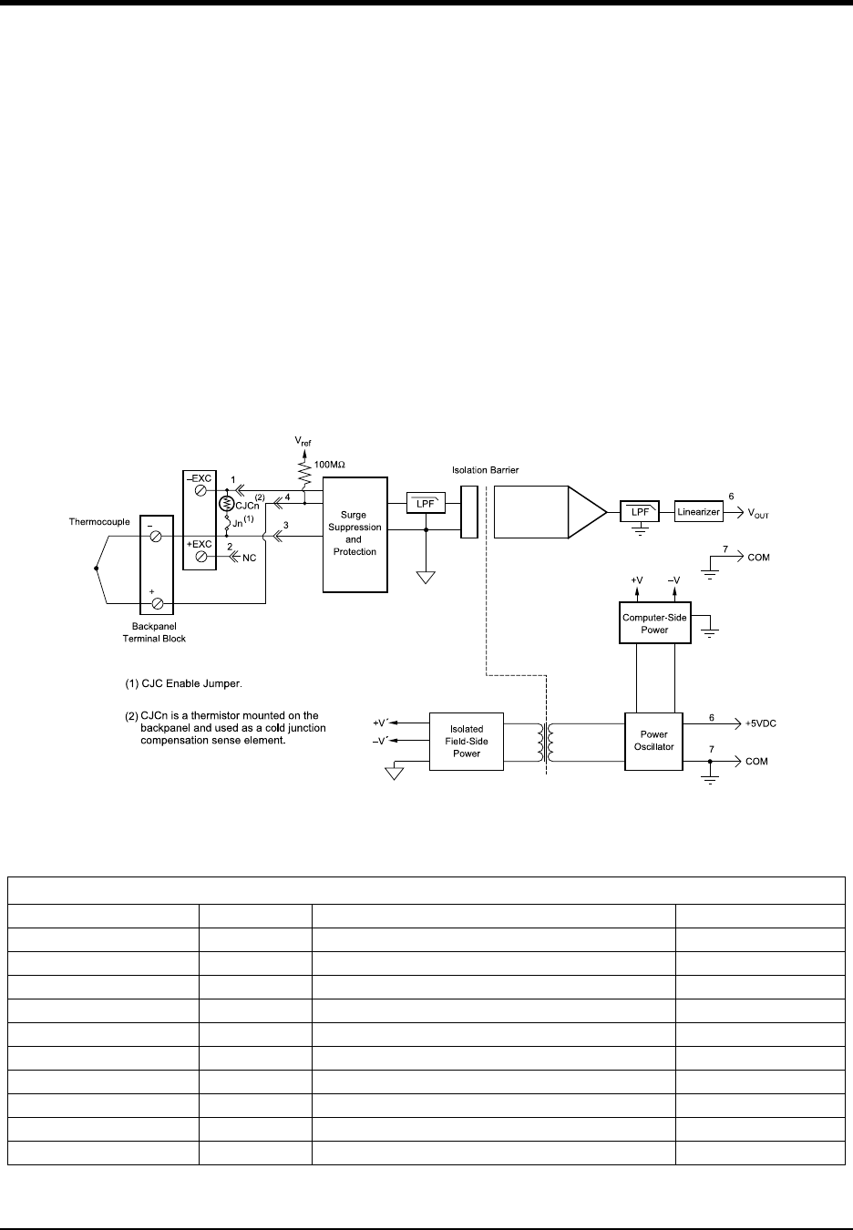
DI–720/DI–722/DI–730 Series User Manual
Accessories
69
DI-8B47 Linearized Thermocouple Input Modules
Each DI-8B47 module isolates, filters, amplifies, and linearizes a single channel of temperature input from a thermo-
couple and provides an analog voltage output.
Linearization is accomplished using a four breakpoint piece wise linear approximation.
The DI-8B47 can interface to industry standard thermocouple type J, K, and T and has an output signal of 0V to +5V.
Each module is cold-junction compensated to correct for parasitic thermocouples formed by the thermocouple wire
and screw terminals on the mounting backpanel. Upscale open thermocouple detect is provided by an internal pull-up
resistor.
Signal filtering is accomplished with a three-pole filter optimized for time and frequency response which provides
70dB of normal-mode-rejection at 60Hz. One pole of this filter is on the field side of the isolation barrier for anti-
aliasing, and the other two are on the system side.
A special input circuit on the DI-8B47 module provides protection against accidental connection of power-line volt-
ages up to 240VAC.
Note: The temperature accuracy of these thermocouple modules when used with the DI-78B is ±2ºC @25ºC.
Ordering Information
MODEL TYPE INPUT RANGE ACCURACY*
DI-8B47J-01 Type J 0°C to +760°C (+32°F to +1400°F) ±0.24% ±1.82°C
DI-8B47J-02 Type J -100°C to +300°C (-148°F to +572°F) ±0.24% ±0.96°C
DI-8B47J-03 Type J 0°C to +500°C (+32°F to +932°F) ±0.21% ±1.05°C
DI-8B47J-12 Type J -100°C to +760°C (-148°F to +1400°F) ±0.24% ±2.10°C
DI-8B47K-04 Type K 0°C to +1000°C (+32°F to +1832°F) ±0.24% ±2.40°C
DI-8B47K-05 Type K 0°C to +500°C (+32°F to +932°F) ±0.24% ±1.05°C
DI-8B47K-13 Type K -100°C to +1350°C (-148°F to +2462°F) ±0.24% ±3.60°C
DI-8B47K-14 Type K 0°C to +1200°C (+32°F to +2192°F) ±0.24% ±2.88°C
DI-8B47T-06 Type T -100°C to +400°C (+32°F to +392°F) ±0.48% ±2.40°C
DI-8B47T-07 Type T 0°C to +200°C (+32°F to +392°F) ±0.39% ±0.75°C
*Includes conformity, hysteresis and repeatability. Does not include CJC accuracy.
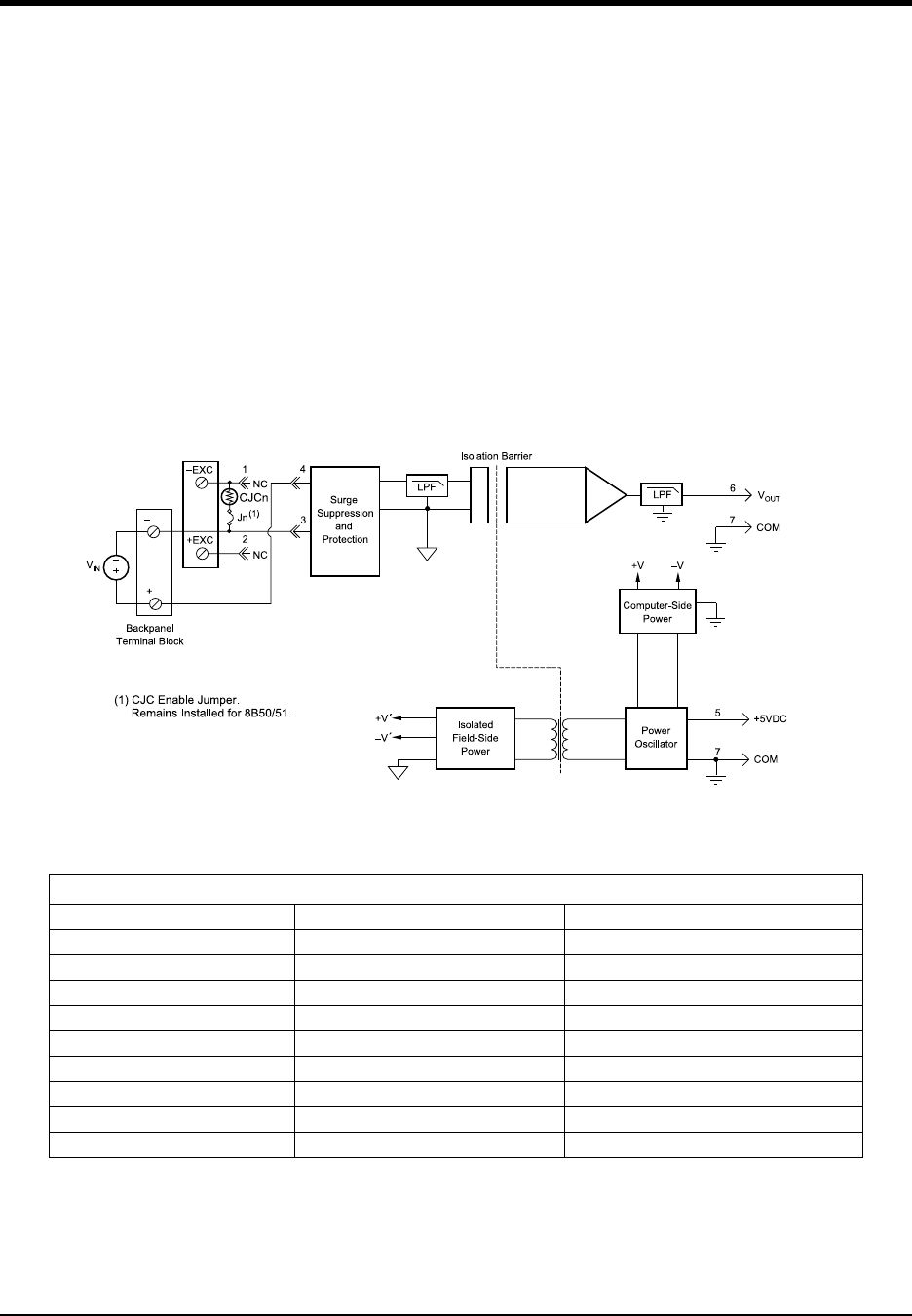
DI–720/DI–722/DI–730 Series User Manual
Accessories
70
DI-8B50/51 Analog Voltage Input Modules, 20kHz Bandwidth
Each DI-8B50 and DI-8B51 module isolates, filters, and amplifies a voltage input signal and provides an analog volt-
age output.
Signal filtering is accomplished with a multiple pole filter optimized for time and frequency response which provides
70dB of normal-mode-rejection at 60Hz. One pole of this filter is on the field side of the isolation barrier for anti-
aliasing, and the remaining poles are on the system side.
A special input circuit on the DI-8B50 and DI-8B51 modules provides protection against accidental connection of
power-line voltages up to 240VAC. Clamp circuits on the I/O and power terminals protect against harmful transients.
Isolation is provided by optical coupling to suppress transmission of common mode spikes or surges. The module is
powered from +5VDC, ±5%.
Ordering Information
MODEL INPUT RANGE OUTPUT RANGE
DI-8B50-01 -10mV to +10mV -5V to +5V
DI-8B50-02 -50mV to +50mV -5V to +5V
DI-8B50-03 -100mV to +100mV -5V to +5V
DI-8B51-01 -1V to +1V -5V to +5V
DI-8B51-02 -5V to +5V -5V to +5V
DI-8B51-03 -10V to +10V -5V to +5V
DI-8B51-07 -20V to +20V -5V to +5V
DI-8B51-09 -40V to +40V -5V to +5V
DI-8B51-12 -60V to +60V -5V to +5V

DI–720/DI–722/DI–730 Series User Manual
Accessories
71
DI-75B 5B Module Channel Expander
The DI-75B is an eight-channel, 5B-module expansion device for DI-720, DI-722, and DI-730 instruments. Each DI-
75B accepts up to eight high performance, plug-in signal conditioning modules, thereby expanding the measurement
capability of it host instrument to include virtually any isolated, industrial-type signal. Each DI-75B is provided with
the appropriate cable to connect it to its host instrument.
Each DI-75B channel consumes one channel from its host instrument in return for the isolated, signal-conditioned
input it provides. A maximum of two DI-75B instruments may be connected to its host instrument to get a total of 16,
5B-conditioned input channels (in addition to any remaining channels within the host instrument). Signal connections
are made to the DI-75B through a removable screw terminal block. Power is obtained from the host instrument
through the supplied, dual-ended power cable.
Connecting the DI-75B to the Host Instrument
NOTE: The included expansion signal cable and the dual-ended power cable are sized to fit when the DI-75B is
stacked on top of (or below) the host instrument. If these instruments are not in a stacked configuration, do so before
proceeding.
6. Connect the appropriate end of the included expansion signal cable to the EXPANSION port on the rear panel of
the host instrument.
7. Connect the other end of the expansion cable to EXPANSION IN on the rear panel of the DI-75B.
Applying Power to the DI-75B
A separate power supply is not required. Power is obtained from the host instrument through the dual-ended power
cable supplied with the DI-75B. Apply power using the following procedure:
1. Unplug the five-pin DIN end of the power adapter cable that is currently supplying power to your DI-720, DI-
722, or DI-730, and plug it into one of the DI-75B's power input jacks.
2. Plug one end of the dual-ended power cable into the remaining power jack on the DI-75B and plug the other end
into the host instrument power input jack.
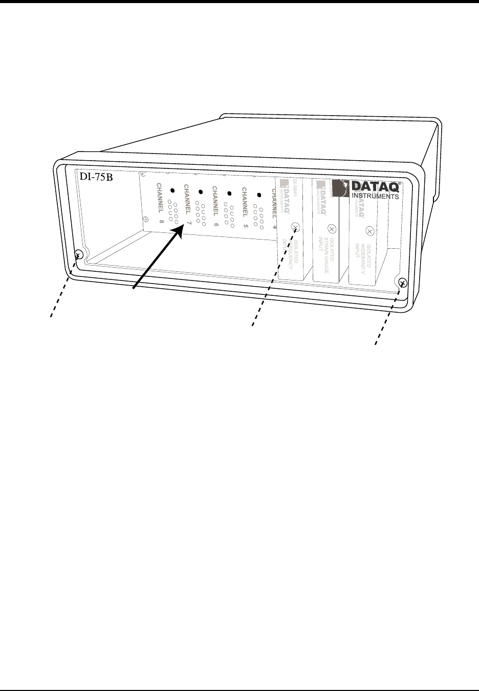
DI–720/DI–722/DI–730 Series User Manual
Accessories
72
Features, Controls, and Indicators
DI-75B Front Panel
Access to the 5B modules is gained by removing the two screws on each side of the front panel, and then removing
the front panel and bezel. When reattaching the front panel, take care not to overtighten the two screws.
DI-5B modules are installed on (or removed from) a socketed backplane and are secured to the backplane with a non-
removable mounting screw. Each channel position is labeled “CHANNEL 1,” “CHANNEL 2,” etc., on the socketed
backplane. The DI-5B modules can be mixed or matched in any combination suitable for the application.
1. Remove front panel and bezel by removing the two screws.
2. DI-5B Modules are installed to the 5B backplane using the set screw.
5B backplane
1
1
2
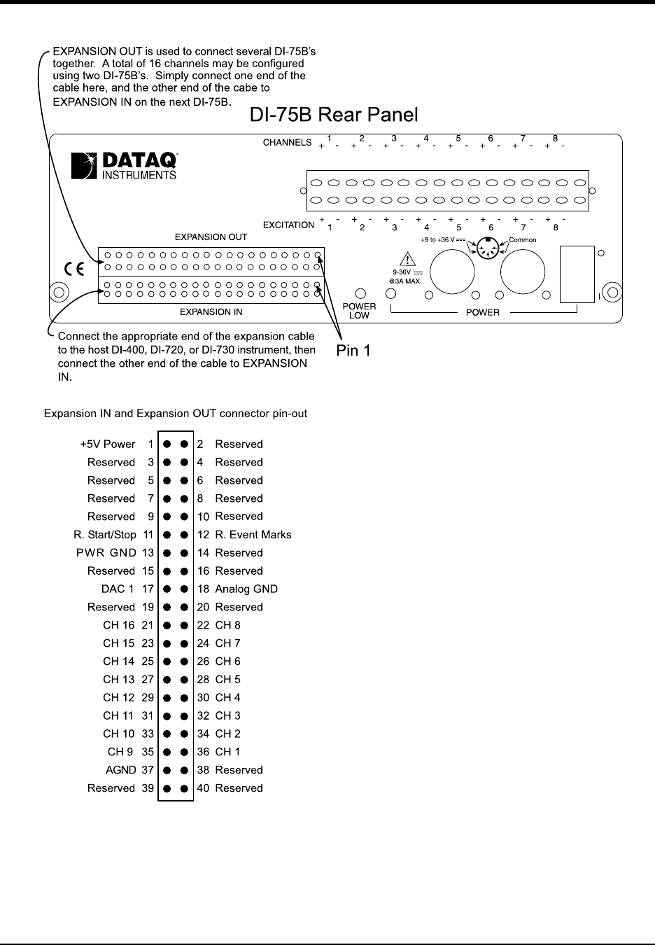
DI–720/DI–722/DI–730 Series User Manual
Accessories
73
DI-75B Rear Panel
Removable Screw Terminal Block — Allows signal connections to be made to the DI-75B. The input signal con-
nections are made along the top row while the excitation connections (for those DI-5B modules that require exci-
tation) are made along the bottom row. Note that this screw terminal block can be removed from the DI-75B, thus
making signal connections to the screw terminals easy. Note also that the screw terminal block is “keyed,” thus diffi-
cult to improperly re-insert. Each channel (labeled “CHANNEL 1,” “CHANNEL 2,” etc. on the socketed backplane)
has four corresponding screw terminals for your signal connections: channel +, channel -, excitation +, and excitation
-. These terminals satisfy all transducer inputs and provide sensor excitation when necessary.

DI–720/DI–722/DI–730 Series User Manual
Accessories
74
POWER switch — Controls power to the DI-75B. 1 is on, 0 is off.
POWER input jacks — Allows you to apply an alternate power source to the instrument, if necessary. When used
with either a DI-720 or DI-730, the DI-75B-7 can be powered by these instruments through the supplied dual-ended
power cable. Simply unplug the five-pin DIN end of the power adapter cable that is currently supplying power to
your DI-720 or DI-730, and plug it into one of the DI-75B's power input jacks. Now plug one end of the dual-ended
power cable into the remaining power jack on the DI-75B and plug the other end into the host instrument power input
jack. When used with a DI-700, the DI-75B-4 requires a separate power supply (user-supplied or available from
Dataq Instruments as an additional cost item, part number 100454-25R).
POWER status lamp — Glows green when the POWER switch is in the 1 position, indicating power is applied to
the DI-75B.
POWER LOW lamp — Glows red when the DI-75B cannot derive adequate power from its host instrument. In this
case, an alternate power source is required. Any suitable power source (+9 to +36 volts DC at 3A maximum) may be
connected to either power input jack to provide the necessary power.
EXPANSION OUT connector — Used to connect multiple DI-75B's together. Connect one end of an expansion
cable to this connector and connect the other end of the cable to EXPANSION IN on the next DI-75B instrument.
EXPANSION IN connector — Connects the DI-75B to its host instrument.
Configuring Channels with the DI-75B
In WINDAQ/Pro or WINDAQ/Pro+ data acquisition software, channels are enabled or configured for acquisition with
the channel selection grid. The channel selection grid is accessed by selecting Channels… from the Edit menu. Con-
sult the WINDAQ help files for more information on selecting channels.
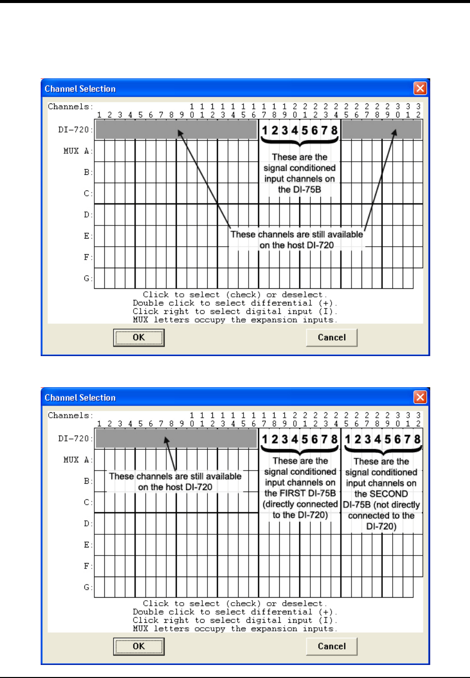
DI–720/DI–722/DI–730 Series User Manual
Accessories
75
DI-72x Host Instruments
All channels (on both the DI-72x and the DI-75B) are enabled on the top row of the grid. The shaded areas show the
channels that are still available on the host instrument after the DI-75B is connected. Channels 17 to 24 (channels 1 to
8 on the DI-75B) are defined by DI-5B modules and are enabled by clicking once with the left mouse button. Note
that if a DI-5B module is not plugged into a slot on the DI-75B, then that channel is available on the host instrument.
The following grid is typical of two DI-75B's used with a DI-72x. Again, if a DI-5B module is not plugged into a slot
on the DI-75B, then that channel is available on the host instrument.
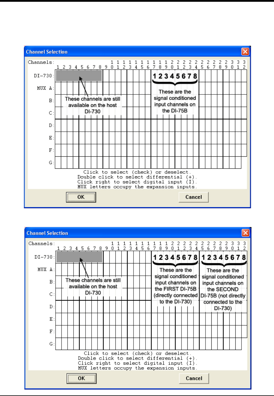
DI–720/DI–722/DI–730 Series User Manual
Accessories
76
DI-730 Host Instruments
All channels (on both the DI-730 and the DI-75B) are enabled on the top row of the grid. The shaded area shows the
channels still available on the host DI-730 instrument when the DI-75B is connected. Channels 17 to 24 (channels 1
to 8 on the DI-75B) are defined by DI-5B modules and are enabled by clicking once with the left mouse button. Note
that if a DI-5B module is not plugged into a slot on the DI-75B, then that channel is available on the host instrument.
The following grid is typical of two DI-75B' s used with a DI-730. Again, if a DI-5B module is not plugged into a slot
on the DI-75B, then that channel is available on the host DI-730 instrument.
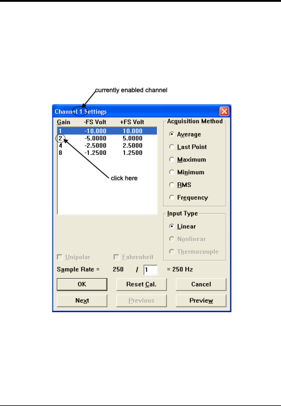
DI–720/DI–722/DI–730 Series User Manual
Accessories
77
Configuring Host Instrument Channel Gain
The signal conditioned (or DI-5B module) channels on the DI-75B output ±5 volts to the host instrument. Since the
DI-75B connections to the DI-700-PGH, DI-720 Series, and DI-730 Series (available through the EXPANSION con-
nector) host instruments are ±10 volt input devices, each DI-75B signal conditioned channel in use must be set to a
gain of 2, so they have a full scale measurement range of ±5 volts.
1. Enable channels in WINDAQ/Pro or WINDAQ/Pro+ recording software.
2. In the Edit menu click on Channel Settings…. The Channel X Settings dialog box (where X represents the cur-
rently enabled channel) displays.
3. In the upper left corner of the dialog box, click the gain factor 2 to get a ± full scale range of 5 volts.
4. Click the Next (or Previous) command button at the bottom of the dialog box to step to the next (or previously)
enabled channel. Note that when either the Next or Previous button is activated, the channel number in the title
bar of the dialog box changes to indicate the channel you are currently working on.
5. Repeat steps 2 and 3 for each DI-75B signal conditioned channel in use.
6. Click the OK command button to close the Channel Settings dialog box.
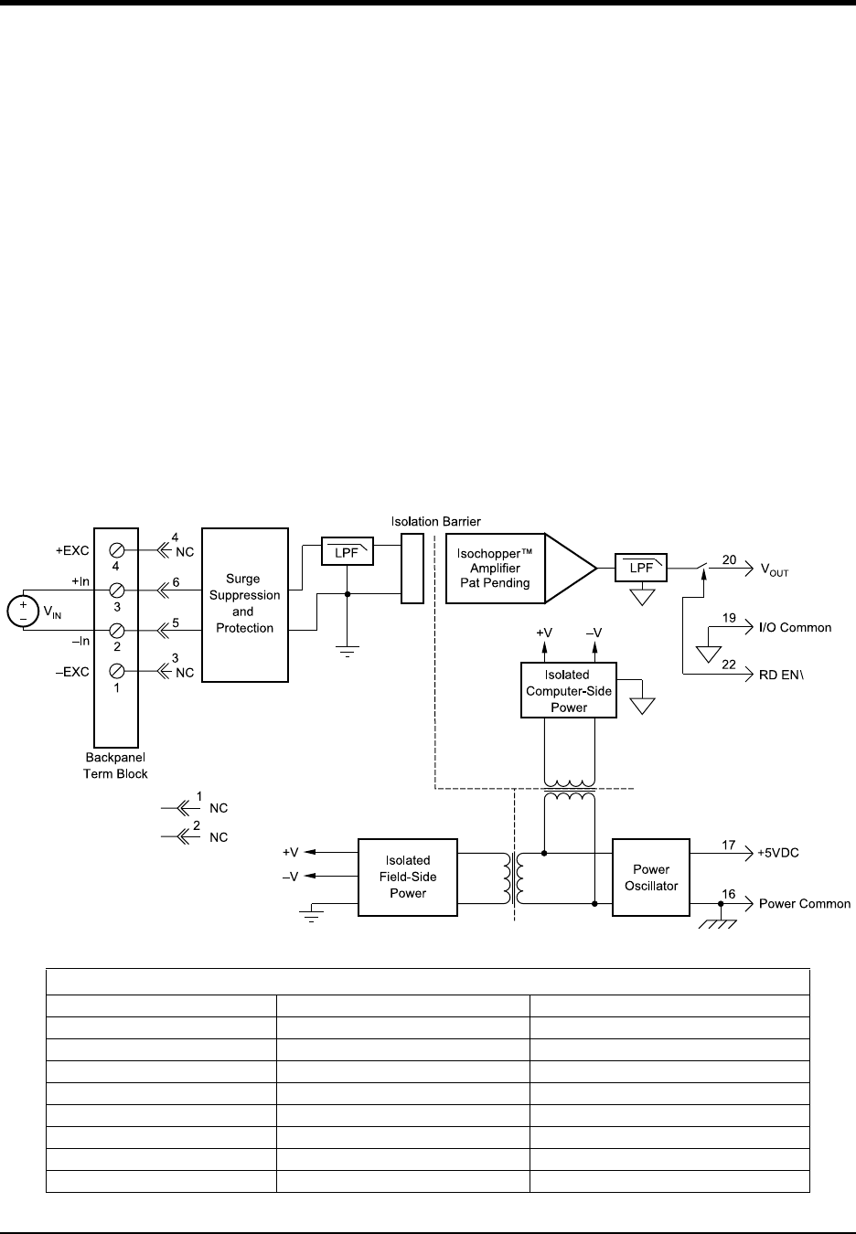
DI–720/DI–722/DI–730 Series User Manual
Accessories
78
DI-5B Modules
DI-5B30/31 Analog Voltage Input Modules, Narrow Bandwidth
Each DI-5B30 and DI-5B31 voltage input module provides a single channel of analog input which is filtered, iso-
lated, amplified, and converted to a high level analog voltage output (see block diagram). This voltage output is logic-
switch controlled, allowing these modules to share a common analog bus without the requirement of external multi-
plexers.
The DI-5B modules are designed with a completely isolated computer side circuit which can be floated to ±50V from
Power Common, pin 16. This complete isolation means that no connection is required between I/O Common and
Power Common for proper operation of the output switch. If desired, the output switch can be turned on continuously
by simply connecting pin 22, the Read-Enable pin to I/O Common, pin 19.
Signal filtering is accomplished with a six-pole filter which provides 95dB of normal-mode-rejection at 60Hz and
90dB at 50Hz. Two poles of this filter are on the field side of the isolation barrier, and the other four are on the com-
puter side.
After the initial field-side filtering, the input signal is chopped by a proprietary chopper circuit. Isolation is provided
by transformer coupling, again using a proprietary technique to suppress transmission of common mode spikes or
surges. The module is powered from +5VDC, ±5%.
A special input circuit on the DI-5B30 and DI-5B31 modules provides protection against accidental connection of
power-line voltages up to 240VAC.:
Ordering Information
MODEL INPUT RANGE OUTPUT RANGE
DI-5B30-01 -10mV to +10mV -5V to +5V
DI-5B30-02 -50mV to +50mV -5V to +5V
DI-5B30-03 -100mV to +100mV -5V to +5V
DI-5B31-01 -1V to +1V -5V to +5V
DI-5B31-02 -5V to +5V -5V to +5V
DI-5B31-03 -10V to +10V -5V to +5V
DI-5B31-07* -20V to +20V -5V to +5V
DI-5B31-09* -40V to +40V -5V to +5V
*CSA certification pending.
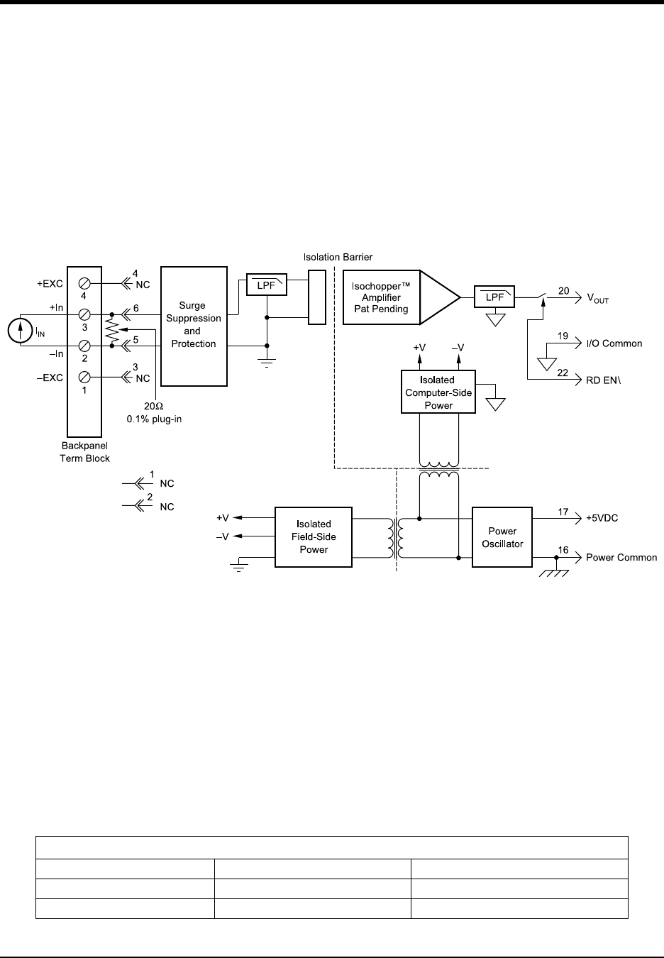
DI–720/DI–722/DI–730 Series User Manual
Accessories
79
DI-5B32 Analog Current Input Modules
Each DI-5B32 current input module provides a single channel of analog input which is filtered, isolated, amplified,
and converted to a high level analog voltage output (see block diagram). This voltage output is logic switch con-
trolled, which allows these modules to share a common analog bus without the requirement of external multiplexers.
The DI-5B modules are designed with a completely isolated computer side circuit which can be floated to ±50V from
Power Common, pin 16. This complete isolation means that no connection is required between I/O Common and
Power Common for proper operation of the output switch. If desired, the output switch can be turned on continuously
by simply connecting pin 22, the Read-Enable pin to I/O Common, pin 19.
A precision 20 current conversion resistor is supplied with the DI-5B32 module (see block diagram for installation
details).
Signal filtering is accomplished with a six-pole filter which provides 95dB of normal-mode rejection at 60Hz and
90dB at 50Hz. Two poles of this filter are on the field side of the isolation barrier, and the other four are on the com-
puter side.
After the initial field-side filtering, the input signal is chopped by a proprietary chopper circuit. Isolation is provided
by transformer coupling, again using a proprietary technique to suppress transmission of common mode spikes or
surges. The module is powered from +5VDC, ±5%.
A special input circuit on the DI-5B32 modules provides protection against accidental connection of power-line volt-
ages up to 240VAC.
Ordering Information
MODEL INPUT RANGE OUTPUT RANGE
DI-5B32-01 4mA to 20mA 0V to +5V
DI-5B32-02 0mA to 20mA 0V to +5V
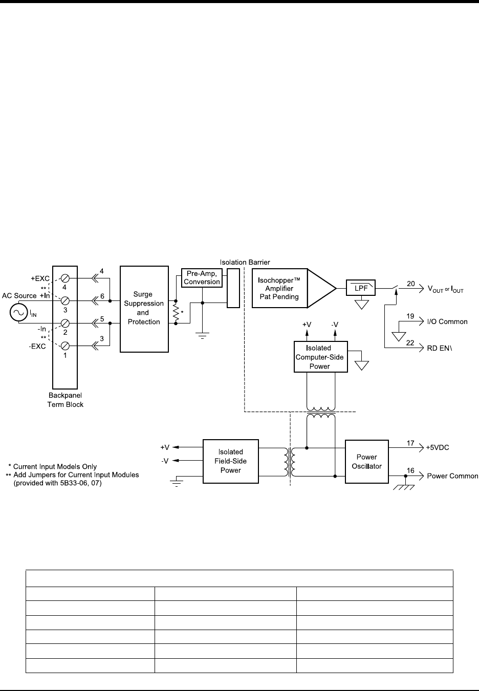
DI–720/DI–722/DI–730 Series User Manual
Accessories
80
DI-5B33 Isolated True RMS Input Modules
Each DI-5B33 True RMS input module provides a single channel of AC input which is converted to its True RMS dc
value, filtered, isolated, amplified, and converted to a standard process voltage or current output (see block diagram).
The DI-5B modules are designed with a completely isolated computer side circuit which can be floated to ±50V from
Power Common, pin 16. This complete isolation means that no connection is required between I/O Common and
Power Common for proper operation of the output switch. If desired, the output switch can be turned on continuously
by simply connecting pin 22, the Read-Enable pin to I/O Common, pin 19.
The field voltage or current input signal is processed through a pre-amplifier and RMS converter on the field side of
the isolation barrier. The converted dc signal is then chopped by a proprietary chopper circuit and transferred across
the transformer isolation barrier, suppressing transmission of common mode spikes and surges. The computer side
circuitry reconstructs, filters and converts the signal to industry standard outputs. Modules are powered from +5VDC,
±5%.
For current output models an external loop supply is required having a compliance voltage of 14 to 48VDC. Connec-
tion, with series load, is between Pin 20 (+) and Pin 19 (-).
Ordering Information
MODEL INPUT RANGE OUTPUT RANGE
DI-5B33-01 100mV 0V to +5V
DI-5B33-02 1V 0V to +5V
DI-5B33-03 10V 0V to +5V
DI-5B33-04 150V 0V to +5V
DI-5B33-05 300V 0V to +5V
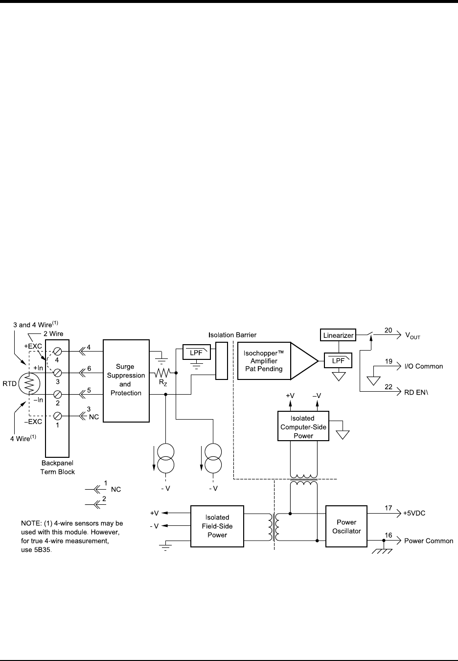
DI–720/DI–722/DI–730 Series User Manual
Accessories
81
DI-5B34 Linearized 2- or 3-Wire RTD Input Modules
Each DI-5B34 RTD input module provides a single channel of RTD input which is filtered, isolated, amplified, lin-
earized, and converted to a high level analog voltage output (see block diagram). This voltage output is logic switch
controlled, which allows these modules to share a common analog bus without the requirement of external multiplex-
ers.
The DI-5B modules are designed with a completely isolated computer side circuit which can be floated to ±50V from
Power Common, pin 16. This complete isolation means that no connection is required between I/O Common and
Power Common for proper operation of the output switch. If desired, the output switch can be turned on continuously
by simply connecting pin 22, the Read-Enable pin to I/O Common, pin 19.
RTD excitation is provided from the module by two matched current sources. When using a three-wire RTD, this
method allows an equal current to flow in each RTD lead, which cancels the effects of lead resistances. The excitation
currents are very small (0.25mA for 100 Pt and 120 Ni, and 1.0mA for 10 Cu) which minimizes self-heating of
the RTD.
Signal filtering is accomplished with a six-pole filter which provides 95dB of normal-mode-rejection at 60Hz and
90dB at 50Hz. Two poles of this filter are on the field side of the isolation barrier, and the other four are on the com-
puter side. After the initial field-side filtering, the input signal is chopped by a proprietary chopper circuit. Isolation is
provided by transformer coupling, again using a proprietary technique to suppress transmission of common mode
spikes or surges. The module is powered from +5VDC, ±5%.
A special input circuit on the DI-5B34 modules provides protection against accidental connection of power-line volt-
ages up to 240VAC.

DI–720/DI–722/DI–730 Series User Manual
Accessories
82
Ordering Information
MODEL INPUT RANGE OUTPUT RANGE ACCURACY*
100 Pt, = 0.00385
DI-5B34-01
DI-5B34-02
DI-5B34-03
DI-5B34-04
-100°C (-148°F) to +100°C (+212°F)
0°C (32°F) to +100°C (+212°F)
0°C (32°F) to +200°C (+392°F)
0°C (32°F) to +600°C (+1112°F)
0V to +5V
0V to +5V
0V to +5V
0V to +5V
±0.46°C
±0.36°C
±0.46°C
±0.88°C
10 Cu, = 0.004274
DI-5B34C-01
DI-5B34C-02
DI-5B34C-03**
0°C (32°F) to +120°C (+248°F) (10 at 0°C)
0°C (32°F) to +120°C (+248°F) (10 at 25°C)
0°C (32°F) to +160°C (+320°F) (10 at 0°C)
0V to +5V
0V to +5V
0V to +5V
±0.23°C
±0.23°C
±0.32°C
120 Ni, = 0.00672
DI-5B34N-01 0°C (32°F) to +300°C (+572°F) 0V to +5V ±0.40°C
* Includes conformity, hysteresis and repeatability.
**CSA certification pending.
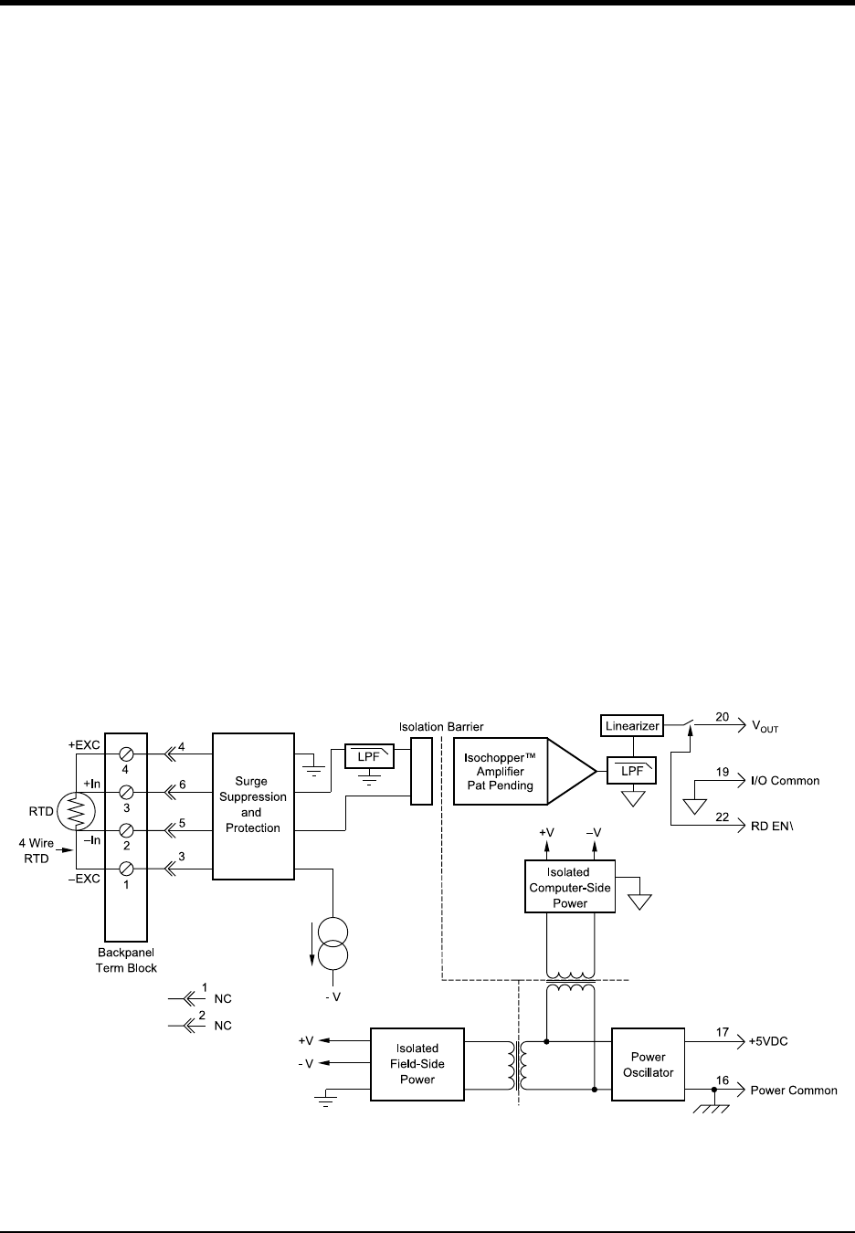
DI–720/DI–722/DI–730 Series User Manual
Accessories
83
DI-5B35 Linearized 4-Wire RTD Input Modules
In RTD temperature measurement applications requiring a very high level of accuracy, the DI-5B35 4-Wire RTD
input module offers a significant advantage over 3-wire measurement techniques (see block diagram). The DI-5B35
measures only the voltage dropped across the RTD and almost completely ignores the resistance or length of the RTD
lead wires. The DI-5B34 3-Wire RTD module provides lead resistance compensation, but requires equal lead resis-
tances, while the DI-5B35 does not require matched lead resistances.
Each DI-5B35 RTD input module provides a single channel of RTD input which is filtered, isolated, amplified, lin-
earized, and converted to a high level analog voltage output. This voltage output is logic switch controlled, which
allows these modules to share a common analog bus without the requirement of external multiplexers.
The DI-5B modules are designed with a completely isolated computer side circuit which can be floated to ±50V from
Power Common, pin 16. This complete isolation means that no connection is required between I/O Common and
Power Common for proper operation of the output switch. If desired, the output switch can be turned on continuously
by simply connecting pin 22, the Read-Enable pin to I/O Common, pin 19.
RTD excitation is provided from the module by a precision current source. The excitation current is available on two
leads which are separate from the two input signal measuring leads. The excitation current does not flow in the input
signal leads, which allows RTD measurement to be totally independent of lead resistance. The excitation current is
very small (0.25mA for 100 Pt and 120 Ni, and 1.0mA for 10 Cu) which minimizes self-heating of the RTD.
Signal filtering is accomplished with a six-pole filter which provides 95dB of normal-mode-rejection at 60Hz and
90dB at 50Hz. Two poles of this filter are on the field side of the isolation barrier, and the other four are on the com-
puter side. After the initial field-side filtering, the input signal is chopped by a proprietary chopper circuit. Isolation is
provided by transformer coupling, again using a proprietary technique to suppress transmission of common mode
spikes or surges. The module is powered from +5VDC, ±5%.
A special input circuit on the DI-5B35 modules provides protection against accidental connection of power-line volt-
ages up to 240VAC.

DI–720/DI–722/DI–730 Series User Manual
Accessories
84
Ordering Information
MODEL INPUT RANGE OUTPUT RANGE ACCURACY*
100 Pt, = 0.00385
DI-5B35-01
DI-5B35-02
DI-5B35-03
DI-5B35-04
-100°C (-148°F) to +100°C (+212°F)
0°C (32°F) to +100°C (+212°F)
0°C (32°F) to +200°C (+392°F)
0°C (32°F) to +600°C (+1112°F)
0V to +5V
0V to +5V
0V to +5V
0V to +5V
±0.46°C
±0.36°C
±0.46°C
±0.88°C
10 Cu, = 0.004274
DI-5B35C-01
DI-5B35C-02DI-
5B35C-03**
0°C (32°F) to +120°C (+248°F) (10 at 0°C)
0°C (32°F) to +120°C (+248°F) (10 at 25°C)
0°C (32°F) to +160°C (+320°F) (10 at 0°C)
0V to +5V
0V to +5V
0V to +5V
±0.23°C
±0.23°C
±0.32°C
120 Ni, = 0.00672
DI-5B35N-01 0°C (32°F) to +300°C (+572°F) 0V to +5V ±0.40°C
* Includes conformity, hysteresis and repeatability.
**CSA certification pending.
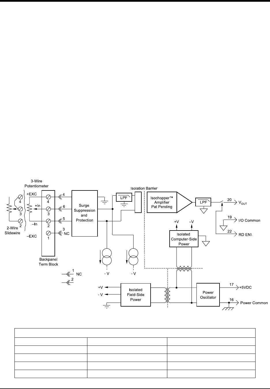
DI–720/DI–722/DI–730 Series User Manual
Accessories
85
DI-5B36 Potentiometer Input Modules
Each DI-5B36 Potentiometer input module provides a single channel of Potentiometer input which is filtered, iso-
lated, amplified, and converted to a high level analog voltage output (see block diagram). This voltage output is logic
switch controlled, which allows these modules to share a common analog bus without the requirement of external
multiplexers.
The DI-5B modules are designed with a completely isolated computer side circuit which can be floated to ± 50V from
Power Common, pin 16. This complete isolation means that no connection is required between I/O Common and
Power Common for proper operation of the output switch. If desired, the output switch can be turned on continuously
by simply connecting pin 22, the Read-Enable pin to I/O Common, pin 19.
Excitation for the potentiometer is provided from the module by two matched current sources. When using a three-
wire potentiometer, this method allows cancellation of the effects of lead resistances. The excitation currents are very
small (less than 1.0mA) which minimizes self-heating of the potentiometer.
Signal filtering is accomplished with a six-pole filter which provides 95dB of normal-mode-rejection at 60Hz and
90dB at 50Hz. Two poles of this filter are on the field side of the isolation barrier, and the other four are in the output
stage. After the initial field-side filtering, the input signal is chopped by a proprietary chopper circuit. Isolation is pro-
vided by transformer coupling, again using a proprietary technique to suppress transmission of common mode spikes
or surges. The module is powered from +5VDC, ±5%.
A special input circuit on the DI-5B36 module provides protection against accidental connection of power-line volt-
ages up to 240VAC.
Ordering Information
MODEL INPUT RANGE OUTPUT RANGE
DI-5B36-01 0 to 1000V to +5V
DI-5B36-02 0 to 5000V to +5V
DI-5B36-03 0 to 1k0V to +5V
DI-5B36-04 0 to 10k0V to +5V
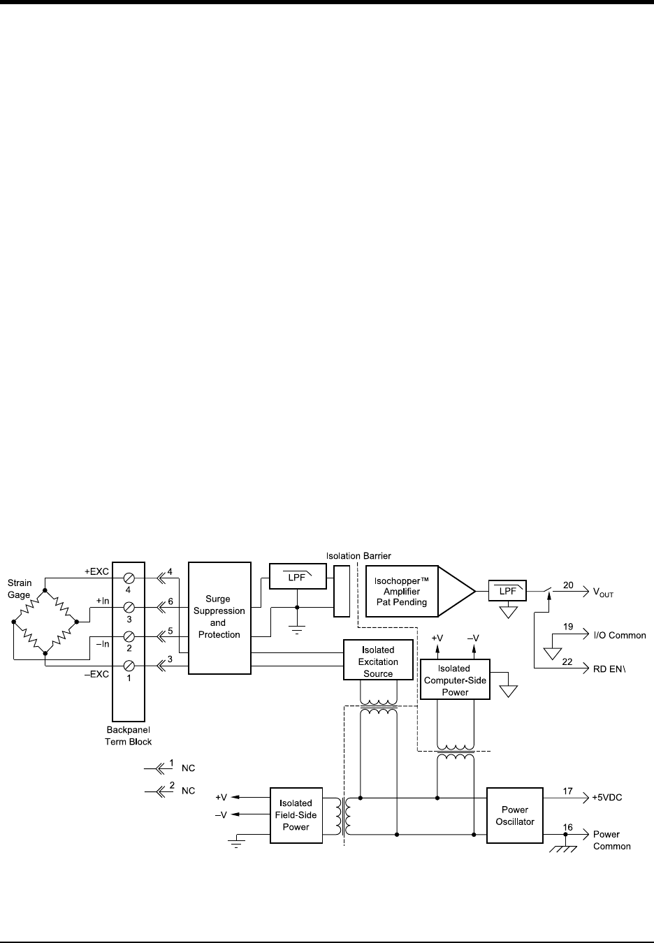
DI–720/DI–722/DI–730 Series User Manual
Accessories
86
DI-5B38 Strain Gage Input Modules, Narrow & Wide Bandwidth
Each DI-5B38 Strain Gage input module provides a single channel of Strain Gage input which is filtered, isolated,
amplified, and converted to a high level analog voltage output (see block diagram). This voltage output is logic
switch controlled, which allows these modules to share a common analog bus without the requirement of external
multiplexers.
The DI-5B modules are designed with a completely isolated computer side circuit which can be floated to ±50V from
Power Common, pin 16. This complete isolation means that no connection is required between I/O Common and
Power Common for proper operation of the output switch. If desired, the output switch can be turned on continuously
by simply connecting pin 22, the Read-Enable pin to I/O Common, pin 19.
The DI-5B38 can interface to full- or half-bridge transducers with a nominal resistance of 100 to 10k. A matched
pair of bridge-completion resistors (to ±1mV at +10V excitation) allows use of low cost half- or quarter-bridge trans-
ducers. On wide bandwidth modules, the 10kHz bandwidth allows measurement of high speed processes such as
vibration analysis.
Strain Gage excitation is provided from the module by a very stable 10V or 3.333V source. The excitation supply is
fully isolated, allowing the amplifier inputs to operate over the full range of the excitation voltage. Full scale sensitiv-
ities of 2mV/V, 3mV/V or 10mV/V are offered. With 10V excitation, this results in a ±20mV, ±30mV or ±100mV full
scale input range.
On wide bandwidth modules, the input signal is processed through a preamplifier on the field side of the isolation
barrier. This preamplifier has a gain-bandwidth product of 5MHz and is bandwidth limited to 10kHz. On all modules,
after initial field side filtering, the input signal is chopped by a proprietary chopper circuit. Isolation is provided by
transformer coupling, again using a proprietary technique to suppress transmission of common mode spikes or
surges. The module is powered from +5VDC, ±5%.
Special input circuits on the DI-5B38 module provide protection of the signal inputs and the isolated excitation sup-
ply up to 240VAC.

DI–720/DI–722/DI–730 Series User Manual
Accessories
87
Ordering Information
MODEL INPUT
BRIDGE TYPE
INPUT RANGE EXCITATION OUTPUT RANGE
DI-5B38-31 or DI-5B38-01 Full Bridge 100 to 10k3.333V at 3mV/V Sensitivity -5V to +5V
DI-5B38-32 or DI-5B38-02 Full Bridge 300 to 10k10.0V at 3mV/V Sensitivity -5V to +5V
DI-5B38-33 or DI-5B38-03 Half Bridge 100 to 10k3.333V at 3mV/V Sensitivity -5V to +5V
DI-5B38-34 or DI-5B38-04 Half Bridge 300 to 10k10.0V at 3mV/V Sensitivity -5V to +5V
DI-5B38-35 or DI-5B38-05 Full Bridge 300 to 10k10.0V at 2mV/V Sensitivity -5V to +5V
DI-5B38-36 or DI-5B38-06 Full Bridge 100 to 10k3.333V at 10mV/V Sensitivity -5V to +5V
DI-5B38-37 or DI-5B38-07 Full Bridge 300 to 10k10.0V at 10mV/V Sensitivity -5V to +5V
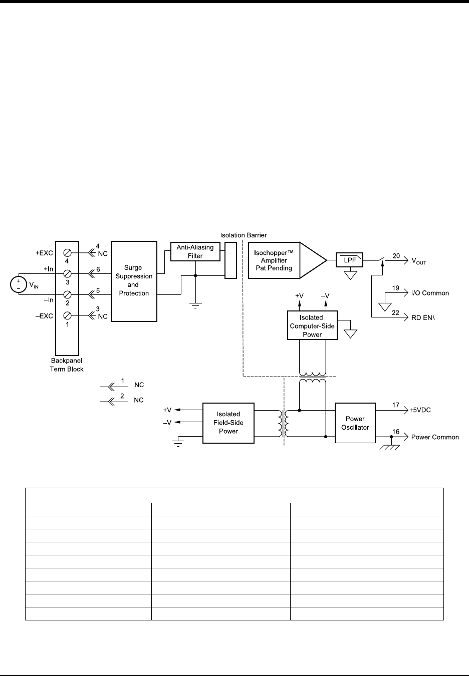
DI–720/DI–722/DI–730 Series User Manual
Accessories
88
DI-5B40/41 Analog Voltage Input Modules, Wide Bandwidth
Each DI-5B40 and DI-5B41 wide bandwidth voltage input module provides a single channel of analog input which is
amplified, isolated, and converted to a high level analog voltage output (see block diagram). This voltage output is
logic-switch controlled, allowing these modules to share a common analog bus without the requirement of external
multiplexers.
The DI-5B modules are designed with a completely isolated computer side circuit which can be floated to ±50V from
Power Common, pin 16. This complete isolation means that no connection is required between I/O Common and
Power Common for proper operation of the output switch. If desired, the output switch can be turned on continuously
by simply connecting pin 22, the Read-Enable pin to I/O Common, pin 19.
The input signal is processed through a preamplifier on the field side of the isolation barrier. This preamplifier has a
gain-bandwidth product of 5MHz and is bandwidth limited to 10kHz. After amplification, the input signal is chopped
by a proprietary chopper circuit. Isolation is provided by transformer coupling, again using a proprietary technique to
suppress transmission of common mode spikes or surges. The module is powered from +5VDC, ±5%.
A special input circuit on the DI-5B40 and DI-5B41 modules provides protection against accidental connection of
power-line voltages up to 240VAC.
Ordering Information
MODEL INPUT RANGE OUTPUT RANGE
DI-5B40-01 -10mV to +10mV 0V to +5V
DI-5B40-02 -50mV to +50mV 0V to +5V
DI-5B40-03 -100mV to +100mV 0V to +5V
DI-5B41-01 -1V to +1V 0V to +5V
DI-5B41-02 -5V to +5V 0V to +5V
DI-5B41-03 -10V to +10V 0V to +5V
DI-5B41-07** -20V to +20V 0V to +5V
DI-5B41-09** -40V to +40V 0V to +5V
*Required for DI-500-HV high voltage option.
**CSA certification pending.
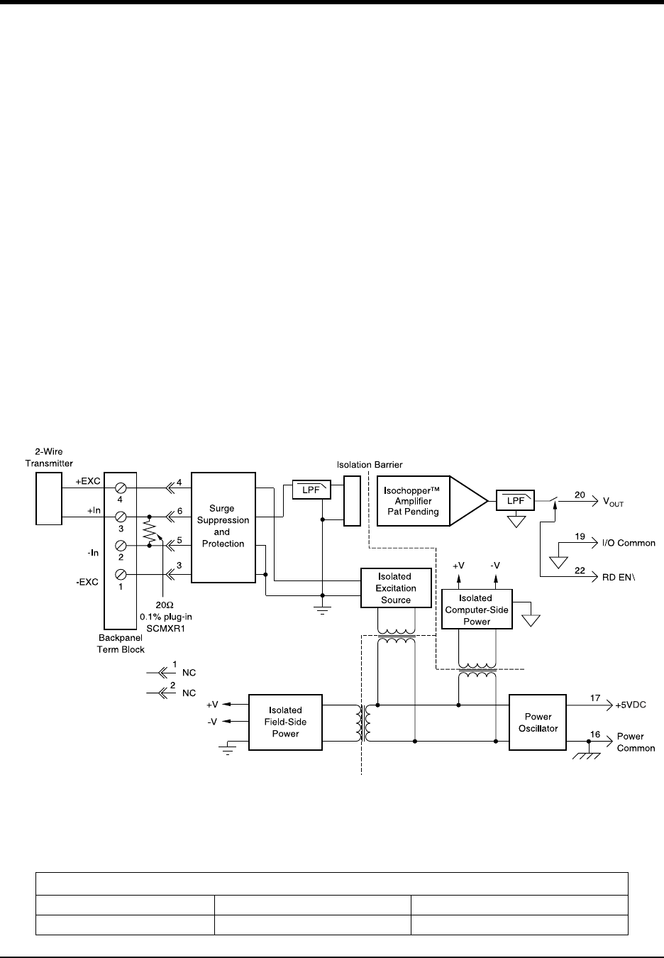
DI–720/DI–722/DI–730 Series User Manual
Accessories
89
DI-5B42 2-Wire Transmitter Interface Modules
Each DI-5B42 2-wire transmitter interface module provides a single channel which accepts a 4 to 20 mA process cur-
rent input and provides a standard +1 to +5V output signal (see block diagram). An isolated +20VDC regulated
power supply is provided to power the current transmitter. This allows a 2-wire loop powered transmitter to be
directly connected to the DI-5B42 without requiring an external power supply. The regulated supply will provide a
nominal +20VDC at a loop current of 4mA to 20mA.
The DI-5B42 will provide a 1500V isolation barrier for non-isolated 2-wire field transmitters. It can also be used
when additional isolation is required between an isolated 2-wire transmitter and the input stage of the control room
computer.
The voltage output is logic switch controlled, which allows these modules to share a common analog bus without the
requirement of external multiplexers.
The DI-5B modules are designed with a completely isolated computer side circuit which can be floated to ±50V from
Power Common, pin 16. This complete isolation means that no connection is required between I/O Common and
Power Common for proper operation of the output switch. If desired, the output switch can be turned on continuously
by simply connecting pin 22, the Read-Enable pin to I/O Common, pin 19.
A precision 20 current conversion resistor is supplied with the module. All field inputs are fully protected from
accidental connection of power-line voltages up to 240VAC. The module has a 3dB bandwidth of 100Hz. Signal fil-
tering is accomplished with a six-pole filter, with two poles on the field side of the isolation barrier, and the other four
on the computer side.
Ordering Information
MODEL INPUT RANGE OUTPUT RANGE
DI-5B42-01 4mA to 20mA +1V to +5V
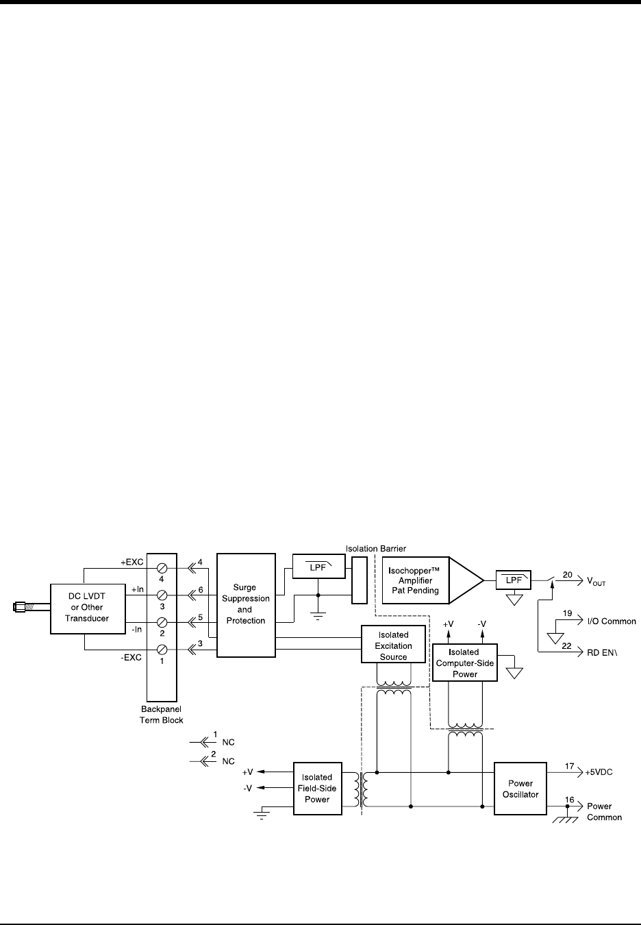
DI–720/DI–722/DI–730 Series User Manual
Accessories
90
DI-5B43 Isolated DC Transducer Amplifier Input Module
Each DI-5B43 displacement transducer module provides a single channel of displacement transducer input which is
filtered, isolated, scaled, and converted to a high level analog voltage output (see block diagram). This voltage output
is logic switch controlled, which allows these modules to share a common analog bus without the requirement of
external multiplexers.
The DI-5B modules are designed with a completely isolated computer side circuit which can be floated to ±50V from
Power Common, pin 16. This complete isolation means that no connection is required between I/O Common and
Power Common for proper operation of the output switch. If desired, the output switch can be turned on continuously
by simply connecting pin 22, the Read-Enable pin to I/O Common, pin 19.
The DI-5B43 can interface to DC displacement transducers and other devices which require a precision 10VDC sup-
ply and produce a high level output. The 1kHz bandwidth significantly reduces ripple and noise inherent in these
devices.
Transducer excitation is provided from the module by a very stable 10V source. The excitation supply is fully iso-
lated, allowing the amplifier inputs to operate over the full range of the excitation voltage. This feature offers signifi-
cant flexibility in real world applications. Ten full scale input ranges are provided, from ±1V to ±10V, producing ±5V
full scale output.
The input signal is processed through a preamplifier on the field side of the isolation barrier. This preamplifier has a
gain-bandwidth product of 5MHz and is bandwidth limited to 1kHz. After amplification, the input signal is chopped
by a proprietary chopper circuit. Isolation is provided by transformer coupling, again using a proprietary technique to
suppress transmission of common mode spikes or surges. The module is powered from +5VDC, ±5%. Special input
circuits on the DI-5B43 module provide protection of the signal inputs and the isolated excitation supply up to
240VAC.

DI–720/DI–722/DI–730 Series User Manual
Accessories
91
Ordering Information
MODEL* MAXIMUM INPUT EXCITATION
DI-5B43-01 ±1V +10.0Vdc @ 40mA
DI-5B43-02A ±2V +10.0Vdc @ 40mA
DI-5B43-03 ±3V +10.0Vdc @ 40mA
DI-5B43-04A ±4V +10.0Vdc @ 40mA
DI-5B43-05 ±5V +10.0Vdc @ 40mA
DI-5B43-06 ±6V +10.0Vdc @ 40mA
DI-5B43-07A ±7V +10.0Vdc @ 40mA
DI-5B43-08A ±8V +10.0Vdc @ 40mA
DI-5B43-09 ±9V +10.0Vdc @ 40mA
DI-5B43-10 ±10V +10.0Vdc @ 40mA
*CSA certification pending.
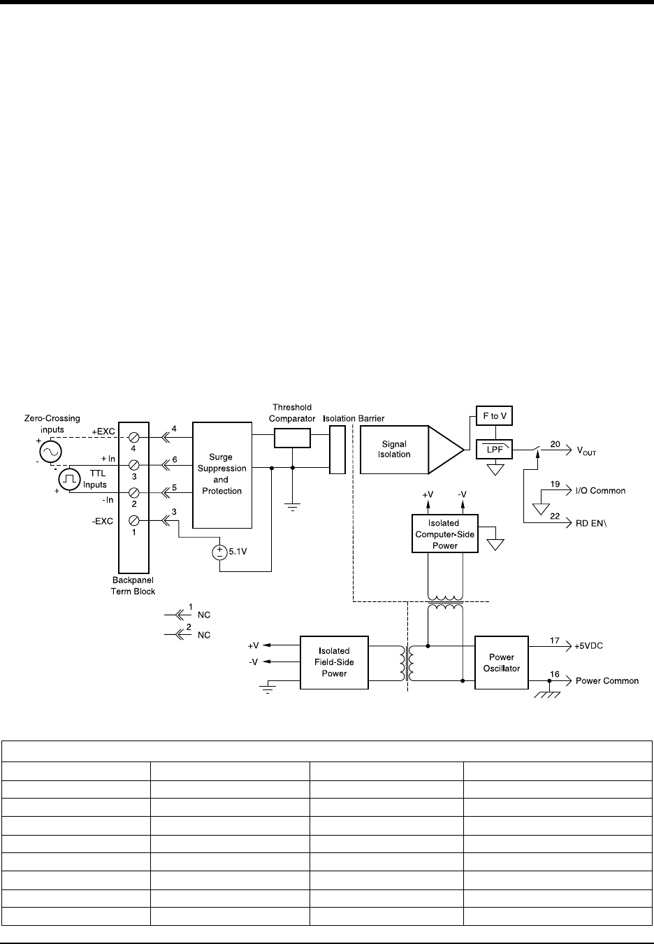
DI–720/DI–722/DI–730 Series User Manual
Accessories
92
DI-5B45 Frequency Input Modules
Each DI-5B45 frequency input module provides a single channel of frequency input which is isolated and converted
to a high level analog voltage output. This voltage output is logic switch controlled, which allows these modules to
share a common analog bus without the requirement of external multiplexers (see block diagram).
The frequency input signal can be a TTL level signal or a zero-crossing signal. Terminal 3 (+In) on the field-side ter-
minal block is the “common” or ground connection for input signals. A TTL signal is connected from terminal 2 (-In)
to terminal 3 (+In), while a zero-crossing signal is connected from terminal 4 (+EXC) to terminal 3 (+In). Input cir-
cuitry for each of the signal types has hysteresis built in. An input signal must cross entirely through the hysteresis
region in order to trigger the threshold comparator.
A 5.1V excitation is available for use with magnetic pickup or contact-closure type sensors. The excitation is avail-
able on pin 1 (-EXC) and the excitation common is pin 3 (+In).
The DI-5B modules are designed with a completely isolated computer side circuit which can be floated to ±50V from
Power Common, pin 16. This complete isolation means that no connection is required between I/O Common and
Power Common for proper operation of the output switch. If desired, the output switch can be turned on continuously
by simply connecting pin 22, the Read-Enable pin to I/O Common, pin 19.
A special circuit in the input stage of the module provides protection against accidental connection of power-line
voltages up to 240VAC.
Ordering Information
MODEL INPUT RANGE OUTPUT RANGE EXCITATION
DI-5B45-01 0 to 500Hz 0 to +5V +5.1Vdc @ 8mA
DI-5B45-02 0 to 1kHz 0 to +5V +5.1Vdc @ 8mA
DI-5B45-03 0 to 3kHz 0 to +5V +5.1Vdc @ 8mA
DI-5B45-04 0 to 5kHz 0 to +5V +5.1Vdc @ 8mA
DI-5B45-05 0 to 10kHz 0 to +5V +5.1Vdc @ 8mA
DI-5B45-06 0 to 25kHz 0 to +5V +5.1Vdc @ 8mA
DI-5B45-07 0 to 50kHz 0 to +5V +5.1Vdc @ 8mA
DI-5B45-08 0 to 100kHz 0 to +5V +5.1Vdc @ 8mA
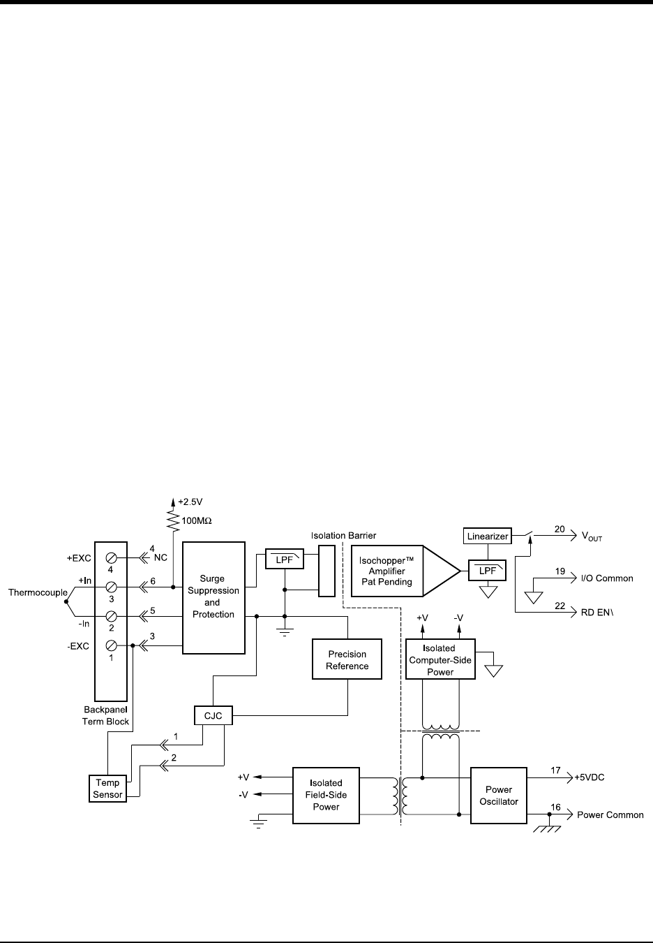
DI–720/DI–722/DI–730 Series User Manual
Accessories
93
DI-5B47 Linearized Thermocouple Input Modules
Each DI-5B47 thermocouple input module provides a single channel of thermocouple input which is filtered, iso-
lated, amplified, linearized and converted to a high level analog voltage output (see block diagram). This voltage out-
put is logic switch controlled, which allows these modules to share a common analog bus without the requirement of
external multiplexers.
The DI-5B modules are designed with a completely isolated computer side circuit which can be floated to ±50V from
Power Common, pin 16. This complete isolation means that no connection is required between I/O Common and
Power Common for proper operation of the output switch. If desired, the output switch can be turned on continuously
by simply connecting pin 22, the Read-Enable pin to I/O Common, pin 19.
The DI-5B47 can interface to eight industry standard thermocouple types: J, K, T, E, R, S, N, and B. Its correspond-
ing output signal operates over a 0 to +5V range. Each module is cold-junction compensated to correct for parasitic
thermocouples formed by the thermocouple wire and screw terminals on the mounting hardware. Upscale open ther-
mocouple detect is provided by an internal pull-up resistor. Downscale indication can be implemented by installing
an external 47M resistor, ±20% tolerance, between screw terminals 1 and 3.
Signal filtering is accomplished with a six-pole filter which provides 95dB of normal-mode-rejection at 60Hz and
90dB at 50Hz. Two poles of this filter are on the field side of the isolation barrier, and the other four are on the com-
puter side.
After the initial field-side filtering, the input signal is chopped by a proprietary chopper circuit. Isolation is provided
by transformer coupling, again using a proprietary technique to suppress transmission of common mode spikes or
surges. The module is powered from +5VDC, ±5%.
A special circuit in the input stage of the module provides protection against accidental connection of power-line
voltages up to 240VAC.

DI–720/DI–722/DI–730 Series User Manual
Accessories
94
Ordering Information
MODEL TYPE INPUT RANGE ACCURACY*
DI-5B47J-01 Type J 0°C to +760°C (+32°F to +1400°F) ±0.61°C
DI-5B47J-02 Type J -100°C to +300°C (-148°F to +572°F) ±0.32°C
DI-5B47J-03 Type J 0°C to +500°C (+32°F to +932°F) ±0.36°C
DI-5B47J-12** Type J -100°C to +760°C (-148°F to +1400°F) ±0.70°C
DI-5B47K-04 Type K 0°C to +1000°C (+32°F to +1832°F) ±0.80°C
DI-5B47K-05 Type K 0°C to +500°C (+32°F to +932°F) ±0.38°C
DI-5B47K-13** Type K -100°C to +1350°C (-148°F to +2462°F) ±1.20°C
DI-5B47K-14** Type K 0°C to +1200°C (+32°F to +2192°F) ±0.96°C
*Includes conformity, hysteresis and repeatability. Does not include CJC accuracy.
**CSA certification pending.
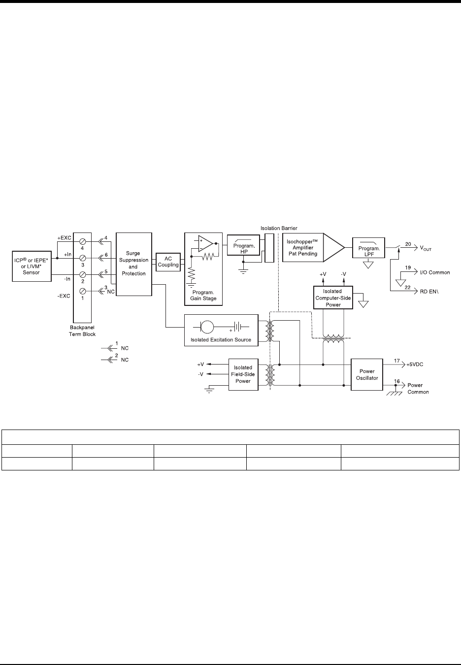
DI–720/DI–722/DI–730 Series User Manual
Accessories
95
DI-5B48 Accelerometer Input Modules
The DI-5B48 provides excitation to piezoelectric sensors with built-in microelectronic amplifiers, commonly known
as ICP®* or IEPE* or LIVM* sensors. The module provides a constant current excitation to the sensor, then isolates,
filters, and amplifies the sensor output, yielding a high-level analog voltage output. The excitation current, signal
gain, and filter high-pass and low-pass cutoff frequencies are field-configurable through a set of slide switches.
Six poles of signal filtering in the DI-5B48 module result in greater than 100dB of normal-mode rejection for signal
frequencies above the cutoff frequency. One pole of filtering is on the field side of the isolation barrier for anti-alias-
ing purposes and the remaining five-pole programmable Bessel filter is located on the system side. High-pass filter-
ing is achieved through a second order passive filter, located on the field side. If desired, the output switch can be
turned on continuously by simply connecting pin 22, the Read-Enable pin, to I/O Common, pin 19.
The DI-5B48 offers the option of setting the constant current source for sensor excitation to common values of 4mA
or 9mA with a compliance voltage of 24VDC. Programmable gains of 1, 10 and 100 are selectable and the module
offers a ±10V output. The required supply level is +5VDC, ±5%.
To ensure protection of expensive data acquisition equipment, the DI-5B48 module signal inputs and sensor exci-
tation outputs are protected against accidental connection of voltages up to 240Vrms.
Ordering Information
MODEL INPUT RANGE OUTPUT RANGE BANDWIDTH ISOLATION VOLTAGE
DI-5B48-01 ±10V max ±10V 2.5kHz to 20kHz 1500

