772940 Leica Viva Tech Ref_V5.0.0_en Ref V5.0.0 En
User Manual: 772940 Leica Viva TechRef_V5.0.0_en
Open the PDF directly: View PDF ![]() .
.
Page Count: 956 [warning: Documents this large are best viewed by clicking the View PDF Link!]
- Introduction
- Table of Contents
- 1 Configurable Keys
- 2 TPS Settings
- 3 GPS Settings
- 4 Main Menu
- 5 Jobs & Data - Jobs
- 6 Jobs & Data - Data
- 7 Codelists
- 8 Coordinate Systems
- 9 Jobs & Data - Create control data
- 10 Jobs & Data - Import data
- 11 Jobs & Data - Export & copy data
- 12 Instrument - TPS settings
- 13 Instrument - GPS settings
- 14 Antenna Heights
- 15 Connections.. - GPS connection wizard
- 16 Connections.. - TPS connection wizard
- 17 Connections.. - CS connection wizard
- 18 Connections.. - Internet wizard
- 19 Connections.. - All other connections
- 19.1 Accessing Configuration Connections
- 19.2 CS Internet / GS Internet / TS Internet
- 19.3 GPS Rover / Base Sensor
- 19.4 ASCII Input
- 19.5 GPS Hidden Pt
- 19.6 Export Job
- 19.7 RTK Rover
- 19.8 Base RTK 1 / Base RTK 2
- 19.9 NMEA 1 / NMEA 2
- 19.10 Remote (OWI)
- 19.11 PPS Output
- 19.12 Event Input 1/Event Input 2
- 19.13 Total Station
- 19.14 GSI Output
- 19.15 Field Controller Connection
- 19.16 GeoCom Connection
- 20 Connections.. - All other connections, Cntrl.. Key
- 21 Configuration of Devices
- 22 Instrument - Instrument status info
- 23 Instrument - Base settings
- 24 Instrument - TPS camera settings
- 25 User - Work settings
- 26 Coding
- 27 Linework
- 28 User - Working style wizard
- 29 User - System settings
- 30 User - Tools & other utilities
- 31 User - Check & Adjust
- 31.1 Overview
- 31.2 Details on Instrument Errors
- 31.3 Accessing the Check & Adjust Wizard
- 31.4 Combined Adjustment (l, t, i, c, ATR and tele camera)
- 31.5 Tilting Axis Adjustment (a)
- 31.6 Compensator Adjustment (l, t)
- 31.7 Viewing the Current Values
- 31.8 Configuring Check & Adjust
- 31.9 Adjusting the Circular Level of the Instrument and Tribrach
- 31.10 Adjusting the Circular Level of the Prism Pole
- 31.11 Inspecting the Laser Plummet of the Instrument
- 31.12 Servicing the Tripod
- 32 User - About Leica Viva
- 33 Camera & Imaging
- 34 TPS Functions
- 35 Calculator
- 36 NTRIP via Internet
- 37 MapView Interactive Display Feature
- 38 Tap Map
- 39 Applications - General
- 40 COGO
- 40.1 Overview
- 40.2 Accessing COGO
- 40.3 Configuring COGO
- 40.4 COGO Calculation - Inverse Method
- 40.5 COGO Calculation - Traverse Method
- 40.6 COGO Calculation - Intersection Method
- 40.7 COGO Calculation - Line/Arc Calculations Method
- 40.8 COGO Calculation - Area Division
- 40.9 COGO Calculation - Shift, Rotate & Scale
- 40.10 COGO Calculation - Angle Method
- 40.11 COGO Calculation - Horizontal Curve Method
- 40.12 COGO Calculation - Triangle Method
- 40.13 Selecting a Result from Previous COGO Inverse Calculations
- 40.14 Modifying Values for Azimuths, Distances and Offsets
- 41 Determine Coordinate System
- 42 QuickGrid
- 43 Reference Line
- 44 Reference Plane & Grid Scan
- 44.1 Overview
- 44.2 Accessing Reference Plane & Grid Scan
- 44.3 Creating a Reference Plane From Previously Stored Points
- 44.4 Selecting a Reference Plane from a Job
- 44.5 Configuring Reference Plane & Grid Scan
- 44.6 Editing a Reference Plane
- 44.7 Measuring Points to a Reference Plane
- 44.8 Grid Scan on Plane
- 44.9 Grid Scan on Surface
- 45 Roads - General
- 45.1 Overview
- 45.2 Jobs & Design Data
- 45.3 Configuring Roads Applications
- 45.3.1 Configuration Settings
- 45.3.2 Road Line - Info Page
- 45.3.3 Road Local Line - Info Page
- 45.3.4 Road Surface Grade - Info Page
- 45.3.5 Road Manual Slope, Local Manual Slope and Slope - Info Page
- 45.3.6 Road Crown - Info Page
- 45.3.7 Road Layer - Info Page
- 45.3.8 Road DTM - Info Page
- 45.3.9 Rail - Info Page
- 45.3.10 Tunnel - Info Page
- 45.3.11 Workflow for Height (aim to stake ht)
- 45.4 Working with Shifts
- 45.5 Tasks
- 45.6 Understanding Terms and Expressions
- 45.6.1 Road - Basic Terms
- 45.6.2 Road - Horizontal and Vertical Geometry Elements
- 45.6.3 Road - Basic Elements for Stake and Check Measurements
- 45.6.4 Road - Stake Offset and Stake Height Difference
- 45.6.5 Road - Chainage or Station Equations
- 45.6.6 Road - Working Corridor
- 45.6.7 Road - Extension of the Centreline
- 45.6.8 Road/Rail - Working with Heights
- 45.6.9 Rail - Working with a Single Track
- 45.6.10 Rail - Working with Multiple Tracks
- 45.6.11 Rail - Check Elements and Stakeout Elements
- 45.6.12 Rail - Working with Offsets
- 45.6.13 Tunnel - Basic Terms
- 45.6.14 Tunnel - Elements for Stake Out and Check Measurements
- 45.6.15 Tunnel - Shifts
- 46 Roads - Alignment Editor
- 46.1 Basic Terms
- 46.2 Starting Alignment Editor
- 46.3 Configuring Alignment Editor
- 46.4 Edit Horizontal Alignments Using Elements
- 46.5 Edit Horizontal Alignments Using PIs
- 46.6 Edit Vertical Alignments Using Elements
- 46.7 Edit Vertical Alignments Using PIs
- 46.8 Edit Cross Section Templates
- 46.9 Edit Cross Section Assignments
- 46.10 Edit Chainage Equation
- 46.11 Convert to job
- 47 Roads - Road
- 47.1 Creating a New Road Job
- 47.2 Defining the Work
- 47.3 Staking/Checking the Road
- 47.3.1 The Stake/Check Screen
- 47.3.2 Measuring Points by Chainage and Offset
- 47.3.3 Measuring Lines Relative to a Centreline
- 47.3.4 Measuring Local Lines without Centrelines
- 47.3.5 Indefinite Triangle
- 47.3.6 Measuring Surface Grades
- 47.3.7 Measuring Manual Slopes, Local Manual Slopes and Design Slopes
- 47.3.8 Measuring Road Crowns
- 47.3.9 Measuring Road Layers
- 47.3.10 Measuring Digital Terrain Models (DTM)
- 47.4 The Tools Menu
- 47.4.1 Overview
- 47.4.2 Use heights from DTM
- 47.4.3 Apply current chainage
- 47.4.4 Get current angle to alignment
- 47.4.5 Stake individual point
- 47.4.6 COGO Road - Alignment Information
- 47.4.7 Additional Layer Information
- 47.4.8 Box / base definition
- 47.4.9 Get current slope
- 47.4.10 Manual Slope
- 47.4.11 Reset slope to design
- 47.4.12 Shift reference line
- 47.4.13 Re-initialise search
- 47.4.14 Stake intersection point
- 48 Roads - Rail
- 49 Roads - Tunnel
- 50 Scanning
- 51 Sets of Angles
- 52 Setup
- 53 Stakeout
- 54 Seismic Stakeout
- 55 Base Menu - Start base
- 56 Survey - General
- 57 Survey - General
- 58 Survey - Auto Points
- 59 Survey Cross Section
- 60 Survey - Hidden Points
- 61 Hidden Point
- 62 Survey - Remote Point
- 63 Traverse
- 64 Volumes & Surfaces
- 65 QuickVolume
- Appendix A Menu Tree
- Appendix B Internal Memory
- Appendix C Directory Structure of the Memory Device
- Appendix D Pin Assignments and Sockets
- Appendix E Cables
- Appendix F NMEA Message Formats
- F.1 Overview
- F.2 Symbols Used for Describing the NMEA Formats
- F.3 GGA - Global Positioning System Fix Data
- F.4 GGK - Real-Time Position with DOP
- F.5 GGK(PT) - Real-Time Position with DOP, Trimble Proprietary
- F.6 GGQ - Real-Time Position with CQ
- F.7 GLL - Geographic Position Latitude/Longitude
- F.8 GNS - GNSS Fix Data
- F.9 GSA - GNSS DOP and Active Satellites
- F.10 GSV - GNSS Satellites in View
- F.11 LLK - Leica Local Position and GDOP
- F.12 LLQ - Leica Local Position and Quality
- F.13 RMC - Recommended Minimum Specific GNSS Data
- F.14 VTG - Course Over Ground and Ground Speed
- F.15 ZDA - Time and Date
- Appendix G AT Commands
- Appendix H Event Input Notify Message Format
- Appendix I PPS Output Notify Message Format
- Index

Leica Viva Series
Technical Reference
Manual
Version 5.0
English

Viva Series, Introduction 2
Introduction
Purchase Congratulations on the purchase of a Leica SmartWorx Viva instrument.
To use the product in a permitted manner, please refer to the detailed safety direc-
tions in the CS10/CS15 User Manual, the GS10/GS15 User Manual, the GS25 User
Manual, the TS11 User Manual, the TS15 User Manual, the Leica TS12 Robotic User
Manual and the Leica MS50/TS50/TM50 User Manual.
Product identifica-
tion
The type and serial number of your product are indicated on the type plate.
Enter the type and serial number in your manual and always refer to this information
when you need to contact your agency or Leica Geosystems authorised service work-
shop.
Symbols The symbols used in this manual have the following meanings:
Trademarks • Windows is a registered trademark of Microsoft Corporation in the United States
and other countries
• CompactFlash and CF are trademarks of SanDisk Corporation
• Bluetooth® is a registered trademark of Bluetooth SIG, Inc.
• SD Logo is a trademark of SD-3C, LLC.
All other trademarks are the property of their respective owners.
Validity of this
manual
• This manual applies to SmartWorx Viva. For the Lite version of SmartWorx Viva,
some functionality described in this manual is not available.
• This manual applies to the Leica Viva Series. Differences between GPS and TPS are
marked and described.
Available
documentation
Type: _______________
Serial No.: _______________
Type Description
Important paragraphs which must be adhered to in practice as they
enable the product to be used in a technically correct and efficient
manner.
Name Description/Format
CS10/CS15 User
Manual
All instructions required to operate the product to a basic
level are contained in the User Manual. Provides an over-
view of the product together with technical data and
safety directions.
-
GS10/GS15 User
Manual
All instructions required to operate the product to a basic
level are contained in the User Manual. Provides an over-
view of the product together with technical data and
safety directions.
-
TS11 User Manual All instructions required to operate the product to a basic
level are contained in the User Manual. Provides an over-
view of the product together with technical data and
safety directions.
-

Viva Series, Introduction 3
Refer to the following resources for all Leica Viva Series documentation/soft-
ware:
• the SmartWorx Viva USB documentation card
• https://myworld.leica-geosystems.com
GS25User Manual All instructions required to operate the product to a basic
level are contained in the User Manual. Provides an over-
view of the product together with technical data and
safety directions.
-
TS15 User Manual All instructions required to operate the product to a basic
level are contained in the User Manual. Provides an over-
view of the product together with technical data and
safety directions.
-
TS12 Robotic
User Manual
All instructions required to operate the product to a basic
level are contained in the User Manual. Provides an over-
view of the product together with technical data and
safety directions.
-
TS12 Lite User
Manual
All instructions required to operate the product to a basic
level are contained in the User Manual. Provides an over-
view of the product together with technical data and
safety directions.
-
Name Description/Format
Viva GNSS Getting
Started Guide
Describes the general working of the product in standard
use. Intended as a quick reference field guide.
-
Viva TPS Getting
Started Guide
Describes the general working of the product in standard
use. Intended as a quick reference field guide.
-
Viva Series Tech-
nical Reference
Manual
Overall comprehensive guide to the product and applica-
tion functions. Included are detailed descriptions of
special software/hardware settings and software/hard-
ware functions intended for technical specialists.
-
Name Description/Format

Viva Series, Table of Contents 4
Table of Contents
In this manual Chapter Page
1 Configurable Keys 19
1.1 Hot Keys 19
1.2 Favourites Key 20
2 TPS Settings 21
2.1 Leica TPS Favourites 21
2.2 Check Point 23
2.3 Joystick 24
2.4 Turn Instrument to Hz/V 25
2.5 Orientation With Compass 26
2.6 Using the Digital Camera 27
3 GPS Settings 28
3.1 Leica GPS Favourites 28
4 Main Menu 30
4.1 Main Menu Functions 30
4.2 Go to Work! 31
4.3 Jobs & Data 31
4.4 Instrument 33
4.5 User 34
4.6 Icons 35
5Jobs & Data - Jobs 42
5.1 Overview 42
5.2 Creating a New Job 42
5.3 Job Properties and Editing a Job 47
5.4 Choosing a Job 51
5.5 Managing Job Codes 51
6 Jobs & Data - Data 54
6.1 Overview 54
6.2 Accessing Data Management 54
6.3 Point Management 57
6.3.1 Creating a New Point 57
6.3.2 Editing a Point 59
6.3.3 Mean Page 62
6.4 Line/Area Management 65
6.4.1 Overview 65
6.4.2 Creating a New Line/Area 65
6.4.3 Editing a Line/Area 68
6.5 Data Log 70
6.6 Point Sorting and Filters 71
6.6.1 Sorting and Filters for Points, Lines and Areas 71
6.6.2 Point, Line and Area Code Filter 74
6.6.3 Stakeout Filter 75
6.7 Scan Viewer 76
7Codelists 78
7.1 Overview 78
7.2 Accessing Codelist Management 78
7.3 Creating/Editing a Codelist 79

Viva Series, Table of Contents 5
7.4 Managing Codes 80
7.4.1 Accessing Codes 80
7.4.2 Creating/Editing a Code 81
7.5 Managing Code Groups 82
8Coordinate Systems 84
8.1 Overview 84
8.2 Accessing Coordinate System Management 85
8.3 Coordinate Systems - Creating and Editing 86
8.4 Transformations 87
8.4.1 Accessing Transformation Management 87
8.4.2 Creating/Editing a Transformation 88
8.5 Ellipsoids 89
8.5.1 Accessing Ellipsoid Management 89
8.5.2 Creating/Editing an Ellipsoid 89
8.6 Projections 90
8.6.1 Accessing Projection Management 90
8.6.2 Creating/Editing a Projection 92
8.7 Geoid Models 92
8.7.1 Overview 92
8.7.2 Accessing Geoid Model Management 93
8.7.3 Creating a New Geoid Model from the Data Storage
Device / Internal Memory 94
8.8 CSCS Models 94
9 Jobs & Data - Create control data 95
10 Jobs & Data - Import data 99
10.1 Overview 99
10.2 Importing Data in ASCII/GSI Format 100
10.3 Importing Data in LandXML Format 103
10.4 Importing Alignment Data 104
10.5 Importing Data in DXF Format 108
10.6 Importing DTM Data 109
11 Jobs & Data - Export & copy data 111
11.1 Overview 111
11.2 Exporting Data from a Job to an ASCII Format 112
11.3 Exporting Data from a Job to a Custom Format 114
11.4 Exporting Data in DXF Format 115
11.5 Exporting Data in XML Format 119
11.6 Exporting Data using Stylesheets 121
11.7 Exporting Data in FBK/RW5/RAW Format 122
11.8 Copy Data Between Jobs 124
12 Instrument - TPS settings 126
12.1 Measure mode & target 126
12.1.1 Measure & Target Settings 126
12.1.2 Targets 129
12.1.3 Creating/Editing a Target 130
12.2 Prism search settings 131
12.3 Atmospheric corrections 134
12.4 Level bubble & compensator 136
12.5 Offsets & Quality Control 137
12.6 Lights / Lights & accessories 139

Viva Series, Table of Contents 6
13 Instrument - GPS settings 143
13.1 RTK rover wizard 143
13.1.1 Overview 143
13.1.2 Creating a New RTK Profile 144
13.1.3 Loading an Existing RTK Profile 144
13.1.4 Editing an Existing RTK Profile 145
13.2 Satellite tracking 145
13.3 Antenna heights 148
13.3.1 Rover Antenna Heights 148
13.3.2 Antennas 149
13.3.3 Creating/Editing an Antenna 150
13.4 Quality control 151
13.5 Raw data logging 156
14 Antenna Heights 158
14.1 Overview 158
14.2 Mechanical Reference Planes, MRP 159
14.3 Determining Antenna Heights 160
14.3.1 Pillar Setup 160
14.3.2 Tripod Setup 162
14.3.3 Pole Setup 163
14.4 SmartStation Setup 164
15 Connections.. - GPS connection wizard 165
15.1 Starting the GPS Connection Wizard 165
15.2 Connection to GS10/GS15/GS08plus/GS12/GS25 166
16 Connections.. - TPS connection wizard 168
16.1 Starting the TPS Connection Wizard 168
16.2 Connection Using Cable 169
16.3 Connection Using Bluetooth 169
16.4 Connection Using Internal Radio 171
16.5 Connection To Leica Legacy and Third Party Total Stations 171
17 Connections.. - CS connection wizard 174
17.1 Starting the CS Connection Wizard 174
17.2 Connection Using TCPS 176
17.3 Connection Using Cable 177
18 Connections.. - Internet wizard 178
19 Connections.. - All other connections 179
19.1 Accessing Configuration Connections 179
19.2 CS Internet / GS Internet / TS Internet 180
19.3 GPS Rover / Base Sensor 182
19.4 ASCII Input 183
19.4.1 Configuration of an ASCII Input Connection 183
19.4.2 Configuration of a Command to the Device 185
19.5 GPS Hidden Pt 186
19.6 Export Job 190
19.7 RTK Rover 192
19.7.1 Configuration of a Rover Real-Time Connection 192
19.7.2 Configuration with Digital Cellular Phone and Radio 201
19.7.3 Configuration of GGA Message Sending for Reference
Network Applications 202

Viva Series, Table of Contents 7
19.8 Base RTK 1 / Base RTK 2 203
19.8.1 Configuration of a Reference Real-Time Connection 203
19.9 NMEA 1 / NMEA 2 206
19.10 Remote (OWI) 211
19.11 PPS Output 212
19.12 Event Input 1/Event Input 2 214
19.13 Total Station 216
19.14 GSI Output 217
19.15 Field Controller Connection 222
19.16 GeoCom Connection 223
20 Connections.. - All other connections, Cntrl.. Key 225
20.1 Digital Cellular Phones 225
20.1.1 Overview 225
20.1.2 Configuring a GSM Connection 225
20.1.3 Configuring a CDMA Connection 227
20.2 Modems 229
20.3 Radios for GPS Real-Time 230
20.4 Radios for Remote Control 233
20.5 RS232 234
20.6 Internet 234
20.7 Configuring the Stations to Dial 237
20.7.1 Accessing Dial-up Connection List 237
20.7.2 Creating / Editing a Station to Dial 238
20.8 Configuring the Server to Connect 239
20.8.1 Accessing Server to Connect 239
20.8.2 Creating / Editing a Server 240
21 Configuration of Devices 241
21.1 Devices 241
21.1.1 Overview 241
21.1.2 Digital Cellular Phones 241
21.1.3 Modems 242
21.1.4 Radios for Real-Time 243
21.1.5 Radios for Remote Control 243
21.1.6 RS232 243
21.1.7 USB 244
21.1.8 Hidden Point Measurement Devices 244
21.1.9 GPRS / Internet Devices 245
21.2 Accessing Devices / GPRS Internet Devices 245
21.3 Creating/Editing a Device 247
22 Instrument - Instrument status info 250
22.1 Status Functions 250
22.2 Battery & memory 251
22.3 Satellite tracking 252
22.4 RTK data link status 254
22.5 Current GPS position 259
22.6 Raw data logging 261
22.7 Connection status 263
22.7.1 Connection Status 263
22.7.2 Internet 263
22.7.3 ASCII Input 264
22.7.4 RTK Data Link Status 264
22.7.5 Remote (OWI) 264

Viva Series, Table of Contents 8
22.7.6 Event Input 1/Event Input 2 265
22.8 Internet connection status 266
22.9 TPS current station info 266
23 Instrument - Base settings 268
23.1 Satellite tracking 268
23.2 Base raw data logging 270
24 Instrument - TPS camera settings 272
25 User - Work settings 272
25.1 ID templates 272
25.1.1 Accessing ID Template Configuration 272
25.1.2 Creating/Editing an ID Template 274
25.2 Coding & linework 276
25.3 My Survey Screen 279
25.4 Hot keys & favourites 283
25.5 Prompt before storing 285
26 Coding 286
26.1 Overview 286
26.2 Thematical Coding 287
26.2.1 Thematical Coding with Codelist 287
26.2.2 Thematical Coding without Codelist 290
26.3 Free Coding 290
26.3.1 Free Coding Using a Codelist 290
26.3.2 Free Coding with Direct Input 291
26.4 Quick Coding 292
26.5 SmartCodes 293
26.5.1 Overview 293
26.5.2 Configuring SmartCodes 293
26.5.3 Code Block 295
26.6 Code and Attribute Mismatch 297
26.6.1 Code Mismatch 297
26.6.2 Attribute Mismatch 298
26.7 Code Information 299
27 Linework 300
27.1 Overview 300
27.2 Performing Linework using the Linework Field 300
27.3 Performing Linework with Thematical Coding 301
28 User - Working style wizard 304
28.1 Overview 304
28.2 Accessing the Working Style Wizard 304
28.3 Choosing a Different Working Style 305
28.4 Creating a New Working Style 305
28.5 Editing a Working Style 306
29 User - System settings 307
29.1 Regional settings 307
29.2 SmartWorx options 313
29.3 Screen & audio 314
29.4 Admin settings 315

Viva Series, Table of Contents 9
30 User - Tools & other utilities 317
30.1 Transfer user objects 317
30.2 Uploading System Files 319
30.3 Load licence keys 320
30.4 Ftp data transfer 321
30.5 Format memory devices 324
30.6 View contents of ASCII files 325
30.7 Leica Exchange 325
30.7.1 Overview 325
30.7.2 Configuring Leica Exchange 327
30.7.3 Sending Data 329
30.7.4 Getting Data 330
30.7.5 Data Transfer Status 331
30.7.6 In the Office 332
31 User - Check & Adjust 333
31.1 Overview 333
31.2 Details on Instrument Errors 334
31.3 Accessing the Check & Adjust Wizard 337
31.4 Combined Adjustment (l, t, i, c, ATR and tele camera) 338
31.5 Tilting Axis Adjustment (a) 341
31.6 Compensator Adjustment (l, t) 343
31.7 Viewing the Current Values 344
31.8 Configuring Check & Adjust 345
31.9 Adjusting the Circular Level of the Instrument and Tribrach 345
31.10 Adjusting the Circular Level of the Prism Pole 346
31.11 Inspecting the Laser Plummet of the Instrument 346
31.12 Servicing the Tripod 347
32 User - About Leica Viva 348
33 Camera & Imaging 349
33.1 Overview 349
33.2 Instrument - TPS camera settings 350
33.3 Taking an Image 352
33.3.1 Overview 352
33.3.2 Outside of Applications 352
33.3.3 Within Applications 355
33.3.4 Screenshot 359
33.3.5 Panoramic Imaging 360
33.4 Image Management 362
33.5 Sketching 364
33.5.1 Sketching on Images 364
33.5.2 Field Sketching 365
33.6 Exporting Images 367
34 TPS Functions 368
34.1 EDM 368
34.2 Prism Search Methods 368
34.2.1 Automatic aiming 368
34.2.2 PowerSearch 369
34.3 Follow Moving Prisms - Lock 370
34.4 RCS 371
34.5 EGL 371

Viva Series, Table of Contents 10
34.6 Illumination 372
34.7 Connection to Other Total Stations 373
34.7.1 Leica Legacy Total Stations 373
34.7.2 Topcon 374
34.7.3 Sokkia 374
34.7.4 Nikon 375
35 Calculator 376
35.1 Accessing the Calculator 376
35.2 Configuring the Calculator 376
35.3 Using the Calculator 377
35.3.1 RPN Mode 377
35.3.2 Standard Mode 378
35.3.3 Description of Softkeys 379
36 NTRIP via Internet 382
36.1 Configuring Access to the Internet 382
36.2 Using the NTRIP Service with a Real-Time Rover 384
37 MapView Interactive Display Feature 387
37.1 Overview 387
37.2 Accessing MapView 387
37.3 Configuring MapView 387
37.4 MapView Components 390
37.4.1 Screen Area 390
37.4.2 Keys, Softkeys and Toolbar 392
37.4.3 Point Symbols 393
37.5 Selecting Points, Lines and Areas 393
37.6 Context Menu 394
37.7 Viewing Results 396
38 Tap Map 398
39 Applications - General 402
40 COGO 403
40.1 Overview 403
40.2 Accessing COGO 404
40.3 Configuring COGO 405
40.4 COGO Calculation - Inverse Method 408
40.4.1 Selecting the Inverse Method 408
40.4.2 Point to Point and Current Position to Point 410
40.4.3 Point to Line and Current Position to Line 412
40.4.4 Point to Arc and Current Position to Arc 414
40.5 COGO Calculation - Traverse Method 417
40.6 COGO Calculation - Intersection Method 421
40.6.1 Selecting the Intersection Method 421
40.6.2 Intersection with Double Bearing 423
40.6.3 Intersection with Double Distance 425
40.6.4 Intersection with Bearing - Distance 428
40.6.5 Intersection with By Points 430
40.6.6 Intersection with TPS Observation - TPS Observation 432
40.7 COGO Calculation - Line/Arc Calculations Method 434
40.7.1 Selecting the Line/Arc Method 434
40.7.2 Arc Calculation 436

Viva Series, Table of Contents 11
40.7.3 Calculate Line Offset Point and Calculate Line Base
Point 439
40.7.4 Segment an Arc 442
40.7.5 Segment a Line 442
40.8 COGO Calculation - Area Division 443
40.8.1 Selecting the Division Method 443
40.8.2 Choosing an Area to be Divided 447
40.8.3 Dividing an Area 448
40.8.4 Results of the Area Division 449
40.9 COGO Calculation - Shift, Rotate & Scale 451
40.9.1 Selecting the Shift, Rotate & Scale Method and the
Points to be Moved 451
40.9.2 Manually Entered 455
40.9.3 Matching Points 459
40.10 COGO Calculation - Angle Method 462
40.11 COGO Calculation - Horizontal Curve Method 463
40.12 COGO Calculation - Triangle Method 465
40.13 Selecting a Result from Previous COGO Inverse Calculations 466
40.14 Modifying Values for Azimuths, Distances and Offsets 467
41 Determine Coordinate System 470
41.1 Overview 470
41.2 Selecting the Transformation Method 471
41.3 The Normal Method 473
41.3.1 Configuring the Normal Method 473
41.3.2 Determining a New Coordinate System 474
41.3.3 Modifying a Coordinate System 481
41.3.4 Matching Points: Selecting/ Editing a Pair of Matching
Points 482
41.3.5 Transformation Results for Onestep and Twostep 483
41.3.6 Transformation Results for Classic 3D 484
41.4 The One Point Localisation Method 485
41.4.1 Determining a New Coordinate System 485
41.4.2 Computing Required Azimuth 493
41.4.3 Computing the Grid Scale Factor 494
41.4.4 Computing the Height Scale Factor 495
42 QuickGrid 496
42.1 Selecting the Transformation Method 496
42.2 Determining a New Coordinate System 499
43 Reference Line 502
43.1 Overview 502
43.2 Accessing Reference Line 506
43.3 Configuring Reference Line 508
43.4 Defining the Reference Line 515
43.4.1 Overview 515
43.4.2 Defining the Line 516
43.4.3 Defining a Segment of a Line 520
43.4.4 Defining Reference Line Slopes 520
43.5 Measuring to a Reference Line 522
43.6 Staking to a Reference Line 526
43.7 Gridstaking to a Reference Line 532

Viva Series, Table of Contents 12
44 Reference Plane & Grid Scan 535
44.1 Overview 535
44.2 Accessing Reference Plane & Grid Scan 539
44.3 Creating a Reference Plane From Previously Stored Points 540
44.4 Selecting a Reference Plane from a Job 543
44.5 Configuring Reference Plane & Grid Scan 544
44.6 Editing a Reference Plane 546
44.7 Measuring Points to a Reference Plane 549
44.8 Grid Scan on Plane 550
44.9 Grid Scan on Surface 553
45 Roads - General 556
45.1 Overview 556
45.2 Jobs & Design Data 558
45.2.1 Accessing Roads Applications 558
45.2.2 Working with a DTM Job 560
45.2.3 Design Data 560
45.2.4 Viewing and Editing the Design Data 563
45.3 Configuring Roads Applications 569
45.3.1 Configuration Settings 569
45.3.2 Road Line - Info Page 583
45.3.3 Road Local Line - Info Page 585
45.3.4 Road Surface Grade - Info Page 588
45.3.5 Road Manual Slope, Local Manual Slope and Slope -
Info Page 591
45.3.6 Road Crown - Info Page 594
45.3.7 Road Layer - Info Page 596
45.3.8 Road DTM - Info Page 599
45.3.9 Rail - Info Page 600
45.3.10 Tunnel - Info Page 602
45.3.11 Workflow for Height (aim to stake ht) 603
45.4 Working with Shifts 604
45.5 Tasks 608
45.6 Understanding Terms and Expressions 609
45.6.1 Road - Basic Terms 609
45.6.2 Road - Horizontal and Vertical Geometry Elements 610
45.6.3 Road - Basic Elements for Stake and Check
Measurements 610
45.6.4 Road - Stake Offset and Stake Height Difference 612
45.6.5 Road - Chainage or Station Equations 613
45.6.6 Road - Working Corridor 615
45.6.7 Road - Extension of the Centreline 615
45.6.8 Road/Rail - Working with Heights 616
45.6.9 Rail - Working with a Single Track 616
45.6.10 Rail - Working with Multiple Tracks 618
45.6.11 Rail - Check Elements and Stakeout Elements 619
45.6.12 Rail - Working with Offsets 620
45.6.13 Tunnel - Basic Terms 620
45.6.14 Tunnel - Elements for Stake Out and Check
Measurements 621
45.6.15 Tunnel - Shifts 623

Viva Series, Table of Contents 13
46 Roads - Alignment Editor 625
46.1 Basic Terms 625
46.2 Starting Alignment Editor 626
46.2.1 Accessing Alignment Editor 626
46.2.2 Creating a New Alignment 626
46.2.3 Modifying an Existing Alignment 627
46.2.4 Importing Alignment Data 628
46.2.5 Alignment Editor Menu 629
46.3 Configuring Alignment Editor 630
46.4 Edit Horizontal Alignments Using Elements 632
46.4.1 Overview 632
46.4.2 Editing the Start Point 633
46.4.3 Inserting/Editing an Element in a Horizontal Align-
ment 633
46.5 Edit Horizontal Alignments Using PIs 639
46.5.1 Overview 639
46.5.2 Inserting/Editing a PI in a Horizontal Alignment 640
46.6 Edit Vertical Alignments Using Elements 642
46.6.1 Overview 642
46.6.2 Editing the Start Point 643
46.6.3 Inserting/Editing an Element in a Vertical Alignment 643
46.7 Edit Vertical Alignments Using PIs 647
46.7.1 Overview 647
46.7.2 Inserting/Editing a PVI in a Vertical Alignment 647
46.8 Edit Cross Section Templates 649
46.8.1 Overview 649
46.8.2 Creating/Editing a Cross Section Template 649
46.8.3 Add/Edit a Layer 651
46.9 Edit Cross Section Assignments 653
46.9.1 Overview 653
46.9.2 Creating/Editing a Cross Section Assignment 654
46.10 Edit Chainage Equation 655
46.10.1 Overview 655
46.10.2 Creating/Editing a Chainage Equation 655
46.11 Convert to job 656
47 Roads - Road 657
47.1 Creating a New Road Job 657
47.2 Defining the Work 658
47.2.1 Defining the Method and the Task 658
47.2.2 Selecting a Line 664
47.2.3 Advanced Slope Settings 666
47.3 Staking/Checking the Road 672
47.3.1 The Stake/Check Screen 672
47.3.2 Measuring Points by Chainage and Offset 677
47.3.3 Measuring Lines Relative to a Centreline 678
47.3.4 Measuring Local Lines without Centrelines 679
47.3.5 Indefinite Triangle 679
47.3.6 Measuring Surface Grades 680
47.3.7 Measuring Manual Slopes, Local Manual Slopes and
Design Slopes 681
47.3.8 Measuring Road Crowns 682
47.3.9 Measuring Road Layers 682
47.3.10 Measuring Digital Terrain Models (DTM) 683

Viva Series, Table of Contents 14
47.4 The Tools Menu 683
47.4.1 Overview 683
47.4.2 Use heights from DTM 684
47.4.3 Apply current chainage 685
47.4.4 Get current angle to alignment 685
47.4.5 Stake individual point 686
47.4.6 COGO Road - Alignment Information 686
47.4.7 Additional Layer Information 688
47.4.8 Box / base definition 689
47.4.9 Get current slope 691
47.4.10 Manual Slope 693
47.4.11 Reset slope to design 693
47.4.12 Shift reference line 693
47.4.13 Re-initialise search 695
47.4.14 Stake intersection point 696
48 Roads - Rail 699
48.1 Creating a New Rail Job 699
48.1.1 Overview 699
48.1.2 Installing all necessary Software 699
48.1.3 Importing the Track Design with Leica Geo Office 700
48.1.4 Loading the Track Design onto the Instrument 706
48.2 Defining the Work 706
48.3 Staking/Checking the Track 708
48.3.1 The Stake/Check Screen 708
48.3.2 Offset Library 716
48.3.3 Working with Pendular Displacements 717
48.4 The Tools Menu 717
48.4.1 Overview 717
48.4.2 Use heights from DTM 717
48.4.3 Apply current chainage 718
48.4.4 Stake individual point 719
48.4.5 Second point of cant 719
48.4.6 COGO Rail 720
49 Roads - Tunnel 721
49.1 Creating a New Tunnel Job 721
49.1.1 Preparing Design Data 721
49.1.2 Tunnel Centreline 721
49.1.3 Design Profiles 722
49.1.4 Data Transfer to Instrument 723
49.2 Defining the Work 723
49.3 Staking/Checking the Tunnel 727
49.3.1 Overview 727
49.3.2 Stake face 734
49.3.3 Stake profile and Check profile 738
49.3.4 Scan profile 739
49.4 The Tools Menu 742
49.4.1 Profile Viewer 742
49.4.2 Stake face auto 743

Viva Series, Table of Contents 15
50 Scanning 746
50.1 Accessing Scanning 746
50.2 Defining a Scan 746
50.3 Configuring Scanning 750
50.4 Starting a Scan 751
51 Sets of Angles 752
51.1 Overview 752
51.2 Sets of Angles 753
51.2.1 Accessing Sets of Angles 753
51.2.2 Configuring Sets of Angles 754
51.2.3 Creating New Point Groups 757
51.2.4 Managing Existing Point Groups 761
51.2.5 Measuring the Sets 762
51.2.6 Managing Results 766
51.3 Monitoring 770
52 Setup 772
52.1 Overview 772
52.2 Accessing Setup 773
52.3 Configuring Setup 773
52.4 Set Station Point 777
52.5 Enter Station Information 778
52.6 Setup Reminder 779
52.7 Setup Methods 780
52.7.1 Set orientation and Known backsight 780
52.7.2 Multiple backsights 783
52.7.3 Transfer height 785
52.7.4 Resection 785
52.7.5 Orientate to line 786
52.8 Setup Results 787
52.9 Finding a Target Point 791
53 Stakeout 792
53.1 Overview 792
53.2 Accessing Stakeout 793
53.3 Configuring Stakeout 794
53.4 Staking Out 799
53.5 Stakeout Difference Limit Exceeded 803
53.6 Staking Out a DTM or Points & DTM 804
54 Seismic Stakeout 806
54.1 Overview 806
54.2 Accessing Stakeout 806
54.3 Configuring Stakeout 809
54.4 Staking Out 811
55 Base Menu - Start base 813
55.1 Start base over known point 813
55.2 Start base over last setup 814
55.3 Start base over any point 815

Viva Series, Table of Contents 16
56 Survey - General 816
56.1 Surveying Points 816
56.1.1 Post-Processed Kinematic and Static Operations 816
56.1.2 Real-Time Rover Operations 817
56.2 Adding Annotations 819
56.3 Timed Measurements 820
56.4 Initialisation for Real-Time Rover Operations 821
56.4.1 Accessing Initialisation for Real-Time Rover Opera-
tions 821
56.4.2 Initialise while Moving 821
56.4.3 Initialise while Static 822
56.4.4 Initialise on Known Point 822
57 Survey - General 823
58 Survey - Auto Points 825
58.1 Overview 825
58.2 Configuring Auto Points 825
58.3 Measuring Auto Points 831
58.4 Offset Points of Auto Points 834
58.4.1 Overview 834
58.4.2 Configuring Offset Points 836
59 Survey Cross Section 839
59.1 Overview 839
59.2 Accessing Survey Cross Section 840
59.3 Creating/Editing a Cross Section Template 841
59.4 Surveying Cross Sections 843
59.5 Configuring Survey Cross Section 845
60 Survey - Hidden Points 847
60.1 Overview 847
60.2 Hidden Point Methods 848
60.2.1 Bearing & Distance 848
60.2.2 Using 2 Bearings 848
60.2.3 Using 2 Distances 849
60.2.4 Chainage & Offset 850
60.2.5 Backwards Bearing & Distance 850
60.3 Hidden Point Measurements 851
60.4 Hidden Point Results 853
60.5 Computing an Azimuth 854
60.5.1 Using the Sun 854
60.5.2 Using Auxiliary Point 855
60.6 Computing Horizontal Distances from Slope Distances 856
60.7 Hidden Point Measurement Including Heights 858
61 Hidden Point 860
61.1 Overview 860
61.2 Accessing Hidden Point and Measuring 861
61.3 Configuring Hidden Point 863
62 Survey - Remote Point 865
62.1 Overview 865
62.2 Accessing Remote Point 865
62.3 Configuring Remote Point 867

Viva Series, Table of Contents 17
63 Traverse 868
63.1 Overview 868
63.2 Accessing Traverse 868
63.3 Creating/Editing a Traverse 869
63.4 Selecting an Existing Traverse 870
63.5 Traverse Data 871
63.6 Configuring Traverse 872
63.7 Traverse Methods 874
63.7.1 Starting Traverse 874
63.7.2 Continuing an Existing Traverse 875
63.7.3 Closing Traverse 876
63.7.4 Creating a Control Point from Backsight by Azimuth 878
63.8 Traverse Point Results 878
63.9 Traverse Results 881
63.10 Traverse Adjustment 882
63.10.1 Accessing Traverse Adjustment 882
63.10.2 Adjustment Results 884
64 Volumes & Surfaces 886
64.1 Overview 886
64.2 Accessing Volumes & Surfaces 886
64.3 Configuring Volumes & Surfaces 887
64.4 Calculating Volumes 888
64.4.1 Create a New Surface by Measuring New Points 888
64.4.2 Create a New Surface by Using Grid Scan 890
64.4.3 Create a New Surface from Previously Stored Points 890
64.4.4 Choosing an Existing Surface 892
64.4.5 Selecting the Surface Task 892
64.4.6 Boundary Definition 893
64.4.7 Compute Volumes 895
65 QuickVolume 898
65.1 Overview 898
65.2 Accessing Volume Calculations 898
65.3 Volume Calculations 898
Appendix A Menu Tree 900
Appendix B Internal Memory 905
Appendix C Directory Structure of the Memory Device 906
Appendix D Pin Assignments and Sockets 908
D.1 GS08plus 908
D.2 GS10 908
D.3 GS14 910
D.4 GS15 910
D.5 GS25 912
D.6 CS10/CS15 914
D.7 TS11/TS15/TS12 Lite 915
D.8 MS50/TS50/TM50 915
D.9 TPS1200+ 916
Appendix E Cables 917
E.1 GPS Cables 917
E.2 TPS Cables 920

Viva Series, Table of Contents 18
Appendix F NMEA Message Formats 922
F.1 Overview 922
F.2 Symbols Used for Describing the NMEA Formats 922
F.3 GGA - Global Positioning System Fix Data 924
F.4 GGK - Real-Time Position with DOP 925
F.5 GGK(PT) - Real-Time Position with DOP, Trimble Proprietary 926
F.6 GGQ - Real-Time Position with CQ 927
F.7 GLL - Geographic Position Latitude/Longitude 928
F.8 GNS - GNSS Fix Data 928
F.9 GSA - GNSS DOP and Active Satellites 929
F.10 GSV - GNSS Satellites in View 930
F.11 LLK - Leica Local Position and GDOP 931
F.12 LLQ - Leica Local Position and Quality 932
F.13 RMC - Recommended Minimum Specific GNSS Data 933
F.14 VTG - Course Over Ground and Ground Speed 934
F.15 ZDA - Time and Date 935
Appendix G AT Commands 936
Appendix H Event Input Notify Message Format 938
Appendix I PPS Output Notify Message Format 939
Appendix J Glossary 942
J.1 A 942
J.3 C 943
J.4 D 951
J.7 G 952
J.8 H 955
J.9 I 956
J.14 N 957
J.15 O 959
J.16 P 960
J.19 S 960
J.20 T 963
J.22 V 968
J.23 W 968
Index 940

Viva Series, Configurable Keys 19
1 Configurable Keys
1.1 Hot Keys
Hot keys are found on the TS and on the CS15 model only. The CS10 model does not
have any hotkeys.
Description Two levels of hot keys exist:
• The first level is the keys F7, F8, ..., F12 and F13, the user definable Smartkey.
• The second level is the combination of Fn and F7, F8, ..., F12.
Functionality Hot keys provide a shortcut for quickly and directly carrying out functions or starting
applications assigned to the keys. The assignment of functions and applications to hot
keys is user configurable.
Use • The first level is accessed by pressing F7, F8, ..., F12 or F13, the user definable
Smartkey, directly.
• The second level is accessed by pressing Fn first followed by F7, F8, ... F12.
• Hot keys can be pressed at any time. It is possible that a function or application
assigned to a hot key cannot be executed in certain situations.
Define hot key
step-by-step
This step-by-step description shows how to assign the Coding & linework settings
screen to the F7 key and to the first line of the My GPS Favourites or My TPS Favour-
ites menu.
User definable
Smartkey
The user definable Smartkey is located next to the right hand fine drives. It enables
fast and comfortable recording of measurements. Being equipped with a soft touch
key located in the instruments turning axis allows highest precision measurements. All
functions and application programs that can be assigned to the hot keys can be assign
to the user definable Smartkey including <None>.
Step Description
1. Select Main Menu: User\Work settings\Hot keys & favourites.
2. Hot Keys & Favourites
For hot keys/Fn hot keys select F7: User - Coding & linework settings.
For favourites select 1: User - Coding & linework settings.
3. OK
4. OK
5. Press F7 to access Coding & linework settings.
OR
Press the favourites key and 1 to access Coding & linework
settings.
Press Fn, the favourites key and 1 to access Coding & linework
settings.

Viva Series, Configurable Keys 20
1.2 Favourites Key
Description
•Fn opens the My GPS Favourites menu.
• The key alone opens the Leica GPS Favourites menu.
•Fn opens the My TPS Favourites menu.
•The key alone opens Leica TPS Favourites.
The following chapter is about the My GPS Favourites and My TPS Favourites menus
only. Refer to Leica TPS Favourites for more information about Leica TPS Favour-
ites.
Functionality of the
favourites menu
The My GPS Favourites and My TPS Favourites menus can be configured to contain
the most used functions or applications. The favourites menu cannot be accessed
while in a configuration screen.
Selecting an option in the menu carries out the function or starts the application
assigned to the option.
My favourites menu The following screen is an example of what a My GPS Favourites or My TPS Favour-
ites menu can look like. The softkeys and their order is fixed. The functions and appli-
cations which are assigned to the individual places in the menu can differ depending
on the configuration.
Define favourites
menu step-by-step
Defining the favourites menu is the same process as for defining the hot keys. Refer
to "1.1 Hot Keys".
Key Description
OK To execute the selected function.
Fn Quit To exit the screen.

Viva Series, TPS Settings 21
2TPS Settings
2.1 Leica TPS Favourites
Description Frequently used settings can be accessed and changed quickly. The change is applied
immediately. The workflow is not interrupted.
This screen displays the possible settings to change to.
Changes made on this screen are stored in the active working style.
Access Tap the target aiming icon or select .
Leica TPS Favourites The appearance of the screen changes, depending on whether the instrument is
equipped with motorisation, ATR, reflectorless EDM or PowerSearch.
To change to the displayed setting do one of the following:
• Tap on the icon on the touch screen.
• Highlight a field and press .
• Highlight a field and press .
• Highlight a field and press OK.
• Press the number next to the function.
Description of options
Key Description
OK To apply the selected setting, or to access the selected function.
Fn Quit To exit the screen.
Icon Description
Measure any
surface To measure to any surface (reflectorless). Automatically sets
Target aiming: Manual.
Measure to prism To measure to prisms.
Continuous meas
on To set the measure mode to continuous.
Continuous meas
off To set the measure mode to the previous non-continuous mode.
Change face To change the face of the telescope.
PowerSearch right Prisms are searched for with PowerSearch in the PS window
when this icon is used.
OK

Viva Series, TPS Settings 22
If this icon is selected and reflectorless measurements is
still set, then this setting is changed to measurements to
prisms.
PowerSearch left To start PowerSearch right in anti-clockwise direction.
Red laser on To turn the red laser of the reflectorless EDM on.
Red laser off To turn the red laser of the reflectorless EDM off.
Auto aiming To set Target aiming: Automatic.
Manual aiming To set Target aiming: Manual.
Target lock on To set Target aiming: LOCK.
Target lock off To set Target aiming to the previous non-lock setting.
Joystick To turn the instrument using the arrow keys. Refer to Joystick.
Turn to Hz/V To turn the instrument to a specific entered position. Refer to
Turn Instrument to Hz/V.
Check point To check a point or the instrument orientation. Refer to Check
Point.
Compass To turn the instrument using compass readings. Refer to Orien-
tation With Compass.
Bluetooth connec-
tion To define Bluetooth connections.
Camera To begin the camera function of the CS field controller. Refer to
"2.6 Using the Digital Camera".
Panoramic image To generate a panoramic image. Refer to "33.3.5 Panoramic
Imaging".
Panoramic images can only be generated with motorized
instruments with overview camera.
Sketch pad To create a sketch on a virtual piece of paper. Refer to "33.5.2
Field Sketching".
Start Active Assist To connect to the Active Assist service.
End Active Assist To disconnect from the Active Assist service.
Icon Description

Viva Series, TPS Settings 23
2.2 Check Point
Description This screen is used to check if a measured point is identical to a point already stored
in the job, or if the instrument’s orientation to a backsight point is still correct.
Access In Leica TPS Favourites click Check point.
Check Point
Description of fields
Key Description
Dist To measure a distance.
Store To store the point and return to Main Menu.
Positn To position to the selected point.
For Target aiming: Automatic the instrument does an ATR search.
For Target aiming: LOCK the instrument tries to lock on to a prism.
More To display additional information.
Last To recall the point ID of the last checked point.
Fn Quit To exit the screen.
Field Option Description
Point ID Selectable list Point ID to be checked.
If a stored point was checked, the point ID for
that point is remembered and recalled when Last
is pressed.
Target height Editable field The last used prism height is suggested. An indi-
vidual prism height can be typed in.
Target Selectable list Target names as configured in the Targets
screen.
azimuth Display only Difference between calculated azimuth and
current orientation.
hz dist Display only Difference between calculated and current
distance.
height Display only Difference between calculated and current
height.
Current
azimuth Display only Current orientation.
Horiz distance Display only Current distance between station and backsight
point.

Viva Series, TPS Settings 24
2.3 Joystick
Description The instrument can be turned using the keyboard arrow keys on the instrument or
field controller, or the arrow keys displayed on the touch screen.
When this screen is accessed, the EGL is turned on automatically. When leaving the
screen, the EGL is turned off.
Access In Leica TPS Favourites click Joystick.
Move by Joystick Use the arrow keys to start the telescope movement.
Press an arrow key again to speed up the movement. Press any of the other arrow
keys while the instrument turns to stop the movement.
Press OK to stop the instrument movement.
Description of fields
Height differ-
ence Display only Current height difference between station and
backsight point.
Calc'd azimuth Display only Calculated azimuth between station and back-
sight point.
Calc'd hz dist Display only Calculated horizontal distance between station
and backsight point.
Calc'd height Display only Calculated height difference between station and
backsight point.
Field Option Description
Key Description
OK To return to Main Menu.
Fn Quit To exit the screen.
Field Option Description
Speed -----, Very
slow, Slow,
Medium and
Fast
Displays the rotating speed of the instrument.
Press the same arrow key to change the speed.

Viva Series, TPS Settings 25
2.4 Turn Instrument to Hz/V
Description This screen is used when the instrument is remote controlled and the telescope is to
be turned to a certain direction.
Access In Leica TPS Favourites click Turn to Hz/V.
Turn Instrument to
Hz/V,
Absolute page
Description of fields
Next step
Page changes to the Relative page.
Turn Instrument to
Hz/V,
Relative page
The values are added to the current telescope position to calculate the new direction
for the telescope to turn to.
Description of fields
Next step
Press OK. The instrument turns to the prism.
Key Description
OK To return to Main Menu. The instrument turns to the prism.
Page To change to another page on this screen.
Fn Quit To exit the screen.
Field Option Description
Azimuth Editable field Oriented horizontal direction for the instrument
to turn to.
Angle right Editable field Displays the horizontal angle difference between
the backsight point and the current telescope
position.
V angle Editable field Vertical direction for the instrument to turn to.
Field Option Description
Hz Editable field Angular difference for the horizontal angle to
turn to.
VEditable field Angular difference for the vertical angle to turn
to.

Viva Series, TPS Settings 26
For Target aiming: Automatic an ATR measurement is performed. If no prism was
found, the instrument turns to the position typed in.
For Target aiming: Lock the instrument locks on the prism and the LOCK icon is
displayed. If no prism was found, the instrument turns to the position typed in.
2.5 Orientation With Compass
Description Using a conventional magnetic compass while remotely controlling the instrument, it
is possible to determine the direction towards which the instrument should turn to
perform a target search to locate the prism.
Access In Leica TPS Favourites press Comps.
The instrument must be connected to a radio to be remote controlled with the field
controller.
Orientation with
compass step-by-
step
Step Description
1. Set up the instrument.
2. Start the Survey application.
3. Turn the telescope until Hz: 0.0000.
4. Look through the telescope with Hz: 0.0000 to select an object which is
easily recognisable.
5. Standing at the instrument, point the compass to the selected object. Turn
the rotating dial until the "N" lines up with the north end of the compass
needle.
The compass dial must not be turned once the "N" is lined up with
the north end of the compass needle.
6. Go to the prism. From the prism aim the "N" of the compass towards the
instrument. Read the horizontal angle as pointed to by the north end of the
compass needle.
7. In Leica TPS Favourites click on the Compass icon.
8. Orientation With Compass
Compass reading: The horizontal angle read from the compass while aiming
to the instrument.
V angle: If the compass works as a clinometer, those values can also be used.
The horizontal and vertical angle reads from the compass are always
displayed in degree regardless of the system settings.
9. OK to return to the survey screen. The instrument turns to the prism.
For Target aiming: Automatic an ATR measurement is performed. If no prism
was found, the instrument turns to the position typed in.
For Target aiming: Lock the instrument locks on the prism and the LOCK icon
is displayed. If no prism was found, the instrument turns to the position
typed in.

Viva Series, TPS Settings 27
2.6 Using the Digital Camera
Taking a picture
step-by-step Step Description
1. Aim the camera to the desired target.
2. Check the view at the display.
3. Press OK or click Capture to take the picture.
Capture changes to Save.
4. Press OK again or click Save to open the Save As dialog.
5. Click Discard to reject the picture.

Viva Series, GPS Settings 28
3 GPS Settings
3.1 Leica GPS Favourites
Description Frequently used settings can be accessed and changed quickly. The change is applied
immediately. The workflow is not interrupted.
This screen displays the possible settings to change to.
Changes made on this screen are stored in the active working style.
Access Tap the position status icon or select .
Leica GPS Favourites The appearance of the screen changes, depending on the RTK settings defined.
To change to the displayed setting do one of the following:
• Tap on the icon on the touch screen.
• Highlight a field and press .
• Highlight a field and press .
• Highlight a field and press OK.
• Press the number next to the function.
Description of options
Key Description
OK To apply the selected setting, or to access the selected function.
Once leaving a screen, the system returns to the screen from where
this screen was accessed..
Fn Quit To exit the screen.
Icon Description
Current GPS posi-
tion To open the status screen Current GPS Position. Refer to "22.5
Current GPS position".
Satellite tracking To open the status screen Satellite Tracking. Refer to "22.3
Satellite tracking".
RTK data link
status Available when RTK is configured. Opens the status screen RTK
Data Link Status or RTK Data Link Status (RTK1)/RTK Data Link
Status (RTK2). Refer to "22.4 RTK data link status".
RTK settings To open the configuration screen RTK Rover Settings or RTK
base settings (RTK1)/RTK base settings (RTK2). Refer to "19.7
RTK Rover" and "19.8 Base RTK 1 / Base RTK 2".
Load RTK profile To load an existing profile via the RTK Rover Wizard. Refer to
"13.1 RTK rover wizard".
OK

Viva Series, GPS Settings 29
Radio ch. / dial-up To open the configuration screen Radio Configuration. Refer to
"20.3 Radios for GPS Real-Time".
Start RTK stream To start streaming RTK data.
Stop RTK stream To stop streaming RTK data.
Quality control To open the configuration screen GNSS Quality Control
Settings. Refer to "13.4 Quality control".
Raw data logging To open the status screen Raw Data Logging Status. Refer to
"22.6 Raw data logging".
Bluetooth connec-
tion To define Bluetooth connections.
Camera To begin the camera function of the CS field controller. Refer to
"2.6 Using the Digital Camera".
Sketch pad To create a sketch on a virtual piece of paper. Refer to "33.5.2
Field Sketching".
Start Active Assist To connect to the Active Assist service.
End Active Assist To disconnect from the Active Assist service.
Icon Description

Viva Series, Main Menu 30
4 Main Menu
4.1 Main Menu Functions
Main Menu
Description of the
main menu func-
tions
Key Description
OK To select the highlighted option and to continue with the subsequent
screen.
Map To open Tap Map. Refer to "38 Tap Map".
Fn Mode To switch between GPS and TPS mode.
Fn Exit To close Leica SmartWorx Viva software.
Main menu function Description Refer to
chapter
Go to Work! To select and start an application. "4.2 Go to
Work!"
Jobs & Data To manage jobs and data, as well as import
and export. Available in SmartWorx when
operating an RTK rover or a TPS.
"4.3 Jobs &
Data"
Instrument To access settings regarding GPS and instru-
ment connections as well as status informa-
tion.
"4.4 Instru-
ment"
User To make settings regarding the software and
the display as well as other useful tools. Avail-
able in SmartWorx when operating an RTK
rover or a TPS.
"4.5 User"

Viva Series, Main Menu 31
4.2 Go to Work!
Description The Go to Work! menu contains all loaded applications. Selecting an option in the
menu starts the application. Configurations and measurements that can be performed
depend on the application.
The menu can be displayed as drop-down menu or as icon menu. To change between
both options go to User\System Settings\SmartWorx options. Change to the General
page and check or uncheck Use drop down menus in the main menu.
Go to Work!
Next step Refer to Applications - General for information on the applications.
4.3 Jobs & Data
Description Jobs & Data is available in SmartWorx when operating an RTK rover or a TPS. It is used
to:
The menu can be displayed as drop-down menu or as icon menu. To change between
both options go to User\System Settings\SmartWorx options. Change to the General
page and check or uncheck Use drop down menus in the main menu.
Key Description
OK To start the highlighted application or to open a submenu.
• Create a new job. • View and edit data.
• Select a job. • Import data.
• View job properties. • Export and copy data.

Viva Series, Main Menu 32
Jobs & Data
Next step
Key Description
OK To select the highlighted option and to continue with the subsequent
screen.
New job Refer to chapter 5.2.
View & edit data Refer to chapter 6.
Create control data Refer to chapter 9.
Job properties Refer to chapter 5.3.
Choose working job Refer to chapter 5.4.
Choose control job Refer to chapter 5.4.
Import data Refer to chapter 10.
Export & copy data Refer to chapter 11.

Viva Series, Main Menu 33
4.4 Instrument
Description Instrument is used to:
• Configure parameters related to the instrument.
• Configure parameters related to the interfaces.
• Check status information.
The menu can be displayed as drop-down menu or as icon menu. To change between
both options go to User\System Settings\SmartWorx options. Change to the General
page and check or uncheck Use drop down menus in the main menu.
Instrument
Next step
Key Description
OK To select the highlighted option and to continue with the subsequent
screen.
GPS settings Refer to chapter 13.
TPS settings Avialable for TPS. Refer to chapter 13.
Base settings Available in SmartWorx when operating an RTK base.
Refer to chapter 22.
Connections..
•GPS connection wizard Refer to chapter 13.1.
•TPS connection wizard Avialable for TPS. Refer to chapter 13.
•All other connections Refer to chapter 19.
Base connections Available in SmartWorx when operating an RTK base.
Refer to chapter 22.
Instrument status info Available in SmartWorx when operating an RTK rover
or a TPS. Refer to chapter 22.
Base status info Available in SmartWorx when operating an RTK base.
Refer to chapter 22.

Viva Series, Main Menu 34
4.5 User
Description User is available in SmartWorx when operating an RTK rover or a TPS. It is used:
• To configure user favourite settings for the survey and the instrument.
• For functionality which is not directly related to surveying data, such as loading
firmware or licence keys, format data storage devices and viewing ASCII files.
The menu can be displayed as drop-down menu or as icon menu. To change between
both options go to User\System Settings\SmartWorx options. Change to the General
page and check or uncheck Use drop down menus in the main menu.
User
Next step
Key Description
OK To select the highlighted option and to continue with the subsequent
screen.
Work settings Refer to chapter 25.
Working style wizard Refer to chapter 28.
System settings Refer to chapter 29.
Tools & other utilities Refer to chapter 30.

Viva Series, Main Menu 35
4.6 Icons
Description The screen icons display the status information of the instrument.
The icons provide information related to basic instrument functions. The icons that
appear depend upon which instrument is used and the current instrument configura-
tion.
TPS specific icons
GNSS specific icons
Automatic aiming
Icon Description
Automatic aiming Displays the current automatic aiming or PowerSearch
settings.
Prism Displays the selected prism.
Measure mode Displays the selected measurement mode. The red laser
icon will display when the red laser is active.
Compensator level and
Instrument face I or II
Displays the compensator is off or out of range icons, or
the instrument face I or II icon.
Icon Description
Position status Displays the status of the current position. As soon as this
icon becomes visible the instrument is in a stage where
practical operation can commence.
Number of visible satel-
lites
Displays the number of theoretically visible satellites
above the configured cut-off angle according to the
current almanac.
Contributing satellites Displays the number of satellites that are contributing to
the currently computed position solution.
The number of contributing satellites can differ
from the number of visible satellites. This differ-
ence can be because satellites cannot be viewed,
or because the observations to these satellites are
considered too noisy to be used.
Real-time device Displays the real-time device configured to be used.
Real-time status Displays the status of the real-time device configured to
be used.
Icon Description
The instrument is in Auto Aiming mode using ATR.
The instrument is in manual aiming mode

Viva Series, Main Menu 36
Prism
The instrument is in target lock mode, however not
following a prism at current. Lock Status: Unlocked.
The instrument is in target lock mode, following a prism
at current. Lock Status: Locked.
The Visibility setting in Measure & Target Settings is set
to Rain & fog. This setting ensures better performance
under unfavourable visibility conditions.
The Visibility setting in Measure & Target Settings is set
to Sun & reflections. This setting ensures better perfor-
mance under sunny conditions with reflexions.
The instrument is in prediction or locking on the fly is
activated. The instrument will lock towards a prism
coming into the field of view and follow this prism.
The prediction time has elapsed. The instrument beeps
and the EGL is blinking.The instrument will lock towards a
prism coming into the field of view and follow this prism.
Searching for the prism using Auto aiming.
Searching for the prism using PowerSearch.
Icon Description
Icon Description
Leica circular prism
Leica 360° prism
Leica mini prism
Leica mini 0
Leica mini 360°
Leica Machine Automation power prism MPR122
Leica reflective tape or HDS target.
Reflectorless
User defined prism

Viva Series, Main Menu 37
Measure mode
Compensator level
and instrument face
I or II
Position status
Icon Description
No active distance measurement
Distance measurement active
Measure mode Single
Measure mode Single (fast)
Measure mode Continuous
Measure mode Averaging
Measure mode Continuous+
Measure mode Long range (>4km)
Measure mode Long range avg
Red laser is turned on
Icon Description
Compensator is turned off.
Compensator is turned on, but is out of range.
The current face of the instrument is shown, if the
compensator and the Hz-correction are turned on.
Icon Description
Navigation position available
Code solution available
Fixed position available
xRTK fixed position available
Precise mode

Viva Series, Main Menu 38
Number of visible
satellites
Contributing satel-
lites
The number of contributing satellites can differ from the number of visible
satellites. This may be either because satellites cannot be viewed or the obser-
vations to these satellites are considered to be too noisy to be used in the
position solution.
The number of contributing GLONASS satellites could be zero if five or more
GPS satellites are used for the position computation. The processing algorithm
automatically selects the best possible set of satellite combinations for the
position computation. A position computation with R = 0 is certainly within the
specified reliability.
Real-time device
The ticks indicate that an ambiguity check is being made.
Icon Description
Icon Description
The number of visible satellites.
Icon Description
When a position status icon is displayed then
the number of satellites currently used for the position
computation are shown.
If no position is currently available then
• the L1, L2 and L5 values (GPS only) show how many
satellites are being tracked. OR
• the sum and G (GPS), R (GLONASS), E (Galileo) or B
(BeiDou) values show how many satellites are being
tracked.
Icon Description
Radio
Digital cellular phone/modem
Internet
SBAS/WAAS/EGNOS/MSAS/GAGAN
CTR16
NTRIP

Viva Series, Main Menu 39
Real-time status
Current active
instrument
RS232
Caution
Icon Description
Icon Description
An arrow pointing down indicates a real-time rover
configuration. The arrow flashes when real-time
messages are received.
An arrow pointing up indicates a real-time base configu-
ration. The arrow flashes when real-time messages are
received.
Sending/receiving data
Raw data logging active
Synchronization active
Icon Description
TS instrument
TS with cable
GS rover instrument
GS rover with cable
TS and GS rover connected via cable. The instrument in
the foreground is used first.
TS and GS rover connected via Bluetooth. The instrument
in the foreground is used first.
GS base with active Bluetooth connection
CS with GS05 used
TS and CS used
GS25 used
GS25 with cable connection
GS base and GS25 connected via cable

Viva Series, Main Menu 40
Camera
Internet online
status
Leica Exchange
service
Active Assist
service
GS12 rover instrument
GS12 rover connected via cable
GS12 base
Caution. Connection between CS and GS via Bluetooth.
Icon Description
Icon Description
To capture an image with the camera
Image capture in progress
Icon Description
Instrument is online in the Internet.
Internet not connected.
Icon Description
Logged into Leica Exchange.
Data upload in progress.
Data download in progress.
Exchanging new data.
Data transfer problem.
Icon Description
Active Assist is active. Leica technical support can gain
remote access to the instrument.

Viva Series, Main Menu 41
Data management
Memory storage
Battery
Icon Description
To access data management where lines/areas can be
opened/closed.
At least one line is open.
At least one area is open.
At least one line and one area are open.
Icon Description
Internal memory. Sufficient memory space available.
CompactFlash card is inserted and can be removed. Suffi-
cient memory space available.
Secure Digital Memory card is inserted and can be
removed. Sufficient memory space available.
USB stick is inserted and can be removed. Sufficient
memory space available.
The memory device is inserted and cannot be removed. It
is strongly recommended not to remove the memory
device to avoid loss of data.
Memory device full
Icon Description
A CS internal battery is inserted and in use. Sufficient
power available.
A GS internal battery is inserted and in use. Sufficient
power available.
A TS internal battery is inserted and in use. Sufficient
power available.
Power level is getting low.
Power level is getting low.
Battery empty.

Viva Series, Jobs & Data - Jobs 42
5Jobs & Data - Jobs
5.1 Overview
Description Jobs
• structure surveying projects.
• contain all points, lines, areas and codes that are measured/recorded and stored.
• can be downloaded to LGO for post-processing or for data transfer to a further
program.
• can be uploaded from LGO, for example, for (real-time) stakeout operations.
• can be stored on the data storage device or, if fitted, the internal memory.
Type of jobs • Data jobs. Explained in this chapter.
• DTM files. Refer to "53.6 Staking Out a DTM or Points & DTM".
•Road alignment files.
Default job A job called Default is available on the instrument after: formatting the memory
device, inserting a previously formatted data storage device or deleting all jobs from
Job properties.
Working job The working job is the one data is stored to. One job is always considered the working
job. After formatting the memory device, the job Default is used until a user-defined
job is created and selected.
When a job becomes the working job, then the sort and filter settings of this job are
saved in the SystemRAM. If the data storage device is formatted then these last used
sort and filter settings are used for the job Default.
5.2 Creating a New Job
Access Select Main Menu: Jobs & Data\New job.
New Job,
General
Key Description
Store To store the settings.
Page To change to another page on this screen.
Fn Quit To exit the screen.

Viva Series, Jobs & Data - Jobs 43
Description of fields
Next step
Page changes to the Codelist page.
New Job,
Codelist page
Description of fields
Next step
Page changes to the CAD files page.
New Job,
CAD files page
Field Option Description
Name Editable field A unique name for the new job. The name can be
up to 16 characters long and include spaces. Input
required.
Description Editable field Two lines for a detailed description of the job, for
example, work to be performed or the classes
contained in the job. Input optional.
Creator Editable field The person’s name who is creating the job. Input
optional.
Device Selectable list The device on which the new job will be stored.
Depending on the instrument options, this may
be a display only field.
Use with
System1200 Check box When this box is checked, the job can be used on
System 1200 instruments. The setting of this
check box is remembered until changed manually.
Field Option Description
Codelist Selectable list Choosing a codelist copies the codes to the job.
Key Description
Store To store the settings. Selected and attached CAD files will be avail-
able in the job as background maps.
Unit To change between the options in the Unit column. Available when
the Unit column is visible after using the More key.
The default value for the units depends on the selection in
Regional Settings, Distance page. If the regional settings
units are inches or miles, then the default cad file units are
feet. If the regional settings are kilometer, then the default
settings for cad files are meters.

Viva Series, Jobs & Data - Jobs 44
Description of columns
Next step
Page changes to the Coord system page.
New Job,
Coord system page
Description of fields
Next step
Page changes to the Averaging page.
Page changes to the Scale page.
New Job,
Averaging page
In order to check measurements, the same point can be measured more than once. If
activated, an average or an absolute difference is calculated.
Description of fields
Attach To attach a CAD file from the \DATA folder of any data storage device.
The new job and the CAD file need not be on the same data storage
device. The setting in the Use column will be updated. CAD heights
are supported.
More To display information about the format, size, source and units.
Page To change to another page on this screen.
Fn Quit To exit the screen.
Column Description
File The name of the CAD files available in the \DATA directory of any data
storage device.
Format The format of the CAD file: dxf, shp or Leica for CAD files that are
already attached to other jobs and converted to Leica format.
Size (MB) The size of the CAD file in megabytes.
Source The memory device where the CAD file is stored.
Unit The units used for the CAD file.
Use If set to Yes, the file is attached to the job when Store is pressed.
Key Description
Field Option Description
Coord system Selectable list Choosing a coordinate system attaches it to the
job. If it is not known which coordinate system to
use, select Coord system: WGS 1984.
All other fields on this screen are display only fields. They depend on the transforma-
tion type of the selected coordinate system.
Field Option Description
Mode Defines the averaging principles for multiple
measured points. The selection determines the
availability of the subsequent fields for setting
the acceptable averaging limits or absolute differ-
ences.

Viva Series, Jobs & Data - Jobs 45
Next step
Store creates a new job.
New Job,
Scale page
The geometric distance correction (geometric ppm) is derived from the map projection
distortion (map projection ppm), the height above reference datum correction (height
ppm) and an individual correction (individual ppm).
The calculation of the map projection ppm follows the formula for the Transversal
Mercator Projection. The individual factors are: the scale factor of the line of projection
central meridian, Gauss-Krüger = 1.0, UTM = 0.9996, etc. and the offset from the line
of projection.
The calculation of the height ppm is derived from the height of the instrument station
above the reference datum. Normally this is the height above mean sea level MSL.
Average Computes the average for the position and the
height. Points exceeding the defined limits are
marked with ! in Edit Point:, Mean page.
Absolute differ-
ences Computes the absolute differences between two
points selected from a list of measured points
which are all stored with the same point ID.
Off Averaging is turned off. No other fields are avail-
able.
Method The method used for computing the average.
Available for Mode: Average.
Weighted Calculates a weighted average
No weighting Calculates an arithmetic average.
Points to use Selectable list The type of points which will be taken into
account for averaging or absolute differences.
Available for Mode: Average and Mode: Absolute
differences.
Limit in posi-
tion and Limit
in height
Editable field The acceptable difference for the position and
height components. Available for Mode: Average.
From Easting
to Cartesian Z Editable fields The acceptable absolute differences for each
coordinate component. Available for Mode:
Absolute differences.
Field Option Description
Key Description
Store To store the settings.

Viva Series, Jobs & Data - Jobs 46
Description of fields
SF/ppm To change between entering the scale factor or the ppm. Only avail-
able for Compute scale using:SF/GeoPPM.
ppm=0 To set Geometric ppm:0.0.
Page To change to another page on this screen.
Fn Quit To exit the screen.
Field Option Description
Compute scale
using Projection &
ht info To enter all values for determining the geometric
ppm.
SF/GeoPPM To enter only the scale factor or the geometric
ppm value.
Stn & coord
system To automatically calculate the ppm/scale factor
from the coordinate system and station position.
Scale at CM Editable field The scale at the central meridian.
Available for Compute scale using:Projection &
ht info.
Offset to CM Editable field The offset to the central meridian.
Available for Compute scale using:Projection &
ht info.
Map proj ppm Display only The map projection ppm value. If this value
cannot be calculated, then ----- is displayed and is
also ignored in the calculation of the geometric
ppm value.
Available for Compute scale using:Projection &
ht info and Compute scale using:Stn & coord
system.
Ground height Editable field The height of the instrument station above the
reference datum.
Available for Compute scale using:Projection &
ht info.
Height ppm Display only The height ppm value calculated from the height
coordinates of the current station stored in the
internal memory. If this value cannot be calcu-
lated, then ----- is displayed and is also ignored in
the calculation of the geometric ppm value.
Available for Compute scale using:Projection &
ht info and Compute scale using:Stn & coord
system.
User entered ppm Editable field The individual ppm value.
Available for Compute scale using:Projection &
ht info and Compute scale using:SF/GeoPPM.
Geometric ppm Display only For Projection & ht info:
Geometric ppm =
Map proj ppm + User entered ppm + height
ppm value calculated fromGround height.
For Stn & coord system:
Geometric ppm =
Map proj ppm + Height ppm.
Key Description

Viva Series, Jobs & Data - Jobs 47
Additional calculation method for the geometric ppm value
The geometric ppm value can also be calculated by a resection calculation. The scale
factor from the resection is used for User entered ppm.
Individual ppm=(s-1)*106.s=1+ppm*10-6. The Geometric ppm value is calculated with
the following:
•Scale at CM: 1,
•Offset to CM: 0,
•Map proj ppm: 0 and
•Ground height: 0.
Automatic calculation of the geometric ppm value
When Compute scale using:Stn & coord system:
• the ppm values for Map Proj ppm, Height ppm and Geometric ppm are automat-
ically calculated. The coordinates of the current instrument station stored in the
internal memory are used, which are based on the currently active coordinate
system.
• each time an application is accessed, the geometric ppm value is automatically
calculated. The coordinates of the current instrument station stored in the
internal memory are used (these coordinates may have been updated), which
are based on the currently active coordinate system (this coordinate system
may have changed). This way, the user is always working with the correct
geometric ppm value.
•when the <None> coordinate system is chosen, then the geometric ppm value
cannot be automatically calculated. A message will appear, allowing the user to
either manually enter the ppm values or accept ppm values of 0.
Next step
Page changes to the Averaging page.
5.3 Job Properties and Editing a Job
Description In the Job Properties:, the settings for a job can be viewed and changed.
Access Select Main Menu: Jobs & Data\Job properties.
Job Properties:,
General page
The fields on this page are identical with the fields in New Job, General. Refer to "5.2
Creating a New Job".
User entered scale
factor Editable field The user entered scale factor.
Compute scale using:SF/GeoPPM.
Field Option Description

Viva Series, Jobs & Data - Jobs 48
Next step
Page changes to the Codelist page.
Job Properties:,
Codelist page
Description of fields
Key Description
Store To store the settings.
Data.. To view, edit and delete points, lines and areas stored with the job.
Points, lines and areas are shown on separate pages. Selected sort
and filter settings apply.
Page To change to another page on this screen.
Fn Log.. To view, edit and delete points, lines and areas stored with the job.
Points, lines and areas are sorted by time in one list.
Fn Quit To exit the screen.
Key Description
Store To store the settings.
Import To add additional codes from a new codelist to the job. The name of
this codelist is copied to the job.
Codes.. To view codes currently stored in the job. Refer to "5.5 Managing Job
Codes".
Data.. To view, edit and delete points, lines and areas stored with the job.
Points, lines and areas are shown on separate pages. Selected sort
and filter settings apply.
Page To change to another page on this screen.
Fn Log.. To view, edit and delete points, lines and areas stored with the job.
Points, lines and areas are sorted by time in one list.
Fn Export To copy codes from the job to an existing or new codelist.
Fn Quit To exit the screen.
Field Option Description
Codelist <None> No codes are stored in the job.
This default setting can be changed. Choosing a
codelist copies the codes to the job.

Viva Series, Jobs & Data - Jobs 49
Next step
Page changes to the CAD files page.
Job Properties:,
CAD files page
Description of columns
Display only Codes are stored in the job.
If codes had been copied from a codelist in the
internal memory, the name of the codelist is
displayed. If codes have been typed in, then the
name of the working job is displayed.
Field Option Description
Key Description
Store To store the settings.
Add To select a CAD file to be added to the job properties. The screen that
opens is very similar to New Job,CAD files page. Refer to "5.2
Creating a New Job" for a description of the screen.
Only the files that are currently not attached to the job are displayed
in the CAD Files screen. The files listed are all dxf, shp files and mpl
files from the \Data directory on a data storage device or in the
internal memory. If an mpl file is selected, then this file, including all
related files, is copied to the appropriate job folder.
Rmove To delete the highlighted Map file from the job.
If deleted accidentally, the file must be attached again.
View To change the setting in the View column.
Page To change to another page on this screen.
Fn Layrs.. To change to the CAD layers screen. On this screen, it is possible to
make layers from the CAD file visible or invisible for MapView.
Fn Log.. To view, edit and delete points, lines and areas stored with the job.
Points, lines and areas are sorted by time in one list.
Fn Quit To exit the screen.
Column Description
Maps The name of the CAD files that can be used.
The files displayed are the converted Leica Map files (*.mpl) within
the job. The original file extension is added to the file name with an
underscore, for example example_dxf.
View If set to Yes, the map is visible as background maps in MapView.

Viva Series, Jobs & Data - Jobs 50
Next step
CAD Layers
Description of columns
IF you want to change to THEN
another page Page changes to the Coord system page and the Aver-
aging page and for also to the Scale page. The func-
tionality on all pages is identical with the creation of a new
job. Refer to "5.2 Creating a New Job"
If the coordinate system of the working job is edited, and
Use auto coordinate system has been selected in the RTK
Rover Wizard, a message will display requesting confirma-
tion to deactivate auto coordinate system.
the CAD Layers page press Fn Layrs... Refer to "CAD Layers".
Key Description
Store To store the settings.
State To change between the options in the Visible column of the high-
lighted layer.
Shapefiles are not displayed on this screen. Shape files are
only displayed in Job Properties:, CAD files page.
All To make all layers have the same state as the currently highlighted
layer.
Fn Quit To exit the screen.
Column Description
Layer The name of the layer.
For dxf files, all layers are listed, no matter if the layer is filled or empty.
Visible The state of the layer:
•Hidden
These layers are not shown on the Map page and their positions are
not used when zooming to extents. Nothing in these layers can be
selected.
•Visible
These layers are shown on the Map page and their positions are used
when zooming to extents. Nothing in these layers can be selected.
Empty dxf layers can be set to visible.
•Selectable
These layers are shown on the Map page and their positions are used
when zooming to extents. Objects on these layers are available to be
selected.

Viva Series, Jobs & Data - Jobs 51
5.4 Choosing a Job
Access • For a working job, where measured points are stored to, select Main Menu: Jobs
& Data\Choose working job.
•For a control job with control points, select Main Menu: Jobs & Data\Choose
control job.
Choose working job Listed are all data jobs stored on the data storage device or in the internal memory
depending on the current device.
5.5 Managing Job Codes
Description Available for jobs which have a codelist attached. To view, edit, group and sort all
codes currently stored in the job. The functionality of this screen is mainly the same
as for Main Menu: Jobs & Data\New job, Codelist. For simplicity, the functionality
which is different for Main Menu: Jobs & Data\Job properties, Codelist is explained
here. Refer to "7.4 Managing Codes" for information on Main Menu: Jobs & Data\New
job, Codelist.
Access step-by-step
Key Description
OK To select the highlighted job and to return to the screen from where
this screen was accessed.
New.. To create a job. Refer to "5.2 Creating a New Job".
Edit.. To edit the highlighted job. Refer to "5.3 Job Properties and Editing a
Job".
Delete To delete the highlighted job, including all map files from attached
CAD files.
CF card, SD
card or Intrnl To change between viewing jobs stored on another data storage
device or internal memory.
Step Description
1. Select Main Menu: Jobs & Data\Job properties.
OR
Select Main Menu: Jobs & Data\Choose working job or Choose control
job. Edit.. to access Job Properties:.
2. Page until the Codelist page is active.
3. Codes.. to access Job Codes.

Viva Series, Jobs & Data - Jobs 52
Job Codes
Next step
Edit Code
Key Description
OK To return to the previous screen.
New.. To create a new code. Refer to "7.4.2 Creating/Editing a Code".
Info To edit the highlighted code. Accesses Edit Code where new attrib-
utes can be added to a code and line styles can be changed.
More To display information about the code group, the code type, the code
description and the quick codes if available.
Fn Group To access Code Groups. To view, create, activate and deactivate
code groups. Refer to "7.5 Managing Code Groups".
Fn Sort To access Sort Codes. To sort codes by code name, code description,
quick code or last used.
Fn Quit To exit the screen.
IF THEN
the job codes do not need to be changed OK closes the screen.
a new job code is to be created New... Refer to "7.4.2 Creating/Editing a
Code".
an existing job code is to be edited highlight the job code and Info.
Key Description
Store To store the code including any newly created attributes.
+Attrib To add a new attribute to a code.

Viva Series, Jobs & Data - Jobs 53
The behaviour of this screen varies with the type of code to be edited. The differences
are explained in the table.
Name or Value Available for attributes for which an attribute name can be typed in.
To highlight the field of the attribute name or the field for the
attribute value. The name of the attribute can be edited and an
attribute value can be typed in.
Fn Quit To exit the screen.
Type of code Description
Point codes
and
Free codes
New attributes can be added with +Attrib.
Line codes
and
Area codes
• New attributes can be added with +Attrib.
• The line style can be changed. This new line style is stored
to the code. It can be decided whether to update the line
style of all previously stored lines/areas with this code in
this job.
Key Description

Viva Series, Jobs & Data - Data 54
6Jobs & Data - Data
6.1 Overview
Description Data management is the administration of data stored in the working job, including
• viewing data and related information.
• editing data.
•creating new data.
• deleting existing data.
• filtering existing data.
6.2 Accessing Data Management
Access Select Main Menu: Jobs & Data\View & edit data.
The objects listed on the pages belong to the working job. The objects listed and their
order depend on the active sort and filter settings. An active filter for a page is indi-
cated by * to the right of the name of the page. Refer to "6.6 Point Sorting and Filters"
for information about sort and filter settings.
Data:,
Points page
Key Description
OK To close the screen and return to the screen from where this screen
was accessed.
New.. To create a point.
Edit.. To edit the highlighted point.
Delete To delete the highlighted point.
More To display information about the codes and code information if
stored with any point, the 3D coordinate quality, the class, Easting,
Northing and Elevation, the time and the date of when the point was
stored, and the flag for Linework.
The order in which the Easting and Northing columns are
shown depends on the Grid format configured to be used in
Regional Settings, Coords page.
The Easting, Northing and Elevation values are shown in the
unit configured in Regional Settings,Distance page.
Page To change to another page on this screen.
Fn Log.. To view points, lines, areas and free codes stored with the job sorted
by time. Refer to "6.5 Data Log".
Fn Filter.. To define sort and filter settings. Refer to "6.6 Point Sorting and
Filters".

Viva Series, Jobs & Data - Data 55
Next step
Page changes to the Lines and Areas page.
Data:,
Lines and Areas
page
The explanations given for the softkeys are valid for both pages.
The number in brackets next to the name of the page indicate the number of open
lines/areas. Example: Lines (2)/Areas (2) means that two lines/areas are open.
Description of columns
Fn Quit To exit the screen.
Key Description
Key Description
OK To close the screen and return to the screen from where this screen
was accessed.
New.. To create a line/area. After storing the new line/area, all existing lines
and areas which are open are closed. Refer to "6.3.1 Creating a New
Point".
Edit.. To edit the highlighted line/area.
Close and
Open To change between the options in the Open column of the high-
lighted line/area. Only available for the current working job.
More To display information about the codes if stored with any line/area,
the start time, the end time of when the last point was added to the
line/area, the length of the line, the perimeter and the area of the
area.
Page To change to another page on this screen.
Fn Delete To delete the highlighted line/area.
Fn Filter.. To define sort and filter settings. Refer to "6.6 Point Sorting and
Filters".
Fn Quit To exit the screen.
Column Description
Line or Area The listed lines/areas already stored in the working job.
Open The status of a line/area.
•Yes
The line/area is open. Measured points are assigned to the
line/area.

Viva Series, Jobs & Data - Data 56
Next step
For information on camera and images refer to "33.4 Image Management".
Data:,
Scans page
•No
The line/area is closed. Measured points are not assigned to the
line/area.
Close and Open change between the options.
IF the line/area THEN
which was last used
is to be opened
press a hot key configured to reopen last used line/area. This
hot key can be used at any time. Refer to "1.1 Hot Keys" for
information on hot keys.
is to be viewed Page until the Map page is active.
Column Description
Key Description
OK To close the screen and return to the screen from where this screen
was accessed.
View To open Scan Viewer for scans that show Yes in the Display column.
Scan Viewer is a perspective display of the 3D-point clouds.
To cancel the loading of the selected scan(s) pressing ESC.
Display To change the setting in the Display column for the highlighted scan.
More To display information about the date, the time, the status, the
number of surface points and the number of boundary points.
Page To change to another page on this screen.
Fn Delete To delete the highlighted scan.
Fn All or Fn
None
To change the setting in the Display column for all scans at once.
Fn Quit To exit the screen.

Viva Series, Jobs & Data - Data 57
6.3 Point Management
6.3.1 Creating a New Point
Access In Data:, Points page, press New...
New Point,
Coords page
Description of fields
Key Description
Store To store the new point entered and all associated information.
Coord To view other coordinate properties.
North or South Available for local geodetic or WGS 1984 geodetic coordinates when
Local latitude or WGS84 latitude is highlighted. Changes between
North and South latitude.
East or West Available for local geodetic or WGS 1984 geodetic coordinates when
Local longitude or WGS84 longitude is highlighted. Changes
between East and West longitude.
Page To change to another page on this screen.
Fn Ell Ht or Fn
Elev
Available for local coordinates. Changes between the ellipsoidal and
the orthometric height.
Fn IndivID or
Fn Run For an individual name independent of the ID template or to change
back to the next ID from the configured ID template.
Fn Quit To exit the screen.
Field Option Description
Point ID Editable field The name of the new point. The configured point
ID template is used. The ID can be changed in the
following ways:
• To start a new sequence of point IDs, type
over the point ID.
• For an individual name independent of the ID
template Fn IndivID. Fn Run changes back to
the next ID from the configured ID template.
Coordinate
fields
Editable field Negative geodetic coordinates are interpreted as
being of the opposite hemisphere or other side of
the central meridian. For example, entering -
25 °N will be stored as 25 °S, entering -33 °E will
be stored as 33 °W.

Viva Series, Jobs & Data - Data 58
Next step
Page changes to the Code page.
New Point,
Code page
The settings for Code & attributes in Main Menu: User\Work settings\Coding & line-
work determine the availability of the subsequent fields and softkeys.
Description of fields
Key Description
Store To store the new point entered and all associated information.
+Attrib To create additional attributes for this point code.
Name or Value Available for attributes for which an attribute name can be typed in.
To highlight the field of the attribute name or the field for the
attribute value. The name of the attribute can be edited and an
attribute value can be typed in.
Last To recall the last used attribute values which were stored with this
point code.
Default To recall the default attribute values for the selected code.
Page To change to another page on this screen.
Fn Quit To exit the screen.
Field Option Description
Point code Selectable list When the check box Use a list box to view codes
is checked in Coding & Linework Settings:
The codes from the job codelist are used.
All point codes of the job codelist can be selected.
The description of the code is shown as a display
only field. The attributes are shown as display
only, editable fields or selectable lists depending
on their definition.
Editable field When the check box Use a list box to view codes
is not checked in Coding & Linework Settings:
Codes for points can be typed in but not selected
from a codelist.
A check is performed to see if a point code of this
name already exists in the job. If so, an informa-
tion message is displayed. If Suggested attrib-
utes: Last used in Coding & Linework Settings,
the according attributes are also shown.

Viva Series, Jobs & Data - Data 59
Next step
Store stores the new point entered and all associated information.
The properties stored with the point are:
• Class: Ctrl
• Sub class: Fixed (Pos & Ht)
•Source: User entered
• Instrument source: GPS
It may happen that a point with the same point ID exists in the job. If the codes and/or
attribute values of the new and the existing point do not match, a screen opens where
they can be corrected.
6.3.2 Editing a Point
Access In Data:, Points page highlight a point to be edited. Press Edit...
Edit Point:,
Coords page
The visible pages on this screen depend on the properties of the point being edited.
It is possible to edit the point ID and for points of Class: Ctrl and Class: Est also the
coordinates. Other point-related data is shown in display only fields.
Changing the point ID of a point, applies this new point ID to all other points
with the same original name, regardless of their class.
Points of Class: Ref cannot be renamed.
Changing coordinates of a point which has been previously used in other appli-
cations, for example COGO, or hidden point measurements does not update
the application results.
An edited point retains the creation value for Time.
Attribute Editable field When the check box Use a list box to view codes
is checked: Up to 20 attribute values are available.
When the check box Use a list box to view codes
is not checked: Up to eight attribute values are
available.
Field Option Description
Key Description
Store To store the changes.
Coord To view other coordinate properties.
Prev To display the previous point in the list of points displayed in
Data:,Points page. Available unless the beginning of the list is
reached.

Viva Series, Jobs & Data - Data 60
Next step
Page changes to the next page.
Edit Point:,
Obs page
Available when the edited point is Class: Meas.
For GPS points
The name of the real-time base station from where the GPS/GNSS point was meas-
ured, the name of antenna used to measure the point and the baseline values, are
shown in display only/observations fields.
For TPS points
It is possible to edit the reflector height. The name of the station from where the point
was measured is shown in a display only field.
Changing the reflector height recalculates the point height.
The distance variables Hz, V, slope dist are shown in a display only field, when-
ever a measurement has been taken in both faces.
More displays the horizontal angle or the azimuth from the point to the instrument.
Next step
Page changes to the next page.
Edit Point:,
RTK info page
Available for GNSS points which were recorded in real-time mode, however not for
average or mean points.
All fields are display only fields and cannot be edited.
The information is obtained from System settings and data coming across with the
real-time information and the Ntrip connection.
Next To display the next point in the list of points displayed in
Data:,Points page. Available unless the end of the list is reached.
More To display information about class, sub class, 3D coordinate quality,
time and date of when point was stored, instrument source, source
and the flag for Linework if available.
Page To change to another page on this screen.
Fn Ell Ht or Fn
Elev
Available for local coordinates. Changes between the ellipsoidal and
the orthometric height. Changing the height type does not edit the
point.
Fn Quit To exit the screen.
Key Description

Viva Series, Jobs & Data - Data 61
Description of fields
Next step
Page changes to the next page.
Edit Point:,
Code page
Available when the edited point is Class: Meas.
The point code and code information can be edited. All point codes in the job can be
selected.
The description of the code is shown as a display only field.
The attributes are shown as display only, editable fields or selectable lists depending
on their definition.
The attribute values shown depend on the setting in Coding & Linework Settings.
Suggested attributes: Last used shows the last used attribute values which are stored
for this point code in the active codelist. Suggested attributes: Default values shows
the default attribute values for this point code if existing.
Field Option Description
Network solu-
tion type Single baseline Displayed when Use RTK network is not checked
in RTK Rover Settings, RTK network page.
Network solution Displayed when Use RTK network is checked in
RTK Rover Settings, RTK network page.
Network type FKP, VRS, MAX,
i-MAX The type of reference network selected in RTK
Rover Settings. Refer to "RTK Rover Settings, RTK
network page".
Nearest If Network type:Nearest is selected in RTK Rover
Settings, a singlebase solution is calculated and
the number of base stations equals 1.
RTK data
format Display only Refer to "RTK Rover Settings, General page".
No. of ref
stations in
solution
Display only • For single-baseline solutions, this number is
always 1.
• For VRS and i-MAX, this number is always 1
since it is not possible to derive the number of
base stations contributing to the VRS or i-MAX
corrections from the data format.
• For network solutions, this information is
derived from the content of the data format.
Only RTCM v3 and Leica 4G are able to
provide this number.
Mountpoint Display only The Ntrip server sending out real-time data. Avail-
able for network RTK with Ntrip.
The information is available for all Ntrip connec-
tions independent from the Network type used.
The information is derived from the Connection
Settings, either manually defined or selected
from the NTRIP Source Table.
Point meas-
ured inside
network
Display only Available for network RTK with Ntrip and MAX and
data format RTCM v3 or Leica 4G.
User ID Display only Available for single baseline RTK, network RTK
with/without Ntrip.

Viva Series, Jobs & Data - Data 62
It may happen that a point with the same point ID exists in the job. If the codes
and/or attribute values of the new and the existing point do not match, a
screen opens where they can be corrected.
Next step
Page changes to the next page.
Edit Point:,
Annots page
Available when the edited point is Class: Nav or Class: Meas and no offset point.
The comments to be stored with the point can be edited.
Next step
Page changes to the next page.
Edit Point:,
Mean page
Available when the edited point is Class: Avge.
Refer to "6.3.3 Mean Page" for a detailed description.
6.3.3 Mean Page
Description In order to check measurements, the same point can be measured more than once.
These measured points are assigned the class Meas. The various measured coordinate
triplets for one point can be recorded using the same point ID. If the averaging mode
is activated, an average is calculated when more than one measured coordinate triplet
is available for the same point ID.
The averaged point is given the class Avge. It is checked if the deviations of each single
point are within the limits configured in Job Properties:,Averaging page.
After averaging, the Mean page becomes available in Edit Point: and accessible from
the Survey application. Available functionality on the Mean page depends on the
selected averaging mode.
Averaging Defining the averaging mode and configuring the limits
The averaging mode and the limits are configured in Job Properties:,Averaging page.
Refer to "5.3 Job Properties and Editing a Job".
Description of averaging modes
Averaging
mode
Description
Average When more than one measured coordinate triplet is recorded for the
same point, the average for the position and the height is computed.
Depending on the selected averaging method, the average will be
computed weighted or arithmetic (no weighting). The class Avge is
assigned to the averaged point.
The horizontal and height distances from the measured points to the
average are computed and displayed on the Mean page.
A check is performed that the differences in position and height,
between the averaged point and the point being stored, do not
exceed the defined limits.
Absolute
differences What is described for Average also applies for Absolute differences.
Additionally, the absolute difference between two points selected
from a list of measured points with the same point ID, is checked to
be within the defined limits.

Viva Series, Jobs & Data - Data 63
Averaging with position only or height only points
Position only points, height only points and points with full coordinate triplets are
handled in the averaging.
Access step-by-step The Mean page can be accessed if
Mode: Average or Mode: Absolute differences is configured in Job
Properties:,Averaging page.
AND
more than one measured coordinate triplet is recorded for the same point using
the same point ID.
Access within data management
Access within Survey
From within the Survey application, the Mean page is accessible when the RTK Rover
interface is active.
In Survey, Points page, press Fn Avg or Fn Abs to access Edit Point:, Mean page.
Edit Point:,
Mean page
All measured coordinate triplets recorded using the same point ID are shown.
Off Averaging functionality is turned off. With more than one measured
coordinate triplet recorded for the same point, no average for the
position and the height is computed.
Averaging
mode
Description
Step Description
1. In Data:, Points page highlight a point to be edited.
2. Edit.. to access Edit Point:, Mean page.
Key Description
Store To store the changes.
Use To change between the options in the Use column for the highlighted
coordinate triplet. To include or exclude this triplet in or from the
calculation of the average.
Edit.. To view and edit the highlighted measured coordinate triplet. It is
possible to edit the point ID and the antenna height without impact
on all other classes of the point with the same original name. The
coordinates are updated. A change in codes must be an overall
change for the average point.

Viva Series, Jobs & Data - Data 64
Description of columns
Next step
Store stores the changes.
Example: One of the measured coordinate triplets has a wrong point
ID and should not be included in the average. By editing the point ID,
the point is renamed and no longer contributes to the average.
Delete To delete the highlighted coordinate triplet. The average is recom-
puted.
More To change between time and date of when the point was stored and
the 3D coordinate quality.
Page To change to another page on this screen.
Fn Diffs Available for Mode: Absolute differences and Yes is set in the Use
column for exactly two measurements. To display the absolute coor-
dinate differences when a local coordinate system is active. Differ-
ences exceeding the defined limit are indicated by !.
Column Description
Use The use of a measured coordinate triplet in the averaging.
•Auto
The coordinate triplet is included in the averaging computation if
within the averaging limit defined in Job Properties::Averaging
page.
•Yes
The coordinate triplet is always included in the averaging compu-
tation even if it would fall outside the averaging limit defined in
Job Properties::Averaging page.
•No
The coordinate triplet is never included in the averaging computa-
tion.
•-----
The coordinate triplet cannot be included in the averaging compu-
tation. Automatically set by the system.
Use changes between the options.
Time The time the measured coordinate triplet was stored.
Date The date the measured coordinate triplet was stored. The format is
as defined in Regional Settings, Time page.
dPos The horizontal distance from the measured coordinate triplet to the
average. dPos :----- indicates unavailable information, for example
for a height only point.
dHt The height distance from the measured coordinate triplet to the
average. dHt:----- indicates unavailable information, for example for
a position only point.
!Available for measured coordinate triplets with Auto or Yes in the
Use column if Mode: Average. Indicates an exceeding of the limits.
Key Description

Viva Series, Jobs & Data - Data 65
6.4 Line/Area Management
6.4.1 Overview
Description A line/area consists of points and can be created/edited in Data:, Lines and Areas
page. The individual points are measured within any application. All points can be used
except auxiliary points. Points can be simultaneously assigned to one or more lines
and/or areas.
A line/area can have
• a style for display in MapView.
• a code independent of the point code of the points comprising the line/area.
Points are assigned to a line/area when the line/area is open. Refer to "6.2 Accessing
Data Management" for information on how to open a line/area.
6.4.2 Creating a New Line/Area
The functionality of all screens and fields are similar for the creation of both lines and
areas. The descriptions for lines can be applied for areas.
Access In Data:, Lines page, press New...
New Line,
General page
Description of fields
Key Description
Store To store the new line entered and all associated information.
Page To change to another page on this screen.
Fn IndivID or
Fn Run For an individual name independent of the ID template or to change
back to the next ID from the configured ID template.
Fn Quit To exit the screen.
Field Option Description
Line ID Editable field The name of the new line. The configured ID
template for lines is used. The ID can be changed
in the following ways:
• To start a new sequence of line IDs, type over
the line ID.
• For an individual name independent of the ID
template Fn IndivID. Fn Run changes back to
the next ID from the configured ID template.

Viva Series, Jobs & Data - Data 66
Next step
Page changes to the Code page.
New Line,
Code page
The settings for Code & attributes in Main Menu: User\Work settings\Coding & line-
work determine the availability of the subsequent fields and softkeys.
The value for Start time with which the line is stored is the time when Store
was pressed. The same value is assigned to the value for End time until a point
is added to the line.
Points to store Selectable list The type of points which are used to form the line
during a survey.
Style Selectable list The line style in which lines/areas are represented
in MapView and LGO. For Line code:<None> on
the Code page a line style can be selected from a
selectable list. Otherwise the line style as defined
for the selected line code is shown.
Colour Selectable list A colour in which the line will be displayed.
Field Option Description
Key Description
Store To store the new line entered and all associated information. Any
existing lines and areas which are open are closed.
+Attrib To create additional attributes for this line code.
Name or Value Available for attributes for which an attribute name can be typed in.
To highlight the field of the attribute name or the field for the
attribute value. The name of the attribute can be edited and an
attribute value can be typed in.
Last To recall the last used attribute values which were stored with this
line code.
Default To recall the default attribute values for the selected code.
Page To change to another page on this screen.
Fn Quit To exit the screen.

Viva Series, Jobs & Data - Data 67
Description of fields
Next step
Store stores the new line entered and all associated information.
Creating lines/areas
most efficiently
Field Option Description
Line code The line code to be stored with the point.
Selectable list When the check box Use a list box to view codes
is checked in Coding & Linework Settings:
All line codes of the job codelist can be selected.
The description of the code is shown as a display
only field.
The line style is shown as defined for the selected
line code. It is the style in which lines/areas are
represented in MapView and LGO. For Line
code:<None>, it can be changed.
The attributes are shown as display only, editable
fields or selectable lists depending on their defi-
nition.
Editable field When the check box Use a list box to view codes
is not checked in Coding & Linework Settings:
Codes for lines can be typed in but not selected
from a codelist.
A check is performed to see if a line code of this
name already exists in the job. If so, the line style
and colour are copied from the existing code and
shown as display only. If Suggested attributes:
Last used in Coding & Linework Settings, the
according attributes are also shown.
Attribute Editable field When the check box Use a list box to view codes
is checked: up to 20 attribute values are available.
When the check box Use a list box to view codes
is not checked: up to eight attribute values are
available.
IF the task is to
create
THEN
multiple lines/areas
with subsequent
line/area IDs
use the hot key/favourites menu function Linework - Create
new line (quick)/Linework - Create new area (quick). Pressing
the hot key or selecting the function from the My GPS
Favourites menu creates and immediately stores the new
line/area. For the line/area ID, the line/area ID template as
defined in ID Templates is used. The code and attributes are
taken over from the last created line/area.
lines/areas with
certain codes
use quick coding. The job codelist must contain quick codes for
lines/areas. By typing the quick code a new line/area is created
and immediately stored with that line/area code and attributes.
For the line/area ID, the line/area ID template as defined in ID
Templates is used.

Viva Series, Jobs & Data - Data 68
6.4.3 Editing a Line/Area
The functionality of all screens and fields are similar for the creation of both lines and
areas. The descriptions for lines can be applied for areas.
Access In Data:, Lines page, press Edit...
Edit Line,
General page
Description of fields
Key Description
Store To store the changes.
More To display End time and End date.
Page To change to another page on this screen.
Fn Quit To exit the screen.
Field Option Description
Line ID Editable field The name of the line can be edited.
A line cannot be renamed to an already
existing line ID.
Points to store Selectable list The type of points which are used to form the line
during a survey can be edited.
Style Editable field The line style in which lines/areas are represented
in MapView and LGO.
Colour Editable field A colour in which the line will be displayed.
Number of
points Display only The number of points contained within the line.
Length Display only The sum of the distances between the points in
the sequential order in which they are stored for
the line. This length can be a horizontal grid
distance or a geodetic distance on the WGS 1984
ellipsoid.
Start date and
Start time Display only The time/date when the line was created.
An edited line retains the creation value
for Start time.
End date and
End time Display only The time/date when the last point was added to
the line. This can be different to the time the
point was created. The values do not change after
deleting the last added point or after editing
unless an additional point is added to the line.

Viva Series, Jobs & Data - Data 69
Next step
Page changes to the Points page.
Edit Line,
Points page
All points belonging to the line are listed. The point that was added last to the line is
at the top of the list.
Next step
Page changes to the Code page.
Edit Line,
Code page
The line code can be edited. All line codes can be selected. For Line code:None, the
line style can be changed.
The description of the code is shown as a display only field.
The attributes are shown as display only, editable fields or selectable lists depending
on their definition.
Next step
Store stores the changes.
Key Description
Store To store the changes.
Add To add an existing point from the working job to the line. A new point
is added above the point which was highlighted when the key was
pressed. The value for End time on the General page changes when
a point was added to the line.
Edit.. To edit the highlighted point.
Remov To remove the highlighted point from the line. The point itself is not
deleted.
More To display information about the point codes if stored with the line,
the time and the date of when the line was stored, the 3D coordinate
quality, the class and the flag for Linework.
Page To change to another page on this screen.
Fn Quit To exit the screen.

Viva Series, Jobs & Data - Data 70
6.5 Data Log
Description A list of all objects and free codes in the working job is displayed in order of time.
Access step-by-step Access within data management
In Data:, Points page, press Fn Log.. to access Data Log.
Access within job management
In Job Properties:, General page, press Fn Log.. to access Data Log.
Data Log In the column Data record, all points, lines and areas as well as free codes stored
within the working job are displayed. They are always sorted by time with the most
recent record at the top. For lines and areas, the value for Start time is relevant.
Next step
OK returns to the screen from where Data Log was accessed.
Key Description
OK To close the screen.
New.. To insert a free code below/before the currently highlighted object or
record. The functionality of inserting a free code is identical to the
functionality of entering a free code during a survey.
Edit.. To edit the highlighted object or free code. The functionality of
editing a free code is identical to the functionality of entering a free
code during a survey. Refer to "26.3 Free Coding".
Delete To delete the highlighted object or free code.
More To display information about the type of data recorded, the time and
the date of when it was stored or for lines and areas when they were
created and the codes if stored with any object.
Fn Quit To exit the screen.

Viva Series, Jobs & Data - Data 71
6.6 Point Sorting and Filters
6.6.1 Sorting and Filters for Points, Lines and Areas
Description The sort settings define the order of the objects in the working job. The filter settings
define the objects to be viewed.
Three types of filters are available:
For information on camera and images refer to "33.4 Image Management".
The sort and filter settings are stored in the job. They are remembered after turning
off the instrument.
When a job becomes active, then the sort and filter settings of this job are saved in
the internal memory. If the data storage device is formatted then these last used sort
and filter settings are used for the job Default.
When a new job is created, the sort and filter settings from what was the working job
are copied to the new job.
Changing the working job influences the sort and filter settings for the objects. The
settings are changed to those of the selected job.
An active filter for an object is indicated in Data: by * located on the right side of the
page name.
Access In Data: on the Points, Lines or Areas page, press Fn Filter.. to access Sorts & Filters.
Sorts & Filters,
Points page
The available fields on this screen depend on the selected setting for Filter by.
Point filter: An active point filter shows selected points in Data:, Points page.
Line filter: An active line filter shows selected lines in Data:, Lines page.
Area filter: An active area filter shows selected areas in Data:, Areas page.
Key Description
OK To close the screen and return to the screen from where this screen
was accessed. The selected sort and filter settings are applied.
Codes.. Available for Filter by: Point code. To define the code filters. Refer
to "6.6.2 Point, Line and Area Code Filter".
Stake.. To filter points for the Stakeout application. Refer to "6.6.3 Stakeout
Filter".
Page To change to another page on this screen.
Fn Quit To exit the screen.

Viva Series, Jobs & Data - Data 72
Description of fields
Field Option Description
Sort by Ascending point ID,
Descending point
ID, Forward time or
Backward time
Always available. The method points are
sorted by.
Filter by Always available. The method the points are
filtered by.
No filter Shows all points.
Highest class Shows points of highest class.
Range of point IDs Shows points with point IDs between the
entered start and end ID. The points are left
aligned and sorted by the first digit.
Pt ID wildcard Shows points with point IDs matching the
wildcard.
Time Shows points which were recorded within a
defined time window.
Class Shows points of the selected class.
Instrument Shows points originating from the selected
instrument or software program type.
Coordinate type Shows points of the selected type of coordi-
nates.
Point code Shows points with selected codes attached.
Box around point Shows points within the defined radius from
a particular point. The radius is the horizontal
distance.
Individual line Shows points forming a selected line. This can
be useful, for example, during stakeout.
Individual area Shows points forming a selected area. This
can be useful, for example, during stakeout.
Start ID Editable field Available for Filter by: Range of point IDs.
The first point to be displayed.
End ID Editable field Available for Filter by: Range of point IDs.
The last point to be displayed.
Wildcard Editable field Available for Filter by: Pt ID wildcard. * and ?
are supported. * indicates an undefined
number of unknown characters. ? indicates a
single unknown character.
Start date Editable field Available for Filter by: Time. The date of the
first point to be displayed.
Start time Editable field Available for Filter by: Time. The time of the
first point to be displayed.
End date Editable field Available for Filter by: Time. The date of the
last point to be displayed.
End time Editable field Available for Filter by: Time. The time of the
last point to be displayed.

Viva Series, Jobs & Data - Data 73
Next step
Page changes to the Lines page.
Sorts & Filters,
Lines and Areas
page
Control (Ctrl),
Adjusted (Adj),
Reference (Ref),
Average (Avge),
Measured
(Meas), Navi-
gated (Nav),
Estimated (Est),
None
Show or Hide Available for Filter by: Class. Defined classes
are shown or hidden.
View Available for Filter by: Class.
Highest triplet The coordinate triplets of the highest class
are shown.
All triplets All classes for one coordinate triplet are
shown.
Instrument All, TPS, GPS,
LEICA Geo Office,
Level, Controller,
Third party SW or
Unknown
Available for Filter by: Instrument. Points
originating from this instrument type are
shown.
Type WGS84 only or
Local only Available for Filter by: Coordinate type.
Points from the chosen coordinate type are
shown.
Point ID Selectable list Available for Filter by: Box around point. The
point to which the radius is applied. Opening
the selectable list opens Data:. Refer to "6.2
Accessing Data Management".
Radius Editable field Available for Filter by: Box around point. The
radius of the circle within which the points are
shown.
Line ID Selectable list Available for Filter by: Individual line.
Opening the selectable list opens Data:. Refer
to "6.2 Accessing Data Management".
Area ID Selectable list Available for Filter by: Individual area.
Opening the selectable list opens Data:. Refer
to "6.2 Accessing Data Management".
Field Option Description

Viva Series, Jobs & Data - Data 74
Description of fields
Next step
OK closes the screen.
6.6.2 Point, Line and Area Code Filter
For each object, a code filter exists. The point, line and area code filters are inde-
pendent from each other. The functionality is identical. For simplicity, the point code
filter is explained.
Access step-by-step
Point Code Filter This screen shows the point codes from the working job and codes currently used as
filter. Point codes are sorted according to the settings in Sort Codes.
Key Description
OK To close the screen and return to the screen from where this screen
was accessed. The selected sort and filter settings are applied.
Codes.. Available for Filter by: Code / code group. To select the line codes to
be used.
Page To change to another page on this screen.
Fn Quit To exit the screen.
Field Option Description
Sort by Ascending line ID,
Descending line ID, Forward
start time, Backward start
time, Forward end time, Back-
ward end time
Always available. The method the lines
are sorted by.
Filter by Always available. The method by which
the lines are filtered.
No filter Shows all lines.
Code / code group Shows lines with selected codes
attached.
Step Description
1. In Sorts & Filters select Filter by: Point code.
2. Codes.. to access Point Code Filter.

Viva Series, Jobs & Data - Data 75
6.6.3 Stakeout Filter
Description The settings on this screen define a filter for the Stakeout application. The Stakeout
filter can be applied to show points which are already staked or points that are still to
be staked.
The stakeout filter acts in addition to any other filter set in Sorts & Filters. For
example, points still to be staked out with a particular code can be filtered.
Access In Sorts & Filters, Points page, press Stake.. to access Stakeout Filter.
Stakeout Filter
Description of fields
Key Description
OK To close the screen and return to the screen from where this screen
was accessed.
Group To activate and deactivate code groups. Accesses Code Groups. Any
code group that has been previously deactivated are displayed as
deactivated here. Codes belonging to a deactivated code group are
not displayed in Point Code Filter.
Use To activate and deactivate the filter for the highlighted code.
None or All To deactivate or activate all point codes.
Fn Sort To define the order of the codes. Accesses Sort Codes.
Fn Quit To exit the screen.
Key Description
OK To close the screen and return to the screen from where this screen
was accessed.
Reset To reset the staked flag for all points of the currently working job.
Fn Quit To exit the screen.
Field Option Description
View All points Shows all points.
Points to stake Shows points not yet staked out.
Staked points Shows points which are already staked out.

Viva Series, Jobs & Data - Data 76
6.7 Scan Viewer
Description The Scan Viewer is available on MS50.
The Scan Viewer is a point cloud viewer. One or more scans can be viewed.
The Scan Viewer respectively the Scans tab in the data management is available as
soon as a scan in available in the data job.
Scan Viewer provides a perspective display of the 3D point clouds which allows for a
better overall understanding of the measured data.
The displayed data can be navigated in.
Access
Scan Viewer
Scan View Settings Description of fields
Step Description
1. In Data:, Scans page, highlight one scan and press Display to set Yes in the
Display column.
To set Yes in the Display column for all scans. press Fn All.
2. Press View.
Key Description
OK To return to Data:, Scans page.
Fn Config.. To configure Scan Viewer. Refer to "Scan View Settings".
Fn Quit To exit the screen.
Field Option Description
Background
colour Selectable list A colour in which the background will be
displayed.
Point cloud
colour Intensity The point cloud is colored according to the inten-
sity value of the received EDM signal.
Single colour A point cloud gets a single colour. If several scans
are available, each point cloud gets a different
colour. A colour table is defined in the back-
ground, from which the colours are picked for
each point cloud.
RGB The point cloud is coloured according to the RGB
(red, green, blue) values from the panoramic
image. If a panoramic image has been taken when
defining a scan, the RGB values are available.

Viva Series, Jobs & Data - Data 77
Toolbar icons Icon Description
To scroll the Scan Viewer toolbar.
The fit icon fits all displayable data using the largest possible scale.
To zoom into the map.
Pressing ESC stops the zooming process.
To zoom out of the map.
Pressing ESC stops the zooming process.
To zoom into the point cloud in real-time by tapping the screen and
moving the stylus up. To zoom out move the stylus down the screen.
To rotate the point cloud in 3D. The rotation point is the closest point
of the scan to the centre of the 3D viewer.
To toggle between pre-defined perspective views zoomed fit: top
view, front view and side view.
To change the pixel size of a single scan point displayed in the viewer.

Viva Series, Codelists 78
7Codelists
7.1 Overview
It is recommended to create a codelist in LGO. A codelist can be transferred from LGO
to the internal memory of the instrument using the data storage device.
Steps from creating
to using a codelist
The creating, editing and managing of codelists is explained in this chapter. In order
to use a codelist on the instrument, it must be transferred from the data storage
device to the internal memory.
7.2 Accessing Codelist Management
Access
Codelists Listed are all codelists stored in the internal memory.
Instrument Codelist Manage-
ment: Create codelist LGO Tools:
Transfer
Serial
upload Data storage
device
Internal memory: Internal memory codelist
Selecting codelist(s) for a job:
Copy of codes
Job: Job codelist
Step Description
1. Go to Job Properties:, Codelist page when creating a new job or editing an
existing working or control job.
2. Open the selectable list for Codelist.
Key Description
OK To return to the screen from where this screen was accessed. The
codes from the highlighted codelist are copied to the working job.
New.. To create a codelist. Refer to "7.3 Creating/Editing a Codelist".
Edit.. To edit the highlighted codelist. Refer to "7.3 Creating/Editing a
Codelist".

Viva Series, Codelists 79
7.3 Creating/Editing a Codelist
Access In Codelists press New.. or Edit...
New Codelist or Edit
Codelist
Description of fields
Delete To delete the highlighted codelist.
More To display information about the creator and the date of when the
codelist was created.
Fn Quit To exit the screen.
Key Description
Key Description
Store To store the codelist.
Codes.. To access Codes where codes can be created, edited or deleted and
code groups can be accessed.
Fn Quit To exit the screen.
Field Option Description
Name Editable field A unique name for the codelist. The name can be up to
16 characters long and include spaces. Input required.
Description Editable field A detailed description of the codelist. This description
can be, for example, work to be performed. Input
optional.
Creator Editable field The person’s name who is creating the codelist. Input
optional.

Viva Series, Codelists 80
7.4 Managing Codes
7.4.1 Accessing Codes
Description Managing codes includes
•creating new codes
• viewing codes with their related information
• editing codes
• deleting existing codes.
Access step-by-step
Codes Codes from currently active code groups are shown.
The listed codes belong to
the codelist selected from the internal memory when this screen was accessed
through New job\Codelist
OR
to the job codelist when this screen was accessed through Job properties\Codelist.
The * indicates codes which have attributes attached.
Step Description
1. In Codelists, highlight the codelist of the codes which are to be managed.
2. Edit.. to access Edit Codelist.
3. Codes.. to access Codes.
Key Description
OK To close the screen and return to the screen from where this screen
was accessed.
New.. To create a new code. Refer to "7.4.2 Creating/Editing a Code".
Edit.. To edit the highlighted code. Refer to "7.4.2 Creating/Editing a
Code".
Delete To delete the highlighted code.
More To display information about the code description, the quick codes if
available, the code groups and the code type.
Fn Group To view, create, delete, activate and deactivate code groups. Refer
to "7.5 Managing Code Groups".
Fn Sort To sort codes by code name, code description, quick code or the last
use.

Viva Series, Codelists 81
7.4.2 Creating/Editing a Code
The values for code groups, codes and attributes are case sensitive. For example, the
code group Tree is not the same as the code group TREE.
Attribute names that have already been typed in cannot be edited in a job codelist.
A new code can also be created within an application. In this case, the new code is
added to the job codelist.
New Code or Edit
Code
Description of fields
Key Description
Store To add the new code and any associated attributes to the codelist
in the internal memory.
+Attrib To add a new editable field for an attribute of attribute type normal
and of value type text.
Name or Value Available for attributes for which an attribute name can be typed in.
To highlight the field of the attribute name or the field for the
attribute value. The name of the attribute can be edited and the
attribute value to be used as the default attribute value can be typed
in.
Fn Quit To exit the screen.
Field Option Description
Code Editable field A unique name for the new code. The name can
be up to 16 characters long and include spaces.
Input required.
Description Editable field A detailed description of the code. This descrip-
tion can be, for example, the full designation if
Code is an abbreviation. Input optional.
Code group Selectable list The code group to which the code is to be
assigned.
Code type Selectable list Defines the use of the code. It can be used as
thematical code for points, lines or areas or as a
free code.
Makes a code unique. A code can have the same
value with different types within the same
codelist. For example a code OAK can be of type
Point, Line, Area and/or Free.

Viva Series, Codelists 82
7.5 Managing Code Groups
Access In Codes, press Fn Group.
Code Groups The listed code groups belong to
the codelist selected from the internal memory when this screen was accessed
through New job\Codelist
OR
to the job codelist when this screen was accessed through Job properties\Codelist.
Codes from currently active code groups are shown.
Linework Selectable list Only available for Code type: Point. To allow a
new line or new area to be opened whenever the
point code is newly selected. This functionality is
also available when creating codelists with LGO
Codelist Management.
None Select this option to disable the functionality. All
other code settings on the instrument are not
affected when this option is set.
Begin line When a point code is newly selected, a new line is
opened and the point being stored is added to
the line. When the same point code remains
selected, a new line is not opened. The point
being stored is added to the current line.
Begin area The behaviour for opening a new area is the same
as the behaviour for opening a new line.
Style Selectable list Available for Code type: Line and Code type:
Area. The style in which lines/areas are repre-
sented in MapView and LGO.
Attribute Editable field Up to twenty attributes can be created.
Attributes of attribute type mandatory or
fixed and of value type real or integer
must be created in LGO.
Field Option Description
Key Description
OK To close the screen and return to the screen from where this screen
was accessed.

Viva Series, Codelists 83
Description of columns
New.. To create a new code group. In New Code Group type in a unique
name for Name. Store stores the new code group typed in and
returns to Code Groups.
Edit.. Available for codelists in the internal memory. To edit the highlighted
code group. In Edit Code Group type in the changes for Name. Store
stores the changes and returns to Code Groups.
Use To activate and deactivate the highlighted code group. Codes
belonging to a deactivated code group are not displayed in Codes.
None or All To deactivate or activate all code groups.
Fn Quit To exit the screen.
Column Description
Code group The name of the code group.
Activated Use code group or not. The codes belonging to a deactivated code
group cannot be selected from the selectable list for code selection.
Use changes between the options.
Key Description

Viva Series, Coordinate Systems 84
8 Coordinate Systems
8.1 Overview
Description A coordinate system
• consists of up to five elements.
• allows the conversion from WGS 1984 geodetic or cartesian coordinates to, local
cartesian, geodetic or grid coordinates and back.
• can be attached to jobs.
• can be manually defined.
• can be computed in the field.
• can be directly received from a reference network. Refer to "19.7.1 Configuration
of a Rover Real-Time Connection".
• can be downloaded to LGO.
• can be uploaded from LGO.
Using coordinate
systems on TPS
Coordinate systems are used on TPS instruments to combine GPS data with TPS data.
An attached coordinate system is not used to reduce any measured distance on
a TPS instrument.
All GPS surveyed points are always stored as WGS 1984 geodetic coordinates regard-
less of the coordinate system being used. Using a different coordinate system
converts the coordinates displayed on the screen, but does not convert and restore
the coordinate values in the database DBX.
Points surveyed with a TPS instrument are always stored in local GRID coordinates
regardless of the coordinate system being used.
One coordinate system can be attached to a job at one time. This coordinate system
remains attached to the job unless it is changed.
Default coordinate
systems
The default coordinate system is WGS 1984. It cannot be deleted. It is not possible to
create a coordinate system called WGS 1984.
Additional default coordinate systems may be available for certain countries.
Active coordinate
system
The active coordinate system is the one attached to the working job. One coordinate
system is always considered as the active coordinate system.
Automatic coordi-
nate system (RTCM
transformation
parameters)
When Use auto coordinate system is checked in the RTK Rover Wizard, the coordi-
nate system is directly received from the reference network via RTCM correction data.
Refer to "19.7.1 Configuration of a Rover Real-Time Connection".
Coordinate systems
when transferring
jobs between GPS
and TPS
When transferring a job from GPS to TPS, or vice versa, the coordinate system stays
attached to the job. It then appears like any other coordinate system on the instru-
ment.

Viva Series, Coordinate Systems 85
8.2 Accessing Coordinate System Management
Access
Coordinate Systems Listed are all coordinate systems stored in the database DBX. Any unavailable infor-
mation is shown as -----.
Step Description
1. Go to Job Properties:, Coord system page when creating a new job or
editing an existing working or control job.
2. Open the selectable list for Coord system.
Key Description
OK To select the highlighted coordinate system and to return to the
previous screen. With a data storage device inserted, the selected
coordinate system will be attached to the working job.
New.. To create a coordinate system manually. Refer to "8.3 Coordinate
Systems - Creating and Editing".
Edit.. To edit the highlighted coordinate system. Refer to "8.3 Coordinate
Systems - Creating and Editing".
Delete To delete the highlighted coordinate system. Deletion is not possible
if the highlighted coordinate system is active and its source is RTCM.
More To display information about the type of transformation used, the
type of heights computed, the number of control points used for the
determination and the date of when the coordinate system was
created.
Fn Set-D Available unless a default coordinate system is highlighted. To turn
the highlighted coordinate system into a user defined default coor-
dinate system stored in the instrument.
Fn Default To recall the deleted default coordinate systems.
Fn Quit To exit the screen.

Viva Series, Coordinate Systems 86
8.3 Coordinate Systems - Creating and Editing
Coordinate systems can be defined by manual creation or determined by calculation.
In this chapter, the manual creation of coordinate systems is explained. Refer to "41
Determine Coordinate System" for information on the determination by calculation.
Coordinate systems with a Classic 3D transformation can be defined by manual crea-
tion.
The type of transformation of the selected coordinate system determines which
elements of a coordinate system can be edited. The name of the coordinate system,
the method of residual distribution and the geoid model in use are always editable.
For coordinate systems with source RTCM, only the geoid model in use can be
changed.
However, if no projection is received with the automatic coordinate system, then the
projection can also be defined.
Access In Coordinate Systems, highlight a coordinate system. A copy of this coordinate
system is taken for further configurations. Press New.. or Edit...
New Coordinate
System or Edit Coor-
dinate System
Description of fields
Key Description
Store To store the coordinate system.
Fn Quit To exit the screen.
Field Option Description
Name Editable field A unique name for the new coordinate system.
The name can be up to 16 characters long and
include spaces.
Residuals Available for transformations with control points.
Manually entered transformations do not have
control points. The method by which residuals are
distributed throughout the transformation area.
The transformation results become more realistic
and any strain is dispersed in the transformation.
1/distance,
1/distance²,
1/distance³/²
Distribute the residuals of the control points
according to the distance between each control
point and the newly transformed point.

Viva Series, Coordinate Systems 87
8.4 Transformations
8.4.1 Accessing Transformation Management
Transformations cannot be accessed for coordinate systems with source RTCM. Refer
to "Automatic coordinate system (RTCM transformation parameters)".
Access step-by-step
Transformations Listed are all Classic 3D transformations stored in the database DBX. Any unavailable
information is shown as -----.
Multiquadratic Distributes the residuals using a multiquadratic
interpolation approach.
Transforma-
tion Selectable list The type of transformation.
Pre Transform Selectable list Available when editing a coordinate system and
for Twostep transformations. The name of a
preliminary 3D transformation, which, together
with the selected projection, is used to obtain
preliminary grid coordinates for a final 2D trans-
formation.
Ellipsoid Selectable list Available unless projection Type: Customised.
The local coordinates are based on this ellipsoid.
Projection Selectable list The map projection.
Geoid model Selectable list The geoid model.
CSCS model Selectable list The Country Specific Coordinate System model.
Field Option Description
Step Description
1. In Coordinate Systems, highlight a coordinate system.
2. Press New.. or Edit...
3. Highlight Transformation.
4. ENTER to access Transformations.
Key Description
OK To select the highlighted transformation and to return to the
previous screen.
New.. To create a new transformation. Refer to "8.4.2 Creating/Editing a
Transformation".

Viva Series, Coordinate Systems 88
8.4.2 Creating/Editing a Transformation
Classic 3D transformations can be created.
Access In Transformations, highlight a transformation. A copy of this transformation is taken
for further configurations. Press New.. or Edit...
New Transformation
or Edit Transforma-
tion,
General page
Description of fields
Next step
Page changes to the Parameters page.
Edit.. To edit the highlighted transformation. Refer to "8.4.2
Creating/Editing a Transformation".
Delete To delete the highlighted transformation.
More To display information about the type of heights computed and the
number of control points used for the determination of the transfor-
mation.
Fn Set-D To turn the highlighted transformation into a user-defined default
transformation stored in the instrument.
Fn Quit To exit the screen.
Key Description
Key Description
Store To store the transformation.
Clear To set the editable fields to 0. Available on the Parameters and the
Advanced page.
Page To change to another page on this screen.
Fn Quit To exit the screen.
Field Option Description
Name Editable field A unique name for the new transformation. The
name can be up to 16 characters long and include
spaces.
Type Display only No other transformations than Classic 3D can be
created.

Viva Series, Coordinate Systems 89
New Transformation
or Edit Transforma-
tion,
Parameters page
Enter the known values of the transformation parameters.
Next step
Page changes to the Advanced page.
New Transformation
or Edit Transforma-
tion,
Advanced page
Select at least a height mode and a transformation model.
Description of fields
Next step
Store stores the transformation.
8.5 Ellipsoids
8.5.1 Accessing Ellipsoid Management
Ellipsoids cannot be accessed for coordinate systems with source RTCM. Refer to
"Automatic coordinate system (RTCM transformation parameters)".
Access step-by-step
8.5.2 Creating/Editing an Ellipsoid
Access In Ellipsoids, highlight an ellipsoid. A copy of this ellipsoid is taken for further config-
urations. Press New.. or Edit...
New Ellipsoid or Edit
Ellipsoid
Field Option Description
Height mode Selectable list The type of heights to be computed.
Model Selectable list The transformation model to be used. For
Model:Molodensky-Badakus, additional editable
fields are available.
Step Description
1. In Coordinate Systems, highlight a coordinate system.
2. Press New.. or Edit...
3. Highlight Ellipsoid.
4. ENTER to access Ellipsoids.
Key Description
Store To store the ellipsoid.
Fn Quit To exit the screen.

Viva Series, Coordinate Systems 90
Description of fields
8.6 Projections
8.6.1 Accessing Projection Management
Projections cannot be accessed for coordinate systems with source RTCM. Refer to
"Automatic coordinate system (RTCM transformation parameters)".
Access step-by-step
Projections Listed are all projections stored in the database DBX. Any unavailable information is
shown as -----.
Field Option Description
Name Editable field A unique name for the new ellipsoid. A name is
mandatory, can be up to 16 characters long and
include spaces.
Axis a Editable field The semi-major axis a.
1/f Editable field The reciprocal value of flattening f.
Step Description
1. In Coordinate Systems, highlight a coordinate system.
2. Press New.. or Edit...
3. Highlight Projection.
4. ENTER to access Projections.
Key Description
OK To select the highlighted projection and to return to the previous
screen.
New.. To create a new projection. Refer to "8.6.2 Creating/Editing a Projec-
tion".
Edit.. To edit the highlighted projection. Refer to "8.6.2 Creating/Editing a
Projection".
Delete To delete the highlighted projection.
Fn Set-D Available unless a default projection is highlighted. To turn the high-
lighted projection into a user-defined default projection stored in the
instrument.
Fn Default To recall the deleted default projections.
Fn Quit To exit the screen.

Viva Series, Coordinate Systems 91
Description of columns
Column Option Description
Type The projection type. Refer to standard surveying liter-
ature for details on projections.
Customised Customised projection. Certain fixed projections which
cannot be defined by any of the following options.
Transverse
Mercator Transverse Mercator. Conformal projection onto a
cylinder with its axis lying on the equatorial plane. The
cylinder is tangential to a meridian.
UTM Universal Transverse Mercator. Transverse Mercator
Projection with fixed zone-defining constants. The
central meridian is selected automatically according to
the selected zone number.
Oblique
Mercator Oblique Mercator. Oblique Mercator Conformal projec-
tion onto a cylinder. The cylinder is tangent to any
circle other than the equator or a meridian.
Mercator Mercator. Conformal projection onto a cylinder with its
axis lying on a meridian plane. The cylinder is tangent
to the sphere along the equator.
Lambert 1
parallel Lambert 1 Parallel. Conformal projection onto a cone,
with its axis coinciding with the z-axis of the ellipsoid.
Lambert 2
parallel Lambert 2 Parallel. Conformal projection onto a cone,
with its axis coinciding with the z-axis of the ellipsoid.
The cone is secant to the sphere.
Cassini Soldner-Cassini. Projection onto a cylinder. It is not an
equal area or conformal. The scale is true along the
central meridian and along lines perpendicular to
central meridian.
Polar stereo Polar Stereographic. Conformal azimuthal projection
onto a plane. The point of projection is on the surface
of the ellipsoid diametrically opposite of the origin
which is the centre of the projection.
Double stereo Double Stereographic. Conformal azimuthal projection
onto a plane. The point of projection is on the surface
of the sphere diametrically opposite of the centre of
the projection.
RSO Rectified Skewed Orthomorphic. This is a special type
of Oblique Mercator projection.

Viva Series, Coordinate Systems 92
8.6.2 Creating/Editing a Projection
Access In Projections, highlight a projection. A copy of this projection is taken for further
configurations. Press New.. or Edit...
New Projection or
Edit Projection
Description of fields
8.7 Geoid Models
8.7.1 Overview
Use in the field For use on the instrument in the field, geoid field files are created from the geoid
model.
Create geoid
models on the
instrument
Geoid models can be created on the instrument in one of three ways:
Key Description
Store To store the projection.
Fn Quit To exit the screen.
Field Option Description
Name Editable field A unique name for the new projection. A name is
mandatory, can be up to 16 characters long and
include spaces.
Type Selectable list The projection type. The setting for determines
the availability of the subsequent fields for the
parameters of the projection. Refer to "8.6.1
Accessing Projection Management" for a descrip-
tion of the projection types.
1. The geoid field file is stored on a data storage device and can be used when the
data storage device is inserted in the instrument. It is recommended for large
geoid field files. This method is explained in this chapter.
2. The geoid field file is stored in the internal memory of the instrument. It is
recommended for large geoid field files. This method is also explained in this
chapter.
3. The geoid field file is transferred to the internal memory and can be used at any
time. Refer to "30.1 Transfer user objects"for information on how to transfer
geoid field files to the internal memory on the instrument.

Viva Series, Coordinate Systems 93
8.7.2 Accessing Geoid Model Management
Access step-by-step
Geoid Models Listed are all geoid models stored in the database DBX. Any unavailable information is
shown as -----. For example, ----- would be shown if the geoid field file associated to
the geoid model is not available on the data storage device / internal memory.
Step Description
1. In Coordinate Systems, highlight a coordinate system.
2. Press New.. or Edit...
3. Highlight Geoid model.
4. ENTER to access Geoid Models.
Key Description
OK To select the highlighted geoid model and to return to the previous
screen.
CF card To create a new geoid model. The \DATA\GPS\GEOID directory on the
data storage device is automatically scanned for geoid field files.
Refer to "8.7.3 Creating a New Geoid Model from the Data Storage
Device / Internal Memory".
Edit.. To view the highlighted geoid model. None of the fields can be
edited. The geoid field file from which the geoid model was created
must be stored in the internal memory or in the \DATA\GPS\GEOID
directory on the data storage device.
Delete To delete the highlighted geoid model. The geoid field file which was
associated with this geoid model is then also deleted.
Fn Quit To exit the screen.

Viva Series, Coordinate Systems 94
8.7.3 Creating a New Geoid Model from the Data Storage Device /
Internal Memory
Requirement At least one geoid field file with the extension *.gem is in the \DATA\GPS\GEOID direc-
tory on the data storage device / internal memory.
Create geoid model
step-by-step
8.8 CSCS Models
Use in the field For use on the instrument in the field, CSCS field files are created from the CSCS
model.
The creation of CSCS models on the instrument and the functionality of all screens and
fields are similar to those for geoid models. Refer to " Requirement".
The directory on the data storage device / internal memory for CSCS field files with the
extension *.csc is \DATA\GPS\CSCS.
Step Description
1. Listed in Geoid Models are all geoid models stored in the internal
memory.
OR
Press CF card to scan the \DATA\GPS\GEOID directory on the data storage
device.
2. For each geoid field file on the data storage device or in the internal memory,
one geoid model is automatically created. The names given to the geoid
models are those names which were entered in LGO.
Existing geoid models are automatically overwritten by new models
with the same name.
3. The creation of a geoid model is finished.

Viva Series, Jobs & Data - Create control data 95
9Jobs & Data - Create control data
All changes made effect the control job.
Access Select Main Menu: Jobs & Data\Create control data.
Data.. displays the Data in the control job.
Create new point This screen is similar to the New Point screen. Refer to "New Point, Coords page".
Methods for
creating lines, arcs
and polylines
Description of fields
Create new line/arc For all point fields, the MapView interactive display can be used to select the desired
point.
Key Description
Next To store the point and to remain in the screen. The point ID incre-
ments according to point ID template.
Field Option Description
Method Select one of the following options to create a
line/arc/polyline.
2 points and Line
- 2 points For lines/polylines. Uses two known points to
define the reference line.
Pt, brng, dist,
grade and Line -
Pt, brng, dist,
grad
For lines/polylines. Defines the reference line
using a known point, a distance, an azimuth and
the gradient of the line. A new point is created at
the end of the line.
Pt, brng, dist, ht
and Line - Pt,
brng, dist, ht
For lines/polylines. The same as Pt, brng, dist,
grade/Line - Pt, brng, dist, grad but uses the
difference in height instead of the gradient. A
new point is created at the end of the line.
3 points and Arc -
3 points For arcs/polylines. Defines the reference arc using
three known points.
2 points/radius
and Arc - 2
points/radius
For arcs/polylines. Defines the reference arc with
two known points and a known radius.
Key Description
Store To store the line/arc to the control job.
Next To store the line/arc and to remain in the screen. The line ID incre-
ments according to line ID template.
Survy.. To manually measure a point. Available when a point field is high-
lighted.
Page To change to another page on this screen.
Fn IndivID and
Fn Run To change between entering an individual line ID different to the
defined ID template and the running line ID according to the ID
template.
Fn Quit To exit the screen.

Viva Series, Jobs & Data - Create control data 96
Description of fields
Next step
Page changes to the Code page. Refer to "New Line, Code page".
Create new polyline
- Segment by
segment
Field Option Description
Line ID Editable field The name of the new line. The configured ID
template for lines is used. The ID can be changed
in the following ways:
• To start a new sequence of line IDs, type over
the line ID.
• For an individual name independent of the ID
template Fn IndivID. Fn Run changes back to
the next ID from the configured ID template.
Azimuth Editable field The azimuth of the line from the start point.
height Editable field The difference in height from the start point to
the end point of the line.
End point Selectable list The last point forming the line.
Grade Editable field The gradient of the line from the start point to
the end point of the line.
Horiz distance Editable field The horizontal grid distance from the start point
to the end point of the line.
Line length Display only For lines: The horizontal grid distance between
the two points of the line. If the distance cannot
be calculated, ----- is displayed.
For arcs. The horizontal grid distance along the
arc between the points. If the distance cannot be
calculated, ----- is displayed.
Radius Editable field The radius of the arc.
Second point Selectable list The medium point forming the arc.
Start point Selectable list The first point forming the line.
Point ID Editable field The end point of the defined line. Available for
creating a line with Method:Pt, brng, dist, ht.
Step Description
1. In Create New Polyline select Segment by segment.
2. Select the method to use for the first segment. Refer to "Methods for
creating lines, arcs and polylines" for a description of methods.
3. Type in the values for the first segment. Refer to "Create new line/arc" for a
description of the input fields.
4. Next to store the segment.
5. Repeat step 2. to 4. until all segments are entered.
6. Finish to store the polyline.

Viva Series, Jobs & Data - Create control data 97
Create new polyline
- Enter point IDs In Create New Polyline select Enter point IDs.
Description of fields
Key Description
Store To store the line to the control job.
Page To change to another page on this screen.
Fn Config.. To access Screen & Audio Settings and change the text input. Avail-
able when Points in line is highlighted. Refer to "29.3 Screen &
audio".
Fn IndivID and
Fn Run To change between entering an individual line ID different to the
defined ID template and the running line ID according to the ID
template.
Fn Quit To exit the screen.
Field Option Description
Line ID Editable field The name of the new line. The configured ID
template for lines is used. The ID can be changed
in the following ways:
• To start a new sequence of line IDs, type over
the line ID.
• For an individual name independent of the ID
template Fn IndivID. Fn Run changes back to
the next ID from the configured ID template.
Points in line Editable field Enter a list of points from the control job and
characters to define the line.
. Entering a dot between the points adds point-by-
point to the polyline.
Example: Entering 1.3.5 creates a polyline with
the points 1, 3 and 5 in that order.
- Entering a minus between the points adds all
points between the two points to the polyline,
according to the point ID ordering.
Example: Entering 1-5 creates a polyline with all
points between 1 and 5.
This can only be used with numeric point
IDs.
() Entering () creates an arc between the points
which are outside () through the point which is
inside ().
Example: Entering 1(3)5 creates a 3-point arc
from 1 to 5 through 3 as the arc mid point.
Line length Display only The calculated 2D line length according to the
selected points. Units according to distance in
regional settings.
The line length is shown in the unit config-
ured in Regional Settings,Distance page.

Viva Series, Jobs & Data - Import data 99
10 Jobs & Data - Import data
10.1 Overview
Description The data to import must be stored on the data storage device or in the internal
memory.
Data can be imported to a job
•on the data storage device.
• on the internal memory.
Import formats Format Characteristic Description
ASCII Import variables Point ID, grid coordinates, thematical
codes. No free codes, no attributes.
Format definition Free format. Use and order of variables
and delimiter can be defined during
import.
Units As currently configured on the instrument
Height Orthometric or ellipsoidal
Specialities
Local heights but no coordi-
nates in file
Points are imported without coordinates
but with local height and code if available.
Coordinates but no heights
in file
Points are imported without height but
with coordinates and code if available.
No coordinates or heights
in file
No import
No point IDs in file No import
GSI8
GSI16
Import variables Point ID (WI 11), local coordinates (WI 81,
WI 82, WI 83), thematical codes (WI 71).
No free codes, no attributes. Example for
GSI8:
110014+00001448 81..01+00001363
82..01-00007748 83..01-00000000
71....+000sheep
Format definition Fixed format. Easting and Northing can be
switched during import.
Units As defined in the GSI file
Heights Orthometric or ellipsoidal
Specialities
Local heights but no coordi-
nates in file
Points are imported without coordinates
but with local height and code if available.
Coordinates but no heights
in file
Points are imported without height but
with coordinates and code if available.
No coordinates or heights
in file
No import
No point IDs in file No import
DXF Import variables Block, point, line, arc, polyline. Local coor-
dinates. No free codes, no attributes.
Format definition Fixed format (X/Y/Z).
Units Not predefined.

Viva Series, Jobs & Data - Import data 100
Checks Points are always imported with the class Ctrl and a coordinate quality of -----. Refer
to "Appendix J Glossary".
While importing points to a job, checks are performed against point ID, class and
coding of points already existing in the job.
10.2 Importing Data in ASCII/GSI Format
Requirements At least one ASCII file with any file extension, is stored in the \DATA or \GSI directory
of the data storage device.
Do not remove the data storage device while importing the data.
Access Select Main Menu: Jobs & Data\Import data\Import ASCII data.
Import ASCII Data
Description of fields
Heights Z value imported as orthometric.
Specialities
No coordinates or heights
in file
No import
MxGenio --
LandXML --
DTM data Format definition DXF file containing DTM data
Format Characteristic Description
Key Description
OK To import the data.
Config.. To define the format of the data to be imported.
View To view the file from which data will be imported.
Fn Hts.. To define how heights and the Easting are imported.
Fn Quit To exit the screen.
Field Option Description
From Selectable list Defines from which storage device the data are
imported.
Data type to
import Selectable list Defines if ASCII or GSI data are imported.

Viva Series, Jobs & Data - Import data 101
Next step
Config.. accesses, depending on selection for Data type to import, either Configura-
tion or Configuration (GSI).
Configuration
Description of fields
From file Selectable list For Data type to import:ASCII data: All files in the
\DATA directory on the data storage device can be
selected.
For Data type to import:GSI data: All files with
extension *.gsi in the \GSI directory on the data
storage device can be selected.
Header lines Selectable list This option allows up to ten header lines which
can exist in an ASCII file to be skipped. Select the
number of header lines.
To job Selectable list Available when Create new job on import is not
checked. Choosing a job as destination for import
makes this job the working job.
Editable field Available when Create new job on import is
checked. The name of the new job.
Create new job
on import Check box When this box is checked and the file from which
the data should be imported is selected the To
job field displayes a suggested jobname. The
suggested jobname is the name of the file
without the extension.
Create new job
as Selectable list The new job can wither be a working job or a
control job.
Device Selectable list The device on which the new job will be stored.
Field Option Description
Key Description
OK To return to the previous screen.
Default To recall the default import settings.
Fn Quit To exit the screen.
Field Option Description
Delimiter Selectable list The separator between the import variables.

Viva Series, Jobs & Data - Import data 102
Next step
Configuration (GSI) Description of fields
Next step
Define Ht Type &
Easting Import Description of fields
OK leads back to Import ASCII Data.
Point ID posi-
tion, Easting
position,
Northing posi-
tion, Height
position and
Code position
None (not for
Point ID position)
and from 1 to 20
Select the positions of the particular variables. An
example is shown at the bottom of the screen.
Multiple
spaces
between data
Available for Delimiter:Space.
Yes For space delimited data having multiple spaces
between the variables.
No For space delimited data having one space
between the variables.
Number of
lines/pt Selectable list Available for Delimiter:Line feed. The number of
lines used to describe each point.
Step Description
1. OK leads back to Import ASCII Data.
2. Fn Hts.. to access Define Ht Type & Easting Import.
Field Option Description
Field Option Description
Switch
WI81/WI82 Yes or No All WI 81 data, normally Easting, is imported as
Northing and all WI 82 data, normally Northing, is
imported as Easting. This coordinate switch is
necessary for “left handed” coordinate systems.
Definition of
feet Selectable list The type of feet used in the GSI file.
Step Description
1. OK leads back to Import ASCII Data.
2. Fn Hts.. to access Define Ht Type & Easting Import.
Field Option Description
Import as Selectable list The height type for the imported data.
Easting Selectable list The Easting can be imported as written in the
ASCII file or it can be multiplied by -1. This change
is required by some coordinate systems.

Viva Series, Jobs & Data - Import data 103
10.3 Importing Data in LandXML Format
Requirements At least one file in LandXML format with the file extension *.xml has to be stored in
the \DATA directory of the data storage device.
The file can contain points, lines, areas, alignments (Road/Rail/Tunnel jobs) and
DTM’s/PLA’s.
Access Select Main Menu: Jobs & Data\Import data\Import XML data.
Import XML Data
Description of fields
Next step
OK start the import.
Key Description
OK To import the data.
Fn Quit To exit the screen.
Field Option Description
From Selectable list Defines from which storage device the data are
imported.
From file Selectable list All files with extension *.xml in the \DATA direc-
tory on the data storage device can be selected.
Import points,
lines, areas,
coord
systems &
point codes
Check box When this box is checked, points, lines and areas
are imported and a job can be selected.
Import align-
ments Check box When this box is checked, alignments are
imported and a job can be selected.
Import DTM Check box When this box is checked, DTM’s are imported and
a new DTM job is created which can be selected.

Viva Series, Jobs & Data - Import data 104
10.4 Importing Alignment Data
Requirements The requirements depend on the file type:
• For MxGenio: At least one file in MxGenio format with the file extension *.txt is
stored in the \DATA directory of the data storage device.
• For LandXML and Terramodel: At least one file in LandXML format with the file
extension *.xml is stored in the \DATA directory of the data storage device.
• For DXF: At least one file in DXF format with the file extension *.dxf is stored in
the \DATA directory of the data storage device.
• For Carlson: At least one file in Carlson format with the file extension *.cl is
stored in the \DATA directory of the data storage device.
Access Select Main Menu: Jobs & Data\Import data\Import alignment data.
Import Alignment
Data
Description of fields
Key Description
OK To import the data.
Config.. To define the format of the data to be imported. Available for Data
type to import:MX Genio, Data type to import:DXF and Data type to
import:Carlson.
Fn Quit To exit the screen.
Field Option Description
Data type to
import Selectable list Defines if MX Genio, LandXML, DXF, Terramodel
or Carlson data are imported.
From file Selectable list For Data type to import:MX Genio: All files with
the extension *.txt in the \DATA directory on the
data storage device can be selected.
For Data type to import:LandXML: All files with
the extension *.xml in the \DATA directory on the
data storage device can be selected.
For cross section-based LandXML data,
vertex connection definitions are manda-
tory.
For Data type to import:DXF: All files with exten-
sion *.dxf in the \DATA directory on the data
storage device can be selected.

Viva Series, Jobs & Data - Import data 105
Configuration This screen is available for Data type to import:MX Genio, Data type to import:DXF
and Data type to import:Carlson.
Description of fields
For Data type to import:Terramodel: A
Terramodel *.xml file in the \DATA directory on
the data storage device can be selected. The file
must contain the centreline.
For Data type to import:Carlson: All Carlson
centreline files with the extension *.cl in the
\DATA directory on the data storage device can be
selected.
Section file Selectable list For Data type to import:Terramodel: All ASCII
cross-section files with the extension *.txt in the
\DATA directory on the data storage device can be
selected.
For Data type to import:Carlson: All Carlson
cross-section files with the extension *.sct in the
\DATA directory on the data storage device can be
selected.
Job type Road and Rail The type of job the data are converted to.
To road job or
To rail job Selectable list When importing data, a new/empty rail or road
job must be created for the data to be stored in.
Field Option Description
Key Description
OK To return to the previous screen.
Fn About To display information about the program name, the version number,
the date of the version, the copyright and the article number.
Fn Quit To exit the screen.
Field Option Description
File linear
units Selectable list The units used in the file to import.
Line prefix Editable field Available for Data type to import:DXF. The prefix
to be used.
Line prefix can not be defined for Carlson
data.

Viva Series, Jobs & Data - Import data 106
Next step
Import MX Genio
Data,
for Road jobs
Line selection is also possible on the Map page.
Description of columns
Next step
OK start the import.
Define Track Design,
MxGenio for Rail
jobs
For MxGenio, only single track Rail jobs can be created.
Step Description
1. OK leads back to Import Alignment Data.
2. OK opens, depending on the selections made, a screen for the line, layer or
track selection.
Key Description
OK To start the import.
Centre To set the highlighted line as centreline.
Use To set Yes or No in the Use column for excluding/including the high-
lighted line from/to import.
Fn Quit To exit the application.
IF THEN
a single line is to be selected tap on the line.
multiple lines are to be selected click the icon, drag the stylus on the
screen in a diagonal line to make a rectan-
gular area.
the context menu is to be activated hold down the supplied stylus anywhere
on the map for 0.5 second. Refer to "37.6
Context Menu".
To deselect all objects for import,
select Clear selected object.
Column Description
Line name Displays the name of all the lines in the layer.
CL Shows CL for the line selected as centreline.
Use For Yes: The selected line is used for the import.
For No: The selected line is not used for the import.
Key Description
OK To start the import.
Ch CL To select/deselect the highlighted line as external chainage centre-
line. The selection is optional.
T. CL To select/deselect the highlighted line as track centreline. The selec-
tion is mandatory.
Rail L To select/deselect the highlighted line as left rail. The selection is
optional.

Viva Series, Jobs & Data - Import data 107
Line selection/deselection is also possible on the Map page.
Description of columns
Next step
OK start the import.
Select Layers to
Import,
for DXF Road/Rail
data, LandXML
Road/Raildata,
Terramodel Road
data and Carlson
Roaddata
Description of columns
Rail R To select/deselect the highlighted line as right rail. The selection is
optional.
Fn Quit To exit the application.
IF THEN
a single line is to be selected/deselected tap on the line.
the context menu is to be activated hold down the supplied stylus anywhere
on the map for 0.5 second. Refer to "37.6
Context Menu".
Column Description
Line name Displays the name of all the lines.
Use as Displays a line selected as external chainage centreline, track
centreline, left rail or right rail.
Key Description
Key Description
OK To start the import.
Edit.. • For Road: To define the centerline and to turn lines on and off for
the highlighted layer.
• For Rail: To define the external chainage centreline (optional), to
define the track centerline (mandatory), to define the left rail
(optional) and to define the right rail (optional).
By default, the longest stringline is set as the centreline.
For DXF and LandXML data (Road and Rail), line selection, per
layer, is also possible in Edit Layer, Map page.
• To select a single line, tap on the line.
• For Road: To select multiple lines, click the icon, drag the
stylus on the screen in a diagonal line to make a rectangular
area.
• To activate the context menu, hold down the supplied stylus
anywhere on the map for 0.5 second. Refer to "37.6 Context
Menu".
Use To set Yes or No in the Use column for excluding/including the high-
lighted line from/to import.
Fn Quit To exit the application.
Column Description
Layer name Displays the name of all layers available for importing.

Viva Series, Jobs & Data - Import data 108
Next step
OK start the import.
10.5 Importing Data in DXF Format
Requirements At least one file in DXF format with the file extension *.dxf has to be stored in the
\DATA directory of the data storage device.
Do not remove the data storage device while importing the data.
Access Select Main Menu: Jobs & Data\Import data\Import DXF data.
Import DXF Data
Description of fields
Next step
Config.. accesses Configuration.
Use For Yes: The selected layer is used for the import.
For No: The selected layer is not used for the import.
Column Description
Key Description
OK To import the data.
Config.. To define the format of the data to be imported.
Fn Quit To exit the screen.
Field Option Description
From Selectable list Defines from which storage device the data are
imported.
From file Selectable list All files with extension *.dxf in the \DATA direc-
tory on the data storage device can be selected.
To job Selectable list Choosing a job as destination for import makes
this job the working job.

Viva Series, Jobs & Data - Import data 109
Configuration Description of fields
Next step
OK leads back to Import DXF Data.
10.6 Importing DTM Data
Requirements • At least one file in DXF format with the file extension *.dxf has to be stored in the
\DATA directory of the data storage device.
• The DXF file must contain a 3D face layer.
Do not remove the data storage device while importing the data.
Access Select Main Menu: Jobs & Data\Import data\Import DTM data.
Import DTM data
Field Option Description
Block prefix Editable field Optional prefix to imported blocks.
Point prefix Editable field Optional prefix to imported points.
Line prefix Editable field Optional prefix to imported lines.
File units Selectable list Choosing the unit for the DXF data to be
imported.
Create points
at the vertices
of lines
Check box Option if points will be created at vertices of the
imported line/arc/polyline elements.
Convert white
elements Check box Option if white coloured elements will be
converted to black coloured elements.
Height to
exclude Selectable list Height values inside the DXF file are considered
invalid and will not be converted.
Apply height
to 2D CAD
data on import
Check box When this box is checked, a height can be defined
which is then applied to all imported 2D CAD
points.
Height to
apply Editable field Available when Apply height to 2D CAD data on
import is checked. The height to apply to 2D CAD
points.
Key Description
OK To import the data.
Config.. To define the linear units of the data to be imported.
Fn Quit To exit the screen.

Viva Series, Jobs & Data - Import data 110
Description of fields
Next step
Config.. accesses Configuration.
Configuration Description of fields
Next step
OK leads back to Import DXF Data.
Field Option Description
From Selectable list Defines from which storage device the data are
imported.
From dxf file Selectable list All files with extension *.dxf in the \DATA direc-
tory on the data storage device can be selected.
To job Selectable list Choosing a job as destination for import makes
this job the DTM job.
Device Selectable list Defines to which storage device the data are
imported.
Field Option Description
File linear
units Selectable list Choosing the unit for the DXF data to be
imported.

Viva Series, Jobs & Data - Export & copy data 111
11 Jobs & Data - Export & copy data
11.1 Overview
Description Data can be exported
• to a file on the data storage device.
• to a file on the internal memory.
Export format Format Characteristic Description
ASCII Export variables Point ID, grid coordinates, thematical
codes, code description, up to four attrib-
utes and linework. No free codes.
Format definition Free format. Use and order of variables
and delimiter can be defined during
export.
Units As currently configured on the instrument
Height Orthometric or ellipsoidal
Custom Export variables Refer to the online help of LGO.
Format definition Composed individually as format file using
LGO. Refer to the online help of LGO for
information on creating format files.
Units Defined within the format file.
Coordinate conversion All coordinate types are supported.
Height All height types are supported. If the
desired height cannot be computed, the
default value for the missing variable is
output.
Specialities:
Points in file outside of
CSCS model
If the variable is missing, the default value
is output.
Points in file outside of
geoid model
If the variable is missing, or a geoid sepa-
ration is available, the default value is
output.
DXF Coordinate conversion All points are converted to local grid posi-
tion using the coordinate system.
Height Orthometric height and ellipsoidal height
are supported.
Specialities:
Points in file outside of
CSCS model
Points outside of CSCS model are not
exported.
Points in file outside of
geoid model
The ellipsoidal height is exported.
LandXML Coordinate conversion All points are converted to local grid posi-
tion using the coordinate system.
Height Orthometric height and ellipsoidal height
are supported.
Specialities:
Points in file outside of
CSCS model
LocalGrid position of the points outside of
CSCS model is not exported.

Viva Series, Jobs & Data - Export & copy data 112
11.2 Exporting Data from a Job to an ASCII Format
Description The settings on this screen define the data that is converted and exported and what
format is used.
Data is exported from the selected job. Currently active view, filter and sort settings
are applied.
Access Select Main Menu: Jobs & Data\Export & copy data\Export ASCII data.
Export ASCII Data
Description of fields
Points in file outside of
geoid model
The ellipsoidal height is exported.
FBK/RAW5/
RAW
Coordinate conversion All points are converted to local grid posi-
tion using the coordinate system.
Height If a geoid model exists, then orthometric
height is supported, otherwise ellipsoidal
height is exported.
Units Metre, US Ft or Int Feet, Gons, Dec Deg,
DMS
Format Characteristic Description
Key Description
OK To select the highlighted format file.
Config.. To define the format of the data to be exported.
Filter.. To define the order in which points, lines and areas are exported as
well as which points are exported.
CrdSys. To update the coordinate system in which the coordinates are
exported.
Fn Quit To exit the screen.
Field Option Description
Export to Selectable list Defines where the exported data are saved to.
For Export to: Internal memory the data is
always exported to the \DATA directory.
Folder Selectable list The data can be exported to the \DATA or the root
directory or to the folder where the selected job
is located.

Viva Series, Jobs & Data - Export & copy data 113
Next step
Config.. accesses Configuration.
Configuration
Description of fields
Job Selectable list To select the job to export.
Coord system Display only The coordinate system currently attached to the
selected job.
Output file to
write Editable field The name of the file to which the data will be
exported.
Field Option Description
Key Description
OK To return to the previous screen.
Default To recall the default import settings.
Fn Quit To exit the screen.
Field Option Description
Delimiter Selectable list The separator between the import variables.
1st position to
8th position None, Point ID,
Easting,
Northing, Eleva-
tion, Code, Code
information,
Code & code info,
Description,
Attribute 1 to
Attribute 4 and
Linework
Select the variable of the particular positions. An
example is shown on the Export ASCII Data
screen.

Viva Series, Jobs & Data - Export & copy data 114
11.3 Exporting Data from a Job to a Custom Format
Description The settings on this screen define the data that is converted and exported and what
format is used.
Data is exported from the selected job. Currently active view, filter and sort settings
are applied.
Requirements At least one format file was created using LGO and transferred to the internal memory.
Access Select Main Menu: Jobs & Data\Export & copy data\Export custom data.
Export Custom Data
Description of fields
Key Description
OK To select the highlighted format file.
Config.. To configure the default extension to be used.
Filter.. To define the order in which points, lines and areas are exported as
well as which points are exported.
CrdSys. To update the coordinate system in which the coordinates are
exported.
Fn Quit To exit the screen.
Field Option Description
Export to Selectable list Defines where the exported data are saved to.
For Export to: Internal memory the data is
always exported to the \DATA directory.
Folder Selectable list Available for Export to: CF card, Export to: SD
card and Export to: USB. The data can be
exported to the \DATA, the \GSI or the root direc-
tory or to the folder where the selected job is
located. Data must be stored to the \GSI directory
to be read in a TPS instrument.
Job Selectable list To select the job to export.
Coord system Display only The coordinate system currently attached to the
selected job.
Format file to
use Selectable list The format files currently available in the internal
memory.
Output file to
write Editable field The name of the file to which the data will be
exported.

Viva Series, Jobs & Data - Export & copy data 115
11.4 Exporting Data in DXF Format
General Data can be exported to a DXF file in a data storage device or the internal memory.
Do not remove the data storage device while exporting the data.
Access Select Main Menu: Jobs & Data\Export & copy data\Export DXF Data.
Export DXF data
Description of fields
Next step
Config.. goes to Configuration, Export page.
Key Description
OK To accept the settings.
Config.. To define what is exported.
Fn Quit To exit the screen.
Field Option Description
Folder Selectable list Defines if the data is exported to the \DATA direc-
tory or to the folder where the selected job is
located.
Export to Selectable list Available for Folder:Data. Defines which data
storage device the data is exported to.
Display only Available for Folder:Same as job. Displays the
data storage device of the selected Job.
Job Selectable list To select the job to export.
Coord system Display only The coordinate system currently attached to the
selected job.
File name Editable field The name of the file to which the data will be
exported.

Viva Series, Jobs & Data - Export & copy data 116
Configuration,
Export page
Description of fields
Next step
Page changes to the DXF page.
For information on camera and images refer to "33.6 Exporting Images".
Configuration,
DXF page
Description of fields
Next step
Page changes to the Labels page.
Key Description
OK To export the data.
Filter.. To define the order in which points, lines and areas are exported as
well as which points are exported. Refer to "6.6.1 Sorting and Filters
for Points, Lines and Areas".
Fn Quit To exit the screen.
Field Option Description
Points Check box When this box is checked, points are exported.
Lines Check box When this box is checked, lines are exported.
Areas Check box When this box is checked, areas are exported.
Export images Check box When this box is checked, images are exported.
Field Option Description
Export lines &
areas Selectable list Defines if lines and areas are exported as Line or
Polyline entities.
Symbol size Editable field Defines the size used for creation of the LGO
symbols.
Dimensions Selectable list Defines if the data is exported as 2D or 3D.
Export to DXF
layer Selectable list Defines the DXF layer.
Export LGO
symbols Check box When this box is checked, the relevant symbols
for LGO are also exported.

Viva Series, Jobs & Data - Export & copy data 117
Configuration,
Labels page
Description of columns
Next step
Edit.. access Labels.
Key Description
OK To accept the settings.
Edit.. To define if the label is exported, its colour, the number of decimal
places to use and what layer or block it is exported to.
More To display information about the layer name, the colour and the deci-
mals.
Page To change to another page on this screen.
Fn About To display information about the program name, the version number,
the date of the version, the copyright and the article number.
Fn Quit To exit the screen.
Column Description
Label The name of the label.
Export Shows if the label is exported or not.
Layer name The name of the layer that is exported which can be:
• Name of a user-defined layer
If the label is exported to a user-defined layer.
•Same layer as point
If the label is exported to the same layer as the point symbol.
•Block with point
If the label is exported to a block with the point symbol.
•-----
The label is not exported.
Colour The colour of the label.
Decimals The number of decimals used.

Viva Series, Jobs & Data - Export & copy data 118
Labels Description of fields
Next step
OK returns to Configuration.
Field Option Description
First field on
screen
Check box When this box is checked, the chosen label types
are exported.
All other fields on the screen are active
and can be edited.
Colour Selectable list Defines the colour for the label.
Decimals From 0 to 4Available for the labels Coordinates and Height.
Defines the number of decimal places for the
label.
Export to User defined The label is exported to a user defined layer.
Same layer as
point The label is exported to the layer which the point
symbols are exported to.
Block with point The label is exported to a block with the point
symbol and all other labels which are also set to
be exported to Block with point. Only one block
is created for a point and there can be one or
more labels in this block.
Layer name Selectable list Available for Layer name:User defined is
checked. The name of the layer.
Export code
descriptions Check box Available when Point Code is highlighted in
Configuration, Labels page. Defines if the code
descriptions are exported with the point code.
Export
attribute
names
Check box Available when Attribute is highlighted in Config-
uration, Labels page. Defines if the attribute
names are exported with the attribute values.

Viva Series, Jobs & Data - Export & copy data 119
11.5 Exporting Data in XML Format
General Data can be exported to a XML file in the.
•\DATA directory or
• same directory as the job is in
on the
• data storage device or
• internal memory.
Do not remove the data storage device while exporting the data.
Access Select Main Menu: Jobs & Data\Export & copy data\Export XML Data.
Export XML Data
Description of fields
Next step
Config.. accesses Configuration, Export page.
Key Description
OK To export the data.
Config.. To define what is exported.
Fn Quit To exit the screen.
Field Option Description
Export to Selectable list Defines where the exported data are saved to.
Folder Selectable list The data can be exported to the \DATA directory
or to the folder where the selected job is located.
Job type Points/lines/area
s, Road, Rail or
Tunnel
The type of job to be exported. To use this option,
select LandXML version: 1.2 and check Use
Hexagon XML extension in Configuration, XML
page.
Job Selectable list To select the job to export. The selectable list
depends on the setting for Job type.
Coord system Display only The coordinate system currently attached to the
selected job.
File name Editable field The name of the file to which the data will be
exported.

Viva Series, Jobs & Data - Export & copy data 120
Configuration,
Export page
Description of fields
Next step
Page changes to the XML page.
For information on camera and images refer to "33.6 Exporting Images".
Key Description
OK To return to the previous screen.
Filter.. To set the sort and filter settings for export. Refer to "6.6.1 Sorting
and Filters for Points, Lines and Areas".
Fn Quit To exit the screen.
Field Option Description
Points Check box When this box is checked, points are exported.
Lines Check box When this box is checked, lines are exported.
Areas Check box When this box is checked, areas are exported.
Images Check box When this box is checked, all onboard, TPS and
panoramic images are exported.
TPS measure-
ments Check box When this box is checked, TPS observations are
exported.
GPS measure-
ments Check box When this box is checked, GPS observations are
exported.
Codes Check box When this box is checked, point codes, line codes
and area codes are exported.
Free codes Check box When this box is checked, the free code, free
code description, free code group and the free
code attributes, are all exported to the LandXML
file associated to each exported point.
Free code export works also when Use Hexagon
XML extension is checked on the XML page.
Application
results Check box When this box is checked, all application results
such as stakeout and reference line are exported.
They are only exported when Use Hexagon XML
extension is checked on the XML page.

Viva Series, Jobs & Data - Export & copy data 121
Configuration,
XML page
Description of fields
11.6 Exporting Data using Stylesheets
Access Select Main Menu: Jobs & Data\Export & copy data\Export using stylesheets.
Export Data Using
Stylesheet
Description of fields
Field Option Description
Dimensions Selectable list Defines the dimension of the exported entities.
LandXML
version Selectable list Defines the LandXML version of the file exported
file.
Use Hexagon
XML exten-
sion
Check box Available for LandXML version: 1.2. When this
box is checked, a job type can be selected for the
export in the Export XML Data screen.
Key Description
OK To export the data.
Fn Quit To exit the screen.
Field Option Description
Folder Selectable list The data can be exported to the \DATA directory
or to the folder where the selected job is located.
Export to Selectable list Defines where the exported data is saved to.
Job type Points/lines/area
s, Road, Rail or
Tunnel
The type of job to be exported.
Job Selectable list To select the job to export.
Coord system Display only The coordinate system currently attached to the
selected job.
Stylesheet to
use Selectable list The stylesheets currently available in the
\CONVERT folder on the internal memory of the
CS: My Device\Leica GeoSystems\SmartWorx
Viva\Convert.
Description: Display only A detailed description of the stylesheet. This
information is entered by the user in a variable
within the stylesheet.
File name Editable field The name of the file to which the data will be
exported. The file extension is defined by the user
in a variable inside the stylesheet. Default is "txt"
if the extension has not been defined.

Viva Series, Jobs & Data - Export & copy data 122
11.7 Exporting Data in FBK/RW5/RAW Format
General Data can be exported to an AutoDesk FBK, TDS RAW, TDS RW5, Carlson RW5 or Micro-
Survey RW5 file. The newly created file is stored in the \DATA directory of the data
storage device or the internal memory.
The formatted FBK files can be imported directly into Autodesk products.
The created RW5 and RAW files can be processed with various survey office packages.
Although the export operation converts any job to an FBK/RW5/RAW file, the figure
creation is based on existing lines and areas present in the job.
Point codes
Each point collected should have a point code.
Line/Area ID
Do not remove the data storage device while exporting the data.
Access Select Main Menu: Jobs & Data\Export & copy data\Export FBK/RW5/RAW data.
Export
FBK/RW5/RAW data
IF you are creating THEN
Autodesk FBK file Point codes are used to match the Description Keys in
Autodesk LDT and Civil 3D to each position located.
TDS RW5 file Point codes are used to generate raw linework in TDS
Foresight.
MicroSurvey RW5 file Point codes are used to match the Description Keys in
MicroSurvey CAD to each position located.
IF you are creating THEN
Autodesk FBK file The figure ID follows the user selection as defined in
the configuration menu.
TDS RW5 file The line and area IDs are not used when importing
data into TDS Foresight.
MicroSurvey RW5 file The line and area IDs are not used when importing
data into MicroSurvey CAD 2005.
Key Description
OK To export the data.
Config.. To configure some format-specific options.
Fn Quit To exit the application.

Viva Series, Jobs & Data - Export & copy data 123
Description of fields
Next step
Config.. to access the configuration screen.
Configuration for
FBK,
General page
Description of fields
Next step
Page changes to the Objects page.
Configuration for
FBK,
Objects page
Field Option Description
Export to Selectable list Defines where the exported data are saved to.
Folder Display only The data can be exported to the \DATA directory
or to the folder where the export job is located.
Job Selectable list To select the job to export.
Coord system Display only The coordinate system currently attached to the
selected job.
Data format Autodesk FBK,
TDS RW5, TDS
RAW, Carlson
RW5 or Micro-
Survey RW5
Ensure that this field is set properly.
File name Editable field Default is the name of the selected Job. It can be
changed.
The extension designation (.FBK, .RW5 or
.RAW) is added automatically.
Field Option Description
Use numerical
pt ID Check box Available unless Data format: TDS RW5.
Pt ID offset Editable field The point IDs are offset by this value.
Use angle
right Check box Define if angle right values are exported.
Figure ID Selectable list Available for Data format: Autodesk FBK. For all
other formats, the figure ID is set to point code
only automatically.
Key Description
OK To return to Export FBK/RW5/RAW data.

Viva Series, Jobs & Data - Export & copy data 124
Description of fields
Next step
OK returns to Export FBK/RW5/RAW data.
11.8 Copy Data Between Jobs
Description This chapter explains the process of copying data from one job to another.
Important features:
• Points are copied as defined by the point filter settings.
• Points selected for copying can be viewed in a points listing. The point sort settings
define the order of the points in the listing. The point filter settings define the
points to be viewed in the listing.
• Only points are copied - observation data is not copied.
• When points are copied from one job to another:
• the point codes and attached attributes are also copied.
•the Class is retained.
•the Sub class is retained.
•the Source is changed to Copied Point.
• the point coordinate quality is retained.
•the Instrument Flag is retained.
•the Date and Time is retained.
Access Select Main Menu: Jobs & Data\Export & copy data\Copy data between jobs.
Copy Data Between
Jobs
All To check all boxes at once.
Page To change to another page on this screen.
Fn About To display information about the application name, the version
number, the date of the version, the copyright and the article
number.
Fn Quit To exit the application.
Field Option Description
All fields Check box To include points from an application, check a
box.
Key Description

Viva Series, Jobs & Data - Export & copy data 125
Description of fields
Key Description
OK To copy a selection of points.
Filter.. To define the point sort and/or point filter settings of points from the
job. Refer to "6.6.1 Sorting and Filters for Points, Lines and Areas".
Data.. To view, edit and delete points, lines and areas stored with the job.
Points, lines and areas are shown on separate pages. Selected sort
and filter settings apply. Refer to "6 Jobs & Data - Data".
CrdSys. To select a different coordinate system.
Fn Quit To exit the screen.
Field Option Description
From job Selectable list Describes where the points are to be copied from.
Coord system Display only The coordinate system which is currently
attached to the job.
To job Selectable list Describes where the points are to be copied to.

Viva Series, Instrument - TPS settings 126
12 Instrument - TPS settings
12.1 Measure mode & target
12.1.1 Measure & Target Settings
Description The settings on this screen define the active EDM Electronic Distance Measurement
and ATR Automatic Target Recognition settings.
Available options depend on the purchased model, for example with or without ATR.
Access Select Main Menu: Instrument\TPS settings\Measure mode & target.
Measure & Target
Settings Description
• This screen has two pages - the Survey page and the Setup page.
•The Survey page and Setup page contain identical fields.
• The settings made in the Survey page are used by all applications and all measure-
ments taken outside of the Setup application.
• The settings made in the Setup page are only used inside the Setup application.
• Any changes made to the Measure & Target Settings, for example via icons or
hotkeys, while the Setup application is active, only affect the Setup Measure &
Target Settings.
• Any changes made to the Measure & Target Settings, for example via icons or
hotkeys, while the Setup application is not active, only affect the Survey Measure
& Target Settings.
• When entering the Setup application, the Setup Measure & Target Settings are
active.
• When leaving the Setup application, the Survey Measure & Target Settings are
active.
• Both Survey and Setup Measure & Target Settings are part of the working styles.
Key Description
OK To accept changes and return to Main Menu.
Page To change to another page on this screen.
Fn Test To access the Measurement Signal Test screen.
Fn Quit To exit the screen.

Viva Series, Instrument - TPS settings 127
Description of fields
Field Option Description
Measure Prism All fields are set to the last used options.
The infrared EDM exists for all instrument types
and allows to measure the distance to a prism or
a tape. For Target aiming: Automatic or Target
aiming: Lock this option is automatically set.
Any surface To measure without reflector.
Measure mode Single Available for Measure:Prism. When a single
measurement with high precision is required.
Single (fast) Available only for Measure:Prism. When a single
measurement is required but the time to survey
must be minimised. The highest accuracy is of
less importance.
Use this mode for example when performing,
“typical” topographical surveys.
Continuous When continuous distance measurements are
required.
Use this mode for example when continually
checking the positions of a moving prism pole.
Continuous+ Available for Measure:Prism. This is the meas-
urement mode for the interpolation of angle
measurements in prism LOCK continuous mode.
In difference to normal continuous mode, where
angle measurements are only assigned to certain
distance measurements, Continuous+ will
perform a linear interpolation between the
previous and following angle measurement,
based upon the timestamp of the EDM measure-
ment. Using this interpolation procedure, a
higher accuracy for all dynamic applications, for
example machine guidance, is possible.
Use this mode for example with machine control
applications.
Averaging Repeats measurements in standard measuring
mode. The average distance of No. of distances
and the standard deviation for the averaged
distance are calculated.
Use this mode for example when performing
cadastral survey where rigid guidelines must be
followed.
Long range
(>4km) Available only for Measure:Prism. When long
distances (> 4 km) to prisms are needed.
Use this mode for example for triangulation
measurements.
Long range
avg Available for Measure:Prism. Whenever long
distances (> 4 km) to prisms are needed but in
addition, average values and standard deviations
for multiple precise distance measurements are
required.

Viva Series, Instrument - TPS settings 128
Use this mode for example when performing
triangulation measurements within a cadastral
survey where rigid guidelines must be followed.
Precise Available for Measure:Prism on TS50/TM50. Fine
measuring mode for highest precision measure-
ments with prisms.
No. of distances Available if Measure mode: Averaging or
Measure mode: Long range avg. Input field for
the maximum number of distances to be aver-
aged from 2 to 999 distances.
Target Selectable list Target names as configured in the Targets
screen.
Leica constant Display only The additive constant as stored for the selected
prism in the SmartWorx Viva software.
Absolute constant Display only The true additive constant.
Target aiming Manual Measurements are done without any automa-
tion. ATR search and/or ATR measurement are
not performed.
Automatic Positioning to static prisms. The ATR sensor is
used for measurements to static prisms. If
needed an ATR measurement or ATR search is
performed after pressing Meas or Dist.
Lock Unavailable for SmartStation/TS12 Lite. The
instrument locks onto and follows the moving
prism. The ATR sensor is used to follow moving
prisms and to find prisms after loss of lock.
Depending on Measure single or continuous
measurements are performed pressing Meas or
Dist.
Visibility Good If weather conditions are normal, then select this
mode.
Rain & fog To increase the instrument measuring ability
during suboptimal weather conditions. This mode
is automatically deactivated when the instrument
is turned off.
Rain & fog
always As for Rain & fog, however this mode stays active
when the instrument is turned off.
Sun & reflec-
tions To increase the instrument measuring ability
during incident solar radiation and reflections, for
example safety vests. This mode has a consider-
abel influence on the range (restriction 100 -
150 m). This mode is automatically deactivated
when the instrument is turned off.
Sun & rflctns
always As for Sun & reflections, however this mode
stays active when the instrument is turned off.
Allow lock in on
the fly Check box Available for Target aiming: Lock. For robotic
instruments and the remote operation with
CS10/CS15.
Field Option Description

Viva Series, Instrument - TPS settings 129
12.1.2 Targets
Description Each prism type has an absolute constant.
Leica Geosystems prisms are predefined as defaults and can be selected. Additional
prisms can be defined.
Default targets Following default prisms are always available on the instrument:
Access Open the selectable list for Target in Measure & Target Settings.
When this box is checked, the instrument locks to
a prism as soon as it enters the ATR field of view
when previously locked to a prism and target lock
was lost.
A power search helps to lock to shaking
prisms.
Works on all prisms and tape targets.
High dynamics at
short range Check box Available for Target aiming: Lock. For robotic
instruments and the remote operation with TS15.
When this box is checked, the performance
improves for distances less than 20 m to the
instrument. The instrument reacts faster to
changes in prism speed and direction.
Use precise target
aiming Check box Available for the 0.5" instruments of TS50/TM50.
When this check box is checked, ATR measure-
ments with higher accuracy are performed.
Field Option Description
Product Name Name in list Type Leica
constant Absolute
constant
GRZ4, GRZ122 Leica 360° Prism Prism +23.1 mm -11.3 mm
GMP111-0 Leica Mini 0 Prism 0.0 mm -34.4 mm
GRZ101 Leica Mini 360° Prism +30.0 mm -4.4 mm
GMP101, GMP111 Leica Mini Prism Prism +17.5 mm -16.9 mm
GZM29, GZM30,
GZM31, CPR105
Leica Reflectve
Tape Tape +34.4 mm 0.0 mm
GPR1, GPR111,
GPR113, GPR121,
GPH1P
Leica Round
Prism Prism 0.0 mm -34.4 mm
-Reflectorless RL +34.4 mm 0.0 mm
MPR122
For Machine
Control
purposes only!
Leica HDS
Target Prism +28.1 mm -6.3 mm

Viva Series, Instrument - TPS settings 130
Targets
12.1.3 Creating/Editing a Target
Access In Targets, highlight a target. All constants are copied from this target. Press New.. or
Edit...
New Target
Description of fields
Key Description
OK To select the highlighted target and to return to the previous screen.
New.. To define a new target. Refer to "12.1.3 Creating/Editing a Target".
Edit.. To edit the highlighted target. It is not possible to edit default
targets. Refer to "12.1.3 Creating/Editing a Target".
Delete To delete the highlighted target. It is not possible to delete default
targets.
More To display information about the additive constant, the target type
and the creator of the target.
Fn Default To recall previously deleted default targets and to reset default
targets to the default settings. User-defined targets are not
affected.
Fn Quit To exit the screen.
Key Description
Store To store the target.
Fn Quit To exit the screen.
Field Option Description
Name Editable field A significant name for the new target.

Viva Series, Instrument - TPS settings 131
12.2 Prism search settings
Description The settings on this screen define
• the size of search windows for prisms to be searched in. The prisms can be
searched with PowerSearch in the PowerSearch window or with ATR in the Fine
search window.
• the behaviour of automatic prism search after the target is lost in lock mode.
Access Select Main Menu: Instrument\TPS settings\Prism search settings.
Prism Search
Settings,
Target prediction
page
Type Prism, Tape or
Undefined The type of target to be defined.
Leica constant Editable field The additive constant as stored for the selected
prism in the SmartWorx Viva software.
An additive constant of 0.0 mm has been
defined for the Leica Geosystems
standard targets GPR1, GPR111, etc. All
entered or selected additive constant
values are differences to this 0.0 mm
based Leica Geosystems TPS prism
system.
Absolute
constant Editable field The true additive constant. The additive constant
is always in mm.
The additive constants of non-Leica
Geosystems prisms are often given in the
true zero prism system. Use the following
formula to convert the additive constant
to the Leica Geosystems TPS prism
system. This Leica constant must be
entered into the Leica instrument.
Formula: True zero constant - 34.4 mm =
Leica constant.
It is highly recommended to check the addi-
tive constant for non-Leica Geosystems
prisms on a baseline with an appropriate
procedure.
Creator Editable field A name of the creator or other comments can be
entered.
Field Option Description

Viva Series, Instrument - TPS settings 132
Description of fields
Next step
Page changes to the PowerSearch window page.
Prism Search
Settings,
PowerSearch
window page
Key Description
OK To accept changes and return to Main Menu.
Default To recall the default settings.
Page To change to another page on this screen.
Fn Quit To exit the screen.
Field Option Description
Time limit for
predicting target
location
From 1s to
5s
If the target is lost when Target aiming: Lock the
path of the prism is predicted for the selected
number of seconds.
If no target found
after prediction
then
Stop
searching Perform no search after prediction.
Start fine
search Perform search after prediction with ATR in a
dynamic Fine search window.
Start Power-
Search Perform search after prediction with Power-
Search. Activate PowerSearch on the Power-
Search window page.
Turn to last
msd pt If the target is lost when Target aiming: Lock,
then the instrument turns back to the last stored
point. The field of view is disabled while the
instrument is repositioning.
Key Description
OK To accept changes and return to Main Menu.
New.. To define new PowerSearch window.
Centre To centre the PowerSearch window to the current position of the
telescope.
Show To position the telescope to corners of PowerSearch window.
Page To change to another page on this screen.
Fn Quit To exit the screen.

Viva Series, Instrument - TPS settings 133
Description of fields
Next step
Page changes to the Fine search window page.
Prism Search
Settings,
Fine search window
page
Description of fields
Next step
Page changes to another page on this screen.
Field Option Description
Use PowerSearch
window Check box If checked, PowerSearch searches in the
defined window.
Hz angle left, Hz angle
right, V angle up and V
angle down
Display only The left, right, upper and lower bounda-
ries of the PowerSearch window.
Minimum range No limit and from
25 m to 175 m
Minimum distance of the search range
for the PS window to be defined.
Maximum range From 25 m to
175 m and No
limit
Maximum distance of the search range
for the PS window to be defined.
Key Description
OK To accept changes and return to Main Menu.
Default To recall the default settings.
Page To change to another page on this screen.
Fn Quit To exit the screen.
Field Option Description
Width of Hz search Editable field Horizontal extent of window.
Height of V search Editable field Vertical extent of window.

Viva Series, Instrument - TPS settings 134
12.3 Atmospheric corrections
Description The settings on this screen define the atmospheric ppm and the refraction.
For standard applications, the distance is corrected due to atmospheric influences.
The geometrical correction and the projection distortions are set to 0.00. Heights are
reduced with the standard refraction coefficient.
Refer to the TS11 User Manual, the TS15 User Manual, the Leica TS12 Lite User Manual
and the MS50/TS50/TM50 User Manual for information on calculations.
Access Select Main Menu: Instrument\TPS settings\Atmospheric corrections.
Atmospheric Correc-
tions,
Atmospheric ppm
page
The atmospheric distance corrections are derived from the dry air temperature, air
pressure or elevation above mean sea level MSL, and the relative air humidity or wet
bulb temperature.
Description of fields
Next step
Page changes to the Refraction page.
Key Description
OK To accept changes and return to Main Menu.
Page To change to another page on this screen.
Fn P<>E To change Pressure to Elev above MSL and back.
Fn %<>T' To change Humidity to Temp wet-bulb and back.
Fn ppm=0 To set Atmospheric ppm:0.0.
Fn Quit To exit the screen.
Field Option Description
Temperature Editable field Sets the temperature.
Pressure or Elev
above MSL Editable field Sets the atmospheric pressure or the elevation
above mean sea level dependent on selection.
Humidity or Temp
wet-bulb Editable field Sets the relative air humidity or the wet bulb
temperature dependent on selection.
Atmospheric ppm Editable field
or display only
The atmospheric ppm is either set or calculated
from the values in the previous fields.

Viva Series, Instrument - TPS settings 135
Atmospheric Correc-
tions,
Refraction page
The refraction correction is taken into account during the calculation of the height
difference.
Description of fields
Next step
Page changes to another page.
Key Description
OK To accept changes and return to Main Menu.
Default To recall the default settings.
Page To change to another page on this screen.
Fn Quit To exit the screen.
Field Option Description
Use refraction
coefficient correc-
tion
Check box If checked, refraction correction is applied to
measurements.
Coefficient (k) Editable field Refraction coefficient to be used for calculation.

Viva Series, Instrument - TPS settings 136
12.4 Level bubble & compensator
Description If raw data is to be displayed and recorded, the compensator and the horizontal
correction can be deactivated.
The graphical level bubble is displayed correctly for the situation when the first
screen is aligned with two foot screws.
Access Select Main Menu: Instrument\TPS settings\Level bubble & compensator.
OR
Tap / .
Level Bubble &
Compensator
Description of fields
Key Description
OK To accept changes and return to Main Menu.
Fn Quit To exit the screen.
Field Option Description
Intensity Scroll bar To adjust the intensity of the laser plummet.
Tilt compensator On Vertical angles are relative to plumb line. The
horizontal angle is corrected for the transversal
tilt errors if Hz correction:On.
Off Vertical angles are relative to vertical/standing
axis.
Always off The mode stays always deactivated.
Hz correction On The horizontal angles are corrected for the line of
sight, tilting axis and if Tilt compensator:On
transversal tilt errors.
Off Horizontal angles are not corrected.
Always off The mode stays always deactivated.

Viva Series, Instrument - TPS settings 137
12.5 Offsets & Quality Control
Description Quality control
The instrument can be configured to monitor sequentially stored measurements and
to notify the user if the coordinates lie within a defined range of each other.
If configured, the X,Y coordinates of a point being stored can be compared to the
coordinates of the last previously stored point. If the difference is less than the
defined position tolerance then a warning is shown. It can now be decided whether to
store the point or not.
If configured, backsight target points and resection target points which were meas-
ured during the setup procedure are then also checked in this manner.
Offsets
The offset values are applied to measured points. The Offset function allows offset
points to be determined, for instance when the reflector cannot be set up directly on
a point. Transverse, longitudinal and/or elevation offsets can be defined from the
reflector position to the offset point. All of the displayed and recorded measurement
data is in relation to the offset point.
Access Select Main Menu: Instrument\TPS settings\Offsets & Quality Control.
Offsets & Quality
Control,
Target QC page
P0 Station
P1 Current position
P2 Offset point
P3 Offset point
d1 Offset cross left
d2 Offset cross right
d3 Offset length towards instrument
d4 Offset length away from instrument
d5 Offset height down
d6 Offset height up
TS_003
d3
d5
d6
d1 d2 d4
P1
P3
P0
P2
Key Description
OK To accept changes and return to Main Menu.
Page To change to another page on this screen.
Fn Quit To exit the screen.

Viva Series, Instrument - TPS settings 138
Description of fields
Next step
Page changes to the Target offsets page.
If configured in a survey screen page, the offset values appear also in the survey
screen page in Survey.
Offsets & Quality
Control,
Target offsets page
Description of fields
Next step
Page changes to another page.
Field Option Description
Check for repeated
measurements to same
target
Check box If checked, target checking is activated.
Target tolerance Editable field The position tolerance. The units are defined
by User\System settings\Regional settings.
Key Description
OK To accept changes and return to Main Menu.
Offst=0 To set all offsets to 0.000.
Page To change to another page on this screen.
Fn Quit To exit the screen.
Field Option Description
Offset mode Reset after
storing The offset values are reset to 0.000 after a point
is measured with Store or Meas.
Permanent The offset values are applied to every measured
point until reset or changed.
Offset left/right Editable field Sets cross offset of target point, perpendicular to
the line of sight.
Offset in/out Editable field Sets length offset of target point, in the direction
of the line of sight.
Offset height Editable field Sets height offset of target point.

Viva Series, Instrument - TPS settings 139
12.6 Lights / Lights & accessories
Description The settings on this screen allow the lights on the instrument to be configured.
For motorised instruments (TS15, TS12 Lite), the horizontal/vertical boundaries of a
search window can be defined.
Access For manual TPS instruments:
Select Main Menu: Instrument\TPS settings\Lights.
For motorised TPS instruments:
Select Main Menu: Instrument\TPS settings\Lights & accessories.
Instrument Lights This screen is available for TPS instruments or TS11.
Description of fields
Key Description
OK To accept changes and return to Main Menu.
Fn Quit To exit the screen.
Field Option Description
Use the red laser
pointer Check box If checked, the red laser of the reflectorless EDM
is turned on.
Use the instrument
guide lights (EGL) Check box If checked, the Emitting Guide Light (EGL) is
turned on.
This field is only available if EGL is fitted.
Intensity From 0 % to
100 %
To adjust the EGL/Laser Guide intensity using the
left and right arrow keys.
Use the reticule
light Check box If checked, the reticule illumination is turned on.
Intensity From 0 % to
100 %
To adjust the reticule illumination intensity using
the left and right arrow keys.

Viva Series, Instrument - TPS settings 140
Lights & Accesso-
ries,
Lights page
This screen is available for motorised instruments.
Description of fields
Next step
Page changes to the Hz limit page.
Lights & Accesso-
ries,
Hz limit page
This screen is available for motorised instruments.
Key Description
OK To accept changes and return to Main Menu.
Page To change to another page on this screen.
Fn Quit To exit the screen.
Field Option Description
Use laser guide Check box When this box is checked, either the GUS74 or
the red laser guide can be activated.
Use the laser guide Check box Available if the instrument has a GUS74. If
checked, the GUS74 is turned on.
Intensity From 0 % to
100 %
To adjust the GUS74 intensity using the left and
right arrow keys.
Use the red laser
pointer Check box If checked, the red laser of the reflectorless EDM
is turned on.
Use the reticule
light Check box If checked, the reticule illumination is turned on.
Intensity From 0 % to
100 %
To adjust the reticule illumination intensity using
the left and right arrow keys.
Use the instrument
guide lights (EGL) Check box If checked, the Emitting Guide Light (EGL) is
turned on.
This field is only available if EGL is fitted.
Intensity From 0 % to
100 %
To adjust the EGL/Laser Guide intensity using the
left and right arrow keys.
Key Description
OK To accept changes and return to Main Menu.
New.. To define new search window. Follow the instructions on the screen.
Show To position the telescope to corners of the search window.
Page To change to another page on this screen.
Fn Quit To exit the screen.

Viva Series, Instrument - TPS settings 141
Description of fields
Next step
Page changes to the V limit page.
Lights & Accesso-
ries,
V limit page
This screen is available for motorised instruments.
Description of fields
Lights & Accesso-
ries,
Battery & charging
page
This screen is available for MS50/TS50/TM50 on the CS when is connected to a
MS50/TS50/TM50.
Description of fields
Field Option Description
Limit Hz move-
ment of instrument Check box When this box is checked, horizontal boundaries
for the search window can be defined.
Hz begin and Hz
end Editable field The boundaries of the search window as hori-
zontal angles where the search begins/ends.
Key Description
OK To accept changes and return to Main Menu.
New.. To define new search window. Follow the instructions on the screen.
Show To position the telescope to corners of the search window.
Page To change to another page on this screen.
Fn Quit To exit the screen.
Field Option Description
Limit V movement
of instrument Check box When this box is checked, vertical boundaries for
the search window can be defined.
Limit movement
for Selectable list Limits can be set for eyepiece and/or lens.
V begin and V end Editable field The boundaries of the search window as vertical
angles where the search begins/ends. For
eyepiece and lens.
Key Description
OK To accept changes and return to Main Menu.
Fn Quit To exit the screen.
Field Option Description
Main power source Determines the power source to be used when
internal and external battery are attached at the
same time.
Internal
battery Select this setting if an internal battery and an
external power source are attached but the
internal battery must be used first.

Viva Series, Instrument - TPS settings 142
External
power Select this setting if:
• an interal battery is attached but an
external battery will be attached later.
Then the external power source will used
as power source.
• an external power source and an internal
battery is attached but the external power
source must be used.
Charge the internal
battery when
external power is
connected
Check box The internal battery is charged from the external
power source, if attached.
Field Option Description

Viva Series, Instrument - GPS settings 143
13 Instrument - GPS settings
13.1 RTK rover wizard
13.1.1 Overview
Description Using this wizard, the settings for a real-time rover behaviour are defined at one
glance. These settings are stored in an RTK profile.
Access Select Main Menu: Instrument\GPS settings\RTK rover wizard.
If RTK profiles exist, the wizard starts with the screen shown in this section. Other-
wise, the wizard starts the process of creating a new RTK profile. In this case refer to
"13.1.2 Creating a New RTK Profile".
RTK rover wizard
Next step
Key Description
Next To accept changes and to continue with the subsequent screen
within the wizard.
Fn Quit To exit the wizard.
IF you want to THEN
create a new set of
settings
select Create a new profile, press Next and continue with
"13.1.2 Creating a New RTK Profile".
select a different
set of settings
select Load an existing profile, press Next and continue with
"13.1.3 Loading an Existing RTK Profile".
edit an existing set
of settings
select Edit an existing profile, press Next and continue with
"13.1.4 Editing an Existing RTK Profile".

Viva Series, Instrument - GPS settings 144
13.1.2 Creating a New RTK Profile
RTK rover wizard,
Enter a name for the
new RTK profile.
Type in the name and a description for the new set of settings.
13.1.3 Loading an Existing RTK Profile
RTK rover wizard,
Choose an RTK
profile.
Select an existing RTK profile from the selectable list. Listed are profiles that match
the instrument in use.
Key Description
Next To accept changes and to continue with the subsequent screen
within the wizard.
Back To return to the previous screen.
Fn Quit To exit the wizard.
Key Description
Next To accept changes and to continue with the subsequent screen
within the wizard.
Delete Pressing this key deletes the RTK profile currently shown in the
selectable list.
Back To return to the previous screen.
Fn Quit To exit the wizard.

Viva Series, Instrument - GPS settings 145
13.1.4 Editing an Existing RTK Profile
RTK rover wizard,
Choose an RTK
profile.
Select the RTK profile to be edited from the selectable list. Listed are profiles that
match the instrument in use.
Description of fields
13.2 Satellite tracking
Description The settings on this screen define which satellite system, satellites and satellite
signals are used by the instrument.
Access Select Main Menu: Instrument\GPS settings\Satellite tracking.
Satellite Tracking
Settings,
Tracking page
Key Description
Next To accept changes and to continue with the subsequent screen
within the wizard.
Delete Pressing this key deletes the RTK profile currently shown in the
selectable list.
Back To return to the previous screen.
Fn Quit To exit the wizard.
Field Option Description
Create a copy Check box Creates a copy before the editing process starts.
Key Description
OK To accept changes.
Page To change to another page on this screen.

Viva Series, Instrument - GPS settings 146
Description of fields
Next step
Page changes to the Advanced page.
Satellite Tracking
Settings,
Advanced page
Description of fields
Fn Quit To exit the screen.
Field Option Description
GPS L5 Check box Defines if the GPS L5 signal will be tracked.
Glonass Check box Defines if GLONASS satellite signals are accepted
by the instrument when tracking satellites.
Galileo Check box Defines if Galileo satellite signals are accepted by
the instrument when tracking satellites.
BeiDou Check box Defines if BeiDou satellite signals are accepted by
the instrument when tracking satellites.
Show message &
audio warning,
when loss of lock
occurs
Check box Activates an acoustic warning signal and a
message given by the instrument when satellites
are lost.
Key Description
Key Description
OK To accept changes.
Hlth.. Available for Satellite health: User defined. To configure the satel-
lites used in the survey.
Page To change to another page on this screen.
Fn Quit To exit the screen.
Field Option Description
Cut-off angle Editable field Sets the elevation in degrees below which satel-
lite signals are not recorded and are not shown to
be tracked. Recommended settings:
•For real-time: 10°.
• For purely post-processing applications: 15°.

Viva Series, Instrument - GPS settings 147
Next step
Hlth.. changes to Satellite Health.
Satellite Health This screen consists of the GPS page, Glonass page and the Galileo page. The expla-
nations given for the softkeys are valid for all pages.
DOP limit None, GDOP,
HDOP, PDOP or
VDOP
If activated, the limit defined in Limiting value is
checked. GPS positions are unavailable when the
limit is exceeded.
Limiting value Editable field The maximum acceptable DOP value.
Available unless DOP limit: None.
L2C tracking Automatic L2 signals which are flagged as unhealthy are not
recorded or used for real-time computations.
Always track L2C signals are always tracked.
Satellite
health Sets the satellite tracking behaviour.
This setting is remembered when the
instrument is turned off. It is stored as
part of the configuration set.
Automatic Incoming satellite signals are monitored by the
instrument. Data from signals which are flagged
as unhealthy is not recorded or used for real-time
computations.
User defined Satellites must manually be included/excluded
from data recording and real-time computations
with Hlth...
Field Option Description
Key Description
OK To accept changes and return to the screen from where this screen
was accessed.
Use To change between the options in the column User.
Page To change to another page on this screen.
Fn Quit To exit the screen.

Viva Series, Instrument - GPS settings 148
Description of columns
Next steps
13.3 Antenna heights
13.3.1 Rover Antenna Heights
Access Select Main Menu: Instrument\GPS settings\Antenna heights.
Rover Antenna
Heights This screen consists of two pages:
• If a GS10/GS15/GS08plus/GS14 is selected, then no pages are available.
• If a GS05/GS06 is selected, then two page tabs are available - Internal and
External. The internal settings are used when an external (connected by cable)
antenna is NOT used. The external settings are used when an external
(connected by cable) antenna is used.
Column Option Description
Satellite 01 to 32 The Pseudo Random Noise number (GPS, 1 to 32),
the Slot ID (GLONASS, 1 to 24) or the Space Vehicle
number (Galileo, 1 to 30) of the satellites.
There is a prefix G for GPS satellites, a prefix R for
GLONASS satellites and a prefix E for Galileo satel-
lites.
System RAM OK, N/A or
Unhealthy Information on the satellite health taken from the
almanac. N/A stands for not available.
User Bad Excludes satellite from tracking.
OK Includes satellite in tracking.
Auto Automatic satellite tracking when satellite is
healthy.
Step Description
1. Page changes to the Glonass page and to the Galileo page, where GLONASS
satellites and Galileo satellites used in the survey can be configured.
2. OK returns to Satellite Tracking.
3. OK returns to Main Menu.
Key Description
OK To return to the Main Menu.
Fn Quit To exit the screen.

Viva Series, Instrument - GPS settings 149
Description of fields for the External page
13.3.2 Antennas
Description Listed are antennas in the instrument’s internal memory.
Access Open the selectable list for Rover antenna in Rover Antenna Heights.
Antennas
Field Option Description
Rover antenna Selectable list Leica Geosystems antennas are predefined as
default and can be selected from the list. Default
antennas contain an elevation-dependent correc-
tion model. New antenna correction models can
be set up and transferred to the instrument using
LGO. Open the list to define or edit additional
antennas.
Refer to "14 Antenna Heights".
Vertical offset Display only The vertical antenna offset for the selected
antenna.
Antenna
height when
measuring
points
Editable field Sets the default antenna height for the current
working style. This height is then also the default
antenna height during the use of applications.
The antenna height can still be changed during a
survey. The initial value depends on the selected
antenna.
Unavailable for SmartStation. The height is added
in the Setup and GPS Survey application.
Use offset for
moving
antenna
Check box When unchecked, the moving antenna height is
considered the same as the default antenna
height.
Offset Editable field When the check box Use offset for moving
antenna is checked: Sets the default antenna
height for auto points and for the moving part of
a track when logging raw observations.
Key Description
OK To select the highlighted antenna and to return to the previous
screen.
New.. To define a new antenna. Refer to "13.3.3 Creating/Editing an
Antenna".

Viva Series, Instrument - GPS settings 150
13.3.3 Creating/Editing an Antenna
Access In Antennas, highlight an antenna. All offsets are copied from this antenna. Press
New.. or Edit...
New Antenna or Edit
Antenna,
General page
Description of fields
Edit.. To edit the highlighted antenna. It is not possible to edit default
antennas. Refer to "13.3.3 Creating/Editing an Antenna".
Delete To delete the highlighted antenna. It is not possible to delete default
antennas.
Fn Default To recall previously deleted default antennas and to reset default
antennas to the default settings. User-defined antennas are not
affected.
Fn Quit To exit the screen.
Key Description
Key Description
Store To store the antenna.
Clear To set the editable fields to 0. Available on the Parameters and the
Advanced page.
Page To change to another page on this screen.
Fn Quit To exit the screen.
Field Option Description
Name Editable field A unique name for the new antenna.
Hz offset Editable field Horizontal offset of measurement reference
point.
Vertical offset Editable field Vertical offset of measurement reference point.
L1 phase
offset Editable field Offset of L1 phase centre.
L2 phase
offset Editable field Offset of L2 phase centre.
Copy addi-
tional correc-
tions
Check box Allows additional corrections to be copied from
the antenna which was highlighted before this
screen was accessed.

Viva Series, Instrument - GPS settings 151
Next step
Page changes to the IGS page.
New Antenna or Edit
Antenna,
IGS page
The combination of values typed in here provides a unique standardised ID for the
antenna being used.
Description of fields
Next step
Store stores the new antenna.
13.4 Quality control
Description The settings on this screen define the limits for coordinate quality accepted for point
occupations.
Access Select Main Menu: Instrument\GPS settings\Quality control.
Quality Control,
General page
Description of fields
Field Option Description
IGS name Editable field The International GPS/GNSS Service name of the
antenna.
Serial number Editable field The serial number of the antenna.
Setup number Editable field The setup number of the antenna. Identifies the
version number of the current calibration.
Key Description
OK To accept changes.
Param.. To configure the time interval after which a point occupation can be
stopped automatically.
Page To change to another page on this screen.
Fn Quit To exit the screen.
Field Option Description
Automatically
stop point
measurement
Check box Activates a selectable list for the stop criteria.
Stops the measurements automatically when the
parameter defined for Stop criteria reaches
100 %.

Viva Series, Instrument - GPS settings 152
Stop criteria: Accuracy or Positions
Stop criteria Defines the method used for Automatically stop
point measurement. The setting determines the
computation and value to be shown in the survey
screen mask and in the status screen. Parameters
for the selected method are defined with
Param...
Accuracy or Posi-
tions Available when working with real-time device.
Records observations between pressing Meas
and Stop. Recommended for normal real-time
applications. Refer to the diagram below.
Instantaneous Records the time tag when Meas is pressed. A
coordinate is interpolated between the positions
at the neighbouring two epochs to filter out
effects of slight movement. Recommended when
measuring positions of objects while the antenna
is moving very fast.
Example: Measuring the position of lampposts by
driving in a car along the road and pressing Meas
when the car is next to the lamppost. Refer to the
diagram below.
Stop & go indi-
cator Available when raw data logging is configured.
The occupation time is based on a user defined
baseline length, the number of satellites and the
GDOP.
Time, Observa-
tions or Number
of satellites
Available when working without real-time device
and when raw data are recorded for post-
processing.
Automatically
store point Check box Stores points automatically after stopping the
point occupation. If Automatically stop point
measurement and Automatically store point are
checked, then points are recorded by pressing
one button.
Check quality
before storing Check box If activated, the limit defined in Tolerance is
checked before storing a point. A warning signal
is given when the limit is exceeded.
Check Position only,
Height only or
Position & height
The type of coordinate quality to be checked
before storing a point.
Tolerance Editable field The maximum acceptable coordinate quality.
a) Time in epochs
b) Meas pressed
c) Stop pressed
d) Post-processed coordinates computed
by averaging resulting positions of
epochs 2 and 3
Field Option Description
12345
a
cb
d
GS_046

Viva Series, Instrument - GPS settings 153
Stop criteria: Immediately
Next step
Quality Control,
Advanced page
Description of fields
Next step
OK closes the screen.
Parameters for Auto
Stop The parameters shown on this screen depend on the setting for Stop criteria.
a) Time in epochs
b) Meas pressed and point coordinates
interpolated based on epochs 2 and 3
c) Meas pressed and point coordinates
interpolated based on epochs 4 and 5
d) Plan view
e) Meas pressed and point coordinates
interpolated based on epochs 2 and 3
f) Meas pressed and point coordinates
interpolated based on epochs 4 and 5
IF parameters for
Stop criteria THEN
are not to be config-
ured
Page changes to the Advanced page.
are to be configured Param.. changes to Parameters for Auto Stop or Real-Time
Stop Criteria.
GS_047
1
1
2
2
3
3
4
4
5
5
a
d
f
e
bc
Field Option Description
Automatically start meas-
uring point on entering
survey
No Starts point occupation when pressing
Meas.
Yes Starts point occupation automatically
when entering the survey screen. All
subsequent points must be occupied by
pressing Meas.
Timed Starts point occupation automatically at a
certain time.

Viva Series, Instrument - GPS settings 154
Description of fields
Next step
Key Description
OK To accept changes.
Field Option Description
Time at point Editable fields Sets the required observation time for each point.
Counting time starts when Meas is pressed. The
instrument stops measuring when the set length
of time is reached.
Number of obs Editable fields Sets the required number of observations that
are to be recorded at each point. Counting obser-
vations starts when Meas is pressed. The instru-
ment stops measuring when the set number of
observations is reached.
At logging rate Display only Displays the rate at which static raw observations
are logged as configured.
8+ satellites for, 7
satellites for, 6
satellites for, 5
satellites for and 4
satellites for
Editable field Sets the required observation time depending on
the number of satellites available. Counting time
starts when Meas is pressed. The instrument
stops measuring when the set length of time for
a certain number of satellites is reached.
Should the number of available satellites change
during observation, the observations already
recorded will be taken into account.
Baseline length Selectable list Used for the calculation of the occupation time
for Stop criteria:Stop & go.
Extend occupa-
tion time by factor
of
From 1.0 to
5.0
The factor extends the point occupation time
recommended by SmartWorx Viva. It directly influ-
ences the occupation time shown in Time at point
on the Survey screen.
Step Description
1. OK closes the screen.
2. OK returns to the screen from where Parameters for Auto Stop was
accessed.

Viva Series, Instrument - GPS settings 155
Observation time
depending on the
number of satellites
available
Thin line represents 6 satellites for: 3 min.
Bold line represents 5 satellites for: 5 min.
Dashed line represents 4 satellites for: 7 min.
Real-Time Stop
Criteria The parameters shown on this screen depend on the setting for Stop criteria.
Description of fields
a) Meas is pressed. Counting time starts.
b) Observation is stopped.
c) 40 % for six satellites.
d) 30 % for five satellites.
e) 30 % for four satellites.
1234
4
5
6
5678
abc
e
dbb
GS_048
Key Description
OK To accept changes.
Fn Quit To exit the screen.
Field Option Description
Pos quality
better than
and Ht quality
better than
Editable field Sets the maximum position and height qualities
for each point occupation. Calculating the quali-
ties starts when Meas is pressed. The instrument
stops measuring when the position and height
qualities are both less than the configured values.
Positions Editable field Raw data is logged for a minimum number of
positions even when the Pos quality better than
and Ht quality better than is already less than the
specified maximum.

Viva Series, Instrument - GPS settings 156
Next step
OK closes the screen.
13.5 Raw data logging
Description Logged raw observations are used for
• static and kinematic operations. With these operations, raw data is always post-
processed in the office. Raw data must therefore be logged on both base and rover
instruments.
• real-time operations
to check the work in the office by post-processing.
OR
to fill in gaps when a real-time position could not be calculated in the field, for
example, due to problems with the real-time data reception from the reference
station or the RTK network provider
Observations must be logged on all instruments which will be used for post-
processing.
The settings on this screen define the logging of raw observations.
Access • The licence for raw data logging is required to log GNSS raw data on the GS, CS or
TS instrument.
• The licence for RINEX logging is required to log RINEX data on the GS or CS. RINEX
data cannot be logged on the TS11/TS15/TS12 Lite.
The licence key can only be loaded from an SD card using the Webserver or
myWorld@Leica Geosystems.
Select Main Menu:Instrument\GPS settings\Raw data logging.
Raw data logging
settings
Position
update Display only Displays the value for GPS position update rate
as configured in Instrument\Instrument status
info: Position.
No. of posi-
tions Editable field Sets the number the positions which must be
observed before the instrument stops measuring.
Counting the number of positions starts when
Meas is pressed.
Field Option Description

Viva Series, Instrument - GPS settings 157
Description of fields
Key Description
OK To accept changes.
Fn Quit To exit the screen.
Field Option Description
Log data for
post-
processing
Check box Activates raw data logging.
Log data to Controller or GS
sensor For GS10/GS14/GS15/GS25, data can either be
logged to the field controller or to the GS.
Controller For GS05/GS06/GS08plus/GS12 data can only be
logged to the field controller.
TS instrument or
GS sensor For SmartStation, data can either be logged to the
TS11/TS15 or to the GS14/GS15.
Logging starts Selectable list Available for GS10/GS14/GS15/GS25 with Log data
to:GS sensor. Data logging can start as soon as the
instrument is turned on or only while in the Survey
application.
For GS05/GS06/GS08plus/GS12 data can only be
logged with the Survey application.
Log data when Static Raw observation logging during static intervals when
occupying a point. The instrument has to be
stationary. For SmartStation, this is the only option
available.
Static & kinematic Raw observation logging during static and moving
intervals. For post-processed kinematic rover opera-
tions. Unavailable for SmartStation.
Kinematic Raw observation logging during moving intervals.
For post-processed kinematic antenna operations.
Unavailable for SmartStation.
Rate From 0.05s to
300.0s Rate at which raw observations are logged.
For GS05/GS06/GS08plus/GS12 logging rates of 0.2s
and slower are supported.
Recommendations:
• The maximum logging rate using Bluetooth on
the field controller is 0.2 s.
• For static operations with long baselines and
over long time Rate:15.0s or Rate:30.0s.
• For base stations for post-processed and real-
time kinematic rovers, Rate at the base should be
the same rate as at the rover.
• For initialisation while static and occupying
distinct points in kinematic chains Rate between
0.1s and 2.0s.
Data type Selectable list Unavailable for SmartStation.
Available for Log data to:GS sensor. Data can be
logged in the Leica proprietary MDB format or in
RINEX.
For GS05/GS06/GS08plus/GS12, this field is available
for Log data when:Static.

Viva Series, Antenna Heights 158
14 Antenna Heights
14.1 Overview
Description The height of the GNSS antenna above a point consists of three components:
• the vertical or slope height reading,
• the vertical offset,
• the vertical phase centre variations.
For most operations, pre-configured standard settings in the instrument can be used.
They automatically take the vertical phase centre variations into account.
Vertical or slope
height
Only vertical antenna heights measured to the Mechanical Reference Plane are
accepted.
Measurements
required
This table is an overview of required measurements depending on antennas, setup and
accessories. All former Leica antenna types are supported.
IF the antenna is AND the accesso-
ries are
AND the setup is THEN the meas-
urements required
are
Leica antenna, for
example GS15
standard Leica tripod or tripod
short
vertical height from
height hook
Leica antenna, for
example GS15
standard Leica pole none.
Value is 2.00 m as
indicated on the
pole
Leica antenna, for
example GS15
standard Leica pillar vertical height to
the MRP.
Leica antenna, for
example GS15
non-Leica any • vertical height to
the MRP.
• possibly vertical
offset.
non-Leica antenna standard Leica
OR
non-Leica
any • vertical height to
the MRP.
• possibly vertical
offset.
• phase centre
variations.
• horizontal offset
if a slope height
reading.

Viva Series, Antenna Heights 159
Vertical phase
centre variations
The antenna calibrations to determine the phase centre variations of all Leica
antennas were executed by Geo++® GmbH.
14.2 Mechanical Reference Planes, MRP
General The Mechanical Reference Plane
• is where the antenna heights are measured to.
• is where the phase centre variations refer to.
• varies for different antennas.
GS15
GS08plus/GS12/
GS14
AS05/AS10
For Leica antennas: Are handled automatically in the standard antenna
records.
For non-Leica antennas: Can be stored in a newly created antenna record.
OR
Antenna records including azimuth and elevation-
dependent corrections must be created using LGO or
imported using the ANTEX format.
a) The mechanical reference plane is the
underside of the threaded metal insert.
GS_031 a
a) The mechanical reference plane is the
underside of the thread.
a
GS_127
a) The mechanical reference plane is the
underside of the threaded metal insert.
GS_032 a

Viva Series, Antenna Heights 160
14.3 Determining Antenna Heights
14.3.1 Pillar Setup
• One of the Leica standard antennas is used, for example GS15. All former Leica
antenna types are supported.
• Leica standard accessories are used.
Pillar setup
Vertical height
reading
The vertical height reading is the height difference between the pillar benchmark and
the mechanical reference plane of the antenna. Normally, it is determined indirectly
by levelling.
Determine the
antenna height
step-by-step
Sometimes, it is difficult to measure to the MRP directly.
a) Mechanical reference plane
b) Vertical phase centre offset for L1
c) Vertical phase centre offset for L2
d) Vertical height reading
Vertical offset = 0
GS_033
d
a
bc
Step Description
1. Determine the height difference between the pillar benchmark and a surface
on the carrier.
2. Look up the height difference between this surface on the carrier and where
the MRP of the antenna sits on the carrier.
3. Add the values determined in step 1. and 2., to get the vertical height
reading.
4. For Leica standard antennas plus accessories, the vertical offset is 0.00 m.

Viva Series, Antenna Heights 161
Carrier and adapter
dimensions
GRT247 carrier, preferred for GS15 -
Tripod Short setup
GRT146 carrier - Tripod setup
GRT144 carrier with GAD31 screw-to-stub
adapter - Tripod setup
GS_038
40 mm
GS_036
36.5 mm
145.5 mm
109 mm
GS_037
36.5 mm
145.5 mm
99.7 mm
9.3 mm

Viva Series, Antenna Heights 162
Next step • At the beginning of a survey, enter the vertical height reading into the instrument.
• The vertical offset of 0.00 m is stored in the antenna setup record for a pillar setup
and will automatically be taken into account.
•Refer to Overview for the vertical phase centre variations.
For carriers other than those carriers shown in the diagram above, the dimensions
must be determined.
Except for Leica standard antennas plus accessories, the vertical offset must be meas-
ured. This value must be entered in the antenna setup record.
14.3.2 Tripod Setup
• One of the Leica standard antennas is used, for example GS15. All former Leica
antenna types are supported.
• Leica standard accessories are used.
Tripod setup
Vertical height
reading
The vertical height reading is the height difference between the ground mark and the
bottom end of the height hook. It is determined using the height hook.
Determine the
antenna height
step-by-step
Next step • Determine the antenna type.
• At the beginning of a survey, enter the vertical height reading into the instrument.
• The vertical offset is stored in the antenna setup record for all tripod setups and
will automatically be taken into account. It does not need to be entered.
•Refer to Overview for the vertical phase centre variations.
a) Mechanical reference plane
b) Vertical phase centre offset for L1
c) Vertical phase centre offset for L2
d) Vertical offset
e) Vertical height reading
GS_034
d
e
b
c
a
Step Description
1. Determine the vertical height reading using the height hook.
2. For Leica standard antennas plus accessories, the vertical offset is 0.36 m
for a Tripod setup and 0.2545 m for a Tripod Short setup.

Viva Series, Antenna Heights 163
For other than the carriers shown in the diagram above, the dimensions must be
determined, the vertical offset must be adapted and entered into a new antenna
record.
For other height measurement devices than the height hook, the dimensions must be
determined and the vertical offset must be adapted.
For other than Leica standard antennas, the vertical offset must be measured. It must
be entered in the antenna setup record.
14.3.3 Pole Setup
• One of the Leica standard antennas is used, for example GS15. All former Leica
antenna types are supported.
• Leica standard accessories are used.
Pole setup
Vertical height
reading
The vertical height reading is the height difference between the bottom end and the
top end of the pole. Usually, this height difference is a fixed value.
Next step • At the beginning of a survey, enter the vertical height reading into the instrument.
A standard rover configuration with a standard antenna setup record for a pole
setup uses the value of 2.00 m already as default.
• The vertical offset of 0.00 m is stored in the antenna setup record for a pole setup
and will automatically be taken into account. It does not need to be entered.
•Refer to Overview for the vertical phase centre variations.
For other than the Leica standard poles, the dimensions must be determined.
For other than Leica standard antennas, the vertical offset must be measured. It must
be entered in the antenna setup record.
a) Mechanical reference plane
b) Vertical phase centre offset for L1
c) Vertical phase centre offset for L2
d) Vertical height reading, 2.00 m for the
fully extended Leica telescopic pole.
Vertical offset = 0
GS_035
d
b
c
a

Viva Series, Antenna Heights 164
14.4 SmartStation Setup
• For a SmartStation setup, select the SmartStation antenna in use. This configura-
tion depends on both the used GS and the used TS instrument. The configuration
will ensure the correct vertical offset is applied to the antenna heights.
• For a SmartStation setup, the antenna height value in the GPS survey screen must
equal the value for Instrument height. Instrument height is seen in the preceding
Set Station Point.
• Leica standard accessories are used.
SmartStation setup
a) Mechanical reference plane
b) Vertical phase centre offset for L1
c) Vertical phase centre offset for L2
d) Vertical offset
e) Instrument height reading
GS_078
e
bc
d
a

Viva Series, Connections.. - GPS connection wizard 165
15 Connections.. - GPS connection wizard
15.1 Starting the GPS Connection Wizard
Description This chapter explains how the field controller can be connected with a GNSS antenna
using a wizard.
Access Select Main Menu: Instrument\Connections..\GPS connection wizard.
GS Connection
Wizard - Step 1
Next step
Key Description
Next To confirm the settings and to continue to the next screen.
Back To return to the previous screen.
Fn Quit To exit the screen.
IF connecting a THEN
GS10/GS15/GS08plus/
GS12/GS25
refer to "15.2 Connection to
GS10/GS15/GS08plus/GS12/GS25".
GS05/GS06 follow the instruction on the screen.

Viva Series, Connections.. - GPS connection wizard 166
15.2 Connection to GS10/GS15/GS08plus/GS12/GS25
GS Connection
Wizard - Step 2
Next step
Next changes to the next screen.
GS Connection
Wizard - Step 3
This screen is displayed if a Bluetooth connection has previously been configured.
Next step
Follow the instructions on the screen.
Key Description
Next To confirm the settings and to continue to the next screen.
Back To return to the previous screen.
Fn Quit To exit the screen.
IF THEN
connected via cable follow the instructions on the screen.
connected via Bluetooth the screen shown depends on whether a Bluetooth GPS
connection has previously been configured or not.
Key Description
Next To confirm the settings and to continue to the next screen.
Search To search for a different GPS instrument.
Back To return to the previous screen.
Fn Quit To exit the screen.

Viva Series, Connections.. - GPS connection wizard 167
GS Connection
Wizard - Step 3
This screen is displayed if a NO Bluetooth connection has previously been configured.
Move the focus using the arrow keys or the stylus to select a Bluetooth device.
Next step
Follow the instructions on the screen.
Key Description
Next To connect to the selected device and continue to the next screen.
Search To search for a different total station.
Back To return to the previous screen.
Fn Quit To exit the screen.

Viva Series, Connections.. - TPS connection wizard 168
16 Connections.. - TPS connection wizard
16.1 Starting the TPS Connection Wizard
Description This chapter explains how the field controller can be connected with a total station
using a wizard.
Access Select Main Menu: Instrument\Connections..\TPS connection wizard.
TPS Connection
Wizard - Step 1
Description of fields
Next step
Next changes to the next screen.
Key Description
Next To confirm the settings and to continue to the next screen.
Back To return to the previous screen.
Fn Quit To exit the screen.
Field Option Description
Manufacturer Selectable list The brand of the instrument.
Model Selectable list The instrument model.
The Leica models TC1000 and TC1100 are
not supported.
Connect using Cable, Bluetooth
or Internal radio How the instrument is connected. The options
available depend on the selection for Model.
Radio cap
(CTR16) The CTR16 can be only used on the CS15. To
connect a CS15 to a TS with RH16 or TCPS29
attached.
Offline configuration is possible if a Blue-
tooth address is known.
IF THEN
connected via cable refer to Connection Using Cable.
connected via Bluetooth refer to Connection Using Bluetooth.
connected via internal
radio
refer to Connection Using Internal Radio.
connected via CTR16 refer to "16.3 Connection Using Bluetooth".

Viva Series, Connections.. - TPS connection wizard 169
16.2 Connection Using Cable
Description The connection settings must be specified.
TPS Connection
Wizard - Step 2
Description of fields
Next step
Next and follow the instructions on the screen.
16.3 Connection Using Bluetooth
Description The screen shown depends on whether a last used Bluetooth ID is available for the
chosen instrument model.
Key Description
Next To confirm the settings and to continue to the next screen.
Default To return the fields back to their default values.
Back To return to the previous screen.
Fn Quit To exit the screen.
Field Option Description
Baud rate From 1200 to
115200
Frequency of data transfer from instrument to
device in bits per second.
Parity None, Even or
Odd Error checksum at the end of a block of digital
data.
Data bits 6, 7 or 8Number of bits in a block of digital data.
Stop bit 1 or 2Number of bits at the end of a block of digital
data.
Flow control None or RTS/CTS Activates hardware handshake.
When the instrument/device is ready for data, it
asserts the Ready To Send line indicating it is
ready to receive data. This line is read by the
sender at the Clear To Send input, indicating it is
clear to send the data.

Viva Series, Connections.. - TPS connection wizard 170
TPS Connection
Wizard - Step 2
This screen is displayed if the chosen instrument model has a previously used Blue-
tooth ID already stored.
For a CTR16 connection, the last total station which was connected via RH16 or
TCPS29 and CTR16 is displayed.
Next step
Follow the instructions on the screen.
Total Station Connec-
tion - Step 2
This screen is displayed if the chosen instrument model has NO previous used Blue-
tooth ID already stored.
Move the focus using the arrow keys or the stylus to select a Bluetooth device.
Next step
Follow the instructions on the screen.
Key Description
Next To confirm the settings and to continue to the next screen.
Search To search for a different total station.
For a CTR16 connection also: To check if the radio used for the
connection was changed.
Back To return to the previous screen.
Fn Quit To exit the screen.
Key Description
Next To connect to the selected device and continue to the next screen.
Search To search for a different total station.
Back To return to the previous screen.
Fn Quit To exit the screen.

Viva Series, Connections.. - TPS connection wizard 171
16.4 Connection Using Internal Radio
TPS Connection
Wizard - Step 2
Description of fields
Next step
Next and follow the instructions on the screen.
16.5 Connection To Leica Legacy and Third Party Total Stations
Once you begin working with the CS always work on the controller! Do not touch the
total station software, excluding turning the laser pointer, laser plummet or guide
lights on/off for some models.
Refer to "34.7 Connection to Other Total Stations" for supported functions.
Settings required Before using any Leica Legacy or third party total station, please ensure that the
following values are set on the TPS:
Field Option Description
Link number Editable field The assigned channel number.
Set as Remote or Base The radio modules inside the field
controller and the TPS instrument must be
set to opposite settings. It is recom-
mended to set the field controller to
Remote and TPS instrument to Base.
Instrument Settings
Leica Legacy total
station
1. Total station ppm/scale:
• Atmospheric ppm = 0
• Geometric ppm = 0 or scale factor = 1
These settings ensure that the correct coordinates are
calculated at the CS. It is still possible to apply the rele-
vant atmospheric and geometric ppm/scale factor values.
These values must then be set on the CS.
2. Communication settings:
• The communication settings on the TPS must match
the default parameters for that particular instrument
type as seen on the CS.
• For TPS1000, TPS2000 and TPS1100 instruments:
• set the communication mode to GSI
• ensure the TPS is in the measurement screen when
trying to connect.
Third party total station
- Topcon
1. Total station ppm/scale:
• Atmospheric ppm = 0
• Geometric ppm = 0 or scale factor = 1
• Prism constant = 0 (non-motorised instruments only)
• The vertical angle on the total station must be set to
zenith for all Topcon instruments.
• The angular unit on both the total station and
controller must match
These settings ensure that the correct coordinates are
calculated at the CS. It is still possible to apply the rele-
vant atmospheric and geometric ppm/scale factor values.
These values must then be set on the CS.

Viva Series, Connections.. - TPS connection wizard 172
2. Communication settings:
• The communication settings on the TPS must match
the default parameters for that particular instrument
type as seen on the CS.
• On motorised Topcon total stations, for example
GTS800 and above, set the communication values
through Prog\Ext. Link\Setting\RS232.
• For non-motorised instruments ensure that the total
station is in the survey measurement screen when
trying to connect.
3. External Link mode
• To connect to motorised Topcon total stations, for
example GTS800 and above, set the external link
mode through Prog\Ext. Link\Execute.
4. Required cable:
• TDS DB9 Data Cable (148 SCGTSSOKTOP –
Topcon/Sokkia)
Third party total station
- Sokkia
1. Total station ppm/scale:
• Atmospheric ppm = 0
• Geometric ppm = 0 or scale factor = 1
•Prism constant=0
• The vertical angle display setting must be the same on
the CS and the total station
These settings ensure that the correct coordinates are
calculated at the CS. It is still possible to apply the rele-
vant atmospheric and geometric ppm/scale factor values.
These values must then be set on the CS.
2. Units:
• For a Set 030R/220/010 instrument, the angle unit at
the total station must be set to degrees, minutes,
seconds. The angle setting at the CS does not matter.
3. Communication settings:
• The communication settings on the TPS must match
the default parameters for that particular instrument
type as seen on the CS.
• For all Sokkia instruments ensure the TPS is in the
measurement screen when trying to connect.
• On motorised Sokkia total stations, set additional
total station communication values: Comms
mode: RS232C, Checksum: No and Controller: 2
Way + Remote
• For the Sokkia SRX set Tilt correction: No to have an
uninterrupted connection. On the total station go to
Settings\Obs. Condition\Tilt crn: No.
4. Required cable:
• TDS DB9 Data Cable (148 SCGTSSOKTOP –
Topcon/Sokkia)
Instrument Settings

Viva Series, Connections.. - TPS connection wizard 173
Third party total station
- Nikon
1. Total station ppm/scale:
• Atmospheric ppm = 0
• Geometric ppm = 0 or scale factor = 1
•Prism constant=0
• The angular unit on both the total station and
controller must match
These settings ensure that the correct coordinates are
calculated at the CS. It is still possible to apply the rele-
vant atmospheric and geometric ppm/scale factor values.
These values must then be set on the CS.
2. Communication settings:
• The communication settings on the TPS must match
the default parameters for that particular instrument
type as seen on the CS.
• For all Nikon instruments ensure the TPS is in the
measurement screen when trying to connect.
3. Required cable:
• TDS DB9 Data Cable (148 CNTG Nikon)
Instrument Settings

Viva Series, Connections.. - CS connection wizard 174
17 Connections.. - CS connection wizard
17.1 Starting the CS Connection Wizard
Description This chapter explains how to configure a total station for remote controlled from the
CS.
Access Select Main Menu: Instrument\Connections..\CS connection wizard.
CS Connection
Wizard,
Which software is
running on the field
controller?
Next step
Independent of the selection made, Next changes to a screen where the connection
type must be selected.
CS Connection
Wizard,
How do you want to
connect to the field
controller?
Key Description
Next To confirm the settings and to continue to the next screen.
Back To return to the previous screen.
Fn Quit To exit the wizard.
Key Description
Next To confirm the settings and to continue to the next screen.
Back To return to the previous screen.
Fn Quit To exit the wizard.

Viva Series, Connections.. - CS connection wizard 175
Description of fields
Next step
Next changes to the next screen.
Field Option Description
Connect using How the instrument is connected.
Radio handle,
Bluetooth or
External radio
When External radio is selected, choose the type
of External radio in use.
Cable For TS11/TS15: Serial cable connection.
For MS50/TS50/TM50: USB cable connection.
Select Cable for a USB cable connection. Use the
cables GEV234 (Lemo - USB), GEV237 (Lemo -
Lemo) or GEV261 (combined RS232/USB cable).
Cable RS232 Available on MS50/TS50/TM50 to configure serial
connection.
WLAN Available when A software other than SmartWorx
Viva is checked in the previous screen. Requires
configurations in WinCE.
IF THEN
connected via Radio-
Handle
Next changes to the next screen.
The RadioHandle is detected automatically, if it is plugged
onto the TS. The name of the RadioHandle is then
displayed.
If the RadioHandle is not plugged onto the TS, then select
the RadioHandle which will be used. Press Next.
The RH16 can only be connected to a CS15
equipped with a CTR16.
connected via
TCPS27/TCPS28
Select the TCPS connected and press Next. Refer to "17.2
Connection Using TCPS".
connected via TCPS29 Select the TCPS connected. Further configurations are not
required.
connected via cable refer to "17.3 Connection Using Cable".
a MS50/TS50/TM50 is
connected via cable and
SmartWorx Viva is running
on the field controller
the systems sets all the parameters to be able to connect
to a CS via USB interface from port 1.
a MS50/TS50/TM50 is
connected via cable and a
software other than
SmartWorx Viva is running
on the field controller
• for a serial connection refer to "17.3 Connection Using
Cable".
• for a USB connection, the systems sets all the parame-
ters to be able to connect to a CS via USB interface
from port 1.
connected via Bluetooth Next changes to the next screen.
The Bluetooth connection is established automatically.
Press Finish.
connected via WLAN enabled and configure WLAN within WinCE.
Next changes to the next screen.
Press Finish.

Viva Series, Connections.. - CS connection wizard 176
17.2 Connection Using TCPS
TPS Radio Communi-
cation This screen is valid for TCPS27 and TCPS28.
The channel on which the TCPS broadcasts can be changed. Changing channels
changes the frequency at which the TCPS operates. This may be necessary to enable
multiple pairs of TCPS to work simultaneously in the same area without interferring
with each other.
Description of fields
Next step
OK and follow the instructions on the screen.
Key Description
OK To confirm the settings and to continue to the next screen.
Default To return the fields back to their default values.
Back To return to the previous screen.
Fn Quit To exit the screen.
Field Option Description
Radio type Display only The type of protocol.
Link number Editable field The assigned channel number.
Set as Remote or Base The TCPS inside the field controller and the
TS11/TS15 must be set to opposite settings. It is
recommended to set the field controller to
Remote and TS11/TS15 to Base.

Viva Series, Connections.. - CS connection wizard 177
17.3 Connection Using Cable
CS Connection
Wizard - Connect the
cable between the
total station & CS.
Ensure same settings
are made on the CS.
Valid for TS11/TS15.
Description of fields
Next step
Next and follow the instructions on the screen.
Key Description
Next To confirm the settings and to continue to the next screen.
Default To return the fields back to their default values.
Back To return to the previous screen.
Fn Quit To exit the screen.
Field Option Description
Baud rate From 1200 to
115200
Frequency of data transfer from instrument to
device in bits per second.
Parity None, Even or
Odd Error checksum at the end of a block of digital
data.
Data bits 6, 7 or 8Number of bits in a block of digital data.
Stop bit 1 or 2Number of bits at the end of a block of digital
data.
Flow control None or RTS/CTS Activates hardware handshake.
When the instrument/device is ready for data, it
asserts the Ready To Send line indicating it is
ready to receive data. This line is read by the
sender at the Clear To Send input, indicating it is
clear to send the data.

Viva Series, Connections.. - Internet wizard 178
18 Connections.. - Internet wizard
Description This chapter explains how the field controller can be connected to the Internet using
a wizard and without using RTK.
Access Select Main Menu: Instrument\Connections..\Internet wizard.
The screen displayed varies.
Next step
Make a selection, press Next and follow the instructions on the screen.
IF AND THEN
the Internet wizard is
started for the first time
a CS is used the Internet device can be
connected to the
•Internal 3.5G modem
•Bluetooth mobile phone
a TS11/TS15/TS12
Lite/MS50/TS50/TM50 is
used
the Internet device can be
connected to a Bluetooth
phone of type
•GSM/GPRS/UMTS
device
•CDMA device
the Internet connection is
configured
not connected • the Internet connection
can be edited.
• the connection can be
started.
the Internet connection is
configured
connected • the Internet connection
can be edited.
• the connection can be
stopped.

Viva Series, Connections.. - All other connections 179
19 Connections.. - All other connections
19.1 Accessing Configuration Connections
Description The instrument has various connections which can be configured to be used with
different ports and devices. The configuration varies depending on the individual appli-
cation.
Access For RTK rover, TPS, TS11/TS15 and MS50/TS50/TM50:
• Select Main Menu:Instrument\Connections..\All other connections.
For RTK base:
• Select Main Menu:Base connections\Connections..\All other connections.
Connection Settings The screen gives an overview of all connections with the currently assigned port and
device.
For an RTK rover, this screen consists of the CS connections and the GS connections
or TS connections page.
For a GS05/GS06/GS08plus/GS12, this screen consists of only one page.
Key Description
OK To return to the screen from where this screen was accessed.
Edit.. To configure the parameters related to the highlighted connection.
Refer to the sections on each individual connection in this chapter.
Cntrl.. Available for certain devices connected to certain connections. To
configure additional parameters related to the highlighted device.
For MS50/TS50/TM50: Available when the GeoCom connection is set
to Cable (USB) and WLAN. To show the IP and the port for third party
connections.
Fn Conect and
Fn Disco Available for a real-time connection configured to use an Internet
connection. To connect/disconnect from the GPS reference data.

Viva Series, Connections.. - All other connections 180
19.2 CS Internet / GS Internet / TS Internet
Description The Internet connection
• allows accessing the Internet using the field controller (CS internal GSM) or the
instrument plus a GPRS device.
• can be used together with the real-time connection to receive real-time data from,
for example, an Ntrip Caster via Internet communication.
Refer to "36 NTRIP via Internet" for information about Ntrip.
The settings on this screen define the port and parameters required for accessing the
Internet.
Access For RTK rover:
•In Connection Settings, CS connections page, highlight CS Internet. Edit...
•In Connection Settings, GS connections page, highlight GS Internet. Edit...
For RTK base:
•In Base Connection Settings, select GS Internet. Edit...
For TPS:
•In Connection Settings, highlight CS Internet. Edit...
For TS11/TS15/TS12 Lite:
•In Connection Settings, highlight TS Internet. Edit...
Internet Connection,
Internet page
Key Description
OK To accept changes and return to the screen from where this screen
was accessed.
Search To search for all available Bluetooth devices. If more than one Blue-
tooth device is found a list of available devices is provided. Available
if CS Bluetooth 1 or CS Bluetooth 2 are selected.
Devce.. To create, select, edit or delete a device. Refer to "21.2 Accessing
Devices / GPRS Internet Devices". Available if the Internet connection
is activated.
For Connect using:CS 3.5G modem, a special screen opens to edit
the CS 3.5G modem settings. Refer to "21.3 Creating/Editing a
Device".
Page To change to another page on this screen. Available if the Internet
connection is activated.
Fn Quit To exit the screen.

Viva Series, Connections.. - All other connections 181
Description of fields
Next step
Page changes to the Advanced page.
Internet Connection,
Advanced page
Description of fields
Field Option Description
Use Internet
connection on
CS, Use
Internet
connection on
GS or Use
Internet
connection on
TS
Check box Activates the Internet connection.
Connect using The ports available for connection to the Internet.
CS 3.5G modem The internal GSM modem of the field controller.
CS RS232 port The RS232 port on the field controller.
CS Bluetooth 1
and CS Bluetooth
2
The Bluetooth ports on the field controller which
will be used for the connection functionality.
CS 3.5G modem
GS Port 1 For GS10: The physical port P1 on the box.
For GS15: The red LEMO port.
GS Port 2 For GS10: The physical port P2 on the box.
For GS15: The black LEMO port.
GS Port 3 For GS10: The physical port P3 on the box.
For GS15: The port for the slot devices.
TS Bluetooth 1
and TS Bluetooth
2
The Bluetooth ports on the TS11/TS15/TS12 Lite
which will be used for the connection function-
ality.
Device Display only The name of the selected device.
Use user ID &
password for
Internet
connection
Check box If checked, a user ID and a password can be typed
in.
User ID Editable field Some providers ask for a user ID to allow
connecting to the Internet via GPRS. Contact your
provider if a user ID must be used.
It is possible to show/hide the User ID.
Password Editable field Some providers ask for a password to allow
connecting to the Internet via GPRS. Contact your
provider if a password is required.
Field Option Description
Use static IP
address Check box In order to get access to the Internet, an IP
address is required. This IP address identifies the
instrument in the Internet. This option should
only be checked if a static IP address is available
for the instrument.

Viva Series, Connections.. - All other connections 182
Next step
OK returns to the screen from where Internet Connection was accessed.
19.3 GPS Rover / Base Sensor
Description To connect the field controller to the sensor (antenna) either on the base or on the
rover side.
Access For RTK rover:
•In Connection Settings, CS connections page, highlight GPS Rover. Edit...
• Select Instrument\Connections..\GPS connection wizard.
For RTK base:
•In Base Connection Settings, select Base Sensor. Edit...
• Select Instrument\Base connections\Connect to base sensor.
GPS Rover Connec-
tion / Connect to
Base Sensor
The IP address to get access to the Internet is
provided by the network provider permanently.
Each time the instrument wants to access the
Internet via the device the same IP address iden-
tifies the instrument. This behaviour is important
if the instrument is used as a TCP/IP server.
IP address Editable field Available if Use static IP address is checked. To
set the IP address.
Field Option Description
Key Description
OK To accept changes and return to the screen from where this screen
was accessed.
When changing the sensor type, SmartWorx Viva must be shutdown
and re-started before the sensor can be used.
Search To search for all available Bluetooth devices. If more than one Blue-
tooth device is found a list of available devices is provided. Available
for GS10/GS15/GS08plus/GS12/GS14/GS25 with Connection
using:Use Bluetooth.
Fn Quit To exit the screen.

Viva Series, Connections.. - All other connections 183
Description of fields
19.4 ASCII Input
19.4.1 Configuration of an ASCII Input Connection
Description The ASCII Input connection receives ASCII messages from third-party devices such as
depth sounders, barometers, digital cameras, pipe detectors, Geiger counters, etc.
The ASCII messages are stored as annotations together with the next manually meas-
ured point and/or auto point.
The settings on this screen define the port and the device to be used and the type of
ASCII messages to be written to individual annotations.
Access For RTK rover:
•In Connection Settings, CS connections page, highlight ASCII Input. Edit...
For TPS:
•In Connection Settings, highlight ASCII Input. Edit...
ASCII Input,
ASCII input page
Field Option Description
Sensor Selectable list Select the attached model.
GS08plus is only available if SmartWorx
Viva LT is used on a CS10.
Connect using Cable or Blue-
tooth How the instrument is connected. The options
available depend on the selection for Sensor. The
availability of the other fields depends on the
selection made here.
Last used
rover Display only For GS10/GS15/GS08plus/GS12/GS14/GS25:
Available for RTK rover.
The name of the selected Bluetooth device.
Last used
base Display only For GS10/GS15/GS08plus/GS12/GS14/GS25:
Available for RTK base.
The name of the selected Bluetooth device.
Bluetooth ID Display only For GS10/GS15/GS08plus/GS12/GS14/GS25: The
ID of the selected Bluetooth device.
Key Description
OK To accept changes and return to the screen from where this screen
was accessed.

Viva Series, Connections.. - All other connections 184
Description of fields
Next step
Page changes to the Annotation 1/Annotation 2/Annotation 3/Annotation 4 page.
ASCII Input,
Annotation 1/
Annotation 2/
Annotation 3/
Annotation 4 page
Description of fields
Devce.. Available when Receive ASCII data via a device is checked. To create,
select, edit or delete a device. Refer to "21.2 Accessing Devices /
GPRS Internet Devices".
Page To change to another page on this screen.
Fn Cmnd.. To configure a message to be sent through the configured port to the
device.
Fn Quit To exit the screen.
Field Option Description
Receive ASCII
data via a
device
Check box Activates the ASCII input connection.
Connect using CS Bluetooth 1
and CS Bluetooth
2
The Bluetooth ports on the field controller which
will be used for the connection functionality.
CS RS232 port The RS232 port on the field controller.
Device Display only The name of the device selected for ASCII input.
End of
message CR, LF or CR/LF The character to be used to identify the end of
the incoming ASCII message.
Key Description
Field Option Description
Store ASCII
data to this
annotation
Check box If checked, ASCII messages are recorded with the
selected annotation.
Message desc Editable field The description for the ASCII message being
received. This description is then displayed in
other screens, for example in the status screen.
Message ID Display only The message ID to identify a particular ASCII
message coming from the device. The message is
then saved to the annotation. The following char-
acters can be used as filter:
^ To accept strings starting with the subsequent
characters. For example, ^1 accepts 12 but not
21.
$ To accept strings ending with the preceding
characters. For example, 1$ accepts 21 but not
12.
. To accept any character except newline.
[ ] To accept a set of characters. For example, [0-
9] accepts all numbers.
Any characters to accept strings that include the
characters at any position. For example 1 accepts
1234, 4321 or 2134 but not 2345.

Viva Series, Connections.. - All other connections 185
Next step
Page changes to another page on this screen.
19.4.2 Configuration of a Command to the Device
Access For RTK rover:
•In ASCII Input, ASCII input page, Fn Cmnd...
Send Command to
Device
Description of fields
Prefix
'@<Desc>@'
when writing
Check box Stores the description in Message desc as prefix
to the ASCII message. This prefix helps to more
easily identify the annotations registered with a
point.
Field Option Description
Key Description
OK To accept changes and return to the screen from where this screen
was accessed.
Send To send the command to the device.
Fn Quit To exit the screen.
Field Option Description
Command Editable field A message to be sent to the device through the
configured port when the survey or stakeout
application is accessed. This functionality, for
example, allows the device to be started
remotely. The last used command that was
entered is remembered as part of the active
working style.

Viva Series, Connections.. - All other connections 186
19.5 GPS Hidden Pt
Description Hidden point measurement devices are used for measuring to points which cannot be
directly measured with GPS, for example house corners or trees. The measurements
made with a hidden point measurement device are directly transferred to the instru-
ment for the calculation of the coordinates of the hidden point. They can also be
entered manually.
The settings on this screen define the port, the device and estimated qualities to be
used for the hidden point connection.
Access For RTK rover:
•In Connection Settings, CS connections page, highlight GPS Hidden Pt. Edit...
Hidden Point Meas-
urement
Description of fields
Key Description
OK To accept changes and return to the screen from where this screen
was accessed.
Offset.. To configure the height and external angle offsets.
Search Available when a Bluetooth port and device is selected. To search for
all available Bluetooth devices. If more than one Bluetooth device is
found a list of available devices is provided.
Devce.. To create, select, edit or delete a device. Refer to "21.2 Accessing
Devices / GPRS Internet Devices".
Fn Quit To exit the screen.
Field Option Description
Use a device
to measure
hidden points
Check box To compute a hidden point with height. Activates
the hidden point connection. If not checked, the
measured values must be entered manually.
Connect using CS Bluetooth 1
and CS Bluetooth
2
The Bluetooth ports on the field controller which
will be used for the connection functionality.
CS RS232 port The RS232 port on the field controller.
Device Display only The name of the selected hidden point device.
Bluetooth ID Display only Available if CS Bluetooth 1 or CS Bluetooth 2 are
selected. The Bluetooth ID of the hidden point
device.

Viva Series, Connections.. - All other connections 187
Next step
Default
method The method which is suggested first when
starting the Survey Hidden Points application.
Bearing &
distance The distance and bearing from the known point
to the hidden point are to be determined. An
auxiliary point helps compute the bearing which
might not be known. The auxiliary point can be
measured in the direction from the known point
to the hidden point.
Using 2 bearings The bearings from the known points to the
hidden point are to be determined. Auxiliary
points help compute the bearings which might
not be known. Auxiliary points can be measured in
the direction from the known points to the
hidden point.
Using 2 distances The distances from the known points to the
hidden points are to be determined. The location
of the hidden point relative to the line between
the two known points is to be defined.
Chainage & offset The chainage from one known point along the line
between the two known points must be deter-
mined. The offset of the hidden point to the line
between the two known points must be deter-
mined.
Back brng &
distance The distance and the bearing from the hidden
point to the known point are to be determined.
An auxiliary point helps compute the bearing
which might not be known. An auxiliary point can
be measured in the direction from the hidden
point to the known point.
Set 2DCQ to Editable field The estimated value for the position quality
assigned to all hidden points. This value must be
estimated because hidden point measurement
devices do not output position qualities.
Compute
height for
hidden points
Check box Select to compute a hidden point with height.
Set 1DCQ to Editable field Available when Compute height for hidden points
is checked. The estimated value for the height
quality assigned to all hidden points.
IF height and external
angle/distance offsets
THEN
are not to be configured OK closes the screen and returns to the screen from
where Hidden Point Measurement was accessed.
are to be configured Offset...
Field Option Description

Viva Series, Connections.. - All other connections 188
Hidden Point Device
Offsets
Description of fields
Key Description
OK To accept changes and to return to Hidden Point Measurement.
Fn Quit To exit the screen.
Field Option Description
Distance
offset Editable field The offset is automatically added to the meas-
ured distance.
Height offset Available when Compute height for hidden points
is checked in Hidden Point Measurement.
None No height offsets are used. The result is the delta
height between the centre of the device and the
aimed point.
Device height When measuring hidden points, the height of the
hidden point measurement device can be typed
in. This option should be used when the hidden
point can be directly measured using the hidden
point device.
Device & target ht When measuring hidden points, the height of the
hidden point measurement device as well as the
target height can be typed in. This option should
be used when the hidden point cannot be directly
measured with a hidden point device, but a target
point can be used to calculate the position.
Device height Editable field The height of the hidden point measurement
device. This height is the distance from the
ground to the centre of the device.
Target height Editable field The distance from the hidden point to the aimed
point.
Angle offset Sets the default method for entering an angle
offset. EAO is an offset angle between the North
of the device being used and WGS 1984 geodetic
North. EAOs are applied when measuring hidden
points using a device capable of measuring
azimuths.
None No EAO value is applied to the azimuth measure-
ment received from the hidden point measure-
ment device.

Viva Series, Connections.. - All other connections 189
Next step
Diagram
Permanent Applies a default value for the offset angle. The
value is changeable.
New for each
point Offset angle values must be entered for each new
hidden point.
Offset Editable field Available for Angle offset:Permanent.
The default value for the offset angle.
Step Description
1. OK returns to Hidden Point Measurement.
2. OK returns to the screen from where Hidden Point Measurement was
accessed.
Field Option Description
P0 Known point
P1 Target point
P2 Hidden point
aHeight of P0
b Height of P2 = a + d1 + d4 - d3
d1 Device height: height of hidden point
measurement device above P0
d2 Slope distance
d3 Device height: height of P1 above P2
d4 Height difference between hidden
point measurement device and P1
d5 Horizontal distance
a
d1
d2
d5
d3
b
P1
P2
P0
d4
GS_052

Viva Series, Connections.. - All other connections 190
Distance offsets at
hidden point meas-
urement devices
A Leica DISTO is shown as an example
19.6 Export Job
Description The Export Job connection allows data from a job to be exported from the instrument
to another instrument.
The settings on this screen define the port and the device to which the data will be
exported.
Access For RTK rover:
•In Connection Settings, CS connections page, highlight Export Job. Edit...
For TPS and TS11/TS15/TS12 Lite:
•In Connection Settings highlight Export Job. Edit...
Export Job Connec-
tion
a) Negative Distance offset
b) Positive Distance offset
c) Pole
d) DISTO
P0 Hidden point
a
b
c
d
P0
GS_053
Key Description
OK To accept changes and return to the screen from where this screen
was accessed.

Viva Series, Connections.. - All other connections 191
Description of fields
Search Available when CS Bluetooth 1 or CS Bluetooth 2 are selected. To
search for all available Bluetooth devices. If more than one Bluetooth
device is found a list of available devices is provided.
Devce.. To create, select, edit or delete a device. Refer to "21.2 Accessing
Devices / GPRS Internet Devices".
Fn Quit To exit the screen.
Field Option Description
Export job to
external
device
Check box Activates the connection.
Connect using CS Bluetooth 1 /
CS Bluetooth 2 or
TS Bluetooth 1 /
TS Bluetooth 2
The Bluetooth ports on the field controller or the
TS11/TS15/TS12 Lite which will be used for the
connection functionality.
CS RS232 port or
Cable The RS232 port on the field controller or the
TS11/TS15/TS12 Lite.
Radio handle Hotshoe connection for RadioHandle. This port is
located on top of Communication side cover.
Device Display only The device currently assigned to the selected port
within the active working style. The device which
is selected determines the availability of the next
fields.
Job Number Selectable list Available if the Device is a Leica instrument.
Select a job number to assign to the job.
Name Editable field Available if the Device is a Leica instrument. The
name of the job.
Key Description

Viva Series, Connections.. - All other connections 192
19.7 RTK Rover
19.7.1 Configuration of a Rover Real-Time Connection
Description The real-time connection allows real-time related parameters to be configured. These
parameters include defining the real-time messages and the base to be used.
Access For RTK rover:
•In Connection Settings, GS connections page, highlight RTK Rover. Edit...
RTK Rover Settings,
General page
The available fields and keys on this screen depend on the selected settings.
Description of fields
Key Description
OK To accept changes and return to the screen from where this screen
was accessed.
Search Available when connecting via Bluetooth. To search for all available
Bluetooth devices. If more than one Bluetooth device is found a list
of available devices is provided.
Devce.. To create, select, edit or delete a device. Refer to "21.2 Accessing
Devices / GPRS Internet Devices".
For Connect using:CS 3.5G modem, a special screen opens to edit
the CS 3.5G modem settings. Refer to "21.3 Creating/Editing a
Device".
Page To change to another page on this screen.
Fn Quit To exit the screen.
Field Option Description
Receive RTK
data Check box If checked, the rover real-time connection is acti-
vated.
Connect using CS 3.5G modem The internal GSM modem of the field controller.
CS RS232 port The RS232 port on the field controller. Unavail-
able for GS08plus.
CS Bluetooth 1
and
CS Bluetooth 2
The Bluetooth ports on the field controller which
will be used for the connection functionality.
CS Internet 1,
CS Internet 2 and
CS Internet 3
The Internet ports on the field controller. If these
ports are not assigned to a specific connection,
then these ports are additional remote ports.

Viva Series, Connections.. - All other connections 193
GS Port 1 For GS10: The physical port P1 on the box.
For GS14/GS15: The red LEMO port.
GS Port 2 For GS10: The physical port P2 on the box.
For GS15: The black LEMO port.
GS Port 3 For GS10: The physical port P3 on the box.
For GS15: The slot for a device.
GS Internet 1,
GS Internet 2 and
GS Internet 3
The Internet ports on the GS10/GS14/GS15. If
these ports are not assigned to a specific connec-
tion, then these ports are additional remote
ports.
TS Bluetooth 1
and
TS Bluetooth 2
The Bluetooth ports on the TPS which will be used
for the connection functionality.
TS Internet 1,
TS Internet 2 and
TS Internet 3
The Internet ports on the TPS. If these ports are
not assigned to a specific connection, then these
ports are additional remote ports.
CS CGR radio The CGR10/CGR15 that can be attached to the CS.
RTK device Display only The device currently assigned to the selected port
within the active working style. The device which
is selected determines the availability of the next
fields.
RTK data
format If a mountpoint was selected from a
downloaded source table during the use
of the RTK connection wizard, then the
RTK format which is used with the NTRIP
mountpoint is displayed.
Leica The proprietary Leica real-time GPS data format
supporting GPS L1/L2 and GLONASS L1/ L2. This
format is recommended when working exclusively
with Leica instruments.
Leica 4G The proprietary Leica real-time GNSS data format
supporting GPS L1/ L2/ L5, GLONASS L1/ L2 and
Galileo E1/E5a/E5b/Alt-BOC. This format is recom-
mended when working exclusively with Leica
instruments.
CMR/CMR+ CMR and CMR+ are compacted formats used to
broadcast data for third-party instruments.
RTCM 18,19 v2 Message according to RTCM version 2.x. Uncor-
rected carrier phase and pseudorange. Message 3
is also generated. Use for real-time operations
where the ambiguities will be resolved at the
rover. Accuracy at the rover: 1 - 5 cm rms after a
successful ambiguity resolution.
RTCM v3 Use RTCM when rover units from a different
manufacturer are to be used.
Message according to RTCM version 3. A new
standard format for transmission of Global Navi-
gation Satellite System correction information.
Higher efficiency than RTCM v2.x. Supports real-
time services with significantly reduced band-
width.
Field Option Description

Viva Series, Connections.. - All other connections 194
Message types for real-time GNSS operation:
• 1001: L1-only GPS real-time observables
• 1002: Extended L1-only GPS real-time observ-
ables
• 1003: L1 & L2 GPS real-time observables
• 1004: Extended L1 & L2 GPS real-time observ-
ables
• 1005: Stationary real-time base station
Antenna Reference Point
• 1006: Stationary real-time base station ARP
with antenna height
• 1007: Antenna descriptor
• 1008: Antenna descriptor and serial number
• 1009: L1-only GLONASS real-time observables
• 1010: Extended L1-only GLONASS real-time
observables
• 1011: L1 & L2 GLONASS real-time observables
• 1012: Extended L1 & L2 GLONASS real-time
observables
Network RTK Messages according to Master-
Auxiliary Concept:
• 1014: Network Auxiliary Station Data
message.
This message contains details of the base
stations in the network. For example, the
master station and its coordinates, and the
coordinate differences between the master
and its auxiliaries.
• 1015: Ionospheric Correction Differences
message
• 1016: Geometric Correction Differences
message
• 1021: Helmert / Abridged Molodensky trans-
formation
• 1022: Molodensky-Badekas transformation
• 1023: Transformation Residual Message, ellip-
soidal grid representation; CSCS/position &
geoid/height residuals are supported
• 1024: Transformation Residual Message,
plane grid representation; CSCS/position &
geoid/height residuals are supported
• 1025: Projection types except LCC2SP, OM
• 1026: Projection type Lambert Conic
Conformal (LCC2SP)
• 1027: Projection type Oblique Mercator (OM)
• 1029: Unicode Text String message
• 1032: Physical Reference Station Position
message
Field Option Description

Viva Series, Connections.. - All other connections 195
• 1033: Receiver and Antenna Descriptor
message
• 1037: GLONASS Ionospheric Correction Differ-
ences message (phase).
• 1038: GLONASS Geometric Correction Differ-
ences message (phase).
• 1039: GLONASS Combined Geometric and
Ionospheric Correction Differences message
(phase).
• 1068: GLONASS Ionospheric Correction Differ-
ences message (code).
• 1069: GLONASS Geometric Correction Differ-
ences message (code).
• 1070: GLONASS Combined Geometric and
Ionospheric Correction Differences message
(code).
Pseudorange and phase range values for L1 and
L2. Depending on the type of instrument, the
data for L1-only or for L1 and L2 are sent out.
Accuracy at the rover:
• For L1-only: 0.25 - 1 m rms.
• For L1 and L2: 1 - 5 cm rms after a successful
ambiguity resolution.
RTCM 1,2 v2 Message according to RTCM version 2.x. Differen-
tial and delta differential GPS corrections.
Message 3 is also generated. Use for DGPS appli-
cations. Accuracy at the rover: 0.25 - 1 m rms.
RTCM 9,2 v2 Message according to RTCM version 2.x. GPS
partial correction set and delta differential GPS
corrections. Message 3 is also generated. Use for
DGPS applications with a slow data channel in the
presence of interference. Accuracy at the rover:
0.25 - 1 m rms.
RTCM 20,21 v2 Message according to RTCM version 2.x. Real-time
carrier phase corrections and high accuracy pseu-
dorange corrections. Message 3 is also gener-
ated. Use for real-time operations. Accuracy at
the rover: 1 - 5 cm rms after a successful ambi-
guity resolution.
RTCM 1,2,18,19
v2 Available for RTK base. Message according to
RTCM version 2.x. Combination of RTCM 1,2 v2
and RTCM 18,19 v2.
RTCM 1,2,20,21
v2 Available for RTK base. Message according to
RTCM version 2.x. Combination of RTCM 1,2 v2
and RTCM 20,21 v2.
The availability of the following options, depends on the selection
made for SBAS tracking on the Advanced page.
Automatic SBAS SBAS satellites will be tracked and the SBAS
service used will be automatically selected.
Field Option Description

Viva Series, Connections.. - All other connections 196
Next step
Page changes to the RTK base page.
RTK Rover Settings,
RTK base page
Description of fields
WAAS Wide Area Augmentation System satellites will be
tracked.
WAAS (test) To track Wide Area Augmentation System satel-
lites while the system is still in test mode.
EGNOS European Geostationary Navigation Overlay
System satellites will be tracked.
EGNOS (test) To track European Geostationary Navigation
Overlay System satellites while the system is still
in test mode.
MSAS MTSAT Satellite-based Augmentation System
where MTSAT stands for Multi-functional Trans-
port SATellite
GAGAN GPS Aided Geo Augmentation Navigation satel-
lites will be tracked.
RTCM version 1.x, 2.1, 2.2 or
2.3
Available when the selected RTK data format is
an RTCM version 2 format. The same version must
be used at the reference and the rover.
Bits per byte 6 or 8Defines the number of bits/byte in the RTCM
message being received.
Use auto coor-
dinate system Check box Available for RTK data format: RTCM v3. To set
an RTCM coordinate system received by a refer-
ence network as active coordinate system.
Receive RTK
network infor-
mation
Check box Available for RTK data format: RTCM v3. Acti-
vates an info message (RTCM message 1029).
Behaviour Selectable list Available for RTK data format: RTCM v3.
Log only The info message will only be logged to a text file.
Show only The info message will only be shown by the
instrument.
Show & log The info message will be shown by the instrument
and logged to a text file.
Field Option Description
Field Option Description
Sensor at base Selectable list The instrument type used at the base. If the real-
time data format contains information of the
instrument type, certain corrections based on this
information are applied in order to provide correct
results. The real-time data formats Leica, Leica
4G, CMR/CMR+ and RTCM v3 contain this infor-
mation. These corrections are important when
third party instruments are used as reference.

Viva Series, Connections.. - All other connections 197
Next step
Page changes to the RTK network page.
RTK Rover Settings,
RTK network page
Antenna at
base Selectable list The antenna used at the base. If the real-time data
format contains information of the antenna,
certain corrections based on this information are
applied in order to provide correct results. The
real-time data formats Leica, Leica 4G,
CMR/CMR+ and RTCM v3 contain this information.
If the reference data is corrected by abso-
lute antenna calibration values and a Leica
standard antenna is being used on the
rover, select ADVNULLANTENNA as base
antenna.
RTK base is
sending
unique ID
Check box If checked, an ID can be typed in.
RTK base ID Editable field The special ID of the base station from which real-
time data is to be received. The allowed minimum
and maximum values vary.
From 0 to 31 For RTK data format: Leica and RTK data format:
CMR/CMR+.
From 0 to 1023 For RTCM version: 2.x.
From 0 to 4095 For RTK data format: Leica 4G and RTK data
format: RTCM v3.
Field Option Description
Key Description
OK To accept changes and return to the screen from where this screen
was accessed.
Fn GGA.. To activate the sending of a GGA message for RTK network applica-
tions. Refer to "19.7.3 Configuration of GGA Message Sending for
Reference Network Applications".
Page To change to another page on this screen.
Fn Quit To exit the screen.

Viva Series, Connections.. - All other connections 198
Description of fields
Next step
Page changes to the Advanced page.
Field Option Description
Use RTK
network Check box If checked, an RTK network can be used.
Network type Defines the type of reference network to be used.
Refer to Leica GNSS Spider documentation for
more detailed descriptions.
Nearest The rover sends its position via NMEA GGA
message to Leica GNSS Spider. From this position,
Leica GNSS Spider determines the reference in a
reference network that is closest to the rover. The
corrections from that reference are sent to the
rover. Supported for all real-time data formats.
If this option is selected, an NMEA GGA message
must be activated using Fn GGA...
i-MAX individualised Master-AuXiliary corrections. The
rover sends its position via NMEA GGA message to
Leica GNSS Spider where the Master-Auxiliary
corrections are calculated. The corrections are also
individualised by Leica GNSS Spider, which means it
determines the best suitable corrections for that
rover.
If this option is selected, an NMEA GGA message
can be activated using Fn GGA...
MAX Master-AuXiliary corrections
The rover typically does not send its position to
Leica GNSS Spider. Leica GNSS Spider calculates
and sends Master-Auxiliary corrections to the
rover.
The rover individualises the corrections for its posi-
tion, which means it determines the best suitable
corrections. The corrections are sent in RTCM v3
with message types 1015/1016.
If this option is selected, an NMEA GGA message
can be activated using Fn GGA...
VRS Virtual Reference Station. If this option is selected,
an NMEA GGA message must be activated using Fn
GGA... Refer to "19.7.3 Configuration of GGA
Message Sending for Reference Network Applica-
tions".
FKP Area correction parameters. Derived from German:
FlächenKorrektur Parameter
Send user ID Check box Activates the sending of a Leica proprietary NMEA
message defining the user.
User ID 1 and
User ID 2 Editable field The specific user IDs to be sent as part of the Leica
proprietary NMEA message. By default the serial
number of the instrument is displayed.

Viva Series, Connections.. - All other connections 199
RTK Rover Settings,
Advanced page
Description of fields
Next step
Page changes to another page on this screen.
Field Option Description
Use prediction Check box To activate and deactivate the prediction of real-
time observations between the data rate of the
base. Available unless RTK data format:RTCM 1,2
v2 or RTK data format:RTCM 9,2 v2.
Use height
filter Check box To activate and deactivate the height filter for
height smoothing.
Compute
xRTK posi-
tions
Check box To activate or deactivate a slightly less accurate
RTK position type, typically 5 - 10 cm, automati-
cally providing more availability for phase fixed
positions with a reliability of 99%. Recommended
when working in heavy canopy environments.
Available for GS10/GS14/GS15/GS25.
For NMEA messages, positions measured
with the x-RTK mode are flagged as fixed.
Glonass mode Automatic The instrument decides automatically if GLONASS
observations are fixed or not. Available for
GLONASS instruments.
For GS05/GS06, the option Automatic is always
used.
Glonass fix The GLONASS observations are fixed in an RTK
solution.
Glonass float The GLONASS observations are not fixed in an RTK
solution.
SBAS tracking Allows a Space-Based Augmentation System to be
configured to provide additional corrections in
conjunction with GPS signals. Also commonly referred
to as Satellite-Based Augmentation System, SBAS
provides corrected time and distance measurements
calculated by a network of ground relay stations and
geostatic satellites. An SBAS can correct for problems
such as atmospheric delays, poor satellite geometry
and incorrect satellite positioning.
Automatic SBAS SBAS satellites will be tracked and the SBAS service
used will be automatically selected.
WAAS Wide Area Augmentation System satellites will be
tracked.
WAAS (test) To track Wide Area Augmentation System satel-
lites while the system is still in test mode.
EGNOS European Geostationary Navigation Overlay
System satellites will be tracked.
EGNOS (test) To track European Geostationary Navigation
Overlay System satellites while the system is still in
test mode.
MSAS MTSAT Satellite-based Augmentation System
where MTSAT stands for Multi-functional Trans-
port SATellite
GAGAN GPS Aided Geo Augmentation Navigation satellites
will be tracked.

Viva Series, Connections.. - All other connections 200
Prediction The following provides additional information on the prediction of real-time positions
between the data rate of the base.
Access
In RTK Rover Settings, Advanced page.
Description
Prediction is the interpolation of real-time corrections between those corrections
regularly transmitted by a reference at a defined data rate.
Advantages in using prediction
• Computation of real-time positions on the rover is independent from the transmis-
sion rate of the data from the base station.
• Positions computed with prediction have a reduced latency of around 20 ms.
Recommended settings for using prediction
The slower the data rate the more important it is to activate prediction.
Height smoothing The following provides additional information on the height filter for height
smoothing.
Access
In RTK Rover Settings, Advanced page.
Description
Height smoothing is a filter applied to all heights measured in the WGS84 or a local
coordinate system or output via NMEA. The filter defaults are best suited for high
dynamic variations in height up to 1 m/s as carried out by graders.
Height Smoothing with high dynamic GPS operations
All GPS computed positions are almost twice as accurate in plan than in height. For the
position determination, satellites can appear in all four quadrants. For the height
determination, satellites can appear in two quadrants. Having fewer quadrants,
weakens the height position compared to the plan position.
Position determination with satellites
appearing in all four quadrants.
Height determination with satellites
appearing in two quadrants.
GS12_041
N
H
N
E

Viva Series, Connections.. - All other connections 201
In high dynamic GPS operations, this fact results in height variations of a few centime-
tres as shown in the blue curve in the following diagram. Some GPS monitoring appli-
cations require a stabilised height. By applying the filter, the height variations are
smoothed and most of the noise in the height component is eliminated.
19.7.2 Configuration with Digital Cellular Phone and Radio
Description An ideal real-time setup is to combine a radio and a digital cellular phone to get the
best of both technologies. The radio can be used where the radio signals can be
received, the advantage being that the radio data transmission is free. If the radio
channel is broken, when the rover goes out of range or due to an obstruction, change
to the digital cellular phone to complete the survey. This switch allows maximum
productivity and minimal costs with real-time GPS.
Field procedure
step-by-step
a) Height
b) Height varia-
tions
c) Smoothed
height
20 40 60 80 100 1200
201.15
201.16
201.17
201.18
201.19
201.2
201.14
c
b
[sec]
a [m]
GS_050
Step Description
1. Set up a base.
2. On the base, attach a digital cellular phone to one port and a radio to
another port.
3. Configure both connections on the base.
4. Start the base. Real-time data is transmitted on two ports simultaneously -
using different devices.
5. Set up a rover.
6. On the rover, attach a digital cellular phone to one port and a radio to
another port.
7. Use two working styles to configure both connections on the rover.
8. Start the rover using either the digital cellular phone connection or the radio
connection.
9. On the rover, change the working style in use in order to change between
using digital cellular phone and radio. There is no need to return to the base.

Viva Series, Connections.. - All other connections 202
19.7.3 Configuration of GGA Message Sending for Reference Network
Applications
Description Most reference networks require an approximate position of the rover. For reference
network applications, a rover dials into the reference network and submits its approx-
imate position in form of an NMEA GGA message.
By default, the instrument sends GGA messages with updated current positions auto-
matically when a reference network is selected.
Surveying regulations in some countries require that one certain position can be
selected. This position is then sent to the reference network as GGA message through
the real-time connection every five seconds.
Refer to "F.3 GGA - Global Positioning System Fix Data" for information on GGA
message format.
Access step-by-step In RTK Rover Settings, RTK network page, press Fn GGA...
Send GGA NMEA
Description of fields
Key Description
OK To accept changes and return to the screen from where this screen
was accessed.
Coord Available for GGA position:From job and GGA position:
LAST/HERE Posn. To view other coordinate types. Local coordinates
are available when a local coordinate system is active.
Last Available for GGA position:LAST/HERE Posn. To use the same
coordinates in the GGA message as when the instrument was last
used in a reference network application. This functionality is possible
when position coordinates from a previous reference network appli-
cation are still stored in the internal memory.
Here Available for GGA position:LAST/HERE Posn. To use the coordi-
nates of the current navigation position in the GGA message.
Fn Ell Ht and
Fn Elev To change between the ellipsoidal and the orthometric height. Avail-
able for local coordinates.
Fn Quit To exit the screen.
Field Option Description
GGA position Automatic The current rover position is sent to the reference
network. The position is updated and sent every
five seconds.

Viva Series, Connections.. - All other connections 203
19.8 Base RTK 1 / Base RTK 2
19.8.1 Configuration of a Reference Real-Time Connection
Unavailable for GS05/GS06.
Description The real-time connection allows real-time related parameters to be configured. These
parameters include defining the real-time messages, data rates and time slicing. Up to
two real-time connections can be configured on the instrument.
Access For RTK base:
•In Base Connection Settings highlight Base RTK 1. Edit...
Two real-time devices can be attached to two different ports, for example a
radio and a digital cellular phone. On the reference, the two devices can
operate simultaneously. Highlight Base RTK 2 and press Edit.. to configure a
second real-time connection.
RTK base settings
(RTK1)/RTK base
settings (RTK2),
General page
The available fields and pages on this screen depend on the selected settings.
From job A point from the working job can be selected in
Point ID. The position of this point is sent to the
reference network every five seconds.
LAST/HERE Posn The position last used in a reference network
application or the current navigation position can
be selected using Last or Here. The selected posi-
tion is sent every five seconds.
None No GGA message is sent to the reference
network.
Point ID Selectable list Available for GGA position:From job.
The coordinates of this point are sent out in the
GGA message.
Field Option Description
Key Description
OK To accept changes and return to the screen from where this screen
was accessed.
Devce.. Available for Connect using:GS Port 1/GS Port 2/GS Port 3/GS
radio/GS modem. To create, select, edit or delete a device. Refer to
"21.2 Accessing Devices / GPRS Internet Devices".
Page To change to another page on this screen.
Fn Quit To exit the screen.

Viva Series, Connections.. - All other connections 204
Description of fields
Next step
Page changes to the Data rates page.
RTK base settings
(RTK1)/RTK base
settings (RTK2),
Data rates page
This page is unavailable for GS08plus/GS12.
Description
For all real-time data formats, parts of the message can be output at different rates.
The settings on this screen define the output rates for the various parts of the
selected real-time data format. The available fields on this screen depend on the
selected setting for RTK data format in RTK base settings (RTK1)/RTK base settings
(RTK2).
Field Option Description
Transmit RTK
base info Check box Activates the base real-time connection.
Connect using GS Port 1 For GS10: The physical port P1 on the box.
For GS14/GS15: The red LEMO port.
For GS08plus/GS12: Fixed to this setting.
Streaming of RTK data throught the CS is not
allowed.
GS Port 2 For GS10: The physical port P2 on the box.
For GS15: The black LEMO port.
GS Port 3 For GS10: The physical port P3 on the box.
For GS15: The slot for a device.
GS Internet 1,
GS Internet 2 and
GS Internet 3
The internet ports on the GS10/GS14/GS15. If
these ports are not assigned to a specific connec-
tion, then these ports are additional remote
ports.
GS radio Available for GS14.
GS modem Available for GS14.
Device Display only The device currently assigned to the selected port
within the active working style.
RTK data
format Leica, Leica 4G,
CMR/CMR+,
RTCM 18,19 v2,
RTCM v3,
RTCM 1,2 v2,
RTCM 9,2 v2,
RTCM 20,21 v2,
RTCM 1,2,18,19
v2
Refer to "19.7.1 Configuration of a Rover Real-
Time Connection" for information about these
real-time data formats.
For GS08plus/GS12, the setting is fixed to
RTCM v3.
RTCM version 1.x, 2.1, 2.2 or
2.3
Available when the selected RTK data format is
an RTCM version 2 format. The same version must
be used at the reference and the rover.
Use external
antenna on
GS15
Check box Available for Connect using:GS Port 3. Allows
external radio / GSM antenna on the GS15 to be
used for slot devices.

Viva Series, Connections.. - All other connections 205
Description of fields
Next step
Page changes to the Time slicing page.
Field Option Description
RTK data
format Display only The selected data format.
Data From 0.1s to
60.0s
Rates for the transmission of raw observations.
The default settings are suitable for standard
applications. They can be changed for special
applications. A check is performed for permissible
combinations.
Message type Selectable list The message type of RTCM v3 and Leica 4G.
Compact is suitable for standard applications.
Coords From 10s to
120s
Rate for the transmission of reference coordi-
nates.
Info From 10s to 120s Rate for the transmission of base station infor-
mation such as point ID.
End of
message Nothing or CR To add a Carriage Return at the end of the real-
time message.
Messages to
be streamed
(local coords
will be
computed
using coordi-
nate system
on the GS
sensor)
Selectable list Available for RTCM version: 2.3. The messages
sent within the coordinate message.
RTK base ID Editable field An identification for a base station. It is converted
into a compact format and sent out with real-
time data in all real-time data formats. It is
different from the point ID of the base station.
An ID of the base station is required if working
with several base stations in time slicing mode on
the same frequency. In this case, the ID of the
base station from which data is to be accepted
must be typed in at the rover.
The allowed minimum and maximum values vary.
From 0 to 31 For Leica and CMR/CMR+.
From 0 to 1023 For any RTCM version 2 format.
From 0 to 4095 For Leica 4G and RTCM v3.

Viva Series, Connections.. - All other connections 206
RTK base settings
(RTK1)/RTK base
settings (RTK2),
Time slicing page
This page is unavailable for GS08plus/GS12.
Description of fields
Next step
Page changes to another page on this screen.
19.9 NMEA 1 / NMEA 2
Unavailable for GS05/GS06/GS08plus/GS12.
For GS05/GS06/GS08plus/GS12, streaming of GGA messages is supported for RTK
network operations.
Description National Marine Electronics Association has developed a message standard related to
the marine electronics industry. NMEA messages have been accepted as the standard
for sharing specific data information between companies since the late 1970s. Refer
to "Appendix F NMEA Message Formats" for a comprehensive description of each
NMEA message.
The settings on this screen define the port, the device and the type of NMEA message
to be used for the NMEA Out connection.
Up to two NMEA Out connections can be configured. Each NMEA Out connection can
output different messages at different rates with different talker IDs. The output of
NMEA messages on both ports is simultaneous.
The screens for the configuration of both NMEA connections are identical except for
the title - NMEA Output 1 and NMEA Output 2. For simplicity, the title NMEA Output
1 is used in the following.
Access For RTK rover:
•In Connection Settings, GS connections page, highlight NMEA 1 or NMEA 2.
Edit...
Field Option Description
Use time
slicing Check box The possibility to send delayed real-time
messages. This functionality is required when
real-time messages from different base stations
are sent on the same radio channel. Time slicing
works for all device types.
Total base
stations being
used
2, 3 or 4The number of base stations in use from where
real-time messages are sent.
Time slot for
this base 2, 3 or 4
The contents of
the selectable list
depend on the
settings for Total
base stations
being used.
The time slot represents the actual time delay.
The number of possible time slots is the number
of base stations in use. The time delay equals 1 s
divided by the total number of base stations. If
two base stations are used, the time delay is
0.50 s. Therefore, the time slots are at 0.00 s and
at 0.50 s. With three base stations, the time delay
is 0.33 s. The time slots are at 0.00 s, 0.33 s and
0.66 s.

Viva Series, Connections.. - All other connections 207
NMEA Output 1
Description of fields
Key Description
OK To accept changes and return to the screen from where this screen
was accessed.
Mesgs To configure what NMEA messages are output, the rates and the
output timing method. Refer to paragraph "NMEA Messages".
Devce.. To create, select, edit or delete a device.
Fn Quit To exit the screen.
Field Option Description
Stream NMEA
messages
from the GS
Check box Activates the output of NMEA.
Stream NMEA
messages
from the GS
Check box Activates the output of NMEA.
Connect using GS Port 1 For GS10: The physical port P1 on the box.
For GS15: The red LEMO port.
GS Port 2 For GS10: The physical port P2 on the box.
For GS15: The black LEMO port.
GS Port 3 For GS10: The physical port P3 on the box.
For GS15: The slot for a device.
GS BT The Bluetooth port on the GS10/GS15.
Device Display only Usually, RS232 is used to transfer NMEA
messages.
Use a defined
talker ID Check box When this box is checked, a user-defined talker ID
can be typed in. Otherwise, the NMEA Talker ID
based on the NMEA standards v3.0 is used
(default GP for GPS.)
Talker ID Editable field Available when Use a defined talker ID is checked.
Appears at the beginning of each NMEA message.
Messages to be
streamed (local
coords will be
computed
using coordi-
nate system on
the GS sensor)
Display only The NMEA messages currently selected for output.

Viva Series, Connections.. - All other connections 208
Next step
NMEA Messages This screen shows the messages that can be output, which messages are currently
output, the output rates and the output timing method.
Next step
NMEA Message to
Send
IF NMEA messages THEN
are not configured OK closes the screen.
are to be configured Mesgs.
Key Description
OK To accept changes and return to the screen from where this screen
was accessed.
Edit.. To configure how the currently highlighted message is output. Refer
to paragraph "NMEA Message to Send".
All and None To activate and deactivate the output for all messages.
Use To activate and deactivate the output for the highlighted message.
Fn Quit To exit the screen.
IF an NMEA
message
THEN
is not to be config-
ured
OK closes the screen.
is to be configured highlight the message and Edit...

Viva Series, Connections.. - All other connections 209
Description of fields
Key Description
OK To accept changes and return to the screen from where this screen
was accessed.
Fn Quit To exit the screen.
Field Option Description
Stream the
NMEA
message
Check box When this box is checked, the selected NMEA
message is output.
Output At each epoch The NMEA message is created at the exact epoch
of the screen update rate. It is sent out in the
time interval as defined in Rate. With Output
Delay, the output can also be delayed by a time
after this epoch. Refer to paragraph "Diagram".
Immediately The NMEA message is created as soon as the
information is available. It is sent out in the time
interval as defined in Rate.
On point stored The NMEA message is sent on point storage.
If the time interval defined in Rate is
shorter than the epochs of the screen
update, then the internal computation of
positions is changed to allow the specified
rate of NMEA positions. The screen
update remains unchanged.
Output Delay Editable field Available for Output:At each epoch.
Delays the output of the NMEA message. The
delay is applied from the epoch as defined in
Rate. The time of delay can be a value up to Rate.
This option is required if two or more instruments
are being used to monitor the position of an
object. The position of each instrument is being
output as NMEA message back to a control
station. If all instruments sent their position
message at the same time, as would be the case
with Output:Immediately, then the control
station may not be able to cope with all the posi-
tional data messages. In this case, the output of
the second instrument could be delayed. The
control station would then receive the message
from each instrument at a slightly different time.
Point Type Available for Output:On point stored.
Defines the type of points for which the NMEA
message is sent.
All points The NMEA message is sent when any type of
point is stored.
Occupied pts
only The NMEA message is sent when a manually
measured point is stored.
Auto pts only The NMEA message is sent when auto points are
stored.

Viva Series, Connections.. - All other connections 210
Next step
Diagram
Rate From 0.05s to
3600.0s
Available unless Output:On point stored.
Defines the time intervals at which the NMEA
messages are created.
For GS05/GS06 logging rates > 5 Hz are
supported.
Monitor CQ
values Check box When this box is checked the CQ control can be
defined.
CQ Control Position only,
Height only or
Position & height
Available when Monitor CQ values is checked.
Activates a control over the coordinate quality. If
the coordinate quality of the position and/or
height component exceeds the limit as defined in
Maximum CQ, then NMEA messages are not
output.
Maximum CQ Editable field Available when Monitor CQ values is checked.
The limit for the coordinate quality up to which
NMEA messages are output.
Step Description
1. OK returns to NMEA Messages.
2. OK returns to the screen from where NMEA Messages was accessed.
Field Option Description
For Output:At each epoch with Rate:
1.0s
a1 Data 1 available
b1 NMEA message for data 1 composed
c1 NMEA message for data 1 sent
a2 Data 2 available
b2 NMEA message for data 2 composed
c2 NMEA message for data 2 sent
For Output:Immediately with Rate: 1.0s
A1 Data 1 available
B1 NMEA message for data 1 composed
and sent
A2 Data 2 available
B2 NMEA message for data 2 composed
and sent
0123 4
a1 A1
b1 B1
b2 B2
c1,a2 A2
c2
GS_051

Viva Series, Connections.. - All other connections 211
19.10 Remote (OWI)
Unavailable for GS05/GS06/GS08plus/GS12.
Description The remote connection allows:
• the instrument to be controlled using a device other than the field controller, for
example a computer. Outside World Interface or Leica Binary 2 commands can be
used to control the instrument through the remote port. Documentation for OWI
and LB2 is available on request from the Leica Geosystems representative.
• a message log to be requested from a remote client via an OWI message. A
message log contains a history of warning messages and message lines.
• the downloading of data directly from the instrument’s memory device to LGO
through a serial port on the computer. The CS does not need to be removed from
the instrument.
The settings on this screen define the port and the device to be used for the remote
control.
A port configured as a remote port can be used to output event input, meteo or tilt
notification messages.
The OWI commands listed here are protected by a licence key. Refer to "30.3 Load
licence keys" for information on how to type in the licence key. The corresponding LB2
commands are also protected. If these OWI commands have been activated by a
licence key, it is indicated in About Leica Viva.
Access For RTK rover:
•In Connection Settings, GS connections page, highlight Remote (OWI). Edit...
Remote (OWI)
Connections
•AHT •DPM •GLL •POB •RTK
•ANT •GGA •GNS •POE •TPV
•CNF •GGK •LLK •POQ •USR
•DCF •GGK(PT) •LLQ •POS
•DCT •GGQ •NET •RMC
Key Description
OK To accept changes and return to the screen from where this screen
was accessed.
Cntrl.. To configure additional parameters.
Devce.. Available unless an internet connection is used. To create, select, edit
or delete a device. Refer to "21.2 Accessing Devices / GPRS Internet
Devices".

Viva Series, Connections.. - All other connections 212
Description of columns
19.11 PPS Output
The PPS output is an optional interface requiring a special port.
Description PPS stands for Pulse Per Second. It is a pulse that is output at a specified interval time.
This can be used to activate another device. Additionally, a notification message can
be output through the GS25 ports P1, P2, P3, P4 or BT when a PPS output occurs.
For example, in aerial photography, an aerial camera can be configured to take a photo
each time it receives a pulse from the instrument.
The settings on this screen define the output port and parameters for the PPS option.
This screen is available if the instrument is fitted with a PPS output port.
This option is only available on GS25.
Access For RTK rover:
•In Connection Settings, GS connections page, highlight PPS Output. Edit...
PPS Output,
PPS Output page
Use Available unless a connection is NMEA 1, NMEA 2 or Remote (OWI).
To use the highlighted connection by Remote (OWI).
Fn Quit To exit the screen.
Column Description
Port The physical port on the instrument which will be used for the
connection functionality.
Connection The connection configured for the ports. Any port which is not
configured is automatically assigned the remote connection.
Device The hardware connected to the chosen port.
Key Description
Key Description
OK To accept changes and return to the screen from where this screen
was accessed.
Page To change to another page on this screen.
Fn Quit To exit the screen.

Viva Series, Connections.. - All other connections 213
Description of fields
Next step
Page changes to the Notification page.
PPS Output,
Notification page
Description of fields
Next step
Page changes to another page on this screen.
Field Option Description
Stream Puls
Per Second
from the GS
Check box When this box is checked, the output of PPS is
activated and relevant settings can be configured.
Rate From 0.05s to
20.0s The rate at which pulses are output.
Polarity Negative edge
and Positive edge Measure the time from the negative edge or the
positive edge of the pulse.
Restrict
output by time
accuracy
Check box To restrict the PPS output by the accuracy of time.
If the time accuracy is degraded below a defined
value, for example, due to a lack of satellites, no
PPS output is generated.
When this box is checked, the observation of the
time accuracy limit within which pulses are gener-
ated is activated.
Accuracy limit Editable field The time accuracy limit in nanoseconds. Available
when Restrict output by time accuracy is
checked.
Key Description
OK To accept changes and return to the screen from where this screen
was accessed.
Page To change to another page on this screen.
Fn Quit To exit the screen.
Field Option Description
Send notifica-
tion on each
PPS output
Check box When this box is checked, the output of a notifi-
cation message with each PPS output is activated.
Refer to "Appendix I PPS Output Notify Message
Format" for information on the message format.
Connect using GS Port 1,
GS Port 2 or
GS Port 3
The ports on the GS25 used for the connection.
GS BT The Bluetooth ports on the GS25 used for the
connection.
Device Display only The hardware connected to the chosen port.
Notification Selectable list The message can be in ASCII or in binary format.

Viva Series, Connections.. - All other connections 214
19.12 Event Input 1/Event Input 2
The event input is an optional interface requiring a special port.
Description The event input interface allows pulses which are sent from devices connected to the
instrument to be recorded. These records can later be superimposed on the processed
kinematic data and the positions where the events took place can be interpolated in
LGO. Events logged during real-time operations can also be exported to an ASCII file
using an appropriate format file. Additionally, a notification message can be output
through the GS25 ports P1, P2, P3, P4 or BT providing information about when the
event occurred. A port configured as a remote port can be used to output the notifi-
cation message.
For example, in aerial photography, an aerial camera can be connected through the
event input port. When the shutter opens, the position at which the event occurred is
recorded.
The settings on this screen define the input port and parameters for the event input
option. This screen is available if the instrument is fitted with a event input port.
This option is only available on GS25.
Event input 1/Event
input 2,
Event input page
Description of fields
Key Description
OK To accept changes and return to the screen from where this screen
was accessed.
Page To change to another page on this screen.
Fn Quit To exit the screen.
Field Option Description
Receive event
input pulses Check box When this box is checked, the detection and
logging of events being sent to the event ports is
activated and relevant settings can be configured.
Information to
log Time,pos,vel,CQ,
Time,pos,vel,
Time,pos or Time
Time, position, velocity and coordinate quality
can be recorded in various combinations.
Polarity Negative edge or
Positive edge The polarity according to the device in use.

Viva Series, Connections.. - All other connections 215
Next step
Page changes to the Bias values page.
Event input 1/Event
input 2,
Bias values page
Description of fields
Next step
Page changes to the Notification page.
Event input 1/Event
input 2,
Notification page
Description of fields
Accuracy limit Editable field If two or more events take place during the time
defined in s, the first event is recorded. Enter 0 to
accept all events. The shortest recording time is
0.05 s.
Description Editable field Records up to four lines of data with the event
record. Use the description to differentiate
between the two event records if two event input
ports are used at the same time.
Field Option Description
Key Description
OK To accept changes and return to the screen from where this screen
was accessed.
Page To change to another page on this screen.
Fn Quit To exit the screen.
Field Option Description
External bias Editable field Sets a calibration value in ns according to the
external event device and cable being used.
Enter user
defined
internal bias
Check box When this box is checked, personal calibration
values for the particular instrument can be config-
ured.
When this box is not checked, default calibration
values for the particular instrument are used.
Internal bias Editable field Available when Enter user defined internal bias is
checked. Sets the particular calibration value in ns
for the instrument.
Key Description
OK To accept changes and return to the screen from where this screen
was accessed.
Page To change to another page on this screen.
Fn Quit To exit the screen.
Field Option Description
Send notifica-
tion on each
Event Input
Check box When this box is checked, the output of a notifi-
cation message with each event input is acti-
vated. Refer to "Appendix H Event Input Notify
Message Format" for information on the message
format.

Viva Series, Connections.. - All other connections 216
Next step
Page changes to another page on this screen.
19.13 Total Station
Description The settings on this screen define the communication of the field controller with Leica
total stations and third-party instruments.
Access For TPS:
•In Connection Settings highlight Total Station. Edit...
Total Station Connec-
tion
Description of fields
Connect using GS Port 1,
GS Port 2 or
GS Port 3
The ports on the GS25 which are used for the
connection.
GS BT The Bluetooth ports on the GS25 used for the
connection.
Device Display only The hardware connected to the chosen port.
Notification Selectable list The message can be in ASCII or in binary format.
Field Option Description
Key Description
OK To accept changes and return to the screen from where this screen
was accessed.
Search To search for all available Bluetooth devices. If more than one Blue-
tooth device is found a list of available devices is provided. Available
if Connect using:Bluetooth is selected.
Cntrl.. Available for certain devices connected to certain connections. To
configure additional parameters, for example changing the radio
channel.
Default To return the fields back to their default values.
Fn Quit To exit the screen.
Field Option Description
Manufacturer Selectable list The brand of the instrument.
Model Selectable list The instrument model.

Viva Series, Connections.. - All other connections 217
19.14 GSI Output
Description Each time a measured point is stored to the working job, GSI data is streamed through
the configured port of the field controller.
Access In Connection Settings highlight GSI Output. Edit...
GSI Output Connec-
tion
Connect using Cable,
Bluetooth,
Internal radio,
External radio
How the instrument is connected. The options
available depend on the selection for Model. The
availability of the other fields depends on the
selection made here.
Radio cap
(CTR16) To configure a connection between a CS15 with
CTR16 and a TS with RH16.
Baud rate From 1200 to
115200
Frequency of data transfer from instrument to
device in bits per second.
Parity None, Even or
Odd Error checksum at the end of a block of digital
data.
Data bits 6, 7 or 8Number of bits in a block of digital data.
Stop bit 1 or 2Number of bits at the end of a block of digital
data.
Flow control None or RTS/CTS Activates hardware handshake.
When the instrument/device is ready for data, it
asserts the Ready To Send line indicating it is
ready to receive data. This line is read by the
sender at the Clear To Send input, indicating it is
clear to send the data.
Bluetooth ID
and Name Display only The last connected total station using CTR16.
If no information of a last total station is avail-
able, then ---- is displayed.
Field Option Description
Key Description
OK To accept changes and return to the screen from where this screen
was accessed.
Search Available when CS Bluetooth 1 or CS Bluetooth 2 are selected. To
search for all available Bluetooth devices. If more than one Bluetooth
device is found a list of available devices is provided.
Devce.. To create, select, edit or delete a device.
Fn Quit To exit the screen.

Viva Series, Connections.. - All other connections 218
Description of fields
Output format - GSI
Format
GSI data is transmitted in blocks. Every block consists of several data words, refer to
the examples in the following table. Every data word begins with a two character Word
Index, the WI code, specifying the data type within this block. Each GSI8 word has in
total 16 characters, consisting of 7 information characters followed by 8 data charac-
ters and finally the blank character ASCII code 32. The GSI16 block is like the GSI8
block, but begins with * and the data word contains 16 characters for large values
such as UTM coordinates, alphanumeric codes, attributes or point IDs.
Field Option Description
Output GSI data
to device Check box Activates the connection.
Connect using CS RS232 port The RS232 port on the field controller.
CS Bluetooth 1
and
CS Bluetooth 2
The Bluetooth ports on the field controller which
will be used.
TS Bluetooth 1
and
TS Bluetooth 2
The Bluetooth ports on the TS11/TS15/TS12 Lite
which can be used.
Cable The RS232 port on the TS11/TS15/TS12 Lite.
Radio handle Hotshoe connection for RadioHandle. This port is
located on top of Communication side cover.
Device Display only The device currently assigned to the selected
port.
GSI Format GSI8 polar &
crtsn GSI Polar and Cartesian (8 data characters)
(Point ID, Hz, V, SlopeDist, PPM, E, N, Elev.)
GSI16 polar GSI Polar (16 data characters)
(Point ID, Hz, V, SlopeDist, PPM, reflector height)
GSI16 cartesian GSI Cartesian (16 data characters)
(E, N, Elev, Reflector Height)
Pt,N,E,Ht,Date Coordinate data
(Northing BEFORE Easting)
Pt,E,N,Ht,Date Coordinate data
(Easting BEFORE Northing)
Pseudo NMEA
GGA Based on NMEA (National Marine Electronics
Association), which is a standard for interfacing
marine electronic devices.
GSI8 polar GSI Polar (8 data characters)
(Point ID, Hz, V, SlopeDist, PPM)
GSI16 polar 2 GSI Polar (16 data characters)
(Point ID, Hz, V, SlopeDist, PPM)
Use RS232 GSI
protocol Check box A protocol defines if the system expects a hand-
shake or no handshake.
If checked, a handshake is required.
A data block is sent out from the instrument and
a receipt confirmation is expected. This hand-
shake requires that GeoCom Mode is activated.

Viva Series, Connections.. - All other connections 219
Example 1 shows a GSI8 block sequence with the words for point ID (11), Easting coor-
dinate (81) and Northing coordinate (82). Example 2 shows a GSI16 block sequence
with the words for point ID (11), horizontal (21) and vertical angle (22).
Example 1: GSI8
Each word has 16 characters of which 8 characters are used for the data block.
Example 2: GSI16
Each word has 24 characters of which 16 characters are used for the data block.
GSI Word information
Type GSI8 Polar&Cart GSI16 Polar GSI16 Cartesian
WI 11 Point ID Point ID Point ID
WI 21 Hz Hz -
WI 22 V V -
WI 31 SlopeDist SlopeDist -
WI 51 PPM Total/mm PPM Total/mm -
WI 81 East - East
WI 82 North - North
WI 83 Elev. - Elev.
WI 87 Refl. Ht - Refl. Ht
Word 1 Word 2 Word 3
110001+0000A110 81..00+00005387 82..00-00000992
110002+0000A111 81..00+00007586 82..00-00003031
110003+0000A112 81..00+00007536 82..00-00003080
110004+0000A113 81..00+00003839 82..00-00003080
110005+0000A114 81..00+00001241 82..00-00001344
Word 1 Word 2 Word 3
*110001+000000000PNC0055 21.002+0000000013384650 22.002+0000000005371500
*110002+000000000PNC0056 21.002+0000000012802530 22.002+0000000005255000
*110003+000000000PNC0057 21.002+0000000011222360 22.002+0000000005433800
*110004+000000000PNC0058 21.002+0000000010573550 22.002+0000000005817600
*110005+000000000PNC0059 21.002+0000000009983610 22.002+0000000005171400
Pos. Name Description of values Applicable for
1-2 Word Index (WI)
3 No signifi-
cance
.: No information. WI 11, WI 21,
WI 22, WI 31,
WI 51, WI 81,
WI 82, WI 83, WI 87
4Auto-
matic
index
informa-
tion
.: No information.
0: Tilt compensator:Off
3: Tilt compensator:On
WI 21, WI 22

Viva Series, Connections.. - All other connections 220
Output format -
Pt,N,E,Ht,Date Format
Point ID, Northing, Easting, Elevation, Date, Time <CR/LF>
Description of fields
The format settings are defined in Regional Settings.
Example
2004,4997.635,6010.784,393.173,09/10/2001,16:34:12.2
2005,4997.647,6010.765,393.167,09/10/2001,16:34:12.4
2006,4997.657,6010.755,393.165,09/10/2001,16:34:12.7
5Input
mode
.: No information.
0: Measured values transferred from instru-
ment
1: Manual input from keyboard
2: Measured value, Hz correction:On.
3: Measured value, Hz correction:Off.
4: Result calculated from functions
WI 21, WI 22,
WI 31, WI 51,
WI 81, WI 82,
WI 83, WI 87
6 Units .: No information.
0: Distance:Metre (m), last digit 1 / 1000 m
1: Distance:US ft (ft) last digit 1 / 1000 ft
2: Angle:400 gon
3: Angle:360° dec
4: Angle:360°'"
5: Angle:6400 mil
6: Distance:Metre (m), last digit 1 / 10000 m
7: Distance:US ft (ft) last digit 1 / 10000 ft
WI 21, WI 22,
WI 31, WI 81,
WI 82, WI 83, WI 87
7 Sign +: Positive value
-: Negative value
WI 21, WI 22,
WI 31, WI 51,
WI 81, WI 82,
WI 83, WI 87
8-15
8-23
Data Data includes a sequence of 8 (16) numerical
or alphanumerical characters.
Certain data blocks are allowed to
carry more than one value for example
ppm/mm. This data is automatically
transferred with the according sign
before each single value.
WI 11, WI 21,
WI 22, WI 31,
WI 51, WI 81,
WI 82, WI 83, WI 87
16
24
Sepa-
rating
character
: Blank WI 11, WI 21,
WI 22, WI 31,
WI 51, WI 81,
WI 82, WI 83, WI 87
Pos. Name Description of values Applicable for
Field Description
Point ID Text describing the point identification
Northing The Northing coordinate.
Easting The Easting coordinate.
Elevation The height coordinate.
Date The measurement/origination date.
Time The measurement/origination time.
<CR/LF> Carriage Return Line Feed

Viva Series, Connections.. - All other connections 221
Output format -
Pt,E,N,Ht,Date Format
This output format is identical to the Pt,N,E,Ht,Date format except the order of the
Easting and Northing variables are reversed.
Output format -
Pseudo NMEA GGA Description
This output format is based on NMEA (National Marine Electronics Association), which
is a standard for interfacing marine electronic devices.
Format
$GPGGA,Time,Northing,N,Easting,E,1,05,1.0,Elevation,M,0.0,M,0.0,0001*99 <CR/LF>
Description of Fields
Example
$GPGGA,171933.97,7290747.02,N,3645372.06,E,1,05,1.0,1093609.54,F,0.0,M,0.0,0001*99
$GPGGA,171934.20,7290747.02,N,3645372.06,E,1,05,1.0,1093609.54,F,0.0,M,0.0,0001*99
$GPGGA,171934.45,7290747.03,N,3645372.06,E,1,05,1.0,1093609.54,F,0.0,M,0.0,0001*99
Fields are always separated by a comma. A comma is never placed before the
Checksum field. When information for a field is not available, the position in the data
string is empty.
Field Description
$GPGGA Sentence identification (header including talker identification). A
Talker ID appears at the beginning of the header of each NMEA
message.
Time UTC time of position (hhmmss.ss)
Northing The Northing coordinate (always output with 2 decimal places)
NFixed text (N)
Easting The Easting coordinate (always output with 2 decimal places)
EFixed text (E)
GPS Quality Indi-
cator
Fixed number (1=no real-time position, navigation fix)
Number of satel-
lites
Number of satellites in use (00 to 12)
HDOP Fixed number (1.0)
Elevation The height coordinate (always output with 2 decimal places)
Elevation units Elevation units (F or M). The format settings are defined in
Regional Settings.
Height Geoid Fixed number (0.0)
Height units Fixed text (M)
Time since last
DGPS update
Fixed number (0.0)
DGPS
Base station ID
Fixed number (0.0001)
Checksum Fixed number (*99)
<CR/LF> Carriage Return Line Feed

Viva Series, Connections.. - All other connections 222
19.15 Field Controller Connection
Description The Remote connection allows the TS11/TS15/TS12 Lite/MS50/TS50/TM50 instrument
to be steered remotely from a field controller where SmartWorx Viva is running.
The settings on this screen define the port and the device used for the remote
connection.
Field Controller
Connection
Description of fields
Next step
When the connection is established, keys are locked except Meas, Dist, Store. Dist
and Store have the same functionality as on the CS or as on the TS11/TS15/TS12
Lite/MS50/TS50/TM50 when it is independently controlled.
Key Description
OK To accept changes and return to the screen from where this screen
was accessed.
Devce.. Available unless Connect using: Cable is selected on TS50. To create,
select, edit or delete a device. Refer to "21.2 Accessing Devices /
GPRS Internet Devices".
Fn Quit To exit the screen.
Field Option Description
Allow field
controller to
connect to this
instrument
Check box When this box is checked, the remote connection
is activated.
Connect using Cable For TS11/TS15/TS12 Lite: The RS232 port.
For MS50/TS50/TM50: The cable USB port.
Radio handle Hotshoe connection for RadioHandle. This port is
located on top of Communication side cover.
Bluetooth The Bluetooth port on the TS11/TS15/TS12 Lite
which is used.
Cable RS232 The RS232 port on the MS50/TS50/TM50.
Device Display only The device currently assigned to the selected
port.

Viva Series, Connections.. - All other connections 223
19.16 GeoCom Connection
Description The GeoCOM Mode permits communication of the TS11/TS15/MS50/TS50/TM50 with
a 3rd party device.
TS12 Lite can not communicate with a 3rd party device.
GeoCom Connection
Description of fields
Key Description
OK To accept changes and return to the screen from where this screen
was accessed.
Devce.. Available unless Connect using: Cable is selected on TS50. To create,
select, edit or delete a device. Refer to "21.2 Accessing Devices /
GPRS Internet Devices".
Fn Quit To exit the screen.
Field Option Description
Allow GeoCom
communication
with this instru-
ment
Check box When this box is checked, the GeoCOM mode is
activated.
Connect using Cable For TS11/TS15/TS12 Lite: The RS232 port.
For MS50/TS50/TM50: The cable USB port.
Radio handle Hotshoe connection for RadioHandle. This port is
located on top of Communication side cover.
TS Bluetooth 1
and
TS Bluetooth 2
The Bluetooth ports on the TS11/TS15 which can
be used.

Viva Series, Connections.. - All other connections 224
Cable RS232 The RS232 port on the MS50/TS50/TM50.
WLAN The WLAN port on the MS50/TS50/TM50.
Device Display only The device currently assigned to the selected
port.
Field Option Description

Viva Series, Connections.. - All other connections, Cntrl.. Key 225
20 Connections.. - All other connections, Cntrl.. Key
20.1 Digital Cellular Phones
20.1.1 Overview
Description For digital cellular phones, information such as
• the base stations that can be contacted
• the phone numbers of the base stations and
• the type of protocol to be used
can be defined.
Changing the base station to be dialled is of interest in two cases.
Technologies
20.1.2 Configuring a GSM Connection
Access For RTK rover and TPS:
•In Connection Settings, highlight a connection which has a digital cellular phone
of GSM technology attached. Cntrl...
For RTK base:
•In Base Connection Settings, highlight a connection which has a digital cellular
phone of GSM technology attached. Cntrl...
GSM Dial-Up Connec-
tion,
Dial-up details page
Case 1: Two real-time base stations, each equipped with a digital cellular
phone, are set up at two locations belonging to different network
providers.
When leaving the area of one base, the station can be changed and the
other base can be called.
Case 2: Set up as in case 1.
Two separate fixes from each base for each point can be obtained,
providing redundancy for future least squares adjustment operations.
CDMA Code Division Multiple Access is a high speed data transmission for
effective and flexible use of available resources such as bandwidth.
Users of a cellular phone network occupy the same frequency band. The
signal is especially coded for each user.
GSM Global System for Mobile Communications is a more efficient version of
CDMA technology that uses smaller time slots but faster data transfer
rates. It is the world’s most commonly used digital network.
Key Description
OK To accept changes and return to the screen from where this screen
was accessed.

Viva Series, Connections.. - All other connections, Cntrl.. Key 226
Description of fields
Next step
Page changes to the Sim codes page.
GSM Dial-Up Connec-
tion,
Sim codes page
Description of fields
Next step
Page changes to the Advanced page.
Near To find the nearest base station with a digital cellular phone of GSM
technology. Available when base stations to dial are already created
in Dial-up Connection List. Coordinates of these stations must be
known.
Page To change to another page on this screen. Available if the Internet
connection is activated.
Fn Cmnd.. To send AT commands to the digital cellular phone.
Fn Clear Available on the Sim codes page. To set the additional editable fields
to 0.
Fn Quit To exit the screen.
Field Option Description
GSM device Display only Available for RTK rover and TPS. The type of
digital cellular phone highlighted when this screen
was accessed.
Dial-up
connection Selectable list Available for RTK rover and TPS. The digital cellular
phone base station to be dialled. Opening the
selectable list accesses Dial-up Connection List
where new base stations can be created and
existing base stations can be selected or edited.
Refer to "20.7 Configuring the Stations to Dial".
Number Display only Available for RTK rover and TPS. The number of
the digital cellular phone at the selected Dial-up
connection as configured in Dial-up Connection
List.
Protocol Display only Available for RTK rover and TPS. The configured
protocol of the digital cellular phone at the
selected Dial-up connection as configured in
Dial-up Connection List.
APN Editable field Available for RTK base with Internet capable
devices.
The Access Point Name of a server from the
network provider, which allows access to data
services. Contact your provider to get the correct
APN.
Key Description
Field Option Description
PIN code Editable field To enter the Personal Identification Number of
the SIM card.
PUK code Editable field If the PIN is locked for any reason, for example
the wrong PIN was entered, input the Personal
UnblocKing code for access to the PIN.

Viva Series, Connections.. - All other connections, Cntrl.. Key 227
GSM Dial-Up Connec-
tion,
Advanced page
Description of fields
Next step
Page changes to another page on this screen.
20.1.3 Configuring a CDMA Connection
Access For RTK rover and TPS:
•In Connection Settings, highlight a connection which has a digital cellular phone
of CDMA technology attached. Cntrl...
For RTK base:
•In Base Connection Settings, highlight a connection which has a digital cellular
phone of CDMA technology attached. Cntrl...
CDMA Connection
Field Option Description
Network data
rate The network baud rate.
Selectable list For digital cellular phones of GSM technology that
do not support autobauding choose the baud rate
from the selectable list.
Autobauding Select this option for an automatic search of the
network baud rate.
Use trans-
parent mode Check box Define if the digital cellular phone uses Radio
channel Protocol. Check for digital cellular phones
that do use transparent mode. Uncheck for digital
cellular phones that use RLP. Check with the
network provider if the digital cellular phone uses
transparent mode or not.
Manually
select cell-
phone
network
Check box Available for digital cellular phone devices unless
they are in data mode. When this box is checked,
the currently selected network provider is
displayed and the Search key is available.
Press Search for a list of all available networks
and to select a specific network.
Key Description
OK To accept changes and return to the screen from where this screen
was accessed.

Viva Series, Connections.. - All other connections, Cntrl.. Key 228
Description of fields
Next step
Fn Info changes to CDMA Information.
CDMA Information Description of fields
Next step
Near To find the nearest base station with a digital cellular phone of CDMA
technology. Available when base stations to dial are already created
in Dial-up Connection List. Coordinates of these stations must be
known.
Fn Info To provide information about the CDMA device being used, such as
the manufacturer, the model and the electronic serial number.
Fn Reg To register the settings of the CDMA digital cellular phone over the
air. For US and Canada only. Available when the registration process
must be done manually.
Fn Cmnd.. To send AT commands to the digital cellular phone.
Fn Quit To exit the screen.
Field Option Description
CDMA Type Display only The type of digital cellular phone highlighted
when this screen was accessed.
Dial-up
connection Selectable list The digital cellular phone base station to be
dialled. Opening the selectable list accesses Dial-
up Connection List where new base stations can
be created and existing base stations can be
selected or edited. Refer to "20.7 Configuring the
Stations to Dial".
Number Display only The number of the digital cellular phone at the
selected Dial-up connection as configured in
Dial-up Connection List.
Protocol Display only The configured protocol of the digital cellular
phone at the selected Dial-up connection as
configured in Dial-up Connection List.
Key Description
Field Option Description
Manufact Display only The manufacturer of the CDMA device being used.
Model Display only The model of the CDMA device being used.
ESN No. Display only Electronic Serial Number
For registration purposes, send the electronic
serial number to the network provider in order to
receive the service programming code and the
mobile directory number. These numbers must be
typed in CDMA Registration.
Step Description
1. Press Print to print all information to a file CDMA Info.log in the \DATA direc-
tory on the data storage device.
2. Press OK to return to CDMA Connection.
3. For US and Canada only: Press Reg to access CDMA Registration.

Viva Series, Connections.. - All other connections, Cntrl.. Key 229
CDMA Registration The settings allow the CDMA digital cellular phone to be registered over the air.
Description of fields
Next step
OK to return to CDMA Connection.
20.2 Modems
Description For modems, information such as
• the base stations that can be contacted and
• the phone numbers of the base stations
can be controlled.
Changing the base station to be dialled is of interest in two cases.
Access For RTK rover and TPS:
•In Connection Settings, highlight a connection which has a modem attached.
Cntrl...
For RTK base:
•In Base Connection Settings, highlight a connection which has a modem
attached. Cntrl...
Modem Dial-up
Connection
Field Option Description
MSL/SPC Display only The Service Program Code provided by the
network provider.
MDN Display only The Mobile Directory Number provided by the
network provider
MSID/MIN Display only Mobile Station Identity Number and Mobile Iden-
tificationNumber. Another 10-digit number to
identify the mobile phone. Sometimes identical
with the MDN.
Case 1: Two real-time base stations, each equipped with a digital cellular
phone, are set up at two locations belonging to different network
providers.
When leaving the area of one base, the station can be changed and the
other base can be called.
Case 2: Set up as in case 1.
Two separate fixes from each base for each point can be obtained,
providing redundancy for future least squares adjustment operations.

Viva Series, Connections.. - All other connections, Cntrl.. Key 230
Description of fields
20.3 Radios for GPS Real-Time
Description For radios the channels on which the radio broadcasts can be changed. Changing
channels changes the frequency at which the radio operates. Not all radios support
channel changing.
Changing radio channels is of interest in three cases.
Requirements for
channel changing
Key Description
OK To accept changes and return to the screen from where this screen
was accessed.
Near To find the nearest base station with a modem. Available when base
stations to dial are already created in Dial-up Connection List. Coor-
dinates of these stations must be known.
Fn Cmnd.. To send AT commands to the modem.
Fn Quit To exit the screen.
Field Option Description
Modem Display only The type of modem highlighted when this screen
was accessed.
Dial-up
connection Selectable list The modem base station to be dialled. Opening
the selectable list accesses Dial-up Connection
List where new base stations can be created and
existing base stations can be selected or edited.
Refer to "20.7 Configuring the Stations to Dial".
Number Display only The number of the modem at the selected Dial-up
connection as configured in Dial-up Connection
List.
Protocol Display only The configured protocol of the modem at the
selected Dial-up connection as configured in
Dial-up Connection List.
Case 1: Two real-time base stations are set up at two locations, each broad-
casting on a different channel.
If the signal from one base station is jammed, the channel can be
changed and the other base can be used.
Case 2: Set up as in case 1.
Two separate fixes for each point can be obtained, providing redun-
dancy for future least squares adjustment operations.
Case 3: One real-time base and one real-time rover are being used.
If the signal is blocked due to radio interference, the channel at the
base and the rover can be changed in order to work on a different
frequency.
Pacific Crest radios: • channel changing must be activated by a Pacific Crest
dealer.
• A special licence might be required.
Satelline radios: The radio must be in programming mode. This mode can be set
by a Satelline dealer.

Viva Series, Connections.. - All other connections, Cntrl.. Key 231
Channel changing may contravene radio broadcasting regulations in certain countries.
Before operating with radios, check the regulations in force in the working area.
The number of channels available and the frequency spacing between channels
depends on the radio used.
If channel changing is to be used, when configuring the base real-time connection, set
RTK base ID in RTK base settings (RTK1)/RTK base settings (RTK2), Data rates page
to a different ID for each base site. By doing so, the rover can recognise if the
incoming real-time data after channel changing is being received from a different base
station or if the original base station is using a new frequency. In the first case, the
ambiguities are recomputed.
Access For RTK rover and TPS:
•In Connection Settings, highlight a connection which has a radio attached.
Cntrl...
For RTK base:
•In Base Connection Settings, highlight a connection which has a radio attached.
Cntrl...
Radio Configuration
Description of fields
Key Description
OK To accept changes and return to the screen from where this screen
was accessed.
Scan To provide information such as the station ID, latency and the data
format of incoming signals from base stations broadcasting on the
same radio channel. This information can be used to select appro-
priate base stations to dial.
Fn Quit To exit the screen.
Field Option Description
Radio type Display only The type of radio highlighted when this screen
was accessed.
Channel Editable field The radio channel. The channel used must be
within minimum and maximum allowed input
values. The minimum and maximum allowed input
values for a radio depend on the number of chan-
nels supported by the radio and the spacing
between the channels.
Actual
frequency Display only Available for Radio type: Satelline 3AS. Displays
the actual frequency of the radio.

Viva Series, Connections.. - All other connections, Cntrl.. Key 232
Settings for Modulation type:Pac Crest GMSK and
Modulation type:Pac Crest 4FSK
Next step
Scan to access Scan for Base Station.
Scan for Base Station This screen provides information about the base stations, with specific types of
devices attached, for example a radio, from which real-time corrections are being
received. This information can also be useful for finding out if anyone else in the area
is using a particular radio channel.
Use different
protocol Check box Available when a Satelline radio is selected as
Radio type.
When this box is checked, the Satelline radio can
transmit data to and receive data from a Pacific
Crest radio. The radio is configured accordingly
online. The radio need not be connected to a PC
and no configuration software is needed.
When this box is not checked and OK is pressed
the device switches to the standard Satel
3AS/3ASd mode.
Modulation
type Pac Crest GMSK
or Pac Crest
4FSK
Defines the settings supported on Pacific Crest
radios. Refer to the next table. Available when
Use different protocol is checked.
Setting Modulation type/Channels with channel spacing
Pac Crest
GMSK/25 kHz
Pac Crest
GMSK/12.5 kH
z
Pac Crest
4FSK/25 kHz
Pac Crest
4FSK/12.5 kHz
Protocol Type Transparent
with EOT
Timeout
Transparent
with EOT
Timeout
Transparent
with EOT
Timeout
Transparent
with EOT
Timeout
Link Rate 19200 9600 9600 4800
Modulation Type 4FSK 4FSK GMSK GMSK
Use Forward
Error Correction
ON ON ON ON
Field Option Description
Key Description
OK To select the highlighted base station and to continue with the
subsequent screen.

Viva Series, Connections.. - All other connections, Cntrl.. Key 233
Description of columns
20.4 Radios for Remote Control
Description For radios the channels on which the radio broadcasts can be changed. Changing
channels changes the frequency at which the radio operates. This change in frequency
can be necessary to enable multiple pairs of radios to work simultaneously in the same
area without interfering with each other.
Access For TPS:
•In Connection Settings, highlight a connection which has an internal radio, a
TCPS or a GFU attached. Cntrl...
Internal radio
Chnl-1 and
Chnl+1 Available for scanning base stations with radios attached. To switch
the radio to one channel lower/higher than the current channel. The
base stations displayed change to those broadcasting on the new
channel.
Column Description
Station ID Station ID of available base stations from which a signal is being
received.
For radios, the base station radios transmitting on the same channel
will be listed.
Latency(s) Time delay, in seconds and configured on the base, from when the
base collects the data to when the data is transmitted.
RTK data
format Format of the data from the base station. Refer to "19.8.1 Configu-
ration of a Reference Real-Time Connection" for more information
about data formats.
Key Description
Key Description
OK To accept changes and return to the screen from where this screen
was accessed.
Default To change to the default radio settings.
Fn Save To save the radio settings.
Fn Quit To exit the screen.

Viva Series, Connections.. - All other connections, Cntrl.. Key 234
Description of fields
20.5 RS232
Description RS232 is a standard serial communication method that is able to transfer data without
the need for predefined time slots.
Access For RTK rover and TPS:
•In Connection Settings, highlight a connection which has an RS232 device
attached. Cntrl...
For RTK base:
•In Base Connection Settings, highlight a connection which has an RS232 device
attached. Cntrl...
RS232 Connection Displayed is the type of device highlighted when this screen was accessed.
20.6 Internet
Description Internet
The Internet connection allows connection to the Internet to receive real-time data. A
GPRS / Internet device must be attached to the instrument.
Requirements For Internet
•Check Use Internet connection on GS in Internet Connection.
• An Internet port must be selected in RTK base settings (RTK1)/RTK base settings
(RTK2) or RTK Rover Settings.
Access For RTK rover:
•In Connection Settings, highlight a connection which has an Internet device
attached. Cntrl...
For RTK base:
•In Base Connection Settings, highlight a connection which has an Internet
device attached. Cntrl...
Field Option Description
Radio type Display only The type of radio device selected for the connec-
tion.
Link number Editable field The assigned channel number.
The channel number for the field
controller and the radio must be the same.
The communication settings for the field
controller and the radio must also be
same.
Set as Remote or Base The radio modules inside the field
controller and the radio must be set to
opposite settings. It is recommended to
set the field controller to Remote and the
radio to Base.

Viva Series, Connections.. - All other connections, Cntrl.. Key 235
Internet Port Connec-
tion
Description of fields
Next step
Select Source to access NTRIP Source Table.
Highlight a mountpoint about which more information is required. This information
helps to configure the instrument to use the selected mountpoint as a base. Press Info
to access Mountpoint.
Mountpoint,
General page
Description of fields
Key Description
OK To accept changes and return to the screen from where this screen
was accessed.
Fn Quit To exit the screen.
Field Option Description
Internet port Display only The name of the Internet port attached to the
connection that was highlighted when this page
was accessed.
User type Selectable list How the instrument will operate in the Internet.
Available for RTK base.
Client Must be selected when using Ntrip as Internet
application. Inside the Internet, Ntrip Clients and
Ntrip Servers are considered as clients.
Server to use Selectable list The server to be accessed in the Internet.
Opening the selectable list accesses Server to
Connect where new servers can be created and
existing servers can be selected or edited.
NTRIP mount-
point Editable field Mountpoints are the Ntrip servers sending out
real-time data.
Field Option Description
Identifier Display only The name of the selected Mountpoint.
Format Display only The real-time data format sent out by the Mount-
point.
Format details Display only Details about Format, for example the RTCM
message types including update rates in seconds
displayed in brackets.
Authentic The type of password protection required for the
authorisation to the Ntrip server.

Viva Series, Connections.. - All other connections, Cntrl.. Key 236
Next step
Page changes to the Location page.
Mountpoint,
Location page
Detailed information about the location of the Mountpoint is displayed.
Next step
Page changes to the Miscell page.
Mountpoint,
Miscell page
Description of fields
Next step
OK to return to the previous screen.
None If no password is required.
Basic If the password does not require encryption.
Digest If the password must be encrypted.
NMEA Display only Indicates if the Mountpoint must receive GGA
NMEA data from the rover in order to compute
VRS information.
Charges Display only Indicates if charges are currently made for the
connection.
Carrier Display only The type of carrier message sent out.
System Display only The type of satellite system supported by the
Mountpoint.
Field Option Description
Field Option Description
Generator Display only The hard- or software generating the data
stream.
Compress Display only The name of the compression / encryption algo-
rithm.
Bitrate Display only The data speed in bits per second.
Info Display only Miscellaneous information if available.

Viva Series, Connections.. - All other connections, Cntrl.. Key 237
20.7 Configuring the Stations to Dial
20.7.1 Accessing Dial-up Connection List
Description Dial-up Connection List allows new stations to be created, provides a list of base
stations that can be dialled and allows existing stations to be edited.
For digital cellular phones of any technology and for modems, the phone numbers of
the device at the base station must be known. For a base station to be dialled, a name,
the phone number and, if available, the coordinates can be configured.
The configuration is possible for rover and base digital cellular phones and modems.
Access step-by-step
Dial-up Connection
List
Description of columns
Step Description
1. In Connection Settings, highlight a connection which has a digital cellular
phone of any technology or modem attached.
2. Cntrl...
3. Open the selectable list for Dial-up connection.
Key Description
OK To select the highlighted station and to return to the screen from
where this screen was accessed.
New.. To create a new station. Refer to "20.7.2 Creating / Editing a Station
to Dial".
Edit.. To edit a station. Refer to "20.7.2 Creating / Editing a Station to Dial".
Delete To delete the highlighted station.
Fn Quit To exit the screen.
Column Description
Name Name of all available base stations.
Number Phone number of the station to dial.

Viva Series, Connections.. - All other connections, Cntrl.. Key 238
20.7.2 Creating / Editing a Station to Dial
Access In Dial-up Connection List press New.. or Edit...
New Dial-up Connec-
tion
Description of fields
Key Description
Store To return to the screen from where this screen was accessed.
Coord To view other coordinate types.
Fn Quit To exit the screen.
Field Option Description
Name Editable field A unique name for the new base station to be
dialled. The name can be up to 16 characters long
and include spaces. Input optional.
Number Editable field The number of the base station to dial. If the
survey is to be undertaken across country borders
it is necessary to input the phone number using
standard international dialling codes. For
example, +41123456789. Otherwise it can be
input as a standard digital cellular phone number.
Protocol Available for digital cellular phones of GSM tech-
nology. The configured protocol of the digital
cellular phone of GSM technology.
Analog For conventional phone networks.
ISDN v.110 or
ISDN v.120 For GSM networks.
Use coordi-
nates Selectable list Select Yes to type in the approximate coordinates
of the base station.

Viva Series, Connections.. - All other connections, Cntrl.. Key 239
20.8 Configuring the Server to Connect
20.8.1 Accessing Server to Connect
Description Server to Connect allows new servers to be created, provides a list of servers that can
be accessed in the Internet and allows existing servers to be edited.
Access step-by-step
Server to Connect
Description of columns
Step Description
1. In Connection Settings, highlight a connection which has an Internet
connection attached.
2. Cntrl...
3. Open the selectable list for Server name.
Key Description
OK To select the highlighted server and to return to the screen from
where this screen was accessed.
New.. To create a new server. Refer to "20.8.2 Creating / Editing a Server".
Edit.. To edit a server. Refer to "20.8.2 Creating / Editing a Server".
Delete To delete the highlighted server.
More To change between the IP Address and the TCP/IP Port of the server.
Fn Quit To exit the screen.
Column Description
Name Name of all available servers.
IP address IP addresses of all available servers.
TCP/IP port TCP/IP Port numbers of all available servers.

Viva Series, Connections.. - All other connections, Cntrl.. Key 240
20.8.2 Creating / Editing a Server
Access In Server to Connect press New.. or Edit...
New Server,
General page
Description of fields
Next step
Page changes to the NTRIP page.
New Server,
NTRIP page
Description of fields
Next step
Store to store the settings.
Key Description
Store To return to the screen from where this screen was accessed.
Page To change to another page on this screen.
Fn Quit To exit the screen.
Field Option Description
Name Editable field A unique name for the new server to be accessed.
The name can be up to 16 characters long and
include spaces.
Address Editable field Type in the host name or the IP address of the
server to be accessed in the Internet.
Port Editable field The port of the Internet server through which the
data is provided. Each server has several ports for
various services.
Field Option Description
Use NTRIP Check box Check to activate Ntrip.
User ID Editable field A user ID is required to receive data from to the
Ntrip Caster. Contact the Ntrip administrator for
information.
Password Editable field A password is required to receive data from the
Ntrip Caster. Contact the Ntrip administrator for
information.

Viva Series, Configuration of Devices 241
21 Configuration of Devices
21.1 Devices
21.1.1 Overview
Description Before using any device, it is necessary to configure the interface with which it will be
used. Refer to "19.1 Accessing Configuration Connections" for information on how to
configure the interfaces.
Some devices can be used with different interfaces for different applications. For
example:
• A radio can be used to receive real-time base data but a second radio could
also be used to output simultaneous NMEA messages.
• A radio can be used for remote control with a TPS but also to send GeoCOM
commands from a computer to a TPS.
21.1.2 Digital Cellular Phones
Description Digital cellular phones comprise of the technologies CDMA and GSM.
Typical uses • To transmit real-time data.
• To receive real-time data.
• To download raw observations from a remote location.
• To steer an instrument.
Example use
Requirements for
using digital cellular
phones
Step Description
1. Base and rover must both be equipped with a digital cellular phone.
2. Ensure that the digital cellular phone at the base is on.
3. The rover digital cellular phone contacts the selected base of which the
phone number was pre-defined. Refer to "21.3 Creating/Editing a Device".
4. One rover can dial in to the base digital cellular phone at a time.
5. As soon as the base digital cellular phone is contacted, real-time data is sent
to the rover digital cellular phone that has called.
Several digital cellular phone numbers can be pre-defined on the rover. Dial-
ling a different number dials that particular base station.
Always required: • AT command language must be supported by the digital
cellular phone.
• Working area must be covered by a digital cellular phone
network.
• The network operator must support data transmission.
Sometimes required: • SIM card. This SIM card is the same as is normally used in
mobile phones. The SIM card must be enabled to transmit
data. Contact the service provider to enable the SIM card.
•Personal Identification Number
• Registration

Viva Series, Configuration of Devices 242
Supported digital
cellular phones
Some digital cellular phones are predefined.
Other digital cellular phones can be used. Their settings must be defined by creating
a new digital cellular phone configuration. Refer to "21.3 Creating/Editing a Device".
These digital cellular phones must be connected with a cable or Bluetooth. Refer to
"Appendix E Cables" for information on cables. Please contact the local selling unit or
dealer for further information.
Advantages • Unlimited range of the data channel between base and rover.
• Free of jamming from other users.
• Cheaper in price in the initial costs of buying.
Disadvantages Fees are charged for the time that the digital cellular phone network is being used.
Base and rover can both be equipped with a digital cellular phone and a radio. On the
base, they operate simultaneously. On the rover, use the radio when within radio
range of the base and the digital cellular phone when radio reception is not possible.
21.1.3 Modems
Typical uses • To transmit NMEA messages.
• To download raw observations from a remote location.
• To transmit real-time data.
Example of use
Requirements for
using modem
AT command language must be supported by the modem.
Supported modems Some modems are predefined. Modems must be connected with a cable.
Other modems can be used. Their settings must be defined by creating a new modem
configuration. Refer to "21.3 Creating/Editing a Device".
Step Description
1. The base is equipped with a modem.
2. The rover is equipped with a digital cellular phone.
3. Ensure that the modem is switched on.
4. The rover digital cellular phone contacts the selected base of which the
phone number was pre-defined. Refer to "21.3 Creating/Editing a Device".
5. One rover can dial in to the base modem at a time.
6. As soon as the base modem is contacted, it sends its data to the rover digital
cellular phone that has called.
Several modem numbers can be pre-defined on the rover. Dialling a different
number changes the base station.

Viva Series, Configuration of Devices 243
21.1.4 Radios for Real-Time
Typical uses • To transmit real-time data.
• To receive real-time data.
• To steer an instrument.
Example of use
Supported radios Some radios are predefined.
Other radios can be used. Their settings must be defined by creating a new radio
configuration. Refer to "21.3 Creating/Editing a Device". These radios must be
connected with a cable.
Base and rover can both be equipped with a digital cellular phone and a radio. On the
base, they operate simultaneously. On the rover, use the radio when within radio
range of the base and the digital cellular phone when radio reception is not possible.
21.1.5 Radios for Remote Control
Typical uses • To remote control the TPS.
• To transmit data between a TPS and computer.
Supported radios • The default radios used with TPS for remote control are the internal radio CTR16,
the RadioHandle and the external radios TCPS. The TPS has to be set to the correct
communication mode to send and receive data and commands via the radio.
• A Communication side cover must be fitted to the TPS when operating with the
RadioHandle.
User defined radios Other radios than the default radios can be used. Their settings must be defined by
creating a new radio configuration. Refer to "21.3 Creating/Editing a Device". These
radios must be connected with a cable. Refer to "Appendix E Cables" for information
on cables.
21.1.6 RS232
Standard RS232 Standard RS232 is supported by default. The settings are:
Step Description
1. Base and rover must both be equipped with radios using the same frequency
range and the same data format.
2. The base radio continuously sends out real-time data until the instrument is
turned off, the configuration is changed or the radio is detached.
3. The rover radio continuously receives real-time data until the instrument is
turned off, the configuration is changed or the radio is detached.
4. Several rovers can receive data from the same base at the same time.
Several base radios can transmit real-time data simultaneously using
different radio channels. Changing to a different radio channel on the rover
changes the base from which real-time data is received.
Baud rate: 115200 Stop bits: 1
Parity: None Flow control: None
Data bits: 8

Viva Series, Configuration of Devices 244
21.1.7 USB
USB USB is supported on the MS50/TS50/TM50. The USB interface on port 1 can be used
to:
• connected to the CS via the USB interface.
•configure GeoCom Connection (cable). USB and serial interface are possible.
•configure GSI Output Connection (cable). USB and serial interface are possible.
•configure Export Job Connection (cable). USB and serial interface are possible.
If cable is selected (serial – RS232), then the USB interface is also available. If USB is
selected, the serial interface is also available but with the default respectively previ-
ously set parameters.
The IP address of the RNDIS interface of the MS50/TS50/TM50 cannot be
changed within SmartWorx Viva. Use Windows CE to change the IP address, for
example when connecting two instruments via USB to the same PC.
21.1.8 Hidden Point Measurement Devices
Typical uses To measure
• distances (reflectorless distance measurements using laser technology)
•angles
•azimuths
to points which are not directly accessible with GPS, for example house corners or
trees. If the device is connected to the instrument, the measurements taken with
hidden point measurement devices are directly transferred. If the device is not
connected, measurement can be typed in manually to calculate the coordinates of a
hidden point.
Example of use
Supported hidden
point measurement
devices
Some devices are predefined.
Hidden point measurement devices of the same type but with different settings must
be defined by creating a new hidden point measurement device. Refer to "21.3
Creating/Editing a Device".
Step Description
1. An instrument must be a rover with or without real-time configuration.
2. A hidden point measurement device is connected to the instrument via cable
or Bluetooth.
3. Hidden point measurements are configured and activated.
4. Distances, angles and azimuths are measured to the hidden point with the
hidden point measurement device.
5. The measurements are directly transferred to the instrument and displayed
in the appropriate fields.
Hidden point measurement devices can be connected in addition to any of
the other devices. They can be active at the same time. Changing of ports is
not required.

Viva Series, Configuration of Devices 245
21.1.9 GPRS / Internet Devices
Description GPRS is a telecommunication standard for transmitting data packages using the
Internet Protocol.
When using GPRS technology, charges are made based on the amount of transferred
data and not, as per normal digital cellular phones, for the connection time.
Typical uses To access the Internet with an instrument in order to receive real-time data from the
Internet.
Example use
Requirements for
using GPRS /
Internet devices
Supported GPRS /
Internet devices
Some GPRS/Internet devices are predefined. Other GPRS capable devices can be used
as long as they use AT commands. Their settings must be defined by creating a new
device configuration. Refer to "21.3 Creating/Editing a Device". Please contact the
local selling unit or dealer for further information.
Advantages • Unlimited range of the data channel between base and rover.
• Free of jamming from other users.
• Fees are charged for the amount of data being transferred.
21.2 Accessing Devices / GPRS Internet Devices
Description Allows devices to be created, edited, selected and deleted.
Access step-by-step
Step Description
The following is an example use for receiving data from the Internet.
1 Rover must be equipped with a GPRS / Internet device.
2 The GPRS / Internet device accesses the Internet where the rover connects
for example to Ntrip.
3 The rover receives real-time corrections via the Internet.
• AT command language must be supported by the digital cellular phone.
•Access Point Name of a server from the network provider. The APN can be thought
of as the home page of a provider supporting GPRS data transfer.
• SIM card. This SIM card is the same as is normally used in mobile phones. The SIM
card must be enabled to transmit data. Contact the service provider to enable the
SIM card.
•Personal Identification Number
• Registration
Step Description
1. For RTK rover and TPS:
• Select Main Menu:Instrument\Connections..\All other connections.
For RTK base:
• Select Main Menu:Base connections\Connections..\All other connec-
tions.
2. Highlight the appropriate interface based on the type of device to be config-
ured. For example, highlight RTK Rover when a radio is to be configured.
3. Edit...
4. Activate the interface by checking the check box.
5. Devce.. to access Devices.

Viva Series, Configuration of Devices 246
Devices This screen may consist of several pages and provides different devices for selection
depending on which interface the screen was accessed from. The functionality
described here is always the same.
Description of columns
Key Description
OK To select the highlighted device and return to the screen from where
this screen was accessed.
New.. To create a new device. Refer to "21.3 Creating/Editing a Device".
Edit.. To edit the highlighted device. Refer to "21.3 Creating/Editing a
Device".
Delete To delete the highlighted device.
More To display information about the type of device and the creator of
the device.
Page To change to another page on this screen.
Fn All or Fn
Filter..
Available for Internet and Bluetooth devices. To list all devices or to
hide devices which are not Internet or Bluetooth capable.
Fn Default To recall previously deleted default devices and to reset default
devices to the default settings.
Fn Quit To exit the screen.
Column Description
Name Names of available devices.
Type Type of device defined when creating the device.
Creator The creator of the device. The creator can be either Default if the
device is a default, or User if the device has been created.
If a Default device is edited by using Edit.. then its creator is
still displayed as Default.

Viva Series, Configuration of Devices 247
21.3 Creating/Editing a Device
Description Allows a new device to be configured or an existing device to be edited.
Access In Devices, highlight a device of the same type as the device to be created, from the
list. Press New.. or Edit...
New Device or
Edit Device
Description of fields
Key Description
Store To store the new device and to return to the screen from where this
screen was accessed.
AT Msg Available for digital cellular phones and modems. To configure
communication commands.
Fn Quit To exit the screen.
Field Option Description
Name Editable field Name of new device.
Type Display only Same device type as was highlighted when New..
or Edit.. was used.
Use this
device for
Internet (use
GPRS)
Check box Available for digital cellular phones and modems.
Defines the device as an Internet capable device
and adds it to the list in GPRS Internet Devices.
Use UMTS
network if
available
Check box In case of using GSM only modems together with
modems, which are UMTS capable, this option
must be disabled.

Viva Series, Configuration of Devices 248
Next step
AT Msg For Use this device for Internet (use GPRS) checked in New Device or Edit Device,
this screen consists of two pages:
The following table lists the fields of both pages.
Description of fields
Baud rate From 1200 to
230400 Frequency of data transfer from instrument to
device in bits per second. Unavailable for CS 3.5G
modem.
Parity None, Even or
Odd Error checksum at the end of a block of digital
data. Unavailable for CS 3.5G modem.
Data bits 6, 7 or 8Number of bits in a block of digital data. Unavail-
able for CS 3.5G modem.
Stop bit 1 or 2Number of bits at the end of a block of digital
data. Unavailable for CS 3.5G modem.
Flow control None or Flow
control Activates hardware handshake.
When the instrument/device is ready for data, it
asserts the Ready To Send line indicating it is
ready to receive data. This line is read by the
sender at the Clear To Send input, indicating it is
clear to send the data. Unavailable for CS 3.5G
modem.
IF the device is a THEN
radio or device
other than digital
cellular phone or
modem
Store to close the screen and to return to the screen from
where this screen was accessed.
digital cellular phone
or modem
AT Msg.
Field Option Description
GSM/CSD page: The AT commands configure the devices for normal digital
cellular phone/modem mode.
GPRS/Internet page The AT commands configure the devices for GPRS/Internet
mode. Please refer to the manual of the GPRS / Internet device
for information about which AT commands must be entered or
contact the supplier.
Field Option Description
Initialisation 1 Editable field Initialisation sequence to initialise digital cellular
phone/modem.
When the device is used, between Initialisation 1
and Initialisation 2, a check for the PIN is
performed.
(continued) Editable field Allows the Initialisation 1, Initialisation 2 or the
Connect string to continue onto a new line.
Initialisation 2 Editable field Initialisation sequence to initialise digital cellular
phone/modem.
Dial Editable field Dialling string used to dial the phone number of
the real-time base.

Viva Series, Configuration of Devices 249
Next step
Store returns to New Device or Edit Device.
Hang-up Editable field Hangup sequence used to end the network
connection.
Escape Editable field Escape sequence used to switch to the command
mode before using the hangup sequence.
Connect Editable field Dialling string used to dial into the Internet.
Field Option Description

Viva Series, Instrument - Instrument status info 250
22 Instrument - Instrument status info
22.1 Status Functions
The Status functions for the GPS RTK base menu, the GPS rover menu and for TPS are
similar. The functions are described in the same chapters, differences are outlined.
Description The STATUS functions help using the instrument by showing the state of many instru-
ment functions. All fields are display only fields. Unavailable information is indicated
by -----.
Access •For RTK base:
Select Main Menu: Instrument\Base status info.
• For RTK rover and TPS:
Select Main Menu: Instrument\Instrument status info.
Status Menu
Description of the
Status functions
Key Description
OK To select the highlighted option and to continue with the subsequent
screen.
STATUS function Description Refer to
chapter
Battery & memory Information related to usage and status of
battery and memory.
"22.2 Battery &
memory"
Satellite tracking • Information related to the satellites
ordered by the elevation angle.
"22.3 Satellite
tracking"
• A skyplot shows satellite information in a
graphical way.
• Another page shows the date of the used
almanacs, and, as shown on the skyplot,
the number of satellites tracked and the
number of satellites available above the
cut-off elevation mask.
RTK data link status Information related to real-time data, for
example the data link and the device used to
transfer real-time data.
"22.4 RTK data
link status"
Current GPS posi-
tion Information related to the current antenna
position and the speed of the antenna.
"22.5 Current
GPS position"
Raw data logging Information related to logging of raw obser-
vations.
"22.6 Raw data
logging"

Viva Series, Instrument - Instrument status info 251
22.2 Battery & memory
Access Besides the standard access from the Instrument status info/Base status info menu,
access is also possible by tapping the battery icon.
Battery & Memory This description is valid for all pages of the screen. For the GPS base page, the infor-
mation that is displayed depends on the real-time message.
For GS05/GS06/GS08plus, the GPS rover page is unavailable.
Description of fields
Connection status • Information related to the configuration
and use of interfaces, ports and devices.
"22.7 Connection
status"
• Information related to the incoming data
from active devices.
TPS current
station info
Information related to the current station
set on the instrument.
"22.9 TPS current
station info"
STATUS function Description Refer to
chapter
Leica/Leica 4G: Transfers precise values for all fields.
RTCM: Transfer of any of the information not part of the message.
CMR/CMR+: Transfers general status information such as O.K. and Low.
Key Description
Page To change to another page on this screen.
Fn Quit To exit the screen.
Field Description
Battery,
Battery 1 or
Battery 2
The percentage of remaining power capacity for the battery is
displayed numerically. If no information for a field is available, for
example no battery is inserted, then 0% is displayed.
On the MS50/TS50/TM50, if the battery gets charged
(charging) is stated behind the percentage of the battery
power level.
When the battery is getting low on the TS, a warning message
is displayed on the CS.
External
power Shows if an external power supply is connected.

Viva Series, Instrument - Instrument status info 252
22.3 Satellite tracking
Description This screen shows information related to the satellites ordered by the elevation angle.
Access Besides the standard access from the Instrument status info/Base status info menu,
access is also possible by tapping the number of visible satellites icon.
Satellite Tracking:
RTK rover,
GPS/Glonass/Galileo
page
Description of columns
Next step
Page changes to another page on this screen.
Internal
memory, CF
card, SD card
or USB stick
The total/free memory for data storage on the data storage device.
If no information for a field is available, for example no data storage
device is inserted, then ----- is displayed.
Field Description
Key Description
OK To return to the Main Menu.
Base / Rover To change between the SNR values of rover and base.
Hlth.. To view the numbers of satellites categorised in good, bad and
unavailable.
Page To change to another page on this screen. The Galileo page is
unavailable with GS08plus.
More To display information about the SNR values for GPS satellites (if GPS
L5 is checked in GPS settings\Satellite tracking) and Galileo satel-
lites. Available on the Satellite tracking and GAL page.
Fn Quit To exit the screen.
Column Description
Sat The Pseudo Random Noise number (GPS), the Slot number
(GLONASS) or the Space Vehicle number (Galileo) of the satellites.
Elev The elevation angle in degrees. The arrows indicate if the satellite is
rising or falling.
Azmth The azimuth of the satellite.
S/N 1, S/N 2
and S/N L5 The SNR on L1, L2 and L5 for GPS, on L1 and L2 for GLONASS and on
E1, E5a, E5b and Alt-Boc for Galileo. If the signal is currently not
being used in the position calculations, the number is shown in
brackets.
For GS05/GS06, S/N 2 is unavailable.

Viva Series, Instrument - Instrument status info 253
Satellite Tracking:
GPS,
Skyplot page
Satellites below the Cut-off angle configured in Satellite Tracking are marked grey.
The part of the skyplot between the 0° elevation and the cut-off angle is marked grey.
Description of symbols
Next step
Page changes to the Almanac page.
Satellite Tracking:
GPS,
Almanac page
The almanac page shows the date of the used almanacs, and, as shown on the skyplot,
the number of satellites tracked and the number of satellites available above the cut-
off elevation mask.
Key Description
OK To return to the Main Menu.
GPS ? / GPS ? To hide or show the GPS satellites (shown by the prefix G).
GLO ? / GLO ? To hide or show the GLONASS satellites (shown by the prefix R).
Available when Glonass is activated in Satellite Tracking.
GAL ? / GAL ? To hide or show the Galileo satellites (shown by the prefix E).
Available when Galileo is activated in Satellite Tracking.
Page To change to another page on this screen.
Fn Quit To exit the screen.
Symbol Description
Satellites above the Cut-off angle configured in Satellite Tracking.
Satellites below the Cut-off angle configured in Satellite Tracking.

Viva Series, Instrument - Instrument status info 254
Next step
OK exits Satellite Tracking.
Satellite Tracking,
RTK rover page
The information about the satellites at the base shown on this page is identical with
the information shown for the rover.
Next step
OK exits Satellite Tracking.
22.4 RTK data link status
Description This screen shows information related to real-time data, for example the data link and
the device used to transfer real-time data.
Access Standard access from the Instrument status info/Base status info menu.
RTK Data Link
Status,
General page
Description of fields
Key Description
OK To return to the Main Menu.
Page To change to another page on this screen.
Key Description
OK To exit the screen.
Data.. To view the data being received. Depending on the RTK data format,
the shown data differ.
Page To change to another page on this screen.
Fn Quit To exit the screen.
Field Description
RTK data format The received real-time data format message type.
GPS used L1/L2 The number of satellites on L1, L2 and L5 (when GPS L5 is acti-
vated in Satellite Tracking) being used in the current position solu-
tion.
GLO used L1/L2 Available if Glonass is activated in Satellite Tracking. The number
of satellites on L1 and L2 being used in the current position solu-
tion.

Viva Series, Instrument - Instrument status info 255
Next step
Page changes to the Device page.
RTK Data Link
Status,
Device page
The content of this page differs for each type of device in use.
For all devices available
Description of fields
GAL used
E1/E5a Available if Galileo is activated in Satellite Tracking. The number of
satellites on E1 and E5a being used in the current position solution.
GAL used
E5b/ABOC Available if Galileo is activated in Satellite Tracking. The number of
satellites on E5b and Alt-BOC being used in the current position
solution.
Last data sent Available for an RTK base. Seconds since the last message from the
base was sent.
Last received Available for an RTK rover. Seconds since the last message from the
base was received.
In last minute Available for an RTK rover. The percentage of real-time data
received from the base compared with the data received from the
antenna within the last minute. This percentage indicates how well
the data link is working.
RTK network Available for an RTK rover. The type of base network in use.
Stream NMEA
messages from
the GS
Available for an RTK rover in a base network. NMEA positions must
be send to a network. The type of NMEA message sent to the base
network. If more than one message is sent at a time, then all types
are shown separated by comma.
Field Description
Key Description
OK To exit the screen.
Page To change to another page on this screen.
Field Description
Name The name of the device.

Viva Series, Instrument - Instrument status info 256
For RS232
Description of fields
For digital cellular phones and modems
Description of fields
For radios
Description of fields
The available fields depend on the radio type.
Next step
Page changes to the RTK base page.
Field Description
Type The type of device.
Port The port to which the device is connected.
Bluetooth Available if device is connected via Bluetooth. Indicates the state of
the connection.
Field Description
Type The type of device.
Port The port to which the device is connected.
Firmware The software version of the attached digital cellular phone.
Operator The name of the network operator in which the digital cellular phone
is operating.
Status The current mode of the digital cellular phone. The options are
Unknown, Detection and Registered.
Bluetooth Available if device is connected via Bluetooth. Indicates the state of
the connection. Unavailable for CS 3.5G modem.
Signal Indication of received signal strength of the digital cellular phone
network.
Field Description
Port The port to which the device is connected.
Type The type of device.
Channel The radio channel.
Actual frequency The current set frequency of the radio.
Central freq The defined central frequency of the radio.
Firmware The software version of the attached radio.
Signal Indication of strength of received radio signal.

Viva Series, Instrument - Instrument status info 257
RTK Data Link
Status,
RTK base page
As shown below, the name of the page changes depending on the type of base being
used.
Description of fields
Next step
Name of page Description
RTK base page Base is a real base station.
Base (Nearest)
page
Base is the closest to the rover determined by for example Leica
GNSS Spider.
Base (i-MAX) page Base information is individualised Master-Auxiliary corrections
determined and sent by for example Leica GNSS Spider.
Base (MAX) page Base information is Master-Auxiliary corrections determined and
sent by for example Leica GNSS Spider.
Base (VRS) page Base is a virtual base station.
Base (FKP) page Base information is area correction parameters.
Field Description
RTK base ID An identification for a base station. The ID can be converted into a
compact format to be sent out with real-time data in all real-time
data formats. It is different from the point ID of the base station.
Antenna
height •For RTK data format: Leica, RTK data format: Leica 4G, RTK data
format: RTCM v3 or RTK data format: RTCM 9,2 v2/RTCM 1,2 v2
with RTCM version: 2.3:
The antenna height at the base from the marker to the MRP.
•For RTK data format: CMR/CMR+ and RTK data format: RTCM
18,19 v2 or RTK data format: RTCM 18,19 v2 with RTCM version:
2.2:
The antenna height at the base from the marker to the phase
centre.
• For all other RTK data format:
----- is displayed because the data format does not include infor-
mation about the antenna height.
Coords of The coordinates for the base station which are transferred depend
on the active real-time data format.
• For real-time messages which include antenna height and
antenna type: Marker.
• For real-time messages which do not include antenna informa-
tion: Phase Centre of L1.
Number of aux
ref The number of active auxiliary base stations from which data is
received.
Antenna at
base The antenna used at the base.
Sensor type at
base The instrument type used at the base.
IF THEN
other coordinate types are to be viewed Coord. Local coordinates are available
when a local coordinate system is active.
another page is to be accessed Page.
this screen is to be quit OK exits the screen.

Viva Series, Instrument - Instrument status info 258
RTK Data Link
Status,
Connectivity page
This screen shows the status real-time connectivity as dynamic troubleshooting
screen. It shows the success of each of the steps in the connectivity to receive real-
time corrections. If one step fails, the check box is unchecked.
As each step is successfully completed, the check box will be checked.
Real-Time Input Data The following provides additional information on the satellite data received via real-
time message. Information of those satellites is displayed, which are used on both
base and rover.
Access
Data.. on RTK Data Link Status, General page.
Description of fields
The data being received from the satellites and the layout of the screen depend on
the active real-time data format.
Key Description
OK To return to RTK Data Link Status.
Sat - To display information about the satellite with the next smaller PRN.
Sat + To display information about the satellite with the next larger PRN.
Field Description
Sat PRN The PRN number (GPS), the Slot number (GLONASS)
or the Space Vehicle number (Galileo) of the satel-
lites shown with the prefix G (GPS), R (GLONASS) or
E (Galileo).
Sat Time The GPS time of the satellite.
Phase L1, Phase L2, Phase L5 The number of phase cycles from the antenna to the
GPS satellite on L1, L2 and L5.
Phase L1, Phase L2 The number of phase cycles from the antenna to the
GLONASS satellite on L1 and L2.
Phase E1, Phase E5a, Phase
E5b, Phase AltBOC The number of phase cycles from the antenna to the
Galileo satellite on E1, E5a, E5b and Alt-BOC.
Msg 18 L1, Msg 18 L2 The uncorrected carrier phases for L1 and L2.
Msg 20 L1, Msg 20 L2 The carrier phase corrections for L1 and L2.
Code L1, Code L2, Code L5 The pseudorange from the antenna to the GPS satel-
lite for L1, L2 and L5.
Code L1, Code L2 The pseudorange from the antenna to the GLONASS
satellite on L1 and L2.

Viva Series, Instrument - Instrument status info 259
22.5 Current GPS position
Description This screen shows information related to the current antenna position and the speed
of the antenna. For real-time rover configurations, the baseline vector is also shown.
MapView shows the current position in a graphical format.
Access Besides the standard access from the Instrument status info/Base status info menu,
access is also possible by:
• Tapping the position Status icon.
Current GPS Posi-
tion,
Position page
Code E1, Code E5a, Code E5b,
Code AltBOC The pseudorange from the antenna to the Galileo
satellite on E1, E5a, E5b and Alt-BOC.
Msg 19 L1, Msg 19 L2 The uncorrected pseudoranges for L1 and L2.
Msg 21 L1, Msg 21 L2 The pseudorange corrections for L1 and L2.
PRC Pseudorange corrections.
RRC Rate of change of the corrections.
IODE Issue Of Data Ephemeris. The identification number
of the ephemeris for a satellite.
Field Description
Key Description
OK To return to the Main Menu.
Coord To see other coordinate types. Local coordinates are available when
a local coordinate system is active.
Page To change to another page on this screen.
Fn Config.. To determine how often positions are computed and the screen
display is updated.
Fn Elev To see height as elevation. Available when local grid coordinates are
displayed.
Fn Ell Ht To see height as ellipsoidal height. Available when local grid coordi-
nates are displayed.
Fn Quit To exit the screen.

Viva Series, Instrument - Instrument status info 260
Description of fields
Next step
Current GPS Posi-
tion,
Baseline page
Information on the baseline vector is displayed.
Next step
Page changes to the Speed page.
Current GPS Posi-
tion,
Speed page
Description of fields
Next step
OK exits Current GPS Position.
Field Description
Position latency The latency of the computed position. Latency is mostly due to
time required for data transfer and computation of position.
Depends on the use of the prediction mode.
Position quality
and
Height quality
Available for phase fixed and code only solutions. The 2D coor-
dinate and height quality of the computed position.
HDOP and VDOP Available for navigated solutions.
IF THEN
the instrument is a real-time rover Page changes to the Baseline page.
the instrument is not configured for real-
time
Page changes to the Speed page.
the instrument is a real-time base OK exits Current GPS Position.
Field Description
Horizontal
speed The speed over ground in the horizontal direction.
On bearing Available for local coordinate systems.
The bearing for the horizontal direction related to the North direc-
tion of the active coordinate system.
Vertical speed The vertical component of the current velocity.

Viva Series, Instrument - Instrument status info 261
22.6 Raw data logging
Description This screen shows information related to logging of raw observations.
Access Standard access from the Instrument status info/Base status info menu.
Raw Data Logging
Status,
General page
Description of fields
Next step
Page changes to the Point occupation page.
Raw Data Logging
Status,
Point occupation
page
Description of fields
Key Description
OK To return to the Main Menu.
Page To change to another page on this screen.
Fn Quit To exit the screen.
Field Description
Data format Shows if raw data is saved and if so in which format.
Logging to Shows where the data is saved.
Current
interval The type of current interval.
Obs logged in
current
interval
The number of observations logged in current interval.
Total no. of
static obs The number of static epochs recorded in the current job.
Total no. of
moving obs The number of moving epochs recorded in the current job.
Field Description
Current Status Shows if the instrument is moving or not.
GDOP Current GDOP.
Logging rate Rate at which raw observations are being recorded.
No. of moving
obs The number of logged moving raw observations. Reset as soon a new
moving interval starts.

Viva Series, Instrument - Instrument status info 262
Next step
Page changes to the RTK base page.
Raw Data Logging
Status,
RTK base page
As shown below, the name of the page changes depending on the type of base used.
Description of fields
Next step
OK exits Raw Data Logging Status.
Logging data
from more
than 5 sats
since
The time for how long five or more satellites are tracked on L1 and
L2 without interruption. If less than five satellites were tracked, the
counter is reset. The counter is not reset after Meas, Stop or Store.
Measurement
completed The percentage of collected data required for successful processing.
It is a conservative estimate based on a 10 - 15 km baseline. The
criteria used to display this value depend on the settings for Auto-
matically stop point measurement, Stop criteria and Enter the
values to be used to automatically stop the point occupation: in
Main Menu: Instrument\GPS settings\Quality control.
Time to go The estimated time in hours, minutes and seconds until the config-
ured criteria for Stop criteria or Enter the values to be used to auto-
matically stop the point occupation: is reached. The criteria used to
display this value depend on the settings for Automatically stop
point measurement, Stop criteria and Enter the values to be used to
automatically stop the point occupation: in Main Menu: Instru-
ment\GPS settings\Quality control.
Field Description
Name of page Description
RTK base page Base is a real base station.
Base (Nearest)
page
Base is the closest to the rover determined by for example Leica
GNSS Spider.
Base (i-MAX) page Base information is individualised Master-Auxiliary corrections
determined and sent by for example Leica GNSS Spider.
Base (MAX) page Base information is Master-Auxiliary corrections determined and
sent by for example Leica GNSS Spider.
Base (VRS) page Base is a virtual base station.
Base (FKP) page Base information is area correction parameters.
Field Option Description
Logging static
obs A time in sec The logging rate at the base. This information is
shown if the real-time message format supports
this information and raw observations are being
logged at the base.
----- Raw observations are not being logged, or status
information is not supported by RTK format.

Viva Series, Instrument - Instrument status info 263
22.7 Connection status
22.7.1 Connection Status
Description This screen gives an overview of all interfaces with the port and the devices currently
assigned.
Access Standard access from the Instrument status info/Base status info menu.
Connection Status This screen consists of two pages, one for the field controller interfaces and one for
the GS interfaces. For a GS05/GS06/GS08plus/GS12, the GS connections page is not
shown.
22.7.2 Internet
Description This screen shows
• if the instrument is online on the Internet.
• for how long the instrument is online.
• the technology of data transfer.
• the amount of data received or sent since the instrument is online.
Access This screen is accessible for a configured and activated Internet interface.
•On the Connection Status, CS connections page, highlight CS Internet.Intfce.
•On the Connection Status, GS connections page, highlight GS Internet. Intfce.
Key Description
OK To return to the Main Menu.
Intfce Available for configured interfaces being highlighted. To view infor-
mation related to real-time data or the internet connection.
Devce.. To view the status of the attached device.
Page To change to another page on this screen.
Fn Quit To exit the screen.

Viva Series, Instrument - Instrument status info 264
22.7.3 ASCII Input
Description This screen shows the
• incoming ASCII data which is stored as an annotation.
• description of the incoming ASCII data for each annotation field.
Not used is shown for annotation fields which are not configured to receive incoming
ASCII data.
Access This screen is accessible for a configured and activated ASCII Input interface.
On the Connection Status, CS connections page, highlight ASCII Input.Intfce.
ASCII Input - Data
22.7.4 RTK Data Link Status
Description For information about this screen, refer to "22.4 RTK data link status".
Access This screen is accessible for a configured RTK rover interface.
On the Connection Status, GS connections page, highlight RTK Rover.Intfce.
22.7.5 Remote (OWI)
Description This screen shows all available ports and the interfaces and devices configured to
these ports.
Access This screen is accessible for a configured and activated remote interface.
On the Connection Status, GS connections page, highlight Remote (OWI) Connec-
tions.
Key Description
OK To exit the screen.
Data.. and
Descr To change between the given description for the incoming ASCII data
or the last received ASCII data.

Viva Series, Instrument - Instrument status info 265
Remote (OWI)
Description of fields
Next step
OK exits the screen.
22.7.6 Event Input 1/Event Input 2
Description This screen shows the incoming data from the event input interface.
Access This screen is accessible for a configured and activated event input interface.
On the Connection Status, GS connections page, highlight Event Input 1 or Event
Input 2.
Event input 1/Event
input 2 Description of fields
Key Description
OK To exit the screen.
Devce.. Available for some devices. To view status information about the
devices.
Column Description
Port The physical port on the instrument which is being used for the inter-
face functionality.
Connection The interface configured for the ports.
Device The hardware connected to the chosen port.
Field Description
Time The local time of when the last event was available.
Event Count The incrementing number of detected events. Counting starts as
soon as the event input is configured and activated. To reset the
counter to 0, press Reset.
Event Pulse
Count The incrementing number of detected pulses in the event input.
Events which do not fulfil the requirements configured are counted
as an event pulse but not as an event. This is, for example, the case
when the time between two events is shorter than defined in Time.
Counting starts as soon as the event input is configured and acti-
vated. To reset the counter to 0, press Reset.

Viva Series, Instrument - Instrument status info 266
Next step
OK exits the screen.
Diagram
22.8 Internet connection status
Description The information on this screen is valid for the CS or TS11/TS15/TS12 Lite. The infor-
mation is invalid for the GS.
The status of the device used for the Internet connection is displayed as well as the
status of the Internet connection itself.
Access Besides the standard access from the Instrument status info menu, access is also
possible by tapping the Internet icon.
Internet Connection
Status For a description of the Device, refer to "22.4 RTK data link status".
On the Connectivity page, all necessary steps for an Internet connection are
displayed. A checked box indicates that this step has been accomplished successfully.
22.9 TPS current station info
Access Standard access from the Instrument status info menu.
TPS Current Station
Info
a) Event
b) Event pulse
c) Accuracy limit
0
GS12_129
ccc
b
b
aaaa
Key Description
OK To exit the screen.
Coord To display other coordinate types.
ppm/SF To switch between displaying the station scale factor and the station
ppm.
Fn Quit To exit the screen.

Viva Series, Instrument - Instrument status info 267
Description of fields
Field Description
Station ID Station ID of the current station setup.
Instrument height Instrument height of the current station setup.
Easting Easting value of the instrument position.
Northing Northing value of the instrument position.
Local ellipsoid ht
or Elevation For a selected coordinate system, ellipsoidal height and eleva-
tion can be displayed.
Temperature Temperature set on the instrument.
Pressure Pressure set on the instrument.
Atmospheric ppm Atmospheric ppm set on the instrument.
Station ppm Ppm of the current station set up.
Station scale Scale factor of the current station set up.

Viva Series, Instrument - Base settings 268
23 Instrument - Base settings
23.1 Satellite tracking
Description The settings on this screen define which satellite system, satellites and satellite
signals are used by the instrument.
Unavailable for GS05/GS06.
This screen contains the same settings as the RTK Rover Satellite Tracking Settings
screen. Changes made to the settings here in RTK Base mode, will be reflected in the
RTK Rover mode and vice versa.
Access For RTK base:
Select Main Menu: Instrument\Base settings\Satellite tracking.
Satellite Tracking
Settings,
Tracking page
Description of fields
Next step
Page changes to the Advanced page.
Key Description
OK To accept changes.
Page To change to another page on this screen.
Fn Quit To exit the screen.
Field Option Description
GPS L5 Check box Defines if the GPS L5 signal will be tracked.
Glonass Check box Defines if GLONASS satellite signals are accepted
by the instrument when tracking satellites.
Galileo Check box Defines if Galileo satellite signals are accepted by
the instrument when tracking satellites.
BeiDou Check box Defines if BeiDou satellite signals are accepted by
the instrument when tracking satellites.
Show message &
audio warning,
when loss of lock
occurs
Check box Activates an acoustic warning signal and a
message given by the instrument when satellites
are lost.

Viva Series, Instrument - Base settings 269
Satellite Tracking
Settings,
Advanced page
Description of fields
Next step
Hlth.. changes to Satellite Health.
Key Description
OK To accept changes.
Hlth.. Available for Satellite health: User defined. To configure the satel-
lites used in the survey.
Page To change to another page on this screen.
Fn Quit To exit the screen.
Field Option Description
Cut-off angle Editable field Sets the elevation in degrees below which satel-
lite signals are not recorded and are not shown to
be tracked. Recommended settings:
•For real-time: 10°.
• For purely post-processing applications: 15°.
DOP limit None, GDOP,
HDOP, PDOP or
VDOP
If activated, the limit defined in Limiting value is
checked. GPS positions are unavailable when the
limit is exceeded.
Limiting value Editable field The maximum acceptable DOP value.
Available unless DOP limit: None.
L2C tracking Automatic L2 signals which are flagged as unhealthy are not
recorded or used for real-time computations.
Always track L2C signals are always tracked.
Satellite
health Sets the satellite tracking behaviour.
This setting is remembered when the
instrument is turned off. It is stored as
part of the configuration set.
Automatic Incoming satellite signals are monitored by the
instrument. Data from signals which are flagged
as unhealthy is not recorded or used for real-time
computations.
User defined Satellites must manually be included/excluded
from data recording and real-time computations
with Hlth...

Viva Series, Instrument - Base settings 270
Satellite Health This screen consists of the GPS page, Glonass page and the Galileo page. The expla-
nations given for the softkeys are valid for all pages.
Description of columns
Next steps
23.2 Base raw data logging
Unavailable for GS05/GS06.
Description Logged raw observations are used for
Key Description
OK To accept changes and return to the screen from where this screen
was accessed.
Use To change between the options in the column User.
Page To change to another page on this screen.
Fn Quit To exit the screen.
Column Option Description
Satellite 01 to 32 The Pseudo Random Noise number (GPS, 1 to 32),
the Slot ID (GLONASS, 1 to 24) or the Space Vehicle
number (Galileo, 1 to 30) of the satellites.
There is a prefix G for GPS satellites, a prefix R for
GLONASS satellites and a prefix E for Galileo satel-
lites.
System RAM OK, N/A or
Unhealthy Information on the satellite health taken from the
almanac. N/A stands for not available.
User Bad Excludes satellite from tracking.
OK Includes satellite in tracking.
Auto Automatic satellite tracking when satellite is
healthy.
Step Description
1. Page changes to the Glonass page and to the Galileo page, where GLONASS
satellites and Galileo satellites used in the survey can be configured.
2. OK returns to Satellite Tracking.
3. OK returns to Main Menu.

Viva Series, Instrument - Base settings 271
• static and kinematic operations. With these operations, raw data is always post-
processed in the office. Raw data must therefore be logged on both base and rover
instruments.
• real-time operations
to check the work in the office by post-processing.
OR
to fill in gaps when a real-time position could not be calculated in the field, for
example, due to problems with the real-time data reception from the reference
station or the RTK network provider
Observations must be logged on all instruments which will be used for post-
processing.
The settings on this screen define the logging of raw observations.
Access For RTK base:
Select Main Menu: Instrument\Base settings\Base raw data logging.
Raw Data Logging
Settings
Description of fields
Key Description
OK To accept changes.
Fn Quit To exit the screen.
Field Option Description
Log base data
for post
processing
Check box Activates raw data logging.
Rate From 0.05s to
300.0s Rate at which raw observations are logged.
Recommendations:
• For static operations with long baselines and
over long time Rate:15.0s or Rate:30.0s.
• For base stations for post-processed and real-
time kinematic rovers, Rate at the base should
be the same rate as at the rover.
Data type Selectable list Data can be logged in the Leica proprietary MDB
format or in RINEX.

Viva Series, Instrument - TPS camera settings 272
24 Instrument - TPS camera settings
For information on camera and images refer to "33 Camera & Imaging".
25 User - Work settings
25.1 ID templates
25.1.1 Accessing ID Template Configuration
Description ID templates are predefined templates for point, line or area numbers. ID templates
save having to type in the ID for each object. They are useful when many points are
collected quickly, for example in post-processed and real-time kinematic operations.
The ID templates that are selected to be used suggest IDs for Point ID, Line ID and
Area ID when points, lines and areas are to be surveyed.
Access Select Main Menu: User\Work settings\ID templates.
ID Templates
Description of fields
Key Description
OK To accept changes and return to the screen from where this screen
was accessed. The currently active working style is automatically
updated, to include the selected ID template.
Fn Quit To exit the screen.
Field Option Description
GPS
points
Selectable list Sets the ID templates for manually occupied GPS
points.
GPS auto
points
Selectable list Sets the ID templates for GPS auto points. These
points are automatically recorded at a specific
rate.
TPS
points
Selectable list Sets the ID templates for manually occupied TPS
points.
TPS auto
points
Selectable list Sets the ID templates for TPS auto points. These
points are automatically recorded at a specific
rate.
Auxiliary
points Selectable list Sets the ID templates for auxiliary points. These
points are used when trying to find a stakeout
point.

Viva Series, User - Work settings 273
Next step
ENTER to open a selectable list and to access ID Template Library.
ID Template Library
Description of columns
Default ID templates
Some ID templates are implemented by default.
Lines Selectable list Sets the ID templates for lines.
Areas Selectable list Sets the ID templates for areas.
Field Option Description
Key Description
OK To select the highlighted template.
New.. To create a new ID template.
Edit.. To edit the highlighted ID template.
Delete To delete the highlighted ID template. It does not matter if the ID
template is being used in a working style. The ID template will be
rebuilt when that working style becomes active.
Fn Default To recall deleted default ID templates.
Fn Quit To exit the screen.
Column Description
Template The name of the ID template and the format of the ID object.
Increment The amount by which the point ID is incremented.
Default ID
template
Description
<Manually enter> The last point ID during a survey will be displayed. This ID is
automatically incremented if it contains numerical characters.
If this ID is overwritten, the auto increment starts from the new
ID. The automatic incrementation can be turned off when
editing this ID template.
Area0001 Suggested as ID for areas in default working styles. This ID is
automatically incremented.
Aux0001 Suggested as ID for auxiliary points in default working styles.
These points are used when trying to find a stakeout point.
This ID is automatically incremented.

Viva Series, User - Work settings 274
25.1.2 Creating/Editing an ID Template
Access In ID Template Library, highlight an ID template. A copy of this ID template is taken
for further configurations. New...
New ID Template/
Edit ID Template
Description of fields
GPS0001 Suggested as ID for GPS measured points in default working
styles. This ID is automatically incremented.
GPS_Auto_0001 Suggested as ID for GPS auto points in default working styles.
These points are automatically recorded at a specific rate. This
ID is automatically incremented.
Line0001 Suggested as ID for lines in default working styles. This ID is
automatically incremented.
TPS0001 Suggested as ID for TPS measured points in default working
styles. This ID is automatically incremented.
TPS_Auto_0001 Suggested as ID for TPS auto points in default working styles.
These points are automatically recorded at a specific rate. This
ID is automatically incremented.
Date & time The current local time and date is the ID.
Default ID
template
Description
Key Description
OK To store the new ID template into the ID template library.
Fn Quit To exit the screen.
Field Option Description
ID Editable field The name of the ID template and the format of
the ID object. Any characters including spaces are
allowed. Leading spaces are not accepted.
Increment Selectable list IDs are incremented numerically or alphanumeri-
cally.
Increment by Editable field The amount by which the point ID is incremented.

Viva Series, User - Work settings 275
Examples for incre-
mentation
For Increment: Numeric only
The rightmost numeric part is incremented within the point ID.
For Increment: Alphanumeric
The rightmost character within the point ID is incremented regardless of whether that
character is numeric or alphanumeric.
Cursor posi-
tion Selectable list The character position at which the cursor is
placed when ENTER is pressed in Point ID, Line ID
or Area ID when surveying points. Last Character
means that the cursor is placed immediately to
the right of the last character.
Field Option Description
ID Increment
by Next point ID Notes
Point994 5 Point999
Point1004
...
-
994point 5 999point
1004point
...
-
123point123 -10 123point113 Numbers on the right are
incremented. Negative
increments allowed.
Point11 -6 Point5
Point-1
Point-7
Point-13
...
-
Abcdefghijklmn94 5 Abcdefghijklmno99
Point ID increment fail
Incrementation fails if next
increment will result in more
than 16 characters.
Abcdefghijklmno9 -5 Abcdefghijklmnop4
Point ID increment fail
Negative incrementing fails
if next increment requires
negative sign and will result
in more than 16 characters.
ID Increment
by Next point ID Notes
Point994 5 Point999
Point99E
Point99J
...
-
994point 5 994poiny
Point ID increment fail
Lower case alpha characters
increment until z is reached.
Then a new point ID must
be entered.

Viva Series, User - Work settings 276
25.2 Coding & linework
Description The settings on this screen define the method of coding. Refer to "26 Coding" for a
complete description of coding.
Access Select Main Menu: User\Work settings\Coding & linework.
Coding & linework
settings,
Code & attributes
page
Description of fields
Abcdef -5 Abcdea
AbcdeV
…
AbcdeB
Point ID increment fail
Lower case alpha characters
decrement from lower to
upper case until A is
reached. Then a new point
ID must be entered.
ABCDEB 5 ABCDEG
ABCDEL
...
Abcdez
Point ID increment fail
Upper case alpha characters
increment from upper to
lower case until z is
reached. Then a new point
ID must be entered.
ID Increment
by Next point ID Notes
Key Description
OK To accept changes and return to Main Menu.
Page To change to another page on this screen.
Fn Quit To exit the screen.
Field Option Description
Use a list box
to view codes Check box If checked, codes stored within the job codelist
can be selected from a selectable list to code
points, lines and areas.
Otherwise, each code must be entered manually.
Suggested
attributes Determines the attribute values displayed under
certain circumstances. This setting is applicable to
both the storing and displaying of attribute
values.
Default values When available, the default attribute values, as
stored in the job, are displayed and stored.

Viva Series, User - Work settings 277
Next step
Page changes to the Linework page.
Coding & linework
settings,
Linework page
The flags for Linework are defined on this screen. A flag
• is stored as a property of a point.
• can be exported with a format file.
• is different to a code.
The flags defined on this screen are linked to the options available for Linework in a
survey screen page of an application. The selection for Linework in a survey screen
page determines the flag stored with a point. The availability of Linework in a survey
screen page is configured in My Survey Screen Settings. Refer to "27 Linework" for
information on Linework.
Description of fields
Last used When available, the last used attribute values as
stored in the job are displayed and stored.
Prompt for
mandatory
attributes
Always prompt A screen to enter mandatory attributes will
always appear when codes being stored have one
or more attributes of attribute type mandatory.
Attributes of attribute type mandatory or fixed
can only be created in LGO.
Only if no value A screen to enter mandatory attributes will only
appear when codes being stored have one or
more attributes of attribute type mandatory,
without an attribute value. Attributes of attribute
type mandatory must always be created in LGO.
Code change
only A screen to type in mandatory attributes will only
appear when a new code with a mandatory
attribute was selected.
Field Option Description
Field Option Description
Automatically
create lines &
areas when
coding
Check box If checked, lines and areas can be automatically
created and opened using codes.
Use a
stringing
attribute
Check box Available if Automatically create lines & areas
when coding is checked.
If checked, surveyed points that have the same
code and attribute value for the Stringing
attribute are strung together on one line.
Attribute Selectable list Available if Use a stringing attribute is checked.
The attribute value used to determine which
surveyed points are strung together on one line.
Begin line Editable field Opens a new line when the next point is stored.
Any lines which are currently open are closed. The
point can be stored with a point code.
3pt curve Editable field Stores the linework flag for a curve through the
next three measured points and continues a
line/area.

Viva Series, User - Work settings 278
Next step
Page changes to the Quickcoding page.
Coding & linework
settings,
Quickcoding page
Description of fields
Next step
Page changes to another page on this screen.
Re-open last
line Editable field Opens the last used line again.
End line Editable field Closes all open lines.
Cont line/area Editable field Indicates a line/area is open.
Start spline Editable field Stores the linework flag for beginning a spline and
continues any open line/area.
End spline Editable field Stores the linework flag to stop a spline.
Cont spline Editable field Indicates a line/area is open with spline line type.
Begin area Editable field Opens a new area when the next point is stored.
Any areas which are currently open are closed.
The point can be stored with a point code.
Re-open last
area Editable field Opens the last used area again.
Close area Editable field Closes all open areas.
Field Option Description
Field Option Description
Quickcoding Never Prevents the use of quick coding completely.
On Allows the use of quick coding and activates it.
Off Allows the use of quick coding, but keeps it deac-
tivated.
Digits to use 1, 2 or 3Sets the mostly used number of digits for the
quick code. Quick codes with fewer digits can still
be used. While typing a quick code during a
survey, using ENTER after typing one or two digits
of the quick code indicates the end of the input.
Store free
code After pt is stored
or Before pt is
stored
Determines if a free code measured with a quick
code is stored before or after the point.

Viva Series, User - Work settings 279
25.3 My Survey Screen
Description Display settings define the parameters shown on a page on the survey screen.
Four survey screen pages are definable.
The settings on this screen define the layout of the four survey screen pages.
Access Select Main Menu: User\Work settings\My Survey Screen.
My Survey Screen
Settings,
TPS and GPS page
Description of fields
Next step
Highlight the survey screen page and Config.. to access Configure Page.
Page 1: Always shown on the survey screen.
Page 2: Can be shown or hidden on the survey screen.
Page 3: Can be shown or hidden on the survey screen.
Page 4: Never shown on the survey screen. Reserved for applications.
Key Description
OK To accept changes and return to Main Menu.
Config.. To configure the selected survey screen page.
Page To change to another page on this screen.
Fn Quit To exit the screen.
Field Option Description
Define Page 1, 2, 3 or 4Selected survey screen page.
Use in survey Check box Indicates if the survey screen page is shown or
hidden as a page in Survey.

Viva Series, User - Work settings 280
Configure Page
Description of fields
Key Description
OK To accept changes and to return to previous screen.
Clear To set all fields to Line space full.
Default To recall the default settings.
Fn Quit To exit the screen.
Field Option Description
Name Editable field The name of the page is shown as page name in
Survey.
Show in the
Survey appli-
cation
Check box Shows or hides the page as a page in Survey.
1st line Display only Fixed to Point ID.
2nd line to
16th line For each line, one of the following options can be
selected.
Angle right Displays the horizontal angle difference between
the backsight point and the current telescope
position.
% completed Display only field for the percentage of the time
for which the point has been occupied based on
the setting for Stop criteria in screen Quality
Control. Appears in the page during the point
occupation if Quality Control is checked.
Annotation 1 to
Annotation 4 Editable field for comments to be stored with the
point.
Antenna
height
Input field for antenna height for static observa-
tions.
Attrib (free) 01 to
Attrib (free) 20 Display only field for attributes for free codes.
Attrib 01 to Attrib
20 Editable field for attributes for codes.
Automation Unavailable for SmartStation. Select automation
type.
Avg max
#distances
Input field for maximum number of distance
measurements in the averaging EDM mode.
Azimuth Display only field for the azimuth.

Viva Series, User - Work settings 281
Backsight pt
ID
Display only field for the point ID of the backsight
point.
Code Editable field for codes.
Code (free) Editable field for free codes.
Code desc (free) Display only field for the description of free
codes.
Code information Editable field for additional information relating
to the code, such as instructions to the CAD
package to start a line and string number and
curve information.
Description Display only field for the description of codes.
Easting Display only field for Easting coordinate of meas-
ured point.
GDOP Display only field for the current GDOP of the
computed position.
HDOP Display only field for the current HDOP of the
computed position.
Elevation Display only field for the height coordinate of the
measured point.
Height
difference
Display only field for the height difference
between station and reflector.
Horiz
distance
Display only field for horizontal distance.
Humidity Editable field for relative humidity to be stored
with point.
Hz angle Display only field for the horizontal angle.
Instrument
height
Display only field for the instrument height.
Line space full Insert full line space.
Line space half Insert half line space.
Linework Selectable list with option for flagging a line/area.
Local ellipsoid
ht
Display only field for the elevation of the current
GNSS position.
Measure
mode
Select EDM measurement mode.
Measure Select EDM type.
Moving antenna
ht
Input field for antenna height for moving obser-
vations.
Msd PP obs Display only field for the number of static obser-
vations recorded over the period of point occupa-
tion. Appears in the page when recording of static
observations is configured.
Northing Display only field for Northing coordinate of
measured point.
Number of
dists
Display only field for number of averaged
distances measured with EDM mode averaging.
Field Option Description

Viva Series, User - Work settings 282
Offset
left/right
Input field for horizontal distance offset for
measured point, perpendicular to the line of
sight.
Offset height Input field for height offset for measured point.
Offset in/out Input field for horizontal distance offset, in the
direction of line of sight.
Offset mode Select offset mode.
PDOP Display only field for the current PDOP of the
computed position.
PPM atmos Display only field for atmospheric ppm.
PPM
geometric
Display only field for geometric ppm value.
PPM total Display only field for the total ppm value.
Point ID Editable field for the point ID.
Pressure Editable field for atmospheric pressure.
Prism
constant
Display only field for additive constant of
currently selected reflector.
Quality 1D Display only field for the current height coordi-
nate quality of computed position.
Quality 2D Display only field for the current 2D coordinate
quality of computed position.
Quality 3D Display only field for the current 3D coordinate
quality of computed position.
RTK
positions
Display only field for the number of positions
recorded over the period of point occupation.
Appears in the page of real-time rover configura-
tions.
SD (last
recorded)
Display only field for the last recorded distance.
Slope
distance
Display only field for measured slope distance.
Station ID Display only field for current station ID.
Station
easting
Display only field for current station Easting coor-
dinates.
Station
height
Display only field for current station height coor-
dinates.
Station
northing
Display only field for current station Northing
coordinates.
Std
deviation
Display only field of standard deviation in millime-
tres of averaged distances.
Target Select a prism.
Target
height
Input field for prism height.
Temp dry Editable field for dry temperature to be stored
with point.
Field Option Description

Viva Series, User - Work settings 283
25.4 Hot keys & favourites
Description The settings on this screen assign functions, screens or applications to each of the
first and second level of hot keys, including the user definable Smartkey F13, and the
favourites key.
Access Select Main Menu: User\Work settings\Hot keys & favourites.
OR
Hold a hot key down for two seconds. This action is also possible after pressing Fn.
Hot Keys & Favour-
ites,
GPS Hot Keys/
TPS Hot Keys page
To configure the first level of hot keys.
This page is only available for CS15 models. CS10 models do not have hot keys.
Temp wet Editable field for wet temperature to be stored
with point.
Time at point Display only field for the time from when the
point is occupied until point occupation is
stopped. Appears in the page during the point
occupation.
Type Display only field for the type of code, for
example point code, line code or area code.
V angle Display only field for vertical angle.
V angle
display
Select vertical angle display.
VDOP Display only field for the current VDOP of the
computed position.
WGS84 ellipsoid
ht
Display only field for the current GNSS position.
WGS84
latitude
Display only field for the current GNSS position.
WGS84
longitude
Display only field for the current GNSS position.
Field Option Description
Key Description
OK To accept changes and return to Main Menu.
Page To change to another page on this screen.
Fn Quit To exit the screen.

Viva Series, User - Work settings 284
Description of fields
Next step
Page changes to the GPS Fn+hot keys/TPS Fn+hot keys page.
Hot Keys & Favour-
ites,
GPS Fn+hot
keys/TPS Fn+hot
keys page
To configure the second level of hot keys.
This page is only available for CS15 models. CS10 models do not have hot keys.
The functionality on this page is identical to the one on the GPS Hot Keys/TPS Hot
Keys page.
Next step
Page changes to the GPS Fn+favourites/TPS Fn+favourites page.
Hot Keys & Favour-
ites,
GPS Fn+favour-
ites/TPS Fn+favour-
ites page
Description of fields
Next step
Page changes to the first page on this screen.
Field Option Description
F7 to F12 Selectable list All functions, screens or applications which can be
assigned to the particular key.
F13 Selectable list Available for MS50/TS50/TM50. All functions,
screens or application programs which can be
assigned to the user definable Smartkey.
Key Description
OK To accept changes and return to Main Menu.
Page To change to another page on this screen.
Fn Quit To exit the screen.
Field Option Description
1 to 9Selectable list All functions, screens or applications which can be
assigned to the individual lines in the user-
defined menu.

Viva Series, User - Work settings 285
25.5 Prompt before storing
Access Select Main Menu: User\Work settings\Prompt before storing.
Prompt Before
Storing,
GPS and TPS page
Check a box if you want to be asked for input/selection when storing a point with
Store.
Enter the Following This screen is displayed when prompting is configured in Prompt Before Storing and
when storing a point with Store.
Only the fields relating to the ticked check boxes in Prompt Before Storing are
shown.

Viva Series, Coding 286
26 Coding
26.1 Overview
Description A code is a description which can be stored by itself or with a point, line, or area.
SmartWorx Viva coding is flexible with what types of codes can be stored and also how
they are entered. Thematical and/or free codes can be stored to the system by;
• selecting codes from a codelist,
• entering a quick code combination,
• directly typing in the code, or
• selecting the code from a SmartCodes screen.
Quick coding and SmartCodes are both quick ways for a code to be selected, a point
to be measured, and both code and point to be stored.
For coding, points, lines and areas have the same behaviour. In this chapter, the word
object is used as a generic term for points, lines and areas.
Coding methods Coding
method
Characteristic Description
Thematical Use To store a description together with an object
inside an application or in Main Menu:Jobs &
Data\View & edit data.
Selection of the
codes
• For thematical coding with codelist:
On a configured survey screen page, codes
are selected from the job codelist in a
selectable list. It is also possible to add
thematical codes from the codelist to a
SmartCodes screen for quick selection, or to
select thematical codes using the quick
coding method. The job codelist must contain
thematical codes.
• For thematical coding without codelist:
On a configured survey screen page, codes
are manually typed in.
Recording of the
codes
Together with the objects.
Free Use To store a description independent of an object
at any time. A free code can be used to store a
description related to an object, or additional
descriptions such as the job name or tempera-
ture.
Selection of the
codes
• For free coding using a codelist:
Pressing the configured hot key opens a
selectable list with the free codes of the job
codelist. It is also possible to select free codes
using the quick coding method. The job
codelist must contain free codes.
• For free coding with direct input:
Pressing the configured hot key opens a
screen for alphanumeric input.

Viva Series, Coding 287
Configure coding Refer to "25.2 Coding & linework" for information on configuring coding.
26.2 Thematical Coding
26.2.1 Thematical Coding with Codelist
Requirements • The job codelist contains thematical codes for points, lines and/or areas.
•Use a list box to view codes is checked in Coding & Linework Settings.
• A survey screen page with an editable field for codes must be configured.
Access Open the selectable list for Code in a survey screen page of an application.
OR
Open the selectable list for a Code/Point code in New Point, Code page. The
procedure is similar for lines and areas.
OR
Open the selectable list for Point code in Edit Point:, Code page. The procedure is
similar for lines and areas.
OR
Open the selectable list for Code (auto) in Survey, Auto page, if configured.
Recording of the
codes
Stored as time-related information. A time stamp
is stored with each free code. Free codes
selected using quick coding can be configured to
be stored before or after the object.
Quick Use Quick coding is the storing of an object plus a
thematical or free code using a minimum number
of keystrokes.
Selection of the
codes
Shortcuts must be assigned to codes in the job
codelist. Quickcoding: On must be set in Coding
& linework settings, Quickcoding page. Typing
the shortcut searches for the assigned code.
Point measurement begins.
Recording of the
codes
• For thematical codes:
Together with the objects. With Automati-
cally stop point measurement and Automati-
cally store point both checked in Quality
control, the points and codes are immediately
stored.
•For free codes:
Stored as time-related information before or
after the points. A time stamp is stored with
each free code.
Quick codes must be created in LGO.
Characters that can be assigned to quick codes
are:
•0 to 9
•A to Z
•a to z
Coding
method
Characteristic Description

Viva Series, Coding 288
Select Code Select Code is shown as an example.
Depending on the setting for Automatically create lines & areas when coding in
Coding & Linework Settings, Linework page, either;
• all point, line and area codes are available for selection, or
• only those point codes from the job codelist, which belong to an active code
group, are available for selection.
Codes marked with * have attributes attached.
Next step
Highlight the desired code.
• If a point code is selected then any open line/area is closed. The measured point
is stored with the selected code independently of any line/area.
• If a line code is selected then any open line is closed and a new line with the
selected code is created. The line ID is defined by the configured line ID
template. The measured point is assigned to that line. The line stays open until
it is closed manually or another line code is selected.
• If an area code is selected then the behaviour is as for lines.
Attrib to access Enter Attributes.
Key Description
OK To accept changes and to return to the screen from where this
screen was accessed.
New.. To create a new code.
Attrib Available unless creating/editing a point/line/area. To type in
attribute values for the selected code and/or add new attributes for
the selected code.
Last Available if a code has been previously used in the working job. To
select from a list of last used codes. The codes are sorted by time
with the most recently used code at the top of the list.
More To display information about the code description, the code group,
the code type and the quick code if codes with quick codes exist in
the job.
Fn Group To view, create, delete, activate and deactivate code groups. Refer
to "7.5 Managing Code Groups".
Fn Sort To sort codes by code name, code description, quick code, in the
order they were added to the codelist, or the last used.
Fn Quit To exit the screen.

Viva Series, Coding 289
Enter Attributes If configured for the selected code, editable fields for attribute values are available.
Any preconfigured attribute rules, for example, integer numbers only, a set range, or
a selectable list, control what values can be entered. Type in the attribute values.
Attribute values for attributes of type
•normal can be edited.
• fixed cannot be edited.
Next step
Press OK. The code and any associated attribute values are stored when the point is
stored. If a point with the same point ID exists in the job, the codes, attribute names
and attribute values of the new and existing points must be identical. Should they not
be identical, a screen opens where the code or attribute mismatch can be corrected.
Key Description
OK To return to the screen from where this screen was accessed.
+Attrib To add a new attribute of type normal and of value type text. Up to
twenty attributes can be added. Attributes of type mandatory or
fixed and of value type real or integer must be created in LGO.
Name or Value Available for attributes for which an attribute name can be typed in.
To highlight the field of the attribute name or the field for the
attribute value. The name of the attribute can be edited and the
attribute value to be used as the default attribute value can be typed
in.
Last To recall the last used attribute values for the selected code.
Default To recall the default attribute values for the selected code.
Fn Quit To exit the screen.

Viva Series, Coding 290
26.2.2 Thematical Coding without Codelist
Requirements •Use a list box to view codes is NOT checked in Coding & Linework Settings.
• A survey screen page with an editable field for codes must be configured.
• A survey screen page with a selectable list for code types must be configured.
Access A thematical code is typed in the field
Code in a survey screen page of an application.
OR
Code/Point code in New Point, Code page. The procedure is similar for lines and
areas.
OR
Point code in Edit Point:, Code page. The procedure is similar for lines and areas.
OR
in the field Code (auto) in Survey, Auto page, if configured.
Survey,
Code page
Type in a code and attribute values. Up to eight attributes can be added. This setting
is configured in the survey screen page.
• If a point code is selected then any open line/area is closed. The measured point
is stored with the selected code independently of any line/area.
• If a line code is selected then any open line is closed and a new line with the
selected code is created. The line ID is defined by the configured line ID
template. The measured point is assigned to that line. The line stays open until
it is closed manually or another line code is selected.
• If an area code is selected then the behaviour is as for lines.
Next step
Press Meas.
26.3 Free Coding
26.3.1 Free Coding Using a Codelist
Requirements • The job codelist contains free codes.
• A hot key is configured to access the screen Enter Free Code & Attributes or the
favourites menu is configured to display the option Select free code from list.
Access Press a hot key configured to access the screen Enter Free Code & Attributes.
Refer to "1.1 Hot Keys" for information on hot keys.
OR
For GPS mode, press and select Select free code from list to access the screen
Select Free Code.
For TPS mode, press Fn and select Select free code from list to access the
screen Select Free Code.
Refer to "1.2 Favourites Key" for information on the key.

Viva Series, Coding 291
Select Free Code All free codes from the job codelist which belong to an active code group, are available
for selection. Free codes marked with * have attributes attached.
26.3.2 Free Coding with Direct Input
Requirements A hot key is configured to access the screen Enter Free Code & Attributes or the
favourites menu is configured to display the option Enter free code.
Access Press a hot key configured to access the screen Enter Free Code & Attributes.
Refer to "1.1 Hot Keys" for information on hot keys.
OR
For GPS mode, press and select Enter free code to access the screen Enter
Free Code & Attributes.
For TPS mode, press Fn and select Enter free code to access the screen Enter
Free Code & Attributes.
Refer to "1.2 Favourites Key" for information on the key.
Enter Free Code &
Attributes Type in a code and attribute values. As soon as a free code is typed in, a codelist is
created within the job. Up to eight attributes can be added. Refer to "26.3.1 Free
Coding Using a Codelist" for a description of keys.
Next step
Press Store.
Key Description
Store To store the free code and any associated attribute values and to
return to the screen from where this screen was accessed.
New.. To create a new code.
Attrib To type in attribute values and/or add new attributes for the selected
free code. Refer to "26.2.1 Thematical Coding with Codelist".
Last Available if a free code has been previously used in the working job.
To select from a list of last used free codes. The free codes are sorted
by time with the most recently used code at the top of the list.
More To display information about the code description, the code group
and the quick code if codes with quick codes exist in the job.
Fn Group To view, create, delete, activate and deactivate code groups. Refer
to "7.5 Managing Code Groups".
Fn Sort To sort codes by code name, code description, quick code or the last
used.
Fn Quit To exit the screen.

Viva Series, Coding 292
26.4 Quick Coding
Requirements • The job codelist contains quick codes for points, lines and/or areas.
• According to the user requirements, set Store free code:Before pt is stored or
Store free code:After pt is stored in Coding & Linework Settings, Quickcoding.
Activate quick
coding
The current setting for Quickcoding in the Quickcoding page determines how quick
coding is activated. Quick coding can be activated at any time.
•For Quickcoding:On, Quick coding is active and can be used.
•For Quickcoding:Off, use a hot key, the favourites menu or tap the quick
coding icon.
•For Quickcoding:Never, change the setting manually.
Performing Quick
coding
A screen must be active where points can be measured.
Type in the one, two or three digits of the quick code. The current setting for Digits
to use in Coding & Linework Settings, Quickcoding page determines by how many
keystrokes quick coding is executed.
Press ENTER to execute quick coding after less than the configured keystrokes. This
action is possible after one keystroke for Digits to use: 2 and one or two keystrokes
for Digits to use: 3.
Press ESC to clear digits from the entry.
Only mandatory attribute values can be entered. For non-mandatory attributes, either
the default or the last used attribute values are stored, depending on the setting for
Suggested attributes in Coding & Linework Settings, Code & attributes page.
For point codes:
• The point code assigned to the quick code is searched for in the job codelist and
point measurement begins.
• The point code and any associated attribute values are stored with the point.
• If a point with the same point ID exists in the job, the codes, attribute names
and attribute values of the new and existing points must be identical. Should
they not be identical, a screen opens where the code or attribute mismatch can
be corrected.
For free codes:
• The free code assigned to the quick code is searched for in the job codelist and
point measurement begins.
• The free code, associated attribute values and time related information are
stored. The setting for Store free code in Coding & Linework Settings, Quick-
coding page determines if the free code is stored before or after the point.
For line/area codes:
• The line/area code assigned to the quick code is searched for in the job codelist.
• A new line/area is created and immediately stored with that line/area code and
attributes. For the line/area ID, the line/area ID template as defined in ID
Templates is used.

Viva Series, Coding 293
26.5 SmartCodes
26.5.1 Overview
Description SmartCodes is a quick way for a code to be selected and a point to be measured. All
existing coding, linework, and point measurement functionality is retained.
26.5.2 Configuring SmartCodes
Access In Survey press Fn Config.. to access Configuration.
Configuration Smart-
Codes page
The settings on this page activate the using of SmartCodes and define the method. All
settings in this screen are stored within the currently active working style.
Description of fields
Key Description
OK To accept changes and return to the screen from where this screen
was accessed.
Page To change to another page on this screen.
Fn Quit To exit the screen.
Field Option Description
Use Smart-
Codes Check box If checked, using of SmartCodes is activated.
All other fields on the screen are active
and can be edited.
Measure point
when box is
tapped
Check box If checked, when one of the code boxes is tapped
in Survey, SmartCodes page, then the code is
selected and the point is measured.
Automatically
move focus to
next box
Method by which subsequent code box is selected
after a point is stored.
Not used Nine code boxes are shown in the Survey, Smart-
Codes page, but no automatic movement of the
focus takes place.
Zig-Zag Each new code rotation through the block is
started at the same end where the previous code
rotation finished.
Same direction Each new code rotation through the block is
started at the same end where the previous code
rotation started.

Viva Series, Coding 294
Refer to "59 Survey Cross Section" for an expla-
nation of Zig-Zag and Same direction.
Direction to
move Available for Automatically move focus to next
box:Zig-Zag and Automatically move focus to
next box:Same direction. The way of using the
code boxes. This setting controls the order in
which the code boxes will be rotated through
automatically.
Forward The code boxes are used in the same way as
defined in Survey, SmartCodes page.
Backward The code boxes are used in the reverse way as
defined in Survey, SmartCodes page.
Number of
code boxes From 1 to 9Available for Automatically move focus to next
box:Zig-Zag and Automatically move focus to
next box:Same direction. Number of code boxes
shown in Survey, SmartCodes page.
Show at
bottom of
screen
Information shown in line 8 of Survey, Smart-
Codes page.
Not used No survey screen page element is shown.
Point ID The identifier for manually measured points. The
configured point ID template is used.
3D CQ The current 3D coordinate quality of the
computed position.
2D CQ The current 2D coordinate quality of the
computed position.
1D CQ The current height coordinate quality of the
computed position.
Linework The linework flag to be stored with the point. The
options available depend on whether a line/area
is currently open.
Antenna
height
The height of the antenna that is being used.
Changing the antenna height here does not
update the default antenna height as defined in
the active working style.
Target
height
The height of the reflector that is being used.
Changing the reflector height here does not
update the default reflector height as defined in
the active configuration set.
Hz The current horizontal angle of the measured
point.
VThe current vertical angle of the measured point.
Horiz
distance
The current horizontal distance of the measured
point.
Slope
distance
The current slope distance of the measured point.
Height
difference
The current height difference between the
station and the measured point.
Field Option Description

Viva Series, Coding 295
26.5.3 Code Block
Requirements •Use SmartCodes ticked in Configuration, SmartCodes page.
Survey,
SmartCodes page
Description of fields
Automatically
create lines &
areas when
coding
Check box If checked, lines and areas can be automatically
created and opened using codes.
Use a
stringing
attribute
Check box Available if Automatically create lines & areas
when coding is checked.
If checked, surveyed points that have the same
code and attribute value for the Stringing
attribute are strung together on one line.
Stringing
attribute Selectable list Available if Use a stringing attribute is checked.
The attribute value used to determine which
surveyed points are strung together on one line.
Show code
description
instead of
code
Check box If checked, the code descripton is shown in the
code boxes instead of the code.
Field Option Description
Key Description
Meas To start recording positions.
Codes.. To select a code to be assigned to the highlighted code block. Avail-
able when a code box is highlighted.
Page To change to another page on this screen.
Field Option Description
Code block Selectable list The code block to be used.
Code box - A measured point is stored with the code
assigned to the highlighted code box.

Viva Series, Coding 296
Next step
Highlight a code block and press Codes.. to access Select Code.
Select Code
When Stringing attribute is configured in
Stringing attribute, SmartCodes page, an
attribute value can be typed in below the
code name of the highlighted code box.
The attribute value can also be modified
using the softkeys + and -.
For Measure point when box is tapped
being checked in Stringing attribute,
SmartCodes page, tapping the code box
with the supplied stylus automatically
starts measuring the point. Selecting the
code box by using the arrow keys will not
start measuring the point.
Lines/areas are automatically opened and
closed using SmartCodes, as configured.
Linework Selectable list Available for Show at bottom of screen: Line-
work. Select the linework flag to be stored with
the point. Then move the focus on the line/area
code box.
Field Option Description
Key Description
OK To accept changes and return to the screen from where this screen
was accessed.
New.. To create a new code.
Attrib To type in attribute values for the selected code and/or add new
attributes for the selected code.
Last Available if a code has been previously used in the working job. To
select from a list of last used codes. The codes are sorted by time
with the most recently used code at the top of the list.
More To display information about the code description, the code group,
the code type and the quick code if codes with quick codes exist in
the job.
Fn Group To view, create, delete, activate and deactivate code groups. Refer
to "7.5 Managing Code Groups".
Fn Sort To sort codes by code name, code description, quick code, in the
order they were added to the codelist, or the last used.

Viva Series, Coding 297
Copying a code
block to a new job
step-by-step
26.6 Code and Attribute Mismatch
26.6.1 Code Mismatch
Description When storing a point with a code, it can happen that a point with the same point ID
already exists in the job. If the codes of the new and the existing point do not match,
a screen opens where the code can be corrected. One point cannot have different
codes.
Point Code Mismatch This screen opens automatically if the codes of the new and the existing point do not
match. Highlight the code to be stored with the new point.
Fn Quit To exit the screen.
Key Description
Step Description
Code blocks are stored in the job.
1. Select Main Menu: Jobs & Data\Job properties.
OR
Select Main Menu: Jobs & Data\Choose working job or Choose control
job. Edit.. to access Job Properties:.
Codelist: If codes had been copied from the internal memory codelist, the
name of the codelist is displayed. If codes have been typed in, then the name
of the job is displayed.
2. Fn Export to copy codes and code blocks from the job to an existing or new
codelist.
Copying code blocks to an existing codelist overwrites the code blocks of the
existing codelist.
3. OK and Store to save the current job and return to Main Menu.
4. Create a new job and assign the related codelist to the job.
SmartCodes from the codelist are now available within the new job.
Key Description
Store To store the highlighted code and any associated attributes with the
point being stored and to continue with the application or data
management.
More To display information about the code description, the code group
and any attributes associated with the highlighted code.
Fn Quit To exit the screen.

Viva Series, Coding 298
Description of fields
26.6.2 Attribute Mismatch
Description If a point with the same point ID exists in the job, the codes, attribute names and
attribute values of the new and existing points must be identical. Should the attributes
not be identical, a screen opens where the attribute mismatch can be corrected. One
point cannot have different attribute information.
The name of the screen changes with pressing Current or Stored:
Attributes Already
Stored/Attributes
Being Stored
This screen opens automatically if the attribute names and/or values of the new and
the existing point do not match.
Description of fields
Field Option Description
New Code Display only The code for the point.
Stored Code Display only The code as stored for the existing point in the
job.
Pressing Current:Attributes Being Stored
Pressing Stored:Attributes Already Stored
Key Description
Store To store the selected attributes with the new/created point and to
continue with the application or data management.
Current or
Stored To change between viewing the attribute names and values of the
new/created point and those values stored for the existing point in
the job.
Fn Quit To exit the screen.
Field Option Description
Point code Display only • For Attributes Already Stored: The code of the
existing point in the job.
•For Attributes Being Stored: The code of the
new point.
Attributes Display only • For Attributes Already Stored: The attributes
as stored for the existing point in the job.
•For Attributes Being Stored: The attributes of
the new point.

Viva Series, Coding 299
26.7 Code Information
Description Code information is additional information with up to 40 alphanumeric characters.
Code information relates to the code, such as instructions to the CAD package to start
a line and string number and curve information.
Code information can be used independently of a code being selected. Code informa-
tion is stored when the measured point is stored.
Activating an edit-
able field for code
information
The editable field for code information can be selected to be used in any survey screen
mask for GPS and TPS.
To configure a survey screen mask select Main Menu: User\Work settings\My Survey
Screen. Press Config.. and select Code information for one of the fields.
Using the code
information edit-
able field within
applications
If the use of the Code information field is configured to be used in a survey screen
mask, then the editable field is shown on that survey screen mask in any application.
At any time, text can be typed into the field. This text is remembered and remains
displayed after the point is stored.
To recall entered text use the keys Prev and Next when the Code information is high-
lighted.
Viewing and editing
code information
To view/edit code information, go to:
•Data:, Points page. Use More until the code information is visible.
•Edit Point:, Code page.
Exporting code
information
To export code information select:
•Main Menu: Jobs & Data\Export & copy data\Export ASCII data. Press Config..
to activate the export of code information.
•Main Menu: Jobs & Data\Export & copy data\Export custom data. Configure a
format file to export code information for entered points/lines/areas,
points/lines/areas measured by GPS/TPS, GPS baselines or TPS measurements.

Viva Series, Linework 300
27 Linework
27.1 Overview
Description Working with lines can be automated. Two ways of working are available. They are
listed in this table. The two ways of working can be mixed.
The linework flag can be used without thematical coding by using the linework field in
the Survey screen page configuration.
The code can be linked to linework if it is configured as a point code to start a
line/area, or it is a line or area code.
Quick coding can be used as described in "26.4 Quick Coding".
27.2 Performing Linework using the Linework Field
The Survey application is used here to explain Linework.
Requirements • A survey screen page with a selectable list for Linework must be configured.
• The linework flags must be defined in Coding & Linework Settings, Linework page.
• The rover menu must be used.
Access Select Main Menu: Go to Work!\Survey.
Linework using the
linework field step-
by-step
Linework
by
Description
Linework
listbox
The Auto page in Survey and any survey screen page, can be configured
to show a field Linework with a selectable list. Any application can be
configured to display a survey screen page and therefore have access
to this Linework field.
The selection from the selectable list determines
• the action taken for a line/area, for example opening or closing a
line.
• the linework flag stored with a point.
The linework flags
• are configured in Coding & Linework Settings, Linework page.
• can be exported with a format file.
Coding Point, line or area codes can be selected in many applications.
Selecting a point, line or area code closes any open line/area and opens
a new line/area.
Refer to "26 Coding" for more information.
Step Description
1. Go to the point to be measured.
2. Select the linework flag to be stored with the point.
3. Measure the point.
Depending on the option selected for Linework, a line/area is opened,
closed or reopened.
4. Repeat steps 1. to 5. until all points for the linework are measured.
5. Fn Quit to exit the Survey application.
6. Use a format file to export the points including the linework flags.

Viva Series, Linework 301
27.3 Performing Linework with Thematical Coding
Description Linework and coding can be combined.
This combination can be useful, because coding, assigning linework flags and
opening/closing lines/areas can all be done with one point observation.
Combining Linework and coding can only be configured if thematical point codes or if
thematical point, line and area codes are available for selection. Thematical coding can
be done with or without codelists.
Linework and coding can also be combined using SmartCodes. Refer to "26.5 Smart-
Codes".
Configuration
options
The configuration for the types of codes available and the configuration for coding
with/without a codelist both have an influence on the following:
• The required configuration of a survey screen page.
• The behaviour of the fields configured for the survey screen page.
• The behaviour of the software.
The possible configurations and their influence on the coding related fields are shown
in this table:
Requirements • A survey screen page must be configured with
• a field for Code.
• a selectable list for Linework.
• a selectable list for Code type when using point, line and area codes without a
codelist (Use a list box to view codes is unchecked).
This field is not required if only point codes are used, or when working with a
codelist (Use a list box to view codes is checked).
•Configure in Coding & Linework Settings, Code & attributes page
•Automatically create lines & areas when coding checked or not checked.
•Use a list box to view codes checked or not checked.
•In Coding & Linework Settings, Linework page, define the linework flags.
• The rover menu must be used.
Configuration selected in the
Coding & Linework Settings screen
Behaviour of the coding related fields
depending on the configuration selected.
Code Code type Linework
Use a list box to view codes Selectable list Display only Selectable list
Automatically create lines &
areas when coding
Use a list box to view codes Selectable list Display only Selectable list
Automatically create lines &
areas when coding
Use a list box to view codes Editable field Selectable list Selectable list
Automatically create lines &
areas when coding
Use a list box to view codes Editable field Display only Selectable list
Automatically create lines &
areas when coding

Viva Series, Linework 302
The Survey application is used here to explain the combination of Linework and
Coding.
Access Select Main Menu: Go to Work!\Survey.
Survey,
Survey page
This example is what a survey screen page configured for Linework and coding looks
like.
The most important keys are explained.
Linework and
Coding step-by-step
Key Description
Meas To start recording positions. The key changes to Stop.
Stop To end recording of positions when enough data is collected. The key
changes to Store.
Store To store the point information. The key changes to Meas.
Meas To measure and store distances and angles.
Stop Available if Measure mode:Continuous and Dist was pressed. Stops
the distance measurements. The key changes back to Meas.
Dist To measure and display distances. Available unless Measure
mode:Continuous and/or Log auto points checked, after the
tracking or logging is started.
Store To record data. If Measure mode:Continuous and/or Log auto
points checked, records measured point and continues tracking.
Step Field Description for thematical coding
Use a list box to view codes
checked
Use a list box to view codes
not checked
1. Code Select a code from the
selectable list. Depending on
the configuration only point
codes, or also line and area
codes are available for selec-
tion.
Type in a code.
<None> to store a point
without code or to perform
Linework without coding.
----- to store a point without
code or to perform Linework
without coding.
2. Code type Point is displayed. This field is a display only field. It cannot
be changed.

Viva Series, Linework 303
3. Linework Select an option for the linework flag to be stored with the
point. Refer to "27.2 Performing Linework using the Line-
work Field" for a description of the options.
Select ----- to store a point without linework flag or to
perform coding without Linework.
4. - Press Meas, Stop and Store.
Press Meas.
- • The point is stored with the selected code.
- • The point is stored with the selected linework flag.
- • The choice of linework flags available for Linework is
updated.
Step Field Description for thematical coding
Use a list box to view codes
checked
Use a list box to view codes
not checked

Viva Series, User - Working style wizard 304
28 User - Working style wizard
28.1 Overview
Description The software has many configurable parameters and functions which can be set by
the user to suit their preferred method of working. These preferred settings can be
saved as a Working Style.
Using the Working Style Wizard, all the settings can be defined at once. Alternatively,
all screens of this wizard can also be accessed individually from User\Work settings
and User\System settings.
Default working
style
A default working style exists on the instrument. It uses standard settings for most
applications. The default working style can be edited or deleted. It is always possible
to restore the default working style by formatting the internal memory.
User defined
working styles
New working styles can be created. The working style wizard assists in editing working
styles.
Edit outside the
working style
wizard
Parameters and functions can be edited without going through the working style
wizard.
28.2 Accessing the Working Style Wizard
Access Select Main Menu: User\Working style wizard.
Working Style Wizard
Next step
Key Description
Next To accept changes and to continue with the subsequent screen
within the wizard.
Back To return to the previous screen.
Fn Quit To exit the wizard.
IF you want to THEN
select a different
set of settings
select New working style, press Next and continue with "28.3
Choosing a Different Working Style".
create a new set of
settings
select Choose a different working style, press Next and
continue with "28.4 Creating a New Working Style".
edit an existing set
of settings
select Edit a working style, press Next and continue with "28.5
Editing a Working Style".

Viva Series, User - Working style wizard 305
28.3 Choosing a Different Working Style
Working Style
Wizard,
Choose the working
style to use.
Select an existing working style from the selectable list.
28.4 Creating a New Working Style
Working Style
Wizard,
Enter the working
style details.
Type in the name and a description for the new working style.
Key Description
Next To accept changes and to continue with the subsequent screen
within the wizard.
Delete To delete the highlighted working style.
Back To return to the previous screen.
Key Description
Next To accept changes and to continue with the subsequent screen
within the wizard.
Back To return to the previous screen.
Fn Quit To exit the wizard.

Viva Series, User - Working style wizard 306
28.5 Editing a Working Style
Working Style
Wizard,
Choose the working
style to edit.
Select the working style to be edited from the selectable list.
Description of fields
Key Description
Next To accept changes and to continue with the subsequent screen
within the wizard.
Delete To delete the working style currently shown in the selectable list
immediately.
Back To return to the previous screen.
Fn Quit To exit the wizard.
Field Option Description
Create a copy Check box Creates a copy of the working style before the
editing process starts.

Viva Series, User - System settings 307
29 User - System settings
29.1 Regional settings
Description The settings on this screen define
• the units for all types of measurement data displayed.
• information related to some types of measurement data.
• the order in which coordinates are displayed.
• the instrument identification number.
• the languages available on the instrument.
Access Select Main Menu: User\System settings\Regional settings.
Regional Settings,
Distance page
Description of fields
Key Description
OK To accept changes and return to Main Menu.
Page To change to another page on this screen.
Fn Quit To exit the screen.
Field Option Description
Distance The units shown for all distance and coordinate
related fields.
Metre (m) Metres [m]
International ft (fi) International feet [fi], storage in US feet
Intl ft/inch (fi) International feet [fi], inches and 1/8 inches (0'
00 0/8 fi), storage in US feet
US ft (ft) US feet [ft]
US ft/inch (ft) US feet, inches and 1/8 inches (0' 00 0/8 fi) [ft]
US mile (mi) US miles [mi]
Kilometre (km) Kilometres [km]
Distance
decimal From 0 to 4The number of decimal places shown for all
distance and coordinate related fields. This
setting is for data display and does not apply to
data export or storage. The available options
depend on the selected Distance.
Chainage
format Selects display format for all chainage informa-
tion fields.
+123456.789 Default chainage display form.

Viva Series, User - System settings 308
Next step
Page changes to the Slope page.
Regional Settings,
Slope page
Description of fields
Next step
Page changes to the Angle page.
+123+456.789 Separator between hundreds and thousands.
+1234+56.789 Separators between tens and hundreds.
+123.4+56.789 Separator between tens and hundreds with addi-
tional decimal point.
PegN°+10.000 In this format, a peg distance is used to calculate
a peg number and determine what additional
value is shown next to it.
For example, at chainage of 100 m and a peg
distance of 20 m, the peg number equals
5 (100/20 = 5).
Chainage 100 m = 5 + 0.000
Chainage 110 m = 5 + 10.000
Chainage -100 m = -5 - 0.000
Chainage -90 m = -4 - 10.000
Area m², Intl acres (Ai),
US acres (A),
Hectares (ha), fi²
or ft²
The units shown for all area-related fields.
Volume m³, fi³, ft³ or yd³ The units shown for all volume-related fields.
Field Option Description
OK
To accept changes and return to Main
Menu.
Page
To change to another page on this
screen.
Fn Quit
To exit the screen.
Field Option Description
All fields The input and output format for grades.
h:v Horizontal by vertical distance.
v:h Vertical by horizontal distance.
%(v/h x 100) Percentage of vertical by horizontal distance.
Elevation angle Elevation angle.

Viva Series, User - System settings 309
Regional Settings,
Angle page
Description of fields
Field Option Description
Angle 400 gon, 360°'",
360° dec or 6400
mil
The units shown for all angular and coordinate
related fields.
Angle decimal The number of decimal places shown for all
angular and coordinate related fields. This setting
is for data display and does not apply to data
export or storage.
From 1 to 4Available for Angle:6400 mil.
From 2 to 4Available for Angle:400 gon and Angle:360° dec.
5Available for MS50/TS50/TM50 and Angle:400
gon or Angle:360° dec. Unavailable for remote
configuration.
0.1", 1", 5", 10"
or 60" Available for Angle:360°'".
Hz angle
display North azimuth,
South
azimuth,North
anti-clockwise
Sets the reference direction as well as the direc-
tion from where and how azimuths are
computed.
The azimuth fields in other screens are called
Azimuth.
Bearing The azimuth fields in screens are called Bearing.
NE, SW, SE and NW indicate the quadrant of the
bearing.
Angle right Displays the horizontal angle difference between
the backsight point and the current telescope
position.
The azimuth fields in screens are called Angle
right.
NNENW
SESW
GS_049
P0
P1
P2
GS_128

Viva Series, User - System settings 310
Next step
Page changes to the Time page.
Regional Settings,
Time page
The time zone is read from WinCE.
Description of fields
Next step
Page changes to the Coords page.
P0 Instrument station
P1 Backsight point
P2 Point in direction of current telescope posi-
tion
Azimuth
Angle right
GPS direction
ref True or Magnetic Sets the North direction.
Declination Editable field Available for GPS direction ref:Magnetic.
The value for the magnetic declination. It is
considered when computing or using any azimuth
values.
V angle
display
Zenith angle V=0 in zenith.
Elevation angle V = 0 horizontal elevation angle. Vertical angles
are positive above the horizon and negative
below it.
Elevation angle % V = 0 horizontal. Vertical angles are expressed in
% and are positive above the horizon and nega-
tive below it.
Hold V angle
after a Dist
measurement
Check box If checked, the vertical angle is fixed after a
distance measurement with Dist, whereas the
horizontal angle is continuously updated with the
telescope movement.
If not checked, the vertical angle is continuously
updated with the telescope movement.
The active prism height is applied in the
calculation of remote point elevations.
The prism height must be set to zero to
display and record the elevation of the
targeted remote point.
Field Option Description
Field Option Description
Time format 24 hour or 12
hour (am/pm) How the time is shown in all time-related fields.
Current time Display only Shows an example of the selected time format.
Date format Day.month.year,
Month/day/year
or
Year/month/day
How the date is shown in all date-related fields.
Current date Display only Shows an example of the selected date format.

Viva Series, User - System settings 311
Regional Settings,
Coords page
Description of fields
Next step
Page changes to the Language page.
Regional Settings,
Language page
Description of columns
Field Option Description
Grid format Easting, northing
or Northing,
easting
The order in which grid coordinates are shown in
all screens. The order in survey screen pages
depends on the user settings.
Geodetic
format Latitude, longi-
tude or Longi-
tude, latitude
The order in which geodetic coordinates are
shown in all screens. The order in survey screen
pages depends on the user settings.
Switch
Easting for
CAD files and
Switch
Northing for
CAD files
Check box When these boxes are checked, then the signs of
the Easting and Northing coordinates of CAD files
are changed so that the CAD file in MapView is
mirrored. The setting applies to all applications,
including Roads.
The signs of the Easting/Northing coordi-
nate only change for the display purposes.
The signs are not changed in the data-
base.
When importing/exporting dxf data, the
signs of the data are switched according
to the setting.
Key Description
OK To accept changes and return to Main Menu.
Delete To delete the highlighted language.
Page To change to another page on this screen.
Fn Quit To exit the screen.
Column Description
Language The languages available on the instrument. Three languages can be
stored on the instrument at one time - English and two others.
English cannot be deleted.

Viva Series, User - System settings 312
Next step
Page changes to the Others page.
Regional Settings,
Others page
Description of fields
Next step
Page changes to the Device ID page.
Regional Settings,
Device ID page
Description of fields
Next step
Page changes to another page on this screen.
The selected language is used for the system software. If a language
is not available for the system software, the English language is used
instead.
Applications are available in the languages that were loaded on the
instrument when the application was installed.
Column Description
Field Option Description
Temperature Celsius (°C) or
Fahrenheit (°F) The units shown for all temperature-related
fields.
Pressure mbar, mmHg,
Inch Hg (inHg),
hPa or psi
The units shown for all pressure-related fields.
PSI = pounds per square inch.
Velocity unit Km/h (kmh), Mph
(mph) or Knots
(kn)
The units shown for all velocity-related fields.
Field Option Description
Device ID Editable field This number is used for the generation of the file
names. Using format files, the instrument ID can
be exported together with data from the instru-
ment. By doing so, it can be identified which
instrument was used for certain measurements.
Sets a four-digit number as instrument identifica-
tion number. By default the last four numbers of
the serial number are used.

Viva Series, User - System settings 313
29.2 SmartWorx options
Description The settings on this screen define the behaviour of the instrument for a general start
up.
Access Select Main Menu: User\System settings\SmartWorx options.
Welcome to Smart-
Worx Viva! If a check box is checked, the corresponding screen is shown during start up.
If all check boxes are unchecked, then, after turning on the instrument, the Main Menu
is accessed immediately.
Welcome to Smart-
Worx Viva!, StartUp
PIN code page
If Use PIN: Yes, then, after turning on the instrument, a PIN code must be entered.
Description of fields
Next step
Page changes to the General page.
Welcome to Smart-
Worx Viva!, General
page
If the check box for Use drop down menus in the main menu is checked, then menus
will appear as drop down menus.
If the check box for Use drop down menus in the main menu is unchecked, then
menus will appear as graphical menus.
Next step
OK to the save the changes and return to the Main Menu.
Key Description
OK To accept changes and return to Main Menu.
Fn Quit To exit the screen.
Field Option Description
Use PIN Yes PIN protection is activated and a PIN code must
be entered at startup.
No PIN protection is not activated and no PIN code is
required at startup.
New PIN Editable field Available if Use PIN: Yes
The new PIN code that will be required at startup.
PIN codes must be numerical only and 4 to 6 digits
in length.

Viva Series, User - System settings 314
29.3 Screen & audio
Description The settings on this screen allow the screen appearance to be configured, turn the
notification beeps on and off and define the behaviour of the keys. The settings are
stored on the field controller itself. If the field controller is exchanged, the settings
stored on the new field controller apply.
Access Select Main Menu: User\System settings\Screen & audio.
Screen & Audio
Settings,
Screen page
Description of fields
Next step
Page changes to the Audio page.
Screen & Audio
Settings,
Audio page
Description of fields
Key Description
OK To accept changes and return to Main Menu.
Calib To calibrate the touch screen.
Page To change to another page on this screen.
Fn Quit To exit the screen.
Field Option Description
Minimise
instrument
icon tool bar
Check box If checked, the icon tool bar on the top of the
screen is minimised to one small icon on the top
left. Tap this icon to make the full icon tool bar
visible again.
Use the touch
screen Check box If checked, the touch screen is turned on.
Field Option Description
Message
sounds Sounds only A sound alert will be given when an information
message appears.
Sounds & voice A sound and voice alert will be given when an
information message appears.
Use Hz sector
beeps with
total stations
Check box If checked, the horizontal sector beep is turned
on. The instrument beeps when within
5 gon/4°30’ of the defined sector, has a long and
consistent beep within 0.5 gon/27’ and no beep
within 0.005 gon/16’’.

Viva Series, User - System settings 315
Next step
Page changes to the Text input page.
Screen & Audio
Settings,
Text input page
Description of fields
Next step
Page changes to another page on this screen.
29.4 Admin settings
Description By the settings on this screen, access to certain areas of the system can be locked for
other users, for example restricting them from creating a new working style.
To unlock the system, a correct password has to be entered. The number of attempts
of password entries is not limited.
Access Select Main Menu: User\System settings\Admin settings.
Admin Settings
Wizard,
What do you want to
do?
Hz sector
angle Editable field Editable field for the sector angle for which a
beep will sound.
Field Option Description
Field Option Description
Data input
method Function keys,
Mobile phone
style or Pop-up
keyboard
Alphanumeric input can either be through func-
tion or numeric keys.
For the CS10 model, alphanumeric input can also
be through an on-screen pop-up keyboard to be
used with the stylus.
Default char-
acters Selectable list Sets the set of extra characters available through
Alpha or F1-F6 whenever an entry is made.
The choices available depend on the character
sets loaded on the instrument and the language
configured to be used.
IF the system is THEN
locked the password must be typed in.
not locked restriction settings can be set and a password can be
defined. Refer to "Admin Settings Wizard, What do you
want to do?".

Viva Series, User - System settings 316
Next step
Admin Settings
Wizard,
Enter new admin
password.
Description of fields
Next step
Page saves the password and changes the state of the system to Restricted.
Admin Settings
Wizard,
Select the settings to
be available.
Admin Settings
Wizard,
Do you want to apply
user restrictions?
Key Description
Next To accept changes and to continue with the subsequent screen
within the wizard.
Fn Quit To exit the wizard.
IF you want to THEN
lock settings select Edit user restrictions, press Next and continue with
"Admin Settings Wizard, Enter new admin password.".
edit lock settings select Edit user restrictions, press Next and follow the instruc-
tions on the screen. Then continue with "Admin Settings
Wizard, Select the settings to be available.".
Field Option Description
Password Editable field Type in the password.
Key Description
Next To accept changes and to continue with the subsequent screen
within the wizard.
Edit.. To open the screen corresponding to the highlighted field. Shows the
screen that will be hidden or displayed.
Back To return to the previous screen.
Fn Quit To exit the wizard.
Key Description
Next When Yes, apply user restrictions now is checked and this key is
pressed, a password can be typed in.
When No, just finish the wizard is checked, this key returns to the
Main Menu.
Back To return to the previous screen.

Viva Series, User - Tools & other utilities 317
30 User - Tools & other utilities
30.1 Transfer user objects
Description This chapter describes the basic procedure for
• transferring objects between the data storage device and the internal memory.
• sending a job from the CS10/CS15 to the TS11/TS15/TS12 Lite and vice versa.
Since the TS menu cannot be used when it is connected to the CS, the
commands for sending the jobs from and to the TS must be operated from the
CS only.
Refer to "Appendix C Directory Structure of the Memory Device" for information about
file types and locations of files on the data storage device.
Access Select Main Menu: User\Tools & other utilities\Transfer user objects.
Transfer User
Objects
Description of fields
Key Description
OK To transfer an object and return to the screen from where this screen
was accessed.
For transfer between TS and CS, the job is transferred through Blue-
tooth, radio or cable.
Fn Quit To exit the screen.
Field Option Description
Object to
transfer Selectable list Listed are the objects that can be transferred.
The available fields on the screen depend on the
option selected.
From Data storage device to transfer object from.
CF card Transfer from CS CompactFlash card.
SD card Transfer from CS Secure Digital Memory card.
USB Transfer from CS USB.
Internal memory Transfer from the field controller.
TS Internal
memory Transfer from TS internal memory.
TS SD card Transfer from TS Secure Digital Memory card.
To Selectable list Data storage device to transfer object to. Data
storage device not selected in From.

Viva Series, User - Tools & other utilities 318
Job Selectable list To select the job to be transferred between
memory devices or to/from TS.
Admin
settings Selectable list To transfer the Admin settings defined.
Antenna Selectable list To select the antenna records to be transferred.
Codelist Selectable list To select the codelist to be transferred.
Working style Selectable list To select the configuration set to be transferred.
Coordinate
system Selectable list To select the coordinate system to be trans-
ferred.
CSCS field file Selectable list To select the Country Specific Coordinate System
to be transferred.
File Display only The dial-up list, the RTK Rover Wizard list, the
server list to be transferred as a binary file.
To select the custom templates stored on the
data storage device in
CONFIG\SKETCH_TEMPLATES.
Format file Selectable list To select the format files to be transferred.
Geoid field file Selectable list To select the Geoid Field File to be transferred.
Choose
working job Selectable list To select the job to be transferred.
Rail job Selectable list To select the Rail job to be transferred. Available
when the Roads application is loaded.
Road job Selectable list To select the Road job to be transferred. Available
when the Roads application is loaded.
Tunnel job Selectable list To select the Tunnel job to be transferred. Avail-
able when the Roads application is loaded.
XSL
Stylesheet Selectable list To select the stylesheets to be transferred.
Transfer for
use with
System1200
Check box Available for jobs with To: CF card. When this box
is checked, the job files are copied to the DBX
folder, not to a subfolder.
Transfer all
objects of the
selected type
Check box Available for some transfer object options. To
transfer all objects.
Transfer all
objects into a
single
VivaSystem.zi
p file
Check box Available for Object to transfer:All objects. To
zip all objects automatically during transfer.
Custom templates for the sketch pad are
included.
Field Option Description

Viva Series, User - Tools & other utilities 319
30.2 Uploading System Files
Access Select Main Menu: User\Tools & other utilities\Load firmware & Apps.
Load firmware &
Apps
Description of fields
Key Description
OK To upload an application, firmware or language and return to the
screen from where this screen was accessed.
Delete To delete an application or language.
Fn Quit To exit the screen.
Field Option Description
Object to
transfer Apps Application uploads are possible from the data
storage device to the field controller. These files
are stored in the \SYSTEM directory of the data
storage device and use the extension *.a*.
Firmware Firmware uploads are possible from the data
storage device to the field controller. These files
are stored in the \SYSTEM directory of the active
memory device and use the extension *.fw.
The firmware file for SmartWorx Viva
includes the firmware of the CS 3.5G
modem. However, the firmware of the CS
3.5G modem can also be loaded separately
by using the stand-alone loader tool
loader.exe. Refer to the CS10/CS15 User
Manual and follow the CS firmware update
instructions.
Language Language uploads are possible from the data
storage device to the field controller. These files
are stored in the \SYSTEM directory of the data
storage device and use an extension that is indi-
vidual to each language.
From Selectable list Upload from CompactFlash card, Secure Digital
Memory card or USB stick.
App Selectable list List of application files stored on the card.
Firmware Selectable list List of firmware files stored on the card.
Language Selectable list List of language files stored on the card.

Viva Series, User - Tools & other utilities 320
In order to load the firmware to a GS05/GS06, the GS05/GS06 must be connected to
the CS.
It is not possible to have more than three language files stored on the instrument.
English is always available as the default language and cannot be deleted.
There is only one version of each application. The application will be installed in English
and in any other language that is already loaded onto the instrument. If a new
language is loaded after an application has been installed, the application will need to
be reinstalled to become available in the new language.
30.3 Load licence keys
Description A licence key can be used to activate applications and protected options and can be
used to define the expiry date of the software maintenance. Refer to "32 User - About
Leica Viva" to find out how to check the expiry date of the software maintenance.
A licence key file can be uploaded to the field controller. To upload a licence key file
the file must be located on the \SYSTEM directory of the data storage device. Licence
key files use the naming convention L_123456.key, where 123456 is the instrument
serial number.
In order to upload the GS05/GS06 Glonass licence, the GS05/GS06 must be connected
to the field controller.
To delete the GS05/GS06 Glonass licence from the GS05/GS06, upload the GS05/GS06
GPS licence.
Access Select Main Menu: User\Tools & other utilities\Load licence keys.
OR
Select an application not yet activated.
Load Licence Keys
Version Display only Version of the application/firmware/language file
chosen.
Field Option Description
Key Description
OK To accept changes and return to Main Menu or continue with the
application.
Fn Delete To delete all licence keys on the field controller.
Fn Quit To exit the screen.

Viva Series, User - Tools & other utilities 321
Description of fields
30.4 Ftp data transfer
Description This functionality is to transfer jobs, codelists and other Viva Series related files on the
data storage device with a standard and simple FTP server.
FTP protocol is used to transfer between Viva Series, which runs SmartWorx Viva and
has an Internet device connected, and the FTP server. The zip/unzip functionality is
included. Licence keys can also be typed in manually in Main Menu:User\Tools & other
utilities\Load licence keys or the first time the functionality is started.
Supported files The following list shows the supported file extensions that will automatically move to
the corresponding directory after downloading.
Field Option Description
Load key The method used to input the licence key to acti-
vate the application or the protected options or
the software maintenance.
Upload key from
file The licence key file is uploaded from the data
storage device. The licence key file must be
stored in the \SYSTEM directory on the data
storage device.
Enter manually Allows the licence key to be typed in manually.
Key Editable field Available for Load key:Enter manually. The
licence key required to activate an application.
Entry is not case sensitive.
Supported file File extension Directory
Almanac file Almanac.sys DATA/GPS
Antenna file from GPS List.ant GPS
Application files *.a* SYSTEM
ASCII files for import/export to/from job *.txt DATA
Coordinate system file from GPS Trfset.dat DBX
CSCS field files *.csc DATA/GPS/CSCS
DXF files for import/export to/from job *.dxf DATA
Firmware files *.fw SYSTEM
Format files *.frt CONVERT
Geoid field files *.gem DATA/GPS/GEOID
GSI files *.gsi GSI
GSM/Modem station list from GPS *.fil GPS
Language files *.s* SYSTEM
Licence file *.key SYSTEM
Report sheets created from applications *.log DATA
TPS working style files *.xfg CONFIG
System files System.ram SYSTEM
Custom ASCII file (SmartWorx Viva Export) *.cst DATA

Viva Series, User - Tools & other utilities 322
Configure and connect the Internet interface before using this function.
Access Select Main Menu: User\Tools & other utilities\Ftp data transfer.
Ftp Connection
Details
Description of fields
Next step
Conect. Once the connection to the FTP server is established, the Ftp Data Transfer,
Field page is displayed.
Comma separated variables, text file format
(ASCII)
*.csv DATA
Supported file File extension Directory
Key Description
Conect To connect to the FTP server entered.
Fn Quit To exit the screen.
Field Option Description
Host Editable field In order to get access to the Internet, a host
name is required. This host name identifies the
instrument in the Internet.
TCP/IP port Editable field Port to be used. Any number between 0 and
65535 is valid.
User ID Editable field The User ID allows connection to the ftp site. If no
value is typed in, then the instrument logs into
the FTP server anonymously.
Password Editable field The password to get access to the ftp site.

Viva Series, User - Tools & other utilities 323
Ftp Data Transfer,
Field page
The files and folders on the selected memory device of the instrument are displayed
including their size. To get into the folders, highlight the folder and ENTER.
Next step
Page changes to the Office page.
Ftp Data Transfer,
Office page
The files located on the FTP server are displayed.
Whenever switching to this page, if the connection to the server was disconnected,
then a refresh action is done or it reconnects to the server.
The most important keys are explained.
Key Description
Send To copy the file or folder to its corresponding directory on the ftp
server. Files or folders bigger than 100 KB are zipped before sending.
Unzip To unzip a file in the download directory. Available if a zip file is high-
lighted.
Import To move a file from the \Download folder to the appropriate directory
folder based on its file extension type.
Available in the \Download folder when a file is highlighted. Unavail-
able for unrecognised files in the \Download folder. These files must
stay in the \Download folder.
CF card, SD
card, USB or
Intrnl
To change between the data storage devices and the internal
memory.
Fn Quit To return to Main Menu and disconnect automatically from the FTP
server.

Viva Series, User - Tools & other utilities 324
30.5 Format memory devices
Description Allows the data storage device and the internal memory to be formatted. All data will
be erased.
If the internal memory is formatted, all system data such as almanac, user-defined
configuration sets, user-defined antennas, codelists, geoid field files and CSCS field
files will be lost.
Access Select Main Menu: User\Tools & other utilities\Format memory devices.
Format Memory
Device
Description of fields
Key Description
Transf To download the highlighted file or folder list on the FTP server to the
local download folder.
If recognised by the system, downloaded files are moved automati-
cally to the corresponding directories. If not, they are stored in the
download folder. Zipped files are unzipped before storing in the
download folder.
Page To change to another page on this screen.
Fn Refrsh To refresh the FTP directory.
Fn Quit To return to Main Menu and disconnect automatically from the FTP
server.
Key Description
OK To format a memory device and return to the screen from where this
screen was accessed.
Fn Quit To exit the screen.
Field Option Description
Memory
device Selectable list The type of memory to be formatted.
CF card Formatting the CF card will delete all data currently
stored on the CF card.

Viva Series, User - Tools & other utilities 325
30.6 View contents of ASCII files
Description Allows ASCII files selected for From file in Import ASCII Data to be viewed in WordPad.
Access Select Main Menu: User\Tools & other utilities\View contents of ASCII files. WordPad
opens.
30.7 Leica Exchange
30.7.1 Overview
Availability Leica Exchange is available on your TS11/TS15/TS12 Lite/MS50/TS50/TM50 instrument
or CS10/CS15 field controller.
Description Leica Exchange is an online service that allows the data exchange between two users
of the service. For example:
• The user in the field sends the daily measured data to the user in the office.
• The user in the field sends a codelist to a second user in the field.
Requirements •Valid Leica Exchange subscription
• SmartWorx Viva 4.0 or higher
•Leica Exchange licence key loaded on a CS field controller/TS instrument
AND / OR
•Leica Exchange entitlement ID loaded on a computer with Leica Exchange Office
Creating User name
and Password step-
by-step
Internal memory Formatting the Internal Memory will delete the
following objects currently stored on the internal
memory - Jobs, Admin Settings, Codelists, Coordi-
nate Systems, Format Files, Geoid & CSCS field
files, RTK Profiles, Sketch Templates & User
Entered Antenna.
SD card Formatting the SD card will delete all data currently
stored on the SD card.
USB stick Formatting the USB stick will delete all data currently
stored on the USB stick.
Apps Formatting the Apps will delete all currently loaded
apps.
System Formatting the System RAM will delete the following
objects - Working Styles, Stations to Dial lists &
Server lists.
Field Option Description
Step Description
1. Order a Leica Exchange subscription. You will receive a subscription form.
2. Take the subscription ID in the subscription form and log in to your myWorld
account (https://myworld.leica-geosystems.com).
3. Navigate to myTrustedServices.
4. On the My Trusted Services tab, select Add Service and type in the subscrip-
tion ID.
5. The Leica Exchange Service is shown in the My Trusted Services tab. Once
the Leica Exchange Service is registered, users can be assigned to the service
on the My Users tab.

Viva Series, User - Tools & other utilities 326
Access Select Main Menu: User\Tools & other utilities\Leica Exchange.
If a user is currently logged in then the Leica Exchange Main Menu screen is
accessed.If no user is currently logged in then the Leica Exchange Login screen is
accessed.
Leica Exchange
Login User name and password must be typed in each time the Leica Exchange service is
accessed.
Description of fields
Next step
The first time you log into Leica Exchange you need to accept the license agreement.
If a connection to the Leica Exchange server is active and if the user name and pass-
word are recognised, then OK accesses Leica Exchange Main Menu.
Leica Exchange Main
Menu
6. Click the Add button to define a new user and to assign services to the user.
For each user:
• Enter contact information
• Define a unique user name
• Assign a password
The user name and password are needed each time you access the Leica
Exchange Service. The Leica Exchange Service can be accessed from Smart-
Worx Viva in the field or using Leica Exchange Office PC software.
After registering the subscription ID in your myWorld account, the subscription
usage statistic is fully accessible. The total quota is shown and the consumed
and remaining GB are displayed in total GB and GB/month.
Step Description
Field Option Description
User name Editable field The user ID created in MyWorld allows connection
to the exchange server.
Password Editable field The password created in MyWorld to get access
to the exchange server.
Key Description
OK To access the selected functionality.
Fn Quit To exit the screen.

Viva Series, User - Tools & other utilities 327
Description of options
30.7.2 Configuring Leica Exchange
Access Select Config.. in Leica Exchange Main Menu.
OR
Press Fn Config.. in Select Data to Send, Select People to Send Data or Leica
Exchange Data Transfer.
Configuration,
General page
This screen consists of two pages. The explanations for the softkeys given here are
valid for all pages.
Icon Description
Send data.. To select objects to be uploaded to the server from the CS or TS
and to start the upload. Access Leica Exchange Data Transfer.
Get data.. To select objects to be downloaded from the server to the CS or
TS and to start the download. Access Select Data to Download.
Data sent to a user are stored in the users “inbox” for two
weeks.
Transfer status.. To check the transfer status for the last 20 transfers since login.
Config.. To access the Configuration screen for Leica Exchange.
Connection
status.. To see details about the connection. The Internet Connection
Status opens. A checked box for Connected to Leica Exchange
indicates an established connection to the Leica Exchange
Server.
Exit & stay logged
in To remain logged in but return to the Main Menu. Any transfer
in progress continues in the background. You can see from
anywhere inside SmartWorx when new files are received.
Exit & log out To unlog and to return to the Main Menu. Any transfer in
progress is stopped.
Key Description
OK To accept changes and return to the screen from where this screen
was accessed.
Page To change to another page on this screen.
Fn Quit To exit the screen.

Viva Series, User - Tools & other utilities 328
Description of fields
Next step
Page changes to the Sorts & filters page.
Configuration,
Sorts & filters page
Description of fields
Next step
OK closes the screen.
Field Option Description
Captured
images Check box When this box is checked, the jobs are sent with
the Images folder.
CAD files
attached to job Check box When this box is checked, the jobs are sent with
the Map files folder.
Store down-
loaded jobs &
data to
Selectable list The device on which the jobs and data are stored.
Jobs and data are stored in the internal
memory when the chosen memory device
is not available.
Field Option Description
Sort objects
by The method points are sorted by.
Time Sorts objects on the instrument by the time they
were created.
Sorts objects in the inbox by the time when they
were uploaded to the server.
Size Sorts the objects by size in Kb.
File name Sorts the objects alphabetically by the object
name.
Type Sorts the objects in alphabetical order of the
object types. After applying the alphabetical
order, the time is considered for the order of the
files.
Display
following
objects for
sending:
Check boxes When a box is checked, the filter is active for that
object type.
The filter is valid for objects sent from the instru-
ment. Objects on the server are always visible.

Viva Series, User - Tools & other utilities 329
30.7.3 Sending Data
Access Select Main Menu: User\Tools & other utilities\Leica Exchange\Send data...
Select Data to Send
Description of columns
Next step
Make a selection and press Next.
Select People to
Send Data
Key Description
Next To confirm the settings and to continue to the next screen. The
Internet and server connection is checked.
Select To set Yes or No in the Selected column for the highlighted object.
More To change between type, size, modification date and source of the
listed objects.
Fn Config.. To configure Leica Exchange.
Fn All or Fn
None
To select or deselect all object for sending data.
Fn Quit To exit the screen.
Column Description
Name The user-defined name of the objects.
Type Supported are job, CAD files (dxf and shape files), data files, coordi-
nate systems and codelists.
Size The size of the selected object.
Modified date The date when the object was last modified.
Source The memory device where the object is stored.
Selected For Yes: The selected object is used for sending data.
For No: The selected object is not used for sending data.
Key Description
Next To confirm the settings and to continue to the next screen.
Select To set Yes or No in the Selected column for the highlighted name.
Back To return to the previous screen.
Fn Config.. To configure Leica Exchange.
Fn Quit To exit the screen.

Viva Series, User - Tools & other utilities 330
Description of columns
Next step
Make a selection and press Next. The transfer starts.
While the transfer is in progress,
• the status can be checked by pressing Status. Refer to "30.7.5 Data Transfer
Status".
• other tasks can be done. Press Finish to exit the wizard.
30.7.4 Getting Data
Access Select Main Menu: User\Tools & other utilities\Leica Exchange\Get data...
Select Data to Send The information shown is derived from the list of information retrieved from the
server.
Description of columns
Column Description
Name The name of the person data can be send to. The list is downloaded
from MyWorld. Refer to "Creating User name and Password step-by-
step" for information on how to define user names.
Selected For Yes: Data is sent to the person. Multiple selection is possible.
For No: Data is not sent to the person.
Key Description
Next To confirm the settings and to continue to the next screen. The
Internet and server connection is checked.
Select To set Yes or No in the Selected column for the highlighted object.
More To change between type, size, modification date and source of the
listed objects.
Fn Config.. To configure Leica Exchange.
Fn All or Fn
None
To select or deselect all object for sending data.
Fn Quit To exit the screen.
Column Description
Name The user-defined name of the objects.
Type Supported are job, CAD files (dxf and shape files), data files, coordi-
nate systems and codelists.

Viva Series, User - Tools & other utilities 331
Next step
Make a selection and press Next. The transfer starts.
While the transfer is in progress,
• the status can be checked by pressing Status. Refer to "30.7.5 Data Transfer
Status".
• other tasks can be done. Press Finish to exit the wizard.
30.7.5 Data Transfer Status
Access Select Transfer status.. in Leica Exchange Main Menu.
OR
Press Status in the wizard window while data is being send/received.
Data Transfer Status The last 20 transfers since login are displayed.
Description of columns
Jobs downloaded from the server are stored in a subfolder of the DBX
folder of the data storage device selected in Store downloaded jobs
& data to in Configuration, General page.
All files with unknown format, for example CAD or data files, are
stored in the \DATA folder of the selected data storage device.
Coordinate systems and codelists are stored to the internal memory
of the CS or TS. From the internal memory, the codelist/coordinate
system can be directly selected when creating/editing a job.
Size The size of the selected object.
Modified date The date when the object was last modified.
Selected For Yes: The selected object is used for sending data.
For No: The selected object is not used for sending data.
Column Description
Key Description
OK To return to Leica Exchange Main Menu.
Pause To pause all transers.
Resume To restart all transfers.
Accept Available when a row with status Conflict is highlighted. To choose
between replacing or discarding the downloaded file.
Remov Available for finished or cancelled transfers. To remove the transfer
from the list.
Cancel To cancel the highlighted transfer.
More To change between user, size, date and expected time by when the
transfer will be finished.
Fn Config.. To configure Leica Exchange.
Fn Quit To exit the screen.
Column Description
Type The type of file transferred.
Name The name of the file transferred.
Who The user the file is transferred to or from.

Viva Series, User - Tools & other utilities 332
30.7.6 In the Office
In the office
Status ... down/up - The downloading/uploading transfer is running is in
progress.
Sent - The upload has been successfully finished.
Downloaded - The download has been successfully finished.
Pending - A transfer is in progress and the current transfer has not
been started.
Paused - The transfer has been paused.
Canceled - The transfer has been cancelled.
Conflict - The transfer is finished, but there is another file with the
same name in the designated folder. Press Accept.
Interrup. - The transfer has been interrupted due to internet connec-
tion loss or other events that result in interrupting the transfer.
Column Description
Step Description
1. After activating the Entitlement ID, login to Leica Exchange Office with your
user name and password.
2. Click on one of the icons to define the view in the right half of the window:
Inbox, Status, History, Contacts. On the left side of the window, the data
on the computer are displayed. Navigate to the folder you want to place
received data or to where the data to be sent are stored.
3. To get files from the inbox, click Inbox, select the files and drag them into
the left half of the window.
To send data, click Contacts and drag & drop the files from the left to the
right. To send files to multiple users, select the users, drag & drop the files
from the left to the right.
4. To see the status of current transfers, click Status.
To see all transfers done from both field and office and also the time when
the objects were sent and received, click History.

Viva Series, User - Check & Adjust 333
31 User - Check & Adjust
31.1 Overview
Description Leica Geosystems instruments are manufactured, assembled and adjusted to the best
possible quality. Quick temperature changes, shock or stress can cause deviations and
decrease the instrument accuracy. It is therefore recommended to check and adjust
the instrument from time to time. This check and adjust can be done in the field by
running through specific measurement procedures. The procedures are guided and
must be followed carefully and precisely as described in the following chapters. Some
other instrument errors and mechanical parts can be adjusted mechanically.
Electronic adjust-
ment
The following instrument errors can be checked and adjusted electronically:
If the compensator and the horizontal corrections are activated in the instrument
configuration, every angle measured in the daily work is corrected automatically .
Select Main Menu: Instrument\TPS settings\Level bubble & compensator to check
whether the tilt correction and the horizontal correction are turned on.
The results are displayed as errors but used with the opposite sign as corrections
when applied to measurements.
Mechanical adjust-
ment
The following instrument parts can be adjusted mechanically:
• Circular level on instrument and tribrach
• Optical plummet - option on tribrach
•Allen screws on tripod
Precise measure-
ments
To get precise measurements in the daily work, it is important:
• To check and adjust the instrument from time to time.
• To take high precision measurements during the check and adjust procedures.
• To measure targets in two faces. Some of the instrument errors are eliminated by
averaging the angles from both faces.
During the manufacturing process, the instrument errors are carefully determined and
set to zero. As mentioned above, these errors can change and it is highly recom-
mended to redetermine them in the following situations:
• Before the first use
• Before every high precision survey
• After rough or long transportation
• After long working periods
• After long storage periods
• If the temperature difference between current environment and the temperature
at the last calibration is more than 20°C
l, t Compensator longitudinal and transversal index errors
i Vertical index error, related to the standing axis
c Horizontal collimation error, also called line of sight error
a Tilting axis error
ATR ATR zero point error for Hz and V - option
Telescope camera Telescope camera zero point error, relation between principal
point of telescope camera and crosshair in telescope in Hz and V
- option

Viva Series, User - Check & Adjust 334
Before starting to work, the instrument has to become acclimatised to the ambient
temperature. Approximately two minutes per °C of temperature difference from
storage to working environment, but at least 15 min, should be taken into account.
Even after adjustment of the ATR, the crosshairs may not be positioned exactly on the
centre of the prism after an ATR measurement has been completed. This outcome is
a normal effect. The telescope is not normally positioned exactly on the centre of the
prism, to speed up the ATR measurement. These small deviations/ATR offsets, are
calculated individually for each measurement and corrected electronically. This means
that the horizontal and vertical angles are corrected twice: first by the determined ATR
errors for Hz and V, and then by the individual small deviations of the current aiming.
31.2 Details on Instrument Errors
Definition Instrument errors occur, if the standing axis, the tilting axis and the line of sight are
not precisely perpendicular to each other.
Horizontal collima-
tion error (c)
The Horizontal collimation error (c) is also called line of sight error. It is caused by the
deviation between the optical line of sight, which means the direction in which the
crosshairs points and the line perpendicular to the tilting axis. This error affects all
horizontal readings and increases with steep sightings.
Before determining the instrument errors, the instrument has to be
levelled using the electronic level. Select Main Menu: Instrument\TPS
settings\Level bubble & compensator to access the Level Bubble &
Compensator screen.
The tribrach, the tripod and the underground should be stable and secure
from vibrations or other disturbances.
The instrument should be protected from direct sunlight to avoid thermal
warming.
It is also recommended to avoid strong heat shimmer and air turbulence.
The best conditions are early in the morning or with overcast sky.
a) Tilting axis
b) Line perpendicular to tilting axis
c) Horizontal collimation error (c), also
called line of sight error
d) Line of sight
a
a
b
dc
TS_073

Viva Series, User - Check & Adjust 335
Tilting axis error (a)
The deviation between the mechanical tilting axis and the line perpendicular to the
vertical axis causes the tilting axis error (a).
This error affects horizontal angles. The effect is zero in the horizon and increases
with steep sights. To determine this error, it is necessary to point to a target located
significantly below or above the horizontal plane. To avoid influences from the hori-
zontal collimation error (c), this has to be determined prior to the tilting axis error.
Vertical index error
(i)
A vertical index error (i) exists, if the 0° mark of the vertical circle reading does not
coincide with the mechanical vertical axis of the instrument, also called standing axis.
The V index error (i) is a constant error that affects all vertical angle readings.
Compensator index
errors (l, t)
The compensator index errors (l, t) occur, if the vertical axis of the instrument and the
plumb line are parallel but the zero points of the compensator and the circular level
do not coincide. The calibration procedure electronically adjusts the zero point of the
compensator.
A longitudinal component in direction of the telescope and a transversal component
perpendicular to the telescope define the plane of the dual axis compensator of the
TS11/TS15/TS12 Lite/MS50/TS50/TM50.
The longitudinal compensator index error (l) has a similar effect as the vertical index
error and affects all vertical angle readings.
a) Axis perpendicular to the vertical axis
b) Mechanical vertical axis of the instru-
ment, also called standing axis
c) Tilting axis error
d) Tilting axis
a
b
dc
TS_074
a) Mechanical vertical axis of the instru-
ment, also called standing axis
b) Axis perpendicular to the vertical axis
c) V = 90° reading in a specific face
d) Vertical index error
TS_068
b
c
d
a
a) Mechanical vertical axis of the instru-
ment, also called standing axis
b) Plumb line
c) Longitudinal component (l) of the
compensator index error
d) Transversal component (t) of the
compensator index error
TS_067
a
c
b
ba
d

Viva Series, User - Check & Adjust 336
The transversal compensator index error (t) is similar to the tilting axis error. The
effect of this error to the horizontal angle readings is 0 at the horizon and increases
with steep sightings.
Automatic aiming
collimation errors
The ATR collimation error is the angular divergence between the line of sight, which
means the direction in which the crosshairs point, and the ATR CCD camera axis, which
detects the centre of the prism. The horizontal and vertical components of the ATR
calibration errors correct the horizontal and vertical angles to measure exactly to the
centre of the prism.
Telescope camera
collimation error
The telescope camera collimation error is the angular divergence between the physical
crosshairs in the telescope and digital crosshairs in the telescope camera view. The
determined horizontal and vertical offset values are applied as constant offset to the
recent calibration values.
A full telescope camera calibration takes other camera parameters into account, for
example focus position, rotation, scale and lens distortion. The full calibration is
performed after production and in service.
Even after adjustment of the ATR, the crosshairs might not be positioned exactly on
the centre of the prism after an ATR search. This is a normal effect. To speed up the
ATR search, the telescope is not positioned exactly on the centre of the prism. The
small rest deviations, the ATR offsets, are measured individually for each measure-
ment and corrected electronically. This means that the horizontal and vertical angles
are corrected twice: first by the determined ATR errors for horizontal and vertical and
then by the individual small deviations of the current pointing, the ATR offsets.
a) Centre of prism
b) Crosshairs
c) V component of ATR collimation error
d) Hz component of ATR collimation error
a
b
c
d
TS_075
a) Physical crosshairs in the telescope
b) Digital crosshairs in the telescope camera view
c) Hz component of telescope camera collimation
error
d) V component of telescope camera collimation error
005117_001
a
b
c
d

Viva Series, User - Check & Adjust 337
Summary of errors
to be adjusted elec-
tronically
31.3 Accessing the Check & Adjust Wizard
Access Select Main Menu:User\Check & Adjust.
Check & Adjust
Wizard,
What do you want to
do?
Next step
Instrument error Effects
Hz
Effects V Elimination
with two face
measurement
Automati-
cally
corrected
with proper
adjustment
c - Line of sight error -
a - Tilting axis error -
l - Compensator index error -
t - Compensator index error -
i - Vertical index error -
ATR Collimation error -
Co-axial camera collimation
error
Key Description
Next To accept changes and to continue with the subsequent screen
within the wizard.
Fn Quit To exit the wizard.
IF you want to THEN
determine the instru-
ment errors
select one of the three available check and adjust procedures
and refer to the relevant subchapters.
view the current values select View the current values. Refer to "31.7 Viewing the
Current Values".
configure Check &
Adjust select Configure Check & Adjust. Refer to "31.8 Configuring
Check & Adjust".
adjust the circular level Refer to "31.9 Adjusting the Circular Level of the Instrument
and Tribrach".
inspect the laser
plummet
Refer to "31.11 Inspecting the Laser Plummet of the Instru-
ment".
adjust the tripod Refer to "31.12 Servicing the Tripod".

Viva Series, User - Check & Adjust 338
31.4 Combined Adjustment (l, t, i, c, ATR and tele camera)
Access In Check & Adjust Wizard,What do you want to do? select Check & adjust the
compensator, index error, line of sight error & automatic target aiming or Check &
adjust the compensator, index error, line of sight error, automatic target aiming &
telescope camera for MS50/TS50/TM50 and press Next.
Description The combined adjustment procedure determines the following instrument errors in
one process:
Before determining the instrument errors, the instrument has to be:
• levelled up using the electronic level
• protected from direct sunlight
• acclimatised to the ambient temperature, approximately 2 minutes per °C differ-
ence compared to the storage place.
Check & Adjust
Wizard,
Step 1
Description of fields
l, t Compensator longitudinal and transversal index errors
i Vertical index error, related to the standing axis
c Horizontal collimation error, also called line of sight error
ATR Hz ATR zero point error for horizontal angle - option
ATR V ATR zero point error for vertical angle - option
Telescope camera Hz Telescope camera zero point error for horizontal angle -
option
Telescope camera V Telescope camera zero point error for vertical angle - option
Key Description
Next To measure the target.
Fn Quit To exit the wizard.
Field Option Description
Calibrate the
automatic
target aiming
Check box When this box is checked, the determination of
the ATR horizontal and vertical adjustment values
is included.
Use a clean Leica standard prism as target.
Do not use a 360° prism.
When this box is not checked, the determination
of the ATR horizontal and vertical adjustment
value is excluded.
Calibrate the
telescope
camera
Check box When this box is checked, the determination of
the telescope camera horizontal and vertical zero
point adjustment values is included.
In Camera Settings, TS overview page,
Use TS overview camera must be
checked.
A prism is not required to run the proce-
dure.
Use a clean Leica standard prism as target.
Do not use a 360° prism.

Viva Series, User - Check & Adjust 339
Check & Adjust
Wizard,
Step 2
Description of fields
Aim the telescope accurately at a target at a
distance of about 100 m. The target must be
positioned within ±9°/±10gon of the hori-
zontal plane
The procedure can be started in face I
or II.
The fine pointing must be performed
manually in both faces.
Meas to measure and to continue to the next
screen.
For MS50/TS50/TM50:
If Calibrate the telescope camera has been
checked, aim at the same target accurately
with the telescope camera using the view
finder and the digital crosshair on the display.
Meas to measure and to continue to the next
screen.
Motorised instruments change automatically to
the other face.
Non-motorised instruments guide to the other face using the Telescope Positioning
screen.
Meas to measure the same target in the other face and to calculate the instrument
errors.
If one or more errors are bigger than the predefined limits, the procedure must
be repeated. All measurements of the current run are rejected and are not
averaged with the results from previous runs.
± 9°
~ 100 m
TS_069
180°
180°
TS_071
Key Description
Next To measure the target.
Fn Quit To exit the wizard.
Field Option Description
No. of meas-
urements Display only Shows the number of runs. One run consists of a
measurement in face I and II.
All other fields Display only The standard deviations of the determined
adjustment errors are displayed. The standard
deviations can be calculated from the second run
onwards.

Viva Series, User - Check & Adjust 340
Check & Adjust
Wizard,It is recom-
mended to repeat the
last calibration
routine at least three
times.
Measure at least two more runs.
Next step
Check & Adjust
Wizard,
Results
Description of columns and fields
IF THEN
more runs must be added select Add another calibration loop and press Next.
no more runs must be
added
select Finish the calibration & store the results and press
Next to accept the measurements and to access the
results screen.
Key Description
Finish To accept and store the new determined instrument errors, where
Yes is set in the Use column. If the report sheet recording has been
enabled, then the results are written or appended to an existing
report sheet.
Redo To reject all results and to repeat the complete check and adjust
procedure.
Use To set Yes or No in the Use column for the highlighted set.
More To view additional information about the current used old instrument
errors.
Column Option Description
New Display only The new determined and averaged instrument
errors.
Use Yes Stores the new adjustment error.
No Keeps the currently used error active on the
instrument and rejects the new one.
Old Display only The old adjustment errors, which are currently
valid on the instrument.

Viva Series, User - Check & Adjust 341
31.5 Tilting Axis Adjustment (a)
Access In Check & Adjust Wizard,What do you want to do? select Check & adjust the tilting
axis and press Next.
Description This adjustment procedure determines the following instrument error:
Before determining the tilting axis error, the instrument has to be:
• levelled up using the electronic level
• protected from direct sunlight
• acclimatised to the ambient temperature, approximately 2 minutes per °C differ-
ence compared to the storage place.
• The horizontal collimation error must be determined before.
Check & Adjust
Wizard,
Step 1
a Tilting axis error
Key Description
Next To measure the target.
Fn Quit To exit the wizard.
Aim the telescope accurately at a target at a
distance of about 100 m. For distances less
than 100 m, make sure to point to the target
precisely. The target must be positioned within
at least 27°/30 gon above or beneath the hori-
zontal plane.
The procedure can be started in face I
or II.
The fine pointing must be performed
manually in both faces.
Meas to measure and to continue to the next
screen.
Motorised instruments change automatically to
the other face.
Non-motorised instruments guide to the other face using the Telescope Positioning
screen.
Meas to measure the same target in the other face and to calculate the instrument
errors.
If one or more errors are bigger than the predefined limits, the procedure must
be repeated. All measurements of the current run are rejected and are not
averaged with the results from previous runs.
V=90°
+ 27°
- 27°
TS_070
180°
180°
TS_071

Viva Series, User - Check & Adjust 342
Check & Adjust
Wizard,
Step 2
Description of fields
Check & Adjust
Wizard,It is recom-
mended to repeat the
last calibration
routine at least three
times.
Measure at least two more runs.
Next step
Check & Adjust
Wizard,
Results
Description of columns and fields
Key Description
Next To measure the target.
Fn Quit To exit the wizard.
Field Option Description
No. of meas-
urements Display only The number of runs. One run consists of a meas-
urement in face I and II.
a T-axis Display only The standard deviation of the determined tilting
axis error. The standard deviation can be calcu-
lated from the second run onwards.
IF THEN
more runs must be added select Add another calibration loop and press Next.
no more runs must be
added
select Finish the calibration & store the results and press
Next to accept the measurements and to access the
results screen.
Key Description
Finish To accept and record the new determined tilting axis error. If the
report recording has been enabled, then the results are written to or
appended to an existing report sheet.
Redo To reject the result and to repeat the complete check and adjust
procedure.
Fn Quit To exit the wizard.
Column Option Description
New Display only The new determined and averaged tilting axis
error.
Old Display only The old instrument error, which is currently valid
on the instrument.

Viva Series, User - Check & Adjust 343
31.6 Compensator Adjustment (l, t)
Access In Check & Adjust Wizard,What do you want to do? select Check & adjust the
compensator and press Next.
Description The compensator adjustment procedure determines the following instrument errors:
Before determining the compensator index errors, the instrument has to be:
• levelled up using the electronic level
• protected from direct sunlight
• acclimatised to the ambient temperature, approximately 2 minutes per °C differ-
ence compared to the storage place.
Check & Adjust
Wizard,
1st tilt measurement
in any face.
Check & Adjust
Wizard,
Step 2
Description of fields
l Compensator longitudinal index error
t Compensator transversal index error
Key Description
Next To measure the target.
Fn Quit To exit the wizard.
Meas to measure the first face. No target has
to be aimed at.
Motorised instruments change to the other
face and release a measurement automatically.
Non-motorised instruments guide to the other face using the Telescope Positioning
screen.
Meas to release the measurement in the other face.
If one or more errors are bigger than the predefined limits, the procedure must
be repeated. All measurements of the current run are rejected and are not
averaged with the results from previous runs.
180°
TS_072
Key Description
Next To measure the target.
Fn Quit To exit the wizard.
Field Option Description
No. of meas-
urements Display only The number of runs. One run consists of a meas-
urement in face I and II.
l Comp and
t Comp Display only The standard deviations of the determined
adjustment errors. The standard deviations can
be calculated from the second run onwards.

Viva Series, User - Check & Adjust 344
Check & Adjust
Wizard,It is recom-
mended to repeat the
last calibration
routine at least three
times.
Measure at least two more runs.
Next step
Check & Adjust
Wizard,
Results
Description of columns and fields
31.7 Viewing the Current Values
Access In Check & Adjust Wizard, What do you want to do? select View the current values
and press Next.
Atmospheric Correc-
tions
The temperature of the environment around the instrument can differ from the tempera-
ture shown on the screen as it is the internal temperature of the instrument.
IF THEN
more runs must be added select Add another calibration loop and press Next.
no more runs must be
added
select Finish the calibration & store the results and press
Next to accept the measurements and to access the
results screen.
Key Description
Finish To accept and record the new determined instrument errors. If the
report sheet recording has been enabled, then the results are written
and appended to an existing report sheet.
Redo To reject all results and to repeat the complete check and adjust
procedure.
Fn Quit To exit the wizard.
Column Option Description
New Display only The new determined and averaged instrument
errors.
Old Display only The old instrument errors, which are currently
valid on the instrument.
Key Description
OK To return to Check & Adjust Wizard, What do you want to do?.
More To display information about the date of the determination, the
standard deviation of the errors and the temperature during the
determination.
Fn Quit To exit the wizard.

Viva Series, User - Check & Adjust 345
31.8 Configuring Check & Adjust
Access In Check & Adjust Wizard, What do you want to do? select Configure Check & Adjust
and press Next.
Check & Adjust
Wizard
Description of options
Next step
Next to change to the Report sheet screen.
31.9 Adjusting the Circular Level of the Instrument and Tribrach
Adjusting the
circular level step-
by-step
Key Description
Next To accept changes and to continue with the subsequent screen
within the wizard.
Back To return to the previous screen.
Fn Quit To exit the wizard.
Option Description
2 weeks, 1 month,
3 months, 6
months or 12
months
If one or more adjustment values were determined longer ago
than the time specified with this parameter, then a reminder
message is displayed each time the instrument is turned on. This
helps to redetermine the instrument errors on a regular basis.
Never A reminder message to readjust the instrument is never
displayed. This setting is not recommended.
Step Description
1. Place and secure the instrument into the tribrach and onto a tripod.
2. Using the tribrach footscrews, level the instrument with the electronic level.
3. Select Instrument\TPS settings\Level bubble & compensator to access the
Level Bubble & Compensator screen.
4. Check the position of the circular level on the instrument and tribrach.
5. a) If both circular levels are centred, no adjustments are necessary
b) If one or both circular levels are not centred, adjust as follows:
Instrument: If it extends beyond the circle, use the supplied allen key to
centre it with the adjustment screws. Turn the instrument by 200 gon
(180°). Repeat the adjustment procedure if the circular level does not
stay centred.
Tribrach: If it extends beyond the circle, use the supplied allen key to
centre it with the adjustment screws.
After the adjustments, all adjusting screws must have the same tightening
tension and no adjusting screw should be loose.
2
1
4
4
TS_077

Viva Series, User - Check & Adjust 346
31.10 Adjusting the Circular Level of the Prism Pole
Adjusting the
circular level step-
by-step
31.11 Inspecting the Laser Plummet of the Instrument
The laser plummet is located in the vertical axis of the instrument. Under normal condi-
tions of use, the laser plummet does not need adjusting. If an adjustment is necessary
due to external influences, return the instrument to any Leica Geosystems authorised
service workshop.
Inspecting the laser
plummet step-by-
step
The following table explains the most common settings.
Step Description
1. Suspend a plumb line.
2. Use a pole bipod, to align the prism pole parallel to the
plumb line.
3. Check the position of the circular level on the prism
pole.
4. a) If the circular level is centred, no adjustment is
necessary.
b) If the circular level is not centred, use an allen key
to centre it with the adjustment screws.
After the adjustments, all adjusting screws must have the same tightening
tension and no adjusting screw should be loose.
1
2
4b
4a
TS_080
Step Description
1. Place and secure the instrument into the tribrach and onto a tripod.
2. Using the tribrach footscrews, level the instrument with the electronic level.
3. Select Instrument\TPS settings\Level bubble & compensator to access the
Level Bubble & Compensator screen.
4. The laser plummet is switched on when the Level Bubble & Compensator
screen is entered. Adjust the laser plummet intensity. Inspection of the laser
plummet should be carried out on a bright, smooth and horizontal surface, like
a sheet of paper.
5. Mark the centre of the red dot on the ground.
6. Turn the instrument through 360° slowly, carefully observing the movement of
the red laser dot.
The maximum diameter of the circular movement described by the centre of the
laser point must not exceed 3 mm at a distance of 1.5 m.
7. If the centre of the laser dot describes a perceptible circular movement, or
moves more than 3 mm away from the point which was first marked, an adjust-
ment may be required. Inform your nearest Leica Geosystems authorised service
workshop. Depending on brightness and surface, the diameter of the laser dot
can vary. At 1.5 m, it is about 2.5 mm.
TS_078
1
4
5
6
360°
3 mm / 1.5 m
Ø 2.5 mm / 1.5 m

Viva Series, User - Check & Adjust 347
31.12 Servicing the Tripod
Servicing the tripod
step-by-step
The following table explains the most common settings.
Step Description
The connections between metal and timber components must always be
firm and tight.
1. Tighten the leg cap screws moderately, with the supplied allen key.
2. Tighten the articulated joints on the tripod head enough to keep the tripod
legs open when lifting the tripod off the ground.
3. Tighten the allen screws of the tripod legs.
1
2
3
TS_076

Viva Series, User - About Leica Viva 348
32 User - About Leica Viva
Access Select Main Menu: User\About Leica Viva.
About Leica Viva,
CS controller page
The information relates to the field controller. This screen shows, depending on the
controller type:
•The serial number,
• The equipment number,
• The firmware version of the boot software,
• The firmware version for the Electric Front Interface,
• If a total station radio installed,
• If Wireless LAN is installed,
•If the internal GSM/CS 3.5G modem is installed.
Next step
Page changes to the Total station page.
About Leica Viva,
Total station
page
The information relates to the TPS instrument. This screen shows:
• The type of instrument,
• Additional instrument hardware options such as EDM or PowerSearch.
Next step
Page changes to the GS sensor page.
About Leica Viva,
GS sensor page
The information relates to the GPS instrument. This screen shows:
• The currently active system language,
• The serial number of the measurement engine,
• The availability of additional instrument hardware options,
• If the protected OWI commands and the ability to track GPS L5, GLONASS, Galileo
and BeiDou have been activated by a licence key.
Next step
Page changes to the SmartWorx Viva page.
About Leica Viva,
SmartWorx Viva
page
The information relates to the SmartWorx Viva instrument. This screen shows the
applications installed on the instrument, and the following information.
Description of fields
Next step
Page changes to another page on this screen.
Field Description
WinCE version Firmware version for WinCE.
SmartWorx Viva Firmware version for the onboard software.
API version Firmware version for the application interface.
CCP end Expiry date of the software maintenance.
Load licence keys The information listed here indicates for which applications the
licence keys are loaded.

Viva Series, Camera & Imaging 349
33 Camera & Imaging
33.1 Overview
Description Instruments can be equipped with up to two cameras:
The camera & imaging functionality is an interactive feature embedded in SmartWorx
Viva but used by some applications as well as data management. A licence key is
required to store overview and telescope camera images.
• The cameras can be used to take images of survey relevant objects for docu-
mentation purposes.
• The images can be linked to points, lines and areas stored in the working job.
• Screenshots can be taken from the display as additional information.
• Images, screenshots and digital sketches can be edited and sketched on. This
functionality is also available on instruments which do not have a camera or a
imaging licence.
• Overview and telescope camera images can be transferred can be transferred
from the TPS to the CS.
• Images can be exported in DXF and LandXML format.
• The cameras can be switched.
Depending on where the camera & imaging functionality is accessed from, different
functionality is available.
Camera & imaging
workflow on the TS
Type Available on
Overview camera TS11 I, TS15 I, MS50, TM50 I, TS50 I, CS
Telescope camera TM50 I, TS50 I, MS50
Overview or tele-
scope camera on
TS
Camera on back
of CS
Sketch Pad
Screenshot
Edit, link and store image
DBX
Step Description
The camera functionality on the TS must be licensed.
1. Select Main Menu:Jobs & Data\New job. Create a working job. Return to the
Main Menu.
2. Select Main Menu:Instrument\TPS camera settings. On the TS overview/TS
telescope page, check Use overview camera/Use TS overview & telescope
cameras. Return to the Main Menu.

Viva Series, Camera & Imaging 350
33.2 Instrument - TPS camera settings
Access Select Main Menu:Instrument\TPS camera settings.
Camera Settings,
TS overview/TS tele-
scope (for TS50)
page
Description of fields
3. Select Main Menu:Go to Work!\Setup. Define the station setup. Return to
the Main Menu.
4. Select Main Menu:Go to Work!\Survey. Measure a point.
5. Page until the Camera page is active. Cpture to take an image on demand.
6. The image is only displayed, not stored yet.
7. To draw on the image, press the sketching icon on the toolbar.
8. To store the image, press Store.
9. Decide how to link the image:
• With the last measured point
• With any point, line or area
• No link at all
•Cancel
Step Description
Key Description
OK To accept changes and return to Main Menu.
Page To change to another page on this screen.
Fn Quit To exit the screen.
Field Option Description
Use TS over-
view camera Check box Available for TS11 I/TS15 I. The overview camera
can be physically switched on and off.
When this box is checked, the camera is switched
on.
Use TS over-
view & tele-
scope
cameras
Check box Available for MS50/TS50 I/TM50 I. The overview
AND the telescope camera can be physically
switched on and off. The order of images taken
is: 1. telescope camera, 2. overview camera.
When this box is checked, the cameras are
switched on.

Viva Series, Camera & Imaging 351
Next step
Page to change to the Image documentation page.
Camera Settings,
Image documenta-
tion page
Description of fields
Resolution Selectable list The resolution has a direct influence on the file
size. When images are transferred between TS
and CS, select Medium or Small. Small is recom-
mended to save transfer time.
White balance Selectable list This setting defines the colour impression. If
Automatic does not provide satisfying results,
select Indoor or Outdoor depending on the
surveying environment.
Image quality The grade of compression of the image.
Highest quality Low jpg compression, better image quality, larger
file size
Standard quality Higher jpg compression, standard image quality,
smaller file size
Field Option Description
Key Description
OK To accept changes and return to Main Menu.
Page To change to another page on this screen.
Fn Quit To exit the screen.
Field Option Description
Capture image
with every
measurement
Check box When this box is checked, an image is taken auto-
matically with every measurement.
When this box is not checked, pictures can be
taken on demand. Use this option to save power.
In the Survey, Reference Plane and Setup applica-
tions, use Cpture on the Camera page to take
pictures.
Outside of applications, set a hot key to User -
Use camera. Press the defined hot key to take a
picture on demand. Or use the icon.
Images taken with the camera are always
stored related to the active working job.
The images are stored in a subfolder of
the active working job. The images can be
viewed in the Data Management.
Link image
with measure-
ment
Check box Available when Capture image with every meas-
urement is checked.
When this box is checked, the image taken with a
measurement is automatically linked to the last
measurement taken.

Viva Series, Camera & Imaging 352
33.3 Taking an Image
33.3.1 Overview
Description • The camera can be used to take images of survey relevant objects.
• The images can be linked to points, lines and areas stored in the job.
• Screenshots can be taken from the display as additional information in support
cases.
Standard functionality is provided by softkeys, keys and a toolbar.
The softkeys are available regardless of where the camera functionality was accessed
from and always perform the same functions.
If Display TS camera focussing toolbar is checked in Camera View Settings, icons are
available in a toolbar. One toolbar is located on the right side of the screen. A second
toolbar on the left side of the screen is available when the telescope camera is active.
Some of the functions performed by the icons can also be replicated using a softkey
or key in the same mode as when the icon appears.
Requirements • A TS11 I/TS15 I/MS50/TM50 I/TS50 I must be used.
• The camera configuration must be active. Refer to "33.2 Instrument - TPS camera
settings".
• The documentation configuration must be set. Refer to "33.2 Instrument - TPS
camera settings".
33.3.2 Outside of Applications
Access Press a function key configured with the option User - Use camera.
OR
Click .
Capture Image with
Camera
One measured point can be linked to
several images. One image can be linked
to several measured points.
When this box is not checked, the image taken
with a measurement is not automatically linked to
a measurement. The image can be linked manu-
ally in data management.
Store cross-
hair on image Check box Available for TS11 I/TS15 I/MS50/TS50 I/TM50.
When this box is checked, the crosshairs are
stored on the picture.
Field Option Description

Viva Series, Camera & Imaging 353
Overview of keys,
softkeys and icons
The softkeys described in this table are standard on all camera & imaging screens. For
descriptions of mode-specific softkeys, see appropriate chapters.
Key Description
Cpture To take an image with the current pixel resolution. The image is then
displayed but not stored on the memory device yet.
Fn Config.. To configure what is displayed on the Camera page. Refer to
"Camera View Settings, General page".
Fn Quit To exit the screen.
Icon Key or Softkey Description
- To scroll the camera & imaging toolbar.
1The fit icon displays, after zooming in/out, the
complete image in VGA resolution.
2To zoom into the image.
3To zoom out of the image.
5To zoom to the maximum in the current viewing
direction.
- To define a range by a minimum and a maximum
distance. Three-dimensional points within the
defined range are displayed.
This functionality is only available on the
Camera page within the Survey applica-
tion.
Top slider
The maximum distance
from the instrument, for
example set to 400.
Bottom slider
The minimum distance from
the instrument, for example
set to 10.
Result
Points between 10 m and
400 m from the instrument
are displayed on the image.
To move the slider, tap on the slider, hold
and drag it or use the up and down arrow
keys.
Fn Config.. To access Camera View Settings. Refer to "
Camera View Settings, General page".
- To increase the brightness from the current
value.
- To decrease the brightness from the current
value.

Viva Series, Camera & Imaging 354
- To return to automatic brightness of the image.
- To configure the camera. Refer to "33.2 Instru-
ment - TPS camera settings".
- To switch between overview and telescope
camera. After turning the instrument on the
overview camera is in use. The style of the cross-
hairs changes with the camera in use.
Or use the hot key/favourites menu func-
tion TPS - Toggle overview/telescope
camera.
- To switch continuous autofocus on and off.
- Continuous autofocus is active.
Focus To activate a single autofocus. Single autofocus
deactives continuous autofocus. Same function-
ality as pressing the autofocus button on the
side cover of the instrument.
Or use the hot key/favourites menu func-
tion TPS - Single auto focus.
While continuous autofocus is active, any
manually measured distance updates the
focus position.
- + Available on CS. To focus manually:
• Up and down arrow: To focus in big steps.
• Right and left arrow: To focus in small
steps.
-Pressing 2x auto-
focus button on
side cover - short
To perform an automatic contrast based re-
focus.
- Pressing autofocus
button on side
cover - long
To start continuous autofocus.
Icon Key or Softkey Description
Fn
OK

Viva Series, Camera & Imaging 355
33.3.3 Within Applications
Access In the Survey, Reference Plane and Setup application, go to the Camera page.
In Survey A Camera page is displayed.
The style of the crosshairs changes with the camera in use.
Refer to "Overview of keys, softkeys and icons" for information on the toolbar.
Key Description
Meas To measure and store distances and angles.
If configured, an image is taken automatically.
If configured, the image is linked to the point measurement automat-
ically.
Stop Available if Measure mode: Continuous and Dist was pressed. Stops
the distance measurements. The key changes back to Meas.
Dist To measure and display distances.
Store To record data.
If Measure mode:Continuous and/or Log auto points is checked,
measured points are recorded and tracking continues.
Depending on the configuration, crosshairs are stored on top
of the image. If a valid distance measurement is available,
then the parallax is corrected and the crosshairs are overlaid
on the image on their true position.
Cpture To take an image with the current pixel resolution. The image is then
displayed but not stored on the memory device yet.
Page To change to another page on this screen.
Fn Config.. To configure what is displayed on the Camera page. Refer to
"Camera View Settings, General page".
Fn 2Store Available for Measure mode: Single and Measure mode: Single
(fast). To take an angle only measurement in Face I and Face II and
automatically store an average of the two measurements. When
using instruments fitted with auto aiming, the point is automatically
measured in both faces. The resulting point is stored and the instru-
ment is returned to the first face.
Fn 2 Face Available for Measure mode: Single and Measure mode: Single
(fast). To take an angle and distance measurement in Face I and Face
II. The point stored is an average of the two measurements. When
using instruments fitted with auto aiming, the point is automatically
measured in both faces. The resulting point is stored and the instru-
ment is returned to the first face.

Viva Series, Camera & Imaging 356
In Setup In the setup application, points can be linked with images. Depending on the configu-
ration the images are linked either automatically or manually.
A Camera page is displayed. Depending on the screen, the available keys differ.
The style of the crosshairs changes with the camera in use.
Refer to "Overview of keys, softkeys and icons" for information on the toolbar.
For Set Station Orientation and Measure Target
Fn IndivID and
Fn Run To change between entering an individual point ID different to the
defined ID template and the running point ID according to the ID
template. Refer to "25.1 ID templates".
Fn Quit To exit the application.
Key Description
Key Description
Set For Setup method:Set orientation: To set the station and orienta-
tion and exit the Setup application.
If configured, an image is taken automatically, also for two face
measurements.
If configured, the image is linked to the point measurement automat-
ically.
Meas For Setup method:Multiple backsights: To measure and store the
distances and angles made to the control points.
If configured, an image is taken automatically, also for two face
measurements.
If configured, the image is linked to the point measurement automat-
ically.
For measurements in two faces, two images are linked with one
point.
Dist To measure and display distances.
Store For Setup method:Set orientation: To store the measurement with
or without a distance.
For Setup method:Multiple backsights: To record display values
temporarily. The target measurements will not be stored to the
current job until the station is set.
If configured, an image is taken automatically, also for two face
measurements.
If configured, the image is linked to the point measurement automat-
ically.
For measurements in two faces, two images are linked with one
point.
Cpture To take an image with the current pixel resolution. The image is then
displayed but not stored on the memory device yet.
For Setup method:Multiple backsights, Setup method:Transfer
height and Setup method:Resection:
Images which are to be linked with ‘target n’ must be taken on
‘Measure target n-1’ screen.
Page To change to another page on this screen.
Fn Config.. To configure what is displayed on the Camera page. Refer to
"Camera View Settings, General page".
Fn Quit To exit the screen.

Viva Series, Camera & Imaging 357
For the Results screen
Camera View
Settings,
General page
Description of fields
Next step
Page to change to the Points display page.
Camera View
Settings,
Points display page
Description of fields
Key Description
Cpture To take an image with the current pixel resolution. The image can
then be linked to the calculated setup point.
Page To change to another page on this screen.
Fn Config.. To configure what is displayed on the Camera page. Refer to
"Camera View Settings, General page".
Fn Quit To exit the screen.
Field Option Description
Display TS
camera
zooming
toolbar /
Display TS
camera focus-
sing toolbar
Check box Determines if the toolbar of icons is displayed.
Refer to "Overview of keys, softkeys and icons".
Display cross-
hairs Check box
If no distance is measured, then the coarse style
crosshair is indicated which is approximately the
field of view.
If a valid distance is measured and the parallax
can be resolved, then the fine style crosshair is
indicated as two intersecting lines on the true
position. When the instrument turns about three
gon in horizontal or vertical direction after meas-
uring a distance, then the crosshair style changes
back to the field of view variant.
In tracking mode or when locked onto a prism, the
crosshairs are always on the correct position and
displayed as two intersecting lines.
Crosshair
colour Selectable list Available if Display crosshairs is checked.
Defines the colour of the crosshairs.
Field Option Description
Display points Check box When this box is checked, points from the
working job with 3D local grid coordinates are
displayed on the view finder. Use the display of
points to check completeness and reliability of
the survey.
Points are displayed with a visual 3D effect:
Points further away from the instrument are
displayed smaller than points closer to the instru-
ment.

Viva Series, Camera & Imaging 358
Next step
Page changes to the Lines / areas display page.
Camera View
Settings,
Lines / areas display
page
Description of fields
Points are only displayed on the image.
They are not saved with the image.
Point ID, Point
code, Height
of point or
Quality of
point
Check box When this box is checked, the relevant informa-
tion of a measured point is displayed next to the
point symbol.
Point symbol
colour Selectable list Available if Display points is checked. Defines the
colour of the points.
Number of
points Selectable list Available if Display points is checked. The
maximum number of overlaid points. The last
points stored in the DBX are displayed, regardless
of the point class. If 20 is selected and a new
point is measured, then the first point of the
previous 20 is no longer displayed.
Only display
points meas-
ured from
current station
Check box In addition to the selected number of points, the
points displayed can be restricted further by
showing only points measured from the current
station.
Field Option Description
Field Option Description
Display lines &
area Check box When this box is checked, lines/areas from the
working job with 3D local grid coordinates are
displayed on the view finder. Use the display of
points to check completeness and reliability of
the survey.
Points are displayed with a visual 3D effect:
Points in further away from the instrument are
displayed smaller than points closer to the instru-
ment.
Points are only displayed on the image.
They are not saved with the image.
Display line &
area IDs Check box When this box is checked, then the line/area IDs
are displayed with the lines/areas.
Use fixed
colour for
lines & areas
Check box When this box is checked, a colour for displaying
lines/areas can be selected.
When this box is not checked, the lines/areas are
displayed in the line/area code colour.
Colour Selectable list This colour is used for the lines/areas and for the
text related to the line and area IDs.
Number of
lines / areas to
show
Selectable list Available if Display lines & area is checked. The
maximum number of overlaid lines/areas. The last
lines/areas stored in the DBX are displayed. If 20
is selected and a new line/area is measured, then
the first line/area of the previous 20 is no longer
displayed.

Viva Series, Camera & Imaging 359
Next step
Page changes to another page on this screen.
For MS50: Page changes to the ScanArea display page.
Camera View
Settings,
ScanArea display
page
Available for MS50.
Description of fields
Next step
Page changes to another page on this screen.
33.3.4 Screenshot
Description A screenshot can be taken and stored when SmartWorx is running on the
TS11/TS15/TS12 Lite and CS.
Press a hot key configured to User - Screenshot capture or Fn and ’.’. The screenshot
is displayed and can be edited by sketching.
The screenshot can be linked with points manually. Sketching on the screenshot is
possible.
The screenshot is stored as jpg with a predefined compression rate. The resolution is
640 x 480. Screenshots can be georeferenced by linking to a point. Screenshots
cannot be orientated and calibrated.
The selected number is the sum of lines
and areas. For example, if 20 is selected,
this can be 5 lines and 15 areas.
Field Option Description
Field Option Description
Current scan
definition
colour
Selectable list This colour is used in Scan Viewer for the scan
area currently defined.
Show existing
scan defini-
tions
Check box When this box is checked, then scan areas previ-
ously defined are displayed in Scan Viewer.
Colour Selectable list This colour is used for the previously defined scan
areas.

Viva Series, Camera & Imaging 360
33.3.5 Panoramic Imaging
Description A panoramic image is a combination of single images. Panorama images show the area
of what can be seen from the instrument station. Panorama images are used for docu-
mentation purposes and support the evaluation of the surveying data directly in the
field or in the office. Panorama images can be imported into LGO.
Panoramic images can be generated independent of any application.
A panorama is organised with a panorama instance within the DBX. The single images
are stored in the DBX\JOB\IMAGES folder of the data storage device. The single images
are named Img_Pano_x_y_date_time.jpg where as
Panoramic images can only be generated with motorized instruments with overview
camera (TS15).
Access In Leica TPS Favourites click Panoramic image.
OR
Press a function key configured with the option User - Use camera.
OR
At the end of Setup, a panoramic image can be taken.
Select Panoramic
Image Type Description of fields
Next step
OK and follow the instructions on the screen to define the area.
Once the panoramic image area is defined then the Panoramic Image Capture screen
opens.
Field Description
x Number of the row, starts with upper left corner
y Number of columns, starts with upper left corner data
Date Same as with normal images
Time Same as with normal images
Field Option Description
Image type Rectangular area Area defined by upper left and lower right corner
Multi-row 360°
image 360° with one or more rows above each other
Single row 360°
image 360° in one row
Polygonal area Area defined by three or more corners in clock-
wise direction.

Viva Series, Camera & Imaging 361
Panoramic Image
Capture
Description of fields
Next step
The panorama and the images are stored in the images folder of the working job,
either with or without link to the reference triplet of the current station.
An image belonging to a panorama image can be linked manually with another object
without affecting the panorama image.
Key Description
Start To start taking the panorama images.
Stop To end taking the panorama images.
Pause To pause taking the panorama images.
Resume To continue taking panorama images after Pause has been pressed.
Fn Quit To exit the screen.
Field Option Description
Images taken Display only The number of captured images.
Images
remaining Display only The number of images remaining to be taken.
% completed Display only In percent, the number of images taken against
the total number of images which must be taken.
Image file
name Display only The name of the file where the image is stored to.
Brightness
control To control the brightness of each tile of the pano-
rama image.
From first image The brightness is measured for first image of the
panorama. The value is applied to all further tiles.
Recommended for panorama images taken under
normal conditions
From each image The brightness is measured for each image of the
panorama. Recommended for panorama images
with diverse brightness.

Viva Series, Camera & Imaging 362
33.4 Image Management
Image Management is available on instruments which have a camera or a camera
license.
Access
Data:,
Images page
Next step
Image Notes Use the arrow keys on the keypad to move the image on the screen.
Step Description
1. Select Main Menu: Jobs & Data\View & edit data.
2. Page until the Images page is active.
Key Description
OK To close the screen and return to the screen from where this screen
was accessed.
Link.. To display a points list and to link the image to a point.
View.. To display an image. Refer to "Image Notes".
Delete To delete the highlighted image and all its links.
More To display information about the image size and the time and the
date of when the image was stored.
Page To change to another page on this screen.
Fn Filter.. To define sort and filter settings. Refer to " Sorts & Filters, Images
page".
Fn Quit To exit the screen.
IF THEN
an image is to be viewed or edited Open. Refer to "Image Notes".
sort and filter settings are to be defined Fn Filter... Refer to "Sorts & Filters, Images
page".
Key Description
Store To store the image with the added link or a sketch created.
If no sketch was created, then the image is not stored a second time
to avoid a loss of quality.
Prev To display the previous image in the list of images displayed in
Data:,Images page. Available unless the beginning of the list is
reached.

Viva Series, Camera & Imaging 363
Next step
Store returns to Data:, Images page.
Sorts & Filters,
Images page
Description of fields
Next To display the next image in the list of images displayed in
Data:,Images page. Available unless the end of the list is reached.
Fn Config.. To activate or deactivate a toolbar with icons for sketching.
Fn Quit To exit the screen.
Key Description
Key Description
OK To close the screen and return to the screen from where this screen
was accessed. The selected sort and filter settings are applied.
Page To change to another page on this screen.
Fn Quit To exit the screen.
Field Option Description
Sort by Ascending filename,
Descending filename,
Forward time and Backward
time
Always available. The method the images
are sorted by.
Filter by Always available. The method by which
the images are filtered.
No filter Shows all images.
Image source Shows photos taken with the camera or
screenshots. Make the selection in the
Image source field.
Camera type Shows images taken with the TS11/TS15
or CS camera. Make the selection in the
Camera type field.
Linked / unlinked Shows linked or unlinked images. Make
the selection in the Image field.
Image
source Available for Filter by:Image source.
Camera Shows images taken with the camera on
the TS11/TS15 or CS.

Viva Series, Camera & Imaging 364
Next step
OK returns to Data:, Images page.
33.5 Sketching
33.5.1 Sketching on Images
Description A sketch can be overlaid on an image taken with a camera.
A sketch can be made on every jpg file stored in the DBX\JOB\IMAGES folder of the
working job.
The sketch is stored together with the image in jpg format. The compression rate is
specified in the Camera Settings screen. The image with the sketch is stored by
pressing Store.
Access step-by-step In data management (the image is already stored and possibly linked)
For images
For screenshots(the image is already stored and possibly linked)
Press a hot key configured to User - Screenshot capture. The screenshot is displayed
and can be edited by sketching.
Screenshot Shows pictures taken from the instru-
ment screen.
Field sketch Shows field sketches created.
Camera
type Available for Filter by:Camera type.
Overview camera Shows images taken with the camera on
the TS11/TS15.
CS camera Shows images taken with the camera on
the CS.
Image Selectable list Available for Filter by:Linked / unlinked.
Either linked or unlinked images are
displayed.
Field Option Description
Step Description
1. Select Main Menu: Jobs & Data\View & edit data.
2. Page until the Images page is active.
3. Press View.
4. In Sketch Pad, click the icon in the toolbar.
Step Description
1. Click .
OR
Start the Survey or Setup application and go to the Camera page.
2. Press Cpture. The image is taken as with a digital camera.

Viva Series, Camera & Imaging 365
Overview of keys,
softkeys and icons
for sketching
33.5.2 Field Sketching
Description The field sketch functionality is used to create a sketch on a virtual paper. Sketching
is possible on predefined or on customer templates. Custom templates can, for
example, include a company logo or check boxes for tasks that must be done.
The sketch is stored as image in jpg format. The jpg file is stored in the
DBX\JOB\IMAGES folder of the data storage device.
The predefined templates are optimised for A4 printout. Customer templates can be
optimised for any format.
A screenshot cannot be made from the field sketch.
Icon Key or Softkey Description
- To scroll the camera & imaging toolbar.
1The fit icon displays, after zooming in/out, the
complete image in VGA resolution.
2To zoom into the image.
Pressing ESC stops the zooming process.
3To zoom out of the image.
Pressing ESC stops the zooming process.
- The windowing icon zooms to a specified area
window. An area window can be drawn by drag-
ging the stylus on the screen in a diagonal line to
make a rectangular area or by tapping twice on
the screen to define diagonally opposite corners
of a rectangular area. This action causes the
screen to zoom to the selected area.
-To activate sketching. The icon is displayed.
The image cannot be moved.
-To quit sketching. The icon is displayed. The
image can be moved.
- To change the line style. Tap the icon to open a
window displaying line styles for selection. The
selected line style is remembered.
- To change the line colour. Tap the icon to open a
window displaying line colours for selection. The
selected line colour is remembered.
- To change the line width. Tap the icon to open a
window displaying line widths for selection. The
selected line width is remembered.
- To undo all changes since the last saving.

Viva Series, Camera & Imaging 366
Access In Leica TPS Favourites or Leica GPS Favourites click Sketch pad.
OR
Press a hot key configured to access the screen Choose Sketch Template. Refer to
"25.4 Hot keys & favourites" for information on hot keys.
Choose Sketch
Template
Description of fields
Next step
Select a template. OK to access Sketch pad.
Key Description
OK To create a copy of the selected sketch template and to start
sketching.
Fn Delete To delete the selected custom template.
Fn Quit To exit the screen.
Field Option Description
Sketch
template Plain paper,
Lined paper-
narrow, Lined
paper-wide, Grid
paper (small grid)
or Grid paper
(large grid)
The predefined sketch templates.
Custom templates The custom templates must be jpg files with a
maximum of five megapixel. The templates are
stored in the CONFIG\SKETCH_TEMPLATES folder
of the data storage device. To make a custom
template selectable in the list, transfer the
template to the internal memory in Main Menu:
User\Tools & other utilities\Transfer user
objects. Refer to "30.1 Transfer user objects".

Viva Series, Camera & Imaging 367
Sketch Pad Refer to "Overview of keys, softkeys and icons" for information on the toolbar.
33.6 Exporting Images
Exporting images in
DXF format
Exporting images in
XML format
Key Description
Store To store and link the field sketch.
Fn Quit To exit the screen.
Step Description
1. Select Main Menu: Jobs & Data\Export & copy data\Export DXF Data.
2. Config.. goes to Configuration, Export page.
3. Checking Export images activates the export of images linked with any point,
line or area.
If multiple images are linked with one point, one line or one area, then all
images linked are exported.
Images are exported according to the filter settings. Press Filter.. to check
the settings.
Step Description
1. Select Main Menu: Jobs & Data\Export & copy data\Export XML Data.
2. Config.. accesses Configuration, Export page.
3. Checking Images activates the export of images linked with any point, line or
area.
Images are exported according to the filter settings. Press Filter.. to check
the settings.

Viva Series, TPS Functions 368
34 TPS Functions
34.1 EDM
Description Electronic Distance Measurement EDM is the function used for distance measure-
ments.
There are different modes the instrument can work in. Refer to Measure & Target
Settings.
34.2 Prism Search Methods
34.2.1 Automatic aiming
Description Automatic aiming is the function which recognises and measures the position of a
prism using a CCD array. A laser beam is transmitted and the reflected beam is received
by the built-in CCD array. The position of the reflected spot with respect to the centre
of the CCD is computed. These automatic aiming offsets are used to correct the hori-
zontal and vertical angles. The automatic aiming offsets are also used to control the
motors which turn the instrument to centre the crosshairs to the prism. In order to
minimise the time for measuring, the crosshairs are not moved to the exact centre of
the prism. The automatic aiming offset can be up to 500 cc depending on selected
Measure mode. The automatic aiming function measures the offsets between the
crosshairs and prism centre and corrects the horizontal and vertical angles accordingly.
Therefore the horizontal and vertical angles are measured to the prism-centre, even
if the crosshairs are not aimed precisely at the centre of the prism.
Motorised instruments can be equipped with automatic aiming. For Target aiming:
Automatic the instrument can find a static prism and measure a distance once Meas
or Dist is pressed. The instrument does not follow a moving prism.
Field of view The telescope field of view is the region seen when looking through the telescope. The
automatic aiming field of view is the region seen by the automatic aiming. Both are
identical on TPS instruments.
Automatic aiming
measurement
If the prism is in the field of view with Target aiming:
Automatic the crosshairs are automatically positioned to
the prism when, for example Meas or Dist is pressed. No
automatic aiming search is started.
The displayed values are always related to the
centre of the prism after Meas or Dist is pressed.
For Meas, these values are displayed only shortly
after the key press.
The crosshairs of the telescope may not fully coin-
cide with the centre of the prism when viewed
through the telescope. The remaining automatic
aiming offsets for the horizontal and vertical angles
are measured by the automatic aiming function and
applied to the measured and displayed angles.
TS_004

Viva Series, TPS Functions 369
Automatic aiming
search
Automatic aiming
window
The automatic aiming window is a relative window based on the current telescope
position. The horizontal and vertical extent can be defined.
Fine search window If no target is found after the prediction time and If no target found after prediction
then: Start fine search is set, then the prism is searched for with automatic aiming
using a dynamic automatic aiming window. This window covers a horizontal region
from the position of loss of lock to the current telescope position, and the same
extent on the other side. The vertical dimension of the dynamic window is one third
of the horizontal expansion.
Targeting modes Refer to Measure & Target Settings.
34.2.2 PowerSearch
Description The PowerSearch module allows an automatic prism detection within a short time
period. The PowerSearch function can be started in the Leica TPS Favourites screen
and configured in TPS settings\Prism search settings, PowerSearch window.
Functionality
If a PS window is defined and active, PowerSearch is executed within the defined
limits.
If the prism is not in the field of view when
Meas or Dist is pressed, an automatic
aiming search is started. For the automatic
aiming search the automatic aiming
window is scanned line by line starting at
the current telescope position. If the
•prism was not found: Retry can be
pressed to search for the prism in an
increased area.
• prism was found: The automatic aiming
measurement is performed to position
the telescope to the centre of the
prism.
TS_005
The PowerSearch function consists of a
transmitter (a) and a receiver (b). Both are
installed in the telescope.
When PowerSearch is activated, the
instrument starts to rotate around its
standing axis. The transmitter emits a
vertical laser swath. If the laser swath
detects a prism, the rotation of the instru-
ment is stopped. Afterwards an automatic
aiming measurement in the vertical direc-
tion is performed.
a) EGL
b) Transmitter
c) Receiver
ab c
TS_006

Viva Series, TPS Functions 370
360° search If the search window is not defined and PowerSearch is started, the prism is searched
for with PowerSearch in the 360° window. The default search with PowerSearch
consists of a short swing in anti-clockwise direction followed by a complete 360° turn
in clockwise direction. If a prism is detected the movement is stopped and an auto-
matic aiming search is performed.
PowerSearch
window
The PowerSearch window can be defined individually. It is specified by absolute angle
values and does not change its position. The PowerSearch window can be set in the
Prism Search Settings, PowerSearch window page by aiming at two opposite points
of the PowerSearch window. When Use PowerSearch window is checked and a
PowerSearch is started, a prism is searched for within the defined window.
Dynamic Power-
Search window
When Use PowerSearch window is not checked and the instrument has lost lock, after
the prediction time, the prism is searched for in a dynamic PowerSearch window. This
window covers a region at the position after prediction of horizontal 100 gon by
vertical 40 gon.
Direction of search The PowerSearch routine can be activated clockwise or anticlockwise by using hotkeys.
This action will have no influence on the prism search settings.
34.3 Follow Moving Prisms - Lock
Description Lock enables instruments equipped with automatic aiming to follow a moving prism.
The automatic aiming sensor is active when Lock is active. When Target lock on is
selected in Leica TPS Favourites, an automatic aiming search is executed. The instru-
ment locks onto the prism and follows its movements. Automatic aiming offsets are
continuously applied to the angle measurements. When the instrument loses lock to
the prism, a PowerSearch or fine search (auto aiming search) can be executed
depending on the prism search settings.
Lock is unavailable for SmartStation.
If the speed of the prism is too fast, the target may be lost. Make sure that the speed
does not exceed the figure given in the technical data.
Enable lock Selecting Target lock on in Leica TPS Favourites, will immediately activate an auto-
matic aiming search to find the prism. Alternatively, as long as Target aiming is set to
Lock in Measure & Target Settings, then pressing Meas, Dist, PowerSearch right, OK
in Check Point, Joystick, Turn to Hz/V and Orientation With Compass will start a
PowerSearch or automatic aiming search to find the prism. When the prism is found,
the instrument locks onto the prism. The instrument follows the moving prism and the
automatic aiming function remains active.
Loss of lock When the instrument is locked onto a prism, lock may be lost if the movement of the
prism is too fast for the instrument to follow or the prism is hidden behind an object.
After lock is lost, the prediction, as set in Prism Search Settings is used to find the
prism again.
The automatic aiming function is still active.
Whenever the prism is moved in the field of view during the prediction and any other
search periods, the instrument locks automatically to the prism.
Prediction
a) Moving prism locked onto by the instru-
ment
b) Loss of lock
c) Prediction
TS_007
abc

Viva Series, TPS Functions 371
As long as the prism is being tracked by the instrument a mathematical filter continu-
ously calculates the average speed and direction of the prism. If the line of sight
between instrument and prism is disturbed, the instrument keeps on moving using
these calculated values. This behaviour is called prediction. The prediction time can be
configured. During prediction, the LOCK icon is displayed and if the prism comes into
the instruments field of view again the automatic aiming will lock to the prism.
Prism search after
prediction
After prediction, the prism is searched for depending on the settings in Prism Search
Settings.
•If no target found after prediction then: Stop searching. If the prism moved in the
field of view, the prism is not searched for until Meas, Dist, Target lock on is
pressed.
•If no target found after prediction then: Start fine search: prism is searched for in
the dynamic automatic aiming window with automatic aiming.
•If no target found after prediction then: Start PowerSearch and Use PowerSearch
window is checked: prism is searched for in the PS window with PowerSearch.
•If no target found after prediction then: Start PowerSearch and Use PowerSearch
window is NOT checked: prism is searched for in the dynamic PowerSearch window.
Relock Independent of the setting for If no target found after prediction then the instrument
can relock to the prism. Refer to paragraph "Enable lock".
34.4 RCS
Description The instrument can be controlled by the field controller via radio. The automatic aiming
function does not necessarily have to be active when working in RCS mode. The field
controller is used to remote control the instrument. No data can be stored on the field
controller. The screen and content displayed on the field controller are a copy of the
remote controlled instrument.
The communication between the total station and the field controller is established
via radio modems. One radio modem has to be connected to the total station serial
port.
34.5 EGL
Description The Emitting Guide Light, EGL, consists of two differently coloured flashing lights in
the telescope housing of the TPS. The EGL is used for guidance into the line of sight.
If the left light is seen, the prism must be moved right and vice versa. If both flashing
lights can be seen, the prism is in the line of sight of the instrument.

Viva Series, TPS Functions 372
Functionality
Using the EGL step-
by-step
34.6 Illumination
Description There are several different illumination types built into the instrument that all fulfil
different functions. Some are to support measurements, for example the visible red
laser pointer. Others, such as the screen illumination, are for more convenient work
with the instrument. These different types of illumination are described in this
chapter.
Laser plummet The laser plummet allows setting up the instrument over a marked point. The laser
beam is emitted from the bottom of the instrument, pointing to the ground. When the
instrument is levelled and the laser beam points exactly at the ground point, the
instrument is set up correctly.
The laser plummet can be turned on and off. It is turned on automatically when
opening the Instrument\TPS settings\Level bubble & compensator screen and turned
off when leaving the screen.
The EGL can be used
• to help guide the prism into the tele-
scope line of sight when the instru-
ment is controlled remotely and Target
aiming: Lock.
• to stake out points.
The instrument emits two differently
coloured flashing cones of light. At a
target distance of 100 m, the cones have
a width of 6 m. Between the two cones of
light, a sector with a width of 30 mm is
created where both guide lights are visible
simultaneously. In this position, the prism
is in the line of sight of the instrument.
TS_008
6 m
(20 ft)
6 m
(20 ft)
100 m (300 ft)
Step Description
1. Check Use the instrument guide lights (EGL) in the Instrument Lights
screen.
OR
Set Target aiming: Lock and press Comps or Turn to Hz/V or J Stick on
the Leica TPS Favourites screen.
2. Align instrument line of sight and prism, where both flashing EGL lights can
be seen simultaneously.
3. OK to lock onto the prism.
4. If the instrument has locked onto the prism the EGL is turned off automati-
cally.
If the EGL was turned on in Instrument Lights, it has to be turned off by
unchecking the check box.

Viva Series, TPS Functions 373
Visible red laser
pointer
The visible red laser pointer is used to measure to any surface. The visible red laser
pointer is arranged coaxially with the line of sight of the telescope and emitted
through the objective. If the instrument is correctly adjusted, the visible red laser beam
coincides with the line of sight.
The direction of the beam should be inspected before precise distance measurements
are executed. An excessive deviation of the laser beam from the line of sight can cause
inaccurate results.
GUS74 Laser Guide The GUS74 Laser Guide is an option for TPS instruments. It is built into a special tele-
scope compartment and emits a visible red laser beam to visualise the line of sight
over long ranges. The GUS74 Laser Guide is used for special applications such as
tunnelling. Refer to GUS74 Laser Guide Manual for detailed information.
34.7 Connection to Other Total Stations
34.7.1 Leica Legacy Total Stations
Supported func-
tions
SmartPole and SmartStation are not supported with Leica Legacy instruments.
Prism constants and correction values set at the CS are applied to the raw measure-
ment data taken from the total station.
Function TPS300
TPS400
TPS700
TPS700A TPS800 TPS1000
TPS1100
Robotic control - - - -
Auto aiming - -
Level bubble - - - -
Auto aiming in setup - 1-1
Compensator on/off
Laser plummet on/off -
Laser pointer on/off -
EGL on/off
Connection status
TPS battery status----
Move between reflector-
less & prism measure-
ments
Measure mode continuous
Auto logged points
Supported
- Not supported
1The auto aiming function when doing a setup only works if a distance is meas-
ured. The Meas or Dist key must be used. When using the Store key only, the
auto aiming function in setup is unavailable.

Viva Series, TPS Functions 374
34.7.2 Topcon
Supported func-
tions
Prism constants and correction values set at the CS are applied to the raw measure-
ment data taken from the total station.
34.7.3 Sokkia
Supported func-
tions
Function GTS
GPT
GPT-L
GTS800
GTS820
GTS900
GPT8000
GPT8200
GPT9000
Robotic control - - -
Auto aiming - - -
Level bubble - - -
Compensator on/off - - -
Laser plummet on/off - - -
Laser pointer on/off - - -
EGL on/off
Connection status
TPS battery status - - -
Move between reflectorless &
prism measurements
Measure mode continuous - - -
Auto logged points - - -
Supported
- Not supported
Function
Set 030R/220/010
Set 10/10K Series
Set 20/20K Series
Set 30R/30RK/130R
Set 110 Series
Set 110R
Set 120 Series
Set 110M Series
Set 230RM Series
Set 300/500/600
SRX Series
Set X Series
Set SCT6
Robotic control -------
Auto aiming -------
Level bubble - - - - - - -
Compensator on/off -------
Laser plummet on/off -------
Laser pointer on/off ------
EGL on/off - - - --
Connection status
TPS battery status -------
Move between reflectorless
& prism measurements
1---
Measure mode continuous
Auto logged points
Others 2------

Viva Series, TPS Functions 375
Prism constants and correction values set at the CS are applied to the raw measure-
ment data taken from the total station.
34.7.4 Nikon
Supported func-
tions
Prism constants and correction values set at the CS are applied to the raw measure-
ment data taken from the total station.
Supported
- Not supported
Not available
1 Set Prism or Any surface measure modes at the instrument.
Set the correct prism constant at the controller.
2 Setup not available. Set horizontal angle at instrument.
Function
800 Series
Nikon A Series
DTM300 Series
DTM330 Series
NPL330 Series
DTM500 Series
Nivo C
Nivo M
Robotic control - - - - - -
Auto aiming -- -- --
Level bubble - - - - - -
Compensator on/off - - - - -
Laser plummet on/off - - - - - -
Laser pointer on/off - - - - - -
EGL on/off - - - - -
Connection status
TPS battery status -- -- --
Move between reflectorless & prism
measurements
-- - -
Measure mode continuous -
Auto logged points -
Others - 1-- --
Supported
- Not supported
Not available
1 Setup not available. Set horizontal angle at instrument.

Viva Series, Calculator 376
35 Calculator
35.1 Accessing the Calculator
Description The calculator can be used to perform the following arithmetic operations such as
• addition, subtraction, multiplication and division
• statistics
• trigonometry, hyperbolic trigonometry and calculations with Pi
• polar, rectangular and angle conversions
• powers, logs, roots and exponential functions.
Operating modes The calculator has two operating modes - RPN mode and Standard mode.
The arithmetic operations available are identical, the difference lies in the way infor-
mation is entered, stored and displayed on the screen.
Access Press Calc in any screen when editing an editable field for numeric characters, such
as Azimuth in Traverse Input.
35.2 Configuring the Calculator
Access In RPN Calculator or Standard Calculator press Fn Config.. to access Calculator
Configuration.
Calculator Configura-
tion
Type Description
RPN Reverse Polish Notation
This operating mode was developed as a way of writing mathematical
expressions without using parenthesis and brackets. Many scientific
calculators, for example Hewlett Packard calculators, are implemented
with this operating mode. Values are entered and kept in a working
stack.
Standard This operating mode is based on the principles of conventional pocket
calculators. There is no stacking of values.
Key Description
OK To accept changes and return to the screen from where this screen
was accessed.
Fn Quit To exit the screen.

Viva Series, Calculator 377
Description of fields
Next step
OK confirms the selections made and returns to the screen from where this screen
was accessed.
35.3 Using the Calculator
35.3.1 RPN Mode
Requirements Operating mode: RPN in Calculator Configuration.
RPN Calculator
Description of fields
Field Option Description
Operating
mode RPN The principle of, for example, Hewlett Packard
calculators.
Standard The principle of conventional pocket calculators.
Angular unit The unit used for trigonometric functions in the
calculator. The selection here is independent
from the angle setting in Regional Settings,
Angle.
DEG Degrees
RAD Radians
GRAD Gon
Display Dec From 0 to 10 deci-
mals The number of decimal places shown.
Key Description
F1 -F6 The function keys are allocated seven times. Refer to Description of
Softkeys.
Using the up and down keys the various allocations can be accessed.
Field Option Description
First field on
the screen
Display only The unit used for trigonometric functions in the
calculator as configured in Calculator Configura-
tion.
DEG Degrees
RAD Radians
OK

Viva Series, Calculator 378
Next step
Fn Quit returns to Main Menu.
35.3.2 Standard Mode
Requirements Operating mode: Standard in Calculator Configuration.
Standard Calculator
Description of fields
GRAD Gon
YDisplay only The result of the sum or difference of values in Y
using + and -.
XDisplay only The result of the sum or difference of values in X
using + and -.
TDisplay only Third stack. After an operation, the value from Z
is written here.
ZDisplay only Second stack. After an operation, the value from
Y is written here.
YDisplay only First stack. After an operation, the value from X is
written here.
XEditable field The value for the next operation.
Field Option Description
Key Description
F1 -F6 The function keys are allocated seven times. Refer to Description of
Softkeys.
Using the up and down keys the various allocations can be accessed.
Field Option Description
First field on
the screen
Display only The unit used for trigonometric functions in the
calculator as configured in Calculator Configura-
tion.
DEG Degrees
RAD Radians
GRAD Gon
Display only The result of the sum or difference of values in
the last field on the screen using + and -.
OK

Viva Series, Calculator 379
Next step
Fn Quit returns to Main Menu.
35.3.3 Description of Softkeys
Overview of soft-
keys
The softkeys shown and described are from Operating mode:RPN. Most of the soft-
keys are identical and their functionality is similar to the softkeys from Operating
mode:Standard.
Description of soft-
keys
First level
Third to sixth
field on the
screen
Display only Previously entered value
OR
Latest operation including result.
# indicates that the value is cut after the third
decimal.
Last field on
the screen
Editable field The value for next operation or result from latest
operation.
Field Option Description
Key Description
F1 -F6 The function keys are allocated seven times.
Using the up and down keys the various allocations can be accessed.
OK
Key Description
+To add X and Y.
-To subtract X from Y.
*To multiply X by Y.
/To divide Y by X.

Viva Series, Calculator 380
Second level
Third level
Fourth level
Fifth level
+/- To change between positive and negative algebraic sign for X.
Clr X To clear X.
Key Description
+To add X to X and Y to Y.
-To subtract X from X and Y from Y.
Mean To calculate the mean X.
SDev To calculate the standard deviation for X.
Clr To clear X and T.
Key Description
Sin To calculate sine of X.
Cos To calculate cosine of X.
Tan To calculate tangent of X.
Asin To calculate arcsine of X.
Acos To calculate arccosine of X.
Atan To calculate arctangent of X.
Key Description
°DMS To convert decimal degrees into dd.mm.ss.
°Dec To convert dd.mm.ss into decimal degrees.
PI To insert X: 3.1415926536. The number of decimals depends on the
selection for Display Dec in Calculator Configuration.
D->R To convert degrees into radians.
R->D To convert radians into degrees.
Key Description
Polar Conversion of rectangular coordinates into polar coordinates. The y
coordinate must be visible in Y and the x coordinate in X when
pressing this key. The angle is displayed in Y and the distance in X.
Key Description

Viva Series, Calculator 381
Sixth level
Seventh level
Fn to access the second level of function keys
Rect Conversion of polar coordinates into rectangular coordinates. The
angle must be visible in Y and the distance in X when pressing this
key. The y coordinate is displayed in Y, the x coordinate in X.
Sqrt To calculate X.
X^2 To calculate X2.
1/X To inverse X:.
Y^X To calculate YX.
Key Description
Log To calculate the log10X.
10^X To calculate 10X.
LN To calculate the logeX.
e^X To calculate eX.
Y^X To calculate YX.
Key Description
Sto To store X to the memory. Up to ten values can be stored.
Rcl To recall a value for X from the memory. Up to ten values can be
recalled.
X<>Y To swap the values for X and Y.
Last X To recall the last X before recent calculation.
Clear To delete everything.
Key Description
Fn Config.. To configure the calculator.
Fn Done To return to Main Menu.
Fn Quit To exit the screen.
Key Description

Viva Series, NTRIP via Internet 382
36 NTRIP via Internet
36.1 Configuring Access to the Internet
It is recommended to configure an Ntrip connection via the RTK Rover Wizard. Select
Main Menu\Instrument\GPS settings\RTK rover wizard and follow the on-screen
instructions.
The remainder of this chapter describes each of the steps and screens when config-
uring without the use of the RTK Rover Wizard.
One Internet interface is available - the CS Internet.
Two Internet interfaces are available - the CS Internet and the GS Internet.
The CS Internet is used as an example. The explanations are also valid for the GS
Internet.
To access the Internet with a GPS or TPS instrument, General Packet Radio System
devices will normally be used. GPRS is a telecommunication standard for transmitting
data packages using the Internet Protocol (IP).
Select the internet
interface
Select Main Menu:Instrument\Connections..\All other connections.
On the CS connections page highlight CS Internet.
Press Edit...
Configure the
Internet interface
Step Description
1. Select a port (Connect using).
2. Select a device (Devce..).
3. If necessary enter User ID and Password. Some providers ask for a User ID
and a Password to allow connecting to the Internet via GPRS. Contact your
provider if a user ID and password needs to be used.
4. OK to return to Connection Settings.
5. In Connection Settings press Cntrl... Continue with the next paragraph.

Viva Series, NTRIP via Internet 383
Configure the
GPRS/Internet
Connection
Check the status of
the Internet
connection
Step Description
1. On the GPRS details page, type in the APN (Access Point Name of a server
from the network provider). Contact your provider to get the correct APN.
2. On the Sim codes page, type in the PIN code for the Sim card.
If the PIN is locked for any reason, for example the wrong PIN was entered,
input the Personal UnblocKing code for access to the PIN.
3. OK twice to return to the Main Menu.
The instrument is now online to the Internet. The Internet online status icon
is displayed. But because GPRS is being used, no charges are yet made since
no data transfer from the Internet has yet taken place.
Step Description
1. Select Main Menu:Instrument\Instrument status info\Connection status.
2. On the CS connections page highlight CS Internet.
3. Press Intfce.
4. Check the Internet online status.
5. OK twice to return to the Main Menu.

Viva Series, NTRIP via Internet 384
36.2 Using the NTRIP Service with a Real-Time Rover
Select the internet
interface
Select Main Menu:Instrument\Connections..\All other connections.
On the GS connections page highlight RTK Rover.
Press Edit...
Settings for the RTK
rover
Select the server to
be accessed in the
Internet
Step Description
1. On the General page, make sure that an Internet port is selected for
Connect using.
2. On the RTK network page, enable Use RTK network.
3. Press OK to return to Connection Settings, GS connections page.
4. Press Cntrl.. to access Internet Port Connection. Continue with the next
paragraph.

Viva Series, NTRIP via Internet 385
Select the Ntrip
mountpoint
Step Description
1. The Server to use, must be Ntrip enabled. To create a new server click into
the selectable list.
2. In New Server, General page, type in the address and the port of the server
through which the data is provided. Each server has several ports for various
services.
3. In New Server, NTRIP page, activate the use of Ntrip.
4. Type in the NTRIP user ID and the NTRIP password. A user ID and the pass-
word are required to receive data from the Ntrip Caster. Contact the Ntrip
administrator for information.
5. Store followed by OK to return to Internet Port Connection.

Viva Series, NTRIP via Internet 386
Step Description
1. If the selected server is Ntrip enabled, Ntrip mountpoint is available.
2. Press Source to access NTRIP Source Table.
3. All mountpoints are listed. Mountpoints are the Ntrip servers sending out
real-time data. This screen consists of two columns. The first column shows
the abbreviations for the Mountpoints, the second the city where the Mount-
point is located.
4. Highlight a mountpoint.
5. Press OK twice to return to Connection Settings, GS connections page.
6. Fn Conect and Fn Disco are now available in all applications to connect to
and disconnect from the Ntrip server.

Viva Series, MapView Interactive Display Feature 387
37 MapView Interactive Display Feature
37.1 Overview
Description MapView is an interactive display feature embedded in the firmware. MapView
provides a graphical display of the survey elements which allows for a better overall
understanding of how the data being used and measured relates to each other.
Depending on the application and where in the application MapView is accessed from,
different functionality is available.
The displayed data in all modes of MapView can be shifted by using both the arrow
keys and the touchscreen.
Displayable data The data displayed in MapView is defined by the application through which it was
accessed, filters set in Sorts & Filters, and the selections made in Map View Settings.
The datum view is always considered as local.
If negative coordinates are used in CAD files to suit projections with the origin in
North-East and the axes going South and West, use the setting Switch Easting for
CAD files and Switch Northing for CAD files in Regional Settings, Coords page to
mirror the CAD file in MapView.
37.2 Accessing MapView
Description The MapView interactive display feature is provided as a page within all applications
and data management. It is accessed through the application itself. Depending on the
application and from where in the application MapView is accessed, different MapView
modes are available.
Access step-by-step Example for data management
Example for an application
37.3 Configuring MapView
Description Allows options to be set which are used as default options within MapView. These
settings are stored within the working style and apply to all Map and Plot pages,
regardless of how MapView is accessed.
Any changes made in Map View Settings affect the appearance of MapView in all appli-
cations, not just the active application.
Step Description
1. Select Main Menu:Jobs & Data\View & edit data.
2. Page until the Map page is active.
Step Description
1. Select Main Menu:Go to Work!\COGO\Intersection.
2. COGO Intersection
Choose a method and enter appropriate data.
3. Calc to access Intersection Result, Results page.
4. Page until the Plot page is active.

Viva Series, MapView Interactive Display Feature 388
Access step-by-step Press Fn Config.. on any Map or Plot page.
Map View Settings,
General page
Description of fields
Next step
Page changes to the Points page.
Map View Settings,
Points page
Description of fields
Field Option Description
Display map-
view toolbar Check box Determines if the toolbar of icons is displayed.
Refer to "37.4.2 Keys, Softkeys and Toolbar".
Show my path Check box Displays the path of the rover as a dashed line.
Centre
to
Target To centre the map on the target.
For Measure mode:Standard and Measure
mode:Single (fast), the map will centre onto the
last measured point.
For Measure mode:Continuous and Measure
mode:Long range (>4km), the map will centre
onto the current reflector position.
TPS instrument To centre the map on the instrument.
Rotate data in
map by 180° Check box To rotate the map by 180°. The north arrow is not
rotated and still orientated towards the top of
the screen.
Key Description
OK To confirm the selections and to return to the screen from where this
screen was accessed.
Symbol To view all point symbols and their descriptions.
Page To change to another page on this screen.
Field Option Description
Display points Check box Determines if points are displayed in MapView.
Point ID Check box Available if Display points is checked. Determines
if the ID of a point is displayed.
Point code Check box Available if Display points is checked. Determines
if the code of a point is displayed.
Height of point Check box Available if Display points is checked. Determines
if the height of a point is displayed.
Quality of
point Check box Available if Display points is checked. Determines
if the coordinate quality of a point is displayed.
Show pt info
for a maximum
of 200 pts
Check box If checked, point information is not shown when
more than 200 points are displayed.
If not checked, the point information as config-
ured is shown regardless of the number of points
being displayed.

Viva Series, MapView Interactive Display Feature 389
Displayable point information
Next step
Page changes to the Lines & areas page.
Map View Settings,
Lines & areas page
Description of fields
Displayable line/area information
A line is shown as example.
Next step
Page changes to the DTM page.
Map View Settings,
DTM page
Description of fields
Next step
Page changes to the Alignments page.
a) Point ID
b) Point code
c) Height of point
d) Quality of point
Field Option Description
Display lines Check box Determines if lines are displayed in MapView.
Line ID Check box Available if Display lines is ticked. Determines if
the ID of a line is displayed.
Line code Check box Available if Display lines is ticked. Determines if
the code of a line is displayed.
Display areas Check box Determines if areas are displayed in MapView.
Area ID Check box Available if Display areas is ticked. Determines if
the ID of an area is displayed.
Area code Check box Available if Display areas is ticked. Determines if
the code of an area is displayed.
a) Line ID
b) Line code
Field Option Description
Display DTM
in map Check box When this box is checked, DTM triangles are
shown within the Map page of the Stakeout,
Reference Line, Road or Rail application.
The setting of for this check box is linked
to the setting for the Show DTM on map
check box in Use heights from DTM
(Roads, Tools Menu).
Colour Selectable list Defines the colour of the active DTM layer
boundary.

Viva Series, MapView Interactive Display Feature 390
Map View Settings,
Alignments page
Description of fields
Next step
Page changes to the CAD import page.
Map View Settings,
CAD import page
Description of fields
Next step
OK confirms the selections and returns to the previous screen.
37.4 MapView Components
37.4.1 Screen Area
Standard screen
Field Option Description
Vertical exag-
geration of
profiles
Editable field The exaggeration factor of the map. The value can
be between 0.1 and 50.
This setting only has an effect in applica-
tions where cross-section views are
displayed.
Display all
layers in
cross-section
view
Check box When this box is checked, all layers of an align-
ment are displayed in a cross section view.
Field Option Description
Point prefix,
Line prefix or
Area prefix
Editable field The identifier with up to four characters is added
in front of the ID of the imported CAD points,
lines or areas.
Create points
at the vertices
of lines
Check box Option if points will be created at vertices of the
imported line/arc/polyline elements.
Height to
exclude Editable field Height values inside the DXF file are considered
invalid and will not be converted.
Apply height
to 2D CAD
data on import
Check box When this box is checked, a height can be defined
which is then applied to all imported 2D CAD
points.
Height to
apply Editable field Available when Apply height to 2D CAD data on
import is checked. The height to apply to 2D CAD
points.
a) North arrow
b) Scale bar
c) Toolbar
SYS13_030
a
b
c

Viva Series, MapView Interactive Display Feature 391
Scale bar
North arrow
Toolbar
Point with focus
Line/area with focus
Rover
Prism
Instrument station
Symbol Description
Scale of the current screen. The minimum is 0.1 m. There is no maximum
for the zoom but the scale cannot display values greater than 99000 m.
In this case the value displayed will be >99000 m.
Symbol Description
North arrow. North is always orientated towards the top of the screen.
Symbol Description
Icon toolbar. Refer to "37.4.2 Keys, Softkeys and Toolbar" for more
information about the functionality of the icons in the toolbar.
Symbol Description
The point that has the focus.
Symbol Description
The line/area that has the focus is bolder than other lines shown in blue
for the full and in orange for Lite version of SmartWorx Viva.
Symbol Description
Available in survey mode. Position of the rover. The rover path is shown
as dotted line.
Symbol Description
Measured position. The orientation of the instrument is shown as dotted
line.
Symbol Description
Position of the instrument station.

Viva Series, MapView Interactive Display Feature 392
37.4.2 Keys, Softkeys and Toolbar
Description Standard functionality is provided by softkeys, keys and a toolbar within MapView.
The softkeys are available regardless of the mode in which MapView was accessed and
always perform the same functions.
Icons are available in a toolbar. The toolbar is always located on the right side of the
screen. Some of the functions performed by the icons can also be replicated using a
softkey or key in the same mode as when the icon appears. The softkey/key equivalent
of each icon, if one exists, are indicated in the following table.
Overview of keys,
softkeys and icons
The softkeys described in this table are standard on all MapView screens. For descrip-
tions of mode-specific softkeys, see appropriate chapters.
Icon Key or Softkey Description
- To scroll the MapView toolbar.
1 or Fn Refrsh in
some applications
The fit icon fits all displayable data, according to
filters and the map configuration, into the screen
area, using the largest possible scale.
2To zoom into the map.
Pressing ESC stops the zooming process.
3To zoom out of the map.
Pressing ESC stops the zooming process.
- The windowing icon zooms to a specified area
window. An area window can be drawn by drag-
ging the stylus on the screen in a diagonal line to
make a rectangular area or by tapping twice on
the screen to define diagonally opposite corners
of a rectangular area. This action causes the
screen to zoom to the selected area.
5To centre the selected point, the GPS rover, the
TPS target or TPS instrument.
- To select multiple objects. Points within the
rectangular area are always selected. Depending
on the application also lines, for example dbx
lines, Road/Rail job lines or lines from background
maps, and areas are selected.
Drag the stylus on the screen in a diagonal line to
make a rectangular area.
• Drag from top left to bottom right to select
all lines inside the rectangular window.
• Drag from bottom right to top left to select
all lines crossing the rectangular window.
Fn Config.. To configure MapView. Refer to "37.3 Configuring
MapView".
Fn Layrs.. To turn layers of background maps (CAD files) on
and off. Refer to "5.2 Creating a New Job" for
information on CAD files.
- To import CAD files for background only maps.
Refer to "5.2 Creating a New Job".

Viva Series, MapView Interactive Display Feature 393
37.4.3 Point Symbols
Description When Display points is checked in Map View Settings, Points page, points are
displayed, in all modes, according to their class. A list of the point types available, and
their description, is available.
Access Press Symbol in Map View Settings, Points page.
Symbols
Points of class None or points of class Ctrl/Meas with a height only component cannot
be displayed in MapView.
37.5 Selecting Points, Lines and Areas
Selecting a
point/line/area
using the touch
screen step-by-step
The instructions for selecting a point using the softkeys can be applied for lines and
areas.
- To switch the view. Available in some applica-
tions, for example Reference Plane, Road or Rail.
-0To make the MapView do a complete redraw.
-Fn Filter.. To change the filter settings. Refer to "6.6 Point
Sorting and Filters".
Icon Key or Softkey Description
Symbol Description
3D control point is a point of class CTRL with full coordinate triplet.
2D control point is a position only point of class CTRL.
Adjusted point is a point of class ADJ.
Base point is a point of class REF.
Average point is a point of class AVGE.
Measured point is a point of class MEAS.
Single Point Position uploaded from LGO.
Navigated point is a point of class NAV.
Estimated point is a point of class EST.
Step Description Display
1. Go to Data:, Map page.
If no point field is highlighted on the previous page
when the Map page is accessed, then any point that is
selected will be assigned to the first point field on the
previous page, the second point to the second point
field, etc.
If a point field is highlighted when the Map page is
accessed then the point selected will be assigned to
that field.
2. Tap on the point to be selected.

Viva Series, MapView Interactive Display Feature 394
Select a
point/line/area
without touch
screen
Without touch screen or when Use the touch screen is not checked in Screen & Audio
Settings, Screen page, points, lines and areas can only be selected using the
selectable lists.
37.6 Context Menu
Access The context menu is available in Survey, COGO, Stakeout (points and DTM), Reference
Line, Roads and Data Management.
On a Map page hold down the supplied stylus on an object for 0.5 second.
Options in the
context menu
The options available in the context menu depend on the object and the application.
When there are multiple points within the same area
and the precise selection is unclear, tapping on the
point will access Select Point.
3. Have multiple points been selected?
• If yes, continue with step 4.
• If no, continue with step 5.
4. Select Point
Point ID The ID of the points within range of the point
selection.
Point code The code of the points within range of the
point selection.
Select the desired point.
More to display information about the point code, the
3D coordinate quality and class, the time the point was
stored and the date the point was stored.
5. OK returns to Data:, Map page with the focus on the
selected point.
6. A square is centred on the selected point and the point
parameter text is highlighted.
Step Description Display
Option Available in Description
Import • Data Management
•COGO
• Reference Line
• Stakeout
•Survey
•Roads
Imports the selected CAD object into the
DBX. The object is imported to the job the
CAD is attached to.
The entities the object is imported with are
displayed.
The import settings are configured in Map
View Settings, CAD import page. Refer to
"37.3 Configuring MapView".
Information.. • Data Management
•COGO
• Reference Line
• Stakeout
•Survey
•Roads
Displays the entities of the object.

Viva Series, MapView Interactive Display Feature 395
Manage layers.. • Data Management
•COGO
• Reference Line
• Stakeout
•Survey
•Roads
Opens the CAD Layers screen and high-
lights the layer to which the object belongs.
Refer to "CAD Layers".
Stake point.. • Stakeout Imports the selected point to the control job
and selects it for staking immediately.
Stake vertices.. • Stakeout Available when Create points at the vertices
of lines is checked in Map View Settings,
CAD import page.
Imports the selected line/area, along with
the new points being created at the vertices.
The vertices are imported in a sequential
order following the direction of the line. The
first point created is the point automatically
selected to be staked. The next point to be
staked is the next vertex along the line.
Use as CL • Import Alignment
Data
To select/deselect the highlighted line as
external chainage centreline.
Use as Track CL • Import Alignment
Data
To select/deselect the highlighted line as
track centreline.
Use as left
Rail/Use as right
Rail
• Import Alignment
Data
To select/deselect the highlighted line as
left/right rail.
Clear selected
object • Import Alignment
Data
To remove the highlight from the highlighted
line.
Turn to point •in survey
mode.
To display the current direction as dashed
line. A point on the Map page can then be
tapped and the instrument turns to this
direction.
If Target aiming:Automatic the instrument
does an ATR search. If Target aiming:Lock
the instrument tries to lock on to a prism.
Turn to here •in survey
mode.
To display the current direction as dashed
line. A location on the Map page can then be
tapped and the instrument turns to this
direction.
Option Available in Description

Viva Series, MapView Interactive Display Feature 396
37.7 Viewing Results
Description MapView can be used to view the results of an application. Results are shown in black,
all other information, that is displayable, is shown in grey.
Example of results
displayed in
MapView
Application Display Description
COGO Intersec-
tion, Double
bearing
Intersecting lines
with known bear-
ings from known
points
COGO line
calculation,
Segmentation
Points defining
the line and those
points created on
the line
COGO Shift,
Rotate & Scale
Original points in
grey, calculated
COGO points in
black
COGO Area
Division
Points from the
area and the area
division are black,
other points are
grey
Reference Line,
Edit Reference
Line
Reference line
with target point
as offset from
reference line
Reference
Plane, Edit
Reference
Plane
A dashed
rectangle indi-
cates the face
view of the plane.

Viva Series, MapView Interactive Display Feature 397
Sets of Angles,
Calculating
Angles
Directions from
station to sets of
angle points
Setup Directions to
resection points.
Application Display Description

Viva Series, Tap Map 398
38 Tap Map
Description Tap Map is an extended MapView regarding the context menus.
Tap Map can easily be accessed from the Main Menu.
The configuration and the toolbar of Tap Map are identical with those of MapView.
Access In Main Menu, press Map.
Tap Map Hold down the supplied stylus on an object for 0.5 second.
Refer to "37.4.1 Screen Area" for information on the screen area and the toolbar.
Options in the
context menu
The options available in the context menu depend on the object.
Multi selection is only possible when lines are closed.
Tap and hold on no object and no other object is currently selected
Key Description
OK To return to the Main Menu.
Jobs To define if data from the active working or control job, Road job or
DTM job is shown. And, for Road and DTM jobs to define the layer of
which data is displayed in the Tap Map screen.
Fn Config.. To configure Tap Map. Refer to "37.3 Configuring MapView".
Fn Layrs.. To turn layers of background maps (CAD files) on and off. Refer to
"5.2 Creating a New Job" for information on CAD files and CAD back-
ground maps.
Option Description
Create point here To open the New Point screen. Refer to "New Point, Coords
page".
Turn to here The instrument turns to the direction of the tapped
point or pixel. The CAD element that was tapped is NOT
imported.
If Target aiming:Automatic the instrument does an ATR
search. If Target aiming:Lock the instrument tries to lock on
to a prism.

Viva Series, Tap Map 399
Tap on a point
Two points selected
Option Description
Turn to here The instrument turns to the direction of the tapped
point or pixel. The CAD element that was tapped is NOT
imported.
If Target aiming:Automatic the instrument does an ATR
search. If Target aiming:Lock the instrument tries to lock on
to a prism.
Bearing & dist from
pt.. To open the Traverse Input of COGO. The tapped point is
displayed in the field From. Refer to "Traverse Input, Input
page".
Check point.. To open the Check Point screen. Refer to "Check
Point".
Stake point.. Available when a DBX or CAD point was tapped. To open the
Stakeout application. The tapped point is the point to be
staked. Refer to "Stakeout, Stake page".
Change to arc (mid pt) Not for CAD points. To create an arc in the line to which the
point belongs. The arc is created running through the
selected point and the point before and the point after. This
functionality is only possible if the point:
• belongs to a line or area.
• is not the first or last point in the line or area.
• is not currently the middle point of an arc in that line.
Remove arc Not for CAD points. To remove the arc of which the tapped
point is the centre point. This functionality is only possible if
the selected point belongs to a DBX line or area and is
currently the middle point of an arc in that line.
Edit point.. To open the Edit Point: screen. Refer to"Edit Point:, Coords
page".
Import For CAD points. Imports the selected point into the DBX. The
point is imported to the job the CAD is attached to. The enti-
ties the point is imported with are displayed. The import
settings are configured in Map View Settings, CAD import
page. Refer to "Map View Settings, CAD import page".
Information.. For CAD points. Displays the entities of the point.
Manage layers.. For CAD points. To open the CAD Layers screen. Refer to
"CAD Layers".
Delete point To delete the tapped point.
Clear selected object To remove the highlight from all highlighted objects.
Option Description
Create line To create a line from the selected points. The points are
added in the order in which they were tapped.
Compute inverse.. To open the Inverse Point to Point screen. Refer to "Inverse
Point to Point/Inverse Point to Current Pos, Inverse page".
Segment line.. To open the Define Line Segmentation screen. Refer to
"Create Line, Input page".

Viva Series, Tap Map 400
Three points selected
One line/area selected
Import For CAD points. Imports the selected point into the DBX. The
point is imported to the job the CAD is attached to. The enti-
ties the point is imported with are displayed. The import
settings are configured in Map View Settings, CAD import
page. Refer to "Map View Settings, CAD import page".
Delete point To delete the tapped point.
Clear selected objects To remove the highlight from all highlighted objects.
Option Description
Create line For CAD points. To create a line from the selected points. The
points are added in the order in which they were tapped.
Create area For CAD points. To create an area from the selected points.
The points are added in the order in which they were tapped.
Clear selected objects To remove the highlight from all highlighted objects.
Option Description
Use in Roads To stake/check a (local) line/(local) manual slope.
Use in Reference Line To stake/measure a line (with slope), to stake a grid from the
line or to select a stake/measure task.
Open line/Open area To open the selected line/area. If a CAD line/area was
selected, then the CAD line is first imported to the DBX.
Edit line../Edit area.. To edit the line/area properties. Refer to "Edit Line, General
page".
Stake vertices.. Available when Create points at the vertices of lines is
checked in Map View Settings, CAD import page.
Imports the selected line/area, along with the new points
being created at the vertices.
The vertices are imported in a sequential order following the
direction of the line. The first point created is the point auto-
matically selected to be staked. The next point to be staked
is the next vertex along the line.
Measure to line/Stake
to line For CAD lines/areas. To measure/stake a line, segment, slope
line or slope segment or to stake a grid.
Import For CAD lines/areas. Imports the selected line/area into the
DBX. The line/area is imported to the job the CAD is attached
to. The entities the line/area is imported with are displayed.
The import settings are configured in Map View Settings,
CAD import page. Refer to "Map View Settings, CAD import
page".
Information.. For CAD lines/areas. Displays the entities of the line/area.
Manage layers.. For CAD lines/areas. To open the CAD Layers screen. Refer
to "CAD Layers".
View line details.. For Road lines. To view and edit the design data. Refer to
"View & Edit Data".
Delete line/Delete area To delete the line/area.
Option Description

Viva Series, Tap Map 401
Several lines selected
Overview of icons in
the drawing toolbar
If Display drawing toolbar is checked in Map View Settings, General page, icons are
available in the drawing toolbar. The drawing toolbar is always located on the left side
of the screen.
Clear selected object To remove the highlight from all highlighted objects.
Option Description
Delete objects To delete all highlighted objects.
Clear selected object To remove the highlight from all highlighted objects.
Option Description
Icon Description
To scroll the MapView toolbar.
To create a line. After storing the new line, all existing lines which are
open are closed. If a line is open, then measured points are assigned
to the line.
To create an area. After storing the new area, all existing areas which
are open are closed. If an area is open, then measured points are
assigned to the area.
Available if objects are closed. To open the highlighted object
(lines/areas).
Available if objects are open. To close the highlighted object
(lines/areas).
Available if a line/area is open. To create a straight line between the
last point of a line to the new point being tapped or surveyed.
Available if a line/area is open. To create an arc from the next two
points which are tapped or surveyed. This icon is unavailable if the
currently open line or area contains no points.
Available if a line/area is open. To create an arc from the next three
points which are tapped or surveyed.

Viva Series, Applications - General 402
39 Applications - General
Description Applications are software packages supporting specific tasks. Available for both GPS
and TPS are:
•COGO
•Determine coord system
•TPS hidden point for TPS
•Ref plane & grid scan
•Roads (Alignment Editor, Roads - Stakeout, Roads - As built check, Rail - Stakeout,
Rail - As built check, Tunnel - Stakeout for TPS, Tunnel - As built check for TPS)
•Scanning for MS50 R2000
•Setup for TPS
•Sets of angles for TPS including monitoring
•Stakeout DTM
•Stakeout
•Stake points & DTM
•Measure to ref line /Stake to ref line
•Survey, including auto point and for GPS also hidden points
•Cross Section
•Traverse for TPS
•QuickVolume
•Volume calculations
• Customised applications
•Start base over known point for GPS
•Start base over last setup for GPS
•Start base over any point for GPS
For an explanation of the applications refer to the relevant chapters.
Loadable and non-
loadable applica-
tions
Licence key Some loadable applications are protected. They are activated through a specific
licence key, which can either be typed in Main Menu: User\Tools & other utilities\Load
licence keys or the first time the application is started. Refer to "30.3 Load licence
keys" for information on how to type in or upload a licence key.
Customised applica-
tions
Customised applications can be developed locally using the GeoC++ development envi-
ronment. Information on the GeoC++ development environment is available on
request from the Leica Geosystems representative.
Access to the Go to
Work! drop-down
menu
Select Main Menu: Go to Work!.
OR
Press .
The screens for each COGO.. calculation method can be accessed directly by pressing
a configured hot key or via the key. The currently active configuration set and job
are used.
Loadable applications: • Can be loaded onto the instrument.
• Can be deleted from the instrument.
Non-loadable application: • Are always available on the instrument.
• Survey is a non-loadable application. To get an
update for the application, the system software
has to be reloaded.

Viva Series, COGO 403
40 COGO
40.1 Overview
Description COGO is an application to perform coordinate geometry calculations such as
• coordinates of points.
• bearings between points.
• distances between points.
The calculations can be made from
• existing point data in the job, known distances or known azimuths.
• manually measured points.
•entered coordinates.
In contrast to hidden point measurements within the Survey application, COGO is more
of a calculation program than a measuring program.
Changing coordinates of a point which has been previously used in COGO does not
result in the point being recomputed.
COGO calculation
methods
The COGO calculation methods are:
•Inverse
• Traverse
•Intersection
• Line and arc calculations
•Area division
• Shift, rotate & scale
•Angle
• Horizontal curve
•Triangle
Distances and
azimuths
Coding of COGO
points
• Thematical coding is available in the results screen after the COGO calculation.
Thematical coding of COGO points is identical to coding manually measured points.
Refer to "26 Coding" for information on coding.
• For the COGO calculation shift, rotate & scale, the codes from the original points
are taken over for the calculated COGO points.
Type of distances: The choices are
•Ground
•Grid
• Ellipsoidal
Type of azimuths: The azimuths are grid azimuths relative to the local grid.

Viva Series, COGO 404
40.2 Accessing COGO
Access Select Main Menu: Go to Work!\COGO and select a COGO calculation method.
COGO calculation
methods
Description of the COGO calculation methods
COGO calculation
methods
Description
Inverse To calculate the direction, the distance and the 3D coordi-
nate differences between two known points (or one known
point and the current GPS position).
To calculate the direction, the distance and the 3D coordi-
nate differences between a known point (or the current GPS
position) and a user-defined line.
To calculate the direction, the distance and the 3D coordi-
nate differences between a known point (or the current GPS
position) and a user-defined arc.
For these calculations, only points with full coordinate
triplets or position only points can be used.
Traverse To calculate the position of new points using
• the azimuth/bearing and the distance from a known
point. Offset optional.
• the angle and the distance from a known point. Offset
optional.
For these calculations, only points with full coordinate
triplets or position only points can be used.
Intersection To calculate the position of an intersection point using
• bearings from two known points.
• a bearing and a distance from two known points.
• distances from two known points.
•four points.
• two TPS observation lines.
For these calculations, only points with full coordinate
triplets or position only points can be used.
Line & arc calculations To calculate;
• the centre point of an arc.
• an offset point from a distance along, and offset from,
an arc.
• an offset point from a distance along, and offset from, a
line.
• a base point on an arc of a known offset point.
• a base point on a line of a known offset point.
• new points along an arc by segmentation.
• new points along a line by segmentation.
Area division To divide an area by a
• defined line.
• percentage.
• defined area size.

Viva Series, COGO 405
40.3 Configuring COGO
Access Press Fn Config.. in the Input screen of any COGO calculation method.
Configuration,
General page
This screen consists of the General page, Points & Quality page, TPS specific page,
Residuals page and the Report sheet page. The explanations given for the softkeys
given are valid for all pages.
Description of fields
Shift, rotate & scale To calculate the coordinates of new points using shifts,
rotation and scale.
The values for the shift, rotation and/or scale can either be
entered manually or computed using selected matching
points.
For these calculations, points with full coordinate triplets,
position only points or height only points can be used.
Angle To calculate the angles that are defined by three points.
Horizontal curve To calculate the missing parameters of a curve by the input
of the known parameters.
Triangle To define a triangle by entering the three sides of the
triangle or by selecting three points.
COGO calculation
methods
Description
Key Description
OK To accept changes and return to the screen from where this screen
was accessed.
Page To change to another page on this screen.
Fn About To display information about the program name, the version number,
the date of the version, the copyright and the article number.
Fn Quit To exit COGO calculation.
Field Option Description
Distance type The type of distances and offsets to be accepted
as input or displayed in the fields, and used in the
calculation.
Grid Distances are calculated as the trigonometric
distance between the position of two points. The
distance field is Horiz distance.

Viva Series, COGO 406
Next step
Page changes to the Points & Quality page.
Configuration,
Points & Quality
page
Description of fields
Next step
Page changes to the TPS specific page.
Ground Distances are horizontal distances between two
points at the mean elevation parallel to the ellip-
soid of the active coordinate system. The
distance field is Horiz dist (ground).
Ellipsoid Distances are reduced to the ellipsoid. They are
calculated as the shortest distance between the
two points on the ellipsoid. A scale factor is
applied. The distance field is Horiz dist (ell).
In the attached coordinate system, a
projection, an ellipsoid and a transforma-
tion have to be defined to calculate grid,
ground and ellipsoid coordinates.
Use offsets Yes or No Activates the use of offsets in the COGO calcula-
tions. Editable fields for the offsets are available
in the Input screen of any COGO calculation
method.
a Ellipsoid
Known
P1 First known point
P2 Second known point
Unknown
d1 Ground distance
d2 Ellipsoid distance
d3 Grid distance
Field Option Description
P1
a
d1
d2
d3
P2
SYS13_001
Field Option Description
Store
computed
COGO points
with class
Measured (Meas)
or Control (Ctrl) Defines the point class of COGO calculated and
stored points as Measured (Meas) or Control
(Ctrl) triplets.
Position
quality for
computed
COGO point
Editable field The estimated value for the position quality
assigned to all calculated COGO points which is
used for the averaging calculation.
Height quality
for computed
COGO point
Editable field The estimated value for the height quality
assigned to all calculated heights which is used
for the averaging calculation.

Viva Series, COGO 407
Configuration,
TPS specific page
Description of fields
Next step
Page changes to the Residuals page.
Configuration,
Residuals page
This page applies to Shift, Rotate & Scale (Match Pts).
Description of fields
Next step
Page changes to the Report sheet page.
Field Option Description
Measure in
two faces Defines if the instrument measures the second
face automatically after storing the first.
Yes After storing a measurement with Meas or Store
motorised instruments change face automati-
cally, non-motorised instruments access Tele-
scope Positioning. The measurements of face I
and face II are averaged on the base of face I. The
averaged value is stored.
No No automatic measurement in two faces.
TPS observa-
tion Compute
height
Defines the height being used within TPS obser-
vations.
Using average Using an average of the two observations.
Use upper height Using the upper height.
Use lower height Using the lower height.
Field Option Description
Easting Editable field The limit above which Easting residuals will be flagged
as possible outliers.
Northing Editable field The limit above which Northing residuals will be flagged
as possible outliers.
Elevation Editable field The limit above which Height residuals will be flagged
as possible outliers.
Residual
Distbtn The method by which the residuals of the control
points will be distributed throughout the transforma-
tion area.
None No distribution is made. Residuals remain with their
associated points.
1/distance,
1/distance²
or
1/distance³/²
Distributes the residuals according to the distance
between each control point and the newly transformed
point.
Multiquad-
ratic Distributes the residuals using a multiquadratic inter-
polation approach.

Viva Series, COGO 408
Configuration,
Report sheet page
Description of fields
Next step
Page changes to the first page on this screen.
Azimuth is used throughout this chapter. This term should also always be considered
to mean Bearing.
40.4 COGO Calculation - Inverse Method
40.4.1 Selecting the Inverse Method
Access Select Main Menu: Go to Work!\COGO\Inverse.
COGO Inverse
Field Option Description
Create report
sheet Check box To generate a report sheet when the application is
exited.
A report sheet is a file to which data from an applica-
tion is written to. It is generated using the selected
format file.
Report sheet Selectable
list
Available when Create report sheet is ticked. The name
of the file to which the data will be written. A report
sheet is stored in the \DATA directory of the active
memory device. The data is always appended to the
file.
Opening the selectable list accesses the Report Sheets
screen. On this screen, a name for a new report sheet
can be created and an existing report sheet can be
selected or deleted.
Format file to
use Selectable
list
Available when Create report sheet is ticked. A format
file defines which and how data is written to a report
sheet. Format files are created using LGO. A format file
must first be transferred from the data storage device
to the internal memory before it can be selected. Refer
to "30.1 Transfer user objects" for information on how
to transfer a format file.
Opening the selectable list accesses the Format Files
screen where an existing format file can be selected or
deleted.
Key Description
OK To select a method and to continue with the subsequent screen.

Viva Series, COGO 409
Description of the Inverse methods
Inverse methods Description
Point to point The direction, the distance and the coordinate differences
between the two known points can be calculated depending
on the data available. Points with full coordinate triplets,
position only points and height only points can be used.
Elements that must be known are
• coordinates of two points.
The coordinates of the known points
• can be taken from the working job.
• can be manually measured during the COGO calculation.
•can be entered.
Point to current pos The direction, distance and coordinate differences between
the current rover position and a known point can be calcu-
lated depending on the data available. Points with full coor-
dinate triplets, position only points and height only points
can be used.
Elements that must be known are
• coordinates of one point.
The coordinates of the known point
• can be taken from the working job.
• can be manually measured during the COGO calculation.
•can be entered.
Current pos to line The direction, distance and coordinate differences between
the current position and a given line can be calculated
depending on the data available. Points with full coordinate
triplets, position only points and height only points can be
used.
Sufficient information must be known to define a line.
The coordinates of the known points
• can be taken from the working job.
• can be measured during the COGO calculation.
•can be entered.
Point to line The direction, distance and coordinate differences between
a known point and a given line can be calculated depending
on the data available. Points with full coordinate triplets,
position only points and height only points can be used.
Sufficient information to define a line and the coordinates
of one point must be known.
The coordinates of the known points
• can be taken from the working job.
• can be measured during the COGO calculation.
•can be entered.

Viva Series, COGO 410
40.4.2 Point to Point and Current Position to Point
Diagram
Point to arc The direction, distance and coordinate differences between
the current position and a given arc can be calculated
depending on the data available. Points with full coordinate
triplets, position only points and height only points can be
used.
Sufficient information to define an arc and the coordinates
of one point must be known.
The coordinates of the known points
• can be taken from the working job.
• can be measured during the COGO calculation.
•can be entered.
Current pos to arc The direction, distance and coordinate differences between
a known point and a given arc can be calculated depending
on the data available. Points with full coordinate triplets,
position only points and height only points can be used.
Sufficient information must be known to define an arc.
The coordinates of the known points
• can be taken from the working job.
• can be measured during the COGO calculation.
•can be entered.
Inverse methods Description
Known
P0 First known point/current position
P1 Second known point
Unknown
αDirection from P0 to P1
d Horizontal distance between P0 and
P1
GS_001 P0
P1
d

Viva Series, COGO 411
Inverse Point to
Point/Inverse Point
to Current Pos,
Inverse page
For all point fields, the MapView interactive display on the Map page can be used to
select the desired point.
To type in coordinates for a known point open a selectable list. Press New.. to create
a new point.
----- is displayed for unavailable information, for example height cannot be calculated
if a position only point is used.
Description of fields
Key Description
Store To store the result.
Revers To swap the From and To points around.
Survy.. To manually measure a point for the COGO calculation. Available
when From or To is highlighted.
Page To change to another page on this screen.
Fn Config.. To configure the COGO application.
Fn Quit To exit COGO calculation.
Field Option Description
From Selectable list The point ID of the first known point for the
COGO calculation.
Current position Available for Inverse method: Point to current
pos.
To Selectable list The point ID of the second known point for the
COGO calculation.
Current position Available for Inverse method: Point to current
pos.
Azimuth Display only The direction from the first to the second known
point.
Horiz
distance,
Horiz dist
(ground) or
Horiz dist (ell)
Display only The horizontal distance between the two known
points.
height Display only The height difference between the two known
points.
Slope
distance Display only The slope distance between the two known
points.
Grade Display only The grade between the two known points.

Viva Series, COGO 412
Next step
Page changes to the Map page. The calculated distance between the two known
points is indicated.
40.4.3 Point to Line and Current Position to Line
Diagram
Inverse Point to
Line/Inverse Current
Pos to Line,
Input page
For all point fields, the MapView interactive display on the Map page can be used to
select the desired point.
To type in coordinates for a known point open a selectable list. Press New.. to create
a new point.
----- is displayed for unavailable information, for example height cannot be calculated
if a position only point is used.
easting Display only The difference in Easting between the two known
points.
northing Display only The difference in Northing between the two
known points.
Field Option Description
Known
P0 Start point
P1 End point
P2 Offset point
Unknown
P3 Base point
d1 Offset distance
d2 ∆Line distance
P0
P1
P2
d2
d1
P3
GS_003
Key Description
Calc To calculate COGO point.
Inv.. To calculate the values for the distance and the offset from two
existing points. Available if Azimuth or Horiz distance is highlighted.
Last.. To recall previous results from COGO inverse calculations. Available if
Azimuth or Horiz distance is highlighted.

Viva Series, COGO 413
Description of fields
Next step
Calc calculates and accesses Inverse Result.
Inverse Result,
Result page
Survy.. To manually measure a point for the COGO calculation. Available if
Start point, End point or Offset point is highlighted.
Page To change to another page on this screen.
Fn Config.. To configure the COGO application.
Fn Modif.. To mathematically modify the values. Available if Azimuth or Horiz
distance is highlighted.
Fn Quit To exit COGO calculation.
Field Option Description
Offset point Selectable list Available for Inverse to: Known Point. The offset
point.
Current position Available for Inverse method: Current pos to line.
Create line
using The method by which the line will be defined.
2 points Uses two known points to define the line.
Pt, bearing & dist Defines the line using a known point, a distance
and an azimuth of the line.
Start point Selectable list The start point of the line.
End point Selectable list Available for Method: 2 points. The end point of
the line.
Azimuth Editable field Available for Method: Pt, bearing & dist. The
azimuth of the line.
Horiz
distance,
Horiz dist
(ground) or
Horiz dist (ell)
Editable field Available for Method: Pt, bearing & dist. The hori-
zontal distance from the start point to the end
point of the line.
Key Description
Key Description
Store To store the result.
Coord To view other coordinate types.

Viva Series, COGO 414
Description of fields
Next step
Page changes to the Plot page.
40.4.4 Point to Arc and Current Position to Arc
Diagram
Page To change to another page on this screen.
Fn Ell Ht and
Fn Elev To change between the ellipsoidal and the orthometric height.
Field Option Description
Offset point Display only Point ID of offset point or Current position.
Distance along
line Display only Horizontal distance from start point to base
point.
Offset Display only Offset from base point to offset point. Positive to
the right and negative to the left of the line.
Bearing to offset
pt Display only Bearing from base point to offset point.
Line length Display only Length of line from start point to end point.
Line bearing Display only Bearing of line from start point to end point.
Easting and
Northing Display only The calculated coordinates.
Elevation Display only The height of the calculated point.
Key Description
Known
P0 Start point
P1 End point
P2 Offset point
Unknown
P3 Base point
d1 Offset-XX
d2 ∆ArcDist-XX
P0
P1
P3
d2
d1
P2
GS_004

Viva Series, COGO 415
Inverse Point to
Arc/Inverse Current
Pos to Arc,
Input page
For all point fields, the MapView interactive display on the Map page can be used to
select the desired point.
To type in coordinates for a known point open a selectable list. Press New.. to create
a new point.
----- is displayed for unavailable information, for example height cannot be calculated
if a position only point is used.
Description of fields
Key Description
Calc To calculate COGO point.
Inv.. To calculate the values for the distance and the offset from two
existing points. Available if Radius, Arc length or Chord length is
highlighted.
Last.. To recall previous results from COGO inverse calculations. Available if
Radius, Arc length or Chord length is highlighted.
Survy.. To manually measure a point for the COGO calculation. Available if
Start point, Second point, End point, Offset point or PI point is high-
lighted.
Page To change to another page on this screen.
Fn Config.. To configure the COGO application.
Fn Modif.. To mathematically modify the values. Available if Radius, Arc length
or Chord length is highlighted.
Fn Quit To exit COGO calculation.
Field Option Description
Offset point Selectable list Available for Point to arc:Point to line. The offset
point.
Current position Available for Inverse method:Current pos to arc.
Create arc
using The method by which the arc will be defined.
3 points Uses three known points to define the arc.
2 points & radius Defines the arc using two known points and a
radius of the arc.
2 tngnts & radius Defines the arc using two tangents and a radius
of the arc.
2 tngnts & arc
lngth Defines the arc using two tangents and the length
of the arc.
2 tngnts & crd
lngth Defines the arc using two tangents and the chord
of the arc.

Viva Series, COGO 416
Next step
Calc calculates the result and accesses Inverse Result.
Inverse Result,
Result page
Start point Selectable list The start point of the arc. Available for Method:3
points and Method:2 points & radius.
Second point Selectable list The second point of the arc. Available for
Method:3 points.
End point Selectable list The end point of the arc. Available for Method:3
points and Method:2 points & radius.
Point 1 Selectable list A point on the first tangent. Available for
Method:2 tngnts & radius, Method:2 tngnts &
arc lngth and Method:2 tngnts & crd lngth.
PI point Selectable list The point of intersection of the two tangents.
Available for Method:2 tngnts & radius, Method:
2 tngnts & arc lngth and Method:2 tngnts & crd
lngth.
Point 2 Selectable list A point on the second tangent. Available for
Method:2 tngnts & radius, Method:2 tngnts &
arc lngth and Method:2 tngnts & crd lngth.
Radius Editable field The radius of the arc. Available for Method:2
points & radius and Method:2 tngnts & radius.
Arc length Editable field The length of the arc. Available for Method:2
tngnts & arc lngth.
Chord length Editable field The length of the chord. Available for Method:2
tngnts & crd lngth.
Field Option Description
Key Description
Store To store the result.
Coord To view other coordinate types.
Page To change to another page on this screen.
Fn Ell Ht and
Fn Elev To change between the ellipsoidal and the orthometric height.

Viva Series, COGO 417
Description of fields
Next step
Page changes to the Plot page.
40.5 COGO Calculation - Traverse Method
Description Elements that must be known are
• the coordinates of one point.
• the direction from the known point to the COGO point.
• the distance from the known point to the COGO point.
• offsets, if necessary and configured.
The coordinates of the known point
• can be taken from the working job.
• can be manually measured during the COGO calculation.
•can be entered.
The direction from the known point to the COGO point can be an azimuth or an angle.
Points with full coordinate triplets and position only points can be used. Position only
is calculated, height can be typed in.
A COGO traverse calculation can be calculated for
•a single point.
• multiple points. Several single points are calculated in one sequence.
•sideshots.
Field Option Description
Offset point Display only Point ID of offset point for Inverse to: Known
Point or current position.
Distance along
arc Display only Horizontal distance along the arc from start point
to base point.
Offset Display only Offset from base point to offset point. Positive to
the right and negative to the left of the line.
Bearing to offset
pt Display only Bearing of offset point from base point to offset
point.
Arc radius Display only Computed radius of arc.
Arc length Display only Computed length of arc.
Easting and
Northing Display only The calculated coordinates.
Elevation Display only The height of the calculated point.

Viva Series, COGO 418
Diagram COGO traverse calculation with offset for a single point
COGO traverse calculation without offset for multiple points
Traverse Input,
Input page
For all point fields, the MapView interactive display on the Map page can be used to
select the desired point.
To type in coordinates for a known point open a selectable list. Press New.. to create
a new point.
Known
P0 Known point
αDirection from P0 to P1
d1 Distance between P0 and P1
d2 Positive offset to the right
d3 Negative offset to the left
Unknown
P1 COGO point without offset
P2 COGO point with positive offset
P3 COGO point with negative offset
Known
P0 Known point
α1 Direction from P0 to P1
α2 Direction from P1 to P2
α3 Direction from P2 to P3
α4 Direction from P2 to P4
d1 Distance between P0 and P1
d2 Distance between P1 and P2
d3 Distance between P2 and P3
d4 Distance between P2 and P4
Unknown
P1 First COGO point
P2 Second COGO point
P3 Third COGO point - sideshot
P4 Fourth COGO point
d1
d2
d3
P2
P1
P0
P3
GS_005
P0
P1
P2
P4
P3
d1
d2
d4
d3
GS_002
Key Description
Calc To calculate the result.

Viva Series, COGO 419
Description of fields
Next step
Calc calculates the result and accesses Traverse Results.
Inv.. To calculate the values for the distance and the offset from two
existing points. Available when Azimuth, Horiz distance, Offset or
Angle right is highlighted.
SShot To calculate the point as a sideshot.
Last.. To recall previous results from COGO inverse calculations. Available
when Azimuth, Horiz distance, Offset or Angle right is highlighted.
Survy.. To manually measure a point for the COGO calculation. Available
when From or Backsight is highlighted.
Page To change to another page on this screen.
Fn Config.. To configure the COGO application.
Fn Modif.. To add, subtract, multiply and divide values. Available when Azimuth,
Horiz distance, Offset or Angle right is highlighted.
Fn Quit To exit COGO calculation.
Field Option Description
Method Azimuth The direction from the known point to the COGO
point is an azimuth.
Angle right The direction from the known point to the COGO
point is an angle.
From Selectable list The point ID of the known point for the COGO
calculation.
Backsight Selectable list The point ID of a point used as backsight. Avail-
able for Angle right.
Angle right Editable field The angle between Backsight and the new COGO
point to be calculated from the point selected as
From: A positive value is for clockwise angles. A
negative value is for anticlockwise angles. Avail-
able for Angle right.
Azimuth Editable field The direction from the known point to the COGO
point.
Horiz
distance,
Horiz dist
(ground) or
Horiz dist (ell)
Editable field The horizontal distance between the known point
and the COGO point.
Offset Editable field The offset of the COGO point from the line of
direction. A positive offset is to the right, a nega-
tive offset is to the left. Available for Use offsets:
Yes in Configuration, General page.
Key Description

Viva Series, COGO 420
Traverse Results,
Result page
Description of fields
Next step
On the Code page, type in a code if desired.
On the Plot page, an arrow points from the known point to the calculated COGO point.
Store stores the result.
Key Description
Store To store the result.
Coord To view other coordinate types.
Stake.. To access the Stakeout application and stake out the calculated
COGO point.
Page To change to another page on this screen.
Fn Ell Ht and
Fn Elev To change between the ellipsoidal and the orthometric height. Avail-
able for local coordinates.
Fn IndivID For an individual point ID independent of the ID template. Fn Run
changes back to the next ID from the configured ID template.
Fn Quit To not store the COGO point and to exit COGO calculations.
Field Option Description
Point ID Editable field The identifier for the COGO point depending on
the point ID template configured for the currently
active instrument type in ID Templates. The point
ID can be changed.
Easting and
Northing Display only The calculated coordinates.
Elevation Editable field The height of the known point used in the COGO
calculation is suggested. A height value to be
stored with the calculated point can be typed in.

Viva Series, COGO 421
40.6 COGO Calculation - Intersection Method
40.6.1 Selecting the Intersection Method
Access Select Main Menu: Go to Work!\COGO\Intersection.
COGO Intersection
Description of the Intersection methods
Key Description
OK To select a method and to continue with the subsequent screen.
Intersection methods Description
Double bearing Calculates the intersection point of two lines. A line is
defined by a point and a direction.
Elements that must be known are
• the coordinates of two points.
• the direction from these known points to the COGO
point.
• offsets if necessary and configured.
The coordinates of the known points
• can be taken from the working job.
• can be manually measured during the COGO calculation.
•can be entered.
Points with full coordinate triplets and position only points
can be used. Position only is calculated, height can be typed
in.

Viva Series, COGO 422
Double distance Calculates the intersection point of two circles. The circles
are defined by the known point as the centre point and the
distance from the known point to the COGO point as the
radius.
Elements that must be known are
• the coordinates of two points.
• the distance from the known points to the COGO point.
The coordinates of the known points
• can be taken from the working job.
• can be manually measured during the COGO calculation.
•can be entered.
Points with full coordinate triplets and position only points
can be used.
Bearing & distance Calculates the intersection point of a line and a circle. The
line is defined by a point and a direction. The circle is defined
by the centre point and the radius.
Elements that must be known are
• the coordinates of points.
• the direction from one known point to the COGO point.
• the distance from the second known point to the COGO
point.
• offsets if necessary and configured.
The coordinates of the known points
• can be taken from the working job.
• can be manually measured during the COGO calculation.
•can be entered.
Points with full coordinate triplets and position only points
can be used.
By points Calculates the intersection point of two lines. A line is
defined by two points.
Elements that must be known are
• the coordinates of four points.
• offsets of the lines if necessary and configured.
The coordinates of the known points
• can be taken from the working job.
• can be manually measured during the COGO calculation.
•can be entered.
Points with full coordinate triplets and position only points
can be used.
Intersection methods Description

Viva Series, COGO 423
40.6.2 Intersection with Double Bearing
Diagram
Intersection Double
Bearing,
Input page
For all point fields, the MapView interactive display on the Map page can be used to
select the desired point.
To type in coordinates for a known point open a selectable list. Press New.. to create
a new point.
TPS observations Calculates the intersection point of two lines. A line is
defined by a TPS station and a TPS measurement from this
station.
Elements that must be known are
• the coordinates of two points.
• azimuths of the lines.
The coordinates of the known points
• must be taken from the working job.
• must be TPS station points.
The azimuths of the lines
• must be TPS measurements from the known points.
Points with full coordinate triplets and position only points
can be used.
Intersection methods Description
Known
P0 First known point
P1 Second known point
α1 Direction from P0 to P2
α2 Direction from P1 to P2
Unknown
P2 COGO point
P0
P1
P2
GS_006

Viva Series, COGO 424
Description of fields
Next step
Calc calculates the result and accesses Intersection Result.
Intersection Result,
Result page
Key Description
Calc To calculate the result.
Inv.. To calculate the values for the distance and the offset from two
existing points. Available when Azimuth or Offset is highlighted.
Last.. To recall previous results from COGO inverse calculations. Available
when Azimuth or Offset is highlighted.
Survy.. To manually measure a point for the COGO calculation. Available
when 1st point or 2nd point is highlighted.
Page To change to another page on this screen.
Fn Config.. To configure the COGO application.
Fn Modif.. To add, subtract, multiply and divide values. Available when Azimuth
or Offset is highlighted.
Fn Quit To exit COGO calculation.
Field Option Description
1st point Selectable list The point ID of the first known point for the
COGO calculation.
2nd point Selectable list The point ID of the second known point for the
COGO calculation.
Azimuth Editable field The direction from the first known point to the
COGO point.
Offset Editable field The offset of the COGO point from the line of
direction. A positive offset is to the right, a nega-
tive offset is to the left. Available for Use offsets:
Yes in Configuration, General page.
Key Description
Store To store the result.
Coord To view other coordinate types.
Stake.. To access the Stakeout application and stake out the calculated
COGO point.
Page To change to another page on this screen.

Viva Series, COGO 425
Description of fields
Next step
On the Code page, type in a code if desired.
On the Plot page, arrows point from the known points to the calculated COGO point.
Store stores the result.
40.6.3 Intersection with Double Distance
Diagram
Fn Ell Ht and
Fn Elev To change between the ellipsoidal and the orthometric height. Avail-
able for local coordinates.
Fn IndivID For an individual point ID independent of the ID template. Fn Run
changes back to the next ID from the configured ID template.
Fn Quit To not store the COGO point and to exit COGO calculations.
Field Option Description
Point ID Editable field The identifier for the COGO point depending on
the point ID template configured for Auxiliary
points in ID Templates. The point ID can be
changed.
Easting and
Northing Display only The calculated coordinates.
Elevation Editable field The height of the first point used in the COGO
calculation is suggested. A height value to be
stored with the calculated point can be typed in.
Key Description
Known
P0 First known point
P1 Second known point
r1 Radius, as defined by the distance
from P0 to P2
r2 Radius, as defined by the distance
from P1 to P2
Unknown
P2 First COGO point
P3 Second COGO point
r1
r2
P0
P1
P3
P2
GS_008

Viva Series, COGO 426
Intersection Double
Distance,
Input page
For all point fields, the MapView interactive display on the Map page can be used to
select the desired point.
To type in coordinates for a known point open a selectable list. Press New.. to create
a new point.
Description of fields
Next step
Calc calculates the result and accesses Intersection Result.
Key Description
Calc To calculate the result.
Inv.. To calculate the values for the distance and the offset from two
existing points. Available when Horiz distance is highlighted.
Last.. To recall previous results from COGO inverse calculations. Available
when Horiz distance is highlighted.
Survy.. To manually measure a point for the COGO calculation. Available
when 1st point or 2nd point is highlighted.
Page To change to another page on this screen.
Fn Config.. To configure the COGO application.
Fn Modif.. To add, subtract, multiply and divide values. Available when Horiz
distance is highlighted.
Fn Quit To exit COGO calculation.
Field Option Description
1st point Selectable list The point ID of the first known point for the
COGO calculation.
2nd point Selectable list The point ID of the second known point for the
COGO calculation.
Horiz
distance,
Horiz dist
(ground) or
Horiz dist (ell)
Editable field The horizontal distance between the known
points and the COGO point.

Viva Series, COGO 427
Intersection Result,
Result 1/Result 2
page
Description of fields
Next step
On the Code page, type in a code if desired.
On the Plot page, the calculated COGO points are shown.
Store stores the result.
Key Description
Store To store the result.
Coord To view other coordinate types.
Result1 or
Result2 To view the first and second result.
Stake.. To access the Stakeout application and stake out the calculated
COGO point.
Page To change to another page on this screen.
Fn Ell Ht and
Fn Elev To change between the ellipsoidal and the orthometric height. Avail-
able for local coordinates.
Fn IndivID For an individual point ID independent of the ID template. Fn Run
changes back to the next ID from the configured ID template.
Fn Quit To not store the COGO point and to exit COGO calculations.
Field Option Description
Point ID Editable field The identifier for the COGO point depending on
the point ID template configured for GPS / TPS in
ID Templates. The point ID can be changed.
Easting and
Northing Display only The calculated coordinates.
Elevation Editable field The height of the first point used in the COGO
calculation is suggested. A height value to be
stored with the calculated point can be typed in.

Viva Series, COGO 428
40.6.4 Intersection with Bearing - Distance
Diagram
Intersection Bearing
& Dist,
Input page
For all point fields, the MapView interactive display on the Map page can be used to
select the desired point.
To type in coordinates for a known point open a selectable list. Press New.. to create
a new point.
Known
P0 First known point
P1 Second known point
αDirection from P0 to P2
r Radius, as defined by the distance
from P1 to P2
Unknown
P2 First COGO point
P3 Second COGO point
r
P0
P1
P2
P3
GS_007
Key Description
Calc To calculate the result.
Inv.. To calculate the values for the distance and the offset from two
existing points. Available when Azimuth, Horiz distance or Offset is
highlighted.
Last.. To recall previous results from COGO inverse calculations. Available
when Azimuth, Horiz distance or Offset is highlighted.
Survy.. To manually measure a point for the COGO calculation. Available
when 1st point or 2nd point is highlighted.
Page To change to another page on this screen.
Fn Config.. To configure the COGO application.
Fn Modif.. To add, subtract, multiply and divide values. Available when Azimuth,
Horiz distance or Offset is highlighted.
Fn Quit To exit COGO calculation.

Viva Series, COGO 429
Description of fields
Next step
Calc calculates the result and accesses Intersection Result.
Intersection Result,
Result 1 page
Field Option Description
1st point Selectable list The point ID of the first known point for the
COGO calculation.
2nd point Selectable list The point ID of the second known point for the
COGO calculation.
Azimuth Editable field The direction from the first known point to the
COGO point.
Offset Editable field The offset of the COGO point from the line of
direction. A positive offset is to the right, a nega-
tive offset is to the left. Available for Use offsets:
Yes in Configuration, General page.
Horiz
distance,
Horiz dist
(ground) or
Horiz dist (ell)
Editable field The horizontal distance between the known point
and the COGO point.
Key Description
Store To store the result.
Coord To view other coordinate types.
Result1 or
Result2 To view the first and second result.
Stake.. To access the Stakeout application and stake out the calculated
COGO point.
Page To change to another page on this screen.
Fn Ell Ht and
Fn Elev To change between the ellipsoidal and the orthometric height. Avail-
able for local coordinates.
Fn IndivID For an individual point ID independent of the ID template. Fn Run
changes back to the next ID from the configured ID template.
Fn Quit To not store the COGO point and to exit COGO calculations.

Viva Series, COGO 430
Description of fields
Next step
On the Code page, type in a code if desired.
On the Plot page, an arrow points from the first known points to the calculated COGO
point.
Store stores the result.
40.6.5 Intersection with By Points
Diagram
Intersection By
Points,
Input page
For all point fields, the MapView interactive display on the Map page can be used to
select the desired point.
To type in coordinates for a known point open a selectable list. Press New.. to create
a new point.
Field Option Description
Point ID Editable field The identifier for the COGO point depending on
the point ID template configured for GPS / TPS in
ID Templates. The point ID can be changed.
Easting and
Northing Display only The calculated coordinates.
Elevation Editable field The height of the first point used in the COGO
calculation is suggested. A height value to be
stored with the calculated point can be typed in.
Known
P0 First known point
P1 Second known point
P2 Third known point
P3 Fourth known point
a Line from P0 to P1
b Line from P2 to P3
Unknown
P4 COGO point
a
b
P0
P1
P2
P3
P4
GS_009
Key Description
Calc To calculate the result.

Viva Series, COGO 431
Description of fields
Next step
Calc calculates the result and accesses Intersection Result.
Intersection Result,
Result page
Inv.. To calculate the values for the distance and the offset from two
existing points. Available when Offset is highlighted.
Last.. To recall previous results from COGO inverse calculations. Available
when Offset is highlighted.
Survy.. To manually measure a point for the COGO calculation. Available
when 1st point, 2nd point, 3rd point or 4th point is highlighted.
Page To change to another page on this screen.
Fn Config.. To configure the COGO application.
Fn Modif.. To add, subtract, multiply and divide values. Available when Offset is
highlighted.
Fn Quit To exit COGO calculation.
Field Option Description
1st point Selectable list The point ID of the known start point of the first
line for the COGO calculation.
2nd point Selectable list The point ID of the known end point of the first
line for the COGO calculation.
3rd point Selectable list The point ID of the known start point of the
second line for the COGO calculation.
4th point Selectable list The point ID of the known end point of the
second line for the COGO calculation.
Offset Editable field The offset of the line in the direction 1st point to
2nd point or 3rd point to 4th point. A positive
offset is to the right, a negative offset is to the
left. Available for Use offsets: Yes in Configura-
tion, General page.
Key Description
Key Description
Store To store the result.
Coord To view other coordinate types.
Stake.. To access the Stakeout application and stake out the calculated
COGO point.

Viva Series, COGO 432
Description of fields
Next step
On the Code page, type in a code if desired.
On the Plot page, two solid lines are displayed.
Store stores the result.
40.6.6 Intersection with TPS Observation - TPS Observation
Diagram
Page To change to another page on this screen.
Fn Ell Ht and
Fn Elev To change between the ellipsoidal and the orthometric height. Avail-
able for local coordinates.
Fn IndivID For an individual point ID independent of the ID template. Fn Run
changes back to the next ID from the configured ID template.
Fn Quit To not store the COGO point and to exit COGO calculations.
Field Option Description
Point ID Editable field The identifier for the COGO point depending on
the point ID template configured for GPS / TPS in
ID Templates. The point ID can be changed.
Easting and
Northing Display only The calculated coordinates.
Elevation Editable field The height of the first point used in the COGO
calculation is suggested. A height value to be
stored with the calculated point can be typed in.
Key Description
Known
P0 First known point (TPS station)
P1 Second known point (TPS station)
α1 Direction from P0 to P2
α2 Direction from P1 to P2
Unknown
P2 COGO point
TS_001
P1
P2
P0 2
1

Viva Series, COGO 433
Intersection TPS
Obs,
Input page
For all point fields, the MapView interactive display on the Map page can be used to
select the desired point.
To type in coordinates for a known point open a selectable list. Press New.. to create
a new point.
Description of fields
Next step
Calc calculates the result and accesses Intersection Result.
Key Description
Calc To calculate the result.
Survy.. To manually measure a point for the COGO calculation. Available
when 1st TPS station or 2nd TPS station is highlighted and the
selected station is the active TPS setup.
Page To change to another page on this screen.
Fn Config.. To configure the COGO application.
Fn Quit To exit COGO calculation.
Field Option Description
1st TPS
station Selectable list The point ID of the first TPS station which is the
known start point of the first line for the COGO
calculation.
TPS intersec-
tion observa-
tions
Selectable list The point ID of the TPS measurement which is
the known end point of the first line for the COGO
calculation.
Azimuth Display only The azimuth related to the known end point of
the first/second line for the COGO calculation.
2nd TPS
station Selectable list The point ID of the second TPS station which is
the known start point of the second line for the
COGO calculation.
TPS intersec-
tion observa-
tions
Selectable list The point ID of the TPS measurement which is
the known end point of the second line for the
COGO calculation.

Viva Series, COGO 434
40.7 COGO Calculation - Line/Arc Calculations Method
40.7.1 Selecting the Line/Arc Method
Access Select Main Menu: Go to Work!\COGO\Line & arc calculations.
COGO Line/Arc
Calculations
Description of the Line/Arc methods
Key Description
OK To select a method and to continue with the subsequent screen.
Line/Arc Methods Description
Calculate arc centre Calculates the coordinates of the centre of the arc.
Elements that must be known are
• coordinates of three points
OR
• coordinates of two points
• radius to the two points
The coordinates of the known points
• can be taken from the working job.
• can be measured during the COGO calculation.
•can be entered.
Calculate arc offset pt Calculates the coordinates of a new point after input of arc
and offset values in relation to an arc.
Elements that must be known are
• coordinates of three points.
• offsets.
OR
• coordinates of two points.
• radius to the two points.
• offsets.
The coordinates of the known points
• can be taken from the working job.
• can be measured during the COGO calculation.
•can be entered.

Viva Series, COGO 435
Calculate line offset pt Calculates the coordinates of a new point after input of
station and offset values in relation to a line.
Elements that must be known are
• coordinates of two points.
• offsets.
OR
• coordinates of one point.
•bearing and distance from one point.
• offsets.
The coordinates of the known points
• can be taken from the working job.
• can be measured during the COGO calculation.
•can be entered.
Calculate arc base pt Calculates the coordinates of the base point, station and
offset of a point in relation to an arc.
Elements that must be known are
• coordinates of three points
• coordinates of an offset point
OR
• coordinates of two points
• radius to the two points
• coordinates of an offset point
The coordinates of the known points
• can be taken from the working job.
• can be measured during the COGO calculation.
•can be entered.
Calculate line base pt Calculates the base point, station and offset of a point in
relation to a line.
Elements that must be known are
• coordinates of two points and an offset point.
OR
• coordinates of one point and an offset point
•bearing and distance from one point
The coordinates of the known points
• can be taken from the working job.
• can be measured during the COGO calculation.
•can be entered.
Segment an arc This method is similar to Segment a line. See the following
row.
Line/Arc Methods Description

Viva Series, COGO 436
40.7.2 Arc Calculation
Diagram for arc
centre
Diagram for arc
base point and
offset point
Segment a line Calculates the coordinates of new points on a line.
Elements that must be known are
• coordinates of the start and the end point of the line
OR
• a bearing and distance from a known point that define
the line
AND EITHER
• the number of segments dividing the line
OR
• a segment length for the line.
The coordinates of the known points
• can be taken from the working job.
• can be measured during the COGO calculation.
•can be entered.
Line/Arc Methods Description
P0 Start point
P1 End point
P2 Arc centre
d1 Arc radius
d2 Arc length
d1
d2
P0 P2
P1
GS_010
P0 Start point
P1 End point
P2 Offset point
P3 Base point
d1 Offset
d2 Distance along arc
P0
P1
P3
d2
d1
P2
GS_004

Viva Series, COGO 437
Create Arc,
Input page
The softkeys are similar to line calculation. Refer to "40.7.3 Calculate Line Offset Point
and Calculate Line Base Point" for information on softkeys.
Description of fields
Next step
Field Option Description
Create arc
using The method by which the arc will be defined.
3 points Uses three known points to define the arc.
2 points & radius Defines the arc using two known points and a
radius
of the arc.
2 tngnts & radius Defines the arc using two tangents and a radius
of the arc.
2 tngnts & arc
lngth Defines the arc using two tangents and the length
of the arc.
2 tngnts & crd
lngth Defines the arc using two tangents and the chord
of the arc.
Start point Selectable list The start point of the arc. Available for Create arc
using: 3 points and Create arc using: 2 points &
radius.
Second point Selectable list The second point of the arc. Available for Create
arc using: 3 points.
End point Selectable list The end point of the arc. Available for Create arc
using: 3 points and Create arc using: 2 points &
radius.
Point 1 Selectable list A point on the first tangent. Available for Create
arc using: 2 tngnts & radius, Create arc using: 2
tngnts & arc lngth and Create arc using: 2 tngnts
& crd lngth.
PI point Selectable list The point of intersection of the two tangents.
Available for Create arc using: 2 tngnts & radius,
Create arc using: 2 tngnts & arc lngth and Create
arc using: 2 tngnts & crd lngth
Point 2 Selectable list A point on the second tangent. Available for
Create arc using: 2 tngnts & radius, Create arc
using: 2 tngnts & arc lngth and Create arc using:
2 tngnts & crd lngth.
Radius Editable field The radius of the arc. Available for Create arc
using: 2 points & radius and Create arc using: 2
tngnts & radius.
Arc length Editable field The length of the arc. Available for Create arc
using: 2 tngnts & arc lngth.
Chord length Editable field The length of the chord. Available for Create arc
using: 2 tngnts & crd lngth.
IF THEN
Line/arc method:
Calculate arc centre Calc accesses Centre of Arc Result.

Viva Series, COGO 438
Calculations Input,
Input page
Description of fields
Next step
Centre of Arc
Result/Line/Arc
Calculation Result,
Result page
The result screens for base point and offset point are similar.
Refer to paragraph " Line/Arc Calculation Result, Result page" for information on soft-
keys.
Description of fields
Line/arc method:
Calculate arc offset
pt
OK accesses Calculations Input.
Line/arc method:
Calculate arc base
pt
OK accesses Calculations Input.
IF THEN
Field Option Description
Distance
along arc Editable field Horizontal distance along the arc from start point
to base point. Available for Line/arc method:
Calculate arc offset pt.
Offset, Offset
(ground) or
Offset (ell)
Editable field Offset from base point to offset point. Positive to
the right and negative to the left of the arc. Avail-
able for Line/arc method: Calculate arc offset pt.
Offset point Selectable list Point ID of offset point. Available for Line/arc
method: Calculate arc base pt.
IF THEN
Line/arc method:
Calculate arc offset
pt
Calc accesses Line/Arc Calculation Result.
Line/arc method:
Calculate arc base
pt
Calc accesses Line/Arc Calculation Result.
Field Option Description
Point ID Editable field The identifier for the COGO point depending on
the point ID template configured for GPS / TPS in
ID Templates.
Elevation or
Local ellipsoid
ht
Editable field The height of the start point of the arc is
suggested. A height value to be stored with the
calculated point can be typed in.
Arc radius Display only Computed radius of arc.
Arc length Display only Computed length of arc.
Bearing to
offset pt Display only Bearing of offset point from base point to offset
point. Available for Line/arc method:Calculate
arc offset pt.
Offset point Display only Point ID of offset point. Available for Line/arc
method:Calculate arc base pt.

Viva Series, COGO 439
Next step
On the Code page, type in a code if desired.
On the Plot page, the arc and the new point is shown.
Store stores the result
40.7.3 Calculate Line Offset Point and Calculate Line Base Point
Diagram
Line management is not available for COGO line calculations.
Create Line,
Input page
Distance
along arc,
Distance
along arc
(grnd) or
Distance
along arc (ell)
Display only Horizontal distance along the arc from start point
to base point. Available for Line/arc
method:Calculate arc offset pt.
Offset, Offset
(ground) or
Offset (ell)
Display only Offset from base point to offset point. Positive to
the right and negative to the left of the line. Avail-
able for Line/arc method:Calculate arc offset pt.
Field Option Description
P0 Start point
P1 End point
P2 Offset point
P3 Base point
d1 Offset-XX:
d2 Line-XX:
P0
P1
P2
d2
d1
P3
GS_003
Key Description
OK To change to the second layer of editable fields.

Viva Series, COGO 440
Description of fields
Next step
OK accesses Calculations Input.
Calculations Input,
Input page
Description of fields
Inv.. To calculate the values for the distance and the offset from two
existing points. Available if Azimuth or Horiz distance is highlighted.
Last.. To select the values for the distance and the offset from previous
COGO inverse calculations. Available if Azimuth or Horiz distance is
highlighted.
Survy.. To measure a point manually for the COGO calculation. Available if
Start point or End point is highlighted.
Fn Config.. To configure the COGO application.
Fn Modif.. To mathematically modify the values. Available if, Azimuth or Horiz
distance is highlighted.
Page To change to another page on this screen.
Fn Quit To exit COGO calculation.
Field Option Description
Create line
using The method by which the line will be defined.
2 points Uses two known points to define the line.
Pt, bearing & dist Defines the line using a known point, a distance
and an azimuth of the line.
Start point Selectable list The start point of the line.
End point Selectable list The end point of the line. Available for Create line
using: 2 points.
Azimuth Editable field The azimuth of the line. Available for Create line
using: Pt, bearing & dist.
Horiz
distance,
Horiz dist
(ground) or
Horiz dist (ell)
Editable field The horizontal distance from the start point to
the end point of the line. Available for Create line
using: Pt, bearing & dist.
Key Description
Field Option Description
Distance
along line,
Distance
along line
(ground) or
Distance
along line (ell)
Editable field Available for Line/arc method:Calculate line
offset pt. Horizontal distance from start point to
base point.
Offset, Offset
(ground) or
Offset (ell)
Editable field Available for Line/arc method:Calculate line
offset pt. Offset from base point to offset point.
Positive to the right and negative to the left of
the line.

Viva Series, COGO 441
Next step
Calc accesses Line/Arc Calculation Result.
Line/Arc Calculation
Result,
Result page
The result screens for base point and offset point are similar. The explanations given
for the softkeys are valid for the Result page.
Description of fields
Offset point Selectable list Available for Line/arc method:Calculate line
base pt. The offset point.
Field Option Description
Key Description
Store To store the result.
Coord To view other coordinate types.
Stake.. To access the Stakeout application and stake out the calculated
COGO point.
Page To change to another page on this screen.
Fn Ell Ht and
Fn Elev To change between the ellipsoidal and the orthometric height.
Fn IndivID and
Fn Run To change between entering an individual point ID different to the
defined ID template and the running point ID according to the ID
template.
Field Option Description
Point ID Editable field The identifier for the COGO point depending on
the point ID template configured for GPS / TPS in
ID Templates.
Elevation or
Local ellipsoid
ht
Editable field The height of the start point of the line is
suggested. A height value to be stored with the
calculated point can be typed in.
Offset point Display only Point ID of offset point. Available for Line/arc
method: Calculate line base pt.
Distance
along line,
Distance
along line
(ground) or
Distance
along line (ell)
Display only Horizontal distance from start point to base
point. Available for Line/arc method: Calculate
line base pt.

Viva Series, COGO 442
Next step
On the Code page, type in a code if desired.
On the Plot page, the line and the new point is shown.
Store stores the result.
40.7.4 Segment an Arc
Exceptions to line
calculation segmen-
tation
The arc segmentation and the functionality of all screens and fields are similar to those
for line segmentation. Refer to "40.7.5 Segment a Line"
New field and option in Define Arc Segmentation
40.7.5 Segment a Line
Diagram
For a description of the Create Line, Input page, refer to "40.7.3 Calculate Line Offset
Point and Calculate Line Base Point".
Define Line Segmen-
tation Description of fields
Offset, Offset
(ground) or
Offset (ell)
Display only Offset from base point to offset point. Positive to
the right and negative to the left of the line. Avail-
able for Line/arc method: Calculate line base pt.
Line length Display only Length of line from start point to end point.
Line bearing Display only Bearing of line from start point to end point.
Bearing to
offset pt Display only Bearing of offset point from base point to offset
point.
Field Option Description
Field Option Description
Method Delta angle To divide the arc by an angular value.
Delta angle Editable field The angular value by which new points will be
defined on the arc.
Line divided by Method: No. of segments
P0 Start point
P1 End point
d Equally spaced segments result from
dividing a line by a certain number of
points.
Line divided by Method Segment length
P0 Start point
P1 End point
d1 Segment length
d2 Remaining segment
dddd
P0 P1
SYS13_002
d1 d1 d1 d2
P0 P1
SYS13_003
Field Option Description
Method Selectable list How the line is to be divided. Depending on the
selection, the following fields are editable or
display only fields.

Viva Series, COGO 443
Next step
Calc calculates the coordinates of the new points. The heights are computed along
the line assuming a linear slope between Start point and End point.
On the Plot page, the known points defining the line and those points created on the
line are shown.
40.8 COGO Calculation - Area Division
40.8.1 Selecting the Division Method
Description The COGO calculation area division divides an area by a defined line, by percentage or
by the size of a subarea.
Elements that must be known for the calculation depend on the area division method.
At least three points are required to form an area.
The coordinates of the known points
• can be taken from the working job.
• can be measured during the COGO calculation.
•can be entered.
Access Select Main Menu: Go to Work!\COGO\Area division.
Line length Display only Calculated line length between the selected Start
point and End point.
No. of
segments Editable field or
display only
For Method: No. of segments type in the number
of segments for the line. For Method: Segment
length this field indicates the calculated number
of segments. This method can result in a
remaining segment.
Segment
length Editable field or
display only
For Method: No. of segments this field is the
calculated length of each segment. For Method:
Segment length type in the required segment
length.
Last segment Display only Available for Method: Segment length. The length
of the remaining segment.
Starting pt ID Editable field The point ID to be assigned to the first new point
on the line. The selected point ID templates from
ID Templates are not applied.
Pt ID incre-
ment Editable field Is incremented numerically for the second, third,
etc. point on the line.
Field Option Description

Viva Series, COGO 444
COGO Area Division
Description of the Area Division methods
Elements required
Key Description
OK To select a method and to continue with the subsequent screen.
Area Division method Description
Parallel line (%) The border will be parallel to a line defined by two points.
The division is calculated using a defined percentage split.
Parallel line (area) The border will be parallel to a line defined by two points.
The division is calculated using a defined area size.
Parallel line (line) The border will be parallel to a line defined by two points.
The division is calculated by defining the position of the
dividing line.
Perpendic line (%) The border will be perpendicular to a line defined by two
points. The division is calculated using a defined percentage
split.
Perpendic line (area) The border will be perpendicular to a line defined by two
points. The division is calculated using a defined area size.
Perpendic line (line) The border will be perpendicular to a line defined by two
points. The division is calculated by defining the position of
the dividing line.
Swing line (%) The border will be a line rotated around a rotation point by
an azimuth. The division is calculated using a defined
percentage split.
Swing line (area) The border will be a line rotated around a rotation point by
an azimuth. The division is calculated using a defined area
size.
Divide by Using Elements required
Line Parallel line Through a point • Two points defining the line
• One point on the dividing line
By a distance • Two points defining the line
•Distance
Perpendicular line Through a point • Two points defining the line
• One point on the dividing line
By a distance • Two points defining the line
•Distance

Viva Series, COGO 445
Diagram The diagrams show the area division methods. Some diagrams apply to several area
division methods.
Percentage Parallel line - • Percentage size of new area
• Two points defining the line
Perpendicular line - • Percentage size of new area
• Two points defining the line
Swing line Rotation point • Percentage size of new area
• Rotation point of the swing
line
Area Parallel line - • Size of new area
• Two points defining the line
Perpendicular line - • Size of new area
• Two points defining the line
Swing line Rotation point • Size of new area
• Rotation point of the swing
line
Divide by Using Elements required
Area division method Using Divide Shift
1. Parallel Line By Defined Line By Distance
2. Parallel Line By Percentage -
3. Parallel Line By Area -
P0 Point A of defined line
P1 Point B of defined line
P2 First new COGO point
P3 Second new COGO point
dHoriz distance
aArea left of line
Area division method Using Divide Shift
1. Perpendic Line By Defined Line By Distance
2. Perpendic Line By Percentage -
3. Perpendic Line By Area -
P0 Point A of defined line
P1 Point B of defined line
P2 First new COGO point
P3 Second new COGO point
dHoriz distance
aArea left of line
d
a
P1
P2
P0
P3
d
P1
P2
P0
P3
a

Viva Series, COGO 446
Area division method Using Divide Shift
1. Parallel Line By Defined Line Through Point
P0 Point A of defined line
P1 Point B of defined line
P2 Through point; in this case it is a
known point of the existing border
P3 New COGO point
dHoriz distance
Area division method Using Divide Shift
1. Perpendic Line By Defined Line Through Point
P0 Point A of defined line
P1 Point B of defined line
P2 Through point; in this case it is a
known point of the existing border
P3 New COGO point
dHoriz distance
Area division method Using Divide Shift
1. Swing Line By Percentage -
2. Swing Line By Area -
P0 First new COGO point
P1 Second new COGO point
P2 Rotation point
αAzimuth
aArea left of line
dP1
P2
P0
P3
d
P1
P2
P0
P3
P2
P0
P1
a

Viva Series, COGO 447
40.8.2 Choosing an Area to be Divided
Choose Area to be
Divided
Description of fields
Next step
Key Description
OK To accept the changes and access the subsequent screen.
Field Option Description
Area to use The setting determines the availability of the
subsequent fields and screen.
Select existing
area To use an area from the working job. The area can
be edited and a new area can be created from
points existing in the job.
Survey new area To survey points that do not exist in the job yet.
The points will be added to a new area.
Create new with
pts To create a new area by selecting points from the
job.
Area ID Selectable list For Area to use: Select existing area. To select
the area to be divided.
Editable field For Area to use: Survey new area and Area to
use: Create new with pts. To enter a name for the
new area.
No. of points Display only Number of points forming the area.
Area Display only The size of the selected area.
Perimeter Display only The perimeter of the area.
IF THEN
Area to use: Select
existing area OK accesses Define How to Divide Area. Refer to "40.8.3
Dividing an Area".
Area to use: Survey
new area OK accesses Survey Job name. Refer to "56 Survey - General".
Area to use: Create
new with pts OK accesses Edit Area. Refer to "6.4.3 Editing a Line/Area".

Viva Series, COGO 448
40.8.3 Dividing an Area
Define How to Divide
Area,
Input page
After each change of parameters on this screen, the values in the display only fields
are recalculated and updated.
Description of fields
Key Description
Calc To perform the area division and to continue with the subsequent
screen. Calculated COGO points are not yet stored.
Inv.. To calculate the value for the distance from two existing points.
Available if Horiz distance is highlighted.
Size and %To display the size and the percentage of the subarea.
Last.. To select the value for the distance from previous COGO inverse
calculations. Available if Horiz distance is highlighted.
Survy.. To manually measure a point for the COGO calculation. Available if
Point A, Point B, Rotation point or Through point is highlighted.
Page To change to another page on this screen.
Fn Config.. To configure the COGO application.
Fn Quit To exit COGO calculation.
Field Option Description
Area left of
line Editable field For dividing by percentage or area. The size of the
sub area must be typed either in % or in m2.
When dividing the area using a parallel or perpendic-
ular line, a reference line is defined by Point A and
Point B. The direction of the new dividing line is
always the same as the direction of the reference
line. The direction of a perpendicular line is the same
as the reference line rotated 90° anticlockwise. The
sub area is always to the left of the new dividing
line.
When dividing an area using a swing line, the direc-
tion of the new dividing line is defined by the Rota-
tion point and the Azimuth. The sub area is always
to the left of the new dividing line.
Display only For dividing by a line. The size of the sub area is
calculated and displayed.
Point A Selectable list The first point of the line which is used as the refer-
ence for a new parallel or perpendicular border.

Viva Series, COGO 449
Next step
Calc performs the area division and accesses Area Division Result.
40.8.4 Results of the Area Division
Area Division Result,
Result page
Description of fields
Point B Selectable list The second point of the line which is used as the
reference for a new parallel or perpendicular border.
Shift Available for dividing by a line.
By distance The new border will run in a certain distance from
the line defined by Point A and Point B.
Through point The new border will run through a point defined in
Through point.
Through
point Selectable list Available for Shift: Through point. The point
through which the new border will run.
Rotation
point Selectable list Available for using a swing line. The point around
which the new border will rotate by Azimuth.
Azimuth Display only Available for using a swing line. The angle of the new
border from Rotation point to the new COGO point.
Horiz
distance,
Horiz dist
(ground) or
Horiz dist (ell)
Display only The distance from the line defined by Point A and
Point B to the new border.
Field Option Description
Key Description
OK To accept the calculation and to continue with the subsequent
screen. Calculated COGO points are not yet stored.
Page To change to another page on this screen.
Fn Quit To exit COGO calculation.
Field Option Description
Area ratio Display only The ratio of the size of the two sub areas in
percent.
Area left of
line Display only The size of the first sub area in m2.

Viva Series, COGO 450
Next step
On the Plot page, the points defining the area and the calculated COGO points are
shown in black.
OK accesses Area Divisions Results.
Area Divisions
Results,
Result page
The coordinates of the intersection points of the new border with the original area are
displayed.
Next step
On the Code page, type in a code if desired.
On the Plot page, The points defining the area and the points of the new border are
shown in black.
Store stores the results.
Area right of
line Display only The size of the second sub area in m2.
Field Option Description
Key Description
Store To store the two results and to return to Choose Area to be Divided
once both points are stored.
Coord To view other coordinate types.
Result1 or
Result2 To view the first and second result.
Stake.. To access the Stakeout application and stake out the calculated
COGO point.
Page To change to another page on this screen.
Fn Ell Ht and
Fn Elev To change between the ellipsoidal and the orthometric height.
Fn IndivID and
Fn Run To change between entering an individual point ID different to the
defined ID template and the running point ID according to the ID
template. Refer to "25.1 ID templates".
Fn Quit To exit COGO calculation.

Viva Series, COGO 451
40.9 COGO Calculation - Shift, Rotate & Scale
40.9.1 Selecting the Shift, Rotate & Scale Method and the Points to be Moved
Access Select Main Menu: Go to Work!\COGO\Shift, rotate & scale.
COGO Shift, Rotate &
Scale
Description of the Shift, Rotate & Scale methods
Key Description
OK To select a method and to continue with the subsequent screen.
Shift, Rotate & Scale
methods
Description
Manually entered Applies shifts and/or rotation and/or scale to one or several
known points. The values for shifts and/or rotation and/or
scale are typed in manually.
Elements that must be known are
• the coordinates of the points to be shifted, rotated
and/or scaled. They must be stored in the working job.
• the shift values. They can be defined as: the direction of
Easting, Northing and Height, or as an azimuth and a grid
distance, or as shift from one point to another.
• the rotation value. It can be defined by a point as rota-
tion centre plus a rotation or by an existing and new
azimuth.
• the scale. It is only applied to the position, not to the
height.
Points with full coordinate triplets, position only points and
height only points can be used.

Viva Series, COGO 452
Next step
OK accesses Point Selection which is the same for Method:Manually entered and
Method:Matching points.
Point Selection Listed are points which have been selected for shifting, rotating and/or scaling.
Matching points Applies shifts and/or rotation and/or scale to one or several
known points. The shifts and/or rotation and/or scale are
calculated from selected points using a 2D Helmert transfor-
mation.
Elements that must be known are
• the coordinates of at least two matching points for the
calculation of the shifts and/or rotation and/or scale.
• the coordinates of the points to be shifted, rotated
and/or scaled. They must be stored in the working job.
Points with full coordinate triplets, position only points and
height only points can be used.
The number of pairs of points matched determines whether
the shift, rotation and scale values are computed. For only
one point, only shifts are calculated, rotation and scale are
not.
Shift, Rotate & Scale
methods
Description
Key Description
OK To perform the shift, rotation and scale calculation and to continue
with the subsequent screen. Calculated COGO points are not yet
stored.
+ All.. To add all points from the working job to the list. Selected sort and
filter settings apply. OK adds all displayed points to the list in Point
Selection and returns to that screen.
+ One.. To add one point from the working job to the list. Selected sort and
filter settings apply. OK adds the currently highlighted point to the
list in Point Selection and returns to that screen.
Remov To remove the highlighted point from the list. The point itself is not
deleted.

Viva Series, COGO 453
Next step
Select points by
range
More To display information about the codes if stored with any point, the
time and the date of when the point was stored and the 3D coordi-
nate quality and the class.
Fn Rem A To remove all points from the list. The points themselves are not
deleted.
Fn Range To define a range of points from the working job to be added to the
list.
Fn Quit To exit COGO calculation.
IF AND THEN
all points are to be added - + All...
one point is to be added - + One...
a range of points is to be
added
-Fn Range accesses Select
points by range.
all points are added Method:Manually
entered OK accesses Computed
Parameters. Refer to "40.9.2
Manually Entered".
Method:Matching points OK accesses Match Common
Points (%d). Refer to "40.9.3
Matching Points".
Key Description
Key Description
OK To add the points within the selected range to the list in Point Selec-
tion. Returns to the screen from where this screen was accessed.
Next To add the points within the selected range to the list in Point Selec-
tion without quitting this screen. Another range of point IDs can be
selected.

Viva Series, COGO 454
Description of fields
Next step
Select a range of points.
OK returns to Point Selection.
Diagram
Field Option Description
From pt ID and
To pt ID Editable field • Numeric point IDs in both fields:
Points with numeric point IDs falling within the
range are selected.
Example:
From pt ID: 1, To pt ID: 50
Selected are point IDs 1, 2, 3, 4, 5, 6, 7, 8, 9,
10…. 49, 50 as well as 001, 01, 0000045, ...
Not selected are point IDs 100,200,300, ...
• Alphanumeric point IDs in both fields:
The left most character of both entries is used
as the basis for the range. The standard ASCII
numerical range is used. Points with alphanu-
meric point IDs falling within the range are
selected.
Example:
From pt ID: a9, To pt ID: c200
Selected are point IDs a, b, c, aa, bb, cc, a1, b2,
c3, c4, c5, a610, ...
Not selected are point IDs d100, e, 200, 300,
tzz ...
Shift
aHeight
bEasting
P1 Known point
P1’ Shifted point
P2 Known point
P2’ Shifted point
a
b
P1
P1’
P2
P2’
SYS13_004

Viva Series, COGO 455
40.9.2 Manually Entered
Computed Parame-
ters,
Shift page
Rotation
aHeight
bEasting
P0 Rotation point
P1 Known point
P1’ Rotated point
P2 Known point
P2’ Rotated point
Scale
aHeight
bEasting
P1 Rotation point, can be held fixed, all
other points are then scaled from
here
P2 Known point
P2’ Scaled point
P3 Known point
P3’ Scaled point
P4 Known point
P4’ Scaled point
P5 Known point
P5’ Scaled point
a
b
P0 P1
P2
P1’
P2’
SYS13_005
a
b
P1 P3
P4
P5
P2
P5’ P4’
P3’P2’
SYS13_006
Key Description
Calc To perform the shift, rotation and scale calculation and to continue
with the subsequent screen. Calculated COGO points are not yet
stored.
Inv.. To calculate the amount of shift in Easting, Northing and height from
two existing points. Available if Azimuth, Horiz distance, easting,
northing or height is highlighted.
Last.. To select the value for the shift from previous COGO inverse calcula-
tions. Available if Azimuth, Horiz distance, easting, northing or
height is highlighted.

Viva Series, COGO 456
Description of fields
Next step
Page accesses Computed Parameters, Rotate page.
Survy.. To manually measure a point for the COGO calculation. Available for
Method: Use 2 points if From or To is highlighted.
Page To change to another page on this screen.
Fn Config.. To configure the COGO application. Refer to "40.3 Configuring
COGO".
Fn Modif.. To mathematically modify the values. Available if Azimuth, Horiz
distance, easting, northing or height is highlighted.
Fn Quit To exit COGO calculation.
Field Option Description
Method The method by which the shift in ∆Easting,
∆Northing and ∆Height will be determined.
east, north,
ht Defines the shift using coordinate differences.
Bearing, dist,
height Defines the shift using an azimuth, a distance and
a height difference.
Use 2 points Computes the shift from the coordinate differ-
ences between two known points.
From Selectable list Available for Method: Use 2 points. The point ID
of the first known point for calculating the shift.
To Selectable list Available for Method: Use 2 points. The point ID
of the second known point for calculating the
shift.
Azimuth Editable field Available for Method: Bearing, dist, height. The
azimuth defines the direction of the shift.
Horiz
distance,
Horiz dist
(ground) or
Horiz dist (ell)
Editable field Available for Method: Bearing, dist, height. The
amount of shift from the original point to the
calculated COGO points.
easting Editable field or
display only
The amount of shift in East direction.
northing Editable field or
display only
The amount of shift in North direction.
height Editable field or
display only
The amount of shift in height.
Key Description

Viva Series, COGO 457
Computed Parame-
ters,
Rotate page
The softkeys are the same as on the Shift page.
Description of fields
Next step
Page accesses Computed Parameters, Scale page.
Computed Parame-
ters,
Scale page
The softkeys are the same as on the Shift page.
Description of fields
Next step
Calc performs the shift, rotation and scale calculation and accesses Shift, Rotate &
Scale Results.
Field Option Description
Method The method by which the rotation angle will be
determined.
User entered The rotation can be manually typed in.
Computed The rotation will be calculated as New azimuth
minus Existing azimuth.
Rotation point Selectable list The point around which all points will be rotated.
Existing
azimuth Editable field Available for Method: Computed. A known direc-
tion before rotating.
New azimuth Editable field Available for Method: Computed. A known direc-
tion after rotating.
Rotation Editable field or
display only
The amount by which the points will be rotated.
Field Option Description
Method The method by which the scale factor will be
determined.
User entered The scale factor can be manually typed in.
Computed The scale factor will be calculated as New
distance divided by Existing distance.
Existing
distance Editable field Available for Method: Computed. A known
distance before scaling. This value is used for
calculating the scale factor.
New distance Editable field Available for Method: Computed. A known
distance after scaling. This value is used for calcu-
lating the scale factor.
Scale Editable field or
display only
The scale factor used in the calculation.
Scale from
point No Scaling is performed by multiplying the original
coordinates of the points by Scale.
Yes Scale is applied to the coordinate difference of all
points relative to Rotation point selected on the
Rotation page. The coordinates of Rotation point
will not change.

Viva Series, COGO 458
Shift, Rotate & Scale
Results,
General page
Description of fields
Next step
Key Description
Store To store the results and continue with the next screen.
Page To change to another page on this screen.
Fn Quit To exit COGO calculation.
Field Option Description
Points
selected Display only The number of selected points having been
shifted, rotated and/or scaled.
Store points to
job Selectable list The calculated COGO points will be stored in this
job. The original points are not copied to this job.
Store Point ID
with Prefix Adds the setting for Store Point ID with in front
of the original point IDs.
Suffix Adds the setting for Store Point ID with at the
end of the original point IDs.
Prefix / suffix Editable field The identifier with up to four characters is added
in front of or at the end of the ID of the calculated
COGO points.
IF THEN
the used parame-
ters are to be
viewed
Page accesses Shift, Rotate & Scale Results, Summary page.
the calculated COGO
points are to be
viewed graphically
Page accesses Shift, Rotate & Scale Results, Plot page. Orig-
inal points are displayed in grey, calculated COGO points are
displayed in black.
the calculated COGO
points are to be
stored
Store accesses Shift, Rotate & Scale Results, Result page.
Refer to paragraph "Shift, Rotate & Scale Results, Result page".

Viva Series, COGO 459
Shift, Rotate & Scale
Results,
Result page
Description of fields
Next step
OK returns to COGO Shift, Rotate & Scale.
40.9.3 Matching Points
Point Selection Listed are points which have been selected for shifting, rotating and/or scaling.
Next step
Field Option Description
No. of new points Display only Number of new points created.
No. of skipped pts Display only Number of points which were skipped either due
to not being able to convert coordinates, or
points with identical point IDs already in the Store
points to job.
Key Description
OK To perform the shift, rotation and scale calculation and to continue
with the subsequent screen. Calculated COGO points are not yet
stored.
+ All.. To add all points from the working job to the list. Selected sort and
filter settings apply. OK adds all displayed points to the list in Point
Selection and returns to that screen.
+ One.. To add one point from the working job to the list. Selected sort and
filter settings apply. OK adds the currently highlighted point to the
list in Point Selection and returns to that screen.
Remov To remove the highlighted point from the list. The point itself is not
deleted.
More To display information about the codes if stored with any point, the
time and the date of when the point was stored and the 3D coordi-
nate quality and the class.
Fn Rem A To remove all points from the list. The points themselves are not
deleted.
Fn Range To define a range of points from the working job to be added to the
list.
Fn Quit To exit COGO calculation.
IF AND THEN
all points are to be added - + All...

Viva Series, COGO 460
Match Points This screen provides a list of points chosen from the working job. The points are used
for the determination of the 2D Helmert transformation. The number of points
matched is indicated in the title, for example (2). Unless there is no pair of matching
points in the list all softkeys are available.
Description of columns
one point is to be added - + One...
a range of points is to be
added
-Fn Range accesses Select
points by range.
all points are added Method:Manually
entered OK accesses Computed
Parameters. Refer to "40.9.2
Manually Entered".
Method:Matching points OK accesses Match Common
Points (%d). Refer to "40.9.3
Matching Points".
IF AND THEN
Key Description
Calc To confirm the selections, compute the transformation and continue
with the subsequent screen.
New.. To match a new pair of points. This pair is added to the list. A new
point can be manually measured. Refer to paragraph"Choose
Matching Points or Edit Matching Points".
Edit.. To edit the highlighted pair of matched points.
Delete To delete the highlighted pair of matched points from the list.
Match To change the type of match for a highlighted pair of matched points.
Resid To display a list of the matched points used in the transformation
calculation and their associated residuals. Refer to paragraph "Fix
Parameters".
Fn Param To define the parameters to be fixed in the 2D transformation.
Fn Quit To exit COGO calculation.
Column Description
Source point The point ID of the points of origin for the calculation of the shifts
and/or rotation and/or scale.
Target point The point ID of the target points for the calculation of the shifts
and/or rotation and/or scale.

Viva Series, COGO 461
Next step
Choose Matching
Points or Edit
Matching Points
Description of fields
Match The type of match to be made between the points. This information
is used in the transformation calculation. Position &Height, Position
only, Height only or None.
None removes matched common points from the transformation
calculation but does not delete them from the list. This option can be
used to help improve residuals.
IF THEN
the transformation
is to be computed
Calc. The calculated shift, rotation and scale values are
displayed in Point Selection. They cannot be edited. The
remaining functionality of the calculation is similar to shift,
rotate & scale (manual). Refer to "40.9 COGO Calculation -
Shift, Rotate & Scale".
a pair of points is to
be matched or
edited
New.. or Info. Refer to paragraph "Choose Matching Points or
Edit Matching Points".
parameters for the
transformation are
to be fixed
Fn Param. Refer to paragraph "Fix Parameters".
Column Description
Key Description
OK To confirm the selections.
Fn Quit To exit COGO calculation.
Field Option Description
Source point Selectable list A point of origin for the calculation of the shifts
and/or rotation and/or scale.
Target point Selectable list A target point for the calculation of the shifts
and/or rotation and/or scale.
Match type The type of match to be made between the
points selected.
Pos & height Position and height
Pos only Position only

Viva Series, COGO 462
Fix Parameters The settings on this screen define the parameters to be used in the transformation.
Description of fields
Next step
40.10 COGO Calculation - Angle Method
COGO Angle,
Input page
For all point fields, the MapView interactive display on the Map page can be used to
select the desired point.
To type in coordinates for a known point open a selectable list. Press New.. to create
a new point.
Description of fields
Height only Height only
None None
Field Option Description
IF the value for a
field is
THEN the value for this parameter will be
----- calculated.
any number fixed to that value.
Field Option Description
easting Editable field Shift in Easting direction.
northing Editable field Shift in Northing direction.
height Editable field Shift in Height direction.
Rotation Editable field Rotation around the vertical axis.
Scale Editable field Scale factor.
IF AND THEN
a field displays
----- the parameter
must be fixed to a
value
highlight the field. Enter the value of the param-
eter. Fix.
a field displays
a value
the parameter
must be calcu-
lated
highlight the field. Adjst.
all parameters
are configured
-OK to return to Match Points.
Key Description
Calc To calculate the result.
Survy.. To manually measure a point for the COGO calculation.
Page To change to another page on this screen.
Fn Quit To exit COGO calculation.
Field Option Description
Point ID Selectable list The backsight point.

Viva Series, COGO 463
Next step
Calc calculates the result and accesses COGO Angle, Results.
COGO Angle,
Results page
Description of fields
40.11 COGO Calculation - Horizontal Curve Method
Horizontal Curve
Calculator,
Input page
For all point fields, the MapView interactive display on the Map page can be used to
select the desired point.
To type in coordinates for a known point open a selectable list. Press New.. to create
a new point.
Description of fields
At point Selectable list The point of intersection of the backsight and
foresight direction.
To point Selectable list The foresight point.
Field Option Description
Key Description
OK To accept changes and return to the Input page.
Page To change to another page on this screen.
Fn Quit To not store the COGO point and to exit COGO calculations.
αAzimuth at-from
ßAzimuth at-to
γDeflection angle
δAngle right
εAngle left
P0 Point ID
P1 At point
P2 To point
d1 Horiz distance at-from
d2 Horiz distance at-to
TS_131
d1
d2
P1
P0
P2
Key Description
Calc To calculate the result.
Inv.. To calculate the values for a distance and an angle from two existing
points. Available when a distance field or an angle field is highlighted.
Last.. To recall previous results from COGO inverse calculations. Available
when a distance field or an angle field is highlighted.
Survy.. To manually measure a point for the COGO calculation.
Page To change to another page on this screen.
Fn Quit To exit COGO calculation.
Field Option Description
Method Selectable list The horizontal curve can either be defined by
three points or by two parameters.

Viva Series, COGO 464
Next step
Calc calculates the result and accesses Horizontal Curve Calculator, Results.
Horizontal Curve
Calculator,
Results page
Description of fields
Parameter 1,
Parameter 2 Select which parameters are known. Available for
Method:2 parameters.
Radius Radius of the curve.
Delta angle Angle in the radius point.
DOC - Arc The degree of curve defines the sharpness or flat-
ness of the curve. Degree of curvature in arc defi-
nition. The central angle subtended by one
station of circular arc. Mainly used in highway
design.
SI units: 1station=20m)
English system: 1 station = 100 ft
DOC - Chord The degree of curve defines the sharpness or flat-
ness of the curve. Degree of curvature in chord
definition. The central angle subtended by one
station length of chord. Mainly used in railway
design.
Arc length Total length of the circular curve from start point
to end point measured along its arc.
Tangent Length of the tangent from the tangent point to
the point of intersection.
External secant The distance from the point of intersection to the
midpoint of the curve. The external distance
bisects the interior angle at the point of intersec-
tion.
Mid ordinate The distance from the midpoint of the curve to
the midpoint of the long chord. The extension of
the middle ordinate bisects the central angle.
Delta angle The angle where the two tangents intersect. The
angle between the tangents is also equal to the
angle at the centre of the curve
Field Option Description
Key Description
OK To accept changes and return to the Input page.
Page To change to another page on this screen.
Fn Quit To not store the COGO point and to exit COGO calculations.
αDelta angle
P0 Start point
P1 End point
P2 Second point
rRadius
d1 Chord length
d2 Arc length
d3 Tangent
d4 Mid ordinate
d5 External secant
TS_132
d1 rd4
d2
d5
d3
P0
P1
P2

Viva Series, COGO 465
Horizontal Curve
Calculator,
Areas page
Description of fields
40.12 COGO Calculation - Triangle Method
COGO Triangle,
Input page
For all point fields, the MapView interactive display on the Map page can be used to
select the desired point.
To type in coordinates for a known point open a selectable list. Press New.. to create
a new point.
Description of fields
Next step
Calc calculates the result and accesses COGO Triangle, Results.
Key Description
OK To accept changes and return to the Input page.
Page To change to another page on this screen.
Fn Quit To not store the COGO point and to exit COGO calculations.
Sector Segment Fillet
TS_133 TS_134 TS_135
Key Description
Calc To calculate the result.
Inv.. To calculate the values for a distance and an angle from two existing
points. Available when a distance field or an angle field is highlighted.
Last.. To recall previous results from COGO inverse calculations. Available
when a distance field or an angle field is highlighted.
Survy.. To manually measure a point for the COGO calculation.
Page To change to another page on this screen.
Fn Quit To exit COGO calculation.
Field Option Description
Method Selectable list The triangle can either be defined by three points
or by three parameters.
Parameters Selectable list Select which combination of angle value and side
length are known. Available for Method:3 param-
eters.
Side a, Side b,
Side c Editable field The side lengths of the triangle.
Angle A,
Angle C Editable field The angle values of the triangle.
Point A, Point
B, Point C Selectable list The points forming the triangle.

Viva Series, COGO 466
COGO Triangle,
Results page
Description of fields
40.13 Selecting a Result from Previous COGO Inverse Calculations
Description Azimuths, distances and offsets required within the COGO traverse and intersection
calculations can be selected from previously calculated inverse results.
Access In Traverse or Intersection, highlight Azimuth, Horiz distance or Offset and press
Last...
Last Inverse Calcula-
tions All previous COGO inverse calculations stored in the working job are displayed, sorted
by time with the most recent at the top. This screen consists of three columns. The
information displayed can vary. ----- is displayed for unavailable information, for
example the Azimuth cannot be calculated if a height only point is used.
Key Description
OK To accept changes and return to the Input page.
Result1 or
Result2 To view the first and second result.
Page To change to another page on this screen.
Fn Quit To not store the COGO point and to exit COGO calculations.
αAngle A
ßAngle B
γAngle C
P1 Point A
P2 Point B
P3 Point C
aSide a
bSide b
cSide c
TS_130
P1
P2
P3 a
bc
Key Description
OK To return to the previous screen.
View To view all calculated values for the highlighted COGO inverse calcu-
lation. Includes the height difference, the slope distance, the grade
and the coordinate differences between the two known points.
Delete To delete the highlighted COGO inverse calculation.
More To display other information in the third column.
Fn Quit To exit COGO calculation.

Viva Series, COGO 467
Description of columns
Next step
Highlight the COGO inverse calculation of which a result is to be taken over.
OK. The relevant result of the highlighted COGO inverse calculation is copied into the
field which was initially highlighted on the Input page.
40.14 Modifying Values for Azimuths, Distances and Offsets
Description The values for the azimuth, the distance and the offset required within the COGO trav-
erse and intersection calculation can be mathematically modified.
Access step-by-step In Traverse or Intersection, highlight Azimuth, Horiz distance or Offset and press Fn
Modif...
Modify Value On this screen, numbers can be typed in for the multiplication, division, addition and
subtraction with the original azimuth, distance or offset value. The standard rules of
mathematical operations apply.
Description of fields
Column Description
From The point ID of the first known point for the COGO inverse calcula-
tion.
To The point ID of the second known point for the COGO inverse calcu-
lation.
Azimuth The direction from the first to the second known point.
HDist The horizontal distance between the two known points.
Date and Time When the COGO inverse calculation was stored.
Key Description
OK To accept the modified value and to return to the screen from where
this screen was accessed. The modified value is copied into the field
which was initially highlighted on the Input page.
Fn Quit To exit COGO calculation.
Field Option Description
Azimuth, Horiz
distance or
Offset
Display only The name of the field and the value which was
highlighted before accessing Modify Value.
Multiply Editable field The number to multiply by.

Viva Series, COGO 468
Next step
OK accepts the modified value and returns to the screen from where this screen was
accessed.
Example: Calcula-
tions for an azimuth
Example: Calcula-
tions for a distance
The behaviour for an offset is identical.
• Minimum: -3000
• Maximum: 3000
• ----- performs a multiplication by 1.
Divide Editable field The number to divide by.
• Minimum: -3000
• Maximum: 3000
• ----- performs a division by 1.
Add Editable field The number to be added.
•For azimuths
Minimum: 0
Maximum: Full circle
• For distances and offsets
Minimum: 0 m
Maximum: 30000000 m
• ----- performs an addition of 0.000.
Subtract Editable field The number to be subtracted.
•For azimuths
Minimum: 0
Maximum: Full circle
• For distances and offsets
Minimum: 0 m
Maximum: 30000000 m
• ----- performs a subtraction of 0.000.
Azimuth, Horiz
distance or
Offset
Display only The modified value for the field in the first line.
This field is updated with every mathematical
operation. Angles greater than the full circle are
reduced accordingly.
Field Option Description
Step Editable field Value as calculated Value as displayed
Azimuth: 250.0000 g
1. Multiply: 2 500 Azimuth: 100.0000 g
2. Divide: 3 166.667 Azimuth: 166.6670 g
3. Add: 300 466.667 Azimuth: 66.6670 g
4. Subtract: 100 366.667 Azimuth: 366.6670 g
Step Editable field Value as calculated Value as displayed
Horiz distance: 250.000
m
1. Multiply: 2 500 Horiz distance: 500.000
m

Viva Series, COGO 469
2. Divide: 3 166.667 Horiz distance: 166.667
m
3. Add: 300 466.667 Horiz distance: 466.667
m
4. Subtract: 100 366.667 Horiz distance: 366.667
m
Step Editable field Value as calculated Value as displayed

Viva Series, Determine Coordinate System 470
41 Determine Coordinate System
41.1 Overview
Description GPS measured points are always stored based on the global geocentric datum known
as WGS 1984. Most surveys require coordinates in a local grid system. For example,
based on a country’s official mapping datum or an arbitrary grid system used in a
particular area such as a construction site. To convert the WGS 1984 coordinates into
local coordinates a coordinate system must be created. Part of the coordinate system
is the transformation used to convert coordinates from the WGS 1984 datum to the
local datum.
The Determine Coordinate System application allows:
• the parameters of a new transformation to be determined.
• the parameters of an existing transformation to be recomputed.
With one common control point, it is still possible to calculate a Classic 3D transfor-
mation, as long as the rotations and the scale parameter are fixed. Such a transfor-
mation fits perfectly in the vicinity of the common control point, but is degraded by
the distance from that point. This degradation is because the orientation of the local
reference frame or any scale factor within the local datum cannot be taken into
account.
Requirements to
determine a trans-
formation
To determine a transformation it is necessary to have common control points whose
positions are known in both WGS 1984 coordinates and local coordinates. The more
points that are common between datum, the more accurately the transformation
parameters can be calculated. Depending on the type of transformation used, details
about the map projection, the local ellipsoid and a local geoid model can also be
needed.
Requirements for
control points
• The control points used for the transformation should surround the area for which
the transformation is to be applied. It is not good practice to survey or convert
coordinates outside of the area covered by the control points as extrapolation
errors can be introduced.
• When a geoid field file, and/or a CSCS field file is used in the determination of a
coordinate system, the control points for the calculation must fall within the areas
of the field files.

Viva Series, Determine Coordinate System 471
41.2 Selecting the Transformation Method
Description Determine Coordinate System is the conventional method of determining a coordinate
system. Parameters such as the height mode must be set by the user.
One or more control points for both the WGS 1984 and the local datum are needed.
Depending on the number of control points and available information, a Onestep,
Twostep or Classic 3D transformation can be used.
Access Select Main Menu:Go to Work!\Survey+\Determine coord system.
Determine Coord
System Description of fields
Field Option Description
Method The type of transformation to be used when
determining a coordinate system.
Onestep Transforms coordinates directly from WGS 1984
to local grid and vice versa without knowledge
about the local ellipsoid or the map projection.
Procedure:
1 The WGS 1984 coordinates are projected onto
a temporary Transverse Mercator Projection.
The central meridian of this projection passes
through the centre of gravity of the common
control points.
2The results of 1. are preliminary grid coordi-
nates for the WGS 1984 points.
3 These preliminary grid coordinates are
matched with the local grid control points. The
Easting and Northing shifts, the rotation and
the scale factor between these two sets of
points are then computed. This process is
known as a classic 2D transformation.
4 The height transformation is a single dimen-
sion height approximation.
Refer to "Appendix J Glossary".
Twostep Combines the advantages of the Onestep and the
Classic 3D transformation. It allows treating posi-
tion and height separately, but is not restricted to
smaller areas. Procedure:
1 The WGS 1984 coordinates of the common
control points are shifted closely to the local
datum using a given Classic 3D pre-transfor-
mation. This Classic 3D transformation is typi-
cally a rough transformation valid for the
country of the local datum.
2 The coordinates are projected onto a prelimi-
nary grid, but this time using the true map
projection of the local points.
3 A 2D transformation is applied, exactly as with
the Onestep transformation.
Refer to "Appendix J Glossary".

Viva Series, Determine Coordinate System 472
Next step
Choose WGS84 &
Local Jobs
Description of fields
Classic 3D Also known as Helmert transformation.
Transforms coordinates from WGS 1984 carte-
sian to local cartesian coordinates and vice versa.
A map projection can then be applied to obtain
grid coordinates. As a similarity transformation, it
is the most rigorous transformation type and
keeps the full geometrical information. Refer to
"Appendix J Glossary".
Modify existing To modify an existing determine coordinate
system. Refer to "41.3.3 Modifying a Coordinate
System".
IF the selected method is THEN
Onestep, Twostep or Classic
3D OK to access Choose WGS84 & Local Jobs. Refer to
the following paragraph: Choose WGS84 & Local
Jobs.
Modify existing OK to access Coordinate Systems. Refer to "41.3.3
Modifying a Coordinate System".
Field Option Description
Key Description
OK To confirm the selections and to continue with the subsequent
screen.
Config.. To configure the selected coordinate system determination method.
Fn Quit To exit the screen.
Field Option Description
Name Editable field A unique name for the coordinate system. The
name can be up to 16 characters in length and
can include spaces. Input is mandatory.
Entering the name of a coordinate system
will allow that existing system to be
updated.
WGS84 points
job Selectable list The job from which the points with WGS 1984
coordinates will be taken.

Viva Series, Determine Coordinate System 473
Next step
Press Config.. with Use one point localisation method NOT checked to access Config-
uration.
41.3 The Normal Method
41.3.1 Configuring the Normal Method
Description The configuration allows options to be set, which are used in the Determine Coordi-
nate System application. These settings are stored within the active working style.
Access Press Config.. in Choose WGS84 & Local Jobs with Use one point localisation
method NOT checked.
Configuration,
Residuals page
The explanations for the softkeys given here are valid for all pages, unless otherwise
stated.
Description of fields
Local points
job Selectable list The job from which the points with local coordi-
nates will be taken.
Use one point
localisation
method
Check box Number of control points needed: One control
point for both the WGS 1984 and the local datum.
Transformation to use:
• Onestep or Twostep when information about
the necessary rotations and scale factor is
known.
• Classic 3D when the rotations are to be set to
zero and the scale factor to one.
Field Option Description
Key Description
OK To accept changes and return to the screen from where this screen
was accessed.
Page To change to another page on this screen.
Fn Quit To exit the screen.
Field Option Description
Easting Editable field The limit above which Easting residuals will be
flagged as possible outliers.

Viva Series, Determine Coordinate System 474
Next step
Page changes to the Advanced page.
Configuration,
Advanced page
Description of fields
Next step
OK returns to Choose WGS84 & Local Jobs.
41.3.2 Determining a New Coordinate System
Access Press OK in Choose WGS84 & Local Jobs with Use one point localisation method
NOT checked.
Set Height Mode
Northing Editable field The limit above which Northing residuals will be
flagged as possible outliers.
Elevation Editable field The limit above which Height residuals will be
flagged as possible outliers.
Field Option Description
Field Option Description
Model Bursa-Wolf or
Molodensky-
Badakus
The transformation model to be used. Refer to
standard surveying literature for details on the
models.
Prompt me to
enter fixed
transforma-
tion parame-
ters
Check box To configure Classic 3D transformation parame-
ters during the process of calculation.
Key Description
OK To confirm the selections and to continue with the subsequent
screen.
Fn Quit To exit the screen.

Viva Series, Determine Coordinate System 475
Description of fields
Next step
OK continues to Choose System Components.
If a coordinate system was chosen to be edited in Choose WGS84 & Local Jobs,
pressing OK accesses Matched Points (n). Pressing ESC does not reaccess Choose
WGS84 & Local Jobs but accesses Choose System Components and Set Height
Mode.
Choose System
Components This screen contains different fields, depending on what method was chosen in Deter-
mine Coord System.
For Onestep
Description of fields
Field Option Description
Transforma-
tion name Editable field A unique name for the transformation. The name
can be up to 16 characters in length and include
spaces. If a coordinate system is being updated
then its name is displayed.
Transfrm Type Display only The type of transformation to be used when
determining a coordinate system.
Height mode The height mode to be used in the determination
of a coordinate system.
Orthometric or
Ellipsoidal Available when determining a new coordinate
system.
Display only Available when updating a coordinate system.
The height mode shown is the same as the mode
used in the existing system.
Key Description
OK To confirm the selections and to continue with the subsequent
screen.
Fn Quit To exit the screen.
Field Option Description
Geoid model Selectable list The geoid model to be used in the transforma-
tion.
Pre Transform Selectable list For Twostep: The pre-transformation to use for
the preliminary 3D transformation.

Viva Series, Determine Coordinate System 476
Next step
OK continues to Matched Points (n).
Matched Points (n) This screen provides a list of points chosen from WGS84 points job and Local pts. The
number of control points matched between both jobs is indicated in the title. Unless
there is no pair of matching points in the list all softkeys are available. Refer to "41.3.4
Matching Points: Selecting/ Editing a Pair of Matching Points" for information on how
to match points.
Ellipsoid Selectable list For Twostep and Classic 3D: The ellipsoid to use
in the transformation.
Display only For Twostep and Classic 3D: The ellipsoid being
used by a fixed projection when selected in
Projection.
Projection Selectable list For Twostep and Classic 3D: The projection to use
in the transformation.
CSCS model Selectable list For Classic 3D: The CSCS model to use in the
transformation.
Field Option Description
Key Description
Calc To confirm the selections, compute the transformation and continue
with the subsequent screen.
New.. To match a new pair of points. This pair is added to the list. A new
point can be manually occupied. Refer to " Choose Matching
Points/Edit Matching Points".
Edit.. To edit the highlighted pair of matched points. Refer to " Choose
Matching Points/Edit Matching Points".
If a coordinate system to be updated contains a point that
was deleted from the working job and a new point was
created in that job with the same point ID but different coor-
dinates, the coordinates of the old point will still be used for
the calculation. Pressing Edit.. to edit a highlighted pair of
matched points containing the deleted point, will overwrite
the coordinates of the old point. The coordinates of the new
point will be used in the calculation.
Delete To delete the highlighted pair of matched points from the list.
Match To change the type of match for a highlighted pair of matched points.
Refer to "41.3.4 Matching Points: Selecting/ Editing a Pair of
Matching Points".

Viva Series, Determine Coordinate System 477
Description of columns
Next step
Calc computes the transformation and continues to Check Residuals or to Classic
3D Parameters if Prompt me to enter fixed transformation parameters was checked
during the configuration.
Classic 3D Parame-
ters The settings on this page define the parameters to be used in a Classic 3D transfor-
mation. Refer to "Appendix J Glossary" for more information about how many trans-
formation parameters are computed, based on the number of points common to both
datum.
Description of fields
Auto To scan both jobs for points that have the same point ID. Points with
matching point IDs are added to the list.
Fn Quit To exit the screen.
Column Description
WGS84 pts The point ID of the points chosen from WGS84 points job.
Local pts The point ID of the points chosen from Local points job.
Match The type of match to be made between the points. This information
is used in the transformation calculation. Position & Height, Position
only, Height only or None.
• For Onestep or Twostep possible options are P & H, P only, H only
or None.
• For Classic 3D, possible options are P & H or None.
None removes matched common points from the transformation
calculation but does not delete them from the list. This option can be
used to help improve residuals.
Key Description
IF the value for a
field is
THEN the value for this parameter will be
----- calculated.
any number fixed to that value.
Field Option Description
Model Bursa-Wolf or
Molodensky-
Badakus
The transformation model to be used. Refer to
standard surveying literature for details on the
models.
Shift dX Editable field Shift in X direction.
Shift dY Editable field Shift in Y direction.
Shift dZ Editable field Shift in Z direction.
Rotation X Editable field Rotation around the X axis.
Rotation Y Editable field Rotation around the Y axis.
Rotation Z Editable field Rotation around the Z axis.
Scale Editable field Scale factor.

Viva Series, Determine Coordinate System 478
Next step
Check Residuals Displays a list of the matched points used in the transformation calculation and their
associated residuals.
Description of columns
IF AND THEN
a field displays
----- the parameter
must be fixed to a
value
highlight the field. Fix.
Enter the value of the parameter.
a field displays
a value
the parameter
must be calcu-
lated
highlight the field. Adjust.
all parameters
are configured
-OK computes the transformation and continues
to Check Residuals.
Key Description
OK To accept the residuals and to continue with the subsequent screen.
Result To view results of the transformation. Refer to "41.3.5 Transforma-
tion Results for Onestep and Twostep".
More To display information about height residuals.
Fn Quit To exit the screen.
Column Description
WGS84 pts The point ID of the points chosen from WGS84 points job.
East The Easting residual. If positions are not used in the transformation
calculation then ----- will be displayed.
North The Northing residual. If positions are not used in the transformation
calculation then ----- will be displayed.
Height The Height residual. If heights are not used in the transformation
calculation then ----- will be displayed.
!Indicates residuals that exceed the residual limit defined in Configu-
ration, Residuals page.
!Indicates the largest residual in East, North and Height.

Viva Series, Determine Coordinate System 479
Next step
Store Coordinate
System,
Summary page
Description of fields
Next step
Page changes to the Coord system page.
IF the residuals
are
THEN
unacceptable ESC returns to Matched Points (n). Matched points can be
edited, deleted or temporarily removed from the list and the
transformation recalculated.
acceptable OK continues to Store Coordinate System.
Key Description
Store To store the coordinate system to the DBX and return to Main Menu.
Page To change to another page on this screen.
Fn Quit To exit the screen.
Field Option Description
Name Editable field The name of the coordinate system can be
changed. The name can be up to 16 characters in
length and include spaces.
Transforma-
tion type Display only The type of transformation used.
No. of
matched pts Display only Number of matched points.
Easting Display only Largest Easting residual from the transformation
calculation.
Northing Display only Largest Northing residual from the transforma-
tion calculation.
Elevation Display only Largest Height residual from the transformation
calculation.

Viva Series, Determine Coordinate System 480
Store Coordinate
System,
Coord system page
Description of fields
Next step
Store stores the coordinate system to the DBX and attaches it to the WGS84 points
job selected in Choose WGS84 & Local Jobs, replacing any coordinate system
attached to this job. WGS84 points job becomes the working job.
Determine Coord
System Description of fields
Field Option Description
Residuals None, 1/distance,
1/distance² or
1/distance³/²
The method by which the residuals of the control
points will be distributed throughout the trans-
formation area.
Geoid model Display only Name of geoid model used.
Pre Transform Display only For Twostep: Name of the pre-transformation
used.
Transforma-
tion Display only For Classic 3D: Name of transformation used.
Ellipsoid Display only For Twostep and Classic 3D: Name of ellipsoid
used.
Projection Display only For Twostep and Classic 3D: Name of projection
used.
CSCS model Display only For Classic 3D: Name of CSCS model used.
Field Option Description
Method The type of transformation to be used when
determining a coordinate system.
Onestep Transforms coordinates directly from WGS 1984
to local grid and vice versa without knowledge
about the local ellipsoid or the map projection.
Procedure:
1 The WGS 1984 coordinates are projected onto
a temporary Transverse Mercator Projection.
The central meridian of this projection passes
through the centre of gravity of the common
control points.
2The results of 1. are preliminary grid coordi-
nates for the WGS 1984 points.
3 These preliminary grid coordinates are
matched with the local grid control points. The
Easting and Northing shifts, the rotation and
the scale factor between these two sets of
points are then computed. This process is
known as a classic 2D transformation.
4 The height transformation is a single dimen-
sion height approximation.
Refer to "J.20 T".
Twostep Combines the advantages of the Onestep and the
Classic 3D transformation. It allows treating posi-
tion and height separately, but is not restricted to
smaller areas. Procedure:

Viva Series, Determine Coordinate System 481
Next step
41.3.3 Modifying a Coordinate System
Access OK in Determine Coord System when Method:Modify existing.
Coordinate Systems Select an existing coordinate system and press OK.
All the following steps are identical with the determination of a new coordinate system
from the Matched Points (n) screen onwards. Refer to "41.3.2 Determining a New
Coordinate System"
1 The WGS 1984 coordinates of the common
control points are shifted closely to the local
datum using a given Classic 3D pre-transfor-
mation. This Classic 3D transformation is typi-
cally a rough transformation valid for the
country of the local datum.
2 The coordinates are projected onto a prelimi-
nary grid, but this time using the true map
projection of the local points.
3 A 2D transformation is applied, exactly as with
the Onestep transformation.
Refer to "J.20 T".
Classic 3D Also known as Helmert transformation.
Transforms coordinates from WGS 1984 carte-
sian to local cartesian coordinates and vice versa.
A map projection can then be applied to obtain
grid coordinates. As a similarity transformation, it
is the most rigorous transformation type and
keeps the full geometrical information. Refer to
"J.20 T".
Modify existing To modify an existing determine coordinate
system. Refer to "41.3.3 Modifying a Coordinate
System".
IF the selected method is THEN
Onestep, Twostep or Classic
3D OK to access Choose WGS84 & Local Jobs. Refer to
the following paragraph: Choose WGS84 & Local
Jobs.
Modify existing OK to access Coordinate Systems. Refer to "41.3.3
Modifying a Coordinate System".
Field Option Description

Viva Series, Determine Coordinate System 482
41.3.4 Matching Points: Selecting/ Editing a Pair of Matching Points
Description Before calculating a transformation, it must be defined which points in WGS84 points
job and Local points job are to be matched. Pairs of matched points are displayed in
one line in Matched Points (n). New pairs of matched points can be created, existing
pairs of matched points can be edited and pairs of matched points can be deleted.
Access Press New.. or Edit.. in Matched Points (n).
Choose Matching
Points/Edit Matching
Points
Description of fields
Key Description
OK To return to Matched Points (n) and to adds a new line of matched
points to the matched points list.
Survy.. To manually occupy a point and store it in WGS84 points job. Avail-
able when WGS84 point is highlighted.
Fn Quit To exit the screen.
Field Option Description
WGS84 point Selectable list A WGS 1984 control point.
Local point Selectable list A local control point.
Match in The type of match to be made between the
points selected.
P & H, P only, H
only or None.
Available for Onestep and Twostep.
P & H or None Available for Classic 3D.

Viva Series, Determine Coordinate System 483
41.3.5 Transformation Results for Onestep and Twostep
Access Press Result in Check Residuals.
Transformation
Results,
Position page
Results of the transformation between the WGS 1984 datum and the local datum are
shown for each of the transformation parameters. This screen consists of the Position
page and the Height page. The explanations for the softkeys given here are valid for
the pages as indicated.
Description of fields
Next step
Page changes to the Height page.
Transformation
Results,
Height page
Description of fields
Key Description
OK To return to Check Residuals.
Scale.. or Ppm Available on the Position page. To switch between displaying the
true scale and displaying the ppm.
Rms or
Param.. To switch between the root mean square values of the parameters
and the actual parameter values. The name of the screen changes to
Transformation Results rms when displaying rms values.
Page To change to another page on this screen.
Fn Quit To exit the screen.
Field Option Description
Shift dX Display only Shift in X direction.
Shift dY Display only Shift in Y direction.
Rotation Display only Rotation of transformation.
Scale Display only Scale factor used in transformation. Either true
scale or ppm.
Rotation orgn
XDisplay only Position in the X direction of the origin of rota-
tion.
Rotation orgn
YDisplay only Position in the Y direction of the origin of rota-
tion.
Field Option Description
Slope in X Display only Tilt of the transformation in the X direction.
Slope in Y Display only Tilt of the transformation in the Y direction.

Viva Series, Determine Coordinate System 484
Next step
OK returns to Check Residuals.
41.3.6 Transformation Results for Classic 3D
Access Press Result in Check Residuals.
Transformation
Results,
Parameters page
Results of the transformation between the WGS 1984 datum and the local datum are
shown for each of the transformation parameters. This screen consists of the Param-
eters page and the Rotation origin page. The explanations for the softkeys given here
are valid for the pages as indicated.
Description of fields
Height shift Display only Shift in height between WGS 1984 datum and
local datum.
Field Option Description
Key Description
OK To return to Check Residuals.
Scale.. or Ppm Available on the Position page. To switch between displaying the
true scale and displaying the ppm.
Rms or
Param.. To switch between the root mean square values of the parameters
and the actual parameter values. The name of the screen changes to
Transformation Results rms when displaying rms values.
Page To change to another page on this screen.
Fn Quit To exit the screen.
Field Option Description
Shift dX Display
only
Shift in X direction.
Shift dY Display
only
Shift in Y direction.
Shift dZ Display
only
Shift in Z direction.
Rotation X Display
only
Rotation around the X axis.
Rotation Y Display
only
Rotation around the Y axis.

Viva Series, Determine Coordinate System 485
Next step
Page changes to the Rotation origin page.
Transformation
Results,
Rotation origin page
Description of fields
Next step
OK returns to Check Residuals.
41.4 The One Point Localisation Method
41.4.1 Determining a New Coordinate System
Access Press OK in Choose WGS84 & Local Jobs with Use one point localisation method
being checked.
Set Height Mode
Rotation Z Display
only
Rotation around the Z axis.
Scale Display
only
Scale factor used in transformation. Either true scale or
ppm.
Field Option Description
Field Option Description
Model Display only Classic 3D transformation model used for the transfor-
mation.
Rotation orgn
XDisplay only Available for Model: Molodensky-Badakus. Position in
the X direction of the origin of rotation.
Rotation orgn
YDisplay only Available for Model: Molodensky-Badakus. Position in
the Y direction of the origin of rotation.
Rotation orgn
ZDisplay only Available for Model: Molodensky-Badakus. Position in
the Z direction of the origin of rotation.
Key Description
OK To confirm the selections and to continue with the subsequent
screen.
Fn Quit To exit the screen.

Viva Series, Determine Coordinate System 486
Description of fields
Next step
OK continues to Choose System Components.
Azimuth is used throughout this chapter. This term must always be considered to
mean also Bearing.
Choose System
Components This screen contains different fields, depending on what method was chosen in Deter-
mine Coord System.
For Onestep
Description of fields
Field Option Description
Transforma-
tion name Editable field A unique name for the transformation. The name
can be up to 16 characters in length and include
spaces. If a coordinate system is being updated
then its name is displayed.
Transfrm Type Display only The type of transformation to be used when
determining a coordinate system.
Height mode The height mode to be used in the determination
of a coordinate system.
Orthometric or
Ellipsoidal Available when determining a new coordinate
system.
Display only Available when updating a coordinate system.
The height mode shown is the same as the mode
used in the existing system.
Key Description
OK To confirm the selections and to continue with the subsequent
screen.
Fn Quit To exit the screen.
Field Option Description
Geoid model Selectable list The geoid model to be used in the transforma-
tion.
Pre Transform Selectable list For Twostep: The pre-transformation to be used
for the preliminary 3D transformation.
Ellipsoid Selectable list For Twostep and Classic 3D: The ellipsoid to be
used in the transformation.

Viva Series, Determine Coordinate System 487
Next step
OK continues to Choose Common Point.
Choose Common
Point
Description of fields
Display only For Twostep: The ellipsoid being used by a fixed
projection when selected in Projection.
Projection Selectable list For Twostep and Classic 3D: The projection to be
used in the transformation.
CSCS model Selectable list For Classic 3D: The CSCS model to be used in the
transformation.
Field Option Description
Key Description
OK To confirm the selections and to continue with the subsequent
screen.
Survy.. Available for WGS84 point being highlighted. To occupy a point
manually and store it in WGS84 points job.
Fn Quit To exit the screen.
Field Option Description
Match in For Onestep and Twostep: How the horizontal
and vertical shifts of the transformation will be
computed.
Position & height Position and height are taken from the same pair
of matching points.
Position only Position is taken from one pair of matching
points. The height can be taken from another pair
of matching points.
WGS84 point Selectable list The point ID of the horizontal and/or vertical
control point chosen from WGS84 points job.
Local point Selectable list The point ID of the horizontal and/or vertical
control point chosen from Local points job.
Match height Check box For Onestep and Twostep: Available for Match
in:Position only. Activates the determination of
the vertical shift from a separate pair of matching
points.

Viva Series, Determine Coordinate System 488
Next step
For Onestep and Twostep: OK continues to Determine Rotation.
For Classic 3D: OK continues to Store Coordinate System.
Determine Rotation For Onestep and Twostep only.
Description of fields
Local height Use WGS84 point
ht or Use Local
point ht
For Classic 3D: The source of the height informa-
tion to use in the transformation.
Field Option Description
Key Description
OK To confirm the selections and to continue with the subsequent
screen.
Inv Available for Method:Two WGS84 points and Method:User entered.
To compute an azimuth between two local points. Refer to "41.4.2
Computing Required Azimuth".
Survy.. To manually occupy a point and store it in WGS84 points job. Avail-
able when Point 1 or Point 2 are highlighted for Method:Two WGS84
points or when WGS84 point is highlighted for
Method:Convergence angle.
Fn Quit To exit the screen.
Field Option Description
Method Use WGS84
north, User
entered, Conver-
gence angle or
Two WGS84
points
Method by which the rotation angle for the trans-
formation is determined.
Rotation Display only • For Method:Use WGS84 north: Transforma-
tion will be rotated to North as defined by the
WGS 1984 datum. North is 0.00000 °.
•For Method:Convergence angle: The rotation
of the transformation calculated as 0.00000 °
minus the computed convergence angle. The
field is updated as Coord system and WGS84
point are changed.

Viva Series, Determine Coordinate System 489
Diagram for Onestep, Method:Convergence angle
•For Method:Two WGS84 points: The rotation
of the transformation calculated as required
azimuth minus azimuth. The field is updated as
Point 1, Point 2 and Required azimuth are
changed.
Editable field • For Method:User entered: Allows the orienta-
tion of the transformation to be manually
typed in or calculated in Compute Required
Azimuth.
Coord system Selectable list Coordinate system to provide the direction of grid
North in the area where the control point used for
determining the local coordinate system, is
located. Available for Method:Convergence
angle.
WGS84 point Selectable list WGS 1984 point of which the convergence angle
will be calculated. Available for
Method:Convergence angle.
Point 1 Selectable list First point to use for computation of Azimuth.
Available for Method:Two WGS84 points.
Point 2 Selectable list Second point to use for computation of Azimuth.
Available for Method:Two WGS84 points.
Azimuth Display only Computed azimuth between Point 1 and Point 2.
Available for Method:Two WGS84 points.
Required
azimuth Editable field The required grid azimuth, computed between
two local points. Refer to "41.4.2 Computing
Required Azimuth". Available for Method:Two
WGS84 points.
a) WGS 1984 coordinate system
b) Local coordinate system
c) Geodetic North
d) Grid North
e) Point on WGS 1984 datum
f) Meridian
αConvergence angle
Field Option Description
a
c
d
b
f
e
SYS13_008

Viva Series, Determine Coordinate System 490
Diagram for Onestep, Method:Two WGS84 points
Next step
OK continues to Determine Scale.
Determine Scale For Onestep and Twostep only.
The scale is calculated using the formula (r + h)/r where
r is the distance from the centre of the ellipsoid to the WGS 1984 point selected in
Choose Common Point, and
h is the height of this point above the WGS 1984 ellipsoid.
a) WGS 1984 coordinate system
b) Local coordinate system
c) Line between two WGS 1984 points
d) Line between two local points
αAzimuth of two WGS 1984 points
βKnown azimuth or azimuth of two local
points
a
a
c
d
b
b
SYS13_009
Key Description
OK To confirm the selections and to continue with the subsequent
screen.
Grid.. Available Twostep and for Method:Combined SF. To compute the
grid scale factor. Refer to "41.4.3 Computing the Grid Scale Factor".
Hgt.. Available Twostep and for Method:Combined SF. To compute the
height scale factor. Refer to "41.4.4 Computing the Height Scale
Factor".
Scale or Ppm To switch between displaying the true scale and displaying the ppm.
Survy.. To manually occupy a point and store it in WGS84 points job.
Method:Convergence angle when WGS84 point is highlighted.
Fn Quit To exit the screen.

Viva Series, Determine Coordinate System 491
Description of fields
Next step
OK continues to Store Coordinate System.
Field Option Description
Method Known WGS84
pt, Known
WGS84 ht or User
entered
Available for Onestep: Method of determining the
scale factor of the transformation.
User entered or
Combined SF Available for Twostep. The default method for
determining the Combined Scale Factor to be
used in the transformation process.
Scale
(Reducing
points to the
ground)
Editable field Available for Onestep. Allows the scale factor to
be typed in manually. Available for Method:User
entered.
Display only Available for Onestep. The calculated scale factor.
Available for Method:Known WGS84 pt and
Method:Known WGS84 ht.
WGS84 point Selectable list Available for Onestep. WGS 1984 point from
which the scale factor will be calculated. The scale
factor is calculated using the height of the known
WGS 1984 point.
Available for Method:Known WGS84 pt.
Known height Editable field Available for Onestep. The WGS 1984 height of a
point can be typed in. The scale factor is calcu-
lated using this height. Available for
Method:Known WGS84 ht.
Grid SF Display only Available for Twostep and Method:Combined SF.
The grid scale factor as computed in Compute
Grid Scale Factor. Refer to "41.4.3 Computing
the Grid Scale Factor".
Height SF Display only Available for Twostep and Method:Combined SF.
The height scale factor as computed in Compute
Height Scale Factor. Refer to "41.4.4 Computing
the Height Scale Factor".
Combined SF Available for Twostep.
The combined scale factor of the transformation.
Editable field Available for Method:User entered. The scale
factor can be typed in.
Display only Available for Method:Combined SF. The product
of the grid scale factor and the height scale
factor.

Viva Series, Determine Coordinate System 492
Store Coordinate
System
For Onestep
Description of fields
Next step
Store stores the coordinate system and returns to Main Menu.
Key Description
Store To store the coordinate system to the DBX, attach the system to
WGS84 points job that was selected in Choose WGS84 & Local Jobs
and return to Main Menu.
Scale or Ppm For Onestep and Twostep. To switch between displaying the true
scale and displaying the ppm.
Coord For Classic 3D: To view other coordinate types.
Fn Quit To exit the screen.
Field Option Description
Name Editable field A unique name for the coordinate system. The
name can be up to 16 characters in length and
include spaces.
Shift dX Display only For Onestep and Twostep: Shift in X direction.
Shift dY Display only For Onestep and Twostep: Shift in Y direction.
Shift dZ Display only For Classic 3D: Shift in Z direction.
Rotation Display only For Onestep and Twostep: Rotation of transfor-
mation.
Scale Display only For Onestep and Twostep: Scale factor of trans-
formation.
Rotation orgn
XDisplay only For Onestep and Twostep: Position in the X direc-
tion of the origin of rotation.
Rotation orgn
YDisplay only For Onestep and Twostep: Position in the Y direc-
tion of the origin of rotation.

Viva Series, Determine Coordinate System 493
41.4.2 Computing Required Azimuth
Description Available for:
• One Point Localisation method with Onestep or Twostep transformation.
•Method: Two WGS84 points and Method: User entered in Determine Rotation.
Allows two local points to be chosen from local job between which the required
azimuth will be computed. This azimuth is then used with an azimuth computed
between two WGS 1984 points chosen from the WGS84 job to calculate the rotation
of the transformation.
The computed required azimuth appears in the Required azimuth field for Method:
Two WGS84 points and the Rotation field for Method: User entered in Determine
Rotation.
Access Press Inv in Determine Rotation.
Compute Required
Azimuth
Description of fields
Next step
OK returns to Determine Rotation.
Key Description
OK To calculate the required azimuth and return to the screen from
where this screen was accessed.
Fn Quit To exit the screen.
Field Option Description
From Selectable list The point ID of the first known point for the
azimuth calculation.
To Selectable list The point ID of the second known point for the
azimuth calculation.
Azimuth Display only The calculated azimuth.

Viva Series, Determine Coordinate System 494
41.4.3 Computing the Grid Scale Factor
Description For One Step Localisation method with Twostep transformation. Calculates the grid
scale factor. The grid scale factor is the scale factor of the point chosen, relative to
the projection being used.
Access Press Grid.. in Determine Scale.
Compute Grid Scale
Factor
Description of fields
Next step
OK returns to Determine Scale.
Key Description
OK To confirm the selections and return to the screen from where this
screen was accessed.
Scale or Ppm To switch between displaying the true scale and displaying the ppm.
Fn Quit To exit the screen.
Field Option Description
Method Method by which the grid scale factor is to be
calculated.
User entered Grid scale factor can be manually typed in.
Known local pt Grid scale factor is computed using the position
of a known local point.
Local point Selectable list Available for Method:Known local pt. The point
ID of the point chosen from the local job from
which the grid scale factor is computed using the
projection selected.
Grid SF The grid scale factor.
Editable field Available for Method:User entered. To type in
the grid scale factor.
Display only Available for Method:Known local pt. The
computed grid scale factor.

Viva Series, Determine Coordinate System 495
41.4.4 Computing the Height Scale Factor
Description For One Point Localisation method with Twostep transformation. Calculates the height
scale factor of the point chosen.
Access Press Hgt.. in Determine Scale.
Compute Height
Scale Factor
Description of fields
Next step
OK returns to Determine Scale.
Key Description
OK To confirm the selections and return to the screen from where this
screen was accessed.
Scale or Ppm To switch between displaying the true scale and displaying the ppm.
Fn Quit To exit the screen.
Field Option Description
Method Method by which the height scale factor is to be
calculated.
User entered Height scale factor can be manually typed in.
Known local pt Height scale factor is computed using the position
of a known local point.
Known local ht Height scale factor is computed using an entered
height value.
Known Point Selectable list Available for Method:Known local pt. The point
ID of the point chosen from the local job from
which the height scale factor is computed.
Known height Editable field Available for Method:Known local ht. A known
local height.
Height SF The height scale factor.
Editable field Available for Method: User entered. To ty pe in the
height scale factor.
Display only Available for Method:Known local pt and
Method:Known local ht. The computed height
scale factor.

Viva Series, QuickGrid 496
42 QuickGrid
42.1 Selecting the Transformation Method
For an overview of determine coordinate systems, refer to "41.1 Overview"
Description QuickGrid is designed to allow for quick coordinate system determination on site.
Particularly for those users who must combine GPS and TPS data. All points must be
measured by GPS, and therefore this method is not available in TPS mode. There are
five different methods to choose from, Single point, Multi point, Single point from
base, Orientate to line & Quickshift.
Access Select Main Menu:Go to Work!\Survey+\QuickGrid.
Choose QuickGrid
Method Description of fields
Field Option Description
Method Single point This method is fast and targeted at the basic
customer who wants to set up a local coordinate
system based on a single point.
The orientation is fixed to WGS 1984 north.
A height scale is applied to bring GPS distances to
“ground” using measured point WGS 1984
height.
Multiple points This method is fast and targeted at the more
rigorous customer who wants to set up a local
coordinate system based on multiple points.
Rotation and scale are as calculated.
Single point base This method is fast and targeted at the basic
customer who wants to set up a local coordinate
system based on the base station position.
The orientation is fixed to WGS 1984 north.
A height scale is applied to bring GPS distances to
“ground” using measured point WGS 1984
height.
Orientate to line This method is fast and targeted at the more
advanced customer who wants to set up a local
coordinate system based on a single point, but
set the orientation of the resulting grid by meas-
uring a second point.
The rotation is as calculated.
A height scale is applied to bring GPS distances to
“ground” using measured point WGS 1984
height.
QuickShift This method is fast and targeted at the more
advanced customer who wants to shift their
existing coordinate system based on a single
point.
A 3D transformation is calculated.

Viva Series, QuickGrid 497
Next step
Select Coordinate
System This screen is only available for Method: QuickShift.
Description of fields
Next step
OK accesses Define Local Quickgrid Point.
IF the selected method is THEN
Single point, Multiple points,
Single point base or Orien-
tate to line
OK to access Define Local Quickgrid Point. Refer to
paragraph Define Local Quickgrid Point.
QuickShift OK to access Select Coordinate System. Refer to
paragraph Select Coordinate System.
Key Description
OK To confirm the selections and to continue with the subsequent
screen.
Fn Quit To exit the screen.
Field Option Description
Coord system Selectable list Select the coordinate system to be shifted.
Transforma-
tion Display only The type of transformation.
Ellipsoid Display only The coordinates are based on this ellipsoid.
Projection Display only The map projection.
Geoid model Display only The geoid model.
CSCS model Display only The Country Specific Coordinate System model.

Viva Series, QuickGrid 498
Define Local Quick-
grid Point
Description of fields
Key Description
OK To confirm the selections and to continue with the subsequent
screen.
Fn Quit To exit the screen.
Field Option Description
Local point User entered The local QuickGrid point is entered by the user.
From working job The local QuickGrid point is selected from the
working job.
From control job The local QuickGrid point is selected from the
control job.
Point ID The point ID of the local QuickGrid point.
Editable field For Local point:User entered.
Selectable list For Local point:From working job and Local
point:From control job.
Easting The Easting coordinate of the local QuickGrid
point.
Editable field For Local point:User entered.
Display only For Local point:From working job and Local
point:From control job.
Northing The Northing coordinate of the local QuickGrid
point.
Editable field For Local point:User entered.
Display only For Local point:From working job and Local
point:From control job.
Elevation The orthometric height of the local QuickGrid
point.
Editable field For Local point:User entered.
Display only For Local point:From working job and Local
point:From control job.
Ignore local
height & use
WGS84 height
Check box When this box is checked, no height adjustment is
calculated.
When this box is not checked, a height adjust-
ment is calculated.
Use geoid Check box Check this box to select a geoid model for the
calculation.

Viva Series, QuickGrid 499
Next step
OK accesses Measure QuickGrid Point.
42.2 Determining a New Coordinate System
Access Press OK in Define Local Quickgrid Point.
Measure QuickGrid
Point This screen is similar to the standard Survey screen. Refer to "56.1.2 Real-Time Rover
Operations".
Next step
•For Method: Multiple points: After measuring and storing a point, Matched Pts &
Residuals is accessed.
•For Method: Orientate to line: Measure the points of the line. Then Store Coordi-
nate System is accessed.
• For all other QuickGrid methods: After measuring and storing a point, Store Coor-
dinate System is accessed.
Matched Pts & Resid-
uals This screen shows what points have been matched so far. More points can be added,
matched points can be deleted.
Description of columns
Geoid model Selectable list Available when Use geoid is checked. To select a
geoid model.
Field Option Description
Key Description
OK To confirm the selections, compute the transformation and continue
with the subsequent screen.
New.. To survey another point and return to the Survey screen.
Match To change the type of match for the highlighted point.
Delete To delete the highlighted point from the list.
More To display information about height residuals.
Fn Quit To exit the screen.
Column Description
WGS84 pts The point ID of the points chosen from WGS84 points job.

Viva Series, QuickGrid 500
Next step
Press New.. to return to Measure QuickGrid Point and to survey another point for the
calculation.
Press OK to continue with Store Coordinate System.
Store Coordinate
System,
Summary page
The available fields, keys and pages depend on the selected QuickGrid method.
Description of fields
Match The type of match to be made between the QuickGrid point and the
surveyed point. This information is used in the transformation calcu-
lation. Position &Height, Position only, Height only or None.
East, North
and Height The residuals of the matched points.
Column Description
Key Description
Store To store the coordinate system and to exit the Determine Coordinate
System application.
Page To change to another page on this screen.
Fn Quit To exit the screen.
Field Option Description
Name Editable field The name of the new coordinate system.
No. of
matched pts Display only Available for Multiple points.
The number of matched points.
Largest resid-
uals
East, North
and Height
Display only Available for Multiple points.
The largest residuals of the transformation.
Rotation from
north Display only Available for Orientate to line.
The rotation is shown in the configured angle
units.
Shift dX Display only Available for QuickShift.
Shift in X direction.
Shift dY Display only Available for QuickShift.
Shift in Y direction.
Shift dZ Display only Available for QuickShift.
Shift in Z direction.

Viva Series, QuickGrid 501
Next step
Page changes to the Coord system page.
Store Coordinate
System,
Coord system page
The available fields, keys and pages depend on the selected QuickGrid method.
Description of fields
Next step
Store saves the new coordinate system.
Key Description
Store To store the coordinate system and to exit the Determine Coordinate
System application.
Page To change to another page on this screen.
Fn Quit To exit the screen.
Field Option Description
Residuals For Multiple points.
The method by which the residuals of the control
points will be distributed throughout the trans-
formation area.
None No distribution is made. Residuals remain with
their associated points.
1/distance,
1/distance² or
1/distance³/²
Distributes the residuals according to the
distance between each control point and the
newly transformed point.
Multiquadratic Distributes the residuals using a multiquadratic
interpolation approach.
Transforma-
tion Display only Available for QuickShift.
The type of transformation.
Ellipsoid Display only Available for QuickShift.
The coordinates are based on this ellipsoid.
Projection Display only Available for QuickShift.
The map projection.
Geoid model Display only Available for Multiple points and QuickShift.
The geoid model used.
CSCS model Display only Available for QuickShift.
The Country Specific Coordinate System model.

Viva Series, Reference Line 502
43 Reference Line
43.1 Overview
Description The Reference Line application can be used to set out or measure points relative to a
line.
Reference line
tasks
The Reference Line application can be used for the following tasks:
• Measuring to a reference line where the coordinates of a design point can be calcu-
lated from its position relative to the defined reference line.
• Staking to a reference line where the position of a design point is known and
instructions to locate the point are given relative to the reference line.
• Gridstaking a reference line where a grid can be staked relative to a reference line.
• Viewing the position relative to a slope defined from the reference line.
Other functionality available includes:
• Shifting the reference line with parallel offsets.
• Referencing to a specific segment of a line.
• Reversing the direction of a reference line.
Activating the appli-
cation
If the message panel appears which requires that the application must be activated via
a license key then refer to "30.3 Load licence keys".
Measuring and staking out of points is possible for GPS and TPS.
Point types Reference lines/arcs can be created from points stored as:
• WGS 1984 geodetic
•Local grid
A local grid must always be available when using the application.
Terms Reference point: Used in this chapter to refer to the point from which the perpen-
dicular offset, from the reference line to the design point, is
measured.
Design point: The design point.
• For measuring to a reference line, this term refers to the point
with the coordinates of the current position and the designed
or calculated height.
• For staking or grid staking to a reference line, this term refers
to the point to be staked, defined by the user
Measured point: The current position.
Line: A line can be a straight line between two
points, an arc or a multi-point line made up
of multiple individual line sections. It may be
constructed by joining many “point to
points”, by creating the sections segment-
by-segment, or by creating an alignment.
Line segment: A line segment is an individual component of
a multi-line such as a polyline or an align-
ment. The segment can be a straight or an
arc.
003976_001
003977_001

Viva Series, Reference Line 503
Preparing the data Line data can be created by one of the following methods:
Method Description
Create lines onboard
The Reference Line application supports DBX polylines. Lines created with
SmartWorx Viva 4.50 or higher are DBX polylines. DBX areas can be also used
as closed polylines.
Data management Refer to "6 Jobs & Data - Data".
Create Control Data Lines can be created using the Create line function.
Refer to "Create new line/arc".
Tap Map From Tap Map, lines can be created, imported or
selected to be used in Reference Line. Refer to "38
Tap Map".
Survey linework Lines can be created by measuring points in the field.
Lines can be made using the linework commands in
the Survey page. Also, taking measurements with
line objects open as well using Jobs & Data or line
codes can create lines.
Road data in Alignment Editor Using the Alignment Editor application, a simple
centreline alignment can be created and be
imported.
Only straight and curve elements are
supported. The alignment created with the
Alignment Editor application has to be
converted to a RoadRunner Job.
Import lines
Import an individual line from
DXF background map
Using a DXF file attached as a background map, lines
can be selected and imported within the map screens
of Tap Map, Survey or Reference Line applications.
Import all objects including
lines from DXF
Copy the DXF files to the \Data directory on the data
storage device of the Viva Series instrument. Once
the card is back in the instrument the DXF import
program can be used to bring the lines into the job.
Import from XML Copy the DXF files to the \Data directory on the data
storage device of the Viva Series instrument. Once
the card is back in the instrument the XML import
program can be used to bring the lines into the job.
Import Road alignments The Import alignment data application in Jobs &
Data supports various different formats like dxf,
LandXml, MxGenio, Terramodel, Carlson.
Create lines externally
Leica Geo Office Refer to LGO Online Help.
Design to Field Using the Design to Field tool of Leica Geo Office, the
user is able to bring in lines from multitudes of
formats. For example, XML, DXF, Microstation XML
and many more. Refer to LGO Online Help for infor-
mation on Design to Field.
Some 3rd party software
export to Leica database
-

Viva Series, Reference Line 504
Refer to "Appendix C Directory Structure of the Memory Device" for the placements of
the data files on the data storage device.
Defining chainage The chainage of the start point of a reference line can be defined.
Coordinate systems Lines and points defining the lines can be read from the control job using the active
coordinate system. For this reason, the coordinate system in the control job must
match the active one in the working job.
If using TPS, select the <None> or a local grid coordinate system.
If using GPS, a local grid coordinate system must be used. Working in WGS84 coordi-
nates is not supported. Measured WGS84 coordinates are converted to grid using the
active coordinate system.
It is possible to use a valid coordinate system, but have the line or part of it lying
outside the projection or CSCS model being used.
In these cases, the field values relating to the difference in coordinates between the
design point and current position are shown as -----.
Azimuth is used throughout this chapter. This term must always be considered to
mean also Bearing.
Direction of values The following diagram shows the direction of positive and negative values for distance
and height differences between the design point and the reference point for refer-
ence lines.
P0 Start point
P1 End point
P2 Design point
P3 Reference point
P0 Instrument station
P1 Start point
P2 End point
P3 Design point
P4 Reference point
GS_017
P0
P1
P2
P2 P3
+
+
-
-
TS_023
P1
P2
P3
P3 P4
+
+
-
-
P0

Viva Series, Reference Line 505
Shifts A reference line can be shifted. A shift is permanently applied to the reference line for
the duration of the Reference Line task.
P0 Start point
P1 End point
P0a Start point with Up/down shift
P1a End point with Up/down shift
P0b Start point with Left/right shift
P1b End point with Left/right shift
d1 Up/down shift
d2 Left/right
P0 Instrument station
P1 Start point
P2 End point
P1a Start point with Up/down shift
P2a End point with Up/down shift
P1b Start point with Left/right shift
P2b End point with Left/right shift
d1 Up/down
d2 Left/right
000237_002
d2
d1
P0
P0b
P0a
P1a
P1 P1b
000407_002
d2
d1
P1
P1b
P1a
P2a
P2
P2
P0

Viva Series, Reference Line 506
43.2 Accessing Reference Line
Access • For measuring tasks:
Select Main Menu: Go to Work!\Survey+\Measure to ref line.
• For staking tasks:
Select Main Menu: Go to Work!\Stakeout+\Stake to ref line.
• From Tap Map:
Tap & hold on a line from the displayed job or attached CAD. Select Use in Refer-
ence Line from the context menu. Select how to enter the application: Stake task
selection, Measure task selection, Stake line, Measure line with slope, Measure
line, Stake line with slope
Job Selection
Description of fields
Key Description
OK To select the highlighted option and to continue with the subsequent
screen.
Fn Config.. To configure the Reference Line application.
Fn Quit To exit the screen.
Field Option Description
Choose
control job Selectable list The reference lines are stored in this job.
The measurements are stored to the
working job. The coordinate systems in
the control job and in the working job
must match, otherwise a warning
message appears to prevent any further
step.
Use a DTM job Check box When this box is checked, a DTM job can be
selected. A DTM job holds DTM (Digital Terrain
Model) or TIN (Triangular Irregular Network) data.
The files are stored in the \DBX folder or a
subfolder of \DBX.
DTM job Selectable list Holds DTM (Digital Terrain Model) data or TIN
(Triangular Irregular Network) data. The DTM job
to be used must be stored in the \DBX directory
on the active memory device.
The DTM job is a read-only source of information
and cannot be selected as a working or control
job.

Viva Series, Reference Line 507
Next step
OK accesses Reference Line Task.
Reference Line Task
Description of the Reference Line tasks
For measuring to a reference line
For staking to a reference line
DTM layer Selectable list To choose the DTM layer.
Field Option Description
Key Description
OK To select the highlighted option and to continue with the subsequent
screen.
Fn Config.. To configure the Reference Line application.
Fn Quit To exit the screen.
Task Description
Line Measure relative to a line by viewing the distance, offset &
height values.
Line with slope Measure relative to a line by viewing the distance, offset &
height values. Additionally view position relative to a defined
slope from the line.
Segment Measure relative to a line segment by viewing the distance,
offset & height values. A segment may be an individual straight
or arc, or a segment within a line.
Segment with slope Measure relative to a line segment by viewing the distance,
offset & height values. Additionally view position relative to a
defined slope from the line.
Quick Line Create a temporary line from 2 points & measure relative to it by
viewing the distance, offset & height values.
Task Description
Line Stakeout relative to a line by defining the distance, offset &
height.
Line with slope Stakeout relative to a line by defining the distance, offset &
height. Additionally view position relative to a defined slope from
the line.

Viva Series, Reference Line 508
Next step
OK accesses Define Line.
43.3 Configuring Reference Line
Access Press Fn Config.. in the input screens of the Reference Line application.
Configuration,
General page
Description of fields
Grid Define & stakeout a grid of points relative to a line.
Segment Stakeout relative to a line segment, by defining the distance,
offset & height. A segment may be an individual straight or arc,
or a segment within a line.
Segment with slope Stakeout relative to a line segment, by defining the distance,
offset & height. Additionally view position relative to a defined
slope from the line.
Quick Line Create a temporary line from 2 points & stakeout relative to it by
defining the distance, offset & height.
Task Description
Key Description
OK To accept changes and return to the screen from where this screen
was accessed.
Page To change to another page on this screen.
Fn About To display information about the application name, the version
number, the date of the version, the copyright and the article
number.
Fn Quit To exit the screen.
Field Option Description
Use chainages Check box Activates the use of chainages within the refer-
ence line application. If this is deactivated, Dist
along line will be used for data input purposes.
Allow stake
definition in
stake page
Check box When this box is checked, stake values can be
defined on the Stake page.

Viva Series, Reference Line 509
Next step
Page changes to the Quality control page.
Configuration,
Quality control page
Description
Especially when checking points it is useful to enable the Quality control criteria avail-
able. For every point stored the chosen parameters are checked. When Quality control
criteria is fulfilled, green ticks are shown in the stake page, and the measured point
can be directly stored. If the check limits are exceeded a warning is shown. This func-
tion guarantees a higher productivity as it is no longer necessary to check the values
for every shot taken.
Description of fields
Always enable
editing of
design height
Check box When this box is checked, the design height can
be changed manually for Heights to use: From
line or Heights to use: Start point. Available when
Allow stake definition in stake page is checked.
View results
page after
staking a point
Check box When this box is checked, the stake results are
displayed after staking a point.
Only update
stakeout
values when
distance is
measured
Check box When this box is checked, angles and
stakeout values are updated after a distance was
measured. Then all values are frozen until the
next distance is taken.
Turn to point
automatically Check box When this box is checked, the instrument
positions automatically to the point to be staked.
Turn to Selectable list Available when Turn to point automatically
is checked.
Position only Instrument positions horizontally to the
point to be staked.
Position & height Instrument positions horizontally and verti-
cally to the point to be staked.
Use two face
measure-
ments
Check box To take a measurement in Face I and Face
II. The point stored is an average of the two
measurements. When using instruments fitted
with auto aiming, the point is automatically meas-
ured in both faces. The resulting point is stored
and the instrument is returned to the first face.
Field Option Description
Field Option Description
Check deltas
to point before
storing (set
Limit to 0 if
you wish to
always be
shown differ-
ences before
storing)
Check box When this box is checked, a position check is
done when storing a staked point. When the
defined tolerance is exceeded, the stake out can
be repeated, skipped or stored.
When this box is not checked, no quality check is
done during stake out of points.

Viva Series, Reference Line 510
Next step
Page changes to the Design page.
Configuration,
Design page
On this page, additional design points to be staked are set. Refer to "43.6 Staking to
a Reference Line" for a graphic.
Description of fields
Delta values Depending on this selection the following
lines are enabled/disabled.
Ch, offset &
height Check for chainage, horizontal offset and height.
Ch & offset Check for chainage and horizontal offset.
Position & height Check for 2D position and height.
Position Check for 2D position.
Height Check for height.
Chainage limit From 0.001 to
100
Maximum difference in chainage.
Offset limit From 0.001 to
100
Maximum horizontal offset from defined position.
Position limit From 0.001 to
100
Maximum radial horizontal distance.
Height limit From 0.001 to
100
Maximum height difference.
Field Option Description
Field Option Description
Horizontal
(PC, PT, AP) Check box Horizontal type points occur at the junction
between two segments in a line.
Mid curve
(MCP) Check box Occurs in arc segments.
Curve radius
(RP) Check box Occurs in arc segments.
Offset
bisected point
(BP)
Check box Occurs when the junction between two segments
in a line is not tangent AND when offsets are
active.
Offset in
average direc-
tion (Avg)
Check box Occurs when the junction between two segments
in a line is not tangent AND when offsets are
active.
Vertical (VPI,
Low, High,
VPC, VPT)
Check box Vertical type points occur at the junction between
two segments in the vertical alignment of the
line, or when a high or low element is found.
Example: In a curve between two grades

Viva Series, Reference Line 511
Configuration,
Graphics page
This page is only available for staking operations.
Description of fields
Field Option Description
Navigate direction The reference direction to be used to stakeout
points. The stakeout elements and the graphical
display shown in the Reference Line application
are based on this selection.
From instru-
ment The direction of the orientation is from
the instrument to the point to be staked.
To instrument The direction of the orientation is from
the point to be staked to the instrument.
To north The North direction shown in the graphical
display based on the active coordinate system.
To sun The position of the sun calculated from
the current position, the time and the date.
To last point Time-wise, the last recorded point.
To point (cntrl
job) A point from the control job selected in Job
Selection.
To point A point from the working job.
To reference
line The direction of the orientation is parallel to the
reference line.
Following
arrow The direction of the orientation is from the
current position to the point to be staked. The
graphical display shows an arrow pointing in the
direction of the point to be staked.
Point Selectable list Available for Navigate direction: To point (cntrl
job) and Navigate direction: To point. To select
the point to be used for orientation.
Navigate using The method of staking out.
Direction &
distance The direction from the orientation reference, the
horizontal distance and the cut/fill is displayed.
In/out,
left/right The distance forwards/backwards to the point,
the distance right/left to the point and the
cut/fill is displayed.
Switch to bulls eye
when 0.5m from
target
Check box When this box is checked, a bulls eye bubble is
shown in the stakeout graphic when less than
half a metre from the point being staked.
Beep faster when
getting close to
point
Check box The instrument beeps when the horizontal radial
distance from the current position to the point
to be staked, is equal to or less than defined in
Start within.
Distance to use Height The distance in height is used as indicator.
Horizontal
distance The distance from Easting and Northing is used
as indicator.
Position &
height The distance from Easting, Northing and Height
is used as indicator.

Viva Series, Reference Line 512
Next step
Page changes to the Info page.
Configuration,
Info page
Two things can be configured on this page:
1) The required information for the stake or measure method to be displayed on the
Info page.
2) If and which additional user-defined survey screen page is displayed.
Description of fields
Start within Editable field The horizontal radial distance from the current
position to the point to be staked when a beep
will be heard.
Field Option Description
Key Description
OK To confirm the changes and continue.
Clear To clear all parameters from all lines.
Default To set the default value for all lines.
Fn About To display information about the application name, the version
number, the date of the version, the copyright and the article
number.
Fn Quit To exit the screen.
Field Option Description
Show additional
page from My
Survey Screen
Check box Shows a selectable list for the survey screen
pages.
Page to show Selectable list The user-defined survey screen page to be
shown. All survey screens defined in My Survey
Screen Settings can be selected.
Method Display only The method is based on the selected Reference
Line task. The settings in the following lines can
only be changed for the current task.
The method defines the parameters available to
view on the Info page of the application.
Different combinations of the parameters to
view can be stored.
1st line to 16th
line Selectable list To modify the selection on any particular line,
place the cursor on the line to modify using the
arrow keys and press the ENTER key. Use the
arrow keys to select the required parameter and
press the ENTER key to confirm the choice.
Define which parameters are viewed on each
line. Up to 16 lines of parameters can be
defined.
Some of the options are explained in
graphics in the following chapters.
Always available
Point ID To enter the point ID.

Viva Series, Reference Line 513
Antenna height To enter the antenna height.
Target height To enter the target height.
Code Editable field for codes.
Code desc
(free) Displays the description of free codes.
Attrib 01 and
Attrib 02 Editable field for attributes for codes.
Chainage Displays the current chainage.
Dist along line Displays the horizontal distance from the start
point to the reference point along the reference
line.
Line offset Displays the horizontal offset perpendicular
from the line to the current position.
Line height diff Displays the height difference from the defined
line to the current position.
Line name Displays the name of the reference line.
Line type Displays the line type as straight, arc or polyline.
Easting Displays the Easting coordinate of the current
position.
Northing Displays the Northing coordinate of the current
position.
Height Displays the height of the current position.
Quality 3D Display only field for the current 3D coor-
dinate quality of computed position.
Cut/fill Displays the height difference between the
design height and the measured height.
Line space full Insert full line space.
Line space half Insert half line space.
For measure with/without slope also available
Dist to start
point Displays the horizontal distance from the meas-
ured point to the start point of the line.
Dist to end
point Displays the horizontal distance from the meas-
ured point to the end point of the line.
Line dist to end Displays the horizontal distance from the end
point of the line to the base point of the meas-
ured point, along the line.
Perp distance Displays the slope distance between the refer-
ence point and the measured point, perpendic-
ular to the reference line. Not displayed when
shifts are applied.
Perp ht to line Displays the height difference perpendicular
from the reference line to the horizontal base
point. Not displayed when shifts are applied.
Spatial dist Displays the slope distance between the start
point and the reference point. Not displayed
when shifts are applied.
For stake with/without slope also available
Field Option Description

Viva Series, Reference Line 514
Next step
Page changes to the Report sheet page.
dist along line Displays the horizontal distance along the refer-
ence line from the current position to the
defined design point.
chainage Displays the difference between the defined
chainage and the current chainage.
height Displays the vertical offset between the defined
position and the current position.
Defined
chainage Displays the defined chainage of the point to be
staked out.
Defined line
dist Displays the defined horizontal distance along
the reference line from the start point to the
design point.
Defined offset Displays the defined horizontal offset perpen-
dicular from the reference line to design point.
Direction to
point Displays the direction from the current position
to the design point.
Distance to
point Displays the distance from the current position
to the design point.
Design easting Displays the Easting of the design point.
Design
northing Displays the Northing of the design point.
Design height Displays the height of the design point,
depending on the defined heights to use.
For slope only also available
Slope ratio
meas Displays the ratio of the slope from the current
position to the hinge.
Slope ratio
defined Displays the ratio of the slope from the design
point to the hinge, as defined by the user.
Slope dist
hinge Displays the slope distance offset from the
hinge to measured point.
Slope dist line Displays the slope distance offset from line to
measured point.
Slope height
diff Displays the height difference between the
current position and the height of the slope at
that position. A cut is above the slope. A fill is
below the slope.
Hinge offset Displays the horizontal offset from the hinge
point of the slope to the current position.
Hinge height
diff Displays the height difference from the hinge
point of the slope to the current position.
Field Option Description

Viva Series, Reference Line 515
Configuration,
Report sheet page
Description of fields
Next step
Page changes to the first page on this screen.
43.4 Defining the Reference Line
43.4.1 Overview
Description The definition of the reference line to be used can require up to three steps,
depending on the selected task:
Field Option Description
Create report
sheet Check box To generate a report sheet when the application is
exited.
A report sheet is a file to which data from an applica-
tion is written to. It is generated using the selected
format file.
Report sheet Selectable
list
Available when Create report sheet is ticked. The name
of the file to which the data will be written. A report
sheet is stored in the \DATA directory of the active
memory device. The data is always appended to the
file.
Opening the selectable list accesses the Report Sheets
screen. On this screen, a name for a new report sheet
can be created and an existing report sheet can be
selected or deleted.
Format file to
use Selectable
list
Available when Create report sheet is ticked. A format
file defines which and how data is written to a report
sheet. Format files are created using LGO. A format file
must first be transferred from the data storage device
to the internal memory before it can be selected. Refer
to "30.1 Transfer user objects" for information on how
to transfer a format file.
Opening the selectable list accesses the Format Files
screen where an existing format file can be selected or
deleted.
Task Define Line Define Segment Define Slope
Line
Quick Line
--
Segment
Grid
-
Line with slope -
Segment with slope

Viva Series, Reference Line 516
43.4.2 Defining the Line
Access 1) Select Main Menu: Go to Work!\Survey+\Measure to ref line or Stake to ref line.
2) In the job selection screen, select the required job and press OK.
3) In Reference Line Task, select the required task and press OK.
Define Line,
Line page
Description of fields
Key Description
OK To accept changes and continue with the subsequent screen.
Create.. To create a line. Refer to "9 Jobs & Data - Create control data".
Shifts.. To apply horizontal and vertical shifts to the selected line. Refer to
"Shift Settings". Available for lines only. If using line segments, shifts
are applied in the Define Segment screen.
Page To change to another page on this screen.
Fn Config.. To configure the Reference Line application.
Fn Report To view an alignment report. Refer to "Line Report, Points page".
Fn Quit To exit the screen.
Field Option Description
Line to use Selectable list To select a line. Open the selectable list to access
the Line Selection screen showing all selectable
lines from the control job.
Type Display only The selected line type as straight, arc or polyline.
Length Display only The horizontal grid distance between the two
points of the line.
Start chainage Display only The beginning chainage of the line.
Heights to use Selectable list Depending on the task chosen this parameter
determines the design height.
• When measuring to a line, it affects the height
difference value.
• When staking, it affects the delta height value.
From line Heights are computed along the reference line.
Manually enter Heights are typed in manually into the Design
height field.
Start point Heights are computed relative to the height of
the starting point of the line.

Viva Series, Reference Line 517
Next step
OK accesses Define Slope, Define Segment, Measure to Line or Define Stake.
Define Line,
Map page
Define Quick Line When Quick Line is the selected task, the line is defined by two points from the
control job, instead of an existing line.
When the task is finished or a new quick line is defined, the previously defined
quick line is automatically deleted from the database.
Description of fields
DTM The height computed from the DTM at the posi-
tion of the reference point.
Field Option Description
Key Description
Revrs To reverse the direction of the lines, so that the distance along
line/chainage increment is in the opposite direction to the original:
Original: Reverse:
Key Description
OK To accept changes and continue with the subsequent screen.
Shifts.. To apply horizontal and vertical shifts to the defined line. Refer to
"Shift Settings".
Survy.. To measure a point. Available when Start point or End point is high-
lighted.
Fn Config.. To configure the Reference Line application.
Fn Quit To exit the screen.
Field Option Description
Start point Selectable list The first point forming the line.
End point Selectable list The last point forming the line.
Length Display only The horizontal grid distance between the two
points of the line.
Heights to use Selectable list Depending on the task chosen this parameter
determines the design height.
• When measuring to a line, it affects the height
difference value.
• When staking, it affects the delta height value.
From line Heights are computed along the reference line.

Viva Series, Reference Line 518
Line selection and
importing lines
Selecting lines
In Define Line, open the selectable list for Line to use.
The list contains all selectable lines from the control job. The line ID and the start
chainages of lines can be edited.
Importing lines
Press Import to import a single alignment from a Road or Rail job, or a line/area from
another survey job, to a line to be used in the application. The Import Line screen
opens.
Only alignment geometry that contains lines and simple curves are supported.
Clothoids are not supported and can not be imported.
If the source survey job for the importation is the same as the control job, for
example when you want to import areas, the imported element is converted to
a line with the suffix _001.
Description of fields
Manually enter Heights are typed in manually into the Design
height field.
Start point Heights are computed relative to the height of
the starting point of the line.
DTM The height computed from the DTM at the posi-
tion of the reference point.
Field Option Description
Key Description
OK To select the highlighted reference line and to return to the screen
from where this screen was accessed.
Edit.. To edit line ID and the start chainage.
Import To import a line from a Road/Rail job or from an external survey job.
Fn Quit To exit the screen.
Key Description
OK To import the selected alignment data to active raw alignment.
Fn Quit To exit the screen.
Field Option Description
Data source The file type of the data source.
Road job To import lines from an existing Road job.

Viva Series, Reference Line 519
Line Report,
Points page
The report displays information on the points that have been measured with the
current selected control job, and current select line.
Next step
Page changes to the Map page. Use Prev and Next to the previous or next measured
point.
Shift Settings The Map page is not updated with shifts.
Description of fields
Rail job To import lines from an existing Rail job.
Survey job To import lines/areas from an existing survey job.
Road+ (GSI
format) To import lines from an existing Road job defined
in GSI format.
From job Selectable list All jobs are available for selection.
Line Selectable list Line from the selected Road job. The line must be
stored in the \dbx folder of the memory device to
be selectable.
Field Option Description
Key Description
OK To return to the screen from which this screen was accessed.
Edit.. To edit details of the highlighted point.
Save.. To save the alignment report.
More To change the values displayed between Offset, Cut/fill, Measured
height, Design height, Point ID and Pt code.
Page To change to another page on this screen.
Fn Quit To exit the screen.
Key Description
OK To confirm the selections and to return to the previous screen.
Fn Quit To exit Reference Line application.
Field Option Description
Shift line Check box Check to apply a shift.
Left/right Editable field Distance to shift the reference line horizontally to
the left or right.

Viva Series, Reference Line 520
43.4.3 Defining a Segment of a Line
Description Define Segment, Segment page appears when the selected method is Segment,
Segment with slope or Grid. A segment can be a straight or an arc.
Define Segment,
Segment page
Description of fields
Next step
Page changes to the Map page. Refer to "Define Line, Map page".
43.4.4 Defining Reference Line Slopes
Description It is possible to define slopes for reference line. When measuring or staking to the
reference line, additional information about the position relative to the slope is
displayed.
Stakeout values still refer to the reference line. For the Info page, additional informa-
tion relative to the slope can be configured in Configuration, Info page.
Up/down Editable field The vertical shift of the reference line.
Rotate line Editable field Available for Measure: Quick Line.
To rotate the line by the defined angle value -
clockwise if not defined otherwise in Regional
settings.
If values are entered for both Rotate line
and Left/right, the horizontal shift is
applied to the rotated line.
Field Option Description
Key Description
OK To accept changes and continue with the subsequent screen.
Shifts.. To apply horizontal and vertical shifts to the selected segment. Refer
to "Shift Settings".
Seg- or Seg+ To select the previous/next segment in the line.
Page To change to another page on this screen.
Fn Config.. To configure the Reference Line application.
Fn Quit To exit the screen.
Field Option Description
Line to use Display only The current line.
Segment no Editable field The line segment number to work with. A polyline
is split into segments, naming from 1 upwards.
Segment type Display only The selected line type as straight or arc.
Segment
length Display only The horizontal grid distance between the two
points of the line segment.
Start chainage Display only The beginning chainage of the line segment.

Viva Series, Reference Line 521
Define Slope
Description of fields
Key Description
OK To accept changes and to continue with the subsequent screen.
Fn Config.. To configure the Reference Line application.
Fn Quit To exit Reference Line application.
Field Option Description
Line to use Selectable list To select a line. Or select a line on the Map page.
Slope direc-
tion The method how the slope is created.
Left down Creates a downward plane extending to the left
of the defined reference line.
Right down Creates a downward plane extending to the right
of the defined reference line.
Left up Creates an upward plane extending to the left of
the defined reference line.
Right up Creates an upward plane extending to the right of
the defined reference line.
Slope grade Editable field Inclination of the slope.
Hinge hz
offset Editable field Horizontal offset from the line that sets where
the slope starts.
Hinge vt offset Editable field Vertical offset from the line that sets where the
slope starts.

Viva Series, Reference Line 522
43.5 Measuring to a Reference Line
Description The horizontal and vertical position and the distance along line/chainage of a manually
measured point can be calculated relative to the defined reference line.
Information can be measured and displayed in the Info page, and then exported. Refer
to "Configuration, Info page".
Measure to line -
straight segment -
horizontal measure-
ments
Measure to line -
straight segment -
vertical measure-
ments
P0 Start point
P1 End point
P2 Measured point
P3 Reference point
d1 Line offset
d2 Dist along line
d3 Line dist to end
d4 Dist to start point
d5 Dist to end point
P0 Start point
P1 End point
P2 Measured point
P3 Reference point
d1 Line offset
d2 Dist along line
d3 Line dist to end
d4 Dist to start point
d5 Dist to end point
P0
P1
P2
d2
d3
d1
d5
d4
P3
GS_020
000411_002
P1
P2
P3
d2
d3
d1
d5
d4
P0
P0 Start point
P1 End point
P2 Measured point
P3 Reference point
P4 Perpendicular point
P5 Horizontal base point
d1 Line height diff
d2 Perp distance
d3 Spatial dist
d4 ht start of line
d5 Perp ht to line
000240_002
P0
P1
P2
P4P3
P5 d1
d2
d3
d4
d5
Z
X
Y
P0
P1
P4
P3
d1
d5
P5
Z
X

Viva Series, Reference Line 523
Measure to line - arc
segment - hori-
zontal measure-
ments
Design point inside arc
P0 Start point
P1 End point
P2 Measured point
P3 Reference point
P4 Perpendicular point
P5 Horizontal base point
P6 Instrument station
d1 Line height diff
d2 Perp distance
d3 Spatial dist
d4 ht start of line
d5 Perp ht to line
000412_002
P0
P1
d2
d5
d3
P4
P5
P3
d1
d4
P2
P6
P0
P1
P4
P3
d1
d5
P5
Z
X
Z
X
Y
P0 Start point
P1 End point
P2 Measured point
P3 Reference point
d1 Line offset
d2 Dist along line
d3 Line dist to end
d4 Dist to start point
d5 Dist to end point
P0 Instrument station
P1 Start point
P2 End point
P3 Measured point
P4 Reference point
d1 Line offset
d2 Dist along line
d3 Line dist to end
d4 Dist to start point
d5 Dist to end point
d2
d3
d5
d1
d4
P3
P0
P2
P1
GS_022
TS_028
d2
d3
d5
d1
d4
P4
P1
P3
P2
P0

Viva Series, Reference Line 524
Measure to line - arc
segment - vertical
measurements
Design point outside the range of the selected element:
When measuring outside of the defined lines, lines and arcs are extended in a straight
projection tangent to the start/end of the line. For Heights to use: From line, the
start/end grade of the line is also extended. A warning appears when this is the case.
When working with segments, the same extension rules are applicable to the selected
segment beyond its limits. For lines imported from a road alignment, heights are not
extended outside the segment.
Measure to Line,
Measure page
An additional page is available when a user-defined survey screen page is used.
P0 Start point
P1 End point
P2 Measured point
P3 Reference point
d1 ht start of line
d2 Line height diff
P0 Instrument station
P1 Start point
P2 End point
P3 Measured point
P4 Reference point
d1 ht start of line
d2 Line height diff
P0
P1
P3
d1
P2
d2
GS_024
TS_030 P1
P2
P4
d1
d2
P3
P0
Key Description
Meas To start measuring the point being staked. The key changes to
Stop. The difference between the current position and the point
being staked is still displayed.
To measure a distance and store distance and angles.

Viva Series, Reference Line 525
Description of fields
Stop To end measuring the point being staked. When Automatically stop
point measurement is checked in Quality Control, General page
recording of positions ends automatically as defined by the stop
criteria. The position mode icon changes to the moving icon. The key
changes to Store.
Store To store the measured point. When Automatically store point
is checked in Quality Control, General page, the measured point is
stored automatically. The key changes to Meas.
To store angles and distance. Distance must be measured
before.
Dist To measure a distance.
Page To change to another page on this screen.
Fn Config.. To configure the Reference Line application. Available when Meas is
displayed. Refer to "43.3 Configuring Reference Line".
Fn Conect and
Fn
Disco
To connect/disconnect from the GPS reference data.
Fn Init To select an initialisation method and to force a new initialisation.
Available when Meas or Store is displayed and for working styles
allowing phase fixed solutions. Refer to "56.4 Initialisation for Real-
Time Rover Operations".
Fn IndivID and
Fn Run To change between entering an individual point ID different to the
defined ID template and the running point ID according to the ID
template. Refer to "25.1 ID templates".
Fn Quit To exit the screen.
Field Option Description
Point ID Selectable list The point ID of the point to be measured.
Antenna
height Editable field The default antenna height. Changing the
antenna height here does not update the default
antenna height as defined in the active working
style. The changed antenna height is used until
the application is exited.
Target height Editable field The last used target height is suggested.
An individual target height can be typed in.
Chainage Display only Chainage of the current position along the line.
This value is the chainage of the start of the
reference line plus Dist along line.
Defined line
dist Display only Horizontal distance from the start point to the
reference point along the reference line.
Line offset Display only Perpendicular offset from the reference line
measured from the reference point to the meas-
ured point.
Height diff Display only Difference between measured height and design
height.
Key Description

Viva Series, Reference Line 526
Next step
Page changes to the user definable Info page. Refer to "43.3 Configuring Reference
Line" for information on all available items.
Page changes to the Map page. Displayed is
• the horizontal distance or chainage along the reference line from the start point to
the reference point.
• the perpendicular offset from the reference line measured from the reference
point to the measured point.
•the cut/fill value.
43.6 Staking to a Reference Line
Description Allows for the position of a point to be defined relative to a reference line and then
staked.
Stake to line - hori-
zontal measure-
ments
Stake to line -
vertical measure-
ments
P0 Start point
P1 End point
P2 Design point
P3 Reference point
d1 Line offset
d2 Dist along line
d3 Defined line dist
d4 Defined offset
d5 offset
d6 dist along line
P0 Instrument station
P1 Start point
P2 End point
P3 Design point
P4 Reference point
d1 Line offset
d2 Dist along line
d3 Defined line dist
d4 Defined offset
d5 offset
d6 dist along line
004099_002
P0
P1
P2
d2
d1
P3
d3
d4 d5 d6
004098_002
P1
P2
d2
d1
P0 d3
d4 d5 d6
P3
P4
P0 Start point
P1 End point
P2 Design point
P3 Reference point
d1 Height offset, for Heights to
use:Start point
d2 Height offset, for Heights to
use:From line
P0
P1
P3
d2
d1
P2

Viva Series, Reference Line 527
Define Stake This screen is for typing in the stakeout values for a point relative to the reference line.
The fields available depend on the options chosen in the Configuration screen.
Description of fields
P0 Instrument station
P1 Start point
P2 End point
P3 Design point
P4 Reference point
d1 Height offset, for Heights to
use:Start point
d2 Height offset, for Heights to
use:From line
000417_002
P1
P2
P4
d2
d1
P3
P0
Key Description
OK To confirm the selections and to continue with the subsequent
screen.
Stk-/Ch- To decrease the distance along line/the chainage by Increment.
Stk+/Ch+ To increase the distance along line/the chainage by Increment.
Fn Config.. To configure the Reference Line application. Refer to "43.3 Config-
uring Reference Line".
Fn Report To view an alignment report. Refer to " Line Report, Points page".
Fn Start and
Fn End
To change between the start point and the end point of the line.
Fn Quit To exit the screen.
Field Option Description
Line Display only The name of the selected reference line.
Start chainage Display only The chainage of the start point of a reference
line.
Chainage Editable field Chainage along the line. Define this value as
chainage of the start of the reference line plus a
distance along the line.
Dist along line Editable field Horizontal distance from the start point along the
line to the design point.

Viva Series, Reference Line 528
Next step
OK to accept changes and continue to Stakeout. Refer to "53.4 Staking Out".
Offset Editable field The offset from the reference line to the design
point
Height offset Display only The height offset of the design point.
•For Heights to use:Start point
The height of the design point is calculated as
the height of the start point plus Height
offset.
•For Heights to use:From line
The height of the design point is calculated as
the height of the reference point plus Height
offset.
Design height Editable field • For Heights to use:Manually enter
The height of the design point is entered
manually.
Use stake
incre-
ments/Use
chainage
increments
Check box Activates the use of stake/chainage increments.
After storing Sets behaviour of the stake/chainage after a
point is stored.
Do nothing Does not change the stake/chainage after a point
is stored.
Move forwards Proceeds to the next point up stake/chainage
after each stored staked point.
Move backwards Proceeds to the next point down stake/chainage
after each stored staked point.
Use different
increment on
curves
Check box Option to use a different chainage increment
along a curve.
Increment Editable field Available when Use different increment on
curves i s checke d. Chainage i ncre men t to b e used
along the small radius curve.
Radius under Editable field Available when Use different increment on
curves is checked. Defines the threshold value of
a small radius curve. For example, a curve with a
radius smaller than this value, uses the chainage
increment defined in the following field.
Field Option Description

Viva Series, Reference Line 529
Stakeout,
Stake page
Once in the Stakeout screens, the user is guided to reach design positions.
The functionality of this screen is similar to the Stakeout screen. Differences between
the two screens are outlined here. Refer to paragraph "53.4 Staking Out" for all other
key and field explanations.
In the title bar is a description of where the stake point is on the alignment. This
description can come from the position of the defined stake point someway along the
line or a point of interestion. For points of interest refer to "Points of interest".
The availability of the fields depends on the configuration in Configuration, General
page.
Description of fields
Next step
Page changes to the Results page, if configured.
Key Description
Stk-/Ch- To decrease the distance along line/the chainage by Increment.
Stk+/Ch+ To increase the distance along line/the chainage by Increment.
Fn IndivID and
Fn Run To change between entering an individual point ID different to the
defined ID template and the running point ID according to the ID
template. Refer to "25.1.1 Accessing ID Template Configuration".
Field Option Description
Point ID/ Pt Editable field The point ID of the point to be staked.
Target height Editable field The last used target height as defined is
suggested. An individual target height can be
typed in.
Antenna ht Editable field The default antenna height as defined in
the active working style is suggested.
Ch Editable field The current chainage to be staked.
Off Editable field Current offset being staked.
Current height Display only Measured elevation. The orthometric height of
the current position is displayed.
Design height Editable field Design elevation. The orthometric height of the
point to be staked is displayed.

Viva Series, Reference Line 530
Points of interest Points of interest are staked out if they appear within the defined Ch-/Ch+/Stk-/Stk+
range and if checked in Configuration, Design page. Refer to "Configuration, Design
page".
Results,
General page
If View results page after staking a point is checked in Configuration, General page,
this screen opens automatically once a point is measured and stored.
On the original line: On the offseted line:
P1 BOP - Beginning of project P1’ Offset BOP - Beginning of project
P2 PC - Beginning of curve P2’ Offset PC - Beginning of curve
P3 RP - Radius point of the centre of the
curve
P4 MCP - Mid point curve P4’ Offset MCP - Mid point curve
P5 PT - End of curve section - Start of
straight segment
P5’ Offset PT - End of curve section -
Start of straight segment
P6 AP - Angle point P6’ AP-F - Offset angle point projected to
the next segment
P6a’AP-B - Offset angle point projected to
the previous segment
P6b’AVG - Offset in average direction
P6c’BP - Offset bisected point
P7 EOP - End of project P7’ EOP - End of project
General terms:
•Curve - Along a curve section
• Extension - Along an extended part of the line
• Curve mid point - Mid curve point
• Straight - Along a straight section
• VPI - Vertical interesection point
• Offset PI avg - Offset intersection point average element
000262_002
P3
P5
P2
P2’
P1’
P5’
P6a’
P6’
P6c’
P6
P7 P7’
P1
P4
P6b’
P4’
Key Description
OK To return to the stake screen.

Viva Series, Reference Line 531
Description of fields
Next step
Page changes to the Coords page. This page displays the design coordinates as well
as the differences between design and measured coordinates.
Page changes to the Code where codes can be selected or typed in.
Page changes to the Map page. This page provides an interactive display of the data.
Edit.. To add a vertical offset to the design height and to display the new
height.
Page To change to another page on this screen.
Fn Quit To exit the screen.
Field Option Description
Point ID Editable field The point ID of the point staked.
Chainage Display only The chainage measured at the stored point.
Offset Display only The offset from the alignment measured at the
stored point.
Design height Display only The entered design elevation.
Measured height Display only The height measured at the stored point.
Cut/Fill Display only The height difference between the Design height
and the Measured height.
Annot 1 Display only Fixed value recorded for certain software pack-
ages.
Annot 2 to Annot 4 Editable field Available for additional notes.
Key Description

Viva Series, Reference Line 532
43.7 Gridstaking to a Reference Line
Description A grid can be defined relative to a reference line and points staked out in that defined
grid.
Stake grid from line In same direction
In reverse direction
P0 Start point
P1 End point
d1 Distance along line to first grid point
d2 Grid spacing along line
d3 Grid spacing across line
P0 Instrument station
P1 Start point
P2 End point
d1 Distance along line to first grid point
d2 Grid spacing along line
d3 Grid spacing across line
P0 Start point
P1 End point
d1 Distance along line to first grid point
d2 Grid spacing along line
d3 Grid spacing across line
P0
P1
d1
d2
d3
GS_026
TS_034
P0
P1
P2
d1
d2
d3
P0
P1
d1
d3 d2
GS_027

Viva Series, Reference Line 533
Define Grid
Description of fields
Next step
OK to accept changes and continue to the stakeout screen.
P0 Instrument station
P1 Start point
P2 End point
d1 Distance along line to first grid point
d2 Grid spacing along line
d3 Grid spacing across line
TS_035
P1
P2
d1
d3 d2
P0
Key Description
OK To confirm the selections and to continue with the subsequent
screen.
Fn Quit To exit the screen.
Field Option Description
Chainage Editable field Chainage of the first design point to be staked
along the line.
Across line Editable field Spacing between grid lines.
Along line Editable field Spacing between points on the grid line.
Stake next
grid line Method by which the grid will be staked out.
In same direction Each new grid line is started at the same end as
where the previous grid line started.
In reverse direc-
tion Each new grid line is started at the same end as
where the previous grid line finished.
Store point
using Determines the format of the point ID for grid
points.
Grid reference Point ID is shown as the position of the grid being
staked, where +yyy.yy is the chainage position
along the grid line, and +xxx.xx is the grid line
offset.
Pt ID template The point ID template as defined in the active
working style is used. The point ID template can
be defined in Main Menu:User\Work settings.

Viva Series, Reference Line 534
Stake +yyy.yy
+xxx.xx
The title of this screen indicates the position of the grid being staked, where +yyy.yy
is the chainage position along the grid line, and +xxx.xx is the grid line offset.
The functionality of this screen is similar to the Stakeout screen. Differences between
the two screens are outlined here. Refer to paragraph "53.4 Staking Out" for all other
key and field explanations.
Description of fields
Next step
Page changes to the Map page. Displayed is
• the horizontal distance from the current position to the point to be staked.
• the height difference from the height of the current position to the height of the
point to be staked.
Key Description
Skip To skip the currently displayed chainage and increment to the next
chainage. Available when Meas is displayed.
Line+ To start staking the next grid line. Moves grid stake point to the next
line (right) in the grid. There is no automatic Line+ when the end of
the line is reached.
Field Option Description
First field on
the screen
Editable field The point ID of the grid point to be staked. The
point ID is based on the selection for Store point
using in Define Grid. If a different point ID is
typed in, the next point ID will still be shown as
the next automatically computed point ID.
Target height Editable field The last used target height as defined is
suggested. An individual target height can be
typed in.
Antenna ht Editable field The default antenna height as defined in
the active working style is suggested.
Current height Display only Measured elevation. The orthometric height of
the current position is displayed.
Design height Editable field Design elevation. The orthometric height of the
point to be staked is displayed.

Viva Series, Reference Plane & Grid Scan 535
44 Reference Plane & Grid Scan
44.1 Overview
Description The Reference Plane & Grid Scan application can be used to measure points relative
to a reference plane.
Any surface can also be grid scanned. It is possible to measure either a regular
grid on a predefined reference plane or any surface with an angle based resolution.
Reference Plane &
Grid Scan tasks
The Reference Plane & Grid Scan application can be used for the following tasks:
• Measuring points to calculate and store the perpendicular distance to the plane.
• Viewing and storing the instrument and/or local coordinates of the measured
points.
• Viewing and storing the height difference from the measured points to the plane.
• Grid Scan a defined area on a predefined reference plane with a regular grid
or on any surface with an angle based resolution.
Planes can only be computed with grid coordinates.
Face scan is available for instruments with reflectorless EDM.
Activating the appli-
cation
The Reference Plane & Grid Scan application must be activated via a licence key. Refer
to "30.3 Load licence keys" for information on how to activate the application.
Defining a refer-
ence plane
Reference planes are created using a right hand system. For two points defining a
plane, a vertical plane is used. A reference plane is defined with the X axis and the Z
axis of the plane. The Y axis of the plane defines the positive direction of the plane. A
reference plane can be defined in the following ways:
•vertical
•tilted
• horizontal
P1 Point defining reference plane
P2 Point defining reference plane
P3 Point defining reference plane
P4 Point defining reference plane
P5 Point defining reference plane
P0 Instrument station
P1 Point defining reference plane
P2 Point defining reference plane
P3 Point defining reference plane
P4 Measured point
P5 Measured point
GS_058
P2
P4
P5
P1 P3
TS_039
P1
P0
P3
P2
P4
P5

Viva Series, Reference Plane & Grid Scan 536
•Measure to plane is applicable for tilted and horizontal plane definitions.
•Measure to plane and Grid scan on plane is applicable for tilted and hori-
zontal plane definitions.
Tilted plane Any number of points define the plane. The axes of the tilted reference plane are:
For :
For :
Horizontal plane The axes of the horizontal reference plane are:
X axis: Horizontal and parallel to the plane
Z axis: Defined by steepest direction of the plane
Y axis: Perpendicular to the plane; increases in the direction as defined
Offsets are applied in the direction of the Y axis.
aHeight
bEasting
NNorthing
P1 Origin of plane
X X axis of plane
Y Y axis of plane
Z Z axis of plane
GS_059
Z
Y
a
b
X
P1
GS_060
Z
a
b
Y
XP1
TS_041
Z
Y
a
b
X
P1
TS_041a
aZ
b
Y
XP1
X axis: Horizontal and parallel to the plane
Z axis: Perpendicular to the plane; increases in the direction as defined
Y axis: Parallel to the plane
Offsets are applied in the direction of the Z axis.

Viva Series, Reference Plane & Grid Scan 537
For :
For :
Vertical plane The axes of the vertical reference plane are:
aHeight
bEasting
NNorthing
P1 Origin of plane
X X axis of plane
Y Y axis of plane
Z Z axis of plane
aHeight
bEasting
NNorthing
P1 Origin of plane
P2 Point of plane
X X axis of plane
Y Y axis of plane
Z Z axis of plane
GS_114
a
b
P1
Z
Y
X
GS_115
a
b
P1
Z
Y
X
TS_066
P1
Z
Y
X
P2
a
b
TS_066a
Z
a
b
P1
Y
X
P2
X axis: Horizontal and parallel to the plane; X axis starts in point defined as
origin point
Z axis: Parallel to the instrument zenith and parallel to the plane
Y axis: Perpendicular to the plane; increases in the direction as defined
Offsets are applied in the direction of the Y axis.

Viva Series, Reference Plane & Grid Scan 538
With four or more points, a least squares adjustment is calculated resulting in a best
fit plane.
Origin The origin of the reference plane can be defined to be in the plane coordinates or in
relation to the national coordinate system.
Grid orientation The orientation of the grid is part of a reference plane. The orientation is defined
during the reference plane definition and can be changed when editing a reference
plane.
Positive direction of
plane
The positive direction of the plane is defined by the direction of the Y axis. The direc-
tion of the Y axis can be redefined by selecting a point on the desired side of the plane.
Offset of the plane
aHeight
bEasting
NNorthing
P1 Origin of plane
P2 Point of plane
X X axis of plane
Y Y axis of plane
Z Z axis of plane
TS_040
P1
Z
Y
X
P2
a
b
TS_040a
Z
a
b
P1
Y
X
P2
P1 Origin of plane
X X axis of plane
Y Y axis of plane
Z Z axis of plane
d1 Positive offset
d2 Negative offset
P1 Origin of plane
P2 Point defining offset of plane
P2’ P2 projected on original plane
d1 Offset defined by P2
X X axis of plane
Y Y axis of plane
Z Z axis of plane
TS_038
Y
P1
Z
X
d1
d2
TS_039
Y
Z
X
P2
P2'
P1
d1

Viva Series, Reference Plane & Grid Scan 539
44.2 Accessing Reference Plane & Grid Scan
Access Select Main Menu:Go to Work!\Survey+\Ref plane & grid scan.
Ref Plane & Grid
Scan
Description of the Reference Plane & Grid Scan tasks
Next step
Key Description
OK To accept changes and to continue with the subsequent screen.
Fn Config.. To configure the reference plane. Refer to "44.5 Configuring Refer-
ence Plane & Grid Scan".
Fn Quit To exit the application.
Task Description
Measure to plane The coordinates of measured points are calculated relative
to the reference plane.
Grid scan on plane Measures a regular grid on a defined reference plane
within a defined area.
Grid scan on surface Measures any surface within a defined area.
IF THEN
Task:Measure to
plane or Grid scan
on plane
OK.
• To create a new plane by measuring points, enter a name
for the reference plane. New points can be measured by
starting the Survey application.
• To create a new plane from previously stored points,
enter a name for the reference plane. Refer to "44.3
Creating a Reference Plane From Previously Stored
Points".
• For selecting an existing reference plane from a job, refer
to "44.4 Selecting a Reference Plane from a Job". Only
available when a reference plane has already been stored
in the actual working job.
Task:Grid scan on
surface OK accesses Define Grid Scan Area. Refer to "44.9 Grid Scan
on Surface".

Viva Series, Reference Plane & Grid Scan 540
44.3 Creating a Reference Plane From Previously Stored Points
Access In Ref Plane & Grid Scan, select Create a new plane from previously stored points.
Press OK.
New Reference
Plane,
General page
Description of fields
Next step
Page changes to the Points page.
New Reference
Plane,
Points page
•* is shown to the right of the point for a point which will be used as origin of the
plane.
•! is shown to the left of the point if the point is outside maximum distance between
a point and the calculated plane as defined on the General page.
•The column d displays the perpendicular distance of the point from the definition
of the plane.
Key Description
OK To continue to the next screen.
Page To change to another page on this screen.
Fn Quit To exit the application.
Field Option Description
Ref plane
name Display only The name of the new reference plane.
No. of points Display only Number of points used for plane definition.
Std deviation Display only Standard deviation of used points for plane defi-
nition. ----- is displayed unless more than four
points are used to define the plane.
Max dDisplay only Maximum distance between measured point and
defined plane. ----- is displayed unless more than
four points are used to define the plane.

Viva Series, Reference Plane & Grid Scan 541
Next step
Page changes to the Plot page.
New Reference
Plane,
Plot page
Points displayed depend on the settings in Configuration, Parameters page. Points
defining the plane are displayed in black, the other points are displayed in grey.
Select the icon to change between the face view and the plan view of the plane.
Next step
OK changes to the Ref Plane Coordinate System.
Ref Plane Coordinate
System This screen is displayed if Use local plane coordinate system is checked in Configu-
ration, Parameters page.
Key Description
OK To continue to the next screen.
+Point To add points from the working job to define the reference plane.
Available when creating a new plane from previously stored points.
Use To change between Yes and No in the Use for the highlighted point.
Delete To remove the highlighted point from the list.
Survy.. To measure a point to be used for the plane. Available when creating
a new plane by measuring new points.
Page To change to another page on this screen.
Fn Origin To use the highlighted point as the origin of the plane.
Fn Quit To exit the application.

Viva Series, Reference Plane & Grid Scan 542
Description of fields
Ref Plane Grid Orien-
tation Choose how you want to define the grid orientation on the reference plane.
Description of fields
Next step
OK changes to the Offset of Reference Plane.
Key Description
OK To compute and store the reference plane.
Survy.. Available when Point is highlighted. To measure a point to define the
plane direction.
Fn Quit To exit the application.
Field Option Description
Currently
selected
origin point
Display only Point which has been selected as origin point. To
change the origin point, press ESC and Fn Origin.
X coordinate Editable field Enter local X coordinate of origin. The origin is
defined as the projection of the measured point
onto the calculated plane.
Z coordinate Editable field Enter local Z coordinate of origin. The origin is
defined as the projection of the measured point
onto the calculated plane.
Point Selectable list Defines the direction of the Y axis.
Key Description
OK To continue to the next screen.
Fn Quit To exit the application.
Field Option Description
Currently
selected
origin point
Display only Point which has been selected as origin point. To
change the origin point, return to the previous
screen and press ESC and Fn Origin.
Use the fall
line of the
reference
plane
Check box The fall line is the line of greatest slope. The fall
line is a curve following the steepest slope. It is
always orthogonal to the contour lines. Mathe-
matically it is determined by the gradient of the
height.
Select a point
of the refer-
ence plane
besides the
origin point
Check box The orientation is defined by the origin point and
another point on the reference plane.
Orientation
Point Selectable list The point which defines the orientation together
with the origin point.

Viva Series, Reference Plane & Grid Scan 543
Offset of Reference
Plane
Description of fields
44.4 Selecting a Reference Plane from a Job
Access In Ref Plane & Grid Scan, select Create a new surface from previously stored points.
Press OK. Highlight Ref plane name. Press ENTER.
Available if a reference plane has already been stored in the actual working job.
Manage Reference
Planes
Key Description
OK To compute and store the reference plane.
Survy.. Available when Offset pt ID is highlighted. To measure a point to
define the offset point.
Fn Quit To exit the application.
Field Option Description
Offset plane Selectable list An offset can be defined by a point or a distance.
The defined plane is shifted along the Y axis by
the offset.
Offset pt ID Selectable list Available for Offset plane:Offset to a point. Point
ID of offset point.
Offset Display only or
editable field
Distance by which to offset the plane along the Y
axis.
For Offset plane:Offset by distance, the distance
can be entered.
For Offset plane:Offset to a point, the calculated
distance to the adjusted plane is displayed. ----- if
no values are available.

Viva Series, Reference Plane & Grid Scan 544
44.5 Configuring Reference Plane & Grid Scan
Description Allows options to be set which are used within the Reference Plane & Grid Scan appli-
cation. These settings are stored within the working style.
Access Select Main Menu:Go to Work!\Survey+\Ref plane & grid scan. Press Fn Config...
Configuration,
Parameters page
Description of fields
Key Description
OK To select the highlighted reference plane.
Delete To delete the highlighted reference plane.
More To display information about date and time of when the reference
plane was created and the number of points defining the plane.
Fn Quit To exit the application.
Key Description
OK To accept changes and return to the screen from where this screen
was accessed.
Config.. To edit the survey screen page currently being displayed. Available
when a list item in Page to show is highlighted. Refer to "25.3 My
Survey Screen".
Page To change to another page on this screen.
Fn About To display information about the application name, the version
number, the date of the version, the copyright and the article
number.
Fn Quit To exit the application.
Field Option Description
Page to show Selectable list The names of the available survey screen pages.
Max +/- d for
defining plane Editable field The maximum perpendicular deviation of a point
from the calculated plane.
Max +/- d for
grid scan on
ref plane
Editable field The maximum perpendicular deviation of a
measured point in grid scan on plane from
defined plane. Measured points outside the
defined limit are not stored.

Viva Series, Reference Plane & Grid Scan 545
Next step
Page changes to the Report sheet page.
Configuration,
Report sheet page
Description of fields
Display This parameter defines the points displayed in the
Plot and Map pages of the Reference Plane & Grid
Scan application in the plan view.
All points Displays all points in the plan view.
Points within
slice Displays points within the defined Slice width in
the plan view.
Slice width Editable field Available for Display:Points within slice.
This parameter defines the distance from the
plane in which points are displayed. This distance
is applied to both sides of the plane. If lines and
areas are displayed in a Map page, then the parts
of lines and areas that fall within the defined slice
are also displayed.
Use local
plane coordi-
nate system
Check box When this box is checked, then point results are
additionally stored with X, Y, Z coordinates based
on the local plane coordinate system. The screen
Ref Plane Coordinate System is displayed in the
reference plane definition workflow. Local coordi-
nates and the positive direction of the reference
plane can be defined.
When this box is not checked, then points on the
plane are transformed into the global coordinate
system.
Field Option Description
Field Option Description
Create report
sheet Check box To generate a report sheet when the application is
exited.
A report sheet is a file to which data from an applica-
tion is written to. It is generated using the selected
format file.
Report sheet Selectable
list
Available when Create report sheet is ticked. The name
of the file to which the data will be written. A report
sheet is stored in the \DATA directory of the active
memory device. The data is always appended to the
file.
Opening the selectable list accesses the Report Sheets
screen. On this screen, a name for a new report sheet
can be created and an existing report sheet can be
selected or deleted.

Viva Series, Reference Plane & Grid Scan 546
Next step
Page changes to the first page on this screen.
44.6 Editing a Reference Plane
Access After creating or selecting a reference plane, select Edit Reference Plane in Measure
to Plane or Grid Scan on Reference Plane.
Edit Reference Plane,
General page
Description of fields
Next step
Page changes to the Points page.
Edit Reference Plane,
Points page
•* is shown to the right of the point for a point which will be used as origin of the
plane.
•! is shown to the left of the point if the point is outside maximum distance between
a point and the calculated plane as defined on the General page.
•The column d displays the perpendicular distance of the point from the definition
of the plane.
Format file to
use Selectable
list
Available when Create report sheet is ticked. A format
file defines which and how data is written to a report
sheet. Format files are created using LGO. A format file
must first be transferred from the data storage device
to the internal memory before it can be selected. Refer
to "30.1 Transfer user objects" for information on how
to transfer a format file.
Opening the selectable list accesses the Format Files
screen where an existing format file can be selected or
deleted.
Field Option Description
Key Description
OK To compute and store the reference plane.
Page To change to another page on this screen.
Fn Quit To exit the application.
Field Option Description
Ref plane
name Editable field The name of the reference plane.
No. of points Display only Number of points used for plane definition.
Std deviation Display only Standard deviation of used points for plane defi-
nition. ----- is displayed unless more than four
points are used to define the plane.
Max dDisplay only Maximum distance between measured point and
defined plane. ----- is displayed unless more than
four points are used to define the plane.
Key Description
OK To compute and store the reference plane.

Viva Series, Reference Plane & Grid Scan 547
Next step
Page changes to the Origin page.
Edit Reference Plane,
Origin page
Description of fields
Next step
Page changes to the Offset page.
+Point To add points from the working job to define the reference plane.
Use To change between Yes and No in the Use for the highlighted point.
Delete To remove the highlighted point from the list.
Survy.. To measure a point to be used for the plane.
Page To change to another page on this screen.
Fn Origin To use the highlighted point as the origin of the plane.
Fn Quit To exit the application.
Key Description
Key Description
OK To compute and store the reference plane.
Survy.. Available when Point is highlighted. To measure a point to define the
plane direction.
Page To change to another page on this screen.
Fn Quit To exit the application.
Field Option Description
Use local
plane coordi-
nate system
Check box When this box is checked, then point results are
additionally stored with X, Y, Z coordinates based
on the local plane coordinate system.
When this box is not checked, then points on the
plane are transformed into the global coordinate
system.
Currently
selected
origin point
Display only The point which has been selected as origin point.
To change the origin point, change to the Points
page and Fn Origin. Set the highlighted point as
the origin point.
X coordinate Editable field Enter local X coordinate of origin. The origin is
defined as the projection of the measured point
onto the calculated plane.
Z coordinate Editable field Enter local Z coordinate of origin. The origin is
defined as the projection of the measured point
onto the calculated plane.
Point Selectable list Defines the direction of the Y axis.

Viva Series, Reference Plane & Grid Scan 548
Edit Reference Plane,
Offset page
Description of fields
Next step
Page changes to the Plot page.
Edit Reference Plane,
Plot page
Points displayed depend on the settings in Configuration, Parameters page. Points
defining the plane are displayed in black, the other points are displayed in grey.
Select the icon to change between the face view and the plan view of the plane.
Key Description
OK To compute and store the reference plane.
Survy.. Available when Offset pt ID is highlighted. To measure a point to
define the offset point.
Page To change to another page on this screen.
Fn Quit To exit the application.
Field Option Description
Use offset for
reference
plane
Check box When this box is checked, an offset can be
defined for the reference plane.
Offset plane Selectable list An offset can be defined by a point or a distance.
The defined plane is shifted along the Y axis by
the offset.
Offset pt ID Selectable list Available for Offset plane:Offset to a point. Point
ID of offset point.
Offset Display only or
editable field
Distance by which to offset the plane along the Y
axis.
For Offset plane:Offset by distance, the distance
can be entered.
For Offset plane:Offset to a point, the calculated
distance to the adjusted plane is displayed. ----- if
no values are available.

Viva Series, Reference Plane & Grid Scan 549
44.7 Measuring Points to a Reference Plane
Access After creating or selecting a reference plane, select Measure to plane in Measure to
Plane.
Measure Points to
Plane,
Reference page
Description of fields
Key Description
Meas To start measuring the point. The key changes to Stop. The differ-
ence between the current position and the adjusted plane is
displayed.
Stop To end measuring the point. The key changes to Store. After ending
the measurement, the differences between the measured point and
the adjusted plane are displayed.
Meas To measure a distance and store distance and angles.
Dist To measure a distance.
Store To store the point information.
Cmpare To calculate offsets to previously measured points.
Plane To edit the selected reference plane.
Page To change to another page on this screen.
Fn IndivID and
Fn Run To change between entering an individual point ID different to the
defined ID template and the running point ID according to the ID
template. Refer to "25.1 ID templates".
Fn Quit To exit the application.
Field Option Description
Point ID Editable field The number of the measured point.
Target height Editable field The target height.
Antenna
height Editable field The height of the antenna.
Offset perp
dist Display only The perpendicular distance between the meas-
ured point and the adjusted plane.
Offset ht Display only The vertical distance between the measured point
and the adjusted plane.
X coordinate,
Y coordinate,
Z coordinate
Display only For Use as origin:Plane coordinates.

Viva Series, Reference Plane & Grid Scan 550
Next step
Page changes to the Map page.
Select the icon to change between the face view and the plan view of the plane.
44.8 Grid Scan on Plane
Description Grid scan on plane automates the process of measuring a sequence of points along
the defined vertical, tilted or horizontal reference plane. The window of interest can
be either rectangular or polygonal. The boundaries of the window of interest and the
increment values can be defined. Grid scan on plane can be run on instruments with
the option "reflectorless EDM" only.
Access step-by-step
Diagram
Easting,
Northing,
Elevation
Display only For Use as origin:Instrument coords.
Field Option Description
Step Description
1. After creating or selecting a reference plane, select Grid scan reference
plane in Grid Scan on Reference Plane.
2. Press OK.
3. Choose between:
•Rectangular area: Two opposite corner points define the rectangular
grid scan area. The area must be defined from the first to the second
point. Grid scan areas bigger than 180° are not allowed.
•Polygonal area: Three or more clockwise measured points define the
polygonal grid scan area. The polygonal grid scan area is calculated
based on the sequence of the points. Grid scan areas bigger than 180°
are not allowed.
4. Press OK.
Known
P0 Station
Unknown
Grid point coordinates
TS_120 P0

Viva Series, Reference Plane & Grid Scan 551
Measure corner For a rectangular grid scan area, measure two points at opposite corners.
For a polygonal grid scan area, measure all corner points in consecutive order.
Grid Scan Settings,
Define grid spacing
on the reference
plane.
Description of fields
Key Description
OK To either measure another corner point of the grid scan area or to
start grid scanning the area.
Dist Available on the Camera page. To measure distances for displaying
the fine-style crosshairs.
Done For polygonal areas, this key appears for the first time after the third
measured point.
Cpture Available on the Camera page. To take an image with the current
pixel resolution. The image is then displayed but not stored on the
memory device yet.
Fn Config.. To configure what is displayed on the Camera page. Refer to
"Camera View Settings, General page".
Page To change to another page on this screen.
Fn Quit To exit the application.
ESC To delete the last measured point of the rectangular or polygonal grid
scan area. This allows the remeasurement of scan area points.
Field Option Description
Left / right Editable field For tilted and vertical planes. Horizontal grid
distance.
Up / down Editable field Up slope grid distance.
Grid scan area Display only Size of the grid scan area.
Estimated
points Display only Estimated number of points to be grid scanned.
>20'000 is shown for all resolution bigger than
20'000 points.
It is not checked if all points from the scan
resolution fall within the defined grid scan
area. For more than 20’000 points, grid
scanning the defined grid scan area with
the selected resolution may take very
long.
Also measure
the boundary
of the defined
scan area
Check box When this box is checked, the boundary of the
grid scan area is also measured.

Viva Series, Reference Plane & Grid Scan 552
Grid Scan Settings,
Define start point ID
& increment.
Description of fields
Grid Scan Settings,
Choose the grid scan
mode to be used.
This screen is only displayed for motorised instruments. For all other instrument types,
the standard measurement mode is set.
Description of fields
Grid Scan Status,
Progress page
Field Option Description
Start point Editable field The point ID to start with.
Increment Editable field The incrementation used for Start point. No point
ID template used
•For Start point: RMS and Increment: 10 the
points are RMS, RMS10, RMS20, ..., RMS100,
...
•For Start point: 100 and Increment: 10 the
points are 100, 110, ..., 200, 210, ...
•For Start point: abcdefghijklmn89 and Incre-
ment: 10 the points are abcdefghijklmn99,
point ID incrementing fails.
Field Option Description
Standard -
accuracy &
range opti-
mised
Check box This measurement mode is accuracy and range
optimized. It uses the reflectorless single distance
measurement mode.
Fast - speed &
performance
optimised
Check box Available for TS15. This measurement mode is
speed and performance optimized. It uses the
reflectorless continuous distance measurement
mode.
Key Description
Stop To stop the grid scanning of points.
Pause To pause the grid scanning of points.
Scan To continue grid scanning.
Page To change to another page on this screen.
Fn Quit To exit the application.

Viva Series, Reference Plane & Grid Scan 553
Description of fields
Next step
If the instrument has a camera and the camera functionality is activated, Page
changes to the Camera page. Refer to "33 Camera & Imaging" for information on
camera and imaging.
Page changes to the Plot page. Points currently scanned are displayed in black, previ-
ously measured points, lines and areas are displayed in grey.
Select the icon to change between the face view and the plan view of the plane.
44.9 Grid Scan on Surface
Description Grid Scan on Surface allows the measurement of a grid on any surface based on an
angular resolution (constant delta horizontal and delta vertical values). No reference
plane is required. The grid scan area can be either rectangular or polygonal. Optionally,
the boundary of the grid scan area can be measured.
Grid Scan on Surface can be run on instruments with the option "reflectorless EDM"
only.
Diagram
Access step-by-step
Field Option Description
Points meas-
ured Display only Number of points being measured.
Points
remaining Display only Number of points remaining to be grid scanned.
Points
rejected Display only Number of skipped points.
% completed Display only Percentage of points measured.
Time left Display only Estimated time remaining until grid scan is
finished.
Point ID Display only Point ID of last stored point.
Known
P0 Station
Unknown
Grid point coordinates
TS_121 P0
Step Description
1. In Ref Plane & Grid Scan, select Grid scan on surface.
2. Press OK.
3. Choose between:
•Rectangular area: Two opposite corner points define the grid scan area.
The area must be defined by pointing the instrument to opposite corners
of the area. Grid scan areas bigger than 180° are allowed.
•Polygonal area: Three or more clockwise measured points define the grid
scan area. The polygonal grid scan area is calcualated based on the
sequence of the points. Grid scan areas bigger than 180° are allowed.

Viva Series, Reference Plane & Grid Scan 554
Most steps are identical with the steps for Grid scan on plane. Refer to "44.8 Grid
Scan on Plane" for a description of the screens.
Surface Scan
Settings,
Define grid scan
spacing.
Description of fields
4. Press OK.
Step Description
Key Description
OK To continue with the next screen.
Dist Available when Define spacing by:Distances is selected.
To take a reflectorless distance measurement. The measured value is
displayed in the Horiz distance field.
Fn Quit To exit the application.
Field Option Description
Define
spacing by Angles The scan resolution is defined by horizontal and
vertical angle values.
Distances The scan resolution is defined by horizontal and
vertical spacings at a certain range.
Hz and VEditable field Available for Define spacing by:Angles. The
horizontal and vertical angle values defining the
scan resolution.
Horiz distance Editable field Available for Define spacing by:Distances. The
range for which the horizontal and vertical
spacing are valid.
Horizontal
spacing and
Vertical
spacing
Editable field Available for Define spacing by:Distances. The
horizontal and vertical spacing defining the scan
resolution at the defined range.
Also measure
the boundary
of the defined
scan area
Check box When this box is checked, then the boundary of
the grid scan area is also measured.
Estimated
points Display only The number of points to be scanned according to
the defined scan resolution.
>20’000 is displayed for all scan resolution
exceeding 20’000 points.

Viva Series, Reference Plane & Grid Scan 555
It is not checked if all points from the scan
resolution fall within the defined grid scan
area. For more than 20’000 points, grid
scanning the defined grid scan area with
the selected resolution may take very
long.
Field Option Description

Viva Series, Roads - General 556
45 Roads - General
45.1 Overview
Please be aware that the terminology or workflow used on different construction sites
can vary from the one used in this manual. However, basic principles remain the same.
Description Roads is an umbrella term for four subapplications.
Name of subapplica-
tion
Description
Alignment Editor • Alignment Editor is an "add-on" component to the
Roads application. It is only intended for quick and easy
modification of existing alignments, or creation of new
ones. Alignment Editor is not an onboard road planning
and design application.
• This application supports the following alignment types:
• Horizontal alignments
• Vertical alignments
•Cross section templates
• Cross section assignments
•Chainage equations
• This application is a free application provided by Leica
Geosystems AG. If the application does not appear on
your menu or you are otherwise unable to access it,
please contact your Leica Geosystems AG representa-
tive.
Roads • This subapplication allows the measuring and staking of
roads and other alignments.
• It can be used with GPS and with total stations.
• It consists of two main functions:
•Roads - As built check for checking or measuring
existing lines, surface grade, slopes or surfaces and
comparing the measurements against design data.
•Roads - Stakeout for setting or staking out and
adjusting road elements during construction using
design data.
• The data can be typed in manually by using the Align-
ment Editor or data created in a design package can be
converted. The Import alignment data application and
the Design to Field component of Leica Geo Office offer
converters from several road design and CAD packages.
Rail • This subapplication allows the measuring and staking of
railways and other alignments.
• It can be used with GPS and with total stations.
• It consists of two main functions:
•Rail - As built check for checking or measuring an
existing track and comparing the measurements
against design data.
•Rail - Stakeout for setting or staking out and
adjusting track features during construction using
design data.

Viva Series, Roads - General 557
Roads, Rail and Tunnel subapplications are licence protected. They can be activated
through a licence key which is specific to the instrument. This licence key can be
entered either through Main Menu: User\Tools & other utilities\Load licence keys or
alternatively, the first time the program is started.
• Single track or multiple track designs can be imported
for use with this application.
• For horizontal and vertical alignments, the data can
be typed in manually by using the Alignment Editor
application or data created in a design package can
be converted.
• For multiple track designs, it is possible to define
one centreline which is common to all tracks.
• A superelevation table can be created for each track
using the Rail Editor computer application. This applica-
tion is part of the Design to Field component in Leica
Geo Office.
Tunnel • This subapplication allows the measuring and staking of
tunnels.
• It is for use with total stations only.
• It consists of two main functions:
•Tunnel - As built check for checking a built or exca-
vated tunnel with a tunnel design.
•Tunnel - Stakeout for setting out tunnel features
during construction.
• The centreline of the tunnel can be imported for use
onboard the instrument using the industry standard
LandXML data format. Alternatively the centreline can
be imported in formats exported from many other
tunnel design packages using the Design to Field
component of the Leica Geo Office.
• Tunnel design profiles can be created using the Tunnel
Profile Editor computer application. This application is
integrated into the Design to Field component in Leica
Geo Office.
Name of subapplica-
tion
Description

Viva Series, Roads - General 558
45.2 Jobs & Design Data
45.2.1 Accessing Roads Applications
Access Select Main Menu:Go to Work!\Roads.
Then select the subapplication required to access the job selection screen.
For the Alignment Editor, refer to "46.2.1 Accessing Alignment Editor".
Job selection When the application is resumed, the last active selections are remembered and can
be accessed again. This ability means the settings do not need to be reselected every
time after turning off the instrument.
Description of fields
The methods available in the Define the Work to be Done screen depend on
the selected job types (road or control job). Refer to Define the Work to be
Done.
Key Description
OK To continue with the next screen.
Fn Quit To exit the application.
Field Option Description
Working job Selectable list Available for Road. The working job is the one
data is stored to. If a CAD file is attached to this
job and no Control job is used, then the CAD file
is displayed in the background of Map pages.
Use alignment
from road job Check box Available for Road. When this box is checked, a
road alignment file can be selected. Contains all
the information about the road design. For
example, the geometry of the line, the formation
layer of the road or the information related to the
construction of cuttings and embankments.
Road align-
ment Selectable list Available for Road. The files are stored in the \DBX
folder or a subfolder of \DBX.
The data is either typed in manually in the Align-
ment Editor application or converted from a road
design package.
For tunnel projects, all road design information
for road data outside of the tunnel must be
stored in the road job.
The road job is a read-only source of information
and cannot be selected as a working or control
job.

Viva Series, Roads - General 559
Next step
Rail job Selectable list Available for Rail. Contains all the information
about the rail design including the geometry of
the centreline and the rail definition (supereleva-
tion). The files are stored in the \DBX folder or a
subfolder of \DBX.
The rail job is a read-only source of information
and cannot be selected as a working or control
job.
Tunnel job Selectable list Available for Tunnel. Contains all the information
about the tunnel design including the geometry
of the centreline and the tunnel profile. The files
are stored in the \DBX folder or a subfolder of
\DBX.
The tunnel job is a read-only source of informa-
tion.
Use line &/or
points from
control job
When this box is checked, a control job can be
selected. Individual lines and/or points of a
control job can be staked out and set in relation
to the alignment.
Control job Selectable list The control job is the one control points are
stored in. The control job holds all control point
information needed in the field, for example,
control points, points with known coordinates
used for a TPS setup. Lines of the control job can
be used for Roads - Stakeout or Roads - As built
check.
A CAD file attached to a control job can be used
to view and import the CAD lines for working with.
The CAD lines are viewable in any Map page of the
Stake/Check screen.
Use a DTM Check box Available for Roads and Rail. When this box is
checked, a DTM job can be selected. A DTM job
holds DTM (Digital Terrain Model) or TIN (Trian-
gular Irregular Network) data. The files are stored
in the \DBX folder or a subfolder of \DBX.
DTM Selectable list Available for Roads and Rail. Holds DTM (Digital
Terrain Model) data or TIN (Triangular Irregular
Network) data. The DTM job to be used must be
stored in the \DBX directory on the active memory
device.
The DTM job is a read-only source of information
and cannot be selected as a working or control
job.
If only a DTM job is selected, then only
check measurements relative to the
selected DTM layer can be done.
IF you want to
continue with
THEN refer to
configuration "45.3 Configuring Roads Applications".
Field Option Description

Viva Series, Roads - General 560
45.2.2 Working with a DTM Job
Access Start the Roads or Rail subapplication.
In the job selection screen check Use a DTM.
Open the selectable list for DTM.
DTM
45.2.3 Design Data
Design data for
Road
2D and 3D lines
Depending on the method to be used, the design in all road jobs must consist of either
2D or 3D lines.
2D lines are required at least when working with lines, local lines, manual slope, local
manual slope or layer. If the design consists of 2D lines, heights can be considered
manually.
3D lines are required when working with slope, surface grade or crown. 3D lines can
also be used when working with lines, local lines, manual slope, local manual slope or
layer.
Roads "47 Roads - Road".
Rail "48 Roads - Rail".
Tunnel "49 Roads - Tunnel".
IF you want to
continue with
THEN refer to
Key Description
OK To select the highlighted DTM job and continue.
Layrs.. To view the DTM layers and the number of triangles of the high-
lighted DTM job.
A DTM job can consist of multiple DTM layers or surfaces. These DTM
layers can cover different locations, be on top of each other or inter-
sect each other.
Delete To delete the highlighted DTM job.
CF card, SD
card, USB or
Intrnl
To change between viewing jobs stored on another data storage
device or internal memory.
Fn Quit To exit the application.

Viva Series, Roads - General 561
Description
Depending on the complexity of the road job, the design data can vary from a single
horizontal alignment to a design containing profiles with dozens of defined vertices.
Design elements can be grouped logically for faster access.
Lines
When manually typing in a road job, alignments and cross sections are used. Align-
ments are defined by geometric elements, for example straights and arcs, and the
cross sections by vertices. Furthermore, at which chainage a certain cross section is
used is also defined. By defining these elements the vertices are connected to create
a series of lines representing the three-dimensional design of the road.
In Roads, such lines defining the design are called lines. Lines are the base elements
used for stakeout and check activities. Lines have a project unique name by which they
are identified and selected. Whenever a new road design is typed in or imported from
a design package these lines are generated automatically in the background.
A cross section can be derived from the line model by slicing the group of lines
with a vertical plane orthogonal to the centreline.
Lines are referenced by layers and can be used in more than one layer.
Every layer is relative to a centreline. This centreline does not have to be a part
of the layer. In the previous example, layer one - general fill - uses the centre-
line for calculation even though the centreline is not part of the layer surface.
Whereas the centreline is part of layer three - final surface.
Design data for Rail Horizontal and vertical alignments
All rail jobs must consist of at least one horizontal alignment. Each horizontal align-
ment can either be typed in manually using the Alignment Editor application, or
converted from a rail design package using Import alignment data application or the
Design To Field component within the Leica Geo Office program.
Horizontal alignments can consist of straights, circular curves, clothoids, parabolic
curves and bloss curves.
Vertical alignments can consist of straights, circular curves and parabolic curves.
Line representation of a road
design.
Vertical cut of a line
group defines a cross
section.
Road_029
Road_030

Viva Series, Roads - General 562
If a design comprises multiple tracks, one horizontal alignment can be defined as the
chainage centreline. From the chainage centreline all chainages will be calculated and
additional horizontal and vertical alignments can be used to define each track.
Rail definition
Rails can be defined by:
• entering the design data manually in the field
• by using the Alignment Editor
• by using Import alignment data application
• by converting data from a rail design package using the Design To Field compo-
nent and if required the Rail Editor (for defining the superelevation) component
within the Leica Geo Office program
Rails are stored as lines (continuous 2D or 3D lines) within the rail job.
Tracks
Tracks are used to group related lines (centreline and rails) together.
In the case of a single track, the track centreline and the two rails are grouped
together in one track.
In the case of multiple tracks where one chainage centreline is used for all tracks, each
track consists of four lines: the track centreline, the chainage centreline and the left
and right rails.
In the case of multiple tracks where chainage is calculated relative to the track centre-
line, each track is stored as a single track as described previously.
Design data for
Tunnel
Horizontal and vertical alignments
All tunnel jobs must consist of at least a horizontal and a vertical alignment. This data
can be converted from a road design package using the Design To Field component
within the Leica Geo Office application.
Profiles
Depending on the complexity of the tunnel job, the design data can vary from a single
horizontal and vertical alignment to a design containing many different design profiles
with dozens of defined vertices.
Design profiles can be defined and edited using the Design To Field component within
the Leica Geo Office application.
Layers
Tunnels generally consist of layers made of different materials, for example a shot-
crete surface or a lining. At different times throughout a project, it may be required to
work with different layers of the tunnel.
The Tunnel Profile Editor allows the possibility of creating such layers by grouping
together design profiles that will be used at the same chainage.
a) The vertices A1-A7 could be grouped
together in a layer (a) and represent
the final lining of the tunnel.
b) The vertices B1-B7 could be grouped
together in a layer (b) and represent
the inner shotcrete layer of the tunnel.
a
A1 A7
B1
B2
B3
B4
B5
B6
B7
A2
A3
A4
A5
A6
b
Tunnel_023

Viva Series, Roads - General 563
Design Profile Layers can be assigned to chainages along the centreline using the
Tunnel Profile Editor within the Design To Field component.
The layer of the tunnel to set out or check can be defined when creating a task.
45.2.4 Viewing and Editing the Design Data
Access Start the Roads subapplication required.
In the job selection screen highlight Road Jobs, Rail job or Tunnel job. Open the
selectable list
In Road Jobs/Rail jobs/Tunnel jobs highlight a job and press Data.
View & Edit Data The design data stored within the road/rail/tunnel job contains all information about
the road/rail/tunnel design. This information includes the lines and layers, for example,
the geometry of the centreline or the layers of the different materials/surfaces which
form the road/tunnel. The design data can be viewed and partially edited on this
screen.
Description of fields
Key Description
OK To return to the job selection.
Edit.. To edit the general job details and the start chainage of the centre-
line of the selected layer.
For Road additionally to select another centreline and
include/exclude lines from the selected layer.
View To view geometry details of the lines and to view cross-section plots.
For Road and Rail additionally to view the list of all lines in the layer.
Fn Config.. To access the configuration settings. Refer to "45.3 Configuring
Roads Applications".
Fn Quit To exit the application.
Field Option Description
Job name Display only The name of the active road/rail/tunnel job, as
selected in the job selection screen.
Layer Display only To select a layer from the active road/rail/tunnel
job. All layers within the active road/rail/tunnel
job can be selected.
No. of lines Display only Available for Road and Rail. The number of lines
from the selected layer.

Viva Series, Roads - General 564
Next step
Edit:,
Layer page
Only available for Road.
Description of columns
Number of
profiles Display only Available for Tunnel. The number of profiles from
the selected layer.
Centreline Display only The name of the layer centreline.
Every layer must have a centreline.
Chainage Editable field To enter chainage to use when viewing the data.
The default value is the start chainage of the layer
centreline.
Ch increment Editable field To enter a chainage increment to use when step-
ping through the data.
IF you want to THEN press
edit data Edit.. to access the screen Edit:. Refer to "Edit:, Layer page".
view data View to access the screen View at. Refer to "View at, Line Info
page".
Field Option Description
Key Description
Store To store data and return to the previous screen.
Centre To set the highlighted line as centreline.
Use To set Yes or No in the Use column for excluding/including the high-
lighted line of selected layer.
Page To change to the next page.
Fn Quit To exit the application.
Column Description
Line name Displays the name of all the lines in the layer.
CL Shows CL for the line selected as centreline.
Use For Yes: The selected line is used for stake/check.
For No: The selected line is not used for stake/check.

Viva Series, Roads - General 565
Next step
Page changes to the Centreline page.
Edit:,
Centreline/Chainage
line page
Description of fields
Next step
Store to store the changes.
View to access the screen View at.
View at,
Line Info page
If a value is unavailable in the design data, the field is shown as -----.
Key Description
Store To store changes and return to the previous screen.
Reset To clear all changes made and to reset to the original start chainage.
The original start chainage is always remembered.
Page To change to the next page.
Fn Quit To exit the application.
Field Option Description
Centre-
line/Chainage
line
Display only The name of the centreline.
Set start
chainage Editable field To enter a start chainage for the layer centreline.
End chainage Display only The end chainage of the layer centreline. By using
the centreline length, the end chainage is auto-
matically calculated.

Viva Series, Roads - General 566
Description of fields
Next step
Page to change to the Lines page.
View at,
Lines page
Unavailable for Tunnel.
Key Description
OK To return to the previous screen.
Ch- To decrease the chainage by the chainage increment, as defined in
the View & Edit Data screen.
Ch+ To increase the chainage by the chainage increment, as defined in
the View & Edit Data screen.
Segmnt To access Segment Info - Start Point.
Hz or Vt To change between the vertical alignment data and the horizontal
alignment data.
Page To change to another page on this screen.
Fn Quit To exit the application.
Field Option Description
Line name Selectable list All lines available at the defined chainage are
displayed and can be selected.
Easting,
Northing and
Height
Display only The East/North coordinate and height of the line
at defined chainage.
Hz tangent Display only The tangent direction of the line at defined
chainage.
Grade Display only The grade of the line at defined chainage.
Hz radius Display only The horizontal radius of the line segment at
defined chainage.
Vertical radius Display only The vertical radius of the line segment at defined
chainage.
Hz type Display only The horizontal segment type at defined chainage.
Vertical type Display only The vertical segment type at defined chainage.
Hz offset Display only The horizontal offset to the layer centreline at
defined chainage.
Vertical offset Display only The vertical offset to the layer centreline at
defined chainage.

Viva Series, Roads - General 567
Description of columns
Next step
Page to change to the Map page.
The Map page shows a cross section, profile and planar view of the design data at the
selected chainage.
Segmnt to access Segment Info - Start Point/Segment Info - End Point.
Segment Info - Start
Point/Segment Info -
End Point,
Hz alignment page
If a value is unavailable in the design data, the field is shown as -----.
Key Description
OK To return to the previous screen.
Ch- To decrease the chainage by the chainage increment, as defined in
the View & Edit Data screen.
Ch+ To increase the chainage by the chainage increment, as defined in
the View & Edit Data screen.
Segmnt To access Segment Info - Start Point.
More To change between the height differences or absolute heights at the
selected chainage.
Page To change to another page on this screen.
Fn Quit To exit the application.
Column Description
Line name The name of the lines available at defined chainage in the
selected layer.
CL offset The horizontal offset of the line from the layer centreline.
Ht diff The height difference of the line to the layer centreline.
Height The absolute height of the line.
Key Description
OK To return to the previous screen.
Seg- To move to the previous segment.
Seg+ To move to the next segment.
End Pt or Start
Pt To change between the start point and the end point of the segment.
Page To change to another page on this screen.
Fn Quit To exit the application.

Viva Series, Roads - General 568
Description of fields
Next step
Page to change to the Vertical alignment page.
Segment Info - Start
Point/Segment Info -
End Point,
Vertical alignment
page
Refer to "Segment Info - Start Point/Segment Info - End Point, Hz alignment page" for
a description of keys.
If a value has not been defined, the field is shown as -----.
Description of fields
Next step
OK returns to the previous screen.
Field Option Description
Line name Display only The name of the selected line.
Chainage Display only The chainage of start/end point of the segment.
Easting Northi
ng and Height Display only The East/North coordinate and height of the
start/end point of the segment.
Hz tangent Display only The tangent direction at the start/end point of
the segment.
Hz radius Display only The radius at the start/end point of the segment.
Hz type Display only The current segment type.
Field Option Description
Line name Display only The name of the selected line.
Chainage Display only The chainage of start/end point of the segment.
Easting,
Northing and
Height
Display only The East/North coordinate and height of the
start/end point of the segment.
Grade Display only The grade at the start/end point of the segment.
Vertical radius Display only The radius at the start/end point of the segment.
Vertical type Display only The current segment type.

Viva Series, Roads - General 569
45.3 Configuring Roads Applications
45.3.1 Configuration Settings
Access In the job selection screen press OK and then, depending on the subapplication
Config.. or Fn Config...
Configuration,
Graphics page
Description of fields
Key Description
OK To confirm the changes and move to the previous screen.
Page To change to another page on this screen.
Fn About To display information about the application name, the version
number, the date of the version, the copyright and the article
number.
Fn Quit To exit the screen.
Field Option Description
Navigation
direction The reference direction used to stakeout points.
The stakeout elements and the graphics displayed
are based on this selection.
To alignment The stake out is relative to the alignment.
To north The North direction shown in the graphical display
based on the active coordinate system.
To sun The position of the sun calculated from the
current position, the time and the date.
To last point Time-wise, the last recorded point. If no points
are yet staked, Navigation direction:To north is
used for the first point to be staked.
To point (cntrl
job) A point from the control job is selected.
Following arrow The direction of the orientation is from the
current position to the point to be staked. The
graphical display shows an arrow pointing in the
direction of the point to be staked.
From station The reference direction is from the station
to the current position.
To station The reference direction is from the current
position to the station.

Viva Series, Roads - General 570
Next step
Page changes to the Design page.
Configuration,
Design page
Description of fields
Point ID Selectable list Available for Navigation direction:To point (cntrl
job). To select the point or line to be used for
orientation.
Navigate
using The method of staking out.
Direction &
distance The direction from the orientation reference, the
horizontal distance and the cut/fill is displayed.
In/out, left/right The distance forwards to/backwards from the
point, the distance right/left to the point and the
cut/fill is displayed.
Switch to bulls
eye when 0.5m
from target
Check box When this box is checked, a bulls eye bubble is
shown in the stakeout graphic when less than
half a metre from the point being staked.
Beep faster
when getting
close to point
Check box The instrument beeps when the distance from
the current position to the point to be staked is
equal to or less than defined in Start within.
The closer the instrument is to the point to be
staked the faster the beeps will be.
Distance to
use Height, Hori-
zontal distance or
Position & height
Available when Beep faster when getting close to
point is checked. The type of distance to use for
the stake beep.
Start within Editable field Available when Beep faster when getting close to
point is checked. The horizontal radial distance,
from the current position to the point to be
staked, when a beep is to be heard.
Field Option Description
Field Option Description
Working
corridor Editable field Valid offset range defined by the working corridor
left and right of the centreline. If a measured
point is further away from the working corridor
distance, an error message is displayed.
Refer to "45.6 Understanding Terms and Expres-
sions" for more information on the working
corridor.
Show tangent
points Check box When this box is checked, a message box is
shown when a tangent point (PI or PVI) has been
detected within the chainage increment range.
This tangent point can be selected for stakeout.
Refer to "47.3.1 The Stake/Check Screen" for
further details.
When this box is not checked, no tangent points
are indicated.
Type Available when Show tangent points is checked.
Horizontal Indicates tangent points of the horizontal align-
ment only.

Viva Series, Roads - General 571
Vertical Indicates tangent points of the vertical alignment
only.
Horizontal &
vertical Indicates all tangent points.
Slope signs Available for Road only. Selects sign definition
method for slopes and surface grades.
Mathematical All slope signs defined from left to right, inde-
pendent of whether left or right of the centreline.
Relative to CL Slope signs defined relative to the centreline.
Relative from CL Slope signs defined relative from the centreline.
Extend slopes When using slopes generated by a design
package, the quality of the change from cut to fill
or where slopes start and end, depends on the
terrain model used for the project. Occasionally,
one of the lines defining the slope ends before
intersecting with the natural surface. A message
appears asking to extended the slope, as soon as
a measurement is taken outside of the defined
design slope.
Yes (with
warning) The slope is expanded beyond and above or
below the hinge point. A warning is shown as
soon as leaving the defined slope.
Yes The slope is expanded beyond and above or
below the hinge point. No warning is when
leaving the defined slope.
No The slope is not expanded beyond and above or
below the hinge point.
Extend lines Check box Extend each line or curve at its beginning and end
with a tangent. The extension is used for
projecting a point to the line and for intersecting
the line.
Field Option Description
+
+
+
Road_054c
++
++
Road_054a
++
+
Road_054b

Viva Series, Roads - General 572
Checked Intersection points on extended
lines/curves are not shown in cross-
sections and cannot be staked out.
a) Any type of line or curve
b) Extended line
c) Projected point on extended line
Not checked This option is recommended when
working with closed alignments (for
example roundabout, slip road, motorway
exit).
a) Any type of line or curve
b) Projected point on line
Project scale
for length
values
Check box When this box is not cheked, no scale factor is
applied to length values. Length values are
displayed in the grid format.
When this box is checked, a defined scale factor
is applied to length values. All distance values
(chainages, chainage increments, offsets, ∆
chainage, ∆ offset, ∆ height, …) are displayed in
ground using the Scale factor.
The Road job data is still in grid format.
All data is saved to the DBX in ground
format. Only ground data is written to the
log file.
Scale factor Editable field To apply an appropriate geodetic map projection
to scale over the ground. The scale factor is only
applied to Road, not to Rail or Tunnel.
Field Option Description
bc
a
Road_094
b
a
Road_095

Viva Series, Roads - General 573
Next step
Configuration,
Rail design page
Available for Rail only.
Description of fields
IF you work with THEN Page changes to the
Road Quality control page.
Rail Rail design page.
Tunnel Tunnel design page.
Field Option Description
Nominal
gauge Editable field Nominal distance between the active (internal)
faces of the left and right rails.
a) Superelevation base
b) Nominal gauge
Superelevatn
base Editable field Distance over which the superelevation is to be
applied. This distance normally corresponds to
the distance between the rail axes.
Supereleva-
tion Design To use the superelevation values from the design.
If these values don’t exist in the design, then all
superelevation values are ignored.
Manual To ignore all superelevation values from the
design and to enter them manually.
None All superelevation values are ignored.
Apply target
height Plumbline The target height is applied in plumbline to the
measured position.
a) Superelevation base
b) Nominal gauge
c) Measured point (Easting, Northing, Height)
Perpendicular Use this setting when working with a rail bar
(solar gauge) with a fix mounted prism.
Easting, Northing and Elevation of the measured
point is calculated using the design cant or, if
enabled, the manually defined cant.
a
b
Rail_014
a
c
b
Rail12_17

Viva Series, Roads - General 574
a) Superelevation base
b) Nominal gauge
c) Measured point (Easting, Northing, Height)
d) Superelevation
CL height CL geometry The centreline height is taken from the alignment
centreline.
Rail interpolated The centreline height is interpolated between the
left rail height and right rail height.
Lower rail The height of the lower rail is used as centreline
height.
Calculate
chainage
directly onto
chainage
centreline
Check box Chainage calculation method when checking
points of multiple tracks with respect to a
chainage centreline.
The direct measurement method is when the
chainage is calculated by projecting the measured
point directly onto the chainage centreline.
The indirect measurement method is when the
chainage is calculated by first projecting the
measured point onto the track centreline, and
then projecting the point onto the chainage
centreline.
Checked Project measured point directly onto the chainage
centreline.
a) Chainage centreline
b) Track centreline
c) Left rail
d) Right rail
e) Measured point
f) Direct chainage
Field Option Description
a
c
d
b
Rail12_18
Rail_010
a
c
e
f
b
d

Viva Series, Roads - General 575
Next step
Page changes to the Quality control page.
Configuration,
Tunnel design page
Available for Tunnel only.
Description of fields
Not checked Project measured point onto track centreline and
then make a second projection onto the chainage
centreline.
a) Chainage centreline
b) Track centreline
c) Left rail
d) Right rail
e) Measured point
f) Indirect chainage
g) Measured point projected onto track centre-
line
Disable
chainage
centreline
Check box Only affecting multiple track designs. The defined
chainage centreline is disabled and the track
centreline is used for chainage calculations.
Field Option Description
Rail_011
a
c
e
g
f
b
d
Field Option Description
Theoretical
profile direc-
tion
Defines the direction in which the design profile
is considered. The setting has an influence on the
profile offset sign.
Clockwise The design profile is defined in a clockwise direc-
tion. In underbreak areas the profile offset values
are negative where as in overbreak areas they are
positive.
Counter-clock-
wise The design profile is defined in a counter-clock-
wise direction. In underbreak areas the profile
offset values are positive where as in overbreak
areas they are negative.
Profile defini-
tion Vertical Profiles are always defined as vertical.
Tilted Profiles are always defined perpendicular to the
vertical alignment of the tunnel axis.

Viva Series, Roads - General 576
Scan area
defnd by Available for Method to use:Scan profile.
When measuring tunnel profiles, it is possible to
scan various profiles from one instrument posi-
tion.
Chainage Allows a scan area to be defined by entering a
back and forward chainage.
Distance Allow a scan area to be defined by meas-
uring/entering a back distance and forward
distance from the station chainage.
Plan view
a) Alignment
b) Station chainage
c) Start chainage or Start distance
d) End chainage or End distance
e) Before stn every
f) After stn every
Drilling rig
orientation Parallel to align-
ment Guides a jumbo to drill in the direction parallel to
the alignment.
a) Alignment
b) Drill direction
Drill Pattern Guides a jumbo to drill in the user defined direc-
tion. This must not be parallel to the alignment.
a) Alignment
b) Drill direction
Field Option Description
d
cebf
a
Tunnel_030
b
a
Tunnel_031
b
a
Tunnel_032

Viva Series, Roads - General 577
Next step
Page changes to the Quality control page.
Configuration,
Quality control page
Description
Especially when checking points in an as-built control or when staking out it is useful
to enable the Quality control criteria available. For every point stored the chosen
parameters are checked and if the check limits are exceeded a warning is shown. This
function guarantees a higher productivity as it is no longer necessary to check the
values for every shot taken. When checking layers of a road, a too thick layer results
in higher costs as more material is used. Alternatively, a too thin layer can lead to
problems and could cause serious damage. Therefore different check limits for above
and below the design can be defined.
Graphic
Height limits below the design surface are entered as negative values (for example,
the Lower ht limit with -10 mm in the previous diagram). By using the signs of the
height limits, it is also possible to cover situations like the one shown in the following
diagram, with a valid range between -10 to -50 mm below the design surface.
Description of fields
a) Layer is too thick
b) Design surface
c) Layer is too thin
d) Upper ht limit
e) Lower ht limit
a) Design surface
b) Upper ht limit
c) Lower ht limit
Field Option Description
Check deltas to
point before
storing
Check box When this box is checked, a position check is
done when storing a staked or checked point.
When the defined tolerance is exceeded, the
stake out/check can be repeated, skipped or
stored.
When this box is not checked, no quality check
is done during stake out/check of points.
Delta values Depending on this selection the
following lines are enabled/disabled.
Ch, offset &
height Check for chainage, horizontal offset and
height.
Ch & offset Check for chainage and horizontal offset.
Position &
height Check for 2D position and height.
Position Check for 2D position.
Height Check for height.
Profile Available for Tunnel. Check for distance from
design profile.
b
a
c
d
e
Road_087
a
c
b
Road_088

Viva Series, Roads - General 578
Next step
Page changes to the Info page.
Configuration,
Info page
Two things can be configured on this page:
1) The required information for each stakeout and check method to be displayed on
the Info page. Depending on the working method used on the construction site,
different information is written on the stakes. The information to be written on the
stake is displayed on the Info page.
2) If and which additional user-defined survey screen page is displayed.
Description of fields
Chainage limit From 0.001 to
100
Maximum difference in chainage.
Offset limit From 0.001 to
100
Maximum horizontal offset from defined posi-
tion.
Position limit From 0.001 to
100
Maximum radial horizontal distance.
Upper ht limit From -100 to
+100
Maximum height difference.
Lower ht limit From -100 to
+100
Maximum height difference.
Profile tolerance From 0.001 to
100
Available for Tunnel. Permitted distance from
design profile.
Field Option Description
Key Description
OK To confirm the changes and continue.
Clear To clear all parameters from all lines.
Default To set the default value for all lines.
Fn About To display information about the application name, the version
number, the date of the version, the copyright and the article
number.
Fn Quit To exit the screen.
Field Option Description
Show additional
page from My
Survey Screen
Check box The user-defined survey screen page to be
shown in the stake or check screen.

Viva Series, Roads - General 579
Next step
Page changes to the TPS page.
Page changes to the Report sheet page.
Page to show Selectable list The names of the available survey screen pages.
Method Display only The method is based on the selected subappli-
cation and, if available, the setting for Method
to use. The settings in the following lines can
only be changed for the current method.
The method defines the parameters available to
view on the Info page of the application.
Different combinations of the parameters to
view can be stored
1st line to 16th
line Selectable list To modify the selection on any particular line,
place the cursor on the line to modify using the
arrow keys and press the ENTER key.Use the
arrow keys to select the required parameter and
press the ENTER key to confirm the choice.
Define which parameters are viewed on each
line. Up to 16 lines of parameters can be
defined.
The available parameters depending on the
Method selected are explained separately:
•For Road Line, refer to "45.3.2 Road Line -
Info Page".
•For Road Local line, refer to "45.3.3 Road
Local Line - Info Page".
•For Road Surface grade, refer to "45.3.4
Road Surface Grade - Info Page".
•For Road Manual slope, Local manual slope
and Slope, refer to "45.3.5 Road Manual
Slope, Local Manual Slope and Slope - Info
Page".
•For Road Crown, refer to "45.3.6 Road Crown
- Info Page".
•For Road Layer, refer to "45.3.7 Road Layer
- Info Page".
•For Road DTM, refer to "45.3.8 Road DTM -
Info Page".
• For Rail refer to "45.3.9 Rail - Info Page".
• For Tunnel refer to "45.3.10 Tunnel - Info
Page".
Field Option Description

Viva Series, Roads - General 580
Configuration,
TPS page
Description of fields
Field Option Description
Only update
stakeout values
when distance is
measured
Check box When this box is checked, angles and stakeout
values are updated after a distance measure-
ment. All values are then frozen until the next
distance is taken. When Target aiming:Lock is
selected and the instrument is locked onto a
target the angular values do not change.
When this box is not checked, angles are
updated with telescope movement after a
distance was measured.
Turn to point Check box Available for Road and Rail.
To make stake out of points even more effi-
cient, a motorised instrument offers you the
possibility to aim automatically at the stakeout
position.
Turn to Available for Road and Rail and when Turn to
point is checked.
Position only The instrument positions horizontally in the
direction of the point to stake out.
Position &
height The instrument positions horizontally and verti-
cally to the point to stake out.
The instrument only points to the correct posi-
tion on the ground if the point to stake out has
the same height as the natural surface. If the
natural surface is higher than the point to stake
out, the measured point would be closer than
the stakeout point. If the natural surface is
lower than the point, the measured point would
be further away.
With Position & measure, the possibility of iter-
ative positioning using the auto position, this
problem can be avoided.
a) Point to stake out, defined with 3D coordi-
nates
b) Position if natural surface is higher than
point to stake out
c) Position if natural surface is lower than point
to stake out
Position &
measure Allows the instrument to aim at a 2D position.
As the natural surface height is unknown the
correct position is calculated via iterations.
Depending on the settings chosen for
Red laser pointer the instrument will
turn on the red laser as soon as the posi-
tion is found.
a
b
c
Road_071

Viva Series, Roads - General 581
The first position (b) the instrument points to is
defined by the 2D coordinates (a) of the point
to stake out ( = horizontal direction) and the
current vertical angle. Therefore, aim the instru-
ment at the approximate position of the point
to stake out.The measured 2D position is
compared with the stakeout position to deter-
mine a new position (c) to aim at. As no infor-
mation about the natural surface is available, a
point at the same height as the measured posi-
tion is calculated. The new position (d) is meas-
ured and compared again with the point to
stake out (a).This iteration process runs until
the tolerances defined for the stakeout are
reached.
a) 2D position to stake out
b) First position measured defined by 2D coor-
dinates and current vertical angle
c) New position calculated based on height of b
d) Second position measured
e) New position calculated based on height of
d. The measured position for this point is
within the defined tolerance, the correct
position is found.
Prompt before
turn The method how the instrument turns is not
fixed but is selected when pressing Positn.
Additionally to the three methods listed above,
an option allowing the instrument to find the
height on the peg is available:
a) Peg placed at the correct position
b) First height, manually chosen direction
c) Required height on the peg
Field Option Description
a
b
de
c
a
b
de
f
c
Road_064
a
b
c
Road_072

Viva Series, Roads - General 582
Next step
Page changes to the Report sheet page.
Configuration,
Report sheet page
Description of fields
For more information refer to "45.3.11 Work-
flow for Height (aim to stake ht)".
Position limit From 0.001 to
10
Maximum permitted radial horizontal distance.
Available for Tunnel and for Road/Rail with Turn
to:Position & measure or Turn to:Prompt
before turn.
Height limit From 0.001 to
10
Maximum height difference. Available for Road
and Rail.
Chainage limit From 0.001 to
10
Chainage tolerance of the position to stake out.
Available for Tunnel and for Road/Rail with Turn
to:Position & measure or Turn to:Prompt
before turn.
Offset limit From 0.001 to
10
Maximum horizontal offset from defined posi-
tion. Available for Road and Rail.
Red laser pointer Defines when the visible red laser beam is
turned on during the automatic search of the
position.
Available for Tunnel and for Road/Rail with Turn
to:Position & measure or Turn to:Prompt
before turn.
Always off Visible red laser is turned off.
On at point only Visible red laser is turned on as soon as the
point is found.
Always on Visible red laser is turned on during the whole
search.
The laser can also be permanently
turned on by using the instrument
settings. Refer to "12.6 Lights / Lights &
accessories" for more information.
Max iterations From 2 to 10 Maximum number of iterations for the distance
measurement before stopping.
Available for Tunnel and for Road/Rail with Turn
to:Position & measure or Turn to:Prompt
before turn.
Field Option Description
Field Option Description
Create report
sheet Check box To generate a report sheet when the application is
exited.
A report sheet is a file to which data from an applica-
tion is written to. It is generated using the selected
format file.

Viva Series, Roads - General 583
Next step
Page changes to the first page on this screen.
45.3.2 Road Line - Info Page
Description This info page is used for staking and checking Road lines.
Available fields
The following parameters are available. All fields are display only.
Report sheet Selectable
list
Available when Create report sheet is ticked. The name
of the file to which the data will be written. A report
sheet is stored in the \DATA directory of the active
memory device. The data is always appended to the
file.
Opening the selectable list accesses the Report Sheets
screen. On this screen, a name for a new report sheet
can be created and an existing report sheet can be
selected or deleted.
Format file to
use Selectable
list
Available when Create report sheet is ticked. A format
file defines which and how data is written to a report
sheet. Format files are created using LGO. A format file
must first be transferred from the data storage device
to the internal memory before it can be selected. Refer
to "30.1 Transfer user objects" for information on how
to transfer a format file.
Opening the selectable list accesses the Format Files
screen where an existing format file can be selected or
deleted.
Field Option Description
a) Line to stake out
b) Centreline
c) Line offset
d) Line ht diff
e) CL offset
f) CL ht diff
Field Description
Line task Name defined for the line task.
offset Horizontal offset between the defined position and the
current position.
height Vertical offset between the defined position and the
current position.
chainage Difference between the defined chainage Stake
chainage on the General page and the current chainage
Chainage shown on the Stake page.
If no defined chainage exists, for example if
staking out random chainages or checking, this
field reads chainage:-----.
a
f
bd
e
c
Road_043

Viva Series, Roads - General 584
Chainage The current chainage. This field is independent of the
chosen settings for Navigation direction and Navigate
using in Configuration, Graphics page.
Stake chainage Chainage to stake out.
Line offset Horizontal offset from the line.
Line ht diff Height difference from the defined line.
Line name Name of the line to stake out or the stake out is relative
to.
Additional line The name of an additional line.
Additnl line chnge Current local chainage of additional line.
Additnl line offset Current perpendicular offset to the additional line
including the defined stake/check offset of additional
line of the Offsets page.
Additnl line ht diff Current height difference to the additional line including
the defined stake/check height difference of the addi-
tional line of Offsets page.
CL ht diff Height difference from the centreline.
CL height Height of the centreline at the current chainage.
CL radius Radius of the centreline at the current chainage.
CL type Element type of the centreline.
CL offset Perpendicular horizontal offset from the centreline. This
field is independent of the chosen settings for Naviga-
tion direction and Navigate using in Configuration,
Graphics page.
CL tangent Tangent direction of the centreline at the current
chainage.
Offset angle The current angle to selected line.
Nearest hz tngnt pt Refer to "47.3.1 The Stake/Check Screen" for details on
this field.
Nearst vt tngnt pt Distance to the nearest vertical tangent point of the
design.
Vertical sqr offset Offset perpendicular to the vertical component of the
selected line.
This value can be useful when dealing with pipelines,
cables and in the construction segment.
Vertical chainage Chainage of the measured point is projected perpendic-
ular to the vertical component of the selected line.
a) Vertical chainage
b) Chainage
c) Centreline
d) Centreline height difference
e) Vertical square offset
Field Description
b
a
c
d
e
Road_089

Viva Series, Roads - General 585
45.3.3 Road Local Line - Info Page
Available fields
The following parameters are available. All fields are display only.
CL grade Grade of the centreline at the current position.
Direction to point Direction from the current position to the point to stake
out.
Distance to point Distance from the current position to the point to stake
out.
Defined easting Easting of the point to stake out.
Defined northing Northing of the point to stake out.
Defined height Height of the point to stake out.
Current dsgn east Easting of the design for the current position (relevant
point at the selected line).
Current dsgn north Northing of the design for the current position (relevant
point at the selected line).
Current dsgn ht Height of the design for the current position (relevant
point at the selected line).
Actual easting Easting of the current position.
Actual northing Northing of the current position.
Actual height Height of the current position.
Quality 3D Standard deviation of the point measurement.
Line space half and Line
space full Empty line.
Field Description
Stake out of roundabout
a) Position to stake out
b) Line to stake out
c) Centreline
d) Chainage
e) chainage
f) offset
g) height
Field Description
Line task Name defined for the local line task.
Additional line The name of an additional line.
Additnl line chnge Current local chainage of additional line.
Additnl line offset Current perpendicular offset to the additional line
including the defined stake/check offset of additional
line of the Offsets page.
fg
e
a
b
d
c
Road_085

Viva Series, Roads - General 586
Additnl line ht diff Current height difference to the additional line including
the defined stake/check height difference of the addi-
tional line of Offsets page.
offset Horizontal offset between the defined position and the
current position.
height Vertical offset between the defined position and the
current position.
chainage Difference between the defined chainage Stake
chainage on the General page and the current chainage
Chainage shown on the Stake page.
If no defined chainage exists, for example if
staking out random chainages or checking, this
field reads chainage:-----.
Chainage The current chainage. This field is independent of the
chosen settings for Navigation direction and Navigate
using in Configuration, Graphics page.
Stake chainage Chainage to stake out.
Line offset Horizontal offset from the line.
Line ht diff Height difference from the defined line.
Line name Name of the line to stake out or the stake out is relative
to.
CL ht diff Height difference from the centreline.
CL height Height of the centreline at the current chainage.
CL radius Radius of the centreline at the current chainage.
CL type Element type of the centreline.
CL offset Perpendicular horizontal offset from the centreline. This
field is independent of the chosen settings for Naviga-
tion direction and Navigate using in Configuration,
Graphics page.
CL tangent Tangent direction of the centreline at the current
chainage.
Offset angle The current angle to selected line.
Nearest hz tngnt pt Distance to the nearest horizontal tangent point of the
design. Refer to "47.3.1 The Stake/Check Screen" for
details on this field.
Nearst vt tngnt pt Distance to the nearest vertical tangent point of the
design.
Vertical sqr offset Offset perpendicular to the vertical component of the
selected line.
This value can be useful when dealing with pipelines,
cables and in the construction segment.
Vertical chainage Chainage of the measured point is projected perpendic-
ular to the vertical component of the selected line.
Field Description

Viva Series, Roads - General 587
Working with pipe-
lines
Description
When staking/checking pipes, a common task is to use height differences at the
start/end of the pipe. The two Info page items for local lines enable the height differ-
ence to be added to the end of the vertical alignments ht end of v align and Ht end
vert align.
a) Vertical chainage
b) Chainage
c) Centreline
d) Centreline height difference
e) Vertical square offset
CL grade Grade of the centreline at the current position.
Direction to point Direction from the current position to the point to stake
out.
Distance to point Distance from the current position to the point to stake
out.
Defined easting Easting of the point to stake out.
Defined northing Northing of the point to stake out.
Defined height Height of the point to stake out.
Actual easting Easting of the current position.
Actual northing Northing of the current position.
Actual height Height of the current position.
Current dsgn east Easting of the design for the current position (relevant
point at the line).
Current dsgn north Northing of the design for the current position (relevant
point at the line).
Current dsgn ht Height of the design for the current position (relevant
point at the line).
Ht end vert align Height at the endpoint of the vertical alignment of the
line.
ht end of v align Height difference to the endpoint of the vertical align-
ment of the line.
Quality 3D Standard deviation of the point measurement.
Line space half and Line
space full Empty line.
Field Description
b
a
c
d
e
Road_089

Viva Series, Roads - General 588
45.3.4 Road Surface Grade - Info Page
Available fields
The following parameters are available. All fields are display only.
a) Surface grade to stake
out
b) Right line of the surface
grade Right name
c) Left line of the surface
grade Left name
d) Centreline
e) CL offset
f) CL ht diff
g) Surf. grade offset
h) Surf. grade ht diff
i) Left offset
j) Left ht diff
k) Right offset
l) Right ht diff
m) Surface grade ratio
n) Width
o) Square offset
p) Camber (in this case
negative)
q) Square slope dist
Field Description
Surface grade task Name defined for the surface grade task.
Additional line The name of an additional line.
Additnl line chnge Current local chainage of additional line.
Additnl line offset Current perpendicular offset to the additional line
including the defined stake/check offset of additional
line of the Offsets page.
Additnl line ht diff Current height difference to the additional line including
the defined stake/check height difference of the addi-
tional line of Offsets page.
offset Horizontal offset between the defined position and the
current position.
height Vertical offset between the defined position and the
current position.
chainage Difference between the defined chainage Stake
chainage on the General page and the current chainage
Chainage shown on the Stake page.
If no defined chainage exists, for example if
staking out random chainages or checking, this
field reads chainage:-----.
Chainage The current chainage. This field is independent of the
chosen settings for Navigation direction and Navigate
using in Configuration, Graphics page.
Stake chainage Chainage to stake out.
Surf. grade offset Horizontal offset from the surface grade.
Surf. grade ht diff Height difference to the surface grade. If no stake height
difference is used Surf. grade ht diff = height.
a
qb
m
c
d
g
i
e
klh
o
f
p
j
n
Road_044

Viva Series, Roads - General 589
Camber The superelevation of the active surface grade.
The calculation is always in relation to the defined refer-
ence line of the surface grade:
Camber = line – reference line
Left name Name of the left line defining the surface grade.
Left offset Horizontal offset from the left point of the surface
grade.
Left ht diff Height difference from the left point of the surface
grade.
Right name Name of the right line defining the surface grade.
Right offset Horizontal offset from the right point of the surface
grade.
Right ht diff Height difference from the right point of the surface
grade.
Ref line Indicates which side of the surface grade the stake out
is relative to.
Ref offset Horizontal offset from the line of the surface grade used
as reference. Depends on Ref line and is identical to
Right offset or Left offset.
Ref ht diff Height difference from the line of the surface grade used
as reference. Depends on Ref line and is identical to
Right ht diff or Left ht diff.
Surface grade ratio Slope ratio of the surface grade.
Square offset Offset from the surface grade, perpendicular to the
surface grade.
Square slope dist Slope distance from the slope reference line to the
current position perpendicular to the slope. The slope
distance is always at the same grade as the defined or
current slope. If the current position is above or below
the slope, the slope distance is projected square to the
slope, and then the slope distance is calculated to the
defined reference point.
The Square slope dist is measured from the current
position to the reference line.
CL ht diff Height difference from the centreline.
CL ht diff Height of the centreline at the current chainage.
CL radius Radius of the centreline at the current chainage.
CL type Element type of the centreline.
CL offset Perpendicular horizontal offset from the centreline. This
field is independent of the chosen settings for Naviga-
tion direction and Navigate using in Configuration,
Graphics page.
CL tangent Tangent direction of the centreline at the current
chainage.
Width Horizontal width of the surface grade.
Nearest hz tngnt pt Distance to the nearest horizontal tangent point of the
design. Refer to "47.3.1 The Stake/Check Screen" for
details on this field.
Field Description

Viva Series, Roads - General 590
Nearst vt tngnt pt Distance to the nearest vertical tangent point of the
design.
CL grade Grade of the centreline at the current position.
Vertical sqr offset Offset perpendicular to the vertical component of the
selected line.
This value can be useful when dealing with pipelines,
cables and in the construction segment.
Vertical chainage Chainage of the measured point is projected perpendic-
ular to the vertical component of the selected line.
a) Vertical chainage
b) Chainage
c) Centreline
d) Centreline height difference
e) Vertical square offset
Direction to point Direction from the current position to the point to stake
out.
Distance to point Distance from the current position to the point to stake
out.
Defined easting Easting of the point to stake out.
Defined northing Northing of the point to stake out.
Defined height Height of the point to stake out.
Actual easting Easting of the current position.
Actual northing Northing of the current position.
Actual height Height of the current position.
Current dsgn east Easting of the design for the current position (relevant
point on the surface grade = Actual easting).
Current dsgn north Northing of the design for the current position relevant
point on the surface grade = Actual northing).
Current dsgn ht Height of the design for the current position (relevant
point on the surface grade).
Quality 3D Standard deviation of the point measurement.
Line space half and Line
space full Empty line.
Field Description
b
a
c
d
e
Road_089

Viva Series, Roads - General 591
45.3.5 Road Manual Slope, Local Manual Slope and Slope - Info Page
Available fields
The following parameters are available. All fields are display only.
a) Slope to stake
out/check
b) Hinge point Hinge
name, reference line
c) Second line of slope
Additnl line name
d) Real catch point
e) Centreline
f) Natural surface
g) CL offset
h) CL ht diff
i) Slope offset
j) Slope height diff
k) Hinge offset
l) Hinge ht diff
m) Slope dist hinge
n) Slope ratio
o) Square offset
p) Current ratio
q) Additnl line offset
r) Additnl line ht diff
s) Square slope dist
Field Description
Slope task Name defined for the slope task.
offset Horizontal offset between the defined position and the
current position.
height Vertical offset between the defined position and the
current position.
chainage Difference between the defined Stake chainage on the
General page and the current chainage Chainage shown
on the Stake page.
If no defined chainage exists, for example if
staking out random chainages or checking, this
field reads chainage:-----.
Chainage The current chainage. This field is independent of the
chosen settings for Navigation direction and Navigate
using in Configuration, Graphics page.
Stake chainage Chainage to stake out.
Slope offset Horizontal offset from the slope.
Slope height diff Height difference from the slope. If no stake height
difference is used Slope height diff = height.
Ht diff rail Height difference from the batter rail to mark the slope
(for Type:Batter rail vertical in Slope Stakeout
Settings).
Hinge name Name of the line defining the hinge of the slope.
Hinge offset Horizontal offset from the hinge point of the slope.
f
a
s
p
m
c
d
k
l
i
n
o
h
qj
r
b
eg
Road_045

Viva Series, Roads - General 592
Hinge ht diff Height difference from the hinge point of the slope.
Additnl line name Name of the second line defining the slope.
Additnl line offset Horizontal offset from the second line of the slope.
Additnl line ht diff Height difference from the second line of the slope.
Slope ratio Ratio of the slope.
The display format is defined as system setting in
Regional Settings, Slope page.
Slope dist hinge Slope distance to the hinge point.
All defined settings for a batter rail or reference
point are already taken into account. This value is
the information to write on the stake.
Slope ratio gon Slope ratio in gon.
Slope ratio degree Slope ratio in decimal degrees.
Slope ratio % Slope ratio in percent.
Current ratio Ratio of the slope from the current position to the hinge.
For the catch point the Current ratio is identical
to the Slope ratio.
Square offset Offset from the slope, perpendicular to the slope.
Square slope dist Slope distance from the slope reference line to the
current position perpendicular to the slope. The slope
distance is always at the same grade as the defined or
current slope. If the current position is above or below
the slope, the slope distance is projected square to the
slope, and then the slope distance is calculated to the
defined reference point.
For slope, the Square slope dist is measured from the
current position to the reference line.
For manual slope and local manual slope, Square slope
dist is measured from the current position to the hinge
line.
CL ht diff Height difference from the centreline.
CL height Height of the centreline at the current chainage.
CL radius Radius of the centreline at the current chainage.
CL type Element type of the centreline.
CL offset Perpendicular horizontal offset from the centreline. This
field is independent of the chosen settings for Naviga-
tion direction and Navigate using in Configuration,
Graphics page.
CL tangent Tangent direction of the centreline at the current
chainage.
Offset angle Available for manual slope. The defined value for the
angle to alignment.
Traveller height Height of the traveller in use.
Refer to "47.2.3 Advanced Slope Settings" for informa-
tion on the different methods of slope staking.
Nearest hz tngnt pt Distance to the nearest horizontal tangent point of the
design. Refer to "47.3.1 The Stake/Check Screen" for
details on this field.
Field Description

Viva Series, Roads - General 593
Nearst vt tngnt pt Distance to the nearest vertical tangent point of the
design.
Vertical sqr offset Offset perpendicular to the vertical component of the
selected line.
This value can be useful when dealing with pipelines,
cables and in the construction segment.
Vertical chainage Chainage of the measured point is projected perpendic-
ular to the vertical component of the selected line.
a) Vertical chainage
b) Chainage
c) Centreline
d) Centreline height difference
e) Vertical square offset
CL grade Grade of the centreline at the current position.
Direction to point Direction from the current position to the point to stake
out.
Distance to point Distance from the current position to the point to stake
out.
Defined easting Easting of the point to stake out.
Defined northing Northing of the point to stake out.
Defined height Height of the point to stake out.
Actual easting Easting of the current position.
Actual northing Northing of the current position.
Actual height Height of the current position.
Current dsgn east Easting of the design for the current position (relevant
point on the slope = Act Easting).
Current dsgn north Northing of the design for the current position relevant
point on the slope = Act Northing).
Current dsgn ht Height of the design for the current position (relevant
point on the slope).
Quality 3D Standard deviation of the point measurement.
Line space half and Line
space full Empty line.
Field Description
b
a
c
d
e
Road_089

Viva Series, Roads - General 594
45.3.6 Road Crown - Info Page
Available fields
The following parameters are available. All fields are display only.
a) Left surface grade of road
crown
b) Right surface grade of
road crown
c) Centreline
d) CL offset
e) CL ht diff
f) Left most line of the
crown Left name
g) Middle line of the crown
Mid name
h) Right most line of the
crown Right name
i) L surf. grade ht
j) R surf. grade ht
k) Left offset
l) Left ht diff
m) Mid offset
n) Mid ht diff
o) Right offset
p) Right ht diff
q) L surf. grade ratio
r) R surf. grade ratio
s) Left width
t) Right width
Field Description
Crown task Name defined for the road crown task.
Additional line The name of an additional line.
Additnl line chnge Current local chainage of additional line.
Additnl line offset Current perpendicular offset to the additional line
including the defined stake/check offset of additional
line of the Offsets page.
Additnl line ht diff Current height difference to the additional line including
the defined stake/check height difference of the addi-
tional line of Offsets page.
offset Horizontal offset to the line of the crown defined as the
reference line.
If working in the toggle offset left/right mode, the
correct line is automatically selected as the reference
depending on whether the measured point is to the left
or right of the middle line. Refer to "47.3.8 Measuring
Road Crowns" for more information on the toggle offset
left/right mode.
ht left Vertical offset to the left/right surface grade defining the
road crown.
ht right Vertical offset to the left/right surface grade defining the
road crown.
a
st
u
m
b
o
h
p
r
q
k
j
l
v
i
f
e
g
c
d
n
Road_056

Viva Series, Roads - General 595
chainage Difference between the defined Stake chainage on the
General page and the current chainage Chainage shown
on the Stake page.
If no defined chainage exists, for example if
staking out random chainages or checking, this
field reads chainage:-----.
Chainage The current chainage. This field is independent of the
chosen settings for Navigation direction and Navigate
using in Configuration, Graphics page.
Stake chainage Chainage to stake out.
L surf. grade ht Height difference from the road crowns left surface
grade.
R surf. grade ht Height difference from the road crowns right surface
grade.
Ht diff crown Height difference from Active surf. grade of the crown.
Active surf. grade Indicates if you are on the left or right surface grade of
the road crown.
Actv surf. grade ratio Slope ratio of Active surf. grade. This value is equal to L
surf. grade ratio or R surf. grade ratio depending on the
value of Active surf. grade.
Left name Name of the left most line defining the road crown.
Left offset Horizontal offset from the left line of the road crown.
Left ht diff Height difference from the left line of the road crown.
Right name Name of the left most line defining the road crown.
Right offset Horizontal offset from the right line of the road crown.
Right ht diff Height difference from the right line of the road crown.
Mid name Name of the mid line defining the road crown.
Mid offset Horizontal offset from the mid line of the road crown.
Mid ht diff Height difference from the mid line of the road crown.
L surf. grade ratio Slope ratio of the road crowns left surface grade.
R surf. grade ratio Slope ratio of the road crowns right surface grade.
Left width Horizontal width of the road crowns left surface grade.
Right width Horizontal width of the road crowns right surface grade.
CL ht diff Height difference from the centreline.
CL height Height of the centreline at the current chainage.
CL radius Radius of the centreline at the current chainage.
CL type Curve type of the centreline.
CL offset Perpendicular horizontal offset from the centreline. This
field is independent of the chosen settings for Naviga-
tion direction and Navigate using in Configuration,
Graphics page.
CL tangent Tangent direction of the centreline at the current
chainage.
Nearest hz tngnt pt Distance to the nearest horizontal tangent point of the
design. Refer to "47.3.1 The Stake/Check Screen" for
details on this field.
Field Description

Viva Series, Roads - General 596
45.3.7 Road Layer - Info Page
Available fields
The following parameters are available. All fields are display only.
Nearst vt tngnt pt Distance to the nearest vertical tangent point of the
design.
CL grade Grade of the centreline at the current position.
Direction to point Direction from the current position to the point to stake
out.
Distance to point Distance from the current position to the point to stake
out.
Defined easting Easting of the point to stake out.
Defined northing Northing of the point to stake out.
Defined height Height of the point to stake out.
Actual easting Easting of the current position.
Actual northing Northing of the current position.
Actual height Height of the current position.
Current dsgn east Easting of the design for the current position (relevant
point on the crown = Actual easting).
Current dsgn north Northing of the design for the current position relevant
point on the crown = Actual northing).
Current dsgn ht Height of the design for the current position (relevant
point on the crown).
Quality 3D Standard deviation of the point measurement.
Line space half and Line
space full Empty line.
Field Description
a) Relevant part of the
layer
b) Centreline
c) CL offset
d) CL ht diff
e) Slope offset
f) Layer ht diff
g) Right name
h) Right offset
i) Right ht diff
j) Left name
k) Left offset
l) Left ht diff
m) Width
n) Slope ratio or Surface
grade ratio
o) Square offset
Field Description
Layer task Name defined for the layer task.
Layer name Name of the layer to check.
a
m
g
b
h
k
n
j
c
l
id
e
o
f
Road_047

Viva Series, Roads - General 597
Chainage Chainage of the current measured position.
chainage Difference between the defined Stake chainage on the
General page and the current chainage Chainage shown
on the Stake page.
If no defined chainage exists, for example if
staking out random chainages or checking, this
field reads chainage:-----.
Stake chainage Chainage to stake out.
Layer offset Horizontal offset from the layer. Surface between Left
line and Right line.
Layer ht diff Height difference of the measured position to the layer
height Height difference to the layer, including the stake or
check height difference.
Left name Name of the line next to the current position on the left
side.
Left offset Horizontal offset from the left line Left name.
Layer ht diff Height difference to the left line Left name.
Right name Name of the line next to the current position on the right
side.
Right offset Horizontal offset from the right line Right name.
Right ht diff Height difference to the right line Right name.
Slope ratio Ratio of the slope between the left line Left name and
the right line Right name.
The display format is defined as system setting in
Regional Settings, Slope page.
Surface grade ratio Ratio of the surface grade between the left line Left
name and the right line Right name.
The display format of the Surface grade ratio
depends on the type chosen for Surface grade
on Regional Settings, Slope page.
Square offset Offset from the slope, perpendicular to the slope.
CL ht diff Height difference from the centreline.
CL height Height of the centreline at the current chainage.
CL radius Radius of the centreline at the current chainage.
CL type Curve type of the centreline.
CL offset Horizontal offset from the centreline at the current
chainage.
CL tangent Tangent direction of the centreline at the current
chainage.
Traveller height The height of the traveller.
Nearest hz tngnt pt Distance to the nearest horizontal tangent point of the
design. Refer to "47.3.1 The Stake/Check Screen" for
details on this field.
Nearst vt tngnt pt Distance to the nearest vertical tangent point of the
design.
Field Description

Viva Series, Roads - General 598
Vertical sqr offset Offset perpendicular to the vertical component of the
selected line.
This value can be useful when dealing with pipelines,
cables and in the construction segment.
Vertical chainage Chainage of the measured point is projected perpendic-
ular to the vertical component of the selected line.
a) Vertical chainage
b) Chainage
c) Centreline
d) Centreline height difference
e) Vertical square offset
CL grade Grade of the centreline at the current position.
Direction to point Direction from the current position to the point to stake
out.
Distance to point Distance from the current position to the point to stake
out.
Defined easting Easting of the point to stake out.
Defined northing Northing of the point to stake out.
Defined height Height of the point to stake out.
Actual easting Easting of the current position.
Actual northing Northing of the current position.
Actual height Height of the current position.
Current dsgn east Easting of the design for the current position (relevant
point on the crown = Actual easting).
Current dsgn north Northing of the design for the current position relevant
point on the crown = Actual northing).
Current dsgn ht Height of the design for the current position (relevant
point on the crown).
Quality 3D Standard deviation of the point measurement.
Line space half and Line
space full Empty line.
Field Description
b
a
c
d
e
Road_089

Viva Series, Roads - General 599
45.3.8 Road DTM - Info Page
An Info page for Road DTM is only available for Roads - As built check.
Available fields
The following parameters are available. All fields are display only.
a) Relevant triangle of the DTM
b) Projected point on DTM
c) Easting
d) Northing
e) DTM height diff
f) Flow direction
g) Flow ratio
Field Description
DTM task Name defined for the DTM task.
DTM height diff Vertical height difference to the DTM.
height Height difference to the layer including the stake or
check height difference.
DTM height Height of the DTM at the current measured position.
Flow direction Direction of maximum slope ratio on the current DTM
triangle. This direction is the direction water would flow
toward from the projected point.
Flow ratio Slope ratio of the DTM. This ratio is the maximum slope
ratio of the triangle.
DTM name Name of the DTM surface.
Actual easting Easting of the current position.
Actual northing Northing of the current position.
Actual height Height of the current position.
Current dsgn east Easting of the DTM for the current position (= Actual
easting).
Current dsgn north Northing of the DTM for the current position (= Actual
northing).
Current dsgn ht Height of the DTM for the current position.
Quality 3D Standard deviation of the point measurement.
Line space half and Line
space full Empty line.
ae
g
f
c
b
d
Road_046

Viva Series, Roads - General 600
45.3.9 Rail - Info Page
Available fields The following parameters are available. All fields are display only.
Field Description
offset Distance from the measured point to the point to set out
in a direction perpendicular to the horizontal alignment.
height Vertical offset between the defined position and the
current position.
chainage Difference between the defined Stake chainage on the
General page and the current chainage Chainage shown
on the Stake page.
If no defined chainage exists, for example if
staking out random chainages or checking, this
field reads chainage:-----.
Chainage The current chainage. This field is independent of the
chosen settings for Navigation direction and Navigate
using in Configuration, Graphics page.
CL ht diff Height difference from the centreline.
CL height Height of the centreline at the current chainage.
CL radius Radius of the horizontal alignment at the chainage of the
measured point.
CL type Element type of the centreline.
CL offset Perpendicular horizontal offset from the centreline. This
field is independent of the chosen settings for Naviga-
tion direction and Navigate using in Configuration,
Graphics page.
CL tangent Tangent direction of the centreline at the current
chainage.
Nearest hz tngnt pt Refer to "47.3.1 The Stake/Check Screen" for details on
this field.
Nearst vt tngnt pt Distance to the nearest vertical tangent point of the
design.
CL grade Grade of the centreline at the current position.
Direction to point Direction from the current position to the point to stake
out.
Distance to point Distance from the current position to the point to stake
out.
Defined easting Easting of the point to stake out.
Defined northing Northing of the point to stake out.
Defined height Height of the point to stake out.
Actual easting Easting of the current position.
Actual northing Northing of the current position.
Current dsgn east Easting of the design for the current position (relevant
point at the selected line).
Current dsgn north Northing of the design for the current position (relevant
point at the selected line).
Current dsgn ht Height of the design for the current position (relevant
point at the selected line).
Quality 3D Standard deviation of the point measurement.

Viva Series, Roads - General 601
Ht diff lower rail Height difference between the measured point and the
lower rail.
Ht lower rail Height of the lower rail at current chainage.
Current design cant Design cant at the current position.
Ref offset Horizontal distance between the measured point and the
rail or centreline being used as a reference.
Ref ht diff Height difference between the measured point and the
rail or centreline being used as a reference.
Offset (using cant) Offset calculated regarding the cant.
Ht diff (using cant) Height difference calculated regarding the cant.
Rail task Name of the current task.
Rail name Name of the centreline or rail being used as a reference.
Defined desgn cant Design cant at the defined chainage.
Pendular length The pendulum length as distance value: The difference in
elevation of the pendulum centre on the original track
and above the axis point.
Def pendulum displace-
ment The defined horizontal displacement for the track.
Def pendulum angle The pendulum angle is defined by the pendulum
displacement and the superelevation (cant).
Actl pendulum displace-
ment The current horizontal displacement for the track.
Line space half and Line
space full Empty line.
Current cant Available for Check. Superelevation of the current posi-
tion. This value is calculated by using the ’Second Point
of Cant’ option, which is located in the Tools menu.
Measured cant Displays the value entered on Check Track, General
page. The value is usually measured with a camber meas-
urement instrument.
Using Second Point of Cant of the Tools menu,
Measured cant on the Info page is set to ----- and
is not stored in the DBX. This means, that the
cant value of Second Point of Cant (current cant)
is used and not the manually entered measured
cant value.
Cant difference The calculation depends on the setting for Supereleva-
tion in Configuration,Rail design page:
•For Superelevation:Design:
Cant difference = Measured cant - Current design
cant
•For Superelevation:Manual:
Cant difference = Measured cant - Manually
defined cant of Check Track,General page
•For Superelevation:None:
Cant difference =-----
Field Description

Viva Series, Roads - General 602
45.3.10 Tunnel - Info Page
Available fields The following parameters are available. All fields are display only.
Field Description
Line task Name of the current task.
offset Horizontal offset between the defined position and the
current position.
height Vertical offset between the defined position and the
current position.
chainage Difference between the defined chainage Stake
chainage on the General page and the current chainage
Chainage shown on the Stake page.
If no defined chainage exists, for example if
staking out random chainages or checking, this
field reads chainage:-----.
Chainage The current chainage. This field is independent of the
chosen settings for Navigation direction and Navigate
using in Configuration, Graphics page.
Line offset Horizontal offset from the line.
Line ht diff Height difference from the defined line.
Line name Name of the line to stake out or the stake out is relative
to.
CL ht diff Height difference from the centreline.
Vertical sqr offset Offset perpendicular to the vertical component of the
selected line.
This value can be useful when dealing with pipelines,
cables and in the construction segment.
CL height Height of the centreline at the current chainage.
CL radius Radius of the centreline at the current chainage.
CL type Element type of the centreline.
CL offset Perpendicular horizontal offset from the centreline. This
field is independent of the chosen settings for Naviga-
tion direction and Navigate using in Configuration,
Graphics page.
CL tangent Tangent direction of the centreline at the current
chainage.
Nearest hz tngnt pt Distance to the nearest horizontal tangent point of the
design. Refer to "The Stake/Check Screen" for details on
this field.
Nearst vt tngnt pt Distance to the nearest vertical tangent point of the
design.
CL grade Grade of the centreline at the current position.
Direction to point Direction from the current position to the point to stake
out.
Distance to point Distance from the current position to the point to stake
out.
Defined easting Easting of the point to stake out.
Defined northing Northing of the point to stake out.
Defined height Height of the point to stake out.

Viva Series, Roads - General 603
45.3.11 Workflow for Height (aim to stake ht)
Step-by-step In this example, the height of the surface grade is marked on a peg by using the auto
position function.
Actual easting Easting of the design for the current position (relevant
point at the selected line).
Actual northing Northing of the design for the current position (relevant
point at the selected line).
Actual height Height of the design for the current position (relevant
point at the selected line).
Quality 3D Standard deviation of the point measurement.
Line space half and Line
space full Empty line.
Prof Distance from the design profile to the measured point.
Profile element no. Element number of the closest design profile element to
the measured point.
Profile element(%) Distance in percentage terms of the measured point
along the design profile element.
Dist along profile Distance of the measured point along the design profile
starting at the origin of the profile.
Top distance Distance of the measured point along the design profile
starting at the top of the profile.
CL Off Rotated Perpendicular horizontal offset from the current position
to the centreline, along the X-axis of the rotated tunnel
profile
CL Ht Diff Rotated Height difference from the current position to the
centreline along the Y-axis of the rotated tunnel profile.
Field Description
a) Peg placed at the correct position
b) First height, manually chosen direction
c) Required height on the peg
Step Description
1. In the Configuration,TPS page, select Turn to:Prompt before turn.
Make sure that the instrument uses the reflectorless EDM mode.
2. After staking out the peg at the correct position with Stake Surface Grade,
aim the instrument at the peg.
3. Press Fn Positn to open the Configuration screen.
4. Configuration
Highlight Height (aim to stake ht).
5. Press OK.
The instrument searches for the point on the peg at the required height
without changing the horizontal direction.
As soon as the defined Upper ht limit/Lower ht limit from
Configuration,Quality control is reached, the instrument stops.
a
b
c
Road_072

Viva Series, Roads - General 604
45.4 Working with Shifts
Description When working on site, often design data does not match the measured data. For
example, an existing road surface that should intersect with the design surface may
be 15 cm higher than the plans indicate. To guarantee a smooth intersection, this
difference has to be distributed over the remaining 100m of paving. To handle these
situations, shifts can be added to the existing design data. A shift is applied when
selecting the element to stake out/check.
Horizontal and vertical shifts can be applied to the selected element. By using these
shifts the design can be lifted/lowered and moved horizontally.
A shift is always an overlay of the existing design and is stored with the task. For a
horizontal alignment, the shift is applied perpendicular to the centreline. For the
vertical part of the alignment, shifts are applied following the plumb line.
Shifts are applied temporarily to the design data. The original design data is not modi-
fied when a shift is applied.
Access Press Shifts.. in the Define screen.
Shift Settings,
Horizontal
shift/Vertical
shift/Scale
profile/Apply an
expand or shrink
value to scale the
tunnel profile page
The parameters required for applying the shift are identical for all entities.
Description of fields
Depending on the settings chosen, the instrument turns on the red laser to
mark the height.
Step Description
Field Option Description
Apply hori-
zontal
shift/Apply
vertical shift
Check box When this box is checked, shifts can be defined.
Horizontal shifts are always rectangular to the
centreline of the element being worked with.
Whereas vertical shifts are defined along the
plumb
line.
a) Horizontal alignment with constant shift
b) Vertical alignment with constant shift
Shift type
a) Constant shift
b) Linear shift
c) Parabolic shift and reverse curve
ba
Road_013
a b c
Road_014

Viva Series, Roads - General 605
Linear The difference between the shift at the begin
chainage and the shift defined at the end
chainage is distributed in a linear fashion.
Constant A constant shift is applied from the begin
chainage of the shift to the end chainage of the
shift. The shift stays the same from its start
chainage or station to the end chainage or
station.
Parabolic Available for Road and Rail. The difference
between the shift at the begin chainage and the
shift defined at the end chainage is distributed
using a cubic parabola. Parabolic shifts allow a
smooth transition between the existing curve and
the shifted part.
Reverse curve Available for Road and Rail. Two arcs with the
same radius are used to distribute the shift. As
for parabolic shifts, reverse curves guarantee a
smooth transition between the existing curve and
the shifted part.
a) Chainage
b) Shift
c) Start shift at chainage (e)
d) End shift at chainage (f)
e) Start chainage of the shift
f) End chainage of the shift
g) Radius of the two arcs used as transition curve
h) Random chainage between (e) and (f)
i) Shift applied at chainage (h)
Begin
chainage Editable field Chainage from which the shift is applied.
Begin shift Editable field Magnitude of the shift to apply at the begin
chainage.
Shift value Editable field Available for Shift type:Constant. The magnitude
of shift.
End chainage Editable field Chainage at which the shift ends.
End shift Editable field Magnitude of the shift to apply at the end
chainage.
Field Option Description
b
c
d
h
i
e
g
g
f
a
Road_077

Viva Series, Roads - General 606
Plot page with
shifts
The application offers for all stakeout and check methods a page showing a graphical
representation of the measured position in relation to the design. If shifts are applied
to the design the plot shows the original unshifted cross section view of the design as
well as the shifted element. The current element is shown in blue.
Sign convention for
shifts
The sign convention for design shifts is identical to the convention used for stake
offset and height difference.
Horizontal stake offsets are always defined perpendicular to the centreline of the
layer the line/s belongs to.
Before / after Available for Road and Rail. Defines the object
outside of the defined shift range.
a) None
b) Step
c) Parallel
None The object only exists within the defined shift
range.
Parallel The begin shift and the end shift are continued
parallel. The start shift is used from the start of
the alignment until the start chainage. The end
shift is used from the end chainage until the end
of the alignment.
Step Before/after the defined shift range, no shift is
added. Outside of the defined shift area the orig-
inal design is used. This option means a "step" will
appear at the start and/or end of the shifted
area.
Field Option Description
abc
Road_057
a) Centreline
b) Line on left side
c) Negative horizontal shift
d) Negative vertical shift
e) Line on right side
f) Positive horizontal shift
g) Positive vertical shift
a
g
b
c
d
e
f
++
Road_053
a) Line the horizontal shift is applied to
b) User defined horizontal shift for the line
c) Centreline
d) Shifted line
a
b
d
c
Road_010

Viva Series, Roads - General 607
Shifts for lines,
slopes, layers and
DTMs
The shifts applied to lines, slopes, road crowns layers and DTMs are identical with one
exception: Given that DTMs are not defined relative to a centreline and hold no orien-
tation information, no horizontal shift is possible for a DTM.
Shift for surface
grade and road
crowns
Description
To allow widening and narrowing of surface grade and road crowns, only one of the
two lines defining the surface grade or crown, is shifted when adding a horizontal
shift. This behaviour is useful for small changes to the original design, for example to
bus stops or emergency bays.
Horizontal shift
For surface grades and crowns, the horizontal shift is added to the line that is defined
as the reference line. To maintain the original surface grade/crown ratio the line is
shifted along the surface grade/crown.
Vertical shift
The vertical component of the shift for a surface grade or crown is applied to all lines.
a) Slope to shift
b) Centreline
c) Value for horizontal shift
d) Value for vertical shift
e) Shifted slope
ad
e
b
c
Road_016
a) Centreline
b) Original line of the design
c) Line with horizontal parabolic shift
a) Surface grade to shift
b) Reference line of the surface grade
c) Second line of the surface grade
d) Positive horizontal shift
e) Position of the shifted reference line
a) Surface grade to shift
b) Right line of the surface grade
c) Left line of the surface grade
d) Negative vertical shift
e) Shifted surface grade
a
b
c
Road_017
ae
b
d
c
+
Road_018
a
e
b
d
c
Road_019

Viva Series, Roads - General 608
Horizontal align-
ment with constant
horizontal shift
Horizontal shifts are always perpendicular to the centreline.
45.5 Tasks
Description When staking out or checking a road/rail/tunnel, often it is not possible to finish a
particular task in one go. The element to be staked out or checked can be stored
together with all defined settings as a work task.
Stored in a task are:
• Selected layer
•Working chainage
• Selected line(s) or element
•Shifts
Tasks are stored within the selected Road/Rail/Tunnel job. They can be created at any
time when working in the field or during preparation in the office.
Deleting a task does not delete the referenced jobs.
Deleting a Road/Rail/Tunnel job deletes all referencing tasks.
Tasks are method-specific.
Creating a task
Loading a task Access
Press Load.. in the Define screen.
Load a Defined Task
Plan view
a) Reference line
b) Point to stake
c) Stake height difference
d) Stake offset
Rail_013
a
b
d
c
Step Description
1. Start the Roads/Rail/Tunnel application.
2. In the job selection screen, select the required jobs and press OK.
3. Select a method, if required, and press OK.
4. In the Define screen press Save...
5. Type in a name for the task and press OK.

Viva Series, Roads - General 609
45.6 Understanding Terms and Expressions
45.6.1 Road - Basic Terms
Terms and expres-
sions
Key Description
OK To select the highlighted task and continue.
Delete To delete the selected task.
More To display information about Date, Time, Creator and Description.
Fn Name or
Time To sort task list by name or time.
Fn Quit To exit the application.
a) Cut situation
b) Fill situation
c) Centreline
d) Natural surface
e) Hinge point
f) Catch point
g) Carriage way
h) Shoulder
i) Slope
j) Top
k) Toe
Term / expression Description
Carriage way The part of the road on which users drive once the road is
finished.
Shoulder or Verge Often located next to the carriage way, usually with a
slightly higher slope ratio than the carriage way.
Slope Located next to the verge and can be thought of as linking
the road level with the natural surface. The ratio of the
slope is greater than the ratio of the verge. A slope starts
at the hinge point.
Natural surface or orig-
inal ground
The undisturbed surface before project construction.
Finished road level Describes the final road surface.
Catch point or daylight
point
Indicates the point of intersection between the slope and
the natural surface. Both the hinge point and the catch
point lie on the slope. For a cut slope, the catch point
forms part of the top of a bank. For a fill slope, the catch
point forms part of the bottom of a bank.
Chainage or station The cumulative distance along the centreline, frequently
but not always starting at zero.
c
ab
e
e
k
c
d
h
g
i
i
hg
j
f
Road_001
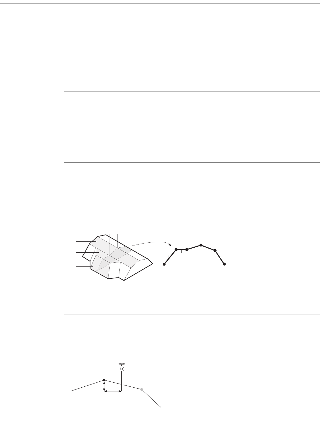
Viva Series, Roads - General 610
45.6.2 Road - Horizontal and Vertical Geometry Elements
Horizontal align-
ment
The application supports the following elements in the horizontal component of align-
ments:
•Straights
•Arcs
• Clothoids, entry and exit as well as partial
• Cubic parabolas, entry and exit as well as partial
• Bloss curves, entry and exit as well as partial; only available for Rail
• Multipoints, all elements that cannot be described by one of the previous types
are represented by discrete points along the curve. For example, a line parallel
to a clothoid.
Vertical alignment The application supports the following elements in the vertical component of align-
ments:
•Straights
•Arcs
• Quadratic parabolas
• Asymmetric quadratic parabola
• Multipoints, all elements that cannot be described by one of the previous types
are represented by discrete points along the curve.
45.6.3 Road - Basic Elements for Stake and Check Measurements
Description In general, there are four different basic stakeout and check elements:
• Surface grades, for example, the final carriage way
• Lines, for example, a centreline
• Slopes, for example, the end-slopes of a cross section
• Surfaces, for example, a DTM surface
Every stakeout or check is based on one or more of these four base elements. For
example, a road crown consists of two surface grades with one common line.
Lines The stake out of a line is used in different situations:
•Centre line of a road
• Edges of a road or any other change in slope
•Gutters
• Pipelines, cables and any other line-related design feature
a) Lines
b) Surface grades
c) Slopes
a
a
a
bb
c
a
b
b
c
Road_002
a) Line to stake out or check, in this case the centre-
line
b) Line offset
c) Line height difference
a
cb
Road_003
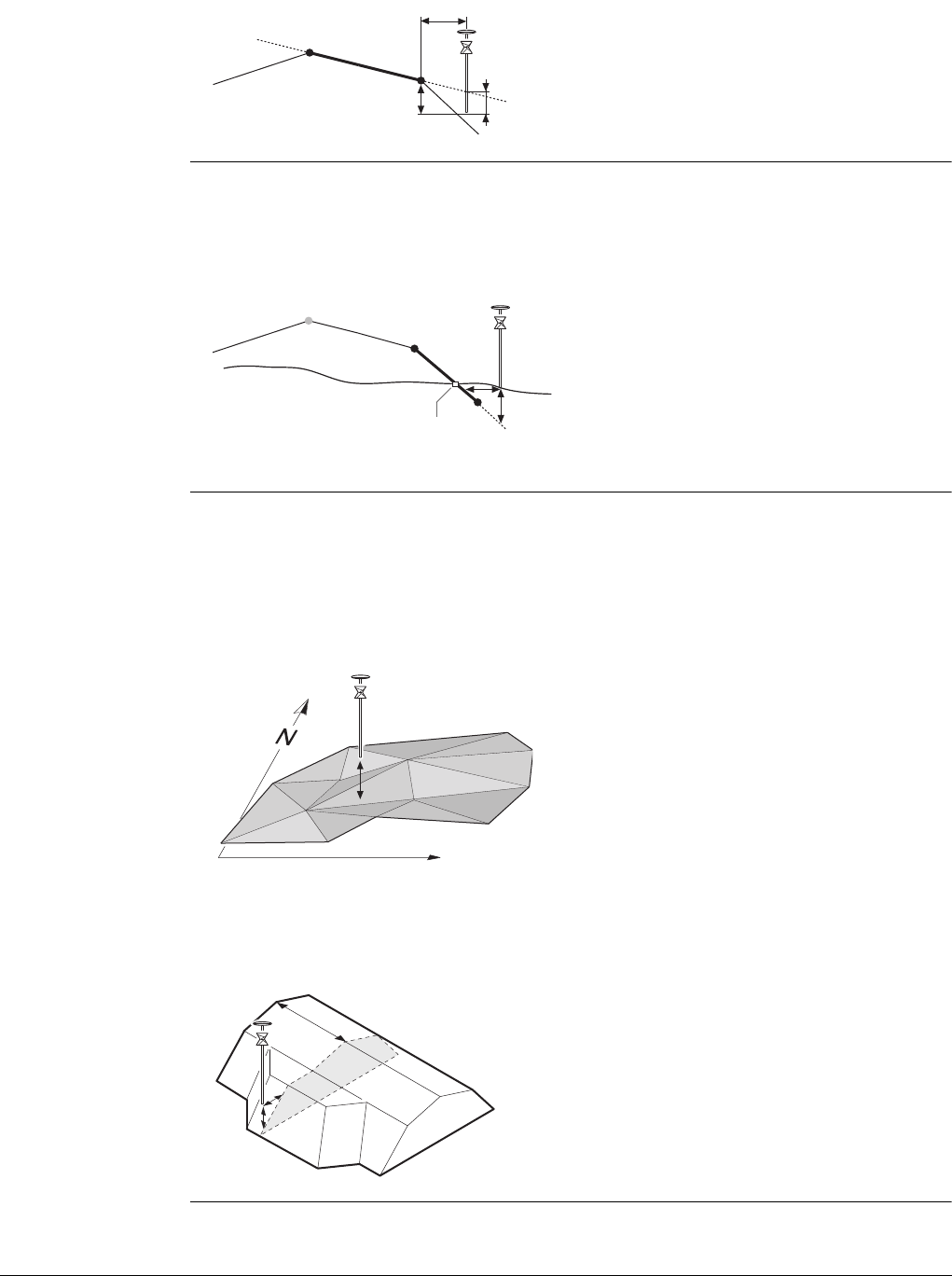
Viva Series, Roads - General 611
Surface grades Surface grades are defined by two lines. The two lines define the right and left edge
of the surface grade. One of the two lines is used as the reference line.
Slopes Slopes, like surface grades, are defined by two lines. Different to surface grades, only
one edge of the slope, the hinge point, is known. The second edge, catch point or
daylight point, is defined by the intersection of the slope and the natural surface. As
the natural surface is unknown this edge can only be staked out in the field. Finding
and staking out the catch point is the most important task when working with slopes.
Surfaces There are two types of surfaces supported that represent a three-dimensional design:
•DTM / TIN (Digital Terrain Model; Triangular Irregular Network)
•Layer
A DTM consists of several 3D triangles. DTMs do not include information relating the
DTM to a centreline. Positions are defined by easting, nothing and height values.
A layer is a combination of lines that form a 3D surface relative to a centreline. Thus
it is possible to define points by chainage or station, offset and height. Refer to
"45.2.3 Design Data" for more information.
a) Surface grade to stake out or check
b) Reference line
c) Horizontal offset to reference line
d) Height difference to reference line
e) Height difference to expanded surface grade
a
d
b
c
e
Road_004
a) Centreline
b) Slope
c) Hinge Point
d) Second line defining the slope
e) Catch point
f) Natural surface
g) ∆ Offset from the slope
h) Height difference from the slope
b
a
fg
e
h
c
d
Road_005
a) Height difference from the triangle of the
DTM found in the same vertical line as the
measured point
b) Easting of coordinate system
c) Northing of the coordinate system
a) Chainage or station
b) Layer Offset
c) Layer height difference
Road_006
b
ca
a
Road_007
b
c
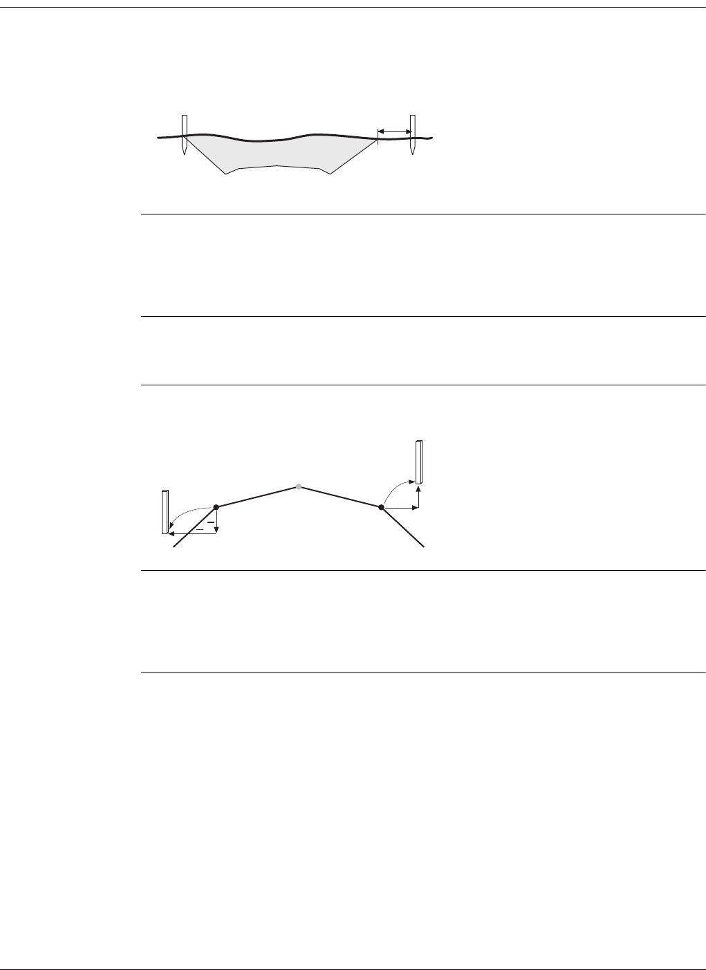
Viva Series, Roads - General 612
45.6.4 Road - Stake Offset and Stake Height Difference
Description When conducting a stake out, the aim is usually to mark the position of geometric
elements defined by the design. For example, in the graphic below, the catch point of
a slope. A point can be staked either directly or indirectly. For a directly staked point,
the peg ends up at exactly the position of the point to be staked. Staking the same
point indirectly, the peg will be placed with a certain offset to the point.
Horizontal stake offsets are, like shifts, defined perpendicular to the centreline of the
layer the line(s) belongs to, if no offset angle on Offsets page has been defined. For
surface grades and road crowns, the stake offset is applied following the same rules
as stated for horizontal shifts. Refer to "45.4 Working with Shifts" for more informa-
tion.
Stake offset For each stakeout method, a horizontal and/or vertical offset can be defined. The
stake offset and stake height difference are defined on the Offsets page of the stake
screen.
Sign convention for
stake offset and
height difference
The sign convention for stake offsets and height differences is identical to the conven-
tion used for design shifts.
Plot page with stake
offset and stake
height difference
The application offers for all stake out methods a page showing a graphical represen-
tation of the measured position in relation to the design. If stake offset and/or stake
height difference are used, the plot shows the original cross section view of the design
as well as the position to stake out. The position to stake out is marked by a
yellow/black peg.
One reason to stake out a point indi-
rectly is that the peg would not last
long at the position of the actual
point. In this example, the peg
staked directly would be removed as
soon as the excavation work starts.
Road_009
ab
c
d
a) Centreline
b) Line on left side
c) Negative stake offset
d) Negative stake height difference
e) Line on right side
f) Positive stake offset
g) Positive stake height difference
a
g
b
c
d
e
f
++
Road_011

Viva Series, Roads - General 613
45.6.5 Road - Chainage or Station Equations
Description Chainage or station equations are used to adjust the alignment chainage or station.
The most common reason for doing so is the insertion or removal of curves during the
design process. Inserting or removing a curve would require recalculating the chainage
or station of an entire alignment. Using chainage or station equations eliminates this
need. Chainage or station equations can create either a gap or an overlap as shown in
the following diagrams.
Multiple chainage or
station
In the case of the overlap shown in the example, the chainages or stations between
seven and thirteen appear twice. When a duplicate chainage or station is entered, a
message asks which one is to be used.
Example As more than one chainage or station equation is possible, a chainage or station can
appear more than twice on a design. In this example, the chainages or stations 11 to
13 appear three times.
In this example, when chainage or station 12 is entered in Road - Multiple Chainage,
the following screen shows how the option to select the right chainage or station is
displayed:
Gap chainage or station
equation. Chainage or
station back 10 =
chainage or station
ahead 15.
a) Old
b) New
Overlap chainage or
station equation.
Chainage or station
back 13 = chainage or
station ahead 7.
a) New
b) Old
12
1
2
3
4
5
6
7
8
910
5
6
7
8
9
10
11 12 13 14 15
345678910
15 1
ba
Road_062
12
22
3
3
3
4
4
45
5
5
6
6
6
7
7
7
8
8
9
9
10
10
11
11
1
12 13
a b
Road_063
Overlap chainage or
station equation.
Chainage back 13 =
chainage ahead 7 and
chainage back 15 =
chainage ahead 11.
0.. ..5 6 7 8 9 10 11 12 13
7 8 9 101112131415
11 12 13 14 15 16.. ..24
Road_069
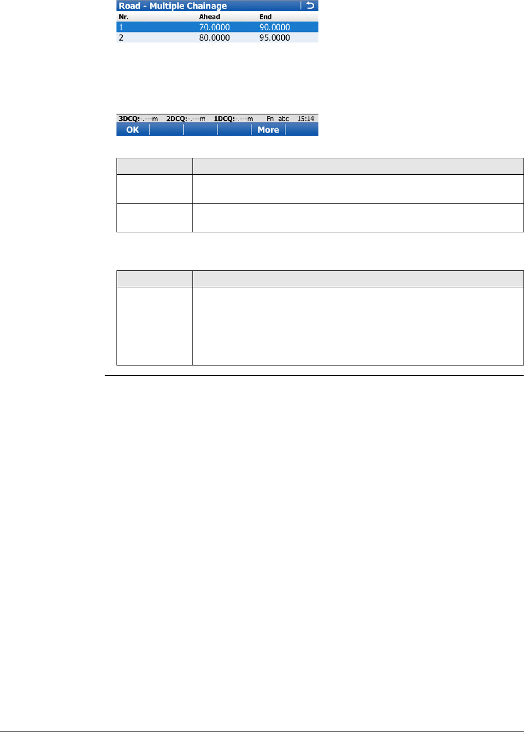
Viva Series, Roads - General 614
Description of columns
Key Description
OK To select the highlighted chainage or station equation and return to
the stake out screen.
More To switch the value displayed in the last column to show the end
chainage or station of the chainage or station equation.
Column Description
End Shows the end chainage or station for the chainage or station equa-
tion. In this example, the field shows 13.000 for Nr. 1, 15.000 for Nr.
2 and 24.000 for Nr. 3. End shows to which chainage or station, the
current chainage or station equation is valid. As for the first part of
the alignment, no chainage or station equation exists, Ahead stays
empty for the first row.

Viva Series, Roads - General 615
45.6.6 Road - Working Corridor
Description A working corridor defines the valid offset range left and right of the centreline. When
working with irregular alignments such as traffic islands and parking lots, working
corridors are useful to avoid displaying results from the wrong centreline element.
The following example shows the result if working without a defined working corridor.
For the measured position (b), the application finds the centreline point (c) with the
minimum perpendicular offset (f).
With a defined working corridor (e), the application would display a message advising
that the measured position is outside of the defined centreline.
The working corridor is defined in Configuration, Design page. Refer to "45.3 Config-
uring Roads Applications" for more information.
45.6.7 Road - Extension of the Centreline
Description Whenever centrelines must be extended, for example, at the start and end area of an
alignment or slope. The projection of the measured position to the centreline is made
using the tangent of the start/end point of the centreline.
In this case a warning appears informing that the original design is exceeded. The
application will advise as soon as a measured position is within the design area once
again.
Concept When expanding the centreline the geometry will be continued using the tangent of
the start/end point of the centreline.
Method Description
When staking out in the region of the start/end area of the design centreline, situa-
tions occur where an expansion of the centreline is useful. As soon as measurements
are outside the defined centreline, the application will prompt if, and with which
method, the centreline should be expanded.
a) Centreline
b) Measured position
c) Projected point on the centreline
d) Defined offset range for the working corridor
e) Working corridor
f) Offset from the centreline, if no working
corridor is used
a
b
e
e
f
cd
d
Road_081
a) Centreline
b) Extended centreline
b
a
Road_090

Viva Series, Roads - General 616
The extension of a centreline is made following its start/end tangent. Outside of the
original design area correct results cannot be guaranteed.
45.6.8 Road/Rail - Working with Heights
Description Normally, heights stored with the design data are used. The Rail application offers the
possibility to switch to either:
• a height which is entered manually by the user,
This option enables the manual definition of a height, which can be applied for
staking out or checking. This height is entered in the General page.
• a height which is retrieved from an existing Height Layer, as defined in the DTM job
associated with the project. The layer from the DTM is applied and used as a height
reference for the staking out or checking of alignments. 2D and 3D are possible.
This option is configured in the Tools menu.
Understanding
priorities of various
heights
45.6.9 Rail - Working with a Single Track
Terms and expres-
sions
Type of height Overrules Stake Height Diff
Manually entered All other heights Considered
Of individual point All other heights Considered
From height layer of DTM Design height Considered
From design No other heights Considered
Term / expression Description
Track A track comprises two separate rails.
Single track A single track is defined as one track with one centreline
and two rails. All chainages are calculated from the
centreline.
Track centreline Geometric alignment in two or three dimensions to which
all design elements of the project are referenced. It could
be that the vertical component of the alignment does not
coincide with the plan component. In this case the vertical
part of the alignment will generally coincide with the
lowest rail.
Chainage or station The cumulative distance along the centreline, frequently
but not always starting at zero.
Left/right rail Planimetric position of the left/right rail of a track.
The sense of the left/right rail is given by the direction of
increasing chainage.
When a section of the track is viewed in the direction of
increasing chainage, the left rail is to the left of the centre
of the track.
Nominal gauge The nominal distance between the active (internal) faces
of the left and right rails.
Superelevation base The distance over which the superelevation is applied.
This distance is normally the distance between the centre
of the left and right rail.
Left/right supereleva-
tion
Left/right cant
The superelevation or height difference of each rail with
respect to the track centreline. Usually expressed in milli-
metres.
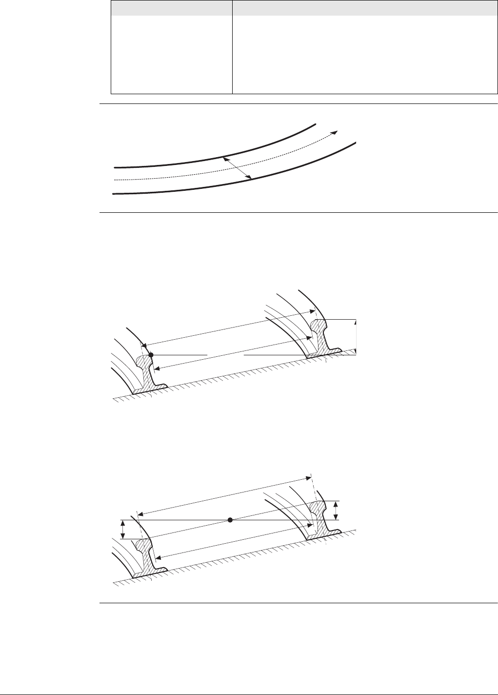
Viva Series, Roads - General 617
Diagram - Plan
Diagram - Section Two generic methods can be used to define the section of the track.
Method 1 - A definition using rotation around a known point
This method involves rotating the section around a known point, normally the lowest
rail.
Method 2 - A definition using relative height distances
This method uses height differences relative to the vertical alignment to define the
height of the left and right rail.
If one of the rails is used to rotate the track section, or
the height of the vertical alignment coincides with the
lowest rail, the superelevation of the rotation point or
lowest rail will be zero.
Superelevation is also known by the term cant. These two
words can be interchanged.
Term / expression Description
a) Track centreline
b) Left rail
c) Right rail
d) Nominal gauge
a
b
d
Rail_001
a) Left rail
b) Right rail
c) Rotation point
d) Nominal gauge
e) Superelevation base
f) Superelevation (cant)
a) Track centreline
b) Left rail
c) Right rail
d) Nominal gauge
e) Superelevation base
f) Left superelevation (left
cant)
g) Right superelevation (right
cant)
e
a
b
d
c
Rail_002
Rail_003
a
b
c
e
g
d
f

Viva Series, Roads - General 618
45.6.10 Rail - Working with Multiple Tracks
Description Multiple tracks are used when more than one track share a common centreline, from
which all chainages are calculated.
When there are multiple tracks with independent centrelines for each track, each track
is then considered as a single track. Refer to "45.6.9 Rail - Working with a Single Track"
for details on single tracks.
Diagram - Plan
Diagram - Section
Calculations For multiple tracks, the chainage centreline is used only to calculate the chainage. The
superelevation of each track is calculated with respect to the corresponding (left /
right) vertical alignment. The chainage centreline can consist of a plan and a vertical
component. Although the vertical component of the chainage centreline is not used
for any calculation.
a) Chainage centreline
b) Left track centre ine
c) Left track left rail
d) Left track right rail
e) Right track centreline
f) Right track left rail
g) Right track right rail
b
afeg
c
d
Rail_004
a) Chainage centreline
b) Left track centreline
c) Left track left rail
d) Left track right rail
e) Left track left rail superelevation
f) Left track right rail superelevation
g) Right track centreline
h) Right track left rail
i) Right track right rail
j) Right track left rail superelevation
k) Right track right rail superelevation
Rail_005
b
a
c
d
f
e
g
j
h
i
k

Viva Series, Roads - General 619
45.6.11 Rail - Check Elements and Stakeout Elements
Description Points can be staked with respect to three basic elements of the track:
• Track centreline
•Left rail
• Right rail
Centreline stakeout Description
The line to stake out can be a track centreline or, in the case of multiple tracks, the
left or right track centreline. In both cases, a horizontal offset with respect to the
centreline can be applied. Additionally, if a vertical alignment is available for a track
centreline, a vertical offset can be applied.
Diagram - Single track elements
Left/right rail
stakeout
Description
The left or right rail of a track can be staked out:
• directly,
• horizontal and/or vertical offsets can be used to stake any point relative to
either rail.
Diagram - Staking out a point relative to the right rail
The position from which the horizontal and rail offsets will be applied depends
on how the left and right rails were defined in the imported design data. Using
standard practice, the horizontal offset would be defined from the active face
of the rail, and the height offset would be defined from the highest part of the
rail, as shown in the diagram.
a) Track centreline
b) Left rail
c) Right rail
d) Point to stake
e) Horizontal offset from
track centreline
f) Vertical offset from track
centreline
a
Rail_006
a
b
c
d
e
f
a) Track centreline
b) Left rail
c) Right rail
d) Point to stake
e) Horizontal offset from
right rail
f) Vertical offset from right
rail
Rail_007
a
b
c
d
e
f

Viva Series, Roads - General 620
45.6.12 Rail - Working with Offsets
Sign convention for
offsets
The sign convention for offsets is:
45.6.13 Tunnel - Basic Terms
Terms and expres-
sions
General terms
a) Centreline
b) Positive horizontal offset
c) Positive vertical offset
d) Negative horizontal offset
e) Negative vertical offset
Rail_008
ad+
-b
c+
e-
Term / expression Description
Centreline Geometric alignment in two or three dimensions to which
all design elements of the project are referenced.
Chainage or station The cumulative distance along the centreline, frequently
but not always starting at zero.
Design Profile Geometric description of the designed shape of the cross-
section of the tunnel. The design profile can contain
straight or curve elements.
Excavated Profile Shape of the cross-section of the tunnel that has been
excavated.
Underbreak When the excavated profile is inside the design profile, the
underbreak is the perpendicular distance between the
design profile and the excavated profile.
Overbreak When the excavated profile is outside of the design profile,
the overbreak is the perpendicular distance between the
design profile and the excavated profile.
Tunnel Portal The open end of a tunnel.
Tunnel Face The point where the excavated tunnel meets existing
terrain.
Superelevation (Rota-
tion)
Angle of rotation of a design profile. Used to take into
account the velocity of a moving vehicle through a curve.
Rotation Point The point about which the design profile is rotated. This
point may or may not coincide with the centreline.
a) Centreline
b) Centreline offset
c) Point on design profile
d) Centreline height offset
e) Design profile
f) Excavated profile
g) Underbreak
h) Overbreak
g
h
f
e
d
c
b
a
Tunnel_001
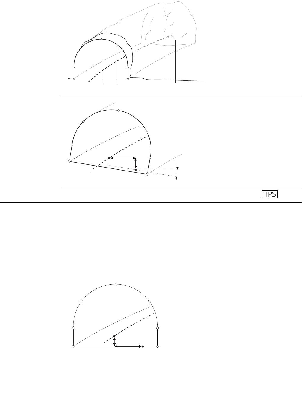
Viva Series, Roads - General 621
3D View
Superelevation
45.6.14 Tunnel - Elements for Stake Out and Check Measurements
Tunnel face Staking tunnel faces
It is usually required to stake out the tunnel face to indicate the position to excavate
when certain tunnelling methods are used. For example, Drill and Blast or excavation
using a roadheader.
The points to stake on the tunnel face can be defined in various ways:
Horizontal and vertical offsets
By horizontal and vertical offsets with respect to the centreline:
a) Centreline or axis
b) Tunnel portal
c) Tunnel face
ba c
Tunnel_002
a) Centreline or axis
b) Rotation point
c) Centreline offset
d) Centreline height offset
e) Superelevation (Rotation)
ac
d
be
Tunnel_003
a) Centreline
b) Point on tunnel face to stake
c) Centreline offset
d) Centreline height offset
d
c
b
a
Tunnel_004
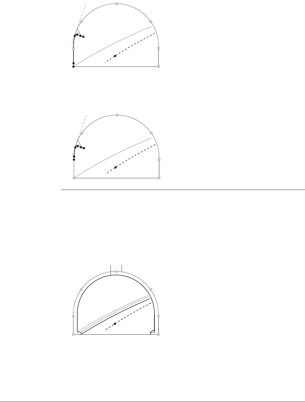
Viva Series, Roads - General 622
Distance along profile
By the distance from the start of the design profile and an offset from the design
profile.
Distance along a particular element
By the distance along a particular element of the design profile and an offset from the
element.
Tunnel profiles Staking tunnel profiles
Tunnel profiles are normally staked after excavation to indicate the position of tunnel
design elements or services such as lighting or ventilation.
Basic terms
Usually a tunnel under construction is designed and built in various stages such that a
given chainage can have various design profiles. For example shotcrete or final lining.
Each design profile is called a layer.
Measuring tunnel profiles
Tunnel profiles are normally measured after excavation to compare the excavated
profile with the design profile. This check can occur during the excavation phase of the
project or for quality control checks of the built tunnel.
a) Centreline
b) Point on tunnel face to stake
c) Point defining start of design profile
d) Distance from start of design profile
e) Offset perpendicular to design profile
a) Centreline
b) Point on tunnel face to stake
c) Element of design profile to stake
d) Distance from start of design profile
element
e) Offset perpendicular to design profile
d
e
c
b
a
Tunnel_005
de
c
b
a
Tunnel_006
a) Centreline or axis
b) Final lining
c) Shotcrete
b
a
c
Tunnel_007

Viva Series, Roads - General 623
When measuring tunnel profiles, it is possible to scan various profiles from one instru-
ment position. The profiles to scan are defined with respect to a defined chainage.
Profiles can be scanned at a given forward and back interval within a given forward
and back distance from the defined profile.
Measuring tunnel profiles - Plan view
Profile view
Tunnel profiles can be measured vertically, horizontally or perpendicular to the tunnel
centreline.
45.6.15 Tunnel - Shifts
Description When working on site, often design data does not match the measured data. For
example, an existing road surface that should intersect with the design surface may
be 15 cm higher than the plans indicate. To guarantee a smooth intersection, this
difference has to be distributed over the remaining 100 m of paving. To handle these
situations, the application allows the possibility of adding shifts to the existing design
data. A shift is applied when selecting the element to stake out/check.
Shifts do not change the stored design. They are applied temporarily for stake out
purposes.
Centreline shifts Horizontal and vertical shifts
Horizontal shifts are always perpendicular to the centreline whereas vertical shifts are
applied along the plumb line.
a) Centreline
b) Instrument position
c) Tunnel face
d) Defined profile to scan
e) Instrument profile
f) Back distance
g) Forward distance
h) Back interval
i) Forward interval
a) Centreline
b) Tunnel face
c) Horizontal profile
d) Profile perpendicular to
centreline
e) Vertical profile
c
d
hi
fg
a
b
e
Tunnel_009
a
ce
d
b
Tunnel_010
a) Horizontal alignment with
constant shift (plan view)
b) Vertical alignment with
constant shift (profile
view)
ba
Road_013

Viva Series, Roads - General 624
Constant and linear shifts are supported
For both horizontal and vertical shifts, two different types can be applied:
Sign convention
The sign convention for design shifts is identical to the conventions used for centreline
offset and height shifts difference.
Design profile shift A shift can be applied to the design profile. The shift is applied perpendicularly to the
design profile at any point along the design profile.
A positive shift will increase the size of the profile, a negative shift will decrease the
size of the profile.
Constant: The shift remains the same from its start chainage or station to the
end chainage or station.
Linear: The shift is linearly interpolated along the chainage or station.
a) Constant shift
b) Linear shift
a) Centreline
b) Positive horizontal shift
c) Positive vertical shift
d) Negative horizontal shift
e) Negative vertical shift
a b
Tunnel_025
ad (-) b (+) c (+)
e (-)
Tunnel_011
a) Design profile with negative shift
b) Original design profile
c) Design profile with positive shift
d) Negative shift
e) Positive shift
a (-) b c (+)
d (-)
e (+)
Tunnel_012
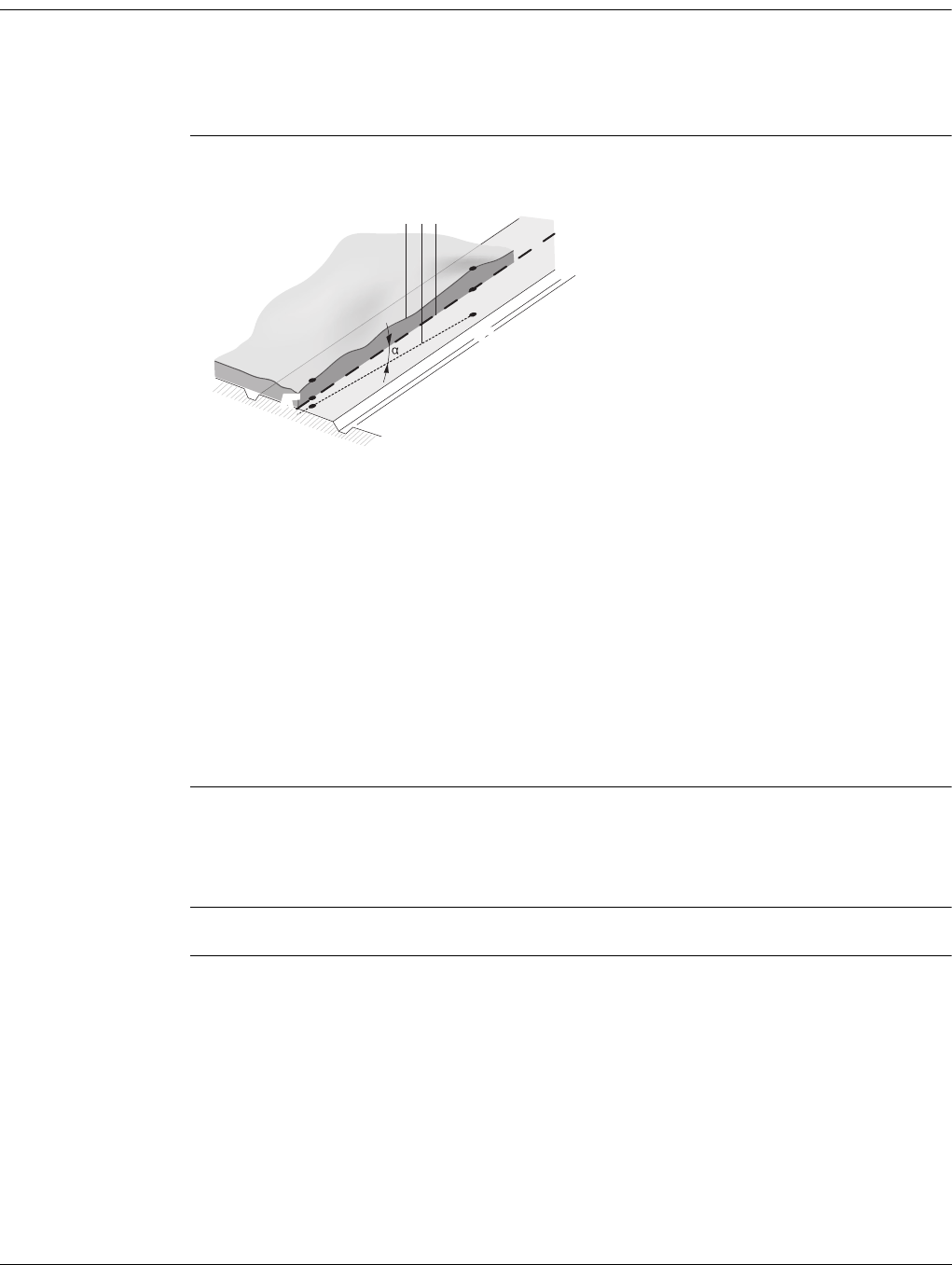
Viva Series, Roads - Alignment Editor 625
46 Roads - Alignment Editor
46.1 Basic Terms
Description A road surface can be thought of three different types of design elements:
• the horizontal alignment
• the vertical alignment
• the cross section
Basic concepts
Any point A in a project has ENH coordinates in a determined coordinate system. Each
point has three different positions:
• A’ - Point on real surface
• A’’ - Point on horizontal alignment
• A’’’- Point on vertical alignment
By adding a second point B to the project an alignment is defined. The alignment can
be thought in three ways:
• Horizontal alignment (A’’-B’’)
• Projection of the horizontal alignment onto the real surface (A’-B’)
• Vertical alignment (A’’’-B’’’)
The angle between the horizontal and the vertical alignment is the grade ().
Geometric elements A road design is fitted to a base plan or map using the three basic geometric elements:
•Straight
•Curve
•Spiral
Refer to "Appendix J Glossary" for a definition of the terms.
a - Natural surface.
b - The vertical alignment.
c - The horizontal alignment.
A’’/B’’ - Points on horizontal alignment
A’/B’ - Points on real surface
A’’’/B’’’- Points on vertical alignment
TS_051
A’
A’’’
B’
B’’
abc
A’’
B’’’
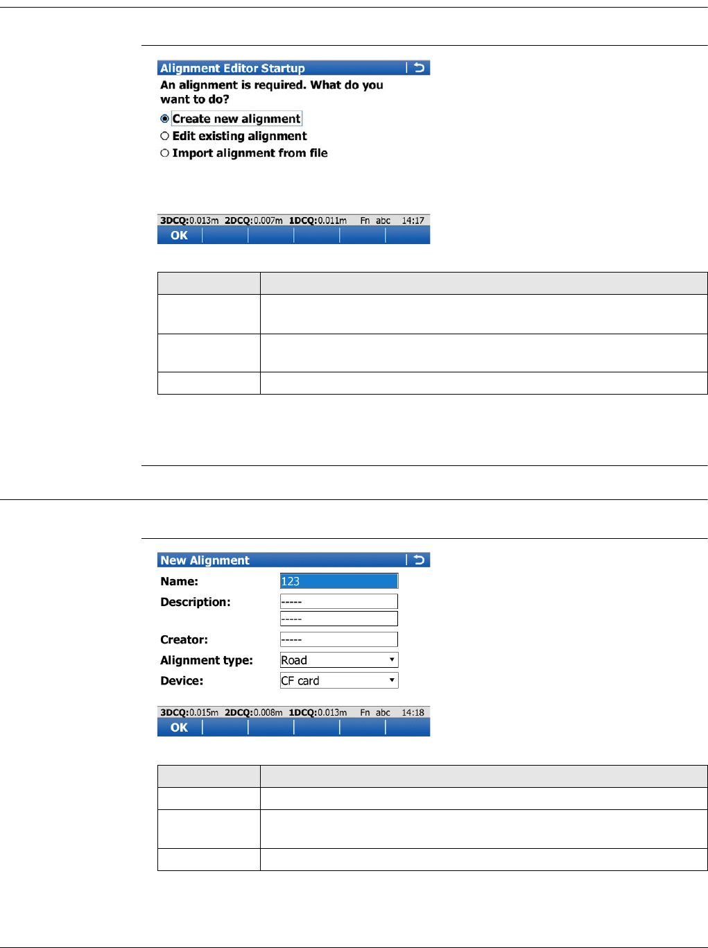
Viva Series, Roads - Alignment Editor 626
46.2 Starting Alignment Editor
46.2.1 Accessing Alignment Editor
Access Select Main Menu: Go to Work!\Roads\Alignment Editor.
Alignment Editor
Startup
Next step
Select an option and press OK.
46.2.2 Creating a New Alignment
Access Select Create new alignment in Alignment Editor Startup and press OK.
New Alignment
Key Description
OK To select the highlighted option and to continue with the subsequent
screen.
Fn Config.. To configure the Alignment editor application. Refer to "46.3 Config-
uring Alignment Editor".
Fn Quit To exit the application.
Key Description
OK To accept the screen entries and continue.
Fn Config.. To configure the Alignment editor application. Refer to "46.3 Config-
uring Alignment Editor".
Fn Quit To exit the application.
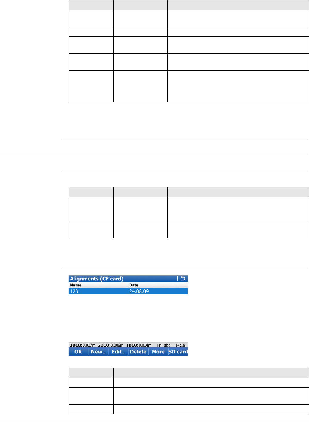
Viva Series, Roads - Alignment Editor 627
Description of fields
Next step
Press OK to access the Alignment Editor Menu. Refer to "46.2.5 Alignment Editor
Menu".
46.2.3 Modifying an Existing Alignment
Access Select Edit existing alignment in Alignment Editor Startup and press OK.
Select Alignment Description of fields
Next step
Highlight the Alignment name field and press ENTER.
Alignments
Field Option Description
Name Editable field The name of the new Alignment editor raw align-
ment.
Description Editable field Optional description of the new raw alignment.
Creator Editable field Optional description of the creator of this align-
ment.
Alignment
type Selectable list Defines if the alignment is for Roadrunner Road
or Rail applications.
Device Selectable list The device on which the new Alignment editor raw
alignment will be stored. Depending on the
inserted memory devices, this field may be a
display only field.
Field Option Description
Alignment
name Selectable list All existing Alignment editor raw alignments
currently stored in the \Data\XML folder with the
file extension *.xml.
Alignment
type Selectable list Defines if the alignment is for Roadrunner Road
or Rail applications.
Key Description
OK To select the highlighted raw alignment and continue.
New.. To create a new raw alignment. Refer to "46.2.2 Creating a New
Alignment".
Edit.. To edit the name and description of an existing raw alignment.
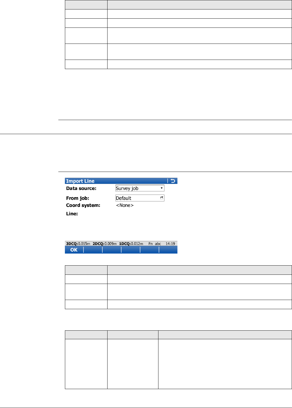
Viva Series, Roads - Alignment Editor 628
Next step
Press OK to select the highlighted raw alignment and return to the Select Alignment
screen.
Press OK to access the Alignment Editor Menu. Refer to "46.2.5 Alignment Editor
Menu".
46.2.4 Importing Alignment Data
Access 1) Select Import alignment from file in Alignment Editor Startup and press OK.
2) Create a new alignment in the New Alignment screen. Refer to "46.2.2 Creating a
New Alignment".
3) Press OK.
Import Line
Description of fields
Delete To delete an existing raw alignment.
More To switch the last column between Date, Time and Size.
CF card, SD
card or Intrnl To change between viewing jobs stored on another data storage
device or internal memory.
Fn Backup To restore a raw alignment file with the extension *.xmb currently
stored in the \Data\XML folder.
Fn Quit To exit the application.
Key Description
Key Description
OK To import the selected alignment data to active raw alignment.
Fn Config.. To configure the Alignment editor application. Refer to "46.3 Config-
uring Alignment Editor".
Fn Quit To exit the application.
Field Option Description
Data source The file type of the data source.
Survey job To import lines or areas from the selected job.
Road job To import lines from an existing Road job.
Road+ (GSI
format) To import GSI alignment data.
Rail job To import lines from an existing Rail job.
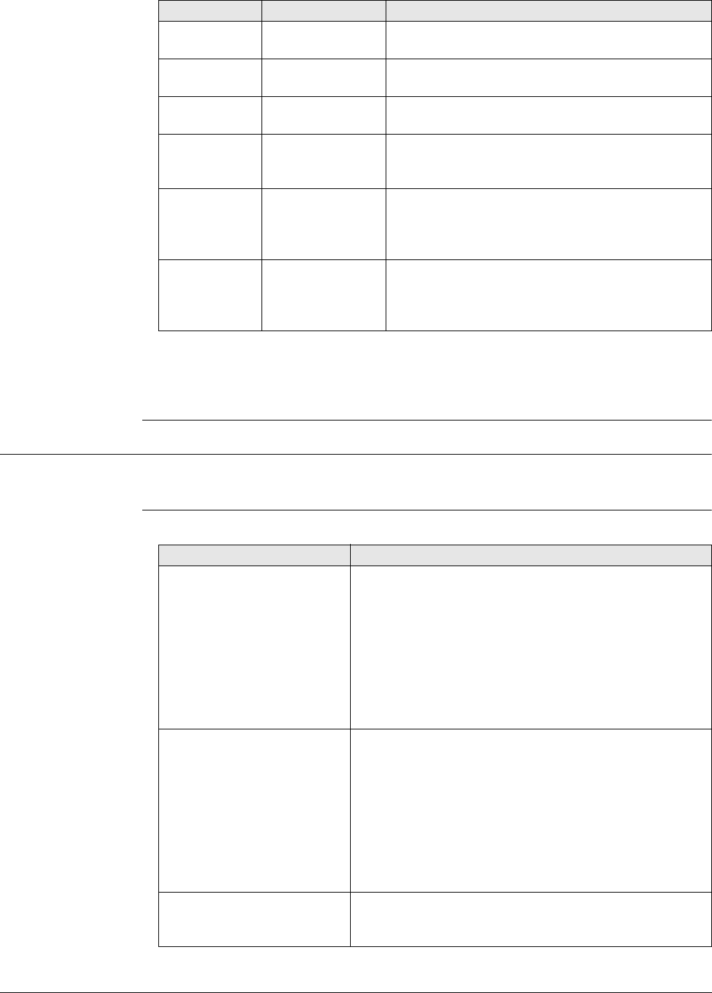
Viva Series, Roads - Alignment Editor 629
Next step
OK imports the selected alignment data and accesses the Alignment Editor Menu.
Refer to "46.2.5 Alignment Editor Menu".
46.2.5 Alignment Editor Menu
Access This screen is always accessed after successfully creating, editing or importing an
alignment file from the Alignment Editor Startup screen.
Alignment Editor
Menu Description of options
From job Selectable list All jobs are available for selection. Available for
Survey job, Road job and Rail job.
Coord system Display only The coordinate system currently attached to the
selected Survey job, Road job or Rail job.
Line Selectable list Line or area element from the selected job. Avail-
able for Survey job.
Alignment Selectable list Line from the selected Road job. The line must be
stored in the \dbx folder of the memory device to
be selectable. Available for Road job and Rail job.
Alignment
(.aln) file Selectable list Horizontal alignment file in GSI format. The GSI
alignment file must be stored in the \GSI folder of
the memory device to be selectable. Available for
Road+ (GSI format).
Vertical (.prf)
file Selectable list Vertical alignment file in GSI format. The GSI align-
ment file must be stored in the \GSI folder of the
memory device to be selectable. Available for
Road+ (GSI format).
Field Option Description
Option Description
Edit horizontal alignment Depending on the setting for Use PI instead of element
for horizontal alignment definition in Configuration,
Advanced page:
• To create, edit and delete elements of a hori-
zontal alignment. Refer to "46.4 Edit Horizontal
Alignments Using Elements".
• To create, edit and delete PIs of a horizontal
alignment. Refer to "46.5 Edit Horizontal Align-
ments Using PIs".
Edit vertical alignment Depending on the setting for Use PVI instead of
element for vertical alignment definition in Configura-
tion, Advanced page:
• To create, edit and delete elements of a vertical
alignment. Refer to "46.6 Edit Vertical Align-
ments Using Elements".
• To create, edit and delete PVIs of a vertical align-
ment. Refer to "46.7 Edit Vertical Alignments
Using PIs".
Edit cross section
templates To create, edit and delete cross section templates.
Refer to "46.8 Edit Cross Section Templates". Only
available for road jobs.
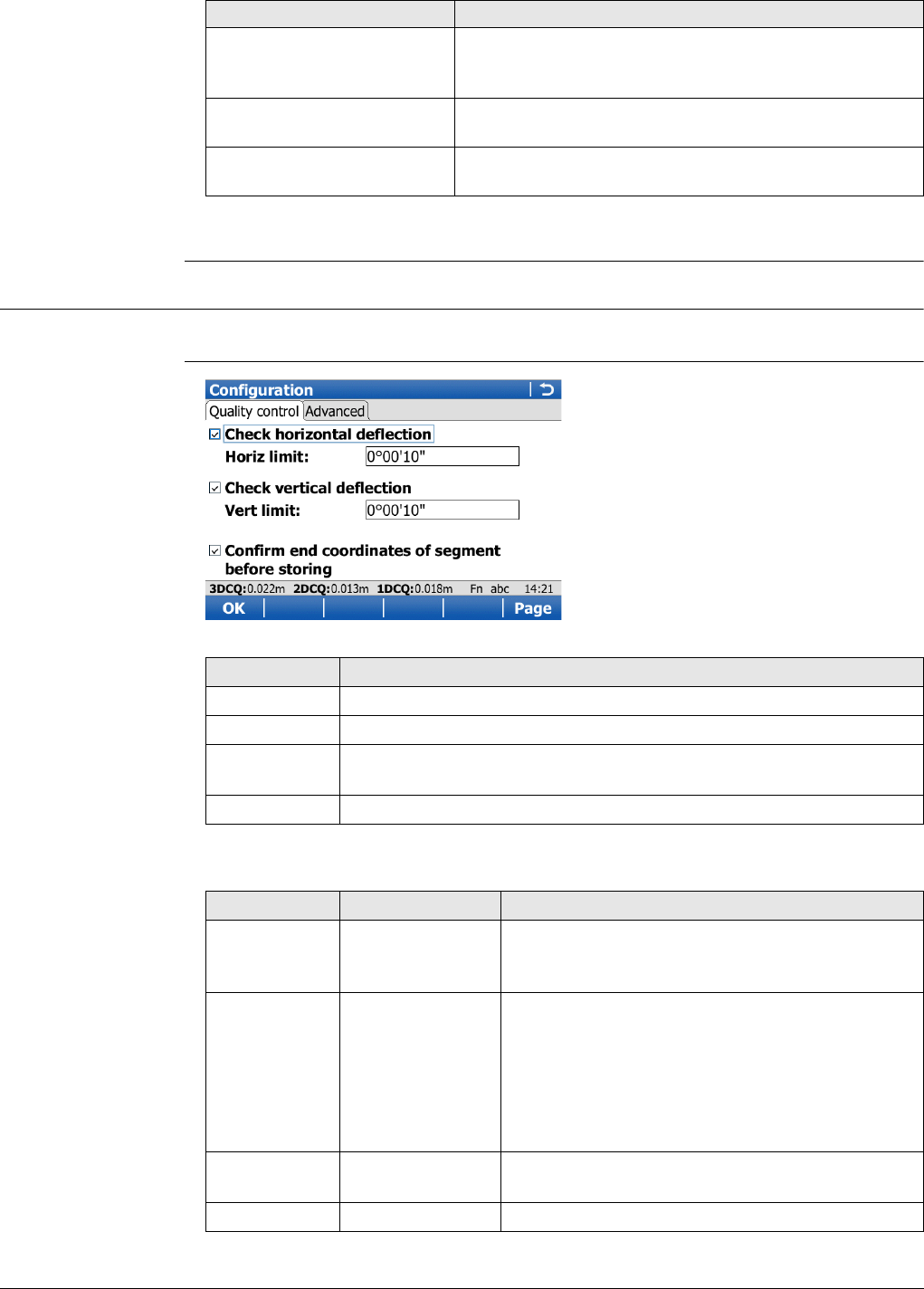
Viva Series, Roads - Alignment Editor 630
To be able to convert alignments to a Roadrunner job, at least a horizontal alignment
must exist.
46.3 Configuring Alignment Editor
Access Select Main Menu: Go to Work!\Roads\Alignment Editor. Press Fn Config...
Configuration,
Quality control page
Description of fields
Edit cross section assign-
ments To create, edit and delete cross section assignments.
Refer to "46.9 Edit Cross Section Assignments". Only
available for road jobs.
Edit chainage equation To create, edit and delete chainage equations. Refer to
"46.10 Edit Chainage Equation".
Convert to job To convert existing LandXML alignments to a Road-
Runner job. Refer to "46.11 Convert to job".
Option Description
Key Description
OK To accept the screen entries and continue.
Page To change to another page on this screen.
Fn About To display information about the program name, the version number,
the date of the version, the copyright and the article number.
Fn Quit To exit the application.
Field Option Description
Check hori-
zontal deflec-
tion
Check box Possibility to do a deflection check for the hori-
zontal alignment.
Horiz limit Editable field The deflection tolerance for horizontal align-
ments. The tolerance value used for determining
deflection errors. A deflection error occurs when
the beginning curve tangent of an element does
not match the ending tangent of the previous
element. If the actual error in deflection is greater
than this value, the error will be reported.
Check vertical
deflection Check box Possibility to do a deflection check for the vertical
alignment.
Vert limit Editable field The deflection tolerance for vertical alignments.

Viva Series, Roads - Alignment Editor 631
Next step
Page changes to the Advanced page.
Configuration,
Advanced page
Description of fields
Confirm end
coordinates of
segment
before storing
Check box If this box is checked, then each time a new align-
ment element has been entered, a confirmation
message displays the end coordinates for confir-
mation.
Field Option Description
Field Option Description
Vertical
parabola defi-
nition
Parameter defining the parabola.
Parameter p
K factor K factor = Parameter p/100.
Use PI instead
of element for
horizontal
alignment
definition
Check box When this box is not checked, elements such as
straights, curves and parabolas define the hori-
zontal alignment.
When this box is checked, the horizontal align-
ment is defined by Points of Intersection
(tangent/geometrical points).
• Horizontal alignments are defined by the
coordinates of the PI and the curve radius
(for circular curves).
• Horizontal transitions are defined by coor-
dinate of PI, the circular curve radius plus
tangent length in and tangent length out.
Use PVI
instead of
element for
vertical align-
ment defini-
tion
Check box When this box is not checked, elements such as
straights, curves and parabolas define the vertical
alignment.
When this box is checked, the vertical alignment
is defined by Points of Vertical Intersection
(tangent/geometrical points).
• Vertical alignments with symmetrical curves
are defined by the PVI chainage, the eleva-
tion of PVI and the total length of curve,
where the tangent length is half the total
length of the VC.
• Vertical Alignments with non-symmetrical
curves are defined by the PVI chainage, the
elevation of the PVI and both tangent
lengths.
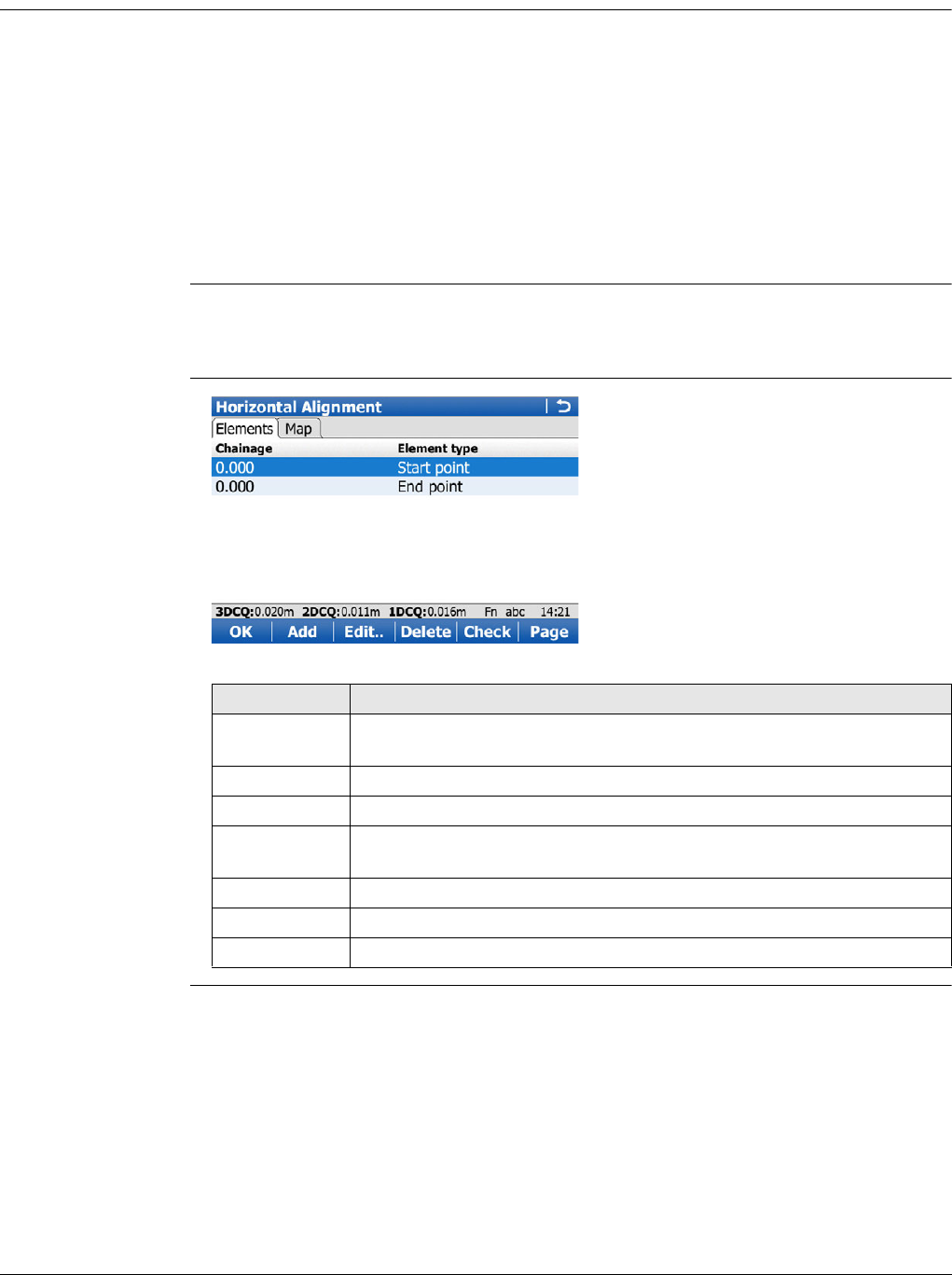
Viva Series, Roads - Alignment Editor 632
46.4 Edit Horizontal Alignments Using Elements
46.4.1 Overview
Description Allows creating, editing and deleting of the following elements:
•Start Point
• Straight (Tangent)
•Curve
•Clothoid
•Cubic Parabola
• Partial Bloss
as well as checking the horizontal alignment.
Access In Alignment Editor Menu highlight Edit horizontal alignment. Press OK.
Use PI instead of element for horizontal alignment definition must be
unchecked in Configuration, Advanced page.
Horizontal Align-
ment,
Elements page
Key Description
OK To accept the screen entries and return to the Alignment Editor
Menu.
Add To add a new horizontal element after the highlighted element.
Edit.. To edit the highlighted element of the horizontal alignment.
Delete To delete the highlighted element of the horizontal alignment. Either
all following elements or only the next element can be adjusted.
Check To check the horizontal alignment.
Page To change to another page on this screen.
Fn Quit To exit the application.
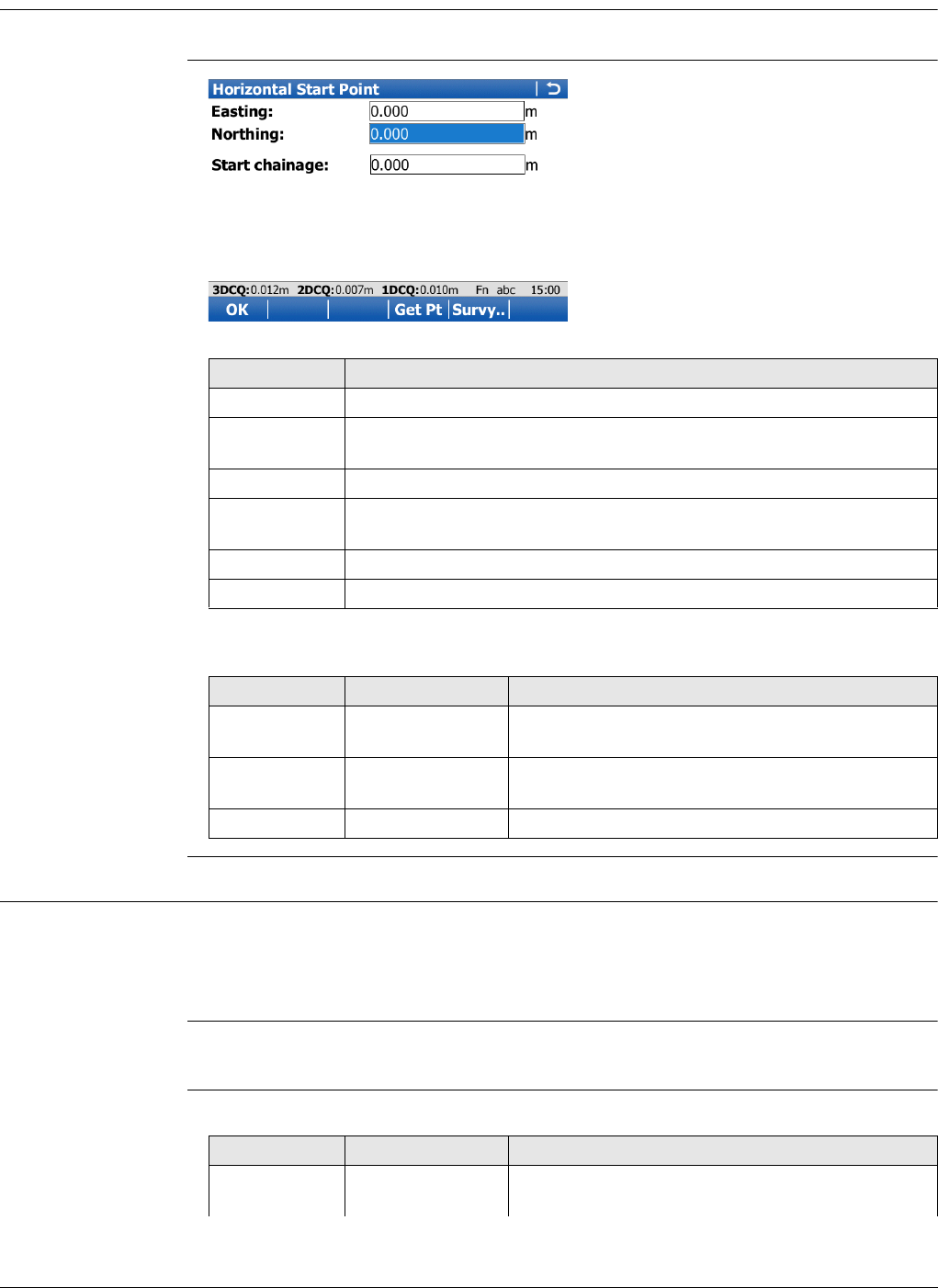
Viva Series, Roads - Alignment Editor 633
46.4.2 Editing the Start Point
Access In Horizontal Alignment, highlight the start point and press Edit...
Horizontal Start Point
Description of fields
46.4.3 Inserting/Editing an Element in a Horizontal Alignment
Access In Horizontal Alignment, Elements page, highlight the start point, or an element if one
exists, and press Add or Edit...
Elements can be added after the start point and either before or after other
elements.
Creating and editing an alignment element are similar processes. For simplicity, only
the creation of an alignment element is explained and differences are clearly outlined.
Add Horizontal
Element Description of fields
Key Description
OK To accept the screen entries and continue.
Get Pt To apply coordinates or heights from an existing point in the working
job.
Survy.. To go to Survey and measure a point.
Fn Config.. To configure the Alignment editor application. Refer to "46.3 Config-
uring Alignment Editor".
Fn Reset To reset all screen entries.
Fn Quit To exit the application.
Field Option Description
Easting Editable field Easting of the start point of the horizontal align-
ment.
Northing Editable field Northing of the start point of the horizontal align-
ment.
Start chainage Editable field Start chainage of the horizontal alignment.
Field Option Description
Element type Straight To insert/edit a straight to/in a horizontal align-
ment.
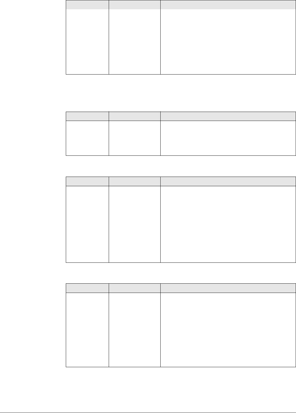
Viva Series, Roads - Alignment Editor 634
The options available for the field Method depend on the Element type selected.
For Element type: Straight
For Element type: Curve
For Element type: Spiral
Curve To insert/edit a curve to/in a horizontal align-
ment.
Spiral To insert/edit a clothoid to/in a horizontal align-
ment.
Cubic parabola To insert/edit a cubic parabola to/in a horizontal
alignment.
Bloss To insert/edit a bloss curve to/in a horizontal
alignment.
Field Option Description
Method Azimuth & length Using the azimuth and the length of the straight.
Azi & end
chainage Using the azimuth and the end chainage of the
straight.
End coords Using the end coordinates of the straight.
Field Option Description
Method Radius & length Using the radius of the curve and its length.
Radius & delta Using the radius and the delta angle of the curve.
Radius & end
chain Using the radius of the curve and the end
chainage.
Radius & end
coords Using the radius and the end coordinates of the
curve.
Center & end
coords Using the coordinates of the centre point and the
end point of the curve.
3 points Using three points.
Field Option Description
Method Radius & length Using the radius of the clothoid and its length.
Radius & end
chain Using the radius of the clothoid and the end
chainage.
Param & length Using the parameter A and the length of the
connecting curve.
Param & end
chain Using the parameter A and the end chainage of
the spiral.
Radius & param-
eter Using the parameter A and the radius.
Field Option Description
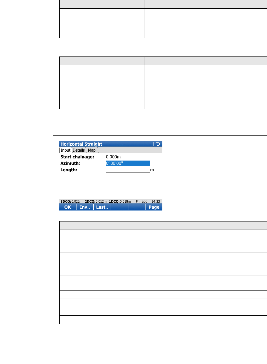
Viva Series, Roads - Alignment Editor 635
For Element type: Cubic parabola
For Element type: Bloss
Next step
OK to access the next screen.
Horizontal
Straight/Horizontal
Curve/Horizontal
Clothoid/Horizontal
Cubic Parabola/Hori-
zontal Bloss,
Input page
Field Option Description
Method Radius & length Using the radius of the cubic parabola and its
length.
Radius & end
chain Using the radius of the cubic parabola and the
end chainage.
Field Option Description
Method Radius & length Using the radius of the connecting curve and its
length.
Radius & end
chain Using the radius of the connecting curve and its
end chainage.
Rad,lngth,end
coord Using the radius, length and end coordinates of
the bloss curve.
Key Description
OK To accept the screen entries and continue.
Inv.. To calculate the distance and angle between two points from the
working job.
Last.. To select values from the last inverse calculations.
Get Pt To apply coordinates or heights from an existing point in the working
job. Available when coordinates must be typed in.
Survy.. To go to Survey and measure a point. Available when coordinates
must be typed in.
Page To change to another page on this screen.
Fn Config.. To access the Alignment Editor configuration.
Fn Reset To reset all screen entries.
Fn Quit To exit the application.
Viva Series, Roads - Alignment Editor 636
Description of fields
The other fields and options available depend on the Method and Element type
selected in Add Horizontal Element.
For Element type: Straight
For Element type: Curve
Field Option Description
Start chainage Display only The end chainage of the start point / previous
element is automatically used and cannot be
edited.
Field Option Description
Azimuth Editable field The azimuth displayed is from the previous
element. Another value can be entered manually.
Available for Method:Azimuth & length or
Method:Azi & end chainage.
End chainage Editable field Chainage at the end of the element. Available for
Method:Azi & end chainage.
End easting Editable field Easting for the end chainage. Available for
Method:End coords.
End northing Editable field Northing for the end chainage. Available for
Method:End coords.
Length Editable field Length of the straight element. Available for
Method:Azimuth & length.
Field Option Description
Start azimuth Editable field The azimuth of the tangent in the start point. This
azimuth is used from the previous element. The
value can be edited. Available for Method:Radius
& length, Method:Radius & delta or
Method:Radius & end chain.
CP easting Editable field Easting of the centre point of the curve. Available
for Method:Center & end coords.
CP northing Editable field Northing of the centre point of the curve. Avail-
able for Method:Center & end coords.
Curve direc-
tion Right or Left The direction of the curve when looking in the
direction of increasing chainage. Available for
Method:Radius & length, Method:Radius &
delta, Method:Radius & end chain or
Method:Radius & end coords.
Radius Editable field Radius of the curve. The signs are set by the
system depending on the curve direction defined
in Curve direction. Available for Method:Radius
& length, Method:Radius & delta,
Method:Radius & end chain or Method:Radius
& end coords.
Delta Editable field The deflection angle. Available for
Method:Radius & delta.
Length Editable field Length from the start to the end point of the
curve. Available for Method:Radius & length.
Viva Series, Roads - Alignment Editor 637
For Element type: Spiral
End chainage Editable field The end chainage of the curve element can be
typed in. Available for Method:Radius & end
chain.
Int easting Editable field Easting of the intermediate point of the 3-pt-arc.
Available for Method:3 points.
Int northing Editable field Northing of the intermediate point of the 3-pt-
arc. Available for Method:3 points.
End easting Editable field Easting for the end chainage. Available for
Method:Radius & end coords, Method:Center &
end coords and Method:3 points.
End northing Editable field Northing for the end chainage. Available for
Method:Radius & end coords, Method:Center &
end coords and Method:3 points.
Field Option Description
Start azimuth Editable field The azimuth of the tangent in the start point. This
azimuth is used from the previous element. The
value can be edited.
Spiral direc-
tion Right or Left The direction of the clothoid looking in the direc-
tion of increasing chainage.
Spiral in/out Spiral in For transition from tangent to curve.
Spiral out For transition from curve to tangent.
Radius Editable field Radius of the clothoid. Available for
Method:Radius & length, Method:Radius & end
chain and Method:Radius & parameter.
Parameter A Editable field The parameter A defining the clothoids. Available
for Method:Param & end chain, Method:Param
& length and Method:Radius & parameter.
Length Editable field Length of the clothoid element. Available for
Method:Param & length and Method:Radius &
length.
Start radius Editable field The entry radius of the spiral. The signs are set by
the system depending on the spiral direction
defined in Spiral direction. Available for
Method:Radius & length and Method:Radius &
end chain when Use partial spiral is checked.
End radius Editable field The exit radius of the spiral. The signs are set by
the system depending on the spiral direction
defined in Spiral direction. Available for
Method:Radius & length and Method:Radius &
end chain when Use partial spiral is checked.
End chainage Editable field The end chainage of the clothoid can be typed in.
Available for Method:Radius & end chain and
Method:Param & end chain.
Use partial
spiral Check box To create partial clothoids. Available for
Method:Radius & length and Method:Radius &
end chain.
Field Option Description
Viva Series, Roads - Alignment Editor 638
For Element type: Cubic parabola
For Element type: Bloss
Field Option Description
Start azimuth Editable field The azimuth of the tangent in the start point. This
azimuth is used from the previous element. The
value can be edited.
Spiral direc-
tion Right or Left The direction of the cubic parabola looking in the
direction of increasing chainage.
Spiral in/out Spiral in For a transition from tangent to curve.
Spiral out For a transition from curve to tangent.
Radius Editable field Radius of the cubic parabola.
Start radius Editable field The entry radius of the spiral. The signs are set by
the system depending on the spiral direction
defined in Spiral direction. Available when Use
partial spiral is checked.
End radius Editable field The exit radius of the spiral. The signs are set by
the system depending on the spiral direction
defined in Spiral direction. Available when Use
partial spiral is checked.
Length Editable field Length of the cubic parabola element. Available
for Method:Radius & length.
End chainage Editable field The end chainage of the cubic parabola element
can be typed in. Available for Method:Radius &
end chain.
Use partial
spiral Check box To create partial cubic parabolas.
Field Option Description
Start azimuth Editable field The azimuth of the tangent in the start point. This
azimuth is used from the previous element. The
value can be edited.
Spiral direc-
tion Right or Left The direction of the bloss looking in the direction
of increasing chainage.
Spiral in/out Spiral in For a transition from tangent to curve.
Spiral out For a transition from curve to tangent.
Radius Editable field Radius of the bloss.
Start radius Editable field The entry radius of the spiral. The signs are set by
the system depending on the spiral direction
defined in Spiral direction. Available for
Method:Rad,lngth,end coord.
End radius Editable field The exit radius of the spiral. The signs are set by
the system depending on the spiral direction
defined in Spiral direction.
Available for Method:Rad,lngth,end coord.
Length Editable field Length of the bloss curve element. Available for
Method:Radius & length and
Method:Rad,lngth,end coord.

Viva Series, Roads - Alignment Editor 639
Next step
Page changes to the Details page, where all entered and calculated elements are
displayed.
46.5 Edit Horizontal Alignments Using PIs
46.5.1 Overview
Description Allows creating, editing and deleting PIs by chainage, easting and northing.
Access In Alignment Editor Menu highlight Edit horizontal alignment. Press OK.
Use PI instead of element for horizontal alignment definition must be checked
in Configuration, Advanced page.
Horizontal Align-
ment,
PI page
End chainage Editable field The end chainage of the bloss curve element can
be typed in. Available for Method:Radius & end
chain.
End easting Editable field Easting for the end chainage. Available for
Method:Rad,lngth,end coord.
End northing Editable field Northing for the end chainage. Available for
Method:Rad,lngth,end coord.
Field Option Description
Key Description
OK To accept the screen entries and return to the Alignment Editor
Menu.
Add To add a new horizontal PI after the highlighted PI.
The chainage values must be added in the correct order.
Edit.. To edit the highlighted PI of the horizontal alignment.
Delete To delete the highlighted PI of the horizontal alignment. Either all
following elements or only the next element can be adjusted.
More To display information about the length in/out and the parameter
in/out in the fourth column.
Page To change to another page on this screen.
Fn Quit To exit the application.
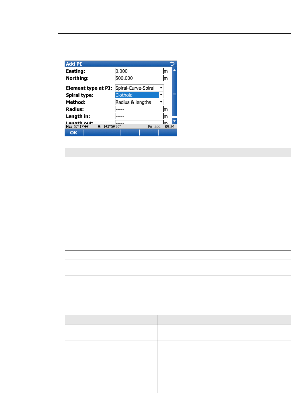
Viva Series, Roads - Alignment Editor 640
46.5.2 Inserting/Editing a PI in a Horizontal Alignment
Access In Horizontal Alignment, PI page, highlight a PI and press Add or Edit...
A PI can also be selected on the Map page.
Elements are added after the highlighted PI.
Creating and editing an alignment PI are similar processes. For simplicity, only the crea-
tion of an alignment PI is explained and differences are clearly outlined.
Add PI
Description of fields
Key Description
OK To accept the screen entries and return to the Alignment Editor
Menu.
Get Pt To apply coordinates from an existing point in the working job. Avail-
able when Easting or Northing is highlighted.
Survy.. To go to Survey and measure a point. Available when Easting or
Northing is highlighted.
Inv.. To calculate the values for the distance and the offset from two
existing points. Available when Radius, Length in, Length out, Param
in or Param out is highlighted.
Last.. To recall previous results from COGO inverse calculations. Available
when Radius, Length in, Length out, Param in or Param out is high-
lighted.
Page To change to another page on this screen.
Fn Config.. To configure the Alignment editor application. Refer to "46.3 Config-
uring Alignment Editor".
Fn Reset To reset all screen entries.
Fn Quit To exit the application.
Field Option Description
Easting and
Northing Editable field The coordinates of the PI.
Element type
at PI None No element is defined at the PI.
Curve A curve is defined at the PI.
Spiral A spiral is defined at the PI.
Spiral-Curve Spiral - curve is defined at the PI.
Curve-Spiral Curve - spiral is defined at the PI.
Viva Series, Roads - Alignment Editor 641
The other fields on the screen depend on the Element type at PI selected.
For Element type at PI:Curve
For Element type at PI:Spiral
For Element type at PI:Spiral-Curve and Element type at PI:Curve-Spiral
Spiral-Spiral Two spirals are defined at the PI.
Spiral-Curve-
Spiral Spiral - curve - spiral is defined at the PI.
Field Option Description
Radius Editable field Using the radius of the curve.
Field Option Description
Spiral type Clothoid, Cubic
parabola or Bloss Bloss is available for Rail jobs only.
Spiral in/out Selectable list The type of spiral.
Method Available for Spiral type:Clothoid.
Radius & lengths Using the radius of the clothoid and its length.
Radius & parame-
ters Using the radius of the clothoid and its parame-
ters.
Radius Editable field The radius of the clothoid, parabola or bloss.
Available unless Use partial spiral is checked.
Radius in and
Radius out Editable field The radius of the partial spiral for a clothoid or
parabola. Available when Use partial spiral is
checked.
Length in and
Length out Editable field The lengths of the clothoid, parabola or bloss.
Param in and
Param out Editable field Depending on the configuration, the parameters
P or factors K of the clothoid. Available for Spiral
type:Clothoid with Method:Radius & parame-
ters.
Use partial
spiral Check box To create a partial clothoid. Available for Spiral
type:Clothoid and Spiral type:Cubic parabola.
Field Option Description
Method Available for Spiral type:Clothoid.
Radius & lengths Using the radius of the clothoid and its length.
Radius & parame-
ters Using the radius of the clothoid and its parame-
ters.
Radius Editable field The radius of the curve.
Length in Editable field The lengths of the connecting curve.
Param in Editable field Depending on the configuration, the parameters
P or factors K of the clothoid. Available for Spiral
type:Clothoid with Method:Radius & parame-
ters.
Field Option Description

Viva Series, Roads - Alignment Editor 642
For Element type at PI:Spiral-Spiral and Element type at PI:Spiral-Curve-Spiral
Next step
OK to access the next screen.
46.6 Edit Vertical Alignments Using Elements
46.6.1 Overview
Description Allows creating, editing and deleting of the following elements:
•Start Point
• Straight (Tangent)
•Parabola
• Asymmetric parabola
•Curve
as well as checking the vertical alignment.
Throughout the whole component height and elevation is used for local orthometric
height. If no local orthometric height is available, the local ellipsoidal height is used
instead.
Access In Alignment Editor Menu highlight Edit vertical alignment. Press OK.
Use PVI instead of element for vertical alignment definition must be
unchecked in Configuration, Advanced page.
Vertical Alignment,
Elements page
The available keys are identical to the keys in Horizontal Alignment. Refer to the para-
graph "Horizontal Alignment, Elements page".
Field Option Description
Method Available for Spiral type:Clothoid.
Radius & lengths Using the radius of the clothoid and its length.
Radius & parame-
ters Using the radius of the clothoid and its parame-
ters.
Radius Editable field The radius of the curve.
Length in and
Length out Editable field The lengths of the connecting curve.
Param in and
Param out Editable field Depending on the configuration, the parameters
P or factors K of the clothoid. Available for Spiral
type:Clothoid with Method:Radius & parame-
ters.
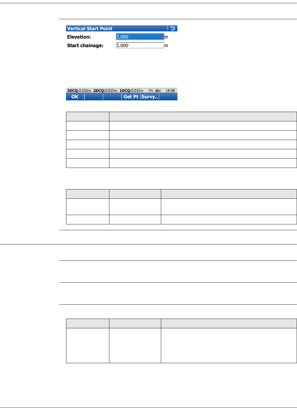
Viva Series, Roads - Alignment Editor 643
46.6.2 Editing the Start Point
Access In Vertical Alignment, highlight the start point and press Edit...
Vertical Start Point
Description of fields
46.6.3 Inserting/Editing an Element in a Vertical Alignment
Access In Vertical Alignment, Elements page, highlight the start point and press Add or Edit...
Creating and editing an alignment element are similar processes. For simplicity, only
the creation of an alignment element is explained and differences are clearly outlined.
For grade units, the system settings are applied. Refer to "29.1 Regional settings" to
change the system setting.
Add Vertical Element Description of fields
The options available for the field Method depend on the Element type selected.
Key Description
OK To accept the screen entries and continue.
Get Pt To apply heights from an existing point in the working job.
Survy.. To go to Survey and measure a point.
Fn Reset To reset all screen entries.
Fn Quit To exit the application.
Field Option Description
Elevation Editable field Elevation at the start chainage of the vertical
alignment.
Start chainage Editable field Start chainage of the vertical alignment.
Field Option Description
Element type Straight To insert/edit a straight to/in a vertical alignment.
Parabola To insert/edit a quadratic parabola to/in a vertical
alignment.
Curve To insert/edit a curve to/in a vertical alignment.
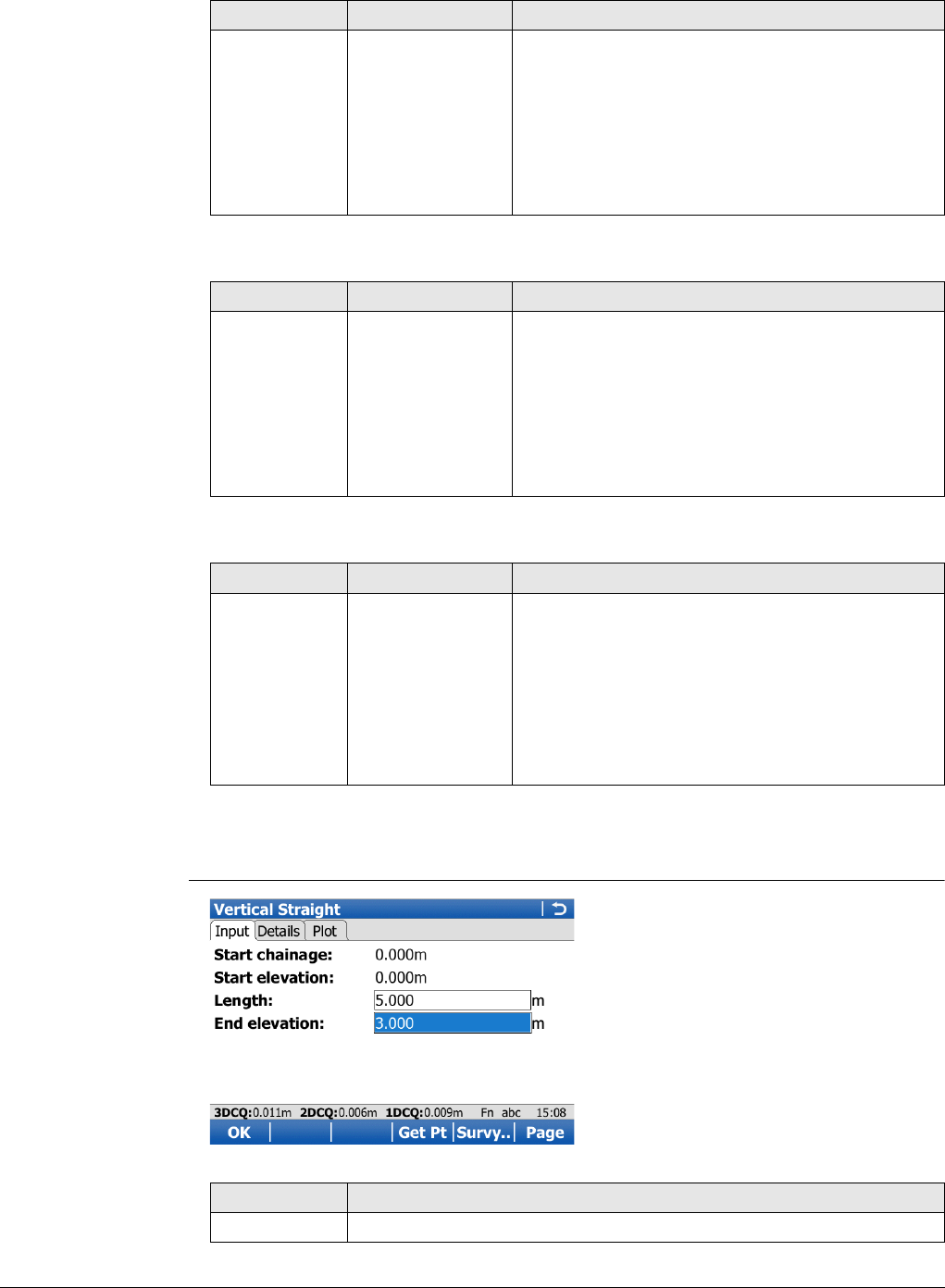
Viva Series, Roads - Alignment Editor 644
For Element type: Straight
For Element type: Parabola
For Element type: Curve
Next step
OK to access the next screen.
Vertical
Straight/Vertical
Parabola/Vertical
Curve,
Input page
Field Option Description
Method Length & end elev Using the length and the end elevation of the
straight.
End chain & elev Using the end chainage and the elevation of the
straight.
Length & grade Using the length and the grade of the straight.
End chain &
grade Using the end chainage and the grade of the
straight.
Field Option Description
Method Length & grades Using the length and the grades of the parabola.
End chain &
grades Using the end chainage and the grades of the
parabola.
Param & end elev Using the parameter and the end elevation of the
parabola.
3 elevations Using three elevations at defined chainages of
the parabola.
Field Option Description
Method Radius & length Using the radius of the curve and its length.
Radius & end
chain Using the radius and the end chainage of the
curve.
Radius & grades Using the radius and the grades of the curve.
Length & grades Using the length and the grades of the curve.
End chain &
grades Using start, intermediate and end elevation and
chainage of the curve.
Key Description
OK To accept the screen entries and continue.
Viva Series, Roads - Alignment Editor 645
Description of fields
The other fields and options available depend on the Method and Element type
selected in Add Vertical Element.
For Element type: Straight
For Element type: Parabola
Inv.. To calculate the distance and angle between two points from the
working job.
Last.. To select values from the last inverse calculations.
Get Pt To apply coordinates or heights from an existing point in the working
job. Available when coordinates must be typed in.
Survy.. To go to Survey and measure a point. Available when elevation must
be typed in.
Page To change to another page on this screen.
Fn Config.. To access the Alignment Editor configuration.
Fn Reset To reset all screen entries.
Fn %/V:H/H:V To switch between h:v, v:h and %(v/h x 100) for the grade unit.
Fn Quit To exit the application.
Field Option Description
Start chainage Display only The end chainage of the previous element is
automatically used and cannot be edited.
Start elevation Display only The end height of the previous element is auto-
matically used and cannot be edited.
Field Option Description
Length Editable field Length of the straight element as slope distance.
Available for Method:Length & end elev and
Method:Length & grade.
End chainage Editable field Chainage at the end of the element. Available for
Method:End chain & elev and Method:End
chain & grade.
End elevation Editable field Height at the end of the element. Type in manu-
ally or, alternatively, press Get Pt when the focus
is on this line to select the height from an existing
point in the working job. Available for
Method:Length & end elev and Method:End
chain & elev.
Grade Editable field The grade of the straight element. Positive
inclines have positive values, negative inclines
have negative values. Available for
Method:Length & grade and Method:End chain
& grade.
Field Option Description
Curve type Crest The curve type is convex. Available for
Method:Param & end elev.
Key Description

Viva Series, Roads - Alignment Editor 646
For Element type: Curve
Sag The curve type is concave. Available for
Method:Param & end elev.
Parameter p or
K factor Editable field Parameter of the parabola. Available for
Method:Param & end elev.
The field name depends on the value chosen for
the Vertical parabola definition in the Configura-
tion, Advanced page.
Length Editable field Length of the parabola as horizontal distance.
Available for Method:Length & grades and
Method:Param & end elev.
Int chainage Editable field Chainage of the second elevation. Available for
Method:3 elevations.
Int elevation Editable field Second elevation. Type in manually or press Get
Pt when the focus is on this line to select the
height from an existing point in the working job.
Available for Method:3 elevations.
End chainage Editable field Chainage at the end of the element. Available for
Method:End chain & grades and Method:3
elevations.
End elevation Editable field Height at the end of the element. Type in manu-
ally or, alternatively, press Get Pt when the focus
is on this line to select the height from an existing
point in the working job. Available for
Method:Param & end elev and Method:3 eleva-
tions.
Grade in Editable field The grade at the beginning of the parabola. Posi-
tive inclines have positive values, negative inclines
have negative values. Available for parabolas with
Method:Length & grades and Method:End
chain & grades.
Grade out Editable field The grade at the end of the parabola. Positive
inclines have positive values, negative inclines
have negative values. Available for
Method:Length & grades and Method:End
chain & grades.
Field Option Description
Curve type Crest The curve type is convex.
Sag The curve type is concave.
Radius Editable field Radius of the curve. Available for Method:Radius
& length, Method:Radius & end chain and
Method:Radius & grades.
Length Editable field Length of the curve along the segment. Available
for Method:Radius & length and
Method:Length & grades.
End chainage Editable field Chainage at the end of the element. Available for
Method:End chain & grades and
Method:Radius & end chain.
Field Option Description
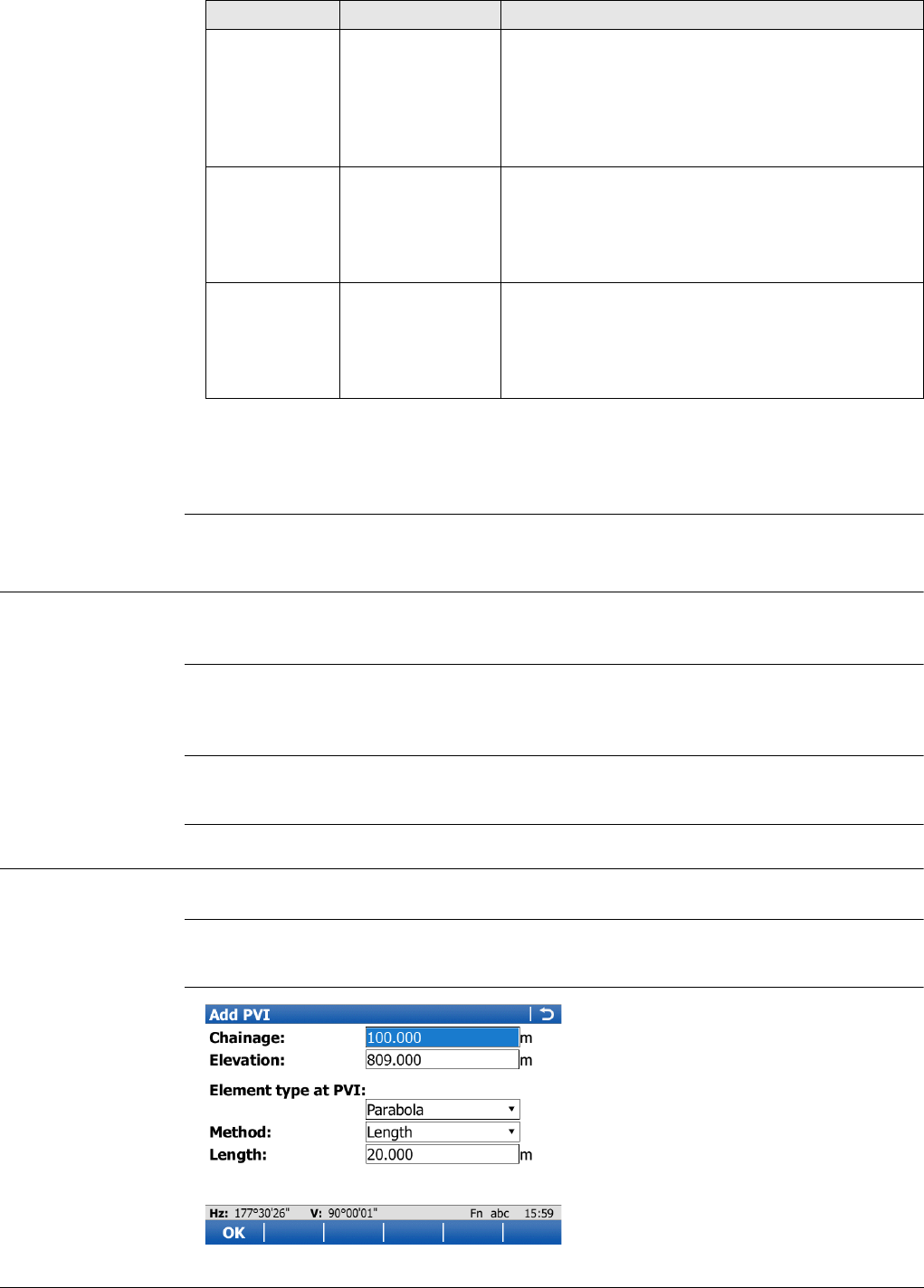
Viva Series, Roads - Alignment Editor 647
Next step
Page changes to the Details page, where all entered and calculated elements are
displayed.
46.7 Edit Vertical Alignments Using PIs
46.7.1 Overview
Description Allows creating, editing and deleting PIs by chainage, elevation and if required an
element type (parabola, curve).
Access In Alignment Editor Menu highlight Edit vertical alignment. Press OK.
Use PVI instead of element for vertical alignment definition must be checked
in Configuration, Advanced page.
Vertical Alignment,
PVI page
The available keys are identical to the keys in Horizontal Alignment. Refer to the para-
graph "Horizontal Alignment, PI page".
46.7.2 Inserting/Editing a PVI in a Vertical Alignment
Access In Vertical Alignment, PVI page, highlight a PVI and press Add or Edit...
Creating and editing an alignment PVI are similar processes. For simplicity, only the
creation of an alignment PVI is explained and differences are clearly outlined.
Add PVI
End elevation Editable field Height at the end of the element. Type in manu-
ally or, alternatively, press Get Pt when the focus
is on this line to select the height from an existing
point in the working job. Available for
Method:Radius & length and Method:Radius &
end chain.
Grade in Editable field The grade at the beginning of the parabola. Posi-
tive inclines have positive values, negative inclines
have negative values. Available for
Method:Radius & grades, Method:Length &
grades and Method:End chain & grades.
Grade out Editable field The grade at the end of the parabola. Positive
inclines have positive values, negative inclines
have negative values. Available for
Method:Radius & grades, Method:Length &
grades and Method:End chain & grades.
Field Option Description
Viva Series, Roads - Alignment Editor 648
Description of fields
The other fields on the screen depend on the Element type at PVI selected.
For Element type at PVI:Curve
For Element type at PVI:Parabola
Key Description
OK To accept the screen entries and return to the Alignment Editor
Menu.
Get Pt To apply heights from an existing point in the working job. Available
when Elevation is highlighted.
Survy.. To go to Survey and measure a point. Available when Elevation is
highlighted.
Inv.. To calculate the values for the distance and the offset from two
existing points. Available when Radius or Length is highlighted.
Last.. To recall previous results from COGO inverse calculations. Available if
Radius or Length is highlighted.
Page To change to another page on this screen.
Fn Config.. To configure the Alignment editor application. Refer to "46.3 Config-
uring Alignment Editor".
Fn Reset To reset all screen entries.
Fn Quit To exit the application.
Field Option Description
Chainage Editable field The chainage of the vertical PVI.
Elevation Editable field The elevation of the vertical PVI.
Element type
at PVI None No element is defined at the vertical PVI.
Curve A curve is defined at the vertical PVI.
Parabola A quadratic parabola is defined at the vertical PVI.
Field Option Description
Method Length To define the curve by its length.
Radius To define the curve by its radius.
Length Editable field The length of the curve.
Radius Editable field The radius of the curve.
Field Option Description
Method Length To define the parabola by its length.
Parameter To define the parabola by its parameter.
Length Editable field The length of the parabola.
Parameter p Editable field Depending on the configuration, the parameters
P or factors K of the parabola.
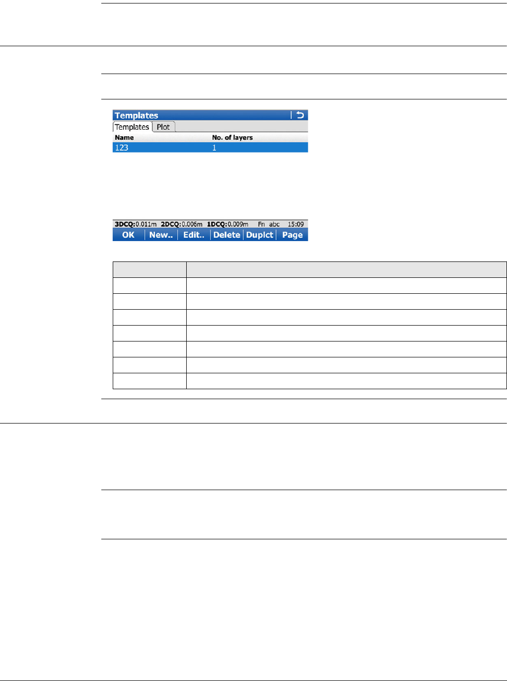
Viva Series, Roads - Alignment Editor 649
Next step
OK to access the next screen.
46.8 Edit Cross Section Templates
46.8.1 Overview
Description Allows creating, editing, deleting and duplicating of cross section templates.
Access In Alignment Editor Menu highlight Edit cross section templates. Press OK.
Templates
46.8.2 Creating/Editing a Cross Section Template
Access In Templates
press New.. to create a new cross section template
OR
highlight an existing template and press Edit...
Creating and editing a cross section template are similar processes. For simplicity, only
the creation of a cross section template is explained and differences are clearly
outlined.
Key Description
OK To accept the screen entries and continue.
New.. To create a new cross section template.
Edit.. To edit the highlighted cross section template.
Delete To delete the highlighted cross section template.
Duplct To duplicate the highlighted template.
Page To change to another page on this screen.
Fn Quit To exit the application.
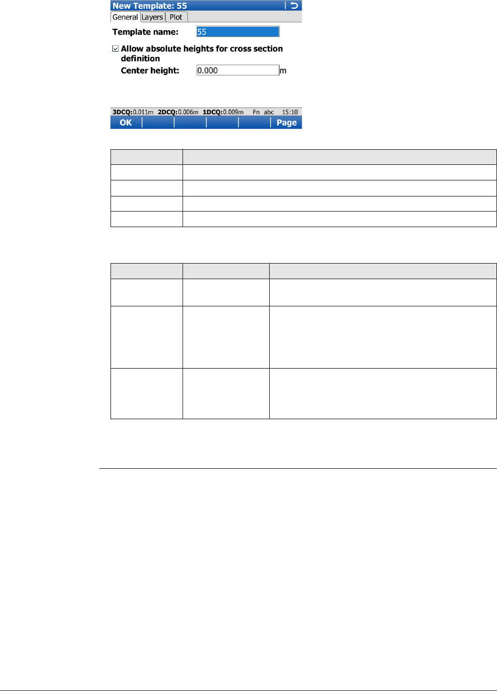
Viva Series, Roads - Alignment Editor 650
New Template,
General page
Description of fields
Next step
Page changes to the Layers page where the layers of the template are listed.
Key Description
OK To accept the screen entries and continue.
Page To change to another page on this screen.
Fn Config.. To access the Alignment Editor configuration.
Fn Quit To exit the application.
Field Option Description
Template
name Editable field Name of the cross section template to be
created/edited.
Allow abso-
lute heights
for cross
section defini-
tion
Check box If this box is checked, in addition to relative to line
input methods, absolute heights can also be
entered to define cross section segments.
Center height Editable field To be able to create segments using absolute
heights, a centre height must be defined. Avail-
able if Allow absolute heights for cross section
definition is checked.
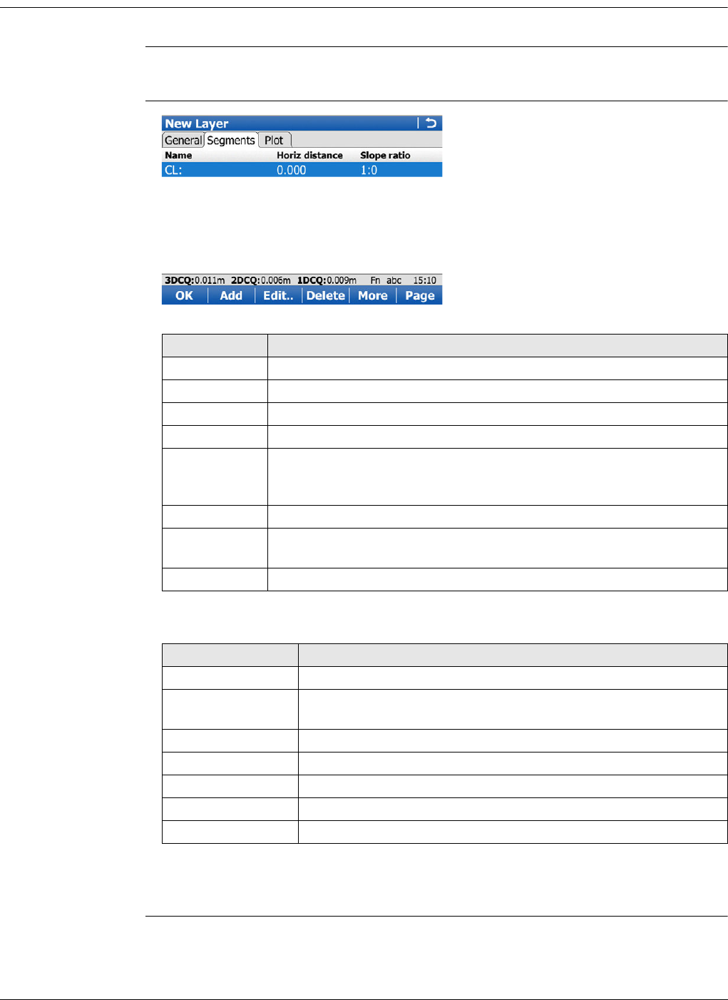
Viva Series, Roads - Alignment Editor 651
46.8.3 Add/Edit a Layer
Access In New Template/Edit Template, Layers page, press New.. or Edit...
Creating and editing a layer of a cross section template are similar processes. For
simplicity, only the creation of a layer is explained and differences are clearly outlined.
New Layer,
Segments
Description of columns
Next step
Add to add a segment.
Key Description
OK To accept the screen entries and continue.
Add To create and add a new segment.
Edit.. To edit the highlighted segment.
Delete To delete the highlighted segment.
More To switch between CL horizontal offset, Slope distance, Horiz
distance in the second column and between CL vertical offset, Slope
ratio, Vertical distance in the third column.
Page To change to another page on this screen.
Fn Mirror To mirror the entered segments to the other side of the cross
section.
Fn Quit To exit the application.
Column Description
Name The name of the segment.
CL horizontal
offset Horizontal offset to the centre line of the segment.
CL vertical offset Vertical offset to the centre line of the segment.
Slope distance Slope distance to the neighbouring vertex.
Slope ratio Slope ratio of the segment.
Horiz distance Horizontal distance to the neighbouring vertex.
Vertical distance Vertical distance to the neighbouring vertex.
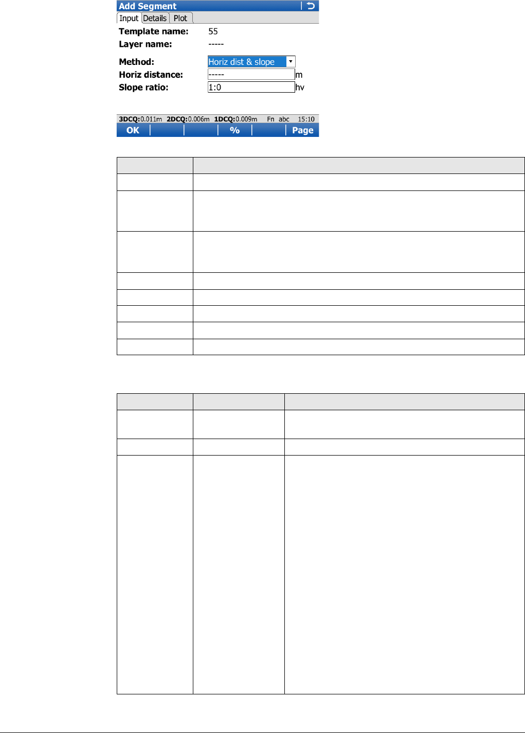
Viva Series, Roads - Alignment Editor 652
Add Segment,
Input page
Description of fields
Key Description
OK To accept the screen entries and continue.
Inv.. Available when Horiz distance, CL horizontal offset or Slope
distance is highlighted. To calculate the distance and angle between
two points from the working job.
Last.. Available when Horiz distance, CL horizontal offset or Slope
distance is highlighted. To select values from the last inverse calcu-
lations.
%/V:H/H:V To switch between h:v, v:h and %(v/h x 100) for the slope ratio.
Page To change to another page on this screen.
Fn Config.. To access the Alignment Editor configuration.
Fn Reset To reset all screen entries.
Fn Quit To exit the application.
Field Option Description
Template
name Display only Name of the cross section template to be edited.
Layer name Display only Name of the layer to be edited.
Method Method to be used for defining the segment.
Horiz dist & slope Using a horizontal distance and slope ratio to
define the segment.
Horiz dist & vert
dist Using a horizontal distance and a vertical distance
to define the segment.
CL offsets Using a horizontal and vertical offset in relation to
the centre line.
Slope dist & ratio Using a slope distance and slope ratio to define
the segment.
Horiz dist &
height Using a horizontal and absolute height to define
the segment. Only available for templates with
Allow absolute heights for cross section defini-
tion enabled.
CL offset & height Using a horizontal offset in relation to the centre
line and absolute height. Only available for
templates with Allow absolute heights for cross
section definition enabled.
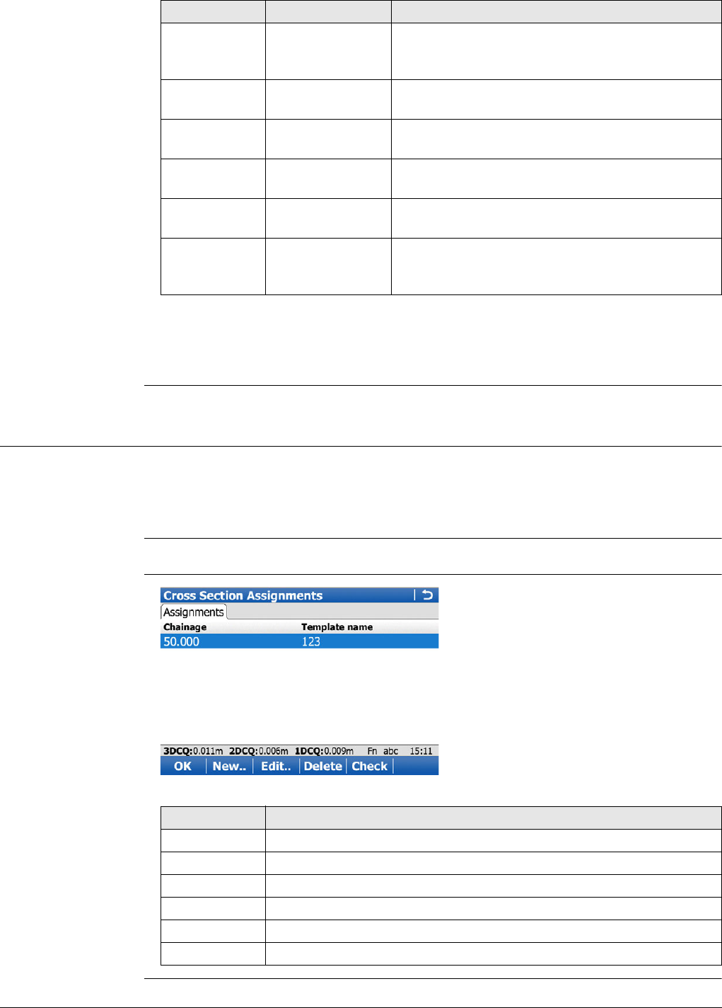
Viva Series, Roads - Alignment Editor 653
Next step
Page changes to the Details page, where all entered and calculated elements are
displayed.
46.9 Edit Cross Section Assignments
46.9.1 Overview
Description Allows the creation, editing and deleting of cross section assignments as well as
checking the cross section assignments.
A cross section assignment defines from which chainage on a cross section template
is to be used.
Access In Alignment Editor Menu highlight Edit cross section assignment. Press OK.
Cross Section
Assignments
Horiz distance Editable field Horizontal distance of the segment. Available for
Method:Horiz dist & slope and Method:Horiz
dist & vert dist.
Vertical
distance Editable field Vertical distance of the segment. Available for
Method:Horiz dist & vert dist.
CL horizontal
offset Editable field Horizontal centre line offset of the segment. Only
available for Method:CL offsets.
CL vertical
offset Editable field Vertical centre line offset of the segment. Only
available for Method:CL offsets.
Slope
distance Editable field Slope distance of the segment. Only available for
Method:Slope dist & ratio.
Slope ratio Editable field Slope ratio of the segment. Available for
Method:Horiz dist & slope and Method:Slope
dist & ratio.
Field Option Description
Key Description
OK To accept the screen entries and continue.
New.. To create a new cross section assignment.
Edit.. To edit a cross section assignment.
Delete To delete a cross section assignment.
Check To check the cross section assignments.
Fn Quit To exit the application.
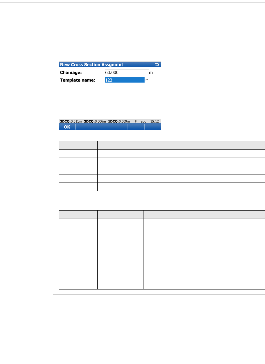
Viva Series, Roads - Alignment Editor 654
46.9.2 Creating/Editing a Cross Section Assignment
Access In Cross Section Assignments press New.. or Edit...
Creating and editing a cross section assignment are similar processes. For simplicity,
only the creation of a cross section assignment is explained and differences are clearly
outlined.
Assigned cross section templates must contain the same number of vertices.
New Cross Section
Assgnmnt
Description of fields
Key Description
OK To accept the screen entries and continue.
StartCh To take the start chainage of the vertical alignment for Chainage.
End Ch To take the end chainage of the vertical alignment for Chainage.
Fn Config.. To access Alignment Editor configuration.
Fn Quit To exit the application.
Field Option Description
Chainage Editable field The chainage to which the cross section template
is assigned to.
Type in or edit the value for Chainage. Alterna-
tively press StartCh or End Ch to apply the start
or end chainage of the vertical alignment.
Template
name Selectable list The cross section template to be assigned to. All
existing cross section templates currently stored
to the alignment can be selected.
Select an existing template from the list or create
a new one to be assigned to the Chainage.
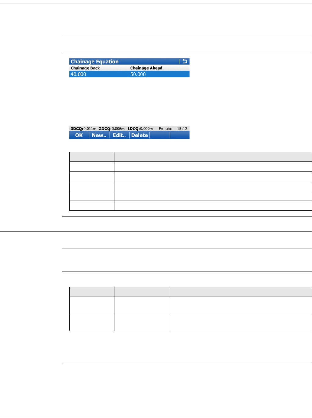
Viva Series, Roads - Alignment Editor 655
46.10 Edit Chainage Equation
46.10.1 Overview
Description Allows creating, editing and deleting of:
•Gaps
•Overlaps
Access In Alignment Editor Menu highlight Edit chainage equation. Press OK.
Chainage Equation
46.10.2 Creating/Editing a Chainage Equation
Access In Chainage Equation press New.. or Edit...
Creating and editing a Chainage equation are similar processes. For simplicity, only the
creation of a Chainage equation is explained and differences are clearly outlined.
New Chainage Equa-
tion Description of fields
Next step
OK to create the chainage equation or to store the edited chainage equation.
Key Description
OK To accept the screen entries and continue.
New.. To create a new chainage equation.
Edit.. To edit a chainage equation.
Delete To delete a chainage equation.
Fn Quit To exit the application.
Field Option Description
Chainage
back Editable field Chainage back. Type in or edit the value.
Chainage
ahead Editable field Chainage ahead. Type in or edit the value.
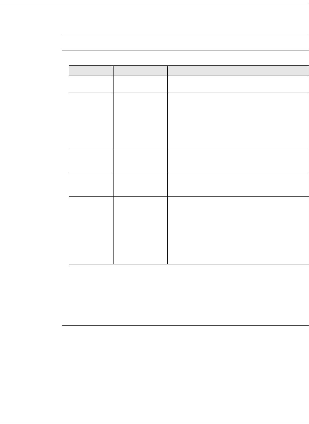
Viva Series, Roads - Alignment Editor 656
46.11 Convert to job
Description Allows the onboard conversion of existing LandXML alignments including horizontal
alignment, vertical alignment, cross sections and chainage equations to a RoadRunner
job.
Access In Alignment Editor Menu highlight Convert to job. Press OK.
Convert to Road Job/
Convert to Rail Job Description of fields
Next step
Press OK to start the conversion.
Alignment Editor creates a report sheet during the conversion. The file
LandXml2Dbx.log can be found in the \Data\XML folder on the data storage device.
After the successful conversion, press OK to return to the Main Menu on the instru-
ment.
Field Option Description
From align-
ment Display only Displays the modified or newly created alignment
to be converted.
To road job Selectable list The Road job to which the alignment will be
converted. Create a new job. Available if the
Alignment type is set to Road in Select Align-
ment.
If a new job with the same name as an
existing job must be created, then the
existing job must be deleted first.
To rail job Selectable list The Rail job to which the alignment will be
converted. Create a new job. Available if the
Alignment type is set to Rail in Select Alignment.
If a new job with the same name as an
existing job must be created, then the
existing job must be deleted first.
Conversion
mode Defines the mode to be used for the conversion
process.
Horiz & vert Only horizontal and vertical alignment will be
converted.
Horizontal only Only horizontal alignment will be converted.
Hz,vert,cross
section Horizontal alignment, vertical alignment and cross
sections will be converted. Only available for road
jobs.
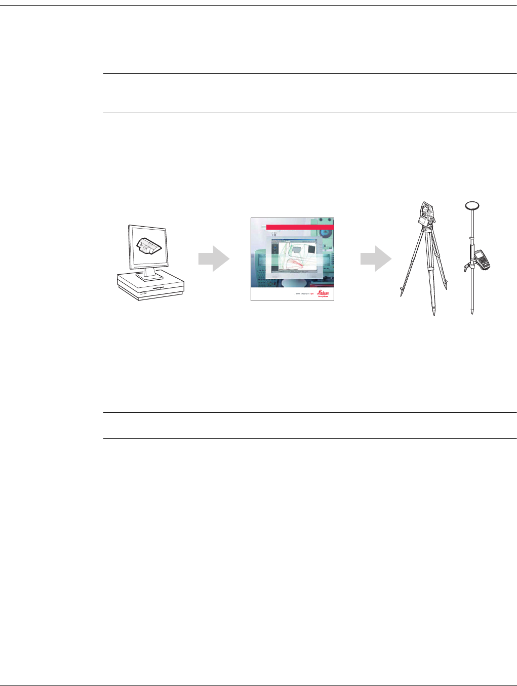
Viva Series, Roads - Road 657
47 Roads - Road
47.1 Creating a New Road Job
Description There are two ways of creating road/rail jobs:
Typing them in manually by using the Alignment Editor application.
OR
Converting data created in a design package.
Manually entered
data
Data can be typed in and edited with Alignment Editor. Refer to "46 Roads - Align-
ment Editor" for information on how to enter data manually.
Converted data The Import alignment data application in Jobs & Data supports various different
formats like dxf, LandXml, MxGenio, Terramodel, Carlson.
The Design to Field component of Leica Geo Office offers converters from several
road/rail design and CAD packages. Several design packages also include a built-in
converter to Roads/Rail. As different design packages follow different philosophies in
representation, creation and storage of data the conversion process differs slightly.
Leica Geo Office can be found on the Leica Geo Office DVD.
The latest version of the Design to Field importers can be found in the downloads
section of:
• myWorld@Leica Geosystems
https://myworld.leica-geosystems.com
Job selection Refer to "45.2.1 Accessing Roads Applications".
LEICA Geo Office
Road_065
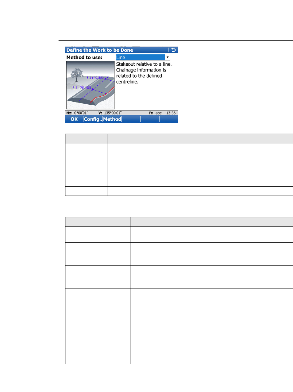
Viva Series, Roads - Road 658
47.2 Defining the Work
47.2.1 Defining the Method and the Task
Access 1) Select Main Menu:Go to Work!\Roads\Roads - Stakeout or Roads - As built check.
2) In the job selection screen, select the required jobs. Refer to "45.2.1 Accessing
Roads Applications".
3) Press OK.
Define the Work to be
Done
Description of the methods
Key Description
OK To continue to the next screen.
Fn Config.. To access the configuration settings. Refer to "45.3 Configuring
Roads Applications".
Method To define what is shown in the selectable list for Method to use.
Local line can not be hidden.
Fn Quit To exit the screen.
Method Description
Line To stake/check any type of line, for example a centreline or
kerb. Chainage information is related to the centreline.
Local line Like the previous method when staking/checking any line of
a layer. The stake/check is always in relation to the chainage
of the line itself and not the centreline of the layer.
Surface grade To stake/check a surface grade defined by the road design.
Two lines define the surface grade (a lane or running
surface).
Manual slope To stake/check a manually defined slope relative to an
existing centreline. The slope is defined by one line (hinge
point) and the slope direction with ratio. The stake/check is
always in relation to the chainage of the line itself and not
the centreline of the layer.
Local manual slope To stake/check a manually defined slope relative to an
existing hinge line. The slope is defined by one line (hinge
point) and the slope direction with ratio.
Slope To stake/check a slope defined by two lines of the 3D road
design.
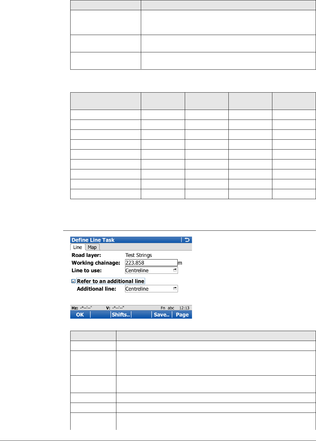
Viva Series, Roads - Road 659
The available methods depend on the selected job types (road or control job):
Next step
OK accesses the Define Task screen.
Define Task screen
Crown To stake/check a road crown defined by two surface grades
and one common line. The information for both surface
grades is displayed at the same time.
Layer To stake/check a layer surface defined by the road design
relative to the layer centreline.
DTM To check a DTM surface. Available for Roads - As built check
only.
Available method Road job
only
Control job
only
Road job &
control job
DTM job only
Line --
Local line -
Surface grade ---
Manual slope --
Local manual slope -
Slope ---
Crown ---
Layer ---
DTM ---
Method Description
Key Description
OK To continue to the next screen.
Slope Available for Method to use:Manual slope, Method to use:Local
manual slope and Method to use:Slope. To define the slope param-
eters. Refer to "47.2.3 Advanced Slope Settings".
Shifts.. To apply horizontal and vertical shifts to the selected element. Refer
to "45.4 Working with Shifts".
Load.. To load a task. Refer to "45.5 Tasks".
Save.. To save the settings as a task. Refer to "45.5 Tasks".
Page To change, depending on the selected method, to Hinge offset
and/or Map page.
Viva Series, Roads - Road 660
The fields available depend on the selection for Method to use in Define the Work to
be Done.
Description of fields
Common to all methods
For Method to use:Line
Any line can be selected on the Map page.
Dxf lines have to be imported to a control job before they can
be used for Roads. Refer to "37.6 Context Menu".
Fn Config.. To access the configuration settings. Refer to "45.3 Configuring
Roads Applications".
Fn Quit To exit the application.
Field Option Description
Layer Display only or
selectable list
The selected layer in the Road job.
Field Option Description
Working
chainage Editable field The chainage for the stake/check survey. The
chainage can range between the start chainage
and the end chainage. The default is the setup
point for TPS and the current position for GPS.
Line to use Selectable list To select a line at the Working chainage. Or
select a line on the Map page. Refer to "47.2.2
Selecting a Line".
Refer to an
additional line Check box When this box is checked, a second line can be
selected.
Allows chainage, offset and height difference
information to be obtained from any other string
of the layer, independent from those strings
currently selected for the chosen method. For
example: Staking a surface grade where the
height information comes from the surface grade,
but the chainage information comes from a string
which is not the centreline of the current layer.
For the additional line, an offset and a height
difference can be defined on the Offsets page.
Line to use Selectable list The lines available as second lines, independent
of the Working chainage. Or select a line on the
Map page. Refer to "47.2.2 Selecting a Line".
Key Description
Viva Series, Roads - Road 661
For Method to use:Local line
For Method to use:Surface grade
For Method to use:Manual slope and Method to use:Local manual slope
Field Option Description
Line to use Selectable list To select a line at the Working chainage. Or
select a line on the Map page. Refer to "47.2.2
Selecting a Line".
Refer to an
additional line Check box When this box is checked, a second line can be
selected.
Allows chainage, offset and height difference
information to be obtained from any other string
of the layer independent from those strings
currently used. For example: Staking a surface
grade where the height information comes from
the surface grade but the chainage information
comes from a string which is not the centreline of
the current layer.
Line to use Selectable list The lines available as second lines, independent
of the Working chainage. Or select a line on the
Map page. Refer to "47.2.2 Selecting a Line".
Field Option Description
Working
chainage Editable field The chainage for the stake/check survey. The
chainage can range between the start chainage
and the end chainage. The default is the setup
point for TPS and the current position for GPS.
Left line Selectable list The name of the left line defining the surface
grade. Refer to "47.2.2 Selecting a Line".
Right line Display only The name of the right line defining the surface
grade.
Reference line Left line or Right
line To select one of the lines to be used as the refer-
ence line.
Refer to an
additional line Check box When this box is checked, a second line can be
selected.
Allows chainage, offset and height difference
information to be obtained from any other string
of the layer independent from those strings
currently used. For example: Staking a surface
grade where the height information comes from
the surface grade but the chainage information
comes from a string which is not the centreline of
the current layer.
Line to use Selectable list The lines available as second lines, independent
of the Working chainage. Or select a line on the
Map page. Refer to "47.2.2 Selecting a Line".
Field Option Description
On the Slope page:
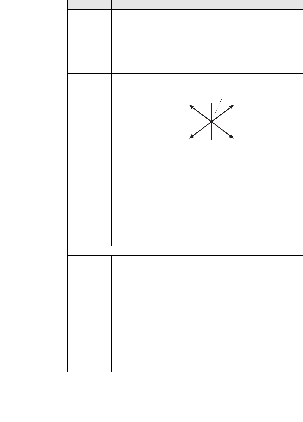
Viva Series, Roads - Road 662
Chainage of
slope Editable field The chainage for the stake/check survey. The
chainage can range between the start chainage
and the end chainage of selected line.
Hinge line Selectable list To select the hinge point of the slope. Or select a
line on the Map page. Refer to "47.2.2 Selecting
a Line".
For Manual slope, only lines from the
Road job can be selected.
Slope location Left or Right Defines if the slope is left or right of the hinge
point.
a) Hinge Point
b) Left, cut
c) Right, cut
d) Left, fill
e) Right, fill
Use cut and
Use fill Check box When the box is checked, a cut/fill is used for the
calculation. During the surveying process, the
system calculates if it is a cut or a fill.
Check only one box to work only with cut or fill.
Slope cut ratio
and Slope fill
ratio
Editable field Defines the cut/fill ratio of the slope.
The slope ratio format is defined as
system setting in Regional Settings,
Slope page.
On the Hinge offset page:
Apply hinge
offsets Check box When this box is checked, a horizontal and
vertical offset of the hinge point can be defined.
Ht offset type The vertical offset type for the hinge point.
Absolute The only option available for 2D lines.
Relative to line or
Relative to DTM Available for 3D lines.
Relativ to surf
grade Available for Method to use:Manual slope. The
manual slope is defined by the:
• Hinge offset relative to the selected hinge
reference line
• Hinge height, calculated by using the hinge
offset on the selected surface grade (left or
right selected surface grade, depending on
Offset – or +)
Field Option Description
a
bc
de
Road_079
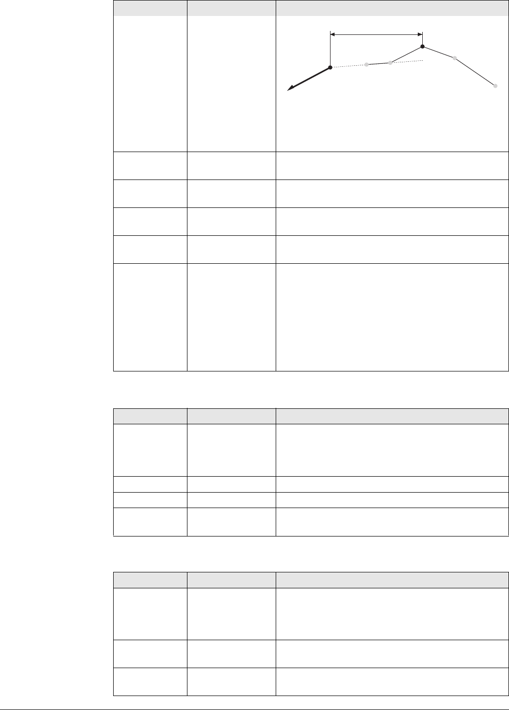
Viva Series, Roads - Road 663
For Method to use:Slope
For Method to use:Crown
a) Hinge point of manual slope
b) Defined hinge offset (-)
c) Left surface grade of design
d) Selected hinge reference
Offset Editable field The horizontal offset of the hinge point from the
centreline/reference line.
Elevation Editable field The elevation of the hinge point (absolute
height). Available for Ht offset type:Absolute.
Left line Editable field The name of the left line. Available for Ht offset
type:Relativ to surf grade.
Right line Display only The name of the right line. Available for Ht offset
type:Relativ to surf grade.
Height differ-
ence Editable field For Ht offset type:Relative to line: A vertical
offset for the hinge point using a height differ-
ence can be defined.
For Ht offset type:Relative to DTM: A height
difference to the DTM height can be applied.
For Ht offset type:Relativ to surf grade: Height
difference of the hinge point to the calculated
height on the end slope.
Field Option Description
Working
chainage Editable field The chainage for the stake/check survey. The
chainage can range between the start chainage
and the end chainage. The default is the setup
point for TPS and the current position for GPS.
Left line Selectable list The name of the left line defining the slope.
Right line Display only The name of the right line defining the slope.
Reference line Left line or Right
line To select one of the lines to be used as the refer-
ence line (= hinge line).
Field Option Description
Working
chainage Editable field The chainage for the stake/check survey. The
chainage can range between the start chainage
and the end chainage. The default is the setup
point for TPS and the current position for GPS.
Crown line Selectable list Line defining the middle line of the crown. Refer
to "47.2.2 Selecting a Line".
Left line Display only The name of the line defining left line of the
crown.
Field Option Description
b
ac
d
Road_105
Viva Series, Roads - Road 664
For Method to use:Layer
For Method to use:DTM, available for Roads - As built check
Next step
OK to access the Stake or Check screen.
47.2.2 Selecting a Line
Access • In the Define screen, open a selectable list for a line, for example for Line to use
or Left line.
• Or, tab on a line on the Map page.
• Or, for dxf lines, hold down the supplied stylus on an object for 0.5 second and
select Select Line.
The selection of lines depends on:
• Availability of horizontal alignments
• Availability of vertical alignment information
• View (plan or cross section view)
• Working chainage defined or not
• Selected method
Right line Display only The name of the line defining right line of the
crown.
Reference line Left line or Right
line To select one of the lines to be used as the refer-
ence line.
Refer to an
additional line Check box When this box is checked, a second line can be
selected.
Allows chainage, offset and height difference
information to be obtained from any other string
of the layer independent from those strings
currently used. For example: Staking a surface
grade where the height information comes from
the surface grade but the chainage information
comes from a string which is not the centreline of
the current layer.
Line to use Selectable list The lines available as second lines.
Field Option Description
Layer Selectable list A list of all available layers of the selected Road
job.
Centreline Display only Active centreline of the selected layer.
Extend end
slopes Check box When this box is checked, the left most and right
most end slopes of the design are extended.
Field Option Description
DTM layer Display only A list of all DTM surfaces available in the selected
DTM job.
Number of
triangles Display only Number of triangles the selected DTM consists of.
Field Option Description
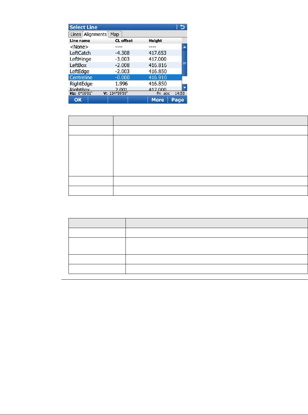
Viva Series, Roads - Road 665
Lines The screen can have a Lines page (if control job is selected), an Alignments page (if
road alignment is selected) and a Map page.
If no working chainage has been entered, the lists show all lines of the current layer.
If a working chainage is available, all lines existing at that chainage are listed only.
Description of columns
In addition to the list selection the required lines and slopes can also be selected on
Map page.
Lines can be selected in a graphical way by using the
• cross section view. The cross section view is available if a working chainage has
been defined. The selected line (3D only) or area from the control job is also
displayed. Unavailable for Method to use:Local manual slope.
• planar view which is always available. The defined working chainage is displayed
as a grey line. The size corresponds to the working corridor settings.
Key Description
OK To return to the previous screen.
More On the Lines and Areas page: To display information about the
codes if stored with any line, the start time, the end time of when
the last point was added to the line and the length of the line.
On the Alignments page: To display information about the absolute
height or the height difference. Unavailable for local lines.
Page To change to another page on this screen.
Fn Quit To exit the application.
Column Description
Line name The name of the line.
CL offset The offset from the centreline. The format is defined as system
setting in Regional Settings.
Height The absolute height of the line.
Ht diff The height difference to the centreline.
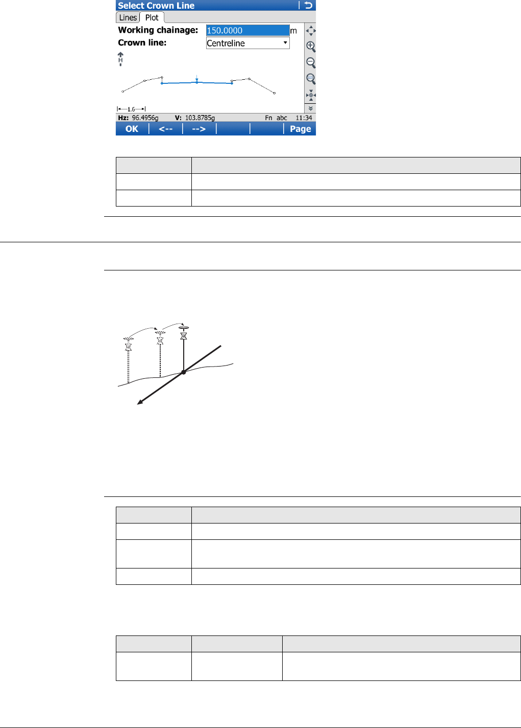
Viva Series, Roads - Road 666
47.2.3 Advanced Slope Settings
Access Press Slope in the Define screen.
General slope
stakeout
Description
This method involves a generic approach to slope stakeout for direct stakeout of the
catch point. No special batter rails or reference point parameters are defined.
Workflow
As the natural surface is unknown the catch point can only be staked out iteratively.
If staking out on a horizontal natural surface, the values shown for offset indicate
how far the catch point is away. If the natural surface is not horizontal, more iterations
could be needed.
Slope Stakeout
Settings
Description of fields
Common to all types
Key Description
<-- For lines from Road jobs: To select the previous line.
--> For lines from Road jobs: To select the next line.
a) Slope to stake out
b) Natural surface
c) Catch point
a
c
b
Road_055
Key Description
OK To return to the Define screen.
Types To define which slope stakeout types are shown and which are
hidden.
Fn Quit To exit the screen.
Field Option Description
Use advanced
slope stakeout Check box When this box is checked, slope stakeout settings
are available.
Viva Series, Roads - Road 667
For Type:Reference point
For Type:Batter rail vertical and Type:Batter rail perpend
For Type:Ref batter vertical and Type:Ref batter perpend
Type Reference point Stakeout of a reference peg with a defined offset
from the catch point. Refer to "Slope staking
using Reference point".
Batter rail vertical Stakeout of batter rails using defined rail heights
vertically above the batter.
Refer to "Slope staking using Batter rail vertical or
Batter rail perpend".
Batter rail
perpend Stakeout of batter rails using defined rail heights
perpendicularly above the batter.
Refer to "Slope staking using Batter rail vertical or
Batter rail perpend".
Ref batter vertical Stakeout of batter rails using defined rail heights
vertically above the batter. The innermost
peg/stake is offset at a defined horizontal
distance from the catch point.
Refer to "Slope staking using Ref batter vertical or
Ref batter perpend".
Ref batter
perpend Stakeout of batter rails using defined rail heights
perpendicularly above the batter. The innermost
peg/stake is offset at a defined horizontal
distance from the catch point.
Refer to "Slope staking using Ref batter vertical or
Ref batter perpend"
Ref point surface Stakeout of a reference peg in the slope surface
with a defined height difference to the hinge
point. Slope values for the reference point cannot
be entered.
Refer to "Slope staking using Ref point surface".
Field Option Description
Ref offset Editable field The defined offset of the reference point from
the catch point.
Field Option Description
Batter type Cut or Fill Defines the cut or fill rail.
Traveller
height Editable field Depending on the selected Type, the vertical or
perpendicular height of the rail top above the
batter.
Rail over
ground Editable field The vertical height of the rail over the ground.
Field Option Description
Ref offset Editable field The defined offset of the inner peg from the
catch point.
Field Option Description
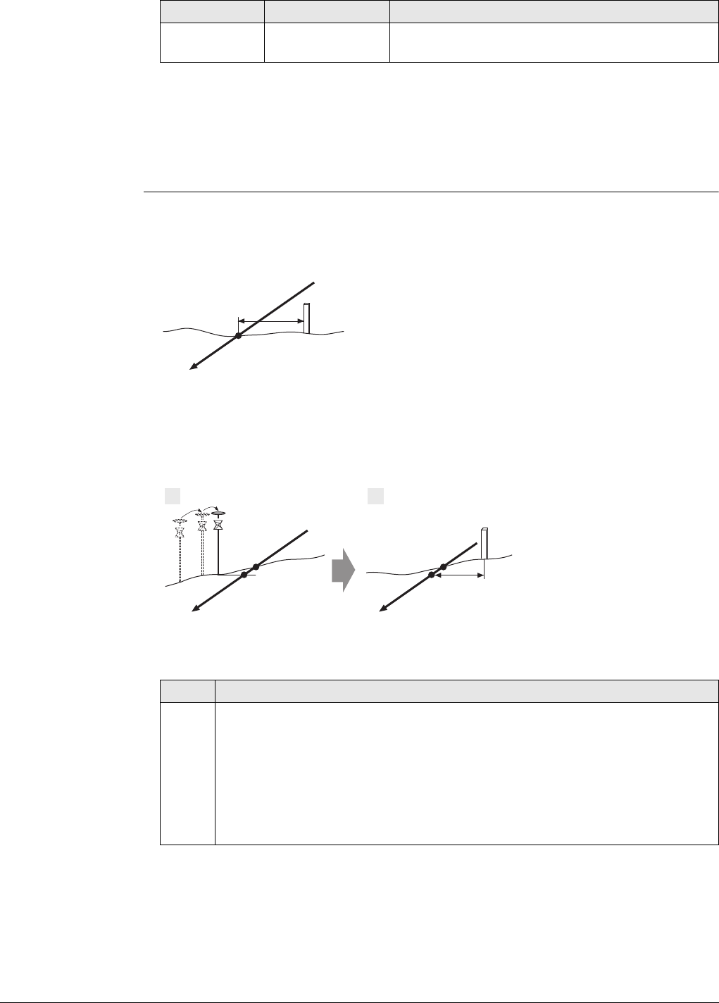
Viva Series, Roads - Road 668
For Type:Ref point surface
The only available fields are Use advanced slope stakeout and Type.
Next step
OK returns to the Define screen.
Slope staking using
Reference point Description
When staking out slopes using the reference point method, the catch point of the
slope is marked with a reference peg using a defined offset. The grade of the slope is
marked and controlled by "grade checkers".
The reference point offset guarantees that all pegs are placed with the same hori-
zontal offset to the catch point.
Workflow
Traveller
height Editable field Depending on the selected Type, the vertical or
perpendicular height of the rail above the batter.
Field Option Description
a) Slope to stake out
b) Natural surface
c) Catch point of the slope
d) Defined reference point offset
e) Reference peg
a) Slope to stake out
b) Natural surface
c) Real catch point
d) Projected catch point
e) Approximate staked out
catch point after three
iterations
f) Defined reference point
offset
g) Reference peg
Step Description
1. The first step when staking out is to find the catch point of the slope. As the
natural surface is unknown, this process has to be done iteratively. As soon
as the measured position (e) is close enough to the real catch point (c), it
can be used as the approximate catch point. Based on this approximate catch
point, the projected catch point (d) on the slope is calculated.
No reference point offset and no traveller height are taken into account for
this step. The projected catch point (d) is then used as a starting point for
the stakeout of the reference peg (g).
a
c
bde
Road_022
a
c
bd
e
g
c
d
f
1 2
Road_023
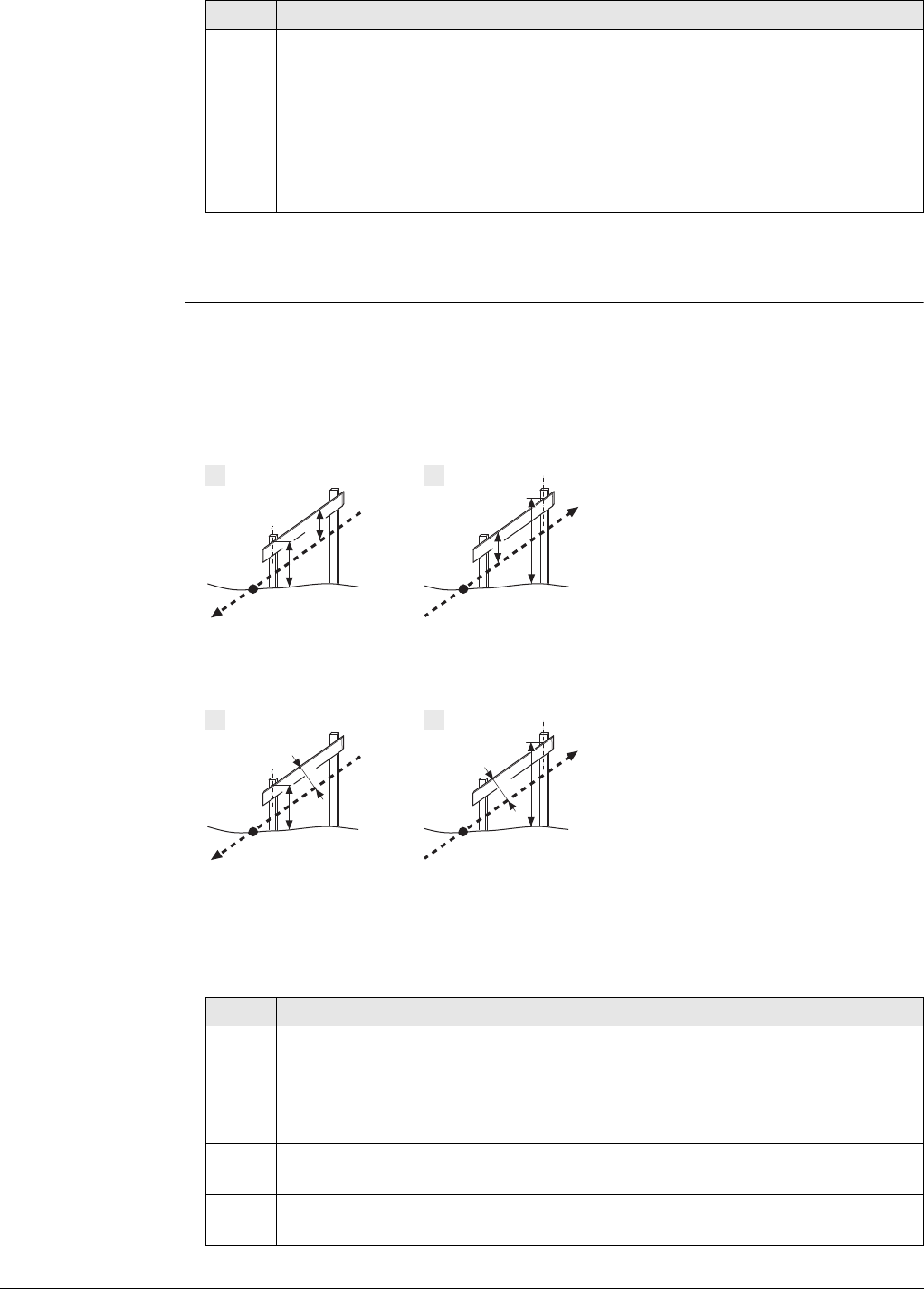
Viva Series, Roads - Road 669
The closer the real catch point and the approximated stakeout catch point are, the
closer the projected catch point gets to the real catch point.
Slope staking using
Batter rail vertical or
Batter rail perpend
Description
When staking out slopes with the Batter rail vertical or Batter rail perpend method,
the grade of the slope is marked with a board. Using this method it is not necessary
to stake out the catch point first.
For Batter rail vertical
For Batter rail perpend
The defined rail over ground should guarantee that the rails are positioned as high as
possible, to make them easier to use.
2. The second step is to stake out the reference point relative to the projected
catch point. Select Place reference peg from the Tools menu. Values in Stake
Slope Reference Point,Stake page will guide the user to the position to
place the peg. The defined reference point offset (f) is already taken into
account.
The catch point is marked indirectly via the reference peg. Values to be
marked on the reference peg can be found on Stake Slope Reference
Point,Info page.
Step Description
1 Batter rail for a cut
2 Batter rail for a fill
a) Slope to stake out
b) Natural surface
c) Catch point of the slope
d) Rail over ground
e) Rail over batter, vertical
1 Batter rail for a cut
2 Batter rail for a fill
a) Slope to stake out
b) Natural surface
c) Catch point of the slope
d) Rail over ground
e) Rail over batter, perpendicular
Step Description
1. The first peg to stake out is always the peg closest to the hinge point.
Stake out the position of the first peg of the batter by using offset on the
Stake page of the Stake/Check screen. The height of the rail over ground Rail
over ground is taken into account for offset. This action means that when
offset is equal to zero the first peg is in the correct position.
2. Place the pole on top of the first peg. The value for height indicates how
far below the top of the batter has to be placed.
3. Stake out the second peg of the batter rail by using chainage and place
the peg.
Road_024
ac
bd
ea
c
b
d
e
1 2
Road_101
ac
bd
ea
c
b
d
1 2
e
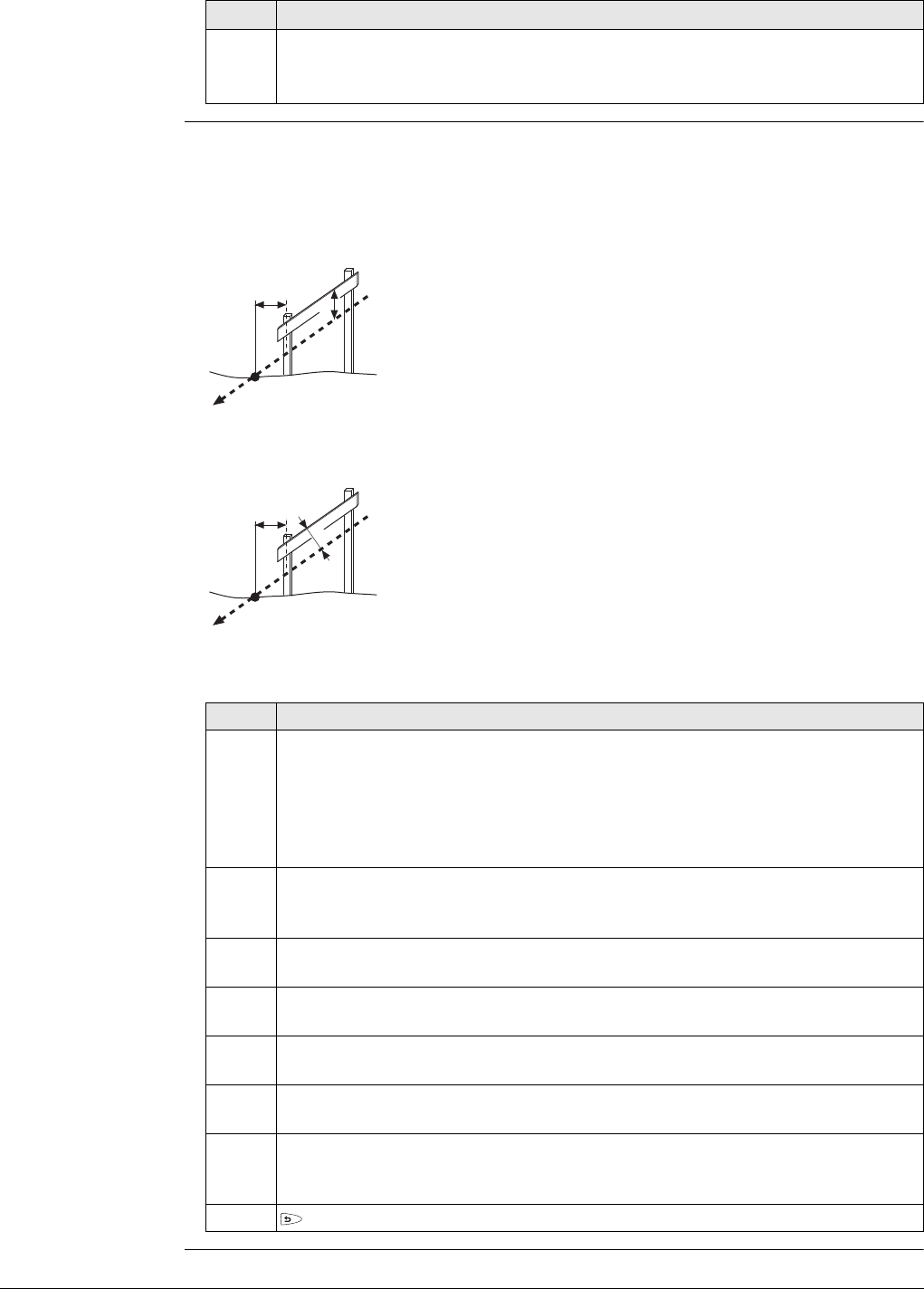
Viva Series, Roads - Road 670
Slope staking using
Ref batter vertical or
Ref batter perpend
Description
This method is used if batter rails with a constant distance from the inner peg to the
catch point are required.
For Ref batter vertical
For Ref batter perpend
Workflow
4. Place the pole on the position of the batter rail to be used as a reference for
the slope values to mark on the batter rail. height should now read zero.
All values shown under the Info page are relative to the original slope.
Step Description
a) Slope to stake out
b) Natural surface
c) Catch point of the slope
d) Defined reference point offset
e) Height of the "traveller", vertical
a) Slope to stake out
b) Natural surface
c) Catch point of the slope
d) Defined reference point offset
e) Height of the "traveller", perpendicular
Step Description
The first step is to stake out the catch point of the slope. The reference point
offset and traveller height are not taken in account in this step. Based on
this approximate catch point the projected catch point on the slope is calcu-
lated.
The projected catch point is used as a starting point for the stakeout of the
reference peg.
1. Stake out the position of the catch point by using offset and/or height
on the Stake page of the Stake/Check screen. When offset and height
are equal to zero, the catch point has been located.
2. Fn Tools.. to access the Tools screen. The measured position is used as the
catch point for the stake out of the reference point.
3. Select Place reference peg to access the stakeout screen for the reference
peg.
4. Stake out the reference point using offset. When offset is equal to zero
the reference peg position has been found.
5. Place the pole on top of the reference peg. The value for height indicates
how far below the top of the peg the batter has to be placed.
6. Place the pole on the position of the batter rail to be used as a reference for
the slope values to mark on the batter rail. height should now read zero.
All values shown under the Info page are relative to the original slope.
7. to return to Stake Slope. Stake out the next catch point from this screen.
ac
b
de
Road_025
ac
b
d
e
Road_100
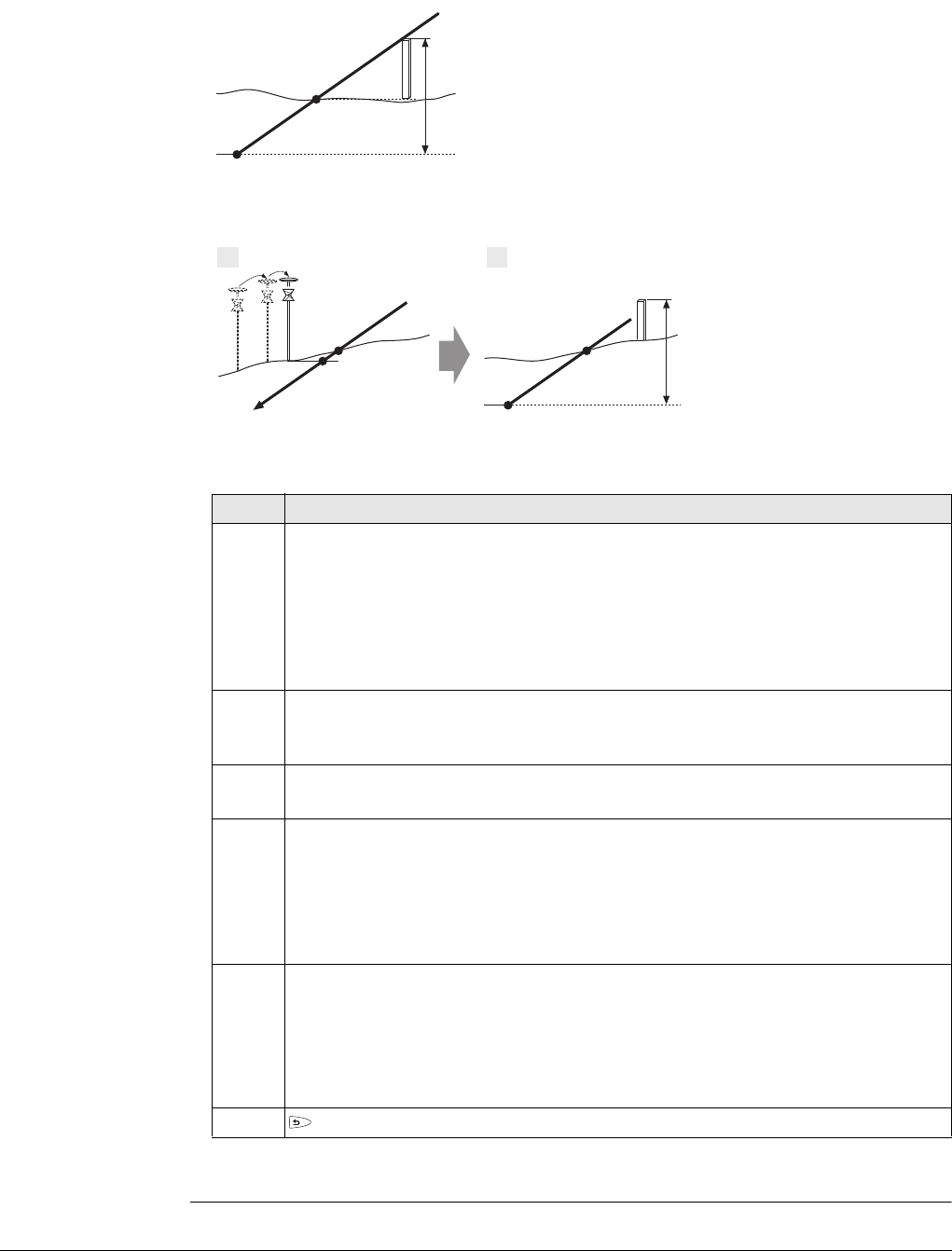
Viva Series, Roads - Road 671
Slope staking using
Ref point surface Description
When staking out slopes using the reference point surface method, the reference peg
is staked out with a defined height difference to the hinge point.
Workflow
The closer the real catch point and the approximated stakeout catch point are, the
closer the projected catch point gets to the real catch point.
a) Slope to stake out
b) Natural surface
c) Catch point of the slope
d) Reference peg
e) Defined hinge height difference
f) Hinge point
a) Slope to stake out
b) Natural surface
c) Real catch point
d) Projected catch point
e) Approximate staked out
catch point after three
iterations
f) Hinge point
g) Reference peg
h) Defined hinge height
difference
Step Description
The first step when staking out is to find the catch point of the slope. As the
natural surface is unknown, this process has to be done iteratively. As soon
as the measured position (e) is close enough to the real catch point (c), it
can be used as the approximate catch point. Based on this approximate catch
point, the projected catch point (d) on the slope is calculated.
The projected catch point (d) is then used as a starting point for the stakeout
of the surface reference peg (g).
1. Stake out the position of the catch point by using offset and/or height
on the Stake page of the Stake/Check screen. When offset and height
are equal to zero, the catch point has been located.
2. Define the hinge height difference.
Fn Tools.. to access the Tools screen.
3. Select Place surface reference peg to access the define screen for the refer-
ence peg field. The measured position from step 1. is used as the catch point
for the stake out of the reference point.
The Actual hinge ht diff field displays the Hinge ht diff value from the Stake
page of the Stake/Check screen.
Type in the appropriate value for Defined hinge ht diff.
4. Stake out the surface reference point relative to the projected catch point.
Values in Stake Slope Ref Point Surface,Stake page guide you to the posi-
tion to place the peg. The defined hinge height difference (h) is already
taken into account.
Values to be marked on the reference peg can be found on Stake Slope Ref
Point Surface,Info page.
5. to return to Stake Slope. Stake out the next catch point from this screen.
a
c
bd
e
f
Road_096
a
c
bd
e
g
c
f
1 2
h
Road_097
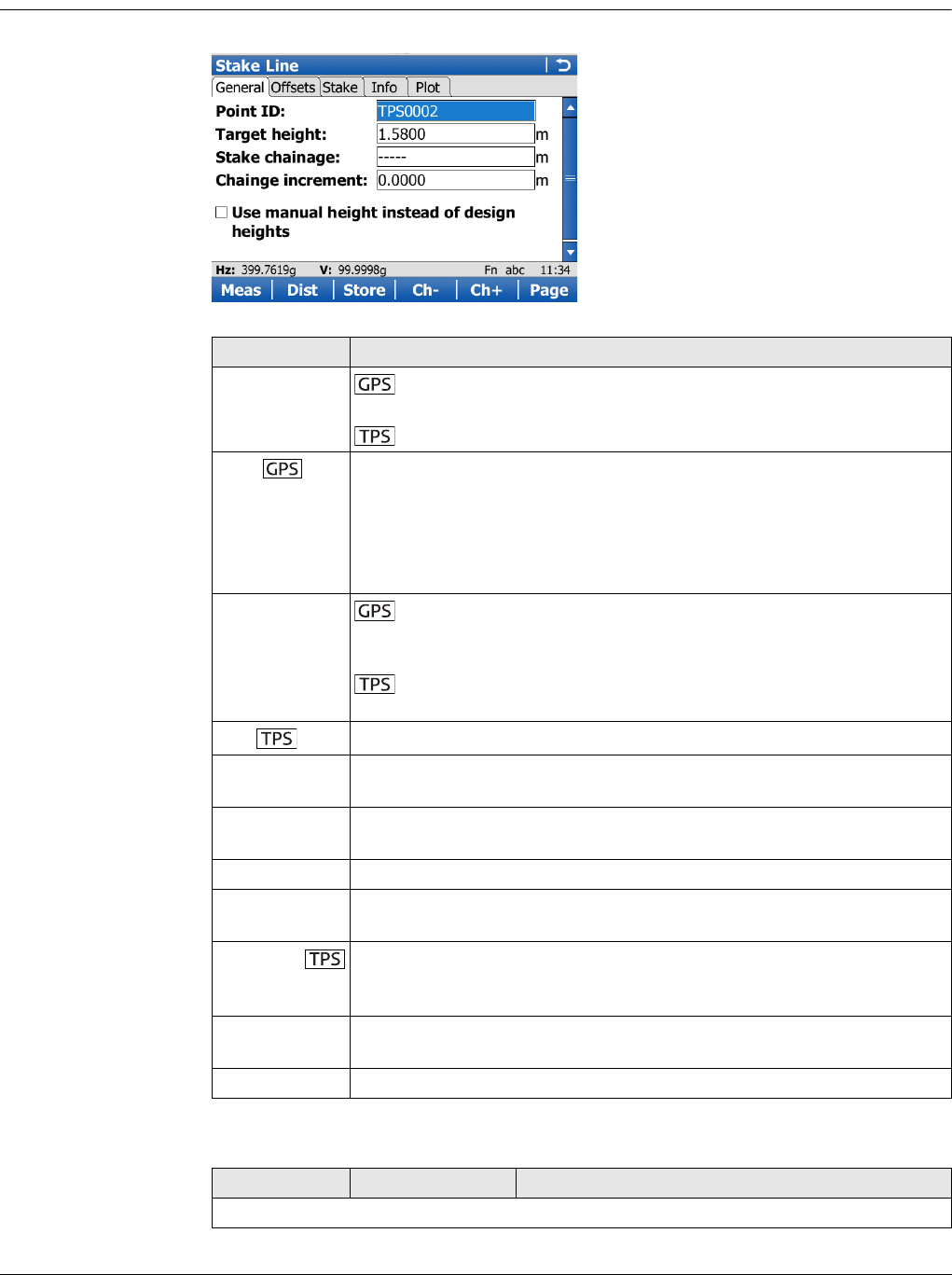
Viva Series, Roads - Road 672
47.3 Staking/Checking the Road
47.3.1 The Stake/Check Screen
Stake/Check screen,
General page
The Stake Line is shown as example.
Description of fields
Key Description
Meas To start measuring the point being staked. The key changes to
Stop.
To measure a distance and store distance and angles.
Stop To end measuring the point being staked. When Automatically stop
point measurement is checked in Quality Control,General page
recording of positions ends automatically as defined by the stop
criteria. The key changes to Store. After ending the measurements,
the differences between the measured point and the point to be
staked are displayed.
Store To store the measured point. When Automatically store point
is checked in Quality Control,General page, the measured point is
stored automatically. The key changes to Meas.
To store angles and distance. Distance must be measured
before.
Dist To measure a distance.
Ch- Available for Roads - Stakeout. To decrease the chainage as defined
by Chainge increment.
Ch+ Available for Roads - Stakeout. To increase the chainage as defined
by Chainge increment.
Page To change to another page on this screen.
Fn Config.. To access configuration settings. Refer to "45.3 Configuring Roads
Applications".
Fn Positn To position the total station to the defined stakeout point, including
defined offsets. This depends on the settings for Turn to point in
Configuration, TPS page. Refer to " Configuration, TPS page".
Fn Tools.. To access the method-specific Tools Menu. Refer to "47.4 The Tools
Menu".
Fn Quit To exit the application.
Field Option Description
The following fields are always shown in all Stake and Check methods.
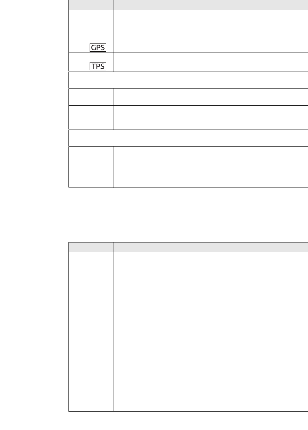
Viva Series, Roads - Road 673
Next step
Page changes to the Offsets page.
Stake/Check screen,
Offsets page
Refer to "Stake/Check screen, General page" for a description of keys.
Description of fields
Point ID Editable field Name of the next point to be stored. The ID is
incremented/decremented whenever a point gets
stored.
Antenna
height
Editable field Height of the antenna.
Target
height
Editable field Height of the prism.
The following fields are always shown in all Stake methods, except for method
Layer.
Stake
chainage Editable field Nominal chainage of the point to be staked out.
Chainge incre-
ment Editable field Chainage increment. Value by which the nominal
chainage increases/decreases when pressing Ch-
/Ch+.
The following field is shown in the Stake and Check methods except for Slope
and Manual slope.
Use manual
height instead
of design
heights
Check box When this box is checked, a height value typed in
manually is used instead of design height or DTM
height. When this box is not checked, the height
from design is used.
Manual height Editable field The height to be used.
Field Option Description
Field Option Description
Apply offsets Check box When this box is checked, the defined
stake/check offsets are applied.
Stake offset Editable field Available for Stake. Horizontal offset from the
reference line (as defined by the chosen method)
of the point to stake.
When a stake offset is entered for line,
local line, manual slope and local manual
slope and Work with non-perpendicular
offset is checked on the Offsets page:
When coming to a corner when working at
a stake chainage along an alignment,
choose one of the following from the
message:
•Prev: To stake out the point according to
the tangent direction of the previous line.
•Avg: To stake the average tangent direc-
tion. The stake distance from the corner is
the offset value defined.
•Next: To stake out the point according to
the tangent direction of the next line.
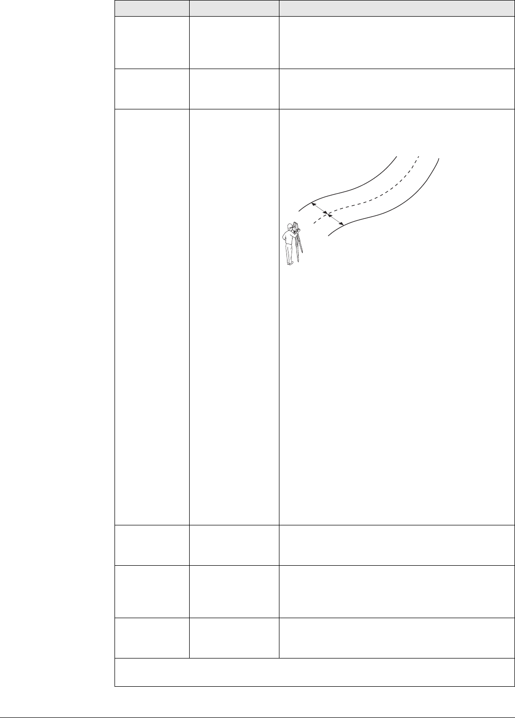
Viva Series, Roads - Road 674
CL stake
offset Editable field Available for Stake with Layer. The Easting and
Northing values for staking are calculated by the
horizontal offset from the centreline. The height
is derived from the layer.
Stake height
diff Editable field Available for Stake. Vertical offset from the refer-
ence line or surface (as defined by the chosen
method) of the point to stake.
Toggle offsets
left/right Check box When this box is checked, points can be
staked/checked on the left/right side of the
selected line in one process.
a) Line
b) Defined Stake offset
c) Parallel right line
d) Parallel left line
This functionality is available for the following
stake out/check methods:
•Line: Toggle between line left and right.
•Surface grade: Toggle between left and
right line of the surface grade.
•Crown: Toggle between left and right
surface grade.
The application automatically detects which side
of the centreline is being used and selects the
appropriate line as a reference.
Auto position
When pressing auto position Fn Positn, available
in total station mode, a message box comes up
prompting if either the left or right side should be
staked out/checked.
Check offset Editable field Available for Check. Horizontal offset from the
reference line, as defined by the chosen method,
of the point to stake.
CL check
offset Editable field Available for Check with Layer. The Easting and
Northing values for checking are calculated by the
horizontal offset from the centreline. The height
is derived from the layer.
Check height
diff Editable field Available for Check. Vertical offset from the refer-
ence line or surface, as defined by the chosen
method, of the point to stake.
The following field is shown for the Stake methods Line, Local line, Local
manual slope and Manual slope.
Field Option Description
a
b
b
d
c
Road_073
Viva Series, Roads - Road 675
Next step
Page changes to the Stake page.
Understanding
priorities of various
heights
Stake screen,
Stake page This page is available for Roads - Stakeout only.
This page displays the differences between the measured points and stakeout points
(delta values). If these values are zero, the measured point coincides with the
stakeout point.
Refer to "Stake/Check screen, General page" for a description of keys.
Refer to "53.4 Staking Out" for a description of the elements of the graphical display.
Description of fields
Work with
non-perpen-
dicular offset
Check box When this box is not checked the measured point
is projected in a right angle to the selected line.
When this box is checked, any projection angle
can be defined.
Offset angle Editable field Manually defined projection angle.
The following fields are shown in the Line, Local line, Surface grade and
Crown methods when Refer to an additional line is checked in the Define
screen.
Apply offsets
to additional
line
Check box When this box is checked, an offset to the addi-
tional line can be defined.
Offset Editable field Horizontal stake/check offset to the additional
line.
Height differ-
ence Editable field Vertical stake/check height difference to the
additional line.
Field Option Description
Type of height Overrules Stake height diff
Manually entered
OR
Obtained from individual point
All other heights Considered
Use DTM height for stakeout (Tools
menu: Use heights from DTM)
Design height Considered
From design No other heights Considered
Show DTM height difference on Info
page (Tools menu: Use heights
from DTM)
No influence on priorities
For additional info only
-
Field Option Description
Chainage Display only The current chainage.
CL O Display only Perpendicular horizontal offset to the centreline.
chainage Display only Difference between the defined Stake chainage
and the current chainage Chainage of the meas-
ured position.
If no defined chainage exists, for example if
staking out random chainages or checking, this
field shows -----.
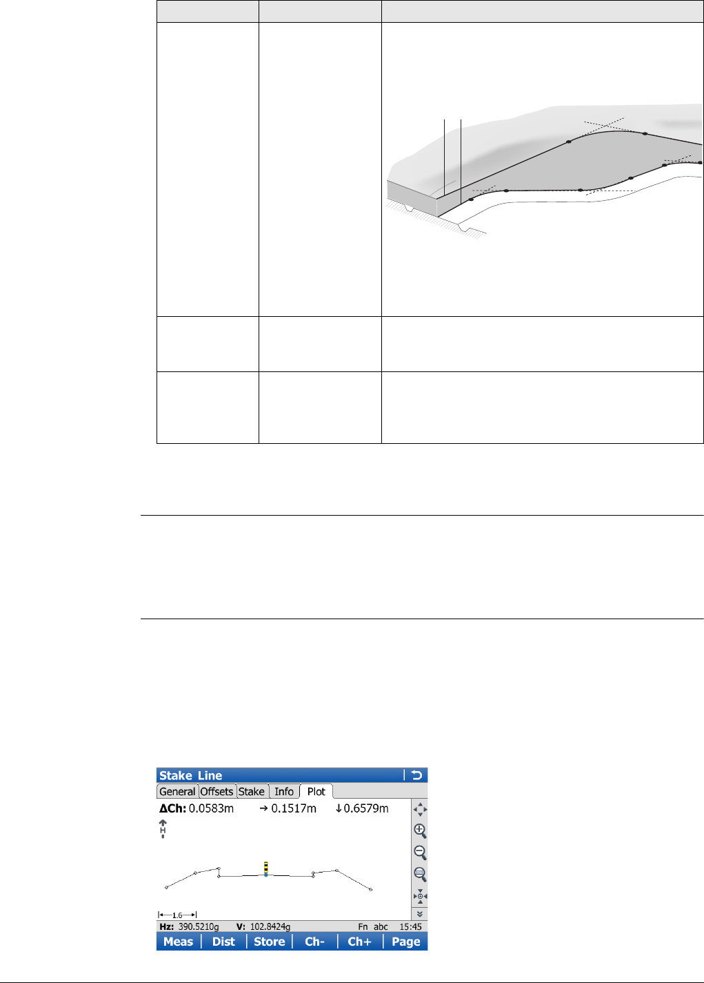
Viva Series, Roads - Road 676
Next step
Page changes to the Info page.
Stake/Check screen,
Info page
A user definable Info page exists for each of the stake methods and check methods.
Refer to the chapters from "45.3.2 Road Line - Info Page"to "45.3.8 Road DTM - Info
Page".
Refer to "Configuration, Info page" for information on all available items for the Info
page and how to select them.
Stake/Check screen,
Map page
The Map page for Stake shows information about the measured point relative to the
design. The design is defined by the selected layer and line, and the values entered on
the General page.
The Map page for Check and Stake are similar. The only difference is that the current
chainage is always shown instead of chainage.
For Check and when only a DTM job is used, the Map page shows the DTM and the
lines of selected Road layer - always in plan view. At the top of the page, DTM height
and delta height are shown.
NrTP Display only The chainage difference between the measured
point and the nearest tangent point (start/end
point of a road segment) of the design is
displayed.
a) Vertical alignment
b) Horizontal alignment
Only tangent points (start/end point of a road
segment) are detected.
O Display only Horizontal offset between the defined position
and the current position. The Stake offset defined
on the Offsets page is taken into account.
height Display only Vertical offset between the defined position and
the current position. The Stake height diff
defined on the Offsets page is taken into
account.
Field Option Description
ab
Road_099
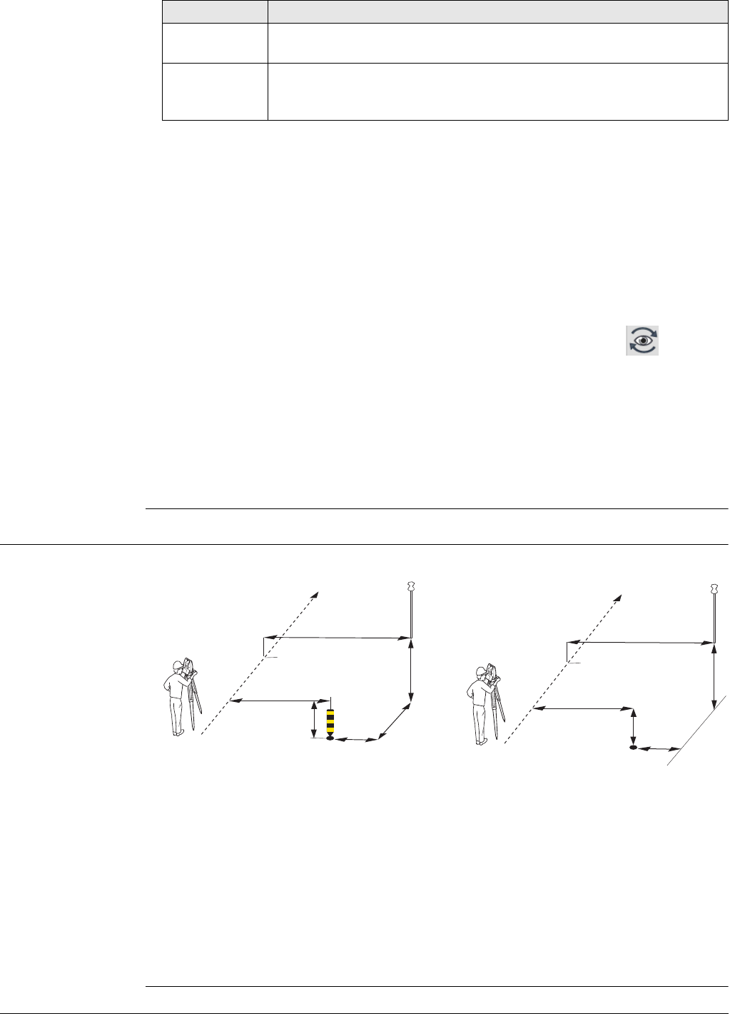
Viva Series, Roads - Road 677
The following information is shown:
47.3.2 Measuring Points by Chainage and Offset
Graphical overview
Key Description
Refer to "Stake/Check screen, General page" for a description of
keys.
Fn Layrs.. To turn layers of background maps (CAD files) on and off. Refer to
"5.2 Creating a New Job"for information on CAD files and CAD back-
ground maps.
1. Chainage difference between the measured point and the defined chainage.
When working with random chainages, for instance if no defined chainage has
been entered on the General page, Ch changes to Ch. Ch is the current
chainage as shown on the Stake page.
2. Horizontal offset (left/right arrow) to the design
3. Height difference (up/down arrow) to the design
4. The measured point (prism pole or GPS antenna)
5. The element to stake is shown in bold and blue. The position to stake is marked
with a yellow-black peg.
6. The plot can be shown as a cross plot or plan view by using the eye icon
on second level of MapView toolbar. Displayed is:
Cross plot: • Road job lines of the selected layer
• Only selected line of the control job (not all lines)
Plan view: • Road job lines of the selected layer
•Lines of control job
• Background maps, for example dxf(s), attached to control
job
• Working job items are displayed in grey
Roads - Stakeout Roads - As built check
a) Position to stake out, defined by
chainage, stake offset and, option-
ally, stake height difference
b) Centreline/line the position is
defined relative to
c) Stake offset
d) Stake height diff
e) Chainage
f) CL offset/Ref offset
g) chainage
h) offset
i) height
a) Position to check, defined by check
offset and, optionally, check height
difference
b) Centreline/line the position is
defined relative to
c) Check offset
d) Check height diff
e) Chainage
f) CL offset/Ref offset
g) offset
h) height
a
ei
h
dg
b
c
f
Road_034
a
eh
g
d
b
c
f
Road_080
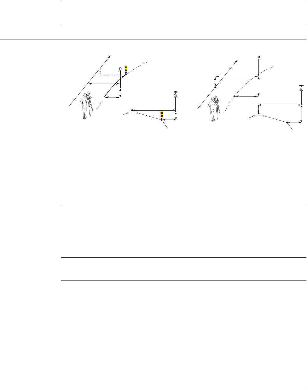
Viva Series, Roads - Road 678
Description • When staking points, the points are defined by the stake chainage and, if enabled,
by the stake offset and the stake height difference relative to an existing 2D or 3D
centreline or line.
• When checking points, the points are defined by the check offset and the check
height difference relative to an existing 2D or 3D centreline or line.
Required elements • For 2D, a horizontal centreline is required.
• For 3D, a 3D centreline is required.
47.3.3 Measuring Lines Relative to a Centreline
Graphical overview
Description • Lines define various elements, including:
• Centreline of the design
• Change in slope ratio, for example, the edge of a carriage way
• Gutter, cable, pipeline or any other type of alignment element
• Refer to "45.6.3 Road - Basic Elements for Stake and Check Measurements" for
information on the usage of lines.
Required elements • For 2D, at least a 2D line and a 2D centreline are required.
• For 3D, a 3D line and a 2D or 3D centreline are required.
Roads - Stakeout Roads - As built check
a) Position to stake out
b) Line to stake out
c) Centreline
d) Stake chainage
e) Chainage
f) CL offset
g) chainage
h) offset
i) height
a) Line to check
b) Projected point on line
c) Centreline
d) Chainage
e) CL offset
f) CL ht diff
g) offset
h) height
a=b
i
h
f
c
a
e
hi
g
db
c
f
Road_035
a=b
c=d g
h
e
f
a
e
h
g
b
d
c
f
Road_066
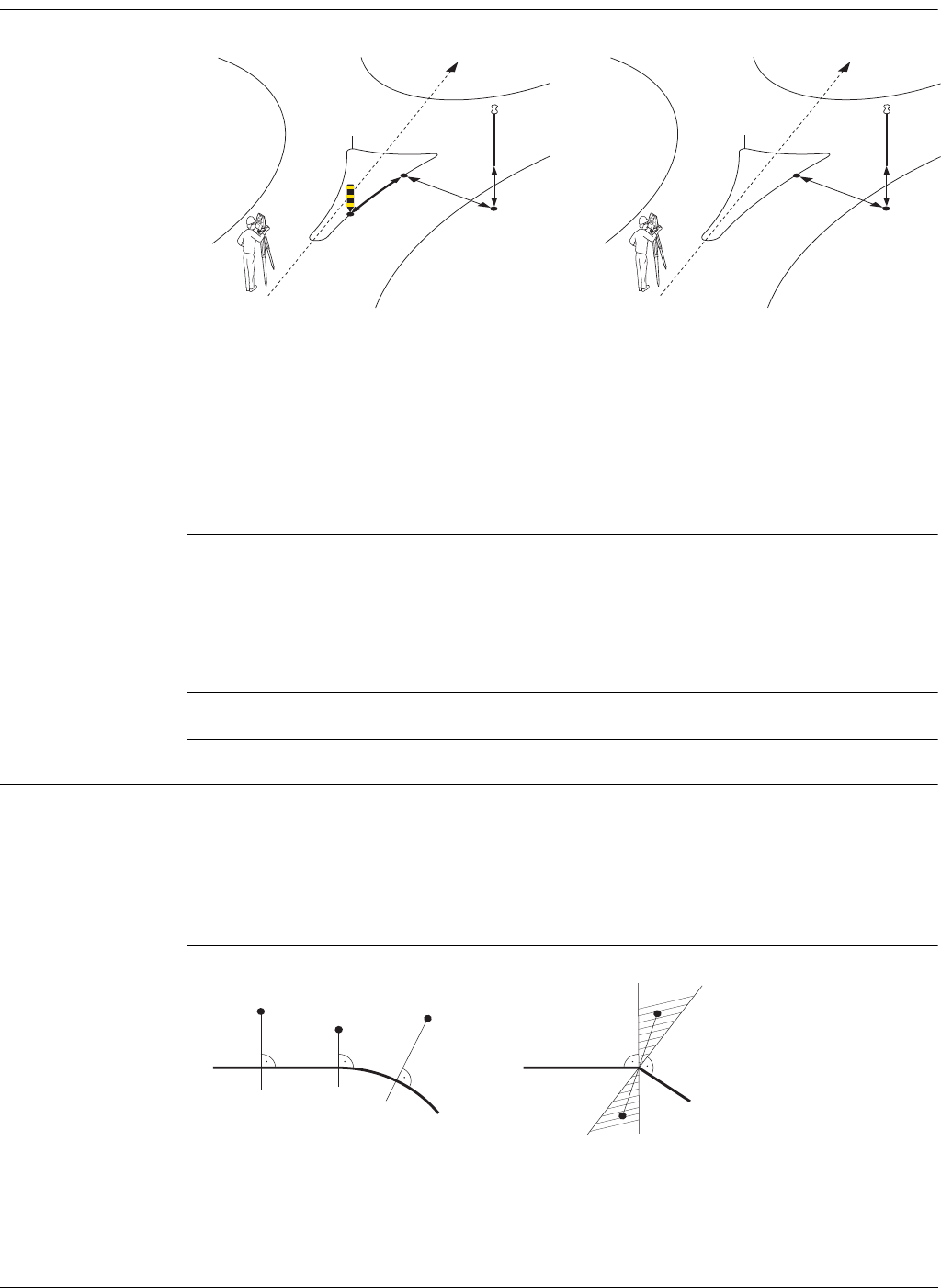
Viva Series, Roads - Road 679
47.3.4 Measuring Local Lines without Centrelines
Graphical overview
Description This process is different to lines, where the stake/check is always relative to the
centreline defined for the layer. Local lines no longer have a relationship to an overall
centreline. Local lines are used to check roundabouts, parking bays, subdivision works
and any other type of lines. The different lines to stake/check can be stored within
one layer, which does not require a defined centreline. This ability is different to the
stake/check of any other type which always require a centreline.
Required elements A 2D or 3D design of the line to stake/check is required.
47.3.5 Indefinite Triangle
Description In almost all situations, a measured position is shown relative to the local line by the
line chainage and a square offset to the line. However, situations can arise where a
road design has extreme changes in the deflection angle of tangent points. In these
cases, it is not always possible to show a measured position by the nominal chainage
and offset. An indefinite triangle is a region in which these situations arise. Points
measured within an indefinite triangle are shown relative to the tangent point.
Graphic
Roads - Stakeout Roads - As built check
Stakeout of Roundabout
a) Position to stake out
b) Line to stake out
c) Centreline of the layer- is not used
for the local line
d) Chainage
e) chainage
f) offset
g) height
Checking a Roundabout
a) Line to check
b) Chainage
c) Centreline of the layer- is not used
for the local line
d) offset
e) height
fg
e
a
b
d
c
Road_085
de
a
b
c
Road_084
aa
AB
b
bbb‘
b“
Road_091
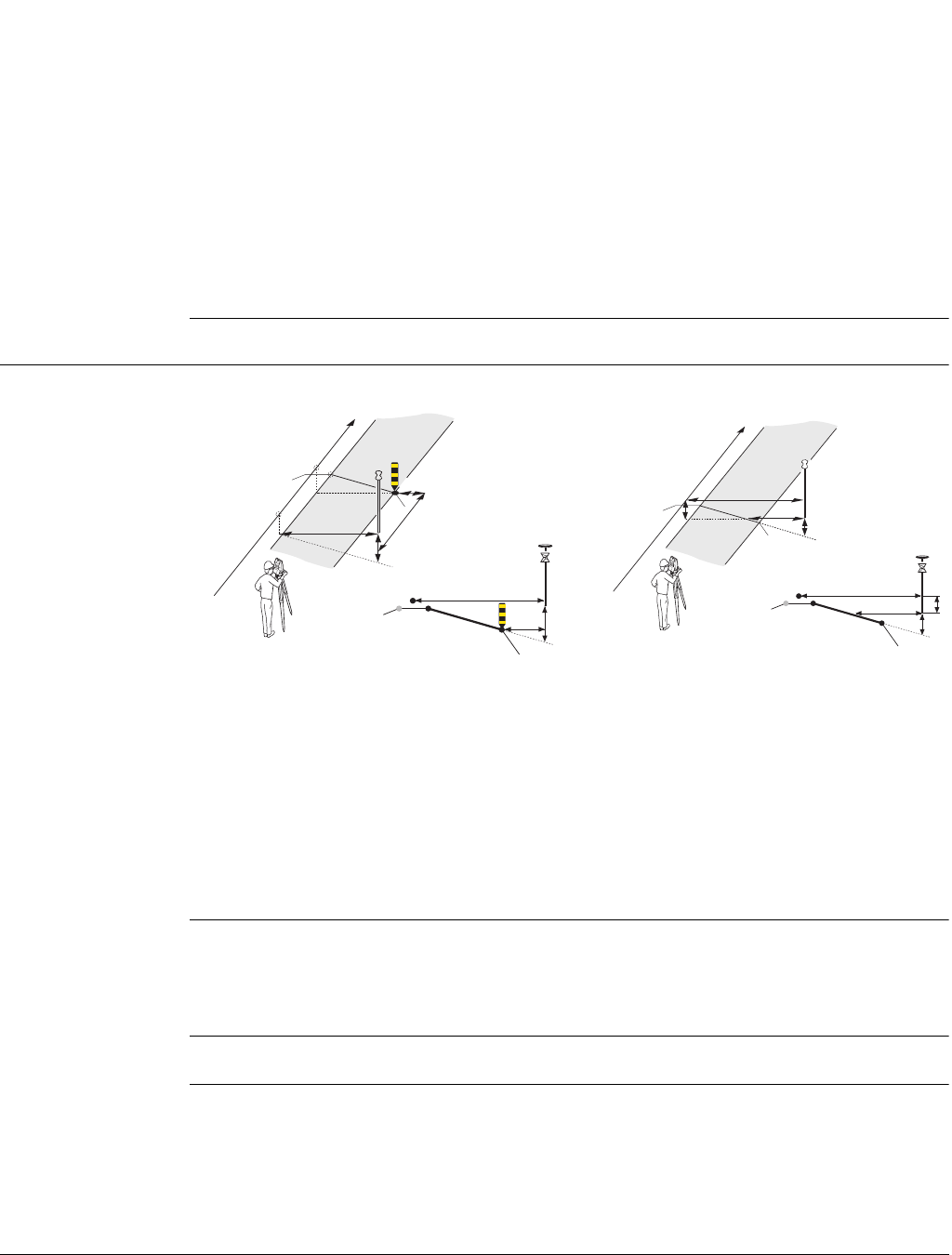
Viva Series, Roads - Road 680
Screen
Points measured within an indefinite triangle are always shown relative to the tangent
point.
47.3.6 Measuring Surface Grades
Graphical overview
Description • Surfaces such as the final carriage way, are often staked/checked using surface
grades. A surface grade consists of a combination of two lines.
• Refer to "45.6.3 Road - Basic Elements for Stake and Check Measurements" for
information on the usage of surface grades.
Required elements A 3D design of the road is required.
Road Design A
a) Local line
b) Measured position (displayed relative to the line by chainage and square offset)
Road Design B
a) Local line with extreme changes in the deflection angle of tangent points
b) Measured position within indefinite triangle
This position cannot be shown in the usual manner and is displayed relative to the
tangent point
b")Measured position within indefinite triangle
This position can be shown in the usual manner and is displayed by chainage and
square offset
Roads - Stakeout Roads - As built check
a) Position to stake out
b) Surface grade to stake out
c) Left line
d) Right line
e) Centreline
f) Working chainage
g) Chainage
h) CL offset
i) chainage
j) offset
k) height
a) Surface grade to check
b) Left line
c) Right line
d) Centreline
e) Chainage
f) offset
g) height
h) Surf. grade offset
i) Surf. grade ht diff
a=d
k
k
j
j
h
b
b
f
e
e
g
a
i
d
c
c
h
Road 036
c
g
i
i
g
k
h
h
f
f
a
a
b
e
d
dc
b
Road_067
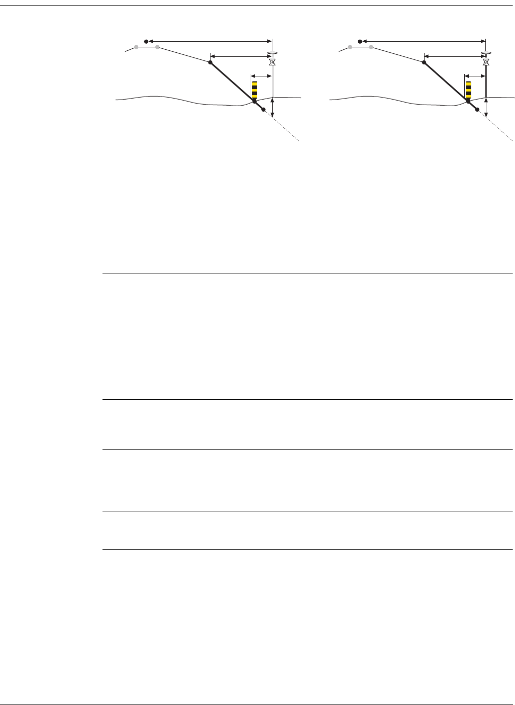
Viva Series, Roads - Road 681
47.3.7 Measuring Manual Slopes, Local Manual Slopes and Design Slopes
Graphical overview
Description • Surfaces, such as the end slopes of a cut or fill, are staked/checked using slope
methods.
• Slopes are defined by two lines. Refer to "45.6.3 Road - Basic Elements for Stake
and Check Measurements".
• When staking slopes, the point of interest is the intersection of the defined slope
with the natural surface (= catch point). Refer to "47.2.3 Advanced Slope Settings"
for information on the slope staking methods supported.
• When checking slopes, the slope check is independent of the slope method
selected.
Description of
manual slopes
The slope is defined manually relative to a selected 3D centreline, slope direction and
slope ratio or relative to a 2D line using a manual height, slope direction and slope
ratio. Chainage information is related to the centreline.
Description of local
manual slopes
The slope is defined manually relative to a selected 3D line, slope direction and slope
ratio or relative to a 2D line using a manual height, slope direction and slope ratio.
Chainage information is related to the selected line itself and not the centreline of the
layer.
Description of
design slopes
For this method, a 3D representation of the slope, defined by two lines, is required.
Roads - Stakeout Roads - As built check
a) Catch point
b) Centreline
c) Slope to stake out
d) Hinge point = left line
e) Second / right line
f) Natural surface
g) Hinge offset
h) CL offset
i) offset
j) height
a) Catch point
b) Centreline
c) Slope to check
d) Hinge point
e) Second line of the slope
f) Natural surface
g) Hinge offset
h) CL offset
i) Slope offset
j) Slope height diff
aej
i
f
b
d
h
c
g
Road_037
aej
i
f
b
d
h
c
g
Road_037
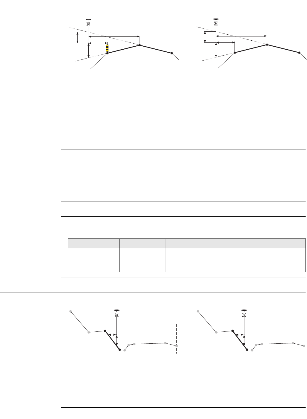
Viva Series, Roads - Road 682
47.3.8 Measuring Road Crowns
Graphical overview
Description • Staking road crowns allows the stake out of two surface grades at the same time.
If Toggle offsets left/right is checked, the reference for offset is automatically
switched between the right and left surface grade depending on whether the
measured position is to the right or left of the middle line.
• When checking road crowns, it allows the check of two surface grades at the same
time. The information for both surface grades is shown at the same time.
Required elements A 3D design of the road, defining a crown consisting of three lines, is required.
Specific fields The following fields vary from the description used in "47.3.1 The Stake/Check
Screen":
47.3.9 Measuring Road Layers
Graphical overview
Roads - Stakeout Roads - As built check
a) Position to stake out, in this case the
left line of the crown
b) Middle line of the crown, in this case
also the centreline
c) Left surface grade to stake out
d) Right surface grade to stake out
e) CL offset
f) offset
g) ht left
h) ht right
a) Left line of the crown
b) Middle line of the crown, common
for both surface grades
c) Left surface grade to check
d) Right surface grade to check
e) CL offset
f) offset
g) ht left
h) ht right
a
b
g
hf
e
cd
Road_040
a
b
g
hf
e
cd
Road_076
Field Option Description
ht left/ ht
right or
HtL/HtR
Display only Vertical offset to the left/right surface grade
defining the road crown.
Roads - Stakeout Roads - As built check
a) Relevant part of the layer for the
current position
b) Left line Left name
c) Right line Right name
d) offset
e) height
a) Relevant part of the layer for the
current position
b) Left line Left name
c) Right line Right name
d) Slope offset
e) Layer ht diff
Road_068
c
ae
d
b
Road_068
c
ae
d
b
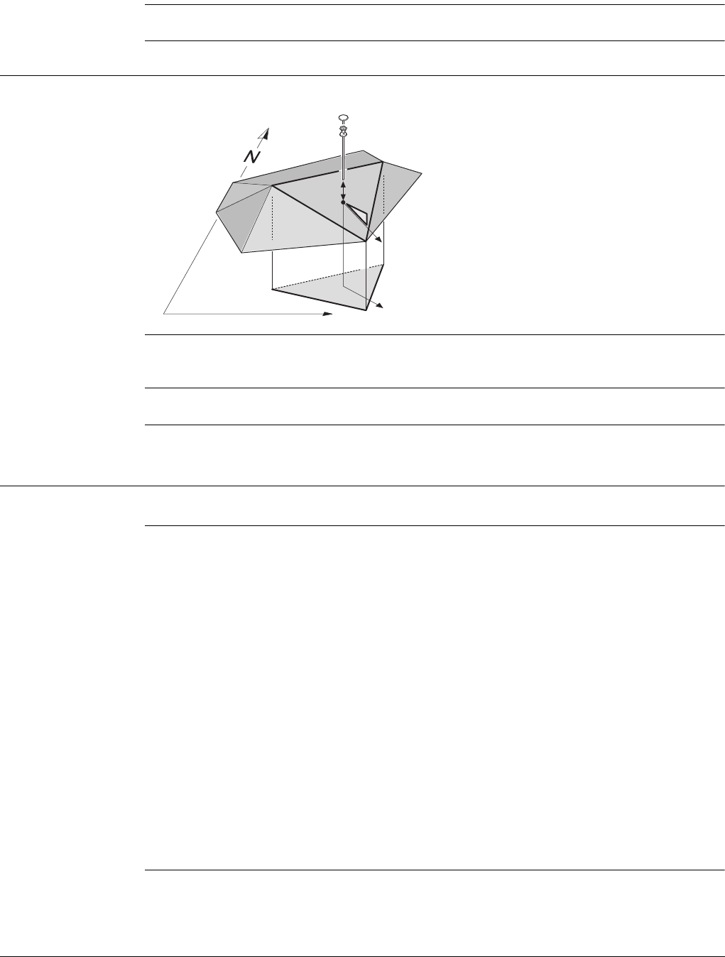
Viva Series, Roads - Road 683
Description All lines are grouped in layers. Such a layer describes a surface of the road. When
staking/checking out a layer, it is automatically detected the line left and right of the
measured position.
Required elements A 3D design of the road is required.
47.3.10 Measuring Digital Terrain Models (DTM)
Graphical overview
Description A DTM check returns the height difference between the current height and the height
of the DTM at the measured position.
Required elements A DTM job is required.
47.4 The Tools Menu
47.4.1 Overview
Access Press Fn Tools.. on any page of the Stake/Check screen.
Description The Tools menu contains additional functionality for each of the stake and check
methods. This functionality is additional to those already existing functions which are
available via the function keys.
The functionality differs between the stake and check methods. Refer to these
subchapters for a detailed description of the functionalities:
• "47.4.2 Use heights from DTM"
• "47.4.3 Apply current chainage"
• "47.4.4 Get current angle to alignment"
• "47.4.5 Stake individual point"
• "47.4.6 COGO Road - Alignment Information"
• "47.4.7 Additional Layer Information"
• "47.4.8 Box / base definition"
• "47.4.9 Get current slope"
• "47.4.10 Manual Slope"
• "47.4.11 Reset slope to design"
• "47.4.12 Shift reference line"
• "47.4.13 Re-initialise search"
• "47.4.14 Stake intersection point"
Roads - As built check
a) Relevant triangle of the DTM
b) Projected point on DTM
c) Easting
d) Northing
e) DTM height diff
f) Flow direction
g) Flow ratio
ae
g
f
c
b
d
Road_046
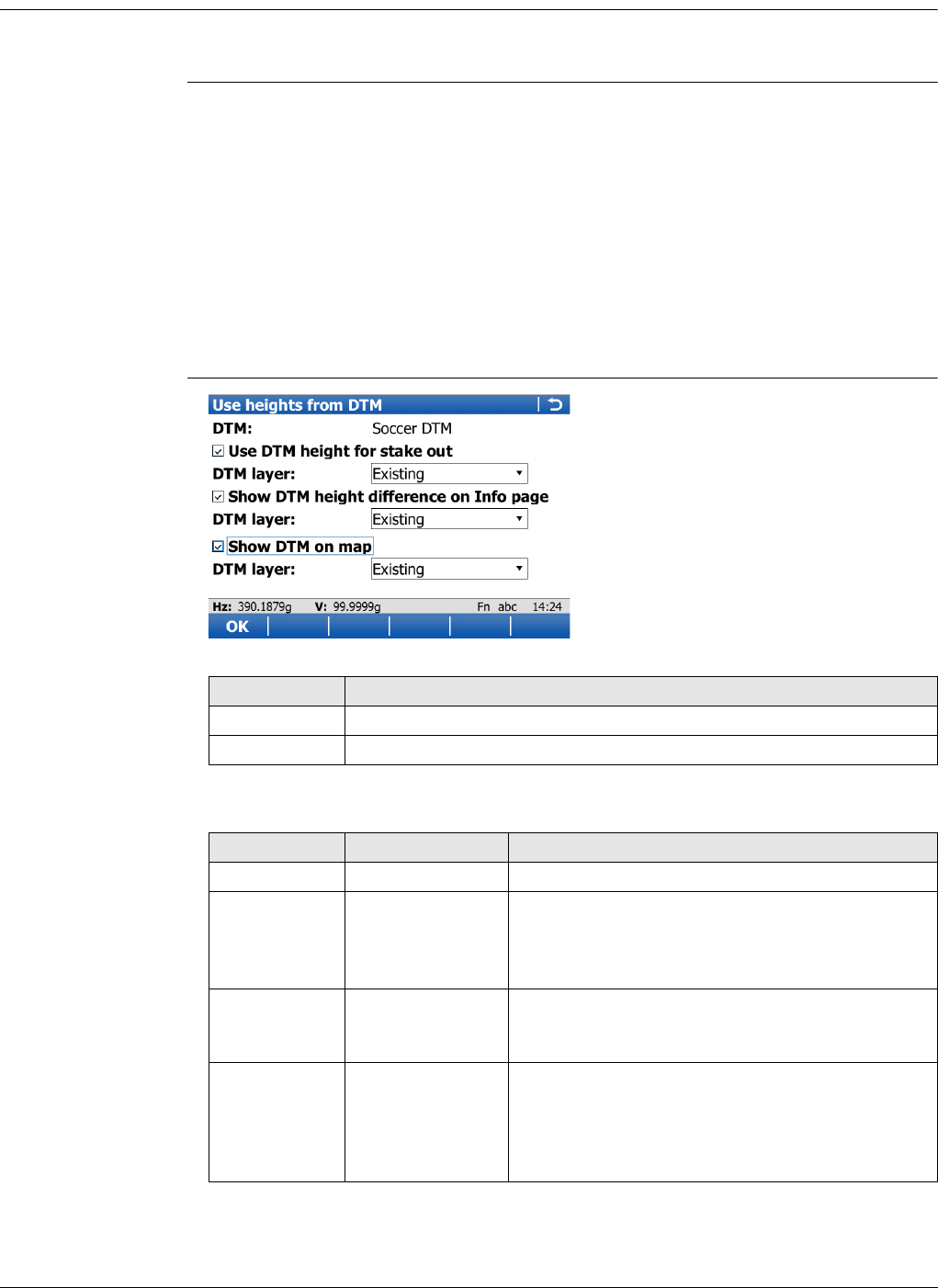
Viva Series, Roads - Road 684
47.4.2 Use heights from DTM
Availability This menu function is available for the following stake/check methods: Line, local line,
surface grade, crown, layer.
Description The application offers the possibility to
• switch to a height which is retrieved from an existing height layer, as defined in
the selected DTM job. The layer from the DTM is applied and used as a height
reference for the staking out or checking of alignments.
• retrieve heights from an existing layer, as defined in the DTM job associated with
the project. The DTM used is not considered for the stake values. Three new
information lines are added to the Info page: DTM Ht Diff, DTM Height and DTM
Layer.
• show the DTM triangles in the planar view and in the cross section view on the
Map page.
Once defined, each layer remains active until it is turned off. DTM heights can be used
for both 2D and 3D alignments.
Use heights from
DTM
Description of fields
Key Description
OK To confirm the settings and return to the Stake/Check screen.
Fn Quit To exit the application.
Field Option Description
DTM Display only DTM from the selected DTM job.
Use DTM
height for
stake out
Check box When this box is checked, a layer of the DTM is
used as a height reference.
When this box is not checked, no DTM heights are
applied for stakeout or check.
DTM layer Selectable list Available when Use DTM height for stake out is
checked. When selecting a DTM layer the relevant
triangle of the DTM is shown on the Map page.
Show DTM
height differ-
ence on Info
page
Check box When this box is checked, a layer of the DTM to
be used as a height reference on the Info page.
When this box is not checked, no additional
height information relative to the DTM is shown
on the Info page.
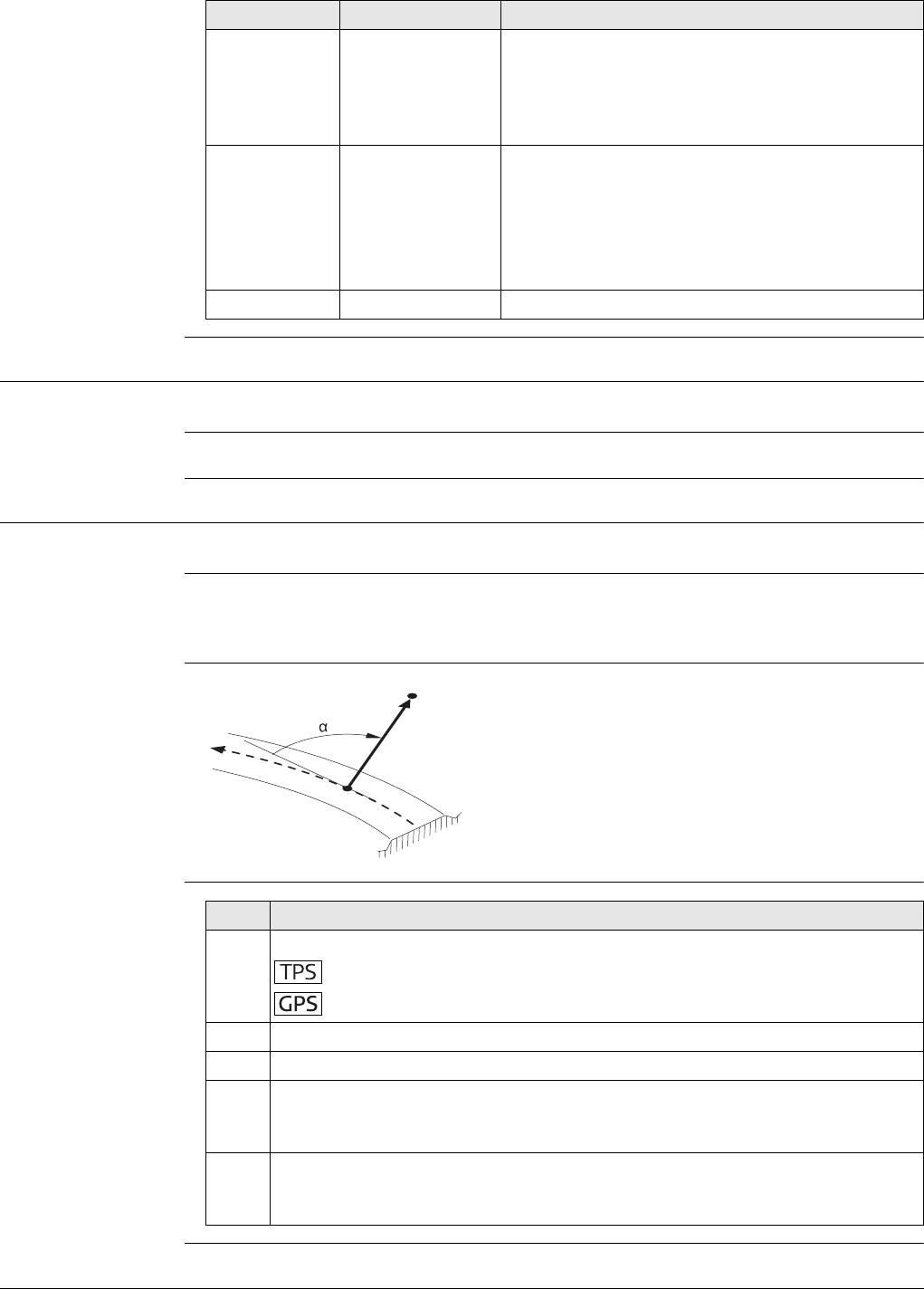
Viva Series, Roads - Road 685
47.4.3 Apply current chainage
Availability This menu function is available for all stake methods except layer.
Description To set Stake chainage on the General page of the stakeout to the current chainage.
47.4.4 Get current angle to alignment
Availability This menu function is available for the stake/check of lines and local lines.
Description To project a measured point to the alignment considering the entered Stake chainage.
This functionality is only available when Work with non-perpendicular offset is
checked in the Stake screen on the Offsets page.
Graphic
Workflow
DTM layer Selectable list Available when Show DTM height difference on
Info page is checked. Layer of the DTM to be used
as a height reference. When selecting a DTM layer
the relevant triangle of the DTM is shown in cross
section view on the Map page.
Show DTM on
map Check box When this box is checked, the DTM triangles are
displayed in planar view on the Map page.
The setting of for this check box is linked
to the setting for the Display DTM in map
check box in Map View Settings, DTM
page.
DTM layer Selectable list All available layers are selectable.
Field Option Description
a) Alignment
b) Defined chainage
c) Current position
αAngle to alignment
a
b
c
Road_098
Step Description
1. Measure a point:
Dist
Meas and Stop
2. Press Fn Tools.. to access the Tools menu.
3. Select Get current angle to alignment.
4. At the defined chainage, the angle between the tangent direction and the
direction to the current position is calculated. This angel is set as Offset angle
for Work with non-perpendicular offset on the Offsets page.
5. Continue with staking out using the calculated Stake chainage and Offset
angle values. These values are valid until new values are defined manually or
by using Get current angle to alignment.
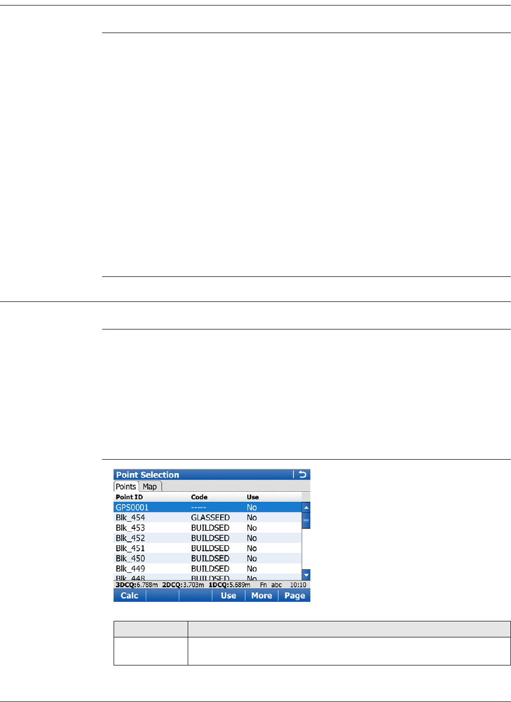
Viva Series, Roads - Road 686
47.4.5 Stake individual point
Availability This menu function is available for the stake/check of lines and local lines.
Description To select the point to stake from the selected Working job.
If a control job has been selected on the job selection screen, a point from the control
job can be selected. When staking out/checking an individual point, the selected point
is set in relation to the alignment and all line relevant values are calculated and
displayed.
To access Data:, Points page, which allows staking out points with known Easting,
Northing and Height. Points can either be selected from the Working job or manually
typed in.
The Stake chainage and Stake offset of the Stake screen are calculated based on the
coordinates of the selected point.
The height for the stakeout can be set as Manual height.
If the chosen point has no height the design height will be used. If the point
has a height it is possible to use that one or continue working with the design
height.
47.4.6 COGO Road - Alignment Information
Availability This menu function is available for staking/checking a line/local line.
Description This function allows
• the selection of existing single or multiple points from a job.
•viewing the selected points along the alignment.
• displaying the respective alignment chainage and offset information.
Any job containing points from any data storage device can be used.
The calculated alignment information is stored and a report sheet can be used for
extracting the data.
Point Selection
Key Description
Calc To perform the chainage and offset calculation and to continue with
the subsequent screen. Calculated COGO points are not yet stored.
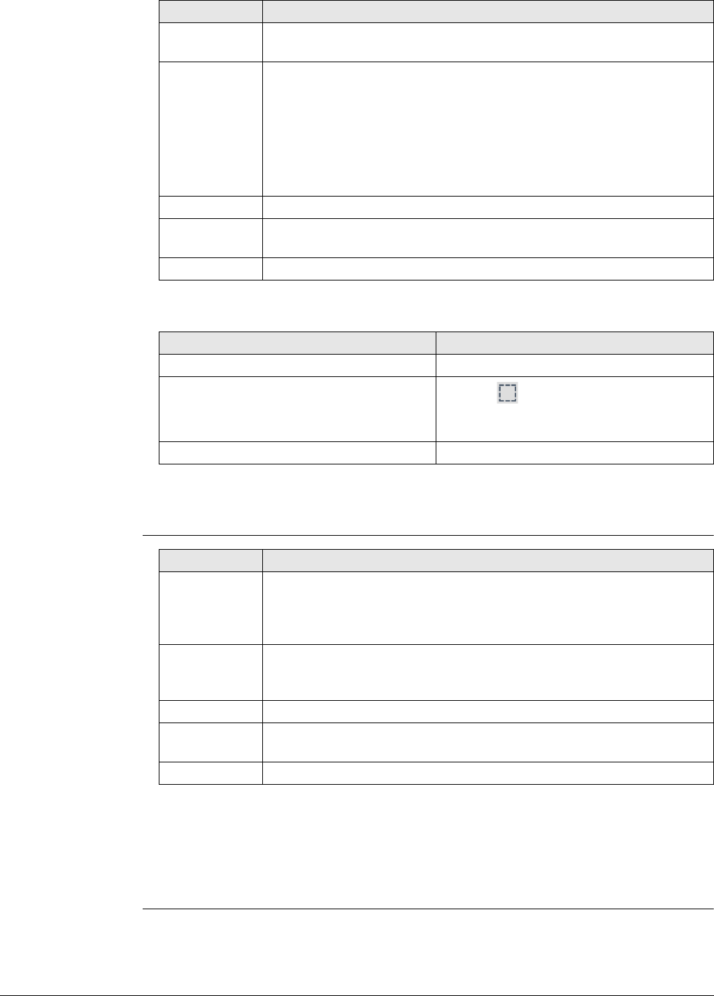
Viva Series, Roads - Road 687
Point selection/deselection is possible on the Map page.
Next step
Calc computes the alignment information.
Alignment Results,
Points page
Next step
Page changes to another page.
The fields and information displayed on the Info page are as defined in Configuration,
Info page. Refer to "Configuration, Info page".
The Plot page displays all the calculated points against the design data.
Use To change between Yes and No in the Use column for the highlighted
point.
More To display information about the codes if stored with any point, the
Easting, Northing, Elevation, time, date and 3D coordinate quality.
The order in which the Easting and Northing columns are
shown depends on the Grid format configured to be used in
Regional Settings, Coords page.
The Easting, Northing and Elevation values are shown in the
unit configured in Regional Settings,Distance page.
Page To change to another page on this screen.
Fn None or Fn
All
To deactivate or activate all points for the COGO calculation.
Fn Quit To exit the application.
IF THEN
a single point is to be selected/deselected tap on the point.
multiple points are to be selected/dese-
lected click the icon, drag the stylus on the
screen in a diagonal line to make a rectan-
gular area.
all points are to be selected press All or None.
Key Description
Key Description
Store To store the results. Points are stored in the working job together
with the alignment information. The points can be exported with a
report sheet later. The information is the same as if the points had
been measured along the alignment.
More To display information about the calculated alignment information:
Horizontal offset from the line, height difference from the defined
line and horizontal offset from the centreline.
Page To change to another page on this screen.
Config.. To configure if the calculated points are stored with the original point
ID, a prefix or a suffix.
Fn Quit To exit the application.
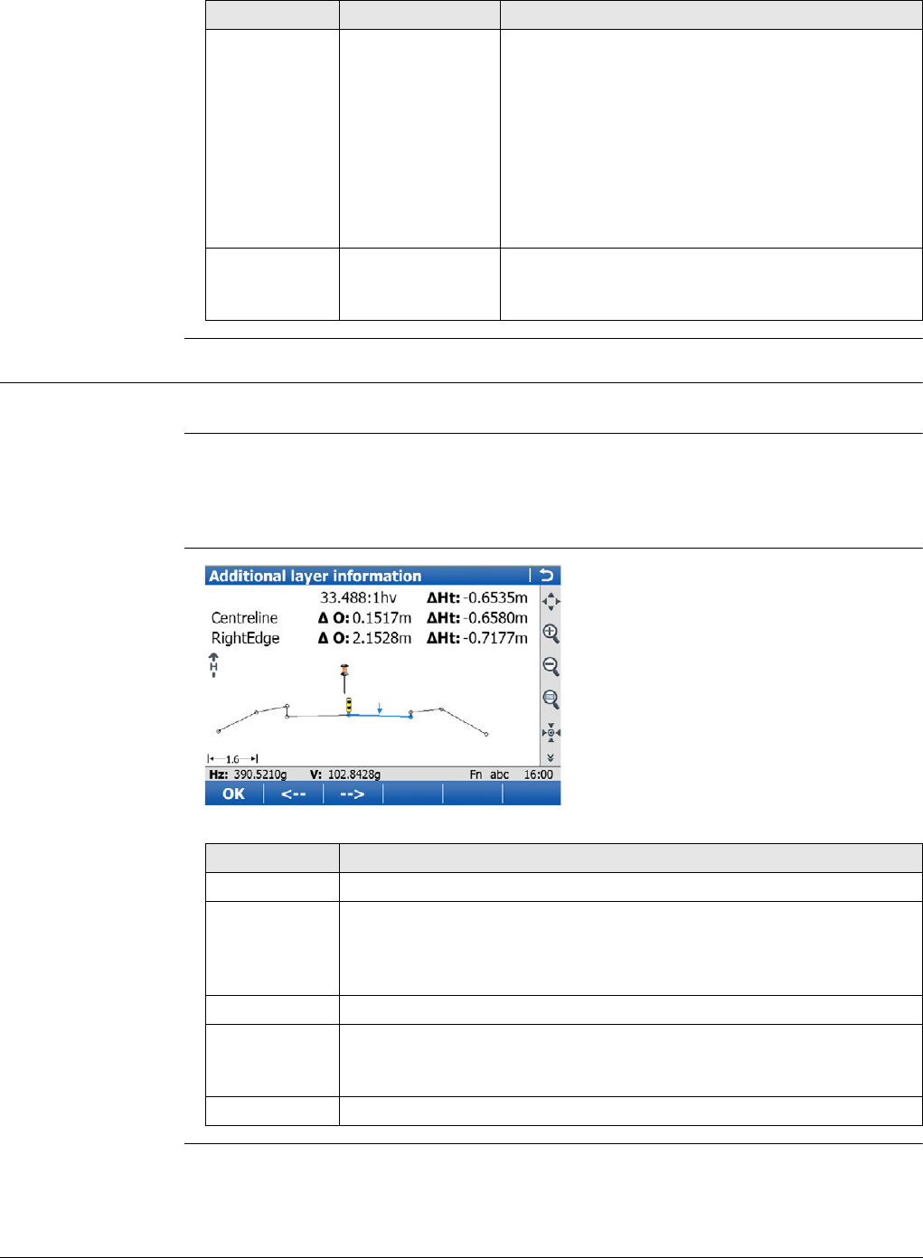
Viva Series, Roads - Road 688
Configuration Description of fields
47.4.7 Additional Layer Information
Availability This menu function is available for all stake/check methods except layer.
Description This function allows additional road data to be obtained during a check or stake survey
of a road element.
Road elements include centrelines, kerb and gutters and slopes.
The map shows cross section view only and allows setting the vertical exaggeration.
Additional Layer
Information
Field Option Description
Store point ID
with Same point ID The same point ID from the selected job is used
when storing to the working job.
If a point exists with the same point ID in the
working job a warning appears. Choose to over-
write the existing point or not.
Prefix Adds the setting for Store point ID with in front
of the original point IDs.
Suffix Adds the setting for Store point ID with at the
end of the original point IDs.
Prefix / suffix Editable field The identifier with up to four characters is added
in front of or at the end of the ID of the calculated
COGO points.
Key Description
OK To store the selected element, which is then automatically recalled.
<-- or --> To select the relevant element in the plot. The information displayed
shows the current slope ratio and the height difference of the
element. Also displayed are the offset and height differences from
the left and right vertices of the element.
Fn Config.. To configure MapView. Refer to "37.3 Configuring MapView".
Fn Layrs.. To turn layers of background maps (CAD files) on and off. Refer to
"5.2 Creating a New Job" for information on CAD files and CAD back-
ground maps.
Fn Quit To exit the application.
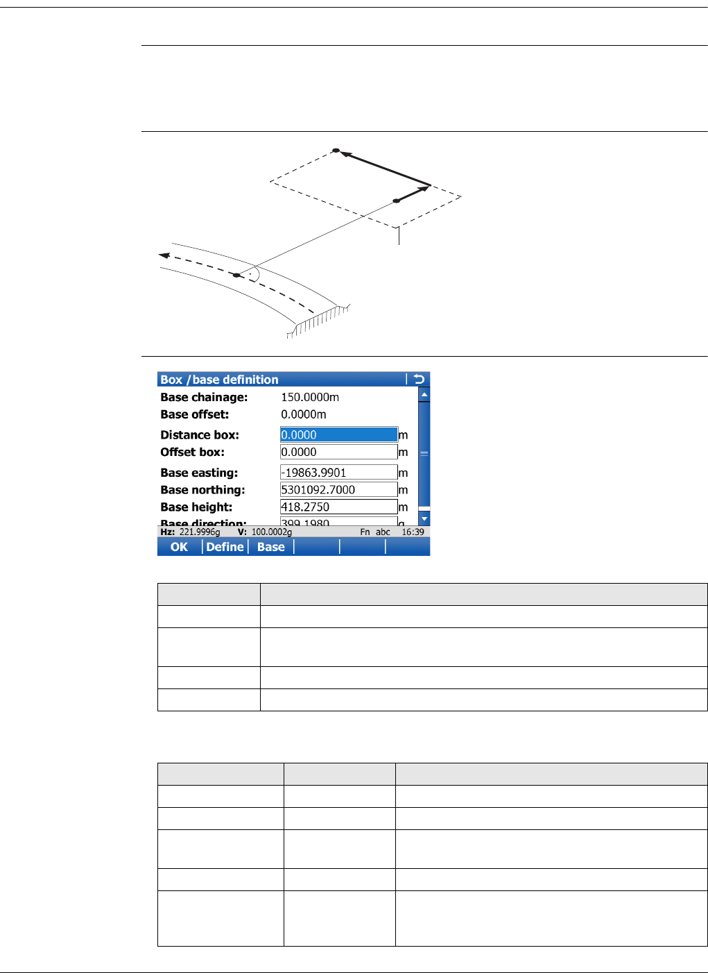
Viva Series, Roads - Road 689
47.4.8 Box / base definition
Availability This menu function is available for the stake/check of lines and local lines.
Description This function allows a box or similar structure to be set out during a check or stake
survey of a road element. The box is set out relative to a line chainage and parallel
offset. A base point of the box, user-defined dimensions of the box (a base distance
and a base offset) are required.
Diagram
Box / base definition
Description of fields
a) Centreline
b) Defined chainage
c) Stake offset
d) Base point
e) Base offset
f) Base distance
g) Box to stake out
a
b
c
de
f
g
Road_092
Key Description
OK To store the selected element, which is then automatically recalled.
Define To overwrite the values before pressing Base If a different base had
been defined before.
Base or Clear To freeze or unfreeze the values of the base point.
Fn Quit To exit the application.
Field Option Description
Base chainage Display only The position defined by Stake chainage.
Base offset Display only The position defined by Stake offset.
Distance box Editable field The distance in the direction of increasing
chainage of base point is positive.
Offset box Editable field The offset to the right of base point is positive.
Base easting,
Base northing and
Base height
Editable field The coordinates of the base point, either from
the Working job or from a surveyed point.
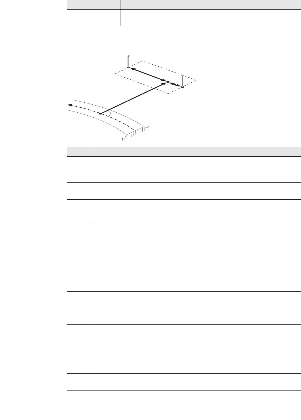
Viva Series, Roads - Road 690
Example The following steps describe the stakeout of two reference pegs from a centreline
chainage and offset.
Base direction Editable field The orientation of the local coordinate system
(azimuth).
Field Option Description
a) Centreline
b) Defined chainage
c) Stake offset
d) Base point
e) Base distance, positive (e+),
negative (e-)
f) Peg to stake out
Step Description
1. Define the base point for the box/base stakeout using Stake offset and Stake
height diff from the Offsets page.
2. Press Fn Tools.. to access the Tools menu.
3. Select Box / base definition.
Press OK to continue to the next screen.
4. The position defined by Stake chainage and Stake offset is used as Base
chainage and Base offset when accessing Box / base definition for the first
time within a stakeout session.
5. Similar to the stakeout of individual points in the Tools menu. The Box/Base
functionality calculates the new point to stake out and changes the according
values of Stake chainage and Stake offset. The Box/Base functionality also
activates the Manual height functionality.
6. To avoid these values being used as the next base point when accessing the
box/base menu, press Base in the Box/Base Definition screen. Pressing this
key freezes the values of the base point. Base is now replaced by Clear. If a
different base had been defined before, use Define to overwrite the values
before pressing Base.
7. Define the Distance box and Offset box. Both follow the same rules as used
for the definition of offsets and chainages in general. That is; offset to the
right = positive; distance in direction of increasing chainage = positive.
8. Press OK to continue to the next screen.
9. The values of Stake chainage, Stake offset and the Manual height are
adjusted accordingly.
10. The fields chainage, offset and height on the Stake page guide you to
the new position to stake out.
Press Fn Tools.. to access Tools menu.
11. Select Box / base definition.
Press OK to continue to the next screen.
a
b
c
de-
e+
f
f
Road_093
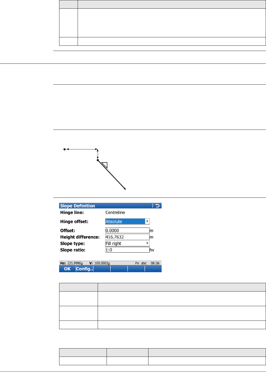
Viva Series, Roads - Road 691
47.4.9 Get current slope
Availability This menu function is available for the stake/check of slopes, local manual slopes and
manual slopes.
Description To access Slope Definition. The slope ratio Current ratio of the last measured position
is used as the defined Slope ratio. All other values in Slope Definition are filled in with
the last measured position. The defined manual slope is used for all points to stake
out or check.
The manual slope is active until it is turned off with Reset slope to design from
the Tools menu.
Graphic Slopes are defined relative to the centreline.
Slope Definition
Description of fields
12. The next point of the box to stake out can now be defined.
To change back to the original chainage and offset defined for the base point
definition use Clear.
13. Start with step 1. to define a new box/base.
Step Description
a) Centreline
b) Hinge point
c) New slope
d) Defined hinge offset Offset
e) Defined hinge height difference Height differ-
ence
f) Slope ratio
f
a
b
d
c
e
Road_038
Key Description
OK To accept changes and move to the next screen depending on the
settings for slope staking.
Config.. To access the configuration settings. Refer to "45.3 Configuring
Roads Applications".
Fn Quit To exit the application.
Field Option Description
Hinge line Display only The line the slope is defined relative to.
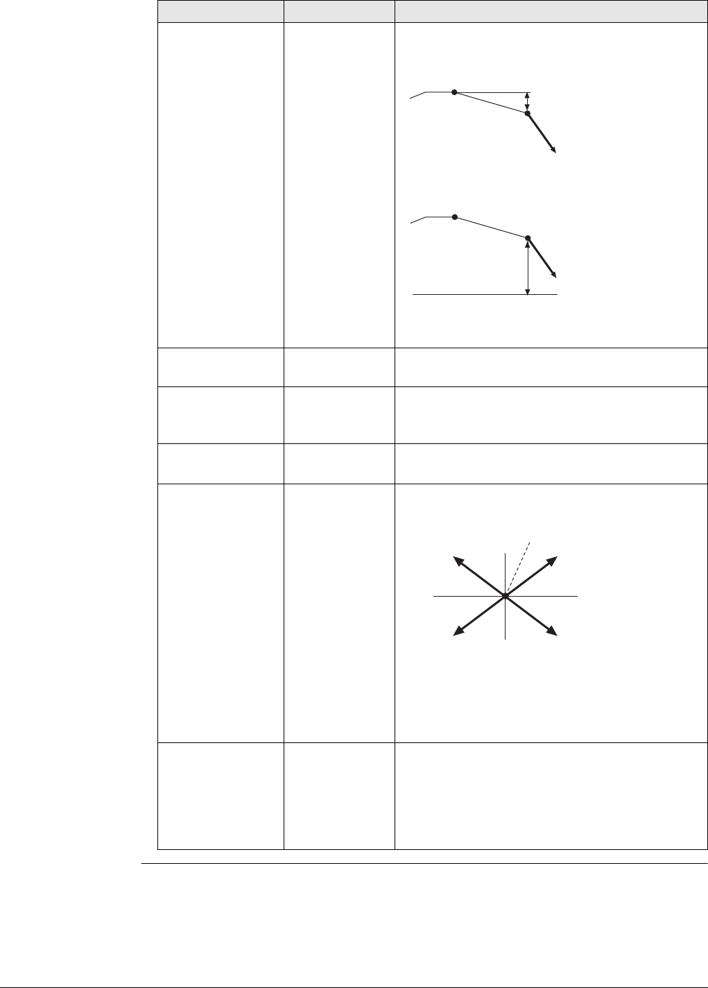
Viva Series, Roads - Road 692
Hinge offset The vertical offset type for the hinge point.
Relative to line Define the hinge point by the height difference
relative to the selected Reference line.
a)Hinge point
b)Slope
Absolute Define the hinge point using its absolute height.
a)Hinge point
b)Slope
Hold hinge The hinge point of the slope stays fixed at the
defined line.
Offset Editable field The horizontal offset of the hinge point from
the centreline/reference line.
Height difference Editable field The height difference of the hinge point from
the centreline/reference line.
Available for Hinge offset:Relative to line.
Elevation Editable field The absolute height of the hinge point.
Available for Hinge offset:Absolute.
Slope type Selectable list Differentiates if the defined slope is a cut/fill
and left/right.
a) Hinge point
b) Left cut
c) Right cut
d) Left fill
e) Right fill
Slope ratio Editable field Defines the ratio of the slope. The measured
slope ratio is the default value. This value can be
edited manually.
The display format is defined as system
setting in Regional Settings, Slope
page.
Field Option Description
a
b
Road_039a
a
b
Road_039b
a
bc
de
Road_079
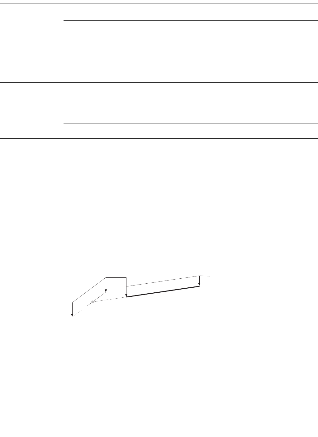
Viva Series, Roads - Road 693
47.4.10 Manual Slope
Availability This function is available for stake/check of slopes.
Description To access Slope Definition. Allows a manual slope to be defined. The defined manual
slope is then used for all points to stake out or check. Refer to "Slope Definition"for
a description of the screen.
The manual slope is active until it is turned off with Reset slope to design from
the Tools menu.
47.4.11 Reset slope to design
Availability This function is available for stake/check of slopes.
Description This option is only available if a slope has been defined by using Get current slope.
The manually defined slope is deactivated and reset to the design slope.
47.4.12 Shift reference line
Availability This menu function is available for the stake/check of slopes and surface grades.
The Shift reference line item of the Tools menu stays disabled until the first measured
position is available. The current chainage is used for the cross section shown to pick
the reference line.
Description When staking out or checking different layers of the road strata, such as the subgrade,
gravel or asphalt, it is often found that not all these layers are available in the design.
For such cases, the application offers the possibility to apply either a negative or posi-
tive height shift to the design values.
Example
A gravel layer with a thickness of 10 cm is to be staked out. A negative vertical shift
to the final design surface is applied. This shift is applied:
•by pressing Shifts.. in the Define screen and
• by applying a vertical shift of -10 cm.
As shown, the selected surface grade is shifted by 10 cm.
a) Reference surface
b) Shifted reference point
c) Original surface grade
d) Shifted surface grade
c
a
d
10 cm
15 cm b
Road_086
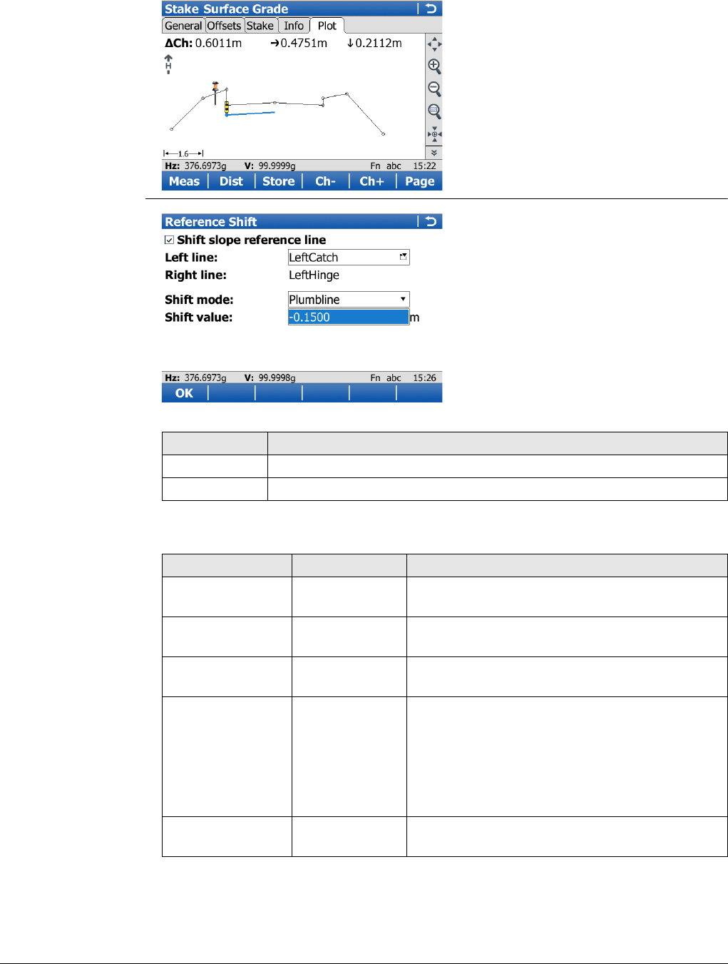
Viva Series, Roads - Road 694
When staking out the newly shifted surface grade, the original left edge of the shifted
surface grade is of little interest. It is the intersection with the left end slope that is
of greater interest.
Reference Shift
Description of fields
Key Description
OK To confirm the settings and return to the Stake/Check screen.
Fn Quit To exit the application.
Field Option Description
Shift slope refer-
ence line Check box When this box is checked, the settings for the
shift can be set.
Left line Display only Shows the name of the left line from the
surface.
Right line Display only Shows the name of the right line from the
surface.
Shift mode The vertical shift applied to the surface
selected.
Plumbline The shift defined under Shift value gets applied
following the plumb line.
Perpendicular The shift defined under Shift value gets applied
perpendicular to the selected surface.
Shift value Editable field Value the selected surface gets shifted
following the chosen Shift mode.
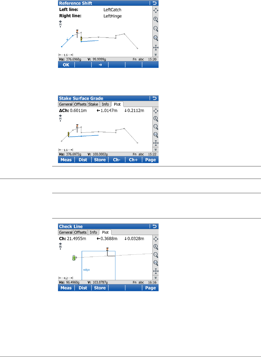
Viva Series, Roads - Road 695
The graphical selection.
The expanded element and the shifted reference line, marked with a cross, are shown
in the Map page in the Stake/Check screen.
On the Stake page, the offset and height guide you to the new shifted position.
47.4.13 Re-initialise search
Availability This menu function is available for all stake/check methods except layer.
Description When staking or checking complex road designs it can happen that the current position
is not projected to the desired segment of the alignment. The Re-initialise search
forces a re-projection of the current position.
Example
Before initialisation
This screen shows the projection of the
current position to the left segment,
although the distance to the right
segment is shorter.
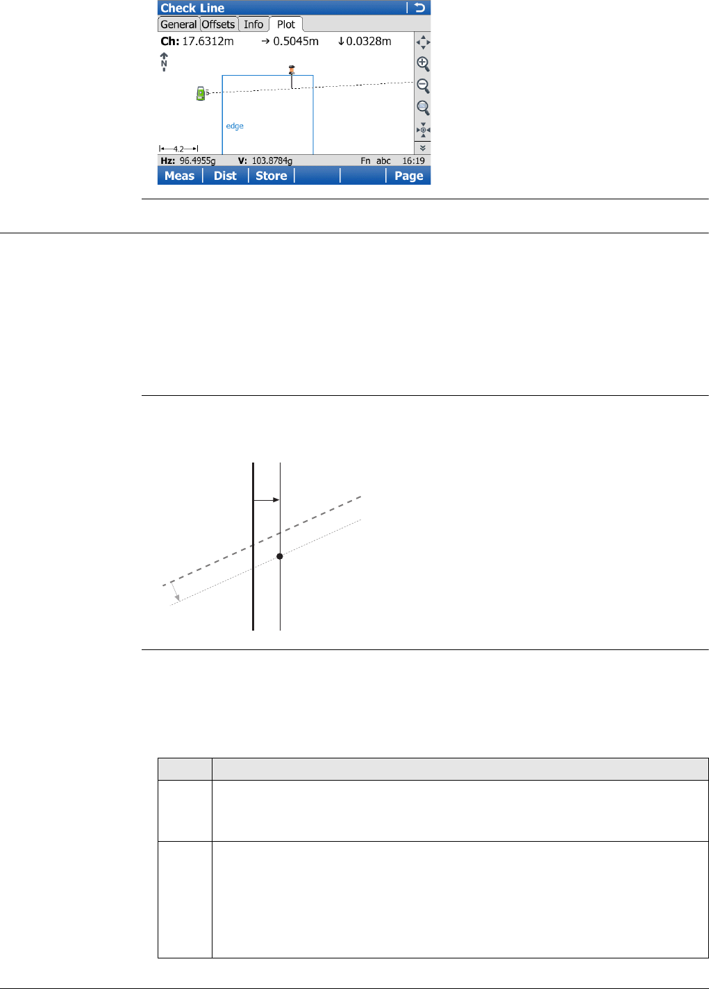
Viva Series, Roads - Road 696
47.4.14 Stake intersection point
Availability This menu function is available for staking a line with Refer to an additional line
checked in Define Line Task
The additional line must be a Straight.
Offsets for the selected line and the additional line can be defined.
The menu function Stake intersection point is only available if the offsets are
defined perpendicular to the selected line. Work with non-perpendicular offset
must not be checked.
Description Stake intersection point is commonly used to stake out bridge abutment positions.
The graphic shows an example.
Calculation of the
stake intersection
point and chainage
The calculation of the intersection point is based on:
• A perpendicular offset from the selected line, for example bridge centreline
• A perpendicular offset from the additional line
Step-by-step
After initialisation
This screen shows the projection after
the reinitialisation.
a) Selected line, for example bridge
centreline
b) Perpendicular offset from the
selected line
c) Selected additional line, for example
abutment line
d) Perpendicular offset from the
selected line
P1 Required intersection point for
stakeout
P1
d
b
a
c
Road_102
Step Description
1. Define Line Task
Select the line to work with (bridge centreline) and select a second inter-
secting line (abutment centreline) under Refer to an additional line.
2. Stake Line, Offsets page
If necessary, check Apply offsets. Type in the offset of the intersection point
in relation to selected line (bridge centreline).
Non-perpendicular offsets are not allowed. If necessary, check Apply
offsets to additional line. Type in the offset of the intersection point
in relation to selected additional line (abutment centreline).
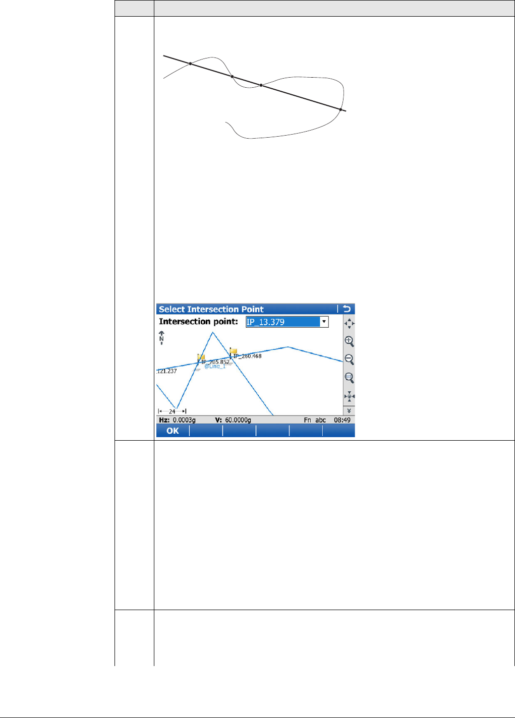
Viva Series, Roads - Road 697
3. Fn Tools.. to access the Tools menu and select Stake intersection point.
In some cases, more than one intersection point can be calculated.
a) Selected line
b) Additional line
P1 Intersection point 1
P2 Intersection point 2
P3 Intersection point 3
P4 Intersection point 4
In this case a plot with the possibility to select the desired intersection point
appears. The selection is made using the touch screen and a selectable list.
All intersection points are marked with a yellow flag.
The point ID and the point symbol of a selected intersection point are
displayed in blue.
4. Height confirmation
Depending on the available height information of the selected lines the
following possibilities are available to define the height of the intersection
point which has been selected for stakeout.
• Using the design height, which is the height of the selected line (bridge
centreline). This option is used by default or by pressing None.
• Using the height of the additional line as manual height. This option
appears when the additional line contains height information.
• Using the average height of the selected line and of the additional line
as manual height. This option appears when the additional line
contains height information.
•Using Use heights from DTM from the Tools Menu. This option is only
available if a DTM has been selected in the job selection screen.
5. Stake Line, General page
Depending on the height selection, the check box Use manual height instead
of design heights is enabled automatically and the selected height is used
for staking out.
Step Description
P1 P2
P3
P4
a
b
Road_104
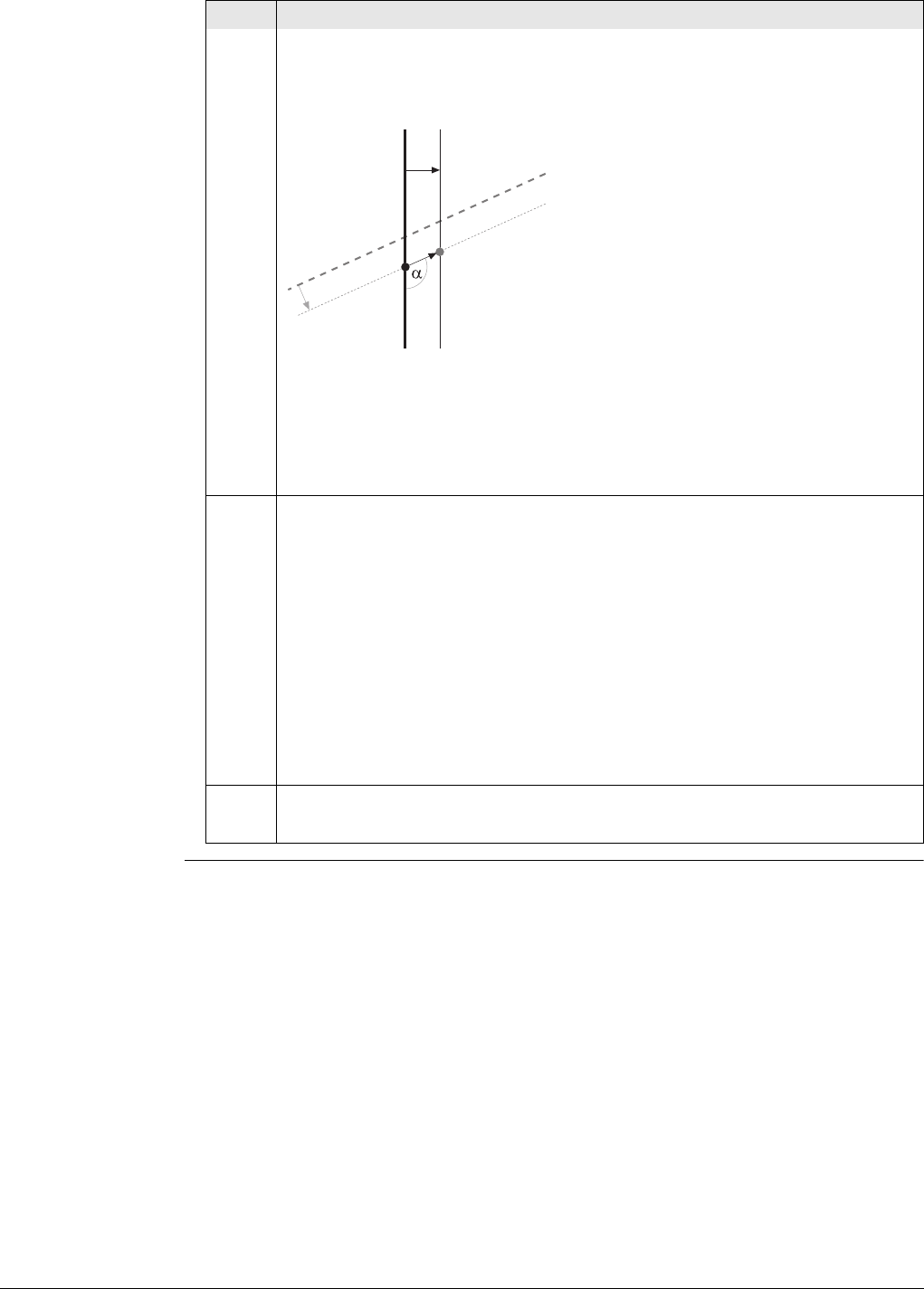
Viva Series, Roads - Road 698
Stake chainage is the intersection of the original line (bridge centreline) and
the line which is offset from the additional line. This value is updated auto-
matically.
a) Selected line, for example bridge centreline
b) Stake chainage of intersection point
c) Non-perpendicular offset from the selected line
d) Selected additional line, for example abutment line
Non-perpendicular offset angle
P1 Required intersection point for stakeout
6. Stake Line, Offsets page
Stake offset: After pressing Fn Tools.. and selecting Stake intersection
point, the value is updated automatically to the non-perpendicular offset of
the intersection point to the selected line (bridge centreline).
Work with non-perpendicular offset: The check box is checked automatically
after pressing Fn Tools.. and selecting Stake intersection point. Offset angle
is updated automatically to the non-perpendicular offset angle of the inter-
section point to the selected line (bridge centreline).
To stake further points along the same alignment to the additional
line, update the value for Stake offset by the required distances. In
this case, Stake offset is the distance along/parallel to the additional
alignment.
7. Stake Line, Stake page
To stake out the selected intersection point, all delta values must be 0.000.
Step Description
P1
bc
a
d
Road_103
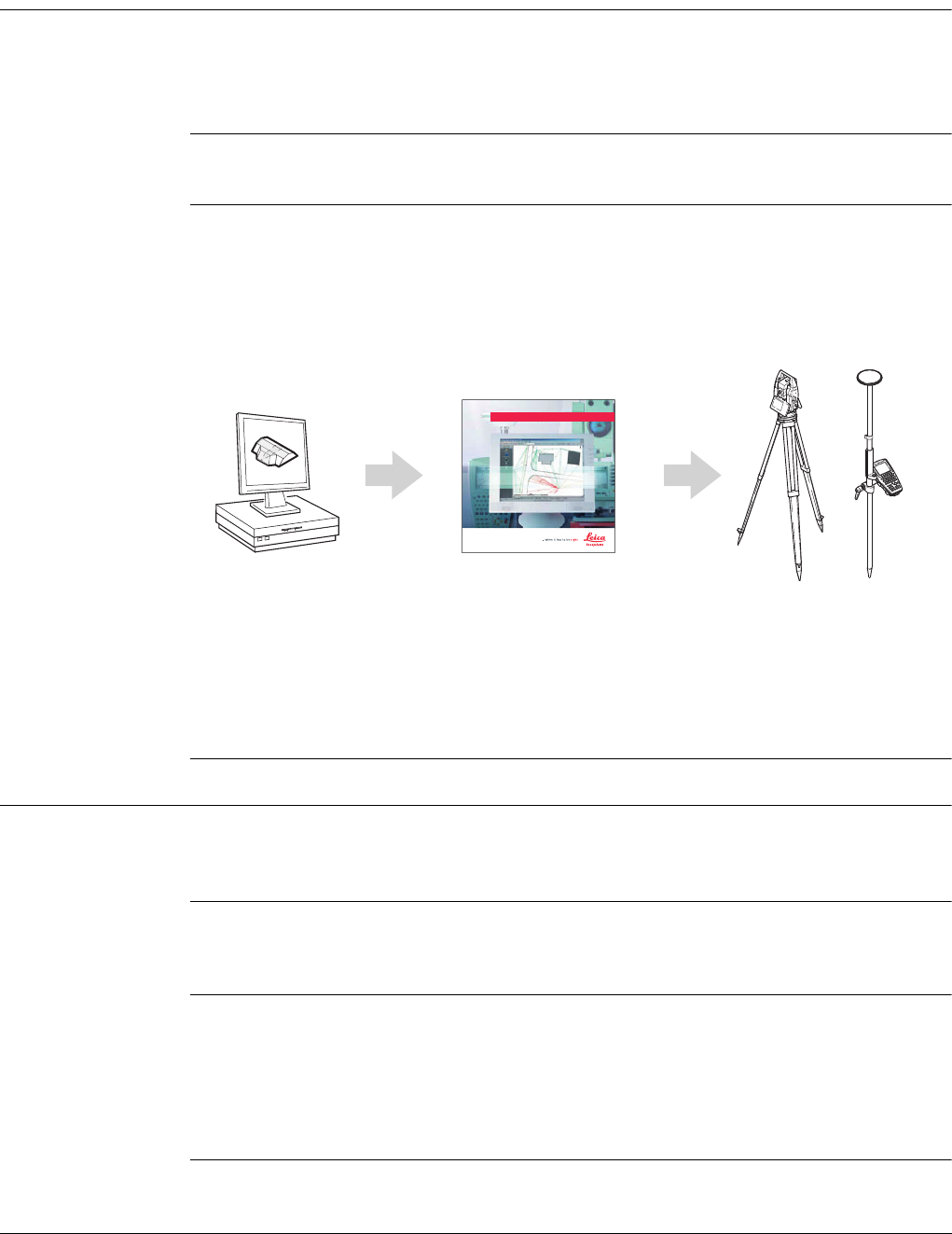
Viva Series, Roads - Rail 699
48 Roads - Rail
48.1 Creating a New Rail Job
48.1.1 Overview
Description There are two ways of creating road/rail jobs:
Typing them in manually by using the Alignment Editor application.
OR
Converting data created in a design package.
Manually entered
data
Data can be typed in and edited with Alignment Editor. Refer to "46 Roads - Align-
ment Editor" for information on how to enter data manually.
Converted data The Import alignment data application in Jobs & Data supports various different
formats like dxf, LandXml, MxGenio, Terramodel, Carlson.
The Design to Field component of Leica Geo Office offers converters from several
road/rail design and CAD packages. Several design packages also include a built-in
converter to Roads/Rail. As different design packages follow different philosophies in
representation, creation and storage of data the conversion process differs slightly.
Leica Geo Office can be found on the Leica Geo Office DVD.
The latest version of the Design to Field importers can be found in the downloads
section of:
• myWorld@Leica Geosystems
https://myworld.leica-geosystems.com
48.1.2 Installing all necessary Software
Install Leica Geo
Office
LGO runs under WindowsXP or Windows Vista and can only be installed successfully if
the user is logged in as the Administrator. To install LGO, run the setup file from the
DVD and follow the instructions on the screen.
Install Design To
Field
To prepare the track design for use on the instrument successfully, the data must first
be converted from its original format to an onboard job. This conversion is achieved
using Design to Field, a component of LGO which is automatically installed with LGO.
Install Importers The field importers are used by Design to Field to read in the track design. These
importers are installed separately and have the file extension *.rri.
The latest version of the Design to Field importers can be found in the downloads
section of:
• myWorld@Leica Geosystems:
https://myworld.leica-geosystems.com
LEICA Geo Office
Road_065
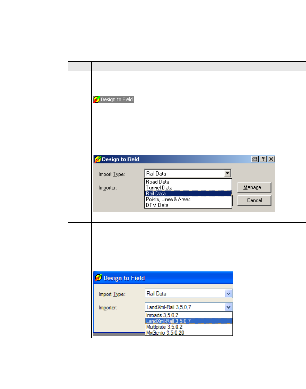
Viva Series, Roads - Rail 700
Install Rail Editor Rail Editor is a computer program for defining the height of the rails relative to the
horizontal and vertical alignments (superelevation). Rail Editor is automatically
installed into LGO from the Field Importers install package, which can be found in the
downloads section of the Leica Geosystems website. Rail Editor can be run either
externally or within Design To Field.
Install Roads and
Rail
Roads and Rail are the onboard programs which are loaded onto the instrument:
• via a data storage device (under the System folder), which is inserted into the
instrument,
• via a serial cable and LGO.
48.1.3 Importing the Track Design with Leica Geo Office
Importing the
design Step Description
1. Starting the Design to Field program
To import a track centreline select Design to Field from the Tools menu in
LGO.
2. Selecting an Import Type
To prepare track design for onboard use successfully, it has to be converted
from its original data format to an onboard job which will run on the instru-
ment.
Select Importer Type: Rail Data
3. Selecting a Field Importer
Importers are used to convert the data. Additional importer formats can be
added to the selectable list by clicking Manage.
Select the importer related to the track design from the selectable list of
available importers.
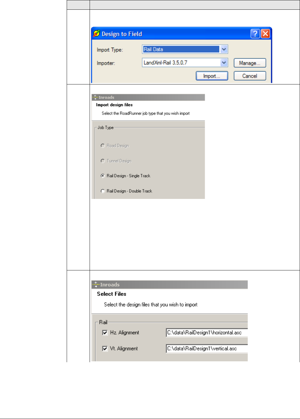
Viva Series, Roads - Rail 701
4. Importing
Click Import to start the file selection wizard.
5. Selecting the job type
• For single tracks, select Rail Design-Single Track.
A single track design can consist of a horizontal alignment, a vertical align-
ment and superelevation.
• For double tracks, select Rail Design-Double Track.
A double track design can consist of a horizontal alignment, a vertical
alignment and superelevation for each track. Alternatively, a third hori-
zontal alignment can also be defined and used for calculating the
chainage of both tracks (chainage centreline).
Click Next to move to the next page of the wizard.
6. Selecting the horizontal and vertical alignment files
Step Description
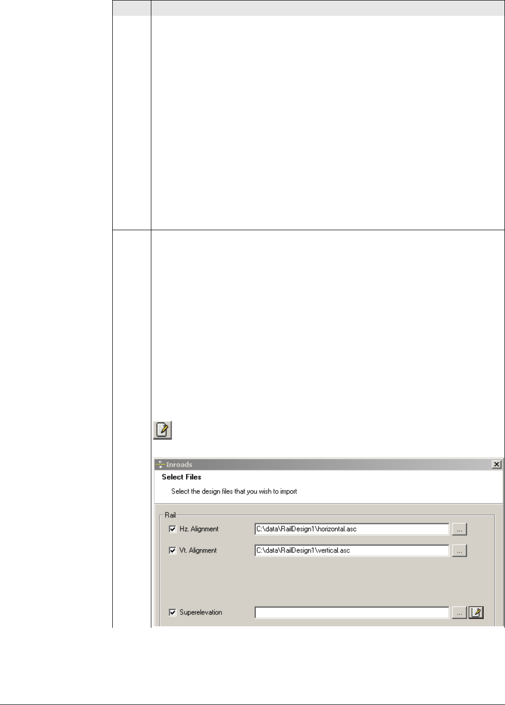
Viva Series, Roads - Rail 702
• For a single track, select the horizontal and vertical alignments using the
browse button.
• For a double track, three screens are used to define the design data. The
arrows at the bottom of the screens can be used to move between the
different screens.
First screen - Centreline: The first screen defines the horizontal and
vertical alignment of the chainage centreline. If the chainage for each
track is to be calculated relative to each track centreline, then it is not
mandatory to select a chainage centreline. The horizontal and vertical
alignment on the first screen can be left blank.
Second screen - Left track: The second screen defines the horizontal and
vertical alignments and the rail definition (superelevation) of the left
track.
Third screen - Right track: The third screen defines the horizontal and
vertical alignments and the rail definition (superelevation) of the right
track.
Click Next to move to the next page of the wizard.
7. Superelevation (rail definition)
• Design data which is compulsory:
A track design must contain a horizontal alignment.
• Design data which is optional:
A track design can include a vertical alignment and a rail definition (super-
elevation). Superelevation is only possible when the track design includes
a vertical alignment.
A superelevation file can be obtained in the following ways:
• by selecting an existing superelevation file.
• by selecting an existing superelevation file and modifying it with Rail
Editor.
• by creating a new superelevation file with Rail Editor.
Creating a superelevation (rail definition)
To create a rail definition (superelevation) for any track, click the Edit
button next to the Superelevation file name. This action starts the Rail
Editor program.
Step Description
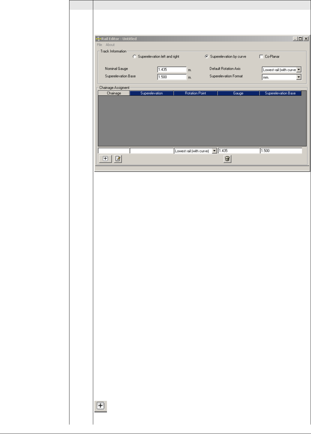
Viva Series, Roads - Rail 703
The Rail Editor program is used to define the height of the rails at a given
chainage. The height of the rails can be defined by a rotation point and a
cant or by a left and right cant.
Describing the screen elements - Entering Track Information
Superelevation left and
right
To define the height of the rails using one
superelevation value for the left rail and another
superelevation value for the right rail.
Superelevation by curve To define the rails using a rotation point and a
superelevation value.
Once the method by which the superelevation
values are defined has been selected, it cannot
be changed
Co-Planar (for multiple
tracks)
To define the height of the rails of the second
track by extending the plane which runs through
the rails of the first track.
Nominal Gauge The default nominal distance between the
active (internal) faces of the left and right rails.
This value can be changed if necessary for any
rail definition (superelevation).
Superelevation Base The distance over which the superlevation is
applied. This distance is normally the distance
between the centre of the left and right rail.
This value can be changed if necessary for any
rail definition (superelevation).
Default Rotation Axis If a rotation point is used, this selection will be
used as the default for all new rail definitions.
This value can be changed if necessary for any
rail definition (superelevation).
Superelevation Format The format in which the superelevation values
are entered.
Once all superelevation data has been entered, press the button to add
the data to the chainage assignment screen.
Step Description
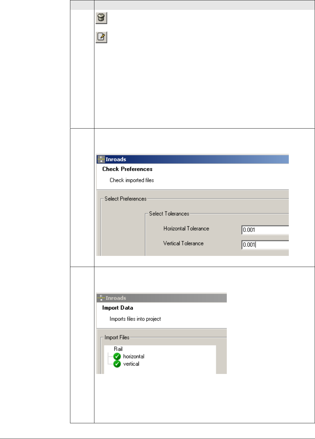
Viva Series, Roads - Rail 704
To delete an element, select the element and press the button.
To modify an existing element, select the element, modify the data and
press the button.
Once all values have been entered for the entire alignment, the file can be
saved in an XML format using Save from the File menu.
To return to the Design To Field converter, select Exit from the File menu.
To modify an existing rail definition (superelevation) file, for example XML
files, use Load option from the File menu.
8. Entering the alignment tolerances
Enter the appropriate horizontal and vertical tolerances to be used during
the checking of the alignments.
Click Next to move to the next page of the wizard.
9. Checking the track design
When the track design has been imported, information is displayed to show
the success or failure of the import.
• When the import is successful: Click Next to move to the next page of the
wizard.
• When the import is unsuccessful: Click Back to step back through the
wizard.
• If a problem is encountered a red symbol appears. Double click on the red
symbol and a window containing a description of the problem appears.
Step Description
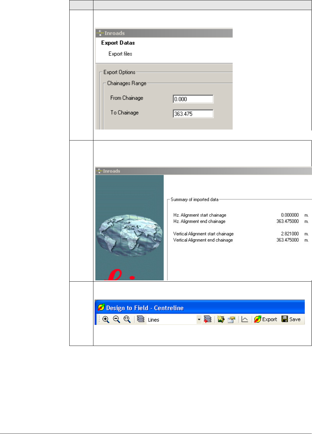
Viva Series, Roads - Rail 705
10. Entering the range of chainages to be used
Enter the range of chainages to be exported.
Click Next to move to the next page of the wizard.
11. Checking the summary report
• When the report is correct: Click Finish to complete the wizard.
• When the report is incorrect: Click Back to step back through the wizard.
12. Viewing the track design
The track design can be viewed graphically.
Click Export to create the files for onboard use.
Step Description
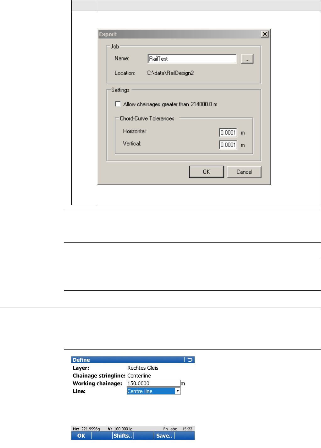
Viva Series, Roads - Rail 706
Refer to the Design to Field User Manual for details on importing various types of data
with various field importers. This manual is included in the Design to Field Converters
install application RR_Design_to_Field.exe, which can be downloaded.
48.1.4 Loading the Track Design onto the Instrument
Loading the design Once the track design has been converted, copy all the database files to the \DBX
folder of the data storage device of the instrument. Refer to "Appendix C Directory
Structure of the Memory Device".
48.2 Defining the Work
Access 1) Select Main Menu:Go to Work!\Roads\Rail - Stakeout or Rail - As built check.
2) In the job selection screen, select the required jobs. Refer to "45.2.1 Accessing
Roads Applications".
3) Press OK.
Define
13. Creating the files for onboard use
The track design can now be prepared.
Click OK to create the files for onboard use. The database files are created
and are located in the same folder as the source alignment files.
Step Description
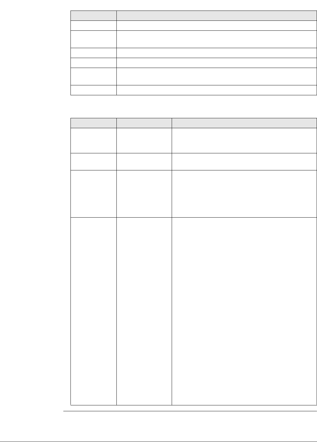
Viva Series, Roads - Rail 707
Description of fields
Key Description
OK To continue to the next screen.
Shifts.. To apply horizontal and vertical shifts to the selected element. Refer
to "45.4 Working with Shifts".
Load.. To load a task. Refer to "45.5 Tasks".
Save.. To save the settings as a task. Refer to "45.5 Tasks".
Fn Config.. To access the Rail configuration settings. Refer to "45.3 Configuring
Roads Applications".
Fn Quit To exit the application.
Field Option Description
Layer Display only or
selectable list
Layers contained in the active rail job can be
selected, for example layer of left or right track
design.
Chainage line Display only Shows the name of the chainage line, at the
selected layer.
Working
chainage Editable field To enter a chainage (ranging between the start
chainage and end chainage) of the chainage
centreline. The default is the setup point for TPS
and the current position for GPS. Only those
elements which appear at this chainage can then
be selected from Line to use.
Line to use The measured point values can be compared with
the left rail, the right rail or the track centreline.
The selectable list allows the selection of the line
with which measured values are then compared.
Centre line The track centreline.
Left rail or Right
rail • For design data including the rails:
When working with design data including the
rails, the horizontal and vertical alignment of
the design is used. Depending on the rail
design configuration setting, the supereleva-
tion of the design or the manually defined
superelevation can be used.
• For design data without rails (only track
centreline):
If the design data does not contain the rail
design, then the position of the left rail is
calculated. The nominal gauge entered in the
program configuration is used for the calcula-
tion.
• When working with horizontal alignments only:
The height of the rails is calculated by using
the values for Manual cant definition defined
on Stake Track/Check Track, General page.
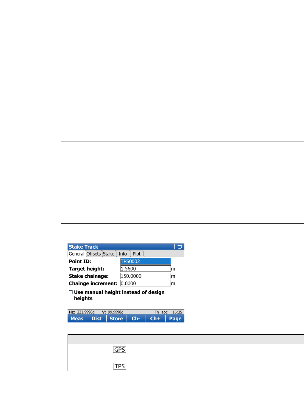
Viva Series, Roads - Rail 708
48.3 Staking/Checking the Track
48.3.1 The Stake/Check Screen
Staking points It is possible to stakeout points using a rail job with and without a stored rail design.
When the position of the rails is not stored in the rail job, it is possible to stake out:
• The horizontal and vertical alignment of the track centreline
• Points with a known horizontal and vertical offset from the horizontal and
vertical alignment of track centreline
• The rails of the track by entering the track superelevation, superelevation base
and nominal gauge
• Points with known horizontal and vertical offsets from the manually defined
rails.
When the position of the rails is stored in the rail job, it is possible to stake out:
• The horizontal and vertical alignment of track centreline
• Points with a known horizontal and vertical offset from the horizontal and
vertical alignment of track centreline
•The rails of the track
• Points with known horizontal and vertical offsets from the defined rails.
Checking points Besides checking points, it is also possible to work with cants (superelevation):
• The cant value can be entered manually. The value is measured using a device
to measure the cant with an inclination sensor (camber measurement instru-
ment).
• The difference of the manually entered cant value and the current design cant
can be displayed on Info page and is stored in the DBX.
• The cant value can be measured by using the option Second point of cant of the
Tools menu. A second point on the track is measured to calculate the cant using
the measured height difference and the configured superelevation base.
Stake Track/Check
Track,
General page
Information regarding the measured point can be entered. This screen allows any
point of the track to be checked against design values.
Key Description
Meas To start measuring the point being staked. The key changes to
Stop.
To measure a distance and store distance and angles.
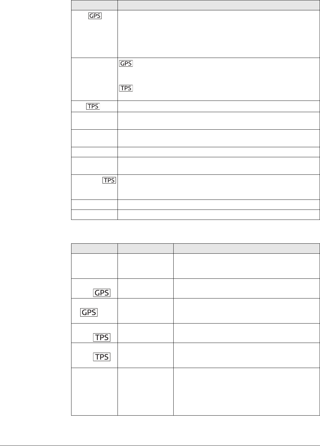
Viva Series, Roads - Rail 709
Description of fields
Stop To end measuring the point being staked. When Automatically stop
point measurement is checked in GPS Settings Quality
Control,General page recording of positions ends automatically as
defined by the stop criteria. The key changes to Store. After ending
the measurements, the differences between the measured point and
the point to be staked are displayed.
Store To store the measured point. When Automatically store point
is checked in GPS Settings Quality Control,General page, the meas-
ured point is stored automatically. The key changes to Meas.
To store angles and distance. Distance must be measured
before.
Dist To measure a distance.
Ch- Available for Rail - Stakeout. To decrease the chainage as defined by
Chainge increment.
Ch+ Available for Rail - Stakeout. To increase the chainage as defined by
Chainge increment.
Page To change to another page on this screen.
Fn Config.. To access Rail configuration settings. Refer to "45.3 Configuring
Roads Applications".
Fn Positn To position the total station to the defined stakeout point, including
defined offsets. This depends on the settings for Turn to point in
Configuration, TPS page. Refer to " Configuration, TPS page".
Fn Tools.. To access the Tools Menu. Refer to "48.4 The Tools Menu".
Fn Quit To exit the application.
Field Option Description
Point ID Editable field Name of the next point to be stored. The ID is
incremented/decremented whenever a point gets
stored.
Antenna
height
Editable field Height of the antenna.
Perp. antenna
ht
Editable field Perpendicular height of the antenna. Available
when the perpendicular height is configured.
Refer to " Configuration, Rail design page".
Target
height
Editable field Height of the prism.
Perp. target
height
Editable field Perpendicular height of the prism. Available when
the perpendicular height is configured. Refer to "
Configuration, Rail design page".
Stake
chainage Editable field The defined chainage of the point to be staked
out. For multiple tracks that have a defined
chainage centreline, the chainage to be staked
out always refers to the chainage of the chainage
centreline, not to the chainage of the track
centreline.
Key Description
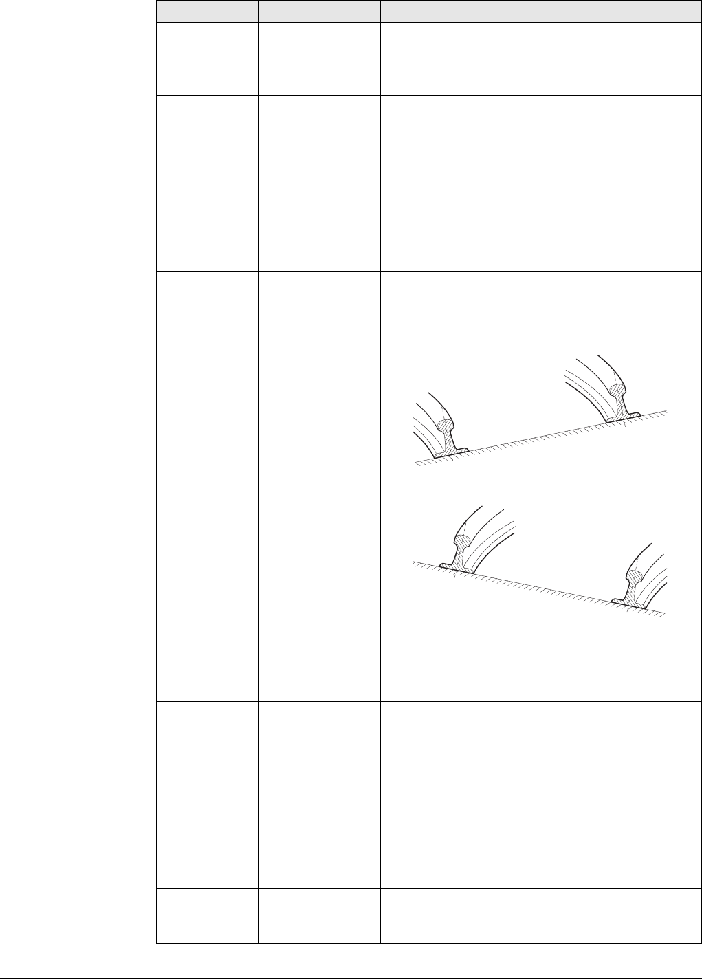
Viva Series, Roads - Rail 710
Chainge incre-
ment Editable field Value by which the nominal chainage
increases/decreases when pressing Ch-/Ch+.
If a point is to be staked at more than one
chainage, a chainage increment can be defined.
Use cant
device Check box When this box is checked, the cant value (super-
elevation) which was measured with an inclina-
tion sensor can be entered manually. The differ-
ence of the manually entered cant value and the
current design cant is displayed on Info page.
When this box is not checked, no cant difference
(superelevation) is calculated of the current
design cant and the measured cant. The current
cant can be measured using the option Second
point of cant from the Tools menu.
Measured cant Editable field Available when Use cant device is checked. Posi-
tive or negative signs must be entered. Seen in
increasing chainage direction:
• Negative cant value (example: -0.1900 m)
• Positive cant value (example: 0.1900 m)
When Second Point of Cant of the Tools
menu is active, the current cant value is
used for the cant difference calculation,
not the value for Measured cant.
Use manual
height instead
of design
heights
Check box When this box is checked, a height value typed in
manually is used instead of design height or DTM
height.
When this box is not checked, the height from
design is used.
Available for Superelevation:Design in Configu-
ration, Rail design page.
Manual height Editable field Available when Use manual height instead of
design heights is checked. The height to be used.
Manual cant
definition Display only This field and the following fields are available for
Superelevation:Manual in Configuration, Rail
design page.
Field Option Description
Rail_017
Rail_018
Viva Series, Roads - Rail 711
Next step
Page changes to the Offsets page.
Stake Track/Check
Track,
Offsets page
Refer to "Stake Track/Check Track, General page" for a description of keys.
Description of fields
Ht lower rail Editable field Defines the absolute height of the lowest rail at
the defined chainage.
Cant left Editable field Defines the superelevation at the left rail.
• When working with horizontal alignments only:
If the superelevation is rotated around the left
rail, the superelevation would be zero.
• When working with horizontal and vertical
alignments: If the track is rotated around the
left rail, the vertical alignment would coincide
with the left rail and the superelevation would
thus be zero.
Cant right Editable field Defines the superelevation at the right rail.
• When working with horizontal alignments only:
If the track is rotated around the right rail, the
superelevation would be zero. The total super-
elevation (left + right) is applied across the
distance defined as the superelevation base in
the configuration.
• When working with horizontal and vertical
alignments: If the track is rotated around the
right rail, the vertical alignment would coincide
with the right rail and the superelevation
would thus be zero. The total superelevation
(left + right) is applied across the distance
defined as the superelevation base in the
configuration.
Field Option Description
Field Option Description
Apply offsets Check box When this box is checked, offsets can be typed in.
Often it is necessary to set out points with a fixed
plan offset and fixed height offset from a known
reference line (track centreline or rail).
Offsets are applied in the same way, irrespective
of how the rail design has been entered, whether
the offsets are manually entered or if library
offsets are used. The sign of the offsets
conforms to the offset sign convention described
in "45.6 Understanding Terms and Expressions".
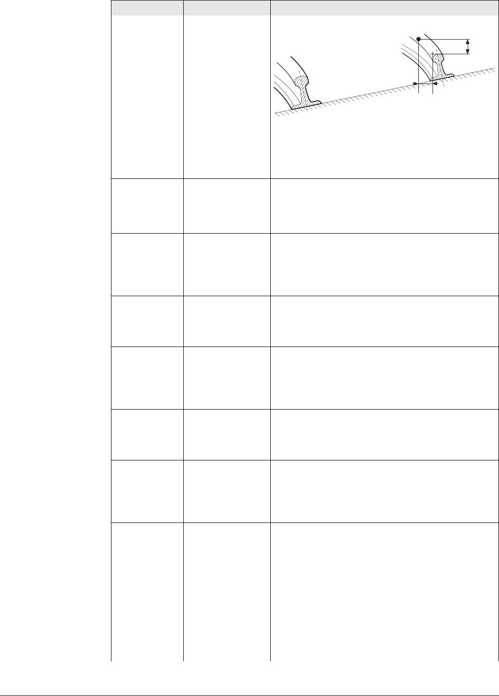
Viva Series, Roads - Rail 712
a) Reference line (right rail)
b) Point to stake
c) Stake height diff
d) Stake offset
Offsets Manual Offsets can be entered in Stake offset/Check
offset or Stake height diff/Check height diff.
From library The offset is stored as part of the rail job and
recalled whenever required.
Offsets Selectable list Available for Offsets:From library. The point ID
of the stored stake offsets. To select a different
stored offset or to create a new point, highlight
this field and open the selectable list. Refer to
"48.3.2 Offset Library".
Stake offset Editable field Available for Stake. Horizontal offset applied to
the position of the reference line as defined by
the design data or as calculated from manually
entered data using the nominal gauge.
Stake height
diff Editable field Available for Stake. Vertical offset applied to the
height of the reference line as defined by the
design data or as calculated from manually
entered data using the superelevation and super-
elevation base.
Check offset Editable field Available for Check. Horizontal offset applied to
the position of the reference line as defined by
the design data or as calculated using manually
entered data using the nominal gauge.
Check height
diff Editable field Available for Check. Vertical offset applied to the
height of the reference line as defined by the
design data or as calculated from manually
entered data using the superelevation and super-
elevation base.
Work with
pendular
displacement
Check box This functionality is used in railway tunnels.
The functionality is available for Rail - Stakeout
and Rail - As built check.
Some rail projects require additional pendular
displacement calculation for the design axis.
The track is rotated based on a line with a defined
height offset (pendulum length) from the track
centreline. This action defines a horizontal
displacement for the track. The vertical alignment
is independent from the pendular displacement
and does not change.
Field Option Description
Rail_013
a
b
d
c
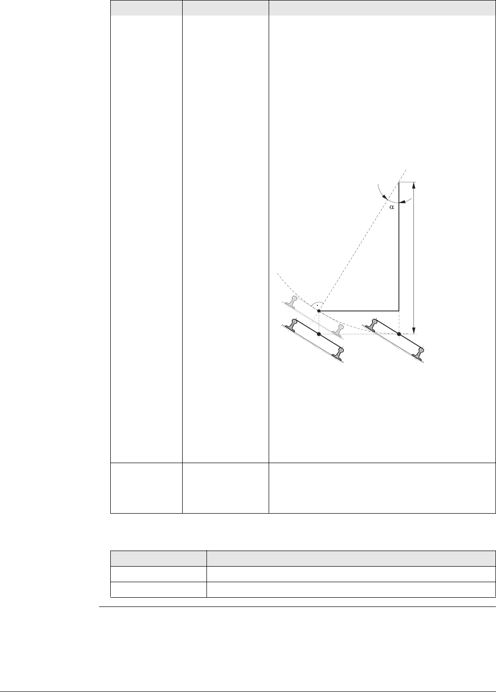
Viva Series, Roads - Rail 713
Next step
The pendular displacement calculation
only influences the horizontal position of
the design axis. It does not change the
height of the track.
When this box is checked, a pendulum length can
be entered. From the original track definition, a
pendulum centre is defined exactly above the axis
point. The difference in elevation of the
pendulum centre is the pendulum length. With
the help of the superelevation, a displacement is
calculated. The effect of the pendular displace-
ment is displayed on the Info page.
a) Pendulum length: The difference in elevation
of the pendulum centre on the original track
and above the axis point
b) Resulting pendular displacement
c) Displaced design axis based on pendular
displacement calculation
d) Design axis defined in horizontal alignment
Pendulum angle
Pendular
length Editable field Available when Work with pendular displacement
is checked. The pendulum length as distance
value. Positive values (0 - 9999.9999) point
upwards. Negative values are not allowed.
IF you work with THEN Page changes to the
Rail - Stakeout Stake page.
Rail - As built check Info page.
Field Option Description
Rail_016
b
a
c
cd
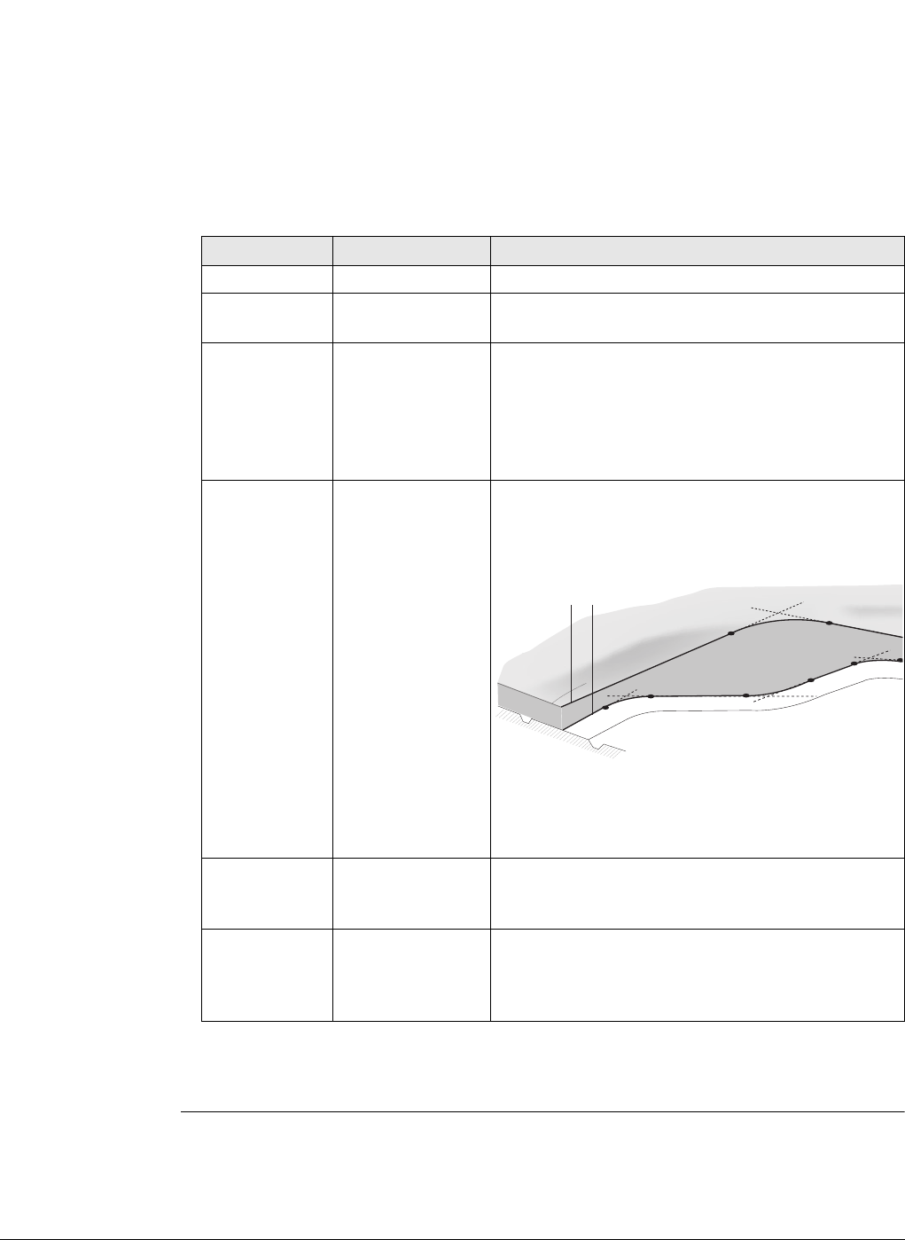
Viva Series, Roads - Rail 714
Stake Line,
Stake page This page is available for Rail - Stakeout only.
This page displays the differences between the measured point and the defined point.
The position of the point to stake is reached when all difference values are close to
zero.
The chainage can be de-/incremented by pressing left/right arrow key. The defined
value for chainage increment is applied.
Refer to "Stake Track/Check Track, General page" for a description of keys.
Refer to "53.4 Staking Out" for a description of the elements of the graphical display.
Description of fields
Next step
Page changes to the Info page.
Field Option Description
Chainage Display only The current track chainage.
CL O Display only Perpendicular horizontal offset from the centre-
line.
chainage Display only Difference between the defined Stake chainage
and the current chainage Chainage of the meas-
ured position.
If no defined chainage exists, for example if
staking out random chainages or checking, this
field shows -----.
NrTP Display only The chainage difference between the measured
point and the nearest tangent point (start/end
point of a road segment) of the design is
displayed.
a) Vertical alignment
b) Horizontal alignment
Only tangent points (start/end point of a road
segment) are detected.
O Display only Horizontal offset between the defined position
and the current position. The Stake offset defined
on the Offsets page is taken into account.
height Display only Vertical offset between the defined position and
the current position. The Stake height diff
defined on the Offsets page is taken into
account.
ab
Road_099
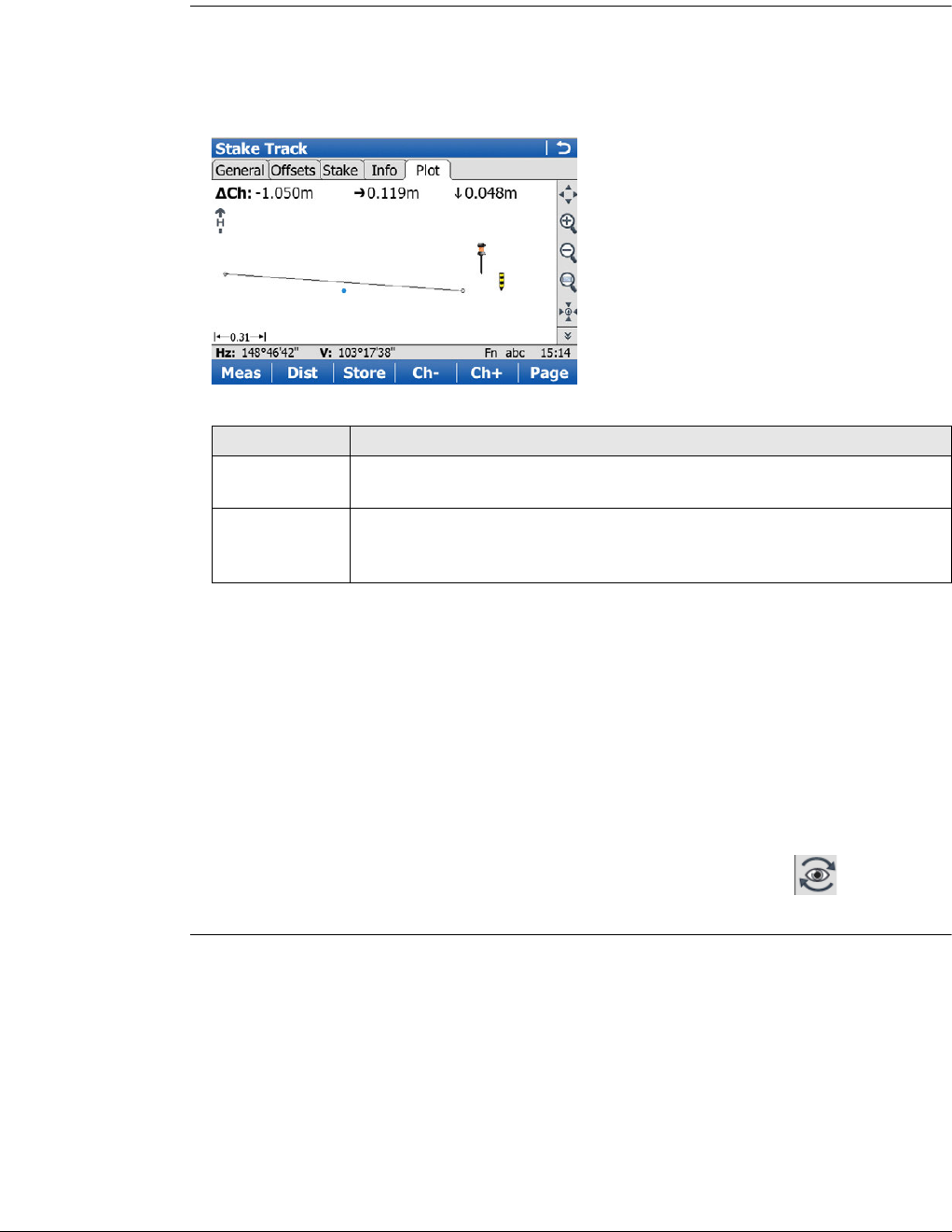
Viva Series, Roads - Rail 715
Stake Track/Check
Track,
Info page
The Info page displays the differences between the measured and design data.
The fields viewed on this page can be configured in Rail Configuration, Info page.
Refer to "Configuration, Info page" for information on all available items for the Info
page and how to select them.
Stake Track/Check
Track,
Map page
The Map page displays a plot of the measured point with respect to the track design.
The design is defined by the selected rail or track centreline, and the values entered
on the General page.
The Map page for Check and Stake are similar. The only difference is that the current
chainage is always shown, as shown on the Info page.
The following information is shown:
1) Chainage difference between the measured point and the defined chainage. When
working with random chainages, for instance if no defined chainage has been
entered on the General page, Ch changes to Ch. Ch is the current chainage as
shown on the Stake page.
2) Horizontal offset (left/right arrow) to the design
3) Height difference (up/down arrow) to the design
4) The measured point
5) The element to stake is shown in bold and blue. The position to stake is marked
with a yellow-black peg.
6) The plot can be shown as a cross plot or plan view by using the eye icon on
second level of MapView toolbar.
Key Description
Refer to "Stake Track/Check Track, General page" for a description of
keys.
Fn Layrs.. To turn layers of background maps (CAD files) on and off. Refer to
"5.2 Creating a New Job"for information on CAD files and CAD back-
ground maps.
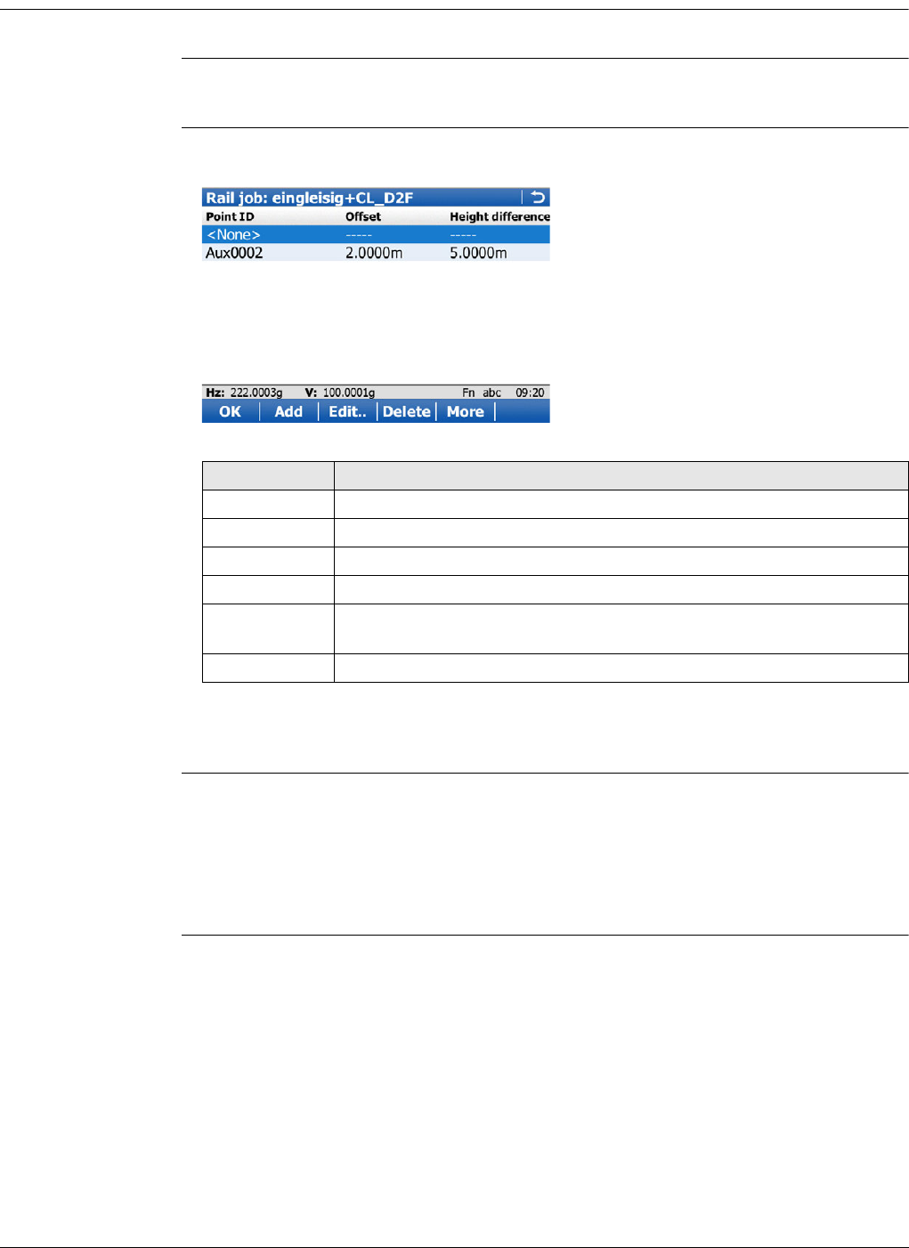
Viva Series, Roads - Rail 716
48.3.2 Offset Library
Description To select a different stored offset or to create a new point.
Access 1) In Stake Track/Check track, Offsets page, select Offsets:From library.
2) Highlight Offsets and open the selectable list.
Rail job: Job name This screen allows offsets relative to a reference line to be defined and stored in the
rail job. These points can be recalled at any time.
Next step
Press Add or Edit...
Rail job: Job name,
Offsets This screen allows the values of the stake/check offsets to be entered/edited. In addi-
tion to the horizontal and vertical offsets, an offset name (point ID) can be entered
for each item.
Next step
Press OK twice to return to Stake Track/Check track.
Key Description
OK To select a defined offset and to continue.
Add To enter an offset.
Edit.. To edit an existing offset.
Delete To delete an existing offset.
More To display information about the reference rail or the Offset and the
height difference.
Fn Quit To exit the application.
Viva Series, Roads - Rail 717
48.3.3 Working with Pendular Displacements
Requirements In Stake Track/Check Track, Offsets page, check Work with pendular displacement
and type in a value for Pendular length.
Specific values on
the Info page
48.4 The Tools Menu
48.4.1 Overview
Access Press Fn Tools.. on any page of the Stake/Check screen.
Description Additional functions for staking/checking the track can be accessed through the Tools
menu. This functionality is additional to those already existing functions which are
available via the function keys.
The functionality differs between the stake and check methods. Refer to these
subchapters for a detailed description of the functionalities:
• "48.4.2 Use heights from DTM"
• "48.4.3 Apply current chainage"
• "48.4.4 Stake individual point"
• "48.4.5 Second point of cant"
• "48.4.6 COGO Rail"
48.4.2 Use heights from DTM
Availability This menu function is available for stake and check.
Description The application offers the possibility to
• switch to a height which is retrieved from an existing height layer, as defined in
the selected DTM job. The layer from the DTM is applied and used as a height
reference for the staking out or checking of alignments.
• retrieve heights from an existing layer, as defined in the DTM job associated with
the project. The DTM used is not considered for the stake values. Three new
information lines are added to the Info page: DTM Ht Diff, DTM Height and DTM
Layer.
• show the DTM triangles in the planar view and in the cross section view on the
Map page.
Once defined, each layer remains active until it is turned off. DTM heights can be used
for both 2D and 3D alignments.
Value Description
Pendular length The defined pendulum length as entered on Offsets
page.
Def pendulum displace-
ment Resulting horizontal displacement at defined chainage.
Actl pendulum displace-
ment Resulting horizontal displacement at current chainage.
Def pendulum angle Resulting pendulum angle at defined chainage.
Actl pendulum angle Resulting pendulum angle at current chainage.
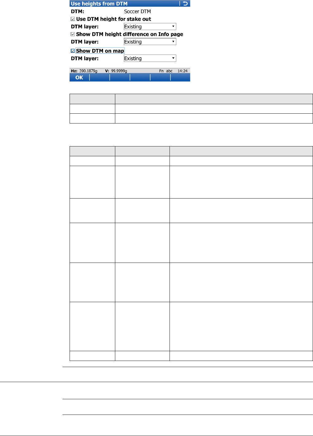
Viva Series, Roads - Rail 718
Use heights from
DTM
Description of fields
48.4.3 Apply current chainage
Availability This menu function is available for stake.
Description To set Stake chainage on the General page of the stakeout to the current chainage.
Key Description
OK To confirm the settings and return to the Stake/Check screen.
Fn Quit To exit the application.
Field Option Description
DTM Display only DTM from the selected DTM job.
Use DTM
height for
stake out
Check box When this box is checked, a layer of the DTM is
used as a height reference.
When this box is not checked, no DTM heights are
applied for stakeout or check.
DTM layer Selectable list Available when Use DTM height for stake out is
checked. When selecting a DTM layer the relevant
triangle of the DTM is shown on the Map page.
Show DTM
height differ-
ence on Info
page
Check box When this box is checked, a layer of the DTM to
be used as a height reference on the Info page.
When this box is not checked, no additional
height information relative to the DTM is shown
on the Info page.
DTM layer Selectable list Available when Show DTM height difference on
Info page is checked. Layer of the DTM to be used
as a height reference. When selecting a DTM layer
the relevant triangle of the DTM is shown in cross
section view on the Map page.
Show DTM on
map Check box When this box is checked, the DTM triangles are
displayed in planar view on the Map page.
The setting of for this check box is linked
to the setting for the Display DTM in map
check box in Map View Settings, DTM
page.
DTM layer Selectable list All available layers are selectable.
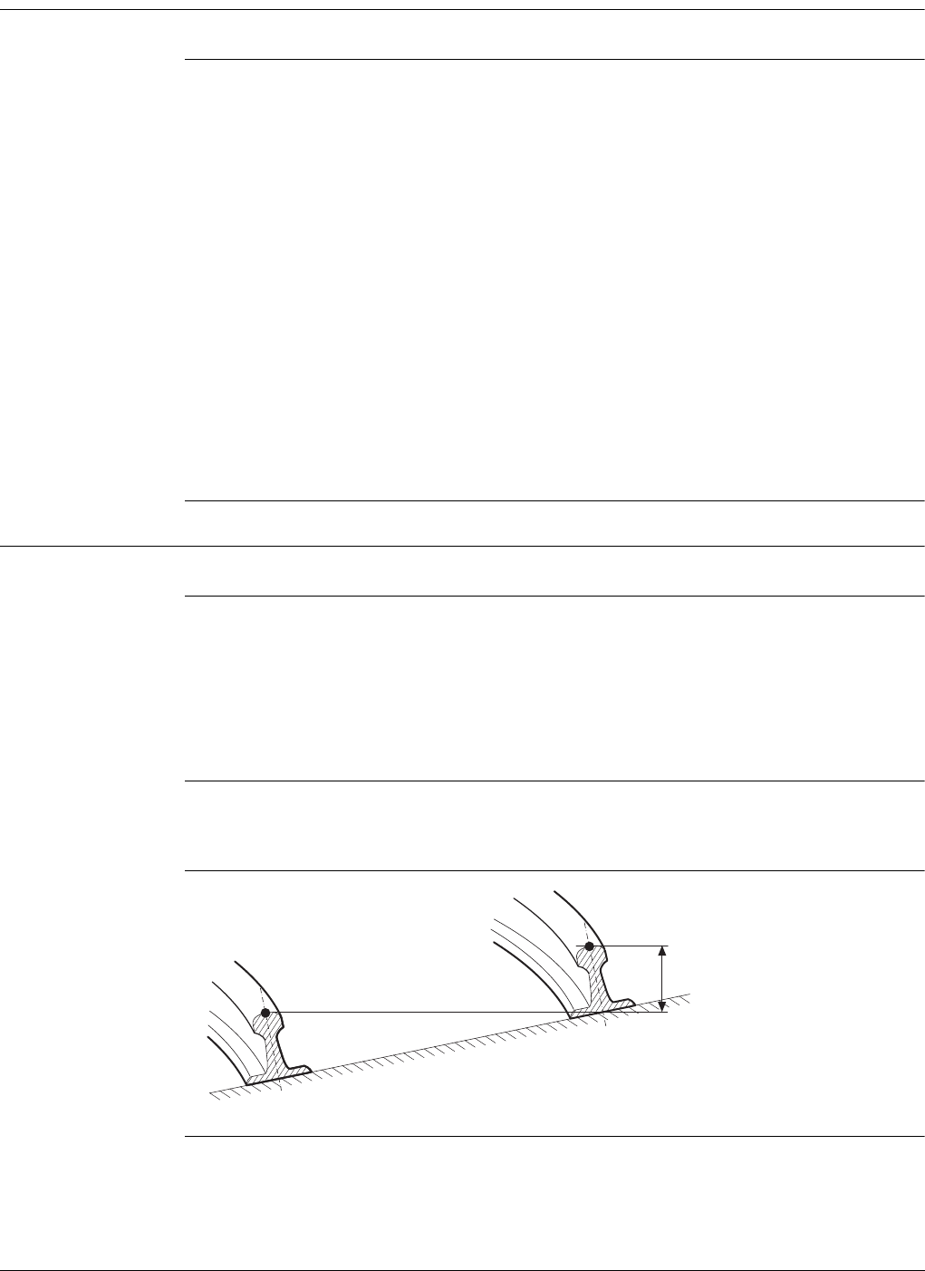
Viva Series, Roads - Rail 719
48.4.4 Stake individual point
Availability This menu function is available for stake.
Description To select the point to stake from the selected Working job.
If a control job has been selected on the job selection screen, a point from the control
job can be selected. When staking out/checking an individual point, the selected point
is set in relation to the alignment and all line relevant values are calculated and
displayed.
To access Data:, Points page, which allows staking out points with known Easting,
Northing and Height. Points can either be selected from the Working job or manually
typed in.
The Stake chainage and Stake offset of the Stake screen are calculated based on the
coordinates of the selected point.
The height for the stakeout can be set as Manual height.
If the chosen point has no height the design height will be used. If the point
has a height it is possible to use that one or continue working with the design
height.
48.4.5 Second point of cant
Availability This menu function is only available for check.
Description To determine the current cant of two rails.
In order to calculate the current cant, it is necessary to measure two points, one on
each rail. A mechanical device can be used to measure these points if necessary.
Additionally, the current cant can be calculated by first measuring any two points
(example, the track centreline and lower rail) and then using the superelevation base.
The calculation is dependent upon the superelevation base.
When Second point of cant is active, the Current cant is used for the calculation of
the cant difference, not the measured cant value from a cant device as seen in Check
Track, General page.
Diagram
a) Left rail
b) Right rail
c) first point
d) Second point of cant
e) Current cant
e
a
b
d
c
Rail_015

Viva Series, Roads - Rail 720
Procedure Measuring the first point
The first point can be measured directly from the Check Track screen.
Measuring the second point
The second point is measured after accessing the Second point of cant in the Tools
menu. Once the second point has been measured, the value Current cant is displayed
on the Info page.
48.4.6 COGO Rail
The functionality of COGO Rail is identical with COGO Road. Refer to "47.4.6 COGO
Road - Alignment Information".
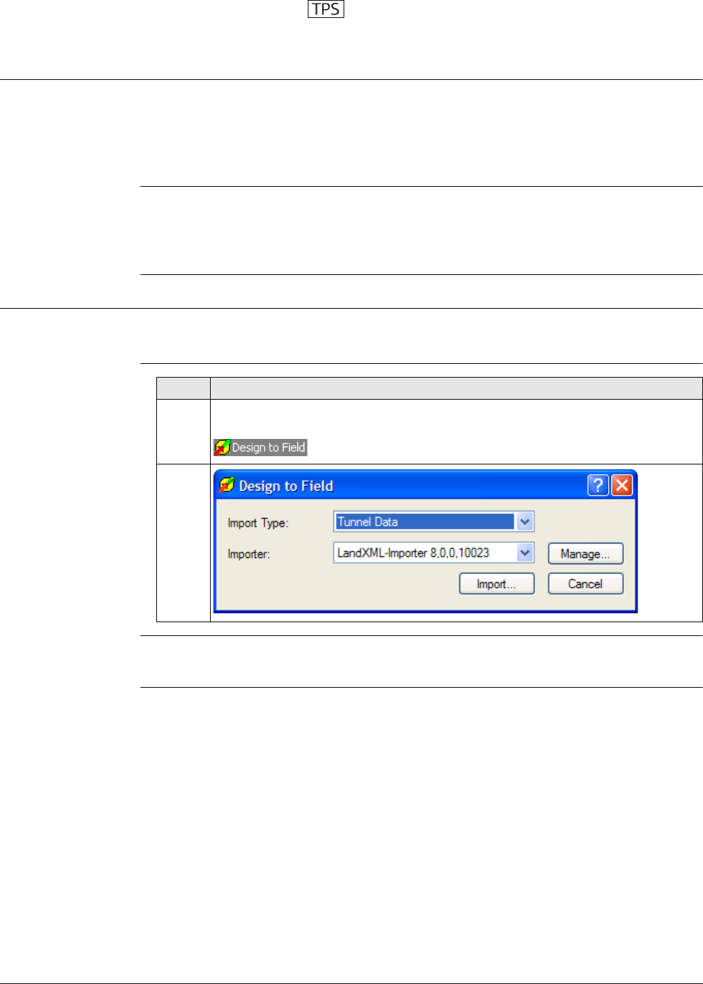
Viva Series, Roads - Tunnel 721
49 Roads - Tunnel
49.1 Creating a New Tunnel Job
49.1.1 Preparing Design Data
Downloads section The tunnel design data is imported for use onboard the instrument using
• the industry standard LandXML data format
• formats exported from some other design packages using the Design to Field
component of the Leica Geo Office computer application.
Converters are available for more than 15 different design packages.
The latest version of the Design to Field importers can be found in the downloads
section of:
• myWorld@Leica Geosystems
https://myworld.leica-geosystems.com
49.1.2 Tunnel Centreline
Basics The tunnel centreline is defined in two or three dimensions. If design profiles are to
be used, a three-dimensional centreline is required.
Design to field
For general information about Design to Field, please refer to the Leica Geo Office
manual or Online Help.
Step Description
1. To import a centreline using the Design to Field component select the
Tools/Design to Field option of the Leica Geo Office computer application.
2.
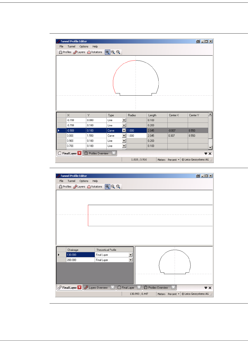
Viva Series, Roads - Tunnel 722
49.1.3 Design Profiles
Tunnel design
profiles
If tunnel design profiles are available, they are created using the Tunnel Profile Editor
computer application. This application is integrated in the Design to Field viewer. It
allows users to import or create tunnel data like profiles, layers and rotations. Refer
to the Tunnel Profile Editor online help for more information.
Tunnel Profile
Editor,
Profile details view
Tunnel Profile
Editor,
Layer details view
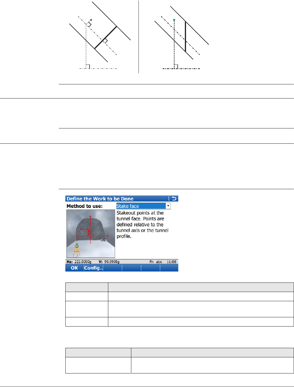
Viva Series, Roads - Tunnel 723
Vertical or perpen-
dicular profiles
The Tunnel Profile Editor allows users to define tunnel profiles vertically or perpendic-
ular to the vertical alignment of the tunnel axis. This results in different tunnel sizes
for equal profile definitions as shown in the graphic.
49.1.4 Data Transfer to Instrument
Getting data
onboard
Once the design data have been converted, copy the database files to the DBX folder
of the data storage device that is used on the instrument. The file names are
jobname.x**.
49.2 Defining the Work
Access 1) Select Main Menu:Go to Work!\Roads\Tunnel - Stakeout or Tunnel - As built
check.
2) In the job selection screen, select the required jobs. Refer to "45.2.1 Accessing
Roads Applications".
3) Press OK.
Define the Work to be
Done
Description of the methods
A Perpendicular (tilted)
profile
BVertical profile
a) Vertical alignment of
tunnel axis
b) Horizontal alignment of
tunnel axis
c) Chainage for perpendic-
ular profile definition
d) Chainage for vertical
profile definition
aa
bb
d
c
Tunnel_027
BA
Key Description
OK To continue to the next screen.
Config.. To access the configuration settings. Refer to "45.3 Configuring
Roads Applications".
Fn Quit To exit the screen.
Method Description
Stake face Stakeout points at the tunnel face. Points are defined relative to
the tunnel axis or the tunnel profile.
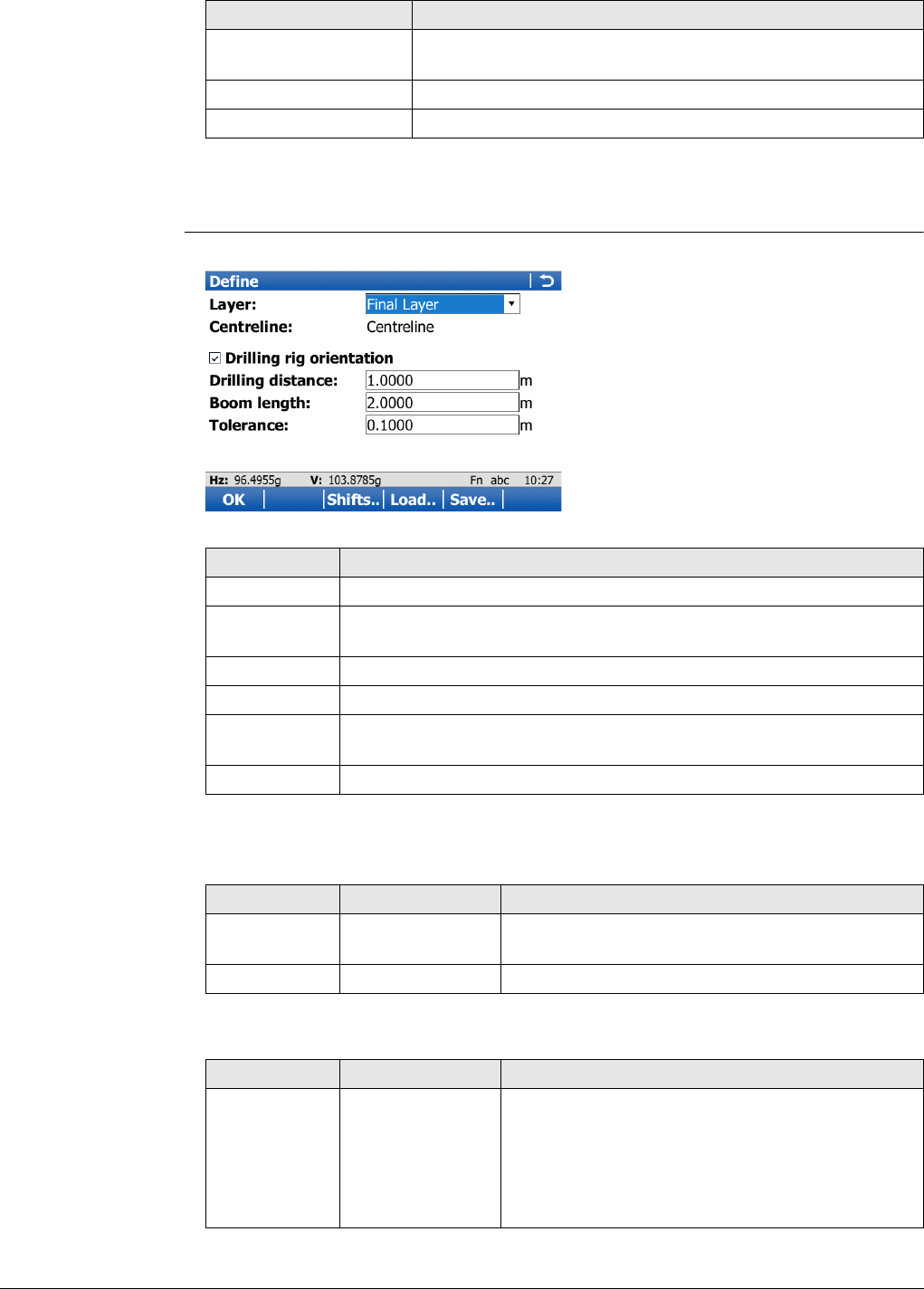
Viva Series, Roads - Tunnel 724
Next step
OK accesses the Define screen.
Define The screen is an example valid for Method to use:Stake face.
Description of fields
Common to all methods
For Method to use:Stake face
Stake profile Stakeout points at defined chainages. Points are defined rela-
tive to the tunnel axis or the tunnel profile.
Check profile Measure deviations of the built tunnel to the original design.
Scan profile Automatically scan profiles in a defined section of the tunnel
Method Description
Key Description
OK To continue to the next screen.
Shifts.. To apply horizontal, vertical and profile shifts to the selected
element. Refer to "45.4 Working with Shifts".
Load.. To load a task. Refer to "45.5 Tasks".
Save.. To save the settings as task. Refer to "45.5 Tasks".
Fn Config.. To access the configuration settings. Refer to "45.3 Configuring
Roads Applications".
Fn Quit To exit the application.
Field Option Description
Layer Display only or
selectable list
Layers contained in the active tunnel job can be
selected.
Centreline Display only The name of the layer centreline.
Field Option Description
Drilling rig
orientation Check box Available for Method to use:Stake face.
This functionality helps to orientate the drilling rig
when drilling holes parallel to the tunnel axis
direction. The entry point at the tunnel face is
marked and delta angles to align the drilling rig
are provided.
Viva Series, Roads - Tunnel 725
For Method to use:Check profile
The following fields are available when Drilling rig orientation:Parallel to alignment
is selected in Tunnel Configuration, Tunnel design page:
Drilling
distance Editable field The bore hole length. Available when Drilling rig
orientation is checked and used to calculate the
direction parallel to the alignment.
Check Jumbo
position Check box When this box is checked, the jumbo position is
checked after measuring to the back of the boom.
Boom length Editable field The length of the boom is used for calculating and
checking the jumbo position when Check Jumbo
position is checked.
Tolerance Editable field Defines how accurately the boom must be posi-
tioned to calculate the delta angles (max 10% of
boom length). Available when Check Jumbo posi-
tion is checked.
The following fields are available when Drilling rig orientation:Drill Pattern is
selected in Tunnel Configuration, Tunnel design page:
Apply drill
pattern from Meas Chainage The drill pattern is directly applied to the meas-
ured chainage.
To acquire the measured chainage, take a meas-
urement, press Fn Tools.. and select Apply
current chainage.
Defined Chainage This chainage is typed manually into the Stake
chainage editable field. It is used to calculate the
corresponding position and drill direction at the
measured chainage.
Field Option Description
Apply target
radius Check box Available for Method to use:Check profile. When
using a prism to check a design profile, it is impor-
tant to take the prism radius into account.
The measured point is projected by a distance
equivalent to the radius of the prism in a direction
perpendicular to the tangent of the design
profile.
When this box is not checked, the design profile
is compared to the coordinates of the centre of
the prism at the measured position.
Field Option Description
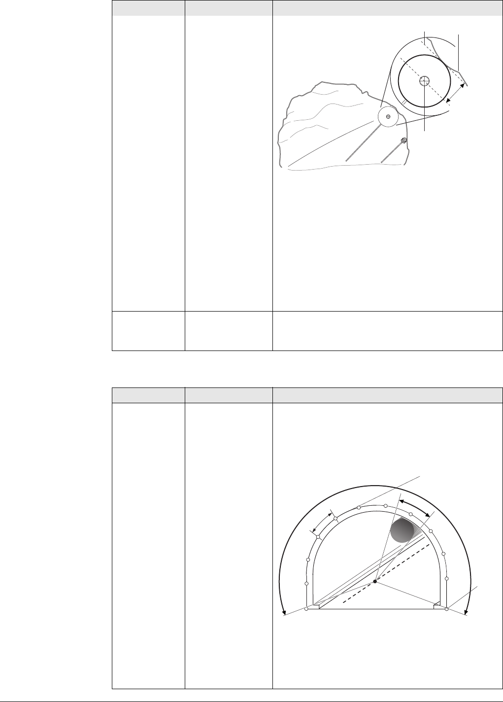
Viva Series, Roads - Tunnel 726
For Method to use:Scan profile
a) Tangent to design profile
b) Prism radius
c) Prism
d) Design profile
If reflectorless measurements are used or no
design profile has been defined, the prism radius
parameter will not be used in the calculation.
In Check Profile, Map page a plot of the meas-
ured point regarding the design profile is
displayed.
Target radius Editable field Available for Method to use:Check profile and
when Apply target radius is checked. The radius
of the prism.
Field Option Description
Define a scan
task Scan whole
profile Each profile is scanned 360°/400 gon.
Scan using
segment The tunnel profile can be split into user-defined
segments. Each segment can be assigned as a
scan segment or non scan segment.
a) Instrument axis
b) Ventilation shaft
c) Scan segment, included
d) Scan segment, excluded
e) Scan interval
Field Option Description
b
ad
c
~2m
>4m
Tunnel_013
a
d
e
c
b
Tunnel_014
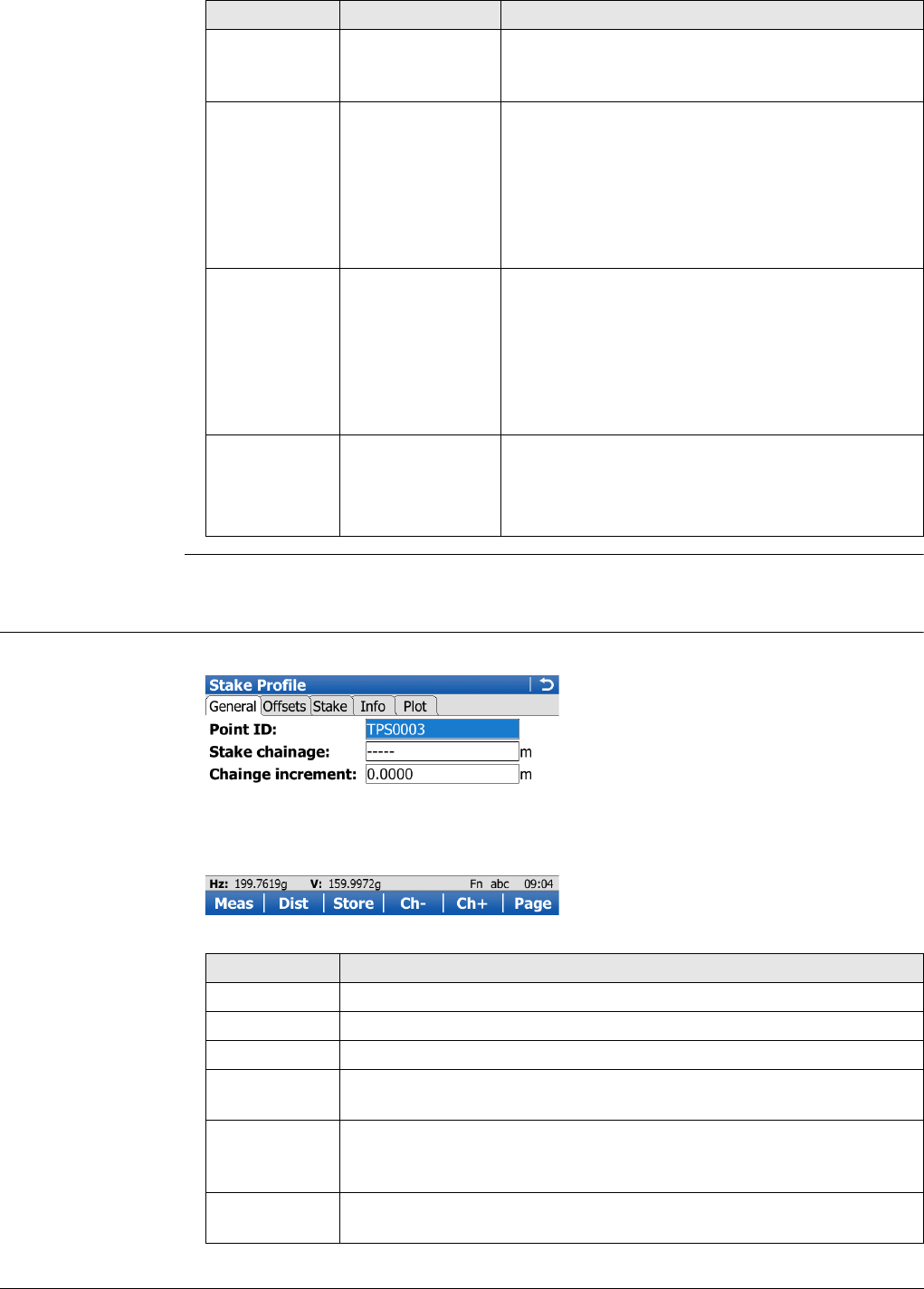
Viva Series, Roads - Tunnel 727
49.3 Staking/Checking the Tunnel
49.3.1 Overview
Stake face/Stake
profile/Check profile,
General page
This screen is an example valid for Method to use:Stake profile.
Scan interval Editable fields Available for Define a scan task:Scan whole
profile. Defines at what interval to measure a
point around the profile.
Scan Mode Accuracy opti-
mised This measurement mode is accuracy and range
optimized. It uses the reflectorless single distance
measurement mode.
Speed optimised Available for TS15. This measurement mode is
speed and performance optimized. It uses the
reflectorless continuous distance measurement
mode.
TPS handle is
on Check box When this box is checked, scanning a segment
above the instrument is excluded automatically.
The TPS handle would otherwise interfere with
measurements.
If scanning at the station chainage, then
the scan does not include the profile
segment beneath the total station.
Handle type Normal handle If this option is selected, then it is not scanned
between 386 gon and 7 gon.
Radio handle If this option is selected, then it is not scanned
between 380 gon and 25 gon.
Field Option Description
Key Description
Meas To measure a distance and store distance and angles.
Dist To measure a distance.
Store To store angles and distance. Distance must be measured before.
Ch- Available for Tunnel - Stakeout. To decrease the chainage as defined
by Chainge increment.
Dist+ To increase the distance along the profile. Available for Input
method:Profile, dist & offset and Input method:Dist from
top&offset.
Ch+ Available for Tunnel - Stakeout. To increase the chainage as defined
by Chainge increment.
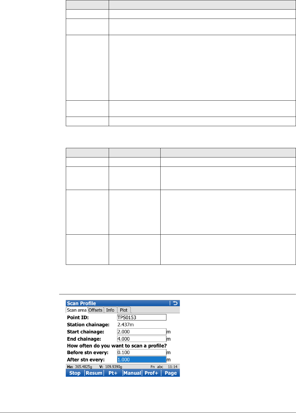
Viva Series, Roads - Tunnel 728
Description of fields
Next step
Page changes to the Offsets page.
Scan profile,
Scan area page
Page To change to another page on this screen.
Fn Config.. To access configuration settings. Refer to "45.3 Configuring Roads
Applications".
Fn Positn Available for Tunnel - Stakeout. To stake the point automatically. The
instrument aims toward the point at the given chainage and offsets
and measures a distance. If this distance is not within the required
tolerance an iterative process is started until:
• the number of iterations set as the configuration parameter
Max iterations is reached, or
• the difference between the measured point and the design
point is less than the value set as the configuration parameter
Position limit.
Fn Tools.. Available for Tunnel - Stakeout. To access the tools menu. Refer to
"47.4 The Tools Menu".
Fn Quit To exit the application.
Field Option Description
Point ID Editable field The point identifier of the point to be staked.
Stake
chainage Editable field Available for Tunnel - Stakeout. The defined or
approximate chainage of the point to be staked
out.
Chainge incre-
ment Editable field Available for Method to use:Stake
profile.Chainage increment. Value by which the
nominal chainage increases/decreases when
pressing Ch+/Ch-.
If a point is to be staked at more than one
chainage, a chainage increment can be defined.
Target height Editable field Available for Method to use:Check profile. The
height of the prism. If a prism is used, type in the
vertical difference between the point to be meas-
ured and the point of the prism pole.
Key Description
Viva Series, Roads - Tunnel 729
Description of fields
Key Description
Scan Available for automatic scanning. To start the scanning process.
Refer to "During a scan".
Stop Available for automatic scanning. To stop the scanning process.
Pause To pause the scan.
Resum To re-start scanning.
Get Ch Point the telescope to the start or end chainage and press Get Ch to
measure to the start/end chainage.
Meas Available for manual scanning. To measure a distance and store
distance and angles.
Dist Available for manual scanning. To measure a distance.
Store Available for manual scanning. To store angles and distance. Distance
must be measured before.
Pt+ To skip the point being measured and move onto the next profile
point.
Prof+ To stop scanning the current profile and move onto the next profile.
Manual or
Auto To switch between manual and automatic scanning.
Page To change to another page on this screen.
Fn Config.. To access configuration settings. Refer to "45.3 Configuring Roads
Applications".
Fn Temp To define a temporary scan interval. This will result in all scan
segments being scanned at the defined temporary scan interval until
the temporary scan interval is disabled.
Fn Tools.. To access the tools menu. Refer to "49.4 The Tools Menu".
Fn Quit To exit the application.
Field Option Description
Point ID Editable field The point identifier of the point to be staked.
Station
chainage Editable field The chainage of the instrument station.
Start chainage
and Start
distance
Editable field Enter/measure a chainage/distance value where
scanning starts along the alignment. This can be
before or after the station chainage. If entering a
distance value to indicate start scanning before
the station chainage use a negative. If entering a
distance value to indicate start scanning after the
station chainage use positive.
End chainage
and End
distance
Editable field Enter/measure a chainage/distance value where
scanning ends along the alignment. This can be
before or after the station chainage. If entering a
distance value to indicate end scanning before
the station chainage use a negative. If entering a
distance value to indicate end scanning after the
station chainage use positive.
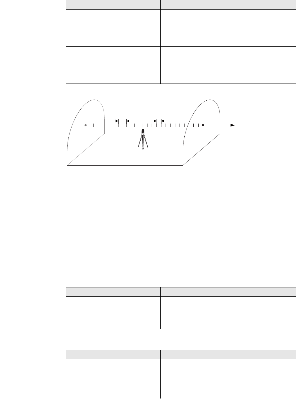
Viva Series, Roads - Tunnel 730
Next step
Page changes to the Offsets page.
Stake face/Stake
profile/Check
profile/Scan profile,
Offsets page
Refer to "Stake face/Stake profile/Check profile, General page" for a description of
keys.
Description of fields
Common for all methods
For Tunnel - Stakeout
Before stn
every Editable field If the scan area starts before the station chainage
then define how often to scan a profile along the
alignment from this chainage until the defined
end chainage or station chainage (which ever
comes first).
After stn every Editable field If the scan area ends after the station chainage
then define how often to scan a profile along the
alignment from the station chainage or start
chainage (which ever has a greater chainage)
until the defined end chainage/distance.
a) Alignment
b) Station chainage
c) Start chainage or Start distance
d) End chainage or End distance
e) Before stn every
f) After stn every
Field Option Description
d
cebf
a
Tunnel_030
Field Option Description
Apply offsets Check box When this box is checked, horizontal and vertical
offsets can be applied.
For Scan profile this does NOT offset or
expand/shrink the design profile.
Field Option Description
Input method To define the position of the point to be staked
out.
Offset & height The point is staked out with a known perpendic-
ular and vertical offset from the horizontal and
vertical alignments respectively.
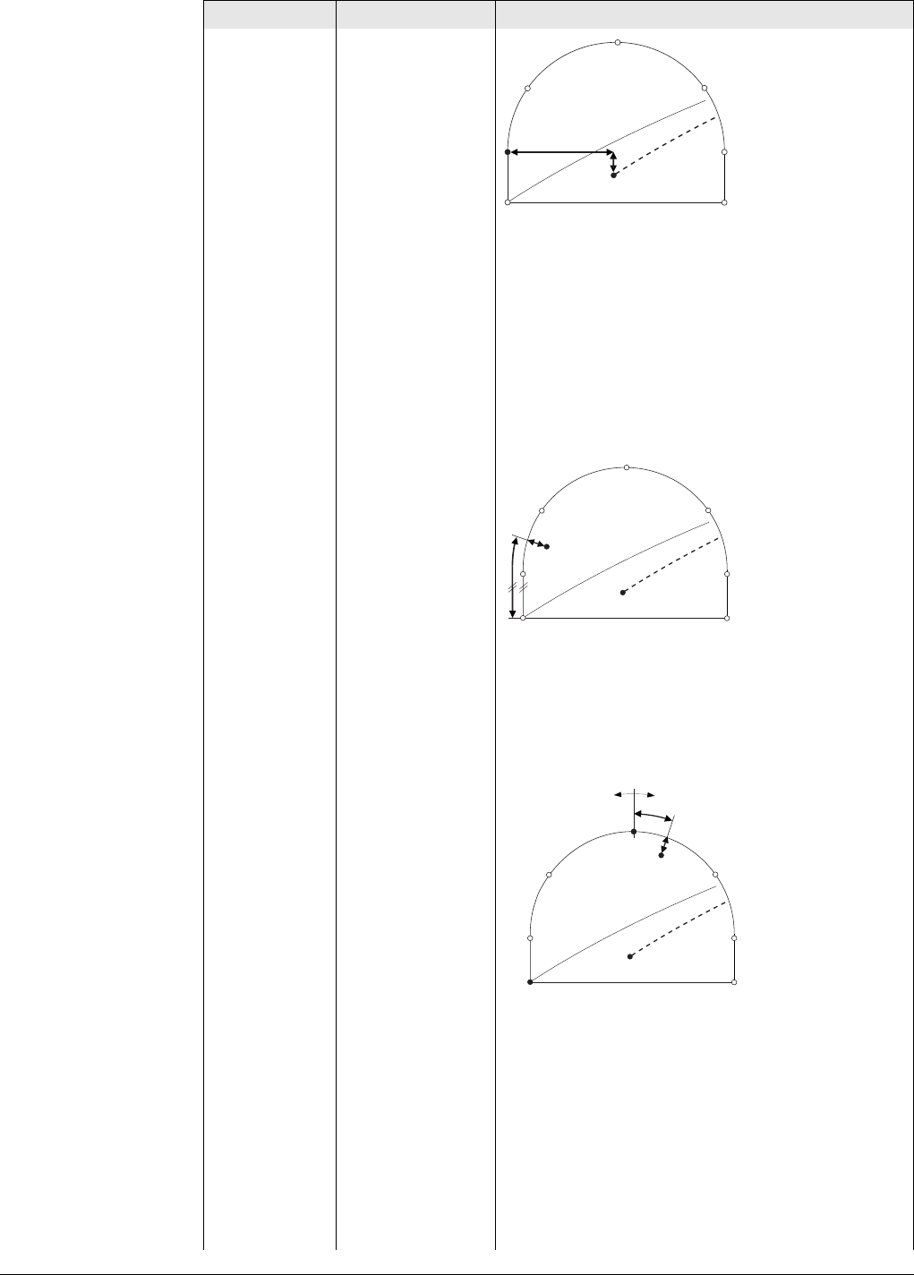
Viva Series, Roads - Tunnel 731
a) Centreline
b) Centreline height difference
c) Centreline offset
From job The offsets of the point are stored as coordinates
in the Working job. The Stake offset is stored as
the X coordinate and the Stake height diffis
stored as the Y coordinate.
Profile, dist &
offset The point is defined by the distance from the
start of the profile and an offset perpendicular to
the design profile.
a) Centreline
b) Profile offset
c) Distance from start of design profile
Dist from
top&offset The point is defined by the distance from the top
of the tunnel and an offset perpendicular to the
design profile.
a) Centreline
b) Top of profile
c) Offset perpendicular to the profile segment
d) Distance from the top of the profile
Element & offset The point to stake out is defined by:
1) The number of the element on which the
point lies
2) The percentage of the distance along the
element of the point to stake out
3) The offset perpendicular to the design
profile.
Field Option Description
c
b
a
Tunnel_018
ca
b
Tunnel_019
a
c
b
+-
d
Tunnel_028
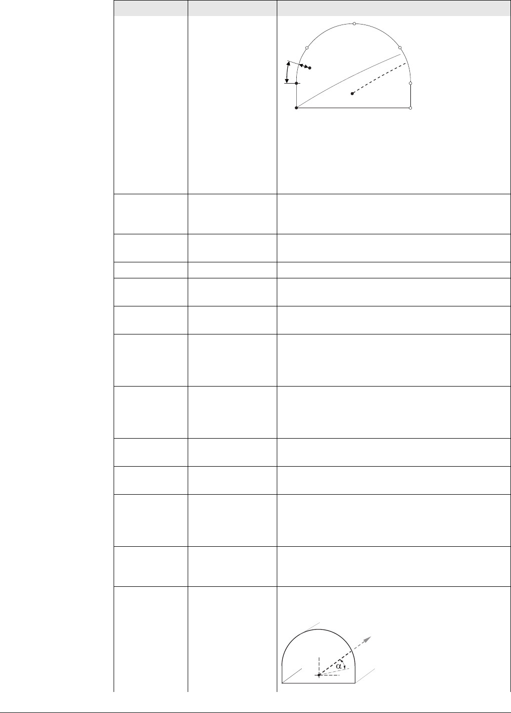
Viva Series, Roads - Tunnel 732
a) Centreline
b) Point defining start of design profile
c) Offset perpendicular to profile segment
d) Distance from start of start point of segment
in %
e) Start point of segment
Stake offset Editable field Applies a horizontal offset perpendicular to the
centreline. Available for Input method:Offset &
height.
Stake height
diff Editable field Applies a vertical offset to the centreline. Avail-
able for Input method:Offset & height.
Point ID Selectable list Available for Input method:From job.
Profile
distance Editable field The distance from start of design profile. Avail-
able for Input method:Profile, dist & offset.
Top distance Editable field The distance from the top of the tunnel. Available
for Input method:Dist from top&offset.
Profile offset Editable field The offset from the design profile. Available for
Input method:Profile, dist & offset, Input
method:Dist from top&offset and Input
method:Element & offset.
Increment Editable field To increment the distance for offset definitions
as distance and offset. Available for Input
method:Profile, dist & offset and Input
method:Dist from top&offset.
Element no. Editable field Element number 1 is the first element of the
design profile.
% Element Editable field Distance in percentage terms of the measured
point along the design profile element.
Check offset Editable field Available for Method to use:Check profile.
Applies a horizontal offset perpendicular to the
centreline used for comparing to the measured
point.
Check height
diff Editable field Available for Method to use:Check profile.
Applies a vertical offset to the centreline used for
comparing to the measured point.
Drill hz angle Editable field The horizontal direction 0 is along the centreline
of the tunnel alignment.
Field Option Description
de
a
b
c
Tunnel_020
Tunnel_034
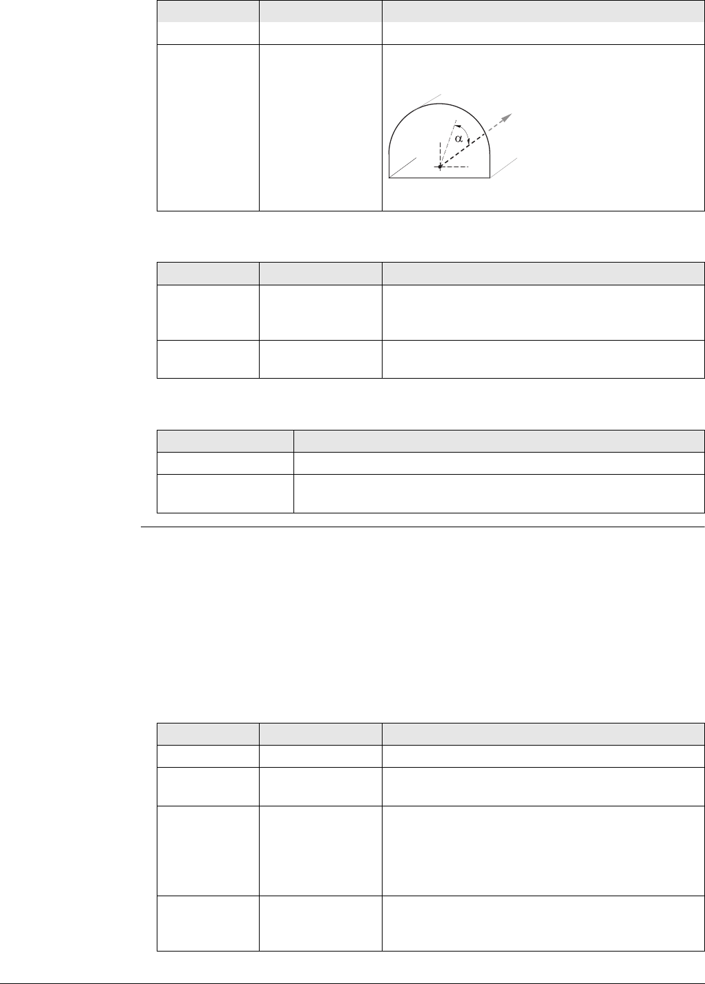
Viva Series, Roads - Tunnel 733
For Tunnel - As built check
Next step
Stake face/Stake
profile,
Stake page
This page is available for Tunnel - Stakeout only.
This page displays the differences between the measured point and the defined point.
The position of the point to stake is reached when all difference values are close to
zero.
Refer to "Stake face/Stake profile/Check profile, General page" for a description of
keys.
Refer to "53.4 Staking Out" for a description of the elements of the graphical display.
Description of fields
αDrill hz angle
Drill v angle Editable field The vertical direction 0 is along the centreline of
the tunnel alignment.
αDrill v angle
Field Option Description
Check offset Editable field Applies a horizontal offset perpendicular to the
centreline used for comparing to the measured
point.
Check height
diff Editable field Applies a vertical offset to the centreline used for
comparing to the measured point.
IF you work with THEN Page changes to the
Tunnel - Stakeout Stake page.
Tunnel - As built
check Info page.
Field Option Description
Tunnel_035
Field Option Description
Chainage Display only The current chainage.
CL O Display only Perpendicular horizontal offset from the centre-
line.
chainage Display only Difference between the Stake chainage and the
current chainage.
If no defined chainage exists, for example if
staking out random chainages or checking, this
field shows -----.
O Display only Horizontal offset between the defined position
and the current position. The offset defined on
the Offsets page is taken into account.
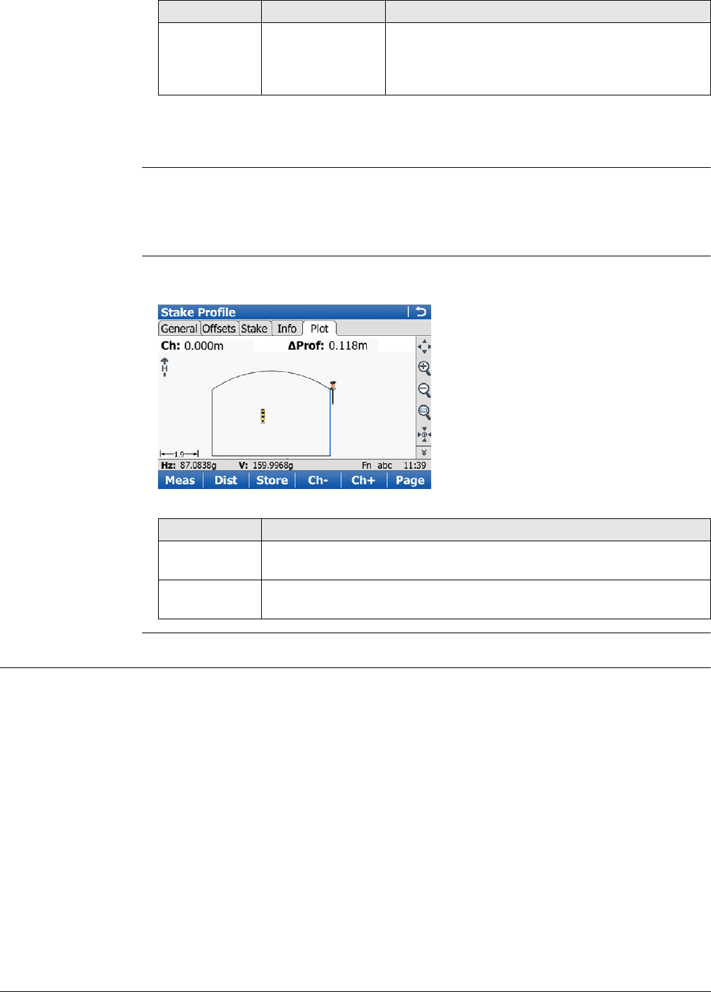
Viva Series, Roads - Tunnel 734
Next step
Page changes to the Info page.
Stake face/Stake
profile/Check
profile/Scan profile,
Info page
The Info page displays the differences between the measured and design data.
The fields viewed on this page are be configurable.
Refer to " Configuration, Info page" for information on all available items for the Info
page and how to select them.
Stake face/Stake
profile/Check
profile/Scan profile,
Map page
The Map page displays a plot of the measured point regarding the tunnel design.
This screen is an example valid for Method to use:Stake profile.
49.3.2 Stake face
Stake face Overview
When excavating a tunnel, it is required to stake out the tunnel portal before excava-
tion can begin. In addition, for excavation methods other than those involving tunnel
boring machines (TBMs), it is then required to stake out the tunnel face at given inter-
vals during the excavation.
The tunnel face can be staked out at any time within the Tunnel application using
Stake face.
This function allows the setting out of a series of points perpendicular to the hori-
zontal alignment. The horizontal alignment indicates the position of the design profile
at the chainage of the tunnel face.
height Display only Vertical offset between the defined position and
the current position. The height difference
defined on the Offsets page is taken into
account.
Field Option Description
Key Description
Ch- Available for Tunnel - Stakeout. To decrease the chainage as defined
by Chainge increment.
Ch+ Available for Tunnel - Stakeout. To increase the chainage as defined
by Chainge increment.
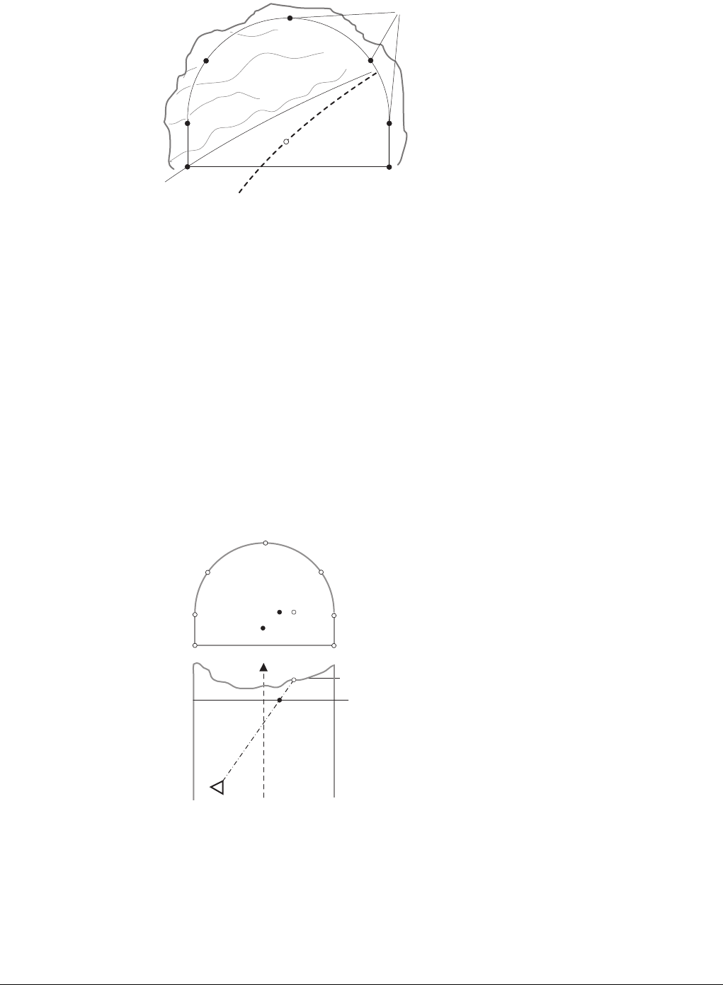
Viva Series, Roads - Tunnel 735
Cross section view
Given that it is likely that a degree of rock debris is present at the tunnel face or that
inexact excavation techniques such as blasting are used, it cannot be assumed that
the tunnel face at any stage of the excavation is perpendicular to the horizontal align-
ment.
This situation in turn implies that we cannot stake out a point on the tunnel face at a
given chainage as the chainage of the tunnel face at any particular point is unknown.
Iterative techniques are necessary to enable any defined point on the tunnel face to
be staked out accurately.
The Stake face function involves setting out a point on the tunnel face at this
unknown chainage. First of all the point to stake out on the tunnel face is staked out
at an approximate chainage (e).
The point is defined by offsets regarding the centreline or by its position along the
design profile and its offset from the profile. Given that the excavated tunnel face
does not intersect the defined chainage, another point (e') is measured.
First iteration
The true chainage of the measured point of the first iteration (e') is then calculated.
The defined point (e) is staked out at the calculated chainage (d).
a) Points to stake out
a) Centreline
b) Instrument position
c) Tunnel face
d) Approximate chainage to stake out
e) Point to stake out at approximate
chainage
e') Point to stake out on tunnel face
a
Tunnel_015
d
c
e
e
e'
e'
a
a
b
Tunnel_016
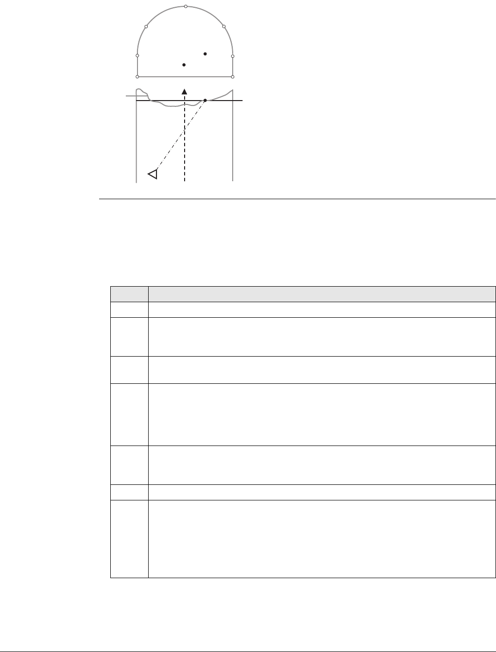
Viva Series, Roads - Tunnel 736
Second iteration
This process is repeated until the differences between staked point and the defined
point are within a tolerance set by the user.
Drilling rig orienta-
tion
Description
This functionality helps to orientate the drilling rig when drilling holes parallel to the
tunnel axis or using a drilling pattern, that is manual entry of drill direction.
Drilling rig orientation step-by-step with Drilling rig orientation:Parallel to align-
ment
a) Centreline
b) Instrument position
c) Tunnel face
d) Calculated chainage from first iteration
e) Point to stake out at calculated
chainage
d
e
e
a
a
b
c
Tunnel_017
Step Description
1. Make sure that Tunnel - Stakeout and Method to use:Stake face is selected.
2. In Tunnel Configuration, Tunnel design page, set Drilling rig
orientation:Parallel to alignment. Refer to "Configuration, Tunnel design
page".
3. In the Define screen check Drilling rig orientation and type in the values.
Refer to "Defining the Work".
4. If Drilling rig orientation:Parallel to alignment was selected in Tunnel
Configuration, Tunnel design page and Check Jumbo position was checked
in the Define screen, then proceed to define the drill entry position on the
tunnel face by entering the respective centreline offset in Stake Face,
Offsets page.
5. In Stake Face, General page, enter the approximate tunnel face chainage.
To position the laser pointer to the drill entry point press Fn Positn to find
the point.
6. Position the drill bit to the laser point on the tunnel face.
7. Now the jumbo boom moves onto line between the laser point on wall and
the telescope so that the laser now points at the back of the boom. Press Fn
Tools... Select Check Jumbo position to get the delta angles which will be
used by the drilling rig to move the boom parallel to the alignment.
Horizontal angle
Vertical angle
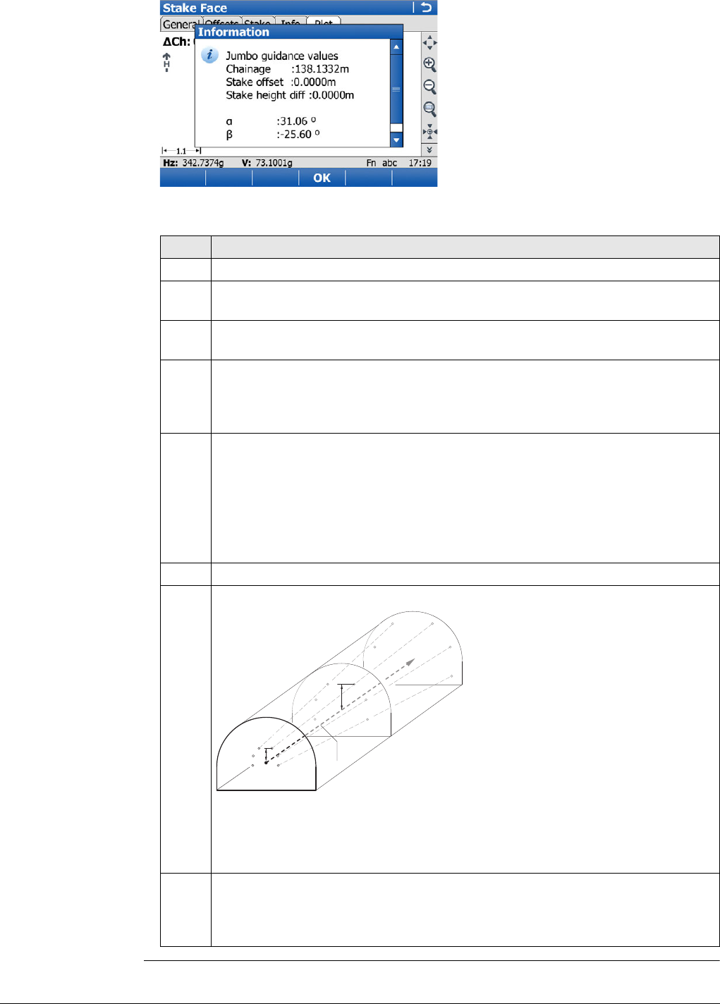
Viva Series, Roads - Tunnel 737
Drilling rig orientation step-by-step with Drilling rig orientation:Drill Pattern
Step Description
1. Make sure that Tunnel - Stakeout and Method to use:Stake face is selected.
2. In Tunnel Configuration, Tunnel design page, set Drilling rig
orientation:Drill Pattern. Refer to "Configuration, Tunnel design page".
3. In the Define screen, check Drilling rig orientation and select the application
of the drill pattern. Refer to "Defining the Work".
4. If Apply drill pattern from:Defined Chainage was selected, then proceed to
define the drill entry position for the measured chainage by entering the
defined chainage centreline offsets in the Stake Face, Offsets page and the
drill angles according to the defined chainage.
5. In the Stake Face, General page, enter the defined chainage value in the
Stake chainage editable field. To position the laser pointer correctly on the
measured tunnel face press Fn Positn.
The delta chainage value after using Fn Positn is the difference
between the defined and measured chainage. It is normal if this is
large. The delta position and delta height values after this step should
equal zero.
6. Position the drill bit to the laser point on the tunnel face.
Example:
aChainage 10
bChainage 15
cChainage 20
dCentreline
d1 Stake height diff at defined
chainage 10
d2 Stake height diff at defined
chainage 15
Stake face point 1 at chainage 10 (point1). Stake face point 1 at
chainage 15 as defined at chainage 10. Position and direction at
chainage 15 are a result of the Stake offset, Stake height diff and
drilling angles as defined for chainage 10.
7. Now the jumbo boom moves onto line between the laser point on wall and
the telescope so that the laser now points at the back of the boom. Press Fn
Tools... Select Check Jumbo position to get the delta values which will be
used by the drilling rig to move the boom for the correct drilling direction.
d
a
d1
d2
b
c
Tunnel_033
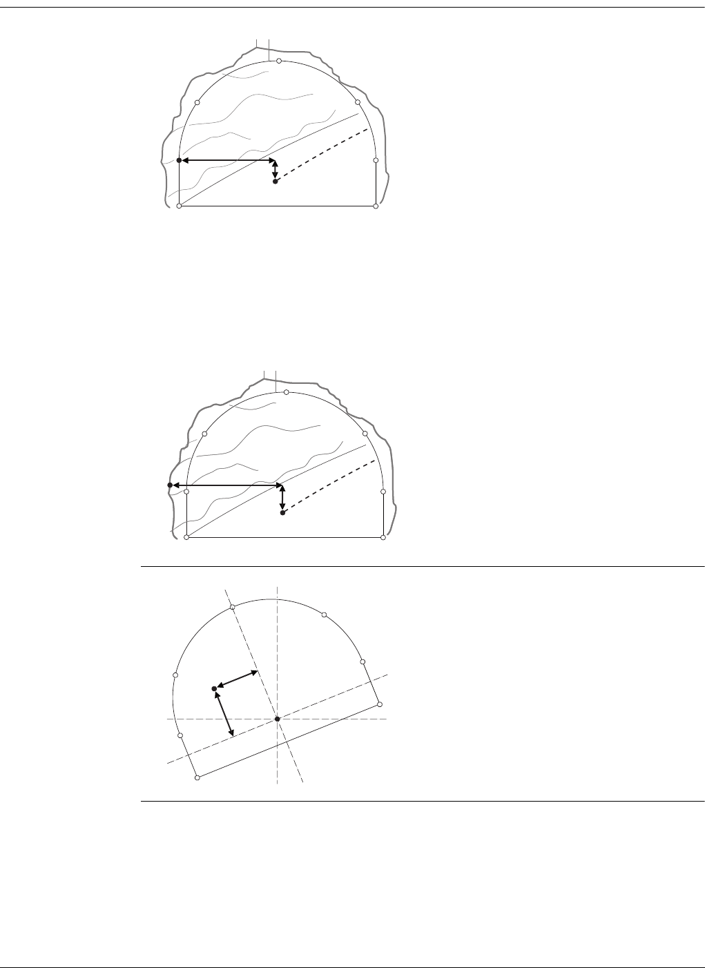
Viva Series, Roads - Tunnel 738
49.3.3 Stake profile and Check profile
Stake/Check point
on surface
If it is not possible to stake out the defined point between successive iterations, the
instrument will maintain the chainage and height difference from the vertical align-
ment fixed. The horizontal offset from the centreline to calculate the new position of
the point are modified. The point that will be staked out will thus maintain the defined
chainage and height difference but will have a modified offset value from the centre-
line.
Rotated profile
a) Centreline
b) Design point to stake out
c) Excavated profile
d) Design profile
e) Centreline offset
f) Centreline height difference
a) Centreline
b) Point to stake out on excavated profile
c) Excavated profile
d) Design profile
e) Centreline offset
f) Centreline height difference
e
f
b
cd
a
Tunnel_021
e
f
b
cd
a
Tunnel_022
a) Centreline
b) Rotated centreline offset
c) Rotated centre height difference
c
b
a
Tunnel_029
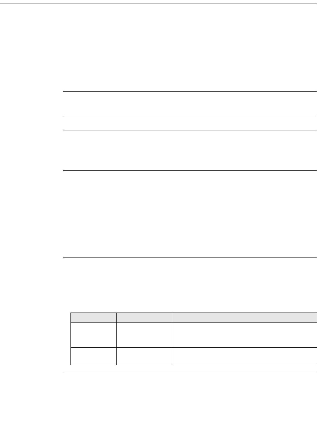
Viva Series, Roads - Tunnel 739
49.3.4 Scan profile
Overview A tunnel surface is scanned in detail during construction and/or at the completion of
construction to detect overbreak, underbreak and/or to create an 'as built plan' of the
finished tunnel surface.
Scan profile allows measuring a user-defined number of tunnel profiles along an
existing tunnel alignment.
It can be defined:
• Whether to scan the whole tunnel profile or just a segment of it.
• The interval between measurements around the profile.
It does not matter if a design profile exists in the job or not.
If the job does not contain a design profile, then before scanning the defined scan
area the instrument will first scan a profile at the instrument chainage.
For a description of the Scan profile,Scan area page, refer to "49.3.1 Overview".
During a scan During a scan
•Pt+: To skip the point being measured and move onto the next profile point.
•Prof+: To stop scanning the current profile and move onto the next profile.
•Temp: To enter a temporary scan interval.
Pause and options
before continuing
It is possible to end the scan once started using Stop. To pause the scan, for example
to allow passing site traffic through, use Pause.
Once the scan has been paused, several options are available before continuing:
•Stop: To end the scan.
•Resum: To continue the scan at the next position.
•Manual: To interrupt the current scan so aiming can be done manually and
points added.
•Auto: After measuring points manually, press Auto to continue scanning where
you finished before pressing Manual.
Define Temp Scan
Interval By pausing the current scan and pressing Temp, a temporary scan interval can be
entered. This results in all scan segments being scanned at the defined temporary scan
interval until the Define Temp Scan Interval screen is re-entered and Use a temporary
scan interval is unchecked.
Description of fields
Field Option Description
Use a tempo-
rary scan
interval
Check box If this box is checked, then scanning stops and
any defined scan interval is ignored and replaced
by the temporary scan interval.
Temporary
scan interval Editable field How often a point is measured around a profile.
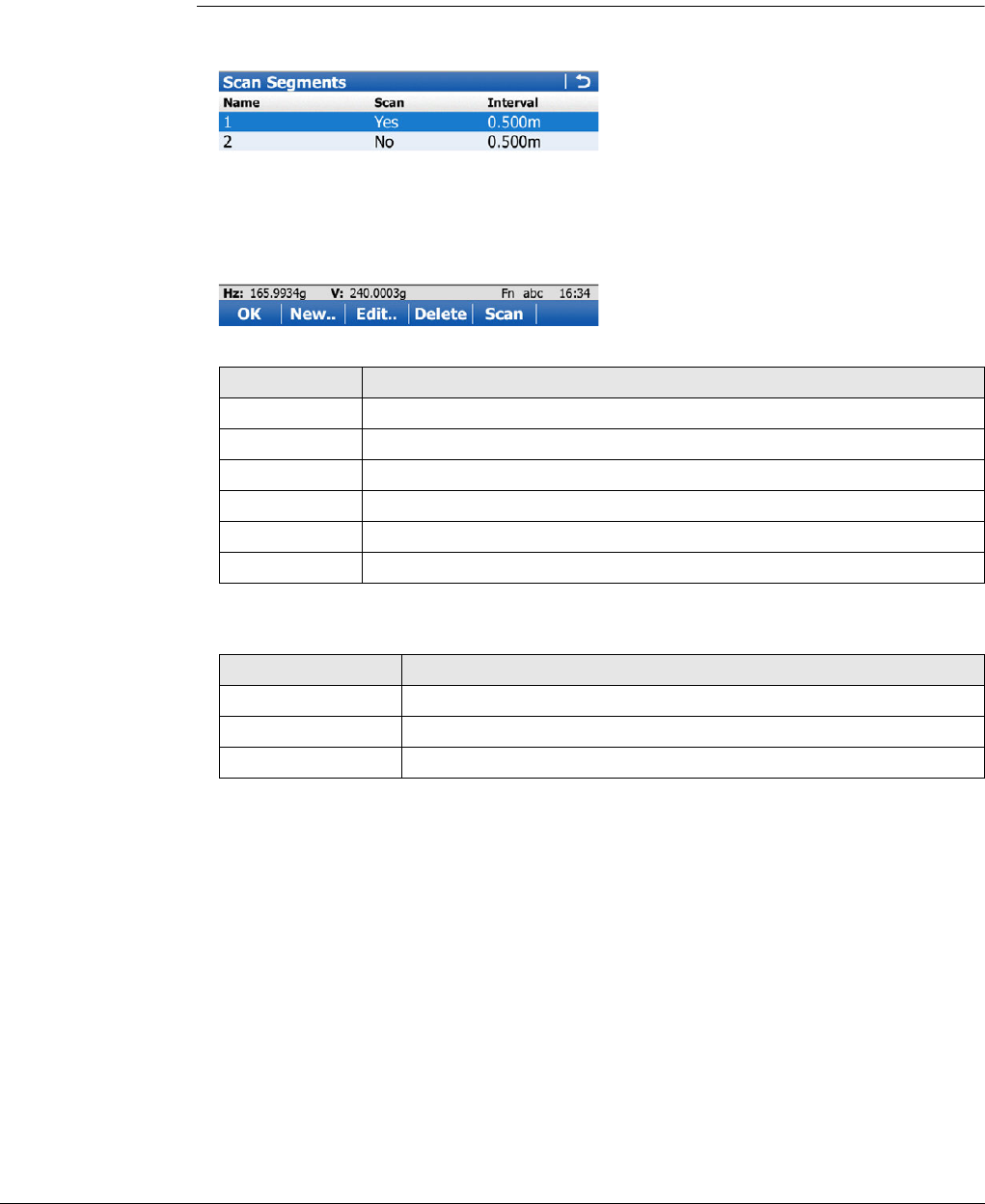
Viva Series, Roads - Tunnel 740
Invalid measure-
ments
This process is repeated until the measured point is within the chainage limit or the
maximum number of iterations has been reached.
Invalid measurement situations could occur, for example:
• in irregular tunnel surfaces, where the horizontal alignment is formed by a curve
with a small radius.
• if the end distance or start distance defined in Scan Profile, Scan area page
were too large.
Scan Segments If Define a scan task:Scan using segment was selected in the Define screen, then
the Scan Segments screen allows creating, editing or deleting scan segments.
Description of columns
Next step
New.. to access New Scan Segment.
New Scan Segment
This screen allows the definition of one or multiple segment(s) of the scan profile as
opposed to scanning the whole profile.
Key Description
OK To continue to Scan Profile after defining the scan segments.
New.. To create a new scan segment.
Edit.. To edit a defined scan segment.
Delete To delete a defined scan segment.
Scan To set Yes or No in the Scan column for the highlighted segment.
Fn Quit To exit the application.
Column Description
Name Name of the scan segment.
Scan Status to scan or not scan a segment.
Interval How often a point is measured around the profile.
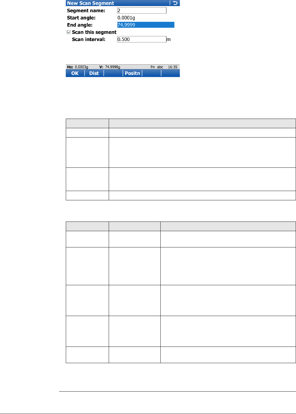
Viva Series, Roads - Tunnel 741
When defining the scan segment, define the start and end angles in the station
profile. The vertical circle values are used not the horizontal circle values so
transit the telescope between face 1 and 2 as needed.
Description of fields
If overlapping segments are defined, then a non scan segment has priority over
a scan segment.
Key Description
OK To store the defined scan segment and return to Scan Segments.
Dist To measure the distance to points at the starting angle and the end
angle of a segment. When Start angle or End angle is highlighted, set
the verticle circle values by aiming the telescope at the relevant point
and press Dist.
Positn To review the position of the segment once it has been defined. The
instrument turns to the corresponding angle. Available when Start
angle or End angle is highlighted.
Fn Quit To exit the application.
Field Option Description
Segment
name Editable field The name of the scan segment.
Start angle Display only The angle measured to the point at the beginning
of the segment.
Highlight this field, aim at the start of the
segment and press Dist to see the angle value in
this field.
End angle Display only The angle measured to the point at the end of the
segment.
Highlight this field, aim at the end of the segment
and press Dist to see the angle value in this field.
Scan this
segment Check box When this box is checked, the segment is
scanned.
When this box is not checked, the segment is not
scanned.
Scan interval Editable field Defines how often a point is measured in this
segment of the profile.
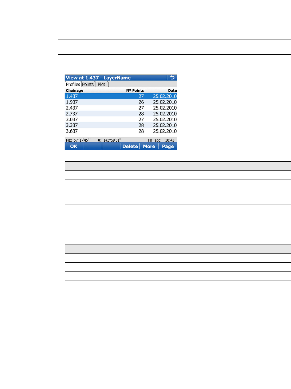
Viva Series, Roads - Tunnel 742
49.4 The Tools Menu
49.4.1 Profile Viewer
Availability This menu function is available for the check method Scan profile.
This menu option is always available. The data that can be viewed depends on those
data available in the working job. It is independent of the currently measured Scan
Profile points.
The measured profiles to be viewed must be saved in the working job.
Access Press Fn Tools.. on the Scan Profile page.
View at - Layer
Name,
Profiles page
Description of columns
Next step
Page changes to the Points page. The points belonging to the profile which is high-
lighted on the Profiles page are displayed. Points can be deleted from the profile.
Page changes to the Map page.
Key Description
OK To confirm the settings and return to the Scan Profile screen.
Delete To delete the highlighted profile.
More To display information about the time and the date of when the
profile was stored.
Page To change to another page on this screen.
Fn Quit To exit the application.
Column Description
Chainage The chainage of the profile.
Nº Points The number of points in the profile.
Time and Date The time and the date of when the profile was stored.
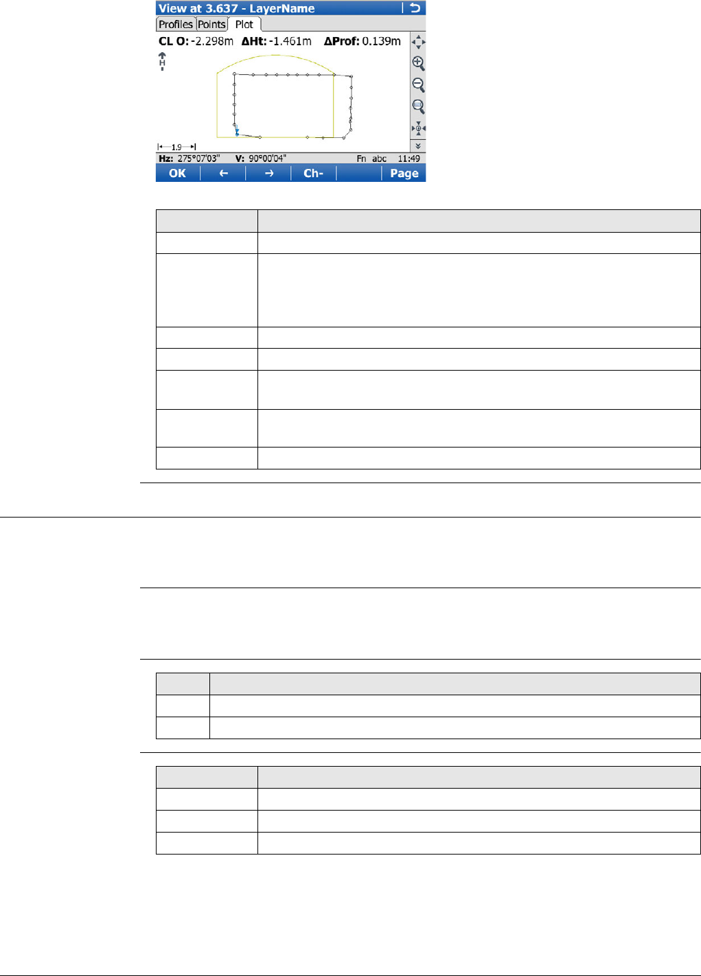
Viva Series, Roads - Tunnel 743
View at - Layer
Name,
Map page
49.4.2 Stake face auto
Description To stakeout tunnel face points automatically. The surveyor configures and selects the
points to use in the stakeout. The person driving the drilling machine can see the
stakeout points looking to the current position of the laser.
Availability This menu function is available for the stake method Stake face.
This menu option is available if the defined chainage has a valid value.
Measure mode: Continuous is supported.
Access
Stake Face Auto,
General page
Key Description
OK To accept the settings and return to the Scan Profile screen.
<-- or --> To select the relevant point in the plot. The information displayed
shows the centreline offset, the delta height and delta profile of the
point.
Points can also be selected on the touch screen.
Ch- or Ch+ To decrease/increase the chainage.
Page To change to another page on this screen.
Fn Config.. To access MapView configuration settings. Refer to "37.3 Configuring
MapView".
Fn Positn To position the total station to the defined point, including defined
offsets.
Fn Quit To exit the application.
Step Description
1. Press Fn Tools.. in Stake Face.
2. Select Stake Face Auto in Stake Face Toolbox.
Key Description
OK To access the Stake Face Auto screen.
Page To change to another page on this screen.
Fn Quit To exit the application.
Viva Series, Roads - Tunnel 744
Description of fields
Next step
Page changes to the Points page.
Stake Face Auto,
Points page
Select the points to include in the stakeout.
Description of columns
Next step
Page changes to the Map page.
Field Option Description
Store staked
points Check box When this box is checked, the staked points are
stored.
Wait time after
staked point Check box When this box is checked, a time delay is active
after staking a point and before staking the next
point starts.
Delay Editable field The time delay after staking a point and before
staking the next point starts. Available when Wait
time after staked point is checked.
Verify orienta-
tion Check box When this box is checked, the system checks
orientation automatically in a defined interval. If
the orientation error is greater than the defined
Hz tolerance, then the auto mode is stopped.
Orientation
job Selectable list A point for the orientation check can be selected
from a job on a data storage device. Available
when Verify orientation is checked.
Orientation
point Selectable list The point ID of the point for the orientation
check. Available when Verify orientation is
checked.
Hz tolerance Editable field Tolerance for horizontal directions. If the orienta-
tion error is greater than the defined angle, then
the auto mode is stopped. Available when Verify
orientation is checked.
Key Description
OK To access the Stake Face Auto screen.
Use To set Yes or No in the Use column for excluding/including the high-
lighted point.
Any line can be selected on the Map page.
Page To change to another page on this screen.
Fn Quit To exit the application.
Column Description
Point ID Displays the name of all points in the selected Tunnel job.
Use For Yes: The selected point is used for stake.
For No: The selected point is not used for stake.
CL offset The horizontal offset of the point from the layer centreline.
CL ht diff The height difference of the point to the layer centreline.
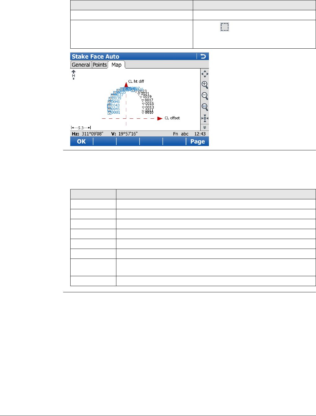
Viva Series, Roads - Tunnel 745
The Map page shows a cross section, profile and planar view of the design data at the
selected chainage.
Point selection/deselection is possible on the Map page.
Stake Face Auto When Stake face auto is activated, the measurement screen opens. In a loop, all
selected points are automatically staked indefinitely until the user stops the measure-
ment, or the orientation check is out of tolerance.
IF THEN
a single point is to be selected/deselected tap on the point.
multiple points are to be selected click the icon, drag the stylus on the
screen in a diagonal line to make a rectan-
gular area.
Key Description
Stop To stop the automatic stakeout.
Pause To pause the automatic stakeout.
Resum To re-start the automatic stakeout.
<-- To select the previous point.
--> To select the next point.
Page To change to another page on this screen.
Fn Config.. To access configuration settings. Refer to "45.3 Configuring Roads
Applications".
Fn Quit To exit the application.
Viva Series, Scanning 746
50 Scanning
50.1 Accessing Scanning
Availability Available for MS50 R2000 and on CS when connected to MS50 R2000.
Access Select Main Menu: Go to Work!\Survey+\Scanning.
Scanning Depending on the status of the job and actual instrument setup, the icons are active
or not. If a new working job and a new setup have been created, then only Create scan
definition and Scan settings are active.
50.2 Defining a Scan
Access Select Create scan definition in Scanning.
The New Scan Definition wizard starts.
Create Scan Defini-
tion A unique name for the new scan definition. The name can be up to 16 characters long
and include spaces. Input required.
Next changes to the next screen.
Choose Scanning
Method Description of fields
Field Option Description
Method Select one of the following options to define a
scan area.
Rectangular area Area defined by upper left and lower right corner.
Either turn the telescope manually. Or use the
Turn to point option from the context menu.
Refer to "37.6 Context Menu".
If the first point is the top left corner, then the
second point is then to the bottom right corner
point.
Or the first corner is the bottom left corner point
and the second point is then the top right corner
point.
Polygonal area Area defined by three or more corners in clock-
wise direction. Either point the telescope to the
corners (actual position of the crosshair). Or draw
the polygonal scan area on the Camera tab.
The closing line between the first and the
last point has a different line style.
Manually entered To define a scan area manually by typing in the HZ
and V value of two diagonal corners of a
rectangle.
If scan definitions have already been
defined from the current instrument
setup, the scan areas are displayed on the
Camera tab in Manually Entered Extents.
A new scan area can be defined in addi-
tion to the existing scan areas.
Full dome scan
area The scan area is the full field of view of the instru-
ment.
Viva Series, Scanning 747
Next step
Next changes to the next screen.
Camera view and
Camera page
The scan area can be defined on the camera view/Camera page of the telescope
camera and overview camera. Switching between both cameras is possible.
Description of keys
Description of icons
If Display TS camera zooming toolbar is checked in Camera View Settings, General
page, icons are available in a toolbar located on the right side of the screen. Refer to
"Overview of keys, softkeys and icons" for the right toolbar icons.
The toolbar on the left side of the screen is always active.
Key Description
Next Available when defining rectangular areas. To accept the selected
point and to continue with the subsequent screen within the wizard.
Available when defining a scan area manually. To accept the defined
extension of the scan area and to continue with the subsequent
screen within the wizard.
Add Available when defining polygonal areas. To add the current crosshair
position as a next point to the polygonal area.
Dist To correct the paralaxe by taking a reflectorless distance measure-
ment. The crosshair style changes from the coarse style to the fine
style.
Done Available when defining polygonal areas. To confirm the defined scan
area and to proceed to the subsequent screen. At least three points
must be defined.
Back To return to the previous screen where the definition mode can be
selected.
Fn Config.. To configure the camera view. Refer to "Camera View Settings,
General page".
Fn Quit To exit the screen.
Icon Description
To scroll the toolbar.
Drawing mode is active. To add a point to the polygonal area tap the
point on the display. Moving by joystick is active in the drawing mode.
Tab and turn mode is active. To add a point to the polygonal area tab
a point on the display. The instrument turns so that the digital cross-
hairs on the display point to the tapped point. Check the point and
press Add.
To delete the last selected point of the polygonal area.
To delete the whole boundary of the polygonal area and to re-start
the definition of the polygonal scan area.
Viva Series, Scanning 748
Scan Resolution The resolution has a direct influence on the file size.
Description of fields
Next step
Next changes to the next screen.
Scan Mode
Description of fields
Key Description
Next To accept changes and to continue with the subsequent screen
within the wizard.
Dist Available when Define spacing by: Distances is selected. To take a
reflectorless distance measurement. The measured value is displayed
in the Slope distance.
Back To return to the previous screen.
Fn Quit To exit the screen.
Field Option Description
Define
spacing by Angles The scan resolution is defined by horizontal and
vertical angle values.
Distances The scan resolution is defined by horizontal and
vertical spacings at a certain range.
Hz and VEditable field Available for Define spacing by:Angles. The
horizontal and vertical angle values defining the
scan resolution.
Slope
distance Editable field Available for Define spacing by:Distances. The
range for which the horizontal and vertical
spacing are valid.
Horizontal
spacing and
Vertical
spacing
Editable field Available for Define spacing by:Distances. The
horizontal and vertical spacing defining the scan
resolution at the defined range.
Estimated
points Display only The estimated number of points to be scanned
according to the defined scan resolution.
Key Description
Next To accept and record the scan mode.
Dist To measure and display distances.
Back To return to the previous screen.
Fn Quit To exit the screen.
Field Option Description
Optimise scan
for.. 1000 pts/s, up to
300m • 1000 Hz scanning mode.
• Range up to 300 m.
• Optimal to use when time is critical.
Viva Series, Scanning 749
Next step
Next changes to the next screen.
Scan Distance Filter
Description of fields
Next step
Finish to exit the wizard.
250 pts/s, up to
400m • 250 Hz scanning mode.
• Range up to 400 m.
• Optimal for use when time and accuracy are
critical.
62 pts/s, up to
500m • 62 Hz scanning mode.
• Range up to 500 m.
• Optimal for use when accuracy and range are
critical.
Approx 1 pt/s, up
to 1000m • 1 Hz long range mode.
• Range up to 1000 m.
• Optimal for long range applications
Time required Display only The time that the measurement needed.
Average scan
distance
(optional)
Editable field Slope distance to the scanning object. This
distance is optional. By knowing the distance to
the object, the system optimises the scanning
speed.
Field Option Description
Key Description
Finish To exit the wizard.
Back To return to the previous screen.
Fn Quit To exit the screen.
Field Option Description
Use distance
filter - only
objects within
the minimum
& maximum
distance will
be scanned
Check box When this box is checked, only objects within the
defined distance range are scanned.
Min distance Editable field Minimum distance of the scan distance.
Max distance Editable field Maximum distance of the scan distance.
Viva Series, Scanning 750
50.3 Configuring Scanning
Access Select Scan settings in Scanning.
Scan Settings
Description of fields
Key Description
OK To return to Scanning.
Fn Quit To exit the screen.
Field Option Description
Store signal to
noise ratio
(SNR) values
with scan
points
Check box When this box is checked, the value of the Signal
to Noise Ration of the returned signal is stored as
additional information to the scan area.
Store scan
area on pano-
ramic image (if
panoramic
image is
captured)
Check box When this box is checked, the scan area is laid
over the image and stored with the image when a
panoramic image is captured.
Pause scan-
ning when a
message is
shown
Check box When this box is checked, a scan is paused when
a message is shown.
Apply filter to
optimise the
point cloud
Check box When this box is checked, the filter creates an
optimum of the point cloud regarding data
quality.
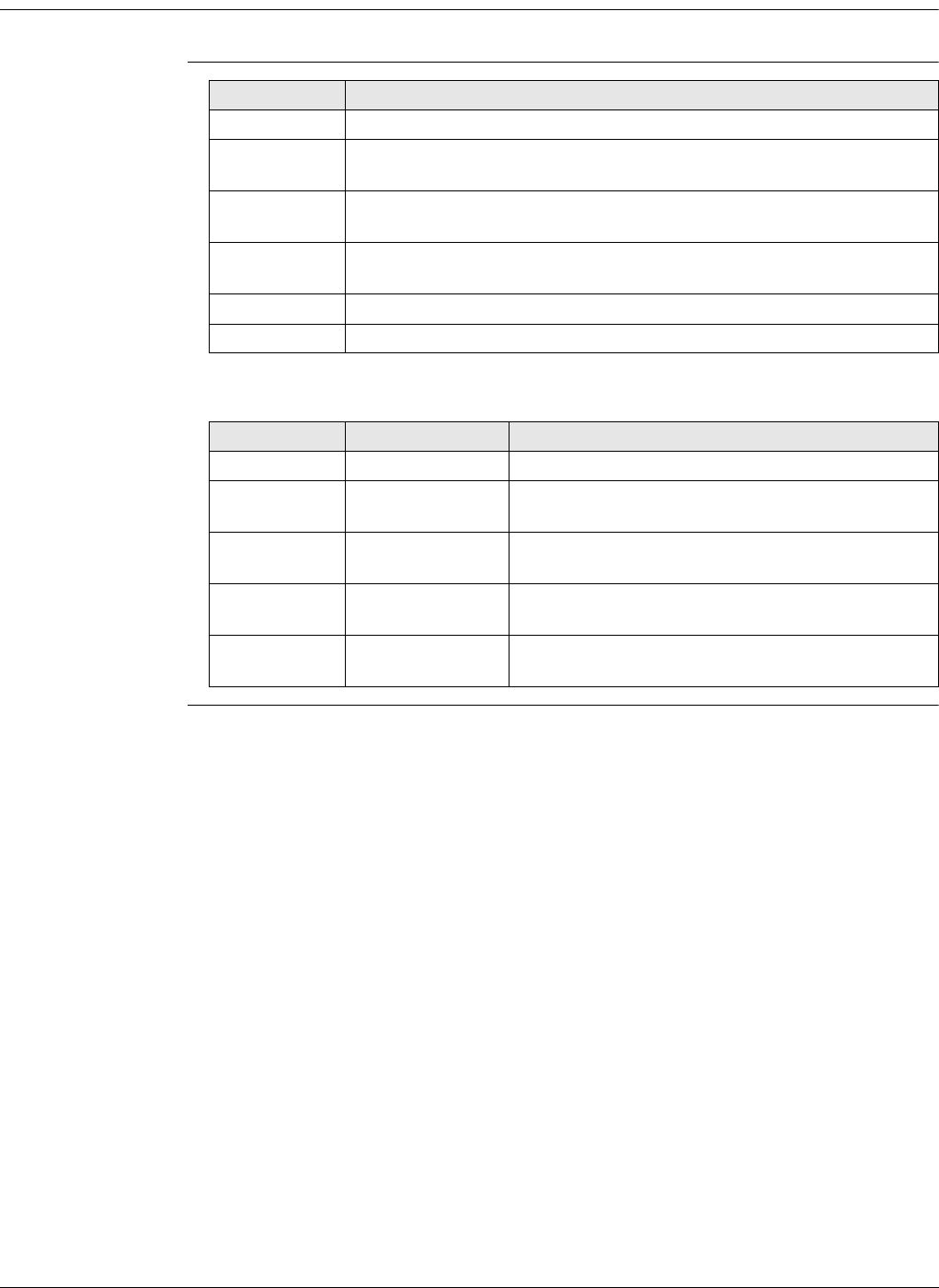
Viva Series, Scanning 751
50.4 Starting a Scan
Access Select Start scan in Scanning.
Scan Status,
Progress page
Description of fields
Key Description
Start To start scanning.
Stop To end scanning. By stopping the scan, the already scanned points
are stored in a file. The scan gets the status Scan completed.
Pause and
Scan To pause/re-start scanning.
Cpture Available as long as the scan has not yet started. To take an image
with the current pixel resolution.
Page To change to another page on this screen.
Fn Quit To exit the screen.
Field Option Description
Scan name Display only Then name of the first or current scan.
Points
scanned Display only The total number of scanned points.
% completed Display only In percent, the number of scans taken against the
total number of scans which must be taken.
Time
remaining Display only Estimated time remaining until the scan is
finished.
Scans
completed Display only Number of scans being measured / Number of
total scans
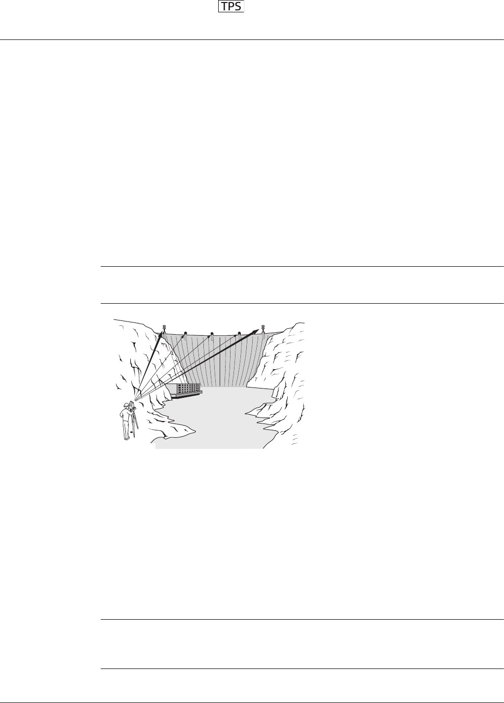
Viva Series, Sets of Angles 752
51 Sets of Angles
51.1 Overview
Description Sets of Angles:
• This application is used to measure multiple sets of directions and distances
(optional) to pre-defined target points in one or two faces. The application can
include Monitoring as an option.
• The mean direction and mean distance (optional) to each target point, within a set
is calculated. The residual for each direction and distance (optional) within a set is
also calculated.
• The reduced average direction and average distance (optional) to each target point,
for all active sets is calculated.
• Coordinates to each target point are calculated using the reduced average direction
and average distance (optional).
Monitoring:
• This module can be integrated within the Sets of Angles program.
• With this module, it is possible to use a timer to enable repeated and automated
angle and distances measurements to pre-defined target points at defined inter-
vals.
If the message panel appears which requires that the application must be activated via
a license key then refer to "30.3 Load licence keys".
Diagram
Automatic aiming Automatic aiming (search and measurements) can be performed to a prism. After
completing the first measurements to each target point, the measurements to the
target points in subsequent sets are automated.
Known:
P1 Pre-defined target point - E,N,Height (optional)
P2 Pre-defined target point - E,N,Height (optional)
P3 Pre-defined target point - E,N,Height (optional)
P4 Pre-defined target point - E,N,Height (optional)
P5 Pre-defined target point - E,N,Height (optional)
Unknown:
a) Mean direction and mean distance (optional) to each target point, within a set
b) Mean coordinates (optional) for each target point, for all active sets
c) Residual for each direction and distance (optional ), within a set
d) Reduced average direction and average distance (optional) to each target point,
for all active sets
TS_048
P1
P0
P2 P3 P4 P5
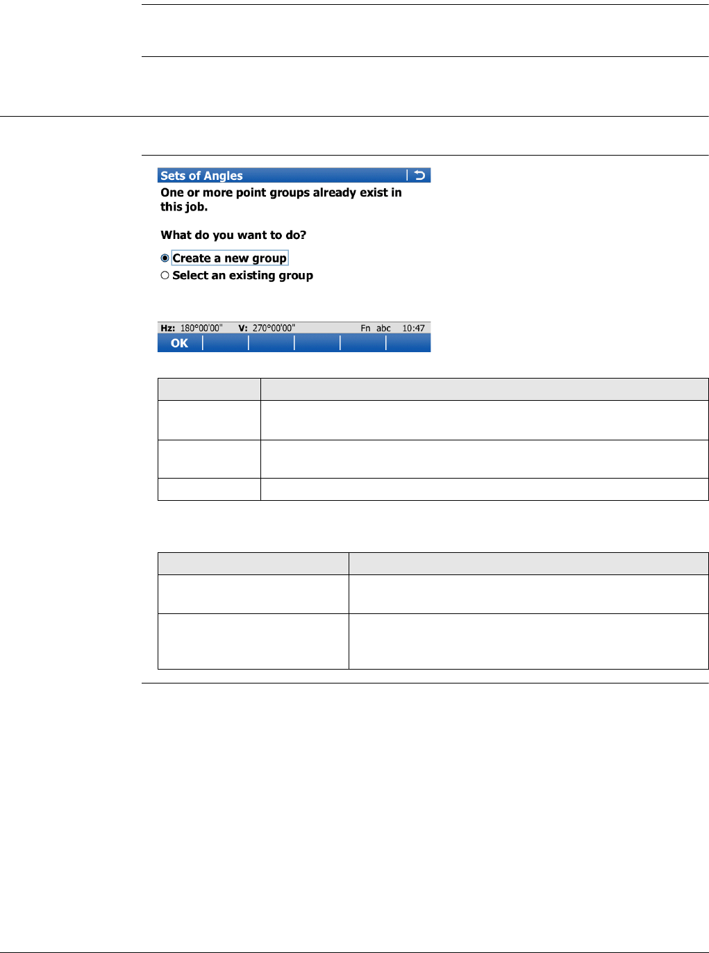
Viva Series, Sets of Angles 753
Station setup and
station orientation
If oriented grid coordinates are to be recorded, a station set up and station orientation
is required before starting the Sets of Angles application.
Point averaging Sets of Angles points are never calculated as an average, even if a measured point of
class Meas already exists with the same point ID.
51.2 Sets of Angles
51.2.1 Accessing Sets of Angles
Access Select Main Menu: Go to Work!\Survey+\Sets of angles.
Sets of Angles
Description of options
Key Description
OK To select the highlighted option and to continue with the next
screen.
Fn Config.. To configure the Sets of Angles application. Refer to "51.2.2 Config-
uring Sets of Angles".
Fn Quit To exit the application.
Options Description
Create a new group To define the target points. Refer to "51.2.3 Creating
New Point Groups".
Select an existing group To select, edit and manage a points group of the target
points for the survey. Refer to "51.2.4 Managing
Existing Point Groups".
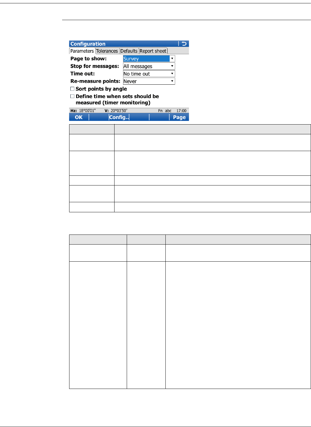
Viva Series, Sets of Angles 754
51.2.2 Configuring Sets of Angles
Access Select Main Menu: Go to Work!\Survey+\Sets of angles. Press Fn Config...
Configuration,
Parameters page
The explanations for the softkeys given here are valid for all pages, unless otherwise
stated.
Description of fields
Key Description
OK To accept changes and return to the screen from where this screen
was accessed.
Config.. To edit the survey screen page currently being displayed. Available
when a list item in Page to show is highlighted. Refer to "25.3 My
Survey Screen".
Page To change to another page on this screen.
Fn About To display information about the program name, the version number,
the date of the version, the copyright and the article number.
Fn Quit To exit the application.
Field Option Description
Page to show Selectable
list
The names of the available survey screen pages.
Stop for messages To define what action is taken when a message
screen appears during a measurement set.
All
messages All message screens are displayed as per normal
and are closed as defined by the settings in Time
out.
Tol
exceeded
only
Only the message screen relating to the exceeding
of tolerances is displayed and is closed as defined
by the settings in Time out.
Never stop No message screens are displayed except for
specific warnings.
Specific warnings which affect the instrument and
its ability to continue with the monitoring process
will be displayed and will remain on the screen.
These warnings include the overheating of the
instrument, low battery levels, or unavailable
space on the data storage device.

Viva Series, Sets of Angles 755
Next step
Page changes to the Tolerances page.
Configuration,
Tolerances page
Description of fields
Time out To define the time delay for the automatic closing
of message screens during a measurement set.
This selectable list is not available when Stop for
messages:Never stop.
No time out There is no automatic closure, only by user inter-
action in a message screen. When a message
screen appears, press Yes to close.
1sec to
60 sec
All message screens are automatically closed as
defined by these individual time settings.
Re-measure points To define the action if a target point cannot be
measured.
Never The target point is skipped and the next target
point in the list is measured.
Automati-
cally The measurement to the target point is repeated
automatically.
The option for Measure mode in Measure &
Target Settings is also changed for the
repeated measurement. If the option is
changed, then it is applied to all following
sets.
Manually The measurement to the target point can be
repeated manually or the target point can be
skipped.
Sort points by Hz
angle Check box Check this box to sort the target points automati-
cally. The instrument will work in a clockwise direc-
tion and find the shortest path to move between
the target points.
Define time when
sets should be
measured (timer
monitoring)
Check box This field is only available when Monitoring is regis-
tered through the licence key.
When this box is checked, automatic monitoring of
target points is activated.
When this box is not checked, automatic moni-
toring of target points is not activated. The Sets of
Angles application will apply.
Field Option Description
Field Option Description
Use tolerances Check box If checked, the entered horizontal, vertical and
distance tolerances are checked during the meas-
urements to verify accurate pointing and meas-
urements.
Hz tolerance Editable field Tolerance for horizontal directions.
V tolerance Editable field Tolerance for vertical directions
Distance tolerance Editable field Tolerance for distances.

Viva Series, Sets of Angles 756
Next step
Page changes to the Defaults page.
Configuration,
Defaults page
Define the default target properties for points that are added to the point group by
importing.
Description of fields
Field Option Description
Target height Editable field The default prism height.
Target Selectable list Target names as configured in the Targets
screen.
Leica constant Display only The additive constant as stored for the selected
prism in the SmartWorx Viva software.
Target aiming Manual Measurements are done without any automation.
ATR search and/or ATR measurement are not
performed.
Automatic Positioning to static prisms. The ATR sensor is
used for measurements to static prisms. If
needed an ATR measurement or ATR search is
performed after pressing Meas or Dist.
Lock Availability depends on instrument type. The
instrument locks onto and follows the moving
prism.
Visibility Good If weather conditions are normal, then select this
mode.
Rain & fog To increase the instrument measuring ability
during suboptimal weather conditions. This mode
is automatically deactivated when the instrument
is turned off.
Rain & fog
always As for Rain & fog, however this mode stays active
when the instrument is turned off.
Sun & reflec-
tions To increase the instrument measuring ability
during incident solar radiation and reflections, for
example safety vests. This mode has a consider-
able influence on the range. This mode is auto-
matically deactivated when the instrument is
turned off.
Sun & rflctns
always As for Sun & reflections, however this mode
stays active when the instrument is turned off.
Use precise target
aiming Check box Available for the 0.5" instruments of TS50/TM50.
When this check box is checked, ATR measure-
ments with higher accuracy are performed.
Use ultra fine
aiming Check box Reduces the field of view of the ATR. The setting
is only applied for Target aiming: Automatic in
Measure & Target Settings.
Automatically
survey points Check box Check this box to survey the target points auto-
matically. The instrument will automatically turn
and measure the target point. For instruments
with automatic aiming.
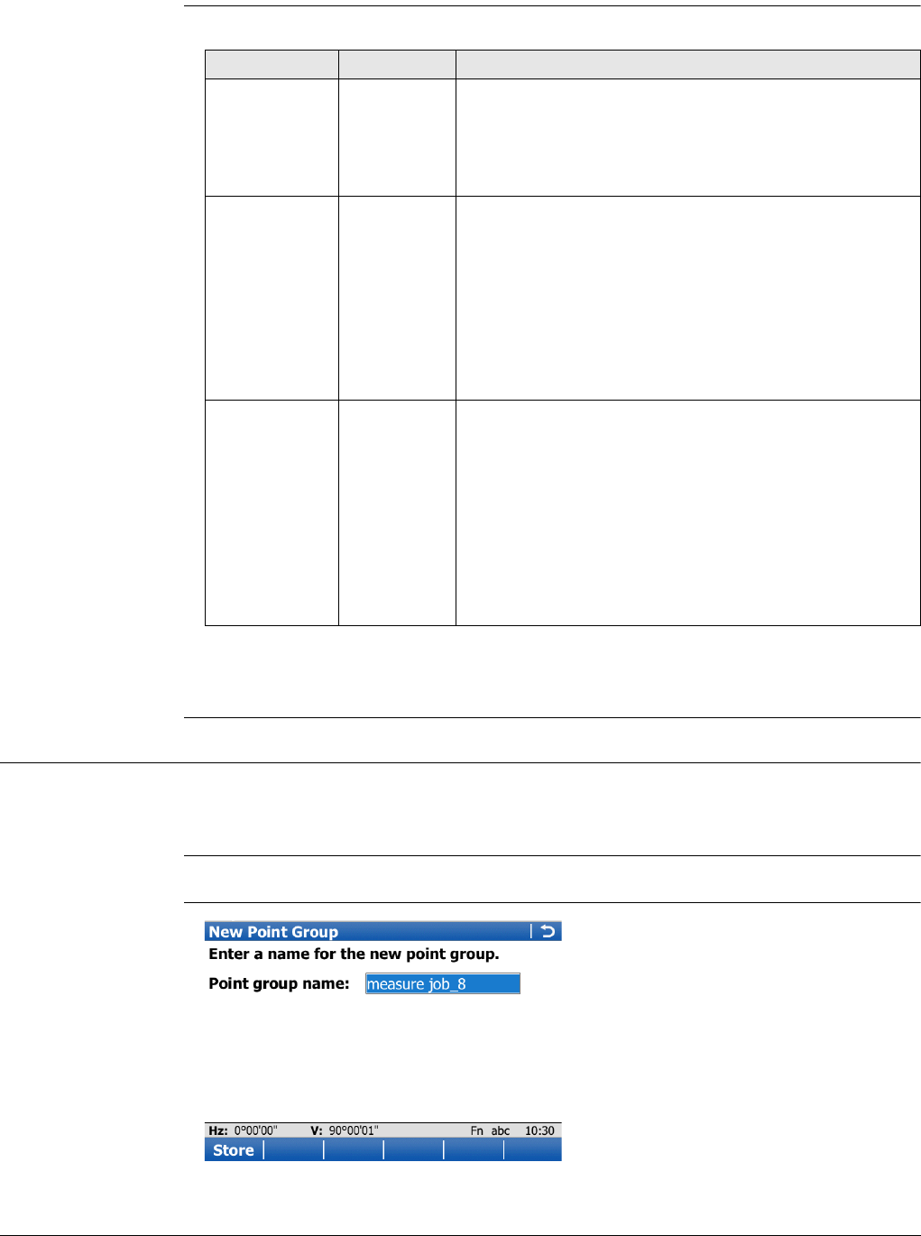
Viva Series, Sets of Angles 757
Next step
Page changes to the Report sheet page.
Configuration,
Report sheet page
Description of fields
Next step
Page changes to the first page on this screen.
51.2.3 Creating New Point Groups
Description The points to be used for Sets of Angles can be selected and the first set measured.
The measurement settings of the first measurement to each point are used for all
further sets.
Access Highlight Create a new group in Sets of Angles and OK.
New Point Group
Field Option Description
Create report
sheet Check box To generate a report sheet when the application is
exited.
A report sheet is a file to which data from an applica-
tion is written to. It is generated using the selected
format file.
Report sheet Selectable
list
Available when Create report sheet is ticked. The name
of the file to which the data will be written. A report
sheet is stored in the \DATA directory of the active
memory device. The data is always appended to the
file.
Opening the selectable list accesses the Report Sheets
screen. On this screen, a name for a new report sheet
can be created and an existing report sheet can be
selected or deleted.
Format file to
use Selectable
list
Available when Create report sheet is ticked. A format
file defines which and how data is written to a report
sheet. Format files are created using LGO. A format file
must first be transferred from the data storage device
to the internal memory before it can be selected. Refer
to "30.1 Transfer user objects" for information on how
to transfer a format file.
Opening the selectable list accesses the Format Files
screen where an existing format file can be selected or
deleted.
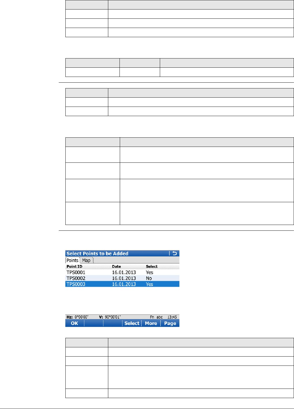
Viva Series, Sets of Angles 758
Description of fields
Add Points To Group
Description of options
Select Points to be
Added,
Points page
The points are sorted in alphabetical order. To sort points by horizontal angle,
check Sort points by Hz angle in Configuration Parameters, page.
Key Description
Store To store the new points group.
Fn Config.. To configure the Sets of Angles application.
Fn Quit To exit the application.
Field Option Description
Point group name Editable field The name of the points group.
Key Description
OK To select the checked option and to continue with the next screen.
Fn Quit To exit the application.
Option Description
Measure points When this box is checked, the points to be used for Sets of
Angles can be measured.
Use for sets Available when Measure points is checked. To select the meas-
uring sequence.
Add individual
points from a job When this box is checked, a control job can be selected. Indi-
vidual points can be selected from this job. Refer to "Select
Points - Survey, Sets page".
Add all points from
a job When this box is checked, a control job can be selected. All
points from the control job are added to the point group by
pressing OK.
Key Description
OK To store the points to the group.
Select To change the setting in the Select column for the highlighted point.
More To display information about the 3D coordinate quality, the class,
Easting, Northing and Elevation, the time and the date of when the
point was stored,
Page To change to another page on this screen.
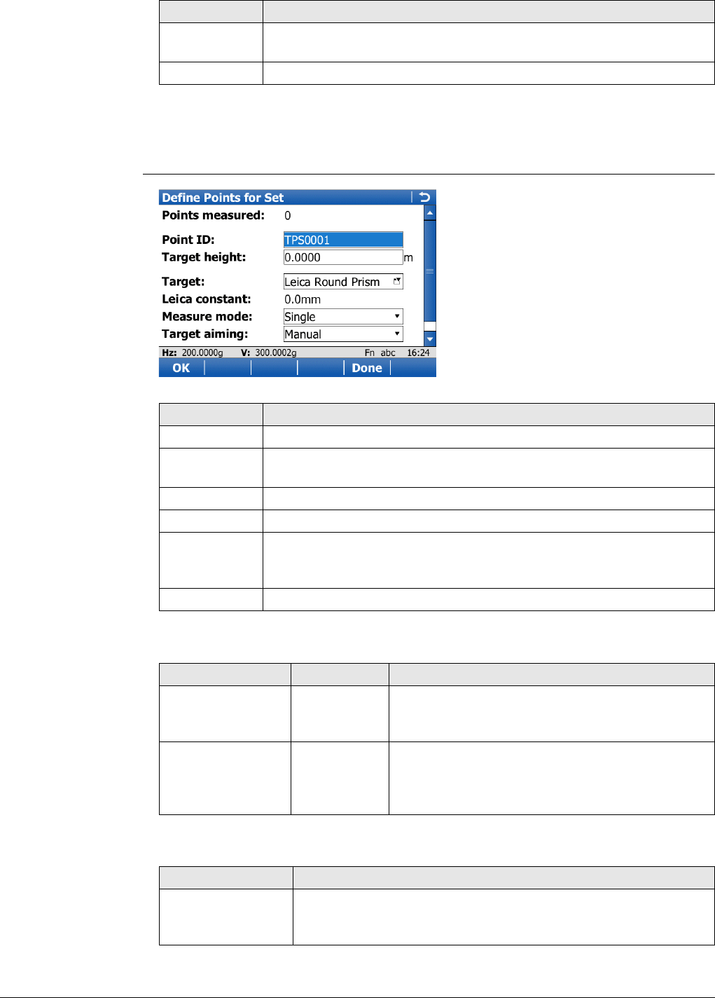
Viva Series, Sets of Angles 759
Next step
Page changes to the Plot page. The points from the list are displayed in black. The
other points from the working job are displayed in grey.
Define Points for Set
Description of fields
Next step
Fn All or Fn
None
To change the setting in the Select column for all scans at once.
Fn Quit To exit the application.
Key Description
Key Description
OK To measure the entered point and to access Select Points - Survey.
Done To finish selection of points and access Sets of Angles for further
steps.
Fn Config.. To configure the Sets of Angles application.
Fn Get Pt To select points stored in the database.
Fn IndivID and
Fn Run To change between entering an individual point ID different to the
defined ID template and the running point ID according to the ID
template. Refer to "25.1 ID templates".
Fn Quit To exit the application.
Field Option Description
Use ultra fine
aiming Check box Reduces the field of view of the ATR. The setting
is only applied for Target aiming: Automatic in
Measure & Target Settings.
Automatically
survey points Check box Available for instruments with automatic aiming
and Target aiming:Automatic. If checked, search
and measurements are done to specified targets
in additional sets.
IF THEN
new or selected
points are to be
measured
OK to access Select Points - Survey.
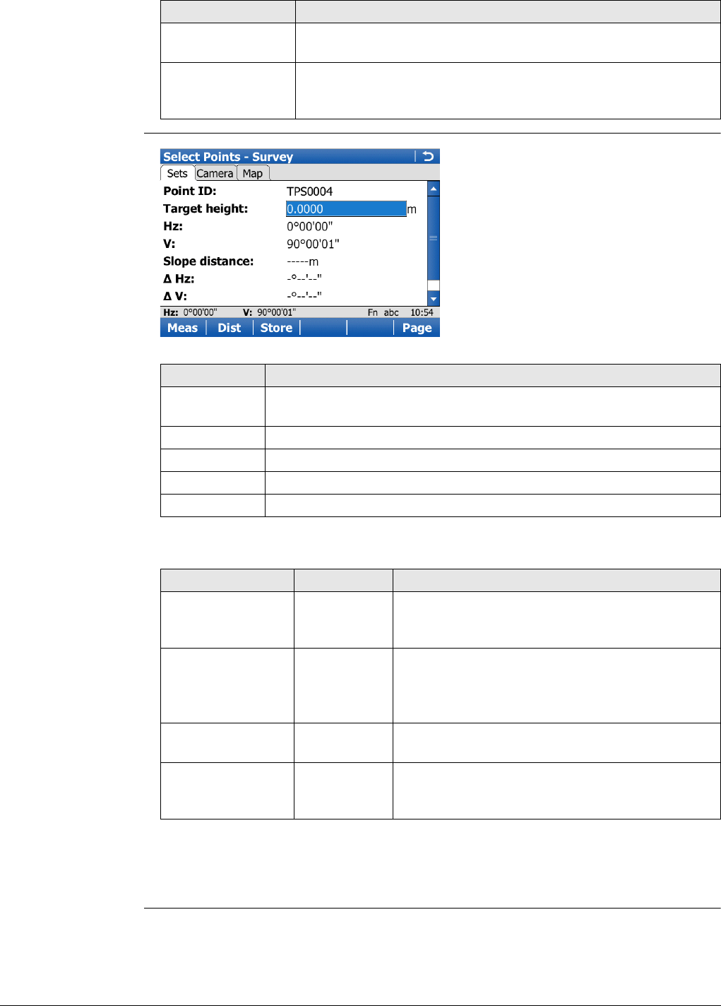
Viva Series, Sets of Angles 760
Select Points -
Survey,
Sets page
Description of fields
Next step
Meas to measure and store the angles and distance, and to return to Define Points
for Set.
existing points are
to be selected
Fn Get Pt to select a point from Data, Points page.
all desired points
have been selected
and measured
Done to return to the Manage Point Group:.
IF THEN
Key Description
Meas To measure and store the angles and distance, and to return to
Define Points for Set.
Dist To measure a distance.
Store To store data and to return to Define Points for Set.
Page To change to another page on this screen.
Fn Quit To exit the application.
Field Option Description
Hz Display only Difference between the current horizontal angle
and the horizontal angle to this target when
selected.
AR Display only Available when Hz angle display: Angle right is
configured in Regional Settings, Angle page.
Difference between the current angle right and
the angle right to this target when selected.
V Display only Difference between the current vertical angle and
the vertical angle to this target when selected.
slope Display only Difference between the current slope distance to
the target and the slope distance to this target
when selected.
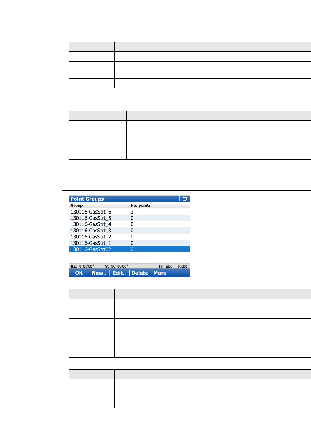
Viva Series, Sets of Angles 761
51.2.4 Managing Existing Point Groups
Description A point group of the target points for the survey can be selected.
Access Highlight Select an existing group in Sets of Angles and OK.
Existing Point
Groups
Description of fields
Next step
OK to access Point Groups.
Point Groups
Edit Point Group,
Points page
Key Description
OK To continue with the next screen.
Fn Config.. To configure the Sets of Angles application. Refer to "51.2.2 Config-
uring Sets of Angles".
Fn Quit To exit the application.
Field Option Description
Point Groups Selectable list The name of the points group.
No. of points Display only The number of points in the group.
Creation date Display only The date of when the point group was created.
Creation time Display only The time of when the point group was created.
Key Description
OK To continue with the next screen.
New.. To create a new point group.
Edit.. To edit the highlighted point group.
Delete To delete an existing points group.
More To display additional information.
Fn Quit To exit the application.
Key Description
OK To store the points to the group.
+ Pts To add points to the group.
Prop.. To view or change the settings for a point.
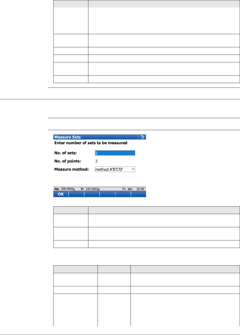
Viva Series, Sets of Angles 762
51.2.5 Measuring the Sets
Description The points defined in the point group are measured with the defined measurement
method and for the defined number of sets.
Access Highlight Measure Sets in Sets of Angles and OK.
Measure Sets
Description of fields
Prev to display the previous point of the point group. Avail-
able unless the beginning of the list is reached.
Next to display the next point in the list of points. Available
unless the end of the list is reached.
More To display information about the date, the 3D coordinate quality, the
point code, the target height and fine aiming.
Page To change to another page on this screen.
Fn - One To remove all points from the group.
Fn - All To remove the highlighted point from the group. The point itself is
not deleted.
Fn Quit To exit the application.
Key Description
Key Description
OK Opens a screen to measure the points. When auto survey is acti-
vated, measurements are done automatically.
Fn Config.. To configure the Sets of Angles application. Refer to "51.2.2 Config-
uring Sets of Angles".
Fn Quit To exit the application.
Field Option Description
No. of sets Editable field The number of sets to measure with the target
points. The maximum of sets allowed is 200.
No. of points Display only The number of target points.
Measure method Determines the order in which the target points
are to be measured.
A'A"B"B' The target points are measured in face I and face
II.
point A I - point A II - point B II - point B I ...
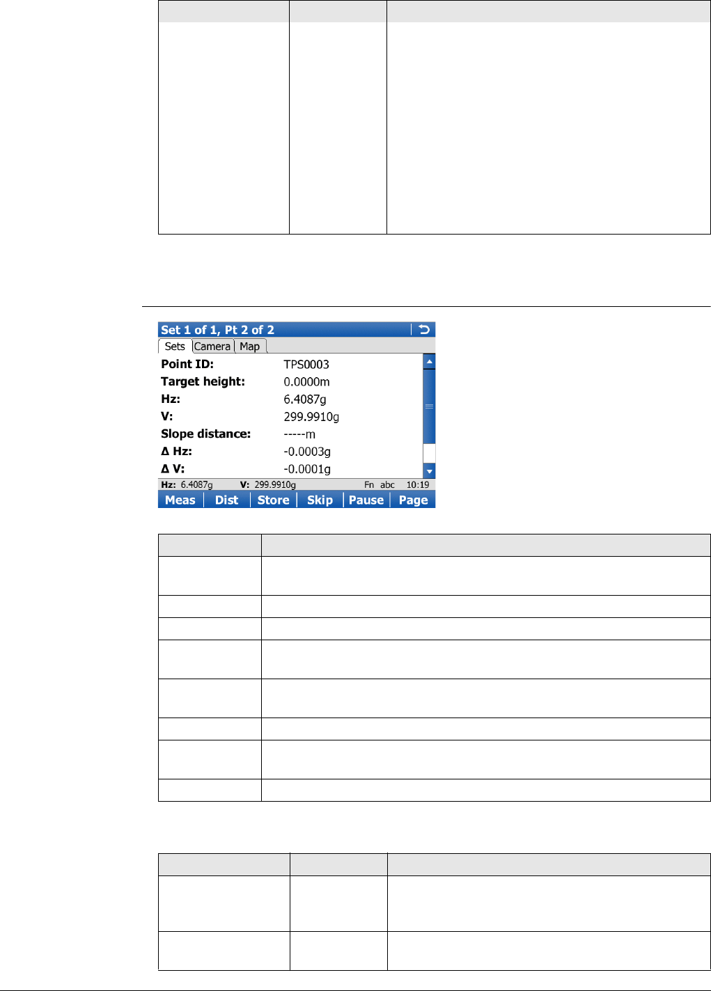
Viva Series, Sets of Angles 763
Next step
OK to measure further sets of the defined points.
Set n of n, Pt n of n,
Sets page
Description of fields
A'A"B'B" The target points are measured in face I and face
II.
point A I - point A II - point B I - point B II ...
A'B'A"B" The target points are measured in face I and face
II.
point A I - point B I... point A II - point B II ...
A'B'B"A" The target points are measured in face I and face
II.
point A I - point B I... point B II - point A II...
A'B'C'D' The target points are only measured in face I.
point A I - point B I - point C I - point D I ...
Field Option Description
Key Description
Meas To measure and store the angles and distances, and to increment to
the next point.
Dist To measure a distance.
Store To store data and to increment to the next point.
Skip To skip measuring the displayed point and continue with the next
point.
Pause or
Resume To pause/re-start the set measurement.
Page To change to another page on this screen.
Fn Done To end the sets of angles measurements and to return to Sets of
Angles.
Fn Quit To exit the application.
Field Option Description
Hz Display only Difference between the current horizontal angle
and the horizontal angle to this target when
selected.
V Display only Difference between the current vertical angle and
the vertical angle to this target when selected.

Viva Series, Sets of Angles 764
Next step
Meas to measure further sets of the selected points.
• Motorised instruments point automatically in the direction of the targets.
• Instruments with automatic aiming and auto survey activated, measure the targets
automatically.
slope Display only Difference between the current slope distance to
the target and the slope distance to this target
when selected.
Target aiming Manual Measurements are done without any automation.
ATR search and/or ATR measurement are not
performed.
Automatic Positioning to static prisms. The ATR sensor is
used for measurements to static prisms. If
needed an ATR measurement or ATR search is
performed after pressing Meas or Dist.
Lock Availability depends on instrument type. The
instrument locks onto and follows the moving
prism.
Visibility Good If weather conditions are normal, then select this
mode.
Rain & fog To increase the instrument measuring ability
during suboptimal weather conditions. This mode
is automatically deactivated when the instrument
is turned off.
Rain & fog
always As for Rain & fog, however this mode stays active
when the instrument is turned off.
Sun & reflec-
tions To increase the instrument measuring ability
during incident solar radiation and reflections, for
example safety vests. This mode has a consider-
abel influence on the range (restriction 100 -
150 m). This mode is automatically deactivated
when the instrument is turned off.
Sun & rflctns
always As for Sun & reflections, however this mode
stays active when the instrument is turned off.
Use precise target
aiming Check box Available for the 0.5" instruments of TS50/TM50.
When this box is checked, four ATR measure-
ments are performed and the mean value out the
measurements is considered for the angle value.
Use ultra fine
aiming Check box Reduces the field of view of the ATR. The setting
is only applied for Target aiming: Automatic in
Measure & Target Settings.
Field Option Description
Viva Series, Sets of Angles 765
Measurement
Summary This screen is displayed automatically at the end of the sets measurement.
Description of columns
After measuring
sets
Depending on points skipped or not, select how to continue.
Description of options
Key Description
OK To continue with the next screen.
Fn Quit To exit the application.
Column Description
Point This column is always visible. Points of the point group in the
same order as in the point group.
Compl meas How many times the point was successfully measured.
Example: 4/6 - The point was measured four times, six sets were
measured.
In tolerance How many times the tolerance configured was met.
Example: 4/6 - The point falls within the defined tolerance four
times, six sets were measured.
Compl sets How many sets are completed. The value is the same for all
points.
Example: 4/6 - The point was measured in a complete set four
times, six sets were measured.
Key Description
OK To select the highlighted option and to continue with the next
screen.
Fn Quit To exit the application.
Options Description
Always available:
Measure more sets To measure additional sets.
Available for sets incomplete:
Re-measure incomplete
sets To re-measure the skipped points in the face that was
skipped. To fill in the missing measurements in the
sets.
Remove incomplete points To calculate results. The skipped points are discarded.
Only points measured in all sets are used for the calcu-
lation.
Remove incomplete sets To calculate results. The sets that contain skipped
points are discarded. Only the complete sets are used
for the calculation.
Available for sets complete:
View and manage results Available when no points are skipped. Refer to "51.2.6
Managing Results".
Compute points from
results Available when no points are skipped. To compute
points from set results.
Exit Sets of Angles To end the Sets of Angles program.
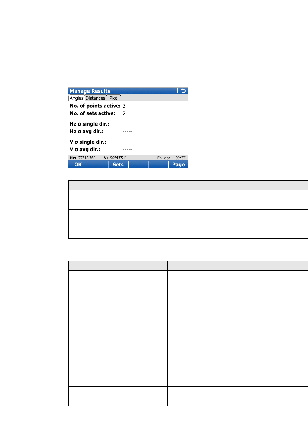
Viva Series, Sets of Angles 766
51.2.6 Managing Results
Description For two and more sets measured with angles and distances in two faces, calculations
for angles and distances can be done.
For sets measured in one face, the standard deviation and average values can be
viewed.
If only one set or point is measured, only some of the values are displayed.
Manage Results if points measured with method A'B'C'D', the points results are limited and only
standard deviation and average values are shown.
Description of fields
Key Description
OK To return to the previous screen.
sets To view angle/distance results.
Use To activate/deactivate sets.
Page To change to another page on this screen.
Fn Quit To exit the application.
Field Option Description
No. of points active Display only Number of active points which are set to Yes in
the Use column in the Sets of Angles screen.
Refer to "Residuals in Set n".
No. of sets active Display only Number of active sets which are set to Yes in the
Use column in the Angle Results/Distance
Results screen. Refer to "Angle Results/Distance
Results".
Hz single dir. Display only Standard deviation of the single horizontal direc-
tion.
Hz avg dir. Display only Standard deviation of the average horizontal
direction.
V single dir. Display only Standard deviation of a single vertical direction.
V avg dir. Display only Standard deviation of the average vertical direc-
tion.
single distance Display only Standard deviation of a single distance.
avg distance Display only Standard deviation of the average distance.
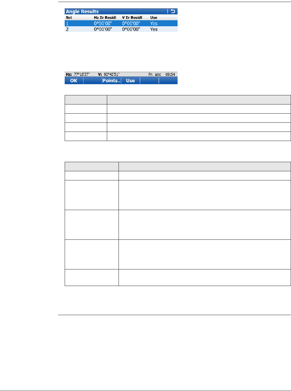
Viva Series, Sets of Angles 767
Next step
sets accesses the Angle Results/Distance Results screen.
Angle
Results/Distance
Results
Description of columns
Next step
Points.. to access Residuals in Set n.
Key Description
OK To return to the previous screen.
Points.. To access Residuals in Set n.
Use To set Yes or No in the Use column for the highlighted set.
Fn Quit To exit the application.
Column Description
Set Displays the number of the sets.
Hz r Residl Shows the calculated absolute sum of residuals in Hz of the
selected set. The sum of residuals is the sum of the difference
between the reduced average direction and each sets directions.
For sets not used in the calculation, ----- is shown.
V r Residl Shows the calculated absolute sum of residuals in V of the
selected set. The sum of residuals is the sum of the difference
between the average vertical angles and each sets vertical
angles. For sets not used in the calculation, ----- is shown.
Max Residl SD Shows the calculated maximum residuals in slope distance of the
selected set. The sum of residuals is the sum of the difference
between the average distance and each sets distance. For sets
not used in the calculation, ----- is shown.
Use For Yes: The selected set is used for calculations.
For No: The selected set is not used for calculations.
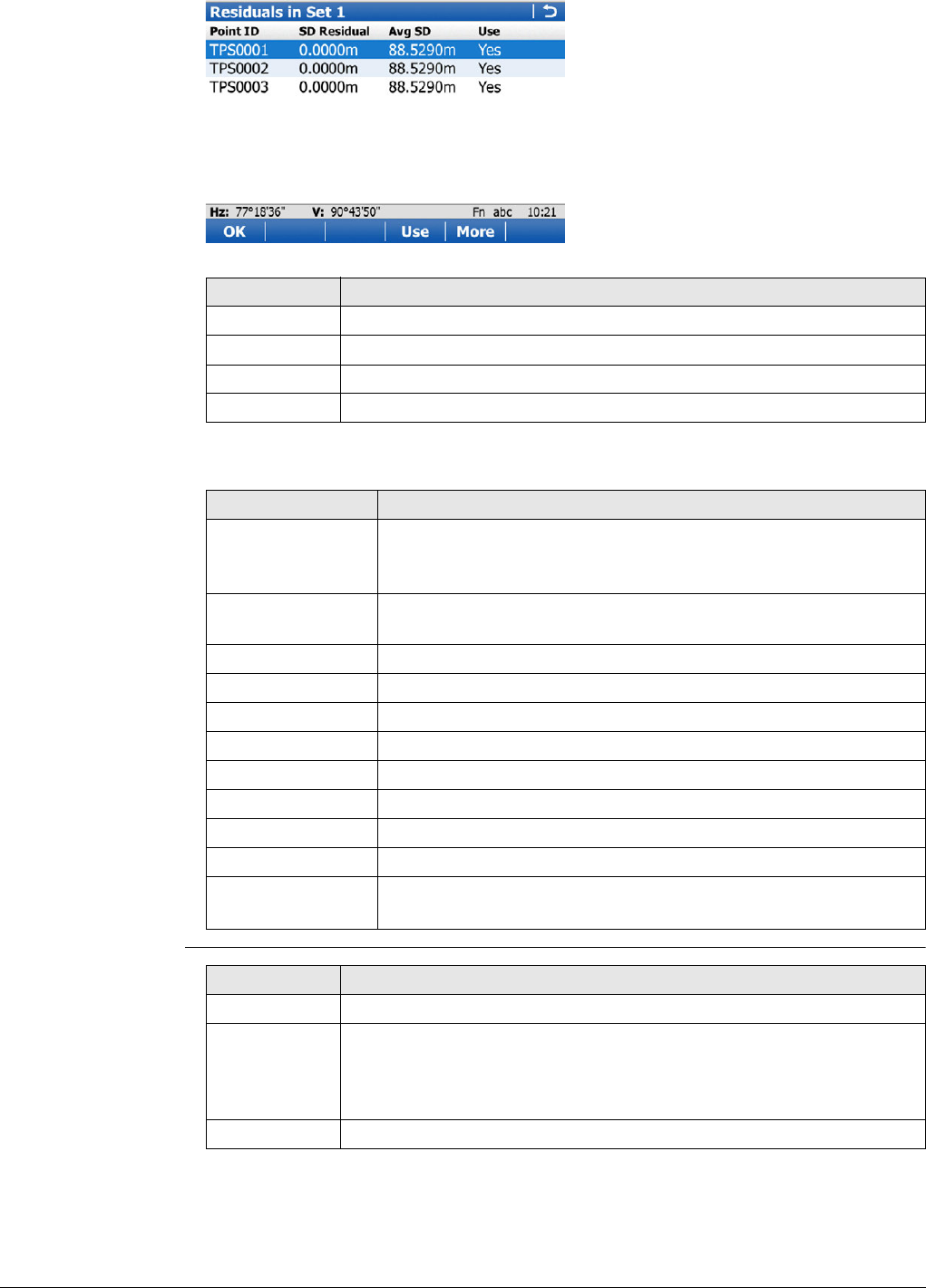
Viva Series, Sets of Angles 768
Residuals in Set n
Description of columns
Compute Points,
General page
Key Description
OK To return to the previous screen.
Use To set Yes or No in the Use column for the highlighted point.
More To view additional information.
Fn Quit To exit the application.
Column Description
Point This column is always visible.
Point ID of the measured points in the order they were defined
and measured.
Hz Residual Residual in the Hz value of the selected point within the single
set.
V Residual Residual in the V value of the selected point within the single set.
Avg Hz Reduced Average Hz value of the point in all active sets.
Avg V Average V value of the point in all active sets.
Mean Hz Mean Hz value of the point within the single set.
Mean V Mean V value of the point within the single set.
SD Residual Residual in the distance value of the point within the single set.
Avg SD Average distance value of the point in all active sets.
Mean SD Mean distance value of the point within the single set.
Use For Yes: The selected point is used for calculations in all sets.
For No: The selected point is not used for calculations in any set.
Key Description
Store To store the results and continue with the next screen.
Page To change to another page on this screen.
The functionality and softkeys available on the Plot page are
described in the MapView chapter. Refer to "37.4.1 Screen Area" for
information functionality.
Fn Quit To exit the application.
Viva Series, Sets of Angles 769
Description of fields
Compute Points,
Points page
Description of columns
Field Option Description
No. of points
active Display only The number of selected points having been meas-
ured.
No. of sets
active Display only The number of sets having been measured.
Store Point ID
with Prefix Adds the setting for Prefix/suffix in front of the
original point IDs.
Suffix Adds the setting for Prefix/suffix at the end of
the original point IDs.
Prefix/suffix Editable field The identifier with up to four characters is added
in front of or at the end of the ID of the calculated
points.
Use a point as
reference Check box When this box is checked, the point selected is
considered fixed: known coordinates and there-
fore Easting and Northing are made equal to
zero.
The values shown on the Points page are updated
accordingly.
Key Description
Store To store the calculated points which are set to Yes in the Accept
column.
Accept To set Yes or No in the Accept column for the highlighted point.
Fn Quit To exit the application.
Column Description
Point Point ID of the measured points in the order they were defined
and measured.
Easting The difference in Easting between the original and the calculated
points.
Northing The difference in Northing between the original and the calcu-
lated points.
Accept For Yes: The selected point is used for calculations in all sets.
For No: The selected point is not used for calculations in any set.

Viva Series, Sets of Angles 770
51.3 Monitoring
Description Monitoring is a module integrated within the Sets of Angles application.
Monitoring uses a timer to enable repeated and automated angle and distances meas-
urements to pre-defined target points at defined intervals. The ability to configure the
handling of message screens during measurement sets is also enabled.
Important aspects For monitoring, instruments must be motorised.
Monitoring is licence protected and is only activated through a licence key. The licence
key can be entered manually or loaded from the data storage device.
Monitoring prepara-
tion
This step-by-step description is an example on preparing a set for monitoring.
Step Description
1. Select the control and the working job.
2. Set station coordinates and station orientation.
3. Select Main Menu: Go to Work!\Survey+\Sets of angles.
4. In Sets of Angles press Fn Config.. to configure Sets of Angles for moni-
toring.
For the Parameters page set:
•Page to show: None (for example purposes only).
•Stop for messages: All messages (for example purposes only).
•Time out: 10 secs (for example purposes only).
•Define time when sets should be measured (timer monitoring) (this
option must be selected for monitoring). This setting will enable access
to the Define Monitoring Timer screen.
5. Press OK to access the Sets of Angles screen.
6. Select Create a new group.
7. Press OK to access the Define Points for Set screen.
8. Enter details of the target point as required.
For each target point, ensure that auto survey is activated. This setting will
enable the automated measurement and recording of the target point in the
other face. The setting also enables the automated measurement and
recording of all target points during monitoring.
9. Press OK to access the Select Points - Survey screen.
10. Measure and record the measurement to the target point as required.
11. Continue with steps 8. to 10. until all target points for the first measurement
set have been measured and recorded.
12. Press Done to complete the selection of the target points for the first meas-
urement set in one face. This action then begins the measurement of the
target points in the other face. On completion, the Sets of Angles screen will
be accessed.
13. Select Measure Sets.
14. Press OK to access the Define Monitoring Timer screen.

Viva Series, Sets of Angles 771
Define Monitoring
Timer Description of fields
Next step
When all required information is entered press OK to begin the monitoring process.
A screen displays a notice that monitoring is in progress. If necessary, press Cancel to
stop the monitoring process and return to Sets of angles menu.
Refer to "51.2 Sets of Angles" for information about calculations and the viewing of
results.
Monitoring interval Description
The dates and times entered define the timeframe for when the monitoring will take
place.
The time interval defines the time between the start of each measurement set during
the monitoring period. The interval time begins at the start of a measurement set and
ends at the start of the next measurement set.
Example
Data;
Results;
• The time taken to measure 4 sets of 3 target points in both faces is 10 minutes.
• The measurements will start at 14:00:00 on 03.11.2010.
• At 14:10:00, the first measurement set is complete.
• The instrument will wait until 14:30:00 for the next scheduled measurement set.
Field Option Description
Begin date Editable field Start date for monitoring.
Begin time Editable field Start time for monitoring.
End date Editable field End date for monitoring.
End time Editable field End time for monitoring.
Interval Editable field The time between the start of each scheduled
measurement set.
Measure method Determines the order in which the target
points are to be measured.
A'A"B"B' The target points are measured in face I and
face II.
point A I - point A II - point B II - point B I ...
A'A"B'B" The target points are measured in face I and
face II.
point A I - point A II - point B I - point B II ...
A'B'A"B" The target points are measured in face I and
face II.
point A I - point B I... point A II - point B II ...
A'B'B"A" The target points are measured in face I and
face II.
point A I - point B I... point B II - point A II...
A'B'C'D' The target points are only measured in face I.
point A I - point B I - point C I - point D I ...
•3 target points •4 measure sets
• Begin Date: 03.11.2010 • Begin Time: 14:00:00
• End Date: 06.11.2010 • End Time: 14:00:00
• Interval: 30 min
Viva Series, Setup 772
52 Setup
52.1 Overview
Description The Setup application is only available for use with TPS instruments. Setup determines
the station coordinates and the instrument orientation using TPS measurements
and/or GPS measurements.
Setup methods
• Each setup method requires different input data and a different number of target
points.
• All setup methods are described in "52.7 Setup Methods".
Setup types
Incomplete setups • For a "Standard" setup, the user must always measure all setup points consecu-
tively to complete the setup. This type of setup is always regarded as a complete
setup.
• For "On-the-Fly" setups, the setup points can be measured together with the
survey points. It is not necessary to complete the setup before measuring survey
points. Until the user selects Set in Station Results, this type of setup is regarded
as incomplete.
Setup with GPS using SmartPole Setup with GPS using SmartStation
SmartPole allows target points to be
determined using GPS measurements. The
new points are then used as control
points for the TPS setup.
SmartStation allows TPS station coordi-
nates (position and height) to be deter-
mined from GPS measurements.
Setup Method
"Standard"
setup type
"On-the-Fly"
setup type
Methods for
TPS
Methods for
SmartPole
Methods for
SmartStation
Set orientation --
Known backsight -
Multiple backsights
Transfer height --
Resection -
Orientate to line --
"Standard" setup "On-the-Fly" setup
This type of setup is the traditional type.
The user must always measure all setup
points consecutively to complete the
setup. The TPS station coordinates and
TPS orientation must be set before meas-
uring survey points.
This setup type allows the user to move
between setup and survey before
completing the setup (working
"on the fly"). When leaving setup the TPS
station coordinates and orientation do
not have to be final, they can be set at
anytime during the survey.
This setup can only be used when meas-
uring survey points. When staking out
points, the TPS station coordinates and
TPS orientation must be set first.
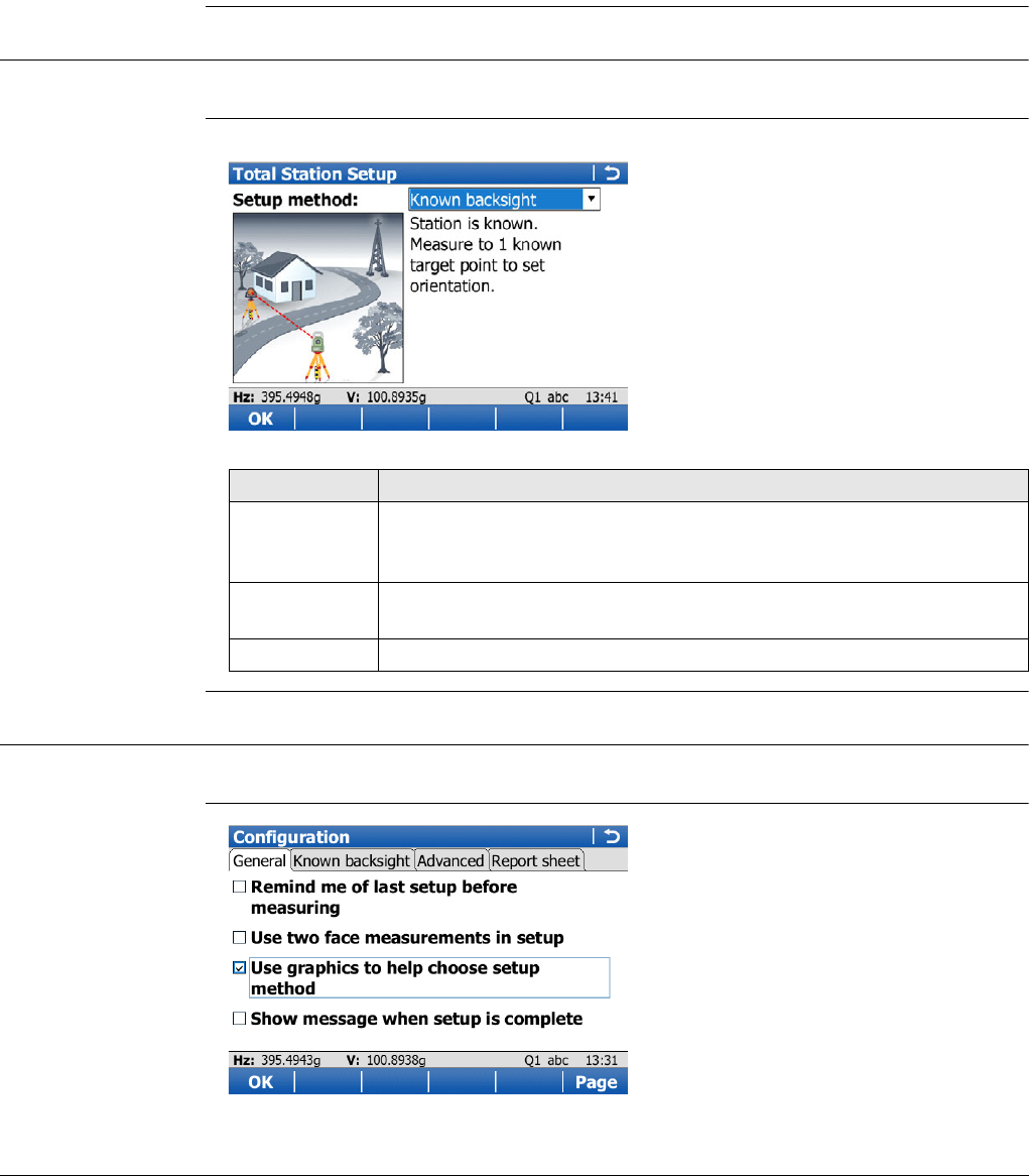
Viva Series, Setup 773
An incomplete setup, or a setup where more targets can be added, can be
accessed in the following ways:
52.2 Accessing Setup
Access Select Main Menu:Go to Work!\Setup.
Total Station Setup An illustration and a description is shown for each Setup method.
52.3 Configuring Setup
Access Press Fn Config.. in Total Station Setup.
Configuration,
General page
1. In the Survey application, Setup can be accessed by selecting the
Setup softkey.
2. When entering any panel where it is possible to do a measurement, a message is
displayed to notify that the setup is incomplete. It is then possible to:
a) continue with the existing application, or OK
b) start Setup and create a new station setup, or New..
c) start Setup and continue to measure additional fixpoints. Setup
3. Assigning the function TPS - Continue open setup to the favourites or a hot key.
Key Description
OK To accept changes and access the subsequent screen. The chosen
settings become active. Refer to "52.4 Set Station Point" or "52.5
Enter Station Information".
Fn Config.. To configure the Setup application. Refer to "52.3 Configuring
Setup".
Fn Quit To exit the wizard.

Viva Series, Setup 774
Description of fields
Next step
Page changes to the Known backsight page.
Key Description
OK To accept changes and return to the screen from where this screen
was accessed.
Page To change to another page on this screen.
Fn About To display information about the application name, the version
number, the date of the version, the copyright and the article
number.
Fn Quit To exit the screen.
Field Option Description
Remind me of last
setup before
measuring
Check box Current instrument setup details can be displayed
to remind the user to either keep the current
instrument setup, check the backsight, or create
a new setup.
Refer to "52.6 Setup Reminder" for details.
Use two face
measurements in
setup
Check box Defines if the instrument measures the second
face automatically after storing the first.
When this box is checked, after storing a meas-
urement with All or Store motorised instruments
change face automatically, non-motorised instru-
ments access Telescope Positioning. The meas-
urements of face I and face II are averaged. The
averaged value is stored.
When this box is not checked, no automatic
measurement in two faces.
When using two face measurements, then
the angle right value is averaged between
both two face measurements.
Use graphics to
help choose setup
method
Check box When this box is checked, the setup methods are
displayed in a screen accompanied by a graphic
and text describing each setup method.
When this box is not checked, the setup methods
are selected from the drop-down menu in Go to
Work!.
Show message
when setup is
complete
Check box When this box is checked, a message informs
when the setup is finished.
Viva Series, Setup 775
Configuration,
Known backsight
page
For Setup method: Known backsight, the settings on this page apply.
Description of fields
Next step
Page changes to the Advanced page.
Configuration,
Advanced page
For Setup method:Resection and Setup method:Multiple backsights, the settings
on this page apply.
Description of fields
Field Option Description
Check backsight
position Check box Allows a check to be made on the horizontal coor-
dinate difference between the existing and the
measured known backsight point. If the defined
Position limit is exceeded, the setup can be
repeated, skipped or stored.
Position limit Editable field Available when Check backsight position is
checked. Sets the maximum horizontal coordinate
difference accepted in the position check.
Check backsight
height Check box Allows a check to be made on the vertical differ-
ence between the existing and the measured
known backsight point. If the Height limit is
exceeded, the setup can be repeated, skipped or
stored.
Height limit Editable field Available when Check backsight height is
checked. Sets the maximum vertical difference
accepted in the height check.
Field Option Description
Auto position to
setup targets Check box When this box is checked, the instrument posi-
tions horizontally and vertically to the point.
Calculate scale
from target obser-
vations
Check box Only available if the job properties do not have
Compute scale using set to Stn & coord system.
If checked, a station scale will be calculated from
the target observations. The user will have the
option to apply this new scale (calculated ppm +
current ppm = new ppm) to all survey observa-
tions, including the setup observations, from that
setup.
If not checked, then the calculated ppm will not
be displayed and therefore not applied to any
survey observations.
Use Helmert
method for resec-
tion
Check box Helmert calculation is used.
Height weighting 1/distance or
1/distance² Available when Use Helmert method for resection
is checked. To change the distance weighting that
is used in the calculation of the station height in
the resection.
Viva Series, Setup 776
Next step
Page changes to the Report sheet page.
Configuration,
Report sheet page
Description of fields
Next step
Page changes to the first page on this screen.
Edit default station
quality checks Check box Check to type in values for standard deviation,
position and height accuracy. If the limits are
exceeded, a message will be shown when Calc is
selected.
Orientation limit Editable field Available when Edit default station quality
checks is checked. Define a limit for the standard
deviation of the orientation.
Position limit Editable field Available when Edit default station quality
checks is checked. Define a position accuracy of
the target point.
Height limit Editable field Available when Edit default station quality
checks is checked. Define a height accuracy of
the target point.
Field Option Description
Field Option Description
Create report
sheet Check box To generate a report sheet when the application is
exited.
A report sheet is a file to which data from an applica-
tion is written to. It is generated using the selected
format file.
Report sheet Selectable
list
Available when Create report sheet is ticked. The name
of the file to which the data will be written. A report
sheet is stored in the \DATA directory of the active
memory device. The data is always appended to the
file.
Opening the selectable list accesses the Report Sheets
screen. On this screen, a name for a new report sheet
can be created and an existing report sheet can be
selected or deleted.
Format file to
use Selectable
list
Available when Create report sheet is ticked. A format
file defines which and how data is written to a report
sheet. Format files are created using LGO. A format file
must first be transferred from the data storage device
to the internal memory before it can be selected. Refer
to "30.1 Transfer user objects" for information on how
to transfer a format file.
Opening the selectable list accesses the Format Files
screen where an existing format file can be selected or
deleted.
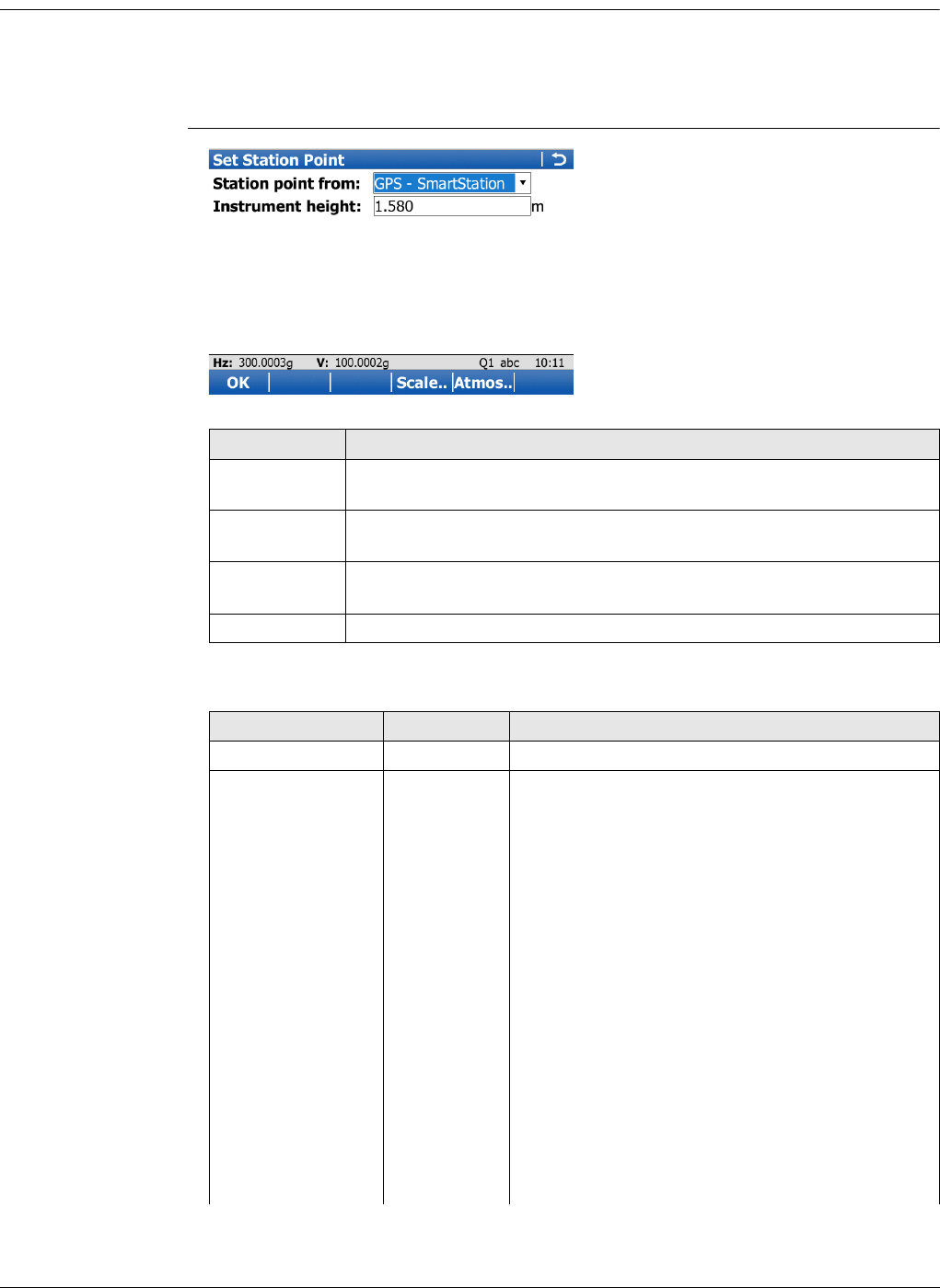
Viva Series, Setup 777
52.4 Set Station Point
Access A station point must be selected for Setup method:Set orientation, Setup
method:Known backsight, Setup method:Multiple backsights and Setup
method:Transfer height. Set Station Point is then accessed automatically from
Setup.
Set Station Point
Description of fields
Key Description
OK To accept changes and return to the screen from where this screen
was accessed.
Scale.. To type in values for the scale corrections. Refer to "New Job, Scale
page".
Atmos.. To type in values for the atmospheric corrections. Refer to "Atmos-
pheric Corrections, Atmospheric ppm page".
Fn Quit To exit the screen.
Field Option Description
Instrument height Editable field The height of the instrument.
Station point from The selection made here determines the availa-
bility of the other fields on this screen.
Job A station point can be selected from a job on a
data storage device.
Enter new
point Pressing OK opens a screen where a new point
can be typed in. After pressing Store there, the
Setup application continues.
GPS - Smart-
Station Available when TPS and GPS are used. Pressing
OK opens the GPS Survey application. After
measuring a point with Meas, Stop, Store there,
the Setup application continues. Refer to "56.1.2
Real-Time Rover Operations".
In order to use GPS, a coordinate system
for the setup is required and must be
attached to the working job. If not, then a
coordinate system must be selected, or
local coordinates for the station must be
typed in, during the setup process.
Viva Series, Setup 778
Refer to "14 Antenna Heights" for further information regarding height values used in
a SmartStation.
52.5 Enter Station Information
Access Station information must be typed in for Setup method:Resection and Setup
method: Orientate to line. Enter Station Information is accessed after selecting OK in
Total Station Setup with one of these setup methods selected.
Enter Station Infor-
mation For a description of keys refer to "52.4 Set Station Point".
Description of fields
Refer to "14 Antenna Heights" for further information regarding height values used in
a SmartStation.
To obtain the correct elevation of the
setup point, measure the instrument
height as usual and ensure the antenna
type is set to the relevant SmartStation
antenna.
If SmartPole is used in the setup or later in
Survey, remember to update the antenna
type after finishing the SmartStation
measurement.
Last used
station The station used last in the Setup application is
displayed.
Job Selectable list The job from which the station is to be selected.
Refer to "5.4 Choosing a Job".
Point ID Display only The point ID of the station point.
Easting, Northing
and Elevation Display only The coordinates of the station point.
Current scale Display only The scale according to the scale settings for the
selected station.
Field Option Description
Field Option Description
Station ID Editable field Type in an ID for the station point.
Point code Selectable list Select a point code for the station point if
desired.
Instrument height Editable field The height of the instrument.
Use control job for
the target points Check box Target points can be selected from the control
job.
Job Selectable list The control job from which the target points can
be selected. Refer to "5.4 Choosing a Job".
Current scale Display only The scale according to the scale settings for the
selected station.
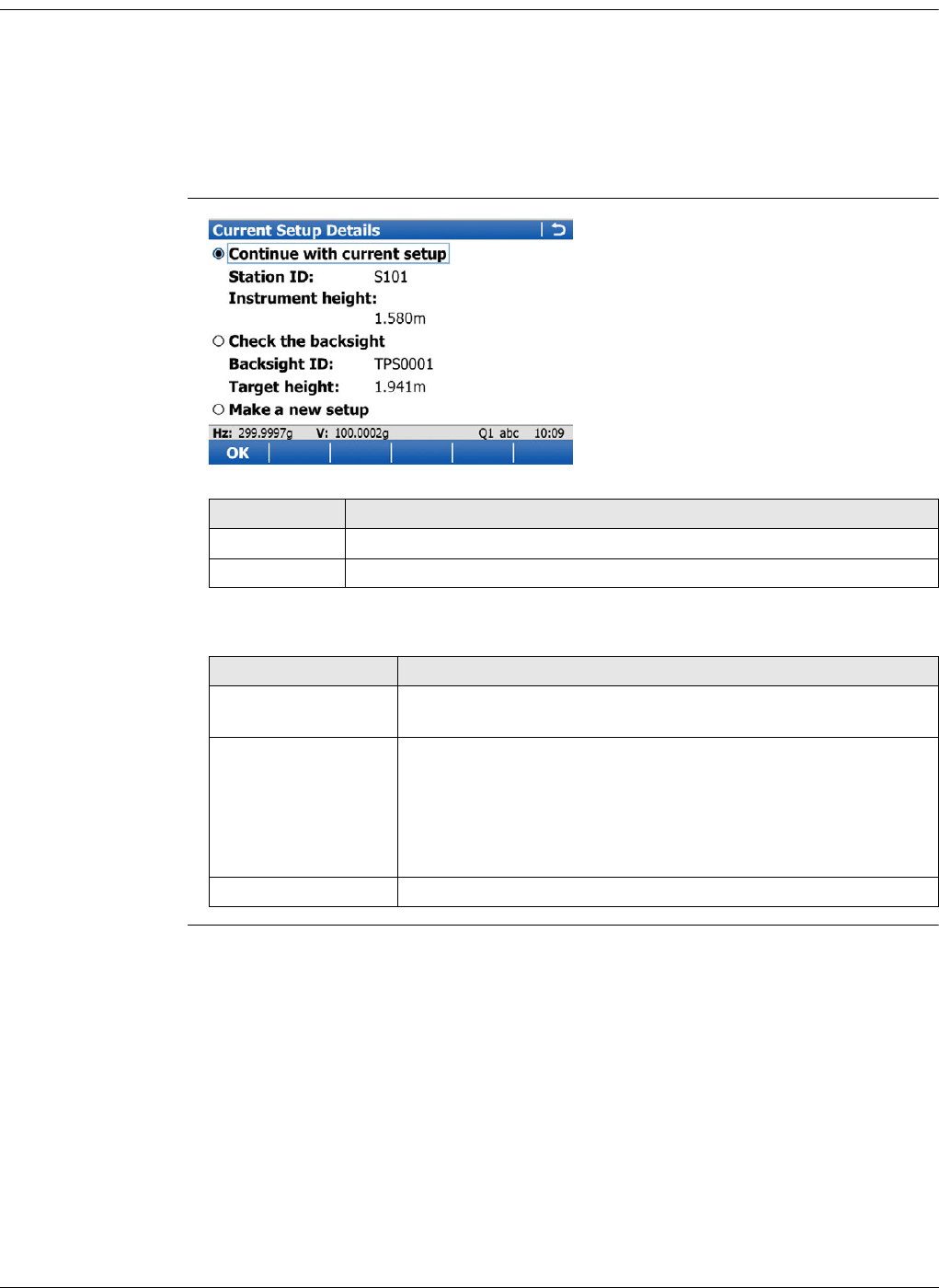
Viva Series, Setup 779
52.6 Setup Reminder
Description When activated, the setup reminder appears whenever the user enters a measure-
ment screen. The reminder allows the user to check the current station setup details
before proceeding with the survey. When this reminder appears, three options are
available to the user:
1) To keep the current station setup and proceed with the survey.
2) To check the backsight point.
3) To create a new station setup.
Current Setup Details
Description of fields
Key Description
OK To accept the selection.
Fn Quit To exit the screen.
Field Description
Continue with
current setup The last setup is used and recorded in the working job.
Check the backsight To open the Check Point screen. The point suggested is the
point which Setup uses as the reference orientation. For the
setup methods Set orientation and Known backsight, the
orientation target point is suggested. For the setup methods
Multiple backsights, Transfer height, Resection and Orientate
to line, the first target is suggested.
Make a new setup To start the Setup application and create a new station setup.
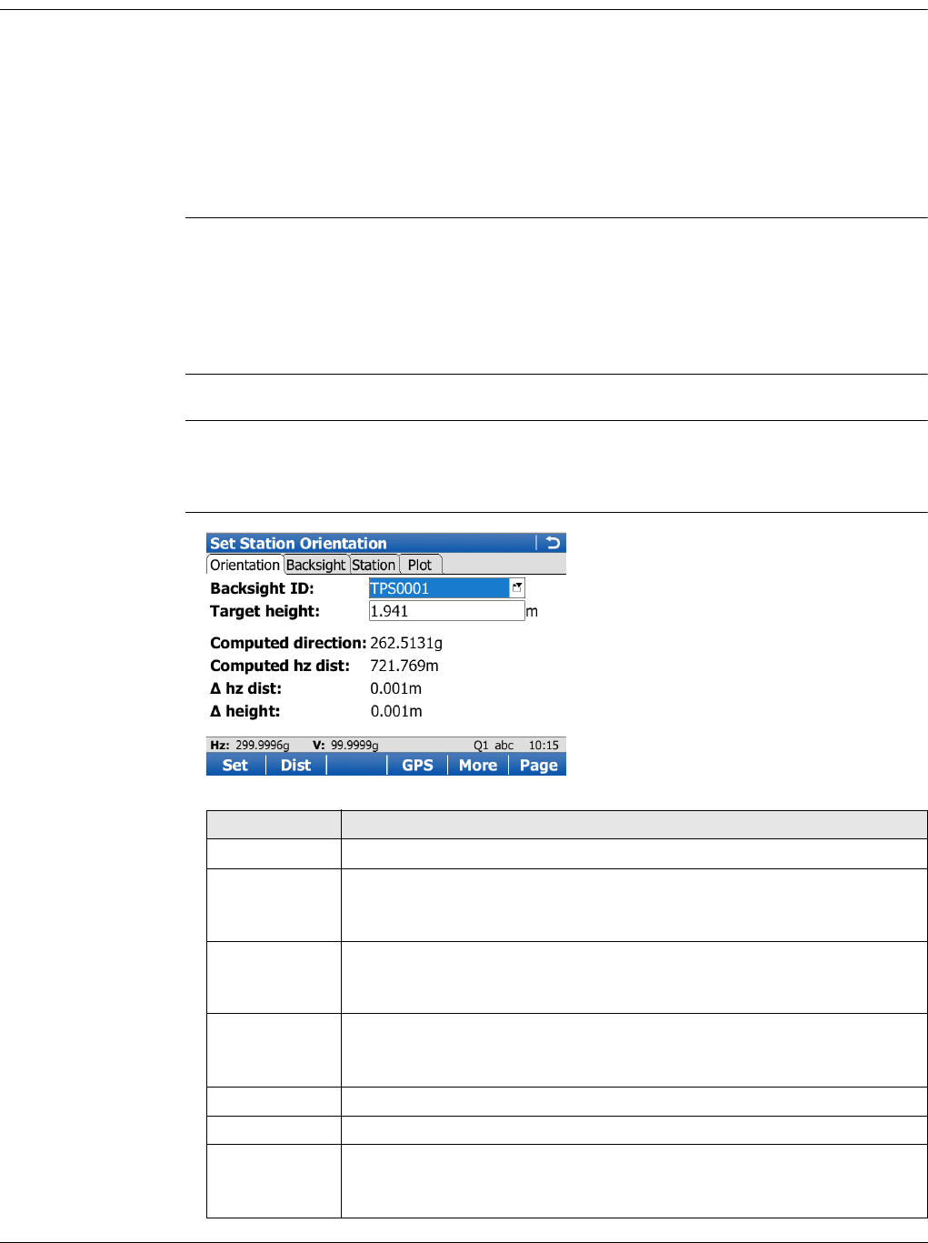
Viva Series, Setup 780
52.7 Setup Methods
52.7.1 Set orientation and Known backsight
Requirements The position coordinates of the station point are required.
For Set orientation: The instrument is set up and oriented to either a known or
unknown target point, to which a true or assumed azimuth is set.
For Known backsight: The instrument is set up and oriented to a known backsight
target.
For SmartStation, the position coordinates of the station are unknown and are deter-
mined with GPS. The instrument is set and oriented to either a known or unknown
target point, to which a true or assumed azimuth is set.
Updating Hz meas-
urements
A station setup using the Set orientation method, is always automatically flagged with
an ’update later’ attribute. If the backsight point is measured again, for example from
another station, and found to have different coordinates, then a message will appear.
The user can then select whether to update the original setup or not. The update will
use the backsight point coordinates to recalculate the orientation and subsequently
update all measured points connected to the setup.
For information on camera and images refer to "33.3.3 Within Applications".
Access In Total Station Setup, select Setup method:Set orientation or Known backsight.
Press OK.
In Set Station Point, select a station. Press OK.
Set Station Orienta-
tion,
Orientation page
Key Description
Set To set the station and orientation and exit the Setup application.
Dist To measure a distance to the point being used to set the azimuth.
For Set orientation: A distance measurement is NOT required when
setting the Station and the Orientation with Set.
GPS For Known backsight applicable when using SmartPole. To enter the
GPS Survey screen and measure a point with GPS. The antenna height
is automatically converted from the target height.
Store To store the measurement with or without a distance. Only available
when Use two face measurements in setup is selected in the Setup
configuration.
More To change between the slope and the horizontal distance.
Page To change to another page on this screen.
Fn Run /
IndivID Available for Setup method:Set orientation only. Run automatically
chooses the next available point ID from the list of points already
stored. IndivID allows the user to type in any value for Backsight ID.
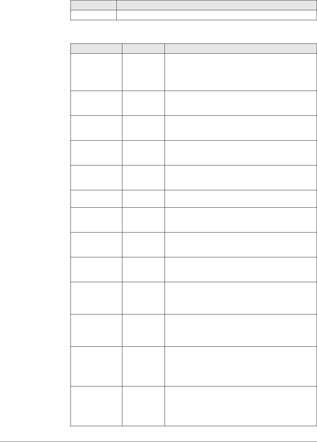
Viva Series, Setup 781
Description of fields
Fn Quit To exit the screen.
Field Option Description
Backsight ID Point ID of the backsight point.
Editable field For Set orientation.
Selectable list For Known backsight. Select a point from the points
stored in the control job.
Target height Editable field Height of the target above or below the backsight
point. The last setup target height is always remem-
bered.
Direction Editable field Available for Set orientation. The direction is set to
0 by default. This value can be edited. The value is
not set to the system until Set is pressed.
Slope distance Display only Available for Set orientation. The slope distance
measured between the station point and the back-
sight point.
Horiz distance Display only Available for Set orientation. Press Dist to measure
a distance to the target point being used to set the
azimuth.
Height differ-
ence Display only Available for Set orientation. The vertical distance
between the station point and the backsight point.
Computed
direction Display only Available for Known backsight. Displays the calcu-
lated azimuth from the selected station to the back-
sight point.
Computed hz
dist Display only Available for Known backsight. Displays the calcu-
lated horizontal distance between the selected
station and backsight point.
Computed slp
dist Display only Available for Known backsight. Displayed after
More was pressed. The calculated slope distance to
the backsight point.
hz dist Display only Available for Known backsight. The difference
between the calculated horizontal distance from
station to backsight point and the measured hori-
zontal distance.
slope dist Display only Available for Known backsight. Displayed after
More was pressed. The difference between the
calculated slope distance from station to backsight
point and the measured slope distance.
height Display only Available for Known backsight. The difference
between the control height of the backsight point
and the measured height of the backsight point. If
the backsight point is a 2D point, this field shows --
---.
Angle right Display only Available when Hz angle display: Angle right is
configured in Regional Settings, Angle page.
Displays the horizontal angle difference between
the backsight point and the current telescope posi-
tion.
Key Description
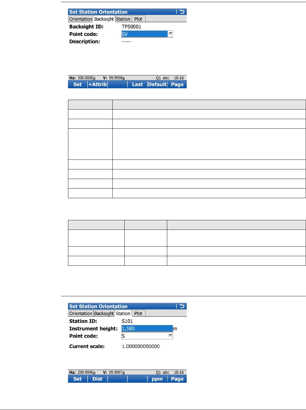
Viva Series, Setup 782
Next step
Page changes to the Backsight page.
Set Station Orienta-
tion,
Backsight page
Description of fields
Next step
Page changes to the Station page.
Set Station Orienta-
tion,
Station page
Key Description
Set To set the station and orientation and exit the Setup application.
+Attrib To create additional attributes for this point code.
Name or Value Available for attributes for which an attribute name can be typed in.
To highlight the field of the attribute name or the field for the
attribute value. The name of the attribute can be edited and an
attribute value can be typed in.
Last To recall the last used attribute values for the selected code.
Default To recall the default attribute values for the selected code.
Page To change to another page on this screen.
Fn Quit To exit the screen.
Field Option Description
Backsight ID Editable field
or display only
Point ID of the backsight point.
Point code Selectable list The code for the backsight point.
Description Display only A short description of the code.
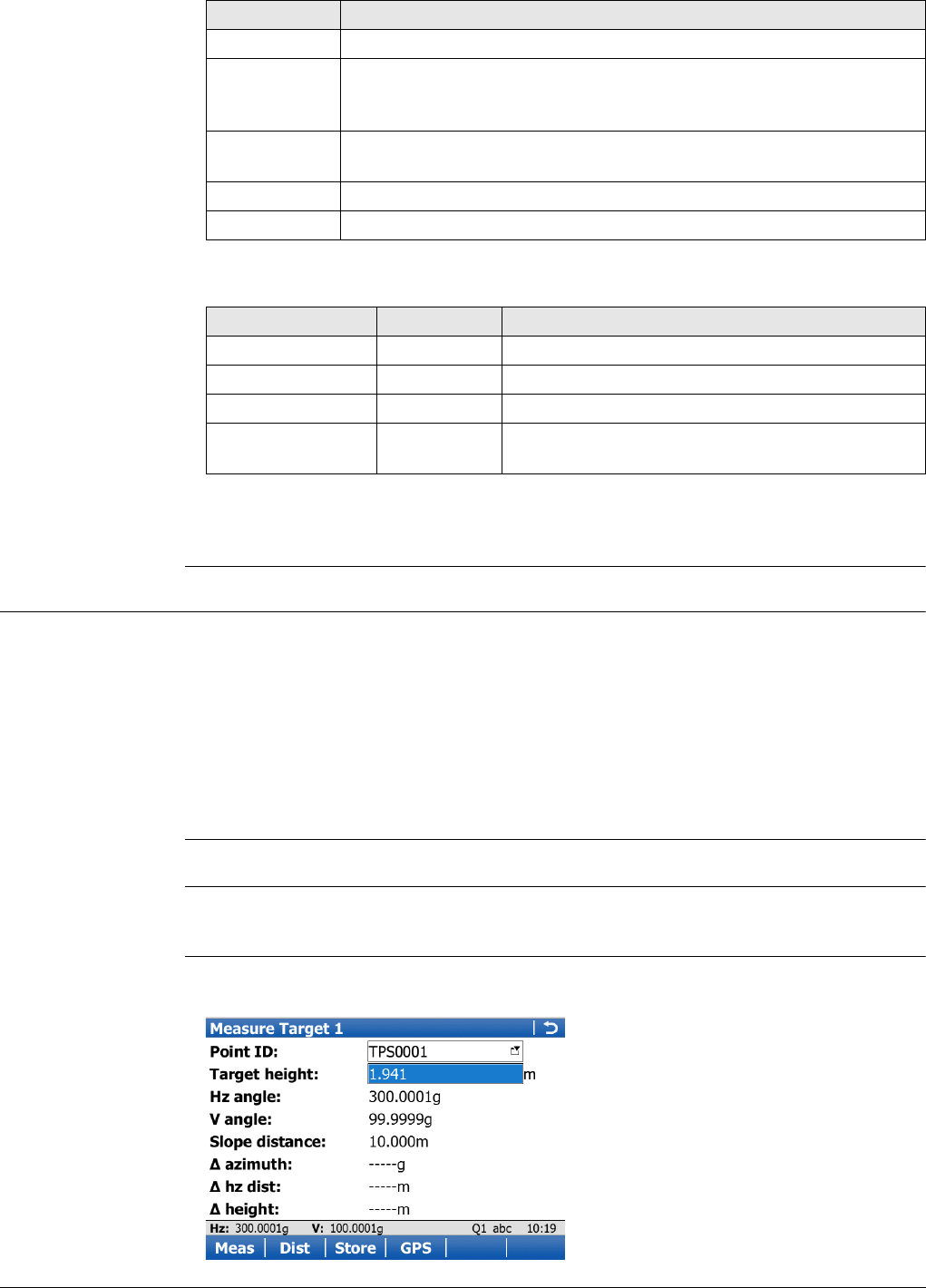
Viva Series, Setup 783
Description of fields
Next step
Page changes to the Plot page.
52.7.2 Multiple backsights
Requirements The position coordinates of the station point are required. The instrument is set up
and oriented to one or more known backsight targets.
For SmartStation, the position coordinates of the station are unknown and are deter-
mined with GPS. The instrument is set up and oriented to one or more known back-
sight targets.
For TPS and SmartStation, the orientation is determined by sighting to one or more
known target points (maximum of ten target points). Only angles or both angles and
distances can be measured. The height of the station point can also be derived from
the target points.
For information on camera and images refer to "33.3.3 Within Applications".
Access In Total Station Setup, select Setup method:Multiple backsights. Press OK.
In Set Station Point, select a station. Press OK.
Measure Target Unless otherwise stated the following screen and description applies to the setup
methods: Multiple backsights, Transfer height, Resection, and Orientate to line.
Key Description
Set To set the station and orientation and exit the Setup application.
Dist To measure a distance to the point being used to set the azimuth. A
distance measurement is NOT required when setting the Station and
the Orientation with Set.
SF / Ppm To switch between displaying the current scale as a scale factor or
ppm value.
Page To change to another page on this screen.
Fn Quit To exit the screen.
Field Option Description
Station ID Display only Station ID as selected in Set Station Point.
Instrument height Editable field The instrument height.
Point code Selectable list The code for the backsight point.
Current PPM /
Current scale Display only The current job scale. Refer to " New Job, Scale
page" for more information on scale corrections.
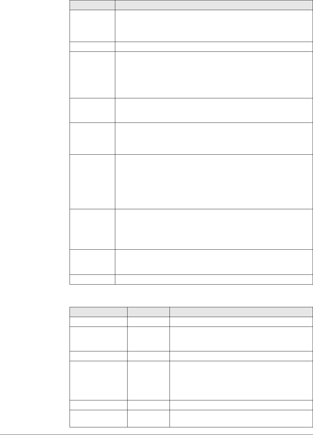
Viva Series, Setup 784
Description of fields
Key Description
Meas To measure and store the distances and angles made to the control
points. After storing the measurement data, the next point ID in the
job is displayed. The instrument positions to the point if enough data
is available.
Dist To measure and display distances.
Store Records displayed values temporarily. The target measurements will
not be stored to the current job until the station is set. A distance
measurement is not necessary before pressing Store. After recording
the measurement data, the next point ID in the job is displayed. The
instrument positions to the point if enough data is available and the
instrument is robotic.
GPS Applicable when using SmartPole. To enter the GPS Survey screen and
measure a point with GPS. The antenna height is automatically
converted from the target height.
Done For Resection only. To temporarily exit the Setup application. The
station setup will be incomplete but can be continued and completed
at a later time. This softkey is replaced by Calc when sufficient data
is available.
Calc For Multiple backsights: Available after the first measurement.
Allows the user to see the calculated station orientation and other
results.
For Resection: Available after measuring two target points or as
soon as a preliminary station and orientation can be calculated. The
calculated station coordinates and overall “quality” of the results are
displayed.
Fn Find Stakeout values are provided to guide the prism holder to the
selected target point.
For Resection: Available once sufficient data is available for calcula-
tion.
Refer to "52.9 Finding a Target Point".
Fn Positn To position the instrument to the selected target point.
For Resection: Available once sufficient data is available for calcula-
tion.
Fn Quit To exit the screen.
Field Option Description
Point ID Selectable list The point ID of the target point to be measured.
Target height Editable field The height of the target above or below the back-
sight point. The last setup target height is always
remembered.
Hz angle Display only The current horizontal angle.
Angle right Display only Available when Hz angle display: Angle right is
configured in Regional Settings, Angle page.
Displays the horizontal angle difference between
the backsight point and the current telescope
position.
V angle Display only The current vertical angle.
Slope distance Display only The measured slope distance after Dist was
pressed.

Viva Series, Setup 785
A maximum of ten target points can be measured and used for the calculation. When
the maximum number of points is exceeded, a message will appear. The user can
remove previous points or finish the setup. Points can be removed from the Station
Results, Targets page.
52.7.3 Transfer height
Requirements This method is used to compute a station height to apply to the selected station. Only
the height is updated, the orientation is not updated.
The position coordinates of the station point are required.
Access In Total Station Setup, select Setup method:Transfer height. Press OK.
In Set Station Point, select a station. Press OK.
For a description of the Measure Target screen, refer to "52.7.2 Multiple backsights".
52.7.4 Resection
Requirements The coordinates of the station point are unknown. The coordinates and orientation
are determined by sighting to at least two or more known target points (maximum of
ten target points). Only angles or both angles and distances can be measured. For a
resection, least squares or robust calculations are used. The resection calculations can
be done using the Helmert method, robust method or least squares method, after
three measurements to known backsights have been completed.
Access In Total Station Setup, select Setup method:Resection. Press OK.
In Enter Station Information, type in the required information. Press OK.
For a description of the Measure Target screen, refer to "52.7.2 Multiple backsights".
azimuth Display only Displays the difference between the calculated
azimuth and the current horizontal angle.
If Setup method:Resection, displays ----- until
sufficient data for calculation is available.
hz dist Display only The difference between the calculated and the
measured horizontal distance.
height Display only The difference between the given and the meas-
ured height of the target point.
Field Option Description
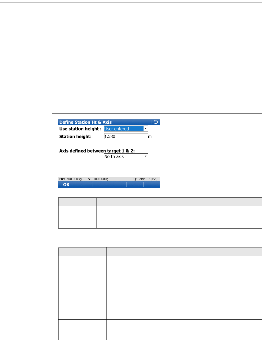
Viva Series, Setup 786
52.7.5 Orientate to line
Description This method can be used to calculate the 2D or 3D local coordinates for the instrument
station and the orientation of the horizontal circle. The calculation is done using the
distance and angle measurements to two target points.
The first target point always defines the origin of the local coordinate system. The
second target point, in conjunction with the first target point, always defines the local
direction of North or East (depending on the working style).
Requirements Important features:
• All coordinates calculated are local coordinates.
• The first target point always defines the origin of the local coordinate system
(North=0, East=0, Height=0 (optional))
• The second target point, in conjunction with the first target point, always defines
the local direction of North or East.
Access In Total Station Setup, select Setup method:Orientate to line. Press OK.
In Enter Station Information type in the required information. Press OK.
Define Station Ht &
Axis
Description of fields
Key Description
OK To accept all settings and continue. The chosen settings are activated
and the next screen, Measure Target, is displayed.
Fn Quit To exit the screen.
Field Option Description
Use station height User entered The height value of the station will be entered by
the user and used to calculate the height of the
measured points.
Transfer from
trgt 1 The height of the station will be calculated rela-
tive to the first measured point.
Station height Editable field Available for Use station height: User entered.
The elevation of the instrument station.
Target 1 height Editable field Available for Use station height: User entered.
The height of the first measured point.
Axis defined
between target 1 &
2
To define the positive North or positive East axis.
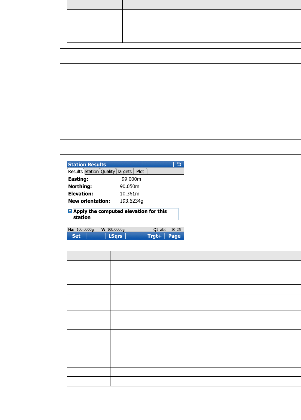
Viva Series, Setup 787
For a description of the Measure Target screen, refer to "52.7.2 Multiple backsights".
52.8 Setup Results
Description The results screen is displayed after pressing Calc in the Measure Target screen. The
results screen is part of the Multiple backsights, Transfer height, Resection and
Orientate to line setup methods.
Excluding Orientate to line, after three measurements to known targets, the calcula-
tions can be done using the robust method or the least squares method. For Resec-
tion, the calculations can also be done using the Helmert method. After the station is
set, all following measurements will be related to this new station and orientation.
For information on camera and images refer to "33.3.3 Within Applications".
Station Results,
Results page
North axis The second point measured defines the direction
of the positive North axis.
East axis The second point measured defines the direction
of the positive East axis.
Field Option Description
Key Description
Set To set the orientation, to store all setup data and exit the applica-
tion.
For Transfer height: To store all setup data and exit the application.
Done To exit the setup without setting it, the setup is incomplete.
Robust or
LSqrs To display the results for the robust or the least squares calculation
method.
Trgt+ To access Measure Target and to measure more target points.
Page To change to another page on this screen.
Fn 3 par or Fn
4 par Switches between a 3 parameter and 4 parameter calculation. For 3
parameter, the current scale is not applied to setup observations for
a new station calculation. For 4 parameter, the current scale is
applied. The station coordinates will be automatically updated
according to the setting used. Defaults to 4 parameter.
SF or ppm To display the scale results by scale factor or as a ppm value.
Fn Quit To exit the screen.

Viva Series, Setup 788
Description of fields
Next step
Page changes to the Station page.
Field Option Description
New orientation Display only New oriented azimuth with running angle as tele-
scope moves. Not available for setup method
Transfer height.
Angle right Display only Available when Hz angle display: Angle right is
configured in Regional Settings, Angle page.
Displays the horizontal angle difference between
the backsight point and the current telescope
position.
height Display only The difference between the new calculated
height and the old height.
Available for setup methods Multiple backsights
and Transfer height.
Use the new height Check box For setup method Multiple backsights: When this
box is checked, both orientation and height are
updated. If not checked, only the orientation is
updated.
For setup method Transfer height: When this box
is checked, the station height is updated. If not
checked, the station height does not change.
Not available for any other setup methods.
New height Display only The calculated height is displayed.
Available for setup methods Multiple backsights
and Transfer height.
Old height Display only The original height is displayed.
Available for setup methods Multiple backsights
and Transfer height.
height Display only Standard deviation of the calculated station
height.
Available for setup methods Transfer height.
Easting Display only The calculated Easting is displayed.
Available for setup methods Resection and
Orientate to line.
Northing Display only The calculated Northing is displayed.
Available for setup methods Resection and
Orientate to line.
Elevation Display only The calculated Height is displayed.
Available for setup methods Resection and
Orientate to line.
Apply the
computed eleva-
tion for this station
Check box When this box is checked, then the height from
the solution is set as the station height. When
this box is not checked, then the height is not
updated.
Available for setup method Resection.
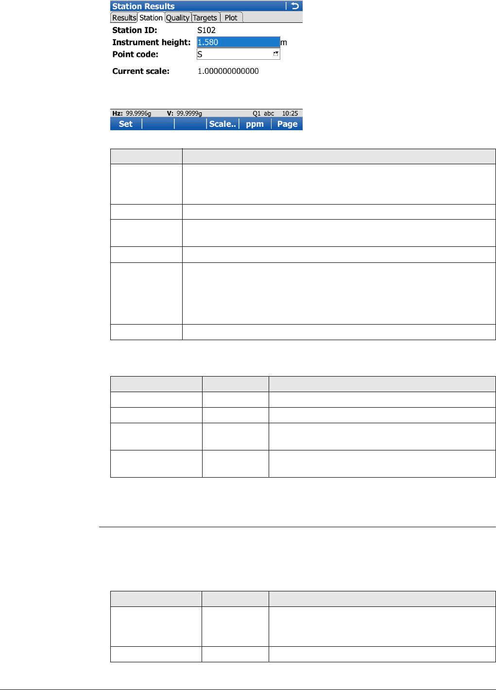
Viva Series, Setup 789
Station Results,
Station page
Description of fields
Next step
Page changes to the Quality page.
Station Results,
Quality page
For a description of the softkeys refer to "Station Results, Station page".
This page is not available for setup methods Transfer height or Orientate to line.
Description of fields
Key Description
Set To set the orientation, to store all setup data and exit the applica-
tion.
For Transfer height: To store all setup data and exit the application.
Done To exit the setup without setting it, the setup is incomplete.
Scale.. To type in values for the scale corrections. Refer to "New Job, Scale
page".
Page To change to another page on this screen.
Fn 3 par or Fn
4 par Switches between a 3 parameter and 4 parameter calculation. For 3
parameter, the current scale is not applied to setup observations for
a new station calculation. For 4 parameter, the current scale is
applied. The station coordinates will be automatically updated
according to the setting used. Defaults to 4 parameter.
Fn Quit To exit the screen.
Field Option Description
Station ID Display only Station ID of the current station set up.
Instrument height Editable field The current instrument height.
Point code Selectable list Select a point code for the station point if
desired.
Current PPM /
Current scale Display only The current job scale. Refer to " New Job, Scale
page" for more information on scale corrections.
Field Option Description
New orientation Display only New oriented azimuth with running angle as tele-
scope moves.
Available for setup method Multiple backsights.
new orientation Display only Standard deviation of the calculated orientation.
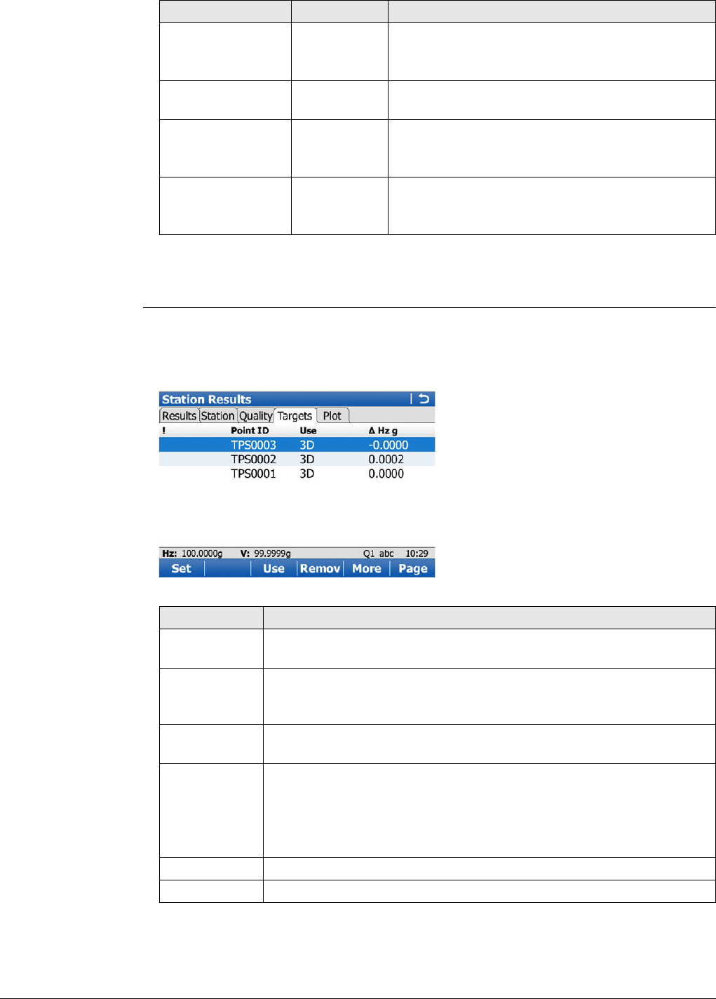
Viva Series, Setup 790
Next step
Page changes to the Targets page.
Station Results,
Targets page
This screen displays information about the accuracy of the measured target points and
allows exclusion of measurements that are not to be used in the calculation.
Additional measurements can be made and measurements can be deleted.
This page is not available for setup method Orientate to line.
height Display only Delta height, the difference between original and
calculated height.
Available for setup method Multiple backsights.
height Display only Standard deviation of the calculated station
height.
easting Display only Standard deviation of the calculated station
Easting.
Available for setup method Resection.
northing Display only Standard deviation of the calculated station
Northing.
Available for setup method Resection.
Field Option Description
Key Description
Set To recalculate the station data and update all values after target
points have been deleted or excluded from the calculation.
Use To change between using the selected point as 3D, 2D, 1D or not at
all, in the calculation. The change automatically updates any new
coordinate or orientation values.
Remov To delete a point from the list of measured target points and exclude
it from the Setup calculation.
More To change the value displayed in the fourth column.
For Resection: To change between Hz, hz dist, height,
easting and northing.
For Multiple backsights: To change between Hz and height.
For Transfer height: Only height available.
Page To change to another page on this screen.
Fn Quit To exit the screen.

Viva Series, Setup 791
Description of columns
Next step
Page changes to the Plot page.
52.9 Finding a Target Point
Description The Find Target screen can be accessed, to guide the prism to the selected target
point.
The screen is only available if the Stakeout application is available on the instrument.
The functionality of this screen is similar to a stake out routine and is intended to help
find hidden survey bench marks or base points.
Access Press Fn Find in Measure Target once enough data is available to calculate roughly the
new orientation.
Find Target This screen is similar to the Stakeout, Stake page and is configured through the
Stakeout configuration settings. Refer to "Stakeout, Stake page" for a detailed
description of this screen.
Column Description
!The ! indicates that the delta value of either measured horizontal
angle, distance or height exceeds the calculation limit.
Point ID The point ID of the measured target points.
Use Indicates if and how a target point is used in the station calcula-
tion. Choices are 3D, 2D, 1D and No.
Hz Can be displayed by pressing More.
Difference between calculated and measured horizontal angle
for the target points. If a target point does not have coordinates,
----- are displayed. Differences exceeding the defined limit are
indicated by a !.
hz dist Can be displayed by pressing More.
Difference between calculated and measured distance from the
station to the target points. If a target point does not have coor-
dinates, ----- are displayed. Differences exceeding the defined
limit are indicated by a !.
height Can be displayed by pressing More.
Difference between the known control point height and the
measured height of the target point. If a target point does not
have a height coordinate, ----- are displayed. Differences
exceeding the defined limit are indicated by a !.
easting Can be displayed by pressing More.
Difference between control point and measured point, calcu-
lated from new station coordinates.
northing Can be displayed by pressing More.
Difference between control point and measured point, calcu-
lated from new station coordinates.
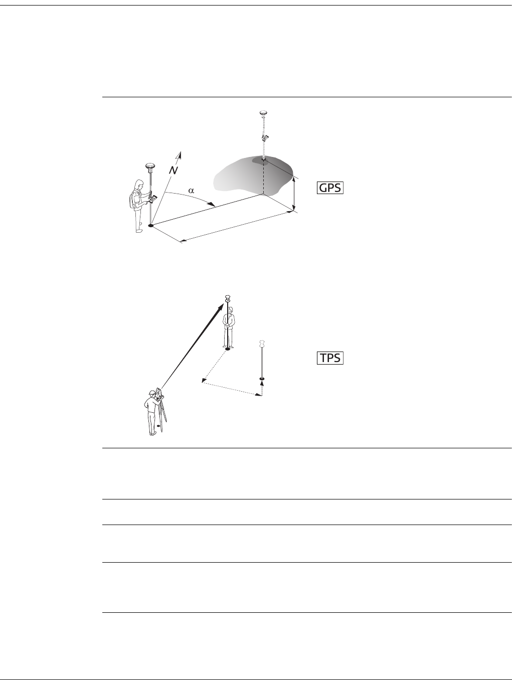
Viva Series, Stakeout 792
53 Stakeout
53.1 Overview
Description The Stakeout application is used to place marks in the field at predetermined points.
These predetermined points are the points to be staked. The points to be staked can
• be uploaded to a job on the instrument using LGO.
• already exist in a job on the instrument.
• be uploaded from an ASCII file to a job on the instrument using Main Menu:Jobs
& Data\Import data\Import ASCII data.
Diagram
Stakeout modes Points can be staked using different modes:
• Polar mode.
• Orthogonal mode.
Staking out is possible for RTK rover and TPS.
The points to be staked must exist in a job on the active memory device or can be
typed in.
Coordinate system If staking local grid points with GNSS, always ensure that the correct coordinate
system is being used. For example, if the points to be staked are stored in WGS 1984,
the active coordinate system must also be WGS 1984.
P0 Current position
P1 Point to be staked
d1 Stake out distance
d2 Height difference between current
position and point to be staked
αStake out direction
P0 Station
P1 Current position
P2 Point to be staked
d1 Stake out element
d2 Stake out element
d3 Stake out element
d1
P1
P0
d2
GS_057
TS_009
P1
P0
P2
d1
d2 d3
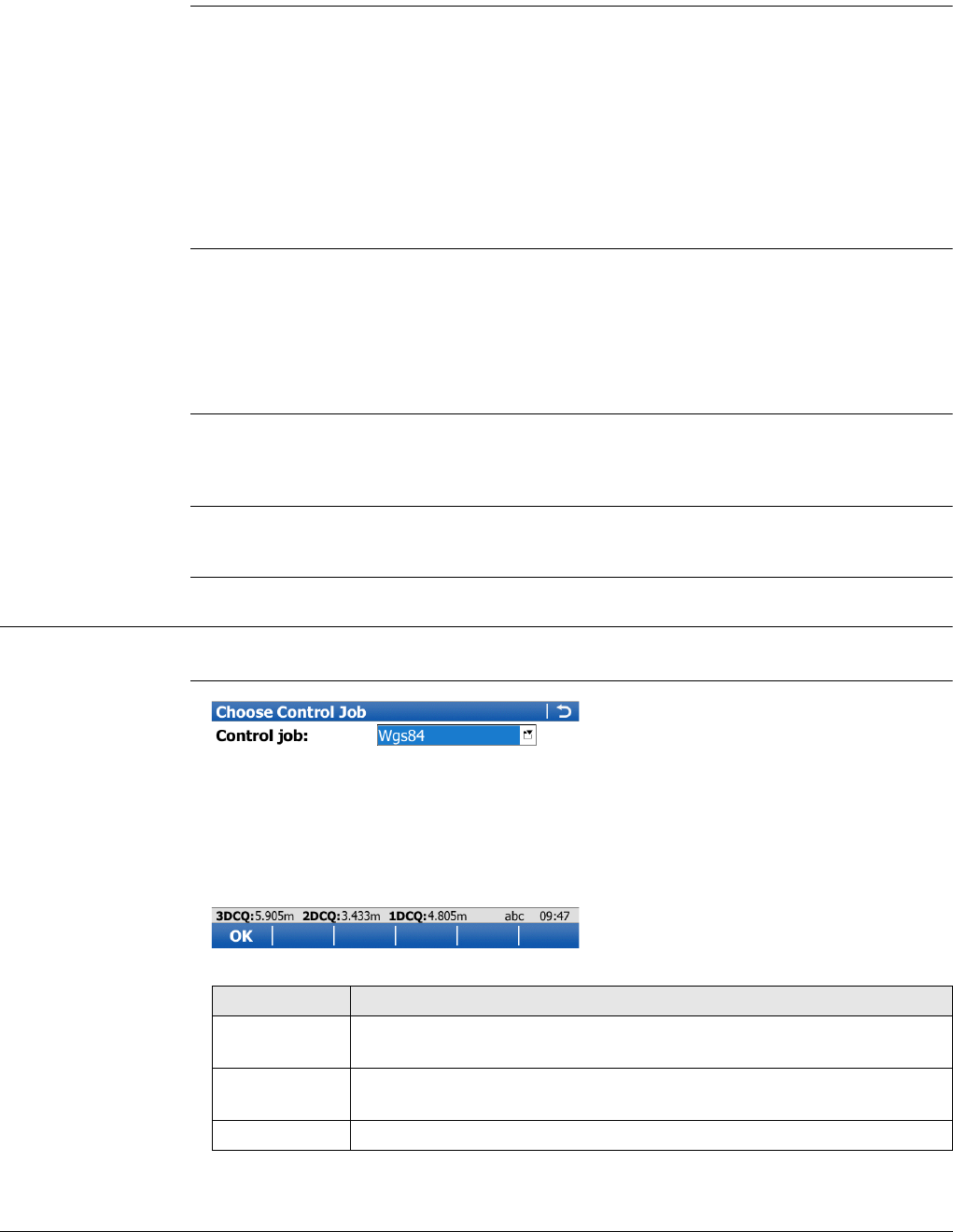
Viva Series, Stakeout 793
Point types It is possible to stake:
• Position only points.
• Height only points.
• Points with full sets of coordinates.
Height types
Height source Heights can be taken into account from
• the vertical component of a coordinate triplet.
•a Digital Terrain Model.
The DTM licence key must be loaded. Refer to "30.3 Load licence keys" for information
on how to enter the licence key.
If loaded, the height of the points to be staked can be edited in the field.
Coding of staked
points
Codes can be attached to staked points, lines and areas. The behaviour of the coding
functionality depends on the definition of a survey screen page with editable fields for
coding and attributes.
Averaging of staked
points
The principles for averaging are identical to the averaging principles of the Survey
application.
53.2 Accessing Stakeout
Access Select Main Menu:Go to Work!\Stakeout.
Stakeout
Height type of the point to be staked: Orthometric OR ellipsoidal
Height type computed for current position:Orthometric OR ellipsoidal depending on
the
• configured transformation,
• availability of a geoid model,
• height type of the point to be staked.
If possible, the height type of the point to
be staked is computed for the current
position.
Key Description
OK To accept changes and access the subsequent screen. The chosen
settings become active.
Fn Config.. To configure Stakeout application. Refer to "53.3 Configuring
Stakeout".
Fn Quit To exit the screen.
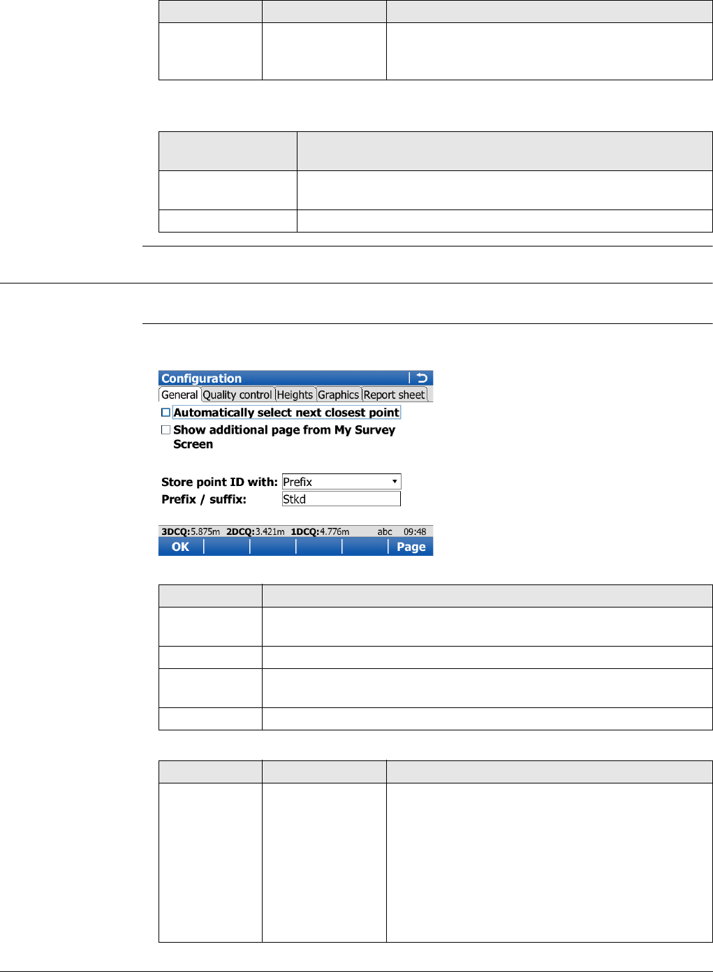
Viva Series, Stakeout 794
Description of fields
Next step
53.3 Configuring Stakeout
Access Select Main Menu:Go to Work!\Stakeout. Press Fn Config...
Configuration,
General page
This screen consists of five pages. The explanations for the softkeys given here are
valid for all pages, unless otherwise stated.
Description of fields
Field Option Description
Control job Selectable list The job containing the points to be staked.
Points which are measured during staking
out are stored in the working job.
IF the Stakeout
application
THEN
is to be accessed OK accepts the changes and accesses Stakeout application.
Refer to "53.4 Staking Out".
is to be configured Config... Refer to "53.3 Configuring Stakeout".
Key Description
OK To accept changes and return to the screen from where this screen
was accessed.
Page To change to another page on this screen.
Fn About To display information about the program name, the version number,
the date of the version, the copyright and the article number.
Fn Quit To exit the screen.
Field Option Description
Automatically
select next
closest point
Check box The order of the points suggested for staking out.
When this box is checked, then the next point
suggested for staking out is the point closest to
the point which was staked. If there are many
points in the job, the search can take a few
seconds.
When this box is not checked, the next point
suggested for staking out is the subsequent one
in the job.
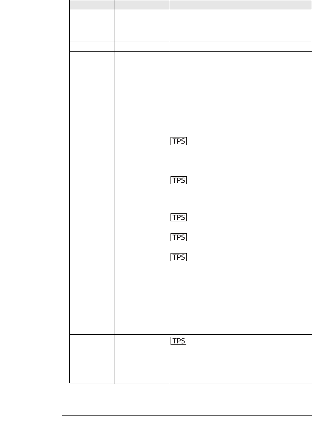
Viva Series, Stakeout 795
Next step
Page changes to the Quality control page.
Show addi-
tional page
from My
Survey Screen
Check box The user-defined survey screen page to be shown
in the Stakeout screen.
Page to show Selectable list The names of the available survey screen pages.
Store point ID
with Stake point ID The staked points are stored with the same point
IDs as the points to be staked.
Prefix Adds the setting for Prefix / suffix in front of the
original point IDs.
Suffix Adds the setting for Prefix / suffix at the end of
the original point IDs.
Prefix / suffix Editable field Available for Store point ID with:Prefix and Store
point ID with:Suffix. The identifier with up to
four characters is added in front of or at the end
of the ID of the staked point.
Only update
stakeout
values when
distance is
measured
Check box When this box is checked, angles and
stakeout values are updated after a distance was
measured. Then all values are frozen until the
next distance is taken.
Automatically
turn to point Check box When this box is checked, the instrument
positions automatically to the point to be staked.
Turn to Available when Automatically turn to point is
checked.
Horiz distance Instrument positions horizontally to the
point to be staked.
Position & height Instrument positions horizontally and verti-
cally to the point to be staked.
Show direc-
tion message
to next point
For each point which is selected for
staking, angle and distance information is
momentarily displayed in the message line.
Instrument The delta horizontal angle that the instrument
must turn to the point, and the distance from the
instrument to the point, is displayed in the
message line.
Last point The delta horizontal angle that the instrument
must turn to the point, and the distance from the
last staked point, is displayed in the message line.
Use two face
measure-
ments
Check box To take a measurement in Face I and Face
II. The point stored is an average of the two
measurements. When using instruments fitted
with auto aiming, the point is automatically meas-
ured in both faces. The resulting point is stored
and the instrument is returned to the first face.
Field Option Description
Viva Series, Stakeout 796
Configuration,
Quality control page
Description of fields
Next step
Page changes to the Heights page.
Configuration,
Heights page
Description of fields
Next step
Page changes to the Graphics page.
Field Option Description
Check
distance
before storing
(set Limit to 0
if you wish to
always be
shown differ-
ences before
storing)
Check box Allows a check to be made on the horizontal coor-
dinate difference between the staked point and
the point to be staked. If the defined Limit is
exceeded, the stake out can be repeated, skipped
or stored.
Limit Editable field Available when Check distance before storing
(set Limit to 0 if you wish to always be shown
differences before storing) is checked. Sets the
maximum horizontal coordinate difference
accepted in the position check.
Check cut/fill
before storing Check box Allows a check to be made on the vertical differ-
ence between the staked point and the point to
be staked. If the defined Limit is exceeded, the
stake out can be repeated, skipped or stored.
Limit Editable field Available when Check cut/fill before storing is
checked. Sets the maximum vertical difference
accepted in the height check.
Field Option Description
Allow height
of point being
staked to be
edited
Check box When this box is checked, the field Design height
is displayed in Stakeout, Stake page. The design
height is the height of the point to be staked. The
value for Design height can be changed.
When this box is not checked, the field Current
height for the height of the current position is
displayed in Stakeout, Stake page. The value for
Current height cannot be changed.
Offset height
of all points
being staked
Check box Allows a constant height offset to be applied to
the height of the points being staked.
Height offset Editable field The height offset that is applied.
Viva Series, Stakeout 797
Configuration,
Graphics page
Description of fields
Field Option Description
Navigate
direction The reference direction to be used to stakeout
points. The stakeout elements and the graphical
display shown in the Stakeout application are
based on this selection.
From instrument The direction of the orientation is from the
instrument to the point to be staked.
To instrument The direction of the orientation is from the
point to be staked to the instrument.
To north The North direction shown in the graphical display
based on the active coordinate system.
From north The direction of the orientation is from the
North direction to the point to be staked.
To sun The position of the sun calculated from the
current position, the time and the date.
To last point Time-wise, the last recorded point. If no points
are yet staked, Navigate direction:To north is
used for the first point to be staked.
To point A point from the working job.
To point (cntrl
job) A point from the Control job selected in
Stakeout.
To line (cntrl job) The direction of the orientation is parallel to a
reference line from the Control job. Open the
listbox to create, edit or delete a reference line.
To line The direction of the orientation is parallel to a
reference line from the working job. Open the
listbox to create, edit or delete a reference line.
Following arrow The direction of the orientation is from the
current position to the point to be staked. The
graphical display shows an arrow pointing in the
direction of the point to be staked.
Point ID or
Line Selectable list Available for Navigate direction:To point (cntrl
job), Navigate direction:To point, Navigate
direction:To line and Navigate direction:To line
(cntrl job). To select the point or line to be used
for orientation.
Navigate
using The method of staking out.
Direction &
distance The direction from the orientation reference, the
horizontal distance and the cut/fill is displayed.
In/out, left/right The distance forwards to/backwards from the
point, the distance right/left to the point and the
cut/fill is displayed.
Switch to bulls
eye when 0.5m
from target
Check box When this box is checked, a bulls eye bubble is
shown in the stakeout graphic when less than
half a metre from the point being staked.
Viva Series, Stakeout 798
Next step
Page changes to the Report sheet page.
Configuration,
Report sheet page
Description of fields
Next step
Page changes to the first page on this screen.
Beep faster
when getting
close to point
Check box The instrument beeps when the distance from
the current position to the point to be staked is
equal to or less than defined in Start within.
The closer the instrument is to the point to be
staked the faster the beeps will be.
Distance to
use Height, Hori-
zontal distance or
Position & height
The type of distance to use for staking.
Start within Editable field Available when Beep faster when getting close to
point is checked. The horizontal radial distance,
from the current position to the point to be
staked, when a beep is to be heard.
Field Option Description
Field Option Description
Create report
sheet Check box To generate a report sheet when the application is
exited.
A report sheet is a file to which data from an applica-
tion is written to. It is generated using the selected
format file.
Report sheet Selectable
list
Available when Create report sheet is ticked. The name
of the file to which the data will be written. A report
sheet is stored in the \DATA directory of the active
memory device. The data is always appended to the
file.
Opening the selectable list accesses the Report Sheets
screen. On this screen, a name for a new report sheet
can be created and an existing report sheet can be
selected or deleted.
Format file to
use Selectable
list
Available when Create report sheet is ticked. A format
file defines which and how data is written to a report
sheet. Format files are created using LGO. A format file
must first be transferred from the data storage device
to the internal memory before it can be selected. Refer
to "30.1 Transfer user objects" for information on how
to transfer a format file.
Opening the selectable list accesses the Format Files
screen where an existing format file can be selected or
deleted.
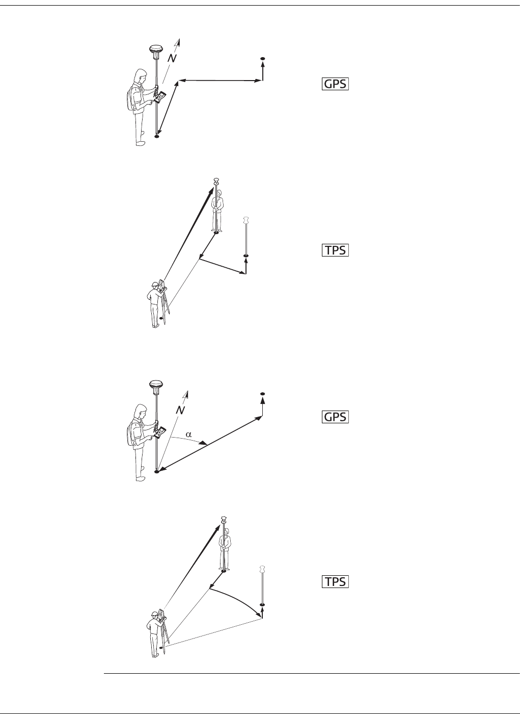
Viva Series, Stakeout 799
53.4 Staking Out
Diagram This diagram shows an example for Navigate using:In/out, left/right.
This diagram shows an example Navigate using:Direction & distance.
P0 Current position
P1 Point to be staked
d1 Forwards or backwards
d2 Right or left
d3 Fill or cut
P0 Station
P1 Current position
P2 Point to be staked
d1 Forward or backwards
d2 Right or left
d3 Cut or fill
P0 Current position
P1 Point to be staked
d1 Distance
d2 Cut or fill
αDirection
P0 Station
P1 Current position
P2 Point to be staked
aDistance
b Horizontal angle
cCut or fill
P0
P1
d3
d2
d1
GS_054
TS_011
P0
P1
P2
d2+ d3+
d1-
P0
GS_055
P1
d2
d1
TS_010
P1
P2
P0
a
c
b
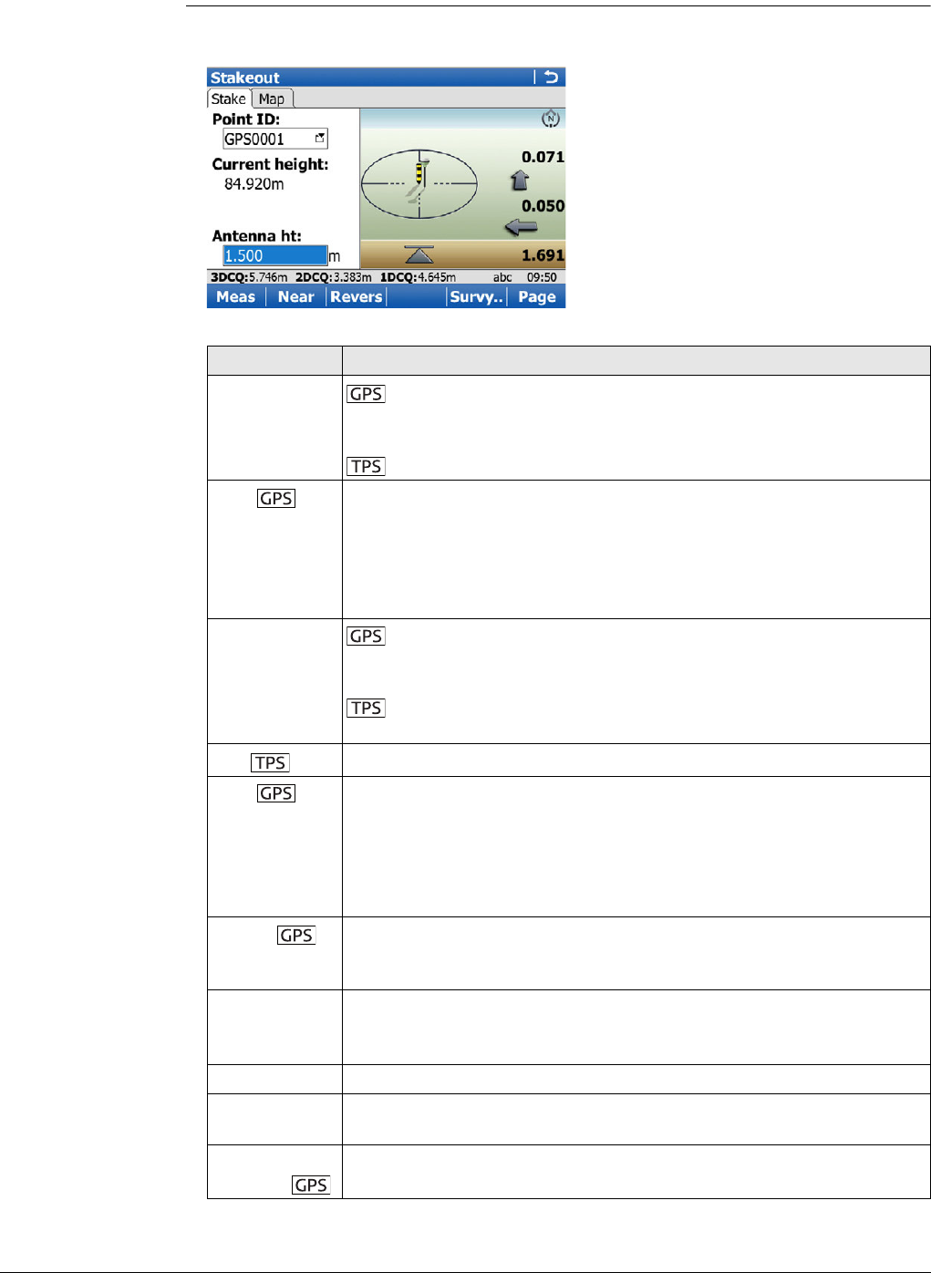
Viva Series, Stakeout 800
For information on camera and images refer to "33.3.3 Within Applications".
Stakeout,
Stake page
The pages shown are from a typical working style. An additional page is available when
a user-defined survey screen page is used.
Key Description
Meas To start measuring the point being staked. The key changes to
Stop. The difference between the current position and the point
being staked is still displayed.
To measure a distance and store distance and angles.
Stop To end measuring the point being staked. When Automatically stop
point measurement is checked in Quality Control, General page
recording of positions ends automatically as defined by the stop
criteria. The key changes to Store. After ending the measurements,
the differences between the measured point and the point to be
staked are displayed.
Store To store the measured point. When Automatically store point
is checked in Quality Control, General page, the measured point is
stored automatically. The key changes to Meas.
To store angles and distance. Distance must be measured
before.
Dist To measure a distance.
Near To search the Control job for the point nearest to the current posi-
tion when the key is pressed. The point is selected as the point to be
staked and is displayed in the first field on the screen. After staking
and storing the nearest point, the next point suggested for staking
out is the one which was suggested before the key was pressed.
Available when Meas is displayed.
Revers To reverse the graphical display top to bottom. A reversed graphical
display can be used when the point to be staked lies behind the
current position.
Survy.. To survey additional points which may be needed during staking out.
To return to Stakeout application, press Fn Quit or ESC.
Available when Meas is displayed.
Page To change to another page on this screen.
Fn Config.. To configure the Stakeout application. Refer to "53.3 Configuring
Stakeout".
Fn Conect and
Fn Disco
To connect/disconnect from the GPS reference data.
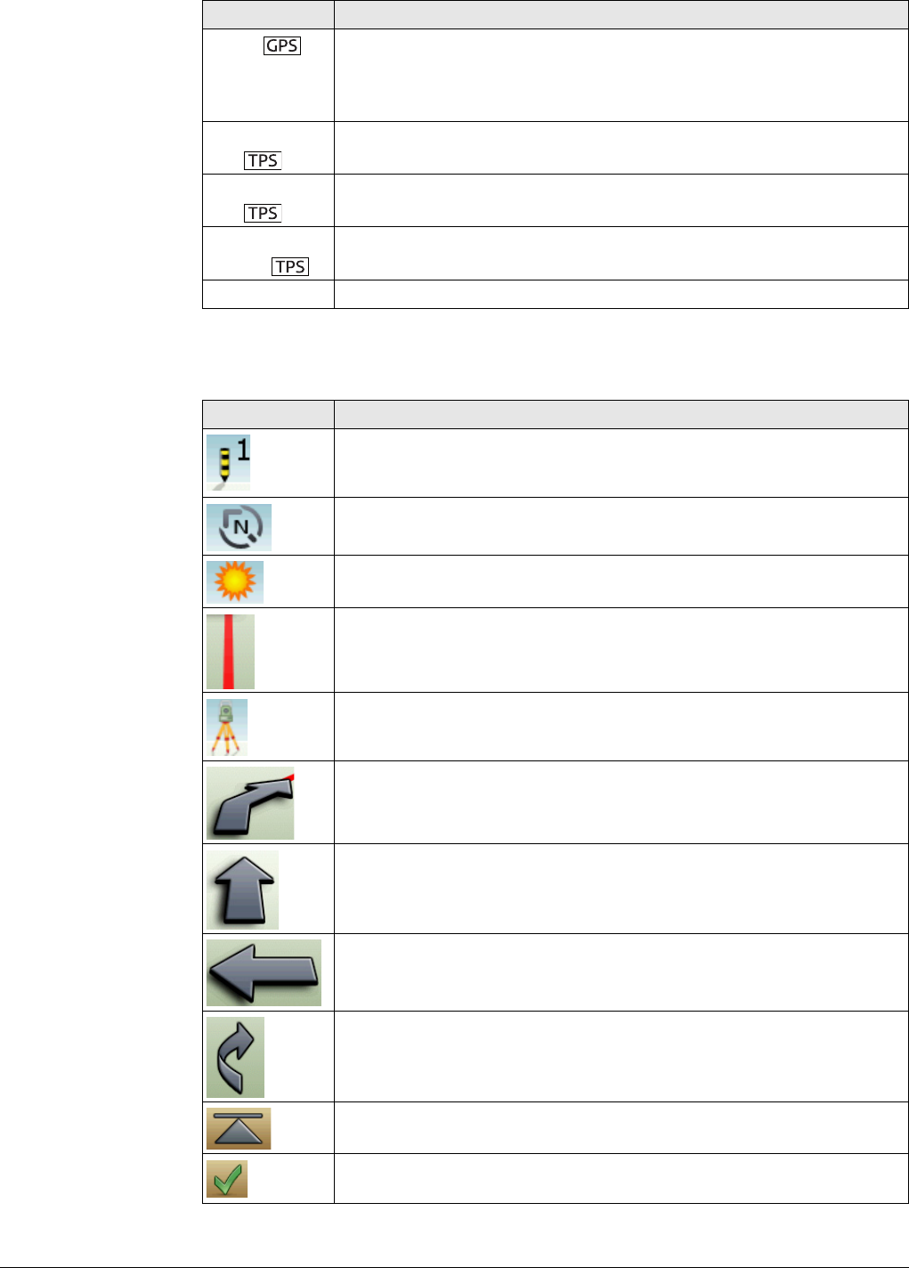
Viva Series, Stakeout 801
Description of the elements of the graphical display
The graphical display provides a guide to find the point to be staked out.
Fn Init To select an initialisation method and to force a new initialisation.
Available when Meas or Store is displayed and for working styles
allowing phase fixed solutions. Refer to "56.4 Initialisation for Real-
Time Rover Operations".
Fn 2D
Pos
To position the telescope (X,Y) onto the point to be staked.
Fn 3D
Pos
To position the telescope (X,Y,Z) onto the point to be staked.
Fn
Mnual..
To enter angle and distance values to stake out a point.
Fn Quit To exit Stakeout application.
Element Description
Point to be staked / known point
North
Sun
Defined line
From instrument
Follow arrow
Forward arrow, distance to point
Side arrow, distance to point
Polar arrow, direction to point
Height
The current position and/or height is within the configured stake out
limit for position and/or height.
Key Description
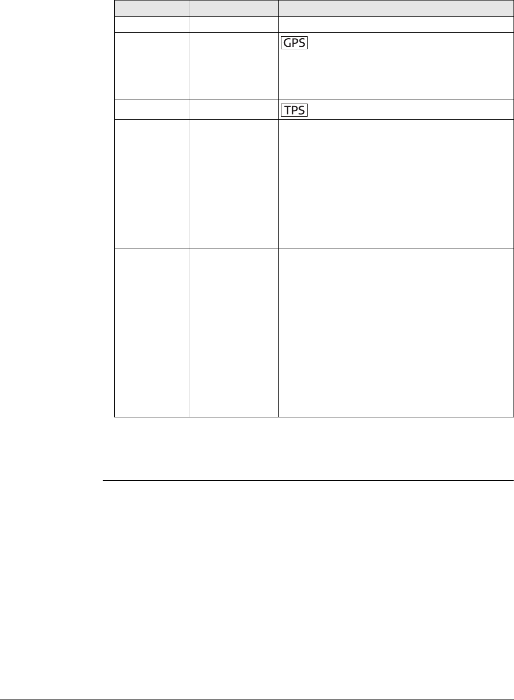
Viva Series, Stakeout 802
Description of fields
Next step
Page changes to the Map page. Refer to "37 MapView Interactive Display Feature" for
information on the functionality and softkeys available.
Field Option Description
Point ID Selectable list The point ID of the point to be staked.
Antenna ht Editable field The default antenna height. Changing the
antenna height here does not update the default
antenna height as defined in the active working
style. The changed antenna height is used until
the application is exited.
Target height Editable field The default prism height.
Current height Display only Available when Allow height of point being
staked to be edited is not checked in Configura-
tion, Heights page.
The orthometric height of the current position is
displayed. If the orthometric height cannot be
displayed, the local ellipsoidal height is displayed.
If it is not possible to display the local ellipsoidal
height, the WGS 1984 height is displayed. The
value for Height offset configured in Configura-
tion, Heights page is taken into account.
Design height Editable field Available when Allow height of point being
staked to be edited is checked in Configuration,
Heights.
The design height, which is the orthometric
height of the point to be staked, is displayed. If
the orthometric height cannot be displayed, the
local ellipsoidal height is displayed. If it is not
possible to display the local ellipsoidal height, the
WGS 1984 height is displayed. The value for
Height offset configured in Configuration,
Heights page is not taken into account.
Changing the value for Design height changes the
values displayed for cut and fill.
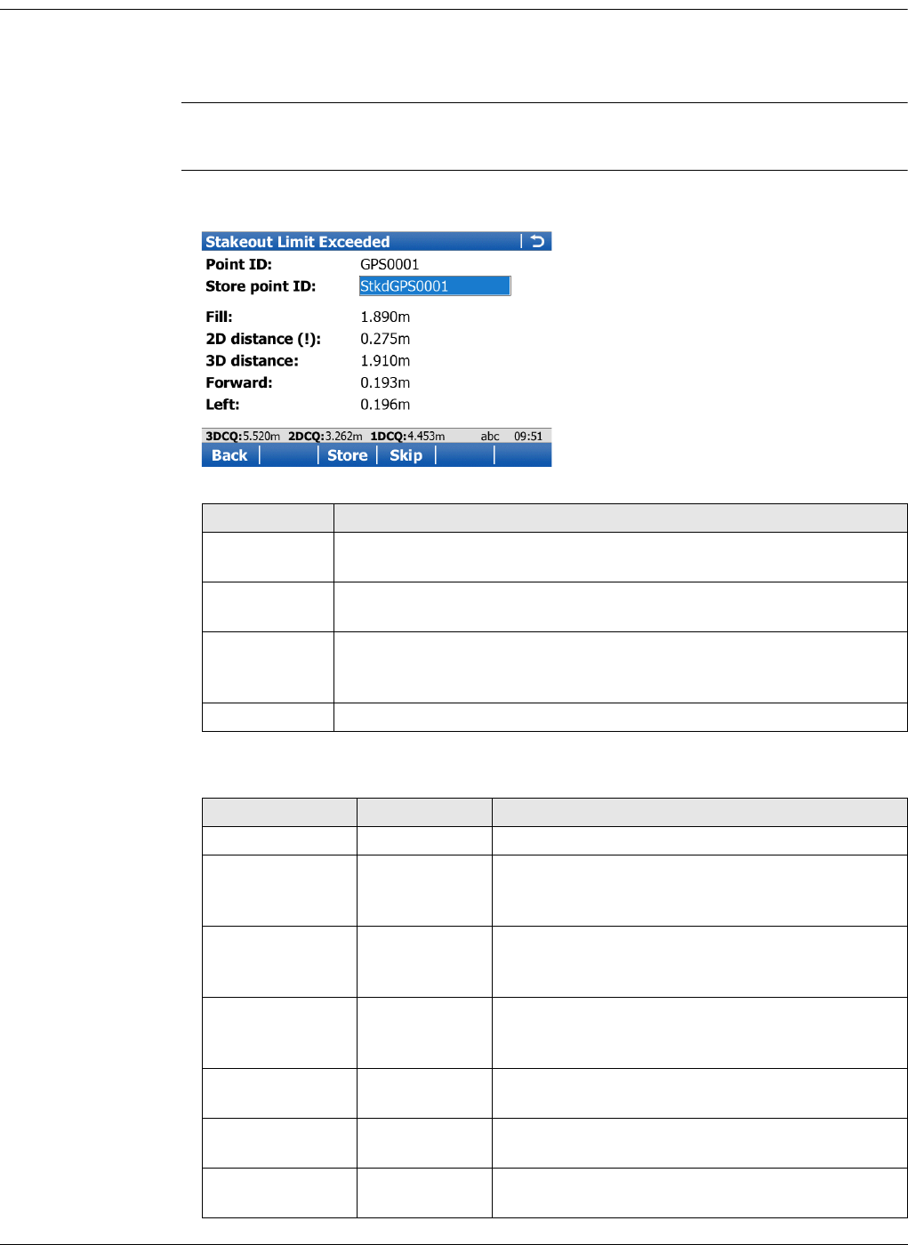
Viva Series, Stakeout 803
53.5 Stakeout Difference Limit Exceeded
Description If configured a check is made on the horizontal and/or vertical coordinate distance
from the staked point to the point to be staked. Refer to "53.3 Configuring Stakeout"
for information on configuring the check and the limits.
Access If either of the configured difference limits are exceeded, the following screen is
accessed automatically when the point is stored.
Stakeout Limit
Exceeded The availability of the fields depends on the configuration for Navigate using.
The limits that have been exceeded are shown in bold and indicated by a !.
Description of fields
Key Description
Back To return to the Stakeout screen without storing the point. Staking
out of the same point continues.
Store To accept the coordinate differences, store the point information
and return to the Stakeout screen.
Skip To return to the Stakeout screen without storing the point.
According to filter and sort settings the next point is suggested for
staking out.
Fn Quit To exit the screen.
Field Option Description
Point ID Display only The point ID of the point to be staked.
Store point ID Editable field The unique number which is used to store the
staked point. Allows a different point ID to be
typed in, if needed.
Cut Display only The negative height difference from the height of
the staked point to the height of the point to be
staked. To move down.
Fill Display only The positive height difference from the height of
the staked point to the height of the point to be
staked. To move up.
2D distance Display only Displays the horizontal difference from the
staked point to the point to be staked.
3D distance Display only Displays the spatial difference from the staked
point to the point to be staked.
Hz Display only The bearing from the staked point to the point to
be staked.
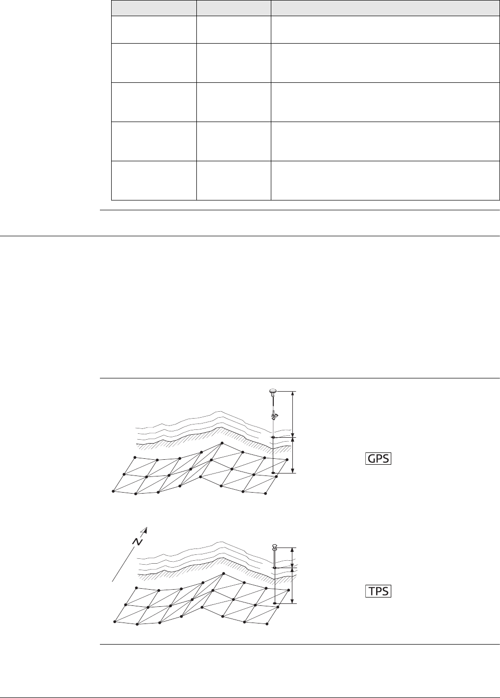
Viva Series, Stakeout 804
53.6 Staking Out a DTM or Points & DTM
Description A Digital Terrain Model can be staked alone or together with points. The heights of
the current positions are compared against the heights of a selected DTM job. The
height differences are calculated and displayed.
Staking a DTM can be used for
• staking out where the DTM represents the surface to be staked.
• quality control purposes where the DTM represents the final project surface.
DTM jobs are created in LGO. DTM jobs are stored in the \DBX directory on the active
memory device.
Diagram
Dist Display only Horizontal distance from the staked point to the
point to be staked.
Forward Display only The horizontal distance from the current position
to the point to be staked in the direction of the
orientation.
Back Display only The horizontal distance from the current position
to the point to be staked in the reverse direction
of the orientation.
Right Display only Horizontal distance from the staked point to the
point to be staked orthogonal to the right of the
orientation direction.
Left Display only Horizontal distance from the staked point to the
point to be staked orthogonal to the left of the
orientation direction.
Field Option Description
P1 Point to be staked
d1 Antenna height
d2 Cut or fill
P1 Point to be staked
d1 Cut or fill
d2 Reflector height
GS_056
d2
d1
P1
TS_012
d2
d1
P1

Viva Series, Stakeout 805
Access If the message panel appears which requires that the application must be activated via
a license key then refer to "30.3 Load licence keys".
To stake out DTM heights only:
Select Main Menu:Go to Work!\Stakeout+\Stakeout DTM.
To stake out positions of points and DTM heights:
Select Main Menu:Go to Work!\Stakeout+\Stake points & DTM.
Stakeout Description of fields
The stake out procedure is identical as for the normal Stakeout application but the
heights to be staked are taken from the selected DTM job. The negative or positive
height differences from the current position to the equivalent point in the selected
DTM job is calculated and displayed. Height offsets apply.
Refer to "53.3 Configuring Stakeout", "53.4 Staking Out" and "53.5 Stakeout Differ-
ence Limit Exceeded".
Field Option Description
Control job Selectable list The positions of points in the job selected here
are staked out. Heights to be staked out are
taken from the DTM job.
Points which are measured during staking
out are stored in the working job.
DTM Selectable list The DTM job to be used must be stored in the
\DBX directory on the active memory device.
Heights without positions are staked out relative
to the selected DTM job.
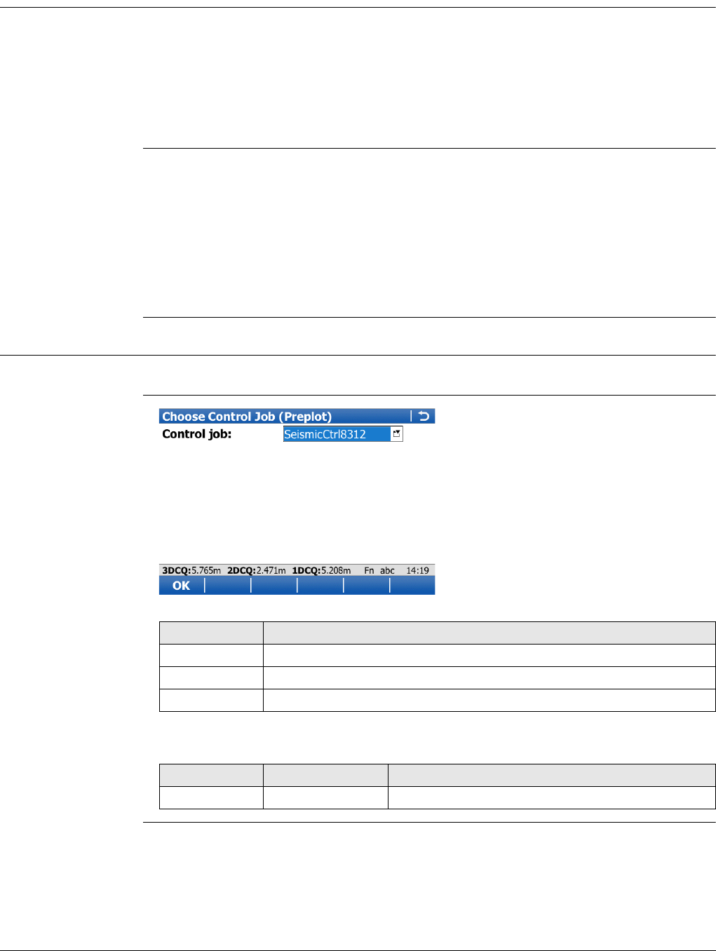
Viva Series, Seismic Stakeout 806
54 Seismic Stakeout
54.1 Overview
Description The Seismic Stakeout application includes all the standard stakeout functionality plus
extra features that are specific to seismic survey. It supports exclusion zone files in
order to warn users when the selected preplot point position or the current measured
position falls inside a protected area. It provides a specific Offset page in the main
stakeout screen to help staking, offsetting or skidding preplot points. A “default line
width annotation” feature is available for users who need to report the width of the
cut line.
Terms
54.2 Accessing Stakeout
Access Select Main Menu:Go to Work!\Stakeout+\Seismic stakeout.
Choose Control Job
(Preplot)
Description of fields
Exclusion zone: Protected area where drilling is not allowed.
Preplot: Refers to design. For example preplot points and preplot job –
not control points or control job.
Track and bin: The preplot point IDs are comprised of a track(line) and
bin(station). For example, if the point ID 162304 has 3 bin char-
acters then its track would be 162 and its station 304.
Key Description
OK To activate the selected control job (preplot job).
Fn Config.. To configure Seismic Stakeout application.
Fn Quit To exit the screen.
Field Option Description
Control job Selectable list Job that contains preplot points to be staked.
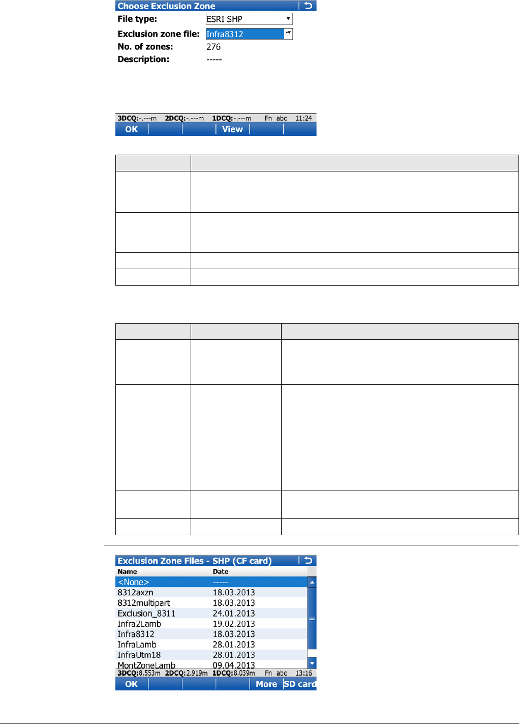
Viva Series, Seismic Stakeout 807
Choose Exclusion
Zone
Description of fields
Exclusion Zone Files
- SHP
Key Description
OK To validate the selected exclusion zone file. Opens the Define Line
Settings screen. The file is converted to an internal format (*.xnz)
when used for the first time.
View To open the Exclusion zone viewer after loading the zones in
memory. The file is converted to an internal format (*.xnz) when
used for the first time. Refer to "Exclusion zone viewer".
Fn Config.. To configure Seismic Stakeout application.
Fn Quit To exit the screen.
Field Option Description
File type ESRI SHP Polygon shapefile in local grid coordinate system
GPSeismic LZO Leica exclusion zone format by GPSeismic soft-
ware
Exclusion
zone file Selectable list The file that contains exclusion zones against
which the measured or selected preplot position
will be tested. The file must be stored in the
DATA\ZONE directory on the data storage device.
Open the selectable list to change the memory
device as needed. Select <None> if no file is avail-
able for a given project area. Refer to "Exclusion
Zone Files - SHP".
No. of zones Display only Numbers of exclusion zones included in the
selected file.
Description Display only File description as read in the file’s header.
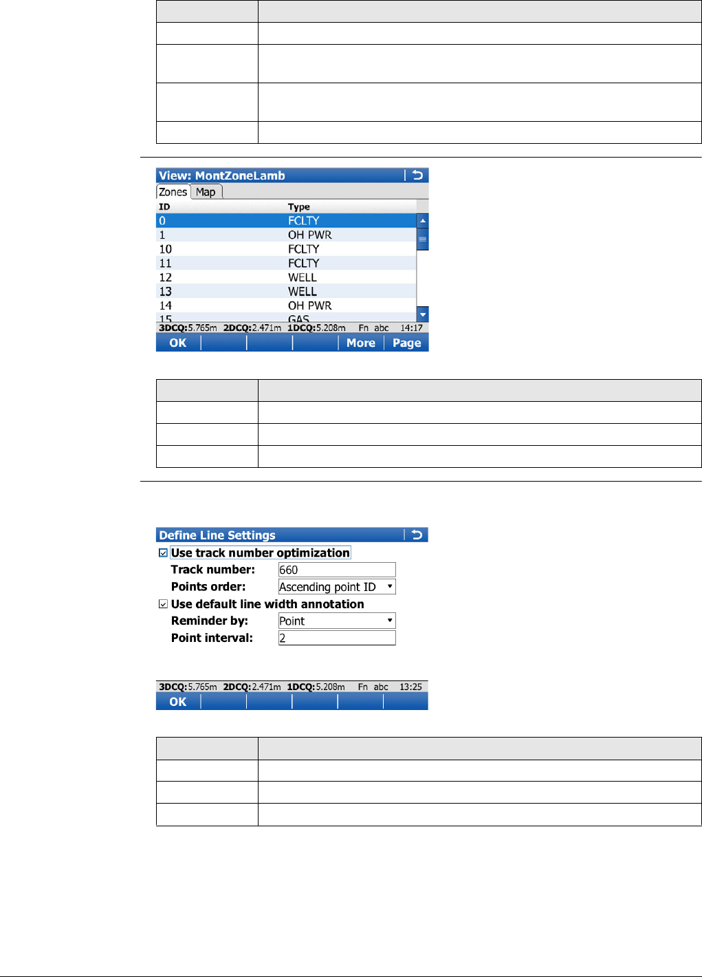
Viva Series, Seismic Stakeout 808
Exclusion zone
viewer
Define Line Settings Seismic stakeout is usually done following a line of preplot points. The application can
take advantage of line settings definitions to improve the seismic stakeout.
Key Description
OK To accept the selection.
More To display information about the file name, size and last modification
date/time.
CF card, SD
card or Intrnl To change between viewing exclusion zone files stored on another
data storage device or internal memory.
Fn Quit To exit the screen.
Key Description
OK To return to the previous screen.
More To display information about the zone ID, type and geometry.
Fn Quit To exit the screen.
Key Description
OK To open the Seismic Stakeout screen.
Fn Config.. To configure Seismic Stakeout application.
Fn Quit To exit the screen.
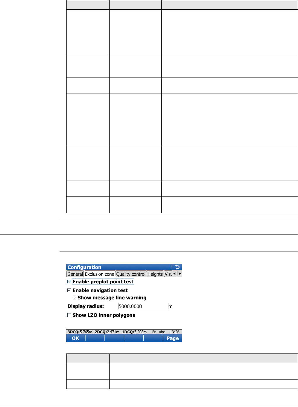
Viva Series, Seismic Stakeout 809
Description of fields
54.3 Configuring Stakeout
Access Select Main Menu:Go to Work!\Stakeout+\Seismic stakeout. Press Fn Config...
Configuration,
Seismic stakeout
page
For all other pages on this screen, refer to "53.3 Configuring Stakeout".
Field Option Description
Use track
number opti-
mization
Check box The track(line) number can be used internally by
the application to filter preplot points that belong
to the current line being staked. This option also
increase the performance of the preplot point
test by reducing the number of exclusion zones
loaded into memory.
Track number Editable field Track number of the line being staked. Common
prefix identifier of all preplot points that belong
to a given line.
Points order Selectable list Line walking direction as defined by preplot point
IDs.
Use default
line width
annotation
Check box This option is for users who need to report the
width of the cut line. It allows to store automati-
cally the last entered line width in the staked
point annotation (Annot 4). Depending on the
reminder method, a dialog will show-up after
point store that recall the user to measure and
update the line width value.
Reminder by Reminder method for line width annotation
update.
Point Reminds after a point interval
Distance Reminds after a distance interval
Point interval Editable field Number of staked point after which the default
line width annotation must be updated.
Distance
interval Editable field The distance after which the default line width
annotation must be updated.
Key Description
OK To accept changes and return to the screen from where this screen
was accessed.
Page To change to another page on this screen.
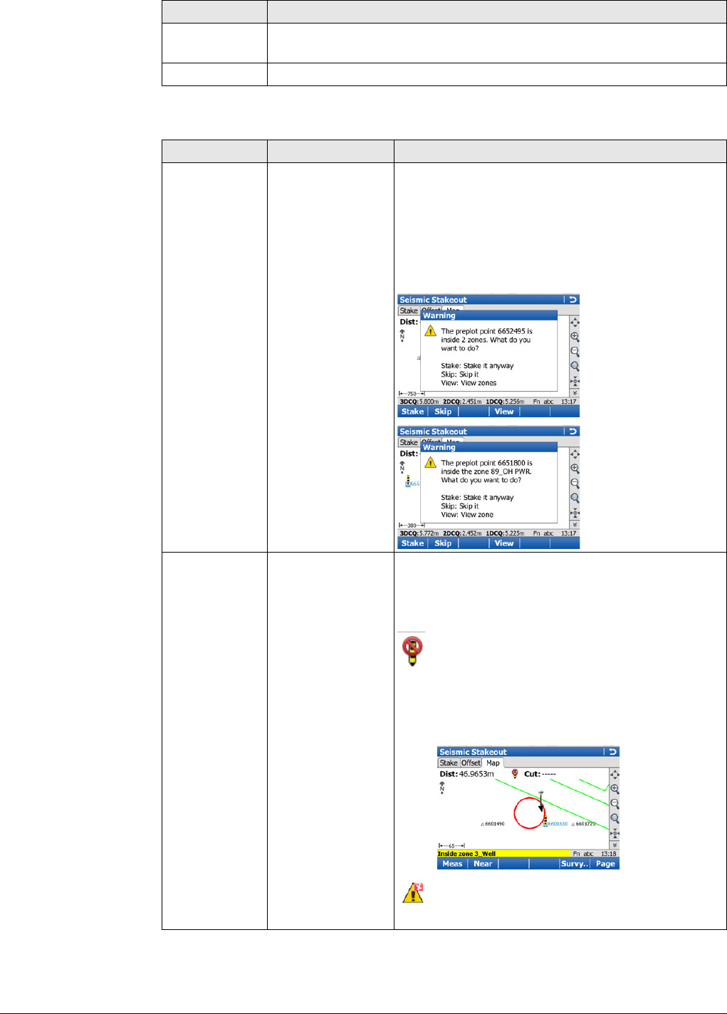
Viva Series, Seismic Stakeout 810
Description of fields
Fn About To display information about the program name, the version number,
the date of the version, the copyright and the article number.
Fn Quit To exit the screen.
Field Option Description
Enable preplot
point test Check box The preplot point test is done each time the
current point ID selection changes (in Stake or
Map page from Seismic Stakeout screen). The
preplot point position is tested against exclusion
zones and an appropriate warning message
appears when the position is inside one or more
zones.
Enable navi-
gation test Check box The navigation test is done continuously on the
current measured position. The current position is
tested against all exclusion zones in the
surrounding area as defined by Display radius.
Appears in the Stake and Map page when
the measured position falls inside one or
more exclusion zones.
In addition, the touched zone is highlighted
in red in the map (that could be more than
one zone).
Appears in the Stake and Map page when
an exclusion zone file is active and the navi-
gation test is disabled.
Key Description
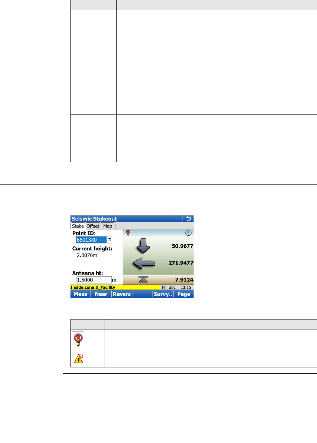
Viva Series, Seismic Stakeout 811
54.4 Staking Out
Seismic Stakeout,
Stake page
Same as standard Stakeout application, except for specific warning icons that appear
in the left upper corner of the bulls-eye. Refer to "53.4 Staking Out" for a description
of keys, fields and standard elements of the graphical display.
Description of specific elements of the graphical display
Show
message line
warning
Check box Inside zone warning displayed at the message line
when the current measured position falls inside
one or more exclusion zones. The message line
stays on for seven seconds when triggered even
if the user gets out of the zone(s).
Display radius Editable field This radius defines the area around the current
measured position for which the exclusion zones
will be added to the stakeout map.
It is better to keep this value as small as
possible to not load too many exclusion
zones in memory. The application auto-
matically readjusts this radius when more
than 200 zones overlap the defined area
Show LZO
inner poly-
gons
Check box An inner polygon is created when adding an
offset to an exclusion zone in GPSeismic (LZO
format). Use this option to display inner polygons
on the stakeout map. Inner polygons are
displayed in yellow and no inclusion test is done
against them.
Field Option Description
Element Description
Indicates that current measured position falls inside one or more exclu-
sion zones.
Indicates that an exclusion zone file is active but navigation test is disa-
bled.
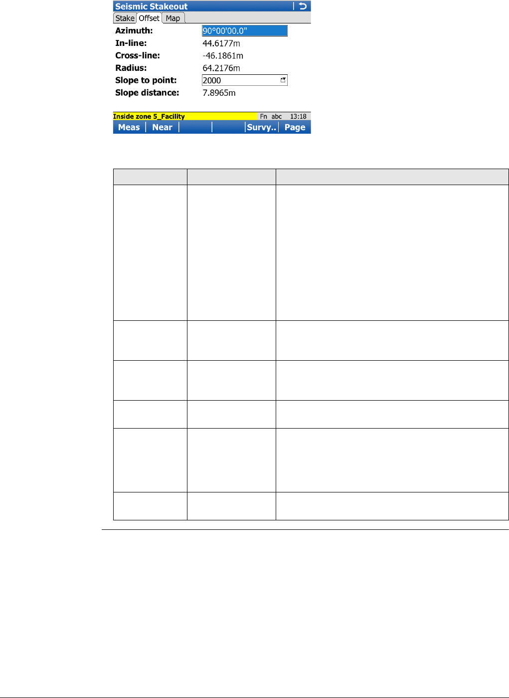
Viva Series, Seismic Stakeout 812
Seismic Stakeout,
Offset page
Refer to "53.4 Staking Out" for a description of keys.
Description of fields
Field Option Description
Azimuth Editable field Direction from the current preplot point for which
the In-line and Cross-line offsets are computed.
This azimuth value is automatically updated each
time the selected preplot point changes in the
Stake and Map page.
The computed azimuth is based on the next
preplot point in the list. If no next point is avail-
able then it will be from previous point to current
one.
Or enter an azimuth value for specific validation.
In-line Display only Measured position in/out offset based on the line
from the current preplot point to the given
azimuth direction. Negative value is in.
Cross-line Display only Measured position left/right offset based on the
line from the current preplot point to the given
azimuth direction. Negative value is left.
Radius Display only Horizontal distance from the measured position
to the current preplot point.
Slope to point Selectable list Point stored in the working job for which the
slope distance from the current measured posi-
tion is required. Useful when offsetting a preplot
point to validate cable length from previous
staked point.
Slope
distance Display only Slope distance from measured position to
selected Slope to point.
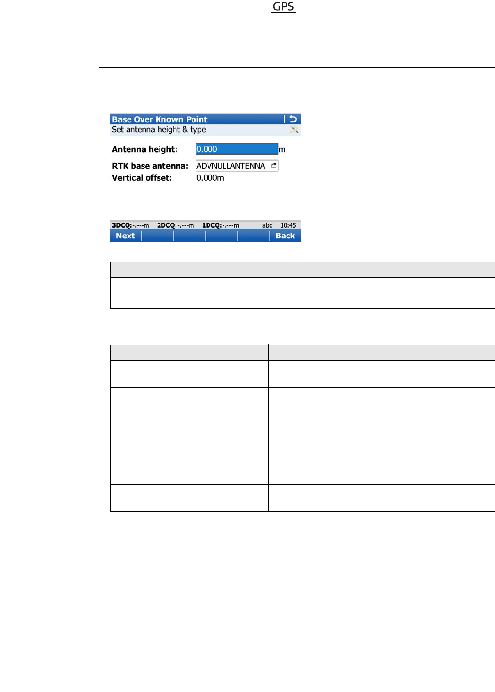
Viva Series, Base Menu - Start base 813
55 Base Menu - Start base
55.1 Start base over known point
Description In this option, a known point stored in the working job is used to set up the RTK base.
Access Select Base Menu\Go to Work!\Start base over known point.
Set antenna height &
type. Type in the antenna height and select the antenna being used.
Description of fields
Next step
Next to access Select known point.
Key Description
Next To accept changes and access the subsequent screen.
Fn Quit To exit the screen.
Field Option Description
Antenna
height Editable field The height of the antenna that is being used.
RTK base
antenna Selectable list Leica Geosystems antennas are predefined as
default and can be selected from the list. Default
antennas contain an elevation-dependent correc-
tion model. New antenna correction models can
be set up and transferred to the instrument using
LGO. Open the list to define or edit additional
antennas. Refer to Antennas for information on
antennas.
Vertical offset Display only The vertical offset of the measurement reference
point.
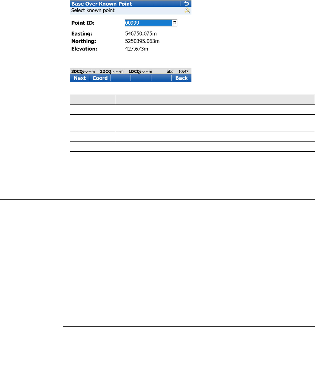
Viva Series, Base Menu - Start base 814
Select known point Select the point to be used as base station.
A point could already be stored in the control job either by manual entry, by
measuring or by transfer from LGO.
If a new point is to be created, open the selectable list for Point ID and press
Point ID.
If an existing point is to be edited, open the selectable list for Point ID and
press Edit...
Next step
Next to access Base setup complete.. Follow the instructions on the screen.
55.2 Start base over last setup
Description To use the same coordinates as when the instrument was last used as a base. Avail-
able when the instrument has previously been used as a base and no point in the
control job has the same point ID as the one last used.
After turning off, the base coordinates are stored in the System RAM. They can be
used again the next time the instrument is used as a base. This functionality means
that even if the data storage device that previously contained the base coordinates is
formatted, the last used coordinates can still be used.
Access Select Base Menu\Go to Work!\Start base over last setup.
Set antenna height &
type. This screen is identical with the one in Start base over known point. Refer to Start
base over any point.
Next step
Next to access Last used RTK base point..
Last used RTK base
point. The point ID and coordinates of the last used base are displayed in grid. When no local
coordinate system is active, WGS 1984 coordinates are displayed. Refer to Start base
over any point for information on the keys.
Key Description
Next To accept changes and access the subsequent screen.
Coord To view other coordinate types. Local coordinates are available when
a local coordinate system is active.
Back To return to the previous screen.
Fn Quit To exit the screen.

Viva Series, Base Menu - Start base 815
Next step
Next to access Base setup complete.. Follow the instructions on the screen.
55.3 Start base over any point
Description To use the coordinates of the current navigation position as base coordinates.
Access Select Base Menu\Go to Work!\Start base over any point.
Set antenna height &
type. This screen is identical with the one in Start base over known point. Refer to Start
base over any point.
Next step
Next to access Measure new point..
Measure new point. Type in a point ID for this new point. Refer to Start base over any point for infor-
mation on the keys.
Code information or annotations can be added in the rover menu in View & edit data.
Next step
Next to access Base setup complete.. Follow the instructions on the screen.
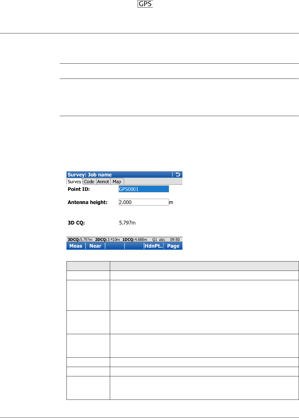
Viva Series, Survey - General 816
56 Survey - General
56.1 Surveying Points
56.1.1 Post-Processed Kinematic and Static Operations
Requirements • A typical working style for a static or post-processed kinematic operation is used.
Ensure that the working style has Log data for post-processing selected in the
Raw Data Logging Settings screen.
For information on camera and images refer to "33.3.3 Within Applications".
Access For RTK rover:
Select Main Menu: Go to Work!, Survey.
If configured for post-processed kinematic operations, the logging of moving
observations begins.
Survey,
Survey page
The fields shown are from a typical working style for static or post-processed kine-
matic operations. The screen described consists of four pages. The explanations for
the softkeys given here are valid for the Survey page, the Code page and the Annot
page. Refer to "37 MapView Interactive Display Feature" for information on the keys
on the Map page.
The fields and functionality of this screen vary slightly when accessed from other
applications where individual point measurements are needed.
Key Description
Meas To start logging of static observations. The key changes to Stop.
Stop To end recording of positions when enough data is collected. When
Automatically stop point measurement is checked in Quality
Control, General, recording of positions ends automatically as
defined by the stop criteria. The key changes to Store.
Store To store the point information. When Automatically store point is
checked in Quality Control, General, the measured point is stored
automatically. The key changes to Meas.
Near To compare the user’s current position with the coordinates of all
points already stored in the job and find the nearest point. This point
ID is then suggested as the next point ID to be used.
HdnPt.. To measure a hidden point. Refer to "60 Survey - Hidden Points".
Page To change to another page on this screen.
Fn Config.. To configure SmartCodes, auto points and hidden point measure-
ments. Refer to "26.5 SmartCodes", "58 Survey - Auto Points" and
"60 Survey - Hidden Points".
Viva Series, Survey - General 817
Description of fields
56.1.2 Real-Time Rover Operations
Requirements • A typical working style for real-time rover operations is used.
• The appropriate real-time device is attached and working properly.
For information on camera and images refer to "33.3.3 Within Applications".
Access For RTK rover:
Select Main Menu: Go to Work!, Survey.
Survey,
Survey page
The fields shown are from a typical working style for real-time rover operations. The
screen described consists of four pages. The explanations for the softkeys given here
are valid for the Survey page, the Code page and the Annot page. Refer to "37
MapView Interactive Display Feature" for information on the keys on the Map page.
The fields and functionality of this screen vary slightly when accessed from other
applications where individual point measurements are needed.
Fn IndivID and
Fn Run To change between entering an individual point ID different to the
defined ID template and the running point ID according to the ID
template. Refer to "25.1 ID templates".
Fn Quit To exit the screen.
Field Option Description
Point ID Editable field The identifier for manually measured points. The
configured point ID template is used. The ID can
be changed in the following ways:
• To start a new sequence of point IDs type over
the point ID.
• For an individual point ID independent of the
ID template Fn IndivID. Fn Run changes back
to the next ID from the configured ID
template.
Antenna
height Editable field The default antenna height as defined in the
active working style is suggested. Changing the
antenna height here does not update the default
antenna height as defined in the active working
style. The changed antenna height is used until
the application is exited.
3D CQ Display only The current 3D coordinate quality of the
computed position.
Key Description
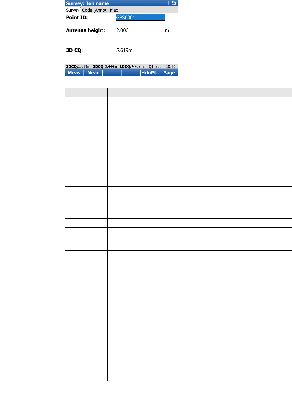
Viva Series, Survey - General 818
Key Description
Meas To start logging of static observations. The key changes to Stop.
Stop To end recording of positions when enough data is collected. When
Automatically stop point measurement is checked in Quality
Control, General, recording of positions ends automatically as
defined by the stop criteria. The key changes to Store.
Store To store the point information. When Automatically store point is
checked in Quality Control, General, the measured point is stored
automatically. The key changes to Meas.
It may happen that a point with the same point ID exists in the job.
If the codes and/or attribute values of the new and the existing point
do not match, a screen opens where they can be corrected. Refer to
"26.6 Code and Attribute Mismatch".
Near To compare the user’s current position with the coordinates of all
points already stored in the job and find the nearest point. This point
ID is then suggested as the next point ID to be used.
HdnPt.. To measure a hidden point. Refer to "60 Survey - Hidden Points".
Page To change to another page on this screen.
Fn Config.. To configure SmartCodes, auto points and hidden point measure-
ments. Refer to "26.5 SmartCodes", "58 Survey - Auto Points" and
"60 Survey - Hidden Points".
Fn Avg To check the residuals for the averaged position. Available for Mode:
Average in Job Properties:, Averaging page and for more than one
measured coordinate triplet recorded for the same point. Refer to
"6.3.3 Mean Page".
Fn Abs To check the absolute difference between measurements. Available
for Mode: Average in Job Properties:, Absolute differences page
and for more than one measured coordinate triplet recorded for the
same point. Refer to "6.3.3 Mean Page".
Fn Conect and
Fn Disco To connect/disconnect from the GPS reference data.
Fn Init.. To select an initialisation method and to force a new initialisation.
Available for working styles allowing phase fixed solutions. Refer to
"56.4 Initialisation for Real-Time Rover Operations".
Fn IndivID and
Fn Run To change between entering an individual point ID different to the
defined ID template and the running point ID according to the ID
template. Refer to "25.1 ID templates".
Fn Quit To exit the screen.
Viva Series, Survey - General 819
Description of fields
56.2 Adding Annotations
Description Annotations can be used to add either field notes or comments to points being
surveyed.
Access For RTK rover:
Select Main Menu: Go to Work!, Survey. Go to the Annot page.
If it is not already displayed, the Annot page can be configured to appear in
the Survey application through the My Survey Screen Settings screen. Refer
to "25.3 My Survey Screen"for more information.
Survey,
Annot page
Description of fields
Next step
Field Option Description
Point ID Editable field The identifier for manually measured points. The
configured point ID template is used. The ID can
be changed in the following ways:
• To start a new sequence of point IDs type over
the point ID.
• For an individual point ID independent of the
ID template Fn IndivID. Fn Run changes back
to the next ID from the configured ID
template.
Antenna
height Editable field The default antenna height as defined in the
active working style is suggested. Changing the
antenna height here does not update the default
antenna height as defined in the active working
style. The changed antenna height is used until
the application is exited.
3D CQ Display only The current 3D coordinate quality of the
computed position.
Field Option Description
Annot 1 to
Annot 4 Editable field Type in the annotation. The annotation can be up
to 16 characters long and include spaces.
When the ASCII input interface is config-
ured to be used and an annotation is
reserved for the incoming ASCII string,
then no other information can be typed in
for the particular annotation.
CE to clear the entry.
Last to recall all annotations entered for
the previously surveyed point. Any anno-
tations just entered are overwritten.
ENTER. The next line is highlighted.
Step Description
1. Meas to start the point measurement.
2. Stop to end the point measurement.
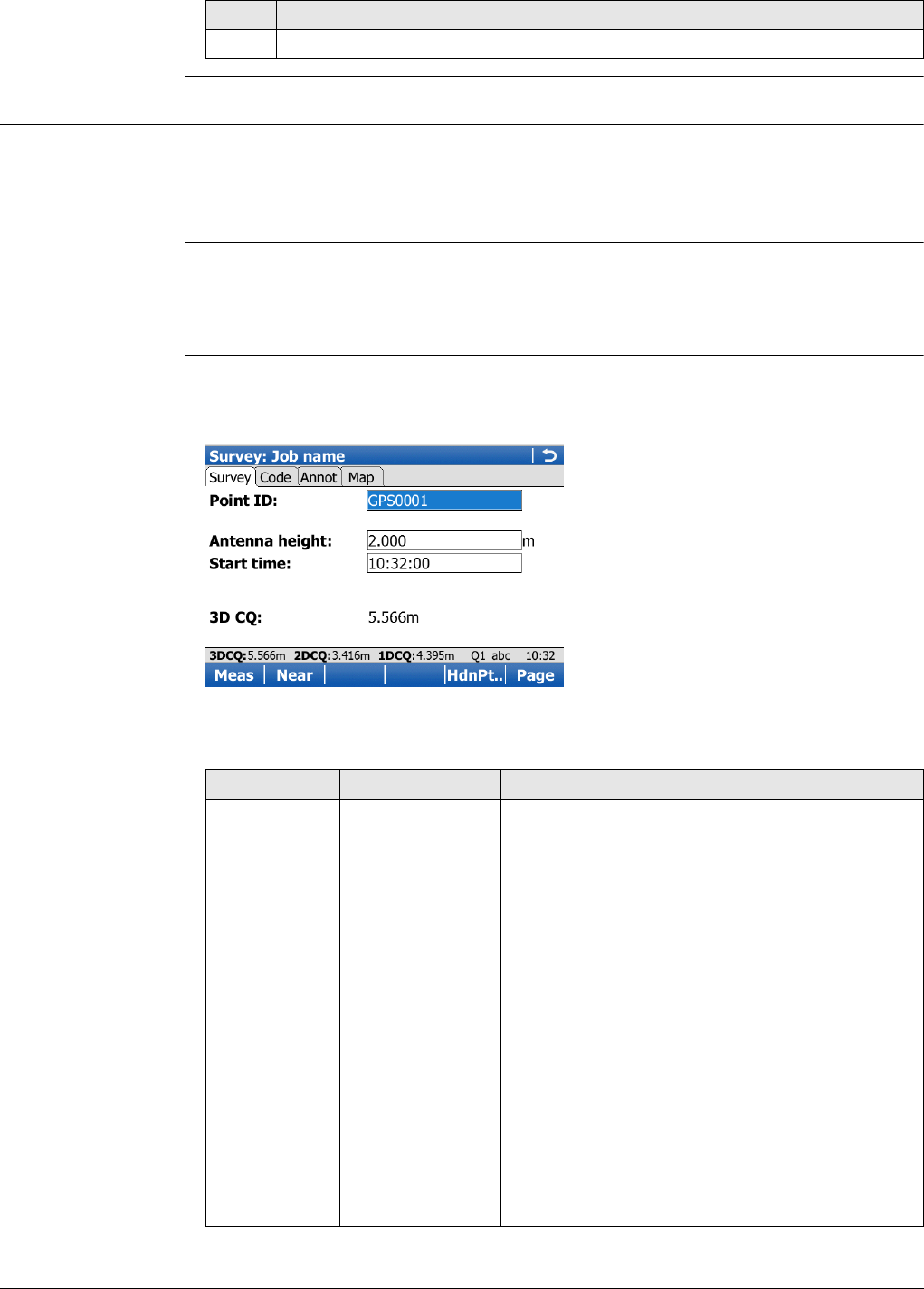
Viva Series, Survey - General 820
56.3 Timed Measurements
Description Surveying regulations in some countries require that several instruments in a session
start the point measurement simultaneously at a predefined time. Timed measure-
ments are possible for all types of GPS operations, except for real-time base opera-
tions.
Requirements •Automatically start measuring point on entering survey: Timed is configured in
Quality Control, Advanced page. Refer to "13.4 Quality control".
•Time at point is configured for one of the lines in one of the survey screen pages.
Refer to "25.3 My Survey Screen".
Access For RTK rover:
Select Main Menu: Go to Work!, Survey.
Survey,
Survey page
Refer to "56.1 Surveying Points" for a description of keys.
Description of fields
3. Store to store the point information including the annotations.
Step Description
Field Option Description
Start time Editable field The current local time with the seconds rounded
to 00, for example for the current local time
07:37:12 it is 07:38:00.
Type in the start time in hours, minutes and
seconds for when the point measurement will
begin.
Press Meas. The point measurement does not
start yet. The name of the field changes to Time
to go.
Time to go Display only The countdown time in hours, minutes and
seconds before the point measurement starts
automatically. The point measurement starts
when it is 00:00:00.
Then, data is logged as configured in the working
style. Any measurement counter defined to be
used in survey screen page is displayed and starts
incrementing. The name of the field changes to
Time at point.
Viva Series, Survey - General 821
56.4 Initialisation for Real-Time Rover Operations
56.4.1 Accessing Initialisation for Real-Time Rover Operations
Requirements • The active working style is a real-time rover configuration.
Access For RTK rover:
• Select Main Menu: Go to Work!, Survey. Press Init...
• Access is possible from other screens where individual point measurements are
needed, for example from Inverse Pt - Pt with Survy...
Re-initialise the RTK
56.4.2 Initialise while Moving
Initialise while
moving step-by-
step
Time at point Display only The time in hours, minutes and seconds from
when the point is measured until point measure-
ment is stopped.
Press Stop and Store when enough data is
collected. The name of the field changes to Start
time.
Field Option Description
Initialisation
method
Description Refer to
chapter
Initialise while
moving The rover antenna can be moved during the
initialisation process.
"56.4.2
Initialise
while
Moving"
Initialise while static The antenna setup must be static on a
pillar, a tripod or on a pole with a quick-
stand.
"56.4.3
Initialise
while
Static"
Initialise on a known
point The antenna setup must be static on a
pillar, a tripod or on a pole with a quick-
stand.
The coordinates of the point must be
stored in, or able to be converted to, the
WGS 1984. They must be stored in the
working job either by manual entry or by
measuring.
"56.4.4
Initialise
on Known
Point"
Step Description
1. Does the instrument currently have a fixed solution?
• If yes, continue with step 3.
• If no, continue with the next row.
The initialisation starts automatically.
2. Continue with the row after step 3.
3. Yes to start the initialisation. The current ambiguity solution is discarded.
Meas is available but must not be pressed until the ambiguity solution is
gained.
4. The initialisation is gained when the ambiguities are solved.
5. Continue with the surveying operation.
Viva Series, Survey - General 822
56.4.3 Initialise while Static
Initialise while
static step-by-step
56.4.4 Initialise on Known Point
Initialise on known
point step-by-step
Step Description
1. Does the instrument currently have a fixed solution?
• If yes, continue with step 3.
• If no, continue with the next row.
The initialisation starts automatically.
2. Continue with step 6.
3. Yes to start the initialisation. The current ambiguity solution is discarded.
Stop is available but must not be pressed until the ambiguity solution is
gained.
The initialisation is gained when the ambiguities are solved.
4. Any configurations for Automatically stop point measurement in Quality
Control, General page are ignored. Stop when enough data is collected.
5. When Automatically stop point measurement is not checked in Quality
Control, General page, Store to store the point information.
6. Continue with the surveying operation.
Step Description
1. Does the instrument currently have a fixed solution?
• If yes, continue with step 3.
• If no, continue with step 4.
2. Yes to start the initialisation. The current ambiguity solution is discarded.
3. In Data:, Points page, highlight the known point for the initialisation.
4. OK starts the initialisation.
Survey screen
Point ID: The ID of the selected known point is displayed.
Antenna height: The default antenna height as defined in the active working
style is suggested. Changing the antenna height here does not update the
default antenna height as defined in the active working style. The changed
antenna height is used until the application is exited.
Enter the correct antenna height.
If desired, add a code.
If desired, add an annotation.
Stop is available but must not be pressed until the ambiguity solution is
gained.
The initialisation is gained when the ambiguities are solved.
5. Any configurations for Automatically stop point measurement in Quality
Control, General page are ignored. Stop when enough data is collected.
6. When Automatically stop point measurement is not checked in Quality
Control, General page, Store to store the point information.
An average is automatically calculated with the known coordinates.
7. Continue with the surveying operation.
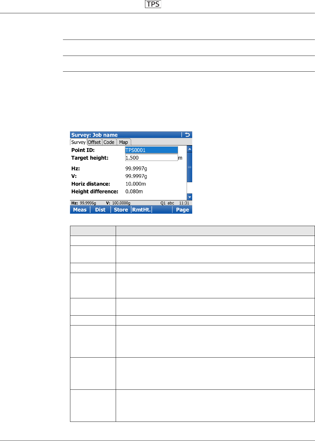
Viva Series, Survey - General 823
57 Survey - General
Description The Survey application is used for point measurement. Angles and distances for points
can be measured and the calculated coordinates stored using Meas, Dist and Store.
For information on camera and images refer to "33.3.3 Within Applications".
Access Select Main Menu: Go to Work!\Survey.
Survey,
Survey page
The fields shown are from a typical working style. The screen described consists of
four pages. The explanations for the softkeys given here are valid for the Survey page,
the Offset page, and the Code page. Refer to "37 MapView Interactive Display
Feature" for information on the keys on the Map page.
The fields and functionality of this screen vary slightly when accessed from other
applications where individual point measurements are needed.
Key Description
Meas To measure and store distances and angles.
Stop Available if Measure mode: Continuous and Dist was pressed. Stops
the distance measurements. The key changes back to Meas.
Dist To measure and display distances.
Store To record data.
If Measure mode: Continuous and/or Log auto points is checked,
records measured point and continues tracking.
RmtHt. To access Survey Remote Point. Available if Measure remote points
is checked in Configuration, Remote points page.
Page To change to another page on this screen.
Fn Config.. To configure SmartCodes, auto points and remote point measure-
ments. When Fn Avg or Fn Abs are active, this key is not available.
Refer to "26.5 SmartCodes", "58 Survey - Auto Points" and to "62
Survey - Remote Point" for information on the fields and keys.
Fn Avg To check the residuals for the averaged point. Available for Mode:
Average in Job Properties:, Averaging page and for more than one
measured coordinate triplet recorded for the same point. Refer to
"6.3.3 Mean Page".
Fn Abs To check the absolute difference between the measurements. Avail-
able for Mode: Average in Job Properties:, Absolute differences and
for more than one measured coordinate triplet recorded for the
same point. Refer to "6.3.3 Mean Page".
Viva Series, Survey - General 824
Description of fields
Fn 2Store To aim manually at the target and only record the angle measure-
ment (Hz/V) in face I and face II. The point stored is an average of the
two measurements.
Fn 2Face Available for Measure mode: Single and Measure mode: Single
(fast). To take a measurement in Face I and Face II. The point stored
is an average of the two measurements. When using instruments
fitted with auto aiming, the point is automatically measured in both
faces. The resulting point is stored and the instrument is returned to
the first face.
Fn IndivID and
Fn Run To change between entering an individual point ID different to the
defined ID template and the running point ID according to the ID
template. Refer to "25.1 ID templates".
Fn Quit To exit the application.
Field Option Description
Point ID Editable field The identifier for measured points. The config-
ured point ID template is used. The ID can be
changed:
• To start a new sequence of point IDs overtype
the point ID.
• For an individual number independent of the
ID template Fn IndivID. Fn Run changes back
to the next ID from the configured ID
template.
Target height Editable field The last used target height is suggested when
accessing the Survey application. An individual
target height can be typed in.
Hz Display only The current horizontal angle.
VDisplay only The current vertical angle.
Horiz distance Display only The horizontal distance after Dist was pressed.
No distance is displayed when accessing the
screen and after Store or Meas.
Height difference Display only The height difference between station and meas-
ured point after Dist. Displays ----- when
accessing the screen and after Store or Meas.
Easting Display only Easting coordinate of the measured point.
Northing Display only Northing coordinate of the measured point.
Elevation Display only Elevation of the measured point.
Key Description
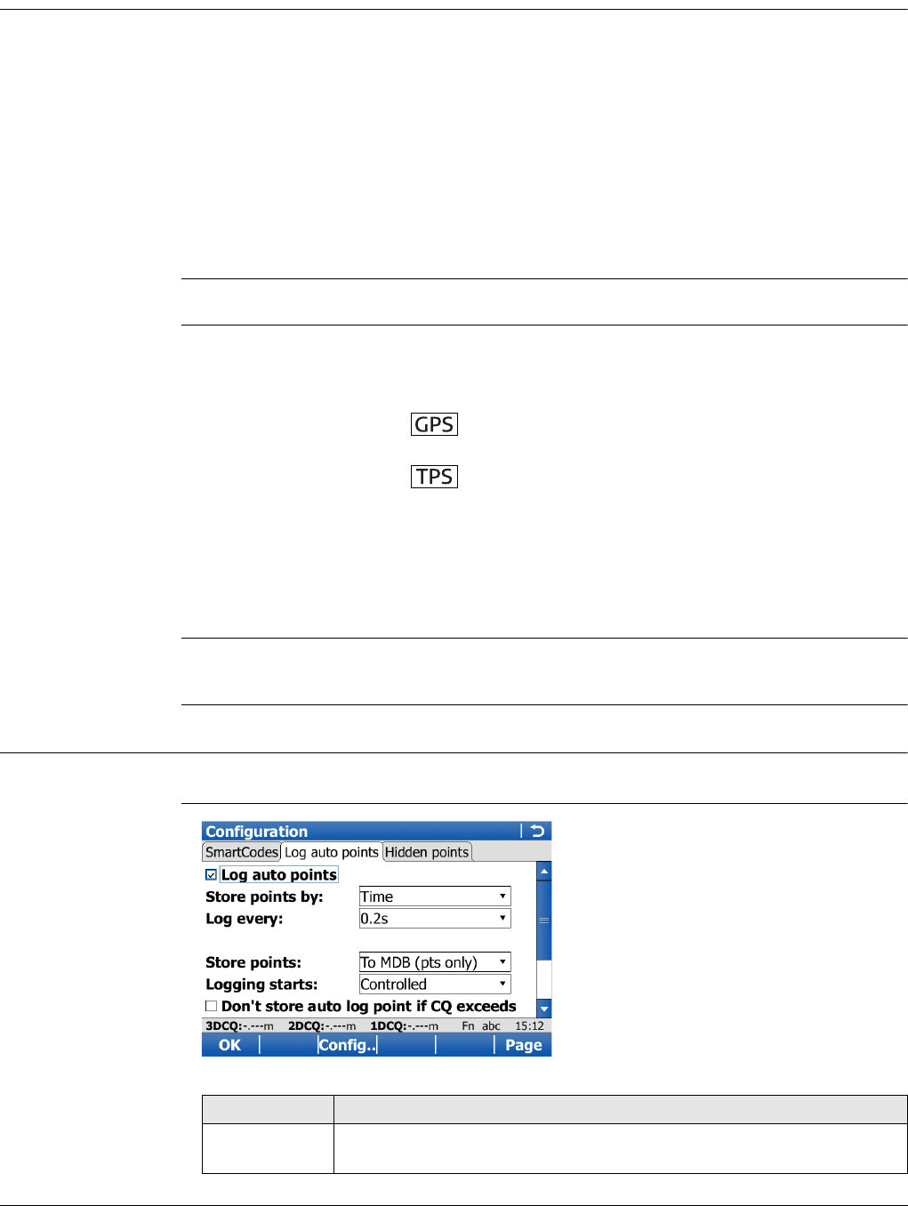
Viva Series, Survey - Auto Points 825
58 Survey - Auto Points
58.1 Overview
Description Auto points are used to automatically log points at a specified rate. Additionally, indi-
vidual auto points can be stored outside the defined rate.
Auto points can be collected in the Survey application. An Auto page is visible when
logging of auto points is active.
Auto points are used in moving applications to document a track which was walked or
driven along. Auto points that are logged between starting and stopping logging of
auto points form one chain. A new chain is formed each time logging of auto points is
started.
Up to two offset points related to one auto point can be logged. The offset points can
be both to the left or right and they can be coded independently of each other and of
the auto points.
Logging of auto points is possible for TPS and in the GPS rover menu.
Coding of auto
points
Coding of auto points is similar to coding manually occupied points. Refer to "26
Coding" for information on coding.
The differences are:
Averaging of auto
points
An average is never calculated for auto points even if a manually occupied point of
class Meas already exists with the same point ID.
58.2 Configuring Auto Points
Access Select Main Menu: Go to Work!, Survey. Press Fn Config...
Configuration,
Auto points page
• Thematical coding: Available for Store points:To DBX (pts&codes) in
Configuration, Log auto points page.
Always available.
• Free coding: Always available.
• Quick coding: Not available.
• Codes of auto points overwrite the codes of points with the same point ID but a
different code, existing in the working job.
• Codes of auto points can be changed when no auto points are being logged.
• Up to three attributes can be stored with a code.
Key Description
OK To accept changes and return to the screen from where this screen
was accessed.
Viva Series, Survey - Auto Points 826
Description of fields
Config.. To configure what is viewed in the Auto page in the Survey applica-
tion. Available for Log auto points checked.
Page To change to another page on this screen.
Fn Quit To exit the screen.
Field Option Description
Log auto
points Check box Activates the logging of auto points.
All other fields on the screen are active
and can be edited.
Store points
by Time Auto points are logged according to a time
interval. The time interval is independent from
the update interval for the position on the screen.
Distance The difference in distance from the last stored
auto point, which must be reached before the
next auto point is logged. The auto point is logged
with the next available computed position.
Height difference The height difference from the last stored auto
point, which must be reached before the next
auto point is logged. The auto point is logged with
the next available computed position.
Distance or
height Before the next auto point is logged, either the
difference in distance or the difference in height
must be reached. The auto point is logged with
the next available computed position.
Stop & go An auto point is stored when the position of the
antenna/prism does not move more than the
distance configured in Minimum distance
between points within the Stop time.
Once a point has been stored, the position must
change more than the distance configured in
Minimum distance between points before the
routine starts again.
User decides An auto point is stored upon pressing
Meas ()/ Store () in Survey, Auto
page. In the beginning, the chain to which the
auto points will be assigned must be started with
Start. In the end, the chain must be closed with
Stop.
Log every Available unless Store points by:Distance or
height.
Editable field For Store points by:Distance and Store points
by:Height difference. The difference in distance
or height before the next auto point is logged.
From 0.05s to
60.0s For Store points by:Time. The time interval
before the next auto point is logged.
For GS05/GS06/GS08plus/GS12 logging rates of
0.2s and slower are supported.
Key Description
Viva Series, Survey - Auto Points 827
Max distance Editable field Available for Store points by: Distance or height.
The value for the difference in distance before
the next auto point is logged.
Max height Editable field Available for Store points by:Distance or height.
The value for the height difference before the
next auto point is logged.
Minimum
distance
between
points
Editable field Available for Store points by:Stop & go. The
distance within which the position is considered
stationary.
Stop time Editable field Available for Store points by:Stop & go. The time
while the position must be stationary until an
auto point is stored.
Store
points Changing this setting while auto points
are being logged stops the logging. It must
then be restarted.
To MDB (pts only) Logs auto point to a job file. Point logging at up
to 20 Hz. Coding and logging of offset points is
not possible. Points cannot be displayed in
MapView or output via format files.
To DBX
(pts&codes) Logs auto points to the DBX. Point logging at up
to 1 Hz. Coding and logging of offset points is
possible. Points can be displayed in MapView or
output via format files.
Logging
starts
Automatically Logging of auto points starts immediately when
the Survey screen is accessed.
Controlled Logging of auto points starts upon pressing Start
on the Auto page in Survey.
Don't store
auto log point
if CQ exceeds
limit
Check box If checked, monitoring of the coordinate quality is
activated. Auto points are stored when the coor-
dinate quality is within the defined limit. For
example, only phase fixed solutions can be logged
by defining a CQ limit.
3D CQ
limit
Editable field Available if Don't store auto log point if CQ
exceeds limit is checked.
Limit for the coordinate quality above which an
auto point is no longer automatically stored.
When the CQ of the auto point falls again below
the defined value then the storing of auto points
begins again.
Beep when
auto logged
point is
stored
Logging Instrument beeps when storing an auto point.
Never Instrument never beeps.
Field Option Description
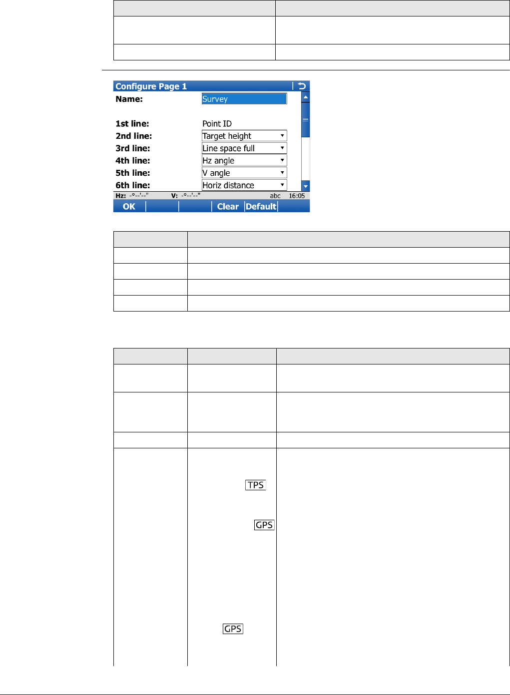
Viva Series, Survey - Auto Points 828
Next step
Configure Page
Description of fields
IF the survey screen mask THEN
is not to be configured OK closes the screen and returns to the previous
screen.
is to be configured Config...
Key Description
OK To accept changes and to return to previous screen.
Clear To set all fields to Line space full.
Default To recall the default settings.
Fn Quit To exit the screen.
Field Option Description
Name Editable field The name of the page is shown as page name in
Survey.
Show in the
Survey appli-
cation
Check box Shows or hides the page as a page in Survey.
1st line Display only Fixed to Point ID.
2nd line to
16th line For each line, one of the following options can be
selected.
Angle right Displays the horizontal angle difference between
the backsight point and the current telescope
position.
% completed Display only field for the percentage of the time
for which the point has been occupied based on
the setting for Stop criteria in screen Quality
Control. Appears in the page during the point
occupation if Quality Control is checked.
Annotation 1 to
Annotation 4 Editable field for comments to be stored with the
point.
Antenna
height
Input field for antenna height for static observa-
tions.
Attrib (free) 01 to
Attrib (free) 20 Display only field for attributes for free codes.
Viva Series, Survey - Auto Points 829
Attrib 01 to Attrib
20 Editable field for attributes for codes.
Automation Unavailable for SmartStation. Select automation
type.
Avg max
#distances
Input field for maximum number of distance
measurements in the averaging EDM mode.
Azimuth Display only field for the azimuth.
Backsight pt
ID
Display only field for the point ID of the backsight
point.
Code Editable field for codes.
Code (free) Editable field for free codes.
Code desc (free) Display only field for the description of free
codes.
Code information Editable field for additional information relating
to the code, such as instructions to the CAD
package to start a line and string number and
curve information.
Description Display only field for the description of codes.
Easting Display only field for Easting coordinate of meas-
ured point.
GDOP Display only field for the current GDOP of the
computed position.
HDOP Display only field for the current HDOP of the
computed position.
Elevation Display only field for the height coordinate of the
measured point.
Height
difference
Display only field for the height difference
between station and reflector.
Horiz
distance
Display only field for horizontal distance.
Humidity Editable field for relative humidity to be stored
with point.
Hz angle Display only field for the horizontal angle.
Instrument
height
Display only field for the instrument height.
Line space full Insert full line space.
Line space half Insert half line space.
Linework Selectable list with option for flagging a line/area.
Local ellipsoid
ht
Display only field for the elevation of the current
GNSS position.
Measure
mode
Select EDM measurement mode.
Measure Select EDM type.
Moving antenna
ht
Input field for antenna height for moving obser-
vations.
Field Option Description
Viva Series, Survey - Auto Points 830
Msd PP obs Display only field for the number of static obser-
vations recorded over the period of point occupa-
tion. Appears in the page when recording of static
observations is configured.
Northing Display only field for Northing coordinate of
measured point.
Number of
dists
Display only field for number of averaged
distances measured with EDM mode averaging.
Offset
left/right
Input field for horizontal distance offset for
measured point, perpendicular to the line of
sight.
Offset height Input field for height offset for measured point.
Offset in/out Input field for horizontal distance offset, in the
direction of line of sight.
Offset mode Select offset mode.
PDOP Display only field for the current PDOP of the
computed position.
PPM atmos Display only field for atmospheric ppm.
PPM
geometric
Display only field for geometric ppm value.
PPM total Display only field for the total ppm value.
Point ID Editable field for the point ID.
Pressure Editable field for atmospheric pressure.
Prism
constant
Display only field for additive constant of
currently selected reflector.
Quality 1D Display only field for the current height coordi-
nate quality of computed position.
Quality 2D Display only field for the current 2D coordinate
quality of computed position.
Quality 3D Display only field for the current 3D coordinate
quality of computed position.
RTK
positions
Display only field for the number of positions
recorded over the period of point occupation.
Appears in the page of real-time rover configura-
tions.
SD (last
recorded)
Display only field for the last recorded distance.
Slope
distance
Display only field for measured slope distance.
Station ID Display only field for current station ID.
Station
easting
Display only field for current station Easting coor-
dinates.
Station
height
Display only field for current station height coor-
dinates.
Station
northing
Display only field for current station Northing
coordinates.
Field Option Description
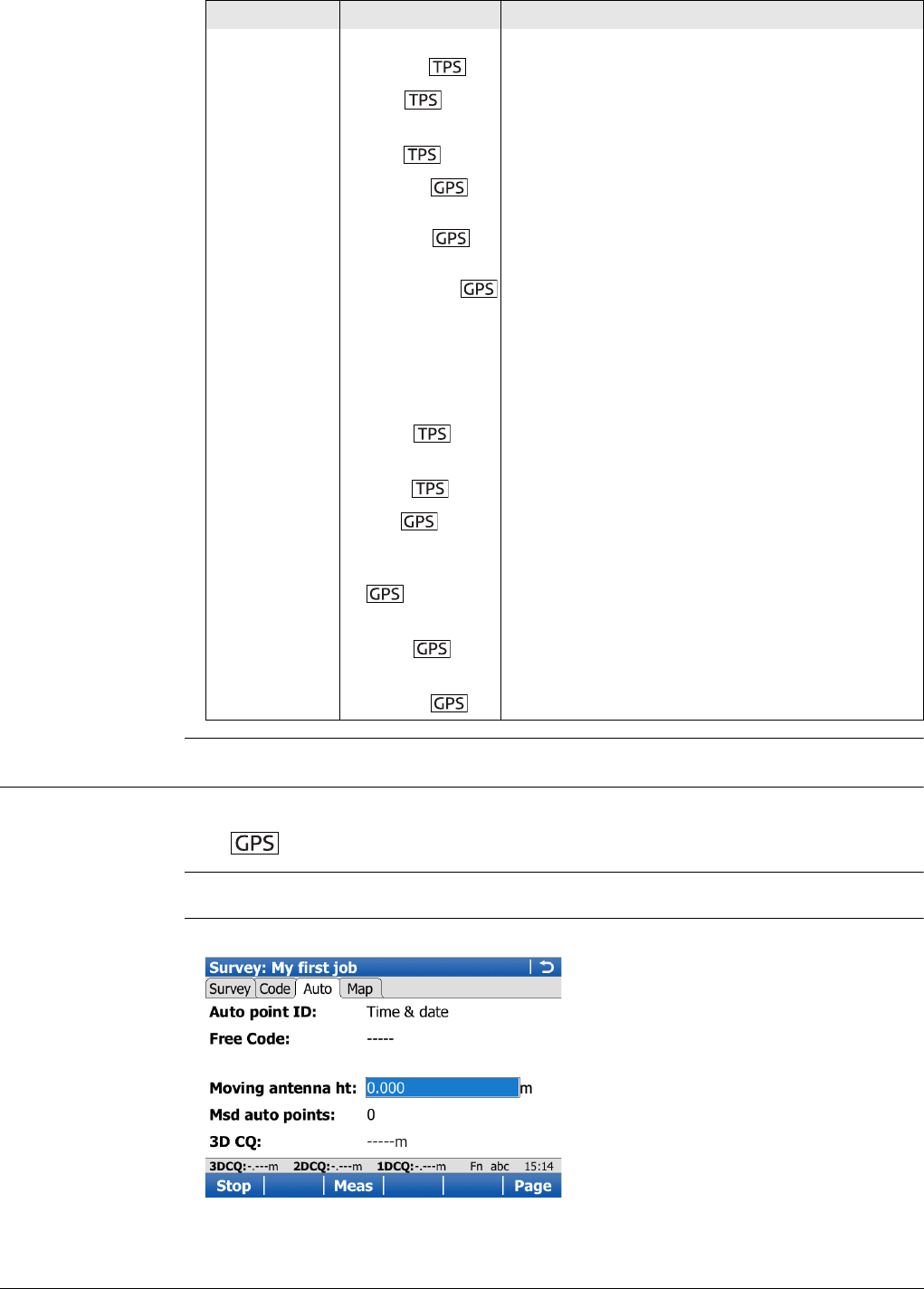
Viva Series, Survey - Auto Points 831
58.3 Measuring Auto Points
Requirements •Log auto points in Configuration, Log auto points page.
• The rover menu must be used.
Access Select Main Menu: Go to Work!, Survey. Go to the Auto page.
Survey,
Auto page
Before logging of auto points has started, the page appears as shown:
Std
deviation
Display only field of standard deviation in millime-
tres of averaged distances.
Target Select a prism.
Target
height
Input field for prism height.
Temp dry Editable field for dry temperature to be stored
with point.
Temp wet Editable field for wet temperature to be stored
with point.
Time at point Display only field for the time from when the
point is occupied until point occupation is
stopped. Appears in the page during the point
occupation.
Type Display only field for the type of code, for
example point code, line code or area code.
V angle Display only field for vertical angle.
V angle
display
Select vertical angle display.
VDOP Display only field for the current VDOP of the
computed position.
WGS84 ellipsoid
ht
Display only field for the current GNSS position.
WGS84
latitude
Display only field for the current GNSS position.
WGS84
longitude
Display only field for the current GNSS position.
Field Option Description
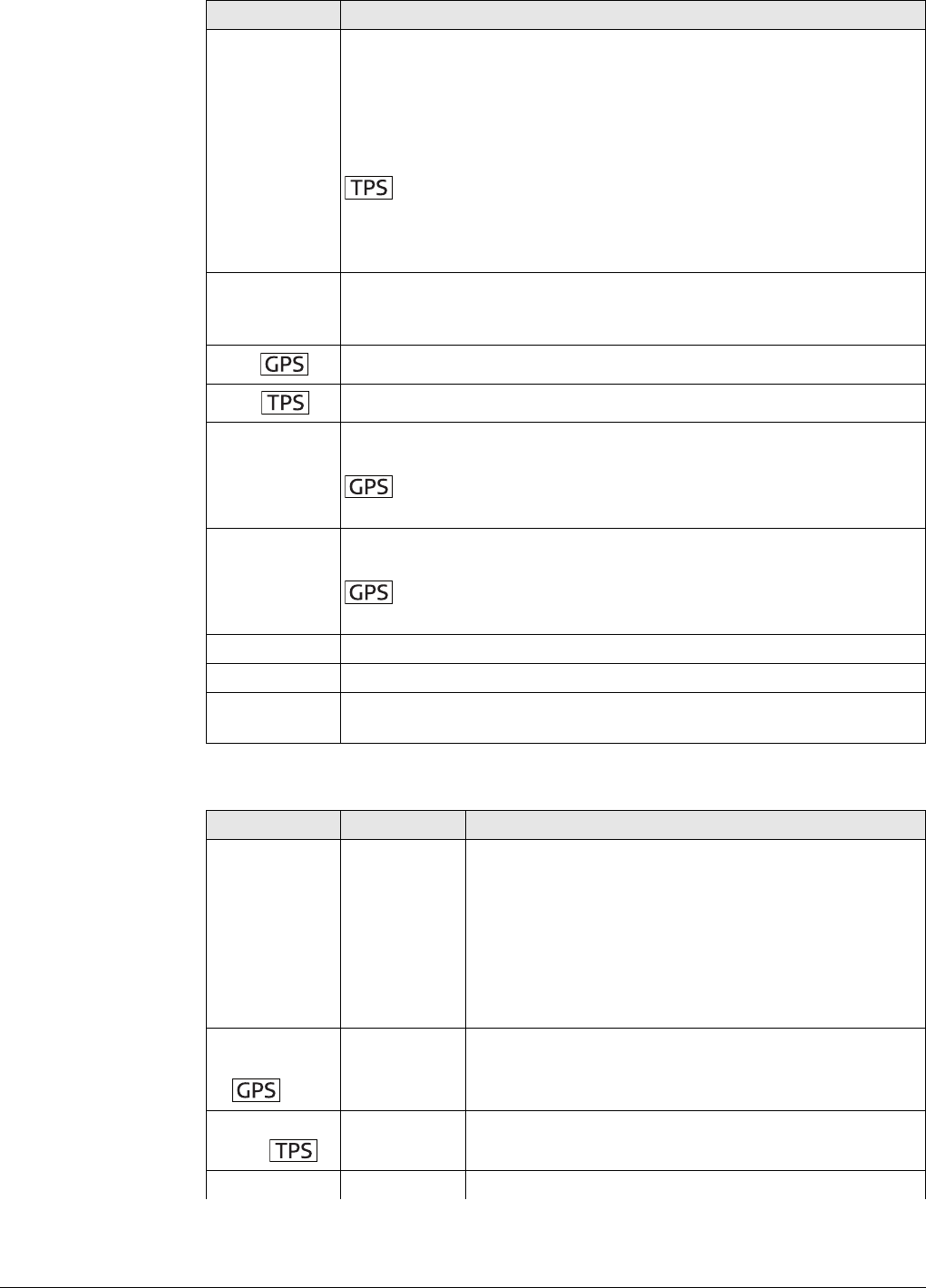
Viva Series, Survey - Auto Points 832
Description of fields
Key Description
Start For Logging starts:Automatically in Configuration, Log auto points
page, logging of auto points starts immediately when the Survey
screen is accessed and Start need not be pressed.
To start logging of auto points and offset points if configured or, for
Store points by:User decides, to start the chain to which the auto
points will be assigned. The first auto point is stored.
Measure mode:Continuous becomes active. For
Measure:Prism instrument locks onto prism. For Measure mode-
Long range (>4km), Measure:Prism is set and instrument locks onto
the prism.
Stop To end recording of auto points and offset points if configured or,
for Store points by:User decides, to end the chain to which the auto
points are assigned.
Meas Available for Stop. To store an auto point at any time.
Store Available for Stop. To store an auto point at any time.
Offst1.. To configure recording of the first type of offset points. Refer to
"58.4.2 Configuring Offset Points".
Available for Store points:To DBX (pts&codes) in Configura-
tion, Log auto points page.
Offst2.. To configure recording of a second type of offset points. Refer to
"58.4.2 Configuring Offset Points".
Available for Store points:To DBX (pts&codes) in Configura-
tion, Log auto points page.
Page To change to another page on this screen.
Fn Config.. To configure auto points. Refer to "58.2 Configuring Auto Points".
Fn Quit To exit the Survey application. Point information logged until pressing
Fn Quit is saved in the database.
Field Option Description
Auto point ID Editable field Available unless GPS auto points:Date & time/TPS
auto points:Date & time in ID Templates. The identi-
fier for auto points. The configured ID template for
auto points is used. The ID can be changed. To start a
new sequence of point IDs, type over the point ID.
Date & time Available for GPS auto points:Date & time/TPS auto
points:Date & time in ID Templates. The current local
time and date is used as identifier for auto points.
Moving
antenna
ht
Editable field The default antenna height for auto points as defined
in the active working style is suggested.
Target
height
Editable field The default reflector height as defined in the active
configuration set is suggested.
Code (auto) The thematical code for the auto point.
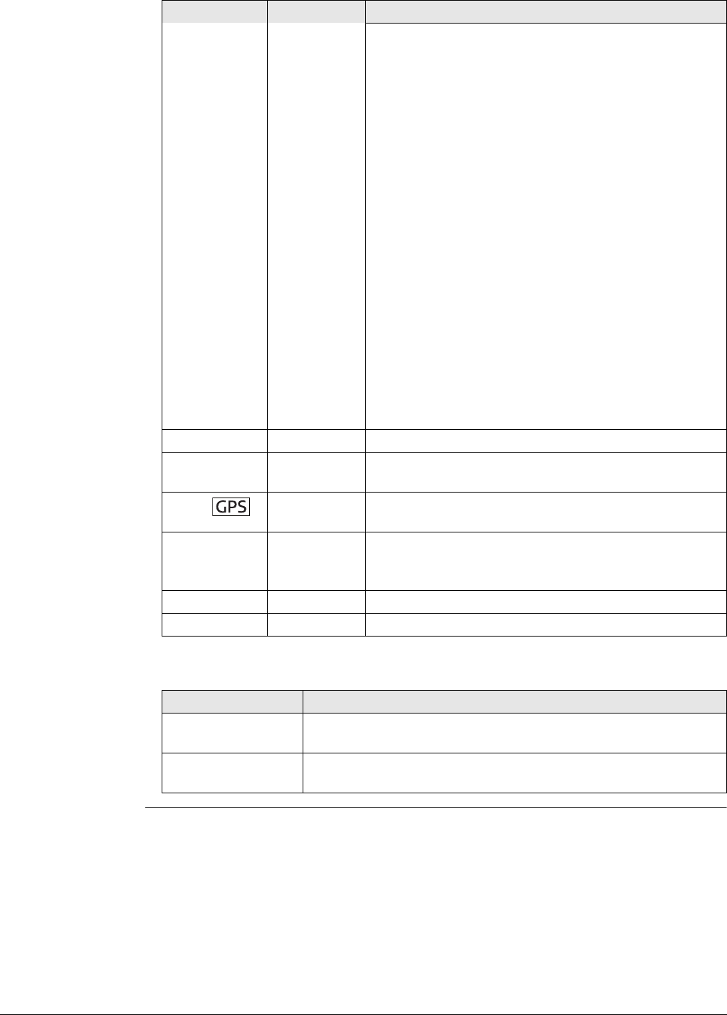
Viva Series, Survey - Auto Points 833
Next step
• If a point code is selected then any open line/area
is closed. The occupied point is stored with the
selected code independently of any line/area.
• If a line code is selected then any open line is
closed and a new line with the selected code is
created. The line ID is defined by the configured
line ID template. The occupied point is assigned to
that line. The line stays open until it is closed
manually or another line code is selected.
• If an area code is selected then the behaviour is as
for lines.
Selectable list Available if Use a list box to view codes is checked.
The attributes are shown as display only, editable field
or selectable list fields depending on their definition.
Editable field Available if Use a list box to view codes is not
checked. Codes can be typed in but not selected from
a codelist. A check is performed to see if a code of this
name already exists in the job. If so, the according
attributes are shown.
Configure a survey screen mask with a selectable list
for code types to define if a point, line or area code is
typed in.
Description Display only The description of the code.
Msd auto
points Display only Available after pressing Start. The number of auto
points logged since Start has been pressed.
3D CQ Display only The current 3D coordinate quality of the computed
position.
Slope
distance Display only The measured slope distance.
When Start is pressed, Measure mode:Continuous is
set and the slope distance is constantly updated.
Hz Display only The current horizontal angle.
VDisplay only The current vertical angle.
IF THEN
auto points are to
be logged
Start. Then, for Store points by:User decides, Meas whenever
an auto point is to be logged.
offset points are to
be configured
Offst1.. or Offst2... Refer to "58.4 Offset Points of Auto Points".
Field Option Description
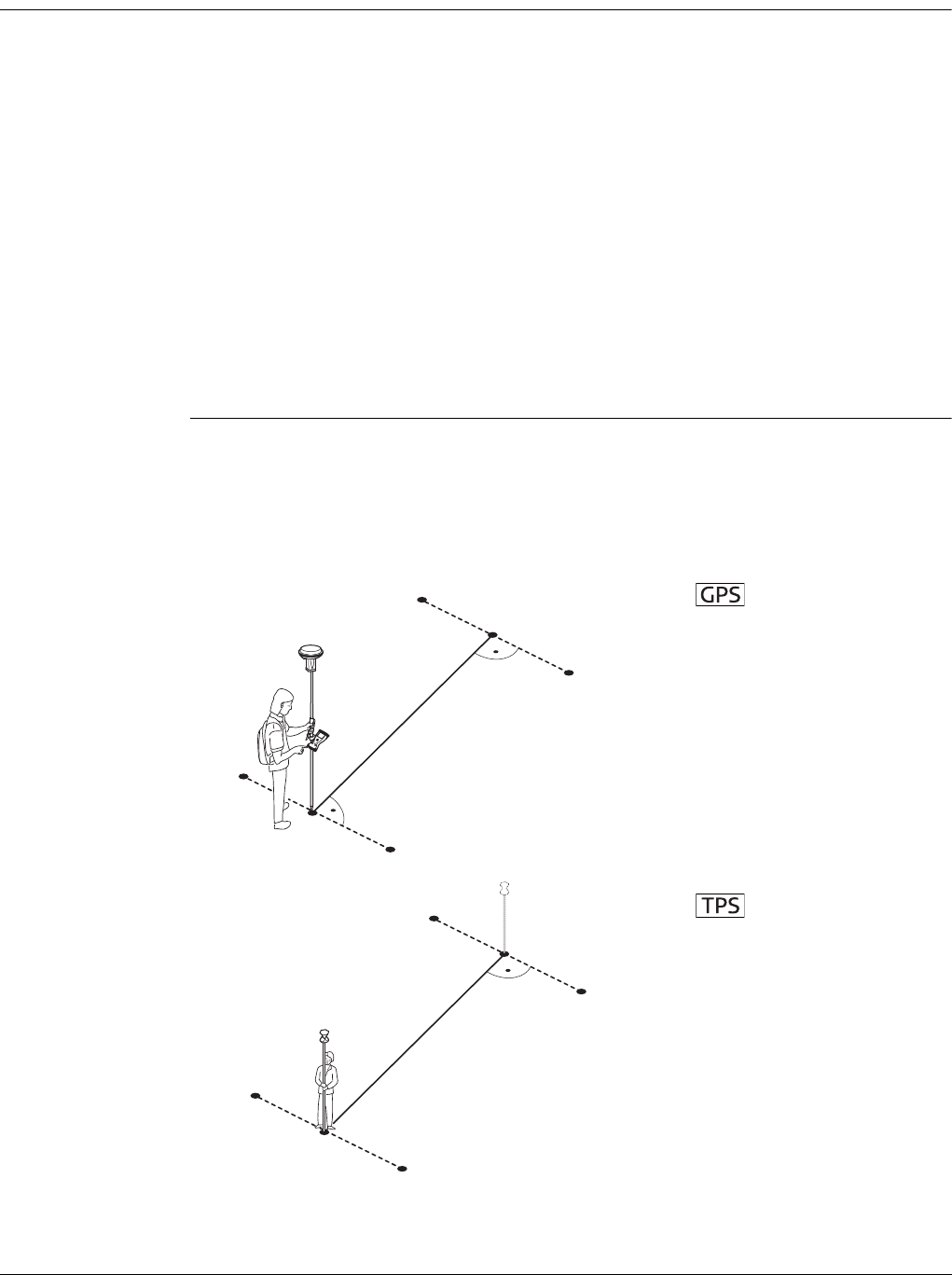
Viva Series, Survey - Auto Points 834
58.4 Offset Points of Auto Points
58.4.1 Overview
Description Offset points
• can be created with auto points when auto points are stored to the DBX.
• can be to the left or to the right of auto points.
• are automatically computed with the logging of auto points, if configured.
• form a chain relative to the chain of auto points to which they are related. Subse-
quent computed chains are independent from each other.
• can be coded independently of auto points.
• have the same time of when they were stored as the auto points to which they are
related.
• have the same coding functionality, properties and averaging functionality as auto
points.
Up to two offset points can be related to one auto point.
The screens for the configuration of offset points are identical except for the title
Auto Points - Offset 1 and Auto Points - Offset 2. For simplicity, the title Auto Points
- Offset 1 is used in the following description.
Computation of
offset points
The computation of offset points depends on the number of auto points in one chain.
One auto point
No offset points are computed or stored.
Two auto points
The configured offsets are applied perpendicular to the line between two auto points.
P0 First auto point
P1 Second auto point
P2 First offset point for P0
P3 Second offset point for
P0
P4 First offset point for P1
P5 Second offset point for
P1
d1 Horizontal offset to the
left
d2 Horizontal offset to the
right
P1 First auto point
P2 Second auto point
P4 First offset point for P1
P3 Second offset point for
P1
P5 First offset point for P2
P6 Second offset point for
P2
d1 Horizontal offset to the
left
d2 Horizontal offset to the
right
GS_061
P0
P1
P2
P3
P4
P5
d2
d1
TS_044
P1
P2
P3
P4
d2
d1
P5
P6
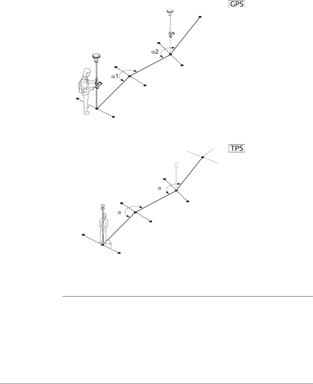
Viva Series, Survey - Auto Points 835
Three or more auto points
The first offset points are computed perpendicular to the line between the first and
the second auto point.
The last offset point is computed perpendicular to the line between the last auto point
and the one before.
All other offset points are computed on a bearing. The bearing is half of the angle
between the last and the next measured auto point.
P0 First auto point
P1 Second auto point
P2 First offset point for P0
P3 Second offset point for
P0
P4 Third auto point
P5 First offset point for P1
P6 Second offset point for
P1
P7 Fourth auto point
P8 First offset point for P4
P9 Second offset point for
P4
d1 Horizontal offset to the
left
d2 Horizontal offset to the
right
α1Angle between P0 and P4
α2Angle between P1 and P7
P1 First auto point
P2 Second auto point
P3 First offset point for P1
P4 Second offset point for
P1
P5 Third auto point
P6 First offset point for P2
P7 Second offset point for
P2
P8 Fourth auto point
P9 First offset point for P5
P10 Second offset point for
P5
d1 Horizontal offset to the
left
d2 Horizontal offset to the
right
α1Angle between P1 and P5
α2Angle between P2 and P8
GS_062
P0
P1
P4
P7
P6
P9
P8
P5
P2
P3
d2
d1
TS_045
P1
P2
P5
P7
P10
P8
P9
P6
P3
P4
d2
d1
1
2
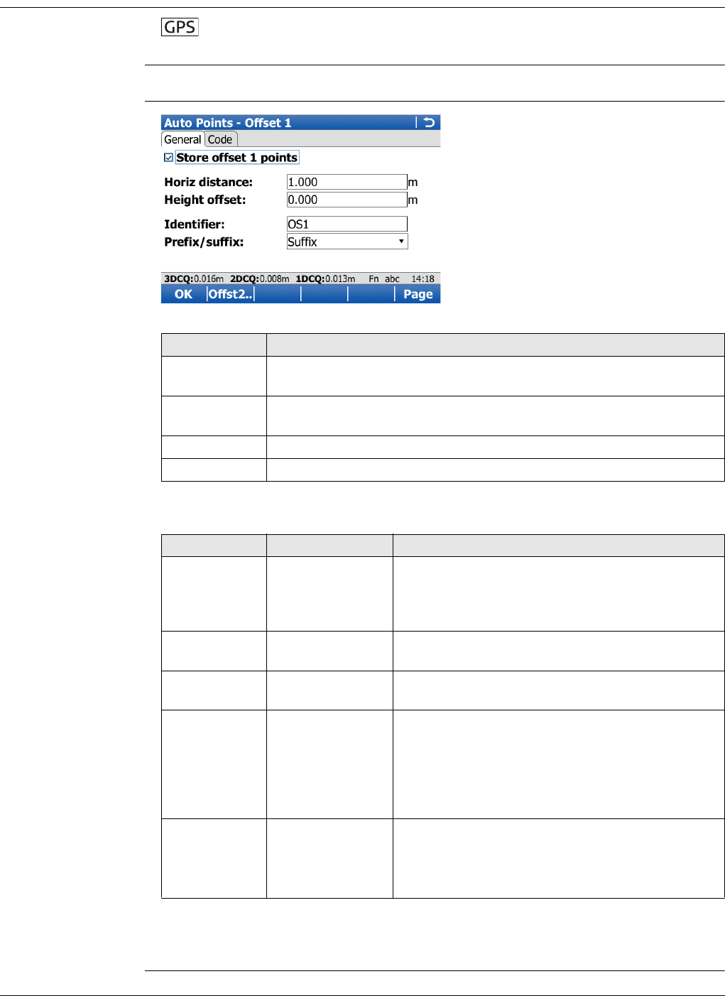
Viva Series, Survey - Auto Points 836
58.4.2 Configuring Offset Points
Requirements Available for Store points: To DBX (pts&codes) in Configuration, Log auto
points page.
Access Press Offst1.. or Offst2.. in Survey, Auto page.
Auto Points - Offset
1,
General page
Description of fields
Next step
Page changes to the Code page.
Key Description
OK To accept changes and return to the screen from where this screen
was accessed.
Offst2.. and
Offst1.. To switch between configuring offset point type one and two.
Page To change to another page on this screen.
Fn Quit To exit the screen.
Field Option Description
Store offset 1
points and
Store offset 2
points
Check box Activates logging of offset points.
All other fields on the screen are active
and can be edited with this setting.
Horiz distance Editable field The horizontal offset between -1000 m and
1000 m at which the offset point is collected.
Height offset Editable field The height offset between -100 m and 100 m
from the related auto point.
Identifier Editable field The identifier with up to four characters is added
in front of or at the end of the ID of the auto
point. This ID is then used as the point ID for the
related offset point. This functionality could
support an automatic workflow into CAD pack-
ages including setting symbols and stringing lines.
Prefix/suffix Prefix Adds the setting for Identifier in front of the auto
point ID.
Suffix Adds the setting for Identifier at the end of the
auto point ID.
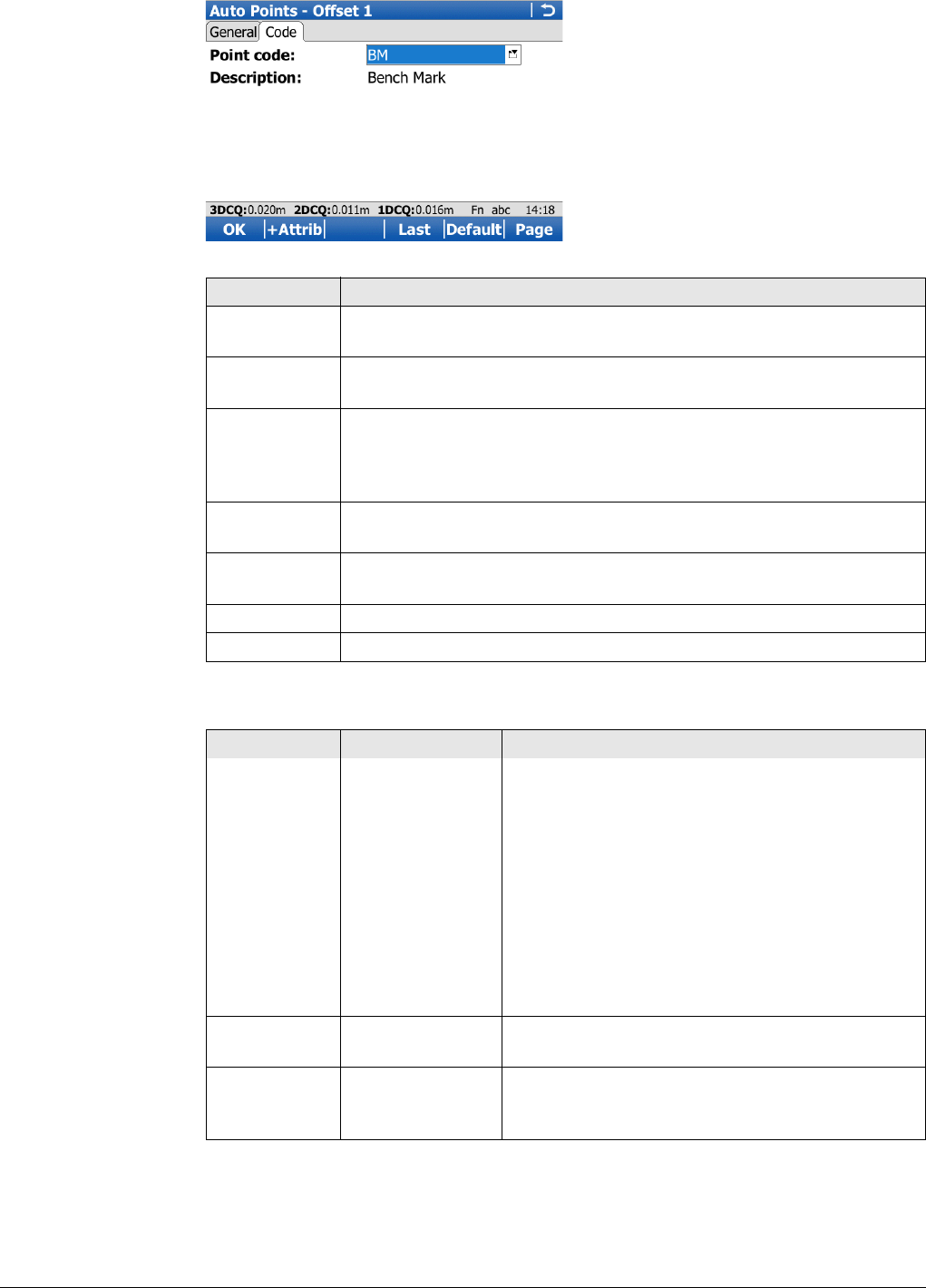
Viva Series, Survey - Auto Points 837
Auto Points - Offset
1,
Code page
Description of fields
Key Description
OK To accept changes and return to the screen from where this screen
was accessed.
+Attrib To create additional attributes for the selected code. Available if Use
a list box to view codes is checked.
Name or Value To highlight the attribute field or the field for the attribute value. The
name of the attribute can be edited and an attribute value can be
typed in. Available if Use a list box to view codes is checked. Avail-
able for attributes for which an attribute name can be typed in.
Last To recall the last used attribute values for the selected code. Avail-
able if Use a list box to view codes is checked.
Default To recall the default attribute values for the selected code. Available
if Use a list box to view codes is checked.
Page To change to another page on this screen.
Fn Quit To exit the screen.
Field Option Description
Point code Selectable list The thematical code for the offset point.
Available if Use a list box to view codes is
checked. The attributes are shown as display
only, editable field or selectable list fields
depending on their definition.
Code Editable field The thematical code for the offset point.
Available if Use a list box to view codes is
checked. Codes can be typed in but not selected
from a codelist. A check is performed to see if a
point code of this name already exists in the job.
If so, the according attributes are shown.
Description Display only Available if Use a list box to view codes is
checked. The description of the code.
Attributes Editable field Available if Use a list box to view codes is
checked. Up to three attribute values can be
stored.
Viva Series, Survey - Auto Points 838
Next step
Example for offset
point IDs
The offset point ID is a combination of the auto point ID and an identifier as a prefix
or suffix.
The right most part of the auto point ID is incremented within the point ID. If the
length of the auto point ID plus identifier is greater than 16 characters, then the auto
point ID is truncated from the left.
Refer to "25.1 ID templates" for more information on point IDs.
IF THEN
offset point config-
uration is finished
OK to return to the survey screen.
a second offset
point is to be
configured
Page and then Offst2.. or Offst1.. to change to configuration
screen for the second point.
Auto point ID Identifier Prefix/Suffix Offset point ID
Auto1234
Auto1235
OS1 Prefix OS1Auto1234
OS1Auto1235
…
Auto1234
Auto1235
OS1 Suffix Auto1234OS1
Auto1235OS1
…
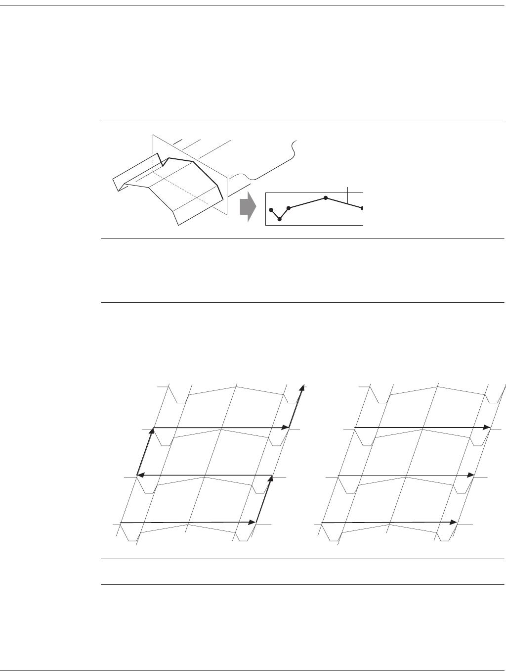
Viva Series, Survey Cross Section 839
59 Survey Cross Section
59.1 Overview
Description The Survey Cross Section application allows for the automatic changing of codes
during a survey. This function is useful when surveying multiple cross sections. Exam-
ples could include surveys of railway lines, roads, small waterways, driveways and
paths.
The codes for the elements in the cross section to be surveyed are all stored and pre-
defined in a template. The codes are then automatically changed after each point
observation.
Diagram
Template Templates are used to pre-define the order of the codes for the survey.
A template pre-defines
• the coding sequence of a cross section.
• the type of coding.
Cross section
methods and direc-
tions
Templates can be applied
• to the ZigZag method or the Same Direction method.
• in either a forward direction or in a backward direction.
Survey Cross Section is possible for RTK rover and TPS.
a) Cross section element
GS_075
a
ZigZag Same Direction
GS_076
GS_077
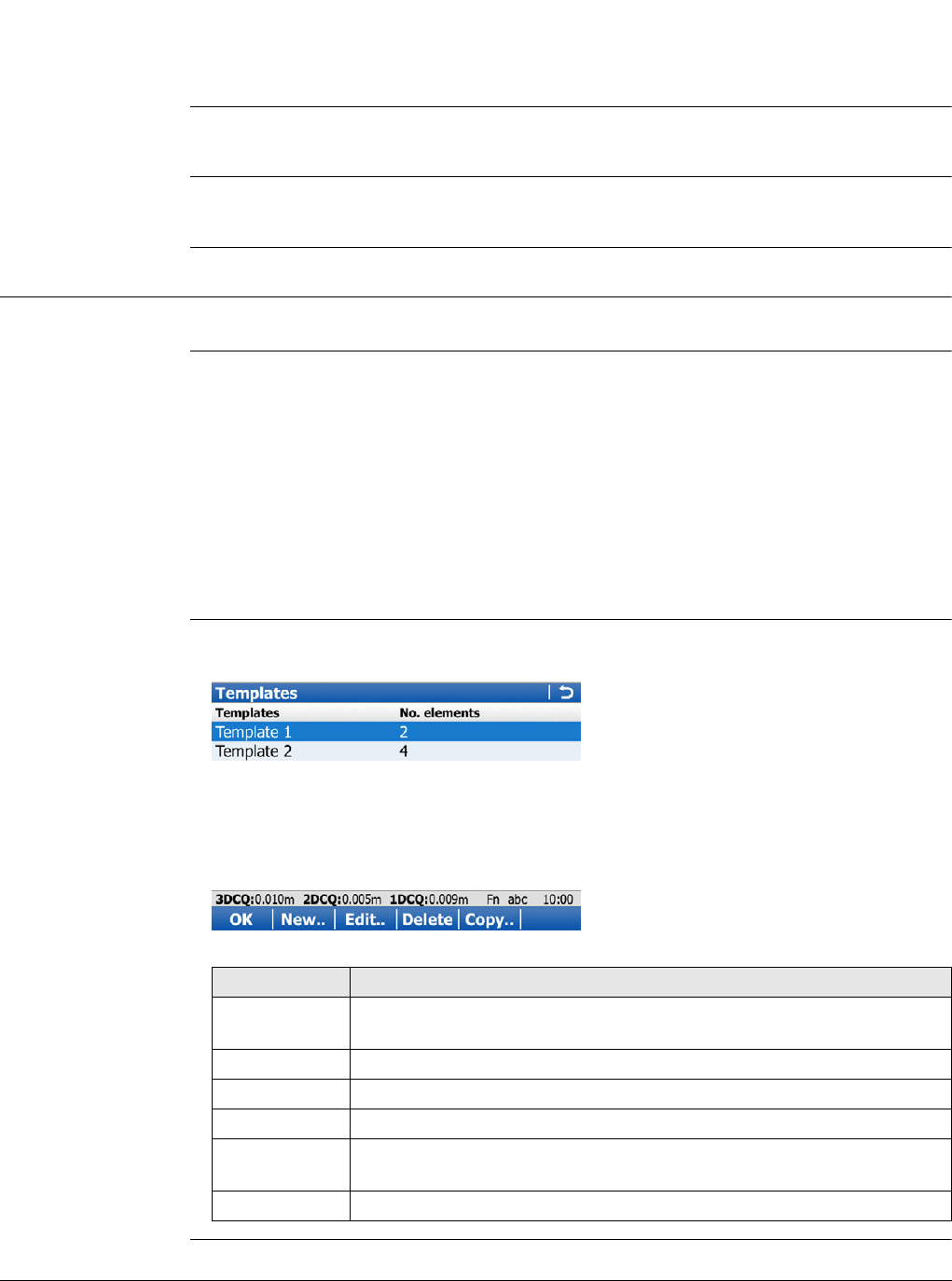
Viva Series, Survey Cross Section 840
Coding of cross
section elements
Codes can be attached to cross section elements. Refer to "26 Coding" for information
on coding.
• Thematical coding: Available
•Free coding: Available
• Quick coding: Not available
Averaging of cross
section elements
The principles for averaging are identical to the principles use in the Survey application.
Refer to "6.3.3 Mean Page" for information on averaging.
Exporting data The points and lines are recorded as for all other applications. The data can be
exported as normal.
59.2 Accessing Survey Cross Section
Access Select Main Menu:Go to Work!\Survey+\Survey cross section.
Description Cross section templates
• pre-define the sequence of codes for a cross section.
• consist of elements.
Elements can be defined such that the surveyed points of a cross section are
• stored with a point code.
• stored with a free code.
During the process of surveying a cross section, the code for the next element to be
measured is then selected and suggested automatically.
Survey X Section -
Templates All cross section templates stored in the working job are listed in alphabetical order,
including the number of elements in each cross section template.
Key Description
OK To select the highlighted cross section template and to start
surveying a cross section.
New.. To create a cross section template.
Edit.. To edit the highlighted cross section template.
Delete To delete the highlighted cross section template.
Copy.. To create a cross section template based on the one currently high-
lighted.
Fn Quit To exit the application.
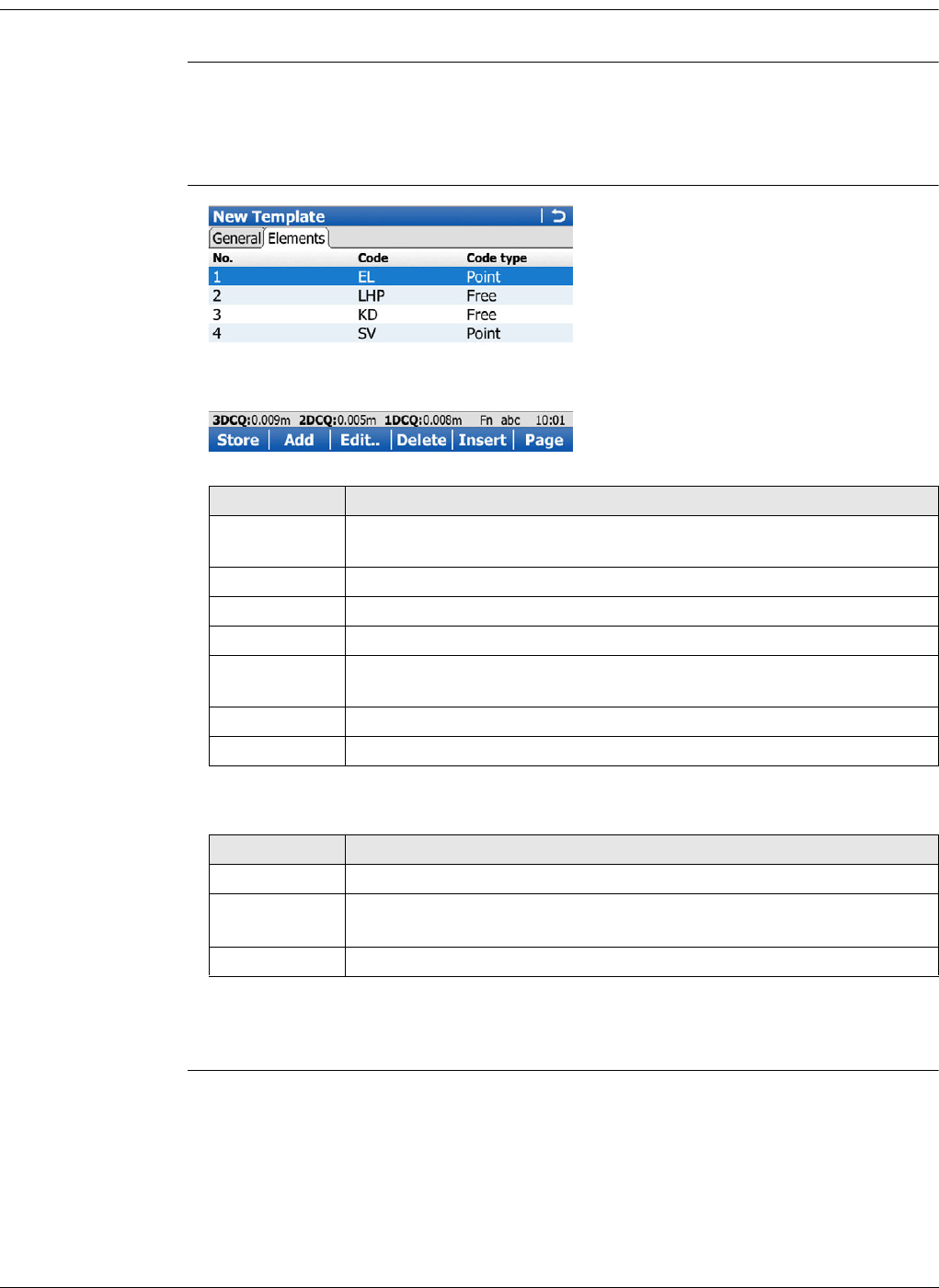
Viva Series, Survey Cross Section 841
59.3 Creating/Editing a Cross Section Template
Access In Survey X Section - Templates, press New.., Copy.. or Edit...
New Template/Edit
Template/Copy
Template,
General page
Type in a name for the new cross section template.
Next step
Page changes to the Elements page.
New Template/Edit
Template/Copy
Template,
Elements page
Description of columns
Next step
Add, Edit.. or Insert accesses Add Element/Edit Element/Insert Element.
Key Description
Store To store the cross section template and to return to the screen from
where this screen was accessed.
Add To add one or more elements to the end of the current list.
Edit.. To edit the highlighted element.
Delete To delete the highlighted element from the list.
Insert To insert one element before the currently highlighted element of
the list.
Page To change to another page on this screen.
Fn Quit To exit the application.
Field Description
No. The number of the element.
Code The code assigned to the element.
If no code is assigned to the element, ----- is displayed.
Code type The type of the code assigned to the element.
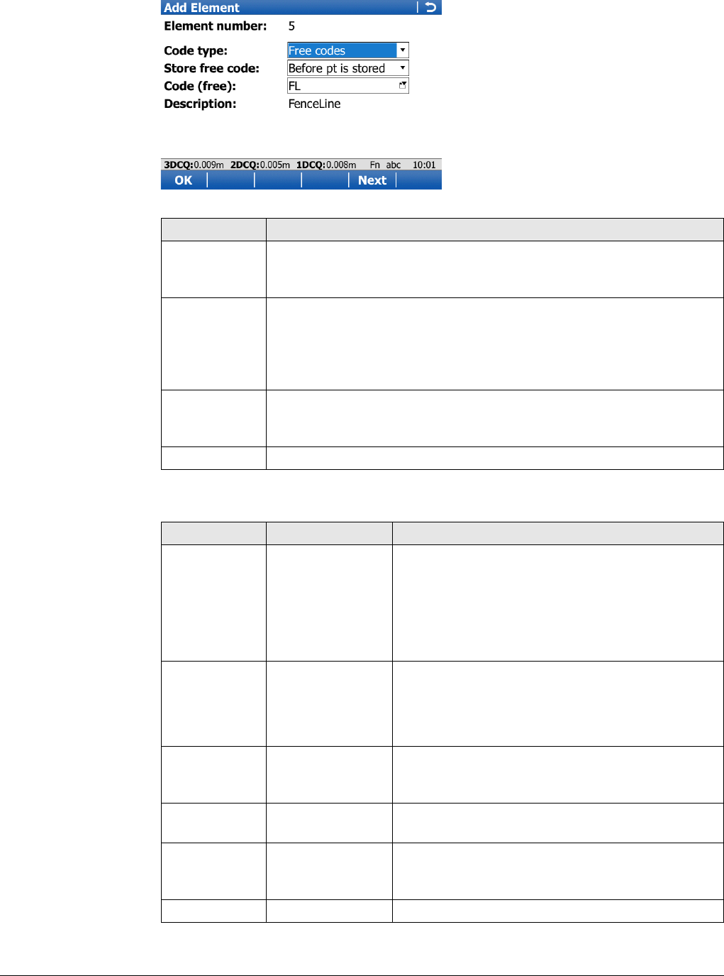
Viva Series, Survey Cross Section 842
Add Element/Edit
Element/Insert
Element
The functionality of the screens adding, editing and inserting an element are similar.
Differences are outlined.
Description of fields
Key Description
OK To add the element at the end of the cross section template or to
store the changes. To return to the screen from where this screen
was accessed.
Next In Add Element: To add the element to the end of the Elements list
and stay in the Add Element screen to add further elements.
In Edit Element: To update the element in the Elements list and stay
in the Edit Element screen to edit details of the next element in the
list.
Prev Available in Edit Element. To update the element in the Elements list
and stay in the Edit Element screen to edit details of the previous
element in the list.
Fn Quit To exit the application.
Field Option Description
Element
number Display only For Add Element and Insert Element: The number
of the element to be added.
For Edit Element: Displayed as x/y.
x Number of the element to be edited.
y Total number of elements on the active
template.
Code type The type of code to be used with the element.
Free codes To store a code independent of the element as
time-related information.
Thematic codes To store a code together with the element.
Store free
code After pt is stored
or Before pt is
stored
Determines if a free code is stored before or after
the point. Available for Code type:Free codes.
Code (free) Selectable list The code which will be stored before or after the
point/line. Available for Code type:Free codes.
Code Selectable list The code which will be stored with the next
point/line. Available for Code type:Thematic
codes.
Description Display only A line for a detailed description of the code.
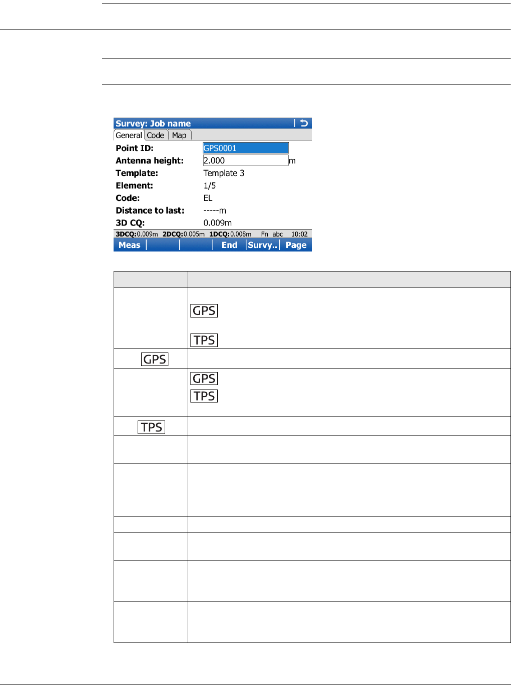
Viva Series, Survey Cross Section 843
Next step
OK adds the element or stores the changes.
59.4 Surveying Cross Sections
Description The fields on this screen indicate which cross section element is to be surveyed next.
Access Press OK in Survey X Section - Templates.
Survey,
General page
The pages shown are from a typical working style. An additional page is available when
a user-defined survey screen page is used.
Key Description
Meas Available if a template has been opened with Start.
To start measuring the next point of the cross section. The key
changes to Stop.
To measure a distance and store distance and angles.
Stop To end measuring the point. The key changes to Store.
Store To store the measured point. The key changes to Meas.
To store angles and distance. Distance must be measured
before.
Dist To measure a distance.
Start and End To open and close the selected cross section template. While the
template is open, the elements of the cross section can be surveyed.
Survy.. To manually measure a point that is not part of the cross section. The
point is not treated as an element of the cross section. The open
template remains open.
Available if a template has been opened with Start.
Page To change to another page on this screen.
Fn Config.. To configure the Cross Section Survey application. Refer to "59.5
Configuring Survey Cross Section".
Fn Prev To select the previous element of the cross section template. The
currently measured element will not be stored.
Available when End is displayed.
Fn Next To select the next element of the cross section template. The
currently measured element will not be stored.
Available when End is displayed.
Viva Series, Survey Cross Section 844
Description of fields
Fn IndivID and
Fn Run To change between entering an individual point ID different to the
defined ID template and the running point ID according to the ID
template. Refer to "25.1 ID templates".
Fn Quit To exit the application.
Field Option Description
Point ID Editable field The identifier for manually measured points. The
configured point ID template is used. The ID can
be changed in the following ways:
• To start a new sequence of point IDs type over
the point ID.
• For an individual point ID independent of the
ID template Fn IndivID. Fn Run changes back
to the next ID from the configured ID
template.
Antenna ht Editable field The default antenna height. Changing the
antenna height here does not update the default
antenna height as defined in the active working
style. The changed antenna height is used until
the application is exited.
Target height Editable field The default prism height.
Template The active template for the cross section.
Selectable list The cross section template is closed.
Opening the selectable list accesses Survey X
Section - Templates where a new template can
be created and an existing template can be
selected or deleted. Refer to "59.3
Creating/Editing a Cross Section Template".
Display only The cross section template is open.
Element Display only Displayed as x/y.
x The number of the next element on active
template. The number increases/decreases as
moving across the cross section depending on
the selection for Method in Configuration.
y Total number of elements on active template.
Code Display only The name of the code.
Point codes will be stored with the measured
point.
Free codes will be stored, depending on the
configuration, before or after the measured
point.
Distance to
last Display only The horizontal distance from the current position
to the last surveyed element position in the
previous cross section. ----- is displayed for
unavailable information.
Key Description
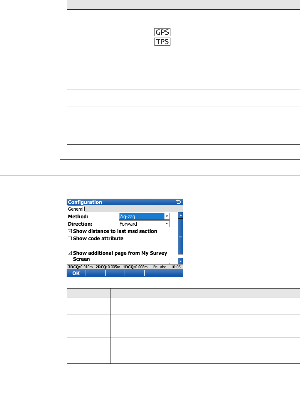
Viva Series, Survey Cross Section 845
Next step
59.5 Configuring Survey Cross Section
Access In the survey screen of the cross section application, press Config...
Configuration,
General page
IF THEN
a cross section template is to
be opened
select the desired template and press Start.
an element of a cross section
is to be surveyed Meas, Stop and then Store.
Meas, or Dist and then Store.
Once the end of a cross section is surveyed
then the next cross section will be measured.
Depending on the Method selected in Config-
uration, General page, the measurement is
either in the same direction or in the reverse
direction.
a cross section template is to
be closed
select the desired template and press End.
data is to be viewed graphi-
cally
Page. An element of a cross section template can
also be surveyed from the Map page.
Refer to "37 MapView Interactive Display Feature" for
information on the functionality and softkeys avail-
able.
the application is to be exited Fn Quit.
Key Description
OK To accept changes and return to the screen from where this screen
was accessed.
Config.. To edit the survey screen page currently being displayed. Available
when a list item in Page to show is highlighted. Refer to "25.3 My
Survey Screen".
Fn About To display information about the program name, the version number,
the date of the version, the copyright and the article number.
Fn Quit To exit the application.

Viva Series, Survey Cross Section 846
Description of fields
Next step
OK returns to the screen from where this screen was accessed.
Field Option Description
Method Method by which subsequent cross sections will
be surveyed. Refer to "59.1 Overview" for a
diagram.
Zig-zag Each new cross section is started at the same end
as where the previous cross section finished.
Same direction Each new cross section is started at the same end
as where the previous cross section started.
Direction The way of surveying the cross section. This influ-
ences in which order the elements of a template
will be applied. Refer to "59.1 Overview" for a
diagram.
Forward The cross sections will be surveyed in the same
way as the elements are defined in the selected
template.
Backward The cross sections will be surveyed in the reverse
way as the elements are defined in the selected
template.
Show distance
to last msd
section
Check box Activates a display only field in the survey screen.
The horizontal distance from the current position
to the last surveyed element position in the
previous cross section will be displayed.
Show code
attribute Check box When this box is checked, some attribute fields
are displayed in the survey screen. Useful if the
surveyor is stringing, to see that the correct string
attribute value is being used.
Attribute to
show From 1 to 20 The number of attribute fields which is displayed
in the survey screen. Available when Show code
attribute is checked.
Show addi-
tional page
from My
Survey Screen
Check box When this box is checked, a user-defined survey
screen page is shown in the survey screen.
Page to show Selectable list The names of the available survey screen pages.
Available when Show additional page from My
Survey Screen is checked.

Viva Series, Survey - Hidden Points 847
60 Survey - Hidden Points
60.1 Overview
Description Hidden points are points which cannot be measured directly by GPS, because, either
they cannot be physically reached, or because satellites are obstructed, for example
by trees or tall buildings.
• A hidden point can be calculated by measuring distances and/or azimuths to the
hidden point using a hidden point measurement device. Or for distances a tape can
be used.
• Additional auxiliary points can be manually measured.
• Bearings can be computed from previously measured points.
In contrast to the COGO application, hidden point measurements is more of a meas-
uring application than a calculation application.
Example
Changing coordinates of a point which has been previously used in hidden point meas-
urements does not result in the hidden point being recomputed.
Hidden point meas-
urement methods
A hidden point can be measured by
A hidden point measurement device can be attached to the instrument such that the
measurements are automatically transferred to the instrument.
Heights If configured, heights are taken into account. Refer to "60.7 Hidden Point Measure-
ment Including Heights" for information on configuring height offsets.
Device height and Target height configured in Hidden Point Device Offsets are
applied when the hidden points are computed. height in Hidden Point Connection
is the value directly from the hidden point measuring device.
Coding of hidden
points
Application: Completing a survey of telegraph poles for a tele-
communication company.
Aim: The telegraph poles must be surveyed to 0.3 m
accuracy in plan but height is not of concern.
Use of hidden point measure-
ments:
For poles surrounded by heavy undergrowth,
where it is not possible to measure the pole
directly without taking time to cut a path through
the undergrowth.
• Bearing and distance • Chainage and offset
• Two bearings • Backwards bearing and distance
•Two distances
• Thematical coding: Available in Hidden Point Result after the calculation of a
hidden point. Thematical coding of hidden points is identical
to coding of manually measured points.
• Free coding: Can be started while in Hidden Point Connection. Free
coding of hidden points is identical to coding of manually
measured points.
• Quick coding: Not available.
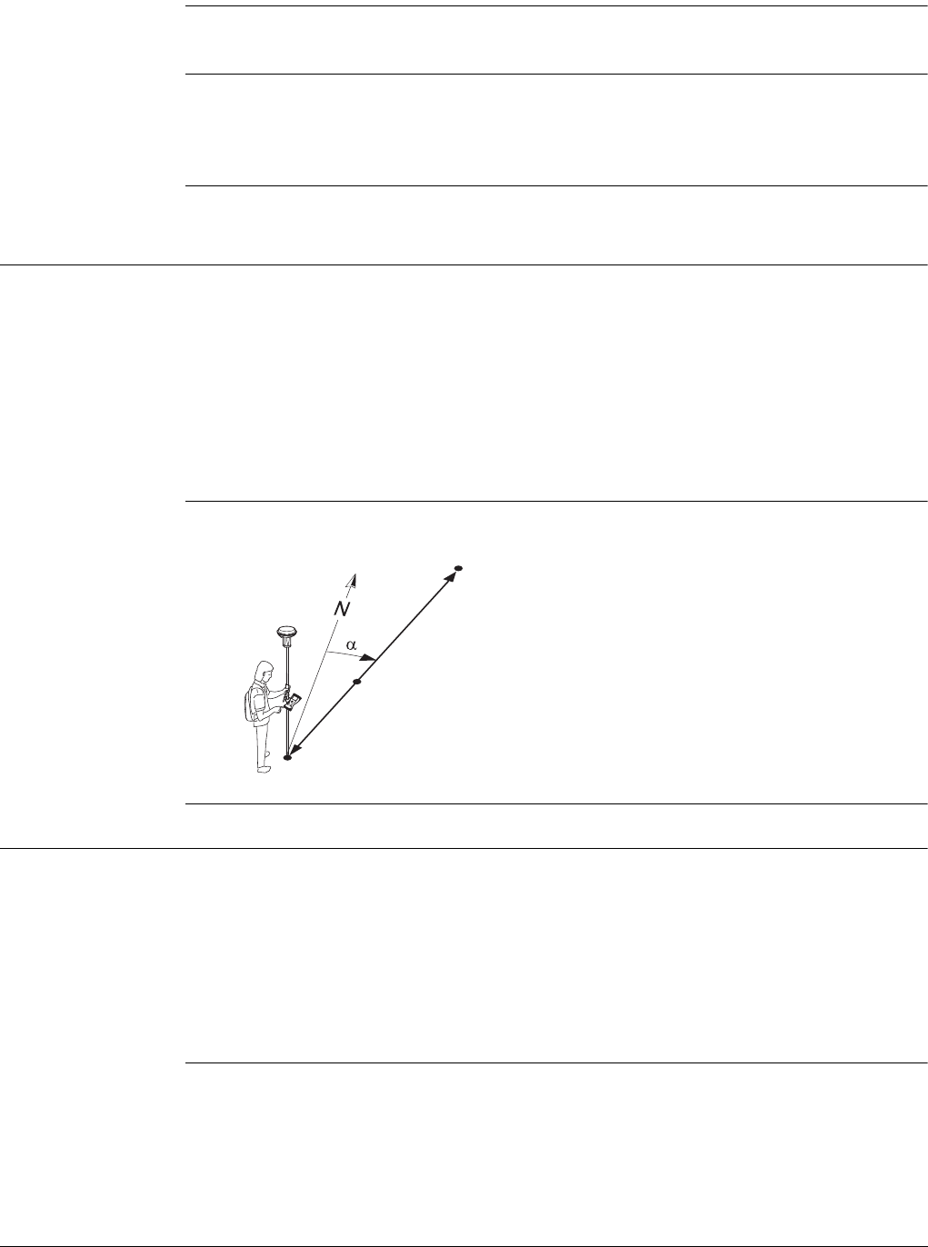
Viva Series, Survey - Hidden Points 848
Averaging of hidden
points
An average is calculated for hidden points if a point of class Meas already exists with
the same point ID.
Azimuth is used throughout this chapter. This term must always be considered to
mean also Bearing.
Auxiliary points Auxiliary points are used to compute azimuths required for the calculation of hidden
point coordinates. Auxiliary points can be points existing in the job or they can be
manually measured. The point ID template configured for Auxiliary points in ID
Templates is applied.
60.2 Hidden Point Methods
60.2.1 Bearing & Distance
Description One point must be known. It
• can already exist in the job.
• can be manually measured during the hidden point measurements.
• can be manually typed in.
The distance and the bearing from the known point to the hidden point are to be
determined. An auxiliary point helps compute the bearing which might not be known.
The auxiliary point can be determined in the direction from the known point to the
hidden point.
Diagram
60.2.2 Using 2 Bearings
Description Two points must be known. They
• can already exist in the job.
• can be manually measured during the hidden point measurements.
• can be manually typed in.
The bearings from the known points to the hidden point are to be determined. Auxil-
iary points help compute the bearings which might not be known. Auxiliary points can
be measured in the direction from the known points to the hidden point.
Known
P0 Known point
To be measured
d Distance from P0 to P2
αBearing from P0 to P2
P1 Auxiliary point, optional
Unknown
P2 Hidden point
GS_063 P0
P1
P2
d
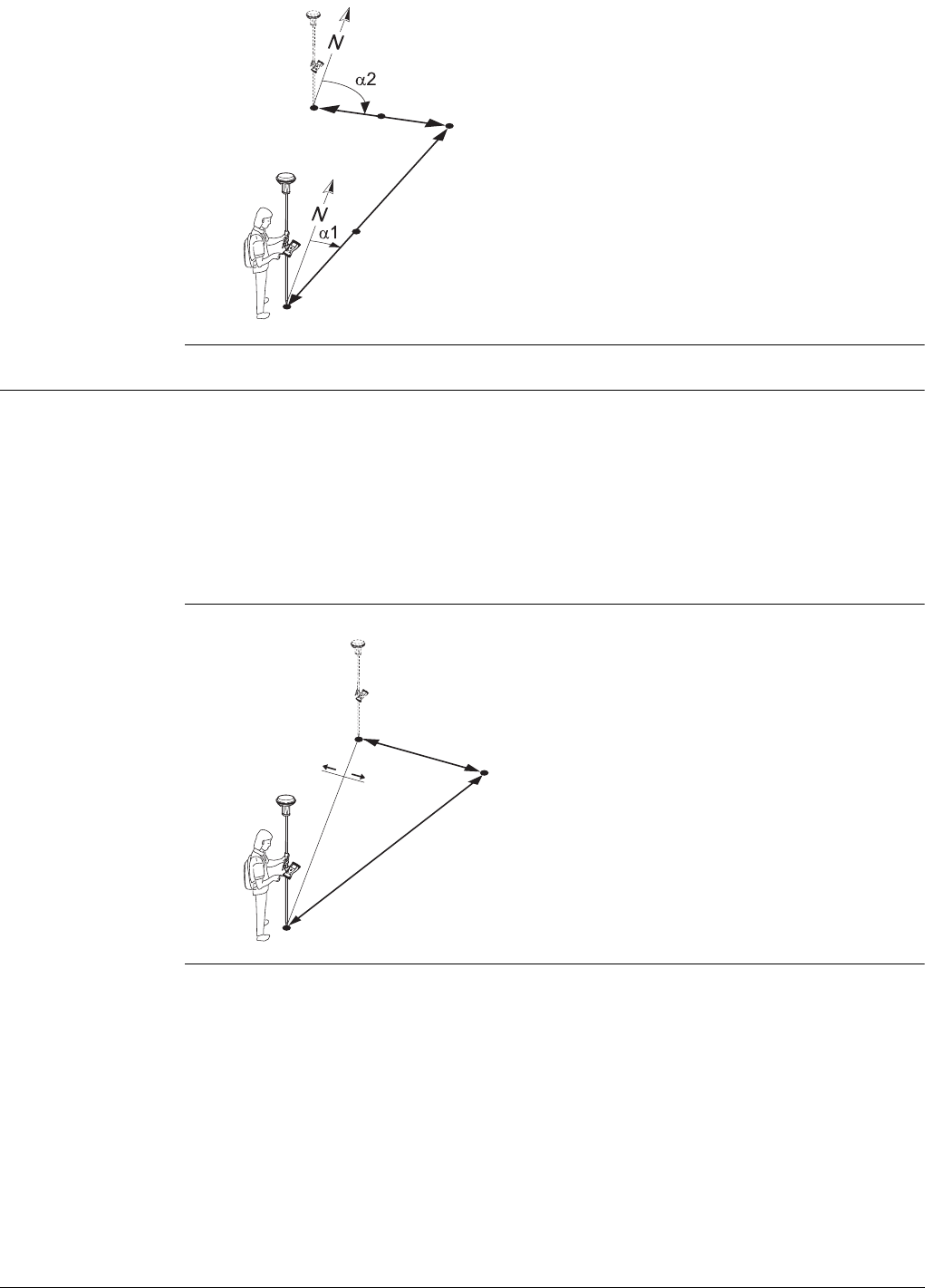
Viva Series, Survey - Hidden Points 849
Diagram
60.2.3 Using 2 Distances
Description Two points must be known. They
• can already exist in the job.
• can be manually measured during the hidden point measurements.
• can be manually typed in.
The distances from the known points to the hidden points are to be determined. The
location of the hidden point relative to the line between the two known points is to
be defined.
Diagram
Known
P0 First known point
P3 Second known point
To be measured
α1Bearing from P0 to P2
α2Bearing from P3 to P2
P1 First auxiliary point, optional
P4 Second auxiliary point, optional
Unknown
P2 Hidden point
GS_064 P0
P1
P4
P3
P2
Known
P0 First known point
P2 Second known point
d3 Line from P0 to P2
aRight of d3
bLeft of d3
To be measured
d1 Distance from P0 to P1
d2 Distance from P2 to P1
Unknown
P1 Hidden point
GS_065
P2
P1
d3
d2
d1
P0
b
a
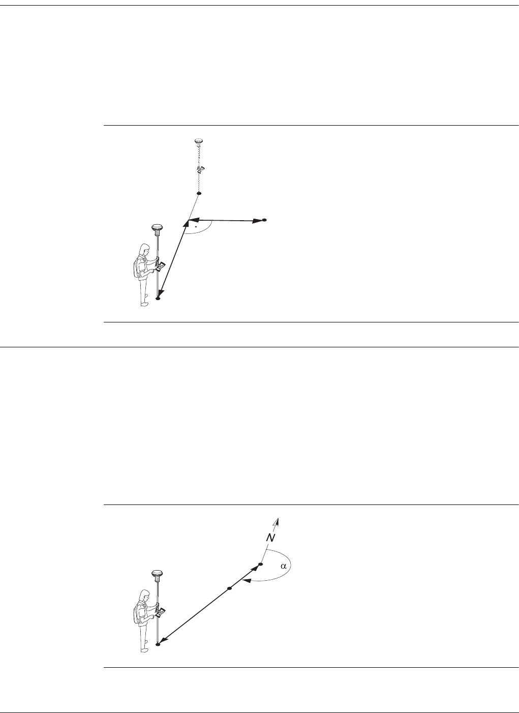
Viva Series, Survey - Hidden Points 850
60.2.4 Chainage & Offset
Description Two points must be known. They
• can already exist in the job.
• can be manually measured during the hidden point measurements.
• can be manually typed in.
The chainage from one known point along the line between the two known points
must be determined. The offset of the hidden point to the line between the two
known points must be determined.
Diagram
60.2.5 Backwards Bearing & Distance
Description In order to compute the hidden point, the measurements are taken from the hidden
point.
One point must be known. It
• can already exist in the job.
• can be manually measured during the hidden point measurements.
• can be manually typed in.
The distance and the bearing from the hidden point to the known point are to be
determined. An auxiliary point helps compute the bearing which might not be known.
An auxiliary point can be measured in the direction from the hidden point to the known
point.
Diagram
Known
P0 First known point
P1 Second known point
To be measured
d1 Chainage
d2 Offset
Unknown
P2 Hidden point
GS_067 P0
P1
d1
d2 P2
Known
P0 Known point
To be measured
αBearing from P2 to P0
d Distance from P2 to P0
P1 Auxiliary point, optional
Unknown
P2 Hidden point
GS_068 P0
P1
P2
d
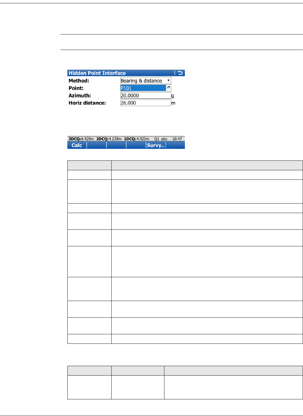
Viva Series, Survey - Hidden Points 851
60.3 Hidden Point Measurements
Hidden point measurements are possible from the Survey application and when the
Survey application screen is called from another application, for example from
Stakeout.
Access Press HdnPt.. in the survey screen.
Hidden Point Meas-
urement The setting for Method on this screen determines the availability of the subsequent
fields and softkeys.
Description of fields
Key Description
Calc To calculate the hidden point and to display the results.
EAO Available for Angle offset:New for each point or Angle
offset:Permanent in Hidden Point Device Offsets. To change or
enter an External Angle Offset.
Hts.. To type in the device and target heights to be considered.
Sun Available when Azimuth is highlighted. The azimuth from the direc-
tion of the sun to the known point is computed.
Azmth Available when Azimuth is highlighted. To select or manually measure
an auxiliary point and to compute the azimuth.
Posn ? To determine chainage and offset of the current position relative to
the line between the two known points. The values are displayed in
Chainage and Offset. The point from where the chainage has been
measured is selected in Chainage from.
Slope Available when Horiz distance or Chainage is highlighted. To
measure a slope distance and an elevation angle or percentage
grade. The values are used to compute the horizontal distance.
Survy.. Available when a point field is highlighted. To measure the known
point manually for the calculation of the hidden point.
Fn Config.. To configure hidden point measurements. Refer to "19 Connections..
- All other connections".
Fn Quit To exit the screen.
Field Option Description
Method Selectable list The method for measuring hidden points. Refer
to "60.2 Hidden Point Methods" for a description
of the methods.

Viva Series, Survey - Hidden Points 852
Next step
Calc calculates the hidden point and displays the results in Hidden Point Result.
Point Selectable list The point ID of the current position. This point is
the known point for the calculation of the hidden
point.
To type in coordinates manually for the
known point open the selectable list and
create a new point.
Point A Selectable list The point ID of the current position. This point is
the first known point for the calculation of the
hidden point.
To type in coordinates manually for the
known point open the selectable list and
create a new point.
Point B Selectable list The point ID of the current position. This point is
the second known point for the calculation of the
hidden point.
To type in coordinates manually for the
known point open the selectable list and
create a new point.
Azimuth Editable field The azimuth from the known point to the hidden
point. Type in an azimuth. When a hidden point
measurement device is attached to the instru-
ment to measure the azimuth, the value is auto-
matically transferred.
Horiz distance Editable field The horizontal distance from the known point to
the hidden point. Type in a distance. When a
hidden point measurement device is attached to
the instrument to measure the distance, the
value is automatically transferred.
Location Selectable list Available for Method:Using 2 distances. The
location of the hidden point relative to the line
from Point A to Point B.
Chainage from Selectable list Available for Method:Chainage & offset. The
chainage from one known point along the line
between the two known points. Looking from the
point selected in Chainage from, a positive
chainage is towards the second known point. A
negative chainage is into the opposite direction
of the second known point.
Field Option Description
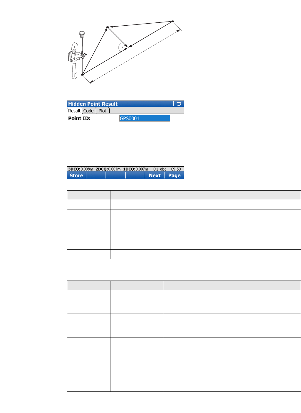
Viva Series, Survey - Hidden Points 853
60.4 Hidden Point Results
Computed
distances on Hidden
Point Result
Hidden Point Result
Description of fields
P0 First known point
P1 Hidden point
P2 Second known point
d1 Distance from P0 to P1
d2 Distance from P2 to P1
d3 Check chainage A
d4 Check chainage B
d5 Check offset
d6 Check distance AB
GS_066
d1
d2
d5
d3
d4
d6
P0
P1
P2
Key Description
Store To store the result.
Fn IndivID and
Fn Run To change between entering an individual point ID different to the
defined ID template and the running point ID according to the ID
template.
Next To store the hidden point and to return to Hidden Point Measure-
ment. Another hidden point can be measured.
Fn Quit To not store the hidden point and to exit the screen.
Field Option Description
Point ID Editable field The identifier for the hidden point. The config-
ured point ID template is used. The ID can be
changed. Type in a point ID.
Check
distance AB Display only Available for Method:Using 2 bearings and
Method:Using 2 distances. The computed hori-
zontal distance between Point A and Point B.
Check bearing
AB Display only Available for Method:Using 2 bearings and
Method:Chainage & offset. The computed
bearing from Point A to Point B.
Check
distance A Display only Available for Method:Using 2 bearings and
Method:Chainage & offset. The computed hori-
zontal distance between Point A and the hidden
point.
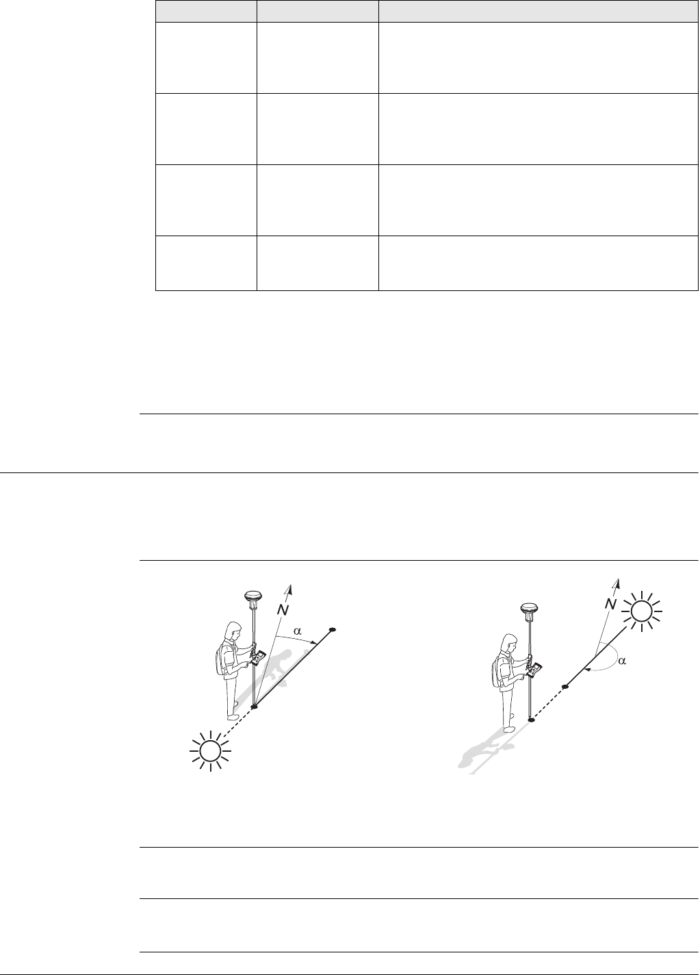
Viva Series, Survey - Hidden Points 854
Next step
On the Code page, type in a code if desired.
On the Map page, measured distances are indicated by solid arrows, bearings are indi-
cated by half solid and half dashed arrows.
Store stores the hidden point.
60.5 Computing an Azimuth
60.5.1 Using the Sun
Description The azimuth for a hidden point measurement can be computed using a known point
and the sun. The known point can be manually measured. The location of the hidden
point can be away from the sun or in the direction towards the sun. Ensure that the
shadow of the pole falls in the direction of the point.
Diagram
Requirements Bearing & distance, Using 2 bearings or Back brng & distance must be selected for
Method.
Access In Hidden Point Measurement highlight Azimuth. Press Sun.
Follow the instructions on the screen.
Check
distance B Display only Available for Method:Using 2 bearings and
Method:Chainage & offset. The computed hori-
zontal distance between Point B and the hidden
point.
Check
chainage A Display only Available for Method:Using 2 distances. The
computed distance on the line from Point A to
Point B from Point A to the point of intersection
with Check offset.
Check
chainage B Display only Available for Method:Using 2 distances. The
computed distance on the line from Point B to
Point A from Point B to the point of intersection
with Check offset.
Check offset Display only Available for Method:Using 2 distances. The
computed perpendicular distance from the
hidden point to the line from Point A to Point B.
Field Option Description
P0 Known point
P1 Hidden point
αBearing from P0 to P1
P0 Known point
P1 Hidden point
αBearing from P0 to P1
GS_069
P1
P0
P0
P1
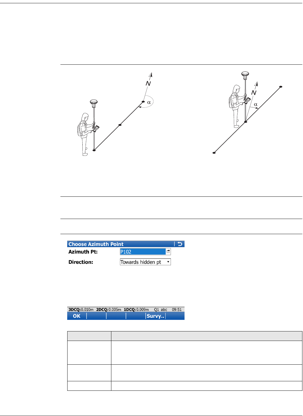
Viva Series, Survey - Hidden Points 855
60.5.2 Using Auxiliary Point
Description The azimuth for a hidden point measurement can be computed using an auxiliary
point. The auxiliary point
• can already exist in the job.
• can be manually measured during the hidden point measurements.
• can be manually typed in.
The location of the auxiliary point can be in the direction towards the hidden point or
away from the hidden point.
Diagram
Requirements Bearing & distance, Using 2 bearings or Back brng & distance must be selected for
Method.
Access In Hidden Point Measurement highlight Azimuth. Press Azmth.
Choose Azimuth
Point
P0 Known point
P1 Auxiliary point, Azimuth Pt
P2 Hidden point
αBearing from P2 to P0
P0 Known point
P1 Auxiliary point, Azimuth Pt
P2 Hidden point
αBearing from P0 to P2
GS_071 P0
P2
P1
GS_072 P1
P2
P0
Key Description
OK To accept changes and return to the screen from where this screen
was accessed. The azimuth is computed and displayed in Azimuth in
Hidden Point Measurement.
Survy.. Available for Azimuth Pt being highlighted. To measure the auxiliary
point manually for the calculation of the azimuth.
Fn Quit To exit the screen.
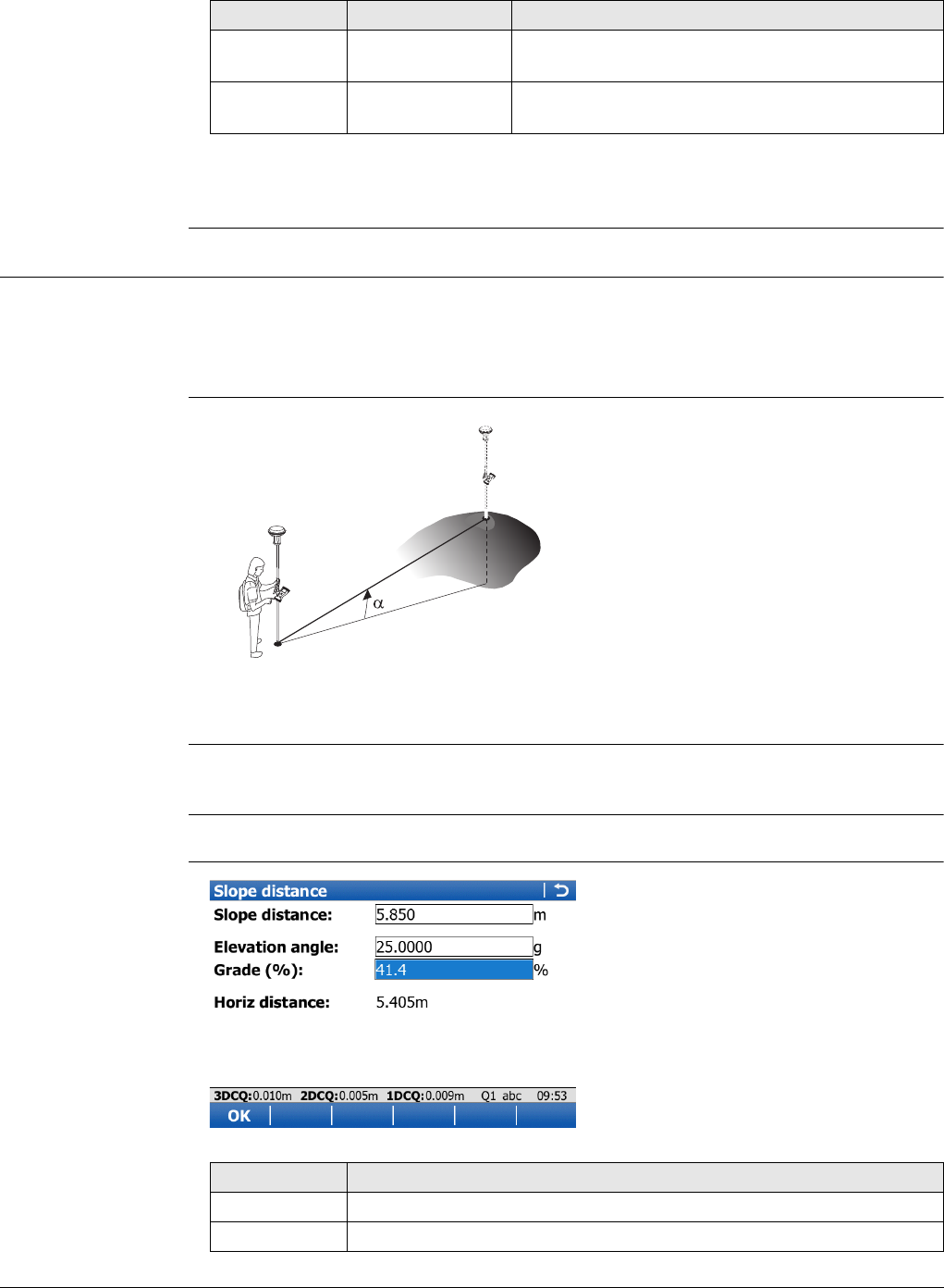
Viva Series, Survey - Hidden Points 856
Description of fields
Next step
OK closes the screen.
60.6 Computing Horizontal Distances from Slope Distances
Description The horizontal distance for a hidden point measurement can be computed using a
slope distance, and an elevation angle or percentage grade. The slope distance and
the elevation angle can either be typed in or measured with a hidden point measure-
ment device.
Diagram
Requirements Bearing & distance, Using 2 bearings or Back brng & distance must be selected for
Method.
Access In Hidden Point Measurement highlight Horiz distance. Press Slope.
Slope distance
Field Option Description
Azimuth Pt Selectable list The auxiliary point for the calculation of the
azimuth.
Direction Selectable list The location of the auxiliary point relative to the
hidden point.
P0 Known point
P1 Hidden point
d1 Slope distance
d2 Horizontal distance
αElevation angle
GS_073
d1
P1
P0
d2
Key Description
OK To take over the result.
Fn Quit To exit the screen.

Viva Series, Survey - Hidden Points 857
Description of fields
Next step
OK returns to Hidden Point Measurement. The horizontal distance is displayed in
Horiz distance.
Field Option Description
Slope
distance Editable field Type in a distance from the known point to the
hidden point. When a hidden point measurement
device is attached to the instrument to measure
the distance, the value is automatically trans-
ferred.
Elevation
angle Editable field Type in the elevation angle from the known point
to the hidden point. When a hidden point meas-
urement device is attached to the instrument to
measure the elevation angle, the value is auto-
matically transferred.
Grade (%) Editable field The grade from the known point to the hidden
point is automatically computed from the slope
distance and the elevation angle.
The value for Grade (%) can be typed in
instead of the value for Elevation angle.
Then Elevation angle is computed auto-
matically.
Horiz distance Display only The horizontal distance from the known point to
the hidden point is automatically computed from
the slope distance and the elevation angle.
height Display only Available if using heights is configured. The height
difference between the known point and the
hidden point is automatically computed from the
slope distance and the elevation angle.
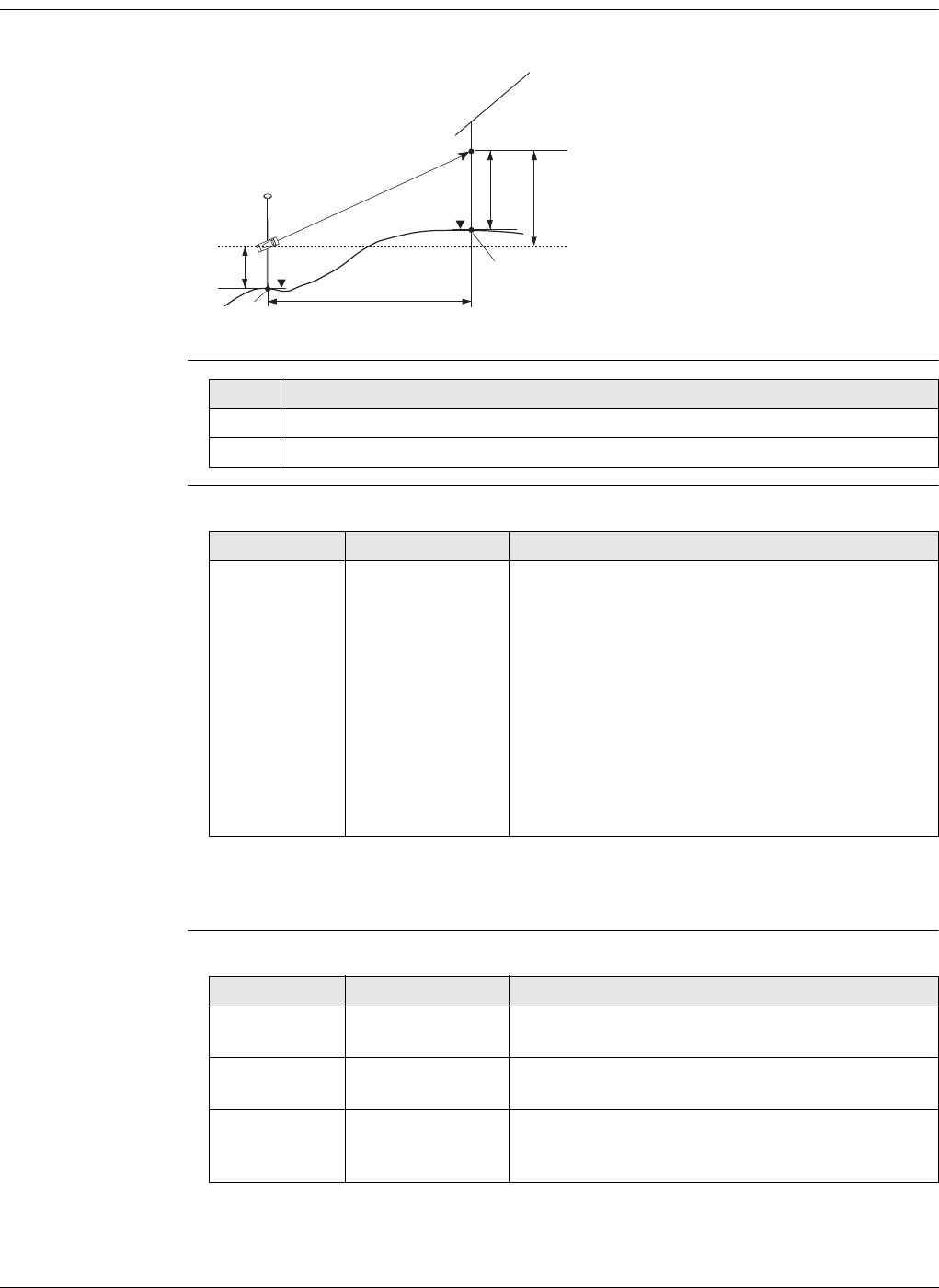
Viva Series, Survey - Hidden Points 858
60.7 Hidden Point Measurement Including Heights
Diagram
Configuration step-
by-step
Hidden Point Meas-
urement Description of fields
Next step
Press Hts...
Device & Target
Height Description of fields
P0 Known point
P1 Target point
P2 Hidden point
aHeight of P0
b Height of P2 = a + d1 + d4 - d3
d1 Device height: Height of hidden point
measurement device above P0
d2 Slope distance
d3 Target height: Height of P1 above P2
d4 Height difference between hidden
point measurement device and P1
d5 Horizontal distance
GS_074
a
d1
d2
d5
d3
b
P1
P2
P0
d4
Step Description
1. Compute height for hidden points is checked in Configuration.
2. Height offset:Device & target ht in Hidden Point Device Offsets.
Field Option Description
height Selectable list The positive or negative height difference
between the centre of the hidden point measure-
ment device and the target point. Type in the
value. When a hidden point measurement device
is attached to the instrument to measure the
height difference, the value is automatically
transferred.
For hidden point measurement methods
using two known points, height must be
determined from each known point.
Refer to "60.3 Hidden Point Measurements" for a
description of all other fields on the screen.
Field Option Description
Device ht at pt
AEditable field The height of the hidden point measurement
device above Point A.
Target height Editable field The height of the target point above the hidden
point when measured from Point A.
Device ht at pt
BEditable field Available for hidden point measurement methods
using two known points. The height of the hidden
point measurement device above Point B.

Viva Series, Survey - Hidden Points 859
Next step
OK closes the screen and returns to Hidden Point Measurement.
There, height still displays the positive or negative height difference between the
centre of the hidden point measurement device and the target point. The heights of
the hidden point measurement device above the ground, and the target point above
the hidden point, are applied when the hidden point is computed. For hidden point
measurement methods using two known points, this computation is done for each
known point. In this case, the height of the hidden point is the average.
Target height Editable field Available for hidden point measurement methods
using two known points. The height of the target
point above the hidden point when measured
from Point B.
Field Option Description
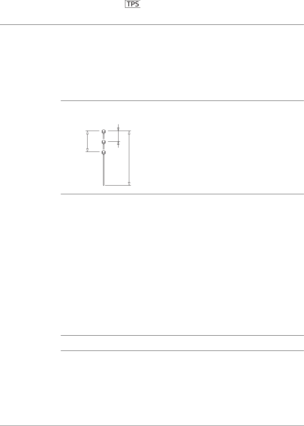
Viva Series, Hidden Point 860
61 Hidden Point
61.1 Overview
Description Hidden points cannot be measured directly by a TPS instrument, because they are not
directly visible.
A hidden point can be calculated from measurements to prisms mounted on a hidden
point rod. The spacing and length of the hidden point rod are known. The hidden point
rod can be held at any angle, as long as it is stationary for all measurements.
Measurements for the hidden point are calculated as if the hidden point was observed
directly. These calculated measurements can also be recorded.
The hidden point rod can have either two or three prisms. If three prisms are used the
average will be calculated.
Hidden point rod The prisms on the hidden point rod are also called auxiliary points after they have been
measured.
Hidden point tasks The Hidden Point application can be used for the following tasks:
• The hidden point application can be used to obtain accurate three-dimensional
coordinates for a point that is blocked from direct measurement by an obstruction.
• Determination of flow line locations and elevations in manholes, without measuring
from the manhole rim to the flow line, and then estimating corrections for nonver-
ticality of the measuring tape and eccentricity from the rim measurement to the
flow line.
• Determination of recesses in building corners for detailed surveys, without esti-
mating right angle offsets, with or without taping of the dimensions.
• Measurements behind overhangs, buttresses and columns for quantity determina-
tions in underground construction or mining, without estimating right angle
offsets, with or without taping of the dimensions.
• Measurements of industrial process piping or other equipment in close quarters.
• Detailed architectural surveys for remodelling or cultural preservation or restora-
tion work
• Any place where accurate measurements would require many more instrument
setups in order to achieve line of sight from the instrument to the points being
measured.
The TPS Hidden Point application does not generate a report sheet.
1Prism 1
2Prism 2
3Prism 3
d1 Rod length
d2 Distance from prism 1 to prism 2
d3 Distance from prism 1 to prism 3
TS_046
d1
d2
d3
1
3
2
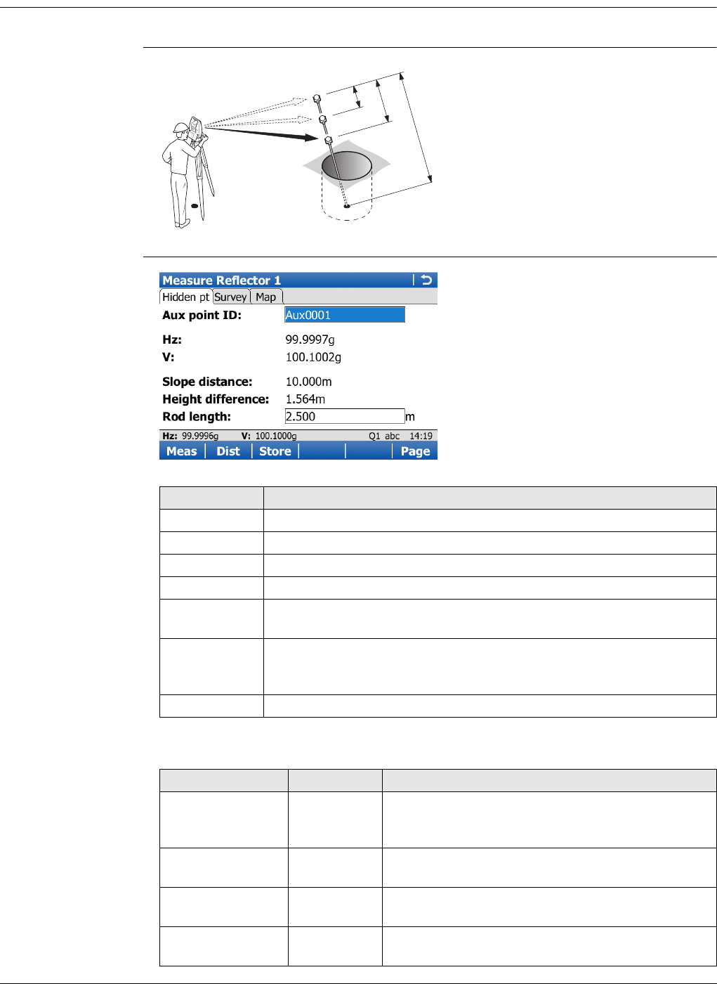
Viva Series, Hidden Point 861
61.2 Accessing Hidden Point and Measuring
Access Select Main Menu:Go to Work!\Survey+\TPS hidden point.
Diagram
Measure Reflector 1,
Hidden pt page
Description of fields
d1 Rod length
d2 Distance from prism 1 to prism 2
d3 Distance from prism 1 to prism 3
TS_047
P1
P0
d1
d2
d3
1
3
2
Key Description
Meas To measure and store the prism, and access the next screen.
Dist To measure a distance.
Store To store data.
Page To change to another page on this screen.
Fn Config.. To configure the TPS hidden point application. Refer to "61.3 Config-
uring Hidden Point".
Fn IndivID and
Fn Run To change between entering an individual point ID different to the
defined ID template and the running point ID according to the ID
template. Refer to "25.1 ID templates".
Fn Quit To exit the screen.
Field Option Description
Aux point ID Editable field The point ID of the auxiliary point, the prism on the
hidden point rod. The Auxiliary Points ID template
is used.
Hz Display only The horizontal angle to prism 1, the auxiliary point,
is displayed.
VDisplay only The vertical angle to prism 1, the auxiliary point, is
displayed.
Slope distance Display only The slope distance to prism 1, the auxiliary point,
is displayed.
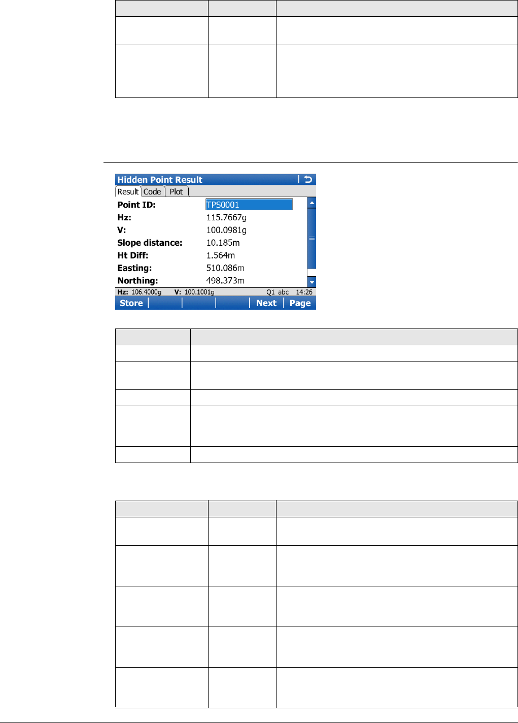
Viva Series, Hidden Point 862
Next step
Take the measurements to prism 2 and, if desired, to prism 3. After the last prism of
the hidden point rod is measured, Hidden Point Result, Result page is accessed.
Hidden Point Result,
Result page
Description of fields
Height difference Display only The height difference to prism 1, the auxiliary
point, is displayed.
Rod length Editable field The length of the rod can be adjusted before the
hidden point result is displayed. The rod length
always keeps the distances R1-R2 for two prisms
and R1-R3 for three prisms into account.
Field Option Description
Key Description
Store To measure the prism and exit the application.
Next To store the hidden point and to access Measure Reflector 1 to take
more hidden point measurements.
Page To change to another page on this screen.
Fn IndivID and
Fn Run To change between entering an individual point ID different to the
defined ID template and the running point ID according to the ID
template. Refer to "25.1 ID templates".
Fn Quit To exit the screen.
Field Option Description
Point ID Editable field The name of the hidden point. The configured
point ID template is used.
Hz Display only The calculated horizontal angle to the computed
hidden point. ----- is displayed for unavailable
information.
VDisplay only The calculated vertical angle to the computed
hidden point. ----- is displayed for unavailable
information.
Slope distance Display only The calculated slope distance to the computed
hidden point. ----- is displayed for unavailable
information.
Height difference Display only The calculated height difference from instrument
to computed hidden point. ----- is displayed for
unavailable information.
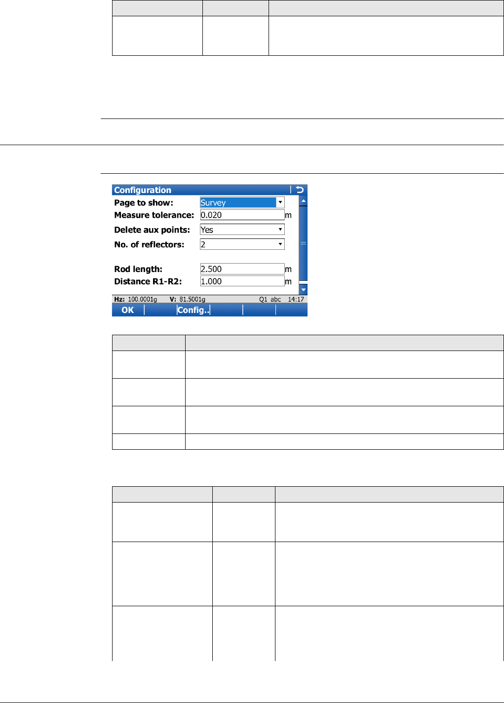
Viva Series, Hidden Point 863
Next step
Page changes to the Code page. Type in a code if desired. Page changes to the Plot
page. Measured distances are indicated by solid arrows.
61.3 Configuring Hidden Point
Access Select Main Menu:Go to Work!\Survey+\TPS hidden point. Press Fn Config...
Configuration
Description of fields
Easting, Northing
and Height Display only The calculated coordinates of the computed
hidden point. ----- is displayed for unavailable
information.
Field Option Description
Key Description
OK To accept changes and return to the screen from where this screen
was accessed.
Config.. To configure the selected survey screen page. Refer to "25.3 My
Survey Screen".
Fn About To display information about the program name, the version number,
the date of the version, the copyright and the article number.
Fn Quit To exit the screen.
Field Option Description
Page to show Selectable
list
The user-defined survey screen page to be
shown in Measure Reflector 1, Measure
Reflector 2 and Measure Reflector 3.
Measure tolerance Editable
field
Limit of the difference between input and meas-
ured spacing of the prisms.
For three prisms being used, limit for
maximum deviation of the three measure-
ments.
Delete aux points Yes or No The auxiliary points are deleted when the hidden
point is stored.
The auxiliary points are prism 1, prism 2 and
prism 3 of the hidden point rod.

Viva Series, Hidden Point 864
Next step
OK returns to the screen from where this screen was accessed from.
The Auxiliary Points ID template is used for the
auxiliary points. The Survey Points ID template is
used for the computed hidden point.
No. of reflectors 2 or 3Two or three prisms are used on the rod.
Auto position Yes or No Available for No. of reflectors: 3. The third prism
is aimed at automatically.
Rod length Editable
field
Total length of hidden point rod.
Distance R1-R2 Editable
field
Spacing between the centres of prism 1 and
prism 2.
Distance R1-R3 Editable
field
Available for No. of reflectors: 3. Spacing
between the centres of prism 1 and prism 3.
Prism 3 is situated between prism 1 and prism 2.
Field Option Description
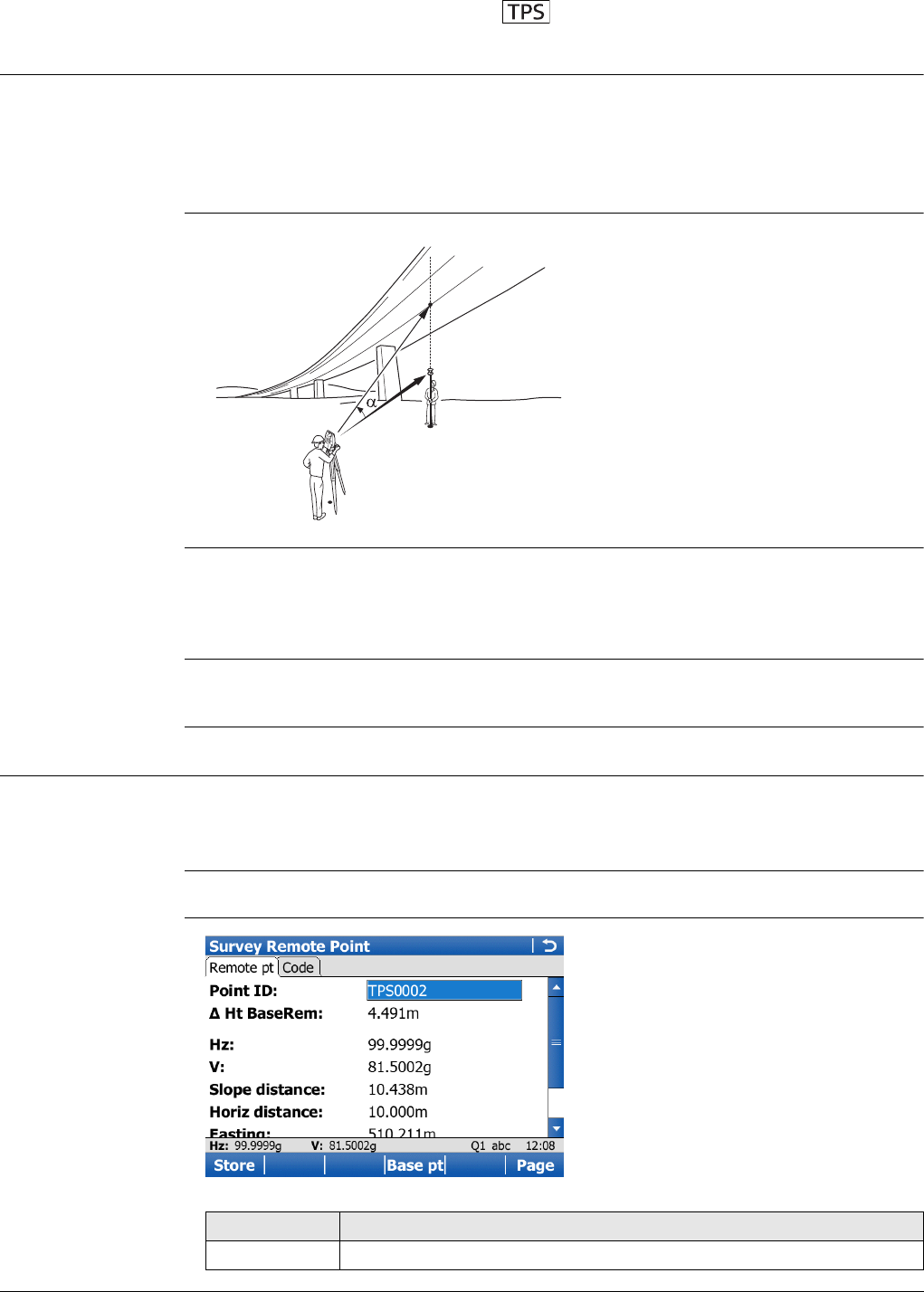
Viva Series, Survey - Remote Point 865
62 Survey - Remote Point
62.1 Overview
Description Remote point is used to determine the 3D coordinates of inaccessible points, for
example on bridges. The horizontal distance to a base point directly underneath or
above the remote point is measured. Then the instrument is aimed at the remote
point. The coordinates of the remote point are calculated with the distance measured
to the base point and the angles measured to the remote point.
Diagram
To ensure correct results, the remote point and the prism must be lined up vertically.
If it is not possible to maintain an exactly vertical line, the acceptable Hz dist tolerance
must be chosen. The horizontal distance to the remote point and to the base point
should coincide.
Averaging of
remote points
An average can be calculated for remote points if a measured point of class Meas
already exists with the same point ID. The average flag for the point is Auto.
62.2 Accessing Remote Point
Description Remote point measurements are possible from the Survey application when Measure
remote points is checked in the Configuration, Remote points page and a valid
distance measurement is available.
Access Press RmtHt. in Survey, Survey page after one point is measured with Dist.
Survey Remote
Point, Remote points
page
P0 Instrument station
P1 Base point
P2 Remote point
d1 Horizontal distance to the base point
αVertical angle between base point and
remote point
a Vertical axis from P1 to P2
TS_043
a
P1
P0
P2
d1
Key Description
Store Stores the remote point. Stays in this screen.
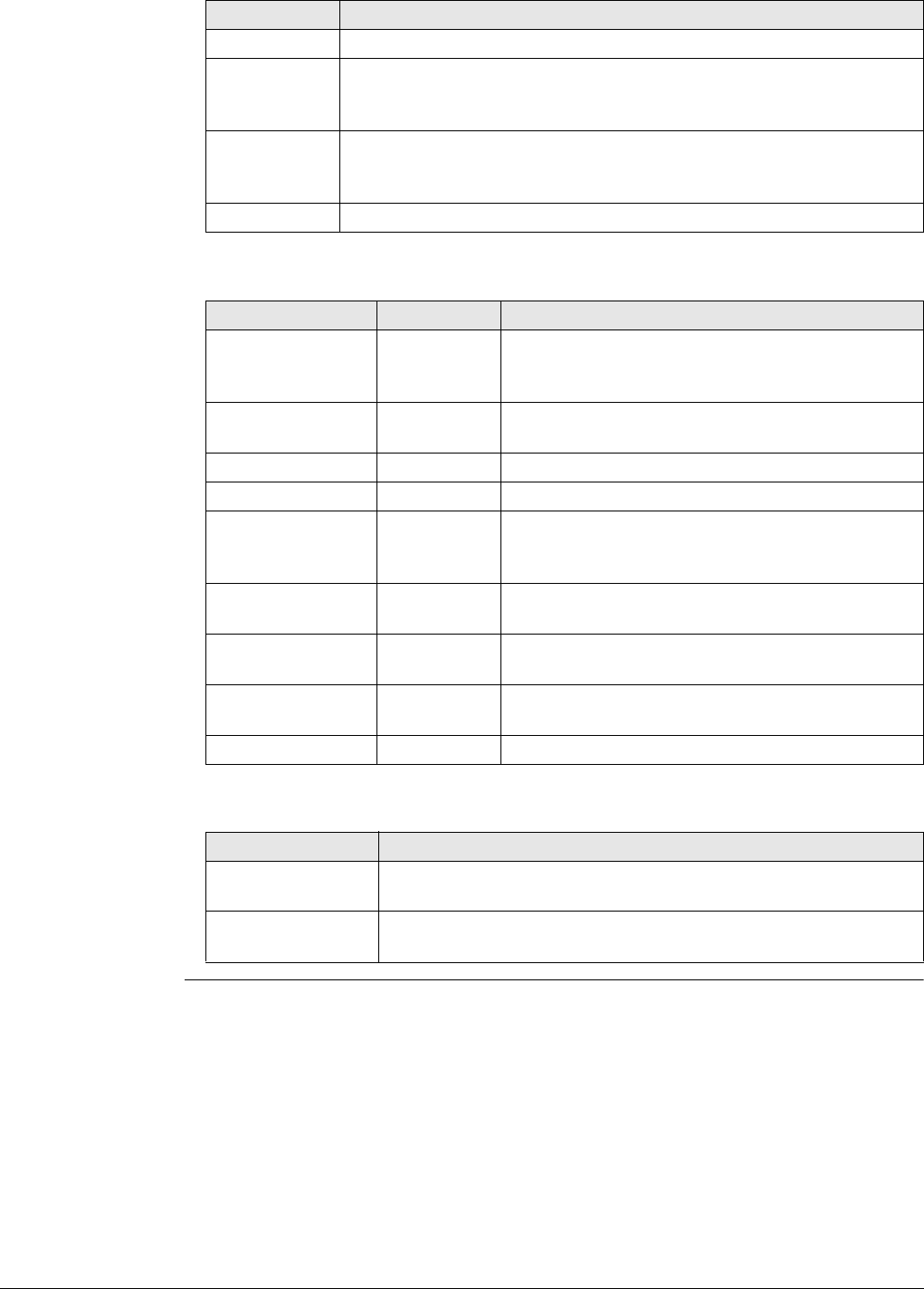
Viva Series, Survey - Remote Point 866
Description of fields
Next step
Base pt Returns to the Survey screen. The distance measurement is cleared.
Page To change to another page on this screen. The page available
depends on the Page to show selected in the Configuration, Remote
points screen. Refer to "62.3 Configuring Remote Point".
Fn IndivID and
Fn Run To change between entering an individual point ID different to the
defined ID template and the running point ID according to the ID
template. Refer to "25.1 ID templates".
Fn Quit To exit the application.
Field Option Description
Point ID Editable field Displays the point ID for the remote point. The
point ID in Survey Remote Point is always iden-
tical to the point ID in Survey.
height - remote
to base Display only The elevation difference between the base point
and the remote point.
Hz Display only The current horizontal angle.
VDisplay only The current vertical angle.
Slope distance Display only The current slope distance to the remote point
calculated from the horizontal distance to the
base point and the current vertical angle.
Horiz distance Display only The horizontal distance measured to the base
point.
Easting Display only Calculated Easting coordinate for the remote
point.
Northing Display only Calculated Northing coordinate for the remote
point.
Elevation Display only Calculated height for the remote point.
IF THEN
if a remote point is
to be stored
Store.
a new base point is
to be measured
Base pt to return to the Survey screen.
Key Description
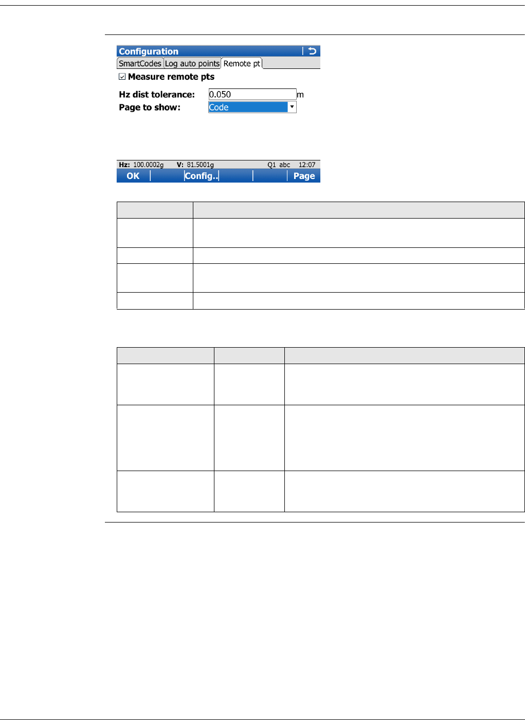
Viva Series, Survey - Remote Point 867
62.3 Configuring Remote Point
Access In Survey press Fn Config.. to access Configuration.
Configuration,
Remote points page
Description of fields
Key Description
OK To accept changes and return to the screen from where this screen
was accessed.
Page To change to another page on this screen.
Config.. To configure the selected survey screen page. Available when Page
to show is highlighted. Refer to "25.3 My Survey Screen".
Fn Quit To exit the application.
Field Option Description
Measure remote
points Check box If checked, the remote point function is active.
RmtHt. is added to the function keys in Survey
after Dist is pressed.
Hz dist tolerance Editable field The horizontal distance to the remote point is
equal to the horizontal distance of the base
point. The value for Hz dist tolerance is the
maximum tolerated length of the chord between
the base point and the remote point.
Page to show Selectable list All survey screen pages from Main Menu:
User\Work settings\My Survey Screen can be
selected.
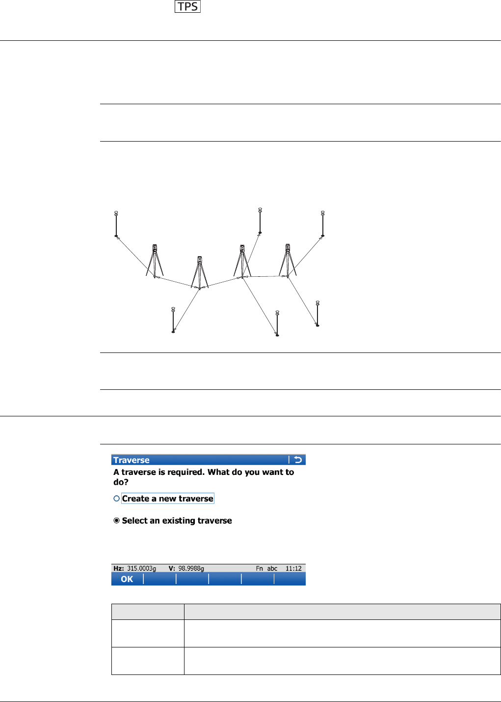
Viva Series, Traverse 868
63 Traverse
63.1 Overview
Description The Traverse application is used to fulfil one of the most common operations done by
surveyors; to establish a control point base system to be used as a skeleton for other
survey operations. For example, topographic survey, point stakeout, line stakeout or
road stakeout.
If the message panel appears which requires that the application must be activated via
a license key then refer to "30.3 Load licence keys".
Types of traverse • External reference & closed loop
• Internal reference & position check
•Open end & position check
• Closed end traverse
Averaging of Trav-
erse points
An average point of class Meas is calculated by the Traverse application.
63.2 Accessing Traverse
Access Select Main Menu:Go to Work!\Survey+\Traverse.
Traverse
P1 Traverse point
P2 Backsight point
P3 Traverse point
P4 Sideshot point
P5 Traverse point
P6 Sideshot point
P7 Sideshot point
P8 Closing point
P9 Sideshot point
P10 Closing angle point
TS_049
P1
P2 P10
P3
P5 P8
P4 P7 P9
P6
Key Description
OK To select the highlighted option and to continue with the subsequent
screen.
Fn Config.. To configure the Traverse application. Refer to "63.6 Configuring
Traverse".
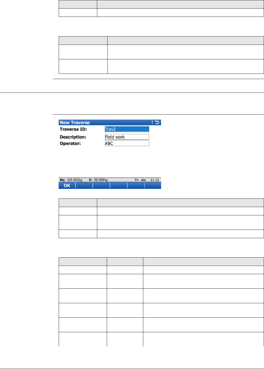
Viva Series, Traverse 869
Next step
63.3 Creating/Editing a Traverse
Access •In Traverse, select Create a new traverse. Press OK.
•In Manage Traverses, press New.. or Edit...
New Traverse/Edit
Traverse
Description of fields
Fn Quit To exit the application.
IF THEN
a traverse is to be
created or selected
highlight the relevant option and press OK.
Traverse is to be
configured
Fn Config... Refer to "63.6 Configuring Traverse".
Key Description
Key Description
OK To store the settings.
Fn Config.. To configure the Traverse application. Refer to "63.6 Configuring
Traverse".
Fn Quit To exit the application.
Field Option Description
Traverse ID Editable field The ID of the traverse.
Description Editable field A line for a detailed description of the traverse,
for example, work to be performed. Optional.
Operator Editable field The person’s name who is creating the traverse.
Optional.
Date Display only The date of when the traverse was created. Avail-
able in the Edit Traverse screen.
Time Display only The time of when the traverse was created. Avail-
able in the Edit Traverse screen.
Status Open The traverse is not closed in position. Available in
the Edit Traverse screen.
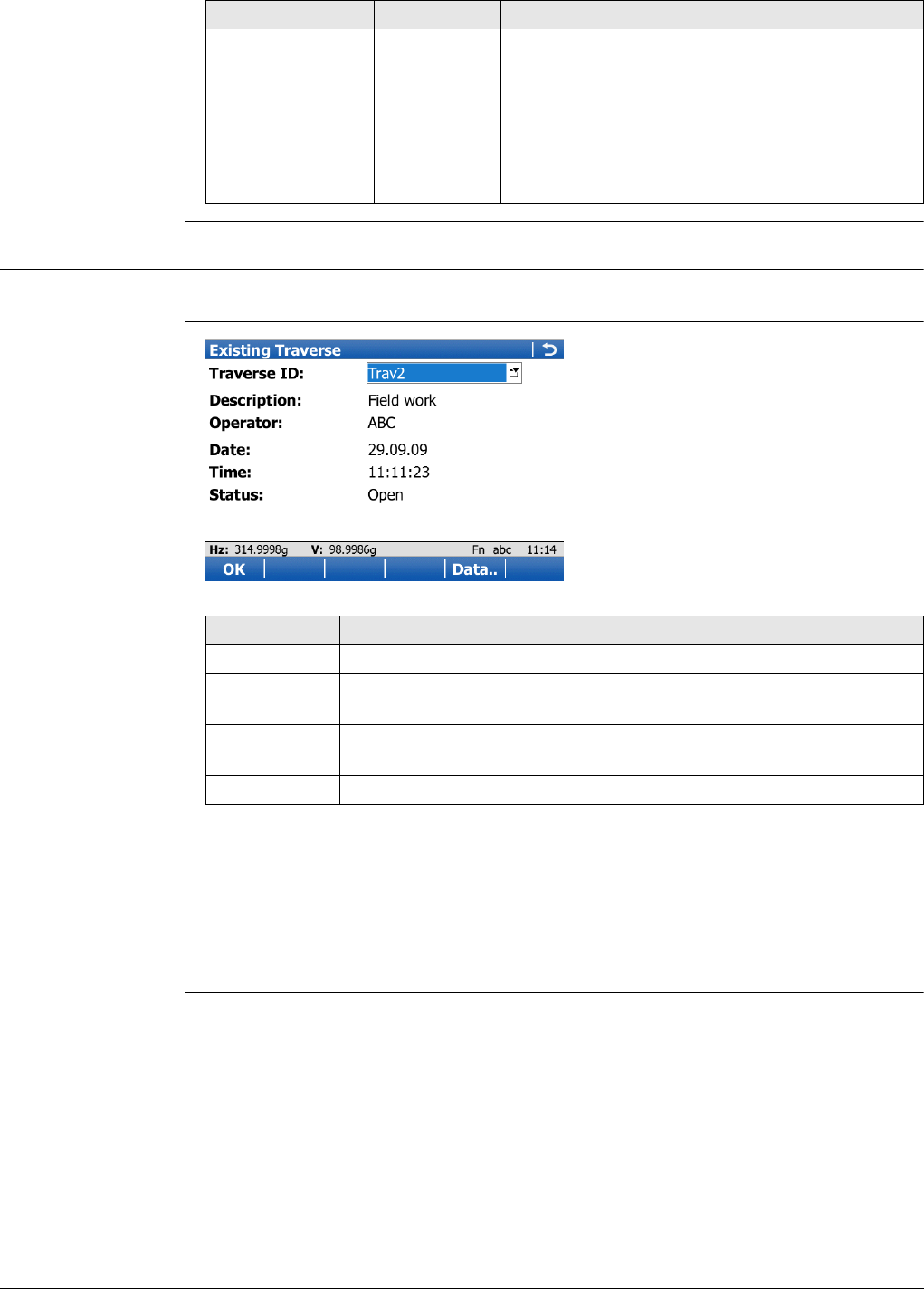
Viva Series, Traverse 870
63.4 Selecting an Existing Traverse
Access In Traverse, select Existing Traverse. Press OK.
Existing Traverse
Description of fields
The fields are identical with those fields in the Edit Traverse screen. Refer to "63.3
Creating/Editing a Traverse".
Next step
ENTER when Traverse ID is highlighted. Accesses Manage Traverses.
Position
closed The traverse has been closed in position on a
control point. Available in the Edit Traverse
screen.
Posn & angle
closed The traverse has been closed both in position and
angularly. Available in the Edit Traverse screen.
Adjusted The traverse data is the result from an adjust-
ment. Available in the Edit Traverse screen.
Field Option Description
Key Description
OK To accept the settings.
Data.. To display traverse data. Refer to "63.5 Traverse Data". Not available
for adjusted traverses.
Fn Config.. To configure the Traverse application. Refer to "63.6 Configuring
Traverse".
Fn Quit To exit the application.

Viva Series, Traverse 871
Manage Traverses All traverses of the working job are displayed.
63.5 Traverse Data
Description This screen allows the review and editing of traverse stations inside of a traverse and
allows the user to access Point Results for editing.
Access Data.. in Manage Traverses.
OR
Data.. in a Confirmation window of the Point Results screen.
Traverse Data
Key Description
OK To confirm selection of highlighted traverse and return to Select an
existing traverse.
New.. To create a new traverse. Refer to "63.3 Creating/Editing a Traverse".
Edit.. To edit the traverse ID and description of the highlighted traverse.
Refer to "63.3 Creating/Editing a Traverse".
Data.. To display traverse data. Refer to "63.5 Traverse Data" for more
information.
Fn Quit To exit the application.
Key Description
OK To return to where this screen was accessed from.
Edit.. To access the Point Results screen. Refer to "63.8 Traverse Point
Results".
Delete To permanently delete the LAST traverse station.
Page To change to another page on this screen.
Fn Quit To exit the application.
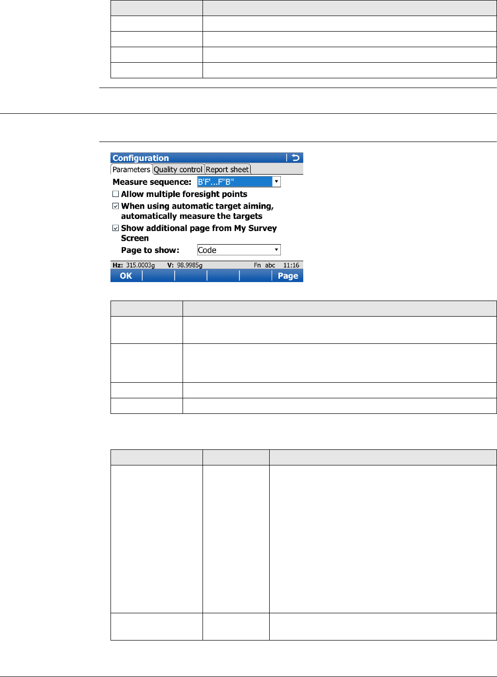
Viva Series, Traverse 872
Description of columns
63.6 Configuring Traverse
Access Select Main Menu:Go to Work!\Survey+\Traverse. Press Fn Config...
Configuration,
Parameters page
Description of fields
Column Description
Station ID Point ID of the station.
Backsight ID The backsight point measured from the current station ID.
No. sets Number of measured sets.
No. FS Number of measured foresight points.
Key Description
OK To accept changes and to return to the screen from where this
screen was accessed.
Config.. To edit the survey screen page currently being displayed. Available
when a list item in Page to show is highlighted. Refer to "25.3 My
Survey Screen". Available on the Parameters page.
Page To change to another page on this screen.
Fn Quit To exit the application.
Field Option Description
Measure sequence B'F'...F''B'' All points are measured in face I, then measured
in face II in reverse sequential order.
B'F'...B''F'' All points are measured in face I, then measured
in face II.
B'B''F'F''... Backsight point is measured in face I immediately
followed by face II. Other points are measured in
face I, face II order.
B'B''F''F'... Backsight point is measured in face I immediately
followed by face II. Other points are measured in
alternating face order.
B'F'... All points are measured in face I only.
Foresight Check box Option to define if only one foresight point or
multiple points are used during the sets.
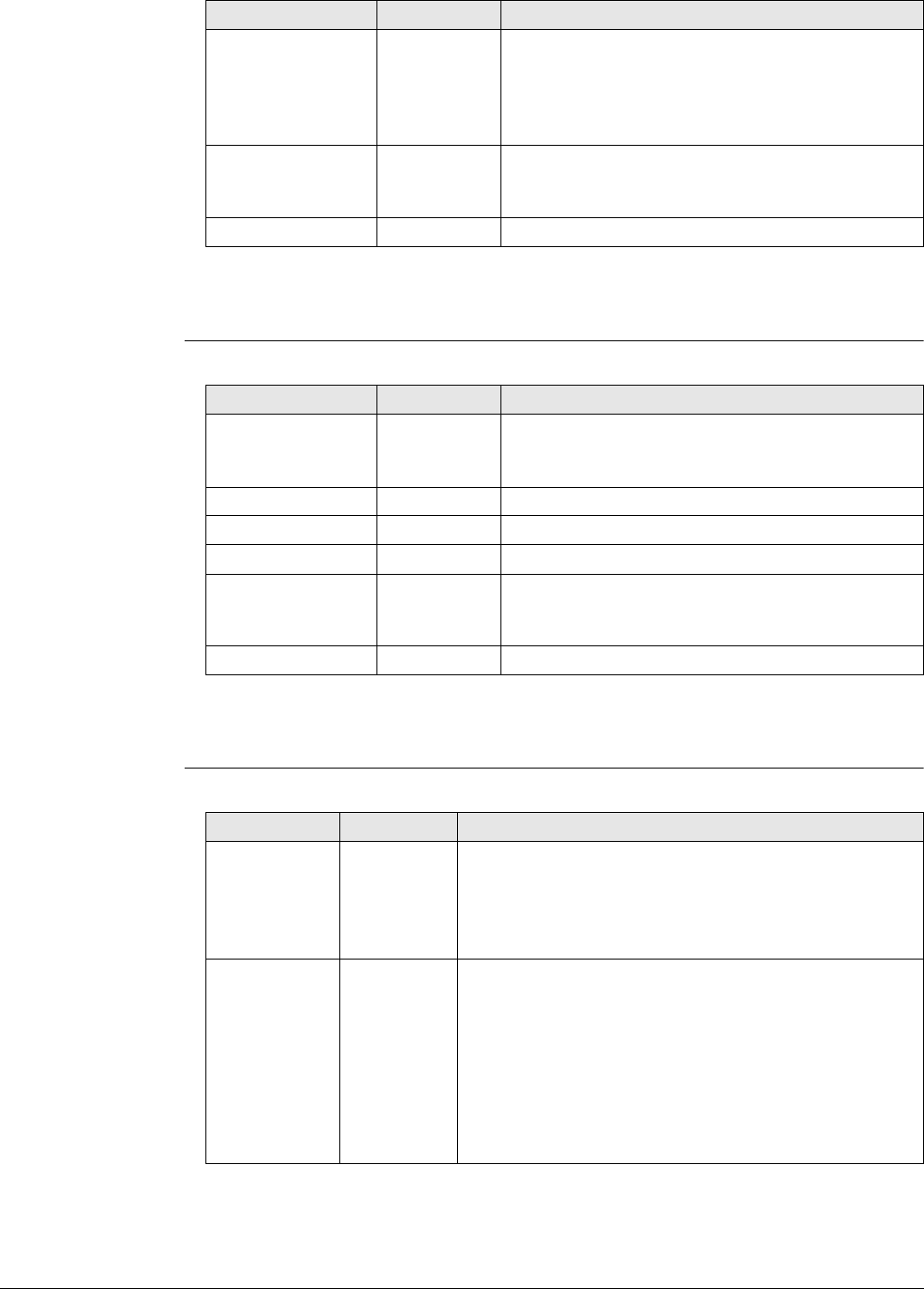
Viva Series, Traverse 873
Next step
Page changes to the Quality control page.
Configuration,
Quality control page
Description of fields
Next step
Page changes to the Report sheet page.
Configuration,
Report sheet page
Description of fields
When using auto-
matic target
aiming, automati-
cally measure the
targets
Check box For instruments with automatic aiming and this
option checked, automatic aiming search and
automatic aiming measurements are done to
specified targets and subsequent sets.
Show additional
page from My
Survey Screen
Check box The user-defined survey screen page to be shown
in the Traverse screen.
Page to show Selectable list The names of the available survey screen pages.
Field Option Description
Field Option Description
Check for errors
before storing Check box The entered horizontal, vertical and distance
tolerances are checked during the measurements
to verify accurate pointing and measurements.
Hz tolerance Editable field Tolerance for horizontal directions.
V tolerance Editable field Tolerance for vertical directions.
Distance tolerance Editable field Tolerance for distance.
Check for back-
sight height Check box The entered height tolerance for the backsight
point is checked during the measurements to
verify accurate pointing and measurements.
Height limit Editable field Tolerance for the backsight height.
Field Option Description
Create report
sheet Check box To generate a report sheet when the application is
exited.
A report sheet is a file to which data from an applica-
tion is written to. It is generated using the selected
format file.
Report sheet Selectable
list
Available when Create report sheet is ticked. The name
of the file to which the data will be written. A report
sheet is stored in the \DATA directory of the active
memory device. The data is always appended to the
file.
Opening the selectable list accesses the Report Sheets
screen. On this screen, a name for a new report sheet
can be created and an existing report sheet can be
selected or deleted.
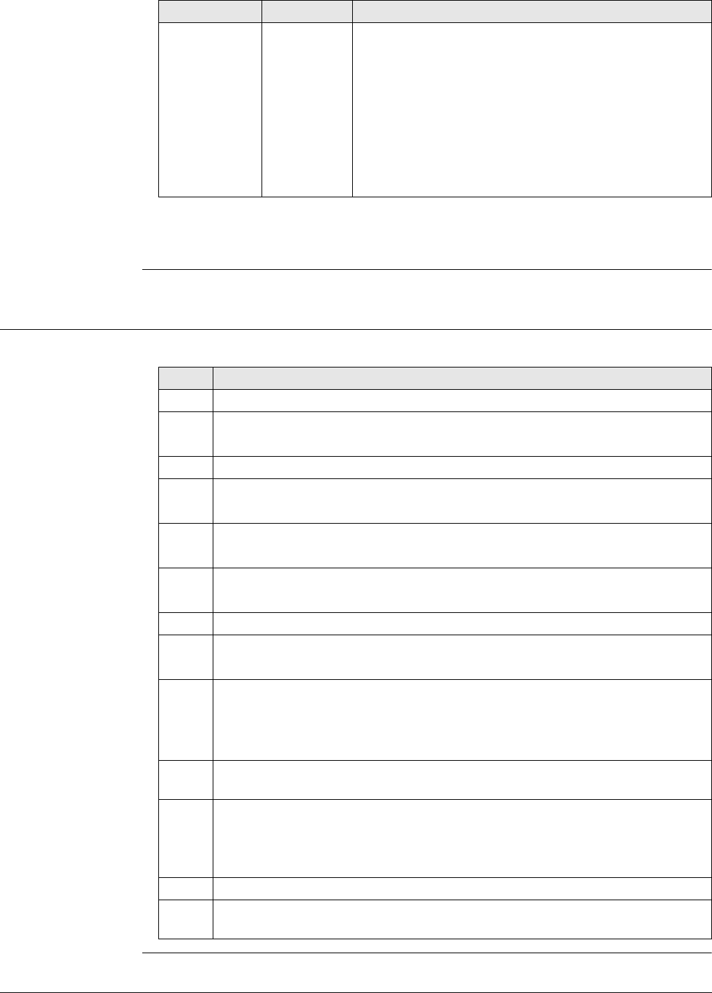
Viva Series, Traverse 874
Next step
Page changes to the first page on this screen.
63.7 Traverse Methods
63.7.1 Starting Traverse
Start traverse step-
by-step
The quickest setup method is described.
Format file to
use Selectable
list
Available when Create report sheet is ticked. A format
file defines which and how data is written to a report
sheet. Format files are created using LGO. A format file
must first be transferred from the data storage device
to the internal memory before it can be selected. Refer
to "30.1 Transfer user objects" for information on how
to transfer a format file.
Opening the selectable list accesses the Format Files
screen where an existing format file can be selected or
deleted.
Field Option Description
Step Description
1. Start the Traverse application.
2. Traverse
Select Create a new traverse.
3. OK to access New Traverse.
4. New Traverse
Type in the name of the new traverse.
5. OK to access Configuration.
Check the settings.
6. OK to access Total Station Setup.
Any standard setup method can be used.
7. Set to set the station and orientation.
8. A confirmation window is displayed.
FS Pt..
9. Foresight, Set:
Foresight ID The name of the foresight point.
Target height The target height of the foresight point.
Number of sets The number of sets to be measured.
10. Meas to measure and record. The measurement settings for the first meas-
urement to each point are used for all further sets.
11. Point Results
OK to move to the next station, to return to the Point Results screen (and
set a point as a closing point), to survey a sideshot, to view traverse data or
to end the traverse.
12. Move to move to the next station.
After pressing Move, Traverse is exited. To continue with the traverse from
the next station refer to "63.7.2 Continuing an Existing Traverse".
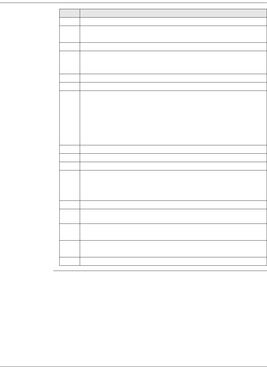
Viva Series, Traverse 875
63.7.2 Continuing an Existing Traverse
Measure traverse
step-by-step Step Description
1. Start the Traverse application.
2. Traverse
Select Select an existing traverse.
3. OK to access Existing Traverse.
4. Existing Traverse
Traverse ID The name of the traverse. ENTER to select a different existing
traverse.
Data.. to view data of the active traverse.
Fn Config.. to change the working style settings.
5. OK to access Backsight, Set:.
Enter Instrument height.
Hz, V and Horiz distance The measured values are displayed.
Calc azimuth The calculated azimuth from the current station point to the
backsight point.
hz dist and height The difference between the computed and measured
values.
More to change between the displayed values.
6. Meas to measure and record the backsight point.
7. FS Pt.. to measure a foresight point.
8. Foresight, Set:
Foresight ID The name of the foresight point.
Target height The target height of the foresight point.
Number of sets The number of sets to be measured.
Survy.. to measure sideshot points.
9. Meas to measure and record the foresight points. The measurement settings
for the first measurement to each point are used for all further sets.
10. Point Results
OK
11. A confirmation window is displayed.
Move to move to the next station.
12. Repeat steps 1. to 11. until traverse is ready to be closed.

Viva Series, Traverse 876
63.7.3 Closing Traverse
Close traverse step-
by-step Step Description
1. Refer to paragraph "63.7.2 Continuing an Existing Traverse" to measure a
traverse. Measure a backsight on a new station.
2. The confirmation window in Foresight, Set: is displayed.
Close.. to begin the process for closing the traverse.
3. The confirmation window to select a known point is displayed.
OK
4. The Data: screen for the control job is displayed.
Highlight the closing point.
5. OK to select the highlighted point.
6. Foresight, Set:
Meas to measure and record the closing point.
7. Point Results
OK to view traverse results.
8. Traverse Results
OK to display the confirmation window.
9. C Ang.. to close the traverse with angular closure.
Optionally the traverse can be adjusted.
10. Move to the closure point and start Traverse application.
11. Traverse
Select Select an existing traverse.
12. OK to access Existing Traverse.
13. Existing Traverse
Traverse ID The name of the traverse to be closed is displayed.
14. OK to access Close Angle.
15. Close Angle
Closing method To measure onto a known point or a known azimuth.
Foresight ID The point ID of the foresight point.
Known azimuth Available for Closing method :By known azimuth. Known
azimuth for foresight point.
16. OK to access Backsight, Set:.
17. Meas to measure all sets.
18. Point Results
OK to view traverse results.
19. Traverse Results
OK to exit viewing traverse results.
20. Quit to quit the Traverse application.
Optionally the traverse can be adjusted.
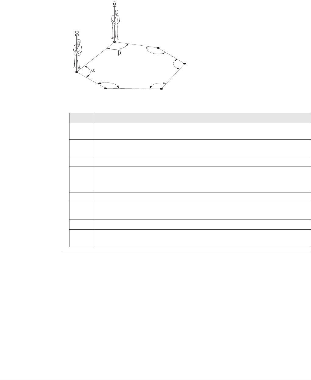
Viva Series, Traverse 877
Close traverse on
internal reference
This option is used for determining the closure of a closed loop traverse, consisting of
a single control point with an arbitrary backsight azimuth. This function allows comple-
tion of a traverse without having to reoccupy the initial station setup to measure a
closing angle. The positional closure is calculated by comparing the control position of
the initial station setup to the measured position of the final foresight. The angular
closure is calculated by comparing the set azimuth of the initial backsight to the
azimuth of the final measured leg.
The first station setup is on P1, and
an assumed direction to backsight
P6. Upon closing this traverse, with
the last setup over P6, the closing
point is P1. In this case the only point
that is considered as a control is P1.
Step Description
1. The first station setup is on P1 in the diagram shown. Begin the traverse,
moving in the direction P1, P2...P6.
2. When on the last setup point (P6 in the diagram shown), measure a back-
sight.
3. Close
4. Data:
Select the closing point from the available list (P1 in the diagram shown).
OK
5. Measure all the sets to the closing point as per a standard traverse.
6. Point Results
OK when the review of the results is completed.
7. Yes to confirm the automatic calculation.
8. Traverse Results
The traverse closure is shown with positional and angular values.
TS_050
P1
P6 P5
P4
P3
P2
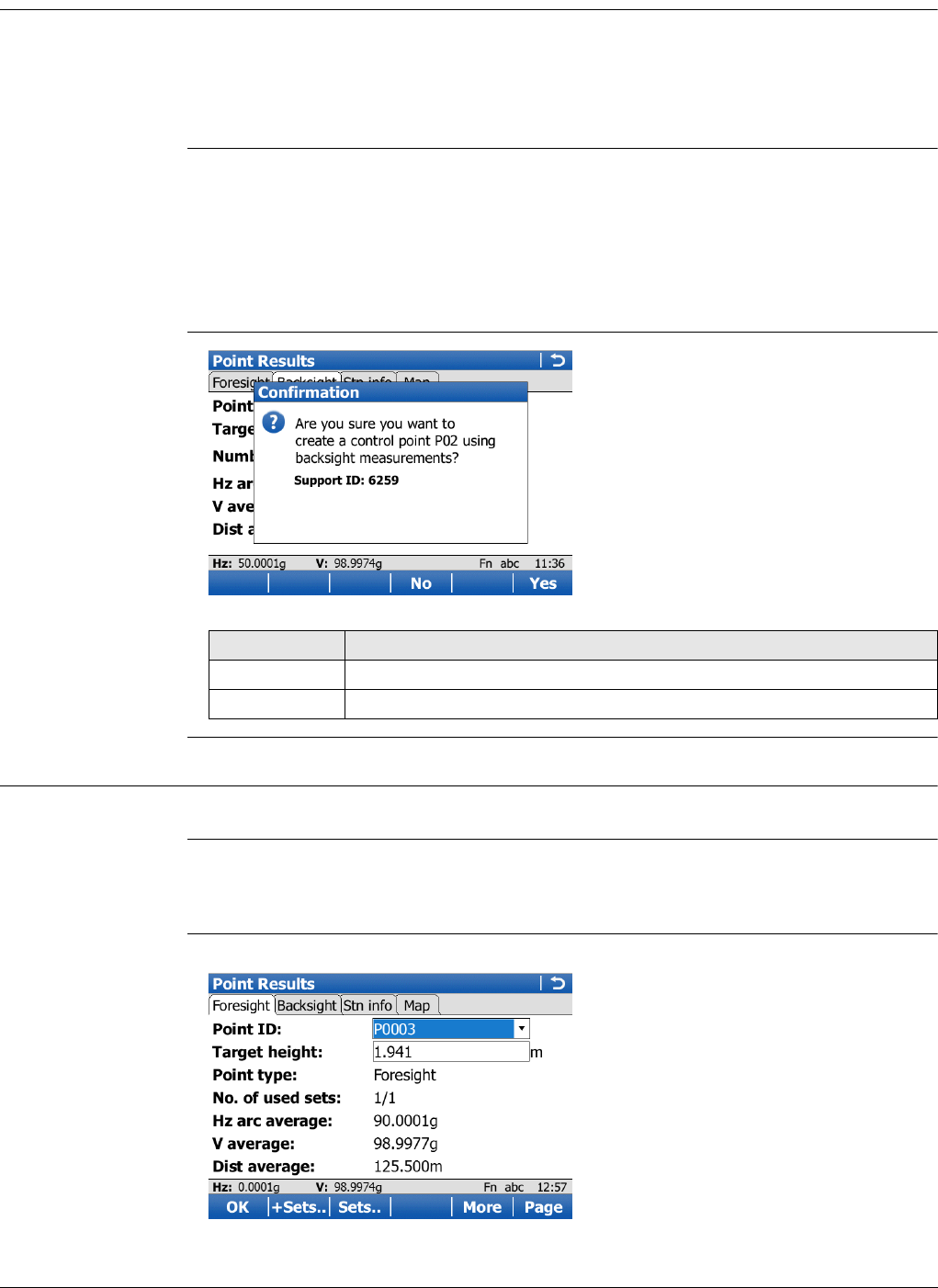
Viva Series, Traverse 878
63.7.4 Creating a Control Point from Backsight by Azimuth
Description If a traverse is to be established on existing control points, two control points must be
defined to start the traverse. If the traverse absolute position is arbitrary, it can be
convenient to define the control in the field with arbitrary values. This functionality is
an option to turn the averaged position value into a control point when a backsight by
azimuth is collected.
Access At the beginning of a traverse, when all the measurements are completed to the
backsight: On the Point Results screen, select Page to reach the Backsight page.
Fn Ctrl.
OR
Anytime during the traverse: On the Traverse Data screen, highlight the first
station setup then Edit... On the Point Results screen, select Page to reach the
Backsight page. Fn Ctrl.
Point Results Confir-
mation
63.8 Traverse Point Results
Description Point observation results are displayed on this screen.
Access Is displayed automatically after measuring all sets from the current station.
OR
In Traverse Data press Edit...
Point Results,
Foresight page and
Backsight page
The softkeys are explained, except for the softkeys on the Map page.
Key Description
No To close the confirmation window without further action.
Yes To store the point as control point.
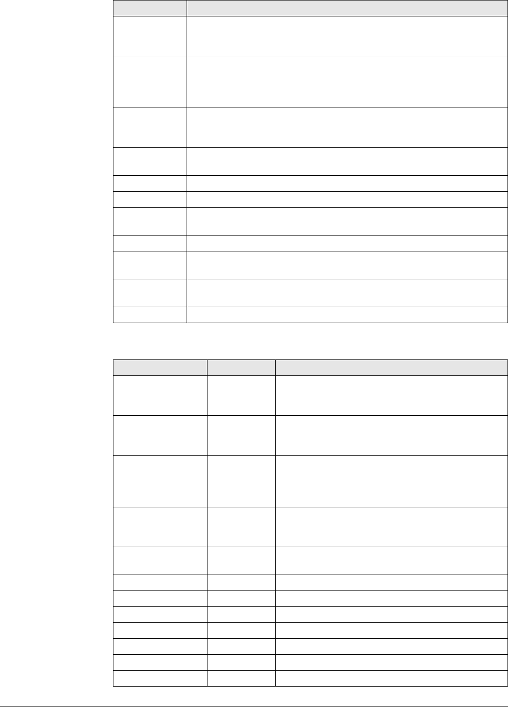
Viva Series, Traverse 879
Description of fields
Key Description
OK While measuring a traverse: Displays a confirmation window with
traverse measurement options. Otherwise: To return to Traverse
Data.
+Sets.. To add more sets while still at the setup. It could be necessary on
particular legs of a traverse that more than the designated number
of sets is required. Possibly some of the sets from the first run
exceeded the tolerance limit and must be disabled.
Sets.. To include or exclude measured sets in the calculation of a foresight
point. In the Sets, Point screen press Use to include or exclude a set
and Spread/Resid to review the effect of using the set.
Close.. To set a point as a closing point if not selected before measurement.
Or to revert a closing point to a normal foresight.
More To display additional information.
Page To change to another page on this screen.
Fn Config.. To configure the Traverse application. Refer to "63.6 Configuring
Traverse".
Fn Edit.. To edit point code and annotations.
Fn Check.. Available on the Foresight page. To check inverse distances and
closure between the selected point and a point from the fixpoint job.
Fn Ctrl Available on the Backsight page of the initial station. Refer to
"63.7.4 Creating a Control Point from Backsight by Azimuth".
Fn Quit To exit the application.
Field Option Description
Point ID Selectable list
or display
only
Selected point ID.
Target height Selectable list
or display
only
The target height of the target point.
Point type Foresight,
Closing point
or Closing
angle
The current point type. Available on the Foresight
page.
No. of used sets Display only The number of sets out of all measured sets used
for the calculation. Available on the Foresight
page.
Number of sets Display only The number of sets the point was measured in.
Available on the Backsight page.
Hz arc average Display only Average horizontal angle.
V average Display only Average vertical angle.
Dist average Display only Average distance.
Hz arc std dev Display only Standard deviation of horizontal angle.
V std dev Display only Standard deviation of vertical angle.
Dist std dev Display only Standard deviation of distance.
Hz spread Display only Spread of horizontal angle.
Viva Series, Traverse 880
Next step
Page changes to the Stn info page.
Point Results,
Stn info page
Description of fields
Next step
Page changes to the Map page which provides an interactive display of the data.
V spread Display only Spread of vertical angle.
Dist spread Display only Spread of distance.
Field Option Description
Field Option Description
Station ID Display only The station ID of the instrument station.
Instrument height Editable field Current instrument height. Editable.
Easting Display only Easting value of the station position.
Northing Display only Northing value of the station position.
Elevation Display only Orthometric height of the station position.
Scale Display only Scale factor used in the calculation.
Temperature Display only Temperature set on the instrument.
Pressure Display only Atmospheric ppm set on the instrument.
IF accessed THEN
after sets meas-
urement
OK opens a confirmation window with options that are
dependent on traverse status:
• For an open traverse:
Move to next station, return to Point Results, to survey a
sideshot, to view traverse data or to quit the traverse appli-
cation.
• For a closed traverse:
Move to close angle, return to Point Results, to survey a side-
shot, to adjust the traverse or to quit the traverse application.
from Traverse
Data OK returns to Traverse Data.
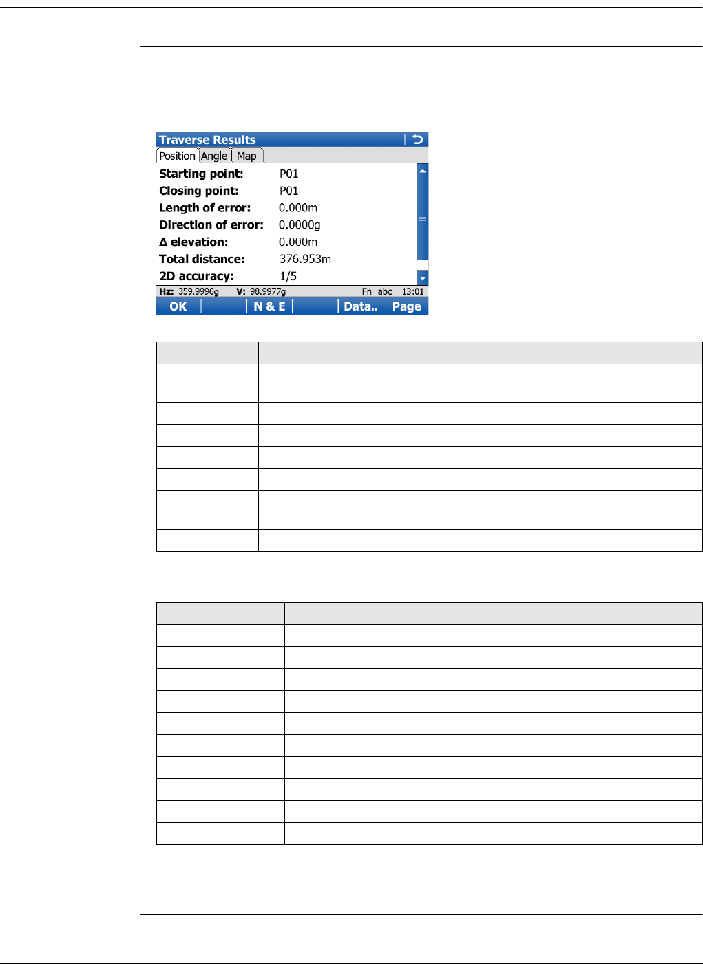
Viva Series, Traverse 881
63.9 Traverse Results
Description Traverse closure results are displayed on this screen.
Access Is displayed automatically after the traverse closing point is measured or selected.
OR
Reslt.. in Traverse Data when a traverse is closed.
Traverse Results,
Position page
Description of fields
Next step
Page changes to the Angle page.
Key Description
OK To move to close angle, to return to Traverse Results, to survey a
sideshot, to adjust the traverse or to quit the Traverse application.
N & E or L & D To view the misclosure error in north/east or length/direction.
Adjust.. To adjust the traverse.
Data.. To display traverse data.
Page To change to another page on this screen.
Fn Config.. To configure the Traverse application. Refer to "63.6 Configuring
Traverse".
Fn Quit To exit the application.
Field Option Description
Starting point Display only The point ID of the traverse start point.
Closing point Display only The point ID of the traverse closing point.
Length of error Display only The length of the misclosure error.
Direction of error Display only The direction of the misclosure error.
north Display only Error in north.
east Display only Error in east.
elevation Display only Error in height.
Total distance Display only Total length of the traverse.
2D accuracy Display only Position ratio of misclosure.
1D accuracy Display only Height ratio of misclosure.
Viva Series, Traverse 882
Traverse Results,
Angle page
Description of fields
Next step
OK to move to close angle, to return to Traverse Results, to survey a sideshot, to
adjust the traverse or to quit the Traverse application.
63.10 Traverse Adjustment
63.10.1 Accessing Traverse Adjustment
Description • A traverse adjustment can be performed on three components: 2D positions,
angles and elevations.
• Various adjustment methods are available for selection. Once the adjustment is
performed, the results can be reviewed. Adjusted points are stored into a new job,
and a report can be generated.
• If the message panel appears which requires that the application must be activated
via a license key then refer to "30.3 Load licence keys".
Survey points have to be measured while Traverse is running to be part of the adjust-
ment calculations.
Access The traverse adjustment option can be reached in different ways based on specific
conditions.
Upon completing the observations onto the closing point, Adjust.. to access Trav-
erse Adjustment.
OR
After the measurements are done on the closing line for angular closure, Adjust..
to access Traverse Adjustment.
OR
When the traverse is closed: Reslt.. in Traverse Data, then Adjust.. in Traverse
Results to access Traverse Adjustment.
Field Option Description
Foresight ID Display only Point ID of the closing angle point. Displays ----- if
no values are available.
Known azimuth Display only Defined azimuth of closing line. Displays ----- if no
values are available.
Azimuth average Display only Mean value of the measured azimuth closing line.
Displays ----- if no values are available.
Angular misclo-
sure Display only Angular misclosure of traverse. Displays ----- if no
values are available.
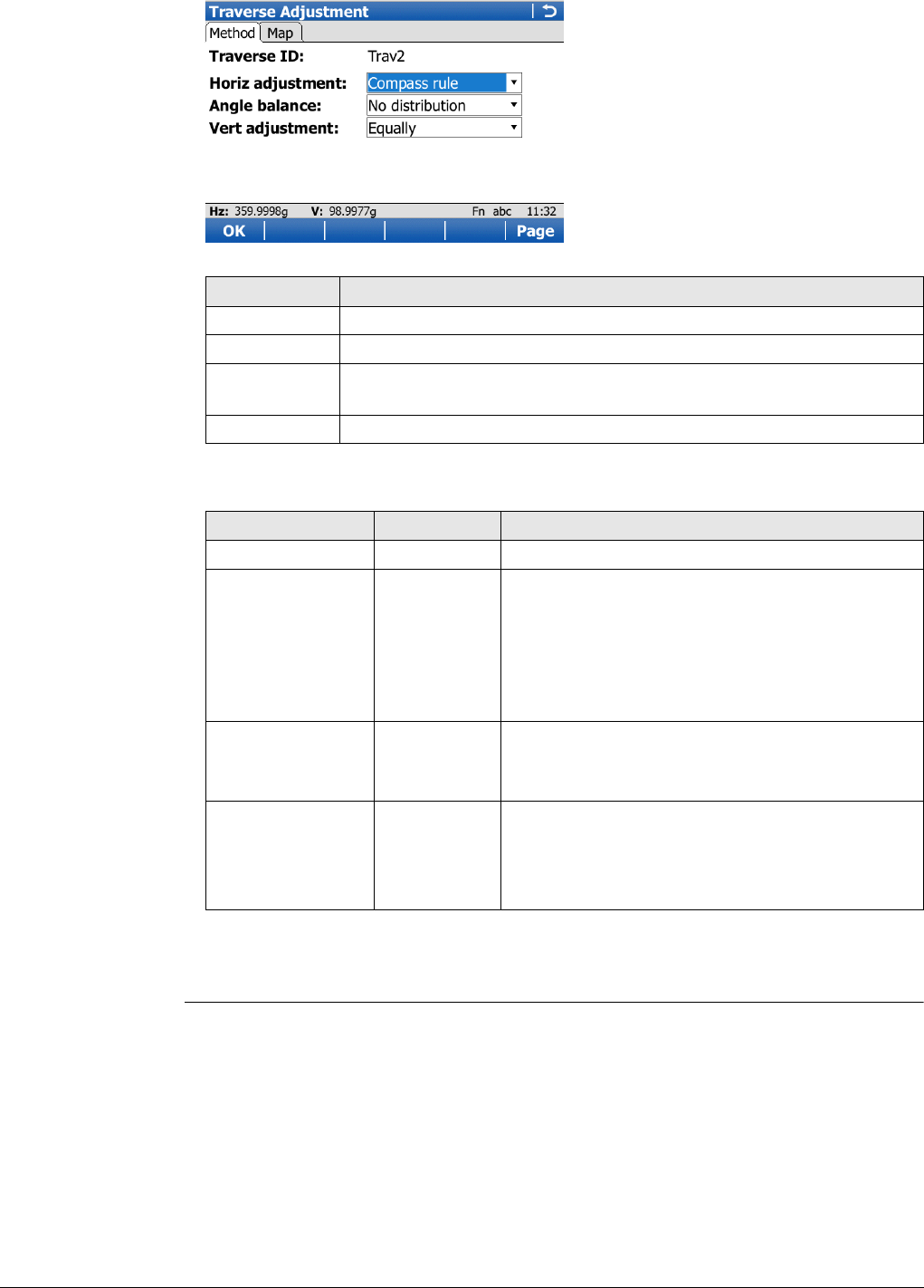
Viva Series, Traverse 883
Traverse Adjust-
ment,
Method page
Description of fields
Next step
OK starts the adjustment calculation.
Key Description
OK To calculate the result.
Page To change to another page on this screen.
Fn Config.. To configure the Traverse application. Refer to "63.6 Configuring
Traverse".
Fn Quit To exit the application.
Field Option Description
Traverse ID Display only The ID of the traverse.
Horiz adjustment Compass rule Suitable for surveys, where angles and distances
were measured with equal precision.
Transit rule Suitable for surveys, where angles were meas-
ured with a higher precision than the distances.
No distribu-
tion No distribution is made.
Angle balance Equally The angle misclosure is distributed equally.
No distribu-
tion No distribution is made.
Vert adjustment Equally The height error is distributed equally.
By distance The height error is distributed by distance.
No distribu-
tion No distribution is made.
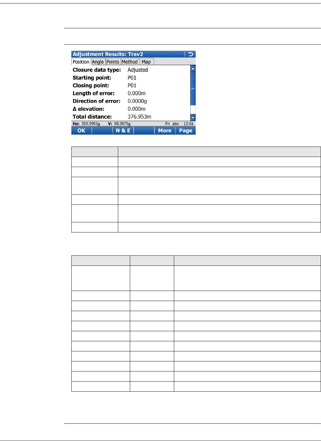
Viva Series, Traverse 884
63.10.2 Adjustment Results
Description The results of the adjustment calculations can be reviewed by accessing the different
pages.
Access OK in Traverse Adjustment.
Adjustment Results,
Position page
Description of fields
Next step
Page changes to the Angle page.
Key Description
OK To access the next screen.
N & E or L & D To view the misclosure error in north/east or length/direction.
More To display the values for the unadjusted, the balanced and the
adjusted solution.
Page To change to another page on this screen.
Fn Config.. To configure the Traverse application. Refer to "63.6 Configuring
Traverse".
Fn Quit To exit the application.
Field Option Description
Closure data type Adjusted,
Unadjusted or
Balanced
More to change between the options and display
the values accordingly.
Starting point Display only The point ID of the traverse start point.
Closing point Display only The point ID of the traverse close point.
Length of error Display only The length of the misclosure error.
Direction of error Display only The direction of the misclosure error.
north Display only Error in north.
east Display only Error in east.
elevation Display only Error in height.
Total distance Display only Total length of the traverse.
2D accuracy Display only Position ratio of misclosure.
1D accuracy Display only Height ratio of misclosure.
Viva Series, Traverse 885
Adjustment Results,
Angle page
Description of fields
Next step
Page changes to the Points page.
Adjustment Results,
Points page
The adjusted points are listed. The Point type column shows the function for each
point.
View.. shows the coordinate values of the highlighted point.
Next step
Page changes to the Method page.
Adjustment Results,
Method page
The adjustment methods previously selected in Traverse Adjustment and used for the
adjustment are displayed.
Next step
Page changes to the Map page. The Map page provides an interactive display of the
data.
OK accesses Adjustment Store.
Adjustment Store Description of fields
Next step
Store.. stores the results.
Field Option Description
Closure data type Display only More to change between the options.
Known azimuth Display only Defined azimuth of closing line. Displays ----- if no
values are available.
Azimuth average Display only Mean value of the measured azimuth closing line.
Displays ----- if no values are available.
Angular misclo-
sure Display only Angular misclosure of traverse. Displays ----- if no
values are available.
Field Option Description
Traverse ID Display only The ID of the traverse.
Store adjusted job
to Selectable list The location to save the adjusted job. The job can
be saved to the CF card, SD card, USB or Internal
memory.
New job Editable field The new job name. Once adjustment results have
been reviewed and accepted, the adjusted posi-
tion of the points are stored in a separate job.
Include survey
points Check box Survey points can be included or not. Adjusted
points are stored in the new job as a triplet of
class ADJ (adjusted).
Store point ID with Same point
ID Adjusted points are stored in the new job with the
original point IDs.
Prefix Adjusted points are stored in the new job with a
prefix in front of the original point IDs.
Suffix Adjusted points are stored in the new job with a
suffix at the end of the original point IDs.
Prefix / suffix Editable field Available when Prefix or Suffix is selected in
Store point ID with. The value that is added to the
front or end of the original point ID.
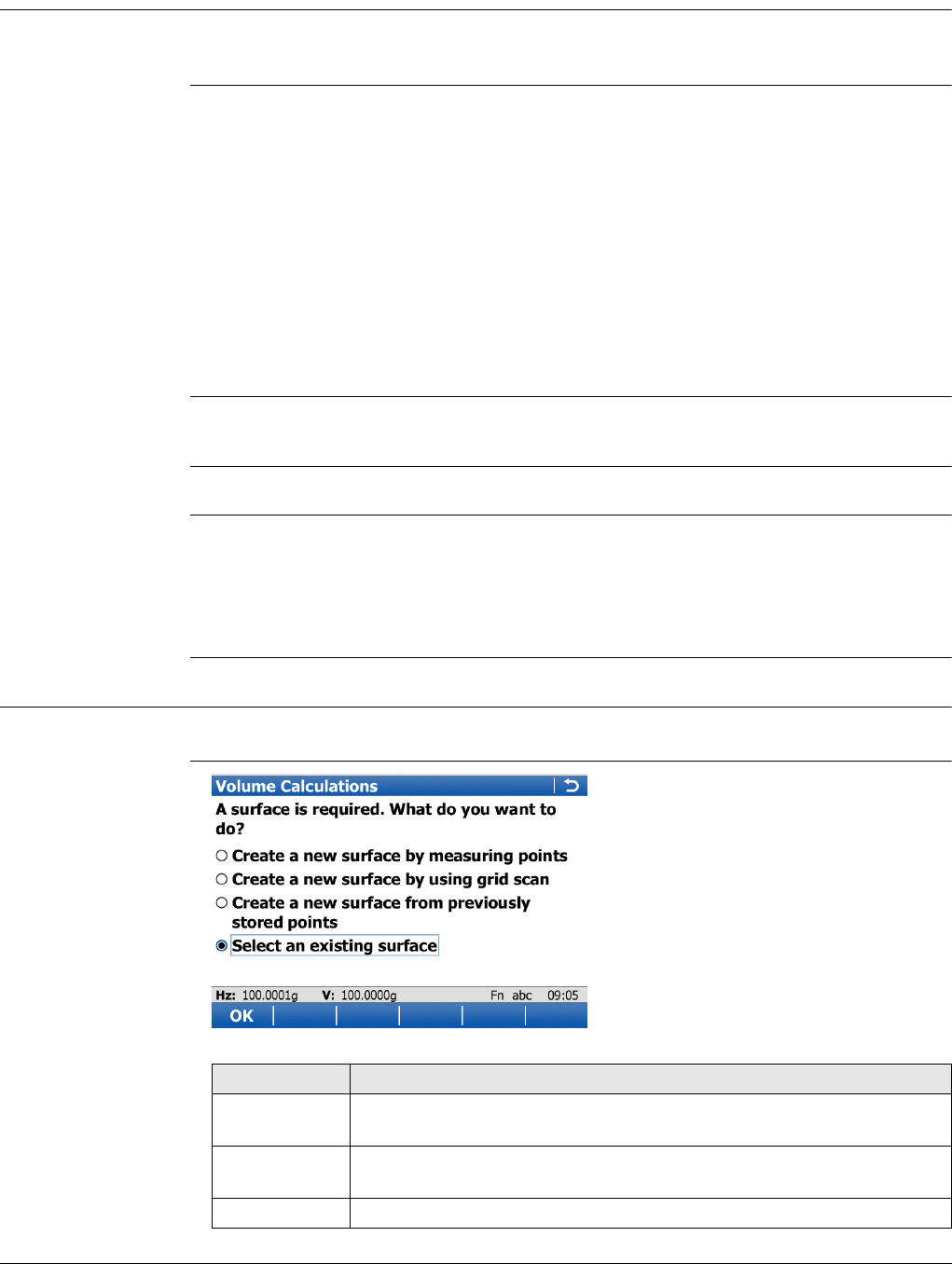
Viva Series, Volumes & Surfaces 886
64 Volumes & Surfaces
64.1 Overview
Description The Volume Calculations application allows surfaces to be measured and volumes (and
other information) to be computed from these surfaces.
Volume calculations
tasks
The Volume calculations application can be used for the following tasks:
• Measuring points (surface points and boundary points) defining a new surface or
extending existing surfaces from the working job.
• Calculating the triangulation of the measured surface points to establish the
surface.
• Calculating volumes from a base (3D point, entered elevation) or by a stockpile
method.
The surface calculation can be made from:
• existing point data in the job.
• manually occupied points.
•entered coordinates.
Activating the appli-
cation
If the message panel appears which requires that the application must be activated via
a license key then refer to "30.3 Load licence keys".
Volume Calculations are possible for RTK rover and TPS.
Point types Surfaces can be created from points stored as:
•Local grid
• Height mode can be ellipsoidal or orthometric.
Heights and positions are always taken into account. Points must have full coordinate
triplets.
64.2 Accessing Volumes & Surfaces
Access Select Main Menu:Go to Work!\Survey+\Volume calculations.
Volume Calculations
Key Description
OK To select the highlighted option and to continue with the subsequent
screen.
Fn Config.. To configure the Volume Calculations application. Refer to "64.3
Configuring Volumes & Surfaces".
Fn Quit To exit the screen.
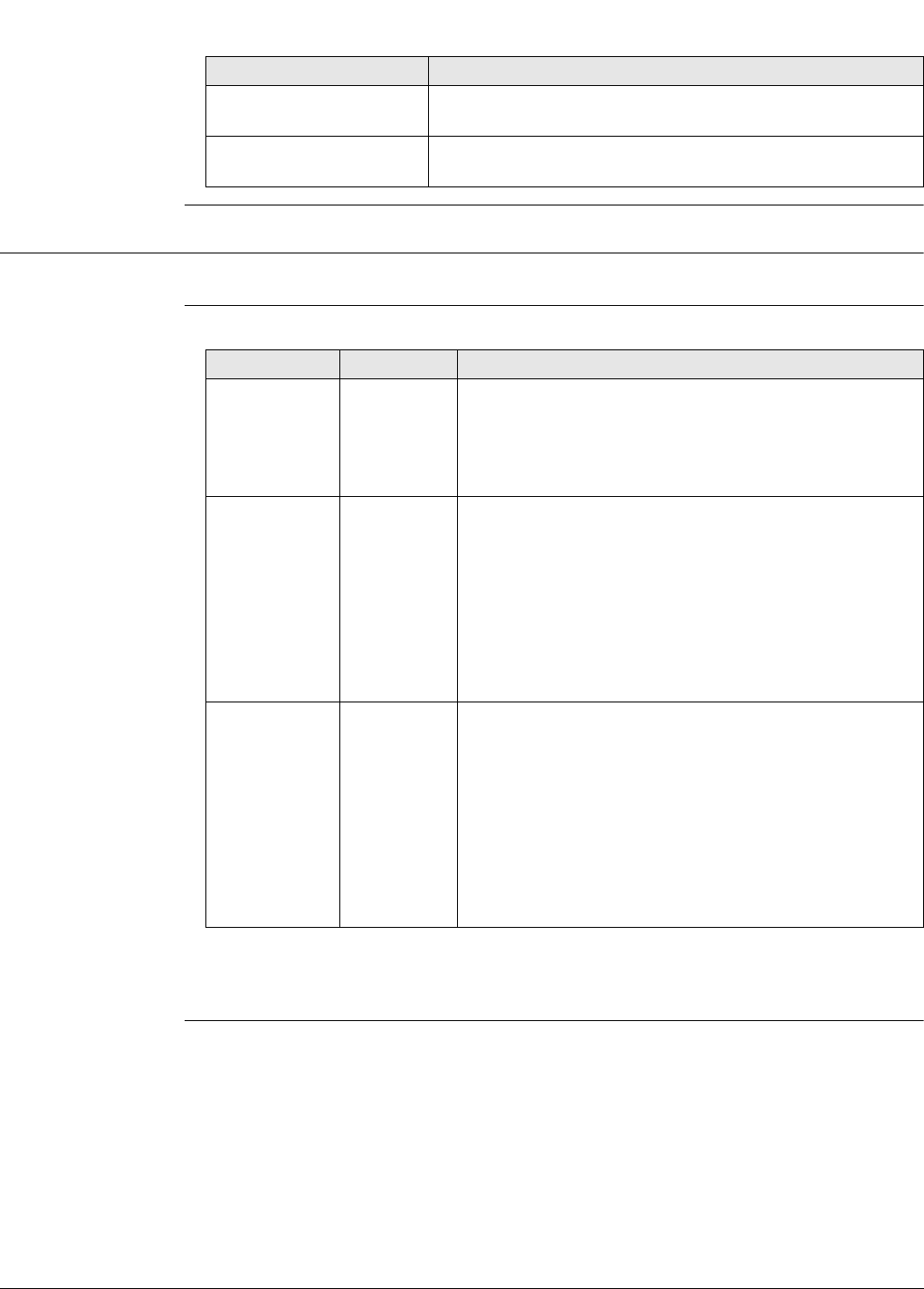
Viva Series, Volumes & Surfaces 887
Next step
64.3 Configuring Volumes & Surfaces
Access Select Main Menu:Go to Work!\Survey+\Volume calculations. Press Fn Config...
Configuration,
Report sheet page
Description of fields
Next step
Page changes to the first page on this screen.
IF THEN
a Volume Calculations
method is to be started
highlight the relevant option and press OK.
Volume Calculations is to
be configured
Fn Config... Refer to "64.3 Configuring Volumes &
Surfaces".
Field Option Description
Create report
sheet Check box To generate a report sheet when the application is
exited.
A report sheet is a file to which data from an applica-
tion is written to. It is generated using the selected
format file.
Report sheet Selectable
list
Available when Create report sheet is ticked. The name
of the file to which the data will be written. A report
sheet is stored in the \DATA directory of the active
memory device. The data is always appended to the
file.
Opening the selectable list accesses the Report Sheets
screen. On this screen, a name for a new report sheet
can be created and an existing report sheet can be
selected or deleted.
Format file to
use Selectable
list
Available when Create report sheet is ticked. A format
file defines which and how data is written to a report
sheet. Format files are created using LGO. A format file
must first be transferred from the data storage device
to the internal memory before it can be selected. Refer
to "30.1 Transfer user objects" for information on how
to transfer a format file.
Opening the selectable list accesses the Format Files
screen where an existing format file can be selected or
deleted.
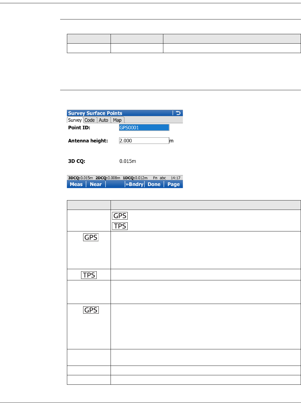
Viva Series, Volumes & Surfaces 888
64.4 Calculating Volumes
64.4.1 Create a New Surface by Measuring New Points
Access Select Create a new surface by measuring points in Volume Calculations.
New Surface Description of fields
Next step
OK to access Survey Surface Points. After measuring surface points, more points can
be surveyed, points can be grid scanned or a surface can be reviewed and edited.
Survey Surface
Points,
Survey page
The pages shown are from a typical working style. An additional page is available when
a user-defined survey screen page is used.
Field Option Description
Surface ID Editable field The name/number of the new surface.
Key Description
Meas To start measuring the surface point. The key changes to Stop.
To measure a distance and store distance and angles.
Stop To end measuring the surface point. When Automatically stop point
measurement is checked in Quality Control, General page recording
of positions ends automatically as defined by the stop criteria. The
position mode icon changes to the moving icon. The key changes to
Store.
Dist To measure a distance.
Store To store the measured surface point. When Automatically store
point is checked in Quality control, General, the measured point is
stored automatically. The key changes to Meas.
Near To search the working job for the point nearest to the current posi-
tion when the key is pressed. The point is selected as the point to be
measured and is displayed in the first field on the screen. After meas-
uring and storing the nearest point, the next point suggested is the
one which was suggested before the key was pressed.
Available when Meas is displayed.
»Bndry and
»Surf To change the type of point to be measured between surface point
and boundary point.
Done To finish measuring.
Page To change to another page on this screen.
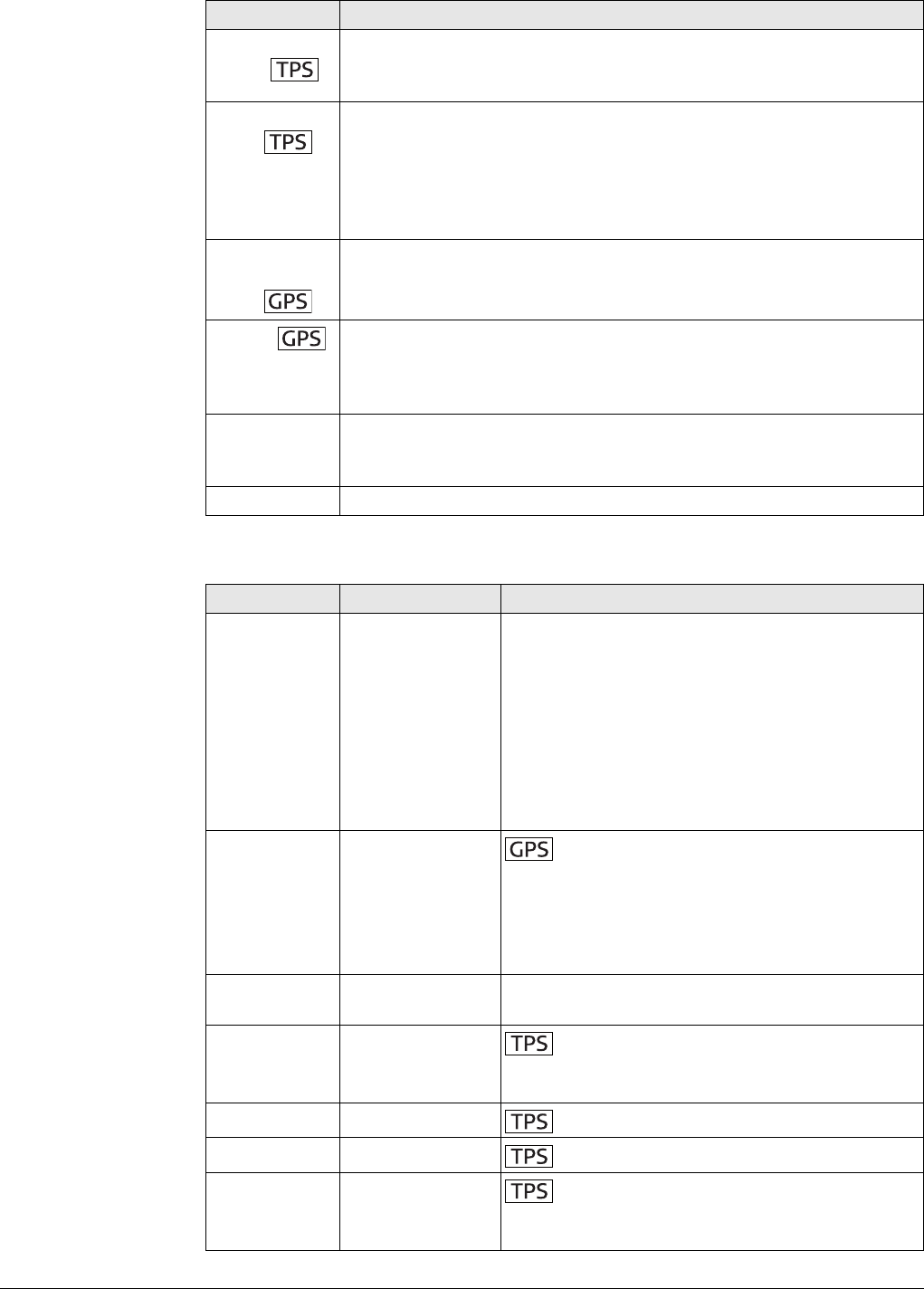
Viva Series, Volumes & Surfaces 889
Description of fields
Fn
2Store
To aim manually at the target and only record the angle measure-
ment (Hz/V) in face I and face II. The point stored is an average of the
two measurements.
Fn
2Face
Available for Measure mode: Single and Measure mode: Single
(fast). To take a measurement in Face I and Face II. The point stored
is an average of the two measurements. When using instruments
fitted with auto aiming, the point is automatically measured in both
faces. The resulting point is stored and the instrument is returned to
the first face.
Fn Conect and
Fn
Disco
To connect/disconnect from the GPS reference data.
Fn Init.. To select an initialisation method and to force a new initialisation.
Available when Meas or Store is displayed and for working styles
allowing phase fixed solutions. Refer to "56.4 Initialisation for Real-
Time Rover Operations".
Fn IndivID and
Fn Run To change between entering an individual point ID different to the
defined ID template and the running point ID according to the ID
template. Refer to "25.1 ID templates".
Fn Quit To exit the screen.
Field Option Description
Point ID Editable field The identifier for manually occupied points. The
configured point ID template is used. The ID can
be changed in the following ways:
• To start a new sequence of point IDs type over
the point ID.
• For an individual point ID independent of the
ID template Fn IndivID. Fn Run changes back
to the next ID from the configured ID
template.
Antenna
height Editable field The default antenna height as defined in
the active working style is suggested. Changing
the antenna height here does not update the
default antenna height as defined in the active
working style. The changed antenna height is
used until the application is exited.
3D CQ Display only The current 3D coordinate quality of the
computed position.
Target height Editable field The last used target height is suggested
when accessing this screen. An individual target
height can be typed in.
Hz Display only The current horizontal angle.
VDisplay only The current vertical angle.
Horiz distance Display only The horizontal distance after Dist was
pressed. No distance is displayed when accessing
the screen and after Store or Meas.
Key Description
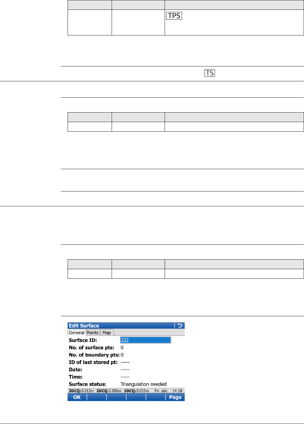
Viva Series, Volumes & Surfaces 890
Next step
Measure all points. Then press Done.
64.4.2 Create a New Surface by Using Grid Scan
Access Select Create a new surface by using grid scan in Volume Calculations.
New Surface Description of fields
Next step
OK to access Survey Surface Points. After measuring surface points, more points can
be surveyed, points can be grid scanned or a surface can be reviewed and edited.
Grid scan points to
surface
Refer to "44.9 Grid Scan on Surface" for defining the grid scan area, defining the scan
settings as well as starting and ending grid scanning.
64.4.3 Create a New Surface from Previously Stored Points
Access Select Create a new surface from previously stored points in Volume Calculations.
When accessing the Edit Surface screen after selecting Create a new surface
from previously stored points the Points page is active. Any other time this
screen is accessed the General page is active.
New Surface Description of fields
Next step
OK to access Survey Surface Points. After measuring surface points, more points can
be surveyed, points can be grid scanned or a surface can be reviewed and edited.
Edit Surface,
General page
Height differ-
ence Display only The height difference between station and
measured point after Dist. Displays ----- when
accessing the screen and after Store or Meas.
Field Option Description
Field Option Description
Surface ID Editable field The name/number of the new surface.
Field Option Description
Surface ID Editable field The name/number of the new surface.
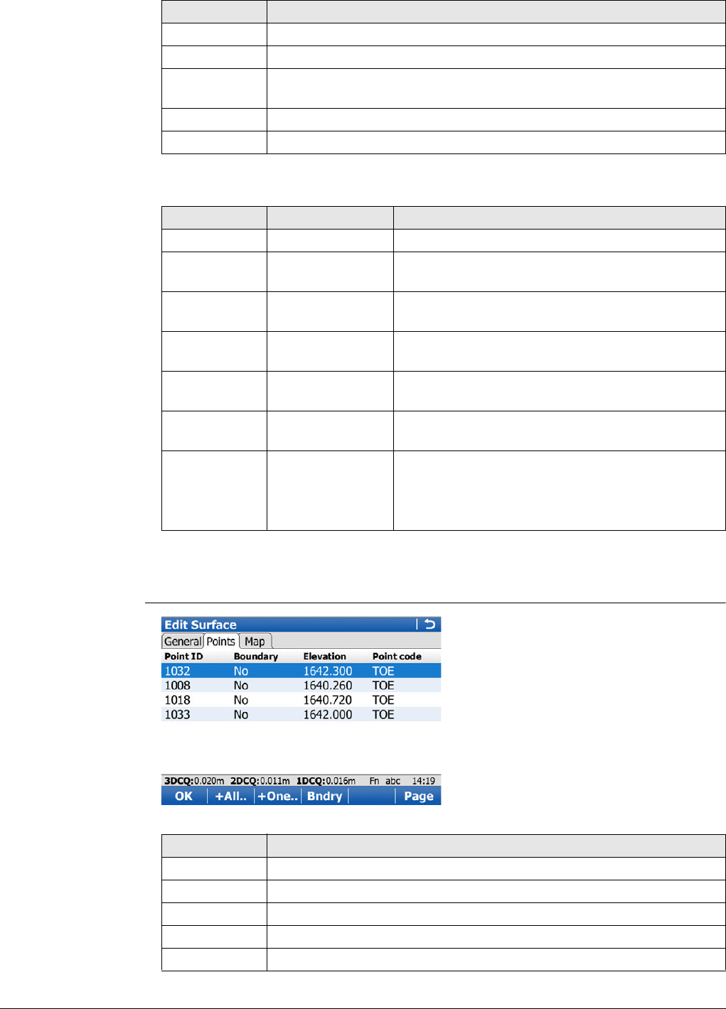
Viva Series, Volumes & Surfaces 891
Description of fields
Next step
Page changes to the Points page.
Surface status,
Points page
Key Description
OK To accept all settings and continue with the next screen.
Page To change to another page on this screen.
Fn Config.. To configure the Volume Calculations application. Refer to "64.3
Configuring Volumes & Surfaces".
Fn Del Srf To delete the surface.
Fn Quit To exit the screen.
Field Option Description
Surface ID Selectable list Name of the surface to be triangulated.
No. of surface
pts Display only Number of points inside the surface.
No. of
boundary pts Display only Number of boundary points of the surface.
ID of last
stored pt Display only ID of the last measured point of the chosen
surface.
Date Display only Date of the last measured point of the chosen
surface.
Time Display only Time of the last measured point of the chosen
surface.
Surface status Triangulation
done The surface has been triangulated and not been
modified since the last triangulation.
Triangulation
needed The surface has been modified since the last
triangulation or no triangulation exists.
Key Description
OK To accept all settings and continue with the next screen.
+All.. To add all points from the working job to the surface.
+One.. To add one point from the working job to the surface.
Bndry To use this point for the boundary.
Page To change to another page on this screen.
Viva Series, Volumes & Surfaces 892
Next step
OK continues to Surface Task Selection. Refer to "64.4.5 Selecting the Surface Task".
64.4.4 Choosing an Existing Surface
Access Select Create a new surface from previously stored points in Volume Calculations.
Existing Surface The fields available are identical with the fields in Surface status, General page. Refer
to "64.4.3 Create a New Surface from Previously Stored Points".
Next step
Select the desired surface ID then press OK. OK continues to Surface Task Selection.
Refer to Selecting the Surface Task.
64.4.5 Selecting the Surface Task
Surface Task Selec-
tion Description of the options
Next step
Select the task to do next. OK selects an option.
Fn -One To remove the marked point from the surface.
Fn -All To remove all points from the surface.
Fn Quit To exit the screen.
Key Description
Options Description
Measure more points to the
surface To measure points defining a new surface or
extending existing surfaces and boundaries by
surveying. Refer to "64.4.1 Create a New Surface by
Measuring New Points".
Grid scan more points to the
surface To add more points to the surface by grid scanning
new points. The grid scan procedure restarts.
Review & edit the surface To view the surface summary and add/remove points
from the surface. Refer to "64.4.3 Create a New
Surface from Previously Stored Points".
Edit the boundary & triangu-
late surface To define/redefine the boundary using manual point
selection, or one of the existing automatic methods,
and then create a triangulation. A DXF model can
then be exported if desired. Refer to "64.4.6
Boundary Definition".
Calculate the volume To compute the volume of a surface by a reference
(3D point, entered elevation) or by the stockpile
method. Refer to "64.4.7 Compute Volumes". Avail-
able when a valid triangulation of the surface exists.
Exit the Volumes app To end the application and return to the screen from
where Volume Calculations was accessed.
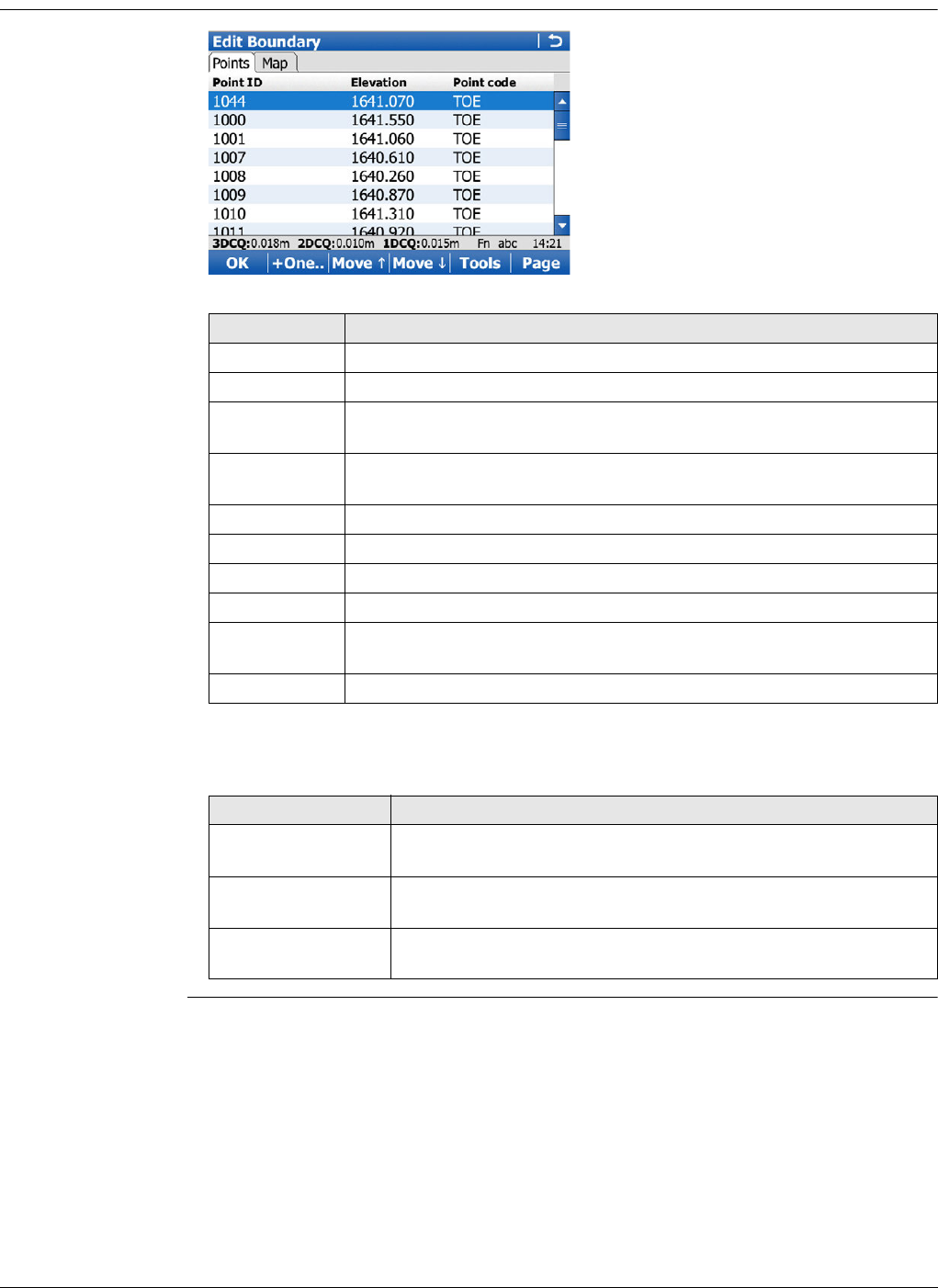
Viva Series, Volumes & Surfaces 893
64.4.6 Boundary Definition
Edit Boundary,
Points page
Next step
Page changes to the Map page.
Key Description
OK To start calculating the triangulation.
+One.. To add points from the working job to the surface.
Move To move the focused point one step up within the boundary defini-
tion.
Move To move the focused point one step down within the boundary defi-
nition.
Tools To access the Boundary Tools Menu.
Page To change to another page on this screen.
Home To move the focus to the first point within the boundary definition.
End To move the focus to the last point within the boundary definition.
Fn -One To remove the marked point from the boundary definition or
completely from the surface.
Fn Quit To exit the screen.
IF you want to THEN
change to the Map
page
Page to change to the Map page.
check the triangula-
tion results
OK to access Triangulation Results.
access the Tools
menu
Tools accesses Boundary Tools Menu.
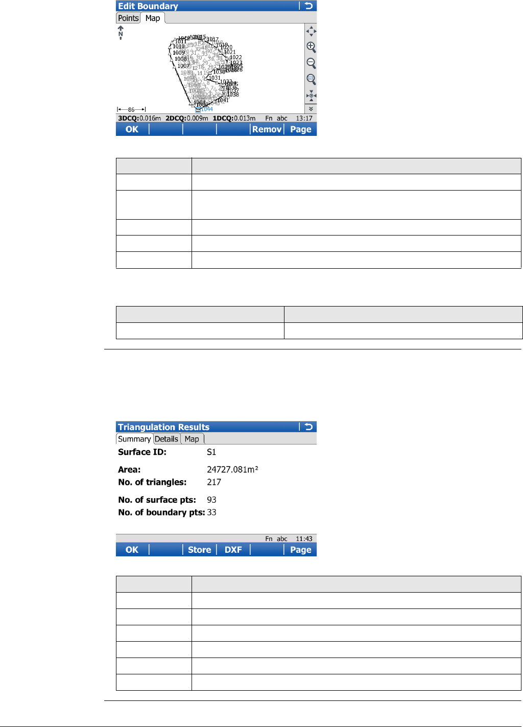
Viva Series, Volumes & Surfaces 894
Edit Boundary,
Map page
Next step
Triangulation Results The Summary page and the Details page contain only display only fields. Information
such as the number of triangles/surface points/boundary points, the
minimum/maximum elevation or the 3D area is shown.
The Map page contains a plot of the triangles of the surface’s triangulation and also
its boundary.
Key Description
OK To start calculating the triangulation.
Remov To remove the marked point from the boundary definition or
completely from the surface.
Page To change to another page on this screen.
Fn Config.. To configure MapView. Refer to "37.3 Configuring MapView".
Fn Quit To exit the screen.
IF you want to THEN
check the triangulation results OK to access Triangulation Results.
Key Description
OK To return to Surface Task Selection.
Store To go to a screen where the surface can be saved as DTM job.
DXF To go to a screen where the triangulation can be saved as a DXF.
Page To change to another page on this screen.
Fn Config.. To configure the report sheet.
Fn Quit To exit the screen.
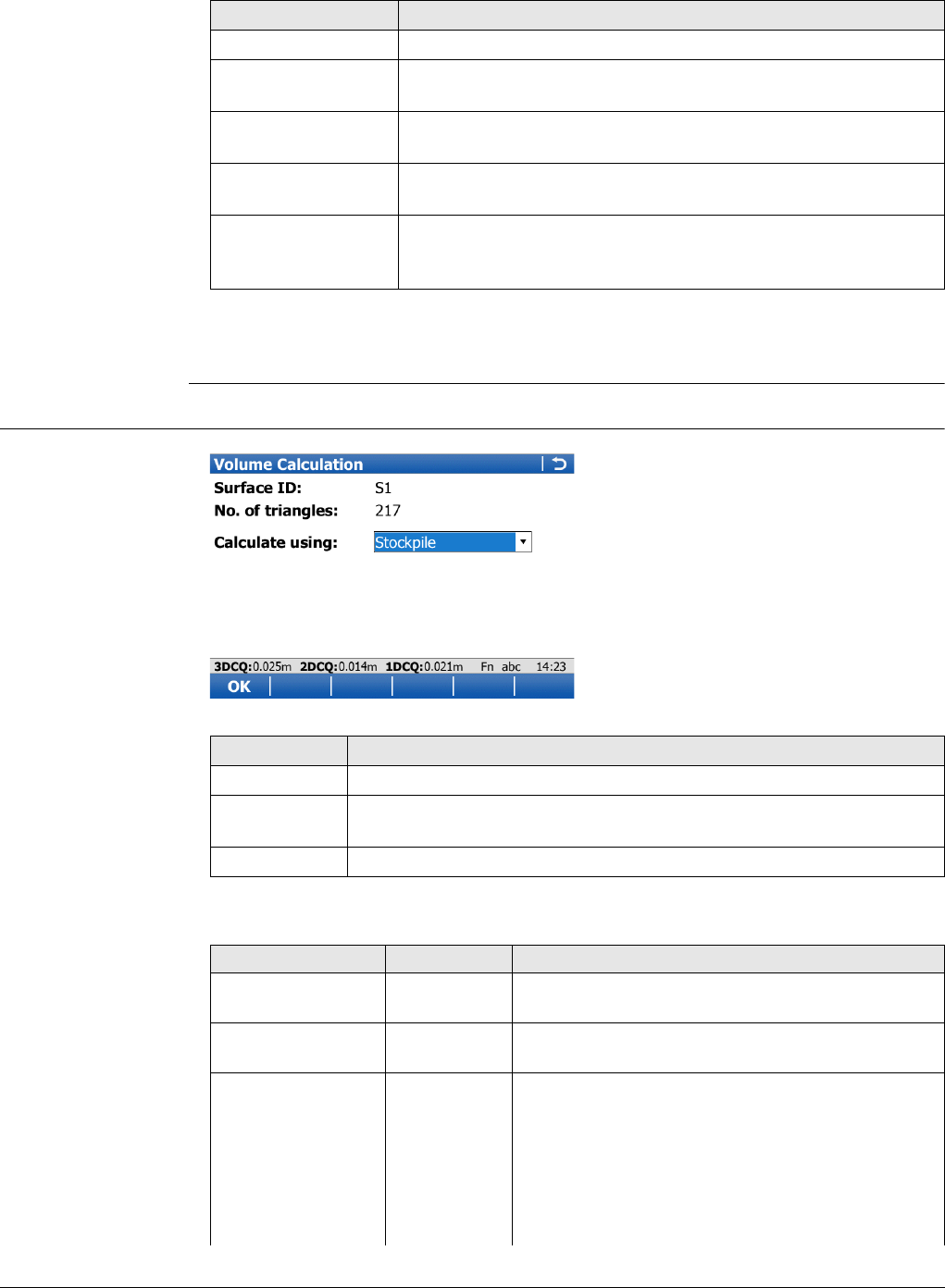
Viva Series, Volumes & Surfaces 895
Boundary Tools
Menu Description of fields
Next step
Select the task to do next. OK selects an option and returns to Edit Boundary.
64.4.7 Compute Volumes
Volume Calculation
Description of fields
Field Description
Add many points Lists all points in the working job.
Remove all points Method to remove all points that are indicated in Edit
Boundary, Points page.
Sort points by time Method to sort all points in Edit Boundary, Points page by the
time they were stored.
Sort points by prox-
imity Method to sort all points Edit Boundary, Points page by the
closest proximity.
Compute rubber
band bndry Method to define a new boundary as if a rubber band was
placed around the points. The current list of boundary points
will be ignored.
Key Description
OK To compute the volume.
Fn Config.. To configure the Volume Calculations application. Refer to "64.3
Configuring Volumes & Surfaces".
Fn Quit To exit the screen.
Field Option Description
Surface ID Selectable list Surface chosen from the triangulated surfaces
currently stored to the working job.
No. of triangles Display only Number of triangles from the triangulation of the
surface.
Calculate using To calculate the volume of the triangulated
surface.
Stockpile Volume between the triangulated surface and the
plane defined by the boundary points of the
surface.
Surface to
elevation Volume between the triangulated surface and the
height entered by the user.
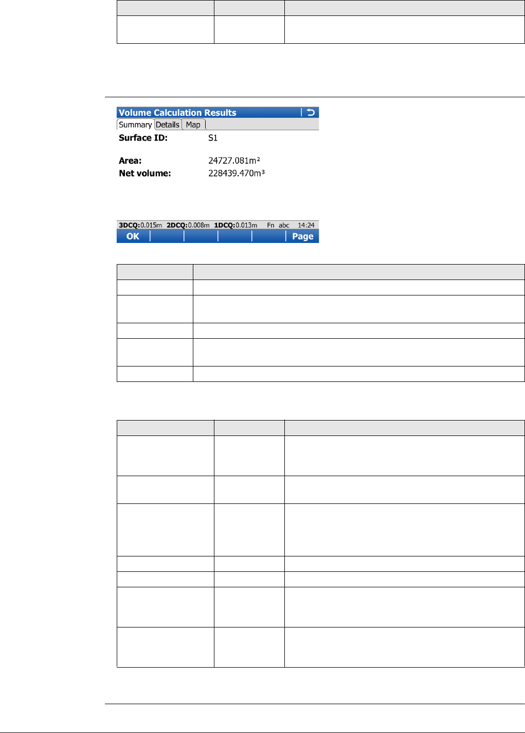
Viva Series, Volumes & Surfaces 896
Next step
OK calculates the volume and continues to Volume Calculation Results.
Volume Calculation
Results,
Summary page
Description of fields
Next step
Page changes to the Details page.
Surface to
point Volume between the triangulated surface and the
height of a selected point.
Field Option Description
Key Description
OK To close the triangulation of the surface.
DXF To export the triangulation results to a DXF file on the data or root
directory of the CF Card.
Page To change to another page on this screen.
Fn Config.. To configure the Volume Calculations application. Refer to "64.3
Configuring Volumes & Surfaces".
Fn Quit To exit the screen.
Field Option Description
Surface ID Display only Name of the surface used for the calculation.
Available for Calculate using:Surface to eleva-
tion and Calculate using:Surface to point.
Point ID Display only The point to which the volume is calculated. Avail-
able for Calculate using:Surface to point.
Elevation Display only The elevation of the point to which the volume is
calculated. Available for Calculate using:Surface
to elevation and Calculate using:Surface to
point.
Area Display only Area of the base plane.
Net volume Display only Volume of the surface.
Volume cut Display only Cut of the volume. Available for Calculate
using:Surface to elevation and Calculate
using:Surface to point.
Volume fill Display only Fill of the volume. Available for Calculate
using:Surface to elevation and Calculate
using:Surface to point.

Viva Series, Volumes & Surfaces 897
Volume Calculation
Results,
Details page
Description of fields
Next step
Page changes to the Plot page.
Field Option Description
Minimum elevation Display only Minimal elevation of the triangulated surface.
Maximum eleva-
tion Display only Maximal elevation of the triangulated surface.
Average thickness Display only Average thickness of the calculated volume.
Perimeter Display only Perimeter of the measured surface area (inter-
section of the measured surface to the reference
datum).
Viva Series, QuickVolume 898
65 QuickVolume
65.1 Overview
Description The application allows volumes to be computed from ALL scans and/or ALL measured
points stored in a job.
65.2 Accessing Volume Calculations
Access Select Main Menu:Go to Work!\Survey+\QuickVolume.
Choose Job
Description of fields
Surface Name
Description of fields
65.3 Volume Calculations
Volume Calculation
Description of fields
Key Description
OK To accept changes and access the subsequent screen. The chosen
settings become active.
Fn Quit To exit the screen.
Field Option Description
Job Selectable list The job from which a volume will be computed.
Key Description
OK To start the triangulation. All points and scans within the selected job
are used in the triangulation.
Fn Quit To exit the screen.
Field Option Description
Surface name Selectable list Name of the surface to be triangulated.
Key Description
OK To accept all settings and continue with the next screen.
MinElv To set the minimum elevation point of the current surface as eleva-
tion value. Available for Calculate using:Surface to elevation.
Fn Quit To exit the screen.
Field Option Description
Calculate using To calculate the volume of the triangulated
surface.
Stockpile Volume between the triangulated surface and the
plane defined by the boundary points of the
surface.
Surface to
elevation Volume between the triangulated surface and the
height entered by the user.
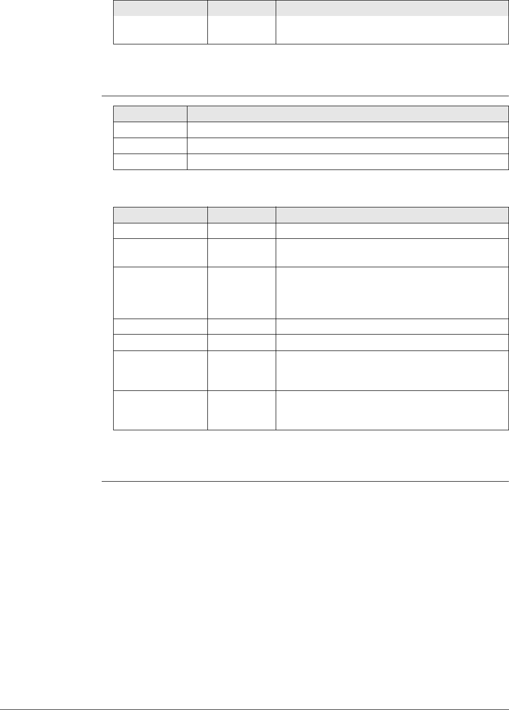
Viva Series, QuickVolume 899
Next step
OK calculates the volume and continues to Volume Calculation Results.
Volume Calculation
Results,
Summary page
Description of fields
Next step
Page changes to the Details page.
Surface to
point Volume between the triangulated surface and the
height of a selected point.
Field Option Description
Key Description
Store To return to Surface Task Selection.
Page To change to another page on this screen.
Fn Quit To exit the screen.
Field Option Description
Surface ID Display only Name of the surface used for the calculation.
Point ID Display only The point to which the volume is calculated. Avail-
able for Calculate using:Surface to point.
Elevation Display only The elevation of the point to which the volume is
calculated. Available for Calculate using:Surface
to elevation and Calculate using:Surface to
point.
Area Display only Area of the base plane.
Net volume Display only Volume of the surface.
Volume cut Display only Cut of the volume. Available for Calculate
using:Surface to elevation and Calculate
using:Surface to point.
Volume fill Display only Fill of the volume. Available for Calculate
using:Surface to elevation and Calculate
using:Surface to point.

Viva Series, Menu Tree 900
Appendix A Menu Tree
Menu tree for GNSS
RTK rover and TPS
|—— Go to Work!
||
||—— Setup (TPS)
||
||—— Survey
||
||—— Stakeout
||
||—— Survey+
|||
|||—— Scanning for MS50
|||
|||—— Measure to ref line
|||
|||—— Ref plane & grid scan
|||
|||—— Volume calculations
|||
|||—— QuickVolume
|||
|||—— TPS hidden point (TPS)
|||
|||—— Sets of angles (TPS)
|||
|||—— Determine coord system
|||
|||—— QuickGrid (GPS)
|||
|||—— Traverse (TPS)
|||
|||—— Survey cross section
||
||—— Stakeout+
|||
|||—— Stake to ref line
|||
|||—— Stakeout DTM
|||
|||—— Stake points & DTM
||
||—— COGO..
|||
|||—— Inverse
|||
|||—— Traverse
|||
|||—— Intersection
|||
|||—— Line & arc calculations
|||
|||—— Area division
|||
|||—— Shift, rotate & scale
|||
|||—— Angle

Viva Series, Menu Tree 901
|||
|||—— Horizontal curve
|||
|||—— Triangle
||
||—— Roads..
|||
|||—— Alignment Editor
|||
|||—— Roads - Stakeout
|||
|||—— Roads - As built check
|||
|||—— Rail - Stakeout
|||
|||—— Rail - As built check
|||
|||—— Tunnel - Stakeout (TPS)
|||
|||—— Tunnel - As built check (TPS)
||
||—— Switch to Base menu (GPS)
Unavailable for GS05/GS06
|
|—— Jobs & Data
||
||—— New job
||
||—— View & edit data
||
||—— Create control data
||
||—— Job properties
||
||—— Choose working job
||
||—— Choose control job
||
||—— Import data
|||
|||—— Import ASCII data
|||
|||—— Import alignment data
|||
|||—— Import DXF data
|||
|||—— Import DTM data
|||
|||—— Import XML data
||
||—— Export & copy data
||
||—— Export ASCII data
||
||—— Export custom data
||
||—— Export DXF data
||

Viva Series, Menu Tree 902
||—— Export XML Data
||
||—— Export Data Using Stylesheet
||
||—— Export FBK/RW5/RAW data
||
||—— Copy data between jobs
|
|—— Instrument
||
||—— TPS settings (TPS)
|||
|||—— Measure mode & target
|||
|||—— Prism search settings
|||
|||—— Atmospheric corrections
|||
|||—— Level bubble & compensator
|||
|||—— Offsets & Quality Control
|||
|||—— Lights / Lights & accessories (TS)
||
||—— GPS settings
|||
|||—— RTK rover wizard
|||
|||—— Satellite tracking
|||
|||—— Antenna heights
|||
|||—— Quality control
|||
|||—— Raw data logging
||
||—— Connections..
|||
|||—— GPS connection wizard (GPS)
|||
|||—— TPS connection wizard (TPS)
|||
|||—— Internet wizard
|||
|||—— CS connection wizard (TS)
|||
|||—— All other connections
||
||—— Instrument status info
|||
|||—— Battery & memory
|||
|||—— Satellite tracking (GPS)
|||
|||—— RTK data link status (GPS)
|||
|||—— Current GPS position (GPS)
|||

Viva Series, Menu Tree 903
|||—— Raw data logging (GPS)
|||
|||—— Connection status
|||
|||—— Internet connection status
|||
|||—— TPS current station info (TPS)
||
||—— TPS camera settings (TPS, CS)
|
|—— User
|
|—— Work settings
||
||—— ID templates
||
||—— Coding & linework
||
||—— My Survey Screen
||
||—— Hot keys & favourites
||
||—— Prompt before storing
|
|—— Working style wizard
|
|—— System settings
||
||—— Regional settings
||
||—— SmartWorx options
||
||—— Screen & audio
||
||—— Admin settings
|
|—— Tools & other utilities
||
||—— Transfer user objects
||
||—— Load firmware & Apps
||
||—— Load licence keys
||
||—— Ftp data transfer
||
||—— Format memory devices
||
||—— View contents of ASCII files
||
||—— Leica Exchange
|
|—— Check & Adjust (TS)
|
|—— About Leica Viva

Viva Series, Menu Tree 904
Menu tree for GPS
RTK base
|—— Go to Work!
||
||—— Start base over known point
||
||—— Start base over last setup
||
||—— Start base over any point
||
||—— Go to rover menu
|
|—— Instrument
|
|—— Base settings
|
|—— Satellite tracking
|
|—— Base raw data logging
|
|—— Base connections
||
||—— Connect to base sensor
||
||—— All other connections
|
|—— Base status info
|
|—— Battery & memory
|
|—— Satellite tracking
|
|—— Current position
|
|—— Raw data logging
|
|—— Connection status

Viva Series, Internal Memory 905
Appendix B Internal Memory
Available memory >500MB.
Data stored to the
internal memory
The following are examples of the data types that can be stored to the internal
memory.
• Applications
•Codelists
• Coordinate systems
• Format files
• Geoid and CSCS files
•Jobs & Data
•System languages
•Working styles

Viva Series, Directory Structure of the Memory Device 906
Appendix C Directory Structure of the Memory Device
Description On the memory device, files are stored in certain directories. The following diagram of
the directory structure refers to the data storage devices and the internal memory.
All files are fully compatible with Leica System 1200 and vice versa, with the exception
of the following listed files which are not compatible between the systems:
• Working styles and configuration sets
• System.ram and VivaSystem.zip
•Licence files
• Language files, and
• Application files.
Directory structure |—— CODE • Codelists, various files
|
|—— CONFIG • Working style files (*.xfg)
||
| |—— RTK_PROFILE • RTK profile files (*.rpr)
||
| |—— SKETCH_TEMPLATE • Custom templates (*.jpg) for sketching
||
| |—— USERMANAGEMENT • Administration settings files (*.usm)
|
|—— CONVERT • Format files (*.frt)
|
|—— DATA
||
||
||
||
||
||
||
||
||
||
||
• ASCII (*.txt), DXF (*.dxf), LandXML (*.xml),
Terramodel (*.xml), Carlson (*.cl) and Shape files
(*.shp, *.shx and *.dbf and all other shape file
components) for import/export to/from job
• Section files for Carlson (*.sct) and ASCII report
files for Terramodel (*. txt) for import to job
• Report sheets created from applications
||—— GPS
|||
| | |—— CSCS • CSCS field files (*.csc)
|||
| | |—— GEOID • Geoid field files (*.gem)
|||
| | |—— RINEX • RINEX files
||
| |—— XML • Alignment Editor Alignments (*.xml)
|
|—— DBX • DTM jobs, various files
| | • Coordinate system file (Trfset.dat)
| | • Job files for System 1200
||—— JOB
|| • Job files, various files. Jobs are stored in a folder
per job.
||—— MAP
|| • Map related files (for example *.mpl), stored in a
subfolder per job.
||—— IMAGES
|| • Image files (*.jpg), stored in a subfolder per job.
| |—— SCANS • Scan database files (*.sdb files)
| | | • Bitmaps of intensity values (*.bmp files)
|
|—— DOWNLOAD
| • Various files, downloaded by the Ftp data transfer
application (*.*)
|—— GPS • Antenna file (List.ant)

Viva Series, Directory Structure of the Memory Device 907
| • GSM/Modem station list (*.fil)
| • Server list (*.fil)
|
|—— GSI • GSI files (*.gsi)
| • ASCII files for export from job (*.*)
|
|—— SYSTEM • Application files (*.axx)
•Firmware files (*.fw)
•Language files (*.s*)
• Licence file (*.key)
• System files (VivaSystem.zip)
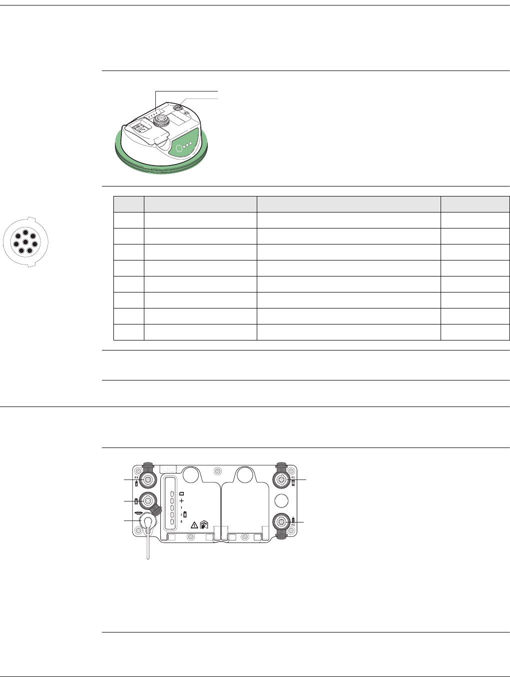
Viva Series, Pin Assignments and Sockets 908
Appendix D Pin Assignments and Sockets
D.1 GS08plus
Description Some applications require knowledge of the pin assignments for the GS08plus/GS12
ports.
In this chapter, the pin assignments and sockets for the ports of the GS08plus/GS12
are explained.
Ports at the instru-
ment underside
Pin assignments for
8pin LEMO-1
Sockets
D.2 GS10
Description Some applications require knowledge of the pin assignments for the GS10 ports. In
this chapter, the pin assignments and sockets for the ports of the GS10 are explained.
Ports at the instru-
ment front panel
a) Clip on contacts (only GS12)
b) Lemo port (USB and serial)
GS_122
TRK
BT
PWR
ON
OFF
a
b
17
6
8
5
4
3
2
PIN_001
Pin Signal Name Function Direction
1 USB_D+ USB data line In or out
2 USB_D- USB data line In or out
3GND Signal ground -
4 RxD RS232, receive data In
5 TxD RS232, transmit data Out
6 ID Identification pin In or out
7 PWR Power input, 10.5 V-28 V In
8 TRM_ON/USB_ID RS232, general purpose signal In or out
8 pin LEMO-1: LEMO-1, 8 pin, LEMO EGI.1B.308.CLN
a) Port P3: Power out, data in/out or remote interface in/out. 8 pin LEMO
b) Port PWR: Power in. 5 pin LEMO
c) Port ANT: GNSS antenna in
d) Port P1: CS field controller in/out or remote interface in/out. 8 pin LEMO
e) Port P2: Power out, data in/out or remote interface in/out. 8 pin LEMO
GS_093
a
b
c
d
e
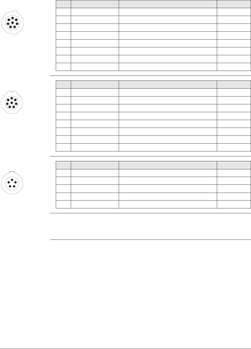
Viva Series, Pin Assignments and Sockets 909
Pin assignments for
port P1
Pin assignments for
port P2, and port P3
Pin assignments for
port PWR
Sockets
17
6
8
5
4
3
2
PIN_001
Pin Signal Name Function Direction
1 USB_D+ USB data line In or out
2 USB_D- USB data line In or out
3 GND Signal ground -
4 RxD RS232, receive data In
5 TxD RS232, transmit data Out
6 ID Identification pin In or out
7 PWR Power input, 10.5 V-28 V In
8 TRM_ON/USB_ID RS232, general-purpose signal In or out
17
6
8
5
4
3
2
PIN_003
Pin Signal Name Function Direction
1 RTS RS232, ready to send Out
2 CTS RS232, clear to send In
3 GND Signal ground -
4 RxD RS232, receive data In
5 TxD RS232, transmit data Out
6 ID Identification pin In
7 GPIO RS232, configurable function In or out
8 +12 V 12 V power supply out Out
1
5
43
2
PIN_004
Pin Signal Name Function Direction
1 PWR1 Power input, 11 V-28 V In
2ID1 Identification pin In
3 GND Signal ground -
4 PWR2 Power input, 11 V-28 V In
5ID2 Identification pin In
Port P1 LEMO-1, 8 pin, LEMO EGI.1B.308.CLN
Port P2 and port P3: LEMO-1, 8 pin, LEMO HMA.1B.308.CLNP
Port PWR: LEMO-1, 5 pin, LEMO HMG.1B.305.CLNP
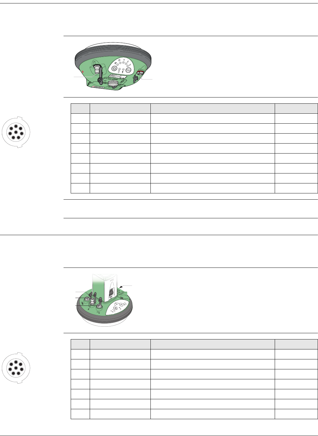
Viva Series, Pin Assignments and Sockets 910
D.3 GS14
Description Some applications require knowledge of the pin assignments for the instrument ports.
In this chapter, the pin assignments and sockets for the instrument ports are
explained.
Ports at the instru-
ment underside
Pin assignments for
port P1
Sockets
D.4 GS15
Description Some applications require knowledge of the pin assignments for the GS15 ports.
In this chapter, the pin assignments and sockets for the ports of the GS15 are
explained.
Ports at the instru-
ment underside
Pin assignments for
port P1
a) QN-connector, only for models with
UHF radio
b) Port 1 (USB and serial)
004118_002
ab
17
6
8
5
4
3
2
PIN_001
Pin Signal Name Function Direction
1 USB_D+ USB data line In or out
2 USB_D- USB data line In or out
3 GND Signal ground -
4 RxD RS232, receive data In
5 TxD RS232, transmit data Out
6 ID Identification pin In or out
7 PWR Power input, 10.5 V-28 V In
8 GPIO RS232, general-purpose signal In or out
Port 1: LEMO-1, 8 pin, LEMO HMI.1B.308.CLWP
a) QN-connector
b) Port 2
c) Port 1 (USB and serial)
d) Port 3
GS_094
a
b
c
d
17
6
8
5
4
3
2
PIN_001
Pin Signal Name Function Direction
1 USB_D+ USB data line In or out
2 USB_D- USB data line In or out
3 GND Signal ground -
4 RxD RS232, receive data In
5 TxD RS232, transmit data Out
6 ID Identification pin In or out
7 PWR Power input, 10.5 V-28 V In
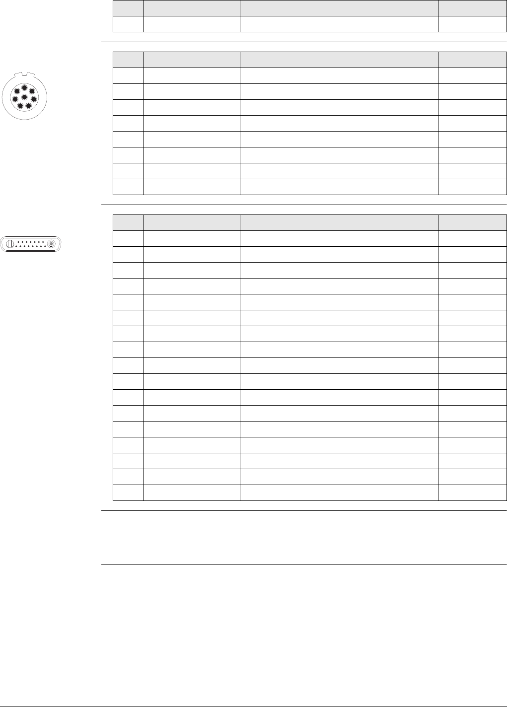
Viva Series, Pin Assignments and Sockets 911
Pin assignments for
port P2
Pin assignments for
port P3
Sockets
8 TRM_ON/USB_ID RS232, general-purpose signal In or out
Pin Signal Name Function Direction
17
6
8
5
4
3
2
PIN_003
Pin Signal Name Function Direction
1 RTS RS232, ready to send Out
2 CTS RS232, clear to send In
3 GND Signal ground -
4 RxD RS232, receive data In
5 TxD RS232, transmit data Out
6 ID Identification pin In
7 GPIO RS232, configurable function In or out
8 +12 V 12 V power supply out Out
PIN_005
1
A1 A2
8 9 10 11 12 13 14 15
234567
Pin Signal Name Function Direction
1 PWR 4 V power supply in In
2Tx Transmit data In
3 Rx Receive data Out
4 GPO/DCD General-purpose out, carrier detect out Out
5 RTS Request to send In
6 CTS Clear to send Out
7 GPI/CFG General-purpose in, config mode in In
8 PWR 6 V power supply in In
9 GPIO General-purpose signal In or out
10 GND Signal and chassis ground -
11 USB+ USB data line (+) In or out
12 USB- USB data line (-) In or out
13 GND Signal and chassis ground -
14 ID Identification pin In or out
15 GPIO General-purpose signal In or out
A1 NC Not used -
A2 RF1 Antenna port, radio to antenna -
Port 1: LEMO-1, 8 pin, LEMO EGI.1B.308.CLN
Port 2: LEMO-1, 8 pin, LEMO HMA.1B.308.CLNP
Port 3: 15 pin RS232:RS232, 15 pin, DE15
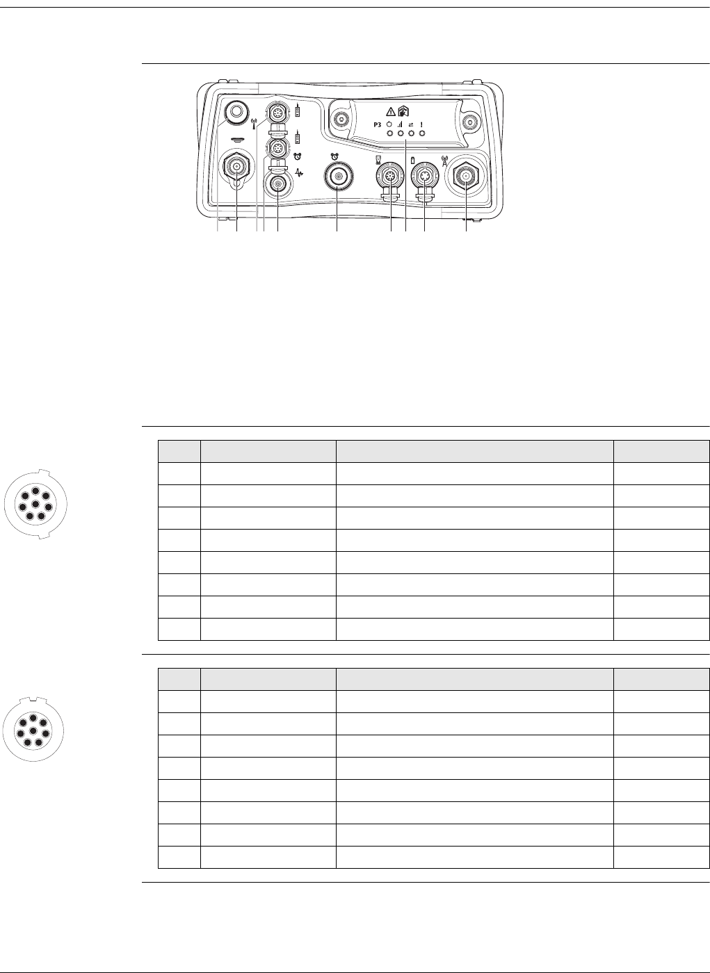
Viva Series, Pin Assignments and Sockets 912
D.5 GS25
Description Some applications require knowledge of the pin assignments for the GS25 ports. In
this chapter, the pin assignments and sockets for the ports of the GS25 are explained.
Ports at the instru-
ment back panel
Pin assignments for
port P1
Pin assignments for
port P2
a) Port BT: Bluetooth antenna
b) Port ANT: GNSS antenna in
c) Port P2: Power out, data in/out or remote interface in/out. 8 pin LEMO
d) Port P4 and E2: Serial/Event port. 8 pin LEMO
e) Port PPS: Puls per second output
f) Port E1: Event 1
g) Port P1: CS field controller in/out or remote interface in/out. 8 pin LEMO
h) Port 3: Communication slot-in port and LEDs
i) Port PWR: Power in. 5 pin LEMO
j) Communication Slot-in port, Antenna, TNC
GS25_001 be f hgi jcda
P2
P4
E2 E1 P1
17
6
8
5
4
3
2
PIN_001
Pin Signal Name Function Direction
1 USB_D+ USB data line In or out
2 USB_D- USB data line In or out
3 GND Signal ground -
4 RxD RS232, receive data In
5 TxD RS232, transmit data Out
6 ID Identification pin In or out
7 PWR Power input, 10.5 V-28 V In
8 TRM_ON/USB_ID RS232, general-purpose signal In or out
17
6
8
5
4
3
2
PIN_003
Pin Signal Name Function Direction
1 RTS RS232, ready to send Out
2 CTS RS232, clear to send In
3 GND Signal ground -
4 RxD RS232, receive data In
5 TxD RS232, transmit data Out
6 ID Identification pin In
7 GPIO RS232, configurable function In or out
8 +12 V 12 V power supply out Out
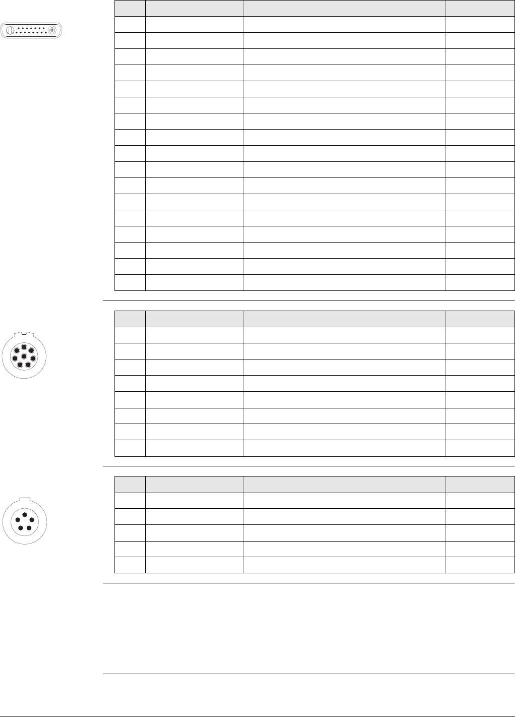
Viva Series, Pin Assignments and Sockets 913
Pin assignments for
port P3
Pin assignments for
port P4/E2
Pin assignments for
port PWR
Sockets
PIN_005
1
A1 A2
8 9 10 11 12 13 14 15
234567
Pin Signal Name Function Direction
1 PWR 4 V power supply in In
2Tx Transmit data In
3 Rx Receive data Out
4 GPO/DCD General-purpose out, carrier detect out Out
5 RTS Request to send In
6 CTS Clear to send Out
7 GPI/CFG General-purpose in, config mode in In
8 PWR 6 V power supply in In
9 GPIO General-purpose signal In or out
10 GND Signal and chassis ground -
11 USB+ USB data line (+) In or out
12 USB- USB data line (-) In or out
13 GND Signal and chassis ground -
14 ID Identification pin In or out
15 GPIO General-purpose signal In or out
A1 NC Not used -
A2 RF1 Antenna port, radio to antenna -
17
6
8
5
4
3
2
PIN_003
Pin Signal Name Function Direction
1 RTS RS232, ready to send Out
2 CTS RS232, clear to send In
3 GND Signal ground -
4 RxD RS232, receive data In
5 TxD RS232, transmit data Out
6 ID Identification pin In or out
7 GPIO/EVT2 IN RS232, general purpose input/output In or out
8 +12 V 12 V power supply out Out
1
5
43
2
PIN_004
Pin Signal Name Function Direction
1 PWR1 Power input, 11 V-28 V In
2ID1 Identification pin In
3 GND Signal ground -
4 PWR2 Power input, 11 V-28 V In
5ID2 Identification pin In
Port P1 LEMO-1, 8 pin, LEMO EGI.1B.308.CLN
Port P2 and P4/E2: LEMO-1, 8 pin, LEMO HMA.1B.308.CLNP
Port 3: 15 pin RS232:RS232, 15 pin, DE15
Port PWR: LEMO-1, 5 pin, LEMO HMG.1B.305.CLNP
PPS: LEMO REN.OS.250.CTL
E1: LEMO HGP.00.250.CTL
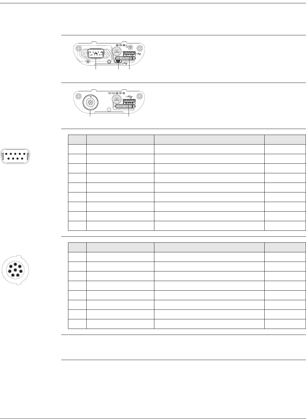
Viva Series, Pin Assignments and Sockets 914
D.6 CS10/CS15
Description Some applications require knowledge of the pin assignments for the CS10/CS15 ports.
In this chapter, the pin assignments and sockets for the ports of the CS10/CS15 are
explained.
Ports at the instru-
ment bottom panel
- DSUB9 connector
Ports at the instru-
ment bottom panel
- Lemo connector
Pin assignments for
RS232 serial port
Pin assignments for
8pin LEMO-1
Sockets
a) DSUB9 port
b) USB Mini port
c) USB A Host port
CS_022 a b c
a) Lemo port (USB and serial)
b) USB A Host port
CS_021 a b
PIN_002
1
6789
2345
Pin Signal Name Function Direction
1 NC Not connected -
2 RxD RS232, receive data In
3 TxD RS232, transmit data Out
4 NC Not connected -
5GND Signal Ground -
6 NC Not connected -
7 RTS RS232, request to send Out
8 CTS RS232, clear to send In
9 NC Not connected -
17
6
8
5
4
3
2
PIN_001
Pin Signal Name Function Direction
1 USB_D+ USB data line In or out
2 USB_D- USB data line In or out
3GND Signal ground -
4 RxD RS232, receive data In
5 TxD RS232, transmit data Out
6 ID Identification pin In or out
7 PWR Power input, 10.5 V-28 V In
8 TRM_ON/USB_ID RS232, general purpose signal In or out
9 pin RS232: RS232, 9 pin, DB9
8 pin LEMO-1: LEMO-1, 8 pin, LEMO EGI.1B.308.CLN
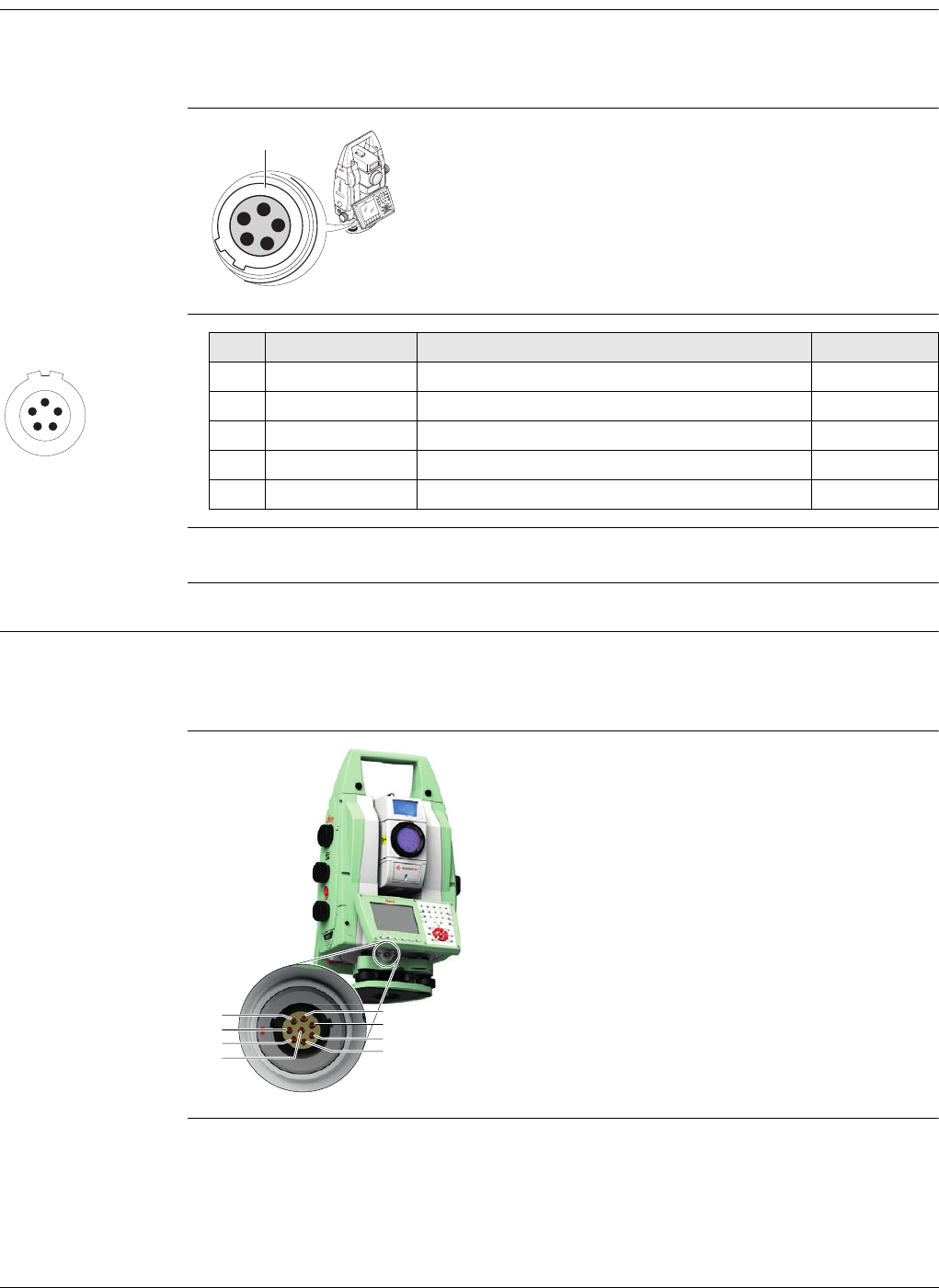
Viva Series, Pin Assignments and Sockets 915
D.7 TS11/TS15/TS12 Lite
Description Some applications require knowledge of the pin assignments for the instrument port.
In this chapter, the pin assignments and socket for the port 1 of the TS11/TS15/TS12
Lite instrument are explained.
Ports at the
TS11/TS15/TS12
Lite instrument
Pin assignments for
port P1
Sockets
D.8 MS50/TS50/TM50
Description Some applications require knowledge of the pin assignments for the instrument port.
In this chapter, the pin assignments and socket for the port 1 of the MS50/TS50/TM50
instrument are explained.
Ports at the
MS50/TS50/TM50
instrument
a) Port 1
TS_127
a
54
3
2
1
1
5
43
2
PIN_006
Pin Signal Name Function Direction
1 PWR Power input, + 12 V nominal (11 V - 16 V) In
2- Not used -
3 GND Single ground -
4 RxD RS232, receive data In
5 TxD RS232, transmit data Out
Port 1: LEMO-0, 5 pin, LEMO ENA.OB.305.CLN
a) Pin 1
b) Pin 2
c) Pin 3
d) Pin 4
e) Pin 5
f) Pin 6
g) Pin 7
h) Pin 8
005037_001
a
b
g
h
f
e
d
c
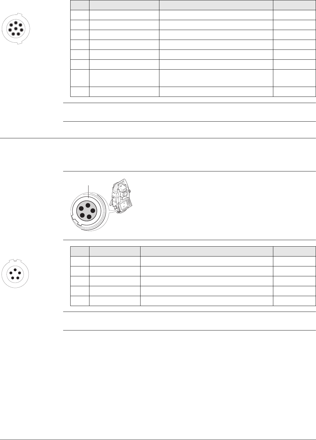
Viva Series, Pin Assignments and Sockets 916
Pin assignments for
8pin LEMO-1
Sockets
D.9 TPS1200+
Description Some applications require knowledge of the pin assignments for the instrument port.
In this chapter, the pin assignments and socket for the port 1 of the TPS1200+ instru-
ment are explained.
Ports at the TPS
instrument
Pin assignments for
port P1
Sockets
17
6
8
5
4
3
2
PIN_001
Pin Signal Name Function Direction
1 USB_D+ USB data line In or out
2 USB_D- USB data line In or out
3GND Signal ground -
4 RxD RS232, receive data In
5 TxD RS232, transmit data Out
6 ID Identification pin In or out
7 PWR Power input, nominal +12 V (11 V -
16 V)
In
8 NC Not connected -
Port 1: LEMO-1, 8 pin, LEMO EGI.1B.308.CLN
a) Port 1
TS_002
a
54
3
2
1
1
5
43
2
PIN_006
Pin Signal Name Function Direction
1 PWR Power input, + 12 V nominal (11 V - 16 V) In
2- Not used -
3 GND Single ground -
4 RxD RS232, receive data In
5 TxD RS232, transmit data Out
Port 1: LEMO-0, 5 pin, LEMO ENA.OB.305.CLN
Viva Series, Cables 917
Appendix E Cables
E.1 GPS Cables
Power cables
Y cables
Radio programming
cables
Name Description
GEV97 • Allows GS10 (power port) to be externally powered
• LEMO-1, 5 pin, 30° / LEMO-1, 5 pin, 30°
•1.8m
GEV71 • Allows powering of any device from car battery.
• Crocodile clips / LEMO-1, 5 pin , 30° (female)
•4.0m
GEV172 • Allows GS10 (power port) to be externally powered from two external
batteries
• LEMO-1, 5 pin / LEMO-1, 5 pin, 30°
•2.8m
GEV219 • Allows CS10/CS15 (with LEMO CBC01 connector module) to be exter-
nally powered via the LEMO port
• Allows GS10/GS15 (port 1) to be externally powered
• LEMO-1, 8 pin, 135° / LEMO-1, 5 pin, 30°
•1.8m
GEV235 • Allows CS10/CS15 (with either connector modules) to be externally
powered via the power jack
• Wall adapter / 3 mm barrel connector
•1.5m
Name Description
GEV172 • Allows GS10 (power port) to be externally powered from two external
batteries
• LEMO-1, 5 pin / LEMO-1, 5 pin, 30°
•2.8m
GEV205 • Allows connections between GS10/GS15 (port 1), an external radio in
GFU1200 housing and the GEB71, with GS10/GS15 and a radio being
externally powered
• LEMO-1, 8 pin, 135° / LEMO-1, 8 pin, 135° (female) / LEMO-1, 5 pin
•1.8m
GEV215 • Allows connections between CS10/CS15 (with LEMO CBC01 connector
module), the GS10/GS15 (port 1) and the GEB71, with the GS10/GS15
being powered from the GEB71.
• LEMO-1, 8 pin, 135° / LEMO-1, 5 pin, 30° / LEMO-1, 5 pin, 30°
•2.0m
GEV261 • Allows connections between MS50/TS50/TM50, external battery
GEB171 and a PC with either USB or 9 pin D-Sub RS232.
• LEMO-1, 8 pin, 135° / LEMO-1, 5 pin/USB/9pol D-Sub
•1.8m
Name Description
GEV231 • Allows an “SLR” radio device to be externally powered and
programmed by a computer
• 15 pin (GS15 slot-in port) (female) / 9 pin, RS232 serial / LEMO-1, 5 pin
•1.8m
Viva Series, Cables 918
Radio cables
Serial data transfer
cables
GEV171 • Allows a radio within a GFU1200 device to be externally powered and
programmed by a computer
• LEMO-1, 8 pin, 135° (female) / 9 pin, RS232 serial / LEMO-1, 5 pin
•1.8m
Name Description
Name Description
GEV67 • Allows System 500 GFU housings to be connected to a GS10 (port 2
and 3), or GS15 (port 2)
• LEMO-1, 8 pin, 30° / LEMO-1, 8 pin, 135° / LEMO-1, 5 pin, 30°
•0.5m
GEV125 • Allows a Satel modem (not inside housing) to be connected to a GS10
(port 2 and 3), or GS15 (port 2)
• LEMO-1, 8 pin, 30° / 15 pin, RS232 serial
•1.8m
GEV232 • Allows System 1200 GFU housings to be connected to a GS10 (port 2
and 3), or GS15 (port 2)
• LEMO-1, 8 pin, 30° / LEMO-1, 8 pin, 30° (female)
•2.8m
GEV233 • Allows System 1200 GFU housings to be connected to a GS10 (port 2
and 3), or GS15 (port 2)
• LEMO-1, 8 pin, 30° / LEMO-1, 8 pin, 30° (female)
•0.8m
Name Description
GEV160 • Allows serial connection between GS10 (port 2 and 3), or GS15 (port
2) to a computer to stream NMEA or RTK data
• LEMO-1, 8 pin, 30° / 9 pin, RS232 serial
•2.8m
GEV162 • Allows serial connection between GS10/GS15 (port 1) to a computer
to stream NMEA or RTK data
• Allows serial connection between CS10/CS15 (with LEMO CBC01
connector module) and, for example, a hidden point device, ASCII input
device, or computer.
• Allows serial connection between CS10/CS15 (with 9 pin serial CBC02
connector module) and GS10/GS15 (port 1). This connection is useful
when using third-party software such as Carlson SurvCE on the
CS10/CS15 and a cable connection is required to the GS10/GS15.
• LEMO-1, 8 pin, 135° / 9 pin, RS232 serial
•2.8m
GEV163 • Allows serial connection between CS10/CS15 (with LEMO CBC01
connector module) and GS10/GS15 port 1. This connection is useful
when using third-party software such as Carlson SurvCE on the
CS10/CS15 (with LEMO CBC01 connector module) and a cable connec-
tion is required to the GS10/GS15.
• LEMO-1, 8 pin, 30° / LEMO-1, 8 pin, 135°
•1.8m
Viva Series, Cables 919
USB to serial
converter cables
USB data transfer
cables
Antenna cables
Name Description
GEV195 • Allows GS10 (port 2 and 3) or GS15 (port 2) to be connected to a
computer where a serial connection is required, but no 9 pin RS232
port physically exists on the computer. This cable allows a serial
connection through the USB port of the computer to the CS10/CS15
or GS10/GS15 hardware.
• LEMO-1, 8 pin, 30° / USB type A
•2.0m
GEV269 • Allows CS10/CS15 (with LEMO CBC01 connector module) and
GS10/GS15 (port 1) to be connected to a computer where a serial
connection is required, but no 9 pin RS232 port physically exists on the
computer. This cable allows a serial connection through the USB port
of the computer to the CS10/CS15 or GS10/GS15 hardware.
• LEMO-1, 8 pin, 135° / USB type A
•2.0m
Name Description
GEV223 • Allows USB data transfer between CS10/CS15 (both connector
modules) and a computer.
• USB Type A / Mini USB Type B
•1.8m
GEV234 • Allows a CS10/CS15 (with 9 pin serial CBC02 connector module) to
connect to a GS10/GS15 (port 1). This cable is for when a cable
connection is needed between CS10/CS15 and GS10/GS15 when the
CS10/CS15 is using the CBC02 connector module.
• Allows a USB connection between the USB port of a computer and the
GS10/GS15 (port 1)
• Allows a USB connection between the USB port of a computer and the
CS10/CS15 (with LEMO CBC01 connector module)
• LEMO-1, 8 pin, 135° / USB type A
•1.65m
GEV237 • Allows a CS10/CS15 (with LEMO CBC01 connector module) to connect
to a GS10/GS15 (port 1). This cable is for when a cable connection is
needed between CS10/CS15 and GS10/GS15 when the CS10/CS15 is
using the CBC01 connector module.
• LEMO-1, 8 pin, 135° / LEMO-1, 8 pin, 135°
•1.65m
Name Description
GEV108 • TNC connector / TNC connector
•30m
GEV119 • TNC connector / TNC connector
•10m
GEV120 • TNC connector / TNC connector
•2.8m
GEV134 • TNC connector / TNC connector
•50m
GEV141 • TNC connector / TNC connector
•1.2m
Viva Series, Cables 920
E.2 TPS Cables
Power cables
Radio / Y cables
Serial data transfer
cables
GEV142 • TNC connector / TNC connector (male)
•1.6m
- • TNC connector / TNC connector
•70m
Name Description
Name Description
GEV52 • Allows TS11/TS12 Robotic/TS15 to be externally powered
• LEMO-0, 5 pin, 30° / LEMO-1, 5 pin
•1.8m
GEV219 • Allows CS10/CS15 (with LEMO CBC01 connector module) to be exter-
nally powered via the LEMO port
• Allows GS10/GS15 (port 1) to be externally powered
• LEMO-1, 8 pin, 135° / LEMO-1, 5 pin, 30°
•1.8m
Name Description
GEV186 • Allows connections between TS11/TS12 Robotic/TS15, an external
battery and TCPS27/TCPS28/TCPS29
• LEMO-0, 5 pin, 30° / LEMO-0, 8 pin,30° / LEMO-1, 5 pin
•1.8m
GEV220 • Allows connections between MS50/TS50/TM50, external battery
GEB171 and a PC with 9 pin D-Sub RS232.
• LEMO-1, 8 pin, 135° / LEMO-1, 5 pin/USB/9pol D-Sub
•1.8m
GEV236 • Allows connection between MS50/TS50/TM50, an external battery and
TCPS27/TCPS28/TCPS29
• LEMO-1, 8 pin, 15/150° / LEMO-1, 5pin / LEMO-1, 8 pin, 30°
•1.8m
GEV261 • Allows connections between MS50/TS50/TM50, external battery
GEB171 and a PC with either USB or 9 pin D-Sub RS232.
• LEMO-1, 8 pin, 135° / LEMO-1, 5 pin/USB/9pol D-Sub
•1.8m
Name Description
GEV102 • Allows serial connection between TS11/TS12 Robotic/TS15 and a
computer
• Allows serial connection between TS11/TS12 Robotic/TS15 and
CS10/CS15 (with 9 pin serial CBC02 connector module)
• LEMO-0, 5 pin, 30° / 9 pin, RS232 serial
•2.0m
GEV162 • Allows serial connection between CS10/CS15 (with 9 pin serial CBC02
connector module) and a computer
• LEMO-1, 8 pin, 135° / 9 pin, RS232 serial
•2.8m

Viva Series, Cables 921
USB to serial
converter cables
USB data transfer
cables
GEV163 • Allows serial connection between CS10/CS15 (with LEMO CBC01
connector module) and GS10/GS15 port 1. This connection is useful
when using third-party software such as Carlson SurvCE on the
CS10/CS15 (with LEMO CBC01 connector module) and a cable connec-
tion is required to the GS10/GS15.
• LEMO-1, 8 pin, 30° / LEMO-1, 8 pin, 135°
•1.8m
GEV187 • Allows connections between TS11/TS12 Robotic/TS15, an external
battery and a computer
• LEMO-0, 5 pin, 30° / 9 pin, RS232 serial / LEMO-1, 5 pin, 30°
•2.0m
GEV217 • Allows serial connection between TS11/TS12 Robotic/TS15 and
CS10/CS15 (with LEMO CBC01 connector module)
• LEMO-1, 8 pin, 135° / LEMO-0, 5 pin,30°
•1.8m
Name Description
Name Description
GEV189 • Allows TS11/TS12 Robotic/TS15 to be connected to a computer where
a serial connection is required, but no 9 pin RS232 port physically
exists on the computer. This cable allows a serial connection through
the USB port of the computer to the TS11/TS12 Robotic/TS15 or DNA
hardware
• LEMO-0, 5 pin, 30° / USB type A
•2.0m
Name Description
GEV234 • Allows a USB connection between the USB port of a computer and the
CS10/CS15 (with LEMO CBC01 connector module)
• LEMO-1, 8 pin, 135° / USB type A
•1.65m
GEV237 • Allows a CS10/CS15 (with LEMO CBC01 connector module) to connect
to a GS10/GS15 (port 1). This cable is for when a cable connection is
needed between CS10/CS15 and GS10/GS15 when the CS10/CS15 is
using the CBC01 connector module.
• LEMO-1, 8 pin, 135° / LEMO-1, 8 pin, 135°
•1.65m
Viva Series, NMEA Message Formats 922
Appendix F NMEA Message Formats
F.1 Overview
Description National Marine Electronics Association is a standard for interfacing marine electronic
devices. This chapter describes all NMEA-0183 messages which can be output by the
instrument.
Access Select Main Menu: Instrument\Instrument\All other connections\NMEA 1 or NMEA 2.
Press Mesgs.
A Talker ID appears at the beginning of the header of each NMEA message.
The Talker ID can be user defined or standard (based on the NMEA 3.0). The standard
is normally GP for GPS but can be changed in NMEA Output 1 or NMEA Output 2.
F.2 Symbols Used for Describing the NMEA Formats
Description NMEA messages consist of various fields. The fields are:
•Header
•Special format fields
• Numeric value fields
• Information fields
•Null fields
Certain symbols are used as identifier for the field types.
These symbols are described in this section.
Header
Special format
fields
Symbol Field Description Example
$- Start of sentence $
--ccc Address • -- = alphanumeric characters identi-
fying the talker
GPGGA
Options:
GP = GPS only
GL = GLONASS only
GN = Global Navigation Satellite
System
• ccc = alphanumeric characters identi-
fying the data type and string format
of the successive fields. Usually the
name of the message.
Symbol Field Description Example
A Status • A = Yes, Data Valid, Warning Flag Clear V
• V = No, Data Invalid, Warning Flag Set
llll.ll Latitude • Degreesminutes.decimal 4724.538950
• Two fixed digits of degrees, two fixed
digits of minutes and a variable
number of digits for decimal fraction
of minutes.
Viva Series, NMEA Message Formats 923
Numeric value fields
• Leading zeros are always included for
degrees and minutes to maintain
fixed length.
yyyyy.yy Longitude • Degreesminutes.decimal 00937.04678
5
• Three fixed digits of degrees, two
fixed digits of minutes and a variable
number of digits for decimal fraction
of minutes.
• Leading zeros are always included for
degrees and minutes to maintain
fixed length.
eeeeee.eee Grid Easting At the most six fixed digits for metres
and three fixed digits for decimal frac-
tions of metres.
195233.507
nnnnnn.nnn Grid Northing At the most six fixed digits for metres
and three fixed digits for decimal frac-
tions of metres.
127223.793
hhmmss.ss Time • hoursminutesseconds.decimal 115744.00
• Two fixed digits of hours, two fixed
digits of minutes, two fixed digits of
seconds and a variable number of
digits for decimal fraction of seconds.
• Leading zeros are always included for
hours, minutes and seconds to main-
tain fixed length.
mmddyy Date • Monthdayyear - two fixed digits of
month, two fixed digits of day, two
fixed digits of year.
093003
• Leading zeros always included for
month, day and year to maintain fixed
length.
No specific
symbol
Defined field • Some fields are specified to contain
predefined constants, most often
alpha characters.
M
• Such a field is indicated by the pres-
ence of one or more valid characters.
Excluded from the list of valid charac-
ters are the following that are used to
indicate other field types: A, a, c, x,
hh, hhmmss.ss, llll.ll, yyyyy.yy.
Symbol Field Description Example
Symbol Field Description Example
x.x Variable
numbers
• Integer or floating numeric field 73.10 =
73.1 =
073.1 = 73
• Optional leading and trailing zeros.
Decimal point and associated decimal-
fraction are optional if full resolution
is not required.
Viva Series, NMEA Message Formats 924
Information fields
Null fields
Fields are always separated by a comma. Before the Checksum field there is never a
comma.
When information for a field is not available, the position in the data string is empty.
F.3 GGA - Global Positioning System Fix Data
Syntax $--GGA,hhmmss.ss,llll.ll,a,yyyyy.yy,a,x,xx,x.x,x.x,M,x.x,M,x.x,xxxx*hh<CR><LF>
Description of
fields
hh_ Fixed HEX field Fixed length HEX numbers 3F
Symbol Field Description Example
Symbol Field Description Example
c--c Variable text Variable length valid character field A
aa_ Fixed alpha
field
Fixed length field of upper case or lower
case alpha characters
N
xx_ Fixed number
field
Fixed length field of numeric characters 1
Symbol Field Description Example
No symbol Information
unavailable for
output
Null fields do not contain any informa-
tion.
,,
Field Description
$--GGA Header including Talker ID
hhmmss.ss UTC time of position
llll.ll Latitude (WGS 1984)
a Hemisphere, North or South
yyyyy.yy Longitude (WGS 1984)
aEast or West
x Position quality indicator
0 = Fix not available or invalid
1 = No real-time position, navigation fix
2 = Real-time position, ambiguities not fixed
3 = Valid fix for GNSSPrecise Positioning Service mode, for example
WAAS
4 = Real-time position, ambiguities fixed
xx Number of satellites in use, 00 to 26.
x.x HDOP
x.x Altitude of position marker above/below mean sea level in metres. If no
orthometric height is available the local ellipsoidal height will be
exported. If the local ellipsoidal height is not available either, the
WGS 1984 ellipsoidal height will be exported.
M Units of altitude as fixed text M
Viva Series, NMEA Message Formats 925
Examples User-defined Talker ID = GN
$GNGGA,113805.50,4724.5248541,N,00937.1063044,E,4,13,0.7,1171.281,M,-
703.398,
M,0.26,0000*42
F.4 GGK - Real-Time Position with DOP
Syntax $--GGK,hhmmss.ss,mmddyy,llll.ll,a,yyyyy.yy,a,x,xx,x.x,EHTx.x,M*hh<CR><LF>
Description of
fields
x.x Geoidal separation in metres. The Geoidal separation is the difference
between the WGS 1984 earth ellipsoid surface and mean sea level.
M Units of geoidal separation as fixed text M
x.x Age of differential GNSS data, empty when DGPS not used
xxxx Differential base station ID, 0000 to 1023
*hh Checksum
<CR> Carriage Return
<LF> Line Feed
Field Description
Field Description
$--GGK Header including Talker ID
hhmmss.ss UTC time of position
mmddyy UTC date
llll.ll Latitude (WGS 1984)
a Hemisphere, North or South
yyyyy.yy Longitude (WGS 1984)
aEast or West
x Position quality indicator
0 = Fix not available or invalid
1 = No real-time position, navigation fix
2 = Real-time position, ambiguities not fixed
3 = Real-time position, ambiguities fixed
5 = Real-time position, float
xx Number of satellites in use, 00 to 26.
x.x GDOP
EHT Ellipsoidal height
x.x Altitude of position marker as local ellipsoidal height. If the local ellip-
soidal height is not available, the WGS 1984 ellipsoidal height will be
exported.
M Units of altitude as fixed text M
*hh Checksum
<CR> Carriage Return
<LF> Line Feed

Viva Series, NMEA Message Formats 926
Examples Standard Talker ID
$GNGGK,113616.00,041006,4724.5248557,N,00937.1063064,E,3,12,1.7,EHT1171.
742,M*6D
User-defined Talker ID = GN
$GNGGK,113806.00,041006,4724.5248557,N,00937.1063064,E,3,13,1.4,EHT1171.
746,M*66
F.5 GGK(PT) - Real-Time Position with DOP, Trimble Proprietary
Syntax $PTNL,GGK,hhmmss.ss,mmddyy,llll.ll,a,yyyyy.yy,a,x,xx,x.x,EHTx.x,M*hh<CR><LF>
Description of
fields
Examples Standard Talker ID
$PTNL,GGK,113616.00,041006,4724.5248557,N,00937.1063064,E,3,12,1.5,EHT117
1.742,M*4C
User-defined Talker ID = GN
$PTNL,GGK,113806.00,041006,4724.5248557,N,00937.1063064,E,3,13,1.2,EHT117
1.746,M*43
Field Description
$PTNL $ = Start of sentence delimiter, talker ID fixed with PTNL
GGK GGK sentence formatter
hhmmss.ss UTC time of position
mmddyy UTC date
llll.ll Latitude (WGS 1984)
a Hemisphere, North or South
yyyyy.yy Longitude (WGS 1984)
aEast or West
x Position quality indicator
0 = Fix not available or invalid
1 = No real-time position, navigation fix
2 = Not existing
3 = Real-time position, ambiguities fixed
4 = Real-time position, ambiguities not fixed
xx Number of satellites in use, 00 to 26.
x.x PDOP
EHT Ellipsoidal height
x.x Altitude of position marker as local ellipsoidal height. If the local ellip-
soidal height is not available, the WGS 1984 ellipsoidal height will be
exported.
M Units of altitude as fixed text M
*hh Checksum
<CR> Carriage Return
<LF> Line Feed

Viva Series, NMEA Message Formats 927
F.6 GGQ - Real-Time Position with CQ
Syntax $--GGQ,hhmmss.ss,mmddyy,llll.ll,a,yyyyy.yy,a,x,xx,x.x,x.x,M*hh<CR><LF>
Description of
fields
Examples Standard Talker ID
$GNGGQ,113615.50,041006,4724.5248556,N,00937.1063059,E,3,12,0.009,1171.2
81,M*22
$GPGGQ,113615.50,041006,,,,08,,*67
$GLGGQ,113615.50,041006,,,,04,,*77
User-defined Talker ID = GN
$GNGGQ,113805.50,041006,4724.5248541,N,00937.1063044,E,3,13,0.010,1171.2
81,M*2E
Field Description
$--GGQ Header including talker ID
hhmmss.ss UTC time of position
mmddyy UTC date
llll.ll Latitude (WGS 1984)
a Hemisphere, North or South
yyyyy.yy Longitude (WGS 1984)
aEast or West
x Position quality indicator
0 = Fix not available or invalid
1 = No real-time position, navigation fix
2 = Real-time position, ambiguities not fixed
3 = Real-time position, ambiguities fixed
5 = Real-time position, float
xx Number of satellites in use, 00 to 26.
x.x Coordinate quality in metres
x.x Altitude of position marker above/below mean sea level in metres. If no
orthometric height is available the local ellipsoidal height will be
exported. If the local ellipsoidal height is not available either, the
WGS 1984 ellipsoidal height will be exported.
M Units of altitude as fixed text M
*hh Checksum
<CR> Carriage Return
<LF> Line Feed
Viva Series, NMEA Message Formats 928
F.7 GLL - Geographic Position Latitude/Longitude
Syntax $--GLL,llll.ll,a,yyyyy.yy,a,hhmmss.ss,A,a*hh<CR><LF>
Description of
fields
The Mode indicator field supplements the Status field. The Status field is set to A for
the Mode indicators A and D. The Status field is set to V for the Mode indicator N.
Examples Standard Talker ID
$GNGLL,4724.5248556,N,00937.1063059,E,113615.50,A,D*7B
User-defined Talker ID = GN
$GNGLL,4724.5248541,N,00937.1063044,E,113805.50,A,D*7E
F.8 GNS - GNSS Fix Data
Syntax $--GNS,hhmmss.ss,llll.ll,a,yyyyy.yy,a,c--c,xx,x.x,x.x,x.x,x.x,xxxx*hh<CR><LF>
Description of
fields
Field Description
$--GLL Header including talker ID
llll.ll Latitude (WGS 1984)
a Hemisphere, North or South
yyyyy.yy Longitude (WGS 1984)
aEast or West
hhmmss.ss UTC time of position
A Status
A = Data valid
V = Data not valid
aMode indicator
A = Autonomous mode
D = Differential mode
N = Data not valid
*hh Checksum
<CR> Carriage Return
<LF> Line Feed
Field Description
$--GNS Header including talker ID
hhmmss.ss UTC time of position
llll.ll Latitude (WGS 1984)
a Hemisphere, North or South
yyyyy.yy Longitude (WGS 1984)
aEast or West
c--c Mode indicator
N = Satellite system not used in position fix or fix not valid
A = Autonomous; navigation fix, no real-time fix
D = Differential; real-time position, ambiguities not fixed
R = Real-time kinematic; ambiguities fixed
Viva Series, NMEA Message Formats 929
Examples Standard Talker ID
$GNGNS,113616.00,4724.5248557,N,00937.1063064,E,RR,12,0.9,1171.279,-
703.398,0.76,0000*6C
$GPGNS,113616.00,,,,,,08,,,,,*69
$GLGNS,113616.00,,,,,,04,,,,,*79
User-defined Talker ID = GN
$GNGNS,113806.00,4724.5248547,N,00937.1063032,E,R,13,0.7,1171.283,-
703.398,0.76,0000*39
F.9 GSA - GNSS DOP and Active Satellites
Syntax $--GSA,a,x,xx,xx,xx,xx,xx,xx,xx,xx,xx,xx,xx,xx,x.x,x.x,x.x*hh<CR><LF>
Description of
fields
xx Number of satellites in use, 00 to 99
x.x HDOP
x.x Altitude of position marker above/below mean sea level in metres. If no
orthometric height is available the local ellipsoidal height will be
exported. If the local ellipsoidal height is not available either, the
WGS 1984 ellipsoidal height will be exported.
x.x Geoidal separation in metres
x.x Age of differential data
xxxx Differential base station ID, 0000 to 1023
*hh Checksum
<CR> Carriage Return
<LF> Line Feed
Field Description
Field Description
$--GSA Header including talker ID
aMode
M = Manual, forced to operate in 2D or 3D mode
A = Automatic, allowed to change automatically between 2D and 3D
xMode
1 = Fix not available
2 = 2D
3 = 3D
xx Numbers of the satellites used in the solution. This field is repeated 12
times.
1 to 32 = PRN numbers of GPS satellites
33 to 64 = Numbers of WAAS and WAAS like satellites
65 to 96 = Slot numbers of GLONASS satellites
x.x PDOP
x.x HDOP
x.x VDOP
*hh Checksum
<CR> Carriage Return
<LF> Line Feed
Viva Series, NMEA Message Formats 930
Examples Standard Talker ID
$GNGSA,A,3,01,11,14,17,19,20,24,28,,,,,1.5,0.9,1.2*26
$GNGSA,A,3,65,66,67,81,,,,,,,,,1.5,0.9,1.2*29
User-defined Talker ID = GN
$GNGSA,A,3,01,11,14,17,19,20,23,24,28,,,,65,66,67,81,,,,,,,,,1.2,0.7,1.0*27
F.10 GSV - GNSS Satellites in View
Syntax $--GSV,x,x,xx,xx,xx,xxx,xx,.....*hh<CR><LF>
Description of
fields
Satellite information can require the transmission of multiple messages, specified by
the total number of messages and the message number.
The fields for the PRN / Slot number, Elevation, Azimuth and SNR form one set. A vari-
able number of these sets are allowed up to a maximum of four sets per message.
Examples Standard Talker ID
$GPGSV,3,1,11,01,55,102,51,11,85,270,50,14,31,049,47,17,21,316,46*7A
$GPGSV,3,2,11,19,31,172,48,20,51,249,50,22,00,061,,23,11,190,42*7E
$GPGSV,3,3,11,24,11,292,43,25,08,114,,28,14,275,44,,,,*45
$GLGSV,2,1,06,65,16,055,42,66,64,025,48,67,46,262,42,68,01,245,*64
$GLGSV,2,2,06,81,52,197,47,83,07,335,,,,,,,,,*68
User-defined Talker ID = GN
$GNGSV,3,1,10,01,55,100,51,11,86,263,50,14,31,049,47,17,22,316,46*65
$GNGSV,3,2,10,19,30,172,48,20,52,249,51,23,12,190,42,24,12,292,42*6C
$GNGSV,3,3,10,25,09,114,,28,14,274,44,,,,,,,,*62
Field Description
$--GSV Header including talker ID
x Total number of messages, 1 to 4
x Message number, 1 to 4
xx Number of theoretically visible satellites according to the current
almanac.
xx PRN (GPS) / Slot (GLONASS) number of satellite
xx Elevation in degrees, 90 maximum, empty when not tracking
xxx Azimuth in degrees true north, 000 to 359, empty when not tracking
xx Signal to Noise Ration C/No in dB, 00 to 99 of L1 signal, null field when
not tracking.
... Repeat set PRN / Slot number, elevation, azimuth and SNR up to four
times
*hh Checksum
<CR> Carriage Return
<LF> Line Feed
Viva Series, NMEA Message Formats 931
F.11 LLK - Leica Local Position and GDOP
Syntax $--LLK,hhmmss.ss,mmddyy,eeeeee.eee,M,nnnnnn.nnn,M,x,xx,x.x,x.x,M*hh<CR><LF>
Description of
fields
Examples Standard Talker ID
$GNLLK,113616.00,041006,764413.024,M,252946.774,M,3,12,1.7,1171.279,M*0F
$GPLLK,113616.00,041006,,,,,,08,,,*57
$GLLLK,113616.00,041006,,,,,,04,,,*47
User-defined Talker ID = GN
$GNLLK,113806.00,041006,764413.021,M,252946.772,M,3,13,1.4,1171.283,M*04
Field Description
$--LLK Header including talker ID
hhmmss.ss UTC time of position
mmddyy UTC date
eeeeee.eee Grid Easting in metres
MUnits of grid Easting as fixed text M
nnnnnn.nnn Grid Northing in metres
M Units of grid Northing as fixed text M
x Position quality
0 = Fix not available or invalid
1 = No real-time position, navigation fix
2 = Real-time position, ambiguities not fixed
3 = Real-time position, ambiguities fixed
5 = Real-time position, float
xx Number of satellites used in computation
x.x GDOP
x.x Altitude of position marker above/below mean sea level in metres. If no
orthometric height is available the local ellipsoidal height will be
exported.
M Units of altitude as fixed text M
*hh Checksum
<CR> Carriage Return
<LF> Line Feed
Viva Series, NMEA Message Formats 932
F.12 LLQ - Leica Local Position and Quality
Syntax $--LLQ,hhmmss.ss,mmddyy,eeeeee.eee,M,nnnnnn.nnn,M,x,xx,x.x,x.x,M*hh<CR><LF>
Description of
fields
Examples Standard Talker ID
$GNLLQ,113616.00,041006,764413.024,M,252946.774,M,3,12,0.010,1171.279,M*
12
$GPLLQ,113616.00,041006,,,,,,08,,,*4D
$GLLLQ,113616.00,041006,,,,,,04,,,*5D
User-defined Talker ID = GN
$GNLLQ,113806.00,041006,764413.021,M,252946.772,M,3,13,0.010,1171.283,M*
1A
Field Description
$--LLQ Header including talker ID
hhmmss.ss UTC time of position
mmddyy UTC date
eeeeee.eee Grid Easting in metres
MUnits of grid Easting as fixed text M
nnnnnn.nnn Grid Northing in metres
M Units of grid Northing as fixed text M
x Position quality
0 = Fix not available or invalid
1 = No real-time position, navigation fix
2 = Real-time position, ambiguities not fixed
3 = Real-time position, ambiguities fixed
5 = Real-time position, float
xx Number of satellites used in computation
x.x Coordinate quality in metres
x.x Altitude of position marker above/below mean sea level in metres. If no
orthometric height is available the local ellipsoidal height will be
exported.
M Units of altitude as fixed text M
*hh Checksum
<CR> Carriage Return
<LF> Line Feed
Viva Series, NMEA Message Formats 933
F.13 RMC - Recommended Minimum Specific GNSS Data
Syntax $--RMC,hhmmss.ss,A,llll.ll,a,yyyyy.yy,a,x.x,x.x,xxxxxx,x.x,a,a*hh<CR><LF>
Description of
fields
Examples Standard Talker ID
$GNRMC,113616.00,A,4724.5248557,N,00937.1063064,E,0.01,11.43,100406,11.4
3,E,D*1C
User-defined Talker ID = GN
$GNRMC,113806.00,A,4724.5248547,N,00937.1063032,E,0.00,287.73,100406,287
.73,E,D*10
Field Description
$--RMC Header including talker ID
hhmmss.ss UTC time of position fix
A Status
A = Data valid
V = Navigation instrument warning
llll.ll Latitude (WGS 1984)
a Hemisphere, North or South
yyyyy.yy Longitude (WGS 1984)
aEast or West
x.x Speed over ground in knots
x.x Course over ground in degrees
xxxxxx Date: ddmmyy
x.x Magnetic variation in degrees
aEast or West
a*hh Mode Indicator
A = Autonomous mode
D = Differential mode
N = Data not valid
<CR> Carriage Return
<LF> Line Feed
Viva Series, NMEA Message Formats 934
F.14 VTG - Course Over Ground and Ground Speed
Syntax $--VTG,x.x,T,x.x,M,x.x,N,x.x,K,a*hh<CR><LF>
Description of
fields
The Magnetic declination is set in the instrument in Regional Settings, Angle page.
Examples Standard Talker ID
$GNVTG,11.4285,T,11.4285,M,0.007,N,0.013,K,D*3D
User-defined Talker ID = GN
$GNVTG,287.7273,T,287.7273,M,0.002,N,0.004,K,D*3E
Field Description
$--VTG Header including talker ID
x.x Course over ground in degrees true north, 0.0 to 359.9
T Fixed text T for true north
x.x Course over ground in degrees magnetic North, 0.0 to 359.9
M Fixed text M for magnetic North
x.x Speed over ground in knots
N Fixed text N for knots
x.x Speed over ground in km/h
K Fixed text K for km/h
aMode Indicator
A = Autonomous mode
D = Differential mode
N = Data not valid
*hh Checksum
<CR> Carriage Return
<LF> Line Feed
Viva Series, NMEA Message Formats 935
F.15 ZDA - Time and Date
Syntax $--ZDA,hhmmss.ss,xx,xx,xxxx,xx,xx*hh<CR><LF>
Description of
fields
This message is given high priority and is output as soon as it is created. Latency is
therefore reduced to a minimum.
Examples Standard Talker ID
$GPZDA,091039.00,01,10,2003,-02,00*4B
User-defined Talker ID = GN
$GNZDA,113806.00,10,04,2006,02,00*76
Field Description
$--ZDA Header including talker ID
hhmmss.ss UTC time
xx UTC day, 01 to 31
xx UTC month, 01 to 12
xxxx UTC year
xx Local zone description in hours, 00 to ±13
xx Local zone description in minutes, 00 to +59
*hh Checksum
<CR> Carriage Return
<LF> Line Feed
Viva Series, AT Commands 936
Appendix G AT Commands
AT commands Hayes Microcomputer Products is a leading manufacturer of modems that has devel-
oped a language called the AT command set for controlling digital cellular phones and
modems. This AT command set has become the de facto standard.
List of selected AT
commands
The characters in this table are the most commonly used AT commands when config-
uring a digital cellular phone or modem. Refer to the manual of the used digital cellular
phone or modem for information on which AT commands to use.
AT command Description
~ Inserts a delay of 1/4 second.
^# Inserts the phone number as defined in digital cellular phone connec-
tion.
^^ Inserts character ^.
^C Bearer Service: Connection Element.
^M Inserts a carriage return and send command.
^S Bearer Service: Speed including Protocol and NetDataRate.
AT Starts a command line to be sent to phone.
AT&F[<value>] Sets the configuration parameters to default values specified by
manufacturer of phone.
<value>:
• 0 = Factory default configuration profile
ATD<number> Starts a call to the phone number given as parameter. If “;” is
present, a voice call to the given number is performed.
AT+CBST=
[<speed>
[,<name>
[,<ce>]]]
Sets the bearer service <name> with data rate <speed>, and the
connection element <ce> . Refer to the manual of the used digital
cellular phone or modem for a list of supported name, speed and
connection element values.
AT+CREG=
[<mode>]
Enables/disables network registration reports depending on the
parameter <mode>.
AT+CREG? Reports the <mode> and registration status <stat> of phone.
<mode>:
• 0 = Disable network registration unsolicited result code
• 1 = Enable network registration unsolicited result code
<stat>:
• 0 = Not registered, ME is not currently searching a new oper-
ator to register to
• 1 = Registered, home network
• 2 = Not registered, but ME is currently searching a new oper-
ator to register to
•3 = Registration denied
• 4 = Unknown
•5 = Registered, roaming

Viva Series, AT Commands 937
AT+COPS=
[<mode>
[,<format>
[,<oper>>[,
< AcT>]]]]
Forces an attempt to select and register the GSM\UMTS network
operator.
<mode>:
• 0 = Automatic choice
• 1 = Manual choice
<format>:
• 0 = Alphanumeric long form
• 1 = Short format alphanumeric
•2 = Numeric, 5 digits
<oper>:
• Network operator in format defined by <format>
<AcT>:
Access technology selected:
•0 = GSM
•2 = UTRAN
AT+COPS? Returns the currently registered network operator.
AT+COPS=? Returns a list of all available network operators in form of:
<stat>, long alphanumeric <oper>, short alphanumeric <oper>,
numeric <oper>,<AcT>:
<stat>:
Operator availability:
• 0 = Unknown
•1 = Available
• 2 = Current
•3 = Forbidden
<AcT>:
Access technology selected:
•0 = GSM
•1 = GSM Compact
•2 = UTRAN
AT+CPIN=<pin
>[,<newpin>]
Sends the PIN to the phone.
AT+CPIN? Returns the status of the PIN request:
• READY = Phone can be used
• SIM PIN = PIN is not set, phone not ready for use.
• SIM PUK = PUK is required to use the device
• ERROR = No SIM card inserted
AT+CSQ Reports received signal quality indicators in form of:
<signal strength><bit error rate>
AT+CSQ=? Returns the supported ranges.
AT+FLO=<type
>
Selects the flow control behaviour of the serial port in both direc-
tions.
•0 = Flow control None
• 1 = Flow control Software (XON-XOFF)
• 2 = Flow control Hardware (CTS-RTS)
AT command Description
Viva Series, Event Input Notify Message Format 938
Appendix H Event Input Notify Message Format
Description With GS25, a message can be created. This message provides information about
• the fact that an event was detected by the receiver
• the time when the event was detected.
The message can be in ASCII or in binary format. It is sent to a connected device, for
example a PC.
Refer to "19.12 Event Input 1/Event Input 2" for configuring the event input interface.
Example $PLEIR,HPT,134210000,1203*17
Syntax in ASCII $PLEIR,EIX,sssssssss,tttttttt,nnnn,cccc,dddd*hh<CR><LF>
Description of the
fields
Example $PLEIR,EI2,292412000,28932,1203,203,1*70
Field Description
$PLEIR Header
EIX Message identifier.
X = 1 for port E1
X = 2 for port E2
ssssssssss GPS time of week of event in ms
tttttttt GPS time of week of event in ns
nnnn GPS week number
cccc Event count
dddd Event pulse count
This is the count of all pulses including those violating the specified
accuracy limit boundary conditions set in Event input 1/Event input 2,
Event input page. This allows determination of missed events.
*hh Checksum
<CR> Carriage return
<LF> Line feed
Viva Series, PPS Output Notify Message Format 939
Appendix I PPS Output Notify Message Format
Description With GS25, a message can be created. This message informs about the output of a
PPS pulse. The message can be in ASCII or in binary format. It is sent to a connected
device, for example a PC.
The message is sent at least 0.5 s before the next pulse. For this reason, notify
messages are sent when the PPS output rate is greater than 1 s.
Refer to "19.11 PPS Output" for configuring the PPS output interface.
Syntax in binary
format
In binary, the notification message format is Leica Binary v2. Documentation for LB2
is available on request from the Leica Geosystems representative.
Syntax in ASCII $PLEIR,HPT,sssssssss,nnnn*hh<CR><LF>
Description of the
fields
Example $PLEIR,HPT,134210000,1203*17
Field Description
$PLEIR Header
HPT Message identifier, High Priority Time
sssssssss GPS time of week of next PPS output in ms
nnnn GPS week number
*hh Checksum
<CR> Carriage return
<LF> Line feed

Viva Series, Index 940
Index
3
3D transformation ........................................... 963
3rd party instruments ...................................... 373
A
Absolute coordinate difference
Display ........................................................... 63
Limit exceeded ............................................... 63
Absolute difference between two points .......... 62
Access
Find target point .......................................... 791
GPS settings ................................................... 28
Joystick .......................................................... 24
Known backsight .......................................... 780
Multiple backsights ....................................... 783
Orientate to line .......................................... 786
Orientate with compass ................................. 26
Positioning Hz/V ............................................. 25
Remote point ............................................... 865
Resection ..................................................... 785
Set orientation ............................................. 780
Sets of angles .............................................. 753
Setup application ......................................... 773
Survey .......................................................... 823
TPS settings ................................................... 21
Transfer height ............................................ 785
Access Point Name .......................................... 245
Activate
Code filter ...................................................... 75
Code group .................................................... 75
Adapter, screw-to-stub .................................... 161
Add point to line ................................................ 69
Adj, class ......................................................... 944
Adjustment
Combined (l, t, i, c, ATR and OAC) ................ 338
Compensator (l, t) ........................................ 343
Electronic ..................................................... 333
Inspecting laser plummet ............................. 346
Inspecting the laser plummet ....................... 346
Mechanical ................................................... 333
Of circular level on instrument ............. 345, 345
Of circular level on prism pole ...................... 346
Of circular level on tribrach .................. 345, 345
Tilting axis (a) .............................................. 341
Adjustment results ........................................... 884
Admin settings ................................................. 315
Admin settings file, directory ........................... 906
Alignment
Backup ........................................................ 628
Horizontal ................................................... 625
Vertical ....................................................... 625
Alignment Editor
Configuration ..............................................630
Menu ...........................................................629
Alignment Editor Files, directory .......................906
Angle, COGO calculation method ......................462
Angle, display format .......................................309
Annotations
Add ..............................................................819
Configuration ...............................................184
Recall ...........................................................819
Antenna
Calibration ....................................................159
Create ..........................................................150
Edit ..............................................................150
Recall deleted default ...................................150
Antenna file, directory ..............................906, 906
Antenna height ................................................158
Determine ....................................................160
Antenna management, access ..........................149
Antennas .........................................................149
Default .........................................................149
APN ..................................................................245
Application
COGO ...........................................................403
Customised ..................................................402
Delete ..........................................................319
Description ...................................................402
Determine coordinate system
Traditional ..............................................470
Loadable and non-loadable ...........................402
Reference Line .............................................502
Reference Plane & Grid Scan ........................535
Sets of angles ..............................................752
Setup ...........................................................772
Stakeout ......................................................792
Survey
Auto points .............................................825
Hidden points .........................................847
Survey Cross Section ....................................839
Survey GPS
General ...................................................816
Survey TPS
General ...................................................823
Remote point ..........................................865
TPS hidden point ..........................................860
Traverse .......................................................868
Upload ..........................................................319
Application program file, directory ....................907
Applications, general information .....................402
Arc Calculations,COGO calculation method ........434

Viva Series, Index 941
Area
Code ............................................................ 945
Delete ............................................................ 55
Edit ................................................................ 68
Area management ............................................. 65
Areas,sorting and filter ...................................... 71
Arrow, orientate to
Reference Line ............................................. 511
As built check, definition .................................. 556
ASCII
Export format .............................................. 111
Import format ................................................ 99
ASCII file, directory ........................................... 906
ASCII input
Connection .................................................. 183
Status .......................................................... 264
ASCII report file (Terramodel), directory ........... 906
Asymmetric parabola ....................................... 642
AT Msg ............................................................ 247
Atmospheric ppm ............................................. 134
ATR
Measurement ............................................... 368
Search ......................................................... 369
Window ....................................................... 369
ATR collimation error ....................................... 336
Attribute
Add for
Free code ............................................... 291
Thematical code ............................. 288, 296
Description .................................................. 942
Type in new ................................................... 81
Attribute mismatch .......................................... 298
Attribute type .................................................. 942
Attribute value region ...................................... 943
Attribute value type ......................................... 943
Auto points
Averaging ..................................................... 825
Coding ......................................................... 825
Configure ..................................................... 825
Store ........................................................... 827
Auto position, Roads ....................................... 580
Automatic aiming ............................................. 368
Automatic aiming collimation error .................. 336
Automatic Prism Search ................................... 131
Automatic Target Aiming ATR
Positioning of crosshairs .............................. 334
Automatic targeting mode ............... 128, 756, 764
Auxiliary points
Azimuth computation ................................... 855
Hidden point measurements ........................ 848
Averaging .......................................................... 62
Auto points .................................................. 825
Configure ....................................................... 44
Cross section elements .................................840
Hidden points ...............................................848
Include/exclude coordinate triplet ...................63
Limit, exceeded ..............................................64
Offset points ................................................834
Sets of angles ..............................................753
Staked points ...............................................793
Traverse points .............................................868
Averaging mode ...............................................943
Define ............................................................62
Avge, class .......................................................944
Azimuth, compute
Determine coordinate system .......................493
Hidden point measurements .........................854
Azimuth/bearing fields .....................................309
Azmth ..............................................................855
B
Backsight point, check ........................................23
Backsight, traverse ...........................................875
Backward in Survey Cross Section .....................846
Backwards Bearing & Distance
Hidden point measurements .........................850
Backwards compatible ......................................906
Base pt ............................................................866
Basic terms ......................................................625
Batter rail .........................................................669
Battery, status .................................................251
Bearing ............................................................309
Bearing & Distance
Hidden point measurements .........................848
Bearing/azimuth fields ......................................309
Beep ................................................................314
Auto points ..................................................827
Hz-Sector .....................................................314
Bitmaps of intensity values, directory ...............906
C
Cables ..............................................................917
CAD files, directory ...........................................906
Calculator .........................................................376
Operating mode ...........................................376
Calibrate touch screen ......................................314
Calibration, antennas .......................................159
Camera ............................................................349
Camera configuration ...............................272, 350
Cant Left/Right
Description for Rail Check .............................711
Cant value ........................................................708
Carlson file, directory .......................................906
Carriage way ....................................................609
Carrier ..............................................................161
Cassini projection ...............................................91
Catch point ......................................................609

Viva Series, Index 942
CDMA .............................................................. 225
Connection, configure .................................. 227
Centreline ........................................................ 620
Chainage ...................................................... 618
Extension ..................................................... 615
Chainage .......................................................... 609
Ahead .................................................. 943, 950
Back ............................................................. 943
Centreline .................................................... 618
Equation ...................................................... 613
Format ......................................................... 307
Gap .............................................................. 613
Overlap ........................................................ 613
Reference Line ..................................... 504, 508
Chainage & Offset
Hidden point measurements ........................ 850
Chainage equation ........................................... 943
Edit ............................................................. 630
Chainage, definition ......................................... 616
Change
Radio channel, requirements ........................ 230
Change face ....................................................... 21
Channel changing, requirements ...................... 230
Check
Backsight point .............................................. 23
Recorded point .............................................. 23
Check & Adjust Menu ....................................... 337
Check and adjust instrument ............................ 333
Check tunnel .................................................... 557
Class ................................................................ 943
Classic 3D transformation ................................ 963
Results ......................................................... 484
Classification of points, hierarchy .................... 943
Clear To Send .................................................. 248
Clockwise, Tunnel ............................................ 732
Cmnd.. ............................................................. 184
CMR/CMR+, data format ................................... 193
Cntrl..
Configure station to dial ...................... 237, 239
Code
Area ............................................................. 945
Create ............................................................ 81
Description .................................................. 944
Edit ................................................................ 81
Free ............................................................. 945
Line ............................................................. 945
Point ............................................................ 945
Quick ........................................................... 945
Code filter for lines and areas ............................ 74
Code group ...................................................... 945
Activate/deactivate ........................................ 75
Manage .......................................................... 82
Code information ............................................. 299
Code mismatch .................................................297
Code type ..................................................81, 945
Codelist, directory ............................................906
Codelists ............................................................78
Codes
Manage
Job codes ..................................................51
Point, line, area codes ..............................80
Sort
Codelist management ...............................80
Data management ....................................75
Coding
Auto points ..................................................825
COGO points .................................................403
Configure settings ........................................276
Cross section elements .................................840
Hidden points ...............................................847
Offset points ................................................834
Staked points ...............................................793
Thematical
With codelist ...........................................287
Without codelist .....................................290
COGO ...............................................................403
Angle ............................................................405
Arc Calculations ............................................404
Area Division ................................................404
Configure .....................................................405
Distance input/output ..................................405
Horizontal curve ...........................................405
Intersections ................................................404
Inverse .........................................................404
Line Calculations ...........................................404
Modify values ...............................................467
Shift, Rotate & Scale ....................................405
Traverse .......................................................404
Triangle ........................................................405
COGO points
Coding ..........................................................403
Combined adjustment (l, t, i, c, ATR and telescope
camera) ...........................................................338
Combined Scale Factor .....................................491
Command, send to device ................................185
Compass ............................................................22
Compass, orientate with ....................................26
Compatible with Leica System1200 ..................906
Compensator ....................................................136
Adjustment (l, t) ...........................................343
Configuration ...............................................136
Index errors (l, t) ..........................................335
Computation, offset point ................................834
Configuration
Camera .................................................272, 350
Check & Adjust .............................................345

Viva Series, Index 943
Compensator ............................................... 136
Hidden point ................................................ 863
Leica Exchange ............................................. 327
Offsets ........................................................ 138
Remote point ............................................... 867
Sets of angles .............................................. 754
Setup ........................................................... 773
Traverse ....................................................... 872
Configuration file, directory ............................. 906
Configure
SBAS ............................................................ 199
Connection
Configure ..................................................... 179
CS to TS with RH16 or TCPS29 ..................... 168
Leica Legacy TPS .......................................... 171
Third Party TPS ............................................. 171
To GS05/GS06 .............................................. 165
Connections, status ......................................... 263
Constant .......................................................... 624
Context Menu, MapView ................................... 394
Control points .................................................. 470
Convert to RoadRunner ............................ 630, 656
Converters, Tunnel ........................................... 721
Coordinate geometry calculations .................... 403
Coordinate Quality
GPS .............................................................. 947
TPS .............................................................. 948
Coordinate system ............................................. 84
Active ............................................................ 84
Create ............................................................ 86
Default .......................................................... 84
Determine .................................... 474, 485, 499
Edit ................................................................ 86
Recall deleted default .................................... 85
Turn into user defined default ........................ 85
Update ......................................................... 481
Coordinate system file, directory ..................... 906
Coordinate system management, access ............ 85
Coordinate triplet ............................................ 946
Copy data ........................................................ 111
Copy points/data between jobs ........................ 124
Counterclockwise, Tunnel ................................. 732
Country Specific Coordinate System models ..... 946
CQ
GPS .............................................................. 947
TPS .............................................................. 948
Create
Area ............................................................... 65
Code .............................................................. 81
Codelist .......................................................... 79
Coordinate system ......................................... 86
CSCS models .................................................. 94
Ellipsoid ......................................................... 89
Geoid model ...................................................94
ID template ..................................................274
Line ................................................................65
Point ..............................................................57
Prism ............................................................130
Projection .......................................................92
Transformation ...............................................88
Traverse .......................................................869
Create reference plane
From measured points ..................................539
From stored points .......................................540
Cross section assignment .................................950
Check ..........................................................653
Create .........................................................654
Delete .........................................................653
Edit .....................................................630, 654
Cross section element
Average ........................................................840
Coding ..........................................................840
Cross Section Survey, configure ........................845
Cross section template .....................................951
Add a layer ..................................................651
Create .........................................................649
Delete .........................................................649
Duplicate .....................................................649
Edit .....................................................629, 649
Crown Road
Info page ......................................................594
Crown, Stakeout ...............................................682
csc file .............................................................946
CSCS field file ...................................................946
CSCS field file, directory ...................................906
CSCS model ........................................................94
Create from data storage device .....................94
Description ...................................................946
Types ...........................................................946
CSF ...................................................................491
CTR16 on CS15 .................................................168
Ctrl
CDMA ...........................................................227
Class .............................................................943
GPS Real-Time ..............................................231
GSM .............................................................225
Internet/Ethernet .........................................234
Modem .........................................................229
Radios for remote control ............................233
RS232 ..........................................................234
CTS ..................................................................248
Current key ......................................................298
Current position, status ....................................259
Curve ...............................................................642
Custom template, directory ..............................906
Custom, export format .....................................111

Viva Series, Index 944
Customised application .................................... 402
Cut-off angle ........................................... 146, 269
D
Data ................................................................ 951
Copy between jobs ....................................... 124
Exchange between two users ....................... 325
Preparing for Reference Line ........................ 503
Up-/download to/from exchange server ....... 325
Data export ..................................................... 111
Directory ...................... 112, 114, 115, 119, 121
Data format, real-time ............................. 193, 193
Data management ............................................. 54
Access ........................................................... 54
Data storage device ......................................... 723
Daylight point .................................................. 609
DBX ................................................................. 723
Deactivate
Code filter ...................................................... 75
Code group .................................................... 75
Default prisms ................................................. 129
Default targets ................................................ 129
Default, recall
Antenna ....................................................... 150
Coordinate system ......................................... 85
Devices ........................................................ 246
Projection ...................................................... 90
Survey screen settings ......................... 280, 828
Target .......................................................... 130
Deflection error ............................................... 630
Delete
Antenna ....................................................... 150
Application ................................................... 319
Code .............................................................. 80
Codelist .......................................................... 79
Coordinate system ......................................... 85
Coordinate triplet ........................................... 63
Cross section template ................................. 840
Element in alignment ................................... 632
Element in cross section template ................ 841
Format file .. 408, 515, 546, 583, 757, 776, 798,
874, 887
From Data Log ............................................... 70
Geoid model .................................................. 93
ID template .................................................. 273
Image ........................................................... 362
Inverse COGO calculation ............................. 466
Job ................................................................. 51
Language ..................................................... 311
Line/area ....................................................... 55
Matched points .................................... 460, 476
PI in alignment ............................................. 639
Point .............................................................. 54
Point from line ............................................... 69
Points from profile .......................................742
Projection .......................................................90
Report sheet 408, 515, 545, 583, 757, 776, 798,
873, 887
RTK Profile ............................................144, 145
Scan ...............................................................56
Surface .........................................................891
Target ..........................................................130
Transformation ...............................................88
Working style ...............................................305
Descr ...............................................................264
Design element ................................................625
Bloss curve ..................................................955
Parabola ..............................................951, 960
Spiral ...........................................................962
Straight (tangent) ...............................962, 963
Design height ...........................................616, 675
Design point .....................................................502
Design to Field
Description ...................................................699
Installing .......................................................699
Details on instrument errors .............................334
Devce.. .....................................................217, 245
Device
Configure .....................................................247
Create ..........................................................247
Description ...................................................951
Edit ..............................................................247
Device height
Hidden point measurements .........................858
Devices
Configuration ...............................................241
Configure .....................................................245
Control .........................................................225
For Internet, configure .................................245
Overview ......................................................241
Recall deleted default ...................................246
Difference limit exceeded in Stakeout ..............803
Digital cellular phone
Control .........................................................225
Version .........................................................256
Digital cellular phones ......................................241
Requirements for using ................................241
Supported ....................................................242
Dimensions, carrier and adapter .......................161
Display .............................................................314
Settings ........................................................279
Distance input/output in COGO ........................405
Distribution
Residuals COGO Shift, Rotate & Scale ...........407
Documentation ....................................................2
Double Stereographic projection ........................91
Download data from exchange server ...............325

Viva Series, Index 945
Downloads, Tunnel .......................................... 721
Drilling rig orientation ...................................... 736
DTM height .............................................. 616, 675
DTM job, directory ........................................... 906
DTM layer, select ............................................. 805
DXF ................................................................... 99
Data export ................................................. 115
Data import ................................................ 108
Export format .............................................. 111
DXF file, directory ............................................ 906
Dynamic ATR window ....................................... 132
Dynamic PS window ......................................... 132
E
EAO
Configure ..................................................... 188
Hidden point measurements ........................ 851
Edit
Area ............................................................... 68
Code .............................................................. 81
Codelist .......................................................... 79
Coordinate system ......................................... 86
Ellipsoid ......................................................... 89
Job ................................................................. 47
Line ............................................................... 68
Measured coordinate triplet ........................... 63
Point .............................................................. 59
Projection ...................................................... 92
Transformation .............................................. 88
Traverse ....................................................... 869
EDM ................................................. 127, 368, 368
EGL .................................................................. 371
EGNOS, real-time data format .......................... 196
Electronic Adjustment ...................................... 333
Electronic Distance Measurement .................... 368
Electronic serial number ................................... 228
Elevation .......................................................... 951
local ellipsoidal height ................................. 642
local orthometric height .............................. 642
Elevation mask ......................................... 146, 269
Ellipsoid
Create ............................................................ 89
Edit ................................................................ 89
Ellipsoid distance in COGO ............................... 406
Ellipsoid management, access ............................ 89
Ellipsoidal height .............................................. 952
Ellipsoids ........................................................... 89
Emitting Guide Light EGL .................................. 371
End date, line/area ............................................ 68
End time, line/area ............................................. 68
ESN number ..................................................... 228
Est, class ......................................................... 944
European Geostationary Navigation
Overlay System .....................................196, 199
Event input
Interface ......................................................214
Notification message format ........................938
Status ..........................................................265
Exceeded limit
Absolute coordinate difference .......................63
Average ..........................................................64
Coordinate quality ........................................152
Difference in Stakeout ..................................803
Height
Stakeout .................................................796
Position
Stakeout .................................................796
Exchange data ..................................................325
Exclude coordinate triplet from averaging ...........63
Expiry date, software maintenance ...................348
Export ................................................................48
Images .........................................................367
Export & copy data ..........................................111
Export data ......................................................111
Export format ...................................................111
Export Job, connection .....................................190
Export key ........................................................297
Exporting cross section elements .....................840
Extended RTK ...................................................199
F
Favourites, configuration ..................................283
FBK ..................................................................122
Field file
CSCS .............................................................946
Geoid ...........................................................952
Field of view .....................................................368
Field sketching .................................................365
Field to office ...................................................321
Filter
Activate/deactivate for codes .........................75
Height smoothing .........................................199
Point, line and area codes ..............................74
Points, lines and areas ....................................71
Filter setting, define ...................................54, 362
Filter symbol ......................................................71
Filter.. ........................................................54, 362
Areas ..............................................................55
Export ..........................................112, 114, 120
Lines ..............................................................55
Finding a target point .......................................791
Fine search ...............................................369, 370
Finished road level ...........................................609
Firmware file, directory ....................................907
Firmware, CS 3.5G modem ...............................319

Viva Series, Index 946
Firmware, current version ................................ 348
Firmware, upload ............................................. 319
Firmware, version ............................................ 348
FKP, Flächenkorrekturparameter ...................... 198
Following arrow, orientate to
Stakeout ...................................................... 797
Format
Data storage device ..................................... 324
Event input notify message .......................... 938
Export .......................................................... 111
Import ............................................................ 99
NMEA message ............................................ 922
PPS output notify message .......................... 939
Format file, export ASCII .................................. 111
Format files, directory ...................................... 906
Forward in Survey Cross Section ...................... 846
Free code ........................................................ 945
Delete ............................................................ 70
Free coding ...................................................... 286
Frequency, change for radio ............................ 230
Functions ......................................................... 368
Functions, main menu ........................................ 30
G
GAGAN ..................................................... 196, 199
gem file ........................................................... 952
GeoC++ ............................................................ 402
GeoCOM Mode ................................................. 223
Geoid field file ................................................. 952
Geoid field file, directory .......................... 906, 906
Geoid model ...................................................... 92
Create from
Data storage device / internal memory ..... 94
Delete ............................................................ 93
Description .................................................. 952
Management, access ...................................... 93
View ............................................................... 93
Geoid separation ............................................. 952
Geoid, height above ......................................... 952
Geometric elements ......................................... 625
Geometric ppm .................................................. 45
GetPt ............................................................... 759
GGA ......................................................... 202, 924
GGK ................................................................. 925
GGK(PT) ........................................................... 926
GGQ ................................................................. 927
GLL .................................................................. 928
GNS ................................................................. 928
Go to Work! ....................................................... 30
Go To Work! Menu
Description .................................................... 31
GPRS ................................................................ 245
GPRS device
Requirements for using ................................245
Supported ....................................................245
GPS Aided Geo Augmentation Navigation .196, 199
GPS Settings .......................................................28
GPS used for TPS Setup ....................................777
Grade
In ........................................................646, 647
Out .....................................................646, 647
Graph, showing satellites .................................253
Grid distance in COGO ......................................405
Grid orientation ................................................538
Ground distance in COGO .................................406
Group
Codes .............................................................80
Coding
Thematical ..............................288, 291, 296
Job codes .......................................................52
GSA ..................................................................929
GSI
Data .............................................................217
Format .........................................................217
Output .........................................................217
Word information .........................................219
GSI file, directory ..............................................907
GSI16 .................................................................99
GSI8 ...................................................................99
GSM .................................................................225
GSM connection, configure ...............................225
GSV ..................................................................930
GUS74 Laser Guide ...........................................373
H
HdnPt.. .............................................................851
Height
Design ..................................................616, 675
Ellipsoidal .....................................................952
Entered manually ..........................................616
Entered manually, Roads ..............................675
Geoid ...........................................................952
Height layer of DTM ..............................616, 675
Hidden point measurement ..........................858
Individual point .............................616, 616, 675
Info layer of DTM ..........................................675
Levelled ........................................................952
Mean sea level ..............................................952
Orthometric ..................................................952
Priorities .......................................................675
Road and Rail ...............................................616
Second height ..............................................675
Height (aim to stake ht) ...................................603
Height filter ......................................................199
Height mode ......................................................89

Viva Series, Index 947
Height offset, stakeout .................................... 796
Height smoothing ............................................ 200
Height type
Current position ........................................... 793
Point to be staked ....................................... 793
Hidden point measurement devices ................. 244
Supported .................................................... 244
Hidden point measurement, heights ................ 858
Hidden point, connection ................................. 186
Hidden points .................................................. 847
Averaging ..................................................... 848
Coding ......................................................... 847
Method ........................................................ 848
Hinge point ...................................................... 609
Hlth.. ....................................................... 146, 269
Horizontal alignment ............................... 610, 955
Create a bloss curve .................................... 635
Create a curve ............................................. 635
Create a straight ......................................... 635
Edit ............................................................. 629
Edit a bloss curve ........................................ 635
Edit a curve ................................................. 635
Edit a straight ............................................. 635
Delete element ............................................ 632
Delete PI ...................................................... 639
Horizontal collimation error (c) ........................ 334
Horizontal curve, COGO calculation method ..... 463
Hot keys
Configure ..................................................... 283
Description .................................................... 19
Hts.. ................................................................ 100
I
ID .................................................................... 959
ID template ...................................................... 272
Create .......................................................... 274
Identification number ...................................... 312
Illumination ...................................................... 372
Image
Delete .......................................................... 362
Management ................................................ 362
Taking .......................................................... 352
Image files, directory ....................................... 906
Images
Exporting ..................................................... 367
Sketching ..................................................... 364
Images, panorama ........................................... 360
Imaging ............................................................ 349
Import ............................................................... 48
Format ........................................................... 99
Importers
Description .................................................. 699
Installing ...................................................... 699
Include coordinate triplet in averaging ................63
Increase point ID ..............................................274
Increasing NE, SE, SW, NW ................................309
Incrementation .................................................275
Point ID’s ......................................................274
Indefinite triangle .............................................679
IndivID ..............................759, 817, 818, 824, 866
Info page .........................................................578
Information, additional to codes ......................299
Initialisation .............................................818, 956
Access ..........................................................821
Methods .......................................................956
Moving .........................................................821
On known point ............................................822
Static ............................................................822
Instrument .........................................................30
Errors, details ...............................................334
Instrument source ............................................957
Instrument, 3rd party TPS .................................373
Instrument, Leica Legacy TPS ............................373
Instrument, orientate to
Reference Line .............................................511
Stakeout ......................................................797
Interface
Status
Event input .............................................265
Internet ..................................................263
Remote ...................................................264
Interface, description .......................................957
Interference .....................................................230
Internal memory ...............................................905
Internet
Connection ...................................................180
Control .........................................................234
Status ..........................................................263
Internet connection status ...............................266
Internet device
Requirements for using ................................245
Supported ....................................................245
Intersection, COGO calculation method ............421
Intfce
Status
Rover ......................................................264
Inv.. ..................................419, 424, 426, 428, 431
Inverse, COGO calculation method ....................408
J
Job
Create ............................................................42
Default ...........................................................42
Digital Terrain Model (DTM) job, Roads .........559
Edit ................................................................47
Management ..................................................42

Viva Series, Index 948
Management, (Road, Rail, Tunnel) ................ 558
Rail job, Roads ............................................. 559
Tunnel job, Roads ........................................ 559
Working ......................................................... 42
Job file, directory ............................................. 906
Job files Sys1200, directory .............................. 906
Jobs & Data ....................................................... 30
Joystick, move by ............................................... 24
K
Keys, configure .................................................. 19
Known backsight ............................................. 780
Known point, initialisation method .................. 956
L
Lambert 1 Parallel projection ............................. 91
Lambert 2 Parallel projection ............................. 91
LandXML
Export format .............................................. 111
LandXML file, directory .................................... 906
Language
Delete .......................................................... 311
Select .......................................................... 311
Upload ......................................................... 319
Language file, directory ................................... 907
Laser plummet ................................................. 372
Inspect ......................................................... 346
Last point, orientate to
Reference Line ............................................. 511
Stakeout ...................................................... 797
Layer
Select DTM, Stakeout .................................. 805
Road, Info page ........................................... 596
Stakeout ...................................................... 682
Layers .............................................................. 562
Left rail ............................................................ 616
Leica 4G, data format ...................................... 193
Leica Exchange
User name and password creation .............. 325
Configuration ............................................... 327
Transfer status ............................................ 331
Leica Geosystems TPS prism system ................ 131
Leica legacy instruments .................................. 373
Leica Legacy TPS
Connection .................................................. 171
Leica SmartWorx Viva software, exit ................... 30
Leica, data format ........................................... 193
Length ............................................................... 68
Levelled height ................................................ 952
LGO
Creation
Antenna records ..................................... 159
Attributes ............................................... 942
Codes .....................................................945
CSCS field files ........................................946
DTM jobs .................................................804
Geoid field files .......................................952
Quick codes ............................................287
Download
Coordinate systems ..................................84
Jobs ..........................................................42
Upload
Coordinate systems ..................................84
Jobs ..........................................................42
Licence file, directory .......................................907
Licence key ......................................................402
Limit, exceeded
Absolute coordinate difference .......................63
Average ..........................................................64
Line ..........................................................561, 610
Create ............................................................65
Delete ............................................................55
Edit ................................................................68
Orientate to
Reference line .........................................511
Stakeout .........................................797, 797
Reference .....................................................502
Stake out .....................................................678
Line calculations, COGO calculation method ......434
Line code .........................................................945
Filter ..............................................................74
Line management ...............................................65
Line of sight .....................................................334
Line of sight error (c) .......................................334
Line Road, Info page ........................................583
Line style
Coding ............................................................82
For line/area code ..........................................53
New line .........................................................66
Linear ...............................................................624
Lines, sorting and filter ......................................71
Linework ....................................................82, 300
Using the linework field ................................300
with thematical coding .................................301
List reference stations .....................................233
LLK ...................................................................931
LLQ ..................................................................932
Loadable application ........................................402
Local line
Info page ......................................................585
Local Line
Stakeout ......................................................679
Local Manual Slope Road, Info page .................591
Lock .................................................................370
Lock settings ....................................................315
Log of messages ..............................................211

Viva Series, Index 949
Log raw observations ....................... 137, 156, 270
Logging status ................................................. 261
Loss of Lock .................................................... 370
M
Main menu ......................................................... 30
Management
Antennas ..................................................... 149
Area ............................................................... 65
Codelists ........................................................ 78
Coordinate systems ....................................... 84
Data .............................................................. 54
Images ......................................................... 362
Jobs ............................................................... 42
Jobs (Road, Rail, Tunnel) .............................. 558
Line ............................................................... 65
Points ............................................................ 57
Prisms .......................................................... 129
Manual slope Road, Info page .......................... 591
Manual, validity .................................................... 2
Manually entered height .......................... 616, 675
Map ................................................................. 398
Map files, directory .......................................... 906
MapView .......................................................... 387
Access ......................................................... 387
Area with focus, symbol ............................... 391
Configure ..................................................... 387
Context Menu .............................................. 394
Example of results in plot mode ................... 396
Keys ............................................................. 392
Line with focus, symbol ................................ 391
North arrow ................................................. 391
Point symbols .............................................. 393
Point with focus, symbol .............................. 391
Scale bar ...................................................... 391
Screen area .................................................. 390
Select Lines and Areas ................................. 393
Select Points, Lines and Areas ...................... 393
Softkeys ...................................................... 392
Symbol
Instrument station .................................. 391
Reflectors ............................................... 391
Rover ..................................................... 391
Toolbar
Description ............................................. 392
Symbol ................................................... 391
View results ................................................. 396
Master-Auxiliary Correction ...................... 198, 198
Match points ............................................ 460, 476
Matching points
Choose ........................................................ 482
Edit .............................................................. 482
MAX ................................................................. 198
Mean page ......................................................... 62
Access ............................................................63
Mean sea level, height ......................................952
Meas, class .......................................................944
Measure
Antenna height .............................................158
Sets, sets of angles ......................................762
Setup points .................................................783
Measure & target settings ................................126
Measure mode
Fast ..............................................................127
Long range ...................................................127
Tracking ........................................................127
Measure to .......................................................127
Mechanical Adjustment .....................................333
Mechanical Reference Plane .............................159
Memory
Device to be formatted ................................324
Status ..........................................................251
Menu
Go To Work! ...................................................31
My Favourites .................................................20
Mercator projection ............................................91
Message log .....................................................211
Mismatch
Attribute ......................................................298
Code ............................................................297
Mode
Targeting ......................................................369
Mode, Calculator ..............................................376
Modem .............................................................242
Control .........................................................229
Requirements for using ................................242
Supported ....................................................242
Modify values in COGO .....................................467
Molodensky-Badekas ..........................................89
Mountpoint ..............................................235, 385
Move by joystick .................................................24
Moving initialisation method .............................956
MRP .................................................................159
MSAS ...............................................................196
MTSAT
Satellite-based Augmentation System ...196, 199
Multiple backsights ...........................................783
Multiple chainage .............................................613
N
National Marine Electronics Association ............922
Natural surface ................................................609
Nav, class .........................................................944
Negative offset, COGO .....................................418
Next available point ID
Real-time rover operations ...........................819
Static operations ..........................................817

Viva Series, Index 950
NMEA ............................................................... 922
NMEA, connection ............................................ 206
Nominal gauge ................................................. 616
None, class ...................................................... 944
Non-loadable application ................................. 402
North, orientate to
Reference Line ............................................. 511
Stakeout .............................................. 797, 797
NTRIP ............................................................... 957
Number of satellites, used in solution ..... 254, 254,
255, 255
O
Object
Delete ............................................................ 70
Description .................................................. 959
Oblique Mercator projection ............................... 91
Offset
Antenna
Input ...................................................... 150
Vertical ........................................... 158, 162
External angle .............................................. 188
Hidden point measurements ........................ 188
Reference plane ........................................... 538
Stakeout, height .......................................... 796
Offset point
Computation ................................................ 834
Configure ..................................................... 836
Description .................................................. 825
ID ................................................................. 838
ID, Examples ................................................ 838
Offsets .................................................... 137, 621
Defining, Rail check ...................................... 716
Sign convention ........................................... 620
Using offsets with Rail ................................. 711
Onestep transformation .................................. 964
Results ......................................................... 483
Orientate
Reference Line ............................................. 511
Stakeout ...................................................... 797
Orientate with compass ..................................... 26
Origin, reference plane .................................... 538
Original ground ................................................ 609
Orthometric height .......................................... 952
Overbreak ........................................................ 620
Overwrite, code for auto points ....................... 825
P
Panoramc imaging ........................................... 360
Parabola .......................................................... 642
Parabola, asymmetric ....................................... 642
Parameters, set for transformation .................. 477
Partial Bloss Curve ........................................... 632
Password for Leica Exchange, creation .............325
Pendular displacement .....................................713
Pendulum length ......................................712, 713
Perpendicular ...................................................623
Phase center variations, vertical .......................159
Pillar setup .......................................................160
Pin assignment .................................................908
Plumb line ........................................................623
Point
Add to line .....................................................69
Auto .....................................................825, 825
Auxiliary ........................................................848
Azimuth computation ...................................855
Create ............................................................57
Delete ............................................................54
Delete from line .............................................69
Edit ................................................................59
Height ..........................................................675
Hidden .........................................................847
Orientate to, Reference Line ........................511
Orientate to, Stakeout ..................................797
Point code ........................................................945
Filter ..............................................................74
Point ID
Incrementation .............................................274
Next available
Real-time rover operations .....................819
Static operations ....................................817
Point management .............................................57
Point symbols, MapView ...................................393
Points
Copy between jobs .......................................124
Delete from profile .......................................742
Sorting and filter ............................................71
Polar Stereographic projection ............................91
Pole
Height ..........................................................163
Setup ...........................................................163
Port, description ...............................................960
Portal ...............................................................620
Positioning Hz/V .................................................25
Positive offset, COGO .......................................418
Post-processed kinematic .................................954
Power down .....................................................313
PowerSearch ....................................................369
ppm
Atmospheric .................................................134
Geometric ......................................................45
Transformation results .........................483, 484
PPS output .......................................................939
Interface ......................................................212
Precise Measurements ......................................333
Prediction .................................................132, 370

Viva Series, Index 951
Advantages ................................................. 200
Description .................................................. 200
Recommended settings ................................ 200
Preparing data for Reference Line .................... 503
Priority of heights ............................................ 616
Prism
Create .......................................................... 130
Default ........................................................ 129
Prism search .................................................... 368
After prediction ............................................ 371
Prism system
Leica Geosystems TPS .................................. 131
True zero ..................................................... 131
Prisms
Management ................................................ 129
PRN ................................................................. 252
Profile .............................................................. 951
Profile (tunnel), view ....................................... 742
Projection
Cassini ........................................................... 91
Create ............................................................ 92
Delete ............................................................ 90
Double Stereographic ..................................... 91
Edit ................................................................ 92
Lambert 1 Parallel .......................................... 91
Lambert 2 Parallel .......................................... 91
Mercator ........................................................ 91
Oblique Mercator ........................................... 91
Polar Stereographic ........................................ 91
Recall deleted default .................................... 90
RSO ............................................................... 91
Transverse Mercator ...................................... 91
UTM ............................................................... 91
Projection distortion .......................................... 45
Projection management, access ......................... 90
Projections ......................................................... 90
Properties
Offset points ............................................... 834
PS .................................................................... 369
360° search ................................................. 370
Window ....................................................... 370
Pseudorandom Noise ....................................... 252
Q
Quadrant ......................................................... 309
Quick access to screens, configure .................. 283
Quick code ....................................................... 945
Quick coding .................................................... 287
Quick Settings
GPS ................................................................ 28
TPS ................................................................ 21
R
Radio
Change channels ..........................................230
Default .........................................................243
For GPS ........................................................243
For TPS .........................................................243
Interference .................................................230
Supported ............................................243, 243
User defined .................................................243
Version .........................................................256
Radio Link Protocol ..........................................227
Rail Check
Check height of lower rail .............................711
Checking a track ...................................708, 708
Rail Editor
Description ...................................................700
Installing .......................................................700
Rail, Info page ..................................................600
RAW .................................................................122
Raw data logging ..............................................261
Raw observations, log ......................137, 156, 270
RCS ..................................................................371
Ready To Send .................................................248
Real-time .........................................................192
Base .............................................................955
Rover ...........................................................955
Status ..........................................................254
Recall
Annotations .................................................819
Default
Attribute values ..................................58, 66
Survey screen settings ....................280, 828
Deleted default
Antenna ..................................................150
Coordinate system ....................................85
Devices ...................................................246
Projection .................................................90
Target .....................................................130
Last used attribute values ........................58, 66
Previous result, COGO ...419, 424, 426, 428, 431
Receive data from third party device ................183
Recorded point, check ........................................23
Rectified Skewed Orthomorphic projection .........91
Red laser ..........................................................139
Visible ...........................................................373
Ref, class .........................................................944
Reference datum ................................................45
Reference line
Configure .....................................................508
Measure to ...................................................522
Stake to .......................................................526
Reference plane
Create from measured points .......................539

Viva Series, Index 952
Tilted ........................................................... 536
Reference Plane
Create from stored points ............................ 540
Reference plane & scan
Application ................................................... 535
Reference point ....................................... 502, 668
Reference point surface ................................... 671
Refraction
Coefficient ................................................... 135
Correction .................................................... 135
Relock ............................................................. 371
Remote connection .......................................... 222
Remote connection, configuration ................... 211
Remote point ................................................... 865
Access ......................................................... 865
Configuration ............................................... 867
Use .............................................................. 867
Report sheet, create name 408, 515, 545, 583, 757,
776, 798, 873, 887
Report sheet, directory .................................... 906
Resection ........................................................ 785
Residual
Distribution COGO Shift, Rotate & Scale ....... 407
Result1 ............................................ 427, 429, 466
Result2 ............................................ 427, 429, 466
Results ............................................................ 881
Traverse ....................................................... 878
Traverse adjustment .................................... 884
Resurvey staked point ..................................... 803
Reticule ........................................................... 139
Reticule illumination ......................................... 139
Retry ............................................................... 369
Right rail .......................................................... 616
RLP .................................................................. 227
RmtHt .............................................................. 823
Road alignment file .......................................... 558
Road job, new .................................................. 657
Robotic targeting mode ................... 128, 756, 764
Rotate, MapView .............................................. 388
Rotation Point ................................................. 620
Rotations, set for transformation .................... 477
RPN mode ........................................................ 376
RS232 .............................................................. 243
RSO projection ................................................... 91
RTCM
Data format ................................................. 193
V3 ................................................................ 193
RTK network info ............................................... 60
RTK Profile
Create new .................................................. 143
Delete .................................................. 144, 145
Edit .............................................................. 143
Select another ............................................. 143
RTK profile file, directory ..................................906
RTK with more availability .................................199
RTS ..................................................................248
Run ..........................................759, 817, 818, 824
RW5 .................................................................122
S
S/N ...................................................................252
Same Direction, Survey Cross Section ...............839
Satellite status .................................................252
Satellite tracking, settings ........................145, 268
Satellites
Health ..................................................147, 269
Number used in solution .......254, 254, 255, 255
SBAS, description .............................................199
Scale
Roads ...........................................................572
Set for transformation ..................................477
Transformation results .........................483, 484
Scale factor, combined .....................................491
Scan .................................................................623
Delete ............................................................56
Scan database files, directory ...........................906
Scan Viewer .......................................................76
Scanning
Configure .....................................................750
Search Windows ...............................................131
Second point of cant ........................................708
Section file (Carlson), directory ........................906
Segment
Slope distance .............................................651
Slope ratio ...................................................651
Select DTM layer ...............................................805
Serial number ...................................................348
Set orientation .................................................780
Set-D
Coordinate system .........................................85
Projection .......................................................90
Transformation ...............................................88
Sets of angles ..................................................752
Access ..........................................................753
Configuration ...............................................754
Measure sets ................................................762
Measurement methods .........................762, 771
Settings for communication with TPS ...............171
Settings, lock and unlock ..................................315
Setup
Access ..........................................................773
Application ...................................................772
Configuration ...............................................773
Known backsight ..........................................780
Measure target points ..................................783
Methods .......................................................780

Viva Series, Index 953
Resection ..................................................... 785
Set orientation ............................................. 780
Setup on TPS using GPS ................................... 777
Setup reminder ................................................ 779
Shape file, directory ......................................... 906
Shape files, directory ....................................... 906
Shift
Constant ...................................................... 605
Linear .......................................................... 605
Parabolic ...................................................... 605
Reverse ........................................................ 605
Sign convention ........................................... 606
Surface grade ............................................... 607
Shift, Rotate & Scale, COGO ............................ 451
Shifts ............................................................... 623
For Roads .................................................... 604
Set for transformation ................................. 477
Shoulder .......................................................... 609
Sign convention ............................................... 624
Signal to noise ratio ......................................... 252
Single Point Position ........................................ 393
Sketching
Field ............................................................. 365
Sketching on images ........................................ 364
Skip point
Sets of Angles .............................................. 763
Stakeout ...................................................... 803
Skyplot ............................................................ 253
Slope ............................................................... 611
Distance
Hidden point measurements ................... 856
Slope Road
Info page ..................................................... 591
Slope, key ........................................................ 856
SmartAntenna firmware, upload ...................... 319
SmartCodes ..................................................... 293
Assigning codes ................................... 295, 296
Code Block ................................................... 295
Configuration ............................................... 293
Copying code block ...................................... 297
Smartkey ........................................................... 19
Smoothing heights ........................................... 199
Socket ............................................................. 908
Sockets ............................................ 915, 916, 916
Soldner Cassini projection .................................. 91
Sort
Codes
Codelist management ............................... 80
Data management .................................... 75
Points, lines and areas ................................... 71
Sort settings, define .................................. 54, 362
Source ............................................................. 960
Space-Based Augmentation System ................. 199
Spiral
In ................................................................962
Out .............................................................962
Spiral parameter A ............................................942
SPP ..................................................................393
Stake
Height difference .................................674, 712
Offset ..................................................673, 712
Stake mode, Roads ..........................................570
Stake offset .....................................................612
Sign convention ............................................612
Stake out
Chainage and offset .....................................677
Direct ...........................................................612
Indirect .........................................................612
Line ..............................................................678
Surface grade ...............................................680
Stake tunnel .....................................................557
Staked points
Average ........................................................793
Coding ..........................................................793
Stakeout
Configure .............................................794, 809
Crown ...........................................................682
Definition .............................................556, 556
Difference limit exceeded .............................803
Layer, Roads .................................................682
Local line ......................................................679
To centre line ...............................................619
To rail ...........................................................619
Standard deviation ...........................................949
GPS ..............................................................947
Standard mode ................................................376
Standing axis ....................................................334
Start up ............................................................313
Static ...............................................................953
Initialisation method .....................................956
Station .............................................................609
Station equation
Delete .........................................................655
Term ............................................................613
Station setup, delete in Traverse ......................871
Station to dial
Configure .....................................................237
Create ..........................................................238
Edit ..............................................................238
Station, definition ............................................616
Status ..............................................................250
Connections .................................................263
Internet connection ......................................266
Transfer via Leica Exchange Server ................331
Store, auto points ............................................827
Stored key .......................................................298

Viva Series, Index 954
Straight ........................................................... 642
Sub class ......................................................... 962
Sun .................................................................. 854
Azimuth computation ................................... 854
Orientate to
Reference Line ....................................... 511
Stakeout ................................................ 797
Superelevation ......................................... 616, 620
Superelevation base ........................................ 616
Supported functions
Nikon ........................................................... 375
Sokkia .......................................................... 374
Topcon ........................................................ 374
Supported functions, Leica Legacy TPS ............. 373
Surface ............................................................ 611
DTM ............................................................. 611
Layer ........................................................... 611
Surface grade .................................................. 611
Stake out ..................................................... 680
Surface grade Road, Info page ......................... 588
Surface, delete ................................................ 891
Survey
Access ................................. 816, 817, 820, 823
Auto points .................................................. 825
Default screen ............................................. 823
Hidden points .............................................. 847
Post-processed kinematic operations ........... 816
Real-time rover operations ........................... 817
Static operations .......................................... 816
Status TPS .................................................... 251
Survey Cross Section
Direction ...................................................... 846
Methods ...................................................... 839
Survey GPS
Application general ...................................... 816
Points .......................................................... 816
Survey remote point, TPS ................................. 865
Survey screen page .......................................... 279
Survey TPS
Application general ...................................... 823
Points .......................................................... 823
Remote point ............................................... 865
Symbols, for points in MapView ....................... 393
System file, directory ....................................... 907
System information, status .............................. 348
System1200, backwards compatible ................ 906
T
Taking an image ............................................... 352
Talker ID .......................................................... 922
Tangent ........................................................... 642
Tap Map .......................................................... 398
Target
Default .........................................................129
Recall deleted default ...................................130
Target height, hidden point measurements ......858
Target point
Find ..............................................................791
Task, Roads ......................................................608
Telescope camera collimation error ..................336
Template (customer for sketching), directory ...906
Template, Survey Cross Section ................839, 840
Terramodel file, directory .................................906
Text .................................................................314
Thematical coding ............................................286
Third Party TPS
Connection ...................................................171
Tilting axis ........................................................334
Adjustment (a) .............................................341
Error (a) .......................................................335
Time slicing ......................................................206
Time stamp ......................................................287
Timed measurement .........................................820
Toe ..................................................................609
Tolerances, Traverse .........................................873
Tools Menu
For Rail .........................................................717
Top ..................................................................609
Touch screen on, off ........................................314
TPS Corrections ................................................134
TPS Settings .......................................................21
Track ................................................................616
Centre line ....................................................616
Definition of a single track ...........................616
Definition of multiple tracks .........................618
Transfer objects ...............................................317
Transformation
Create ............................................................88
Delete ............................................................88
Description ...................................................963
Edit ................................................................88
Requirements .......................................470, 963
Set parameters .............................................477
Transformation management, access .................87
Transformation model ........................................89
Transformation parameters ..............................963
Transformations .................................................87
Transverse Mercator projection ..........................91
Traveller ...........................................................670
Traverse
Application ...................................................868
Backsight screen ...........................................875
Close traverse ...............................................876
Configuration ...............................................872
Continuing an existing traverse .....................875

Viva Series, Index 955
Create .......................................................... 869
Delete station setup .................................... 871
Edit .............................................................. 869
Point results ................................................. 878
Start traverse ............................................... 874
Traverse point, averaging ................................. 868
Traverse, COGO calculation method ................. 417
Triangle, COGO calculation method .................. 465
Triplet .............................................................. 946
Tripod setup .................................................... 162
True zero prism system .................................... 131
Tunnel centreline ............................................. 721
Tunnel Profile Editor ........................................ 722
Layer details view ........................................ 722
Profile details view ....................................... 722
Two real-time devices .............................. 242, 243
Twostep transformation .................................. 966
Results ......................................................... 483
Type in new attribute ........................................ 81
U
Underbreak ...................................................... 620
Universal Transverse Mercator projection ........... 91
Unlock settings ................................................ 315
Update coordinate system ............................... 472
Upload
Application ................................................... 319
Firmware ...................................................... 319
Language ..................................................... 319
Upload data to exchange server ....................... 325
USB ................................................................. 244
User ................................................................... 30
Check and adjust .......................................... 333
User name for Leica Exchange, creation ........... 325
Using 2 Bearings, hidden point measurements . 848
Using 2 Distances, hidden point measurements 849
UTM projection .................................................. 91
V
Verge ............................................................... 609
Versions of system firmware ............................ 348
Vertical alignment ............................................ 610
Create a curve ............................................. 644
Create a parabola ........................................ 644
Create a straight ......................................... 644
Delete an element .............................. 632, 639
Edit ............................................................. 629
Edit a curve ................................................. 644
Edit a parabola ............................................ 644
Edit a straight ............................................. 644
Vertical index error (i) ...................................... 335
Vertical offset, antenna ........................... 158, 162
Vertical plane ................................................... 537
View
File ...............................................................325
Geoid model ...................................................93
Points, lines, areas, free code stored in job ....54
View profile (tunnel) .........................................742
Virtual Reference Station ..................................198
Volume Calculations, end application ................892
VRS ..................................................................198
VTG ..................................................................934
W
WAAS ...............................................196, 196, 199
WGS84 .............................................................968
Wide Area Augmentation System ..............196, 199
Wildcard .............................................................72
Wizard for RTK Rover settings ..........................143
Work Settings... ................................................272
Working style
Default .........................................................304
Description ...................................................304
User defined .................................................304
Wizard ..........................................................304
X
XML
Data export .................................................119
X-RTK ...............................................................199
Z
ZDA ..................................................................935
ZigZag, Survey Cross Section ............................839
Zoom .......................................................353, 392
Window ................................................365, 392

Total Quality Management: Our commitment to total
customer satisfaction.
Leica Geosystems AG, Heerbrugg, Switzerland,
has been certified as being equipped with a
quality system which meets the International
Standards of Quality Management and Quality
Systems (ISO standard 9001) and Environmental Management Systems
(ISO standard 14001).
Ask your local Leica Geosystems dealer/sales representa-
tive for more information about our TQM program.
Leica Geosystems AG
Heinrich-Wild-Strasse
CH-9435 Heerbrugg
Switzerland
Phone +41 71 727 31 31
www.leica-geosystems.com
772940-5.0.0en
Original text
Published in Switzerland
© 2013 Leica Geosystems AG, Heerbrugg, Switzerland
