C 7600, 7700 77 4208 3
User Manual: 7600, 7700
Open the PDF directly: View PDF ![]() .
.
Page Count: 10
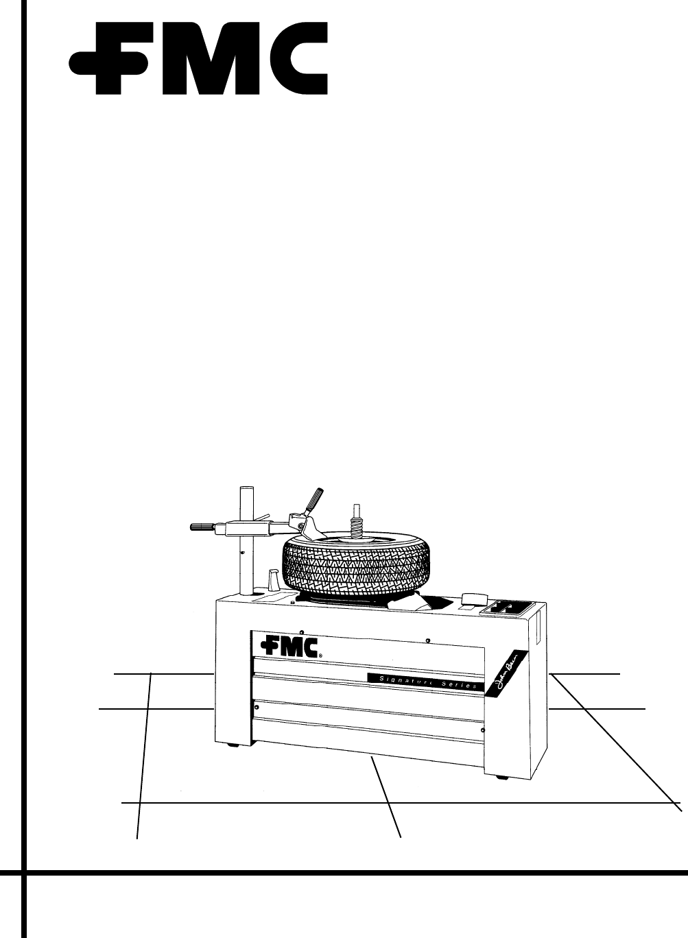
Model 7600/7700
Tire Changer
Operators Manual
Form 77-4208-3
I. INSTALLATION
1. Remove carton, blocks, and machine pro-
tection.
2. Remove tire changer from shipping pallet
(optional).
3. Inspect for any possible shipping damage.
4. Connect 3/8" air supply line to 150 psi
source. A minimum of 120 p.s.i. (maximum
of 180 p.s.i.) is required at machine. Do not
place hands near machine, because it will
cycle when air is applied. To extend the ser-
vice life of the air operated components, the
addition of a Filter/Oiler is recommended.
FMC offers the Air Filter Kit under part no.
66495.
5. Cycle machine and ensure smooth opera-
tion in both forward and reverse directions of
travel. Check air blast and air inflation opera-
tions with deflated tire on the table.
CAUTION: STAND CLEAR OF THE AIR
BLAST RING ON THE TABLE IF AIR
BLAST CAPABILITY IS BEING TESTED
WITHOUT A TIRE/WHEEL OVER IT. THE
AIR SYSTEM MAY CONTAIN FOREIGN
PARTICLES.
6. Install bracket, Lube Bottle, and Brush. Add
approved tire lube mixture to the lube bottle
at this time.
7. Check the location of the stub of the cen-
ter shaft when at rest. It should point to the
right-hand corner of the table for operator con-
venience. It should always return to this lo-
cation at the end of a complete cycle.
MODEL 7600/7700 TIRE CHANGER
OPERATORS MANUAL
TABLE OF CONTENTS
I. INSTALLATION
II. BEAD LOOSENING AND
DEMOUNTING
III. TIRE MOUNTING
IV. TIRE INFLATION
V. SPECIAL WHEELS
VI. MAINTENANCE INSTRUCTIONS
VII. SPECIFICATIONS
VIII. TROUBLESHOOTING THE
7600/7700

8. Check that standard accessories are on
hand. Current list is as follows:
66009 Pin extension weldment
66008 Shaft extension weldment
66181 Dismount boot
66182 Mounting boot
II. BEAD LOOSENING AND
DEMOUNTING
Place the tire and wheel on the conical table
with the narrow side of bead seat up and with
tire valve located on operator’s side of the
machine at 6 o’clock. Secure with locator
positioning pin. Thread the hold-down cone
clockwise on center post. As the tapered end
of the cone enters the rim center hole, the
wheel will adjust itself onto the conical top.
Be sure the hold-down cone is hand tight and
is centered in the rim.
Set the adjustable knob under the lower shoe
to the correct height according to the label
on top of the shoe. On earlier models, insert
one of the two buttons in the hole provided
under the lower shoe.
Add the lower shoe extension if you are de-
mounting a wheel with deeper than usual drop
center. Care should be taken on wheels that
have shallow drop center.
With Alloy Wheels, use the Econo-Mag or one
of the Mag Cushions to secure the wheel. The
hold-down cone centers the wheel. Rubber
spacer ring(s) may be necessary for mount-
ing some wheels. Install the cushion between
hold-down cone and wheel. Using the air in-
flation valve, pressurize the tire to 60 psi (pop-
off valve will exhaust at 60 psi). The Mag
Cushion spreads an equal load over wheel
to prevent any breakage. (See note about
alloy accessories). To deflate a Mag Cush-
ion, simply attach air chuck and press air re-
lease valve.
Remove valve core to deflate tire. Place up-
per bead breaker approximately one inch
away from bead and rim, taking care that the
shoe does not contact the rim.
fig 1
fig 2

Press down on foot pedal and the upper and
lower bead breakers will follow an arc to con-
tact upper bead and loosen it. Simulta-
neously, the lower bead breaker will rise and
loosen bottom bead.
Should upper bead breaker engage rim, stop
operation and move bead breaker back ac-
cordingly.
After loosening beads, apply a liberal amount
of rubber lubricant before demounting tire
from rim. The lubricant makes tire removal
easier and helps to protect the beads. Lubri-
cant should be used to prevent bead dam-
age during mounting/demounting operations.
CAUTION Stabilize combination tool with
Free hand to prevent it from becoming dis-
engaged from the center post and striking
operator or bystander.
Insert combination tool between the upper
bead and rim and align tool with centerpost.
Place combination tool over the center post
and step on the foot pedal. Use left hand to
pull up on tire to help remove it from the rim.
Center post will power the combination tool,
thus removing the upper bead. Repeat for
lower bead removal.
Remove tool from center post before releas-
ing foot pedal at the end of each stroke. When
handling narrow or wide diameter wheels,
limit the stroke to avoid engaging drop cen-
ter of rim.
The dual power capability of the 7600/7700
is utilized fully when mounting or demount-
ing tires onto or off of standard steel rims.
fig 3
fig 4
fig 5

With the standard steel rims, you can realize
the full stroke and power potential of the 7600/
7700 in both directions. This feature allows
you to work with the tire/wheel on every
stroke, thus reducing wasted effort.
Use nylon rim protectors when mounting/de-
mounting Alloy Wheels.
With tube-type wheel, do not extend combi-
nation tool any farther than necessary beyond
bead.
III. TIRE MOUNTING
Place the wheel on table with the valve stem
facing the operator (near 6 o’clock) and cen-
tering pin in a lug hole. Secure tire with a hold-
down cone or Mag Cushion.
Check the height setting of the lower shoe to
prevent it from damaging the rim.
If your machine has the removable lower shoe
feature, you might want to remove the lower
shoe during the tire mounting
process. The lower shoe serves no purpose
during the mounting of a tire.
Apply a liberal amount of lubricant as the first
step in mounting a tire.
Lubrication makes tire mounting easier and
helps protect beads. Also, before mounting
tire, inspect the rim for damage that could
affect bead seating.
Place tire to be mounted over the rim and at
angle indicated. Hook the Combination tool
over the rim and place slot over the center
post. Rotate tire clockwise until the bead is in
the groove on the combination tool and the
lower bead is in the drop center of the wheel.
Using your left hand, push down on the tire
at the 7 o’clock position and step on the foot
pedal. Press down on the right side of the
tire with your right hand and release the pedal.
With your free hand resting on the combina-
tion tool, let the tool rotate and it will install
the tire on the rim. Hold your foot on the pedal,
remove the tool from the tire, and place it over
the edge of the wheel. Double beading tires
is not recommended; however, can be done
for most tire mounting applications.
fig 6
fig 7

IV. TIRE INFLATION
Connect the air inflation chuck to the valve
stem with the valve core removed.
Holding the tire as shown, lift up and rotate
so the top bead is against the rim and par-
ticularly ensuring the top bead is above the
valve stem. Do not hang over the changer.
Step on the air inflation pedal to full extent
and hold approximately one second. This will
deliver a high velocity burst of air from the
inflate tube jets, which will seat beads. As
soon as beads seat, release the pedal and
loosen the hold-down cone.
Remove air inflation chuck and install valve
core, then press the foot pedal half way to
complete inflation of the tire.
During inflation, frequently release the pedal
to read pressure gauge. DO NOT OVER IN-
FLATE. If too much pressure is put into the
tire, it can be bled down by pressing the re-
lieving valve on operators left.
CAUTION: If beads do not seat at 40 psi,
deflate the tire and re-lubricate beads. Do not
exceed tire manufacturers recommended air
pressure when inflating.
V. SPECIAL WHEELS
The 7600/7700 can easily be set up to handle
most specialty wheels and the big GM front-
wheel drive cars (Eldorado, Toronado, &
Riviera), using accessories that are supplied
as standard. The lower shoe angle can be
adjusted by simply turning a threaded knob
below the shoe.
Earlier models were supplied with two lengths
of insertable buttons that raised the lower
shoe to different heights - some even earlier
units came with a bead loosening shim for
use with wide flange alloy wheels.
Econo-Mag or Mag Cushion and accessories
should be used for holding alloy rims to the
changer.
fig 8
fig 9
fig 10
Extensions are also supplied to extend the
length of the lower shoe, the height of the
center shaft, and the locator pin, Nylon rim
protectors are also supplied for use with the
combination tool when handling alloy or
chrome wheels.
Many other options are available if needed.
Consult the Tire Changer Accessory Catalog
or contact the nearest FMC sales Represen-
tative, Distributor, or Field Service Technician.
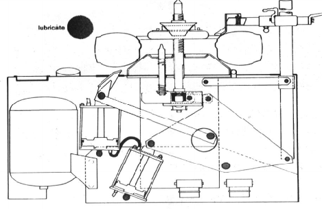
VI. MAINTENANCE INSTRUCTIONS
1. LUBRICATION - periodically remove the
side panels and lubricate pivot pins, & rack
and pinion.
The recommended greases are:
Franklin Oil Corp MTS-1000
Franklin oil H-80 Moly grease
Dow Corning MolyKote 165 open gear lube
Dow Corning MolyKote 299 open gear lube
Dow Corning MolyKote G-Plus paste
Dow Corning MolyKote G paste
2. LOWER SHOE - If equipped with a remov-
able shoe, inspect the condition of shoe re-
taining parts. Replace as necessary.
3. CYLINDER OIL - Stroke of lower bead
breaker should be 6-1 /2". A shorter stroke
may be due to a loss of hydraulic oil (the
power transfer fluid enclosed between the two
cylinders.) Should hydraulic oil appear around
the valve assembly, contact your service rep.
or cylinder repair. Otherwise, hydraulic oil
can be added to the system through the “T”
plug on top of the lower cylinder. Hydraulic
oil must be non-foaming and non-detergent.
The following is a list of preferred oils:
Esso Univis H42
Exxon Univis P32
Exxon Univis J26
SunOil 2105
Mobil Oil D.T.E. 25
4. AIR VALVES AND HOSES - Inspect peri-
odically for air leaks and for presence of wa-
ter or hydraulic oil. Contaminates in the air
system will, if left undetected, tend to cause
“O”rings and valves to deteriorate.
5. LOSS OF POWER - Check:
(a) Air supply - should be 150 psi through
3/8" line.
(b) Air lines for obstruction or leak, or air cyl-
inders for leakage.
(c) Air valves and mufflers (on 4-way valve) -
should be functioning properly with no restric-
tions. Clogged mufflers will
cause a restricted air system, thus slow the
machine down and eventually stop it. Re-
place as necessary.
WARNING: Tire or wheel failure under
pressure can be hazardous. Inspect tire
and wheel carefully for wear or defects
before seating or inflating. Never inflate
tire beyond the tire industry recommen-
dation of 40 psi. Always lubricate with
approved rubber lubricant and never dam-
age tire beads. Keep hands and entire
body back from inflating or inflated tire.
1. Never stand with any part of the body over
a tire during the inflation process.
2. Before starting, release all air from the tire.
3. Place rim with narrowest bead-seat or
flange up.
4. Position tire with valve directly in front of
operator.
5. Hand tighten hold-down cone over adapter
before breaking bead - mounting or demount-
ing.
6. Use approved lubricant on all beads be-
fore breaking over or seating beads.
7. On air inflate unit, depress foot pedal only
when seating or inflating tire.
8. Loosen hold-down cone one full turn im-
mediately after obtaining initial bead seat, and
before attempting further inflation.
9. To seat beads, use a small amount of in-
termittent air. Never exceed 40 psi.
10. During inflation, frequently observe pres-
sure at air gauge and avoid distraction to pre-
vent over-inflation.
VII. Specifications
Rim Diameter:
11.0 - 17" (254-455mm)
Rim Width:
3.0 - 19.75" (76-483mm)
Air Supply (operating range:)
120 - 180 PSI (825-1 238kPa)
Center Post Torque
450 ft. Ibs @ 120 psi
650 ft. Ibs @ 175 psi
(62kgm@825kga, 90kgm @ 1205kPa)
Cylinders:
Two 7" diam. x 6.5" stroke
(177.9mm x 165.1mm)
Surge Tank:
(ASME approved): 10"diam. x
18.75"high (254mm x 476mm):
0.75 cu ft. (21.25L)
Cycle Time:
6 seconds (complete forward and re
verse stroke)
Forward & Return Power
Air-hydraulic
Mount & Demount Capability
Both forward and reverse strokes
Unit Dimensions:
22" x 54.5" x 44"
(0.53m x 1.38m x 1.11 m)
Shipping Volume:
39 cu ft (1.1m3)
Shipping Weight:
500 Ibs (225kg)
NOTE: FMC Corporation reserves the right
to incorporate changes in designs or ma-
terials, affecting product improvements,
without obligation of incorporating same
on equipment of prior manufacture.

7600/7700 Troubleshooting Chart
Possible Causes
Clogged mufflers or 4-way valve
Restricted air line
Low air supply pressure
Leaking dump valve
Air line leak to 4-way valve input
Defective "O" rings in 4-way valve
Defective 4-way valve
Leaking dump valve
Defective pop off valve
Air in hydraulic system
Clogged muffler in lower cyl
exhaust path.
Defective "O" ring in 4-way valve
Leak in air line to lower cylinder
Defective "O" ring cap seal on cyl.
Clogged muffler in upper cyl
exhaust return.
Defective "O" ring in 4-way valve
Leak in air line to upper cylinder
Defective "O" ring cap seal on cyl.
Low on hydraulic fluid
Leak in hydraulic pressure hose
Defective "O" ring cap seal on cyl.
Air in hydraulic system
Lost hydraulic fluid
Defective Hydraulic pressure hose
Defective cylinder cap "O" ring
Broken center shaft
Defective pinion gear
Defective rack wear pad
Worn our DU bearing
Worn out Nyliner bushing
Badly worn pinion gear
Badly worn rack
Air in hydraulic system
Action
Replace mufflers - clean 4-way valve
Clean out or replace
Check compressor & supply line
Replace
Repair fitting/replace line
Replace rings or 4-way valve
Clean, rebuild or replace
Replace
Replace & check air pressure
Call for Service
Replace mufflers
Replace rings or 4-way valve
Repair fitting/replace line
Call for Service
Replace mufflers
Replace rings or 4-way valve
Repair fitting/replace line
Call for Service
Add hyd. fluid at upper cylinder
Tighten clamps or call for service
Call for Service
Call for Service
Call for Service
Call for Service
Call for Service
Replace center shaft, nyliner, DU
Replace pinion gear, pin or both
Replace rack or wear pad
Replace DU bearing
Replace Nyliner bushing
Replace pinion Gear - check wear pad
Replace rack - check pinion
Call for Service
Symptom
1. Stroke becoming slower
2. Decreased shaft power in both
directions
3. Decreased power in forward
stroke only
4. Decreased power in reverse
stroke only
5. Decreased stroke (shaft
travel)
6. Center shaft & cylinders will
not move
7. Center shaft will not rotate,
but breaker operates normally.
8. Center shaft loose
9. Lower shoe "creeps up" after
normal stroke
