Manual Protect 3.M 2.0 English AEG Power Supply 1.1 8000029390 07 BAL En 20110905
User Manual: AEG Power Supply Protect 1.1
Open the PDF directly: View PDF ![]() .
.
Page Count: 81

Uninterruptible
Power Supply UPS
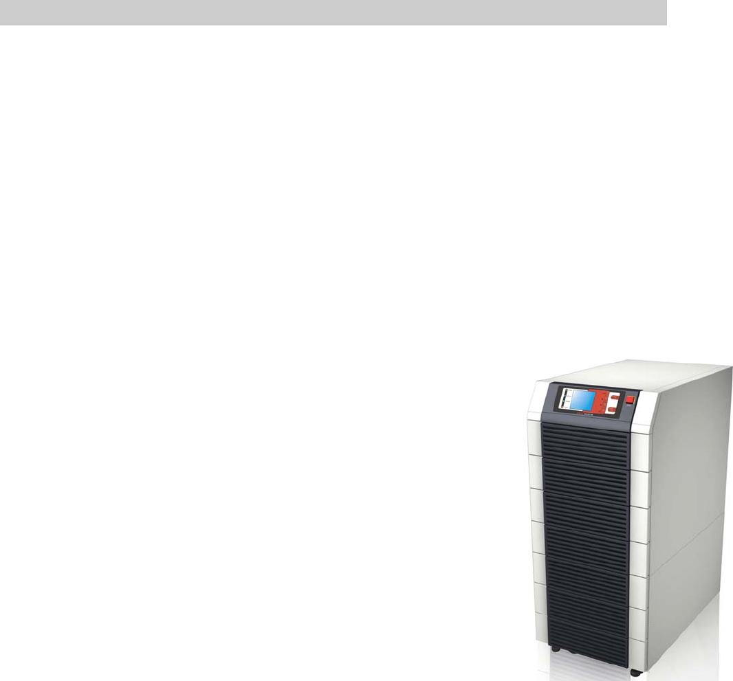
Protect 3.M 2.0
80 / 120 kVA Model
AEG Power Solutions GmbH
Department: EMS PM
Name: Schulz
Revision: 07
Date: 08.09.2011
Operating Instructions
8000029390 BAL, en
Content
0. Important Safety Instructions ..........................................................................0-1
1. Introduction .......................................................................................................1-1
1-1 Advanced Features .....................................................................................1-1
2. Operation...........................................................................................................2-1
2-1 Normal Mode (Single Installation) ...............................................................2-1
2-2 Backup Mode (Single Installation)...............................................................2-1
2-3 Reserve (Bypass) Mode (Single Installation)...............................................2-2
2-4 Manual Bypass Mode (Single Installation) ..................................................2-2
2-5 Normal Mode (Parallel) ...............................................................................2-3
2-6 Backup Mode (Parallel)...............................................................................2-4
2-7 Reserve (Bypass) Mode (Parallel)...............................................................2-5
2-8 Manual Bypass Mode (Parallel)...................................................................2-6
3. General View......................................................................................................3-1
3-1 Appearance .................................................................................................3-1
3-1-1 Dimensions (80kVA).........................................................................3-2
3-1-2 Dimensions (120kVA).......................................................................3-3
3-2 Function Introduction...................................................................................3-5
3-2-1 Front Panel ......................................................................................3-5
3-2-2 Rear Panel.......................................................................................3-6
3-2-3 External Battery Cabinet – Rear Panel ............................................3-7
3-2-4 Power Module ..................................................................................3-9
3-3 Interface ......................................................................................................3-10
3-3-1 Dry Contact Input .............................................................................3-10
3-3-2 Dry Contact Output ..........................................................................3-12
3-3-3 RS232 Port ......................................................................................3-14
3-3-4 Parallel Port .....................................................................................3-14
3-3-5 Smart Card Slot................................................................................3-14
- SNMP Adapter PRO.....................................................................3-15
- SNMP Adapter..............................................................................3-16
- Programmable Relay I/O Card .....................................................3-17
- ModBUS Card ..............................................................................3-18
3-3-6 Additional Options ............................................................................3-19
3-4 Technical Specification ................................................................................3-20
4.Installation ..........................................................................................................4-1
4-1 Before Installation........................................................................................4-1
4-2 Package Inspection.....................................................................................4-1
4-3 Storing Conditions before Installation..........................................................4-2
4-4 Unpacking Procedure..................................................................................4-3
4-4-1 Protect 3.M 2.0 80 kVA ....................................................................4-3
4-4-2 Protect 3.M 2.0 120 kVA ..................................................................4-4
4-5 Installation Environment ..............................................................................4-5
4-5-1 Handling Safety................................................................................4-5
4-5-2 UPS Positioning ...............................................................................4-5
4-5-3 Environment.....................................................................................4-7
4-6 Wiring..........................................................................................................4-8
4-6-1 Preparations.....................................................................................4-8
4-6-2 Wiring (Single Unit) ..........................................................................4-10
4-6-3 Connecting External Battery Cabinet ...............................................4-12
4-6-4 Wiring (Parallel Redundancy, Single Input)......................................4-13
4-6-5 Wiring (Parallel Redundancy, Dual Input) ........................................4-14
5. Operating Procedure.......................................................................................5-1
5-1 Startup Procedure (Single) ..........................................................................5-1
5-2 Battery Startup Procedures (Single)............................................................5-2
5-3 Shutdown Procedure (Single)......................................................................5-2
5-4 Manual Bypass Startup (Single) ..................................................................5-3
5-5 Startup Procedure (Parallel Redundancy)...................................................5-4
5-6 Shutdown Procedure (Parallel Redundancy) ..............................................5-4
5-7 Manual Bypass Startup (Parallel Redundancy) ...........................................5-6
6. Power Module Replacement ............................................................................6-1
6-1 Power Module LED Indication .....................................................................6-1
6-2 Power Module Replacement .......................................................................6-2
7. Display and Configuration ...............................................................................7-1
7-1 Control Panel ..............................................................................................7-1
7-2 LCD Display ................................................................................................7-2
7-2-1 LCD Display Hierarchy.....................................................................7-2
7-3 Default Screen.............................................................................................7-3
7-3-1 Status Display ..................................................................................7-4
7-4 Main Menu ..................................................................................................7-9
7-5 UPS Setup ..................................................................................................7-11
a. Bypass Setup ........................................................................................7-12
b. Output Setup .........................................................................................7-13
c. Battery Setup.........................................................................................7-15
d. Charger Setup .......................................................................................7-17
e. Parallel Setup........................................................................................7-18
f. Control & Test Setup...............................................................................7-19
g. Local Setup ...........................................................................................7-21
7-6 Maintenance................................................................................................7-23

WARNING
This is a class A-UPS product. In a domestic
environment, this product may cause radio
interference, in which case, the user may be
required to take additional measures.
0. Important Safety Instructions
- This manual contains important instructions for the unit that should be followed during installation and
maintenance of the UPS and batteries. All safety and operating instructions should be read thoroughly
before attempting to wire or operate the unit.
- Install the on-line UPS in a well ventilated area, away from flammable liquids and gases. Do not let the
unit come in contact with water.
- External slits and openings in the cabinet are provided for ventilation. To ensure reliable operation of the
product and to protect from overheating, these openings must not be blocked or covered. Objects must
never be inserted into ventilation holes or openings.
- Do not stand beverage containers on the unit.
- This UPS was designed to power all modern computer loads and associated peripheral devices, such
as monitors, modems, cartidge tape drives, external floppy drives and so on. Do not use it for pure
inductive or capacitive loads. It is not rated to power life support equipment.
- All repairs or installation should be performed by qualfied service personnel. The UPS contains voltages
which are potentially hazardous. The output receptacles may be alive even when the UPS is not
connected to the mains.
- Risk of a possible electrocution is possible when the battery is connected to the UPS. Therefore, do not
forget to disconnect the batteries before any service is to be done on the UPS.
- Isolate Uninterruptible Power Supply(UPS) before working on the circuit. A readily accessible
disconnect device (450V, 150A for 80kVA and 225A for 120kVA model) shall be incorporated in the
fixed wiring.
- HIGH LEAKAGE CURRENT – Earth connection essential before connecting power source.
- It is recommended to use a four-pole breaker device and which disconnects all line conductors and the
neutral conductor.
- ATTENTION, hazardous through electrical shock. Also with disconnection of this unit from the mains,
hazardous voltage still may be accessible through supply from the batteries. The battery supply should
be therefore disconnected in the plus and minus pole of the batteries when maintenance or service work
inside the UPS is necessary.
- Do not dispose of the batteries in a fire, the battery may explode.
- Do not open or mutilate the batteries. Released electrolyte is harmful to the skin and eyes. It may be
toxic.
- A battery can present a risk of electric shock and chemical hazard. The following precaution should be
observed when working on batteries.
Remove watches, rings or other metal objects.
Use only tools with insulated handles.
- The UPS only be installed in accordance with the requirements of IEC 60364-4-42.
- The compliance with the following standards provides the conformity:
- EN 62040-1: 2008 (1st edition)
- EN 62040-2 Class A
- EN 62040-3: Class 1
- IEC 61000-4-2 Level 4
- IEC 61000-4-3 Level 3
- IEC 61000-4-4 Level 4
- IEC 61000-4-5 Level 4
- IEC 61000-4-6
SYMBOL INTRODUCTION
PROTECTIVE GROUNDING TERMINAL: A TERMINAL WHICH MUST BE CONNECTED
TO EARTH GROUND PRIOR TO MAKING ANY OTHER CONNECTION TO THE
EQUIPMENT.
A TERMINAL TO WHICH OR FROM WHICH A DIRECT CURRENT OR VOLTAGE MAY BE
APPLIED OR SUPPLIED.
THIS SYMBOL INDICATES THE WORD "PHASE".

Duty to Provide Information
These operating instructions must be read carefully by all persons working with or on the
UPS prior to installation and initial start-up.
These operating instructions are a composite part of the UPS.
The operator of this device is obliged to communicate these instructions to all personnel
transporting or starting the UPS or performing maintenance or any other work on the unit.
Validity
These operating instructions comply with the current technical specifications of the UPS at
the time of publication. The contents do not constitute a subject of contract, but serve for
information purposes only.
AEG Power Solutions GmbH reserves the right to make modifications with regard to contents
and technical data in these operating instructions without prior notification. AEG Power
Solutions GmbH cannot be held liable for any inaccuracies or inapplicable information in
these operating instructions, as no obligation to continuously update the data and maintain
their validity has been entered into.
Warranty
Our goods and services are subject to the general conditions of supply for products of the
electrical industry and our general sales conditions. We reserve the right to alter any
specifications given in these operating instructions, especially with regard to technical data,
operation, weights and dimensions. Claims in connection with supplied goods must be
submitted within one week of receipt, along with the packing slip. Subsequent claims cannot
be considered.
AEG Power Solutions GmbH will rescind all obligations such as warranty agreements,
service contracts etc. entered into by AEG Power Solutions GmbH or its representatives
without notice in the event of maintenance and repairs being carried out with anything other
than original AEG Power Solutions GmbH parts or spare parts purchased by AEG Power
Solutions GmbH.
AEG Power Solutions GmbH
Emil-Siepmann-Straße 32
D-59581 Warstein
Germany
For Service contact please visit our international website:
http://www.aegps.com
Copyright
Weitergabe, Vervielfältigung und/oder Übernahme dieser Betriebsanleitung mittels
elektronischer oder mechanischer Mittel, auch auszugsweise, bedarf der ausdrücklichen
vorherigen schriftlichen Genehmigung der AEG Power Solutions GmbH.
Copyright AEG Power Solutions GmbH 2010. All rights reserverd.
1-1
1. Introduction
AEG Protect 3.M 2.0 Series UPS is designed for large-scale power systems applied in
data center, communication, networking, medical, safety and emergency systems and
all factory facilities.
With innovative PFC design and IGBT architecture, the Protect 3.M 2.0 Series
features high efficiency, low iTHD, low noise and high reliability.
The Protect 3.M 2.0 Series has a modular structure and hot-swappable function to
easily perform maintenance and reduce the MTTR (Mean Time to Repair).
The manual is valid for both models (80/120kVA). The drawings show the 80kVA
model if not different from the 120kVA UPS.
1-1 Advanced Features
Power Rating: 20/40/60/80 kVA or 20/40/60/80/100/120
kVA.
Up to 4/6 modules work in parallel in the single cabinet.
N+x parallel redundancy and expansion (Up to 4/6 units).
No need any extra parallel control card.
High input power factor(pf > 0.99) and low input current
(THDI: < 5%) for installation cost savings and utility
pollution reduction.
Overall high efficiency up to 94,5% with modular structure
and hot-swappable function for operation cost savings.
Dual input – separated rectifier and bypass input.
Built-in manual and static bypass switch for maintenance.
Built-in SRAM, record up to 500 real-time event logs.
Redundant auxiliary power and control circuit. Double
insurance of performing reliability.
Scheduled battery test and battery replacement warning.
Local and remote emergency power off function (LEPO
and REPO).
Compatible with generator design.
Double conversion and IGBT technology.
Multi-interface monitoring and controlling.
User-friendly LCD display and LED indicators.
External battery pack. Limitation of autonomy time
only by capacity of the batteries.
2-1
CB1
CB2
CB3
CB4
CB5
LOAD
MAIN
RESERVE
STS
2. Operation
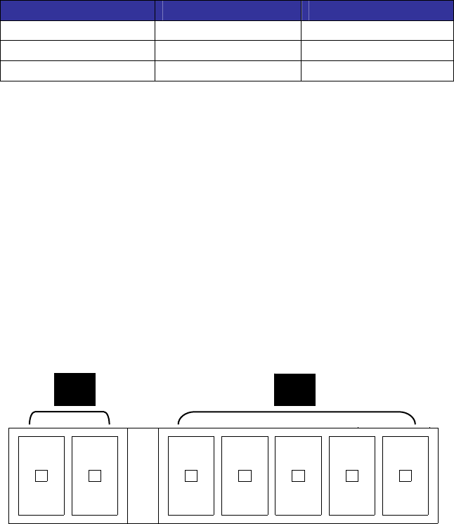
There are four basic operation modes for Protect 3.M 2.0 Series.
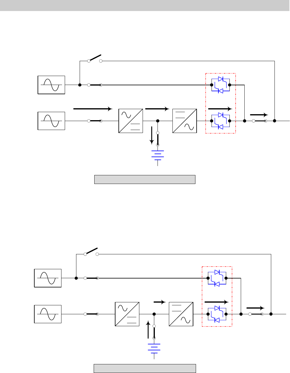
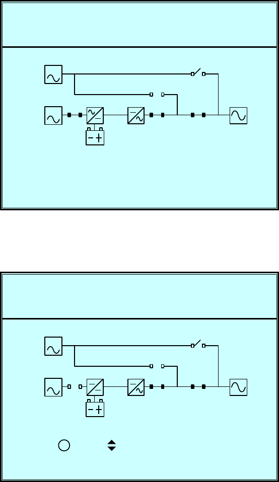
2-1 Normal Mode (Single Installation)
Fig. 2-1 Normal Mode (Single)
In normal mode, DC power rectified from AC input power charges batteries and
powers the inverter that transforms DC power to stable and clean AC power for
various loads. The “Double Conversion” technology allows regulating the utility to
provide pure and stable power to your precious equipment (Refer to Fig. 2-1).
2-2 Backup Mode (Single Installation)
Fig. 2-2 Backup Mode (Single)
When a power event (blackout, transient, surge, fluctuation…) occurs, the UPS will
automatically transfer from normal mode to backup mode. The battery will provide
emergency power to the inverter and then to the loads (Refer to Fig. 2-2).
CB1
CB2
CB3
CB4
CB5
LOAD
MAIN
RESERVE
STS
2-2
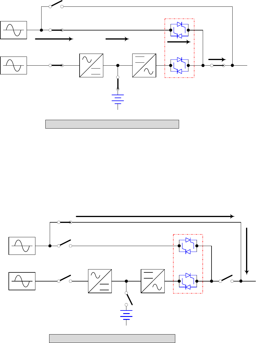
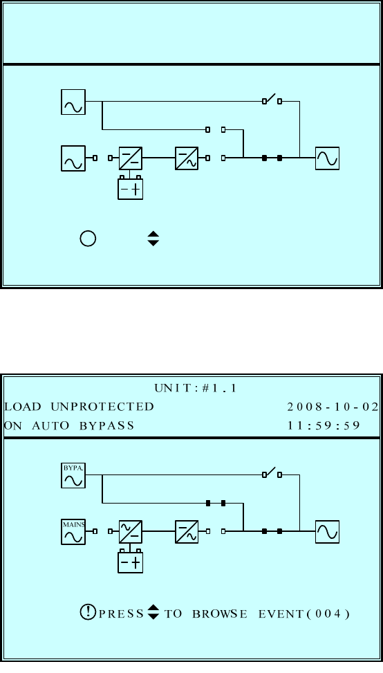
2-3 Reserve (Bypass) Mode (Single Installation)
Fig. 2-3 Reserve (Bypass) Mode (Single)
The inverter will shut down if it encounters any abnormal situation (such as over
temperature, long-time overload, output short, abnormal output voltage and battery
exhausted problems). If the reserve power is available, the UPS will automatically
transfer to reserve mode to make sure the supply to the loads. After abnormal
situations are eliminated, UPS will transfer back to the normal mode immediately
(Refer to Fig. 2-3).
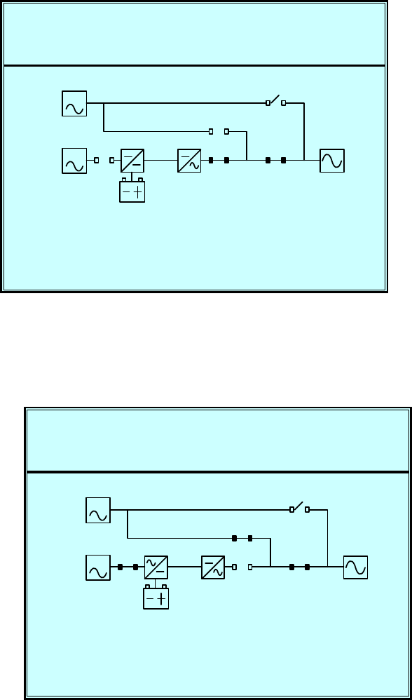
2-4 Manual Bypass Mode (Single Installation)
Fig. 2-4 Manual Bypass Mode (Single)
In maintenance or repair service condition, you will need to cut off the UPS power but
not the power to your equipment. Make sure the UPS is in Bypass mode (see LED at
the front panel), then manually switch the UPS to bypass mode. (Refer to Fig. 2-4).
CB1
CB2
CB3
CB4
CB5
LOAD
MAIN
RESERVE
STS
CB1
CB2
CB3
CB4
CB5
LOAD
MAIN
RESERVE
STS
2-3
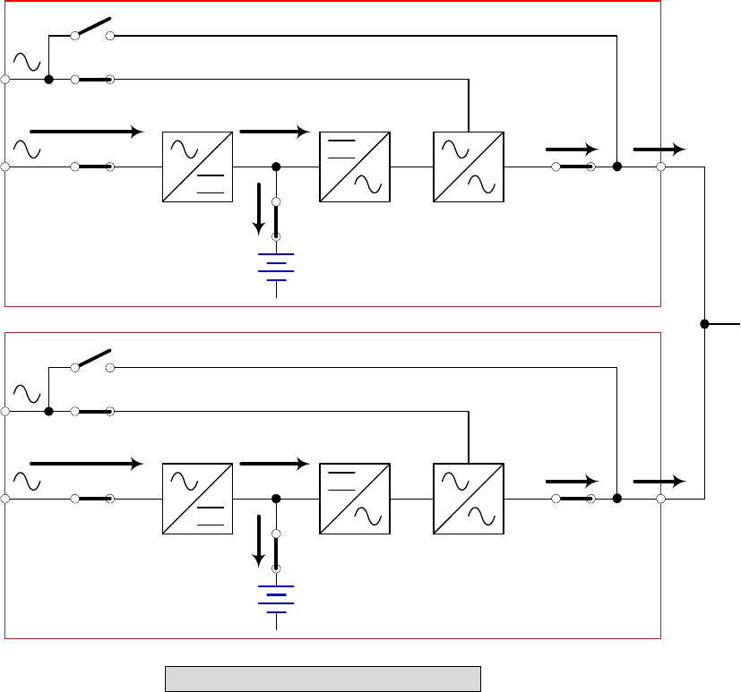
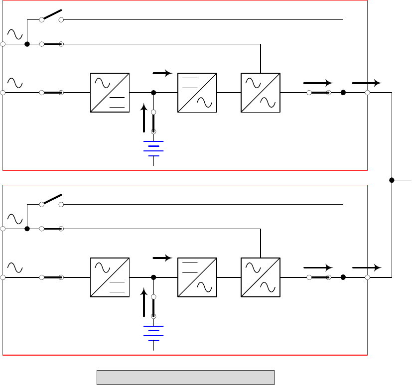
2-5 Normal Mode (Parallel)
Protect 3.M 2.0 Series provides a parallel combination (up to 4 units) to get
redundancy or expand the total capacity.
Fig. 2-5 Normal Mode (Parallel)
Under this installation, the load is shared by two UPS units. If there is any problem in
one of them, the load will be entirely handled by the other. In case the load is greater
than one UPS can take, the UPS will shut down and then transfer all UPS to the
reserve mode (Refer to Fig. 2-5).
CB1
CB2
CB3
CB4
CB5
UPS1
MAIN
RESERVE
STS
CB1
CB2
CB3
CB4
CB5
LOAD
MAIN
RESERVE
STS
UPS2
2-4
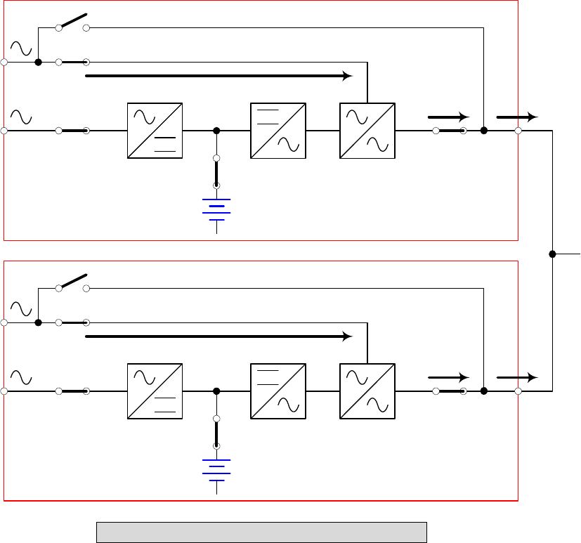
2-6 Backup Mode (Parallel)
Fig. 2-6 Backup Mode (Parallel)
The load is shared by two UPS units when a blackout occurs (Refer to Fig. 2-6).
CB1
CB2
CB3
CB4
CB5
UPS1
MAIN
RESERVE
STS
CB1
CB2
CB3
CB4
CB5
LOAD
MAIN
RESERVE
STS
UPS2
2-5
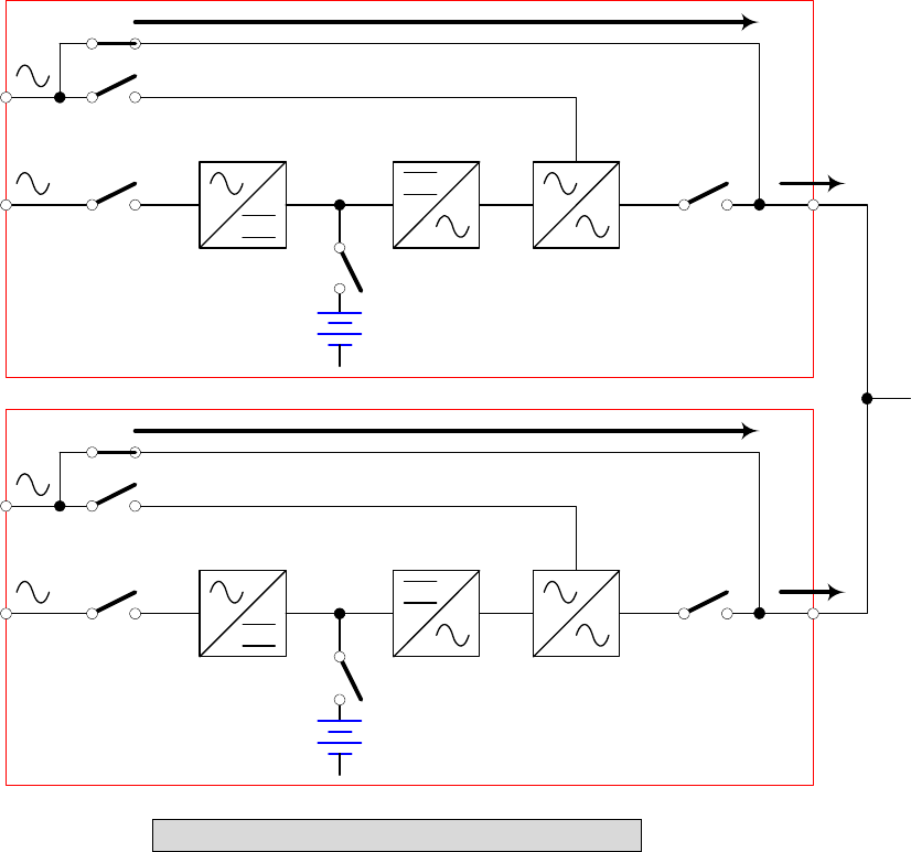
2-7 Reserve (Bypass) Mode (Parallel)
Fig. 2-7 Reserve (Bypass) Mode (Parallel)
The same as what mentioned in Section 2-3 except two UPS units sharing the load.
All parallel UPS will switch at the same time (Refer to Fig. 2-7).
CB1
CB2
CB3
CB4
CB5
UPS1
MAIN
RESERVE
STS
CB1
CB2
CB3
CB4
CB5
LOAD
MAIN
RESERVE
STS
UPS2
2-6
2-8 Manual Bypass Mode (Parallel)
Fig. 2-8 Manual Bypass Mode (Parallel)
The same as what mentioned in Section 2-4 except two UPS units sharing the load.
Remember that all parallel UPS should be transfer to manual bypass mode. The
Reserve mains should be equal for all parallel UPS (Refer to Fig. 2-8).
CB1
CB2
CB3
CB4
CB5
UPS1
MAIN
RESERVE
STS
CB1
CB2
CB3
CB4
CB5
LOAD
MAIN
RESERVE
STS
UPS2
3-1
3. General View
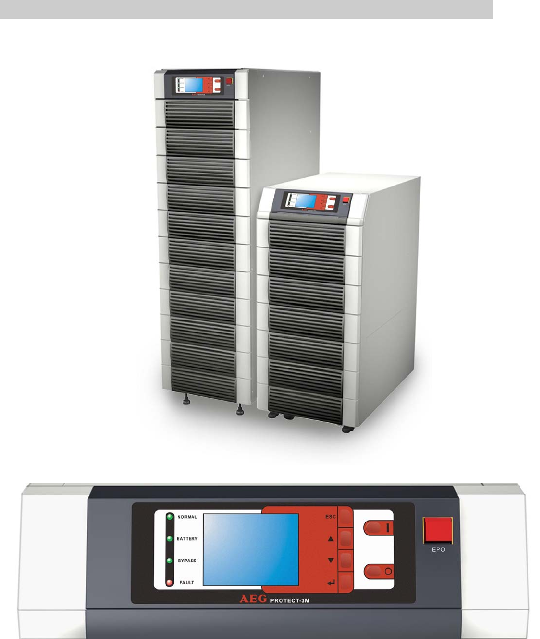
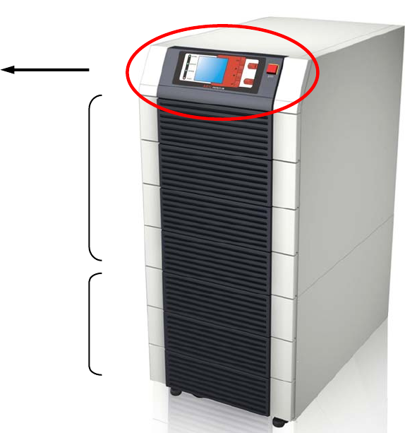
3-1. Appearance
LCD Display and Control Panel
3-2
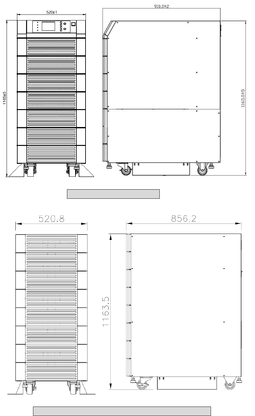
3-1-1 Dimensions (80kVA)
Fig. 3-1 Power Unit 80kVA
Fig. 3-2 External Battery Pack 80 kVA cabinet size
3-3
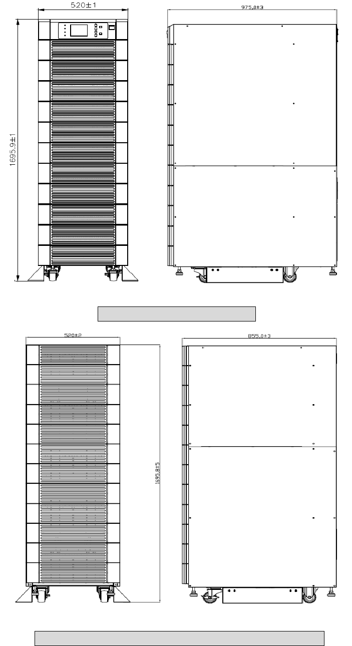
3-1-2 Dimensions (120kVA)
Fig. 3-3 Power Unit 120 kVA
Fig. 3-4 External Battery Pack 120 kVA cabinet size
3-4
3-2 Function Introduction
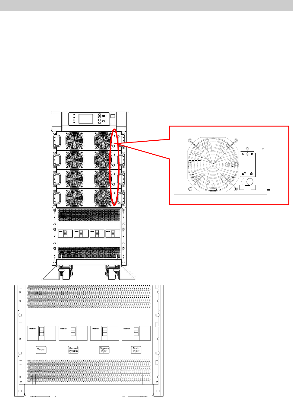
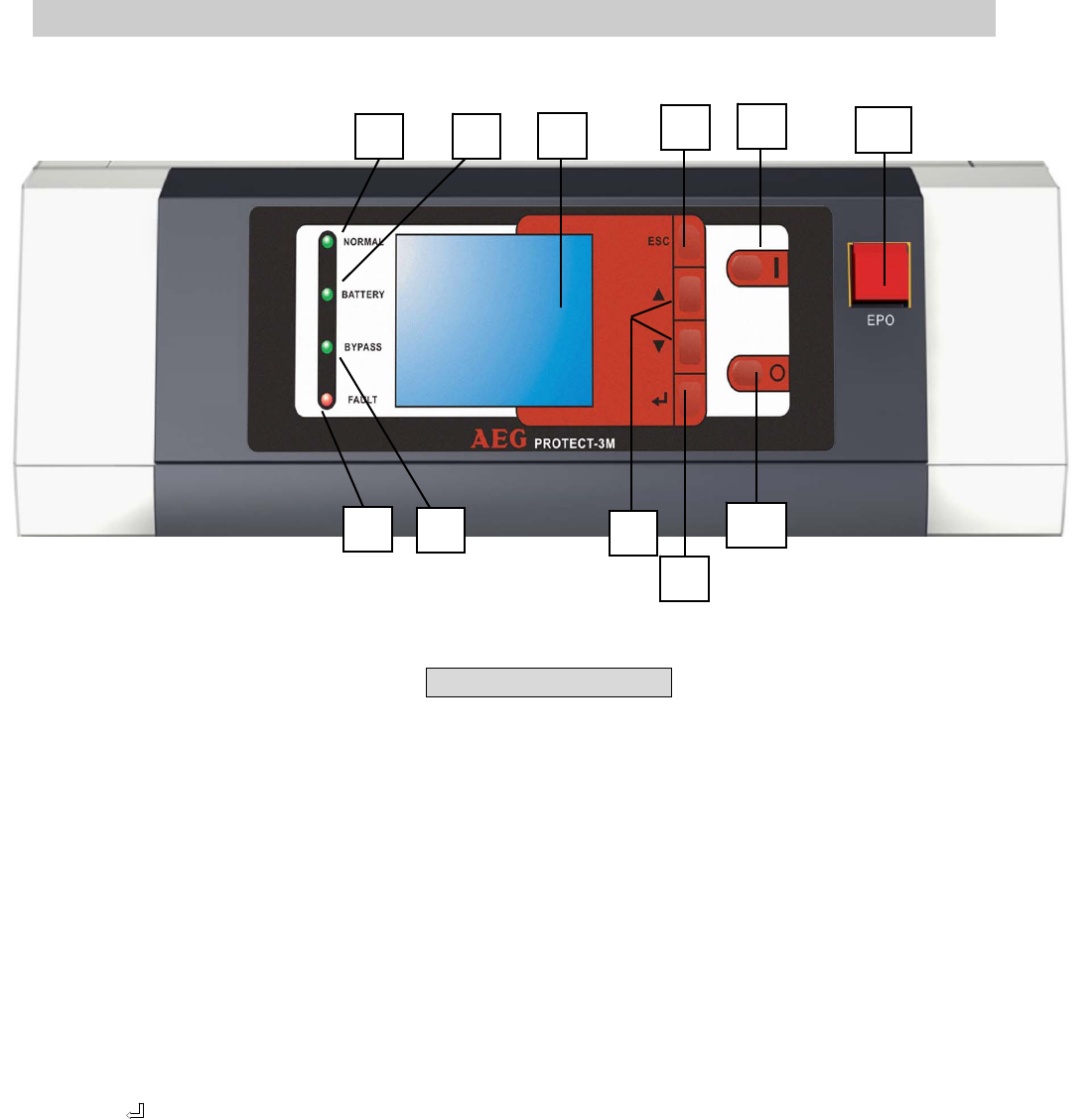
3-2-1 Front Panel
1. LCD Display and Control Panel
/ Status LED indicators
- UPS status and message display.
- Parameter settings and button control.
- UPS startup / shutdown.
- EPO: Emergency power off.
2. Power Modules
- Bezel can be easily removed for maintenance.
- The minimum capacity of each power module is 20KVA and the height is 3U
(132cm).
- The capacity can be expanded at most 4/6 modules i.e.
the maximum capacity in a single cabinet is 80KVA/120kVA.
- Hot swap function for module replacement.
3. Input and Output Circuit Breakers
- There are four circuit breakers: Input, Bypass, Manual Bypass
and Output.
- LCD Display
- Control Panel
- Status LED Indicators
Power Modules
I/P and O/P Protectors
3-5
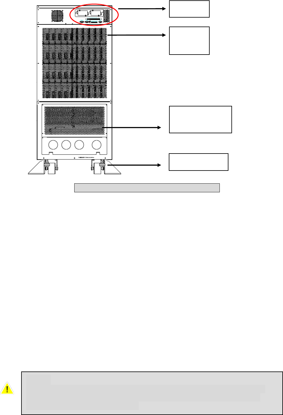
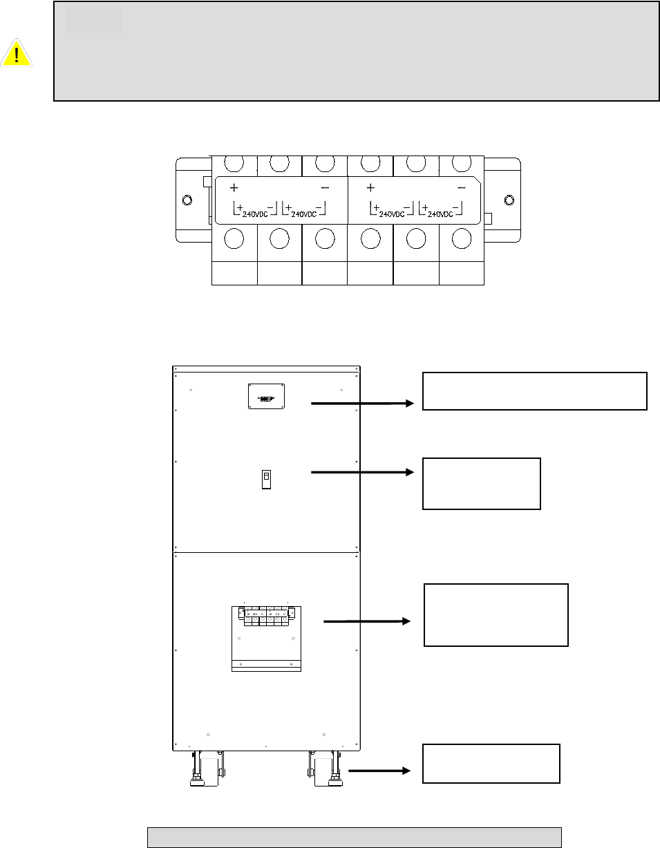
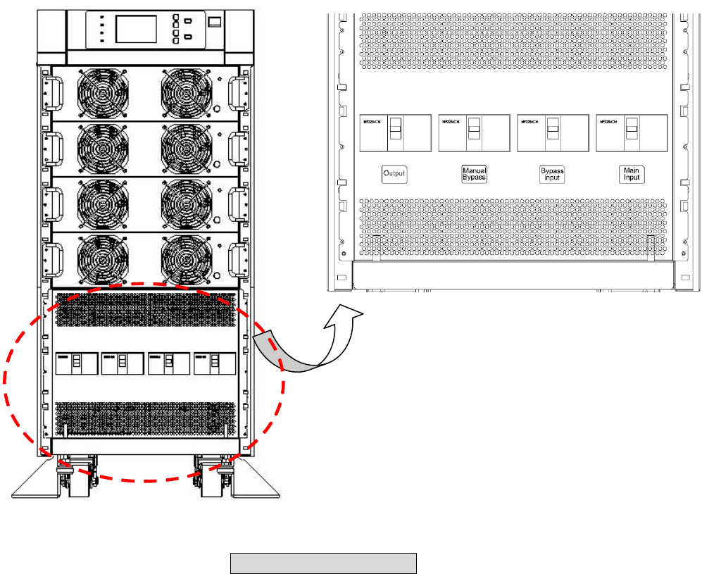
3-2-2 Rear Panel
1. Interfaces
Provide multi-interface for monitoring and control purpose.
There are:
(1) Two multi-function slots (SNMP Adapter, Relay I/O control card and Mobus
card are optional accessories).
(2) Interface for UPS parallel operation
(3) Input and output dry contacts.
(4) RS232: 9-pole Sub-D for external configuration and software updates
2. Power modules
- Remove the cover. After this you have access to the internal wiring for power
modules.
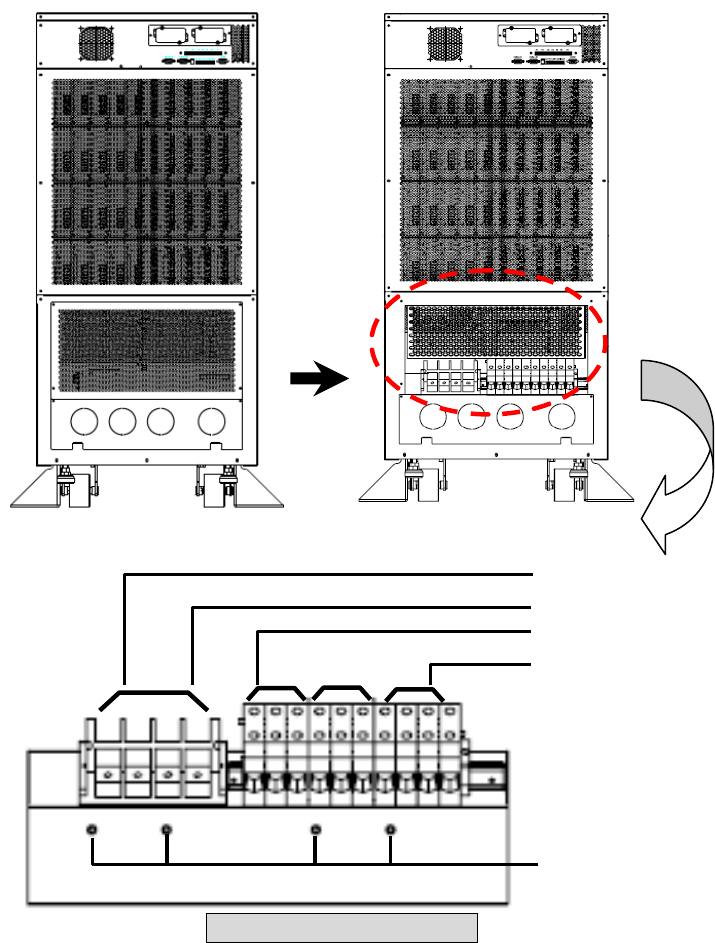
3. Wiring terminal block
- Remove the cover to perform wiring for input, output and external battery.
- Input power source: 3 phases (L1, L2, L3 and neutral N).
- Bypass input source: 3 Phases (L1, L2 and L3).
- External battery pack: positive (+), negative (-) and neutral N.
- UPS output: 3 Phases (L1, L2, L3 and neutral N).
- Protection Earth
Interface
Wiring
Terminal Block
Caster & Stop
Power
Modules
Fig. 3-5 Rear view of Protect 3.M 2.0 80kVA
Note:
Inside the UPS all Neutrals are connected to one common point. If you
have a separate Bypass input source, connect the Neutral also to the
Input Power source “N” terminal.
3-6
Different regions may have their own markings of power phases.
The following table is a cross reference for possible use.
Three Phase America / Asia Europe
L1 R U
L2 S V
L3 T W
4. Caster & Stop:
- Move the UPS for short distance.
- Casters with stop function.
- Adjustable leveler for stabilization.
- Balance supporter for safety.
3-2-3 External Battery Cabinet – Rear Panel
1. Monitoring Contacts
There are two kinds of messages that can be transmitted.
- Battery cabinet temperature
- Battery cabinet status
For more details, refer to Seciton 3-3.
2. Protector
Protection and control switch for batteries.
3. Caster & Stop
- Move the UPS for short distance.
- Casters with stop function.
- Adjustable leveler for stabilization.
- Balance supporter for safety.
A B
A: Temperature of Battery Cabinet
B: Status of Battery Cabinet
3-7
N
240VDC 240VDC
N
240VDC 240VDC
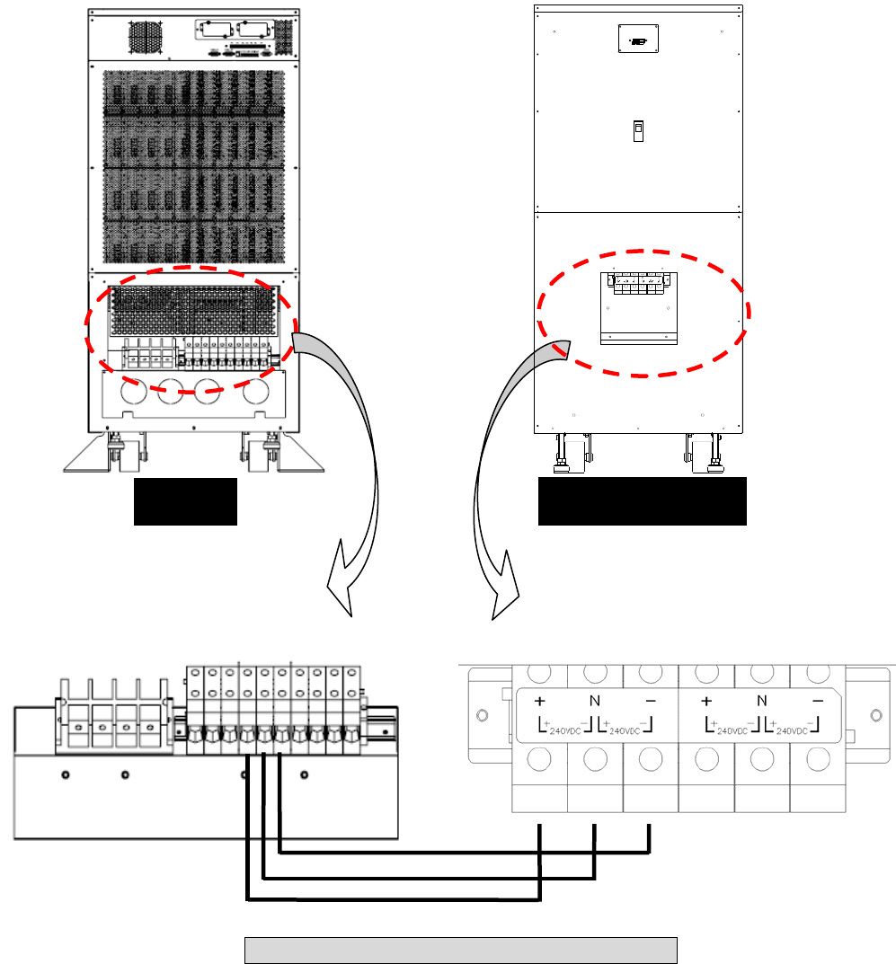
4. Wiring Terminal Block
- You can remove the cover to perform the connection.
- Terminal: Positive(+), negative(-) and neutral (N).
- Two blocks for connecting the UPS and the next battery cabinet.
Circuit
Breaker
Caster & Stop
Wiring
Terminal Block
Monitorting Contacts
Fig. 3-6 Rear View of Battery Cabinet 1165mm height
N N
Note:
For longer autonomy times you can connect up to 4 battery cabinets in
parallel. If you use only one battery cabinet the maximum UPS power for
one 1165 mm cabinet is 40kVA, for one 1665mm is 60kVA.
3-8
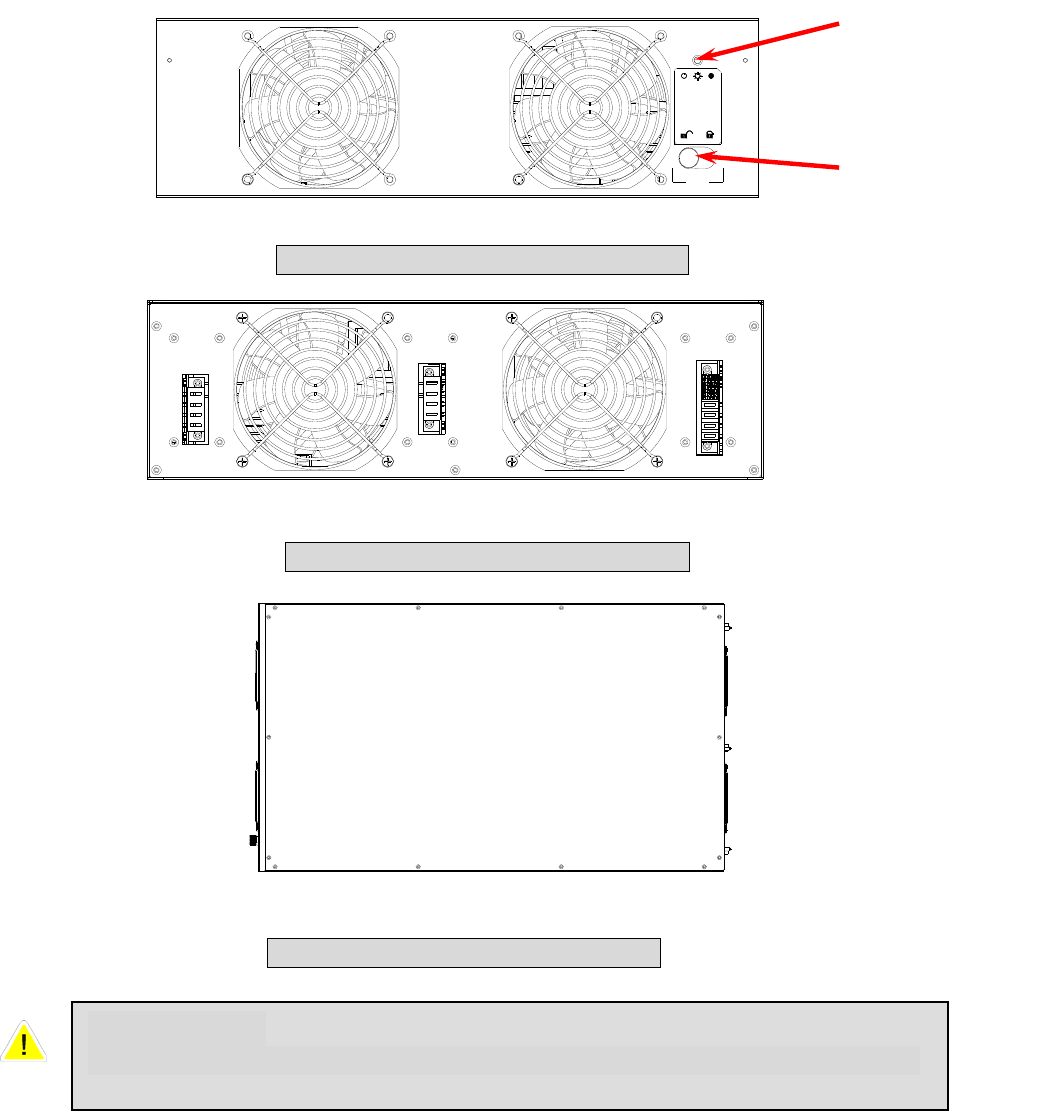
3-2-4 Power Module
Each power module is an independent 20kVA/16kW unit, consisting of a power factor
corrected rectifier, a battery charger and an inverter, with associated monitoring and
control circuitry.
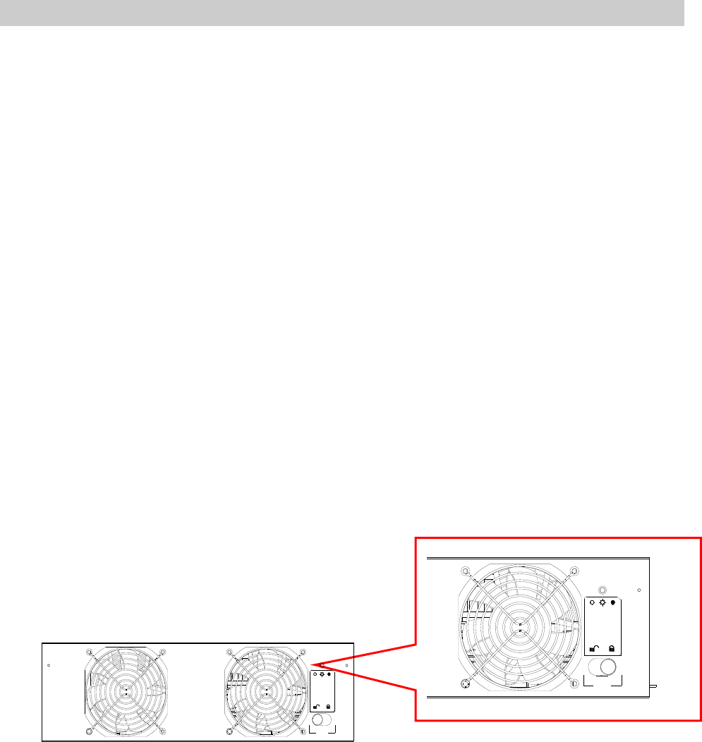
Fail OnOff
Status LED
Locking Latch
Fig. 3-7 Front View of Power Module
Fig. 3-8 Rear View of Power Module
Fig. 3-9 Top View of Power Module
CAUTIONS!
Power Modules are heavy (~30kg). Two people are required for handling.
3-9
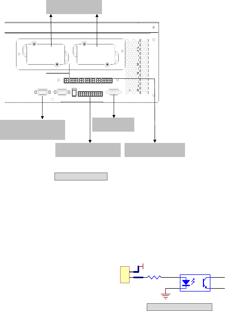
3-3 Interface
3-3-1 Dry Contact Input
P1: REPO (Remote Emergency Power Off)
P2: Dry contact input (Two sets)
P3: External Battery Cabinet Temperature 1
P4: External Battery Cabinet Temperature 2
P5: External Battery Cabinet Temperature 3
P6: External Battery Cabinet Temperature 4
P7: Battery cabinet monitoring
1. P1: REPO
The Protect 3.M 2.0 Series provides a convenient
method for users remotely power off the UPS if an
emergency event occurs.
Simply connect the cable from remote site to this terminal.
The user may install a button or switch to easily press the
button to power off the UPS Inverter. This REPO is a normal
open contact. After reopening the REPO contact the inverter
will not start automatically.
1
2
12V
1
2
4
3
Fig. 3-11 REPO Circuit
Fig. 3-10 Interface
RS232 Port
P1 P2 P3 P4 P5 P6 P7
RS232
OUTPUT DRY CONTACT
PARALLELPARALLEL
Smart Card Slot
Interface for UPS
parallel operation
Dry Contact Output Dry Contact Input
3-10
1
2
3
4
12V
12V
1
2
4
3
1
2
4
3
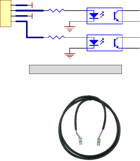
2. P2: Dry Contact Input (Two sets)
The Protect 3.M 2.0 UPS provides two sets of
dry contact input to receive external signals and
then the UPS can take corresponding response.
These contacts belong to “normal open” type.
3. P3~P6: External Battery Cabinet Temperature
You can order the optional accessory “sensor kit” to detect the
temperature of external battery cabinet. (6000008725)
4. P7: Status of External Battery Cabinet
Pin1: +12V
Pin2: The detection cable is connected.
Pin3: Status of external battery cabinet breaker:
- Signal active means the breaker is on.
- Signal inactive means the breaker is off.
Pin4: Reserved
Pin5: Reference voltage
Fig. 3-12 Dry Contact Input
3-11
3-3-2 Dry Contact Output
Fig. 3-13 Dry Contact Output
3 4
1 2
+12VS
DRY1
3 4
1 2
+12VS
DRY2
3 4
1 2
+12VS
DRY3
3 4
1 2
+12VS
DRY4
3 4
1 2
+12VS
DRY5
3 4
1 2
+12VS
DRY6
1
2
3
4
5
6
7
8
9
10
11
12
COMM_A
COMM_B
DRYA_NO
DRYB_NO
COMM_C
COMM_D
DRYC_NO
DRYC_NO
DRYE_NO
DRYF_NO
COMM_E
COMM_F

3-12
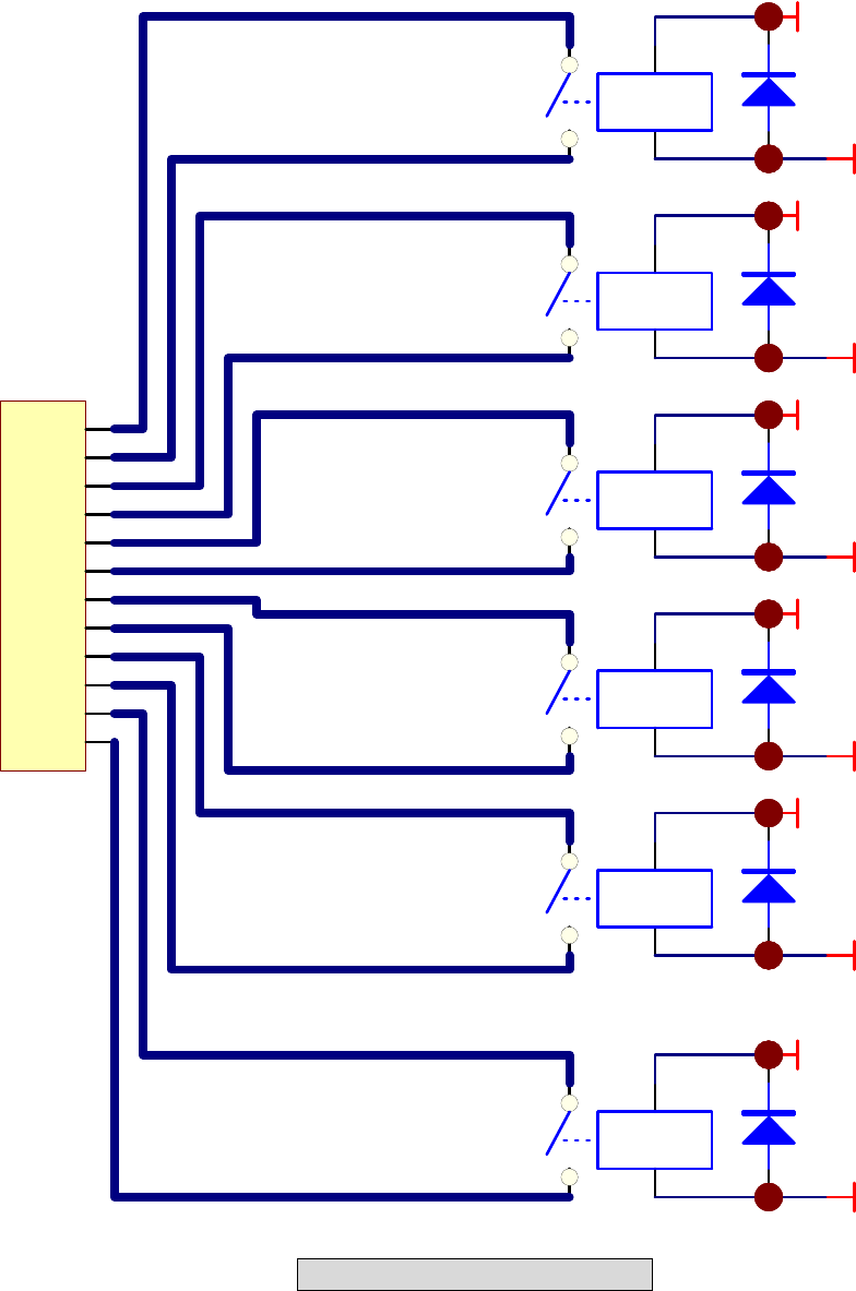
The Protect 3.M 2.0 Series UPS provides 6 dry contact outputs. These contacts can
be set to normally open or normally close. The default message is shown in the table
below.
There are other 13 choices as shown below.
Contact Message Description
7. Internal communication
failure The communication of module is abnormal.
8. External parallel
communication failure During installation of the parallel redundancy, the parallel
communication is abnormal.
9. Output overload
warning/shutdown The loading is over rated output of the UPS.
10. Power module fault
shutdown The module fails and the UPS is shut down.
11. Power module warning The module has errors, but the UPS can still function
normally.
12. EPO activated Urgently power off the UPS.
13. Load on manual bypass The UPS transfers to manual bypass mode.
14. Battery cabinet over
temperature
warning/shutdown
The temperature is too high.
15. Output voltage abnormal The output voltage is too high or too low.
16. Battery need replace Overdue for battery replacement (Compared with system
setup.)
17. Bypass over temperature
warning/shutdown Bypass “static transfer switch” is over temperature.
18. Battery ground fault Grounding error
19. Bypass static switch fault The bypass “static transfer switch” is abnormal.
20. Summary Alarm
Contact Message Description
Pin1-2 Load on inverter The UPS is working normally.
Pin3-4 Load on auto bypass The UPS is in bypass mode.
Pin5-6 Mains1 input fails when
loading on inverter The Utility is blackout or abnormal. The UPS is in backup
mode.
Pin7-8 Battery low The UPS is in backup mode, and the battery voltage is closed
to the terminative limit. (The battery voltage is lower than
220V.)
Pin9-10 Bypass input abnormal The bypass is abnormal (frequency, phase), and the output
frequency will follow the rating.
Pin11-12 Battery test failure Performs the battery test. The battery voltage is lower than the
default value.
3-13
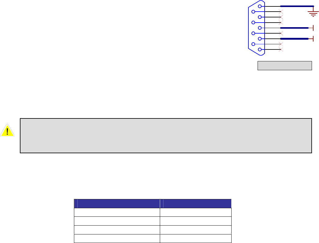
3-3-3 RS232 Port
Use a RS232 cable to connect a computer.
3-3-4 Parallel Port
For redundancy or expansion installation, you simply connect two UPSs via a parallel
communication cable.
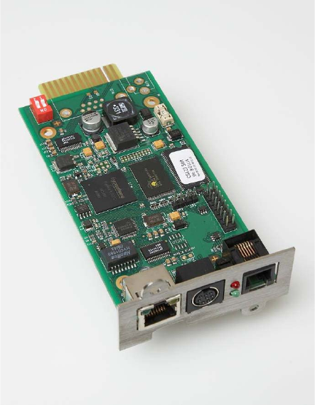
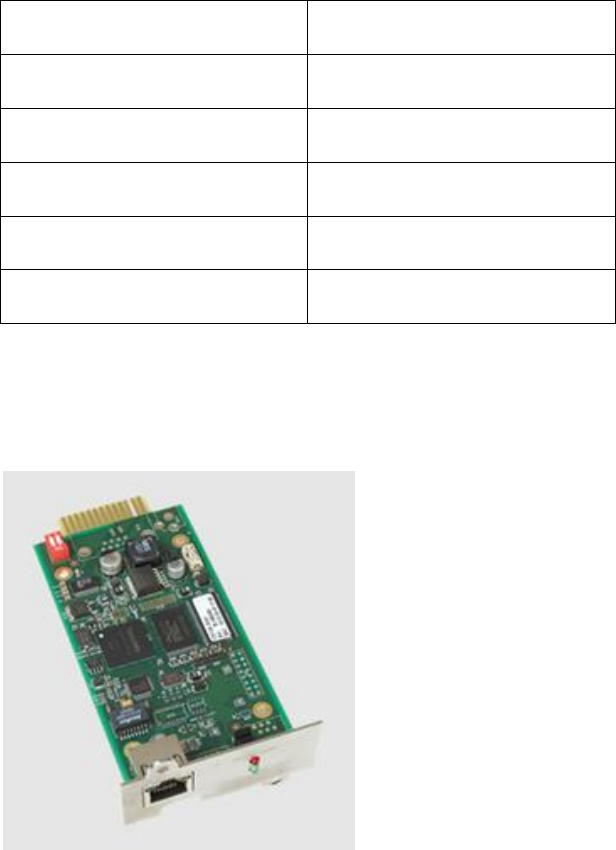
3-3-5 Smart Card Slot
The Protect 3.M 2.0 Series UPS provides two smart slots. AEG offers many powerful
smart cards for various applications. There are 4 accessories available as below.
Please contact your local dealer or agent for orders.
Smartcard Part-No.
SNMP-Adapter PRO 6000001271
SNMP Adapter 6000004036
Relais I/O Card 6000008721
MODBUS Card 6000008722
1
6
2
7
3
8
4
9
5
TX
RX
Fig. 3-14 RS232
Use the parallel communication cable in the accessory pack. Linking the UPS
with other cables might result in communication problems. Max. length of the
parallel cable: 10 meters.
3-14
- SNMP-Adapter PRO (Part-No.: 6000001271)
Features:
RJ45-Network Port
Prepared to connect up to 4 external dry contacts for additional signalling
Prepared to connect an external temperature and humidity sensor
(8000022493)
Agent for RFC1628 MIB UPS standard MIB
Embedded Web-Server
Monitoring via Web
Configuration via Web
Embedded Event Manager
Start of different Jobs
Net Broadcast
E-Mail
Monitoring of environmental conditions
Temperature, Humidity, GenSet, Fire, Air condition, Smoke shutter...
Support Software products
Network Management Software „NMS“
NMS special for Power Supply Systems
Shutdown Software “CompuWatch”
Direct multi-server shutdown of different OS with communication modules
3-15
Technical Data:
Network Line connection RJ-45 (10/100MBits)
Temperature 0~40 °C
Humidity 10~80 % (rel.)
Operation Voltage 12 V DC
Dimensions (D x W x H) 130 x 60 x15 mm
Weight 66 g
- SNMP-Adapter (Part-No.: 6000004036)
Same features as SNMP Adapter but only including RJ-45 Network plug in
connector. No connection of additional dry contacts or external sensors
possible.
3-16
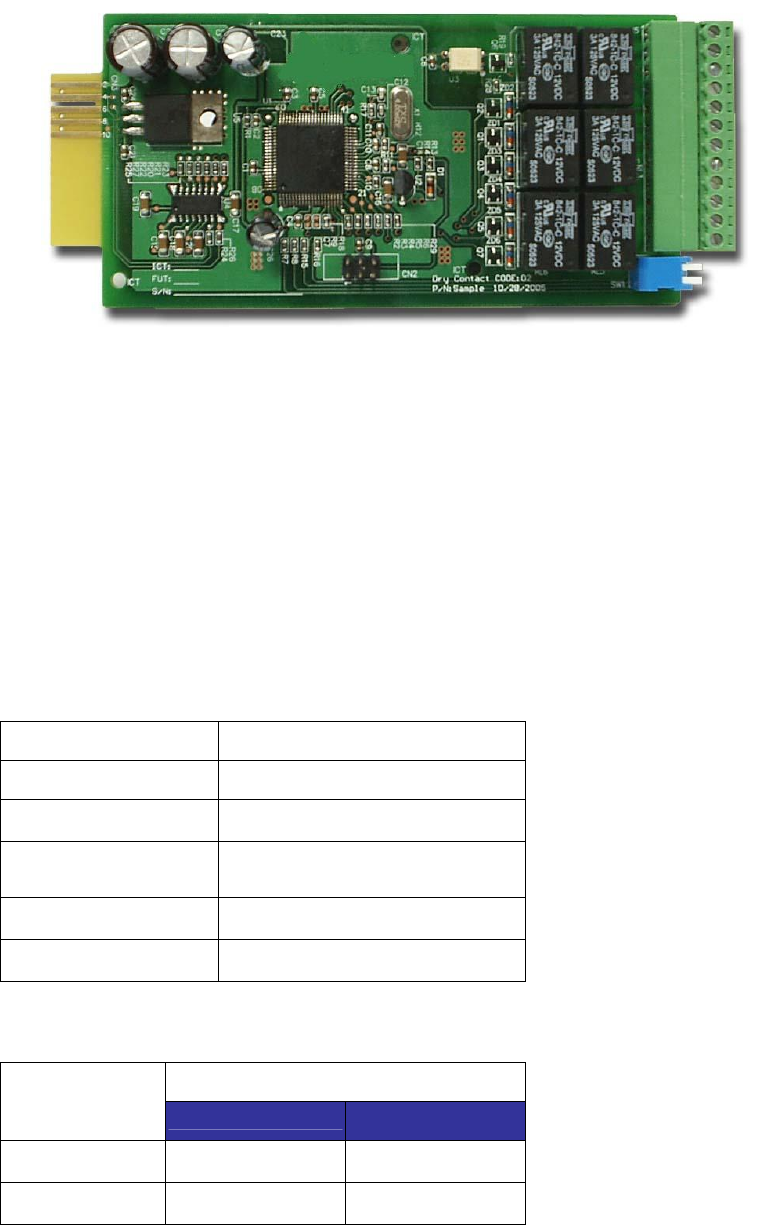
3- Programmable Relay I/O Card (Part No.: 6000008721)
Features:
6 output and 1 input dry contact
Outputs configurable
Input for UPS shutdown or Battery Test
Configuration over RS 232 terminal server
Output contact rating: 24VDC, 1A
Input rating: 24V, 10mA
Technical Specification
Relay I/O
Input Power 8 ~ 20VDC
Temperature 0 ~ 40°C
Humidity 10 ~ 80 %
Power
Consumption 1.2 Watt.(Maximum)
Dimension(L x W) 130x60mm
Weight 200g
Maximum
DC Voltage DC Current
R1~R6 24V 1A
Opto-Input 24V 10mA
3-17
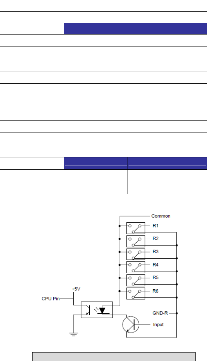
I/O Definition
GND-R: Relay Grounding
Common: 12 ~ 24VDC
Default
R1 Summary Alarm
R2 Input Power Fail
R3 Battery Low
R4 UPS in Bypass Mode
R5 Overload
R6 Over Temperature
Input: Remote shutdown or battery test
Tx: Transmit to PC, connect to RS232 pin-2.
Rx: Receive from PC, connect to RS232 pin-3.
GND-C: Ground for configuration, connect to RS232 pin-5.
OFF (Default) ON
SW1 Normally Open Normally Close
SW2 Default Settings Customized Settings
Fig. 3-15 Circuit diagram Relay I/O Card contacts
3-18
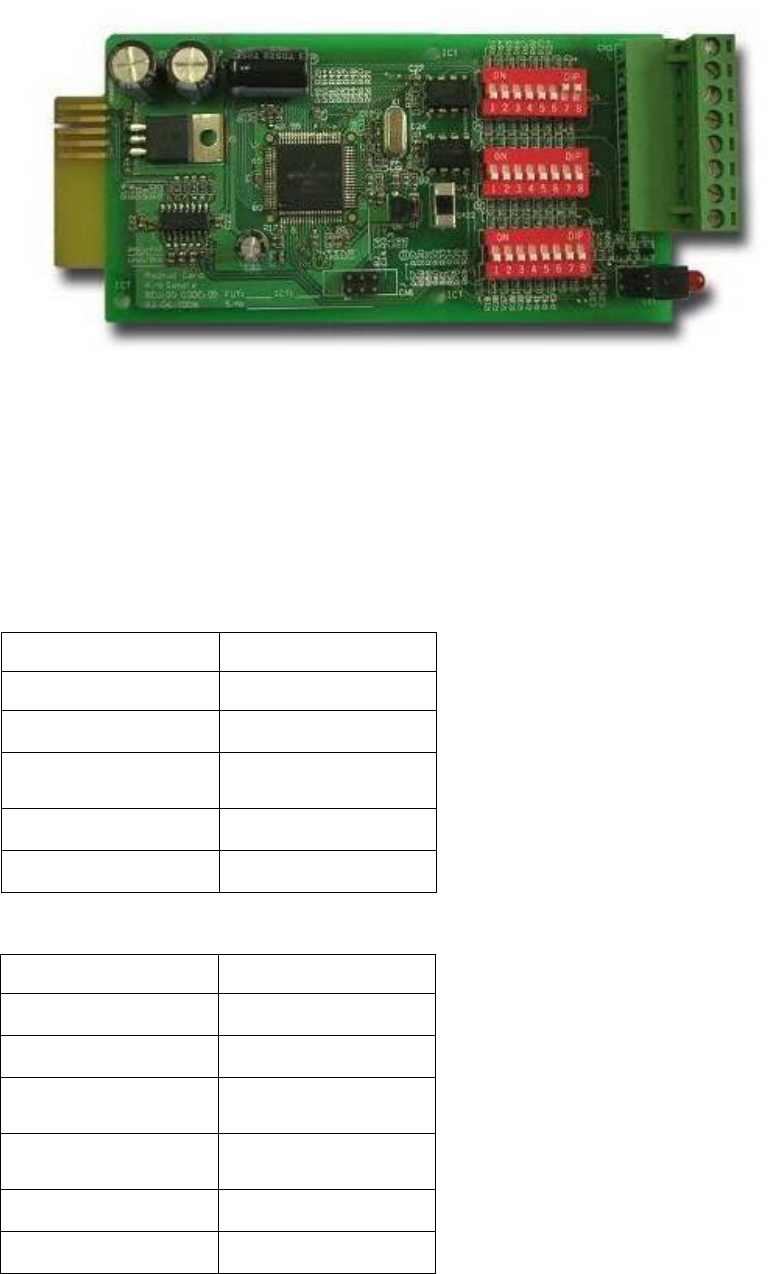
- ModBUS Card (Part No.: 6000008723)
Features:
Translate the UPS RS232 protocol into another RS232 and RS422/485 Modbus
protocol. Device ID is adjustable by 8 dip switches. The value is from 0 to 255.
The RS422/485 terminal resistor is selectable by using dip-switches and easy to
install.
Baud rate and parity options are also adjustable by using dip switches.
2 LEDs for indicating communication status.
Technical Specification
I/O Definition
Input Power 8 ~ 20VDC
Temperature 0 ~ 40°C
Humidity 10 ~ 80 %
Power
Consumption 1 Watt. (Maximum)
Dimension (L x W) 130x60mm
Weight 150g
GND Ground for RS232
RS232-Tx Tx to PC
RS232-Rx Rx from PC
RS422-T+
RS422-D+ T+ for RS422 or
D+ for RS485
RS422-T-
RS422-D- T- for RS422 or
D- for RS485
RS422-R+ R+ for RS422
RS422-R- R- for RS422
3-19
3-3-6 Additional Options
The Protect 3.M 2.0 Series UPS is optional able to measure the battery current and
makes it available in the measuring values which can be displayed (see also Page
7-10 “Measurements”). Therefore you have to add the option “Battery Current
Measurement” Part Nr.: 6000008724
It consists of 2 transducers which have to be placed inside the UPS.
Note: If the option is not installed the UPS display will just show the charging current.

3-20
3-4 Technical Specification
Capacity 80kVA/64KW 120kVA/96KW
Rating Voltage V 220/380, 230/400, 240/415
(3Φ 4W+Earth)
Voltage Regulation % -25 ~ +20
Input Current Harmonic Distortion
(Full Load) % < 5
PFC (Full Load) > 0.99
Frequency Hz 50 / 60
Input
Frequency Tolerance Hz 45 ~ 65
Output Voltage V 220/380, 230/400, 240/415 (3Φ 4W+Earth)
Output Frequency Hz 50 / 60
Total Harmonic (Linear Load) % ≦3
Voltage
Regulation Static % ±1
Dynamic % ±7 (10% ~ 90% Linear Load)
Frequency
Regulation Interior Oscillator Hz ±0.05
Synchronized % ±5
Output
Overload ≦125%: 10minutes ; ≦150%: 1minute
Battery Backup Intermittent Audible
Warning UPS Abnormal Continuous
LED UPS status: Normal, Bypass, Backup and Fault
Display LCD Input/Output, Bypass, Inverter, Frequency, Loading and Battery voltage, current,
UPS abnormal message and intelligent self diagnosis
6 Integrated Dry-contacts
Remote 2 integrated Opto inputs
Standard RS232, Dry Contact Output
Interface Optional SNMP card, Modbus card, Relay I/O control card, Environmental sensor
Parallel Operation Yes (up to 4 UPS of the same type (80/120kVA)
EPO Standard (Local and Remote)
SRAM Event Log Yes (500 records)
Parameter Configuration Yes
N+1 Module redundacy Feasible
Battery Temperature Compensation Optional
Others
Battery Start (Black Strat”) Yes
Normal % 94,5
Efficiency ECO % 97
Transfer Time ms 0 ms
Temperature °C 0~40
Humidity (Non Condensed) % 90
Noise (One Meter) dBA 62-69
Dimension Width mm 520 520
Depth mm 910 975
Height mm 1165 1695
Overall
Weight Kg 259 384

4-1
4. Installation and Wiring
4-1 Before Installation
Due to different installation environment, we strongly recommend that you read this
manual carefully before installation. Only qualified service personnel can perform
installation and maintenance.
4-2 Package Inspections
External
There are some unpredictable situations that can be possibly encountered during UPS
transportation. Therefore, we recommend that you immediately inspect the container
for any obvious damage or mishandling.
Internal
1. When you unpack the container, immediately examine the UPS or battery pack
cabinet.
2. Check the rating label on the rear side of cabinet. Confirm if the model name and
capacity correctly match your original requirements.
3. Examine if the parts are loose or damaged.
4. Examine any accessory is missing. The Protect 3.M 20 Series has the following
accessory:
- RS232 cable: 1 pcs (Length= 1.8m)
- Parallel communication cable: 1 pcs (Length= 2m)
- Remote EPO - wiring connector: 1 set (2 contact module)
- Input dry contact - wiring connector: 1 set (4 contact module)
- Output dry contact – wiring connector: 1 set (12 contact module)
If the following conditions occur:
- Any damage observed, either external or internal.
- Any accessory is missing or damaged,
Please immediately contact your dealer or local agent for assistance.

4-2
4-3 Storing Conditions before Installation
1. If you have received the UPS and do not perform the installation immediately, be
sure to store the UPS under:
- Temperature below 40°C
- Relative humidity below 90%
2. If the period of UPS installation is over 6 months, be sure to charge batteries for at
least 8 hours before the first use.
Charging procedures:
- Connect UPS to the utility power. If there is an external battery pack, connect the
cable of battery pack to the UPS.
- The UPS starts up normally. At this time, the UPS will charge the batteries by
internal charging circuit.
3. The carton and the original packaging must remain sealed to prevent any possible
damage from mouse or similar creatures.
Connect and power the loading only when the battery is fully charged. The
purpose is to make sure that the UPS can provide the backup power to loads
when a blackout occurs.
4-3
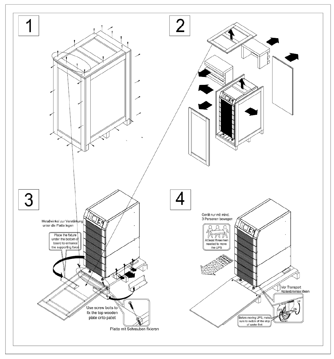
4-4 Unpacking Procedures
4-4-1 Protect 3.M 2.0 80 kVA
4-4
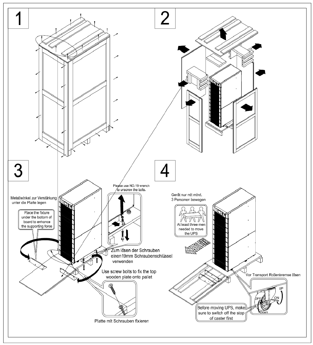
4-4-2 Protect 3.M 2.0 120 kVA
4-5
4-5 Installation Environment
4-5-1 Handling Safety
1. The Protect 3.M 2.0 Series UPS is equipped with casters so that you can roll the
UPS in a short distance to the desired location. During unpacking process, be
sure to make full use of manpower and a suitable machine (such as stacker) with
sufficient capacity to carefully move the UPS.
2. Casters are only suitable for moving on even surface. Avoid moving the UPS on
bumpy route, because this may cause damage of UPS or tip-over accident.
3. Push the UPS from either front or rear side otherwise could cause tip-over accident.
4. When the UPS needs a long-distance movement, make use of a suitable machine
but not casters of the UPS.
4-5-2 UPS Positioning
1. Position the UPS or external battery pack by suitable machine.
2. Refer to Table 4-1 to 4-4. Ensure that the UPS is positioned at a suitable floor
which can sustain for the weight.
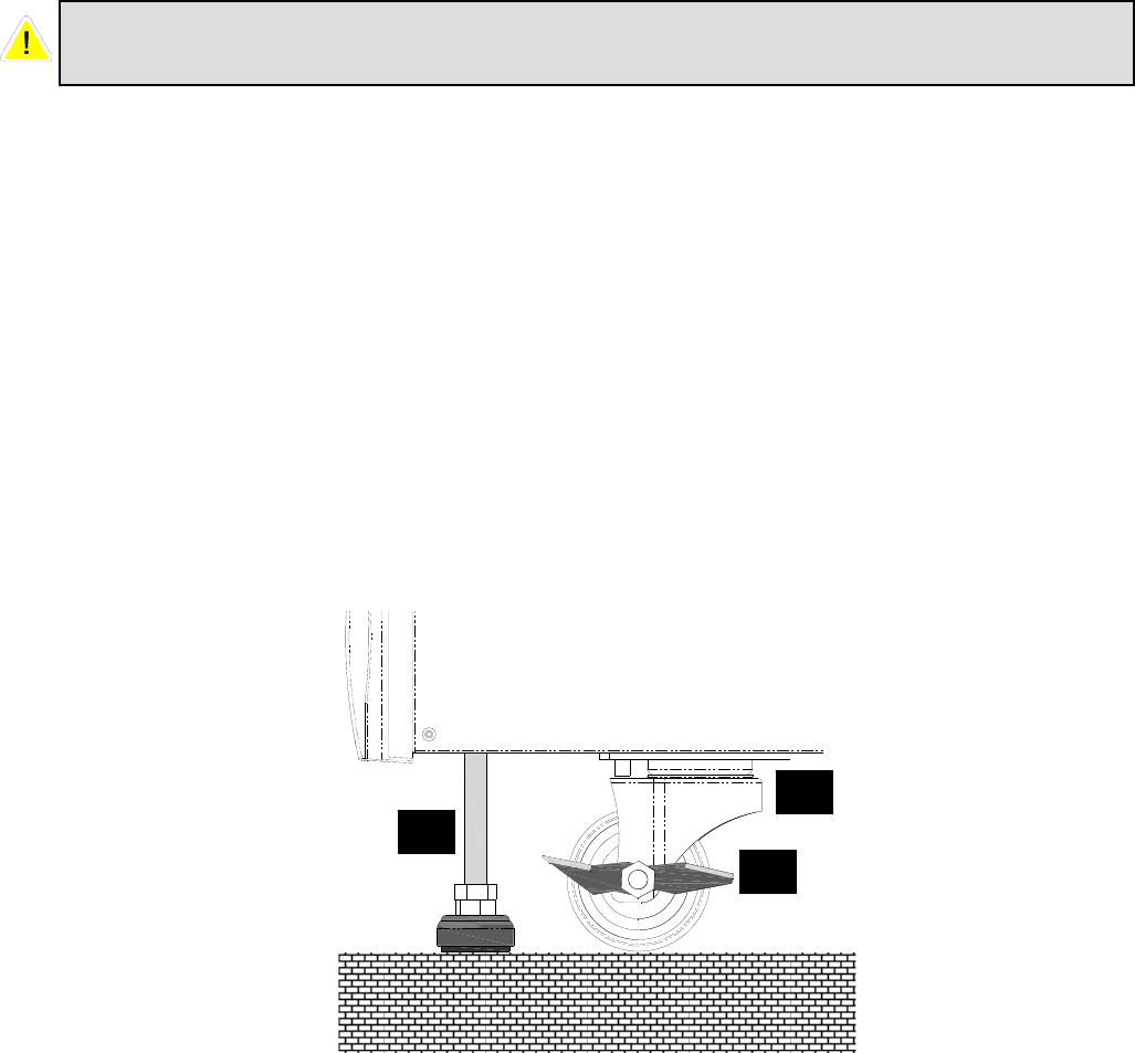
3. After positioning the UPS, ensure to push C (Stop) to “ON” until strictly fastened
and adjust leveler to the floor.
Please pay extremely close attention while unbolting the UPS from the shipping
pallet. Prevent any accident resulting from unexpected move.
A: Leveler
B: Caster
C: Sto
p
A
C
B

4-6
Table 4-1 Floor Loading for 80 kVA UPS
Input: 230/400 Vac / Output: 230/400 Vac
Capacity (KVA) 80
Max Weight (Kg) 259
Floor Loading (kg/㎡) 548
Table 4-2 Floor Loading for External Battery Pack (80 kVA cabinet size)
Batteries - 40 pcs
Capacity (Ah) 12V/26AH
Weight (kg) 487,5
Floor Loading (kg/㎡) 1064
Table 4-3 Floor Loading for 120 kVA UPS
Input: 230/400 Vac / Output: 230/400 Vac
Capacity (KVA) 120
Weight (Kg) 384
Floor Loading (kg/㎡) 748
Table 4-4 Floor Loading for External Battery Pack (120 kVA cabinet size)
Batteries - 40 pcs
Capacity (Ah) 12V/40AH
Weight (kg) 727
Floor Loading (kg/㎡) 1575
4-7
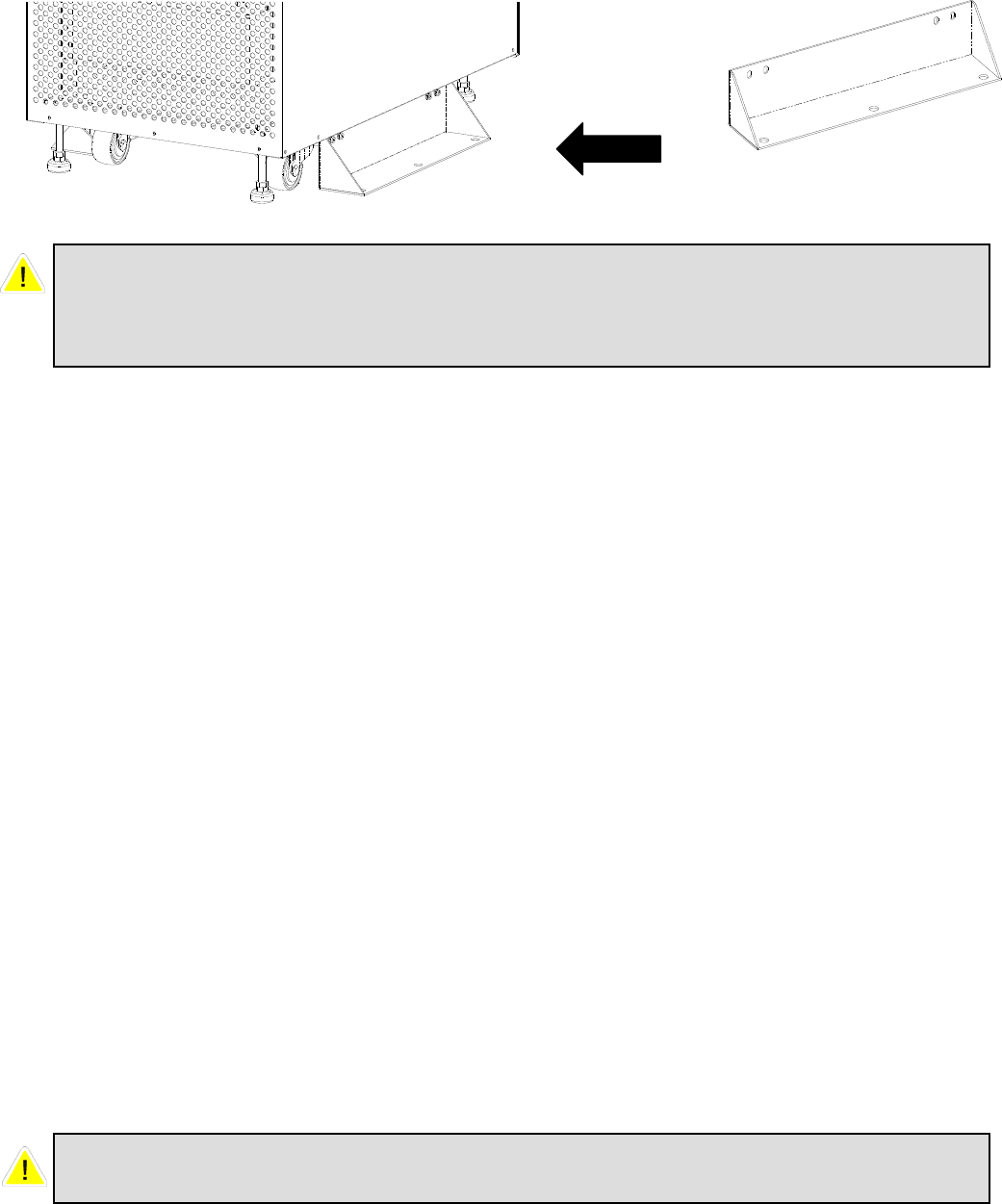
4. Attach the balance supporter to the UPS with bolts.
4-5-3 Environment
1. The Protect 3.M 2.0 series UPS is for in-house use only. The installation space
should be conditioned at temperature of 25°C and relative humidity of <90%. And
the maximum operation altitude is 3000 m.
2. The circumstance surrounding the UPS should be kept clean. Prevent any possible
damage from mice or similar objects.
3. The Protect 3.M 2.0 Series UPS requires good ventilation and heat dissipation. It
features fans for heat dissipation. The air flow circulates from front to the rear
bezel. Therefore, we strongly recommend the following:
(1) A clearance of at least 100cm in front of UPS should be provided to permit
free passage of service engineer and ventilation purpose.
(2) A clearance of at least 50cm between rear bezel of UPS and wall should be
provided to permit free passage of service engineer and ventilation purpose.
(3) A clearance of at least 50cm between the top of UPS and the ceiling should
be provided to permit free passage of service engineer.
(4) A clearance of at least 100cm in front of external battery cabinet should be
provided for maintenance and at least 50cm between rear bezel and the wall
should be provided for ventilation.
Balance
Supporter
The UPS may topple over under unexpected conditions without balance
supporter. Be sure to mount two balance supporters on both sides of the UPS for
safety reasons.
Do not use any air conditioning or similar facility that blows air directly onto the
rear side of the UPS.

4-8
4-6 Wiring
4-6-1 Preparations
1. The UPS should only be installed by a qualified electrically employed person
2. De-energize all input (AC or DC) or output power of the UPS before installing
cables
or making any electrical connection.
3. Ensure that all cables are correctly marked according to the purpose, as well as
the
polarity, phase and diameter.
4. If the input/output power of the UPS is WYE-WYE (Y connection), ”Neutral”
and ”Ground” should not be connected.
If the input power has VNG>0, the solution is to install an isolation transformer
before UPS and input power source. Then, connect “Neutral” and “Ground” of
the UPS together.
5. Make use of suitable conduits and gland to protect I/O wiring according to local
regulations. Refer to Table 4-3.
6. If after the installation many cables are ducted very close together it is
recommended to use cables with isolations made for higher temperature ranges.
Table 4-3 Input/Output Electrical Data
* Recommended cross section following DIN EN 60269-1 (single wire cables in
free air). Please consider possible deviation due to installed region.
7. Confirm the power phase of L1, L2 and L3.
8. Confirm the polarity of battery cable.
9. Connect the ground of external battery cabinet to UPS’s ground.
10. Connect the UPS’s ground to the protective earth.
UPS
module
quantity
Input
(V)
Output
(V)
Input
Fuse
NH, gL
(A)
Input
Cable
(mm²)
Reserve
Fuse
NH, gL
(A)
Reserve
Cable
(mm²)
Output
Fuse
NH, gL
(A)
Output
Cable
(mm²)
Battery
Fuse
NH, gL
(A)
Battery
Cable
(mm²)
1
(20kVA) 230/400 230/400 35 6 50 6 50 6 50 6
2
(40kVA) 230/400 230/400 63 16 75 16 75 16 80 16
3
(60kVA) 230/400 230/400 100 25 125 25 125 25 125 35
4
(80kVA) 230/400 230/400 125 35 150 35 150 35 160 50
5
(100kVA) 230/400 230/400 160 50 200 50 200 50 200 70
6
(120kVA) 230/400 230/400 200 70 250 70 250 70 250 95

4-9
Wrong cabling may burn the UPS and will result in severe accidents or damages.
Due to the dimensioning of the battery cables we suggest to choose a cross
section according to the maximum UPS power per cabinet. For example use for an
80 kVA cabinet always 50mm² even if the UPS is not scaled to the max. Power
now.
Inside the UPS all Neutrals are connected to one common point. Please we aware
that all to the UPS connected neutrals are also connected in your external power
supply environment.
4-10
4-6-2 Wiring (Single Unit, 80kVA model shown)
Wiring procedure:
1. Remove the terminal cover at the rear side. See Fig. 4-1.
2. You can see the terminal block with marks as below.
Input: L1, L2, L3 and neutral
Bypass: L1, L2, L3 (for Bypass neutral use the Input neutral terminal)
Output: L1, L2, L3 and neutral
External Battery: positive(+), negative(-) and neutral
Grounding Terminal: Protection
3. The rated voltage of standard model is 220/380VAC, 230/400VAC or 240/415VAC.
4. The battery rating voltage is ±240VDC.
5. Confirm if the input and bypass input circuit breakers (Q1 and Q2) are cut off (Refer
to Fig.4-2).
Remove
Cover
Main AC Input
Bypass Input
External Battery
Output
Grounding
Terminal
Fig. 4-1 Wiring Terminal
4-11
6. Confirm if the manual bypass circuit breaker (Q3) is cut off.
7. Confirm if the output circuit breaker (Q4) of UPS is cut off.
8. According to UPS model you have selected, use suitable cables and lugs (Refer to
Table 4-3).
9. Connect all cables to the right terminal or location as indicated. (Refer to Fig. 4-1).
Q4 Q3 Q2 Q1
Q1: Input Circuit Breaker
Q2: Bypass Input Circuit Breaker
Q3: Manual Bypass Switch
Q4: Output Circuit Breaker
Fig. 4-2 Circuit Breaker
4-12
4-6-3 Connecting External Battery Cabinet
Connect corresponding terminals (+, N, –) between UPS and external battery cabinet.
UPS Battery Cabinet
Fig. 4-3 Wiring of External Battery Cabinet
N
240VDC 240VDC
N
240VDC 240VDC
4-13
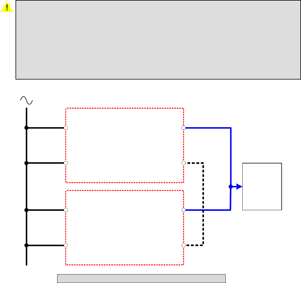
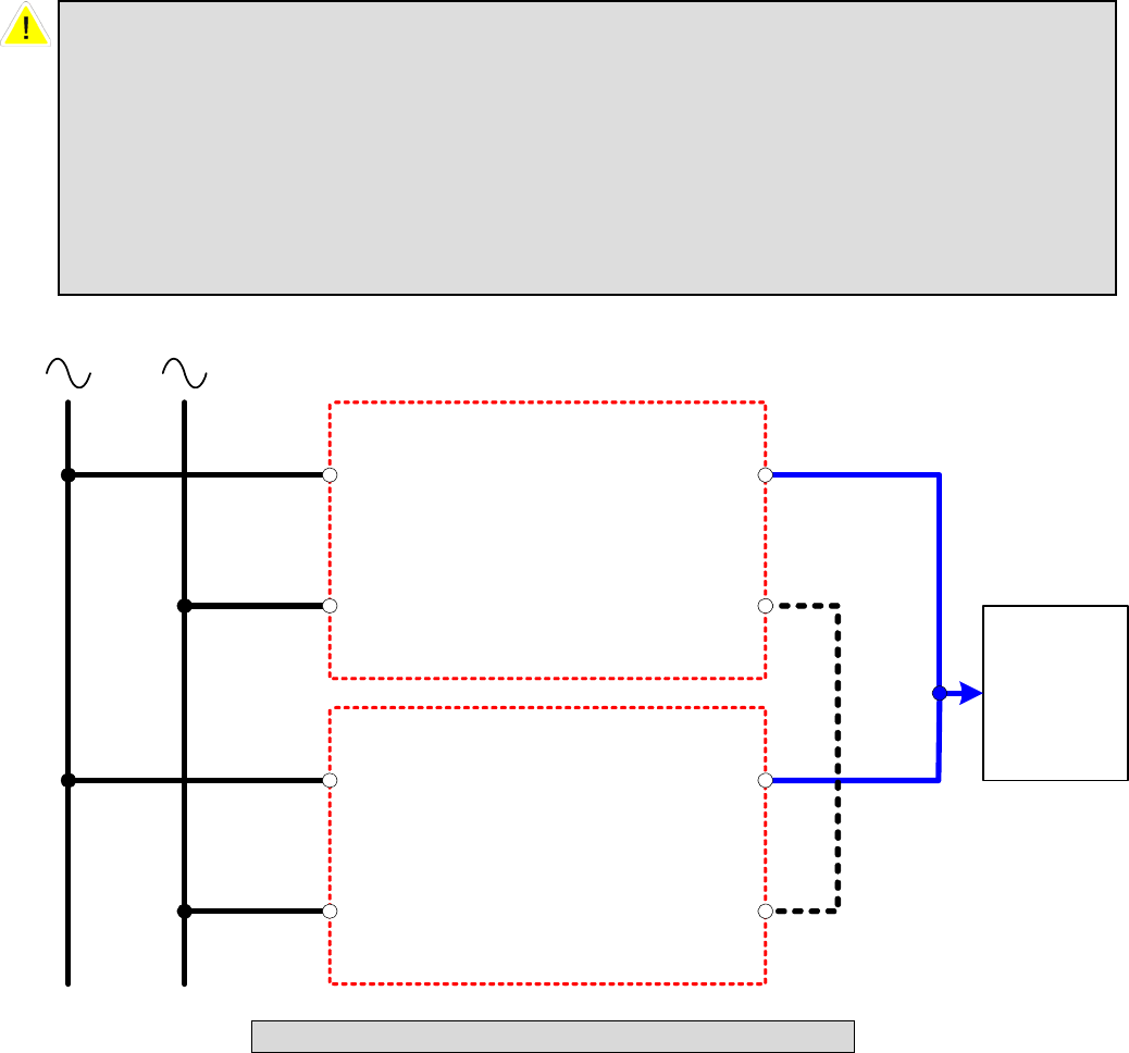
4-6-4 Wiring (Parallel Redundancy, Single Input)
1. Confirm if the input and bypass input breaker (Q1 and Q2) are cut off (Refer to Fig.
4-2).
2. Confirm if the manual bypass circuit breaker (Q3) is cut off.
3. Confirm if the output breaker (Q4) is cut off.
4. According to UPS model you have selected, make use of a suitable cable and lug
(Refer to
Table 4-3).
5. Connect all cables to the right terminal or location as indicated (Refer to Fig. 4-1).
6. Connect the parallel communication cable between UPS1 and UPS2 (Refer Fig. 4-
4).
Fig. 4-4 Wiring (Parallel Redundancy, Single Input)
1. For installation of parallel system, the total cable length of input must be equal
to the one of output. This regulation prevents unbalanced load shared by two
UPSs under reserve mode.
i.e.: Res1 + OP1 = Res2 + OP2 = (The deviation must be less than 10%)
2. Two UPSs must have the same rating/capacity (80 or 120kVA) for parallel
installation. Different ratings cannot link together.
O/P
Main I/P
Reserve I/P
Parallel Port
UPS1
O/P
Main I/P
Reserve I/P
Parallel Port
UPS2
Parallel Cable
Load
AC I/P
Res1
Res2
IP1
IP2
OP1
OP2
4-14
4-6-5 Wiring (Parallel Redundancy, Dual Input)
1. Confirm if the input and bypass input breaker (Q1 and Q2) are cut off (Refer to Fig.
4-2).
2. Confirm if the manual bypass circuit breaker (Q3) is cut off.
3. Confirm if the output breaker (Q4) is cut off.
4. According to UPS model you have selected, make use of a suitable cable and lug
(Refer to
Table 4-3).
5. Connect all cables to the right terminal or location as indicated (Refer to Fig. 4-1).
6. Connect the parallel communication cable between UPS1 and UPS2 (Refer Fig. 4-
5).
1. For installation of parallel system, the total cable length of input must be equal
to one of output. This regulation prevents unbalanced load shared by two UPSs
under reserve mode.
i.e.: Res1 + OP1 = Res2 + OP2 = (Deviation must be less than 10%)
2. Two UPSs must have the same rating/capacity (80 or 120kVA) for parallel
installation. Different ratings cannot link together.
O/P
Main I/P
Reserve I/P
Parallel Port
UPS1
O/P
Main I/P
Reserve I/P
Parallel Port
UPS2
Load
AC I/P 1
Res1
Res2
IP1
IP2
AC I/P 2
Parallel Cable
OP1
OP2
Fig. 4-5 Wiring (Parallel Redundancy, Dual Input)
5-1
5. Operating Procedures
5-1 Startup Procedures (Single Unit)
Before starting up the UPS system, be sure to check the following items first.
Ensure all circuit breakers are cut off and switched to OFF, as well as the breaker
or fuse of the external battery cabinet.
Confirm if the locking latch is located at “”.
Confirm if there is no voltage potential between NEUTRAL and Ground.
Confirm if the input power source matches the rated voltage, frequency, phase
and battery of the UPS that you have installed.
Q4 Q3 Q2 Q1
Fail OnOff
Q1: Input Circuit Breaker
Q2: Bypass Input Circuit Breaker
Q3: Manual Bypass Switch
Q4: Output Circuit Breaker

5-2
If the conditions mentioned above are satisfied, follow the steps below to start
up.
1. If there is an external battery cabinet, switch the circuit breaker of battery cabinet
to ON and confirm if manual bypass protection circuit breaker Q3 is cut off and
switched to OFF.
2. Switch on Q2 and Q4.
The LCD monitor will start displaying. After initialization, the LCD screen will
show ”ON AUTO BYPASS”. In the meantime, the UPS output is supplied by the
bypass source and the LED indicator of ”BYPASS” will also light on.
3. Switch Q1 to ON. If the input power source is within tolerance range, the UPS
power module will be ready to start up.
4. Press the “I” button for 3 seconds until you hear a “beep” and then release the
button. At this time, the inverter will start the synchronization with bypass source.
The UPS will automatically transfer from bypass mode to inverter mode, and the
output will be supplied by the inverter. The ”BYPASS” LED indicator lights off
and the ”NORMAL” LED indicator lights on.
5-2 Battery Startup Procedures (Single Unit)
1. Switch the circuit breaker of external battery cabinet to ON and confirm if Q3 is
cut off and switched to OFF.
2. Press the “I” button for 3 seconds until you hear a “beep” and then release the
button.
3. The UPS will start up by DC-bus soft start. The inverter will be activated by
adopting the default frequency value.
4. When the inverter startup is completed, the UPS will transfer to Inverter mode
and the ”BATTERY” LED indicator lights on.
5-3 Shutdown Procedures (Single Unit)
This operating procedure can cut off all the power supply. Be sure to confirm if the
loads are turned off first! Refer to following steps.
1. Press the “O” button for 3 seconds until you hear a “beep” and then release button.
The LCD screen will show “SHUTDOWN UPS?”, then selected “YES” and
press “ ” to confirm.
If the UPS is originally in
- Normal mode: The UPS will transfer to bypass mode. The LCD screen will
show ”ON AUTO BYPASS”.
- Battery mode: The UPS will shut down the inverter and cut off the output power.
2. Switch off Q1.
3. Switch off Q2.
4. Confirm if the UPS is turned off and all the circuits are off.
5. If there is an external battery cabinet, switch off the circuit breaker of battery cabinet.
6. Switch off Q4.

5-3
5-4 Manual Bypass Startup (Single Unit)
If the UPS is in normal mode, press the “O” button for 3 seconds until you hear a
“beep” and then release the button. The LCD screen will show “SHUTDOWN UPS?”,
then select “YES” and press “ ” to confirm. The UPS will automatically transfer to
bypass mode.
1. Confirm if the UPS is in bypass mode.
2. Switch on “Q3”.
3. Switch off “Q4”.
1. Only for maintenance purpose, you can manually turn on the bypass switch
“Q3”. If you switch on Q3 under normal condition, the inverter will shut down
and the output will be supplied by manual bypass source.
2. Manual bypass mode ensures that the UPS supplies the loads from manual
bypass source. The service personnel can perform maintenance process under
this mode without interrupting the load. At this moment, the UPS is still
supplied by input power source. If the service personnel want to replace any
circuit board or component, the Inverter of the UPS must have been shut down
first (Refer to 5-3). Please be aware that the terminals and breaker area is still
under Voltage. For full maintenance access please use an external manual
bypass.

5-4
5-5 Startup Procedures (Parallel Redundancy)
Before starting up the UPS system, be sure to check the following items first.
All circuit breakers are cut off and switched to OFF, as well as the breaker or
fuse of the external battery cabinet.
Confirm if the locking latch is located at “”.
Confirm if there is no voltage potential between NEUTRAL and Ground.
Confirm if the input power source matches the rated voltage, frequency, phase
and battery of the UPS that you have installed.
Start up procedure:
If the conditions mentioned above are satisfied, follow the steps below to start
up.
1. Connect two UPSs by using the parallel communication cable. Ensure the
connector is fastened to the DB9 port. The connection of up to 4 UPS must be in a
loop. Connect UPS 1 to UPS 2, UPS 2 to UPS 3, UPS 3 to UPS 4 and UPS 4
again to UPS 1. The UPS with the lowest and the highest ID (recommended is
UPS 1 and 4) have to terminate the communication bus. Please set the small
switches at the back of these ups near the parallel connector to “on”.
2. Switch the breaker of external battery cabinet to ON.
3. Switch on bypass input protection circuit breaker “Q2” of each UPS. The LCD
screen will show ”ON AUTO BYPASS”.
4. Switch on “Q1” of each UPS.
5. Press the “I” button for 3 seconds until you hear a “beep” and then release the
button. The inverter will be activated and synchronize with bypass source.
6. Repeat Step 5 to start up another UPS. When the inverter voltage of both UPSs
activates normally, both UPSs will transfer to normal mode at the same time.
7. Check the output voltage deviation per each phase of each UPS (must be less than
5V). If it is normal, switch on “Q4” of each UPS.
5-6 Shutdown Procedures (Parallel Redundancy)
If you need to shut down one of the paralleled UPSs:
1. Press the “O” button on the UPS that you want to shut down for 3 seconds until you
hear a “beep” and then release the button. The LCD screen will show
“SHUTDOWN UPS?”, then select “YES” and press “ ” to confirm.
- If the other UPS can take over the total loads, then the turn-off one will shutdown
inverter. The LCD screen shows ”LOAD NOT POWERED” for the turn-off one.
The working UPS shows ”ONLINE MODE”.
- If the total loads are greater than one UPS can take over, then both UPSs will
shut down the inverter and transfer to bypass mode. Both UPSs show ”ON
AUTO BYPASS”.
For parallel operation, you must set the ID code of each UPS as “01”, “02”, “03”
and “04” by configuring the control panel. Refer to Page 7-18.
5-5
2. Switch off “Q1” and “Q4” of the UPS that you want to shut down.
3. Switch off “Q2” of the UPS that you want to shut down.
4. When all the power modules complete the discharging procedures, the LCD screen
will be off.
5. Switch off the battery circuit breaker of the external battery cabinet.

5-6
5-7 Manual Bypass Startup Procedures (Parallel Redundancy)
5-7-1 Online Mode Transfers to Manual Bypass Mode
1. press the “O” button of the UPS that you want to shut down for 3 seconds until you
hear a “beep” and then release the button. The LCD screen will show
“SHUTDOWN UPS?”, then select “YES” and press “ ” to confirm.
- If the other UPS can take over the total loads, then the turned-off one will shut
down the inverter. The LCD screen shows ”LOAD NOT POWERED” for the
turned-off one. The working UPS shows ”ONLINE MODE”.
- If the total loads are greater than one UPS can take over, then both UPSs will
shut down the inverter and transfer to bypass mode. Both UPSs show ”ON
AUTO BYPASS”.
2. Repeat Step 1 for another UPS.
3. Switch off “Q1” of both UPSs.
4. Confirm if both UPSs are completely shut down.
5. Switch on “Q3” of both UPSs. Reserve power source supplies the loads. The LCD
screen shows ”ON MANUAL BYPASS”.
6. Switch off ”Q4” and ”Q2” of both UPSs. The LCD screen will be off.
7. Switch off battery circuit breaker of the external battery cabinet.
8. In this mode, only ”Q4” and terminal block has hazard voltage. Service personnel
can perform maintenance work.
1. Only for maintenance purpose, you can manually turn on the bypass switch. If
you switch on Q3 under normal status, the inverter will shut down and the
output will be supplied by manual bypass source.
2. Manual bypass mode ensures that the UPS supplies the loads from manual
bypass source. The service personnel can perform maintenance process under
this mode without interrupting the loads. At this moment, the UPS is still
supplied by input power source. If the service personnel want to replace any
circuit board or component, the Inverter of the UPS must have been shut down
first (Refer to 5-3). Please be aware that the Terminal and Breaker area is still
under Voltage. For full maintenance access please use an external manual
bypass.
5-7
5-7-2 Transferring from Manual Bypass Mode to Online Mode
1. Switch on the battery circuit breaker of external battery cabinet.
2. Switch on ”Q2” and ”Q4” of both UPSs.
Switch off ”Q3” of both UPSs. The LCD screens of both UPSs show ”ON AUTO
BYPASS”.
3. Switch on ”Q1” of both UPSs.
4. Press the “I” button for 3 seconds until you hear a “beep” and then release the
button.
5. Repeat Step 5 to start up another UPS. When the inverter voltage of both UPSs
activates normally, both UPSs will transfer to normal mode at the same time.
6-1
6. Power Module Replacement
6-1 Status LED Indicators for Power Module
Each power module features one LED to help inform the user about the power
module status.
LED status:
“OFF”:
When the locking latch is located at “”, the power module is inactive.
When the locking latch is located at “” and the main power is turned on, the
power module is failed.
“FLASHING”:
The power module is failed and had shut down.
“ON”:
The power module is active.
Note:
While releasing the locking latch of power module during normal mode, the power
module is off line but may discharge the DC bus by it’s standby current.
Fail OnOff
Fail OnOff

6-2
6-2 Power Module Replacement
Follow the instructions below to replace or install the Power Module in the system.
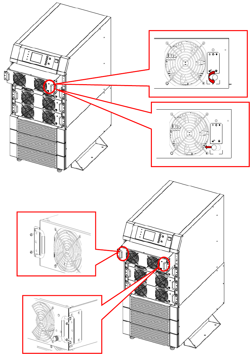
Procedures for Replacing Power Modules
1. Remove the bezel cover of appropriate power module. While replacing a Power
Module, verify the faulty power module based on status LED indicators and the
message on the screen.
2. To de-activate the power module, unscrew the spring-activated knob of locking
latch until it pops out and then move the locking latch to located at “”.
3. Use the screwdriver to unscrew the screws on both sides of power module.
4. Two people stand on both sides of the UPS, then pull out and lift the power
module.
Reverse procedure for installation of replacement power module.
WARNING!
Only trained persons familiar with the construction and operation of the
equipment, as well as the electrical and mechanical hazards involved, may install
and remove system components.
WARNING!
Before removing any Power Module, ensure that the remaining Power Modules can
support the load.
CAUTION
Power Modules are heavy (30kg).
Two people are required for handling.
6-3
Fail OnOff
Fail OnOff
7-1
7. Display and Configuration
7-1. Control Panel
1. Normal (Green): Lights on when the UPS input power is normal.
2. Battery (Amber): Lights on when the UPS is in backup mode.
3. Bypass (Amber): Lights on when the UPS is in bypass mode.
4. Fault (Red): Lights on when any fault occurs.
5. LCD Display: Multi-language display (English, German, French, Italian, Spanish,
Portuguese, Turkish, Russian and Chinese )
6. ESC: Page up.
7,8. Configuration:
and : Cursor up or down.
: Confirm settings.
9. ON: Press for 3 seconds to start up the UPS (Inverter On).
10. OFF: Press for 3 seconds to power off the UPS (Inverter Off)
11. EPO: Emergency Power Off. Press EPO will power off the inverter immediately .
Fig. 7-1 Control Panel
1 2 5 6 9 11
4 3 7
8
10
7-2
7-2 LCD Display
Protect 3.M 2.0 Series UPS features a user-friendly LCD screen to show messages.
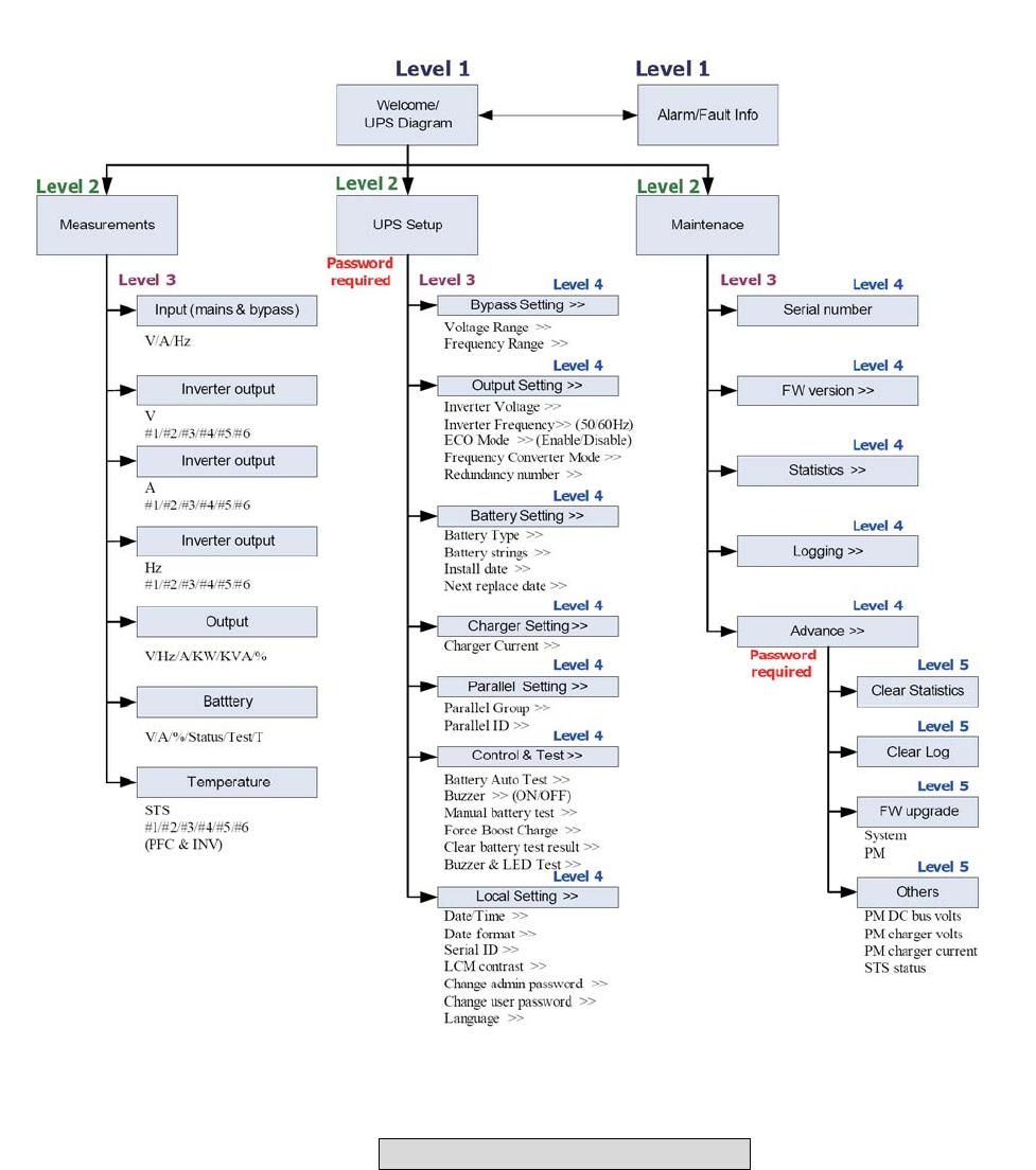
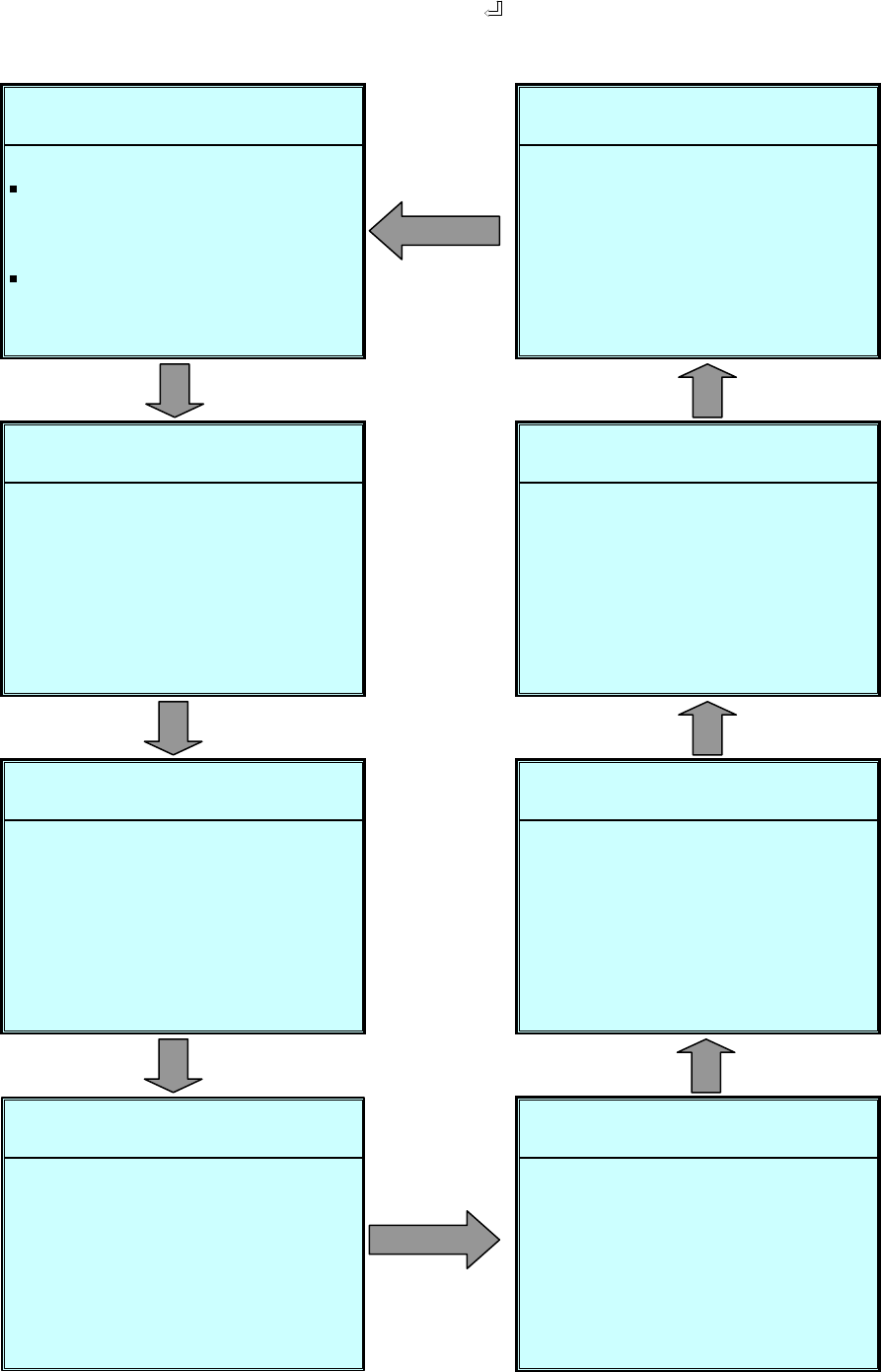
7-2-1 LCD Display Hierarchy
Fig. 7-2 LCD Display Hierarchy
7-3
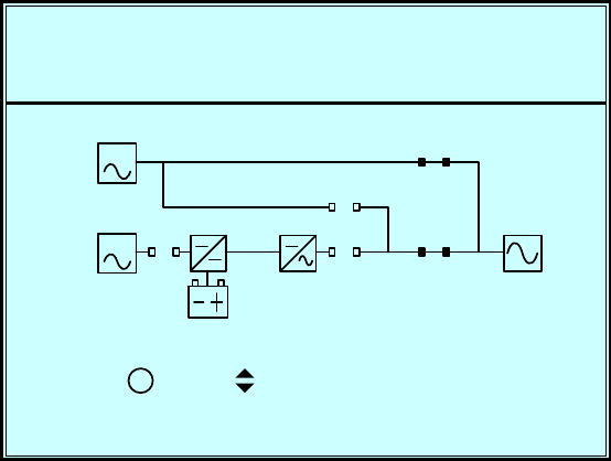
7-3 Default Screen
After the UPS starts up and completes the self test, the screen will show as below.
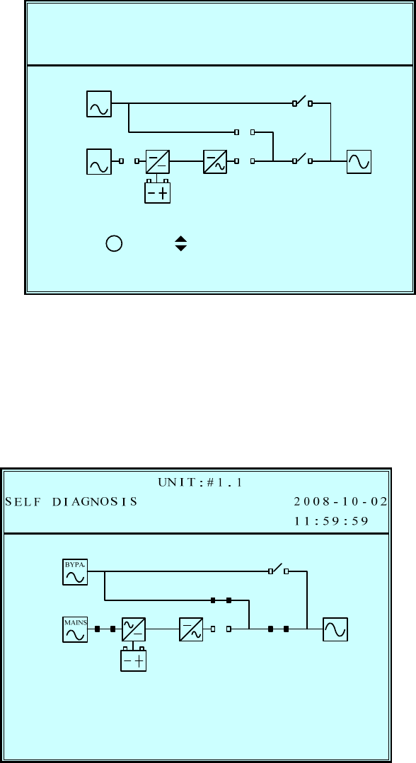
1. When any event occurs, you will see the sign “!” flashes. You can press “” to
see the details. For example:
Press “” again will go to the next message. If there is no further message, the
screen will return to the default screen.
2. Press “ESC” at any time will return to the default screen.
7-4
7-3-1 Status Display
The LCD screen will show different status of the UPS.
1.
This message means the loads behind UPS are not powered on. The UPS cuts off
the output.
Possible causes:
- The UPS automatically shuts down by itself because of an internal error.
- Manually switch off the output circuit breaker.
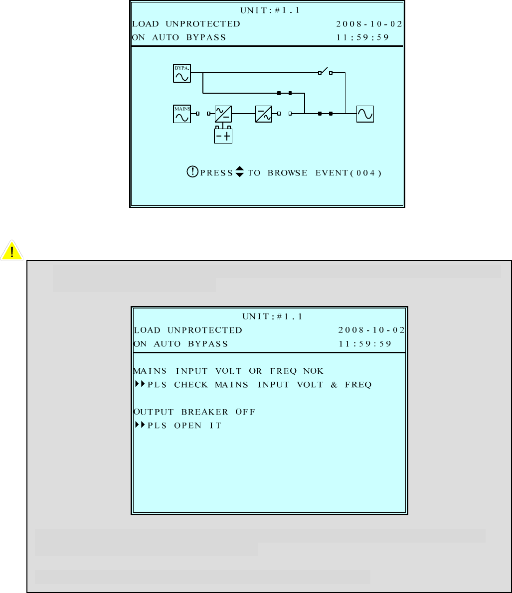
2.
This message means the loads are supplied by bypass source due to initial startup
of the UPS.
T 2008-10-02POWEREDLOAD NO
UN I T : # 1 . 1
11:59:59
RP TO BROWSE EVENT ( 0 0 4 )SES
!
BYPA.
MAINS
7-5
3.
This message means the UPS starts up by battery power (“Black Start”).
4.
This message means the UPS is in bypass mode. In the mean time, the main
power
source and battery are cut off. So the loads may lose power if the bypass source
may fail also.
A 2008-10-02GNOS I SSELF DI
UN I T : # 1 . 1
11:59:59
RP TO BROWSE EVENT ( 0 0 4 )SES
!
BYPA.
MAINS
7-6
5.
This message means the UPS is operating under normal condition (normal mode).
6.
This message means the UPS is in battery backup mode. The loads are supplied by
battery power.
2008-10-02LOAD
UN I T : # 1 . 1
11:59:59ON L I NE
PROTECTED
BYPA.
MAINS
2008-10-02LOAD
UN I T : # 1 . 1
11:59:59RYON BATTE
PROTECTED
RP TO BROWSE EVENT ( 0 0 4 )SES
!
BYPA.
MAINS
7-7
7.
This message means the UPS is performing a “Battery Test”.
8.
This message means the UPS is in ECO (Economic Operation) mode. The loads
are
supplied by bypass source.
2008-10-02LOAD
UN I T : # 1 . 1
11:59:59BAT TEST
PROTECTED
BYPA.
MAINS
2008-10-02LOAD
UN I T : # 1 . 1
11:59:59ON ECO
PROTECTED
BYPA.
MAINS
7-8
9.
This message means the UPS is in manual bypass mode. When the service
personnel perform the maintenance work, the UPS must transfer to this mode first.
In the mean time, the main power source and battery are cut off. So the loads may
lose the power if the bypass source suddenly fails.
2008-10-02LOAD UN
UN I T : # 1 . 1
11:59:59L BYPASSON MANUA
RP TO BROWSE EVENT ( 0 0 4 )SES
!
BYPA.
MAINS
PROTECTED

7-9
7-4 Main Menu
Press “ ” in default screen will change to the main menu.
Press “” or ”” to select the desired item, then press “ ” to confirm.
UR
P
MA I N
EMEA S
UPS
2008-10-02ROTECTEDLOAD UN
UN I T : # 1 . 1
11:59:59BYPAS SON AUTO
NTROLTUP & COSE
NANCETE
7-10
MEASURE
Use “” or ”” to select “Measure”, then press ” ” to confirm.
Use “” or ”” to see all the UPS status.
N
P
Vl ine(
Vph a s e
Iphase
/L2L1-
MA I N
BYPAS S
FREQ(H
2008-10-02ROTECTEDLOAD UN
UN I T : # 1 . 1
11:59:59BYPAS SON AUTO
S
9)221.(V
5384.V)
1)4.(A
060.z)
Vl ine(
Vph a s e )(V
V)
FREQ(Hz )
N/L3L2- N/L3L2 -
7223.
8385.
24.
060.
6222.
9384.
04.
060.
9221.
5384.
060.
7223.
8385.
060.
6222.
9384.
060.
0
ER
P
.4#2 VOL
.2#1 VOL
.2
INVERT
.1
2008-10-02ROTECTEDLOAD UN
UN I T : # 1 . 1
12:09:59BYPAS SON AUTO
0.2V) 22T(
0.4V) 22T(
0.322
0.122
022
22
022
022
#3 VOL V)T(
#4 VOL V)T(
0.1
.3
.2
.1
022
22
022
022
L1 -N NL2- L3-N
0
ER
P
.4#2 CUR
.2#1 CUR
.2
INVERT
.1
2008-10-02ROTECTEDLOAD
UN I T : # 1 . 1
12:09:59ON L I NE
0.2A) 2R(
0.4A) 2R(
0.32
0.12
02
2
02
02
#3 CUR A)R(
#4 CUR A)R(
0.1
.3
.2
.1
02
2
02
02
L1 -N NL2 - L3-N
0
ER
P
.0#2
.0#1 FRE
.0
INVERT
.0
2008-10-02ROTECTEDLOAD UN
UN I T : # 1 . 1
12:10:29BYPAS SON AUTO
0.0Hz ) 6Q(
0.06
0.06
0.06
06
6
06
06
#3
#4
0.0
.0
.0
.0
06
6
06
06
L1 L2 L3
FRE Hz )Q(
FRE Hz )Q(
FRE Hz )Q(
0
P
.0Vl i
.2Vph a s e
.1
OUTPUT
.6
31 32
.0
.6
2008-10-02ROTECTEDLOAD UN
UN I T : # 1 . 1
12:10:29BYPAS SON AUTO
L1-
0.7)22(V
3.238
0.13
0.06
KW
022
38
13
06
6
6
CUR
FRE
LOA
KVA
2.3
.2
.2
.0
122
38
13
06
N/L2
ne(V)
REN A)T(
Q(Hz )
D(%)
L2-N/L3 L3 -N/L1
.66
.66
32
.66
.66
RY
P
CAP
CURREN
BATTE
VOLT ( V
2008-10-02ROTECTEDLOAD UN
UN I T : # 1 . 1
12:10:39BYPAS SON AUTO
4-5+)
1.1 9A) +T(
99 9
CHARG I
NONE
NGSTA
TES
BAT
9
0.-
272. .272
AC I (%)TY
TUS
TR ULTES
#1 ()T
BAT # 2 ()T
BAT # 3 ()T
BAT # 4 ()T
CS
P
#1 PFC
WI TCHSTATI
2008-10-02ROTECTEDLOAD UN
UN I T : # 1 . 1
12:10:39BYPAS SON AUTO
26
53
()T
()T
#2 PFC ()T
#3 PFC ()T
#4 PFC ()T
63
43
73
P2008-10-02ROTECTEDLOAD UN
UN I T : # 1 . 1
12:10:39BYPAS SON AUTO
38#1 INV ()T
#2 INV ()T
#3 INV ()T
#4 INV ()T
37
37
38
7-11
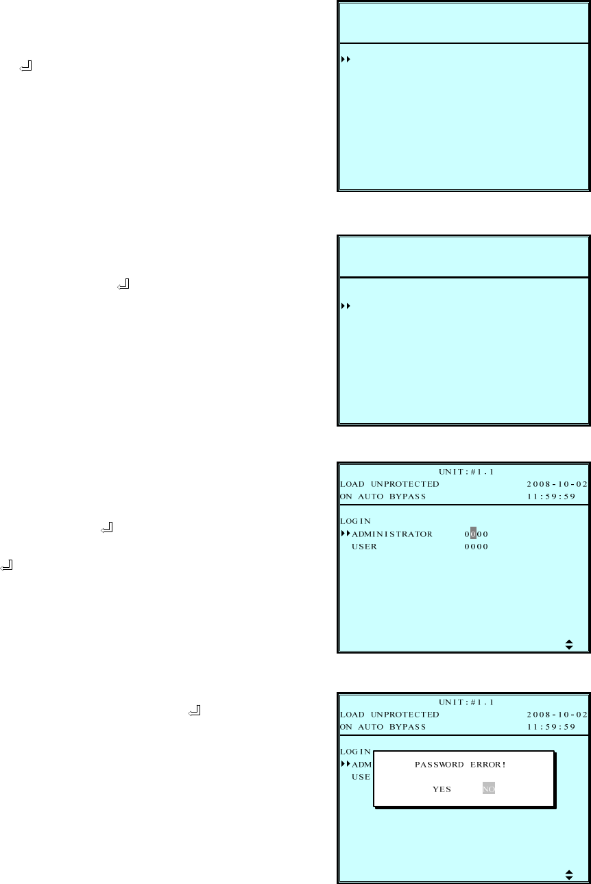
7-5 UPS SETUP
Use “” or ”” to select “Measure”,
then press ” ” to access the “UPS SETUP” menu.
Before changing the setting of each SETUP, you have to login first.
1. The login screen is shown at the
right. Move the cursor to select your
correct ID, then press ” ” to go to
the next page.
ADMINISTRATOR:
Qualified service personnel
User:
The authorization is only to
check the parameter but not to
configure.
2. The password consists of 4 digitals.
Use “” or ”” to select the first
number, then press ” ” for the next
digital. After all digitals are selected,
press ” ” to confirm the selection.
Default password is “0000”
3. If the password is wrong, press ” ”
to reselect.
P2008-10-02ROTECTEDLOAD UN
UN I T : # 1 . 1
11:59:59BYPAS SON AUTO
0000
000
NLOGI
0
IIS RNMAD TRATO
REUS
SS
P
CHAR
BATT
PARA
BYPA
OUTP
LOCAL
CONT
2008-10-02ROTECTEDLOAD UN
UN I T : # 1 . 1
12:09:49BYPAS SON AUTO
UT
YER
RGE
ELLL
L&TESTRO
7-12
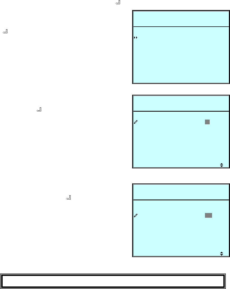
a. BYPASS SETUP
Use “” or ”” to select “BYPASS”, then press ” ” to confirm.
1. Use “” or ”” to select “VOLT
RANGE” or “FREQ RANGE", then
press ” ” to confirm.
2. Use “” or ”” to select the voltage
range, then press ” ” to confirm.
3. Use “” or ”” to select the
frequency range, then press ” ” to
confirm.
Press “ESC” to return to the “UPS SETUP” menu.
S
P
FREQ
ETUP
VOLT
2008-10-02ROTECTEDLOAD UN
UN I T : # 1 . 1
11:59:59BYPAS SON AUTO
V/+- ) 15%ANGE ( 2 2 0R
z/ 5.0(50H
SSBYPA
ANGER+-)
S
P
FREQ
ETUP
VOLT
2008-10-02ROTECTEDLOAD UN
UN I T : # 1 . 1
11:59:59BYPAS SON AUTO
V/+- ) 1 5 %ANGE ( 2 2 0R
z/ 5.0(50H
SSBYPA
ANGER+-)
S
P
FREQ
ETUP
VOLT
2008-10-02ROTECTEDLOAD UN
UN I T : # 1 . 1
11:59:59BYPAS SON AUTO
V/+- ) 15%ANGE ( 2 2 0R
z/ 5 . 0(50H
SSBYPA
ANGER+-)
7-13
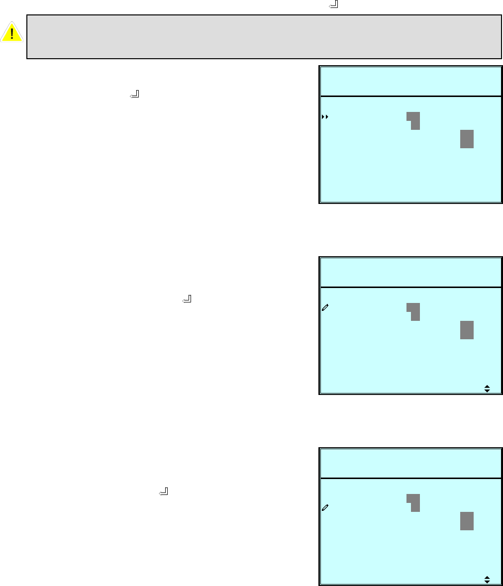
b. OUTPUT SETUP
Use “” or ”” to select “OUTPUT SETUP”, then press ” ” to confirm.
1. Use “” or ”” to select the desired
item, then press ” ” to confirm.
2. Output Voltage
Use “” or ”” to select the desired
output voltage, then press ” ” to
confirm.
(The voltage range is from 220 to
240Vac.)
3. Output Frequency
Use “” or ”” to select the desired
frequency, then press ” ” to
confirm.
(This output frequency is for battery
start condition or when the frequency
converter mode is enabled!)
All parameters in this segment can only be changed under
“B
yp
ass Mode”.
S
P
FREQ
ETUP
VOLT
2008-10-02ROTECTEDLOAD UN
UN I T : # 1 . 1
11:59:59BYPAS SON AUTO
2 2 0
060(
ON O F F
UN I T ) 0
UTOUT P
z)H5
VNOFREQ C
ECO
ANCY ( PWRREDUND
V)(
ON O F F
S
P
FREQ
ETUP
VOLT
2008-10-02ROTECTEDLOAD UN
UN I T : # 1 . 1
11:59:59BYPAS SON AUTO
2 2 0
060(
ON O F F
UN I T ) 0
UTOUT P
z)H5
VNOFREQ C
ECO
ANCY ( PWRREDUND
V)(
ON O F F
S
P
FREQ
ETUP
VOLT
2008-10-02ROTECTEDLOAD UN
UN I T : # 1 . 1
11:59:59BYPAS SON AUTO
2 2 0
060(
ON O F F
UN I T ) 0
UTOUT P
z)H5
VNOFREQ C
ECO
ANCY ( PWRREDUND
V)(
ON O F F
7-14
Press “ESC” to return to the “UPS SETUP” menu.
5. Frequency Converter Mode
Use “” or ”” to select the desired
mode, then press ” ” to confirm.
4. ECO mode
Use “” or ”” to select the desired
mode, then press ” ” to confirm. S
P
FREQ
ETUP
VOLT
2008-10-02ROTECTEDLOAD UN
UN I T : # 1 . 1
11:59:59BYPAS SON AUTO
2 2 0
060(
ON O F F
UN I T ) 0
UTOUT P
z)H5
VNOFREQ C
ECO
ANCY ( PWRREDUND
V)(
ON O F F
S
P
FREQ
ETUP
VOLT
2008-10-02ROTECTEDLOAD UN
UN I T : # 1 . 1
11:59:59BYPAS SON AUTO
2 2 0
060(
ON O F F
UN I T ) 0
UTOUT P
z)H5
VNOFREQ C
ECO
ANCY ( PWRREDUND
V)(
ON O F F
S
P
FREQ
ETUP
VOLT
2008-10-02ROTECTEDLOAD UN
UN I T : # 1 . 1
11:59:59BYPAS SON AUTO
2 2 0
060(
ON O F F
UN I T ) 0
UTOUT P
z)H5
VNOFREQ C
ECO
ANCY ( PWRREDUND
V)(
ON O F F
6. Redundancy
Use “” or ”” to select the desired
number for redundancy, then
press ” ” to confirm. In a parallel
system the redundancy has to be
selected “per UPS”. In case you have
two UPS in parallel and you want to
have a n+1 redundancy, select
Redundancy “0” at UPS 1 and
Redundancy “1” at UPS 2.
7-15
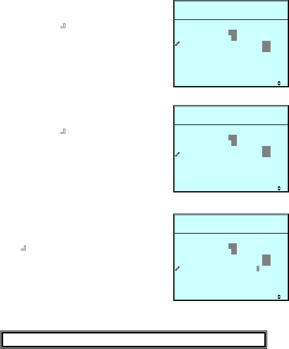
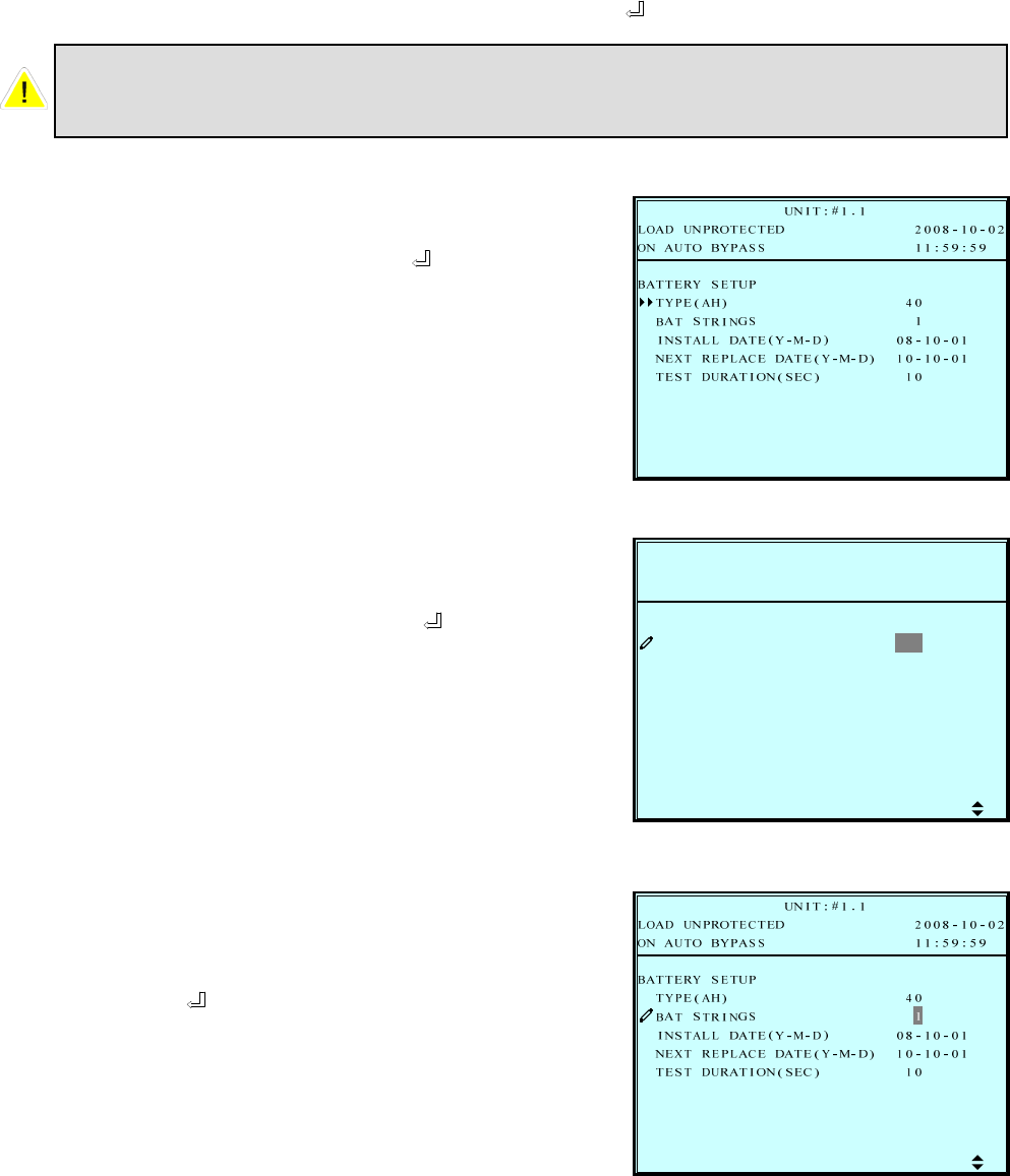
c. BATTERY SETUP
Use “” or ”” to select “BATTERY”, then press ” ” to confirm.
1. Use “” or ”” to select the
desired item, then press ” ” to
confirm.
2. Battery Type
Use “” or ”” to select the desired
battery capacity, then press ” ” to
confirm.
All parameters in this segment can only be changed under
“Bypass Mode”.
L
R
P
BAT
Y
TYPE
2008-10-02ROTECTEDLOAD UN
UN I T : # 1 . 1
11:59:59BYPAS SON AUTO
4 0)
1SS
-M-D) 08 - 1 0 - 01
10-10-01
10
EBATT
RINGT
APECENEXT R
LDATE(YINSTAL
AH(
SETUP
-M-D)DATE ( Y
SEC)TAUR (NIOTEST D
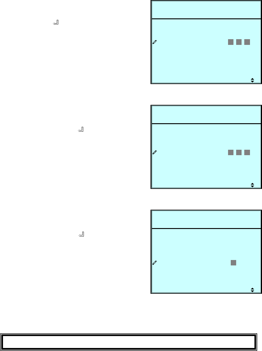
3. Battery Strings
Use “” or ”” to select the desired
number of battery strings, then
press ” ” to confirm.
7-16
6. Battery Test Duration
Use “” or ”” to select the battery
test duration, then press ” ” to
confirm.
Press “ESC” to return to the “UPS SETUP” menu.
4. Battery Install Date
Use “” or ”” to set the installation
date, then press ” ” to confirm.
L
R
P
BAT
Y
TYPE
2008-10-02ROTECTEDLOAD UN
UN I T : # 1 . 1
11:59:59BYPAS SON AUTO
40)
1SS
-M-D) 0 8 -1 0 -0 1
10-10-01
10
EBATT
RINGT
APECENEXT R
LDATE(YINSTAL
AH(
SETUP
-M-D)DATE ( Y
SEC)TAUR (NIOTEST D
L
R
P
BAT
Y
TYPE
2008-10-02ROTECTEDLOAD UN
UN I T : # 1 . 1
11:59:59BYPAS SON AUTO
40)
1SS
-M-D) 08 - 1 0 - 01
1 0 -1 0 -0 1
10
EBATT
RINGT
APECENEXT R
LDATE(YINSTAL
AH(
SETUP
-M-D)DATE ( Y
SEC)TAUR (NIOTEST D
L
R
P
BAT
Y
TYPE
2008-10-02ROTECTEDLOAD UN
UN I T : # 1 . 1
11:59:59BYPAS SON AUTO
40)
1SS
-M-D) 08 - 1 0 - 01
10-10-01
1 0
EBATT
RINGT
APECENEXT R
LDATE(YINSTAL
AH(
SETUP
-M-D)DATE ( Y
SEC)TAUR (NIOTEST D
5. Battery Next Replace Date
Use “” or ”” to set the next
replace date, then press ” ” to
confirm.
(Reach the replace date, the UPS
will alarm the message in LCD
display.)
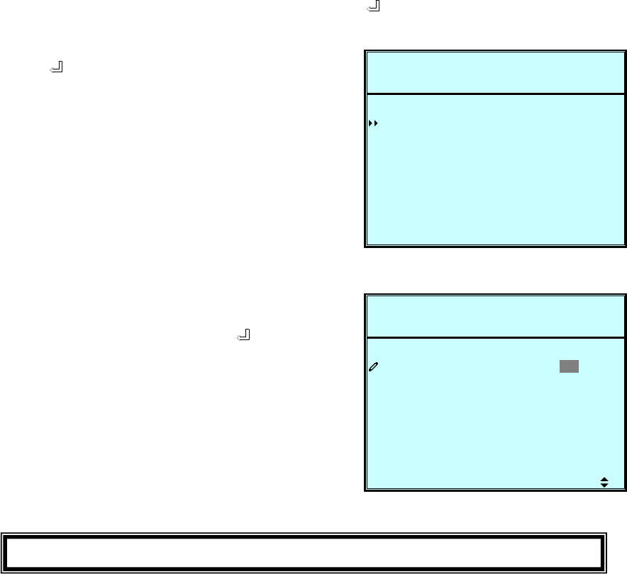
7-17
d. CHARGER SETUP
Use “” or ”” to select “CHARGER”, then press ” ” to confirm.
E
P
R
CHAR
2008-10-02ROTECTEDLOAD UN
UN I T : # 1 . 1
11:59:59BYPAS SON AUTO
T(A) 3URRENC
GCHAR
ERG
SETUP
1. Press ” ” to set the charging
current.
E
P
R
CHAR
2008-10-02ROTECTEDLOAD UN
UN I T : # 1 . 1
11:59:59BYPAS SON AUTO
T(A) 3URRENC
GCHAR
ERG
SETUP
2. Press “” or ”” to change the
charging current, then press ” ”
to confirm. Max. possible charging
current is 5A per module.
Press “ESC” to return to the “UPS SETUP” menu.
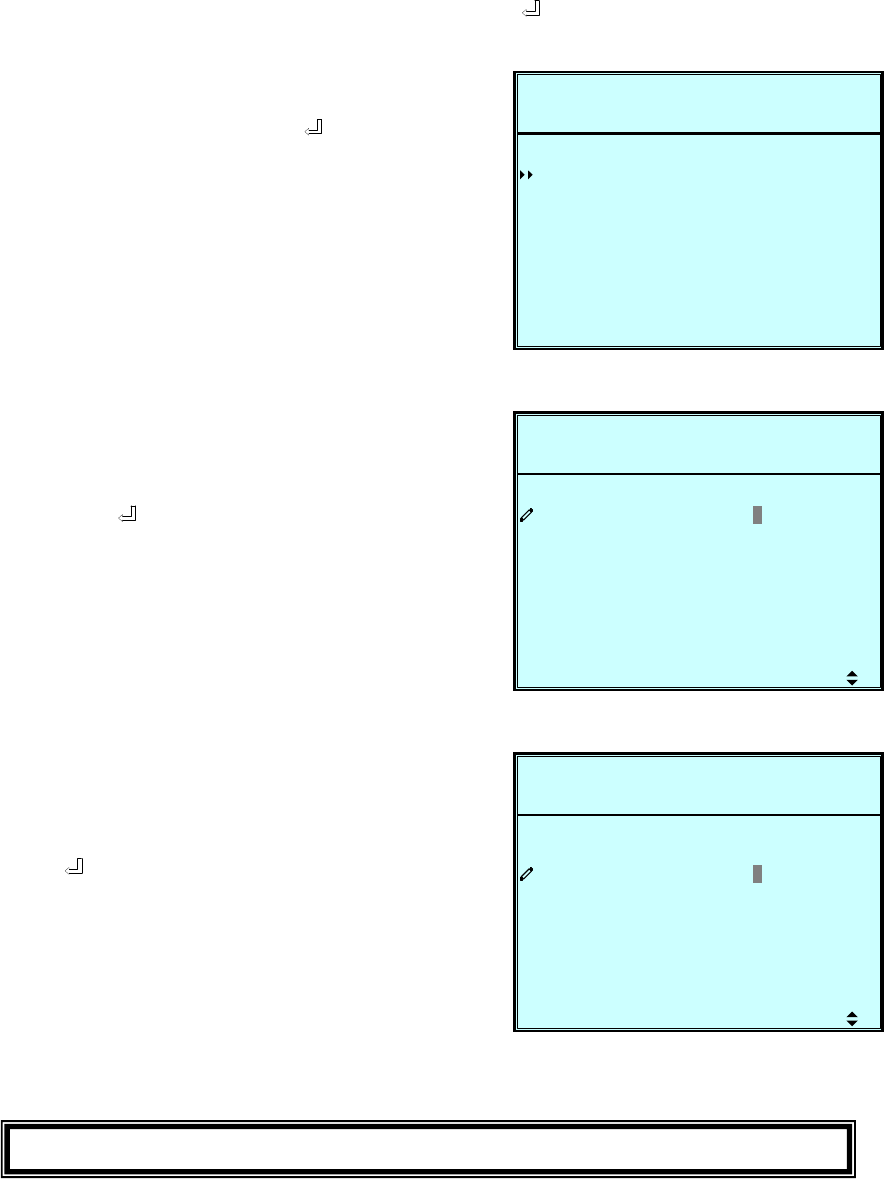
7-18
e. PARALLEL SETUP
Use “” or ”” to select “PARALLEL”, then press ” ” to confirm.
L
P
LE
PARA
2008-10-02ROTECTEDLOAD UN
UN I T : # 1 . 1
11:59:59BYPAS SON AUTO
1GROUPL
1D
LPARA
I
LEL
SETUP
PARA LLEL
L
P
LE
PARA
2008-10-02ROTECTEDLOAD UN
UN I T : # 1 . 1
11:59:59BYPAS SON AUTO
1GROUPL
1D
LPARA
I
LEL
SETUP
PARA LLEL
L
P
LE
PARA
2008-10-02ROTECTEDLOAD UN
UN I T : # 1 . 1
11:59:59BYPAS SON AUTO
1GROUPL
1D
LPARA
I
LEL
SETUP
PARA LLEL
3. PARALLEL ID
Use “” or ”” to set the UPS ID for
parallel redundancy installation, then
press “ ” to confirm.
(The ID is from 0 to 7.)
1. Use “” or ”” to select
the desired item, then press ” ” to
confirm.
2. PARALLEL GROUP
Use “” or ”” to set the UPS group
for parallel redundancy installation,
then press ” ” to confirm.
The setting is just for LBS (Load Bus
Synchronization) application.
The default setting is group 1.
Press “ESC” to return to the “UPS SETUP” menu.
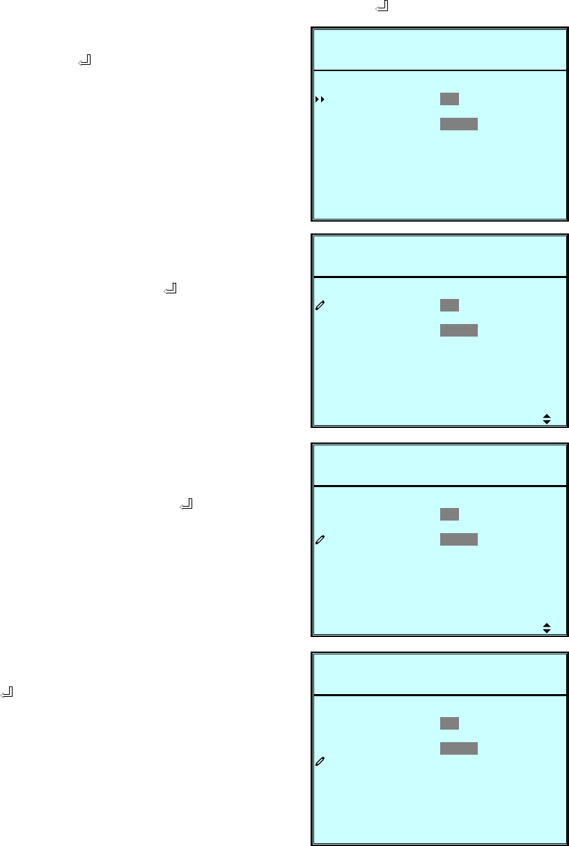
7-19
f. CONTROL & TEST SETUP
Use “” or ”” to select “CONTROL & TEST”, then press ” ” to confirm.
1. Use “” or ”” to select the desired
item, then press ” ” to confirm.
O
P
E
Y
&L
L
KLYBAT
ESULT
EST&LEDTBUZZER
2008-10-02ROTECTEDLOAD UN
UN I T : # 1 . 1
11:59:59BYPAS SON AUTO
O F F DA I LY WETESTO
IWEEKLY MONTH
DISABLE
RCONT
B
ETTRSTCLR BA
UTA
ARGESOBO HCTFORCE
T
AB L E
TABSETMA NU A L
E NBUZZER
TEST
O
P
E
Y
&L
L
KLYBAT
ESULT
EST&LEDTBUZZER
2008-10-02ROTECTEDLOAD UN
UN I T : # 1 . 1
11:59:59BYPAS SON AUTO
O F F DA I LY WETESTO
IWEEKLY MONTH
DISABLE
RCONT
B
ETTRSTCLR BA
UTA
ARGESOBO HCTFORCE
T
AB L E
TABSETMA NU A L
E NBUZZER
TEST
O
P
E
Y
&L
L
KLYBAT
ESULT
EST&LEDTBUZZER
2008-10-02ROTECTEDLOAD UN
UN I T : # 1 . 1
11:59:59BYPAS SON AUTO
O F F DA I LY WETESTO
IWEEKLY MONTH
DISABLE
RCONT
B
ETTRSTCLR BA
UTA
ARGESOBO HCTFORCE
T
AB L E
TABSETMA NU A L
E NBUZZER
TEST
O
P
E
Y
&L
L
KLYBAT
ESULT
EST&LEDTBUZZER
2008-10-02ROTECTEDLOAD UN
UN I T : # 1 . 1
11:59:59BYPAS SON AUTO
O F F DA I LY WETESTO
IWEEKLY MONTH
DISABLE
OK?
RCONT
B
ETTRSTCLR BA
UTA
ARGESOBO HCTFORCE
T
AB L E
TABSETMA NU A L
E NBUZZER
TEST
2. Battery Auto Test
Use “” or ”” to select
the desired item, then press ” ” to
confirm. If you start a battery test
once it will be performed at the same
time of the day due to the timely
sequence you have chosen with this
setting.
3. Buzzer
Use “” or ”” to select enable or
disable the buzzer, then press ” ”
to confirm.
4. Manual Battery Test
Press ” ” to execute “MANUAL
BAT TEST”.
(This item is only accessible for
administrator! The Password will be
needed.)
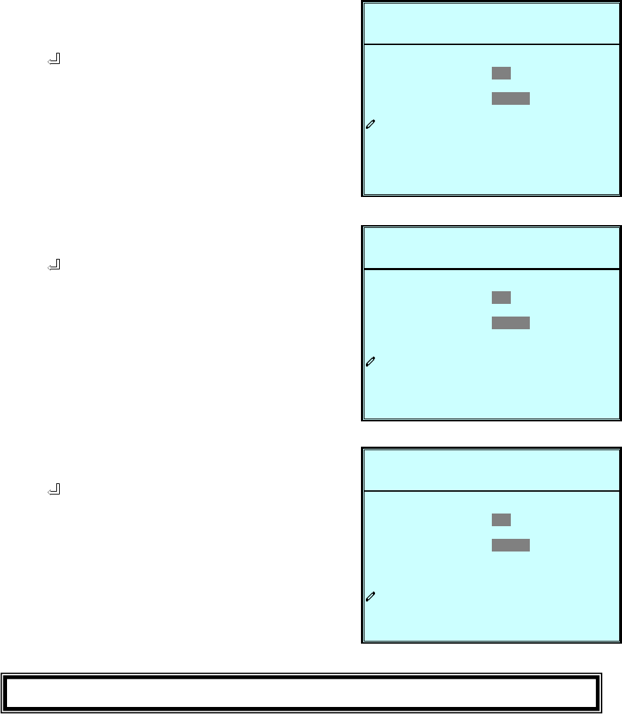
7-20
O
P
E
Y
&L
L
KLYBAT
ESULT
EST&LEDTBUZZER
2008-10-02ROTECTEDLOAD UN
UN I T : # 1 . 1
11:59:59BYPAS SON AUTO
O F F DA I LY WETESTO
IWEEKLY MONTH
DISABLE
OK?
RCONT
B
ETTRSTCLR BA
UTA
ARGESOBO HCTFORCE
T
AB L E
TABSETMA NU A L
E NBUZZER
TEST
O
P
E
Y
&L
L
KLYBAT
ESULT
EST&LEDTBUZZER
2008-10-02ROTECTEDLOAD UN
UN I T : # 1 . 1
11:59:59BYPAS SON AUTO
O F F DA I LY WETESTO
IWEEKLY MONTH
DISABLE
OK?
RCONT
B
ETTRSTCLR BA
UTA
ARGESOBO HCTFORCE
T
AB L E
TABSETMA NU A L
E NBUZZER
TEST
O
P
E
Y
&L
L
KLYBAT
ESULT
EST&LEDTBUZZER
2008-10-02ROTECTEDLOAD UN
UN I T : # 1 . 1
11:59:59BYPAS SON AUTO
O F F DA I LY WETESTO
IWEEKLY MONTH
DISABLE
OK?
RCONT
B
ETTRSTCLR BA
UTA
ARGESOBO HCTFORCE
T
AB L E
TABSETMA NU A L
E NBUZZER
TEST
5. Force Boost Charge
Press ” ” to execute “FORCE
BOOST CHARGE”.
(This item is only accessible for
administrator! The Password will be
needed.
)
6. Clear Battery Test Result
Press “ ” to execute “CLR BAT
TEST RESULT”. This will clear all
battery test results in log.
7. Buzzer & LED Test
Press “ ” to execute “BUZZER &
LED TEST”.
(This item is only accessible for
administrator! The Password will be
needed.)
Press “ESC” to return to the “UPS SETUP” menu.
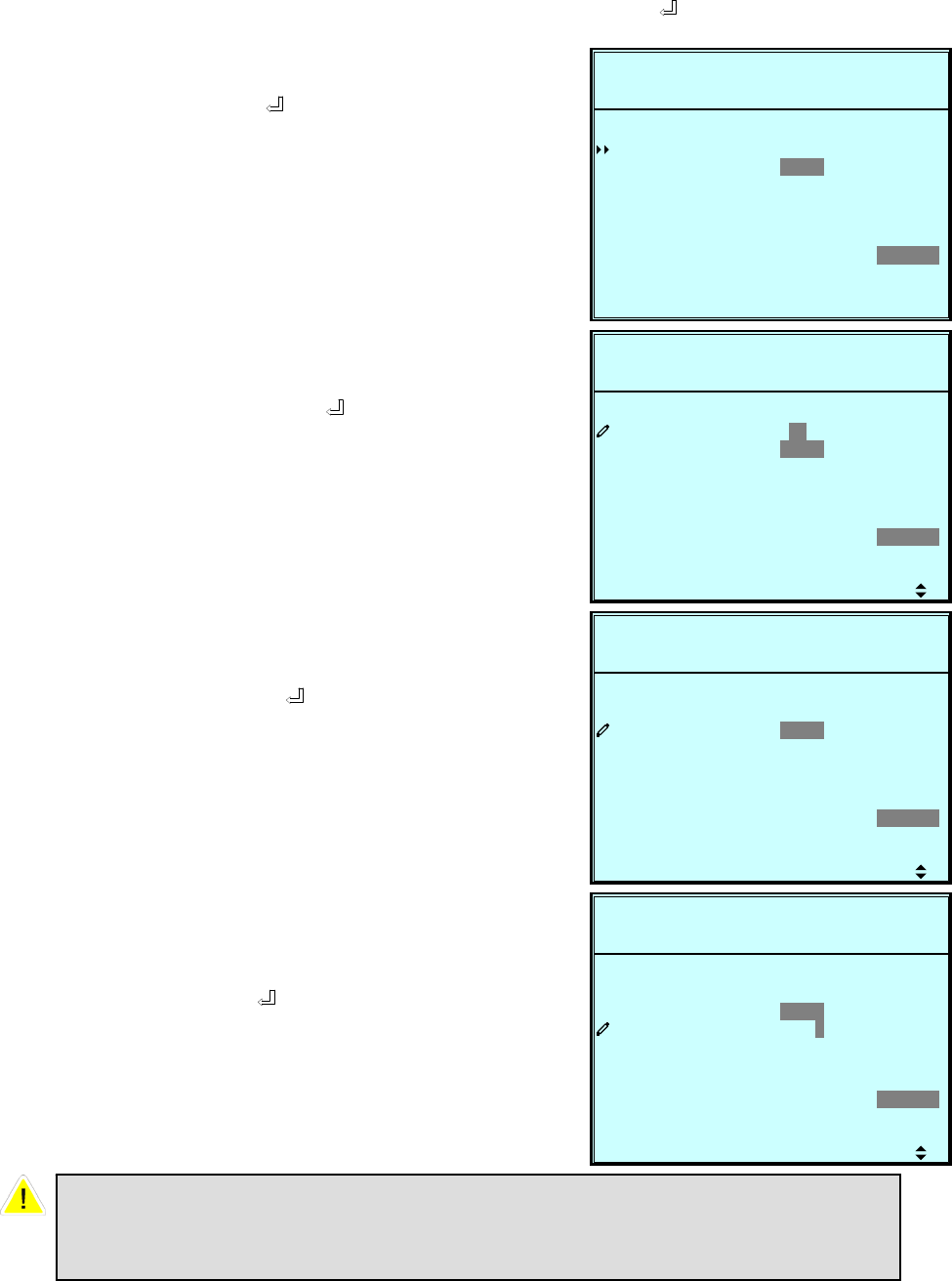
7-21
g. LOCAL SETUP
Use “” or ”” to select “LOCAL SETUP”, then press ” ” to confirm.
1. Use “” or ”” to select the desired
item, then press ” ” to confirm.
2. Date & Time
Use “” or ”” to change the “DATE
and TIME”, then press ” ” to
confirm.
(This item is user accessible!)
3. Date Format
Use “” or ”” to change the date
format, then press ” ” to confirm.
(This item is user accessible! )
4. Serial COM ID
Use “” or ”” to set the ID of serial
port, then press ” ” to confirm.
P
-M-Y
9:59DATE
0000
E NG L I S HGELANGUA
2008-10-02ROTECTEDLOAD UN
UN I T : # 1 . 1
12:19:59BYPAS SON AUTO
ME 08-10-02 12 :1-D)&TIM
Y - M - D M-D -Y DT
0000
LLOCA
MA
WSAS DORUSER P
Y-(
SSPA DRWOADMI N
5
0
ARNT STLCD CO
MOCDISERIAL
DATE RFO
P
-M-Y
9:59DATE
0000
E NG L I S HGELANGUA
2008-10-02ROTECTEDLOAD UN
UN I T : # 1 . 1
12:19:59BYPAS SON AUTO
ME 0 8 -10-02 12:1-D)&TIM
Y - M - D M-D -Y DT
0000
LLOCA
MA
WSAS DORUSER P
Y-(
SSPA DRWOADMI N
5
0
ARNT STLCD CO
MOCDISERIAL
DATE RFO
P
-M-Y
9:59DATE
0000
E NG L I S HGELANGUA
2008-10-02ROTECTEDLOAD UN
UN I T : # 1 . 1
12:19:59BYPAS SON AUTO
ME 08-10-02 12 :1-D)&TIM
Y - M - D M-D -Y DT
0000
LLOCA
MA
WSAS DORUSER P
Y-(
SSPA DRWOADMI N
5
0
ARNT STLCD CO
MOCDISERIAL
DATE RFO
P
-M-Y
9:59DATE
0000
E NG L I S HGELANGUA
2008-10-02ROTECTEDLOAD UN
UN I T : # 1 . 1
12:19:59BYPAS SON AUTO
ME 08-10-02 12 :1-D)&TIM
Y - M - D M-D -Y DT
0000
LLOCA
MA
WSAS DORUSER P
Y-(
SSPA DRWOADMI N
5
0
ARNT STLCD CO
MOCDISERIAL
DATE RFO
For standard RS232 connection, this ID is meaningless; if using the
RS485/RS422 converter of other brands to connect to RS232 port, the ID
can be set to 00, 01…….99.
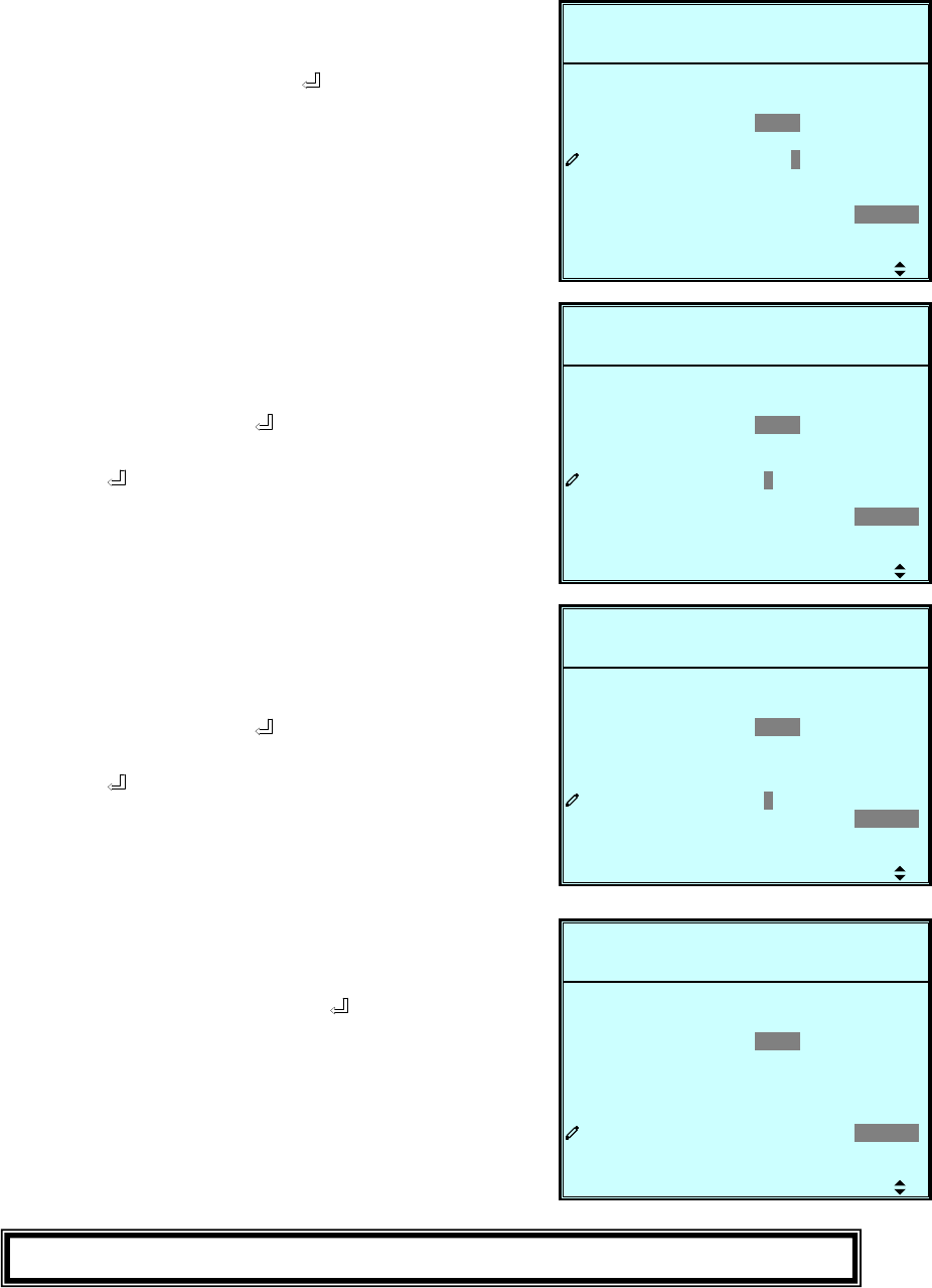
7-22
P
-M-Y
9:59DATE
0000
E NG L I S HGELANGUA
2008-10-02ROTECTEDLOAD UN
UN I T : # 1 . 1
12:19:59BYPAS SON AUTO
ME 08-10-02 12 :1-D)&TIM
Y - M - D M-D -Y DT
0000
LLOCA
MA
WSAS DORUSER P
Y-(
SSPA DRWOADMI N
5
0
ARNT STLCD CO
MOCDISERIAL
DATE RFO
P
-M-Y
9:59DATE
0000
E NG L I S HGELANGUA
2008-10-02ROTECTEDLOAD UN
UN I T : # 1 . 1
12:19:59BYPAS SON AUTO
ME 08-10-02 12 :1-D)&TIM
Y - M - D M-D -Y DT
0000
LLOCA
MA
WSAS DORUSER P
Y-(
SSPA DRWOADMI N
5
0
ARNT STLCD CO
MOCDISERIAL
DATE RFO
P
-M-Y
9:59DATE
0000
E NG L I S HGELANGUA
2008-10-02ROTECTEDLOAD UN
UN I T : # 1 . 1
12:19:59BYPAS SON AUTO
ME 08-10-02 12 :1-D)&TIM
Y - M - D M-D -Y DT
0000
LLOCA
MA
WSAS DORUSER P
Y-(
SSPA DRWOADMI N
5
0
ARNT STLCD CO
MOCDISERIAL
DATE RFO
P
-M-Y
9:59DATE
0000
E NG L I S HGELANGUA
2008-10-02ROTECTEDLOAD UN
UN I T : # 1 . 1
12:19:59BYPAS SON AUTO
ME 08-10-02 12 :1-D)&TIM
Y - M - D M-D -Y DT
0000
LLOCA
MA
WSAS DORUSER P
Y-(
SSPA DRWOADMI N
5
0
ARNT STLCD CO
MOCDISERIAL
DATE RFO
5. LCD Contrast
Use “” or ”” to set the contrast of
LCD screen, then press ” ” to
confirm.
(This item is user accessible!)
6. Administrator Password
The password consists of 4 digitals.
Use “” or ”” to select the first
number, then press ” ” for the next
digital. After all digitals are selected,
press ” ” to confirm.
7. User Password
The password consists of 4 digitals.
Use “” or ”” to select the first
number, then press ” ” for the next
digital. After all digitals are selected,
press ” ” to confirm.
8. Language
Use “” or ”” to select the language
of LCD screen, then press ” ” to
confirm.
(This item is user accessible!)
Press “ESC” to return to the “UPS SETUP” menu.

7-23
7-6 Maintenance
Use “” or ”” to select ”MAINTENANCE” in the main menu, then press “ ” to
confirm.
The first item is the series number of the UPS unit.
E
P
ANN
S/N
2008-10-02ROTECTEDLOAD UN
UN I T : # 1 . 1
11:59:59BYPASSON AUTO
E1E08200013W0
TMA I N
ON
EDADVANC
GLOEVENT
SCTISTATI S
CE
FW V IRSE
1. Use “” or ”” to select the desired
item, then press ” ” to confirm.
2. Firmware Version
Use “” or ”” to select the F/W
version item, then press ” ” to
confirm.
(That will show the firmware version
of the system and each power
module.)
T
P
59OP
10CO
ON BYP
2008-10-02ROTECTEDLOAD UN
UN I T : # 1 . 1
11:59:59BYPAS SON AUTO
123COUNT S
-D M) 00-003-04-ME ( Y
AON B
TI -H-
SSA
UNTS
ERAT ONI
3. Statistics
Use “” or ”” to read the statistics
data, then press ” ” to confirm.
(That will show the “counts on
battery”, “counts on bypass” and
“total operation time”.)
M
P
#2
00#1
#3
otec .Pr
PM
#4
2008-10-02ROTECTEDLOAD UN
UN I T : # 1 . 1
11:59:59BYPAS SON AUTO
INVPFC
00 HSA1A1020882008810
ESYST
10 0HSA 0A11
00881010 0HSA 0A11
00881010 0HSA 0A11
00881010 0HSA 0A11
00HSA1A102088200
00HSA1A102088200
00HSA1A102088200
tX3M2.X

7-24
P
assOn Byp
Of f
2008-10-02ROTECTEDLOAD UN
UN I T : # 1 . 1
11:59:59BYPAS SON AUTO
ormal
rma l
eq
AbnoltageupIn oVtMa i n s
<003>
rF
erBreakOu t pu t
ansAbspBy Fr eq
-82:50008-1 08:10
<002> - 82:50008-1 08:10
<001> - 62:40008-1 08:10
<004> - 92:50008-1 08:10
<005> - 92:50008-1 08:10
upIn tMa i n s rma lAbno
4. Event Log
Use “” or ”” to read the event log,
then press ” ” to confirm.
C
P
DE
2008-10-02ROTECTEDLOAD UN
UN I T : # 1 . 1
11:59:59BYPAS SON AUTO
NADVA
EDRAFW UPG
OTHERS
TA CSSRCL T I ST I
VE GERCL NT LO
5. Advance
Use “” or ”” to select the
“ADVANCED” item, then press ” ”
to confirm.
The “ADVANCED” item includes
“clear statistics”, “clear event log”
“firmware upgrade” and “other status
monitor for service”.
(This item is only accessible for
administrator! The Password will be
required to confirm again.)
Press “ESC” to return to the “Main Menu”.
