QCA402x (CDB2x) Programmer's Guide 80 Ya121 142 D Qca402xcdb2x Programmers
User Manual:
Open the PDF directly: View PDF ![]() .
.
Page Count: 116 [warning: Documents this large are best viewed by clicking the View PDF Link!]
- 1 Introduction to QCA402x
- 2 QCA402x system overview
- 3 QCA402x framework and programming model
- 3.1 RTOS
- 3.2 Thread priorities
- 3.3 Low-power framework
- 3.4 Communication drivers
- 3.5 WLAN features
- 3.5.1 Store-recall (Suspend-resume) of WLAN firmware
- 3.5.2 Packet Filtering and Wake on Wireless (WoW)
- 3.5.3 ARP and NS offload
- 3.5.4 TCP Keepalive offload
- 3.5.5 Debug logs
- 3.5.6 MAC Keepalive timeout for STA
- 3.5.7 Channel switch
- 3.5.8 11v support
- 3.5.9 WNM sleep
- 3.5.10 SetAPBssMaxIdlePeriod
- 3.5.11 Event filtering
- 3.5.12 P2P module and P2P power-save mechanism
- 3.5.13 Antenna diversity
- 3.5.14 WPA Enterprise
- 3.6 NVM configuration
- 3.7 Firmware upgrade
- 3.8 WLAN coexistence usage notes
- 3.9 Network services
- 3.9.1 BSD-Socket interface
- 3.9.2 Acquire an IP address
- 3.9.3 Net buffers and profiles
- 3.9.4 SSL
- 3.9.4.1 Protocol versions
- 3.9.4.2 Modes of operation
- 3.9.4.3 Supported cipher suites
- 3.9.4.4 Server authentication
- 3.9.4.5 Client authentication
- 3.9.4.6 SNI
- 3.9.4.7 ALPN
- 3.9.4.8 SSL certificate manager
- 3.9.4.8.1 Storing certificates and CA lists securely in flash
- 3.9.4.8.1.1 Store certificate and key in PEM format securely into flash using TEE secure storage
- 3.9.4.8.1.2 Store certificate in binary format into flash using TEE secure storage
- 3.9.4.8.1.3 Store CA list in PEM format into flash using secure storage
- 3.9.4.8.1.4 Store Binary CA list into flash using secure storage
- 3.9.4.8.2 Load certificate or CA list from flash into SSL object
- 3.9.4.8.3 List available certificates and CA lists in flash
- 3.9.4.8.4 Calculate SHA256 checksum of certificate or CA list stored in flash
- 3.9.4.8.5 Validating an external certificate
- 3.9.4.8.6 Certificate expiration test
- 3.9.4.8.7 Set up pre-shared key (PSK) table
- 3.9.4.8.8 Clear the pre-shared key (PSK) table
- 3.9.4.8.1 Storing certificates and CA lists securely in flash
- 3.9.4.9 Create a new SSL object and connection
- 3.9.4.10 Configure SSL object and SSL connection
- 3.9.4.11 Connect and disconnect SSL sessions
- 3.9.4.12 Send and receive data using TLS
- 3.9.5 DHCPv4 client
- 3.9.6 DHCPv4 server
- 3.9.7 DHCPv6 client
- 3.9.8 DNS client
- 3.9.9 DNS server
- 3.9.10 DNS-SD (service discovery)
- 3.9.11 HTTP client
- 3.9.12 HTTP server
- 3.9.13 mDNS server
- 3.9.14 MQTT client
- 3.9.15 SNTP client
- 3.9.16 WLAN bridging
- 3.9.17 Websocket client
- 3.9.18 CoAP client
- 3.9.19 CoAP server
- 3.10 Thread
- 3.11 ZigBee
- 3.12 Cryptographic operations
- 3.12.1 Secure storage
- 3.12.2 Transient object operations
- 3.12.3 Delete transient objects
- 3.12.4 Persistent object operations
- 3.12.5 Crypto operations
- 3.12.5.1 Basic operations
- 3.12.5.2 Digest operations
- 3.12.5.3 Cipher operations
- 3.12.5.4 Random number generation
- 3.12.5.5 Authentication encryption operations
- 3.12.5.6 Key derivation
- 3.12.5.7 MAC operations
- 3.12.5.8 Asymmetric sign and verify operations
- 3.12.5.9 Asymmetric encryption operations
- 3.12.5.10 Secure utilities
- 3.12.6 Secure ED25519 keypair generation and signing
- 3.13 Host-target Communications (HTC)
- 4 QCA402x application development
- 4.1 QCA402x SDK compilation model
- 4.2 QCA402x boot flow
- 4.3 Configuration and programming
- 4.3.1 Configuring an application
- 4.3.2 GPIO customization
- 4.3.3 Code placement
- 4.3.4 Resize application memory
- 4.3.5 RAM dump collection and debugging
- 4.3.6 RAM dump collection procedure through USB
- 4.3.7 Collect RAM dump stored in flash memory
- 4.3.8 RAM dump analysis
- 4.3.9 Image encryption
- 4.3.10 Flash programming
- 4.3.11 Flash layout
- 4.3.12 Flash Golden + Current + Trial image set
- 4.3.13 JTAG debug GPIO bootstrap configuration
- 4.4 Secure boot
- 4.5 Power measurement
- 5 QCA402x debugging tools

Qualcomm Technologies, Inc.
All Qualcomm products mentioned herein are products of Qualcomm Technologies, Inc. and/or its subsidiaries.
Qualcomm is a trademark of Qualcomm Incorporated, registered in the United States and other countries. QuRT and Touchlink are
trademarks of Qualcomm Incorporated. Other product and brand names may be trademarks or registered trademarks of their respective
owners.
This technical data may be subject to U.S. and international export, re-export, or transfer (“export”) laws. Diversion contrary to U.S. and
international law is strictly prohibited.
Qualcomm Technologies, Inc.
5775 Morehouse Drive
San Diego, CA 92121
U.S.A.
© 2018 Qualcomm Technologies, Inc. and/or its subsidiaries. All rights reserved.
QCA402x (CDB2x)
Programmer’s Guide
80-YA121-142 Rev. D
November 20, 2018

80-YA121-142 Rev. D MAY CONTAIN U.S. AND INTERNATIONAL EXPORT CONTROLLED INFORMATION 2
Revision history
Revision
Date
Description
A
March 2018
Initial release
B
July 2018
Added the following:
▪ Section 3.5.13, Antenna diversity
▪ Section 3.9.4.8.5, Validating an external certificate
▪ Section 3.9.4.8.6, Certificate expiration test
▪ Section 3.9.11.7, HTTP tunneling
▪ Section 3.9.17, Websocket Client
▪ Section 3.12.4.1, Importing persistent objects from certificate
store
▪ Section 3.12.5.6.1, ECJPAKE algorithm
▪ Section 4.3.5, RAM dump collection and debugging
Updated the following:
▪ Section 3.9.4.8, SSL certificate manager
▪ Section 3.9.4.11.1, Establish a connection
▪ Section 3.9.11.2, Terminate a connection
▪ Section 3.9.11.3, Set URL key-value pairs
▪ Section 3.9.11.6, Send an HTTP request
Section 3.12.5.6, Key derivation
C
November 2018
Numerous updates have been made to chapters 3 and 4. Read
the document in its entirety.
D
November 2018
Updated section 3.12.2.2, Create an object by populating its
attributes

80-YA121-142 Rev. D MAY CONTAIN U.S. AND INTERNATIONAL EXPORT CONTROLLED INFORMATION 3
Contents
1 Introduction to QCA402x ...................................................................................................... 6
1.1 Purpose ..................................................................................................................................................... 6
1.2 Conventions ............................................................................................................................................... 6
2 QCA402x system overview ................................................................................................... 7
2.1 Packages ................................................................................................................................................... 7
2.2 QCA402x processors ................................................................................................................................. 7
3 QCA402x framework and programming model ................................................................... 9
3.1 RTOS ......................................................................................................................................................... 9
3.2 Thread priorities ......................................................................................................................................... 9
3.3 Low-power framework ................................................................................................................................ 9
3.3.1 Processor power management ................................................................................................. 9
3.3.2 Operating mode framework .................................................................................................... 10
3.4 Communication drivers ............................................................................................................................ 13
3.4.1 802.15.4.................................................................................................................................. 13
3.4.2 Wi-Fi ....................................................................................................................................... 15
3.5 WLAN features ........................................................................................................................................ 17
3.5.1 Store-recall (Suspend-resume) of WLAN firmware ................................................................. 17
3.5.2 Packet Filtering and Wake on Wireless (WoW) ...................................................................... 18
3.5.3 ARP and NS offload ............................................................................................................... 19
3.5.4 TCP Keepalive offload ............................................................................................................ 19
3.5.5 Debug logs ............................................................................................................................. 19
3.5.6 MAC Keepalive timeout for STA ............................................................................................. 19
3.5.7 Channel switch ....................................................................................................................... 19
3.5.8 11v support ............................................................................................................................. 20
3.5.9 WNM sleep ............................................................................................................................. 20
3.5.10 SetAPBssMaxIdlePeriod....................................................................................................... 20
3.5.11 Event filtering ........................................................................................................................ 20
3.5.12 P2P module and P2P power-save mechanism ..................................................................... 20
3.5.13 Antenna diversity .................................................................................................................. 21
3.5.14 WPA Enterprise .................................................................................................................... 21
3.6 NVM configuration ................................................................................................................................... 22
3.6.1 BLE NVM parameters list ....................................................................................................... 22
3.6.2 802.15.4 NVM parameters list ................................................................................................ 26
3.6.3 Coexistence NVM parameters list .......................................................................................... 29
3.6.4 Common NVM parameters list ................................................................................................ 32
3.7 Firmware upgrade .................................................................................................................................... 33
3.7.1 Firmware upgrade overview ................................................................................................... 34
3.7.2 Firmware upgrade image set .................................................................................................. 34
3.7.3 Supported flash configurations ............................................................................................... 34
3.7.4 Configuration file ..................................................................................................................... 35
3.7.5 Support for partial upgrade ..................................................................................................... 35
3.7.6 Support for full upgrade .......................................................................................................... 35
3.7.7 Firmware upgrade image generation tool ............................................................................... 36
3.8 WLAN coexistence usage notes .............................................................................................................. 37
3.8.1 Profile usage ........................................................................................................................... 37

QCA402x (CDB2x) Programmer’s Guide Contents
80-YA121-142 Rev. D MAY CONTAIN U.S. AND INTERNATIONAL EXPORT CONTROLLED INFORMATION 4
3.9 Network services...................................................................................................................................... 38
3.9.1 BSD-Socket interface ............................................................................................................. 38
3.9.2 Acquire an IP address ............................................................................................................ 42
3.9.3 Net buffers and profiles........................................................................................................... 42
3.9.4 SSL ......................................................................................................................................... 43
3.9.5 DHCPv4 client ........................................................................................................................ 55
3.9.6 DHCPv4 server ....................................................................................................................... 55
3.9.7 DHCPv6 client ........................................................................................................................ 55
3.9.8 DNS client ............................................................................................................................... 56
3.9.9 DNS server ............................................................................................................................. 56
3.9.10 DNS-SD (service discovery) ................................................................................................. 57
3.9.11 HTTP client ........................................................................................................................... 58
3.9.12 HTTP server ......................................................................................................................... 60
3.9.13 mDNS server ........................................................................................................................ 66
3.9.14 MQTT client .......................................................................................................................... 67
3.9.15 SNTP client ........................................................................................................................... 68
3.9.16 WLAN bridging ..................................................................................................................... 68
3.9.17 Websocket client .................................................................................................................. 69
3.9.18 CoAP client ........................................................................................................................... 72
3.9.19 CoAP server ......................................................................................................................... 74
3.10 Thread ................................................................................................................................................... 75
3.10.1 Network address management ............................................................................................. 75
3.10.2 Low-power mode .................................................................................................................. 75
3.11 ZigBee ................................................................................................................................................... 76
3.11.1 ZigBee DevCfg ..................................................................................................................... 76
3.11.2 Green power proxy ............................................................................................................... 77
3.11.3 Low-power modes ................................................................................................................ 77
3.11.4 Legacy support ..................................................................................................................... 77
3.12 Cryptographic operations ....................................................................................................................... 78
3.12.1 Secure storage ..................................................................................................................... 78
3.12.2 Transient object operations .................................................................................................. 78
3.12.3 Delete transient objects ........................................................................................................ 80
3.12.4 Persistent object operations ................................................................................................. 80
3.12.5 Crypto operations ................................................................................................................. 81
3.12.6 Secure ED25519 keypair generation and signing ................................................................. 86
3.13 Host-target Communications (HTC) ....................................................................................................... 86
4 QCA402x application development.....................................................................................87
4.1 QCA402x SDK compilation model ........................................................................................................... 87
4.2 QCA402x boot flow .................................................................................................................................. 88
4.3 Configuration and programming .............................................................................................................. 88
4.3.1 Configuring an application ...................................................................................................... 88
4.3.2 GPIO customization ................................................................................................................ 90
4.3.3 Code placement ..................................................................................................................... 93
4.3.4 Resize application memory ..................................................................................................... 94
4.3.5 RAM dump collection and debugging ..................................................................................... 96
4.3.6 RAM dump collection procedure through USB ....................................................................... 97
4.3.7 Collect RAM dump stored in flash memory ............................................................................. 98
4.3.8 RAM dump analysis ................................................................................................................ 99
4.3.9 Image encryption .................................................................................................................. 100
4.3.10 Flash programming ............................................................................................................. 101
4.3.11 Flash layout ........................................................................................................................ 101
4.3.12 Flash Golden + Current + Trial image set ........................................................................... 102
4.3.13 JTAG debug GPIO bootstrap configuration ........................................................................ 104
4.4 Secure boot ........................................................................................................................................... 105
4.5 Power measurement .............................................................................................................................. 105
5 QCA402x debugging tools ................................................................................................ 106
5.1 Debug script overview ............................................................................................................................ 106

QCA402x (CDB2x) Programmer’s Guide Contents
80-YA121-142 Rev. D MAY CONTAIN U.S. AND INTERNATIONAL EXPORT CONTROLLED INFORMATION 5
5.1.1 Requirements ....................................................................................................................... 107
A Configure GPIO functions ................................................................................................. 109
Figures
Figure 3-1 Memory map for the three operating modes on APSS................................................................................ 11
Figure 3-2 OMTM State Transitions ............................................................................................................................. 12
Figure 3-3 QCA402x firmware upgrade framework ...................................................................................................... 33
Figure 3-4 QCA402x firmware upgrade config file format ............................................................................................ 35
Figure 4-1 QCA402x SDK compilation model .............................................................................................................. 87
Figure 4-2 Start RAM dump debugging on GDB client ............................................................................................... 100
Figure 4-3 QCA402x SPI NOR flash layout ............................................................................................................... 102
Tables
Table 3-1 Operating modes of functional use cases .................................................................................................... 11
Table 3-2 OMTT structure ............................................................................................................................................ 12
Table A-1 QCA402x GPIO function configuration ...................................................................................................... 109
Table A-2 QCA4020 GPIO function configuration ...................................................................................................... 114

80-YA121-142 Rev. D MAY CONTAIN U.S. AND INTERNATIONAL EXPORT CONTROLLED INFORMATION 6
1 Introduction to QCA402x
1.1 Purpose
This document provides information intended for a software developer that works with the
QCA402x device and is used to enhance, extend, or adapt the reference source code to meet
customer requirements. This document does not attempt to detail every subject; it enables the
reader an opportunity to understand the various components and how they interact. A careful
reading of the code can provide more understanding. The QCA402x QAPI specification (80-
Y9381-7) document describes formal APIs, including valuable comments that describe each
interface and parameter.
QCA402x refers to QCA4020 and QCA4024 devices throughout this document.
1.2 Conventions
Function declarations, function names, type declarations, attributes, and code samples appear in a
different font. For example, #include.
Code variables appear in angle brackets. For example, <number>.
Commands to be entered appear in a different font. For example, copy a:*.* b:.
Button and key names appear in bold font. For example, Click Save or press Enter.

80-YA121-142 Rev. D MAY CONTAIN U.S. AND INTERNATIONAL EXPORT CONTROLLED INFORMATION 7
2 QCA402x system overview
This section provides an overview of the various features of the QCA402x device.
2.1 Packages
QCA402x is available in two packages:
■ QCA4020 (BGA 11.2x11.2 mm) includes Arm Cortex-M4F application processor, an Arm
Cortex-M0 connectivity processor, and a dedicated processor to support the Wi-Fi dual-band
functionality.
■ QCA4024 (68mQFN 8x8 mm) includes an Arm Cortex-M4F application processor and an
Arm Cortex-M0 connectivity processor.
2.2 QCA402x processors
QCA402x contains two processors – Arm -Cortex-M4F and Arm-Cortex-M0.
The first processor is an Arm Cortex-M4F and is used as the application processor, which runs
the Qualcomm® networking stack and the OEM application code.
The processor and memory subsystem attributes are as follows:
■ Arm Cortex-M4F @ up to128 MHz
■ Arm v7-M ISA (Thumb/Thumb-2)
■ Single-precision floating point
■ 704 KB SRAM: 300 KB available for customer code and data
■ 512 KB ROM
■ Memory-mapped, cached view of external QSPI flash. The cache is specified as 32 KB with
4-way associativity.
The second processor is an Arm Cortex-M0, which is used as the connectivity processor for the
BLE and 802.15.4 subsystems.
The processor attributes are as follows:
■ Arm Cortex-M0 @ 64 MHz
■ Arm v6-M ISA (subset of Thumb/Thumb-2)
■ 128 KB SRAM
■ 384 KB ROM

QCA402x (CDB2x) Programmer’s Guide QCA402x system overview
80-YA121-142 Rev. D MAY CONTAIN U.S. AND INTERNATIONAL EXPORT CONTROLLED INFORMATION 8
QCA4024 implements two wireless subsystems on-chip: BLE v5.0 and 802.15.4 v2006.
In addition to the preceding two processors, QCA4020 also has a dedicated WLAN processor. It
implements three wireless subsystems on-chip: 1 x 1 dual-band 11n Wi-Fi, BLE v5.0, and
802.15.4 v2006.

80-YA121-142 Rev. D MAY CONTAIN U.S. AND INTERNATIONAL EXPORT CONTROLLED INFORMATION 9
3 QCA402x framework and programming
model
3.1 RTOS
An application can use QuRT™, ThreadX, or FreeRTOS APIs for real-time operating system
(RTOS) services. ThreadX and FreeRTOS APIs are described in external documentation
available on the Web. Qualcomm’s QuRT APIs are considered part of the QAPI and are
thoroughly described in QCA402x QAPI Specification (80-Y9381-7) documentation.
RTOS APIs perform the following:
■ Create/destroy tasks or threads
■ Wait for an event to be signaled/signal an event
■ Acquire a mutex/release a mutex
■ Decrement a semaphore (consume)/Increment a semaphore (produce)
■ Wait for a timer to expire/set a timer to expire
3.2 Thread priorities
An application can use QuRT API to set thread priority to be assigned to a thread. Thread
priorities are specified as numeric values in the range of 0 – 31 with 0 representing the highest
priority. It is recommended to set user application thread priority to be greater than or equal to 20
to avoid starvation of system threads.
3.3 Low-power framework
QCA402x provides a highly configurable framework for achieving lowest possible power
consumption. The framework consists of following independent sub-modules:
3.3.1 Processor power management
QCA402x consists of two CPUs with independently managed power states-
■ Arm Cortex-M4F – Application Processor Sub-System (APSS) that runs upper-layer stack
firmware. It can run at scalable clock frequencies of 32 MHz, 64 MHz, and 128 MHz.
■ Arm Cortex-M0 - Connectivity Sub-System (CONSS) runs 802.15.4 and BLE firmware. This
CPU runs at a fixed 64 MHz clock frequency.

QCA402x (CDB2x) Programmer’s Guide QCA402x framework and programming model
80-YA121-142 Rev. D MAY CONTAIN U.S. AND INTERNATIONAL EXPORT CONTROLLED INFORMATION 10
CPU power states are managed by “Sleep” subsystem software that runs when CPU is idle. The
sleep subsystem is use-case agnostic that is, it enters and exits low-power states in a manner that
is transparent to the application software. At each idle cycle, sleep module analyzes multiple
system properties to choose an appropriate power state. The following parameters have a role in
choosing an appropriate power state:
■ Sleep duration - Amount of time until the next wakeup event.
■ Maximum interrupt latency - Maximum amount of latency that a non-scheduled interrupt can
tolerate.
The following are the supported CPU power states are:
■ Active – In this state, CPU is executing instructions. XIP and RAM memory is active.
■ Light Sleep – In this state, CPU is clock gated. All RAM contents are retained.
■ Deep Sleep – This is the lowest power state of the CPU. The CPU is turned off and CPU
contents are not retained. RAM contents are retained but RAM banks enter low-power state.
SPI-NOR flash access is turned off. Sleep subsystem manages the CPU state restoration on
wakeup.
3.3.2 Operating mode framework
QCA402x defines a set of operating modes to achieve low power operation based on different
application profiles. A particular operating mode is an active state of the target, which defines
different levels of access to memory resources (RAM and XIP). The operating mode framework
describes the mechanism for transitioning between different modes. The framework is orthogonal
to the CPU power states (light sleep, deep sleep).
3.3.2.1 APSS operating modes
On APSS processor, the following three operating modes are present:
■ Full Operating Mode (FOM) - FOM is the default operating mode when the target boots up.
This memory mode has full access to RAM and Flash (XIP).
■ Sensor Operating Mode (SOM) - SOM enables periodic wakeups to perform sensor
measurements. The duty cycle of the wakeups is application-specific and can be configured
prior to entering Sensor Mode. While running in SOM, only the memory banks associated
with sensor mode operation are retained, The remaining FOM memory banks are turned off.
In this mode:
□ All RAM banks except ones needed by SOM are turned off.
□ XIP access is turned off.
□ Networking services and wireless connectivity is disabled.
□ Only few peripherals are active.
□ This mode is designed to work in non-RTOS environment.
■ Minimal Operating Mode (MOM): This is the lowest power mode. In this mode, only 8 KB
of RAM is turned on and all other memory and peripheral resources are turned off.
QCA402x (CDB2x) Programmer’s Guide QCA402x framework and programming model
80-YA121-142 Rev. D MAY CONTAIN U.S. AND INTERNATIONAL EXPORT CONTROLLED INFORMATION 11
Table 3-1 Operating modes of functional use cases
Operating Mode
Memory State
Available Functionality
RTOS
Full Operating Mode
(FOM)
All RAM On
XIP On
All
Networking
Sensor read
Connectivity
Other functions
RTOS
Sensor Operating
Mode (SOM)
8 KB AON RAM On
Small number of
other RAM banks
On
XIP Off
Limited
Sensor read
Sensor processing
Wi-Fi/15.4/BLE functions are not
available
Single threaded
with no RTOS
Minimum Operating
Mode (MOM)
Only 8 KB AON
RAM On
XIP Off
Very limited
Determine OM to enter based on
wake up event
Enter chosen OM (load from FLASH)
N/A
3.3.2.1.1 SOM application image
Any part of application image that is intended to run in SOM mode must be accordingly placed in
the SOM code and data region. Note that FOM region memory is not available in SOM mode,
therefore, SOM application code does not overlap with FOM region. For details on placing object
files in a region, see section 4.3.3.
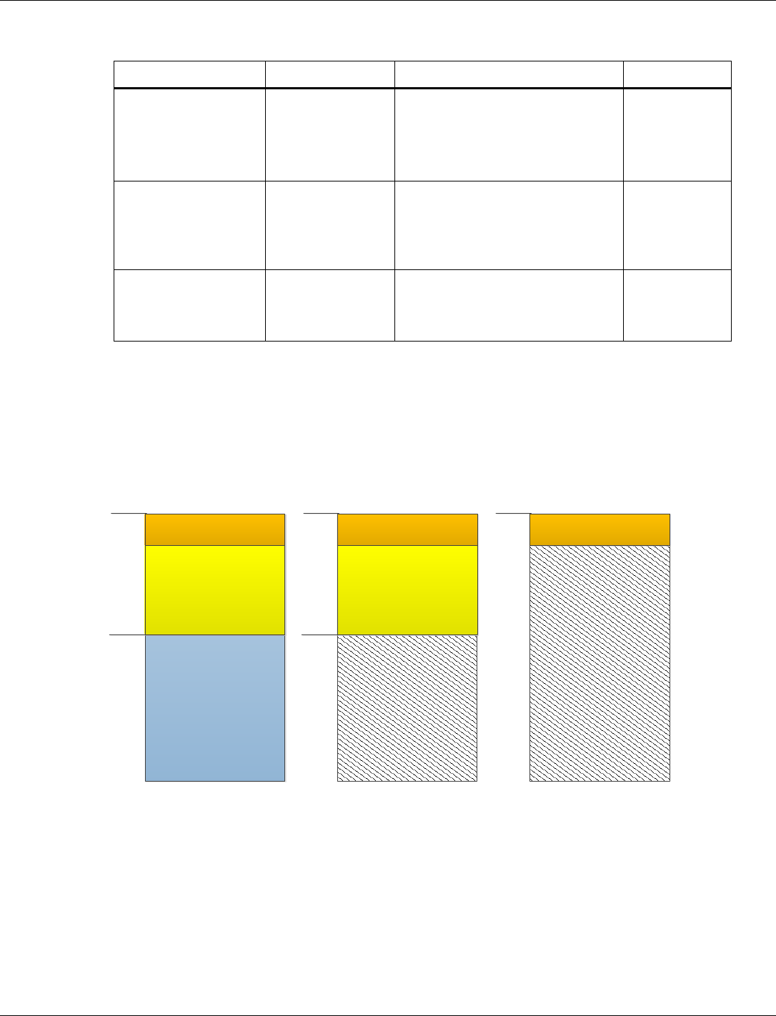
Figure 3-1 shows the memory map for the three operating modes on APSS.
FOM Component
(15.4/BLE/WLAN)
FOM
Unused
0x0
0x12000
8K AON
SOM component
(I2C/ADC/Sensor Algo)
0x0
0x12000
8K AON
SOM component
(I2C/ADC/Sensor Algo)
Unused
0x0
8K AON
SOM MOM
Figure 3-1 Memory map for the three operating modes on APSS
3.3.2.1.2 OMTM
Operating Mode Transition Manager (OMTM) is a software entity that manages mode transitions
in response to application requests.The module provides a set of APIs allowing clients to request
a change to a new Operating Mode. The client might request an immediate change or request that
the OMTM wait for the system to be in a idle state before making the transition.
QCA402x (CDB2x) Programmer’s Guide QCA402x framework and programming model
80-YA121-142 Rev. D MAY CONTAIN U.S. AND INTERNATIONAL EXPORT CONTROLLED INFORMATION 12
3.3.2.1.3 OMTT
1. An Operating Mode Transition Table (OMTT) describes all the possible transitions out of the
current Operating Mode.
2. Each row in the OMTT table corresponds to a possible transition. The OMTT has the
following columns-
□ Target OM – This field contains the identifier to which the Operating Mode is
transitioned.
□ Attribute – This 32-bit field contains the OM attributes. Bit-0 corresponds to the XIP
configuration (on/off).
□ Whitelist (addr, size) – This field contains a pointer to a whitelist structure containing the
address and size of the code or data segment(s) to load from FLASH. The ALM active
and sleep set configurations are derived from the whitelist. Some transitions does not
require anything to be loaded from FLASH.In such a case, this field contains NULL.
□ Entry Point – For transitions that do not change the Scheduling Context, this field is
NULL. For transitions that change the Scheduling Context, this field contains the entry
point to which a switchover occurs to transfer control from the previous Operating Mode
to the new Operating Mode.
The following table shows the example of the OMTT structure:
Table 3-2 OMTT structure
Target OM
Attributes
Whitelist (address,size)
Entry Point
MOM
.XIP = Off
NULL (to be updated)
MOM_main
SOM
.XIP = Off
{0x10000000, 68608}
SOM_main
FOM
.XIP = On
{0x10000000, 652288}
Main
All the operating modes must be registered with the OMTM module before any transition is
requested. While switching between any operating mode, the image (or part of the image if it is a
low memory operating mode) is reloaded and all the drivers/modules are reinitialized.
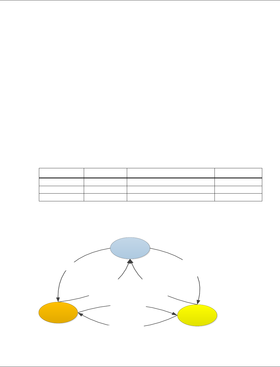
Figure 3-2 shows the state transition diagram for transition between different states.
FOM
- Turn on FOM banks
- Turn on XIP
- Load FOM whitelist
- Jump to FOM entry
SOM
- Turn on FOM banks
- Turn on XIP
- Load FOM whitelist
- Jump to FOM entry
- Turn off XIP
- Load SOM whitelist
- Turn off ALM
- Jump to SOM entry
- Turn on SOM banks
- Load SOM whitelist
- Jump to SOM entry
MOM
- Turn off XIP
- Jump to MOM entry
- Jump to MOM entry
Figure 3-2 OMTM State Transitions

QCA402x (CDB2x) Programmer’s Guide QCA402x framework and programming model
80-YA121-142 Rev. D MAY CONTAIN U.S. AND INTERNATIONAL EXPORT CONTROLLED INFORMATION 13
3.3.2.2 CONSS operating modes
On CONSS processor, the following three operating modesare present:
■ Full Memory Mode (FMM): This is the default operating mode when the target boots. It has
full access to RAM.
■ Low Memory Mode (LMM): In this mode, some RAM banks are turned off.
■ Minimal Memory Mode (MMM) In this mode, all the memory is turned off and the target
enters deep sleep state. When the target wakes up, it goes through the cold boot sequence.
Similar to the APPS processor, switching between the operating modes, the image is reloaded and
all the drivers/modules are reinitialized.
3.3.2.3 OMTM APIs
3.3.2.3.1 Register operating mode
qapi_Status_t qapi_OMTM_Register_Operating_Modes(
qapi_OMTM_Operating_Mode_t *modes, uint32_t num_Modes, uint32_t
cur_Mode );
3.3.2.3.2 Register for a call-back when exiting a mode
qapi_Status_t qapi_OMTM_Register_Mode_Exit_Callback(
qapi_OMTM_Mode_Exit_CB_t func, void *user_Data, int32_t prio );
3.3.2.3.3 Switch operating mode
qapi_Status_t qapi_OMTM_Switch_Operating_Mode(uint32_t mode_Id,
qapi_OMTM_Switch_At_t when);
3.3.2.3.4 Switch CONSS memory mode
qapi_Status_t qapi_OMTM_Switch_ConSS_Memory_Mode(qapi_OMTM_ConSS_Mode_Id
mode_Id );
3.4 Communication drivers
3.4.1 802.15.4
The QCA402x modules include a IEEE 802.15.4-2006 MAC interface. The MAC implements the
features for a nonbeacon PAN that are required for ZigBee and Thread operation. Features
include the following:
■ IEEE 802.15.4-2006 non-beacon PAN
■ O-QPSK 2.4GHz PHY (Page 0, Channels 11-26).
■ Hardware MAC acceleration for packet filtering and auto-acknowledgements.
■ Full-function device (FFD) or reduced-function device (RFD) support
■ MAC level security
□ Hardware accelerated AES128-CCM encryption
□ Automatic key rolling

QCA402x (CDB2x) Programmer’s Guide QCA402x framework and programming model
80-YA121-142 Rev. D MAY CONTAIN U.S. AND INTERNATIONAL EXPORT CONTROLLED INFORMATION 14
■ Auto-poll: MAC periodically polls a coordinator without intervention from the next higher
layer.
■ Vendor-specific commands for RF testing.
3.4.1.1 802.15.4 hardware
The 802.15.4 hardware includes a Hardware MAC (HMAC), Radio Control Unit (RCU), and
modem (MDM). The 15.4 HMAC handles the following functions:
■ Manages the MDM and RCU for transmitting and receiving packets.
■ Schedules the commands.
■ Automatic background tasks such as receive and energy scans.
■ Appends FCS for transmitted packets and validates it for received packets.
■ Parses and validates the frame header for received packets.
■ Transmits and receives the acknowledgment automatically.
■ Manages DMA buffer.
The 15.4 RCU handles ramp-up and ramp-down of the radio and the MDM handles the O-
Quadrature phase-shift keying (O-QPSK) modulation and demodulation.
3.4.1.2 802.15.4 software
The 802.15.4 software executes on the Cortex-M0 and handles the core MAC functionality. A
QAPI exits the Cortex-M4 to provide an application interface and interacts with the core MAC
via an IPC layer.
The following features are supported by the 802.15.4 MAC:
■ IEEE 802.15.4-2006 non-beacon PAN
■ FFD and RFD support
■ Security
■ Mac data service (MCPS) primitives includes data and purge
■ Mac layer management entity (MLME) service primitives includes associate, disassociate,
beacon-notify, get, orphan, reset, Rx-enable, scan, comm-status, set, and poll.
■ Additional vs. service primitives for auto-poll and RF testing.
■ 802.15.4 security with hardware accelerated AES128-CCM support.
3.4.1.3 Auto-poll
The 802.15.4 MAC includes support for an auto-poll command, which allows the MAC to handle
periodically check a coordinator for data without the need for periodic intervention from next
higher layer.
This command sends a MAC data request (similar request is issued by the MLME-POLL.request
primitive) on a periodic basis. If data is received on the poll, a MCSP-DATA.Indication is
generated for the next higher layer.

QCA402x (CDB2x) Programmer’s Guide QCA402x framework and programming model
80-YA121-142 Rev. D MAY CONTAIN U.S. AND INTERNATIONAL EXPORT CONTROLLED INFORMATION 15
Auto polling continues until it is stopped by next higher layer or the poll generates an error (most
commonly, NO_ACK – A NO_DATA error does not stop polling).
3.4.1.4 802.15.4 security
While most of the MAC primitives are based directly on the 802.15.4 specification, the security
functionality is modified for more efficient operation and additional features. The most
significant change is to the Device and Key table PIBs.
According to the 802.15.4 specification, the key table PIB contains a list of all devices that can
use the key. In this implementation, the key table only contains the information for the key and
the entries in the device table have a field that ties it to the key being used. This implementation
enables less memory usage for the key table and easy management of the table.
This mechanism also enables the addition of key rolling. A separation PIB provides an order that
keys can rotate (as the attribute indexes into the key table). When a packet is received for a
device, the MAC first checks if the key source matches the key the device uses. If it does not, the
MAC checks each of the keys in the key rolling sequence that follow the key the device uses. If
any of these matches the key source of the received packet, the MAC updates the information of
the device to use that key and set its frame counter to match the received packet automatically.
For security reasons, keys can only roll in the order specified by the key rotation sequence. If a
packet is received for a key that is earlier in the sequence, it fails security checks.
3.4.2 Wi-Fi
The QCA4020 module includes a wireless LAN (WLAN) chipset that provides IEEE 802.11
WLAN network capability including:
■ Wireless Media Access Control (MAC)
■ Radio
■ Baseband
■ IEEE 802.11 protocol processing handled by an on-chip network processor
3.4.2.1 Wi-Fi hardware
QCA4020 is a combo chip that includes two dies namely, WLAN subsystem and rest of the
system component which are connected through a standard SDIO interface.
The WLAN component includes a CPU, DMA engine, external memory controller, control logic,
a wireless MAC and baseband, a radio, general purpose I/Os (GPIOs), serial port, and EJTAG.
The QCA4020 application processor communicates with the WLAN subsystem through standard
interconnections such as SDIO or SPI bus protocol. The communication between the QCA4020
host and the WLAN chipset occurs primarily through messages sent through a mailbox
(bi-directional FIFO queues) and special purpose registers on the WLAN subsystem. The
mailboxes and registers are accessed through special addresses mapped to the device address
space and through the services provided by a standard interconnect such as SPI or SDIO.

QCA402x (CDB2x) Programmer’s Guide QCA402x framework and programming model
80-YA121-142 Rev. D MAY CONTAIN U.S. AND INTERNATIONAL EXPORT CONTROLLED INFORMATION 16
3.4.2.2 Wi-Fi software
The WLAN software in QCA4020 is partitioned into the application processor software (also
referred to as WLAN host driver) and firmware that executes in WLAN subsystem. The WLAN
firmware is loaded by the WLAN host driver when the application enables WLAN using the
appropriate QAPI.
The WLAN firmware component is completely owned and maintained by Qualcomm and is
supplied to customers only in binary form (conditions apply). The WLAN processor executes
instructions from two sources, namely, an on-chip ROM and an instruction RAM (IRAM). The
on-chip ROM instructions become available when WLAN subsystem is brought out of reset and
IRAM instructions are loaded from external flash through the WLAN host driver when WLAN is
enabled.
The WLAN software is architected in such a way that it comprises a thin host driver and a thin
firmware which is executed on the WLAN processor. The motivation behind this architecture is
to ensure easier portability of WLAN driver across various platforms from the legacy products.
WLAN host driver
The WLAN host software executes in the application processor of QCA4020 and includes the
following major components:
■ QAPI layer
■ WLAN host driver
■ Interconnect/bus drivers
QAPI layer – This is the top most layer of the WLAN host driver stack which exports bunch of
APIs for applications to perform various WLAN operations. These WLAN operations include
functionalities like scan, connect, and setting of various WLAN parameters.
WLAN host driver – This layer forms the core part of the WLAN host software and logically
controls the WLAN hardware. This layer constitutes the control path and data path for WLAN
subsystem. It receives a QAPI, processes it, and passes it onto WLAN firmware as necessary. On
the reverse path, it generates events or passes the events from WLAN firmware to the application
space. All data is passed across the interconnect to and from the WLAN chipset in 32-bit Little
Endian format.
interconnect bus driver – This layer forms the bus-specific driver, which bridges bus-independent
WLAN driver and platform-specific bus driver. Currently supported interconnects are SDIO/SPI
drivers, of which SDIO is the primary mode of interconnection.
WLAN firmware
WLAN firmware executes in the WLAN processor and forms the major portion of the WLAN
functionality. WLAN firmware includes various modules such as upper MAC, lower MAC, WPA
supplicant, WPS supplicant, Wi-Fi Direct, and various offload features.
WLAN firmware implements handlers for various commands issued from the host driver and
responds with appropriate response (if needed) through asynchronous events.

QCA402x (CDB2x) Programmer’s Guide QCA402x framework and programming model
80-YA121-142 Rev. D MAY CONTAIN U.S. AND INTERNATIONAL EXPORT CONTROLLED INFORMATION 17
3.4.2.3 Wi-Fi host driver execution model
This section briefly discusses various execution thread context on which WLAN driver is
executed in the application processor.
■ Application thread – Any QAPI invoked by the application is executed in the context of
application thread. The application thread may be blocked if the underlying QAPI performs a
blocking operation in case of wireless scan operations. Most WLAN QAPIs tend to be non-
blocking.
■ WLAN Driver thread – This thread forms the crux of WLAN driver. Because all pending
requests are sent to WLAN driver queue, regardless of data or control messages, they are
handled in the context of this thread. The WLAN driver thread is also responsible for
notification of various events to applications through asynchronous callback which is
registered by the application at the time of WLAN enablement.
■ Generic Timer thread – Any callback registered with timers started by WLAN driver executes
in this context. Although the WLAN callback is invoked in this context, this callback is
lightweight callback and wakes up WLAN driver with appropriate timer expiry information.
The actual processing of timer is performed in the context of WLAN driver thread.
■ Bus Interrupt Handler (High Priority Interrupt Thread) – On reception of control or data
messages from the WLAN target, the relevant bus interrupt handler invokes the registered
callback function of WLAN driver. The WLAN host software performs minimal, but
extremely time critical operations in this callback and wakes up the driver thread for further
processing.
3.5 WLAN features
3.5.1 Store-recall (Suspend-resume) of WLAN firmware
Suspend/Resume (store-recall) is the mechanism, where user can turn OFF (chip power-down)
the WLAN module for certain duration and turn ON again without impacting the existing state of
WLAN firmware for example, connection, socket, IP and so on.
During suspend time, the host (M4) stores the WLAN firmware information (called dsets) and
restores it after the suspend time expires. WLAN firmware sends Null data frame with PM=1 to
AP before entering to suspend state. After resuming, WLAN firmware sends the Null data frame
PM=0 to AP. Sending of Null data during suspend-resume configurable using devconfig that is
“SYS_TUNE_WLAN_NULL_PACKET_ENABLE”. By default, this flag is enabled.
Use __QAPI_WLAN_PARAM_GROUP_SYSTEM_ENABLE_SUSPEND_RESUME to enable
the store-recall feature. By default, this feature is enabled.
Use qapi_WLAN_Suspend_Start() API to suspend the wlan firmware.
NOTE: User can perform Store-recall operation only when the DUT is running on STA or p2p Client
mode. This operation is not supported while DUT is operating on SoftAP/P2PGO mode or both
devices (dev0 and dev1) are in connected case.

QCA402x (CDB2x) Programmer’s Guide QCA402x framework and programming model
80-YA121-142 Rev. D MAY CONTAIN U.S. AND INTERNATIONAL EXPORT CONTROLLED INFORMATION 18
3.5.2 Packet Filtering and Wake on Wireless (WoW)
Packet filtering feature enables WLAN firmware/target to filter received packets that do not
match the filter rule. This feature is supported in Active state or Suspend state. Each defined
packet filtering rule is based on protocol type. The pattern matching algorithm is applied from
start of protocol header at offset defined by filter rule. The following parameters define filtering
rule:
■ Pattern Index: Index that identifies the filtering pattern. User can choose the index from 1 to
8. ‘Index 0’ is reserved for default filter in each protocol header type.
3. Action Flag: Accept/Reject/Defer/Wake-on-wireless (WoW) Flag.
a. ACCEPT Flag: If the pattern matches and action is ACCEPT, packet is given to host.
b. REJECT Flag: If the pattern matches and action is REJECT, packet is rejected.
c. DEFER Flag: If the pattern matches and action is DEFER, packet is given to next higher
protocol type.
d. WoW Flag: WoW flag enables the target to trigger out of band interrupt to Host (M4).
Priority: Priority associated with the filter rule. Target filter rule is based on priority and any
match found (with Accept/Reject/Defer action) breaks from further processing of filter list.
Priority 0 is reserved for default filter in each protocol header type.
Header Type: 802.3/SNAP/IPv4/IPv6/ICMP/ICMPv6/UDP/TCP/PAYLOAD
Offset: Offset from the header to which pattern match algorithm is applied.
Pattern Size: Size of pattern to search for in the received packet.
Pattern Mask: Mask to perform selective pattern match. Each bit in the mask correspond to byte
in the pattern. If a bit is not set, the corresponding byte in the pattern is ignored. Else, the byte in
the pattern mask is matched against the received byte.
Pattern: Maximum support pattern length is 128 bytes (value must be given in hexadecimal
format)
Target maintains an array of list of pattern rule. Pattern rules are grouped by protocol and each
protocol is list of priority-based sorted pattern. Firmware packet filtering module parses each
packet protocol header and checks if packet filtering required or not. Header length may also vary
based on optional field in IP header or TCP header. The pattern matching algorithm in performs
the following events:.
■ If packet filtering not enabled, forward packet to upper layer.
■ Phrase the received packet and get L2/L3/L4 layer attributes such as header length, offset,
and protocol.
■ Based on the attributes, search the pattern list for match.
■ Pattern search is 4 bytes operation after apply mask.
■ If Action flag is WoW, wake up host(M4) using out of band interrupt
■ If found, ACCEPT – forward to host, REJECT – drop the packet. DEFER – check for high-
level protocol pattern
For more information on packet filter configuration, refer to QCA402x Development Kit User
Guide (80-YA121-140).

QCA402x (CDB2x) Programmer’s Guide QCA402x framework and programming model
80-YA121-142 Rev. D MAY CONTAIN U.S. AND INTERNATIONAL EXPORT CONTROLLED INFORMATION 19
3.5.3 ARP and NS offload
WLAN firmware internally processes and performs protocol and address check on the received
ARP/NS frames. Firmware internally constructs and responds with appropriate ARP/NS response
to the sender without waking up the host by forwarding ARP/NS packets.
3.5.4 TCP Keepalive offload
TCP Keepalive Offload feature is used to offload TCP packet exchange to the firmware after the
initial TCP connection is formed between the TCP client and the server. This means that WLAN
firmware can check the connected TCP socket, and determine whether the connection is still up
and running or if it is broken.
When the TCP connection is setup, WLAN firmware associates a set of timers and after the
Keepalive timer reaches 0, firmware sends a Keepalive probe packet with no data. At this stage,
the ACK flag is turned ON and a reply is expected to be received from the peer with no data and
the ACK set.
If firmware receives a reply to a Keepalive probe, firmware can assert that the connection is still
up and running. If the peer does not respond to a Keepalive probe r, firmware can assert that the
connection cannot be valid. Because WLAN firmware takes care of TCP Keepalive
transmissions, s the application processor enters suspend-state for longer durations.
For more information, refer to QCA402x Development Kit User Guide (80-YA121-140).
3.5.5 Debug logs
Debug logs mechanism is used to collect the debug prints or information across different modules
of system. For more information, see Chapter 5.
3.5.6 MAC Keepalive timeout for STA
This feature is used to keep station connection alive with AP by sending keepalive packets. A
NULL data frame with power management bit set at certain intervals is sent if there is no data
traffic, which ensures that the AP does not disconnect/deauthenticate the STA.
3.5.7 Channel switch
When DUT operates on QCMobileAP mode, this feature can be used to trigger the channel
switch announcement on BSS before switching to new channel. For example, a QCMobileAP that
detects significant traffic from neighboring BSSs on the secondary channel, or significant traffic
on the primary channel for that matter, could move the BSS to a channel pair with less traffic
and/or narrow the operating channel width.
The decision to switch channels is made by the QCMobileAP in BSS and the QCMobileAP must
select a new channel that is supported by all associated stations. The AP informs associated
stations that the BSS is moving to a new channel and/or changing operating channel width in the
Channel Switch Announcement element in beacon frames and probe response frames, so that the
associated STA’s connected to QCMobileAP can move to the new operating BSS channel. The
QCMobileAP attempts to schedule the channel switch, so that all stations in the BSS, including
stations that are in

QCA402x (CDB2x) Programmer’s Guide QCA402x framework and programming model
80-YA121-142 Rev. D MAY CONTAIN U.S. AND INTERNATIONAL EXPORT CONTROLLED INFORMATION 20
power-save mode, receives at least one Channel Switch Announcement element before the
switching of channel occurs.
A scheduled channel switch occurs just before a target beacon transmission time (TBTT). The
Channel Switch Count field indicates the number of TBTTs until the switch, including the TBTT
just before which the switch occurs. A value of 1 indicates that the switch occurs just before the
next TBTT. Whenever DUT operates in STA mode, after the DUT receives a channel switch
Information Element from a connected BSS in the beacon or probe response frame, it stops
transmission on the current channel until the transition moves to a new operating channel.
3.5.8 11v support
QCA402x supports 11v features both in station and QCMobileAP mode. Presently it supports
WNM sleep and BSS max idle period in STA and QCMobileAP mode respectively.
3.5.9 WNM sleep
The WNM-Sleep Interval field (16 bits) STA indicates to the AP how often a STA in
WNM-Sleep Mode wakes up to receive beacon frames, defined as the number of DTIM intervals.
And Sleep interval for the station must be less than BSS max idle period advertised by the AP in
beacons. STA must be connected to AP which supports the 11v feature.
3.5.10 SetAPBssMaxIdlePeriod
The BSS Max Idle period is the timeframe during which an access point (AP) does not
disassociate a client due to nonreceipt of frames from the connected client. The idle time value
indicates the maximum amount of time for which a client can remain idle without transmitting
any frame to an AP.
Refer to QCA402x Development Kit User Guide (80-YA121-140) to configure the 11v
functionality on DUT and further information.
3.5.11 Event filtering
This feature enables the user to filter the event between application processor and WLAN
firmware. User can filter up to 64 events from WLAN firmware. These events are discarded in
WLAN firmware so that it avoids application processor wakeups.
3.5.12 P2P module and P2P power-save mechanism
The peer-to-peer (P2P) module implements a solution for Wi-Fi Peer-to-Peer connectivity which
allows Wi-Fi devices to communicate each other without access point.
There are three components in P2P module: P2P device, P2P Group Owner role and P2P Client
role.
■ After P2P module is enabled, Wi-Fi device works as a P2P device and P2P devices can find
each other through device discovery.
■ The P2P Group Owner role is “AP-like” entity that provides BSS functionality and services
for associated clients.
■ The P2P Client role implements non-AP STA functionality.

QCA402x (CDB2x) Programmer’s Guide QCA402x framework and programming model
80-YA121-142 Rev. D MAY CONTAIN U.S. AND INTERNATIONAL EXPORT CONTROLLED INFORMATION 21
One of the following three methods is used to start a P2P Group:
■ A P2P device autonomously starts a P2P Group by becoming a P2P Group Owner, other P2P
clients connect to P2P Group Owner using WSC method;
4. Two P2P devices use the Group Formation to determine which device that functions as the
P2P Group Owner and the device that functions as the P2P Client and form a new P2P
Group;
5. A P2P device can invoke a Persistent P2P Group for which both P2P Devices have previously
been provisioned. One of the devices is P2P Group Owner for Persistent P2P Group, and the
P2P Group Owner or P2P Client can invite another P2P device to join its P2P Group.
P2P power-save mechanism is based on existing PS and WMM-PS power management delivery
mechanisms with two new procedures that allow the P2P Group Owner to be absent for defined
periods: Opportunistic Power Save and Notice of Absence.
■ Opportunistic Power Save is a power management scheme that allows a P2P Group Owner to
gain additional power savings on an opportunistic basis.
■ The P2P Group Owner use P2P Notice of Absence attribute within transmitted beacon
frames, probe response frames or Notice of Absence Action frames to inform its associated
client of the planned absence timing.
3.5.13 Antenna diversity
The antenna diversity algorithm dynamically configures the best antenna based on RSSI, to
improve the quality and reliability of a wireless link among the multiple antennas on board.
To enable the antenna diversity feature, the hardware platform must support multiple antennas
and also have a fast RF switch to switch between antennas that meets specific requirements.
The antenna diversity algorithm selects the best antenna based on comparison of signal strength
on each antenna to communicate with the peer. The comparison of signal strength can be based
on the specific packet number, the specific time interval, or auto mode. If the signal strength of
the in-use antenna is strong enough, this feature may not try to pick up other antennas.
Refer to QCLI WLAN subgroups section of QCA402x Development Kit User Guide (80-YA121-
140) to configure antenna diversity, set physical antenna, and get antenna diversity statistics.
3.5.14 WPA Enterprise
This feature implements WPA Enterprise, which is also referred as WPA-802.1x or just WPA
as opposed to WPA-PSK. It is available with both WPA and WPA2, and is designed for
enterprise network. It requires a Remote Authentication Dial-In User Service (RADIUS)
authentication server and provides various kinds of EAP methods for authentication.
The tested RADIUS authentication servers are open source FreeRADIUS, Microsoft IAS, and
open source Hostapd. The tested EAP methods are EAP-TTLS/MSCHAPv2,
PEAPv0/EAP-MSCHAPv2, EAP-TLS.
Based on the open source supplicant, the QCA4020 WPA supplicant module imports EAP related
source codes, creates new eloop and socket Rx/Tx, and implements SSL adaptive layer on top of
sharkssl.

QCA402x (CDB2x) Programmer’s Guide QCA402x framework and programming model
80-YA121-142 Rev. D MAY CONTAIN U.S. AND INTERNATIONAL EXPORT CONTROLLED INFORMATION 22
To enable this feature, link the 8021x supplicant related library, and call the respective QAPIs.
Refer to QCLI WLAN subgroups section of QCA402x Development Kit User Guide (80-YA121-
140), which list the supported commands for demonstration.
3.6 NVM configuration
NVM values impact the configuration of the Qualcomm® Bluetooth Low Energy, 802.15.4, and
coexistence subsystems. Default configuration values are already available to the system at boot,
but the defaults might be modified in the application build using the following information.
The “.nvm” files provided in the “/quartz/nvm/config/” directory contain the default values.
Demo application build scripts provided in the SDK automatically convert to C array and link the
correct NVM file from this directory. However, an option is also given to use an NVM file from
another directory. It is not necessary to provide all tag values from an NVM file if the default
values are to be used; the full set of default values in the SDK is provided only for ease of use.
For instance, an NVM file may contain only one tag whose default values are to be overwritten.
3.6.1 BLE NVM parameters list
NVM parameters are grouped into tags. The format and length of the NVM parameters are
different for each tag. The minimum length is one byte. The byte order of the tag is the
little-endian format, which follows the Bluetooth Host Controller Interface (Transport Layer)
specification. The little-endian tag format places the least significant byte (LSB) at the first
position of the tag and the most significant byte (MSB) at the last position of the tag.
Tag number
Name
Length (byte)
1
BLE Size Parameters
13
3
BLE Tx Power Level Table
32
5
Bluetooth Public Address
6
7
BLE Default Tx Power
2
8
BLE Low Power Drift Rate
2
10
BLE RF Compensation
4
17
BLE RCU FEM Tx Control
12
18
BLE RCU FEM Rx Control
12
3.6.1.1 BLE size parameters
Tag number: 1
Length: 13
Title
Options
Default/bit
range
Description
BLE Size Parameters
0x51 00 72 06
04 10 10 14 14
03 01 FB 00
Tag number 1 is used to tweak BLE
parameters related to various
packet/buffer/list sizes. This can be tweaked
to increase/decrease memory consumption
at the expense of other factors (number of
connections and throughput)

QCA402x (CDB2x) Programmer’s Guide QCA402x framework and programming model
80-YA121-142 Rev. D MAY CONTAIN U.S. AND INTERNATIONAL EXPORT CONTROLLED INFORMATION 23
Title
Options
Default/bit
range
Description
Maximum BLE Data
Payload (byte 0-1)
0x5100
This number corresponds to the maximum
data payload that can be set with HCI LE
Set Data Length command. The value is 81
bytes (0x0051) by default
Maximum Extended
Advertising Data Length
(byte 2-3)
0x0672
This number corresponds to the maximum
extended advertising buffer that can be
given to the BLE controller. The default
value is 1650. The maximum value is 1650.
Maximum simultaneous
BLE connections (byte 4)
0x04
The maximum number of simultaneous BLE
connections that are allowed. The value is 4
by default. The maximum value is 10.
Transmit Buffers (byte 5)
0x10
The number of ACL buffers dedicated to
hold transmit data. The default value is 16.
Receive Buffers (byte 6)
0x10
The number of ACL buffers dedicated to
hold receive data. The default value is 16.
Resolving List Size (byte
7)
0x14
The maximum number of entries reserved in
the resolving list. The default value is 20.
White List Size
(byte 8)
0x14
The maximum number of entries reserved in
the white list. The default value is 20.
Max Advertising Reports
Pending (byte 9)
0x03
The maximum number of advertising reports
that can be pending for transmit to the host.
The default value is 3.
Max Advertising Sets
(byte 10)
0x01
The maximum number of extended
advertising sets supported by the controller.
The default value is 1. The maximum value
is 4.
Max Extended
Advertising Data
Fragment Length (byte
11)
0xFB
The maximum length in which extended
advertising data is fragmented before
transmission. The default value is 251. The
maximum value is 251.
Max Scan Request
Receive Events (byte 12)
0x0
The maximum number of scan requests
received HCI events that are buffered for
dispatch to the host. The default value is 0.
3.6.1.2 BLE Tx power level table
Tag number: 3
Length: 32
Title
Options
Default/bit range
Description
BLE Tx Power
Level Table (byte
0-31)
0xB8 F5 DA F6 C3 F7
80 F8 80 F9 4D FA 00
FC 45 FC F3 FC D7 FD
CF FE 70 FF C5 01 8E
02 85 03 4D 04
This tag contains the table to map power level
values (0-15) to dBm. Each entry is 2 bytes in
size. The value for each entry in the table is the
dBm * 256. It can also considered as a fixed-
point number with 8 integers and 8 fractional bits.

QCA402x (CDB2x) Programmer’s Guide QCA402x framework and programming model
80-YA121-142 Rev. D MAY CONTAIN U.S. AND INTERNATIONAL EXPORT CONTROLLED INFORMATION 24
3.6.1.3 Bluetooth public address
Tag number: 5
Length: 6
Title
Options
Default/bit range
Description
Bluetooth Public
Address (byte 0-5)
0x00 00 00 00 00 00
Tag number 5 is used to allow a customer to
program their own public Bluetooth address to
differentiate from the one stored in OTP. When
NVM Tag 5 is set as 0x000000000000, Bluetooth
Public Address stored in OTP is used.
3.6.1.4 BLE default Tx power
Tag number: 7
Length: 1
Title
Options
Default/bit
range
Description
BLE Default Tx
Power (byte 0−1)
0x0404
Tag number 7 is used to set the default Tx Power
level for BLE connections and advertising use
cases. The values are specified in dBm units. If
the controller does not support the exact power
level specified, then the closest supported power
level smaller than the appropriate power level is
chosen.
Advertising
channel
Default: 0x04
Default Tx Power level used for advertising.
Data
channel
Default: 0x04
Default Tx Power level used for connections.
3.6.1.5 BLE Low Power Drift Rate
Tag number: 8
Length: 2
Title
Options
Default/bit range
Description
BLE Low Power
Drift Rate (byte 0−1)
0xF4 01
This parameter contains PPM drift rate for the low
power oscillator used for window-widening
calculations and is reported to the remote device
via the in the CONNECT_IND,
AUX_CONNECT_REQ, and AUX_ADV PDU’s.
The default value is 500 and the maximum value
is 500.
3.6.1.6 BLE RF compensation
Tag number: 10
Length: 4

QCA402x (CDB2x) Programmer’s Guide QCA402x framework and programming model
80-YA121-142 Rev. D MAY CONTAIN U.S. AND INTERNATIONAL EXPORT CONTROLLED INFORMATION 25
Title
Options
Default/bit range
Description
BLE RF
Compensation
(byte 0−3)
0x0000
This tag contains the RF Path compensation values
that are returned when the host queries the controller
via the LE Read RF Path Compensation Command.
Tx RF
compensation
0x00
Tx RF Compensation represented as a signed
integer. Default value is 0.
Rx RF
compensation
0x00
Rx RF Compensation represented as a signed
integer. Default value is 0.
3.6.1.7 BLE RCU FEM Tx control
Tag number: 17
Length: 24
Title
Options
Default/bit range
Description
BLE RCU FEM
Tx Control
(byte 0-23)
0xFF FF FF FF FF FF FF FF
FF FF FF FF FF FF FF FF FF
FF FF FF FF FF FF FF
This tag contains the Front-End Module
controls for assertion logic during BLE
transmit operations.
On 0
0xFFFF
On 1
0xFFFF
On 2
0xFFFF
On 3
0xFFFF
On 4
0xFFFF
On 5
0xFFFF
Off 0
0xFFFF
Off 1
0xFFFF
Off 2
0xFFFF
Off 3
0xFFFF
Off 4
0xFFFF
Off 5
0xFFFF
3.6.1.8 BLE RCU FEM Rx control
Tag number: 18
Length: 24
Title
Options
Default/bit range
Description
BLE RCU FEM
Rx Control
(byte 0-23)
0xFF FF FF FF FF FF FF FF
FF FF FF FF FF FF FF FF FF
FF FF FF FF FF FF FF
This tag contains the Front End Module
controls for assertion logic during BLE
receive operations.
On 0
0xFFFF
On 1
0xFFFF
On 2
0xFFFF
On 3
0xFFFF
On 4
0xFFFF
On 5
0xFFFF
Off 0
0xFFFF

QCA402x (CDB2x) Programmer’s Guide QCA402x framework and programming model
80-YA121-142 Rev. D MAY CONTAIN U.S. AND INTERNATIONAL EXPORT CONTROLLED INFORMATION 26
Title
Options
Default/bit range
Description
Off 1
0xFFFF
Off 2
0xFFFF
Off 3
0xFFFF
Off 4
0xFFFF
Off 5
0xFFFF
3.6.2 802.15.4 NVM parameters list
NVM parameters are grouped into tags. The format and length of the NVM parameters are
different for each tag. The minimum length is one byte. The byte order of the tag is the little-
endian format, which follows the Bluetooth Host Controller Interface (Transport Layer)
Specification. The little-endian tag format places the least significant byte (LSB) at the first
position of the tag and the most significant byte (MSB) at the last position of the tag.
Tag Number
Name
Length (byte)
52
Extended Address
8
54
Device Buffer
3
55
Security Config
2
56
Scan Config
1
57
Rx Hash Table
1
58
Tx Power Level
1
63
IPC Config
5
3.6.2.1 Extended address
Tag number: 52
Length: 8
Title
Options
Default/bit range
Description
Extended
Address
0x0000000000000000
EUI-64 address of the MAC. If set to zero, the
address is read from OTP.
3.6.2.2 Device buffer
Tag number: 54
Length: 3
Title
Options
Default/bit range
Description
Device Buffer
0x04 02 04
Tag number 54 is used to set the size of the 15.4
packet queues and device table.
Indirect Packet
Count (byte 0)
Default: 0x04
The number of indirect packets that can be queued
into the MAC.
Direct Packet
Count (byte 1)
Default: 0x02
The number of direct packets that can be queued
into the MAC.
Device Table
Size (byte 2)
Default: 0x04
The size of the device table of MAC. This determines
the number of remote devices that the MAC can
store information for at a given time.

QCA402x (CDB2x) Programmer’s Guide QCA402x framework and programming model
80-YA121-142 Rev. D MAY CONTAIN U.S. AND INTERNATIONAL EXPORT CONTROLLED INFORMATION 27
3.6.2.3 Security config
Tag number: 55
Length: 2
Title
Options
Default/bit range
Description
Security Config
0x04 04
Tag number 55 is used to set the size of the 15.4 key
and security level tables.
Key Table Size (byte
0)
Default: 0x04
The size of the MAC’s key table.
Security Level Table
Size (byte 1)
Default: 0x04
The size of the MAC’s security level table.
3.6.2.4 Scan config
Tag number: 56
Length: 1
Title
Options
Default/bit range
Description
Security Config
0x02
Tag number 56 is used to set the size of the PAN
descriptor list for scan results.
PAN Descriptor List
Size (byte 0)
Default: 0x02
The maximum number of PAN descriptors that can be
provided in a MLME-SCAN.confirm packet.
3.6.2.5 Rx hash table
Tag number: 57
Length: 1
Title
Options
Default/bit range
Description
Rx Hash Table
0x03
Tag number 57 is used to set the size of the hash
table used to detect duplicate 15.4 packets. Larger
values are less likely to have conflicts, but consumes
more RAM.
Rx Hash Table
Size (byte 0)
Default: 0x03
Size of the hash table used for duplicate packet
detection on received packets.

QCA402x (CDB2x) Programmer’s Guide QCA402x framework and programming model
80-YA121-142 Rev. D MAY CONTAIN U.S. AND INTERNATIONAL EXPORT CONTROLLED INFORMATION 28
3.6.2.6 Tx power level
Tag number: 58
Length: 1
Title
Options
Default/bit range
Description
Tx Power Level
0x0A
Tag number 58 is used to set the default transmit
power used by the 15.4 MAC.
Default Tx Power
Level (byte 0)
Range: 0x0-0x0F
Default: 0x0F
Power level in the range of 0x00 to 0x0F
3.6.2.7 IPC config
Tag number: 63
Length: 5
Title
Options
Default/bit range
Description
Security Config
0x00 02 08 04 08
Tag number 58 is used to tweak the size of the buffers
used to send commands from the M4 to the MAC.
IPC Rx buffer Size
(byte 0-1)
Default: 0x0200
Size of the IPC receive buffer in bytes.
Rx Credit Count
(byte 2)
Default: 0x08
The number of packets from the M4 that can be queued
into the MAC for processing.
Rx Credit
Threshold (byte 3)
Default: 0x04
The threshold at which Rx credits are granted to the
M4.
Tx Queue
Threshold (byte 4)
Default: 0x08
The threshold for the event queue (m0 – m4) at which
the 15.4 receiver is disabled. This prevents possible
packet loss if the M4 processes 15.4 packets for long
periods.
3.6.2.8 15.4 RCU FEM Tx control
Tag number: 73
Length: 24
Title
Options
Default/bit range
Description
15.4 RCU FEM Tx
Control (byte 0-23)
0xFF FF FF FF FF FF FF FF
FF FF FF FF FF FF FF FF FF
FF FF FF FF FF FF FF
This tag contains the front-end module
controls for assertion logic during 15.4
transmit operations.
On 0
0xFFFF
.
On 1
0xFFFF
On 2
0xFFFF
On 3
0xFFFF
On 4
0xFFFF
On 5
0xFFFF
Off 0
0xFFFF
Off 1
0xFFFF
Off 2
0xFFFF
Off 3
0xFFFF

QCA402x (CDB2x) Programmer’s Guide QCA402x framework and programming model
80-YA121-142 Rev. D MAY CONTAIN U.S. AND INTERNATIONAL EXPORT CONTROLLED INFORMATION 29
Title
Options
Default/bit range
Description
Off 4
0xFFFF
Off 5
0xFFFF
3.6.2.9 15.4 RCU FEM Rx control
Tag number: 18
Length: 24
Title
Options
Default/bit range
Description
15.4 RCU FEM Rx
Control
(byte 0-23)
0xFF FF FF FF FF FF FF FF
FF FF FF FF FF FF FF FF FF
FF FF FF FF FF FF FF
This tag contains the front-end module
controls for assertion logic during 15.4
Receive operations.
On 0
0xFFFF
On 1
0xFFFF
On 2
0xFFFF
On 3
0xFFFF
On 4
0xFFFF
On 5
0xFFFF
Off 0
0xFFFF
Off 1
0xFFFF
Off 2
0xFFFF
Off 3
0xFFFF
Off 4
0xFFFF
Off 5
0xFFFF
3.6.3 Coexistence NVM parameters list
NVM parameters are grouped into tags. The format and length of the NVM parameters are
different for each tag. The minimum length is one byte. Common NVM tags are latched on the
first HCI or MLME reset and applied globally. The little-endian tag format places the least
significant byte (LSB) at the first position of the tag and the most significant byte (MSB) at the
last position of the tag.
Tag Number
Name
Length (byte)
101
Coexistence Configuration
14
102
External PTA Configuration
6
103
Priority Configuration
15
104
Threshold Configuration
18

QCA402x (CDB2x) Programmer’s Guide QCA402x framework and programming model
80-YA121-142 Rev. D MAY CONTAIN U.S. AND INTERNATIONAL EXPORT CONTROLLED INFORMATION 30
3.6.3.1 Coexistence configuration
Tag number: 101
Length: 14
Title
Options
Default/bit range
Description
Config Flags
0xE1 01 00 00
This tag contains the flags for coexistence configuration.
The values are defined as:
COEX_CONFIG_FLAG_COEX_ENABLE
0x00000001
COEX_CONFIG_FLAG_EPTA_ENABLE
0x00000002
COEX_CONFIG_FLAG_EPTA_MASTER
0x00000004
COEX_CONFIG_FLAG_WLAN_ENABLE
0x00000008
All other bits are reserved by the system and must remain
their default values.
Grant Delay Timer
Default: 0x02
Delay between stomping one radio and granting another.
WLAN Antenna
Default: 0x00
Antenna number used for WLAN
BLE Antenna
Default: 0x01
Antenna number used for BLE
802.15.4 Antenna
Default: 0x01
Antenna number used for 802.15.4
WLAN Channel
Width
Default: 0x14
WLAN channel width.
BLE Channel Width
Default: 0x02
BLE channel width.
802.15.4 Channel
Width
Default: 0x05
802.15.4 channel width.
Overlap Disable
Default: 0x00
Disabled frequency overlap.
Bit 0 indicates 802.15.4 does not overlap BLE or WLAN
Bit 1 indicates BLE does not overlap WLAN or 802.15.4
Bit 2 indicates WLAN does not overlap BLE or 802.15.4
Concurrency
Default: 0x00
Enables/disables concurrency control.
Bit 0 indicates Rx/Tx concurrency control is enabled
Bit 1 indicates Tx/Tx concurrency control is enabled
Bit 2 indicates Rx/Rx concurrency control is enabled
3.6.3.2 External PTA configuration
Tag number: 102
Length: 6
Title
Options
Default/bit range
Description
Grant Delay Enable
0x00
Enables grant delay on external PTA interface.
Priority Window Timer
0x09
Timer value for the priority window.
A2DP Done Timer
0x14
A2DP done timer value.
A2DP Done Timer Enable
0x00
A2DP done timer enable (1) or disable (0).
T15
0x07
Interface T15 value.
T16
0x05
Interface T16 value.

QCA402x (CDB2x) Programmer’s Guide QCA402x framework and programming model
80-YA121-142 Rev. D MAY CONTAIN U.S. AND INTERNATIONAL EXPORT CONTROLLED INFORMATION 31
3.6.3.3 Priority configuration
Tag number: 103
Length: 15
Title
Options
Default/bit range
Description
EPTA_PRI_REQ_HIGH
0x12
Priority used when a high priority external
PTA request is made.
EPTA_PRI_REQ_LOW
0x0A
Priority used when a low priority external
PTA request is made.
EPTA_PRI_ACTIVE_HIGH
0x3B
Priority used once a high priority external
PTA request is granted.
EPTA_PRI_ACTIVE_LOW
0x2C
Priority used once a low priority external PTA
request is granted.
I15P4_PRI_TX_REQ
0x2A
Priority used when an 802.15.4 Tx request is
made.
I15P4_PRI_RX_REQ
0x2B
Priority used when an 802.15.4 Rx request is
made.
I15P4_PRI_TX_ACTIVE
0x39
Priority used when an 802.15.4 Tx
transaction is granted.
I15P4_PRI_RX_ACTIVE
0x3A
Priority used when an 802.15.4 Rx
transaction is granted.
I15P4_PRI_HOLD_REQ
0x38
Priority used to hold 802.15.4 grant between
back to back transactions.
I15P4_PRI_ED_SCAN
0x29
Priority to use for an 802.15.4 ED scan.
I15P4_PRI_ACK
0x3C
Priority to use for an 802.15.4 ACK.
BLE_PRI_ADV
0x14
Priority to use for a Bluetooth LE
advertisement.
BLE_PRI_SCAN
0x13
Priority to use for a Bluetooth LE scan.
BLE_PRI_DATA_REQ
0x15
Priority used when a Bluetooth LE data
transaction is requested.
BLE_PRI_DATA_ACTIVE
0x2D
Priority used when a Bluetooth LE data
transaction is granted.

QCA402x (CDB2x) Programmer’s Guide QCA402x framework and programming model
80-YA121-142 Rev. D MAY CONTAIN U.S. AND INTERNATIONAL EXPORT CONTROLLED INFORMATION 32
3.6.3.4 Threshold configuration
Tag number: 104
Length: 18
Title
Options
Default/bit range
Description
Flags
0x00 00
Bit 0 enables (1) or disables (0) priority threshold.
BLE Scan Config
0x00 00
BLE scan threshold:
Bits 14-15: Mode, 0 for counter-based, 3 for timer-based
Bits 7-13: Value to use for hold threshold.
Bits 0-6: Value to use for stomp threshold.
BLE Adv Config
0x00 00
BLE advertise threshold:
Bits 14-15: Mode, 0 for counter-based,3 for timer-based
Bits 7-13: Value to use for hold threshold.
Bits 0-6: Value to use for stomp threshold.
BLE Data Config
0x00 00
BLE data threshold:
Bits 14-15: Mode, 0 for counter-based, 3 for timer-based
Bits 7-13: Value to use for hold threshold.
Bits 0-6: Value to use for stomp threshold.
BLE Isoc Config
0x00 00
BLE isochronous threshold:
Bits 14-15: Mode, 0 for counter-based,3 for timer-based
Bits 7-13: Value to use for hold threshold.
Bits 0-6: Value to use for stomp threshold.
802.15.4 ED
Scan Config
0x00 00
802.15.4 ED scan threshold:
Bits 14-15: Mode, 0 for counter-based,3 for timer-based
Bits 7-13: Value to use for hold threshold.
Bits 0-6: Value to use for stomp threshold.
802.15.4 beacon
Scan Config
0x00 00
802.15.4 beacon scan threshold:
Bits 14-15: Mode, 0 for counter-based,3 for timer-based
Bits 7-13: Value to use for hold threshold.
Bits 0-6: Value to use for stomp threshold.
802.15.4 Data
Rx Config
0x00 00
802.15.4 data Rx threshold:
Bits 14-15: Mode, 0 for counter-based, 3 for timer-based
Bits 7-13: Value to use for hold threshold.
Bits 0-6: Value to use for stomp threshold.
802.15.4 Data Tx
Config
0x00 00
802.15.4 data Tx threshold:
Bits 14-15: Mode, 0 for counter-based, 3 for timer-based
Bits 7-13: Value to use for hold threshold.
Bits 0-6: Value to use for stomp threshold.
3.6.4 Common NVM parameters list
NVM parameters are grouped into tags. The format and length of the NVM parameters are
different for each tag. The minimum length is one byte. common NVM tags are latched on the
first HCI or MLME reset, and are applied globally. The little-endian tag format places the least
significant byte (LSB) at the first position of the tag and the most significant byte (MSB) at the
last position of the tag.
Tag Number
Name
Length (byte)
190
FEM Control
6
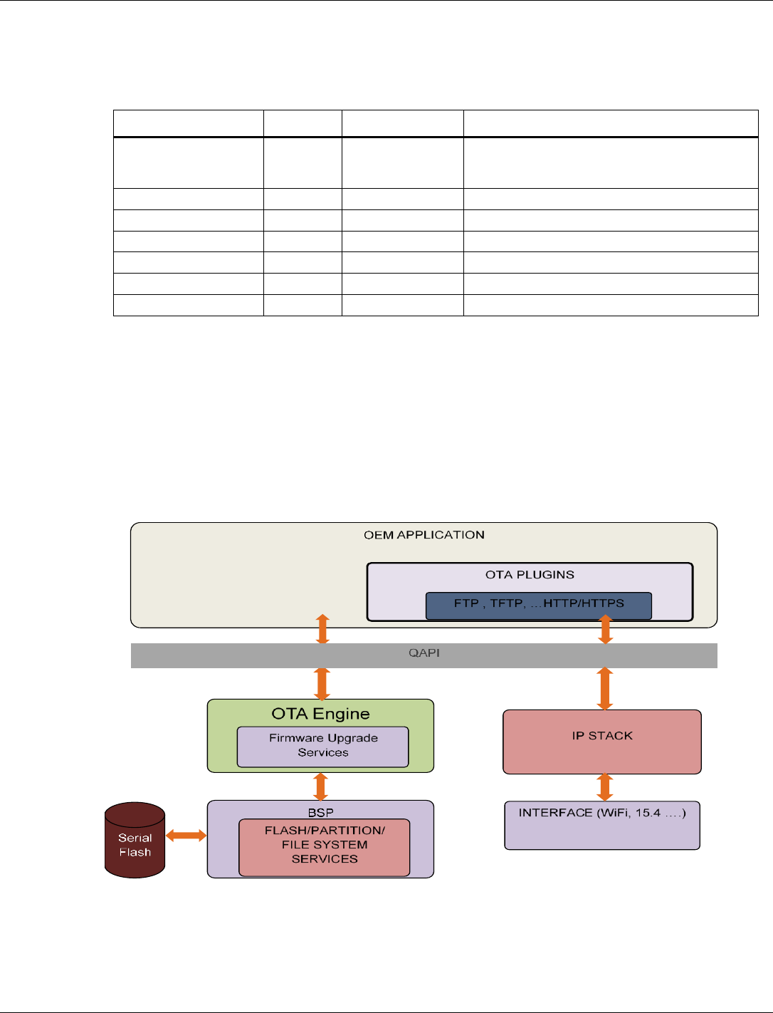
QCA402x (CDB2x) Programmer’s Guide QCA402x framework and programming model
80-YA121-142 Rev. D MAY CONTAIN U.S. AND INTERNATIONAL EXPORT CONTROLLED INFORMATION 33
3.6.4.1 FEM control
Tag number: 190
Length: 6
Title
Options
Default/bit range
Description
FEM Control
0x00 00 00 00 00
00
This tag contains the Front-End Module controls
for assertion logic that is shared between
technologies.
FEM Control 0 (byte 0)
Default: 0x00
FEM Control 1 (byte 1)
Default: 0x00
FEM Control 2 (byte 2)
Default: 0x00
FEM Control 3 (byte 3)
Default: 0x00
FEM Control 4 (byte 4)
Default: 0x00
FEM Control 5 (byte 5)
Default: 0x00
3.7 Firmware upgrade
QCA402x provides a flexible and modular firmware upgrade feature. The upgrade framework is
based on plug-ins for different transport protocols and is agnostic to the interface used.
An example is an the upgrade that can occur over the air using FTP running over the WLAN
interface.
Sample FTP and HTTP plug-ins are provided in the SDK. CLI commands to test firmware
upgrade operation are described in the Firmware upgrade section of QCA402x Development Kit
User Guide (80-YA121-140).
Figure 3-3 QCA402x firmware upgrade framework

QCA402x (CDB2x) Programmer’s Guide QCA402x framework and programming model
80-YA121-142 Rev. D MAY CONTAIN U.S. AND INTERNATIONAL EXPORT CONTROLLED INFORMATION 34
3.7.1 Firmware upgrade overview
At the core of the firmware upgrade mechanism are the concept of “current” and “trial” image
sets in flash. A “current” or “active” image set holds the image currently running on the device. A
“trial” image set is used to store images that are downloaded during firmware upgrade.
Optionally, there is provision for “golden” image set, which can be used to store factory-reset
images.
The following steps provide a high-level overview of firmware upgrade procedure:
■ Application triggers firmware upgrade by invoking upgrade QAPI. Connection and plug-in
parameters are passed via the API.
■ The upgrade plug-in initiates a connection to upgrade server and download the config file.
This file provides information about the number of sub-images, image size, and hash values.
■ Based on the config information, other images are downloaded, validated, and written to a
“trial” partition. If images are written successfully, the “trial “is marked as valid and a system
reset is triggered.
■ The primary boot loader, after detecting the presence of “trial” image set, loads the newly
downloaded images.
■ The application might now choose to run some tests before confirming the success or failure
of the upgrade.
■ If the upgrade is successful, the “trial” images are marked as current. All subsequent reboots
now load the new set of “current” images.
■ If upgrade is a failure, the “trial” image is marked as invalid and a subsequent reboot loads
the last known set of “current” images.
3.7.2 Firmware upgrade image set
A typical image set for QCA402x firmware upgrade contains the following images:
■ Firmware Upgrade Config file.
■ Application Image (runs on Cortex-M4F, generated by OEM)
■ Narrowband Image (Runs on Cortex-M0, provided by Qualcomm)
■ WLAN image (provided by Qualcomm)
■ File-System binary (generated by OEM)
If the RAM dump stored in flash memory is supported, a RAM dump pattern image is mandatory
which is 500 KB prefilled with 0xFF to reserve the partition.
3.7.3 Supported flash configurations
The supported flash configurations are:
■ Current + Trial Image Sets – This image set follows the ping-pong approach. The trial region
holds the newly downloaded images. After the upgrade is validated, trial becomes the new
current. This is the minimal configuration required to perform firmware upgrade.
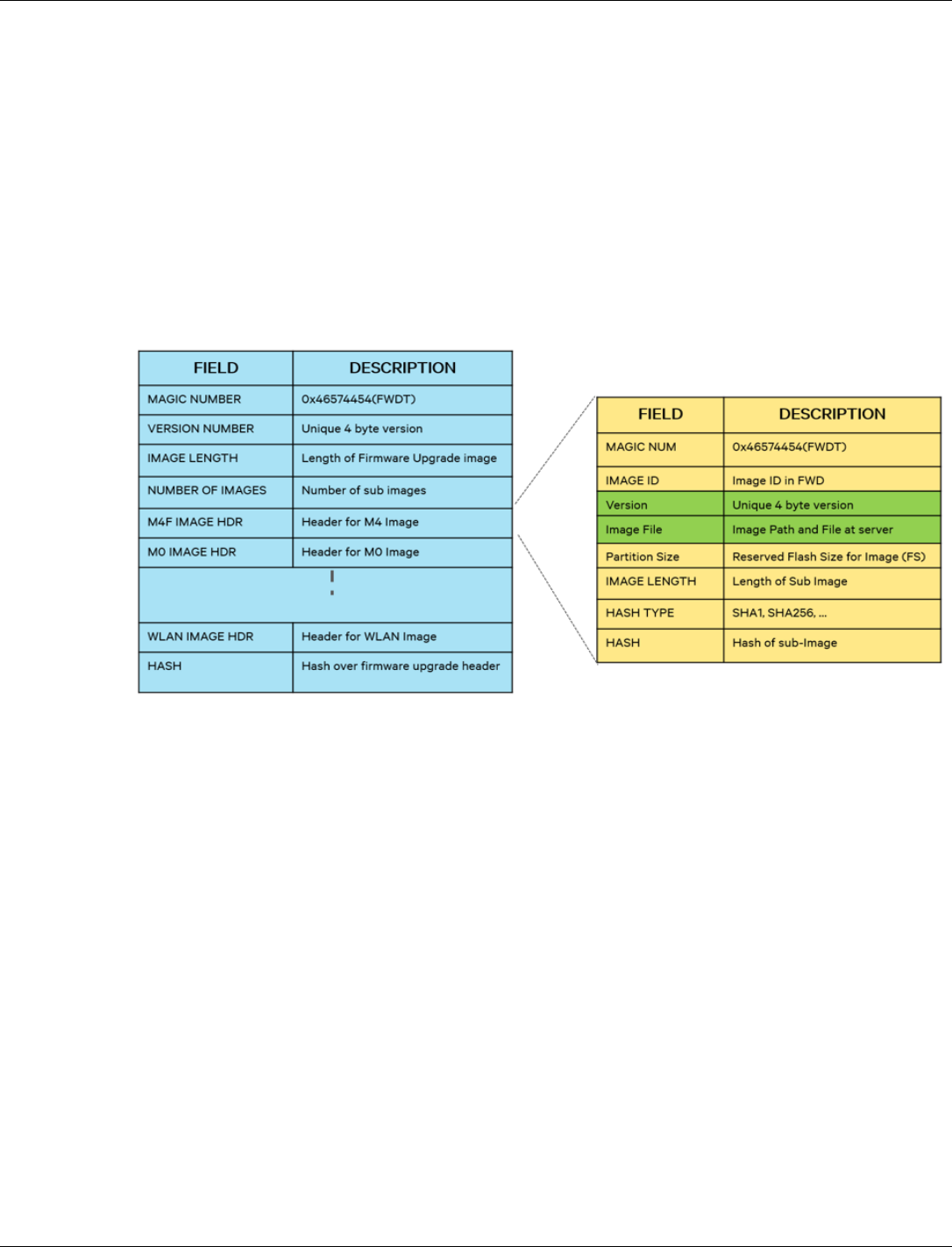
QCA402x (CDB2x) Programmer’s Guide QCA402x framework and programming model
80-YA121-142 Rev. D MAY CONTAIN U.S. AND INTERNATIONAL EXPORT CONTROLLED INFORMATION 35
■ Golden + Current + Trial Image Sets – An Optional scenario where a Golden image set is
used to hold a back-up image. Golden image set cannot be overwritten during a firmware
upgrade.
3.7.4 Configuration file
The configuration file contains all the metadata required by the upgrade engine to perform a
successful upgrade. The SDK contains image generation tools that allow an OEM to generate the
config file based on their requirements. shows the format of the config file.
NOTE: Version number is a 4- byte field that is managed by the OEM. This value is stored in flash
during firmware upgrade and can be retrieved by the application using a QAPI.
Figure 3-4 QCA402x firmware upgrade config file format
3.7.5 Support for partial upgrade
An OEM can optionally choose to upgrade a subset of images instead of the entire image set.
Consider scenario sample scenario where OEM made a critical fix in the application image, but
no changes were made to other images. The image set then consists of config file and application
image.
To re-create the complete image set, the upgrade engine can copy missing images from the
current partition to trial partition. The engine can also identify the subimages that have changed
since the last upgrade (by comparing the hash values) and then selectively download them.
3.7.6 Support for full upgrade
An OEM can optionally choose to upgrade the entire image- set. The upgrade engine copies the
entire image-set to trial partition in a single combined file.

QCA402x (CDB2x) Programmer’s Guide QCA402x framework and programming model
80-YA121-142 Rev. D MAY CONTAIN U.S. AND INTERNATIONAL EXPORT CONTROLLED INFORMATION 36
3.7.7 Firmware upgrade image generation tool
The SDK includes Python- based tools for generating Firmware Upgrade image. The tool is
available at: target\build\tools\fwupgrade\gen_fw_upgrade_img.py
The tool reads an XML configuration file for input parameters. A sample XML file is available at
target\build\tools\fwupgrade\fw_upgrade.xml
The XML file contains information on different images that are included in the combined upgrade
image. Different parameters in the XML file are as follows:
□ “filename”: Indicates path to an image binary/elf. The path must be same path at
fw_upgrade server.
□ “image_id”: An identifier that is associated with each image and must not be modified.
The possible values are:
5: File-system binary (optional)
10: Cortex-m4f image (OEM application image)
11: Cortex-M0 image
13: WLAN firmware image (only valid on QCA4020)
A sample XML file running QCLI demo with ThreadX is as follows:
<?xml version="1.0" ?>
<fw_upgrade_img_descriptor>
<!-- format: 1: partial upgrade, 2: full upgrade in one file -->
<header signature="0x54445746" version="1"/>
<partition filename="" signature="0x54445746" image_id="5" ver=”1”
size_in_kb="64" HASH_TYPE="1"/>
<partition filename="Quartz_HASHED.elf" signature="0x54445746"
image_id="10" ver=”1” size_in_kb="0" HASH_TYPE="1"/>
<partition filename="ioe_ram_m0_threadx_ipt.mbn"
signature="0x54445746" image_id="11" ver=”1” size_in_kb="0"
HASH_TYPE="1"/>
<partition filename="wlan_fw_img.bin" signature="0x54445746"
image_id="13" ver=”1” size_in_kb="0" HASH_TYPE="1"/>
</fw_upgrade_img_descriptor>
“size_in_kb”: Non-zero value is used to reserve space for an image (for example, File system).
When this is set to zero, the size is calculated from the image file.
OEMs can edit this file to indicate location of application image.
The following command generates a combined firmware upgrade image called ‘ota.bin’.
python gen_fw_upgrade_img.py -–xml fw_upgrade.xml -–output ota.bin
■ ota.bin and all files which are listed at fw_upgrade.xml are needed to be copied to firmware
upgrade server for firmware upgrade when “format” in fw_upgrade.xml is set to “1”.
■ ota.bin is needed to be copied to firmware upgrade server for firmware upgrade when
“format” at firmware upgrade.xml setting is “2.” The file includes config file and all files
listed at fw_upgrade.xml.
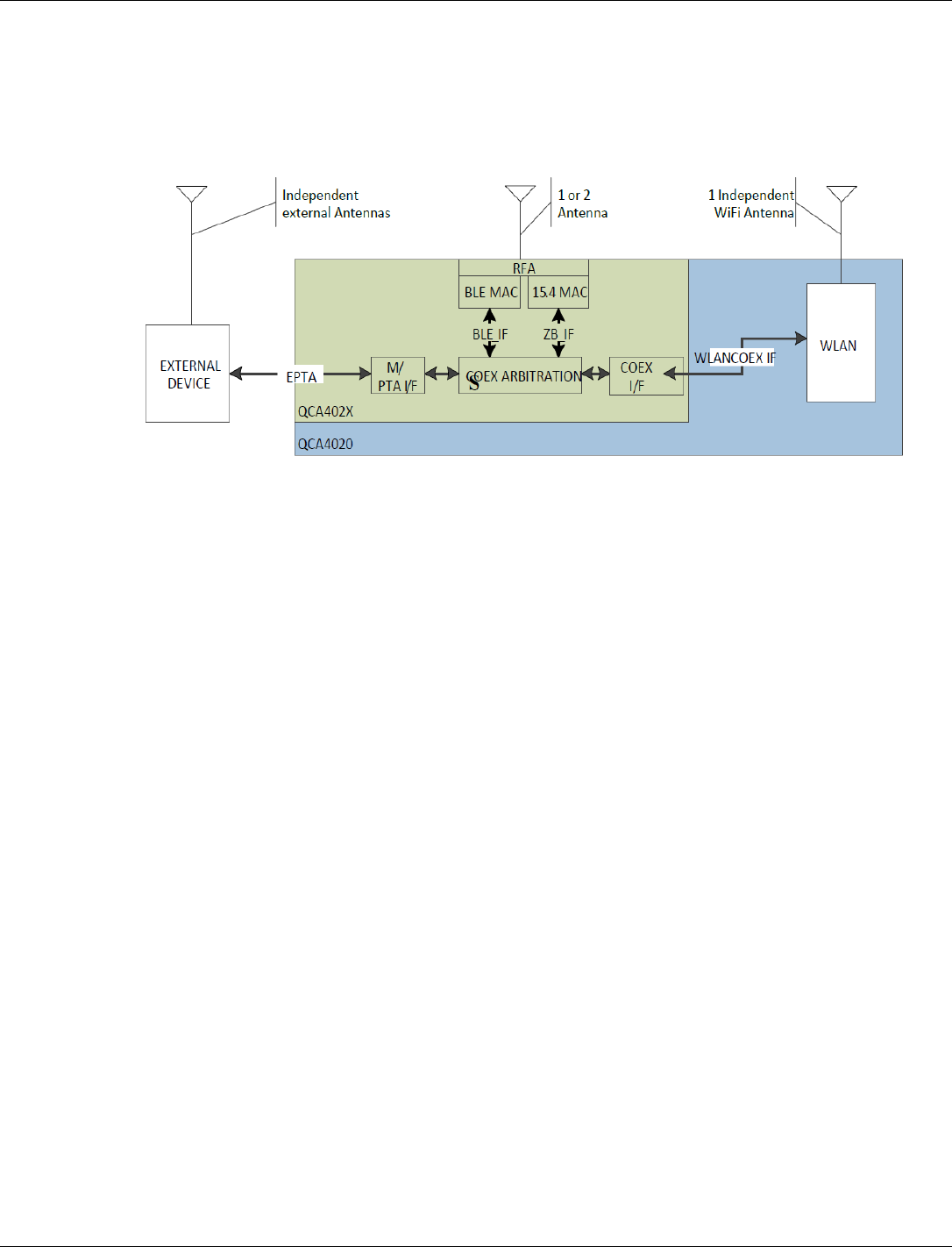
QCA402x (CDB2x) Programmer’s Guide QCA402x framework and programming model
80-YA121-142 Rev. D MAY CONTAIN U.S. AND INTERNATIONAL EXPORT CONTROLLED INFORMATION 37
3.8 WLAN coexistence usage notes
The QCA4020 WLAN subsystem is designed to coexist with both the on-chip BLE/15.4
technologies and off-chip Bluetooth Classic technologies via the external PTA (EPTA) interface
pins of the chip.
The WLAN coexistence subsystem supports simultaneous on-chip BLE and/or 15.4 combined
with a single Bluetooth Classic profile on the EPTA interface. When a profile is enabled, it is
important to specify the appropriate mode for which it needs to be enabled:
■ qapi_WLAN_Coex_Config_Data_t.coex_Mode =
QAPI_WLAN_COEX_3_WIRE_MODE_E for on-chip technologies BLE or 15.4
■ qapi_WLAN_Coex_Config_Data_t.coex_Mode = QAPI_WLAN_COEX_EPTA_MODE_E
for EPTA-connected Bluetooth Classic technologies
After it is applied, coex profiles remain in effect over wake/sleep cycles. However, if the WLAN
subsystem is explicitly disabled, it is necessary for the application to enable the appropriate
WLAN coex profiles upon WLAN enable.
The qapi_WLAN_Coex_Sco_Config, qapi_WLAN_Coex_A2dp_Config,
qapi_WLAN_Coex_Acl_Config, qapi_WLAN_Coex_InqPage_Config,
qapi_WLAN_Coex_Hid_Config, and qapi_WLAN_Coex_Override_Wghts are advanced use
APIs available when the WLAN coex performance requires fine-tuning. Common use cases do
not require the invocation of these APIs. In most cases, the application must invoke the
qapi_WLAN_Coex_Control API to enable or disable profiles appropriately.
3.8.1 Profile usage
■ The application must enable the QAPI_BT_PROFILE_SCAN profile when it performs
narrowband scans and during connection. The QAPI_BT_PROFILE_SCAN profile must be
disabled immediately after a narrowband connect.
■ QAPI_BT_PROFILE_LE must be used with the on-chip BLE and 15.4 technologies.
coex_Mode must be set to QAPI_WLAN_COEX_3_WIRE_MODE_E.
■ QAPI_BT_PROFILE_SCO, QAPI_BT_PROFILE_A2DP, QAPI_BT_PROFILE_ESCO, and
QAPI_BT_PROFILE_HID are Bluetooth Classic technologies. So, coex_Mode must be set to
QAPI_WLAN_COEX_EPTA_MODE_E for those profiles.

QCA402x (CDB2x) Programmer’s Guide QCA402x framework and programming model
80-YA121-142 Rev. D MAY CONTAIN U.S. AND INTERNATIONAL EXPORT CONTROLLED INFORMATION 38
3.9 Network services
The Network services subsystem provides a rich set of QAPIs that enable basic Dual IP network
communication, Secure Socket Layer (SSL) for transport layer security, and built-in
implementation for advanced and common networking services.
3.9.1 BSD-Socket interface
The BSD-Socket QAPI is a collection of standard functions that allow the application to include
Internet communication capabilities. In general, the BSD-Socket interface relies on client-server
architecture and uses a socket object for every operation.
The interface supports TCP and UDP, server mode and client mode, and IPv4 and IPv6
communication.
A socket can be configured with specific options (See socket options as follows).
Due to the memory–constrained properties of the device, it is mandatory to follow the
BSD-socket programming guidelines and check for return values of each function. There is a
chance that an operation may fail due to resource limitations.
Example: The send function might be able to send only some of the data and not all of it in a
single call. A consequent call with the rest of the data is required. In some other cases, an
application thread might need to sleep to allow the system to clear/drain its queues, and process
data.
3.9.1.1 Setting up a socket
To start a communication session, it is required to create a socket using the qapi_socket QAPI,
which requires involves three parameters:
■ Domain: Configures the socket to use either IPv4 protocol (AF_INET) or IPv6 protocol
(AF_INET6). It is not possible to share the same socket for both protocols.
■ Type: Configures the transport layer for the socket. The supported options are TCP
(SOCK_STREAM), UDP (SOCK_DGRAM) or Raw (SOCK_RAW) which has a user-
defined transport layer.
■ Proto: Not used and must be zero.
Upon a successful socket creation, a socket handle is returned, or -1 in case of an error.
The total number of sockets in the system is predefined in the device configuration parameters
and the default value is 12.
After the communication is completed, or if a fatal error is returned by the send or receive
functions, it is required to close the socket using the qapi_socketclose QAPI.
3.9.1.2 Configure socket options
Socket options can be configured at various protocol levels. The supported levels are Socket level
(SOL_SOCKET), IP level (IPPROTO_IP), and IP options to be sent with every packet on the
socket (IP_OPTIONS). See qapi_socket.h for a full list of options. The socket options are generic
and might vary in size. Therefore, the call must specify the exact level, option, option value, and
option size in bytes. The most common options are SO_NBIO to use a non-blocking socket,
SO_KEEPALIVE to enable TCP keepalive option and SO_CALLBACK to enable zero-copy.

QCA402x (CDB2x) Programmer’s Guide QCA402x framework and programming model
80-YA121-142 Rev. D MAY CONTAIN U.S. AND INTERNATIONAL EXPORT CONTROLLED INFORMATION 39
3.9.1.3 Establish a connection
A connection is established between two peers in TCP mode only. UDP is a connection-less
protocol. However, the connection QAPIs can be still used to setup peer communication details,
except for listen and accept commands which are not needed.
Furthermore, there are two basic scenarios where connections are established:
■ The device is a server that accepts remote connections and does not initiate a connection.
■ The device is a client that initiates a connection to a remote server.
NOTE: An application can perform any of these functionalities in parallel.
When operating in server mode, it is required to bind the socket to an address which is composed
of the local IP address and a port on which the socket listens on. This configuration is set up using
the struct sockaddr_in for IPv4 communication and struct sockaddr_in6 for IPv6
communication. This structure must be initialized with the domain, IP address, and port number.
Use htons function to convert the port number to Network order. It is possible to provide a zero
for address and port. If the address is not specified, the system can use any address. If port is not
specified, it uses a random port (not recommended, a server port needs to be well known). The
configuration must be passed to qapi_bind QAPI.
The second step is to listen to incoming connection using qapi_listen QAPI. The backlog
parameter configures the size of the pending connections queue. It is recommended to use zero or
a low value in a memory-constrained system. A value of zero allows one pending connection and
the second connection is refused.
The last step is to accept a connection using qapi_accept QAPI. This function returns a new
socket which represents the foreign (or peer) socket after establishing a connection with a remote
client. The function also provides the address details of the peer. For blocking mode sockets, this
function blocks (indefinitely) until a connection is established.
For non-blocking sockets, the call always returns immediately, irrespective of the establishment
of the connection. For the former, a socket is returned and for the latter, -1 is returned, with error
code of EWOULDBLOCK.
When operating in client mode, it is required to configure the server (remote) address in the
struct sockaddr_in for IPv4 communication and struct sockaddr_in6 for IPv6
communication and use qapi_connect QAPI. If the connection is established, the function
returns zero, otherwise it returns -1.
3.9.1.4 Receive data from a socket
Receiving data from a socket can be done by calling qapi_recv for connected (TCP) sockets,
and qapi_recvfrom for connection-less (UDP) sockets. The caller provides a buffer to be used
to copy the incoming data and its length in bytes. TCP sockets hold stream data internally until all
data has been read by the application, thus calling the receive function with a buffer smaller than
the queued data in the socket. Therefore, data loss is not caused. However, in UDP sockets which
use datagrams, any unread bytes in a datagram are discarded. Therefore, the buffer must be
significant enough for the anticipated data size or MTU.
The receive from function for UDP sockets also provides the peer (remote) address of the sender
because UDP packets can be sent from any host.

QCA402x (CDB2x) Programmer’s Guide QCA402x framework and programming model
80-YA121-142 Rev. D MAY CONTAIN U.S. AND INTERNATIONAL EXPORT CONTROLLED INFORMATION 40
Before calling the receive functions, it is possible to check for pending data in the socket. Using
the qapi_fd_set_t type and the file descriptor QAPIs (qapi_fd_xxx), it is possible to add
sockets which the application is interested to query and call qapi_select function. The select
function checks for activity in the sockets specified in the set, during a specified timeout in
milliseconds (or indefinitely). If there is an activity in one socket or more, the function returns the
number of sockets with an event. If the function returns with a 0, it means that no event has
occurred during the specified timeout. The application can then use qapi_fd_isset to figure out
the socket that had any activity and then call the receive function with the appropriate socket
handle.
An application that cannot block can specify 0 as timeout. This provides an immediate indication
if there is any socket in the set that has an activity.
Zero-copy mode does not use the method to receive data. See section 3.9.1.7.
3.9.1.5 Send data to a socket
Sending data to a socket can be done by calling qapi_send for connected (TCP) sockets and
qapi_sendto (with peer address) for connection-less (UDP) sockets. The caller needs to provide
an application buffer with the data to be sent and its length in bytes.
The send function returns the number of bytes sent, or -1 in case of an error, which can be either a
fatal error (permanent issue) or non-fatal error, such as ENOBUFS, EAGAIN or
EWOULDBLOCK for non-blocking sockets. Non-fatal errors happen due to temporary internal
network buffer shortage or unavailability. In this case, it is required that the application would
yield the CPU to allow other tasks to drain their queues. In case, the application both sends and
receives, the input queue needs to be drained first.
TCP sockets may be able to send all or some of the data in the buffer. There is no limit on the
output buffer size, although the send may return a lower number of bytes sent. The caller must
check the return value and call the send function again from the correct offset.
After all bytes have been confirmed to be sent, the application can reuse the same buffer or free it.
This is not true in Zero-copy mode. For more information, see section 3.9.1.7.
3.9.1.6 Multicast
The device can be configured to receive multicast traffic (Join a Group) or to send multicast
traffic.
To join a group, use the struct ip_mreq to configure an IPv4 Multicast group, or struct
ip_mreq6 to configure an IPv6 Multicast group. Call the set socket option function with
IPPROTO_IP level, and IP_ADDMEMBERSHIP or IPV6_JOIN_GROUP accordingly. It is
mandatory to specify the interface (or scope ID) that is used to receive the traffic.
To send multicast traffic, it is mandatory to specify the interface (or scope ID) that is used to send
the traffic, and recommended to set hops, and disable loopback using the IP_MULTICAST_TTL/
IPV6_MULTICAST_HOPS and IP_MULTICAST_LOOP/IPV6_MULTICAST_LOOP.

QCA402x (CDB2x) Programmer’s Guide QCA402x framework and programming model
80-YA121-142 Rev. D MAY CONTAIN U.S. AND INTERNATIONAL EXPORT CONTROLLED INFORMATION 41
3.9.1.7 Zero-copy interface
The Zero-copy interface allows the application to use and share system network buffers for
sending and receiving data. This interface might reduce memory requirements and copy-
operations that take place between the system and the application. In this mode, the application
allocates a network buffer that can be chained to send data and receive is done via a callback
mechanism, instead of the traditional select/recv way. The mechanism can be enabled by calling
qapi_setsockopt() with option 'level' being SOL_SOCKET or IPPROTO_IP and 'optname'
being SO_CALLBACK (for TCP) or SO_UDPCALLBACK (for UDP).
For example,
To enable TCP zero-copy:
qapi_setsockopt(handle, IPPROTO_IP, SO_CALLBACK, (void *)tcp_rx_callback,
0);
To enable UDP zero-copy:
qapi_setsockopt(handle, IPPROTO_IP, SO_UDPCALLBACK, (void
*)udp_rx_callback, 0);
where 'handle' is the socket handle returned from qapi_socket(). 'tcp_rx_callback' and
'udp_rx_callback' are callback functions called from the stack to inform the application of
received data packets.
The callback functions must conform to the following prototype:
int32_t (*)(void *so, void *pkt, int32_t errcode) tcp_rx_callback;
int32_t (*)(void *so, void *pkt, int32_t errcode, void *from, int32_t
family) udp_rx_callback;
where 'so' is a pointer to an internal socket object, 'pkt' is a pointer to a system buffer
(qapi_Net_Buf_t) containing received data for the socket if it is not NULL.
((qapi_Net_Buf_t *)pkt)->nb_prot points to the start of the received data
((qapi_Net_Buf_t *)pkt)->nb_plen indicates the number of bytes of received data in the
buffer.
The amount of data in the buffer chain is available in ((qapi_Net_Buf_t *)pkt)->nb_tlen field
of the first buffer in the chain. 'errcode' is used by the stack to report some events. If it is not 0, it
is a socket error indicating that an error or other event has occurred on the socket.
For TCP, typical non-zero values are ESHUTDOWN, indicating that the connected peer has
closed its end of the connection and sends no more data ECONNRESET indicates that the
connected peer has abruptly closed its end of the connection and neither sends nor receives more
data. 'from' is a pointer to struct sockaddr_in if 'family' is AF_INET or to struct sockaddr_in6 if
'family' is AF_INET6. 'from' indicates the sender of received data.
If the callback function returns 0, it indicates that the connected peer has accepted responsibility
for the system buffer and returns it to the stack (via call to qapi_Net_Buf_Free(pkt,
QAPI_NETBUF_SYS)) when it no longer needs the buffer. If the callback function returns any
non-zero value, it indicates to the stack that the connected peer has not accepted responsibility for
the system buffer.

QCA402x (CDB2x) Programmer’s Guide QCA402x framework and programming model
80-YA121-142 Rev. D MAY CONTAIN U.S. AND INTERNATIONAL EXPORT CONTROLLED INFORMATION 42
3.9.2 Acquire an IP address
The or IP address is a unique address used to identify hosts and communicate with other hosts in
the IP network. Any device connected to the IP network must have a unique IP address within the
network. There are multiple options to set or acquire an IP address.
3.9.2.1 IPv4 auto-configuration / link local addresses
IPv4 Link-local address is in the range of 169.254.0.0/16 and is valid only for communications
within the network link (or the broadcast domain) that the host is connected to. Link local
addresses are not guaranteed to be unique beyond a single network link but are guaranteed to be
unique within it.
Link local addresses are used in a network that has no DHCPv4 server. There is no
managed/centralized way to acquire a valid IPv4 address.
To generate a unique link local address, the application needs to use the IP configuration QAPI
qapi_Net_IPv4_Config and the QAPI_NET_IPV4CFG_AUTO_IP_E option.
3.9.2.2 Static IPv4 address
An interface can be configured with a static IPv4 address, which is normally used when the
device is in router with QCMobileAP mode (along with DHCPv4 server service).
To generate a unique link local address, the application needs to use the IP configuration QAPI,
qapi_Net_IPv4_Config and use the QAPI_NET_IPV4CFG_STATIC_IP_E option.
3.9.2.3 DHCPv4 client
The system supports automatic acquisition of an IPv4 address using DHCPv4 client. For more
information, see network services.
3.9.2.4 IPv6 link local addresses
IPv6 Link local address, normally in the range of fe80::/64, is reserved for link local unicast
addressing. Unlike IPv4, IPv6 requires a link local address on every interface which results in
multiple concurrent addresses for each interface. The IPv6 link local address is automatically
generated by the system.
3.9.2.5 IPv6 global address
A host uses an IPv6 global address to communicate with remote hosts in the Internet outside the
local link. The IPv6 global address is automatically acquired by the system if there is an IPv6
router in the network (through neighbor discovery protocol and router solicitation message).
The device can also acquire IPv6 global address using DHCPv6 client. For more information, see
network services.
3.9.3 Net buffers and profiles
When an application invokes qapi_send() to send data to the network, the application data is
copied into a net buffer. Similarly, when data is received, and application invokes qapi_recv(),
the data received is copied from Net buffer to application buffer.

QCA402x (CDB2x) Programmer’s Guide QCA402x framework and programming model
80-YA121-142 Rev. D MAY CONTAIN U.S. AND INTERNATIONAL EXPORT CONTROLLED INFORMATION 43
So, a Net buffer holds either a single packet or a chain of packets that are intended to be
transmitted or received at any time. A netbuffer is represented by qapi_Net_Buf_t.
Netbuffers can be of varying sizes. By default, QCA420x supports a free netbuffer pool
containing 128, 512, and 1536 buffer sizes. This free pool serves a netbuffer allocation request. If
there are no netbuffers available, then the allocation might fail.
The free netbuffer pool is configurable using profiles at runtime. The M4 on QCA420x supports
three preset net profiles and a custom profile. The preset profiles are:
■ Performance: This profile must be used when performance is a priority. This requires more
memory.
■ Best Effort: This profile balances performance and memory.
■ Memory optimized: This profile is optimized for memory and hence results in reduced
performance.
The default profile is Best Effort.
To switch between preset profiles, use the following QAPI:
qapi_Status_t qapi_Net_Profile_Set_Active(qapi_Net_Profile_Type_t profile);
To create a custom profile, use the following QAPI:
qapi_Status_t qapi_Net_Profile_Set_Custom(qapi_Net_Profile_Custom_Pool_t
*pNet_buf, uint8_t net_bufq_size);
A user must choose a net profile that meets the application requirement. When switching to a
custom profile using the QAPI, the application should specify the number of netbuffer pools
(net_bufq_size) and a pointer pNet_buf containing the size of netbuffers in each pool and
number of netbuffers in that pool.
For example, A custom profile can be net_bufq_size = 3 and pNet_buf could point to an
array [128 5 512 4 1536 5]. Switching between profiles is not allowed when there are open
sockets in the system. The return status QAPI_ERR_BUSY indicates that there are open sockets.
For other error values, refer to QCA402x QAPI specification (80-Y9381-7).
3.9.4 SSL
The Secure Socket Layer (SSL) interface provides authentication, privacy (encryption), and data
integrity between two peers communicating over TCP or UDP. After a connection is established,
the two peers use a handshake mechanism to authenticate and establish the keys used for
encryption/decryption and data verification. After the handshake is successful, data can be
securely transmitted or received over the SSL connection.
3.9.4.1 Protocol versions
The supported protocols are: TLS1.0, TLS1.1, TLS1.2 (over TCP) and DTLS1.0, DTLS1.2 (over
UDP). The application can select to enable a specific protocol using the
qapi_Net_SSL_Configure QAPI or allow the handshake to select automatically.
SSLv3 support has been deprecated due to security vulnerabilities.

QCA402x (CDB2x) Programmer’s Guide QCA402x framework and programming model
80-YA121-142 Rev. D MAY CONTAIN U.S. AND INTERNATIONAL EXPORT CONTROLLED INFORMATION 44
3.9.4.2 Modes of operation
The two modes of operations are:
■ Server mode: The device waits for incoming connection and participates as the server role in
the handshake.
■ Client mode: The device initiates a connection to a remote server and participates as the client
role in the handshake.
3.9.4.3 Supported cipher suites
The following cipher suites are supported:
■ TLS_PSK_WITH_AES_256_GCM_SHA384 (0x00a9)
■ TLS_PSK_WITH_AES_256_CBC_SHA384 (0x00af)
■ TLS_PSK_WITH_AES_256_CBC_SHA (0x008d)
■ TLS_ECDHE_PSK_WITH_AES_128_CBC_SHA256 (0xc037)
■ TLS_PSK_WITH_AES_128_GCM_SHA256 (0x00a8)
■ TLS_PSK_WITH_AES_128_CBC_SHA256 (0x00ae)
■ TLS_PSK_WITH_AES_128_CBC_SHA (0x008c)
■ TLS_PSK_WITH_AES_128_CCM_8 (0xc0a8)
■ TLS_ECDHE_ECDSA_WITH_AES_256_GCM_SHA384 (0xc02c)
■ TLS_ECDHE_ECDSA_WITH_AES_256_CBC_SHA384 (0xc024)
■ TLS_ECDHE_ECDSA_WITH_AES_128_GCM_SHA256 (0xc02b)
■ TLS_ECDHE_ECDSA_WITH_AES_128_CBC_SHA256 (0xc023)
■ TLS_ECDHE_ECDSA_WITH_AES_256_CBC_SHA (0xc00a)
■ TLS_ECDHE_ECDSA_WITH_AES_128_CBC_SHA (0xc009)
■ TLS_ECDH_ECDSA_WITH_AES_256_GCM_SHA384 (0xc02e)
■ TLS_ECDH_ECDSA_WITH_AES_256_CBC_SHA384 (0xc026)
■ TLS_ECDH_ECDSA_WITH_AES_128_GCM_SHA256 (0xc02d)
■ TLS_ECDH_ECDSA_WITH_AES_128_CBC_SHA256 (0xc025)
■ TLS_ECDH_ECDSA_WITH_AES_256_CBC_SHA (0xc005)
■ TLS_ECDH_ECDSA_WITH_AES_128_CBC_SHA (0xc004)
■ TLS_ECDHE_RSA_WITH_AES_256_GCM_SHA384 (0xc030)
■ TLS_ECDHE_RSA_WITH_AES_256_CBC_SHA384 (0xc028)
■ TLS_ECDHE_RSA_WITH_AES_128_GCM_SHA256 (0xc02f)
■ TLS_ECDHE_RSA_WITH_AES_128_CBC_SHA256 (0xc027)
■ TLS_ECDHE_RSA_WITH_AES_256_CBC_SHA (0xc014)
■ TLS_ECDHE_RSA_WITH_AES_128_CBC_SHA (0xc013)
■ TLS_ECDH_RSA_WITH_AES_256_GCM_SHA384 (0xc032)

QCA402x (CDB2x) Programmer’s Guide QCA402x framework and programming model
80-YA121-142 Rev. D MAY CONTAIN U.S. AND INTERNATIONAL EXPORT CONTROLLED INFORMATION 45
■ TLS_ECDH_RSA_WITH_AES_256_CBC_SHA384 (0xc02a)
■ TLS_ECDH_RSA_WITH_AES_128_GCM_SHA256 (0xc031)
■ TLS_ECDH_RSA_WITH_AES_128_CBC_SHA256 (0xc029)
■ TLS_ECDH_RSA_WITH_AES_256_CBC_SHA (0xc00f)
■ TLS_ECDH_RSA_WITH_AES_128_CBC_SHA (0xc00e)
■ TLS_DHE_RSA_WITH_AES_256_GCM_SHA384 (0x009f)
■ TLS_DHE_RSA_WITH_AES_256_CCM (0xc09f)
■ TLS_DHE_RSA_WITH_AES_256_CCM_8 (0xc0a3)
■ TLS_DHE_RSA_WITH_AES_256_CBC_SHA256 (0x006b)
■ TLS_DHE_RSA_WITH_AES_256_CBC_SHA (0x0039)
■ TLS_DHE_RSA_WITH_AES_128_GCM_SHA256 (0x009e)
■ TLS_DHE_RSA_WITH_AES_128_CCM (0xc09e)
■ TLS_DHE_RSA_WITH_AES_128_CCM_8 (0xc0a2)
■ TLS_DHE_RSA_WITH_AES_128_CBC_SHA256 (0x0067)
■ TLS_DHE_RSA_WITH_AES_128_CBC_SHA (0x0033)
■ TLS_RSA_WITH_AES_256_GCM_SHA384 (0x009d)
■ TLS_RSA_WITH_AES_256_CCM (0xc09d)
■ TLS_RSA_WITH_AES_256_CCM_8 (0xc0a1)
■ TLS_RSA_WITH_AES_256_CBC_SHA256 (0x003d)
■ TLS_RSA_WITH_AES_256_CBC_SHA (0x0035)
■ TLS_RSA_WITH_AES_128_GCM_SHA256 (0x009c)
■ TLS_RSA_WITH_AES_128_CCM (0xc09c)
■ TLS_RSA_WITH_AES_128_CCM_8 (0xc0a0)
■ TLS_RSA_WITH_AES_128_CBC_SHA256 (0x003c)
■ TLS_RSA_WITH_AES_128_CBC_SHA (0x002f)
■ TLS_ECDHE_ECDSA_WITH_CHACHA20_POLY1305_SHA256 (0xcc14)
■ TLS_ECDHE_RSA_WITH_CHACHA20_POLY1305_SHA256 (0xcc13)
■ TLS_DHE_RSA_WITH_CHACHA20_POLY1305_SHA256 (0xcc15)
■ TLS_ECJPAKE_WITH_AES_128_CCM_8 (0xc0ff)
The application can select to enable specific cipher suites using the qapi_Net_SSL_Cipher_Add
and qapi_Net_SSL_Configure QAPIs or allow the handshake to select a cipher suite
automatically.

QCA402x (CDB2x) Programmer’s Guide QCA402x framework and programming model
80-YA121-142 Rev. D MAY CONTAIN U.S. AND INTERNATIONAL EXPORT CONTROLLED INFORMATION 46
3.9.4.4 Server authentication
During the connection to a remote server, as part of the TLS/DTLS handshake process, the local
client can authenticate the server by processing the server certificate.
The authentication process includes:
■ Domain/host name verification
■ Certificate expiration date verification
Furthermore, to verify that the certificate is authentic, there is a need for a root of trust, or a third-
party side that both the client and server trust. A certificate is usually signed by the root or by a
chain of roots, where the client must trust one of them for the server certificate. To allow this
process to happen, it is required to provision a Certificate Authority (CA) List file which contains
details and public keys of CAs that the device can trust and load it to the corresponding SSL
connection object using the qapi_Net_SSL_Cert_Load QAPI. The CA list file provisioning can
be done as part of the production process or using the qapi_Net_SSL_Cert_Store QAPI in
runtime.
The default setting is to skip all verifications and establish the connection. Therefore, it is highly
recommended that the application in production mode enables server authentication using the
qapi_Net_SSL_Configure QAPI.
3.9.4.5 Client authentication
During the connection to a remote server, as part of the TLS/DTLS handshake process, the
remote server can optionally request the local client to authenticate to the server by requesting the
client certificate. This process is similar to server authentication.
To allow this process to happen, it is required to provision a Certificate file which contains the
device’s public and private key pairs. The public key pair is signed by a root (CA) which is
trusted by the server and loads it to the corresponding SSL connection object using the
qapi_Net_SSL_Cert_Load QAPI. The certificate file provisioning can be done as part of the
production process or using the qapi_Net_SSL_Cert_Store QAPI in runtime.
3.9.4.6 SNI
The Server name indication (SNI) transport layer security (TLS) extension allows the application
to specify a host/server name to connect to as a part of the handshake process. It allows a server
to support multiple secure services on the same IP address and port, and thus present the correct
certificate to the client.
To configure SNI, use the qapi_Net_SSL_Configure QAPI.
3.9.4.7 ALPN
The Application layer protocol negotiation (ALPN) TLS extension allows the application to
specify a protocol to be used after the secure connection is established (in client mode), or a list
of supported protocols to offer the client (in server mode). This is done by calling the
qapi_Net_SSL_ALPN_Protocol_Add QAPI.
In client mode, the connection is successful if the server supports the requested protocol or does
not support ALPN extension. The connection fails if the client and server do not agree on a
mutually supported protocol.

QCA402x (CDB2x) Programmer’s Guide QCA402x framework and programming model
80-YA121-142 Rev. D MAY CONTAIN U.S. AND INTERNATIONAL EXPORT CONTROLLED INFORMATION 47
In server mode, the application can use the qapi_Net_SSL_ALPN_Protocol_Get or
qapi_Net_SSL_ALPN_Get_Protocol_For_Peer QAPIs to get the protocol that was negotiated
with the client.
3.9.4.8 SSL certificate manager
The SSL certificate manger is a software module responsible for storing and loading the
certificates and CA lists from flash using secure storage. It contains the following API functions:
■ qapi_Net_SSL_Cert_Store(): Stores the certificate or CA list into flash.
■ qapi_Net_SSL_Cert_Load(): Loads the certificate or CA list from flash into the SSL
object.
■ qapi_Net_SSL_Cert_List(): Lists the certificates or CA lists stored in flash.
■ qapi_Net_SSL_Cert_Get_Hash(): Creates a hash for the certificate or CA list stored in
flash.
■ qapi_Net_SSL_Cert_Validate (): Validates a given certificate against a CA list stored in
flash.
■ qapi_Net_SSL_Cert_Get_Expiration (): Gets the expiration details of a certificate
stored in flash.
■ qapi_Net_SSL_PSK_Table_Set(): Stores the pre-shared keys (PSK) table to be used with
TLS PSK ciphers.
■ qapi_Net_PSK_Table_Clear(): Clears the PSK table.
3.9.4.8.1 Storing certificates and CA lists securely in flash
The qapi_Net_SSL_Cert_Store() QAPI function is used to store both the certificates and the
CA lists securely into the flash. It accepts certificates and CA lists in PEM format or proprietary
binary format. When certificate or CA list in PEM format is passed to this function, it converts it
into a proprietary binary format, and then stores this binary representation into the flash. When
this function is used to store certificate in PEM format, the caller must also pass the private key in
PEM format.
The certificates are stored in the flash using the Secure Storage running on TEE. Since TEE is
used to store the certificates, only the TEE is able to access them. The private key stored with the
certificate never leaves the TEE. Consequently, all operations that need to be performed with
private key are performed inside TEE.
The CA lists are stored into the flash using Secure Storage running on host CPU since they do not
contain private information. Since both the certificates and the CA lists are stored using secure
storage, it is impossible to decrypt the stored certificates or CA lists using external flash reader.
The code snippets show how to store certificates and CA lists in both PEM and binary formats.
3.9.4.8.1.1 Store certificate and key in PEM format securely into flash using TEE
secure storage
qapi_Net_SSL_Cert_Info_t cert_info;
memset(&cert_info, 0, sizeof(cert_info));
cert_info.cert_Type = QAPI_NET_SSL_PEM_CERTIFICATE_WITH_PEM_KEY_E;
cert_info.info.pem_Cert.cert_Buf = BUFFER_CONTAINING_PEM_CERTIFICATE;

QCA402x (CDB2x) Programmer’s Guide QCA402x framework and programming model
80-YA121-142 Rev. D MAY CONTAIN U.S. AND INTERNATIONAL EXPORT CONTROLLED INFORMATION 48
cert_info.info.pem_Cert.cert_Size =
SIZE_OF_BUFFER_CONTAINING_PEM_CERTIFICATE;
cert_info.info.pem_Cert.key_Buf = BUFFER_CONTAINING_PEM_PRIVATE_KEY;
cert_info.info.pem_Cert.key_Size =
SIZE_OF_BUFFER_CONTAINING_PEM_PRIVATE_KEY;
char * name = CERTIFICATE_NAME_TO_STORE_ON_FLASH;
qapi_Status_t status = qapi_Net_SSL_Cert_Store(&cert_info, name);
3.9.4.8.1.2 Store certificate in binary format into flash using TEE secure storage
qapi_Net_SSL_Cert_Info_t cert_info;
memset(&cert_info, 0, sizeof(cert_info));
cert_info.cert_Type = QAPI_NET_SSL_BIN_CERTIFICATE_E;
cert_info.info.bin_Cert.cert_Buf = BUFFER_CONTAINING_BINARY_CERTIFICATE;
cert_info.info.bin_Cert.cert_Size =
SIZE_OF_BUFFER_CONTAINING_BINARY_CERTIFICATE;
char * name = CERTIFICATE_NAME_TO_STORE_ON_FLASH;
qapi_Status_t status = qapi_Net_SSL_Cert_Store(&cert_info, name);
3.9.4.8.1.3 Store CA list in PEM format into flash using secure storage
qapi_Net_SSL_Cert_Info_t cert_info;
memset(&cert_info, 0, sizeof(cert_info));
qapi_CA_Info_t ca_info;
ca_info.ca_Buf = BUFFER_CONTAINING_PEM_CA_LIST;
ca_info.ca_Size = SIZE_OF_BUFFER_CONTAINING_PEM_CA_LIST;
cert_info.cert_Type = QAPI_NET_SSL_PEM_CA_LIST_E;
cert_info.info.pem_CA_List.ca_Cnt = 1;
cert_info.info.pem_CA_List.ca_Info[0] = &ca_info;
char * name = CA_LIST_NAME_TO_STORE_ON_FLASH;
qapi_Status_t status = qapi_Net_SSL_Cert_Store(&cert_info, name);
3.9.4.8.1.4 Store Binary CA list into flash using secure storage
qapi_Net_SSL_Cert_Info_t cert_info;
memset(&cert_info, 0, sizeof(cert_info));
cert_info.cert_Type = QAPI_NET_SSL_BIN_CA_LIST_E;
cert_info.info.bin_CA_List.ca_List_Buf =
BUFFER_CONTAINING_BINARY_CA_LIST;
cert_info.info.bin_CA_List.ca_List_Size =
SIZE_OF_BUFFER_CONTAINING_BINARY_CA_LIST;
char * name = CA_LIST_NAME_TO_STORE_ON_FLASH;
qapi_Status_t status = qapi_Net_SSL_Cert_Store(&cert_info, name);
3.9.4.8.2 Load certificate or CA list from flash into SSL object
The qapi_Net_SSL_Cert_Load() QAPI function is used to load the certificate from flash and
attaching it to an SSL object.
When QCA402x is configured as an SSL server, it needs to have a valid certificate that must be
loaded from flash into the SSL object before the SSL connection object is created. Additionally,
if the QCA402x SSL server needs to perform client authentication (mutual authentication), it also

QCA402x (CDB2x) Programmer’s Guide QCA402x framework and programming model
80-YA121-142 Rev. D MAY CONTAIN U.S. AND INTERNATIONAL EXPORT CONTROLLED INFORMATION 49
needs to contain a valid CA list that must be loaded from flash into the SSL object before the SSL
connection is created. This CA list is used to authenticate the client(s) connecting to the SSL
server. The order in which certificates or CA lists are loaded is irrelevant.
When QCA402x is used as an SSL client, it needs to have a valid CA list that must be loaded
from flash into the SSL object before the SSL connection is created. This CA List is used to
authenticate the server(s) to which the client connects.
Additionally, if the client needs to authenticate itself with the server it connects to, the client must
have a valid certificate that must be loaded from flash into the SSL object before the SSL
connection is created. The order in which certificates or CA lists are loaded is irrelevant.
The code snippets show how to load certificate and CA list into the SSL object.
3.9.4.8.2.1 Load certificate into SSL object
qapi_Net_SSL_Obj_Hdl_t ssl_object = SSL_OBJECT_HANDLE;
qapi_Net_SSL_Cert_Type_t type = QAPI_NET_SSL_CERTIFICATE_E;
char * cert_name = CERTIFICATE_NAME;
qapi_Status_t status = qapi_Net_SSL_Cert_Load(object, type, cert_name);
3.9.4.8.2.2 Load CA list into SSL object
qapi_Net_SSL_Obj_Hdl_t ssl_object = SSL_OBJECT_HANDLE;
qapi_Net_SSL_Cert_Type_t type = QAPI_NET_SSL_CA_LIST_E;
char * ca_list_name = CA_LIST_NAME;
qapi_Status_t status = qapi_Net_SSL_Cert_Load(object, type, ca_list_name);
3.9.4.8.3 List available certificates and CA lists in flash
The qapi_Net_SSL_Cert_List() QAPI function is used to list certificates and CA lists that are
stored in flash. A maximum of 10 certificates and 10 CA lists can be listed by this function.
Each certificate or CA list name is limited to 64 characters.
The code snippets show how to list certificates and CA lists stored in flash.
3.9.4.8.3.1 List certificates stored in flash
qapi_Net_SSL_Cert_List_t * list_of_certificates = (qapi_Net_SSL_Cert_List_t
*) malloc(qapi_Net_SSL_Cert_List_t);
memset(list_of_certificates, 0, sizeof(qapi_Net_SSL_Cert_List_t));
qapi_Status_t status = qapi_Net_SSL_Cert_List(QAPI_NET_SSL_CERTIFICATE_E,
list_of_certificates);
int i;
for ( i = 0; i < QAPI_NET_SSL_MAX_NUM_CERTS; i++ ) {
if ( strlen(list_of_certificates[i]) > 0 ) {
printf("%s\n", list_of_certificates[i]);
}
}
free(list_of_certificates);

QCA402x (CDB2x) Programmer’s Guide QCA402x framework and programming model
80-YA121-142 Rev. D MAY CONTAIN U.S. AND INTERNATIONAL EXPORT CONTROLLED INFORMATION 50
3.9.4.8.3.2 List CA lists stored in flash
qapi_Net_SSL_Cert_List_t * list_of_certificates = (qapi_Net_SSL_Cert_List_t
*) malloc(qapi_Net_SSL_Cert_List_t);
memset(list_of_certificates, 0, sizeof(qapi_Net_SSL_Cert_List_t));
qapi_Status_t status = qapi_Net_SSL_Cert_List(QAPI_NET_SSL_CA_LIST_E,
list_of_certificates);
int i;
for ( i = 0; i < QAPI_NET_SSL_MAX_NUM_CERTS; i++ ) {
if ( strlen(list_of_certificates[i]) > 0 ) {
printf("%s\n", list_of_certificates[i]);
}
}
free(list_of_certificates);
3.9.4.8.4 Calculate SHA256 checksum of certificate or CA list stored in flash
Because certificates are stored securely in TEE and are never given back to the host CPU, there
must be a way to validate that the certificates are stored correctly. For this purpose, the
qapi_Net_SSL_Cert_Get_Hash() function calculates the sha256 checksum of the certificate or
CA list, returning 32 byte checksum that can be compared against the checksum calculated on a
PC.
The code snippets show how to calculate SHA256 checksum of certificates and CA lists stored in
flash.
3.9.4.8.4.1 Calculate SHA256 checksum of certificate stored in flash
char * cert_name = CERTIFICATE_NAME;
qapi_Net_SSL_Cert_Type_t type = QAPI_NET_SSL_CERTIFICATE_E;
uint8_t hash[32];
qapi_Status_t status = qapi_Net_SSL_Cert_Get_Hash(cert_name, type,
hash);
3.9.4.8.4.2 Calculate SHA256 checksum of CA List stored in flash
char * ca_list_name = CA_LIST_NAME;
qapi_Net_SSL_Cert_Type_t type = QAPI_NET_SSL_CA_LIST_E;
uint8_t hash[32];
qapi_Status_t status = qapi_Net_SSL_Cert_Get_Hash(ca_list_name, type,
hash);
3.9.4.8.5 Validating an external certificate
The qapi_Net_SSL_Cert_Validate QAPI function allows the caller to validate a peer certificate,
which can be chained against a CA list in the local storage. The input certificate is in PEM
format. QAPI accepts the peer common name to compare against the CN field of the certificate
and verifies that the certificate has not expired.
This function is useful when there is a need to establish trust with an external peer without using
TLS.

QCA402x (CDB2x) Programmer’s Guide QCA402x framework and programming model
80-YA121-142 Rev. D MAY CONTAIN U.S. AND INTERNATIONAL EXPORT CONTROLLED INFORMATION 51
3.9.4.8.6 Certificate expiration test
The qapi_Net_SSL_Cert_Get_Expiration QAPI function allows the caller to get the
expiration dates (not before and not after) of a certificate in the certificate storage. It allows the
caller to determine whether a certificate is about to expire and take appropriate action.
3.9.4.8.7 Set up pre-shared key (PSK) table
The SSL PSK cipher suite requires the PSK table to be set up for the SSL object before the SSL
connection object is created. The qapi_Net_SSL_PSK_Table_Set() QAPI function provides a
mechanism to set up the PSK table. Each entry of the PSK table consists of identity and the
corresponding pre-shared key.
The code snippet shows how to set PSK table for the SSL object.
qapi_Net_SSL_Obj_Hdl_t ssl_object_hdl = SSL_OBJECT_HANDLE;
uint16_t num_PSK_entries = 2;
qapi_Net_SSL_PSK_t * psk_entries = (qapi_Net_SSL_PSK_t *)
malloc(num_PSK_entries*sizeof(qapi_Net_SSL_PSK_t));
psk_entries[0].identity = { 0xca, 0xfe, 0xba, 0xba, 0x00 };
psk_entries[0].identity_Size = 5
psk_entries[0].psk = { 0xaa, 0xaa, 0xaa, 0xaa };
psk_entries[0].psk_Size = 4;
psk_entries[1].identity = { 0xca, 0xfe, 0xba, 0xba, 0x01 };
psk_entries[1].identity_Size = 5
psk_entries[1].psk = { 0xbb, 0xbb, 0xbb, 0xbb };
psk_entries[1].psk_Size = 4;
qapi_Status_t status = qapi_Net_SSL_PSK_Table_Set(ssl_object_hdl,
psk_entries, num_PSK_entries);
3.9.4.8.8 Clear the pre-shared key (PSK) table
When the SSL object is reused and the PSK table is no longer needed, it should be cleared using
the qapi_Net_SSL_PSK_Table_Clear() QAPI functions. This function must be called only when
there are no SSL connection objects associated with the SSL object.
The code snippet shows how to clear the PSK table for the SSL object.
qapi_Net_SSL_Obj_Hdl_t ssl_object_hdl = SSL_OBJECT_HANDLE;
qapi_Status_t status = qapi_Net_SSL_PSK_Table_Clear(ssl_object_hdl);
3.9.4.9 Create a new SSL object and connection
There are two objects for each SSL session:
■ The SSL object containing the configuration related to SSL (supported ciphers, TLS or DTLS
and so on)
■ The SSL connection object containing the configuration related to the connection (like
negotiated cipher, negotiated ALPN protocol).
An SSL object can have one of the following roles QAPI_NET_SSL_SERVER_E or
QAPI_NET_SSL_CLIENT_E based on the SSL configuration for a server or client.
To create an SSL object:

QCA402x (CDB2x) Programmer’s Guide QCA402x framework and programming model
80-YA121-142 Rev. D MAY CONTAIN U.S. AND INTERNATIONAL EXPORT CONTROLLED INFORMATION 52
qapi_Net_SSL_Obj_Hdl_t qapi_Net_SSL_Obj_New(qapi_Net_SSL_Role_t role);
The QAPI returns a handle to the SSL object that must be used to reference the object until the
SSL session is shut down and QAPI_NET_SSL_INVALID_HANDLE if the QAPI fails to create
an SSL object. The handle is referred to as SSL context.
To create an SSL connection object:
qapi_Net_SSL_Con_Hdl_t qapi_Net_SSL_Con_New(qapi_Net_SSL_Obj_Hdl_t hdl,
qapi_Net_SSL_Protocol_t prot);
The handle, hdl is a handle to the SSL object and the protocol must be QAPI_NET_SSL_TLS_E or
QAPI_NET_SSL_DTLS_E based on the transport (TCP or UDP).
The QAPI returns a handle to SSL connection object that must be used to reference a specific
connection with a remote peer, until the connection is torn down and
QAPI_NET_SSL_INVALID_HANDLE if the QAPI fails to create an object.
3.9.4.10 Configure SSL object and SSL connection
An application must create a configuration variable of type qapi_Net_SSL_Config_t and
configure the different parameters.
An application can configure the SSL protocol to be any of the following
QAPI_NET_SSL_PROTOCOL_TLS_1_0, QAPI_NET_SSL_PROTOCOL_TLS_1_1,
QAPI_NET_SSL_PROTOCOL_TLS_1_2, QAPI_NET_SSL_PROTOCOL_DTLS_1_0,
QAPI_NET_SSL_PROTOCOL_DTLS_1_2 based on the transport (TCP or UDP).
Assuming cfg is a pointer to the configuration data, cfg > verify specifies the certificate
verification policy.
■ To verify the certificate’s commonName against the peer’s domain name, set
cfg > verify.domain to 1.
■ To verify certificate time validity, set cfg > verify.time_Validity to 1.
■ To send an alert in case of error, set cfg > verify.send_Alert to 1.
■ To enable a cipher for the SSL instance:
qapi_Status_t qapi_Net_SSL_Cipher_Add(qapi_Net_SSL_Config_t * cfg,
uint16_t cipher);
The cipher can be QAPI_NET_TLS_RSA_WITH_AES_256_GCM_SHA384. For list of all ciphers,
refer to the QCA402x QAPI specification (80-Y9381-7).
■ To set the maximum fragment length, set the value in cfg > max_Frag_Len.
■ To disable negotiation of maximum fragment length,
set cfg > max_Frag_Len_Neg_Disable to 1.
■ For SNI, the application must specify the name of the server in cfg > sni_Name and the size
or string length in cfg > sni_Name_Size.
■ To configure ALPN use the QAPI:
int qapi_Net_SSL_ALPN_Protocol_Add(qapi_Net_SSL_Obj_Hdl_t hdl, const
char *protocol);
After configuring all the parameters, the application must use the QAPI to configure the SSL
connection.
■ To configure the SSL connection object:

QCA402x (CDB2x) Programmer’s Guide QCA402x framework and programming model
80-YA121-142 Rev. D MAY CONTAIN U.S. AND INTERNATIONAL EXPORT CONTROLLED INFORMATION 53
qapi_Status_t qapi_Net_SSL_Configure(qapi_Net_SSL_Con_Hdl_t ssl,
qapi_Net_SSL_Config_t *cfg);
■ Attach the socket descriptor to the SSL connection, using QAPI:
qapi_Status_t qapi_Net_SSL_Fd_Set(qapi_Net_SSL_Con_Hdl_t ssl, uint32_t
fd);
3.9.4.11 Connect and disconnect SSL sessions
SSL handshake is the process by which a client or server on QCA402x can establish an SSL
session with a remote server or client.
3.9.4.11.1 TLS client
For a TLS client, after configuring the parameters, to connect to a remote server, a TCP session is
established using qapi_connect (UDP does not need a connection). If the connection is successful,
then an SSL connection object is created and configured using the QAPIs mentioned in 3.9.4.10.
■ To initiate an SSL handshake:
qapi_Status_t qapi_Net_SSL_Connect(qapi_Net_SSL_Con_Hdl_t ssl);
The QAPI returns QAPI_SSL_OK_HS if the handshake is successful. For information on other
return values, refer to the QCA402x QAPI specification (80-Y9381-7).
After a successful handshake, the client can send data using qapi_Net_SSL_Write.
■ To tear down a connection:
qapi_Status_t qapi_Net_SSL_Shutdown(qapi_Net_SSL_Con_Hdl_t ssl);
The SSL connection object is freed in this QAPI. The application must invoke
qapi_socketclose to close the socket.
■ To free the SSL object:
qapi_Status_t qapi_Net_SSL_Obj_Free(qapi_Net_SSL_Obj_Hdl_t hdl);
3.9.4.11.2 TLS server
For a TLS server, open a TCP socket using qapi_socket(IPv4 or IPv6). Set the socket to
listening mode using qapi_listen. Invoke qapi_accept to accept incoming connections.
qapi_accept returns 1 if there are new incoming connections.
Create SSL object and connection object and configure these as described in sections 3.9.4.9 and
3.9.4.10. The connection object must be of type QAPI_NET_SSL_TLS_E.
Associate the TCP socket with the SSL connection using qapi_Net_SSL_Fd_Set.
■ To complete the SSL handshake:
qapi_Status_t qapi_Net_SSL_Accept(qapi_Net_SSL_Con_Hdl_t ssl);
The QAPI returns QAPI_SSL_OK_HS if the handshake is successful. For more information on
other return values, refer to QCA402x QAPI specification (80-Y9381-7).
■ To get the status of the connection (handshake), if the socket is in non-blocking mode:
qapi_Status_t qapi_Net_SSL_Con_Get_Status(qapi_Net_SSL_Con_Hdl_t ssl);
After a successful handshake, the server can receive data using qapi_Net_SSL_Read.
■ To tear down a connection:

QCA402x (CDB2x) Programmer’s Guide QCA402x framework and programming model
80-YA121-142 Rev. D MAY CONTAIN U.S. AND INTERNATIONAL EXPORT CONTROLLED INFORMATION 54
qapi_Status_t qapi_Net_SSL_Shutdown(qapi_Net_SSL_Con_Hdl_t ssl);
■ The SSL connection object is freed in this QAPI. The application must invoke
qapi_socketclose to close the socket.
■ To free the SSL object:
qapi_Status_t qapi_Net_SSL_Obj_Free(qapi_Net_SSL_Obj_Hdl_t hdl);
3.9.4.11.3 DTLS client
1. Open a UDP socket using qapi_socket (IPv4 or IPv6).
2. Set the default address to which the datagrams are sent by calling qapi_connect with the
address of the server. This is required for DTLS.
3. Create an SSL object and connection and configure these as described in sections 3.9.4.8,
3.9.4.9, and 3.9.4.10. The connection object must be of type QAPI_NET_SSL_DTLS_E.
4. Associate the UDP socket with the SSL connection using qapi_Net_SSL_Fd_Set.
5. Call qapi_Net_SSL_Connect to start the handshake with the server.
3.9.4.11.4 DTLS server
1. Open a UDP socket using qapi_socket (IPv4 or IPv6).
2. Create an SSL object and connection and configure these as described in sections 3.9.4.8,
3.9.4.9, and 3.9.4.10. The connection object must be of type QAPI_NET_SSL_DTLS_E.
3. Associate the UDP socket with the SSL connection using qapi_Net_SSL_Fd_Set.
4. Call qapi_select and until a client connects and sends data. qapi_select returns either if
the timeout is reached or if a client completes the DTLS handshake and sends application
data. If it is the latter, the decrypted application data can be read following the procedure in
3.9.4.12.
3.9.4.12 Send and receive data using TLS
Prior to sending or receiving data, the TLS handshake must be completed successfully, either
when qapi_Net_SSL_Connect returns for blocking sockets, or a call to
qapi_Net_SSL_Con_Get_Status returns QAPI_SSL_OK_HS for non-blocking sockets.
3.9.4.12.1 TLS sending data
To send data, the application must call qapi_Net_SSL_Write.
3.9.4.12.2 TLS receiving data
To receive data, the application needs to first call qapi_select to confirm that there is data
pending in the socket queue, followed by a call to qapi_Net_SSL_Read.
3.9.4.12.3 DTLS sending data
Clients must call qapi_Net_SSL_Write after the handshake is complete (). Servers must call
qapi_Net_SSL_Write_To which in addition takes the address of the client. Multiple clients may
have connected.

QCA402x (CDB2x) Programmer’s Guide QCA402x framework and programming model
80-YA121-142 Rev. D MAY CONTAIN U.S. AND INTERNATIONAL EXPORT CONTROLLED INFORMATION 55
To know that a client has connected and the address of that client, the client must first send data.
The address of the call is obtained from the call to qapi_Net_SSL_Read_From.
The application must avoid IP layer fragmentation before calling qapi_Net_SSL_Write or
qapi_Net_SSL_Write_To. Call qapi_Net_SSL_DTLS_Client_Get_Data_MTU to get the
maximum payload size.
3.9.5 DHCPv4 client
The Dynamic Host Configuration Protocol (DHCP) v4 client service provides a collection of API
functions that allow the application to manage automatic IPv4 configuration for a given network
interface or acquire an IPv4 address from a DHCPv4 server. This configuration includes the
interface IPv4 address, subnet mask, default gateway, and DNS configuration.
To initiate a DHCPv4 client transaction, the application needs to use the IP configuration QAPI,
qapi_Net_IPv4_Config, and use the QAPI_NET_IPV4CFG_DHCP_IP_E option.
The application can register a callback using qapi_Net_DHCPv4c_Register_Success_Callback,
which is called as the DHCPv4 client successfully acquires an IPv4 address from the server.
If the host no longer needs the IPv4 address obtained through DHCPv4 client, it may call
qapi_Net_DHCPv4c_Release QAPI function to release its IPv4 address.
3.9.6 DHCPv4 server
The DHCP v4 server service provides a collection of API functions that allow the application to
manage a local DHCPv4 Server configuration, which is used by clients attached to the device
running the server.
DHCPv4 server is normally used in a device acting as a router (for example, Both QCMobileAP
and STA interface are concurrently up and not bridged).
The application is required to configure the IPv4 address pool and lease time using the
qapi_Net_DHCPv4s_Set_Pool QAPI, and the rest of the configuration is taken from the
interface itself. It can optionally register to the success callback using
qapi_Net_DHCPv4s_Register_Success_Callback, which is called when the local server has
successfully assigned an IPv4 address to a remote host.
3.9.7 DHCPv6 client
DHCPv6 client is a mechanism to request an IPv6 address from the DHCPv6 server. If the
DHCPv6 client needs to obtain an IPv6 address, it must first be enabled by calling the
qapi_Net_DHCPv6c_Enable QAPI function. When this function is called, the DHCPv6 client
module internally opens an IPv6 UDP socket on port 546.
If a router advertisement is received on the interface with the M bit set, the DHCPv6 client sends
a solicit message to request an IPv6 address. Otherwise, the qapi_Net_DHCPv6c_New_Lease
QAPI function needs to be called to explicitly send the solicit message to request an IPv6 address.
If the host does not need the IPv6 address obtained through DHCPv6 client, it may call
qapi_Net_DHCPv6c_Release_Lease QAPI function to release its IPv6 address. Therefore, it
may call the qapi_Net_DHCPv6c_Disable QAPI function to disable the DHCPv6 client, which
internally closes the IPv6 UDP socket on port 546 that was previously opened with a call to
qapi_Net_DHCPv6c_Enable.

QCA402x (CDB2x) Programmer’s Guide QCA402x framework and programming model
80-YA121-142 Rev. D MAY CONTAIN U.S. AND INTERNATIONAL EXPORT CONTROLLED INFORMATION 56
The module is using callback to notify the caller when a new IPv6 address is obtained or released.
It is recommended to register the DHCPv6c_New_Lease_Complete_CB (callback that is called
when new IPv6 address is obtained) and the DHCPv6c_Release_Lease_Complete_CB (callback
that is called when the IPv6 address is released) prior to calling the qapi_Net_DHCPv6c_Enable
QAPI function.
3.9.7.1 Prefix delegation
The DHCPv6 client can also be used to obtain IPv6 prefix that is advertised on some other
interface. This option is used when the device is used as a router and routes between external
IPv6 network and local network.
To obtain an IPv6 prefix, the DHCPv6 must be enabled (using the qapi_Net_DHCPv6c_Enable
QAPI function). The lease, the actual prefix, the qapi_Net_DHCPv6c_New_Lease function must
be called with the first parameter being the interface name on which the DHCPv6 client is
running and the second parameter is the interface name for which the prefix is appropriate.
To release the prefix, the qapi_Net_DHCPv6c_Release_Lease function must be called with the
first parameter being the interface name on which the DHCPv6 client is running, and the second
parameter being the interface name for which the prefix was previously obtained and now is
required to be released.
3.9.8 DNS client
The domain name system (DNS) client service provides a collection of API functions that allow
the application to configure DNS services in the system and translate domain names to their
numerical IPv4 or IPv6 (or both) addresses. These APIs are needed for initiating communications
with a remote server or service.
The DNS client service can be manually configured or automatically configured when the DHCP
client is enabled.
To use the service, it first needs to be started by calling
qapi_Net_DNSc_Command(QAPI_NET_DNS_START_E). This call initializes the service and
allocates resources. The service can be stopped using
qapi_Net_DNSc_Command(QAPI_NET_DNS_STOP_E) or disabled using
qapi_Net_DNSc_Command(QAPI_NET_DNS_DISABLE_E).
After it is enabled, the DNS client reserves UDP port 53 to communicate with a DNS server and
the application can use qapi_Net_DNSc_Reshost, qapi_Net_DNSc_Get_Host_By_Name or
qapi_Net_DNSc_Get_Host_By_Name2 QAPIs to resolve the address of a host. There are macros
that allow portability of existing applications that use gethostbyname or gethostbyname2.
3.9.9 DNS server
The DNS server provides a name resolution service for the local network to resolve a host name
to an IPv4/IPv6 address, when the device is used in router mode. If a host in the local network
needs to resolve the address of another external host, the DNS server responds when the server
has the answer or queries the next hop server (usually the Gateway) for the answer, and provides
it back to the requesting host.

QCA402x (CDB2x) Programmer’s Guide QCA402x framework and programming model
80-YA121-142 Rev. D MAY CONTAIN U.S. AND INTERNATIONAL EXPORT CONTROLLED INFORMATION 57
To use the service, the DNS server must be started by calling
qapi_Net_DNSs_Command(QAPI_NET_DNS_SERVER_START_E). This call initializes the service
and allocates resources. The service can be stopped using
qapi_Net_DNSs_Command(QAPI_NET_DNS_SERVER_STOP_E) or disabled using
qapi_Net_DNSs_Command(QAPI_NET_DNS_SERVER_DISABLE_E).
The local application can manually add or remove hosts in the local list using the
qapi_Net_DNSs_Add_Host and qapi_Net_DNSs_Del_Host accordingly.
3.9.10 DNS-SD (service discovery)
DNS-based Service Discovery on QCA402x discovers services hosted by other devices on the
local link. For a type of service and a domain, this service allows clients to discover a list of
named instances of that appropriate service, using standard DNS queries.
Before starting DNS-SD, ensure that the interface has a valid IP address.
To discover services using DNS-SD, follow the sequence mentioned as follows:
1. To start DNS-SD:
qapi_Status_t qapi_Net_DNSSD_Start(qapi_Net_DNSSD_Start_t *start);
2. To initialize DNS-SD:
qapi_Status_t qapi_Net_DNSSD_Init(qapi_Net_DNSSD_Init_t *init);
The qapi_Net_DNSSD_Init initializes DNS-SD with context information and allocates the
receive buffer to handle discovery response. The timeout in qapi_Net_DNSSD_Ctxt_t has a
maximum value of 5 seconds, even if the application specifies a large value.
The cb (application callback) specified in the context is invoked with the result when a
request is complete. The invocation of the callback happens in a timer context. So, the
callback must be simple, where it copies the received data into an application buffer. The
callback must complete as quickly as possible and should not perform any CPU-intensive
operations as it might starve other timers and tasks in the system.
The max_Entries is the total number of service response entries that the receive buffer can
hold. The application programmer must be careful when providing this value, because, the
system might run out of memory for an arbitrarily large value.
It is recommended to set max_Entries to 5.
3. To start discovery:
qapi_Status_t qapi_Net_DNSSD_Discover(const char *svcName);
After initialization is successful, an application can perform service discovery.
When a discover request is issued at the end of the timeout, a buffer of type
qapi_Net_DNSSD_Discover_t is returned to the callback. This buffer is empty if no services
were found. The buffer contains the service entries, if services corresponding to the type and
domain were found, if the buffer is the pointer received by the application callback.
The buffer->entries parameter is a pointer to all the service instances that were received matching
the service type and domain. buffer->entries[i] specifies the total number of service instances in
the buffer and corresponds to each service instance. The buffer->entries[i]->data_Count specifies
the number of data entries within that service instance.

QCA402x (CDB2x) Programmer’s Guide QCA402x framework and programming model
80-YA121-142 Rev. D MAY CONTAIN U.S. AND INTERNATIONAL EXPORT CONTROLLED INFORMATION 58
For example, If the application received two instances of _appletv._tcp.local, hosted by two
different devices on the local link, instance1._appletv._tcp.local and instance2._appletv._tcp.local,
here is buffer->entry_Count is 2. Each of those service instances, buffer->entries[i] can have
different data entries.
Based on the entry type specified by buffer->entries[i]->data[j]->type, the application must read
the corresponding fields.
For example, If the type is QAPI_NET_DNSSD_IPV4_ADDR, then the callback must read the IPv4
address from parameter buffer->entries[i]->data[j]->data.ipv4_Addr.
There can be only one concurrent discovery request at any point in time. If the application issues a
new discovery request before the previous one is complete (before timeout expires), a return value
of QAPI_ERR_BUSY is returned to the application.
Other QAPIs:
■ To stop DNS-SD:
qapi_Status_t qapi_Net_DNSSD_Stop(qapi_Net_DNSSD_Ctxt_t *ctxt);
This stoppage frees all the memory and resources allocated for the DNS-SD instance. No
more discovery requests are possible.
■ To get target server information:
qapi_Status_t qapi_Net_DNSSD_Get_Target_Info(const char *svcName);
The QAPI qapi_Net_DNSSD_Get_Target_Info retrieves information required to connect
to a server hosting a specified service (obtained in service discovery) such as Server Name,
port, and so on. This is usually a followup request to service discovery, because certain
devices on the local link may not publish or send all the data related to a service with a single
discovery request and might require subsequent requests.
3.9.11 HTTP client
The HTTP client service provides a collection of API functions that allow the application to
establish connections to HTTP server and perform various HTTP methods. The HTTP client
supports IPv4, IPv6, HTTP mode, and HTTPS mode (secure).
To use the HTTP client, it is required to start it, so resources are allocated using
qapi_Net_HTTPc_Start. When the HTTP client services are not required, a call to
qapi_Net_HTTPc_Stop releases all the resources.
3.9.11.1 Establish a connection
1. Before establishing a secure connection (using SSL), it is required to create an SSL object
that is attached to the HTTP client session, using qapi_Net_SSL_Obj_New. Skip this step if
secure connection is not required.
2. Create a session object using qapi_Net_HTTPc_New_Sess or
qapi_Net_HTTPc_New_Sess2, which accepts the following arguments:
□ Timeout: Maximum time in ms for an HTTP request to wait for the response in this
session.
□ SSL object: Created by qapi_Net_SSL_Obj_New and is required for secure HTTPS
connections.

QCA402x (CDB2x) Programmer’s Guide QCA402x framework and programming model
80-YA121-142 Rev. D MAY CONTAIN U.S. AND INTERNATIONAL EXPORT CONTROLLED INFORMATION 59
□ Callback: An optional user-provided callback that is called to return the server’s
response.
The arguments for the callback are:
● Maximum HTTP body length in bytes
● Maximum HTTP header length in bytes
● Response buffer size in bytes (only for qapi_Net_HTTPc_New_Sess2)
For secure connections, the application might need to configure SSL options before
establishing the connection. The SSL configuration is passed using the
qapi_Net_SSL_Config_t structure, followed by a call to
qapi_Net_HTTPc_Configure_SSL to apply them to the current session.
3. Call qapi_Net_HTTPc_Connect and specify the session object and the destination port
number.
3.9.11.2 Terminate a connection
■ Use the qapi_Net_HTTPc_Disconnect call to terminate a connection.
■ Use qapi_Net_HTTPc_Free_sess to terminate a connection and release all resources
allocated for this connection. For secure connections, free the SSL object using
qapi_Net_SSL_Obj_Free.
3.9.11.3 Set URL key-value pairs
Use the qapi_Net_HTTPc_Set_Param QAPI to add key-value pairs in URL encoding. The
URL-encoded string is placed in the message body for POST request or after the question mark in
the URL for GET request.
3.9.11.4 Set up the HTTP body
Use the qapi_Net_HTTPc_Set_Body QAPI to set up the HTTP body.
3.9.11.5 Modify the HTTP header
■ Use the qapi_Net_HTTPc_Add_Header_Field QAPI to add HTTP header type-value fields.
■ Use the qapi_Net_HTTPc_Clear_Header QAPI to clear the header.
3.9.11.6 Send an HTTP request
The HTTP client supports the following method requests (using qapi_Net_HTTPc_Method_e):
■ GET
■ PUT
■ POST
■ PATCH
■ HEAD
■ DELETE

QCA402x (CDB2x) Programmer’s Guide QCA402x framework and programming model
80-YA121-142 Rev. D MAY CONTAIN U.S. AND INTERNATIONAL EXPORT CONTROLLED INFORMATION 60
■ CONNECT
To request the method, use the qapi_Net_HTTPc_Request QAPI with the requested method and
the URL.
3.9.11.7 HTTP tunneling
The HTTP CONNECT method can be used to create a tunnel. In this mechanism, the client asks
an HTTP proxy server to forward the TCP connection to the required destination (called origin
server). The proxy server proceeds to make the connection on behalf of the client. Once the
connection is established, the proxy server continues to proxy the TCP stream to and from the
client. Only the initial connection request is HTTP; post that, the proxy server proxies the
established TCP connection. After using qapi_Net_HTTPc_Connect to connect to a proxy
server, call qapi_Net_HTTPc_Request with QAPI_NET_HTTP_CLIENT_CONNECT_E to connect
to the origin server. If the origin server is an HTTPS server, use
qapi_Net_HTTPc_Tunnel_To_HTTPS to connect to the origin server. This QAPI starts an SSL
handshake when the tunnel is established. After the tunnel is established, use
qapi_Net_HTTPc_Send_Data to send any raw data to the origin server.
3.9.12 HTTP server
The HTTP server provides a collection of API functions that allow the application to enable and
configure HTTP server. This can be configured to support IPv4, IPv6, or both, HTTP mode,
HTTPS mode (secure), or both.
The HTTP server listens and accepts connection requests on the HTTP port. It reads the HTTP
requests over that connection (socket), extracts key information into a data structure, and places
the data structure on a queue for the Webserver.
The HTTP server can deal with clients that use HTTP 1.1 or the legacy HTTP 1.0 protocol. The
HTTP 1.1 spec provides a standard for persistent connections. If the connection is persistent, then
it can be reused for the subsequent requests related to the original request. If multiple requests are
pipelined on a persistent connection, they are processed in the order in which they are received.
With persistent connections, there are two ways to inform the client that the server has completed
sending the requested data:
■ If the data to be returned is a file or text message of the fixed length, the server uses the
“Content-length: ” header to inform the client the length of the response data.
■ When the Web application (for example, Qualcomm Webserver) dynamically builds the
return data, the length of the response cannot be known in advance. So, the server uses
“Transfer-Encoding: chunked\r\n” header in the response to tell the client that data chunking
is used.
The HTTP server supports Basic Authentication and Digest Authentication (MD5).
To enable HTTP server services, an HTTP server instance has to be created via the call to
qapi_Net_HTTPs_Init(). The function prototype of qapi_Net_HTTPs_Init() is declared in
qapi_httpsvr.h as:
qapi_Status_t qapi_Net_HTTPs_Init(qapi_Net_HTTPs_Config_t *cfg);
Some configuration parameters required in qapi_Net_HTTPs_Config_t are:
■ mode HTTP/HTTPS/Both
■ cert_File The server certificate if mode is HTTPS or both

QCA402x (CDB2x) Programmer’s Guide QCA402x framework and programming model
80-YA121-142 Rev. D MAY CONTAIN U.S. AND INTERNATIONAL EXPORT CONTROLLED INFORMATION 61
■ family IPv4 or IPv6 or both
Other optional parameters must be set to zero.
If the server supports HTTPS, qapi_Net_HTTPs_Set_SSL_Config() can optionally be called to
configure the SSL connection.
When the HTTP server initialization and configuration is done, qapi_Net_HTTPs_Start() must
be called to start the service.
The HTTP server can be temporarily stopped by calling qapi_Net_HTTPs_Stop() which does
not release resources used by the HTTP server. To restart the service, call
qapi_Net_HTTPs_Start().
The HTTP server can be shut down by calling qapi_Net_HTTPs_Shutdown() which stops the
HTTP service, removes all configuration, releases all resources used, and deletes the server
instance from the system.
3.9.12.1 Webserver
The Webserver is a web application that processes requests that have been placed on its queue by
the HTTP server. It calls the internal functions and/or customers’ CGI routines to perform the
requested function or to deliver the requested pages. It uses HTTP server functions to format the
HTTP response header and sends the response data or an error message to the client. The
Qualcomm Webserver can handle GET, HEAD, PUT, and POST requests. With the Webserver,
everything that can be done with a GET could be done with a POST. However, the reverse is not
true. There are many tasks that can be done with a POST, but cannot be done with a GET. The
GET is designed for simple requests that take only a few simple parameters. The POST is used to
send the name/value pairs entered into a form. Only POST messages should be used to send
requests with more than a simple set of parameters.
The client sends requests to:
■ Obtain a file (normally done with GET)
■ Request that one or more functions be performed on the server (GET or POST depending on
whether form data is sent)
■ Upload a file to the server (Not supported.)
The Webserver provides several QAPIs which the app can call to return HTTP response headers
and HTTP response message body to the client.
For example, qapi_Net_Webs_Send_HTTP_headers() to send response headers.
qapi_Net_Webs_Send_Data() to send response message body.
For more information, see qapi_webs.h.
3.9.12.2 VFS
In addition to the local file system, the server can also use so-called Virtual File System (VFS) to
store files or access CGI commands. VFS is a flat (non-hierarchical) file system, in which the
files are stored in the target system memory (RAM or XIP) and are implemented as a linked list
of struct vfs_file structures defined in htmldata.h. Each structure holds key information such as
flags (for example, no/basic/digest authentication) and the file’s size, and each has a pointer to a
buffer that contains the associated file’s contents. When the server locates a file, it goes to VFS
first and if it cannot find the file goes to the local file system. VFS also stores a separate structure

QCA402x (CDB2x) Programmer’s Guide QCA402x framework and programming model
80-YA121-142 Rev. D MAY CONTAIN U.S. AND INTERNATIONAL EXPORT CONTROLLED INFORMATION 62
for each CGI command. This allows the Webserver to obtain a pointer to the CGI routine as if it
were a file.
3.9.12.3 VFS compiler
The VFS Compiler is a software program, which takes the files for web pages and "compiles"
them into the C structures that become VFS files. The web page files can be any file normally put
on a web server. HTML and GIF files are the most common, but the compiler can accept any
binary file. The executable file for the VFS Compiler is vfscomp.exe (Windows) and vfscomp
(Linux). Enter ‘vfscomp’ to get the help message.
The programmer must provide a file as an input (for example, input.txt) to the compiler. This file
contains a list of files that are to become part of the VFS, including the names of any GIF, JPEG,
or Java bytecode files that we want in the VFS. It is a simple text file with one filename per line.
Each file name may be followed by one or more options specifying how the compiler must handle
each file.
Any kind of file can be included in input.txt. If the VFS Compiler does not understand the type
(as indicated by the file extension), it encodes a binary image of the file.
The compiler takes the list of files in input.txt and produces, as output file, htmldata.c, which is to
be linked into the final product image.
To invoke the compiler, enter the following in Windows or Linux shell:
vfscomp -i input.txt -o htmldata.c
3.9.12.4 Script file
In QCA402x server implementation, a Web file with the extension “.iws” or “.iwx” is called a
“script” file. When a script file is requested, the Webserver parses the file looking for escape
sequences that contain embedded commands or that lists one or more other files to include. An
escape sequence in a script file always begins with the string
“<#” and ends with the string “#>”. See an example in index.iws.
When the Webserver encounters the escape sequence, it performs the following:
1. Sends the file data prior to the escape sequence.
2. Parses out the include file or embedded command, including any parameters.
3. Executes the embedded command or read the include file.
4. Sends any data output as a result of the command execution or reading the include file.
5. Continues reading and output the file named in the request until it finds another escape
sequence or the end of file.
If the file extension is “.iws”, the Webserver sets the “Content-type: “ header in the response to
“text/html”. If the file extension is “.iwx”, it sets the “Content-type: “ to “text/xml”.
To include one file within another, the included filename must be within an escape sequence and
the filename must be preceded by the word “include” and followed by a semicolon.
For example: <# include footer.html; #>. The file to be included must be known to the VFS or
the local file system.
A single escape sequence might contain one or more commands and/or include files. Each
command or include file must be followed by a semicolon. The semicolon separates multiple

QCA402x (CDB2x) Programmer’s Guide QCA402x framework and programming model
80-YA121-142 Rev. D MAY CONTAIN U.S. AND INTERNATIONAL EXPORT CONTROLLED INFORMATION 63
commands, but it must always be used, even if there is only one command or one include file in
the escape sequence. Within an escape sequence, white space characters are ignored (space,
horizontal tab, new-line, vertical tab, and form-feed).
An embedded command can be:
■ A built-in command ("include" or "echo")
or
■ The name of a user-defined CGI routine (a CGI command) known to VFS
or
■ A set of one or more commands, include files, or CGI commands within a single escape
sequence.
The commands can be embedded within a script file simply by putting the command within an
escape sequence at the point within the file where the output from the command execution is
displayed. For example, <# my_cgi_command; #>.
An embedded command can include arguments.
Example:
<#
my_cgi_command -x -f filename -n nvalue;
include myfile.htm;
#>
The built-in "echo" command is used to send text to the browser. The text to be sent is delineated
by either single or double quotation marks (whichever is found first following the echo
command.) The text within the quotation marks can contain any characters or escape sequences
acceptable to the browser, except quotation marks. The text can contain semicolons. This permits
the use of special HTML escape sequences such as " ", which is used to code a space. For
example, <# echo "The current time is "; currtime; echo " GMT"; #>
The echo command forwards all characters between the beginning quotation mark and the ending
quotation mark. In the previous example, the browser displays: “The current time is 10:14:11
GMT”.
3.9.12.5 CGI
The CGI mechanism allows a GET or a POST to directly request the execution of a user-defined
routine via the Webserver. The CGI routine can also be executed from an escape sequence in
a .iws or .iwx file.
In the most common use of a CGI, the end-user on a browser first requests a HTML page from
the server, which contains a form. The user fills in the form data and submits the form. The code
that displays the form also specifies the name of the CGI routine that must be executed when the
form is submitted.
Normally, a POST request is used, and the form data is appended to the filename as a string of url
encoded text (“Content-Type: application/x-www-form-urlencoded\r\n”). It is also possible to call
a CGI with a GET request. In this case, any parameter is attached to the request as a question
mark separated list
(Example: GET /cgidemo?name=Jessica&age=26&sex=female). The file name or command
(URI) indicated by the GET or POST is looked up in the VFS.

QCA402x (CDB2x) Programmer’s Guide QCA402x framework and programming model
80-YA121-142 Rev. D MAY CONTAIN U.S. AND INTERNATIONAL EXPORT CONTROLLED INFORMATION 64
For CGI routines, the struct vfs_file for the file points to the CGI routine to be executed.
The HTTP server parses all form/parameter data from the GET or POST request and store them
as name/value pairs in a form structure (qapi_Net_Web_Form_t in qapi_webs.h).
The Webserver subsequently calls the CGI routine and pass the qapi_Net_Web_Form_t to it. A
programmer can use this CGI routine to perform the operations they desire with the passed data.
The routine can change parameters on the server (for example, IP address), write any appropriate
HTML text directly over the socket, or it can ask the Webserver to return a file. The function
prototype of an CGI function is declared in htmldata.h as:
int (*cgi_func)(void *hp, void *form, char **filetext);
hp is an opaque handle from the Webserver
form is a pointer to a list of name/value pairs (qapi_Net_Web_Form_t)
filetext is currently not used
The return code from an CGI function must be one of the following values:
FP_ERR /* Internal (code) error */
FP_DONE /* CGI did everything, just clean up */
FP_BADREQ /* Bad request from the browser */
If the return is not one of the preceding values, or if it is FP_ERR, the Webserver returns an
HTTP 500 (Server error) to the client. If the application wants to send a text message in response
to the request, it must format the response, send it via qapi_Net_Webs_Send_HTTP_headers(),
qapi_Net_Webs_Send_Data() or qapi_Net_Webs_Send_String(), and then return
FP_DONE. This response indicates to the Webserver to clean up the connection. If the
application returns FP_BADREQ, the Webserver sends an HTTP 400 (bad request) response to
the client with the text, "Form Parse Error".
The qapi_Net_Webs_Get_Form_String(), qapi_Net_Webs_Get_Form_Int(),
qapi_Net_Webs_Get_Form_Ip4addr(), qapi_Net_Webs_Get_Form_Ip6addr() allow the
CGI routine to obtain the value of a form entry by name.
Some clients may use POST to send data which is not URL-encoded to the web application. In
this case, the Web application must register the content type of data by calling
qapi_Net_HTTPs_Register_Content_Type(). The webserver passes the data of the
registered type in the POST request to the Web application via a user-defined CGI function. This
CGI function can in turn call qapi_Net_Webs_Get_Message_Body() to retrieve the data sent by
the client. see sample CGI routines in cgi_demo.c and cgi_showintf.c.
3.9.12.6 Creating web application
The HTTP server needs to serve requests. At least one HTML page must be served. Whenever a
connect to a Web server is made, without specifying a specific file (for example, by entering a
URL such as http://192.168.2.100), the browser sends a GET request for a file, but the filename is
only "/", the UNIX slash, for "root").
The server returns a default Web page when it receives a request of this type (The default web
page can be changed by specifying root_Index_Page[] when the HTTP server is created). The
default web page is called "index.iws" a sample of which is shown as follows:
<html>
<head>
<title>IOE Quartz</title>

QCA402x (CDB2x) Programmer’s Guide QCA402x framework and programming model
80-YA121-142 Rev. D MAY CONTAIN U.S. AND INTERNATIONAL EXPORT CONTROLLED INFORMATION 65
</head>
<body>
<div>
<img src="iot_banner.png" alt=""
style="margin:5px;width:900px;height:124px;" />
</div>
<!--
<form action="ABCD" method="post">
-or-
<form> /* "Get" method is used! */
-->
<form method="post">
<br>
Interface name: <input type="text" name="Intfname" maxlength="8" size="8"> <br>
IPv4 addr: <input type="text" name="Ipv4addr" maxlength="16" size="16"> <br>
Subnet mask: <input type="text" name="Subnetmask" maxlength="16" size="16">
<br>
Default gateway: <input type="text" name="Gateway" maxlength="16" size="16">
<input type="submit" value="Submit"> <br>
</form>
<br>
<# setintf; #>
<br>
<br>
<h2>
<# showintf; #>
</h2>
</body>
</html>
This Web page must be included along with other files and CGI commands in the VFS. Create a
text file called “input.txt” which lists files and commands line by line. A sample input.txt is
shown as follows:
#####################################################
# -b Basic authentication
# -d Digest authentication
# -cgi <func> <func> is an CGI routine
#
#####################################################
# Request_URI Options
#(files, commands)
#----------------- -------------------------
index.iws -d
iot_banner.png
setintf -cgi cgi_setintf
showintf -cgi cgi_showintf
cgidemo -cgi cgi_demo
cgidemobasic -b -cgi cgi_demo
cgidemomd5 -d -cgi cgi_demo
Run VFS compiler: vfscomp -i input.txt -o htmldata.c
The compiler generates two files: htmldata.c and htmldata.h.
Any CGI function listed in input.txt has to be implemented. The implementation of the preceding
three CGI functions in cgi_demo.c and cgi_showintf.c.
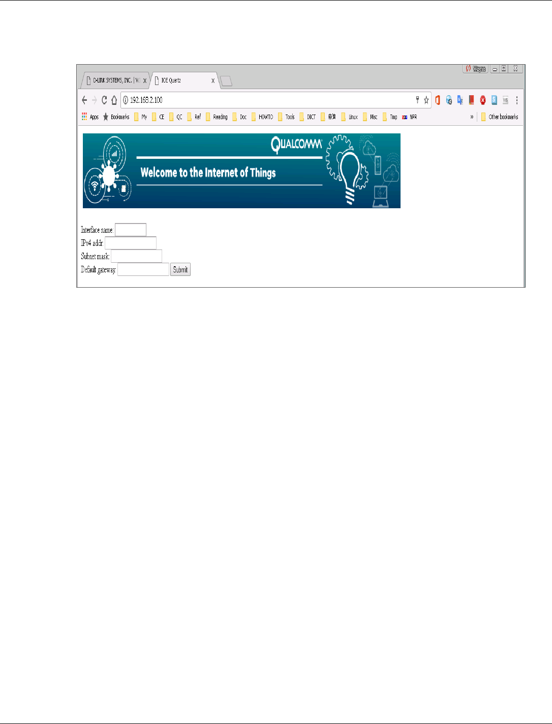
QCA402x (CDB2x) Programmer’s Guide QCA402x framework and programming model
80-YA121-142 Rev. D MAY CONTAIN U.S. AND INTERNATIONAL EXPORT CONTROLLED INFORMATION 66
Compile htmldata.c, cgi_demo.c and cgi_showuntf.c and link them into the image.
Use a browser to display the default Web page:
3.9.13 mDNS server
Multicast-DNS (mDNS) server on QCA402x can be used to perform DNS like operations on local
link in the absence of a conventional unicast DNS server. It uses the same existing DNS packet
structure, name syntax, and resource record types. mDNS server supports both IPv4 and IPv6 and
performs the following operations: registering a service, unregistering existing services, updating
the TXT record of a registered service, and responding to DNS queries sent via IP multicast.
Before configuring mDNS server, ensure that the interface has a valid IP address.
To configure mDNS server, application programmers can use the QAPI
qapi_Net_mDNS_Command with the following parameters:
■ command id: mDNS command to be executed. For example, to startmDNS, use the command
id QAPI_NET_MDNS_START_E.
■ input: Input data varies based on the command ID. For example, if the command ID is
QAPI_NET_MDNS_START_E, the input should be a pointer of qapi_Net_mDNS_Start_t type.
■ blocking: This is a flag to indicate if mDNS server must function in the blocking mode or
non-blocking mode. This flag is relevant only with QAPI_NET_MDNS_START_E and
QAPI_NET_MDNS_ADDSVC_E commands. Even if mDNS server is in blocking mode,
individual service registrations can be non-blocking.
■ app_CB: Application callback that must be registered when starting mDNS server and cannot
be modified.
Application programmers can also use individual QAPIs for each command like
qapi_Net_mDNS_Start, qapi_Net_mDNS_Stop.
To configure mDNS server on QCA402x:
1. Start mDNS.

QCA402x (CDB2x) Programmer’s Guide QCA402x framework and programming model
80-YA121-142 Rev. D MAY CONTAIN U.S. AND INTERNATIONAL EXPORT CONTROLLED INFORMATION 67
qapi_Status_t qapi_Net_mDNS_Start(qapi_Net_mDNS_Start_t *start,
qapi_Net_mDNS_CB_t app_CB, uint8_t blocking);
2. Set hostname.
qapi_Status_t qapi_Net_mDNS_Set_Hostname(const char * host_Name);
The hostname must preferably be of the form hostname.local. The QAPI returns
QAPI_NET_STATUS_MDNSD_HOSTNAME_CONFLICT in case of hostname conflict. For all other
errors, refer to QCA402x QAPI specification (80-Y9381-7).
3. Register a service.
qapi_Status_t qapi_Net_mDNS_Register_Service(qapi_Net_mDNS_Svc_Info_t
*svc_Info, uint8_t blocking);
The service must be of the form <instancename>.<servicetype>.
For example, instance1._appletv._tcp.local, here <instancename> is instance1 and
<servicetype> is _appletv._tcp.local. The protocol can also be UDP if it is an UDP-based
service. If blocking is set to 1, then the QAPI blocks until the operation is complete and
returns the result. If blocking is set to 0, then the result is returned to the application callback
asynchronously. A maximum of QAPI_NET_MDNS_MAX_TXT_RECORDS TXT records can be
specified while registering a service. Each TXT record must be of the form “key=value” and
a maximum length of 63 bytes.
■ To stop the mDNS server:
qapi_Status_t qapi_Net_mDNS_Stop(void);
This removes all the registered services from mDNS server, frees all the resources, and stops
the mDNS server.
■ To unregister a specific service:
qapi_Status_t qapi_Net_mDNS_Unregister_Service(const char *svc_Name);
■ To update or add a new text record:
qapi_Status_t qapi_Net_mDNS_Update_TXT(qapi_Net_mDNS_TXT_t *txt_Update);
The text record must be of the form “key=value” Example: Version=1.0. If the key is an
existing key, the value is updated to the new value. If the key is new, then a new text record is
created.
3.9.14 MQTT client
The Message Queuing Telemetry Transport (MQTT) client service provides a collection of APIs
that allow the application to implement client functionalities, such as CONNECT, SUBSCRIBE,
UNSUBSCRIBE, PUBLISH and DISCONNECT.
qapi_Net_MQTTc_Init() must be called before any other MQTTc QAPI.
To provide services, a client instance must be created via the call to qapi_Net_MQTTc_New().
The number of client instances that can be created is limited by the available memory. If the
client creation is successful, a handle is returned to the caller.
After a client instance is created, the application can call several QAPIs such as
qapi_Net_MQTTc_Set_Will(), qapi_Net_MQTTc_Set_Keep_Alive()to configure the client:
Keep Alive
Will

QCA402x (CDB2x) Programmer’s Guide QCA402x framework and programming model
80-YA121-142 Rev. D MAY CONTAIN U.S. AND INTERNATIONAL EXPORT CONTROLLED INFORMATION 68
Username and password
Wait time for CONNACK packet
Subscribe callback
Connect callback
If the client is to use SSL, qapi_Net_MQTTc_Set_SSL_Config() can be called to configure the
SSL connection.
After the configuration is done, the app can call qapi_Net_MQTTc_Connect() to start a session
with an MQTT broker. During the MQTT session, the app can subscribe some topics and/or
publish some messages via qapi_Net_MQTTc_Subscribe() and
qapi_Net_MQTTc_Publish().
The status of the client is communicated to the app by two callbacks which the app has to register
with the client. The app must call qapi_Net_MQTTc_Register_Connect_Callback() to
register a connect callback to get all QAPI_NET_STATUS_MQTTC_xxxx (defined in
qapi_net_status.h) status codes.
To get the subscription status (denied or granted) and the application messages published by other
MQTT clients, the app must call qapi_Net_MQTTc_Register_Subscribe_Callback() to
register a subscribe callback.
3.9.15 SNTP client
The Simple Network Time Protocol (SNTP) client service provides a collection of QAPI
functions that allow the application to enable automatic acquisition of time from the network
using SNTP.
After the acquisition of time is successful, the SNTP client updates the system time and the
application can use the Time Services API to get the calendar time.
The SNTP client uses UDP port 123 to send and receive data and supports both IPv4 and IPv6.
To use the service, to the SNTP service must be started by calling
qapi_Net_SNTPc_Command(QAPI_NET_SNTP_START_E). This call initializes the service and
allocates resources.
The service can be stopped using qapi_Net_SNTPc_Command(QAPI_NET_SNTP_STOP_E) or
disabled using qapi_Net_SNTPc_Command(QAPI_NET_SNTP_DISABLE_E).
The SNTP client service supports up to 2 servers, using qapi_Net_SNTPc_Add_Server or
qapi_Net_SNTPc_Del_Server, where a default server that can be used is “pool.ntp.org”.
The system time is maintained by the system during the runtime of the device, until a power cycle
or a reset occurs, which requires acquiring the time again. For SSL connections, it is required that
the system has the correct time to verify the expiration of server certificates.
3.9.16 WLAN bridging
WLAN bridging service provides a collection of QAPI functions that allow the application to set
up and manage a 802.1D Bridge over two Wi-Fi interfaces; one is a QCMobileAP, and the other
is a STA (or P2P equivalent).
The implementation ca transparent bridge uses forwarding database to send packets across the
network links. The forwarding database is built as the bridge receives packets. If the destination

QCA402x (CDB2x) Programmer’s Guide QCA402x framework and programming model
80-YA121-142 Rev. D MAY CONTAIN U.S. AND INTERNATIONAL EXPORT CONTROLLED INFORMATION 69
address packet is not found in the forwarding database, the packet is flooded to all ports of the
bridge, except the port that received the packet.
Although a bridge is a Layer 2 function, the implementation must look at IP headers due to the
physical limitation of WLAN networks and hops. The implementation uses the IP addresses to
correlate between MAC addresses and hosts, and replaces the MAC addresses accordingly in
order to be compliant with an upstream AP.
To enable the WLAN bridging functionality, the two WLAN interfaces have to be up and
running, with no IP address configured to them (no traffic).
Use the qapi_Net_Bridge_Enable QAPI to enable the bridge.
It is possible to get the current forwarding database using qapi_Net_Bridge_Show_MACs and set
the aging timeout of the entries using qapi_Net_Bridge_Set_Aging_Timeout.
3.9.17 Websocket client
The Websocket client is a collection of QAPIs to establish a connection with a Websocket server,
and to send and receive messages. The Websocket client uses the HTTP client so it required to
start the HTTP client using qapi_Net_HTTPc_Start before using the Websocket client. When
finished with the Websocket client (and HTTP client), call qapi_Net_HTTPc_Stop.
3.9.17.1 Establish a connection
1. Before establishing a secure connection (using SSL), create an SSL object that is attached to
the Websocket client context, using qapi_Net_SSL_Obj_New. If a secure connection is not
needed, this step can be skipped.
2. Create a client context using qapi_Net_Websocket_Client_New with the following
arguments:
□ Origin (optional): Client origin. NULL if origin is not specified.
□ Subprotocol list (optional): List of strings with supported subprotocols. NULL if
subprotocol is not specified.
□ SSL object: Required for secure HTTPS connections.
When SSL is used, call qapi_Net_Websocket_Configure_SSL to configure the SSL
connection parameters.
□ Receive chunk size: Maximum amount of received message bytes buffered (see Section
3.9.17.3 Receive a message for details).
□ Handshake timeout: Connect timeout
□ Closing timeout: Closing timeout, if peer does not gracefully close within this timeout
period, the Websocket is forcibly shutdown.
3. Register an event call back using qapi_Net_Websocket_Register_Event_Callback. The
callback receives Websocket events − connection established, message received, pong
received, or connection closed.
4. (Optional) Configure additional HTTP headers to include in the initial Websocket HTTP
handshake. The application can add any HTTP header that are not standard headers already
included by the HTTP or Websocket client. This can be done using
qapi_Net_Websocket_Client_Add_Handshake_HTTP_Header_Field.

QCA402x (CDB2x) Programmer’s Guide QCA402x framework and programming model
80-YA121-142 Rev. D MAY CONTAIN U.S. AND INTERNATIONAL EXPORT CONTROLLED INFORMATION 70
5. Call qapi_Net_Websocket_Client_Connect to establish the connection to the server. The
server hostname or IP address, server port, and the resource path are specified as arguments.
This is a non-blocking call. When the connection is established (this occurs when the server
responds with a valid handshake response), the registered event callback receives an event of
QAPI_NET_WEBSOCKET_EVENT_CONNECT_E type. If a list of supported subprotocols has been
configured, the event info (qapi_Net_Websocket_Event_Info_t) provided to the callback
contains the negotiated subprotocol.
If the server responds with an invalid response or the connection times out, the event callback
receives an event of QAPI_NET_WEBSOCKET_EVENT_CLOSE_E type.
3.9.17.2 Send a message
To send a message, call qapi_Net_Websocket_Send. The data type (TEXT or BINARY), data,
data length, and end of message flag are passed as arguments. When the message is sent in a
single call, the end of message flag is set to TRUE. However, for large messages when there is
not enough memory to send the entire message at once, the message can be sent in fragments.
This can be done by doing multiple calls to qapi_Net_Websocket_Send. Each call sends a
fragment of the message. The final call must have the end of message flag set to TRUE. Prior
calls must have the flag set to FALSE.
For example, two calls can be used to send a single message as two fragments − “hello” and
“world”, but the receiving application sees only the final message “helloworld”.
qapi_Net_Websocket_Send(websocket_hdl,
QAPI_NET_WEBSOCKET_DATA_TYPE_TEXT_E,
“hello”, // data
5, // data length
FALSE); // end of message flag
qapi_Net_Websocket_Send(websocket_hdl,
QAPI_NET_WEBSOCKET_DATA_TYPE_TEXT_E,
“world”, // data
5, // data length
TRUE); // end of message flag
The call to send returns the number of bytes sent. When there is a scarcity of network resources, it
is possible that only a part of the message is sent. In this case, the bytes returned maybe less than
the requested bytes to send. If this occurs, the application must call send again (after a delay) on
the remaining bytes of the message. For example, if send is called for the message “helloworld”
and returns 3, it indicates that only the first three bytes “hel” were sent. The application must call
send on “loworld”, and send the rest of the message. If send fails to send the entire message at
once, the application should not send another message until sending the current message is
complete.
3.9.17.3 Receive a message
The messages are received through the registered event callback. When a message is received, the
callback gets an event of type QAPI_NET_WEBSOCKET_EVENT_MESSAGE_E, and associated event
info of type qapi_Net_Websocket_Event_Info_t with the data type (TEXT or BINARY),
data, and length of the message. Finally, there is an end of message flag that is set to either TRUE
or FALSE. The purpose of this flag is explained here.

QCA402x (CDB2x) Programmer’s Guide QCA402x framework and programming model
80-YA121-142 Rev. D MAY CONTAIN U.S. AND INTERNATIONAL EXPORT CONTROLLED INFORMATION 71
Since there may not be enough memory to receive the entire message at once, it is left up to the
application to configure the maximum number of bytes to buffer. This is controlled by the receive
chunk size parameter while creating the client context (this is not related to a “chunk” in HTTP).
When this maximum is reached but there are more bytes in the message to be received, the
application is called with the data buffered so far with the end of message flag set to FALSE. If
there are no more bytes to be received in the message, the end of message flag is TRUE. For
example, if the receive chunk size is 1024 and the server sends a 2560-byte binary message, the
event callback is called three times:
1. (data_Type = BINARY, data_Length = 1024, data = [Bytes 1…1024], end_Of_Message =
FALSE)
2. (data_Type = BINARY, data_Length = 1024, data = [Bytes 1025…2048], end_Of_Message
= FALSE)
3. (data_Type = BINARY, data_Length = 512, data = [Bytes 2048…2560], end_Of_Message =
TRUE)
The data type for TEXT data must be UTF-8; this not enforced by the Websocket implementation
and must be validated by the application if necessary.
3.9.17.4 Ping and Pong
Either endpoint can ping (at the Websocket layer) the other endpoint and receive a pong in
response. A pong can also be sent as an unsolicited heartbeat if the application chooses to use it
in that way. To send a ping, call qapi_Net_Websocket_Ping. In response, the registered event
callback gets an event of type QAPI_NET_WEBSOCKET_EVENT_PONG_E. To send an unsolicited
heartbeat, call qapi_Net_Websocket_Pong.
3.9.17.5 Connection close
A graceful close of Websocket requires the closing side to send a close frame and wait for the
peer to respond with a close frame at which point the connection can be closed. If the server
closes the connection, the registered event callback will get an
QAPI_NET_WEBSOCKET_EVENT_CLOSE_E event.
To initiate a close from the client, call qapi_Net_Websocket_Close. Once the server replies
with a close frame, the event callback gets a QAPI_NET_WEBSOCKET_EVENT_CLOSE_E event.
If the server does not respond with a close frame within the configured close timeout, the
connection is forcibly shutdown. The event callback still gets a close event in this case.
For both the client or server initiated close, event info for a close event contains a close status
code. This is set by the server to indicate why the connection was closed.
After closing a connection, the Websocket client context can be used again for a new connection.
If the client context is no longer needed, it can be freed using
qapi_Net_Websocket_Client_Free.
3.9.17.6 Debugging
The qapi_Net_Websocket_Get_Opt can be used to get information about the connection that is
useful for debugging purposes. The information returned is based on the option type passed to the
function. These include:

QCA402x (CDB2x) Programmer’s Guide QCA402x framework and programming model
80-YA121-142 Rev. D MAY CONTAIN U.S. AND INTERNATIONAL EXPORT CONTROLLED INFORMATION 72
■ STATE: Current state of the connection (example: OPEN, CLOSED)
■ ERRNO: Last connection error while sending or receiving a message or handshake error.
■ SOCKET ERRNO: If errno is QAPI_NET_WEBSOCKET_STATUS_SOCKET_ERROR, this gets the
underlying socket’s errno.
■ SSL ERRNO: if errno is QAPI_NET_WEBSOCKET_STATUS_SSL_ERROR, this gets the last SSL
error.
■ Rx BYTES: Total number of bytes received after the connection is established
■ Tx BYTES: Total number of bytes sent after the connection is established
■ Rx PINGS: Total number of pings received
■ Tx PINGS: Total number of pings sent
■ Rx PONGS: Total number of pongs received
■ Tx PONGS: Total number of pongs sent
3.9.18 CoAP client
The constrained application protocol (CoAP) client service provides a collection of API functions
that allows the application to establish connections to the CoAP server and perform various CoAP
methods. The CoAP client supports IPv4, IPv6, TCP, UDP, CoAP mode, and CoAPS mode
(secure).
To use the CoAP client, run qapi_Net_Coap_Client_Start so that the resources are allocated.
When the CoAP client services are not required, call qapi_Net_Coap_Client_Stop to release
all the resources.
3.9.18.1 Establish a connection
1. Before establishing a secure connection using SSL, create an SSL object that is attached to
the CoAP client session, using qapi_Net_SSL_Obj_New. This step is optional if a secure
connection is not required.
2. Create a session object using qapi_Net_Coap_Client_New_Context, which accepts the
following arguments:
□ Protocol: Indicate to connect server by using UDP or TCP.
□ SSL object: Created by qapi_Net_SSL_Obj_New and is required for secure HTTPS
connections.
□ A callback: An optional user provided callback that is called to return the server’s
response.
□ An argument for the callback.
NOTE: For secure connections, the application configures SSL options before establishing the
connection. The SSL configuration is passed using the qapi_Net_SSL_Config_t structure,
followed by a call to qapi_Net_Coap_Client_SSL_Config to apply them to the current session.

QCA402x (CDB2x) Programmer’s Guide QCA402x framework and programming model
80-YA121-142 Rev. D MAY CONTAIN U.S. AND INTERNATIONAL EXPORT CONTROLLED INFORMATION 73
3. Call qapi_Net_Coap_Client_Connect and specify the session object, the server address,
and the destination port number.
3.9.18.2 Terminate a connection
Use qapi_Net_Coap_Client_Free_Context call to terminate a connection.
Use qapi_Net_Coap_Client_Stop to terminate all clients and release all resources allocated
for this connection.
Use qapi_Net_Coap_Client_Start to start the CoAP client again.
3.9.18.3 Send a CoAP message
Use the qapi_Net_Coap_Client_Send_Msg QAPI to send a request to CoAP server with these
parameters:
□ coap context: Created when establishing a connection.
□ Uri: URI in CoAP server
□ Payload: Payload in the request
□ Payload_length: Payload length
□ Method: GET/PUT/POST/DELTE
□ Message type: Confirmable or non-confirmable
3.9.18.4 Set configuration parameter
Use the qapi_Net_Coap_Client_Add_Parameter QAPI to configure these parameters:
■ qapi_Net_Coap_Para_Flag: Indicates the type of the add parameter as follows:
□ QAPI_COAP_PARAMETER_FLAG_OPTION
□ QAPI_COAP_PARAMETER_FLAG_TOKEN
□ QAPI_COAP_PARAMETER_FLAG_BLOCK
□ QAPI_COAP_PARAMETER_FLAG_TIMEOUT
■ Type: Used when flag is QAPI_COAP_PARAMETER_FLAG_OPTION and
QAPI_COAP_PARAMETER_FLAG_TIMEOUT.
□ When the flag is QAPI_COAP_PARAMETER_FLAG_OPTION, this type indicates if
the option is URI path or URI query.
□ When the flag is QAPI_COAP_PARAMETER_FLAG_TIMEOUT, this type indicates
the type of timeout. It can be COAP_PARAMETER_TYPE_TIMEOUT_SEND and
COAP_PARAMETER_TYPE_TIMEOUT_OBSVER.
■ Data: Value of the add parameter.
■ Length: Length of the data.

QCA402x (CDB2x) Programmer’s Guide QCA402x framework and programming model
80-YA121-142 Rev. D MAY CONTAIN U.S. AND INTERNATIONAL EXPORT CONTROLLED INFORMATION 74
3.9.19 CoAP server
The CoAP server provides a collection of API functions that allow the application to enable and
configure the CoAP server. This can be configured to support:
■ IPv4, IPv6, or both
■ UDP, TCP or both
■ TLS, DTLS, or both
Call qapi_Net_Coap_Server_New_Context to create a new server context. The parameters
are:
■ qapi_Net_Coap_Server_Cfg_t: To enter interface name, port name, multicast
enable/disable, certificate filename, IPv4/IPv6, and UDP/TCP.
■ SSL object: Created by qapi_Net_SSL_Obj_New and is required for secure HTTPS
connections.
Call qapi_Net_Coap_Server_Start to start the server, and qapi_Net_Coap_Server_Stop to
stop the server.
For secure connections, the application configures SSL options before establishing the
connection. The SSL configuration is passed using the qapi_Net_SSL_Config_t structure,
followed by a call to qapi_Net_Coap_Server_SSL_Config to apply them to the current session.
3.9.19.1 Server resource setup
1. Call qapi_Net_Coap_Server_Resource_Init to initial the resource. The parameters of
this function are the URI, and the length of URI.
The flag indicates if this resource must be observed. If the resource must be observed, set
QAPI_COAP_RESOURCE_FLAGS_NOTIFY_CON; else, set the flag to 0. The return value
of this function is a pointer of qapi_Net_Coap_Resource_t.
2. Call qapi_Net_Coap_Server_Resource_Register_Handler to register the handler of this
resource. The parameters are:
□ resource: Return value of qapi_Net_Coap_Server_Resource_Init
□ method: GET/POST/PUT/DELETE
□ handler: Handler register for this resource.
The qapi_Net_Coap_Method_Handler_t must be defined as follows. The
implementation must refer to the resource handler in the coap_demo.c.
typedef void (*qapi_Net_Coap_Method_Handler_t)
(qapi_Net_Coap_Context_t*,
qapi_Net_Coap_Resource_t*,
qapi_Net_Coap_Address_t *,
qapi_Net_Coap_Pdu_t *,
qapi_Net_Coap_Str_t * /* token */,
qapi_Net_Coap_Pdu_t * /* response */);
3. Call qapi_Net_Coap_Server_Add_Attr to add an attribute to a resource. The parameters
are:
□ resource: Return value of qapi_Net_Coap_Server_Resource_Init

QCA402x (CDB2x) Programmer’s Guide QCA402x framework and programming model
80-YA121-142 Rev. D MAY CONTAIN U.S. AND INTERNATIONAL EXPORT CONTROLLED INFORMATION 75
□ name: Attribute name
□ name length
□ attribute value
□ attribute value length
4. Call qapi_Net_Coap_Server_Add_Resource to add a resource to the server context. The
parameters are:
□ context: Return value of qapi_Net_Coap_Server_New_Context
□ resource: Return value of qapi_Net_Coap_Server_Resource_Init
The following APIs are used in the resource handler:
■ qapi_Net_Coap_Server_Add_Option: Add option in PDU.
■ qapi_Net_Coap_Server_Add_Data: Add data in PDU.
■ qapi_Net_Coap_Server_Find_Observer: Find an observer based on peer address and
token ID.
■ qapi_Net_Coap_Server_Check_Option: Check if it has a certain option.
■ qapi_Net_Coap_Server_Get_Data: Get PDU data.
■ qapi_Net_Coap_Server_Add_Block: Add block information in PDU.
■ qapi_Net_Coap_Server_Register_Async: Register the async resource.
The following APIs set the status of resource:
■ qapi_Net_Coap_Server_Resource_Set_Observable: Set the observable resource.
■ qapi_Net_Coap_Server_Resource_Set_Dirty: Set the resource to dirty.
3.10 Thread
The integrated Thread library operates as a network interface for the integrated network stack.
Features include:
■ Support for all device roles (SED, FED, Router, Leader, Border Router, Commissioner, and
so on).
■ Support for on-mesh and off-mesh commissioning.
■ Integrated into QCA402x network stack.
3.10.1 Network address management
The Thread APIs must be used, instead of the network services APIs during the addition or
removal of unicast or multicast addresses to the Thread network interface.
3.10.2 Low-power mode
QCA402x can enter SOM (section 3.3) when the thread stack is initialized. For the system to
enter SOM, the thread must either be operating as a sleepy end-device or idle (not operating on a
network).

QCA402x (CDB2x) Programmer’s Guide QCA402x framework and programming model
80-YA121-142 Rev. D MAY CONTAIN U.S. AND INTERNATIONAL EXPORT CONTROLLED INFORMATION 76
MOM mode must not be used when the Thread stack is operating on a network.
3.11 ZigBee
The ZigBee library provides the functionality required to support ZigBee PRO and ZigBee 3.0
features. The features include:
■ ZigBee PRO R21
■ Green Power Proxy
■ Base Device Behavior and ZigBee 3.0
■ Support for end device, router, and coordinator device roles
■ ZigBee Cluster Library R6:
□ Alarm
□ Basic
□ Color Control
□ Device Temperature
Configuration
□ Groups
□ Identify
□ Level Control
□ On/Off
□ OTA
□ Power Configuration
□ Scenes
□ Time
□ Qualcomm®
Touchlink™
3.11.1 ZigBee DevCfg
The following ZigBee configurations can be modified using DevCfg:
Name
ID
Description
Flags
0x00001000
Configuration flags for ZigBee.
Bit 0: Enable Green Power Proxy
If this flag is set, the GPP is initialized with the ZigBee stack.
This is required for Certifcation of router and coordinator
devices. However, these must be disabled for end devices.
Poll Period
0x00001001
Period in milliseconds the parent is polled when configured
as a sleepy device.
Basic Application Version
0x00001101
Value of the Basic cluster's ApplicationVersion attribute.
Basic Stack Version
0x00001102
Value of the Basic cluster's StackVersion attribute.
Basic Hardware Version
0x00001103
Value of the Basic cluster's HWVersion attribute.
Basic Manufacturer Name
0x00001104
Value of the Basic cluster's ManufacturerName attribute.
Basic Model Identifier
0x00001105
Value of the Basic cluster's ModelIdentifier attribute.
Basic Date Code
0x00001106
Value of the Basic cluster's DateCode attribute.
Basic SW Build ID
0x00001107
Value of the Basic cluster's SWBuildID attribute.
NWK Address Map Table Size
0x00001200
Size of the NWK address map table.
NWK BTT Table Size
0x00001201
Size of the NWK Broadcast Transaction Table.

QCA402x (CDB2x) Programmer’s Guide QCA402x framework and programming model
80-YA121-142 Rev. D MAY CONTAIN U.S. AND INTERNATIONAL EXPORT CONTROLLED INFORMATION 77
Name
ID
Description
NWK Max Packets
0x00001202
Maximum number of outstanding NWK packets allowed.
NWK Neighbor Table Size
0x00001203
Size of the NWK neighbor table.
NWK Route Table Size
0x00001204
Size of the NWK route table.
NWK RREC Table Bits
0x00001205
Number of bits in the Route Record hash table (the actual
size of the table is 2n).
NWK RREC Table Overflow
0x00001206
Number of overflow entries for the Route Record hash table.
NWK RREQ Table Size
0x00001207
Size of the NWK Route Request table.
NWK LQI Cost Map
0x00001208
A 6-byte array that maps LQI to route cost. The array
entries[0–5] represent the minimum LQI values that
correspond to the route cost [1–6]. The minimum LQI for a
route cost of 7 is always 0.
APS Binding Table Size
0x00001300
Size of the APS binding table.
APS Device Key Pair Count
0x00001301
Number of device key pairs that can be retained.
APS Group Table Size
0x00001302
Size of the APS group table.
APS Max Packet Size
0x00001303
Maximum APS packet size.
3.11.2 Green power proxy
The ZigBee stack has integrated support for the Green Power Proxy as required by the R21
specification. If it is enabled using DevCfg, the proxy is automatically initialized with the ZigBee
stack and the typical application does not need to interact with Green Power any more.
3.11.3 Low-power modes
QCA402x can enter SOM (Section 3.3) when the ZigBee stack is initialized. For the system to
enter sensor operating mode (SOM), ZigBee must be operating as a sleepy end device or idle (not
operating on a network). Additionaly, SOM mode is not supported if the Green Power Proxy is
enabled via DevCfg.
Before entering SOM, a SOM transition region must be created. The size required for this region
is largely dependent on the ZigBee stack configuration and the clusters that are initialized. It is
recommended that the ZigBee configuration options are reduced to the minimum acceptable
levels if the application intends to use SOM.
NOTE: Minimum operating mode (MOM) is not supported when the ZigBee stack is initialized.
3.11.4 Legacy support
While operating as a trust center, the BDB v1.0 specification (section 10.3.2) requires a joining
device undergo the link key exchange procedure for ZB 3.0 if the
bdbTrustCenterRequireKeyExchange BIB is set to true (its default value). If a device that does
not support the link key exchange procedure attempts to join the network, it is directed to leave
before the join process completes which can cause compatibility issues with devices that do not
implement BDB. To allow legacy devices to join the network, the
bdbTrustCenterRequireKeyExchange BIB needs to be set to false after the stack has been
initialized.

QCA402x (CDB2x) Programmer’s Guide QCA402x framework and programming model
80-YA121-142 Rev. D MAY CONTAIN U.S. AND INTERNATIONAL EXPORT CONTROLLED INFORMATION 78
3.12 Cryptographic operations
The crypto library provides a collection of API functions that allow the application to perform
various cryptographic operations such as:
■ Digests (SHA1, SHA256, SHA384, SHA512, MD5)
■ Ciphers (AES-CBC, AES-CTR, RSA V1.5, RSA no padding)
■ Key exchange (DH, ECDH, SRP, CURVE25519)
■ Signature (ECDSA, RSA, ED25519)
■ Authenticated encryption (AES-CCM, AES-GCM, ChaCha20Poly1305)
■ Message authentication (HMAC)
The supported algorithms are mentioned inside the parentheses. The crypto QAPIs are designed to
be compatible with those defined by Global Platform, a cross-industry, non-profit association that
publishes specifications for the deployment of secure applications.
"Objects" are the keys used in the crypto operations and "operations" are the cryptographic
functions performed on the keys (sign, key generation and so on).
3.12.1 Secure storage
The secure storage module provides a service that encrypts and authenticates files in the flash file
system. It provides QAPIs to carry out basic operations on encrypted files. The QAPIs supported
by this module allow clients to carry out the following operations:
■ Open an existing secure storage file or create a new file using qapi_Securefs_open
■ Read and write to a secure storage file within file system using qapi_Securefs_write and
qapi_Securefs_read accordingly.
■ Seek to a specific plain text offset using qapi_Securefs_Lseek
■ Get the current plain text offset of a file using qapi_Securefs_Tell
■ Close a secure storage file using qapi_Securefs_close
The open command allows the caller to specify standard access flags and a unique password that
is used to encrypt and decrypt the file. If no password is provided, a default password is used.
Thus, no secure file is stored in plain-text. When using the QAPI_FS_O_SYNC flag, all write
operations to the file are synchronized. The entire file is encrypted and signed for each write
operation.
The Secure storage QAPIs can take time in the order of seconds to complete the operation,
depending on the access speeds of the underlying flash media. The calling tasks/clients must be
prepared to be blocked for this duration. It is mandatory to avoid calling secure storage QAPIs in
time critical sections of the code.
3.12.2 Transient object operations
Transient objects are cryptographic keys that exist in memory while the device is powered on.
QAPIs exist for creating and deleting objects. Transient and persistent objects are sent as input to
the crypto operations APIs.
Each object has an object type. The object type begins with the prefix QAPI_CRYPTO_OBJ_TYPE_”.

QCA402x (CDB2x) Programmer’s Guide QCA402x framework and programming model
80-YA121-142 Rev. D MAY CONTAIN U.S. AND INTERNATIONAL EXPORT CONTROLLED INFORMATION 79
For example, QAPI_CRYPTO_OBJ_TYPE_RSA_KEYPAIR_E represents an RSA key pair.
Objects contain attributes. The attributes begin with the prefix “QAPI_CRYPTO_ATTR_”.
For example, an RSA key pair object contains the attribute QAPI_CRYPTO_ATTR_RSA_MODULUS_E
which represents the RSA modulus value.
There are four ways to create a transient object:
■ Through importing a transient object from a PEM file.
■ Through populating the attributes of the object.
■ Through key generation.
■ Through key derivation.
3.12.2.1 Create an object from a PEM file
PEM is a standard file format for RSA and ECC key pairs or public keys. Create a transient
object from a PEM file using qapi_Crypto Transient_Obj_Import_From_Pem.
3.12.2.2 Create an object by populating its attributes
Allocate a new transient object using qapi_Crypto_Transient_Obj_Alloc.This requires
specifying the key size of the object in bits.
■ For HMAC, the key size is variable. The lower and upper bounds are defined in macros with
the suffix “_MIN_KEY_BITS” and “_MAX_KEY_BITS”.
■ For AES, the key can be 128 or 256 bits. It is defined in the macros
QAPI_CRYPTO_AES128_KEY_BITS and QAPI_CRYPTO_AES256_KEY_BITS.
■ For RSA, the key size is the modulus size. The maximum modulus size supported is 4096.
■ For ECC based algorithm, the key size depends on the curve that is used. For example,
ECDSA. For ECC curves, the types are defined by macros of the form
QAPI_CRYPTO_ECC_CURVE_NIST_P<CURVE> where <CURVE> is the ECC curve.
The supported ECC curves are secp192/224/256/384.
■ For key pairs, the sizes are defined by macros of the form
QAPI_CRYPTO_ECC_<CURVE>_KEYPAIR_BITS where <CURVE> is the ECC curve.
For public keys, the sizes are defined by macros of the form
QAPI_CRYPTO_ECC_<CURVE>_PUBLIC_KEY_BITS.
Constants are also defined for ED25519, CURVE25519, and CHACHA20_POLY1305.
1. Create an array of qapi_Crypto_Attrib_t structures that contain the attributes for the
object. Each qapi_Crypto_Attrib_t structure has an attribute id and value. The value can be
a buffer or a numeric value. The attribute IDs are defined by macros prefixed by
“QAPI_CRYPTO_ATTR_”.
2. Populate the object with the attributes using qapi_Crypto_Transient_Obj_Populate.
3.12.2.3 Create an object using key generation
1. Allocate a new transient object using qapi_Crypto_Transient_Obj_Alloc.

QCA402x (CDB2x) Programmer’s Guide QCA402x framework and programming model
80-YA121-142 Rev. D MAY CONTAIN U.S. AND INTERNATIONAL EXPORT CONTROLLED INFORMATION 80
2. Create an array of qapi_Crypto_Attrib_t structures that contain the attributes for the
object.
3. Generate the keys for the object using qapi_Crypto_Transient_Obj_Key_Gen.
3.12.2.4 Creating an object using key derivation
A key derivation operation can be used to create an object of type
QAPI_CRYPTO_OBJ_TYPE_GENERIC_SECRET_E, which represents a generic secret. For more
information on key derivation, see Section 3.12.5.6.
3.12.3 Delete transient objects
Use qapi_Crypto_Transient_Obj_Free to free the transient object and free any resources that it
uses.
3.12.4 Persistent object operations
Persistent objects such as transient objects are cryptographic keys. The transient objects are
securely stored on flash (with encryption and integrity protection). When the object is created, it
is associated with an object id. A handle to the persistent object can be reopened at any time using
the object id. From an application developer’s perspective, after the handle to persistent object is
opened, they can be used in the same way as transient objects are inputs to the cryptographic
operations QAPIs. One caveat is that persistent objects do not support some of the algorithms that
were extensions to the original global platform specification. Supported algorithms are ECDSA,
RSA, AES, and the HMAC and hash algorithms.
A persistent object can be created from an existing transient object or an existing persistent object
using qapi_Crypto_Persistent_Obj_Create.
■ storage_Id must be
QAPI_CRYPTO_PERSISTENT_OBJ_DATA_TEE_STORAGE_PRIVATE
■ object_Id is a binary identifier for the object of
QAPI_CRYPTO_PERSISTENT_OBJECT_ID_MAX_LEN (64) bytes
■ flags can either be 0 or QAPI_CRYPTO_DATA_EXCLUSIVE. If it is the latter, and an object with
object_Id already exists, an error is returned. If the flag is not set, the existing object is over
written.
■ Attributes: Attribute is either a handle to a transient object or a persistent object. The
attributes for the new object is populated from this object.
■ initial_Data and initial_Data_Len are reserved for future use and must be set to NULL
and zero respectively.
A handle to a persistent object that has already been created can be opened using
qapi_Status_t qapi_Crypto_Persistent_Obj_Open.The flags can either be 0 or
QAPI_CRYPTO_DATA_ACCESS_WRITE_META. The latter is needed if the handle is used to delete or
rename an object.
Other supported operations are:
■ Close a handle to a persistent object using qapi_Crypto_Persistent_Obj_Close

QCA402x (CDB2x) Programmer’s Guide QCA402x framework and programming model
80-YA121-142 Rev. D MAY CONTAIN U.S. AND INTERNATIONAL EXPORT CONTROLLED INFORMATION 81
■ Close a handle to a persistent object and delete it from flash using
qapi_Crypto_Persistent_Obj_Close_and_Delete
■ Rename an object to another object id using qapi_Crypto_Persistent_Obj_Rename
■ Read the public attributes of RSA or ECDSA keys using qapi_Crypto_Obj_Buf_Attrib_Get
or qapi_Crypto_Obj_Val_Attrib_Get.
The persistent objects that exist on the device can be enumerated.
■ Allocate an enumerator using qapi_Crypto_Persistent_Obj_Enumerator_Alloc and start
enumeration using qapi_Crypto_Persistent_Obj_Enumerator_Start.
■ Get the next object information using qapi_Crypto_Persistent_Obj_Enumerator_Get_Next.
Repeat until QAPI_ERR_NO_ENTRY is returned at which point, there are no more objects
to enumerate.
■ Free the enumerator using qapi_Crypto_Persistent_Obj_Enumerator_Free.
NOTE: The changes on the file system such as a persistent object being deleted, while an enumerator is
open, it causes undefined behavior.
3.12.4.1 Importing persistent objects from certificate store
The certificate manager APIs (section 3.9.4.8 SSL certificate manager) provide a way to store
certificates with their associated public and private keys. Typically, the certificates and keys are
used for SSL. To use the crypto QAPIs with keys stored in the certificate store, the application
must import the key pair associated with a certificate into a persistent object using the
qapi_Crypto_Persistent_Obj_Import_From_Cert_Store QAPI. The QAPI takes the name
of the certificate and the ID of the persistent object which contains the copy of key pair associated
with the certificate.
3.12.5 Crypto operations
3.12.5.1 Basic operations
■ Allocate a crypto operation using qapi_Crypto_Op_Alloc.
■ Set the key used by the crypto operation using qapi_Crypto_Op_Key_Set. The key may be a
transient object or a persistent object.
■ After using the object, free it using qapi_Crypto_Op_Free.
3.12.5.2 Digest operations
■ Allocate the digest operation.
■ Update the digest using qapi_Crypto_Op_Mac_Update (Optional).
■ Compute the final digest using qapi_Crypto_Op_Digest_Final_Compute. The size of the
digest is defined by macros of the form QAPI_CRYPTO_<ALG>_DIGEST_BYTES where
ALG is the digest algorithm.
3.12.5.3 Cipher operations
■ Allocate the digest operation and set the key.

QCA402x (CDB2x) Programmer’s Guide QCA402x framework and programming model
80-YA121-142 Rev. D MAY CONTAIN U.S. AND INTERNATIONAL EXPORT CONTROLLED INFORMATION 82
■ Call qapi_Crypto_Op_Cipher_Init to initialize the cipher operation.
■ Update the ciphertext using qapi_Crypto_Op_Cipher_Update. (Optional – AES CBC
NOPAD only).
■ Compute the cipher text using qapi_Crypto_Op_Cipher_Final.
The ciphers supported are AES CTR mode and AES CBC NO PAD. To get the length of the
cipher text buffer that needs to allocated use the macro
QAPI_CRYPTO_AES_ENCRYPT_CIPHER_TEXT_BUFFER_SIZE_BYTES.
NOTE: Because “AES_CBC_NOPAD” does not add padding, the plain text must be a multiple of
the AES block size QAPI_CRYPTO_AES_BLOCK_BYTES (16 bytes).
3.12.5.4 Random number generation
Call qapi_Crypto_Random_Get to generate a pseudorandom number.
3.12.5.5 Authentication encryption operations
Authenticated Encryption with Associated Data (AEAD), in addition to encrypting the data,
outputs a tag that be used for authentication. Additional Authenticated Data (AAD) that is only
authenticated and not encrypted can optionally be provided.
The steps for encrypt and decrypt are similar except for the final step.
■ Allocate the AEAD operation and set the key.
■ Initialize the operation using qapi_Crypto_Op_AE_Init. This operation takes a nonce, which
must be unique per operation. The nonce must be 12 bytes for AES GCM and ChaCha20.
For AES CCM it must be >= 7 and <= 13 bytes. The tag must be 128 bits long for GCM and
ChaCha20 and can be either 128, 64, or 32 bits for CCM.
■ Call qapi_Crypto_Op_AE_AAD_Update to AAD. Subsequent calls to update after the first call
is only supported for ChaCha20.
To encrypt:
■ To encrypt the plain text call qapi_Crypto_Op_AE_Encrypt_Final. To get the size of the
buffer to allocate for encryption use the macro
QAPI_CRYPTO_AES_ENCRYPT_CIPHER_TEXT_BUFFER_SIZE_BYTES for AES GCM and CCM
and the macro
QAPI_CRYPTO_CHACHA20_POLY1305_ENCRYPT_CIPHER_TEXT_BUFFER_SIZE_BYTES for
ChaCha20.
To decrypt:
■ To decrypt the cipher text call qapi_Crypto_Op_AE_Decrypt_Final. Use the macro
QAPI_CRYPTO_AES_DECRYPT_PLAIN_TEXT_BUFFER_SIZE_BYTES to get the size of the plain
text buffer that needs to be allocated. The actual size of the plain text is set in the destLen
parameter by the decrypt operation. For ChaCha20, use the macro,
QAPI_CRYPTO_CHACHA20_POLY1305_DECRYPT_PLAIN_TEXT_BUFFER_SIZE_
BYTES.

QCA402x (CDB2x) Programmer’s Guide QCA402x framework and programming model
80-YA121-142 Rev. D MAY CONTAIN U.S. AND INTERNATIONAL EXPORT CONTROLLED INFORMATION 83
3.12.5.6 Key derivation
The key derivation algorithm allows the device to establish a shared secret with another party.
Both parties have public and private parameters. Each side combines the parameters with the
public parameters of the other party to derive a shared secret. What these parameters are and how
they are combined to derive the shared secret depends on the algorithm. The mechanism by which
the public parameters are shared between the two parties is left up to the application. For
example, the parameters might be shared over a secure TLS connection. Diffie-Helman, Elliptic
Curve Diffie-Helman, and Curve25519 are examples of key derivation algorithms.
Two password authentication key exchange (PAKE) algorithms are also supported − SRP and
ECJPAKE. These two require both the parties to share a common password before running the
key derivation algorithm. The key is derived using the password. The ECJPAKE algorithm is
discussed in section 3.12.5.6.1.
Before running the key derivation operation, the public and private key pair must be stored as
either a transient or persistent object (persistent object is not supported for all algorithms). The
public key values of the other party are also required. The type of object required for each
algorithm is listed in the table below.
Key pair object
Algorithm
Key pair object
Supported type
Diffie-Helmann (DH)
QAPI_CRYPTO_OBJ_TYPE_DH_KEYPAIR_E
Transient
Elliptic Curve Diffie-Helmann
(ECDH)
QAPI_CRYPTO_OBJ_TYPE_ECDH_KEYPAIR_E
Transient or
Persistent
Curve 25519
QAPI_CRYPTO_OBJ_TYPE_CURVE25519_KEY
PAIR_E
Transient
To run the key derivation operation:
1. Allocate the key derivation operation using qapi_Crypto_Op_Alloc. The algorithm IDs are
listed here.
Algorithm
Algorithm ID
Diffie-Helmann (DH)
QAPI_CRYPTO_ALG_DH_DERIVE_SHARED_SECRET_E
Elliptic Curve Diffie-Helmann
(ECDH)
QAPI_CRYPTO_ALG_ECDH_<CurveId>_E (The CurveId
should match the curve of the ECDH keypair
object)
Curve 25519
QAPI_CRYPTO_ALG_CURVE25519_DERIVE_SHARED_SECR
ET_E
2. Call qapi_Crypto_Op_Key_Set with the first argument as the operation allocated in the first
step, and second argument as the persistent or transient object representing the device’s DH
or ECDH keypair.
3. Derive the shared secret using the command qapi_Crypto_Op_Key_Derive. The attrs
parameters is an array of attributes containing public key of the peer. The specific attributes
depend on the algorithms listed here.
Algorithm
Attributes
Diffie-Helmann (DH)
One attribute of type, QAPI_CRYPTO_ATTR_DH_PUBLIC_VALUE

QCA402x (CDB2x) Programmer’s Guide QCA402x framework and programming model
80-YA121-142 Rev. D MAY CONTAIN U.S. AND INTERNATIONAL EXPORT CONTROLLED INFORMATION 84
Algorithm
Attributes
Elliptic Curve Diffie-Helmann
(ECDH)
Two attributes of type:
QAPI_CRYPTO_ATTR_ECC_PUBLIC_VALUE_X and
QAPI_CRYPTO_ATTR_ECC_PUBLIC_VALUE_Y
Curve 25519
One attribute of type,
QAPI_CRYPTO_ATTR_CURVE25519_PUBLIC_VALUE_E
3.12.5.6.1 ECJPAKE algorithm
The ECJPAKE algorithm has a complex call flow when compared to the other key derivation
algorithms. The two parties go through multiple rounds to establish the shared secret.
1. Allocate an ECJPAKE operation qapi_Crypto_Op_Alloc with the algorithm ID
QAPI_CRYPTO_ALG_ECJPAKE_E.
2. Call qapi_Crypto_Op_Key_Set on the operation with the key being a transient object of type
QAPI_CRYPTO_OBJ_TYPE_GENERIC_SECRET_E containing the shared password. The maximum
password length is defined by QAPI_CRYPTO_ECJPAKE_PASSWORD_MAX_BYTES.
3. Allocate a transient object of type
QAPI_CRYPTO_OBJ_TYPE_ECJPAKE_ROUND1_PUBLIC_KEY_AND_ZKP_PAIR_E, to hold the
derived round one parameters.
4. Derive the round one parameters by calling qapi_Crypto_Op_Intermediate_Key_Derive
with the previously allocated ECJPAKE operation, and the round one parameters object. The
identity (QAPI_CRYPTO_ATTR_ECJPAKE_LOCAL_IDENTITY_E) and ECC curve
(QAPI_CRYPTO_ATTR_ECC_CURVE_E) are inputs. The round one parameters object is populated
with the round one parameters.
5. Call qapi_Crypto_Obj_Buf_Attrib_Get on the round one parameters object for the public
round one parameters QAPI_CRYPTO_ATTR_ECJPAKE_ROUND1_PUBLIC_KEY_1_E,
QAPI_CRYPTO_ATTR_ECJPAKE_ROUND1_ZKP_EPHEMERAL_PUBLIC_KEY_1_E,
and QAPI_CRYPTO_ATTR_ECJPAKE_ROUND1_ZKP_SIGNATURE_1_E,
QAPI_CRYPTO_ATTR_ECJPAKE_ROUND1_PUBLIC_KEY_2_E,
QAPI_CRYPTO_ATTR_ECJPAKE_ROUND1_ZKP_EPHEMERAL_PUBLIC_KEY_2_E,
and QAPI_CRYPTO_ATTR_ECJPAKE_ROUND1_ZKP_SIGNATURE_2_E. These must
be shared with the remote party.
6. Allocate a transient object of type
QAPI_CRYPTO_OBJ_TYPE_ECJPAKE_ROUND2_PUBLIC_KEY_AND_ZKP_E to hold the derived
round two parameters.
7. Derive the round one parameters by calling qapi_Crypto_Op_Intermediate_Key_Derive
with the previously allocated ECJPAKE operation, and round two parameters object. The
round one parameters of the remote party as well as the identity of the remote party
(QAPI_CRYPTO_ATTR_ECJPAKE_REMOTE_IDENTITY_E) are input as an array of attributes.
When qapi_Crypto_Op_Intermediate_Key_Derive completes, the round two parameters
transient object is populated.
8. Call qapi_Crypto_Obj_Buf_Attrib_Get to get the public round two parameters to share with the
remote party. These attributes must be shared −
QAPI_CRYPTO_ATTR_ECJPAKE_ROUND2_PUBLIC_KEY_E,
QAPI_CRYPTO_ATTR_ECJPAKE_ROUND2_ZKP_EPHEMERAL_PUBLIC_KEY_E, and
QAPI_CRYPTO_ATTR_ECJPAKE_ROUND2_ZKP_SIGNATURE_E.

QCA402x (CDB2x) Programmer’s Guide QCA402x framework and programming model
80-YA121-142 Rev. D MAY CONTAIN U.S. AND INTERNATIONAL EXPORT CONTROLLED INFORMATION 85
9. Call qapi_Crypto_Op_Key_Derive to obtain the shared secret. The round two parameters
of the remote party as input as an attribute array to this function. The derived_key_hdl is a
handle to a transient object of type QAPI_CRYPTO_OBJ_TYPE_GENERIC_SECRET_E
which has a key length of QAPI_CRYPTO_ECJPAKE_PASSWORD_MAX_BYTES. This
object holds the derived secret.
3.12.5.7 MAC operations
1. After allocating the operation and setting the key, call qapi_Crypto_Op_Mac_Init to
initialize the hash operation.
2. Update the MAC using qapi_Crypto_Op_Mac_Update (Optional).
3. Compute the final MAC using qapi_Crypto_Op_Mac_Final_Compute. The size of the MAC
is defined by macros of the form QAPI_CRYPTO_HMAC_<ALG>_MAC_BYTES where ALG is the
HMAC algorithm.
3.12.5.8 Asymmetric sign and verify operations
To sign:
1. Create a digest of the message.
2. After allocating the operation and setting the key, call qapi_Crypto_Op_Sign_Digest to
sign the digest.
For ECDSA, use the macro QAPI_CRYPTO_ECDSA_SIGNATURE_BUFFER_SIZE_BYTES to get the
size of the buffer that holds the signature.
For RSA, use QAPI_CRYPTO_RSA_SIGNATURE_BUFFER_SIZE_BYTES. Note that for ECDSA
there are multiple standards for the signature format. We use the ASN.1 format.
To verify:
1. Create a digest of the message.
2. After allocating the operation and setting the key, call qapi_Crypto_Op_Verify_Digest to
sign the digest. ECDSA signatures must be in ASN.1 format.
3.12.5.9 Asymmetric encryption operations
1. After allocating the operation and setting the key, call qapi_Crypto_Op_Asym_Encrypt to
encrypt plain text. The supported encryption algorithms are RSA with PKCS 1.5 padding or
RSA with no padding.
For RSA with PKCS 1.5 padding, the plain text must be less than or equal to the RSA key
size. For RSA with no padding, the plain text must be exactly equal to the RSA key size. Use
the macro QAPI_CRYPTO_RSA_ENCRYPT_CIPHER_TEXT_BUFFER_SIZE_BYTES to get the size of
the cipher text buffer that needs to be allocated.
2. Call qapi_Crypto_Op_Asym_Decrypt to decrypt cipher text into plain text. The cipher text
must be encrypted with RSA with PKCS 1.5 padding or with no padding (depending on the
algorithm selected). Use the macro
QAPI_CRYPTO_RSA_DECRYPT_PLAIN_TEXT_BUFFER_SIZE_BYTES to get the size of the plain
text buffer that needs to be allocated.

QCA402x (CDB2x) Programmer’s Guide QCA402x framework and programming model
80-YA121-142 Rev. D MAY CONTAIN U.S. AND INTERNATIONAL EXPORT CONTROLLED INFORMATION 86
3.12.5.10 Secure utilities
Use qapi_Crypto_Secure_Memzero to zero any sensitive data from memory. As opposed to
regular memzero, this call is ensured not to be optimized out by the compiler.
3.12.6 Secure ED25519 keypair generation and signing
The ED25519 module provides secure ED25519 key pair generation and signing operations.
The key pairs are generated and stored using the qapi_Ed25519_Generate_Key_Pair() QAPI
function. The actual generation and storage of the keypair happens inside the Trusted Execution
Environment (TEE), such that the host CPU does not have means to access the private key. On
successful return from this function, the public key is returned to the caller. Later, this public key
must be used with crypto verify operation to verify messages that were signed with the
corresponding private key.
The ED25519 signing operation using the previously generated ED25519 keypair is performed
using the qapi_Ed25519_Sign function. This function is executed inside TEE, because the private
key necessary for generating the signature is securely stored inside TEE and never leaves it.
3.13 Host-target Communications (HTC)
The core library provides an HTC_Slave API to support communication with an external “Host”
or “Master” system. This API is currently supported over SDIO and SPI interconnects, though it
is sufficiently general to support additional Host-Target interconnects in the future.
APIs are provided to:
■ Initialize, configure, start, stop, pause, and resume communications
■ Register handlers for various events, including “received a buffer from Host” and “sent a
buffer to Host” events
■ Send and receive data, currently limited to under 2KB
Communication takes place to/from HTC “endpoints” which might be related to underlying
characteristics of the interconnect hardware or interconnect configuration or might reflect
intended software usage of the interconnect. In addition, the HTC_Slave API provides for
expansion to support multiple Hosts, though only a single Host is currently supported.
An external Host/Master may be any system that adheres to the HTC Protocol. This includes, for
example, an external Linux x86 system or an external MCU running an arbitrary RTOS. It is
expected that a messaging layer is built on top of the generic HTC communication layer so that
OEM software running on the external Host may communicate with OEM software running on
the QCA402x.
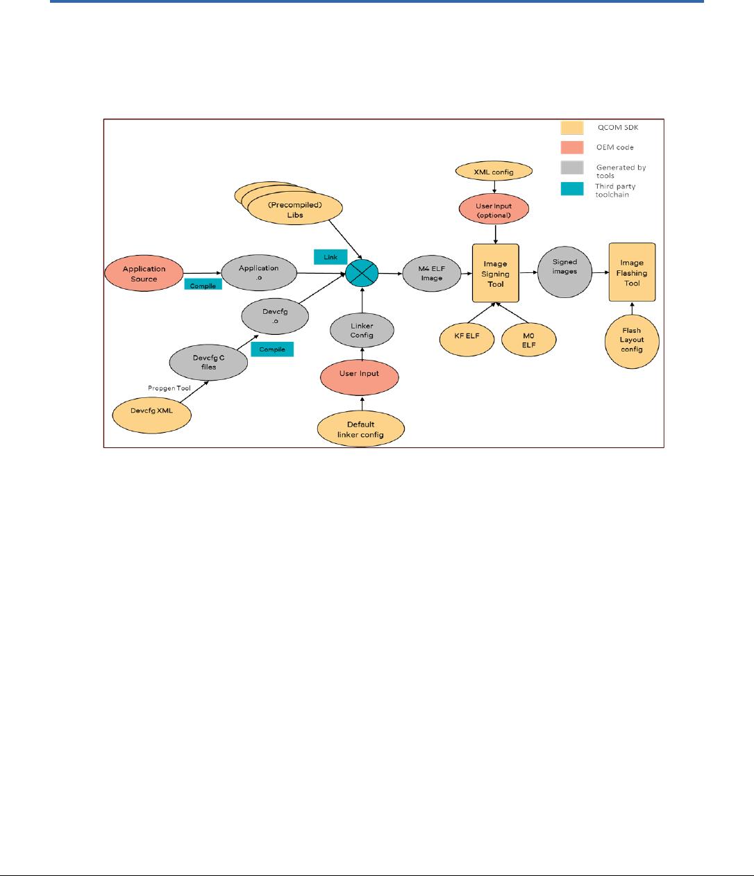
80-YA121-142 Rev. D MAY CONTAIN U.S. AND INTERNATIONAL EXPORT CONTROLLED INFORMATION 87
4 QCA402x application development
4.1 QCA402x SDK compilation model
Figure 4-1 QCA402x SDK compilation model
Figure 4-1 shows the compilation model with application development flow on QCA402x SDK.
An application developer can configure following components as user entries:
■ Application Source: For application code sturcutre, refer to Helloworld demo section in
QCA402x Development Kit User Guide (80-YA121-140).
■ Device Configuration: Feature to tune system parameters at runtime. Master device
configuration XML file is copied from \build\tools\devcfg to application\src\export directory
by build scripts. Python-based propgen tool generates C files from the XML file. See section
4.3.1.
■ Platform Configuration: Feature to tune system parameters at compile time. Master platform
configuration file is copied from quartz\platform\export to application\src\export directory by
build scripts. See section 4.3.1.
■ Linker Configuration: An OEM has an option to place code into the following regions such as
FOM RAM, FOM XIP, or SOM RAM. SDK includes python scripts
\build\scripts\linkerScripts that generate linker configuration files based on user input. The
input to the linker script is a config file provided in the sample application directory. For
details, see section 4.3.3.
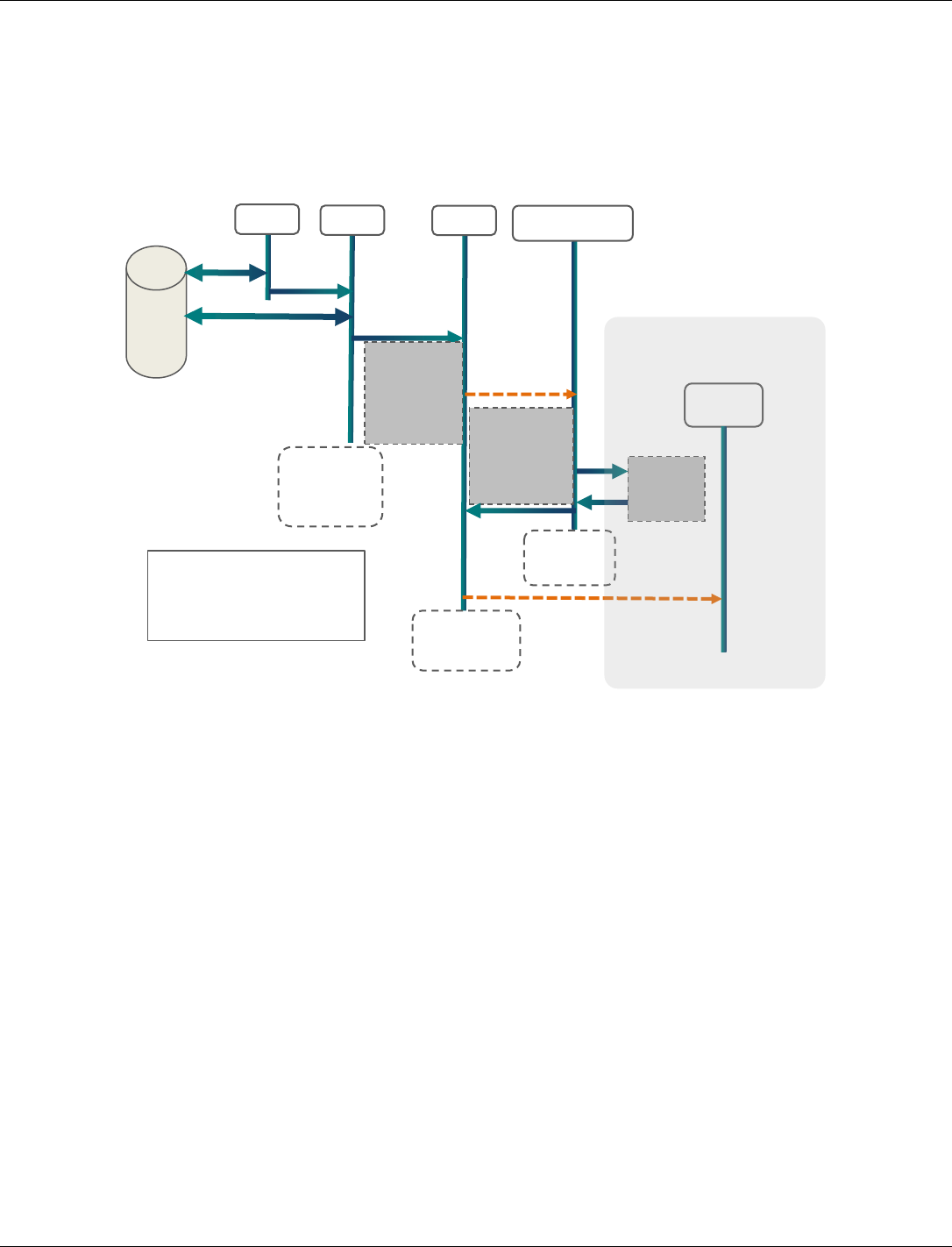
QCA402x (CDB2x) Programmer’s Guide QCA402x application development
80-YA121-142 Rev. D MAY CONTAIN U.S. AND INTERNATIONAL EXPORT CONTROLLED INFORMATION 88
■ Image Signing (Optional): Image signing tool is integrated in SDK. For the image signing
configuration, input parameters are provided to the image signing tool. For more information,
refer to Secure Boot on QCA402x (80-YA121-144) document.
4.2 QCA402x boot flow
4.3 Configuration and programming
4.3.1 Configuring an application
Two types of configuration options are provided in the SDK:
Run-time configuration through DevCfg
The SDK contains a Python-based device configuration utility (PropGen), that provides a
mechanism to tune various system parameters at run-time. A pair of XML files containing
system configuration parameters are provided.
Free-RTOS
target/build/tools/devcfg/freertos/DevCfg_master_devcfg_out_cdb.xml
target/build/tools/devcfg/freertos/DevCfg_master_fom_out_cdb.xml
ThreadX
target/build/tools/devcfg/freertos/DevCfg_master_devcfg_out_cdb.xml
target/build/tools/devcfg/freertos/DevCfg_master_fom_out_cdb.xml
PBL
SBL
Syste
Load,
auth SBL
from
Jump to
SBL
RTOS Init
HEAP init
Create
Platform
thread
Start
Platform
Thread
Platform
thread
starts
FLAS
H
Load, auth
remaining RAM
segments from
flash
Init system
drivers
Init Network
Stack
Jump to
app_start()
SBL ends
(reclaimed
as HEAP)
Jump to
System
mode
app_sta
rt()
Applicat
Platform
thread
ends
APP
Thread(
APP thread
starts
Application Domain
PBL- Primary Boot Loader
SBL- Secondary Boot Loader
app_start() – application entry
function
Scheduler
runs

QCA402x (CDB2x) Programmer’s Guide QCA402x application development
80-YA121-142 Rev. D MAY CONTAIN U.S. AND INTERNATIONAL EXPORT CONTROLLED INFORMATION 89
These files are then installed to the application export directory as a pre-build step. Refer to
QCA402x Development Kit User Guide (80-YA121-140).
target/quartz/demo/QCLI_Demo/src/export/DevCfg_master_devcfg_out_cdb.xml
target/quartz/demo/QCLI_Demo/src/export/DevCfg_master_fom_out_cdb.xml
An OEM can edit these XML files based on product requirements and then run the PropGen tool
to generate C source files.
The following example generates four source files from the two XML files:
python %RootDir%/build/tools/devcfg/propgen.py --XmlFile=
%SrcDir%/DevCfg_master_devcfg_out.xml
--DirName=%SrcDir%/export --ConfigFile=%SrcDir%/DALConfig_devcfg.c
--DevcfgDataFile=%SrcDir%/devcfg_devcfg_data.c --
ConfigType=%CHIPSET_VARIANT%_devcfg_xml
python %RootDir%/build/tools/devcfg/propgen.py --
XmlFile=%SrcDir%/export/DevCfg_master_fom_out.xml --DirName=%SrcDir%/export
--ConfigFile=%SrcDir%/export/DALConfig_fom.c --
DevcfgDataFile=%SrcDir%/export/devcfg_fom_data.c --
ConfigType=%CHIPSET_VARIANT%_fom_xml
Here-
RootDir- target
SrcDir- target/quartz/demo/QCLI_Demo/src/export/
CHIPSET_VARIANT – qca4020, qcq4024
The preceding commands generate the following source files:
DALConfig_devcfg.c
DALConfig_fom.c
devcfg_devcfg_data.c
devcfg_fom_data.c
These source files must be compiled by the OEM along with the application source code and
linked to the final ELF image. Qualcomm modules extract the configuration parameters at run-
time and apply the selected configuration accordingly.
Compile time configuration
QCA4020 SDK also contains platform configuration files that allow disabling of certain optional
driver modules.
Read-only location of platform configuration files.
target\quartz\platform\export\platform_oem.h
target\quartz\platform\export\platform_oem.c
target\quartz\platform\export\platform_oem_som.c
target\quartz\platform\export\platform_oem_mom.c
These files are then installed to the application export directory as a pre-build step.
Refer to QCA402x Development Kit User Guide (80-YA121-140). The OEM may optionally
choose the edit platform_oem.h to disable any unwanted driver modules.
NOTE: The files must be compiled by OEM toolchain.

QCA402x (CDB2x) Programmer’s Guide QCA402x application development
80-YA121-142 Rev. D MAY CONTAIN U.S. AND INTERNATIONAL EXPORT CONTROLLED INFORMATION 90
For example, Disable “Diag” feature at compile time:
■ Edit SRC-IOE-SDK\quartz\QCLI_Demo\src\export\platform_oem.h
■ Un-define DIAG_INIT_COLD macro
■ Rebuild the demo. The resulting elf file do not initialize “Diag” feature.
4.3.2 GPIO customization
GPIO on QCA402x can be configured for various functionalities depending on the user cases.
Some of the commonly used peripherals are SPI, UART, SDIO, and I2C/I2S. In the device
configuration XML file, GPIO pins must be configured properly based on hardware
configuration.
For the supported GPIO configuration options, see Appendix A.
4.3.2.1 Configuring Peripheral Bus GPIO
In DevCfg_master_fom_out.xml, OEM can also configure GPIO for peripheral bus according to
the hardware configuration.
The following example shows HS-UART configuration on OEM board.
HS_UART
Reference Board
OEM Board
GPIO
Func_Sel
I/O
GPIO
Func_Sel
I/O
QCA402x_UART_TX
GPIO 60
(0x003C)
4
Output
GPIO 15
(0x000F)
1
Output
QCA402x_UART_RTS
GPIO 16
(0x0010)
1
Output
GPIO 16
(0x0010)
1
Output
QCA402x_UART_CTS
GPIO 59
(0x003B)
2
Input
GPIO 14
(0x000E)
1
Input
UART Configuration
<!--
GPIO configuration calculation
GPIO DIR values
GPIO_INPUT = 0x0
GPIO_OUTPUT = 0x1
GPIO_PULL values
GPIO_NO_PULL = 0,
GPIO_PULL_DOWN = 0x1,
GPIO_PULL_UP = 0x2,
GPIO_DRV_STRENGTH values
GPIO_2MA = 0,
GPIO_4MA = 0x1,
GPIO_6MA = 0x2,
GPIO_8MA = 0x3,
GPIO_10MA = 0x4,
GPIO_12MA = 0x5,
GPIO_14MA = 0x6,

QCA402x (CDB2x) Programmer’s Guide QCA402x application development
80-YA121-142 Rev. D MAY CONTAIN U.S. AND INTERNATIONAL EXPORT CONTROLLED INFORMATION 91
GPIO_16MA = 0x7,
GPIO configuration = (GPIO_NUM & 0xFF) << 0x10 |
(GPIO_FS_VAL & 0xF) << 0xC |
(GPIO_DRV_STRENGTH & 0xF) << 0x8 |
(GPIO_PULL & 0xF) << 0x4 |
(GPIO_DIR & 0xF)
-->
Reference board
<device id="0x0200000f">
<props id="0x20001" id_name="UART_PROP_STRUCT_ID"
oem_configurable="false" helptext="Internal uart device
structure" type="0x00000012"> uart_second_port </props>
<!-- UART open gpio configurations -->
<props
id="0x20002" id_name="UART_PROP_GPIO_TX_PU_CONF_ID" oem_configurable="tr
ue" helptext="GPIO configuration"
type="0x00000002"> 0x003C4021 </props>
<props
id="0x20003" id_name="UART_PROP_GPIO_RX_PU_CONF_ID" oem_configurable="tr
ue" helptext="GPIO configuration"
type="0x00000002"> 0x00111020 </props>
<props id="0x20004" id_name="UART_PROP_GPIO_RFR_PU_CONF_ID"
oem_configurable="true" helptext="GPIO configuration"
type="0x00000002"> 0x00101021 </props>
<props id="0x20005" id_name="UART_PROP_GPIO_CTS_PU_CONF_ID"
oem_configurable="true" helptext="GPIO configuration"
type="0x00000002"> 0x003B2020 </props>
<!-- UART close gpio configurations -->
<props
id="0x20006" id_name="UART_PROP_GPIO_TX_PD_CONF_ID" oem_configurable="tr
ue" helptext="GPIO configuration"
type="0x00000002"> 0x003C0020 </props>
<props
id="0x20007" id_name="UART_PROP_GPIO_RX_PD_CONF_ID" oem_configurable="tr
ue" helptext="GPIO configuration"
type="0x00000002"> 0x00110020 </props>
<props id="0x20008" id_name="UART_PROP_GPIO_RFR_PD_CONF_ID"
oem_configurable="true" helptext="GPIO configuration"
type="0x00000002"> 0x00100020 </props>
<props id="0x20009" id_name="UART_PROP_GPIO_CTS_PD_CONF_ID"
oem_configurable="true" helptext="GPIO configuration"
type="0x00000002"> 0x003B0010 </props>
</device>
QCA402x (CDB2x) Programmer’s Guide QCA402x application development
80-YA121-142 Rev. D MAY CONTAIN U.S. AND INTERNATIONAL EXPORT CONTROLLED INFORMATION 92
OEM board
<device id="0x0200000f">
<props id="0x20001" id_name="UART_PROP_STRUCT_ID"
oem_configurable="false" helptext="Internal uart device
structure" type="0x00000012"> uart_second_port </props>
<!-- UART open gpio configurations -->
<props
id="0x20002" id_name="UART_PROP_GPIO_TX_PU_CONF_ID" oem_configurable="tr
ue" helptext="GPIO configuration"
type="0x00000002"> 0x000F1021 </props>
<props
id="0x20003" id_name="UART_PROP_GPIO_RX_PU_CONF_ID" oem_configurable="tr
ue" helptext="GPIO configuration"
type="0x00000002"> 0x00111020 </props>
<props id="0x20004" id_name="UART_PROP_GPIO_RFR_PU_CONF_ID"
oem_configurable="true" helptext="GPIO configuration"
type="0x00000002"> 0x00101021 </props>
<props id="0x20005" id_name="UART_PROP_GPIO_CTS_PU_CONF_ID"
oem_configurable="true" helptext="GPIO configuration"
type="0x00000002"> 0x000E1020 </props>
<!-- UART close gpio configurations -->
<props
id="0x20006" id_name="UART_PROP_GPIO_TX_PD_CONF_ID" oem_configurable="tr
ue" helptext="GPIO configuration"
type="0x00000002"> 0x000F0020 </props>
<props
id="0x20007" id_name="UART_PROP_GPIO_RX_PD_CONF_ID" oem_configurable="tr
ue" helptext="GPIO configuration"
type="0x00000002"> 0x00110020 </props>
<props id="0x20008" id_name="UART_PROP_GPIO_RFR_PD_CONF_ID"
oem_configurable="true" helptext="GPIO configuration"
type="0x00000002"> 0x00100020 </props>
<props id="0x20009" id_name="UART_PROP_GPIO_CTS_PD_CONF_ID"
oem_configurable="true" helptext="GPIO configuration"
type="0x00000002"> 0x000E0010 </props>
</device>
4.3.2.2 Configure external PTA GPIO
QCA402x can operate as External PTA master or slave. GPIO 5, 6, and 7 are reserved for the
external PTA interface such as WLAN_ACTIVE, BT_ACTIVE and BT_PRIORITY. The GPIOs
can be interfaced directly with the external chipset. Ensure that the I/O voltage on two chipsets is
at the same level. The GPIOs must be configured according to PTA master or slave mode:
PTA Master Mode
Signal Name
QCA402x GPIO #
Motherboard Pin
I/O (QCA402x)
WLAN_ACTIVE
5
1, Header J15
Output
BT_ACTIVE
6
3, Header J15
Input
BT_PRIORITY
7
5, Header J15
Input
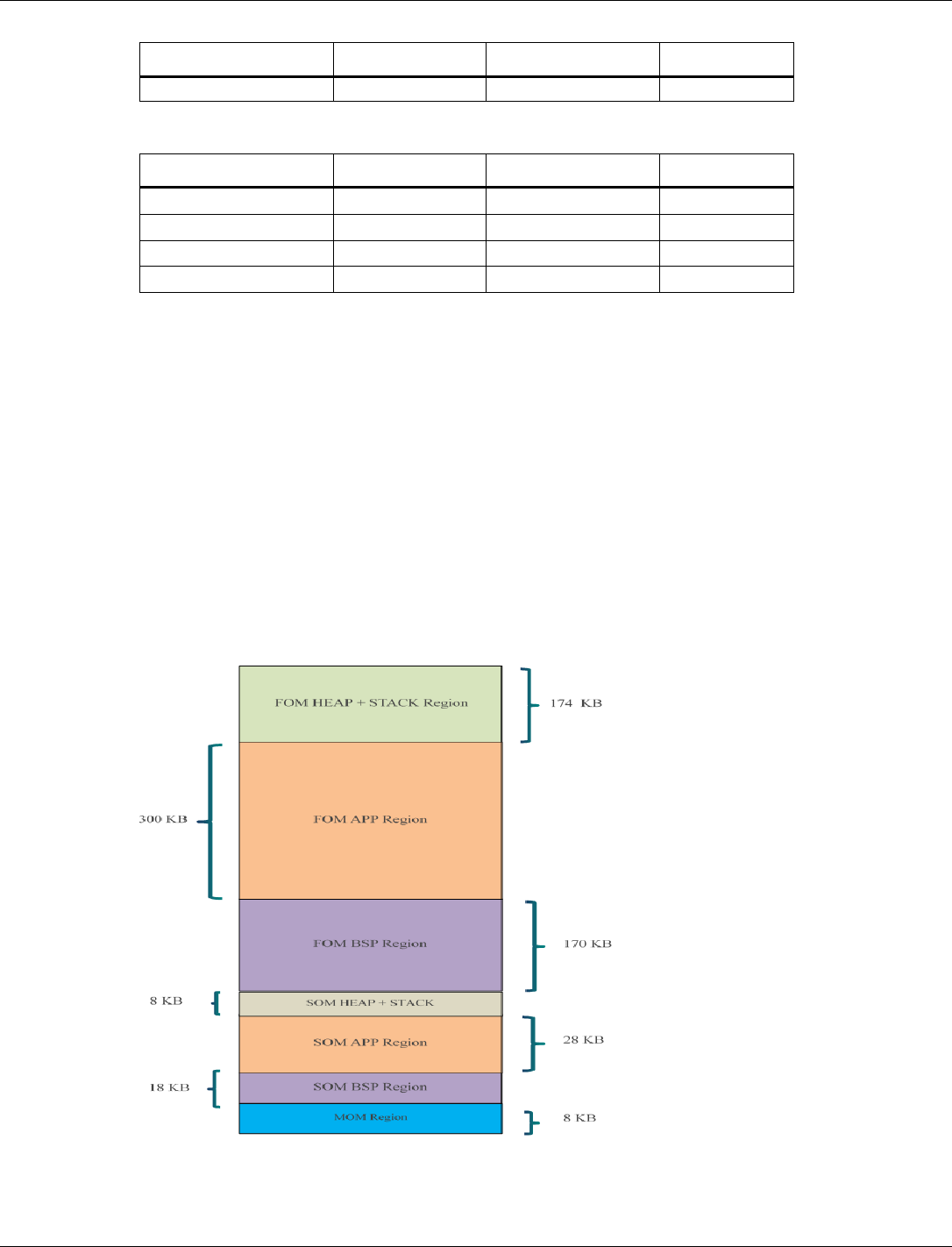
QCA402x (CDB2x) Programmer’s Guide QCA402x application development
80-YA121-142 Rev. D MAY CONTAIN U.S. AND INTERNATIONAL EXPORT CONTROLLED INFORMATION 93
Signal Name
QCA402x GPIO #
Motherboard Pin
I/O (QCA402x)
GND
-
2, Header J15
-
PTA Slave Mode
Signal Name
QCA402x GPIO #
Motherboard Pin
I/O (QCA402x)
BT_ACTIVE
5
1, Header J15
Output
WLAN_ACTIVE
6
3, Header J15
Input
BT_PRIORITY
7
5, Header J15
Output
GND
–
2, Header J15
–
QCA402x SDK contains commands to configure the external PTA mode with GPIOs. The
following example shows how to set external PTA master and slave mode through the QCLI
demo commands:
PTA master mode
Coex EPTAGPIOEnable 2
Coex ConfigureAdvanced 3 0
PTA slave mode
Coex EPTAGPIOEnable 1
Coex ConfigureAdvanced 1 0
4.3.3 Code placement
QCA402x memory map is is split into multiple regions with different power profiles.

QCA402x (CDB2x) Programmer’s Guide QCA402x application development
80-YA121-142 Rev. D MAY CONTAIN U.S. AND INTERNATIONAL EXPORT CONTROLLED INFORMATION 94
An OEM has an option to place code into the following regions:
■ FOM RAM: For time critical code running in full power mode.
■ FOM XIP: For non-time critical code running in full power mode.
■ SOM RAM: For code running in low power (sensor) mode.
To assist with the preceding placement options, SDK includes Python scripts that generate linker
configuration files based on user input.
The scripts are located at: target/build/scripts/linkerScripts
The input to the linker script is a config file provided in the sample application directory.
Location: target/quartz/demo/QCLI_Demo/build/gcc/app.config
Each line in the config file specifies the placement parameters for an application object file. OEM
must update the config file for all application object files.
NOTE: If an object file is not explicitly placed in a region, it ends up in the default region (FOM RAM
region).
Example 1: Placing main.o in SOM RAM region:
“main.o APPS SOM RAM” places main.o in SOM Application RAM region
Example 2: Placing app.o in FOM XIP region:
“app.o APPS FOM XIP” places app.o in FOM Application XIP region
The following steps generate a “quartz.ld” linker configuration file from app.config input file.
See the Makefile for example:
1. Generate app.placement file from app.config and system placement files
python %LinkerScriptDir%\CreateAppPlacementFile.py %RootDir%\bin\cortex-
m4\threadx\sys.placement %RootDir%\bin\cortex-m4\threadx\cust.placement
app.config app.placement
2. Create linker configuration file
python %LinkerScriptDir%\MakeLinkerScript.py %RootDir%\bin\cortex-
m4\threadx\DefaultTemplateLinkerScript.ld app.placement %LIBSFILE% >
%LINKFILE%
RootDir- target
LinkerScriptDir - target/build/scripts/linkerScripts
LIBSFILE – String with all system libs and object files used by
application
LINKFILE – output linker configuration file (quartz.ld for sample
application)
4.3.4 Resize application memory
QCA402x has 328 KB of RAM dedicated for customer applications. In addition to this, OEMs
can choose to place their code in XIP region. OEM can change the distribution between code and
data RAM in 128 KB increments.
The default distribution of Application data and code RAM is as follows.

QCA402x (CDB2x) Programmer’s Guide QCA402x application development
80-YA121-142 Rev. D MAY CONTAIN U.S. AND INTERNATIONAL EXPORT CONTROLLED INFORMATION 95
Code RAM: 232 KB (RAM_FOM_APPS_RO_MEMORY region)
Data RAM: 64 KB (RAM_FOM_APPS_DATA_MEMORY region)
Example 1: To increase the data memory (RAM_FOM_APPS_DATA_MEMORY) by 128 KB, make the
following changes:
1. To increase data memory (RAM_FOM_APPS_DATA_MEMORY), decrease the code memory
(RAM_FOM_APPS_RO_MEMORY) by the same amount. Make the following changes in
DefaultTemplateLinkerScript.ld script
RAM_FOM_APPS_RO_MEMORY (Rx) : ORIGIN = 0x10046000, LENGTH = 0x3a000
RAM_FOM_APPS_DATA_MEMORY (W) : ORIGIN = 0x10080000, LENGTH = 0x10000
to
RAM_FOM_APPS_RO_MEMORY (Rx) : ORIGIN = 0x10046000, LENGTH = 0x1a000
RAM_FOM_APPS_DATA_MEMORY (W) : ORIGIN = 0x10060000, LENGTH = 0x30000
2. By default, the Data Execution Prevention (DEP) is enabled on QCA402x. To make changes
to code and data memory regions, adjust the DEP configuration. Modify
DevCfg_master_devcfg_out.xml file to adjust DEP configuration region.
Th application RAM regions (RAM_FOM_APPS_DATA_MEMORY, RAM_FOM_APPS_RO_MEMORY)
belong to MPU region 2 (row 3 highlighted in the code snippet)
<!-- All the data is in Little Endian Format -->
<!-- FORMAT: -->
<!-- DEP_region_start_address - 4 bytes -->
<!-- DEP_region_size - 4 bytes -->
<!-- DEP_region_index - 1 byte -->
<!-- DEP_sub_region_mask - 1 byte (set bit to '1' for disabling the
sub-region) -->
<!-- DEP_access_control - 1 byte (0x6 for RO, 0x3 for RW) -->
<!-- XN - 1 byte -->
<!-- 64MB ROM region = --> 0x00, 0x00, 0x00, 0x00, 0x00,
0x00, 0x00, 0x04, 0x00, 0x00, 0x06, 0x00,
<!-- 1MB RAM region = --> 0x00, 0x00, 0x00, 0x10, 0x00,
0x00, 0x10, 0x00, 0x01, 0x00, 0x03, 0x01,
<!-- FOM Code and Data region = --> 0x00, 0x00, 0x00, 0x10, 0x00,
0x00, 0x10, 0x00, 0x02, 0xF1, 0x06, 0x00,
<!-- FOM APPS region = --> 0x00, 0x00, 0x08, 0x10, 0x00,
0x00, 0x01, 0x00, 0x03, 0xFF, 0x06, 0x00,
<!-- SOM Code and Data region = --> 0x00, 0x40, 0x00, 0x10, 0x00,
0x40, 0x00, 0x00, 0x04, 0x01, 0x06, 0x00,
<!-- SOM APPS and HEAP = --> 0x00, 0x80, 0x00, 0x10, 0x00,
0x80, 0x00, 0x00, 0x05, 0xE0, 0x06, 0x00,
<!-- MOM region = --> 0x00, 0x10, 0x00, 0x10, 0x00,
0x10, 0x00, 0x00, 0x06, 0xC7, 0x06, 0x00,
<!-- SBL region = --> 0x00, 0x00, 0x0A, 0x10, 0x00, 0x00,
0x01, 0x00, 0x07, 0x00, 0x3, 0x01,
Every 128 KB block that needs to be changed requires corresponding adjustment to
DEP_sub_region_mask byte (highlighted in red). Each bit in DEP_sub_region_mask
corresponds to one 128 KB block. Setting a bit changes the block from code to data. Example:

QCA402x (CDB2x) Programmer’s Guide QCA402x application development
80-YA121-142 Rev. D MAY CONTAIN U.S. AND INTERNATIONAL EXPORT CONTROLLED INFORMATION 96
making it 0xF9 if 128 KB is moved from RO to DATA, 0xFD if 256 KB from RO to DATA is
moved and so on.
Heap starts at the end of APP data region.
In GCC, linker script automatically adjusts start of heap address based on application processor
data region usage.
Resizing FreeRTOS Heap
FreeRTOS requires a dedicated memory pool used for allocating RTOS-specific elements such as
task stack. OEMs might adjust this allocation based on their needs by following the steps.
cd to "./FreeRTOS/2.0/FreeRTOS/Demo/QUARTZ" directory. Edit
FreeRTOSConfig.h, change configTOTAL_HEAP_SIZE to the appropriate value.
Rebuild FreeRTOS library. Refer to QCA402x Development Kit User Guide (80-
YA121-140).
cd to target/bin/cortex-m4/freertos. Edit DefaultTemplateLinkerScript.ld,
change RTOS_HEAP_SIZE to match configTOTAL_HEAP_SIZE from step 1.
Build the application. The new FreeRTOS heap value is applied.
4.3.5 RAM dump collection and debugging
The RAM dump collection mode is configurable in device configuration file
“DevCfg_master_devcfg_out.xml”.
■ Enable/disable RAM dump collection mode in "PLATFORM RAMDUMP ENABLED"
<driver name="platform">
<device id="0x02000006">
== snip ==
<props id="7" id_name="PLATFORM RAMDUMP ENABLED"
oem_configurable="true" helptext="Enable or Disable Ramdump. 1--Enabled, 0--Disabled"
type="0x00000002">
1
</props>
== snip ==
</device>
</driver>
■ Configure RAM dump method through USB/flash in "PLATFORM RAMDUMP CONFIG"
<driver name="platform">
<device id="0x02000006">
== snip ==
<props id="11" id_name="PLATFORM RAMDUMP CONFIG" oem_configurable="true"
helptext="Configure the RAM Dump. " type="0x00000002">
<!-- Mask - RRRRRRRT -->
<!-- Where bits in 0xT represent following -->
<!-- Bit 0: If set, enable the RAM dump via Uart/USB support otherwise disabled -->
<!-- Bit 1: If set, enable the RAM dump on QSPI Flash support otherwise disabled -->
<!-- Bit 2 and Bit 3 are reserved for future use. -->
0x00000003
</props>
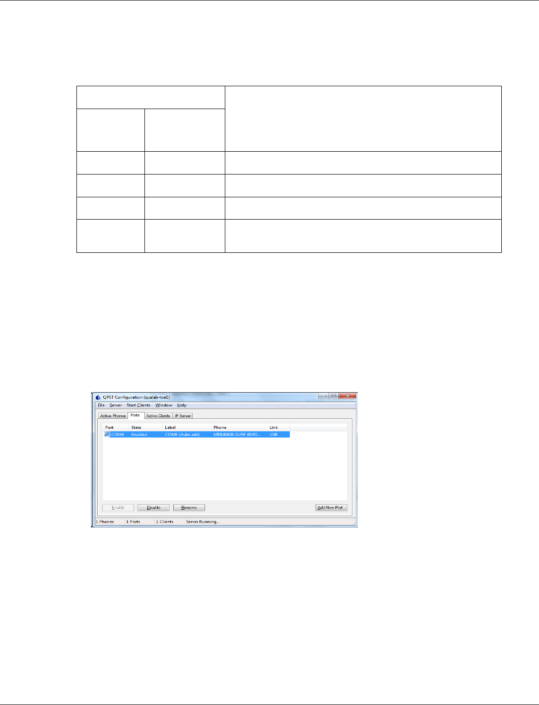
QCA402x (CDB2x) Programmer’s Guide QCA402x application development
80-YA121-142 Rev. D MAY CONTAIN U.S. AND INTERNATIONAL EXPORT CONTROLLED INFORMATION 97
</device>
</driver>
When watchdog reset happens, the RAM dump collection operates according to the device
configuration as given here.
RAM dump collection mode
Expected operation when watchdog reset happens
PLATFORM
RAMDUMP
ENABLED
PLATFORM
RAMDUMP
CONFIG
0
x
System is reset.
1
1
System waits for USB connection in RAM dump mode.
1
2
RAM dump is stored into flash and the system is reset.
1
3
RAM dump is stored into flash and system waits for USB
connection in the RAM dump mode.
4.3.6 RAM dump collection procedure through USB
When PLATFORM RAMDUMP CONFIG sets bit0, the system waits for USB connection in the ram
dump mode. The RAM dumps are collected by a PC based tool − QPST (as part of
QDART_CONN) – available for download at https://createpoint.qti.qualcomm.com/tools/#. The
dumps are collected over USB port (J6) on CDB2x board.
1. Connect a micro USB cable and start QPST configuration.
2. QPST configuration detects the COM ports.
3. If there is a crash, a watchdog reset triggers RAM dump generation and QPST automatically
collects the dump over the newly enumerated USB port.
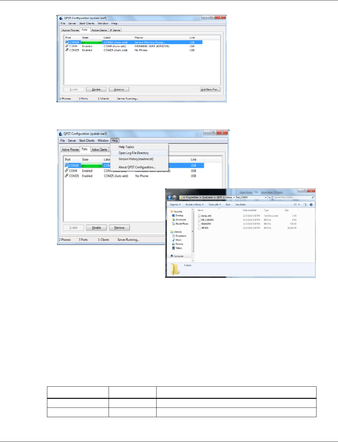
QCA402x (CDB2x) Programmer’s Guide QCA402x application development
80-YA121-142 Rev. D MAY CONTAIN U.S. AND INTERNATIONAL EXPORT CONTROLLED INFORMATION 98
4. The M4, M0, and XIP dump files are available at the location −
(C:\ProgramData\Qualcomm\QPST\Sahara).
4.3.7 Collect RAM dump stored in flash memory
When the PLATFORM RAMDUMP CONFIG mode sets bit 1, the system in RAM dump mode stores
RAM to flash. After reboot, the system can upload the RAM dump stored in flash memory to the
specific network server.
1. If a crash happens, a watchdog reset triggers RAM dump to be stored in flash memory.
2. After reboot, connect WLAN to the specific network server, and upload the RAM dump.
The supported commands for demonstration are:
Server_type: FTP
IP_version: v4
Parameter Name
Type/Range
Description
Server_type
String
Protocol for upload. Only FTP is supported
Ip_version
String
IP version. Only v4 is supported.

QCA402x (CDB2x) Programmer’s Guide QCA402x application development
80-YA121-142 Rev. D MAY CONTAIN U.S. AND INTERNATIONAL EXPORT CONTROLLED INFORMATION 99
Parameter Name
Type/Range
Description
Ftps_ip_address
String
FTP server’s IP address. Only IPv4 addresses are supported.
Login_name
String
FTP login account name
Login_password
String
FTP login account password
Ramdump_path
String
Optional. Directory on FTP server to locate RAM dump files.
Directory under the root is supported.
ftpc_data_port
Integer
Optional. Data port for FTP client
ftps_cmd_port
Integer
Optional. Command port for FTP server
Ramdump_encryption
Integer/0,1
Optional. No encryption is supported yet.
Example: platform ftp v4 192.168.1.11 username password dir
4.3.8 RAM dump analysis
For RAM dump analysis, QCA402x SDK provides GNU debugger (GDB) scripts dumpserver.py
and app_ramdump.gdbinit at /target/quartz/gdb. The GDB scripts load the dump file and
obtain the pc and lr registers from the coredump data structure.
GDB requirements
■ Must be built with Arm support.
■ Should include a fix that allows backtraces to work properly on QCA402x binaries.
■ Must include "Component: Arm Compiler" in symtab.c::arm_idents.
■ Must include python support.
■ The GDB python support files must be available in the expected locations on the system by
setting the system environment variables.
Example:
set PYTHONHOME=C:\Python276
set PYTHONPATH=C:\Python276\Lib
set PATH=%PYTHONHOME%;%PATH%
■ Locate dump files and M4 image file at /target/quartz/gdb
□ RAM dump files: SRAM.BIN, M0_CLM.BIN, and XIP.BIN
□ M4 image elf file: Quartz.elf
To debug the RAM dump:
1. Run “set SDK=<path_to_sdk_root>” at /target/quartz/gdb. The path must include a
forward slash and not back slash.
2. Run GDB scripts, “gdb -x app_ramdump.gdbinit Quartz.elf” in the command prompt. The
script automatically starts dumpserver.py, which is used to access contents of SRAM.BIN
and XIP.BIN
3. The scripts load dump and symbol files. The user can start GDB debugging session. For
useful GDB commands, see section Debugging through GDB in QCA402x Development Kit
User Guide (80-YA121-140).
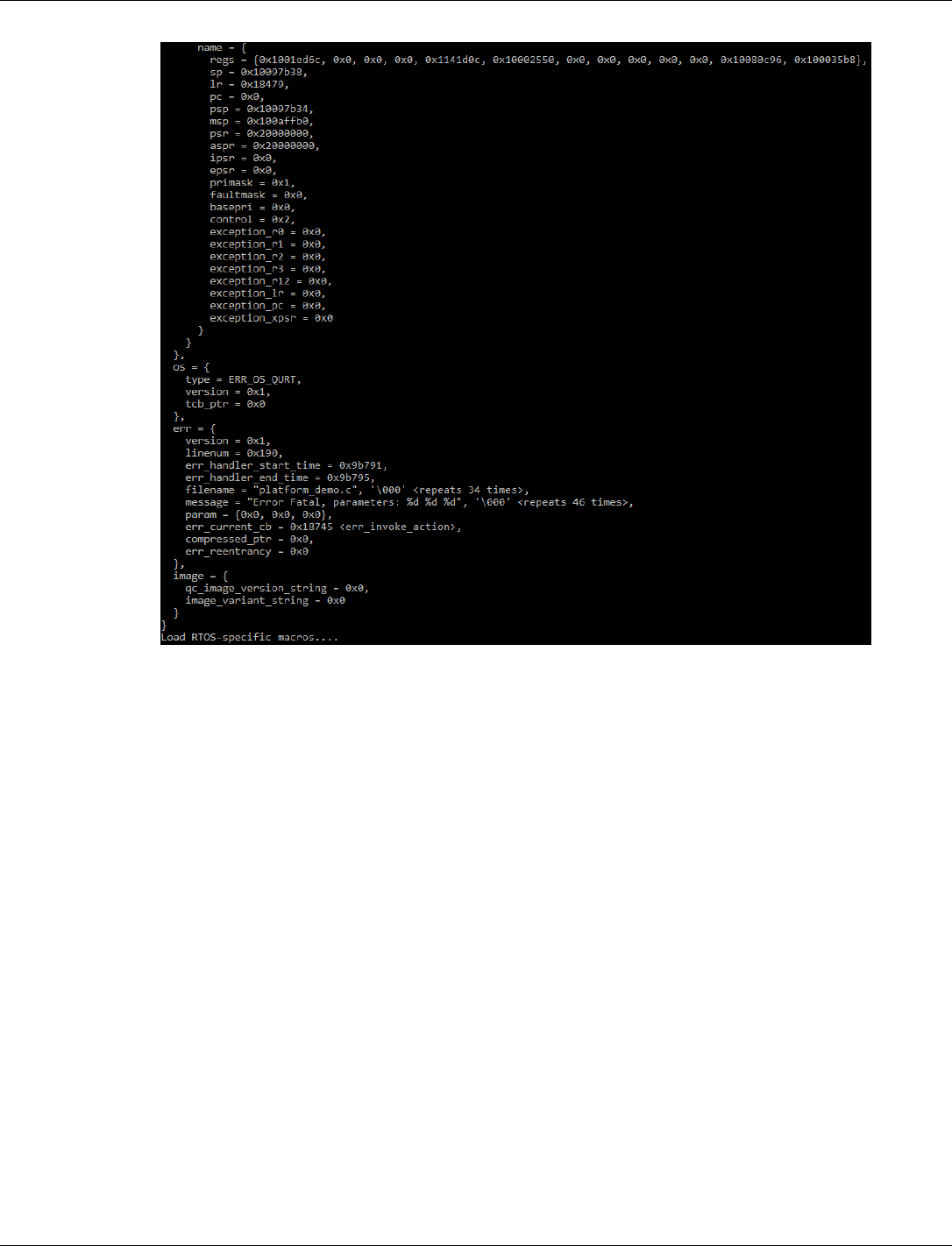
QCA402x (CDB2x) Programmer’s Guide QCA402x application development
80-YA121-142 Rev. D MAY CONTAIN U.S. AND INTERNATIONAL EXPORT CONTROLLED INFORMATION 100
Figure 4-2 Start RAM dump debugging on GDB client
4.3.9 Image encryption
QCA402X SDK includes tools for image encryption. These tools are available at:
target/build/scripts/elf_segment_encryption
An image encryption tool requires image encryption key. A configuration file is also provided to
generate the image encryption key:
target/quartz/mfg/ROT/tools/gen_kdf_pwd.py
target/quartz/mfg/ROT/tools/kdf_config.xml
Edit the configuration file to select image encryption operation and change parameters such as:
■ op_code (operation code: 0x0A to generate image encryption key)
■ oem_id (OEM identification for image encryption, matched in OTP)
■ model_id (model identification for image encryption, matched in OTP)
■ mid_id (machine identification: 1 for M4)
■ otp_encryp_key (hardware encryption key, matched in OTP)
■ dbg_enable (JTAG debug mode, matched in OTP)
■ sw_input (fixed, should be F762C318828B32E5D1328C8130430481)

QCA402x (CDB2x) Programmer’s Guide QCA402x application development
80-YA121-142 Rev. D MAY CONTAIN U.S. AND INTERNATIONAL EXPORT CONTROLLED INFORMATION 101
For a complete list of parameters, refer to build scripts.
The following example generates encrypted M4 images:
Windows-
python %SCRIPTDIR%\elf_segment_encryption\elf_encrpyt.py -p
output\%PROJECT%.elf -k %CFG_ENCRYPT_KEY% -a
%SectoolsDir%\bin\WIN\crypto_cbc.exe -c
%SCRIPTDIR%\elf_segment_encryption\config.json -o output\%PROJECT%.elf
Linux-
python $(SCRIPTDIR)/elf_segment_encryption/elf_encrpyt.py -p
$(OUTDIR)/$(PROJECT).elf -k $(CFG_ENCRYPT_KEY) -a openSSL -c
$(SCRIPTDIR)/elf_segment_encryption/config.json -o $(OUTDIR)/$(PROJECT).elf
For more information on image encryption, refer to Enable secure boot and Image encryption in
the QCA402x (80-YA121-144) document.
4.3.10 Flash programming
To execute firmware, it must be programmed onto the flash memory of the device. Several tools
in the SDK are used in the flashing process:
gen_part_table.py helps in creation of an XML file, “partition_table” that describes the
contents of an Image Set. In other words, it describes which PC files must be programmed onto
QCA402x flash. For instance, if an M0 image is specified, an M4 image, a WLAN image (for
QCA4020), then the empty space is reserved on flash to hold a file system.
gen_fwd_table.py converts the XML partition_table created by gen_part_table.py into
another XML file, “fwd_table” (firmware descriptor table), which contains flash directives to be
interpreted by tools that handle flash programming.
QSaharaServer.exe is used to download the flash programmer over USB from the PC to
QCA402x RAM. This tool works only when QCA402x is in Emergency download (“EDL”)
mode.
fh_loader.exe follows directives in the fwd_table XML file. It sends commands and data over
USB to the flash programmer that was previously loaded into QCA402x RAM.
The SDK files names “flash.txt” in various application directories in the SDK contain detailed
instructions to program QCA402x flash.
4.3.11 Flash layout
Firmware consists of multiple image. For example, An M4 image plus an M0 image plus a
WLAN image. A set of images that function well together in order to make a QCA402xdevice
function is called an ImageSet. It is possible to have more than one ImageSet (each with multiple
images) programmed to flash. For example, it is possible to have a “Golden” read-only factory
ImageSet plus a “Current” ImageSet, which is the firmware that is loaded and used if the
QCA402x device powers on or resets. There might even be a third “Trial” ImageSet which is
used during a Firmware Upgrade. If the Trial firmware is determined to be functional, it may be
promoted, so that it becomes the “Current” ImageSet.
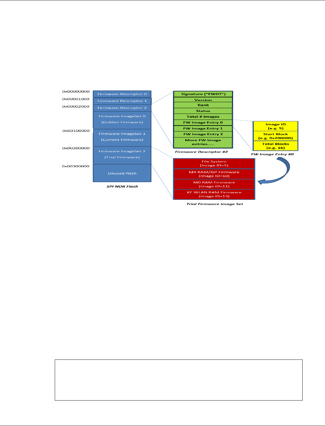
QCA402x (CDB2x) Programmer’s Guide QCA402x application development
80-YA121-142 Rev. D MAY CONTAIN U.S. AND INTERNATIONAL EXPORT CONTROLLED INFORMATION 102
In addition to firmware, flash may contain one or more file systems. A file system may be tied to
a particular ImageSet or may be shared by multiple ImageSets. (This decision is tied to firmware
upgrade policies and is related to the size of the ImageSets and size of the flash.) Besides
firmware and file systems, flash also contains meta-data known as Firmware Descriptors. The
FWDs inform firmware including the Primary Bootloader (PBL) in ROM, about the location of
firmware and file systems on flash.
Figure 4-3 shows one possible organization of flash. The firmware and tools are flexible enough
to support other organizations but this one is standard.
Figure 4-3 QCA402x SPI NOR flash layout
4.3.12 Flash Golden + Current + Trial image set
1. In the DevCfg_master_fom_out_xxx.xml file, change "Supported FWD Numbers" to 3 in
"fwup_scheme".
2. <driver name="fwup_scheme">
== snip ==
<props id="0x26001" id_name="FW_UPGRADE_SCHEME_PROP_FWD_SUPPORT_NUM_ID"
oem_configurable="true" helptext="Support FWD Numbers ( 2 - support two
FWDs, 3 - support three FWDs)" type="0x00000002"> 3 </props>
3. Build the application.
4. Modify the generated_partition_table.xml file in the gcc/output folder
<firmwaredescriptor>
<instructions erase_block_size_bytes="4096"
table_align_size_bytes="4096"/>
<!-- Golden Image -->
<table>

QCA402x (CDB2x) Programmer’s Guide QCA402x application development
80-YA121-142 Rev. D MAY CONTAIN U.S. AND INTERNATIONAL EXPORT CONTROLLED INFORMATION 103
<header rank="0" signature="0x54445746" status="1"
version="1"/>
<partition
dirname="C:\Build\Quartrz\full_build\3p0_0051_4024_full\ioesw\io
esw\quartz\demo\QCLI_demo\build\gcc\output"
filename="Quartz_HASHED.elf" image_id="10" start_block="35"
size_in_kb="732"/> <!--10-->
<partition
dirname="C:\Build\Quartrz\full_build\3p0_0051_4024_full\ioesw\io
esw\bin\cortex-m0\threadx" filename="ioe_ram_m0_threadx_ipt.mbn"
image_id="11" size_in_kb="86"/> <!--M0/CONSS Firmware-->
<partition filename="" image_id="5" start_block="3"
size_in_kb="64"/> <!--Primary Filesystem-->
<partition filename="" image_id="128" start_block="19"
size_in_kb="64"/> <!--Secondary Filesystem-->
</table>
<!-- Current Image ((732+86) / 4) + Golden_start_block(35)
<= 240 -->
<table>
<header rank="1" signature="0x54445746" status="1"
version="1"/>
<partition
dirname="C:\Build\Quartrz\full_build\3p0_0051_4024_full\ioesw\io
esw\quartz\demo\QCLI_demo\build\gcc\output"
filename="Quartz_HASHED.elf" image_id="10" start_block="240"
size_in_kb="732"/> <!--10-->
<partition
dirname="C:\Build\Quartrz\full_build\3p0_0051_4024_full\ioesw\io
esw\bin\cortex-m0\threadx" filename="ioe_ram_m0_threadx_ipt.mbn"
image_id="11" size_in_kb="86"/> <!--M0/CONSS Firmware-->
<partition filename="" image_id="5" start_block="3"
size_in_kb="64"/> <!--Primary Filesystem-->
<partition filename="" image_id="128" start_block="19"
size_in_kb="64"/> <!--Secondary Filesystem-->
</table>
</firmwaredescriptor>
5. In the gcc folder, run:
python ..\..\..\..\..\build\tools\flash\gen_fwd_table.py -x
output\generated_partition_table.xml --rawprogram
output\generated_fwd_table.xml --fdtbin output\firmware_table.bin
6. In gcc folder, run:
python ..\..\..\..\..\build\tools\flash\qflash.py --nogen --comm xx"
7. After reboot, fwd table shows the updated image set.
8. FWD 0: Golden Image Set
FWD 1: Current Image Set
9. The trial image can be updated after OTA upgrade. For OTA upgrade, secondary file system
(FS2_IMG_ID) is required.
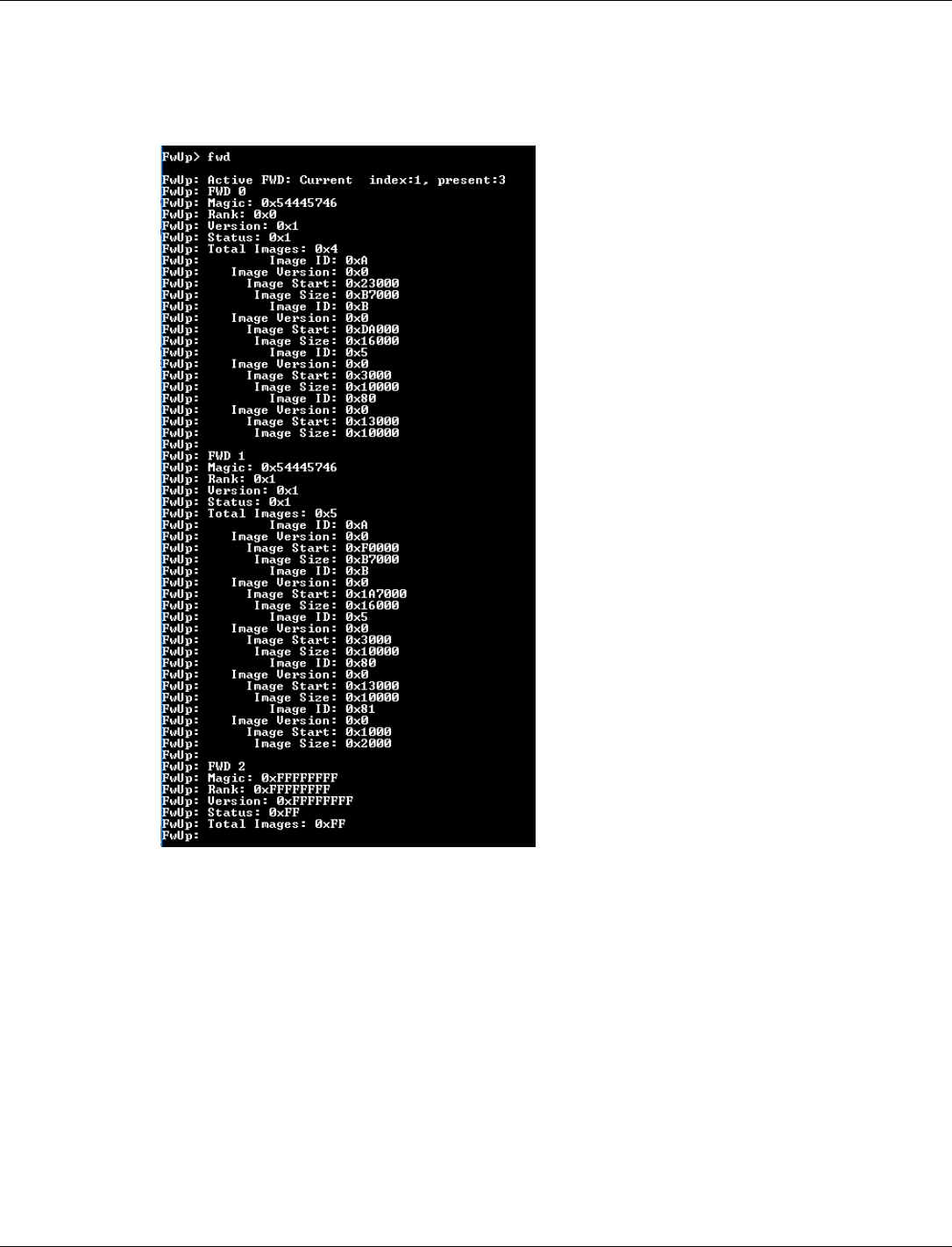
QCA402x (CDB2x) Programmer’s Guide QCA402x application development
80-YA121-142 Rev. D MAY CONTAIN U.S. AND INTERNATIONAL EXPORT CONTROLLED INFORMATION 104
10. FS1_IMG_ID = "5" // 0x5
M4_IMG_ID = "10" // 0xA
M0_IMG_ID = "11" // 0xB
FS2_IMG_ID = "128" // 0x80
UNUSED_IMG_ID = "129" // 0x81
4.3.13 JTAG debug GPIO bootstrap configuration
The debug mode using JTAG depends upon a JTAG debug GPIO bootstrap. This GPIO is kept
high during debug which helps the firmware to wait, in a while loop, for JTAG to connect.
GPIO20 is used for the JTAG debug mode, by default. If GPIO 20 is used for some other purpose
and is kept high, the device goes in to a waiting loop for JTAG and does not boot.
A link time variable 'hold_at_startup_gpio' has been introduced. This variable can be set by the
application during linking. SBL uses this variable for getting the GPIO number and uses it for
waiting.
To set the GPIO number, the application must change 'hold_at_startup_gpio' to GPIO number in
defaultTemplateLinkerScript.ld file:
/* Passing the GPIO number for forcing the device to go in to debug loop */

QCA402x (CDB2x) Programmer’s Guide QCA402x application development
80-YA121-142 Rev. D MAY CONTAIN U.S. AND INTERNATIONAL EXPORT CONTROLLED INFORMATION 105
hold_at_startup_gpio = 20;
4.4 Secure boot
For more information on secure boot, refer to Enable secure boot and Image encryption in the
QCA402x (CDB2x) document.
4.5 Power measurement
For more information, refer to QCA402x Power measurement user guide (80-YA121-146)
document.

80-YA121-142 Rev. D MAY CONTAIN U.S. AND INTERNATIONAL EXPORT CONTROLLED INFORMATION 106
5 QCA402x debugging tools
The QCA402x SDK contains a tool to log and display debug messages and binary logs.
5.1 Debug script overview
The script to use this tool is QCA402x_debug.py and resides at quartz\tools\qdt.
This script can log data from a live serial port or can print formatted data from an already
collected session file. For each live logging session, this tool creates a session file of type MISF
which is used to parse the stored data to user readable text. This filename represents the date and
time of logging.
Currently, the tool supports only remote port for collecting DBGLOGs. For more information on
how to configure binary logs, refer to Dbglog section in QCA402x Development Kit User Guide
(80-YA121-140).
Parameters:
--session_file : binary session file (which captured all raw byte stream
from COM port). Session file must be in MISF format.
OR
--port : Number for the live serial port.
--out : (Optional) output file to store parsed text output. If not
specified STDOUT will be used.
--wlan : (Optional) WLAN dictionary file location with respect to the
directory containing the tool. Default file is
bin/wlan/wlan_fw_dictionary_athwlan_iot.msc
--apps : (Optional) Apps processor dictionary file location with respect to
the directory containing the tool. Default file is bin/cortex-
m4/diag_msg_ARNFRI.strdb
--cnss : (Optional) CNSS processor dictionary file location with respect to
the directory containing the tool. Default file is bin/cortex-
m0/threadx/diag_msg_BRNTRI.strdb
Example usage:
python QCA402x_debug.py --port=COM57
python QCA402x_debug.py --session_file=09072017_185106.misf --
out="sample.log"

QCA402x (CDB2x) Programmer’s Guide QCA402x debugging tools
80-YA121-142 Rev. D MAY CONTAIN U.S. AND INTERNATIONAL EXPORT CONTROLLED INFORMATION 107
5.1.1 Requirements
Follow these steps before running the debug script:
1. PySerial package must be installed on the system for using this tool. Refer to
https://pypi.python.org/pypi/pyserial/2.7
2. Define DIAG_INIT_COLD from quartz/demo/QCLI_demo/export/platform_oem.h.
3. Diag messages can be collected by one of the two methods as follows:
a. Debug UART as output drain channel
b. Edit target/quartz/demo/QCLI_Demo/src/export/DevCfg_master_devcfg_out_cdb.xml
and use the following configuration:
<driver name="diag">
<device id="0x02000014">
<props id="0" type="0x00000008">
<!-- Last byte is unused placeholder --> 2, 2, 64, 0,
end
</props>
<props id="1" type="0x00000002">256</props>
<props id="2" type="0x00000002">256</props>
<props id="3" type="0x00000002">500</props>
</device>
</driver>
c. USB as output drain channel: This option requires Qualcomm USB Drivers to be
downloaded and installed.
d. Edit target/quartz/demo/QCLI_Demo/src/export/DevCfg_master_devcfg_out_cdb.xml
and use the following configuration:
<driver name="diag">
<device id="0x02000014">
<props id="0" type="0x00000008">
<!-- Last byte is unused placeholder --> 2, 1, 64, 0,
end
</props>
<props id="1" type="0x00000002">256</props>
<props id="2" type="0x00000002">256</props>
<props id="3" type="0x00000002">500</props>
</device>
</driver>
e. Change the Sleep Driver setting as follows:
<driver name="Sleep">
<global_def>
<var_seq name="devcfgSleepData" type="0x00000003">
0, 0, 0,
180, 166, 200,
end
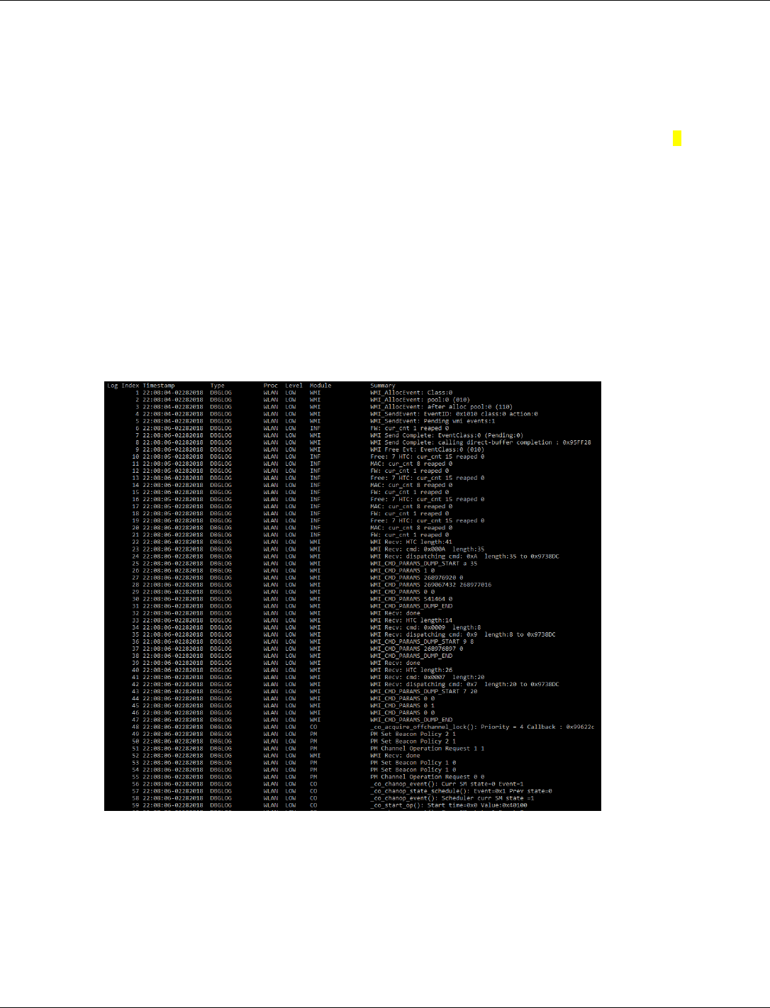
QCA402x (CDB2x) Programmer’s Guide QCA402x debugging tools
80-YA121-142 Rev. D MAY CONTAIN U.S. AND INTERNATIONAL EXPORT CONTROLLED INFORMATION 108
</var_seq>
</global_def>
<device id="0x02000018">
<props id="0x1" oem_configurable="false" type="0x00000014">
devcfgSleepData </props>
<props id="0x2" oem_configurable="false" type="0x00000002"> 0
</props>
<props id="0x3" oem_configurable="false" type="0x00000002"> 632
</props>
<props id="0x4" oem_configurable="false" type="0x00000002"> 96
</props>
</device>
</driver>
4. Build the application and flash the newly built application. For more information, refer to
QCA402x Development Kit User Guide (80-YA121-140).
5. The Debug UART must be connected to J85 or USB at J6 on the board.
Example:

80-YA121-142 Rev. D MAY CONTAIN U.S. AND INTERNATIONAL EXPORT CONTROLLED INFORMATION 109
A Configure GPIO functions
This chapter describes the GPIO configuration options supported that the QCA4020/QCA4024
hardware supports.
NOTE: The default configuration for this release is provided in the device configuration file in the SDK
package.
Table A-1 QCA402x GPIO function configuration
Pin name
Description
GPIO[8]
GPIO configuration
Interface
Signal
0
GPIO
GPIO[8]
1
UART
M4_UART0_RX
2
UART
M0_UART0_RX
3
Keypad
KEY_COL_0_4
4
Keypad
KEY_COL_1_3
6
JTAG
JTAG1_BE_TCK
GPIO[9]
GPIO configuration
Interface
Signal
0
GPIO
GPIO[9]
1
UART
M4_UART0_TX
2
UART
M0_UART0_TX
3
Keypad
KEY_ROW_0_4
4
Keypad
KEY_ROW_1_0
6
JTAG
JTAG1_BE_TDO
GPIO[10]
GPIO configuration
Interface
Signal
0
GPIO
GPIO[10]
1
I2C master
I2C0_Master_SCL
3
Keypad
Key_col_0_5
4
Keypad
Key_row_1_1
6
JTAG
JTAG1_BE_TMS

QCA402x (CDB2x) Programmer’s Guide Configure GPIO functions
80-YA121-142 Rev. D MAY CONTAIN U.S. AND INTERNATIONAL EXPORT CONTROLLED INFORMATION 110
Pin name
Description
GPIO[11]
GPIO configuration
Interface
Signal
0
GPIO
GPIO[11]
1
I2C master
I2C0_Master_SDA
3
Keypad
Key_row_0_5
4
Keypad
Key_row_1_2
6
JTAG
JTAG1_BE_TDI
GPIO[12]
GPIO configuration
Interface
Signal
0
GPIO
GPIO[12]
1
PWM
pwm_out_0
2
Keypad
key_col_0_6
3
Keypad
key_row_1_3
GPIO[16]
GPIO configuration
Interface
Signal
1
UART
HS_UART0_DM_RFR
2
I2C master
I2C1_Master_SCL
3
SPI
SPI0_CS2_N
4
Keypad
key_row_0_0
5
Keypad
key_col_1_7
GPIO[17]
GPIO configuration
Interface
Signal
1
UART
HS_UART0_DM_RXD
2
I2C Master
I2C1_Master_SDA
3
SPI
SPI0_CS1_N
4
Keypad
key_row_0_1
5
Keypad
key_row_1_4
GPIO[18]
GPIO configuration
Interface
Signal
0
GPIO
GPIO[18]
1
PWM
pwm_out_6
2
SDIO/SPI
SDIO_Slave_CLK/
SPI_Slave_CLK
3
SDCC
SD_Master_CLK (O)
5
UART
HS_UART1_DM_CTS
6
Keypad
key_row_1_5

QCA402x (CDB2x) Programmer’s Guide Configure GPIO functions
80-YA121-142 Rev. D MAY CONTAIN U.S. AND INTERNATIONAL EXPORT CONTROLLED INFORMATION 111
Pin name
Description
GPIO[19]
GPIO configuration
Interface
Signal
0
GPIO
GPIO[19]
1
PWM
pwm_out_1
2
SDIO/SPI
SDIO_Slave_CMD/
SPI_Slave_CS_N
3
SDCC
SD_Master_CMD (B)
5
UART
HS_UART1_DM_TXD
6
Keypad
key_col_0_3
7
Keypad
key_row_1_6
GPIO[20]
GPIO configuration
Interface
Signal
0
GPIO
GPIO[20]
1
PWM
pwm_out_2
2
SDIO
SDIO_Slave_DATA_0/
SPI_SLAVE_MISO
3
SDCC
SD_Master_DATA_0 (B)
4
UART
HS_UART1_DM_RXD
5
Keypad
key_row_0_2
6
Keypad
key_row_1_7
GPIO[21]
GPIO configuration
Interface
Signal
0
GPIO
GPIO[21]
1
PWM
pwm_out_4
2
SDIO
SDIO_Slave_DATA_1
3
SDCC
SD_Master_DATA_1 (B)
4
Keypad
key_row_0_3
GPIO[22]
GPIO configuration
Interface
Signal
0
GPIO
GPIO[22]
1
PWM
pwm_out_3
2
SDIO
SDIO_Slave_DATA_2
3
SDCC
SD_Master_DATA_2 (B)

QCA402x (CDB2x) Programmer’s Guide Configure GPIO functions
80-YA121-142 Rev. D MAY CONTAIN U.S. AND INTERNATIONAL EXPORT CONTROLLED INFORMATION 112
Pin name
Description
GPIO[23]
GPIO configuration
Interface
Signal
0
GPIO
GPIO[23]
1
PWM
pwm_out_5
2
SDIO
SDIO_Slave_DATA_3/
SPI_SLAVE_MOSI
3
SDCC
SD_Master_DATA_3 (B)
5
UART
HS_UART1_DM_RFR
GPIO[24]
GPIO configuration
Interface
Signal
0
GPIO
GPIO[24]
1
SPI
SPI0_Master_CS_N
2
UART
M0_UART2_RX
3
UART
M4_UART2_RX
4
Keypad
key_col_0_7
7
JTAG
JTAG2_BE_TCK
GPIO[25]
GPIO configuration
Interface
Signal
0
GPIO
GPIO[25]
1
SPI
SPI0_Master_CLK
2
UART
M0_UART2_TX
3
UART
M4_UART2_TX
4
Keypad
key_row_0_7
7
JTAG
JTAG2_BE_TDO
GPIO[26]
GPIO configuration
Interface
Signal
0
GPIO
GPIO[26]
1
SPI
SPI0_Master_MOSI
2
Keypad
key_col_0_2
6
JTAG
JTAG2_BE_TMS
GPIO[27]
GPIO configuration
Interface
Signal
0
GPIO
GPIO[27]
1
SPI
SPI0_Master_MISO
5
JTAG
JTAG2_BE_TDI
GPIO[42]
GPIO configuration
Interface
Signal
0
GPIO
GPIO[42]
1
QUAD SPI master
QSPI_Master_CLK

QCA402x (CDB2x) Programmer’s Guide Configure GPIO functions
80-YA121-142 Rev. D MAY CONTAIN U.S. AND INTERNATIONAL EXPORT CONTROLLED INFORMATION 113
Pin name
Description
GPIO[43]
GPIO configuration
Interface
Signal
0
GPIO
GPIO[43]
1
QUAD SPI master
QSPI_Master_DAT0
GPIO[44]
GPIO configuration
Interface
Signal
0
GPIO
GPIO[44]
1
QUAD SPI master
QSPI_Master_DAT1
GPIO[45]
GPIO configuration
Interface
Signal
0
GPIO
GPIO[45]
1
QUAD SPI master
QSPI_Master_DAT2
GPIO[46]
GPIO configuration
Interface
Signal
0
GPIO
GPIO[46]
1
QUAD SPI master
QSPI_Master_DAT3
GPIO[47]
GPIO configuration
Interface
Signal
0
GPIO
GPIO[47]
1
QUAD SPI master
QSPI_Master_CS_N
GPIO[55]
GPIO configuration
Interface
Signal
0
GPIO
GPIO[55]
GPIO[56]
GPIO configuration
Interface
Signal
0
GPIO
GPIO[56]
GPIO[57]
GPIO configuration
Interface
Signal
0
GPIO
GPIO[57]
GPIO[58]
GPIO configuration
Interface
Signal
0
GPIO
GPIO[58]
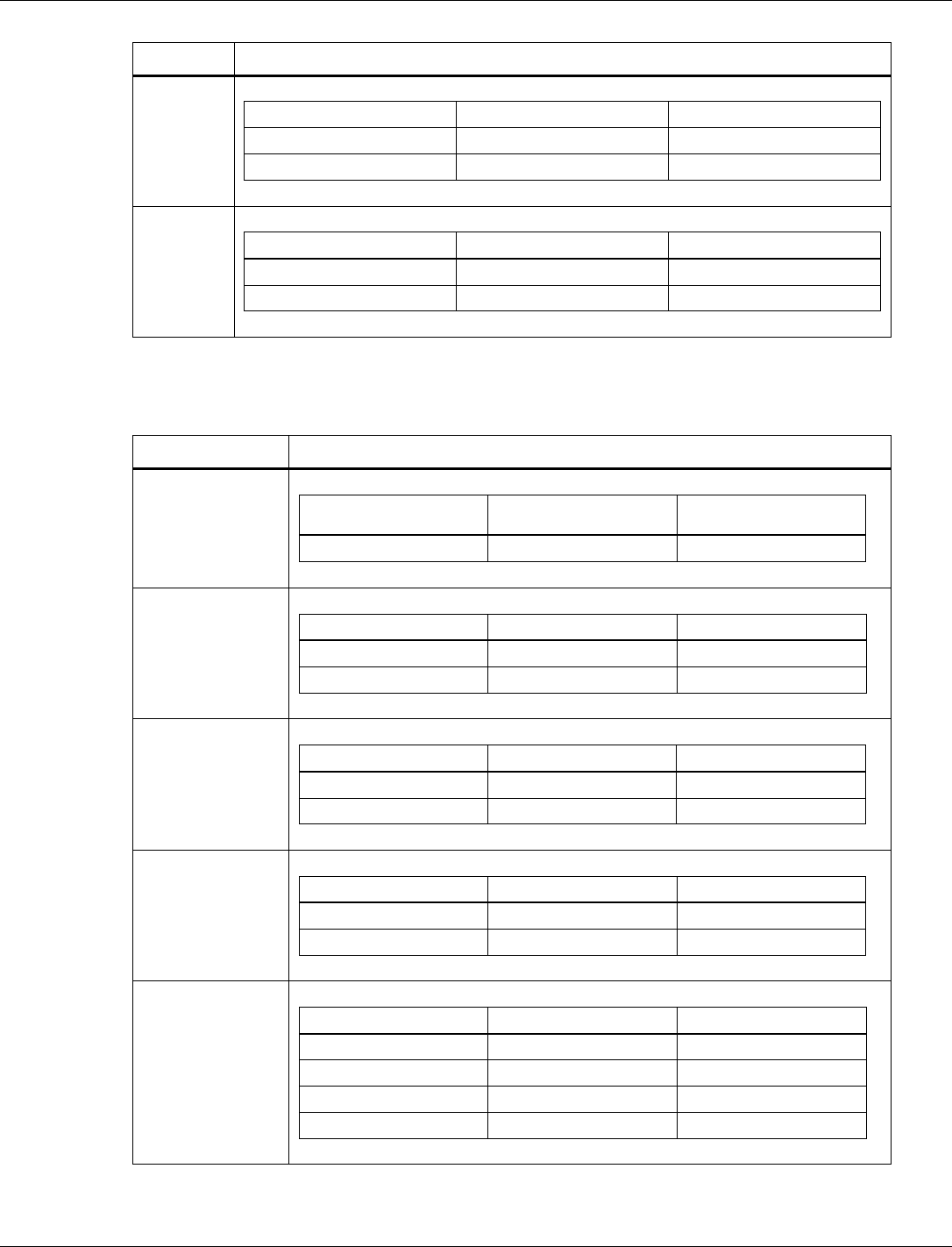
QCA402x (CDB2x) Programmer’s Guide Configure GPIO functions
80-YA121-142 Rev. D MAY CONTAIN U.S. AND INTERNATIONAL EXPORT CONTROLLED INFORMATION 114
Pin name
Description
GPIO[59]
GPIO configuration
Interface
Signal
0
GPIO
GPIO[59]
2
UART
HS_UART2_DM_CTS (I)
GPIO[60]
GPIO configuration
Interface
Signal
0
GPIO
GPIO[60]
4
UART
HS_UART2_DM_TXD (O)
Table A-2 QCA4020 GPIO function configuration
Pin name
Description
GPIO[4]
GPIO configuration
Interface
Signal
1
GPIO
WL_WKUP_BE
GPIO[5]
GPIO configuration
Interface
Signal
1
GPIO
BT_ACTIVE
4
Keypad
KEY_COL_1_0
GPIO[6]
GPIO configuration
Interface
Signal
1
GPIO
WLAN_ACTIVE
4
Keypad
KEY_COL_1_1
GPIO[7]
GPIO configuration
Interface
Signal
1
GPIO
BT_PRIORITY
2
Keypad
KEY_COL_1_2
GPIO[13]
GPIO configuration
Interface
Signal
0
GPIO
GPIO[13]
1
PWM
pwm_out_7
3
Keypad
key_row_0_6
4
Keypad
key_col_1_4

QCA402x (CDB2x) Programmer’s Guide Configure GPIO functions
80-YA121-142 Rev. D MAY CONTAIN U.S. AND INTERNATIONAL EXPORT CONTROLLED INFORMATION 115
Pin name
Description
GPIO[14]
GPIO configuration
Interface
Signal
0
GPIO
GPIO[14]
1
UART
HS_UART0_DM_CTS
2
Keypad
key_col_0_0
3
Keypad
key_col_1_5
GPIO[15]
GPIO configuration
Interface
Signal
0
GPIO
GPIO[15]
1
UART
HS_UART0_DM_TXD
2
Keypad
Key_col_0_1
3
Keypad
key_col_1_6
GPIO[28]
GPIO configuration
Interface
Signal
0
GPIO
GPIO[28]
1
I2S
I2S_BCLK
GPIO[29]
GPIO configuration
Interface
Signal
0
GPIO
GPIO[29]
1
I2S
I2S_RXD
GPIO[30]
GPIO configuration
Interface
Signal
0
GPIO
GPIO[30]
1
I2S
I2S_TXD
GPIO[31]
GPIO configuration
Interface
Signal
0
GPIO
GPIO[31]
1
I2S
I2S_FSYNC
GPIO[32]
GPIO configuration
Interface
Signal
0
GPIO
GPIO[32]
1
I2S
I2S_MCLK
GPIO[33]
GPIO configuration
Interface
Signal
1
GPIO
CHIP_PWD_L_WL

QCA402x (CDB2x) Programmer’s Guide Configure GPIO functions
80-YA121-142 Rev. D MAY CONTAIN U.S. AND INTERNATIONAL EXPORT CONTROLLED INFORMATION 116
Pin name
Description
GPIO[41]
GPIO configuration
Interface
Signal
1
GPIO
PWR_STATUS
GPIO[48]
GPIO configuration
Interface
Signal
1
GPIO
Ext_32K_IN
GPIO[49]
GPIO configuration
Interface
Signal
0
GPIO
GPIO[49]
GPIO[50]
GPIO configuration
Interface
Signal
0
GPIO
GPIO[50]
GPIO[51]
GPIO configuration
Interface
Signal
0
GPIO
GPIO[51]
GPIO[52]
GPIO configuration
Interface
Signal
0
GPIO
GPIO[52]
GPIO[53]
GPIO configuration
Interface
Signal
0
GPIO
GPIO[53]
GPIO[54]
GPIO configuration
Interface
Signal
0
GPIO
GPIO[54]
