McD H52 Service Manual Cover MH52 819 5423 Apr 02
User Manual: MH52
Open the PDF directly: View PDF ![]() .
.
Page Count: 112 [warning: Documents this large are best viewed by clicking the View PDF Link!]
SERVICE MANUAL
FRYMASTER MH52 AND BIH52 SERIES
GAS FRYERS
TABLE OF CONTENTS
WARRANTY STATEMENT .................................................................................................. Page i
INTRODUCTION .................................................................................................................. Page 1-1
INSTALLATION INSTRUCTIONS ........................................................................................ Page 2-1
SERVICE PROCEDURES, TROUBLESHOOTING, AND WIRING DIAGRAMS ................. Page 3-1
PARTS LIST.......................................................................................................................... Page 4-1
Frymaster, L.L.C. 8700 Line Avenue 71106, 5489 Campus Drive 71129
P.O. Box 51000, Shreveport, Louisiana 71135-1000
TEL 318-865-1711 FAX (Parts) 318-219-7140 (Tech Support) 318-219-7135
PRINTED IN THE UNITED STATES SERVICE HOTLINE 819-5423 APR 2002
FOR YOUR SAFETY
Do Not Store or use gasoline or other
flammable vapors and liquids in the
vicinity of this or any other appliance.
This equipment chapter is to be
installed in the Fryer Section of the
Equipment Manual.
MANUFACTURED
BY
FRYMASTER, L.L.C.
P.O. BOX 51000
SHREVEPORT, LOUISIANA 71135-1000
PHONE: 1-318-865-1711
TOLL FREE: 1-800-551-8633
1-800-24 FRYER
FAX: 1-318-219-7135
1-800-24-FRYER U.S. $10.00
WARNING
IMPROPER INSTALLATION, ADJUSTMENT, ALTERATION, SERVICE OR MAINTENANCE CAN CAUSE PROPERTY
DAMAGE, INJURY OR DEATH. READ THE INSTALLATION, OPERATING AND MAINTENANCE INSTRUCTIONS
THOROUGHLY BEFORE INSTALLING OR SERVICING THIS EQUIPMENT.
WARNING
FOR YOUR SAFETY, DO NOT STORE OR USE GASOLINE OR OTHER FLAMMABLE VAPORS AND LIQUIDS IN THE
VICINITY OF THIS OR ANY OTHER APPLIANCE.
COMPUTERS
FCC
This device complies with Part 15 of the FCC rules. Operation is subject to the following two conditions: 1)This
device may not cause harmful interference, and 2) This device must accept any interference received, including
interference that may cause undesired operation. While this device is a verified Class A device, it has been
shown to meet the Class B limits
CANADA
This digital apparatus does not exceed the Class A or B limits for radio noise emissions as set out by
the ICES-003 standard of the Canadian Department of Communications.
Cet appareil numerique n'emet pas de bruits radioelectriques depassany les limites de classe a et b
prescrites dans la norme NMB-003 edictee par le ministre des communications du Canada.
WARNING
THIS PRODUCT CONTAINS CHEMICALS KNOWN TO THE STATE OF CALIFORNIA TO CAUSE CANCER AND/OR
BIRTH DEFECTS OR OTHER REPRODUCTIVE HARM.
Operation, installation and servicing of this product could expose you to airborne particles of glasswool or ceramic fibers,
crystalline silica, and/or carbon monoxide. Inhalation of airborne particles of glasswool or ceramic fibers is known to the
State of California to cause cancer. Inhalation of carbon monoxide is known to the State of California to cause birth
defects or other reproductive harm.
FRYMASTER FRYERS ARE MANUFACTURED FOR USE WITH THE TYPE VOLTAGE AND GAS SPECIFIED ON THE
FRYER RATING PLATE LOCATED ON THE FRYER DOOR. FOR PROPER ELECTRICAL INSTALLATION
PROCEDURES IN THE UNITED STATES, REFER TO THE LATEST EDITION OF THE NATIONAL ELECTRIC CODE
ANSI/N.F.P.A. NO. 70; IN CANADA, CANADIAN ELECTRICAL CODE PART 1, CSA-22.1. FOR INSTALLATION IN
COUNTRIES OTHER THAN THE UNITED STATES AND CANADA, REFER TO THE NATIONAL CODE APPROPRIATE
FOR THE COUNTRY IN WHICH THE EQUIPMENT IS BEING INSTALLED. FOR GAS COMPONENTS, INSTALLATION
IS TO COMPLY WITH THE BASIC PLUMBING CODE OF THE BUILDING OFFICIALS AND CODE ADMINISTRATORS
INTERNATIONAL, INC. (BOCA) AND THE FOOD SERVICE SANITATION MANUAL OF THE U.S. FOOD AND DRUG
ADMINISTRATION (US FDA) OR THE APPLICABLE NATIONAL AND LOCAL REGULATIONS OF THE COUNTRY IN
WHICH THE EQUIPMENT IS BEING INSTALLED.
INFORMATION ON THE CONSTRUCTION AND INSTALLATION OF VENTILATING HOODS MAY BE OBTAINED FROM
THE LATEST EDITION OF THE "STANDARD FOR THE INSTALLATION OF EQUIPMENT FOR THE REMOVAL OF
SMOKE AND GREASE LADEN VAPORS FROM COMMERCIAL COOKING EQUIPMENT,” N.F.P.A. NO. 96. COPIES OF
THESE ELECTRICAL STANDARDS ARE AVAILABLE FROM THE NATIONAL FIRE PROTECTION ASSOCIATION,
BATTERY MARCH PARK, QUINCY, MASS. 02269
i
WARRANTY STATEMENT
The following applies to equipment sold to domestic (U.S.) markets. International warranty
provisions will vary depending upon the country in which the equipment is sold. See your dealer
for specific warranty provisions applicable to your location. For all international warranties, the
customer is responsible for freight and duty charges.
Frymaster, L.L.C. makes the following limited warranties to the original purchaser only for this
equipment and replacement parts:
A. WARRANTY PROVISIONS - FRYERS
1. The Frymaster Corporation warrants all components against defects in material and
workmanship for a period of one year.
2. All parts, with the exception of fuses and filter O-rings, are warranted for one year after
installation date of fryer. (See Sections B and C for frypot and combustion chamber
warranty duration.)
3. If any parts, except fuses and filter O-rings, become defective during the first year after
installation date, Frymaster will also pay straight-time labor costs to replace the part, plus up
to 100 miles/160 km of travel (50 miles/80 km each way).
B. WARRANTY PROVISIONS - FRYPOTS
(Applies to fryers installed on or after November 1, 1994, only.)
1. If a frypot develops a leak within seven years after installation, Frymaster will replace the
frypot, allowing up to the maximum time per the Frymaster time allowance chart of straight-
time labor plus up to 100 miles/160 km of travel (50 miles/80 km each way) to change the
frypot.
2. This warranty is limited to fryers operating on natural or propane (LP) gas. Fryers that
operate on manufactured gas (also known as town gas or high-hydrogen gas) have a lifetime
frypot warranty, parts only.
C. WARRANTY PROVISIONS – COMBUSTION CHAMBERS
(Applies to fryers installed on or after November 1, 1994, only.)
1. The Frymaster Corporation warrants the combustion chambers against defective material or
workmanship for a period of seven years from the original installation date, parts and labor.
2. The combustion chamber consists of the infrared burners and the structural components to
mount the burners. This warranty does not cover ancillary components, including the ignitor,
blower, high-limit thermostat, and temperature probe.
3. This warranty is limited to fryers operating on natural or propane (LP) gas.
ii
D. WARRANTY PROVISIONS - COOKING COMPUTER
1. The Frymaster Corporation warrants the M-100B Cooking Computer against defective
material or workmanship for a period of one year from the original installation date, parts and
labor. Replacements for defective units during the second and third year are available at a
reduced rate.
2. During this warranty period, Frymaster will, at its option, repair or replace defective cooking
computer returned with new or factory rebuilt and functionally operative units.
3. For replacement of defective computers under warranty, call your local Frymaster Factory
Authorized Service Center. All computers replaced under the Frymaster exchange program
are covered by a one-year (parts only) warranty.
E. PARTS RETURN
All defective in-warranty parts must be returned to a Frymaster Authorized Factory Service
Center within 60 days for credit. After 60 days, no credit will be allowed.
F. WARRANTY EXCLUSIONS
This warranty does not cover equipment that has been damaged due to misuse, abuse, alteration,
or accident such as:
• improper or unauthorized repair (including any frypot which is welded in the field);
• failure to follow proper installation instructions and/or scheduled maintenance procedures as
prescribed in your MRC cards (proof of scheduled maintenance is required to maintain the
warranty);
• improper maintenance;
• damage in shipment;
• abnormal use;
• removal, alteration, or obliteration of either the rating plate or the date code on the heating
elements;
• operating the frypot without shortening or other liquid in the frypot;
• no fryer will be warranted under the seven-year program for which a proper start-up form has
not been received.
This warranty also does not cover:
• transportation or travel over 100 miles/160 km (50 miles/80 km each way), or travel over two
hours;
• overtime or holiday charges;
• consequential damages (the cost of repairing or replacing other property which is damaged),
loss of time, profits, use or any other incidental damages of any kind.
There are no implied warranties of merchantability or fitness for any particular use or purpose.

1-1
CHAPTER 1: INTRODUCTION
1.1 General
Read the instructions in this manual thoroughly before attempting to service this equipment. This
manual covers all configurations of models MH52 and BIH52 fryers built since December 1995.
Models designated MH52 do not have built-in filtration systems. Models designated BIH52 are
equipped with FootPrint III built-in filtration systems.
H52 Series fryers feature deep cold-zones and easy to clean open frypots. The fryers are controlled by
multi-product cooking computers or optional thermostat controllers. Fryers in this series come in full
or split-pot arrangements, and can be purchased as single units or grouped in batteries of up to five
fryers.
1.2 Safety Information
Before attempting to service this equipment, read the instructions in this manual thoroughly.
Throughout this manual, you will find notations enclosed in double-bordered boxes similar to the ones
below.
CAUTION boxes contain information about actions or conditions that may cause or result in a
malfunction of the system.
CAUTION
Example of a CAUTION box.
WARNING boxes contain information about actions or conditions that may cause or result in
damage to the system, and which may cause the system to malfunction.
WARNING
Example of a WARNING box.
DANGER boxes contain information about actions or conditions that may cause or result in injury to
personnel, and which may cause damage to your system and/or cause the system to malfunction.
DANGER
Hot cooking oil causes severe burns. Never attempt to move a fryer containing hot
cooking oil or to transfer hot cooking oil from one container to another.
Fryers in this series are equipped with automatic safety features:
1. A high-limit thermostat causes the gas valve to close should the controlling thermostat fail or
computer temperature probe fail.
2. In BIH52 fryers, a safety switch built into the drain valve prevents the gas valve from opening
with the drain valve even partially open.

1-2
1.3 Computer Information
This equipment has been tested and found to comply with the limits for a Class A digital device,
pursuant to Part 15 of the FCC rules. While this device is a verified Class A device, it has been shown
to meet the Class B limits. These limits are designed to provide reasonable protection against harmful
interference when the equipment is operated in a commercial environment. This equipment generates,
uses and can radiate radio frequency energy and, if not installed and used in accordance with the
instruction manual, may cause harmful interference to radio communications. Operation of the
equipment in a residential area is likely to cause harmful interference in which case the user will be
required to correct the interference at his own expense.
The user is cautioned that any changes or modifications not expressly approved by the party
responsible for compliance could void the user's authority to operate the equipment.
If necessary, the user should consult the dealer or an experienced radio and television technician for
additional suggestions.
The user may find the following booklet prepared by the Federal Communications Commission
helpful: "How to Identify and Resolve Radio-TV Interference Problems". This booklet is available
from the U.S. Government Printing Office, Washington, DC 20402, Stock No. 004-000-00345-4.
1.4 European Community (CE) Specific Information
The European Community (CE) has established certain specific standards regarding equipment of this
type. Whenever a difference exists between CE and non-CE standards, the information or instructions
concerned are identified by means of shadowed boxes similar to the one below.
CE Standard
Example of box used to distinguish CE and
Non-CE specific information.

2-1
CHAPTER 2: INSTALLATION INSTRUCTIONS
2.1 General Installation Requirements
NOTE: PROPER INSTALLATION IS ESSENTIAL FOR EFFICIENT, TROUBLE-FREE
OPERATION OF YOUR FRYER. ANY UNAUTHORIZED ALTERATIONS MADE TO THIS
EQUIPMENT WILL VOID THE FRYMASTER WARRANTY.
Upon arrival, inspect the fryer carefully for visible or concealed damage. (See Shipping Damage
Claim Procedure in Chapter 1.)
CLEARANCE AND VENTILATION
The fryer(s) must be installed with a 6” (150 mm) clearance at both sides and back when installed
adjacent to combustible construction; no clearance is required when installed adjacent to noncom-
bustible construction. A minimum of 24” (600 mm) clearance should be provided at the front of the
fryer.
One of the most important considerations of efficient fryer operation is ventilation. Make sure the
fryer is installed so that products of combustion are removed efficiently, and that the kitchen ventila-
tion system does not produce drafts that interfere with proper burner operation.
The fryer flue opening must not be placed close to the intake of the exhaust fan, and the fryer must
never have its flue extended in a “chimney” fashion. An extended flue will change the combustion
characteristics of the fryer, causing longer recovery time. It also frequently causes delayed ignition.
To provide the airflow necessary for good combustion and burner operation, the areas surrounding
the fryer front, sides, and rear must be kept clear and unobstructed.
Fryers must be installed in an area with an adequate air supply and adequate ventilation. Adequate
distances must be maintained from the flue outlet of the fryer to the lower edge of the ventilation
filter bank. Filters should be installed at an angle of 45º. Place a drip tray beneath the lowest edge of
the filter. For U.S. installation, NFPA standard No. 96 states, “A minimum distance of 18 in. (450
mm) should be maintained between the flue outlet and the lower edge of the grease filter.”
Frymaster recommends that the minimum distance be 24 in. (600 mm) from the flue outlet to the
bottom edge of the filter when the appliance consumes more than 120,000 BTU per hour.
For installations in the United States, information on construction and installation of ventilating
hoods can be found in the NFPA standard cited above. A copy of the standard may be obtained from
the National Fire Protection Association, Battery March Park, Quincy, MA 02269.
DANGER
Do not attach an apron drainboard to a single fryer. The fryer may become unstable,
tip over, and cause injury. The appliance area must be kept free and clear of com-
bustible material at all times.

2-2
NATIONAL CODE REQUIREMENTS
The type of gas for which the fryer is equipped is stamped on the data plate attached to the inside of
the fryer door. Connect a fryer stamped “NAT” only to natural gas, those stamped “PRO” only to
propane gas, and those stamped “MFG” only to manufactured gas.
Installation shall be made with a gas connector that complies with national and local codes, and,
where applicable, CE codes. Quick-disconnect devices, if used, shall likewise comply with national,
local, and, if applicable, CE codes.
ELECTRICAL GROUNDING REQUIREMENTS
All electrically operated appliances must be grounded in accordance with all applicable national and
local codes, and, where applicable, CE codes. A wiring diagram is located on the inside of the fryer
door. Refer to the rating plate on the inside of the fryer door for proper voltages.
DANGER
If this appliance is equipped with a three-prong (grounding) plug, it must be plugged
directly into a properly grounded receptacle.
Do not cut or remove the grounding prong from the plug.
DANGER
This equipment requires electrical power for operation.
Place the gas control valve in the OFF position in case of a prolonged power outage.
Do not attempt to use the equipment during a power outage.
FCC COMPLIANCE
The user is cautioned that any changes or modifications to Frymaster computers not expressly ap-
proved by the party responsible for compliance could void the user’s authority to operate the equip-
ment.
Frymaster computers have been tested and found to comply with the limits for a Class A digital de-
vice, pursuant to Part 15 of the FCC rules. While these devices are verified as Class A devices, they
have been shown to meet the Class B limits. These limits are designed to provide reasonable protec-
tion against harmful interference when the equipment is operated in a commercial environment. This
equipment generates, uses, and can radiate radio frequency energy and, if not installed and used in
accordance with the instruction manual, may cause harmful interference to radio communications.
Operation of the equipment in a residential area is likely to cause harmful interference in which case
the user will be required to correct the interference at his own expense.
If necessary, the user should consult the dealer or an experienced radio and television technician for
additional suggestions.

2-3
The user may find the booklet “How to Identify and Resolve Radio-TV Interference Problems” help-
ful. It is prepared by the Federal Communications Commission and is available from the U.S. Gov-
ernment Printing Office, Washington, DC 20402, Stock No. 004-000-00345-4.
2.2 Caster/Leg Installation
Depending upon the specific configuration ordered, your fryer may have been shipped without in-
stalled casters or legs. If casters or legs are installed, you may skip this section and proceed to sec-
tion 2.3, Pre-Connection Preparations.
If your fryer requires the installation of casters/legs, install them in accordance with the in-
structions included in your accessory package.
2.3 Pre-Connection Preparations
DANGER
Do not connect fryer to gas supply before completing each step
in this section.
After the fryer has been positioned under the fry station exhaust hood, ensure the following has been
accomplished:
1. Adequate means must be provided to limit the movement of fryers without depending upon the
gas line connections. If a flexible gas hose is used, a restraining cable must be connected at all
times when the fryer is in use. The restraining cable and installation instructions are packed with
the flexible hose in the accessories box that was shipped with your unit.
2. Single unit fryers must be stabilized by installing restraining chains on fryers equipped with
casters or anchor straps on fryers equipped with legs. Follow the instructions shipped with the
casters/legs to properly install the chains or straps.
3. Level the fryer, if necessary, by loosening the locking screw on the caster legs and rotating the
leg to increase or decrease the exposed length. Verify that the fryer is at the proper height in the
exhaust hood. Frymaster recommends that the minimum distance from the flue outlet to the
bottom edge of the hood be 24 in. (600 mm) when the appliance consumes more than 120,000
BTU per hour.
4. Test the fryer electrical system:
a. Plug the fryer electrical cord(s) into a grounded electrical receptacle.
b. Place the power switch in the ON position.
• For fryers equipped with thermostat controls, note the illumination of the power light and
the heat light.
• For fryers having computers, note that the display reads LO-TEMP
LO-TEMPLO-TEMP
LO-TEMP and the heat light
comes on.
• If the store is equipped with a hood interlock system, the hood exhaust fan should be on.
If not, the store hood interlock system is improperly wired and must be corrected.
2-4
c. Place the fryer power switch in the OFF position. Verify that the power and heat lights are
out, or that the display is blank.
5. Refer to the data plate on the inside of the fryer door to determine if the fryer burner is config-
ured for the proper type of gas before connecting the fryer quick-disconnect device or piping
from the gas supply line.
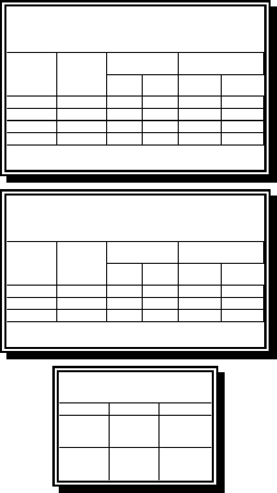
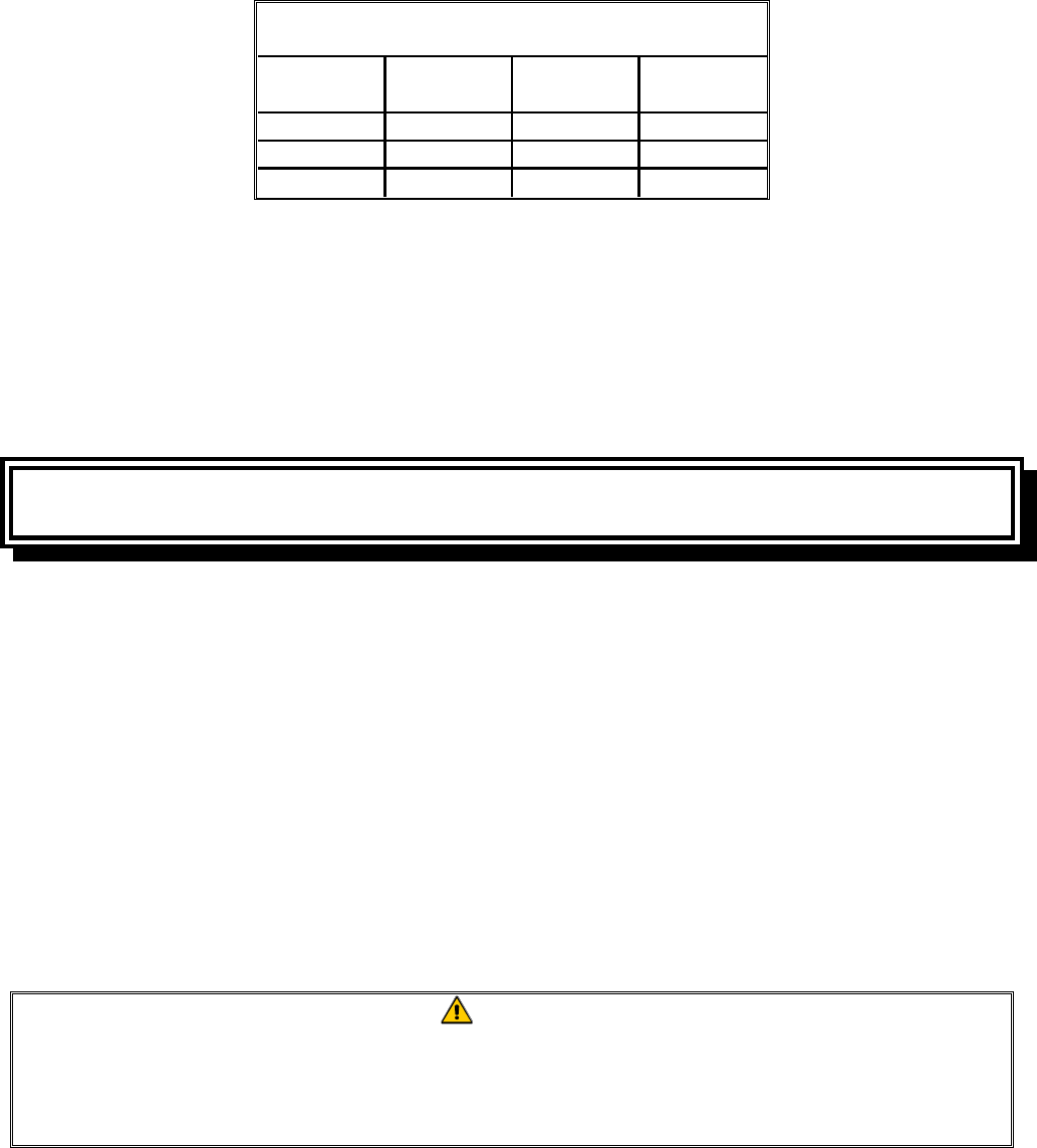
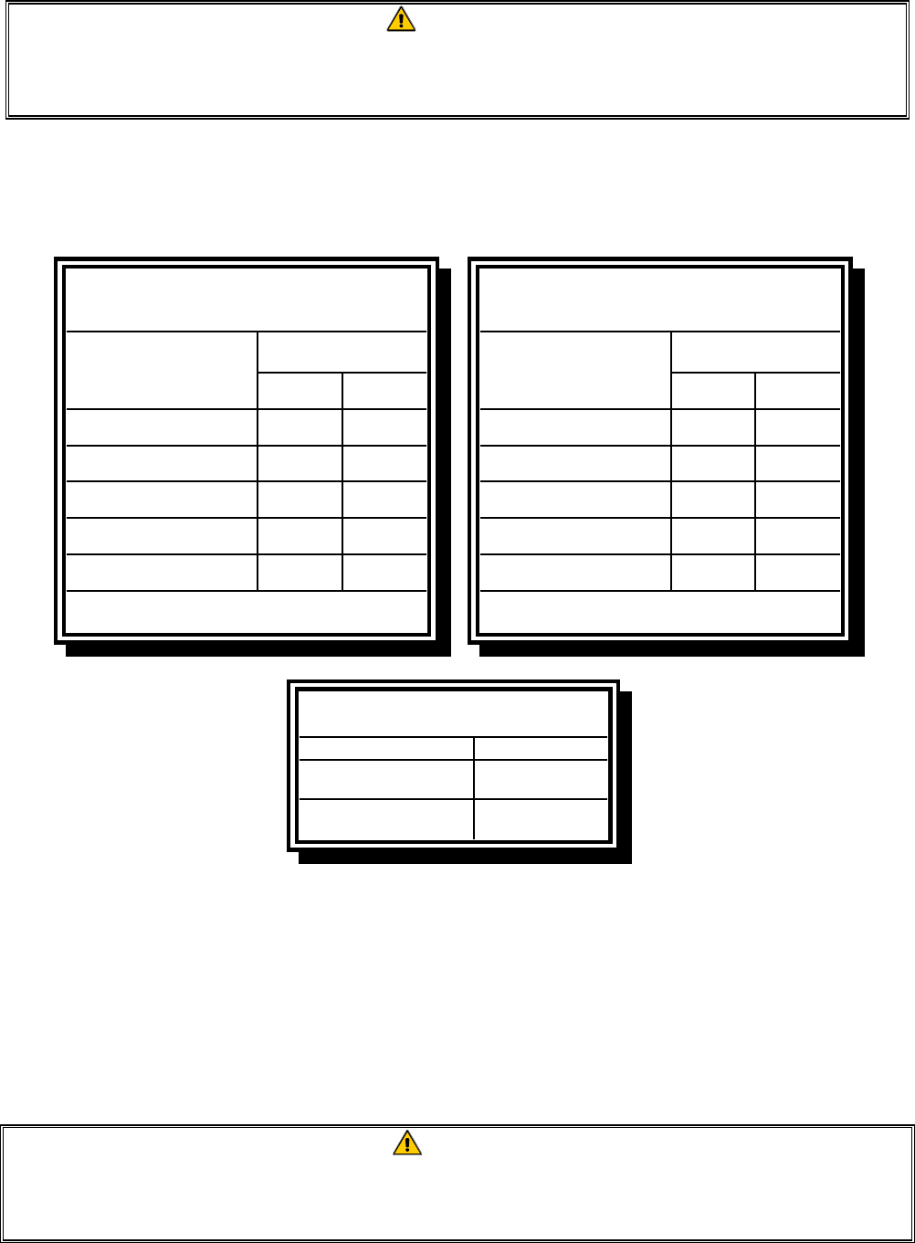
6. Verify the minimum and maximum gas supply pressures for the type of gas to be used in accor-
dance with the accompanying tables.
Orifice Diameter
Single
Vat
Dual
Vat
Single
Vat
Dual
Vat
G20 20 2 x 3.40 2 x 3.40 7 mbar 6.5 mbar
G25 20 or 25 2 x 3.40 2 x 3.40 10 mbar 9 mbar
G30 28/30 or 50 2 x 2.05 2 x 2.05 17 mbar 17 mbar
G31 37 or 50 2 x 2.05 2 x 2.05 20 mbar 18.5 mbar
CE Standard
for Incoming Gas Pressures
for Fryers Manufactured After April 1999
(1) mbar = 10.2 mm H2O
Gas
Pressure
(mbar)(1)
Regulator Pressure
Orifice Diameter
Single
Vat
Dual
Vat
Single
Vat
Dual
Vat
G20 20 2 x 3.40 2 x 3.40 7 mbar 6.5 mbar
G25 20 - 25 2 x 3.40 2 x 3.40 10 mbar 9 mbar
G31 37 - 50 2 x 2.05 2 x 2.05 20.2 mbar 18.5 mbar
CE Standard
for Incoming Gas Pressures
for Fryers Manufactured Through April 1999
(1) mbar = 10.2 mm H2O
Gas
Pressure
(mbar)(1)
Regulator Pressure
Non-CE Standard
for Incoming Gas Pressures
Gas Minimum Maximum
Natural
6" W.C.
1.49 kPa
14.93 mbar
14" W.C.
3.48 kPa
34.84 mbar
LP
11" W.C.
2.74 kPa
27.37 mbar
14" W.C.
3.48 kPa
34.84 mbar
7. For fryers equipped with a FootPrint III system (BIH52 models), plug the electrical cord into a
power receptacle behind the fryer.

2-5
2.4 Connection to Gas Line
The H52 Series has received the CE mark for the countries and gas categories indicated in the
accompanying table. NOTE: The nominal heat input (Qn) is 21kW except for AT, DE, LU, and for
category 3B/P under 50 mbar, which is 23kW.
COUNTRIES CATEGORIES GAS PRESSURE (mbar)
G20 20
G30, G31 50
I2E(R)B G20, G25 20, 25
I3+ G30, G31 28-30, 37
G20 20
G30, G31 30
G20, G25 20, 25
G30, G31 28-30, 37
G20, G25 20, 25
G31 50
G20 20
G30, G31 30
G20, G25 20
G30, G31 50
I3P G31 50
G20 20
G30, G31 28-30, 37
G20 20
G30, G31 28-30, 37
G20 20
G30, G31 28-30, 37
G20 20
G30, G31 50
G25 25
G31 50
G25 25
G30, G31 30
NORWAY (NO) I3B/P G30, G31 30
G20 20
G30, G31 28-30, 37
G20 20
G30, G31 28-30, 37
G20 20
G31 37, 50
G20 20
G30, G31 30
G20 20
G30, G31 28-30, 37
II2ELL3B/P
II2H3B/P
II2Esi3+
II2Esi3P
II2H3B/P
II2E3B/P
II2H3+
II2H3+
II2H3+
II2H3+
II2H3+
II2L3B/P
II2L3P
UNITED KINGDOM (GB) II2H3+
II2H3B/P
II2H3P
NETHERLANDS (NL)
PORTUGAL (PT)
SPAIN (ES)
SWEDEN (SE)
GREECE (GR)
ITALY (IT)
IRELAND (IE)
LUXEMBOURG (LU)
DENMARK (DK)
FRANCE (FR)
FINLAND (FI)
GERMANY (DE)
CE Approved Gas Categories by Country*
AUSTRIA (AT) II2H3B/P
BELGIUM (BE)
* H152-2 units are not approved for G30 (Butane) gas.
The size of the gas line used for installation is very important. If the line is too small, the gas pres-
sure at the burner manifold will be low. This may cause slow recovery and delayed ignition. Fry-
master recommends the incoming gas supply line be a minimum of 1½” (38 mm) in diameter. Refer
to the chart on the following page for the minimum sizes of connection piping.
2-6
Gas Connection Pipe Sizes
(Minimum incoming pipe size should be 1 1/2" (38 mm))
Natural 3/4" (19 mm) 1" (25 mm) 1 1/4" (33 mm)
Propane 1/2" (13 mm) 3/4" (19 mm) 1" (25 mm)
Manufactured 1" (25 mm) 1 1/4" (33 mm) 1 1/2" (38 mm)
Gas Single Unit 2 - 3 Units
4 or more
units*
* For distances of more than 20 feet (6 m) and/or
more than 4 fittings or elbows, increase the con-
nection by one pipe size.
Before connecting new pipe to your unit, the pipe must be thoroughly blown out to remove any for-
eign particles. If these foreign particles get into the burner and controls, they will cause improper
and sometimes dangerous operation.
CE Standard
Required airflow for the combustion air supply is 2m3/h per kW.
1. Connect the quick-disconnect hose to the fryer quick-disconnect fitting under the front of the
fryer and to the building gas line.
NOTE: Some fryers are configured for a rigid connection to the gas supply line. These units are
connected to the gas supply line at the rear of the unit.
When using thread compound, use very small amounts on male threads only. Use a pipe thread
compound that is not affected by the chemical action of LP gases (Loctite™ PST56765 Sealant is
one such compound). DO NOT apply compound to the first two threads. This will ensure that
the burner orifices and control valve do not become clogged.
2. Open the gas supply to the fryer and check all piping, fittings, and gas connections for leaks. A
soap solution should be used for this purpose.
DANGER
Never use matches, candles, or any other ignition source to check for leaks.
If gas odors are detected, shut off the gas supply to the fryer
at the main shut-off valve and contact the local gas company or an authorized
service agency for service.
3. Close the fryer drain valve and fill the frypot with water and boil-out solution to the bottom OIL-
LEVEL line at the rear of the frypot. Light the fryer and perform the boil-out procedures that are
described in the “Lighting Instructions” and “Boiling Out the Frypot” topics found in Chapter 3
of this manual.
2-7
WARNING
“Dry-firing” your unit will cause damage to the frypot. Always ensure that melted
shortening, cooking oil, or water and boil-out solution is in the frypot before firing
your unit for any extended period.
4. It is suggested that the burner manifold pressure be checked at this time by the local gas company
or an authorized service agent. Refer to “Check Burner Manifold Pressure” in Chapter 5 of this
manual for the proper procedure. The accompanying tables list the burner manifold gas pressures
for the various gas types that can be used with this equipment.
Gas
Single
Vat
Dual
Vat
Natural Gas Lacq
(G20) under 20 mbar 77
Natural Gas Groningue *
(G25) under 25 mbar 10 10
Natural Gas Groningue
(G25) under 20 mbar 10 10
Butane
(G30) at 28/30 or 50 mbar 17 17
Propane
(G31) under 37 or 50 mbar 20 20
CE Standard
Burner Manifold Gas Pressures
for Fryers Manufactured After April 1999
Pressure (mbar)
* Belgian G25 = 7,0 mbar (single or dual)
Gas
Single
Vat
Dual
Vat
Natural Gas Lacq
(G20) under 20 mbar 76,5
Natural Gas Gronigue *
(G25) under 25 mbar 10 9
Natural Gas Gronigue
(G25) under 20 mbar 10 9
Butane
(G30) at 28/30 or 50 mbar 17 16,5
Propane
(G31) under 37 or 50 mbar 20,2 18,5
CE Standard
Burner Manifold Gas Pressures
for Fryers Manufactured Through April 1999
Pressure (mbar)
* Belgian G25 = 7,0 mbar (single) or 6,5 (dual)
Gas Pressure
Natural 3" W.C.
0.73 kPa
Propane 8.25" W.C.
2.5 kPa
Non-CE Standard
Burner Manifold Gas Pressures
5. Check the programmed temperature or analog controller thermostat setting. (Refer to Chapter 3,
Operating Instructions, for the setpoint programming instructions for your particular controller.)
2.5 Converting to Another Gas Type
Your fryer is configured at the factory for either natural gas or propane (LP) gas. If you desire to
switch from one type of gas to another, a gas conversion kit must be installed by a Factory
Authorized Service Center technician.
DANGER
Switching to a different type of gas without installing the proper conversion kit may
result in fire or explosion! NEVER attach your fryer to a gas supply for which it is
not configured.

2-8
H52 Series Fryers manufactured for Non-CE countries use different burners for each type gas. The
burners in fryers built for Propane gas have a special gray-colored coating on the burner tiles to en-
able them to withstand the higher caloric value of the Propane gas. Burners designed for use in Pro-
pane units may be used in natural gas applications, but not vice versa.
Non-CE Gas Conversion Kits
Natural Gas to Propane (LP) Gas Propane (LP) Gas to Natural Gas
Full Vat: Part Number 826-1145 Full Vat: Part Number 826-1146
Dual Vat: Part Number 826-1147 Dual Vat: Part Number 826-1148
Units manufactured for export to CE countries are equipped with “universal” burners that may be
used with either natural (G20, G25) gas or Butane (G30) and Propane (G31) gasses.
CE Gas Conversion Kits for Units with Gas Valve 810-1011
G20 or G25 (Natural) to G30 or G31 Gas: G30 or G31 to G20 or G25 (Natural) Gas:
Part Number 826-1196 Part Number 826-1197
CE GAS CONVERSION INSTRUCTIONS
1. Between G20- and G25-type Natural Gas, adjust the gas pressure at the regulator. (Refer to the
CE Standard Burner Manifold Gas Pressure Chart.) Do not change the orifice.
2. Between a 2nd family (G20 or G25) and a 3rd family gas (G30 Butane or G31 Propane):
a. Change the orifices.
b. Change the gas valve spring (units with valve part number 810-1011only)
c. Adjust the manifold pressure.
3. Remove the rating plate and install a new one. Call your local service agency or KES for a new
rating plate.
4. If the destination language changes, replace the labels. Call your local service agency or KES for
a label kit. The language of reference will be on the corner of the label.
2.6 Frypot Boil-Out
Before the fryer is first used for cooking product, it should be boiled out to ensure that any residue
from the manufacturing process has been eliminated.
In addition, after the fryer has been in use for a period of time, a hard film of caramelized vegetable
oil will form on the inside of the frypot. This film should be periodically removed by following the
boil-out procedure.
Refer to Fryers Maintenance Requirement Card (MRC) 14A for the boil-out procedure.
3-1
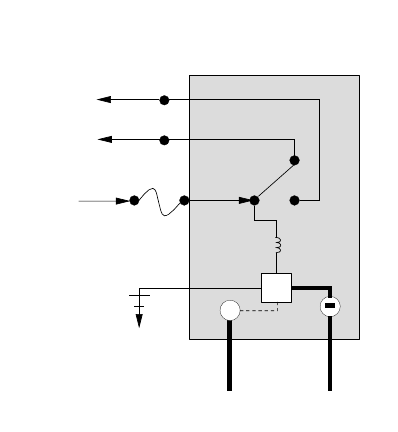
Inside the Ignition Module
TD
Out to
Gas Valve
To Ala rm
25 V +
GND
HV
Ignition Wire Flame Sensor
Coil
CHAPTER 3: SERVICE PROCEDURES,
TROUBLESHOOTING, AND WIRING DIAGRAMS
3.1 Functional Description
H52 Series fryers contain a welded stainless steel frypot that is directly heated by a high efficiency
infrared burner system requiring approximately 43% less energy than conventional burners to cook
the same volume.
Self-contained combustion chambers (referred to as “burners”) are fitted into rails attached to the
sides of the frypot, one on each side. Each combustion chamber is fitted with special ceramic tiles
that are heated by the burning of a forced air/gas mixture. The tiles transfer their heat to the frypot
by means of infrared radiation, providing much more constant and uniform heat dispersion over the
surface of the frypot than do conventional burners. Because relatively less heat is lost to the atmos-
phere in the process, compared to “open-burner” designs, less fuel is required to achieve and main-
tain a given frypot temperature.
In full-vat units, gas flow to both of the burners is regulated by one electromechanical gas valve. In
dual-vat units, each burner has its own valve. All fryers in this series are equipped with 24VAC gas
valve systems, and all are configured with electronic ignition.
THE ELECTRONIC IGNITION SYSTEM
An ignition module mounted in the component box or
“shield” (located behind the control panel) is connected to
an ignitor assembly at the burner. The ignition module
performs three important functions: it provides an ignition
spark, supplies voltage to the gas valve, and proofs the
burner flame. The module contains a 4-second time delay
circuit and a coil that activates the gas valve. Three designs
are in use. The module used in Australian export units
resembles an interface board. A closed-box design is used
in units built for the U.S. and other export markets. Before
mid-2001, fryers (other than Australian) were equipped
with two 807-1006 modules. Fryers built after mid-2001
late-2000 are equipped with one 807-3365 (dual vat) or one
807-3366 (full vat) module. Fryers built between late-2000
and mid-2001 may have either configuration. Australian
units continue to use two 807-2971 modules.
The ignitor assembly consists of a spark plug, an enrichment tube, and a flame sensor.
At start-up, the power switch is placed in the ON position, supplying approximately 12-volts DC to
the heat control circuitry in the controller or computer and to one side of the heat relay coils on the
interface board. If resistance in the temperature probe indicates the temperature in the frypot is
below 180ºF (82ºC), the current flows through a melt cycle circuit where a timer switch alternately
closes for 6 seconds and opens for 24 seconds. If the temperature is 180ºF (82ºC) or above, the
current flows through a heat circuit, bypassing the timer switch. In either case, ground is supplied to
the other leg of the heat relay coils, which then close electronic switches in the 24VAC circuit to
3-2
provide current to the ignition module. Circuitry in the ignition module sends 24VAC to the gas
valve via a normally closed high-limit switch (and, in BIH52 fryers, a normally closed drain safety
switch). Simultaneously, the module causes the ignitor to spark for 4 seconds to light the burner. A
flame sensor verifies the burner is lit by measuring the flow of microamps through the flame. If the
burner does not light (or is extinguished), current to the ignition module is cut, the gas valve closes,
and the ignition module “locks-out” until the power switch is turned off and then back on.
A probe monitors the temperature in the frypot. When the programmed setpoint temperature is
reached, resistance in the probe causes the heat cycle circuitry in the controller to cut off current flow
through the heat relay. This in turn cuts off the 24VAC to the ignition module, causing the gas valve
to close.
H52 Series fryers may be equipped with solid-state analog controls, M100B computers, or M2000
computers.
All fryers in this series have an interface board located in the component box located behind the
control panel.
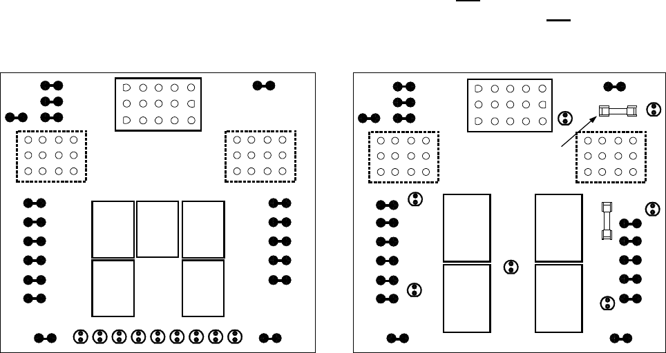
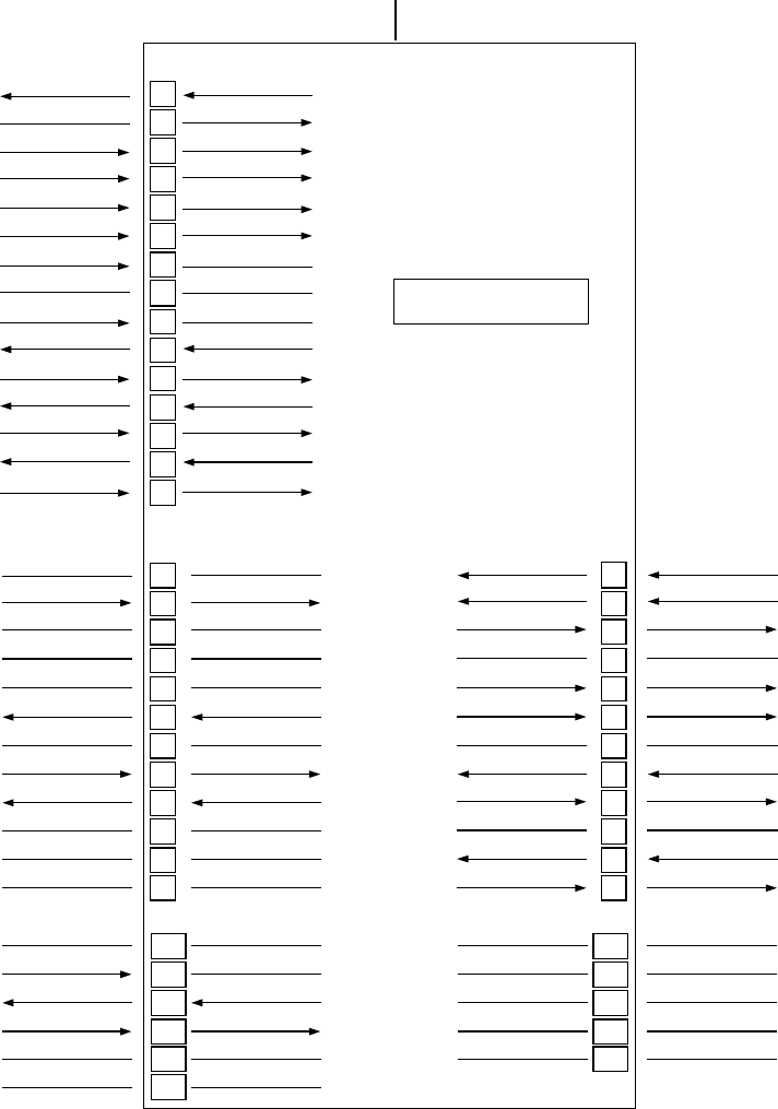
INTERFACE BOARDS
The interface board provides a link between the controller/computer and the fryer’s individual com-
ponents without requiring excessive wiring, and allows the controller to execute commands from one
central point. The H52 Series of fryers has been in production since 1983. Consequently, servicers
are likely to encounter several different interface board designs. Although the boards differ in ap-
pearance, basic functioning and electrical connections are the same from one to another. In mid-
2000, a new, unfused, ignition module design was introduced. Consequently, an additional fuse was
added to the design of interface board 806-3398 to compensate. The new, two-fuse board is P/N
106-0386. With the exception of manufactured gas units, no matter what generation board is in the
fryer now, if it becomes necessary to replace the board, either P/N 806-3398 or 106-0386 will be the
replacement part installed. If unit being serviced is equipped with two P/N 807-1006 or 807-2971
ignition modules, either interface board may be used. If the unit is equipped with one P/N 807-3365
or 807-3366 ignition module, interface board 106-0386 should be used. The two boards most likely
to be seen (i.e., the two latest designs) are illustrated below.
K4
K1 K2
SOUND
1
2
3
GND
GND
V2D
PWR
AD
AS
V2S
GND
V1D
PWR
ALR
V1S
GND GV PWR AL 12V AIR 24V AL PWR GV GND
J2
EARLIER DESIGN INTERFACE BOARD P/N 806-3398
GND
12 6 3 45
J3
3 6 9 12
2 5 8 11
1 4 7 10
J1
3 6 9 12
2 5 8 11
1 4 7 10
15
12963
14
11852
13
10741
BLOWER
MOTOR
RELAY
K3 K5
HEAT
RELAY
HEAT
RELAY
K4
K1
SOUND
1
2
3
GND
GND
V2D
PWR
AD
AS
V2S
GND
GV
PWR
12V
AIR
24V
PWR
GND
V1D
PWR
ALR
V1S
GV
GND
J2
LATER DESIGN INTERFACE BOARDS P/N 806-3398 and 106-0386
GND
J3
3 6 9 12
2 5 8 11
1 4 7 10
J1
3 6 9 12
2 5 8 11
1 4 7 10
15
12963
14
11852
13
10741
K2 K3
HEAT
RELAY
AND
BLOWER
MOTOR
RELAY
D1
D2
D3
D4
D6 D7
Blower
Motor
2 Amp
D5
HEAT
RELAY
AND
BLOWER
MOTOR
RELAY
F2 Ignition
2 AMP Module
This Fuse is NOT
present on 806-3398 IFB.
3-3
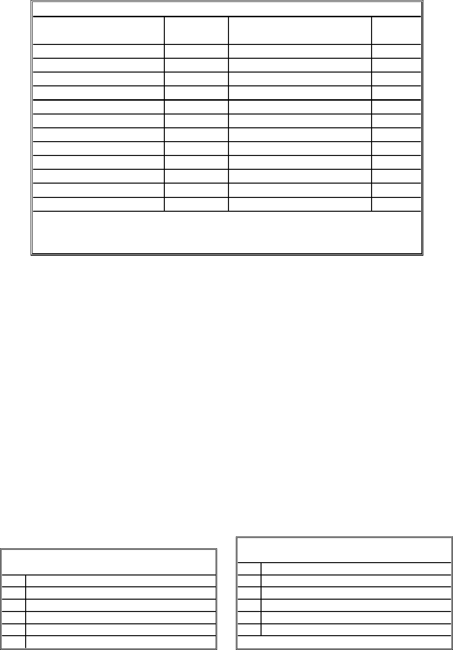
FREQUENTLY USED TEST POINTS FOR INTERFACE BOARDS 806-3398 AND 106-0386
Meter
Test Setting Pins Results
12VAC Power to Controller 50VAC Scale 1 and 3 on J3 or J2 12-18
24VAC Power to Right Module 50VAC Scale 8 on J3 and GROUND 22-28
24VAC Power to Left Module 50VAC Scale 8 on J1 and GROUND 22-28
120 VAC Power 250VAC Scale 11 on J3 and GROUND 110-125
120 VAC Power to Blowers 250VAC Scale 12 on J3 and GROUND 110-125
24VAC Power to Right High-Limit 50VAC Scale 9 on J3 and GROUND 22-28
24VAC Power to Left High-Limit 50VAC Scale 9 on J1 and GROUND 22-28
Probe Resistance (Right) *R x 1000 OHMS 2 and 6 on J3 or 13 and 14 on J2 **
Probe Resistance (Left) * R x 1000 OHMS 2 and 6 on J1 or 14 and 15 on J2 **
Probe Isolation R x 1000 OHMS 6 on J1 or J3 and GROUND ***
High-Limit Continuity (Right) R x 1 OHM 9 on J3 and Wire 13C on Gas Valve 0
High-Limit Continuity (Left) R x 1 OHM 9 on J1 and Wire 12C on Gas Valve 0
** Disconnect 15-pin harness from controller before testing probe circuit.
** See Probe Resistance Chart at end of chapter.
*** 5 mega-Ohms or greater.
These standard interface boards are also used in a number of fryer types besides the H52 Series. The
information contained in this section applies to H52 Series applications ONLY.
The earlier design 806-3398 board contains two heat relays (K1 and K2) that switch 24VAC to the
ignition and gas valve circuits when the computer/controller heat logic circuit calls for heat. Relay
K4 switches 120VAC to the blower motor when either K1 or K2 closes. The relays on this board are
soldered on – if one fails, the whole board must be replaced.
The newer design 806-3398 and 106-0386 boards have only two relays. In this design, K2 and K3
are double-pole-double throw (dpdt) relays that supply 24VAC to the ignition and gas valve circuits,
as well as 120VAC to the blower motor. The relays on this board plug into sockets. If a relay fails,
that relay can be replaced.
All three interface boards have LEDs to assist in troubleshooting. On the earlier design 806-3398
board, nine LEDs are arranged along the bottom. Later versions of the 806-3398 board, and the 106-
0386 board have seven LEDs placed at various locations. The tables below identify the LEDs and
their meaning.
12V Indicates 12 VAC from transformer
24V Indicates 24 VAC from transformer
GV Indicates 24 VAC to gas valve (left or right)
PWR Indicates 24 VAC to module (left or right)
AL Indicates module lock-out (left or right)
AIR CE and Japanese units only: air switch closed
EARLIER DESIGN INTERFACE BOARD
LED DIAGNOSTIC LIGHTS 124 VAC to left gas valve (dual vat only)
224 VAC to left ignition module
324 VAC from transformer
424 VAC to right ignition module
524 VAC to gas valve (right valve if dual vat)
612 VAC from transformer
7CE and Japanese units only: air switch closed
LATER DESIGN INTERFACE BOARD
LED DIAGNOSTIC LIGHTS
3-4
CURRENT FLOW THROUGH
INTERFACE BOARDS 806-3398 AND 106-0386
(H52 APPLICATION)
1
2
3
4
5
6
7
8
9
10
11
12
J3
J2 PIN 1
J2
1
2
4
5
6
7
8
9
10
11
12
13
14
15
1
2
3
4
5
6
7
8
9
10
11
12
J1
LEFT VAT FULL OR RIGHT VAT
INTERFACE BOARD
12 VAC TO CPTR J3 PIN 1
GROUND GROUND
3
COMPUTER (12 VAC) J3 PIN 3
COMPUTER RT HT RELAY
COMPUTER LT HT RELAY
NOT USED NOT USED
NOT USED NOT USED
NOT USED NOT USED
RT ALARM OUT
** ALR (RIGHT)
COMPUTER SOUND DEVICE
LT ALARM OUT
*AD (LEFT)
COMPUTER J3 PIN 6
COMPUTER
COMPUTER J1 PIN 6
J1 PIN 2 & J3 PIN 2
NOT USED NOT USED
NOT USEDNOT USED
NOT USED NOT USED
TEMP PROBE J2 PIN 15
NOT USED
24 VAC IN
NOT USED
MAIN GAS VALVE
NOT USED NOT USED
12 VAC XFMR
J2 PIN 14 TEMP PROBE
J2 PIN 3 12 VAC XFMR
NOT USED NOT USED
J2 PIN 13 TEMP PROBE
NOT USED NOT USED
24 VAC IN
MAIN GAS VALVE
NOT USED NOT USED
120 VAC IN
BLOWER XFMR BOX
COMPUTER 12 VDC TO RELAYS
NOT USEDNOT USED
PWR via LT HT RELAY
V2D
NOT USED NOT USED
BLOWER via K4 (old)
or K2/K3 (new)
PWR via RT HT RELAY
V1S OR V1D
J2 PIN 5 HOOD RELAY
J2 PIN 14TEMP PROBE
V2D
PWR
AD
AS
V2S
GND
V1D
PWR
ALR
V1S
GND
MOD 25V GROUND GROUND
MOD V2D
MOD 25V TERM
DRAIN SWITCH (OPT) J2 PIN 12
NOT USED NOT USED
NOT USED NOT USED
GROUND MOD 25V GROUND
J3 PIN 9 MOD V1D *
MOD 25V TERM
J3 PIN 8 via RT HT RELAY
DRAIN SWITCH (OPT)
J2 PIN 10
MOD V1S **
*
via HLS via HLS
J3 PIN 9
J1 PIN 9
J1 PIN 8 via LT HT RELAY
NOT USED NOT USED
** Dual Vat configurations
** Full Vat configurations
3-5
THERMOSTATS
All fryers in the H52 Series have temperature probes located on the front centerline of each the fry-
pot. (Dual vat frypots have a probe in each vat.) In this type thermostat, the probe resistance varies
directly with the temperature. That is, as the temperature rises, so does resistance, at a rate of ap-
proximately 2 ohms for every 1º F. Circuitry in the controller monitors the probe resistance and
controls burner firing when the resistance exceeds or falls below programmed temperatures (set-
points). The temperatures are programmed by means of a keypad or knob on the face of the control-
ler.
H52 Series fryers are also equipped with a high-limit thermostat. In the event that the fryer fails to
properly control the oil temperature, the high-limit thermostat prevents the fryer from overheating to
the flash point. The high-limit thermostat acts as a normally closed power switch that opens when
exposed to temperatures above 425ºF to 450ºF (218ºC to 232ºC). The different types of thermostats
have different part numbers for CE and Non-CE configured models, and are not interchangeable.
3.2 Accessing Fryers for Servicing
DANGER
Moving a fryer filled with cooking oil/shortening may cause spilling or splattering of
the hot liquid. Follow the draining instructions in Chapter 4 of this manual before
attempting to relocate a fryer for servicing.
1. Shut off the gas supply to the unit. Unplug the power cords. Disconnect the unit from the gas
supply.
2. Remove any attached restraining devices.
3. Relocate the fryer for service accessibility.
4. After servicing is complete, reconnect the unit to the gas supply, reattach restraining devices, and
plug in the electrical cords.
3.3 Cleaning the Gas Valve Vent Tube
NOTE: This procedure is not required for fryers configured for export to CE
countries.
1. Set the fryer power switch and the gas valve to the OFF position.
2. Carefully unscrew the vent tube from the gas valve. NOTE: The vent tube may be
straightened for ease in removal.
3. Pass a piece of ordinary binding wire (.052 inch diameter) through the tube to remove any
obstruction.
3-6
4. Remove the wire and blow through the tube to ensure it is clear.
5. Reinstall the tube and bend it so that the opening is pointing downward.
3.4 Checking the Burner Manifold Gas Pressure
DANGER
Frymaster recommends that ONLY qualified service personnel perform this task.
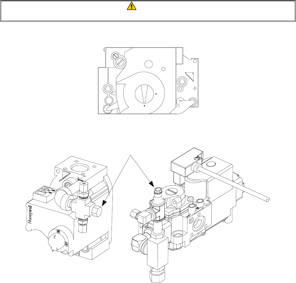
1. On non-CE fryers, ensure that the gas valve knob is in the OFF position.
Honeywell
ON
OFF
2. Remove the pressure tap plug from the gas valve assembly.
Typical Non-CE
Valve Assembly
Typical CE Valve
Assembly
Pressure Tap Plug
2. Insert the fitting for a gas pressure-measuring device into the pressure tap hole.
3. On non-CE fryers only, place the gas valve in the ON position.
4. Place the fryer power switch in the ON position. When the burner has lit and burned steadily for
at least one minute, compare the gas pressure reading to the pressure for the corresponding gas in
the appropriate table found on the following page.

3-7
Gas
Single
Vat
Dual
Vat
Natural Gas Lacq
(G20) at 20 m bar 77
Natural Gas Gronique *
(G25) at 25 m bar 10 10
Natural Gas Gronique
(G25) at 20 m bar 10 10
Butane/Propane
(G30) at 28/30 or 50 m bar 17 17
Propane
(G31) at 37 or 50 m bar 20 20
CE Standard
B u rn er M anifold G as P ressu res
for Fryers M anufactured After April 1999
Pressure (m bar)
* Belgian G 25 = 7.0 m b ar (single o r dual)
Gas
Single
Vat
Dual
Vat
Natural Gas Lacq
(G20) under 20 mbar 76.5
Natural Gas Gronique *
(G25) under 25 mbar 10 9
Natural Gas Gronique
(G25) under 20 mbar 10 9
Propane
(G31) under 37 or 50 mbar 20.2 18.5
CE Standard
Burner M anifold Gas Pressures
for Fryers Manufactured Through April 1999
Pressure (m bar)
* Belgian G25 = 7.0 m bar (single) or 6.5 (dual)
G as Pressure
Natural 3" W .C.
0.73 kPa
LP 8.25" W .C.
2.5 kPa
Non-CE Standard
Burner M anifold G as Pressures
3-8
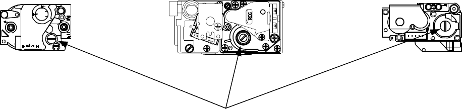
5. To adjust the burner gas pressure, remove the cap from the gas valve regulator and adjust to the
correct pressure.
Non-CE
Valve Earlier Model CE Valve Later Model
CE Valve
GAS VALVE REGULATOR CAP
6. Place the fryer power switch (and the gas valve in non-CE fryers) in the OFF position. Remove
the fitting from the pressure tap hole and reinstall the pressure tap plug.
3.5 Measuring Flame Current
When the burner flame is properly adjusted, it will produce a current between 2.5 µA and 3.5 µA.
Flame current is measured by placing a microamp (not milliamp) meter in series with the sensing
wire on the ignitor. This is accomplished as follows:
1. Place the fryer power switch in the OFF position.
2. Disconnect the white sensing wire from one of the burner ignitors and connect it to the positive
lead of the meter. Connect the negative lead of the meter to the terminal from which the sensing
wire was removed.
3. Place the fryer power switch in the ON position to light the burners. After the frypot temperature
reaches 200°F (93°C), wait at least one minute before checking the reading. NOTE: The closer
the unit is to normal operating temperature, the more accurate the reading will be.
3.6 Replacing Fryer Components
3.6.1 Replacing the Controller or the Controller Wiring Harness
1. Disconnect the fryer from the electrical supply.
2. Remove the two screws in the upper corners of the control panel and swing the panel open from
the top, allowing it to rest on its hinge tabs.
3. Disconnect the wiring harness from the back of the controller and, if replacing the harness, dis-
connect it from the interface board.
4. Disconnect the ground wire from the controller, and remove the controller by lifting it from the
hinge slots in the control panel frame.

3-9
5. Reverse the procedure to install a new controller or wiring harness.
3.6.2 Replacing the Temperature Probe or High-Limit Thermostat
1. Disconnect the fryer from the electrical supply.
2. Drain cooking oil below the level of the probe or thermostat.
3. Remove the screws from the upper corners of the control panel and swing the panel open from
the top, allowing it to rest on its hinge tabs.
4. Unplug the controller wiring harness from the back of the controller.
5. Disconnect the ground wire from the controller, and remove the controller by lifting it from the
hinge slots in the control panel frame.
6. Remove the screws securing the topcap to the fryer and lift the topcap up and off the fryer.
7. Disconnect the ignition cables from the ignitors by grasping the boots and gently pulling toward
you.
8. Remove the screws securing the control panel frame in place and remove the frame.
9. Remove the component box mounting screws and rotate the top of the component box out of the
cabinet. Carefully pull it out far enough to disconnect the wiring harness plug(s) from the back
of the box. Remove the box and set it aside.
10. On CE fryers with a blower shield assembly installed, remove the screws securing the shield in
place and remove it from the cabinet.
11. Make a note of the location of the existing wires. Using a pin-pusher, disconnect the temperature
probe wires (or high-limit thermostat wires) from the connector plug.
12. Unscrew and remove the temperature probe (or high limit thermostat) from the frypot.
13. Apply Loctite® PST56765 pipe thread sealant or equivalent to the replacement part threads.
14. Screw the replacement part into the frypot.
15. Connect the wires from the new component to the connector plug, referring to the note made in
step 11.
16. Reverse steps 1 through 10 to complete the procedure.

3-10
3.6.3 Replacing the Interface Board
1. Remove the component box per steps 1 through 9 of Section 3.6.2.
2. Unplug the controller wiring harness from the interface board.
3. Disconnect the wires attached to the interface board, marking or making a note of the wires and
terminals to facilitate reconnection.
4. Remove the nuts at each corner of the interface board and pull it from the studs.
5. Reverse the procedure to install the replacement board, being sure to reinstall the spacers behind
the interface board.
3.6.4 Replacing an Ignition Module
1. Disconnect the fryer from the electrical supply.
2. Remove the screws from the upper corners of the control panel and swing the panel open from
the top, allowing it to rest on its hinge tabs.
3. Disconnect the wires from the ignition module, marking or making a note of the wires and termi-
nals to facilitate reconnection.
4. Remove the four ignition module screws and pull the module from the component box.
5. Reverse the procedure to install the replacement module.
3.6.5 Replacing an Ignitor Assembly
DANGER
Drain the frypot or remove the handle from the drain valve before proceeding further.
1. Disconnect the fryer from the electrical supply.
2. Disconnect the ignition cable from the ignitor by grasping the boot and gently pulling toward
you.
3. Remove the two sheet metal screws securing the ignitor to the mounting plate and pull the ignitor
from the fryer.
4. Reverse the procedure to install the replacement ignitor.
3-11
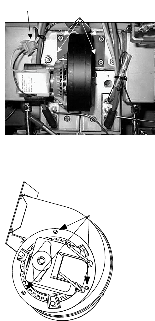
3.6.6 Cleaning or Replacing a Combustion Air Blower
A sheet metal shield or shield assembly prevents inadvertent access to the blower assembly. The
specific design varies depending upon the particular configuration of the fryer and the country for
which manufactured, but in all cases, the shield is attached to the cabinet framing by sheet metal
screws. Remove the screws that secure the shield or shield assembly to the cabinet framing and pull
the shield out of the fryer to expose the combustion air blower assembly.
1. Disconnect the blower wiring harness and remove the blower assembly mounting nuts.
2. Remove the three fasteners that secure the blower motor assembly to the blower housing, and
separate the two components.
Remove these fasteners.
(On black-colored FASCO
blowers there are three
nuts. On silver-colored
KOOLTRONICS blowers
there are three screws.)
Wiring connection
Blower
assembly
mounting
nuts
3-12
3. Wrap the motor with plastic wrap to prevent water from entering it. Spray degreaser or detergent
on the blower wheel and the blower housing. Allow it to soak for five minutes. Rinse the wheel
and housing with hot tap water, then dry with a clean cloth.
Wrap the motor and
wires with plastic wrap
or a plastic bag.
BLOWER HOUSING BLOWER WHEEL
4. Remove the plastic wrap from the blower motor assembly. Reassemble the blower motor
assembly and blower housing. Reinstall the blower assembly in the fryer.
5. Reinstall the blower shield or shield assembly.
6. Light the fryer in accordance with the procedure described in Chapter 3, Section 3.1.
7. After the burners have been lit for at least 90 seconds, observe the flames through the burner
viewing ports located on each side of the combustion air blower.
The air/gas mixture is properly adjusted when the burner manifold pressure is in accordance with the
applicable table on page 3-7 and the burners display a bright orange-red glow. If a blue flame is ob-
served, or if there are dark spots on a burner face, the air/gas mixture requires adjustment.
Right
Viewing
Port
Left Viewing
Port is Behind
Motor
(NOTE: Blower
shield omitted
for clarity.)
3-13
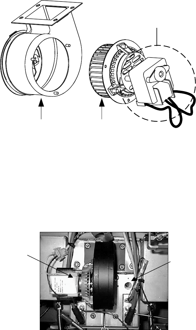
Adjusting Air/Gas Mixture
Non-CE Units and CE Units Built After April 1999
On the side of the blower housing opposite the motor is a plate with one or two locking nuts. Loosen
the nut(s) enough to allow the plate to be moved, then adjust the position of the plate to open or close
the air intake opening until a bright orange-red glow is obtained. Carefully hold the plate in position
and tighten the locking nut(s).
TYPICAL NON-CE BLOWER ASSEMBLY TYPICAL CE BLOWER ASSEMBLY
ON UNITS BUILT AFTER APRIL 1999
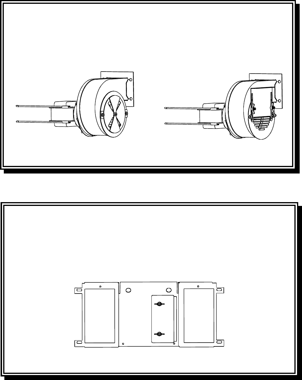
Adjusting Air/Gas Mixture
CE Units Built Through April 1999
CE units built through April 1999 are equipped with a shield assembly in front of the blowers. An
air shutter plate on the face of the shield assembly regulates the amount of airflow to the blower in-
take. To adjust the shutter plate, loosen the locking screws and slide the shutter to the left or right as
necessary to obtain a bright orange-red glow. Carefully hold the shutter plate in position and tighten
the locking screws.
TYPICAL CE BLOWER SHIELD ASSEMBLY
ON UNITS BUILT THROUGH APRIL 1999
3-14
3.6.7 Replacing a Gas Valve
DANGER
Drain the frypot or remove the handle from the drain valve before proceeding further.
1. Disconnect fryer from electrical and gas supplies.
2. Disconnect the wires from the gas valve terminal block, marking each wire to facilitate recon-
nection.
3. Remove the vent tube and the enrichment tube fitting from the valve.
4. Disconnect the flexible gas line(s).
5. Carefully unscrew the valve from the manifold. NOTE: Some models may have the valve at-
tached to the manifold by means of a pipe union. In such cases, remove the valve by uncoupling
the union.
6. Remove all fittings from the old gas valve and install them on the replacement valve, using Loc-
tite® PST56765 or equivalent pipe thread sealant.
7. Apply Loctite® PST 56765 or equivalent pipe thread sealant to the threads of the manifold (or the
union). Reverse steps 1-5 to install the replacement gas valve.
3.6.8 Replacing a Burner Assembly
DANGER
Drain the frypot or remove the handle from the drain valve before proceeding further.
1. Disconnect the unit from the electrical and gas supplies.
2. Remove the combustion air blower per the procedure found in Section 3.6.6.
3. Remove the four nuts from the air plenum assembly and pull the assembly straight out toward
you until it clears the burner tubes.
NOTE: On a dual vat fryer, it will be necessary to remove the drain valve handles before the
plenum can be removed.
4. Disconnect the ignition cables from the ignitors by grasping their boots and pulling toward you.
5. Disconnect the gas lines and enrichment tubes from the burner orifices and ignitor assemblies.
6. Remove the four ¼” (6mm) nuts securing the outer front covers to the frypot assembly.
7. Remove the sheet metal screws at the top of the outer front covers and pull the covers straight out
toward you until clear of the mounting studs.
3-15
8. Remove the washers and tubular spacers from the mounting studs, then pull the inner covers
straight out toward you until clear of the mounting studs.
9. Grasp the burner firmly and pull it toward you until it clears the burner channels, taking care not
to damage the ceramic tiles in the process.
10. Clean all debris from the burner channels and combustion area.
11. Inspect the upper and lower burner rails for cracked or burned-out welds.
a. If the welds in the lower rail are cracked or burned out, the frypot must be replaced. Refer to
Section 3.6.9 for procedure.
b. If the welds in the upper rail are cracked or burned out, the upper rail must be replaced. Re-
fer to Section 3.6.10 for procedure.
12. Place a new insulating strip along the top, rear, and bottom edge of the burner and carefully slide
it straight into the rails.
NOTE: Use P/N 826-0931 for full vat frypots and P/N 826-0932 for dual vat frypots.
13. Reverse steps 1 through 9 to reassemble the components.
14. Fill the frypot with oil. Turn the fryer on, turn off or bypass the melt cycle, and operate the unit
for at least 10 minutes.
15. Visually examine the burner flame. The color and intensity on both sides should be the same.
16. Use an inspection mirror to check for leaks in areas that cannot be directly observed.
17. If a leak is detected, tighten all the lower insulation retainer nuts, allow the frypot to run for five
additional minutes, and repeat steps 15 and 16.
18. If the leak persists, use a rubber hammer and a small block of wood to tap the corners of the
lower combustion chamber insulation retainers. Repeat steps 15 through 17. Repeat this step
until no leakage is detected.
3.6.9 Replacing the Frypot
1. Drain cooking oil/shortening from the frypot.
2. Remove all accessories, e.g., frypot covers, basket lift arms, etc. from the fryer.
4. Disconnect the fryer from gas and electrical supplies.
5. Remove the screws from the topcap above the control panel and lift it up and off the fryer(s).

3-16
6. Remove the screws from the upper left and right corners of the control panel. Open the panel,
disconnect the controller wiring harness and ground wire. Remove the controller from the fryer.
7. Disconnect the ignition wires from the ignitor plugs by grasping their boots and pulling toward
you.
8. Remove the screws securing the component box to the frame, and then rotate the top of the box
forward and out of the fryer enough to disconnect the wiring harness connector plug(s) on the
rear of the box. Set the component box aside.
9. Using a pin pusher, remove the temperature probe and high-limit thermostat wires from the
plug(s), marking each wire to facilitate re-assembly.
10. On BIH52 units, remove the cover from the safety drain switch, disconnect the wires from the
switch, and pull them out of the switch box.
11. On BIH52 units, remove the section(s) of square drain from the drain valve(s) of the frypot to be
removed.
12. Disconnect the gas lines and enrichment tubes from the burner orifices and ignitor assemblies.
13. Remove the frypot hold down bracket.
14. Remove the screws from the flue cap sides and back and lift it clear of the fryer(s).
15. On BIH52 units, disconnect the oil return line(s) from the frypot to be removed.
16. Carefully lift the frypot from the fryer cabinet.
17. Remove the drain valve(s), temperature probe(s), high-limit thermostat(s), and ignitor assem-
blies. Inspect each of these components carefully and install them in the replacement frypot if
they are in serviceable condition. Use Loctite® PST56765 sealant or equivalent on component
threads.
NOTE: Some servicers, based upon their experience, recommend that probes and thermostats be
replaced whenever a frypot is replaced, but this remains the customer’s decision.
18. Reverse steps 1-16 to reassemble fryer.
19. Perform steps 14 through 18 of Section 3.6.8 to ensure that there are no leaks in the burner insu-
lation.
CAUTION
Before installing the temperature probe, high-limit thermostat, and drain valve on the
replacement frypot, clean their threads and apply Loctite® PST56765 thread sealant
or equivalent.
3-17
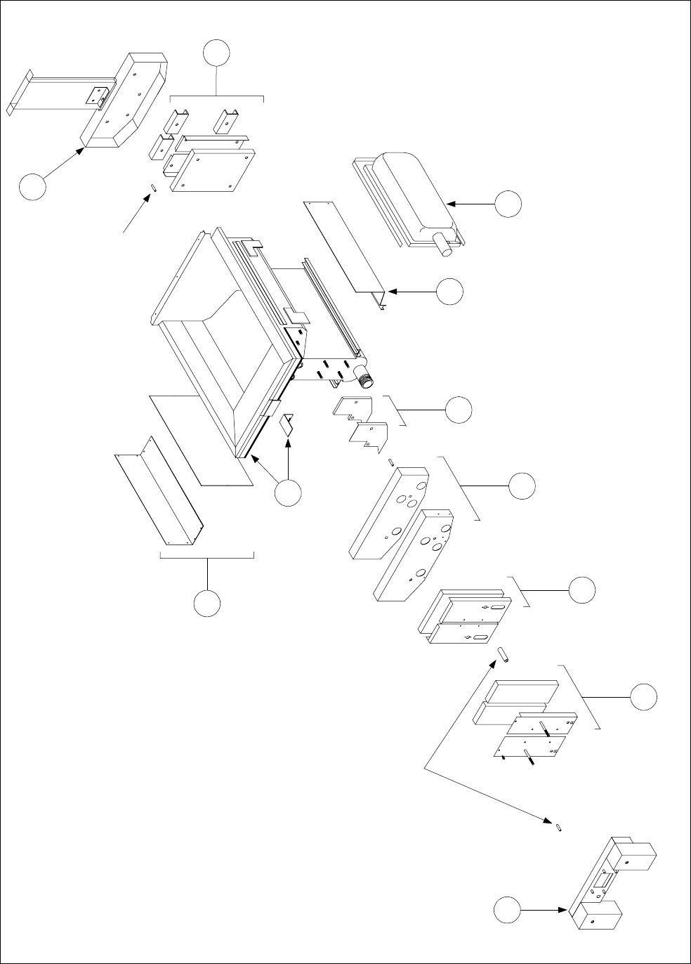
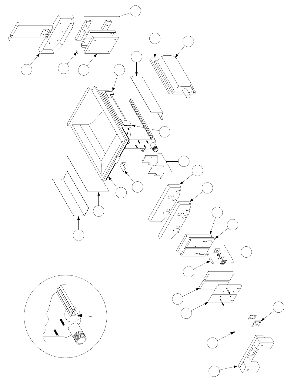
3.6.10 Replacing Frypot Insulation and/or Upper Burner Rails
NOTE: Replacing the burner rails requires completely tearing down the frypot and installing new
frypot insulation. Refer to the frypot exploded view on page 3-18 for component identification.
1. Remove the frypot per Section 3.6.9.
2. Remove the burner assemblies (1).
3. Remove insulation retainers and blanket insulation (2).
4. Remove the upper oil zone insulation bracket and upper oil zone insulation (3).
5. Remove the plenum (4).
6. Remove the front lower combustion chamber insulation retainer and insulation (5), and the front
lower combustion chamber inner insulation retainer and insulation (6).
NOTE: Full vat units have two-piece insulation retainer and insulation components. Dual vat
units have one-piece components.
7. Remove the upper combustion chamber insulation retainer and insulation (7).
8. Remove the inner upper combustion chamber insulation retainer and insulation (8).
9. Remove the rear lower combustion chamber retainers, back, and insulation (9).
NOTE: Full vat units have two-piece backs and four retainers. Dual vat units have one-piece
backs and two retainers.
10. Remove the flue assembly (10).
11. Remove the upper burner rails (11).
NOTE: For the following steps, refer to the frypot exploded view on page 3-19 for component
identification.
12. Remove any residual insulation, sealant, and/or oil from the exterior of the frypot.
13. Place the “L” shaped pieces of combustion chamber insulation (1) in the front and rear corners of
both upper rail-retaining slots.
14. Use a small amount of furnace or muffler repair cement to seal the gaps at each end of both lower
rails. (See inset, page 3-19.)
3-18
Disassembling A Frypot
(Full Vat Illustrated)
Spacers
Spacer
10
9
1
11
8
7
6
5
4
2
3
3-19
Re-assembling A Frypot
(Full Vat Illustrated)
Apply cement
here
6
5
4
7
9
8
2
1
1
24
23
21
22
3
10
11
13
12
14
15
19
17
16
20
18
15. Install the upper burner rails (2) with the heat deflectors slanting toward the rear of the frypot.
The rails will cover the “L” shaped pieces of combustion chamber insulation previously installed.
3-20
16. Place the upper inner combustion chamber insulation and insulation retainers (3) on the top two
studs on each side of the front of the frypot and secure with ¼-20 washer-nuts. (It is normal for
the retainers to slice off the overhanging insulation.)
17. Place the lower rear combustion chamber insulation (4) on the lower four studs at the rear of the
frypot.
18. Place one 1.625-inch tubular spacer (5) on each of the flue assembly (upper) studs at the rear of
the frypot.
NOTE: There are three different sizes of spacers. Verify the size to ensure the correct spacers
are installed.
19. Press the flue assembly (6) over the burner rails. It may be necessary to use a rubber mallet or
screwdriver to align the components. Use four ¼-20 washer nuts to secure the flue assembly.
Do not tighten the retainer nuts at this point. They should be finger-tight only.
NOTE: The flue edge will cover one to two inches of the lower insulation.
20. Install the lower rear combustion chamber back(s) and retainer(s) (7) with the flanged edge(s)
against the flue. Secure with ¼-20 washer nuts.
NOTE: Full vat units have two-piece backs and four retainers. Dual vat units come with one-
piece backs and only two retainers.
21. Insert the burners (9) into the rails to ensure the rail spacing and alignment are correct. The
burner should slide freely into and out of the rails. The upper rail can be bent slightly to increase
or decrease tension on the burner, and the edges of the slot can be closed or opened slightly to
best fit the burner frame.
22. Carefully wrap a strip of burner insulation (8) tightly around the rear and sides of the burner
frame (9), with the glass-tape side of the strip on the outside. Do not use duct tape or adhesive
to secure the strip to the burner frame.
23. Align the burner to the burner rails while maintaining tension on the insulation strip. Insert the
burner at a slight angle and begin pushing the burner slowly into the rails until it contacts the rear
combustion chamber. The fit should be snug, but not excessively tight.
24. Verify that the burners are flush with the front edge of the burner rails. Remove the excess
burner insulation by cutting with a knife or diagonal pliers. Do not try to tear the insulation!
25. Insert the upper front insulation (10) into its retainer (11), making sure that the holes in each
piece are aligned with one another. Install the assembly with the insulation side toward the fry-
pot and secure with ¼-20 washer-nuts. Do not over tighten.
26. Place a washer on each of the four lower studs on the front of the frypot. Install the lower inner
front insulation (12) with the rectangular openings toward the drain valve nipple. Install the
lower inner front insulation retainer(s) (13).
3-21
NOTE: Full vat units have a two-piece insulation retainer. Dual vat units have a one-piece re-
tainer.
27. If necessary, replace the sight-glasses and insulation (14).
28. Place one washer and one 1.888-inch spacer (15) on each stud.
NOTE: There are three different sizes of spacers. Verify the size to ensure the correct spacers
are installed.
29. Insert the front lower insulation (16) into the front lower insulation retainer(s) (17) and install
assembly on frypot. Secure with ¼-20 washer-nuts. If frypot uses two retainers, connect them
together with two ¼” self-tapping screws.
NOTE: Full vat units have a two-piece insulation retainer and two pieces of insulation. Dual
vat units have one-piece components.
30. Return to the rear of the frypot and fully tighten all washer-nuts.
31. Remove and replace the plenum gaskets (18).
32. Place a 0.938-inch spacer (19) on the plenum-mounting studs, and mount the plenum (20). En-
sure the gaskets are clear of the burner tubes by pulling the plenum back slightly. Place a washer
on each stud and secure plenum with ¼-20 locknuts.
33. Install the upper oil-zone insulation (21) by pressing it under the upper combustion chamber
metalwork. Secure the insulation with the bracket (22) and ¼” self-tapping screws.
34. Install the upper burner rail blanket insulation (23). Position any excess insulation toward the top
of the frypot. Avoid overhang past the bottom of the upper burner rail. Overhang in this area
will make future burner replacement more difficult.
35. Cover the insulation with the insulation retainer (24), and secure with ¼” self-tapping screws.
36. Reinstall probes, drain valves, high-limit thermostats and other pipefittings using Loctite®
PST56765 sealant or equivalent on their threads.
3.7 Troubleshooting and Problem Isolation
Because it is not feasible to attempt to include in this manual every conceivable problem or trouble
condition that might be encountered, this section is intended to provide technicians with a general
knowledge of the broad problem categories associated with this equipment, and the probable causes
of each. With this knowledge, the technician should be able to isolate and correct any problem en-
countered.
Problems you are likely to encounter can be grouped into six broad categories:
1. Ignition failures
2. Improper burner functioning
3-22
3. Improper temperature control
4. Computer-related problems
5. Filtration problems
6. Leakage problems
The probable causes of each category are discussed in the following sections. A series of Trouble-
shooting Guides (decision trees) is also included at the end of the chapter to assist in identifying
some of the more common problems.
3.7.1 Ignition Failures
Ignition failure occurs when the ignition module fails to sense a flame within the 4-second time delay
period and locks out. When this happens, the module sends 24VAC through the interface board
alarm circuit to the controller/computer.
Analog controllers indicate ignition failure by illuminating the heat light and trouble light simultane-
ously. M100B and M2000 computers flash “ignition failure” in the display window on the
side that failed (in full-vat units, it will flash in the right window only).
The three primary reasons for ignition failure, listed in order of probability, are:
1. Problems related to the gas and/or electrical power supplies
2. Problems related to the electronic circuits
3. Problems related to the gas valve.
PROBLEMS RELATED TO THE GAS AND/OR ELECTRICAL POWER SUPPLIES
The main indicators of this are that an entire battery of fryers fails to light and/or there are no indi-
cator lights illuminated on the fryer experiencing ignition failure. Verify that the quick disconnect
fitting is properly connected, the fryer is plugged in, the main gas supply valve is open, and the cir-
cuit breaker for the fryer electrical supply is not tripped.
PROBLEMS RELATED TO THE ELECTRONIC CIRCUITS
If gas and electrical power are being supplied to the fryer, the next most likely cause of ignition fail-
ure is a problem in the 24VAC circuit. If the fryer is equipped with a built-in filtration system
(BIH52 models), first verify that the drain valve is fully closed. (The valve is attached to a mi-
croswitch that must be closed for power to reach the gas valve. Often, although the valve handle ap-
pears to be in the closed position, the microswitch is still open.) If the valve is fully closed, or the
fryer does not have a built-in filtration system, refer to the troubleshooting guides TROUBLE-
SHOOTING THE 24VAC CIRCUIT.
Some typical causes of ignition failure in this category include a defective sensing wire in the ignitor
assembly, a defective module, a defective ignition wire, and a defective ignitor.
Occasionally you may encounter an ignition failure situation in which all components appear to be
serviceable and the microamp reading is within specification, but the unit nevertheless goes into
ignition failure during operation. The probable cause in this case is an intermittent failure of an
ignition module. When the unit is opened up for troubleshooting, the module cools down enough to
3-23
operate correctly, but when the unit is again closed up and placed back into service the module heats
up and fails.
PROBLEMS RELATED TO THE GAS VALVE
If the problem is not in the 24VAC circuit, it is most likely in the gas valve itself, but before replac-
ing the gas valve refer to TROUBLE SHOOTING THE GAS VALVE.
3.7.2 Improper Burner Functioning
With problems in this category, the burner ignites but exhibits abnormal characteristics such as
“popping,” dark spots on the burner ceramics, fluctuating flame intensity, and flames shooting out of
the flue.
“Popping” indicates delayed ignition. In this condition, the main gas valve is opening but the burner
is not immediately lighting. When ignition does take place, the excess gas “explodes” into flame,
rather than smoothly igniting.
The primary causes of popping are:
• Incorrect or fluctuating gas pressure
• A defective or incorrectly adjusted combustion air blower
• Inadequate make-up air
• Heat damage to the controller or ignition module
• A cracked ignitor or broken ignition wire
• A defective ignition module
• Cracked burner tile (this typically causes a very loud pop).
If popping occurs only during peak operating hours, the problem may be incorrect or fluctuating gas
pressure. Verify that the incoming gas pressure (pressure to the gas valve) is in accordance with the
appropriate CE or Non-CE Standard found in Section 2.3 of this manual, and that the pressure re-
mains constant throughout all hours of usage. Refer to page 2-6 for the procedure for checking the
pressure of gas supplied to the burner.
If popping is consistent during all hours of operation, the most likely cause is an insufficient air sup-
ply. Check for “negative pressure” conditions in the kitchen area. If air is flowing into the kitchen
area, this indicates that more air is being exhausted than is being replenished and the burners may be
starved for air.
If the fryer’s gas and air supplies are okay, the problem is most likely with one of the electrical com-
ponents. Examine the ignition module and controller for signs of melting/distortion and/or discol-
oration due to excessive heat build-up in the fryer. (This condition usually indicates improper flue
performance.) A melted or distorted ignition module is automatically suspect and should be re-
placed, but unless the condition causing excessive heat is corrected, the problem is likely to recur.
Verify that the ignition wire is tightly connected at both ends and free of obvious signs of damage.
Again, if damage is due to excessive heat in the fryer, that problem must also be corrected.

3-24
Check for proper operation by disconnecting the wire from the ignitor (spark plug), inserting the tip
of a screw driver into the terminal, and holding it near the frame of the fryer as the power switch is
placed in the ON position. A strong, blue spark should be generated for at least 4 seconds.
DANGER
MAKE SURE YOU ARE HOLDING THE INSULATED HANDLE OF THE SCREWDRIVER
AND NOT THE BLADE. THE SPARKING CHARGE IS APPROXIMATELY 25,000
VOLTS.
Examine the ignitor (spark plug) for any signs of cracking. A cracked ignitor must be replaced.
If all other causes have been ruled out, examine the burner tiles for any signs of cracking. If found,
the burner must be replaced.
Fluctuating flame intensity is normally caused by either improper or fluctuating incoming gas pres-
sure, but may also be the result of variations in the kitchen atmosphere. Verify incoming gas pres-
sure in the same way as for “popping,” discussed in the preceding paragraphs. Variations in the
kitchen atmosphere are usually caused by air conditioning and/or ventilation units starting and stop-
ping during the day. As they start and stop, the pressure in the kitchen may change from positive or
neutral to negative, or vice versa. They may also cause changes in airflow patterns that may affect
flame intensity.
Dark spots on the burner tiles are the result of an improper air/gas mixture. Adjust the combustion
air blower to reduce the amount of air in the mixture to correct this problem.
Flames shooting out of the flue are usually an indication of negative pressure in the kitchen. Air is
being sucked out of the burner enclosure and the flames are literally following the air. If negative
pressure is not the cause, check for high burner manifold gas pressure in accordance with the proce-
dures on page 2-6.
An excessively noisy burner, especially with flames visible above the flue opening, may indicate
that the gas pressure is too high, or it may be that, on non-CE units, the gas valve vent tube is
blocked. If the incoming gas pressure is correct and the vent tube on non-CE units is unobstructed,
the gas valve regulator is probably defective.
Occasionally a burner may apparently be operating correctly, but nevertheless the fryer has a slow
recovery rate (the length of time required for the fryer to increase the oil temperature from 270ºF to
320ºF (133ºC to 160ºC)). The primary causes of this are an over-filled vat, a dirty or out-of-
adjustment combustion air blower, low burner manifold pressure, and/or damaged burner tiles.
Adding oil to the frypot during the recovery process will also cause a slow recovery rate. If these
causes are ruled out, the probable cause is a misadjusted gas valve regulator. Refer to page 2-6 for
the procedure for checking the pressure of gas supplied to the burner.
3.7.3 Improper Temperature Control
Temperature control, including the melt cycle, is a function of several interrelated components, each
of which must operate correctly. The principle component is the temperature probe. Other compo-
nents include the interface board, the controller itself, and the ignition module.
3-25
Improper temperature control problems can be categorized into melt cycle problems and failure to
control at setpoint problems.
MELT CYCLE PROBLEMS
The melt cycle is automatically initiated by the controller (Analog, M100B, or M2000) when the
controller is first turned on. The unit should remain in the melt cycle until the oil in the frypot
reaches 180ºF (82ºC). (Do not confuse the melt cycle with the LOW TEMP warning. This warning will
be displayed when the M100B or M2000 computer senses that the oil in the frypot is more than 45ºF
(25ºC) below the setpoint.)
Problems may be with the controller itself, the temperature probe, or a malfunctioning heat relay on
the interface board.
FAILURE TO CONTROL AT SETPOINT
Problems in this category may be with the temperature probe, the interface board, or the controller.
3.7.4 Recovery Time or “Rate Of Rise” and the M100B “Rec Lock” Condition
Recovery time or “rate of rise” is a method of measuring a fryer’s performance. Put simply, it is the
time required for the cooking oil temperature to rise from 270ºF to 320ºF (133ºC to 160ºC). This
range is used as a standard since ambient kitchen temperatures can effect the test if lower ranges are
used.
The M100B computer performs the recovery test when the fryer is first turned on and anytime there-
after when the temperature of the oil drops below 250ºF (121ºC), such as when cold cooking oil is
added to the frypot. If the fryer takes longer than 2 minutes and 35 seconds to recover, the display
will show REC LOCK and the computer will lock out.
The currently recorded recovery time can be viewed anytime the temperature of the cooking oil is
above 270ºF (133ºC) by pressing the recovery time recall switch .
If REC LOCK occurs three or more times within a week, verify that oil is not being added when the
fryer is heating (that is, while a heat mode indicator is illuminated). If oil is not being added while
the fryer is heating, there is a problem with the fryer.
To clear the REC LOCK
REC LOCKREC LOCK
REC LOCK condition, turn the computer off by pressing the right switch. Enter the
programming mode by pressing and releasing the left 1, 2, and switches simultaneously. The
computer will display its model number and then FR FRIES YES. Press the switch. The computer
will display LOCK CLEARED.
3.7.5 Filtration Problems
BIH52 units are equipped with FootPrint III built-in filtration systems. The majority of filtration
problems arise from operator error. One of the most common errors is placing the filter paper on the
bottom of the filter pan rather than over the filter screen.
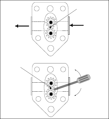
3-26
Whenever the complaint is “the pump is running, but no oil is being filtered,” check the installation
of the filter paper, including that the correct size is being used. While you are checking the filter pa-
per, verify that the O-ring on the bottom of the filter pan is present and in good condition. A missing
or worn O-ring will allow the pump to suck air and decrease its efficiency.
If the pump motor overheats, its thermal overload will trip and the motor will not start until it is re-
set. If the pump motor does not start, press the red reset switch located on the rear of the motor. If
the pump then starts, something caused the motor to overheat. It may just be that several frypots
were being filtered one after the other and the pump got hot. Letting the pump cool down for at least
a half-hour is all that is required in this case. More often, the pump overheated for one of the fol-
lowing reasons:
• Shortening was solidified in the pan or filter lines.
• The operator attempted to filter oil or shortening that was not heated. Cold oil and shortening
are thicker and cause the pump motor to work harder and overheat.
If the motor hums but the pump does not rotate, there is a blockage in the pump. Incorrectly sized or
installed paper will allow food particles and sediment to pass through the filter pan and into the
pump. When sediment enters the pump, the gears can bind up causing the motor to overload, again
tripping the thermal overload. Solidified shortening in the pump will also cause it to seize, with the
same result.
A pump seized by debris or hard shortening can usually be freed by manually moving the gears with
a screwdriver or other instrument as illustrated below. Make sure power to the pump motor is off
before trying this.
1. Disconnect power to the filter system.
2. Remove the input plumbing from the pump.
3. Use a screwdriver to manually turn the gears.
• Turning the pump gears backwards will release a hard particle and allow its removal.
• Turning the pump gears forward will push softer objects and solid shortening through the
pump and allow free movement of the gears.
Sediment Particle
Oil Flow
Up for reverse
Down for forward
Sediment Particle
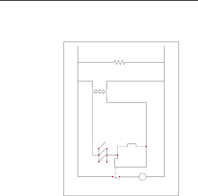
3-27
Improperly sized or installed paper will also allow food particles and sediment to pass through and
clog the suction tube on the bottom of the filter carriage. Particles large enough to block the suction
tube may indicate that the crumb tray is not being used.
Pan blockage can also occur if shortening is left in the pan and allowed to solidify. The heater strip
on the suction tube is designed to prevent solidification of residual shortening left in the tube. It will
not melt or prevent solidification of shortening in the pan.
Blockage removal can be accomplished by forcing the item out with an auger or drain snake.
NEVER use compressed air or other pressurized gases to force out the blockage.
The electronics of the FootPrint III system are simple and straightforward. Microswitches, attached
to handles for each vat and wired in parallel, provide the 24VAC required to activate the pump relay
coil when the handles are moved to the ON position. The activated pump relay coil pulls in the
pump motor switch, supplying power to the pump motor.
Pump Relay
Coil
Micro-
switches
Pump Motor Switch
Pump Motor
Solenoids
(Redesigned
Models Only)
24VAC
Line VAC
FootPrint III Simplified Wiring Diagram
All Heater Tapes (Original and Redesigned Models)
(Heater Tapes have been removed from
oil return lines in Redesigned Models)
M
For FootPrint III systems built before August 1997, all heater tapes are wired directly into the line
VAC source. They remain energized as long as the unit is plugged in. In systems built in August
1997 and later, oil return line heater tapes have been eliminated. In these units, the only heater tape
used is on the suction tube and pump. This tape is still wired directly into the line voltage. A pair of
vacuum-breaking solenoids is wired into the 24VAC circuit.
The redesigned FP III is distinguished from original-design units by the absence of casters on the
filter base assembly. The redesign incorporated an improved oil return system that allows
oil/shortening to drain back to the filter pan when the filter system is turned off, eliminating the need
for most heated oil return components.

3-28
Operation of the redesigned FP-III system is the same as for the original design.
ORIGINAL VS REDESIGNED FP-III FILTRATION SYSTEM
Original System Redesigned System
Return lines and manifolds wrapped with silicone
strip heaters and aluminum tape.
No heater strips or aluminum tape on return lines.
Filter base assembly connected to unit with a
black, heated return hose beneath the filter.
Non-heated Teflon hose with a swivel joint con-
nects the filter base assembly to the unit above
the filter.
Filter base assembly equipped with swivel cast-
ers.
Filter base assembly has no casters.
Operator-removable filter base assembly. (Filter
base assembly stoplocks in cabinet can be ro-
tated to remove tray.)
Filter base assembly is not removable except by
a qualified service technician. (Filter base as-
sembly stoplocks fitted with a screw and nut to
prevent filter removal.)
Oil/shortening remains in return lines when filter
system is turned off.
Oil/shortening gravity-drains back to the filter pan
when filter system is turned off, leaving no oil or
shortening in return lines.
Square Drain Sub-System
The only change to the square drain sub-system is the addition of a ¼” NPT vent coupling to the
leftmost end sections to allow attachment to a vacuum-breaking solenoid. The new end sections may
also be used on the original-design filtration system by plugging the vent port with a ¼” NPT pipe
plug coated with sealant. All other square drain components remain unchanged.
Rear-Flush Sub-System
A one-piece, welded rear manifold and Dormont stainless steel flexlines replace the various pieces of
½” NPT piping, flexlines, and heater-strips used on the original-design filtration system. A solenoid
vent valve is attached at the left end of the oil return manifold mounted at the rear of the leftmost two
frypots. It prevents vacuum-lock of the system as oil/shortening drains back to the filter pan when
the unit is turned off. The solenoid valve is connected to the square drain sub-system by a clear ⅜”
O.D. Teflon tube and threaded fittings. The Gemini ball valve used on the manifold is the same as
that used on the earlier design. Eight and one-half-inch stainless steel Dormont flexlines replace the
flexlines that connect the manifolds to the valves. Standard ½” X ½” X 90º black metal street el-
bows are used to make the connections.
Filter Base Assembly and Pump Sub-System
Casters are not present on the new-design filter base. In addition, the filter base assembly has been
redesigned to prevent it being taken out of the cabinet without removing a set of machine screws and
nuts. The filter pan is unchanged and is completely removable.
A new Teflon hose with a braided stainless steel covering connects the pump to the rear manifold
and replaces the heated hose running from the pump discharge under the unit to the Power Shower
plumbing. The new hose is fitted with a 90º swivel at the manifold end and a straight swivel at the
pump end to prevent kinking.
The pump plumbing has been changed by the addition of a solenoid valve at the pump discharge, a
¼” I.D. Dormont stainless steel flexline that connects the solenoid valve to the pump inlet fittings,
and miscellaneous standard black metal fittings for connections. This design allows oil/shortening to
bypass the pump as it drains from the oil return lines back into the filter pan when the system is
3-29
turned off. Bypassing the pump expedites draining of the lines. The pump solenoid leads are con-
nected to Pins 7 and 9 of the upper 9-pin plug assembly.
Filter Wiring Box
The original-design 5-lead cable connecting the filter assembly to the filter wiring box has been re-
placed with a new, universal 7-lead cable to accommodate the solenoid mounted on the front mani-
fold. The two new leads have a separate connector for attachment to the solenoid. When a filter ca-
ble is ordered for either filtration system configuration (original or redesigned), the new 7-wire cable
will be sent. The two extra wires and connector will not interfere with the original filtration system
or its operation.
Verifying Solenoid Operation
Proper operation of the 24VAC manifold and pump solenoids can be verified by removing the pump
motor lead from terminal 4 of the pump motor relay in the filter wiring box and then activating the
oil return lever. Proper solenoid operation will be evidenced by an audible “click” or vibration of
both the pump solenoid and the manifold solenoid.
3.7.6 Leakage Problems
Leakage of the frypot will usually be due to improperly sealed high limit thermostats, temperature
probes, and drain fittings. When installed or replaced, each of these components must be sealed with
Loctite® PST56765 sealant or equivalent to prevent leakage. In very rare cases, a leak may develop
along one of the welded edges of the frypot. When this occurs, the frypot must be replaced.
If the sides and/or ends of the frypot are coated with oil/shortening, the most likely cause is spillage
over the top of the frypot rather than leakage.
The clamps, which hold the drain tube sections together, may loosen over time as the tubes expand
and contract with heating and cooling during use. If the section of drain tube connected to the drain
valve is removed for whatever reason, make sure that its o-ring is in good condition and properly
fitted around the nipple of the drain section when it is reinstalled. Also, check to insure that the
drain tube runs downward from the drain along its whole length and has no low points where oil or
shortening may accumulate.
3.8 Troubleshooting Guides
The troubleshooting guides found in the pages that follow are intended to assist service technicians
in quickly isolating the probable causes of equipment malfunctions by following a logical, step-by-
step process.
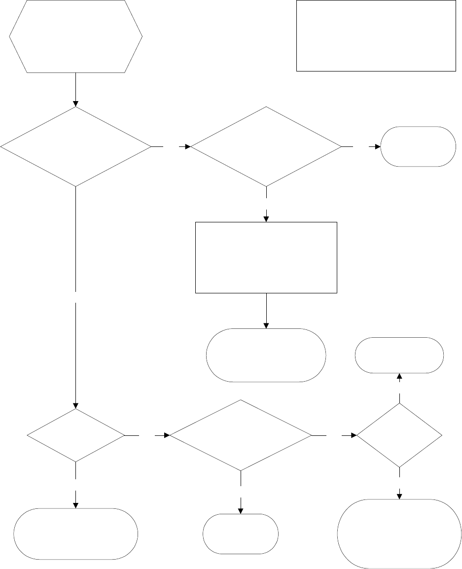
3-30
3.8.1 Troubleshooting the 24VAC Circuit
UNIT IS CONNECTED
TO POWER SUPPLY,
DRAIN VALVE IS FULLY
CLOSED, CONTROLLER
IS ON AND CALLING
FOR HEAT (heat mode
indicator is illuminated).
NOTE: All voltage measurements must
be made within 4 seconds of unit calling
for heat. If unit does not fire within 4
seconds, ignition modules will lock out
and the computer must be turned off
then back on to reset.
Is 24VAC
present on interface
board J3 pin 9 (LED 5 (GV)) and,
on dual vat units, J1 pin 9
(LED 1 (GV))?
Is 24VAC
present across gas valve main
coil (PV terminal) (on both valves
if dual vat)?
Yes
24V circuit is OK.
Problem may be
with gas valve.
Yes
Probable causes are an open high-limit
or a failed wire between the interface
board and the gas valve. On units with
built-in filtration, cause may also be a
failed drain safety switch.
No
Check continuity of high-limit
and continuity of drain safety
switch. If both are zero,
problem is in wiring.
Is LED 3 (24V)
lit continuously?
No
Probable causes are a failed
24V transformer or failed
wiring between transformer and
interface board.
No
Is 24VAC
present on the right PWR
terminal (LED 4) (and left PWR
terminal (LED 2), if
dual vat)?
Yes
Probable cause
is a failed interface
board.
No
Is 24VAC
present on V1S (or
V1D and V2D, if
dual vat)?
Yes
Probable cause is a
failed interface board.
Yes
If ignition module fuse
is good, probable causes are a
failed ignition module or a failed
interface board. Replace suspect
ignition module with one known
to be good to isolate cause.
No
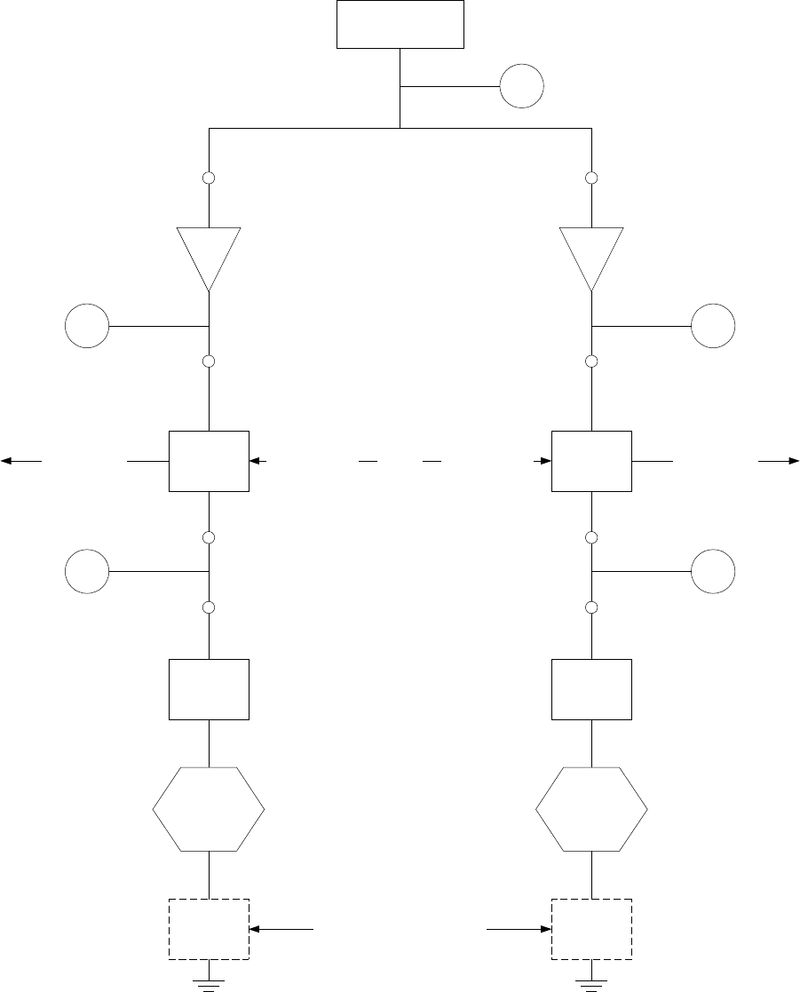
3-31
LEFT VAT
LED 3 (24V)
K1
IGNITION
MODULE
LED2 (PWR)
PWR
V2D
HIGH
LIMIT
SWITCH
LED1 (GV)
GAS
VALVE
K2
IGNITION
MODULE
PWR
V1S (FV) OR V1D (DV)
HIGH
LIMIT
SWITCH
GAS
VALVE
24V
TRANSFORMER
LED 5 (GV)
J1 PIN 9 J3 PIN 9
FULL OR RIGHT VAT
J3 PIN 8J1 PIN 8
24 VOLT CIRCUIT
With Interface Board 806-3398 or 106-0386 and
Two 807-1006 (FV/DV), 807-2971 (FV/DV), or 807-3365 (DV) Ignition Modules
LED 4 (PWR)
High Voltage
to Ignitor
High Voltage
to Ignitor
FV = Full Vat
DV = Dual Vat
DRAIN
SAFETY
SWITCH
DRAIN
SAFETY
SWITCH
This switch used only with
built-in filtration systems.
Flame Sensor Flame Sensor
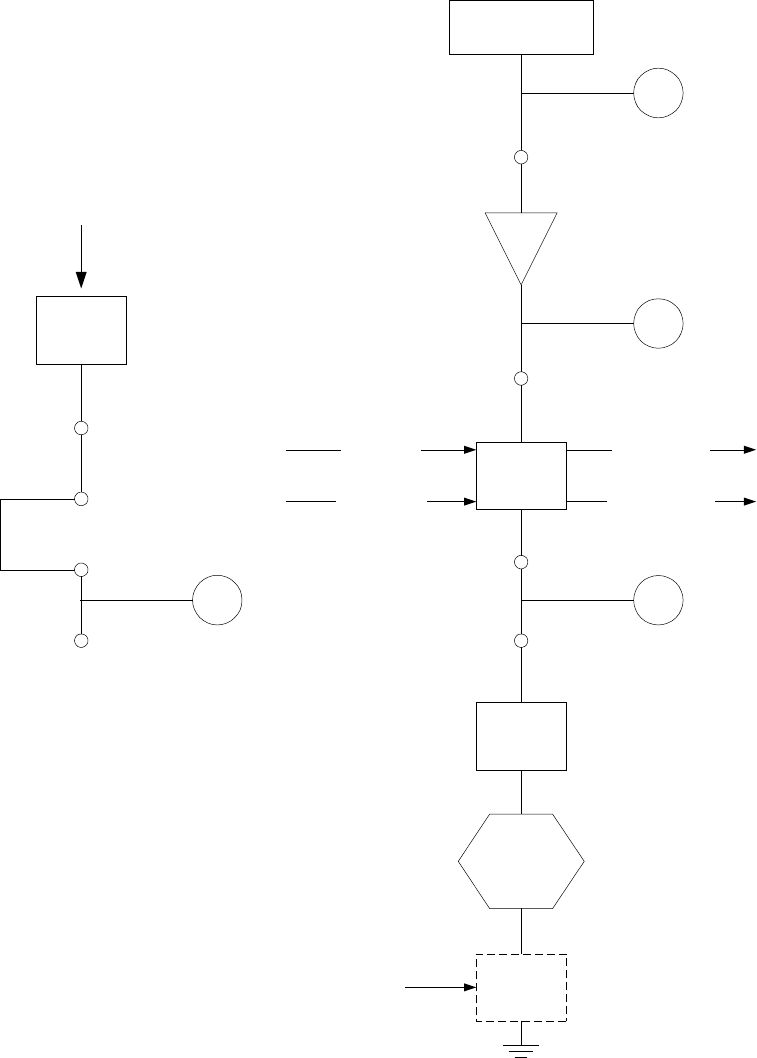
3-32
24 VOLT CIRCUIT
With Interface Board 806-3398 or 106-0386 and
One 807-3366 (FV) Ignition Module
NOTE: Some units may
be wired in this manner.
IGNITION
MODULE
V1S
PWR (left side)
V2S
LED 5 (GV)
J3 PIN 9
Jumper
LED 3 (24V)
24V
TRANSFORMER
K2
IGNITION
MODULE
PWR (right side)
V1D
LED 5 (GV)
J3 PIN 9
J3 PIN 8
LED 4 (PWR)
HIGH
LIMIT
SWITCH
GAS
VALVE
DRAIN
SAFETY
SWITCH
This switch used only with
built-in filtration systems.
High Voltage
to Left Ignitor
High Voltage
to Right Ignitor
Left Flame
Sensor
Right Flame
Sensor
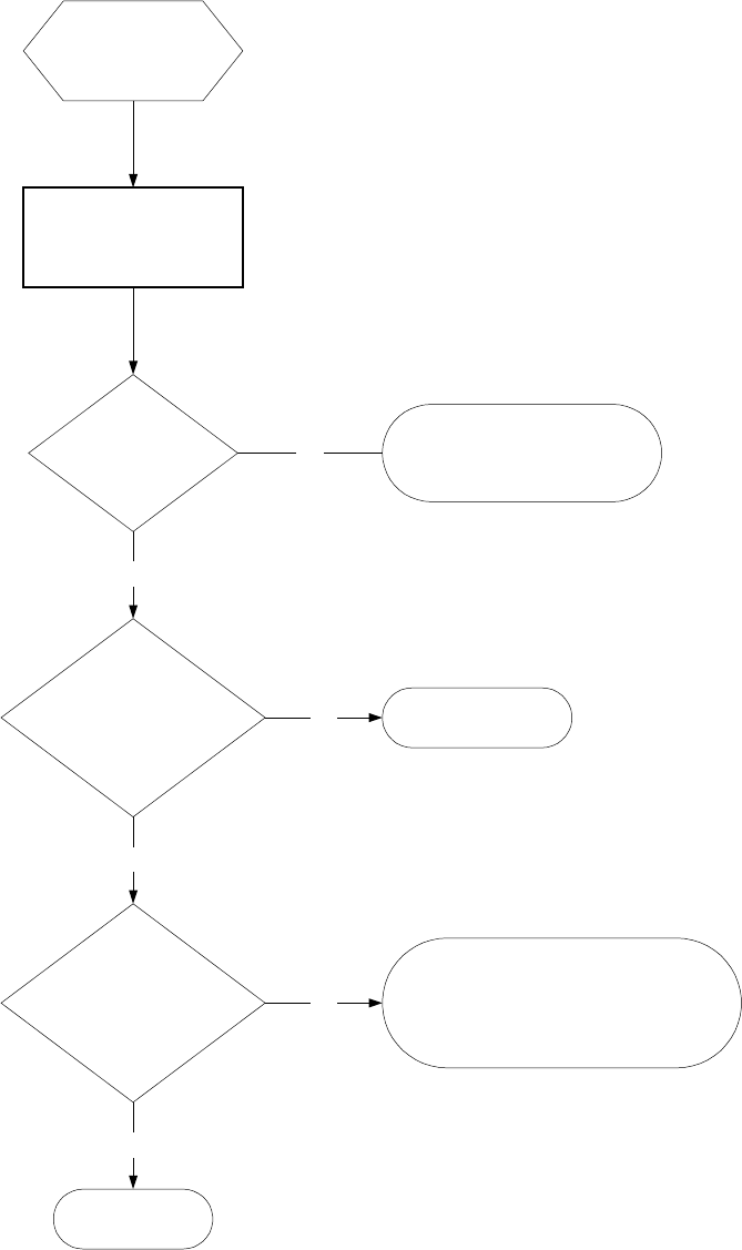
3-33
3.8.2 Troubleshooting the Gas Valve
CONTROLLER
IS CALLING
FOR HEAT.
For non-CE units, verify
gas valve is in ON
position.
Is 24VAC
present across gas
valve main coil?
Is incoming
gas pressure in
accordance with tables in
Section 2.3
of this manual?
Yes
Is outgoing
gas pressure in
accordance with tables on
page 3-7
of this manual?
Yes
Gas valve is OK>
Yes
Probable cause is misadjusted
or failed gas valve. Adjust gas valve in
accordance with Section 3.4 of this
manual. If valve cannot be
adjusted, replace valve.
No
Problem is with
gas supply to fryer.
No
Problem is with 24VAC Circuit.
Refer to "Troubleshooting the
24VAC Circuit" on page 3-30.
No
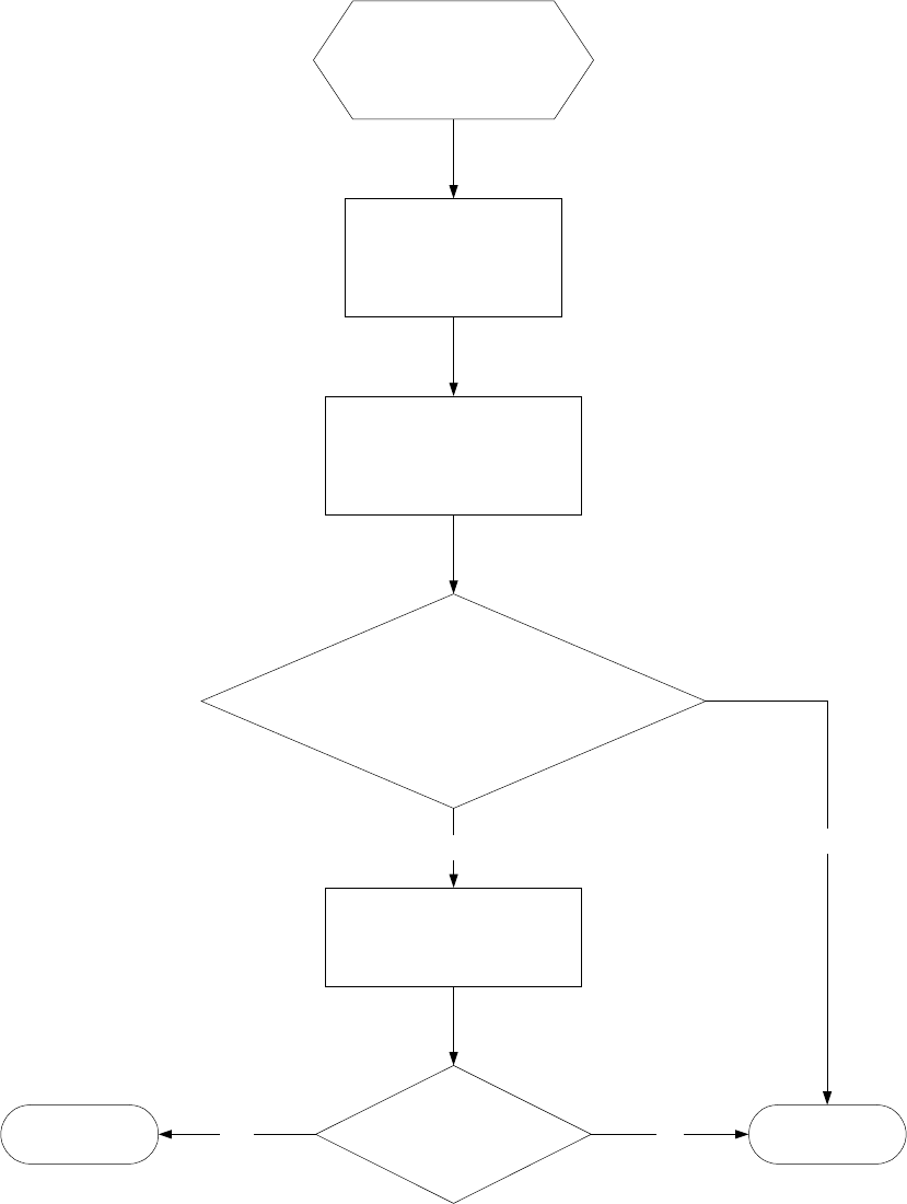
3-34
3.8.3 Troubleshooting the Temperature Probe
While it is still in the
frypot, inspect probe
body for damage.
Remove and replace if
bent, dented or cracked.
Inspect leads for fraying,
burning, breaks, and/or
kinks. If found, replace
probe.
Determine temperature of
cooking oil/shortening using
a thermometer or pyrometer
placed at tip of probe.
Is resistance through
J3 pins 2 and 6 (J1 pins 2 and 6 for
left side of dual vat) approximately equal to
that given in Probe Resistance Chart for
the corresponding temperature?
Measure resistance through
each of the previously tested
pins to ground.
Yes
Is resistance
5 megaohms or greater in
each pin?
Probe has failed.No
Problem is not
with probe. Yes
No

3-35
Probe Resistance Chart
For use with H52 Series fryers manufactured with Minco Thermistor probes only.
FOHMSC FOHMSC FOHMSC FOHMSC FOHMSC
32 1000 0 83 1107 28 134 1214 57 185 1320 85 236 1424 113
33 1002 1 84 1110 29 135 1216 57 186 1322 86 237 1426 114
34 1004 1 85 1112 29 136 1218 58 187 1324 86 238 1428 114
35 1006 2 86 1114 30 137 1220 58 188 1326 87 239 1430 115
36 1008 2 87 1116 31 138 1222 59 189 1328 87 240 1432 116
37 1011 3 88 1118 31 139 1224 59 190 1330 88 241 1434 116
38 1013 3 89 1120 32 140 1226 60 191 1332 88 242 1436 117
39 1015 4 90 1122 32 141 1229 61 192 1334 89 243 1438 117
40 1017 4 91 1124 33 142 1231 61 193 1336 89 244 1440 118
41 1019 5 92 1126 33 143 1233 62 194 1338 90 245 1442 118
42 1021 6 93 1128 34 144 1235 62 195 1340 91 246 1444 119
43 1023 6 94 1131 34 145 1237 63 196 1342 91 247 1447 119
44 1025 7 95 1133 35 146 1239 63 197 1344 92 248 1449 120
45 1027 7 96 1135 36 147 1241 64 198 1346 92 249 1451 121
46 1030 8 97 1137 36 148 1243 64 199 1348 93 250 1453 121
47 1032 8 98 1139 37 149 1245 65 200 1350 93 251 1455 122
48 1034 9 99 1141 37 150 1247 66 201 1352 94 252 1457 122
49 1036 9 100 1143 38 151 1249 66 202 1354 94 253 1459 123
50 1038 10 101 1145 38 152 1251 67 203 1357 95 254 1461 123
51 1040 11 102 1147 39 153 1253 67 204 1359 96 255 1463 124
52 1042 11 103 1149 39 154 1255 68 205 1361 96 256 1465 124
53 1044 12 104 1151 40 155 1258 68 206 1363 97 257 1467 125
54 1046 12 105 1154 41 156 1260 69 207 1365 97 258 1469 126
55 1049 13 106 1156 41 157 1262 69 208 1367 98 259 1471 126
56 1051 13 107 1158 42 158 1264 70 209 1369 98 260 1473 127
57 1053 14 108 1160 42 159 1266 71 210 1371 99 261 1475 127
58 1055 14 109 1162 43 160 1268 71 211 1373 99 262 1477 128
59 1057 15 110 1164 43 161 1270 72 212 1375 100 263 1479 128
60 1059 16 111 1166 44 162 1272 72 213 1377 101 264 1481 129
61 1061 16 112 1168 44 163 1274 73 214 1379 101 265 1483 129
62 1063 17 113 1170 45 164 1276 73 215 1381 102 266 1485 130
63 1065 17 114 1172 46 165 1278 74 216 1383 102 267 1487 131
64 1068 18 115 1174 46 166 1280 74 217 1385 103 268 1489 131
65 1070 18 116 1176 47 167 1282 75 218 1387 103 269 1491 132
66 1072 19 117 1179 47 168 1284 76 219 1389 104 270 1493 132
67 1074 19 118 1181 48 169 1287 76 220 1391 104 271 1495 133
68 1076 20 119 1183 48 170 1289 77 221 1393 105 272 1497 133
69 1078 21 120 1185 49 171 1291 77 222 1395 106 273 1499 134
70 1080 21 121 1187 49 172 1293 78 223 1398 106 274 1501 134
71 1082 22 122 1189 50 173 1295 78 224 1400 107 275 1503 135
72 1084 22 123 1191 51 174 1297 79 225 1402 107 276 1505 136
73 1086 23 124 1193 51 175 1299 79 226 1404 108 277 1507 136
74 1089 23 125 1195 52 176 1301 80 227 1406 108 278 1509 137
75 1091 24 126 1197 52 177 1303 81 228 1408 109 279 1512 137
76 1093 24 127 1199 53 178 1305 81 229 1410 109 280 1514 138
77 1095 25 128 1201 53 179 1307 82 230 1412 110 281 1516 138
78 1097 26 129 1722 54 180 1309 82 231 1414 111 282 1518 139
79 1099 26 130 1204 54 181 1311 83 232 1416 111 283 1520 139
80 1101 27 131 1206 55 182 1313 83 233 1418 112 284 1522 140
81 1103 27 132 1208 56 183 1315 84 234 1420 112 285 1524 141
82 1105 28 133 1210 56 184 1317 84 235 1422 113 286 1526 141

3-36
Probe Resistance Chart (Continued)
For use with H52 Series fryers manufactured with Minco Thermistor probes only.
FOHMSC FOHMSC FOHMSC FOHMSC FOHMSC
287 1528 142 338 1630 170 389 1732 198 440 1833 227 491 1932 255
288 1530 142 339 1632 171 390 1734 199 441 1835 227 492 1934 256
289 1532 143 340 1634 171 391 1736 199 442 1837 228 493 1936 256
290 1534 143 341 1636 172 392 1738 200 443 1839 228 494 1938 257
291 1536 144 342 1638 172 393 1740 201 444 1841 229 495 1940 257
292 1538 144 343 1640 173 394 1742 201 445 1843 229 496 1942 258
293 1540 145 344 1642 173 395 1744 202 446 1845 230 497 1944 258
294 1542 146 345 1644 174 396 1746 202 447 1846 231 498 1946 259
295 1544 146 346 1646 174 397 1748 203 448 1848 231 499 1948 259
296 1546 147 347 1648 175 398 1750 203 449 1850 232 500 1950 260
297 1548 147 348 1650 176 399 1752 204 450 1852 232 501 1952 261
298 1550 148 349 1652 176 400 1754 204 451 1854 233 502 1954 261
299 1552 148 350 1654 177 401 1756 205 452 1856 233 503 1956 262
300 1554 149 351 1656 177 402 1758 206 453 1858 234 504 1958 262
301 1556 149 352 1658 178 403 1760 206 454 1860 234 505 1960 263
302 1558 150 353 1660 178 404 1762 207 455 1862 235 506 1962 263
303 1560 151 354 1662 179 405 1764 207 456 1864 236 507 1964 264
304 1562 151 355 1664 179 406 1766 208 457 1866 236 508 1965 264
305 1564 152 356 1666 180 407 1768 208 458 1868 237 509 1967 265
306 1566 152 357 1668 181 408 1770 209 459 1870 237 510 1969 266
307 1568 153 358 1670 181 409 1772 209 460 1872 238 511 1971 266
308 1570 153 359 1672 182 410 1774 210 461 1874 238 512 1973 267
309 1572 154 360 1674 182 411 1776 211 462 1876 239 513 1975 267
310 1574 154 361 1676 183 412 1778 211 463 1878 239 514 1977 268
311 1576 155 362 1678 183 413 1780 212 464 1880 240 515 1979 268
312 1578 156 363 1680 184 414 1781 212 465 1882 241 516 1981 269
313 1580 156 364 1682 184 415 1783 213 466 1884 241 517 1983 269
314 1582 157 365 1684 185 416 1785 213 467 1886 242 518 1985 270
315 1584 157 366 1686 186 417 1787 214 468 1888 242 519 1987 271
316 1586 158 367 1688 186 418 1789 214 469 1890 243 520 1989 271
317 1588 158 368 1690 187 419 1791 215 470 1892 243 521 1991 272
318 1590 159 369 1692 187 420 1793 216 471 1893 244 522 1993 272
319 1592 159 370 1694 188 421 1795 216 472 1895 244 523 1995 273
320 1594 160 371 1696 188 422 1797 217 473 1897 245 524 1996 273
321 1596 161 372 1698 189 423 1799 217 474 1899 246 525 1998 274
322 1598 161 373 1700 189 424 1801 218 475 1901 246 526 2000 274
323 1600 162 374 1702 190 425 1803 218 476 1903 247 527 2002 275
324 1602 162 375 1704 191 426 1805 219 477 1905 247 528 2004 276
325 1604 163 376 1706 191 427 1807 219 478 1907 248 529 2006 276
326 1606 163 377 1708 192 428 1809 220 479 1909 248 530 2008 277
327 1608 164 378 1710 192 429 1811 221 480 1911 249 531 2010 277
328 1610 164 379 1712 193 430 1813 221 481 1913 249 532 2012 278
329 1612 165 380 1714 193 431 1815 222 482 1915 250 533 2014 278
330 1614 166 381 1716 194 432 1817 222 483 1917 251 534 2016 279
331 1616 166 382 1718 194 433 1819 223 484 1919 251 535 2018 279
332 1618 167 383 1720 195 434 1821 223 485 1921 252 536 2020 280
333 1620 167 384 1722 196 435 1823 224 486 1923 252 537 2022 281
334 1622 168 385 1724 196 436 1825 224 487 1925 253 538 2025 281
335 1624 168 386 1726 197 437 1827 225 488 1927 253 539 2027 282
336 1626 169 387 1728 197 438 1829 226 489 1929 254 540 2029 282
337 1628 169 388 1730 198 439 1831 226 490 1931 254 541 2031 283
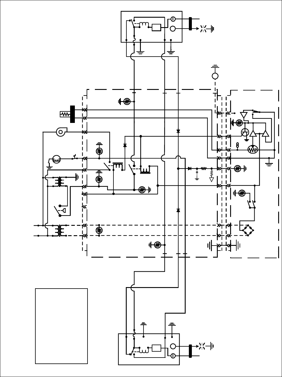
3-37
3.9 Simplified Wiring Diagrams
K2
HEAT
RELAY
K4
BLOWER
RELAY
AIR
OPTIONAL
AIR
SWITCH
BLOWER
HI-LIMIT
12V 24V
TEMP
PROBE
24V
LED 3 LED 5
R-GV
R HEAT
LED 4
R
PWR
V1S
ALARM
LED 6
12V
L HEAT
LED 2
L
PWR
ALARM
V2S
POWER
ON/OFF
TROUBLE
HEAT
T
J3
621291185431
J2
11
11
4
4
13
13
14
14
10
10
5
5
3
3
1
1
2
2
GV
RIGHT IGNITION
MODULE
25V+
ALARM
TD
VALVE
GND
BNR
GND
RIGHT
IGNITOR
LEFT IGNITION
MODULE
25V+
ALARM
TD
VALVE
GND
LEFT
IGNITOR
SD
M
LINE VOLTAGE
GND
BNR
DRAIN SAFETY
SWITCH
H52 SERIES — FULL-VAT — JUNE 1996 - JULY 1999
(TWO RELAYS: K2 (HEAT) & K4 (BLOWER) AND TWO IGNITION MODULES)
HV
HV
1/50
A
A
A
A
47K
1K
DRAIN SAFETY SWITCH
ONLY ON BIH52 MODELS
AIR SWITCH
ONLY ON CE AND
SOME EXPORT UNITS
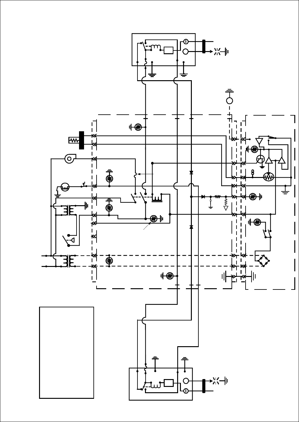
3-38
K3
HEAT &
BLOWER
RELAY
OPTIONAL
AIR
SWITCH
BLOWER
H
I
LIMI
T
12
V24V
TEM
P
PROB
E
24V
LED 3 LED 5
R-GV
R HEAT
LED 4
R
PWR
V1S
ALARM
LED 6
12
V
L HEAT
LED 2
L
PWR
ALARM
V2
S
POWER
ON/OFF
TROUBLE
HEAT
T
J3
621291185431
J2
11
11
4
4
13
13
14
14
10
10
5
5
3
3
1
1
2
2
G
V
RIGHT IGNITION
MODULE
ALARM
TD
VALV
E
GND
BNR
GND
RIGHT
IGNITOR
LEFT IGNITION
MODULE
25V+
ALARM
TD
VALVE
GND
LEFT
IGNITOR
S
D
M
LINE
VOLTAGE
GND
BNR
DRAIN SAFETY
SWITCH
H52 SERIES— FULL-VAT— BEFORE JUNE 1996 & AFTER JULY 1999
(ONE DUAL FUNCTION HEAT/BLOWER RELAY (K3) AND TWO IGNITION MODULES)
HV
HV
1/50
A
A
A
A
47K
1K
F1
F1 Fuse not
present on
fryers
manufactured
before 6/96
DRAIN SAFETY SWITCH
ONLY ON BIH52 MODELS
AIR SWITCH
ONLY ON CE AND SOME
EXPORT UNITS
AIR LED not
present on fryers
manufactured
before 6/96 25V+
AIR
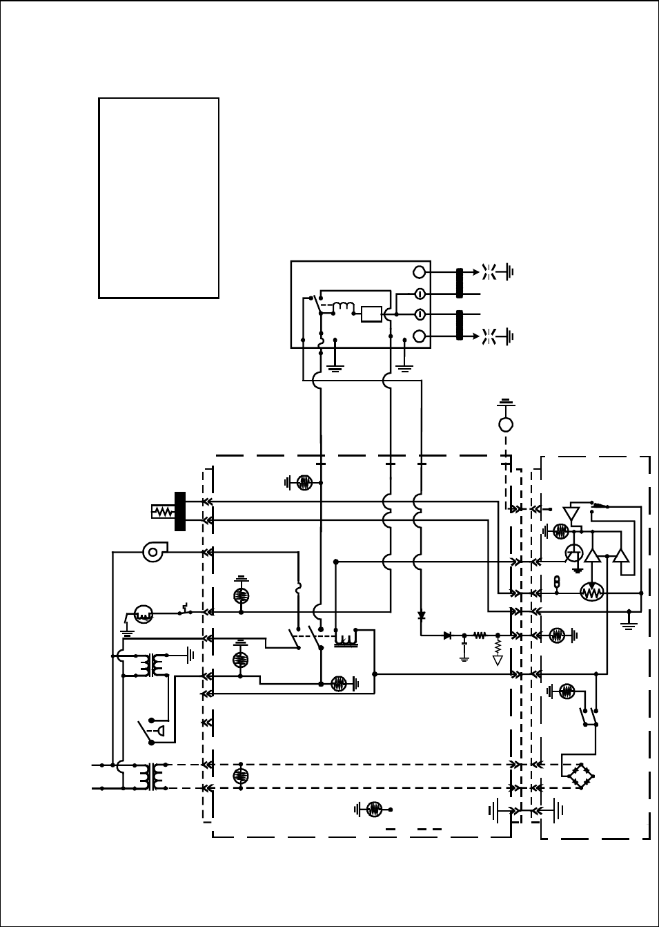
3-39
H52 SERIES— FULL-VAT WITH ONE DUAL-SPARK IGNITION MODULE
(ONE DUAL FUNCTION HEAT/BLOWER RELAY (K3))
DRAIN SAFETY SWITCH
ONLY ON BIH52 MODELS
AIR SWITCH
ONLY ON CE AND SOME
EXPORT UNITS
LINE VOLTAGE
K3
HEAT &
BLOWER
RELAY
AIR
OPTIONAL
AIR
SWITCH
BLOWER
HI
LIMIT
12V 24V TEMP
PROBE
24V
LED 3 LED 5
R-GV
R HEAT
LED 4
R
PWR
V1D
ALARM
LED 6
12V
L HEAT
LED 2
L
PWR
ALARM
V2S
POWER
ON/OFF
TROUBLE
HEAT
T
J3
621291185431
J2
11
11
4
4
13
13
14
14
10
10
5
5
3
3
1
1
2
2
GV
DUAL-SPARK
IGNITION
MODULE
ALARM
TD
VALVE
GND
BNR
GND
RIGHT
IGNITOR
SD
M
DRAIN SAFETY
SWITCH
1/50
A
A
A
A
47K
1K
F1
25V+
HV
HV
LEFT
IGNITOR
NOTE: SOME UNITS
MANUFACTURED AFTER
AUGUST 2000 ARE
EQUIPPED WITH ONE
DUAL-SPARK IGNITION
MODULE. OTHERS MAY
BE EQUIPPED WITH TWO
SINGLE-SPARK IGNITION
MODULES.
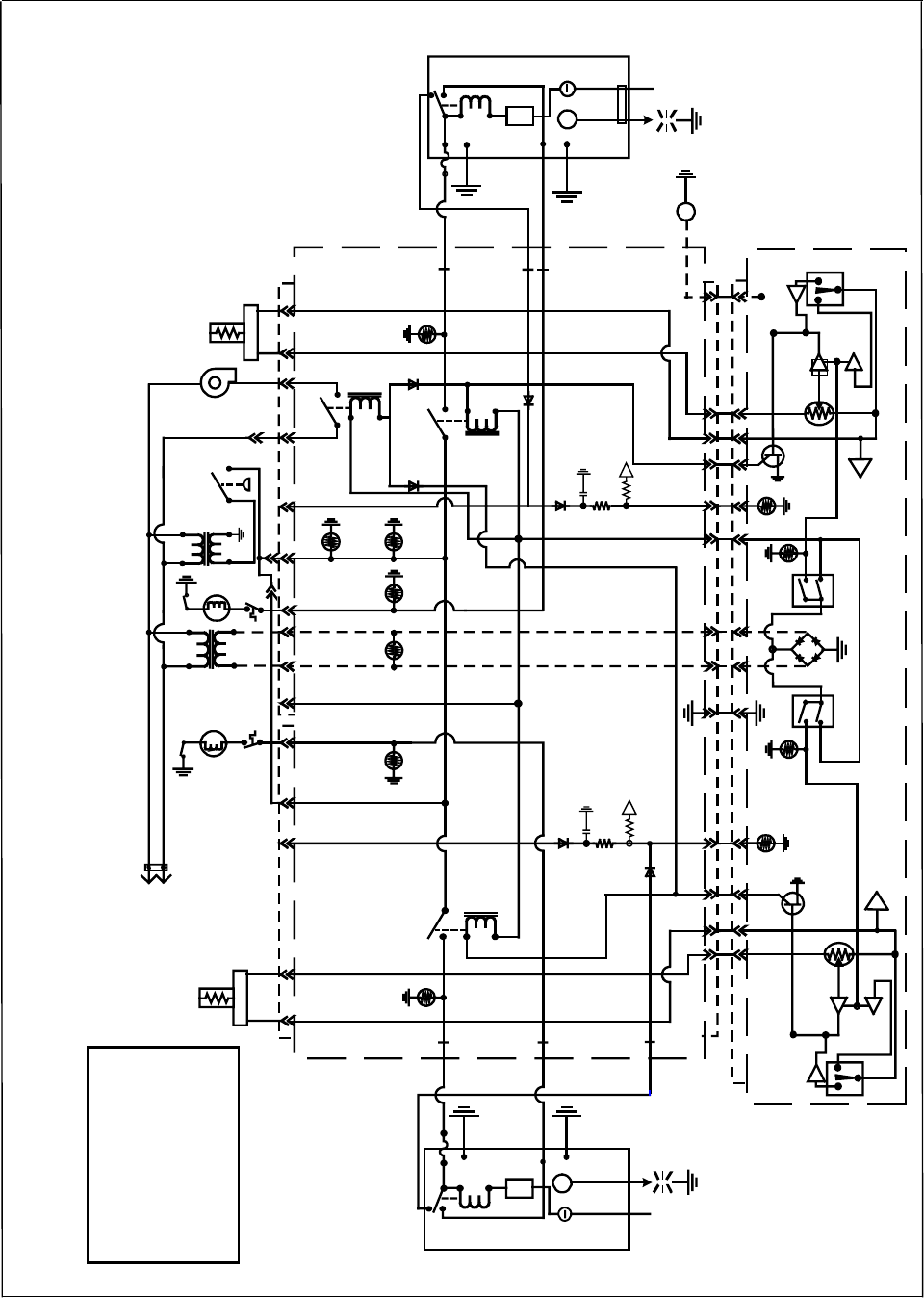
3-40
TD
GND
ALARM
25V+
RIGHT
IGNITOR
VALVE
TEMP
PROBE
BLOWER
24V
DRAIN
SAFETY
SWITCH
HIGH
LIMIT
OPTIONAL
AIR SWITCH
6J3
1148
4
8
9
9
R HEAT
LED 4
K2 HEAT
RELAY
K4
BLOWER
RELAY
R-GV
LED 5 R
PWR
V1D
ALARM
351041314 11J2
351041314 11
TROUBLE
POWER
HEAT
BNR
GND
GV
AIR
24V
LED 3
RIGHT IGNITION
MODULE
TD
BNR
GND
GND
ALARM
25V+
LEFT
IGNITOR
VALVE
TEMP
PROBE
12V
GV
HIGH
LIMIT
LINE
VOLTAGE
31598462J1
L-HEAT
LED 2
K1
HEAT
RELAY
12V
LED 6
L-GV
LED 1
L
PWR
V2D
ALARM
15
15
14
14
6
6
12
12
2
2
1
1
POWER
ON/OFF
TROUBLE
LEFT IGNITION
MODULE
12 2
T
M
T
M
A
A
ON/OFF
SD
1K
47K
1/50
1K
47K
1/50
DRAIN
SAFETY
SWITCH
H52 SERIES — DUAL-VAT — JUNE 1996 - JULY 1999
(THREE RELAYS: K1 & K2 (HEAT) AND K4 (BLOWER))
A
A
A
AA
A
A
A
DRAIN SAFETY SWITCH
ONLY ON BIH52
MODELS
AIR SWITCH
ONLY ON CE AND
SOME EXPORT UNITS
HV HV
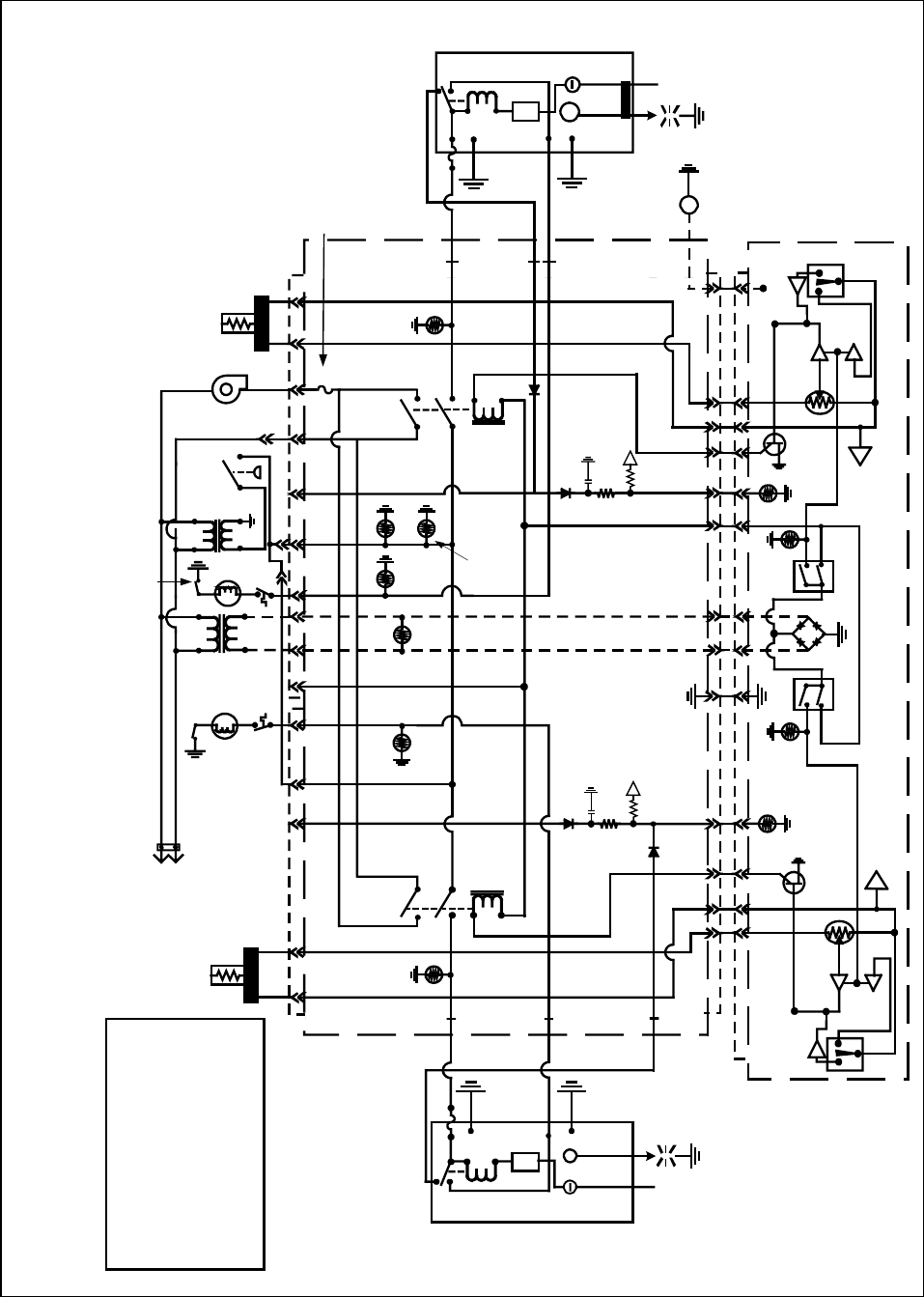
3-41
TD
GND
ALARM
25V+
RIGHT
IGNITOR
VALVE
TEMP
PROBE
BLOWER
24V
HI-LIMIT
OPTIONAL
AIR SWITCH
6J3
1148
4
8
9
9
R-HEAT
LED 4
K2
HEAT
RELAY
R-GV
LED 5
R
PWR
V1D
ALARM
351041314 11J2
351041314 11
TROUBLE
POWER
HEAT
BNR
GND
GV
AIR
24V
LED 3
RIGHT IGNITION
MODULE
TD
BNR
GND
GND
ALARM
25V+
LEFT
IGNITOR
VALVE
TEMP
PROBE
12V
GV
HI- LIMIT
LINE
VOLTAGE
31598462J1
L-HEAT
LED 2
K1
HEAT
RELAY
12V
LED 6
L-GV
LED 1
L
PWR
V2D
ALARM
15
15
14
14
6
6
12
12
2
2
1
1
POWER
ON/OFF
TROUBLE
LEFT IGNITION
MODULE
12 2
T
M
T
M
A
A
ON/OFF
SD
HV
A
A
A
A
1K
47K
1/50
A
A
A
A
1K
47K
1/50
DRAIN
SAFETY
SWITCH
H
V
F1
F1 Fuse not
applicable to
fryers
manufactured
before 6/96
AIR LED not
present on fryers
manufactured
before 6/96
H52 SERIES — DUAL-VAT — BEFORE JUNE 1996 & AFTER JULY 1999
(TWO DUAL-FUNCTION HEAT/BLOWER RELAYS (K1 & K2) AND TWO IGNITION MODULES)
DRAIN SAFETY SWITCH
ONLY ON BIH52 MODELS
AIR SWITCH
ONLY ON CE AND SOME
EXPORT UNITS
DRAIN
SAFETY
SWITCH
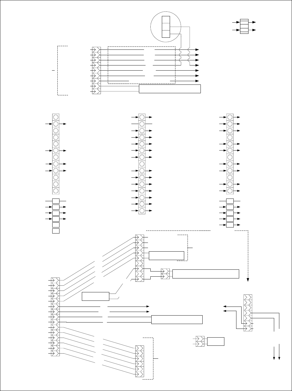
3-42
3.10 Principal Wiring Connections
LEFT PWR VIA K1
GAS VALVE
J1
FROM TO
LEFT VAT
1
2
3
4
5
6
7
8
9
10
11
12
PROBE J2 PIN 14
PROBE J2 PIN 15
C1 PIN 4 (24VAC)
V2D
GROUND GROUND
MODULE VALVE 1 J1 PIN 9
J1 PIN 8 VIA K1 MODULE 25V
DRAIN SWITCH (BIH52 ONLY) J2 PIN 12
GND
V2D
PWR
AD
AS
V2S
J3
RIGHT OR FULL VAT
1
2
3
4
5
6
7
8
9
10
11
12
J2 PIN 1C1 PIN 6 (12VAC)
C1 PIN 4 (24VAC)
V1S OR V1D
GROUNDGROUND
J3 PIN 9MODULE VALVE 1 (DUAL VAT)
J3 PIN 8 VIA K2 MODULE 25V
DRAIN SWITCH (BIH52 ONLY) J2 PIN 10
GND
V1D
PWR
ALR
V1S
J2 PIN 14PROBE
C1 PIN 5 (12VAC) J2 PIN 3
J2 PIN 5 C1 PIN 7
PROBE J2 PIN 13
RIGHT PWR VIA K2
GAS VALVE
C1 PIN 1 (L1) BLOWER VIA K4
C5 PIN 2K4
MODULE VALVE 1 (FULL VAT) J3 PIN 9
FROM TO
J3 PIN 1 CONTROLLER (12VAC)
J2
GROUND
J3 PIN 3 CONTROLLER (12VAC)
GROUND
RIGHT HEAT RELAY (K2)
RELAYS (12VDC) & J3 PIN 5
CONTROLLER
CONTROLLER
LEFT HEAT RELAY (K1)CONTROLLER
K5CONTROLLER
K3CONTROLLER
RIGHT ALARM OUT (FULL VAT)ALR (RIGHT)
SOUND DEVICECONTROLLER
LEFT ALARM OUT (DUAL VAT)AD (LEFT)
J3 PIN 6 CONTROLLER
CONTROLLERJ1 PIN 2 & J3 PIN 2
J1 PIN 6 CONTROLLER
FROM TO
1
2
3
4
5
6
7
8
9
10
11
12
13
14
15
TO T1 & J3 PIN 11
TO J1 PIN 8 & J3 PIN 8
TO J3 PIN 1
TO J3 PIN 3
TO GROUND
TO T2 & C5 PIN 2
TO J3 PIN 5 (12VDC)
LINE VOLTAGE (COM)
LINE VOLTAGE (L1)
LINE VOLTAGE (L1)
GROUND
24VAC
12VAC
12VAC
LINE VOLTAGE (COM)
FROM TRANSFORMER BOX
N.C.
N.O.
COM
AIR SWITCH
(CE AND SOME
EXPORT UNITS)
FILTER PAN SUCTION TUBE HEATER
(BIH52 UNITS ONLY)
C1
T1
T2
(IN COMPONENT BOX)
C2 PIN 1
C2 PINS 3 & 12
LINE VOLTAGE (L1)
LINE VOLTAGE (COM)
HOOD RELAY
1
2
3
4
5
6
7
8
9
WHITE/BLACK (CE = BROWN)
BLUE
ORANGE
WHITE
GREEN
BLACK
GROUND
LINE VOLTAGE L1
GROUND, JUMPERED TO PIN 11
JUMPERED FROM PIN 4
JUMPERED TO PIN 7
JUMPERED TO PIN 6
FROM T2, JUMPERED TO PIN 9
FROM T1, JUMPERED TO PIN 8
LINE VOLTAGE COM TO FILTER BOX (BIH52 ONLY)
C3
C2
TO OIL RETURN SWITCHES OF ADJACENT FRYERS
JUMPERED FROM PIN 3
JUMPERED FROM PIN 5
JUMPERED FROM PIN 1
TO OIL RETURN SWITCHES OF ADJACENT FRYERS
1
2
3
4
5
6
7
8
9
10
11
12
13
14
15
OIL RETURN HEATER
(BIH52 UNITS ONLY)
7P
56C
ORANGE
BLUE
OIL RETURN MANIFOLD SOLENOID VALVE
(BIH52 UNITS ONLY)
1
2
1
2
3
4
5
6
7
8
9
OIL RETURN SWITCH
(BIH52 UNITS ONLY)
FILTER BOX
PUMP RELAY
ORANGE
BLUE
WHITE
GREEN
BLACK
RED
WHITE & BLACK
1
2
3
4
5
6
C4
TO J1 PIN 10
JUMPERED FROM PIN 2
FROM T2
TO J1 PIN 7
TO J3 PIN 10
TO J3 PIN 7
BLACK
GREEN
WHITE
RED
ORANGE
BLUE
NOT USED ON H52 FRYERS
C5
J3 PIN 12
LINE VOLTAGE (COM)
BLOWER
1
2
1
2
3
4
5
6
7
C3
(CE)
OIL RETURN
OIL RETURN
JUMPER TO PIN 4
JUMPER TO PIN 5
PINS 1, 2 & 3
SAME AS NON-CE
CE CONFIGURATION
RED
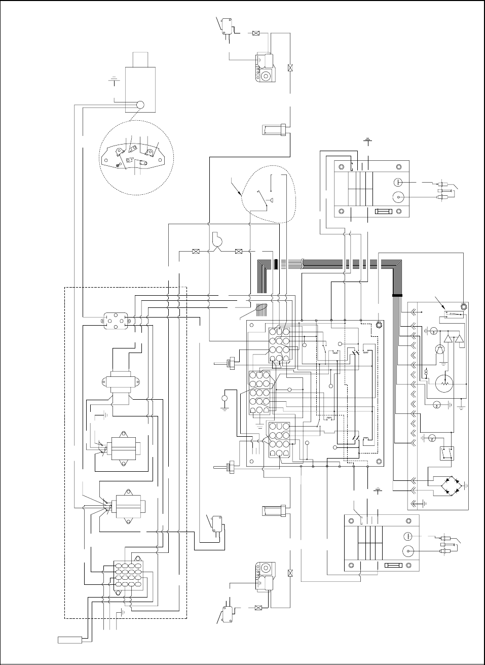
3-43
3.11 Main Wiring Diagrams
ONLY
EXPORT
PUMP
LEFT
LEFT
LEFT
TEMP
PROBE
RIGHT
RIGHT
RIGHT
VALVE
GAS
RIGHT SAFETY
DRAIN SWITCH
51C
C
42C
NC
NO
12C
LIMIT
HIGH
GRN
GND
GND
BURNER
25V
GND
GND
47
6
5
9
8
1
3
2
10
12
11
7101 4
6
8
9
11
2
3
5
12
LEFT IGNITOR
MODULE
IGNITION
LEFT
25V
ALARM
VALVE
82C
25V
GND
25V
BURNER
VALVE
ALARM
137101 4
14
15
6
8
9
11
2
3
5
12
TO J2
CNO
NC
BLK
WHT
7
24V TRANS
LOAD
LINE
LOAD
LINE
27C
YLW
BLK
RED
26C
PRP
BLU
BLK/YLW
PUMP
FILTER
43C
4
3
21
5
6
NC
C
8050926E
22C
NO
BLOWER SWITCH
4C
5C
IGNITION
MODULE
RIGHT
82C
12V TRANS
RELAY
3
4
65
1
2
LOAD
18C
16C
21C
28C
BLOWER
17C
102C
23C
16C
PROBE
TEMP
18C
14C
39C
38C 40C
LINE
24V TRANS
10C
23C
4C
105C
SOUND DEVICE
SOUND
1J2
28C
11C
25C
OIL
C
NC
NO
RETURN
SWITCH
54C
48C
HEATER
2
3
915
10
11
6
4128
13
14
15
16
OIL RETURN
21C
EXTENSION
TRANSFORMER REAR
DRAIN SWITCH
36C
LEFT SAFETY
51C
3C
2C
1C
GND
J3
LED 5
PWR
V1D
V1S
ALM
K4
RELAY
R-GV
K3 HEAT
RIGHT
HEAT
LED 4
FULL POT ONLY
COMPUTER OR CONTROLLER
81C
1114 13
HEAT
74
RELAY
T
M
MELT SWITCH
12V
3
J1
2
24V
LED 3
K2
L-GV
LED 1
LEFT HEAT
LED 2
K1 HEAT
RELAY
HIGH
LIMIT
GND
V2D
7C
ALMD
PWR
ALMS
9C
6C
5
9
RELAY
SWITCH
ON/OFF
TROUBLE
V2S
8C
32 1
10C
INTERFACE BOARD
10
LED 6
GAS
VALVE
41C
RIGHT IGNITOR
BIH152 Main Wiring Diagram (U.S., CE, and Non-CE Export)
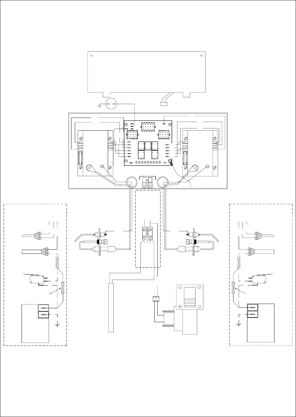
3-44
8050502G
Refer to "PRINCIPAL WIRING
CONNECTIONS" on Page 3-42 for
detail of connection points J1, J2,
J3, C2, C3, and C5.
BIH52/MH52 Main Wiring Diagram (U.S. and Non-CE Export)
MV
14C
BLK
BLOWER
SAFETY
DRAIN
SWITCH
12C
BLK
NO
NC
BLK COM
FOR UNITS WITH NO
SAFETY DRAIN SWITCH
ADD IN-LINE SPLICE
HI- LIM IT
11C
BLK
MV
21
C5
14C
BLK
WHITE
TO J3 PIN12
T2T1
TO C2 PIN1
TO C2 PIN3
TO C2 PIN12
13C
18C
BLK
NO
NC
BLK
BLK
OIL RETURN HEATER FRONT
MV
MV
GAS
VALVE
DRAIN
SAFETY
SWITCH
HI-LIMIT
COM
FO R UNI TS W I TH NO
ADD IN-LINE SPLICE
SAFETY DRAIN SWITCH
PROBE
TEM P
RED
WHITE
BLAC K
FULL VAT
TO J3 PIN6
TO J3 PIN2
TO J3 PIN9
COMPUTER GROUND (81C)
GND
VALVE
VALVE
ALARM
(BURNER)
ORG
BLK
25V
25V
GND
BLUE
BLK
GRN
BLK
ORG
WHT
LINE VOLTAGE (COM)
LINE VOLTAGE (L1)
DETAIL A-A
A
A
DETAIL
BLACK
RED
TO J1 PIN2
TO J1 PIN6
TO J1 PIN9
PWR GVAL24V
K2
ForD
RLY
435
AL 12V
D1
GV PWR
K1
RLY
D
12 6
AIR
B/L
RLY
K5
RT
B/L
RLY
LT
K3 K4
RLY
ForD
RT
LT RT
BLK
ORG
BLK
GND
ORG
V2S
PWR
GND
AS
AD
GND
V2D
SND
J2
2
GND
1
3
SOUND DEVICE
WHT
BLUE
GRN
J1 J3
GND
25V
25V
GREEN
BLUE
ALARM
VALVE
VALVE
(BURNER)
PROBE
TEMP
DUAL VAT
COMPUTER OR CONTROLLER
TO J2
D9
V1S
ALR
PW R
V1D
GND
GND
GND
WHITE WHITE
GAS
VALVE
WHITE
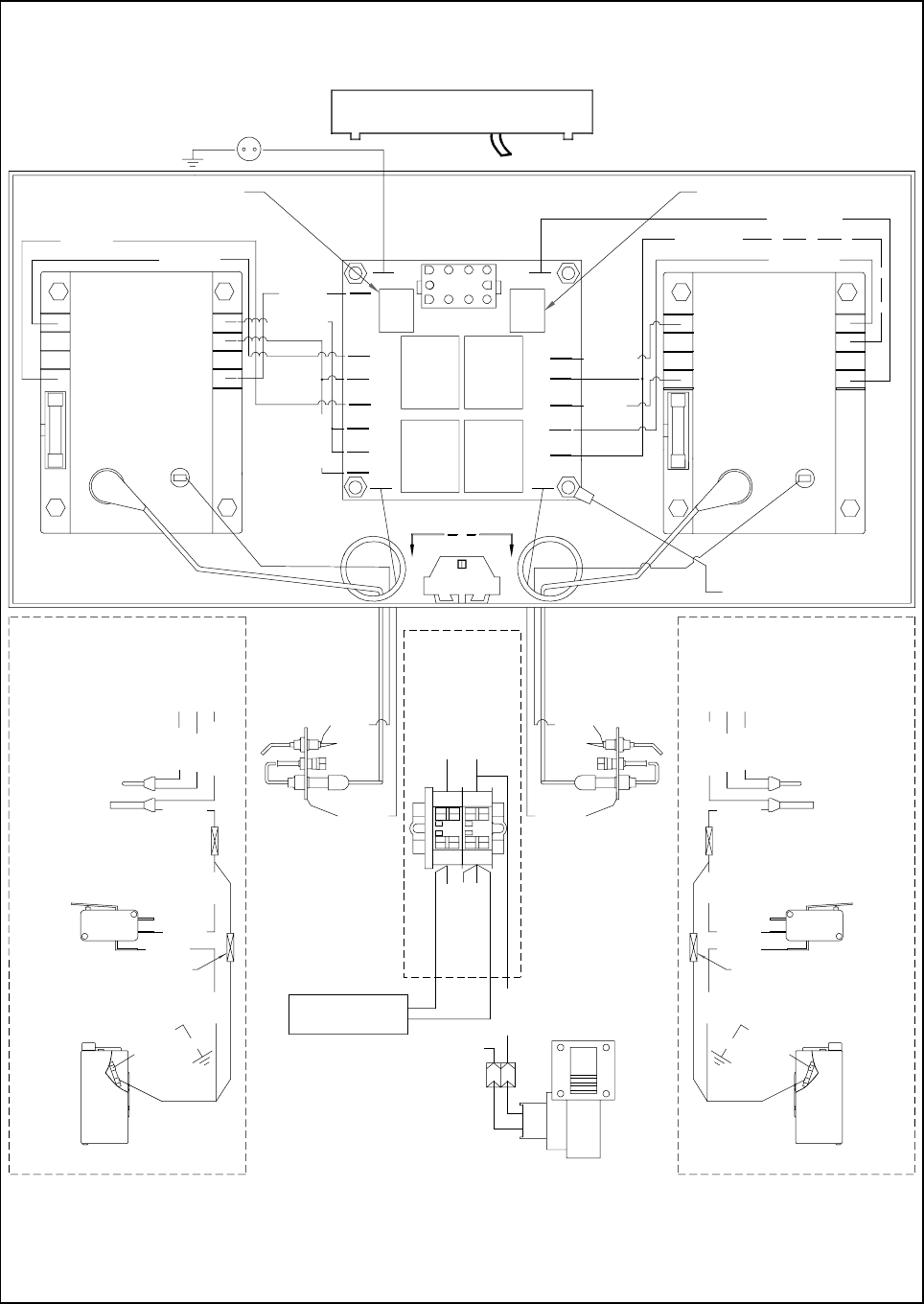
3-45
8050526D
OIL RETURN
HEATER FRONT
WHITE
GREEN
WHITE
ORANGE
BLACK
ALARM
VALVE
VALVE
GROUND
(BURNER)
GROUND
25V
25V
TO J1 PIN9
TO J1 PIN6
TO J1 PIN2
DUAL VAT ONLY
TEMP PROBE
RED
WHITE
HI-LIMIT
BLACK
COM
NC
NO
SAFETY DRAIN SWITCH
BLACK
GAS VALVE
14C
BLACK
13C 18C
FOR UNITS WITH NO
SAFETY DRAIN SWITCH
ADD IN-LINE SPLICE
BLACK
BLACK BLACK
BLACK
ADD IN-LINE SPLICE
SAFETY DRAIN SWITCH
FOR UNITS WITH NO
11C12C
BLACK
14C
GAS VALVE
BLACK
SAFETY DRAIN SWITCH
NO
NC
COM
BLACK TO J3 PIN9
HI-LIMIT
TO J3 PIN2
TO J3 PIN6
WHITE
RED
TEMP PROBE
A
RELAY
LEFT
DUAL DUAL
OR
FULL
RIGHT
RELAY
J2 GND
V1S
ALARM
POWER
V1D
GND
BLUE
GREEN
25V
25V
GROUND
ORANGE
(BURNER)
GROUND
VALVE
VALVE
ALARM
SOUND DEVICE
TO J2
COMPUTER OR CONTROLLER
J3 OPPOSITE SIDE
J1 OPPOSITE SIDE
DETAIL
A
COMPUTER GND (81C)
BLACK
WHITE
GREEN
BLUE
GND GND
GND
GND
V2D
PWR
A D
V2S
A S
TO J3 PIN12
DETAIL A-A
LINE VOLTAGE
LINE VOLTAGETO C2 PIN1
TO C2 PIN3
TO C2 PIN12
12
C5
BLOWER
WHITE
GREEN
WHITE
T1 T2
T1 T2
(L1)
(COM)
BIH52/MH52 Main Wiring Diagram (CE)
Refer to "PRINCIPAL WIRING
CONNECTIONS" on Page 3-42 for
detail of conncection points J1, J2,
J3, C2, C3, and C5.
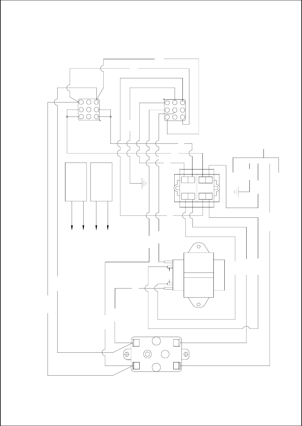
3-46
52C
4 2
30C
41C
13C
T-4
8C
24V/50VA
LINE
RED
3 1
TO PIN 3
12C
RED
32C
45C
TO PIN 9
TO PIN 7
108C
11C
TO PIN 1
4
5
6
26C
9C
MOTOR
TO PUMP
14C
T2T1
62C
92C
9
8
7
8050902C
3
2
1
6
5
4
SOLENOID
PUMP
10C
1
2
HEATER
PUMP
3
51C
27C
7
8
9
BIH52 Filter Box Wiring Diagram (U.S., CE, and Non-CE Export)
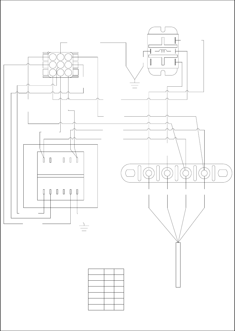
3-47
MH152 Transformer Wiring Diagram (U.S. and Non-CE Export)
N
3
2
COM
4
NO
25C
1
5
NC
32
56
2C GRN/YLW
7C ORG
3C WHT
11C WHT
6C
9C
WHT
89
BLUE
26C
WHT
2 31
10C BLK
79 810
456
12C
WHT
1C
BLK
12
1
5C ORG
4C RED
8050504C
8C BLK
120V CONFIGURATION SHOWN
USE TERMINALS 11 AND 12 FOR 12V OUTPUT.
NOTE: USE TERMINALS 7 AND 8 FOR 24V OUTPUT.
11
2
1
7
4
36C BLK
BLACK RED ORANGE WHITE
C
O
R
D
S
E
T
4
LINE
2
4
5
6
6
VOLTS
100 1
208
220
230
240
1
1
1
1
120 1
COM
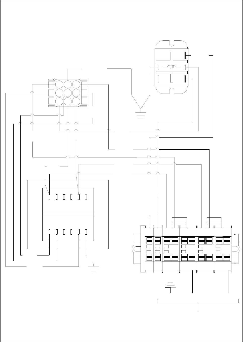
3-48
MH152 Transformer Wiring Diagram (CE)
BRN
230V/1Ø/50HZ
INCOMING POWER
3
8C BLK
NOTE: USE TERMINALS 7 AND 8 FOR 24V OUTPUT.
USE TERMINALS 11 AND 12 FOR 12V OUTPUT.
8050529B
12
4C RED
5C ORG
1
GRN/YLW
10C BLK
11C WHT
3C WHT
711 10 9 8
12C
WHT
62 3 4 5
1 32
26C
WHT
1C
BLK
7C ORG
9C
WHT
2
8
5
4
7
1
6
9
3
6C
BLUE
2C GRN/YLW
25C NC NO
5 4
1 2
COM
3
BLUE
NN
36C BLK
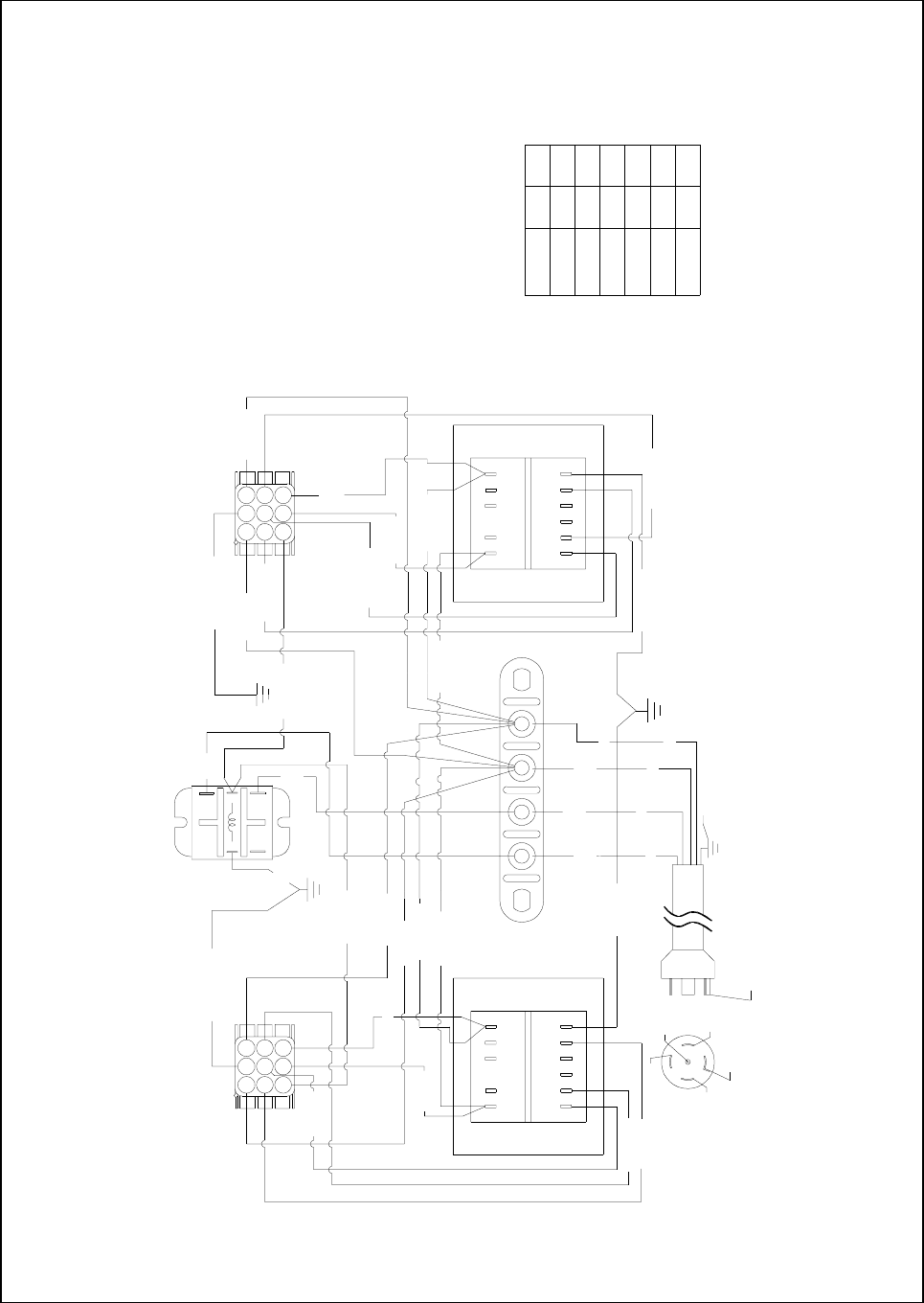
3-49
GREEN
TO BODY
CAUTION: THIS PLUG IS NOT BEING USED IN ITS
STANDARD 5-WIRE 120/208V NEMA L21-20P
CONFIGURATION. DO NOT CONNECT TO A STANDARD
120/208V 5-WIRE POWER SUPPLY.
WHITE
9C WHT
ORANGE
6C BLUE
4C RED
12
RED
BLACK
GREEN
1011 9 78
8C BLK
1245 6
12C WHT
BLK RED
HOOD
RELAY
10C BLK
1C BLK
11C WHT
3C WHT
7C ORG
1 2
2C GRN/YW
5C ORG
9
6
3
87
4
1
5
2
NC
25C
5 4
NO
1 2
COM
3
120V CONFIGURATION SHOWN
24C WHT
17C ORG
WHT
ORG
NEUTRAL
120
VAC
22C BLK
3 N
18C BLUE
1112 10 89 7
21 4 5
23C WHT
20C BLK
6
NOTE: USE TERMINALS 7 AND 8 FOR 24V OUTPUT.
USE TERMINALS 11 AND 12 FOR 12V OUTPUT.
14C GRN/YW
16C RED
19C ORG
26C
WHT
36C
13C BLK
4
987
2C
WHT
2
5
1
6
3
15C WHT
100
208
230
220
120
VOLTS
240
1
1
1
1
1
5
6
4
6
2
LINECOM
14
HOOD
RELAY
8050498D
BIH252/MH252 Transformer Box Wiring Diagram (U.S. and Non-CE Export)
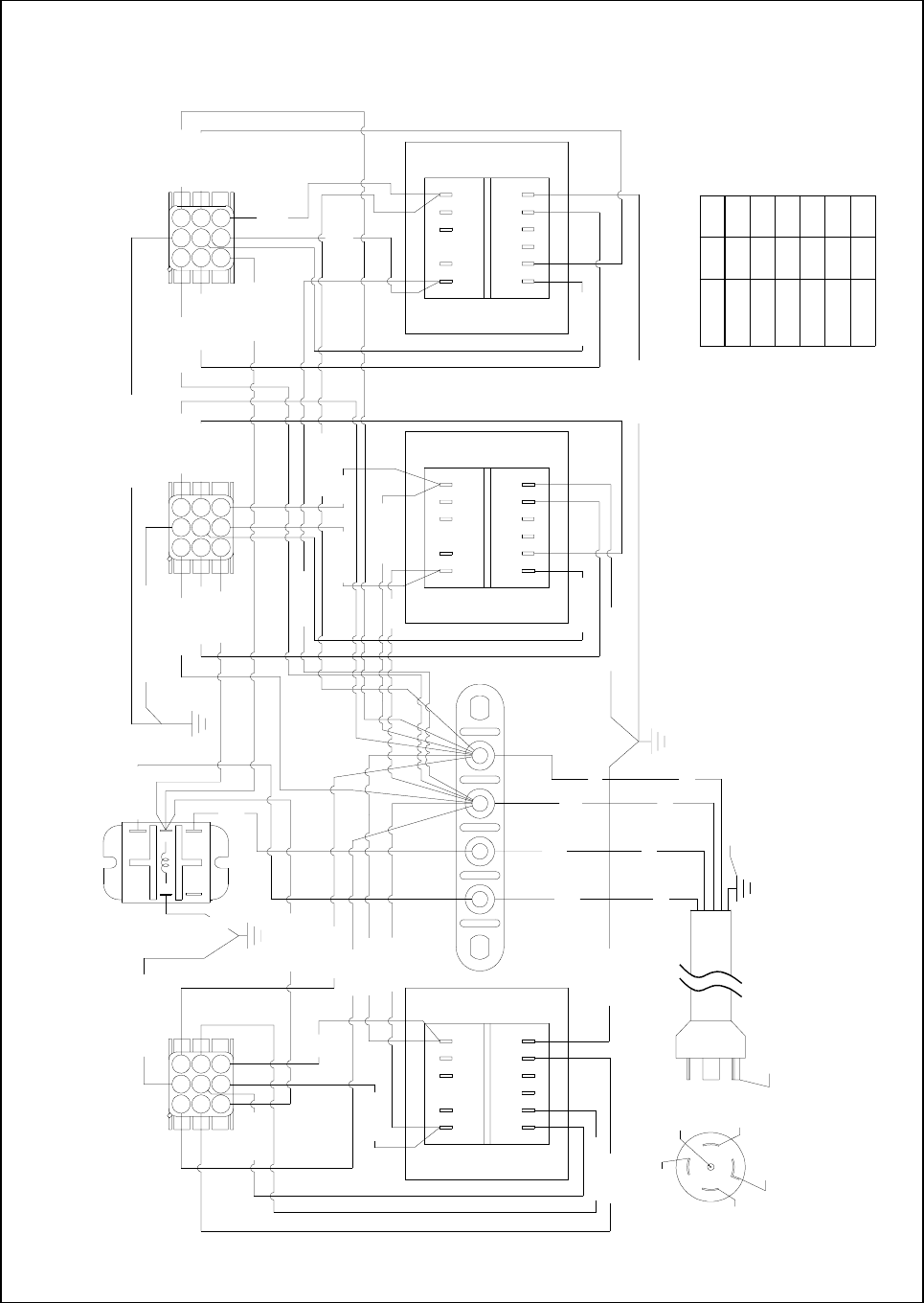
3-50
8050499E
BIH352/MH352 Transformer Box Wiring Diagram (U.S. and Non-CE Export)
CAUTION: THIS PLUG IS NOT BEING USED IN ITS
STANDARD 5-WIRE 120/208V NEMA L21-20P
CONFIGURATION. DO NOT CONNECT TO A STANDARD
120/208V 5-WIRE POWER SUPPLY.
120V CONFIGURATION SHOWN
100
208
230
220
120
VOLTS
240
1
1
1
1
1
5
6
4
6
2
LINECOM
14
NOTE: USE TERMINALS 7 AND 8 FOR 24V OUTPUT.
USE TERMINALS 11 AND 12 FOR 12V OUTPUT.
14C GRN/YLW
19C ORG
BLACK
10
ORANGE
WHITE
GREEN
4C RED
RED
6C BLUE
1211
12
8C BLK
ORG
WHT
GREEN
TO BODY
1
12C WHT
987
BLK
10C BLK
11C WHT
1C BLK
456
9C
WHT3C WHT
N32
NEUTRAL
RED
HOOD
RELAY120
VAC
5C ORG
7
4
1
2C GRN/YLW
9
6
8
5
32
25C
5
1
NC
36C BLK
4
WHT
26C
3
2
NO
COM
34C
BLK
10
38C WHT
17C ORG
24C WHT
12 1011 9 8 7
20C BLK
23C WHT
22C
BLK
1
37C BLK
2 4 56
21C
WHT
39C WHT
31C ORG
1112
1 2
987
456
2
5
8
18C BLUE
15C WHT
28C GRN/YLW
7C ORG
16C RED
13C BLK
9
6
7
4
8
5
31 2
27C BLK
33C ORG
30C RED
7
4
1
32C BLUE
29C WHT
35C
WHT
9
6
3
HOOD
RELAY
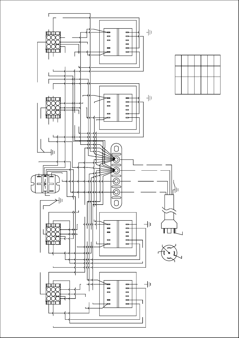
3-51
8050500E
BIH452/MH452 Transformer Box Wiring Diagram (U.S. and Non-CE Export)
CAUTION: THIS PLUG IS NOT BEING USED IN ITS
STANDARD 5-WIRE 120/208V NEMA L21-20P
CONFIGURATION. DO NOT CONNECT TO A STANDARD
120/208V 5-WIRE POWER SUPPLY.
120V CONFIGURATION SHOWN
100
208
230
220
120
VOLTS
240
1
1
1
1
1
5
6
4
6
2
LINECOM
14
NOTE: USE TERMINALS 7 AND 8 FOR 24V OUTPUT.
USE TERMINALS 11 AND 12 FOR 12V OUTPUT.
GREEN
TO BODY
HOOD
RELAY
RED
6C BLUE
GREEN
BLACK
WHITE
ORANGE
12C
WHT
RED
18C BLUE
24C
WHT
BLK
1C BLK
40C BLK
1 2
4C RED
8C BLK
5C ORG
NC
20C BLK
22C BLK
13C BLK
41C WHT
4 5 6 1 2
19C ORG
9C
WHT
16C RED
17C ORG
23C WHT
4 5 6
1
3C WHT
21C
WHT
7C ORG
15C WHT
5
2C GRN/YLW
14C GRN/YLW
1
ORG
WHT
NEUTRAL
120
VAC 39C
WHT
42C BLK29C WHT
NO
30C RED
33C ORG
31C ORG
37C BLK
23N
4
38C WHT
1 2 4 5 6
52C WHT
28C GRN/YLW
36C BLK
2
3
COM
27C BLK
43C GRN/YLW
421 5 6
46C ORG
51C BLK
48C ORG
45C RED
44C WHT
1012 11 9 8 7 1012 11 9 8 7
HOOD
RELAY
1012 11 9 8 7
53C
WHT
1012 11 9 8 7
26C
WHT
25C
BLUE
1
7
4
23
89
56
1
7
4
23
89
56
1
7
4
23
89
56
34C
BLK
35C
WHT
32C
BLUE
49C
BLK
50C
WHT
42C
BLUE
1
7
4
23
89
56
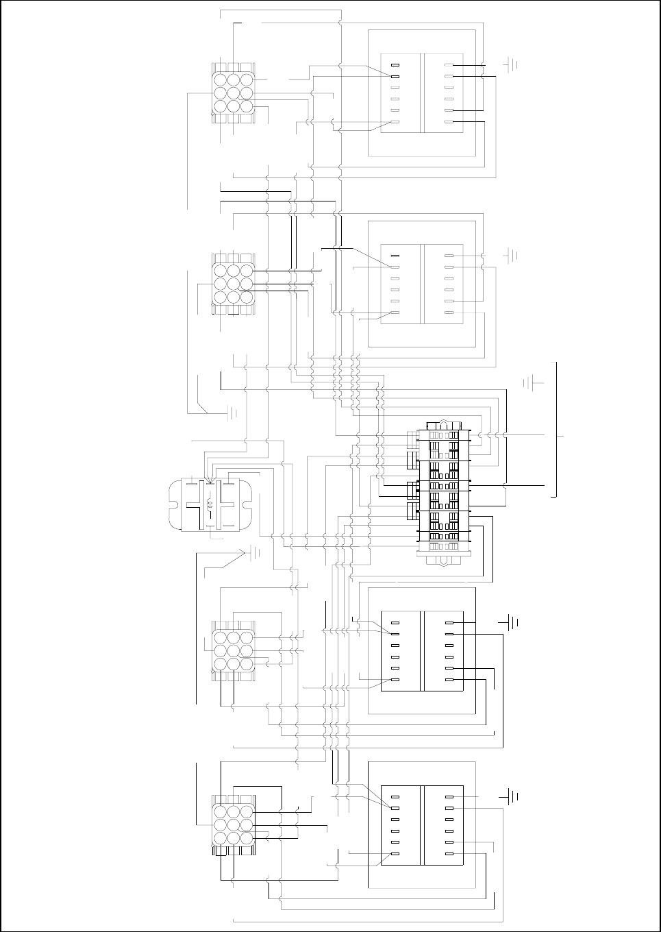
3-52
BIH452/MH452 Transformer Box Wiring Diagram (CE)
NOTE: Also used for CE BIH252/MH252 and CE BIH352/MH352 Transformer Boxes.
36C BLK
6C BLUE
FRYER 1
18C BLUE
8050530D
FRYER 2 BRN
1 N3332
NOTE: USE TERMINALS 7 AND 8 FOR 24V OUTPUT.
USE TERMINALS 11 AND 12 FOR 12V OUTPUT.
8C BLK
40C BLK
1C BLK
19C ORG
5C ORG
4C RED
7C ORG
14C GRN/YLW
22C BLK
13C BLK
41C WHT
20C BLK
17C ORG
16C RED
2C GRN/YLW
3C WHT
23C WHT
15C WHT
NC NO
54
1 2
3
COM
GRN/YLWBLUE
230V/1Ø/50HZ
NN
FRYER 3 FRYER 4
46C ORG
51C BLK
37C BLK
31C ORG
33C ORG
30C RED
28C GRN/YLW
27C BLK
52C WHT
38C WHT
29C WHT
43C GRN/YLW
42C
BLUE
44C WHT
6
987
45
312
6
987
45
312
6
987
45
312
6
987
45
312
50C
WHT
42C BLK
45C RED
48C ORG
49C
ORG
32C
BLUE
35C
WHT
34C
BLK
12 11 10 9 78
1234 65
39C
WHT
12 11 10 9 78
1234 65
53C
WHT
26C
WHT
25C
BLUE
21C
WHT
12 11 10 9 78
1234 65
12 11 10 9 78
1234 65
9C
WHT
24C
WHT
12C
WHT
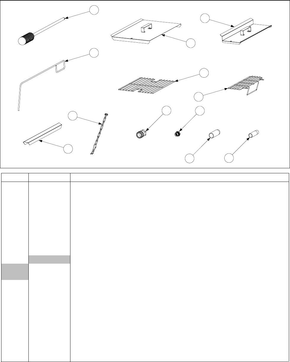
4-1
CHAPTER 4: PARTS LIST
4.1 Accessories
1
2
3
4
5
6
7
8
10
9
11 12
ITEM PART # COMPONENT
1 803-0209 Brush, Frypot Cleaning
2 803-0197 Fryer’s Friend 27" (Clean-out Rod)
3 806-3068 Cover, Full-Vat Frypot
4 806-3407 Cover, Dual-Vat Frypot
* 826-0993SP Kit, Replacement Cover Handle
5 803-0132 Rack, Full-Vat Basket Support
6 803-0133 Rack, Dual-Vat Basket Support
8 826-0900 Kit, Chain Restraint
7 910-7443 Top Connecting Strip
9Coupling, Gas Line Female Quick-Disconnect
810-0070 ¾-inch
810-0073 1-inch
* 810-0478 Gas Line, Flexible, with Cut-Off Valve
10 813-0032 Bushing, Flexible Gas Line
11 812-1378 Drain Extension, Non-Filter Full Vat Fryer
12 812-1374 Drain Extension, Non-Filter Dual Vat Fryer
* 803-0022 Basket, Twin
* 826-1157 Kit, Fuse and Fuse Puller
* 803-0002 Powder, Filter – Approximately 100 Cups
* 803-0046 Cup, Plastic Filter Powder Measuring
* 803-0170 Filter Pack – 100 Sheets
* 803-0219 Pad, McDonald’s FP-III Universal Filter
* Not illustrated.
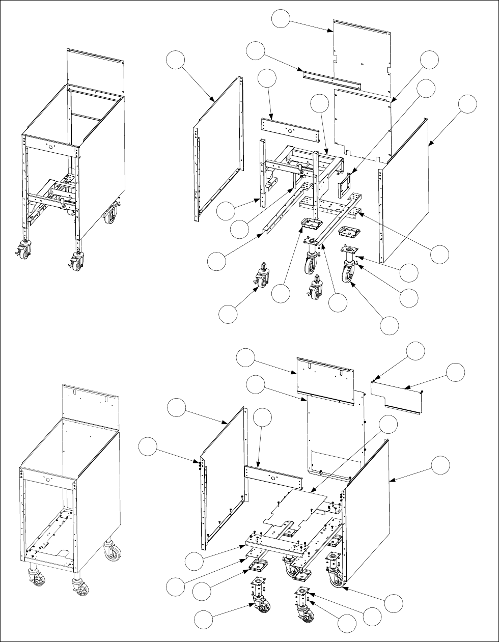
4-2
8.2 Cabinetry Components
8.2.1 BIH152 and MH152 Cabinet Components
1
2
3
10
9
4
18
16
17
18
12
23
21
13
14
26
27
22
7
8
20
5
28
6
9
19
15
11 21
25
24
26
27
28
BIH152
MH152

4-3
ITEM PART # COMPONENT
1 911-7688SP Side, BIH52 Left
2 912-7688SP Side, BIH52 Right
3 900-5521 Back, BIH152 Upper
4 900-5670 Back, BIH152 Lower
5Side, MH52 Left
911-7036 Before 6 Nov 2000
911-7688SP After 5 Nov 2000
6Side, MH52 Right
912-7036 Before 6 Nov 2000
912-7688SP After 5 Nov 2000
7Back, MH152 Lower
900-2654 Before 6 Nov 2000
900-5670 After 5 Nov 2000
8Back, MH152 Upper
900-2410 Before 6 Nov 2000
900-5521 After 5 Nov 2000
9 900-4180 Brace, BIH152/MH152 Top
10 900-5519 Brace, BIH152 Rear (and MH152 after 5 Nov 2000)
11 Channel, MH52 Cabinet Base Left and Right Side
900-7035 Before 6 Nov 2000
900-7687 After 5 Nov 2000
12 901-5526 Channel, BIH152 Base Left Side
13 902-5526 Channel, BIH152 Base Right Side
14 900-4389 Channel, BIH152 Base Rear
15 900-4179 Channel, MH152 Cabinet Base Front and Rear
16 806-8421 Rail Assembly, BIH152
17 910-5656 Leg, BIH152 Front
18 823-2579 Bracket, BIH152 Filter Motor Mount
19 Shield, MH152 Base
900-2541 Before 6 Nov 2000
200-0075 After 5 Nov 2000
20 900-2649 Cover, MH52 Rear Access (notch on right)
21 806-5209 Leg Pad Assembly
22 812-1326 Caster, BIH152 Rear
23 823-2844 Caster, BIH152 Front (on units built prior to Nov 2000, use 823-2582)
* 810-1414 Insert, BIH152 Square Leg (component of Item 23, adapts caster to leg)
24 810-0327 Caster, Rear (without brake)
25 Caster, Adjustable Front (with brake)
810-0326 Before 6 Nov 2000
810-0944 After 5 Nov 2000
26 809-0191 Washer, ¼-inch Lock
27 809-0131 Screw, ¼-20 x ¾-inch Hex Head
28 809-0412 Screw, #10 x ¾-inch Washer Hex Head (cabinet screw)
* Not illustrated.
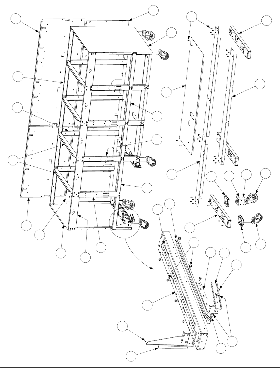
4-4
4.2.2 BIH52 Cabinet Components (Batteries)
Detail of Gusset and
Filter Rail Construction
Detail of Base
Assembly Construction
NOTE: Items 26 and 27
are not used on CE units.
1
2
3
5
4
6
7
8
16
9
10
11
12
15
14
13
16
16
18
17
19
20
21
20
22
23
24
25
25
26
27
28
29
31
30
32
33

4-5
ITEM PART # COMPONENT
1 911-7688SP Side, Left Cabinet (all models)
2 912-7688SP Side, Right Cabinet (all models)
3 900-7714 Back, Upper Cabinet (BIH252, BIH452 and BIH552)
4 900-9424 Back, Upper Cabinet (BIH352 and BIH552)
5 900-7712 Back, Lower Cabinet (BIH252, BIH452 and BIH552)
6 900-9425 Back, Lower Cabinet (BIH352 and BIH552)
7 901-1810 Gusset, Left Cabinet (all models)
* 902-1810 Gusset, Right Cabinet (BIH252)
8 901-1948 Channel, Universal Side Support (all models)
9 911-4690 Rail, Left Top Filter (all models)
* 912-4690 Rail, Right Top Filter (all models)
10 910-5244 Rail, Universal Filter (all models)
11 900-1959 Bracket, Filter Lock Mounting (all models)
12 900-1957 Lock, Filter (all models)
13 809-0422 Screw, 10-32 x .4-inch Shoulder (all models)
14 809-0189 Washer, ¼-inch SS Flat
15 809-0053 Nut, 10-32 Hex
16 900-7687 Channel, Side Base (all models)
17 Channel, Rear Base
900-7686 BIH252
900-9420 BIH352
900-2390 BIH452
900-9555 BIH552
18 Channel, Front Base
900-4787 BIH352
900-2389 BIH452
9009556 BIH552
19 806-5209 Leg Pad Assembly (all models)
20 809-0191 Washer, ¼-inch Lock (all models)
21 809-0131 Screw, ¼-20 x ¾-inch Hex Head (all models)
22 810-0944 Caster with Brake, Front (all models)
23 810-0327 Caster, Rear (all models)
24 Shield
900-2452 BIH352
900-2453 BIH452
900-9601 BIH552
25 809-0412 Screw, #10 x ½-inch Hex Washer Head (cabinet screw, all models)
26 900-4798 Support, Long Cross (all models – not used on CE units)
27 900-2562 Support, Short Cross (all models – not used on CE units)
28 Brace, Top Front
900-7033 BIH252
900-9248 BIH352
900-2393 BIH452
900-9558 BIH552
29 Brace, Top Rear
900-7708 BIH252
900-7709 BIH352
* Not illustrated. LIST CONTINUED ON NEXT PAGE
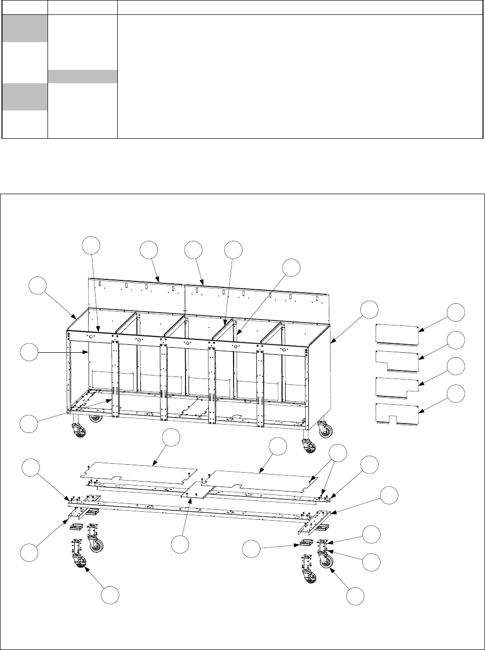
4-6
4.2.2 BIH52 Cabinet Components (Batteries) (Continued)
ITEM PART # COMPONENT
900-2391 BIH452
900-9557 BIH552
30 900-7710 Post, Cabinet (all models)
31 900-7358 Divider, Cabinet (all models)
32 Post, Short Door
900-4797 All non-CE models.
900-2437 All CE models.
33 900-4799 Post, Long Door (BIH352, BIH452 and BIH552)
* 809-0413 Spacer, Door Post (1/4-inch ID x 4mm nylon washer)
* Not illustrated.
4.2.3 MH52 Cabinet Components (Batteries)
NOTE: MH52 cabinetry was standardized with BIH52 cabinetry beginning with units manufactured 6
November 2000 and later. All MH52 cabinetry components except base assembly parts on units
manufactured after 6 November 2000 are the same as those on BIH52 units of the same size.
Detail of Base
Assembly Construction
1
2
3
68
9
7
10
4 5
11 11
10
12
13
13
14
15 16
17
18
23
19
20
21
22

4-7
ITEM PART # COMPONENT
1Side, Left Cabinet (all models)
911-7036 Before 6 Nov 2000
911-7688SP After 5 Nov 2000
2Side, Right Cabinet (all models)
912-7036 Before 6 Nov 2000
912-7688SP After 5 Nov 2000
3Back, Lower Cabinet
Before 6 Nov 2000)
900-2652 MH252
900-2651 MH352
900-4915 MH452
900-9600 MH552
After 5 Nov 2000
900-7712 MH252, MH452, and MH552 (18-inches x 31-inches)
900-9425 MH352 and MH552 (18-inches x 46.5-inches)
4Back, Upper Cabinet, MH252 and MH552
900-2411 Before 6 Nov 2000 (10.2-inches x 31.1-inches)
900-7714 After 5 Nov 2000 (18.72-inches x 31.24-inches)
5Back, Upper Cabinet, MH352 and MH552
900-2412 Before 6 Nov 2000 (10.2-inches x 46.6-inches)
900-9424 After 5 Nov 2000 (18.72-inches x 46.88-inches)
*Back, Upper Cabinet, MH452
900-2413 Before 6 Nov 2000 (9.66-inches x 62.36-inches)
900-7714 After 5 Nov 2000 (18.72-inches x 31.24-inches)
6Brace, Top Front
900-7033 MH252
900-9248 MH352
900-2393 MH452
900-9558 MH552
*Brace, Top Rear (used only on units built after 05 Nov 2000)
900-7708 MH252
900-7709 MH352
900-2391 MH452
900-9557 MH552
7Post, Door (all models)
900-7032 Before 6 Nov 2000
900-4799 After 5 Nov 2000
* 809-0413 Spacer, Door Post (1/4-inch ID x 4mm nylon washer )
8Divider, Cabinet (all models)
900-7356 Before 6 Nov 2000
900-7358 After 5 Nov 2000
9Brace, Back Support (all models)
900-7053 Before 6 Nov 2000
900-7710 After 5 Nov 2000
10 Channel, Cabinet Base Left and Right Side (all models)
900-7035 Before 6 Nov 2000
900-6787 After 5 Nov 2000
* Not illustrated. LIST CONTINUED ON NEXT PAGE

4-8
ITEM PART # COMPONENT
11 Channel, Cabinet Base Front and Rear
MH252
900-7034 Before 6 Nov 2000
900-7686 After 5 Nov 2000
MH352
900-9249 Before 6 Nov 2000
900-9420 After 5 Nov 2000
MH452
900-4906 Before 6 Nov 2000
900-2390 After 5 Nov 2000
MH552
900-9611 Before 6 Nov 2000
900-9555 After 5 Nov 2000
12 Support, Center Base (MH452, MH552)
900-4907 Before 6 Nov 2000
200-0769 After 5 Nov 2000
13 Shield, Cabinet Base
MH252, MH452
900-2527 Before 6 Nov 2000 (18-inches x 25.2-inches) (MH452 uses 2)
200-0772 After 5 Nov 2000 (17.75-inches x 25.06-inches) (MH452 uses 2)
MH352
900-2528 Before 6 Nov 2000 (18-inches x 17.5-inches) plus 900-2527
200-0771 After 5 Nov 2000 (17.75-inches x 40.7-inches)
MH552
900-9623 Before 6 Nov 2000 (18-inches x 33-inches)
After 5 Nov 2000 uses 1 each of 200-0771 and 200-0772
14 806-5209 Leg Pad Assembly (all models)
15 810-0944 Caster with Brake, Front (all models)
16 810-0327 Caster, Rear (all models)
17 809-0191 Washer, ¼-inch Lock (all models)
18 809-0131 Screw, ¼-20 x ¾-inch Hex Head (all models)
19 900-2468 Cover, MH52 Rear Access (no notch)
20 900-2649 Cover, MH52 Rear Access (notch on right corner when viewed from rear)
21 900-2650 Cover, MH52 Rear Access (notch on left corner when viewed from rear)
22 900-5482 Cover, MH52 Rear Access (notch in center)
23 809-0412 Screw, #10 x ½-inch Hex Washer Head (cabinet screw, all models)
* Not illustrated.
4-9
THIS PAGE INTENTIONALLY LEFT BLANK
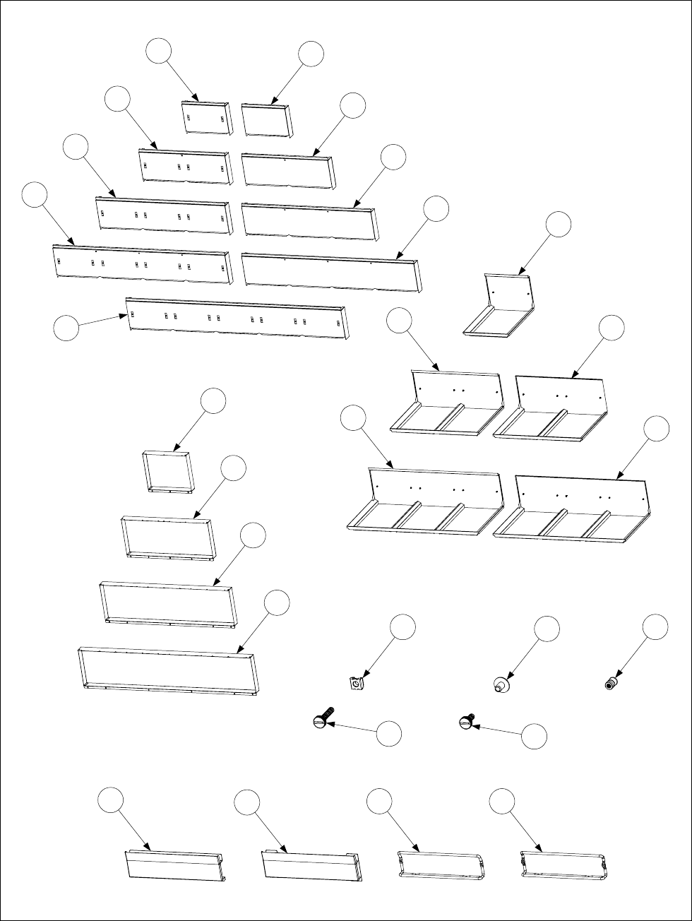
4-10
4.2.4 BIH52/MH52 Cap-N-Splash Assemblies, Fluecaps, Standoffs and Related Parts
7
5
3
9
12
4
6
8
10
11 12
14
13
15
16
17
18
25 26 27
19 20 21 22
23 24
NOTE: Items 19 through 27 are shown
disproportionately larger than other
items for clarity.
Fluecap
Assemblies
Cap-N-Splash
Assemblies
Standoffs
Basket Hangers and
Mounting Hardware

4-11
ITEM PART # COMPONENT
Fluecap Assemblies
1 910-2414 BIH152/MH152 (standard)
2 900-7921 BIH152/MH152 (for units with Cap-N-Splash)
3 823-2544 BIH252/MH252 (standard)
4 900-7926 BIH252/MH252 (for units with Cap-N-Splash)
5 823-2545 BIH352/MH352 (standard)
6 900-2927 BIH352/MH352 (for units with Cap-N-Splash)
7 823-2546 BIH452/MH452 (standard)
8 900-7928 BIH452/MH452 (for units with Cap-N-Splash)
9 823-2887 BIH552/MH552 (standard)
Cap-N-Splash Assemblies
10 823-2276 BIH152/MH152
11 823-2277 BIH252/MH152
12 823-2833 JBIH252 (Japanese units)
13 823-2278 BIH352/MH352
14 823-2879 JBIH352 (Japanese units)
* 823-2279 BIH452
Standoffs
15 900-2406 MH152
16 900-2407 MH252
17 900-2408 MH352
18 900-2409 MH452
Basket Hangers and Mounting Hardware
19 823-0782 Solid (old design)
20 823-1618 Solid (new design)
21 810-1401 Wire Form (with .255-inch mounting holes)
22 810-1403 Wire Form (with .330-inch mounting holes)
23 809-0171 Thumbscrew, ¼-20 x 1⅜-inch
24 809-0402 Thumbscrew, ¼-20 x ½-inch
25 809-0015 Nutsert, ¼-20 Square (for use on standard fluecap)
26 809-0535 T-Nut, ¼-20 x 7/16-inch (for use on Cap-N-Splash assembly)
27 809-0079 Nutsert, ¼-20 Round (for use on early-production Cap-N-Splash)
* Not illustrated.
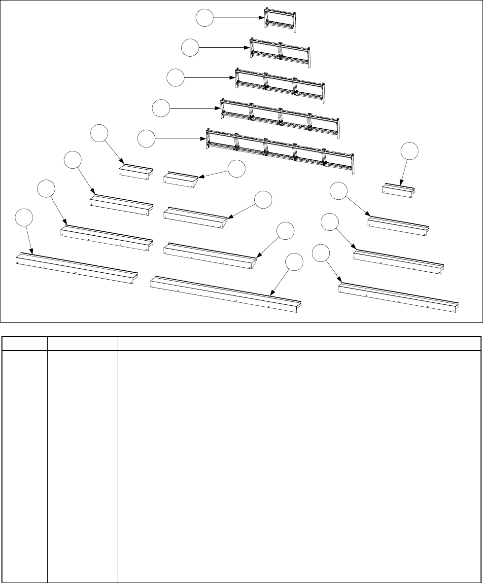
4-12
4.2.5 BIH52/MH52 Control Panel Frames and Topcaps
1
BIH52/MH52
Control Panel Frames
BIH52
Topcaps
MH52
Topcaps
2
3
4
5
6
7
8
10
12
9
11
13
14
15
16
17
ITEM PART # COMPONENT
1 806-6137 BIH152/MH152 Control Panel Frame Assembly
2 806-4819 BIH252/MH252 Control Panel Frame Assembly
3 806-4820 BIH352/MH352 Control Panel Frame Assembly
4 806-5963 BIH452/MH452 Control Panel Frame Assembly
5 806-9750 BIH552/MH552 Control Panel Frame Assembly
6 824-0641 BIH152 Topcap
7 823-2657 JBIH152 Topcap (Japanese units)
8 824-0544 BIH252 Topcap
9 823-2652 JBIH252 Topcap (Japanese units)
10 824-0543 BIH352 Topcap
11 823-2651 JBIH352 Topcap (Japanese units)
12 824-0545 BIH452 Topcap
13 824-0775 BIH552 Topcap
14 824-0641 MH152 Topcap
15 824-0544 MH252 Topcap
16 824-0543 MH352 Topcap
17 824-0545 MH452 Topcap
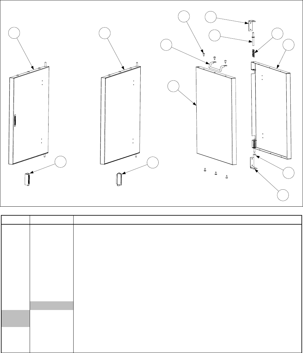
4-13
4.2.6 BIH52/MH52 Door Components
12
3
45
68
7
5
10
9
11 12
Inside Face
of Door
Inside Face
of Door
ITEM PART # COMPONENT
1 806-3057SP Door Assembly with Magnet, BIH52/MH52 Complete
2 806-6545SP Door Assembly without Magnet, BIH52/MH52 Complete
3 810-1422 Handle, Wireform Door
4 826-1379 Screw, #10 x ½-inch Phillips Truss Head (Pkg of 10)
5 810-1508 Hinge, Universal Door
* 826-1371 Screw, #8 x ½-inch Hex Head (Pkg of 25) (for attaching Item 5 to cabinet)
6 106-0554 Pin Assembly, Door Hinge
7 809-0193 Washer, ¼-inch Nylon Flat
8 810-0275 Spring, Door Hinge
9Liner, Door
900-2485 BIH52/MH52 Universal Door (no cutout for magnet)
930-3667 BIH52/MH52 Door (with cutout for magnet)
10 824-0137 Panel, BIH52/MH52 Door
11 810-0066 Magnet (door-mounted, used with Item 1)
12 810-1105 Magnet (door post-mounted, used with Item 2)
* Not illustrated.
NOTE: Handle (Item 3), Hinge (Item 5), and Washer (Item 7) are not included in Door Assemblies
(Items 1 and 2). These components must be ordered separately.
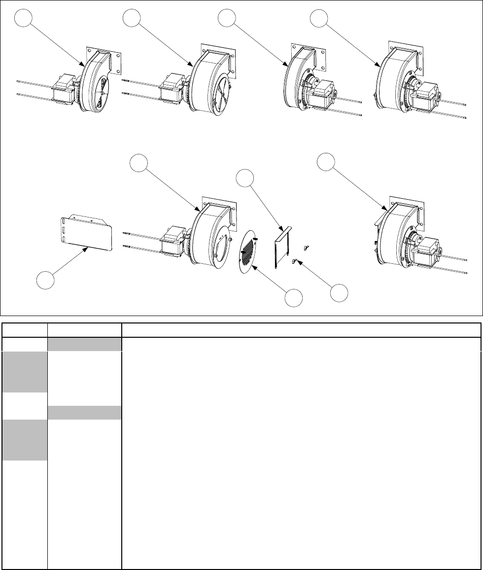
4-14
4.3 Combustion System, Frypot, and Gas System Components
4.3.1 Blowers and Associated Parts
1 2 3 4
56
7
8
9
10
ITEM PART # COMPONENT
1Blower, Left (with 1.54-inch (3.91 cm) wide housing)
806-4354SP 100V, 50/60 Hz
826-1512 115V, 50/60 Hz
806-5841SP 230V, 50 Hz
2 826-1510 Blower, Left, 230V, 50/60 Hz (with 2.8-inch (7.11 cm) wide housing)
3Blower, Right (with 1.54-inch (3.91 cm) wide housing)
806-4697SP 100V, 50/60 Hz
826-1511 115V, 50/60 Hz
806-7060SP 230V, 50 Hz
4 826-1509 Blower, Right, 230V, 50 Hz (with 2.8-inch (7.11 cm) wide housing)
5 806-9703 Blower Assembly, Left 230V, 50 Hz (CE)
6 806-9705 Blower Assembly, Right 230V, 50 Hz (CE)
7 806-9689 Finger Guard/Air Flow Inhibitor Adapter (CE)
8 900-8699 Air Flow Inhibitor (CE)
9 809-0342 Wingnut, 8-32
10 826-1426 Shield, MH52 Blower Motor
* KIT-0155SP High Altitude Blower Kit (required above 5000 Ft, 1525 M)
* Not illustrated.
NOTE: Items 7, 8, and 9 are components of Items 5 and 6. In CE units, they replace the rotating air
shutter that is standard on 230V Blowers 826-1510 and 826-1509 (Items 2 and 4).

4-15
4.3.2 Ignition Sub-System Components
1
2
3
4
6
5
7
9
10
8
ITEM PART # COMPONENT
1 See Pg 4-28 Ignition Module, Full and Dual Vat (original design, with fuse)
2 See Pg 4-28 Ignition Module, Full Vat (new design, without fuse)
3 See Pg 4-28 Ignition Module, Dual Vat (new design, without fuse)
4Ignition Cable (with two 90º connectors, used with Item 1 only)
807-1878 19-inches long
807-1200 27-inches long
5 807-3367 Ignition Cable (with one 90º connector, used with Items 2 and 3 only)
6 806-6085 Wiring Assembly, Ignitor
7 806-6084 Wiring Assembly, Ignition Module
8 807-2263 Switch, Air Pressure (use 807-2262 in units with 100VAC power supply)
9Ignitor and Gasket Kit
826-0981 Natural Gas (G20, G25)
826-0982 Propane/Butane (G30, G31)
826-1002 Manufactured Gas
10 Orifice
810-1221 2.00 mm Propane/Butane (0-4999 Ft, 0-1524 M) (Japan)
810-1325 2.05 mm Propane/Butane (G30, G31) (0-4999 Ft, 0-1524 M)
810-0386 2.10 mm Propane/Butane (0-4999 Ft, 0-1524 M)
810-0413 2.16 mm Propane/Butane (G30, G31) (5000-6999 Ft, 1525-2133 M)
812-1028 2.20 mm Propane/Butane (G30, G31) (7000-10,999 Ft, 2134-3352 M)
812-1134 3.10 mm Natural Gas (G20, G25) (0-4999 Ft, 0-1524 M) (Japan)
810-0403 3.40 mm Natural Gas (G20, G25) (0-4999 Ft, 0-1524 M)
810-0437 3.60 mm Natural Gas (G20, G25) (5000-6999 Ft, 1525-2133 M)
812-1144 3.65 mm Natural Gas (G20, G25) (7000-8999 Ft, 2134-2743 M)
812-1145 3.70 mm Natural Gas (G20, G25) (9000-10,999 Ft, 2744-3352 M)
810-0642 5.95 mm Manufactured Gas (0-4999 Ft, 0-1524 M)
* 826-1196 Conversion Kit, Natural Gas (G20, G25) to Propane/Butane (G30, G31)
* 826-1197 Conversion Kit, Propane/Butane (G30, G31) to Natural Gas (G20, G25)
* Not illustrated.
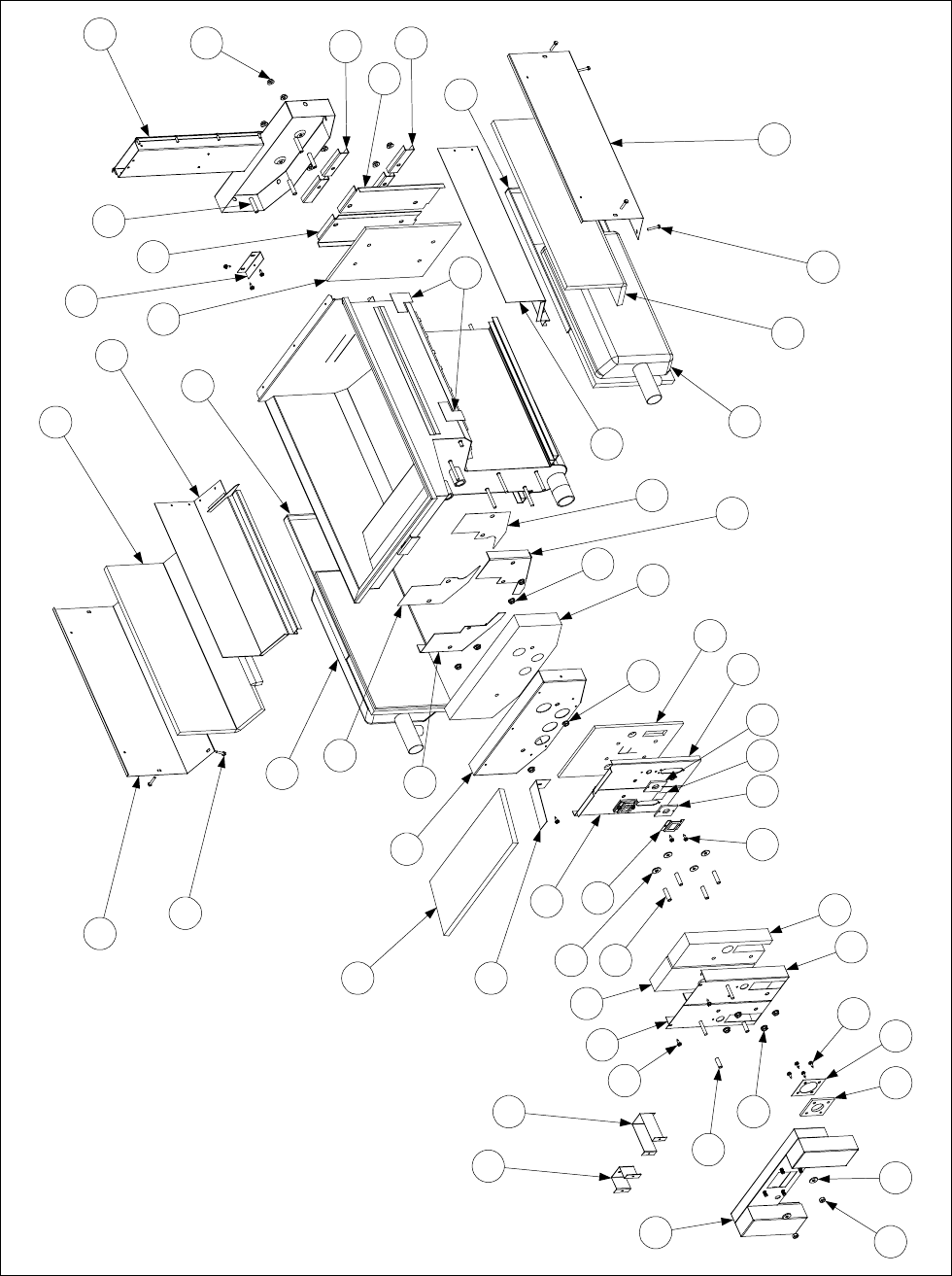
4-16
4.3.3 Frypot Assembly Components
1
234 5
6
7
8
6
9
10
11
11
3
12
6
13
14 15 14
16
17
18
19
20
7
21
22
7
23
23
24
24
25
25
26
27
28
29
29
28
30 31
32
33
7
34
35
33
36
37
38
39
40
41
41
Full Vat Frypot
Components
(See Page 4-20 for
list of Service Frypot
Kits and Insulation
Kits.)
42

4-17
ITEM PART # COMPONENT
1 823-0969SP Plenum (NOTE: use 823-1048 on units equipped with Air Switch)
2 826-1372 Nut, ¼-20 Hex (Pkg of 10)
3 809-0435 Washer, ¼-inch x ¾-inch Flat
4 816-0057 Gasket, Plenum
5 900-1049 Retainer, Plenum Gasket
6 826-1371 Screw, #8 x ½-inch Hex Head (Pkg of 25)
7 826-1368 Nut, ¼-20 Serrated Flange
8 810-0500 Spacer, ¼-inch x 15/16-inch
9 823-11691 Retainer, Full Vat Left Outer Combustion Chamber Insulation
10 823-1169 Retainer, Full Vat Right Outer Combustion Chamber Insulation
11 812-0661 Insulation, Full Vat Combustion Chamber Outer
12 826-1340 Spacer, ¼-inch x 1 3/16-inch (Pkg of 10)
13 900-1031 Retainer, Sight Glass
14 812-0356 Gasket, Sight Glass
15 814-0048 Sight Glass
16 900-1210 Retainer, Full Vat Left Inner Combustion Chamber Insulation
17 900-1211 Retainer, Full Vat Right Inner Combustion Chamber Insulation
18 812-0457 Insulation, Full Vat Inner Combustion Chamber
19 900-3742 Retainer, Full Vat Frypot Outer Front Insulation
20 812-0353 Insulation, Full Vat Frypot Outer Front
21 824-0157 Seal, Full Vat Frypot Left
22 824-0158 Seal, Full Vat Frypot Right
23 812-0404 Insulation, Frypot Seal
24 Kit, Burner Replacement (for use on either side; includes Item 25)
826-1072 Natural and Propane Gas
826-1073 Manufactured Gas
25 812-0357 Insulation, Burner
26 823-17771SP Rail, Full Vat Right Burner
27 823-1777SP Rail, Full Vat Left Burner
28 812-1029 Insulation, Frypot Side
29 900-4452 Retainer, Frypot Side Insulation
30 812-0355 Insulation, Full Vat Rear Combustion Chamber
31 900-1222 Back, Left Full Vat Combustion Chamber
32 900-1223 Back, Right Full Vat Combustion Chamber
33 900-1221 Retainer, Full Vat Combustion Chamber Back
34 810-0406 Spacer, ¼-inch x 1 7/16-inch
35 930-0818 Bracket, Flue to Frypot Mounting
36 806-5859SP Flue Assembly, Full Vat
37 812-0993 Insulation, Frypot Upper
38 900-1515 Retainer, Frypot Upper Insulation
39 900-0857 Bracket, BIH52 Frypot Mounting
40 900-1401 Bracket, MH52 Frypot Mounting
41 809-0362 Screw, #8 x 1-inch Hex Washer Head
42 812-0706 Insulation, Burner Rail
* 813-0156 Plug, ½-inch NPT (for blocking off unneeded ports in service frypot)
* 813-0336 Plug, ½-inch NPT SS (for blocking off unneeded ports in service frypot)
* Not illustrated.
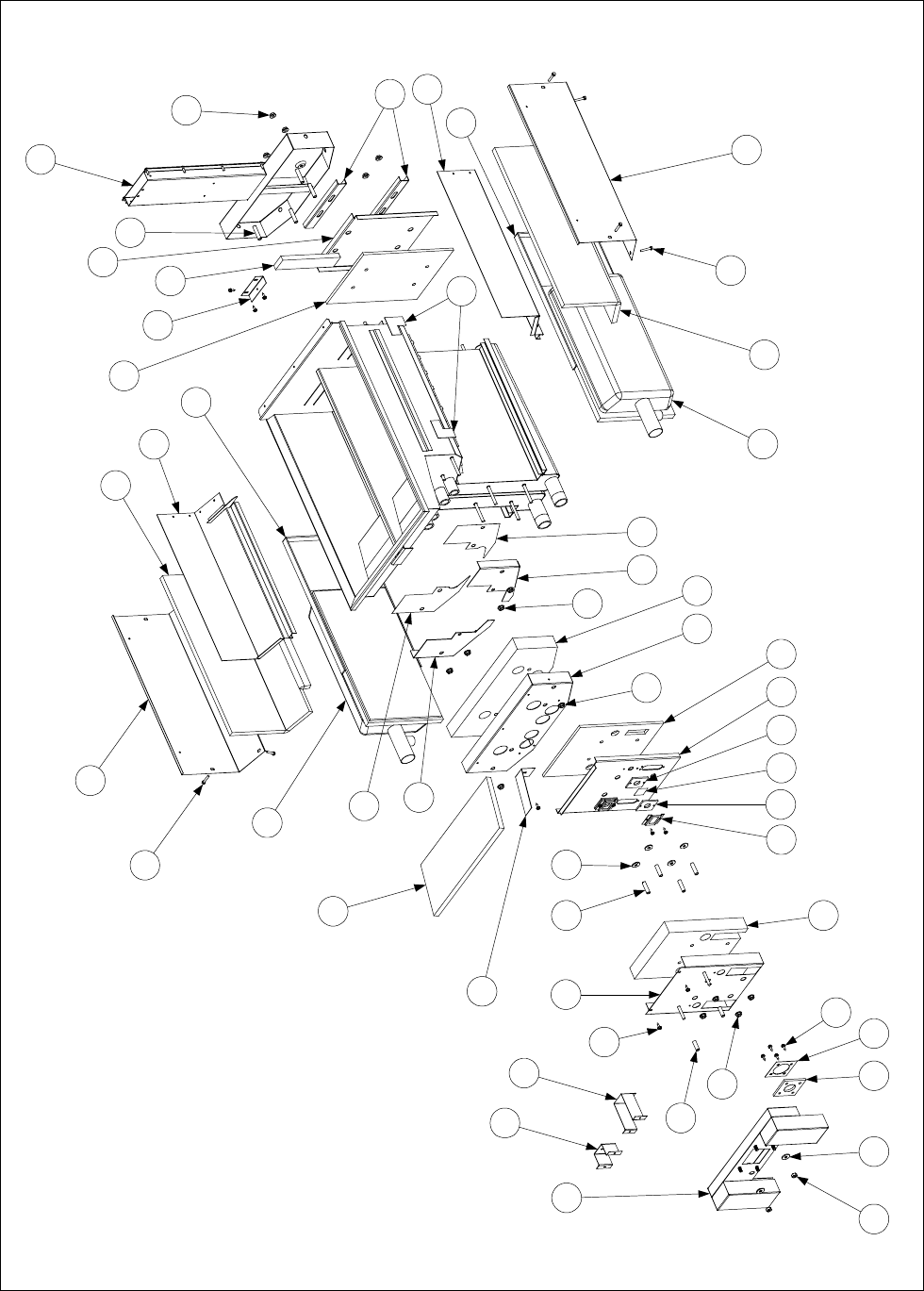
4-18
Dual Vat Frypot
Components
(See Page 4-20 for
list of Service Frypot
Kits and Insulation
Kits.)
1
2 3 4 5
6
7
8
6
9
10
11 3
12 13 14 13 15 16
7
17 18
7
19
20 21
21
22
22
24
23
24
25
26
26
27
28
27
28
29
30
31
7
33
32
34
35
36
37
38
39
40

4-19
ITEM PART # COMPONENT
1Plenum
823-0970SP Standard Dual Vat
823-1049 For use on units with Air Switch.
823-2181 For use on JBIH152 models only.
2 826-1372 Nut, ¼-20 Hex (Pkg of 10)
3 809-0435 Washer, ¼-inch x ¾-inch Flat
4 816-0057 Gasket, Plenum
5 900-1049 Retainer, Plenum Gasket
6 826-1371 Screw, #8 x ½-inch Hex Head (Pkg of 25)
7 826-1368 Nut, ¼-20 Serrated Flange
8 810-0500 Spacer, ¼-inch x 15/16-inch
9 823-0968 Retainer, Dual Vat Outer Combustion Chamber Insulation
10 812-0456 Insulation, Dual Vat Combustion Chamber Outer
11 826-1340 Spacer, ¼-inch x 1 3/16-inch (Pkg of 10)
12 900-1031 Retainer, Sight Glass
13 812-0356 Gasket, Sight Glass
14 814-0048 Sight Glass
15 823-0983 Retainer, Dual Vat Inner Combustion Chamber Insulation
16 812-0458 Insulation, Dual Vat Inner Combustion Chamber
17 930-3628 Retainer, Dual Vat Frypot Outer Front Insulation
18 812-0352 Insulation, Dual Vat Frypot Outer Front
19 824-0159 Seal, Dual Vat Frypot Left
20 824-0160 Seal, Dual Vat Frypot Right
21 812-0404 Insulation, Frypot Seal
22 Kit, Burner Replacement (for use on either side; includes Item 23)
826-1072 Natural and Propane Gas
826-1073 Manufactured Gas
23 812-0357 Insulation, Burner
24 823-2823SP Rail, Dual Vat Right Burner
25 823-2822SP Rail, Dual Vat Left Burner
26 812-1029 Insulation, Frypot Side
27 900-4452 Retainer, Frypot Side Insulation
28 809-0362 Screw, #8 x 1-inch Hex Washer Head
29 812-0354 Insulation, Dual Vat Rear Combustion Chamber
30 930-0789 Back, Dual Vat Combustion Chamber
31 900-0914 Retainer, Dual Vat Combustion Chamber Back
32 812-0688 Insulation, Dual Vat Gas Collector
33 930-0818 Bracket, Flue to Frypot Mounting
34 810-0406 Spacer, ¼-inch x 1 7/16-inch
35 806-5860SP Flue Assembly, Dual Vat
36 812-0993 Insulation, Frypot Upper
37 900-1515 Retainer, Frypot Upper Insulation
38 900-0857 Bracket, BIH52 Frypot Mounting
39 900-1401 Bracket, MH52 Frypot Mounting
40 812-0706 Insulation, Burner Rail
* 813-0156 Plug, ½-inch NPT BM (for blocking off unneeded ports in service frypot)
* 813-0336 Plug, ½-inch NPT SS (for blocking off unneeded ports in service frypot)
* Not illustrated.

4-20
4.3.4 Service Frypot Kits, Insulation Kits, and Miscellaneous Service Parts
Service Frypot Kits
The fully assembled service frypot kits listed below contain all components illustrated on Pages
4-16 and 4-18 except the plenum, and the plenum gasket retainer. The kits also contain two
Ignitor Gaskets (816-0059). These service frypot kits are ready for installation.
• 806-3876SP – Full Vat (Manufactured Gas)
• 806-4787SP – Full Vat (Natural Gas (G20/G25)
• 806-4789SP – Full Vat (Propane/Butane (G30/G31))
• 806-3878SP – Dual Vat (Manufactured Gas)
• 806-4788SP – Dual Vat (Natural Gas (G20/G25))
• 806-4790SP – Dual Vat (Propane/Butane Gas (G30/G31))
Insulation Kits, Complete
The insulation kits listed below contain all insulation illustrated on Pages 4-16 and 4-18,
respectively. The kits also contain two Ignitor Gaskets (816-0059), two Sight Glasses (814-
0048), two Plenum Gaskets (816-0057), one Upper Frypot Insulation Retainer (900-1515), and
all spacers, screws, nuts, and washers required for installing the insulation.
• 826-0929 – Full Vat
• 826-0930 – Dual Vat
Insulation Kits, Burner
• 826-0931 – Full Vat
This kit includes the components listed. Item numbers refer to illustration on Page 4-16.
812-0357 – Insulation, Burner (Item 25)
812-0457 – Insulation, Full Vat Inner Combustion Chamber (Item 18)
812-0355 – Insulation, Full Vat Rear Combustion Chamber (Item 30)
816-0057 – Gasket, Plenum (Item 4)
• 826-0932 – Dual Vat
This kit includes the components listed. Item numbers refer to illustration on Page 4-18.
812-0357 – Insulation, Burner (Item 23)
810-0458 – Insulation, Dual Vat Inner Combustion Chamber (Item 17)
812-0354 – Insulation, Dual Vat Rear Combustion Chamber (Item 29)
816-0057 – Gasket, Plenum (Item 4)
Miscellaneous Frypot Service Parts
• 210-0681 – Probe Guard
• 806-6142SP – Riser Assembly, Flue (replaces upper section of Flue Assemblies 806-5859SP
and 806-5860SP.)
• 900-2298 – Shutter, BIH152 Plenum
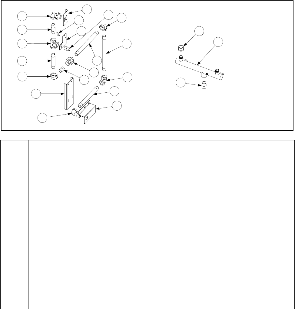
4-21
4.3.5 Gas Manifolds – Single BIH52/MH52 Units
BIH152 Manifold
1
2
3
4
5
7
8
9
10 5
12
10
6
11
13
5
1
14
15
1-piece MH152 Manifold
16
17
18
ITEM PART # COMPONENT
1 813-0165 Elbow, ½-inch NPT Street x 90º
2 813-0265 Nipple, ½-inch NPT x 2½-inch
3 813-0003 Tee, ½-inch NPT
4 813-0093 Nipple, ½-inch NPT x 4-inch
5 813-0062 Elbow, ½-inch NPT x 90º
6 900-5616 Mount, BIH152 Gas Line
7 900-5596 Mount, Valve Plate (used with Non-CE Gas Valves 810-0801/0802 only)
8 809-0107 Screw, 8-32 x ⅜-inch Slotted Round Head
9 900-8740 Mount, Valve Plate (used with CE Gas Valve 810-1715 only)
10 813-0022 Nipple, ½-inch NPT Close
11 813-0173 Union, ½-inch NPT
12 813-0496 Nipple, ½-inch NPT x 9.5-inch
13 813-0253 Nipple, ½-inch NPT x 10-inch
14 813-0320 Nipple, ½-inch NPT x 8-inch
15 900-5615 Support, BIH152 Gas Line
16 810-0959 Manifold, MH152 1-piece Gas
17 813-0469 Cap, ½-inch NPT Pipe (closes off unused port in full vat configurations)
18 813-0109 Nipple, ¾-inch NPT Close
* 810-1425 Fitting, ½-inch Quick Disconnect x ½-inch Female NPT
* Not illustrated.
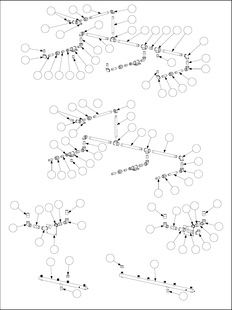
4-22
4.3.6 Gas Manifolds – BIH52/MH52 Multi-Fryer Units
1
2
3
45 6
7
8
6
94110 12
11
13
14
15
16
17 18 19 20 19 21
15
14
22
23
4
9
6
8
12
1
2
3
4
OR 24a24 6
25
17
18 19
28
15
14
22
29
4
26
4
26
11
14
15
1
12
27
10
39
20
37
39
Typical Configuration for Systems
using non-CE Gas Valves
810-0801 or 810-0802
Typical Configuration for Systems
using CE Gas Valve 810-1715
34
31
36
33
31
30
35 34
31
34
31
36
33
35 34
31
34
31
30 33
32
Full Vat (left) and Dual Vat (right)
Manufactured Gas Configurations
(MH52 and BIH52)
1-piece Manifolds (used on MH52 units only)
38
20

4-23
NOTE: The drawings on the preceding page illustrate typical gas manifold configurations. Specific
configurations vary depending upon the number and types of fryers in a battery. The purpose of the
drawings is to illustrate all individual components that may be found in any given configuration.
Determination of which component to use in a particular application should be based upon careful
inspection of the existing components, including taking measurements when appropriate.
ITEM PART # COMPONENT
1 813-0087 Nipple, ½-inch NPT x 1½-inch (3.8 cm)
2 813-0003 Tee, ½-inch NPT
3 813-0156 Plug, ½-inch NPT Pipe
4 813-0173 Union, ½-inch NPT
5 813-0497 Nipple, ½-inch NPT x 12½-inch (31.8 cm)
6 813-0062 Elbow, ½-inch NPT x 90º
7 813-0320 Nipple, ½-inch NPT x 8-inch (20.3 cm)
8 813-0022 Nipple, ½-inch NPT x Close
9 813-0460 Nipple, ½-inch NPT x 3-inch (7.6 cm)
10 813-0031 Bushing, ¾-inch NPT to ½-inch Reducer
11 823-2260 Bracket, ¾-inch NPT Gas Manifold Mounting
12 813-0157 Plug, ¾-inch NPT Pipe
13 813-0168 Elbow, ¾-inch NPT x 90º Street
14 813-0110 Nipple, ¾-inch NPT x 1½-inch (3.8 cm)
15 813-0066 Elbow, ¾-inch NPT x 90º
16 813-0478 Nipple, ¾-inch NPT x 12½-inch (31.8 cm)
17 813-0271 Tee, ¾-inch NPT x ½-inch Branch
18 813-0386 Nipple, ¾-inch NPT x 12-inch (30.5 cm)
19 813-0387 Tee, ¾-inch NPT
20 813-0109 Nipple, ¾-inch NPT x Close
21 813-0479 Nipple, ¾-inch NPT x 11-inch (27.9 cm)
22 813-0068 Elbow, ¾-inch NPT x ½-inch NPT x 90º
23 813-0281 Nipple, ½-inch NPT x 5-inch (12.7 cm)
24 813-0515 Nipple, ½-inch NPT x 12-inch (30.5 cm)
24a 813-0360 Nipple, ½-inch x 14-inch (in CE BIH352-6 Natural Gas (G20/G25) units only)
25 813-0253 Nipple, ½-inch NPT x 10-inch (25.4 cm)
26 813-0265 Nipple, ½-inch NPT x 2½-inch (6.4 cm)
27 813-0112 Nipple, ¾-inch NPT x 2-inch (5.1 cm)
28 813-0476 Nipple, ¾-inch NPT x 14-inch (35.6 cm)
29 813-0096 Nipple, ½-inch NPT x 6-inch (15.2 cm)
30 900-0944 Plate, 1-inch NPT Gas Manifold Mounting
31 813-0202 Elbow, 1-inch NPT x 90º
32 813-0314 Tee, 1-inch NPT
33 813-0318 Nipple, 1-inch NPT x 3-inch (7.6 cm)
34 813-0138 Nipple, 1-inch NPT x Close
35 813-0371 Nipple, 1-inch NPT x 2-inch (5.1 cm)
36 809-0347 Nut, 1-inch NPT Retainer
37 810-0661 Manifold, 1-piece H252 Gas
38 810-0660 Manifold, 1-piece H352 Gas
39 813-0469 Cap, ½-inch NPT Pipe (closes off unused port in full vat configurations)
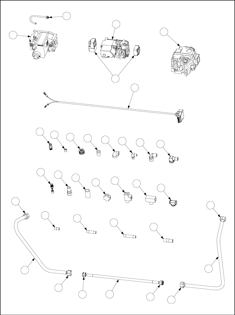
4-24
4.3.7 Gas Valves, Gas Lines, and Fittings
1
2
3
4
6
5
7
8910 11 12 13 14
22
23
24
25
15 16
17
18 19
20
21
26 28
27
27
29
30 30
27
27

4-25
ITEM PART # COMPONENT
1Gas Valve, Non-CE
810-0801 Natural Gas (G20/G25)
810-0802 Propane (LP) Gas (G30/G31)
2 810-0691 Vent Tube (used with Item 1)
3 810-1715 Gas Valve, Universal CE (G20/G25/G30/G31)
4 810-1041 Accessory Kit (2 straight and 2 elbow flanges, screws, O-rings, LP gas spring)
5 806-9678 Plug Assembly, CE Gas Valve (used with Item 3)
6 807-1229 Gas Valve, Manufactured Gas
7 810-1176 Tap, ⅛-inch NPT Pressure
8 813-0411 Plug, ⅛-inch NPT Allen-head Pipe
9 813-0304 Bushing, ½-inch to ¼-inch NPT Reducer
10 810-1006 Bushing, ¼-inch to ⅛-inch NPT Reducer
11 813-0004 Elbow, 90º x ⅛-inch NPT
12 813-0354 Elbow, 90º x ⅛-inch NPT x ⅛-inch Tube (Brass)
13 813-0302 Elbow, 90º x ⅜-inch Tube x ¼-inch Male NPT (Brass)
14 813-0502 Elbow, 90º Street x ¼-inch (Brass)
15 813-0340 Connector, ⅛-inch Tube to ⅛-inch Male NPT (Brass)
* 813-0014 Connector, ⅛-inch Tube to ⅛-inch Male NPT (Brass) (with Item 6 only)
16 810-1025 Connector, ⅜-inch Tube to ¼-inch Male NPT (Brass)
17 813-0507 Coupling, ¼-inch NPT (Brass)
18 813-0378 Cross Fitting, ½-inch Female NPT (Brass)
19 810-1026 Tee, ¼-inch NPT Street (Brass)
20 813-0495 Tee, ¼-inch Male NPT Branch (Brass)
21 813-0377 Tee, ⅛-inch Female NPT (Brass)
22 813-0016 Nipple, ⅛-inch NPT Close
23 813-0315 Nipple, ⅛-inch NPT x 1½-inch (4.8 cm)
24 813-0405 Nipple, ⅛-inch NPT x 2-inch (5.1 cm)
25 813-0471 Nipple, ¼-inch NPT x 1½-inch (4.8 cm)
26 900-3739 Gas Tube (Left), H52 FV Manufactured Gas (pre-formed)
27 810-0503 Compression Nut (Ferrule), ½-inch Manufactured Gas Tube
28 900-3737 Gas Tube (Right), H52 FV Manufactured Gas (pre-formed)
* 900-3735 Gas Tube (Left and Right), H52 DV Manufactured Gas (pre-formed)
29 Flexible Stainless Steel Gasline (Flexline), ⅜-inch OD
810-1353 9-inch (22.9 cm)
810-1354 12-inch (30.5 cm)
810-1355 15-inch (38.1 cm)
30 810-0494 Compression Nut (Ferrule), ⅜-inch Flexible Gas Line
*Enrichment Tube
811-0752 5½-inch (14 cm)
811-0756 8½-inch (21.6 cm)
811-0800 12½-inch (31.8 cm)
812-0742 18-inch (45.7 cm)
* Not illustrated.
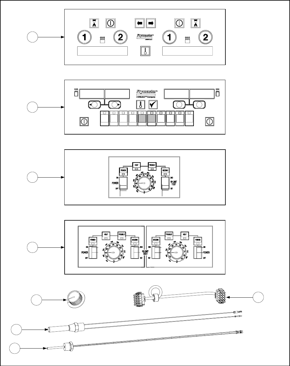
4-26
4.4 Electronics
4.4.1 Computers, Controllers, and Associated Components
1
3
4
5
2
1 1 2
JC
ABC DEF GHI JKL MNO PQR STU VW X YZ-*-
1234567890
2
6
7
8

4-27
ITEM PART # COMPONENT
1Computer, McDonald’s M100B Gas Fryer
806-7990E U.S. and Canada
806-8036E Non-CE Export with 6-second Melt Cycle
806-8041E Non-CE Export with 8-second Melt Cycle
806-8040 Factory-programmed in French
806-8100E CE Export
2Computer, McDonald’s M2000 Gas Fryer
106-0484E U.S. and Canada
106-0487E Non-CE Export with 6-second Melt Cycle
106-0489E Non-CE Export with 8-second Melt Cycle
106-0488E Factory-programmed in French
106-0492E CE Export
3Controller, McDonald’s Full Vat Gas Fryer Solid-State
806-3007 With 6-second Melt Cycle
806-3571 With 8-second Melt Cycle
4Controller, McDonald’s Dual Vat Gas Fryer Solid-State
806-3009 With 6-second Melt Cycle
806-3572 With 8-second Melt Cycle
5 810-0387 Knob, Replacement Control (for use on Solid-State Controllers)
6 806-2071 Cable, Computer/Controller to Interface Board
7 806-7545 Thermostat, High-Limit
8 806-4206 Probe Assembly, Temperature
* 826-1321 Retrofit Kit, Solid-State Controller to M100B Computer
* 826-1675 M100B to M2000 Speaker and Mount Retrofit Kit
* 807-1617 M2000 Speaker
* Not illustrated.
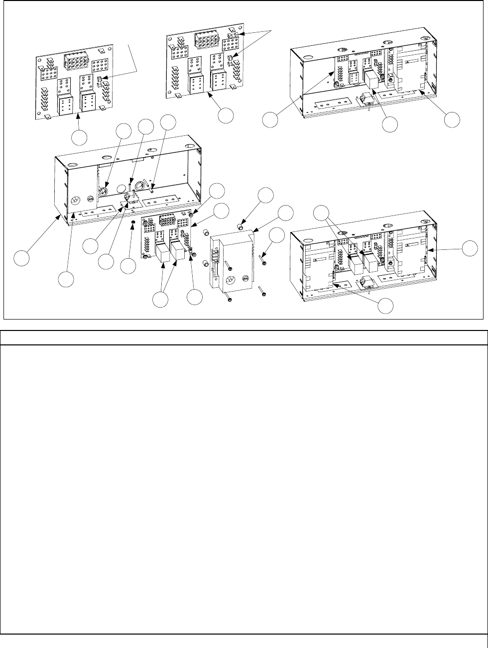
4-28
4.4.2 Component Boxes
IFB 806-3398 (Item 6) has only one fuse. If
used with 807-3365 or 807-3366 modules,
an in-line fuse should be added between the
module and the board.
Full vat units using one 807-3366 module
(Item 3) require only one latch relay (Item 5).
Full or dual vat units using two 807-1006,
807-2971, or 807-3365 modules require a
latch relay (Item 5) for each module.
IFB 106-0386 (Item 7) has two
fuses and may be used with any
of the ignition modules.
1
2
8
9
10 12
11 13
14
6
515
16
17
2
3
4
4
7
6
7
5
5
ITEM PART # COMPONENT
1 806-9849 Box Assembly, One-Piece Component
2 807-1006 Ignition Module, Full or Dual Vat (fuse-protected)
* 807-2971 Ignition Module, Full or Dual Vat (fuse-protected) (Australian units only)
3 807-3366 Ignition Module, Full Vat (unfused – use inline fuse 106-0531)
4 807-3365 Ignition Module, Dual Vat (unfused – use inline fuse 106-0531)
5 807-0833 Relay, 12V 5Amp Latch
6 806-3398 Interface Board (single fuse-protected) (use with 807-1006 only)
7 106-0386 Interface Board (double fuse-protected) (use with 807-3365 or 807-3366)
* 806-4973 Interface Board (used with 240V manufactured gas units only)
8 807-1926 Bushing, .875 Diameter Split
9 816-0217 Paper, Insulating (Items 9, 10, 11, 12 not used on BIH152 or Hong Kong units)
10 810-1164 Block, Terminal (See Item 9)
11 809-0354 Screw, 4-40 x ¾-inch Slotted Round Head (See Item 9)
12 809-0237 Nut, 4-40 Keps Hex (See Item 9)
13 807-1241 Spacer, Interface Board (.151-inch ID x ⅝-inch)
14 809-0250 Nut, 6-32 Keps Hex
15 807-0037 Tab, Push-On Terminal
16 809-0446 Spacer, Ignition Module (.260-inch ID x ½-inch)
17 809-0441 Screw, #7 x 1½-inch Slotted Washer Hex Head
* 806-3660 Sound Device, High Output (Use 807-1617 with M2000 Computers)
* 807-1359 Mount, Tie-Wrap (used on CE units only)
* Not illustrated.
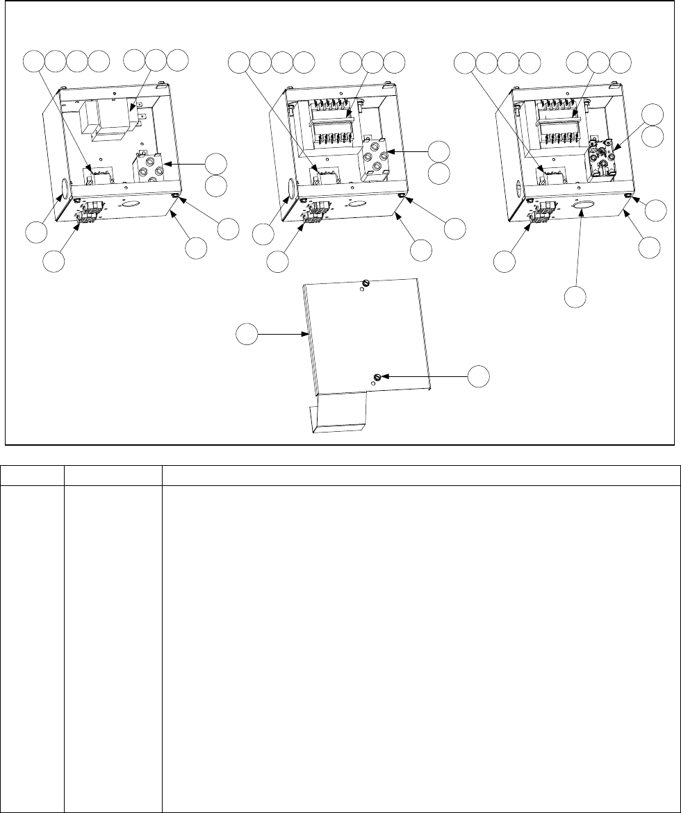
4-29
4.4.2 Filter Box Components
120V FILTER BOX 100/120V DUAL-VOLTAGE
FILTER BOX
MULTI-VOLTAGE (CE)
FILTER BOX
11 12 13 14 11 12 13 14 11 12 13 14
86 7 96 7 106 7
3
4
3
4
3
5
1
1
1
222
15
3
33
3
16
16
16
ITEM PART # COMPONENT
1 900-5250 Box, Filter
2 807-0156 Connector, 9-Pin Female
* 807-2518 Plug, Mate-N-Lock Keying (used w/Item 2)
3 809-0360 Screw, #8 x ⅜-inch Hex Washer Slot Head
4 807-0012 Relay, Non-CE 18 Amp 1⁄3-HP 24V Coil
5 807-2434 Relay, CE 18 Amp 1⁄3-HP 24V Coil
6 809-0096 Screw, 6-32 x ⅝-inch Slot Head
7 809-0250 Nut, 6-32 Keps Hex
8 807-0800 Transformer, 120/24VAC 50/60Hz 50VA
9 807-2176 Transformer, Dual Voltage (100 or 120/24VAC) 50/60Hz 50VA
10 807-1999 Transformer, Multi-Voltage (208, 220, 230, 240/24VAC) 50/60Hz 50VA
11 816-0217 Paper, Insulating
12 810-1164 Block, Terminal
13 809-0354 Screw, 4-40 x ¾-inch Round Slot Head
14 809-0237 Nut, 4-40 Keps Hex
15 900-5530 Cover, Filter Box
16 810-0044 Plug, .875 Button
* Not illustrated.
NOTE: See Page 4-32 for associated wiring assemblies.
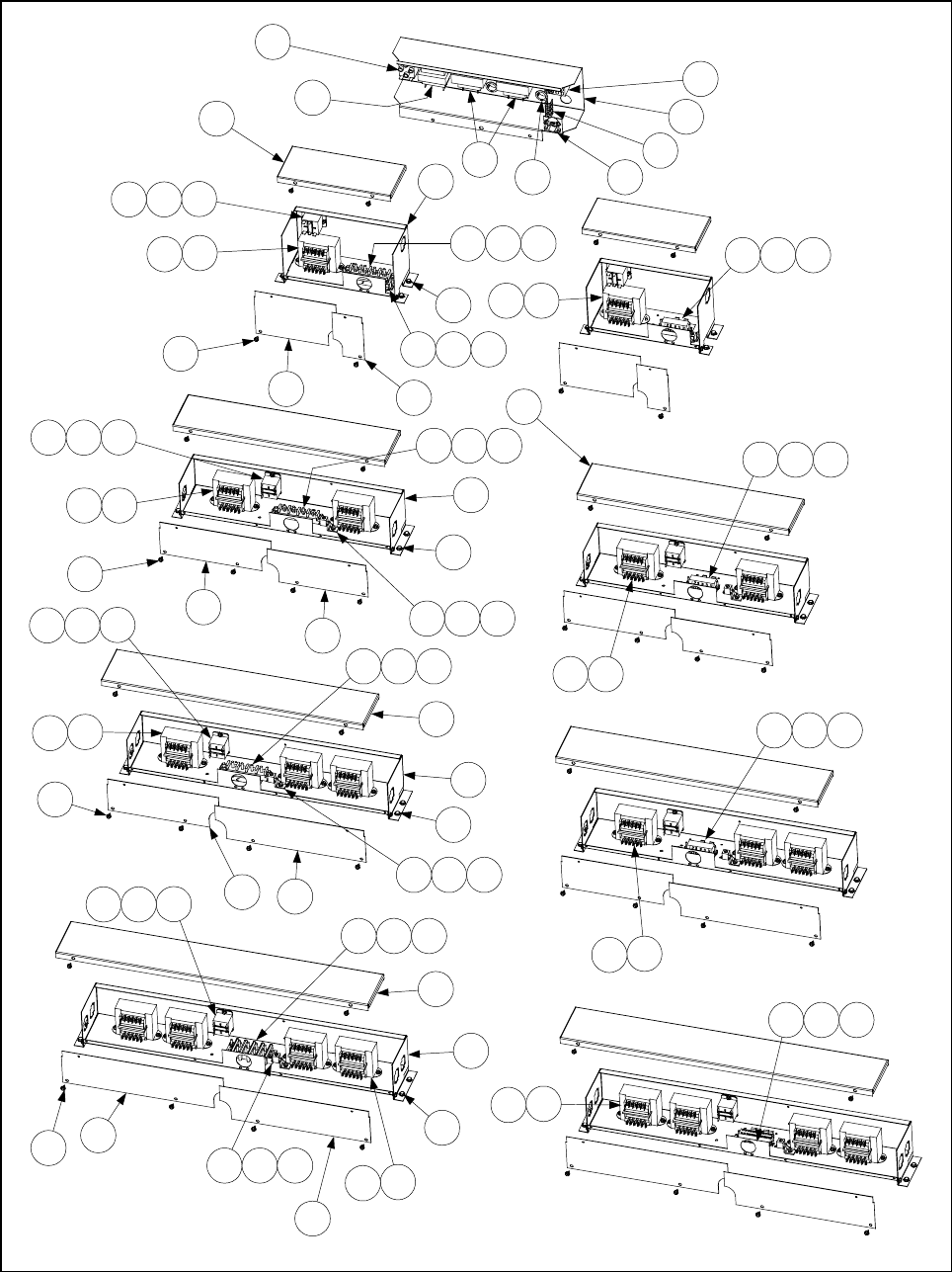
4-30
4.4.3 Transformer Box Components
8
4
3
2
1
7 5
6
24
11
109
17 18 19
20
28
30
13
23
BIH152
11
109
25
13
30
17 18 19
21 22
27
25 26
13
25
32
13
12
33
34 35
31
36 15 16
17 18 19
13
12
13
40
41
38
25
39
20 21 22
MH152 (CE)
BIH352/MH352
BIH452/MH452 (CE)
BIH452/MH452
BIH352/MH352 (CE)
37 18 19
MH152
BIH252/MH252
BIH252/MH252 (CE)
13
12
14 15 16
14 15 16
11
109
13
12
11
109
13
12
1312
14 15 16
1312
1312
20 21 22
20 21 22

4-31
ITEM PART # COMPONENT
1Transformer (for use in BIH152 units)
807-1238 100/24VAC 50 Hz
807-0800 120/24VAC 50/60 Hz
2 807-0855 Transformer, 120/12VAC 50/60 Hz (for use in BIH152 units)
3 807-0012 Relay, 18 Amp 24VDC Coil
4 807-0273 Block, 16-Pin Terminal
5 807-1612 Clamp, ⅜-inch Strain Relief
6 807-0255 Jumper, Double
7 810-0045 Bushing, .875-inch Diameter
* 809-0362 Screw, 8-32 x 1-inch Hex Slotted Washer Head (for mounting Items 1-4)
8 900-5560 Shield, BIH152 Transformer
9 807-1683 Relay, 15 AMP 12VDC Coil
10 809-0103 Screw, 8-32 x ½-inch Slotted Truss Head
11 809-0050 Nut, 8-32 Hex
12 Transformer (for use in MH152 and BIH252/352/452/552 units)
807-2176 100-120/24VAC (used in U.S., Japanese, and Korean units)
807-1999 208-240/24VAC (used in CE and most export units)
13 809-0360 Screw, 8-32 x ⅜-inch Slotted Hex Washer Head
14 807-1973 Block, 4-Post Threaded Terminal (used in Non-CE units)
15 809-0131 Screw, ¼-20 x ¾-inch Hex Head
16 809-0071 Nut, ¼-20 Hex
* 809-0052 Nut, 10-24 Hex (for use on Item 14 and Item 36 terminal posts)
17 810-1163 Block, 3-Position Push-In Terminal (used in CE units)
18 809-0354 Screw, 4-40 x ¾-inch Slotted Round Head
19 809-0237 Nut, 4-40 Keps Hex
20 807-0070 Terminal, Lug
21 809-0103 Screw, 8-32 x ½-inch Slotted Truss Head
22 809-0247 Nut, 8-32 Keps Hex
23 900-2697 Box, MH152 Transformer
24 900-2708 Cover, MH152 Transformer Box Top
25 900-2703 Cover, MH152 Transformer Box Left
26 900-2709 Cover, MH152 Transformer Box Right
27 826-1374 Screw, #10 x ½-inch Self-Tapping Slotted Hex Washer Head (Pkg of 25)
28 900-5924 Box, BIH252/MH252 Transformer
29 900-5927 Cover, BIH252/MH252 Transformer Box Top
30 900-5928 Cover, BIH252/MH252 Transformer Box Left
31 900-5923 Cover, BIH252/MH252 Transformer Box Right
32 900-5925 Box, BIH352/MH352 Transformer Box
33 900-5929 Cover, BIH352/MH352 Transformer Box Top
34 900-5928 Cover, BIH352/MH352 Transformer Box Left
35 900-5930 Cover, BIH352/MH352 Transformer Box Right
36 807-2608 Block, 8-Post Threaded Terminal (used in Non-CE units)
37 810-1162 Block, 4-Position Push-In Terminal (used in CE units)
38 900-5926 Box, BIH452/MH452 Transformer
39 900-5931 Cover, BIH452/MH452 Transformer Box Top
40 900-5932 Cover, BIH452/MH452 Transformer Box Left
41 900-5930 Cover, BIH452/MH452 Transformer Box Right
* Not illustrated.
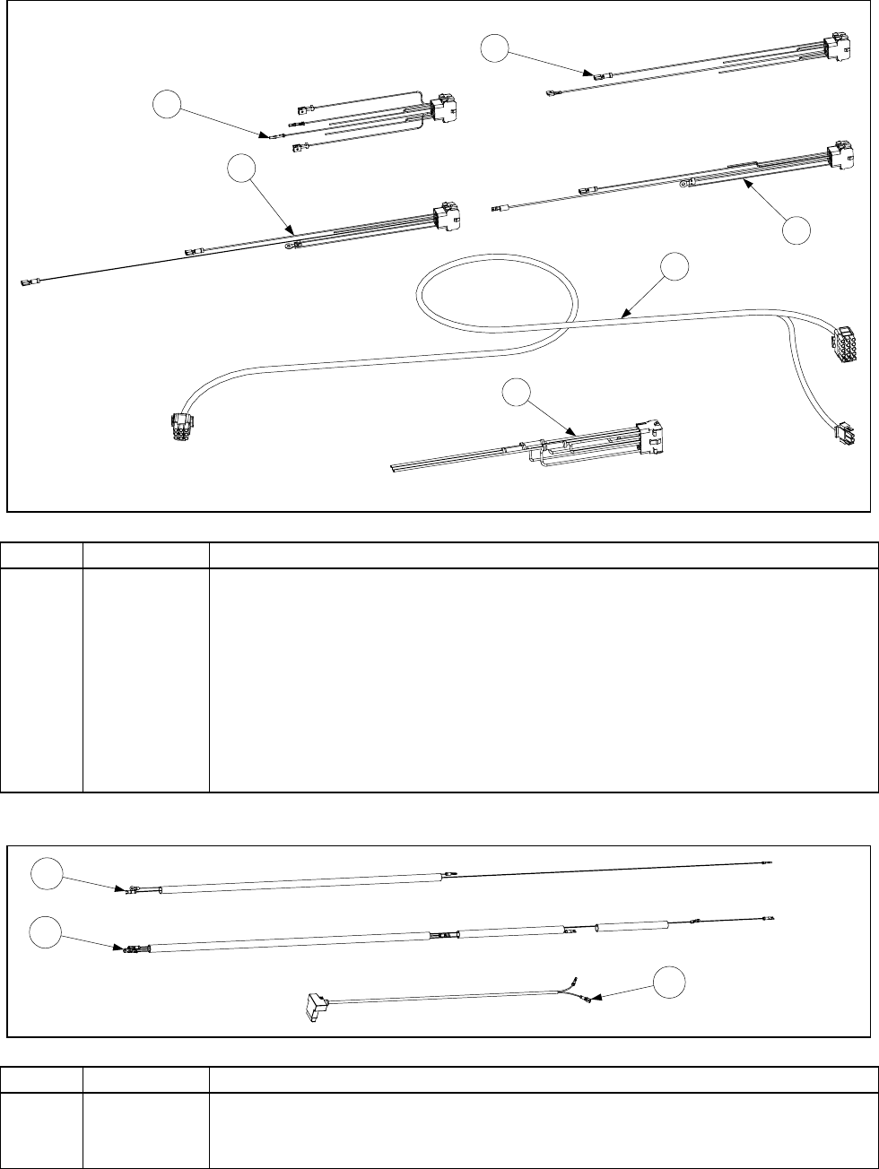
4-32
4.4.5 Wiring
Filter Box Wiring
1
2
3
4
5
6
ITEM PART # COMPONENT
1 806-8021 120V U.S. and 100/120V Non-CE Export Upper 9-Pin Plug Assembly
2 806-7494 120V U.S. Lower 9-Pin Plug Assembly
3 806-6725 230V CE Upper 9-Pin Plug Assembly
4 806-6719 100/120V Non-CE Export and 230V CE Lower 9-Pin Plug Assembly
5 810-1062 Cable, Filter Box Lower 9-Pin Plug to 807-2001 15-Pin (C2) Connector
6 807-2001 Cable, 810-1062 C2 Connector to Component Box Terminal Block
* 806-6728 Pump Motor to Filter Box Wiring Assembly
* WIR0287 120V U.S. Filter Box Internal Wiring
* WIR0233 100-250V CE and Non-CE Export Filter Box Internal Wiring
* Not illustrated.
Gas Valve Wiring
1
2
3
ITEM PART # COMPONENT
1 806-3941 Harness, Full Vat Gas Valve
2 806-3940 Harness, Dual Vat Gas Valve
3 806-9678 Plug Assembly, CE Gas Valve
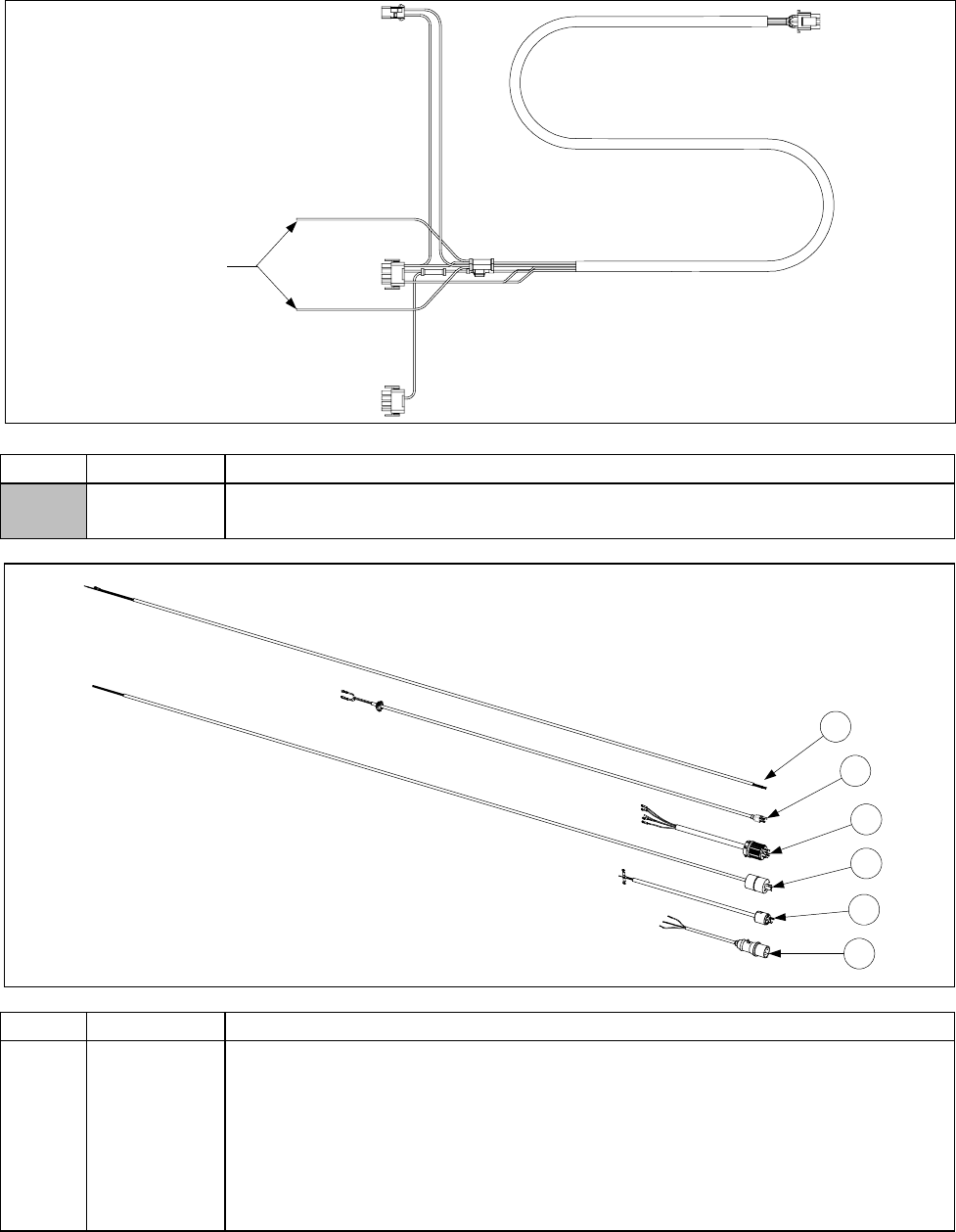
4-33
Main Wiring Harnesses
U.S. and Non-CE harness (shown)
has two unterminated wires.
Unterminated wires.
CE harness has two unterminated
wires plus two additional wires with
push-on terminals.
ITEM PART # COMPONENT
807-1978 U.S. and Non-CE Export MH/BIH52 Main Wiring Harness
807-2168 CE MH/BIH52 Main Wiring Harness
1
2
3
4
5
6
Power Cords
ITEM PART # COMPONENT
1 806-9786 3-Wire without Plug, 450V (Non-CE Export)
2 806-5332 3-Wire with 3-Prong Molded Plug, (U.S., CE, and Non-CE Export)
3 806-6083 5-Wire with 4-Prong Twist-Lock Plug, 120V (U.S. and Non-CE Export)
4 807-1871 3-Wire with 3-Prong Twist-Lock Plug, 125V (Mexico and South America)
5 806-9285 3-Wire with 3-Prong Twist-Lock Plug, 250V (Far East and Pacific Rim)
6 807-1696 3-Wire with 3-Pin Sleeved Plug, 230V (CE)
* 807-1560 Strain Relief
* Not illustrated.
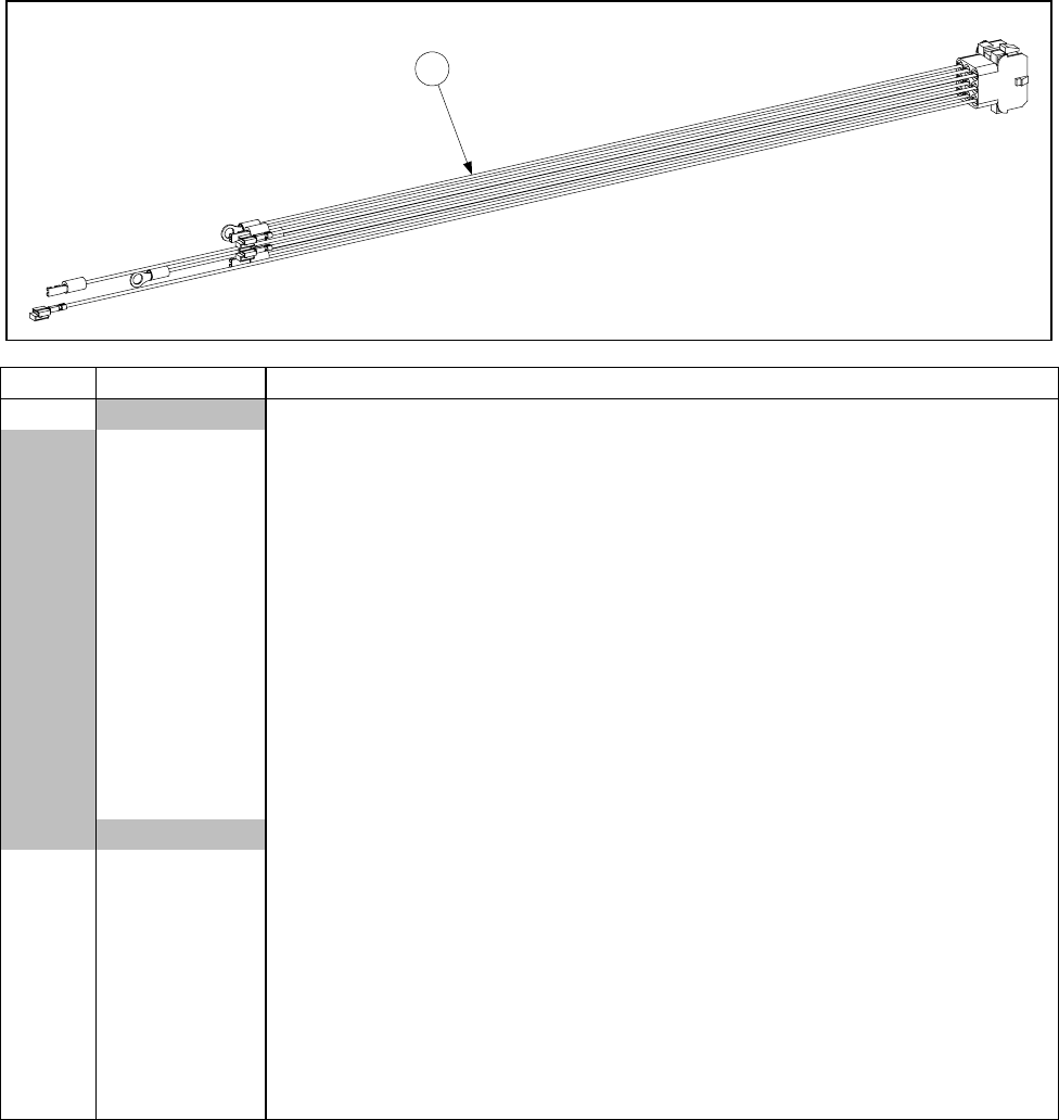
4-34
Transformer Box Wiring
806-8706 BIH252/MH252
Left Position (U.S. and Non-CE Export)
(Typical)
1
ITEM PART # COMPONENT
1Plug and Wire Assembly, Transformer Box 9-Pin Female
806-6077 MH152 (U.S. and Non-CE Export)
806-6597 MH152 (CE)
806-8706 BIH252/MH252, Left Position (U.S. and Non-CE Export)
806-8707 BIH252/MH252, Right Position (U.S. and Non-CE Export)
806-8719 BIH252/MH252, Right Position (CE)
806-8720 BIH252/MH252, Left Position (CE)
806-8708 1BIH352/MH352, Left Front Position (U.S. and Non-CE Export)
806-8709 2BIH352/MH352, Left Rear Position (U.S. and Non-CE Export)
806-8710 3BIH352/MH352, Right Position (U.S. and Non-CE Export)
806-8718 4BIH352/MH352, Right Position (CE)
806-8721 5BIH352/MH352, Left Front Position (CE)
806-8722 6BIH352/MH352, Left Rear Position (CE)
806-8723 BIH452/MH452, Right Front Position (CE)
Internal Wiring Bundles
* WIR0288 100-240V BIH152 (U.S., CE, and Non-CE Export)
* WIR0109 100-240V MH152 (U.S. and Non-CE Export)
* WIR0100 7100-240V BIH252/MH252 (U.S. and Non-CE Export)
* WIR0101 8100-240V BIH352/MH352 (U.S. and Non-CE Export)
* WIR0102 100-240V BIH452/MH452 (U.S. and Non-CE Export)
* WIR0144 230V MH152 (CE)
* WIR0141 9230V BIH252/MH252 (CE)
* WIR0142 10 230V BIH352/MH352 (CE)
* WIR0143 230V BIH452/MH452 (CE)
* Not illustrated.
NOTES:
1. Also used in Left Front Position of BIH452/MH452 (U.S. and Non-CE Export)
2. Also used in Left Rear Position of BIH452/MH452 (U.S. and Non-CE Export)
3. Also used in Right Rear Position of BIH452/MH452 (U.S. and Non-CE Export)
4. Also used in Right Rear Position of BIH452/MH452 (CE)
5. Also used in Left Front Position of BIH452/MH452 (CE)
6. Also used in Left Rear Position of BIH452/MH452 (CE)
7. Also used in BIH552 (U.S. and Non-CE Export)
8. Also used in BIH552 (U.S. and Non-CE Export)
9. Also used in BIH552 (CE)
10. Also used in BIH552 (CE)
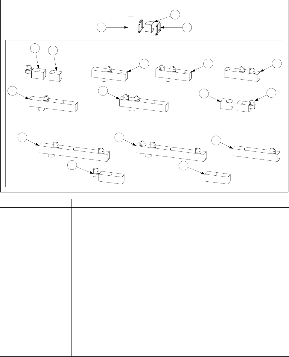
4-35
4.5 Oil Handling System Components
4.5.1 Drain System Components
Square Drain Sections and Seal Components
910 12
11
13 15
14
45
67 8
Dual Vat Components
Full Vat Components
16 17
1
2
3
ITEM PART # COMPONENT
1 KIT-0257SP Clamp Assembly and Seal Kit
2 816-0420 Seal (Rubber Boot)
3 806-6374SP Clamp Assembly
4 823-2199 Dual Vat Left End Outer Section (4.12-inches/10.5 cm)
5 823-2193 Dual Vat Left End Inner Section (3.57-inches/9.1 cm)
6 823-2204 Dual Vat Outlet Section with 1 Bracket (11.55-inches/29.3 cm)
7 823-2192 Dual Vat Outlet Section with 2 Brackets (11.55-inches/29.3 cm)
8 823-2202 Dual Vat Drain Section with 2 Brackets (11.55-inches/29.3 cm)
9 823-2211 Dual Vat Closed Outlet Section with 1 Bracket (15.86-inches/40.3 cm)
10 823-2210 Dual Vat Closed Outlet Section with 2 Brackets (15.86-inches/40.3 cm)
11 823-2212 Dual Vat Right End Inner Section (3.57-inches/9.1 cm)
12 823-2194 Dual Vat Right End Outer Section (4.12-inches/10.5 cm)
13 823-2200 Full Vat Outlet Section with 2 Brackets (23.38-inches/59.4 cm)
14 823-2207 Full Vat Outlet Section with 3 Brackets (23.38-inches/59.4 cm)
15 823-2233 Full Vat Drain Section with 1 Bracket (15.39-inches/39.1 cm)
16 823-2197 Full Vat Left End Section (7.95-inches/20.2 cm)
17 823-2198 Full Vat Right End Section (7.95-inches/20.2 cm)
* 810-1372 Elbow, 90º Vent Tube (used with Items 4 and 16)
* Not illustrated.
NOTE: Item 5 is always used left of outlet section; Item 11 is always used right of outlet section.
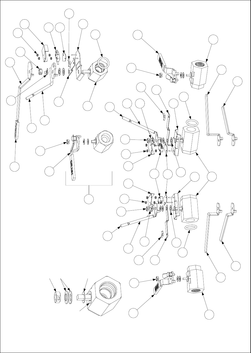
4-36
3
4
4
6
7
7
Compression Washers
NOTE: Concave side of
washers must be mounted
face-to-face.
10
9
14b
14b
1312
15
16
16 17
17
17 17
23
24
25 26
20
20
27
28
29
30
31 31
33
33
Dual Vat Valves
Detail of Valve
Each valve ships with these parts.
Replacement locknuts are available as
separate items.
Locknut
Steel Flat Washer
Plastic Washer
Drain Valves and Associated Components
12
5
7
8
14a
11
15
16
18
17
19
20
21
22
23
31
32
Full Vat Valves
34
34

4-37
ITEM PART # COMPONENT
1 810-1569 Valve, Full Vat 1.25-inch Drain (for use on MH52 units. See NOTE.)
2 810-1018 Valve, Full Vat 1.25-inch Drain (for use on BIH52 units)
3 810-1114 Valve, Dual Vat 1-inch Drain (for use on BIH52 units)
4 810-1338 Valve, Dual Vat 1-inch Drain (for use on MH52 units)
5 807-2103 Switch, Drain Safety (for use on Full Vat BIH52 units)
6 807-2104 Switch, Drain Safety (for use on Dual Vat BIH52 units)
7 816-0135 O-Ring (for use with Items 2 and 3)
8 806-8137 Bracket, Full Vat Drain Safety Switch
9 806-8194 Bracket, Left Dual Vat Drain Safety Switch
10 806-8195 Bracket, Right Dual Vat Drain Safety Switch
11 900-2841 Cover, Full Vat Drain Safety Switch
12 901-2348 Cover, Left Dual Vat Drain Safety Switch
13 902-2348 Cover, Right Dual Vat Drain Safety Switch
14a 900-2354 Bracket, Full Vat Drain Valve
14b 900-2355 Bracket, Dual Vat Drain Valve
15 816-0220 Insulation, Drain Safety Switch
16 809-0237 Nut, 4-40 Keps Hex
17 809-0539 Nut, ⅜-inch 2-Way Lock
18 809-0540 Nut, ½-inch 2-Way Lock
19 823-2371 Handle, Non-CE Full Vat BIH52 Drain Valve
20 810-0677 Grip, Handle
21 900-2521 Handle, CE Full Vat BIH52 Drain Valve
22 814-0047 Sleeve, Handle
23 810-1568 Handle with Lock, Drain Valve (for Full or Left Dual Vat MH52 Valve)
24 810-1569 Handle with Lock, Drain Valve (for Right Dual Vat MH52 Valve)
25 823-2360 Handle, Non-CE Dual Vat BIH52 Left Drain Valve
26 823-2361 Handle, Non-CE Dual Vat BIH52 Right Drain Valve
27 900-2509 Handle, CE Dual Vat BIH52 Left Drain Valve
28 901-5713 Handle, CE Dual Vat BIH152 Left Drain Valve
29 900-2503 Handle, CE Dual Vat BIH52 Right Drain Valve
30 902-5713 Handle, CE Dual Vat BIH152 Right Drain Valve
31 826-1382 Wingnut
32 900-2936 Retainer, Drain Valve ½-inch Nut
33 900-2934 Retainer, Drain Valve ⅜-inch Nut
34 810-1165 Washer, Teflon
NOTE: Item 1 includes Handle, 810-1568 (Item 23).
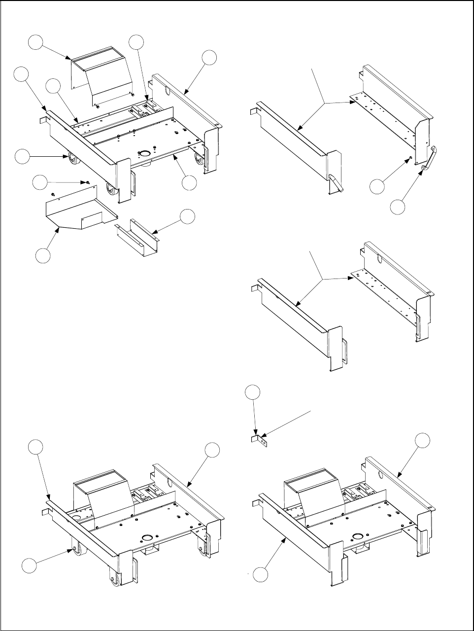
4-38
4.5.2 Filtration System Components
Base Assembly 806-8804SP
(Used on Japanese/Far East Units)
Base Assembly 806-8648SP
(Used on units built August 1997 and later.)
Base Assembly 106-0043SP
(Replaces Base Assembly 806-5985 used
on units built prior to August 1997)
1
3
2
10
4
8
9
5
6
7
11
12
13
14
17
NOTE: Items 1, 2, 3, and 4 are shown
assembled to base assemblies for
illustrative purposes. However, Base
Assemblies 106-0043SP, 806-8804SP,
and 806-8848SP do not include Items
1, 2, 3, and 4. These items must be
ordered separately.
Items 8 and 9 are used on all three
base assemblies.
15 16
NOTE: These types of base sides are no longer available.
They must be replaced with Items 13 and 14. Handles and
screws used with these base sides remain available.
Filter Base Assemblies and Component Parts
NOTE: These types of base sides are no
longer available. They must be replaced with
Items 13 and 14.
18 Lock bracket used on units
built before August 1997.

4-39
NOTE: In September 1999, significant changes were made to the design of the filter base
assemblies used in BIH52 fryers. The most visible change was the removal of the casters on all
assemblies except 806-8804SP (which is used in units manufactured for sale primarily in Japan).
The motor cover was also redesigned and a lower plumbing shield was added. Additionally, the
two-piece motor support (P/Ns 900-7469 and 900-7470) was replaced with a single, stronger
support.
In order to provide continued support for units built prior to August 1997, a new filter base assembly
with casters (P/N 106-0043SP) was created to replace the original 806-5895 filter base assembly,
which is no longer available.
Two additional modifications to the design of the base sides have been made since August 1997.
These include the replacement of the die-cast metal handles with handles formed into the sides, and
the replacement of the separate lock brackets with brackets that are also formed into the sides.
ITEM PART # COMPONENT
1 900-5477 Cover, Motor (September 1999 and later) (used with all three assemblies)
* 824-0558 Cover, Motor (Prior to September 1999)
2 900-1949 Standoff, Filter Wiring Box (used with all three assemblies)
3 900-7557 Cover, Suction Tube (used with all three assemblies)
4 900-9634 Shield, Filter Plumbing (used with all three assemblies)
5 810-0949 Caster, 2.5-inch Swivel (also used in original 806-5985 assembly)
6 806-9153 Side, Left Filter Base (used in 106-0043SP)
7 806-9150 Side, Right Filter Base (used in 106-0043SP)
8 823-2289 Support, Filter Pan (used in all three filter base assemblies)
9 900-5396 Support, Filter Motor (used in all three filter base assemblies)
10 826-1374 Screw, #10 x ½-inch Washer Hex Head (Pkg of 25)
11 810-0180 Handle, Plated Die-cast Metal
12 826-1360 Screw, 10-24 x 5/16-inch Round Slotted Head (Pkg of 25)
13 201-0757 Side, Left Filter Base (used in 806-8648SP)
14 202-0757 Side, Right Filter Base (used in 806-8648SP)
15 806-9154 Side, Left Filter Base (used in 806-8804SP)
16 806-9151 Side, Right Filter Base (used in 806-8804SP)
17 810-1211 Caster, BIH52 Rigid (used in 806-8804SP only)
18 900-1953 Bracket, Filter Lock (used on base assemblies prior to September 1999)
* 809-0440 Nut, 5/16-inch Keps Hex (used for securing casters to base assemblies)
* Not illustrated.
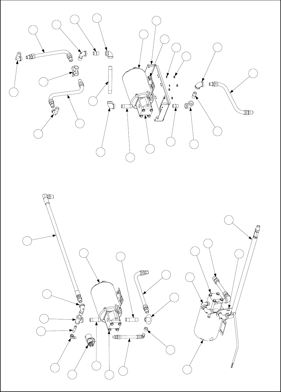
4-40
Filter Motor and Pump Plumbing
10
3
2
4
5
6
7
11
12
14
13
98
Standard BIH52 Filter Motor and Pump
September 1999 and Later
Standard BIH52 Filter Motor and Pump
Prior to September 1999
7
2
15
16
1
1
17
6
6
6
2
7
7
7
11
20
20
19
21
20
2022
23
24
25
26
18
21
BIH152 Filter Motor and Pump
1

4-41
ITEM PART # COMPONENT
1 826-1261 Pump, 4 GPM (15 LPM) (comes with Gasket 816-0093)
2Motor and Gasket Kit, Multi-Voltage
826-1721 100-120VAC (replaces earlier kits 826-1260, -1263, and -1268)
826-1713 200-250VAC (replaces earlier kits 826-1262, -1266, -1269, and -1270)
3 807-2484 Valve, Solenoid Vent
4 810-1404 Flexline, Oil Return (pump to rear manifold)
5 810-1373 Flexline, Pump Bypass
6 806-9437 Flexline, 15½-inch (39.5cm) Oil Return (See NOTE below)
7 813-0165 Elbow, ½-inch x 90º Street
8 813-0530 Tee, ½-inch x ¼-inch x ½-inch Reducing
9 813-0537 Nipple, ¼-inch x 2-inch
10 813-0543 Elbow, ¼-inch x 90º Street
11 813-0265 Nipple, ½-inch x 2½-inch
12 813-0460 Nipple, ½-inch x 3-inch
13 813-0304 Bushing, ½-inch to ¼-inch Reducing
14 813-0331 Elbow, ½-inch 3-way
15 810-1159 Flexline, 7½-inch Oil Return
16 Hose, Heated Oil Return
810-0945 100-120VAC
810-1037 208-250VAC
17 900-1958 Support, Oil Return
18 810-1003 Valve, 180º 3-way Ball
19 813-0022 Nipple, ½-inch x Close
20 813-0062 Elbow, ½-inch x 90º
21 813-0098 Nipple, ½-inch x 6½-inch
22 813-0087 Nipple, ½-inch x 1½-inch
23 900-5543 Mount, Motor
24 809-0131 Screw, ¼-20 x ¾-inch Hex Head
25 809-0191 Washer, ¼-inch Lock
26 809-0071 Nut, ¼-20 Hex
* 806-6728 Wiring Assembly, Pump Motor to Filter Box
* 816-0093 Gasket, Pump Motor
*Thermal Switch
807-1600 Baldor Motor, 120VAC
807-1601 Baldor Motor, 240VAC
807-1598 Magnatek Motor, 120VAC
807-1599 Magnatek Motor, 240VAC
* Not illustrated.
NOTE: Item 6 consists of 13-inch Flexline 810-1057 and two ⅞-inch to ½-inch Male Adapters
810-1668, which may be ordered as separate items.
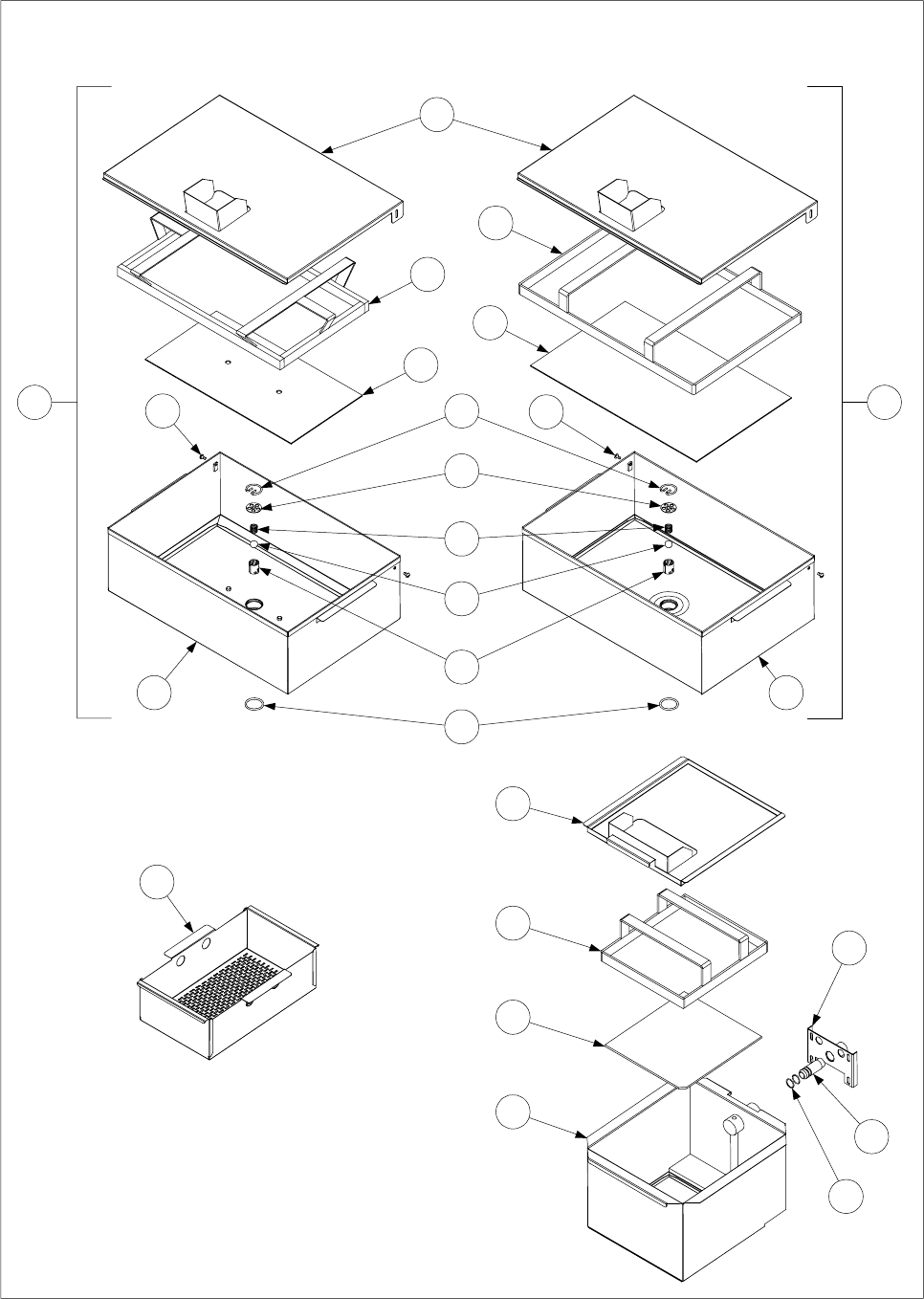
4-42
Filter Pan Assemblies and Associated Components
1 2
3
5
4
6
8
11
12
13
14
15
16
7
9
17
18
19
20
10 10
21
22
23
24

4-43
ITEM PART # COMPONENT
1Pan Assembly, Filter (has screen alignment pins in pan bottom)
806-6423SP Standard
806-7377SP For use on Japanese/Far East (JBIH52) units.
2† 806-5618SP Pan Assembly, Filter (has no screen alignment pins in pan bottom)
3Cover, Filter Pan
823-2027 For use with 806-6423SP and 806-5618SP assemblies.
823-2321 For use with 806-7377SP units (has lower splash guard than 823-2027)
4 810-1405 Ring, Hold Down (for use with 806-6423SP and 806-7377SP assemblies)
5 810-1408 Ring, Hold Down (for use with 806-5618SP assembly)
6 900-8818 Screen, Sana Grid (9 x 17-inch/23 x 43cm, has alignment holes)
7 900-8819 Screen, Sana Grid (12 x 19.5-inch/30.5 x 49.5cm, has no holes)
8 823-2234SP Pan, Filter (has screen alignment pins in pan bottom)
9† 823-1979SP Pan, Filter (has no screen alignment pins in pan bottom)
10 809-0422 Screw, 10-32 x 7/16-inch Slotted Truss Head
11 810-1387 Retainer, Check Valve
12 900-5448 Strainer, Check Valve
13 810-0946 Spring, Check Valve
14 810-0948 Ball, Check Valve
15 810-1388 Tube, Check Valve
16 816-0181 O-Ring, Check Valve
17 823-2586 Cover, Filter Pan (for use with 823-2575SP)
18 824-0430 Screen, Crumb (used with 806-5618SP, 806-6423SP, and 806-7377SP)
19 823-2574 Ring, Hold Down (for use in 823-2575SP)
20 900-8829 Screen, San Grid (10 x 9-inch/23 x 25cm, for use in 823-2575SP)
21 823-2575SP Pan, Filter (for use in BIH152 units)
22 823-2578 Bracket, BIH152 Oil Return
23 810-0697 Disconnect, Male
24 826-1392 O-Ring, BIH152 Oil Return (Pkg of 5)
* 826-1490 Kit, Filter Pan Check Valve Service (consists of Items 11 through 16)
† Used on some early-production Japanese/Far East (JBIH52) units only.
* Not illustrated.
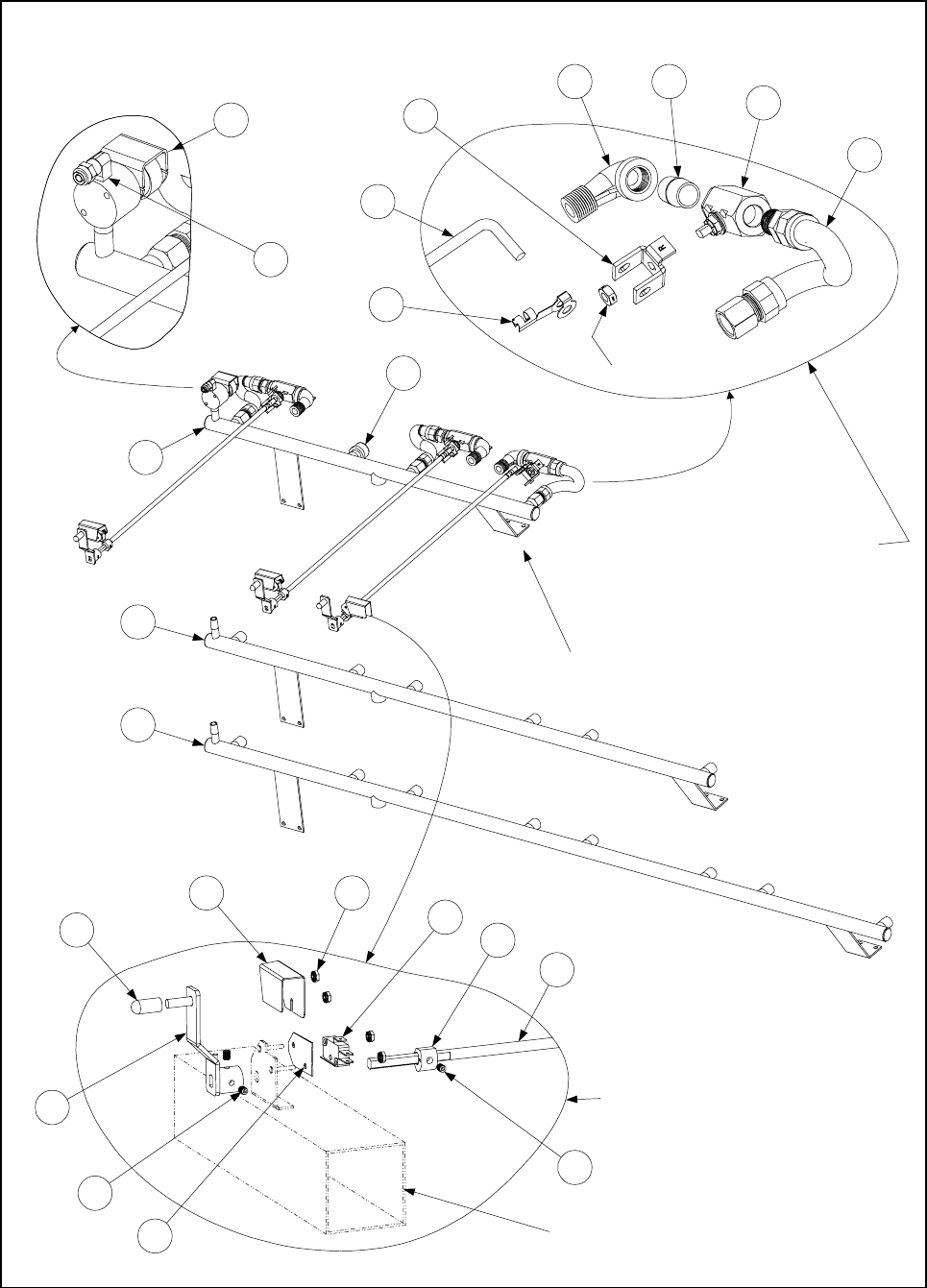
4-44
See Page 8-35 for Square
Drain components
4
14
Right Handle and Switch Assembly
(All components except for Items 4 and 14
are the same for Left Handle and Switch
Assembly)
15
16
17
19
18
18
20
21
Rear Flush Oil Return Components
Right Oil Return Valve Assembly
(All components except for Items 4 and 5
are the same for Left Oil Return Valve
Assembly)
Nut (furnished
with Item 8)
13
12
11
1
2
3
10
4
5
6 7
8
9
TYPICAL CONFIGURATION
(BIH252 Full Vat Left /Dual Vat Right shown)
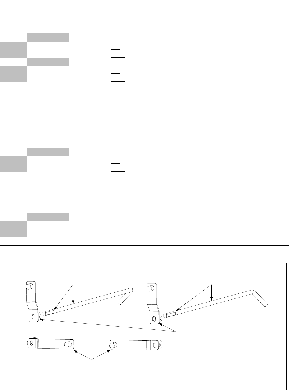
4-45
ITEM PART # COMPONENT
1 807-2484 Valve, Solenoid Vent
2 810-1372 Elbow, 90º x ¼-inch NPT x ⅜-inch Tube
3 809-0601 Clip, Rod End Clevis
4Shaft, Rear Flush Valve
810-1767 For use in left oil return valve assemblies (see illustration below).
810-1766 For use in right oil return valve assemblies (see illustration below).
5Handle, Rear Flush Valve
901-2772 For use in left oil return valve assemblies.
902-2772 For use in right oil return valve assemblies.
6 813-0165 Elbow, 90º x ½-inch Street
7 813-0022 Nipple, ½-inch Close
8 810-0278 Valve, ½-inch Ball
9 806-9828SP Flexline Assembly, 9-inch Oil Return
10 813-0469 Cap, ½-inch Pipe
11 810-1360 Manifold, BIH252 Rear Flush Oil Return
12 810-1357 Manifold, BIH352 Rear Flush Oil Return
13 810-1378 Manifold, BIH452 Rear Flush Oil Return
14 Cover, BIH52 Rear Flush Oil Return Microswitch
901-2214 For use in left handle and switch assemblies.
902-2214 For use in right handle and switch assemblies.
15 809-0237 Nut, 4-40 Keps Hex
16 807-2103 Microswitch
17 810-1186 Cam, Filter System Microswitch
18 809-0414 Setscrew, 10-32 x ¼-inch
19 816-0220 Insulation, Microswitch
20 Handle, Rear Flush
823-2295 For use in Non-CE applications (see illustration below).
823-2259 For use in CE applications only (see illustration below).
21 812-1253 Cover, Rear Flush Handle
NOTE: Left and right refer to the fryer as viewed from the front when facing the fryer.
Shaft 810-1767
(Note orientation of flat
and 45° angle to left.)
Shaft 810-1766
(Note orientation of flat
and 45° angle to right.)
Full Vat or
Left Side of Dual Vat Right Side of Dual Vat
Handle 823-2295
(Note orientation of slot)
This handle is used in
non-CE applications.
NOTE: Handles are shown in
Valve OPEN/Filter ON position.
Handle 823-2259
(Note orientation of slot)
This handle is used in
CE applications.
