Sun Blade 6000 Disk Module Service Manual 820 1703 13
User Manual: 6000
Open the PDF directly: View PDF ![]() .
.
Page Count: 50
- Sun BladeTM 6000 Disk Module Service Manual
- Contents
- Preface
- Introduction to the Sun Blade 6000 Disk Module
- Replacing Disk Drives
- Replacing a Sun Blade 6000 Disk Module
- Replacing a Host Bus Adapter
- Activating LSI RAID Volumes
- Using the lsiutil Software
- Index

Submit comments about this document by clicking the Feedback[+] link at: http://docs.sun.com
Sun BladeTM 6000 Disk Module
Service Manual
Part No. 820-1703-13
June 2009, Revision 01
Sun Microsystems, Inc.
www.sun.com

Please
Recycle
Copyright © 2009 Sun Microsystems, Inc., 4150 Network Circle, Santa Clara, California 95054, U.S.A. All rights reserved.
Sun Microsystems, Inc. has intellectual property rights relating to technology that is described in this document. In particular, and without
limitation, these intellectual property rights may include one or more of the U.S. patents listed at http://www.sun.com/patents and one or
more additional patents or pending patent applications in the U.S. and in other countries.
This document and the product to which it pertains are distributed under licenses restricting their use, copying, distribution, and
decompilation. No part of the product or of this document may be reproduced in any form by any means without prior written authorization of
Sun and its licensors, if any.
Third-party software, including font technology, is copyrighted and licensed from Sun suppliers.
Parts of the product may be derived from Berkeley BSD systems, licensed from the University of California. UNIX is a registered trademark in
the U.S. and in other countries, exclusively licensed through X/Open Company, Ltd.
Sun, Sun Microsystems, the Sun logo, Java, AnswerBook2, docs.sun.com, and Solaris are trademarks or registered trademarks of Sun
Microsystems, Inc. in the U.S. and in other countries.
All SPARC trademarks are used under license and are trademarks or registered trademarks of SPARC International, Inc. in the U.S. and in other
countries. Products bearing SPARC trademarks are based upon an architecture developed by Sun Microsystems, Inc.
The OPEN LOOK and Sun™ Graphical User Interface was developed by Sun Microsystems, Inc. for its users and licensees. Sun acknowledges
the pioneering efforts of Xerox in researching and developing the concept of visual or graphical user interfaces for the computer industry. Sun
holds a non-exclusive license from Xerox to the Xerox Graphical User Interface, which license also covers Sun’s licensees who implement OPEN
LOOK GUIs and otherwise comply with Sun’s written license agreements.
U.S. Government Rights—Commercial use. Government users are subject to the Sun Microsystems, Inc. standard license agreement and
applicable provisions of the FAR and its supplements.
DOCUMENTATION IS PROVIDED "AS IS" AND ALL EXPRESS OR IMPLIED CONDITIONS, REPRESENTATIONS AND WARRANTIES,
INCLUDING ANY IMPLIED WARRANTY OF MERCHANTABILITY, FITNESS FOR A PARTICULAR PURPOSE OR NON-INFRINGEMENT,
ARE DISCLAIMED, EXCEPT TO THE EXTENT THAT SUCH DISCLAIMERS ARE HELD TO BE LEGALLY INVALID.
Copyright 2009 Sun Microsystems, Inc., 4150 Network Circle, Santa Clara, Californie 95054, États-Unis. Tous droits réservés.
Sun Microsystems, Inc. possède les droits de propriété intellectuels relatifs à la technologie décrite dans ce document. En particulier, et sans
limitation, ces droits de propriété intellectuels peuvent inclure un ou plusieurs des brevets américains listés sur le site
http://www.sun.com/patents ,un ou les plusieurs brevets supplémentaires ainsi que les demandes de brevet en attente aux les États-Unis
et dans d’autres pays.
Ce document et le produit auquel il se rapporte sont protégés par un copyright et distribués sous licences, celles-ci en restreignent l’utilisation,
la copie, la distribution, et la décompilation. Aucune partie de ce produit ou document ne peut être reproduite sous aucune forme, par quelque
moyen que ce soit, sans l’autorisation préalable et écrite de Sun et de ses bailleurs de licence, s’il y en a.
Tout logiciel tiers, sa technologie relative aux polices de caractères, comprise, est protégé par un copyright et licencié par des fournisseurs de
Sun.
Des parties de ce produit peuvent dériver des systèmes Berkeley BSD licenciés par l’Université de Californie. UNIX est une marque déposée
aux États-Unis et dans d’autres pays, licenciée exclusivement par X/Open Company, Ltd.
Sun, Sun Microsystems, le logo Sun, Java, AnswerBook2, docs.sun.com, et Solaris sont des marques de fabrique ou des marques déposées de
Sun Microsystems, Inc. aux États-Unis et dans d’autres pays.
Toutes les marques SPARC sont utilisées sous licence et sont des marques de fabrique ou des marques déposées de SPARC International, Inc.
aux États-Unis et dans d’autres pays. Les produits portant les marques SPARC sont basés sur une architecture développée par Sun
Microsystems, Inc.
L’interface utilisateur graphique OPEN LOOK et Sun™ a été développée par Sun Microsystems, Inc. pour ses utilisateurs et licenciés. Sun
reconnaît les efforts de pionniers de Xerox dans la recherche et le développement du concept des interfaces utilisateur visuelles ou graphiques
pour l’industrie informatique. Sun détient une license non exclusive de Xerox sur l’interface utilisateur graphique Xerox, cette licence couvrant
également les licenciés de Sun implémentant les interfaces utilisateur graphiques OPEN LOOK et se conforment en outre aux licences écrites de
Sun.
LA DOCUMENTATION EST FOURNIE "EN L’ÉTAT" ET TOUTES AUTRES CONDITIONS, DÉCLARATIONS ET GARANTIES EXPRESSES
OU TACITES SONT FORMELLEMENT EXCLUES DANS LA LIMITE DE LA LOI APPLICABLE, Y COMPRIS NOTAMMENT TOUTE
GARANTIE IMPLICITE RELATIVE À LA QUALITÉ MARCHANDE, À L’APTITUDE À UNE UTILISATION PARTICULIÈRE OU À
L’ABSENCE DE CONTREFAÇON.

iii
Contents
Preface v
1. Introduction to the Sun Blade 6000
Disk Module 1–1
1.1 Features of the Disk Module 1–1
1.2 Sun Blade 6000 Disk Module Orientation 1–3
1.3 CRUs and FRUs 1–5
1.4 What’s in This Document 1–6
2. Replacing Disk Drives 2–1
2.1 Replacing a Disk Drive 2–1
▼To Replace a Disk Drive 2
3. Replacing a Sun Blade 6000 Disk Module 3–1
3.1 Replacing a Disk Module 3–1
3.1.1 Procedure for Server Blades Using LSI Host Bus Adapters 3–2
▼To Replace a Disk Blade When Its Paired Server Uses an LSI
Host Bus Adapter and is Running the Solaris OS 2
▼To Recover From a Failed lsiutil Command When Replacing
a Disk Blade 4
▼To Replace a Disk Blade When Its Paired Server Uses an LSI
Host Bus Adapter and is Running Windows or Linux 5

iv Sun Blade 6000 Disk Module Service Manual • June 2009
3.1.2 To Replace a Disk Blade When Its Paired Server Uses an Adaptec
Host Bus Adapter 3–6
4. Replacing a Host Bus Adapter 4–1
4.1 LSI Host Bus Adapter Failure and Replacement 4–1
▼To Replace the LSI Host Bus Adapter on an x64 Server Blade Running
Linux or Windows 2
▼To Replace the LSI Host Bus Adapter on Any Server Blade Running the
Solaris OS 2
4.2 Replacing an Adaptec Host Bus Adapter 4–4
▼To Replace an Adaptec Host Bus Adapter 4
A. Activating LSI RAID Volumes A–1
A.1 Activating LSI RAID Volumes A–1
▼To Do Before Activating an LSI RAID Volume: 1
▼To Activate LSI RAID Volumes for x64 Server Blades 2
▼To Activate LSI RAID Volumes for SPARC Server Blades 3
B. Using the lsiutil Software B–1
B.1 Where to Obtain the lsiutil Software B–1
B.2 Installing lsiutil B–2
▼To Use lsiutil From the Command Line 2
▼To Use the Interactive lsiutil Menus 2
B.3 Why Save LSI Host Bus Adapter Persistent Mappings? B–6
B.4 When to Save LSI Host Bus Adapter Persistent Mappings B–6
B.5 Saving and Restoring a Persistence Map B–7
▼To Save a Snapshot of Your Host Bus Adapter Persistent Mappings 7
▼To Restore a Snapshot of Your Host Bus Adapter Persistent Mappings
11
Index Index–1

v
Preface
The Sun Blade 6000 Disk Module Service Manual contains information and procedures
for replacing or upgrading the disk modules.
Before You Read This Document
It is important that you review the safety guidelines in the Sun Blade 6000 Disk
Module Safety and Compliance Guide, 820-1711.
Product Updates
For product updates that you can download for the Sun Blade 6000 disk modules,
visit the following site:
(http://www.sun.com/servers/blades/downloads.jsp#6000dm)
This site contains updates for firmware and drivers, as well as CD-ROM .iso
images.
vi Sun Blade 6000 Disk Module Service Manual • June 2009
Related Documentation
For a description of the document set for the Sun Blade 6000 disk modules, see the
Where To Find Sun Blade 6000 Disk Module Documentation sheet that is packed with
your system and also is posted at the product's documentation site:
(http://docs.sun.com/app/docs/prod/blade.6000disk#hic)
Translated versions of some of these documents are available at the product
documentation site in French, Simplified Chinese, and Japanese. English
documentation is revised more frequently and might be more up-to-date than the
translated documentation.
Typographic Conventions
Third-Party Web Sites
Sun is not responsible for the availability of third-party web sites mentioned in this
document. Sun does not endorse and is not responsible or liable for any content,
advertising, products, or other materials that are available on or through such sites
Typeface Meaning Examples
AaBbCc123 The names of commands, files,
and directories; on-screen
computer output
Edit your.login file.
Use ls -a to list all files.
% You have mail.
AaBbCc123 What you type, when contrasted
with on-screen computer output
%su
Password:
AaBbCc123 Book titles, new words or terms,
words to be emphasized.
Replace command-line variables
with real names or values.
Read Chapter 6 in the User’s Guide.
These are called class options.
You must be superuser to do this.
To delete a file, type rm filename.

Preface vii
or resources. Sun will not be responsible or liable for any actual or alleged damage
or loss caused by or in connection with the use of or reliance on any such content,
goods, or services that are available on or through such sites or resources.
Sun Welcomes Your Comments
Sun is interested in improving its documentation and welcomes your comments and
suggestions. You can submit your comments by going to:
(http://www.sun.com/hwdocs/feedback)
Please include the title and part number of your document with your feedback:
Sun Blade 6000 Disk Module Service Manual, part number 820-1703-13

viii Sun Blade 6000 Disk Module Service Manual • June 2009

1-1
CHAPTER 1
Introduction to the Sun Blade 6000
Disk Module
This chapter contains an overview of the Sun Blade 6000 Disk Module (also called a
disk blade) and contains the following topics:
■Section 1.1 “Features of the Disk Module” on page 1-1
■Section 1.2 “Sun Blade 6000 Disk Module Orientation” on page 1-3
■Section 1.3 “CRUs and FRUs” on page 1-5
■Section 1.4 “What’s in This Document” on page 1-6
1.1 Features of the Disk Module
The Sun Blade 6000 Disk Module is a blade for the Sun Blade 6000 Modular System
that contains disks. It communicates with server blades through Network Express
Modules that support SAS, specifically the Sun Blade 6000 Multi-Fabric NEM and
the Sun Blade 6000 10GbE Multi-Fabric NEM.
TABLE 1-1 summarizes the features of the disk module.
TABLE 1-1 Features of the Sun Blade 6000 Disk Module
Feature Specifications
Disk Drives Eight total with front panel access. The storage blade supports
SAS or Solid State (SSD) disk drives.
Types SAS (2.5 inch or 63.5 mm).
Disk Drive Bracket Sun disk drive mounting bracket.
Management 2 Arm7-S Processors (SAS expander devices).
2MB SRAM code storage, 2MB FLASH, 8K Serial EEPROM.

1-2 Sun Blade 6000 Disk Module Service Manual • June 2009
TABLE 1-1 summarizes the physical specifications of the disk module.
Data Rates 1.5 and 3.0 Gbit/sec. SAS with auto-negotiation.
Two 1x or one 2x wide connections into blade. 12 Gbit/sec total.
Protocols SAS - Serial Attached SCSI - v1.0, v1.1.
SSP - Serial SCSI Protocol.
SMP - Serial Management Protocol.
SES - SCSI Enclosure Services.
Indicators SIS indicators: Activity and Fault for drives and blade. Locate for
blade only.
Health Voltage monitoring, temperature monitoring, disk fault detection,
and blade fault detection.
TABLE 1-2 Sun Blade 6000 Server Module Physical and Environmental Specifications
Specification Value
Width 12.87 inches (327 mm)
Height 1.7 inches (44 mm)
Depth 20.16 inches (512 mm)
Weight 17 pounds (8 kg)
Power 240W Max (estimated)
Environmental Humidity: 10% to 90% non-condensing
Temperature: 5 to 40 deg C operating (-40 to 70 deg C storage)
Altitude: 0 to 10,000 ft (3,048 meters)
Power Supplies 3.3V_AUX from chassis backplane.
12V from chassis backplane.
Other voltages generated on blade.
Cooling Front-to-back forced air (no internal fans).
Regulatory UL/CSA
FCC part15 Class A
TABLE 1-1 Features of the Sun Blade 6000 Disk Module (Continued) (Continued)
Feature Specifications
Chapter 1 Introduction to the Sun Blade 6000 Disk Module 1-3
1.2 Sun Blade 6000 Disk Module Orientation
This section contains illustrations that you can use to become familiar with the Sun
Blade 6000 disk module.
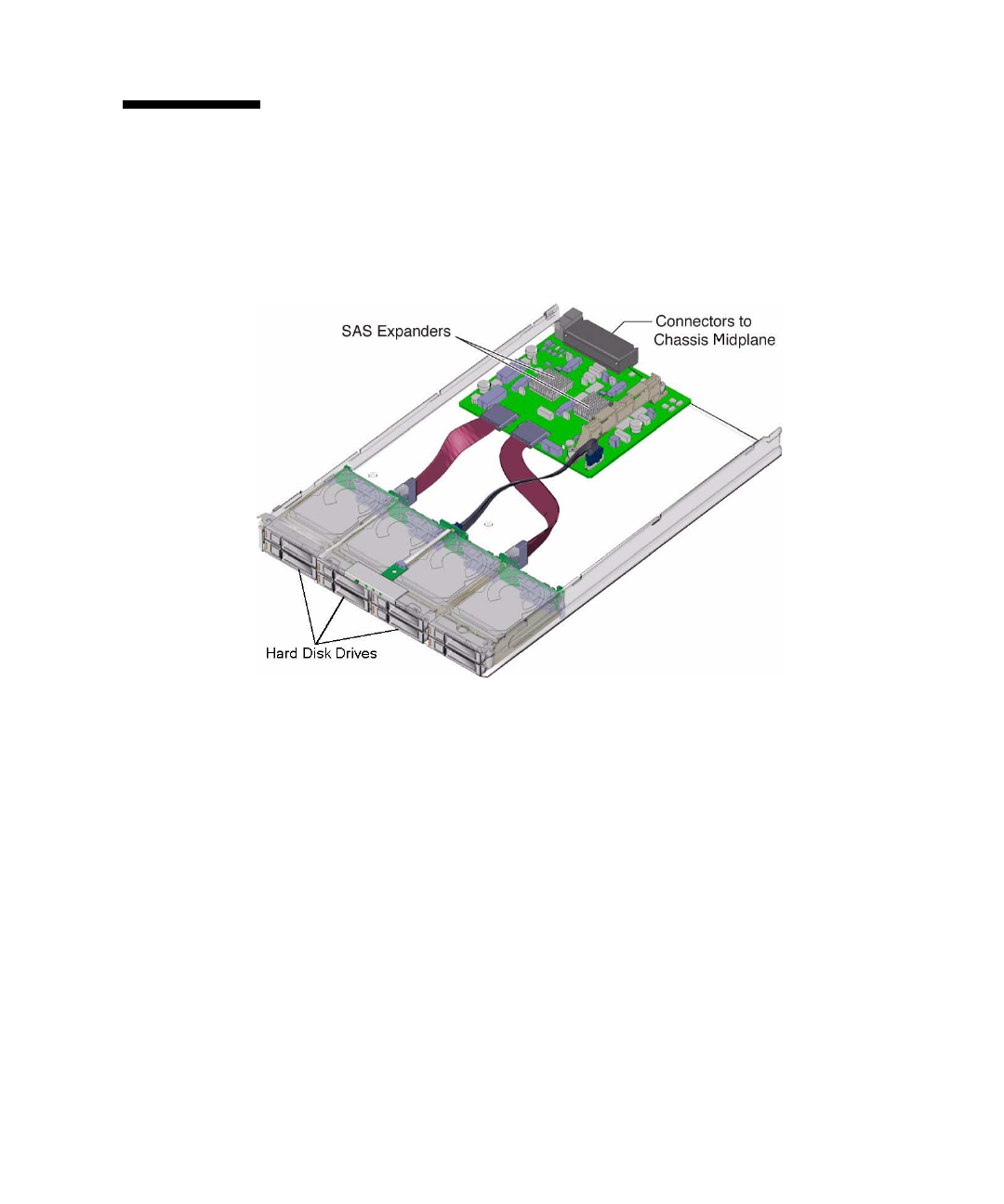
FIGURE 1-1 Interior of the Sun Blade 6000 Disk Blade
FIGURE 1-2 shows the features of the front panel.
1-4 Sun Blade 6000 Disk Module Service Manual • June 2009
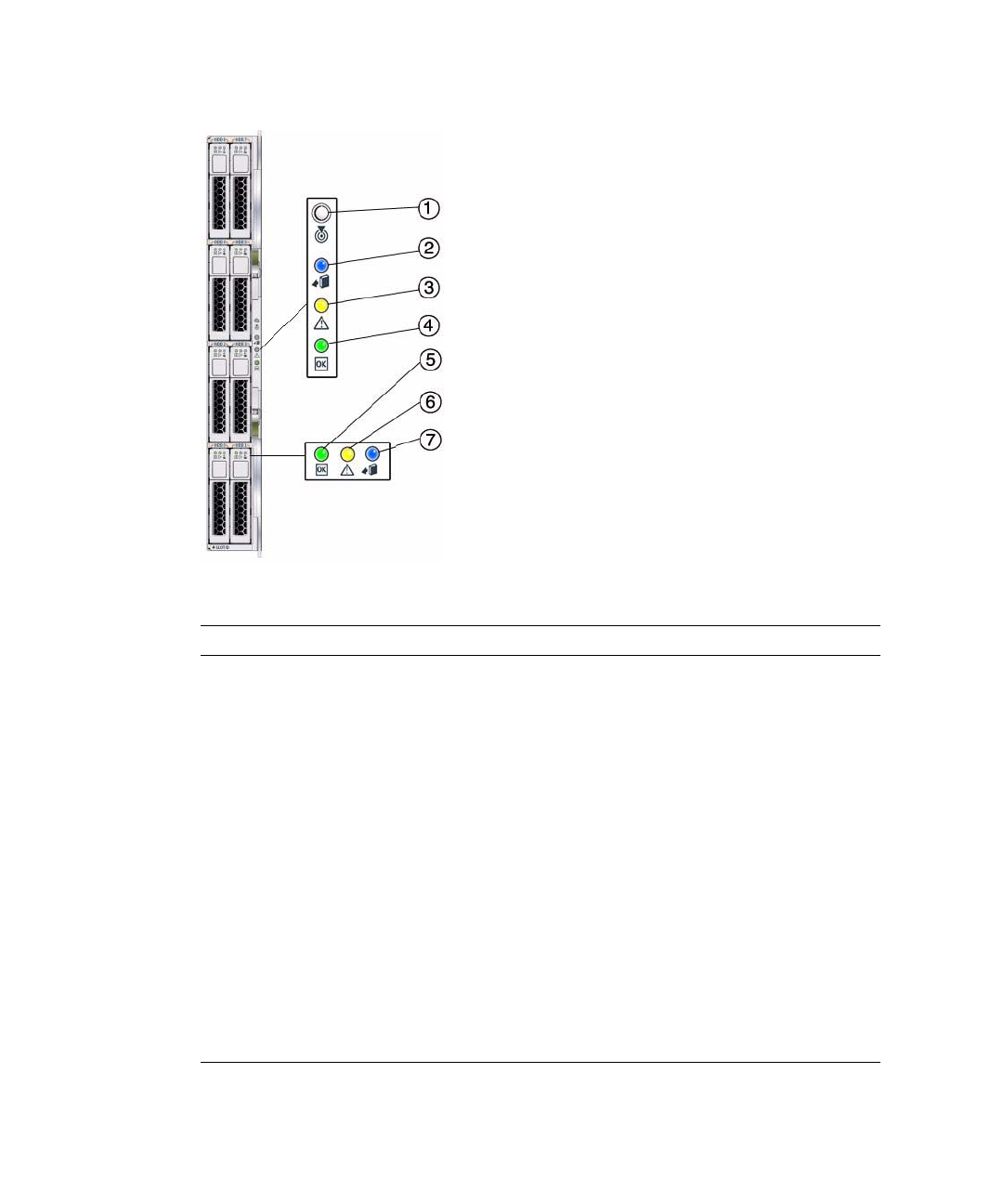
FIGURE 1-2 Sun Blade 6000 Disk Module Front Panel
TABLE 1-3 Front Panel LED Functions
LED Name Description
1 Combined Locate button and
LED (white)
This LED helps you to identify which system in the
rack you are working on in a rack full of servers.
• Push and release this button to make the Locate
LED blink for 30 minutes.
• When Locate LED is blinking, push and release this
button to make the Locate LED stop blinking.
• Hold down the button for 5 seconds to initiate a
“push-to-test” mode that illuminates all other LEDs
for 15 seconds.
• This LED can also be made to blink from a remote
system using the CMM ILOM. Refer to the Sun Blade
6000 Disk Module Administration Guide for
details.
2 Ready-to-Remove LED (blue) Not used.
3 Module Fault LED (amber) This LED has two states:
• On: An event has been acknowledged, and service
action is required.
• Off: Normal operation.

Chapter 1 Introduction to the Sun Blade 6000 Disk Module 1-5
The events that can cause a disk blade’s Module Fault LED (amber) to turn on are:
■Temperature out of range.
■Voltage out of range.
Note – A severe over-temperature condition will shut down the disk blade.
1.3 CRUs and FRUs
For the Sun Blade 6000 Disk Module, the Customer Replaceable Units (CRUs) are the
disks in the disk module. There is only one Field Replaceable Unit (FRU), which is
the disk module itself.
If either a disk or a disk module fails, you must replace it, because there are no
replaceable subassemblies.
You can replace the disks and the disk blade yourself.
4 Module Activity LED (green) This LED has three states:
• Off: Module is offline.
• On: Module is online.
• Slow blinking (1 Hz at 50% duty cycle): Module is
booting or configuring (firmware flash update in
progress).
5 Disk Drive OK LED (green) This LED has three states:
• On: Power is on and disk is online.
• Off: Disk is offline.
• Blinking: Irregular blinking means normal disk
activity; steady, slow blink means a RAID volume is
rebuilding on this disk.
6 Disk Drive Fault and Locate
LED (amber)
This LED has four states:
• On: Disk fault. Service action required.
• Off: Normal operation.
• Slow blink: Disk failure predicted.
• Fast blink: Locate function activated.
7 Ready-to-Remove LED (blue) Not used.
TABLE 1-3 Front Panel LED Functions (Continued)
LED Name Description

1-6 Sun Blade 6000 Disk Module Service Manual • June 2009
1.4 What’s in This Document
The remainder of the document includes these topics:
Chapter 2: This chapter contains information and procedures for servicing the Sun
Blade 6000 disk module hardware, including component removal and replacement
procedures.
Chapter 3: This chapter describes the procedures for replacing a Sun Blade disk
module.
Chapter 4: This chapter describes the procedures for replacing an LSI host bus
adapter on a server blade that is paired with a disk blade and restoring its
configuration. This includes replacing the server blade when the host bus adapter is
embedded in it.
Appendix A: This appendix provides instructions for reactivating inactive RAID
volumes.
Appendix B: This appendix provides instructions information on where to obtain the
lsiutil software and how to use it.

2-1
CHAPTER 2
Replacing Disk Drives
This chapter contains information and procedures for servicing the Sun Blade 6000
disk module hardware, including component removal and replacement procedures.
The following topics are covered in this chapter:
■Section 2.1 “Replacing a Disk Drive” on page 2-1
2.1 Replacing a Disk Drive
On occasion, a disk drive might fail. The status of the drive is indicated by its LEDs,
as shown in TABLE 2-1.
TABLE 2-1 Drive Status LED Indicators
LED Name Description
HDD Activity LED (green) This LED has three states:
• On: Power is on and disk is present.
• Off: Disk is offline or absent.
• Blinking: Irregular blinking means normal disk activity.
Steady, slow blink means a RAID volume is rebuilding
on this disk.
HDD Fault and Locate LED
(amber)
This LED has four states:
• On: Disk fault. Service action required.
• Off: Normal operation.
• Slow blink: Disk failure predicted.
• Fast blink: Locate function activated.
Ready-to-Remove LED (blue) • Not used.
2-2 Sun Blade 6000 Disk Module Service Manual • June 2009
A single disk failure does not cause a data failure when disks are configured as a
mirrored RAID volume. When there is no hot spare assigned to the mirror, the
failed disk can be hot-swapped. When the new disk is inserted, the contents are
automatically rebuilt from the rest of the array with no need to reconfigure the RAID
parameters.
If the mirror was configured with a hot spare, the mirror is automatically rebuilt
with the hot spare.
Caution – Possible data loss: You can remove the failed disk while the mirror is
rebuilding to the hot spare, but you must not insert a new disk in its place until the
rebuilding of the mirror is completed. While data is being rebuilt, the green LED on
the remaining drives will blink slowly. The rebuild process can take a number of
hours for large mirrors.
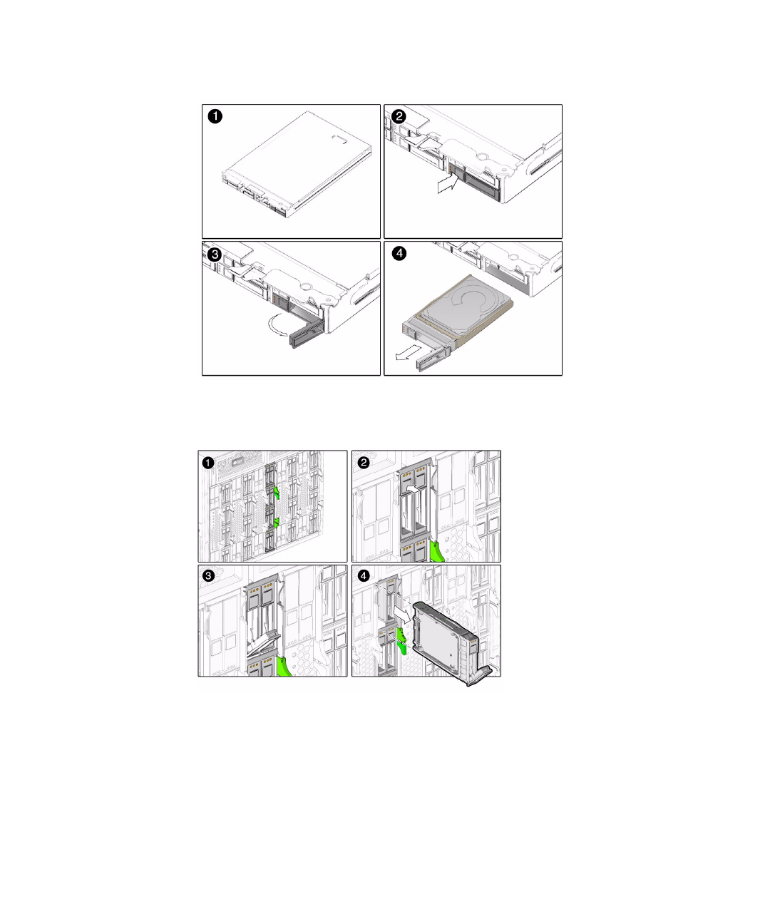
▼To Replace a Disk Drive
The Sun Blade 6000 Disk Module disks can be replaced by users:
1. Observe the amber Fault LEDs on the faces of the disks to identify the
defective disk.
2. Execute the software commands appropriate to the software that you are using
to prepare the hard drive for removal.
3. Press the button on the face of the disk to release the spring-loaded securing
latch. See FIGURE 2-1 and FIGURE 2-2.
4. Grasp the securing latch and remove the disk from the drive bay.
Disks in the Sun Blade 6000 Disk Module are hot-pluggable, so you can remove a
disk either when the disk module is installed in the chassis or when it is out of
the chassis. See FIGURE 2-1 and FIGURE 2-2.
Caution – Slots should always contain either a disk drive or a filler in order to
maintain adequate air flow. Do not operate the system with slots that are empty.
Always insert a filler when you remove a hard drive from a slot.
Chapter 2 Replacing Disk Drives 2-3
FIGURE 2-1 Removing the Disk Drive With the Disk Module Removed From the Chassis
FIGURE 2-2 Removing the Disk Drive Without Removing the Disk Module From the
Chassis

2-4 Sun Blade 6000 Disk Module Service Manual • June 2009
3-1
CHAPTER 3
Replacing a Sun Blade 6000 Disk
Module
This chapter contains information and procedures for replacing the Sun Blade 6000
disk module.
■Section 3.1 “Replacing a Disk Module” on page 3-1
■“To Replace a Disk Blade When Its Paired Server Uses an LSI Host Bus Adapter
and is Running Windows or Linux” on page 3-5
■Section 3.1.2 “To Replace a Disk Blade When Its Paired Server Uses an Adaptec
Host Bus Adapter” on page 3-6
Caution – Several of the service procedures in this chapter require the use of the
lsiutil application. lsiutil has many features and capabilities. Executing
certain combinations of commands can place your system in an unrecoverable state.
When you use this application, be sure you execute the procedures exactly as they
are documented here, command by command. Do not skip commands or steps and
do not add commands or steps that are not in the documented procedure.
3.1 Replacing a Disk Module
If your Sun Blade 6000 Disk Module fails, it must be replaced. The procedures for
replacing the disk module vary, depending on two things:
■The type of SAS host bus adapter.
■The installed OS on the server blade that is paired with the disk blade.
In every case, you must remove the disks from the old disk blade and insert them
into the same slots in the new disk blade.
3-2 Sun Blade 6000 Disk Module Service Manual • June 2009
3.1.1 Procedure for Server Blades Using LSI Host Bus
Adapters
The SAS host bus adapters from LSI identify each disk in a disk blade using the
unique “enclosure ID” of the disk blade (its World Wide Name, or WWN) and the
number of the bay where the disk resides.
If you simply replace a disk blade, its enclosure ID changes. The SAS adapter may
not recognize the new disk blade and may not be able to identify the disks as the
same set, including the boot disk or boot volume.
For server blades running the Solaris OS, you must reconfigure the enclosure ID
information in an LSI host bus adapter so that the disks can be correctly identified in
a replacement disk blade. This procedure uses the lsiutil utility.
For server blades running Windows or Linux, you must reset the host bus adapter’s
persistence mappings. This procedure also uses the lsiutil utility.
Caution – When using lsiutil you must follow the steps in the documented
procedures exactly. An untrained individual using lsiutil can potentially place the
system in an unrecoverable state.
After you reconfigure the persistence mappings in the LSI host bus adapter, the
adapter recognizes the new disk blade in the same way that it recognized the old
one. Your system will operate the same as before the failure.
▼To Replace a Disk Blade When Its Paired Server Uses
an LSI Host Bus Adapter and is Running the Solaris OS
Caution – A SAS-NEM must be functioning in slot NEM 0 when you follow the
procedure documented here.
You must know the enclosure IDs (World Wide Names, or WWNs) of both disk
blades: the old one (the one you are replacing) and the new one. The enclosure ID is
a 16-bit hexadecimal digit that is printed on a yellow sticker on the main circuit
board of the disk blade.
1. Remove the old disk blade from the chassis. Leave all the disks in it for the
moment.
2. Insert a slot filler in the now-empty slot. Do not insert the replacement disk
blade yet.
Chapter 3 Replacing a Sun Blade 6000 Disk Module 3-3
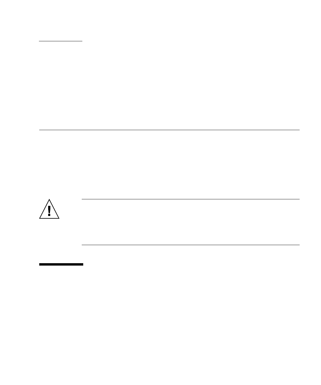
3. Open the old disk blade. Press the green button and remove the top cover (see
FIGURE 3-1).
FIGURE 3-1 Removing the Sun Blade 6000 Disk Module Cover
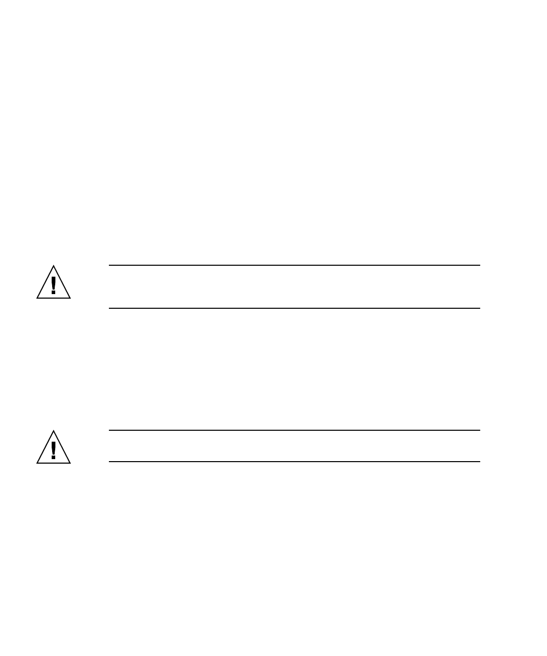
4. Record the old disk blade’s World Wide Name (WWN 128 ADDRESS), which is
the 16 bit hex number that is printed on a yellow label on the main circuit
board (see FIGURE 3-2).
FIGURE 3-2 WWN Label
5. Open the cover of the new (replacement) disk blade and record the WWN
printed on its yellow sticker.
6. Close the cover of the new disk blade and set it aside for the moment.
3-4 Sun Blade 6000 Disk Module Service Manual • June 2009
7. Run the following procedure on the server blade that is paired with the
replacement disk blade.
In a terminal window, change your current directory to the directory where
lsiutil is installed. Type in the following command and press Enter.
lsiutil -p1 -a 6,oldEnclID,newEnclID,,0,0 15
Caution – This command must be typed exactly as shown. If this command is
typed incorrectly or not entered before replacing the disk blade, you must use the
recovery procedure described below (see “To Recover From a Failed lsiutil
Command When Replacing a Disk Blade” on page 3-4).
Replace oldEnclID and newEnclID with the 16-digit hexadecimal numbers from the
labels on the old and new disk blades respectively. Note that the second character
in the -p1 argument is the digit ‘1’ and not the letter ‘l.’
8. Remove the disks from the old disk blade and insert them in the new disk
blade in the exact same slots that they occupied in the old disk blade.
9. Remove the temporary slot filler and put the new disk blade into the chassis in
the same slot as the old one.
10. If the replacement disk blade contains any RAID volumes, reboot the server
blade that is paired with the replacement disk blade.
11. Run lsiutil in interactive mode.
To open the interactive lsiutil menus, you must be logged in as root.
12. Make and save a new persistence map for the server blade (running the Solaris
OS) that is paired with the replacement disk blade, following the procedure out
lined in “To Save a Snapshot of Your Host Bus Adapter Persistent Mappings” on
page B-7.
13. If there are any hardware RAID volumes spanning disks in the disk blade,
reboot the server that is paired with the disk blade.
▼To Recover From a Failed lsiutil Command When
Replacing a Disk Blade
1. Remove the replacement disk blade.
2. Reload the saved persistence map for the server blade that is paired with the
replacement disk blade (see “To Restore a Snapshot of Your Host Bus Adapter
Persistent Mappings” on page B-11.)
3. Continue the preceding disk blade replacement procedure beginning with Step
7.
Chapter 3 Replacing a Sun Blade 6000 Disk Module 3-5
▼To Replace a Disk Blade When Its Paired Server Uses
an LSI Host Bus Adapter and is Running Windows or
Linux
Caution – A SAS-NEM must be functioning in slot NEM 0 when you follow the
procedure documented here.
1. Remove the old disk blade from the chassis. Leave all the disks in it for the
moment.
2. Insert a slot filler in the now-empty slot. Do not insert the replacement disk
blade yet.
3. Remove the disks from the old disk blade and insert them in the new disk
blade in the exact same slots that they occupied in the old disk blade.
4. Remove the temporary slot filler and put the new disk blade into the chassis in
the same slot as the old one.
5. Run lsiutil in interactive mode from a command line.
For Linux, you must be logged in as root.
6. Type 1and press Enter.
The basic interactive menu opens.
You cannot see all the commands in the menu, but you can enter any command
number if you know what it is. In our case, we want to open the Persistence
menu. This is done with command 15.
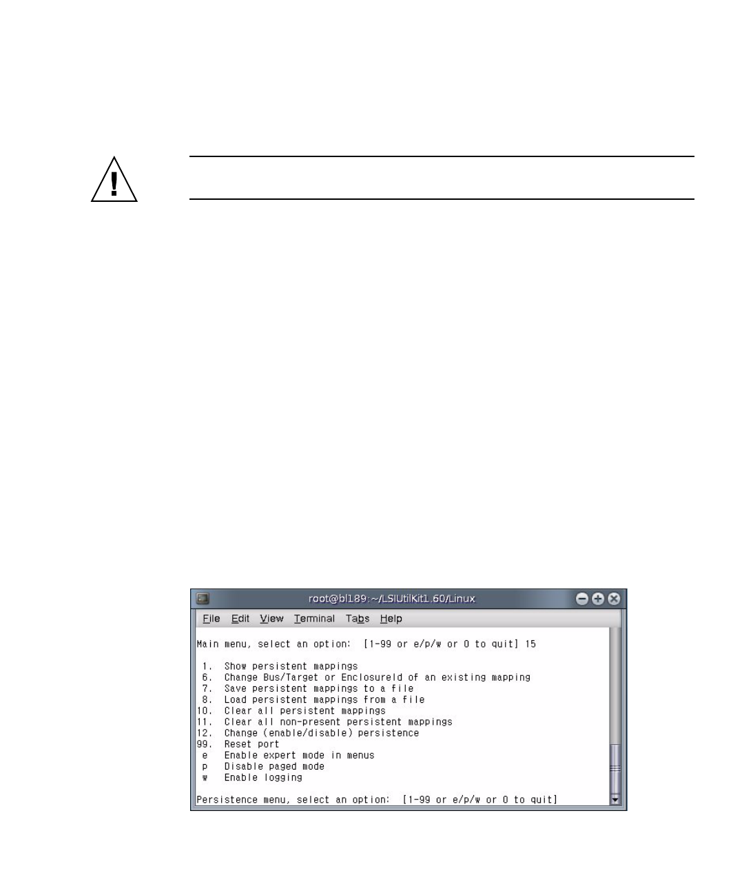
7. Type 15 and press Enter.
The Persistence menu opens.

3-6 Sun Blade 6000 Disk Module Service Manual • June 2009
8. Type 10 and press Enter.
This clears any persistence map that is present in the host bus adapter.
9. Type and enter 0(zero) three times to exit the lsiutil application.
3.1.2 To Replace a Disk Blade When Its Paired Server
Uses an Adaptec Host Bus Adapter
The Adaptec host bus adapters do not rely on the enclosure ID of the disk blade to
identify disks. This is true for any OS.
Therefore, if you are using an Adaptec adapter, you can simply change the disk
module and continue to operate as before without any problems.
4-1
CHAPTER 4
Replacing a Host Bus Adapter
This chapter contains information and procedures for replacing an LSI host bus
adapter.
The following topics are covered in this chapter:
■Section 4.1 “LSI Host Bus Adapter Failure and Replacement” on page 4-1
■“To Replace the LSI Host Bus Adapter on an x64 Server Blade Running Linux or
Windows” on page 4-2
■“To Replace the LSI Host Bus Adapter on Any Server Blade Running the Solaris
OS” on page 4-2
■“To Replace an Adaptec Host Bus Adapter” on page 4-4
Caution – The service procedures in this chapter require the use of a program
named lsiutil. The lsiutil application has many features and capabilities.
Executing certain combinations of commands can place your system in an
unrecoverable state. When you use this application, be sure you execute the
procedures exactly as they are documented here, command by command. Do not
skip commands or steps and do not add commands or steps that are not in the
documented procedure.
4.1 LSI Host Bus Adapter Failure and
Replacement
If an LSI host bus adapter fails, you must replace it. In the case of the Sun Blade
X6220 and T6300 server blades, the host bus adapter is embedded in the server blade
so you must replace the entire blade. For other server blades that use a Sun Blade
RAID 0/1 Expansion Module (REM), you need to replace the REM.

4-2 Sun Blade 6000 Disk Module Service Manual • June 2009
Note – The procedures below are equally valid whether you are replacing a REM or
a server blade with an embedded adapter.
▼To Replace the LSI Host Bus Adapter on an x64
Server Blade Running Linux or Windows
1. Remove the server blade that contains the damaged host bus adapter.
2. Replace the host bus adapter (or the entire blade for X6220 servers) and reinsert
the server blade.
3. Boot an OS.
There are two possibilities:
■(Preferred method in all cases) Boot from an external source. Use a bootable
thumb drive or a network boot.
■If the OS is installed on the server blade (on a single disk in the server blade or
in a RAID volume where at least one of the member disks is in the server
blade), you can boot from the server’s boot drive. If the boot drive is a RAID
volume, during the BIOS boot process you must activate the RAID volume
using the LSI RAID configuration utility (see Section A.1 “Activating LSI RAID
Volumes” on page A-1).
4. During the BIOS boot process, enter the LSI RAID configuration utility and
activate all foreign RAID volumes. (see Section A.1 “Activating LSI RAID
Volumes” on page A-1).
▼To Replace the LSI Host Bus Adapter on Any
Server Blade Running the Solaris OS
Prerequisites:
■You must have a saved snapshot of your old host bus adapter’s persistence table
and the snapshot file must be available to the OS that you boot initially.
■The OS that you boot initially in the following procedure must have the lsiutil
application installed.
1. Remove the server blade that contains the damaged host bus adapter.
2. Make sure that there is a SAS-NEM in slot NEM 0 and that it is functioning
properly (the Fault LED is off).
Chapter 4 Replacing a Host Bus Adapter 4-3
Caution – Make sure that multipathing at the OS level is enabled on all server
blades that remain active in the chassis before you execute step 3. This ensures that
the primary path to disks is not lost, which can cause an OS panic.
For servers running Windows 2003, which does not support multipathing, shut
down IO to all disks on the disk module that are not in hardware RAID volumes.
3. Remove the SAS-NEM in slot NEM 1, if there is one.
This step is required to make RAID volumes return with the same target ID.
Note – If you have a plain NEM, without SAS capability, in slot NEM 1 you can
leave it there.
Caution – Unplugging the SAS-NEM causes the loss of all secondary network
connections and the secondary paths to SAS disks.
4. Replace the host bus adapter (or the entire blade for X6220 and T6300 servers)
and reinsert the server blade.
5. Boot an OS.
There are two possibilities:
■Boot from an external source. Use a bootable thumb drive (x64 only) or a net
boot.
■If the OS is installed on the server blade (on a single disk in the server blade or
in a RAID volume where at least one of the member disks is in the server
blade), you can boot from the server’s boot drive. If the boot drive is a RAID
volume, during the BIOS boot process you must activate the RAID volume
using the LSI RAID configuration utility (see Section A.1 “Activating LSI RAID
Volumes” on page A-1).
6. Run lsiutil in interactive mode (see “To Restore a Snapshot of Your Host Bus
Adapter Persistent Mappings” on page B-11). Type 1and press Enter to open the
main menu.
7. Type 15 on the main lsiutil menu, "Change persistent mappings," and press
Enter.
The persistence menu opens.
8. Type 8, "Load persistent mappings from a file," and press Enter.
It prompts you for the filename.

4-4 Sun Blade 6000 Disk Module Service Manual • June 2009
9. Enter the filename and path of your saved snapshot file.
The persistent map is loaded into the new blade.
10. Reboot the server blade with its own OS.
Rebooting the blade causes it to use the persistent mapping information.
11. Activate all RAID volumes (see Section A.1 “Activating LSI RAID Volumes” on
page A-1).
At this point, the blade has been replaced, and all drives and RAID volumes have
been configured correctly, thus the blade will be able to boot the OS.
12. Reinsert the Multi-Fabric NEM in slot NEM 1.
4.2 Replacing an Adaptec Host Bus Adapter
The procedure outlined for LSI host bus adapters is not needed for Adaptec host bus
adapters.
▼To Replace an Adaptec Host Bus Adapter
1. Install the new RAID 5 Expansion Module.
2. Power on the server blade.
3. During boot the Adaptec configuration utility indicates that foreign arrays
(volumes) are found.
4. Press Enter to accept the configuration change.
The boot process continues. No further steps are required.
A-1
APPENDIX A
Activating LSI RAID Volumes
When you need to activate an LSI RAID volume, you must temporarily remove the
path through a SAS-NEM module in slot NEM 1.
This is required to make RAID volumes return with the same target ID that they had
previously.
A.1 Activating LSI RAID Volumes
▼To Do Before Activating an LSI RAID Volume:
1. Make sure that there is a SAS-NEM in slot NEM 0 and that it is functioning
properly (the Fault LED is off).
Caution – Make sure that multipathing at the OS level is enabled on all server
blades that remain active in the chassis before you execute step 2. This ensures that
the primary path to disks is not lost, which can cause an OS panic.
For servers running Windows 2003, which does not support multipathing, shut
down IO to all disks on the disk module that are not in hardware RAID volumes.
2. Unplug the Multi-Fabric NEM in slot NEM 1 if there is one.
Note – If you have a plain NEM, without SAS capability, in slot NEM 1 you can
leave it there.
A-2 Sun Blade 6000 Disk Module Service Manual • June 2009
Caution – Unplugging one SAS-NEM causes the loss of all secondary network
connections and the secondary paths to SAS disks.
Activate the RAID volumes by following one of these procedures:
■“To Activate LSI RAID Volumes for x64 Server Blades” on page A-2
■“To Activate LSI RAID Volumes for SPARC Server Blades” on page A-3
When you have finished activating the RAID volumes, plug the SAS-NEM back
into slot NEM 1, if you previously unplugged it.
▼To Activate LSI RAID Volumes for x64 Server
Blades
The LSI RAID configuration utility that is entered from the server’s BIOS is valid for
all x64 server blades and all supported operating systems.
1. Power-cycle your server module. The BIOS screen appears. Watch for the LSI
Logic Corp. screen, soon after the opening screen.
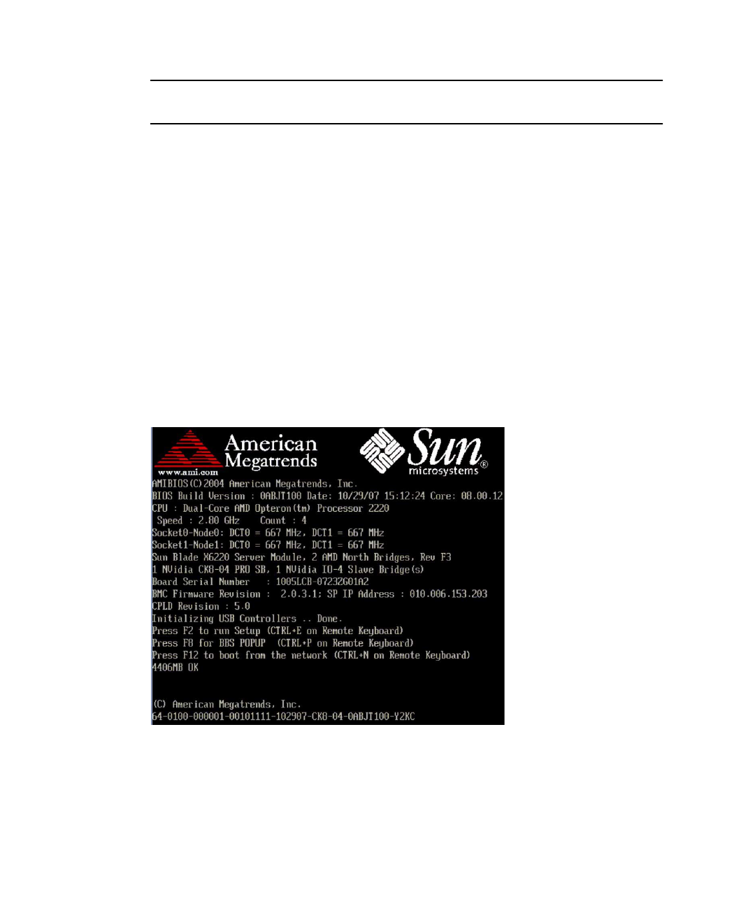
2. When the BIOS screen shows the LSI Logic Corp. message, press Ctrl-C to start
the LSI Logic Configuration Utility.
Appendix A Activating LSI RAID Volumes A-3
The first screen of the utility appears after a short delay.
3. With the LSI 1068E adapter highlighted in the first screen, press Enter.
The main screen of the utility opens.
4. Use the arrow keys to select RAID Properties and press Enter.
If you have only one array, you get a new screen with a View Existing Array
option.
5. With View Existing Array highlighted, press Enter.
The View Array screen appears.
Note – If you have two RAID arrays (volumes) you come directly to this View
Array screen when you select and enter RAID Properties in Step 4.
6. With Manage Array highlighted, press Enter.
7. Use the arrow keys to select Activate Array and press Enter.
8. Return to the View Existing Array screen and press Alt + N to select your other
array (if there is one)
9. Repeat steps 6 and 7 for your second array (volume), if there is one.
10. Exit the LSI RAID configuration utility by pressing Esc repeatedly to go back
screen by screen until you can continue the boot process.
▼To Activate LSI RAID Volumes for SPARC
Server Blades
1. Go to the OBP prompt.

A-4 Sun Blade 6000 Disk Module Service Manual • June 2009
2. At the command line, set the auto-boot? and fcode-debug? variables to
false and reset the system.
ok setenv auto-boot? false
auto-boot? = false
ok setenv fcode-debug? true
fcode-debug? = true
ok reset-all
3. Find the path to the controller.
ok show-disks
a) /pci@0/pci@0/pci@2/LSILogic,sas@0/disk
b) /pci@0/pci@0/pci@1/pci@0/usb@1,2/storage@1/disk
q) NO SELECTION
Enter Selection, q to quit: q
ok
Note – You are looking for the path to the controller. For the T6320 and T6340
blades it contains the phrase “LSILogic,sas@0”. For the T6300 blade, it contains
the phrase “scsi@0“.
4. Select the controller.
ok select /pci@0/pci@0/pci@2/LSILogic,sas@0
5. Show the volumes, looking for any that are inactive.
ok show-volumes
6. Activate the inactive volumes. Repeat the command to activate all inactive
volumes. For example, to activate volume number 1 type:
ok 1 activate-volume
Note – There might be more than two inactive RAID volumes, but you cannot
activate more than two.
7. Deselect the controller.
ok unselect-dev

Appendix A Activating LSI RAID Volumes A-5
8. Set the auto-boot? and fcode-debug? variables to true and reset the
system.
ok setenv auto-boot? true
auto-boot? = true
ok setenv fcode-debug? true
fcode-debug? = true
ok reset-all

A-6 Sun Blade 6000 Disk Module Service Manual • June 2009
B-1
APPENDIX B
Using the lsiutil Software
Some procedures in this manual require the use of a software program called
lsiutil. This appendix provides information on where to obtain the software and
how to use it.
Caution – The lsiutil software has many features and capabilities. Executing
certain combinations of commands can leave your system in an unrecoverable state.
When you use this software, be sure you execute the procedures exactly as they are
documented here, command by command. Do not skip commands or steps and do
not add commands or steps that are not in the documented procedure.
The following topics are covered in this chapter:
■Section B.1 “Where to Obtain the lsiutil Software” on page B-1
■Section B.2 “Installing lsiutil” on page B-2
■“To Use lsiutil From the Command Line” on page B-2
■“To Use the Interactive lsiutil Menus” on page B-2
■Section B.3 “Why Save LSI Host Bus Adapter Persistent Mappings?” on page B-6
■Section B.4 “When to Save LSI Host Bus Adapter Persistent Mappings” on
page B-6
■“To Save a Snapshot of Your Host Bus Adapter Persistent Mappings” on page B-7
■“To Restore a Snapshot of Your Host Bus Adapter Persistent Mappings” on
page B-11
B.1 Where to Obtain the lsiutil Software
To use lsiutil for the procedures in this appendix, you must have version 1.60 at
minimum.
B-2 Sun Blade 6000 Disk Module Service Manual • June 2009
To obtain the latest lsiutil software, go to the disk blade download site:
(http://www.sun.com/servers/blades/downloads.jsp#6000dm)
B.2 Installing lsiutil
Download lsiutil and unzip it in a temporary directory. It will create operating
system-specific subdirectories. If you are running lsiutil on a SPARC blade, use
the Solaris subdirectory. Otherwise, use the Solaris x86 subdirectory.
▼To Use lsiutil From the Command Line
Several of the procedures in this appendix use the lsiutil software at the
command line.
Caution – To avoid harm to your system, you must use the commands exactly as
they are presented in this document.
To run an lsiutil command from the command line, log in as root and then
follow these steps:
1. Change to the directory where you extracted the lsiutil zip file. For example,
#cd directoryname
2. Change to the subdirectory for your operating system. For example:
#cd Solaris x86
3. Change the permissions (read and execute access) on the lsiutil file by entering
the following command:
#chmod 755 lsiutil
4. Enter the command with parameters. For example,
#./lsiutil -p1 -a 0 8
▼To Use the Interactive lsiutil Menus
To open the interactive lsiutil menus, log in as root and then follow these steps:
Appendix B Using the lsiutil Software B-3
1. Change to the directory that contains the appropriate version of lsiutil for
your application. For example,
#cd directoryname/Solaris x86
2. If you have not done so already, change the permissions (read and execute
access) on the lsiutil file by entering the following command:
#chmod 755 lsiutil
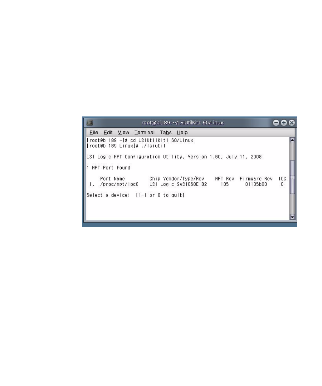
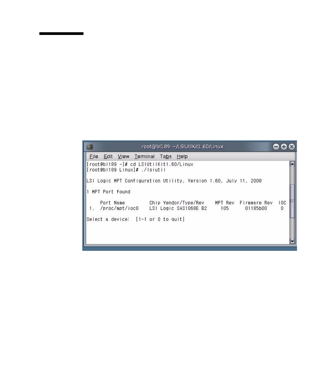
3. Start lsiutil by entering the command:
#./lsiutil
The opening screen appears.
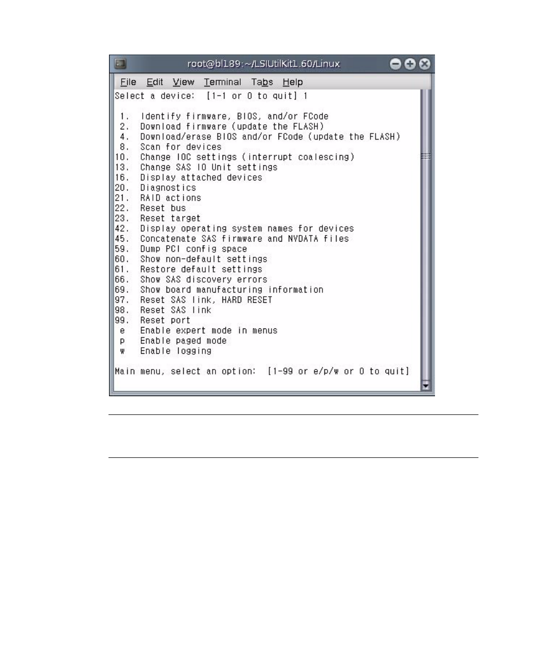
4. Type 1and press Enter.
The main menu appears. Because there are so many menu items (100), not all the
items are shown.
B-4 Sun Blade 6000 Disk Module Service Manual • June 2009
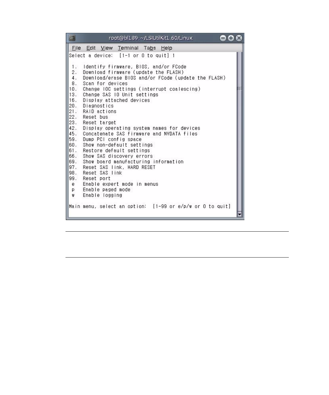
Tip – You do not have to see a command to enter it. If you know its number, just
enter it. Alternatively, you can choose to see the entire menu if you want to, as
shown in Step 4.
5. Enter pto enable paged mode and eto enable the whole menu.
The complete menu appears in paged mode.
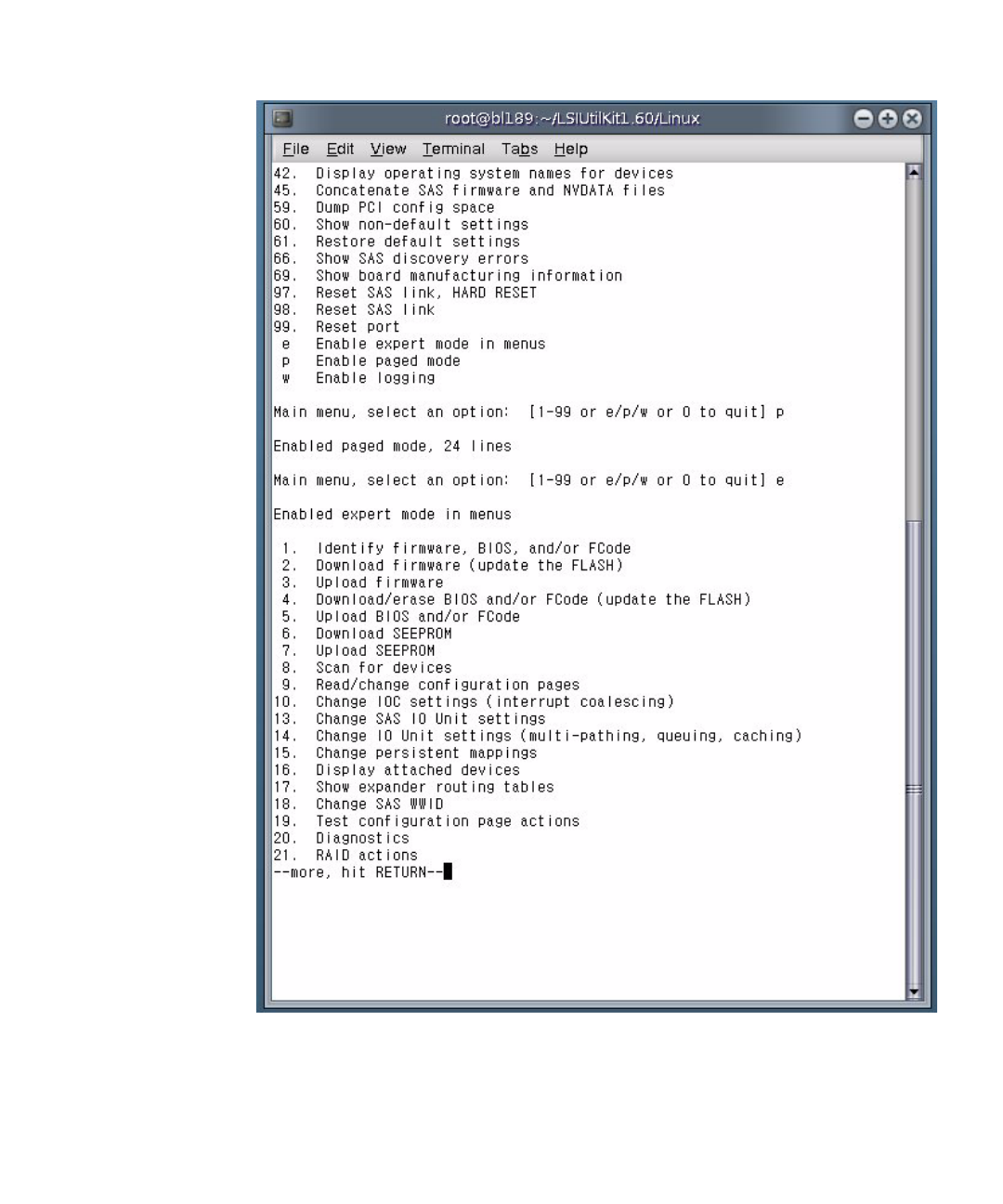
Appendix B Using the lsiutil Software B-5
Each time you press Enter you will see a new page of menu items until you reach
the end.
B-6 Sun Blade 6000 Disk Module Service Manual • June 2009
B.3 Why Save LSI Host Bus Adapter
Persistent Mappings?
Replacing a failed LSI host bus adapter on a server blade running the Solaris OS can
lead to significant downtime if your replacement adapter does not know how the
old adapter was addressing the disks in its server blade and in the disk blade.
Among other problems, your system will not know where your boot drive is located.
The lsiutil software is used to export a snapshot of the addressing configuration
(persistent mappings) of a healthy LSI host bus adapter to a file. Then, if the adapter
fails at a later date, the persistent mappings snapshot can be reloaded on the
replacement adapter and your system will operate as before.
Caution – You need to keep a persistent mappings snapshot for the LSI host bus
adapters on all server blades in your chassis that are running the Solaris OS. A copy
of each file must be kept on external media.
B.4 When to Save LSI Host Bus Adapter
Persistent Mappings
You need to keep a snapshot of the persistent mappings of your LSI host bus
adapters under any of these conditions:
■A new server blade, running the Solaris OS and paired with a disk blade, has
been added to the chassis.
Make the snapshot of the LSI host bus adapter on this server blade after you have
completed its installation and configuration. This means after you have finished
creation of RAID volumes and chosen a boot volume or disk.
■You have replaced a disk blade in the chassis that is paired with a server blade
running the Solaris OS.
Make the snapshot of the LSI host bus adapter on this server blade after you have
replaced the disk blade.
■You have replaced a SAS-NEM in your chassis and the chassis contains server
blades running both CAM (or a CAM agent) and the Solaris OS.
Make the snapshot of the LSI host bus adapter on these server blades after you
have replaced the SAS-NEM
Appendix B Using the lsiutil Software B-7
B.5 Saving and Restoring a Persistence Map
You can use lsiutil to both save and restore a snapshot of your persistence
mapping.
▼To Save a Snapshot of Your Host Bus Adapter
Persistent Mappings
1. Run lsiutil in interactive mode (see “To Use the Interactive lsiutil Menus”
on page 2).
2. Type 1and press Enter.
The basic (incomplete) interactive menu opens.
B-8 Sun Blade 6000 Disk Module Service Manual • June 2009
Tip – You cannot see all the commands in the menu, but you can enter any
command number if you know what it is. In this case you want to open the
Persistence menu. This is done with command 15.
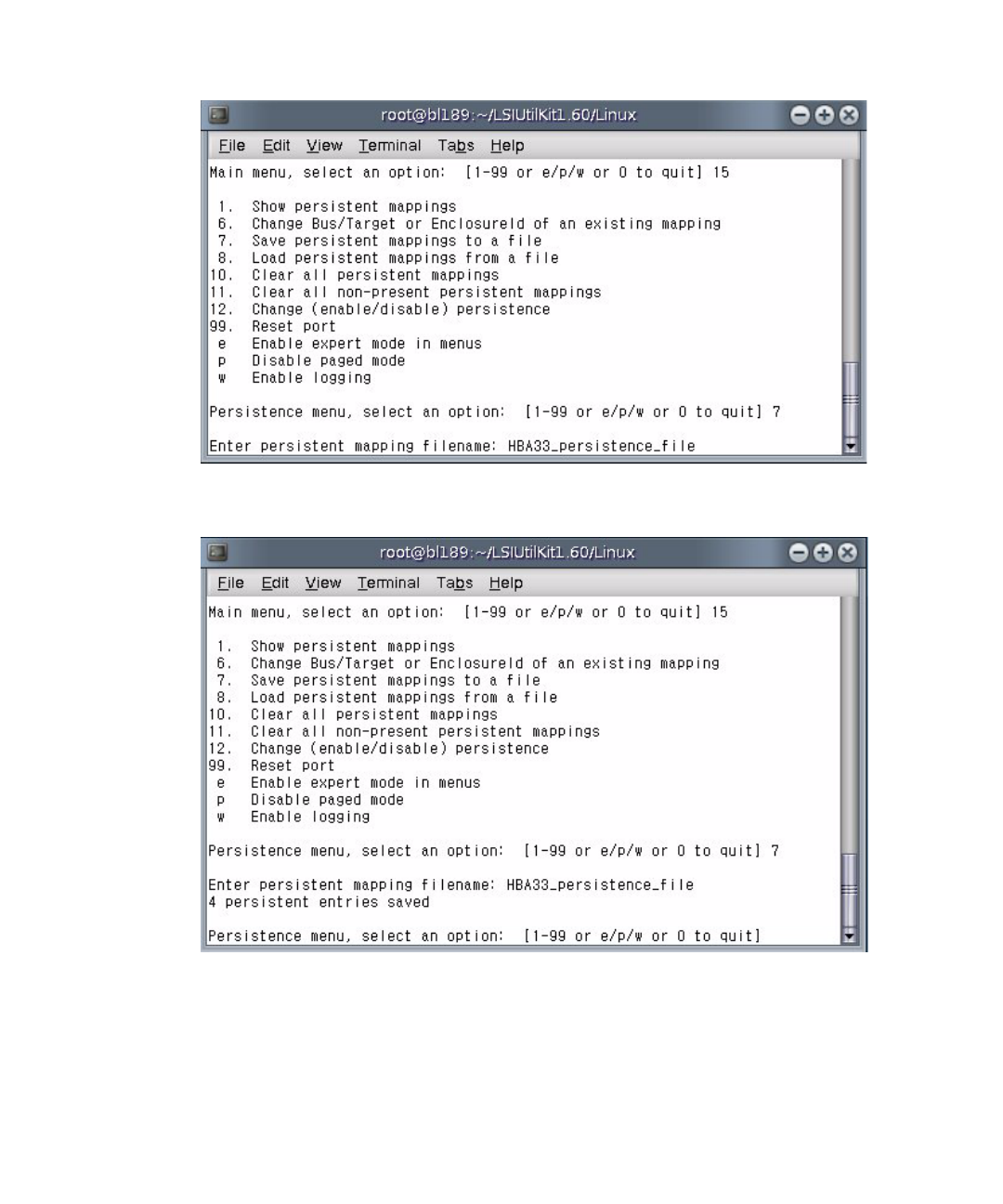
3. Type 15 and press Enter.
The Persistence menu opens.
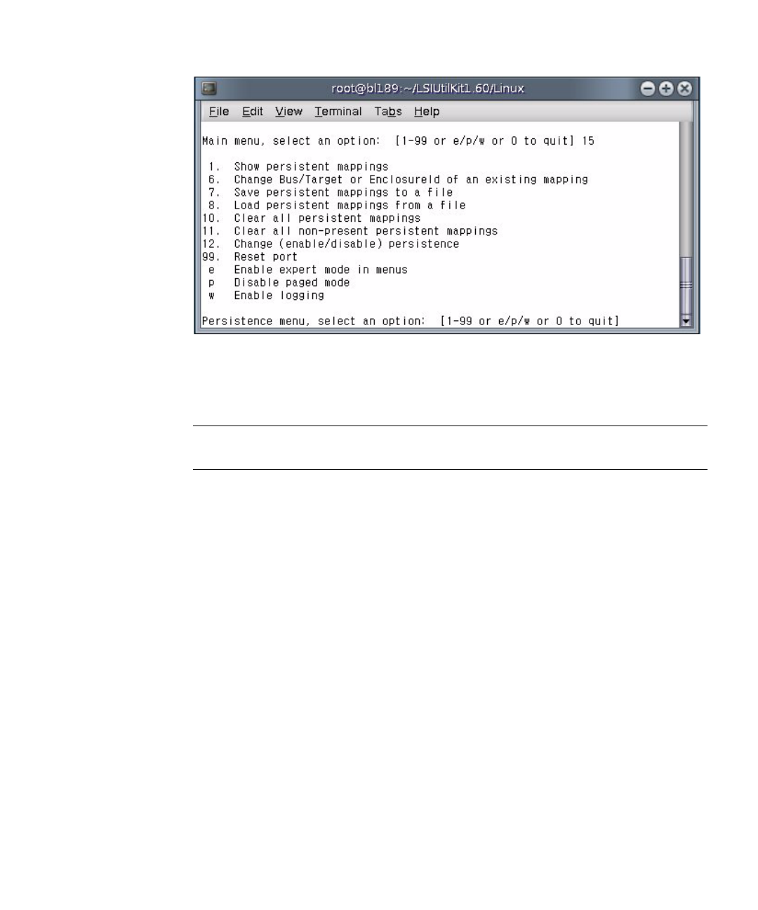
Appendix B Using the lsiutil Software B-9
4. Type 7and press Enter.
You are prompted for the name of the file where you want to store the host bus
adapter persistent mappings snapshot.
Note – If you expect to boot from DOS when you restore the persistent mappings
snapshot, you must restrict the file name to 8 characters.
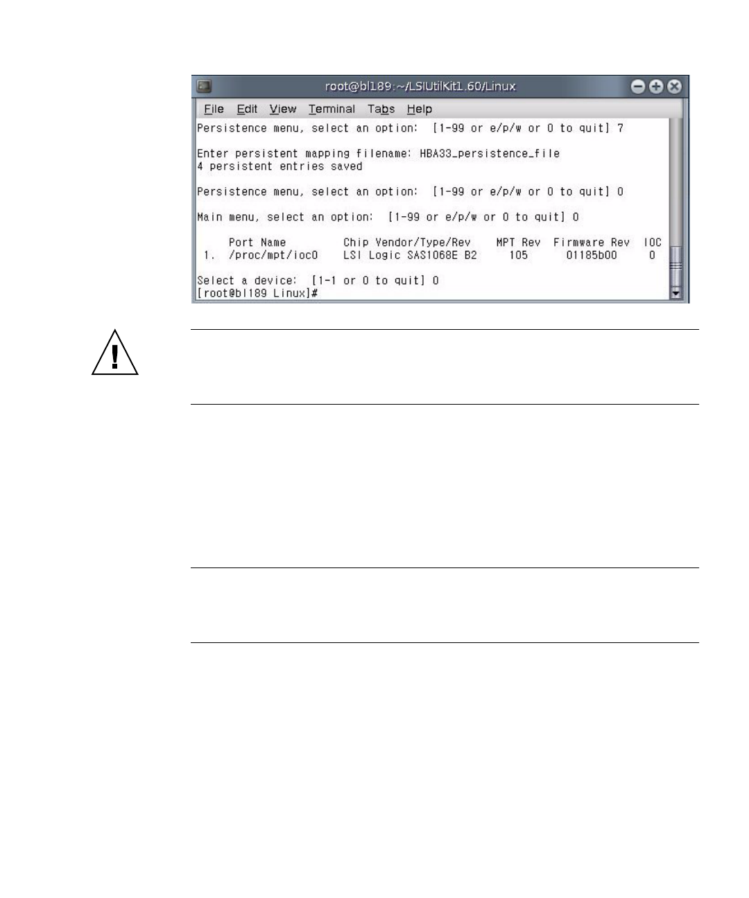
5. Enter a file name. For example, HBA33_persistence_file.
B-10 Sun Blade 6000 Disk Module Service Manual • June 2009
The file is saved to the current directory. lsiutil confirms this by displaying a
statement of the number of persistent entries saved.
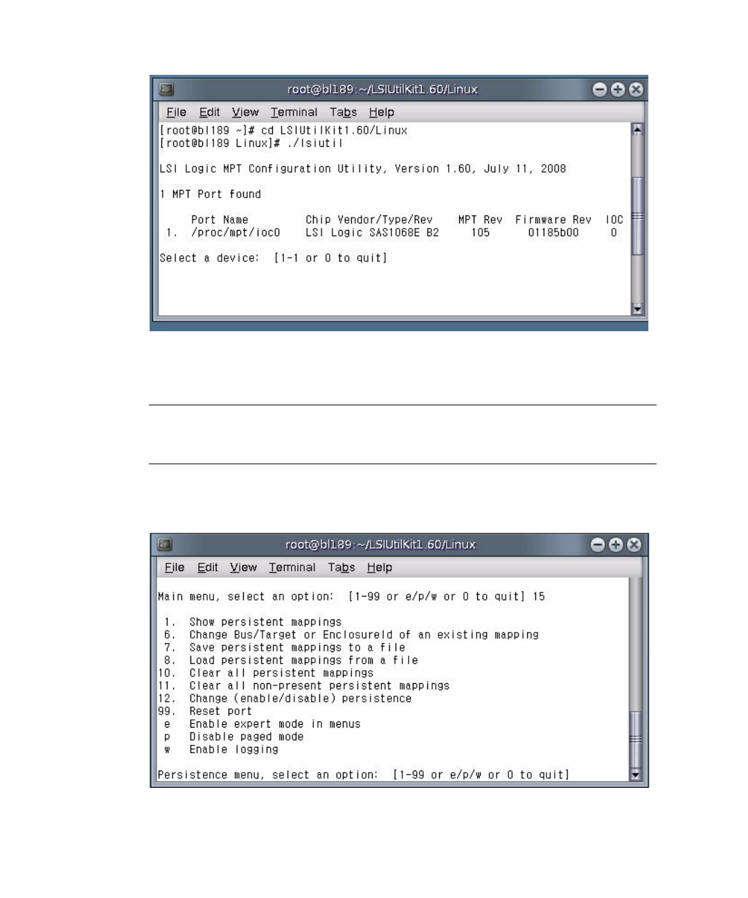
6. Type 0(zero) and press Enter three times to exit lsiutil.
Appendix B Using the lsiutil Software B-11
Caution – You must save the persistence table snapshot to external media as you
will not be able to reinstall it from a local disk if your LSI host bus adapter fails.
You must have a snapshot for every server blade in the chassis. Label them carefully.
▼To Restore a Snapshot of Your Host Bus Adapter
Persistent Mappings
The stored snapshot files are used when a host bus adapter fails and must be
replaced. They are not needed for any other purpose.
Note – Unless your OS is installed on a single disk on your server blade, or a RAID
volume with at least one member disk installed on your server blade (always true
for SPARC systems, for example), you need to reboot with an external OS (a bootable
DOS disk is preferred, if possible) to perform this procedure.
To restore the persistent mappings from a previously saved snapshot file (for
example, HBA33_persistance_file), do the following:
1. Make sure that your saved the persistence mappings snapshot file in the same
directory as the lsiutil software you are using. Copy the file from external
media if necessary.
2. Run lsiutil in interactive mode (see “To Use the Interactive lsiutil Menus”
on page B-2).
B-12 Sun Blade 6000 Disk Module Service Manual • June 2009
3. Type 1and press Enter.
The basic (incomplete) interactive menu opens.
Tip – You cannot see all the commands in the menu, but you can enter any
command number if you know what it is. In our case we want to open the
Persistence menu. This is done with command 15.
4. Type 15 and press Enter.
The Persistence menu opens.
Appendix B Using the lsiutil Software B-13
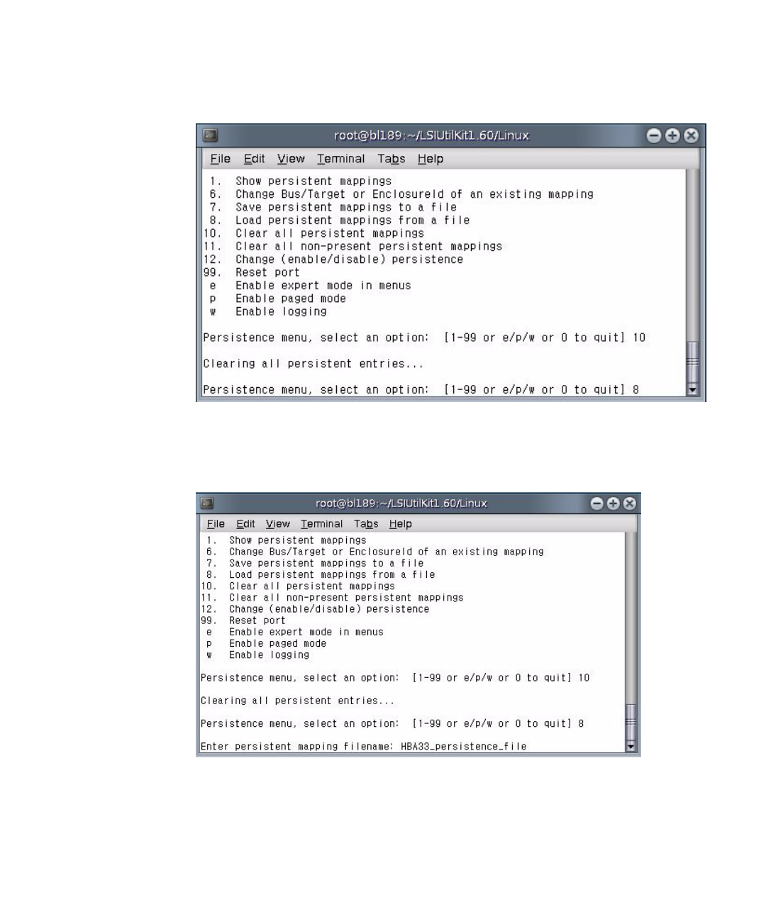
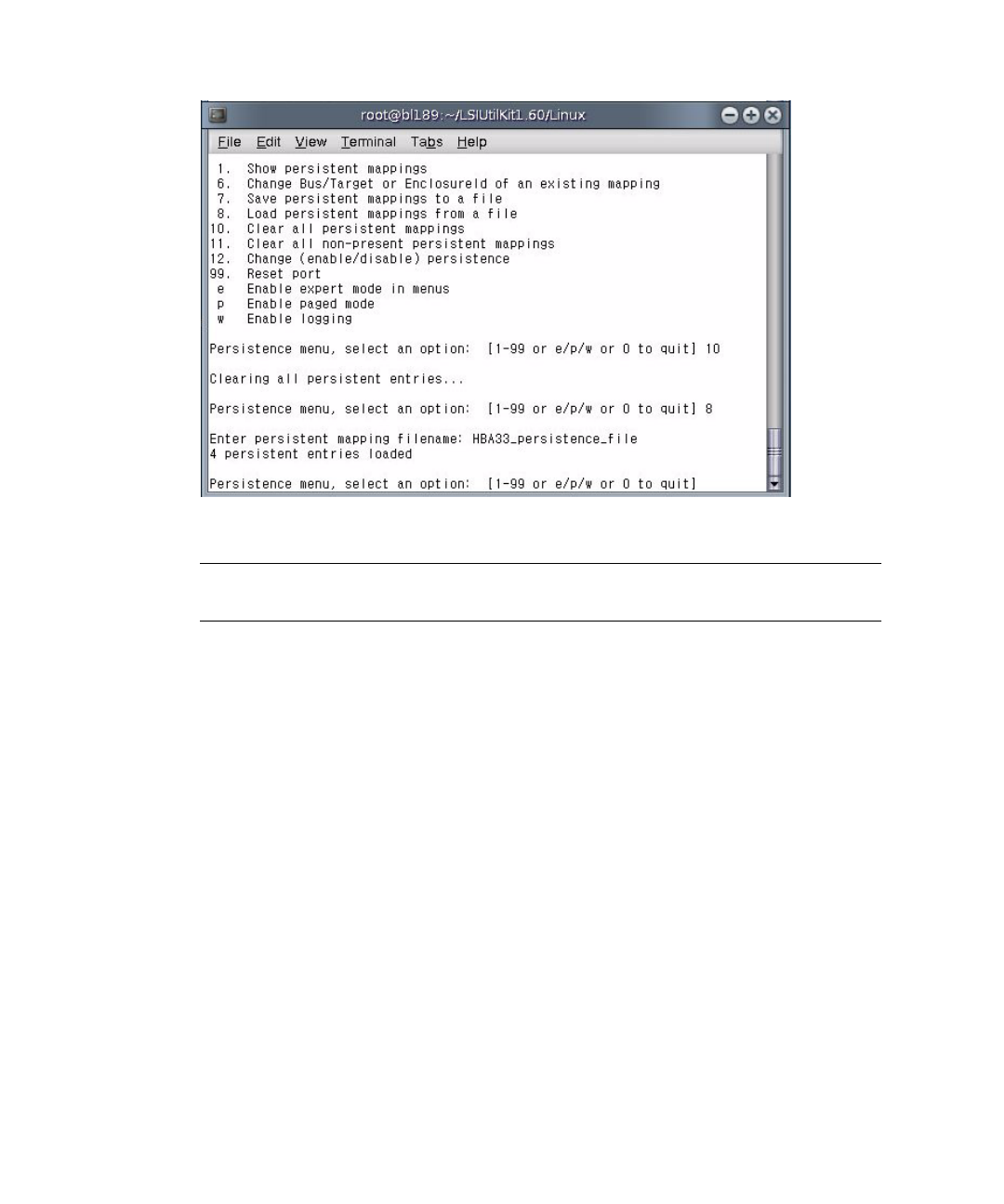
5. Type 10 and press Enter.
This clears any persistence map that is present in the host bus adapter.
6. Type 8 and press Enter.
You are prompted for the name of a persistent mappings snapshot file to load.
Type the name of the snapshot file. For example, HBA33_persistence_file.
7. Press Enter.
The persistence map is loaded. lsiutil confirms that four persistence entries
were loaded.
B-14 Sun Blade 6000 Disk Module Service Manual • June 2009
8. Type 0(zero) and press Enter three times to exit lsiutil.
Note – The adapter persistent mappings snapshot file you just loaded is still valid.
Make sure that you save a copy of it on external media.

Index-1
Index
A
activating LSI RAID volumes for SPARC server
blades, A-3
activating LSI RAID volumes for x64 server
blades, A-2
Adaptec host bus adapter
replacing, 4-4
C
comments and suggestions, -vii
CRU, 1-5
D
disk drive status LEDs, 1-5
disk drives
replacing, 2-1
status LEDs, 2-1
disk module replacement, 3-6
documentation, related, -vi
F
feature summary, 1-1
figures
Interior of the Sun Blade 6000 Disk Blade, 1-3
Removing the Disk Drive After Removing the
Disk Module, 2-3
Removing the Disk Drive Without Removing the
Disk Module, 2-3
Sun Blade 6000 Disk Module Front Panel, 1-4
front panel LEDs, 1-4
front panel LEDs and buttons, 1-3
FRU, 1-5
H
host bus adapter replacement
Adaptec, 4-4
LSI, 4-1
I
indicators See LEDs
L
LEDs
disk drive status, 1-5, 2-1
front panel, 1-4
locate, 1-4
module activity, 1-5
service action required, 1-4
locate LED and button, 1-4
LSI host bus adapter
failure and replacement, 4-1
replacing on an x64 server blade running Linux
or Windows, 4-2
replacing on any server blade running the Solaris
OS, 4-2
LSI host bus adapters
restoring a snapshot of your persistent
mappings, B-11
saving a snapshot of your persistent
mappings, B-7
why save a snapshot of your persistent
mappings, B-6
lsiutil

Index-2 Sun Blade 6000 Disk Module Service Manual • June 2009
installing, B-2
using from the command-line, B-2
using the interactive menus, B-2
where to obtain the software, B-1
M
module activity LED, 1-5
P
persistent mappings
restoring a snapshot for your LSI host bus
adapters, B-11
saving a snapshot for your LSI host bus
adapters, B-7
why save a snapshot for your LSI host bus
adapters, B-6
persistent mappings snapshot
when to save, B-6
physical specifications, 1-2
R
RAID volume activation
SPARC server blades, A-3
unplugging SAS-NEM 1, A-1
x64 server blades, A-2
related documentation, -vi
replacing a disk module
for server blades using Adaptec host bus
adapters, 3-6
for server blades using LSI host bus adapters, 3-
2
recovering from a failed lsiutil command,3-
4
S
safety guidelines, -v
server features list, 1-1
service action required LED, 1-4
specifications, 1-1
summary of features, 1-1
