831_014_BA_LT50_EN_12_03_2014 831014_20140312_LT50_BA_EN 831014 20140312 LT50 BA EN
User Manual: 831014_20140312_LT50_BA_EN
Open the PDF directly: View PDF ![]() .
.
Page Count: 12
Date: 12.03.2014
ESchaudt GmbH, Elektrotechnik und Apparatebau, Planckstraße 8, 88677 Markdorf, Germany, Tel. +49 7544 9577-0, Fax +49 7544 9577-29, www.schaudt--gmbh.de
831.014 BA / EN
Instruction Manual
LT 50 Control Panel
Table of contents
1 Purpose 2...............................................
2 Layout 3................................................
3 Operation 3..............................................
3.1 Switching on and off the 12V supply for the leisure area 3......
3.2 Switching on and off the 12V supply
of different consumers 4...................................
3.3 Displays 5...............................................
3.4 Shutting down 7..........................................
4 Alarms and faults 8.......................................
4.1 Alarms 8................................................
4.2 Faults 9.................................................
5 Technical details 10........................................
6 Maintenance 10...........................................
7 Cleaning 10...............................................
Instruction Manual for LT 50 Control Panel
2Date: 12.03.2014 831.014 BA / EN
1 Purpose
The LT 50 control panel is the central control and display device for the 12V supply and
charging system within the vehicle.
These operating instructions contain important information on the safe operation of devices
from Schaudt and should be kept in the vehicle at all times.
EBL .../
+--
+--
LT 50 control panel
Electroblock
230V AC
12V consumers
Leisure battery
Starter battery
Lighting
Pump
Heater
etc.
LR ...
Solar regulator
(accessory)
LAS ...
Additional charger
(accessory)
Solar cell
(accessory)
Power supply
CSV... Water tank
Waste water
tank
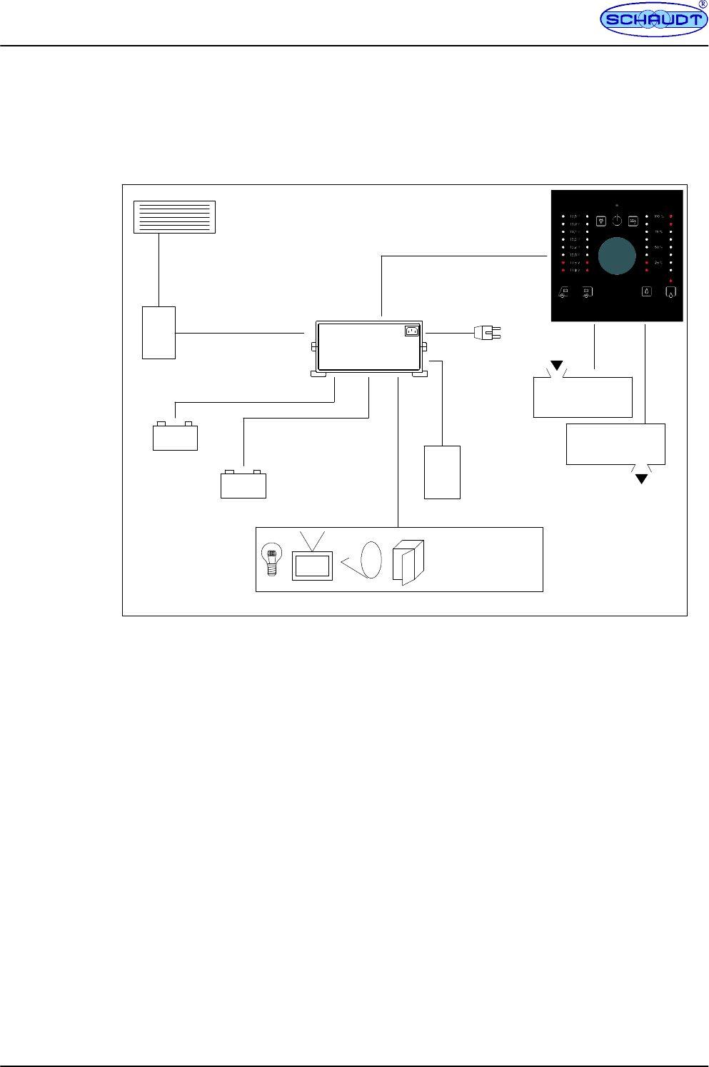
Fig. 1 12V on-board bus charging and supply system
FLT 50 control panel
FEBL ... electroblock (for motorhomes) or CSV... power supply (for caravans)
FSensors and/or probe for water tank
FSensors or probe for waste water tank
FOther potential accessory devices
System
devices
Instruction Manual for LT 50 Control Panel
3
Date: 12.03.2014
831.014 BA / EN
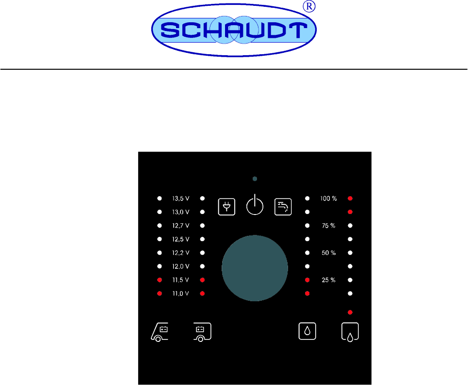
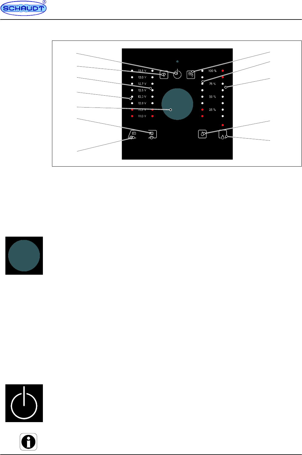
2 Layout
5
2
3
7
6
1
4
9
10
11
8
12
Fig. 2 LT 50 layout
1 ”12V ON” symbol 7 ”Starter battery” symbol
2 ”Mains indicator” symbol 8 ”Water pump” symbol
3 ”Leisure battery voltage” LED scale 9 ”Water tank fill level” LED scale
4 ”Vehicle battery voltage” LED scale 10 ”Waste water tank fill level” LED scale
5 Rotary/press-in encoder 11 ”Water tank” symbol
6 ”Leisure battery” symbol 12 ”Waste water tank” symbol
3 Operation
The only control on the LT 50 is a rotary/press-in encoder. Rotate and press it in to select
displays and run switch functions.
3.1 Switching on and off the 12V supply for the leisure area
The 12V leisure area supply is connected via the encoder.
Exceptions here are consumers requiring constant power when the motorhome or caravan is
being used.
Just which consumers these are depends on the combination used (LT 50/power supply) --
also refer to the operating manual for the EBL ... and CSV ...):
FLT 50 with CSV 410-2 (caravans)
FLT 50 with EBL 208 (motorhome)
FLT 50 with EBL 226 (motorhome)
Briefly press the encoder.
FThe ”12V ON” symbol illuminates -- the 12V supply to the leisure area is on.
If the LT 50 control panel does not respond, either shutdown is active (for EBL 208
and CSV 410-2; see section 3.4 for how to cancel it) or the battery is discharged (fully
charge the battery if required).
If the ”12V ON” and ”Leisure battery” symbols flash 3 times, shutdown is active (see
section 3.4 for how to cancel it).
FThe ”12V ON” symbol goes out -- the 12V supply to the leisure area is switched off.
Switching off is only possible when the ”12V ON” symbol is on.
Switching on
and off
Instruction Manual for LT 50 Control Panel
4Date: 12.03.2014 831.014 BA / EN
3.2 12V supply to the different consumers -- switching on and off
Power to the following consumers can be switched on and off individually:
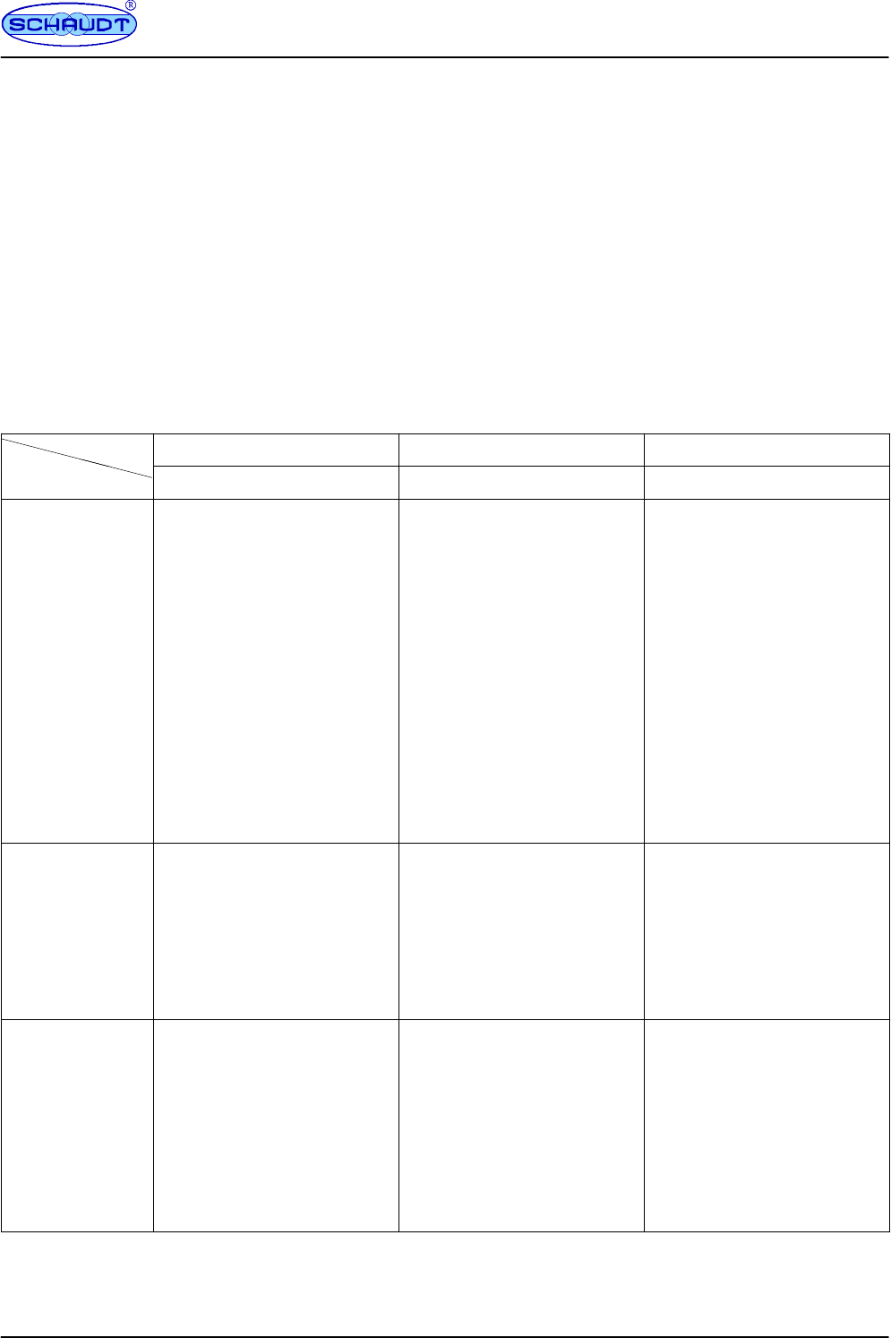
FWater pump
FTank heater
The 12V supply for the leisure area must be switched on for these functions (see section
3.1).
The LT 50 switches to idle mode about 10 seconds after an operation. Lighting up of the re-
levant symbol or LED then indicates the switch states.
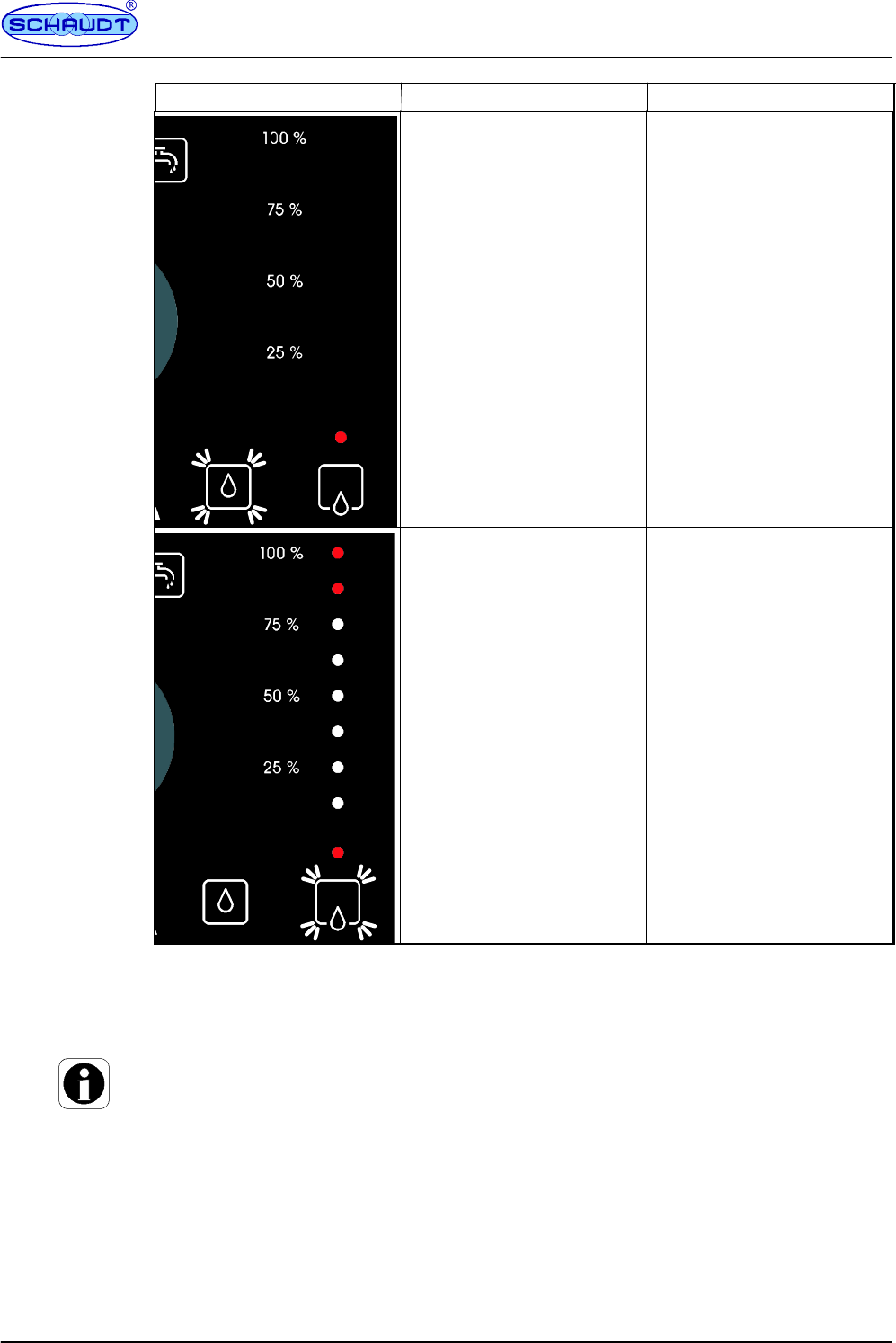
Water pump
Turn the encoder until the fill level of the water tank is displayed on the LED scale.
FThe current switch state is shown by the ”Water tap” symbol.
Press the encoder.
FThe switch state changes (symbol lights or goes out): The 12V supply to the water
pump is switched on/off.
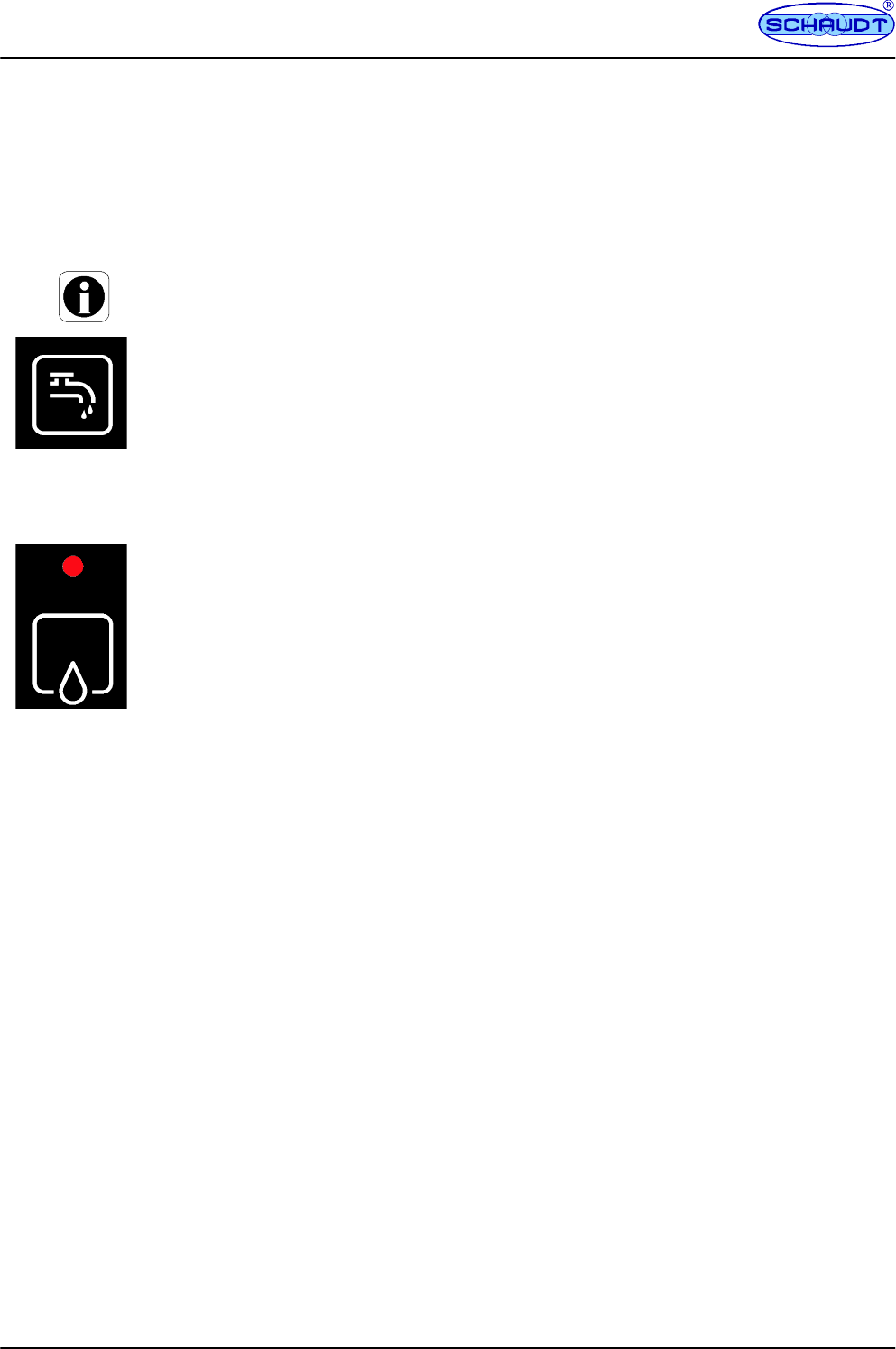
Tank heater, waste water tank
Turn the encoder until the fill level of the waste water tank is displayed on the LED scale.
FThe red LED above the ”Waste water tank” symbol shows the current switch state.
Press the encoder.
FThe switch state changes (LED lights or goes out):
The tank heater is switched on or off.
When the 12V supply to the leisure area is switched off, the power supply for the water
pump is also switched off. The switch state of the ”Waste water tank heater” remains un-
changed (the red LED goes out when the 12V supply is disabled but the tank heater may
remain on).
Instruction Manual for LT 50 Control Panel
5
Date: 12.03.2014
831.014 BA / EN
3.3 Displays
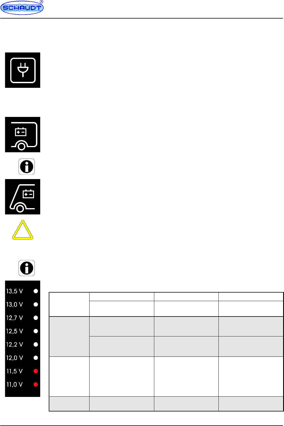
3.3.1 Mains indicator
The ”Mains indicator” symbol lights up when 230V mains voltage is being applied to the 12V
charging system. The batteries are charged.
The display is only shown when the 12V supply for the leisure area is switched on (”12V
ON”).
3.3.2 Battery voltages
The 12V supply for the leisure area must be switched on for the display (see section 3.1).
Turn the encoder until the ”Leisure battery” symbol lights up.
FThe ”Volt” scale lettering lights up.
FThe voltage of the leisure battery is displayed on the LED scale for approx. 20 se-
conds.
The following display function only exists for motorhomes because caravans have no vehicle
battery.
Turn the encoder until the ”Starter battery” symbol lights up.
FThe ”Volt” scale lettering lights up.
FThe voltage of the starter battery is displayed on the LED scale for approx. 20 se-
conds.
CAUTION!
Batteries (regardless of type) can be damaged permanently, possibly beyond repair, when
fully discharged. So therefore:
FAvoid low battery charge (indicated by low voltage)
FCheck the voltage regularly (see section 3.3.2)
It is best to carry out checks in the morning before 12V consumers are switched on.
The following table shows how to correctly interpret the leisure battery voltage.
B
a
t
t
e
r
y
-
Battery operation Mobile operation Mains operation
B
attery-
voltage Vehicle stationary, no
230V connection
Vehicle moving Vehicle stationary,
230V connection
Up to 11V
Risk of total
dischar
g
e
(
see
When consumers are
switched off:
battery flat
The alternator is not
charging the battery
The EBL ... electroblock is
not charging the battery
d
i
s
c
h
a
r
g
e
(
s
e
e
above) When many consumers
are switched on:
possible battery overload
12V vehicle power supply
overloaded
12V vehicle power supply
overloaded
11.5V to 13.2V Normal range 1.
No charging by the
alternator 1)
2.
12V vehicle power supply
overloaded 1)
1.
No charging by the EBL
... electroblock 1)
2.
12V vehicle power supply
overloaded 1)
13.2V and
over
Only occurs briefly after
charging
Battery is charged Battery is charged
1) If the voltage does not exceed this range for several hours.
Instruction Manual for LT 50 Control Panel
6Date: 12.03.2014 831.014 BA / EN
The values specified above apply for running operation, not for the off-load voltage (see be-
low).
Apart from displaying the battery capacity (see section 3.3.2), measuring the off-load voltage
is a simple and effective method of checking the condition of the battery. Off-load voltage is
understood to be the voltage of the charged battery in a passive state, with no current being
supplied or drawn.
Take the measurement several hours after the last charging. No significant load should have
been placed on the battery in the interim period, meaning no current should have been
drawn from it. If the off-load voltage of the battery is less than 12.0V, there is a risk of total
discharge.
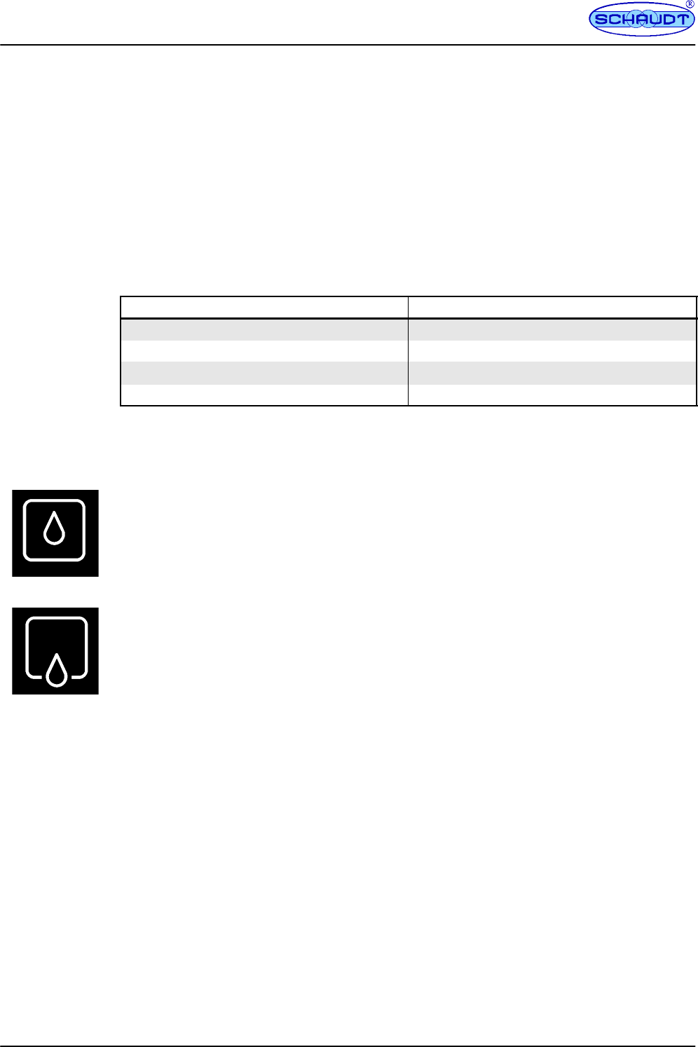
The following table shows the correct interpretation of the off-load voltage displayed. The
values specified apply for Gel batteries.
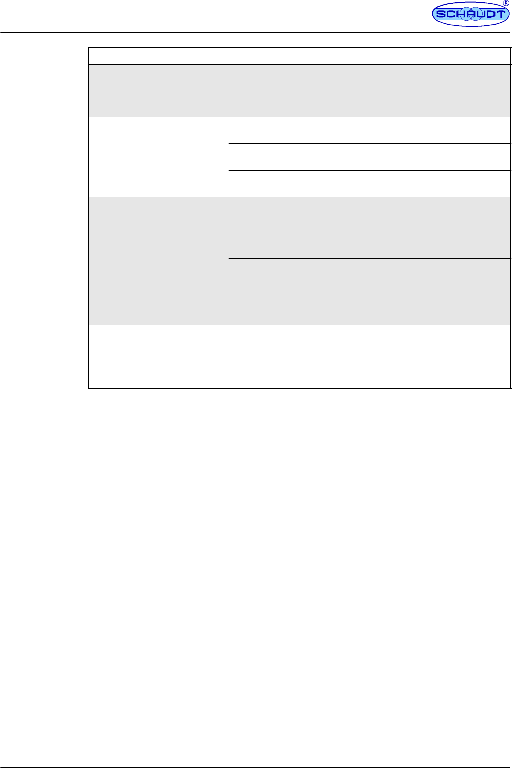
Values for off-load voltage Charge state of the battery
Less than 12V Totally discharged
12.2V Approx. 25%
12.3V Approx. 50%
More than 12.8V Full
3.3.3 Tank fill levels
The 12V supply for the leisure area must be switched on for the display (see section 3.1).
Turn the encoder until the ”Water Tank” symbol lights up.
FThe ”%” scale lettering lights up.
FThe ”Water Tank” symbol lights up (or flashes).
FThe fill level of the water tank is displayed on the LED scale for approx. 20 seconds.
Turn the encoder until the ”Waste Water Tank” symbol lights up.
FThe ”%” scale lettering lights up.
FThe ”Waste Water Tank” symbol lights up (or flashes).
FThe fill level of the waste water tank is displayed on the LED scale for approx. 20 se-
conds.
If the relevant symbol flashes when the fill level of a tank is being displayed, the water tank
is empty (or the waste water tank full).
If the LEDs flash, there is a sensor fault on the relevant tank (see section 4.1).
Off-load
voltage
Instruction Manual for LT 50 Control Panel
7
Date: 12.03.2014
831.014 BA / EN
3.4 Closing down
A shutdown is understood to be the isolation of the 12V charging system and all consumers
from the batteries. Exceptions:
FDevices charging the leisure battery continue to be connected (such as a solar regula-
tor)
The LT 50 control panel is operated at different supply devices. These are the following de-
pending on vehicle model (motorhome or caravan):
FFor caravans:
-- CSV 410-2 caravan power supply
FFor motorhomes:
-- EBL 208 electroblock
-- EBL 226 electroblock
Shutdown and re-enable as follows:
Vehicle Caravan Motorhome Motorhome
Operation on CSV 410-2 EBL 208 EBL 226
LT 50 -- -- Disable 12V supply
Press and keep pressed the
encoder
FSymbols ”Leisure bat-
tery” and ”12V ON” flash
three times after about
10 seconds
FShutdown performed
Cancelling the shutdown:
Press and keep pressed the
encoder
FSymbols ”Leisure bat-
tery” and ”12V ON” flash
three times after about 5
seconds
FShutdown cancelled
F12V supply enabled
Release the encoder
At the relevant
power supply unit
CSV ... / EBL ...
-- Move the ”Battery” battery
isolator on the EBL 208 to
the ”OFF” position
FShutdown performed
Cancelling the shutdown:
Move the ”Battery” battery
isolator on the EBL 208 to
the ”ON” position
FShutdown cancelled
--
On the supply
battery (caravan)
or leisure battery
(motorhome)
Unplug the battery connector
(Molex Minifit SR) on the
CSV, unlatching the side
lock on the connector in the
process.
FShutdown performed
Cancelling the shutdown:
Insert the battery connector
(Molex Minifit SR) on the
CSV.
FShutdown cancelled
-- --
Instruction Manual for LT 50 Control Panel
8Date: 12.03.2014 831.014 BA / EN
4 Alarms and faults
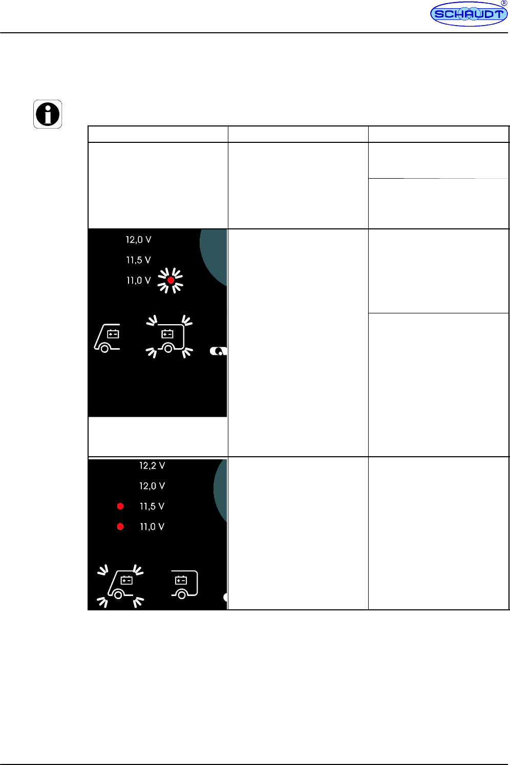
4.1 Alarms
It is best to carry out checks in the morning before 12V consumers are switched on.
Alarm Possible cause Remedy
The LT 50 LED panel
switches off by itself.
The ”11.0V”
L
ED and the
Risk of draining the leisure bat-
tery.
V
olta
g
eo
f
the leisure batter
y
The battery monitor in electro-
block EBL ... automatically swit-
ches off all consumers.
T
h
e
1
1
.
0
V
L
E
D
a
n
d
t
h
e
”Leisure battery” symbol
flashontryingtoswitchon
the LT 50 LED panel (only
EBL 226).
V
o
l
t
a
g
e
o
f
t
h
e
l
e
i
s
u
r
e
b
a
t
t
e
r
y
has fallen below 10.5V. The battery must be charged im-
mediately (see above).
See the electroblock EBL... in-
struction manual. .
When the LT 50 LED panel is
switched on or off:
-- Voltage of the leisure battery
too low (less than 11.0V)
-- Voltage of the leisure battery
has fallen below 11.0V
When the
L
T50
L
ED
p
anel is
Switch off all 12V consumers.
W
h
e
n
t
h
e
L
T
5
0
L
E
D
p
a
n
e
l
i
s
switched off:
-- The LT 50 LED panel, and
hence the 12V supply to the
leisure area, can no longer
be switched on (to protect the
battery) when the leisure bat-
tery voltage is less than
10.5V.
-- The ”11.0V” LED and the
”Leisure battery” symbol flash
on trying to switch on the LT
50 LED panel (only EBL
226).
Charge the battery:
-- Start engine
or
-- connect to 230V power sup-
ply
Not for CSV 410-2:
When the LT 50 LED panel is
switched on or off:
-- Voltage of the starter battery
too low (less than 11.5V)
When the LT 50 LED panel is
switched on and on display of
the ”Starter Battery” voltage:
-- ThetworedLEDs(for
11 ... 11.5V) light up, or only
the lowermost LED (starter
battery voltage less than
11.0V).
Charge the battery:
-- Start engine
or
-- connect to 230V power sup-
ply
Instruction Manual for LT 50 Control Panel
9
Date: 12.03.2014
831.014 BA / EN
Alarm RemedyPossible cause
On display of the ”Water Tank”
fill level:
The water tank is empty
Fill tank.
On display of the ”Waste Water
Tank” fill level:
The waste water tank is full.
Empty tank.
4.2 Faults
A flat battery or defective fuse is the cause of most faults in the 12V system.
For targeted fault location and troubleshooting, the battery must be fully charged and the
system must be connected to the 230V mains supply.
If the leisure battery is discharged, the 12V supply can be re-established by starting the en-
gine.
If fuses are blown: Refer to the instruction manual for the relevant EBL... electroblock for
information on voltage distribution and fusing. .
When it is not possible to rectify a fault based on the following table, please contact Schaudt
customer service (for address, see Page 11).
Start the
engine
Flat vehicle
fuses
Instruction Manual for LT 50 Control Panel
10 Date: 12.03.2014 831.014 BA / EN
Fault Possible cause Remedy
12V supply does not function
(or some areas are not
d
)
12V main switch is switched off. 12V main switch must be
switched on.
powered). Fuse blown. See electroblock EBL...
instruction manual. .
12V indicator LED does not
illuminate.
12V main switch is switched off. 12V main switch must be
switched on.
Leisure battery not charged,
battery monitor has switched off.
Charge the leisure battery.
Fuse blown. See electroblock EBL...
instruction manual. .
Leisure battery is flat. Leisure battery is discharged. Immediately charge the leisure
battery.
The leisure battery is damaged
beyond repair if left totally
discharged for a lengthy period.
The battery can be discharged
by inactive consumers such as
the frost protection valve in the
heater system.
Prior to leaving the motorhome
standing for long periods, fully
charge the living area battery
and use the battery isolator
(also refer to the instruction
manual of the electroblock).
The LED mains indicator does
not illuminate although the 230V
i
l
i
t
d
The mains connection is dead. Check the mains supply (e.g.
camping site).
mains supply is connected. The power cutout to the
electroblock has tripped or is
disabled.
Reset power cutout.
5 Technical details
Dimensions Approx. 120 x 120 x 45 including plug con-
nections and rotary/press-in encoder
Weight Approx. 150 g
Front panel Acryl glass, printed on rear
Colour Black
Storage temperature -- 20C ... 70C
Operating temperature -- 20C ... 50C
Protection rating Front: IP50
Rear: IP00
Humidity Only use in dry environments. Condensation
not permitted.
Operating voltage 12V (10 -- 14.5V), supply via caravan power
supply or electroblock
Fill level reading The fill level reading is only applicable for
plastic water tanks.
CE marked Yes
6 Maintenance
The LT 50 control panel requires no maintenance.
7 Cleaning
Clean the front plate with a soft, slightly damp cloth and a mild detergent. Never use spirit,
thinners or similar substances. Do not allow fluid to penetrate into the control panel.
No part of this manual may be reproduced, translated or copied without express written per-
mission.
E

Instruction Manual for LT 50 Control Panel
11
Date: 12.03.2014
831.014 BA / EN
Appendix
A Customer service
Schaudt GmbH, Elektrotechnik & Apparatebau
Planckstraße 8
D-88677 Markdorf
FPhone: +49 7544 9577-16
FEmail: kundendienst@schaudt-gmbh.de
FWeb: www.schaudt-gmbh.de
Returning a faulty device:
Complete and enclose the fault report, see Appendix B.
Send it to the addressee (free delivery).
B Fault report
In the event of damage, please fill in the fault report and send it with the faulty device to the
manufacturer.
Device type: _______________________
Item no.: _______________________
Vehicle: Manufacturer: _______________________
Model: _______________________
Own installation? Yes -No -
Upgrade? Yes -No -
Upstream overvoltage protection? Yes -No -
Following fault has occurred (please tick):
-Electrical consumers do not work -- which?
(please specify below)
-Switching on and off not possible
-Persistent fault
-Intermittent fault/loose contact
Other comments:
C EC Declaration of Conformity
Schaudt GmbH hereby confirms that model
FLT 50 control panel
complies with the relevant regulations. The Declaration of Conformity can be requested at
any time from the address specified on the cover page, or be downloaded from
www.schaudt-gmbh.de.
Customer
service
address
Send in
device
Instruction Manual for LT 50 Control Panel
12 Date: 12.03.2014 831.014 BA / EN
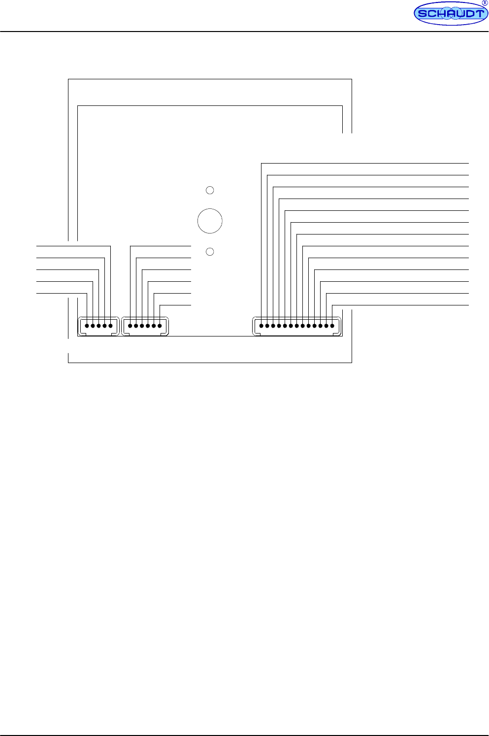
D Wiring diagram
L u m b e r g M S F Q/ 0 1 3 --- w a y
L u m b e r g M S F Q/ 0 5 --- w a y
Base
0.25
0.5
0.75
Full
Full
0.75
0.5
0.25
Base
n.c.
Relay 1 OFF
Relay 1 ON
Relay 2 OFF
Relay 2 ON
Mains
12V OFF
12V ON
--- Leisure battery sensor
+ Leisure battery sensor
+ Starter battery
12V Contr. (EBL 208, CSV 410--- 2) +Bel. (EBL 226)
Ta n k h e a t e r
S --- p u m p
Rear side at top
To w a s t e w a t e r t a n k
L u m b e r g M S F Q/ 0 6 --- w a y
To w a t e r t a n k To :
--- E B L 2 0 8
--- C S V 4 1 0 -2
--- E B L 2 2 6
111
