88 2321 01_sec4_rev G 01 Sec4 Rev
User Manual: 88-2321-01_sec4_revG
Open the PDF directly: View PDF ![]() .
.
Page Count: 28

i
4
Removal and Replacement
4.0 Introduction.......................................................................................................1
4.1 Access Cover....................................................................................................1
4.2 Front Panel Cover.............................................................................................3
4.3 Platen Roller.....................................................................................................5
4.4 Printhead..........................................................................................................8
4.5 Thermal Transfer Assembly............................................................................. 10
4.5.1 Ribbon Supply Hub............................................................................. 11
4.5.2 Ribbon Take-up Hub ........................................................................... 12
4.6 Rewind Assembly ........................................................................................... 13
4.6.1 Rewind Hub ........................................................................................ 14
4.7 Media Sensor.................................................................................................. 15
4.8 Drive Motor Assembly...................................................................................... 16
4.8.1 203 DPI Motor (Belt Driven Version)..................................................... 16
4.8.2 203 DPI and 406 DPI Motor ................................................................. 18
4.8.3 300 DPI and 600 DPI Motor ................................................................. 19
4.9 Fuse Replacement.......................................................................................... 20
4.10 Power Supply Board ....................................................................................... 21
4.11 Main Logic Board ............................................................................................ 23
4.12 Front Panel Board........................................................................................... 25

ii
Removal and Replacement
4-1
4.0 Introduction
This section details removal and replacement procedures for the various printer parts.
CAUTION
Wear a wrist strap and follow standard ESD prevention measures.
Use extreme care when near the printhead; never use a sharp object on the surface.
Never use a sharp object on the platen roller.
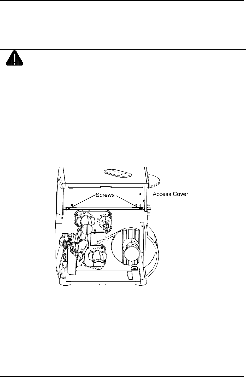
4.1 Access Cover
Removal:
1. Turn ‘Off’ and unplug the printer.
2. Lift the Access Cover and remove the two screws.
Removal and Replacement
4-2
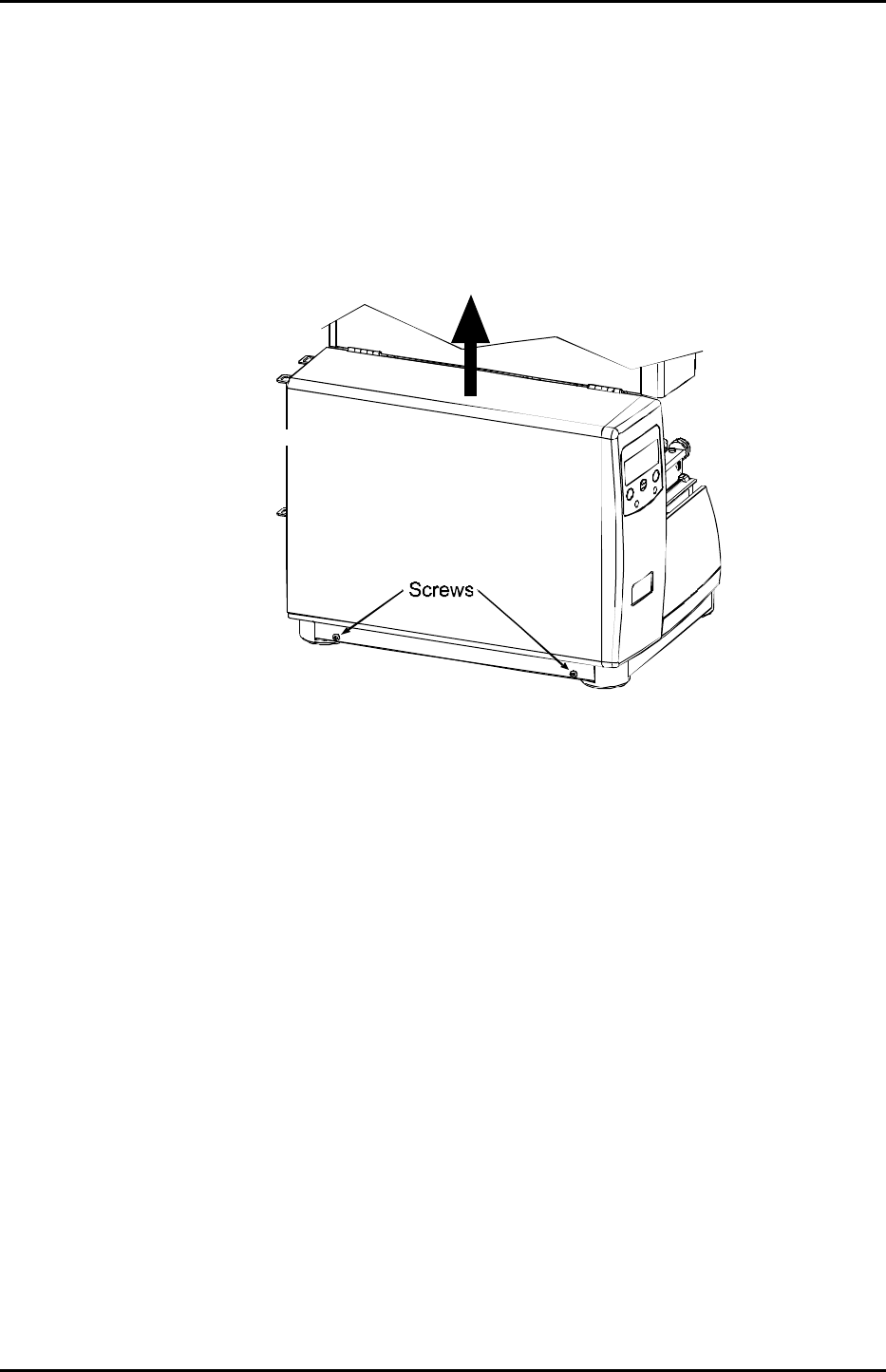
3. Remove the two screws that secure the bottom edge of the cover to the base of the printer.
4. Lift the entire assembly up and then off the printer.
Replacement:
Position the access cover onto the printer and reinstall the previously removed screws.

Removal and Replacement
4-3
4.2 Front Panel Cover
Removal:
1. Turn ‘Off’ and unplug the printer.
2. Remove the cover; see Section 4.1.
3. Push ‘up’ on the two Tabs that secure the Front Panel Cover to the Centerplate. (The Baseplate Tab
is not accessible.)
4. Carefully pull the top of the cover forward until the cover is completely released from the printer.
Removal and Replacement
4-4
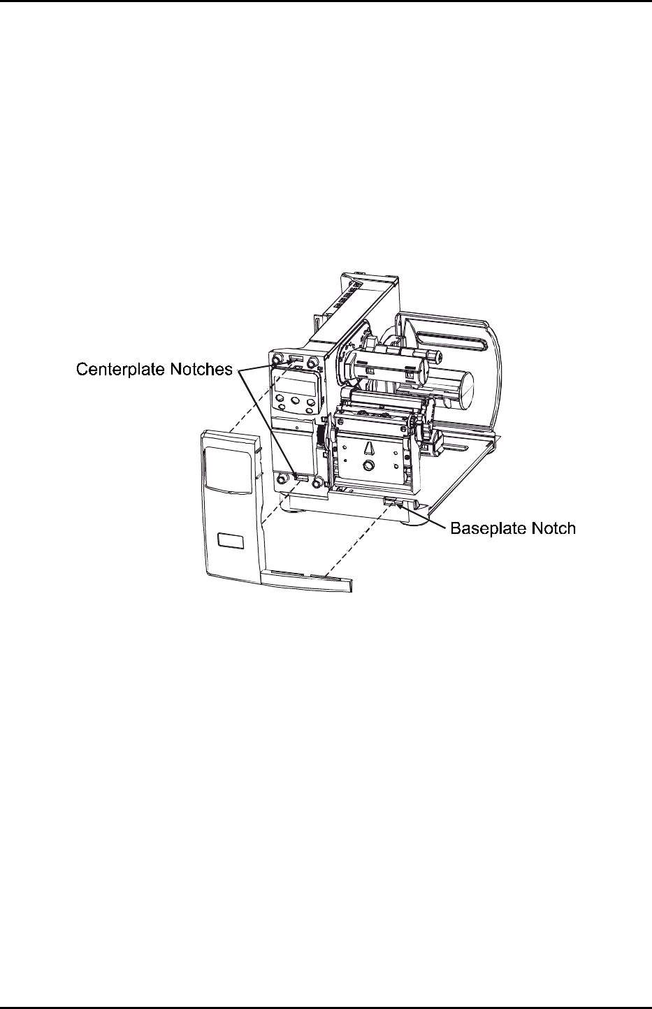
Replacement:
1. Align the Tabs of the Front Panel Cover to the Centerplate Notches and the Baseplate Notch.
2. Press the cover firmly, until the Tabs snap into place.
3. Replace the cover; see Section 4.1
Removal and Replacement
4-5
4.3 Platen Roller
Removal:
1. Turn ‘Off’ and unplug the printer.
2. Open the cover. Rotate the Printhead Latch forward and raise the Printhead.
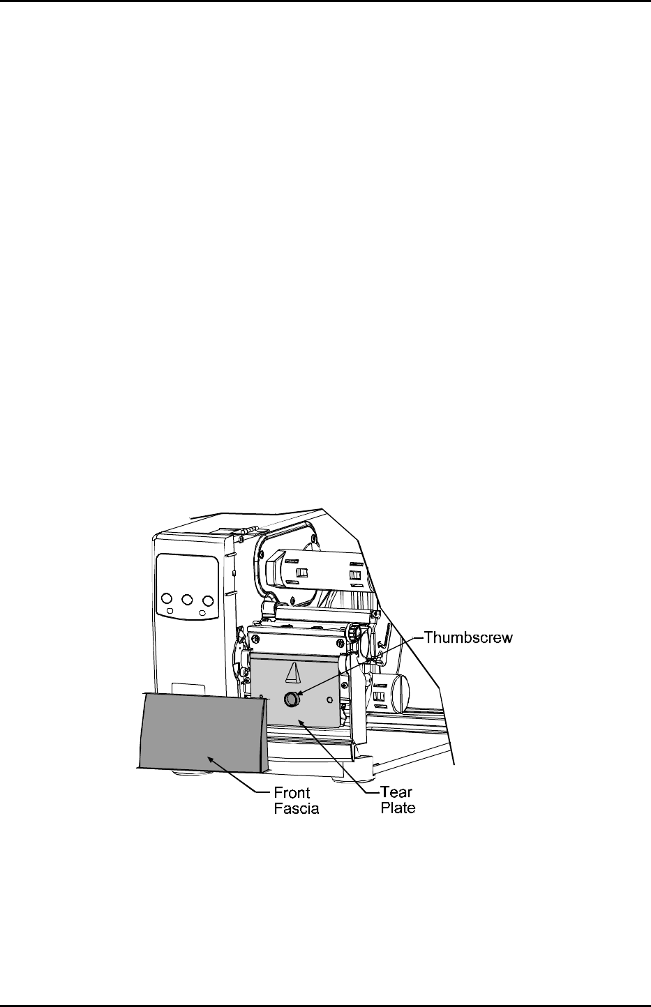
3. Remove the Front Fascia by grasping the top of the panel and pulling it away from the printer, then
Loosen and remove the Thumbscrew and then the Tear Plate.

Removal and Replacement
4-6
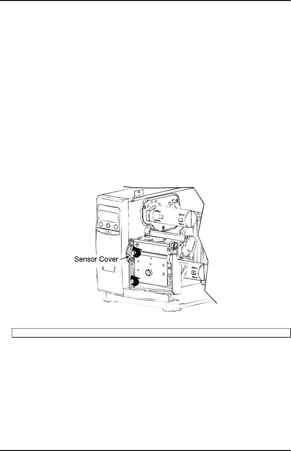
4. Remove the Sensor Cover by pulling it from the printer in the direction of the arrows, as shown. (If
equipped with the optional Present Sensor, first disconnect the cabling to the Options Connector then
remove the Present Sensor).
;
Note: If necessary, the Front Panel can be loosened to facilitate the removal; see Section 4.2.
5. Remove the two Screws securing the Bearing Plate then remove the Bearing Plate.
6. Remove the Platen Roller Assembly.
Removal and Replacement
4-7
Replacement:
1. Place the Outside Bearing onto the Platen Roller Assembly.
2. Using care to avoid the Platen Roller, place a very small amount of silicon grease, P/N 19-2030-01,
on the Compound Gear.
3. Position the new Platen Roller Assembly in the printer.
4. Position the Bearing Plate onto the printer and secure with the two Screws.
5. Position the Sensor Cover, as shown. Then rotate the cover in the direction of the arrows until it
snaps into place. (If equipped with the optional Present Sensor, connect the cable to the Options
Connector).
;
Note: If necessary, the Front Panel can be loosened to facilitate installation; see Section 4.2.
6. Reinstall the Tear Plate, Thumbscrew, and Front Fascia.
Removal and Replacement
4-8
4.4 Printhead
CAUTION
Wear a wrist strap and follow standard ESD prevention measures.
Use extreme care when handling the printhead.
If the power supply is suspected in causing the failure of the printhead, check the +24 VDC supply
voltage before proceeding (see Section 2.2.4).
Removal:
1. Turn ‘Off’ and unplug the printer. Open the Access Cover.
2. Rotate the printhead latch forward and raise the Printhead Assembly. Remove ribbon, if installed.
3. Lower and rotate the printhead latch to the locked position.
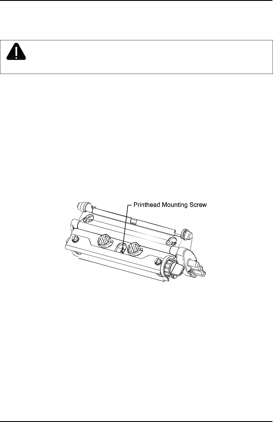
4. Loosen the Printhead Mounting Screw (it will remain captivated in the assembly).
5. Rotate the printhead latch forward while carefully supporting the Printhead and raise the Printhead
Assembly.

Removal and Replacement
4-9
6. Disconnect the two attached Cables and then remove the Printhead.
Replacement:
1. While carefully holding the new Printhead, reconnect both Cables.
2. Position the Printhead onto the Locating Pins in the Printhead Assembly.
3. Secure the Printhead with the Printhead Mounting Screw. DO NOT over-tighten this screw.
;
Note: The Locating Pins in the Printhead Assembly eliminate the need for a printhead alignment.
4. Clean the Printhead and allow it to dry; see Section 2.5.1.
5. Reload ribbon, if removed. Lower and rotate the printhead latch to the locked position.
6. Plug in and turn ‘On’ the printer. Perform a print quality test to verify alignment. If necessary, adjust
the darkness setting to match that of the previous printhead using the Print Control / Custom
Adjustments / Darkness setting in the menu; see the Operator’s Manual for details.
Removal and Replacement
4-10
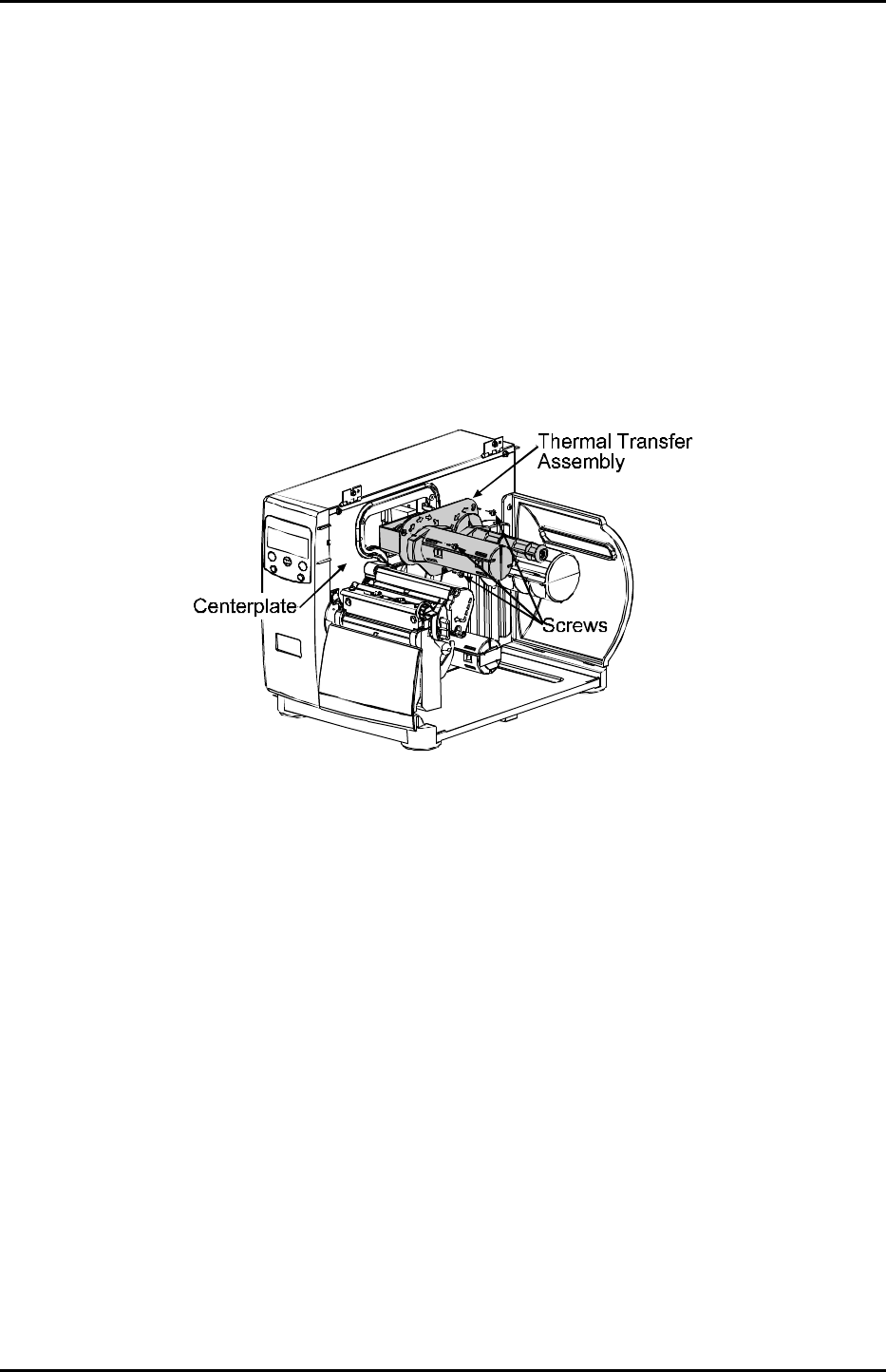
4.5 Thermal Transfer Assembly
Removal:
1. Turn ‘Off’ and unplug the printer. Open the Access Cover.
2. Remove the three Screws securing the Thermal Transfer Assembly to the Centerplate then remove
the Thermal Transfer Assembly.
Replacement:
Reinstall the Thermal Transfer Assembly in the Centerplate and secure it using the three Screws.
Removal and Replacement
4-11
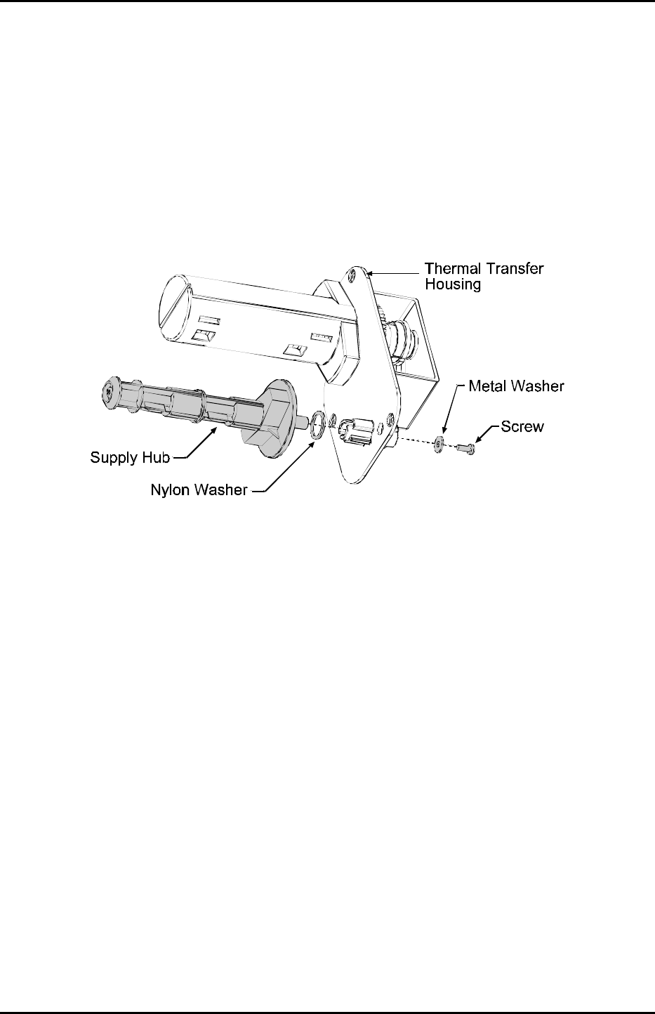
4.5.1 Ribbon Supply Hub
Removal:
1. Remove the Screw and Metal Washer from the back of the Thermal Transfer Housing, followed by
the Supply Hub and Nylon Washer.
Replacement:
1. Slide the Supply Hub (with optical disc) and Nylon Washer into the Thermal Transfer Housing.
Rotate the Supply Hub so that the pin, located on the Supply Hub shaft, slides into the notch on the
Thermal Transfer Housing.
2. Reinstall the Metal Washer and Screw.
Removal and Replacement
4-12
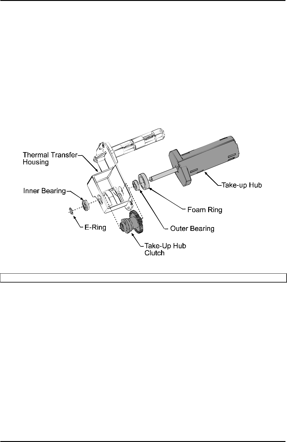
4.5.2 Ribbon Take-up Hub
Removal:
1. Remove the E-Ring from the end of the Take-Up Hub shaft and remove the Inner Bearing.
2. Slide the Take-Up Hub and the Outer Bearing out of the Thermal Transfer Housing. (The Foam Ring
will remain attached to the housing.)
3. Slightly compress the Take-Up Hub Clutch and remove it from the housing.
;
Note: Always replace the Take-Up Clutch as a complete assembly; it contains no serviceable components.
Replacement:
1. Install a new Foam Ring if necessary.
2. Install the Outer Bearing in the Thermal Transfer Housing.
3. Position the Take-Up Hub Clutch in the Thermal Transfer Housing as shown.
4. Slide the Take-Up Hub shaft completely through the housing and clutch.
5. Install the Inner Bearing and the E-Ring to secure the Take-Up Hub.
Removal and Replacement
4-13
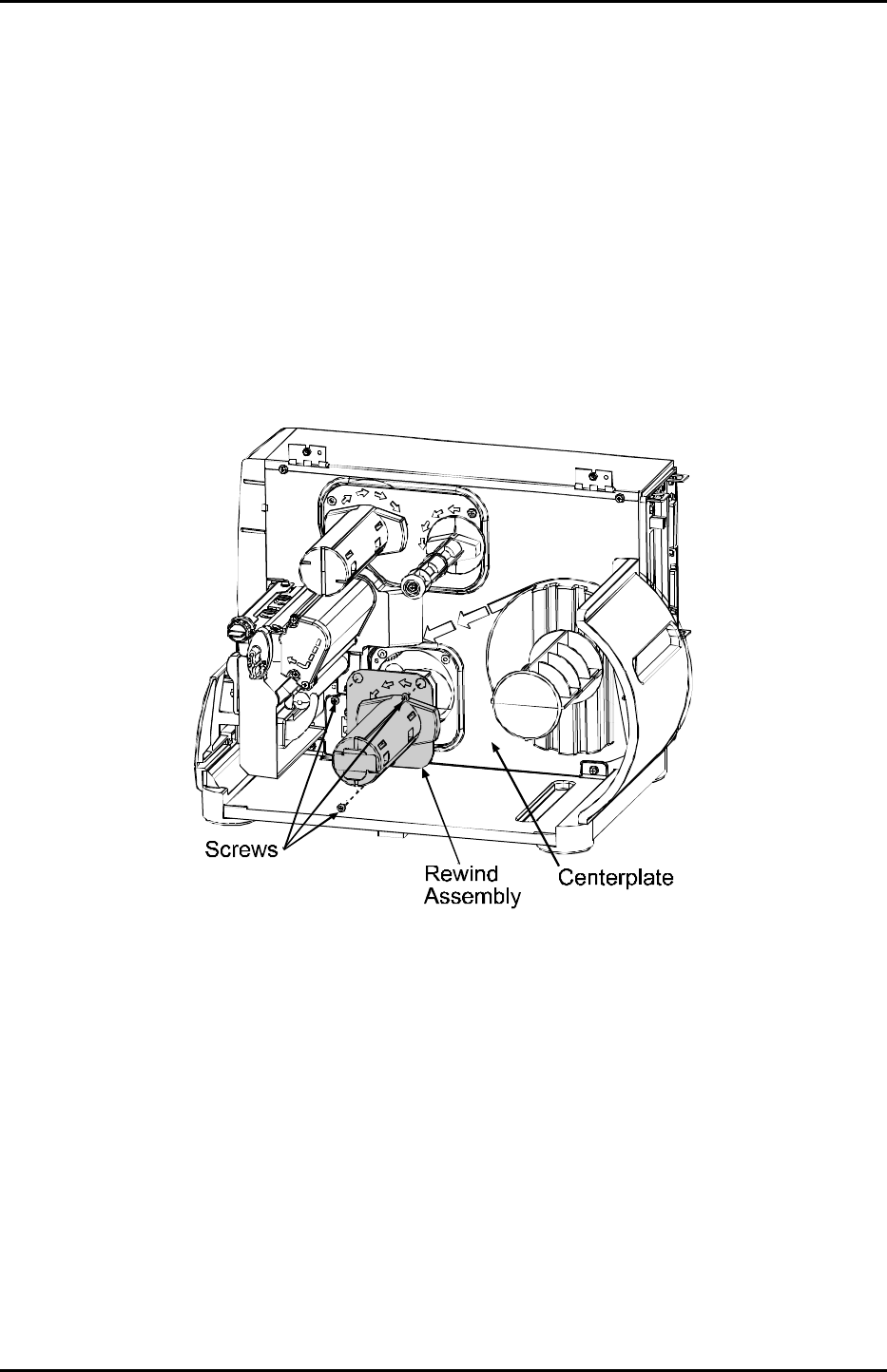
4.6 Rewind Assembly
Removal:
1. Turn ‘Off’ and unplug the printer. Open the cover.
2. Remove the three Screws that secure the Rewind Assembly to the Centerplate and remove the
Rewind Assembly.
Replacement:
Reinstall the Rewind Assembly in the Centerplate and secure it using the three Screws.
Removal and Replacement
4-14
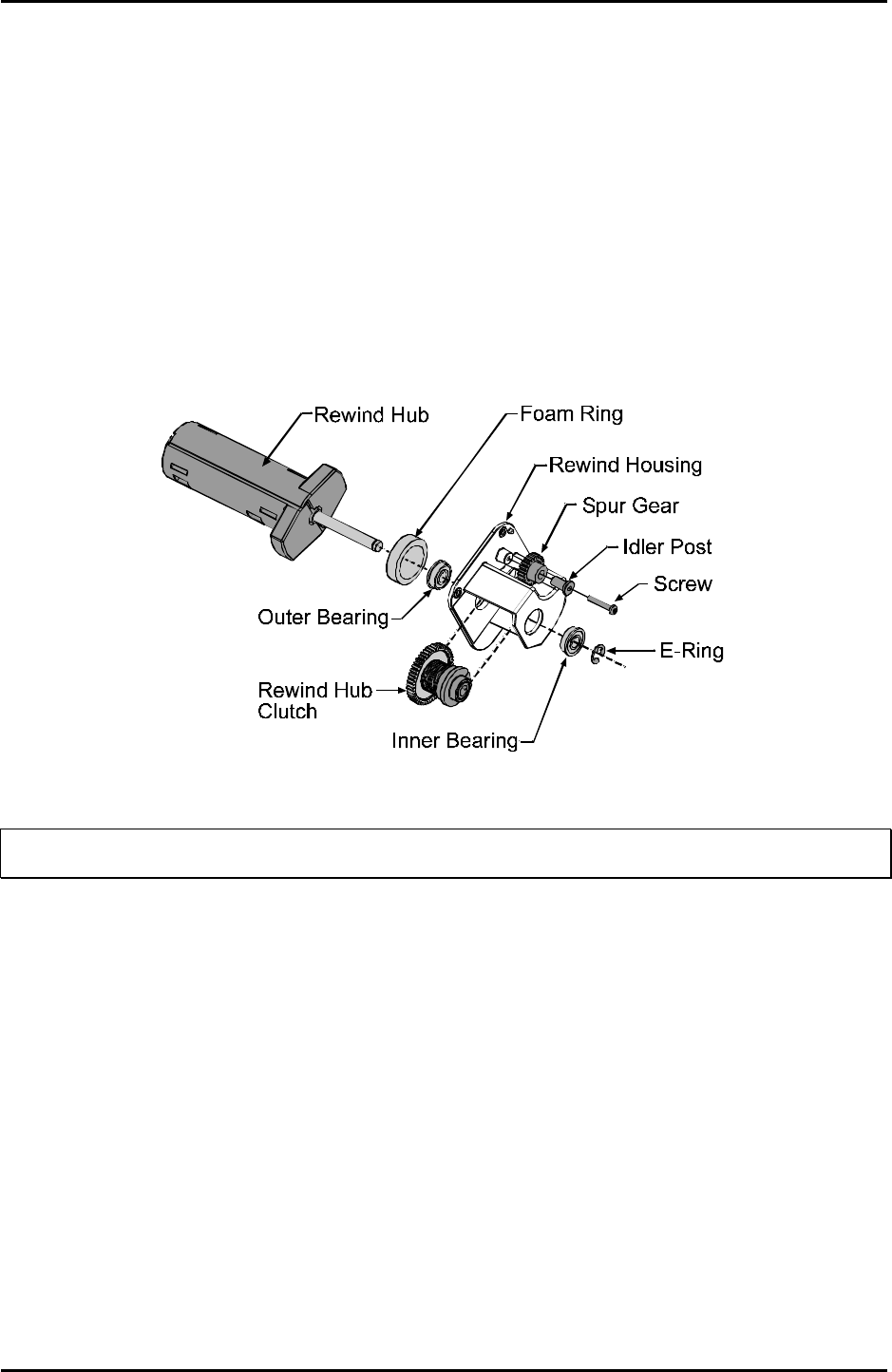
4.6.1 Rewind Hub
Removal:
1. Remove the E-Ring from the end of the Rewind Hub shaft and remove the Inner Bearing.
2. Slide the Rewind Hub and the Outer Bearing out of the Rewind Housing. (The Foam Ring will remain
attached to the housing.)
3. Remove the Rewind Hub Clutch from the Housing. (To remove the Spur Gear and Idler Post, remove
the Screw securing them to the Rewind Housing).
;
Note: Always replace the Rewind Hub Clutch as a complete assembly; it contains no serviceable
components.
Replacement:
1. If necessary, install a new Foam Ring before installing the Outer Bearing in the Rewind Housing.
2. Position the Rewind Hub Clutch in the Rewind Housing and slide the Rewind Hub shaft through.
3. Install the Inner Bearing and the E-ring. (If removed, position the Spur Gear and Idler Post in the
Rewind Housing and secure with the Screw.)
Removal and Replacement
4-15
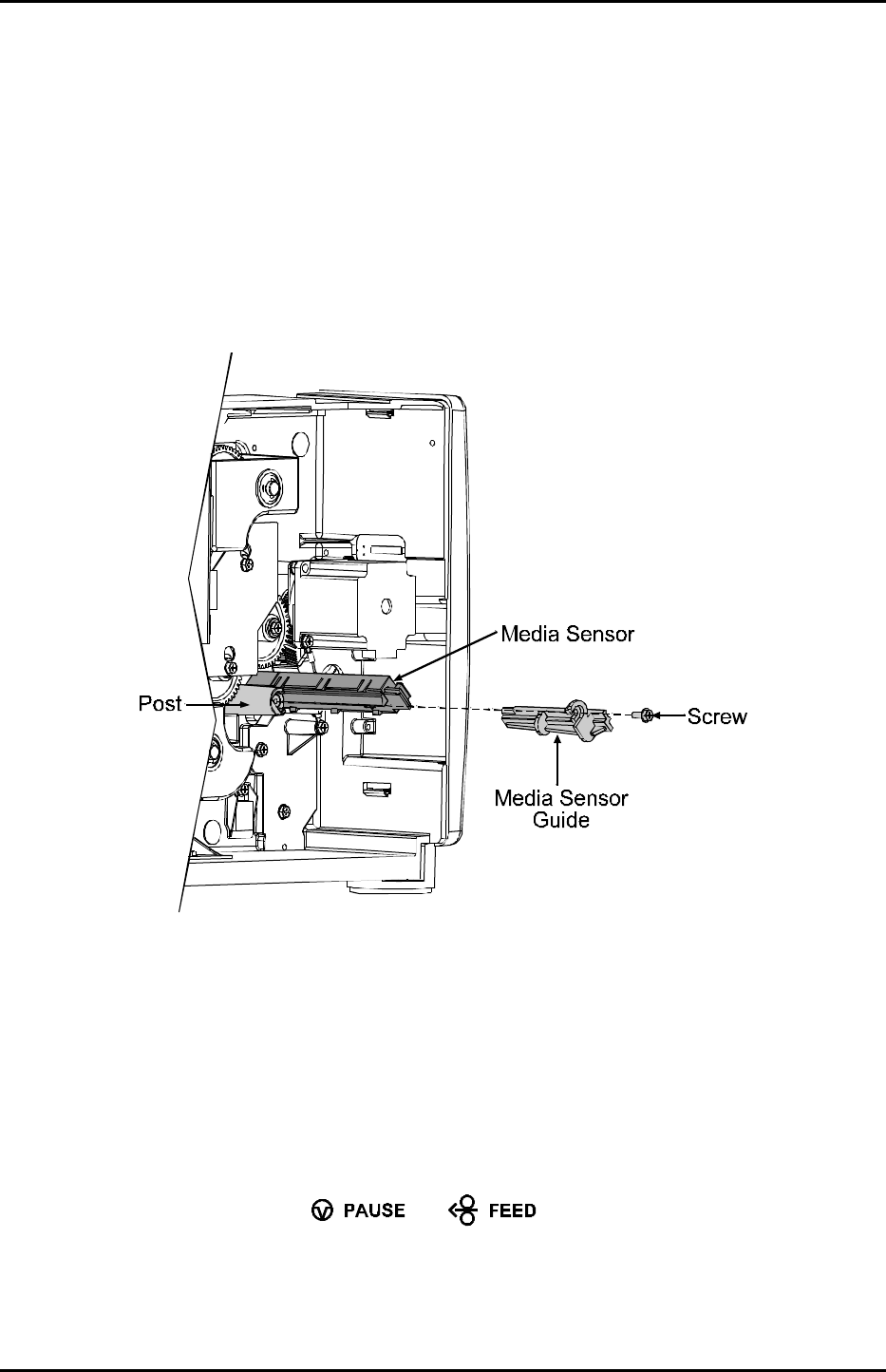
4.7 Media Sensor
Removal:
1. Turn ‘Off’ and unplug the printer, and remove the cover (see Section 4.1).
2. Disconnect the ribbon cable from the Media Sensor and remove the Screw that secures the Media
Sensor Guide to the Post.
3. Pull the Media Sensor Guide out and then the Media Sensor.
Replacement:
1. Replace the Media Sensor and then the Media Sensor Guide.
2. Secure the Media Sensor Guide to the Post with the Screw.
3. Reconnect the ribbon cable to the Media Sensor.
4. Replace the cover; see Section 4.1.
5. Plug in and turn ‘On’ the printer. Calibrate the ‘empty’ sensor value by simultaneously pressing and
holding (about four seconds) the and Keys.
Removal and Replacement
4-16
4.8 Drive Motor Assembly
Depending upon the model and age of the I-Class printer, there are several different drive configurations.
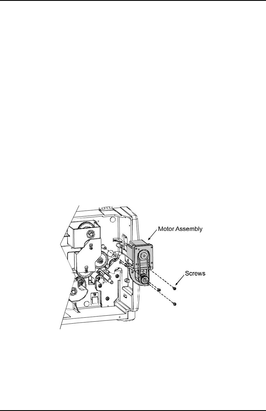
4.8.1 203 DPI Motor (Belt Driven Version)
Removal:
1. Turn ‘Off’ and unplug the printer.
2. Remove the cover; see Section 4.1.
3. Remove the three Screws that secure the Motor Assembly.
Removal and Replacement
4-17
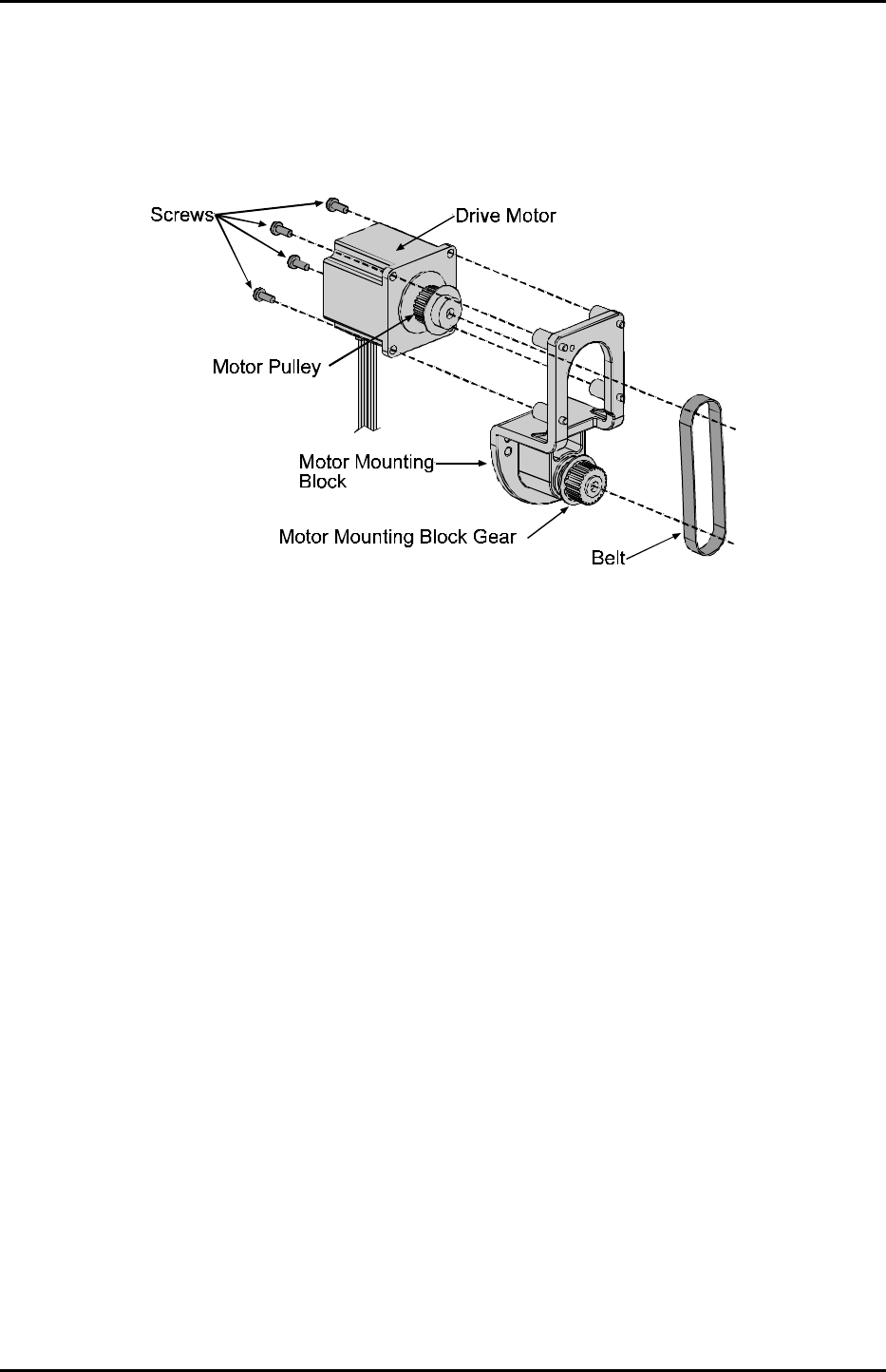
4. Remove the four Screws that secure the Drive Motor to the Motor Mounting Block and slip the Belt
off the Drive Motor pulley.
Replacement:
1. Position the Drive Motor on the Motor Mounting Block. Ensure that the Belt is routed around both
the Drive Motor Pulley and the Motor Mounting Block Gear, and then install and tighten the four
Screws.
2. Reposition the Motor Assembly in the printer, and then install and tighten the three mounting Screws.
3. Replace the cover; see Section 4.1.
Removal and Replacement
4-18
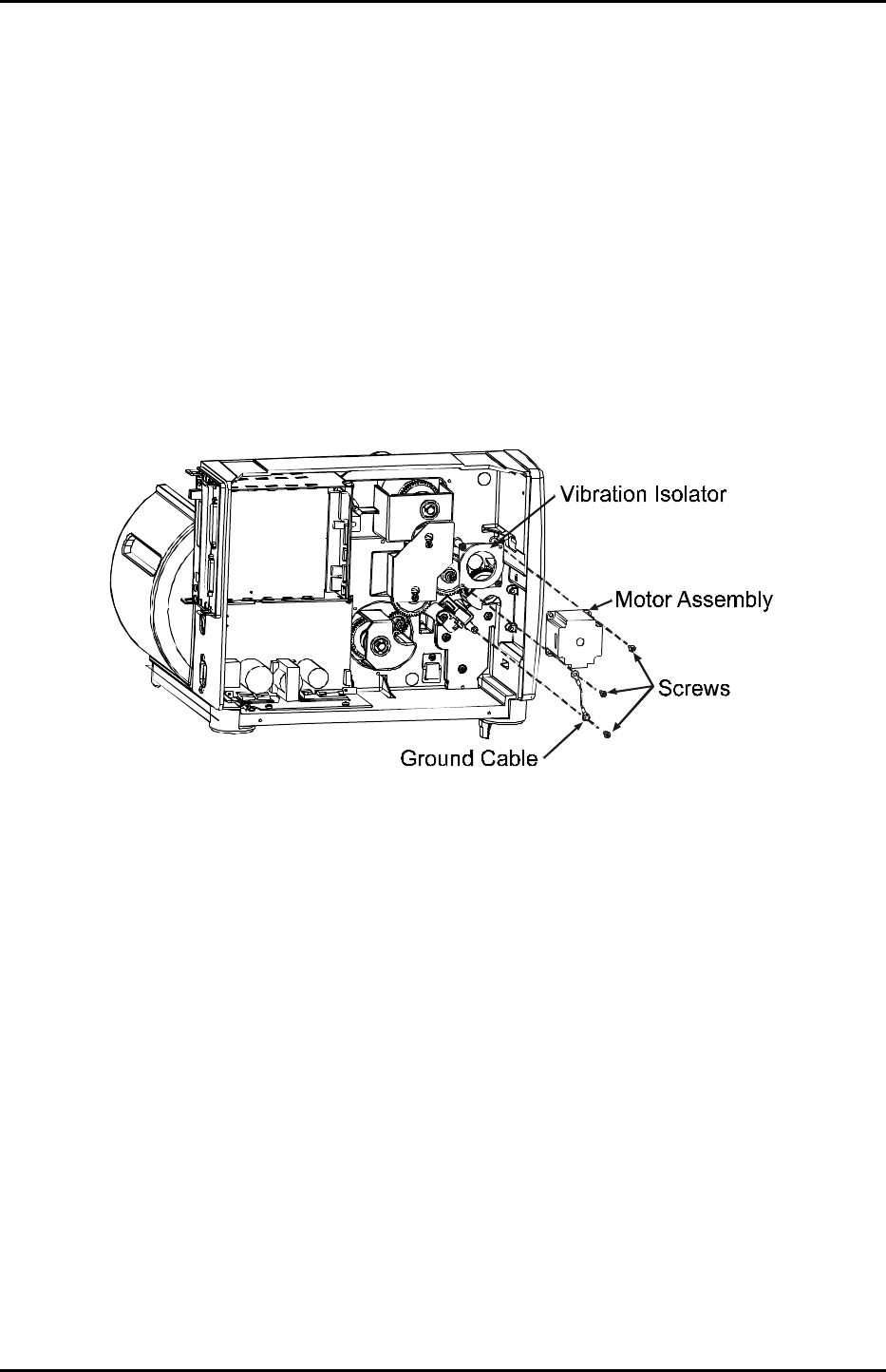
4.8.2 203 DPI and 406 DPI Motor
Removal:
1. Turn ‘Off’ and unplug the printer.
2. Remove the cover; see Section 4.1.
3. Disconnect the motor cable from the Motor Assembly.
4. Remove the Screws securing the Motor Assembly and Ground Cable to the Vibration Isolator.
5. Remove the Motor Assembly.
Replacement:
1. Position the Motor Assembly for mounting onto the Vibration Isolator.
2. Install the Ground Cable and secure the Motor Assembly to the Vibration Isolator with the Screws.
3. Reconnect the motor cable to the Motor Assembly.
4. Replace the cover; see Section 4.1.
Removal and Replacement
4-19
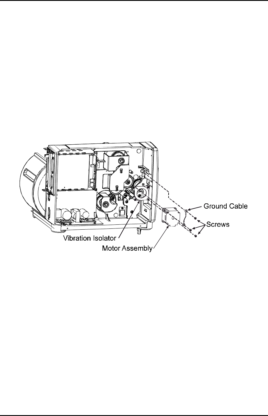
4.8.3 300 DPI and 600 DPI Motor
Removal:
1. Turn ‘Off’ and unplug the printer.
2. Remove the cover; see Section 4.1.
3. Disconnect the motor cable from the Motor Assembly.
4. Remove the Screws securing the Motor Assembly and Ground Cable to the Vibration Isolator.
5. Remove the Motor Assembly.
Replacement:
1. Position the Motor Assembly for mounting onto the Vibration Isolator.
2. Install the Ground Cable and secure the Motor Assembly to the Vibration Isolator with the Screws.
3. Reconnect the motor cable to the Motor Assembly
4. Replace the cover; see Section 4.1.
Removal and Replacement
4-20
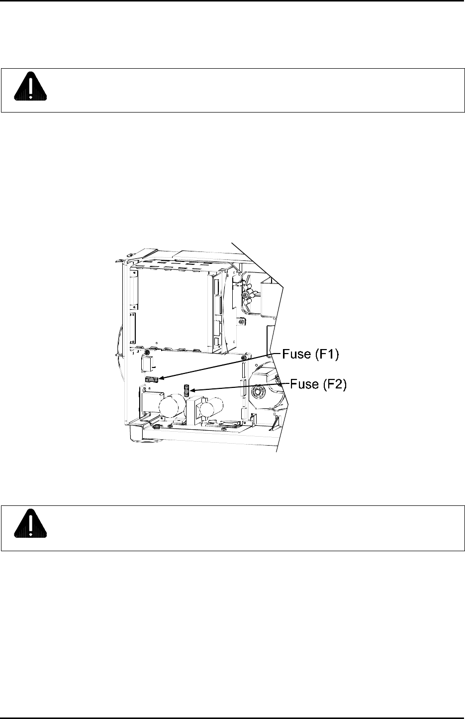
4.9 Fuse Replacement
CAUTION
Only use a replacement fuse with the rating and type as the original fuse; failure to comply could
cause serious damage, including fire.
Removal:
1. Turn ‘Off’ and unplug the printer.
2. Remove the cover; see Section 4.1.
3. Locate and test Fuses F1 and F2.
Replacement:
CAUTION
Use caution when replacing Fuse ‘F1’; this fuse will only blow during a failure in the primary
switching circuit, which may indicate a more serious electrical problem.
1. Replace the blown fuse(s) with part number 42-2179-01.
2. Replace the cover; see Section 4.1.
3. Plug in and turn ‘On’ the printer.
Removal and Replacement
4-21
4.10 Power Supply Board
CAUTION
Wear a wrist strap and follow standard ESD prevention measures.
Removal:
1. Turn ‘Off’ and unplug the printer.
2. Remove the cover; see Section 4.1.
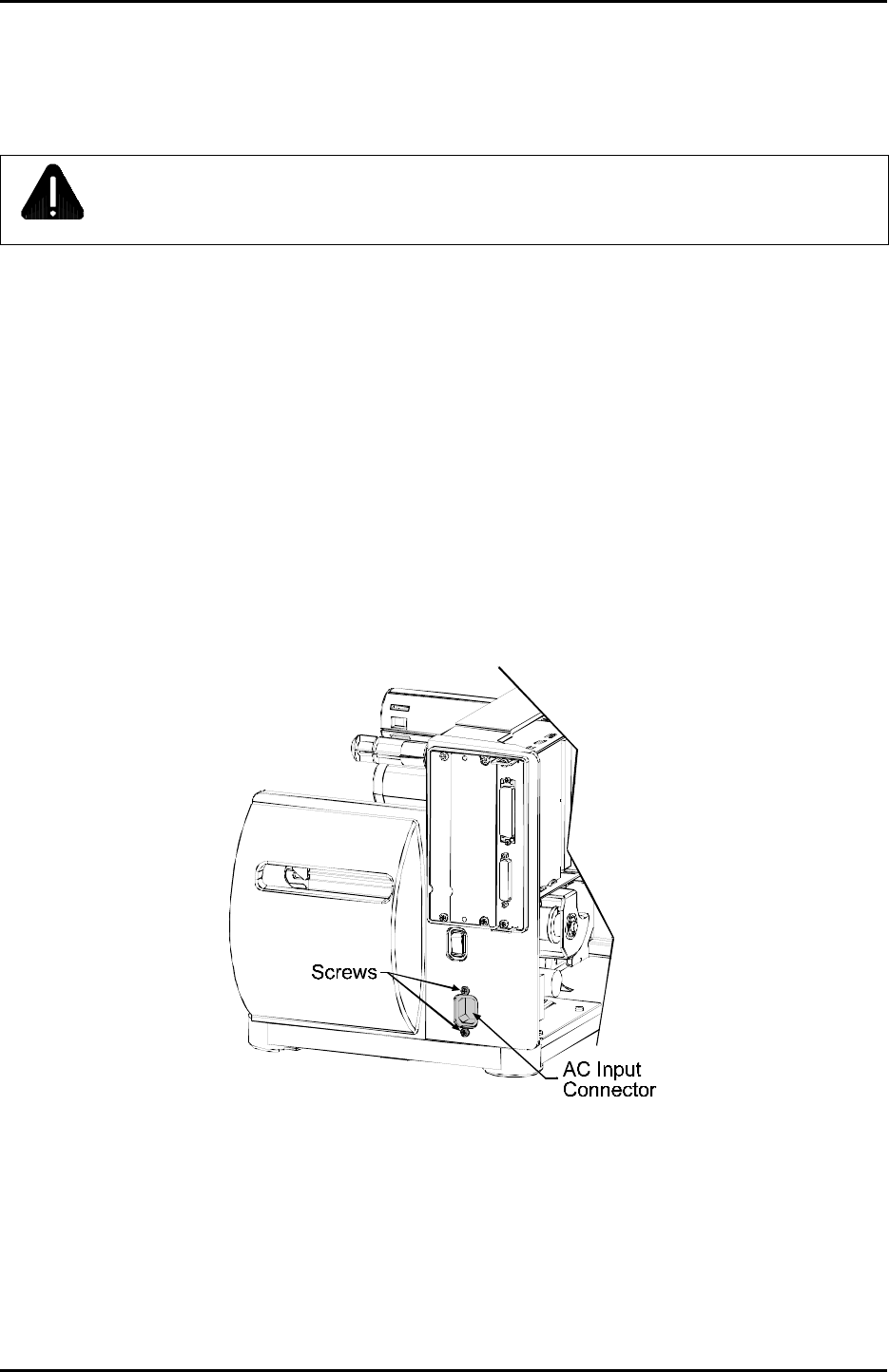
3. Remove the four cables from their respective connectors on the Power Supply Board.
4. Remove the two Screws on the back of the printer and Nut Plate securing the AC Input Connector.
5. Remove the Screw and Washer securing the Ground Wire to the base of the printer.
Removal and Replacement
4-22
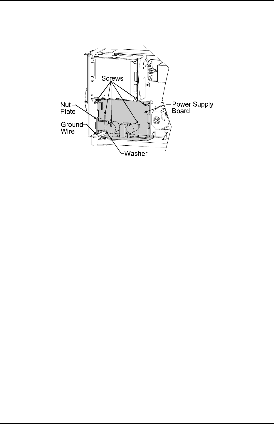
6. Remove the four Screws securing the Power Supply Board to the printer.
Replacement:
1. Position the Power Supply Board in the printer. Secure it in place by installing and tightening the four
Screws.
2. Install the Ground Wire to the base of the printer using the previously removed Screw and Washer.
3. Install the two Screws on the back of the printer and Nut Plate securing the AC Input Connector.
4. Paying close attention, reconnect the four cable connections to their respective plugs on the Power
Supply Board.
5. Check the printhead supply voltage; see Section 2.2.4.

Removal and Replacement
4-23
4.11 Main Logic Board
CAUTION
Wear a wrist strap and follow standard ESD prevention measures.
Removal:
1. Turn ‘Off’ and unplug the printer.
2. Remove any interface cable(s) attached to the printer.
3. Remove the two Screws securing the Main Logic Board.
4. Slide the Main Logic Board out of the printer.
Removal and Replacement
4-24
Replacement:
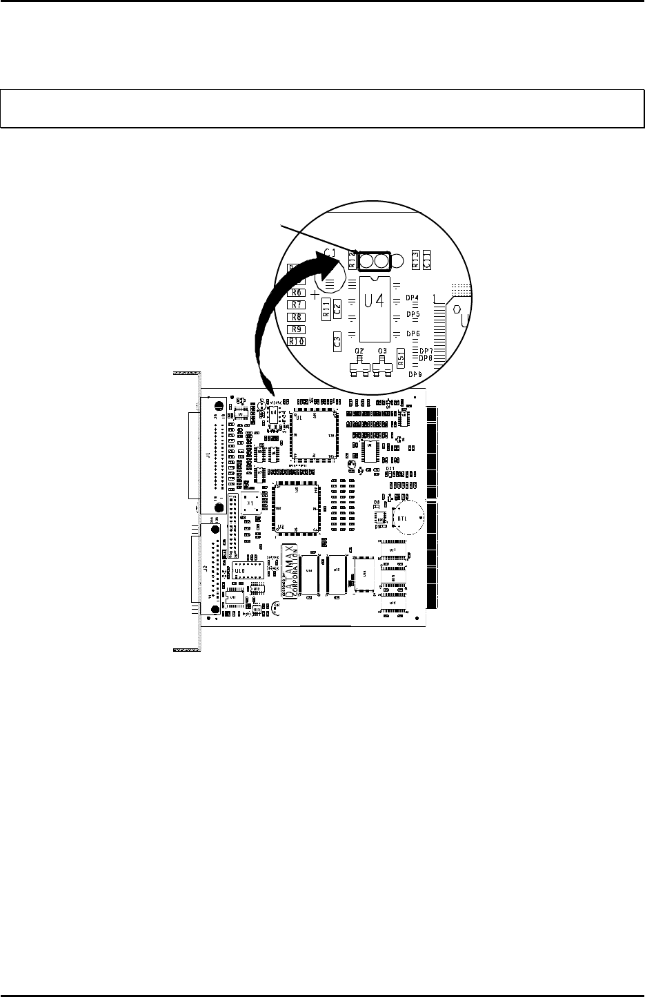
;
Note: If replacing a 51-2301-01 Main Logic Board, before proceeding ensure that the Jumper shown below
is placed between E1 & E2.
1. Slide the Main Logic Board into the printer; push firmly until it seats.
Jumper
E1 E2 E3
51-2301-01
2. Reinstall the two previously removed screws.
3. Replace the interface cable(s).
4. Plug in and turn ‘On’ the printer.
5. If necessary, verify the printer’s model number (located on the Serial Tag) then download the
corresponding Application Version to the Main Logic Board; see Section 2.6.
6. Configure the printer; see the Operator’s Manual for details.
7. Perform calibration; see Section 2.1

Removal and Replacement
4-25
4.12 Front Panel Board
CAUTION
Wear a wrist strap and follow standard ESD prevention measures.
Removal:
1. Turn ‘Off’ and unplug the printer.
2. Remove the cover; see Section 4.1.
3. Remove the front panel; see Section 4.2.
4. Carefully lift the Tabs on the Bezel to remove it from the Front Panel Board (this will also free the
Button Panel).
5. Remove the two Screws that secure the Front Panel Board to the Centerplate. Pull the Front Panel
Board slightly away from the Centerplate, disconnect the ribbon cable from the back of the board,
and then remove the board.
Replacement:
1. Connect the ribbon cable to the Front Panel Board.
2. Secure the Front Panel Board to the Centerplate using the two Screws.
3. Place the Button Panel into the Bezel, align the Tabs of the Bezel to the notches on the Front Panel
Board; then snap the Bezel into place.
4. Replace the front panel; see Section 4.2.
5. Replace the cover; see Section 4.1.

Removal and Replacement
4-26
