89637200 02_1742 30_1742 120_Line_Printer_Controller_Ref_Aug74 02 1742 30 120 Line Printer Controller Ref Aug74
User Manual: 89637200-02_1742-30_1742-120_Line_Printer_Controller_Ref_Aug74
Open the PDF directly: View PDF ![]() .
.
Page Count: 19
CONTROL
DATA
CORPORATION
CONTROL
DATA®
1784 COMPUTER
SYSTEM
1742-30
AND 1742-120
LINE PRINTER CONTROLLER
REFERENCE MANUAL
PRELIMINARY
REVISION
RECORD
REVISION
DESCRIPTION
01
Preliminary
Edition,
Released
Class
B,
ECO
CK
124
(8/18/73)
02
Publication
changes
and
corrections,
ECO
CK 937
(8/28/74)
PUBLICATION
NO.
89637200
ADDITIONAL
COPIES
OF
THIS
MANUAL
MAY
BE
OBTAINED
FROM
THE
NEAREST
CONTROL
DATA
CORPORATION
SALES
OFFICE.
COPYRIGHT€)
CONTROL
DATA
CORPORATION,
1973,
1974
PRINTED
IN
THE
UNITED
STATES
OF
AMERICA
ADDRESS
COMMENTS
CONCERNING
THIS
MANUAL
TO:
CONTROL
DATA
CORPORATION
SMALL
COMPUTER
DEVELOPMENT
DIVISION
44SS
EASTGATE
MALL
LA
JOLLA,
CALIFORNIA
OR
USE
COMMENT
SHEET
IN
THE
BACK
OF
THIS
MANUAL.
89637200
01
PREFACE
This
manual
gives
reference
information
for
the
CONTROL
DATA~
1742-30 and 1742-120 Line
Printers
which
may
be used in
conjunction
with
the
Interrupt
Data Channel
of
the
1784 Computer. For
reference
information
on
the
1784 computer and
peripheral
equipment (which
attach
directly
to
the
1784
Computer)
see
the
1784 Computer System
Reference
Manual,
Publication
No.
89633400.
iii
iv
Introduction
Functional
Des
c
rip
t i on
2
3
System
Relationships
Data
Word
Format
Alarm
Program
Protection
Reply/Reject
Interrupt
Contro
1
Character
Typical
Configuration
Equipment
Select
and
Protect
Bit
Jumper
Plugs
Q
Register
Format
Hexadecimal Code
for
Equipment
Selection
3
3
3
3
3
4
2
4
Code
2
CON
TEN
T S
FIG
U
RES
TAB
L E S
Programming
Codes
Converter
Equipment
Command
Operation
~
5
6
2
Contro
ller
Function
Code
Format
Status
Code Format
Data
Transfer
Format
Addressing
Codes
4
6
6
6
6
11
11
5
5
5
4
89637200
01

INTRODUCTION
FUNCTIONAL
DESCRIPTION
System
Relationships
. ®
The
CONTROL
DATA
1742-20 and 1742-120 Line
Printers
each
consist
of
a
controller
and a
printer.
The model 1742-30
prints
at
300
lines-per-minute
(LPM)
,
the
model 1742-120
at
1200
LPM.
The
controller
consists
of
a
single
50-PAK.
It
interfaces
with
the
AQ
data
channel
of
the
1784 computer.
The
controller
receives
and
interprets
function
codes
from
this
channel
to
initiate
the
print
cycle,
control
paper
motion,
and
enable
interrupts
when
specified
conditions
arise.
The
controller
includes
a
buffer
memory
that
is
capable
of
storing
one
character.
The
Line
Printer
includes
a
buffer
capable
of
storing
a
complete
line
of
pri
nt.
The
controller
interfaces
the
printer
with
the
lower
eight
bits
of
the
Computer A
register
(AOO
through
A07)
through
the
AQ
channel.
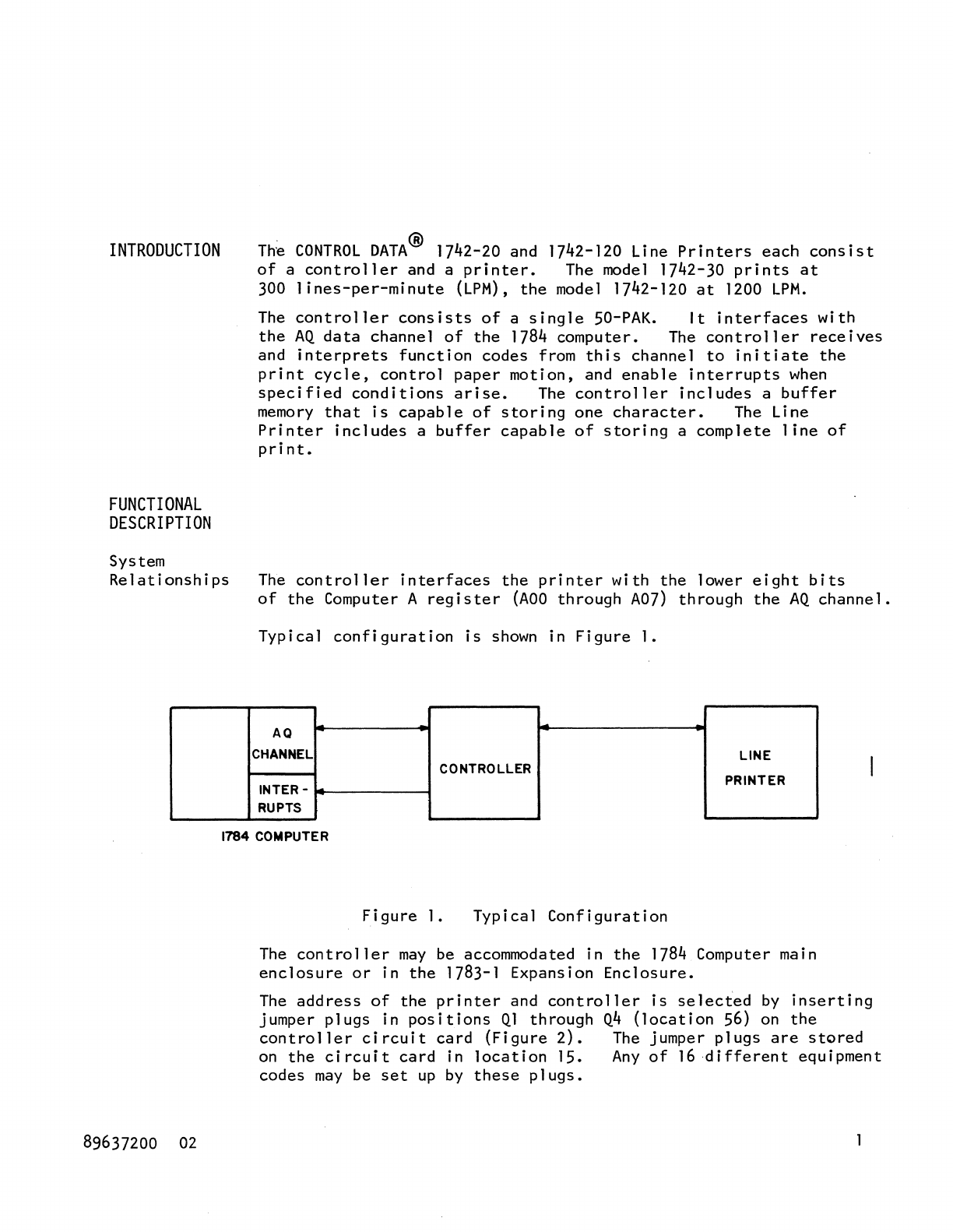
Typical
configuration
is
shown
in
Figure
1.
AQ
CHANNEL
LINE
CONTROLLER
INTER -
PRINTER
RUPTS
1784 COMPUTER
89637200
02
Figure
1.
Typical
Configuration
The
controller
may
be accommodated in
the
1784 Computer main
enclosure
or
in
the
1783-1 Expansion
Enclosure.
The
address
of
the
printer
and
controller
is
selected
by
inserting
jumper
plugs
in
positions
Ql
through
Q4
(location
56)
on
the
controller
circuit
card
(Figure
2).
The
jumper
plugs
are
stored
on
the
circuit
card
in
location
15.
Any
of
16
different
equipment
codes
may
be
set
up
by
these
plugs.
2
/
SI
7 PTcr
/
S5
/
Q07
/
S4
/
Q08
/
S3
/
Q09
/
S2
7
QIO
Figure
2.
Equipment
Select
and
Protect
Bit
Jumper
Plugs
TABLE
I.
HEXADECIMAL
CODE
FOR
EQUIPMENT
SELECTION
CODE
Li
nks
Q10 Q09
Hexadecimal
Code
0 0 0
I 0 0
2 0 0
3 0 0
4 0 1
5 0 1
6 0 1
7 0 1
8 1 0
9 1 0
A 1 0
B 1 0
C I 1
D 1 1
E 1 1
F I 1
Qo8
0
0
J
1
0
0
1
1
0
0
1
1
0
0
1
1
Q07
0
1
0
1
0
1
0
1
0
1
0
I
0
1
0
1
Note:
A
'0'
in
the
binary
code
indicates
the
presence
of
a jumper
plug
for
the
setting
of
the
equipment
code;
a'
I'
its
absence.
89637200
02
Data
Word
Format
Alarm
Program
Protection
Reply/Reject
Interrupt
89637200
01
A
single
data
word which
occupies
the
A
register
lower
eight
bits
(ADO
through
A07)
consists
of
a
single
8-bit
character
code.
An
alarm
indicates
the
presence
of
an abnormal
condition.
The
abnormal
conditions
are
divided
into
two
types.
1. Those which
cause
the
Printer
to
go
Not Ready,
requiring
operator
intervention.
These
conditions
are
paper
out,
paper
tear,
fuse
alarm,
and an open
interlock.
The
alarm
is
cleared
upon
correction
of
the
cause
for
the
Not
Ready.
2.
A
condition
allowing
Ready
status
to
remain. This
condition
occurs
when
ERROR
occurred.
For
definition
of
ERROR
director
status
see
Director
Functions.
When
the
Protect
jumper
plug
is
not
set,
input-output
instructions
not
having
the
protect
bit
set
are
rejected.
Director
Status
requests
are
not
rejected.
To
set
the
Protect
jumper
plug,
see
Operation.
Within
800
nanoseconds,
the
Line
Printer
always responds
to
an
Input-to-A
or
an Output-from-A
instruction
with
either
a Reply
or
a
Reject
signal.
A
Reject
signal
is
sent
by
the
printer
if
it
cannot
perform
the
function
of
transfer
instruction.
Four
conditions
that
will
cause
this
Reject
signal
to
be
returned
are:
1.
The
printer
is
Busy.
2.
A
program-protection
fault
occurs.
3.
The
printer
is
Not
Ready.
4.
Data
Status
is
false.
Four
interrupt
lines
are
available
between
the
Controller
and
the
Computer.
They
are
designated:
Data,
EOP,
Alarm,
Common
and
are
defined
under
the
Director
Status.
3
4
Control
Character
PROGRAMMING
Each
print
1
ine
is
prefaced
by a
Control
Character.
It
controls
the
paper
vertical
motion and
will
not
be
printed.
The
printer
operates
in
'pre-print'
mode,
that
is
paper
motion
is
performed
before
printing.
The
printer
executes
the
Control
Character
immediately
upon
reception
and does
not
set
Busy
Status.
The Busy
Status
will
be
set
after
reception
of
a
Print
Directive.
NOTE:
If
a
Control
Character
is
issued,
which
performs
a
vertical
paper
motion and
CLRP
Directive
is
issued
immediately
thereafter,
the
Busy
Status
will
be
set
until
paper
motion
stops.
Table
2 and
Figures
2
through
6
provide
programming
information.
A
description
of
the
codes
follows
the
figures.
TABLE
2.
ADDRESSING
CODES
COMMAND
CODE
QOO
= 0
QOO
= 1
Figure 3.
Input-to-A
Output-from-A
111
ega
1 Data
transfer
Director
Status
Director
Function
15
II
10
W E
Command
Code
Equipment
Code
Converter
Code
(all
'0'-5)
Q Register
Format
89637200
01
Figure
4.
Figure
5.
Figure
6.
89637200
01
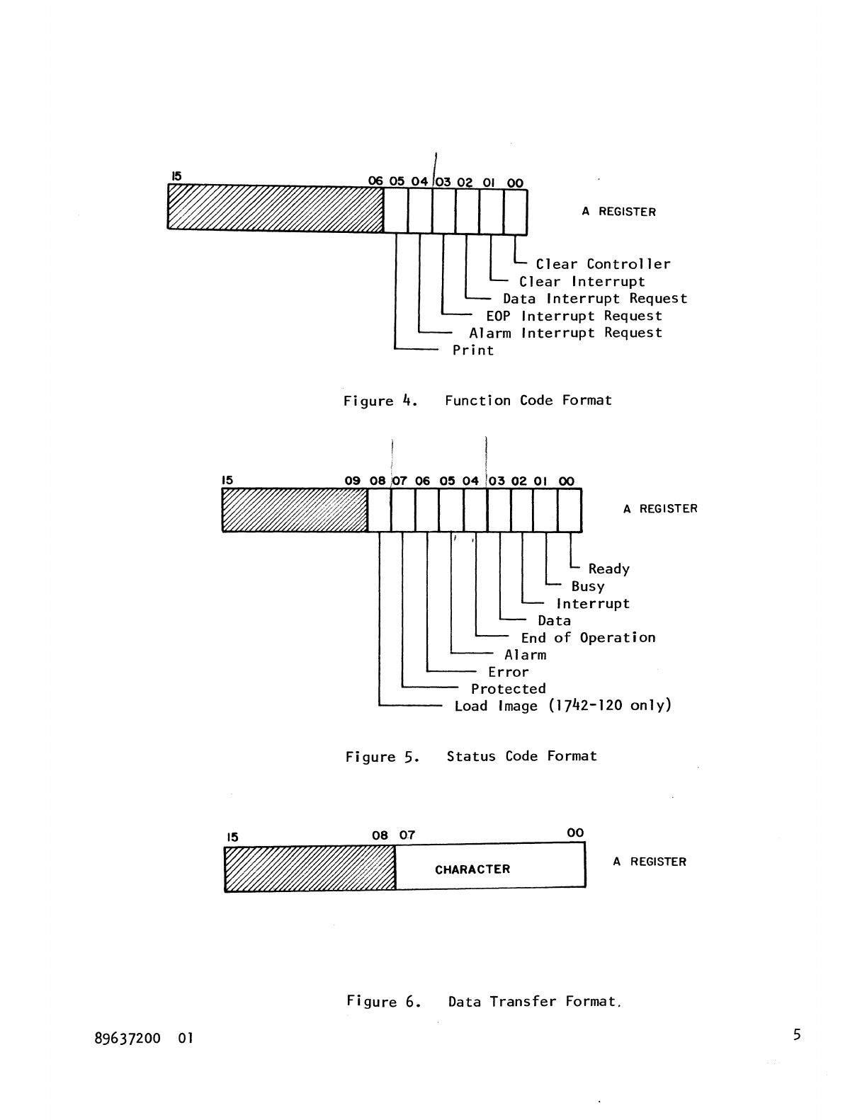
A REGISTER
Clear
Controller
Clear
Interrupt
Data
Interrupt
Request
EOP
Interrupt
Request
Alarm
Interrupt
Request
Print
Function
Code
Format
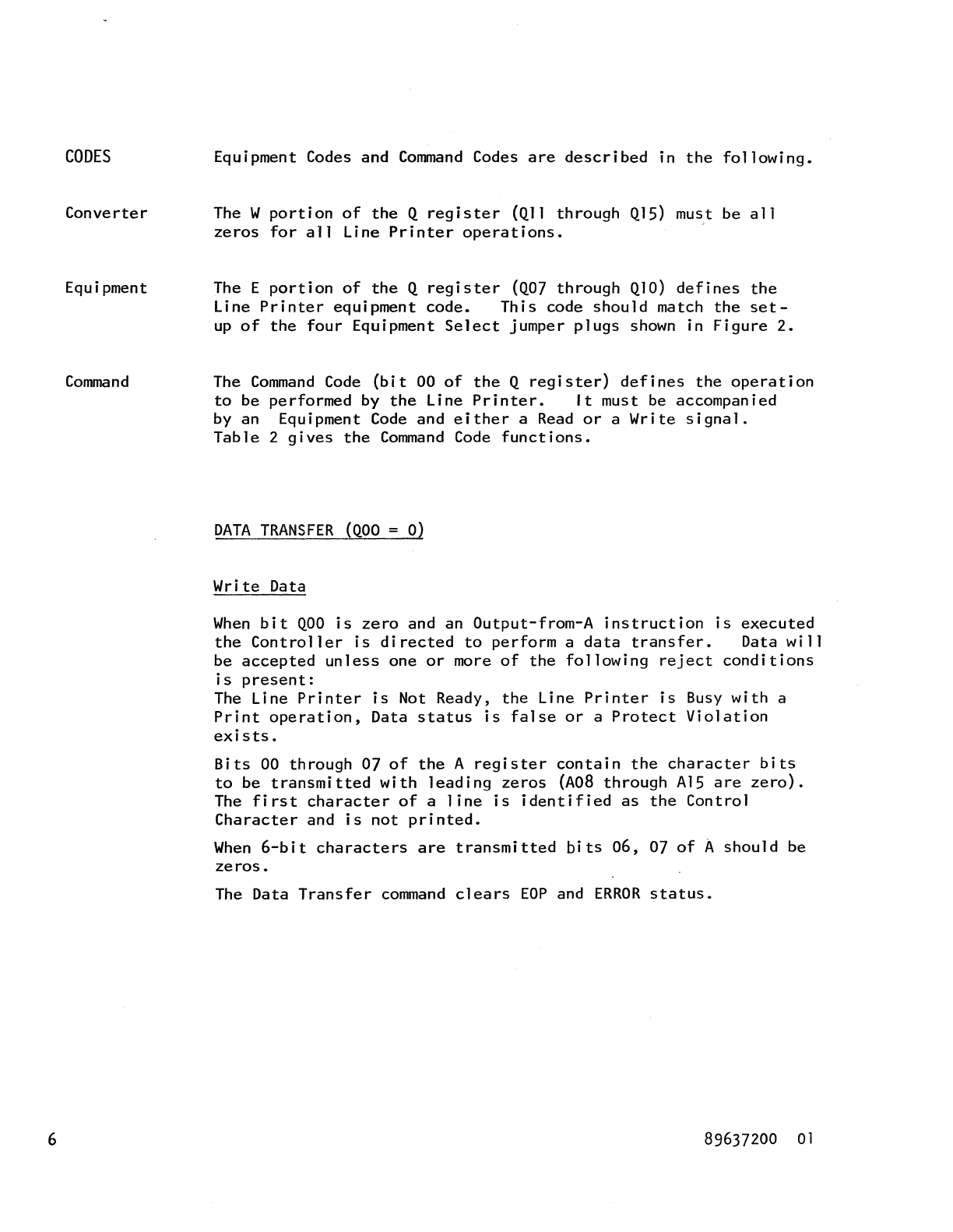
A REGISTER
Ready
Busy
Interrupt
Data
End
of
Operation
Alarm
Error
Protected
Load
Image
(1742-120
only)
Status
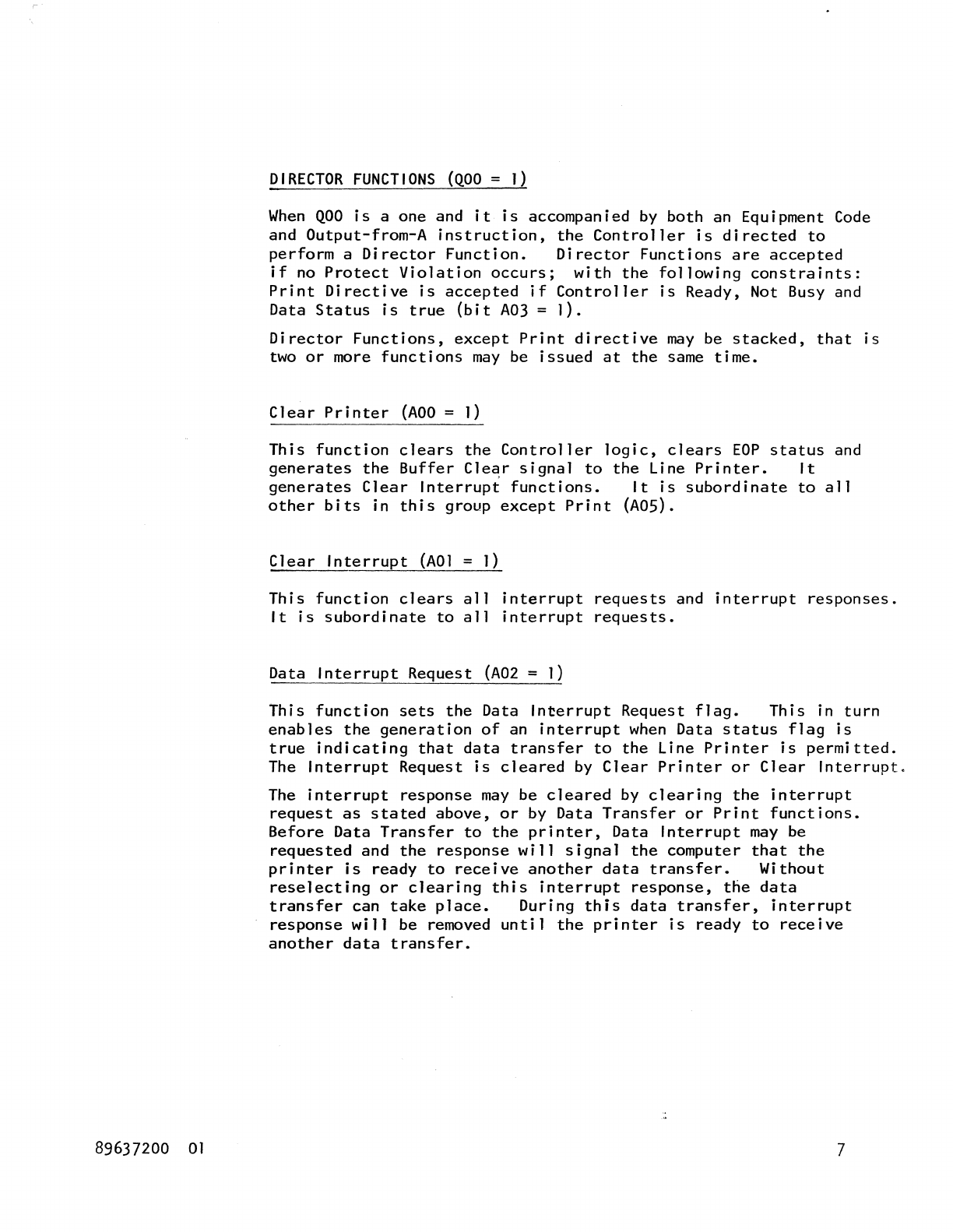
Code
Format
00
CHARACTER
A REGISTER
Data
Transfer
Format.
5
CODES
Converter
Equipment
Command
6
Equipment Codes and
Command
Codes
are
described
in
the
following.
The W
portion
of
the
Q
register
(Qll
through
Ql5) must be
all
zeros
for
all
Line
Printer
operations.
The E
portion
of
the
Q
register
(Q07
through
Ql0)
defines
the
Line
Printer
equipment
code.
This
code
should
match
the
set-
up
of
the
four
Equipment
Select
jumper
plugs
shown
in
Figure
2.
The
Command
Code
(bit
00
of
the
Q
register)
defines
the
operation
to
be
performed
by
the
Line
Printer.
It
must be accompanied
by an Equipment
Code
and
either
a
Read
or
a
Write
signal.
Table
2
gives
the
Command
Code
functions.
DATA
TRANSFER
(QOO
= 0)
Write
Data
When
bit
QOO
is
zero
and an
Output-from-A
instruction
is
executed
the
Controller
is
directed
to
perform
a
data
transfer.
Data
will
be
accepted
unless
one
or
more
of
the
following
reject
conditions
is
present:
The Line
Printer
is
Not Ready,
the
Line
Printer
is
Busy
with
a
Print
operation,
Data
status
is
false
or
a
Protect
Violation
exists.
Bits
00
through
07
of
the
A
register
contain
the
character
bits
to
be
transmitted
with
leading
zeros
(A08
through
Al5
are
zero).
The
first
character
of
a
line
is
identified
as
the
Control
Character
and
is
not
printed.
When
6-bit
characters
are
transmitted
bits
06,
07
of
A
should
be
zeros.
The Data
Transfer
command
clears
EOP
and
ERROR
status.
89637200
01
89637200
01
DIRECTOR
FUNCTIONS
(QOO
=
1)
When
QOO
is
a one and
it
is
accompanied
by
both
an Equipment
Code
and
Output-from-A
instruction,
the
Controller
is
directed
to
perform
a
Director
Function.
Director
Functions
are
accepted
if
no
Protect
Violation
occurs;
with
the
following
constraints:
Print
Directive
is
accepted
if
Controller
is
Ready, Not Busy and
Data
Status
is
true
(bit
A03
=
I).
Director
Functions,
except
Print
directive
may
be
stacked,
that
is
two
or
more
functions
may
be
issued
at
the
same
time.
Clear
Printer
(AOO
=
I)
This
function
clears
the
Controller
logic,
clears
EOP
status
and
generates
the
Buffer
Cle~r
signal
to
the
Line
Printer.
It
generates
Clear
Interrupt
functions.
It
is
subordinate
to
all
other
bits
in
this
group
except
Print
(ADS).
Clear
Interrupt
(AOI
=
1)
This
function
clears
all
interrupt
requests
and
interrupt
responses.
It
is
subordinate
to
all
interrupt
requests.
Data
Interrupt
Request
(A02
=
I)
This
function
sets
the
Data
Interrupt
Request
flag.
This
in
turn
enables
the
generation
of
an
interrupt
when
Data
status
flag
is
true
indicating
that
data
transfer
to
the
Line
Printer
is
permitted.
The
Interrupt
Request
is
cleared
by
Clear
Printer
or
Clear
Interrupt.
The
interrupt
response
may
be
cleared
by
clearing
the
interrupt
request
as
stated
above,
or
by Data
Transfer
or
Print
functions.
Before
Data
Transfer
to
the
printer,
Data
Interrupt
may
be
requested
and
the
response
will
signal
the
computer
that
the
printer
is
ready
to
receive
another
data
transfer.
Without
reselecting
or
clearing
this
interrupt
response,
the
data
transfer
can
take
place.
During
this
data
transfer,
interrupt
response
will
be removed
until
the
printer
is
ready
to
receive
another
data
transfer.
7
8
End-of-Operation
Interrupt
Request
(EOP)
(A03
=
1)
This
function
enables
the
generation
of
an
interrupt
on
completion
of
an
operation,
when
EOP
occurs.
The
interrupt
may
be
selected
before
or
during
the
operation.
An
interrupt
response
will
not
occur
for
an
operation
which was ended
before
the
selection
was
made. The
interrupt
request
may
be
cleared
by
Clear
Controller
or
Clear
Interrupt.
The
interrupt
response
may
be
cleared
by
clearing
the
Request
or
by Data
Transfer
or
Print
functions.
Alarm
Interrupt
Request
(A04
= 1)
This
function
enables
the
generation
of
an
interrupt
when
an Alarm
condition
exists.
An
Alarm
condition
that
exists
at
the
time
this
interrupt
request
is
made
will
immediately
provide
a
response.
If
the
Alarm
condition
does
not
exist
at
the
time
of
the
interrupt
request,
the
interrupt
response
will
be
provided
as
soon
as
an
Alarm
condition
is
detected.
These
conditions
are
listed
in
the
Alarm
section.
The
interrupt
request
may
be
cleared
by
Master
Clear
or
by
either
ADO
= ]
or
AO]
= ]
with
A04
=
O.
The
interrupt
response
may
be
cleared
by
clearing
the
Request
or
by
Data
Transfer
or
Print
Function.
Print
Function
(AOS
= 1)
This
function
directs
the
Line
Printer
to
initiate
a
Print
operation.
A
print
operation
lasts
between
the
acceptance
of
a
Print
Function
and
completion
of
a
line
of
print.
The A
register
bits
06
through
IS
in
this
group
are
not
used.
DIRECTOR
STATUS
The Line
Printer
always
replies
to
therefore
replies
when
QOO
= 1 and
equipment
code and a
Read
signal.
described
below.
Ready
(AOO
= 1)
a
status
request.
It
it
is
accompanied by an
The
status
responses
are
Indicates
that
a Ready
condition
exists.
The
Ready
condition
must be
existing
before
the
printer
can
operate,
and
the
absence
of
anyone
of
several
requirements
can
prevent
this.
89637200
01
89637200
01
Busy
(AOl
=
1)
Indicates
that
the
Line
Printer
is
Busy.
The
Line
Printer
becomes
Busy
-
1. After the
initiation
of a
print
cycle
and
until
the
characters
have
been
printed.
2.
If
Clear
Printer
(AOO
=
1)
directive
was
issued
directly
after
the Control Character
has
been
issued.
Interrupt
(A02
=
1)
This
signal
indicates
that
an
interrupt
occurred.
The
other
status
bits
must be monitored
to
determine
the
cause
of
the
interrupt:
bits
A03
-
AOS
define
which
interrupt
occurred.
This
status
is
cleared
by
either
the
Clear
Printer
(AOO
= 1)
or
Clear
Interrupt
(AOl
=
1).
Data
(A03
=
1)
This
signal
indicates
that
the
Line
Printer
is
ready
to
receive
a
character.
If
Interrupt
on
Data has been
selected,
this
status
will
also
indicate
that
this
interrupt
has
occurred.
The
status
is
cleared
by
Clear
Printer
(AOO
= 1) and
by
either
Data
Transfer
or
Print
directive.
End-of-Operation
(EOP)
(A04
=
1)
Indicates
that
the
Line
Printer
has completed an
operation.
If
Interrupt
on
End-of-Operation
has been
selected,
this
status
bit
will
also
indicate
that
this
interrupt
has
occurred.
This
status
is
true
whenever
the
Line Ready
signal
goes
high.
The
status
is
cleared
by
Clear
Printer,
Data
Transfer,
Print.
Alarm
(AOS
= 1)
Indicates
that
an Alarm
condition
is
present,
that
is,
an
Error
or
Printer
Malfunction
occurred.
The
status
is
cleared
by
Clear
Printer
(AOO
=
1),
Data
Transfer
or
Print
directive
provided
that
the
cause
of
the
alarm
has been
corrected.
9
10
Error
(A06
=
1)
a.
For
the
1742-30 Line
Printer
this
signal
indicates
that
data
transfer
parity
error
occurred.
The
Parity
Error
occurs
when
an
incorrect
character
code
is
received
by
the
Line
Printer.
The
incorrect
character
code
is
printed
as
blank
if
it
is
a
data
character
and ignored
if
a
control
character,
i.e.,
it
is
performed
as
if
"Suppress
Space"
was
isstled.
The
Line
Printer
stays
Ready
when
this
condition
occurs.
The
status
is
cleared
by
Clear
Printer
(AOO
=
1)
or
either
Data
Transfer
or
Print
directive.
b.
For
the
1742-120 Line
Printer
this
signal
indicates
that
any
one
or
any combination
of
Parity
Error,
Synchronization
Error
or
Compare
Error
(indicated
on
the
PrJnter
console)
occurred.
In
case
of
Parity
Error
the
Line
Printer
stays
Ready.
The
condition
is
cleared
by
Clear
Printer
(AOO
=
1)
or
either
Data
Transfer
or
Print
directive.
In
case
of
Synchronization
Error
or
Compare
Error
the
Line
Printer
becomes Busy.
The
condition
is
cleared
by
Clear
Printer
(AOO
=
1)
only.
Protected
(A07
=
1)
This
bit
indicates
that
the
Controller
is
in
the
protect
state,
that
is,
the
protect
jumper
plug
is
in
the
Protect
position
(see
Operation).
In
this
position
the
Controller
accepts
only
instructions
having a 1
on
the
Program
Protect
line.
All
other
instructions
except
Director
Status
will
be
rejected.
The
Program
Protect
bit
is
ignored
when
the
Controller
is
not
in
the
Protect
state.
Load
Image
(A08
=
1)
In
the
1742-120 Line
Printer
this
bit
indicates
that
the
next
288
characters
will
be
transferred
to
the
Line
Printer
Image
Memory.
If
Parity
Error
occurs
no
further
transmission
takes
place
until
Clear
Printer
(AOO
= 1)
is
issued.
Load
Image
status
is
not
applicable
to
the
1742-30.
Bits
A09
through
A15
are
not
used.
89637200
01
OPERATION
Controller
89637200
01
Prepare
the
Controller
for
operation
as
follows:
a.
Set
the
Equipment
Code
as
required
according
to
Table
by
inserting
the
appropriate
jumper
plugs
in
position
(Figure
2).
b.
Set
the
Protect
Bit
as
required
by
inserting
the
protect
bit
jumper
plug
(PTCT)
in
position
(Figure
2).
c.
Connect
the
Device Cable
to
the
proper
connector
on
the
back panel
of
the
1784 Computer.
d.
Insert
the
Controller
card
in
its
place
according
to
the
system
configuration.
1 1

COMMENT SHEET
MANUAL
TITLE
__
1_7_4_2_-_3_0_an_d_l_7_4_2_-_1_2_0_Lin_o_e_Pr_in_te_r_C_o_n_tr_o_l_le_r_R_e_~_er_e_n_c_e_M_an_u_al
_____
_
PUBLICATION NO.
___
89_6_3_7_2_0_0
________
REVISION
_____
0_2
_________
_
FROM NAME:
____________________________________________________________________
__
BUSINE~
ADDRE~:
______
.
_________________________________
_
COMMENTS:
This
form
is
not
intended
to
be
used
as
an
order
blank.
Your
evaluation
of
this
manual
will be welcomed -
by
Control
Data
Corporation.
AZ1y
errors,
suggested
additions
or
deletions,
or
general
comments
may
be
made
below.
Please
include page
number.
STAPLE
STAPLE
FOLD
-----------------------------------~
BUSINESS
REPLY
MAIL
NO
POSTAGE
STAMP
NECESSARY
IF
MAiLED
!N
U.S.A.
POSTAGE
WILL
BE
PAID
BY
CONTROL DATA
CORPORATION
SMALL
COMPUTER
DEVELOPMENT
DIVISION
4455
EASTGATE
MALL
LA
JOLLA,
CALIFORNIA 92037
ATTN:
PUBLICATIONS
DEPARTMENT
FIRST
CLASS
PERMIT
NO.
333
LA
JOLLA.
CA.
------------------------------------~
FOLD
STAPLE
STAPLE
