8•Bus Owner's Manual Mackie 24.8Bus 8bus Om
Mackie 32.8Bus Owner's Manual 8bus_om Mackie - 32.8Bus - Owner's Manual
Mackie 24.8Bus Owner's Manual 8bus_om Mackie - 24.8Bus - Owner's Manual
Mackie 32.8Bus Owner's Manual 8bus_om Mackie - 32.8Bus - Owner's Manual
User Manual: Mackie 24.8Bus Owner's Manual Mackie - 24.8Bus - Owner's Manual
Open the PDF directly: View PDF ![]() .
.
Page Count: 64
- Contents
- Safety Instructions
- Important Sensitivity Adjustment Procedure
- Section 1: Introduction
- Section 2: Panel Layout and Function
- Section 3: General Information
- Section 4: Recording
- Section 5: PA and Sound Reinforcement Applications
- Appendix A: Connections
- Appendix B: Options, Add-Ons, and Extra Stuff
- Appendix C: Specifications
- Service
- Track Sheets
- 8•Bus Limited Warranty
1
8•BUS OWNER'S MANUAL
10
MUTE
11
MUTE
12
MUTE
13
MUTE
14
MUTE
15
MUTE
16
MUTE
17
MUTE
18
MUTE
19
MUTE
20
MUTE
21
MUTE
22
MUTE
23
MUTE
24
MUTE
24x8x2 8-BUS MIXING CONSOLE
9
MUTE
2
MUTE
3
MUTE
4
MUTE
5
MUTE
6
MUTE
7
MUTE
8
MUTE
1
MUTE
CHANNEL
23
CHANNEL
24
CHANNEL
21
CHANNEL
22
CHANNEL
19
CHANNEL
20
CHANNEL
17
CHANNEL
18
CHANNEL
15
CHANNEL
16
CHANNEL
13
CHANNEL
14
CHANNEL
11
CHANNEL
12
CHANNEL
9
CHANNEL
10
PHANTOM
POWER
LINE
IN
DIRECT
OUT
INSERT
BAL-
UNBAL
TIP = OUT
RING = IN
LINE
IN
DIRECT
OUT
INSERT
BAL-
UNBAL
TIP = OUT
RING = IN
LINE
IN
DIRECT
OUT
INSERT
BAL-
UNBAL
TIP = OUT
RING = IN
LINE
IN
DIRECT
OUT
INSERT
BAL-
UNBAL
TIP = OUT
RING = IN
MIC/LINE MIC/LINE MIC/LINE MIC/LINE
LINE
IN
DIRECT
OUT
INSERT
BAL-
UNBAL
TIP = OUT
RING = IN
LINE
IN
DIRECT
OUT
INSERT
BAL-
UNBAL
TIP = OUT
RING = IN
LINE
IN
DIRECT
OUT
INSERT
BAL-
UNBAL
TIP = OUT
RING = IN
LINE
IN
DIRECT
OUT
INSERT
BAL-
UNBAL
TIP = OUT
RING = IN
MIC/LINE MIC/LINE
MIC/LINE MIC/LINE
MIC/LINE
LINE
IN
DIRECT
OUT
INSERT
BAL-
UNBAL
TIP = OUT
RING = IN
LINE
IN
DIRECT
OUT
INSERT
BAL-
UNBAL
TIP = OUT
RING = IN
LINE
IN
DIRECT
OUT
INSERT
BAL-
UNBAL
TIP = OUT
RING = IN
LINE
IN
DIRECT
OUT
INSERT
BAL-
UNBAL
TIP = OUT
RING = IN
LINE
IN
DIRECT
OUT
INSERT
BAL-
UNBAL
TIP = OUT
RING = IN
LINE
IN
DIRECT
OUT
INSERT
BAL-
UNBAL
TIP = OUT
RING = IN
LINE
IN
DIRECT
OUT
INSERT
BAL-
UNBAL
TIP = OUT
RING = IN
LINE
IN
DIRECT
OUT
INSERT
BAL-
UNBAL
TIP = OUT
RING = IN
MIC/LINE MIC/LINE MIC/LINE MIC/LINE MIC/LINE MIC/LINE MIC/LINE
CHANNEL
17
CHANNEL
18
CHANNEL
19
CHANNEL
20
CHANNEL
21
CHANNEL
22
CHANNEL
23
CHANNEL
24
CHANNEL
10
CHANNEL
11
CHANNEL
12
CHANNEL
13
CHANNEL
14
CHANNEL
15
CHANNEL
16
CHANNEL
9
TAPE
MIC/LINE
+4
–10
48
dB
40
dB
U
L
I
N
E
S
E
N
S
I
T
I
V
I
T
Y
M
I
C
/
L
I
N
E
G
A
I
N
TAPE
MIC/LINE
+4
–10
48
dB
40
dB
U
L
I
N
E
S
E
N
S
I
T
I
V
I
T
Y
M
I
C
/
L
I
N
E
G
A
I
N
TAPE
MIC/LINE
+4
–10
48
dB
40
dB
U
L
I
N
E
S
E
N
S
I
T
I
V
I
T
Y
M
I
C
/
L
I
N
E
G
A
I
N
TAPE
MIC/LINE
+4
–10
48
dB
40
dB
U
L
I
N
E
S
E
N
S
I
T
I
V
I
T
Y
M
I
C
/
L
I
N
E
G
A
I
N
TAPE
MIC/LINE
+4
–10
48
dB
40
dB
U
L
I
N
E
S
E
N
S
I
T
I
V
I
T
Y
M
I
C
/
L
I
N
E
G
A
I
N
TAPE
MIC/LINE
+4
–10
48
dB
40
dB
U
L
I
N
E
S
E
N
S
I
T
I
V
I
T
Y
M
I
C
/
L
I
N
E
G
A
I
N
TAPE
MIC/LINE
+4
–10
48
dB
40
dB
U
L
I
N
E
S
E
N
S
I
T
I
V
I
T
Y
M
I
C
/
L
I
N
E
G
A
I
N
TAPE
MIC/LINE
+4
–10
48
dB
40
dB
U
L
I
N
E
S
E
N
S
I
T
I
V
I
T
Y
M
I
C
/
L
I
N
E
G
A
I
N
TAPE
MIC/LINE
+4
–10
48
dB
40
dB
U
L
I
N
E
S
E
N
S
I
T
I
V
I
T
Y
M
I
C
/
L
I
N
E
G
A
I
N
TAPE
MIC/LINE
+4
–10
48
dB
40
dB
U
L
I
N
E
S
E
N
S
I
T
I
V
I
T
Y
M
I
C
/
L
I
N
E
G
A
I
N
TAPE
MIC/LINE
+4
–10
48
dB
40
dB
U
L
I
N
E
S
E
N
S
I
T
I
V
I
T
Y
M
I
C
/
L
I
N
E
G
A
I
N
TAPE
MIC/LINE
+4
–10
48
dB
40
dB
U
L
I
N
E
S
E
N
S
I
T
I
V
I
T
Y
M
I
C
/
L
I
N
E
G
A
I
N
TAPE
MIC/LINE
+4
–10
48
dB
40
dB
U
L
I
N
E
S
E
N
S
I
T
I
V
I
T
Y
M
I
C
/
L
I
N
E
G
A
I
N
TAPE
MIC/LINE
+4
–10
48
dB
40
dB
U
L
I
N
E
S
E
N
S
I
T
I
V
I
T
Y
M
I
C
/
L
I
N
E
G
A
I
N
TAPE
MIC/LINE
+4
–10
48
dB
40
dB
U
L
I
N
E
S
E
N
S
I
T
I
V
I
T
Y
M
I
C
/
L
I
N
E
G
A
I
N
TAPE
MIC/LINE
+4
–10
48
dB
40
dB
U
L
I
N
E
S
E
N
S
I
T
I
V
I
T
Y
M
I
C
/
L
I
N
E
G
A
I
N
FLIP
GAIN
TRIM
FLIP FLIP
GAIN
FLIP
GAIN
FLIP
GAIN
FLIP
GAIN
FLIP
GAIN
FLIP
GAIN
FLIP
GAIN
TRIM
FLIP
TRIM
FLIP FLIP
GAIN
FLIP
GAIN
TRIM
FLIP
GAIN
FLIP
GAIN
FLIP
GAIN
AUX
PRE
1
2
4
3
5
6
MIX-B
CHANNEL
PRE
SHIFT
SOURCE
+15
OO
U
+15
OO
U
+15
OO
U
+15
OO
U
AUX
AUX
PRE
1
2
4
3
5
6
MIX-B
CHANNEL
PRE
SHIFT
SOURCE
+15
OO
U
+15
OO
U
+15
OO
U
+15
OO
U
AUX
910
AUX
PRE
1
2
4
3
5
6
MIX-B
CHANNEL
PRE
SHIFT
SOURCE
+15
OO
U
+15
OO
U
+15
OO
U
+15
OO
U
AUX
AUX
PRE
1
2
4
3
5
6
MIX-B
CHANNEL
PRE
SHIFT
SOURCE
+15
OO
U
+15
OO
U
+15
OO
U
+15
OO
U
AUX
11 12
AUX
PRE
1
2
4
3
5
6
MIX-B
CHANNEL
PRE
SHIFT
SOURCE
+15
OO
U
OO
U
+15
OO
U
+15
OO
U
AUX
PRE
1
2
4
3
5
6
MIX-B
CHANNEL
PRE
SHIFT
SOURCE
+15
OO
U
+15
OO
U
+15
OO
U
+15
OO
U
AUX
13 14
AUX
PRE
1
2
4
3
5
6
MIX-B
CHANNEL
PRE
SHIFT
SOURCE
+15
OO
U
+15
OO
U
+15
OO
U
+15
OO
U
AUX
AUX
PRE
1
2
3
5
6
MIX-B
CHANNEL
PRE
SHIFT
SOURCE
+15
OO
U
+15
OO
U
OO
U
+15
OO
AUX
15 16
AUX
PRE
1
2
4
3
5
6
MIX-B
CHANNEL
PRE
SHIFT
SOURCE
+15
OO
U
+15
OO
U
+15
OO
U
+15
OO
U
AUX
AUX
1
2
4
3
5
6
MIX-B
CHANNEL
PRE
SHIFT
SOURCE
+15
OO
U
+15
OO
U
+15
OO
U
+15
OO
U
AUX
18 19
AUX
PRE
1
2
4
3
5
6
MIX-B
CHANNEL
PRE
SHIFT
SOURCE
+15
OO
U
+15
OO
U
+15
OO
U
+15
OO
U
AUX
AUX
PRE
1
2
4
3
5
6
MIX-B
CHANNEL
PRE
SHIFT
SOURCE
+15
OO
U
+15
OO
U
+15
OO
U
+15
OO
AUX
20 21
AUX
PRE
1
2
4
3
5
6
MIX-B
CHANNEL
PRE
SHIFT
SOURCE
+15
OO
U
+15
OO
U
+15
OO
U
+15
OO
U
AUX
AUX
PRE
1
2
4
3
5
6
MIX-B
CHANNEL
PRE
SHIFT
SOURCE
+15
OO
U
+15
OO
U
+15
OO
U
+15
OO
U
AUX
17 22
AUX
PRE
1
2
4
3
5
6
MIX-B
CHANNEL
PRE
SHIFT
SOURCE
+15
OO
U
+15
OO
U
+15
OO
U
+15
OO
U
AUX
AUX
PRE
1
2
4
3
5
6
MIX-B
CHANNEL
PRE
SHIFT
SOURCE
+15
OO
U
+15
OO
U
+15
OO
U
+15
OO
U
AUX
23 24
+15
AUX
4
+15
U
PRE
U
HI
MID
BAND
WIDTH
500 18k
3k
FREQ
–15 +15
U
1k 5k
3
2
12
NORMAL
HI
MID
BAND
WIDTH
500 18k
3k
FREQ
–15 +15
U
1k 5k
3
2
12
NORMAL
OCTAVES
HI
MID
BAND
WIDTH
500 18k
3k
FREQ
–15 +15
U
1k 5k
3
2
12
NORMAL
HI
MID
BAND
WIDTH
500 18k
3k
FREQ
–15 +15
U
1k 5k
3
2
12
NORMAL
OCTAVES
OCTAVES
HI
MID
BAND
WIDTH
500 18k
3k
FREQ
–15 +15
U
1k 5k
3
2
12
NORMAL
HI
MID
BAND
WIDTH
500 18k
3k
FREQ
–15 +15
U
1k 5k
3
2
12
NORMAL
OCTAVES
OCTAVES
HI
MID
BAND
WIDTH
500 18k
3k
FREQ
–15 +15
U
1k 5k
3
2
12
NORMAL
HI
MID
BAND
WIDTH
500 18k
3k
FREQ
–15 +15
U
1k 5k
3
2
12
NORMAL
OCTAVES
OCTAVES
HI
MID
BAND
WIDTH
500 18k
3k
FREQ
–15 +15
U
1k 5k
3
2
12
NORMAL
HI
MID
BAND
WIDTH
500 18k
3k
FREQ
–15 +15
U
1k 5k
3
2
12
NORMAL
OCTAVES
OCTAVES
HI
MID
BAND
WIDTH
500 18k
3k
FREQ
–15 +15
U
1k 5k
3
2
12
NORMAL
HI
MID
BAND
WIDTH
500 18k
3k
FREQ
–15 +15
U
1k 5k
3
2
12
NORMAL
OCTAVES
OCTAVES
HI
MID
BAND
WIDTH
500 18k
3k
FREQ
–15 +15
U
1k 5k
3
2
12
NORMAL
HI
MID
BAND
WIDTH
500 18k
3k
FREQ
–15 +15
U
1k 5k
3
2
12
NORMAL
OCTAVESOCTAVES
HI
MID
BAND
WIDTH
500 18k
3k
FREQ
–15 +15
U
1k 5k
3
2
12
NORMAL
HI
MID
BAND
WIDTH
500 18k
3k
FREQ
–15 +15
U
1k 5k
3
2
12
NORMAL
OCTAVES
OCTAVES
111111111111111
1
OCTAVES
EQ
LOW CUT
EQ IN
LO
MID
HI
FREQ
75 Hz
18dB/oct
45 3k
–15 +15
U
LO
–15 +15
U
–15 +15
U
250
220 350
EQ
LOW CUT
EQ IN
LO
MID
HI
FREQ
75 Hz
18dB/oct
45 3k
–15 +15
U
LO
–15 +15
U
–15 +15
U
250
220 350
EQ
LOW CUT
EQ IN
LO
MID
HI
75 Hz
18dB/oct
45 3k
–15 +15
U
LO
–15 +15
U
–15 +15
U
250
220 350
EQ
LOW CUT
EQ IN
LO
MID
HI
FREQ
75 Hz
18dB/oct
45 3k
–15 +15
U
LO
–15 +15
U
–15 +15
U
250
220 350
EQ
LOW CUT
EQ IN
LO
MID
HI
FREQ
75 Hz
18dB/oct
45
+15
U
LO
–15 +15
U
–15 +15
U
250
220 350
EQ
LOW CUT
EQ IN
LO
MID
HI
FREQ
75 Hz
18dB/oct
45 3k
–15 +15
80
U
–15 +15
U
–15 +15
U
250
220 350
EQ
LOW CUT
EQ IN
LO
MID
HI
FREQ
75 Hz
18dB/oct
45 3k
–15 +15
U
LO
–15 +15
U
–15 +15
U
250
220 350
EQ
LOW CUT
EQ IN
LO
MID
HI
FREQ
75 Hz
18dB/oct
45 3k
–15 +15
U
LO
–15 +15
U
–15 +15
U
250
220 350
12k
EQ
LOW CUT
EQ IN
LO
MID
HI
FREQ
75 Hz
18dB/oct
45 3k
–15 +15
80
U
LO
–15 +15
U
–15 +15
U
250
220
12k
EQ
LOW CUT
EQ IN
LO
MID
HI
FREQ
75 Hz
18dB/oct
45 3k
–15 +15
80
U
LO
–15 +15
U
–15 +15
U
250
220 350
12k
EQ
LOW CUT
EQ IN
LO
MID
HI
FREQ
75 Hz
18dB/oct
45 3k
–15 +15
80
U
LO
–15 +15
U
–15 +15
U
250
220 350
12k
EQ
LOW CUT
EQ IN
LO
MID
HI
FREQ
75 Hz
18dB/oct
45 3k
–15 +15
80
U
LO
–15 +15
U
–15 +15
U
250
220 350
12k
EQ
LOW CUT
EQ IN
LO
MID
HI
FREQ
75 Hz
18dB/oct
45 3k
–15 +15
80
U
LO
–15 +15
U
–15 +15
U
250
220 350
12k
EQ
LOW CUT
EQ IN
LO
MID
HI
FREQ
75 Hz
18dB/oct
45 3k
–15 +15
80
U
LO
–15 +15
U
–15 +15
U
250
220 350
12k
EQ
LOW CUT
EQ IN
LO
MID
HI
FREQ
75 Hz
18dB/oct
45 3k
–15 +15
80
U
LO
–15 +15
U
–15 +15
U
250
220 350
12k
EQ
LOW CUT
EQ IN
LO
MID
HI
FREQ
75 Hz
18dB/oct
45 3k
–15 +15
80
U
LO
–15 +15
U
–15 +15
U
250
220 350
12k
80
12k
80
12k
80
12k
LO
12k
80
12k
80
12k
80
12k
80
350
3k
–15
FREQ
+15
OO
U
MIX-B
SOURCE
PAN
LEVEL
SPLIT EQ
HI/LO EQ
TO MON
MONITOR
LR
PAN
SOLO
-20
OL
LR
+15
OO
U
MIX-B
SOURCE
PAN
LEVEL
SPLIT EQ
HI/LO EQ
TO MON
MONITOR
LR
PAN
SOLO
-20
OL
LR
FLIP SW
CHANNEL
FLIP SW
CHANNEL
+15
OO
U
MIX-B
SOURCE
PAN
LEVEL
SPLIT EQ
HI/LO EQ
TO MON
MONITOR
LR
PAN
SOLO
-20
OL
LR
+15
OO
U
MIX-B
SOURCE
PAN
LEVEL
SPLIT EQ
HI/LO EQ
TO MON
MONITOR
LR
PAN
SOLO
-20
OL
LR
CHANNEL CHANNEL
+15
OO
U
MIX-B
SOURCE
PAN
LEVEL
SPLIT EQ
HI/LO EQ
TO MON
MONITOR
LR
PAN
SOLO
-20
OL
LR
+15
U
MIX-B
SOURCE
PAN
LEVEL
SPLIT EQ
HI/LO EQ
TO MON
MONITOR
LR
PAN
SOLO
-20
OL
LR
FLIP SW FLIP SW
+15
OO
U
MIX-B
SOURCE
PAN
LEVEL
SPLIT EQ
HI/LO EQ
TO MON
MONITOR
LR
PAN
SOLO
-20
OL
LR
+15
OO
U
MIX-B
SOURCE
PAN
LEVEL
SPLIT EQ
HI/LO EQ
TO MON
MONITOR
LR
PAN
SOLO
-20
OL
LR
FLIP SW
CHANNEL
FLIP SW
CHANNEL
FLIP SW FLIP SW
CHANNEL CHANNEL
+15
OO
U
MIX-B
SOURCE
PAN
LEVEL
SPLIT EQ
HI/LO EQ
TO MON
MONITOR
LR
PAN
SOLO
-20
OL
LR
+15
OO
U
MIX-B
SOURCE
PAN
LEVEL
SPLIT EQ
HI/LO EQ
TO MON
MONITOR
LR
PAN
SOLO
-20
OL
LR
FLIP SW
CHANNEL
FLIP SW
CHANNEL
+15
OO
U
MIX-B
SOURCE
PAN
LEVEL
SPLIT EQ
HI/LO EQ
TO MON
MONITOR
LR
PAN
SOLO
-20
OL
LR
+15
OO
U
MIX-B
SOURCE
PAN
LEVEL
SPLIT EQ
HI/LO EQ
TO MON
MONITOR
LR
PAN
SOLO
-20
OL
LR
FLIP SW
CHANNEL
FLIP SW
CHANNEL
+15
O
U
MIX-B
SOURCE
PAN
LEVEL
SPLIT EQ
MONITOR
LR
PAN
SOLO
OL
L
+15
OO
U
MIX-B
SOURCE
PAN
LEVEL
SPLIT EQ
HI/LO EQ
TO MON
MONITOR
LR
PAN
SOLO
-20
OL
LR
FLIP SW
CHANNEL
FLIP SW
CHANNEL
+15
OO
U
MIX-B
SOURCE
LEVEL
SPLIT EQ
MONITOR
LR
PAN
SOLO
-20
OL
LR
FLIP SW
CHANNEL
HI/LO EQ
TO MON
O
HI/LO EQ
TO MON
-20
R
PAN
FLIP SW
CHANNEL
+15
OO
U
MIX-B
SOURCE
PAN
LEVEL
SPLIT EQ
HI/LO EQ
TO MON
MONITOR
LR
PAN
SOLO
-20
OL
LR
OO
dB
30
20
5
10
L/R
MIX
OO
MUTE
5
10
40
50
80
dB
30
20
5
10
5-6
3-4
1-2
7- 8
L/R
MIX
OO
MUTE
5
10
40
50
80
5-6
3-4
1-2
7- 8
dB
30
20
5
10
L/R
MIX
O
O
MUTE
5
10
40
50
80
dB
30
20
5
10
L/R
MIX
OO
MUTE
5
10
40
50
80
dB
30
20
5
10
L/R
MIX
OO
MUTE
5
10
40
50
80
dB
30
20
5
10
L/R
MIX
MUTE
5
10
40
50
80
5-6
3-4
1-2
7- 8
5-6
3-4
1-2
7- 8
5-6
3-4
1-2
7- 8
5-6
3-4
1-2
7- 8
dB
30
20
5
10
L/R
MIX
OO
MUTE
5
10
40
50
80
dB
30
20
5
10
L/R
MIX
OO
MUTE
5
10
40
50
80
dB
30
20
5
10
L/R
MIX
OO
MUTE
5
10
40
50
80
dB
30
20
5
10
L/R
MIX
OO
MUTE
5
10
40
50
80
5-6
3-4
1-2
7- 8
5-6
3-4
1-2
7- 8
5-6
3-4
1-2
7- 8
5-6
3-4
1-2
7- 8
UUUU UUUU
dB
30
20
5
10
L/R
MIX
OO
MUTE
5
10
40
50
80
dB
30
20
5
10
L/R
MIX
OO
MUTE
5
10
40
50
80
dB
30
20
5
10
L/R
MIX
OO
MUTE
5
10
40
50
80
dB
30
20
5
10
L/R
MIX
OO
MUTE
5
10
40
50
80
UUUU
5-6
3-4
1-2
7- 8
5-6
3-4
1-2
7- 8
5-6
3-4
1-2
7- 8
5-6
3-4
1-2
7- 8
dB
30
20
5
10
L/R
MIX
OO
MUTE
5
10
40
50
80
dB
30
20
5
10
L/R
MIX
OO
MUTE
5
10
40
50
80
UU
5-6
3-4
1-2
7- 8
5-6
3-4
1-2
7- 8
OO
UU
dB
30
20
5
10
OO
5
10
40
50
80
dB
30
20
5
10
OO
5
10
40
50
80
dB
30
20
5
10
O
O
5
10
40
50
80
dB
30
20
5
10
OO
5
10
40
50
80
1234
UUUU
dB
30
20
5
10
OO
5
10
40
50
80
dB
30
20
5
10
OO
5
10
40
50
80
dB
30
20
5
10
OO
5
10
40
50
80
dB
30
20
5
10
OO
5
10
40
50
80
5678
UUUU
MIX
dB
30
20
5
10
OO
5
10
40
50
80
U
SOLO SOLO SO LO SOLO SOLO SOLO SO LO SOLO TALKBACK
MIC
LEFT/RIGHT
MONO
L+R
RLRLRLR
MONO
L+R
MONO
L+R
MONO
L+R
MONO
L+R
ASSIGN
MONO
L+R
MONO
L+R
L
MONO
L+R
ASSIGN ASSIGN ASSIGN ASSIGN ASSIGNASSIGNASSIGN
MIX MIX MIX MIX
LRLRLRL R
MAIN
OR SOLO LEVEL
1
9
17
2
10
18
3
11
19
4
12
20
5
13
21
6
14
22
7
15
23
8
16
24
10
+
7
4
2
0
2
10
7
10
20
30
40
–
10
+
7
4
2
0
2
10
7
10
20
30
40
–
10
+
7
4
2
0
2
10
7
10
20
30
40
–
10
+
7
4
2
0
2
10
7
10
20
30
40
–
10
+
7
4
2
0
2
10
7
10
20
30
40
–
10
+
7
4
2
0
2
10
7
10
20
30
40
–
10
+
7
4
2
0
2
10
7
10
20
30
40
–
10
7
4
2
0
2
10
7
10
20
30
40
–
22
+
MIX-B TO
L/R MIX
SOLO AUX SEND 3/4
MIX-B
CNTRL RM
AUX SEND 5/6
EXTERNAL
SOURCE
MIX B
MONITOR PHONES 1
PHONES
LEVEL
SOLO AUX SEND 3/4
MIX-B
CNTRL RM
AUX SEND 5/6
EXTERNAL
SOURCE
PHONES 2
PHONES
LEVEL
ASSIGN
MIX-B
LEVEL
+15
OO
U
OOOO
MONO
TAPE SUB
MASTERS
AUX SEND 1
2-TK
MIX-B
L/R MIX
EXTERNAL
SOURCE
MONITOR
CNTRL RM
STUDIO
SOLO TALKBACK
LEVEL LEVEL
RUDE
SOLO LITE
AUX SEND 2
PHONES
&
STUDIO
+15
OO
U
+15
OO
U
+15
OO
U
SOLO SOLO
SOLO SOLO
AUX SENDS STEREO AUX RETURNS
4
35
6
PHONES
2
L/R MIX
PHONES
1
PHONES
2
L/R MIX
3
4
LEVEL
ASSIGN
ASSIGN
LEVELLEVEL
PHONES
1
6
+15
OO
U
+15
OO
U
+15
OO
U
+15
OO
U
+20
OO
U
+20
OO
U
5
+20
OO
U
+20
OO
U
SOLO
SOLO
SOLO
SOLO
SOLO SOLO
LEVEL
L/R MIX
1-2 3-4 5-6 7-8
L/R MIX
SOLO 1-2 3-4 5-6 7-8
1
2
ASSIGN
ASSIGN
+20
OO
U
+20
OO
U
LR
LR
SOLO
LEVEL BALANCE
SOLO
SOLO
2
1
+15
OO
U
+15
OO
U
LEVEL
POWER
EXTERNAL
INPUT
MIX-B
OUTPUT
AUX SEND
3
3
R
L
4
4
R
R
5
5
R
L
6
6
R
R
L
7
L
L
L
R
8
R
R
R
SUBMASTER INSERT
AUX RETURN
CNTRL
RM OUTPUT
STUDIO
OUTPUT
MAIN MIX
MAIN
INSERTS
3456
PHONES 12
MONO
L
MONO
L
MONO
L
MONO
L
MONO
1
1
R
L
2
2
R
R
2-TRACK
INPUT
12
MONO
L
MONO
L
MONO
TIP=OUT RING=IN
PHANTOM
POWER
TRIM
GAIN
TRIM TRIM TRIM TRIM TRIM TRIM
GAIN GAIN
TRIM TRIM TRIM TRIM
TRIM
CHANNEL
7
CHANNEL
8
CHANNEL
5
CHANNEL
6
CHANNEL
3
CHANNEL
4
CHANNEL
1
CHANNEL
2
MIC/LINE
LINE
IN
DIRECT
OUT
INSERT
BAL-
UNBAL
TIP = OUT
RING = IN
LINE
IN
DIRECT
OUT
INSERT
BAL-
UNBAL
TIP = OUT
RING = IN
LINE
IN
DIRECT
OUT
INSERT
BAL-
UNBAL
TIP = OUT
RING = IN
LINE
IN
DIRECT
OUT
INSERT
BAL-
UNBAL
TIP = OUT
RING = IN
LINE
IN
DIRECT
OUT
INSERT
BAL-
UNBAL
TIP = OUT
RING = IN
LINE
IN
DIRECT
OUT
INSERT
BAL-
UNBAL
TIP = OUT
RING = IN
LINE
IN
DIRECT
OUT
INSERT
BAL-
UNBAL
TIP = OUT
RING = IN
LINE
IN
DIRECT
OUT
INSERT
BAL-
UNBAL
TIP = OUT
RING = IN
MIC/LINE MIC/LINE MIC/LINE MIC/LINE MIC/LINE MIC/LINE MIC/LINE
CHANNEL
2
CHANNEL
3
CHANNEL
4
CHANNEL
5
CHANNEL
6
CHANNEL
7
CHANNEL
8
CHANNEL
1
TAPE
MIC/LINE
+4
–10
48
dB
40
dB
U
L
I
N
E
S
E
N
S
I
T
I
V
I
T
Y
M
I
C
/
L
I
N
E
G
A
I
N
TAPE
MIC/LINE
+4
–10
48
dB
40
dB
U
L
I
N
E
S
E
N
S
I
T
I
V
I
T
Y
M
I
C
/
L
I
N
E
G
A
I
N
TAPE
MIC/LINE
+4
–10
48
dB
40
dB
U
L
I
N
E
S
E
N
S
I
T
I
V
I
T
Y
M
I
C
/
L
I
N
E
G
A
I
N
TAPE
MIC/LINE
+4
–10
48
dB
40
dB
U
L
I
N
E
S
E
N
S
I
T
I
V
I
T
Y
M
I
C
/
L
I
N
E
G
A
I
N
TAPE
MIC/LINE
+4
–10
48
dB
40
dB
U
L
I
N
E
S
E
N
S
I
T
I
V
I
T
Y
M
I
C
/
L
I
N
E
G
A
I
N
TAPE
MIC/LINE
+4
–10
48
dB
40
dB
U
L
I
N
E
S
E
N
S
I
T
I
V
I
T
Y
M
I
C
/
L
I
N
E
G
A
I
N
TAPE
MIC/LINE
+4
–10
48
dB
40
dB
U
L
I
N
E
S
E
N
S
I
T
I
V
I
T
Y
M
I
C
/
L
I
N
E
G
A
I
N
TAPE
MIC/LINE
+4
–10
48
dB
40
dB
U
L
I
N
E
S
E
N
S
I
T
I
V
I
T
Y
M
I
C
/
L
I
N
E
G
A
I
N
FLIP
GAIN
TRIM
FLIP FLIP
GAIN
FLIP
GAIN
FLIP
GAIN
FLIP
GAIN
FLIP
GAIN
FLIP
GAIN
AUX
PRE
1
2
4
3
5
6
MIX-B
CHANNEL
PRE
SHIFT
SOURCE
+15
OO
U
+15
OO
U
+15
OO
U
+15
OO
U
AUX
AUX
PRE
1
2
4
3
5
6
MIX-B
CHANNEL
PRE
SHIFT
SOURCE
+15
OO
U
+15
OO
U
+15
OO
U
+15
OO
U
AUX
12
AUX
PRE
1
2
4
3
5
6
MIX-B
CHANNEL
PRE
SHIFT
SOURCE
+15
OO
U
+15
OO
U
+15
OO
U
+15
OO
U
AUX
AUX
PRE
1
2
4
3
5
6
MIX-B
CHANNEL
PRE
SHIFT
SOURCE
+15
OO
U
+15
OO
U
+15
OO
U
+15
OO
U
AUX
34
AUX
PRE
1
2
4
3
5
6
MIX-B
CHANNEL
PRE
SHIFT
SOURCE
+15
OO
U
OO
U
+15
OO
U
+15
OO
U
AUX
PRE
1
2
4
3
5
6
MIX-B
CHANNEL
PRE
SHIFT
SOURCE
+15
OO
U
+15
OO
U
+15
OO
U
+15
OO
U
AUX
56
AUX
PRE
1
2
4
3
5
6
MIX-B
CHANNEL
PRE
SHIFT
SOURCE
+15
OO
U
+15
OO
U
+15
OO
U
+15
OO
U
AUX
AUX
PRE
1
2
3
5
6
MIX-B
CHANNEL
PRE
SHIFT
SOURCE
+15
OO
U
+15
OO
U
OO
U
+15
OO
AUX
78
+15
AUX
4
+15
U
HI
MID
BAND
WIDTH
500 18k
3k
FREQ
–15 +15
U
1k 5k
3
2
12
NORMAL
HI
MID
BAND
WIDTH
500 18k
3k
FREQ
–15 +15
U
1k 5k
3
2
12
NORMAL
OCTAVES
OCTAVES
HI
MID
BAND
WIDTH
500 18k
3k
FREQ
–15 +15
U
1k 5k
3
2
12
NORMAL
HI
MID
BAND
WIDTH
500 18k
3k
FREQ
–15 +15
U
1k 5k
3
2
12
NORMAL
OCTAVES
OCTAVES
HI
MID
BAND
WIDTH
500 18k
3k
FREQ
–15 +15
U
1k 5k
3
2
12
NORMAL
HI
MID
BAND
WIDTH
500 18k
3k
FREQ
–15 +15
U
1k 5k
3
2
12
NORMAL
OCTAVESOCTAVES
HI
MID
BAND
WIDTH
500 18k
3k
FREQ
–15 +15
U
1k 5k
3
2
12
NORMAL
HI
MID
BAND
WIDTH
500 18k
3k
FREQ
–15 +15
U
1k 5k
3
2
12
NORMAL
OCTAVES
OCTAVES
1111111
1
12k
EQ
LOW CUT
EQ IN
LO
MID
HI
FREQ
75 Hz
18dB/oct
45 3k
–15 +15
80
U
LO
–15 +15
U
–15 +15
U
250
220
12k
EQ
LOW CUT
EQ IN
LO
MID
HI
FREQ
75 Hz
18dB/oct
45 3k
–15 +15
80
U
LO
–15 +15
U
–15 +15
U
250
220 350
12k
EQ
LOW CUT
EQ IN
LO
MID
HI
FREQ
75 Hz
18dB/oct
45 3k
–15 +15
80
U
LO
–15 +15
U
–15 +15
U
250
220 350
12k
EQ
LOW CUT
EQ IN
LO
MID
HI
FREQ
75 Hz
18dB/oct
45 3k
–15 +15
80
U
LO
–15 +15
U
–15 +15
U
250
220 350
12k
EQ
LOW CUT
EQ IN
LO
MID
HI
FREQ
75 Hz
18dB/oct
45 3k
–15 +15
80
U
LO
–15 +15
U
–15 +15
U
250
220 350
12k
EQ
LOW CUT
EQ IN
LO
MID
HI
FREQ
75 Hz
18dB/oct
45 3k
–15 +15
80
U
LO
–15 +15
U
–15 +15
U
250
220 350
12k
EQ
LOW CUT
EQ IN
LO
MID
HI
FREQ
75 Hz
18dB/oct
45 3k
–15 +15
80
U
LO
–15 +15
U
–15 +15
U
250
220 350
12k
EQ
LOW CUT
EQ IN
LO
MID
HI
FREQ
75 Hz
18dB/oct
45 3k
–15 +15
80
U
LO
–15 +15
U
–15 +15
U
250
220 350 350
+15
OO
U
MIX-B
SOURCE
PAN
LEVEL
SPLIT EQ
HI/LO EQ
TO MON
MONITOR
LR
PAN
SOLO
-20
OL
LR
+15
OO
U
MIX-B
SOURCE
PAN
LEVEL
SPLIT EQ
HI/LO EQ
TO MON
MONITOR
LR
PAN
SOLO
-20
OL
LR
FLIP SW
CHANNEL
FLIP SW
CHANNEL
+15
OO
U
MIX-B
SOURCE
PAN
LEVEL
SPLIT EQ
HI/LO EQ
TO MON
MONITOR
LR
PAN
SOLO
-20
OL
LR
+15
OO
U
MIX-B
SOURCE
PAN
LEVEL
SPLIT EQ
HI/LO EQ
TO MON
MONITOR
LR
PAN
SOLO
-20
OL
LR
FLIP SW
CHANNEL
FLIP SW
CHANNEL
+15
O
U
MIX-B
SOURCE
PAN
LEVEL
SPLIT EQ
MONITOR
LR
PAN
SOLO
OL
L
+15
OO
U
MIX-B
SOURCE
PAN
LEVEL
SPLIT EQ
HI/LO EQ
TO MON
MONITOR
LR
PAN
SOLO
-20
OL
LR
FLIP SW
CHANNEL
FLIP SW
CHANNEL
+15
OO
U
MIX-B
SOURCE
LEVEL
SPLIT EQ
MONITOR
LR
PAN
SOLO
-20
OL
LR
FLIP SW
CHANNEL
HI/LO EQ
TO MON
O
HI/LO EQ
TO MON
-20
R
PAN
FLIP SW
CHANNEL
+15
OO
U
MIX-B
SOURCE
PAN
LEVEL
SPLIT EQ
HI/LO EQ
TO MON
MONITOR
LR
PAN
SOLO
-20
OL
LR
dB
30
20
5
10
L/R
MIX
OO
MUTE
5
10
40
50
80
dB
30
20
5
10
5-6
3-4
1-2
7- 8
L/R
MIX
OO
MUTE
5
10
40
50
80
5-6
3-4
1-2
7- 8
dB
30
20
5
10
L/R
MIX
OO
MUTE
5
10
40
50
80
dB
30
20
5
10
L/R
MIX
OO
MUTE
5
10
40
50
80
dB
30
20
5
10
L/R
MIX
OO
MUTE
5
10
40
50
80
dB
30
20
5
10
L/R
MIX
MUTE
5
10
40
50
80
5-6
3-4
1-2
7- 8
5-6
3-4
1-2
7- 8
5-6
3-4
1-2
7- 8
5-6
3-4
1-2
7- 8
dB
30
20
5
10
L/R
MIX
OO
MUTE
5
10
40
50
80
dB
30
20
5
10
L/R
MIX
OO
MUTE
5
10
40
50
80
5-6
3-4
1-2
7- 8
5-6
3-4
1-2
7- 8
UUUU UUUU
OO
PHANTOM
POWER
TRIM
GAIN
TRIM TRIM TRIM TRIM TRIM
TRIM
OO
Part No. 820-007-90 Rev. A 06/03
©1995-2003 Mackie Designs Inc. All Rights Reserved.
C. The 8•Bus Console and External Power Supply have been
exposed to rain; or
D. The 8•Bus Console and External Power Supply does not appear
to operate or exhibits a marked change in performance; or
E. The 8•Bus Console and External Power Supply has been
dropped, or its chassis damaged.
11. Servicing — Do not attempt to service the 8•Bus Console and
External Power Supply beyond those means described in this operating
manual. All other servicing should be referred to the Mackie Service
Department.
12. To prevent electric shock, do not use the 8•Bus Console and
External Power Supply polarized plug with an extension cord,
receptacle or other outlet unless the blades can be fully inserted to
prevent blade exposure.
Pour prévenir les chocs électriques ne pas utiliser cette fiche polariseé
avec un prolongateur, un prise de courant ou une autre sortie de
courant, sauf si les lames peuvent être insérées à fond sans laisser
aucune pariie à découvert.
13 . Grounding or Polarization — Do not defeat the grounding or
polarization of the 8•Bus Console and External Power Supply.
This apparatus does not exceed the Class A/Class B (whichever is
applicable) limits for radio noise emissions from digital apparatus as
set out in the radio interference regulations of the Canadian
Department of Communications.
ATTENTION —Le présent appareil numérique n’émet pas de bruits
radioélectriques dépassant las limites applicables aux appareils
numériques de class A/de class B (selon le cas) prescrites dans le
règlement sur le brouillage radioélectrique édicté par les ministere des
communications du Canada.
14. Exposure to extremely high noise levels may cause permanent hearing
loss. Individuals vary considerably in susceptibility to noise-induced hearing
loss, but nearly everyone will lose some hearing if exposed to sufficiently
intense noise for a period of time. The U.S. Government’s Occupational
Safety and Health Administration (OSHA) has specified the permissible noise
level exposures shown in the following chart.
According to OSHA, any exposure in excess of these permissible limits
could result in some hearing loss. To ensure against potentially dangerous
exposure to high sound pressure levels, it is recommended that all persons
exposed to equipment capable of producing high sound pressure levels use
hearing protectors while the equipment is in operation. Ear plugs or protectors
in the ear canals or over the ears must be worn when operating the equip-
ment in order to prevent a permanent hearing loss if exposure is in excess
of the limits set forth here.
CAUTION AVIS
RISK OF ELECTRIC
SHOCK
DO NOT OPEN
RISQUE DE
CHOC
ELECTRIQUE
NE PAS OUVRIR
CAUTION: TO REDUCE THE RISK OF ELECTRIC SHOCK
DO NOT REMOVE COVER (OR BACK)
NO USER-SERVICEABLE PARTS INSIDE
REFER SERVICING TO QUALIFIED PERSONNEL
ATTENTION: POUR EVITER LES RISQUES DE CHOC
ELECTRIQUE, NE PAS ENLEVER LE COUVERCLE. AUCUN
ENTRETIEN DE PIECES INTERIEURES PAR L'USAGER. CONFIER
L'ENTRETIEN AU PERSONNEL QUALIFIE.
AVIS: POUR EVITER LES RISQUES D'INCENDIE OU
D'ELECTROCUTION, N'EXPOSEZ PAS CET ARTICLE
A LA PLUIE OU A L'HUMIDITE
The lightning flash with arrowhead symbol within an equilateral
triangle is intended to alert the user to the presence of uninsulated
"dangerous voltage" within the product's enclosure, that may be
of sufficient magnitude to constitute a risk of electric shock to persons.
Le symbole éclair avec point de flèche à l'intérieur d'un triangle
équilatéral est utilisé pour alerter l'utilisateur de la présence à
l'intérieur du coffret de "voltage dangereux" non isolé d'ampleur
suffisante pour constituer un risque d'éléctrocution.
The exclamation point within an equilateral triangle is intended to
alert the user of the presence of important operating and maintenance
(servicing) instructions in the literature accompanying the appliance.
Le point d'exclamation à l'intérieur d'un triangle équilatéral est
employé pour alerter les utilisateurs de la présence d'instructions
importantes pour le fonctionnement et l'entretien (service) dans le
livret d'instruction accompagnant l'appareil.
SAFETY INSTRUCTIONS
1. Read Instructions — Read all the safety and operation instructions
before operating the 8•Bus Console and External Power Supply.
2. Retain Instructions — Keep the safety and operating instructions
for future reference.
3. Heed Warnings — Follow all warnings on the 8•Bus Console and
External Power Supply and in these operating instructions.
4. Follow Instructions — Follow all operating and other instructions.
5. Water and Moisture — Do not use the 8•Bus Console and
External Power Supply near water - for example, near a bathtub,
washbowl, kitchen sink, laundry tub, in a wet basement, near a
swimming pool, swamp or salivating St. Bernard dog, etc.
6. Heat — Locate the 8•Bus Console and External Power Supply
away from heat sources such as radiators, or other devices that
produce heat.
7. Power Sources — Connect the 8•Bus Console and External Power
Supply only to a power supply of the type described in these operation
instructions or as marked on the 8•Bus Console and External Power
Supply.
8. Power Cord Protection — Route power supply cords so that they
are not likely to be walked upon or pinched by items placed upon or
against them, paying particular attention to cords at plugs,
convenience receptacles, and the point where they exit the 8•Bus
Console and External Power Supply.
9. Object and Liquid Entry — Do not drop objects or spill liquids into
the inside of the 8•Bus Console and External Power Supply.
10. Damage Requiring Service — The 8•Bus Console and
External Power Supply should be serviced only by qualified service
personnel when:
A. 8•Bus Console and External Power Supply power-supply cord
or the plug has been damaged; or
B. Objects have fallen, or liquid has spilled into the 8•Bus Console
and External Power Supply; or
Duration Per Day Sound Level dBA, Typical
In Hours Slow Response Example
8 90 Duo in small club
692
4 95 Subway Train
397
2 100 Very loud classical music
1.5 102
1 105 Patrice screaming at Ron about deadlines
0.5 110
0.25 or less 115 Loudest parts at a rock concert
WARNING — To reduce the risk of fire or electric shock,
do not expose this appliance to rain or moisture.
1
IMPORTANT SENSITIVITY
ADJUSTMENT PROCEDURE!
24•8
32•8
Owner’s
Manual
Version
Rev. A
06/03
during mixdown, roll an already-recorded
track from your recorder.
4. The channel’s –20dB LED may light. The
L/R main meters will show the actual internal
operating level of soloed signals. Now you will
optimize levels.
5. ■■For mic or line inputs, adjust the TRIM
control clockwise to get peaks that regularly
hit 0dB on the L/R meters. For mic inputs
this may require full CW rotation depending
on the sensitivity of the mic.
6. If desired (optional):
■■Press the EQ switch in.
■■Adjust the channel strip’s EQ to about
what you will be using during the session.
■■Re-perform Step 5.
7. ■■Return the channel strip’s SOLO button to
its up position.
8. ■■Repeat Steps 1-7 on the next channel that
is being used.
To fully achieve the Mackie 8•Bus console’s
impressive headroom and specs, you should
“tune” channel sensitivity for each channel.
FOLLOW THIS PROCEDURE FOR
EACH CHANNEL IN USE:
1. Assign signal to channel fader:
■■If channel will be used with a micro–
phone, MIC/LINE switch should be up &
FLIP switch should be up.
■■If channel will be used with line input,
MIC/LINE switch should be down &
FLIP switch should be up.
■■If channel will be used with a tape
input keep the FLIP switch down.
2. Set channel strip controls as follows:
■■TRIM pot all the way counterclockwise
(+4dB)
■■AUX SEND controls all the way counter-
clockwise (off)
■■EQ switch up
■■LOW-CUT switch either on or off
(on recommended for mic inputs)
■■Pan hard left or right
■■Channel fader at UNITY
■■SOLO switch down
3. ■■Make appropriate “noise” into the channel
input. For example, have a performer play/
sing/strike something or someone, etc., at
the level at which they’re going to record or
perform. Don’t just play a single sustained
note, but rather, jam away as you would be
during recording or performance. If the
channel is being used for a tape input
Serial #
Please put your serial number
here for future reference (i.e.,
insurance claims, tech support,
return authorization, gloating
privileges, etc.):
Yes, we know it’s only slightly smaller than a
doublewide mobile home, but you will need the
entire carton and internal foam if your console
ever needs service at some time in the future.
If your kids make the box into a fort and cut
holes in it — or if you stuff it in the dumpster of
the fast-food place next door to your studio, we
may have to sell and ship you another packing
box later on. Don’t end up buying an empty box!
PLEASE! SAVE THE
SHIPPING BOX!
2
TABLE OF CONTENTS
SECTION 2* —
Panel Layout and Function .. 4
INPUT CHANNELS .................... 4
Fader .............................. 4
Mute .............................. 4
Pan & Assignment switches 4
–20 & OL LEDs ................. 5
Channel Solo .................... 5
Phantom power ................ 5
Trim .............................. 5
Mic/Line switch ................ 5
The Flip Switch:
Mic/Line or Tape? ............ 6
MIX-B / Monitor ............... 6
MIX-B Pan ........................ 6
MIX-B Level ...................... 6
MIX-B Split ....................... 7
EQ Section ........................ 7
HI Mid EQ ................... 7
LO Mid EQ .................. 8
HI EQ .......................... 8
LO EQ.......................... 8
EQ In/Out .................... 8
LO cut ......................... 8
AUX Sends ........................ 8
AUX 1 & 2 .................... 9
Pre (1&2) ................... 9
AUX 3, 4, 5, 6 ............... 9
Shift ............................. 9
Source ......................... 9
Pre (3-6) ..................... 9
OUTPUT SECTION ............. 10
8•Bus Faders ................. 10
L Mix and R Mix ............ 10
Mono L & R ..................... 10
Solo ............................ 10
L/R Mix Fader ................ 10
Metering Bus
Meters 1-8 ................. 11
Main/Solo Meters ..... 11
AUX Sends ...................... 11
AUX Solo ......................... 12
Stereo AUX Returns ....... 12
Returns 1 & 2 ............ 12
Assign (1&2) ............. 12
Returns 3 & 4 ............ 12
Assign (3&4) ............. 12
Returns 5 & 6 ............ 12
MIX-B/Monitor .......... 12
Phones ....................... 13
Monitor ..................... 13
Solo ........................... 13
Talkback ................... 13
Jack panels (input strip
and Master output) ....... 14
Input Strip ................ 14
Phantom power ........ 14
BNC sockets .............. 14
Mic In ........................ 14
Line In ....................... 14
Direct Out ................. 14
Channel Insert .......... 14
Output Panel .................. 15
Submaster Inserts .... 15
AUX Sends ................ 15
AUX Returns ............. 15
Main Inserts .............. 15
Control Room Output 15
Main Mix ................... 16
MIX-B Output ........... 16
Phones ....................... 16
Studio Output ........... 16
2-Track Input and
External Input .......... 16
REAR PANEL
CONNECTIONS .................. 17
Tape Returns .................. 17
Tape Return
Operating Level .............. 17
Submaster/Tape Outputs17
Submaster/Tape Output
Operating Level .............. 17
Main Bal. Outputs ......... 18
Expander Port................ 18
DC Power in ................... 18
SECTION 3 —
General Information ............. 19
LEVELS ............................... 19
Noise ................................ 19
Headroom ....................... 19
Unity Gain ...................... 19
Metering.......................... 19
BUSES ................................ 20
SENDS & RETURNS .......... 20
SOLO ................................... 20
EQ ....................................... 20
CONNECTORS .................... 22
A BIT MORE ON
MIX-B/FLIP ........................ 22
SECTION 4 —
Recording ............................23
RECORDING OVERVIEW .. 23
SETUP ................................. 23
RECORDING &
OVERDUBBING .................. 23
Using Buses .................... 23
Monitoring ..................... 23
Cue Mix ........................... 23
Wet or Dry Monitor? ...... 24
Let’s Record! ................... 27
Overdub, Anyone? .......... 27
MIXING OVERVIEW .......... 27
MIXING SETUP .................. 28
Pick a Model ................... 28
Consider Compression .. 28
DOING THE MIX ................ 28
Using External Processing 28
Insert Devices ................. 28
Send / Return Devices .... 35
Using Subgroups ............ 35
Finding More Inputs:
Mix-B to L & R Buses ..... 35
Monitoring and Levels .. 36
About Automation ......... 36
SECTION 5:
PA and Sound Reinforcment
Applications ......................... 37
SETUP ................................. 37
HOUSE AND MONITOR MIX
TOGETHER ........................ 42
Headphones .................... 42
MAKING A SIMULTANEOUS
RECORDING ....................... 42
HOUSE MIX ONLY or
MONITOR MIX ONLY ......... 42
Mic Splitters ................... 43
FINDING MORE INPUTS ... 43
APPENDIX A: Connections .. 44
“XLR” CONNECTORS ......... 44
1/4" TRS PHONE PLUGS
& JACKS ............................. 44
1/4" TS PHONE PLUGS
& JACKS ............................. 44
SWITCHED 1/4"
PHONE JACKS ................... 44
RCA PLUGS & JACKS ........ 45
UNBALANCING A LINE ..... 45
SPECIAL CONNECTIONS .. 45
TRS Send/Return
Insert Jacks .................... 45
Using the send
only of an
insert jack ............. 45
Using return only ...... 46
AUX RETURNS: Mono, Stereo,
Whatever ......................... 46
MULTS AND “Y”s ................ 46
APPENDIX B: Options,
Add-Ons and Extra Stuff ...... 47
METER BRIDGE ................ 47
SIDECAR ............................ 47
UN-CIGARETTE LIGHTER .. 47
MIXING SHOES ................. 47
APPENDIX C: Specifications .. 48
GAIN/LEVEL CHART............48
DIMENSIONS ..................... 49
BLOCK DIAGRAM .............. 52
SERVICE ..............................54
TROUBLESHOOTING ........ 54
FACTORY SERVICE ........... 54
SERVICE FROM AN
AUTHORIZED SERVICE
CENTER .............................. 55
TRACK SHEET .................... 56
8•BUS LIMITED WARRANTY 61
* Why did we start with Section 2? As a
matter of policy, our Manual Table of Contents
always skip things that are on the facing page to
the actual listing. Seems like we’re stating the
obvious to tell you that the Introduction is next
to your right hand.
3
RECORDING
SECTION 1: Introduction
The Mackie 8•Bus Series is a flexible ‘in-line
monitoring’ style console. They are available with
24 or 32 microphone/line inputs fed into 8 submix
buses, 2 stereo mix buses and 6 auxiliary send
buses. There are 24 or 32 tape return inputs for
multitrack monitoring and mixing or for use as
additional line inputs. The 8•Bus Series is de-
signed to be the mixing and communications hub
in a multitrack recording studio and is also an ex-
cellent choice for sound reinforcement work.
Numerous inputs, flexible sends and terrific EQ
combined with the legendary Mackie headroom
and noise floor specs make your work easy. It’s
clean. It’s quiet. It’s packed with features. It’s af-
fordable… So pat yourself on the back! You’re
doing something sensible here!
IF YOU IGNORE MANUALS...
You’ll probably ignore this one, too. That’s OK,
the crack Mackie Documentation Department will
get to go on their annual “Typing Without Walls”
outing at campsite four in the Woodinville RV
Park anyway.
But this is a really great manual! It’s got Where
It Is and What It Does and How To Use It covered
totally, with pictures and diagrams and absolutely
no pop quizzes.
Do yourself a favor and at least check out
Section 2 and the block diagram for starters. The
8•Bus Series has a number of routing tricks that
could be hard to suss out without a guide. Then, if
that’s all you can take without pumping some
sound through the console, put the manual in the
bathroom for future reference or read it while you
eat your lunch.
If you’re even more terminally impatient, try to
look for these two icons:
They cover information that is absolutely criti-
cal or is unique to the 8•Bus Series. At some
point, it’s still a good idea to browse through the
rest of the manual.
In addition, sections marked
with the A CLOSER LOOK icon
include in-depth information…
or at least our own opinions.
PANEL LAYOUT
AND FUNCTION
GENERAL INFORMATION
LAYOUT
AND
FUNCTION
GENERAL
INFO
RECORDING
PA AND SOUND
REINFORCEMENT PA & SR
APPENDICES
(CONNECTIONS, ADD-ONS, SPECIFICATIONS, ETC.)
SERVICE
MASTER TRACK SHEETS
FOR DUPLICATION
TRACK
SHEETS
BLOCK DIAGRAM BLOCK
DIAGRAM
ADD-ONS
SPECS
ETC.
SERVICE
4
+15
OO
U
MIX-B
LOW CUT
EQ
IN
75 Hz
18dB/oct
SOURCE
FLIP SW
CHANNEL
PAN
LEVEL
SPLIT EQ
HI/LO EQ
TO MIX-B
MONITOR
LR
PAN
dB
30
20
10
5-6
3-4
1-2
7- 8
L/R
MIX
-20
OL
OO
24
10
40
50
60
MUTE
5
5
SOLO
U
SECTION 2: Panel Layout and Function
INPUT CHANNELS (CHANNEL STRIPS)
The 24 or 32 input channel strips on the Mackie
8•Bus consoles are identical, and contain all of the
level, assignment and equalization controls for each
input channel. This section describes the controls
and functions of each feature of an input channel in
detail.
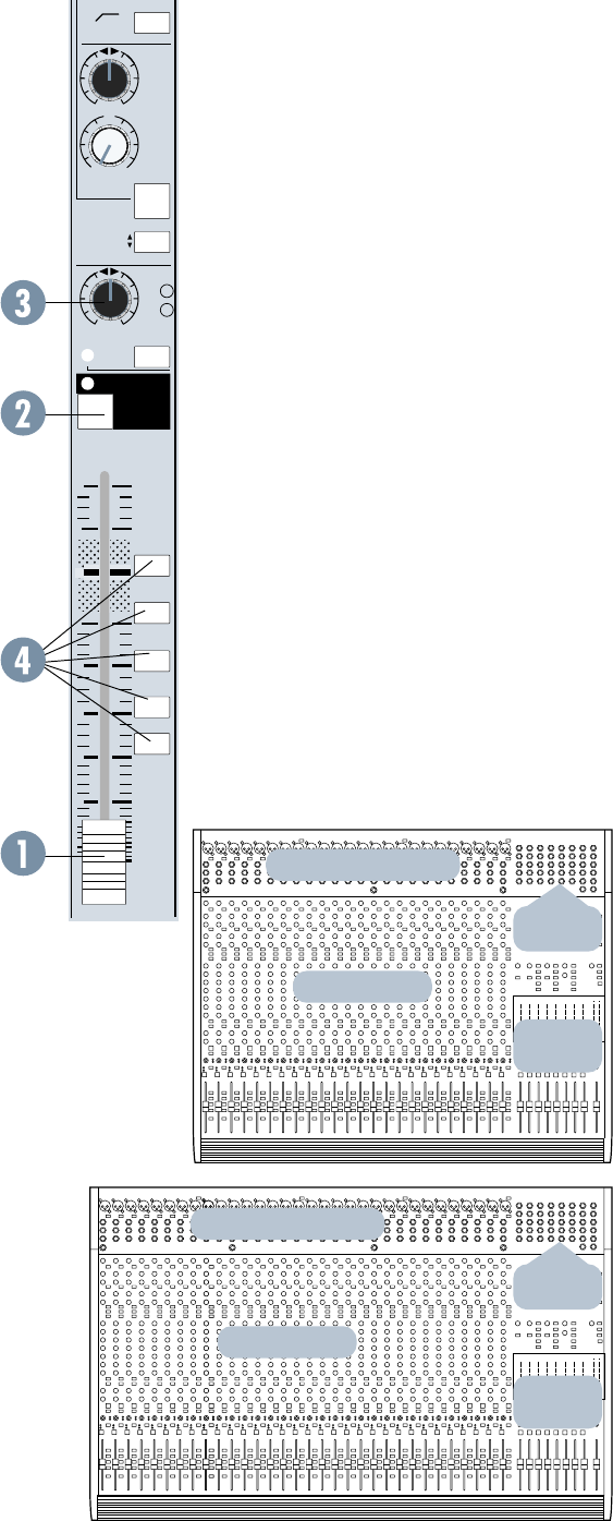
FADER
The channel fader (1) is 100 millimeters long,
with a precise logarithmic taper and attenuation in
dBs printed along the slot for exact and repeatable
level adjustments. The fader affects either the mic or
line input to the channel (for recording) or the tape
return to the channel (for mixing), depending on
the position of the FLIP switch.
MUTE
The MUTE switch, located at the top of the
fader (2), turns off the primary outputs of the
channel: the eight buses, the L & R buses, the
channel solo, the direct output and the post-
fader AUX sends. Pre-fader aux sends are not
muted. With the exception of lighting the mute
LED, pushing the MUTE switch is the same as
pulling the fader all the way down.
GOURMET PAN CONTROL AND
ASSIGNMENT SWITCHES
The PAN control (3), immediately above the
fader, pans the channel signal between the two sides
of the L/R Mix buses, and also between odd and even
pairs of buses 1 through 8.
The actual bus assignment of the PAN control
depends on the positions of the five assignment
switches located along the length of the fader.
With no switches depressed, the PAN control has
no effect (well, unless you solo the channel; it
still pans the solo).
Pushing the L/R MIX switch (4) assigns the PAN
to the main L /R Mix buses. Panning from L to R
moves the sound smoothly (with constant loudness)
from the left channel to the right channel. Assigning
the PAN to a pair of the 8 buses has a similar effect.
For example, pushing the 1-2 switch assigns the PAN
to buses 1 and 2, and panning L to R will move the
sound from bus 1 to bus 2 (from odd to even).
If you want to equally assign a channel to both
buses 1 and 2, leave the PAN control at the top, or
center, of its travel. If you only want bus 2, turn the
PAN control fully clockwise (to the right).
Other comparably-priced consoles provide as
little as 50dB attenuation/separation. We use active,
buffered circuitry and a custom-taper potentiometer
OVERVIEW
The panel layout of the Mackie 8•Bus Series
follows the traditional arrangement: input chan-
nel strips to the left, with a master output/
monitoring/cue section to the right. Additionally,
most of the Mackie input/output jack panel is
located at the top of the mixing panel, for easy
accessibility and patching. The tape outputs and
inputs are on the rear panel.
CHANNEL INPUT/OUTPUT
CHANNEL INPUT/OUTPUT
CHANNEL STRIPS
CHANNEL STRIPS
MASTER
SECTION
MASTER
SECTION
MASTER
I/O
MASTER
I/O
5
+15
OO
U
12k
MIX-B
EQ
LOW CUT
EQ IN
LO
MID
HI
HI
MID
FREQ
75 Hz
18dB/oct
SOURCE
FLIP SW
CHANNEL
45 3k
PAN
LEVEL
BAND
WIDTH
OCTAVES
500 18k
3k
FREQ
–15 +15
80
U
LO
SPLIT EQ
HI/LO EQ
TO MIX-B
MONITOR
LR
–15 +15
U
–15 +15
U
–15 +15
U
1k 5k
250
220 350
3
2
1
12
NORMAL
PAN
-20
OL
SOLO
to achieve 87dB attenuation. You get far better
channel separation plus freedom from level shifts
caused by channel assignment and panning. In
addition, our pan pots are constant loudness.
When you sit between a pair of monitors and pan
from side to side, the apparent volume at your
ears should stay the same, no matter where the
signal is positioned. Our special pan circuitry
maintains consistent apparent energy whether the
pot is dead center, hard left or hard right.
–20 AND OL LEDs
The two LEDs (5) next to the PAN control check
the channel strip signal level at three important cir-
cuit points: at the output of the mic/line preamp,
after the EQ and after the channel fader amplifier.
The green LED marked –20 is there to assure
you that, yes, something is plugged into the channel
(and yes, it does have some output). Most signals
more interesting than tape noise will cause the
green LEDs to flicker, so they give you a good visual
indication of which channels are active. Any peaks
higher than –20dBu (@ 1kHz) trigger the indicator.
When we say “channel”, we mean the signal going
through the channel fader… but not the signal
going through the MIX B Section. Please refer to the
MIX B section of this manual, starting on the next
page, for more details.
The red LED, labeled OL for overload, lights
when the signal level is high enough to cause clip-
ping at any of the three test points. In normal
operation it will almost never light. If it is flashing at
you, your level in that channel is much too high. You
need to turn something down.
• First try the mic/line trim. If that has no effect,
• Turn down the EQ and/or the insert device,
and if that doesn’t fix it,
• Turn down the channel. If this doesn’t fix it, your
input signal is too hot (gasp). Use an external pad
to reduce the level (see the sidebar on page 24).
CHANNEL SOLO
The channel SOLO switch (6) assigns the output
of the channel PAN control to the stereo solo buses
and disconnects all other sources from the monitor
section. SOLO does not interrupt the eight Submas-
ters, the L/R Mix or the AUX sends, and can be
used at any time without affecting the recording
process.
SOLO is handy for spot-checking the presence
and quality of individual inputs while setting up,
recording and mixing. More than one SOLO switch
may be pressed at the same time, allowing you to
listen to the blend of any combination of channels
throughout the console in stereo.
TRIM
FLIP
TAPE
MIC/LINE
CHANNEL
24
GAIN
+4
–10
dBV
50
dB
10
dB
L
I
N
E
S
E
N
S
I
T
I
V
I
T
Y
M
I
C
G
A
I
N
-40
dBV
CHANNEL
24
MIC/LINE
LINE
IN
DIRECT
OUT
BAL-
UNBAL
INSERT
TIP = OUT
RING = IN
PHANTOM
POWER
On the Mackie 8•Bus console, the SOLO
assignments are stereo except for the AUX sends.
SOLO maintains the perspective set up with the
PAN controls. When any SOLO button on the con-
sole is depressed, its associated SOLO LED will glow
steadily, and the RUDE SOLO LITE above the
8•Bus LED meters blinks annoyingly, serving as a
reminder with an attitude.
The channel SOLO function is normally post-
fader/post-mute, but can be modified for PFL or
Pre-Fade (and pre-mute) Listen. See Appendix B:
Options, Add-Ons, and Extra Stuff.
Note: All the SOLO buttons on the 8•Bus
Series operate in the same way (although
they’re not all stereo like the channel SOLO).
SOLO does not interrupt recording; it only
affects the control room monitor.
HIGHLY, MEGA-MONDO-
IMPORTANT: SOLO is
intended for more than just
“soloing.” It is THE way to set
levels for best noise and head-
room. Complete instructions on proper level
setting using SOLO are in Section 3: General In-
formation, starting on page 19.
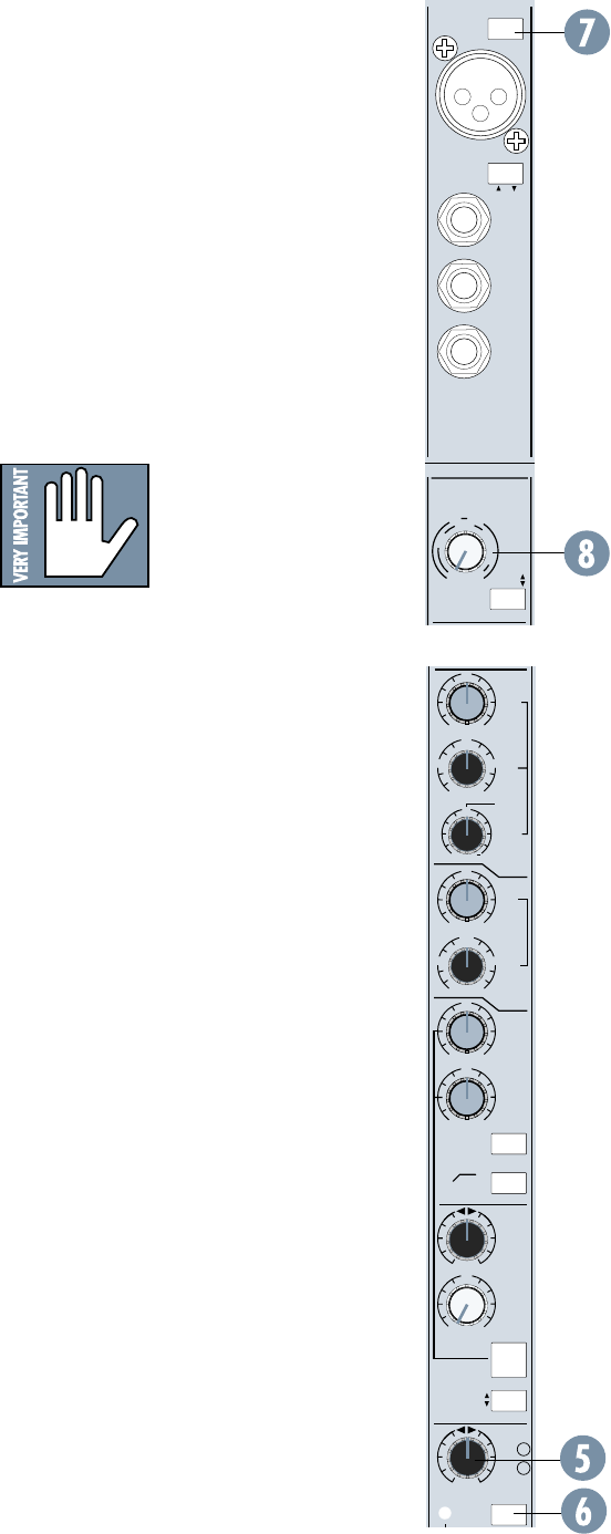
PHANTOM POWER
CAUTION: After switching PHANTOM Power
on or off, wait 1 minute before changing any
mic/line switch settings in that 8-channel block.
At the top of every eight channels is a PHANTOM
Power switch (7). Pressing it sends +48VDC to
the eight XLR sockets to the switch’s left. For
instance, depressing the PHANTOM switch above
Channel 8 sends phantom power to the XLRs on
channels 1 through 8. NOTE: It is always a good
idea to check with the Mic manufacturer to
verify phantom power requirements.
TRIM
The TRIM control (8) sets the gain of the
input amplifier for the MIC and LINE inputs.
Proper setting of the TRIM control is essential
for good noise and headroom performance. Trim
pot settings may vary widely depending upon
the input level. The output of different key-
boards, drum machines, guitar effects boxes,
etc., vary from extremely weak to so hot that
they can practically be connected directly to
speakers. See pages 1, 19, or 24 for advice.
MIC/LINE SWITCH
Now we’ve jumped back to the top of the
strip. Sorry, but logically the input to the chan-
nel is the next thing to talk about. That’s
because it’s the source of the signal applied to
the channel fader and PAN control.
6
TRIM
TAPE
MIC/LINE
CHANNEL
24
GAIN
+4
–10
dBV
50
dB
10
dB
L
I
N
E
S
E
N
S
I
T
I
V
I
T
Y
M
I
C
G
A
I
N
-40
dBV
CHANNEL
24
MIC/LINE
LINE
IN
DIRECT
OUT
BAL-
UNBAL
INSERT
TIP = OUT
RING = IN
PHANTOM
POWER
+15
OO
U
MIX-B
LOW
CUT
SOURCE
FLIP SW
CHANNEL
PAN
LEVEL
SPLIT EQ
HI/LO EQ
TO MIX-B
MONITOR
LR
PAN
dB
30
20
10
5-6
3-4
1-2
7- 8
L/R
MIX
-20
OL
OO
24
10
40
50
60
MUTE
5
5
SOLO
U
strip (via the source switch), can be achieved
by modifying the channels. Instructions for this
modification can be found on our website at
www.mackie.com (click on Support). Or you can
call Tech Support at 1-800-258-6883 for assistance.
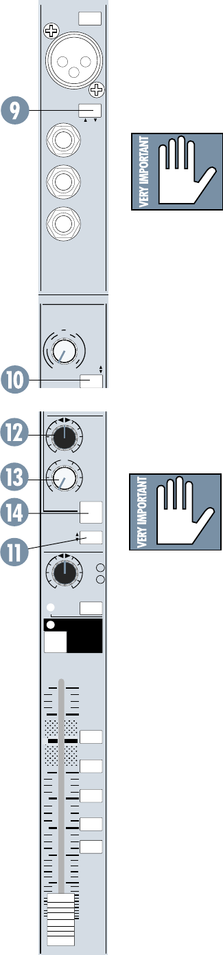
1. When the Mix-B SOURCE switch (11) is
up, MIX-B receives its input from the FLIP
switch. Remember, the FLIP switch alter-
nates MIC/LINE or TAPE to the channel
strip and to MIX-B. With TAPE as an input
(SOURCE up to select the FLIP switch, and
FLIP in the up position), the MIX-B section
functions as a tape monitor submix, allowing
you to listen to the inputs and outputs of
your multi-track recorder as you record. This
is the most common use of the MIX-B
section, during tracking and overdubbing.
2. With MIC/LINE as an input (SOURCE up to
select the FLIP switch, and FLIP in the down
position), MIX-B becomes an additional input
to add tracks or effects during a mixdown.
Simply plug the additional signal into the MIC
or LINE connector. Although they are nor-
mally separate, a button (MIX-B TO L/R MIX)
in the Output Panel (see below) can add the
output of the MIX-B buses to the L/R Mix
buses. Voilà! Double your mix inputs!
3. With CHANNEL as an input (SOURCE down in
CHANNEL position), MIX-B taps its signal from
the channel strip, just before the channel fader.
MIX-B is separately pan-able, EQ-able and
can be used as an alternative stereo mix, a
stereo auxiliary send, a “mix-minus” bus, a
quadraphonic or surround feed, you name
it. Mix B can also have its own aux send
(see Aux sends 3-6).
Check out Section 3: General Info and the
Block Diagram for more information on MIX-B
routing.
MIX-B PAN
The PAN control (12) routes the channel’s
MIX-B signal across the left and right MIX-B buses.
MIX-B LEVEL
The LEVEL control (13) sets the level of
the channel sent to the MIX-B buses. The gain
structure of this circuit (like the AUX send
1–6 circuits, below) includes extra amplifica-
tion. What this means to you is that you will
always have plenty of gonadotropic gain avail-
able for the MIX-B buses. Full left on the
LEVEL control is off; the midpoint of travel is
“U”, or unity gain; full right is 15dB of boost.
The MIC/LINE switch (9) is located way up
amongst the channel jacks. It selects whether
the MIC jack (pin 2=hot[+], pin 3=cold[–],
pin 1=shield) or the LINE jack (balanced 1/4"
phone… tip=hot, ring=cold, sleeve=shield) is
connected to the input amplifier.
THE FLIP SWITCH: MIC/LINE OR TAPE
The switch labeled FLIP
(10) selects the input that is
actually fed into the channel
fader (and the MIX-B con-
trol; see below). As the label
indicates, the MIC/LINE input (after Mic/Line
preamp) is fed to the channel fader when the
FLIP switch is in the up position. This is the
normal mode for tracking and overdubbing. In
the down position, the TAPE return (the output
signal from the corresponding track of your re-
corder) is fed to the channel fader. This is the
normal position for mixdown.
To recap - when the FLIP is up, the Mic/Line
feeds channel and Tape return feeds MIX-B. When
the FLIP is down, the channel is Tape and MIX-B is
MIC/LINE. FLIP... FLOP. OK?
For live PA, leave the FLIP switch up.
MIX-B / MONITOR
Each channel strip has a
dual signal path (Enter Mix-
B!) with extremely flexible
switching. This allows either
the mic/line inputs or tape
return inputs to be routed through either the
channel fader path or Mix-B with separate EQ
and monitoring. Both of the signal paths can
be combined into the main mix by depressing
the Mix-B to L/R Switch in the master section.
OK, now we jump down the channel again to
the MIX-B/Monitor section. This handy and very
simple feature is also called “in-line monitoring”
and is found on quite a few consoles. So we’re
not claiming that it’s anything new… we just
added some extra features for more flexibility.
MIX-B/Monitor routing options can get a bit
complicated, so pay attention. Also, we did add
something that other in-line monitoring sys-
tems don’t have. So double pay attention.
The MIX-B buses are a stereo pair, indepen-
dent of the 8-plus-2 recording buses we’ve
talked about so far. There are three sources
available to MIX-B: MIC/LINE or TAPE (via the
FLIP switch) and the pre-fader output of the
channel strip (via the SOURCE switch). A
fourth source, post-fader output of the channel
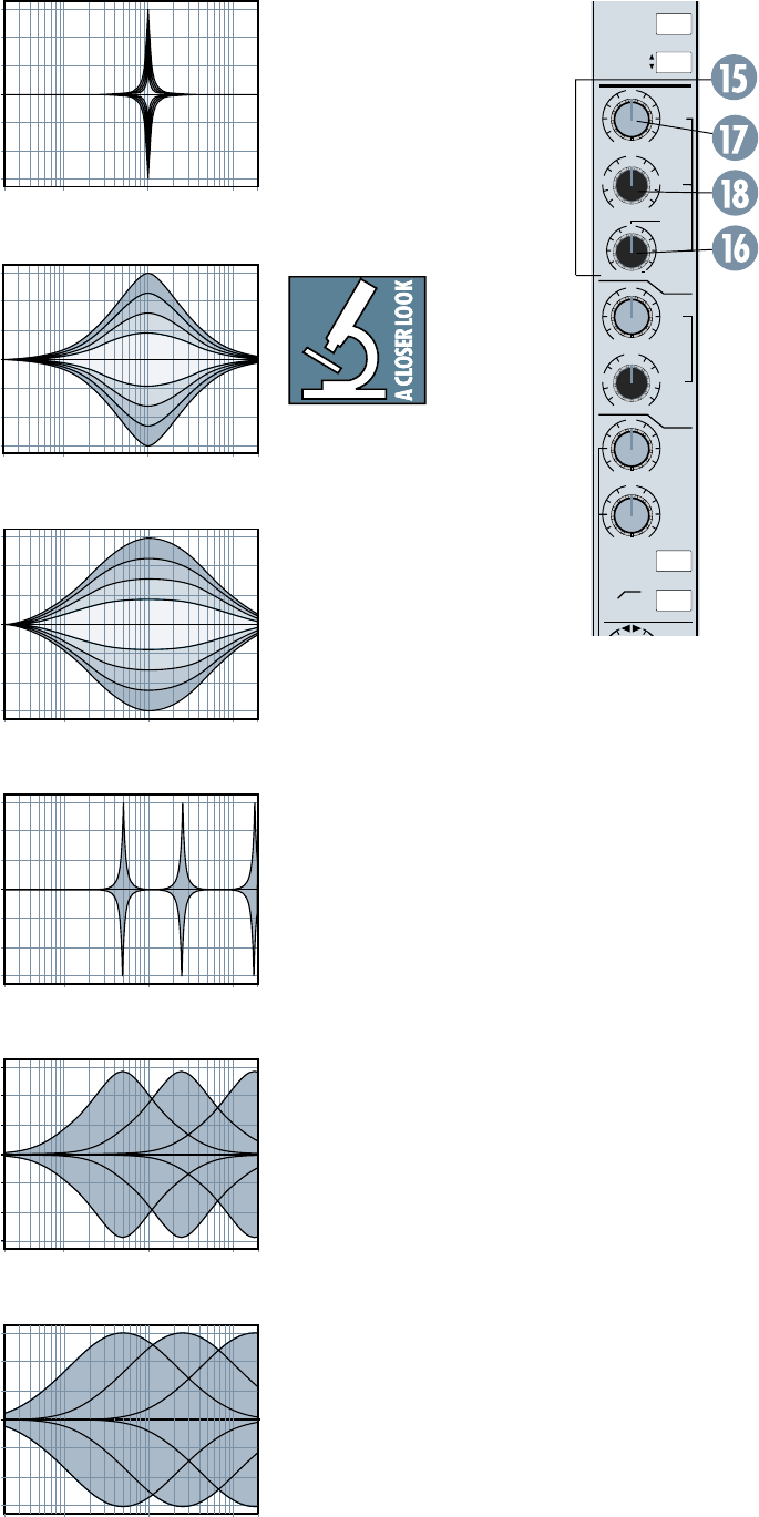
7
20
Hz
100
Hz
1k
Hz
10k
Hz
20k
Hz
–15
–10
–5
0
+5
+10
+15
20
Hz
100
Hz
1k
Hz
10k
Hz
20k
Hz
–15
–10
–5
0
+5
+10
+15
20
Hz
100
Hz
1k
Hz
10k
Hz
20k
Hz
–15
–10
–5
0
+5
+10
+15
20
Hz
100
Hz
1k
Hz
10k
Hz
20k
Hz
–15
–10
–5
0
+5
+10
+15
20
Hz
100
Hz
1k
Hz
10k
Hz
20k
Hz
–15
–10
–5
0
+5
+10
+15
20
Hz
100
Hz
1k
Hz
10k
Hz
20k
Hz
–15
–10
–5
0
+5
+10
+15
MIX-B
CHANNEL
PRE
SHIFT
SOURCE
12k
EQ
LOW CUT
EQ IN
LO
MID
HI
HI
MID
FREQ
75 Hz
18dB/oct
45 3k
BAND
WIDTH
OCTAVES
500 18k
3k
FREQ
–15 +15
80
U
LO
–15 +15
U
–15 +15
U
–15 +15
U
1k 5k
250
220 350
3
2
1
12
NORMAL
24
Freq. center: 1k;
Bandwidth: 3-octave;
±15dB boost/cut
Freq. center: 1k;
Bandwidth: 1-octave;
±15dB boost/cut
Freq.: 500Hz-18kHz sweep;
Bandwidth: 1-octave;
±15dB boost/cut
Freq. center: 1k;
Bandwidth: 1/12-octave;
±15dB boost/cut
Freq.: 500Hz-18kHz sweep;
Bandwidth: 1/12-octave;
±15dB boost/cut
When you put these consoles on
the test bench, you see that the
bandwidth of their EQ is simply
too narrow — often around one
octave. This is OK for extreme
adjustments in live situations,
but that’s about it. It’s just not
wide enough to gently alter the
multiple octaves that voices and
instruments span.
This is just
the opposite
of “classic”
big-studio
consoles.
Their EQ (including Hi Mid)
can be adjusted to be extremely
broad — three or more octaves
wide in many cases. When you
apply this wideband EQ, it
sounds far more “sweet” and
“natural.” Changes sound so
gradual and smooth that you can
add considerably more EQ than
would ever be possible with nar-
rower-band consoles, yet without
compromising the overall sound.
On the other hand, ultra-nar-
row-band EQ also has its place,
both as a corrective tool and for
special effects. So why not give
you even tighter control than
would be possible with a 1/3-
octave graphic equalizer? Thus
was born the 8•Bus’ 1/12-octave
to 3-octave width range.
At this point, as we played
around with the Bandwidth and
Boost/Cut controls using actual
music, we realized that to limit
this circuit to just Hi Mid (typi-
cally above 2.5kHz) would
actually limit its usefulness. The
flexibility that true parametric
control provides is nice to have in
the octaves below the Hi Mid re-
gion as well. So we came up with
what is probably the first console
Hi Mid control that can be swept
all the way down to 500Hz. If Hi
Mid doesn’t do it for you as a
name, think of these three
controls as the Roving-
Parametric-Problem-Solver-O-Matic.
O-Rama.
MIX-B SPLIT
The SPLIT switch (14) in the
MIX-B section splits the EQ sec-
tion of the channel when
depressed. In the up position, all
four sections of EQ remain, if en-
gaged, in the primary channel
signal path feeding the channel
fader and the 8-plus-2 buses. In
this mode there is no equalization
in the MIX-B path.
When the SPLIT switch is de-
pressed, the HI and LO shelving
sections of the EQ are removed
from the channel signal and in-
serted into the MIX-B signal
path. The HI-MID and LO-MID
parametric sections of the EQ re-
main, if engaged, in the channel
signal path.
The SPLIT function allows you to
EQ the channel’s signal and its MIX-
B signal separately.
Note: When the EQ is split, the
main EQ IN/OUT switch only
switches the channel signal’s para-
metric sections. It does not affect
the shelving sections split to MIX-B.
EQ SECTION
Each 8•Bus channel strip equal-
izer section has four bands (HI MID,
LO MID, LO, and HI) plus a low-cut
filter. The equalizer can be split be-
tween main channel signal and
MIX-B signal.
HI MID EQ
The HI MID EQ section (15) is a
true 3-control parametric design,
offering: A) bandwidth variable
from 3 octaves to 1/12 octave (16);
B) ± 15dB of equalization (17) and;
C) variable frequency center from
500Hz to 18kHz (18).
We spent a lot of time on this
part of the 8•Bus Series’ EQ. One
of the things we’ve always noticed
about lower-priced consoles was
how “drastic” their Hi Mid EQ
sounded. Even a little boost could
induce honkiness and nasality.
Frankly, Hi Mid EQ on many
boards is not that useful in studio
applications for just this reason.
Freq.: 500Hz-18kHz sweep;
Bandwidth: 3-octave;
±15dB boost/cut
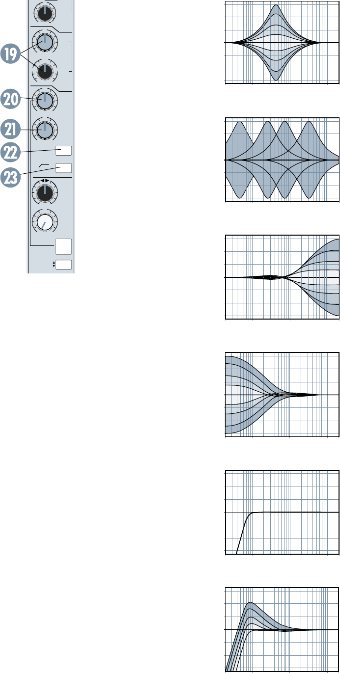
8
20
Hz
100
Hz
1k
Hz
10k
Hz
20k
Hz
–15
–10
–5
0
+5
+10
+15
20
Hz
100
Hz
1k
Hz
10k
Hz
20k
Hz
–15
–10
–5
0
+5
+10
+15
20
Hz
100
Hz
1k
Hz
10k
Hz
20k
Hz
–15
–10
–5
0
+5
+10
+15
20Hz 100Hz 1kHz 10kHz 20kHz
–15
–10
–5
0
+5
+10
+15
20
Hz
100
Hz
1k
Hz
10k
Hz
20k
Hz
–15
–10
–5
0
+5
+10
+15
20
Hz
100
Hz
1k
Hz
10k
Hz
20k
Hz
–15
–10
–5
0
+5
+10
+15
Now you know some of the de-
sign philosophy behind our Hi
Mid EQ. It’s time to start experi-
menting with it yourself. Don’t
forget to try the control at its
bandwidth extremes — espe-
cially at the 3-octave end. You’ll
be pleasantly surprised.
Conversely, if you hate tech-
nology and yearn for the sound of
that old board you sold to buy an
8•Bus, you can achieve a semi-
parametric sound by leaving the
BANDWIDTH knob in the middle
at 2 octaves.
LO MID EQ
The LO MID EQ control (19)
is a semi-parametric (sweepable)
equalizer with a broad, fixed
bandwidth of 2 octaves, ±15dB of
equalization and frequency
variable from 45Hz to 3kHz.
Boosting in this range can put
warmth and body into vocals and
instruments. Cutting can really
help the clarity of some sounds
by reducing boxy and boomy
tones.
HI EQ
The HI EQ control (20) is a
fixed 12kHz shelving equalizer
with ±15dB of equalization avail-
able. A great treble control, it is
switched with LO EQ into the
MIX-B circuit if the SPLIT but-
ton is depressed.
Shelving equalizers work on a
very broad range of frequencies,
and consequently, are very musi-
cal. In a 12kHz shelf like this
section, that means that all the
upper harmonics of a sound are
raised evenly, basically keeping
their original musical relation-
ship to each other. A
high-frequency shelving EQ is
great for putting shimmer into
acoustic guitar and piano tracks
and sizzle into vocals.
LO EQ
The LO EQ control (20) is a
fixed 80Hz shelving equalizer
with ±15dB of equalization avail-
able. It’s a fine bass control, and is
switched with HI EQ into the
MIX-B circuit if the SPLIT button
is depressed.
A low-frequency shelving
equalizer will add or remove bass
in a smooth, musical fashion.
Good for working on bass drum
and bass guitar, fattening up (or
thinning out) a piano or contour-
ing an entire mix.
EQ IN/OUT
The IN switch (22) bypasses the
EQ (though not the LO CUT filter)
when up. Depress it to enable equal-
ization.
LO CUT
The LO CUT switch (23) inserts
an 18dB/octave low-cut (high-pass)
filter with a –3dB point of 75Hz into
the main channel signal. The LO
CUT filter is unaffected by the EQ IN
switch.
A low-cut filter is handy to get rid
of room rumble, traffic noise, wind
noise, popping, and other unwanted
very-low-frequency sounds. It can
also be combined with LO EQ boosts
to produce some interesting bass
curves as shown in the last EQ
graph on this page. It is highly rec-
ommended that this switch be
engaged for vocal microphones, es-
pecially in a live P. A. situation.
AUX SENDS
Auxiliary sends are generally
used to provide mixes for head-
phone cueing and for effects sends,
and in Sound Reinforcement use,
can be assigned monitor submix
duties. The 8•Bus Series consoles
provide 6 mono auxiliary sends with
several routing options.
Note: All of the 8•Bus Series
AUX sends have a very wide range
of gain (just like the MIX-B Level
control discussed earlier). The
first half of the control’s rotation
reaches from the off position to
unity gain (U). This half of the
control’s range corresponds to the
full range of a conventional mixer.
+15
OO
U
12k
MIX-B
EQ
LOW CUT
EQ IN
LO
MID
HI
FREQ
75 Hz
18dB/oct
SOURCE
FLIP SW
CHANNEL
45 3k
PAN
LEVEL
BAND
WIDTH
OCTAVES
–15 +15
80
U
LO
SPLIT EQ
HI/LO EQ
TO MIX-B
MONITOR
LR
–15 +15
U
–15 +15
U
250
220 350
3
2
1
12
NORMAL
Lo Mid EQ
2 octave ±15dB boost/cut
Lo Mid EQ sweeps
from 45Hz to 3kHz
Hi EQ ±15dB boost/cut
above 12kHz
Lo EQ ±15dB boost/cut
below 80Hz
Lo cut (high pass filter)
18dB/oct. at 75hz
Interaction of Lo Cut
with Lo EQ boost.
Verrry eenteresteeng, no?
The second half of the control’s
rotation provides you with even
more gain, from unity to +15dB.
9
AUX
PRE
TRIM
FLIP
1
2
4
3
5
6
MIX-B
CHANNEL
PRE
SHIFT
TAPE
MIC/LINE
SOURCE
+15
OO
U
+15
OO
U
+15
OO
U
+15
OO
U
AUX
GAIN
+4
50
dB
10
dB
L
T
I
V
I
T
Y
-40
dBV
24
For example, when you want a super “wet”
sound(mostly reverb), the extra gain allows you to
bring the channel fader part way down (and the
AUX send way up) so the sound is mostly reverb
with just a touch of “dry” signal.
Don’t worry about having mono effects sends:
almost all effects units, mono or stereo, have mono
inputs. Even if there are two jacks labeled Left and
Right, they are almost always combined into mono
internally. In the rare cases when an effect actually
has true stereo inputs, it is often more convenient
to ignore that and treat it as mono anyway. If you
really need to send in stereo, just use two AUX
sends from the console. Route AUX 1, for example,
to the left input and AUX 2 to the right. Then ad-
just the stereo perspective by favoring one or the
other send. For instance, if you have a stereo synth
into channels 23 and 24, use AUX 1 on channel 23
and AUX 2 on channel 24.
Note: In PRE mode, all AUX SENDS are
connected pre-fader but post-EQ. This is usu-
ally the most useful setup, but if you prefer, all
AUX SENDS can be modified to be pre-EQ,
pre-fader. Instructions for this modification
can be found on our website at www.mackie.com
(click on Support). Or you can call Tech Support
at 1-800-258-6883 for assistance.
AUX 1 & 2
Auxiliary sends 1 & 2 (24) have two inde-
pendent level controls and share a common
PRE/POST switch.
When in the normal post mode, sends 1 & 2
get their signal after the channel fader and the
MUTE switch. This is the usual configuration
for an effects send, since the level of the effect
should follow the volume adjustments made by
the channel fader.
PRE (1&2)
With the PRE switch (25) depressed, AUX
SENDS 1 & 2 receive their input from a point
before the channel fader and MUTE switch, and
are not affected by changes in these controls.
This is the normal switch setting for creating
stage monitor and/or studio cue headphone
sends.
AUX 3, 4, 5, 6
Auxiliary sends 3, 4, 5, and 6 (26) are very simi-
lar to sends 1 & 2. The differences are in the
SHIFT and SOURCE switches. Read on.
SHIFT
The SHIFT button (27) con-
nects the two level controls,
as a pair, to either sends 3 &
4 (in the up position) or to
sends 5 & 6 (in the down
position). Twice the sends in half the space.
SOURCE
The SOURCE switch (28) breaks AUX Sends
3-6 away from the main channel strip world that
sends 1 & 2 are stuck in, and allows the sends to
tap from another source: the MIX-B signal for that
channel. This is a very handy thing, whatever you
happen to be using MIX-B for.
If MIX-B is an additional input for your mix-
down, then (when the SOURCE switch is
depressed) AUX Sends 3-6 are effects sends
connected to that source. If MIX-B is your stu-
dio monitor submix from the recorder, then
AUX Sends 3-6 are a great source of head-
phone cue signals. They will follow playback,
record and punch-ins automatically as your
recorder does its stuff.
PRE (3-6)
The PRE switch (29) for Sends 3-4-5-6 func-
tions just like the PRE switch sends 1 & 2, when
the AUX SOURCE switch is in the CHANNEL (up)
position.
Additionally, the PREswitch will tap the pre-
level (and pre-mute) signal of whichever
SOURCE you have selected-channel or MIX B.
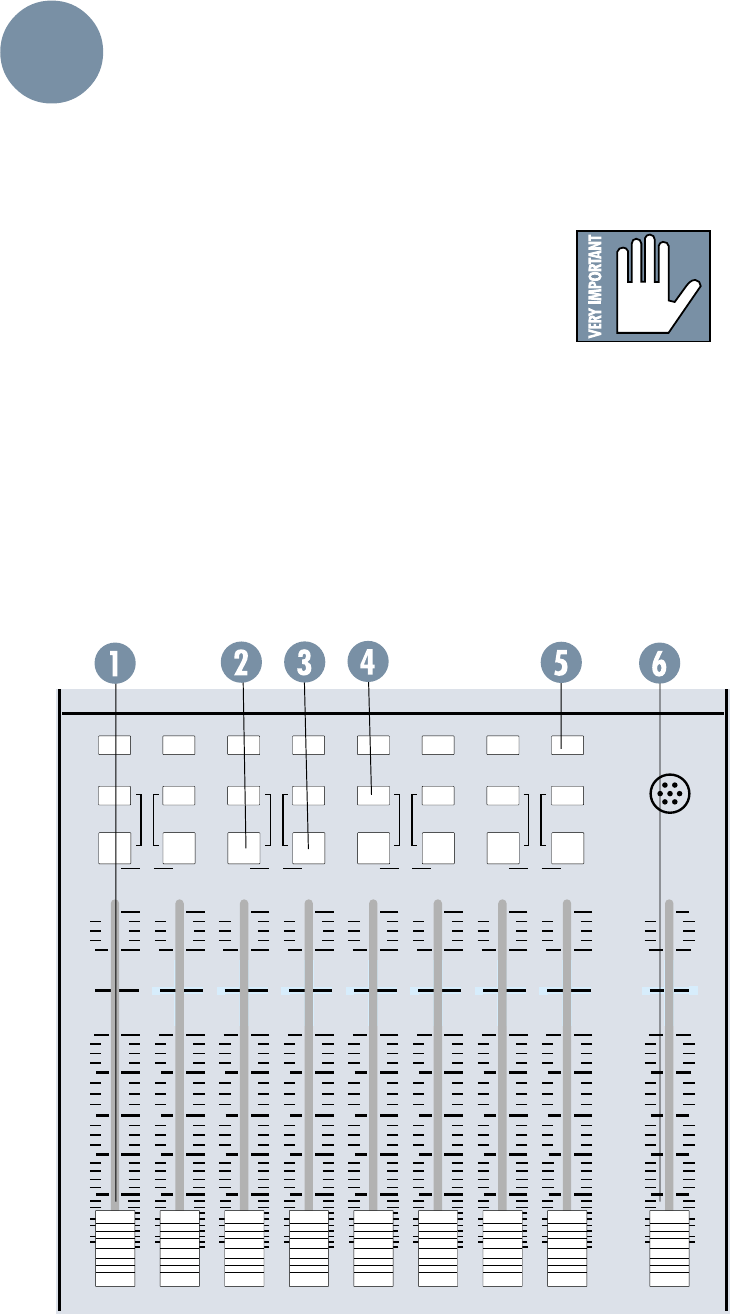
10
SOLO SOLO SOLO SOLO SOLO SOLO SOLO SOLO
MONO
L+R
RLRLRLR
dB
30
20
10
OO
10
40
50
dB
30
20
10
OO
10
40
50
dB
30
20
10
OO
10
40
50
dB
30
20
10
OO
10
40
50
dB
30
20
10
OO
10
40
50
dB
30
20
10
OO
10
40
50
dB
30
20
10
OO
10
40
50
dB
30
20
10
OO
10
40
50
dB
30
20
10
OO
10
40
50
dB
10
10
20
30
40
50
OO
MONO
L+R
MONO
L+R
MONO
L+R
MONO
L+R
ASSIGN
MONO
L+R
MONO
L+R
1
L
2345678
MONO
L+R
ASSIGN ASSIGN ASSIGN ASSIGN ASSIGNASSIGNASSIGN
5
5
5
5
5
5
5
5
5
5
5
5
5
5
5
55
5
5
5
LEFT/RIGHT
MIX
MIX MIX MIX MIX
UUUUUUUU U U
80 80 80 80 80 80 80 80 80 80
TALKBACK
MIC
OUTPUT SECTION
The output section is the large area to the right of
the input channel strips. It contains the master fad-
ers and metering, as well as the send and return
masters, cue, monitoring and communication
controls.
8•BUS FADERS
At the bottom of the output panel are the mas-
ter faders for each of the eight buses (1). Each
fader controls the level of its mix, with precise dB
markings and a unity gain point marked on the
panel. The fader is located in the circuit after the
submaster insert jack but before the final line
amplifier.
There is an Assign section associated with each
bus fader, detailed below. Note that no matter
what the selection of the assignment switches, the
output of each bus is always present at its Sub-
master/Tape Output jack and is monitored on its
own bus meter.
L MIX and R MIX
The odd-numbered buses have an L MIX but-
ton above their faders (2); the even buses have an
R-MIX button (3). Pressing this button assigns
the bus to the L or R Mix bus, respectively. This
switch, along with the MONO L & R switch dis-
cussed below, allows you to assign submix buses
within your L/R mix.
MONO L & R
The MONO L & R switch (4) functions ONLY
when you have first depressed the L MIX or R
MIX. If you’ve pushed L MIX or R MIX, pushing
MONO L & R will assign the bus to both channels
of the Left and Right Mix buses, instead of just the
Left, or just the Right. This is also for submixing,
but allows you to put your submix in the center
rather than on either side.
(Those of you with patch
cords have probably realized
you can patch the bus into a
channel and do even more
fun things, but we’ll talk
about that later.)
SOLO
The SOLO button (5) solos the output of the bus
fader. When any SOLO button is pressed, the SOLO
LED lights.
This is a pretty trick SOLO, too. If you have not
pushed the MONO L & R switch, the SOLO sends the
odd-numbered tracks to the left speaker and the
even-numbered tracks to the right, whether or not
the associated L MIX or R MIX is engaged. But if you
have pressed MONO L & R,
the SOLO circuit is smart
enough to send the bus to
both speakers and put the
stereo image in the middle.
You will be the envy of your
neighborhood.
L/R MIX FADER
The L/R MIX fader (6) is
a stereo fader located at the
far right of the console. The
fader controls the level of
the L/R MIX bus, with pre-
cise dB markings and a
unity gain point marked on
the panel. This fader, like
the bus faders, is located in
the circuit after the L/R in-
sert jack but before the final
line amplifier.
LAYOUT
AND
FUNCTION
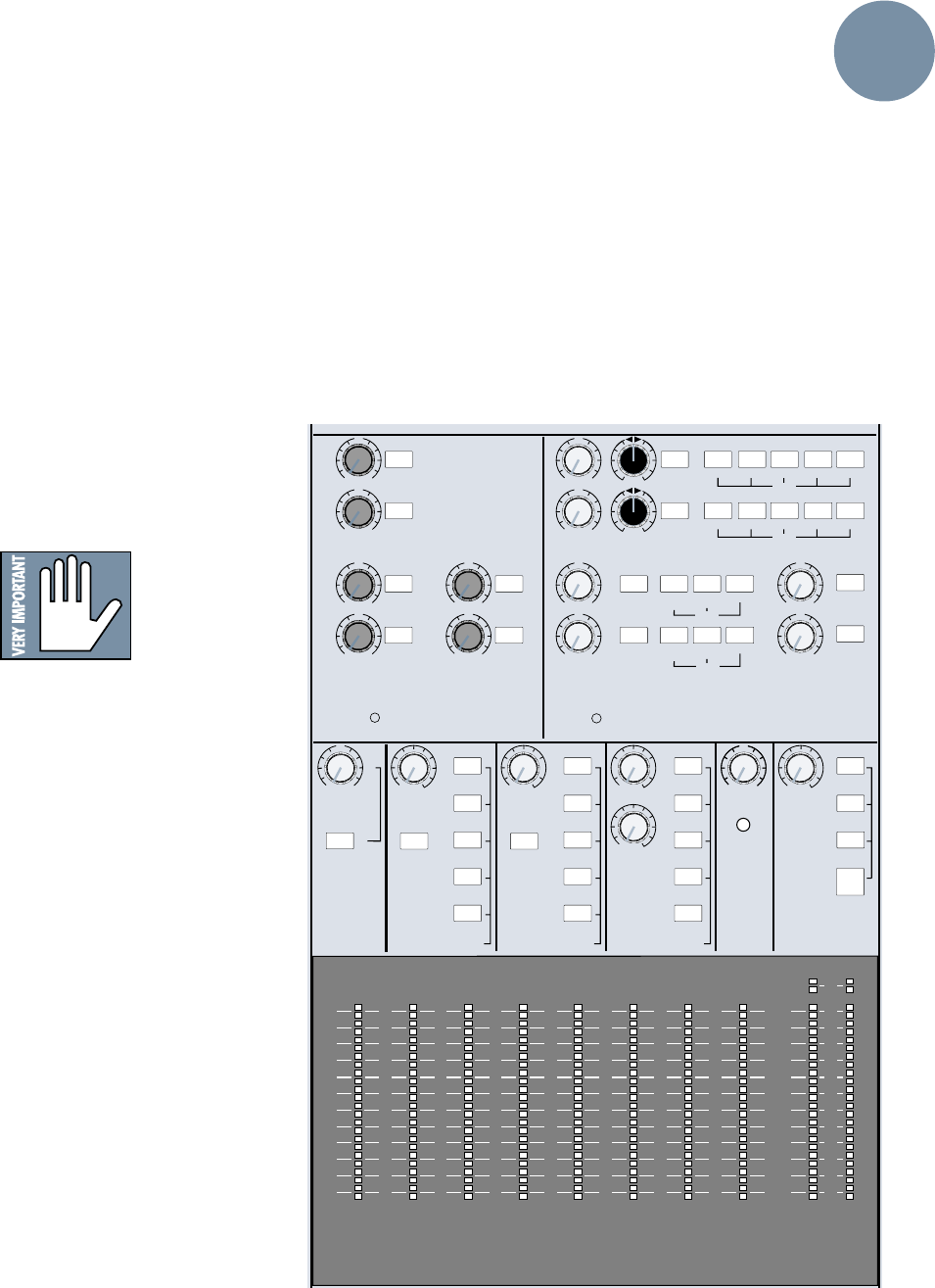
11
SOLO SOLO
SOLO SOLO
SOLO
SOLO
AUX SENDS STEREO AUX RETURNS
4
3
2
5
6
1
PHONES
2L/R MIX
L/R MIX
1-2 3-4 5-6 7-8
L/R MIX
SOLO 1-2 3-4 5-6 7-8
PHONES
1PHONES
2L/R MIX
1
2
3
4
LEVEL
ASSIGN
ASSIGN
ASSIGN
ASSIGN
LEVELLEVEL
PHONES
1
6
+15
OO
U
+15
OO
U
+15
OO
U
+15
OO
U
+15
OO
U
+15
OO
U
+20
OO
U
+20
OO
U
+20
OO
U
+20
OO
U
LR
LR
5
+20
OO
U
+20
OO
U
SOLO
SOLO
SOLO
SOLO
SOLO
SOLO SOLO
LEVEL LEVEL
LEVEL
ASSIGN TO
L/R MIX SOLO AUX SEND
3/4
MIX-B
MONITOR
AUX SEND
5/6
EXTERNAL MONO
TAPE SUB
MASTERS
AUX SEND 1
MASTER
MIX B / MONITOR PHONES 1
PHONES
LEVEL
SOLO
MIX-B
MONITOR
EXTERNAL
PHONES 2
PHONES
LEVEL
2-TK
MIX-B
L/R MIX
EXTERNAL
SOURCE
MONITOR
CNTRL RM
STUDIO
OPERATING
LEVEL
INDICATOR
AND
TALKBACK
LEVEL LEVELMIX-B
LEVEL
RUDE
SOLO LITE
AUX SEND 2
PHONES
&
STUDIO
+15
OO
U
O
OOOOOO
+15
OO
U
BAL ANCE
AUX SEND
3/4
AUX SEND
5/6
SOURCESOURCE
SOLO
OO
OO
+15
OO
U
12345678
169 101112131415
2417 18 19 20 21 22 23
10
+
7
4
2
0
2
4
7
10
20
30
40
–
LR
10
+
7
4
2
0
2
4
7
10
20
30
40
–
LR
10
+
7
4
2
0
2
4
7
10
20
30
40
–
LR
10
+
7
4
2
0
2
4
7
10
20
30
40
–
LR
10
+
7
4
2
0
2
4
7
10
20
30
40
–
22
10
+
7
4
2
0
2
4
7
10
20
30
40
–
10
+
7
4
2
0
2
4
7
10
20
30
40
–
10
+
7
4
2
0
2
4
7
10
20
30
40
–
LR
MAIN
OR SOLO LEVEL
METERING
Bus Meters 1-8
Directly above each bus fader is a peak-reading
meter displaying the bus output level. Zero (0) on
the meter references a level of +4dBu (1.23 volts
RMS) at the output jack.
Note: If the –10dBV switches are engaged at the
Subgroup output jacks, then zero (0) on the meter
references a level of –10dBV at those outputs.
Note: When any SOLO switch is engaged, the
SUBMASTER meters will be extinguished in or-
der to divert your attention to the SOLO/MAIN
meters (discussed below).
MAIN OR SOLO LEVEL Meters
The MAIN OR SOLO LEVEL meters display the
L/R Main Mix levels and are similar to the bus
meters, with these exceptions:
• If a SOLO button is depressed, the meters
display the output of the soloed
signals; if not, the meters show the
level of the signal selected by the
MONITOR SOURCE switches. In
other words, you are always meter-
ing what you’re listening to.
IMPORTANT:
When the console
is in SOLO mode,
zero (0) on the
SOLO/MAIN
meters references the actual
internal operating level, or 0dBu
(.775v). If you have just one signal in
the main L/R path and you SOLO it,
the meter level will jump up 4dB.
Don’t be alarmed. If you’re mixing on
the L/R buses, that’s what you’ll
meter. If you’re checking a tape
playback, that’s what you’ll meter.
When the meters are following the
monitors (not in SOLO), zero (0) on
the meter references a level of
+4dBu (1.23 volts RMS) at the main
L/R outputs, just like the submaster
meters.
Note: The solo levels displayed on
the meters are PRE-solo level,
thus giving you an accurate
showing of the total level of the
soloed signals.This is also the way
to set initial console levels. See the
discussion of the SOLO function,
earlier in this section.
• Additional red LEDs per side at
the top of the meter show output
clipping at +28dBu balanced,
+22dBu unbalanced. (You don’t want these
to ever go on. If they do, try pulling down the
L/R master fader a little.)
AUX SENDS
The six auxiliary send outputs each have a
master level control. Like any level control, turn-
ing the knob turns the volume up or down.
However, the gain of the AUX Sends has been
optimized at the unity (center detent) setting
and should not need adjustment.
The output of each bus is available at its AUX
Send Out jack in the jack panel above. Addition-
ally, AUX Sends 3 & 4 and AUX Sends 5 & 6 are
fed as stereo pairs to the two PHONES SOURCE
switching matrices, for headphone cueing
purposes.
LAYOUT
AND
FUNCTION
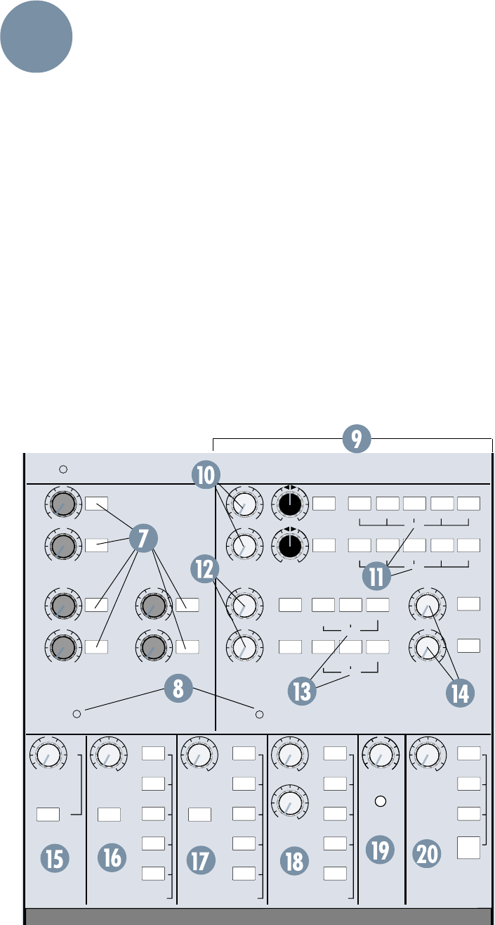
12
AUX SOLO
The SOLO button next to each level control
(7) solos that send and allows you to check the
send level in the main meters. There is a solo
LED (8) in the Send section, to help you locate
what the heck you soloed.
Note: The six AUX Sends are each mono sig-
nals, and they are soloed in mono. If you are
using a stereo pair of sends for headphone cue,
use the SOLO button in the PHONES 1 or 2 ar-
eas to check the sends in stereo.
STEREO AUX RETURNS
The AUX Returns (9) provide 12 additional
inputs to the console for return from effects and re-
verb devices. The returns have switch matrices to
allow easy assignment to headphones or mix buses.
When any return is soloed, the solo LED in the lower
left-hand corner of the Return area lights.
For extra flexibility, the AUX Returns have been
designed with an extremely wide range of available
gain, offering as much as 15dB boost over unity.
The return jacks are wired to provide both stereo
and mono operation. See AUX Returns under JACK
PANEL later in this section for details.
Returns 1 & 2
AUX Returns 1 & 2 (10) each have a stereo SOLO
switch, a stereo LEVEL control, a BALANCE control
and a bank of ASSIGN switches.
ASSIGN (1 & 2)
AUX Returns 1 & 2 are assigned in stereo pairs
(Return 1, L & R; Return 2, L & R) to the L / R MIX
buses or to odd-even pairs of the 8 submix buses
(11). If you would like an effects return to accom-
pany its dry signal on the multitrack (wet tracks),
these are the returns to use.
Returns 3 & 4
AUX Returns 3 & 4 (12) each have a stereo SOLO
switch, a stereo LEVEL control and a smaller bank of
ASSIGN switches.
ASSIGN (3 & 4)
Returns 3 & 4 are assigned in stereo pairs (Return
3, L & R; Return 4, L & R) to the L / R MIX buses or
to the PHONES 1 and PHONES 2 buses via respec-
tive banks of buttons for each return(13). If you
want additional effects returns preset in the head-
phone mixes, these are the returns to use.
Returns 5 & 6
AUX Returns 5 & 6 (14)
each have a stereo SOLO switch
and a stereo LEVEL control. Re-
turns 5 & 6 are permanently
assigned to the L/R MIX bus.
All returns are useful in a mix-
down situation, as they are all
assignable to the L / R mix.
MIX-B / MONITOR
The MIX-B / MONITOR sec-
tion (15) is quite straightfor-
ward. It offers a stereo level
control for the MIX-B output,
and an ASSIGN: MIX-B TO
L / R MIX switch, which can
add the MIX-B bus signal to the
main L / R Mix. This essentially
doubles the inputs available for
mixdown. Avoid this pitfall: If
you are monitoring the L/ R
mix in the control room and
have the MIX-B to the L / R mix
assigned, do not also select
MIX-B in the monitor source
switch matrix. If you do, MIX-B
will sound twice as loud in the
control room as it is in the L / R
mix!
SOLO SOLO
SOLO SOLO
SOLO
SOLO
AUX SENDS STEREO AUX RETURNS
4
3
2
5
6
1
PHONES
2L/R MIX
L/R MIX
1-2 3-4 5-6 7-8
L/R MIX
SOLO 1-2 3-4 5-6 7-8
PHONES
1PHONES
2L/R MIX
1
2
3
4
LEVEL
ASSIGN
ASSIGN
ASSIGN
ASSIGN
LEVELLEVEL
PHONES
1
6
+15
OO
U
+15
OO
U
+15
OO
U
+15
OO
U
+15
OO
U
+15
OO
U
+20
OO
U
+20
OO
U
+20
OO
U
+20
OO
U
LR
LR
5
+20
OO
U
+20
OO
U
SOLO
SOLO
SOLO
SOLO
SOLO
SOLO SOLO
LEVEL LEVEL
LEVEL
ASSIGN TO
L/R MIX SOLO AUX SEND
3/4
MIX-B
MONITOR
AUX SEND
5/6
EXTERNAL MONO
TAPE SUB
MASTERS
AUX SEND 1
MASTER
MIX B / MONITOR PHONES 1
PHONES
LEVEL
SOLO
MIX-B
MONITOR
EXTERNAL
PHONES 2
PHONES
LEVEL
2-TK
MIX-B
L/R MIX
EXTERNAL
SOURCE
MONITOR
CNTRL RM
STUDIO
OPERATING
LEVEL
INDICATOR
AND
TALKBACK
LEVEL LEVELMIX-B
LEVEL
RUDE
SOLO LITE
AUX SEND 2
PHONES
&
STUDIO
+15
OO
U
O
OOOOOO
+15
OO
U
BAL ANCE
POWER
AUX SEND
3/4
AUX SEND
5/6
SOURCESOURCE
SOLO
OO
OO
+15
OO
U
+
LAYOUT
AND
FUNCTION

13
PHONES
The PHONES 1 (16) and PHONES 2 (17) sec-
tions are identical. Each
contains a stereo level control
for the headphones outputs, a
stereo SOLO switch, and five
pushbuttons to select from the
following signal sources: MONITOR, MIX-B, AUX
SENDS 3 & 4, AUX SENDS 5 & 6, and EXTERNAL.
You can select any combination of sources.
• The MIX-B, AUX SENDS 3 & 4 and AUX SENDS
5 & 6 switches are connected directly from the
outputs of their respective circuits.
• MONITOR takes the signal from after the
MONITOR selection switches described below,
and therefore carries the same signal that is
applied to the control room monitors. (The
PHONES section is not affected by the CNTL RM
level control or the MONO switch in the MONI-
TOR section, though.)
• The EXTERNAL switch is connected directly
from the L and R EXTERNAL INPUTS in the jack
panel above. External is an independent cue
channel for click tracks, etc. Its signal DOES NOT
appear at any of the channels or buses.
Note: If MONITOR is selected as a PHONES
source and the solo button in the PHONES section is
depressed, nothing will happen except that the Solo
LEDs will light up. That’s because Solo is disabled
under these conditions to prevent a feedback loop
and its associated anguish.
Note: If nothing is selected, signal may still feed
the PHONES from AUX Return 3 & 4, via that
section’s ASSIGN TO PHONES switches.
MONITOR
The control room monitors and the studio
playback monitors are both controlled from the
MONITOR section of the console (18). There is
a stereo level control for the control room and
another for the studio.
Note: Fully clockwise equals unity gain.
A bank of switches selects the
stereo sources available to the
speakers from L/R Mix, MIX-B,
Tape and External. You can
select any combination of
signal sources.
The L/R MIX and MIX-B switches are con-
nected from the outputs of the L/R and MIX-B
buses. The TAPE and EXTERNAL switches are
connected from the 2-TRACK INPUTS and the
EXTERNAL INPUTS, respectively, on the jack
panel above.
The MONO switch sums the left and right
channels together to allow you to check your mix
in monaural. This affects only the control room
monitor speakers, the studio monitor speakers,
and the L/R meters (although the meters are not
monoed in solo mode.)
SOLO
The Solo section (19) contains the master
level control for the stereo Solo mix. Set at the
center detent, it will match the level of the soloed
signals to the same signals unsoloed. This section
also has the most obnoxious solo light allowed un-
der international trade and safety regulations. We
hope it gets your attention. The monitor switch in
the phones section must be pushed in (selected)
or the solo bus will not feed the phones. (By the
way, if your console has two little tiny Death’s Heads
above your RUDE SOLO LITE, you are very lucky.
Only one in 10,000 Mackie consoles has what we call
“Grim Greg” on it, and if you send in the top panel of
your console with proof of purchase, we will ship
postpaid to your door the bivalve pride of the North-
west, a Quilcene-smoked Geoduck filet, with our
compliments!)
TALKBACK
The talkback section has four momentary
pushbutton switches, which assign talkback to
any combination of AUX Send 1, AUX Send 2,
TAPE SUBGRPS (L/R MIX and the 8 SUBMAS-
TERS) and PHONES/STUDIO. Try setting the
talkback level at the center detent for starters. It
can be tweaked up or down to your liking.
Note: When talkback is engaged, only the con-
trol room outputs are padded by 20dB to avoid
feedback, yet still allow the engineer to hear the
musicians. The studio output is not padded. In
situations where either the control room level is
set way up, or there is a speaker pointing at the
console, there may still be feedback. To prevent
this, turn down the talkback level, the control
room level, or change the angle of the control
room speakers.
The Talkback Microphone is located just above
the L/R MIX fader. This ain’t no Neumann, so
don’t attempt vocals through it (we wanted it to
sound gritty and generally talkback-esque). Appli-
cation of chewing gum to this orifice will degrade
performance further to simulate really beat-up
AM radio production studios.
LAYOUT
AND
FUNCTION
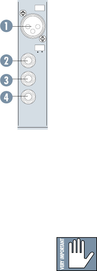
14
Mic In
The channel microphone input (1) is a stan-
dard 3-pin female mic connector (call me
Cannon or call me XLR, just don’t call me late
for dinner). Pin one is ground, pin two is signal
high (+), pin three is signal low (–), as per the
(finally) agreed-upon international standard.
Note: Don’t use these XLR’s for line level
signals — see “Line In”.
Line In
The channel Line Input (2) is a TRS (tip-
ring-sleeve) balanced 1/4" phone jack, with
ground wired to the sleeve, signal high (+) to
the tip and signal low (–) to the ring. Nominal
input level is +4dBu, with a wide range of levels
accommodated by adjustment of the TRIM con-
trol. These jacks also accommodate TS
(tip-sleeve) unbalanced 1/4" phone plugs. See
Appendix A: Connections for more information.
Direct Out
The channel Direct Out (3) is a nominal
+4dBu unbalanced TS 1/4" phone jack, con-
nected to the output of the channel line
amplifier post-EQ/post-fader/post-mute. The out-
put signal of each channel strip is always
available at the Direct Out jack. Using the Direct
Out does not interrupt the normal signal flow
through the channel.
Channel Insert
The channel Insert jack (4) allows you to in-
sert external processing equipment (such as a
compressor, gate, you name it) into the main sig-
nal path of the input channel strip. The insert
point is after the FLIP switch (which also means
that it is after the MIC/LINE or TAPE IN pream-
plifiers) but before the LO CUT filter, EQ and
fader MUTE switch. The TRS jack is configured
for the Tip (send), Ring (return) and Sleeve
(signal ground). See Appendix A for more details
on using external processing and channel inserts.
CHANNEL
24
MIC/LINE
LINE
IN
DIRECT
OUT
BAL-
UNBAL
INSERT
TIP = OUT
RING = IN
PHANTOM
POWER
JACK PANELS (INPUT STRIP &
MASTER OUTPUT)
All of the inputs, outputs and insert points are
located on the jack panels on the top and the
rear panels of the mixer. An external patchbay is
not required, although it does make life easier.
Let’s start by listing what is NOT on the
FRONT jack panel:
• The console outputs to the multitrack tape
recorder (the Submaster/Tape outputs)
• The console inputs from the multitrack tape
recorder
• The balanced main L/R (XLR connector)
outputs (on the rear panel)
All other connections are made at the top of
the front panel, either above the channel Input
Strips or above the Output Panel.
INPUT STRIP
Each channel input strip has its inputs and
outputs located directly above the strip. The
connections are detailed next.
PHANTOM POWER
Microphone phantom power (+48 VDC) is ap-
plied to the channel strips in groups of eight. The
phantom on/off switch for channels 1-8 is located
above channel 8; the switch for 9-16 above chan-
nel 16, and so on. It has a “ramping” function,
which means it gradually ramps from 0 to 48V
when you turn it on, and ramps back down when
you turn it off. This helps pro-
tect your microphones.
We suggest that before plug-
ging or unplugging mics, you
turn off the PHANTOM power.
Give it about a minute to settle
while you get a Diet YooHoo or call your stockbro-
ker. Then connect or disconnect the
microphone(s) and turn PHANTOM power back on.
CAUTION: After switching PHANTOM Power
on or off, wait 1 minute before changing any mic/
line switch settings in that eight-channel block.
Another safe alternative is to turn both TRIM
and Channel Faders down for that bank of eight
channels before switching.
Let there be light (sockets)
Additionally, one or two BNC connectors (de-
pending upon the number of input channels on
the console) are provided above the input strips
for gooseneck lamps. The BNCs are wired with
the center post at +12 VDC. Mackie doesn’t offer
lamps, but most dealers do. We recommend
LittleLite lamps #12G or #12G-HI (a high-intensity
version).
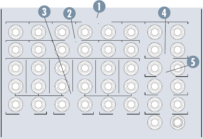
15
OUTPUT PANEL
The input and output jacks that cor-
respond to most of the functions in the
Output Panel are, logically, located in
the jack panel directly above the Output
Panel. The 8•Bus outputs to tape (and
the inputs from tape) are located on the
rear panel.
Submaster Inserts
At the top of the panel are the eight
Submaster Insert jacks (1). These
patch points allow you to insert a serial
processing device (such as a compres-
sor or an equalizer) into any of the
8•Bus submaster circuits. See Appen-
dix A for more details on using external
processing.
The insert point is after the summing amplifier,
but before the fader. Like the Channel Insert
points, the connectors are 1/4" TRS jacks, wired
unbalanced with the output or send signal on the
tip, the input or return signal on the ring, and the
sleeve common or ground.
Note: These inserts can be used as pre-fader
direct outs, using an unbalanced (TS) 1/4” plug in
these two ways:
• Plugs are inserted just to the FIRST click.
There is no interruption of the signal; OR
• Plugs are inserted all the way in to the
SECOND click.This interrupts the signal
and routes it ONLY to the device you’re
sending to.
AUX Sends
The six AUX Sends (2) appear as six 1/4" jacks in
a row, just underneath the Sub Inserts.
AUX Sends 1 and 2 are balanced TRS outputs,
wired tip to high (+), ring to low (–), and sleeve to
ground. AUX Sends 1 and 2 are designed so that
1/4" unbalanced TS phone plugs can also be used,
with no loss of level. AUX Sends 3 through 6 are un-
balanced, with the tip high (+) and ring and sleeve
tied together as ground. Nominal level is +4dBu.
AUX Returns
The AUX Returns (3) are stereo, with a L&R in-
put for each return channel. Inputs are 1/4"
unbalanced jacks, nominal level (+4dBu).
One special feature: The Left input jack to each
return is also labeled “MONO.” If you have only one
return signal, plugging it into the “MONO/L” jack only
will cause it to be connected to both the left and
right return inputs and end up centered in your ste-
reo image. When a jack is plugged into the Right
input of the return, this mono feature is disabled: the
left input is fed to the left return, and the right input
is fed to the right return.
Main Inserts
On the upper right of the panel are two Main In-
sert jacks (4). These patch points allow you to insert
a serial processing device, such as a compressor or
an equalizer, into the Main L/R Mix. See Section 4 for
more details on using external processing.
The Main Insert’s insert point (try saying that fast
three times backward) is after the summing ampli-
fier but before the master fader. Like the Submaster
Insert points, the connectors are 1/4" TRS jacks,
wired unbalanced with the output or send signal on
the tip, the input or return signal on the ring, and the
sleeve common or ground.
Control Room Output
The two Control Room Output jacks (5) carry the
signal for the Control Room speakers. They are 1/4"
unbalanced, wired tip high, ring and sleeve ground.
Nominal level is +4dBu. This is where you connect
your control room monitor amplifier inputs.
EXTERNAL
INPUT MIX-B
OUTPUT
1
AUX SEND
1
R
L
2
2
R
R
3
3
R
L
4
4
R
R
5
5
R
L
6
6
R
R
L
7
L
L
R
8
R
R
R
SUBMASTER INSERT
AUX RETURN
CNTRL
RM OUTPUT
STUDIO
OUTPUT
MAIN MIX
MAIN
INSERT
2-TRACK
INPUT
1234 56
PHONES 12
(MONO)
L
(MONO)
L
(MONO)
L
(MONO)
L
(MONO)
L
(MONO)
(MONO) (MONO)
L
L
TIP = OUT RING = IN
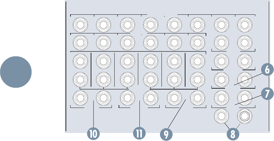
16
EXTERNAL
INPUT MIX-B
OUTPUT
1
AUX SEND
1
R
L
2
2
R
R
3
3
R
L
4
4
R
R
5
5
R
L
6
6
R
R
L
7
L
L
R
8
R
R
R
SUBMASTER INSERT
AUX RETURN
CNTRL
RM OUTPUT
STUDIO
OUTPUT
MAIN MIX
MAIN
INSERT
2-TRACK
INPUT
1234 56
PHONES 12
(MONO)
L
(MONO)
L
(MONO)
L
(MONO)
L
(MONO)
L
(MONO)
(MONO) (MONO)
L
L
TIP = OUT RING = IN
Main Mix
The Main Mix jacks (6) on the top panel are 1/4"
TRS unbalanced, with tip high, and ring and sleeve
tied to ground. The nominal level is +4dBu. These
two jacks carry the L/R Main Mix, for connection to
your master 2-Track recorder’s inputs, for instance.
The same Main L/R Mix is also available, fully bal-
anced, at the two XLR connectors on the back panel.
MIX-B Output
The MIX-B jacks (7) are 1/4" TRS unbalanced,
with tip high, ring and sleeve tied together as ground,
nominal level +4dBu. These jacks make the MIX-B
signal available for external patching.
Phones
The two Phones jacks (8) are 1/4" TRS stereo,
with tip connected to left, ring to right and sleeve to
ground. The final output of Phones 1 and Phones 2
appear here. These jacks may be connected to exter-
nal power amplifiers for headphone distribution, or
you may plug your phones directly into the jacks.
There is plenty of level. In fact, you should turn the
PHONES level down before you plug your phones in,
and then bring the level up to where you want it.
Studio Output
The two Studio Output jacks (9) carry the signal
for the Studio speakers. They are 1/4" unbalanced,
wired tip high, ring and sleeve ground, nominal level
+4dBu. This is where you connect the inputs to your
studio monitor amplifier.
Alternatively, the Studio Output jacks can be
wired to a second Control Room amplifier and set of
speakers. Then, to switch between the two sets, turn
the CNTRL-RM level control fully down and turn up
the STUDIO level control — or vice versa. This con-
cept is very handy during mixdown. It won’t work
very well if you plan to use any of the talkback
switches, as you would during tracking/overdubbing.
2-Track Input and External Input
The 2-Track Input (10) and External Input (11)
are 1/4" TRS unbalanced jacks, with tip wired to high
and ring and sleeve tied together to ground. These
inputs offer you the ability to listen to two mono or
stereo sources directly, without patching through in-
put channels. Either input can be connected to any
stereo source you’d like to listen to. Usually, you will
have the 2-Track Input connected to the output of
your 2-Track master recorder, to check the mix.
The inputs are directly wired to the “2-TK” and
“EXTERNAL” source selection switches in the
Phones 1 and 2 and MONITOR sections of the
Output Panel. These are +4 dBu inputs.
LAYOUT
AND
FUNCTION
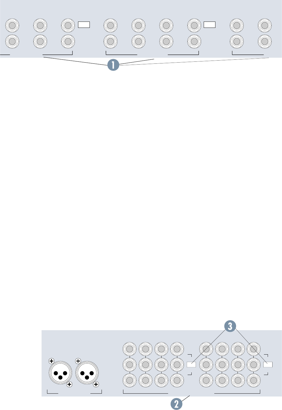
17
OPERATING
LEVEL CH. 17-24
TAPE RETU
R
15 13 11 9 7 5
16 14 12 10 68
17
18
19
20
21
22
TAPE RETURNS 9-16TAPE RETURNS 17-24
OUT +4dBu
IN –10dBV
+4 / –10 BALANCED / UNBALANCED+4 / –10 BALANCED / UNBALANCED +4 / –10 BALANCED /
U
OPERATING
LEVEL CH. 9-16
OUT +4dBu
IN –10dBV
Console Bus 1: Submaster 1, 9 and 17
Console Bus 2: Submaster 2, 10 and 18
Console Bus 3: Submaster 3, 11 and 19
Console Bus 4: Submaster 4, 12 and 20
Console Bus 5: Submaster 5, 13 and 21
Console Bus 6: Submaster 6, 14 and 22
Console Bus 7: Submaster 7, 15 and 23
Console Bus 8: Submaster 8, 16 and 24
Connect the inputs of your multitrack recorder to
the Tape Output jacks.
Why are there 24 submaster output jacks on
an 8-submaster mixer? This is called “triple-bus-
sing.” When you send a signal to Submaster 1
output, for instance, it will appear at Submaster
Outputs #1, #9 and #17. Now, whichever tracks
on your multitrack are in RECORD mode will ac-
cept the signal, while the tracks in SAFE mode
won’t. That way, you can feed a 24-track deck
without having to constantly re-patch. Connect
the Submaster/Tape Outputs to the correspond-
ing inputs on your multitrack, using only
Submasters 1 through 8 for an 8-track deck, or
1-16 for a 16-track deck.
Submaster/Tape Output
OPERATING LEVEL
Nominal level for the Submaster jacks is
switched to either +4dBu (switch out) or
–10dBV (switch in) in groups of 4 channels (3).
If you aren’t sure of your multitrack recorder’s
operating input level, check the specifications
section of the recorder’s owner’s manual.
REAR PANEL
CONNECTIONS
The connections to and from your multitrack re-
corder are on the Rear Panel of the 8•Bus Series.
There are 24 or 32 Tape Return jacks (depending on
the model) and 24 Submaster/Tape Out jacks.
Tape Returns
The Tape Return jacks (1) are 1/4" TRS balanced,
with tip wired to high (+), ring to low (–) and sleeve
to ground. These jacks are also wired to accommo-
date 1/4" TS unbalanced connections. Each jack is
connected to the Tape input on the corresponding
channel, and is selected by the FLIP switch on that
channel.
Connect the outputs of your multitrack recorder
to the Tape In jacks. Note that they are grouped in
sets of eight: 1-8, 9-16 and17-24.
Tape return OPERATING LEVEL
Nominal level for the Tape Return jacks is
switched to either +4dBu (switch out) or -10dBV
(switch in) in groups of 8 channels. If you aren’t sure
of your multitrack recorder’s operating output level,
check the specifications section of the recorder’s
owner’s manual.
Submaster/Tape Outputs
The Tape Out jacks (2) are 1/4" TRS balanced,
with tip wired to high, ring to low and sleeve to
ground. These jacks are also wired to accommodate
1/4" TS unbalanced connections. The Submaster
Outputs of the console appear on these jacks in the
following pattern:
LEFTRIGHT
MAIN BAL OUTPUTS
+28dBu MAX OUT
SUBMASTER / TAPE OUTPUTS
+4dBu BALANCED / –10dBV UNBALANCED
87
15
6
14
5
13
4
12
3
11
2
10
1
9
OUT +4dBu
IN –10dBV
16
171820 1921222324
OPERATING
LEVEL
OUT +4dBu
IN –10dBV
OPERATING
LEVEL
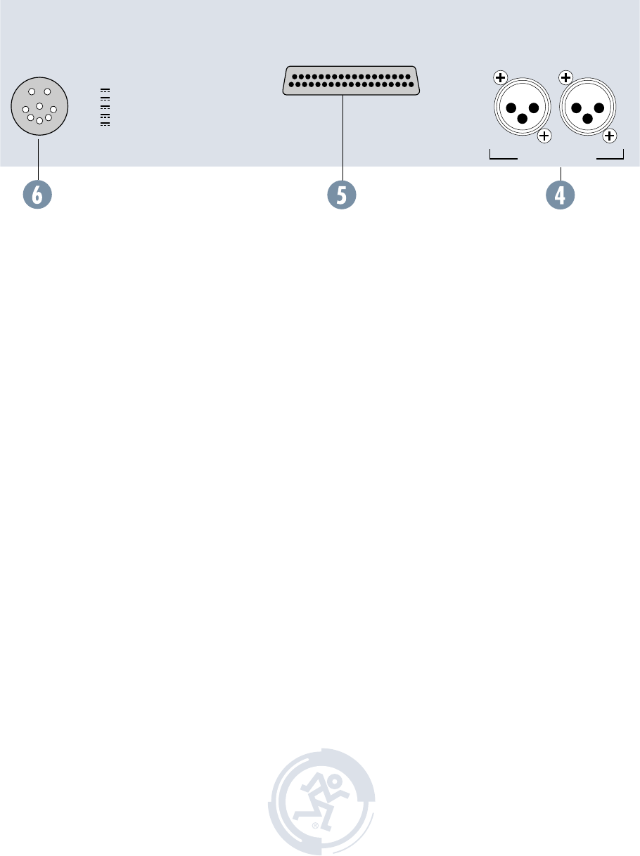
18
LEFTRIGHT
MAIN BAL OUTPUTS
+28dBu MAX OUT
EXPANDER
PORT
THIS CONNECTION FOR MACKIE
8•BUS POWER SUPPLY ONLY !
DC POWER IN
USE MACKIE 8•BUS
EXPANDER CABLE
ONLY! KEEP COVERED
+18V
–18V
+48V
+12V
+5V
MAIN BALANCED OUTPUTS
Along with the unbalanced 1/4” TS Main Mix
jacks on the front panel, balanced Main XLR
Outputs (4) are also provided, wired pin 2 hot,
pin 3 cold, pin 1 shield. Maximum output is
+28dBu.
EXPANDER PORT
The Expander Port (5) connection is pro-
vided for the 24•E Expander console, which has
been discontinued as of this printing.
DC POWER IN
This is where the funny plug that looks like a
Supersoaker squirtgun nozzle fits (6). Your 8•Bus
console should ONLY be powered by the appropriate
Mackie 8•Bus Power Supply.
This concludes our guided tour of the 8•Bus
console’s controls and connections. Now it’s time for
hands-on use!

19
GENERAL
INFO
Do you need to read this section at all?
Many of you reading this manual have a lot
of experience in using large mixing consoles.
For you battle-scarred pros, Section 2 and the
Block Diagram will probably be all that you
need to look at.
Then there are those of you who have worked
extensively with smaller mixers such as our
1604-VLZ PRO — but who have less experience
with a larger, multi-bus console with lots of
gazintas and gozoutas. For you, we recommend
at least adding Section 4 (Recording) and/or
Section 5 (PA) to your reading list. These chap-
ters cover some of the more unusual or less
familiar features of your new 8•Bus console.
Finally, there are those who are either new to
using mixers or just like to read even larger
quantities of our glib prose. For you, we have
provided this short section that discusses the ba-
sic concepts and procedures used in recording,
mixing and sound reinforcement work. If you
can make some sense of it, you’re ready for the
next two sections, which relate these concepts
to actually configuring and using a Mackie
8•Bus Series mixing console.
Also, if the system Block Diagram does not
look as familiar to you as the menu at McD’s,
spend a little time in this section.
GENERAL INFORMATION
Here is a primer covering a few important
ideas you should be on good terms with before
you sit down to a mixing console.
LEVELS
Microphones have very low
output levels. Power amplifi-
ers have very high output
levels. One of the functions
of a mixing console is to amplify or attenuate
(reduce) these signal levels properly. Since it’s
easy to degrade the signal by not handling levels
well, and since it’s your hand on the controls,
you should be sure you know how much gain to
apply and where to apply it.
Noise
Every electronic circuit produces noise or
hiss or hash or buzz, and any noise present on
the input of an electronic circuit will be faith-
fully passed through. Turn it up high enough,
and you will hear the noise.
Headroom
Every electronic circuit also has a point of
overload — a clip point, where the voltage sim-
ply cannot rise any higher, no matter what the
input signal and your fader move would like.
This overload, or clipping, will show up as tooth-
grinding distortion.
Somewhere between the noise and the clip-
ping is an optimum level for your signal: high
enough above the noise floor to render the hiss
inaudible, and far enough below the distortion
point to allow range for loud peaks of music to
pass without clipping. This safe operating zone
might be called operating level or nominal level
or zero or perhaps line level. The range between
your operating level and clipping is called head-
room, which defines just how tall your signal can
be without having to duck for the rafters.
Your mission as a designated Master of the Lev-
els is to get the low-level signals up to line-level as
soon as possible and to keep them there as much
as possible. But don’t turn them up too loud.
Unity Gain
On a Mackie 8•Bus console, the easy way to
do this is to set all the level controls according
to the Sensitivity Adjustment procedure detailed
on page 1.
Metering
When the meters read 0dB, the level will ac-
tually be +4dBu at the outputs (or –10dBV at
the submaster outputs, if you’ve engaged their
+4/–10 switches). Don’t pay too much attention
to the meters. A meter is an aid, a window look-
ing onto part of the dynamic range of your signal,
and it will tell you if your level is in the ballpark,
so to speak.
Try to keep your signals in the middle range
of the meters, for the most part. If the signal is
always very low, you may not be getting the best
noise figures you can. If the meter LEDs are
always solidly lit from bottom to top, you are
likely distorting both the console and your re-
cording tape regularly. Keep the signal in the
middle, with occasional peaks into the yellow.
Remember, the top yellow LED of the meter
(+10) represents an audio level of +14dBu, and
the Mackie 8•Bus doesn’t clip until +28dBu.
Even banging the meters hard, you still have
around 14dB of headroom for your peaks. (The
L/R meters have an additional red LED segment
to show clipping at +28dBu.). There are not
SECTION 3: GENERAL INFORMATION
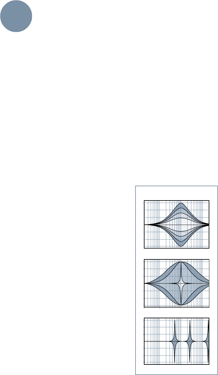
20
HI MID Variable 1: Boost/Cut
HI MID Variable 2: Bandwidth
HI MID Variable 3: Band Center
3 HI MID VARIABLES
many recorders, and no amplifiers, that can tol-
erate such high signal levels. Therefore, it’s best
that the red LEDs never light up.
But, if your music is sounding good, don’t
worry if you’re in the yellow a lot or if some parts
of the track hardly read at all. You’ll quickly get a
feel for what works for you, when you can get
away with really smacking the tape or the elec-
tronics too much.
BUSES
More often than not, the goal in a mixing con-
sole is to mix two or more inputs into one
output. Like a coach who has two or more play-
ers to get to the same ballgame, console
designers use a bus. Even Webster’s Unabridged
Dictionary agrees, defining the word bus in elec-
tronics as “a conductor serving as a common
connector for three or more circuits.”
The Mackie 8•Bus Series has, in fact, many
more than eight buses. The eight memorialized
in the name are important, but there are also six
AUXiliary buses, a pair of L/R Mix buses, the al-
ternate pair of MIX-B buses, and a pair of Solo
buses. We will try to be clear just what bus we
are talking about when we do talk about buses.
SENDS AND RETURNS
Sends are outputs, and returns are inputs. So
why don’t we call them outputs and inputs?
Well, actually, the terms send and return can
mean many things, but the way they are generally
used in mixing console parlance
is to refer to sends, which tap off
a little of a signal to send to some
effects device (like a reverbera-
tion unit), and returns, which
function to return that reverb
back into the mix.
Sends are also used to tap
some mix of signal from a collec-
tion of channels for a
headphone cue mix. For that
matter, sends can be used as
additional mix buses, if needed.
In the same way, if you don’t
need them for reverb or effects,
returns can be used as addi-
tional inputs to your mix.
SOLO
Solo is a standard console
function that allows you to listen
to one or more sources all by
themselves (soloed).
You can check EQ, possible distortion or buzz,
or just listen to see if a particular mic is open or
not. This function can also be handled by each
channel’s –20/OL LEDs. See Section 2 “–20 and
OL LEDs” for more details. When soloing more
than one source, you can listen to the blend of
just part of your mix: only the sopranos, for ex-
ample, or just the tom mics on the drums.
The solo circuits are designed not to inter-
rupt the recording process. The solo bus signal
is sent directly to the control-room monitors
without affecting any of the inputs, outputs or
recording buses.
When you are mixing or monitoring with re-
verb, remember to not only solo the channel
you’d like to hear, but also the AUX Return carry-
ing your reverb. Otherwise, you will hear the
channel soloed dry, without its echo.
EQ
Everybody knows what EQ is, but just in case
you’d like a refresher, we’ll put in a few para-
graphs here.
Equalization (EQ) refers to purposely chang-
ing the frequency response of a circuit,
sometimes to correct for previous unequal re-
sponse (hence the term, equalization), and more
often to add or subtract level at certain frequen-
cies for a pleasing effect.
Bass and treble controls on your stereo are
EQ; so are the devices called parametrics and
graphics and notch filters.
A lot of how we refer to
equalization has to do with
what a graph of the frequency
response would look like. A flat
response (no EQ) is a straight
line; a peak looks like a hill, a
dip is a valley, a notch is a re-
ally skinny valley, and a shelf
looks like a plateau (or a
shelf). The slope is the grade
of the hill on the graph. For in-
stance, if you lived in Texas,
you would set y’all’s EQs flat.
Graphic equalizers have
enough frequency slider con-
trols to form a graph of the EQ
right on the front panel. Para-
metric EQs let you vary several
EQ parameters at once. A filter
is simply a form of equalizer
that allows certain frequencies
through unmolested and either
reduces other frequencies or
eliminates them entirely.
Fig.1
GENERAL
INFO
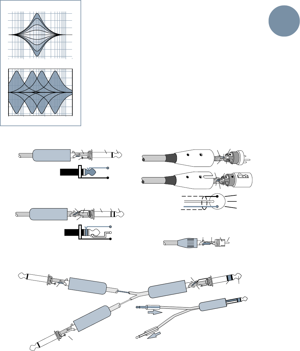
21
GENERAL
INFO
Finally, the bandwidth of the bell-shaped re-
sponse curve around the selected frequency
(also somewhat inaccurately referred to as a ra-
tio known as Q) can be selected with the lower
knob. The range is from as wide as 3 octaves to
as narrow as 1/12 octave. Leave it at the center
detent if you are unfamiliar with the bandwidth
feature. This setting will give you a semi-para-
metric type of EQ.
The 8•Bus console’s set of three HI-MID con-
trols (boost/cut, frequency center and
bandwidth) is VERY powerful in its effects.
Rarely if ever will you need more than a few dB
of boost and cut or, as noted above, will you want
to stray from the NORMAL (2 octave) bandwidth
until you gain some experience recording and
mixing.
The LO MID EQ section is called a semi-para-
metric equalizer, because the bandwidth is not
adjustable (Figure 2). The frequency range is 45Hz
to 3kHz and the bandwidth is fixed at 2 octaves.
The equalizer on the 8•Bus Series combines
several different types of EQ into five different
sections.
The HI MID EQ section is a fully parametric
equalizer. This means all the significant
parameters can be varied, as you can see in Fig-
ure 1. The boost or cut of this section, through a
range of ±15dB,
is set with the
top knob. The
center fre-
quency is dialed
in with the
middle knob,
and can be set
anywhere be-
tween 500Hz
and 18kHz.
LO MID Variable 1: Boost/Cut
LO MID Variable 2: Band Center
2 LO MID VARIABLES
Fig. 2
2
3
1
SLEEVE
TIP
TIPSLEEVE
TIP
SLEEVE
SLEEVE
TIPSLEEVE
TIP
RING
RING
TIP
SLEEVERING
TIPSLEEVETIPSLEEVE
TIP
(SEND)
RING (IN)
TIP (OUT)
RING
(RETURN)
TO MIXER
CHANNEL INSERT
TIP (RETURN)
TIP (SEND)
TO
PROCESSOR
INPUT
FROM
PROCESSOR
OUTPUT
2
2
31
1
COMMON
COLD
HOT
COMMON
COLD
HOT
3
COMMON
COLD
HOT
Balanced XLR Connectors
RCA Plug used on some outboard gear
“Y” insert cable for connecting
signal processors’ inputs and
outputs to 8•Bus insert
Tip/Ring/Sleeve (TRS) Plug
Tip/Sleeve (TS) Plug
Female XLR
Male XLR
Figure 4: Common Connectors
22
The LO and HI
sections of the EQ
are shelving
equalizers, with a
family of curves
shown in Figure 3.
As you can see,
shelving EQs lift
or lower the en-
tire range of
frequencies above
or below a certain
point. Most tone controls on stereos are shelving
EQs, often set at 100Hz for the bass and 10kHz
for the treble. The LO EQ on the 8•Bus is at
80Hz and the HI is at 12kHz.
dB
30
20
5
10
5-6
3-4
1-2
7- 8
L/R
MIX
OO
5
10
40
50
60
U
TAPE IN
24
Channel
Tape Input Channel
Fader
Channel
Input
+15
OO
U
MIX-B
SOURCE
OUTPUT
INPUT
PAN
LEVEL
SHIFT
HI/LO EQ
MONITOR
LR
Channel
Mix B/Monitor
Mixdown DeckMulti-track Deck
(PLAYBACK)
Additional mic or line input
24
CHANNEL
LINE IN
MIC/LINE
Figure 5: FLIP/MIX-B signal path during tracking (“flip” switch up)
Figure 6: FLIP/MIX-B signal path during mixdown
showing additional input (“flip” switch down)
Channel
Input Channel
Fader
Channel
Tape Input
Channel
Mix B/Monitor
Speaker
Section
MONO
TAPE
MIX-B
L/R MIX
EXTERNAL
SOURCE
SPEAKERS
CNTRL RM
STUDIO
+15
OO
U
+15
OO
U
+15
OO
U
MIX-B
SOURCE
OUTPUT
INPUT
PAN
LEVEL
SHIFT
HI/LO EQ
MONITOR
LR
TAPE IN
24
dB
30
20
5
10
5-6
3-4
1-2
7- 8
L/R
MIX
OO
5
10
40
50
60
U
Multi-track Deck
(RECORD)
Control Room
Monitors
Mic
or
line
input
24
CHANNEL
LINE IN
MIC/LINE
1 LO & HI VARIABLE
(HI shown)
Only LO/HI Variable: Boost/Cut
Fig. 3
GENERAL
INFO
The EQ IN/OUT SWITCH will completely re-
move the EQ circuit from the channels signal
path when disengaged, and activate the EQ
when engaged.
When the EQ section is split between the
channel strip and Mix B, the EQ IN/OUT switch
will only shut off the HI MID and LO MID bands.
The LOW CUT filter (also known as a high-
pass filter) reduces everything below about
100Hz. 75Hz is -3dB, and the lower the
frequency, the greater the attenuation. The slope
of the filter is 18dB/octave.
Connectors
If you’ve used a Mackie VLZ PRO compact
mixer, you’re familiar with the various kinds of
connectors used with a mixing board. If you’re
new to this whole thing, review the drawings in
Figure 4 on Page 21. They’re also described in
detail in Appendix A on page 44 of this manual.
A BIT MORE ON MIX-B/FLIP
In Section 2, we described FLIP’s
use during tracking and mixdown.
Before you actually get involved with
recording, we’d like to spring a
couple of block diagrams on you that
may clarify things further.
The switch labeled FLIP selects the input
that is actually fed into the channel fader
(and the MIX-B control).
As the label indicates, the MIC/LINE input
(after Mic/Line preamp) is fed to the chan-
nel fader when the FLIP switch is in the up
position (Figure 5). When FLIP is up, the
channel is fed MIC/LINE and MIX-B gets TAPE.
That way, you can use MIX-B to monitor the sig-
nal as it comes back from the recorder. This is
the normal mode for tracking and overdubbing.
In the down position, the TAPE return (the
output signal from the corresponding track of
your recorder) is fed to the channel fader (Fig-
ure 6). When FLIP is down, the channel input is
TAPE and MIX-B receives MIC/LINE. That en-
ables you to use each channel’s MIC/
LINE input for another input during
mix down. Thus down is the normal
position for mixing.
For PA, leave the FLIP switch up.

23
RECORDING
RECORDING OVERVIEW
The recording process can be as simple as one
microphone recorded on a monaural tape re-
corder. Not much advice needed for that.
But since you’ve bought such a large mixing
console, we expect you’ll occasionally be doing
pretty big sessions. This section will describe at
least one way of approaching a large session—
for example, a big drum set, bass, guitar, piano,
scratch vocal and horns, with background vocals
and synthesizer overdubs. Let’s assume there is a
16-track recorder already patched in to the first
16 Tape In and the 16 Tape Out jacks on the
8•Bus Console. There is a set of Master Track-
ing, Overdub and Mixdown drawings farther on
in this section for general reference.
SETUP
Okay, now let’s get ready for your session.
Make a diagram of your studio setup showing
mic positioning. Then assign an input channel to
each mic.
Trying to make your microphone-to-input layout
sensible now will avoid confusion later. Group
similar instruments together. If there is a left-to-
right pattern to the mics (like drums mics or a
vocal group), keep the same left-to-right sequence
on the console. Plan your basic track assignments
the same way. It’s very confusing to have inputs
randomly strewn across a mixing console.
Now, normal your console (also called “zero-
ing”). This means check the position of every
switch and every knob to be sure they are in the
normal position. Your normal may be different from
someone else’s, but generally it means all switches
off or up, all knobs either all the way down or at
their Unity detent. If you are working in a certain
mode, say, for example, all AUX 3-4 SHIFT switches
in TAPE, this is the time to set them all.
Lay a piece of 1/2" or 3/4" white paper tape
across the top of the input faders and label all your
inputs. (By the way, avoid masking tape. It will
slime your console. Take the time to go to an art
supply store or a recording supply store and get
some better-quality “low tack” tape.)
Since your multitrack returns will be coming
into the MIX-B inputs on some of the same input
strips, you might want to divide your label into
multitrack track labeling and input labeling. See
TRACKING drawings 1&2 on pages 25 and 26.
If you have any careful submixing to do during
the recording, you might want to lay strips of 1/4"
white paper tape alongside each fader slot (bus
faders too, if you need them). Then you can mark
your place as you rehearse your fader moves.
RECORDING AND OVERDUBBING
Using Buses
If you have to combine two or more inputs
into one output (two trumpets on one track, five
drum mics panned across a pair of tracks), you
must assign the inputs to a common bus or pair
of buses.
If you have only one source going to one tape
track, you have a choice: you can assign the chan-
nel to the bus feeding that track, or you can patch
the tape track into the channel’s Direct Out.
Rationale for using a bus:
• It’s there, it’s easy, it sounds great.
• You meet interesting people on the bus.
Rationale for using a Direct Out:
• You’ve already assigned all eight of your buses
to other duties.
• You are a purist and you think you can
hear the additional circuitry used in a bus.
Monitoring
The most straightforward way to monitor during
a recording or overdubbing session is by listening to
the output of the recorder, played through MIX-B.
Properly configured, your recorder will automati-
cally switch between source and playback as you
put the deck into stop, play, fast wind, record and
so on. That way, you’re always hearing your instru-
ments after they travel through the multitrack deck,
regardless of whether or not the tape is rolling.
MIX-B allows you to set up a custom mix of
the tape tracks, independent of your recording
levels. You can set level, pan, reverb and even EQ
in your monitor mix while you record. You can
even patch a cassette recording into the outputs
of MIX-B for a rough mix of the session.
Both the FLIP and MIX-B SOURCE buttons
should be in their up positions. This connects
the Tape In amplifier to the MIX-B level control,
and MIX-B will monitor the recording machine.
Cue Mix
Initially, as you are setting up, set the Phones
source to the MIX-B selection. This way, the mu-
sicians will at least have something to listen to
right away so they can tune up and rehearse,
SECTION 4:
RECORDING WITH THE MACKIE 8•BUS CONSOLE

24
providing all your chosen tracks are in record
mode and auto-switching to input when tape is
not rolling.
Keeping the Phones on MIX-B may work for
the entire session, but usually the musicians will
want one or even two custom mixes. The bass
player and drummer may want bass and drums
featured very loud in their cans, which may be
killing the vocalist. Likely, as soon as you are
close, you will be required to come up with some
new cue feeds for the players.
AUXiliary Sends 3-4 and 5-6 are designed to set
up two different cue mixes from the same source
as MIX-B, which should be the signal from your
recorder. Simply push the SOURCE button by
Sends 3-4-5-6 down to the MIX-B position, and
push the PRE button down (to bypass the MIX-B
level control). With the system configured like
this, you will be able to send a custom mix from
each tape track to either Sends 3-4 or Sends 5-6,
depending on the position of the AUX SHIFT
switch. It’s like having an extra Mix B section.
Sends 3 and 5 are set to feed the left head-
phone, and 4 and 6 the right headphone. An
equal setting on both knobs will place the sound
in the center of the image.
Additional Note: You can modifiy the channel
Aux 1/2 sends to source the pre-fader information
from the tape returns. This would provide an ad-
ditional two aux sends that could be used as cue
mixes from Mix-B (tape returns), and allow all
six aux sends to access Mix-B during tracking or
overdubbing for cue mixes as well as effects. In-
structions for this modification can be found on
our website at www.mackie.com (click on Sup-
port). Or you can call Tech Support at
1-800-258-6883 for assistance.
Wet or Dry Monitor?
Usually, you will not record wet (with reverb)
onto your multitrack master. You can’t undo it
later. However, it is nice to hear a little echo on
the tracks as you are working, and with the 8•Bus
Series, you have the option of wet monitoring.
Since you are using MIX-B as your monitor sub-
mix, you should derive the reverb send from the
same source. When the SOURCE button next to
Sends 3/4/5/6 is depressed but the PRE button is
not, the sends are connected after the MIX-B level
control and make great wet monitor reverb sends.
Once you have your sends happening, you can
assign the return from your reverb into the head-
phone cues by using Stereo Returns 3 or 4, which
can directly assign into the phones. (Even if you
are using Send 6, there is no reason not to patch
the output of the reverb into Returns 3 & 4. The
Send and Return numbers do not have to match.)
FOLLOW THIS LEVEL-SET-
TING PROCEDURE FOR EACH
CHANNEL IN USE:
1. ■■Assign signal to channel fader:
• If channel will be used with a micro-
phone, MIC/LINE switch should be up &
FLIP switch should be up.
• If channel will be used with line input,
MIC/LINE switch should be down &
FLIP switch should be up.
• If channel will be used with a tape input,
the FLIP switch should be down.
2. Set channel strip controls as follows:
■■TRIM pot all the way counterclockwise
(+4dB)
■■AUX SEND controls all the way counter-
clockwise (off)
■■EQ switch up
■■LOW-CUT switch either on or off
(on recommended for mic inputs)
■■Channel fader at UNITY
■■SOLO switch down
3. ■■Make appropriate “noise” into the channel
input. For example, have a performer play/
sing/strike something or someone, etc. at
the level they’re going to record or perform.
Don’t just play a single sustained note,
but rather, jam away as you would be during
recording or performance. If the channel is
being used for a tape input during mixdown,
roll an already-recorded track from your
recorder.
4. The channel’s –20dB LED should light. The L/R
main meters will show the actual internal
operating level of soloed signals. Now you will
optimize levels.
5. ■■• For mic or line inputs, adjust the TRIM
control clockwise to get peaks that
regularly hit 0dB on the L/R meters.
OR
■■• For tape inputs, set the +4/–10 switch on
the console back panel to its in position
(–10) if the signalpeaks are below –10dB
on the L/R main meters.
6. If desired (optional):
■■Press the EQ switch in.
■■Adjust the channel strip’s EQ to about what
you will be using during the session.
■■Re-perform Step 5.
7. ■■Return the channel strip’s SOLO button to
its up position.
8. ■■Repeat Steps 1-7 on the next channel that is
being used.
Text continued on Page 27
RECORDING
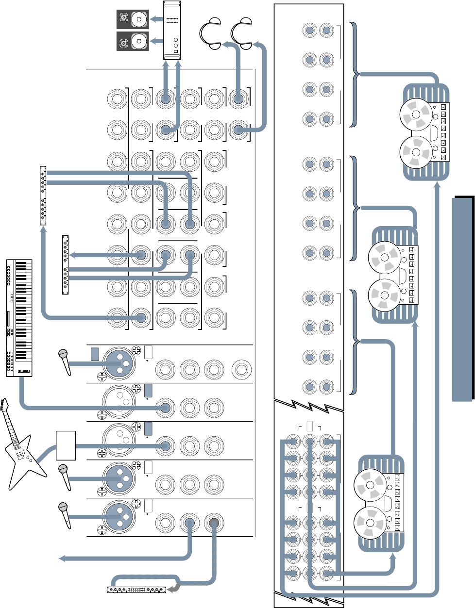
25
EXTERNAL
INPUT MIX-B
OUTPUT
1
AUX SEND
1
R
L
2
2
R
R
3
3
R
L
4
4
R
R
5
5
R
L
6
6
R
R
L
7
L
L
L
R
8
R
R
R
SUBMASTER INSERT
AUX RETURN
CNTRL
RM OUTPUT
STUDIO
OUTPUT
MAIN MIX
MAIN
INSERTS
2-TRACK
INPUT
123456
PHONES
12
MONO
L
MONO
L
MONO
L
MONO
L
MONO
L
MONO
L
MONO MONO
LINE
IN
DIRECT
OUT
INSERT
BAL/UNBAL
TIP = OUT
RING = IN
LINE
IN
DIRECT
OUT
INSERT
PHANTOM
CHANNEL
24
BAL/UNBAL
TIP = OUT
RING = IN
LINE
IN
DIRECT
OUT
INSERT
CHANNEL
20
BAL/UNBAL
TIP = OUT
RING = IN
LINE
IN
DIRECT
OUT
INSERT
BAL/UNBAL
TIP = OUT
RING = IN
MIC
LINE MIC
LINE MIC
LINE MIC
LINE
LINE
IN
DIRECT
OUT
INSERT
CHANNEL
21
BAL/UNBAL
TIP = OUT
RING = IN
MIC
LINE
OPERATING
LEVEL CH. 17-24
TAPE RETURNS 1-8
15 13 11 9 7 5 3 1
16 14 12 10 6 4 28
17
18
19
20
21
22
23
24
TAPE RETURNS 9-16
TAPE RETURNS 17-24
OUT +4dBU
IN –10dBV
+4 / –10 BALANCED / UNBALANCED+4 / –10 BALANCED / UNBALANCED +4 / –10 BALANCED / UNBALANCED
OPERATING
LEVEL CH. 9-16
OUT +4dBU
IN –10dBV
OPERATING
LEVEL CH. 1-8
OUT +4dBU
IN –10dBV
SUBMASTER / TAPE OUTPUTS
+4dBU BALANCED / –10dBV UNBALANCED
87
15
6
14
5
13
4
12
3
11
2
10
1
9
OUT +4dBU
IN –10dBV
16
171820 1921222324
OPERATING
LEVEL
OUT +4dBU
IN –10dBV
OPERATING
LEVEL
CHANNEL
23
CHANNEL
22
To Multi-Track
(optional)
In
Power Amplifier
Control Rm Monitors
Reverb
Out
In
Out
In Out
Keyboard, or other line level input
M
u
l
t
i
-
T
r
a
c
k
R
e
c
o
r
d
e
r
3
M
u
l
t
i
-
T
r
a
c
k
R
e
c
o
r
d
e
r
2
Or from DIRECT OUTS
of individual channels
M
u
l
t
i
-
T
r
a
c
k
R
e
c
o
r
d
e
r
1
Reverb
In
Out
Mono Compressor
TRACKING PART 1: INPUT/OUTPUT
Guitar
Effects
Box
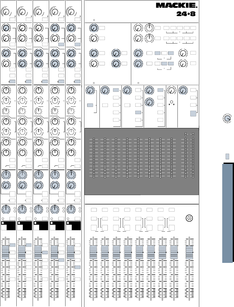
26
+15
OO
U
12k
MIX-B
EQ
LOW CUT
EQ IN
HI
FREQ
75 Hz
18dB/oct
SOURCE
45 3k
PAN
LEVEL
–15 +15
80
U
LO
SPLIT EQ
HI/LO EQ
TO MON
MONITOR
LR
–15 +15
U
250
220 350
PAN
dB
30
20
5
10
SOLO
-20
OL
OO
MUTE
21
5
10
40
50
80
U
LR
MUTE
+15
OO
U
12k
MIX-B
EQ
LOW CUT
EQ IN
HI
FREQ
75 Hz
18dB/oct
SOURCE
45 3k
PAN
LEVEL
–15 +15
80
U
LO
SPLIT EQ
HI/LO EQ
TO MON
MONITOR
LR
–15 +15
U
250
220 350
PAN
dB
30
20
5
10
SOLO
-20
OL
OO
MUTE
22
5
10
40
50
80
U
LR
MUTE
+15
OO
U
12k
MIX-B
EQ
LOW CUT
EQ IN
HI
FREQ
75 Hz
18dB/oct
SOURCE
45 3k
PAN
LEVEL
–15 +15
80
U
LO
SPLIT EQ
HI/LO EQ
TO MON
MONITOR
LR
–15 +15
U
250
220 350
PAN
dB
30
20
5
10
SOLO
-20
OL
OO
MUTE
23
5
10
40
50
80
U
LR
MUTE
+15
OO
U
12k
MIX-B
EQ
LOW CUT
EQ IN
HI
FREQ
75 Hz
18dB/oct
SOURCE
45 3k
PAN
LEVEL
–15 +15
80
U
LO
SPLIT EQ
HI/LO EQ
TO MON
MONITOR
LR
–15 +15
U
250
220 350
PAN
dB
30
20
5
10
SOLO
-20
OL
OO
MUTE
24
5
10
40
50
80
U
LR
MUTE
TALKBACK
MIC
MIX
LEFT/RIGHT
dB
30
20
5
10
OO
5
10
40
50
80
U
dB
30
20
5
10
OO
5
10
40
50
80
U
dB
30
20
5
10
OO
5
10
40
50
80
U
dB
30
20
5
10
OO
5
10
40
50
80
U
dB
30
20
5
10
OO
5
10
40
50
80
U
dB
30
20
5
10
OO
5
10
40
50
80
U
dB
30
20
5
10
OO
5
10
40
50
80
U
dB
30
20
5
10
OO
5
10
40
50
80
U
dB
30
20
5
10
OO
5
10
40
50
80
U
FLIP SW
CHANNEL FLIP SW
CHANNEL FLIP SW
CHANNEL FLIP SW
CHANNEL
AUX
PRE
TRIM
FLIP
1
2
4
3
5
6
MIX-B
CHANNEL
PRE
SHIFT
TAPE
MIC/LINE
CHANNEL
21
SOURCE
+15
OO
U
+15
OO
U
+15
OO
U
+15
OO
U
AUX
GAIN
+4
–10
48
dB
40
dB
U
L
I
N
E
S
E
N
S
I
T
I
V
I
T
Y
M
I
C
/
L
I
N
E
G
A
I
N
LO
MID
HI
MID
BAND
WIDTH
500 18k
3k
FREQ
–15 +15
U
–15 +15
U
1k 5k
3
2
1
12
NORMAL
AUX
PRE
TRIM
FLIP
1
2
4
3
5
6
MIX-B
CHANNEL
PRE
SHIFT
TAPE
MIC/LINE
CHANNEL
22
SOURCE
+15
OO
U
+15
OO
U
+15
OO
U
+15
OO
U
AUX
GAIN
+4
–10
48
dB
40
dB
U
L
I
N
E
S
E
N
S
I
T
I
V
I
T
Y
M
I
C
/
L
I
N
E
G
A
I
N
LO
MID
HI
MID
BAND
WIDTH
500 18k
3k
FREQ
–15 +15
U
–15 +15
U
1k 5k
3
2
1
12
NORMAL
AUX
PRE
TRIM
FLIP
1
2
4
3
5
6
MIX-B
CHANNEL
PRE
SHIFT
TAPE
MIC/LINE
CHANNEL
23
SOURCE
+15
OO
U
+15
OO
U
+15
OO
U
+15
OO
U
AUX
GAIN
+4
–10
48
dB
40
dB
U
L
I
N
E
S
E
N
S
I
T
I
V
I
T
Y
M
I
C
/
L
I
N
E
G
A
I
N
LO
MID
HI
MID
BAND
WIDTH
500 18k
3k
FREQ
–15 +15
U
–15 +15
U
1k 5k
3
2
1
12
NORMAL
AUX
PRE
TRIM
FLIP
1
2
4
3
5
6
MIX-B
CHANNEL
PRE
SHIFT
TAPE
MIC/LINE
CHANNEL
24
SOURCE
+15
OO
U
+15
OO
U
+15
OO
U
+15
OO
U
AUX
GAIN
+4
–10
48
dB
40
dB
U
L
I
N
E
S
E
N
S
I
T
I
V
I
T
Y
M
I
C
/
L
I
N
E
G
A
I
N
LO
MID
HI
MID
BAND
WIDTH
500 18k
3k
FREQ
–15 +15
U
–15 +15
U
1k 5k
3
2
1
12
NORMAL
SOLO SOLO
SOLO SOLO
SOLO
SOLO
AUX SENDS STEREO AUX RETURNS
4
3
2
5
6
1
PHONES
2L/R MIX
L/R MIX
1-2 3-4 5-6 7- 8
L/R MIX
SOLO 1-2 3-4 5-6 7-8
PHONES
1PHONES
2L/R MIX
1
2
3
4
LEVEL
ASSIGN
ASSIGN
ASSIGN
ASSIGN
LEVELLEVEL
PHONES
1
6
+15
OO
U
+15
OO
U
+15
OO
U
+15
OO
U
+15
OO
U
+15
OO
U
+20
OO
U
+20
OO
U
+20
OO
U
+20
OO
U
LR
LR
5
+20
OO
U
+20
OO
U
SOLO
SOLO
SOLO
SOLO
SOLO
SOLO SOLO
LEVEL LEVEL
LEVEL
MIX-B TO
L/R MIX SOLO AUX SEND 3/4
MIX-B
MONITOR
AUX SEND 5/6
EXTERNAL MONO
TAPE
SUBGRPS
AUX SEND 1
SOURCE
MIX B
MONITOR PHONES 1
PHONES
LEVEL
SOLO AUX SEND 3/4
MIX-B
MONITOR
AUX SEND 5/6
EXTERNAL
SOURCE
PHONES 2
PHONES
LEVEL
ASSIGN
2-TK
MIX-B
L/R MIX
EXTERNAL
SOURCE
MONITOR
CNTRL RM
STUDIO
SOLO TALKBACK
LEVEL LEVELMIX-B
LEVEL
RUDE
SOLO LITE
AUX SEND 2
PHONES
&
STUDIO
+15
OO
U
OO
OO
OOOOOO
+15
OO
U
BALANCE
POWER
TRACKING PART 2: THE BOARD CNTRL RM
OO
Tinted buttons
are pressed IN Tinted knobs are used
in this application
SOLO SOLO SOLO SOLO SOLO SOLO SOLO SOLO
MONO
L+R
RLRLRLR
MONO
L+R
MONO
L+R
MONO
L+R
MONO
L+R
ASSIGN
MONO
L+R
MONO
L+R
1
L
2345678
MONO
L+R
ASSIGN ASSIGN ASSIGN ASSIGN ASSIGNASSIGNASSIGN
MIX MIX MIX MIX
12345678
169 101112131415
2417 18 19 20 21 22 23
10
+
7
4
2
0
2
4
7
10
20
30
40
–
LR
10
+
7
4
2
0
2
4
7
10
20
30
40
–
LR
10
+
7
4
2
0
2
4
7
10
20
30
40
–
LR
10
+
7
4
2
0
2
4
7
10
20
30
40
–
LR
10
+
7
4
2
0
2
4
7
10
20
30
40
–
22
10
+
7
4
2
0
2
4
7
10
20
30
40
–
10
+
7
4
2
0
2
4
7
10
20
30
40
–
10
+
7
4
2
0
2
4
7
10
20
30
40
–
LR
MAIN
OR SOLO LEVEL
+15
OO
U
12k
MIX-B
EQ
LOW CUT
EQ IN
HI
FREQ
75 Hz
18dB/oct
SOURCE
45 3k
PAN
LEVEL
–15 +15
80
U
LO
SPLIT EQ
HI/LO EQ
TO MON
MONITOR
LR
–15 +15
U
250
220 350
PAN
dB
30
20
5
10
5-6
3-4
1-2
7- 8
L/R
MIX
SOLO
-20
OL
OO
MUTE
20
5
10
40
50
80
U
LR
MUTE
FLIP SW
CHANNEL
AUX
PRE
TRIM
FLIP
1
2
4
3
5
6
MIX-B
CHANNEL
PRE
SHIFT
TAPE
MIC/LINE
CHANNEL
20
SOURCE
+15
OO
U
+15
OO
U
+15
OO
U
+15
OO
U
AUX
GAIN
+4
–10
48
dB
40
dB
U
L
I
N
E
S
E
N
S
I
T
I
V
I
T
Y
M
I
C
/
L
I
N
E
G
A
I
N
LO
MID
HI
MID
BAND
WIDTH
500 18k
3k
FREQ
–15 +15
U
–15 +15
U
1k 5k
3
2
1
12
NORMAL
Assign channels to the
appropriate bus for the
desired tape channel input.
5-6
3-4
1-2
7- 8
L/R
MIX
5-6
3-4
1-2
7- 8
L/R
MIX
5-6
3-4
1-2
7- 8
L/R
MIX
5-6
3-4
1-2
7- 8
L/R
MIX
OCTAVES
OCTAVES
OCTAVES
OCTAVESOCTAVES
21 22 23 2420
24x8x2 8•BUS MIXING CONSOLE

27
RECORDING
Getting reverb into the monitors is a little
more involved, since there is no return assign-
ment switch to MIX-B. You have three choices:
• Assign MIX-B to L/R Mix in the MIX-B master
section. Then, select L/R Mix as your only source
in the monitor section. Finally, use Stereo AUX
Returns 1-6 to bring the reverb into the L/R Mix
buses. Make sure that none of the channel L/R
switches are engaged. There is no disadvantage to
this patch, unless you are already using the L/R
Mix buses for some other function.
• Patch the returns into unused tape returns, using
the Tape In jacks on the rear of the console. Then
route them into MIX-B, just as if they were
additional tape tracks.
• Patch the returns into unused channel strips,
using the Line In jacks. Then you can route
the reverb anywhere your heart desires.
Let’s Record!
Here’s one way to set the board up (another
option is shown in the hook-up drawings…either
works just fine):
Overdub, Anyone?
See the OVERDUB drawings on page 30 and 31.
Once you’ve got your basic tracks down, take
a moment and log all your settings, right down to
headphone sends and outboard compressor
thresholds. You may be back next week doing it
all over again, and you won’t remember it all. It
seems some engineers use a camera for this
step, but our Polaroids never come out that well.
One easy way to do this is to copy the 8•Bus
panel layouts from the end of the manual and
mark your settings on them in color.
Now, normal all the channel inputs and EQs
and sends—anything that does not affect your
MIX-B monitor and cue submix. Do not change
the FLIP switch settings yet.
Then, pick a convenient input channel or two
and use them as your input for overdubs. As you
record on different tracks, just reassign the bus
outputs from the channels, no sweat. Remember,
with the triple busing feature, explained in Sec-
tion 2 (“Submaster/Tape Outputs”), you won’t
have to repatch anything to feed up to a 24-track
recorder. And your monitor mix and
cue mix haven’t changed. At the end
of the night, you can run the monitor
mix into a cassette or DAT and take
a rough mix home.
If you’re going to do your final
mix right away, you have another
option during overdubbing. First,
pick an input channel for your over-
dub mics beyond the number of
tape tracks you have. If you have a
16-Track, choose channels 17 and
18. These will be your inputs, which
you will then assign to open tape
tracks for the overdubs. Now, push the FLIP
buttons on channels 1-16. This will bring the
Tape Inputs into the main channel faders, and
you can begin working on your mix while you
monitor on the L/R Bus. Headphones can still
be fed via the AUX Send of your choice, or by
assigning monitor to the phones. When you’re
done overdubbing, your mix is ready.
MIXING OVERVIEW
See the MIXDOWN drawings on pages 31 and 32.
Recording and overdubbing require care from
the recording engineer, but the focus really has
to be on the performances. It’s important to get a
good sound, but it’s more important to keep the
musicians really in it, keep the pace up, be ready
to snag that killer track when it happens.
Good mixing, however, focuses solely on the
engineer and requires an emphasis on precision
Your monitoring and cue signals come from
the MIX-B inputs corresponding to the tape
tracks:
Kick .................. Track 1 .............. Tape Return 1 ............ MIX-B
Snare ................ Track 2 .............. Tape Return 2 ............ MIX-B
Drums L ........... Track 3 .............. Tape Return 3 ............ MIX-B
Drums R .......... Track 4 .............. Tape Return 4 ............ MIX-B
Bass .................. Track 5 .............. Tape Return 5 ............ MIX-B
Guitar .............. Track 6 .............. Tape Return 6 ............ MIX-B
Piano L ............ Track 7 .............. Tape Return 7 ............ MIX-B
Piano R ............ Track 8 .............. Tape Return 8 ............ MIX-B
Horns L ............ Track 9 .............. Tape Return 9 ............ MIX-B
Horns R ............ Track 10 ............ Tape Return 10 .......... MIX-B
Scratch Vocal ... Track 11 ............ Tape Return 11 .......... MIX-B
At this point, your recording should pretty
well take care of itself. Keep on top of the play-
ers: be sure they’re in tune, keep them tight.
You’ll have great tracks before midnight.
Kick Drum ............ to Channel 1 ......... Direct Out to Track 1
Snare Drum .......... to Channel 2 ........... Direct Out to Track 2
Cymbals Left ......... to Channel 3 ........... Bus 3 to Track 3
Cymbals Right ....... to Channel 4 ........... Bus 4 to Track 4
Tom 1 ..................... to Channel 6 ........... panned between Buses 3 & 4 to Tracks 3 & 4
Tom 2 ..................... to Channel 7 ........... panned between Buses 3 & 4 to Tracks 3 & 4
Tom 3 ..................... to Channel 8 ........... panned between Buses 3 & 4 to Tracks 3 & 4
Bass Amp ............... to Channel 9 ........... Bus 5 to Track 5
Bass Direct ............ to Channel 10 ......... Bus 5 to Track 5
Scratch Vocal ......... to Channel 11 ......... Direct Out to Track 11
Guitar near ........... to Channel 12 ......... Bus 6 to Track 6
Guitar far .............. to Channel 13 ......... Bus 6 to Track 6
Piano L .................. to Channel 14 ......... Bus 7 to Track 7
Piano R .................. to Channel 15 ......... Bus 8 to Track 8
Trombone I ............ to Channel 16 ......... panned between Buses 1 & 2 to tracks 9 & 10
Trombone II ........... to Channel 17 ......... panned between Buses 1 & 2 to tracks 9 & 10
Flugelhorn ............. to Channel 18 ......... panned between Buses 1 & 2 to tracks 9 & 10
Trumpet ................. to Channel 19 ......... panned between Buses 1 & 2 to tracks 9 & 10

28
and meticulous setup. Creatively, you must blend
the tracks so they at least sound like music
again; technically, you must take into account
the sound of home and car speakers, mono com-
patibility, human perception changes under
different listening conditions, matching similar
product in your market, not to mention tonal
and level balance between songs, and meeting
the criteria for tape and disc mastering.
MIXING SETUP
Clean and align your mixing machine accord-
ing to the manufacturer’s instructions. If it’s a
digital machine, sacrifice a full floppy disk in its
presence to ensure smooth operation during
mixdown.
Group all your inputs in some sensible way, keep-
ing drums, vocals and synths next to each other.
You’ll probably have to repatch some of your
tape returns to do this. Lay a strip of 1/2" white
tape across all the console input channels for la-
beling. Put 1/4" strips of tape vertically along
each fader to mark levels.
Pick a Model
Get copies of music you’d like to approximate in
your mix, and patch the CD or DAT machine into the
external jacks on the console. Then you can A-B your
mix against your model at the flick of a switch to see
if you’re really getting that snare sound or not.
Consider Compression
You can mix an entire project without a lick of
compression; many engineers do. The dynamic
range of a CD can certainly handle it. But con-
sider: most people listen to what you mix under
less than ideal conditions. There is background
noise and road noise, and most people don’t
listen as loud as you mix. A little gentle compres-
sion, whether on individual tracks or on the
entire mix, can reduce the dynamic range a bit
and pull your mix together. Also, if you want to
simulate what your mix will sound like over the
airwaves, you can compresss the heck out of it,
like they do. They use very fancy compressors,
but any compressor will give you an idea of what
will happen. This is good for checking things out,
but not for your final mix.
DOING THE MIX
Assuming the console has been normalled, all
you have to do to get ready to mix is to engage
the FLIP and L/R MIX switches (unless you are
using the submasters to group channels) on
each of the input channels and select L/R MIX
as your Monitor Source. Pull all the channel in-
put faders down.
There is a tendency for levels to creep upwards as
you add more and more tracks to your mix. One way
to keep a handle on this is to set the L/R master
fader a few dB above unity, and to set your initial
monitor levels pretty high. As you get closer and
closer to your final, you can ease the monitor levels
down and easeup the master fader to unity, which is
where it should be.
If your multitrack tape machine will do it, put it in
the loop mode so it will just play the song over and
over. Start mixing a group of tracks that run through-
out the song, maybe drums or the rhythm section.
Set the panning, level, EQ, reverb and delay,
and bring in more tracks as the mix begins to
jell. Don’t make any level marks on your fader
tapes yet, but as the mix comes together, try to
note which sections work without a lot of fader
moves. Look for what appears to be the loudest
part. Sometimes turning the Control Room Level
way down, so the mix is very quiet, will reveal
what sounds are clearly louder than others.
Now take a listen to your model on CD or DAT.
Make some adjustments in your mix to put it
closer. When you think it’s getting reasonable, find
that loudest section that you located, and pull the
master fader back to get the levels close to normal
on the main meters. Then go to the section that
works by itself and start making little marks on
the fader strips. You’re getting close.
Listen to the model again. Start making more
marks for the moves. Repeat until it sounds like
a hit. Serves four adults.
Using External Processing
Compressors, gates and equalizers are gener-
ally inserted into the signal path. They are
referred to as “serial devices,” used in series
with the signal path. All the signal goes into the
device, then out and back to the mixer’s signal path.
Reverb, echo, delay, aural excitement and
spatial enhancement are usually set up as send/
return devices. These are referred to as “parallel
devices.” Some amount of signal is “borrowed”
from a channel via an AUX Send, sent to the de-
vice, processed and returned to the mixer as a
new, wet signal via the AUX Returns, to be mixed
with the original, dry signal.
Insert Devices
A compressor/limiter after EQ will compress
differently than one inserted before the EQ. A
compressor/limiter inserted before a master fader
will limit consistently, but one after the same
fader will effectively have its threshold moved by
the fader level. None of these choices are right or
wrong, they just have different effects.
Text continued on Page 35
RECORDING
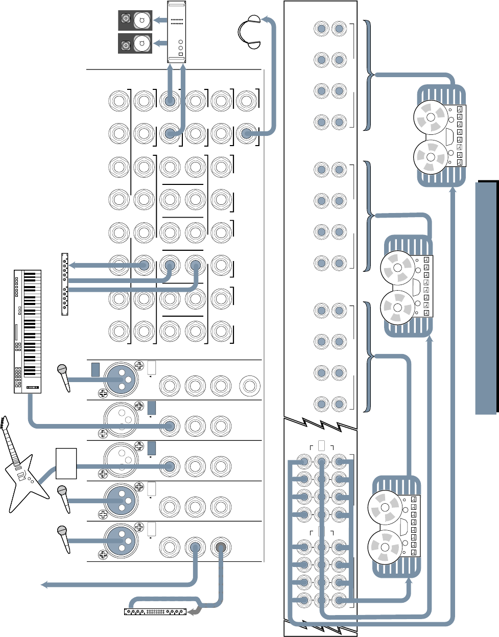
29
OVERDUBBING PART 1: INPUT/OUTPUT
EXTERNAL
INPUT MIX-B
OUTPUT
1
AUX SEND
1
R
L
2
2
R
R
3
3
R
L
4
4
R
R
5
5
R
L
6
6
R
R
L
7
L
L
L
R
8
R
R
R
SUBMASTER INSERT
AUX RETURN
CNTRL
RM OUTPUT
STUDIO
OUTPUT
MAIN MIX
MAIN
INSERTS
2-TRACK
INPUT
123456
PHONES
12
MONO
L
MONO
L
MONO
L
MONO
L
MONO
L
MONO
L
MONO MONO
LINE
IN
DIRECT
OUT
INSERT
BAL/UNBAL
TIP = OUT
RING = IN
LINE
IN
DIRECT
OUT
INSERT
PHANTOM
CHANNEL
24
BAL/UNBAL
TIP = OUT
RING = IN
LINE
IN
DIRECT
OUT
INSERT
CHANNEL
20
BAL/UNBAL
TIP = OUT
RING = IN
LINE
IN
DIRECT
OUT
INSERT
BAL/UNBAL
TIP = OUT
RING = IN
MIC
LINE MIC
LINE MIC
LINE MIC
LINE
LINE
IN
DIRECT
OUT
INSERT
CHANNEL
21
BAL/UNBAL
TIP = OUT
RING = IN
MIC
LINE
OPERATING
LEVEL CH. 17-24
TAPE RETURNS 1-8
15 13 11 9 7 5 3 1
16 14 12 10 6 4 28
17
18
19
20
21
22
23
24
TAPE RETURNS 9-16
TAPE RETURNS 17-24
OUT +4dBU
IN –10dBV
+4 / –10 BALANCED / UNBALANCED+4 / –10 BALANCED / UNBALANCED +4 / –10 BALANCED / UNBALANCED
OPERATING
LEVEL CH. 9-16
OUT +4dBU
IN –10dBV
OPERATING
LEVEL CH. 1-8
OUT +4dBU
IN –10dBV
SUBMASTER / TAPE OUTPUTS
+4dBU BALANCED / –10dBV UNBALANCED
87
15
6
14
5
13
4
12
3
11
2
10
1
9
OUT +4dBU
IN –10dBV
16
171820 1921222324
OPERATING
LEVEL
OUT +4dBU
IN –10dBV
OPERATING
LEVEL
CHANNEL
23
CHANNEL
22
To Multi-Track
(optional)
In
Power Amplifier
Control Rm Monitors
Reverb
Out
Keyboard, or other line level input
M
u
l
t
i
-
T
r
a
c
k
R
e
c
o
r
d
e
r
3
M
u
l
t
i
-
T
r
a
c
k
R
e
c
o
r
d
e
r
2
Or from DIRECT OUTS
of individual channels
M
u
l
t
i
-
T
r
a
c
k
R
e
c
o
r
d
e
r
1
Mono Compressor
In
Out
Out
In
Guitar
Effects
Box
Out
In
Out
In
Out
In
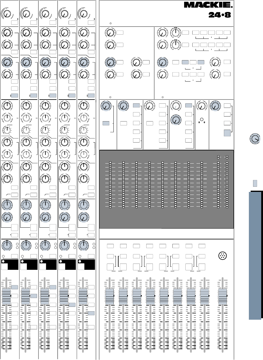
30
+15
OO
U
12k
MIX-B
EQ
LOW CUT
EQ IN
HI
FREQ
75 Hz
18dB/oct
SOURCE
45 3k
PAN
LEVEL
–15 +15
80
U
LO
SPLIT EQ
HI/LO EQ
TO MON
MONITOR
LR
–15 +15
U
250
220 350
PAN
dB
30
20
5
10
L/R
MIX
SOLO
-20
OL
OO
MUTE
21
5
10
40
50
80
U
LR
MUTE
+15
OO
U
12k
MIX-B
EQ
LOW CUT
EQ IN
HI
FREQ
75 Hz
18dB/oct
SOURCE
45 3k
PAN
LEVEL
–15 +15
80
U
LO
SPLIT EQ
HI/LO EQ
TO MON
MONITOR
LR
–15 +15
U
250
220 350
PAN
dB
30
20
5
10
L/R
MIX
SOLO
-20
OL
OO
MUTE
22
5
10
40
50
80
U
LR
MUTE
+15
OO
U
12k
MIX-B
EQ
LOW CUT
EQ IN
HI
FREQ
75 Hz
18dB/oct
SOURCE
45 3k
PAN
LEVEL
–15 +15
80
U
LO
SPLIT EQ
HI/LO EQ
TO MON
MONITOR
LR
–15 +15
U
250
220 350
PAN
dB
30
20
5
10
L/R
MIX
SOLO
-20
OL
OO
MUTE
23
5
10
40
50
80
U
LR
MUTE
+15
OO
U
12k
MIX-B
EQ
LOW CUT
EQ IN
HI
FREQ
75 Hz
18dB/oct
SOURCE
45 3k
PAN
LEVEL
–15 +15
80
U
LO
SPLIT EQ
HI/LO EQ
TO MON
MONITOR
LR
–15 +15
U
250
220 350
PAN
dB
30
20
5
10
L/R
MIX
SOLO
-20
OL
OO
MUTE
24
5
10
40
50
80
U
LR
MUTE
TALKBACK
MIC
MIX
LEFT/RIGHT
dB
30
20
5
10
OO
5
10
40
50
80
U
dB
30
20
5
10
OO
5
10
40
50
80
U
dB
30
20
5
10
OO
5
10
40
50
80
U
dB
30
20
5
10
OO
5
10
40
50
80
U
dB
30
20
5
10
OO
5
10
40
50
80
U
dB
30
20
5
10
OO
5
10
40
50
80
U
dB
30
20
5
10
OO
5
10
40
50
80
U
dB
30
20
5
10
OO
5
10
40
50
80
U
dB
30
20
5
10
OO
5
10
40
50
80
U
FLIP SW
CHANNEL FLIP SW
CHANNEL FLIP SW
CHANNEL FLIP SW
CHANNEL
AUX
PRE
TRIM
FLIP
1
2
4
3
5
6
MIX-B
CHANNEL
PRE
SHIFT
TAPE
MIC/LINE
CHANNEL
21
SOURCE
+15
OO
U
+15
OO
U
+15
OO
U
+15
OO
U
AUX
GAIN
+4
–10
48
dB
40
dB
U
L
I
N
E
S
E
N
S
I
T
I
V
I
T
Y
M
I
C
/
L
I
N
E
G
A
I
N
LO
MID
HI
MID
BAND
WIDTH
500 18k
3k
FREQ
–15 +15
U
–15 +15
U
1k 5k
3
2
1
12
NORMAL
AUX
PRE
TRIM
FLIP
1
2
4
3
5
6
MIX-B
CHANNEL
PRE
SHIFT
TAPE
MIC/LINE
CHANNEL
22
SOURCE
+15
OO
U
+15
OO
U
+15
OO
U
+15
OO
U
AUX
GAIN
+4
–10
48
dB
40
dB
U
L
I
N
E
S
E
N
S
I
T
I
V
I
T
Y
M
I
C
/
L
I
N
E
G
A
I
N
LO
MID
HI
MID
BAND
WIDTH
500 18k
3k
FREQ
–15 +15
U
–15 +15
U
1k 5k
3
2
1
12
NORMAL
AUX
PRE
TRIM
FLIP
1
2
4
3
5
6
MIX-B
CHANNEL
PRE
SHIFT
TAPE
MIC/LINE
CHANNEL
23
SOURCE
+15
OO
U
+15
OO
U
+15
OO
U
+15
OO
U
AUX
GAIN
+4
–10
48
dB
40
dB
U
L
I
N
E
S
E
N
S
I
T
I
V
I
T
Y
M
I
C
/
L
I
N
E
G
A
I
N
LO
MID
HI
MID
BAND
WIDTH
500 18k
3k
FREQ
–15 +15
U
–15 +15
U
1k 5k
3
2
1
12
NORMAL
AUX
PRE
TRIM
FLIP
1
2
4
3
5
6
MIX-B
CHANNEL
PRE
SHIFT
TAPE
MIC/LINE
CHANNEL
24
SOURCE
+15
OO
U
+15
OO
U
+15
OO
U
+15
OO
U
AUX
GAIN
+4
–10
48
dB
40
dB
U
L
I
N
E
S
E
N
S
I
T
I
V
I
T
Y
M
I
C
/
L
I
N
E
G
A
I
N
LO
MID
HI
MID
BAND
WIDTH
500 18k
3k
FREQ
–15 +15
U
–15 +15
U
1k 5k
3
2
1
12
NORMAL
SOLO SOLO
SOLO SOLO
SOLO
SOLO
AUX SENDS STEREO AUX RETURNS
4
3
2
5
6
1
PHONES
2L/R MIX
L/R MIX
1-2 3-4 5-6 7- 8
L/R MIX
SOLO 1-2 3-4 5-6 7-8
PHONES
1PHONES
2L/R MIX
1
2
3
4
LEVEL
ASSIGN
ASSIGN
ASSIGN
ASSIGN
LEVELLEVEL
PHONES
1
6
+15
OO
U
+15
OO
U
+15
OO
U
+15
OO
U
+15
OO
U
+15
OO
U
+20
OO
U
+20
OO
U
+20
OO
U
+20
OO
U
LR
LR
5
+20
OO
U
+20
OO
U
SOLO
SOLO
SOLO
SOLO
SOLO
SOLO SOLO
LEVEL LEVEL
LEVEL
MIX-B TO
L/R MIX SOLO AUX SEND 3/4
MIX-B
MONITOR
AUX SEND 5/6
EXTERNAL MONO
TAPE SUB
MASTERS
AUX SEND 1
SOURCE
MIX B
MONITOR PHONES 1
PHONES
LEVEL
SOLO AUX SEND 3/4
MIX-B
MONITOR
AUX SEND 5/6
EXTERNAL
SOURCE
PHONES 2
PHONES
LEVEL
ASSIGN
2-TK
MIX-B
L/R MIX
EXTERNAL
SOURCE
MONITOR SOLO TALKBACK
LEVEL LEVELMIX-B
LEVEL
RUDE
SOLO LITE
AUX SEND 2
PHONES
&
STUDIO
+15
OO
U
OOOOOO
+15
OO
U
BALANCE
POWER
OVERDUBBING PART 2: THE BOARD
CNTRL RM
OO
Tinted buttons
are pressed IN Tinted knobs are used
in this application
SOLO SOLO SOLO SOLO SOLO SOLO SOLO SOLO
MONO
L+R
RLRLRLR
MONO
L+R
MONO
L+R
MONO
L+R
MONO
L+R
ASSIGN
MONO
L+R
MONO
L+R
1
L
2345678
MONO
L+R
ASSIGN ASSIGN ASSIGN ASSIGN ASSIGNASSIGNASSIGN
MIX MIX MIX MIX
12345678
169 101112131415
2417 18 19 20 21 22 23
10
+
7
4
2
0
2
4
7
10
20
30
40
–
LR
10
+
7
4
2
0
2
4
7
10
20
30
40
–
LR
10
+
7
4
2
0
2
4
7
10
20
30
40
–
LR
10
+
7
4
2
0
2
4
7
10
20
30
40
–
LR
10
+
7
4
2
0
2
4
7
10
20
30
40
–
22
10
+
7
4
2
0
2
4
7
10
20
30
40
–
10
+
7
4
2
0
2
4
7
10
20
30
40
–
10
+
7
4
2
0
2
4
7
10
20
30
40
–
LR
MAIN
OR SOLO LEVEL
+15
OO
U
12k
MIX-B
EQ
LOW CUT
EQ IN
HI
FREQ
75 Hz
18dB/oct
SOURCE
45 3k
PAN
LEVEL
–15 +15
80
U
LO
SPLIT EQ
HI/LO EQ
TO MON
MONITOR
LR
–15 +15
U
250
220 350
PAN
dB
30
20
5
10
L/R
MIX
SOLO
-20
OL
OO
MUTE
20
5
10
40
50
80
U
LR
MUTE
FLIP SW
CHANNEL
AUX
PRE
TRIM
FLIP
1
2
4
3
5
6
MIX-B
CHANNEL
PRE
SHIFT
TAPE
MIC/LINE
CHANNEL
20
SOURCE
+15
OO
U
+15
OO
U
+15
OO
U
+15
OO
U
AUX
GAIN
+4
–10
48
dB
40
dB
U
L
I
N
E
S
E
N
S
I
T
I
V
I
T
Y
M
I
C
/
L
I
N
E
G
A
I
N
LO
MID
HI
MID
BAND
WIDTH
500 18k
3k
FREQ
–15 +15
U
–15 +15
U
1k 5k
3
2
1
12
NORMAL
Assign channels and adjust
panpot to the appropriate bus
for the desired tape channel input.
5-6
3-4
1-2
7- 8
5-6
3-4
1-2
7- 8
5-6
3-4
1-2
7- 8
5-6
3-4
1-2
7- 8
5-6
3-4
1-2
7- 8
CNTRL RM
STUDIO
O
OO
OO
OCTAVES
OCTAVESOCTAVES
OCTAVES
OCTAVES
20 21 22 23 24
24x8x2 8•BUS MIXING CONSOLE
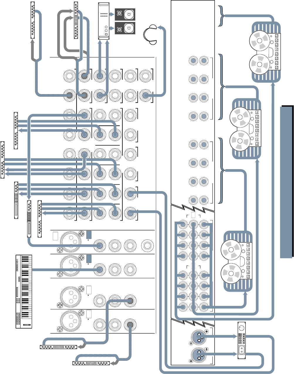
31
EXTERNAL
INPUT MIX-B
OUTPUT
1
AUX SEND
1
R
L
2
2
R
R
3
3
R
L
4
4
R
R
5
5
R
L
6
6
R
R
L
7
L
L
L
R
8
R
R
R
SUBMASTER INSERT
AUX RETURN
CNTRL
RM OUTPUT
STUDIO
OUTPUT
MAIN MIX
MAIN
INSERTS
2-TRACK
INPUT
123456
PHONES
12
MONO
L
MONO
L
MONO
L
MONO
L
MONO
L
MONO
L
MONO MONO
LINE
IN
DIRECT
OUT
INSERT
CHANNEL
23
BAL/UNBAL
TIP = OUT
RING = IN
LINE
IN
DIRECT
OUT
INSERT
PHANTOM
CHANNEL
24
BAL/UNBAL
TIP = OUT
RING = IN
LINE
IN
DIRECT
OUT
INSERT
CHANNEL
21
BAL/UNBAL
TIP = OUT
RING = IN
MIC
LINE MIC
LINE MIC
LINE
LINE
IN
DIRECT
OUT
INSERT
CHANNEL
22
BAL/UNBAL
TIP = OUT
RING = IN
MIC
LINE
OPERATING
LEVEL CH. 17-24
15 13 11 9
16 14 12 10
17
18
19
20
21
22
23
24
TAPE RETURNS 9-16
TAPE RETURNS 17-24
OUT +4dBU
IN –10dBV
+4 / –10 BALANCED / UNBALANCED+4 / –10 BALANCED / UNBALANCED
OPERATING
LEVEL CH. 9-16
OUT +4dBU
IN –10dBV
SUBMASTER / TAPE OUTPUTS
+4dBU BALANCED / –10dBV UNBALANCED
87
15
6
14
5
13
4
12
3
11
2
10
1
9
OUT +4dBU
IN –10dBV
16
171820 1921222324
OPERATING
LEVEL
OUT +4dBU
IN –10dBV
OPERATING
LEVEL
LEFTRIGHT
MAIN BAL OUTPUTS
+28dBU MAX OUT
In
Out
In Out
In Out
In
Out
In
Out
Mono Compressor
Keyboard, or other line level input
In Out
Reverb
Out In
In Out
Reverb
Digital Delay
In Out
Digital Delay
Stereo Reverb
In Out
In
Power Amplifier
Control Rm Monitors
Stereo
Compressor
Out
Processor
In Out
M
u
l
t
i
-
T
r
a
c
k
R
e
c
o
r
d
e
r
2
Or from DIRECT OUTS
of individual channels
Connections same
as for Multi-Track
Recorders 2 & 3
Extra input during mixdown
M
u
l
t
i
-
T
r
a
c
k
R
e
c
o
r
d
e
r
1
M
u
l
t
i
-
T
r
a
c
k
R
e
c
o
r
d
e
r
3
DAT or
2-track
Deck
Noise Gate
In
Out
MULTITRACK MIXING PART 1: INPUT/OUTPUT
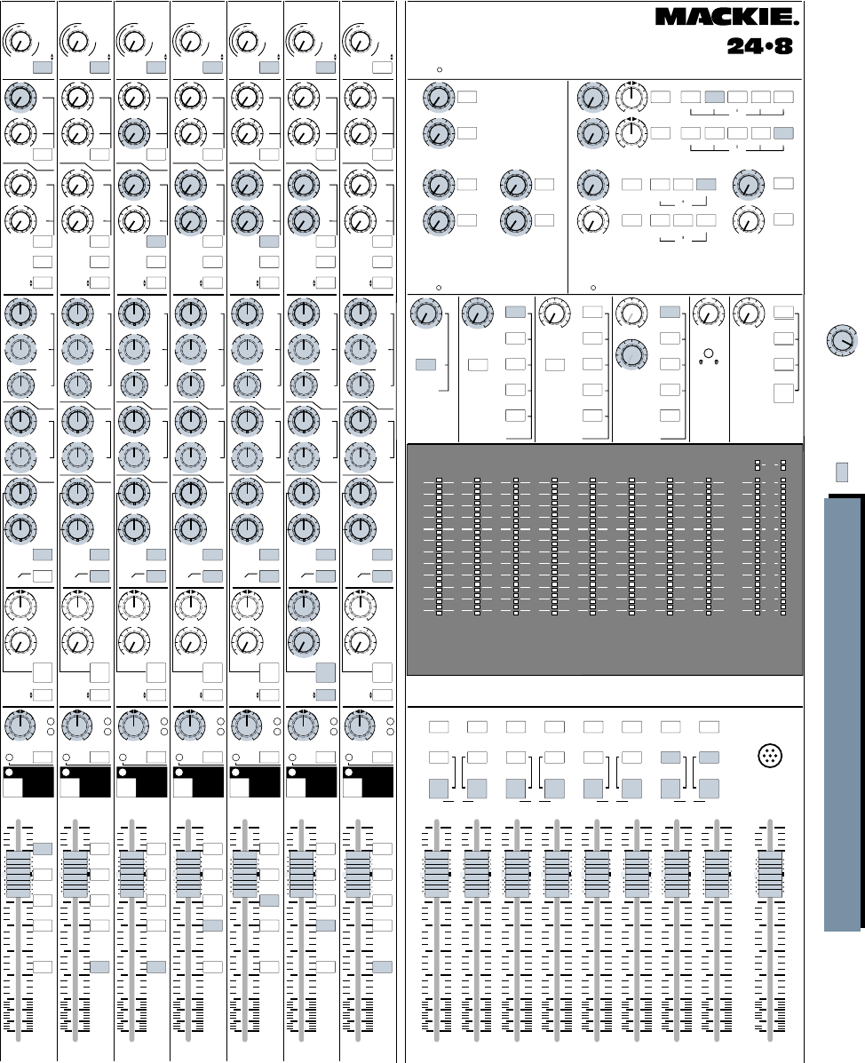
32
+15
OO
U
12k
MIX-B
EQ
LOW CUT
EQ IN
HI
FREQ
75 Hz
18dB/oct
SOURCE
45 3k
PAN
LEVEL
–15 +15
80
U
LO
SPLIT EQ
HI/LO EQ
TO MON
MONITOR
LR
–15 +15
U
250
220 350
PAN
dB
30
20
5
10
SOLO
-20
OL
OO
MUTE
21
5
10
40
50
80
U
LR
MUTE
+15
OO
U
12k
MIX-B
EQ
LOW CUT
EQ IN
HI
FREQ
75 Hz
18dB/oct
SOURCE
45 3k
PAN
LEVEL
–15 +15
80
U
LO
SPLIT EQ
HI/LO EQ
TO MON
MONITOR
LR
–15 +15
U
250
220 350
PAN
dB
30
20
5
10
SOLO
-20
OL
OO
MUTE
22
5
10
40
50
80
U
LR
MUTE
+15
OO
U
12k
MIX-B
EQ
LOW CUT
EQ IN
HI
FREQ
75 Hz
18dB/oct
SOURCE
45 3k
PAN
LEVEL
–15 +15
80
U
LO
SPLIT EQ
HI/LO EQ
TO MON
MONITOR
LR
–15 +15
U
250
220 350
PAN
dB
30
20
5
10
SOLO
-20
OL
OO
MUTE
23
5
10
40
50
80
U
LR
MUTE
+15
OO
U
12k
MIX-B
EQ
LOW CUT
EQ IN
HI
FREQ
75 Hz
18dB/oct
SOURCE
45 3k
PAN
LEVEL
–15 +15
80
U
LO
SPLIT EQ
HI/LO EQ
TO MON
MONITOR
LR
–15 +15
U
250
220 350
PAN
dB
30
20
5
10
SOLO
-20
OL
OO
MUTE
24
5
10
40
50
80
U
LR
MUTE
TALKBACK
MIC
MIX
LEFT/RIGHT
dB
30
20
5
10
OO
5
10
40
50
80
U
dB
30
20
5
10
OO
5
10
40
50
80
U
dB
30
20
5
10
OO
5
10
40
50
80
U
dB
30
20
5
10
OO
5
10
40
50
80
U
dB
30
20
5
10
OO
5
10
40
50
80
U
dB
30
20
5
10
OO
5
10
40
50
80
U
dB
30
20
5
10
OO
5
10
40
50
80
U
dB
30
20
5
10
OO
5
10
40
50
80
U
dB
30
20
5
10
OO
5
10
40
50
80
U
FLIP SW
CHANNEL FLIP SW
CHANNEL FLIP SW
CHANNEL FLIP SW
CHANNEL
Keys
Vocals
Vocal Delay
Drum
L
Drum
R
Rev 1
L
Rev 1
R
Keys 1
Keys 2
Keys
Vox
L
Vox
R
AUX
PRE
TRIM
FLIP
1
2
4
3
5
6
MIX-B
CHANNEL
PRE
SHIFT
TAPE
MIC/LINE
CHANNEL
21
SOURCE
+15
OO
U
+15
OO
U
+15
OO
U
+15
OO
U
AUX
GAIN
+4
–10
48
dB
40
dB
U
L
I
N
E
S
E
N
S
I
T
I
V
I
T
Y
M
I
C
/
L
I
N
E
G
A
I
N
LO
MID
HI
MID
BAND
WIDTH
500 18k
3k
FREQ
–15 +15
U
–15 +15
U
1k 5k
3
2
1
12
NORMAL
AUX
PRE
TRIM
FLIP
1
2
4
3
5
6
MIX-B
CHANNEL
PRE
SHIFT
TAPE
MIC/LINE
CHANNEL
22
SOURCE
+15
OO
U
+15
OO
U
+15
OO
U
+15
OO
U
AUX
GAIN
+4
–10
48
dB
40
dB
U
L
I
N
E
S
E
N
S
I
T
I
V
I
T
Y
M
I
C
/
L
I
N
E
G
A
I
N
LO
MID
HI
MID
BAND
WIDTH
500 18k
3k
FREQ
–15 +15
U
–15 +15
U
1k 5k
3
2
1
12
NORMAL
AUX
PRE
TRIM
FLIP
1
2
4
3
5
6
MIX-B
CHANNEL
PRE
SHIFT
TAPE
MIC/LINE
CHANNEL
23
SOURCE
+15
OO
U
+15
OO
U
+15
OO
U
+15
OO
U
AUX
GAIN
+4
–10
48
dB
40
dB
U
L
I
N
E
S
E
N
S
I
T
I
V
I
T
Y
M
I
C
/
L
I
N
E
G
A
I
N
LO
MID
HI
MID
BAND
WIDTH
500 18k
3k
FREQ
–15 +15
U
–15 +15
U
1k 5k
3
2
1
12
NORMAL
AUX
PRE
TRIM
FLIP
1
2
4
3
5
6
MIX-B
CHANNEL
PRE
SHIFT
TAPE
MIC/LINE
CHANNEL
24
SOURCE
+15
OO
U
+15
OO
U
+15
OO
U
+15
OO
U
AUX
GAIN
+4
–10
48
dB
40
dB
U
L
I
N
E
S
E
N
S
I
T
I
V
I
T
Y
M
I
C
/
L
I
N
E
G
A
I
N
LO
MID
HI
MID
BAND
WIDTH
500 18k
3k
FREQ
–15 +15
U
–15 +15
U
1k 5k
3
2
1
12
NORMAL
SOLO SOLO
SOLO SOLO
SOLO
SOLO
AUX SENDS STEREO AUX RETURNS
4
3
2
5
6
1
PHONES
2L/R MIX
L/R MIX
1-2 3-4 5-6 7- 8
L/R MIX
SOLO 1-2 3-4 5-6 7-8
PHONES
1PHONES
2L/R MIX
1
2
3
4
LEVEL
ASSIGN
ASSIGN
ASSIGN
ASSIGN
LEVELLEVEL
PHONES
1
6
+15
OO
U
+15
OO
U
+15
OO
U
+15
OO
U
+15
OO
U
+15
OO
U
+20
OO
U
+20
OO
U
+20
OO
U
+20
OO
U
LR
LR
5
+20
OO
U
+20
OO
U
SOLO
SOLO
SOLO
SOLO
SOLO
SOLO SOLO
LEVEL LEVEL
LEVEL
MIX-B TO
L/R MIX SOLO AUX SEND 3/4
MIX-B
MONITOR
AUX SEND 5/6
EXTERNAL MONO
TAPE SUB
MASTERS
AUX SEND 1
SOURCE
MIX B
MONITOR PHONES 1
PHONES
LEVEL
SOLO AUX SEND 3/4
MIX-B
MONITOR
AUX SEND 5/6
EXTERNAL
SOURCE
PHONES 2
PHONES
LEVEL
ASSIGN
2-TK
MIX-B
L/R MIX
EXTERNAL
SOURCE
MONITOR SOLO TALKBACK
LEVEL LEVELMIX-B
LEVEL
RUDE
SOLO LITE
AUX SEND 2
PHONES
&
STUDIO
+15
OO
U
OOOOOO
+15
OO
U
BALANCE
POWER
MULTITRACK MIXING PART 2: THE BOARD
CNTRL RM
OO
Tinted buttons
are pressed IN Tinted knobs are used
in this application
SOLO SOLO SOLO SOLO SOLO SOLO SOLO SOLO
MONO
L+R
RLRLRLR
MONO
L+R
MONO
L+R
MONO
L+R
MONO
L+R
ASSIGN
MONO
L+R
MONO
L+R
1
L
2345678
MONO
L+R
ASSIGN ASSIGN ASSIGN ASSIGN ASSIGNASSIGNASSIGN
MIX MIX MIX MIX
12345678
169101112131415
2417 18 19 20 21 22 23
10
+
7
4
2
0
2
4
7
10
20
30
40
–
LR
10
+
7
4
2
0
2
4
7
10
20
30
40
–
LR
10
+
7
4
2
0
2
4
7
10
20
30
40
–
LR
10
+
7
4
2
0
2
4
7
10
20
30
40
–
LR
10
+
7
4
2
0
2
4
7
10
20
30
40
–
22
10
+
7
4
2
0
2
4
7
10
20
30
40
–
10
+
7
4
2
0
2
4
7
10
20
30
40
–
10
+
7
4
2
0
2
4
7
10
20
30
40
–
LR
MAIN
OR SOLO LEVEL
+15
OO
U
12k
MIX-B
EQ
LOW CUT
EQ IN
HI
FREQ
75 Hz
18dB/oct
SOURCE
45 3k
PAN
LEVEL
–15 +15
80
U
LO
SPLIT EQ
HI/LO EQ
TO MON
MONITOR
LR
250
220 350
PAN
dB
30
20
5
10
SOLO
-20
OL
OO
MUTE
20
5
10
40
50
80
U
LR
MUTE
FLIP SW
CHANNEL
Guitar
AUX
PRE
TRIM
FLIP
1
2
4
3
5
6
MIX-B
CHANNEL
PRE
SHIFT
TAPE
MIC/LINE
CHANNEL
20
SOURCE
+15
OO
U
+15
OO
U
+15
OO
U
+15
OO
U
AUX
GAIN
+4
–10
48
dB
40
dB
U
L
I
N
E
S
E
N
S
I
T
I
V
I
T
Y
M
I
C
/
L
I
N
E
G
A
I
N
LO
MID
HI
MID
BAND
WIDTH
500 18k
3k
FREQ
–15 +15
U
–15 +15
U
1k 5k
3
2
1
12
NORMAL
–15 +15
U
+15
OO
U
12k
MIX-B
EQ
LOW CUT
EQ IN
HI
FREQ
75 Hz
18dB/oct
SOURCE
45 3k
PAN
LEVEL
–15 +15
80
U
LO
SPLIT EQ
HI/LO EQ
TO MON
MONITOR
LR
250
220 350
PAN
dB
30
20
5
10
SOLO
-20
OL
OO
MUTE
19
5
10
40
50
80
U
LR
MUTE
FLIP SW
CHANNEL
Bass Guitar
AUX
PRE
TRIM
FLIP
1
2
4
3
5
6
MIX-B
CHANNEL
PRE
SHIFT
TAPE
MIC/LINE
CHANNEL
19
SOURCE
+15
OO
U
+15
OO
U
+15
OO
U
+15
OO
U
AUX
GAIN
+4
–10
48
dB
40
dB
U
L
I
N
E
S
E
N
S
I
T
I
V
I
T
Y
M
I
C
/
L
I
N
E
G
A
I
N
LO
MID
HI
MID
BAND
WIDTH
500 18k
3k
FREQ
–15 +15
U
–15 +15
U
1k 5k
3
2
1
12
NORMAL
U
+15
OO
U
12k
MIX-B
EQ
LOW CUT
EQ IN
HI
FREQ
75 Hz
18dB/oct
SOURCE
45 3k
PAN
LEVEL
–15 +15
80
U
LO
SPLIT EQ
HI/LO EQ
TO MON
MONITOR
LR
250
220 350
PAN
dB
30
20
5
10
5-6
3-4
1-2
7- 8
L/R
MIX
SOLO
-20
OL
OO
MUTE
18
5
10
40
50
80
U
LR
MUTE
FLIP SW
CHANNEL
Drums
AUX
PRE
TRIM
FLIP
1
2
4
3
5
6
MIX-B
CHANNEL
PRE
SHIFT
TAPE
MIC/LINE
CHANNEL
18
SOURCE
+15
OO
U
+15
OO
U
+15
OO
U
+15
OO
U
AUX
GAIN
+4
–10
48
dB
40
dB
U
L
I
N
E
S
E
N
S
I
T
I
V
I
T
Y
M
I
C
/
L
I
N
E
G
A
I
N
LO
MID
HI
MID
BAND
WIDTH
500 18k
3k
FREQ
–15 +15
U
–15 +15
U
1k 5k
3
2
1
12
NORMAL
–15 +15
U
CNTRL RM
STUDIO
O
OO
OO
5-6
3-4
1-2
7- 8
L/R
MIX
5-6
3-4
1-2
7- 8
L/R
MIX
5-6
3-4
1-2
7- 8
L/R
MIX
5-6
3-4
1-2
7- 8
L/R
MIX
5-6
3-4
1-2
7- 8
L/R
MIX
5-6
3-4
1-2
7- 8
L/R
MIX
24
2322
2120
1918
OCTAVES
OCTAVES
OCTAVES
OCTAVES
OCTAVESOCTAVESOCTAVES
24x8x2 8•BUS MIXING CONSOLE
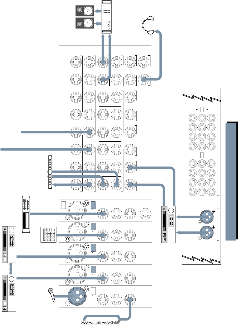
33
EXTERNAL
INPUT MIX-B
OUTPUT
1
AUX SEND
1
R
L
2
2
R
R
3
3
R
L
4
4
R
R
5
5
R
L
6
6
R
R
L
7
L
L
L
R
8
R
R
R
SUBMASTER INSERT
AUX RETURN
CNTRL
RM OUTPUT
STUDIO
OUTPUT
MAIN MIX
MAIN
INSERTS
2-TRACK
INPUT
123456
PHONES
12
MONO
L
MONO
L
MONO
L
MONO
L
MONO
L
MONO
L
MONO MONO
LINE
IN
DIRECT
OUT
INSERT
CHANNEL
23
BAL/UNBAL
TIP = OUT
RING = IN
LINE
IN
DIRECT
OUT
INSERT
PHANTOM
CHANNEL
24
BAL/UNBAL
TIP = OUT
RING = IN
LINE
IN
DIRECT
OUT
INSERT
CHANNEL
19
BAL/UNBAL
TIP = OUT
RING = IN
LINE
IN
DIRECT
OUT
INSERT
CHANNEL
22
BAL/UNBAL
TIP = OUT
RING = IN
MIC
LINE MIC
LINE MIC
LINE MIC
LINE
LINE
IN
DIRECT
OUT
INSERT
CHANNEL
21
BAL/UNBAL
TIP = OUT
RING = IN
MIC
LINE
LEFTRIGHT
MAIN BAL OUTPUTS
+28dBU MAX OUT
SUBMASTER / TAPE OUTPUTS
+4dBU BALANCED / –10dBV UNBALANCED
87
15
6
14
5
13
4
12
3
11
2
10
1
9
OUT +4dBU
IN –10dBV
16
171820 1921222324
OPERATING
LEVEL
OUT +4dBU
IN –10dBV
OPERATING
LEVEL
Mono Compressor
In
Out
VIDEO/BROADCAST 1: INPUT/OUTPUT
Power Amplifier
Control Rm Monitors
Video Deck 1 Cue Mix 1
Cue Mix 2
Sync
Video Deck 2
Drum
Machine
Reverb
Master Deck
Sound FX CD Player
In
In
Out
L Out
R Out
Out Out
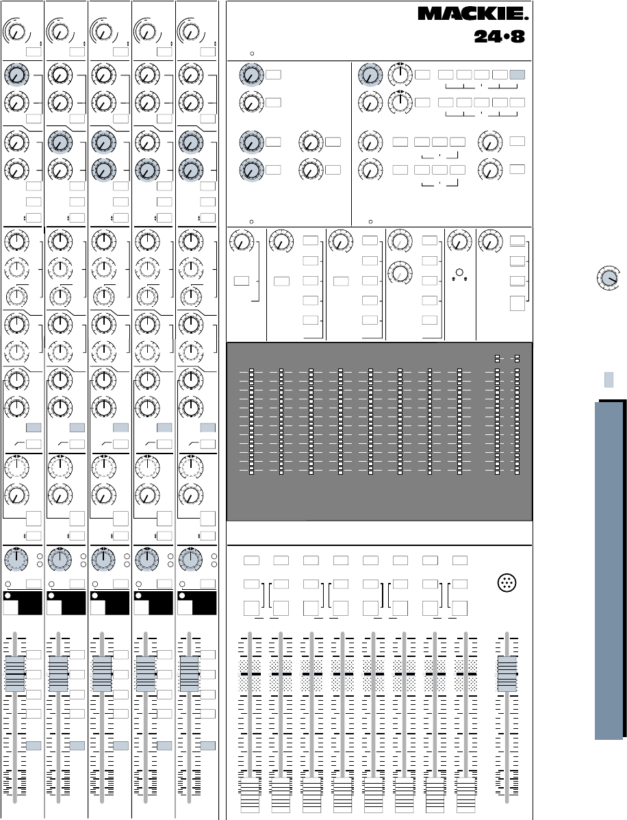
34
+15
OO
U
12k
MIX-B
EQ
LOW CUT
EQ IN
HI
FREQ
75 Hz
18dB/oct
SOURCE
45 3k
PAN
LEVEL
–15 +15
80
U
LO
SPLIT EQ
HI/LO EQ
TO MON
MONITOR
LR
–15 +15
U
250
220 350
PAN
dB
30
20
5
10
SOLO
-20
OL
OO
MUTE
21
5
10
40
50
80
U
LR
MUTE
+15
OO
U
12k
MIX-B
EQ
LOW CUT
EQ IN
HI
FREQ
75 Hz
18dB/oct
SOURCE
45 3k
PAN
LEVEL
–15 +15
80
U
LO
SPLIT EQ
HI/LO EQ
TO MON
MONITOR
LR
–15 +15
U
250
220 350
PAN
dB
30
20
5
10
SOLO
-20
OL
OO
MUTE
22
5
10
40
50
80
U
LR
MUTE
+15
OO
U
12k
MIX-B
EQ
LOW CUT
EQ IN
HI
FREQ
75 Hz
18dB/oct
SOURCE
45 3k
PAN
LEVEL
–15 +15
80
U
LO
SPLIT EQ
HI/LO EQ
TO MON
MONITOR
LR
–15 +15
U
250
220 350
PAN
dB
30
20
5
10
SOLO
-20
OL
OO
MUTE
23
5
10
40
50
80
U
LR
MUTE
+15
OO
U
12k
MIX-B
EQ
LOW CUT
EQ IN
HI
FREQ
75 Hz
18dB/oct
SOURCE
45 3k
PAN
LEVEL
–15 +15
80
U
LO
SPLIT EQ
HI/LO EQ
TO MON
MONITOR
LR
–15 +15
U
250
220 350
PAN
dB
30
20
5
10
SOLO
-20
OL
OO
MUTE
24
5
10
40
50
80
U
LR
MUTE
TALKBACK
MIC
MIX
LEFT/RIGHT
dB
30
20
5
10
OO
5
10
40
50
80
U
dB
30
20
5
10
OO
5
10
40
50
80
U
dB
30
20
5
10
OO
5
10
40
50
80
U
dB
30
20
5
10
OO
5
10
40
50
80
U
dB
30
20
5
10
OO
5
10
40
50
80
U
dB
30
20
5
10
OO
5
10
40
50
80
U
dB
30
20
5
10
OO
5
10
40
50
80
U
dB
30
20
5
10
OO
5
10
40
50
80
U
dB
30
20
5
10
OO
5
10
40
50
80
U
FLIP SW
CHANNEL FLIP SW
CHANNEL FLIP SW
CHANNEL FLIP SW
CHANNEL
AUX
PRE
TRIM
FLIP
1
2
4
3
5
6
MIX-B
CHANNEL
PRE
SHIFT
TAPE
MIC/LINE
CHANNEL
21
SOURCE
+15
OO
U
+15
OO
U
+15
OO
U
+15
OO
U
AUX
GAIN
+4
–10
48
dB
40
dB
U
L
I
N
E
S
E
N
S
I
T
I
V
I
T
Y
M
I
C
/
L
I
N
E
G
A
I
N
LO
MID
HI
MID
BAND
WIDTH
500 18k
3k
FREQ
–15 +15
U
–15 +15
U
1k 5k
3
2
1
12
NORMAL
AUX
PRE
TRIM
FLIP
1
2
4
3
5
6
MIX-B
CHANNEL
PRE
SHIFT
TAPE
MIC/LINE
CHANNEL
22
SOURCE
+15
OO
U
+15
OO
U
+15
OO
U
+15
OO
U
AUX
GAIN
+4
–10
48
dB
40
dB
U
L
I
N
E
S
E
N
S
I
T
I
V
I
T
Y
M
I
C
/
L
I
N
E
G
A
I
N
LO
MID
HI
MID
BAND
WIDTH
500 18k
3k
FREQ
–15 +15
U
–15 +15
U
1k 5k
3
2
1
12
NORMAL
AUX
PRE
TRIM
FLIP
1
2
4
3
5
6
MIX-B
CHANNEL
PRE
SHIFT
TAPE
MIC/LINE
CHANNEL
23
SOURCE
+15
OO
U
+15
OO
U
+15
OO
U
+15
OO
U
AUX
GAIN
+4
–10
48
dB
40
dB
U
L
I
N
E
S
E
N
S
I
T
I
V
I
T
Y
M
I
C
/
L
I
N
E
G
A
I
N
LO
MID
HI
MID
BAND
WIDTH
500 18k
3k
FREQ
–15 +15
U
–15 +15
U
1k 5k
3
2
1
12
NORMAL
AUX
PRE
TRIM
FLIP
1
2
4
3
5
6
MIX-B
CHANNEL
PRE
SHIFT
TAPE
MIC/LINE
CHANNEL
24
SOURCE
+15
OO
U
+15
OO
U
+15
OO
U
+15
OO
U
AUX
GAIN
+4
–10
48
dB
40
dB
U
L
I
N
E
S
E
N
S
I
T
I
V
I
T
Y
M
I
C
/
L
I
N
E
G
A
I
N
LO
MID
HI
MID
BAND
WIDTH
500 18k
3k
FREQ
–15 +15
U
–15 +15
U
1k 5k
3
2
1
12
NORMAL
SOLO SOLO
SOLO SOLO
SOLO
SOLO
AUX SENDS STEREO AUX RETURNS
4
3
2
5
6
1
PHONES
2L/R MIX
L/R MIX
1-2 3-4 5-6 7- 8
L/R MIX
SOLO 1-2 3-4 5-6 7-8
PHONES
1PHONES
2L/R MIX
1
2
3
4
LEVEL
ASSIGN
ASSIGN
ASSIGN
ASSIGN
LEVELLEVEL
PHONES
1
6
+15
OO
U
+15
OO
U
+15
OO
U
+15
OO
U
+15
OO
U
+15
OO
U
+20
OO
U
+20
OO
U
+20
OO
U
+20
OO
U
LR
LR
5
+20
OO
U
+20
OO
U
SOLO
SOLO
SOLO
SOLO
SOLO
SOLO SOLO
LEVEL LEVEL
LEVEL
MIX-B TO
L/R MIX SOLO AUX SEND 3/4
MIX-B
MONITOR
AUX SEND 5/6
EXTERNAL MONO
TAPE SUB
MASTERS
AUX SEND 1
SOURCE
MIX B
MONITOR PHONES 1
PHONES
LEVEL
SOLO AUX SEND 3/4
MIX-B
MONITOR
AUX SEND 5/6
EXTERNAL
SOURCE
PHONES 2
PHONES
LEVEL
ASSIGN
2-TK
MIX-B
L/R MIX
EXTERNAL
SOURCE
MONITOR SOLO TALKBACK
LEVEL LEVELMIX-B
LEVEL
RUDE
SOLO LITE
AUX SEND 2
PHONES
&
STUDIO
+15
OO
U
OOOOOO
+15
OO
U
BALANCE
POWER
VIDEO/BROADCAST PART 2: THE BOARD
CNTRL RM
OO
Tinted buttons
are pressed IN Tinted knobs are used
in this application
SOLO SOLO SOLO SOLO SOLO SOLO SOLO SOLO
MONO
L+R
RLRLRLR
MONO
L+R
MONO
L+R
MONO
L+R
MONO
L+R
ASSIGN
MONO
L+R
MONO
L+R
1
L
2345678
MONO
L+R
ASSIGN ASSIGN ASSIGN ASSIGN ASSIGNASSIGNASSIGN
MIX MIX MIX MIX
12345678
169 101112131415
2417 18 19 20 21 22 23
10
+
7
4
2
0
2
4
7
10
20
30
40
–
LR
10
+
7
4
2
0
2
4
7
10
20
30
40
–
LR
10
+
7
4
2
0
2
4
7
10
20
30
40
–
LR
10
+
7
4
2
0
2
4
7
10
20
30
40
–
LR
10
+
7
4
2
0
2
4
7
10
20
30
40
–
22
10
+
7
4
2
0
2
4
7
10
20
30
40
–
10
+
7
4
2
0
2
4
7
10
20
30
40
–
10
+
7
4
2
0
2
4
7
10
20
30
40
–
LR
MAIN
OR SOLO LEVEL
+15
OO
U
12k
MIX-B
EQ
LOW CUT
EQ IN
HI
FREQ
75 Hz
18dB/oct
SOURCE
45 3k
PAN
LEVEL
–15 +15
80
U
LO
SPLIT EQ
HI/LO EQ
TO MON
MONITOR
LR
–15 +15
U
250
220 350
PAN
dB
30
20
5
10
SOLO
-20
OL
OO
MUTE
20
5
10
40
50
80
U
LR
MUTE
FLIP SW
CHANNEL
AUX
PRE
TRIM
FLIP
1
2
4
3
5
6
MIX-B
CHANNEL
PRE
SHIFT
TAPE
MIC/LINE
CHANNEL
20
SOURCE
+15
OO
U
+15
OO
U
+15
OO
U
+15
OO
U
AUX
GAIN
+4
–10
48
dB
40
dB
U
L
I
N
E
S
E
N
S
I
T
I
V
I
T
Y
M
I
C
/
L
I
N
E
G
A
I
N
LO
MID
HI
MID
BAND
WIDTH
500 18k
3k
FREQ
–15 +15
U
–15 +15
U
1k 5k
3
2
1
12
NORMAL
CNTRL RM
STUDIO
O
OO
OO
5-6
3-4
1-2
7- 8
L/R
MIX
5-6
3-4
1-2
7- 8
L/R
MIX
5-6
3-4
1-2
7- 8
L/R
MIX
5-6
3-4
1-2
7- 8
L/R
MIX
5-6
3-4
1-2
7- 8
L/R
MIX
OCTAVESOCTAVESOCTAVESOCTAVESOCTAVES
21 22 23 2420
24x8x2 8•BUS MIXING CONSOLE
35
Line Input, if you have enough inputs to handle
this. (Bonus: you now have console EQ available
on your reverb return. Be sure the AUX Send
feeding that reverb is turned fully down on the
channels being used as reverb returns. If you
don’t, every dog in the neighborhood will want to
hump your leg.)
Using Subgroups
There will be many times during mixing that
you will want to set up subgroups within your
mix. A subgroup allows you use just one or two
(for stereo) faders on a larger group of tracks
(say, drums or horns or background vocals). This
makes for easier control (especially if you do not
have automation), and also allows you to patch
a single (or a matched pair for stereo) EQ or
compressor on the set of tracks.
The Mackie 8•Bus console offers you several
options using subgroups, depending on the
situation.
• To assign channels to a subgroup during
mixing, first de-assign the channels you want
to subgroup from the L/R MIX. Then choose
the bus or pair of buses you’d like to use as a
subgroup and reassign the channels to that
subgroup. The channel pan controls the
selection of buses for a mono subgroup, and
the position between buses for a stereo
subgroup. For example, if you want a mono
subgroup using Bus #1, select 1/2 assign and
pan those channels fully left. Now, in the
Assign area above the submaster faders,
select the combination of L MIX, R MIX and
MONO L+R switches that suit you. The L MIX
and R MIX switches are upstream of the
MONO L+R switches, and must be engaged to
make the Mono switches work. Compressors
or EQs can be inserted into the Submaster
Insert jacks at the top of the Output section.
• Another option is to bypass the bus assign
switching above the 8•Bus masters and
instead patch the output of the bus(es) back
into the inputs of a channel fader or two.
Then assign those channels only to the L/R
MIX to reinsert the subgroup into the mix. If
you have enough input channels, this configu-
ration gives you console EQ and Sends on
your subgroup, which may be handy.
Finding More Inputs: MIX-B to L & R Buses
There are never enough tracks on your re-
corder, and there are never enough inputs on
your console. It’s always the case. Your unbridled
creativity will find ways to use up everything,
whether you are routing the vocals through a
pair of Leslie speakers or keying a gated set of
There are three common points for inserting pro-
cessing devices in the signal path during mixing:
• In a pre-EQ channel insert point (for one
channel only)
• In a sub-master bus insert point (for a
subgroup)
• In the L/R Mix insert point (to affect the
whole mix)
Send / Return Devices
Since you’re not setting up custom phone cue-
ing while you’re mixing, you will normally have all
six AUXiliary sends available. Use a couple as your
primary reverb sends, perhaps one for a bright
plate and the second the same with a slap or pre-
delay. That leaves you four for special effects. You
can also use the MIX-B outputs or an unused 8-
track bus as additional sends. If you only need to
put the effect on one channel, you can use the
channel Direct Out as a send (and the effects in-
put level as the send level).
Lots of options at this point. Post-fader is al-
most always the preferred mode for reverb
sends. Keep the sends in post unless you don’t
want the reverb to follow the fader moves. If you
want the “wet” sound (lots of reverb), turn the
fader down a bit, and turn up the appropriate
AUX Send to compensate. Now you have less
“dry” signal and more “wet.” Dreamy!
Patch the output of the reverb units to the AUX
Return inputs, which offer level and pan controls,
and assign switches to put your effect where you
want it. Notice that each of the six returns has two
inputs, for a total of twelve. This allows you to send
and return to six stereo effects units and bring all
the reverbs and echoes back in.
Note: There is no rule against sending on 3
and patching the returns into 5 and 6. If your re-
verb has stereo inputs, try feeding a mono signal,
using just one AUX Send, into its “mono” input.
Most reverbs are not true stereo, input-wise. You’ll
lose nothing and get back an AUX Send.
If you are using a mono effect or only one
channel of a stereo effect, using only the Left in-
put jack of a return will place the effect in the
center of your mix. If you use the Right jack, the
effect will be placed on the right side in your
mix. To put the effect on the left side only, patch
the return into the Left jack, and place an
unwired dummy plug into the Right jack. That
will defeat the left-goes-to-center normalling
and allow the signal to remain on the left in the
mix.
As mentioned above, you can use the AUX Re-
turn inputs as additional inputs to the console if
you wish. You can also use channel input strips
as reverb returns. Simply patch the return into a

36
reindeer bells with the snare signal.
The Mackie 8•Bus consoles can’t give you the
infinite number of channels you dream of, but
you can very easily double the number of inputs
by using the MIX-B buses.
If you are mixing off tape as we set it up a few
pages ago, you have engaged the FLIP switch to
put the tape returns into the main channel fader
and EQ. The FLIP switch also switches the Line
Input to the MIX-B circuitry, and that provides
your extra inputs. You can get an AUX Send for
the extras using the SOURCE switch in the AUX
Send 3/4/5/6 area, and you can SPLIT the EQ if
you need to.
Check over in the MIX-B/MONITOR section
above the Sub meters and you’ll see the MIX-B
TO L/R MIX ASSIGN button, which will bring all
your MIX-B inputs back into the main mix. Voila!
Twice as many inputs!
Monitoring and Levels
Check your speakers and amplifiers to be sure
that they’re balanced left-to-right and mounted
symmetrically to your mixing position. A 2dB
shift in monitor balance will produce a 2dB shift
in the opposite direction in your mix.
Also, check your speaker polarity (sometimes
inaccurately called phase). This is a basic thing
we all know about, but it’s amazing the times
we’ve found studio speakers (especially near-
field monitors, which are often plugged and
unplugged regularly) connected with opposing
polarity. You should train your ears to notice out-
of-polarity conditions instantly. It’s easy to hear
(to us it sounds like a combination of not hear-
ing enough bass and feeling like our eyes are
slightly crossed), and getting polarity right will
save you much grief in mixing.
Remember that you need to mix so that your
music or program sounds good on anybody’s sys-
tem. Be sure you have some real-world monitor
speakers in addition to the monitors you like so
well, and check back and forth frequently. See
Section 2 (“Studio Output”), for details on how
to use two sets of control room monitors. Check
at different monitoring levels, too. A mix that
sounds great loud will not necessarily sound
good at low volume. Listen at a barely audible
level from time to time. You should still be able
to hear the essential pieces of your mix.
Also, check your stereo mixes in mono regu-
larly during your mix. Much television and radio
is still heard in mono, and your mix has to sound
its best both ways.
Take a hint from the film mixers and set your
dialog or lead vocals to about 85dB/c at the mix-
ing position. This is a moderate, normal volume;
not quiet but definitely not thundering. If you
have a sound pressure meter available you can
take a measurement to get a feel for how loud
85dB is. If you don’t, run down to Radio Shack
and say: “I want #33-2050 or #32-2055. Here’s
$34.99 or $49.99 plus applicable taxes.” Every
set of self-respecting ears should own one.
This monitoring volume will keep you honest,
and keep your mixes balanced for playback.
Sure, listen at very low levels, too, and crank it
from time to time to remember why you’re in this
line of work, but stay at the moderate 85dB/c
setting most of the time. You will save your hear-
ing and also make better mixes.
A Word About Automation
There is an optional MIDI automated mixing
capability that will be available for the Mackie
8•Bus Series Consoles, so we won’t talk about
automated mixing here. That’s in the manual
that comes with the automation components.
For those of you without automation, there is
hope. Billions and billions of great mixes have
been done on non-automated consoles. Here are
a few tips:
• Use subgroups, discussed earlier.
• “Mult” tracks that need drastic EQ or reverb
changes to two channels, and alternate
between them with the MUTE switches.
(Multing means connecting one output to
two or more inputs by simply paralleling the
connections. Some patch bays have paralleled
mult strips available. You can also make mult
boxes or just use “Y” adapters. Note: Never
mult two or more outputs into one input.
That’s what mixers are for. Only mult one
output into two or more inputs. See Appendix
A: Connections.)
• Enlist several sets of hands.
• And last, most terrifying, but most powerful
and effective: edit between sections of your
mix. It would be wise to make two passes of
your mix before you chop up your only one.
If you’ve been wildly editing mixes for years
and years, you know what we’re talking about. If
not, learn to do it. Whether you do it digitally or
you use a razor blade, you can fix that tiny detail
in an otherwise perfect mix; you can mix a com-
plicated track in sections rather than like a
marathon; you can go from 200 instruments to a
single whispered vocal and back again in a heart-
beat; you can even fix a mix weeks later without
losing the original magic—you just remix the one
chorus that needs fixing and cut it in.
RECORDING

37
One of Mackie Designs’ primary product phi-
losophies is to make its mixers as multi-purpose
as possible to make them more affordable. This
sounds like a contradiction in terms, but it isn’t.
By creating consoles JUST for recording and
other models JUST for PA, other companies com-
plicate the manufacturing process and reduce
their economies of scale.
We designed the 8•Bus Series from the
ground up for both recording and PA sound rein-
forcement applications. If you have any doubt as
to the durability of your new console, just think
of how many smaller Mackie mixers have logged
literally millions of air miles on grueling tours
(and how many vintage Tapco mixers that Greg
Mackie designed are still around and in day-to-
day use).
From a features standpoint, Mackie 8•Bus Se-
ries consoles are easy to configure for public
address and sound reinforcement applications,
whether you are mixing the house, stage monitors
or both at once. Use the L/R main mix buses and
your main L/R outputs as your main signal path.
If you want a headphone cue mix, either
patch the Control Room outputs to a suitable
headphone amplifier, or select MONITOR as the
source for Phones 1 or Phones 2. This will allow
you to listen to any source you can select for the
Control Room. You can also use the solo buses as
headphone cue. If you prefer, you can modify the
solo circuits for PFL (Pre-Fade Listen).
SETUP
Refer to the STEREO LIVE MIX drawings on
page 40 and 41.
You should normally use the L/R Mix buses as
your Main or House feed. Patch out from the L/R
outputs (peferbly the balanced XLR outputs)
into the input to your amp stack (usually your
House graphic equalizer).
Any of the AUX buses can be used to feed a
stage monitor mix, but AUX Send 1 and 2 are
balanced, so they would be the best choice for
several different stage monitor mixes. Set the
AUX Sends in each channel to PRE and patch the
AUX Send outputs to the appropriate amplifiers.
If you need to provide a simultaneous mix for
a stereo recording, use the MIX-B buses as
described in MAKING A SIMULTANEOUS
RECORDING.
SECTION 5:
PA AND SOUND REINFORCEMENT APPLICATIONS
WITH THE MACKIE 8•BUS CONSOLE
Text continued on Page 42
FOLLOW THIS SENSITIVITY
ADJUSTMENT PROCEDURE
FOR EACH CHANNEL IN
USE:
1. ■■Assign signal to channel fader:
• If channel will be used with a micro-
phone, MIC/LINE switch should be up &
FLIP switch should be up.
• If channel will be used with line input,
MIC/LINE switch should be down &
FLIP switch should be up.
2. Set channel strip controls as follows:
■■TRIM pot all the way counterclockwise
(+4dB)
■■AUX SEND controls all the way counter-
clockwise (off)
■■EQ switch up
■■LOW-CUT switch either on or off
(on recommended for mic inputs)
■■Channel fader at UNITY
■■PAN pot hard left or right
■■SOLO switch down
3. ■■Make appropriate “noise” into the channel
input. For example, have a performer play/
sing/strike something or someone, etc. at
the level they’re going to record or perform.
Don’t just play a single sustained note,
but rather, jam away as you would be during
recording or performance.
4. The channel’s –20dB LED should light. The L/R
main meters will show the actual internal
operating level of soloed signals. Now you will
optimize levels.
5. ■■Adjust the TRIM control clockwise to get
peaks that regularly hit 0dB on the L/R
meters.
6. If desired (optional):
■■Press the EQ switch in.
■■Adjust the channel strip’s EQ to about what
you will be using during the session.
■■Re-perform Step 5.
7. ■■Return the channel strip’s SOLO button to
its up position, and set the PAN pot back
where you found it.
8. ■■Repeat Steps 1-7 on the next channel that is
being used.
PA & SR
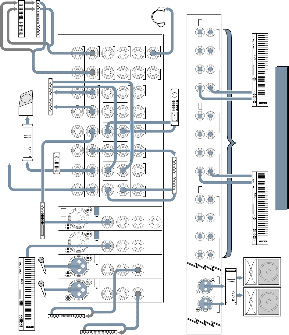
38
AUX RETURN
LEFTRIGHT
MAIN BAL OUTPUTS
+28dBU MAX OUT
OPERATING
LEVEL CH. 17-24
TAPE RETURNS 1-8
15 13 11 9 7 5 3 1
16 14 12 10 6 4 28
17
18
19
20
21
22
23
24
TAPE RETURNS 9-16
TAPE RETURNS 17-24
OUT +4dBU
IN –10dBV
+4 / –10 BALANCED / UNBALANCED
+4 / –10 BALANCED / UNBALANCED +4 / –10 BALANCED / UNBALANCED
OPERATING
LEVEL CH. 9-16
OUT +4dBU
IN –10dBV
OPERATING
LEVEL CH. 1-8
OUT +4dBU
IN –10dBV
EXTERNAL
INPUT MIX-B
OUTPUT
1
AUX SEND
1
R
L
2
2
R
R
3
3
R
L
4
4
R
R
5
5
R
L
6
6
R
R
L
7
L
L
L
R
8
R
R
R
SUBMASTER INSERT
CNTRL
RM OUTPUT
STUDIO
OUTPUT
MAIN MIX
MAIN
INSERTS
2-TRACK
INPUT
123456
PHONES
12
MONO
L
MONO
L
MONO
L
MONO
L
MONO
L
MONO
L
MONO MONO
LINE
IN
DIRECT
OUT
INSERT
CHANNEL
23
BAL/UNBAL
TIP = OUT
RING = IN
LINE
IN
DIRECT
OUT
INSERT
PHANTOM
CHANNEL
24
BAL/UNBAL
TIP = OUT
RING = IN
LINE
IN
DIRECT
OUT
INSERT
CHANNEL
21
BAL/UNBAL
TIP = OUT
RING = IN
LINE
IN
DIRECT
OUT
INSERT
CHANNEL
22
BAL/UNBAL
TIP = OUT
RING = IN
MIC
LINE MIC
LINE MIC
LINE MIC
LINE
EXTRA INPUTS!
Returns 1-24 can be used as
extra line level inputs
when FLIP is in UP position
and MIX B to L/R MIX button
is down
Same As Aux 2
Keyboard, or other line level input
Keyboard, or other line level input Keyboard, or other line level input
Digital Delay
Power Amplifier
Out In
Stage Monitor
Reverb 1
Equalizer or
other processor
Stereo
Compressor
In
Out
Out
In
OutInIn
PA Cabinet PA Cabinet
Power
Amplifier
DAT or 2-track Deck
Reverb 2
Out Out Out OutIn
In
Out
Mono Compressor
Noise Gate
In
Out
STEREO LIVE MIX PART 1: INPUT/OUTPUT
Equalizer or
Procesor
In
Out
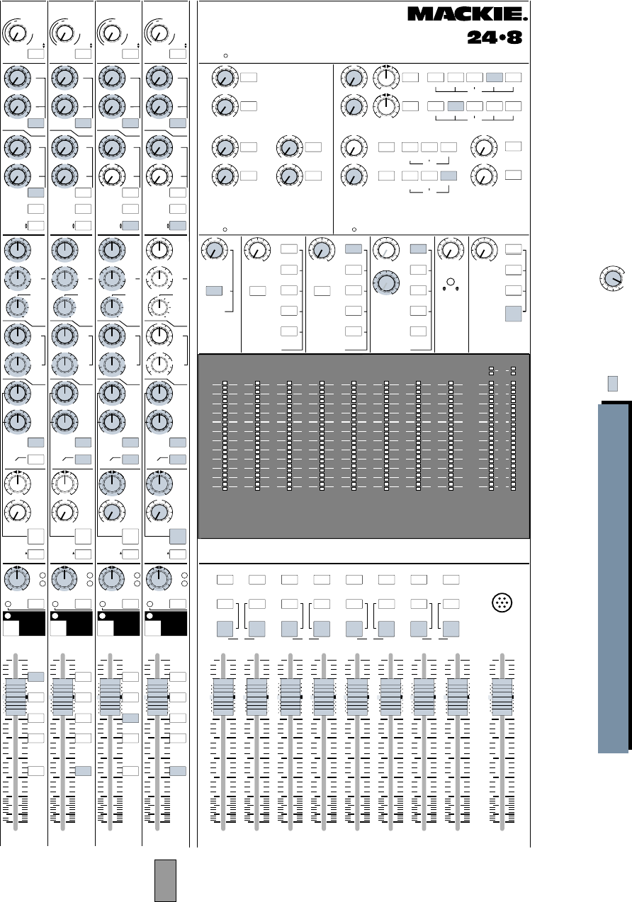
39
+15
OO
U
12k
MIX-B
EQ
LOW CUT
EQ IN
HI
FREQ
75 Hz
18dB/oct
SOURCE
45 3k
PAN
LEVEL
–15 +15
80
U
LO
SPLIT EQ
HI/LO EQ
TO MON
MONITOR
LR
–15 +15
U
250
220 350
PAN
dB
30
20
5
10
SOLO
-20
OL
OO
MUTE
21
5
10
40
50
80
U
LR
MUTE
+15
OO
U
12k
MIX-B
EQ
LOW CUT
EQ IN
HI
FREQ
75 Hz
18dB/oct
SOURCE
45 3k
PAN
LEVEL
–15 +15
80
U
LO
SPLIT EQ
HI/LO EQ
TO MON
MONITOR
LR
–15 +15
U
250
220 350
PAN
dB
30
20
5
10
SOLO
-20
OL
OO
MUTE
22
5
10
40
50
80
U
LR
MUTE
12k
MIX-B
EQ
LOW CUT
EQ IN
HI
FREQ
75 Hz
18dB/oct
SOURCE
45 3k
PAN
LEVEL
–15 +15
80
U
LO
SPLIT EQ
HI/LO EQ
TO MON
MONITOR
–15 +15
U
250
220 350
PAN
dB
30
20
5
10
SOLO
-20
OL
OO
MUTE
23
5
10
40
50
80
U
LR
MUTE
+15
OO
U
12k
MIX-B
EQ
LOW CUT
EQ IN
HI
FREQ
75 Hz
18dB/oct
SOURCE
45 3k
PAN
LEVEL
–15 +15
80
U
LO
SPLIT EQ
HI/LO EQ
TO MON
MONITOR
LR
–15 +15
U
250
220 350
PAN
dB
30
20
5
10
SOLO
-20
OL
OO
MUTE
24
5
10
40
50
80
U
LR
MUTE
TALKBACK
MIC
MIX
LEFT/RIGHT
dB
30
20
5
10
OO
5
10
40
50
80
U
dB
30
20
5
10
OO
5
10
40
50
80
U
dB
30
20
5
10
OO
5
10
40
50
80
U
dB
30
20
5
10
OO
5
10
40
50
80
U
dB
30
20
5
10
OO
5
10
40
50
80
U
dB
30
20
5
10
OO
5
10
40
50
80
U
dB
30
20
5
10
OO
5
10
40
50
80
U
dB
30
20
5
10
OO
5
10
40
50
80
U
dB
30
20
5
10
OO
5
10
40
50
80
U
FLIP SW
CHANNEL FLIP SW
CHANNEL FLIP SW
CHANNEL FLIP SW
CHANNEL
Typical Drum
Mic
Typical Vocal
or Instrument
Mic
Typical Line
(Key) Input
Vox Delay
Drum
L
Keys on
Tape Input
Drum
R
Rev 1
L
Rev 1
R
Keys
L
Keys
R
Rev 2
L
Rev 2
R
AUX
PRE
TRIM
FLIP
1
2
4
3
5
6
MIX-B
CHANNEL
PRE
SHIFT
TAPE
MIC/LINE
CHANNEL
21
SOURCE
+15
OO
U
+15
OO
U
+15
OO
U
+15
OO
U
AUX
GAIN
+4
–10
48
dB
40
dB
U
L
I
N
E
S
E
N
S
I
T
I
V
I
T
Y
M
I
C
/
L
I
N
E
G
A
I
N
LO
MID
HI
MID
BAND
WIDTH
500 18k
3k
FREQ
–15 +15
U
–15 +15
U
1k 5k
3
2
1
12
NORMAL
AUX
PRE
TRIM
FLIP
1
2
4
3
5
6
MIX-B
CHANNEL
PRE
SHIFT
TAPE
MIC/LINE
CHANNEL
22
SOURCE
+15
OO
U
+15
OO
U
+15
OO
U
+15
OO
U
AUX
GAIN
+4
–10
48
dB
40
dB
U
L
I
N
E
S
E
N
S
I
T
I
V
I
T
Y
M
I
C
/
L
I
N
E
G
A
I
N
LO
MID
HI
MID
BAND
WIDTH
500 18k
3k
FREQ
–15 +15
U
–15 +15
U
1k 5k
3
2
1
12
NORMAL
AUX
PRE
TRIM
FLIP
1
2
4
3
5
6
MIX-B
CHANNEL
PRE
SHIFT
TAPE
MIC/LINE
CHANNEL
23
SOURCE
+15
OO
U
+15
OO
U
+15
OO
U
+15
OO
U
AUX
GAIN
+4
–10
48
dB
40
dB
U
L
I
N
E
S
E
N
S
I
T
I
V
I
T
Y
M
I
C
/
L
I
N
E
G
A
I
N
LO
MID
HI
MID
BAND
WIDTH
500 18k
3k
FREQ
–15 +15
U
–15 +15
U
1k 5k
3
2
1
12
NORMAL
AUX
PRE
TRIM
FLIP
1
2
4
3
5
6
MIX-B
CHANNEL
PRE
SHIFT
TAPE
MIC/LINE
CHANNEL
24
SOURCE
+15
OO
U
+15
OO
U
+15
OO
U
+15
OO
U
AUX
GAIN
+4
–10
48
dB
40
dB
U
L
I
N
E
S
E
N
S
I
T
I
V
I
T
Y
M
I
C
/
L
I
N
E
G
A
I
N
LO
MID
HI
MID
BAND
WIDTH
500 18k
3k
FREQ
–15 +15
U
–15 +15
U
1k 5k
3
2
1
12
NORMAL
SOLO SOLO
SOLO SOLO
SOLO
SOLO
AUX SENDS STEREO AUX RETURNS
4
3
2
5
6
1
PHONES
2L/R MIX
L/R MIX
1-2 3-4 5-6 7- 8
L/R MIX
SOLO 1-2 3-4 5-6 7-8
PHONES
1PHONES
2L/R MIX
1
2
3
4
LEVEL
ASSIGN
ASSIGN
ASSIGN
ASSIGN
LEVELLEVEL
PHONES
1
6
+15
OO
U
+15
OO
U
+15
OO
U
+15
OO
U
+15
OO
U
+15
OO
U
+20
OO
U
+20
OO
U
+20
OO
U
+20
OO
U
LR
LR
5
+20
OO
U
+20
OO
U
SOLO
SOLO
SOLO
SOLO
SOLO
SOLO SOLO
LEVEL LEVEL
LEVEL
MIX-B TO
L/R MIX SOLO AUX SEND 3/4
MIX-B
MONITOR
AUX SEND 5/6
EXTERNAL MONO
TAPE SUB
MASTERS
AUX SEND 1
SOURCE
MIX B
MONITOR PHONES 1
PHONES
LEVEL
SOLO AUX SEND 3/4
MIX-B
MONITOR
AUX SEND 5/6
EXTERNAL
SOURCE
PHONES 2
PHONES
LEVEL
ASSIGN
2-TK
MIX-B
L/R MIX
EXTERNAL
SOURCE
MONITOR SOLO TALKBACK
LEVEL LEVELMIX-B
LEVEL
RUDE
SOLO LITE
AUX SEND 2
PHONES
&
STUDIO
+15
OO
U
OOOOOO
+15
OO
U
BALANCE
POWER
STEREO LIVE MIX PART 2: THE BOARD
CNTRL RM
OO
Tinted buttons
are pressed IN Tinted knobs are used
in this application
SOLO SOLO SOLO SOLO SOLO SOLO SOLO SOLO
MONO
L+R
RLRLRLR
MONO
L+R
MONO
L+R
MONO
L+R
MONO
L+R
ASSIGN
MONO
L+R
MONO
L+R
1
L
2345678
MONO
L+R
ASSIGN ASSIGN ASSIGN ASSIGN ASSIGNASSIGNASSIGN
MIX MIX MIX MIX
12345678
169101112131415
2417 18 19 20 21 22 23
10
+
7
4
2
0
2
4
7
10
20
30
40
–
LR
10
+
7
4
2
0
2
4
7
10
20
30
40
–
LR
10
+
7
4
2
0
2
4
7
10
20
30
40
–
LR
10
+
7
4
2
0
2
4
7
10
20
30
40
–
LR
10
+
7
4
2
0
2
4
7
10
20
30
40
–
22
10
+
7
4
2
0
2
4
7
10
20
30
40
–
10
+
7
4
2
0
2
4
7
10
20
30
40
–
10
+
7
4
2
0
2
4
7
10
20
30
40
–LR
MAIN
OR SOLO LEVEL
CNTRL RM
STUDIO
O
OO
OO
LR
+15
OO
U
21 22 23 24
OCTAVES
OCTAVESOCTAVESOCTAVES
5-6
3-4
1-2
7- 8
L/R
MIX
5-6
3-4
1-2
7- 8
L/R
MIX
5-6
3-4
1-2
7- 8
L/R
MIX
5-6
3-4
1-2
7- 8
L/R
MIX
24x8x2 8•BUS MIXING CONSOLE
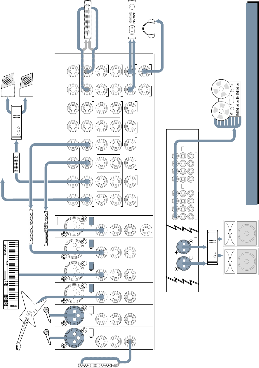
40
LEFT
RIGHT
MAIN BAL OUTPUTS
+28dBU MAX OUT
EXTERNAL
INPUT MIX-B
OUTPUT
1
AUX SEND
1
R
L
2
2
R
R
3
3
R
L
4
4
R
R
5
5
R
L
6
6
R
R
L
7
L
L
L
R
8
R
R
R
SUBMASTER INSERT
AUX RETURN
CNTRL
RM OUTPUT
STUDIO
OUTPUT
MAIN MIX
MAIN
INSERTS
2-TRACK
INPUT
123456
PHONES
12
MONO
L
MONO
L
MONO
L
MONO
L
MONO
L
MONO
L
MONO MONO
LINE
IN
DIRECT
OUT
INSERT
CHANNEL
23
BAL/UNBAL
TIP = OUT
RING = IN
LINE
IN
DIRECT
OUT
INSERT
PHANTOM
CHANNEL
24
BAL/UNBAL
TIP = OUT
RING = IN
LINE
IN
DIRECT
OUT
INSERT
CHANNEL
19
BAL/UNBAL
TIP = OUT
RING = IN
LINE
IN
DIRECT
OUT
INSERT
CHANNEL
20
BAL/UNBAL
TIP = OUT
RING = IN
MIC
LINE MIC
LINE MIC
LINE MIC
LINE
LINE
IN
DIRECT
OUT
INSERT
CHANNEL
22
BAL/UNBAL
TIP = OUT
RING = IN
MIC
LINE
LINE
IN
DIRECT
OUT
INSERT
CHANNEL
21
BAL/UNBAL
TIP = OUT
RING = IN
MIC
LINE
SUBMASTER / TAPE OUTPUTS
+4dBU BALANCED / ±10dBV UNBALANCED
87
15
6
14
5
13
4
12
3
11
2
10
1
9
OUT +4dBU
IN ±10dBV
16
1718
20 19
212223
24
OPERATING
LEVEL
OUT +4dBU
IN ±10dBV
OPERATING
LEVEL
LIVE MIX+2tk RECORDING+8tk RECORDING 1: INPUT/OUTPUT
PA Cabinet PA Cabinet
Power
Amplifier
Keyboard, or other line level input
Power Amplifier
Same as AUX 2
Graphic Equalizer
In Out
Stage Monitor
Stage Monitor
Guitar
DAT
M
u
l
t
i
-
T
r
a
c
k
R
e
c
o
r
d
e
r
Stereo
Digital Delay
Reverb 1
Out In
Out
In
Out In
Mono Compressor
In
Out
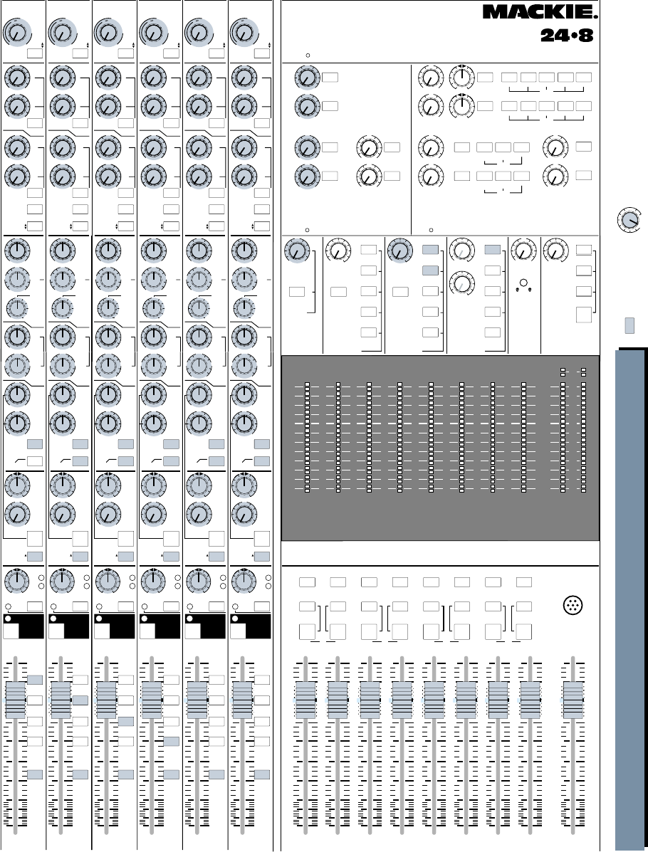
41
+15
OO
U
12k
MIX-B
EQ
LOW CUT
EQ IN
HI
FREQ
75 Hz
18dB/oct
SOURCE
45 3k
PAN
LEVEL
–15 +15
80
U
LO
SPLIT EQ
HI/LO EQ
TO MON
MONITOR
LR
–15 +15
U
250
220 350
PAN
dB
30
20
5
10
SOLO
-20
OL
OO
MUTE 21
5
10
40
50
80
U
LR
MUTE
+15
OO
U
12k
MIX-B
EQ
LOW CUT
EQ IN
HI
FREQ
75 Hz
18dB/oct
SOURCE
45 3k
PAN
LEVEL
–15 +15
80
U
LO
SPLIT EQ
HI/LO EQ
TO MON
MONITOR
LR
–15 +15
U
250
220 350
PAN
dB
30
20
5
10
SOLO
-20
OL
OO
MUTE 22
5
10
40
50
80
U
LR
MUTE
+15
OO
U
12k
MIX-B
EQ
LOW CUT
EQ IN
HI
FREQ
75 Hz
18dB/oct
SOURCE
45 3k
PAN
LEVEL
–15 +15
80
U
LO
SPLIT EQ
HI/LO EQ
TO MON
MONITOR
LR
–15 +15
U
250
220 350
PAN
dB
30
20
5
10
SOLO
-20
OL
OO
MUTE 23
5
10
40
50
80
U
LR
MUTE
+15
OO
U
12k
MIX-B
EQ
LOW CUT
EQ IN
HI
FREQ
75 Hz
18dB/oct
SOURCE
45 3k
PAN
LEVEL
–15 +15
80
U
LO
SPLIT EQ
HI/LO EQ
TO MON
MONITOR
LR
–15 +15
U
250
220 350
PAN
dB
30
20
5
10
5-6
3-4
1-2
7- 8
L/R
MIX
SOLO
-20
OL
OO
MUTE 24
5
10
40
50
80
U
LR
MUTE
TALKBACK
MIC
MIX
LEFT/R IGHT
dB
30
20
5
10
OO
5
10
40
50
80
U
dB
30
20
5
10
OO
5
10
40
50
80
U
dB
30
20
5
10
OO
5
10
40
50
80
U
dB
30
20
5
10
OO
5
10
40
50
80
U
dB
30
20
5
10
OO
5
10
40
50
80
U
dB
30
20
5
10
OO
5
10
40
50
80
U
dB
30
20
5
10
OO
5
10
40
50
80
U
dB
30
20
5
10
OO
5
10
40
50
80
U
dB
30
20
5
10
OO
5
10
40
50
80
U
FLIP SW
CHANNEL FLIP SW
CHANNEL FLIP SW
CHANNEL FLIP SW
CHANNEL
AUX
PRE
TRIM
FLIP
1
2
4
3
5
6
MIX-B
CHANNEL
PRE
SHIFT
TAPE
MIC/LINE
CHANNEL
21
SOURCE
+15
OO
U
+15
OO
U
+15
OO
U
+15
OO
U
AUX
GAIN
+4
–10
48
dB
40
dB
U
L
I
N
E
S
E
N
S
I
T
I
V
I
T
Y
M
I
C
/
L
I
N
E
G
A
I
N
LO
MID
HI
MID
BAND
WIDTH
500 18k
3k
FREQ
–15 +15
U
–15 +15
U
1k 5k
3
2
1
12
NORMAL
AUX
PRE
TRIM
FLIP
1
2
4
3
5
6
MIX-B
CHANNEL
PRE
SHIFT
TAPE
MIC/LINE
CHANNEL
22
SOURCE
+15
OO
U
+15
OO
U
+15
OO
U
+15
OO
U
AUX
GAIN
+4
–10
48
dB
40
dB
U
L
I
N
E
S
E
N
S
I
T
I
V
I
T
Y
M
I
C
/
L
I
N
E
G
A
I
N
LO
MID
HI
MID
BAND
WIDTH
500 18k
3k
FREQ
–15 +15
U
–15 +15
U
1k 5k
3
2
1
12
NORMAL
AUX
PRE
TRIM
FLIP
1
2
4
3
5
6
MIX-B
CHANNEL
PRE
SHIFT
TAPE
MIC/LINE
CHANNEL
23
SOURCE
+15
OO
U
+15
OO
U
+15
OO
U
+15
OO
U
AUX
GAIN
+4
–10
48
dB
40
dB
U
L
I
N
E
S
E
N
S
I
T
I
V
I
T
Y
M
I
C
/
L
I
N
E
G
A
I
N
LO
MID
HI
MID
BAND
WIDTH
500 18k
3k
FREQ
–15 +15
U
–15 +15
U
1k 5k
3
2
1
12
NORMAL
AUX
PRE
TRIM
FLIP
1
2
4
3
5
6
MIX-B
CHANNEL
PRE
SHIFT
TAPE
MIC/LINE
CHANNEL
24
SOURCE
+15
OO
U
+15
OO
U
+15
OO
U
+15
OO
U
AUX
GAIN
+4
–10
48
dB
40
dB
U
L
I
N
E
S
E
N
S
I
T
I
V
I
T
Y
M
I
C
/
L
I
N
E
G
A
I
N
LO
MID
HI
MID
BAND
WIDTH
500 18k
3k
FREQ
–15 +15
U
–15 +15
U
1k 5k
3
2
1
12
NORMAL
+15
OO
U
12k
MIX-B
EQ
LOW CUT
EQ IN
HI
FREQ
75 Hz
18dB/oct
SOURCE
45 3k
PAN
LEVEL
–15 +15
80
U
LO
SPLIT EQ
HI/LO EQ
TO MON
MONITOR
LR
–15 +15
U
250
220 350
PAN
dB
30
20
5
10
SOLO
-20
OL
OO
MUTE 19
5
10
40
50
80
U
LR
MUTE
+15
OO
U
12k
MIX-B
EQ
LOW CUT
EQ IN
HI
FREQ
75 Hz
18dB/oct
SOURCE
45 3k
PAN
LEVEL
–15 +15
80
U
LO
SPLIT EQ
HI/LO EQ
TO MON
MONITOR
LR
–15 +15
U
250
220 350
PAN
dB
30
20
5
10
SOLO
-20
OL
OO
MUTE 20
5
10
40
50
80
U
LR
MUTE
FLIP SW
CHANNEL FLIP SW
CHANNEL
AUX
PRE
TRIM
FLIP
1
2
4
3
5
6
MIX-B
CHANNEL
PRE
SHIFT
TAPE
MIC/LINE
CHANNEL
19
SOURCE
+15
OO
U
+15
OO
U
+15
OO
U
+15
OO
U
AUX
GAIN
+4
–10
48
dB
40
dB
U
L
I
N
E
S
E
N
S
I
T
I
V
I
T
Y
M
I
C
/
L
I
N
E
G
A
I
N
LO
MID
HI
MID
BAND
WIDTH
500 18k
3k
FREQ
–15 +15
U
–15 +15
U
1k 5k
3
2
1
12
NORMAL
AUX
PRE
TRIM
FLIP
1
2
4
3
5
6
MIX-B
CHANNEL
PRE
SHIFT
TAPE
MIC/LINE
CHANNEL
20
SOURCE
+15
OO
U
+15
OO
U
+15
OO
U
+15
OO
U
AUX
GAIN
+4
–10
48
dB
40
dB
U
L
I
N
E
S
E
N
S
I
T
I
V
I
T
Y
M
I
C
/
L
I
N
E
G
A
I
N
LO
MID
HI
MID
BAND
WIDTH
500 18k
3k
FREQ
–15 +15
U
–15 +15
U
1k 5k
3
2
1
12
NORMAL
SOLO SOLO
SOLO SOLO
SOLO
SOLO
AUX SENDS STEREO AUX RETURNS
4
2
5
6
1
PHONES
2L/R MIX
L/R MIX
1-2 3-4 5-6 7- 8
L/R MIX
SOLO 1-2 3-4 5-6 7-8
PHONES
1PHONES
2L/R MIX
1
2
3
4
LEVEL
ASSIGN
ASSIGN
ASSIGN
ASSIGN
LEVELLEVEL
PHONES
1
6
+15
OO
U
+15
OO
U
+15
OO
U
+15
OO
U
+15
OO
U
+20
OO
U
+20
OO
U
+20
OO
U
+20
OO
U
LR
LR
5
+20
OO
U
+20
OO
U
SOLO
SOLO
SOLO
SOLO
SOLO
SOLO SOLO
LEVEL LEVEL
LEVEL
MIX-B TO
L/R MIX SOLO AUX SEND 3/4
MIX-B
MONITOR
AUX SEND 5/6
EXTERNAL MONO
TAPE SUB
MASTERS
AUX SEND 1
SOURCE
MIX B
MONITOR PHONES 1
PHONES
LEVEL
SOLO AUX SEND 3/4
MIX-B
MONITOR
AUX SEND 5/6
EXTERNAL
SOURCE
PHONES 2
PHONES
LEVEL
ASSIGN
2-TK
MIX-B
L/R MIX
EXTERNAL
SOURCE
MONITOR SOLO TALKBACK
LEVEL LEVELMIX-B
LEVEL
RUDE
SOLO LITE
AUX SEND 2
PHONES
&
STUDIO
+15
OO
U
OOOOOO
+15
OO
U
BALANCE
POWER
3
+15
OO
U
LIVE MIX+2tk RECORDING+8tk RECORDING 2: THE BOARD
CNTRL RM
OO
Tinted buttons
are pressed IN Tinted knobs are used
in this application
SOLO SOLO SOLO SOLO SOLO SOLO SOLO SOLO
MONO
L+R
RLRLRLR
MONO
L+R
MONO
L+R
MONO
L+R
MONO
L+R
ASSIGN
MONO
L+R
MONO
L+R
1
L
2345678
MONO
L+R
ASSIGN ASSIGN ASSIGN ASSIGN ASSIGNASSIGNASSIGN
MIX MIX MIX MIX
12345678
169101112131415
2417 18 19 20 21 22 23
10
+
7
4
2
0
2
4
7
10
20
30
40
–
LR
10
+
7
4
2
0
2
4
7
10
20
30
40
–
LR
10
+
7
4
2
0
2
4
7
10
20
30
40
–
LR
10
+
7
4
2
0
2
4
7
10
20
30
40
–
LR
10
+
7
4
2
0
2
4
7
10
20
30
40
–
22
10
+
7
4
2
0
2
4
7
10
20
30
40
–
10
+
7
4
2
0
2
4
7
10
20
30
40
–
10
+
7
4
2
0
2
4
7
10
20
30
40
–
LR
MAIN
OR SOLO LEVEL
CNTRL RM
STUDIO
O
OO
OO
24
23
22
21
20
19
OCTAVESOCTAVESOCTAVESOCTAVESOCTAVESOCTAVES
5-6
3-4
1-2
7- 8
L/R
MIX
5-6
3-4
1-2
7- 8
L/R
MIX
5-6
3-4
1-2
7- 8
L/R
MIX
5-6
3-4
1-2
7- 8
L/R
MIX
5-6
3-4
1-2
7- 8
L/R
MIX
24x8x2 8•BUS MIXING CONSOLE

42
HOUSE AND MONITOR MIX TOGETHER
It’s a big board, but it’s the only one you own.
So you find yourself mixing house and monitors
all from the same panel.
First, let’s take a moment and set everything
up sensibly. Just like in a recording session, it’s
good to group your inputs and sub-mix buses by
instruments, stage position or whatever else
suits you. Try to keep the drum mics next to
each other, the vocals together and so on. Label
your cables, color-code your windscreens, lay
tape across the arm rest, make a cheat sheet,
iron your shorts, give yourself a break. It can be
confusing enough mixing a big show without
wondering which channel is which.
Using AUX Send-Return loops and inserting
outboard gear is the same as when recording,
unless you want to use the AUX Sends as inde-
pendent cue mixes, by engaging the PRE switch
for those AUX Sends.
Subgroups can be very helpful in Sound Rein-
forcement (SR) work. Remember, when you
assign a channel to a subgroup, de-assign that
channel from the L/R Mix.
Headphones
If you like to check things out in your phones,
and especially if you want to use the 8•Bus solo
or (modified) PFL functions as a cue circuit, set
your phones up like this:
• Be sure the MONITOR SOURCE switch is set
to what you want to listen to (usually L/R Mix,
your House feed). You can keep the two
Monitor LEVEL controls turned down,
though, because you are not feeding amplifi-
ers from the Control Room or Studio outputs.
• Plug your phones into one of the two
Phones output jacks; let’s say Phones 1.
Now select MONITOR on the PHONES 1
SOURCE switch. That should give you L/R
Mix bus plus solo. See, the solo bus only
feeds the Control Room and Studio Speak-
ers circuits, so we had to poke a few
buttons to make it work.
MAKING A SIMULTANEOUS RECORDING
You’re all set up, ready to go, when the band’s
manager comes up to you with a DAT machine
and goes “The producer wants us to send him a
recording of tonight’s gig,” and you go, “I’ll patch
it in to the house mix,” and he goes, “No, I’d
rather get a special mix just for the tape,” and
you roll your eyes and go, “You should really get
a remote truck,” and he rolls his eyes and goes,
“Here’s the tape. Make it good and we might
hire you next time.”
Piece of cake.
Refer to the drawings on pages 40 and 41.
MIX-B to the rescue! L/R Mix is your house mix,
you will use the AUX buses for stage monitor mix,
and MIX-B will provide a stereo recording feed.
Simply depress each of the MIX-B SOURCE
switches to CHANNEL, patch the MIX-B outputs
into the recorder inputs and set up your recording
mix with the MIX-B level controls. To monitor,
select MIX-B on the Phones output you’re using
and route the output of the recorder back into
EXTERNAL to check playback.
It’s true, there are no meters on the MIX-B
buses. Try using the recorder meters. If you can’t
see them from where you sit, there are a couple
of patches you can try to get metering:
• Since you’re not using the CONTROL RM or
STUDIO outputs, you can use the MONITOR
section for metering only. Simply engage only
the Mix-B Switch in that section.
• If you have two free submaster buses, patch
the MIX-B buses into the submaster insert
point. (Push the 1/4" plug only halfway in to
the Insert Jack, to the first ‘click.’ See
Appendix A: “Connections” for details.) Set
the submaster faders to –6dB to adjust for the
insert point gain difference. Now you will
have MIX-B levels showing on those two
submaster meters, and you can use the
SUBMASTER OUTPUTS as feeds to your
recorder.
• If you have the optional meter bridge fitted
and you have two extra inputs, patch the
output of MIX-B into the open channels
(either Line In or Tape In, depending on how
you have set the global source switch on the
meter bridge), set the levels at unity and
watch those two channel meters for recording
levels. You can now use the two channel’s
DIRECT OUTS as feeds to your recorder.
Make sure all the channel bus and AUX
assign switches and controls are off, so you
don’t accidentally assign your signal back into
the mix. Also, this way you could add a little
EQ or compression via the channel inserts.
• In either of the above cases, you may want
to keep the extra circuitry out of your
recording signal path. If so, just mult the
MIX-B outputs to both your recorder and to
the patch point for metering.
HOUSE MIX ONLY or MONITOR MIX
ONLY
Much easier than both at once, but requires
two mixers. Simply split the mics, set one mixer
up for house (on the L/R Mix buses, as above)
PA & SR

43
and the other one up for stage monitor. If you
need to do some combination of house/recorder
feed or vocal/drum/keyboard monitors, divide
the functions up between L/R Mix, AUX buses
and MIX-B buses as described above.
Mic Splitters
If you are using one mixing console for your
main or house mix and another for stage moni-
tors, the best way to distribute the microphone
signals to both consoles is by using a good quality
mic splitter box. Splitters use transformers spe-
cially designed to split the signal and keep the
impedance match correct while rejecting noise
and preventing ground loops. You can get split-
ters with as many input channels as you need,
each with from two to five outputs for each mic
input.
Mic splitter transformers are expensive, but
are well worth the investment. They will provide
the most consistent trouble-free performance
with multiple mixers.
If you need to split your inputs but do not
have splitter transformers, you can make a spe-
cial harness of cables to split out of the Mackie
channel insert. This technique is not always as
flexible or ground-loop-proof as splitter trans-
formers, but is much less expensive. See Figure
11 in Appendix A: “Connections.”
FINDING MORE INPUTS
You bought a 32-channel mixer and you still
don’t have enough inputs. Well, before you go to
the bank again, remember that the Mackie
8•Bus Series has some options for you:
• You can get up to 32 additional line inputs using
the Tape In to MIX-B path. You can even split
the EQ and Aux Buses to the MIX-B inputs if
you want. Then assign Mix-B to L/R Mix.
• Any unused AUX returns (there are 12
inputs) can be used as additional line inputs.
• In a pinch, you can use the eight Submaster’s
inserts providing the sub is currently unused
(no channels assigned to it). Use a 1/4” TS
cable and plug in only to the first click. Signals
entering here will be kicked up by +6dB.
PA & SR
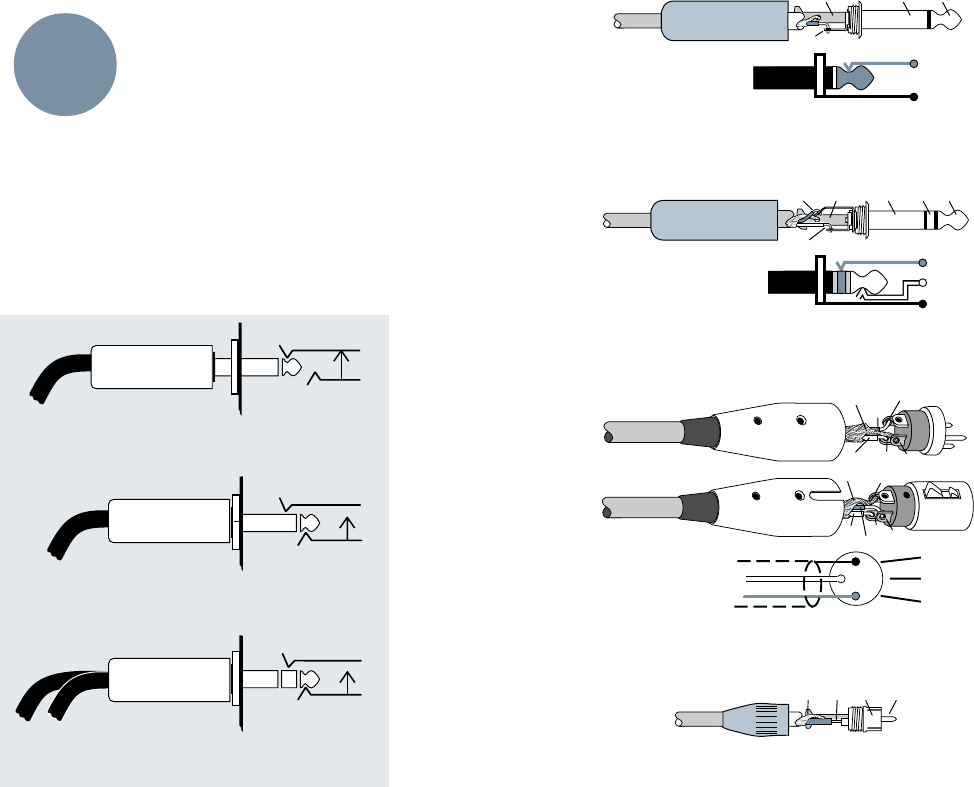
44
“XLR” CONNECTORS
Mackie mixers use 3-pin female “XLR” connec-
tors on all microphone inputs, with pin 1 wired to
the grounded shield, pin 2 wired to the “hot”
(positive polarity) side of the audio signal and
pin 3 wired to the “cold” (negative polarity) side
of the signal (Figure 7).
Use a male “XLR”-type connector, usually found
on the nether end of what is called a “mic cable,”
to connect to these inputs.
Mackie occasionally uses 3-pin male “XLRs” for
balanced line outputs. The Main L/R Outs on the
8•Bus, for example, are available on XLRs. These are
also wired pin 1 ground, pin 2 high and pin 3 low.
1/4" TRS PHONE PLUGS AND JACKS
“TRS” stands for Tip-Ring-Sleeve, the three
connections available on a “stereo” 1/4" phone
jack or plug (Figure 8). TRS jacks and plugs are
used in several different applications:
• Stereo headphones, and rarely, stereo micro-
phones and stereo line connections. When
wired for stereo, a 1/4" TRS jack or plug is
connected tip to left, ring to right and sleeve to
ground. Mackie mixers do not directly accept
1-plug-type stereo microphones. They must be
separated into a left cord and a right cord that
are plugged into two channels.
• Balanced mono circuits. When wired as a
balanced connector, a 1/4" TRS jack or plug is
connected tip to signal high, ring to signal low,
and sleeve to ground.
• Unbalanced Send/Return circuits. When
wired as send/
return connector,
a 1/4" TRS jack or
plug is connected
tip to signal send
(output from
mixer), ring to
signal return
(input back into
mixer), and
sleeve to ground.
1/4" TS PHONE
PLUGS AND
JACKS
“TS” stands for
Tip-Sleeve, the two
connections avail-
able on a “mono”
1/4" phone jack or
plug (Figure 9). TS jacks and plugs are used in
many different applications, always unbalanced.
The tip is connected to the audio signal and the
sleeve to ground. Some examples:
• Unbalanced microphones
• Electric guitars and electronic instruments
• Unbalanced line-level connections
SWITCHED 1/4" PHONE JACKS
1/4" phone jacks can incorporate switches that
are activated by inserting the plug. These switches
may open an insert loop in a circuit, change the
input routing of the signal or serve other func-
tions. The Mackie 8•Bus Series uses switches in
the channel and bus Insert Jacks, and in the
mono/stereo AUX Return Jacks. See Special
Mackie Connections on page 45. We also use these
switches to ground the inputs of most line level
ins/outs when nothing is plugged into them.
Figure 10 (below): RCA connector (Plugis Amateuris)
Figure 7 (above): XLR connectors (Exelaris Triptipus)
APPENDIX A: Connections
Female XLR
2
3
1
TIPSLEEVETIPSLEEVE
2
2
31
1
COMMON
COLD
HOT
COMMON
COLD
HOT
3
COMMON
COLD
HOT
Male XLR
ADD-ONS
SPECS
ETC.
Direct out with no signal interruption to master.
Insert only to first “click”
Channel Insert jack
Channel Insert jack
Channel Insert jack
Direct out with signal interruption to master.
Insert all the way in to the second “click”
For use as an effects loop.
(TIP = SEND to effect, RING = RETURN from effects)
MONO PLUG
MONO PLUG
STEREO
PLUG
SLEEVE
TIP
TIPSLEEVE
TIP
SLEEVE
SLEEVE
TIPSLEEVE
TIP
RING
RING
TIP
SLEEVERING
Figure 9: TS connectors (Plugis Biconnectorus)
Figure 8: TRS connectors (Plugis Triconnectorus)
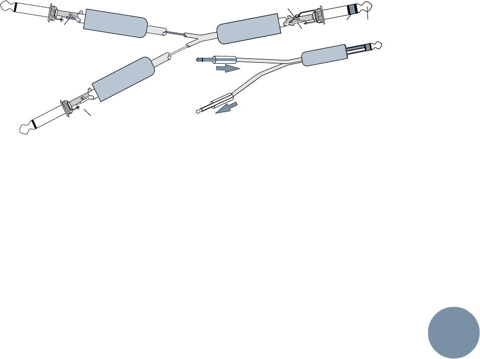
45
TIP
(SEND)
RING (IN)
TIP (OUT)
RING
(RETURN)
TO MIXER
CHANNEL INSERT
TIP (RETURN)
TIP (SEND)
TO
PROCESSOR
INPUT
FROM
PROCESSOR
OUTPUT
Figure 11 : Hybrid connector with Send & Return com-
bined on a TRS plug with the separate Send & Return on
the TS plug ends (Plugis Insertis Hybridus)
In most cases, the plug must be inserted fully
to activate the switch. Mackie takes advantage of
this in some circuits, specifying circumstances
where you are only to partially insert the plug.
Once again, see Special Mackie Connections, on
the next page.
RCA PLUGS AND JACKS
RCA “phono” plugs and jacks are often used in
home stereo and video equipment and in many
other applications (Figure 10). They are unbal-
anced, and electrically identical to a 1/4" TS
phone plug or jack. Connect the signal to the cen-
ter post and the ground or shield to the
surrounding “basket.” There are no RCA jacks on
the Mackie 8•Bus Series Mixing Consoles. Adapt-
ers to convert an RCA male plug to male 1/4” TS
plug are available at any electronic shop, like
Radio Shack.
UNBALANCING A LINE
In most studios, there is a mix of balanced and
unbalanced inputs and outputs on the various
pieces of equipment. This usually will not be a
problem in making connections.
• When connecting a balanced output to an
unbalanced input, be sure the signal high
connections at each end are wired together,
and the balanced signal low goes to the ground
connection at the unbalanced input. In most
cases, the balanced ground will also be
connected to the ground at the unbalanced
input. If there are hum or radio frequency
ground-loop problems, this connection may be
left disconnected at the unbalanced end.
• When connecting an unbalanced output to a
balanced input, be sure that the signal high
connections at each end are wired together.
The unbalanced ground connection should
be wired to the low and the ground connec-
tions of the balanced input. If there are
ground-loop problems, try connecting the
unbalanced ground connection only to the
input low connection, and leaving the input
ground connection disconnected.
In some cases, you will have to make up spe-
cial adapters to interconnect your equipment. For
example, you may need a balanced XLR female
connected to an unbalanced 1/4" TS phone plug.
SPECIAL MACKIE CONNECTIONS
The balanced-to-unbalanced connection has
been anticipated in the wiring of the Mackie
8•Bus Series jacks. A 1/4" TS plug inserted into a
1/4" TRS balanced input, for example, will auto-
matically unbalance the input and make all the
right connections. Conversely, a 1/4” TRS plug
inserted into a 1/4” unbalanced input will auto-
matically tie the ring (low) to ground.
TRS Send/Return Insert Jacks
The Insert Jacks on both the 8•Bus input
channels and on the Submaster and Main Mix
buses are the three-conductor, TRS type 1/4"
phone. They are unbalanced, but have both the
mixer output (send) and the mixer input (re-
turn) signals in one connector (Figure 11 above).
The sleeve is the common ground for both sig-
nals. The send from the mixer to the external unit
is carried on the tip, and the return from the
external unit to the mixer is on the ring.
Using the Send Only on an Insert Jack
If you insert a TS (mono) 1/4" plug only
partially (to the first “click”) into an 8•Bus Se-
ries Insert Jack, the plug will not activate the
jack switch and will not open the insert loop in
the circuit.
This allows you to borrow the channel or bus
signal at that point in the circuit, without inter-
rupting normal operation. Note: Do not overload
or short-circuit the signal you are tapping from
the mixer. That will affect the internal signal in
the 8•Bus Series.
ADD-ONS
SPECS
ETC.
“Y” insert cable
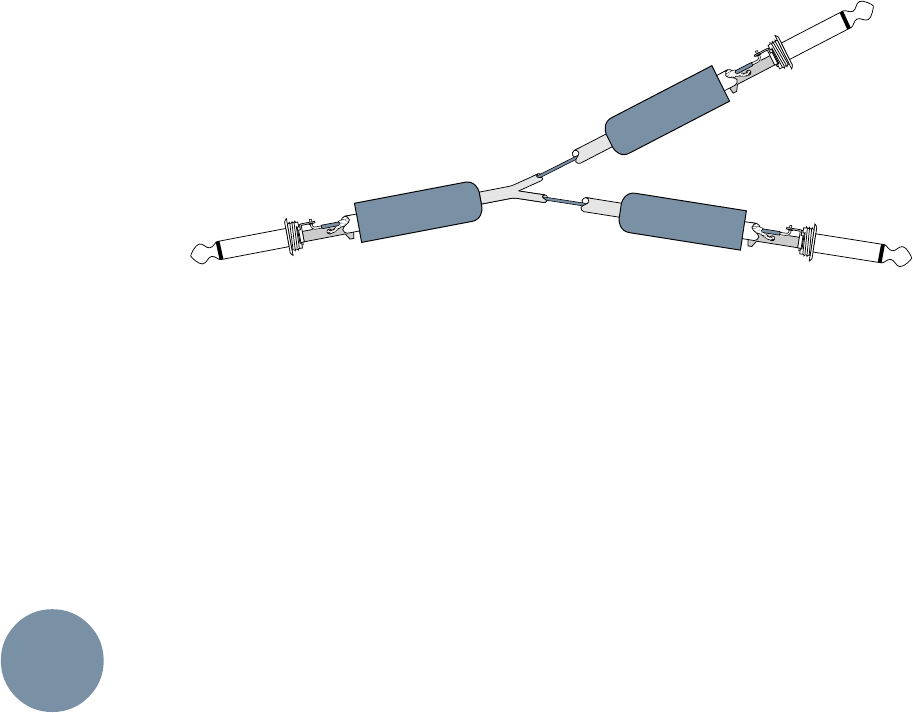
46
Figure 12: “Y”cord (a.k.a MULT) for splitting signal
(Plugis Makus Doublis). Note that all three plugs are the
same — either TS (shown) or TRS. Don’t confuse this
“off the shelf” connector with hybrid insert plugs as
shown in Figure 11.
Using the Return Only on Sub and Main
Insert Jacks
If you insert a TS (mono) 1/4" plug only
partially (to the first “click”) into an 8•Bus
Series Submaster or Main insert jack, the plug
will not activate the jack switch and will not
open the insert loop in the circuit.
This allows you to insert signal into the
submaster or main at that point in the circuit.
Note: Only unused buses can be used in this
manner. Do not insert signal into a bus with
signal on it, or unpredictable results may occur.
MACKIE AUX RETURNS: Mono, Stereo,
Whatever
The Stereo AUX Returns are a fine example of
the Mackie philosophy (which we just made up)
of Maximum Flexibility with Minimum Headache.
The returns will automatically be mono or stereo,
depending upon what you plug into the Return
Jacks. Here’s how it works:
A mono return should be patched into the Re-
turn Jack labeled LEFT (MONO). The signal will
be routed to both the left and right sides of the
return circuit, and will show up in the center in
any stereo pair of buses you assign it to.
A stereo return, having two return plugs,
should be patched into the LEFT (MONO) and
the RIGHT Return Jacks. A jack switch in the
RIGHT Jack will disable the mono function, and
the returns will show up in stereo.
MULTS AND “Y”s
A mult or “Y” connector allows you to route one
output to two or more inputs by simply providing
parallel wiring connections. You can make Ys and
mults for both unbalanced and balanced circuits.
See Figure 12 for an example. Remember: Only
mult or “Y” an output into several inputs. If you
need to combine several outputs into one input,
you must use a mixer, not a mult or a “Y.”
ADD-ONS
SPECS
ETC.

47
APPENDIX B: Options, Add-Ons and Extra Stuff
OPTIONS
Meter Bridge
You can order an optional Mackie meter bridge
for any 8•Bus Series console. The meter bridge
extends across the width of the mixer and pro-
vides a 12-LED bar-graph meter (identical to the
8 submaster bus meters) for each channel strip.
The meters can be globally switched, metering
either the Tape Return signals to the mixer, post-
tape-in level switch (for watching multitrack
source and tape levels) or the post-fader/post-
mute switch channel signals (handy for live
sound mixing).
The Mackie Sidecar
The Sidecar provides eleven rack spaces for
patchbays, the Mackie power supply, etc. At the
back is a cable storage rack for organizing
connection cords.
Un-Cigarette Lighter
An automobile-type cigarette lighter can be
mounted on the front panel of your mixer, but
NOT CONNECTED! What a joke for your smok-
ing friends!
Mixing Shoes
The Mackie Kotoor Coallectshun of fine
wearables includes our way-cool, lightweight Mix-
ing Shoes. They’re designed for long hours and
superior traction so that a little slip never ruins
your mix.
Insist that everyone in the control room wear
Mackie Brand Mixing Shoes. They’re available in
Rock, Soft Rock, Metal, Alternative, Country, Jazz,
Gospel, Insufferable Audiophile and special
spiked-steel-toe Producer/Client-Booters.
ADD-ONS
SPECS
ETC.
48
level up +20
level up +15 level up +15
0000000
00000000
0000000
max out +22
max out +22
max out +22
+14 max in
-10 trim dn
MIC INPUT AUX RETURN CH. LEVEL MIX O/P LEVEL OUTPUT
OUTPUT
OUTPUT
MIX
MIX O/P LEVEL
-50 trim up
+22 max in
trim dn
-40 trim up
+22 max in
switch @+4
-12.3 @-10
LINE INPUT
TAPE INPUT
to point (B)
gain up +15 fader up +10
(A) (B)
pan center -3
gain dn -15
(C)
INSERT EQ FADER PAN SUB INSERT
-6 -6
gain up +15 level up +15 level up +15
gain dn -15
SPLIT EQ CH. LEVEL
MIX B
1-8 from point (C)
L/R from point (D)
-4
to meters
METER FEED (+4 @ O/P = 0 @ METERS)
SUBMASTER or MAIN MIX
CHANNEL
FADER CONTROL ROOM
(D)
level up
fader up +10
L/R bal max out +28
max out +22
1-8 bal/unbal
L/R unbal
from point (A)
AUX SEND
Because Mackie
Designs is always
trying to improve its
products with new
components and
manufacturing
methods, these
specifications may
change at any time.
But you can bet your
left monitor speaker
that the specs won’t
be any worse than
they are here.
APPENDIX C: Specifications
24•8 and 32•8 Specifications
Noise.(Measured 20Hz to 20kHz bandwidth,
Tape Returns selected, no EQ, Channel Pans
alternating L/R, L/R. “Faders up” refers to Unity
gain, 0dBu position.)
Main L/R Output Noise. Master fader down,
–101dBu; master fader up/no ch.’s assigned,
–95dBu; master fader up/24 chs. assigned,
–90dBu; master fader up/24 chs. assigned, ch.
faders up, –86dBu; +4dB operating level S/N
ratio, –90dBu
Submaster Output Noise. Master fader down,
–99dBu; master fader up/no ch.’s assigned,
–96dBu; master fader up/24 chs. assigned,
–90dBu; master fader up/24 chs. assigned, ch.
faders up, –86dBu; +4dB operating level S/N
ratio, 90dB
Total Harmonic Distortion. (1kHz @14dBu
measured 20Hz-20kHz, mic input, 1 channel as-
signed). Direct output, 0.0013% typical; L/R Mix
output, 0.0014% typical; Submaster output,
0.0015% typical
Crosstalk. (1kHz measured relative to 0dBu,
measured 20Hz to 20kHz.) Line In to Adjacent
Channel, –91dBu; L/R mix output w/channel
down, –95dBu; submaster output w/channel
down, –96dBu; L/R mix output w/channel muted,
–95dBu; submaster output w/channel muted,
–96dBu; L/R mix output w/channel unassigned,
–91dBu; submaster output w/channel
unassigned, –95dBu; L/R mix output w/adjacent
channel assigned, –92dBu; submaster output w/
adjacent channel assigned, –94dBu; L/R mix out-
put pan pot attenuation, –87dBu; submaster
output pan pot attenuation, –87dBu
Frequency Response. +0dB/–1dB, any input to
any output 20Hz to 60kHz; +0dB/-3dB, any input
to any output, 10Hz to 120kHz
E.I.N. Mic input (150Ω termination, 20Hz-
20kHz) –129.5dBm
C.M.R.R. Mic input, max gain @1kHz, –83dBu;
line input, minimum gain @1kHz, –45dBu; tape
input, no gain @1kHz, –45dBu
Maximum Levels. Mic input, +14dBu; all other
inputs, +22dBu; L/R Mix balanced output,
+28dBu, all other outputs, +22dBu
Impedances. Microphone input, 1.5 kΩ; channel
insert return, 2.5 kΩ; all other inputs, 10 kΩ or
greater; all outputs, 120Ω
Equalization. Hi Mid, full parametric, +/-15dB
freq. sweep from 500Hz-18kHz, bandwidth (Q)
variable from 1/12 octave to 3 octaves; Lo Mid,
swept, 45Hz-3kHz +/-15dB; Hi, shelving, 12kHz
+/-15dB; Lo, shelving 80Hz +/-15dB; Lo Cut
(HPF) 75Hz,18dB/octave (Tchebechev)
ADD-ONS
SPECS
ETC.
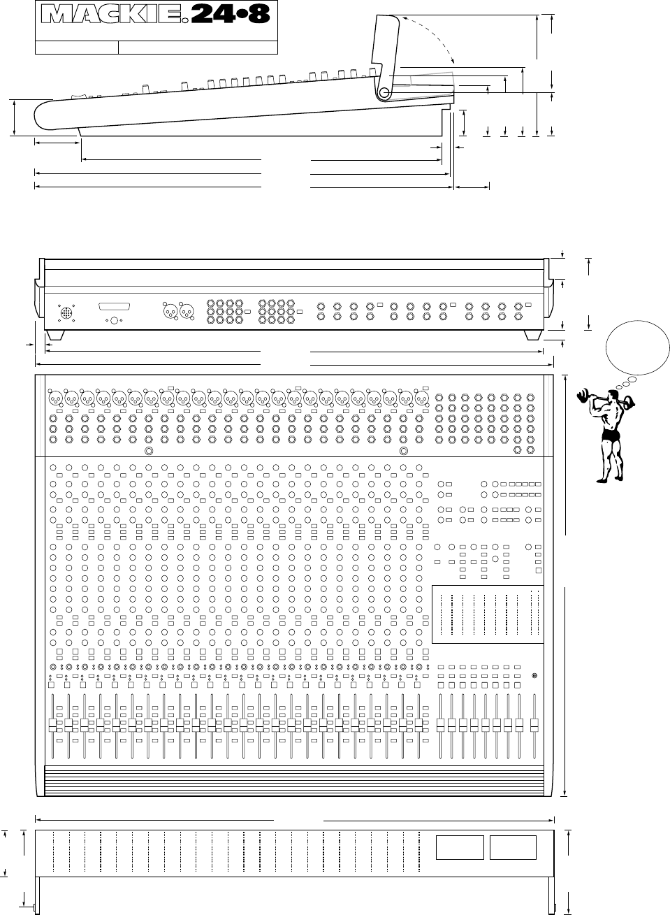
49
2.65"
28.58"
2.50"
0.69"
4.25"
6.00"
9.00"
4.78"
25.24"
28.74"
35.02"
37.02"
1.00"
1.00"
4.78"
6.00"
37.00"
0.54"
28.74"
MB24•8 Optional Meter Bridge
24x8x2 8-BUS MIXING CONSOLE
©1995 MACKIE DESIGNS INC.
*
exclusive
of
meter
bridge
24•8
console
WEIGHT*
64 lbs.
Note: add 3.75" to depth for
power supply cable clearance
2.70"
V. 1.5 6/4/95
5.50"
3.38"
3.67" 5.50"
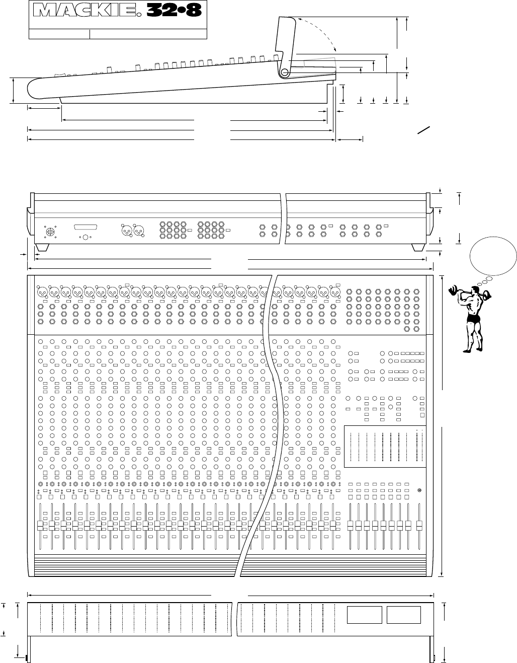
50
Get some help
before lifting this one...
2.65"
28.58"
2.50"
0.69"
4.25"
6.00"
9.00"
4.78"
25.24"
28.74"
43.82"
45.82"
1.00"
1.00"
4.77"
0.54"
28.74"
32x8x2 8-BUS MIXING CONSOLE
©1994 MACKIE DESIGNS INC.
*exclusive
of
meter
bridge
32•8
console
WEIGHT*
78 lbs.
6.00"
45.80"
MB32•8 Optional Meter Bridge
Note: add 3.75" to depth for
power supply cable clearance
2.70"
V. 1.5 6/4/95
5.50"
3.38"
3.67" 5.50"
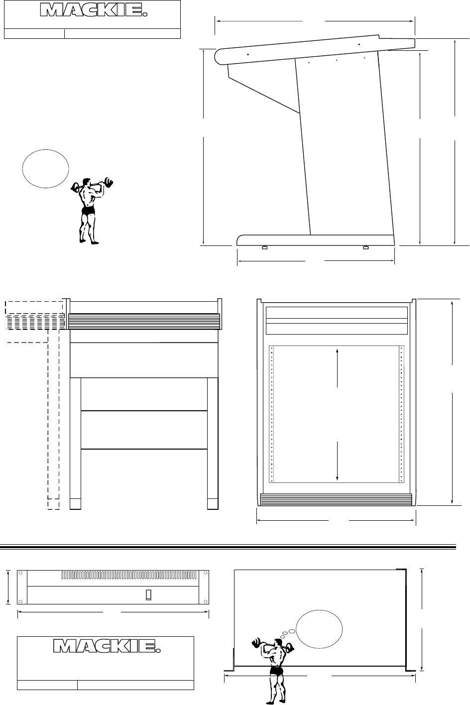
51
V. 1..1 6/5/95
8•BUS SIDE CAR RACK
©1995 MACKIE DESIGNS INC.
28.12"
28.25"
22.5"
29.88"
SIDE VIEW
28.75"
Side Car
WEIGHT*
45 lbs.
19.00"
10.1"
3.50"
(2 rack spaces)
19.0"
220-W
Power Supply
WEIGHT
24 lbs.
V. 1.2 4/4/94
220-WATT POWER SUPPLY FOR
8•BUS CONSOLES & EXPANDER
©1994 MACKIE DESIGNS INC.
23.13"
28.75"
11 RACK SPACES
TOP VIEW
CABLE HANGER
FRONT VIEW
[existing console]
BRACE
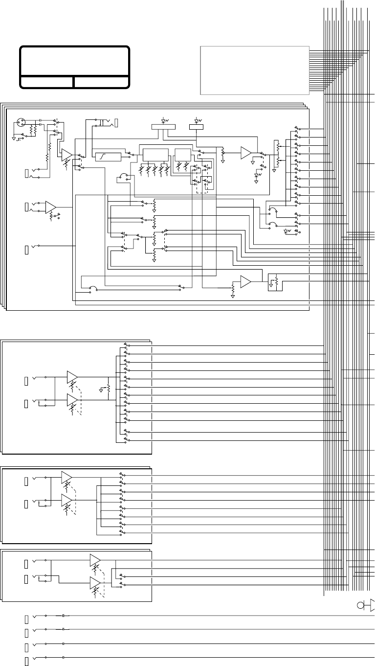
52
©1995 Mackie Designs
8•BUS CONSOLE
BLOCK DIAGRAM
Rev. 5.1- 6/6/95
GAIN
HI
BUS 1
BUS 2 BUS 3
BUS 4 BUS 5
BUS 6 BUS 7
BUS 8 L-BUS
R-BUS
L-SOLO
R-SOLO
AUX 1
AUX 2 AUX 3
AUX 4 AUX 5
AUX 6
L-MIX-B
R-MIX-B
MIC IN
LINE
IN
TAPE
IN
FLIP
POST
SOURCE
AUX 1
AUX 2
AUX 3
AUX 5
AUX 4
AUX 6
CHAN
FADER
TRIM
EQ
IN/OUT
PAN
LEVEL
PAN
1-2
3-4
5-6
7-8
L/R
SOLO
INPUT
1 OF 16 (24) (32)
STEREO AUX RETURN 1
LEVEL
BALANCE
1-2
3-4
5-6
7-8
L/R
SOLO
LEVEL
PHONES 1
PHONES 2
L/R
2-TK IN
L
2-TK IN
R
MIC
FREQ
PRE
POST
LEFT
(MONO)
RIGHT
RIGHT
LEFT
(MONO)
LEFT
(MONO)
RIGHT
(PER 8 CH'S)
+4dBU/–10dBV Select
+
-
+
-
PHANTOM POWER
(PER 8 CH'S)
•
•
MIC/LINE INSERT
•
•
•
•
PRE
POST
PRE
•
•
•
PARAMETRIC
EQ
SHELVING
EQ
MID
"Q"
MIDLO LOHI
GAIN FREQ
•
•
•
HI/LO EQ
TO MIX B
SPLIT
PRE EQ
TO AUX MOD
•
•
•• ••
•
•
•
•
•
•
•
•
•
•
••
•
•
•
•
•
••
•
•
•
•
•
•
•
•
•
••
•
•
•
•
•
••
•
•
•
SOLO
•
•
•
•
•
•
•
SOLO
•
•
•
•
•
•
•
••••••••
•
•
•
•
•
•
•
•
•
•
•
•
•
•
•
••
•
•
•
•
••
•
•
•
•
•
•
•
•
•
•
•
•
•
•
•
•
•
•
•
•
75Hz
HPF
0L
MUTE
MIX-B
SOURCE
•
PFL MOD
•
LO CUT
IN/OUT
•
••••••••••••••••••••
OPTIONAL 24•E
24-CHANNEL MACKIE 8•BUS
EXPANDER CONSOLE
To on-ramp #257
of the Santa Ana Freeway
–20dB
•
•
PRE
POST
•
1
2
3
•
•
•
DIRECT
OUT
(#2 IDENTICAL)
STEREO AUX RETURN 3
(#4 IDENTICAL)
STEREO AUX RETURN 5
(#6 IDENTICAL)
L/R
•
SHIFT
•
•
••
•
FLIP SW
CHANNEL MIX-B SOURCE MOD
•
•
•
EXTERNAL
IN L
EXTERNAL
IN R
LEVEL
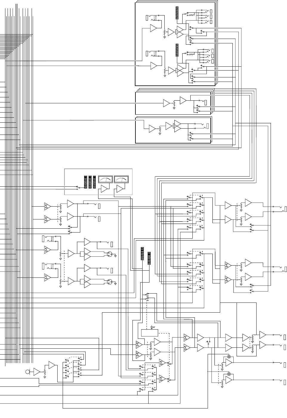
53
BUS 1
BUS 2 BUS 3
BUS 4 BUS 5
BUS 6 BUS 7
BUS 8 L-BUS
R-BUS
L-SOLO
R-SOLO
AUX 1
AUX 2 AUX 3
AUX 4 AUX 5
AUX 6
L-MIX-B
R-MIX-B
L/R MIX
MIX-B
2-TK
EXTERNAL
SUB MASTER 1 & 2
AUX SEND 1
SOLO
CONTROL
SUB MSTR
FADER
(#3 - 8 IDENTICAL)
(#2 IDENTICAL)
LEVEL
AUX OUT
SOLO
MIX B
MASTER
MIX-B
TO
L/R MIX
L
R
L/R
MIX
FADER
MIC
MIC LEVEL
TO AUX 1
R BAL OUTPUT
SOLO
LEVEL
MONO
CONTROL ROOM
PAD LOGIC
L
STUDIO
OUTPUT
STUDIO
LEVEL
CNTRL RM
LEVEL
PHONES 2
LEVEL
SOLO
PHONES 2
SOURCE
PHONES 1
LEVEL
MONITOR
MIX-B
EXTERNAL
AUX 3/4
AUX 5/6
SOLO
EXTERNAL
MIX-B
MONITOR
PHONES 1
OUTPUT
PHONES 1
SOURCE
•
•
•
•
•
•
•
•
•
•
•
•
•
•
•
•
•
•
•
TO AUX 2
TO TAPE/
SUBMASTER
TO PHONES
(AND STUDIO)
••••••••
•
•
MONITOR
SOURCE
•
•
•
•
•
•
•
•
•
•
•
•
•
INSERT
•
•
•
•
••
••
•
•
••
•
•
•
•
•
•
•
••
•
•
•
•
•
•
•
•
•
•
•
•
SUB MSTR
FADER
INSERT
•
•
SOLO
•
•
•
•
•
•
L + R
•
•
•
•
•
•
SOLO
L + R
•
•
•
L METER
R METER
•
•
•
•
••
•
•
••
••
R
STUDIO
OUTPUT
L
CNTRL RM
OUTPUT
R
CNTRL RM
OUTPUT
•
•
•
•
•
•
•
•
•
(DEFEATED WHEN
CNTRL RM SOURCE
IS SELECTED)
(DEFEATED WHEN
CNTRL RM SOURCE
IS SELECTED)
•
•
•
•
•
••
•
•
•
•
•
••
•
•
•
•
•
•
AUX OUT
•
•
AUX SEND 3
(#4, 5, 6 IDENTICAL)
SOLO
•
NOTE: ALL SWITCHES SHOWN IN DISENGAGED (UP) POSITION
TALKBACK:
MIX-B OUTPUT
L MIX
R MIX
••••••••••••••••••••
7
e
eway
•
•
•
•
•
•
SUB OUTS 1, 9 & 17
METER
•
•
•
•
•
vu
•
•
••
•
•
•
•
1
2
3
1
2
3
+
-
+
-
INSERT
vu
GLOBAL
SELECT
CH. OUT
•
•
•
•
•
•
•
•
•
•
•
•
•
•
•
INSERT
-
+
-
METER
•
•
•
•
•
+4/-10
+4/-10
••
•
•
•
•
+
-
•
••
•
•
R UNBAL OUTPUT
L BAL OUTPUT
L UNBAL OUTPUT
OPTIONAL METER BRIDGE
PHONES 2
OUTPUT
L
R
L
R
•
•
•
•
•
•
•
•
•
•
•••
•
•
+
INSERT
•
••
•
SUB OUTS 2, 10 & 18
•
••
•
TAPE IN
•
AUX 5/6
AUX 3/4
∑
∑
∑
∑
∑
∑
LEVEL
LEVEL
54
SERVICE
Intermittent signal problems. Faulty plugs
and cables are often the culprits. A TRS plug can
sit in a socket for months doing its job and then
suddenly decide (based on the phase of the moon
and barometric pressure) to short or stop con-
ducting. If you’re having trouble with an individual
channel, send or return, for gosh sakes swap
cables before sending the board in for service.
Check switch positions. Multi-bus consoles
are pretty complicated. Switches like MIC/LINE,
FLIP and EQ SPLIT can give the impression that
something isn’t working right, if you’re not ex-
pecting them to be engaged.
Finally, it doesn’t hurt to call our Technical
Support Department at 800/258-6883 (8AM-
4:30PM Pacific time) to see if they have any
ideas as to what might be wrong.
Note: For best results have unit in front of you
(or close by).
How to get Mackie service
Service and repairs of Mackie 8•Bus products
are to be performed only :
A. at our factory OR
B. at an Authorized Mackie 8•Bus Warranty
Service Center
Unauthorized service, repairs or
modification will void your warranty.
To obtain factory service:
1. Call Mackie Technical Support at 800/258-6883,
8AM to 4:30PM Monday through Friday (Pacific
Time) to get a Return Authorization (RA).
Please have your serial numbers
ready.[Products returned
without an RA number will be
refused.]
2. Pack the 8•Bus Series Console and Power
Supply in their original shipping cartons. If
you do not have the carton, request one when
you get your RA number, and we’ll send a
shipping carton out promptly. There may be a
charge for this gigantic bale of white cardboard,
however — we put those huge “SAVE THE
BOX” warnings in this manual for a reason.
Make sure that you encase the console in its
plastic wrapper and insert all the foam blocks
to properly protect the console.
3. In some cases, the problem might be the
console OR the power supply. Just to be sure,
send both.
Mackie mixing systems are notoriously bullet-
proof and reliable. But, hey…stuff happens. Any
electronic product with as many parts as an
8•Bus console can occasionally have a minor
casualty somewhere inside.
And even if we could build our products to
never break, there are those acts of nature that
tend to visit consoles on occasion: spilled coffee,
toppling monitors, etc. This section covers how
to get your Mackie 8•Bus console healthy again.
Troubleshooting
It benefits everyone if you do a bit of basic
troubleshooting first, to determine whether or
not your board is really malfunctioning. First, it
saves you downtime and embarassment if, for ex-
ample, you discover that the only thing wrong is
an unplugged power supply. Second, it will save
money. If you ship your console to Mackie or an
Authorized Service Center and they can’t dupli-
cate the problem, you may get slapped with a
service charge (plus shipping costs).
We could write a whole manual on trouble-
shooting, but our main point is that there are a
few obvious things you can easily look for:
Power connections. This sounds insultingly
simple, but if the whole board is completely
dead, it’s time to make sure that the power cable
is connected, that the console power supply is
turned on, plugged in, etc. You may also need to
unplug the AC cord from the power supply to
gain access to the little “drawer” (in the AC re-
ceptacle) in order to check the AC fuse.
PLEASE! SAVE THE
SHIPPING BOX!
Yes, we know it’s only
slightly smaller than a
doublewide mobile home, but you will need
the entire carton and internal foam if your
console ever needs service at some time in
the future.
If your kids make the box into a fort and
cut holes in it — or if you stuff it in the
dumpster of the fast-food place next door to
your studio, we may have to sell and ship
you another packing box later on.
Don’t end up buying an empty box!
SERVICE

55
4. When packing the Console, include:
A. A note explaining exactly how to dupli-
cate the problem. (If we cannot duplicate
the problem at the Mackie Factory or
establish the starting date of your Limited
Warranty, we may, at our option, charge for
service time.)
B. A copy of the sales receipt with price
and date showing.
C. Your return street address (no P.O.
boxes or route numbers, please!).
5. Write the RA number plainly on the
outside of the shipping carton.
6. Ship the product in its original shipping
carton, freight prepaid to:
Mackie Designs
16220 Wood-Red Road N.E.
Woodinville, WA 98072 USA
To obtain service from an Authorized
Mackie Service Center:
1. Call Mackie Designs at 800/258-6883, 8AM to
5PM Monday through Friday (Pacific time) to
obtain an RA number and the name and
address of your nearest Mackie Authorized
8•Bus Service Center.
2. Make sure that you have a copy of your 8•Bus
Series Console sales receipt from the store
where you bought the board. It is necessary to
establish purchase date and thus determine
whether or not your 8•Bus Series Console is
still under warranty. If you can’t find it, the
Authorized Service Center may charge you for
repairs even if your 8•Bus Series Console is
still covered by Mackie’s 1-Year Limited
Warranty.
3. Make sure that the problem can be dupli-
cated. If you bring or ship your 8•Bus Series
Console to an Authorized Service Center and
they can’t find anything wrong with it, you
may be charged a service fee, plus shipping.
4. If the Mackie Authorized Service Center is
located in another city, pack the 8•Bus Series
Console and Power Supply in their original
shipping cartons (be sure to write the RA
number plainly on the outside of the
shipping carton).
SERVICE

56
TRACK SHEETS
Some of you folks are meticulous and do
things like keep your checkbook reconciled and
cross-file each tape. For you we have included
master Track and Master sheets. They are in-
tended for duplication purposes (unless you
bought this console just to do one session).
TRACK
SHEETS
ON
FOLLOWING
PAGES
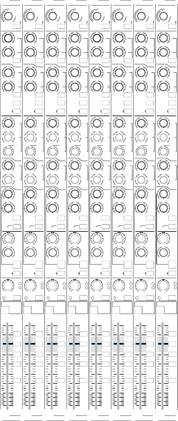
57
+15
OO
U
12k
MIX-B
EQ
LOW CUT
EQ IN
HI
FREQ
75 Hz
SOURCE
45 3k
PAN
LEVEL
–15 +15
80
U
LO
SPLIT
HI/LO EQ
TO MON
MONITOR
LR
–15 +15
U
250
220 350
PAN
dB
30
20
5
10
5-6
13-14
3-4
11-12
1-2
9-10
7- 8
15-16
L/R
MIX
SOLO
-20
OL
OO
MUTE
5
10
40
50
60
U
LR
CHANNEL
+15
OO
U
12k
MIX-B
EQ
LOW CUT
EQ IN
HI
FREQ
75 Hz
SOURCE
45 3k
PAN
LEVEL
–15 +15
80
U
LO
SPLIT
HI/LO EQ
TO MON
MONITOR
LR
–15 +15
U
250
220 350
PAN
dB
30
20
5
10
5-6
13-14
3-4
11-12
1-2
9-10
7- 8
15-16
L/R
MIX
SOLO
-20
OL
OO
MUTE
5
10
40
50
60
U
LR
CHANNEL
+15
OO
U
12k
MIX-B
EQ
LOW CUT
EQ IN
HI
FREQ
75 Hz
SOURCE
45 3k
PAN
LEVEL
–15 +15
80
U
LO
SPLIT
HI/LO EQ
TO MON
MONITOR
LR
–15 +15
U
250
220 350
PAN
dB
30
20
5
10
5-6
13-14
3-4
11-12
1-2
9-10
7- 8
15-16
L/R
MIX
SOLO
-20
OL
OO
MUTE
5
10
40
50
60
U
LR
CHANNEL
+15
OO
U
12k
MIX-B
EQ
LOW CUT
EQ IN
HI
FREQ
75 Hz
SOURCE
45 3k
PAN
LEVEL
–15 +15
80
U
LO
SPLIT
HI/LO EQ
TO MON
MONITOR
LR
–15 +15
U
250
220 350
PAN
dB
30
20
5
10
5-6
13-14
3-4
11-12
1-2
9-10
7- 8
15-16
L/R
MIX
SOLO
-20
OL
OO
MUTE
5
10
40
50
60
U
LR
CHANNEL
FLIP SWITCH
CHANNEL FLIP SWITCH
CHANNEL FLIP SWITCH
CHANNEL FLIP SWITCH
CHANNEL
AUX
PRE
TRIM
FLIP
1
2
4
3
5
6
MIX-B
CHANNEL
PRE
SHIFT
TAPE
MIC/LINE
SOURCE
+15
OO
U
+15
OO
U
+15
OO
U
+15
OO
U
AUX
GAIN
+4
–10
48
dB
40
dB
U
L
I
N
E
S
E
N
S
I
T
I
V
I
T
Y
M
I
C
/
L
I
N
E
G
A
I
N
LO
MID
HI
MID
BAND
WIDTH
500 18k
3k
FREQ
–15 +15
U
–15 +15
U
1k 5k
3
2
1
12
NORMAL
AUX
PRE
TRIM
FLIP
1
2
4
3
5
6
MIX-B
CHANNEL
PRE
SHIFT
TAPE
MIC/LINE
SOURCE
+15
OO
U
+15
OO
U
+15
OO
U
+15
OO
U
AUX
GAIN
+4
–10
48
dB
40
dB
U
L
I
N
E
S
E
N
S
I
T
I
V
I
T
Y
M
I
C
/
L
I
N
E
G
A
I
N
LO
MID
HI
MID
BAND
WIDTH
500 18k
3k
FREQ
–15 +15
U
–15 +15
U
1k 5k
3
2
1
12
NORMAL
AUX
PRE
TRIM
FLIP
1
2
4
3
5
6
MIX-B
CHANNEL
PRE
SHIFT
TAPE
MIC/LINE
SOURCE
+15
OO
U
+15
OO
U
+15
OO
U
+15
OO
U
AUX
GAIN
+4
–10
48
dB
40
dB
U
L
I
N
E
S
E
N
S
I
T
I
V
I
T
Y
M
I
C
/
L
I
N
E
G
A
I
N
LO
MID
HI
MID
BAND
WIDTH
500 18k
3k
FREQ
–15 +15
U
–15 +15
U
1k 5k
3
2
1
12
NORMAL
AUX
PRE
TRIM
FLIP
1
2
4
3
5
6
MIX-B
CHANNEL
PRE
SHIFT
TAPE
MIC/LINE
SOURCE
+15
OO
U
+15
OO
U
+15
OO
U
+15
OO
U
AUX
GAIN
+4
–10
48
dB
40
dB
U
L
I
N
E
S
E
N
S
I
T
I
V
I
T
Y
M
I
C
/
L
I
N
E
G
A
I
N
LO
MID
HI
MID
BAND
WIDTH
500 18k
3k
FREQ
–15 +15
U
–15 +15
U
1k 5k
3
2
1
12
NORMAL
CH. CH. CH. CH.
CH. CH. CH. CH.
+15
OO
U
12k
MIX-B
EQ
LOW CUT
EQ IN
HI
FREQ
75 Hz
SOURCE
45 3k
PAN
LEVEL
–15 +15
80
U
LO
SPLIT
HI/LO EQ
TO MON
MONITOR
LR
–15 +15
U
250
220 350
PAN
dB
30
20
5
10
5-6
13-14
3-4
11-12
1-2
9-10
7- 8
15-16
L/R
MIX
SOLO
-20
OL
OO
MUTE
5
10
40
50
60
U
LR
CHANNEL
+15
OO
U
12k
MIX-B
EQ
LOW CUT
EQ IN
HI
FREQ
75 Hz
SOURCE
45 3k
PAN
LEVEL
–15 +15
80
U
LO
SPLIT
HI/LO EQ
TO MON
MONITOR
LR
–15 +15
U
250
220 350
PAN
dB
30
20
5
10
5-6
13-14
3-4
11-12
1-2
9-10
7- 8
15-16
L/R
MIX
SOLO
-20
OL
OO
MUTE
5
10
40
50
60
U
LR
CHANNEL
+15
OO
U
12k
MIX-B
EQ
LOW CUT
EQ IN
HI
FREQ
75 Hz
SOURCE
45 3k
PAN
LEVEL
–15 +15
80
U
LO
SPLIT
HI/LO EQ
TO MON
MONITOR
LR
–15 +15
U
250
220 350
PAN
dB
30
20
5
10
5-6
13-14
3-4
11-12
1-2
9-10
7- 8
15-16
L/R
MIX
SOLO
-20
OL
OO
MUTE
5
10
40
50
60
U
LR
CHANNEL
+15
OO
U
12k
MIX-B
EQ
LOW CUT
EQ IN
HI
FREQ
75 Hz
SOURCE
45 3k
PAN
LEVEL
–15 +15
80
U
LO
SPLIT
HI/LO EQ
TO MON
MONITOR
LR
–15 +15
U
250
220 350
PAN
dB
30
20
5
10
5-6
13-14
3-4
11-12
1-2
9-10
7- 8
15-16
L/R
MIX
SOLO
-20
OL
OO
MUTE
5
10
40
50
60
U
LR
CHANNEL
FLIP SWITCH
CHANNEL FLIP SWITCH
CHANNEL FLIP SWITCH
CHANNEL FLIP SWITCH
CHANNEL
AUX
PRE
TRIM
FLIP
1
2
4
3
5
6
MIX-B
CHANNEL
PRE
SHIFT
TAPE
MIC/LINE
SOURCE
+15
OO
U
+15
OO
U
+15
OO
U
+15
OO
U
AUX
GAIN
+4
–10
48
dB
40
dB
U
L
I
N
E
S
E
N
S
I
T
I
V
I
T
Y
M
I
C
/
L
I
N
E
G
A
I
N
LO
MID
HI
MID
BAND
WIDTH
500 18k
3k
FREQ
–15 +15
U
–15 +15
U
1k 5k
3
2
1
12
NORMAL
AUX
PRE
TRIM
FLIP
1
2
4
3
5
6
MIX-B
CHANNEL
PRE
SHIFT
TAPE
MIC/LINE
SOURCE
+15
OO
U
+15
OO
U
+15
OO
U
+15
OO
U
AUX
GAIN
+4
–10
48
dB
40
dB
U
L
I
N
E
S
E
N
S
I
T
I
V
I
T
Y
M
I
C
/
L
I
N
E
G
A
I
N
LO
MID
HI
MID
BAND
WIDTH
500 18k
3k
FREQ
–15 +15
U
–15 +15
U
1k 5k
3
2
1
12
NORMAL
AUX
PRE
TRIM
FLIP
1
2
4
3
5
6
MIX-B
CHANNEL
PRE
SHIFT
TAPE
MIC/LINE
SOURCE
+15
OO
U
+15
OO
U
+15
OO
U
+15
OO
U
AUX
GAIN
+4
–10
48
dB
40
dB
U
L
I
N
E
S
E
N
S
I
T
I
V
I
T
Y
M
I
C
/
L
I
N
E
G
A
I
N
LO
MID
HI
MID
BAND
WIDTH
500 18k
3k
FREQ
–15 +15
U
–15 +15
U
1k 5k
3
2
1
12
NORMAL
AUX
PRE
TRIM
FLIP
1
2
4
3
5
6
MIX-B
CHANNEL
PRE
SHIFT
TAPE
MIC/LINE
SOURCE
+15
OO
U
+15
OO
U
+15
OO
U
+15
OO
U
AUX
GAIN
+4
–10
48
dB
40
dB
U
L
I
N
E
S
E
N
S
I
T
I
V
I
T
Y
M
I
C
/
L
I
N
E
G
A
I
N
LO
MID
HI
MID
BAND
WIDTH
500 18k
3k
FREQ
–15 +15
U
–15 +15
U
1k 5k
3
2
1
12
NORMAL
CH. CH. CH. CH.
CH. CH. CH. CH.
SESSION
______________________
DATE ___/___/___
TRACKS _____ thru _____
TRACK COMMENTS:
Tk. ___
______________________
______________________
______________________
Tk. ___
______________________
______________________
______________________
Tk. ___
______________________
______________________
______________________
Tk. ___
______________________
______________________
______________________
Tk. ___
______________________
______________________
______________________
Tk. ___
______________________
______________________
______________________
Tk. ___
______________________
______________________
______________________
Tk. ___
______________________
______________________
______________________
Page__
of ____
58
This is the back of a master track sheet,
which came in the Mackie 8•Bus console
manual.
If you find this sheet in a copy machine,
please return it to the engineer/owner of
the console.
If you find this sheet in the back of a
gloomy tavern, buy it a cold one.
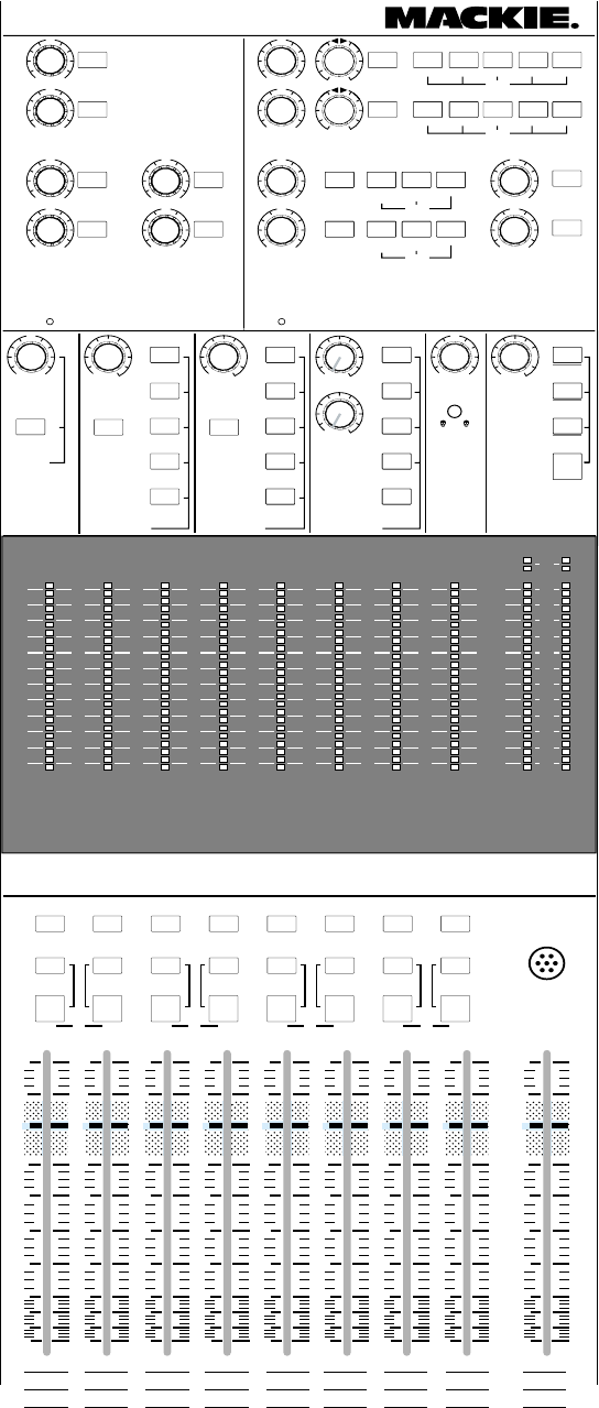
59
TALKBACK
MIC
MIX
L/R
dB
30
20
5
10
OO
5
10
40
50
60
U
dB
30
20
5
10
OO
5
10
40
50
60
U
dB
30
20
5
10
OO
5
10
40
50
60
U
dB
30
20
5
10
OO
5
10
40
50
60
U
dB
30
20
5
10
OO
5
10
40
50
60
U
dB
30
20
5
10
OO
5
10
40
50
60
U
dB
30
20
5
10
OO
5
10
40
50
60
U
dB
30
20
5
10
OO
5
10
40
50
60
U
dB
30
20
5
10
OO
5
10
40
50
60
U
SOLO SOLO
SOLO SOLO
SOLO
SOLO
AUX SENDS STEREO AUX RETURNS
4
3
2
5
6
1
PHONES
2L/R MIX
L/R MIX
1-2 3-4 5-6 7- 8
L/R MIX
SOLO 1-2 3-4 5-6 7-8
PHONES
1PHONES
2L/R MIX
1
2
3
4
LEVEL
ASSIGN
ASSIGN
ASSIGN
ASSIGN
LEVELLEVEL
PHONES
1
6
+15
OO
U
+15
OO
U
+15
OO
U
+15
OO
U
+15
OO
U
+15
OO
U
+20
OO
U
+20
OO
U
+20
OO
U
+20
OO
U
LR
LR
5
+20
OO
U
+20
OO
U
SOLO
SOLO
SOLO
SOLO
SOLO
SOLO SOLO
LEVEL LEVEL
LEVEL
MIX-B TO
L/R MIX SOLO AUX SEND 3/4
MIX-B
MONITOR
AUX SEND 5/6
EXTERNAL MONO
TAPE
SUBGRPS
AUX SEND 1
SOURCE
MIX B / MONITOR PHONES 1
PHONES
LEVEL
SOLO AUX SEND 3/4
MIX-B
MONITOR
AUX SEND 5/6
EXTERNAL
SOURCE
PHONES 2
PHONES
LEVEL
ASSIGN
2-TK
MIX-B
L/R MIX
EXTERNAL
SOURCE
MONITOR SOLO TALKBACK
LEVEL LEVELMIX-B
LEVEL
RUDE
SOLO LITE
AUX SEND 2
PHONES
&
STUDIO
+15
OO
U
OOOOOO
+15
OO
U
PAN
SOLO SOLO SOLO SOLO SOLO SOLO SOLO SOLO
MONO
L+R
RLRLRLR
MONO
L+R
MONO
L+R
MONO
L+R
MONO
L+R
ASSIGN
MONO
L+R
MONO
L+R
1
L
2345678
MONO
L+R
ASSIGN ASSIGN ASSIGN ASSIGN ASSIGNASSIGNASSIGN
MIX MIX MIX MIX
12345678
169 101112131415
2417 18 19 20 21 22 23
10
+
7
4
2
0
2
4
7
10
20
30
40
–
LR
10
+
7
4
2
0
2
4
7
10
20
30
40
–
LR
10
+
7
4
2
0
2
4
7
10
20
30
40
–
LR
10
+
7
4
2
0
2
4
7
10
20
30
40
–
LR
10
+
7
4
2
0
2
4
7
10
20
30
40
–
22
10
+
7
4
2
0
2
4
7
10
20
30
40
–
10
+
7
4
2
0
2
4
7
10
20
30
40
–
10
+
7
4
2
0
2
4
7
10
20
30
40
–LR
MAIN
OR SOLO LEVEL
SESSION
______________________
DATE ___/___/___
BUS COMMENTS:
Bus___
______________________
______________________
______________________
Bus ___
______________________
______________________
______________________
Bus___
______________________
______________________
______________________
Bus___
______________________
______________________
______________________
Bus___
______________________
______________________
______________________
Bus___
______________________
______________________
______________________
Bus___
______________________
______________________
______________________
Bus___
______________________
______________________
______________________
CNTRL RM
STUDIO
O
OO
OO

60
Whaddya say on the last page of a manual?
Well, we’d like to roll the credits.
This manual is copyrighted by Mackie De-
signs, ©1995-2003, all rights reserved.
Set in ITC Century Condensed and Adobe
Futura Condensed via PageMaker
®
for the
Macintosh
®
.
The bulk of this manual was written by David
Mathew. Additional editing and sillies by Ron
Koliha. Propellor-head technical revisions by Jeff
Gilbert. Practical end-user revisions by Keith
Medley. Additional enhancements by Paul
This is the back of a session note sheet,
which came in the Mackie 8•Bus console
manual.
If you find this sheet in a copy machine,
please return it to the engineer/owner of
the console.
If you find this sheet in the back of a
gloomy tavern, buy it a cold one.
Larson and Scott Garside. Proofreading (where
possible considering our usual state of confu-
sion) by Linn Compton and Technical Support.
Page layout and Adobe Illustrator
®
technical
drawings by Bobby Hougham, Bruce Yunker, Ron
Koliha, Gene Endicott and Sara Drake.
Additional “help” from P.D., the Mackie
Corporate Chihuahua who shredded several
drawings at various points during the develop-
ment of this manual.

8•BUS LIMITED WARRANTY
4. If the Mackie Authorized Service Center is
located in another city, pack the product in its
original shipping carton. More information on
packing can be found in the Service section of
this manual.
5. Contact the Mackie Authorized Service Center
to arrange service or bring the product to them.
F. Mackie and Mackie Authorized Service Centers
reserve the right to inspect any products that may
be the subject of any warranty claims before repair
or replacement is carried out. Mackie and Mackie
Authorized Service Centers may, at their option, re-
quire proof of the original date of purchase in the
form of a dated copy of the original dealer’s invoice
or sales receipt. Final determination of warranty cov-
erage lies solely with Mackie Designs Inc. or its
Authorized Service Centers.
G. Any Mackie product deemed eligible for repair or
replacement under the terms of this warranty will be
repaired or replaced within thirty days of receipt by
Mackie. Mackie may use refurbished parts for repair
or replacement of any product. Products returned to
Mackie that do not meet the terms of this Warranty
will be repaired and returned C.O.D. with billing for
labor, materials, return freight, and insurance. Prod-
ucts repaired under warranty at Mackie’s factory will
be returned freight prepaid by Mackie to any location
within the boundaries of the USA.
H. Mackie warrants all repairs performed for 90 days
or for the remainder of the original warranty period.
Mackie assumes no responsibility for the quality or
timeliness of repairs performed by Mackie Authorized
Service Centers.
I. This warranty is extended to the original purchaser
and to anyone who may subsequently purchase this
product within the applicable warranty period.
J. This is your sole warranty. Mackie does not authorize
any third party, including any dealer or sales represen-
tative, to assume any liability on behalf of Mackie
Designs or to make any warranty for Mackie Designs.
K. THE WARRANTY GIVEN ON THIS PAGE IS
THE SOLE WARRANTY GIVEN BY MACKIE AND
IS IN LIEU OF ALL OTHER WARRANTIES,
EXPRESS AND IMPLIED, INCLUDING THE
WARRANTIES OF MERCHANTABILITY AND
FITNESS FOR A PARTICULAR PURPOSE. THE
WARRANTY GIVEN ON THIS PAGE SHALL BE
STRICTLY LIMITED IN DURATION TO ONE
YEAR FROM THE DATE OF ORIGINAL PUR-
CHASE FROM AN AUTHORIZED MACKIE
DEALER. UPON EXPIRATION OF THE APPLI-
CABLE WARRANTY PERIOD, MACKIE SHALL
HAVE NO FURTHER WARRANTY OBLIGATION
OF ANY KIND. MACKIE SHALL NOT BE LIABLE
FOR ANY INCIDENTAL, SPECIAL, OR CONSE-
QUENTIAL DAMAGES THAT MAY RESULT
FROM ANY DEFECT IN THE MACKIE PROD-
UCT OR ANY WARRANTY CLAIM. Some states
do not allow exclusion or limitation of incidental,
special, or consequential damages or a limitation
on how long warranties last, so some of the above
limitations and exclusions may not apply to you.
This warranty provides specific legal rights and you
may have other rights which vary from state to state.
Please keep your sales receipt in a safe place.
A. Mackie warrants all materials, workmanship and
proper operation of this product for a period of one
year from the original date of purchase. If any de-
fects are found in the materials or workmanship or if
the product fails to function properly during the ap-
plicable warranty period, Mackie, at its option, will
repair or replace the product. This warranty applies
only to equipment sold and delivered within the
U.S. by Mackie or its authorized dealers.
B. Failure to register online or return the product
registration card will not void the 1-year warranty.
C. Service and repairs of Mackie products are to be
performed only at the factory (see D below) OR at an
Authorized Mackie Service Center (see E below).
Unauthorized service, repairs, or modification will
void this warranty.
D. To obtain factory service:
1. Call Mackie at 800/258-6883, 8AM to 5PM
Monday through Friday (Pacific Time) to get a
Return Authorization (RA). Products returned
without an RA number will be refused.
2. Pack the product in its original shipping car-
ton. If you do not have the carton, just ask for
one when you get your RA number, and we’ll
send a shipping carton out promptly. More infor-
mation on packing can be found in the Service
section of this manual. Do not use “packing pea-
nuts,” shredded newspapers, or other material
with small particles, old underwear, or socks.
Please seal the Mackie product in a plastic bag.
3. Also include a note explaining exactly how to
duplicate the problem, a copy of the sales receipt
with price and date showing, and your return
street address (no P.O. boxes or route numbers,
please!). If we cannot duplicate the problem at
the Mackie Factory or establish the starting date
of your Limited Warranty, we may, at our option,
charge for service time.
4. Ship the product in its original shipping car-
ton, freight prepaid to:
Mackie Designs
Service Department
16220 Wood-Red Rd. NE
Woodinville, WA 98072 USA
IMPORTANT: Make sure that the RA number is
plainly written on the shipping carton.
E. To obtain service from an Authorized Mackie Ser-
vice Center:
1. Call Mackie at 800/258-6883, 8AM to 5PM
Monday through Friday (Pacific Time) to get:
1) The name and address of your nearest Mackie
Authorized Service Center and 2) A return au-
thorization (RA). You must have an RA number
before taking your unit to a service center.
2. Make sure that you have a copy of your
product’s sales receipt from the store where you
bought the product. It is necessary to establish
purchase date and thus determine whether or
not your product is still under warranty. If you
can’t find it, the Authorized Service Center may
charge you for repairs even if your product is still
covered by Mackie’s 3-Year Limited Warranty.
3. Make sure that the problem can be duplicated.
If you bring your product to an Authorized Service
Center and they can’t find anything wrong with
it, you may be charged a service fee.

