900 0181 Onan YB 200 350 KW Generators & Controls Service Manual (11 1981)
User Manual: 900-0181 Onan YB 200-350 KW Generators & Controls Service Manual (11-1981)
Open the PDF directly: View PDF ![]() .
.
Page Count: 63
Caution: This document contains mixed page sizes (8.5 x 11 or 11 x
17), which may affect printing. Please adjust your printer settings
according to the size of each page you wish to print.
Redistribution or publication of this document,
by any means, is strictly prohibited.

Service
Manual
200
to
350
kW
Generators
And Controls
VB
Troubleshooting and
Test Procedures For
Generators
Regulator
Controls
900-0181
11-81
Printed in
U.S.A.
Redistribution or publication of this document,
by any means, is strictly prohibited.
Safety
Precautions
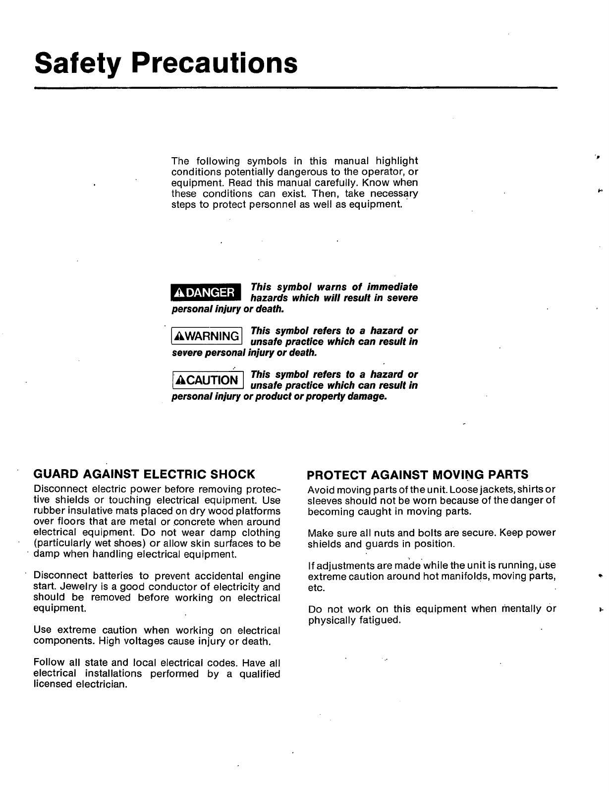
The following symbols in this manual highlight
conditions potentially dangerous to the operator, or
equipment. Read this manual carefully. Know when
these conditions can exist. Then, take necessary
steps to protect personnel as well as equipment.
This symbol warns of immediate
hazards which will result in severe
personal injury
or
death.
This symbol refers to a hazard
or
unsafe practice which can result in
severe personal injury
or
death.
This symbol refers to a hazard
or
k&&!%%l
unsafe practice which can result in
personal injury
or
product
or
property damage.
GUARD AGAINST ELECTRIC SHOCK
Disconnect electric power before removing protec-
tive shields or touching electrical equipment. Use
rubber insulative mats placed on dry wood platforms
over floors that are metal or concrete when around
electrical equipment.
Do
not wear damp clothing
(particularly wet shoes) or allow skin surfaces to be
damp when handling electrical equipment.
Disconnect batteries
to
prevent accidental engine
start. Jewelry
is
a good conductor of electricity and
should be removed before working on electrical
eq u
i
pmen
t.
Use extreme caution when working on electrical
components. High voltages cause injury or death.
Follow
all state and local electrical codes. Have all
electrical installations performed by a qualified
licensed electrician.
PROTECT AGAINST MOVING PARTS
Avoid moving parts of the unit. Loose jackets, shirts or
sleeves should not be worn because of the danger of
becoming caught in moving parts.
Make sure all nuts and bolts are secure. Keep power
shields and guards in position.
If adjustments are madewhile the unit is running, use
extreme caution around hot manifolds, moving parts,
etc.
7
Do
not work on this equipment when mentally or
physically fatigued.
3-
Redistribution or publication of this document,
by any means, is strictly prohibited.
.
..
4
Contents
..
TITLE
PAGE
SAFETY PRECAUTIONS
......
;
.............................
..................
Inside Front Cover
Forward
.......................................................................................
2
Test Equipment
.............................................................................
2.
Abbrevations
..................................................................................
2
INTRODUCTION
...............................................................................
2
Generator
....................................................................................
.4
GENERATOR TROUBLESHOOTING
i..
.....................................................
6
Preparation..
....................................................
i..
............................
6
Flow Chart A.
No.
AC Output Voltage at Rated Engine RPM
..................................
7
Flow Chart
B.
Unstable Voltage, Eng'ine Speed Stable 1800 RPM
..........................
/.
..
8
...
8
9
.
Flow Chart E. Unbalanced Generator Output Voltage.
.:.
......................................
10
Adjustments and Tests
...................................................................
.1
11
.
[A] Testing AC Residual Voltage..
.........................
.!.
............................
11
[B]
Testing L21 Reactor..
.................................................................
11
[C] Testing Rectifier Bridge Asse-mbly (CR21)
.......................
.'.:.
..............
:
....
11
[D] Flashing the Field
.........................................
;.
.............................
12'
[E
]
Testing Reference Transformer T21
....................................................
13
[F
]
VR21 Replacement..
.(.
...
..:.
...
i..
....
i..
...........
:.
............
.:.
.................
13
[HI
Testing Exciter Stator
.;.....
....... ;.
....................
:
............................
i.
14
[K] Testing Generator Stator
.
.'.
....................
:..
..........
:
..........................
14
[L
] Testing Generator Rotor..
................................................................
.15
[hJ] Sensitivity Reference Circuit.
..................................................
i..
.....
:
16
Flow Chart C. Output Voltage
Too
High or Low,.
.............................................
Flow Chart. D. Exciter Field Breaker Trips..
..................................................
..
[GI Testing Rotating Rectifiers
........
.,:.
..................................
i..
......
:
.........
13
.
[J
] Testing Exciter Rotor.
........
.:
.............
:.
............
:
.............................
14
[MI .Wiring Harness Check..
.................................................................
16.
[PI Voltage Regulator Adjustment.
........................
:.
.............
.'.
...................
17
..
[Q] Reconnection
...............
.:
.;..
......
.:.
.................
.:.
.......................
17
Generator Disassembly
.................................................................
~
:.
....
19
.Generator Assembly
.....
:
....................................................................
19
.
CONTROL'SYSTEM
.................................................................................
820
General
...
;
.'.
................
!.
....................................................
i..
...
;
;.
......
2b
Control .Operation
..............................................................................
I.
.';
...
:
22
..
:
Engine Control Relays
...................
..;.
...............
..:
.........
:.
.....
......
:..
.
I..
..
22
Engine Control Modules.
......
.:.I.
....................
:
....................
;;
.............
:.'.
.
24
Control Troubleshooting
...........................................................
.:
........
31
.
31
General
...................................................................
;.
................
Flow Chart
B.
Engine Fails
to
Crank. Switch
In
"Remote Position..
..........................
33
.
.
.
.
.
.
.
.I
.
..
.
..
.,
..
..
Engine Control System CheGkout Procedure
...........................
i
................
i
....
'29,
.Flow Chart
A.
Engine Fails to Crank. Switch
In
"Run"
Position
........................
.:.
....
32
Flow Chart C. Engine Malfunction Shutdown, Fault
.Light
"ON"
(Five Light System),
...........
34
Flow.Char;t
D.
Engine Malfunction Shutdown, Fault
Light
"ON"
(Single Light System)
........
35
WIRING
DIAGRAMS
..........................
.'.
.............................................
36
'.
..
_.
..
Redistribution or publication of this document,
by any means, is strictly prohibited.
Introduction
FOREWORD
This manual provides troubleshooting and repair
information for O"AN series
Y8
generators. %It is
intended to provide the maintenance technician,ser-
viceman or Onan distributor with a logica'l .procedure
to enable him
to
systematically locate and re,pa'ir mal-
functions
in
the generator and control systems. This
information is not applicable to the (engine; refer to
the engine manufacturer's ,manual.
'Re,pa'ir .i.nf.ormation
on
:printed circuit irnodules .is ,no1
extensive ;because t.he iplwg-in lrnodu'les
'lemild
?:hem-
selves m.ore
to
replacem.e:n$
fhan
:repair.
.ONRN
dp.es
not .reco.mmend .repair
.of
the :printed .c'i.rc.uit
exce,pl at the factory and :has in'it'iated..a 're
change service
o
btai,na b le
t
h rough .d:istrii.b
ufo
rs.
For
rn
o.re
.i
nforrnation, contact your :d.i str.i:bu tor 'or t,he
.ONAN
service department
.A,pp'l:ication of meters .orihlgh 'heat soldering :i.rons to
printed ci rcui.t:boardsby other Pha ual if i ed ipe rsom-
.ne
I
can .res ult .i n u n n ecessa ry .a n d .expe n.s i ve
d
a m age.
High vdiage testing or high poten-
tial (or Megger) testing of generator
windings can cause damage to solid state compo-
nents. 'Isolate these components :before testing.
This
:manual
is
.divided
'into
fwo
sectims
as
follows:
1.
GENERATOR
-
.Co:ns!ists of ;g!ene:r.a.l
cations
.on
e
.YB
g:en.erato:r,
troubleshooting guides
and
:procedures 'for
testing and repairin:g Ihe systems.
2.
C0NTR:OLS
-
T!r:o.ubleslhoot:i-ng guides,
procedures for testing :and repairing the system
are contained 'in this section. Adescr'i,pY'ion
oi
the
cornpone.nts and an analysis
.of
the module
!ci:rcaitry
are
ii-nc'luded-
L*
TEST
iEQU'I.P.M,E"T
:Most
01
fh:e tests o.utlined 'in this .manual can be
iperf
o.rm
ed
*with-
S'i,m.pso-n
'V.OM.
.Model
260,
262
o'r :equivalent.
.Kelvin .or
W.
h
eatsto-n e
b.rid.g.e
.oh
rn
me%e,r..
An equivalent VOM
io
a Simpson
260 or 262 should have
a
maximum
battery voltage of 6VDC (preferably with size AA bat-
.teries),
on
ranges other than
R
x
1.
Some VOM's have
outputs
of
\9UDC
or 22.5VDC, which are sufficiently
high
to
damage solid state devices.
WAR
N:l
NG
ONAN RECOMMENDS THXT ALL SERVICE INCLUDING INSTALLATION
OF
REPLACEMENT
.PARTS ONLY BE DONE
BY
PERSONS .QUALIFIED
TO
PERFORM ELECTRICAL AND/OR
MECHANICAL SERVICE. FROM THESTANDPDINT~OF POSSIBLE
'INJURY
AND/OREQUlPMENT
CDAMA
G
E IT IS SIM PERA T THE SERYICE PERSON BE QUALIFIED.
R-S-R
wx3
'N
0
VDC
VAC
LOP
HET
K
*
*Q
R
C
;R.un<Stpp7Remote
.
INorma'l:ly
dlused
rNocmally
(0,pe.n
Volts Direct :Curre.nY
.
Volts Alterna3i.ng Current
!Low
,Oil :Pressure
'High
.Engine
Te.mperature
.Relay
'Transistor
Resistance/.Rheostat
'Capacitor
O/S
-o/c
'LET
CR
'V
R
CB
L
T
TD
LED
SCR
.Overs.peed
Overcran k
'Low
EngineTemp
Crystal RectiTier (diodes')
Voltage Regulator
Circuit 'Breaker
.React0 r
Transformer
TimeDelay
Light Emitting Diode
Silicon Controlled Rectifier
..
a
Redistribution or publication of this document,
by any means, is strictly prohibited.
SERIES
DELTA
'X
X
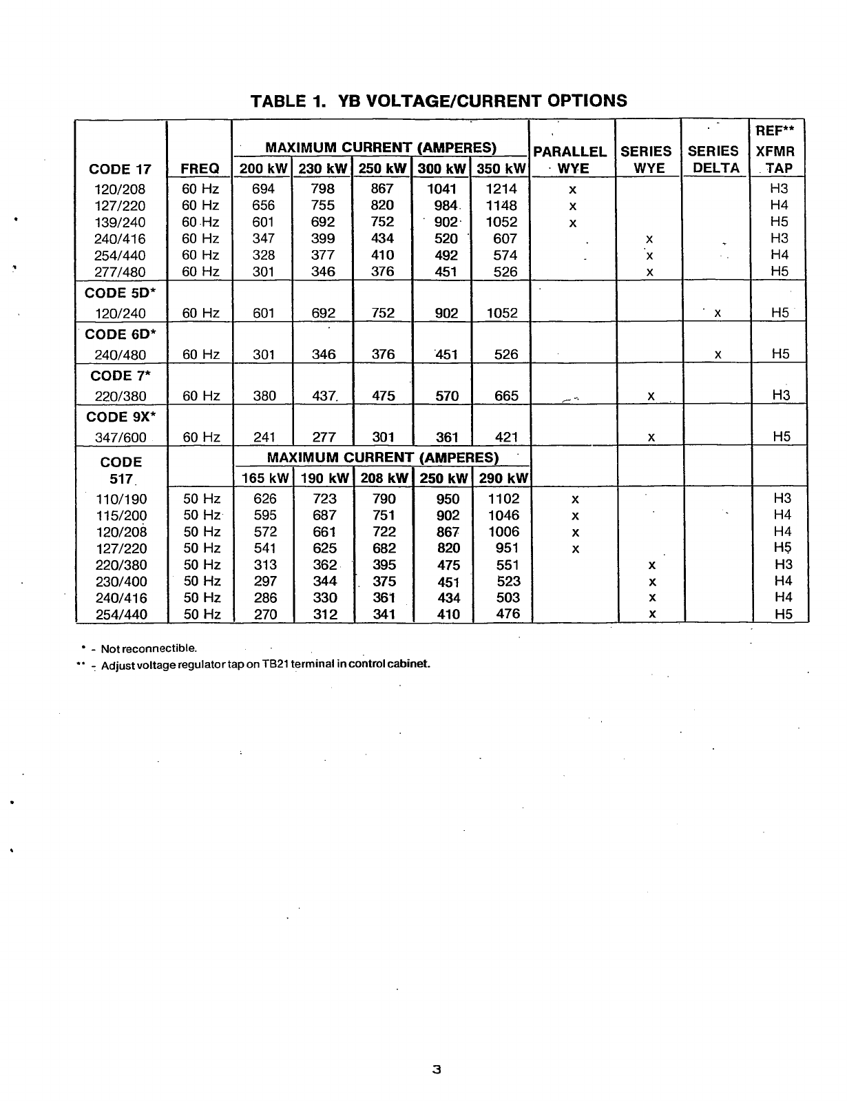
TABLE
1.
YB
VOLTAGE/CURRENT
OPTIONS
I
I'
I
REF**
XFMR
TAP
H3
H4
H5
H3
H4
H5
H5
H5
CODE17 FREQ
120/208 60 Hz
127/220 60 Hz
139/240 60 Hz
240/416 60 Hz
254/440 60 Hz
277/480 60 Hz
120/240 60 Hz
240/480 60 Hz
CODE
7*
220/380 60 Hz
347/600 60 Hz
CODE 5D*
CODE 6D*
CODE 9X*
CODE
51
7
11 0/190
50
Hz
1 15/200
50
Hz
120/208
50
Hz
127/220
50
Hz
220/380
50
Hz
230/400
50
Hz
240/416
50
Hz
1
254/440
50
Hz
:AMPERES)
300
kW 350 kW
1041
1214
984. 1148
'
902. 1052
520
'
607
492 574
451 526
SERIES
PARALLEL
.
WYE
X
X
X
200
kW 230 kW
694 798
656 755
601 692
347 399
328 377
301 346
250 kW
867
820
752
434
41
0
376
902
-
Not reconnectible.
**
-
Adjust voltage regulator tap
on
1621
terminal in control cabinet.
1052
1
X
'45
1
526
H3
H5
H3
H4
H4
H5
H3
H4
H4
H5
MAXIMUM CURRENT (AMPERES)
165 kW 190 kW 208 kW
250
kW
290 kW
626 723 790 950 1102
595 687 75
1
902 1046
572 66
1
722 867 1006
541 625 682 820 95
1
31 3 362 395 475 55
1
297
344
375 451 523
286 330 361 434 503
270 31
2
341
41
0
476
3
X
X
X
X
Redistribution or publication of this document,
by any means, is strictly prohibited.
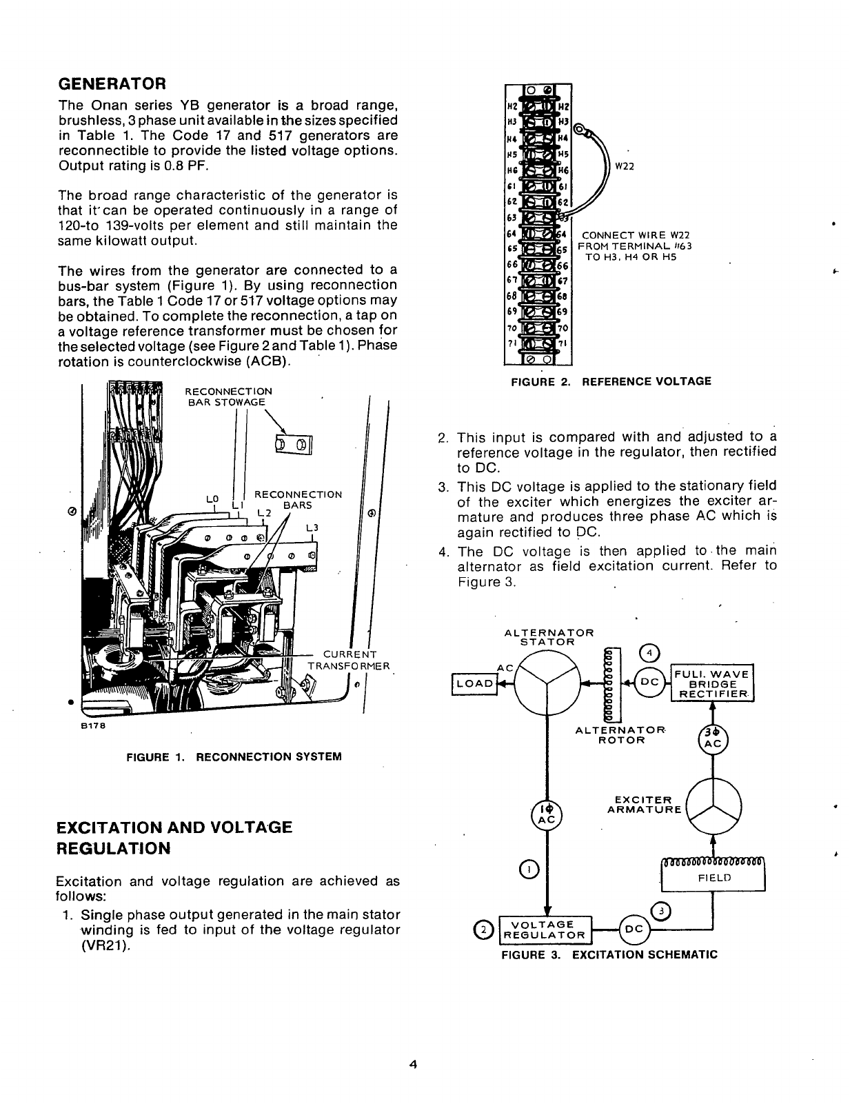
GENERATOR
The Onan series
YB
generator is a broad range,
brushless,
3
phase unit available
in
the sizes specified
in Table
1.
The Code 17 and
517
generators are
reconnectible to provide the listed voltage options.
Output rating is
0.8
PF.
The broad range characteristic of the generator is
that &can be operated continuously in
a
range of
120-to 139-volts per element and still maintain the
same kilowatt output.
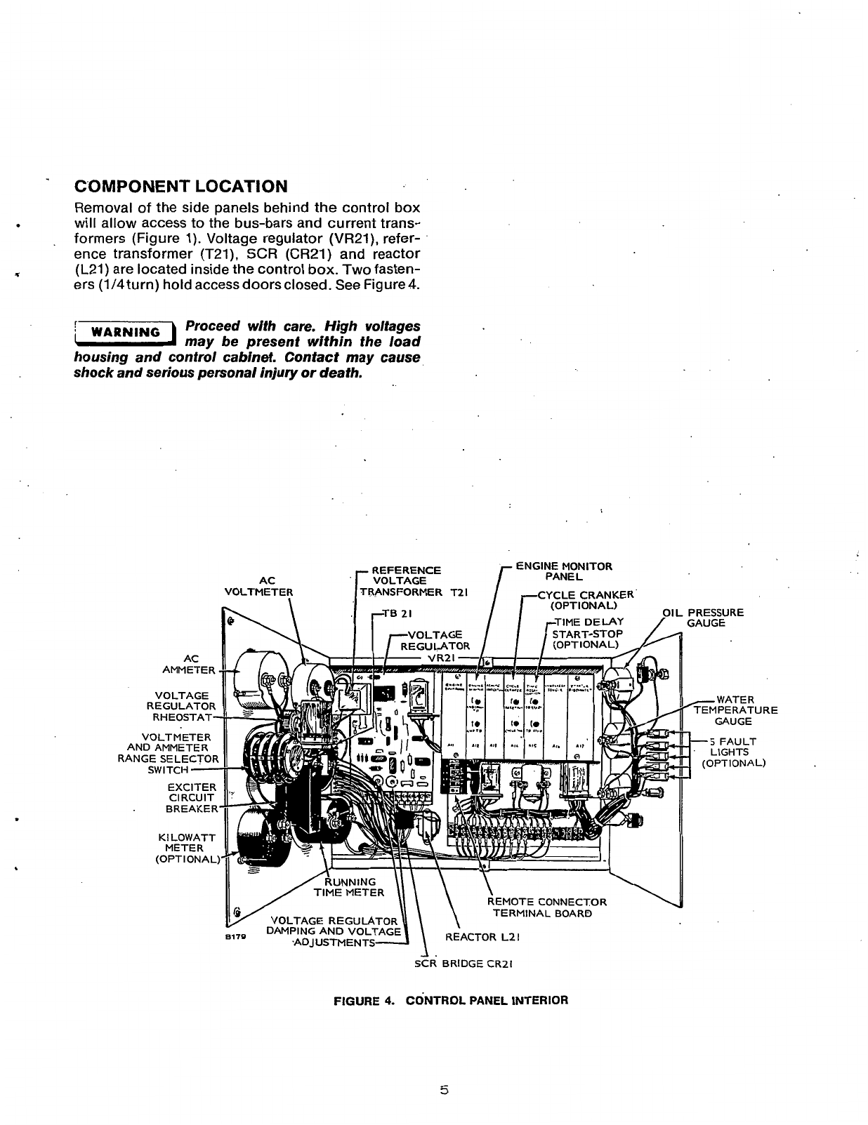
The wires from the generator are connected to a
bus-bar system (Figure 1). By using reconnection
bars, the Table
1
Code 17 or 517 voltage options may
be obtained.
To
complete the reconnection, a tap on
a voltage reference transformer must be chosen for
theselected voltage (see Figure 2 and Table
1).
Phase
rotation is counterclockwise
(ACB).
w22
CONNECT WIRE
FROM
TERMINAL
TO
H3.
H4
OR
H
w22
,
,163
#5
8170
FIGURE
1.
RECONNECTION SYSTEM
EXCITATION AND VOLTAGE
REGULATION
Excitation and voltage regulation are achieved as
f
01
lows:
1.
Single phase output generated
in
the
main stator
winding is fed to input of the voltage regulator
(VR21).
FIGURE
2.
REFERENCE VOLTAGE
2.
This input
is
compared with and adjusted to a
reference voltage in the regulator, then rectified
to DC.
3. This DC voltage is applied to the stationary field
of the exciter which energizes the exciter ar-
mature and produces three phase
A.C
which is
again rectified to DC.
4.
The DC voltage is then applied to. the main
alternator as field excitation current. Refer to
Figure
3.
ALTERNATOR
STATOR
n
RI~
FULI. WAVE
RECTIFIER
U
ALTER
N
AT
0
R.
ROTOR
I
I
Y
VOLTAGE
FIGURE
3.
EXCITATION SCHEMATIC
4
Redistribution or publication of this document,
by any means, is strictly prohibited.
C'O
M
PO NE NT
LO
CAT1 ON
Removal of the side panels behind the control box
will allow access to the bus-bars and current trans-
formers (Figure
1).
Voltage regulator (VR21), refer-
ence transformer (T21), SCR (CR21) and reactor
ers
(1/4
turn) hold access doorsclosed. See Figure
4.
.
T
(L21)
are located inside the control
box.
Two
fasten-
Proceed with care. High voltages
may be present within the load
housing and control cabinet. Contact may cause
shock and serious personal injury or death.
;WARNlNG1
ENGINE MONITOR
PANEL
REFERENCE
AC
TRANSFORMER T21 CYCLE CRANKER
(OPTIONAL) OIL PRESSURE
START-STOP
REGULATOR
VOLTMETER
TIME METER E CONNECTOR
NAL BOARD
FIGURE
4.
CONTROL
PANEL
INTERIOR
/-WATER
TEMPERATURE
GAUGE
-
5
FAULT
LIGHTS
(OPTIONAL)
5
Redistribution or publication of this document,
by any means, is strictly prohibited.

Generator Troubleshooting
PR
E
PARATI
0
N
A
few simple checks and a proper troubleshooting
procedure can locate the probable source of trouble
and cut down service time.
Disconnect battery cable before
performing any checks on genera-
tor. Serious injury
or
death could result from inad-
vertent starting.
Check all modifications, repairs, replacements
performed since last satisfactory operation of set
to ensure that connection of generator leads are
correct.
A
loose wire connection, overlooked
when installing a replacement part could cause
problems. An incorrect connection, an opened
circuit breaker, or a
loose
connection on printed
circuit board are all potential malfunction areas
to be etiminated by a visual check.
0
Unless absolutelysure that panel instrumentsare
accurate, use portabletest metersfortroubleshooting.
Visually inspect components on
VR21.
Look for
dirt, dust, or moisture and cracks in the printed
solder conductors. Burned resistors, arcing
tracks
are all identifiable. Do not mark
0.n
printed
circuif boards with a pencil. Graphite lines are
conductive and can cause leakage or short cir-
cuits between components.
The information in this section is divided into Flow
Charts A, B, C, D, and E as follows:
A. NO AC OUTPUT VOLTAGE AT RATED ENGINE
RPM.
B. UNSTABLE OUTPUT VOLTAGE, ENGINE
SPEED STABLE
1800
RPM.
C. OUTPUT VOLTAGE TOO HIGH
OR
LOW.
D. EXCITER FIELD BREAKER TRIPS.
*
E. UNBALANCED GENERATOR OUTPUT VOLT-
AGE.
.
To troubleshoot a problem, start at upper-left corner
of the chart related to problem, and answer all ques-
tions either YES or NO. Follow the chart until the
problem is found, performing referenced Adjustment
and Test Procedures following the Flow Charts.
Referenced components
in
the Flow Charts and
Adjustment and Test procedures can be found on the
electrical schematic Figure
5,
and on assembly draw-
ings and wiring diagrams.
Ohmmeter checks must be made
with the unit stopped to prevent
meter damage.
DC
OUTPUT
VOLTAGE
EXCITER ROTATING
F2-
ROTOR
RECTIFIER
ASSEMBGES T1 THROUGH
~7-
T4
OR
T12
VOLTAGE
REGULATOR
ASSEMBLY
FIGURE
5.
ELECTRICAL SCHEMATIC,
YB
GENERATOR CONTROL SYSTEM
6
Redistribution or publication of this document,
by any means, is strictly prohibited.
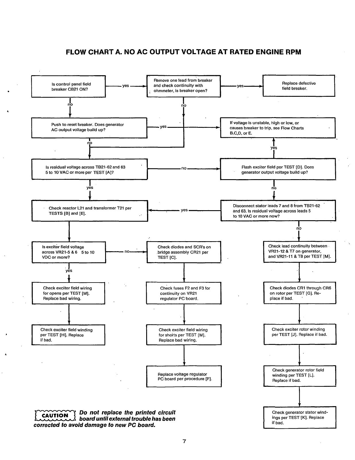
FLOW
CHART
A.
NO
AC OUTPUT VOLTAGE AT RATED ENGINE
RPM
11
-
Is
control panel field and check continuity with Replace defective
breaker CB21
ON?
field breaker.
ohmmeter, is breaker open?
I
I
no
I
I
no
If voltage is unstable, high or low, or
B;C,D. or E.
Push to reset breaker. Does generator
AC output voltage build up?
n.0
t
I
I
I
I
Flash exciter field per TEST [D]. Does
generator output voltage build up?
Is
residual voltage across TB21-62 and 63
5
to
10
VAC or more per TEST [A]?
I
1
I
I
Disconnect stator leads
7
and 8 from TB21-62
and 63.
Is
residual voltage across leads
5
to 10 VAC or more now?
Check reactor L21 and transformer T21 per
TESTS
[B]
and [E].
I
Is
exciter field voltage
across VR2l-5
8
6
5
to 10
VDC
or
more?
Check diodes and SCRs on
.bridge assembly CR21 per
Check exciter field wiring
for opens per TEST [MI.
r-l
Replace bad wiring.
I
Check fuses F2 and F3 for
continuity
on
VR21
regulator PC board.
Check exciter field winding
per TEST [HI. Replace
I
if
bad.
I
Check exciter field wiring
for shorts per TEST [MI.
Replace bad wiring.
I
I
Replace voltage regulator
PC board per procedure [F].
I
I
I
Do not replace the printed circuit
board until external trouble has been
corrected to avoid damage to new
PC
board.
IiO
1
VR21-12
8
T7 on generator,
and VR21-11
8
T8 per TEST [MI.
7
Redistribution or publication of this document,
by any means, is strictly prohibited.

FLOW CHART B. UNSTABLE VOLTAGE, ENGINE SPEED STABLE
1800
RPM
Are there any broken wires or
loose
connections
on voltage regulator assembly? Does voltage
cycle from zero to rated output?
-
yes
-t
Repair as required. Check control panel
voltage adjust rheostat and replace
if
defective (open).
I
1
I
I
I
Does adjustment
of
Dampening control
R26
on
VR21
per adjustment [PI result in stable
voltage?
Check wiring harness from regulator assembly
to end bell per
TEST
[MI. Check
OK?
~~~~ ~
Is
voltage stable within spec at no
load to full load range of generator
set?
-
yes
-+
t
>
Replace voltage regulator PC board per
procedure [F].
Repair wiring or replace as required.
Do
not replace the printed circuit
rn
board untilexternal trouble has been
corrected to avoid damage to new PC board.
Isengine running at correct RPM? -no- Set RPM per instructions in appropriate
engine manual.
*
Does adjustment
of
control
Rl8
on VR21 result
in
correctoutput voltage? Set per Voltage Calibration Adjustment [PI.
no
b.
1
Are reference transformer
(T21)
tap connections
correct and secure on
TB22?
See
TEST
[Q].
..
Are generator output leads properly connected?
See
Figure
19,
page
18.
r(
Do
not replace the printed circuit
board until external trouble has been
corrected to avoid damage to new PC board.
Replace voltage regulator PC board VR21 per
procedure [F].
c
8
Redistribution or publication of this document,
by any means, is strictly prohibited.
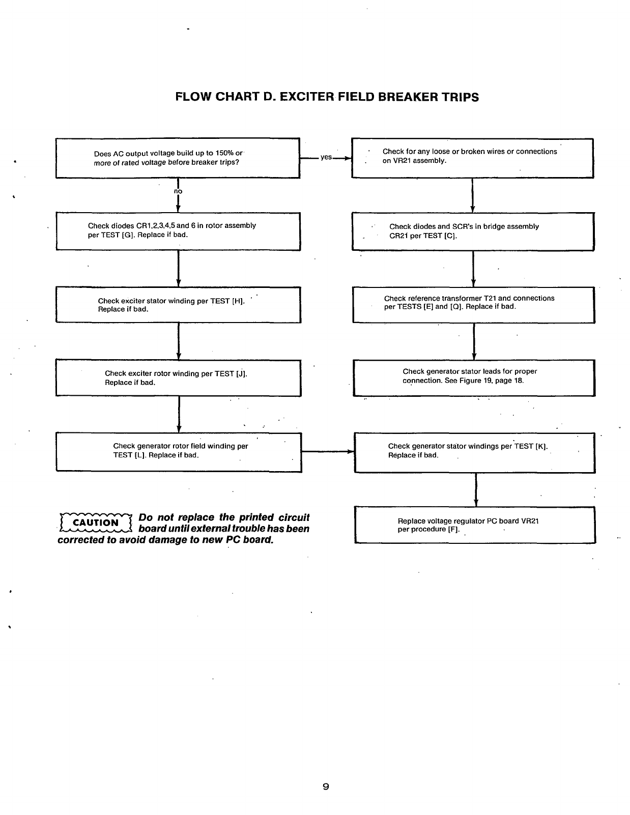
FLOW
CHART
D.
EXCITER
FIELD
BREAKER
TRIPS
Does AC output voltage build up
to
150% or
more
of
rated voltage before breaker trips?
-
'
Check for any
loose
or broken wires or connections
-yes-
.
on VR21 assembly.
nb
I
1
t
Check generator rotor field winding per
TEST
[L].
Replace if bad.
w
Check diodes CR1.2.3.4.5 and
6
in rotor assembly
per TEST
[GI.
Replace
if
bad.
7
Check generator stator windings per TEST
[K].
Replace
if
bad.
L
Check exciter rotor winding per TEST
[J].
Replace
if
bad.
I
I
t
'
Check diodes and SCRs in bridge assembly
.
CR21 per TEST
IC].
r
I
Check reference transformer T21 and connections
per TESTS [E] and
[a].
Replace if bad.
Check generator stator leads for proper
connection. See Figure 19. page 18.
I
Do
not replace the printed circuit
board untilexternal trouble has been
Replace voltage regulator PC board VR21
per procedure
[F].
corrected
to
avoid damage
to
new PC board.
1
J
9
Redistribution or publication of this document,
by any means, is strictly prohibited.

FLOW
CHART
E.
UNBALANCED GENERATOR OUTPUT VOLTAGE
Remove
load
at generator terminals.
Is
output
still unbalanced?
Check for correct grounding of generator
and load.
-no
no
d
Are generator leads connected and grounded
properly?
See
Figure
19.
page
18.
Check load for ground faults and correct as
necessary.
Correct as necessary.
c
Is
generator stator winding continuous per
,
-
no4
TEST
[Kl.
E.
..
Replace stator assembly.
i
10
Redistribution or publication of this document,
by any means, is strictly prohibited.
ADJUSTMENTS AND TESTS
All
of the following Adjustments and Tests can be
performed without disassembly of the generator.
They should be used for testing generator and regu-
lator components
in
conjunction with the trouble-
shooting flow charts. All ohmmeter tests must be
made with the unit stopped to prevent meterdamage.
.
Testing AC Residual Voltage
Generator residual
AC
voltage should be checked
first if there is no
AC
power output. A good place to
check is at TB21 across terminals 62 and 63 (see
Figure
5).
Residual voltage should be 5-10 VAC at
normal operating rpm. If none, flash field per Test
ID].
If
residual voltage is present at TB21, then check
continuity of circuit breaker CB21. If CB21 is
OK,
proceed to VR21 PC board and check for residual
voltage between connector numbers
11
&
12,l &2,
and
9
&
10. If none, check continuity between these
points with the gen set shut down. If voltage is
low,
test L21 reactor Test [B] and T21 transformer Test
[El-
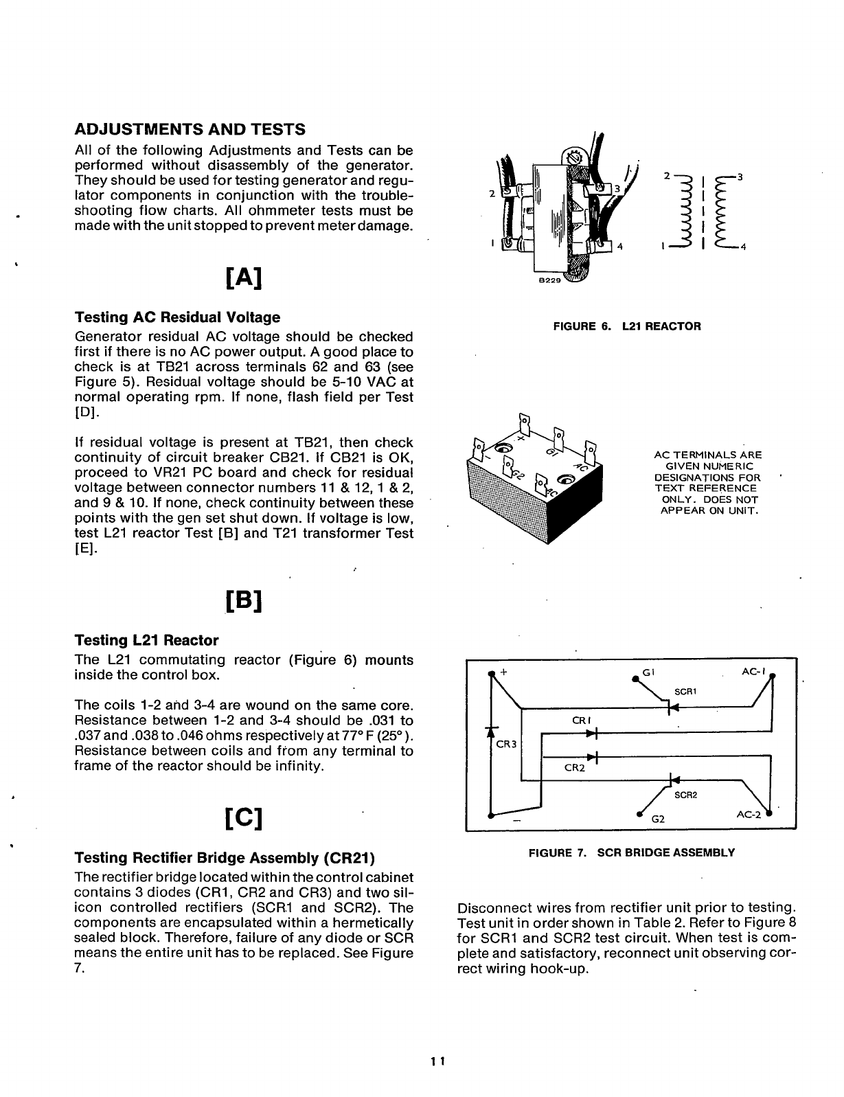
Testing L21 Reactor
The L21 commutating reactor (Figure 6) mounts
inside the control box.
The coils 1-2 and 3-4 are wound on the same core.
Resistance between 1-2 and 3-4 should be .031 to
.037
and .038 to .046 ohms respectively at
77"
F (25O).
Resistance between coils and from any terminal to
frame of the reactor should be infinity.
Testing Rectifier Bridge Assembly (CR21)
The rectifier bridge located within the control cabinet
contains 3 diodes (CRl. CR2 and CR3) and two sil-
FIGURE
6.
L21
REACTOR
AC TERMINALS ARE
GIVEN NUMERIC
DESIGNATIONS
FOR
'
TEXT REFERENCE
ONLY. DOES NOT
APPEAR ON UNIT.
~~ ~~
FIGURE
7.
SCR BRIDGE ASSEMBLY
icon controlled rectifiers (SCR.1 and' SCR2). The
components are encapsulated within a hermetically
sealed block. Therefore, failure of any diode or SCR
means the entire unit has to be replaced. See Figure
7.
rect wiring hook-up.
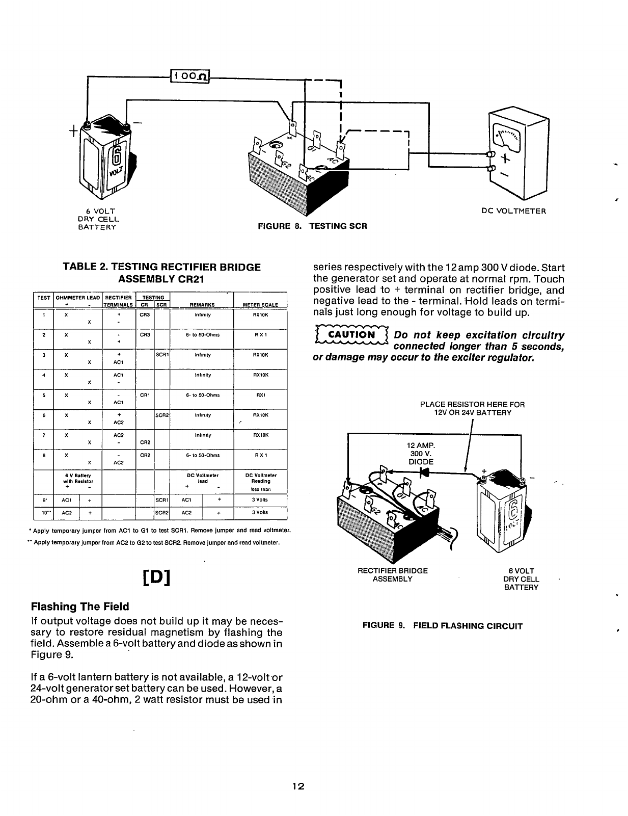
Disconnect wires from rectifier unit prior to testing.
Test unit in order shown
in
Table 2. Refer to Figure 8
for SCRl and SCR2 test circuit. When test is com-
plete and satisfactory, reconnect unit observing cor-
11
Redistribution or publication of this document,
by any means, is strictly prohibited.
_I
I
{
1
oon-
1-1
9'
Io"
t
6
VOLT
+
loss
than
+-
ACI
+
SCRl ACl
+
3
VO11S
AC2
+
SCRZ
AC2
+
3
VO115
DRY CELL
BATTERY
v
FIGURE
8.
.TESTING
SCR
TABLE 2. TESTING RECTIFIER BRIDGE
ASSEMBLY CR21
OHMMETER LEAD
+-
X
X
X
X
X
tntlnlty
RXlOK
It
-
CR1
6-
10
SO-Ohms
RXl
AC1
I
RXlOK
1"ll"ll"
RXlOK
X
6-
lo
SO-Ohms
RXl
AC2
CDI
Flashing
The
Field
If output voltage does not build up
it
may be neces-
sary to restore residual magnetism by flashing the
field. Assemblea 6-volt batteryand diodeasshown
in
Figure
9.
series respectively with the 12amp
300
V
diode. Start
the generator set and operate at normal rpm. Touch
positive lead to
+
terminal on rectifier bridge, and
negative lead to the -terminal. Hold leads on termi-
nals just long enough for voltage to build up.
Do
not keep excitation circuitry
a
connected longer than
5
seconds,
or damage may occur
to
the exciter regulator.
CAUTION
PLACE RESISTOR HERE
FOR
12V
OR
24V
BATTERY
DIODE
RECTIFIER
BRIDGE
ASSEMBLY
6
VOLT
DRY
CELL
BATTERY
FIGURE
9.
FIELD FLASHING CIRCUIT
,
If a 6-volt lantern battery is not available, a 12-volt or
24-volt generator set battery can be used. However,
a
20-ohm or a 40-ohm, 2 watt resistor must be used
in
12
Redistribution or publication of this document,
by any means, is strictly prohibited.
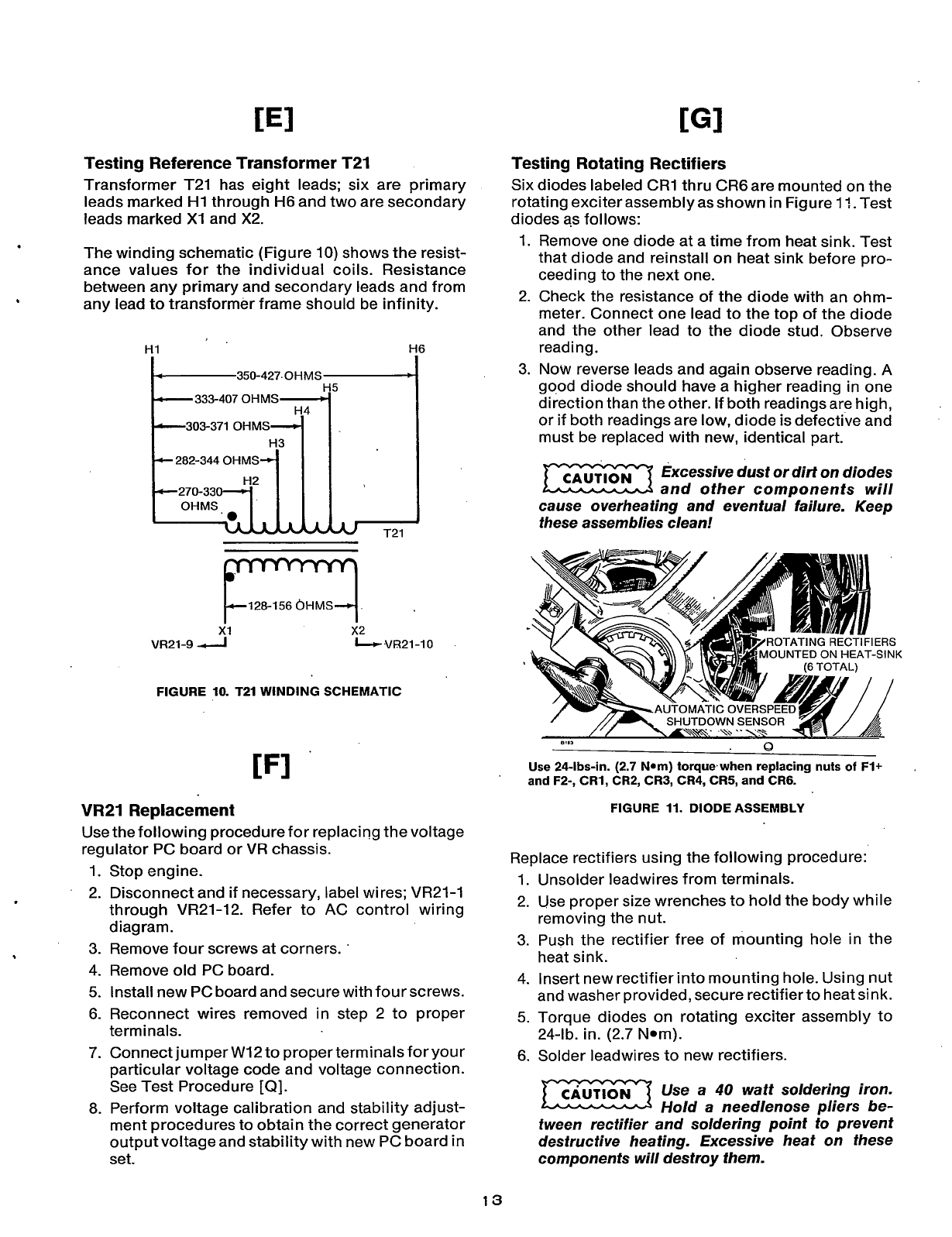
Testing Reference Transformer T21
Transformer T21 has eight leads; six are primary
leads marked
HI
through
H6
and two are secondary
leads marked
X1
and X2.
The winding schematic (Figure
10)
shows the resist-
ance values for the individual coils. Resistance
between any primary and secondary leads and from
any lead to transformer frame should be infinity.
.
'.
I
I
I
350-427.OHMS
I
-333-407
OHMS
-303-371
*
282-344
OHMS
-270-33
T21
k128-156
6HMS
I
x1
x2
VR21-9
4
.VI321
-1
0
FIGURE 10. T21 WINDING SCHEMATIC
VR21
Replacement
Use the following procedure for replacing the voltage
regulator PC board or VR chassis.
1.
Stop engine.
2.
Disconnect and if necessary, label wires; VR21-1
through VR21-12. Refer to AC control wiring
d iag ram.
3.
Remove four screws at corners.
'
4.
Remove old PC board.
5.
Install new PC board and secure with fourscrews.
6.
Reconnect wires removed in step 2 to proper
terminals.
7. ConnectjumperW12to properterminalsfor your
particular voltage code and voltage connection.
See Test Procedure
[Q].
8.
Perform voltage calibration and stability adjust-
ment procedures to obtain the correct generator
output voltage and stability with new PC board
in
set.
.
Testing Rotating Rectifiers
Six diodes labeled CR1 thru CR6 are mounted on the
rotating exciter assembly asshown in Figure
17.
Test
diodes
as
follows:
1.
Remove one diode at a time from heat sink. Test
that diode and reinstall on heat sink before pro-
ceeding to the next one.
2.
Check the resistance of the diode with an ohm-
meter. Connect one lead to the top of the diode
and the other lead to the diode stud. Observe
reading
.
3.
Now
reverse leads and again observe reading. A
good diode should have a higher reading in one
direction than the other. If both readings are high,
or if both readings are
low,
diode is defective and
must be replaced with new, identical part.
Excessive dust or dirt on diodes
rn
and other components will
cause overheating and eventual failure. Keep
these assemblies clean!
CAUT,ON
OUNTED
ON
HEAT-SINK
Use 24-lbs-in. (2.7 Nom) torque,when replacing nuts
of
F1+
and F2-, CR1, CR2, CR3, CR4, CR5, and CR6.
,
FIGURE 11. DIODE ASSEMBLY
Replace rectifiers using the following procedure:
1.
Unsolder leadwires from terminals.
2.
Use proper size wrenches to hold the body while
removing the nut.
3.
Push the rectifier free of mounting hole in the
heat sink.
4.
Insert new rectifier into mounting hole. Using nut
and washer provided, secure rectifierto heat sink.
5.
Torque diodes on rotating exciter assembly to
24-lb. in. (2.7
Nom).
6.
Solder leadwires to new rectifiers.
Use
a
40
watt soldering iron.
Hold
a
needlenose pliers be-
tween rectifier and soldering point
io
prevent
destructive heating. Excessive heat on these
components will destroy them.
13
Redistribution or publication of this document,
by any means, is strictly prohibited.
CRI
CR4
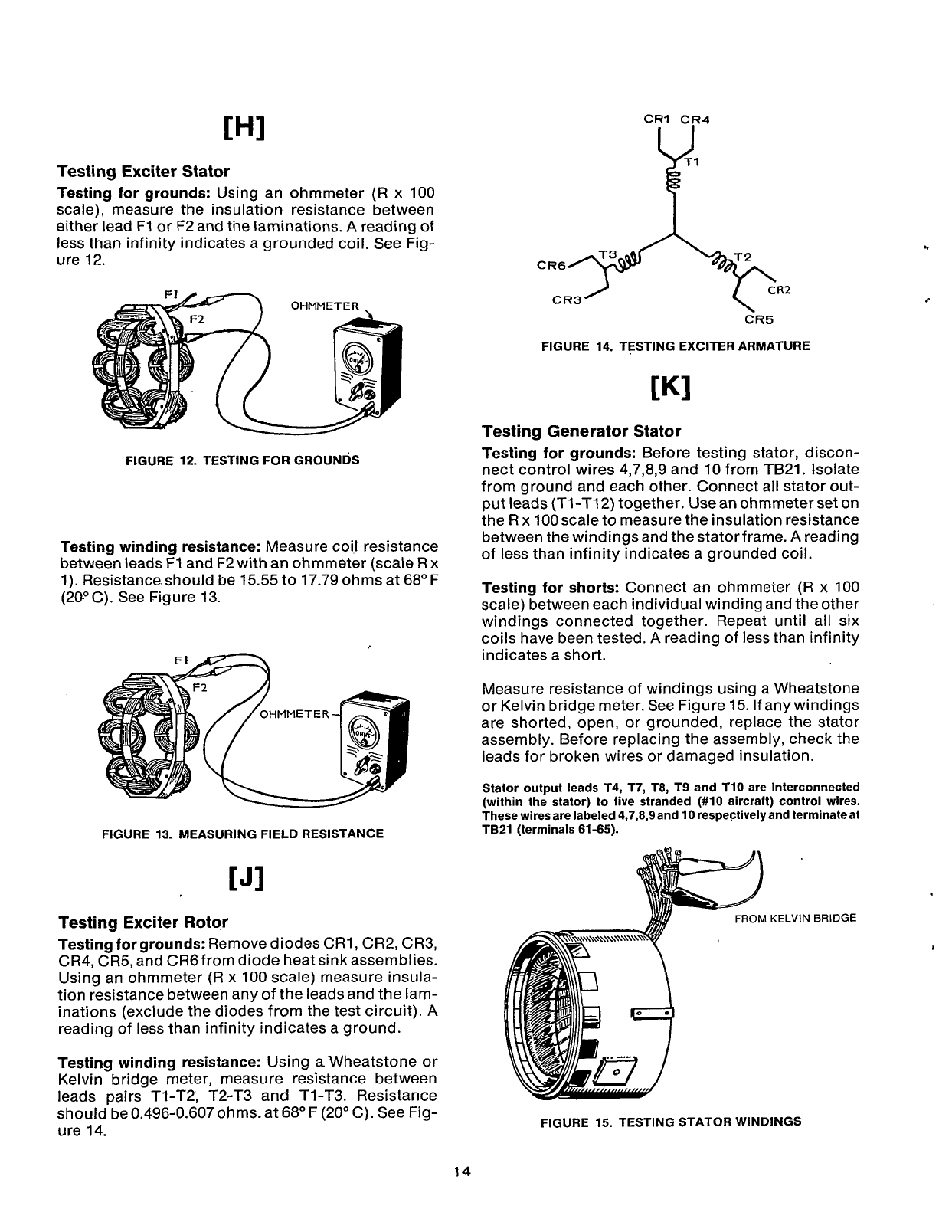
Testing Exciter Stator
Testing for grounds:
Using an ohmmeter
(R
x 100
scale), measure the insulation resistance between
either lead F1
or
F2 and the laminations.
A
reading
of
less than infinity indicates a grounded coil. See Fig-
ure 12.
FIGURE
12.
TESTING
FOR
GROUNDS
Testing winding resistance:
Measure coil resistance
between leads F1 and
F2
with an ohmmeter (scale
R
x
1).
Resistance.should be 15.55 to 17.79 ohms at 68" F
(20°C). See Figure 13.
FIGURE 13. MEASURING FIELD RESISTANCE
Testing Exciter Rotor
Testing for grounds:
Remove diodes CRl, CR2, CR3,
CR4, CR5, and CR6from diode heat sink assemblies.
Using an ohmmeter (R x 100 scale) measure insula-
tion resistance between any of the leads and the lam-
inations (exclude the diodes from the test circuit).
A
reading of less than infinity indicates a ground.
Testing winding resistance:
Using
a
Wheatstone or
Kelvin bridge meter, measure resistance between
leads pairs Tl-T2, T2-T3 and Tl-T3. Resistance
should be 0.496-0.607 ohms. at 68" F (20" C). See Fig-
ure 14.
FIGURE 14. TESTING EXCITER ARMATURE
Testing Generator Stator
Testing for grounds:
Before testing stator, discon-
nect control wires 4,7,8,9 and 10 from TB21. Isolate
from ground and each other. Connect all stator out-
put leads (Tl-T12) together. Use an ohmmeter set on
the
R
x
100scale
to
measure the insulation resistance
between the windings and the statorframe.
A
reading
of less than infinity indicates a grounded coil.
Testing for shorts:
Connect an ohmmeter
(R
x
100
scale) between each individual winding and the other
windings connected together. Repeat until all six
coils have been tested.
A
reading of less than infinity
indicates a short.
Measure resistance of windings using a Wheatstone
or Kelvin bridge meter. See Figure 15. If anywindings
are shorted, open, or grounded, replace the stator
assembly. Before replacing the assembly, check the
leads for broken wires or damaged insulation.
Stator output leads T4, T7, T8, T9 and T10 are interconnected
(within the stator) to five stranded (#lo aircraft) control wires.
These wires are labeled 4,7,8,9 and 10 respectively and terminate at
TB21 (terminals 61-65).
OM
KELVIN
BRIDGE
FIGURE 15. TESTING STATOR WINDINGS
c
14
Redistribution or publication of this document,
by any means, is strictly prohibited.
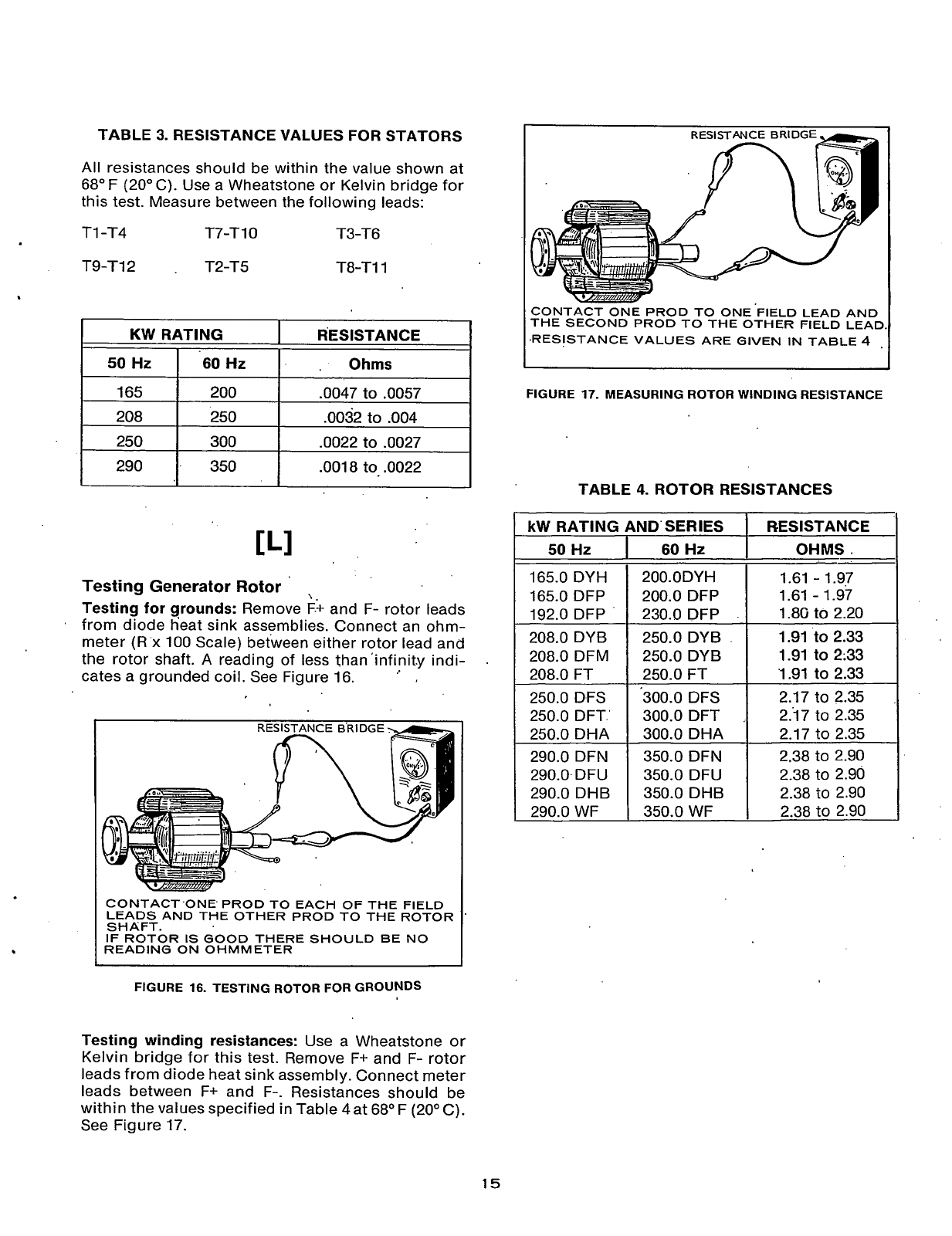
TABLE
3.
RESISTANCE VALUES
FOR
STATORS
KW
RATING
50Hz
I
60
Hz
All resistances should be within the value shown at
68"
F
(20"
C).
Use a Wheatstone or Kelvin bridge for
this test. Measure between the following leads:
TI -T4 T7-T 1
0
T3-T6
T9-112
.
T2-T5 T8-T11
RESISTANCE
,
Ohms
208 250 .0032 to .004
250 300 .0022
to
,0027
290
\.
Testing Generator Rotor
Testing for grounds:
Remove F.+ and F- rotor leads
'
from diode heat sink assemblies. Connect an ohm-
meter
(R
x 100 Scale) between either rotor lead and
the rotor shaft. A reading of less than'infinit.y indi-
cates a grounded coil. See Figure 16.
.
.
350 .0018 to .0022
CONTACT'ONE PROD TO EACH OF THE FIELD
LEADS AND THE OTHER PROD TO THE ROTOR
SHAFT.
IF
ROTOR
IS
GOOD THERE SHOULD BE NO
READING ON OHMMETER
50
Hz
165.0 DYH
165.0 DFP
192.0 DFP
208.0 DYB
208.0 DFM
208.0
FT
250.0 DFS
250.0 DFT'
250.0 DHA
290.0 DFN
290.0.DFU
290.0 DHB
290.0
WF
FIGURE
16.
TESTING ROTOR
FOR
GROUNDS
60
Hz
200.0DYH
200.0 DFP
230.0 DFP
250.0
DYB
250.0 DYB
250.0 FT
300.0 DFS
300.0 DFT
300.0 DHA
350.0 DFN
350.0 DFU
350.0 DHB
350.0 WF
Testing winding resistances:
Use a Wheatstone or
Kelvin bridge for this test. Remove F+ and F- rotor
leads from diode heat sink assembly. Connect meter
leads between F+ and F-. Resistances should be
within the values specified in Table 4 at 68" F (20"
C).
See Figure 17.
I
CONTACT
ONE
PROD
TO
ONE'FIELD
LEAD
AND
THE SECOND PROD TO THE OTHER FIELD LEAD.
,RESISTANCE VALUES ARE GIVEN
IN
TABLE
4
,
FIGURE
17.
MEASURING ROTOR WINDING RESISTANCE
TABLE
4.
ROTOR
RESISTANCES
I
kW
RATING AND'SERIES RESISTANCE
OHMS.
1.61
-
1.97
1.61
-
1.97
1.8G
to
2.20
1.91
to
2.33
1.91
to
2;33
'1.91
to
2.33
2.17 to 2.35
237 to 2.35
2.17 to 2.35
2.38 to 2.90
2.38 to 2.90
2.38 to 2.90
2.38 to 2.90
15
Redistribution or publication of this document,
by any means, is strictly prohibited.
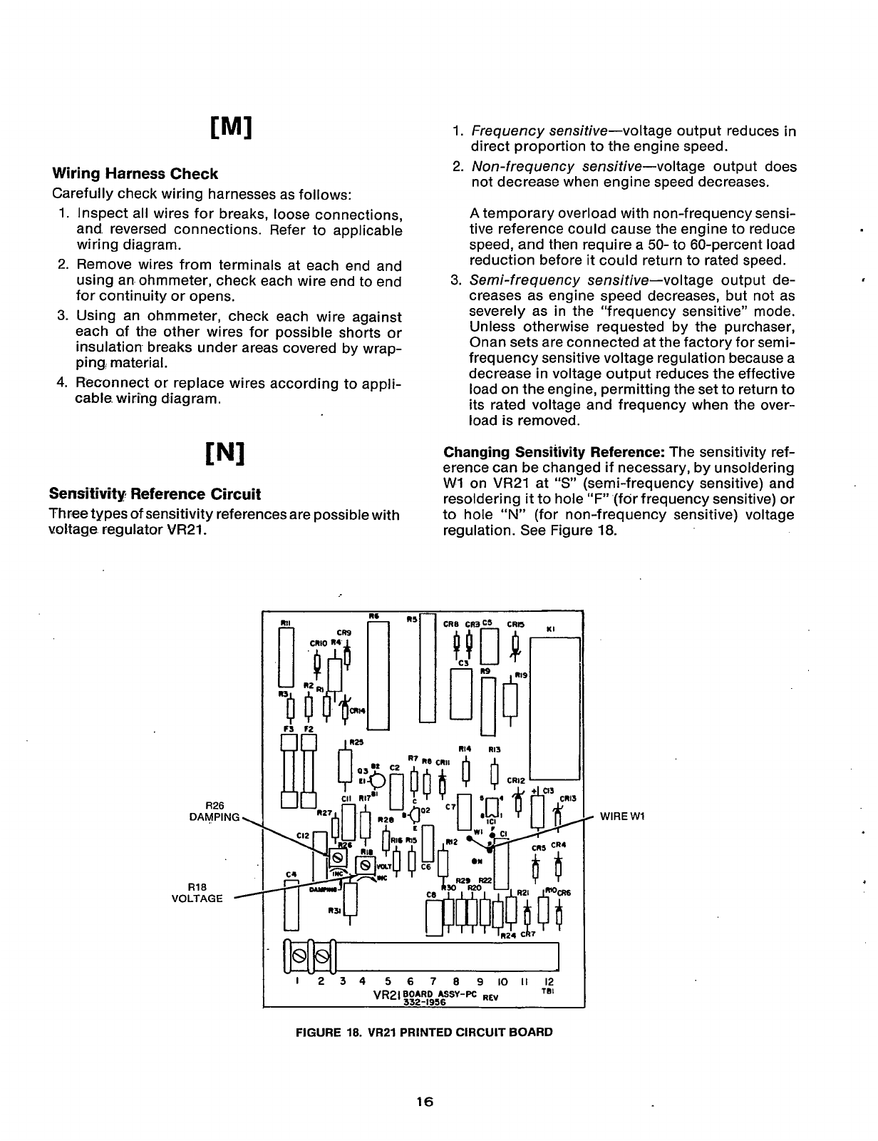
Wiring Harness Check
Carefully check wiring harnesses as follows:
1.
Inspect all wires for breaks, loose connections,
and reversed connections. Refer to applicable
wiring diagram.
2.
Remove wires from terminals at each end and
using an ohmmeter, check each wire end to end
for continuity or opens.
3.
Using an ohmmeter, check each wire against
each of the other wires for possible shorts or
insulation breaks under areas covered by wrap-
ping, material.
4.
Reconnect or replace wires according to appli-
cable wiring diagram.
IN1
Sensitivity Reference Circuit
Three types
of
sensitivity references are possible with
voltage regulator
VR21
R26
DAMPING
\
R18
VOLTAGE
-
1.
Frequency sensitive-voltage output reduces
in
direct proportion to the engine speed.
2.
Non-frequency sensitive-voltage output does
not decrease when engine speed decreases.
A
temporary overload with non-frequency sensi-
tive reference could cause the engine to reduce
speed, and then require a
50-
to 60-percent load
reduction before it could return to rated speed.
3.
Semi-frequency sensitive-voltage output de-
creases as engine speed decreases, but not as
severely as in the “frequency sensitive” mode.
Unless otherwise requested by the purchaser,
Onan sets are connected at the factory for semi-
frequency sensitive voltage regulation because a
decrease in voltage output reduces the effective
load on the engine, permitting the set to return to
its rated voltage and frequency when the over-
load is removed.
Changing Sensitivity Reference:
The sensitivity ref-
erence can be changed if necessary, by unsoldering
W1
on
VR21
at
“S”
(semi-frequency sensitive) and
resoldering
it
to hole
“F”
(for frequency sensitive) or
to hole
“N”
(for non-frequency sensitive) voltage
regulation. See Figure
18.
8
WlREW1
-1
-2-3
4
5
6
7
8
9
IO
II
12
VR2lBOARD
ASSY-PC
R~Y
TBI
332-1956
FIGURE
18.
VR21
PRINTED
CIRCUIT
BOARD
16
Redistribution or publication of this document,
by any means, is strictly prohibited.
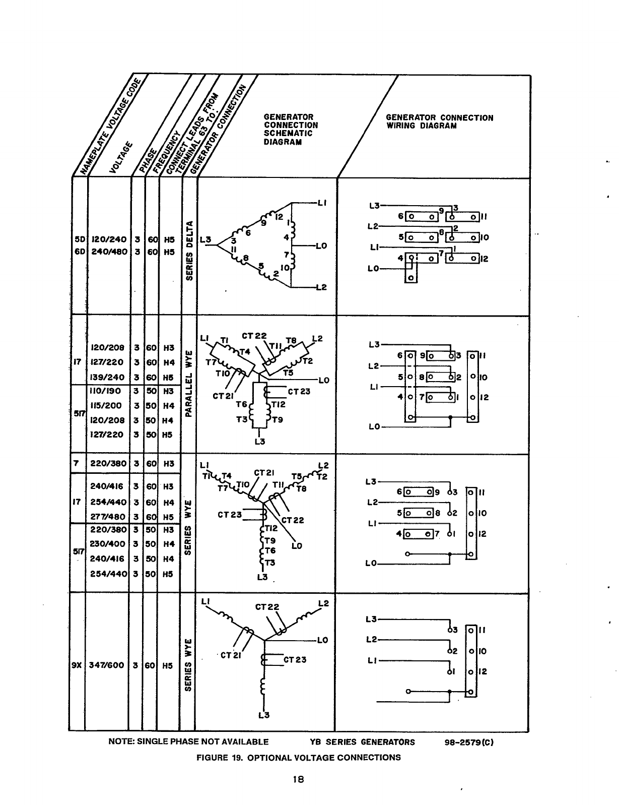
Voltage Regulator Adjustment Reconnection
If
VR21 voltage regulator printed circuit board has
been replaced,
it
may b,e necessary to center the
voltage adjust rheostat
(R21)
on meter panel.
Figure 19 shows reconnection possibilitiesfor the
YB
series generators. When reconnecting bus-bars for a
different voltage, be sure to reconne'ct lead from ter-
minal
63
(inside control box) to either
H3,
H4
or
H5.
See
Figure
and
19.
.
1.
Center the voltage adjust knob
so
pointer is in a
vertical position.
.
..
.
2. Open meter panel doors and start unit.
3.
Using a screwdriver, turn
R18
potentiometer on
printed circuit board
VR21
in direction shown to
increase or decrease the voltage (See Figure
18).
Observe voltmeter on-meter panel while making
'
,
adjustment.
Set
voltage with no load connected
to generator.
'
(Example: For a
120/240
volt connection, set
no.
load voltage at .approximately
246
volts).
..
If voltage is unstable or tends to hunt, turn R26 poten-
circuit,board to increase damping (Figure
18).
r
tiometer on VR.21 in the direction shown .on printed
..
17
Redistribution or publication of this document,
by any means, is strictly prohibited.
120/24C
240/48(
1201208
127/220
139/240
110/190
115/200
120/20a
127/220
220/38c
240/416
254M4C
277/480
220/38(
23
0/40
0
240/416
254/44(
-
347/600
I
-
3
3
3
3
3
5
3
5
5
-
-
3
5
3
5
5
5
5
5
-
-
-
5
-
HS
HS
H3
H4
HI
H3
H4
H4
H5
-
-
H3
H3
H4
H5
H3
HI
H4
HI
-
-
H5
-
GENERATOR
CONNECTION
SCHEMATIC
DIAGRAM
T6v92
T3
L3
-
CT
P'
P
L3
.
LI
i3
GENERATOR CONNECTION
WIRING DIAGRAM
L3
3
L2 2
s-fi
OJII
5fld
0110
LI
O1I2
L3
L2
LI
6[0]9 63
0
II
5/018
bP
o
IO
41-17
di
0
12
n
LO
-
L3b3
L262
LI
dl
'T
NOTE SINGLE PHASE NOT AVAILABLE
YB
SERIES
GENERATORS 98-2579(C)
FIGURE
19.
OPTIONAL VOLTAGE CONNECTIONS
18
Redistribution or publication of this document,
by any means, is strictly prohibited.
1.
2.
3.
4.
5.
6.
7.
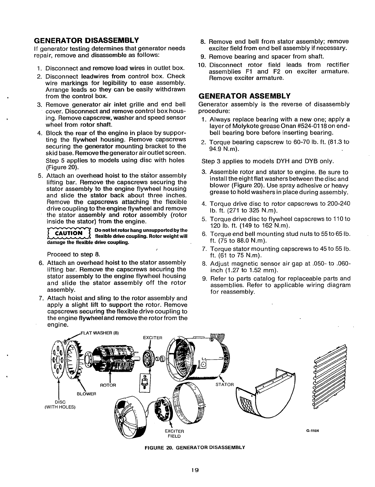
GENERATOR DISASSEMBLY
If
generator testing determines that generator needs
repair, remove and disassemble as follows:
Disconnect and remove load wires in outlet box.
Disconnect leadwires from control box. Check
wire markings for legibility to ease assembly.
Arrange leads
so
they can be easily withdrawn
from the control box.
Remove generator air inlet grille and end bell
cover. Disconnect and remove control box hous-
ing. Remove capscrew. washer and speed sensor
wheel from
rotor
shaft.
Block the rear of the engine
in
place by suppor-
ting the flywheel housing. Remove capscrews
securing the generator mounting bracket to the
skid base. Remove thegenerator air outlet screen.
Step
5
applies to models using disc with holes
(Figure
20).
Attach an overhead hoist to the stator assembly
lifting bar. Remove the capscrews securing the
stator assembly to the engine flywheel housing
and slide the stator back about three inches.
Remove the capscrews attaching the flexible
drive coupling to the engine flywheel and remove
the stator assembly and rotor assembly (rotor
inside the stator) from the engine.
Do
not
lei
rotor
hang unsupported by the
flexible drive coupling. Rotor weight will
damage the flexible drive coupling.
Proceed to step
8.
Attach an overhead hoist to the stator assembly
lifting bar. Remove the capscrews securing the
stator assembly to the engine flywheel housing
and slide the stator assembly off the rotor
assembly.
Attach hoist and sling
to
the rotor assembly and
apply a slight lift to support the rotor. Remove
capscrews securing the flexible drive coupling to
the engine flywheel and remove the rotor from the
engine.
,FLAT
WASHER
(8)
8.
9.
10.
Remove end bell from stator assembly; remove
exciter field from end bell assembly if necessary.
Remove bearing and spacer from shaft.
Disconnect rotor field leads from rectifier
assemblies F1 and F2 on exciter armature.
Remove exciter armature.
GENERATOR ASSEMBLY
Generator assembly is the reverse of disassembly
procedure:
1.
Always replace bearing with a new one; apply a
layer of Molykote grease Onan #524-0118 on end-
bell bearing bore before inserting bearing.
2.
Torque bearing capscrew to 60-70 Ib. ft. (81.3 to
94.9 N.m).
Step
3
applies to models
DYH
and DYB only.
3.
Assemble rotor and stator to engine. Be sure to
install theeight flat washers between the disc and
blower (Figure 20). Use spray adhesive or heavy
grease to hold washers in place during assembly.
4. Torque drive disc to rotor capscrews to 200-240
Ib. ft. (271 to 325 N.m).
5.
Torque drivedisc to flywheel capscrews
to
110 to
120 Ib. ft. (149 to 162 Nm).
6. Torque end bell mounting stud nuts to 55to 65 Ib.
ft.
(75
to 88.0 N.m).
7.
Torque stator mounting capscrews to 45 to
55
Ib.
ft. (61 to 75 Nm).
8.
Adjust magnetic sensor air gap at
.050-
to .060-
inch (1.27 to 1.52 mm).
9.
Refer to parts catalog for replaceable parts and
assemblies. Refer to applicable wiring diagram
for reassembly.
I
DISC
(WITH HOLES)
1
STATOR
6-1104
FIGURE
20.
GENERATOR DISASSEMBLY
19
Redistribution or publication of this document,
by any means, is strictly prohibited.
Control
System
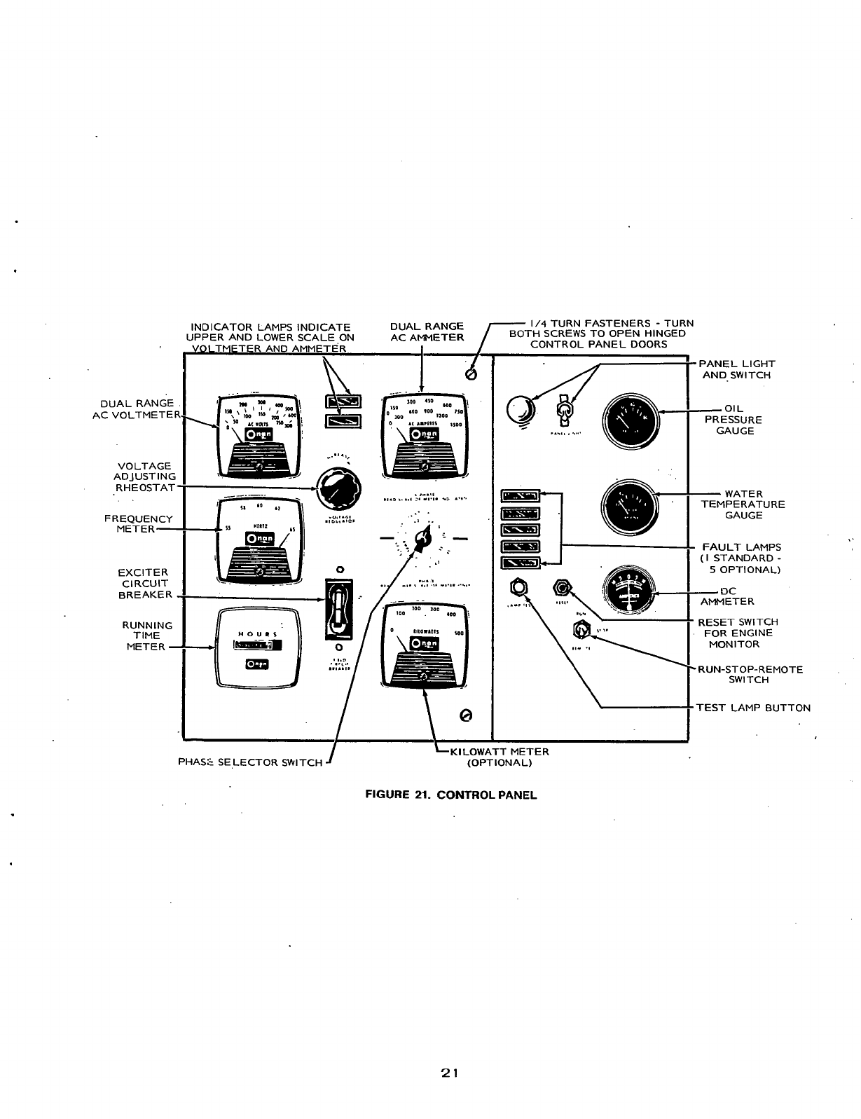
GENERAL
The shock-mounted control box has two doors that
open from the middle. For identification purposes,
left and right is determined by facing the control
panel.
The left hand door is designated the AC panel and
contains the following standard equipment. See Fig-
ure
2.1.
Dual RangeAC Voltmeter:
Scales
50
to
300
volts and
100
to
600
vol.ts AC.
Dual range AC. Ammeter:
Range of meter depends
upon size
of
generator.
Voltmeter ammeter phase selector switch:
Selects
the phases
of
the generator output to be measured by
the AC voltmeter and AC ammeter, ie., line-to-line,
line-ta-neutral, single phase or three phase.
Range Indicator Lights:
Identifies high or low scale to
be read on the AC ammeter or AC voltmeter.
Frequency Meter:
Pointer type meter indicates gen-
erator output frequency in Hertz.
Running Time Meter:
Registers total number of
hours, to one-tenth hour that unit has run. Recorded
time is accumulative; the meter cannot be reset to
zero time.
Voltage Regulator:
Rheostat
(R21)
provides an
adjustment
of
plus or minus
5
percent of generator
output voltage.
Exciter Circuit Breaker (CB21):
Provides generator
exciter and regulator protection from overheating in
the event of certain failure modes of the generator
exciter and voltage regulator.
Optional AC Panel Equipment:
Kilowatt Meter:
Connected to a transducer mounted
on the back of the control cabinet, this instrument
indicates generator output
in
kilowatts. The trans-
ducer is connected across the phases
of
the genera-
tor, and to the current transformers.
Governor Control:
This single-pole double-throw,
center-off, momentary contact switch is wired into a
split-field series motor situated on top of the engine
governor. Used only with a Woodward PSG Gover-
nor, the switch operates the motor which adjusts the
governor and therefore the engine speed.
Standard .DC Panel Equipment:
Oil Pressure Gauge:
Connected to a resistance type
sender on the engine, this instrument indicates
engine circulating oil pressure.
Water Temperature Gauge:
Connected to a resist-
ance type sender on the engine, this instrument indi-
cates engine coolant tem perature.
Ammeter:
Indicates the output current of the battery
charging alternator.
Run-Stop-Remote Switch:
Starts and stops the unit
locally or from a remote location.
Reset Switch:
Manual reset for engine monitor after
shut-down. Run-Stop-Remoteswitch in “STOP” position.
Lamp Test:
Depress to test warning lamp bulbs.
Operate only while engine is running.
Warning Light:
Indicates “Fault
in
engine operation”.
Optional DC Panel Equipment:
Penn State Run-Stop/Reset-Remote Switch:
Momen-
tary contact
in
the depress during reset position.
To
reset engine monitor, hold switch in the
DDR
posi-
tion, actuate reset switch, release and select run to
start engine.
Warning Lights:
Eliminates the one “Fault” light and
substitutes five indicator lights to give warning of:
1.
2.
3.
4.
5.
Ove rc ran k
Overs peed
Low Oil Pressure
High Engine Temperature
Low Engine Temperature
20
Redistribution or publication of this document,
by any means, is strictly prohibited.
DUAL RANGE
AC VOLTMETEI
VOLTAGE
ADJUST
I
NG
RHEOSTAT
FREQUENCY
METER-
EXCITER
CIRCUIT
BREAKER
RUNNING
TIME
METER
-
1/4
TURN FASTENERS
-
TURN
BOTH SCREWS TO OPEN HINGED
INDICATOR LAMPS INDICATE DUAL RANGE
AMMETER
CONTROL PANEL
DOORS
UPPER AND LOWER SCALE ON
VOI
TMFTER AND AMMETER
R
.
.t
.
.-..a
.I.>
....
I
:.
11.1.
.:.
.....
.
.
.-
nouns
1-3
:
.
'
PANEL LIGHT
AND. SWITCH
01
L
PRESSURE
...,,
.
.....
GAUGE
-WATER
TEMPERATURE
GAUGE
'
FAULT LAMPS
(I
STANDARD
-
5
OPTIONAL)
-
DC
AMMETER
RESET SWITCH
FOR ENGINE
MONITOR
\
'i-
RUN-STOP-REM0 TE
LKILOWATT
METER
PHAS2 SE,LECTOR SWITCH
-I
(OPTIONAL)
FIGURE
21.
CONTROL
PANEL
21
Redistribution or publication of this document,
by any means, is strictly prohibited.
CONTROL OPERATION
In emergencies, service personnel may be required to
service afailed generatorset in minimum time. This is
especially true if generator is the backup power
source for life support equipment
in
hospitals.
The information in this section will instruct personnel
on operation of relays and printed circuit modules.
Used with the Wiring Diagrams, it will providegreater
understanding of control system function.
Engine
Control
Relays
The following are brief descriptions of operation and
functions of the control relays. The term
B+
is used to
designate battery voltage (+24 VDC).
Start Disconnect Relay K11:
Placing
R-S-R
(Run-
Stop-Remote) switch in Run position applies
B+
to
coil terminal
B
of relay K11. Coil terminal A is con-
nected to terminal
1
of Start Disconnect module A17.
Coil ground is completed by transistor Q2 on A17.
When K11 energizes, the following occurs:
1.
Contacts7and 4closeand apply
B+
through K14,
(7-1) to Cranker module A14. Relay K13 ener-
gizes and applies
B+
to
the starter solenoid.
2. Contacts
3
and 9 open to start the Overcrank
timing sequence.
3.
Contacts
8
and 2 open and allow engine starting
without low oil pressure shutdown.
Relay K11 remains energized until engine begins to
runandan inputof 150to 190hertzfrom themagnetic
speed sensor is applied to A17 terminals 21 and 22.
This causes transistor Al7-Q2 to stop conducting
and opens the ground circuit to K11 coil causing the
following:
1. Contacts 7 and 4 open to disconnect the
B+
from
the cranking starter circuit.
2. Contacts
3
and 9 close to terminate overcrank
timer.
3. Contacts8and 2closeto enable Low Oil Pressure
shut down circuit.
..
Ignition Relay, K12:
Energized by
B+,
through
module A1
1
when
R-S-R
switch is placed in run posi-
tion. Relay A1 1-K1 N.C. contacts complete the circuit
through module All-20 terminal .to relay K12 coil.
This relay remains energized for duration of engine
run.
When K12 energizes the following occurs:
1.
Contacts 8 and
5
close and apply B+ to voltage
regulator of battery charging alternator to pro-
vide excitation.
a. Oil pressure gauge.
b. Water temperature gauge.
c. Water solenoid valve.
d. Fuel pump.
e. Energize K15, stop relay (not diesel)..
f. K11-7, input to module A14.
g. K15(-6) to energize fuel solenoid valve (not
2.
Contacts 4 and 7 close and apply
B+
to:
diesel
)
.
3.
Contacts 3 and 9 open to initiate Cycle Cranker
sequence.
Deactivation of relay K12 will shut down the engine.
Start Solenoid, K13:
Relay K13 has only one set of
contacts.
It
is energized by closure of K11 (7-4)
through K14 (7-1) and Cranker module A14. When
relay is energized,
it
applies B+ through circuit
breaker CB1 (one engine) to starter shift solenoid K.
When engine starts, relay contacts K11 (7-4), fol-
lowed by K14
(7-1)
open
..
to de-energize K13.
Starter Protection Relay, K14:
Relay K14 is energized
by generator output (190 to 240’VAC) and de-
energizes when voltage falls to
135
V.AC. When ener-
gized the following occurs:
1.
Contacts of K14 (9-6) close to apply
B+
to TB13-
58 and to remote station “Generator on” lamp.
2. Contacts K14 (7-1) open to de-energize K13 and
act as a backup for relay K11 (7-4).
22
Redistribution or publication of this document,
by any means, is strictly prohibited.
TD.
!nART/STOq
ENGINE :ENGINE
IRMT.
iCRANKlNG
/
OVERSPEEG
'
STARTER
FIGURE
Z..
ENGINE CONTROL
MODULE
LOCATION
23
Redistribution or publication of this document,
by any means, is strictly prohibited.
Stop
Relay,
K15
(Natural Gas:
Relay K15 is energized
by closure of K12 (4-7) contacts. Contact switching is
as follows:
1. Contacts 7-1 and 8-2 open to disconnect ground
from magneto (or magnetron) primary coils.
2 .Contacts 3-9 open to disconnect K1 fuel solenoid
from AUX output
of
battery charging alternator.
3. Contacts 6-9 close and apply B+ to K1 fuel
solenoid.
Overspeed Relay
K15
(DHA and DHB Only):
Relay
K15 is normally de-energized and used as a back-up
to the standard Overspeed installation. If engine
overspeed occurs transistor A16-Q2 conducts and a
ground is supplied to terminal 13 of All Engine
Shutdown module. This causes All-Q1 to conduct
and
apply B+ to energize K15 relay.
Closure of K15 contacts 6 and
9
applies
B+
to K4 Air
Inlet solenoid which actuates air shutters to starve
the engine and induce shutdown.
.
Should this back-up system be actuated, manually reset air shutter
doors. The engine will not start until shutters are open.
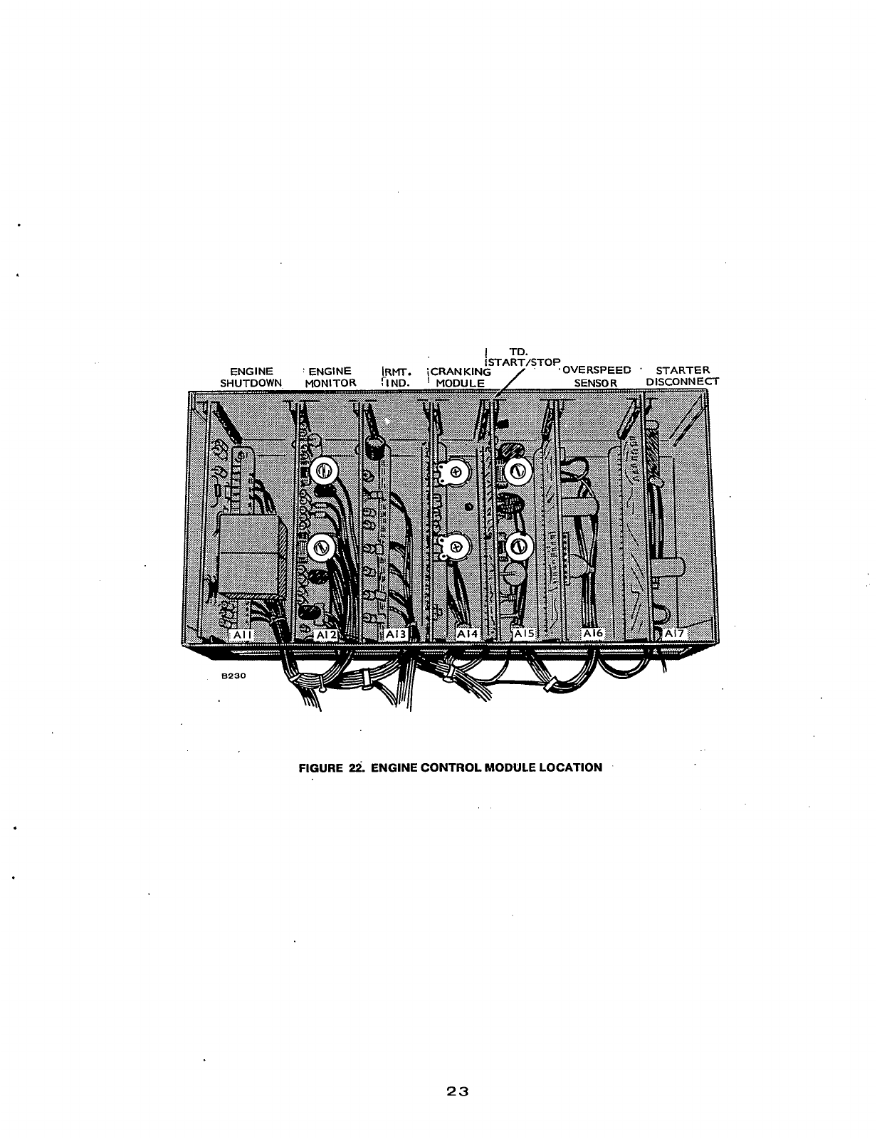
Engine
Control
Models
The following are brief descriptions of operating
functions of the engine control modules shown in
Figure 22. The term B+ is used to designate battery
voltage (+24 VDC).
Engine Control Module,
All:
The
R-S-R
switch in
Run position applies
B+
to energize K12 ignition relay
via All pins
5
and 20. The
B+
at pin 14 goes through
lamp test switch S13, then re-enters at pin 18 and
applied to coils of A1 l-K1 and -K2. A ground at A1 1-7
energizes A1 l-K1 to perform the following functions:
1.
The N.C. contacts open to remove B+ from K12
coil which shuts down the engine.
2. The
N.O.
contacts close to apply B+ (from the
alarm reset switch) to the alarm terminal on TB12.
A ground at A11-3 energizes All-K2 which will func-
tion as follows:
1.
N.O. contacts close to energize alarm and apply
B+through All-19toA12-1 to keepfault lampon.
2.
N.O.
contacts close; if a ground is present on
All-1, relay AII-K1 will energize and shut down
engine .The ground on A1
1-1
will act as a hold-in
circuit for All-Kl coil.
DHA and DHB only: During overspeed shutdown, a
ground is applied to terminal 13. The current flow
across resistor A1 l-R1 will turn on A1 l-Q1 transistor
which applies
B+
to
terminal 9 to energize relay K15.
Engine shutdown caused by malfunction will leave
A1 1-K1 relay latched. Reset relay as follows:
Standard Installation: Place
R-S-R
switch in Stop
position and press Reset button. Return
R-S-R
switch
to
operational position (Run or Remote).
Penn State Installation: Place and hold
R-S-R
switch
in
Depress During Reset position. Press Reset but-
ton. Release switch and return to the required opera-
tional position.
Engine Monitor Module,
A12:
The
R-S-R
switch
in
Run position applies
B+
to All (pins
5
and 20), to
terminal A12-20, to DS12 Overcrank, DS13 Over-
speed and DS14 Low Oil Pressure lamps. Grounds
for
the fault lamps are provided within the Engine
Monitor module.
Start Disconnect relay K11,
N.C.
contacts 9-3 (open
when K11 energized) are between A12-22 and
ground. If after 75-seconds of cranking engine does
not start, a potential built up in capacitor A12-C7 will
discharge and cause unijunction Al2-Q7 to fire. Uni-
junction Al2-Q5firesand turns on A 12-CR9 to apply
a ground to A1 1-K1 relay, which energizes and stops
any further starting action. Al2-CR9 also provides a
ground for the Overcrank lamp to indicate a fault.
Engine start within 75-seconds will cause a signal
from the overspeed sensor through module A16 to
turn off transistor Al7-Q2and de-energize relay Kll.
N.C. contacts 9-3 close and short out capacitor A12-
C7 to prevent engine shutdown through Overcrank
function.
With the engine running and relay K11 de-energized,
low engine oil pressure will cause LOP switch to
close applying a ground to pin 4. Transistor Al2-Q6
will turn off, Al2-CR6 will turn on and apply aground
for Low Oil Pressure light to indicate a fault. A1 1-K1
will
cause K12 relay to shut down the engine and
energize the alarm system.
.
If engine overspeeds (rpm
in
excess of 2010), the
output of A16-IC2 turns on Al6-Q2 which conducts
and applies ground to A12-2. This turns on A12-Q1;
Al2-CR3 will conduct and make ground for the Over-
speed light to indicateafault. A1 l-K1 will energize to
shut off K12 relay to stop the engine. The alarm will
ope rate.
Redistribution or publication of this document,
by any means, is strictly prohibited.
Remote Indicator Module,
A13: This module is used
on five Fault light systems only, to light fault indica-
tors at remote stations.
If a low oil pressure shutdown occursaground will be
applied to A12-5 and A13-1. This turns on A13-Q1
and applies
B+
to All-2 to light the Low Oil Pressure
fault indicator at the remote station. Two extra fault
lightsareconnected into theA13module:
DS15
High
Engine Temperature and DS16 Low Engine Temper-
ature. Closure of High Engine Temperature Sensing
switch appliesa ground
toAl3-20.ThisstartsAl3-Q6
conducting which turns on CR7 to ground pin 14, and
light the High Engine Temperature lamp and apply a
ground to A1 1-K2 for the alarm system. Al3-Q5 will
conduct and apply
B+
to A13-12 for the remote sta-
tion light.
Closure of the Low Engine Temperature Sensing
switch applies a ground to A13-8. Transistor A1344
will turn on the sets panel and remote Low Engine
Temperature lights to indicate a fault. There is no
alarm or engine shutdown with this fault.
Cycle Cranker Module,
A14: Available as an option,
the Cycle Cranker allows three crank cycles and two
rest cycles of the engine starter motor within the
75-second cranking period established by module
A1 2.
Cycle timesare adjustable. Crank cycle time isvaried
by A14-R4 and rest time by A14-R6. Crank time is
13-to 17-seconds and rest time is 8-
to
12-seconds.
The rheostats are accessible through holes
in
the
module plate.
When the
R-S-R
switch is in Run position, K11 is
energized. K11 (7-4) contacts closeand
B+
isapplied
to terminals 3,'A and
5
of A14. Transistor Al4-Q2
conducts and causes Q3, Q4 and
A5
to conduct and
apply
B+
to K13 starter .relay. Capacitor A14-C2
charges and turns off Al4-Q2 which allows Q1 to turn
on.Q3, Q4 and
Q5
turn off and de-energize K13.
Capacitor A1 4-C2 discharges, transistor Q2 turns on
and the cranking cycle is repeated until capacitor
A12-C7
is
charged. At this point A12-CR9 turns on
allowing relay AI 1-K1 to pull-in, to de-activate
igntion relay K12 and prevent any further cranking
action.
-.
If
the engine starts within the cranking cycle time
(75-seconds) relay K11 will de-energize, contacts
K11 (3-9) will close and capacitor Al2-C7 will be
discharged setting its voltage to zero.
Standard Cranker Module,
Al4A:This module allows
B+
to be applied to K13 Starter relay, and cranking to
continue until the engine starts and relay K11 is de-
energized as described above. The 75-second crank-
ing period
is
established by module A12.
Time Delay Start-Stop,
A15: Used only with a remote
control station, this module insertsa timed delay into
the Start and Stop functions. Delay times are adjus-
table: Start, up to 15-seconds and Stop, from 30-
seconds to
5
minutes. Adjustments can be made
through access holes in the module plate.
.When engine start signal is initiated from a remote
station, the set control panel
R-S-R
switch is left in
Remote position. Initiation of a start signal will apply
B+
to terminals A15-17 and A15-9. Voltage at A15-17
allows capacitor A15-C3 to charge. Voltage at A15-9
prevents capacitor A1 5-C4 from charging. Charge
time of A15-C3 is adjusted by rheostat A15-Rl4.
When charged capacitor Al5-C3 will turn on A15-Q1
which will cause A1 5-CR1 to conduct and apply
B+
to
the output terminals of the module, then to distribu-
tion points in the control panel. Once the gate of
Al5-CR1 has been .triggered,
it
will continue to
conduct.
Initiation of a stop signal
is
really removal of the start
signal, which removed
B+
from terminals 17 and 9 to
allow capacitor Al5-C4 to charge. Charge rate is
adjusted by rheostat A15-Rl6. When Al5-C4 has
charged, transistor A1 5-Q8 will
turn
on and cause the
potential across capacitor Al5-C6 to go more posi-
tive and bias the cathode of Al5-CR1 to turn
it
off.
This will shut down the set.
Time Delay Bypass Module,
15A: Use of this module
allows Start/Stop control from a remote station with-
out the time delay advantage.
Engines fitted with turbo super chargers should be run for at least
five minutes after load removal before shutdown. This allows
engine temperature to stabilize and the turbo housing
to
cool off
and prevent warping or cracking of the turbo assembly.
Control panels with the time delay will allow the set to
run for five minutes before automatic shutdown.
25
Redistribution or publication of this document,
by any means, is strictly prohibited.
Overspeed Sensor Module,
A16:
The Overspeed sen-
sor system has two sections: A 20-tooth disc
mounted on the generator shaft and a magnetic pick
up, and an Overspeed sensor printed circuit module.
The output of the disc pickup device is fed into the
sensor module and is used for two purposes:
1. Engine shutdown when speed reaches 2010 rpm.
2. Disconnects starter when engine speed reaches
450
to 570 rpm and reconnects starter at 10 to
30-rpm if engine fails to start.
The 20 tooth disc rotates at engine speed and is
positioned
so
that the teeth are in the field of the
magnetic pick-up. Rotation of the disc induces a vol-
tage in the pickup which is fed to a switching ampli-
fier
in
A16-IC2, and then into a multivibrator (A16-
ICl), where a voltage is produced which is pro-
portional to the inputfrequency. AttransistorAl6-Q1
the same amplifier output is applied to A17 Starter
Disconnect module.
If
engine overspeed occurs, the output of the
frequency-to-voltage converter (A16-IC1) switches a
zener diode into the base of Al6-Q2. Q2 turns on and
provides a ground for the Overspeed fault
light,
alarm
and engine shutdown if engine speed reaches 2010
rpm-
DHA
and
DHB
only:
An additional function when
Al6-Q2
turns
on is application
of
a ground to terminal
13
of
All
Engine Shutdown module
for
air
shutter
operation.
Start
Disconnect Module,
A17:
This module is
responsible for disconnecting
the
starter at an engine
speed of
450-
to 570- rpm to protect the starter and
the engine flywheel. A 5V square wave is fed into pins
21 and 22from the Overspeed Sensor board and then
into an integrated circuit A17-IC1. A difference in
time constant circuitry divides A17-IC1 into two sec-
tions: one for disconnect and one for reconnect. A
square wave output from A17-IC1 is fed into Al7-IC2
(essentially a flip-flop circuit) where
it
becomes
+5VDC applied to an amplifier
in
A17-IC3 and ampli-
fied to 13V. This voltage is connected through azener
diode to the base of transistor A1742 to turn it on
and provide a ground to energize Start/Disconnect
relay K1
1.
Division of A1 7-IC1 also allows a second square wave
output to be applied to another amplifier
in
Al7-IC3.
Here it connects to a filter network and into
a
Nand
gate of A17-IC2. At an engine speed of
450-
to
570-
rpm (150- to
190-
Hertz), the voltage output of A17-
IC2
is
switched to zero which causes A17-Q2to turn
off and disconnect ground from Kll. De-energizing
of K11 will open Starter solenoid K13and prevent the
starter from operating.
A characteristic of the Starter Disconnect circuit is
that Al7-1G2
will
not reverse outputpolarity
until
the
input is reduced to less
than
10-Hertz. Therefore, the
starter motorwill not be reconnected until the engine
rpm drops below 30.
26
Redistribution or publication of this document,
by any means, is strictly prohibited.
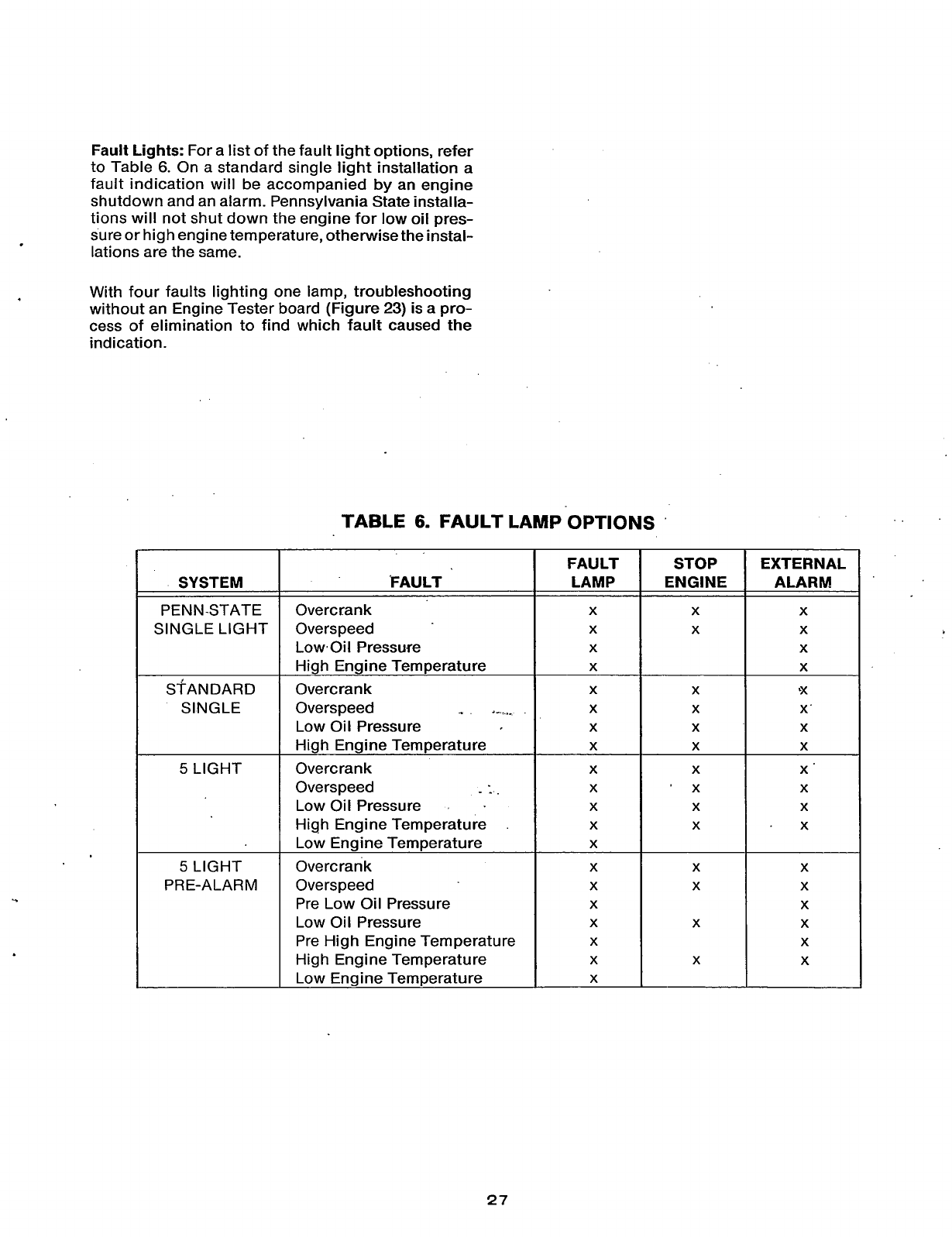
Fault Lights:
For a list of the fault light options, refer
to Table
6.
On a standard single light installation a
fault indication will be accompanied by an engine
shutdown and an alarm. Pennsylvania State installa-
tions will not shut down the engine for
low
oil pres-
sure or high engine temperature, otherwise the instal-
lations are the same.
FAULT
LAMP
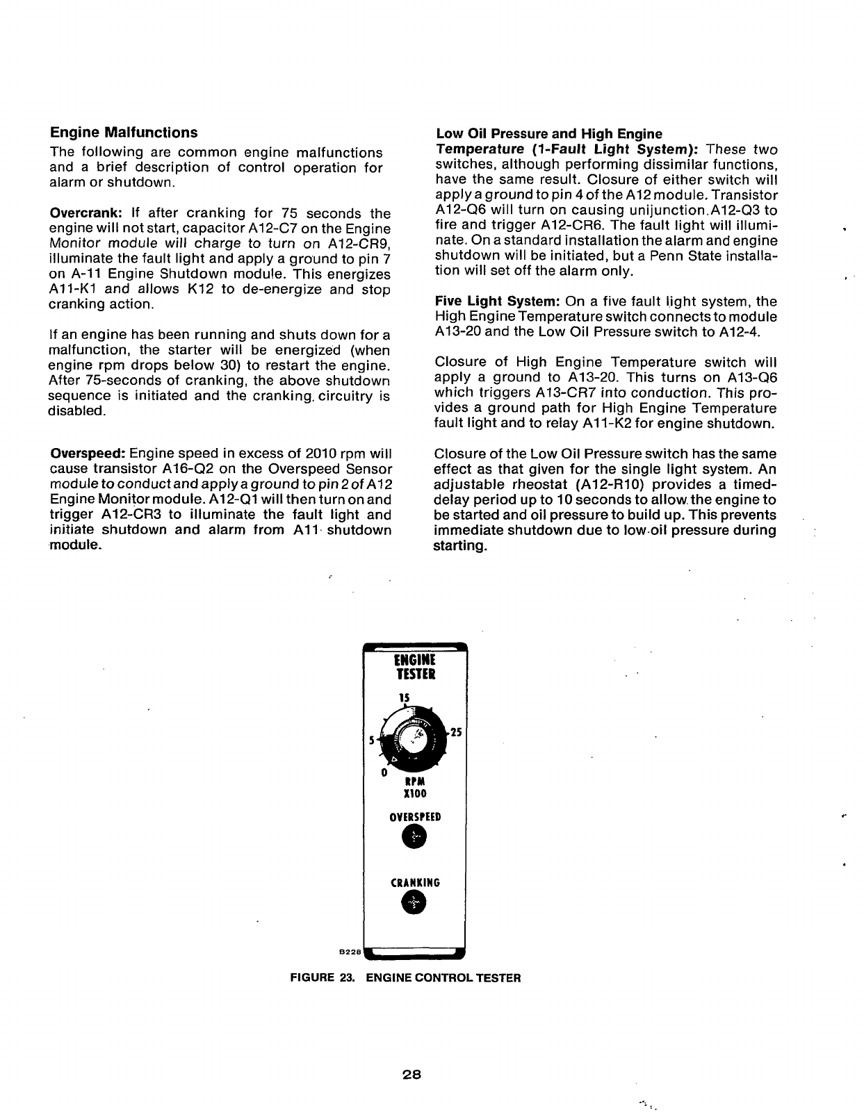
With four faults lighting one lamp, troubleshooting
without an Engine Tester board (Figure
23)
is
a
pro-
cess of elimination to find which fault caused the
indication.
STOP EXTERNAL
ENGINE ALARM
TABLE
6.
FAULT
LAMP
OPTIONS
SYSTEM
PENN-STATE
SINGLE LIGHT
SINGLE
‘FAULT
Overcrank
Overs peed
Low-Oil Pressure
High Engine Temperature
Overcran k
Low Oil Pressure
High Engine Temperature
Overcrank
Low Oil Pressure
High Engine Temperature
Low Engine Temperature
Overcran
k
Overspeed
Pre
Low
Oil Pressure
Low Oil Pressure
Pre High Engine Temperature
High Engine Temperature
Low Engine Temperature
Overspeed
_.
a_...
Overs peed
-
-_
X X
X
X
X
X X
X
X
X
27
Redistribution or publication of this document,
by any means, is strictly prohibited.
Engine
Malfunctions
The following are common engine malfunctions
and a brief description of control operation for
alarm or shutdown.
Overcrank:
If after cranking for 75 seconds the
engine will not start, capacitor Al2-C7 on the Engine
Monitor module will charge to turn on Al2-CR9,
illuminate the fault light and apply a ground to pin 7
on A-11 Engine Shutdown modu!e. This energizes
All-Kl
and allows K12 to de-energize and stop
cranking action.
If an engine has been running and shuts down for a
malfunction, the starter will be energized (when
engine rpm drops below 30) to restart the engine.
After 75-seconds of cranking, the above shutdown
sequence is initiated and the cranking. circuitry is
disabled.
Overspeed:
Engine speed in excess of 2010 rpm will
cause transistor A16422 on the Overspeed Sensor
moduletoconductandapplyaground topin2of A12
Engine Monitor module. A12-Ql will then turn on and
trigger Al2-CR3 to illuminate the fault light and
initiate shutdown and alarm from All. shutdown
module.
Low Oil Pressure and High Engine
Temperature
(+Fault
Light System):
These two
switches, although performing dissimilar functions,
have the same result. Closure of either switch will
apply a ground to pin
4
of the A12 module. Transistor
Al2-Q6 will turn on causing unijunction.A12-Q3 to
fire and trigger A12-CR6. The fault light will illumi-
nate. On a standard installation the alarm and engine
shutdown will be initiated, but a Penn State installa-
tion will set off the alarm only.
Five Light System:
On a five fault light system, the
High Engine Temperature switch connects to module
A13-20 and the Low Oil Pressure switch to A12-4.
Closure of High Engine Temperature switch will
apply a ground to A13-20. This turns on A1346
which triggers Al3-CR7 into conduction. This pro-
vides a ground path for High Engine Temperature
fault light and to relay AI 1-K2 for engine shutdown.
Closure of the Low Oil Pressure switch has the same
effect as that given for the single
light
system. An
adjustable rheostat (A12-RlO) provides a timed-
delay period up to
10
seconds to allow.the engine to
be started and oil pressure to build up. This prevents
immediate shutdown due to low.oil pressure during
starting.
I
I
XI00
c
l322.~-#
FIGURE
23.
ENGINE CONTROL TESTER
20
...
-:
Redistribution or publication of this document,
by any means, is strictly prohibited.

ENGINE
CONTROL
SYSTEM
CHECKOUT
PROCEDURE
This checkout procedure
of
the Engine Control System is
for
use with the Engine Control Tester Part Number
420-0336 (Figure
23).
Designed to enable the serviceman to check out the complete system, the Engine Control
Tester module
is
an indispensable tool for-rapid location
of
faults, or final pre-start system test.
.I
Proceed with the checkout
as
follows:
I
yes
1
1.
Remove front cover
of
engine module rack.
2.
Remove Cycle Cranker module
A14.
See Figure
22.
3.
Insert Engine Control Tester module into
A14
position.
4.
Set rheostat on Tester module
fully
counterclockwise.
Engine
will
not
start
with
controls
in this configuration.
5.
P1ace.R-S-R switch in run position. depress lamp
test switch
to
test fault lamp.
CHECKOUT
Replace Start-Disconnect
Module A17. Return
to
Turn Tester rheostat
lo
2300
rpm.
Does
Overspeed or Fault
light illuminate
on
both
Tester and
panel?
Does
Tester cranking light
Yi'
Does
Overspeed or Fault light
illuminate
on
Tester only?
Turn Tester rheostat to 2300
rpm.
Does
Overspeed or Fault
light come
on?
Replace generator Overspeed
sensor module A16. Return
Place Run-Stop-Remote switch
in
Run
position. Turn Tester
rheostat
to
650
rpm.
Does
Tester Cranking light go off?
1
Yes
Replace Engine Monitor Module
A12. Return to test
0.
Replace Starter Disconnect
Module A17. Return to test
In
10-20 seconds, does Low
Oil Pressure or Fault Light
come on? no
I
yes
I
cont.
following
page
29
Redistribution or publication of this document,
by any means, is strictly prohibited.
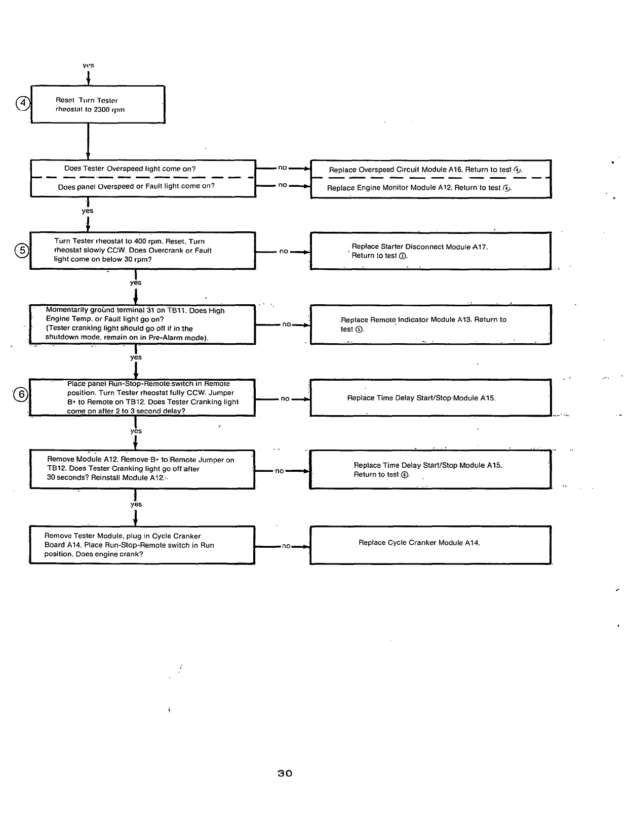
yt's
+
Rcsct Turn Tcstcr
rheostat
lo
2300
rlmi
now
no
-L.
Replace Overspeed Circuit Module A16. Return
to
test
GJ.
Replace Engine Monitor Module A12. Return to test
@,
---.---------
-
-
-
-
-
.-
-
-
--
-
position. Turn Tester rheostat fully CCW. Jumper
B+
to Remote on TB12. Does Tester Cranking light Time Delay Start/Stop.Module A15.
Turn Tester rheostat to
400
rpm. Reset. Turn
light come on below
30
rpm?
Replace Starter Disconnect ModukA17.
Return
to
test
0.
..
.I
..
_.._
~ ~ ~ ~
Remove Tester Module. plug in Cycle Cranker
Board A14 Place Run-Stop-Remote switch in Run
position Does engine crank?
i
..
,.
~
...
..
Remove Module A12. Remove B+ to:Remote Jumper on
TB12.
Does
Tester Cranking light go
off
after
30 seconds? Reinstall Module A12:.
Replace Time Delay StartlStop Module A1.5.
Returnto test
0.
,
.
.
..
r
Replace Cycle Cranker Module A14
no-
yks
1
....
.-
!
30
Redistribution or publication of this document,
by any means, is strictly prohibited.

CONTROL TROUBLESHOOTING
Before troubleshooting, visually inspect all wiring
and connections. Check relay plug-in receptacles for
cold solder connections. Look at the engine control
This manual will help troubleshooting electrical con-
trol problems. The information in this section is
divided into Flow Charts
A,
B, C and
D
as follows:
modules for signs of burned
or
damaged solid state
devices, and again check for cold solder connections.
A.
Engine Fails to Crank. Switch in “Run” position.
B.
Engine Fails TO Crank, Switch in “Remote”
This troubleshooting guide assumes the technicians
knowledge
of
the generator set will allow.him to con-
sider the nature of the fault before proceeding.
For example, the set cranks without starting; he
would check fuel, fuel lines, ignition, carburetion, etc.
If
it
does not crank, he would check
-
0
Batteries
Connected properly?
Connections clean and secure?
position.
.
Five Light System.
.
Single Light System.
C. Engine Malfunction Shutdown, Fault Light “On”.
D.
Engine Malfunction Shutdown. Fault Light
“ON”.
To troubleshoot a problem,, start at upper-left corner
of the chart related to the problem, and answer all
questions either
YES
or
NO.
Follow the chart until the
problem is found, making voltage ‘measurements as
referenced.
,.
Do.
not make voltage measurement
on any module unless an extender
card is used. Make measurement on the extender
Fully charged?
0
Starter connecjions secure?
0
Remote station Start switch in correct position?
-
card. Doing
so
helps prevent damage to the module
A
few minutes spent logically analyzing
a
malfunc-
tion can save time and expense. Consult the engine
operator’s manual for engine troublesho.oting in-
formation.
from accidental short circuit by the test probe.
,
31
Redistribution or publication of this document,
by any means, is strictly prohibited.
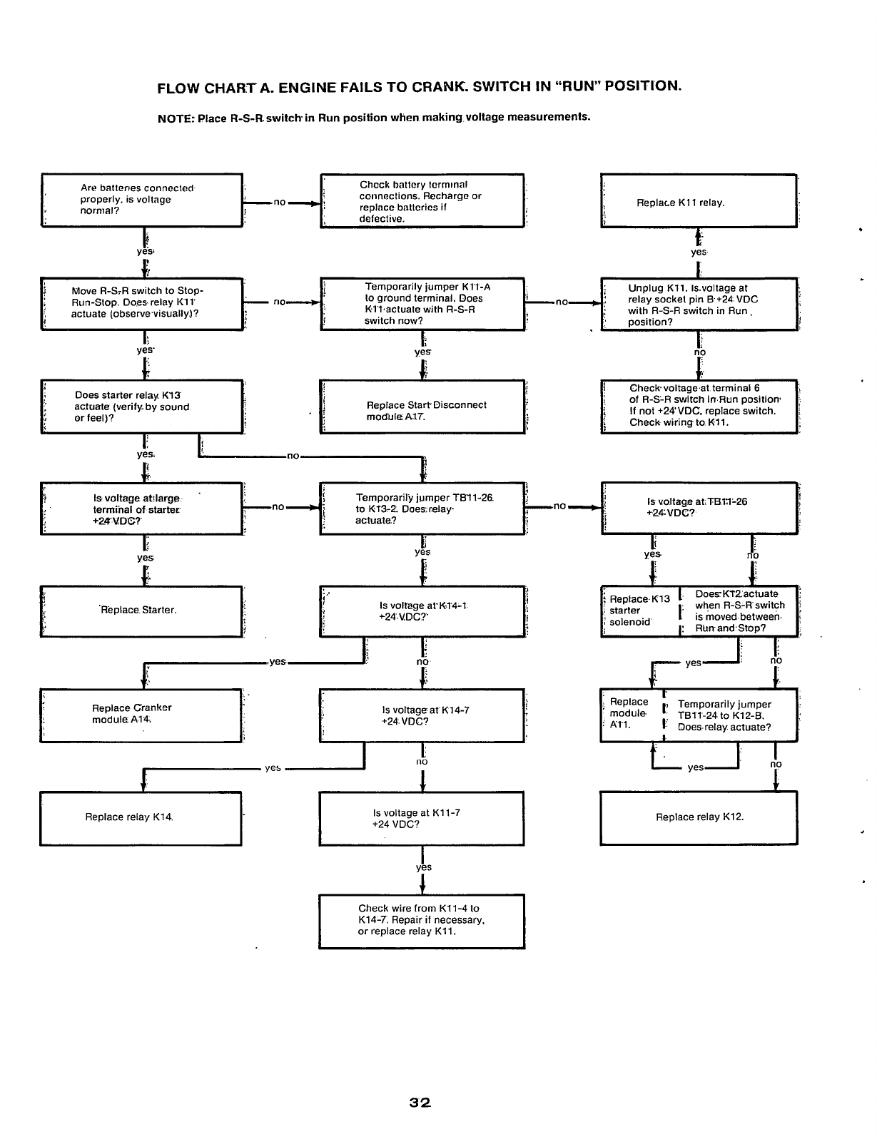
FLOW CHART
A.
ENGINE FAILS TO CRANK. SWITCH
IN
“RUN”
POSITION.
NOTE:
Place
R-S-R.
switch in
Run
position when making voltage measurements.
t
d
t
I
Chcck batlcry lcrrninal
connections. Recharge or
replace bnllcrias
if
Art?
ballcries connected
properly. is voltage
normal?
c
yes:
P
1;
defective.
1:
with
R-S-R
switch in Run,
switch now?
actuate (observe.visually.)?
Gheckvoltage,at terminal
6
.
of
R-S-R
switch in.Run position
;
i
If
not +24‘VDC. replace switch.
L
i
Check wiring to Kll.
Replace Start. Disconnect
moduleA37.
Does
starter relay
K13
actuate (verify
by
sound
orfeel)?
yes.
no
c
?
Is
voltage atJlarge.
‘
p
f
no
no
ID
KT3-2.
Doearelay.
1
actuate.?
terminal
of
starter
+ZrYY%D@?
Ir
!
1.
DoerKf2actuate
i
;
starter
1
when R-S-R‘switch
i
i
IS
moved between.
1:
RunandStop?
;
)’
solenoid
Is
voltege at‘K-14-1
t24-
VD
C?’
Replace. Starter.
I
no
;
Replace Ternporarilyjurnper
module
TB11-24
to K12-B.
‘
All.
1
Does-relay actuate?
Replace Cranker
Is
voltage atK14-7
+24-VDC?
Replace relay K12.
yks
1
Check wire from K11-4
to
K14-7. Repair
if
necessary,
32
Redistribution or publication of this document,
by any means, is strictly prohibited.
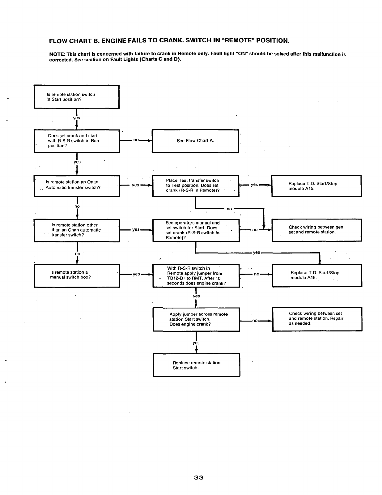
FLOW
CHART
B.
ENGINE FAILS TO CRANK. SWITCH
IN
"REMOTE
POSITION.
NOTE: This chart
is
concerned with failure to crank
in
Remote only. Fault light "ON" should be solved after this malfunction
is
corrected.
See
section on Fault Lights (Charts C and
D).
Is
remote station switch
in Start position?
Does set crank and start See Flow Chart A.
yes
1
Replace T.D. Start/Stop
Automatic transfer switch? module A15
crank
(R-S-R
in Remote)?
.
.
1
Check wiring between gen
set and remote station.
Is
remote station other
transfer switch? set crank
(R-S-R
switch
in
Remote)?
than an Onan automatic
-
yes
_.
I
I
i"'
I
I
yes
Replace T.D. StartIStop
manual switch box?. TBlP-B+ to
RMT.
After 10
seconds does engine crank?
Apply jumper across remote
station Start switch.
Does engine crank? as needed.
Check wiring between set
and remote station. Repair
Replace remote station
Start switch.
33
Redistribution or publication of this document,
by any means, is strictly prohibited.
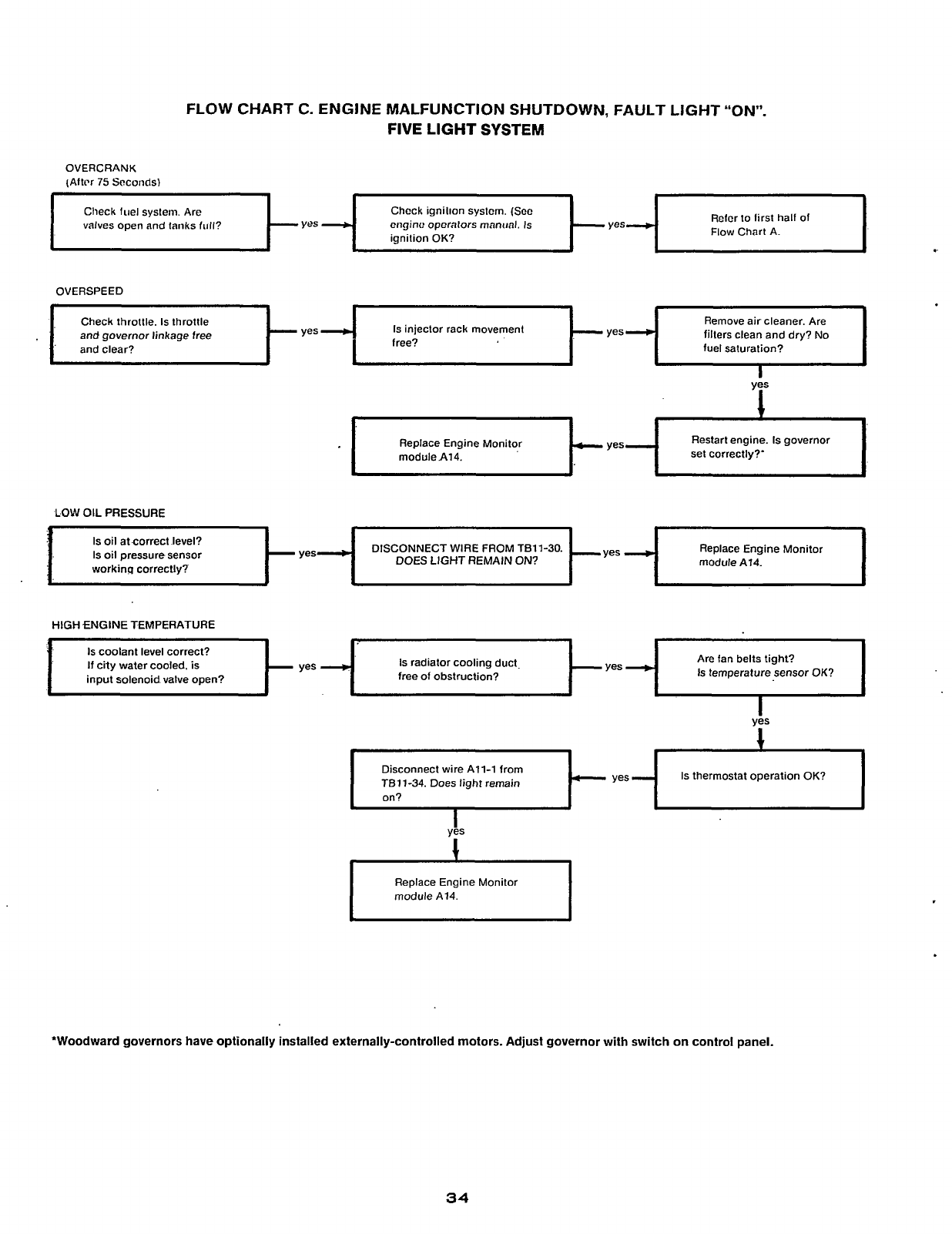
FLOW CHART C. ENGINE MALFUNCTION SHUTDOWN, FAULT LIGHT “ON”.
FIVE
LIGHT
SYSTEM
OVERCRANK
(Altrr
75
Seconds)
Chcck ignilion syslcm.
(Scc
ciiginc? operators mantml. Is
ignition
OK?
Rclcr
to
lirst half of
Check fuel system. Are
valves open and tanks full?
OVERSPEED
Check throttle.
Is
throttle
and governor linkage free
and clear? fuel saturation?
Remove air cleaner. Are
filters clean and dry? No
Is
injector rack movement
Restart engine.
Is
governor
Replace Engine Monitor
module A14. set correctly?’
LOW
OIL
PRESSURE
Replace Engine Monitor
module A14
DISCONNECT WIRE FROM TB11-30.
Is
oil at correct level?
Is
oil
pressure sensor
workinq correctly? DOES LIGHT REMAIN
ON?
HIGH
fNGlNE
TEMPERATURE
If
city water cooled. is
Is
radiator cooling duct Are fan belts tight?
Is
temperature sensor
OK?
yes
1
Is
thermostat operation
OK?
Disconnect wire All-1 from
TEll-34. Does light remain
1
I
Replace Engine Monitor
module
A14.
*Woodward governors have optionally installed externally-controlled motors. Adjust governor with switch on control panel.
34
Redistribution or publication of this document,
by any means, is strictly prohibited.
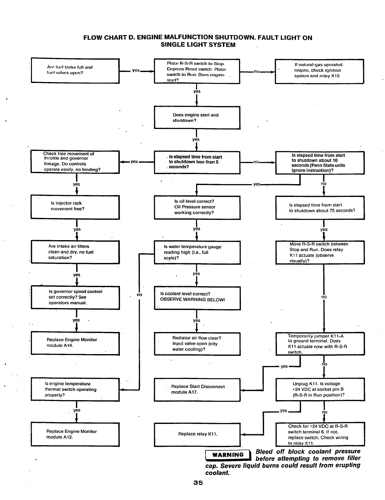
FLOW CHART
D.
ENGINE MALFUNCTION SHUTDOWN. FAULT LIGHT ON
SINGLE LIGHT SYSTEM
.-
AIP
lui’l
tanks
lull
and
IllCl
VillVCS
oprll?
t-
I
I
Di!prt!ss
Ri:si!l
switch Placr?
sw~lcl~
to
RIIII.
Dor!s r!iigini! r!nqinm. chcck ICJnltlCJn
systcm and
relay
K15
ves
I
Does engine start and
shirldown~
Is
elapsed time from start
to shutdown about
10
seconds (Penn State units
ignore instruction)?
Check free movement
of
throttle and governor
linkage. Do controls
.
Is
elapsed
time
from
start
to shutdown
less
than
5
yes
Is
injector rack
movement free?
Are intake air filters
clean and dry. no fuel
saturation?
I
Is
governor speed control
set correctly? See
operators manual.
fi0
Replace Engine Monitor
module
A14.
thermal switch operating
Replace Engine Monitor
module
A12.
no
I
Oil Pressure sensor
working correctly?
Is
water temperature gauge
reading high (i.e.. full
scale)?
I
I
yis
I
t
Is
coolant level correct?
OBSERVE
WARNING
BELOW!
I
Radiator air ilow clear?
Input valve open (city
Replace Start Disconnect
module
A17.
I
..
I
Replace relay
Kll.
Is
elapsed time from start
to shutdown about
75
seconds?
yes
Move
R-S-R
switch between
Stop and Run. Does relay
K11
actuate (observe
visually)?
fl0
to ground terminal. Does
K11
actuate now with
R-S-R
Unplug
K11.
Is
voltage
+24
VDC at socket pin B
(R-S-R
in Run position)?
switch terminal
6.
If
not.
replace switch. Check wiring
I
to relay
KII.
I
WARN,NG
Bleed off block coolant pressure
before attempting to remove filler
cap. Severe liquid burns could result from erupting
coolant.
35
Redistribution or publication of this document,
by any means, is strictly prohibited.
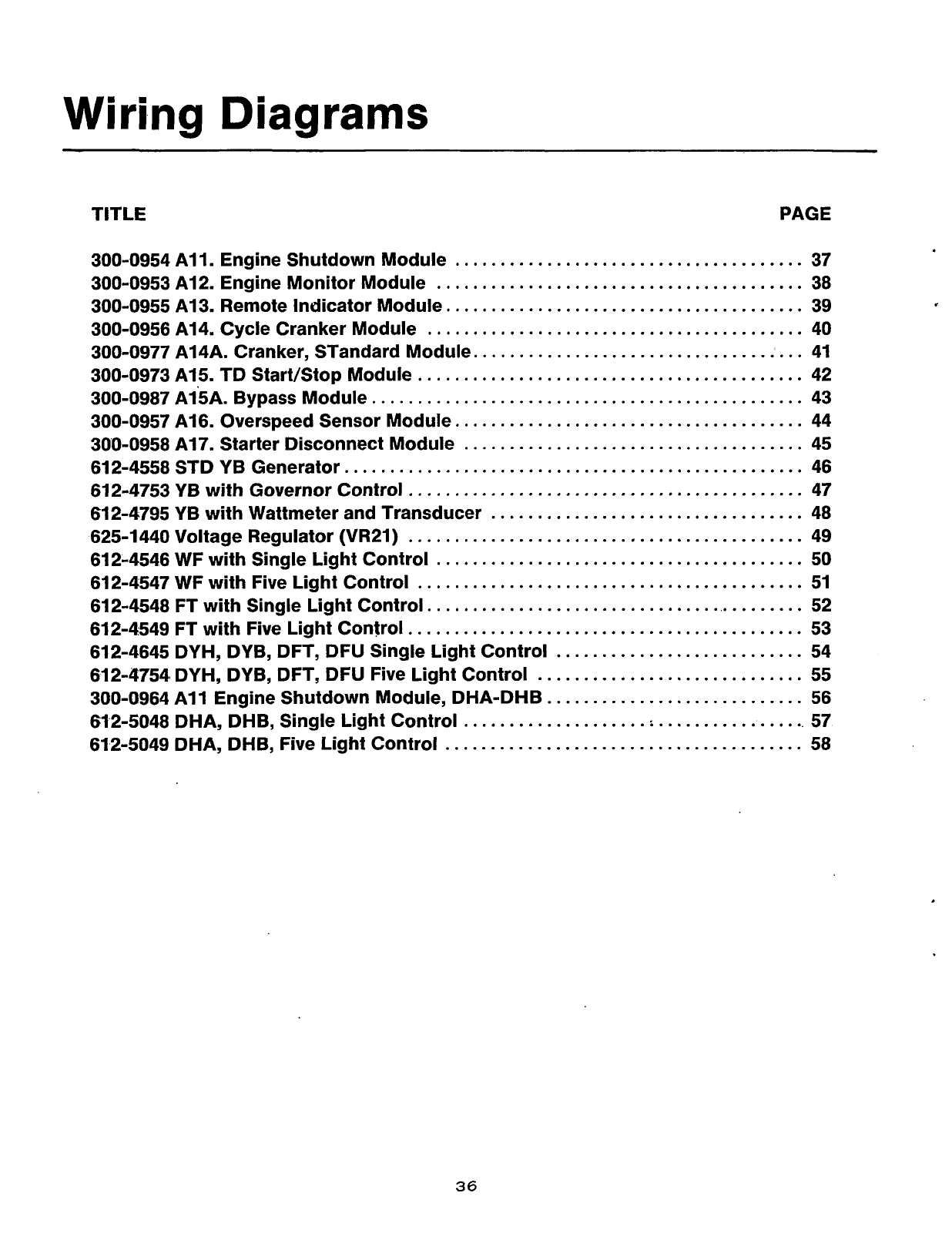
Wiring Diagrams
TITLE
PAGE
300-0954 All
.
Engine Shutdown Module
......................................
37
300-0953 A12
.
Engine Monitor Module
........................................
38
300-0955 A13
.
Remote Indicator Module
.......................................
39
300-0956 A14
.
Cycle Cranker Module
.........................................
40
300-0977 A14A
.
Cranker. STandard Module
....................................
41
300-0973 A15
.
TD Start/Stop Module
..........................................
42
300-0987 A15A
.
Bypass Module
...............................................
43
300-0957 A16
.
Overspeed Sensor Module
......................................
44
300-0958 A17
.
Starter Disconnect Module
.....................................
45
612-4558
STD YB Generator
..................................................
46
612-4753
YB
with Governor Control
...........................................
47
612-4795
YB with Wattmeter and Transducer
..................................
48
612-4546
WF with Single
Light
Control
........................................
50
612-4548
FT with Single Light Control
..........................................
52
625-1440
Voltage Regulator
(VR21)
...........................................
49
612-4547
WF with Five
Light
Control
..........................................
51
612-4549
FT with Five
Light
Control
...........................................
53
612-4645
DYH, DYB, DFT, DFU Single Light Control
...........................
54
612-4754,
DYH, DYB, DFT, DFU Five Light Control
.............................
55
612-5048
DHA, DHB, Single Light Control
......................................
57
612-5049
DHA, DHB, Five Light Control
.......................................
58
300-0964 A1
1
Engine Shutdown Module, DHA-DHB
............................
56
36
Redistribution or publication of this document,
by any means, is strictly prohibited.
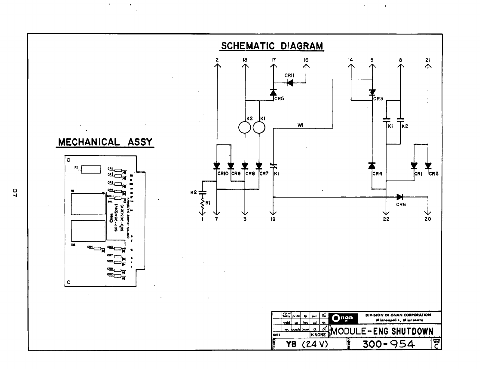
MECHANICAL
ASSY
lo
I
SCHEMATIC
DIAGRAM
2
18
17
16
14
5
8
21
YR5
1'1'
'
R4
17
3
19
22 20
I
:R
2
Redistribution or publication of this document,
by any means, is strictly prohibited.

I
21
4
I
I
>
13,
I4
>
18
?ti
7"
MECHANICAL
ASSY
N
N
0
N
c!
m
2
5
W
W
Ln
P
0
N
r
r
OK
INPUT
O/C
OUTPUT
LAMP TEST
SHUTDOWN
SHUTDOWN
QROUND
ois
OUTPUT
5
6
3
S
P
E
C
I
F
I
C
AT
I
0
N
S
CRI
I
2
B+
POWER
..............................................
.24-6.VDC
LOW
OIL
PRESSURE
TIME DELAY (TDC)
...................................
.12.5~2.5 SEC
OVERCRANK
TIME DELAY (TDC)
......................................
.75+
5
SEC
STORAGE TEMPERATURE..
.........................
40'C
to
100°C
OPERATING TEMPERATURE..
.......................
40°C
to
80°C
DIAGRAM SYMBOL
LOW
OIL
PRESSURE
OVERCRANK
OVERSPEED
Y
I
I1
10.
IY
Redistribution or publication of this document,
by any means, is strictly prohibited.
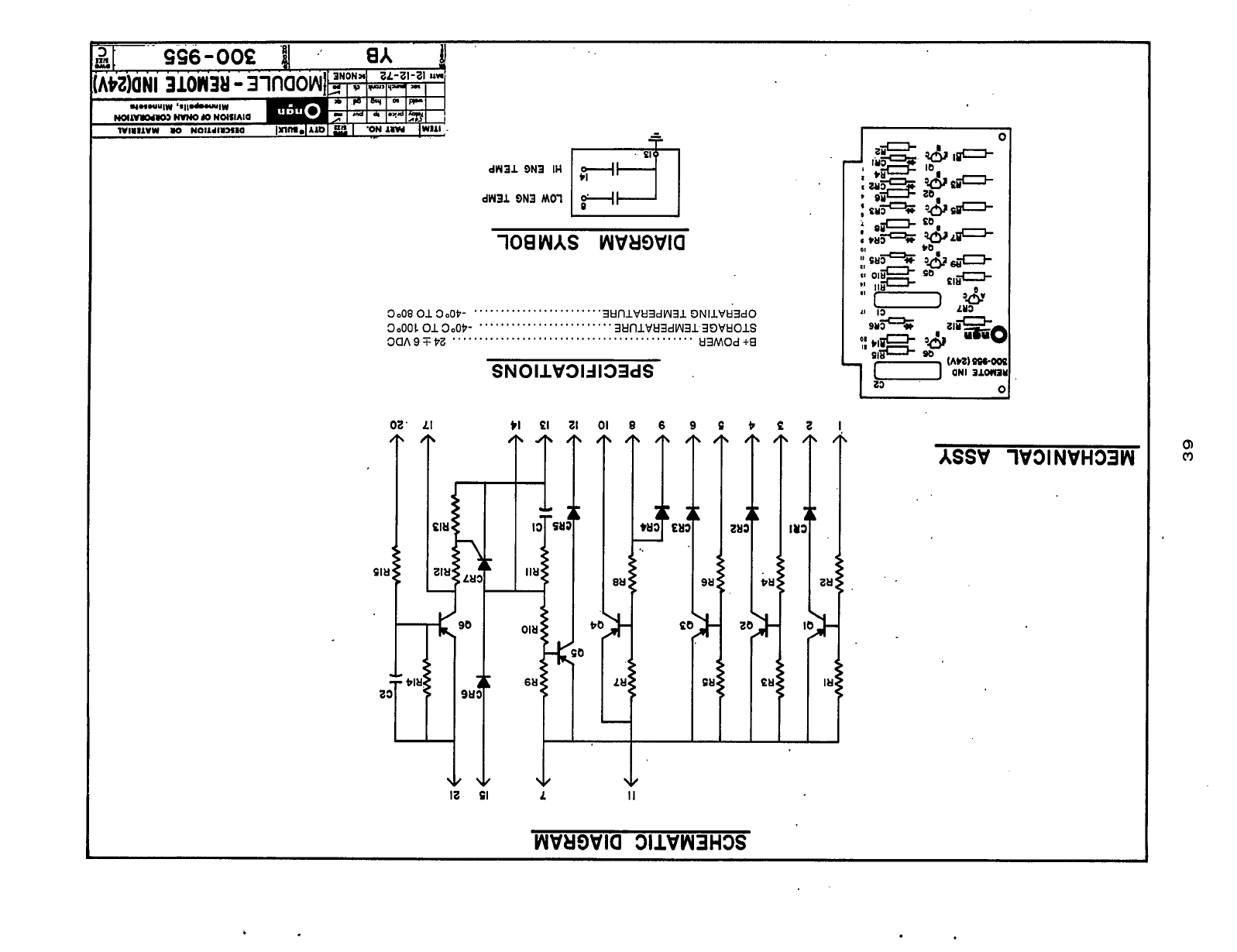
dR31
BN3
11.1
dR31
SN3
Mol
IY3
........................
3tlfllVtl3dW31 DNIlVtl3dO
3tlnlVkl3dW313E)VtlOlS
3oo*
01300p-
3oooL
01300p-
3a*9
-+
pe
.........................
.............................................
kl3MOd
+9
SNOllV313133dS
.
m
IC
02'
LI tlEl2101
8
6
9
E
C
€
2
.
WVUWKl
311VW3H3S
ASSV
1V31NVH33W
.
Redistribution or publication of this document,
by any means, is strictly prohibited.
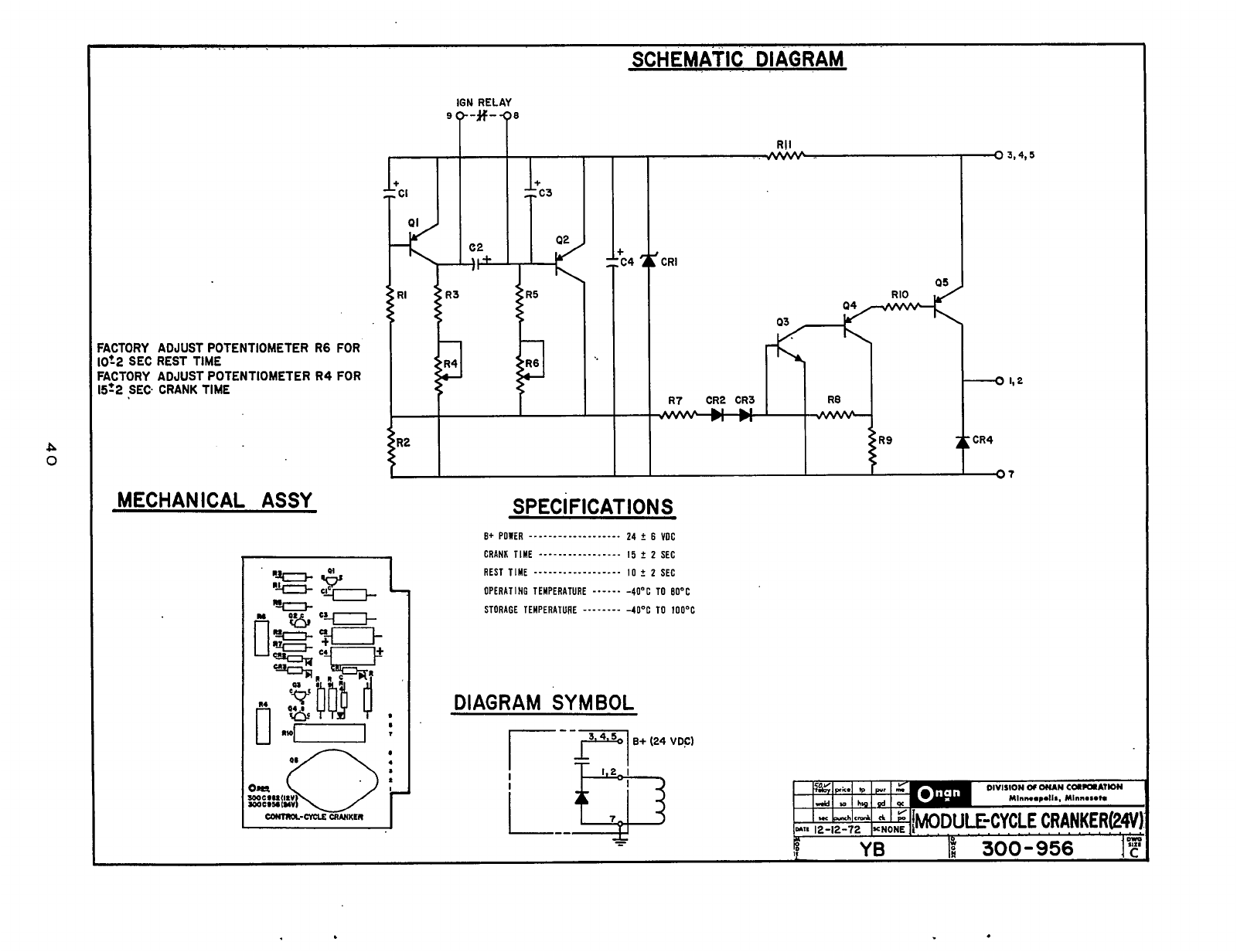
0
..
SCHEMATIC DIAGRAM
ICTORY ADJUST POTENTIOMETER
R6
FOR
Dt2
SEC REST TIME
ICTORY ADJUST POTENTIOMETER
R4
FOR
5r2
SEC CRANK TIME
MECHANICAL ASSY
9
7
IGN
RELAY
'-#-
T8
II
03
SPEC
I
FIC AT ION
S
DIAGRAM
SYMBOL
Redistribution or publication of this document,
by any means, is strictly prohibited.
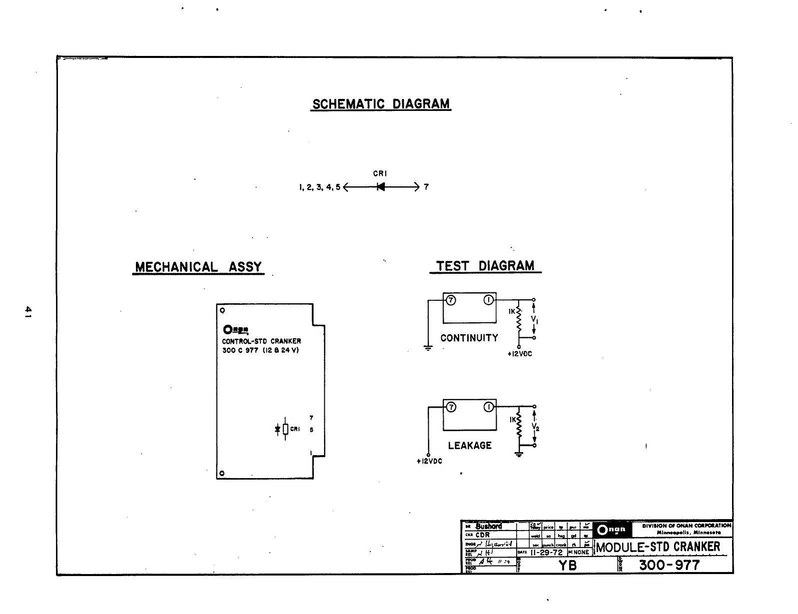
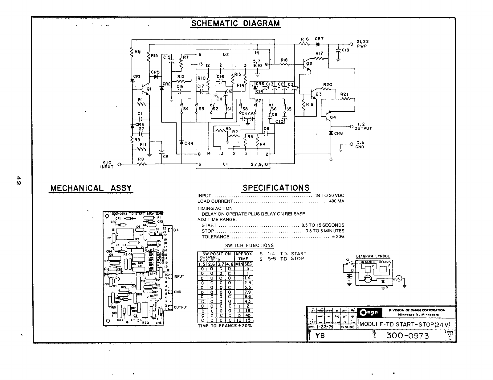
4
.~
........
~
.................
,
......
..
.........
SCHEMATIC
D
I
AG.R
AM
9,lO
INPUT
I'
1
1
CR3
1
/I
MECHANICAL ASSY
R16
CR7
21,22
PWR
INPUT..
...........
SPEC
I
F
IC
AT
I
ON
S
..................................
24
TO
30
VDC
LOAD CURRENT..
.........................................
400
MA
TIMING ACTION
ADJ TIME RANGE:
DELAY ON OPERATE PLUS DELAY
ON
RELEASE
START
......................................
0.5
TO
15
SECONDS
STOP..
.......................................
0.5
TO
5
MINUTES
TOLERANCE
..............................................
5
20%
SWITCH FUNCTIONS
S
S
1-4
5-8
T.D. START
T.D
STOP
DIVISION
01
OlUN
mCQAllON
Ml-*ll..
YI.".#.rn
LEK
-
-h
$d
n
!
DIT
r
Redistribution or publication of this document,
by any means, is strictly prohibited.
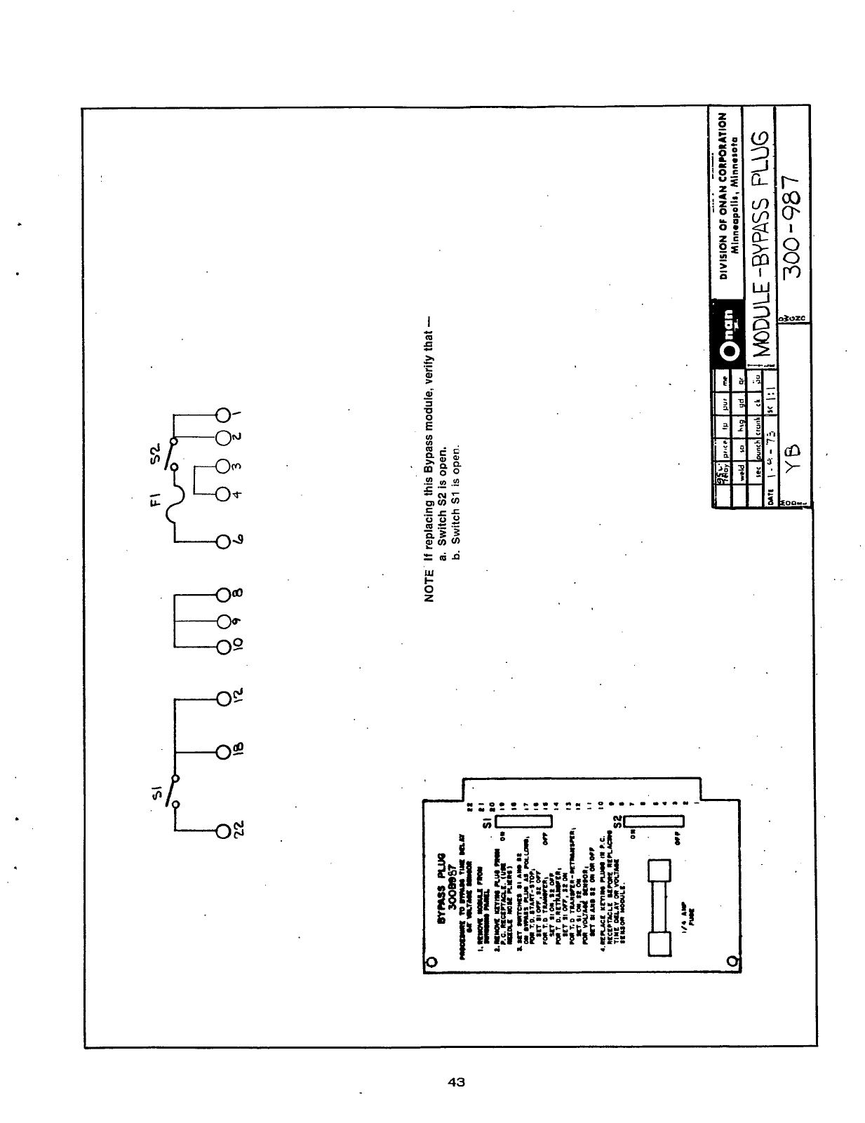
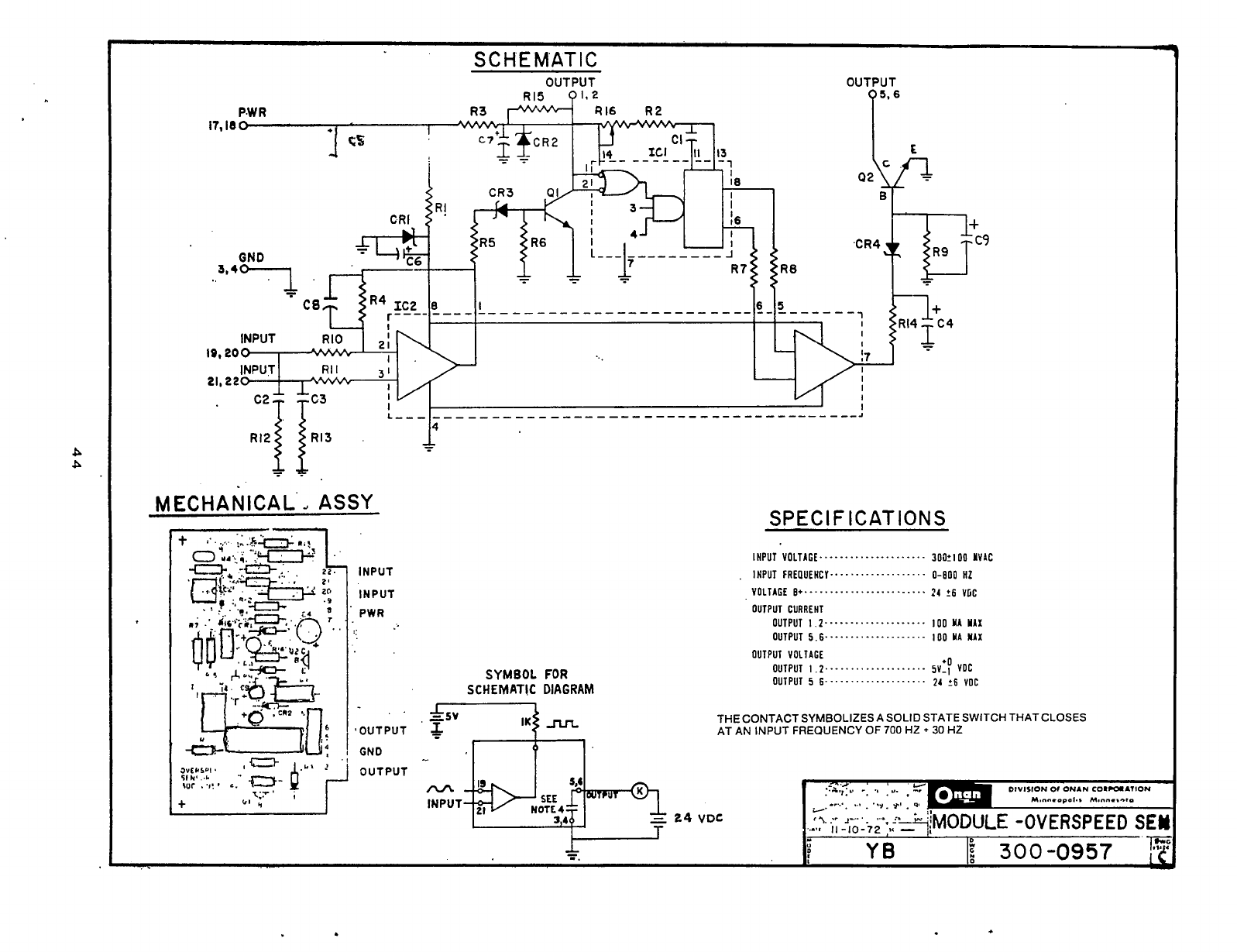
S
C
H
E
MAT
I
C
P.W
R
OUTPUT
p"'
MECHANICAL
ASSY
INPUT
INPUT
PWR
'OUTPUT
GND
OUTPUT
SYMBOL
FOR
SCHEMATIC
DIAGRAM
SPEC1
F
ICATIONS
THE CONTACT SYMBOLIZES A
SOLID
STATE SWITCH THAT CLOSES
AT AN INPUT FREQUENCY
OF
700
HZ
+
30
HZ
Redistribution or publication of this document,
by any means, is strictly prohibited.
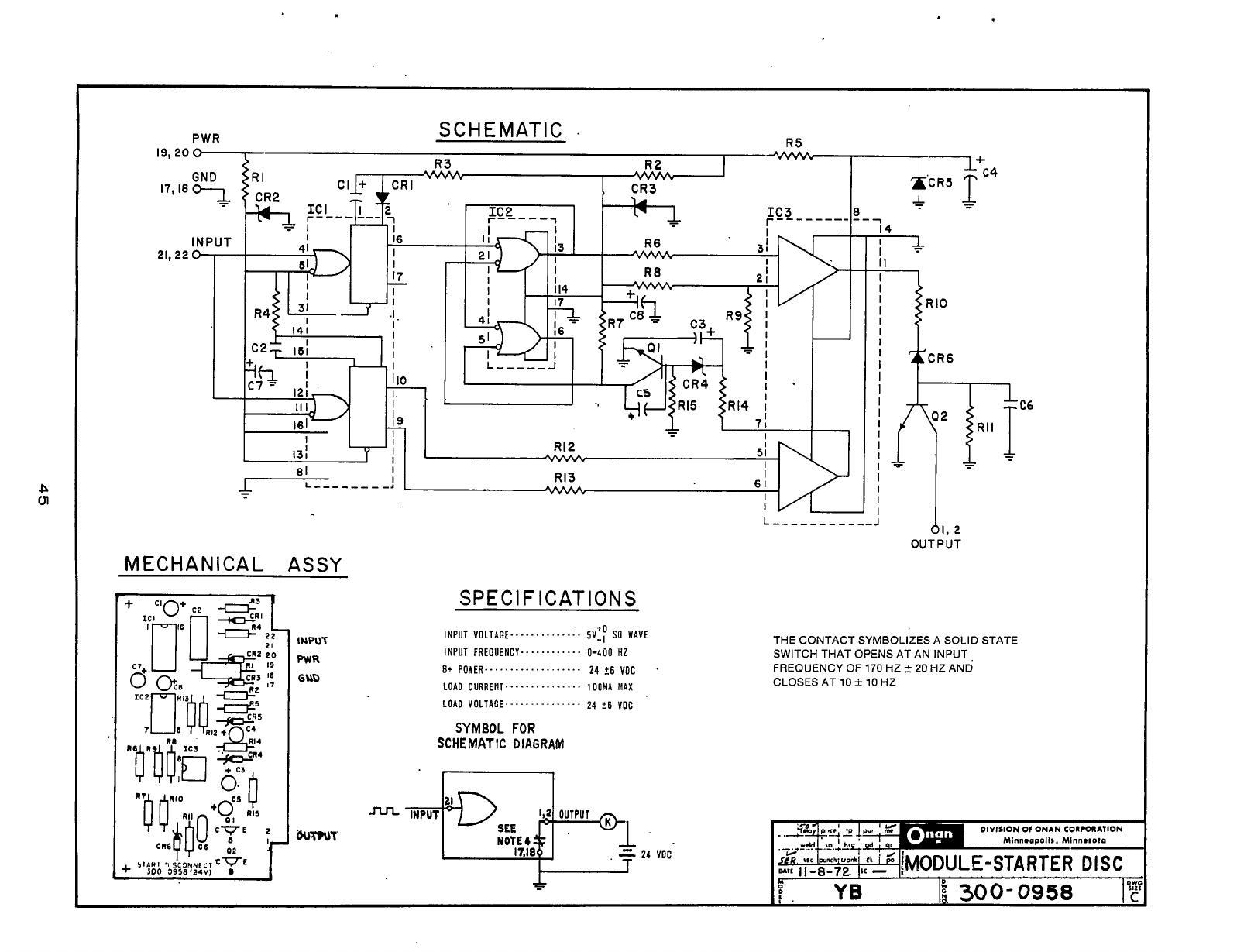
L
cn
INPUT
R5
SCHEMATIC
.
R3
,
CR3
R2
I
+2?4
-
-
7
IC3
8
r--------
--
IC2
r-----i
-
I
131
i4
I
I
I
I
dl.
2
OUTPUT
MECHANICAL ASSY
IUQUT
PWR
6UD
SPEC1
F
ICATIONS
INPUT
VOLTAGE.....
..........
sv'p
sa
WAVE
INPUT
FRERUENCY..
..........
0-400
HZ
E+
POWER
...................
24
+E
VOC
.
LOA0
CURRENT
...............
IOOMA
MAX
LOAD VOLTAGE...
............
24
26
voc
SYMBOL
FOR
SCHEMATIC
DIAGRAM
NOTE
4
=
24
VOC
T
THE CONTACT SYMBOLIZES A SOLID STATE
SWITCH THAT OPENS AT AN INPUT,
CLOSES AT
10
i
10
HZ
FREQUENCY
OF
170
HZ
2
20
HZ AND
DIVISION
Or
ONAN
CORPORAlION
Minn.apolls. Minnesota
€-STARTER
DISC
a8
D
YB
If
300-0958
1'2
:.
Redistribution or publication of this document,
by any means, is strictly prohibited.

1"
I
I
I
I
I
W22-NOTE:
SEE VOLTAGE
CONNECTION
1
CHART
I
I
---t
I-
-
--
1-
-
HGSGG-CONTROL
BOX
W
a
EXCITER
F+
GENERATOR
@FrkTl
CRI
CR2 CR3
-
T2
-
CR4 CR5 CR6 T3
-
T4
-
T5
-
T6
-
T7
-
TB
-
T9
-
TlO-
EXCITER
ALTERNATOR
021
L3
L2
LI
LO
..-
,
-.
CONNECT LEAD
W22
FROM
TERMINAL T821-63 TO T821-IH-I
FOR THESE VOLTAGE CONNECTIONS
AC CONTROL PARTS
LIST
REF.
DES.
CB21
CR21
CT21-23
D321
DS22
G21
K21
L21
M21
M22
M23
M24
R21
R22
521
T21
TB21
VU21
OTY. DESCRIPTION
1
1
1
1
1
1
1
1
1
1
1
1
1
1
1
1
1
1
Circuit Breaker
3
Amp
Rectifier Bridge
Transformer Assy
-
Cur
Light-Upper Scale
Light-Lower Scale
Generator
Relay-Voltage Selector
Reactor Assy Comm
Ammeter
~
AC
Voltmeter
-
AC 0-30G
Meter Frequency
Meter
-
Running Time
Rheostal-Voltage
3.5
k
25
w Ad1
Resislor
-
47
000
Switch-Volt
8
Ammeter
Transformer
-
Volt Re1
Marker-Strip
Board Assy
-
PC Voltage
Regulator
0-600
1
2
Watt
110/190V.
50Hi.
IH31
220f380V
50HZ lH3)
11Sf2OOV.
50H1,
tH4)
230f400V'
SOHI)
IH4)
517R
120f208V.
50Hq
IH41
'pH
240f416V.'
50Hz:
IH41
3PH
127/220V.
SOHI.
IH5)
ZS4M4OV.
SOHZ.
lH5)
120/208V
60Hr
lH31
24Of41E.V.
60Hq
H3
17R l27f220V:60H~.
lH41
3PH 254f440V.
60H2,
IH41
3PH
139f240V.
60Hz.
IHSI
27714BOV.
SOHI. IH51
L3
L2
[ill1
"WL2
"W
17
no
L2
L3
L2
6109
a31Il
50
80
02
010
5[08
12
0
10
4[07
1
I
0
12
LI
LI
Lo
CT23
TU
CT22
4
0
7
0
0
I
0
12
CT21
T6 CT23
TI2
Tv
LO
M
LL
LJI
THIS CHART USE0
FOR
MANUFACTURING ONLY
2~~-';;OKW-17R,,
--
7-30-73 VCIP
rasA
v'''~q
60Hz
200-350KW-517WWI CONTROL-BEN SET AC
NOTE:
UNLESSOTHERWISE NOTED
4LL COMPONENTS ARESHOWk
1;;
l~~!RUSHLESS
POSITION 301-350
-04
-08
-12
12W
RECONNECTABLE.
-
-
(WIRING DIAGRAM)
KW
60Hz
50Hz
IN THE DE-ENERGIZED 251-300
-03
-07
-11
3PH,5D/60Hz
612-4558
-
.'
-
Redistribution or publication of this document,
by any means, is strictly prohibited.
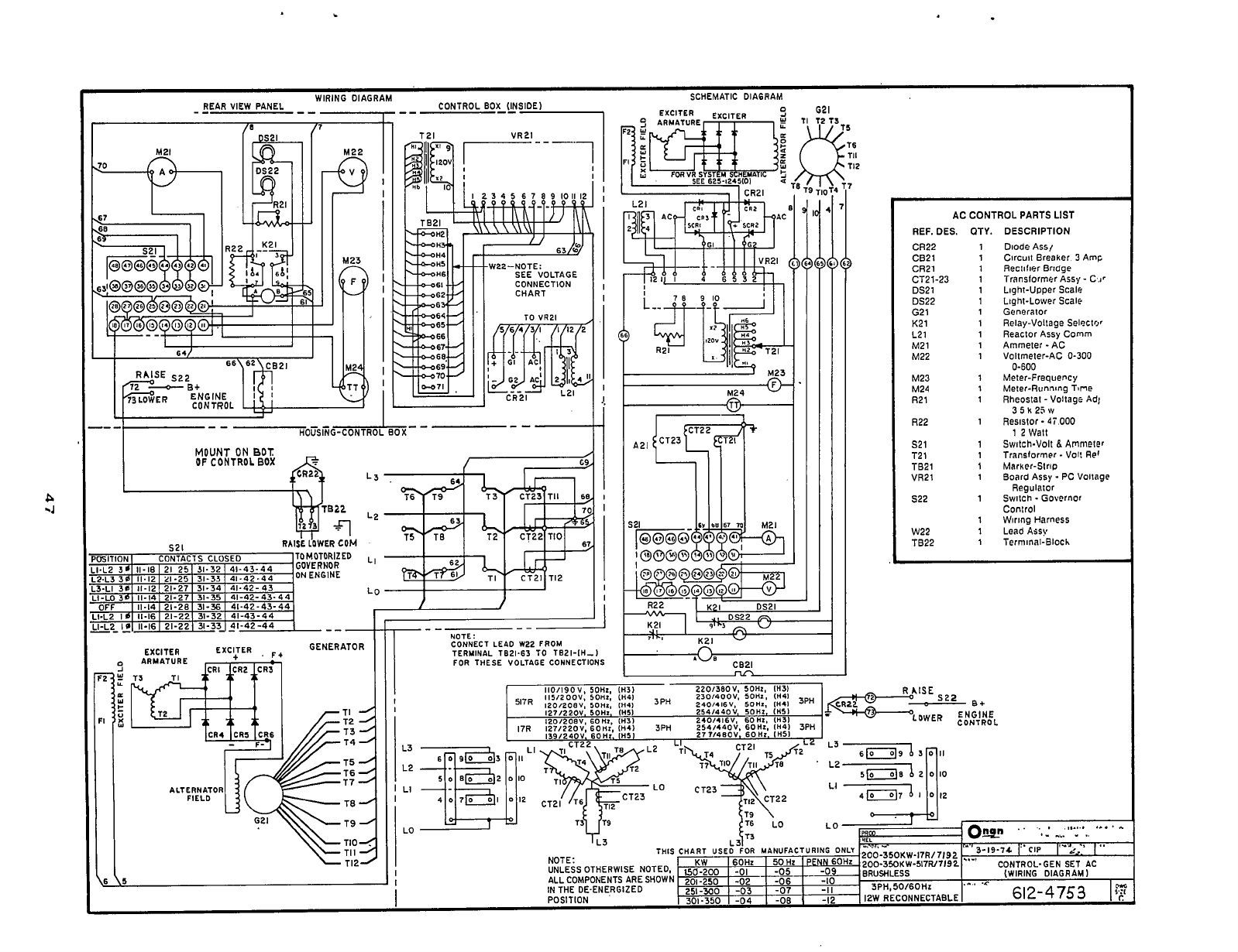
SCHEMATIC-Dl AGR
AM
WIRING DIAGRAM CONTROL
BOX
(INSIDE)
--
1
-
--
REAR
VIEW PANEL
-
-
--
----1
I.
I
I.
.
In
I
-P-
67
L-1
AC CONTROL
PARTS
LIST
REF. DES. OTY.
CR22 1
CB21 1
CR2l 1
CT21-23 1
DS21 1
DS22
1
Gal 1
K21 1
L21 1
M21 1
M22 1
M23 1
M24
1
R21 1
R22
1
521
1
T2
1
1
TB21
1
VR21 1
822 1
1
w22 1
T922 1
DESCRIPTION
Diode
ASS/
Circuit Breaker
3
Amp
Reclilier Bridge
Translormer Assy
-
Light-Upper Scale
Light-Lower Scale
Generator
Relay-Voltage Selector
Reactor Assy Comm
Ammeter
-
AC
Voltmeter-AC
0-300
Meter-Frequency
Meter-Running Tme
Rheostat
-
Voltage
Ad!
Resistor
-
47
000
Switch-Volt
a
Arnmeler
Translormer
-
Vol: Re'
MarKer-SlrlD
9oard Assy
-
PC Voltage
SwllCh Regulator
.
Governor
Control
Wiring Harness
Lead
Assy
Terminal-Block
0-600
35k2Sw
1
2
Watt
W22-NOTE:
SEE
VOLTAGE
CONNECTION
1
I
62
CHART
f
I
I
i'
I
I
--II
-
-I_-
---t-----
-
HOUSING-CONTROL
BOX
MOUNT
ON
BOT:
OF
CONTROL
BOX
L3
'k;
c9,
RAISE
LOWER
COM
L2
JLI
LO
I
I
NOTE:
CONNECT
LE40
W22
FROM
TERMlN4L
TB21.63
TO
TEZI-IH-1
FOR
THESE
VOLTIGE
CONNECTIONS
EXCITER
GENERATOR
T7
ALTERNATOR
FIELD
T9
\6
\S
n
'"'
CB2l
Redistribution or publication of this document,
by any means, is strictly prohibited.
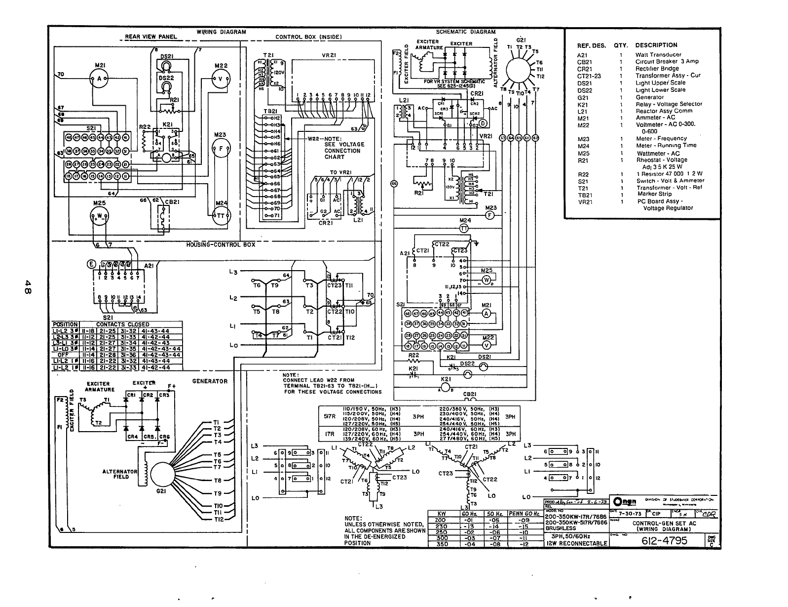
P
00
-3-
WIRING DIAGRAM SCHEMATIC DIAGRAM
REAR VIEW PANEL
-
--
CONTROL
0OX-(4SlDEl
-
-
--
HGSKG-CONTRO
--Y-
W22-NOTE:
SEE
VOLTAGE
CONNECTION
CHART
TO
VR21
E-
-
T21
M24
c/
YJ
'I*'
K21
"
c021
REF. DES.
my.
DESCRIPTION
1 Watt Transducer
A21
CB21 1 1 Circuit Rectilier Breaker Bridge
3
Amp
CR21
CT21-23 1 Translormer
Assy
-
Cur
1 Light UppeiScale
DS21 1 Llghl Lower Scale
DS22
G21 1 Generator
1 Relay
-
Vollage Selector
K21
1
Reactor Assy Corm
L2
1
t
Ammeter
-
AC
M21
M22
1
Vollmeter
-
AC
0-300.
0-600
M23
M24 1 Meter
-
Running Time
M25
R21
1
Resistor Ad1
3
5
K
47
25
000
W
1
2
VJ
R22
s21
1
switch
-
volt
a
Ammeter
T21 1 Transformer
-
Volt
-
Ref
TB21 1 Marker Strip
VR2l
1 Meter
-
Frequency
1 Wattmeter
-
AC
1
Rheostat
-
Voltage
1
1
PC Board ASSY
-
Voltage Regulator
Redistribution or publication of this document,
by any means, is strictly prohibited.

I
I
d
VR21
’
332-1956iD)
WARD
A5SY.K
1
1
SCHEMATK
DIAG-VR
SYSTEM
.-
ICLASSB
:::-,-
625-1440,
]
Redistribution or publication of this document,
by any means, is strictly prohibited.
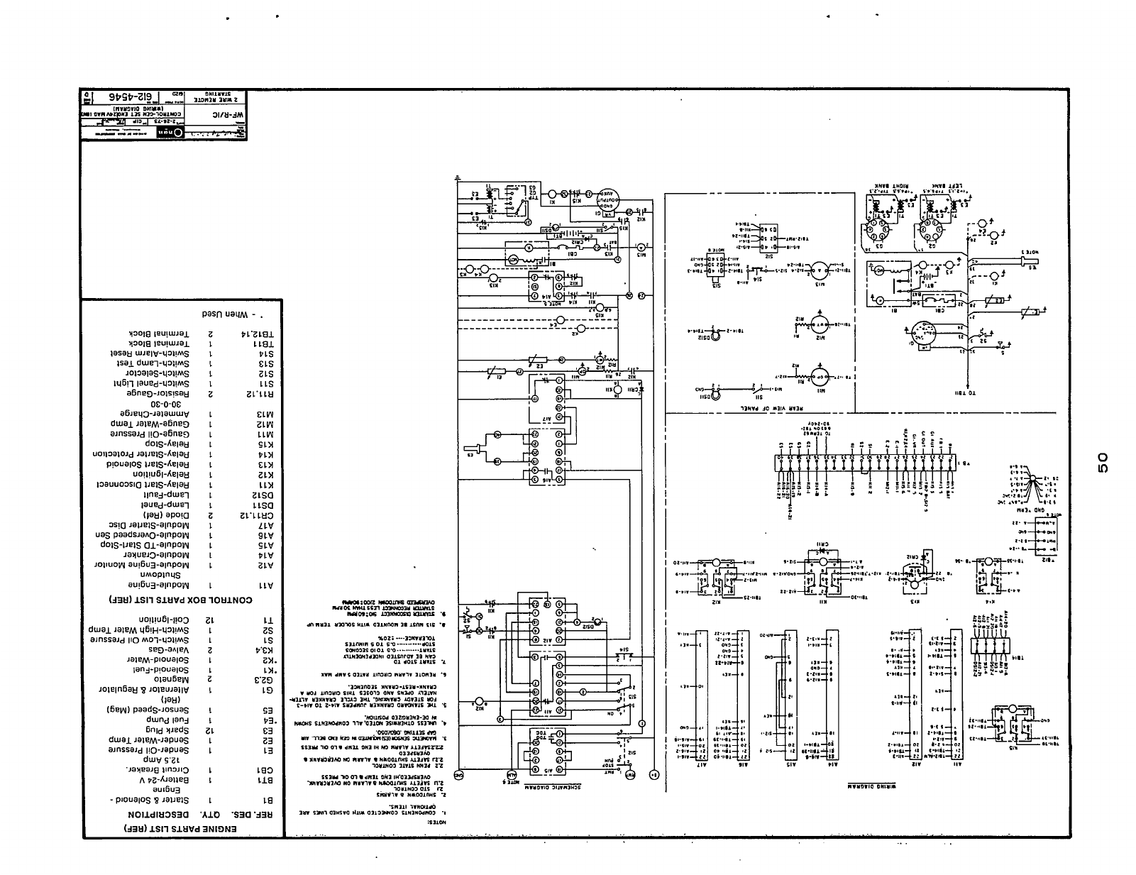
z
L
L
L
L
L
z
L
L
L
L
L
L
L
L
L
L
z
L
L
L
L
L
1
PL'ZLBJ.
L
LBJ.
PLS
ELS
ZLS
L
1s
ZL'LLH
&LW
ZLW
LLW
sin
Pin
tin
ztn
tin
ttsa
ZLSQ
ZL'L
LH3
LLV
9LV
SLV
PLV
ZLV
LLV
1113
I
"l"(1110
01111.
..I
0
LD
Redistribution or publication of this document,
by any means, is strictly prohibited.
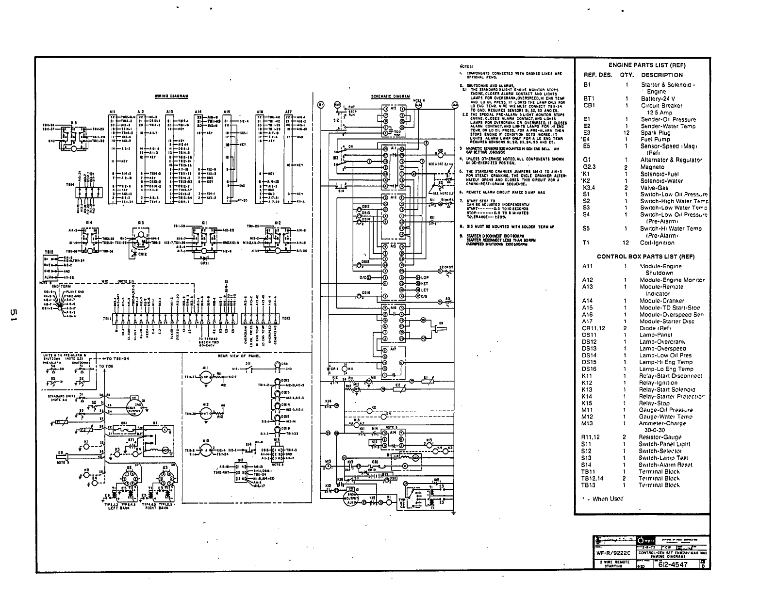
WllYO
0IAOIA.Y
,.
l...
I
TI'
114
113
ENGINE PARTS LIST (REF)
REF. DES.
OTY.
81
1
ET1 1
CB1 1
El 1
E2 1
12
E3
'E4 1
E5 1
G1
1
G2.3 2
'K1 1
'KZ 1
K3.4 2
s1 1
52 1
53 1
54 1
s5 1
T1 12
DESCRIPTION
Starler
8
Solenold
-
Engine
Baltery-24
V
Circuit Breaker
12 5 Amp
Sender-Oil Pressure
Sander-Water Temp
Spark
Plug
Fuel Pump
Sensor-Speea
iUaq~
rReli
Allernator
8
Regulator
Magneto
Solenoid-Fuel
SOlenOld-Waler
Valve-Gas Swltch-Low
011
PrCSs,.rr:
SvillCh-Hlgh VJaler TrFi
Swilch-Low Waler Tecc
Switch-Low
Oil
Presst.*f
Switch-Hi Vlater Temo
Coil-lgnilion
IPre-Alarm
I
IPre-Alarm,
CONTROL BOX PARTS
LIST
(REF)
A1 1 1
A12 1
A13 1
A14 1
A15
1
A16 1
A17
1
CR11.12 2
DS11 1
DS12 1
DS13 1
DS14 1
DS15 1
DS16 1
Kll 1
K12
1
K13 1
K14 1
K15 1
M11 1
M12 1
M13 1
R11.12
2
SI 1
1
512
1
513 1
s14 1
TB11
1
TB12.14 2
TB13 1
-
Whcil
UScd
Uodule-Engine
Shutdown
Module-Englne
hlorlicr
Moatile-Remale
Module-Cranher
Module-TD Star!-Sic@
Module-Oserspeec Sen
Module-Starter DISC
Diode iReli
Lamp-Panel
Lamp-Overcranh
Lamp-Overspeea
Lamp-Low
Oil
Pres
Lamp-Hi Eng Temp
Lanip-Lo
Eng
Temp
Relay-Start Dmonncc:
Relay-Ignition
Relay-Start
Sclri~aic
Relay-Slarlri
Prs:?r:w
Relay-Slop
Gauge-Oil
Prrssurr
Gauge-Watei Tenit\
Aninlelcr-Charge
Resistor-Gauge
Indicator
30-0-30
Swltch-Pailel
Llglll
SwltCh-Selt~i.l~i
SwItCh-LclIlI~
TPSI
Switch-Alariii
Rr~dl
Tsrniiiial
Blacb
Tcitlriirnl
Bloch
Tt.rt1ilii.ll
Bloc
h
Redistribution or publication of this document,
by any means, is strictly prohibited.
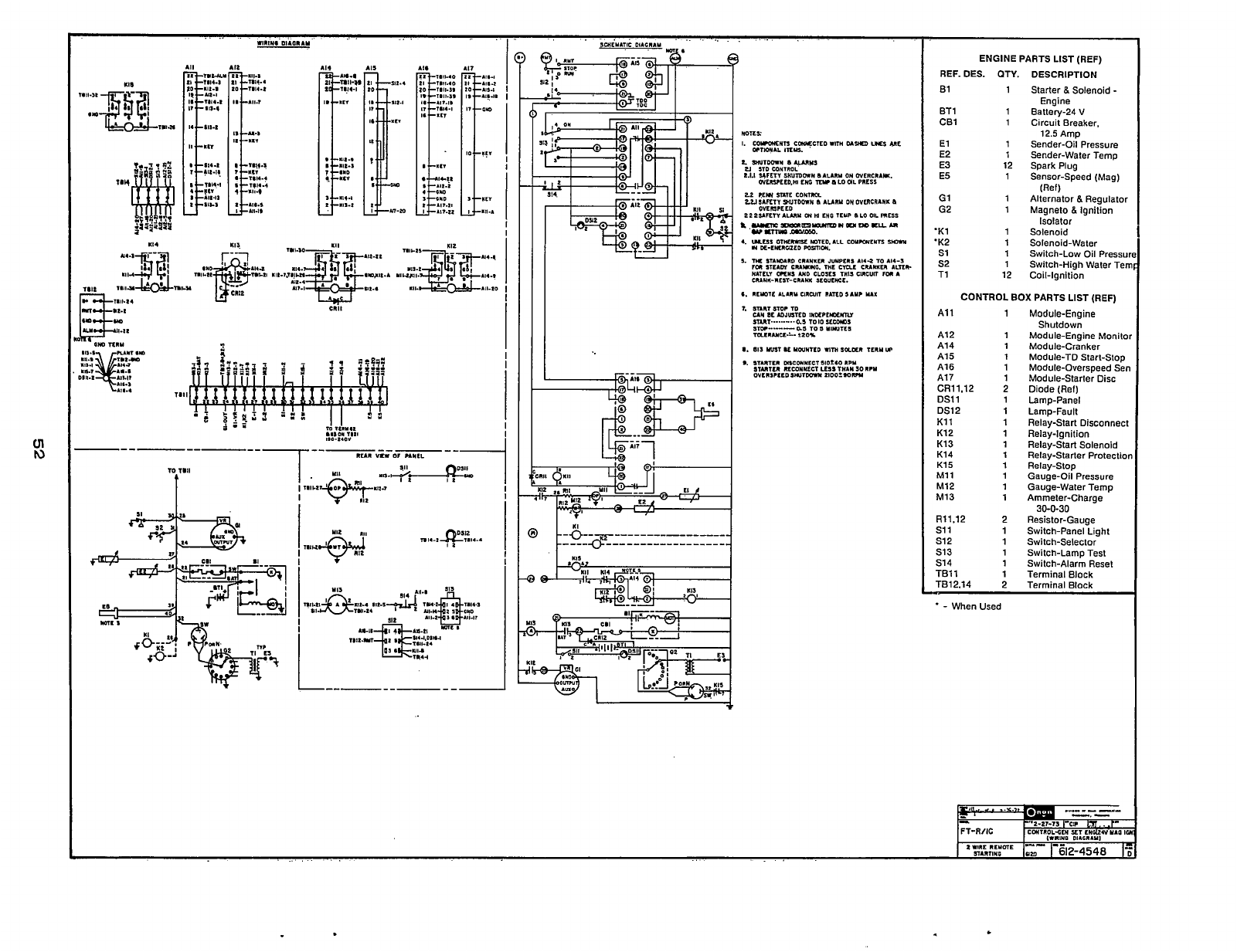
IUS
NI4
m
1111
I
,.+.&
I...
ENGINE PARTS LIST (REF)
REF. DES. QTY. DESCRIPTION
1 Starter
8
Solenoid
-
61
Engine
1 Battery-24
V
ET1 1 Circuit Breaker,
CB1
12.5
Amp
1 Sender-Oil Pressure
El
E2 1 Sender-Water Temp
12
Spark Plug
E3
1 Sensor-Speed (Mag)
E5
G1
1
Alternator
8
Regulator
G2
(Ref)
1
Magneto
8
Ignition
Isolator
'K1 1 Solenoid
'K2 1 Solenoid-Water
s1 1 Switch-Low Oil Pressul
52
1 Switch-High Water Ten
T1 12 Coil-Ignition
CONTROL
BOX
PARTS LIST (REF)
A1 1 1
A12 1
A14 1
A15
1
A16
1
A17 1
CR11.12 2
OS1 1 1
OS12 1
K11
1
K12
1
K13 1
K14
1
K15
1
M11 1
M12
1
M13
1
R11.12 2
s11
1
s12 1
S13 1
S14 1
TI31 1 1
Module-Engine
Shutdown
Module-Engine Monito
Module-Cranker
Module-TD Start-Stop
Module-Overspeed Sen
Module-Starter Disc
Diode (Ref)
Lamp-Panel
Lamp-Fault
Relay-Start Disconnect
Relay-Ignition
Relay-Start Solenoid
Relay-Starter Protectioi
Relay-Stop
Gauge-Oil Pressure
Gauge-Water Temp
Ammeter-Charge
Resistor-Gauge
Switch-Panel Light
Switch-Selector
Switch-Lamp Test
Switch-Alarm Reset
Terminal Block
Terminal Block
30-0-30
.
-
When Used
I
IWIIIYO
Dl.C"IYI
ZWUL
RLYDIE
"-a-
--
~ARTIYG
lam
1
612-4548
E
.
.,
.
,
. .
.
..
.
Redistribution or publication of this document,
by any means, is strictly prohibited.
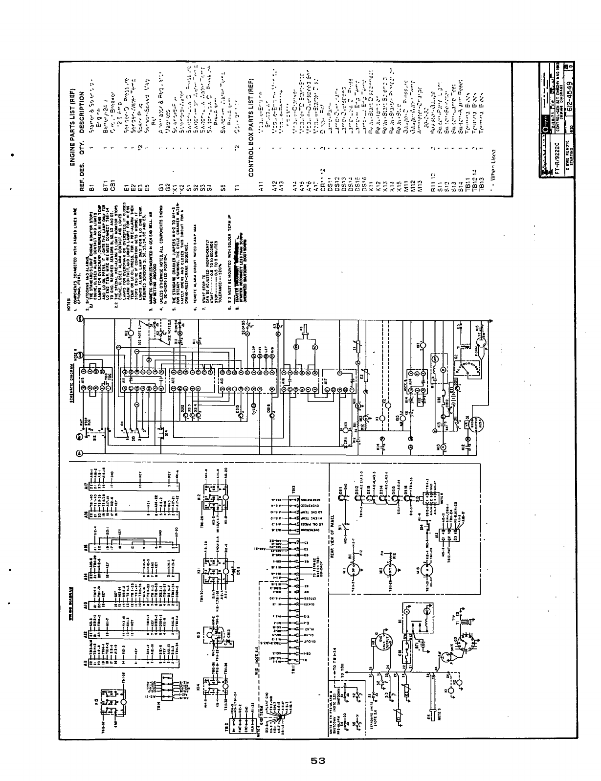
..
.
.,
*.
I.
.:
-I
LL.
0
a
a
e;
-
c
I
I
I--
OG
*I-
!
e-
53
Redistribution or publication of this document,
by any means, is strictly prohibited.

Li
i.;
U
I
ENGINE PARTS LIST (REF)
REF. DES. QTY. DESCRIPTION
B1 1 Starter
8
Solenoid
-
BT 1 1 Ballery-24
V
CB1 1 Circuit Breaker.
El 1 Sender-Oil Pressure
Engine
12.5 Amp
E2
E4
E5
G1
K1
'K2
K3
K4
s1
s2
1
1
1
1
1
1
1
1
1
1
Sender-Waler Temp
Fuel Pump
Sensor-Speed (Mag)
(Ref)
Alternalor
8
Regulator
Solenoid-Eng Sloping
Solenoid-Water
Sol-Eng Stopping
Solenoid-Air Inlet
Switch-Low Oil Pressuri
Swilch-High Water Tern
CONTROL
BOX
PARTS LIST (REF)
All 1
A12 1
A14 1
A15 1
A16 1
A17 1
CR11.12
2
DSll
1
DS12
1
K11 1
K12 1
K13 1
K14 1
M11 1
M12
1
M13 1
R11.12
2
s11 1
512
1
513 1
514 1
TB11
1
TB12.14
2
.
-
When Used
Module-Engine
Shutdown
Module-Engine Monitor
Module-Cranker
Module-TD Starl-Slop
Module-Overspeed Sen
Module-Starter Disc
Diode (Ref)
Lamp-Panel
Lamp-Fault
Relay-Slarl Oisconnecl
Relay-lgnilion
Relay-Start Solenoid
Relay-Slarter Prolection
Gauge-Oil Pressure
Gauge-Waler Temp
Ammeter-Charge
Resistor-Gauge
Swilch-Panel Light
Swilch-Seleclor
Svrilch-Lamp Test
Switch-Alarm Reset
Terminal Block
Terminal Block
30-0-30
i
Redistribution or publication of this document,
by any means, is strictly prohibited.
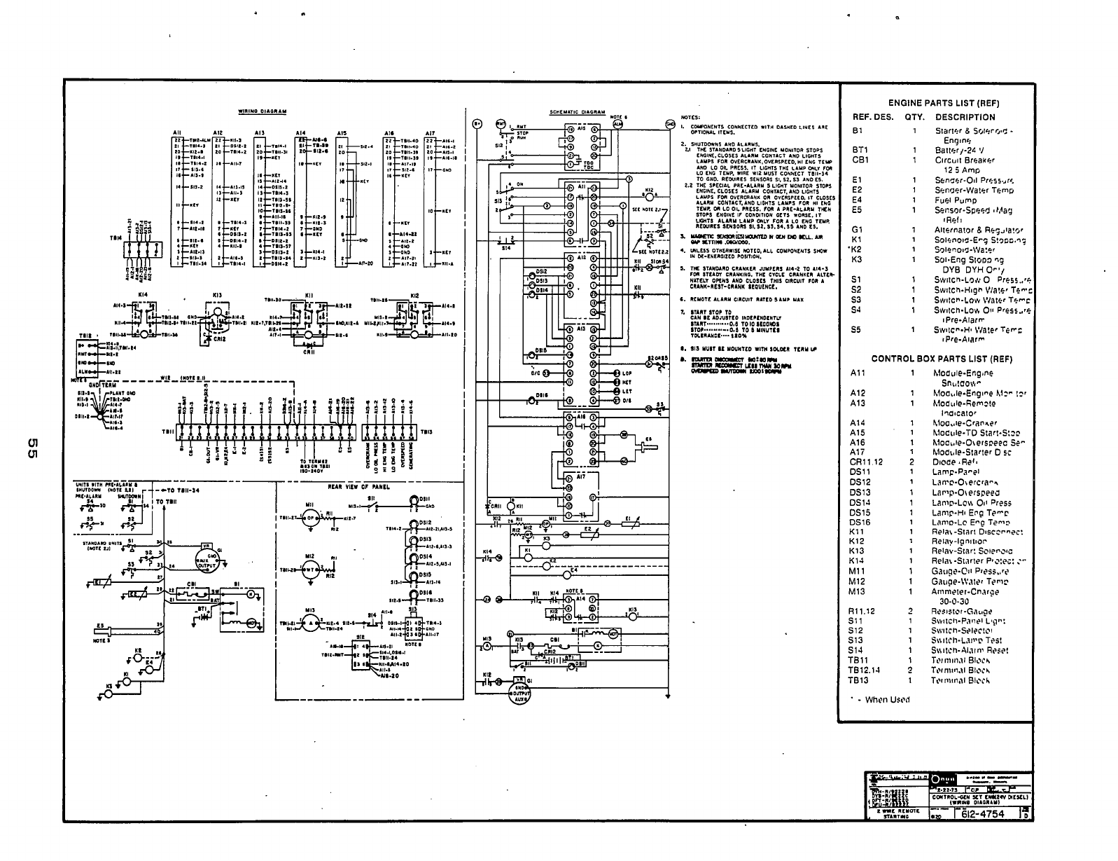
1111
110-1.01
m11
I
I
ENGINE PARTS LIST (REF)
REF.
DES.
QTY. DESCRIPTION
61
1
ET1
1
CB1 1
El
1
E2
1
E4
1
E5
1
G1
1
K1
1
'K2
1
K3
1
s1 1
s2
1
s3
1
SJ
1
s5
1
CONTROL
BOX
PARTS
LIST
(REF)
All
A12
A13
A14
A15
A16
Ali
CRll.12
DS11
DSl2
DS13
DSlJ
DSl5
DS16
K11
K12
K13
K1J
M11
M12
M13
1311.12
s11
512
513
S1.l
TBll
TBl2.14
TB13
1
1
1
1
1
1
1
2
1
1
1
1
1
1
1
1
1
1
1
1
1
3
1
1
1
1
1
?
1
Redistribution or publication of this document,
by any means, is strictly prohibited.
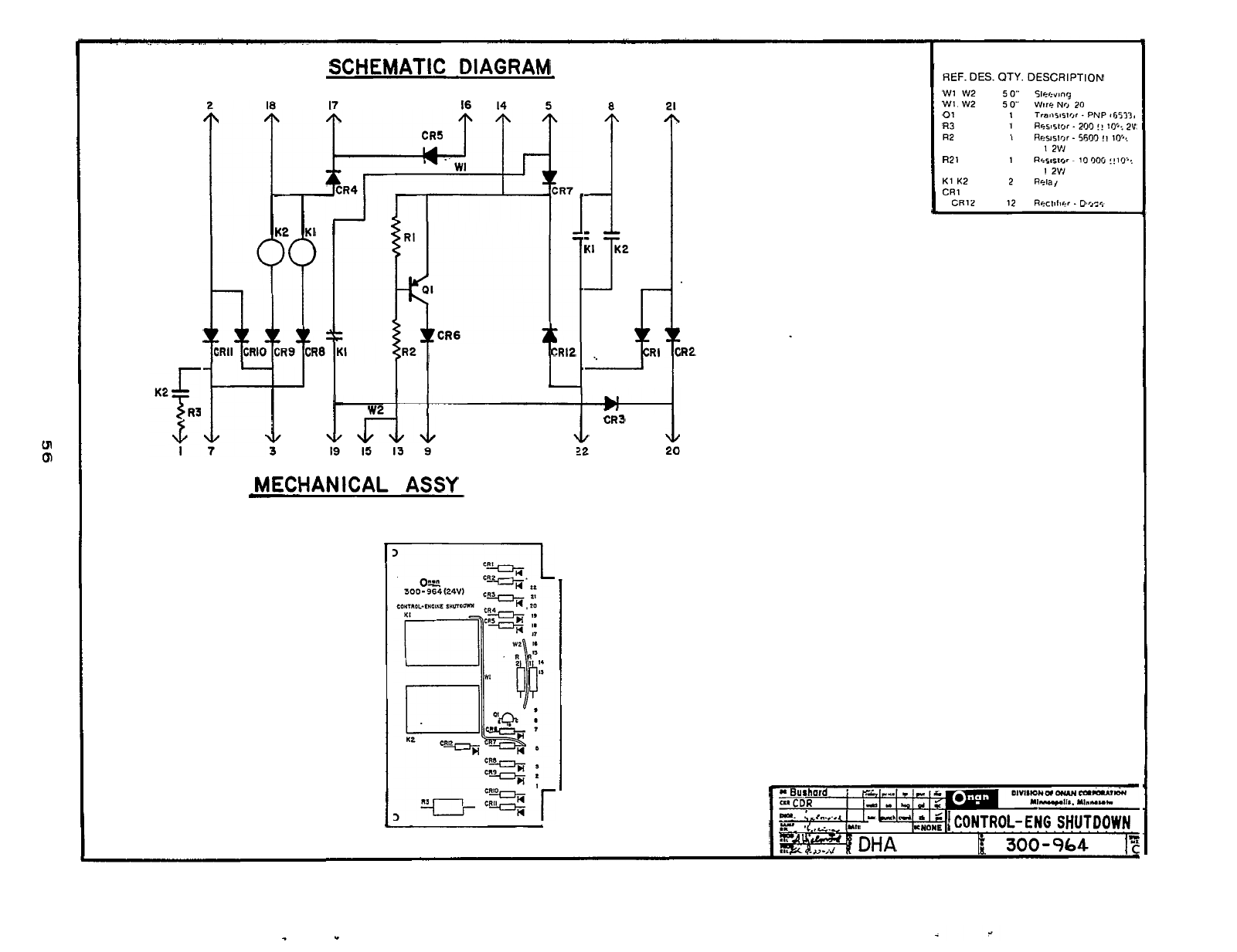
I
I
REF.
DES.
OTY.
DESCRIPTION
SCHEMATIC DIAGRAM
17
16
14
5
K2
KI
CRl2
-
w2
v
v
>
3
19
15
13
9
MECHANICAL
ASSY
1
3
CR3
P
!
W1 W2
5
0"
51oevmg
Wl W2
50
Wire
No
20
01 1
Transistor
.
PNP
#653?,
R3
1
Reswor.
200
!!
10':
2V
R2
1
Resislor
-
5600
!!
10'.
1
2Vl
1
2VI
R2 1
1
Resnslor
-
10006 !!lCP:
K1 K2 2
Relaj
CRl
CR12 12
Roclhc:,r
-
Dvzs
R2
Lh''dI
'
'
1'
CONTROL-
ENG
SHUTDOWN
-. ,=rm...,4
I
I
KNONE
I
mw
&
300-964
]c
"I
Redistribution or publication of this document,
by any means, is strictly prohibited.
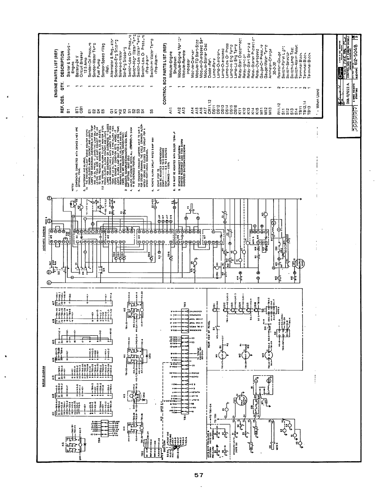
i
r
I
I
I
I
!
Redistribution or publication of this document,
by any means, is strictly prohibited.
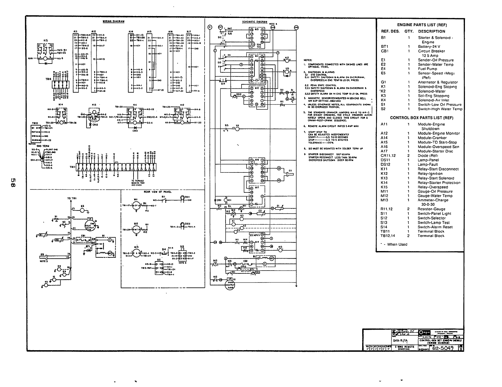
TO
1n11
t
ENGINE PARTS LIST (REF)
REF. DES. OTY. DESCRIPTION
B1
BT1
CB1
El
E2
E4
E5
G1
K1
K2
K3
K4
s1
s2
1
1
1
1
1
1
1
1
1
1
1
1
1
1
Starter
8
Solenoid
-
Engine
Battery-24
V
Circuit Breaker
12
5
Amp
Sender-Oil Pressure
Sender-Water Temp
Fuel Pump
Sensor-Speed #Magi
lRefi
Alternator
8
Regulator
Solenoid-Eng Sloping
Solenoid-Water
Sot-Eng Stopping
Solenoid-Air Inlet
Switch-Low
Oil
Pressure
Switch-High Water Tern1
CONTROL
BOX
PARTS LIST (REF)
A1 1 1
A12
1
A14 1
A15
1
A16 1
A17 1
CR11.12
2
DS11 1
DSl2
1
K11 1
Kl2 1
K13
1
K14 1
K15
1
Mll
1
M12 1
M13 1
R11.12
2
s11
1
512 1
513 1
S14 1
TB11 1
TB12.14 2
.
-
When Used
Module-Engine
Shutdown
Module-Engine Monitor
Module-Cranker
Module-TD Start-Stop
Module-Overspeed Sen
Module-Starter Disc
Dlode iReli
Lamp-Panel
Lamp-Fault
Relay-Start Disconnect
Relay-lgnilion
Relay-Start Solenoid
Relay-Starter Protection
Relay-Overspeed
Gauge-Oil Pressure
Gauge-Water Temp
Ammeter-Charge
Resistor-Gauge
Switch-Panel Light
Switch-Selector
Switch-Lamp Test
Switch-Alarm Reset
Terminal Block
Terminal Block
30-0-30
Redistribution or publication of this document,
by any means, is strictly prohibited.

Redistribution or publication of this document,
by any means, is strictly prohibited.

F
Onan Corporation
1400 73rd Avenue
N.E.
Minneapolis,
MN
55432
61 2-574-5000 International Use
Telex: 275477
Fax: 61 2-574-8087
Onan is
a
registered trademark
of
Onan Corporation
1
-800-888-ONAN
Redistribution or publication of this document,
by any means, is strictly prohibited.
