900 0366 Onan Power Command TP 78 Network Installation & Operation Manual (05 2002)
User Manual: 900-0366 Onan Power Command TP-78 Network Installation & Operation manual (05-2002)
Open the PDF directly: View PDF ![]() .
.
Page Count: 232 [warning: Documents this large are best viewed by clicking the View PDF Link!]
- Cover
- Table of Contents
- Safety Precautions
- 1. Introduction
- 2. Network Hardware and Wiring
- 3. Network Installation - LonMaker
- 4. Network Installation - Configuration Tool
- 5. GenSet Communications Module
- 6. Digital I/O Module
- 7. Network Gateway Module
- 8. Junction Box / Terminator
- 9. Network Annunciator Module
- 10. Controls Communications Module/GenSet
- 11. Controls Communications Module/ATS
- 12. Network Router
- A. Glossary of Network Terms
- B. Accessories
- C. Application Notes and Forms
- D. Network Troubleshooting
- E. Wiring Diagrams
- F. Index
Caution: This document contains mixed page sizes (8.5 x 11 or 11 x
17), which may affect printing. Please adjust your printer settings
according to the size of each page you wish to print.
Redistribution or publication of this document,
by any means, is strictly prohibited.

PowerCommand
Network Installation and Operation Manual
The Power of One
TM
TM

i
SECTION TITLE PAGE
SAFETY PRECAUTIONS v, vi. . . . . . . . . . . . . . . . . . . . . . . . . . . . . . . . . . . . . . . . .
1 INTRODUCTION 1-1. . . . . . . . . . . . . . . . . . . . . . . . . . . . . . . . . . . . . . . . . . . . . . . . . .
About this Manual 1-1. . . . . . . . . . . . . . . . . . . . . . . . . . . . . . . . . . . . . . . . . . . . . . .
Required Background 1-1. . . . . . . . . . . . . . . . . . . . . . . . . . . . . . . . . . . . . . . . . . . .
Required Installation Tools 1-2. . . . . . . . . . . . . . . . . . . . . . . . . . . . . . . . . . . . . . . .
System Overview 1-3. . . . . . . . . . . . . . . . . . . . . . . . . . . . . . . . . . . . . . . . . . . . . . . .
2 NETWORK HARDWARE AND WIRING 2-1. . . . . . . . . . . . . . . . . . . . . . . . . . . . .
Overview 2-1. . . . . . . . . . . . . . . . . . . . . . . . . . . . . . . . . . . . . . . . . . . . . . . . . . . . . . .
Network Configuration 2-1. . . . . . . . . . . . . . . . . . . . . . . . . . . . . . . . . . . . . . . . . . .
System Description 2-2. . . . . . . . . . . . . . . . . . . . . . . . . . . . . . . . . . . . . . . . . . . . . .
System Modules 2-2. . . . . . . . . . . . . . . . . . . . . . . . . . . . . . . . . . . . . . . . . . . . . . . . .
Data Transmission Media 2-5. . . . . . . . . . . . . . . . . . . . . . . . . . . . . . . . . . . . . . . . .
Network Topology 2-5. . . . . . . . . . . . . . . . . . . . . . . . . . . . . . . . . . . . . . . . . . . . . . .
Connectors and Wire Color Codes 2-7. . . . . . . . . . . . . . . . . . . . . . . . . . . . . . . . .
Wiring Guidelines 2-9. . . . . . . . . . . . . . . . . . . . . . . . . . . . . . . . . . . . . . . . . . . . . . . .
Network Power 2-10. . . . . . . . . . . . . . . . . . . . . . . . . . . . . . . . . . . . . . . . . . . . . . . . .
Selecting Network Power Configuration and Power Wire Sizing 2-10. . . . . . .
3 NETWORK INSTALLATION – LONMAKER 3-1. . . . . . . . . . . . . . . . . . . . . . . . . .
About this Section 3-1. . . . . . . . . . . . . . . . . . . . . . . . . . . . . . . . . . . . . . . . . . . . . . .
PowerCommand Network Overview 3-1. . . . . . . . . . . . . . . . . . . . . . . . . . . . . . .
Network Installation Scenarios 3-3. . . . . . . . . . . . . . . . . . . . . . . . . . . . . . . . . . . .
Setting up Network Installation Tools 3-3. . . . . . . . . . . . . . . . . . . . . . . . . . . . . . .
Starting LonMaker Software 3-5. . . . . . . . . . . . . . . . . . . . . . . . . . . . . . . . . . . . . .
Using LonMaker Software 3-6. . . . . . . . . . . . . . . . . . . . . . . . . . . . . . . . . . . . . . . .
LonMaker Network Setup 3-8. . . . . . . . . . . . . . . . . . . . . . . . . . . . . . . . . . . . . . . . .
Installation of Devices with LonMaker 3-17. . . . . . . . . . . . . . . . . . . . . . . . . . . . .
Connect Procedure 3-17. . . . . . . . . . . . . . . . . . . . . . . . . . . . . . . . . . . . . . . . . . . . .
Install Procedure 3-20. . . . . . . . . . . . . . . . . . . . . . . . . . . . . . . . . . . . . . . . . . . . . . .
Checking Connections 3-22. . . . . . . . . . . . . . . . . . . . . . . . . . . . . . . . . . . . . . . . . .
Checking Input and Output Values 3-24. . . . . . . . . . . . . . . . . . . . . . . . . . . . . . . .
Network Service Procedures 3-26. . . . . . . . . . . . . . . . . . . . . . . . . . . . . . . . . . . . .
Testing Devices and Verifying Installation 3-28. . . . . . . . . . . . . . . . . . . . . . . . . .
INCORRECT SERVICE OR REPLACEMENT OF PARTS CAN RESULT IN
DEATH, SEVERE PERSONAL INJURY, AND/OR EQUIPMENT DAMAGE. SER-
VICE PERSONNEL MUST BE QUALIFIED TO PERFORM ELECTRICAL AND/
OR MECHANICAL SERVICE.
Redistribution or publication of this document,
by any means, is strictly prohibited.

ii
(Continued)
4 NETWORK INSTALLATION – CONFIGURATION TOOL 4-1. . . . . . . . . . . . . . .
PowerCommand Configuration Tool 4-1. . . . . . . . . . . . . . . . . . . . . . . . . . . . . . . .
Menu System Description 4-6. . . . . . . . . . . . . . . . . . . . . . . . . . . . . . . . . . . . . . . .
Using the PowerCommand Configuration Tool 4-12. . . . . . . . . . . . . . . . . . . . . .
Controls Communications Module 4-16. . . . . . . . . . . . . . . . . . . . . . . . . . . . . . . .
Genset Communications Module 4-26. . . . . . . . . . . . . . . . . . . . . . . . . . . . . . . . .
Network Gateway Module 4-27. . . . . . . . . . . . . . . . . . . . . . . . . . . . . . . . . . . . . . .
Additional Installation Steps 4-32. . . . . . . . . . . . . . . . . . . . . . . . . . . . . . . . . . . . . .
Installation Checkout 4-32. . . . . . . . . . . . . . . . . . . . . . . . . . . . . . . . . . . . . . . . . . . .
Changes to the LonMaker Database 4-32. . . . . . . . . . . . . . . . . . . . . . . . . . . . . .
5 GENSET COMMUNICATIONS MODULE 5-1. . . . . . . . . . . . . . . . . . . . . . . . . . . . .
Overview 5-1. . . . . . . . . . . . . . . . . . . . . . . . . . . . . . . . . . . . . . . . . . . . . . . . . . . . . . .
Description 5-1. . . . . . . . . . . . . . . . . . . . . . . . . . . . . . . . . . . . . . . . . . . . . . . . . . . . .
Mounting 5-3. . . . . . . . . . . . . . . . . . . . . . . . . . . . . . . . . . . . . . . . . . . . . . . . . . . . . . .
Installation 5-4. . . . . . . . . . . . . . . . . . . . . . . . . . . . . . . . . . . . . . . . . . . . . . . . . . . . . .
GCM Connections 5-6. . . . . . . . . . . . . . . . . . . . . . . . . . . . . . . . . . . . . . . . . . . . . . .
Network Topology, Data Media and Network Power 5-6. . . . . . . . . . . . . . . . . .
Network Data Media and Power Wiring 5-6. . . . . . . . . . . . . . . . . . . . . . . . . . . . .
Switches / Service Points / LEDs 5-6. . . . . . . . . . . . . . . . . . . . . . . . . . . . . . . . . .
Network Installation 5-12. . . . . . . . . . . . . . . . . . . . . . . . . . . . . . . . . . . . . . . . . . . .
Network Alarms 5-12. . . . . . . . . . . . . . . . . . . . . . . . . . . . . . . . . . . . . . . . . . . . . . . .
Network Variables 5-12. . . . . . . . . . . . . . . . . . . . . . . . . . . . . . . . . . . . . . . . . . . . . .
6 DIGITAL I/O MODULE 6-1. . . . . . . . . . . . . . . . . . . . . . . . . . . . . . . . . . . . . . . . . . . . .
Overview 6-1. . . . . . . . . . . . . . . . . . . . . . . . . . . . . . . . . . . . . . . . . . . . . . . . . . . . . . .
Description 6-1. . . . . . . . . . . . . . . . . . . . . . . . . . . . . . . . . . . . . . . . . . . . . . . . . . . . .
Location 6-3. . . . . . . . . . . . . . . . . . . . . . . . . . . . . . . . . . . . . . . . . . . . . . . . . . . . . . . .
Mounting 6-3. . . . . . . . . . . . . . . . . . . . . . . . . . . . . . . . . . . . . . . . . . . . . . . . . . . . . . .
Wiring Diagram 6-4. . . . . . . . . . . . . . . . . . . . . . . . . . . . . . . . . . . . . . . . . . . . . . . . . .
Network Topology, Data Media and Network Power 6-6. . . . . . . . . . . . . . . . . .
Network Data Media and Power Wiring 6-6. . . . . . . . . . . . . . . . . . . . . . . . . . . . .
Customer Input and Relay Output Connections 6-7. . . . . . . . . . . . . . . . . . . . . .
Switches and LEDs 6-7. . . . . . . . . . . . . . . . . . . . . . . . . . . . . . . . . . . . . . . . . . . . . .
Network Installation 6-8. . . . . . . . . . . . . . . . . . . . . . . . . . . . . . . . . . . . . . . . . . . . .
Network Variables 6-8. . . . . . . . . . . . . . . . . . . . . . . . . . . . . . . . . . . . . . . . . . . . . . .
7 NETWORK GATEWAY MODULE 7-1. . . . . . . . . . . . . . . . . . . . . . . . . . . . . . . . . . .
Overview 7-1. . . . . . . . . . . . . . . . . . . . . . . . . . . . . . . . . . . . . . . . . . . . . . . . . . . . . . .
Description 7-1. . . . . . . . . . . . . . . . . . . . . . . . . . . . . . . . . . . . . . . . . . . . . . . . . . . . .
Location 7-2. . . . . . . . . . . . . . . . . . . . . . . . . . . . . . . . . . . . . . . . . . . . . . . . . . . . . . . .
Mounting 7-3. . . . . . . . . . . . . . . . . . . . . . . . . . . . . . . . . . . . . . . . . . . . . . . . . . . . . . .
Wire Cables 7-3. . . . . . . . . . . . . . . . . . . . . . . . . . . . . . . . . . . . . . . . . . . . . . . . . . . .
Network Topology and Data Media 7-5. . . . . . . . . . . . . . . . . . . . . . . . . . . . . . . . .
Service Switch and LED 7-5. . . . . . . . . . . . . . . . . . . . . . . . . . . . . . . . . . . . . . . . . .
Network Installation 7-5. . . . . . . . . . . . . . . . . . . . . . . . . . . . . . . . . . . . . . . . . . . . .
Redistribution or publication of this document,
by any means, is strictly prohibited.

iii
(Continued)
8 JUNCTION BOX/TERMINATOR 8-1. . . . . . . . . . . . . . . . . . . . . . . . . . . . . . . . . . . .
Overview 8-1. . . . . . . . . . . . . . . . . . . . . . . . . . . . . . . . . . . . . . . . . . . . . . . . . . . . . . .
Description 8-1. . . . . . . . . . . . . . . . . . . . . . . . . . . . . . . . . . . . . . . . . . . . . . . . . . . . .
Location 8-2. . . . . . . . . . . . . . . . . . . . . . . . . . . . . . . . . . . . . . . . . . . . . . . . . . . . . . . .
Mounting 8-2. . . . . . . . . . . . . . . . . . . . . . . . . . . . . . . . . . . . . . . . . . . . . . . . . . . . . . .
Wiring Diagram 8-3. . . . . . . . . . . . . . . . . . . . . . . . . . . . . . . . . . . . . . . . . . . . . . . . . .
Network Topology, Data Media and Network Power 8-3. . . . . . . . . . . . . . . . . .
Network Data Media and Power Wiring 8-4. . . . . . . . . . . . . . . . . . . . . . . . . . . . .
Switches 8-4. . . . . . . . . . . . . . . . . . . . . . . . . . . . . . . . . . . . . . . . . . . . . . . . . . . . . . .
9 NETWORK ANNUNCIATOR MODULE 9-1. . . . . . . . . . . . . . . . . . . . . . . . . . . . . .
Overview 9-1. . . . . . . . . . . . . . . . . . . . . . . . . . . . . . . . . . . . . . . . . . . . . . . . . . . . . . .
Description 9-1. . . . . . . . . . . . . . . . . . . . . . . . . . . . . . . . . . . . . . . . . . . . . . . . . . . . .
Location 9-2. . . . . . . . . . . . . . . . . . . . . . . . . . . . . . . . . . . . . . . . . . . . . . . . . . . . . . . .
Mounting 9-2. . . . . . . . . . . . . . . . . . . . . . . . . . . . . . . . . . . . . . . . . . . . . . . . . . . . . . .
Wiring Diagram 9-4. . . . . . . . . . . . . . . . . . . . . . . . . . . . . . . . . . . . . . . . . . . . . . . . . .
Network Topology, Data Media and Network Power 9-7. . . . . . . . . . . . . . . . . .
Network Data Media and Power Wiring 9-7. . . . . . . . . . . . . . . . . . . . . . . . . . . . .
Switches and LEDs 9-7. . . . . . . . . . . . . . . . . . . . . . . . . . . . . . . . . . . . . . . . . . . . . .
Network Installation 9-8. . . . . . . . . . . . . . . . . . . . . . . . . . . . . . . . . . . . . . . . . . . . .
Network Variables 9-8. . . . . . . . . . . . . . . . . . . . . . . . . . . . . . . . . . . . . . . . . . . . . . .
10 CONTROLS COMMUNICATIONS MODULE – GENSET 10-1. . . . . . . . . . . .
Overview 10-1. . . . . . . . . . . . . . . . . . . . . . . . . . . . . . . . . . . . . . . . . . . . . . . . . . . . . .
Description 10-1. . . . . . . . . . . . . . . . . . . . . . . . . . . . . . . . . . . . . . . . . . . . . . . . . . . .
Location 10-4. . . . . . . . . . . . . . . . . . . . . . . . . . . . . . . . . . . . . . . . . . . . . . . . . . . . . . .
CCM Control Box Mounting 10-5. . . . . . . . . . . . . . . . . . . . . . . . . . . . . . . . . . . . . .
Wire and Conduit 10-6. . . . . . . . . . . . . . . . . . . . . . . . . . . . . . . . . . . . . . . . . . . . . . .
Wiring Connections 10-6. . . . . . . . . . . . . . . . . . . . . . . . . . . . . . . . . . . . . . . . . . . . .
Network Topology, Data Media and Network Power 10-10. . . . . . . . . . . . . . .
Network Data Media and Power Wiring 10-10. . . . . . . . . . . . . . . . . . . . . . . . . .
Network Installation 10-10. . . . . . . . . . . . . . . . . . . . . . . . . . . . . . . . . . . . . . . . . .
Switches and LEDs 10-11. . . . . . . . . . . . . . . . . . . . . . . . . . . . . . . . . . . . . . . . . . . .
Network Variables 10-12. . . . . . . . . . . . . . . . . . . . . . . . . . . . . . . . . . . . . . . . . . . .
Redistribution or publication of this document,
by any means, is strictly prohibited.

iv
(Continued)
11 CONTROLS COMMUNICATIONS MODULE – ATS 11-1. . . . . . . . . . . . . . . . .
Overview 11-1. . . . . . . . . . . . . . . . . . . . . . . . . . . . . . . . . . . . . . . . . . . . . . . . . . . . . .
Description 11-1. . . . . . . . . . . . . . . . . . . . . . . . . . . . . . . . . . . . . . . . . . . . . . . . . . . .
Location 11-4. . . . . . . . . . . . . . . . . . . . . . . . . . . . . . . . . . . . . . . . . . . . . . . . . . . . . . .
CCM Control Box Mounting 11-5. . . . . . . . . . . . . . . . . . . . . . . . . . . . . . . . . . . . . .
Wire and Conduit 11-6. . . . . . . . . . . . . . . . . . . . . . . . . . . . . . . . . . . . . . . . . . . . . . .
Prepare CCM Power Supply 11-6. . . . . . . . . . . . . . . . . . . . . . . . . . . . . . . . . . . . .
Wiring Connections 11-6. . . . . . . . . . . . . . . . . . . . . . . . . . . . . . . . . . . . . . . . . . . . .
Network Topology and Data Media 11-9. . . . . . . . . . . . . . . . . . . . . . . . . . . . . . . .
Network Power 11-9. . . . . . . . . . . . . . . . . . . . . . . . . . . . . . . . . . . . . . . . . . . . . . . . .
Network Data Media and Power Wiring 11-9. . . . . . . . . . . . . . . . . . . . . . . . . . .
Network Installation 11-9. . . . . . . . . . . . . . . . . . . . . . . . . . . . . . . . . . . . . . . . . . . .
Switches and LEDs 11-10. . . . . . . . . . . . . . . . . . . . . . . . . . . . . . . . . . . . . . . . . . . .
Network Variables 11-11. . . . . . . . . . . . . . . . . . . . . . . . . . . . . . . . . . . . . . . . . . . . .
12 NETWORK ROUTER 12-1. . . . . . . . . . . . . . . . . . . . . . . . . . . . . . . . . . . . . . . . . . . .
Overview 12-1. . . . . . . . . . . . . . . . . . . . . . . . . . . . . . . . . . . . . . . . . . . . . . . . . . . . . .
Description 12-1. . . . . . . . . . . . . . . . . . . . . . . . . . . . . . . . . . . . . . . . . . . . . . . . . . . .
Location 12-2. . . . . . . . . . . . . . . . . . . . . . . . . . . . . . . . . . . . . . . . . . . . . . . . . . . . . . .
Mounting 12-3. . . . . . . . . . . . . . . . . . . . . . . . . . . . . . . . . . . . . . . . . . . . . . . . . . . . . .
Router Patch Cables 12-3. . . . . . . . . . . . . . . . . . . . . . . . . . . . . . . . . . . . . . . . . . . .
Router Wiring 12-4. . . . . . . . . . . . . . . . . . . . . . . . . . . . . . . . . . . . . . . . . . . . . . . . . .
Service Switch and LEDs 12-5. . . . . . . . . . . . . . . . . . . . . . . . . . . . . . . . . . . . . . . .
Network Topology and Data Media 12-6. . . . . . . . . . . . . . . . . . . . . . . . . . . . . . . .
Network Installation 12-6. . . . . . . . . . . . . . . . . . . . . . . . . . . . . . . . . . . . . . . . . . . . .
APPENDIX A GLOSSARY OF NETWORK TERMS A-1. . . . . . . . . . . . . . . . . . . . . . . . . . . . . . .
APPENDIX B ACCESSORIES B-1. . . . . . . . . . . . . . . . . . . . . . . . . . . . . . . . . . . . . . . . . . . . . . . . . .
Modem B-1. . . . . . . . . . . . . . . . . . . . . . . . . . . . . . . . . . . . . . . . . . . . . . . . . . . . . . . .
UPS B-1. . . . . . . . . . . . . . . . . . . . . . . . . . . . . . . . . . . . . . . . . . . . . . . . . . . . . . . . . .
Multi-Site Communications Module B-1. . . . . . . . . . . . . . . . . . . . . . . . . . . . . . .
APPENDIX C APPLICATION NOTES AND FORMS C-1. . . . . . . . . . . . . . . . . . . . . . . . . . . . . . .
Network Variables C-1. . . . . . . . . . . . . . . . . . . . . . . . . . . . . . . . . . . . . . . . . . . . . .
Binding Network Variables C-1. . . . . . . . . . . . . . . . . . . . . . . . . . . . . . . . . . . . . . .
Types of Connections C-4. . . . . . . . . . . . . . . . . . . . . . . . . . . . . . . . . . . . . . . . . . .
Connection Table Examples C-10. . . . . . . . . . . . . . . . . . . . . . . . . . . . . . . . . . . .
Network Design/Input Forms C-13. . . . . . . . . . . . . . . . . . . . . . . . . . . . . . . . . . . .
APPENDIX D NETWORK TROUBLESHOOTING D-1. . . . . . . . . . . . . . . . . . . . . . . . . . . . . . . . .
Introduction D-1. . . . . . . . . . . . . . . . . . . . . . . . . . . . . . . . . . . . . . . . . . . . . . . . . . . .
APPENDIX E WIRING DIAGRAMS E-1. . . . . . . . . . . . . . . . . . . . . . . . . . . . . . . . . . . . . . . . . . . . .
APPENDIX F INDEX E-1. . . . . . . . . . . . . . . . . . . . . . . . . . . . . . . . . . . . . . . . . . . . . . . . . . . . . . . . . .
Redistribution or publication of this document,
by any means, is strictly prohibited.

PCN–1
v
The PowerCommand Network can be used to re-
motely operate power transfer equipment (e.g.,
transfer switches, paralleling systems) and start
and stop generator sets. All of the safety precau-
tions for that equipment must observed. Refer to the
Operator’s Manual for the equipment that is being
monitored and controlled by the network for impor-
tant safety precautions.
The following symbols, found throughout this
manual, alert you to potentially dangerous condi-
tions to the operator, service personnel, or the
equipment.
This symbol warns of immediate
hazards which will result in severe personal in-
jury or death.
This symbol refers to a hazard or un-
safe practice which can result in severe person-
al injury or death.
This symbol refers to a hazard or un-
safe practice which can result in personal injury
or product or property damage.
MOVING PARTS CAN CAUSE SEVERE
PERSONAL INJURY OR DEATH
•Keep your hands, clothing, and jewelry away
from moving parts.
•Before starting work on the generator set, dis-
connect battery charger from its AC source,
then disconnect starting batteries, negative (-)
cable first. This will prevent accidental starting.
•Make sure that fasteners on the generator set
are secure. Tighten supports and clamps,
keep guards in position over fans, drive belts,
etc.
•Do not wear loose clothing or jewelry in the vi-
cinity of moving parts, or while working on elec-
trical equipment. Loose clothing and jewelry
can become caught in moving parts. Jewelry
can short out electrical contacts and cause
shock or burning.
•If adjustment must be made while the unit is
running, use extreme caution around hot man-
ifolds, moving parts, etc.
ELECTRICAL SHOCK CAN CAUSE
SEVERE PERSONAL INJURY OR DEATH
•Remove electric power before removing pro-
tective shields or touching electrical equip-
ment. Use rubber insulative mats placed on
dry wood platforms over floors that are metal or
concrete when around electrical equipment.
Do not wear damp clothing (particularly wet
shoes) or allow skin surface to be damp when
handling electrical equipment.
•Use extreme caution when working on electri-
cal components. High voltages can cause inju-
ry or death. DO NOT tamper with interlocks.
•Follow all applicable state and local electrical
codes. Have all electrical installations per-
formed by a qualified licensed electrician. Tag
and lock open switches to avoid accidental clo-
sure.
•Jewelry is a good conductor of electricity and
should be removed before working on electri-
cal equipment.
Redistribution or publication of this document,
by any means, is strictly prohibited.
vi
MEDIUM VOLTAGE GENERATOR SETS
(601V to 15kV)
•Medium voltage acts differently than low volt-
age. Special equipment and training is required
to work on or around medium voltage equip-
ment. Operation and maintenance must be
done only by persons trained and qualified to
work on such devices. Improper use or proce-
dures will result in severe personal injury or
death.
•Do not work on energized equipment. Unau-
thorized personnel must not be permitted near
energized equipment. Due to the nature of me-
dium voltage electrical equipment, induced
voltage can remain even after the equipment is
disconnected from the power source. Plan the
time for maintenance with authorized person-
nel so that the equipment can be de-energized
and safely grounded.
TRANSFER SWITCHES
•AC and DC voltages in the transfer switch com-
ponents present serious shock hazards that
can result in severe personal injury or death.
Read and follow these instructions.
•Keep the transfer switch cabinet closed and
locked. Make sure only authorized personnel
have cabinet and operational keys.
•Due to the serious shock hazard from medium
voltages within the cabinet, all service and ad-
justments to the transfer switch must be per-
formed only by an electrician or authorized ser-
vice representative.
•If the cabinet must be opened for any reason:
1. Move the operation selector switch on the gen-
erator set to Stop.
2. Disconnect battery charger from its AC source.
Disconnect the starting batteries of the genera-
tor set. (Remove the negative [–] lead first to
prevent arcing from igniting explosive battery
gas.)
3. Remove AC power to the automatic transfer
switch. If the instructions require otherwise,
use extreme caution due to the danger of shock
hazard.
GENERAL SAFETY PRECAUTIONS
•The PowerCommand Network allows remote
operation of equipment. PowerCommand Soft-
ware for Windows can remotely start and stop a
genset or exercise a transfer switch. Network
modules can independently control other net-
work modules and operate other electrical de-
vices such as fans or pumps etc. Make certain
that all appropriate personnel are notified be-
fore remotely operating equipment and make
them aware of any equipment that can be ener-
gized automatically.
•Do not work on this equipment when mentally
or physically fatigued, or after consuming any
alcohol or drug that makes the operation of
equipment unsafe.
•Use only the latest physical and logical connec-
tion diagrams for installing and maintaining the
PowerCommand Network. If changes are
made to the physical or logical network con-
nections, make sure the site connection dia-
grams are updated. Create a new CSV file if the
number or type of modules changes or if the
bindings change.
Redistribution or publication of this document,
by any means, is strictly prohibited.

1-1
!
ABOUT THIS MANUAL
This manual covers the PowerCommand Net-
work installation, setup, and service information.
The PowerCommand Network is an Echelon Lon-
Works based local operating control network. This
manual is intended for use by trained network in-
stallers.
Sections 1 and 2 provide an overview of this manu-
al, the expected technical background of the install-
er, the required hardware and software tools, and
some basic network concepts.
Section 3 describes procedures for the logical
installation and connection of the various modules
on the network using LonMaker software. This
section also describes network testing and service
procedures using LonMaker.
Much of the material in Section 3 is derived from the
Echelon LonMaker Installation Tool Users Guide.
The Echelon manual is included with the LonMaker
software, and should be considered a reference
companion to this manual.
Section 4 covers procedures for using the Power-
Command Configuration Tool. This software is
used to complete the network installation by per-
forming several functions including setting up the
dial out phone number and creating a .CSV file for
use by PowerCommand Software for Windows.
Sections 5 thru 12 cover individual modules on the
PowerCommand Network and provide procedures
for locating, mounting and wiring these modules
(physical installation). These sections also list the
network variables associated with each module. As
new modules are made available they will be added
to this manual. A glossary of network terms, forms
and additional installation aids will be found in the
Appendices at the back of this manual.
Use normal and necessary safety precautions be-
fore starting any service procedures. Identify all
hazards by referring to the Safety Precautions sec-
tion and observe all warnings and cautions within
the manual. When you are troubleshooting, re-
member that the PowerCommand Network, gener-
ator set, transfer switch, and utility power source
are all interdependent.
Keep this manual where it will be readily available to
the network installer and operator.
REQUIRED BACKGROUND
To use this manual, you need:
•Experience and familiarity with generator set
installation and service.
•A basic understanding of control networks.
•Experience and familiarity with personal com-
puters and using a mouse.
•Experience and familiarity with DOS, and Win-
dows-type graphical user interfaces.
•Experience and familiarity with the organiza-
tion of disk drives, directories, subdirectories,
files, and path names.
PowerCommand is a trademark of Onan Corporation.
Echelon and LonWorks are registered trademarks of Echelon
Corporation.
LonMaker is a trademark of Echelon Corporation.
1995–1997 Onan Corporation
WARNING
THE GENSET, TRANSFER SWITCH AND OTHER EQUIPMENT ASSOCIATED WITH THE POWERCOM-
MAND NETWORK WILL NOT FUNCTION PROPERLY, OR WILL NOT BE SUBJECT TO PROPER MON-
ITORING AND SERVICE UNLESS THE INSTRUCTIONS IN THIS MANUAL ARE FOLLOWED IN DETAIL.
IMPROPER FUNCTIONING CAN RESULT IN SEVERE PERSONAL INJURY, DEATH, AND/OR EQUIP-
MENT DAMAGE. SERVICE PERSONNEL MUST HAVE THE REQUIRED INSTALLATION TOOLS AND
BE QUALIFIED TO PERFORM NETWORK INSTALLATIONS INCLUDING USE OF INSTALLATION SOFT-
WARE AND BE ABLE TO PERFORM ELECTRICAL AND MECHANICAL SERVICE. READ THIS ENTIRE
MANUAL BEFORE STARTING.
Redistribution or publication of this document,
by any means, is strictly prohibited.
1-2
REQUIRED INSTALLATION TOOLS
In additional to conventional tools and all system
components and cabling, you need the following
tools and manuals to install a PowerCommandNet-
work:
•Network Module Library software.
•Echelon LonMaker software.
•PowerCommand Configuration Tool software.
•IBM PC-compatible computer, with an
80486SX or better processor, running at 25
MHz, minimum.
•VGA monitor (color or gray scale) and video
card.
•Windows 3.1 or Windows 95.
•640 KB of conventional RAM, with at least 580
KB available for LonMaker.
•To free 580 KB of conventional memory for
LonMaker, you may have to use DOS (Mem-
maker) or a memory management utility that
lets you store DOS and device drivers in high
memory (640 to 1024 KB).
•8 MB of memory.
•6.7 MB of available hard disk storage as fol-
lows:
1.2 MB for LonMaker software
500 KB for the Network Module Library.
5 MB for PowerCommand Configuration Tool
•Floppy disk drive: 3 1/2”, 1.44 MB.
•Serial port, Network Installation Gateway and
driver software.
•Microsoft-compatible mouse and mouse driver
software.
•Installation gateway cables and connectors
(included with the Network Installation Gate-
way Kit).
•The LonMaker Installation Tool Users Guide
(provided with LonMaker).
To test the PowerCommand Network before leaving
the site, the following tools will be needed:
•PowerCommand Software for Windows
(PCW).
•A Network Gateway Module.
Redistribution or publication of this document,
by any means, is strictly prohibited.

1-3
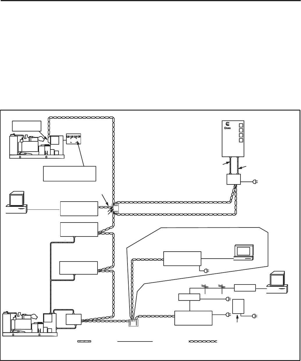
SYSTEM OVERVIEW
Figure 1-1 shows a block diagram using each of the
network modules described in this manual. The net-
work and network modules are covered in detail in
the following sections.
The PowerCommand Control (PCC) communi-
cates through the Genset Communications Module
with other modules, such as a Digital I/O Module, or
Network Gateway Module.
The Genset Communications Module (GCM), is
mounted in the PCC, and is required for connecting
the PCC to the network.
The Digital I/O Module (DIM) provides a group of
relay contact outputs and discrete inputs for inter-
facing the PowerCommand system to alarm or sta-
tus outputs and to equipment that does not have
compatible communications capability.
The Network Annunciator Module (NAM) allows
remote annunciation via the PowerCommand Net-
work of a genset or transfer switch etc.
The Network Gateway Module (NGM) provides a
network interface to a PC or modem.
The Controls Communications Module (CCM)
allows interfacing the network to a non–PCC gener-
ator set or transfer switch.
The network Router (RTR) connects two commu-
nications channels and routes messages between
them. (Refer to the Router Section for a typical
installation diagram).
MODEM OR
LOCAL PC
RELAY
OUTPUTS
NETWORK
ANNUNCIATOR
MODULE (NAM)
CONTROLS
COMMUNICATIONS
MODULE
(CCM-ATS)
NON-PCC
GENERATOR SET
PCC w/GCM
DIGITAL I/O
MODULE (DIM)
NETWORK
GATEWAY
MODULE (NGM)
CUSTOMER
INPUTS
POWERCOMMAND
NETWORK
TRANSFER
SWITCH
JUNCTION
BOX / TERM
T TERMINATE
JUNCTION
BOX / TERM
GENSET COMMUNICATIONS
MODULE (GCM)
T TERMINATE
CUSTOMER
INPUTS
CONTROLS
COMMUNICATIONS
MODULE
(CCM-GENSET)
FIGURE 1-1. BLOCK DIAGRAM OF NETWORK MODULES
Redistribution or publication of this document,
by any means, is strictly prohibited.
1-4
Redistribution or publication of this document,
by any means, is strictly prohibited.
2-1
" #$ %!# ! &
OVERVIEW
This section describes the network communica-
tions protocol and the individual modules used in
the PowerCommand network. This section also de-
scribes network media, network power supply, and
physical connection requirements. For a definition
of the terms used in a PowerCommand network, re-
fer to the Glossary in Appendix A.
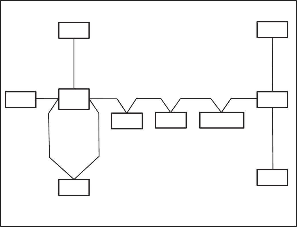
NETWORK CONFIGURATION
The PowerCommand network uses a multidrop bus
topology (Figure 2-2). The network is made up of in-
dividual modules that are connected by twisted-pair
communications cable for the transmission of net-
work data. Network power is transmitted over a sec-
ond pair of wires.
Figure 2-1 shows a typical network with several
modules. Refer to Figures E-1 thru E-3 in Appendix
E for a more detailed network example.
'(()
*
!" #$%&'
() * "
#+ , %- ./ 01'
2
()
()
!"
!" 3
!"
! (
(
! (
./
.
.3
.3
#$%&'
+'
%
"" " 4 / 4
() "*
( ! (
+ 5 4
*
#%6 7&$ ,&$ 8
897:'
()
""
(
*;
"
#'
""!
"
() * "
#+ , %- ./ 01'
() * "
#+ , %- ./ 01'
() (
!"
!
! "
" (
"
4 ! !
! (!
()
(! ()
#98 % &$$07%&8 %1<'
#'
""!
"
() (
!"
!
!
"
4 ""
! "
! (
FIGURE 2-1. TYPICAL NETWORK CONFIGURATION
Redistribution or publication of this document,
by any means, is strictly prohibited.
2-2
SYSTEM DESCRIPTION
The PowerCommand Network is a distributed con-
trol network. Echelon LonWorks technology pro-
vides the communications protocol via Echelon’s
Neuron Chip and firmware. The network consists
of nodes (for example: PCCs with Genset Commu-
nications Modules, Digital I/O Modules, Controls
Communication Modules, and Network Gateway
Modules) wired together on a common network
data bus.
The control of the system does not reside in a cen-
tral device, but rather is distributed at the system
component level. That is, each node has its own in-
telligenceintelligence needed at that location to
perform functions for that particular component.
The nodes communicate control and monitoring in-
formation to one another over the network data bus.
The nodes, their connections to one another, and
the modules/devices they control/monitor collec-
tively form the distributed control system. A distrib-
uted control system is a more robust control
scheme than a conventional central control system.
Single points of failure in the distributed control sys-
tem do not necessarily render the whole system in-
operative.
Communications Protocol
A distributed control network operates on a peer-to-
peer communication protocol, whereby any device
on the communication channel can communicate
with any other device at any time.
Messages can be prioritized so that critical control
messages have first access to the network. Reli-
ability of transmission is provided through use of ac-
knowledged or repeated message service levels.
Accuracy of the message is checked by cyclical re-
dundancy checking.
The application is defined by naming the inputs and
outputs for each device as network variables.
Nodes that do not have a local source of uninter-
rupted power are supplied by the network power
lines.
Neuron Chip
Each node contains a Neuron Chip. The primary
function of the Neuron Chip is to serve as a commu-
nications link between the system component lo-
cated at that node and other system components on
the network. The Neuron Chip also provides the
node with some local processing power to read
switch positions, drive outputs, read analog data,
etc. The Neuron Chip communicates by directly
transmitting and receiving through a transformer-
coupled transceiver.
SYSTEM MODULES
PowerCommand Control
The PowerCommand Control is a microprocessor-
based control for Onan generator sets. It provides
fuel control and engine speed governing, main al-
ternator voltage output regulation, and complete
generator set control and monitoring.
The operating software provides control of the gen-
erator set and its performance characteristics, and
displays operating information on a digital and ana-
log display panel.
The PowerCommand Control (PCC) communi-
cates through the GenSet Communications Module
with other modules, such as a Network Annunciator
Module or Network Gateway Module.
The PowerCommand Control is covered in your
generator set Installation, Operator’s, and Service
manuals.
Neuron is a registered trademark of Echelon Corporation.
Redistribution or publication of this document,
by any means, is strictly prohibited.

2-3
GenSet Communications Module (GCM)
The GenSet Communications (GCM) is mounted
inside the PCC, and is required for connection of the
PCC to the network.
The GCM provides an interface for data between
the PowerCommand Control and other modules on
the network. It communicates with the PCC through
the PCC’s serial port, as well as by monitoring vari-
ous PCC inputs to determine the operating state of
the control. For example, the GCM monitors PCC
data such as voltage, current, engine speed, and oil
temp; and then stores it for the network.
The GCM also provides some direct local control
and monitoring of the PCC. Outputs from the GCM
allow it to “wake up” the PCC when needed, or to
cause an emergency shutdown on command. It
monitors Not-In-Auto mode and battery voltage
(when the PCC is asleep).
The GCM is installed piggyback on the analog
board within the PCC. Description of the GCM is
covered in Section 5.
Digital I/O Module
The Digital I/O Module (DIM) provides a group of
relay contact outputs and discrete inputs for inter-
facing the PowerCommand System to alarm or sta-
tus outputs and to equipment that does not have
compatible communications capability.
The Digital I/O Module provides sixteen 5A,
250VAC/30 VDC Form-C dry contact relay outputs,
which are driven by data from the network. The con-
tacts are connected to pluggable terminal blocks for
field wiring. Each relay can be programmed to oper-
ate from any Boolean variable on the network. The
module also includes four digital inputs to couple
user inputs to the network for use elsewhere in con-
trol or monitoring.
Description and installation of the Digital I/O Module
is covered in Section 6.
Network Gateway Module
The Network Gateway Module (NGM) provides a
network interface to a PC either directly or through a
modem. It translates network protocol into a proto-
col that can be understood by a PC.
The NGM connects to network data wire through an
RJ45 jack. Connecting to the network requires a 24
AWG communications cable (cables are included
with NGM kit) . The NGM receives its power from
AC wall power, and should be backed up by a stand-
by uninterruptable power supply (UPS).
The NGM allows software running on a PC to ac-
cess, and control all modules on a network. The
PowerCommand Software uses this module to ac-
cess the network.
An NGM that is used for monitor
and control of a site cannot be used to install a
site. Failure to use a separate installation NGM
will cause the NV data stored in the site monitor-
ing NGM to be destroyed. If this occurs, do a Re-
pair/Replace in LonMaker on the Site NGM.
LonMaker and PowerCommand Configuration
Tool software require a unique network gateway
module referred to as the “Network Installation
Gateway” for installing and servicing a network
(shown in Figure 2-1).
Description of the NGM is covered in Section 7.
Redistribution or publication of this document,
by any means, is strictly prohibited.
2-4
Junction Box/Terminator
A Junction Box/Terminator (JBT) provides connec-
tion points for network power and data wire. Junc-
tion Boxes may be used throughout a network for
connecting in Pass Thru, Local Loop and Stub con-
figurations. The JBT is a potted assembly.
The JBT is required when connecting an NGM to
the network.
A junction box provides two 6-position pluggable
connector for data and power, two RJ45 jacks for
24AWG stub connections (e.g. NGM), a switch to
connect the data lines to a terminator circuit, and a
switch to select either a Pass Thru or a Local Loop
connection between the data lines on the two con-
nectors.
Description of the JBT is covered in Section 8.
Network Annunciator Module
The Network Annunciator Module (NAM) combines
a hardwired PowerCommand System Annunciator
with a Digital I/O Module. The NAM is connected to
the network by twisted pair communication wire.
The NAM has 20 LEDs to annunciate alarms. In
NFPA 110 applications the network directly controls
16 of the LEDs and indirectly controls one LED
(DS3). The remaining three LEDs can be hard-
wired. In non-NFPA 110 applications the network
controls 16 of the LEDs and four can be hardwired.
This module has its own Operator’s manual
(900-0282).
The NAM is covered in Section 9 of this manual.
Controls Communications Module
for Generator Set and Transfer Switch
Monitoring
The Controls Communications Module (CCM) al-
lows interfacing the network to conventional non-
PCC generator sets, transfer switches, system or
breakers.
These modules monitor discrete inputs, AC and DC
analog inputs, and communicate data to the Power-
Command Network.
The CCM has 32 discrete inputs and 7 analog in-
puts.
The module also includes two Form-C output relays
and two Form-A output relays to provide control of
the monitored equipment from the network. For ex-
ample, these outputs can be used to initiate a test
within a transfer switch, or to remotely start a gener-
ator set.
Description of the CCM for genset applications is
covered in Section 10, and the transfer switch ap-
plications are covered in Section 11.
Network Router
The Network Router (RTR) connects two commu-
nications channels by passing messages between
the two channels. The PowerCommand Network
Router is configured to connect two twisted pair/
transformer isolated 78kb (TP/XF-78) channels.
The Router can be used within a PowerCommand
Network to extend the physical length of the net-
work beyond 4600 feet (1402 m) and/or increase
the maximum number of nodes to more than 44
nodes. Refer to the Section 12 for application infor-
mation on the Network Router.
Redistribution or publication of this document,
by any means, is strictly prohibited.
2-5
DATA TRANSMISSION MEDIA
The modules communicate at 78 kbps over a bus of
22 AWG UL Level IV (or EIA Category 4) twisted
pair communications wire. The network data signal
is coupled to the twisted pair wire by transformer-
coupled transceivers in each node. Nodes are iso-
lated by transformer from the data lines, which
makes the data wiring polarity insensitive. A high
degree of noise immunity is achieved with this me-
dium.
Wiring and connection of data transmission media
is covered in the individual module sections.
NETWORK TOPOLOGY
The wiring topology is a multidrop bus topology.
This topology requires that there be only two ends
to the network. Stubs off the network bus can be no
longer than 10 feet (3 m). The maximum bus length
of a single channel is 4600 feet (1402 m).
A Local Loop must be used when branching off for
more than 10 feet (3 m). The Local Loop lets you
wire “out and back” to a module. Add the length of
the local loop in both directions to the overall bus
length.
Both ends of the network data bus must be termi-
nated with a terminator circuit. Proper termination of
the network is important for reliable communica-
tions. All Onan nodes have the terminator circuit
built in except the NGM and Router. Termination is
activated by a slide switch.
.
!
.
"" "
(
"*
+ 4 # '
(! ()
( "* /
4 # +/ '
"*
+ 4 # '
"*
+ 4 # '
/ (
FIGURE 2-2. TYPICAL MULTIDROP BUS NETWORK
Redistribution or publication of this document,
by any means, is strictly prohibited.

2-6
TABLE 2-1. NETWORK DATA SPECIFICATION
Data Communications Type: Transformer coupled, Differential Manchester encoding
Media: Twisted pair communications wire
Bit Rate: 78k bits/sec
Wiring Topology: Multidrop Bus
Polarity: Polarity insensitive
Max Bus Length: 4600 feet
Max Stub Length: 10 feet
Termination: Terminators required at both ends of the bus
Wire Type Required: Bus – Unshielded 22 AWG UL Level IV or EIA Cat. 4
Twisted Pair Communication Wire
Stubs – same as Bus or may be 24 AWG instead of 22 AWG
Maximum number of nodes
per channel: 44
Maximum no. of channels: 20
Wire Color Codes: Blue and White/Blue – primary wire pair for data
Orange and White/Orange – secondary wire pair for Local Loops with
2 pair cable
Connector: Onan nodes – 6 position pluggable screw terminal block
Onan Junction Box/Terminator – pluggable screw terminal blocks & RJ45s
NGM node — RJ45
(*3"
(*3
"
! (
! ! (
4 "" "
! 4 ! (
FIGURE 2-3. TWO TWISTED PAIR COMMUNICATIONS WIRE
Redistribution or publication of this document,
by any means, is strictly prohibited.
2-7
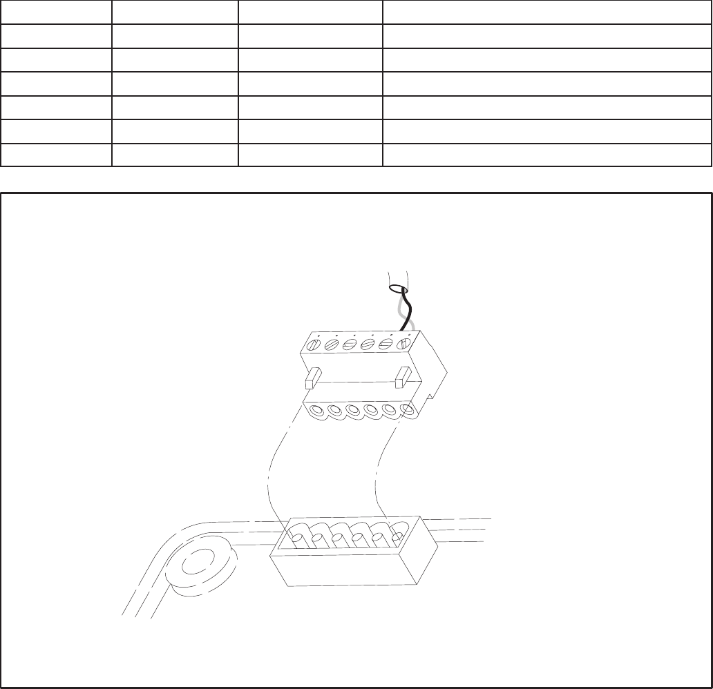
CONNECTORS AND WIRE COLOR CODES
All Onan nodes, except the GCM, have a black,
6-position pluggable screw terminal block for con-
nection to network data and network power. The
GCM uses four positions on the DIN rail customer
connection terminals.
The Junction Box/Terminator module has two
6-position pluggable terminal blocks, as well as two
RJ45 connectors.
The NGM has an RJ45 connector for network data
stub connections.
Connector positions and wire color codes are listed
in Tables 2-2 and 2-3.
TABLE 2-2. 6-POSITION PLUGGABLE TERMINAL BLOCK
Position Signal Wire Color Code Comments
1Net Data1 white/blue if 2pr cable – white/orange for Local Loop
2Net Data2 blue if 2pr cable – orange for Local Loop
3 Net Power+
4 Net Power+
5Net Power–
6Net Power–
/ +
" ")
FIGURE 2-4. 6-POSITION PLUGGABLE CONNECTOR
Redistribution or publication of this document,
by any means, is strictly prohibited.
2-8
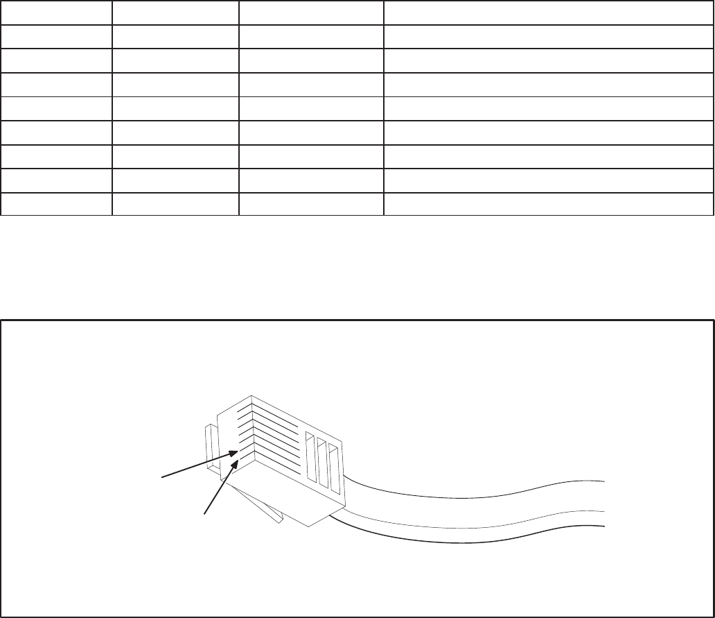
TABLE 2-3. RJ45 CONNECTOR
Position Signal Wire Color Code Comments
1Net Data1 white/blue 24AWG only
2Net Data2 blue 24AWG only
3not used
4not used
5not used
6not used
7not used
8not used
Note: Position numbering goes from left to right when looking into the jack with the pins at the top and the
latching notch at the bottom.
+
FIGURE 2-5. RJ45 CONNECTOR
Redistribution or publication of this document,
by any means, is strictly prohibited.

2-9
WIRING GUIDELINES
Communication over unshielded twisted pair (UTP)
could be distorted by external sources of electro-
magnetic interference (EMI), especially if the con-
ductors are physically degraded in any way. To
avoid or minimize this interference, observe the fol-
lowing guidelines.*
Electromagnetic interference (EMI)
can cause communication signal distortion,
which can cause network failure and unin-
tended equipment operation. Read and follow
these wiring guidelines.
Observe all local wiring codes. Refer to the NEC
(NFPA70) section on Wiring Methods and Materials
for general wiring methods and procedures.
Routing: Whenever possible, cabling should be
installed over corridor areas or along lines that are
parallel to the contours of buildings. All deviations
from straight runs should be made at right angles.
Keep wire away from sharp, abrasive, and hot sur-
faces.
Separation from sources of EMI: All cabling
should be installed in such a way as to comply with
the minimum separations from AC power sources,
as listed in Table 2-4.
In general, communications wiring should not be lo-
cated in spaces that are shared with electrical pan-
els, transformers, or other high voltage equipment.
Tension: All cabling should be free from tension at
both ends, as well as over the length of each run.
Twisted pairs: All terminations should be made in
such a way as to minimize the extent to which
each twisted pair is unraveled at the point of its
physical termination. Allow no more than 0.5 inch
(13 mm) of exposed untwisted pairs.
UTP cable bends: UTP cable bends, or radii,
should be no less than eight times the cable diame-
ter.
Harsh, hazardous, or corrosive environments:
Communications wiring should not be installed
where vapors, fumes, corrosives, dusts, or other in-
dustrial byproducts are present without taking ap-
propriate precautions to protect the cables. Install-
ers and cabling manufacturers of the materials in-
volved must be consulted in all such cases.
Grounding and bonding: Although the use of UTP
does not involve the use of shielded cables in hori-
zontal station runs, the use of shielding in high-pair-
count UTP riser cables as well as cables of all types
used in outdoor conditions is not uncommon. In
some cases, qualified installers or manufacturers
will make related recommendations in the interest
of human safety or mechanical protection of
installed cables (e.g., shielding against rodents).
When shielded cables are used, all applicable regu-
lations for grounding and bonding as defined by lo-
cal building codes for electrical materials must be
strictly adhered to.
TABLE 2-4. MINIMUM SEPARATION DISTANCES OF UTP FROM SOURCES OF EMI
Condition <2 kVA 2–5 kVA >5 kVA
Unshielded power lines or electrical equipment in proximity
to open or nonmetal pathways 5 in.
(127 mm) 12 in.
(305 mm) 24 in.
(610 mm)
Unshielded power lines or electrical equipment in proximity
to a grounded metal pathway 2.5 in.
(64 mm) 6 in.
(152 mm) 12 in.
(305 mm)
Power lines enclosed in a grounded metal conduit (or equiv-
alent shielding) in proximity to a grounded metal pathway 3 in.
(76 mm) 6 in.
(152 mm)
*These guidelines are derived from “The Do’s and Don’ts of UTP Cab-
ling,” by Mark W. McElroy, in EC&M, June 1994.
Redistribution or publication of this document,
by any means, is strictly prohibited.
2-10
NETWORK POWER
This section describes the methods of supplying
power (referred to as network power) to those net-
work modules that require an external power
source. Observe all local wiring codes and regula-
tions when designing and installing network power
wiring.
The modules that require DC network power are:
•Digital I/O Module (DIM)
•Network Annunciator Module (NAM)
•Controls Communications Module – GenSet
Applications (CCM–GenSet)
•Controls Communications Module – Automatic
Transfer Switch Applications (CCM–ATS)
The DIM, NAM and CCM-Genset modules can be
powered by a 24V genset battery. The 24V genset
battery can supply one or more of these modules
within specific distance limitations.
The CCM–Genset module can also be powered by
a 12V genset battery power supply. The distance is
very limited and no other types of modules can be
powered off the same network power circuit. Refer
to Table 2-6 for distance and wire gauge require-
ments. (When powering CCM modules only from a
24V genset battery, refer to Table 2-7.)
The CCM–ATS network power will be supplied by a
12VDC battery that is included along with a battery
charger in the CCM–ATS kit.
A 12V genset battery will not provide an adequate
power supply for DIM’s and NAM’s. In cases where
the genset is powered by a 12V battery, a separate
power supply must be used.
Locate the CCM as close to the device being moni-
tored as possible. Do not mount the CCM on a gen-
set or vibration damage can result.
If current transformers will be monitored, the dis-
tance limitations between the current transformers
and the CCM will generally be more restrictive than
the network power distance limitations. Refer to the
appropriate CCM section for current transformer
distance charts.
24V GenSet Battery Power Supply
The genset batteries cannot deliver network power
over a long distance due to the voltage drop during
cranking. The genset batteries require a battery
charger that can supply the network load and main-
tain the batteries.
Refer to the genset wiring diagram for fused B+ con-
nection points. (On PCC gensets: Use the TB1 ter-
minal in the customer connection box. TB1–12 [+]
and TB1–13 [–] is fused at 10 amps, and are the pre-
ferred connection points. If voltage is not available
at these points, use TB1–1 [+] and TB3/4 [–], fused
at 20 amps. Make sure that the total circuit load
[load factor] does not exceed the fuse rating.)
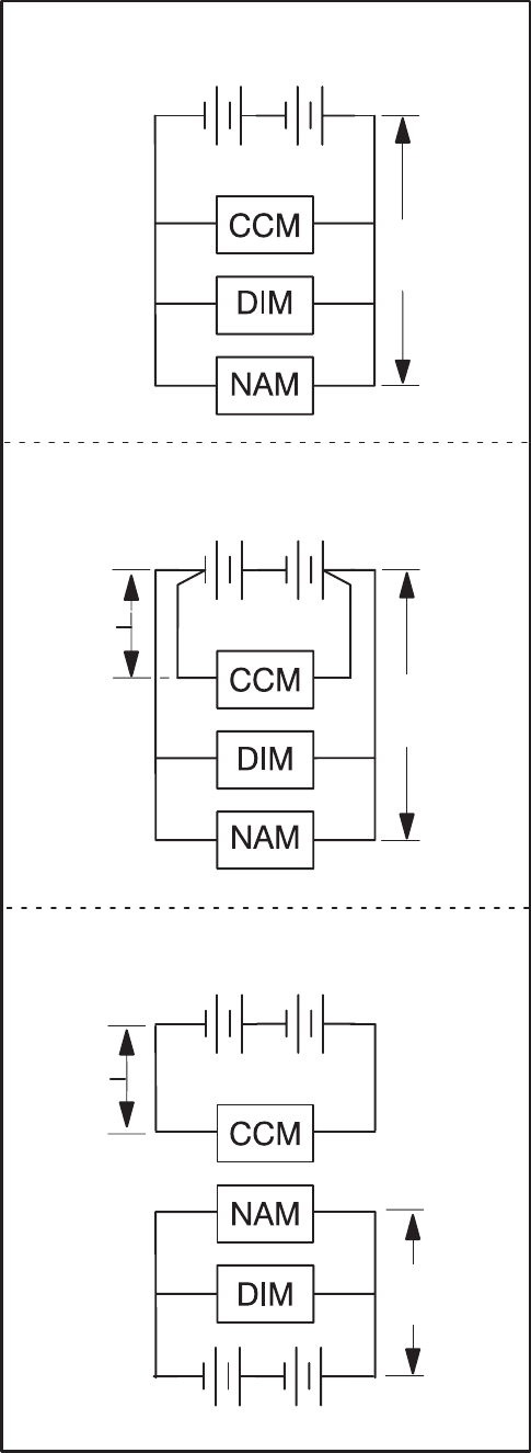
SELECTING NETWORK POWER
CONFIGURATION AND WIRE SIZE
The following section describes the procedures for
selecting the copper wire gauge needed to supply
network power. The wire gauge selected will be a
function of the type and number of modules used,
the type of power supply selected, and the distance
between the power source and the farthest module
in the power supply circuit. Do not use twisted pair
data wire for DC power.
Use this procedure for developing network power
circuits for DIM, NAM and CCM-Genset modules
only. (CCM-ATS modules are not included because
they are equipped with their own power supply.)
Refer to Figure 2-6 for illustrations of typical circuit
configurations and notes.
1. Determine the number and type of load mod-
ules (DIM, NAM and CCM-Genset modules).
Redistribution or publication of this document,
by any means, is strictly prohibited.
2-11
2. Calculate the Total Load Factor by adding up
the individual load factors for each DIM, NAM,
and CCM-Genset in each circuit.
Each CCM-GenSet has a load factor of: 2.40
Each DIM has a load factor of: 0.10
Each NAM has a load factor of: 1.20
3. Determine the distance between the power
source and the farthest load device (DIM, NAM
or CCM-GenSet module) in the circuit.
4. Look up the required minimum copper wire
gauge. Refer to Table 2-5 for 24V genset bat-
tery power supply.
Example:
Application: The network plans call for one CCM-
Genset at 40 feet (12 m), one DIM at 50 feet (15.2
m) and one NAM at 300 feet (91.4 m). The farthest
module from the network power source is the NAM.
The top drawing in Figure 2-6 shows each of these
modules being supplied in one circuit.
Calculation: The total load factor =
(1 X 2.40) + (1 X 0.10) + (1 X 1.20) = 3.70
Wire Size Required: Look up the total load factor
(3.70) in the first column of Table 2-5. Then look
across the table to find a distance equal to or greater
than the distance to the farthest load device (300
feet). Table 2-5 indicates that the maximum dis-
tance obtainable is only 201 feet, this power supply
is not adequate to supply all of these modules in one
circuit.
The circuit can be redesigned so the CCM-GenSet
module is supplied by a second circuit off the same
source (center diagram in Figure 2-6). Be careful
not to exceed the current rating of the circuit. (The
load factor equals the maximum current draw.)
–OR–
The circuit can be supplied by more than one gen-
set power supply if available (bottom diagram in
Figure 2-6). Do not connect separate network pow-
er sources in parallel or damage to the batteries will
result from overcharging.
Using either of the redesigned circuits, recalculate
the wire gauge based on steps 1 thru 4. The CCM–
GenSet with a load factor of 2.40 can be supplied
using 18 gauge wire. The DIM and NAM with a total
load factor of 1.30 can be supplied using 14 gauge
wire.
/ 4
#+ '
/5! " (
() (
/5! " (
( () (
( /5! " (
() ( *
4
#+/ '
4
#+/ '
4
#+/ '
/ 4
#+ '
FIGURE 2-6. NETWORK POWER DIAGRAMS
Redistribution or publication of this document,
by any means, is strictly prohibited.

2-12
TABLE 2-5. 24V GENSET BATTERY POWER SUPPLY
(
(
+=
# $$'
+
# $$'
+/
#> $$'
+
#+ $$'
"
"!
4
! ( * () (
! * 4* "! !5 4
4 4 4 4
+ +==> >+ + />/ +//+ >/>
/ => +/= // >> >/ >>/ ++
++> = / += /= + >=
/ /> +/= >/ = ++= +==> >+
>> ++ += + == + /+
> >> ++> / + + >
+ += > + /> +// >
+ ++ / / > = ++ / +=/
+ + = +> +/
+> += +>+ > == /+ ++/
/ == + / = > >> ++
=/ + / ++ // +
> + + =
> + +> > >/ =
+ + / += /= >>
= +>> =+ +/ // >=
/ +/ = + + /+/ + >
> + = / +> = + +
/ /> +// > = ++ += >
/ // + > + ++ /+ +>= /+
/ / += > + += ++
/> / ++ + + + /=/
= ++ += ++ /
++ > +>/ + > +// /=
/ + / + = +> /+=
> + + = ++ /
+ + > / + =
/= +/ > ++ =
== / +/ > ++ /
> = = // + > + ++ /+
> > = / + = > +=
> > /+ + +/ +>
> >> / + + ++ >
Redistribution or publication of this document,
by any means, is strictly prohibited.

2-13
TABLE 2-5. 24V GENSET BATTERY POWER SUPPLY (Continued)
(
(
+=
# $$'
+
# $$'
+/
#> $$'
+
#+ $$'
"
"!
4
! ( * () (
! * 4* "! !5 4
4 4 4 4
>> / >/ ++= + +=> > >
= / > > ++/ +=+ / ==
= > +++ = +> + >
= = +> +> = >+
=> / +/ / + =
+ / ++ ++ =/
+ +> = /
+ + > /
> + + / / +/ >>
+ + = + /= +/ >
++ +> > = / +
+ + /= > / ++ +
+ + // > > +++ = +>>
+/ + /+ + / +/ / +/
+ + = + > +
+ + + > + /> +//
+> ++ / += / = = // +
+= + +> + =+ / +=
+ + + /= > / ++
+ / / > = ++
NOTES 1. This table is for copper wire at 50°C (122°F). Derate the distances by 0.4% per °C over 50°C
2. Minimum wire gauge for NEC compliance is AWG 14
3. Network power wiring must be run in a conduit separate from the utility/genset power cables
4. Wire sizes given in mm2 are for the nearest standard metric wire size.
5. DIM’s and NAM’s have a minimum operation voltage of 8 VDC. This Table is for use with DIM’s,
NAM’s or DIM’s NAM’s and CCM’s in combination. For network power supplies with CCM’s only
refer to Tables 2-6 and 2-7.
Redistribution or publication of this document,
by any means, is strictly prohibited.

2-14
TABLE 2-6. 12V GENSET BATTERY POWER SUPPLY FOR CCM’S ONLY
(
(
+=
# $$'
+
# $$'
+/
#> $$'
+
#+ $$'
"
"!
4
! ( * () (
! * 4* "! !5 4
4 4 4 4
/ > / += + +
/= + + / + +=
> > +/ / > +
> + + +> + >
+ + = / + + /
+// / + > + ++ +> +
+= / + += > + /
+ + = / +
+ + > + +
/ / + > + +
/ / + += +
NOTES 1. This table is for copper wire at 50°C (122°F). Derate the distances by 0.4% per °C over 50°C.
2. Minimum wire gauge for NEC compliance is AWG 14.
3. Network power wiring must be run in a conduit separate from the utility/genset power cables.
4. Wire sizes given in mm2 are for the nearest standard metric wire size.
5. CCM’s each have a load factor of 2.40. CCM’s have minimum operation voltage of 4 VDC.
Redistribution or publication of this document,
by any means, is strictly prohibited.

2-15
TABLE 2-7. 24V GENSET BATTERY POWER SUPPLY FOR CCM’S ONLY
(
(
+=
# $$'
+
# $$'
+/
#> $$'
+
#+ $$'
"
"!
4
! ( * () (
! * 4* "! !5 4
4 4 4 4
/ += > + == / +/= >/ >
/= = +/ // + >/ > +++=
> + += > +/ / / >/
/ +/ > ++ += >
+ > ++ = +> = +/> //=
+// + / / +/ >> / + >+
+= > / += + +
+ > + = +>= =
+ > + + = /
/ += / == / +/ >
/ +> + > / += > /
== + / / > ++= + +=
+ +/ / > + +>
+ + / + +=
+ + > + / / +/
=/ ++ += / == / +/
/= ++ +> + > = / ++
/ + + /= > /+ +
/ + + / / > ++=
/= > + / > > ++
NOTES 1. This table is for copper wire at 50°C (122°F). Derate the distances by 0.4% per °C over 50°C.
2. Minimum wire gauge for NEC compliance is AWG 14.
3. Network power wiring must be run in a conduit separate from the utility/genset power cables.
4. Wire sizes given in mm2 are for the nearest standard metric wire size.
5. CCM’s each have a load factor of 2.40. CCM’s have minimum operation voltage of 4 VDC.
Redistribution or publication of this document,
by any means, is strictly prohibited.
2-16
Redistribution or publication of this document,
by any means, is strictly prohibited.

3-1
, #$ - *($
ABOUT THIS SECTION
This section describes procedures for the logical
installation and connection of the various modules
on the network using LonMaker. Refer to the Glos-
sary section for definitions of network terms.
Much of the material in this section is derived from
the Echelon LonMaker Installation Tool Users
Guide. The Echelon manual is included with the
LonMaker software, and should be considered a
reference companion to this manual.
Use this manual for basic, Onan-specific network
installation, operation and service information
(hardware and software).
This section covers the following topics:
1. Network Overview
2. Network Installation Scenarios
3. Setting up Network Installation Tools
4. Starting LonMaker Software
5. Using LonMaker Software
6. LonMaker Network Setup
7. Installation of Devices with LonMaker
8. Connect Procedure
9. Install Procedure
10. Checking Connections
11. Checking Input and Output Values
12. Network Service Procedures
13. Testing Devices and Verifying Installation
Items 1 through 3 cover introductory and back-
ground information.
Items 4 through 10 cover the basic elements of a
typical installation.
Items 11 through 13 cover service and trouble-
shooting procedures.
The following section (Section 4) describes the
installation and use of PowerCommand Configura-
tion Tool (PCT). PCT is used to complete the net-
work installation.
The step-by-step procedural information in this sec-
tion is intended for use in conjunction with operating
LonMaker software. Read all introductory and over-
view material, and skim over the major headings of
the procedures ahead of time; but do not expect the
procedural text to be very useful until you are oper-
ating the software and can view its menus and fea-
tures.
Refer to the Echelon LonMaker manual for a de-
tailed explanation of how to use the LonMaker
graphical display screens, and for in-depth cover-
age of definitions, concepts, software installation
and setup procedures, device installation proce-
dures, maintenance and test procedures, error
messages and troubleshooting.
POWERCOMMAND NETWORK OVERVIEW
Devices, or modules on a PowerCommand Net-
work communicate with one another by sending
measurements, instructions, signals, and other
messages. The devices sense monitored condi-
tions and network input messages, and respond
with appropriate actions and output messages.
In a PowerCommand Network, modules are con-
nected to a physical transmission media. In the
PowerCommand Network, however, physical at-
tachment (wiring) is not enough to “install” the sys-
tem. The physical connections only provide a path
for sending and receiving control messages.
Redistribution or publication of this document,
by any means, is strictly prohibited.
3-2
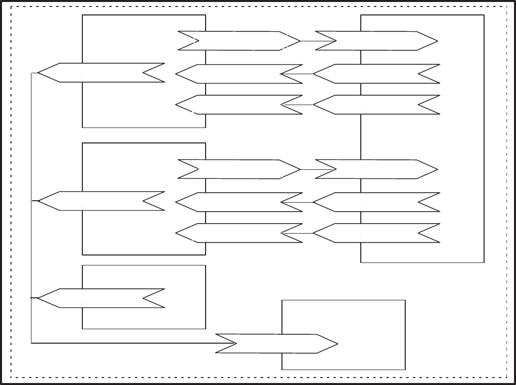
)(
"
?&08@0
?&08@0+
?<%6A+B
(
8CD
%C+
%C+
%C+
?&08@0/
?&08@0
?<%6A+B
?$&@$
?0$
?&&$$&<%$
?$&@$
?0$
?&&$$&<$
(
"
FIGURE 3-1. NETWORK MODULES IN ONE LOCATION AND ONE DOMAIN
With a PowerCommand Network, you must also
install and connect devices by using the LonMaker
software, a personal computer, and a Network
Installation Gateway to send messages over the
network to each device. This procedure, the logical
installation and connection of devices using Lon-
Maker software, identifies all devices on the net-
work and assigns, or links, outputs from specified
devices to inputs on other specified devices (bind-
ing). Many of these terms are defined in the Glossa-
ry in Appendix A.
After installing and connecting devices with Lon-
Maker, use the PowerCommand Configuration Tool
(PCT) software to further define and install configu-
ration information and to make a CSV file for use by
PowerCommand Software for Windows (refer to
PowerCommand Configuration Tool in this section).
The network installer will need documentation list-
ing the device-specific network variable input and
output connection pairs. These network variable
connection instructions define logical input/output
connected pairs, just as a point-to-point wiring dia-
gram defines physical input/output connected
pairs. Refer to the Forms in Appendix C.
Device-specific network installation procedures are
covered in the individual module sections.
Redistribution or publication of this document,
by any means, is strictly prohibited.
3-3
NETWORK INSTALLATION SCENARIOS
There are two basic installation scenarios that you
can use when installing a new network:
•Setup before going to the site, then install and
test at the site.
•Setup, install and test at the site
Setup Before Going To The Site
With this scenario, everything about a new network
configuration is predefined using LonMaker and
PCT before you go to the site. Defining network
components like domain, channel, location, de-
vices, and defining connections can be done before
going to the actual installation site. This information
is stored in the site directory for use at the site.
At the installation site, the network installer uses
LonMaker to “install” each physical device and PCT
to install configuration information and to make a
CSV file for use by PowerCommand Software for
Windows (PCW). Any changes must be made at the
site.
Setup At The Site
With this scenario, the network installer connects to
the site network and uses LonMaker to define net-
work components such as domain, channel, loca-
tion, devices and define and make connections be-
tween device inputs and outputs. The installer will
also use PCT to define module configuration infor-
mation and to make a CSV file for use by PCW at the
network site.
Procedure Overview
Initial network setup, including assigning connec-
tions (binding), can be done off-site, prior to the
physical installation or at the site. This creates a site
database.
After the devices are physically connected at the
site, the installer must connect a PC (with LonMaker
installation software and the site database) to the
Network Installation Gateway Module.
The installer then runs the LonMaker installation
software to perform several functions including de-
fining components of the network and identify spe-
cific device nodes by pressing their individual ser-
vice pins when prompted to do so. Next the installer
runs the PCT software to further define and down-
load module configuration information and to make
a CSV file for use by PowerCommand Software for
Windows.
As a final checkout, the installer should run Power-
Command Software for Windows to thoroughly test
the installation connections, alarms, etc. Refer to
the PCW manual for PCW operating instructions.
This must be done with an NGM configured for
PCW (not the Network Installation Gateway).
Any future modification of an existing network
installation must be done on-site.
SETTING UP NETWORK
INSTALLATION TOOLS
Refer to the the Required Installation Tools in Sec-
tion 1 for the minimum PC system requirements.
LonMaker software, a network gateway driver, Net-
work Module Library and PCT must be installed on
your computer before you can begin the network
installation procedures.
Normally the LonMaker software, Network Module
Library, the network gateway driver and PCT are
installed before you arrive at the installation site.
These programs only need to be added to the instal-
lation computer once.
To connect the installation PC that runs LonMaker
software to a PowerCommand network, you must
connect a Network Installation Gateway between
the network and the PC. This gateway can be con-
nected to the network at a Junction Box/Terminator,
a GCM or at a CCM.
Redistribution or publication of this document,
by any means, is strictly prohibited.
3-4
Network Module Library Installation
The Network Module Library (NML) contains the
data files that are used to create or update a Power-
Command Network. The NML software is used in
conjunction with LonMaker software to install a
PowerCommand Network. The NML software is up-
dated as additional features and modules become
available.
Install the latest NML software as follows:
1. Insert the Module Library Disk into the floppy
drive (A:).
2. At the DOS prompt type:
A:\INSTALL [drive] ↵ Enter\Return.
Note: [drive] Optional. If the drive is not specified, the
drive defaults to C:. To install to a drive other than C:,
enter the drive letter and colon.
The install routine creates a directory called
\ONAN. The Module Library is installed in the
\ONAN directory in a subdirectory called NML (e.g.
C:\ONAN\NML).
The install routine also creates a subdirectory
named BIN (C:\ONAN\BIN). BIN contains the driver
for the Network Installation Gateway.
The install program deletes previous versions of the
Module Library and updates the Installation Gate-
way driver. Review the README.TXT file for the lat-
est information on the NML software.
A line must be added to the config.sys file using a
text editor. Example using MS DOS:
From the C:\ prompt, type edit config.sys to edit the
config.sys file.
Add the following line:
devicehigh=c:\onan\bin\ldvslta.sys /p1 /b9600 /m
Note: Be sure to include a space between ldvslta.sys
and /p1, between /p1 and /b9600, and between /b9600
and /m.
The /p1 specifies that the Network Installation Gate-
way is connected to COM1 on the computer. Use
/p2 if connected to COM2.
The /b9600 specifies the Network Installation Gate-
way baud rate (do not change). The /m specifies the
protocol (do not change).
Network Module Library Removal
To remove the Network Module Library:
1. Insert the Module Library Disk into the floppy
drive (A:).
2. At the DOS prompt type:
A:\BIN\DINSTALL ↵ Enter\Return.
LonMaker Software Installation
This software is provided on two floppy disks. The
files on these disks are compressed, so you must
use the INSTALL program on the LonMaker disks to
transfer the files to your computer.
The INSTALL program will modify the the PATH
statement in the AUTOEXEC.BAT file so that when
the computer is rebooted, the LonMaker directory is
in the defined path.
Insert disk 1 and type: A:\INSTALL (press ↵ En-
ter\Return).
Follow the prompts and choose a drive when re-
quested. When prompted for a subdirectory, editing
the path to add the ONAN directory (\ONAN\LNM)
will help organize the network installation files. Se-
lect the graphical version. Answer yes “Y” to modify
the config.sys file.
The software installation places LonMaker files in a
new directory named LNM. Reboot the computer to
activate these changes.
Create Or Update A Network
Each PowerCommand Network installation site
must have its own site directory. This directory
will contain the files necessary to run LonMaker.
There can be many site directories on your comput-
er with each one corresponding to a different net-
work installation. LonMaker software resides in its
own directory (C:\ONAN\LNM), separate from any
of the site directories.
A utility program is included to create a new site di-
rectory or update a current site with new NML data
files. The NML install routine created a subdirectory
named SITES (C:\ONAN\SITES) to contain net-
work sites. To create or update a site:
1. Change directories (CD) to ONAN
2. From the C:\ONAN> directory enter the follow-
ing:
pcnet c:\onan\sites\<site_id>
Example where the site_id is site_10:
pcnet c:\onan\sites\site_10 ↵ Enter\Return
This utility creates a site directory (\site_10) located
in the \onan\sites directory or updates the existing
site.
Redistribution or publication of this document,
by any means, is strictly prohibited.
3-5
.
""
!
"
"
""
!
"
""35
()
()
""
(
E+ 4
./
()
(
!"
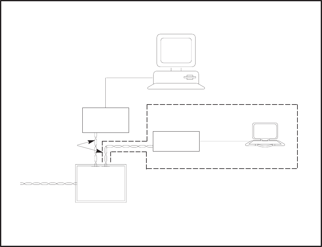
FIGURE 3-2. TYPICAL PC TO NETWORK CONNECTION VIA A JUNCTION BOX/TERMINATOR MODULE
Connecting the Installation PC to the
Network
Connect PC the Network Installation Gateway with
a null modem cable. The gateway can be con-
nected to the network via a JBT, GCM or a CCM.
See Figure 3-2. (The RJ45 connector on the GCM
and CCM should only be used for service or installa-
tion.)
STARTING LONMAKER SOFTWARE
1. Before starting the LonMaker program, change
to the desired site directory. At the DOS
prompt, enter these commands:
cd\onan\sites\[site_id] ↵ Enter\Return
EXAMPLE: cd onan\sites\site_10
2. Start LonMaker by entering the following com-
mand at the site directory:
lnmg ↵ Enter\Return
When you start LonMaker, the it displays copyright
information and the following messages:
Initializing...
Accessing network...
Parts Catalog Rev n
Then the Main screen appears.
Redistribution or publication of this document,
by any means, is strictly prohibited.
3-6
USING LONMAKER SOFTWARE
Figure 3-3 shows the various parts of the LonMaker
Main screen for INSTALLATION.
Task Buttons
Tasks are defined as the procedures that you can
carry out on specific network components. Tasks in-
clude Domain, Channel, Location, and Device Set-
up procedures, as well as Installation, Control, and
Repair procedures.
Task buttons appear in a column at the left of the
screen. Choosing a task button takes you to the ap-
propriate screen for the selected task.
To select a task, use the mouse to move the cursor/
pointer to the task button and click the left mouse
button or type the underlined keyboard access let-
ter.
Action Buttons
Actions are defined as activities that you can re-
quest during each task.
Action buttons appear at the bottom of the screen.
Choosing an action button either initiates an activity
or takes you to another screen, where you can enter
or observe information.
Most action buttons refer to an item that you select
from a list on the screen.
To select an action, use the mouse to move the cur-
sor/pointer to the action button and click the left
mouse button or type the function key shown below
the action button.
Lists
Some lists show specific components that have al-
ready been defined for installation. Other lists show
types of components that you use only when defin-
ing specific components.
You can select components or types of components
from these lists so that LonMaker can act on them.
Action button activities often affect only the items
that you select from a list.
Selected Device and Domain
This area at the top of the screen shows the domain
and device that you have selected.
Network Interface Status/Action Button
This area shows whether LonMaker is communicat-
ing with the network gateway. It is also an action but-
ton that you can use to attach LonMaker to the net-
work, through the network gateway.
Write Text Areas
Many LonMaker screens let you enter information.
Figure 3-4 shows a DEFINE DEVICE screen. In this
example, the write text areas prompt you to enter in-
formation about a Device Name, and the read-only
area provides information about the location of the
device.
To select a write text area, move the cursor/pointer
to the area and click the left mouse button. When
the text area is activated, its background turns gray
and the editing cursor appears.
This symbol, next to a write text area, indicates
a hidden list. To see the list, point and click on
the symbol. To select an item from the list to fill
in the text area, point and click on the item
name.
This symbol, next to a write text area, indicates
a toggle between Yes or No. To toggle between
Yes and No, point and click on the symbol.
Read-Only Text Areas
Read-only text areas provide information. You can-
not activate these text areas or change their con-
tents. Read-only text areas are the same color as
the background area of the screen.
Additional Support
If you are familiar with Microsoft Windows, or similar
graphical user interfaces, you’ll know how to use
many of the features on LonMaker screens. If you
need more information, refer to the LonMaker
Installation Tool Users Guide and to the On-line
Help system.
On-line Help
Select the Help action button on any LonMaker
screen to see a HELP screen with information about
each action and text area.
Select the Index action button on any LonMaker
HELP screen to see the HELP INDEX screen con-
taining a list of all LonMaker screens. If you choose
one of these screen names, the Help system dis-
plays help information for the selected screen.
You can use the Index button to see a succession of
HELP screens. When you choose the Done action
button, the program returns directly to the LonMak-
er screen from which you started.
Redistribution or publication of this document,
by any means, is strictly prohibited.
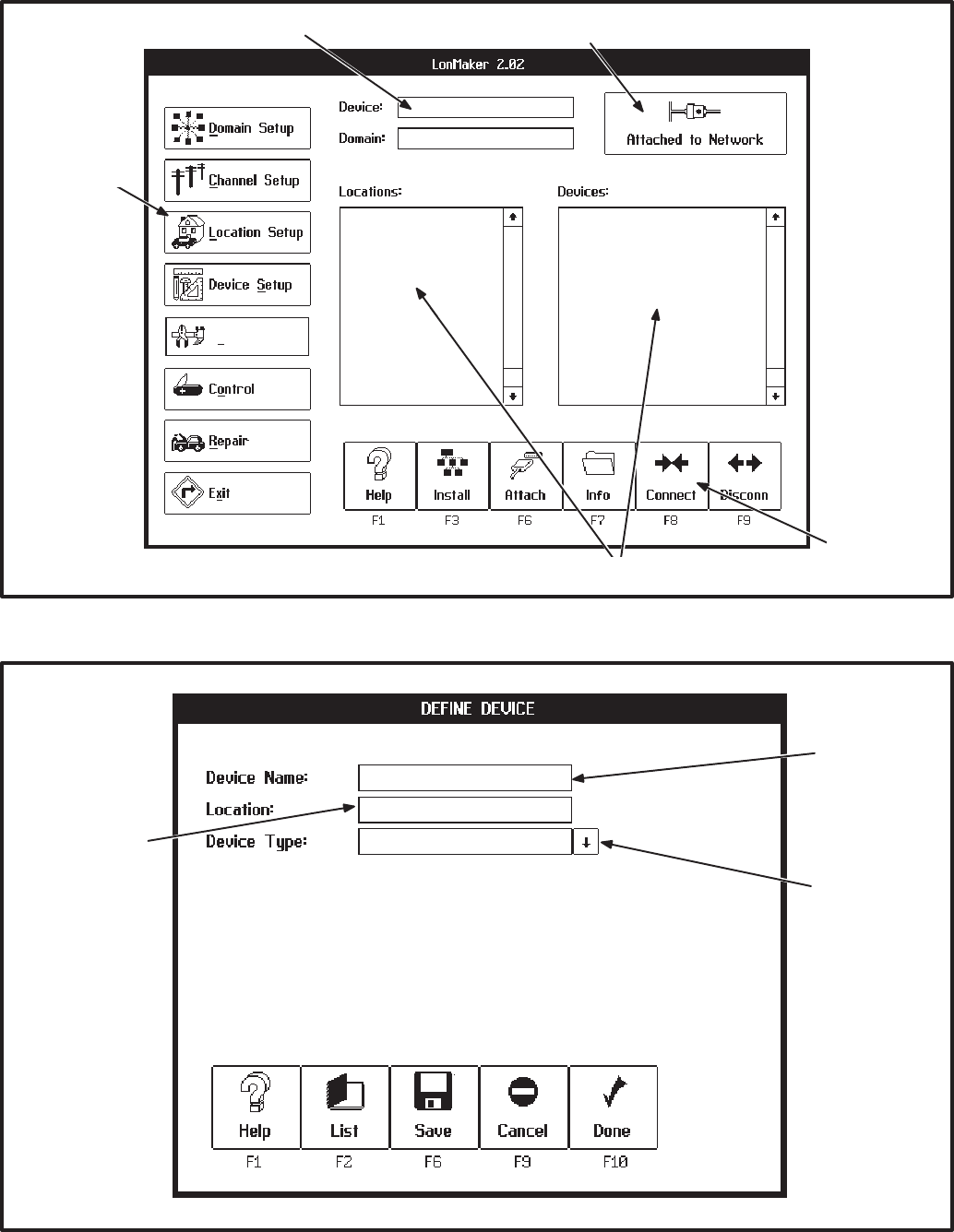
3-7
"! !5 ! !
"
)
() 4 3
Installation
"&%F
FIGURE 3-3. LONMAKER MAIN SCREEN
!"
(
*!! "
FIGURE 3-4. LONMAKER DEFINE DEVICE SCREEN
Redistribution or publication of this document,
by any means, is strictly prohibited.
3-8
LONMAKER NETWORK SETUP
The first steps for installing a network require that
you describe the specific components of the net-
work to the LonMaker program. With this network
setup procedure, you define domains, channels,
locations, and devices. If you encounter error mes-
sages, refer to the LonMaker Installation Tool
User’s Guide, section on Error Messages and Trou-
bleshooting.
The network designer supplies most of this informa-
tion, along with a plan for the physical installation of
devices and communications media. Forms for net-
work design are provided in Appendix C.
As you define components (domains, locations,
channels, and devices) LonMaker records them in a
network database—in the project subdirectories
DB_INST. These definitions affect the operation of
the network only after you install the components.
Installing and connecting devices is covered later in
this section.
Defining and Selecting a Domain
You must name at least one domain for the devices
on your network.
A domain is the top level of organization of the net-
work. Normally, all of the devices in a domain are
assigned only to that one domain.
•A network must have at least one domain.
•A domain has a unique name.
•A domain has a unique ID number. Normally,
this ID limits communication to devices in the
same domain.
•An application device can belong to one or two
domains.
Most PowerCommand network installations will
have only one domain.
Procedure to Define a Domain
You must define a domain for the devices you are
going to install. Follow these steps:
1. Click on the Domain Setup task button. The list
of defined domains appears on the DOMAIN
SETUP screen (Figure 3-5).
2. Click on the Define action button. The DEFINE
DOMAIN screen appears.
3. Type in “domain_∅∅” for the new domain
name (in special cases, use a new name of up
to 16 characters, including spaces). Use the
default ID of “∅∅” in the domain ID, if provided.
Do not change the Domain Auth. Key, (all
F’s) unless instructed specifically, to do so.
4. Click on the Done action button if this is the only
domain you want to define at this time. Click on
the Save action button if you want to define
another domain.
Procedure to Select a Domain
If your network installation contains more than one
domain, before you work with application devices,
you must select the domain that they belong to.
1. Click on the Domain Setup task button. The list
of defined domains appears on the DOMAIN
SETUP screen (Figure 3-5).
2. Click on the domain you want to select. The
name of the selected domain appears at the
top of the screen.
Redistribution or publication of this document,
by any means, is strictly prohibited.
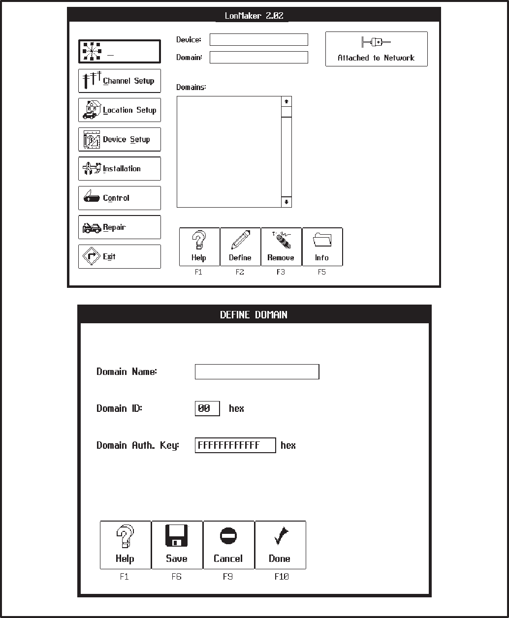
3-9
Domain Setup
&$%D+∅
FIGURE 3-5. DOMAIN SETUP SCREENS
Redistribution or publication of this document,
by any means, is strictly prohibited.
3-10
Defining and Selecting a Channel
You must name at least one channel for your net-
work.
Channels are the physical communications media
that connects the devices and the properties of
these media (such as transmission speed). Most
PowerCommand network installations will have
only one channel (twisted-pair wiring and 78 k bits/
second transmission speed).
An additional channel will be required if the distance
between devices exceeds the operating range of
the communications medium or if the number of de-
vices exceeds the capacity of the channel. Al-
though LonMaker can install up to 127 devices on a
channel, the communications media (22 AWG
twisted pair) has a lower limit (44). Refer to the ma-
terial on data transmission media and network data
specifications in Section 2.
If the network contains a Router, two channels must
be defined (Refer to the Router Section). One addi-
tional channel must be defined for each additional
router.
Procedure to Define a Channel
You must define a channel for the devices you are
going to install. Follow these steps:
1. Click on the Channel Setup task button. The list
of defined channels are displayed.
2. Click on the Define action button. The DEFINE
CHANNEL screen appears.
3. Channel Name: Type in the channel name
“tp78_channel1”.
4. Channel Type: Click on the symbol to the
right of the Channel Type text area to see a list
of available channel types. Double click on
channel type “tp/xf–78” to choose it.
5. Click on the Done action button if done defining
channels, otherwise select save.
Procedure to Select a Channel
1. Click on the Channel Setup task button.
2. Click on channel name. From here, you can re-
move an unused channel, display name and
type information about a channel, or attach the
Network Installation Gateway. You can initiate
these actions by clicking on the Remove, Info,
or Attach action buttons, respectively.
3. Select the channel that the Network Installation
Gateway is connected to. Select Attach.
Redistribution or publication of this document,
by any means, is strictly prohibited.
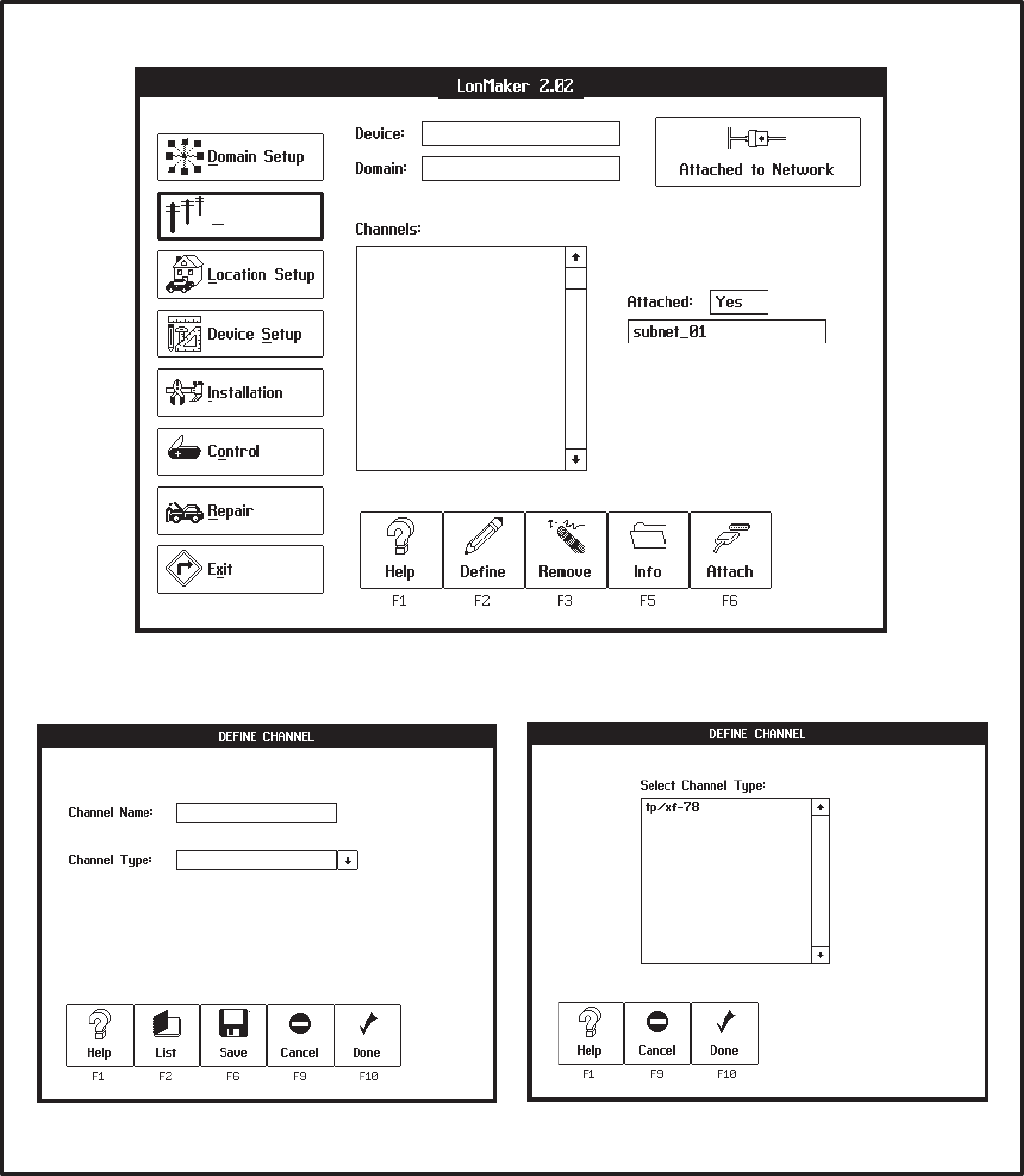
3-11
Channel Setup
@>=D7:%<+
&$%D+∅
FIGURE 3-6. CHANNEL SETUP SCREENS
Redistribution or publication of this document,
by any means, is strictly prohibited.
3-12
Defining and Selecting a Location
You must name at least one location for the devices
on your network.
A location is a subdivision of a network that contains
one or more related devices. Locations are avail-
able for the convenience of the designer and install-
er. They allow you to organize a network installa-
tion.
Locations can be defined to correspond to physical
sites in the project. How locations are defined for a
particular installation project is up to the discretion
of the designer and the installer.
•A network must have at least one location.
•All modules must be assigned a location.
•A module can belong to only one location.
Procedure to Define a Location
You must define a location for the devices you are
going to install. Follow these steps:
1. Click on the Location Setup task button. The list
of defined locations appears on the LOCATION
SETUP screen (Figure 3-7).
2. Click on the Define action button. The DEFINE
LOCATION screen appears.
3. Type in the new location name (up to 16-char-
acters, including spaces).
4. Click on the Done action button if this is the only
location you want to define at this time. Click on
the Save action button if you want to define
another location.
Procedure to Select a Location
Before you work with application devices, you must
select the location that they belong to.
On any screen that shows the Locations list, click on
the location name. A ♦symbol appears to the left of
the selected locations name.
The “ALL” locations name will show all devices in all
locations.
Redistribution or publication of this document,
by any means, is strictly prohibited.
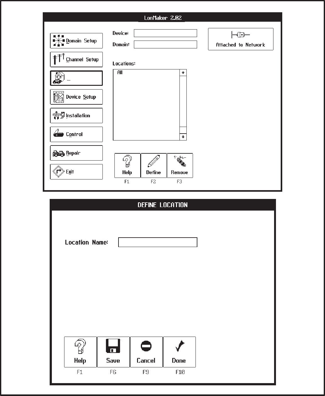
3-13
Location Setup
&.-∅
&$%D+
FIGURE 3-7. LOCATION SETUP SCREENS
Redistribution or publication of this document,
by any means, is strictly prohibited.
3-14
Modules
Every module in the network must be defined.
Modules are the various components of the net-
work, such as the Network Annunciator Module, the
Controls Communications Module, the Genset
Communications Module, etc.
You must identify a domain and location before you
can add a module to the network.
Device Type Names
The following list shows most of the common device
types. These device types will be displayed when
you click on the symbol to the right of the Device
Type text area.
•ccm vX.XX Controls
(ccm /ats vX.XX)* Communications
(ccm/gen vX.XX)* Module
•dim vX.XX Digital I/O Module
•pcc w/gcm vX.XX GenSet
Communications
Module
•mbi /XXX vX.XX Modbus Interface
(5 types)
•nam vX.XX Network Annunciator
Module
•ngm vX.XX Network Gateway
Module
•rtr vX.XX Router
vX.XX = Device Software Version
Modules not covered in this manual may ap-
pear in this list.
*Note: ccm/ats and ccm/gen have pre-defined
configuration data (Refer to Autobindings in
Appendix C).
Procedure to Define Application Devices
You must define the devices you are going to install.
(Routers are covered in a separate section because
the steps are different). Follow these steps:
1. Click on the Device Setup task button.
2. Choose a location for the device. Do not
choose the All location.
3. Click on the Define (F2) action button. The DE-
FINE DEVICE screen appears (Figure 3-8).
4. Device Name: Type in the device name (up to
16 characters, including spaces). An applica-
tion device must have a unique name in the
LonMaker database. This name can occur
only once in all domains and locations in a net-
work. (The period, slash and underscore char-
acters may be used in the name).
5. Device Type: Click on the symbol to the right
of the Device Type text area to see a list of
available device types. Double click a device
type to choose it.
6. Chan Name: Click on the symbol to the right
of the Chan Name text area to see a list of avail-
able channel names. Double click a channel
name to choose it.
7. Chan Priority: Click on the to toggle Yes/
No. A channel priority slot can be assigned to
CCMs, GCMs, and NGMs. The tp/xf-78 chan-
nel type has 16 priority slots available per chan-
nel. This means that up to 16 modules can be
assigned a priority slot. Though not required, a
priority slot assigned to a CCM or GCM gives
dial-out alarm messages priority access over
other network traffic.
8. Click on the Done (F10) action button if you are
done defining devices. Click on the Save ac-
tion button if you want to define another device.
Redistribution or publication of this document,
by any means, is strictly prohibited.
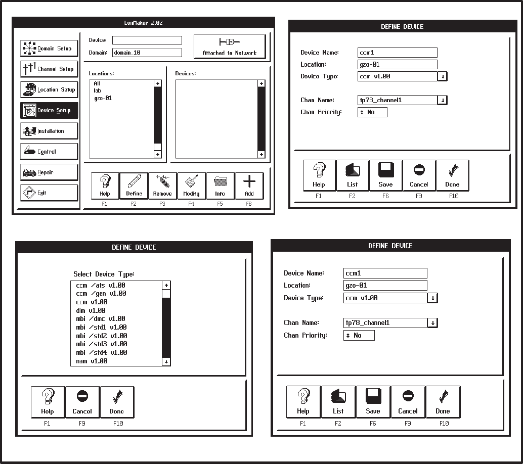
3-15
FIGURE 3-8. DEFINE DEVICE SCREENS
Redistribution or publication of this document,
by any means, is strictly prohibited.
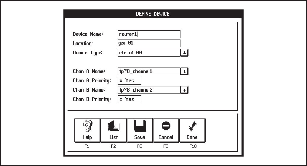
3-16
Procedure to Define a Router
Before you can define a Router, select a Domain
and Location and define the two channels that the
router will connect. Follow these steps to define a
router:
1. Click on the Device Setup task button.
2. Choose a location for the Router. Do not
choose the All location.
3. Click on the Define (F2) action button. The DE-
FINE DEVICE screen appears (Figure 3-9).
4. Device Name: Type in the Router name (up to
16 characters, including spaces). Each Router
must have a unique name in the LonMaker da-
tabase. This name can occur only once in all
domains and locations in a network.
5. Device Type: Click on the symbol to the right
of the Device Type text area to see a list of
available device types. Double click Router (rtr
vx.xx) to choose it.
6. Chan A/B Name: Click on the symbol to the
right of the Chan A Name text area to see a list
of available channel names. Double click a
channel name to choose it. Repeat this step to
select a channel name for channel B.
7. Channel A Priority: Click on the channel A
to toggle Yes. A channel priority slot can be as-
signed to a Router for each channel. The tp/
xf-78 channel type has 16 priority slots avail-
able. This means that up to 16 modules per
channel can be assigned a priority slot. A prior-
ity slot assigned to a Router gives dial-out
alarm messages priority access over other net-
work traffic. An error message will occur if all 16
priority slots are taken.
8. Channel B Priority: Repeat step 7 for channel
B.
9. Click on the Done action button if this is the last
device. Click on the Save action button if you
want to define another device.
FIGURE 3-9. DEFINE DEVICE SCREENS
Redistribution or publication of this document,
by any means, is strictly prohibited.
3-17
INSTALLATION OF DEVICES
WITH LONMAKER
Network installation actually involves two distinct
processes:
•Connecting Modules is the process of as-
signing (or “binding”) device-to-device connec-
tions—linking an output variable of one device
to an an input variable of another device. This
procedure is described under: CONNECT
PROCEDURE.
Initial network setup, including assigning con-
nections (binding), can be done off-site, prior to
the physical installation.
(Any modification of an existing network instal-
lation must be done on-site.)
•Installing Modules is the process of identify-
ing each device as a unique member of the net-
work. This procedure is described under:
INSTALL PROCEDURE.
The installer selects the Installation task, and
identifies specific device nodes by pressing
their individual service pins when prompted to
do so by the LonMaker installation program.
CONNECT PROCEDURE
This section covers setting up connections between
outputs and inputs of application devices. This pro-
cess is also referred to as “binding.” (Refer to the
end of each module section for available bindings.)
You can connect application devices before or after
installing them.
The devices you connect must be in the same do-
main, but they can be in different locations.
These connections are software (logical) connec-
tions, not physical connections between devices.
LonMaker software is used to connect selected
pairs of application devices. The first step in con-
necting devices is to select a “hub” device. The hub
device is the first device that you will use to connect
to several other devices. For example, to connect
the device named “GCM_1” to the devices named
“DIM_1” and “DIM_2,” you should select “GCM_1”
as the hub device. You then select devices to con-
nect to the hub. Refer to Appendix C for Application
Table Consumption to review the number of con-
nections that can be made. In general the DIM and
NAM can connect to a maximum of 5 devices and
the CCM and GCM can connect to up to 15 mod-
ules.
You can connect a device to itself by connecting
(binding) its inputs to its outputs.
Connections occur in two steps:
•Pending: When you first specify connections,
they are stored as proposed or pending con-
nections. LonMaker places a+ symbol next to
device names involved in pending connec-
tions.
•Completed: When you click on the Done ac-
tion button on the CONNECT screen (and the
devices are already installed), LonMaker
sends connection information to the devices
and removes the+ symbol next to device name.
If the devices are not installed yet, LonMaker
saves the connection information and sends it
to the devices when you do install them.
LonMaker refers to the inputs and outputs of de-
vices as network variables (NVs). Inputs and out-
puts on a LonWorks network are not hard-wired
connections, but flexible software connections.
Redistribution or publication of this document,
by any means, is strictly prohibited.
3-18
Procedure for Connecting Devices
1. Click on the Installation task button. (Figure
3-10).
2. Select the specific location that contains the
“hub” device—or select the All location.
3. Select the “hub” device from the Devices list.
The hub device is the device that you will to
connect to several other devices.
4. Click on the Connect (F8) action button. The
CONNECT screen appears (Figure 3-11).
5. Select the next device to connect to from the
Devices list.
6. Choose the Auto or Manual actions.
Auto: If there are automatic (predefined) con-
nections for the two selected devices, this but-
ton appears at the bottom of the screen. Click
on the Auto action button to add these connec-
tions to the pending list. Refer to Appendix C
for a list of Automatic Connections.
Manual: If the selected pair does not have pre-
defined connections, or if you want to set up
other connections, click the Manual action but-
ton. Manual connections are described below.
7. Repeat steps 5 and 6 for each device that con-
nects to the hub device.
8. Click on the Done action button to complete the
pending connections.
9. Repeat steps 2 thru 8 for the next designated
hub device and each of its connected devices.
Procedure for Manual Connections
The network designer will provide instructions
and/or forms that define these connections.
(Sample forms and schematics are provided in
the back of this manual.)
From step 7 above: If the selected pair does not
have predefined connections, or if you want to set
up other connections:
1. Click on the Manual action button. The MANU-
AL CONNECT screen appears (Figure 3-12).
2. Select an output for one device and an input for
the other device. A ♦ symbol appears to the left
of your selections.
The inputs and outputs must be of the same
type.
LonMaker checks your choices for connections
to see if a connection is already pending or com-
pleted, and whether it is appropriate for the
types of inputs and outputs involved.
3. Choose the Add or Next actions.
Add: Adds the input/output connection to the
list of pending connections.
Next: Toggle the display of inputs and outputs
between the two selected devices.
4. Repeat steps 2 and 3 to set all connections be-
tween these two devices.
5. Click on the Done action button to return to the
CONNECT screen. LonMaker completes the
pending connections when you click on the
Done action button on the CONNECT screen.
Redistribution or publication of this document,
by any means, is strictly prohibited.
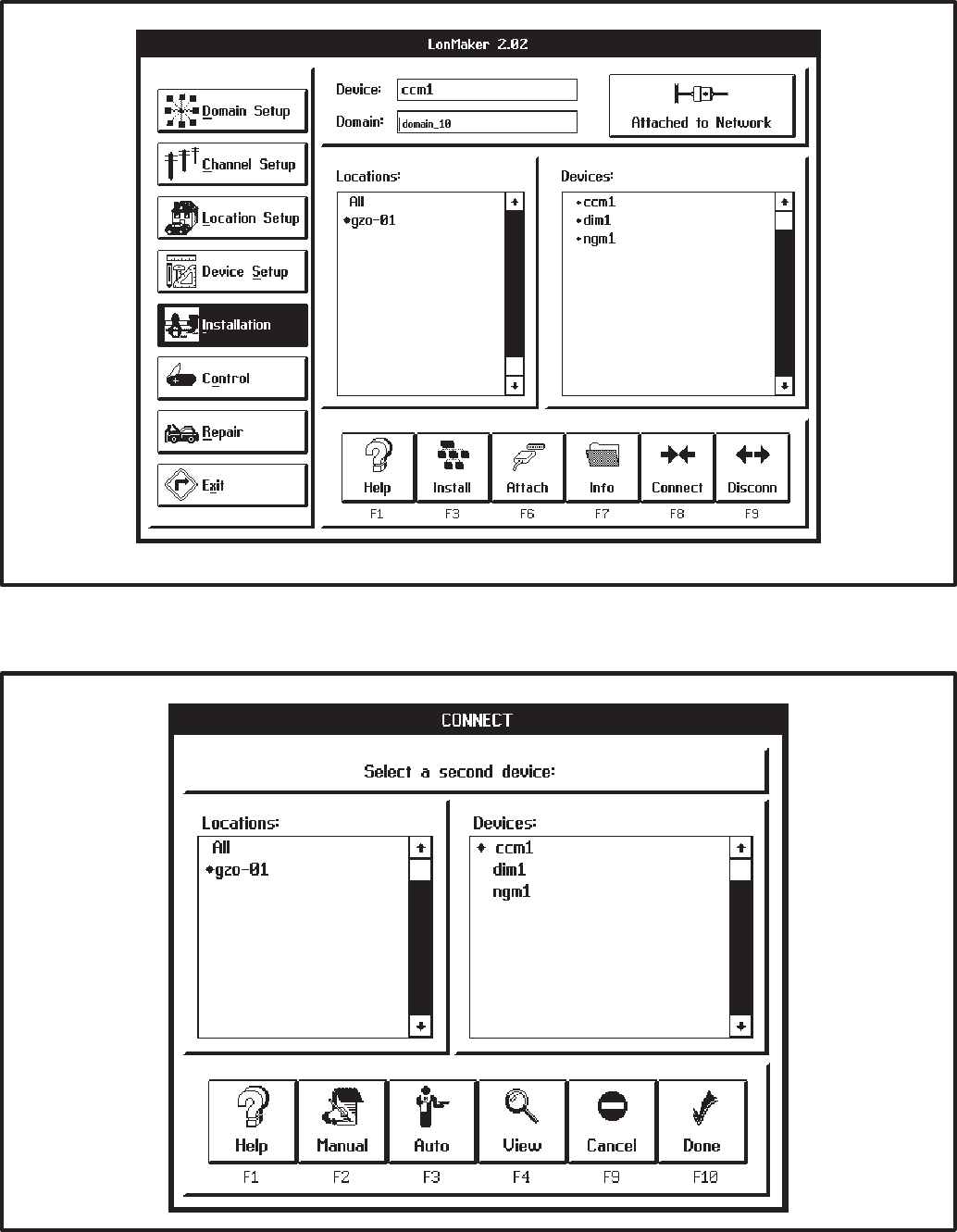
3-19
FIGURE 3-10. INSTALLATION SCREEN
FIGURE 3-11. CONNECT SCREEN
Redistribution or publication of this document,
by any means, is strictly prohibited.

3-20
FIGURE 3-12. MANUAL CONNECT SCREEN
INSTALL PROCEDURE
Preliminary Steps
Before you perform these steps, the specific com-
ponents of the network must be defined. The last
step in setting up LonMaker for network installation
is to identify the channel to which LonMaker is at-
tached. (If the network has only one channel, Lon-
Maker automatically selects this channel.) The set-
up procedures are covered under LonMaker Net-
work Setup.
Network service procedures can
cause accidental starting of the generator set or
operation of a transfer switch or other auxiliary
equipment connected to the network—which
can cause severe personal injury or death.
Place the generator set RUN/OFF/AUTO switch
in the OFF position. Prevent accidental opera-
tion of the transfer switch by disabling the actu-
ating mechanism (see Operator’s Manual).
Before you use LonMaker to install devices on a
network, you must also complete the following
steps:
1. Connect the computer to the Network Installa-
tion Gateway.
2. Physically connect the Network Installation
Gateway to the network channel.
3. Turn on the computer and network interface.
4. Start LonMaker.
(From the site directory you created, type:
lnmg)
5. Make sure that LonMaker is “attached” to the
correct channel. Refer to the icon in the upper
right corner of the screen (Figure 3-13) to de-
termine if the Network Installation Gateway is
attached. If it is not attached, click on this icon.
If it will not attach, check the cable connection
to the PC and verify that it is connected to the
correct COM port as identified in the config.sys
file (/P1, /P2, etc.). Also try cycling power on the
Network Installation Gateway and make sure
its service LED blinks once when the power is
cycled On.
Redistribution or publication of this document,
by any means, is strictly prohibited.

3-21
Procedure to Install Devices
In networks with Routers, the order of installation is
important. Install the Router(s) first. Routers con-
nect different channels. Once they are installed the
other channels can be accessed so that modules on
those channels can be installed.
1. Click on the Installation task button (Figure
3-13).
2. Choose a location for the device. Choose the
All location or the specific location for the de-
vice.
3. Select the device from the Devices list (Routers
first if applicable). Uninstalled devices have a •
symbol next to their names.
4. Click on the Install action button. The INSTALL
screen appears.
5. LonMaker displays a message asking you to
press the service pin on the device to install.
LonMaker waits until you press the service pin
(or until you press the <ESC> key to cancel the
process).
(Service pin location for a specific device is pro-
vided in the hardware description of that device.
Make sure that you press the service pin on the
correct device.)
6. After the service pin is pressed, it can take a
few minutes to install the device. Wait until the
LonMaker popup indicates that the device is
successfully installed.
If the device was previously installed, LonMak-
er informs the installer that the device has been
configured. Select Continue (F2).
When installation of a device is complete, LonMak-
er removes the • symbol from the left side of the de-
vice name.
Repeat steps 2, 3, 4, and 5 for each device in the
network.
Reset Modules
When finished using LonMaker, push the reset but-
ton on each of the modules.
Make Backup Copies
When finished with the installation, make a backup
copy of the entire LonMaker site directory on a sep-
arate floppy disk. Keep the LonMaker site directory
structure intact when backing it up.
Use Microsoft Windows File Manager to copy the
site directory and files to the floppy drive. The di-
rectory structure MUST be preserved.
Store the backup in a safe place.
If this database is lost or corrupted,
the entire installation procedure must be re-
peated. In addition to making and safely stor-
ing backup copies, keep documentation of the
network design (device names, connections,
locations, etc.) up to date with the LonMaker da-
tabase. This is the responsibility of the network
designer and the network installer.
Refer to the remainder of this section for the instal-
lation verifying procedure.
Redistribution or publication of this document,
by any means, is strictly prohibited.
3-22
CHECKING CONNECTIONS
From the CONNECT screen (Figure 3-11), you can
use action buttons to get information about inputs
and outputs, and their connections.
Procedure for Selecting Connection
Viewing screens
To select these information screens, perform the
following steps:
1. From the MAIN screen, select the INSTALLA-
TION screen.
2. Select the location and the hub device.
3. From the INSTALLATION screen, select the
CONNECT screen.
4. If applicable, select the second location and
second device.
5. Click on the View action button. The VIEW
PENDING screen appears.
This screen shows all incomplete (pending) con-
nections between the first selected device and
any other device. This screen also shows a new
set of action buttons:
•Pairs: This action button takes you to the VIEW
PAIR screen.
•All: This action button takes you to the VIEW
ALL screen.
•Pending: This action button returns you to the
VIEW PENDING screen.
Viewing Information about Pending
Connections to One Device
When you select the View action button, the VIEW
PENDING screen (Figure 3-15) appears.
This screen shows all pending connections be-
tween the first selected device and any other de-
vice.
Each pair of text lines shows the names of the con-
nected devices and the pending input/output net-
work variable pair.
This screen also shows the Pairs/All/Pending set of
action buttons.
Viewing Information about Completed
Connections between Two Devices
When you select the Pair action button, the VIEW
PAIR screen (Figure 3-13) appears.
This screen shows a list of all completed connec-
tions between the two selected devices.
Each pair of text lines shows the names of the con-
nected devices and the connected input/output
network variable pair.
This screen also shows the Pairs/All/Pending set of
action buttons.
Viewing Information about All Completed
Connections to One Device
When you select the All action button, the VIEW
ALL screen (Figure 3-13) appears.
This screen shows a list of all completed connec-
tions between the first selected device and all
other devices.
Each pair of text lines shows the names of the con-
nected devices and the connected input/output
network variable pair.
This screen also shows the Pairs/All/Pending set of
action buttons.
Further Information
Viewing connections gets its information from the
LonMaker site database on the PC, and not from
the individual devices. In a properly installed net-
work both will contain the same information.
For information and procedures about checking in-
put and output values, disconnecting devices, tak-
ing devices off line or placing them online, modifying
and replacing devices, moving devices, or remov-
ing devices; refer to the to the Online Help, the re-
maining pages of this section and to the LonMaker
Users Guide.
Redistribution or publication of this document,
by any means, is strictly prohibited.
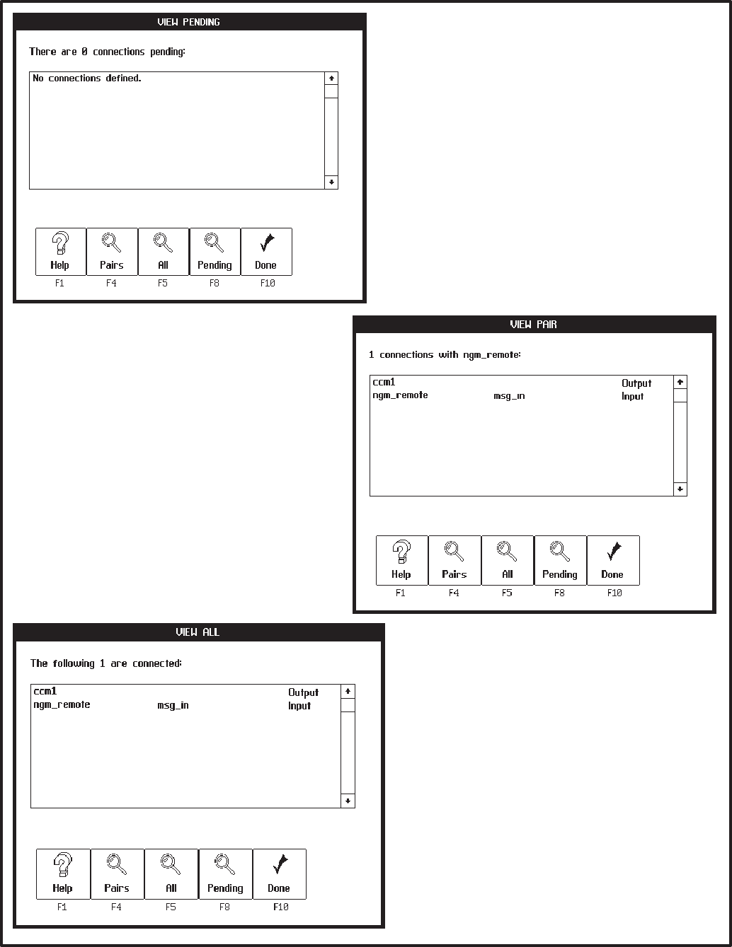
3-23
5(
5( !
5( ""
(&
(&
FIGURE 3-13. CONNECTION VIEWING SCREENS
Redistribution or publication of this document,
by any means, is strictly prohibited.
3-24
CHECKING INPUT AND OUTPUT VALUES
From the CONTROL screen (Figure 3-14), you can
use the Data action button to get information about
the values of individual device input and output vari-
ables.
To select the information screens, perform the fol-
lowing steps:
1. From the MAIN screen, select the CONTROL
task button.
2. Select the location and the device.
3. From the CONTROL screen, click on the Data
action button. The DATA screen appears.
This screen shows the following data:
NOTE: These data lists can be scrolled, using
the scroll bars on the left hand side of the lists.
•Outputs/Inputs: This field displays the names
of the output and input variables.
•Type: This field displays the types of inputs and
outputs, from the parts catalog.
•Value: This field displays the most recent value
sent or received. Until values are determined,
LonMaker displays a “??.” LonMaker polls the
inputs and outputs, and periodically updates
the display. As the values change, new values
are displayed. Do not expect immediate up-
dates, polling takes time.
A value can be a number, text, or the word
“INFO,” indicating a value with multiple fields.
If the value is INFO, click on the Info action but-
ton to view the DATA INFO screen.
NOTE: Not all network variables can be viewed.
For a list of the network variables that can be
viewed, refer to the individual module sections.
Further Information
For information and procedures about disconnect-
ing devices, taking devices off line or placing them
online, modifying and replacing devices, moving
devices, or removing devices; refer to the to the On-
line Help and to the remaining pages of this section.
For information and procedures about changing in-
put and output values, refer to the Online Help and
to the Echelon LonMaker Installation Tool Users
Guide.
These may be tasks for a network designer or
network support specialist. For further informa-
tion, refer to the Echelon LonMaker Installation
Tool Users Guide.
Redistribution or publication of this document,
by any means, is strictly prohibited.
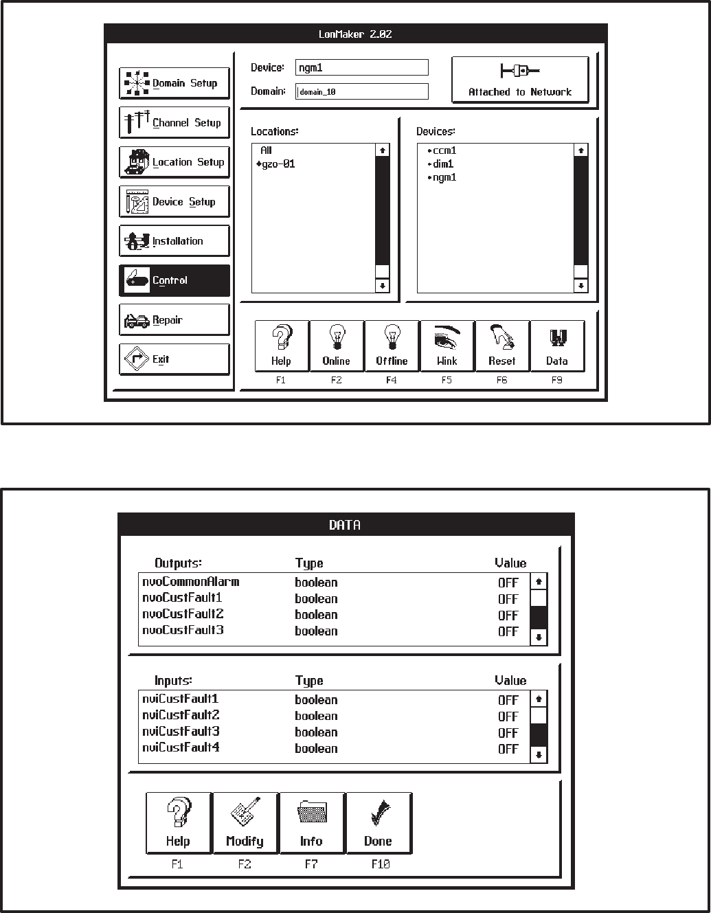
3-25
FIGURE 3-14. CONTROL SCREEN
FIGURE 3-15. DATA SCREEN
Redistribution or publication of this document,
by any means, is strictly prohibited.

3-26
NETWORK SERVICE PROCEDURES
With LonMaker, you can take devices off line or
place them online. You can reset devices, discon-
nect device input and output connections, and re-
move devices from the LonMaker database. You
can modify device names and replace devices.
These procedures are described below.
Other changes that can be made include:
•Adding a Device
•Remove or add channels
•Remove or add domains
•Remove or add locations
•Update device (node) software
Any changes must be backed up and the network
documentation must be updated accordingly. Por-
tions of PCT will need to be run again. Refer to
(Additional Steps Required with PCT Beta Version
– PCT Beta Limitations) for additional instructions.
Network service procedures can
cause accidental starting of the generator set or
operation of a transfer switch or other auxiliary
equipment connected to the network—which
can cause severe personal injury or death.
Place the generator set RUN/OFF/AUTO switch
in the OFF position. Prevent accidental opera-
tion of the transfer switch by disabling the linear
actuators.
Taking Devices Off Line or
Placing Them Online
Using the Offline action, network application de-
vices can be rendered inactive. You may want to
deactivate certain devices while you are trouble-
shooting a network.
Offline devices receive inputs, but respond only to
an Online or Reset action. The Online action re-
stores the activity of an Offline device.
To execute Offline and Online actions, perform the
following steps:
1. From the MAIN screen, click on the Control
task button to select the CONTROL screen.
2. Select the location and the device.
3. From the CONTROL screen, click on the Of-
fline or Online action button to initiate the de-
sired action.
Resetting Devices
Using the Reset action, a network application de-
vice can be set to its initial state and restarted. A re-
set action may also reverse an Offline state, activat-
ing a device. However, an application device may
be programmed to go off line after a reset. Resetting
a device will cancel outgoing calls.
To execute the Reset action, perform the following:
1. From the MAIN screen, click on the Control
task button to select the CONTROL screen.
2. Select the location and the device.
3. From the CONTROL screen, click on the Reset
action button.
Replacing Devices
The Replace action allows you to substitute a new
device for a defective device. You can only replace
one device with an identical device type.
You can also use the Replace action to test a device
that may be defective. Replacing a suspected de-
fective device with a known good device will help
determine whether the original device is defective.
The Replace action installs the new device and
transfers input and output connections, recorded in
the LonMaker database, from the original device to
the replacement device.
Before you begin a replacement, physically remove
the original device, and replace it with the new de-
vice. The replacement device must be installed on
the same channel as the original.
To execute the Replace action, perform the follow-
ing steps:
1. Install the replacement device on the network.
2. Click on the Repair task button. The REPAIR
screen appears.
3. Choose a location, and select the device you
are replacing.
Redistribution or publication of this document,
by any means, is strictly prohibited.
3-27
4. Click on the Replace action button. The RE-
PLACE screen appears.
5. LonMaker displays a message asking you to
press the service pin on the device to install.
LonMaker waits until you press the service pin
(or until you press the <ESC> key on the com-
puter keyboard to cancel the process).
(Service pin location for a specific device is pro-
vided in the hardware description of that device.
Make sure that you press the service pin on the
correct device.)
6. After the service pin is pressed, it can take a
few minutes to install the device. When you see
the message, “Device successfully installed,”
click on the Done button to return to the RE-
PAIR screen.
After replacing a device, the device will have to be re-
configured using PowerCommand Configuration
Tool (PCT). Refer to the PCT section.
Modifying a Device Name
To execute the Modify action, perform the following
steps:
1. From the MAIN screen, click on the Device Set-
up task button to select the DEVICE SETUP
screen.
2. Select the device to be modified.
3. Click on the Modify action button. The MODIFY
DEVICE screen appears.
4. Select the Device Name text area, and type the
new name.
5. Click on the Done action button, to save the
change.
After modifying a device name, the device will have
to be reconfigured using PowerCommand Configu-
ration Tool (PCT). Refer to the PCT section.
Moving Devices
To move a device to a different place on the same
location, domain, and channel, you do not need to
use LonMaker. Simply disconnect the device from
the communications medium and install it at its new
place.
Disconnecting Devices
The Disconn(ect) action removes all input and out-
put connections between a selected pair of devices.
A disconnected device is still installed on the net-
work, but it cannot communicate bound NVs with
other devices. Disconnect removes all records from
the LonMaker database of input and output connec-
tions between the selected devices.
To execute the Disconnect action, perform the fol-
lowing steps:
1. From the MAIN screen, click on the Installation
task button to select the INSTALLATION
screen.
2. Select the location and the first device.
3. Click on the Disconn (F9) action button, to see
the DISCONNECT screen.
4. Select the other device in the connection.
If you do not select a second device, LonMaker
removes all connections between the first de-
vice and all other devices.
5. Use the View Pairs and View All actions to see
the connections.
6. Click on the Done action button to execute the
disconnect. LonMaker prompts you to confirm.
Removing a Device
The Remove action removes an application device
from the network and from the LonMaker database.
Removing a device also removes all of its connec-
tions to other devices in the network.
To execute the Remove action, perform the follow-
ing steps:
1. From the MAIN screen, click on the Device Set-
up task button to select the DEVICE SETUP
screen.
2. Select the device to be removed.
3. Click on the Remove action button.
Further Information
For information and procedures about moving a de-
vice to another location, domain, or channel; or
about removing a domain, removing a location, or
removing a channel; refer to the Online Help and to
the Echelon LonMaker Installation Tool Users
Guide.
Redistribution or publication of this document,
by any means, is strictly prohibited.
3-28
TESTING DEVICES AND
VERIFYING INSTALLATION
You can test installed and connected devices to see
if they are working properly.
The following steps cover the procedure for testing
a device to determine whether it can communi-
cate—receive and send messages—over the net-
work.
Procedure for Testing Devices
1. Click on the Repair task button (Figure 3-16).
2. Select a device from the Devices list.
3. Click on the Test (F3) action button. The TEST
screen appears (Figure 3-17).
The TEST screen displays the following fields:
Test Results: PASSED or FAILED refer to
whether or not LonMaker can communicate
with the selected device.
System Version #: Version of the firmware on
the device’s Neuronchip.
Error: The most recent error message that the
device recorded, if any.
Last Reset: The reason for the last reset. If the
message “Watch-dog timer” occurs repeated-
ly, the device is defective.
Device State: The activity of the device.
Evaluation of these results may be a task for a
network designer, system programmer, or net-
work support specialist. For further informa-
tion, refer to the Echelon LonMaker Installation
Tool Users Guide.
If the device TEST screen displays a
“PASSED” message, you have verified that it
can communicate over the network.
4. Click on the Done action button to return to the
REPAIR screen.
5. Repeat steps 2 through 4 for each device to be
tested.
Test Statistics
Evaluation of these statistics may be a task for a net-
work designer, system programmer, or network sup-
port specialist. For further information, refer to the
Echelon LonMaker Installation Tool Users Guide.
You can further examine the test results by choos-
ing the TEST STATISTICS screen.
1. On the TEST screen, click on the Stats action
button to see the TEST STATISTICS screen.
2. The TEST STATISTICS screen displays the
following fields:
CRC errors: The number of errors in the mes-
sage accuracy test (cyclic redundancy check),
detected on receiving a message packet at the
device. These could result from collisions,
noisy communications media, or signal attenu-
ation.
Transaction timeouts: The number of time-
outs that occurred while the device tried to
carry out a message transaction.
Receive transaction errors: The number of
times the device failed to receive messages
because it had too many pending messages at
one time.
Msgs lost at application level: The number of
messages discarded at the device because its
incoming application buffers were full.
Msgs lost at network level: The number of
messages discarded at the device because its
incoming network buffers were full.
Further Device Testing
For further device testing, you can check informa-
tion about device input and output connections; and
you can check the current values of a device’s input
and output variables.
These procedures are defined earlier in this sec-
tion.
Redistribution or publication of this document,
by any means, is strictly prohibited.
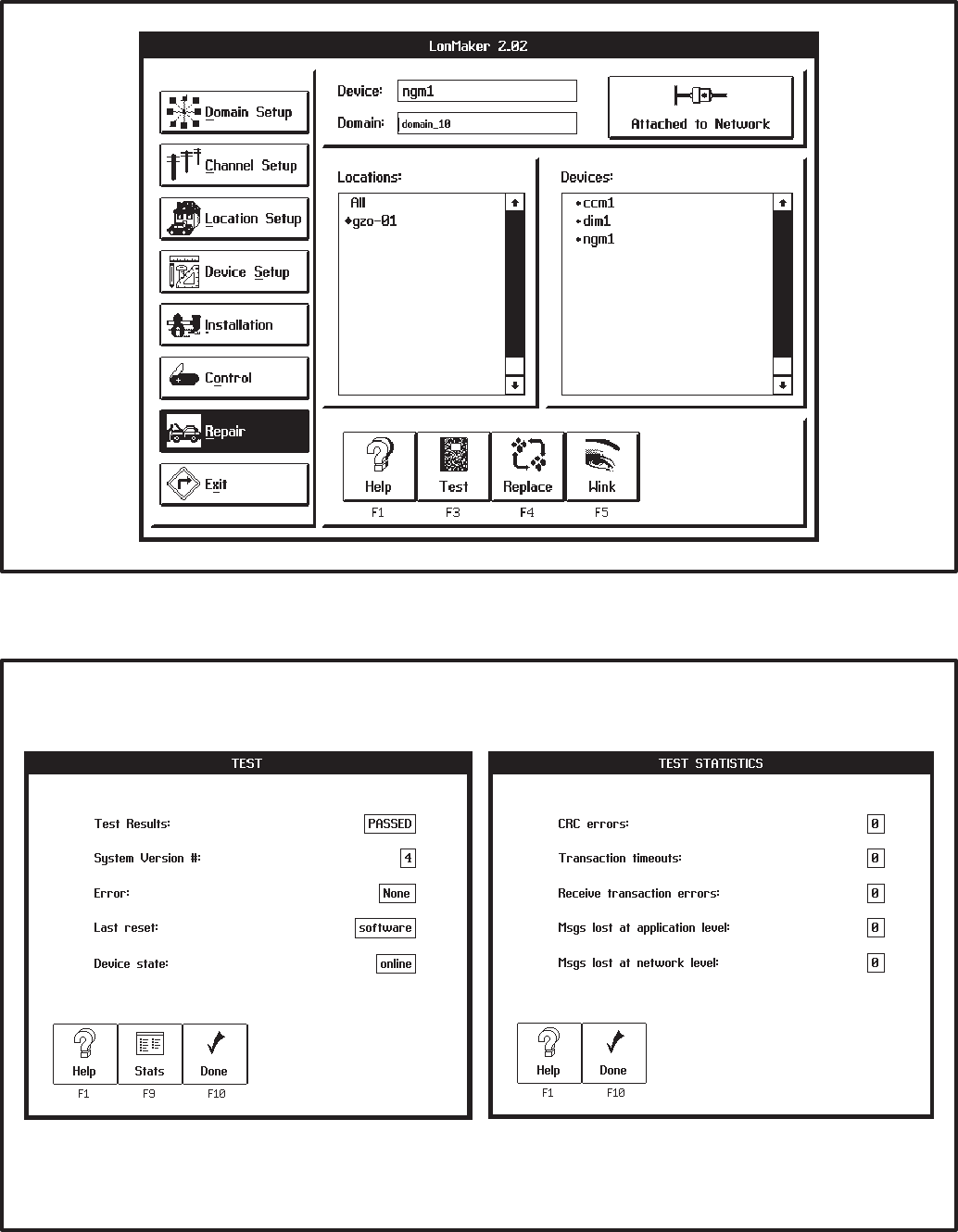
3-29
FIGURE 3-16. REPAIR SCREEN
FIGURE 3-17. TEST SCREENS
Redistribution or publication of this document,
by any means, is strictly prohibited.
3-30
Redistribution or publication of this document,
by any means, is strictly prohibited.

4-1
/ #$ - &
POWERCOMMAND CONFIGURATION
TOOL (PCT)
This section describes installation and use of the
PowerCommand Configuration Tool software, be-
ginning with version 1.00.
Note: PCT v1.00 will not convert site files that were
created with the Beta Release (v0.914). If site config-
uration data for all existing sites were recorded on
the Network Design Forms, proceed with the installa-
tion. Otherwise, record all configuration data for
each site on the design forms. Do this by running
v0.914, open each site and record all configuration
data. Sites that were configured with v0.914 are still
valid and do not require servicing. However, when
servicing is required on one of these sites, the site
files will have to be recreated. All configuration data
must be re-entered (and re-written) with the new soft-
ware.
PCT is used to complete the installation of a Power-
Command Network. After using the LonMaker
installation software to begin the network installa-
tion (Section 3), define and connect modules etc.,
the installer must run PCT. PCT is used to edit and
install the network modules’ configuration settings.
PCT also creates a site information file (.CSV file)
that is used by PowerCommand for Windows
(PCW) software to communicate with the Power-
Command Network.
The site information file (.CSV) contains information
necessary for PCW to communicate with the mod-
ules at the site, including their names, types and ad-
dresses. The file name for the site information file is
the [Site_id].csv. The .CSV extension stands for
Comma Separated Value. The CSV file must be im-
ported by PCW in order to communicate with the
site.
PCW must be updated with the latest .CSV file any-
time a module is added or removed from a site, or
the bindings are changed in LonMaker or the con-
figuration is changed in PCT.
In this section, the network installer will install and
use the PCT software to complete the network
installation. To use this software, you will need to
have experience using Windows application soft-
ware.
Menu commands that are grayed out will not func-
tion. If a command is grayed (dimmed) in the menu
bar or pull down menu list, it may not be available at
that time or in the current software version.
The forms in Appendix C can be used to predefine
and document the information that will be filled into
the PCT screens. By completing these forms before
using PCT, this process may be easier to complete.
The sections that follow this one (beginning with
Section 5) provide detailed information on each of
the individual modules available for the PowerCom-
mand network.
Redistribution or publication of this document,
by any means, is strictly prohibited.
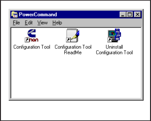
4-2
PowerCommand Configuration Tool
Installation
Before starting installation, close all other applica-
tions including the Microsoft Office Shortcut Bar.
To install the PowerCommand Configuration Tool
under Windows 95:
1. Insert the Configuration Tool Disk 1 into your
floppy drive (A:).
2. Select Run from the Taskbar Start Menu.
3. Type: A:\SETUP (↵ Enter)
To install the PowerCommand Configuration Tool
under Windows 3.1:
1. Insert the Configuration Tool Disk 1 into your
floppy drive (A:).
2. Select Run from the Windows Program Man-
ager File Menu.
3. Type: A:\SETUP (↵Enter)
The install routine creates a subdirectory named
PCT (C:\Onan\Pct) and a shortcut group folder on
the desktop named PowerCommand (Figure 4-1).
Additional PC Setup (Windows 3.1)
In Windows 3.1 the installation computer requires
SMARTDrive and SHARE to be loaded. To load
these, add the following lines to your autoexec.bat
file:
LH C:\DOS\SMARTDRV.EXE
LH C:\DOS\SHARE.EXE /L:100
(LH = Loads these programs in upper memory.)
Save the changes to the autoexec.bat file.
Exit Windows and restart the computer.
FIGURE 4-1. PCT GROUP FOLDER
ReadMe File
When PCT is installed a file named Configuration
Tool ReadMe File is copied to the PowerCommand
directory. This file contains last minute instructions
for using PCT. Open and review each of these in-
structions.
Removing PowerCommand Configuration
Tool
To remove PowerCommand Configuration Tool un-
der Windows 95:
1. Select Programs from the Taskbar Start
menu.
2. Select Uninstall Configuration Tool from the
PowerCommand folder.
To remove PowerCommand Configuration Tool un-
der Windows 3.1:
1. Open the PowerCommand group from within
the Window Program Manager.
2. Double-click on Uninstall Configuration
Tool.
Redistribution or publication of this document,
by any means, is strictly prohibited.
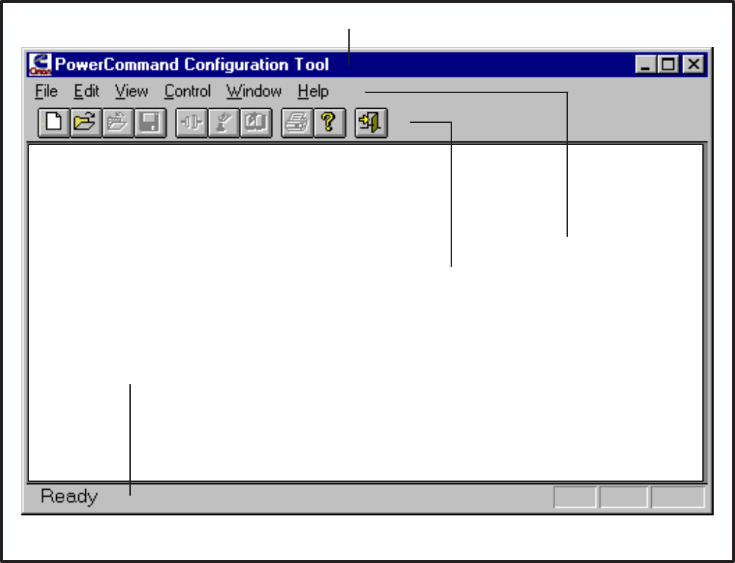
4-3
PowerCommand Configuration Tool
Features
The PowerCommand Configuration Tool software
operates in the Windows graphical environment
and is completely compatible with Windows 3.1 and
Windows 95. You can access the PCT software just
like you would any other Windows application.
All systems commands are accessible by mouse
and keyboard. Frequently used commands have
keyboard shortcuts and toolbar access. Only com-
mands applicable to the current active window are
enabled. All other commands are grayed out.
The Main Window
The main window includes a Menu Bar, ToolBar,
and Status Bar.
The Menu Bar contains the groups of commands
that you will use when running the PowerCommand
Configuration Tool. A list of menu options is avail-
able under each main menu entry (Figure 4-3).
When a menu command is grayed (dimmed), it
means the command is not available at the current
time. You may need to select another action (such
as opening a site) before the grayed command will
be displayed in black type – indicating that it is avail-
able.
The screen captures used in this section were made
in Windows 95. When using Windows 3.1, the
screens in PCT will look different.
"
"
FIGURE 4-2. MAIN WINDOW
Redistribution or publication of this document,
by any means, is strictly prohibited.

4-4
Menu System
To display the list of options under a menu entry,
move the mouse pointer to the menu name and
click the left mouse button (Figure 4-3).
To select an option from a menu list, move the
mouse pointer to the option name and click the left
mouse button or enter the underlined keys (refer to
Keyboard Access).
User Interface Features
Frequently used commands have keyboard short-
cuts and toolbar access. Only commands applica-
ble to the current active window are enabled. All
other commands are grayed out.
Keyboard Access
•PowerCommand Configuration Tool uses
standard Windows keyboard conventions.
•The underlined letter indicates the keyboard
selection for a given menu option. For an ex-
ample, refer to the File Menu in Figure 4-3.
•To select the File Menu, press and hold the “Alt”
key and type an “F” (Alt F).
•To select Open from the File Menu, type an “O”.
•To select Open from the Main Window, without
going through the File Menu, press and hold
the “Ctrl” key and type an “O” (Ctrl O).
FIGURE 4-3. MENU PULL DOWN LISTS
Redistribution or publication of this document,
by any means, is strictly prohibited.
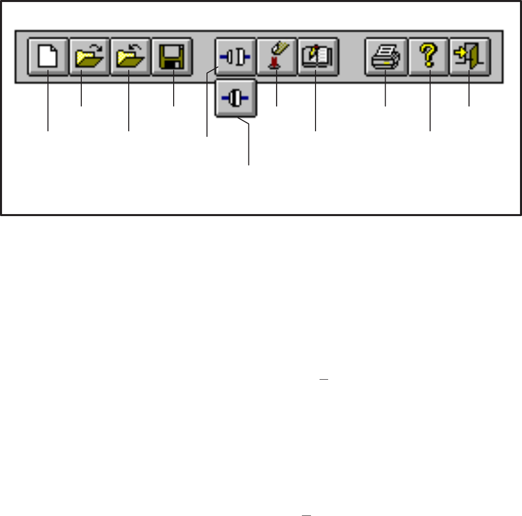
4-5
%?
9
@
<&8
8
&0<
( & &0<
*<@
-
%7:
& %9%6
#&&<1% 7& (:
%7: & %9%6'
FIGURE 4-4. TOOLBAR
Toolbar
The Toolbar provides direct graphical interface
shortcuts to some of the more frequently used
menu options (Figure 4-4).
When a Toolbar button is grayed (dimmed), it
means that the command is not available at the cur-
rent time. You may need to select another action
(such as opening a site) before the grayed com-
mand will be displayed in color (or black type ) – indi-
cating that it is available.
When you place the mouse pointer on a Toolbar
button, a tool tip pop-up window describes the func-
tion of the button. The Status Bar shows a descrip-
tion of operations as they occur.
Dialog Boxes
A dialog box is a window that requires information
from you. Often, when you select a function or menu
option, the software will display a dialog box. You
will then provide the required information by select-
ing an item from a list, by clicking on an option but-
ton, or by typing text. The dialog boxes are de-
scribed throughout this manual.
These rules will apply to all the dialog boxes and
system messages unless specified otherwise.
•The Cancel button allows you to close and exit
a dialog box without saving any modifications
and/or without executing any commands.
•The OK button allows you to save any changes
made and/or execute a command and close
the dialog or message box.
All lists that the dialog boxes display are alphabeti-
cally sorted.
Dialog boxes can also be accessed with the key-
board. The underlined letter indicates the keyboard
entry for a desired selection.
•For example, if a selection bears the caption
“OK,” press and hold the “Alt” key and type an
“O” (Alt O) to select it.
Redistribution or publication of this document,
by any means, is strictly prohibited.
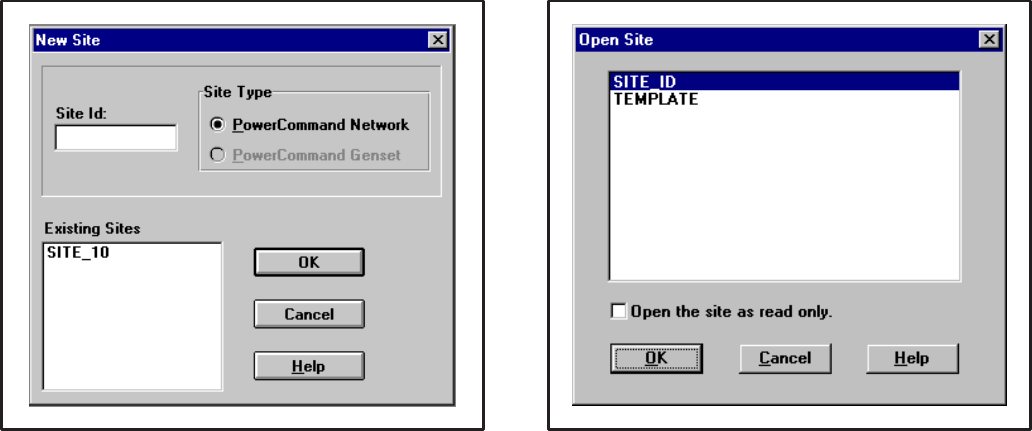
4-6
FIGURE 4-5. FILE – NEW SITE
MENU SYSTEM DESCRIPTION
Continue through this section to review each of the
file menu screens, or skip to the Setup Modules
section to begin configuring a site.
File – New Site
New Site allows you to load a new site. The new site
is added to the existing sites in PCT. The installer
must enter a site ID with a maximum of eight charac-
ters. It is recommended that the site id be the same
as name of the site directory.
FIGURE 4-6. FILE – OPEN SITE
File – Open Site
Open Site is used to open an existing site. The user
will select a site and press OK or double click on the
site. This will allow the user to view or edit an exist-
ing site or download data to a site that has already
been configured and saved.
When the OK button is clicked the selected site is
opened, and its modules list is displayed. The mod-
ules list will load its data from the database.
Each time the site is opened, the site information file
(.CSV file) is updated. The .CSV file is used by Pow-
erCommand for Windows (PCW).
Click on Open the site as read only box to view the
current site configuration in a dialog box
Redistribution or publication of this document,
by any means, is strictly prohibited.
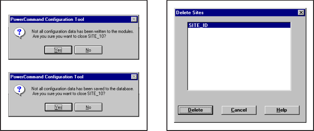
4-7
FIGURE 4-7. FILE – CLOSE SITE
File – Close Site
Closes the current site. If changes have not been
written to the module(s) the user is given the option
to write the changes to the module(s). If changes to
the site have not been saved, the user is given the
option to save the changes. Click on No to close the
site and ignore the last changes.
Write will write all changes to the modules, if at-
tached to the gateway, and save them. Save will
save all changes but not write them to the mod-
ule(s).
If attached to the gateway, closing will release the
gateway.
File – Save Site
Saves the all configuration for the entire site.
FIGURE 4-8. FILE – DELETE SITE
File – Delete Site
File – Delete Site will bring up a list of all existing
sites. To delete a site, select the desired site by
clicking on it, and click on Delete.
After clicking Delete, PCT will prompt you to confirm
your action.
“Are you sure you want to delete <site_id>”
Click on Yes to confirm or No to cancel.
Redistribution or publication of this document,
by any means, is strictly prohibited.
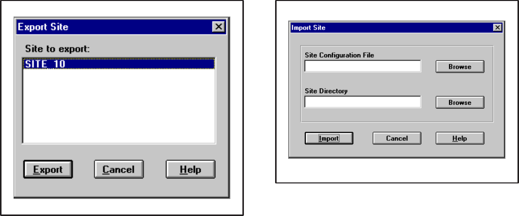
4-8
FIGURE 4-9. FILE – EXPORT SITE
File – Export Site
File – Export Site allows the user to copy a site’s
configuration data to a file that may be imported into
a different computer running PCT. This feature can
also be used to backup a site’s configuration data.
To export, select a site and click on the export but-
ton. PCT creates an export file and places it in the
[PCT_PATH]\EXPORTS directory. The file name is
the site ID and the extension is .pct. PCT will auto-
matically overwrite any existing files of the same
name.
The .pct file can be copied to a floppy disk for back-
up or for importing the configuration data into anoth-
er site (refer to FIle – Import Site).
File – Print, Print Preview, Print Setup
PowerCommand Configuration Tool v1.00 does not
support any printer functions.
FIGURE 4-10. FILE – IMPORT SITE
File – Import Site
File – Import Site allows the user to load configura-
tion data from an existing site to a new or existing
site. The Import Site dialog prompts the user for the
location of the site configuration file (.pct file) and
the location of the site directory. Both must be pro-
vided.
The user can enter the location of the site configura-
tion file manually (example: A:\site_id.pct) or click
on the Browse button. (Refer to File – Export Site for
creating a .pct file).
The user can type in the site directory path for the
site that was created with pcnet (example:
C:\onan\sites\site_id) or click on the Browse button.
PCT uses a standard windows browser to locate file
types, drives, folders and files. Use the scroll bars
and drop down menus to navigate to the the directo-
ry and/or file. Click on the desired directory and/or
file and then click on OK.
When the Import button is clicked the configuration
data is imported into the site. If that site id already
exists, the user is warned and given the option to
overwrite the existing site.
Redistribution or publication of this document,
by any means, is strictly prohibited.
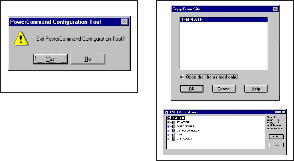
4-9
FIGURE 4-11. FILE – EXIT
File – Exit
File – Exit allows the user to exit the application. If a
site is open, Exit closes the site. If changes to the
site have not been saved, the user is given the op-
tion to write and/or save the changes.
FIGURE 4-12. EDIT – COPY FROM SITE
Edit – Copy From Site
Edit – Copy From Site allows the user to copy a
module’s configuration from another site into the
one they are currently editing.
The Copy From Site dialog displays a list of all exist-
ing sites. The user can select a site to copy from by
double clicking on the site or click on the site and
click on OK. This will open the site as read only.
A module’s configuration can be copied by dragging
the module from the Read Only Site and dropping it
on a module in the current site. The drag and drop
procedure only works with modules of the same
type.
The drag and drop procedure does not copy:
Module Name, Module Type, Site Id,
Edit – Cut, Edit – Copy, Edit – Paste
PowerCommand Configuration Tool v1.00 does not
support these menu commands.
Redistribution or publication of this document,
by any means, is strictly prohibited.
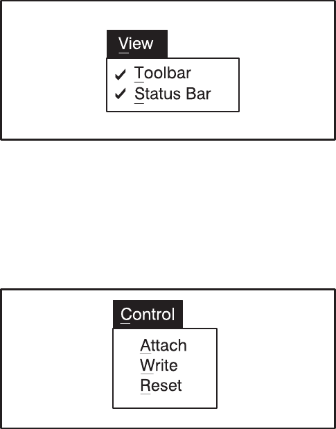
4-10
FIGURE 4-13. VIEW MENU
View Menu
The View Menu contains standard menu options for
displaying (checked) or removing (unchecked) the
Toolbar and Status Bar.
FIGURE 4-14. CONTROL MENU
Control – Attach
Control – Attach allows the user to attach to the Net-
work Installation Gateway. The status of the con-
nection is displayed on the Toolbar. The connector
unplugged icon indicates that the PC is not attached
to Installation Gateway. The connector plugged
icon indicates that the PC is attached to the Installa-
tion Gateway.
If the Attach feature fails to initialize the Installation
Gateway, an error message is displayed:
The gateway is not responding...
Check for the following:
1. Make sure the PC is attached to the Installation
Gateway via the null modem cable. Verify that
the cable connections are making good contact
between the PC and Installation Gateway. Also
verify that the Installation Gateway power
switch is On. Try cycling power on the Installa-
tion Gateway and make sure its service LED
flashes. If the service LED is blinking, exit PCT
and run LonMaker and attach to the network.
2. Make sure that the Installation Gateway driver
is installed as described in Network Module Li-
brary Installation section.
3. Check the COM port connection. Verify that the
cable is attached to the correct COM port as
specified when the driver was loaded in the
config.sys file (/p1, /p2, etc.). IF PCW is setup
to use the same COM port as PCT, make sure
that PCW is not operating before attaching to
the site with PCT.
If the Installation Gateway becomes unattached
while a site is open, and the user attempts to Write
to a module, the following message is displayed:
The gateway is not responding.
Control – Write
Control – Write allows the user to download the con-
figuration data which is selected. (Same function as
the Write button in the configuration site dialog box.)
Write is enabled when a site is open, PCT is at-
tached to the Installation Gateway and a writeable
module, parameter or set of parameters is selected.
(The Write feature is disabled when a module is se-
lected that has no configurable parameters, such as
a DIM or NAM.)
When the Repair – Replace feature has been used in
LonMaker on a module, all configuration data must
be rewritten to the module.
If the write feature fails to write to a module, the fol-
lowing error messages will be displayed:
Error writing LON network variable
Press the reset button on the module that is being
configured. If the problem continues, refer to the
Control – Attach section for troubleshooting.
Control – Reset
Control – Reset allows the user to rest a module.
Reset is enabled when a site is open and PCT is at-
tached. Reset can be used to reset a module, or all
modules in the site, depending on what is selected.
Control – Reset will not be able to reset a CCM if an
error was produced while writing to the module. The
reset button at the module must be used.
Redistribution or publication of this document,
by any means, is strictly prohibited.

4-11
FIGURE 4-15. WINDOW MENU
Window Menu
The Window Menu contains standard Window com-
mands for arranging dialogs.
FIGURE 4-16. HELP MENU
Help Menu
The Help Menu contains standard Windows com-
mands for accessing online help. Help – About dis-
plays the version, date, owner, company and serial
number of the product.
Redistribution or publication of this document,
by any means, is strictly prohibited.
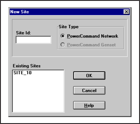
4-12
USING THE POWERCOMMAND
CONFIGURATION TOOL
The following sections provide an overview of the
tasks and procedures that can be performed with
PCT. In some cases there can be more than one
way to perform a function. Generally using the Tool-
bar or clicking a button will be easier than using the
menu commands.
Creating a New Site
When the software is started, the PCT main window
appears. Click on the New Site button (icon) on the
Toolbar.
New Site allows you to load a new site. The new site
is added to the existing sites in PCT. The installer
must enter a site ID with a maximum of eight charac-
ters. It is recommended that the site id be the same
as name of the site directory.
Example: If the site directory is:
“C:\onan\sites\site_10” use “SITE_10” as the
Site Id.
The Site Type defaults to PowerCommand Net-
work, the only type supported by PCT version 1.00.
FIGURE 4-17. FILE – NEW SITE
The existing sites are displayed in the Existing Sites
list box. The Existing Sites list (scrollable list) allows
the user to view the installed sites when selecting a
new Site Id.
Redistribution or publication of this document,
by any means, is strictly prohibited.
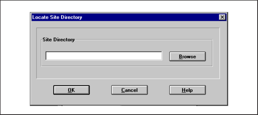
4-13
FIGURE 4-18. LOCATE SITE DIRECTORY
Site Directory Location
When the New Site OK button is clicked, the Site Di-
rectory Location dialog pops up. This dialog box al-
lows the user to specify the location of the site direc-
tory for the new site being created.
The user can Browse for the site directory or manu-
ally enter the path of the site directory.
If the user chooses to overwrite an existing site, all
information for the existing site will be lost.
Example: If the site directory is
“C:\onan\sites\site_10” enter:
C:\ONAN\SITES\SITE_10
– OR –
Use the Browse button to browse to the site.
When the location of the site directory is shown, the
user clicks the OK button and the site is loaded and
opened. If the site directory is not valid, an error
message will appear.
A large site may take some time to load. The mod-
ules list window will identify the modules that are
present at the site (Figure 4-19). If changes have
been made in LonMaker, refer to Changes to the
LonMaker Database at the end of this section.
Redistribution or publication of this document,
by any means, is strictly prohibited.
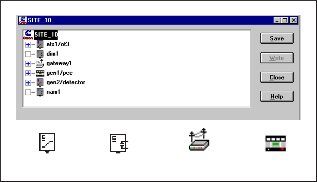
4-14
!3
(3
FIGURE 4-19. CONFIGURE SITE DIALOG (MODULES LIST)
Configuring a Site
Opening a site (or creating a new site), loads the
Site dialog. There are four buttons allowing the user
to save changes, write configuration to the module,
close the site and get online help.
A box with a plus symbol (+) to the left of the module
icon indicates the module has parameters to be
configured. An empty box indicates the module has
no configurable parameters.
Configuration information may be entered manually
as described in the following sections or copied
from another module (which has already been con-
figured). To copy a module’s configuration informa-
tion to another module, drag the module which has
already been configured (source) on top of the mod-
ule which you want to configure (target) and drop it.
You must confirm your action.
The source module may be in the same site or in
another existing site. The target module cannot be
in a site which has been opened as “Read Only”.
Copying a module will copy all parameters for for
that module. It is not possible to copy only certain
parameters.
The software is pre-loaded with five templates for
quickly configuring Cummins/Onan equipment.
These five templates (modules) are found in the
TEMPLATE site. This site is “Read Only”. Applying
a template to a module is accomplished by copying
a module from the TEMPLATE site. (Refer to Edit –
Copy From Site, described earlier in this section).
The following section describes how to navigate the
configure site dialog and how to configure modules.
To configure a module, click on the plus symbol (+)
or double click on the module icon or name. The
module list is expanded, listing its configurable pa-
rameters. Once expanded, A minus symbol (–) ap-
pears in the box to the left of the module allowing the
user then “contract” the module. Selecting a param-
eter will display its configurable fields below. When
displayed, the user may edit the parameter(s).
Digital I/O Modules (DIM) and Network Annunciator
Modules (NAM) have no configurable parameters.
Network Routers (RTR) will not appear in the site’s
module list.
Redistribution or publication of this document,
by any means, is strictly prohibited.

4-15
(
#AB
*5 ('
5
#AB
*5 5!'
#'
*5
(
#'
*5
5!
FIGURE 4-20. CONFIGURE CCM
When the list of parameters is displayed (Figure
4-20), two new icons appear to the left of each list.
The icons to the left of each parameter indicate its
current status. The leftmost icon represents the
write-status and the rightmost icon represents the
save-status.
A red “X” over the write-status icon indicates that
the parameter has not been written (to the module).
A red “X” over the save-status icon indicates that
the parameter has not been saved (to the hard
disk).
A description of the control buttons follows:
Save: Saves the selection (site, module, parameter
or parameter set) in PCT. The user may save pa-
rameters individually as they are edited or or edit all
parameters then save the entire module.
Write: Writes the selection (site, module, parame-
ter or parameter set) to the module and then saves.
The user may write parameters individually as they
are edited or or edit all parameters then write the en-
tire module.
When making minor changes, it is only necessary to
write the parameters that have changed.
Close: Closes the site. If there are parameters in
the site which have not been written, the user is in-
formed and is allowed to return to the site. If there
are parameters that have not been saved, the user
is informed and allowed to return to the site.
Help: The Help button provides online help and in-
formation about the current software version.
The entire site may be configured before the user
arrives at the site. To do this, the site is created us-
ing PCNET.BAT, defined using LonMaker and con-
figured using PCT. At the site, the user must attach
to the site, install the modules with LonMaker and
then write their configuration with PCT.
The following sections describe how to fill in the
configurable fields for each module.
Redistribution or publication of this document,
by any means, is strictly prohibited.

4-16
FIGURE 4-21. CONFIGURE CCM – GENERAL
CONTROLS COMMUNICATIONS MODULE
CCM – General
This parameter contains general information about
the module. Module Name, Type, and Site ID are
not configurable. They are needed for properly
sending alarms and they need to be written to the
module. Phase is the only configurable field. Phase
information is needed for calculating voltages. Se-
lect Three if the CCM is monitoring three-phase
voltages or Single if the CCM is monitoring single-
phase voltages.
Module Name is read from the site directory. This is
the device name that was defined in LonMaker.
Type is read from the site directory. This is the firm-
ware version of the module.
Site ID was entered by the user when the site was
created.
Phase selects the number of phases for the voltage
of the equipment that is being monitored. Click on
the radio button to select the desired phase setting.
Match the phase setting with configuration of the
equipment being monitored by the CCM.
Like any configurable field, the Phase selection can
be made before going to a site. The new data can be
saved ahead of time, but the computer running PCT
must be attached to the site before writing to the net-
work module.
Redistribution or publication of this document,
by any means, is strictly prohibited.
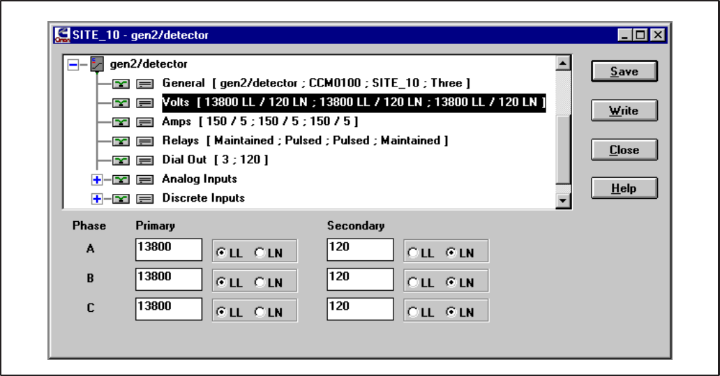
4-17
FIGURE 4-22. CONFIGURE CCM – VOLTS
CCM – Volts
This parameter contains information on external
Potential Transformers (PTs) which may be used to
step down the line voltages. Secondary refers to the
voltage applied to the CCM. For each phase, enter
the nominal Primary and Secondary voltages and
units (volts LN or volts LL) of the PTs. If the CCM is
directly monitoring the line voltage (external PTs are
not used), enter the nominal line voltage in the Pri-
mary and Secondary fields.
Valid PT ratios (Primary:Secondary) are 0 to 138.
Valid values for Secondary are 1 to 425 Volts LN
(736 Volts LL).
Example 1: The CCM is monitoring the load-
side of a Transfer Switch (3-phase, 13,800
volts LL). External PTs are used to step-down
the line voltage from 13,800 Volts LL to 120
Volts LN.
General: Select Three.
Volts: For each phase: Enter 13800 for Prima-
ry and select LL. Enter 120 for Secondary and
select LN.
Example 2: The CCM is directly monitoring a
Genset with a single-phase output of 240 Volts
LL.
General: Select Single.
Volts:
Phase A: Enter 120 for Primary and select LN.
Enter 120 for Secondary and select LN.
Phase B: Enter 120 for Primary and select LN.
Enter 120 for Secondary and select LN.
Phase C: Enter 0 for Primary and select LN.
Enter 120 for Secondary and select LN.
When viewing the module in PowerCommand for
Windows, if the displayed voltages are higher (on av-
erage) than the measured line voltages, decrease the
Primary value(s). Likewise, if the displayed voltages
are lower (on average) than the measured voltages,
increase the Primary value(s).
Redistribution or publication of this document,
by any means, is strictly prohibited.
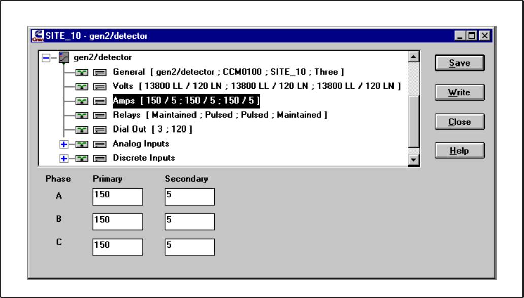
4-18
FIGURE 4-23. CONFIGURE CCM – AMPS
CCM – Amps
This parameter contains information on external
Current Transformers (CTs) which must be used to
step-down the line currents. Secondary refers to
the current winding connected to the CCM. For
each phase, enter the nominal Primary:Secondary
CT ratio.
Valid CT ratios (Primary:Secondary) are 0 to
10,720. Valid values for Secondary are 1 to 5
(Amps).
Example: The CCM is monitoring the load-
side of a Transfer Switch (3-phase). External
CTs are used to step-down the line currents.
The CT ratio is 10,000:5.
Amps: For each phase: Enter 10000 for Pri-
mary and 5 for Secondary.
When viewing the module in PowerCommand for
Windows, if the displayed currents are higher (on av-
erage) than the measured line currents, decrease the
Primary value(s). Likewise, if the displayed currents
are lower (on average) than the measured currents,
increase the Primary value(s).
Redistribution or publication of this document,
by any means, is strictly prohibited.
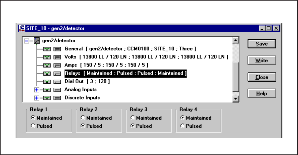
4-19
FIGURE 4-24. CONFIGURE CCM – RELAYS
CCM – Relays
This parameter configures the four CCM on-board
relays (K1–K4). Each relay may be configured as
Maintained or Pulsed. To configure the relays, click
on the radio button below each relay to select the
desired setting.
If configured as Maintained, when activated the
relay is energized indefinitely. The relay remains
energized until de-activated.
If configured as Pulsed, when activated the relay is
energized for approximately 1 second, then it is de-
energized. This is useful for signaling an alarm
which has its own timing circuit (like a pulsed alarm
input on a paralleling system). Or for resetting
equipment that requires a pulsed contact closure.
Redistribution or publication of this document,
by any means, is strictly prohibited.
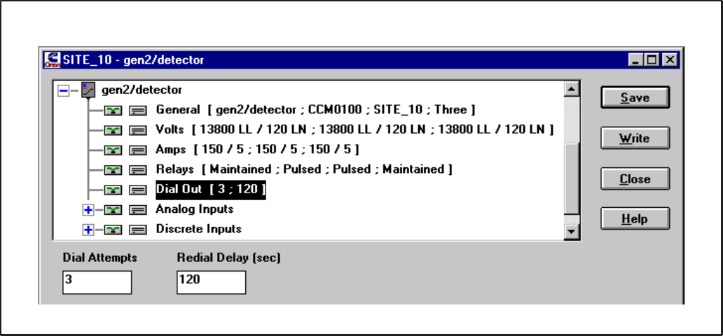
4-20
FIGURE 4-25. CONFIGURE CCM – DIAL OUT
CCM – Dial Out
This parameter configures the re-dial operation
when sending an alarm. Dial Attempts controls the
number of times the module will attempt to deliver
an alarm. Dial Attempts must be between 1 and
255. The CCM will automatically retry sending an
alarm if the first attempt fails (busy, no dial tone,
etc.)
Redial Delay (in seconds) controls the delay be-
tween Dial Attempts. Redial Delay must be be-
tween 10 and 65,535 (seconds).
Example: If sending an alarm fails on the first
attempt, you would like the module to retry 5
times and wait 2 minutes between retries.
Dial Attempts: Enter 6.
Redial Delay: Enter 120.
CCM – Analog Inputs
All 7 analog input configurations are grouped to-
gether in their own parameter set (Figure 4-26). To
view or edit any one of the 7 configurations, click on
the plus symbol (+) or double click on the parameter
set name (Analog Inputs). When expanded, all 7
analog input configurations are listed with their cur-
rent settings. To contract the set, click on the minus
symbol (–) or double click on Analog Inputs. (Refer
to Appendix C, Determine Sender Settings section,
for reference.)
CCM – Temperature 1, Temperature 2,
Temperature 3
These parameters configure the I/O characteristic
of analog inputs Temperature 1, Temperature 2 and
Temperature 3. These inputs can be used to moni-
tor various temperature senders. Select the desired
input to configure and edit the Sender Voltage, Me-
ter Reading and Sender Gain fields to yield mean-
ingful temperature values.
Redistribution or publication of this document,
by any means, is strictly prohibited.
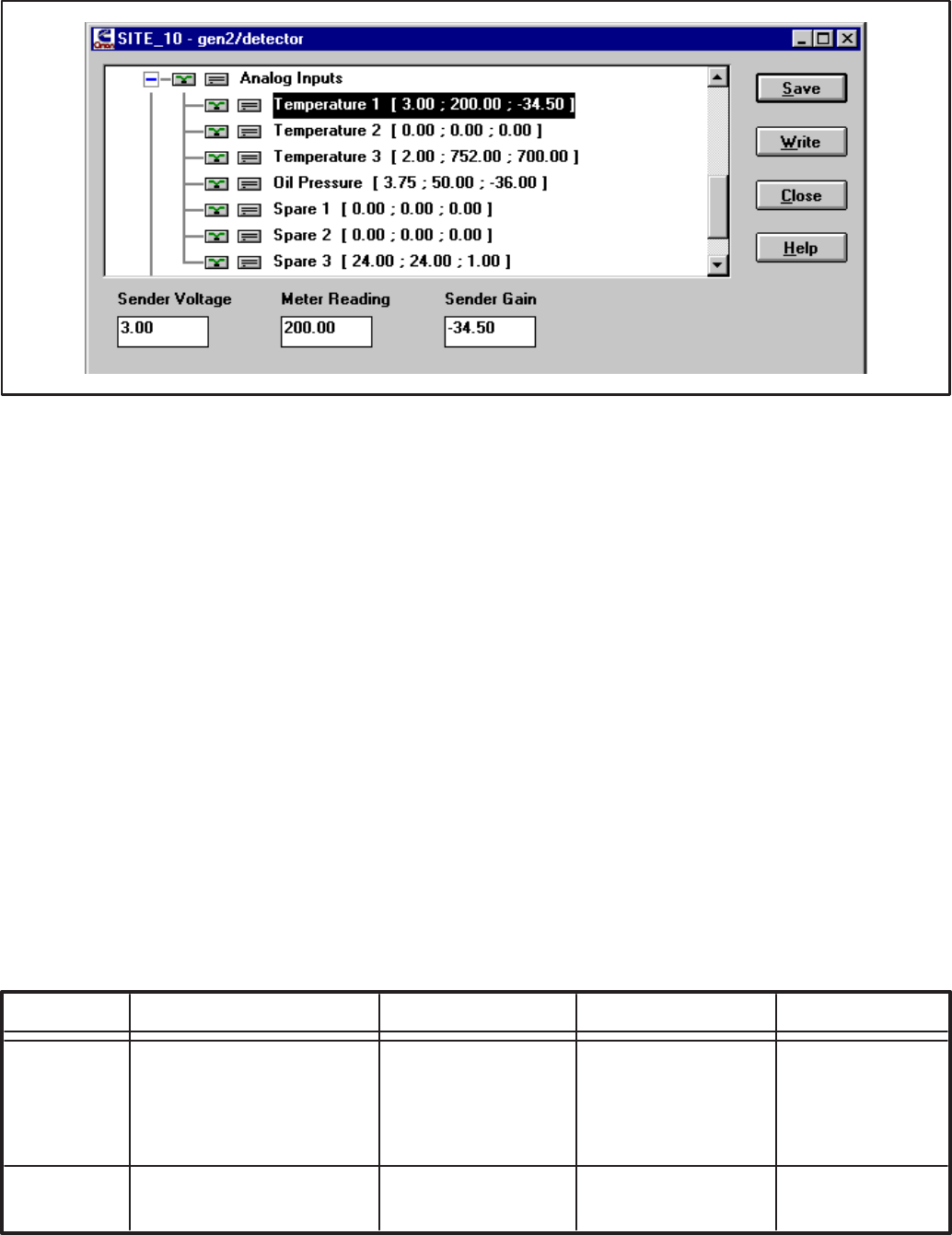
4-21
FIGURE 4-26. CONFIGURE CCM – TEMPERATURE INPUTS
Sender Voltage is the DC voltage of the sender at a
known operating point. Valid values are 0 to +9
(VDC).
Meter Reading is the gauge value of the sender at
the same known operating point. Valid values vary
with Sender Gain (Units may vary).
Sender Gain is the relational slope of Meter Read-
ing to Sender Voltage. Valid values are –838 to
+838 (Units/VDC).
Refer to Table 4-1 for sample temperature sender
settings.
These values are only nominal. Verify these values
yield acceptable readings. If not, refer to Appendix C
for determining the specific sender characteristics.
Example 1: The CCM is monitoring a Detector/
DK Genset with Temperature 1 monitoring the
coolant temperature and Temperature 3 moni-
toring the exhaust temperature. The customer
would like to view all data in English (Imperial)
units.
Temperature 1: Enter 3.00 for Sender Volt-
age, 200 for Meter Reading and –34.50 for
Sender Gain.
Temperature 3: Enter 2.00 for Sender Volt-
age, 752 for Meter Reading and 700 for Sender
Gain.
Example 2: The CCM is monitoring a non-
Onan Genset with Temperature 1 monitoring
an RTD coolant temperature sender and Tem-
perature 3 monitoring an RTD exhaust temper-
ature sender. The customer would like to view
all data in Metric units.
Temperature 1: Enter 3.00 for Sender Volt-
age, 80 for Meter Reading and 53.9 for Sender
Gain.
Temperature 3: Enter 2.00 for Sender Volt-
age, 400 for Meter Reading and 388.8 for
Sender Gain.
TABLE 4-1. TEMPERATURE SENDER GAIN SETTINGS
SENDER SENDER VOLTAGE METER READING SENDER GAIN
TEMP Detector/DK (Imperial) 3 (VDC) 200 (°F) –34.5 (°F/VDC)
(OIL/COOL) Detector/DK (Metric) 3 (VDC) 93.3 (°C) –19.2 (°C/VDC)
500–2200 Ω RTD (Imperial) 3 (VDC) 176 (°F) 97.1 (°F/VDC)
500–2200 Ω RTD (Metric) 3 (VDC) 80 (°C) 53.9 (°C/VDC)
TEMP 80–390 Ω RTD (Imperial) 2 (VDC) 752 (°F) 700 (°F/VDC)
(EXHAUST) 80–390 Ω RTD (Metric) 2 (VDC) 400 (°C) 388.8 (°C/VDC)
Redistribution or publication of this document,
by any means, is strictly prohibited.
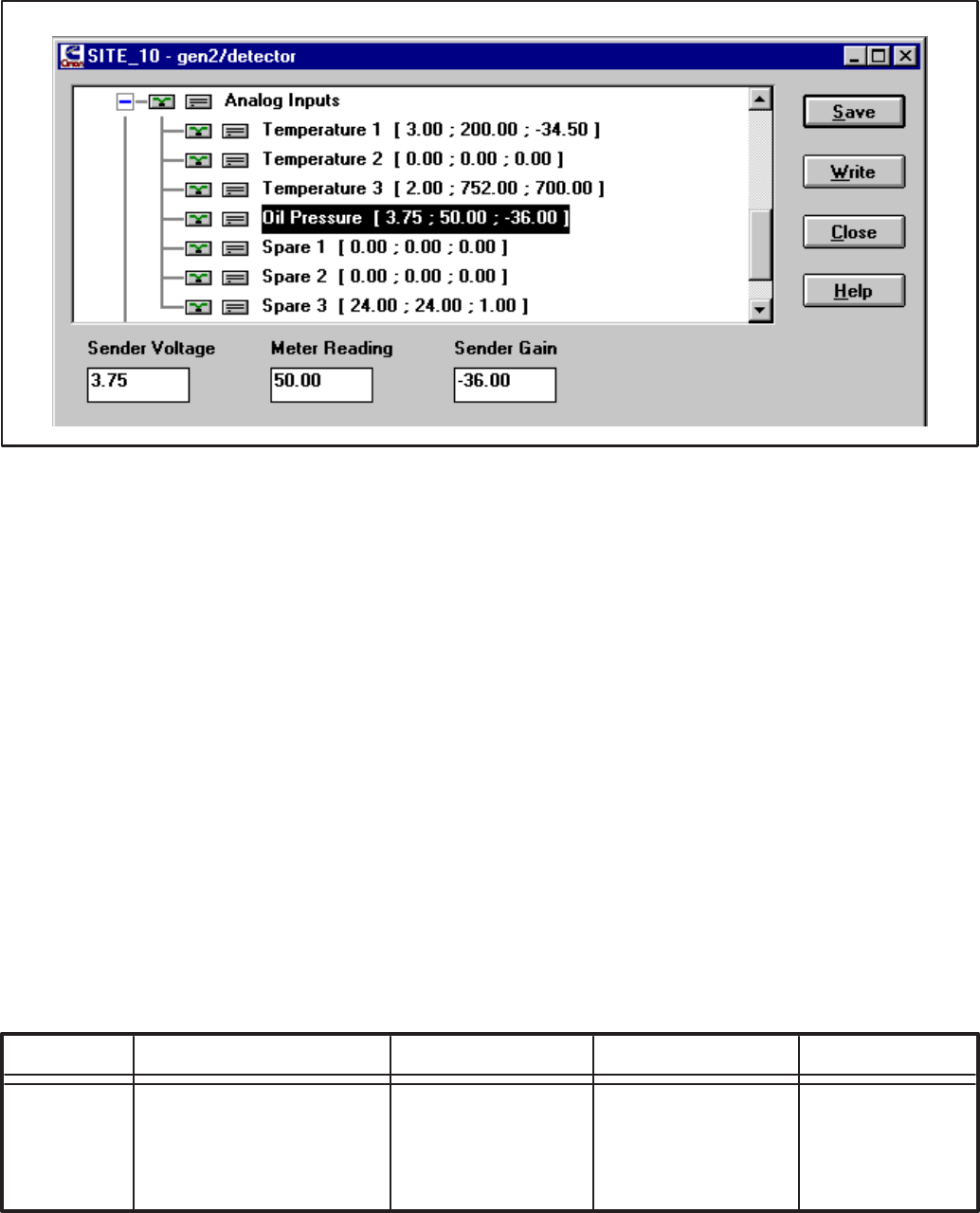
4-22
FIGURE 4-27. CONFIGURE CCM – OIL PRESSURE
CCM – Oil Pressure
This parameter configures the I/O characteristic of
analog input Oil Pressure. This input can be used to
monitor various oil pressure senders. Select Oil
Pressure and edit the Sender Voltage, Meter Read-
ing and Sender Gain fields to configure the input to
yield meaningful pressure values.
Sender Voltage is the DC voltage of the sender at a
known operating point. Valid values are 0 to +9
(VDC).
Meter Reading is the gauge value of the sender at
the same known operating point. Valid values vary
with Sender Gain (Units may vary).
Sender Gain is the relational slope of Meter Read-
ing to Sender Voltage. Valid values are –838 to
+838 (Units/VDC)
Refer to Table 4-2 for sample oil pressure sender
settings.
These values are only nominal. Verify these values
yield acceptable readings. If not, refer to Appendix C
for determining the specific sender characteristics.
Example 1: The CCM is monitoring a Detector/
DK Genset. The customer would like to view all
data in English (Imperial) units.
Oil Pressure: Enter 3.75 for Sender Voltage,
50 for Meter Reading and –36 for Sender Gain.
Example 2: The CCM is monitoring a non-
Onan Genset with a Kavlico oil pressure send-
er. The customer would like to view all data in
Metric units.
Oil Pressure: Enter 2.50 for Sender Voltage,
344.8 for Meter Reading and 172.4 for Sender
Gain.
TABLE 4-2. PRESSURE SENDER GAIN SETTINGS
SENDER SENDER VOLTAGE METER READING SENDER GAIN
PRESSURE Detector/DK (Imperial) 3.75 (VDC) 50 (PSI) –36 (PSI/VDC)
Detector/DK (Metric) 3.75 (VDC) 344.8 (kPa) –248.2 (kPa/VDC)
Kavlico (Imperial) 2.5 (VDC) 50 (PSI) 25 (PSI/VDC)
Kavlico (Metric) 2.5 (VDC) 344.8 (kPa) 172.4 (kPa/VDC)
Redistribution or publication of this document,
by any means, is strictly prohibited.
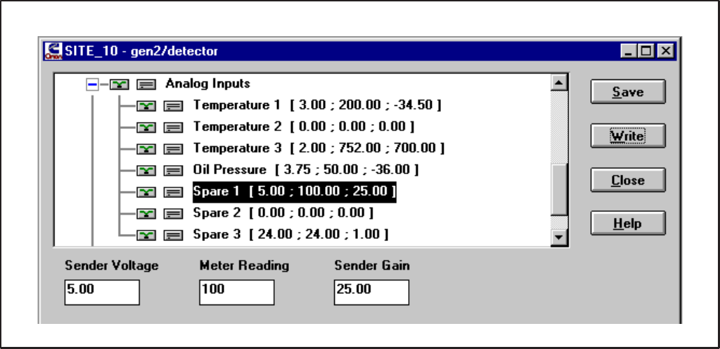
4-23
FIGURE 4-28. CONFIGURE CCM – SPARE INPUTS
CCM – Spare 1, Spare 2
These parameters configure the I/O characteristic
of analog inputs Spare 1 and Spare 2. These can be
used to monitor customer-defined 0–5 VDC analog
voltages. Select the desired input to be configured
and edit the Sender Voltage, Meter Reading and
Sender Gain fields to yield meaningful values.
Sender Voltage is the DC voltage of the sender at a
known operating point. Valid values are 0 to +5
(VDC).
Meter Reading is the gauge value of the sender at
the same known operating point. Valid values vary
with Sender Gain (Units may vary).
Sender Gain is the relational slope of Meter Read-
ing to Sender Voltage. Valid values are –503
to +503 (Units/VDC) .
Example: The CCM is monitoring a 24V De-
tector/DK Genset. Spare 1 is used to monitor
the fuel level in the day tank. The fuel level
sender gives 5.0 VDC when the tank is full (100
gal) and 1 VDC when the tank is empty. The
customer would like to view all data in English
(Imperial) units.
Spare 1: Enter 5.00 for Sender Voltage, 100 for
Meter Reading and 25.00 for Sender Gain.
CCM – Spare 3 (Battery Volts)
This parameter configures the I/O characteristic of
analog input Spare 3. Because it allows 0 to 36
VDC, Spare 3 is typically used to monitor battery
voltage, but may monitor any 0 to 36 VDC signal.
Select Spare 3 and edit the Sender Voltage, Meter
Reading and Sender Gain fields to yield meaningful
values.
Sender Voltage is the DC voltage of the sender at a
known operating point. Valid values for Spare 3 are
0 to +36 (VDC).
Meter Reading is the gauge value of the sender at
the same known operating point. Valid values vary
with Sender Gain (Units may vary).
Sender Gain is the relational slope of Meter Read-
ing to Sender Voltage. Valid values are –85
to +85 (Units/VDC) .
Example: The CCM is monitoring a 24V De-
tector/DK Genset. The customer would like to
view all data in English (Imperial) units.
Spare 3: Enter 24.0 for Sender Voltage, 24.0
for Meter Reading and 1.00 for Sender Gain.
Redistribution or publication of this document,
by any means, is strictly prohibited.
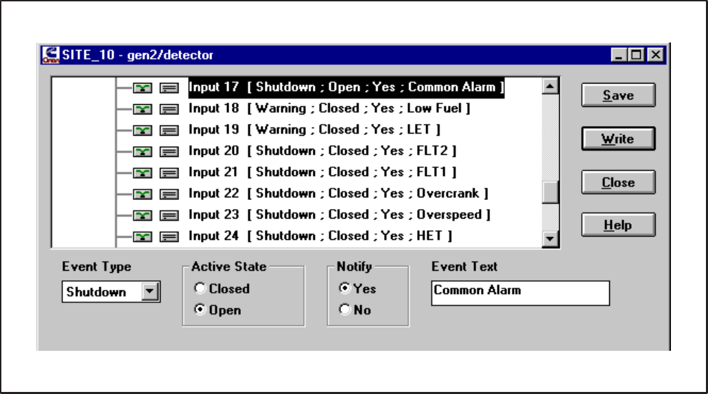
4-24
FIGURE 4-29. CONFIGURE CCM – DISCRETE INPUTS
CCM – Discrete Inputs
All 32 discrete input configurations are grouped to-
gether in their own parameter set. To view or edit
any one of the 32 configurations, click on the plus
symbol (+) or double click on the parameter set
name Discrete Inputs. When expanded, all 32 ana-
log input configurations are listed with their current
settings. To contract the set, click on the minus sym-
bol (–) or double click on Discrete Inputs.
These parameters configure the 32 discrete cus-
tomer inputs. The inputs are used to monitor equip-
ment status and send alarms to a remote or local PC
if the status becomes active. If the input is also used
to send an alarm (Notify), the Event Type and Event
Text must be configured. The Active State of each
input must be configured.
Event Type: This field configures the level of an
alarm/event. Event Type only applies when Notify is
“Yes”.
Event: This will force the event message to be im-
mediately logged at the host. This is useful for log-
ging system events that do not require acknowledg-
ment by a user. An Event will not send a popup
alarm.
Warning: This may force a pop-up message at the
remote PC (if remote PC is configured as such).
The alarm requires acknowledgment by a user be-
fore it is logged.
Shutdown: This may force a pop-up message at the
remote PC (if remote PC is configured as such).
The alarm requires acknowledgment by a user be-
fore it is logged.
Active State: This field configures the state of the
input which is considered “active”. Some input sig-
nals are active when they go to ground while others
are active when they go to B+. The Active State field
allows the user to configure the input for either sce-
nario. The Active State of each input must be con-
figured.
Closed: The input is activated when the input is
shorted to ground.
Open: The input is activated when the input is re-
moved from ground.
Notify: This field configures the module to send an
alarm when the input is activated or not to. If a user
would like notification of this input becoming active,
select “Yes”. If this input does not require notifica-
tion when activated, then select “No”. If “No”, Event
Type and Event Text need not be configured.
Redistribution or publication of this document,
by any means, is strictly prohibited.
4-25
Event Text: This field configures the text message
which will be sent when the input is activated. Event
Text only applies when Notify is “Yes”. The mes-
sage may be 16 alpha-numeric characters includ-
ing spaces. Enter a meaningful message describ-
ing the state of the input.
Example 1: The CCM is monitoring a Detector/
DK Genset. The customer would like to be noti-
fied (via pop-up message at their office PC) on
any change of the Genset status.
Open the TEMPLATE site. Drag the DETEC-
TOR w/CCM template onto the CCM in the site
you are configuring and drop. Confirm the copy
command. Select Discrete Inputs and click on
Write to complete this configuration.
Example 2: The CCM is monitoring a non-
Onan Genset. The Genset has 2 output sig-
nals available: “Running” and “Genset Fault”.
The “Running” output is normally closed while
the “Genset Fault” output is normally open. The
customer would like to be notified (via pop-up
message at their office PC) on any change of
the Genset status.
Input 1: Select “Warning” for Event Type,
“Closed” for Active State, “Yes” for Notify and
enter “Running” for Event Text.
Input 2: Select “Warning” for Event Type,
“Open” for Active State, “Yes” for Notify and en-
ter “Genset Fault” for Event Text.
Redistribution or publication of this document,
by any means, is strictly prohibited.
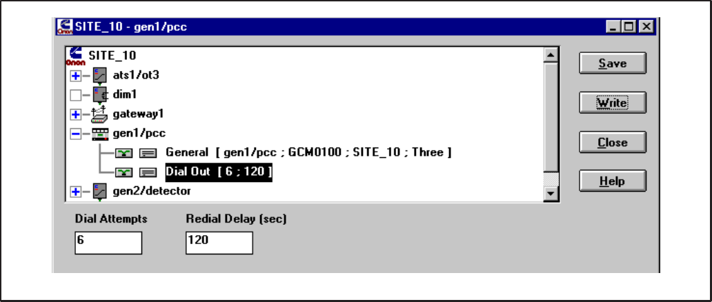
4-26
FIGURE 4-30. CONFIGURE GCM
GENSET COMMUNICATIONS MODULE
PCC W/GCM – General
This parameter contains general information about
the module. Module Name, Type and Site ID fields
are not configurable. They are needed for sending
alarms properly, therefore must be configured.
Phase is the only configurable field. Phase informa-
tion is needed for calculating voltages. Select Three
if the PowerCommand Genset is generating three-
phase voltage or Single if it is generating single-
phase.
Dial Out
This parameter configures the re-dial operation
when sending an alarm. Dial Attempts controls the
number of times the module will attempt to deliver
an alarm. Dial Attempts must be between 1 and
255. The GCM will automatically retry sending an
alarm if the first attempt fails (busy, no dial tone,
etc.)
Redial Delay (in seconds) controls the delay be-
tween Dial Attempts. Redial Delay must be be-
tween 10 and 65,535 (seconds).
Example: If sending an alarm fails on the first
attempt, you would like the module to retry 5
times and wait 2 minutes between retries.
Dial Out: Enter 6 for Dial Attempts and 120 for
Redial Delay.
Redistribution or publication of this document,
by any means, is strictly prohibited.
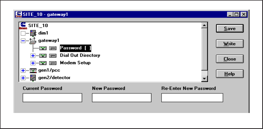
4-27
FIGURE 4-31. CONFIGURE NGM – PASSWORD
NETWORK GATEWAY MODULE
Cycle power on the NGM after all configuration set-
tings have been written. To retrieve the default set-
tings for an NGM (remote connection), copy the
“NGM” template from the TEMPLATE site.
NGM – Password
This parameter configures the [site] password for a
Network Gateway Module. If a password is used, a
host must present the correct password before be-
ing allowed into the site. The password is limited to
8 characters. To change the password, the user
must type the new password twice. An error will be
produced if not re-entered correctly.
Setting a password is recommended to add security
for the customers site. A password will also protect
the site NGM from accidental loss of configuration
information as the result of attempted use as a Net-
work Installation Gateway.
Changing the password to “” (blank), removes the
password and no password is required for access to
the site. The user need not know the Current Pass-
word to change the password.
01 0 #! 0&! *
2 0 3 4# 0 (
0 # 4#! $
Current Password: If a password was previously
configured, this field will contain an * for each char-
acter, enter the current password. If no current
password exists (the field is blank), then this field
must be left blank. The default for new installations
will not contain a current NGM password.
If a password is needed and the Current Password
field is blank, tab to the New Password field to enter
a new password (maximum of eight characters).
New Password: The new password (masked with *
for each character) must be entered twice. Enter the
password for the second time in the Re-Enter New
Password field exactly the way it entered in the New
Password Field. Record the password in a safe
location.
This password must also be entered in the PCW
Site Setup screen “Password:” in order to ac-
cess this site.
Redistribution or publication of this document,
by any means, is strictly prohibited.

4-28
FIGURE 4-32. CONFIGURE NGM – DIAL OUT PREFIX
NGM – Dial Out Directory
Dial Out Prefix and Phone Number 1 are grouped
together in their own parameter set. To view or edit
either of these parameters, click on the plus symbol
(+) or double click on the parameter set name Dial
Out Directory. When expanded, all dial out parame-
ters are listed with their current settings. To contract
the set, click on the minus symbol (–) or double click
on Dial Out Directory. Dial Out Directory only ap-
plies to Gateway Modules which are connected to a
modem (remote connection).
Dial Out Prefix
This parameter configures the prefix string, which is
sent to a modem before the phone number. The
prefix is limited to 16 characters (hyphens and
spaces are not required). The prefix “ATDT”
instructs the modem to dial using touch-tone
(DTMF) signaling. If pulse dialing is used, the prefix
should be set to “ATDP”.
If an outside line is required, the user may elect to
place the “9” (or whatever number accesses an out-
side line) in with the prefix. Dial Out Prefix only ap-
plies to a remote connection incorporating dial out
alarms.
Example: The NGM is connected to a modem
which is connected to a DTMF line. An outside
line and the area code are needed to dial the re-
mote host. Accessing an outside line usually
takes about a second.
Dial Out Prefix: Enter “ATDT 9,,1–612”
4 5 6 ! 040 5-6 &! 0 3
!3 # 33 5226 !! 0 3
!3 4 & &0 !
! 7 & 33 8 ! !9
Redistribution or publication of this document,
by any means, is strictly prohibited.

4-29
FIGURE 4-33. CONFIGURE NGM – PHONE NUMBER
NGM – Phone Number 1
This parameter configures the phone number of the
remote host running PowerCommand for Windows.
PowerCommand for Windows must be running to
receive an alarm. The phone number is limited to 16
characters (hyphens and spaces are not required).
Use the Dial Out Prefix if the phone number ex-
ceeds 16 characters.
All modules at the site will use this phone number
when sending an alarm. Phone Number 1 only ap-
plies to a remote connection incorporating dial out
alarms.
Redistribution or publication of this document,
by any means, is strictly prohibited.
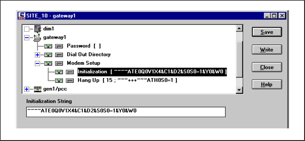
4-30
FIGURE 4-34. CONFIGURE NGM – MODEM INITIALIZATION STRING
NGM – Modem Setup
Modem Initialization and Hang Up are grouped
together in their own parameter set. To view or edit
either of these parameters, click on the plus symbol
(+) or double click on the parameter set name (Mo-
dem Setup). When expanded, all dial out parame-
ters are listed with their current settings. To contract
the set, click on the minus symbol (–) or double click
on Modem Setup. Modem Setup only applies only
to Gateway Modules that are used with a modem
(remote connection).
NGM – Modem Setup – Initialization
This parameter configures the string that the NGM
uses to initialize the modem. The Initialization
String is automatically sent to the modem each time
the NGM is powered up.
The Initialization String is limited to 33 characters.
Enter the following information in the Initialization
String field:
~~~~ATE∅Q∅V1X4&C1&D2&S∅S∅=1&Y∅&W∅
Note: ∅ is used to represent the number zero.
To save time and reduce errors it is generally best to
use the Edit – Copy feature to copy this data from
the Template site or other configured site.
If the site NGM is attached to a modem, turn Off the
NGM power switch, then turn it back On. This step
sends the information stored in the NGM to the mo-
dem to set the modem for proper operation.
Redistribution or publication of this document,
by any means, is strictly prohibited.
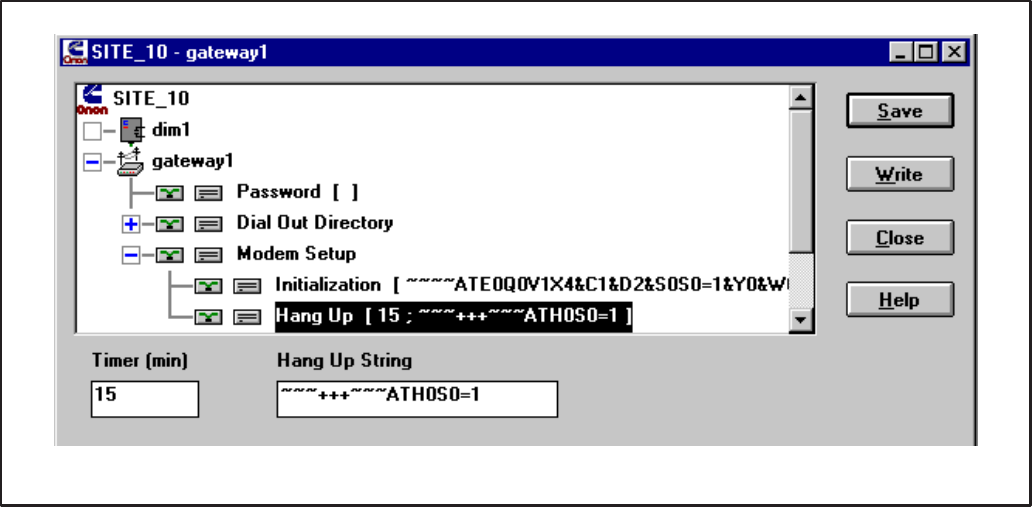
4-31
FIGURE 4-35. CONFIGURE NGM – HANG UP
NGM – Modem Setup – Hang Up
This parameter configures the NGM’s hang up op-
eration. The NGM will automatically hang up and
break a connection (if connected) when the number
of minutes specified by the Hang Up Timer have
elapsed with no activity on the line. Valid values are
0 to 255 (minutes). A value of zero will disable the
timer. Set the Hang Up Timer to 15 (minutes).
Hang Up String configures the string used to termi-
nate a connection if the DTR control fails to do so.
The Hang Up String is limited to 24 characters.
The Hang-up String should appear as follows:
~~~+++~~~ATH∅S∅=1
Note: ∅ is used to represent the number zero.
Do not alter this string unless otherwise instructed.
Redistribution or publication of this document,
by any means, is strictly prohibited.

4-32
ADDITIONAL INSTALLATION STEPS
After using PCT to configure a site, always perform
these steps before testing out a network installa-
tion.
Reset Modules
When installation and configuration are complete,
each of the modules (nodes) must be reset. This
can be done by pressing the reset button on each
module or with the reset feature in PCT. In PCT, at-
tach to the site, select a module and click on the Re-
set button. Repeat this step for each module.
Repower NGM
Turn Off the NGM power switch, then turn it back
On.
Note: A connection problem can occur with
some computers when exiting PCT in Windows
95 to run LonMaker. If LonMaker will not attach
to the Network Installation Gateway, Windows
95 may not be releasing the port.
If this occurs, the port will need to be disabled
and re-enabled. Use Device Manager, located in
the System folder of Control Panel, in Windows
95. Under Ports, select the COM port that the
Network Installation Gateway is attached to and
select Properties. Under Device Usage, unse-
lect the check box to disable the port, then click
OK. Repeat this procedure and click on the
check box to select it and enable the COM port,
then click OK.
INSTALLATION CHECKOUT
Make Backup Copies
Use File – Export Site to make a complete backup
copy of the LonMaker site directory (the exported
file [file.pct] will be located in C:\ONAN\PCT\EX-
PORTS). Also make a separate backup copy of the
CSV file (located in C:\ONAN\PCT\CSV). Keep a
copy of all of the “Binding Forms” used to describe
the modules and connections etc., (see Appendix
C).
Disconnect the installation setup.
Do not use the “installation” com-
puter to run PCW unless it has been discon-
nected from the Network Installation Gateway
and reconnected to the site monitoring NGM.
Refer to the PCW manual (900-0365) for instruc-
tions on installing and running PCW. Operate PCW
to thoroughly check out the installation.
If installation problems are detected, reattach to the
site through an Installation Gateway before running
LonMaker or PCT. Failure to use a Network Installa-
tion Gateway will cause the NV data stored in the
site NGM to be destroyed.
Each time a change is made in LonMaker (such as
adding a module, repairing or replacing a module,
or changing bindings) a new .CSV file is required for
PCW. Open the site in PCT to create the new .CSV
file.
CHANGES TO THE LONMAKER
DATABASE
After a site has been updated with LonMaker (add-
ed, removed, replaced, or installed modules), PCT
should be run to update the site’s configuration.
In PCT, open the site as normal. Each time PCT
opens a site it checks the site directory to see if any
changes have been made to the site. If changes to
the site are detected, PCT will display a message
stating the user must update the modules at the site
(Figure 4-36). The PCT Database Discrepancies
dialog will open, listing all the old and new modules
at the site. Next to each module name is a unique
identification number. No two modules will have the
same identification number.
Redistribution or publication of this document,
by any means, is strictly prohibited.
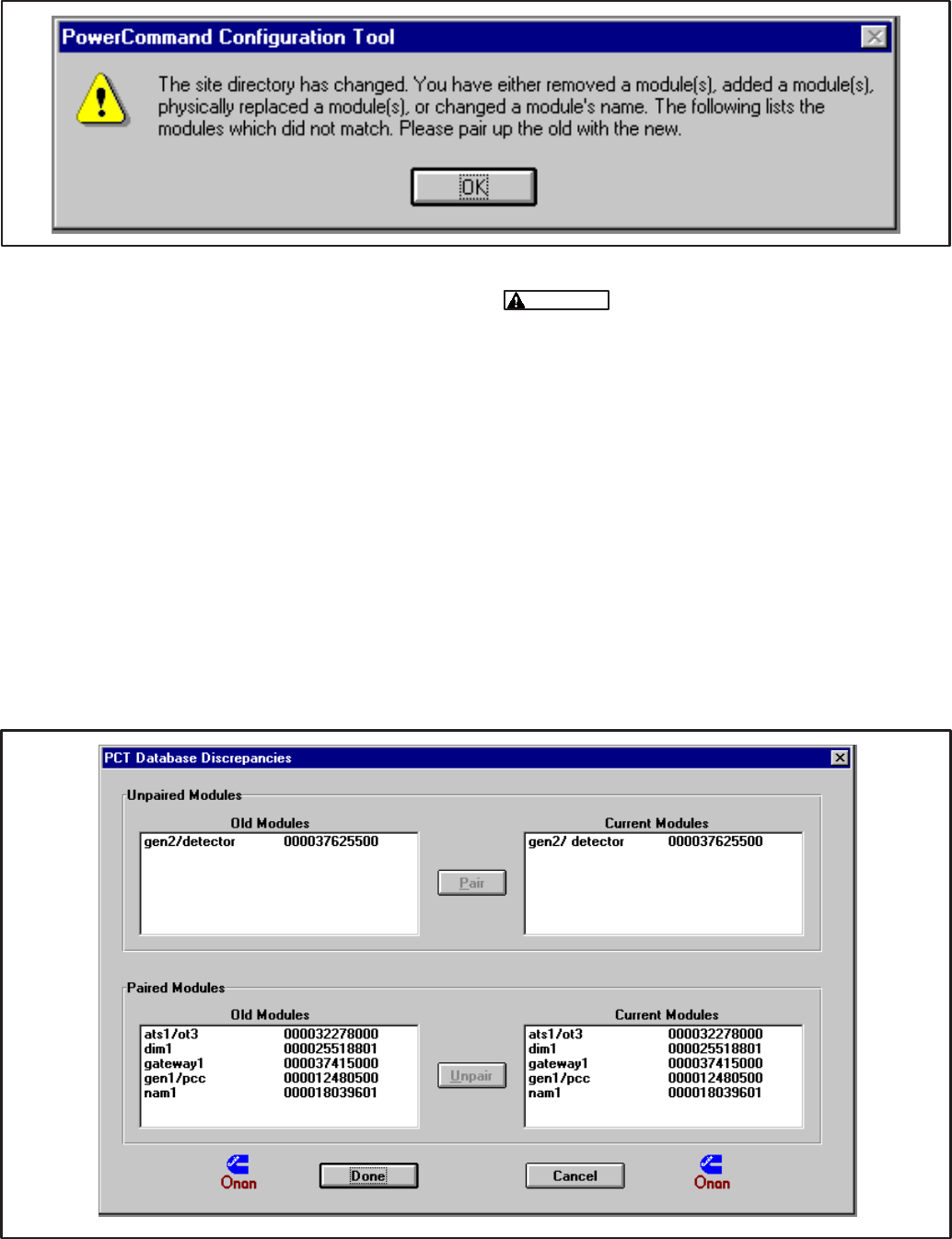
4-33
FIGURE 4-36. CHANGES IN THE LONMAKER DATABASE
Pairing Unpaired Modules
The Discrepancies dialog (Figure 4-37) provides
the option to manually “Pair” each old module con-
figuration with a new module. This allows the user
to retain a module’s configuration. This is needed
after configuring a site in advance of installing it. Or
if a module has been physically replaced and the
user would like to write the identical configuration to
the new hardware.
To retain a module’s configuration, pair the old mod-
ule with the new one. This is done by selecting a
module from the Unpaired Modules (Old Modules)
list and then selecting the corresponding module in
the Current Modules list. Then press the Pair but-
ton. This will move the two modules to the Paired
Modules section.
Old Unpaired Module configuration
will be lost if not paired.
To Pair Modules: In the Unpaired Modules section,
click on the module in the Old Modules dialog, then
click on the module in the Current Modules dialog.
Click on the Pair button to pair the modules.
To Unpair Modules: To undo a pairing, select the
two modules you want to unpair from the Paired
Modules section and press the Unpair button.
When finished pairing modules, click on the Done
button. Modules which have been paired will retain
their configuration. All unpaired New Modules will
be added to the site with their default configuration
while all unpaired Old Modules will be removed
from the site. Make sure the monitoring PC updates
its site information with the latest site information file
(.CSV file).
FIGURE 4-37. PAIRING MODULES
Redistribution or publication of this document,
by any means, is strictly prohibited.
4-34
Redistribution or publication of this document,
by any means, is strictly prohibited.
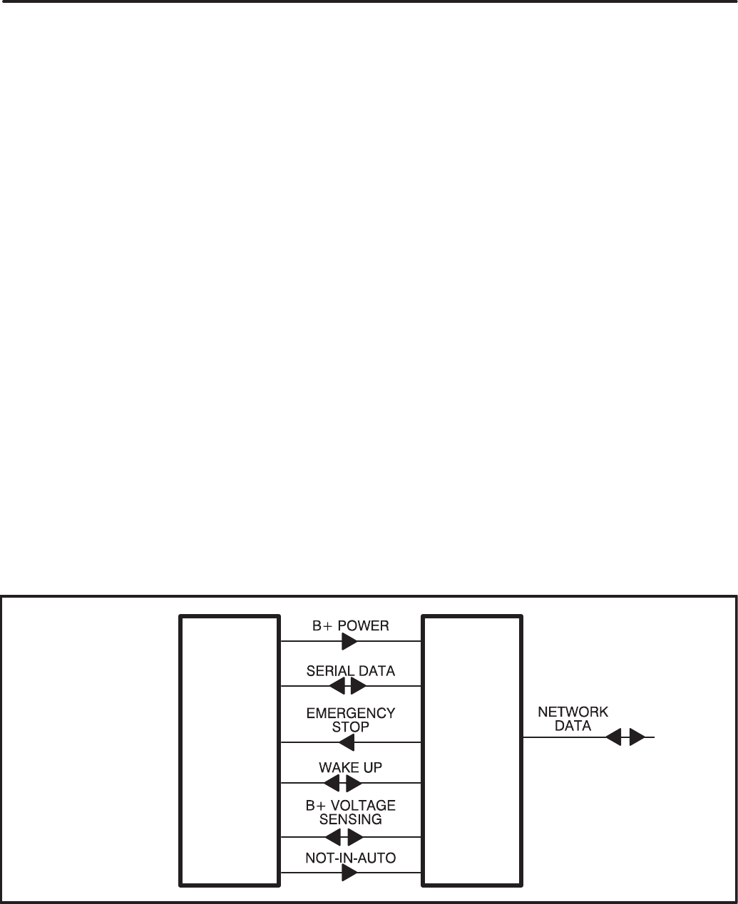
5-1
: 33 (!
OVERVIEW
This section describes the Genset Communica-
tions Module (GCM) and its functional role in the
PowerCommand Network. This section also de-
scribes the physical mounting and wiring of this
module, and provides information for the logical
installation and connection of the GCM on the net-
work.
In network terms, “logical installation and connec-
tion” refers to programming the various devices (or
nodes) on the network so that they can communi-
cate with one another. This communication takes
the form of passing network variables from one de-
vice to another. The process of assigning connec-
tions—linking an output variable of one device to an
an input variable of another device—is called “bind-
ing.”
In addition to functional and physical descriptions,
this section provides definitions of the network input
and output variables assigned to the GCM. Refer to
section 3 for the step-by-step procedure for binding
these variables to input and output variables as-
signed to other network devices.
Refer to Mounting in this section for GCM compati-
bility with PCC software versions.
DESCRIPTION
The GCM is mounted inside the PCC housing. It is
required for connection of the PCC to the Power-
Command Network. Control and monitoring of the
PCC can be accomplished over the network, via the
GCM.
The GCM contains a terminate circuit for use at the
end of a network data bus.
The GCM provides an interface for data from the
PCC to other modules on the network. The GCM
communicates with the PCC via the engine inter-
face board, and it monitors various PCC circuits to
determine the operating state of the control. For ex-
ample, the GCM stores PCC data such as volts, cur-
rent, engine speed, and oil temp; and then sends it
out on the network when another network node re-
quests the data.
Outputs from the GCM allow it to “wake up” the PCC
when needed, or to cause an emergency shutdown
on command. The GCM also provides some direct
local control and monitoring of the PCC. It monitors
for Not-In-Auto mode and High and Low battery
voltage (when the PCC is asleep).
The GCM is powered from the genset battery. It re-
mains powered even when the PCC is “asleep.”
Block Diagram
Refer to Table 5-1 and Figure 5-1 for a block dia-
gram overview of the GCM.
GCMPCC
FIGURE 5-1. BLOCK DIAGRAM: GENSET COMMUNICATIONS MODULE (GCM)
Redistribution or publication of this document,
by any means, is strictly prohibited.

5-2
TABLE 5-1. GCM – BLOCK DIAGRAM DESCRIPTIONS
Function Description/Specification
B+ Power This is an output from the PCC to the GCM. The digital and analog circuitry on
the GCM is powered from CNTRL B+ from the PCC. The GCM is always pow-
ered. It rides through starter dip and crank. The GCM is switch selectable for
12V or 24V systems.
Serial Data This is a bidirectional data path between the PCC and GCM. The GCM com-
municates with the PCC through the PCC’s serial port. Communication rate is
2400 baud. Starting, stopping and exercising of the set, readout of AC data,
Engine data, and Set status information are done through this link.
NOTE: When the PCC’s service port is connected (serial port) to an exter-
nal device, the GCM cannot communicate with the PCC and thus the PCC
state and data cannot be known on the network.
Emergency Stop
Control This is an output from the GCM. The GCM can activate the PCC’s Emergency
Stop Latching Relay. This allows a remote emergency stop over the network.
NOTE: The Emergency Stop condition can only be reset at the PCC front
panel. Can be reset once the E-Stop output from the GCM has been
cleared.
Wake Up Monitor
and Control This is both an output and an input for the GCM. The GCM has the capability to
wake up the PCC. It would do this for example when a network message was
telling the genset to start. The GCM also has the capability to monitor whether
or not the PCC is awake (i.e. due to some other reason). This helps the GCM
determine if it can communicate with the PCC.
B+ Voltage Sensing This is an input to the GCM from the PCC. The GCM directly monitors battery
voltage and determines high and low conditions. This function is needed when
the PCC is not awake (and thus is not capable of monitoring battery voltage
itself). A low or high condition will cause the GCM to wake up the PCC. The
PCC then annunciates the warning. Voltage thresholds are the same as in the
PCC. The GCM annunciates to the network a high or low voltage condition.
Not-In-Auto Monitor This is an input to the GCM from the PCC. The GCM monitors the position of
the front panel Run/Off/Auto switch. When the PCC is not awake, the GCM
annunciates to the network a Not-In-Auto condition.
Network Data Transformer Coupled into Category 4 Twisted Pair at 78,000 bits/sec.
Redistribution or publication of this document,
by any means, is strictly prohibited.
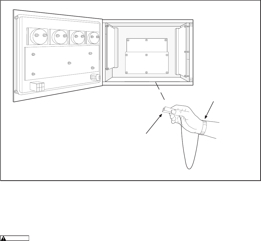
5-3
WRIST STRAP GROUND CLIP
ATTACH TO CLEAN UNPAINTED
SURFACE
WRIST STRAP
FIGURE 5-2. WRIST STRAP CONNECTION
MOUNTING
GCM is mounted inside PCC cabinet on top of the
analog board (Figure 5-2).
Electrostatic discharge will damage
circuit boards. Do not remove the circuit board
from the antistatic shipping bag until you are
grounded to the PCC with a wrist strap.
The GCM must be used with PCC operating soft-
ware version 1.06 or newer for all models except
DFHA, DFHB, DFHC and DFHD (these models
have unique operating software and are GCM com-
patible with version 1.04 or newer). Check the ver-
sion on the display menu. If the version is earlier
than the version listed, obtain and install an
EPROM upgrade kit.
Special Tools Required
•Grounding wrist strap with grounding clip
Circuit Board Handling Precautions
To help prevent circuit board damage due to elec-
trostatic discharge (ESD), a grounding wrist strap
must be worn when handling the circuit board. (The
wrist strap does not provide a direct short to
ground, it is typically rated at approximately 1 meg-
ohm to ground.)
Attach the clip to a clean unpainted surface of the
control box (see Figure 5-2) and place the strap
around your wrist before handling a circuit board.
Redistribution or publication of this document,
by any means, is strictly prohibited.

5-4
INSTALLATION
1. Place the genset Run/Off/Auto switch, on the
control panel, in the Off position.
2. Disconnect the battery charger (if applicable).
Remove all electrical supply sources.
Always disconnect a battery
charger from its AC source before discon-
necting the battery cables. Otherwise, dis-
connecting the cables can result in voltage
spikes high enough to damage the DC con-
trol circuits of the system.
3. Disconnect the genset starting battery
cable(s). Disconnect the negative (–) cable(s)
first to reduce the risk of arcing.
Accidental starting of the gen-
set while working on it can cause severe
personal injury or death. Prevent acciden-
tal starting by disconnecting the starting
battery cables. To reduce the risk of arcing,
disconnect the negative (–) cable first.
When reconnecting, connect the negative
(–) cable last.
Make certain battery area has been well-
ventilated before servicing battery. Arcing
can ignite explosive hydrogen gas given off
by batteries, causing severe personal inju-
ry. Make certain hydrogen gas, engine fuel,
and other explosive fumes are fully dissi-
pated. This is especially important if battery
has been connected to a battery charger.
4. Open the control box door. Connect the wrist
strap ground clip as shown in Figure 5-3.
5. Use a Phillips screwdriver to remove the four
analog board mounting screws shown in Fig-
ure 5-3.
6. Install four new standoffs in place of the analog
board mounting screws removed in step 5
(Figure 5-4). Tighten the standoffs securely.
"
!
FIGURE 5-3. PREPARING TO MOUNT GCM BOARD
FIGURE 5-4. INSTALLING STANDOFFS
Redistribution or publication of this document,
by any means, is strictly prohibited.
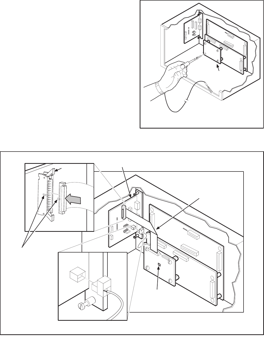
5-5
7. Mount the GCM board as shown in Figure 5-5,
using the screws removed from the analog
board. Tighten the mounting screws securely.
8. Orient the J6 harness connector as shown in
Figure 5-6. Push the J6 plug securely into the
connector on the engine interface board.
9. Spread locking tabs apart on the J7 connector.
Fold the ribbon cable, as shown in Figure 5-6,
align key on plug with socket cutout. Insert the
J7 harness plug into the J7 connector on the
engine interface board. Press in on the harness
connector, at the location indicated by the ar-
row, until the locking tabs lock into place.
10. Set the S4 switch on the GCM board to 24V for
a 24V-battery system or 12V for a 12V-battery
system (Figure 5-6).
Refer to sections 2 and 3 for instructions on network
wiring, network software installation and connec-
tion of the GCM module to the network.
!
FIGURE 5-5. MOUNTING GCM BOARD
.>
4
! +
.
4"!
" *
/ (*
!
")
" )
(*
FIGURE 5-6. INSTALLING J6 AND J7 CONNECTORS
Redistribution or publication of this document,
by any means, is strictly prohibited.

5-6
GCM CONNECTIONS
GCM connections are made at connectors J1, J4,
J6, and J7.
Refer to Table 5-2 and Figures 5-6 and 5-7.
NETWORK TOPOLOGY, DATA MEDIA AND
NETWORK POWER
Refer to Section 2 for information on the network to-
pology and data transmission media. Also refer to
Section 2 for network power supply wiring calcula-
tion procedures.
NETWORK DATA MEDIA
AND POWER WIRING
AC voltages and currents present
an electrical shock hazard that can cause se-
vere personal injury or death. Only trained, ex-
perienced personnel are to perform the follow-
ing procedures.
TB1 Connections
Network data and power wiring connections are
made at terminal block TB1 in the generator set ac-
cessory box, which is located on the back of the
control housing (Figures 5-8 and 5-9).
Conduit
When installing conduit, observe the following pre-
cautions:
1. Before beginning conduit installation, cover the
components in the accessory box to prevent
accidental entry of metal chips.
2. If using rigid conduit, install at least 2 feet (610
mm) of flexible conduit between the rigid con-
duit and generator set to absorb vibration.
3. Always run DC circuit wiring in a separate met-
al conduit from AC power cables to avoid in-
ducing currents that could cause problems
within the control.
4. Data wire can be run without conduit if it is ade-
quately protected. Do not run data wire in con-
duit with network power wiring.
Installation debris can cause
equipment failure and damage. Use ex-
treme care to keep drill chips and filings out
of the accessory box when mounting or
connecting conduit. Screwdrivers should
be used carefully to prevent damage to
components.
SWITCHES/SERVICE POINTS/LEDs
The Service switch is used during installation (when
prompted by the LonMaker program). The Termina-
tor switch must be set to the appropriate position at
installation. Switches are described in Table 5-3.
Service points are described in Table 5-4. LEDs are
described in Table 5-5.
Redistribution or publication of this document,
by any means, is strictly prohibited.

5-7
TABLE 5-2. GCM – CONNECTIONS
Connector Description
J7 Ribbon cable harness from GCM to A31 engine interface board. Plugs into outermost
connector on engine interface board. Cannot physically mate with any of the other con-
nectors. This cable carries all GCM/PCC interface signals except network data.
J6 Twisted pair cable harness from the GCM to the engine interface board. This cable car-
ries network data to the engine interface board where it then goes out through the lower
waterproof connector on its way to the customer connection terminal strip.
J1 26 pin header on the board used for factory test purposes only.
J4 RJ45 connector for network data – service and Installation use only.
TB1–14 Accessory Box –– Network Data 1 signal from GCM
TB1–15 Accessory Box –– Network Data 2 signal from GCM
TABLE 5-3. GCM – SWITCHES
Ref Name Type Description
S1 SERVICE momentary push Used at time of logical installation to identify device to
the installation software. Pressing S1 will light the DS1
LED.
S2 RESET momentary push Resets the Neuron Chip processor. Must be pushed af-
ter Install action.
S3 TERMINATOR slide Switch is set to position opposite of text “TERM” from
factory. The two devices at ends of network data must
have their switches set to “TERM”.
S4 12/24V SENSING slide Selects whether high/low battery sensing is for a 24VDC
or 12VDC system. It is set to 24V position from the fac-
tory.
TABLE 5-4. GCM – SERVICE POINTS
Ref Name Description
TP1 GCM VCC This is the 5.0VDC that supplies the logic on the GCM. It is measured
with respect to TP2. This test point is for troubleshooting use only.
TP2 GND Reference point for TP1.
Redistribution or publication of this document,
by any means, is strictly prohibited.
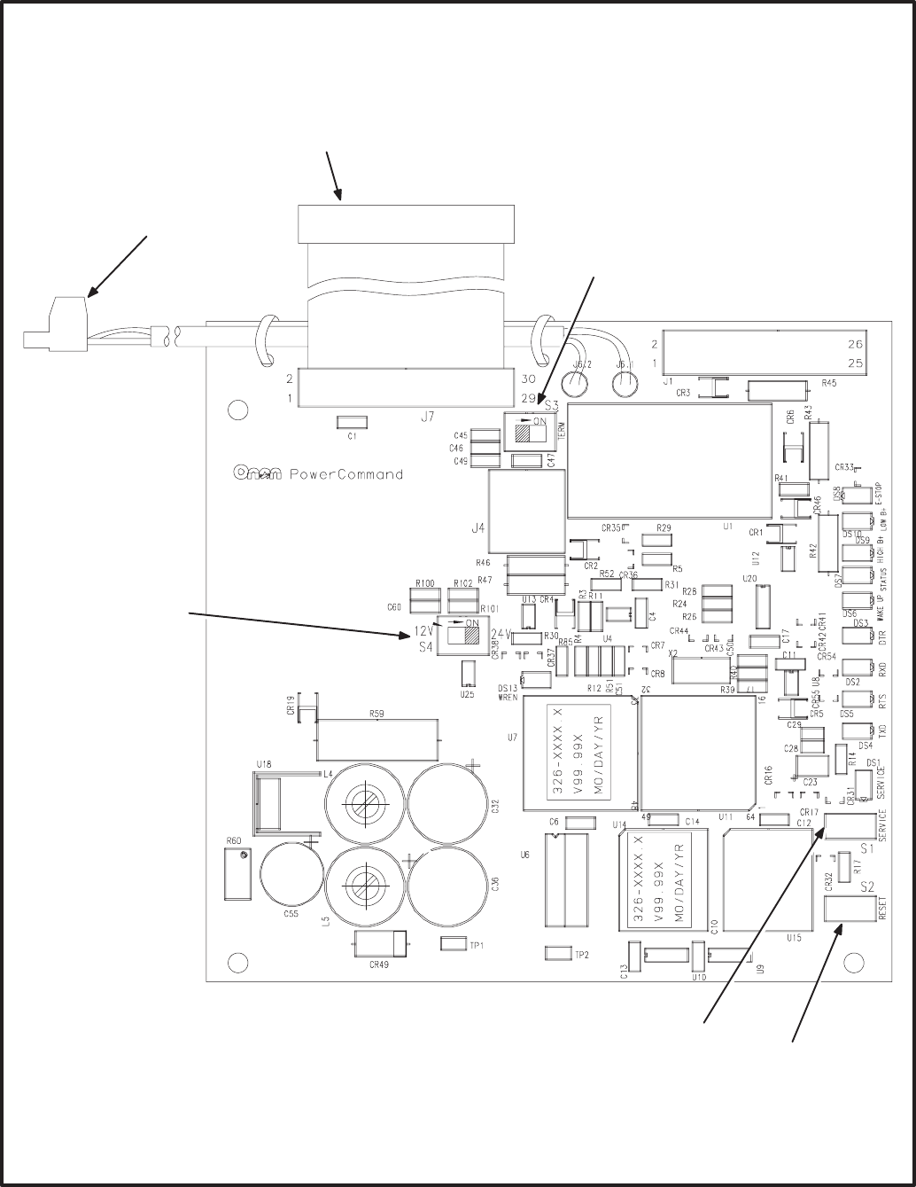
5-8
(*
5
(* +
(*
5"
(* /
.
.>
FIGURE 5-7. GENSET COMMUNICATIONS MODULE
Redistribution or publication of this document,
by any means, is strictly prohibited.

5-9
TABLE 5-5. GCM – LED INDICATORS
Ref Color Name Description
DS1 Amber SERVICE Indicates various states of the GCM node. It will be ON if S1 is pressed
and held. States without S1 pressed:
OFF = All OK. GCM has application image and is installed in a network.
ON= GCM is applicationless or has experienced a error that prevents
Neuron Chip from executing application code.
1/2 Hz BLINKING (1 second on / 1 second off) =GCM has an applica-
tion, but has not been logically installed in a network.
FLASHING (momentarily) once every 2–3 seconds=GCM is experienc-
ing an error condition, causing a watchdog timeout reset.
DS2 Green RXD Indicates Serial Data output from the GCM to the PCC. If the PCC is
awake and no service tool is connected, this LED should be flickering
regularly. RXD may be steady ON if the PCC is not awake.
DS3 Green DTR ON indicates that the PCC is capable of communicating with the GCM
(i.e. PCC is awake and no service tool is connected).
DS4 Green TXD Indicates Serial Data input to the GCM from the PCC. Should be flicker-
ing regularly if the PCC is awake. If the service tool is connected, flicker-
ing will indicate responses from the PCC to the service tool. TXD may be
steady ON if the PCC is not awake.
DS5 Green RTS ON indicates that the PCC has new information for the GCM to retrieve.
(May not be used.)
DS6 Green WAKE UP ON when the GCM has turned on the PCC.
DS7 Green STATUS Approx. 1/2 Hz Blinking (1 second on / 1 second off) indicates that
the GCM’s processor is executing the application code.
DS8 Red E–STOP ON when a network emergency stop is active.
DS9 Red HIGH B+ ON for a high battery condition sensed by GCM.
DS10 Red LOW B+ ON for a low battery condition sensed by GCM.
DS13 Green WREN ON (normal state) indicates that the off-chip EEPROM can be written to.
Indicator must be ON if device is to be logically installed in a network.
OFF could be caused by:
1) PCC CNTRL B+ is below 10VDC.
2) RESET switch being pressed and held.
3) Problem with board or connectors.
Redistribution or publication of this document,
by any means, is strictly prohibited.
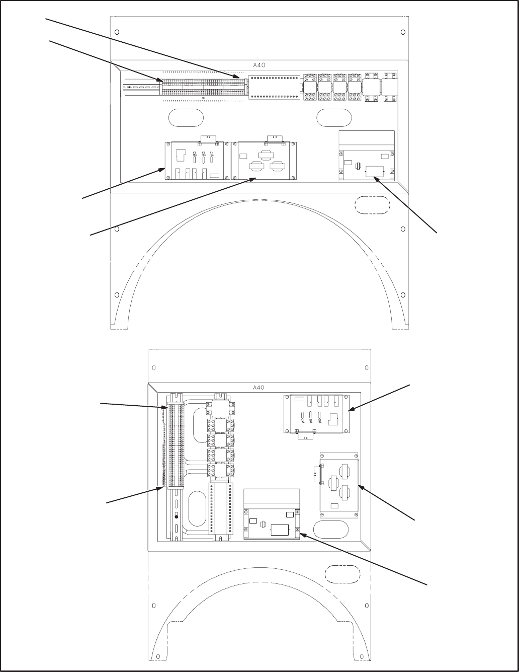
5-10
HC 6/7
HC 4/5
TB1-1
TB1-40
TB1-1
TB1-40
GOVERNOR
OUTPUT MODULE
A38
PT/CT BOARD A36 VOLTAGE
REGULATOR
OUTPUT MODULE
A37
GOVERNOR
OUTPUT MODULE
A38
PT/CT BOARD A36
VOLTAGE
REGULATOR
OUTPUT MODULE
A37
FIGURE 5-8. ACCESSORY BOX
Redistribution or publication of this document,
by any means, is strictly prohibited.
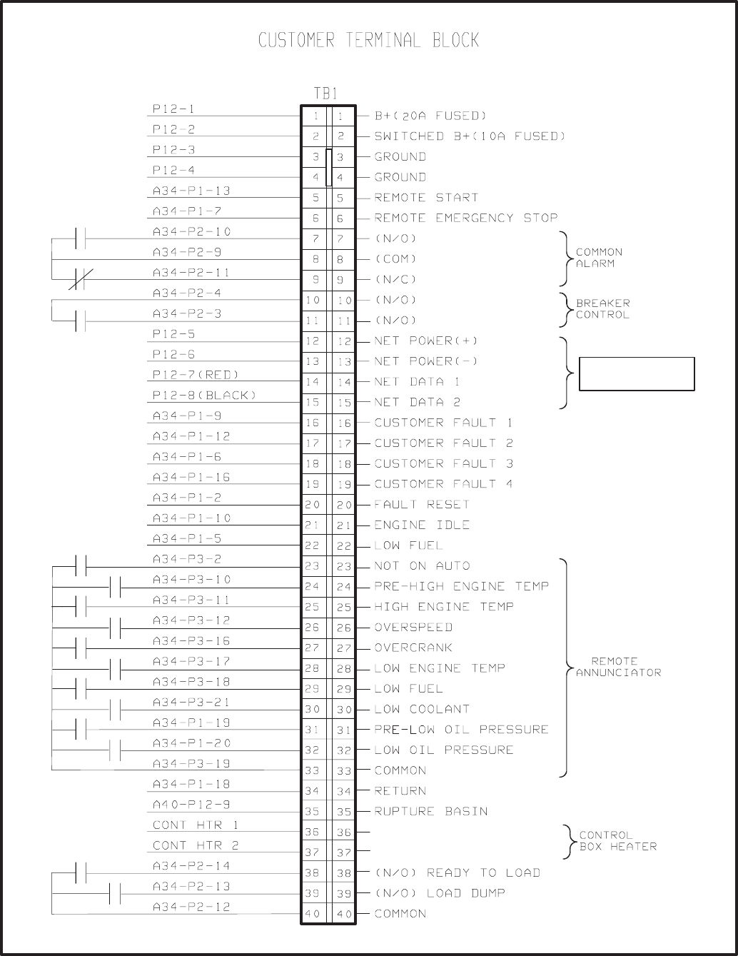
5-11
';
'
FIGURE 5-9. WIRING THE PCC/GCM
Redistribution or publication of this document,
by any means, is strictly prohibited.
5-12
NETWORK INSTALLATION
Section 3 provides a detailed description of the Lon-
Works network installation process. Read sections
1 and 2 before constructing the network. Sections 3
and 4 provide the following step-by-step installation
procedures:
1. Setting up Network Installation Tools
2. Starting LonMaker Software
3. Using LonMaker Software
4. LonMaker Network Setup
5. Connecting Devices with LonMaker
6. Installing Devices with LonMaker
7. Testing Devices and Verifying Installation
8. Setting up PowerCommand Configuration Tool
9. Using PowerCommand Configuration Tool
NETWORK ALARMS
Refer to the generator set service manual for the
PowerCommand fault codes.
NETWORK VARIABLES
Refer to the following tables of connectable network
variables for the GCM during its logical installation
on the network.
Redistribution or publication of this document,
by any means, is strictly prohibited.

5-13
TABLE 5-6. GCM NETWORK VARIABLE OUTPUTS
NV Name Description Used By Data Type Info Active
State
Default
Value(s)
NV Name
Description
Used By
Data Type Info
Active
State
Default
Value(s)
nvoRemoteAnnun1 D16 bit value containing status
of PCC faults and operating
states.
DIntended to be connected to a
Digital I/O Module
DDefault is set up for NFPA
110: high batt volts, low batt
volts, gen running, pre–lop, lop,
pre–het, het, let, os, oc,
not–in–auto, low fuel, and low
coolant level.
DNormal Utility, EPS Supplying
Load, and Battery Charger
Malfunction come from CCM or
PCC hardwired or network
DNet
Connect 16 bits (long): (2 BYTES)(PCC SERIAL)
Data Range
nvoRemoteAnnun1 0..65535
bit 0 = High Batt Volts Warn
bit 1 = Low Batt Volts Warn
bit 2 = Genset Running
bit 3 = not used
bit 4 = not used
bit 5 = Low Oil Press Warn
bit 6 = Low Oil Press Shutdn
bit 7 = High Cool Temp Warn
bit 8 = High Cool Temp Shutdn
bit 9 = Low Cool Temp Warn
bit 10 = Overspeed Shutdn
bit 11 = Fail to Start Shutdn
bit 12 = Not In Automatic
bit 13 = not used
bit 14 = Low Fuel Day Warn
bit 15 = Low Cool Lvl Warn/Shutdn
Notes:
1. Low Batt Volts includes Weak Batt Warning.
2. Genset Running means Ready To Load state.
3. Low Oil Press Warn includes Press Sender Warning.
4. High Coolant Temp includes Temp Sender Warning.
5. Fail to Start combines Mag Pickup, Fail to Crank and
Overcrank faults.
1
1
1
x
x
1
1
1
1
1
1
1
1
x
1
1
If no data
is
available,
all are
inactive
(0).
All “x”
must
always be
0.
Redistribution or publication of this document,
by any means, is strictly prohibited.

5-14
TABLE 5-7. GCM NETWORK VARIABLE OUTPUTS – Continued
NV Name Description Used By Data Type Info Active
State
Default
Value(s)
NV Name
Description
Used By
Data Type Info
Active
State
Default
Value(s)
nvoRemoteAnnun2 D16 bit value containing status
of PCC faults and operating
states.
Dintended to be connected to a
Digital I/O Module
DDefaults are set up for AC
Alarms: Customer Faults 2
and 4, High and Low AC
voltage, UnderFreq,
Overcurrent, Short Circuit,
Reverse Power, Loss of Field,
Loss of AC Input, Fail to Sync,
Fail to Close, Overload, and
Emergency Stop.
DNet
Connect 16 bits (long): (2 BYTES)(PCC SERIAL)
Data Range
nvoRemoteAnnun2 0..65535
bit 0 = Customer Fault 2 Warn/Shutdn
(default =ground fault warn)
bit 1 = Customer Fault 4 Warn/Shutdn
(default =high gen temp warn)
bit 2 = High AC Voltage Shutdown
bit 3 = Low AC Voltage Shutdown
bit 4 = Under Frequency Shutdown
bit 5 = Overcurrent Shutdown
bit 6 = Short Circuit Shutdown
bit 7 = Reverse Power Shutdown
bit 8 = Loss of Field Shutdown
bit 9 = Loss of AC Input Shutdown
bit 10 = Fail to Sync Warning
bit 11 = Fail to Close Warning
bit 12 = Overload Warning
bit 13 = Emergency Stop
bit 14 = Communications Failure
bit 15 = Common Alarm
Notes:
1. Loss of AC Input is same as Low AC Voltage.
2. Fail to Close and Fail to Sync are not available on
non–paralleling PCC.
1
1
1
1
1
1
1
1
1
1
1
1
1
1
1
1
If no data
is
available,
all are
inactive
(0).
Redistribution or publication of this document,
by any means, is strictly prohibited.

5-15
TABLE 5-8. GCM NETWORK VARIABLE OUTPUTS – Continued
NV Name Description Used By Data Type Info Active
State
Default
Value(s)
NV Name
Description
Used By
Data Type Info
Active
State
Default
Value(s)
nvoRemoteAnnun4 D16 bit value containing status
of PCC faults and operating
states.
Dintended to be connected to a
Digital I/O Module
DDefaults are set up for
Paralleling Applications :
Emergency Stop, pre–lop, lop,
pre–het, het, low coolant temp,
os, oc, nia, low coolant level,
fail to sync, fail to close, rev
power, loss of field, overload,
under freq.
DNet
Connect
DMaster
16 bits (long): (2 BYTES)(PCC SERIAL)
Data Range
nvoRemoteAnnun4 0..65535
bit 0 = Emergency Stop
bit 1 = Low Oil Press Warn
bit 2 = Low Oil Press Shutdown
bit 3 = High Coolant Temp Warn
bit 4 = High Coolant Temp Shtdn
bit 5 = Low Coolant Temp Warn
bit 6 = Overspeed Shutdown
bit 7 = Fail To Start Shutdown
bit 8 = Not In Auto
bit 9 = Low Cool Lvl Warn/Shtdn
bit 10 = Fail to Sync Warn
bit 11 = Fail to Close Warn
bit 12 = Reverse Power Shtdn
bit 13 = Loss of Field Shtdn
bit 14 = Overload Warn
bit 15 = Under Freq Shtdn
Notes:
1. .Low Oil Press Warn includes Press Sender Warning.
2. High Coolant Temp includes Temp Sender Warning.
3. Fail to Start combines Mag Pickup, Fail to Crank and
Overcrank faults.
4. Fail to Close and Fail to Sync are not available on
non–paralleling PCC.
1
1
1
1
1
1
1
1
1
1
1
1
1
1
1
1
If no data
is
available,
all are
inactive
(0).
Redistribution or publication of this document,
by any means, is strictly prohibited.

5-16
TABLE 5-9. GCM NETWORK VARIABLE OUTPUTS – Continued
NV Name Description Used By Data Type Info Active
State
Default
Value(s)
NV Name
Description
Used By
Data Type Info
Active
State
Default
Value(s)
nvoRunCmd Ddigital value indicating that the
genset has an active run
command (either from the
network, front panel, or remote
hardwired). Genset is not
necessarily running –– may be
timing to start, or run inhibited.
This Boolean goes True when
the genset is requested to run.
DNet
Connect 1 bit (Boolean): (1 BYTE)(PCC SERIAL)
Data Range
nvoRunCmd 0,1
1 not
applicable
nvoRunning Ddigital value indicating genset
is running (starter disconnect
has occurred)
DNet
Connect 1 bit (Boolean): (1 BYTE)(PCC SERIAL)
Data Range
nvoRunning 0,1
1 not
applicable
nvoReadyToLoad Ddigital value indicating genset
is within rated voltage and
frequency (as determined by
PCC specs.)
DNet
Connect 1 bit (Boolean): (1 BYTE)(PCC SERIAL)
Data Range
nvoReadyToLoad 0,1
1 not
applicable
nvoLoadDump Ddigital value indicating that
genset is overloaded (as
determined by PCC specs. –
overload or underfrequency)
DNet
Connect 1 bit (Boolean): (1 BYTE)(PCC SERIAL)
Data Range
nvoLoadDump 0,1
1 not
applicable
nvoCommonAlarm Ddigital value indicating a PCC
shutdown or warning condition
DNet
Connect 1 bit (Boolean): (1 BYTE)(PCC SERIAL)
Data Range
nvoCommonAlarm 0,1
1 not
applicable
Redistribution or publication of this document,
by any means, is strictly prohibited.

5-17
TABLE 5-10. GCM NETWORK VARIABLE OUTPUTS – Continued
NV Name Description Used By Data Type Info Active
State
Default
Value(s)
NV Name
Description
Used By
Data Type Info
Active
State
Default
Value(s)
nvoCustFault1 Ddigital value indicating state of
PCC Customer Fault #1 input
DNet
Connect 1 bit (Boolean): (1 BYTE)(PCC SERIAL)
Data Range
nvoCustFault1 0,1
1 not
applicable
nvoCustFault2 Ddigital value indicating state of
PCC Customer Fault #2 input
DNet
Connect 1 bit (Boolean): (1 BYTE)(PCC SERIAL)
Data Range
nvoCustFault2 0,1
1 not
applicable
nvoCustFault3 Ddigital value indicating state of
PCC Customer Fault #3 input
DNet
Connect 1 bit (Boolean): (1 BYTE)(PCC SERIAL)
Data Range
nvoCustFault3 0,1
1 not
applicable
nvoCustFault4 Ddigital value indicating state of
PCC Customer Fault #4 input
DNet
Connect 1 bit (Boolean): (1 BYTE)(PCC SERIAL)
Data Range
nvoCustFault4 0,1
1 not
applicable
Redistribution or publication of this document,
by any means, is strictly prohibited.

5-18
TABLE 5-11. GCM NETWORK VARIABLE INPUTS
NV Name Description Used By Data Type Info Active
State
Default
Value(s)
NV Name
Description
Used By
Data Type Info
Active
State
Default
Value(s)
nviRunCmd DBoolean used to give PCC a
run command –– genset will
start and run (if in auto, no
inhibit, no shutdown faults, etc.)
DPCW
DNet
Connect
DMaster
1 bit (Boolean): (1 BYTE)(PCC SERIAL)
Data Range
nviRunCmd 0,1
1 0
nviResetCmd DBoolean used to reset PCC
faults (Emergency Stop has to
be reset at PCC also)
DPCW
DNet
Connect
DMaster
1 bit (Boolean):(1 BYTE) (PCC SERIAL)
Data Range
nviResetCmd 0,1
1 0
nviEmerStopCmd DBoolean used to e–stop the
genset
DNOTE: Once set, setting
nviEmerStopCmd back to the
inactive state is not enough to
clear this state. SOMEONE
MUST PHYSICALLY PRESS
THE RESET SWITCH ON THE
FRONT PANEL OF THE PCC
ITSELF TO CLEAR THIS
STATE OF THE PCC.
DPCW
DNet
Connect
DMaster
1 bit (Boolean):(1 BYTE)
Data Range
nviEmerStopCmd 0,1
1 0
nviWakeUpCmd DBoolean used to turn PCC
power on
Dused to turn on PCC without
starting genset.
DPCW
DNet
Connect
1 bit (Boolean):(1 BYTE)
Data Range
nviWakeUpCmd 0,1
1 0
Redistribution or publication of this document,
by any means, is strictly prohibited.

5-19
TABLE 5-12. GCM NETWORK VARIABLE INPUTS – Continued
NV Name Description Used By Data Type Info Active
State
Default
Value(s)
NV Name
Description
Used By
Data Type Info
Active
State
Default
Value(s)
nviLoadDemandCmd
(Note 1)
DBoolean used to turn put PCC
in Load Demand mode
(shutdown when
nviLoadDemandCmd = 1,
restart when it returns to 0)
DNet
Connect
DMaster
1 bit (Boolean):(1 BYTE) (PCC SERIAL)
Data Range
nviLoadDemandCmd 0,1
1 0
nviGenBrkrCtrl
(Note 1)
DBoolean used to control a
genset breaker connected to
the PCC
DNet
Connect
DMaster
1 bit (Boolean):(1 BYTE) (PCC SERIAL)
Data Range
nviGenBrkrCtrl 0,1
1=close
breaker
0=open
0
nviCustFault1 DBoolean used to activate PCC
Customer Fault1 from a remote
sensor
DNet
Connect
DMaster
1 bit (Boolean):(1 BYTE) (PCC SERIAL)
Data Range
nviCustFault1 0,1
1 0
nviCustFault2 DBoolean used to activate PCC
Customer Fault2 from a remote
sensor
DNet
Connect
DMaster
1 bit (Boolean):(1 BYTE) (PCC SERIAL)
Data Range
nviCustFault2 0,1
1 0
nviCustFault3 DBoolean used to activate PCC
Customer Fault3 from a remote
sensor
DNet
Connect
DMaster
1 bit (Boolean):(1 BYTE) (PCC SERIAL)
Data Range
nviCustFault3 0,1
1 0
nviCustFault4 DBoolean used to activate PCC
Customer Fault4 from a remote
sensor
DNet
Connect
DMaster
1 bit (Boolean):(1 BYTE) (PCC SERIAL)
Data Range
nviCustFault4 0,1
1 0
& + 8 @%%<<<C %@@<7%&8 &<6
Redistribution or publication of this document,
by any means, is strictly prohibited.
5-20
Redistribution or publication of this document,
by any means, is strictly prohibited.
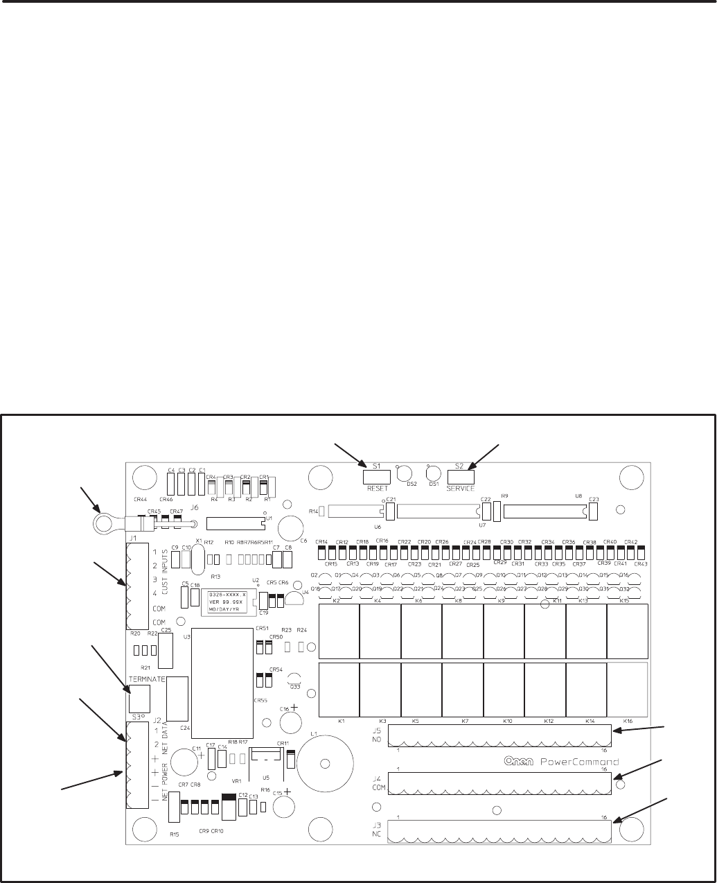
6-1
< )& = (!
OVERVIEW
This section describes the Digital I/O Module (DIM)
and its functional role in the PowerCommand net-
work. It also describes the physical mounting and
wiring of this module, and provides procedures for
the logical installation and connection of the DIM on
the network.
In network terms, “logical installation and connec-
tion” refers to programming the various devices (or
nodes) on the network so that they can communi-
cate with one another. This communication takes
the form of passing network variables from one de-
vice to another. The process of assigning connec-
tions—linking an output variable of one device to an
an input variable of another device—is called “bind-
ing.” Refer to Appendix C for Application Table Con-
sumption to review the number of connections that
can be made.
In addition to functional and physical descriptions,
this section provides definitions of the network input
and output variables assigned to the DIM. Refer to
section 3 for the step-by-step procedure for binding
these variables to input and output variables as-
signed to other network devices.
DESCRIPTION
The DIM provides a group of relay contact outputs
and discrete inputs for interfacing the PowerCom-
mand Network to alarm or status outputs and to
equipment that does not have compatible commu-
nications capability.
The DIM contains a terminate circuit for use at the
end of a network data bus.
The DIM provides16 Form-C relay contacts, which
are driven by data from the network. The contacts
are connected to terminal blocks for field wiring.
Each relay can be programmed to operate from
connectable variables on the network. The module
also includes four isolated digital inputs to couple
user inputs to the network for additional control and
monitoring.
(* +
5
(*
(*
*
!
()
!
()
(
.
./
.
!
.+
FIGURE 6-1. DIGITAL I/O MODULE
Redistribution or publication of this document,
by any means, is strictly prohibited.

6-2
Power Supply
The DIM requires power from the network power
bus. Power supply wiring and connection is covered
under Wiring and Cabling in Section 2. See Figure
6-5 for minimum power input.
Inputs
Four discrete inputs can be connected to external
dry contacts. These inputs must be referenced back
to either of two “input common” terminals through
dry contacts (see note 6 on Figure 6-5).
Outputs
The DIM provides sixteen 5A, 250VAC/30VDC
Form-C dry contact latching relay outputs. Secure
wires in the terminal block to 2 inch-lbs. (0.23 NSm).
External devices that are wired to these relays
should be fused appropriately to prevent dam-
age to the DIM.
Block Diagram
Refer to Table 6-1 and Figure 6-2 for a block dia-
gram overview of the DIM.
TABLE 6-1. DIM – BLOCK DIAGRAM DESCRIPTIONS
Function Description/Specification
16 Form C Relay
Outputs 16 separate sets of form C dry contacts rated individually at 250VAC/30VDC, 5AMPS. Relays
are controlled and powered from the network. Relays are the latching type. They maintain their
last state even when power is removed. When power is reapplied, all relays are first reset and
then put to the correct state.
4 Discrete Inputs Contact closure between an input and the input common activates the input. The state of the
input is available on the network.
Network Data Transformer Coupled into Category 4 Twisted Pair at 78,000 bits/sec.
Network Power The DIM is powered by Network Power (see Section 2).
DIM
FIGURE 6-2. BLOCK DIAGRAM: DIGITAL I/O MODULE
Redistribution or publication of this document,
by any means, is strictly prohibited.

6-3
LOCATION
Refer to sections two and three for network topolo-
gy and maximum network length. All wiring must
follow a specific network topology and must fall
within distance limits.
The module is packaged for panel mounting within
other equipment enclosures. The module is potted
with clear compound in a black molded shell.
Choose a clean, vibration-free mounting surface.
Avoid locations that are hot, damp or dusty. The
temperature range must not exceed –13°F (–25°C)
to 158°F (70°C).
MOUNTING
Figure 6-3 shows the DIM module outline dimen-
sions. The outside dimensions do not include nec-
essary clearance for wire connections (dependant
on conduit size and routing).
If mounting the module to a wall, make sure that no
wires, plumbing, gas or exhaust lines run behind the
wall before drilling the mounting holes.
! *(
* #$$' #'
+ #+'
/> #+'
>=> #'
/ #++' #'
#+'
+
#+'
+ #=+'
FIGURE 6-3. MOUNTING THE DIGITAL I/O MODULE
Redistribution or publication of this document,
by any means, is strictly prohibited.

6-4
WIRING DIAGRAM
Figures 6-4 and 6-5 show the interconnect wiring
diagram and associated notes for the DIM. Refer to
the specifications and notes on the drawing.
REFER TO FIGURE 6-5 FOR IMPORTANT
NOTES AND SPECIFICATIONS
DIGITAL I/O MODULE
J1 DISCRETE INPUTS
FIGURE 6-4. DIGITAL I/O MODULE INTERCONNECT WIRING DIAGRAM
Redistribution or publication of this document,
by any means, is strictly prohibited.
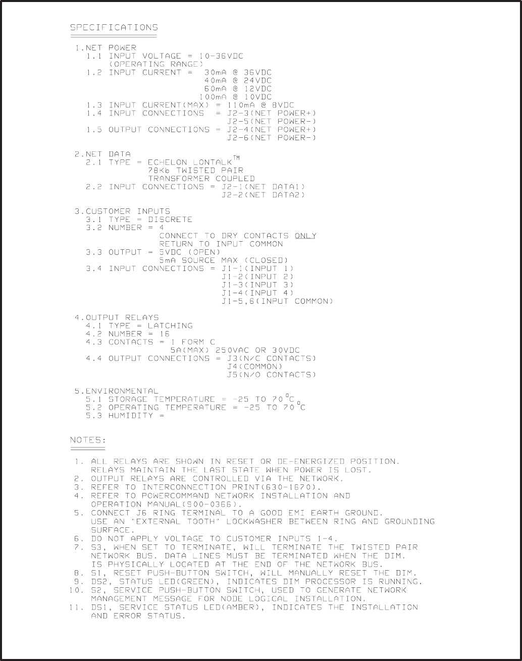
6-5
FIGURE 6-5. DIGITAL I/O MODULE INTERCONNECT WIRING DIAGRAM – NOTES
Redistribution or publication of this document,
by any means, is strictly prohibited.

6-6
NETWORK TOPOLOGY, DATA MEDIA AND
NETWORK POWER
Refer to Section 2 for information on the network to-
pology and data transmission media. Also refer to
Section 2 for network power supply wiring calcula-
tion procedures.
NETWORK DATA MEDIA
AND POWER WIRING
AC voltages and currents present
an electrical shock hazard that can cause se-
vere personal injury or death. Only trained, ex-
perienced personnel are to perform the follow-
ing procedures.
Connections
Network data and power wiring connections are
made at connector J2.
Refer to Figures 6-1 and 6-4. Follow standard wiring
practices. Properly secure wire terminals when
needed. Secure wires in the terminal blocks to 2 in-
lbs. (0.23 NSm).
Conduit
When installing conduit, observe the following pre-
cautions:
1. Before beginning conduit installation, cover all
components to prevent accidental entry of met-
al chips.
2. If using rigid conduit, install at least 2 feet (610
mm) of flexible conduit between the rigid con-
duit and generator set to absorb vibration.
3. Always run DC circuit wiring in a separate met-
al conduit from AC power cables to avoid in-
ducing currents that could cause problems
within the control.
4. Data wire can be run without conduit if it is ade-
quately protected. Do not run data wire in con-
duit with network power wiring.
Installation debris can cause
equipment failure and damage. Use ex-
treme care to keep drill chips and filings out
of the components when mounting or con-
necting conduit. Screwdrivers should be
used carefully to prevent damage to com-
ponents.
Redistribution or publication of this document,
by any means, is strictly prohibited.

6-7
CUSTOMER INPUT AND RELAY OUTPUT
CONNECTIONS
Customer input and relay output connections are
made at connectors J1, J3, J4, and J6.
Refer to Figures 6-1 and 6-4.
SWITCHES AND LEDs
The Service switch is used during installation (when
prompted by the LonMaker program). The Termina-
tor switch must be set to the appropriate position at
installation. Switches are described in Table 6-2.
LED indicators are described in Table 6-3.
TABLE 6-2. DIM – SWITCHES
Ref Name Type Description
S2 SERVICE momentary push Used at time of logical installation to identify device to
the installation software. Pressing S2 will light DS1 LED.
S1 RESET momentary push Resets the Neuron Chip processor. Must be pushed after
Install action.
S3 TERMINATOR slide Switch is set to position opposite of text “TERM” from
factory. The two devices at ends of network data must
have their switches set to “TERM”.
TABLE 6-3. DIM LED INDICATORS
Ref Color Name Description
DS1 Amber SERVICE Indicates various states of the DIM node. It will be ON if S2 is pressed
and held. States without S2 pressed:
OFF = All OK. DIM has application image and is installed in a network.
ON= DIM is application-less or has experienced a error that prevents
Neuron Chip from executing application code.
1/2 Hz BLINKING (1 second on/1 second off) =DIM has an application,
but has not been logically installed in a network.
FLASHING once every 2–3 seconds=DIM is experiencing an error condi-
tion causing a watchdog timeout reset (fatal error).
DS2 Green STATUS 1/2 Hz BLINKING (1 second on/1 second off) indicates that the DIM’s
processor is executing the application code.
In the future, may be used to indicate other conditions for troubleshooting
purposes.
Redistribution or publication of this document,
by any means, is strictly prohibited.
6-8
NETWORK INSTALLATION
Section 3 provides a detailed description of the Lon-
Works network installation process. Read sections
1 and 2 before constructing the network. Section 3
provides the following step-by-step installation pro-
cedures:
1. Setting up Network Installation Tools
2. Starting LonMaker Software
3. Using LonMaker Software
4. LonMaker Network Setup
5. Connecting Devices with LonMaker
6. Installing Devices with LonMaker
7. Testing Devices and Verifying Installation
8. Setting up PowerCommand Configuration Tool
9. Using PowerCommand Configuration Tool
NETWORK VARIABLES
The 16 relays can be individually linked to alarm or
status outputs from any system device. Four digital
inputs are also provided for customer input to the
network.
Network Variable Outputs:
Network variables nvoCustinput1 to nvoCustinput4
are for customer inputs to the Network (the inputs
are located on the DIM). These variables are indi-
vidually set by closing a corresponding external
contact to short that input to the COM pin of the DIM.
Table 6-4 lists the connectable network variable
outputs.
Network Variable Inputs:
When the DIM receives an update of any of the net-
work variables within nviRelay1 to 16, the DIM sets
the appropriate relay to the desired state.
Table 6-5 lists the connectable network variable in-
puts.
Refer to Appendix C for Application Table Con-
sumption to review the number of connections that
can be made.
Redistribution or publication of this document,
by any means, is strictly prohibited.

6-9
TABLE 6-4. DIM NETWORK VARIABLE OUTPUTS
NV Name Description Used
by:
Data Type Info Active
State
Default
Value(s)
NV Name
Description
Used
by:
Data Type Info
Active
State
Default
Value(s)
nvoCustInput1 Ddigital value which indicates
whether Customer Input #1 is
closed (connected) to the
Common.
D used to control other discrete
inputs such as nviRunCmd on
the PCC.
DNet
Connect 1 bit (boolean):
Data Range
nvoCustInput1 0,1
1 = input
closed to
common
0 = open
not applicable
nvoCustInput2 Dsame as nvoCustInput1 DNet
Connect 1 bit (boolean):
Data Range
nvoCustInput2 0,1
1 = input
closed to
common
0 = open
not applicable
nvoCustInput3 Dsame as nvoCustInput1 DNet
Connect 1 bit (boolean):
Data Range
nvoCustInput3 0,1
1 = input
closed to
common
0 = open
not applicable
nvoCustInput4 Dsame as nvoCustInput1 DNet
Connect 1 bit (boolean):
Data Range
nvoCustInput4 0,1
1 = input
closed to
common
0 = open
not applicable
Redistribution or publication of this document,
by any means, is strictly prohibited.

6-10
TABLE 6-5. DIM NETWORK VARIABLE INPUTS
NV Name Description Used
by:
Data Type Info Active
State
Default
Value(s)
NV Name
Description
Used
by:
Data Type Info
Active
State
Default
Value(s)
nviAllRelays D16 bit value which is used to
control all 16 relays at once.
Dlogically or’ed with
corresponding array element of
nviRelay[0..16].
Dbind to nvoRemoteAnnun1
from the GCM for example.
DNet
Connect 16 bits (long):
Data Range
nviAllRelays 0..65535
bit 0 = relay 1
bit 1 = relay 2
..thru
bit 15 = relay 16
in each bit:
1 = set
relay (NO
is closed
and NC is
open)
0 = reset
not applicable
nviRelay [0..16] Dan array of digital values
allowing control of the relays
individually.
DOnly 1 thru 16 are applicable.
(‘0’ is not used.)
Dlogically or’ed with
appropriate bit from
nviAllRelays.
DNet
Connect array:
Data Range
nviRelay[0] not used
nviRelay[1] 0,1
nviRelay[2] 0,1
nviRelay[3] 0,1
nviRelay[4] 0,1
nviRelay[5] 0,1
nviRelay[6] 0,1
nviRelay[7] 0,1
nviRelay[8] 0,1
nviRelay[9] 0,1
nviRelay[10] 0,1
nviRelay[11] 0,1
nviRelay[12] 0,1
nviRelay[13] 0,1
nviRelay[14] 0,1
nviRelay[15] 0,1
nviRelay[16] 0,1
each array
element:
1 = set
relay (NO
is closed
and NC is
open)
0 = reset
not applicable
Redistribution or publication of this document,
by any means, is strictly prohibited.
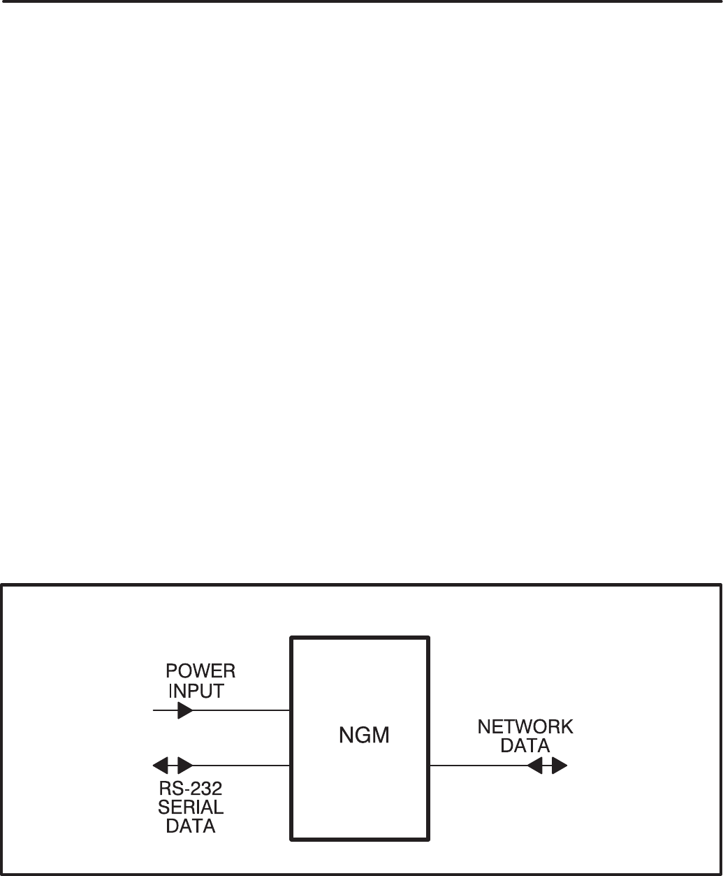
7-1
#$ # (!
OVERVIEW
This section describes the Network Gateway Mod-
ule (NGM) and its functional role in the PowerCom-
mand Network. It also describes the physical
mounting and wiring of the NGM, and provides pro-
cedures for the logical installation and connection of
the NGM on the network.
DESCRIPTION
The NGM provides a PowerCommand Network in-
terface to a PC, either directly or through a modem.
The NGM translates network protocol into a proto-
col that a PC can understand. Figure 7-1 is a block
diagram of the NGM.
The NGM allows software running on a PC to ac-
cess, poll, and control all devices on a network.
PowerCommand Software for Windows (PCW)
uses this device to access the network. In this ap-
plication the NGM is referred to as a “Network Gate-
way Module.”
LonMaker and PowerCommand Configuration Tool
software require an NGM for installing a network
(referred to as a “Network Installation Gateway.”)
The PC can access the network locally via a direct
connection to this module, or remotely for PCW only
via a modem connection to this module.
The NGM (Figure 7-2) has an RJ45 connector on
one end for connection to network data. It has a DB9
connector on the other end for connection to an
RS–232 port on a PC or to an RS-232 port on a mo-
dem.
Externally the NGM has a DC power input jack, an
ON/OFF switch, a SERVICE pushbutton, and a
SERVICE LED indicator.
The NGM does not contain a terminate circuit for
use at the end of a network data bus. If the NGM is
located at the end of the network data bus, use a
JBT to connect the NGM and set the JBT to termi-
nate.
Power Supply
The NGM has a DC power input jack, that connects
to utility power through a plug-in transformer.
If the NGM must remain powered during an electri-
cal power failure, use an Uninterruptable Power
Supply (UPS). Refer to the UPS section of this
manual. If more than one device will be connected
to the UPS, purchase a multi-outlet adapter or multi-
outlet extension cord.
FIGURE 7-1. BLOCK DIAGRAM NETWORK GATEWAY MODULE
Redistribution or publication of this document,
by any means, is strictly prohibited.
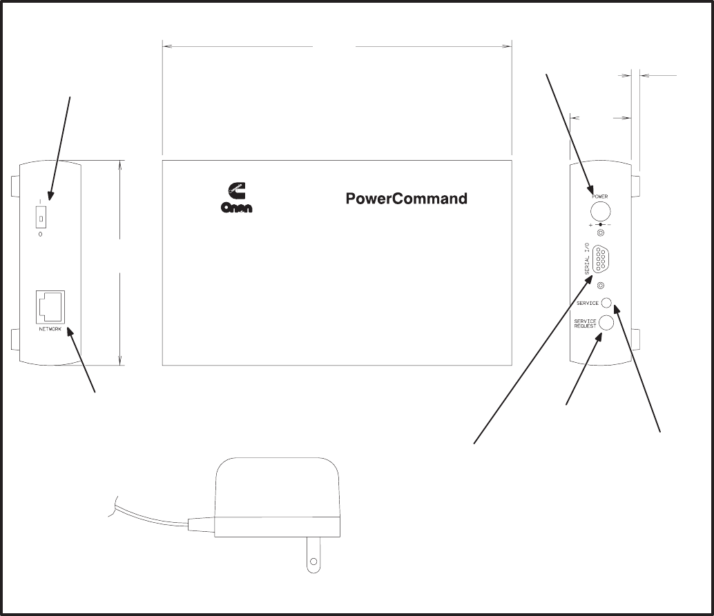
7-2
LOCATION
Locate the NGM near an electrical outlet. Refer to
section 2 for network topology and maximum net-
work length. All wiring must follow a specific net-
work topology and must fall within distance lim-
its.
Choose a clean, vibration-free mounting surface.
Avoid locations that are hot, damp or dusty. The
temperature range must not exceed 32°F (0°C) to
131°F (55°C).
(
344
(*
5
*
./
4
() !
!
4
# !'
5
"!
!
! (
.)
( " !
* #$$'
#+='
#'
+
#/'
++
#'
Network Gateway Module
38,400 BPS
FIGURE 7-2. NETWORK GATEWAY MODULE OUTLINE DRAWING
Redistribution or publication of this document,
by any means, is strictly prohibited.

7-3
!
* #$$'
+
#+'
#+/'
/ + #/='
/
#+/'
#+'
+>
#'
#+'
)
Network Gateway Module
38,400 BPS
FIGURE 7-3. MOUNTING BRACKET OUTLINE
MOUNTING
Figure 7-2 shows the network gateway module out-
line dimensions and connection points.
The module can be placed on a clean flat surface or
it can be mounted to a wall or other flat surface with
mounting brackets. Figure 7-3 shows the outline
and mounting hole locations for the mounting
brackets.
If mounting to the wall, make sure that no wires,
plumbing, gas or exhaust lines run behind the wall
before drilling mounting holes.
The foam tape on the brackets is for spacing the
brackets. The exposed covering can be removed to
adhere the foam spacer to the NGM.
WIRE CABLES
Use only the custom made cables
that are supplied with this kit. Cables from a
computer supply store may look the same, but
they may cause equipment damage or connec-
tion problems.
Figure 7-4 shows each of the cables included in this
kit.
These cables provide the following interconnects:
SNetwork Gateway Module to a modem
SNetwork Gateway Module to a PC
SNetwork Gateway Module to a Junction Box/
Terminator Module or other network RJ45 con-
nection
Only one of the top two cables shown in figure 7-4
will be used. The cables selected will depend on the
application.
Redistribution or publication of this document,
by any means, is strictly prohibited.
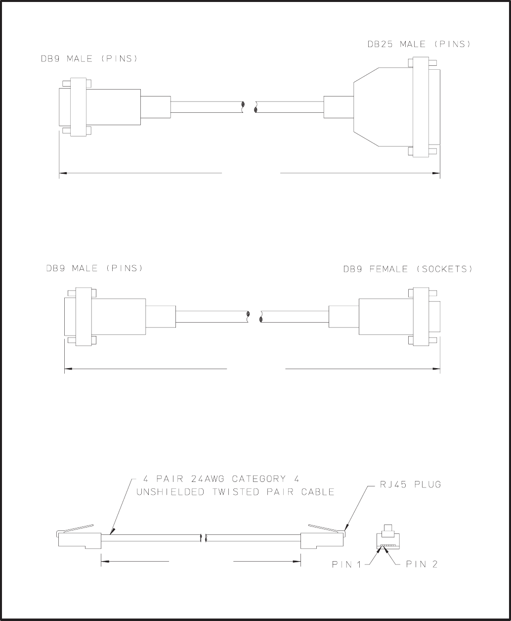
7-4
MODEM CABLE
(NGM TO MODEM)
NULL MODEM CABLE
(NGM TO PC)
NETWORK PATCH CABLE
(NGM TO JUNCTION BOX/TERMINATOR)
> ±
#+= ± +'
> ±
#+= ± +'
+ ±
# ± +'
!
* #7$'
FIGURE 7-4. WIRE HARNESS DRAWINGS
Redistribution or publication of this document,
by any means, is strictly prohibited.

7-5
NETWORK TOPOLOGY AND DATA MEDIA
Refer to section 2 for information on the network to-
pology and data transmission media.
AC voltages and currents present
an electrical shock hazard that can cause se-
vere personal injury or death. Only trained, ex-
perienced personnel are to perform the follow-
ing procedures.
Connections
Network data connections are made at an RJ45
connector for LonWorks network data, and at a DB9
connector for connection to an RS-232 port on a PC
or a modem. (Connectors are shown in Figure 7-2,
cables supplied with the NGM are shown in Figure
7-4.)
SERVICE SWITCH AND LED
The Service switch is used during installation (when
prompted by the LonMaker program). It is impor-
tant to press the service switch on the NGM that
is part of the permanent site (“Network Gateway
Module”) and not the “Network Installation
Gateway” used temporarily as part of the ser-
vice tools for setting up the network.
The yellow LED indicates if the service switch is be-
ing pressed. The LED indicator blinks when the
NGM is unconfigured and is off if the NGM is config-
ured. The LED indicator remains on if an unrecover-
able error is detected.
NETWORK INSTALLATION
Sections 3 and 4 provide a detailed description of
the network installation process. Read Sections 1
and 2, before constructing the network. Sections 3
and 4 provide the following step-by-step installation
procedures:
1. Setting up Network Installation Tools
2. Starting LonMaker Software
3. Using LonMaker Software
4. LonMaker Network Setup
5. Connecting Devices with LonMaker
6. Installing Devices with LonMaker
7. Testing Devices and Verifying Installation
8. Setting up PowerCommand Configuration Tool
9. Using PowerCommand Configuration Tool
Refer to Table 7-1 for an example of a message tag
connection for dial-out.
TABLE 7-1. EXAMPLE OF A MESSAGE TAG CONNECTION FOR DIAL-OUT
MESSAGE TAG CONNECTION FOR DIAL–OUT
From Tag Output: (CCM, GCM) To Tag Input (NGM)
NGMTag1 msg_in
Redistribution or publication of this document,
by any means, is strictly prohibited.
7-6
Redistribution or publication of this document,
by any means, is strictly prohibited.

8-1
> ?@ = 3
OVERVIEW
A Junction Box/Terminator (JBT) is a device that
provides connection points for network power and
data wires. The JBT contains a terminate circuit for
use at the end of a network data bus. JBTs may be
used throughout a network for connecting in Pass
Thru or Local Loop configurations. A JBT is re-
quired to connect an NGM to the end of a network
data bus.
The JBT is used to provide a network termina-
tion for NGM nodes that are located at an end of
the network bus. Termination of nodes at the
ends of the network is required.
DESCRIPTION
The JBT provides two 6-position pluggable terminal
blocks for data and power (J1 and J2), and two
RJ45 jacks for 24AWG stub connections (J3 and
J4). The JBT also has a switch (S1) to connect the
data lines to a terminator circuit, and a switch (S2) to
select either Pass Thru or Local Loop connection
between the data lines on the two terminal blocks.
FIGURE 8-1. JUNCTION BOX / TERMINATOR MODULE
Redistribution or publication of this document,
by any means, is strictly prohibited.
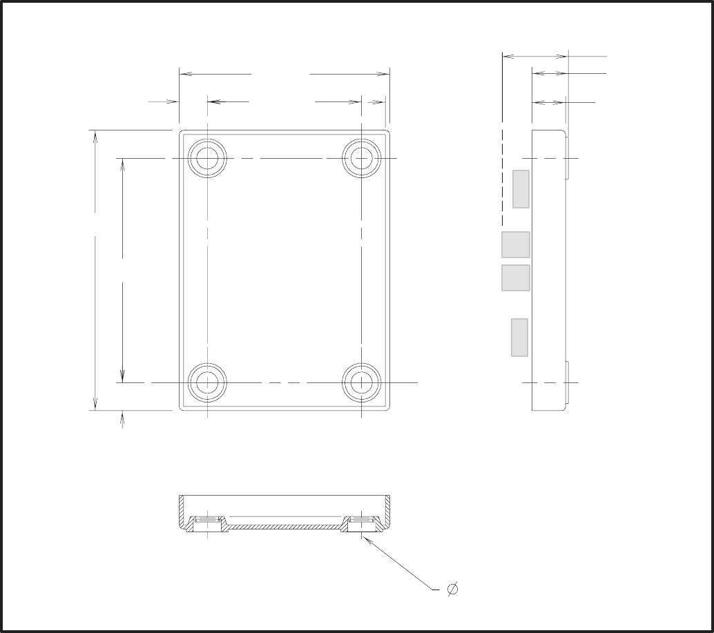
8-2
LOCATION
Refer to Section 2 for network topology and maxi-
mum network length. All wiring must follow a spe-
cific network topology and must fall within dis-
tance limits.
The JBT is designed for panel mounting within other
equipment enclosures. The module is potted with
clear compound in a black molded shell.
Choose a clean, vibration-free mounting surface.
Avoid locations that are hot, damp or dusty. The
temperature range must not exceed –40°F (–40°C)
to 158°F (70°C).
MOUNTING
Figure 8-2 shows the JBT outline dimensions. The
outside dimensions do not include clearance for
wire connections.
If mounting the module to a wall, make sure that no
wires, plumbing, gas or exhaust lines run behind the
wall before drilling the mounting holes.
!
* #$$'
+ #+'
/> #+'
#'
#>'
+> #' #+'
#+'
+ #='
/ #+'
=> #'
FIGURE 8-2. MOUNTING THE JUNCTION BOX / TERMINATOR MODULE OUTLINE DRAWING
Redistribution or publication of this document,
by any means, is strictly prohibited.

8-3
FIGURE 8-3. JUNCTION BOX/TERMINATOR MODULE SCHEMATIC
WIRING DIAGRAM
Figure 8-3 shows the wiring diagram for the JBT.
The diagram shows the functions of the S1 and S2
switches on the module.
NETWORK TOPOLOGY, DATA MEDIA AND
NETWORK POWER
Refer to Section 2 for information on the network to-
pology and data transmission media. Also refer to
Section 2 for network power supply wiring calcula-
tion procedures.
Redistribution or publication of this document,
by any means, is strictly prohibited.

8-4
NETWORK DATA MEDIA
AND POWER WIRING
AC voltages and currents present
an electrical shock hazard that can cause se-
vere personal injury or death. Only trained, ex-
perienced personnel are to perform the follow-
ing procedures.
Connections
Network data and power wiring connections are
made at connectors J1, J2, J3, and J4. (Refer to
Table 8-1 and Figure 8-1.)
Conduit
When installing conduit, observe the following pre-
cautions:
1. Before beginning conduit installation, cover all
components to prevent accidental entry of met-
al chips.
2. If using rigid conduit, install at least 2 feet (610
mm) of flexible conduit between the rigid con-
duit and generator set to absorb vibration.
3. Always run DC circuit wiring in a separate met-
al conduit from AC power cables to avoid in-
ducing currents that could cause problems
within the control.
4. Data wire can be run without conduit if it is ade-
quately protected. Do not run data wire in con-
duit with network power wiring.
Installation debris can cause
equipment failure and damage. Use ex-
treme care to keep drill chips and filings out
of the components when mounting or con-
necting conduit. Screwdrivers should be
used carefully to prevent damage to com-
ponents.
SWITCHES
Terminator and Local Loop / Pass Thru switches are
described in Table 8-2.
TABLE 8-1. JBT CONNECTIONS
Connector Description
J1–1 Network Data1 signal
J1–2 Network Data2 signal
J1–3,4 Network Power+
J1–5,6 Network Power–
J2–1 Network Data1 signal
J2–2 Network Data2 signal
J2–3,4 Network Power+
J2–5,6 Network Power–
J3 Network Data –– Use patch cable 0338–3240 to connect to NGM
J4 Network Data –– Use patch cable 0338–3240 to connect to NGM
TABLE 8-2. JBT SWITCHES
Ref Name Type Description
S1 TERMINATOR slide Switch is set to position opposite of text “TERM” from factory. If the JBT
is used to connect an NGM at one end of the network data bus, then
switch must be set to “TERM”.
S2 LOCAL LOOP/
PASS THRU
SELECT
slide Switch is set to position “PASS THRU” from factory.
Switch should only be set to “LOCAL LOOP” for a local loop wiring ar-
rangement. Setting switch to “LOCAL LOOP” breaks network data con-
nection between J1 and J2. J3 and J4 are then connected as a stub
from J1 only.
Redistribution or publication of this document,
by any means, is strictly prohibited.

9-1
A #$ (!
OVERVIEW
This section describes the Network Annunciator
Module (NAM) and its functional role in the Power-
Command network. It also describes the physical
mounting and wiring of this module, and provides
procedures for the logical installation and connec-
tion of the NAM on the network. Refer to the Net-
work Annunciator Operator’s Manual 900-0282 for
features, customer options and operating proce-
dures.
In network terms, “logical installation and connec-
tion” refers to programming the various devices (or
nodes) on the network so that they can communi-
cate with one another. This communication takes
the form of passing network variables from one de-
vice to another. The process of assigning connec-
tions—linking an output variable of one device to an
an input variable of another device—is called “bind-
ing.” Refer to Appendix C for Application Table Con-
sumption to review the number of connections that
can be made.
The NAM contains a Digital I/O Module that pro-
vides a communications interface with other mod-
ules on the network. Refer to the Digital I/O Module
section for network input and output variables as-
signed to the Digital I/O Module. Refer to Section 3
for the step-by-step procedure for binding these
variables to input and output variables assigned to
other network devices.
DESCRIPTION
The NAM shown in Figure 9-1, combines a hard-
wired PowerCommand System Annunciator with a
Digital I/O Module. The NAM is connected to the
network by twisted pair data wire.
The NAM contains a terminate circuit for use at the
end of a network data bus.
The NAM has 20 LEDs to annunciate alarms. In
NFPA 110 applications the network directly controls
16 of the LEDs and indirectly controls one LED
(DS3), refer to Table 9-4). The remaining three
LEDs can be hardwired. In non-NFPA 110 applica-
tions the network controls 16 of the LEDs and four
can be hardwired.
The Digital I/O Module also includes four isolated
digital inputs to couple user inputs to the network for
additional control and monitoring.
!
" *
FIGURE 9-1. ANNUNCIATOR
Redistribution or publication of this document,
by any means, is strictly prohibited.

9-2
Block Diagram
Refer to Table 9-1 and Figure 9-2 for a block dia-
gram overview of the network annunciator module.
LOCATION
Refer to Section 2 for network topology and maxi-
mum network length. All wiring must follow a spe-
cific network topology and must fall within dis-
tance limits.
This module is available in two versions: one has an
oversize cover for flush mounting and the other has
a smaller cover for surface mounting.
Choose a clean, vibration-free mounting surface.
Avoid locations that are hot, damp or dusty. The
temperature range must not exceed –13°F (–25°C)
to 158°F (70°C).
MOUNTING
Figure 9-3 shows the network annunciator outline
dimensions. The outside dimensions do not include
necessary clearance for wire connections. If mount-
ing the module to a wall, make sure that no wires,
plumbing, gas or exhaust lines run behind the wall
before drilling the mounting holes.
TABLE 9-1. NETWORK ANNUNCIATOR MODULE – BLOCK DIAGRAM DESCRIPTIONS
Function Description/Specification
System
Annunciator/
Digital I/O
Module
Standard hardwired PowerCommand System Annunciator. (See Digital I/O Module section)
Common Alarm
Form C Output Same as on System Annunciator – 2A, 30VDC
Silence/Lamp
Test Input/Output Same as on System Annunciator – 2A, 30VDC. Also acts as input.
Unused Alarm
Inputs
(3 or 4)
Hardwired inputs to the System Annunciator. Only three are available in NFPA110 applications.
Four are available for generic applications.
Customer Inputs
(4) Contact closure between an input and the input common on the DIM section activates the input.
The state of the input is available on the network.
Network Data Transformer Coupled into Category 4 Twisted Pair at 78,000 bits/sec.
Network Power The NAM is powered by Network Power. See “Network Power” in section 2.
SYSTEM
CUSTOMER INPUTS
REFER TO TABLE 9-4
FIGURE 9-2. BLOCK DIAGRAM: NETWORK ANNUNCIATOR MODULE
Redistribution or publication of this document,
by any means, is strictly prohibited.
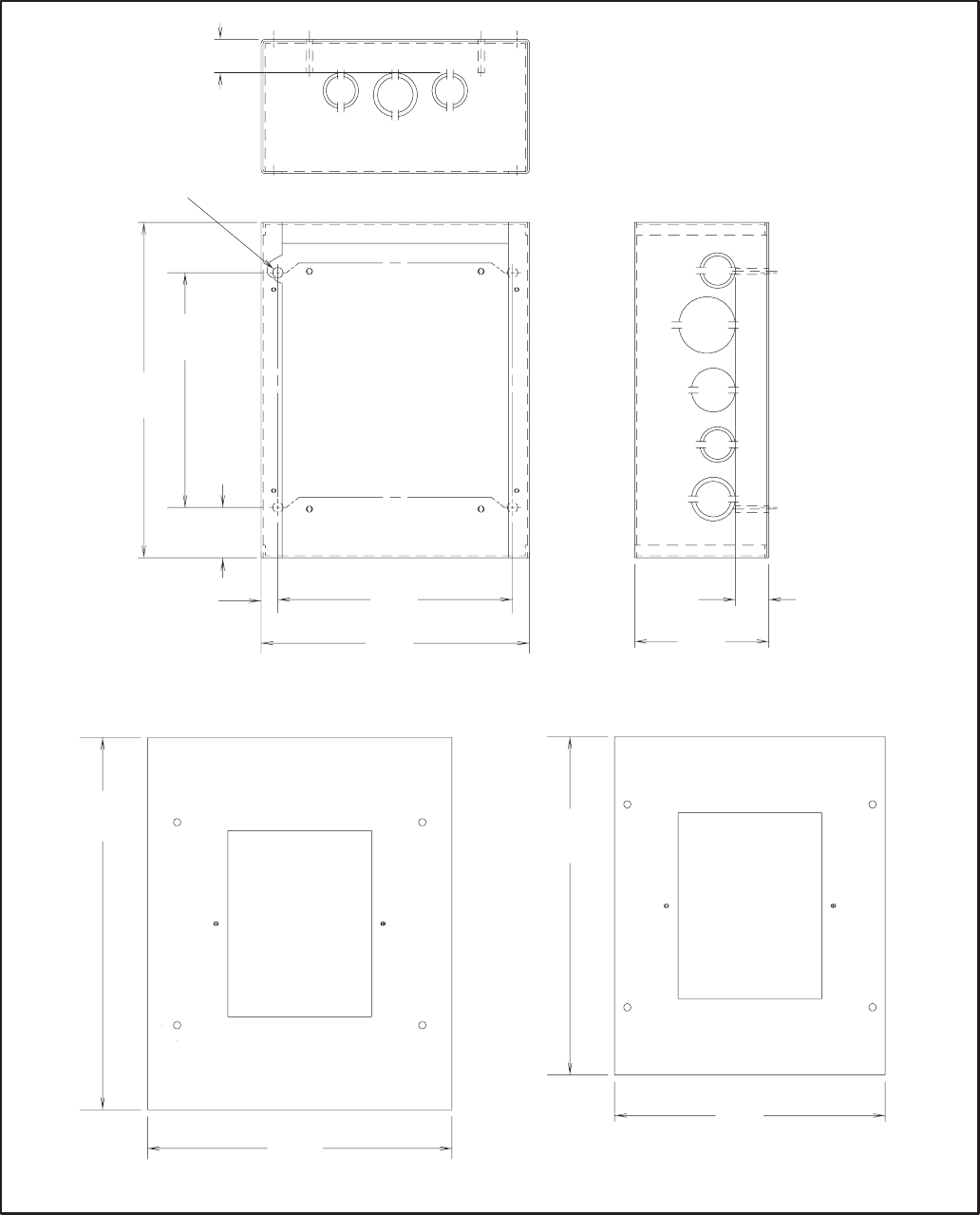
9-3
!
* #$$'
" 5 "" 5
+
#/'
+
#/'
/
#++'
/
+
#>'
>
#+>>='
>
#+>>='
+
#/'
+
#=+'
#+>'
=
#'
+
#/'
=
#'
++
#>/
#=
FIGURE 9-3. ANNUNCIATOR BOX OUTLINE
Redistribution or publication of this document,
by any means, is strictly prohibited.
9-4
WIRING DIAGRAM
Figures 9-4 and 9-5 show the interconnect wiring
diagram and associated notes for the network an-
nunciator module. Refer to the specifications and
notes on the drawing. The DIM is prewired to the
negative logic annunciator. Refer to the NAM Oper-
ator’s Manual (900-0282) for complete wiring infor-
mation.
Power Supply
The Network Annunciator Module requires network
power. Power supply wiring and connection is cov-
ered in Section 2. See Figure 9-4 for minimum pow-
er input.
Inputs
Four digital inputs can be connected to external dry
contacts (J1-1 thru J1-4). These inputs must be ref-
erenced back to either of two “input common” termi-
nals through dry contacts (see note 2 on Figure
9-4). Three customer faults and one customer indi-
cation can be connected to the negative logic an-
nunciator. These inputs must be referenced back to
ground (TB1-24) through dry contacts (see notes 5,
6 and 15 on Figure 9-4).
TB1-20 can be used as both input and output for Si-
lence/Lamp test (see notes 5 and 6 on Figure 9-4).
Outputs
Two Form C relays (K1 and K2) are available for re-
mote Silence/Lamp Test and Remote Alarm. Both
sets of contacts provide ground to an external cir-
cuit and are rated at 2 amps maximum at 30 VDC
(see notes 5 and 6 on Figure 9-4).
Redistribution or publication of this document,
by any means, is strictly prohibited.
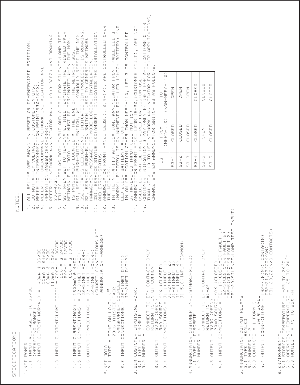
9-5
FIGURE 9-4. NOTES FOR INTERCONNECTION DIAGRAM (FIGURE 9-5)
Redistribution or publication of this document,
by any means, is strictly prohibited.
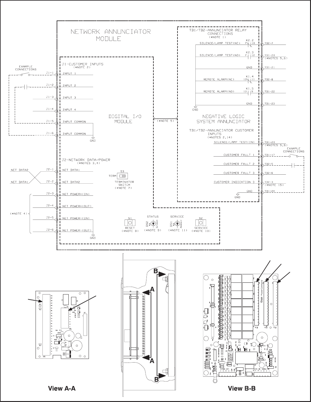
9-6
SEE FIGURE 9-4 FOR INTERCONNECTION DIAGRAM NOTES
5 "
!" 3
!" .
./
.
+
FIGURE 9-5. NETWORK ANNUNCIATOR MODULE INTERCONNECTION DIAGRAM
Redistribution or publication of this document,
by any means, is strictly prohibited.

9-7
NETWORK TOPOLOGY, DATA MEDIA AND
NETWORK POWER
Refer to Section 2 for information on the network to-
pology and data transmission media. Also refer to
Section 2 for network power supply wiring calcula-
tion procedures.
NETWORK DATA MEDIA
AND POWER WIRING
AC voltages and currents present
an electrical shock hazard that can cause se-
vere personal injury or death. Only trained, ex-
perienced personnel are to perform the follow-
ing procedures.
Connections
Network data and power wiring connections are
made at connector J2. Refer to Figures 9-4 and 9-5.
Conduit
When installing conduit, observe the following pre-
cautions:
1. Before beginning conduit installation, cover all
components to prevent accidental entry of met-
al chips.
2. If using rigid conduit, install at least 2 feet (610
mm) of flexible conduit between the rigid con-
duit and generator set to absorb vibration.
3. Always run DC circuit wiring in a separate met-
al conduit from AC power cables to avoid in-
ducing currents that could cause problems
within the control.
4. Data wire can be run without conduit if it is ade-
quately protected. Do not run data wire in con-
duit with network power wiring.
Installation debris can cause
equipment failure and damage. Use ex-
treme care to keep drill chips and filings out
of the components when mounting or con-
necting conduit. Screwdrivers should be
used carefully to prevent damage to com-
ponents.
SWITCHES AND LEDs
The Service switch (S2) is used during installation
(when prompted by the LonMaker program). The
Terminator switch (S3) must be set to the appropri-
ate position at installation. Switches are described
in Table 9-2. LED indicators are described in Table
9-3.
TABLE 9-2. NAM – SWITCHES (LOCATED ON THE DIM)
Ref Name Type Description
S2 SERVICE momentary push Used at time of logical installation to identify device to
the installation software. Pressing S2 will light DS1 LED.
S1 RESET momentary push Resets the Neuron Chip processor. Must be pushed after
the Install action.
S3 TERMINATOR slide Switch is set to position opposite of text “TERM” from
factory. The two devices at ends of network data must
have their switches set to “TERM”.
TABLE 9-3. NAM LED INDICATORS (LOCATED ON THE DIM)
Ref Color Name Description
DS1 Amber SERVICE Indicates various states of the DIM node. It will be ON if S2 is pressed
and held. States without S2 pressed:
OFF = All OK. DIM has application image and is installed in a network.
ON= DIM is application-less or has experienced a error that prevents
Neuron Chip from executing application code.
1/2 Hz BLINKING (1 second on/1 second off) =DIM has an application,
but has not been logically installed in a network.
FLASHING once every 2–3 seconds=DIM is experiencing an error condi-
tion causing a watchdog timeout reset (fatal error).
DS2 Green STATUS Approx. 1/2 Hz BLINKING (1 second on/1 second off, may appear
erratic) indicates that the DIM’s processor is executing the application
code.
Redistribution or publication of this document,
by any means, is strictly prohibited.
9-8
NETWORK INSTALLATION
Sections 3 and 4 provide a detailed description of
the network installation process. Read sections 1
and 2, before constructing the network. Sections 3
and 4 provide the following step-by-step installation
procedures:
1. Setting up Network Installation Tools
2. Starting LonMaker Software
3. Using LonMaker Software
4. LonMaker Network Setup
5. Connecting Devices with LonMaker
6. Installing Devices with LonMaker
7. Testing Devices and Verifying Installation
8. Setting up PowerCommand Configuration Tool
9. Using PowerCommand Configuration Tool
NETWORK VARIABLES
The network variables for the NAM are the same as
the network variables for the Digital I/O Module. Re-
fer to the Digital I/O Module section under Network
Variables for information pertaining to the connect-
able network variables for this module.
Table 9-4 correlates the network variable with the
Network Annunciator Modules front panel LEDs
and NFPA110 fault/event names. LED#s are se-
quential from the top of the annunciator to the bot-
tom.
Redistribution or publication of this document,
by any means, is strictly prohibited.

9-9
TABLE 9-4. NAM NETWORK VARIABLE CORRELATION WITH ANNUNCIATOR FRONT PANEL (NFPA 110)
LED # NFPA 110
PANEL INSERT DIM NETWORK
VARIABLE COMMENTS
1High Battery Voltage nviRelay[1]
2Low Battery Voltage nviRelay[2]
3Normal Battery Voltage see Comments For NFPA110 application, Normal Battery illuminates when both High and
Low Battery Voltage LEDs are off. For generic annunciator applications
this LED may be used as a hardwired input. This requires a switch setting
change on the System Annunciator board. See operator’s manual for
Network Annunciator (900–0282).
4Generator Running nviRelay[3]
5Normal Utility Power nviRelay[4]
6EPS Supplying Load nviRelay[5]
7Pre–Low Oil Pressure nviRelay[6]
8Low Oil Pressure nviRelay[7]
9Pre–High Coolant Temp nviRelay[8]
10 High Coolant Temp nviRelay[9]
11 Low Engine Temp nviRelay[10]
12 Overspeed nviRelay[11]
13 Overcrank nviRelay[12]
14 Not In Auto nviRelay[13]
15 Bat Chgr Malfunction nviRelay[14]
16 Low Fuel nviRelay[15]
17 Low Coolant Level nviRelay[16]
18 Customer Fault #1 (blank) hardwired ONLY
19 Customer Fault #2 (blank) hardwired ONLY
20 Customer Fault #3 (blank) hardwired ONLY
Redistribution or publication of this document,
by any means, is strictly prohibited.
9-10
Redistribution or publication of this document,
by any means, is strictly prohibited.

10-1
B 33 (!=
OVERVIEW
This section describes the Controls Communica-
tions Module (CCM) and its functional role in the
PowerCommand network. This module is used to
monitor and control both gensets and automatic
transfer switches. This section describes the CCM
and applications involving gensets. This section
also describes the physical mounting and wiring of
this module, and provides procedures for the logical
installation and connection of the CCM-Genset on
the network. Section 11 describes automatic trans-
fer switch applications.
In network terms, “logical installation and connec-
tion” refers to programming the various devices (or
nodes) on the network so that they can communi-
cate with one another. This communication takes
the form of passing network variables from one de-
vice to another. The process of assigning connec-
tions—linking an output variable of one device to an
an input variable of another device—is called “bind-
ing.” Refer to Appendix C for Application Table Con-
sumption to review the number of connections that
can be made.
In addition to functional and physical descriptions,
this section provides definitions of the network in-
put and output variables assigned to the CCM-Gen-
set.
DESCRIPTION
The CCM can be used to monitor and control a con-
ventional (non-microprocessor controlled) genset.
It provides a PowerCommand Network interface for
remote monitoring and control.
The module can monitor digital inputs, and AC and
DC analog inputs from generator sets and commu-
nicate monitored data to the PowerCommand net-
work. Relay outputs on the CCM provide a limited
amount of control of the monitored equipment from
the network. For example, these outputs can be
used to remotely start a generator set.
The CCM has 16 channels of analog input and 32
digital inputs. Most of the analog channels are con-
figured for specific types of signals (AC volts, cur-
rent, phase, oil temp, oil pressure, coolant temp, ex-
haust temp, etc.,see Figures E-4 and E-5 in Appen-
dix E. The spare analog inputs are for signal moni-
toring (4-20 mA, 0-1 mA, 0-5V). The three tempera-
ture inputs and the oil pressure input can be used
generically with any sensor that provides between
0-9 VDC.
The 32 discrete inputs permit monitoring of numer-
ous status/fault conditions. These inputs must be
referenced back to either analog ground (J6) or net
power negative (–) through dry contacts or through
a pulldown resistor when active “OPEN” input is +5
to +36 VDC (see notes 6 and 17 in Figure E-5).
The values of the analog and discrete inputs are
read from the network.
The CCM contains a terminate circuit for use at the
end of a network data bus.
CCM Outputs
The CCM has two Form-C relay outputs, and two
Form-A relay outputs. The relays are controlled
from the network and are used to transmit start/
stop/reset control signals.
External devices that are wired to these relays
should be fused appropriately to prevent dam-
age to the CCM.
Standard Displays
Solid state indicators are provided to aid in diagno-
sis of module operating status. These include a ser-
vice LED for the Neuron chip and a running LED on
the main processor.
CCM Power Supply
For genset applications, the 12- or 24-volt set start-
ing battery(ies) will be used to power the CCM. The
genset must have a battery charger capable of
maintaining the starting battery(ies) with the CCM
load.
Refer to Section 2 for a detailed description of Net-
work Power and Network Power Wire Sizing re-
quirements.
Block Diagram
Refer to Table 10-1 and Figure 10-1 for a block dia-
gram overview of the CCM-Genset.
Redistribution or publication of this document,
by any means, is strictly prohibited.
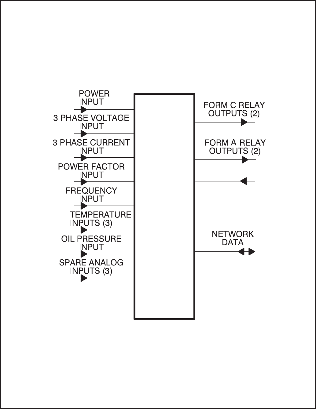
10-2
CCM-
GENSET DISCRETE
INPUTS (32)
FIGURE 10-1. BLOCK DIAGRAM: GENERATOR SET MONITORING MODULE
Redistribution or publication of this document,
by any means, is strictly prohibited.

10-3
TABLE 10-1. CCM – BLOCK DIAGRAM DESCRIPTIONS
Function Description/Specification
Power Input The CCM may be either powered from DC or AC. Local Power Input accepts nominal
voltage of 5–36VDC or 12–24VAC. (Refer to Section 2.)
3 Phase
Voltage Input Directly accepts up to 600 VAC nominal line-to-line. (Direct reading, external PTs to
be used for medium voltage). Can be wired for either delta or wye. Can accept either
3 phase or single phase.
3 Phase
Current Input Directly accepts 0–5 amps AC.
Power Factor
Input Power factor is not a physical input, but is derived from voltage and current inputs.
Frequency
Input Frequency is not a physical input, but is derived from one of the three phase voltage
inputs.
Temperature
Inputs (3) Inputs are set up to either drive RTD senders or just read voltage on existing senders.
Driving an RTD:
These inputs are set up for connection to RTD senders for measuring oil, exhaust, or
coolant temperature. Two of the inputs are switch selectable for connection to either
500–2200 ohm (OIL/WATER Temp) or 80–390 ohm (Exhaust Temp) RTDs. The other
is fixed for 500–2200 ohm only.
Reading an RTD:
If the input is just reading the sender voltage, it can read a range of 0–9VDC.
Oil Pressure
Input Input can provide sender drive if needed.
Input driving the sender:
Intended for use with Kavlico capacitive sensor 0–100 PSIG, 0.5–4.5VDC
Reading only:
The input can read in a range from 0–9VDC.
Spare 1, 2 Accept 0–5V directly or 0–1mA or 4-20 mA signals with addition of an external resistor.
SPARE 3 Accepts input from 0–36VDC.
Form-C Relay
Outputs (2) These relays are used to start/stop the genset, reset faults or other needed control
functions. Contacts are rated 125VAC /0.6A or 30VDC/2A.
Form-A Relay
Outputs (2) Solid state relays used for control. Rated at 100mA, 150VDC/VAC, 50 ohm ON resist-
ance.
Digital
Inputs (32) Used to monitor various status and fault conditions. Inputs are activated through a
contact closure to GND. Inputs 1–24 source 0.5 mA when closed to GND. Inputs
25–32 source 0.05 mA when closed to GND. When the inputs are open, voltage at the
CCM input terminals is less than 5Vdc.
Network Data Transformer coupled into Category 4 twisted pair at 78,000 bits/sec.
Redistribution or publication of this document,
by any means, is strictly prohibited.
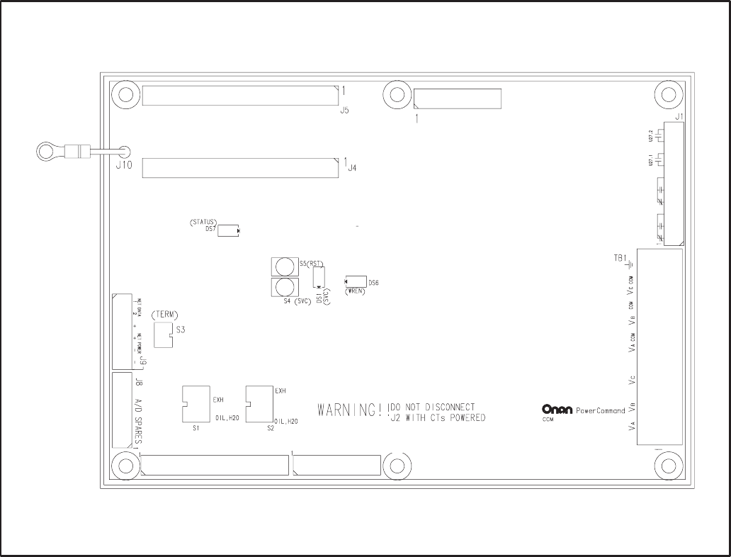
10-4
LOCATION
Mount the CCM control box as close as possible to
the genset so the wire size can be kept to a mini-
mum.
The CCM is preassembled inside an enclosure that
is designed for wall mounting. Choose a clean,
vibration-free mounting surface near the genset.
Avoid locations that are hot, damp or dusty. The
temperature range must not exceed –40°F (–40°C)
to 158°F (70°C).
Refer to Section 2 for network topology and maxi-
mum network length.
DISCRETE INPUTS (17–32)
DISCRETE INPUTS (1–16)
J6 ANALOG GROUND
RELAYS
3-PHASE VOLTAGES
J3 TEMP & OIL INPUTS J2 3-PHASE CURRENT INPUTS
FIGURE 10-2. CONTROLS COMMUNICATION MODULE (CCM)
Redistribution or publication of this document,
by any means, is strictly prohibited.
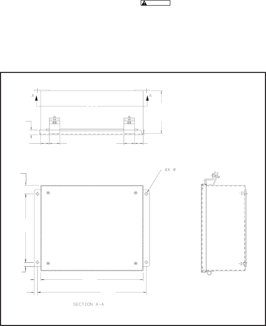
10-5
CCM CONTROL BOX MOUNTING
Figure 10-3 shows the CCM control box outline di-
mensions. The outside dimensions do not include
clearance for wire connections (dependant on con-
duit size and routing). When the mounting location
and wire routing are determined (see Wiring Con-
nections section), make holes in the control box for
AC, DC, and data wire routing. Be careful not to
damage the CCM module. Remove the CCM if dril-
ling is required. If the CCM is removed during
mounting, make sure the ground lead is recon-
nected to the mounting stud when reinstalling the
CCM.
Installation debris can cause equip-
ment failure and damage. Use extreme care to
keep drill chips and filings out of the CCM con-
trol box. Use tools carefully to prevent damage
to components.
Make sure that no wires, plumbing, gas or exhaust
lines run behind the wall before drilling the mounting
holes.
! *(
* #$$'
#+/'
+
#/'
+
#+>'
+
#+>'
+
#/'
#+>'
+
#>'
+
#/='
+>
#='
+
#/'
=
#'
>
#+'
#+>'
=
#'
FIGURE 10-3. CCM CONTROL BOX MOUNTING
Redistribution or publication of this document,
by any means, is strictly prohibited.

10-6
WIRE AND CONDUIT
Measure the distance, one way, between the CCM
mounting location and the genset control. Refer to
the wire size chart in Figure E-13 (in Appendix D) to
determine the appropriate wire gauge for CT wires,
power supply wires and monitor and control wires
(see Table 10-2 for additional CT wire information).
Use stranded wire with a minimum insulation rating
of 600V and a temperature rating of 105°C.
Run one conduit for the AC wire connections and a
second conduit for the DC wire connections be-
tween the CCM and the genset control box. The
data wire does not require conduit unless mechani-
cal protection is desired. The data wire can be
strapped to the outside of the DC conduit and be run
into the control box through a rubber grommet.
Make sure wiring meets all applicable wiring codes.
Install at least 2 feet (610 mm) of flexible conduit on
both lines at the genset control box connection to al-
low for genset vibration during operation. Round off
or cover the ends of the conduit to prevent sharp
edges from cutting the insulation. Use waterproof
conduit if the CCM will be exposed to moisture.
The number of leads pulled through each conduit
will be determined by the type of genset control and
the desired monitor and control features selected.
Refer to the table in Figure E-14 for a list of the pos-
sible AC and DC connections. Number both ends of
each lead for identification before pulling the wire
through the conduit.
Grounding must comply with all codes. Mount the
enclosed ground lug inside the mounting box (refer
to the instructions provided with the lug). Make sure
the paint is removed from the ground lug mounting
location to provide a good ground.
WIRING CONNECTIONS
This section describes connecting the CCM to a
genset with a Detector or DK type of control. Fig-
ures E-13 and E-14 show the interconnect wiring
diagram specifically for the CCM to Detector or DK
control. (Figures E-13 and E-14 apply to both 7-light
and 12-light Detector controls. Connections for Low
Fuel, Low Engine Temp, Fault1 and Fault2 are not
available from the 7-light control.)
Figures E-4 and E-5 provide basic CCM intercon-
nect wiring diagram information, review the notes
on figures E-4 and E-5 and use these drawings for
reference.
Accidental starting of the generator
set while working on it can cause severe injury
or death. Disconnect the battery cables to pre-
vent accidental starting. Be sure to move the
generator set operation selector switch to Stop,
disconnect the battery charger, disconnect the
starting battery (negative [–] lead first).
Ignition of explosive battery gases
can cause severe personal injury. Do not smoke
or cause any spark or flame while servicing bat-
teries.
Always disconnect a battery char-
ger from its AC source before disconnecting the
battery cables. Otherwise, disconnecting the
cables can result in voltage spikes high enough
to damage the DC control circuits of the genera-
tor set.
1. Before making any wiring connections, make
sure the genset cannot be started by moving
the RUN/STOP/REMOTE switch to STOP.
Disconnect the power to the battery charger
and disconnect the starting battery (negative
[–] battery cable[s] first).
Redistribution or publication of this document,
by any means, is strictly prohibited.
10-7
2. Refer to Figures E-13 and E-14 for point-to-
point wiring information and component and
terminal locations. Follow standard wiring
practices. Properly secure wire terminals when
needed. Secure wires in the CCM terminal
blocks to 2 in-lbs. (0.23 NSm). Observe wire
gauge requirements for CT wires, power sup-
ply wires and monitor and control wires.
3. The table in Figure E-13 identifies the DC and
AC connections. The DC leads must be run in-
side a separate conduit from the AC leads.
It may be easiest to start at the top of the table
with the DC connections and make all the con-
nections inside the CCM control box. Then
move to the genset control to complete the wir-
ing. Make sure that each lead is marked and
pay close attention to the associated notes in
the wiring table. Some connections are for
jumpers inside the CCM only.
4. When making connections inside the genset
control box, provide enough wire so that the
leads can be secured to the existing harness.
Leads that connect to components on the con-
trol panel door should be routed near the
hinges and be secured to the existing leads.
5. Connect the data wire to the CCM and provide
an adequate length of twisted pair wire for fu-
ture connection to a junction box. Tighten the
tamperproof control box mounting screws se-
curely to prevent tampering.
6. The module is now ready for network wiring.
Network wiring must be done by a trained net-
work installer. Refer to sections 2, 3 and 4 for
instructions on network wiring the CCM and for
installation and connection of this module to
the network.
7. When the network installation is complete, re-
connect battery (negative [–] battery cable[s]
last), reconnect battery charger and return the
generator control switch to the Remote posi-
tion.
Redistribution or publication of this document,
by any means, is strictly prohibited.

10-8
TABLE 10-2. CT WIRE SIZE VS. DISTANCE
MAXIMUM DISTANCE BETWEEN CCM AND CT’S
IN FEET (M)
BLANK ROWS INDICATE THAT A CT KIT IS REQUIRED
CONTACT YOUR AUTHORIZED PARTS DISTRIBUTOR
CT Number Application Ratio #12 AWG #14 AWG #16 AWG
FEET (M) FEET (M) FEET (M)
302–1984–02 Genset(DK) 25/5
302–1984–02 Genset(DK) 50/5
302–1984–03 Genset(DK) 100/5
302–1984–03 Genset(DK) 50/5
302–1984–04 Genset(DK) 150/5
302–1984–04 Genset(DK) 75/5
302–1984–05 Genset(DK) 100/5
302–1984–05 Genset(DK) 200/5
302–1868–01 Genset(DG) 25/5
302–1868–01 Genset(DG) 50/5
302–1868–02 Genset(DG) 100/5
302–1868–02 Genset(DG) 50/5
302–1868–03 Genset(DG) 150/5
302–1868–03 Genset(DG) 75/5
302–1868–04 Genset(DG) 100/5
302–1868–04 Genset(DG) 200/5
302–1868–05 Genset(DG) 150/5
302–1868–05 Genset(DG) 300/5
302–1868–06 Genset(DG) 200/5
302–1868–06 Genset(DG) 400/5
302–1868–07 Genset(DG) 250/5
302–1868–07 Genset(DG) 500/5
302–1868–08 Genset(DG) 375/5 35 (10.7) 22 (6.7) 14 (4.1)
302–1868–08 Genset(DG) 750/5 72 (22.1) 45 (13.7) 28 (8.6)
302–1868–09 Genset(DG) 400/5 35 (10.7) 22 (6.7) 14 (4.1)
302–1868–09 Genset(DG) 800/5 79 (24) 49 (14.9) 31 (9.3)
302–1868–10 Genset(DG) 1000/5 104 (31.6) 64 (19.6) 40 (12.3)
302–1868–10 Genset(DG) 500/5 41 (12.5) 26 (7.8) 16 (4.9)
302–1868–11 Genset(DG) 1200/5 129 (39.2) 80 (24.3) 50 (15.3)
302–1868–11 Genset(DG) 600/5 54 (16.3) 33 (10.1) 21 (6.4)
302–1868–12 Genset(DG) 1500/5 166 (50.6) 103 (31.4) 65 (19.7)
302–1868–12 Genset(DG) 750/5 79 (24) 49 (14.9) 31 (9.3)
302–1794–01 Genset(DF) 150/5
302–1794–01 Genset(DF) 75/5
302–1794–02 Genset(DF) 100/5
Redistribution or publication of this document,
by any means, is strictly prohibited.

10-9
TABLE 10-2. CT WIRE SIZE VS. DISTANCE (Continued)
MAXIMUM DISTANCE BETWEEN CCM AND CT’S
IN FEET (M)
BLANK ROWS INDICATE THAT A CT KIT IS REQUIRED
CONTACT YOUR AUTHORIZED PARTS DISTRIBUTOR
CT Number Application Ratio #12 AWG #14 AWG #16 AWG
FEET (M) FEET (M) FEET (M)
302–1794–02 Genset(DF) 200/5
302–1794–03 Genset(DF) 150/5
302–1794–03 Genset(DF) 300/5
302–1794–04 Genset(DF) 200/5 41 (12.5) 26 (7.8) 16 (4.9)
302–1794–04 Genset(DF) 400/5 104 (31.5) 64 (19.6) 40 (12.3)
302–1794–05 Genset(DF) 250/5 54 (16.3) 33 (10.1) 21 (6.4)
302–1794–05 Genset(DF) 500/5 135 (41.1) 84 (25.5) 53 (16)
302–1794–06 Genset(DF) 300/5 54 (16.3) 33 (10.1) 21 (6.4)
302–1794–06 Genset(DF) 600/5 135 (41.1) 84 (25.5) 53 (16)
302–1794–07 Genset(DF) 375/5 54 (16.3) 33 (10.1) 21 (6.4)
302–1794–07 Genset(DF) 750/5 135 (41.1) 84 (25.5) 53 (16)
302–1794–08 Genset(DF) 400/5 104 (31.5) 64 (19.6) 40 (12.3)
302–1794–08 Genset(DF) 800/5 228 (69.6) 142 (43.2) 89 (27.2)
302–1794–09 Genset(DF) 1000/5 291 (88.6) 181 (55) 114 (34.6)
302–1794–09 Genset(DF) 500/5 135 (41.1) 84 (25.5) 53 (16)
302–1794–10 Genset(DF) 600/5 135 (41.1) 84 (25.5) 53 (16)
302–1794–10 Genset(DF) 1200/5 291 (88.6) 181 (55) 114 (34.6)
302–1794–11 Genset(DF) 750/5 135 (41.1) 84 (25.5) 53 (16)
302–1794–11 Genset(DF) 1500/5 291 (88.6) 181 (55) 114 (34.6)
302–1794–12 Genset(DF) 1000/5 291 (88.6) 181 (55) 114 (34.6)
302–1794–12 Genset(DF) 2000/5 353 (107.5) 219 (66.7) 138 (42)
302–1794–13 Genset(DF) 1500/5 291 (88.6) 181 (55) 114 (34.6)
302–1794–13 Genset(DF) 3000/5 353 (107.5) 219 (66.7) 138 (42)
302–1794–14 Genset(DF) 2000/5 291 (88.6) 181 (55) 114 (34.6)
302–1794–14 Genset(DF) 4000/5 603 (183.7) 374 (113.9) 236 (71.9)
302–1794–15 Genset(DF) 3000/5 291 (88.6) 181 (55) 114 (34.6)
302–1794–15 Genset(DF) 6000/5 603 (183.7) 374 (113.9) 236 (71.9)
302–1417 Genset(ES) 150/5
302–1845–XX is the same as 302–1868–XX (Example: 302–1845–02 refer to 302–1868–02 row for distances)
NOTES: 1. This table is for copper wire at 50°C (122°F). Derate the distance by 0.4% per °C over 50°C.
2. Minimum wire gauge for NEC compliance is AWG 14
Redistribution or publication of this document,
by any means, is strictly prohibited.

10-10
NETWORK TOPOLOGY, DATA MEDIA AND
NETWORK POWER
Refer to Section 2 for information on the network to-
pology and data transmission media. Also refer to
Section 2 for network power supply wiring calcula-
tion procedures.
NETWORK DATA MEDIA
AND POWER WIRING
AC voltages and currents present
an electrical shock hazard that can cause se-
vere personal injury or death. Only trained, ex-
perienced personnel are to perform the follow-
ing procedures.
Connections
Network data and power wiring connections are
made at connector J9.
Conduit
When installing conduit, observe the following pre-
cautions:
1. Before beginning conduit installation, cover all
components to prevent accidental entry of met-
al chips.
2. If using rigid conduit, install at least 2 feet (610
mm) of flexible conduit between the rigid con-
duit and generator set to absorb vibration.
3. Always run DC circuit wiring in a separate met-
al conduit from AC power cables to avoid in-
ducing currents that could cause problems
within the control.
4. Data wire can be run without conduit if it is ade-
quately protected. Do not run data wire in con-
duit with network power wiring or other non-
power–limited circuits. Make sure wiring meets
all applicable wiring codes.
Installation debris can cause
equipment failure and damage. Use ex-
treme care to keep drill chips and filings out
of the components when mounting or con-
necting conduit. Screwdrivers should be
used carefully to prevent damage to com-
ponents.
NETWORK INSTALLATION
Sections 3 and 4 provide a detailed description of
the network installation process. Read sections 1
and 2, before constructing the network. Sections 3
and 4 provide the following step-by-step installation
procedures:
1. Setting up Network Installation Tools
2. Starting LonMaker Software
3. Using LonMaker Software
4. LonMaker Network Setup
5. Connecting Devices with LonMaker
6. Installing Devices with LonMaker
7. Testing Devices and Verifying Installation
8. Setting up PowerCommand Configuration Tool
9. Using PowerCommand Configuration Tool
Redistribution or publication of this document,
by any means, is strictly prohibited.

10-11
SWITCHES AND LEDs
The Service switch (S4) is used during installation
(when prompted by the LonMaker program). The
Terminator switch (S3) must be set to the appropri-
ate position at installation. Switches are described
in Table 10-3.
LEDs are described in Table 10-4.
TABLE 10-3. CCM SWITCHES
Ref Name Type Description
S4 SERVICE momentary
push Used at time of logical installation to identify device to the instal-
lation software. Pressing S4 will light the DS1 LED.
S5 RESET momentary
push Resets the Neuron Chip processor. Must be pressed after Install
action.
S3 TERMINATOR slide Switch is set to position opposite of text “TERM” from factory.
The two devices at ends of network data must have their
switches set to “TERM”.
S1 TEMP#2
SELECT slide When the input is driving the sender, selects whether tempera-
ture input#2 RTD is 500–2200 ohm or 80–390 ohm. Set to
“OIL/H2O” for 500–2200 ohm. Set to “EXH” for 80–390 ohm.
S2 TEMP#3
SELECT slide When the input is driving the sender, selects whether tempera-
ture input#3 RTD is 500–2200 ohm or 80–390 ohm. Set to
”OIL/H2O” for 500–2200 ohm. Set to “EXH” for 80–390 ohm.
TABLE 10-4. CCM LED INDICATORS
Ref Color Name Description
DS1 Amber SERVICE Indicates various states of the CCM node. It will be ON if S1 is pressed
and held. States without S1 pressed:
OFF = All OK. CCM has application image and is installed in a network.
ON= CCM is applicationless or has experienced a error which prevents
Neuron Chip from executing application code.
1/2 Hz BLINKING (1 second on / 1 second off) =CCM has an applica-
tion, but has not been logically installed in a network.
FLASHING (momentarily) once every 2–3 seconds=CCM is experienc-
ing an error condition causing a watchdog timeout reset.
DS6 Green WREN ON (normal state) indicates that the off–chip EEPROM can be written to.
Indicator must be ON if device is to be logically installed in a network.
OFF could be caused by: 1)CCM’s power input is below 10VDC. 2)RE-
SET switch being pressed and held. 3)problem with board or connectors.
DS7 Green STATUS 1/2 Hz BLINKING (1 second on / 1 second off) to indicate that the
CCM’s processor is executing the application code. In the future, may
be used to indicate other conditions for troubleshooting purposes.
Redistribution or publication of this document,
by any means, is strictly prohibited.

10-12
NETWORK VARIABLES
Table 10-5 shows the correlation between actual in-
puts and outputs for the CCM and the CCM’s con-
nectable network variables based on CCM-Genset
Interconnect Drawing Figures E-13 and E-14 (lo-
cated in Appendix E).
Refer to the connectable network variable outputs
in Tables 10-6 and 10-7 and the connectable net-
work variable inputs in Table 10-8 during the logical
installation of CCM on the network.
TABLE 10-5. ACTUAL INPUTS AND OUTPUTS FOR THE CCM
Signal CCM Network Variable Options Required
Name Active State
DISCRETE INPUTS
Common Alarm nvoCustInput[17] Open (0) standard
Low Fuel nvoCustInput[18] Closed (1) not available on Detector-7 Lite
Low Engine Temperature nvoCustInput[19] Closed (1) not available on Detector-7 Lite
Fault2 (Customer) nvoCustInput[20] Closed (1) not available on Detector-7 Lite
Fault1 (Customer) nvoCustInput[21] Closed (1) not available on Detector-7 Lite
Overcrank nvoCustInput[22] Closed (1) standard
Overspeed nvoCustInput[23] Closed (1) standard
High Engine Temperature nvoCustInput[24] Closed (1) standard
Low Oil Pressure nvoCustInput[25] Closed (1) standard
Pre–High Engine Temperature nvoCustInput[26] Closed (1) standard
Pre–Low Oil Pressure nvoCustInput[27] Closed (1) standard
Genset Running nvoCustInput[28] Closed (1) standard
Switch in Off nvoCustInput[29] Open (0) standard
RELAY OUTPUTS
Remote Start nviRelayControl1 standard
Remote Reset/Lamp Test nviRelayControl2 standard
Notes for PowerCommand Configuration Tool (Section 4):
1. Set the active state as indicated in the table.
2. Coolant Temperature Sensor: Gain = –34.5 degF/V
3. Oil Pressure Sensor: Gain = –36.0 psi/V
4. Battery Voltage: Voltage = 24, Reading = 24, Gain = 1
Redistribution or publication of this document,
by any means, is strictly prohibited.

10-13
TABLE 10-6. CCM NETWORK VARIABLE OUTPUTS
NV Name Description Used By Data Type Info Active Stat
e
Default
Value(s)
NV Name
Description
Used By
Data Type Info
Active State
Default
Value(s)
nvoCustInput[0..32] Da network variable array of
digital values representing the
state of the corresponding
physical discrete input
Dthe active state is configured
with PCT
Donly 1 thru 32 are used (0 is
not used)
DNet
Connect array: (1 BYTE EACH)
Data Range
nvoCustInput[0] not used
nvoCustInput[1] 0,1
nvoCustInput[2] 0,1
nvoCustInput[3] 0,1
nvoCustInput[4] 0,1
nvoCustInput[5] 0,1
nvoCustInput[6] 0,1
nvoCustInput[7] 0,1
nvoCustInput[8] 0,1
nvoCustInput[9] 0,1
nvoCustInput[10] 0,1
nvoCustInput[11] 0,1
nvoCustInput[12] 0,1
nvoCustInput[13] 0,1
nvoCustInput[14] 0,1
nvoCustInput[15] 0,1
nvoCustInput[16] 0,1
nvoCustInput[17] 0,1
nvoCustInput[18] 0,1
nvoCustInput[19] 0,1
nvoCustInput[20] 0,1
nvoCustInput[21] 0,1
nvoCustInput[22] 0,1
nvoCustInput[23] 0,1
nvoCustInput[24] 0,1
nvoCustInput[25] 0,1
nvoCustInput[26] 0,1
nvoCustInput[27] 0,1
nvoCustInput[28] 0,1
nvoCustInput[29] 0,1
nvoCustInput[30] 0,1
nvoCustInput[31] 0,1
nvoCustInput[32] 0,1
each array
element:
1=active
0=inactive
Active state
of the
Customer
Input is set
by PCT
Redistribution or publication of this document,
by any means, is strictly prohibited.

10-14
TABLE 10-7. CCM NETWORK VARIABLE OUTPUTS – Continued
NV Name Description Used By Data Type Info Active Stat
e
Default
Value(s)
NV Name
Description
Used By
Data Type Info
Active State
Default
Value(s)
nvoCustIn1_16 D16 bit value containing status
of Customer Inputs 1 thru 16
Dintended to be connected to a
DIM or NAM
DNet
Connect 16 bits (long):(2 BYTES)
Data Range
nvoCustIn1_16 0..65535
bit 0 = Input 1
bit 1 = Input 2
etc...
1
1
...
nvoCustIn17_32 D16 bit value containing status
of Customer Inputs 17 thru 32
Dintended to be connected to a
DIM or NAM
DNet
Connect 16 bits (long):(2 BYTES)
Data Range
nvoCustIn17_32 0..65535
bit 0 = Input 17
bit 1 = Input 18
etc...
1
1
...
nvoRelayState1 DBoolean value indicating the
state of Relay #1
DNet
Connect 1 bit (boolean): (1 BYTE)
Data Range
nvoRelayState1 0,1 1=relay
energized
nvoRelayState2 DBoolean value indicating the
state of Relay #2
DNet
Connect 1 bit (boolean): (1 BYTE)
Data Range
nvoRelayState2 0,1 1=relay
energized
nvoRelayState3 DBoolean value indicating the
state of Relay #3
DNet
Connect 1 bit (boolean): (1 BYTE)
Data Range
nvoRelayState3 0,1 1=relay
energized
nvoRelayState4 DBoolean value indicating the
state of Relay #4
DNet
Connect 1 bit (boolean): (1 BYTE)
Data Range
nvoRelayState4 0,1 1=relay
energized
Redistribution or publication of this document,
by any means, is strictly prohibited.

10-15
TABLE 10-8. CCM NETWORK VARIABLE INPUTS
NV Name Description Used By Data Type Info Active
State
Default
Value(s)
NV Name
Description
Used By
Data Type Info
Active
State
Default
Value(s)
nviRelayControl1 DBoolean value used to directly
control relay#1
DNet
Connect
DPCW
1 bit (boolean): (1 BYTE)
Data Range
nviRelayControl1 0,1 1=energize
the relay
0
nviRelayControl2 DBoolean value used to directly
control relay#2
DNet
Connect
DPCW
1 bit (boolean): (1 BYTE)
Data Range
nviRelayControl2 0,1 1=energize
the relay
0
nviRelayControl3 DBoolean value used to directly
control relay#3
DNet
Connect
DPCW
1 bit (boolean): (1 BYTE)
Data Range
nviRelayControl3 0,1 1=energize
the relay
0
nviRelayControl4 DBoolean value used to directly
control relay#4
DNet
Connect
DPCW
1 bit (boolean): (1 BYTE)
Data Range
nviRelayControl4 0,1 1=energize
the relay
0
Redistribution or publication of this document,
by any means, is strictly prohibited.
10-16
Redistribution or publication of this document,
by any means, is strictly prohibited.

11-1
33 (!=
OVERVIEW
This section describes the Controls Communica-
tions Module (CCM) used for monitor and control in
automatic transfer switch applications (CCM-ATS).
This section describes the physical mounting and
wiring of this module, and provides procedures for
the logical installation and connection of the CCM-
ATS on the network.
In network terms, “logical installation and connec-
tion” refers to programming the various devices (or
nodes) on the network so that they can communi-
cate with one another. This communication takes
the form of passing network variables from one de-
vice to another. The process of assigning connec-
tions—linking an output variable of one device to an
an input variable of another device—is called “bind-
ing.” Refer to Appendix C for Application Table Con-
sumption to review the number of connections that
can be made.
In addition to functional and physical descriptions,
this section provides definitions of the network in-
put and output variables assigned to the CCM-ATS.
DESCRIPTION
The CCM-ATS can be used to monitor and control a
transfer switch. It provides a PowerCommand
Network interface for remote monitoring and con-
trol. The relay outputs of the CCM provide control of
the transfer switch from the network.
The CCM contains a terminate circuit for use at the
end of a network data bus.
CCM Inputs
The CCM has 16 channels of analog input and 32
digital inputs (refer to Figures E-4 and E-5 in Appen-
dix E).
Most of the analog channels are configured for spe-
cific types of signals (AC volts, current, power fac-
tor, oil temp, oil pressure, coolant temp, exhaust
temp, etc). The spare analog inputs are for signal
monitoring (4-20 mA, 0-1 mA, 0-5V). The three tem-
perature inputs and the oil pressure input can be
used generically with any sensor that provides be-
tween 0-9 VDC.
The 32 discrete inputs permit monitoring of numer-
ous status/fault conditions. These inputs must be
referenced back to either analog ground (J6) or net
power negative (–) through dry contacts or through
a pulldown resistor when active “OPEN” input is +5
to +36 VDC (see notes 6 and 17 in Figure E-5).
The values of the analog and discrete inputs are
read from the network.
CCM Outputs
The CCM has two Form-C relay outputs, and two
Form-A relay outputs. The relays are controlled
from the network and are used to transmit Remote
Test, Transfer Inhibit, and Load Shed control sig-
nals.
External devices that are wired to these relays
should be fused appropriately to prevent dam-
age to the CCM.
CCM Power Supply
The CCM power supply consists of a sealed 12-volt
battery and a battery charger. These parts are in-
cluded in the kit and are located inside the CCM
control box. A separate 120 VAC source is needed
to power the battery charger. If a utility outlet is not
available, a transformer kit is available for obtaining
120 VAC from the ATS.
The battery should be replaced every two years.
Make a note in the Maintenance section of the ATS
Operator’s Manual, or add this information to a
master maintenance schedule for the facility. Main-
tain power to the circuit during battery replacement
by connecting the new battery in parallel with the
power supply circuit, then disconnect the old bat-
tery. If a low battery condition is being monitored,
this will prevent a low battery alarm signal.
Standard Displays
Solid state indicators are provided to aid in diagno-
sis of module operating status. These include a ser-
vice LED for the Neuron chip, a running LED on the
main processor.
Block Diagram
Refer to Table 11-1 and Figure 11-1 for a block dia-
gram overview of the CCM-ATS.
Redistribution or publication of this document,
by any means, is strictly prohibited.
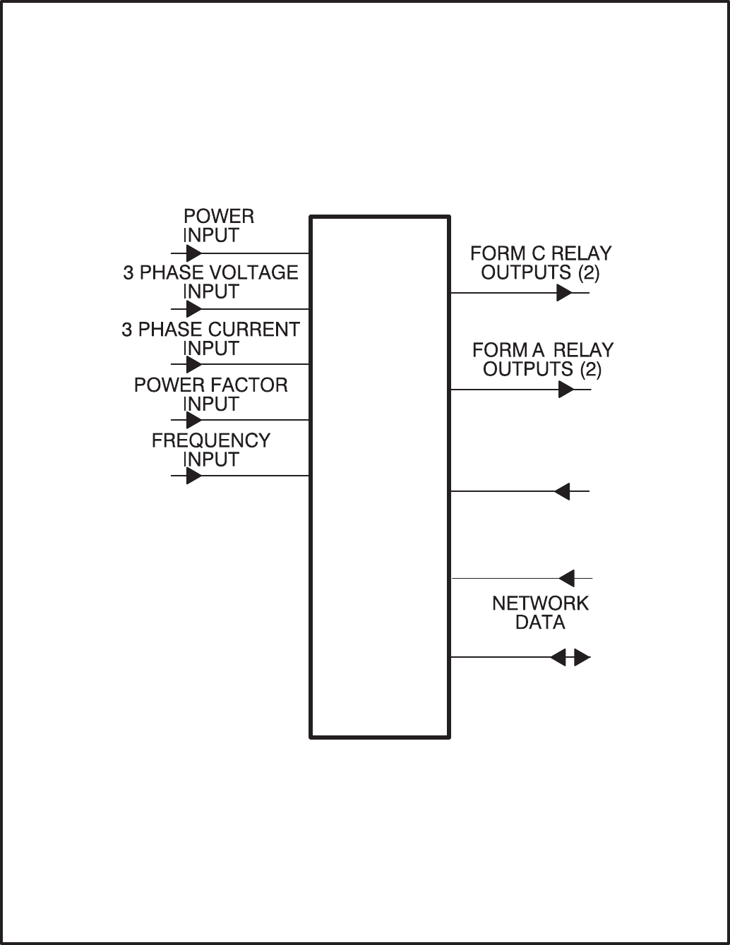
11-2
CCM-ATS DISCRETE
INPUTS (32)
ANALOG
INPUTS (7)
FIGURE 11-1. BLOCK DIAGRAM: CCM-ATS
Redistribution or publication of this document,
by any means, is strictly prohibited.

11-3
TABLE 11-1. CCM-ATS – BLOCK DIAGRAM DESCRIPTIONS
Function Description/Specification
Power Input The CCM may be either powered from DC or AC. Local Power Input accepts nominal
voltage of 5–36VDC or 12–24VAC. (Refer to Section 2.)
3 Phase
Voltage Input Directly accepts up to 600 VAC nominal line-to-line. (Direct reading, external PTs to
be used for medium voltage). Can be wired for either delta or wye. Can accept either
3 phase or single phase.
3 Phase
Current Input Directly accepts 0–5 amps AC.
Power Factor
Input Power factor is not a physical input, but is derived from voltage and current inputs.
Frequency
Input Frequency is not a physical input, but is derived from one of the three phase Voltage
inputs.
Form-C Relay
Outputs (2) These relays are used to start/stop the genset, reset faults or other needed control
functions. Contacts are rated 125VAC /0.6A or 30VDC/2A.
Form-A Relay
Outputs (2) Solid state relays used for control. Rated at 100mA, 150VDC/VAC, 50 ohm ON resist-
ance.
Discrete
Inputs (32) Used to monitor various status and fault conditions. Inputs are activated through a
contact closure to GND. Inputs 1–24 source 0.5mA when closed to GND. Inputs
25–32 source 0.05mA when closed to GND. When the inputs are open, voltage at the
CCM input terminals is less than 5Vdc.
Spare 3 Accepts input from 0 – 36VDC. Battery voltage monitor.
Network Data Transformer coupled into Category 4 twisted pair at 78,000 bits/sec.
Redistribution or publication of this document,
by any means, is strictly prohibited.
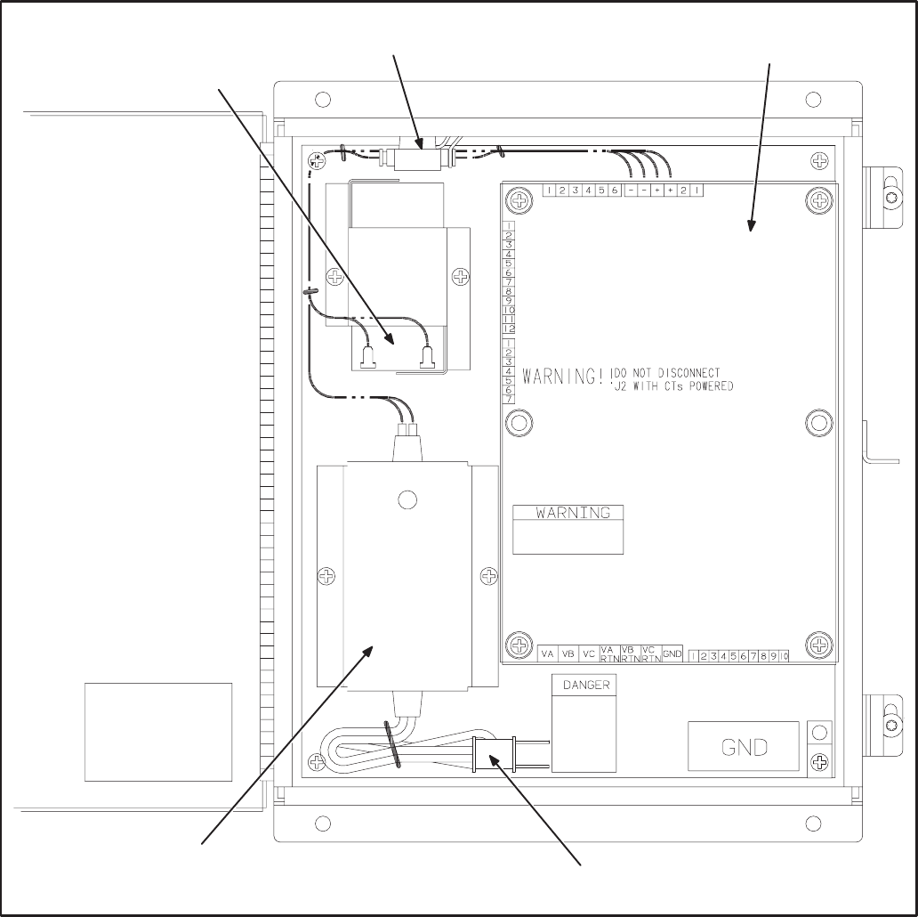
11-4
LOCATION
Mount the CCM control box as close to the ATS as
possible so the wire size can be kept to a minimum.
The CCM is preassembled inside an enclosure that
is designed for wall mounting. Choose a clean,
vibration-free mounting surface near the transfer
switch. Avoid locations that are hot, damp or dusty.
The temperature range must not exceed –40°F
(–40°C) to 158°F (70°C).
Refer to Section 2 for network topology and maxi-
mum network length.
"
!"
4
+5"
*
+5 ( !
..=
.
.
.+
+
FIGURE 11-2. CONTROLS COMMUNICATION MODULE FOR ATS APPLICATIONS
Redistribution or publication of this document,
by any means, is strictly prohibited.
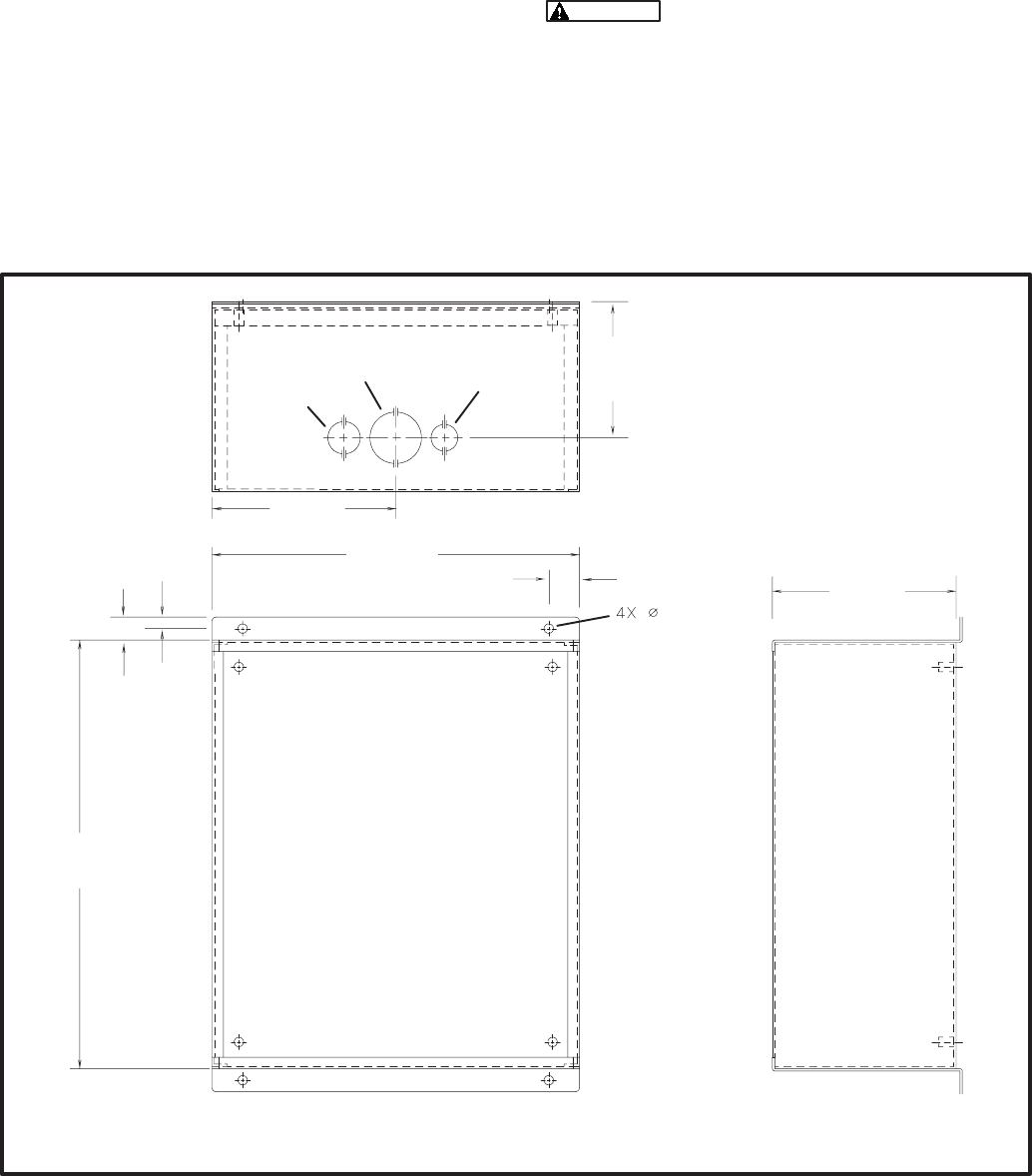
11-5
CCM CONTROL BOX MOUNTING
Figure 11-3 shows the CCM control box outline di-
mensions. The outside dimensions do not include
clearance for wire connections. When the mounting
location and wire routing are determined (see Wir-
ing Connections section), make holes in the control
box for AC, DC, and data wire routing. A separate
connection will be needed for powering the battery
charger inside the CCM control box if it is run from a
utility outlet. Be careful not to damage the CCM
module. If the CCM is removed during mounting,
make sure the ground lead is reconnected to the
mounting stud when reinstalling the CCM.
Installation debris can cause equip-
ment failure and damage. Use extreme care to
keep drill chips and filings out of the CCM con-
trol box. Use tools carefully to prevent damage
to components.
Make sure that no wires, plumbing, gas or exhaust
lines run behind the wall before drilling the mounting
holes.
! *(
* #$$'
+
#/' +
#>'
+
#/='
#+/'
>
#+'
=
#'
+/
#'
/
#'
3/ )
+ +3/ ) +3 )
#+/'
FIGURE 11-3. CCM CONTROL BOX MOUNTING
Redistribution or publication of this document,
by any means, is strictly prohibited.

11-6
WIRE AND CONDUIT
Measure the wiring distance, one way, between the
CCM mounting location and the ATS connection
points. Refer to notes 7 and 8 in Figure E-9 to deter-
mine the appropriate wire gauge for CT, monitor
and control wires (see Table 11-2 for additional CT
wire information). Use stranded wire with a mini-
mum insulation rating of 600V and a temperature
rating of 105°C.
Run one conduit for the AC wire connections and a
second conduit for the DC wire connections be-
tween the CCM and the ATS. Round off or cover the
ends of the conduit to prevent sharp edges from cut-
ting the insulation. Use waterproof conduit if the
CCM installation will be exposed to moisture. The
data wire does not require conduit unless mechani-
cal protection is desired. The data wire can be
strapped to the outside of the DC conduit and be run
into the control box through a rubber grommet.
Make sure wiring meets all applicable wiring codes.
The number of leads pulled through each conduit
will be determined by the features available on the
ATS and the desired monitor and control features
selected. Refer to Figures E-9 thru E-12 for a list of
the possible AC and DC connections. Number both
ends of each lead for identification before pulling
the wire through the conduit.
Grounding must comply with all codes. Use the
ground lug located inside the CCM control box.
PREPARE CCM POWER SUPPLY
A separate 120 VAC source is needed to power the
battery charger. If a utility outlet is not available, a kit
is available for obtaining the voltage from the ATS.
1. Install the enclosed 3-amp fuse in the location
as shown in Figure 11-2. An arc may occur
when the fuse is installed, this is normal.
2. If a 120 VAC outlet is available for the charger,
make a hole in the control housing and route
the power cord to the outlet.
If a power source is not available, refer to the
instructions in the transformer kit.
WIRING CONNECTIONS
Figures E-9 thru E-12 show the interconnect wiring
diagram for connecting the ATS to the CCM. Refer
to the notes on these drawings. Figures E-4 and E-5
provide basic CCM interconnect wiring diagram in-
formation. Review the notes on these drawings and
use these drawings for reference. Follow standard
wiring practices. Properly secure wire terminals
when needed. Secure wires in the CCM terminal
blocks to 2 in-lbs. (0.23 NSm).
The transfer switch presents a
shock hazard that can cause severe personal
injury or death unless all AC power is removed.
Disconnect both the Normal and the Emergency
power sources from the transfer switch. Be sure
to move the generator set operation selector
switch to Stop, disconnect the battery charger,
disconnect the starting battery (negative [–]
lead first), and disconnect AC line power before
beginning the installation.
Ignition of explosive battery gases
can cause severe personal injury. Do not smoke
or cause any spark or flame while servicing bat-
teries.
Always disconnect a battery char-
ger from its AC source before disconnecting the
battery cables. Otherwise, disconnecting the
cables can result in voltage spikes high enough
to damage the DC control circuits of the genera-
tor set.
1. Disconnect both the Normal and the Emergen-
cy power sources from the transfer switch.
2. If a generator set provides Emergency power,
make sure that the generator set cannot be
started by moving the selector switch to Stop.
The selector switch is located on the generator
set control panel on two-wire start systems and
inside the transfer switch cabinet door on
three-wire start systems. If there is an external
battery charger, disconnect it from its AC power
source. Then disconnect the set starting bat-
tery(ies) (negative [–] lead first).
3 Remove the accessory panel cover on the
back of the cabinet door.
Redistribution or publication of this document,
by any means, is strictly prohibited.
11-7
4. Refer to the interconnect wiring diagrams (Fig-
ures E-9 thru E-12). Note that Figure E-9 is for
switches without meters and Figure E-10 is for
switches with meters. Locate the wiring ter-
mination points inside the transfer switch. Iden-
tify which installed options are available for
monitoring and control.
5. Refer to the outline drawing provided with the
transfer switch to locate and make knockouts
for the wire routing to the CCM. Plan the wire
routing so the monitor and control leads from
the CCM follow the existing harness leads.
Provide adequate wire protection at the knock-
out. Follow standard wiring practices. Wiring
must meet all applicable codes.
6. Observe minimum wire gauge requirements
for CT, monitor and control wiring. Connect the
monitor and control wires to the locations
shown in Figures E-9 and E-10. Provide
enough wire so that the leads can be secured
to the existing harness.
The CT wiring shown in Figure E-9 is for trans-
fer switches that do not have meters. If monitor-
ing features that require CTs (i.e. current, pow-
er factor, etc.), a separate CT kit is required.
7. Position and secure the accessory panel cover.
8. Close and lock the cabinet door.
9. Connect the data wire to the CCM and provide
an adequate length of twisted pair wire for fu-
ture connection to a junction box or other net-
work module. Tighten the tamper-proof control
box mounting screws securely to prevent tam-
pering.
10. Connect the normal AC power source, connect
the genset starting battery(ies) (negative [–]
lead last), and return the genset control switch
to the Remote position. Connect the battery
charger, if applicable.
11. The CCM is now ready for network wiring. Net-
work wiring must be done by a trained network
installer. Refer to sections 2 and 3 for instruc-
tions on network wiring the CCM and for instal-
lation and connection of this module to the net-
work.
Redistribution or publication of this document,
by any means, is strictly prohibited.

11-8
TABLE 11-2. CT WIRE SIZE Vs. DISTANCE CHART
CURRENT CT
MAXIMUM DISTANCE BETWEEN CT AND CCM
BLANK ROWS INDICATE THAT A CT KIT IS REQUIRED
CONTACT YOUR AUTHORIZED PARTS DISTRIBUTOR
CT LIST RATIO AWG 12 AWG 14 AWG 16
FEET (M) FEET (M) FEET (M)
302–0209 250/5
302–1392 150/5
302–1393 300/5
302–1394 400/5 41 (12.5) 26 (7.9) 16 (4.9)
302–1395 750/5 41 (12.5) 26 (7.9) 16 (4.9)
302–1396 1000/5 41 (12.5) 26 (7.9) 16 (4.9)
302–1809 500/5 291 (88.6) 181 (55.1) 114 (34.6)
302–1810 1200/5 291 (88.6) 181 (55.1) 114 (34.6)
302–1811 200/5
302–1820–13 1500/5 1102 (335.9) 685 (208.8) 431 (131.3)
302–1821 50/5
302–1822 75/5
302–1830–04 2000/5 603 (183.8) 374 (114) 236 (71.9)
302–1830–05 2500/5 603 (183.8) 374 (114) 236 (71.9)
302–1830–06 3000/5 603 (183.8) 374 (114) 236 (71.9)
NOTES: 1. This table is for copper wire at 50°C (122°F). Derate the distance by 0.4% per °C over 50°C.
2. Minimum wire gauge for NEC compliance is AWG 14.
Redistribution or publication of this document,
by any means, is strictly prohibited.

11-9
NETWORK TOPOLOGY AND DATA MEDIA
Refer to Section 2 for information on the network to-
pology and data transmission media.
NETWORK POWER
The CCM-ATS receives its network power from a
sealed 12-volt battery and a battery charger. These
components are included in CCM control box. A
separate 120 VAC source is needed to power the
battery charger. If a utility outlet is not available, a
transformer kit is available for obtaining the voltage
from the ATS. Refer to the transformer kit for trans-
former installation and power supply wiring informa-
tion.
NETWORK DATA MEDIA
AND POWER WIRING
AC voltages and currents present
an electrical shock hazard that can cause se-
vere personal injury or death. Only trained, ex-
perienced personnel are to perform the follow-
ing procedures.
Connections
Network data connections are made at connector
J9.
Conduit
When installing conduit, observe the following pre-
cautions:
1. Before beginning conduit installation, cover all
components to prevent accidental entry of met-
al chips.
2. If using rigid conduit, install at least 2 feet (610
mm) of flexible conduit between the rigid con-
duit and generator set to absorb vibration.
3. Always run DC circuit wiring in a separate met-
al conduit from AC power cables to avoid in-
ducing currents that could cause problems
within the control.
4. Data wire can be run without conduit if it is ade-
quately protected. Do not run data wire in con-
duit with network power wiring or other non-
power–limited circuits. Make sure wiring meets
all applicable wiring codes.
Installation debris can cause
equipment failure and damage. Use ex-
treme care to keep drill chips and filings out
of the components when mounting or con-
necting conduit. Screwdrivers should be
used carefully to prevent damage to com-
ponents.
NETWORK INSTALLATION
Sections 3 and 4 provide a detailed description of
the network installation process. Read sections 1
and 2 before constructing the network. Sections 3
and 4 provide the following step-by-step installation
procedures:
1. Setting up Network Installation Tools
2. Starting LonMaker Software
3. Using LonMaker Software
4. LonMaker Network Setup
5. Connecting Devices with LonMaker
6. Installing Devices with LonMaker
7. Testing Devices and Verifying Installation
8. Setting up PowerCommand Configuration Tool
9. Using PowerCommand Configuration Tool
Redistribution or publication of this document,
by any means, is strictly prohibited.

11-10
SWITCHES AND LEDs
The Service switch (S4) is used during installation
(when prompted by the LonMaker program). The
Terminator switch must be set to the appropriate
position at installation. Switches are described in
Table 11-3.
LEDs are described in Table 11-4.
TABLE 11-3. CCM SWITCHES
Ref Name Type Description
S4 SERVICE momentary
push Used at time of logical installation to identify device to the instal-
lation software. Pressing S4 will light the DS1 LED.
S5 RESET momentary
push Resets the Neuron Chip processor. Must be pushed after Install
action.
S3 TERMINATOR slide Switch is set to position opposite of text “TERM” from factory.
The two devices at ends of network data must have their
switches set to “TERM”.
TABLE 11-4. CCM LED INDICATORS
Ref Color Name Description
DS1 Amber SERVICE Indicates various states of the CCM node. It will be ON if S1 is pressed
and held. States without S1 pressed:
OFF = All OK. CCM has application image and is installed in a network.
ON= CCM is applicationless or has experienced a error which prevents
Neuron Chip from executing application code.
1/2 Hz BLINKING (1 second on / 1 second off) =CCM has an applica-
tion, but has not been logically installed in a network.
FLASHING (momentarily) once every 2–3 seconds=CCM is experienc-
ing an error condition causing a watchdog timeout reset.
DS6 Green WREN ON (normal state) indicates that the off–chip EEPROM can be written to.
Indicator must be ON if device is to be logically installed in a network.
OFF could be caused by: 1)CCM’s CNTRL B+ is below 10VDC. 2)RE-
SET switch being pressed and held. 3)problem with board or connectors.
DS7 Green STATUS 1/2 Hz BLINKING (1 second on / 1 second off) to indicate that the
CCM’s processor is executing the application code. In the future, may
be used to indicate other conditions for troubleshooting purposes.
Redistribution or publication of this document,
by any means, is strictly prohibited.

11-11
NETWORK VARIABLES
Table 11-5 shows the correlation between actual in-
puts and outputs for the CCM and the CCM’s net-
work variables based on CCM-ATS Interconnect
Drawing Figures E-9 thru and E-12 (located in Ap-
pendix E).
Refer to the connectable network variable outputs
in Tables 10-6 and 10-7 (Section 10) and the con-
nectable network variable inputs in Table 10-8
(Section 10) during the logical installation of CCM
on the network.
TABLE 11-5. ACTUAL INPUTS AND OUTPUTS FOR THE CCM-ATS
Signal CCM Network Variable Options Required
Name Active State
DISCRETE INPUTS
Normal Available nvoCustInput[1] Closed (1) Signal Module
Emergency Available nvoCustInput[2] Closed (1) Signal Module
Normal Connected nvoCustInput[3] Closed (1) Auxiliary Relay
Emergency Connected nvoCustInput[4] Closed (1) Auxiliary Relay
Test/Exercise Mode nvoCustInput[5] Closed (1) Signal Module
Backup Source Failure nvoCustInput[6] Closed (1) Signal Module
Low Genset Battery Voltage nvoCustInput[7] Closed (1) 10A Battery Charger, TB3
Extension
High Genset Battery Voltage nvoCustInput[8] Closed (1) 10A Battery Charger, TB3
Extension
Elevator Transfer Signal nvoCustInput[9] Closed (1) Signal Module
Battery Charger Failure nvoCustInput[10] Closed (1) 10A Battery Charger, TB3
Extension
Bypass to Normal nvoCustInput[11] Closed (1) Bypass Transfer Switch Only
Bypass to Emergency nvoCustInput[12] Closed (1) Bypass Transfer Switch Only
RELAY OUTPUTS
Load Shed nviRelayControl1 Load Shed from Emergency
Option
Transfer Inhibit nviRelayControl2 standard
Remote Test nviRelayControl3 standard
Notes for PowerCommand Configuration Tool (Section 3):
1. Set the active state as indicated in the table.
Redistribution or publication of this document,
by any means, is strictly prohibited.
11-12
Redistribution or publication of this document,
by any means, is strictly prohibited.

12-1
" #$
OVERVIEW
This section describes the PowerCommand Net-
work Router (RTR) and its use in a PowerCommand
Network. It also describes the physical mounting
and wiring of the Router, and provides procedures
for the logical installation and connection of a Rout-
er within the network.
DESCRIPTION
A Router connects two communications channels
by passing messages between the two channels.
The PowerCommand Network Router is config-
ured to connect two twisted pair/transformer iso-
lated 78kb (TP/XF-78) channels.
The Router, shown in Figure 12-1, can be used
within a PowerCommand Network to extend the
physical length of the network beyond 4600 feet
(1402 m) and/or increase the maximum number of
nodes to more than 44 nodes.
Two separate (physical and logical) TP/XF-78
channels must be defined, and at least one
installed, before installing the router. Both channels
must be properly terminated at each end (four ter-
minations total). The router must also be installed
before installing nodes that are physically located
on the other side of the Router. Each additional
Router adds one more channel.
Each PowerCommand Network is limited to a maxi-
mum of 20 channels. Each channel is limited to
4600 feet (1402 m) with a maximum of 44 nodes.
FIGURE 12-1. NETWORK ROUTER
In addition to extending the length of a network and/
or increasing the number of nodes, Routers can
also be used to improve the reliability of the overall
network. When connecting two or more channels in
a network, each channels is physically isolated so a
failure in one channel will not affect the other chan-
nels.
Power Supply
The Router has a 9 VDC input power jack, that con-
nects to utility power through a plug-in transformer.
The Router will not operate when utility power is lost
(no messages are passed).
If the Router must remain powered during an elec-
trical power failure, use an Uninterruptible Power
Supply (UPS). Refer to the UPS section of this
manual. If more than one device will be connected
to the UPS, purchase a multi-outlet adapter or multi-
outlet extension cord.
Redistribution or publication of this document,
by any means, is strictly prohibited.
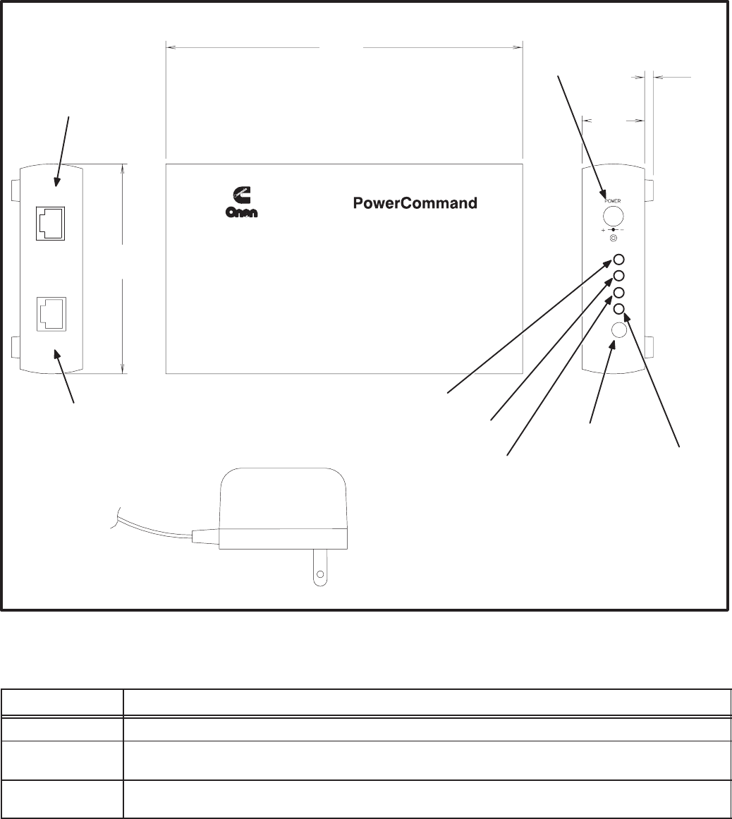
12-2
LOCATION
Locate the Router near an electrical outlet.
Choose a clean, vibration-free mounting surface.
Avoid locations that are hot, damp or dusty. The
temperature range must not exceed 32°F (0°C) to
131°F (55°C).
Figure 12-2 shows the Router outline dimensions.
Refer to section 2 for network topology and maxi-
mum network length. All wiring must follow a spe-
cific network topology and must fall within dis-
tance limits.
5
*
+
./
4
*"
() !
(
"!
5
"!
! (
.)
( "
!
* #$$'
#+='
#'
+
#/'
++
#'
./
4
*"
() !
+
5 +
"!
"!
#$
FIGURE 12-2. NETWORK ROUTER OUTLINE DRAWING
TABLE 12-1. ROUTER – OUTLINE DRAWING DESCRIPTIONS
Function Description/Specification
DC Power Input connector for power supply.
Net 1 RJ45 modular connector for connecting side one of the router to a twisted-pair channel
(Transformer Coupled into Category 4 Twisted Pair at 78,000 bits/sec).
Net 2 RJ45 modular connector for connecting side two of the router to a twisted-pair channel
(Transformer Coupled into Category 4 Twisted Pair at 78,000 bits/sec).
Redistribution or publication of this document,
by any means, is strictly prohibited.
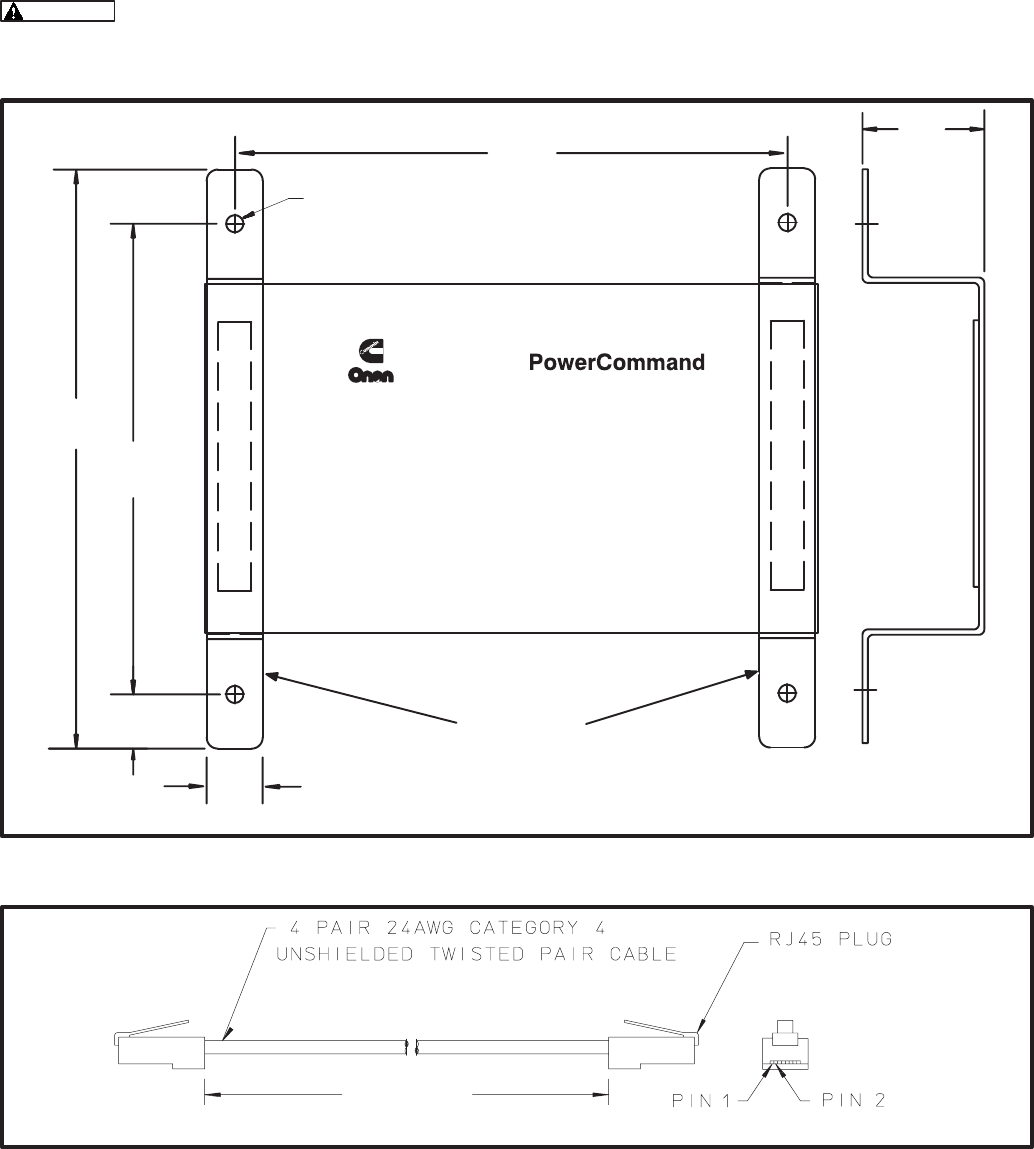
12-3
MOUNTING
The Router can be placed on a clean flat surface or
it can be mounted to a wall or other flat surface with
the enclosed mounting brackets. Figure 12-3
shows the outline and mounting hole locations for
the mounting brackets.
Make sure that no wires, plumbing,
gas or exhaust lines run behind the mounting
area before drilling the mounting holes.
The foam tape on the brackets is for spacing the
brackets. The covering can be removed to adhere
the foam spacer to the Router.
ROUTER PATCH CABLES
The patch cables included in this kit are shown in
Figure 12-4. Connect one cable to each channel
(NET1 and NET 2) on the Router (Figure 12-5).
!
* #$$'
+
#+'
#+/'
/ + #/='
/
#+/'
#+'
+>
#'
#+'
)
Network Router
FIGURE 12-3. MOUNTING BRACKET OUTLINE
+ ±
# ± +'
!
* #7$'
FIGURE 12-4. RJ45 ROUTER PATCH CABLE
Redistribution or publication of this document,
by any means, is strictly prohibited.
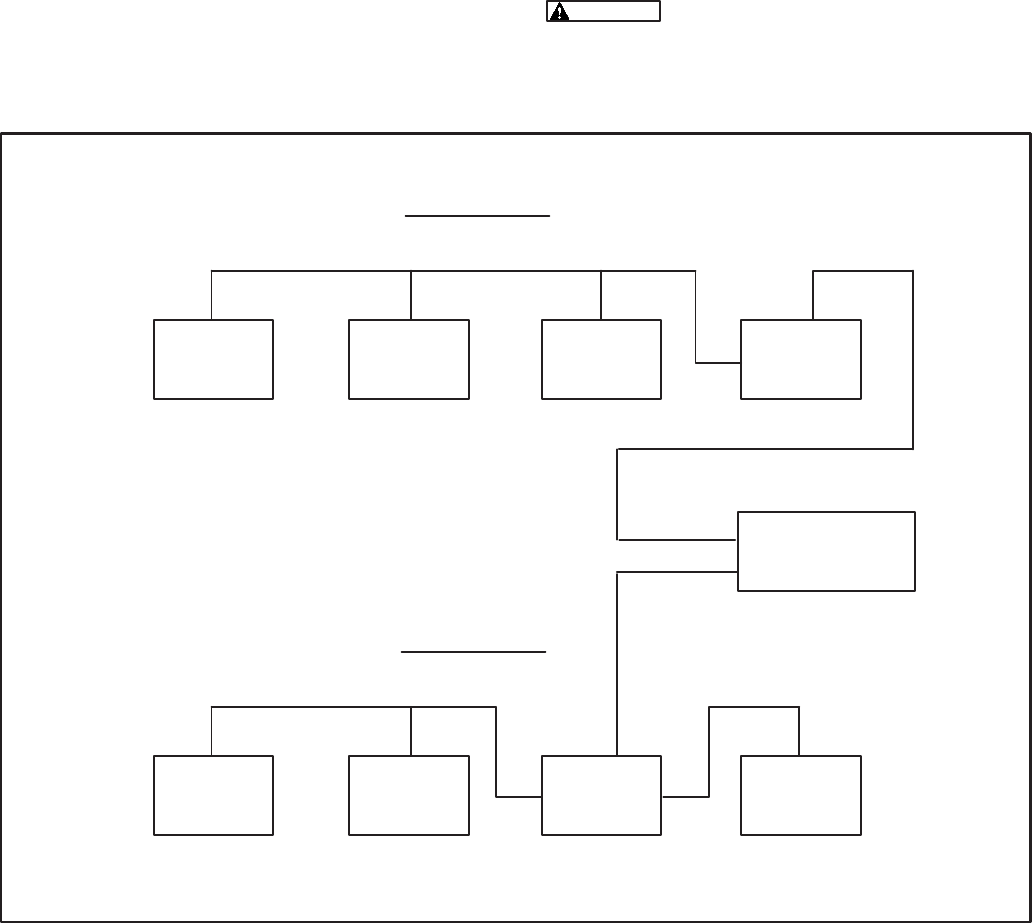
12-4
ROUTER WIRING
Two Junction Box/Terminator (JB/T) modules are
required to connect the two channels to the Router.
The Router may connect to the end of a channel
(see CHANNEL A) or any convenient point on the
channel (see CHANNEL B).
Routers are not equipped with a termination switch.
When a Router is connected to the end of a channel,
the termination switch on the JB/T must be set to
terminate (TERM), as shown in Channel A of Figure
12-5.
Figure 12-5 shows a typical Router installation.
Installing the Router connects two separate physi-
cal (and logical) channels. Each channel requires
termination at each end of the channel.
Each additional channel is limited to 4600 feet
(1402 m) and a maximum of 44 nodes. Routers are
not required for a network that are less than 4600
feet (1402 m) and have no more than 44 nodes.
Each Router allows one additional channel in the
network. PowerCommand Networks are limited to a
maximum of 20 channels.
Refer to Figure 12-2 for the Router connection
points.
Do not route wires over hot, sharp,
or abrasive surfaces.
! +
#'
! ! .3+
#'
! /
#'
! .3 !
#'
*"
*"
+
./ * "
# + 4 A B'
./ * "
# + 4 A B'
FIGURE 12-5. ROUTER USED TO CREATE A NETWORK WITH TWO CHANNELS
Redistribution or publication of this document,
by any means, is strictly prohibited.

12-5
SERVICE SWITCH AND LEDs
The Service switch is used during installation (when
prompted by the LonMaker program).
The yellow LEDs indicate if the service switch is be-
ing pressed. The yellow LED indicators blink when
the RTR is unconfigured and are off if the RTR is
configured. One or both of the yellow LED indica-
tors remains on if an unrecoverable error is de-
tected.
Switches are described in Table 12-2. LED indica-
tors are described in Table 12-3.
TABLE 12-2. ROUTER – SWITCHES
Name Description
SERVICE Momentary push type switch used at time of logical installation to identify the device to
the installation software. Pressing the SERVICE switch will light both Service LEDs to
maximum intensity.
TABLE 12-3. ROUTER – LED INDICATORS
Color Name Description
Yellow SERVICE 1 Indicates various states of the Router. LED is ON with maximum intensity
when the Service switch is pressed and held.
States without Service switch pressed:
ON= An unrecovered error has been detected that prevents the Neuron Chip
on side one from executing application code.
BLINKING = Router side one unconfigured. Routing tables or router node ad-
dress assignment have not been loaded.
OFF = All OK. Router has application image and is installed in a network.
Green POWER ON Indicates that power is being supplied to the router.
Green STATUS BLINKING = Indicates that packets are are being passed in either direction.
The rate of blinking can be used as a rough indicator of router activity.
Yellow SERVICE 2 Indicates various states of the Router. LED is ON with maximum intensity
when the Service switch is pressed and held.
States without Service switch pressed:
ON= An unrecovered error has been detected that prevents the Neuron Chip
on side two from executing application code.
BLINKING = Router side two unconfigured. Routing tables or router node ad-
dress assignment have not been loaded.
OFF = All OK. Router has application image and is installed in a network.
Redistribution or publication of this document,
by any means, is strictly prohibited.

12-6
NETWORK TOPOLOGY AND DATA MEDIA
Refer to section 2 for information on the network to-
pology and data transmission media.
AC voltages and currents present
an electrical shock hazard that can cause se-
vere personal injury or death. Only qualified
personnel are to perform the following proce-
dures.
Connections
Network data connections are made at the RJ45
connectors marked Net 1 and Net 2 (shown in Fig-
ure 12-2, cables supplied with the Router are shown
in Figure 12-4.)
NETWORK INSTALLATION
Sections 3 and 4 provide a detailed description of
the network installation process. Read Sections 1
and 2, before constructing the network. Sections 3
and 4 provide the following step-by-step installation
procedures:
1. Setting up Network Installation Tools
2. Starting LonMaker Software
3. Using LonMaker Software
4. LonMaker Network Setup
5. Connecting Devices with LonMaker
6. Installing Devices with LonMaker
7. Testing Devices and Verifying Installation
8. Setting up PowerCommand Configuration Tool
9. Using PowerCommand Configuration Tool
Logical Installation
After the Router is physically attached to the net-
work, and powered up, it must be logically installed
using LonMaker. The logical installation is covered
in the LonMaker Installation Tool Users Guide.
When installing a network that contains a Rout-
er, the Router must be installed first.
This section provides an overview of the logical
installation of a Router.
A Router is a single device that contains two Neu-
ron chips, one serving each channel. In a network
with one Router, Channel A can have up to 43 addi-
tional nodes and Channel B can have up to 43 addi-
tional nodes, for a maximum of 44 nodes per chan-
nel.
A network diagram is needed to determine the num-
ber of channels in the network and which nodes are
assigned to each channel.
The following is an outline of the steps needed to
Define and Install a Router.
1. Create/Select one Domain and define the
channels that the Router(s) will connect.
2. Choose a Location and Define the Router(s)
using Device Setup. Use a unique name for
each Router, this name can only be used once
in the network. Set up both sides of the Rout-
er(s) as using priority.
3. Select Install Devices and install the Rout-
er(s) first. This will allow access for installing
the other nodes on the channels.
For specific details on filling in LonMaker Fields
when Defining and Installing Routers, refer to the
LonMaker Installation Tool Users Guide.
Redistribution or publication of this document,
by any means, is strictly prohibited.

A-1
#$ 3
Attaching – Term used in this manual to describe
connecting the PC, used for network installation
and service, to the PowerCommand Network via
the Installation Gateway.
Binding – The process of making the logical con-
nections on the network (also called connecting).
This involves connecting network variable outputs
to network variable inputs using LonWorks soft-
ware.
Binding – The process of making the logical con-
nections on the network (also called connecting).
This involves connecting network variable outputs
to network variable inputs using LonWorks soft-
ware.
Boolean – A logical system used to express one of
two states, such as on or off (yes or no, 1 or 0 etc.).
Bound – A network communication technique
whereby a node automatically receives a network
variable from a sender node whenever the sender
node sends it out. The sending is completely con-
trolled by the sender node. The network variables
involved are said to be “bound.”
Bus – The main “backbone” of the network data
wire. It must start at one point and end at another.
Stubs off the main bus wire must not exceed ten
feet. The wire is said to be “daisy-chained” from
one node to the next. Without using a router, the
maximum bus length is 4600 feet (1402 m).
Controls Communications Module (CCM) – A
module for monitoring genset or transfer switch
parameters. It also provides some control capabil-
ity. There are two kit versions: CCM-Genset that
can be used on gensets that do not have a Power-
Command Control, and CCM-ATS that can be
used to monitor and control transfer switches.
(Refer to the CCM-Genset or CCM-ATS sections
of this manual for application information.)
Channel – A Channel is the physical communica-
tions media that connects the devices and the
properties of these media (such as transmission
speed). Most PowerCommand network installa-
tions will have only one channel (twisted-pair wir-
ing and 78 KBaud transmission speed). In a large
network, there may be multiple channels and each
channel may or may not be of the same media
type. Channels are linked together using Routers.
Comma Separated Value (CSV) – A record layout
that separates data fields with a comma and usu-
ally surrounds character data with quotes.
PCW uses the CSV record format.
Configured/Unconfigured – The term configured,
as used in this manual, refers to a module that has
been logically installed with LonMaker Software.
A “network image” (address and binding informa-
tion) is stored in the node. A module that has not
been logically installed with LonMaker is referred
to as being unconfigured. The service LED will
blink on an unconfigured module.
Connecting Devices – Connecting refers to the
process of assigning connections—linking an out-
put variable of one device to an an input variable of
another device. This process is also called “bind-
ing.”
Customer Site Database/ “Site Directory” – A
database that is specific to a customer’s installed
network. It contains two subdirectories,
“DB_TYPE” and “DB_INST”. When the PCNET
utility is executed, this directory structure is set up.
“DB_TYPE” contains the information LonMaker
needs in order to know what each module is and
what it can do. Once LonMaker is run and a specif-
ic customer site is set up (devices and binding de-
fined), this information is stored in the “DB_INST”
subdirectory.
Redistribution or publication of this document,
by any means, is strictly prohibited.
A-2
Digital I/O Module (DIM) – A network module with
four discrete customer inputs, and sixteen 5A, 250
VAC Form-C dry contact outputs. The four cus-
tomer inputs are available on the network to con-
trol other devices or to indicate status. The 16 re-
lays are controlled by other devices on the net-
work.
Distributed Control System – A collection of
nodes that interact to control a system whose
components are spread out over some distance.
Each node has intelligence for operating its own
particular component of the system. Different
parts of the system communicate status and con-
trol information with one another to form a distrib-
uted control system. Typically they communicate
on a peer-to-peer level. This is different from a
type of system where all control and interaction
between components is dictated by one central
control (this type of system typically communi-
cates in a master/slave arrangement).
A distributed control system can be more robust
than a central control type because failure of one
node will not shut down the whole system. The
other working nodes will still interact. If a central
control fails, the whole system shuts down.
Domain – A domain is a network concept that al-
lows independently functioning networks to share
resources, such as transmission media. A domain
designation provides an ID number to identify the
devices that can communicate within that domain.
A network must have at least one domain. Power-
Command network installations will usually have
only one specified domain.
Gateway – A device that acts as interface between
two different communication protocols. The net-
work gateway module (NGM) is an example that
translates PowerCommand network protocol into
a protocol that a PC can understand. Other gate-
way devices may translate between PowerCom-
mand network protocol and other systems such as
SCADA, building automation systems, UNIX sys-
tems, etc.
Genset Communications Module (GCM) – The
GCM provides a communications gateway be-
tween the PCC and the network. The GCM com-
municates with the PCC over a serial data link.
The GCM gets data from the PCC such as volts,
current, engine speed, oil temp, etc. and then
sends it out on the network if another network
node is bound to it or is requesting data. The GCM
also provides some direct local control and moni-
toring of the PCC. It monitors for “Not-In-Auto”,
and both High and Low Battery voltage (when the
PCC is asleep) then sends it out on the network if
another network node is bound to it or is request-
ing data.
Installation Gateway – The term used in this
manual to describe the special Gateway (refer to
Gateway) used only when installaing or servicing
a PowerCommand Network.
Junction Box/Terminator (JBT) – A device that
provides connection points for network power and
data wires. It also contains a network terminator
circuit for use at the end of a network.
Onan has created a junction box/terminator
potted assembly. The JBT is required to connect
an NGM to the network. The JBT provides a (re-
quired) terminator circuit for NGM nodes that are
located at an end of a network. The JBT can also
be used as a convenient device for wiring pass
thru, local loop and stub connections throughout a
network. It provides two 6-position pluggable ter-
minal blocks for data and power, two RJ45 jacks
for temporary 24AWG stub connections (e.g.
NGM), a switch to connect the data lines to a ter-
minator circuit and a switch to select either a pass
thru or a local loop connection between the data
lines on the terminal blocks.
Local Loop – A method of branching out to a node
that is farther away from the main network bus
than a stub would allow (i.e. >10 feet [3m]). It uses
two wire pairs — one pair to go out to the node,
and the other to return from the node. Effectively
the node is “daisy-chained” into the network bus.
The effective bus length for that particular run will
be twice the distance to that node. The total local
loop distance must be added into the maximum
network length of 4600 feet (1402 m).
Redistribution or publication of this document,
by any means, is strictly prohibited.
A-3
Locations – Locations are subdivisions of a net-
work that can be selected strictly for convenience
and organization. Locations may be used to des-
ignate physical places, but they do not have to do
so. For example, a “location” designator could re-
fer to one row of devices, while another “location”
designator could refer to an adjacent row of de-
vices on the same wall.
Network devices in one location can communicate
with network devices in another location. A net-
work must have at least one location name. A de-
vice can be in only one location.
LonMaker Site Database – See Customer Site Da-
tabase
Manchester Encoding – a method of representing
1’s and 0’s on a media which results in polarity in-
sensitive wiring.
Master/Slave – A type of communication protocol
whereby one device controls all communication
on the channel. This is the master. The slaves are
all of the other devices. The slave devices talk only
when the master tells them they can. An example
of this is a computer and a printer. The printer is
the slave device. See Peer-to-Peer.
Media – The hardware level of communications.
This defines two things: 1) what the electrical sig-
nal levels will be and 2) over what they will travel.
Examples of media are: RS-232, RS-485, trans-
former coupled twisted pair, radio frequency, fiber
optic, coax, infrared, and power line. Note that the
media does not define what “language” (protocol)
nodes will use to communicate information with
one another.
Modem – (MOdulator DEModulator) A device that
adapts a terminal or computer to a telephone line.
It converts the computer’s digital pulses into audio
frequencies (analog) for the telephone system
and converts the frequencies back into pulses at
the other side. The modem also dials the line, an-
swers the call and controls transmission speed.
(The modem should be set to operate at 9600 bps
for use in a PowerCommand Network.)
Modules (Nodes) – Modules (sometimes called
nodes or devices) are the various hardware mod-
ules on the network, such as the Digital I/O Mod-
ule, the Controls Communications Module, and
the Genset Communications Module.
Multidrop Bus Topology – The wiring arrange-
ment used for the network data. The bus that
starts at one point and ends at another. The topol-
ogy allows “drops”(or stubs) off of the bus up to 10
feet (3 m) from the bus. One or more “Drops” can
be made any place along the bus (hence “multi-
drop”).
Network – A collection of Nodes that communicate
with one another over a distance. The PowerCom-
mand network communication is implemented
transformer coupled twisted pair data wire. The
“language” that is “spoken” on the network is
called the protocol.
Network Annunciator Module (NAM) – An ap-
plication which combines a hardwired Power-
Command System Annunciator with a Digital I/O
Module. This module is available in two versions:
one has an oversize cover for flush mounting and
the other has a smaller cover for surface mount-
ing. The module is prewired for NFPA110 applica-
tions. The module can be modified for generic an-
nunciation applications.
Network Data – A signal that carries messages be-
tween nodes. In this network, it is a Manchester
encoded digital signal. Manchester encoding
makes the signal insensitive to polarity (i.e. the
two data wires may be connected in either polar-
ity). The signal is transformer-coupled to the net-
work data wire at a rate of 78 k bits/sec. Trans-
former coupling into twisted pair wire gives excel-
lent noise immunity. (It is far superior to either
RS-232 or RS-485 for example.) Shorting of the
wire pair will cause no permanent damage, but
communications will be affected. Opens prevent
nodes on each side of the open from communicat-
ing, but nodes on one side of the open will still
communicate. An unpowered node will not pre-
vent other powered nodes from communicating.
Network Data Wire – Twisted pair communications
wire that carries the network data communication
signals. The wire must meet UL Level IV require-
ments (as listed in UL’s document: “UL’s LAN
Cable Certification Program”). Equally acceptable
is wire conforming to EIA/TIA Category 4 (as de-
scribed in EIA/TIA Technical System Bulletin #36).
These requirements specify the transmission line
characteristics for the wire (attenuation, charac-
teristic impedance, crosstalk, etc.). These charac-
teristics are critical to maintaining a good signal.
22 AWG wire must be used for the network bus. 24
AWG may be used on stubs. The cable does not
need to be shielded. Maximum bus length is 4600
feet (1402 m).
Redistribution or publication of this document,
by any means, is strictly prohibited.
A-4
Network Module Library – The Network Module
Library (NML) is a software database that de-
scribes devices, channels, and predefined input/
output connections. The NML is used by PCNET
to create the “Site Directory.”
Network Gateway Module (NGM) – A network de-
vice that acts as a gateway between a PC or mo-
dem and the network. The “site“ NGM allows soft-
ware running on a PC to access, poll, and control
all devices on a network. The PowerCommand
Software uses this device to access the network.
The NGM connects to network data through an
RJ45 jack. Connecting to it requires a 24 AWG
cable. The NGM receives its power from AC utility
power.
Network Installation Gateway – A special NGM
that is configured for installing and servicing a net-
work. Do not use the Network Gateway Module to
install or service a network or its configuration in-
formation will be lost. Always use the Network
Installation Gateway for installing and servicing
networks.
Network Power – B+ is used to power remote net-
work devices such as the Digital I/O Module, Net-
work Annunciator and Controls Communications
Module. For limited distances, this may be sup-
plied by the genset battery. For greater distances,
an auxiliary battery will be needed to prevent mod-
ule power loss during cranking.
Network Power Wire – Wire used to run power to
nodes that do not have a local source of power
(e.g. Digital I/O Module, Network Annunciator
Module , etc.). The wire gauge must be chosen for
the number and type of nodes and the maximum
distance from the power source to a load node.
Refer to the Network Power section for data on
wire selection.
Network Variable (NV) – Network Variables send a
value with defined units from one device (the out-
put) to another (the input). Each network variable
is either an input or an output. Also see Connect-
ing Devices.
Data that can be accessed or driven through the
network. Examples would be: Genset voltages,
genset start/stop, etc. Some NVs are used purely
for monitoring purposes. Others are used for con-
trol between devices.
LonMaker recognizes device inputs and outputs
as network variables (NVs) and message tags.
This is because inputs and outputs for a LonWorks
network are not hard-wired connections, they are
programmable software values.
Neuron Chip – A communIcations processor de-
veloped by Echelon Corporation for use in distrib-
uted control systems. The Neuron chip firmware
implements a sophisticated communications pro-
tocol, allowing nodes to communicate through the
passing of network variables. The Neuron chip
also has I/O to support modest application cir-
cuits.
Node – A module that can communicate over the
network data wire to other modules. A module
containing a Neuron chip.
Pass Thru – Refers to a junction box connection
where the network bus comes to a connector and
then continues straight on through. It is merely a
point for splicing wires. The Onan junction box/ter-
minator provides this function.
PCNET – A utility program that is used to create a
“customer site” or update an existing site with the
latest NML. This utility program is loaded when
NML is installed. Refer to Section 3, Create or Up-
date a Customer Site.
Peer-to-Peer – A type of communication protocol
whereby any device on the communication chan-
nel can communicate with any other device at any
time. That is, no one device is the master of the
communication medium. The PowerCommand
Network is a peer-to-peer type network.
Polling – A network communication technique
whereby a node asks another node for its current
value of a network variable. The node doing the
asking forces the other node to send out that net-
work variable.
Protocol – The protocol is a language that each
node on the network knows how to speak and in-
terpret. It is not to be confused with communica-
tions media. The media is the hardware level of
the communications. The protocol is what allows
devices to exchange messages with one another.
A protocol can be very simple or very complex.
Echelon’s LonTalk Protocol, used in the Neuron
Chip, is very sophisticated.
RJ45 Connector – An 8-position phone jack con-
nector. Some nodes (e.g., NGM) connect to the
network via an RJ45 connector. Network data is
brought in on positions 1 and 2 (the two left-most
positions as the plug is viewed from the contact
side (as opposed to the side with the latch).
Redistribution or publication of this document,
by any means, is strictly prohibited.
A-5
Router – A router is a device that connects one
channel to another. Routers are not required when
there is only one channel in a network.
A router can also be used to extend the Power-
Command Network bus or extend the number of
modules on the network.
Standby Uninterruptible Power Supply – See
Uninterruptible Power Supply
Stub – A branch off of the network bus. It must not
exceed 10 feet (3m).
Terminator – A circuit that is required at both ends
of the network bus. This circuit acts to optimize the
transmission line characteristics (minimizes sig-
nal reflections). It is critical that the network bus be
properly terminated. Without terminators or termi-
nators in the wrong places, network communica-
tions can be severely hampered. Even if the net-
work appears to be working, messages are likely
getting lost or unnecessarily repeated, increasing
network traffic. Noise immunity is also greatly re-
duced. Each network module except the NGM has
a terminator built in. On Onan-designed nodes, a
slide switch is used to connect the terminator cir-
cuit to the network data lines. Junction boxes also
contain built in terminators with a slide switch to
activate it. The terminator on the junction box
would only be used if an NGM was located at the
end of the network bus because the NGM has no
terminator circuit.
Topology – The physical wiring arrangement for
the network data communications. Example to-
pologies are bus, ring (e.g. Token Ring), star and
mixed. The network data described in this docu-
ment communicates on a multidrop bus topology.
Twisted Pair Communications Cable – A cable
containing typically one, two or four twisted wire
pairs. The cable is specified according to its char-
acteristic impedance, maximum operating fre-
quency, attenuation, capacitance, and cross-talk.
These are all important parameters for reliable
data transmission.
Single pair cable will contain one white/blue and
one blue wire. This would only carry network data.
Two pair cable will contain one pair of white/blue &
blue and one pair of white/orange & orange. The
blue pair would carry network data. the orange
pair could be used in local loop configurations.
Four pair cable will contain paired colors of blue,
orange, green and brown. Again, blue is primary
for network data. Orange, Green and Brown can
be used for network data — may be used for a lo-
cal loop.
The wire comes as either 22 AWG (for main bus or
stubs) or 24 AWG (for stubs only), plenum or PVC
insulation, and with or without a drain/shield. The
PowerCommand Network does not require the
use of shielded cable. Plenum vs. PVC insulation
will be chosen based on code requirements for fire
resistance. If network power is being run in the
cable, then the cable must be in conduit.
Uninterruptible Power Supply (UPS) – A backup
power supply used when the electrical power fails
or drops to an unacceptable level. Small UPS sys-
tems provide power to operate equipment for a
number of minutes. There are two main types of
UPS: an online UPS that provides a constant
source of electrical power from the battery and an
offline UPS, also known as a standby UPS, that
switches to battery power a few milliseconds after
detecting a power failure.
Onan has an optional standby UPS that can be
used to provide backup power for a modem and
network gateway module.
Redistribution or publication of this document,
by any means, is strictly prohibited.
A-6
Redistribution or publication of this document,
by any means, is strictly prohibited.

B-1
?
MODEM
The modem provides a dial in/out link to other com-
munications sites. The modem is AC powered. The
modem communicates with the Network Gateway
Module that communicates at 38,400 bps (on the
serial (RS-232 side). The Onan Model PMDM 100
is the only approved modem for operation in the
PowerCommand Network as of this printing.
STANDBY UNINTERRUPTABLE
POWER SUPPLY (UPS)
Onan has an optional standby UPS that can be
used to provide backup AC power for the Network
Gateway Module and a modem. The UPS will pro-
vide backup power for a minimum of 30 minutes.
Use of a UPS will allow the modules (that are battery
powered) on the PowerCommand network to com-
municate a power failure to a remote location via the
NGM and modem during a power failure.
A multi-plug receptacle will be needed to connect
more than one device to the UPS.
MULTI-SITE COMMUNICATIONS MODULE
The Multi-Site Communications Module allows a
single computer running PowerCommand Software
to communicate with up to eight remote sites simul-
taneously. This module is installed in an ISA bus
compatible personal computer and it contains all of
the necessary RS-232 communications connec-
tions for use with external communications equip-
ment. This module should only be installed by
someone familiar with computer servicing.
Redistribution or publication of this document,
by any means, is strictly prohibited.
B-2
Redistribution or publication of this document,
by any means, is strictly prohibited.

C-1
44 ! +3
NETWORK VARIABLES
The PowerCommand network recognizes module
inputs and outputs as network variables (NVs) and
message tags. Both network variables and mes-
sage tags perform the same basic functions, they
exchange values and information between mod-
ules. These inputs and outputs are not hard-wired
connections between the modules, they are soft-
ware values.
Network variables send a value with defined units
from one device (the output) to another (the input).
Each network variable is either an input or an out-
put.
Message tags are similar to network variables, but
they are used to send explicit messages. In the
PowerCommand network, message tags are only
used to send alarms to the PowerCommand soft-
ware. The CCM and GCM have message tag out-
puts and the NGM has a message tag input.
Some network variables are of the analog data type
structure. These network variables are not con-
nected or bound. Instead, these network variables
are made available to application programs (such
as PowerCommand Software for Windows), which
can then request the data from the source module
(GCM or CCM).
BINDING NETWORK VARIABLES
Logically connecting network variables between
modules is referred to as binding. Connecting the
network variables results in a bound connection.
The result of a bound connection is that when a
module updates an output network variable, input
network variables in other modules that are bound
to it, are automatically updated via the network.
Making these bound connections creates a network
where control signals and data are automatically
sent and received.
When installing the PowerCommand network you
will need a diagram of all the logical connections.
The logical connection diagram should be prepared
before starting the installation to save time during
the installation. A list of the network variables that
can be connected are listed with each module in the
back of the section.
Network Variable Rules and Limits
Network variables and message tags are con-
nected using the LonMaker Installation software
(refer to Section 3). Certain network variable rules
and limits must be followed when making these
connections. Refer to the following rules and limits
when designing or troubleshooting a logical binding
diagram.
Data Type Matching: Connect only variables of the
same data type. The installation tool (LonMaker)
will not allow mismatched types to be connected.
For example, connect only Booleans to Booleans,
words to words, message tags to message tags,
etc.
Connections Within One Node: It is acceptable to
connect one network variable output to one network
variable input on the same module. The result will
function as expected, but the network update will
not appear on the network media, instead it will re-
main within the module.
Redistribution or publication of this document,
by any means, is strictly prohibited.
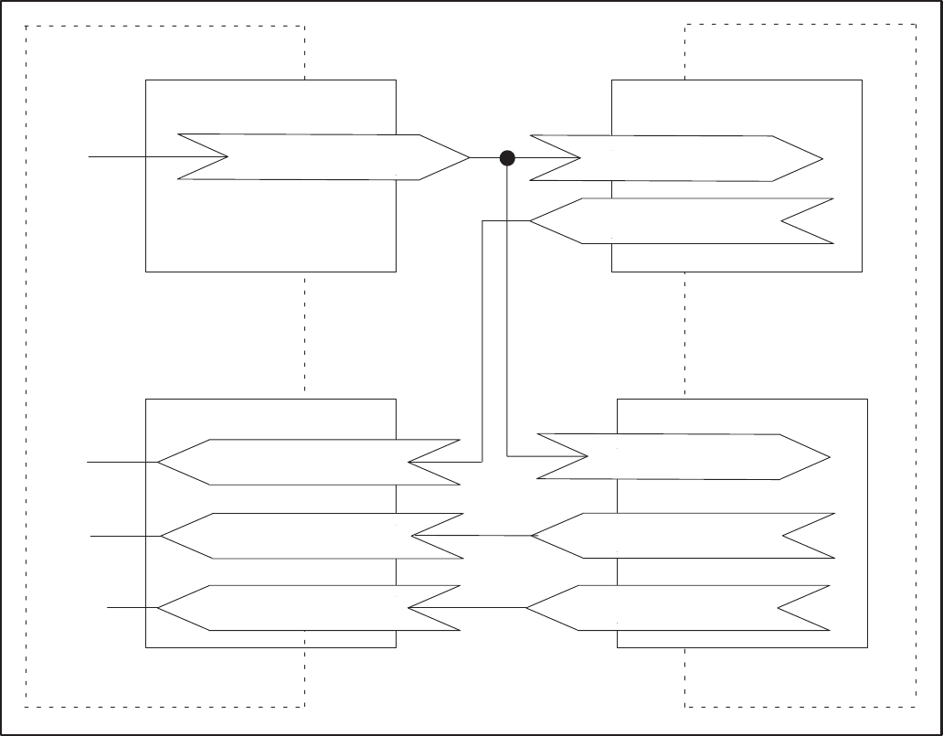
C-2
$&
%
97:
?&0C
?&&$$&<%$
?0$
&$$&
<%$
"%$@
G
0C
"%$@
* * ?
?&08@0+
! +
?&&$$&<%$
+
?<%6+
!
?<%6
?0$
&$$&
<%$
"%$@
?<%6
FIGURE C-1. TYPICAL BINDING DIAGRAM
Making Connections Other Than One Output to
One Input: Making connections other than one-to-
one is allowed, but it must be clearly understood
how the resulting system will behave. The other
scenarios are: 1) multiple outputs connected to one
input; 2) One output connected to multiple inputs;
and 3) multiple outputs connected to multiple in-
puts. These are discussed in more detail below.
Multiple Boolean Outputs: When multiple Bool-
ean outputs are involved in one connection, it is
necessary to understand how the connected Bool-
ean input(s) will respond to updates. Some node
types implement an equivalent hardwired OR’ing
scheme while others do not. Refer to the following
section called Multiple Outputs to One Input for a
description of the possible results.
More Than One NV Input Controlling the Same
Device: The Digital I/O Module has two means of
controlling the relays. There are the individual Bool-
ean inputs, nviRelay[x], and there is the 16–bit
word, nviAllRelays. If both are used, the result will
be that the inputs are logically or’ed within the mod-
ule.
For example:
If both nviRelay[1] and bit 0 in nviAllRelays (bit
which controls Relay1) start out both as “0” (relay in
reset state). If nviRelay[1] is updated to “1”, the
relay will be set. If bit 0 of nviAllRelays then is up-
dated to “1”, the relay will remain in the set state.
Now, if nviRelay[1] is set to “0”, the relay will still re-
main set until bit 0 of nviAllRelays is set to “0”.
Redistribution or publication of this document,
by any means, is strictly prohibited.

C-3
Address Table Consumption: Bindings consume
memory in each module. There is a limited amount
of memory for storing the binding information. It is
stored in a place called the “address table”. The
installation tool (LonMaker) acts to optimize the ad-
dressing so that minimal address table space is
consumed. However, in certain situations, all ad-
dress table entries will be consumed. LonMaker will
inform the user when this occurs.
Due to the complexity of the addressing schemes
that the protocol uses, it would be difficult to create
simple rules to determine whether the address table
limit was going to be exceeded for a particular sys-
tem binding design. In general, the greater the
number of connections, the more address table
space consumed. Address table consumption is in-
creased when connections are made between
many different NV’s on one device to single NV’s on
many different modules. If in doubt about whether a
particular application will exceed the limits, try it out
by creating a test site and then make the connec-
tions using LonMaker. LonMaker will inform the
user if the limits are exceeded.
The most severely limited device in terms of ad-
dress table entries is the Digital I/O Module. It has
only 5 address table slots, whereas the CCM and
GCM module types have 15.
An example of a situation that would NOT WORK
with the DIM or NAM is shown in Table C-1.
Only 5 of the 7 connections listed could be made
due to the address table limit. This is a worst case
example. In this case, add another DIM to the net-
work.
Having only 5 address table entries on the DIM
DOES NOT mean that there can be no more than
5 connections. This example illustrates a particu-
lar situation where this can occur. If connection
numbers 6 and 7 had both come from GCM1, then
all connections could be made.
TABLE C-1. EXAMPLE OF CONNECTIONS THAT EXCEED THE ADDRESS TABLE LIMIT
CONNECTION
NUMBER
FROM TO
NUMBER
MODULE NAME NV OUTPUT MODULE NAME NV INPUT
1 ccm1 nvoCustInput[1] dim1 nviRelay[1]
2 gcm1 nvoLoadDump dim1 nviRelay[5]
3 ccm2 nvoCustInput[13] dim1 nviRelay[2]
4 ccm3 nvoCustInput[1] dim1 nviRelay[7]
5 dim2 nvoCustInput1 dim1 nviRelay[11]
6 gcm2 nvoRunning dim1 nviRelay[3]
7 gcm3 nvoCustFault1 dim1 nviRelay[14]
Redistribution or publication of this document,
by any means, is strictly prohibited.
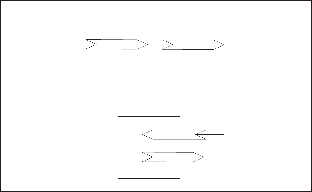
C-4
! +
! +
?
?&
!
?& ?
OR
FIGURE C-2. ONE OUTPUT TO ONE INPUT BINDING DIAGRAM
TYPES OF CONNECTIONS
The different types of connections are explained in
the following sections. It is important to consider the
type of connections being designed or made and
how the results of these connections will affect other
devices. The logic involved may not behave in an
intuitive or familiar manner.
One Output to One Input
This is the most straightforward type of connection.
The only requirement is that the data types must
match. When the output is sent on the network, the
input will automatically get it and take appropriate
action.
Redistribution or publication of this document,
by any means, is strictly prohibited.

C-5
! +
!
?&
! /
?&
?
!
?&
FIGURE C-3. MULTIPLE OUTPUTS TO ONE INPUT BINDING DIAGRAM
Multiple Outputs to One Input
Multiple outputs from one module cannot be con-
nected to one input on a single module.
Some of the Boolean network variable inputs on the
CCM and on the GCM implement a “wired OR”
functionality. All of the Boolean inputs shown in
Table C-2 implement this functionality. When multi-
ple Boolean outputs from other modules are con-
nected to one Boolean input, that Boolean input will
remain a “1” until all of the connected Boolean out-
puts are “0”. The modules implement this by polling
all connected outputs each time a “0” is received
from one of them. If, as a result of the poll, all out-
puts say they are a “0”, the input is set to “0” and ap-
propriate I/O action is taken.
The DIM’s Boolean inputs do not implement a
“wired OR” function. Therefore, if multiple out-
puts are connected to a Boolean input, the input will
be in whatever state it received from the most re-
cent update. If one output tells it to be “1” and anoth-
er afterwards tells it to be a “0”, it will be a “0”. This is
“standard functionality” behavior as described in
the next section.
Standard Functionality: For all network variable
inputs except the Boolean inputs on the CCM and
GCM listed in Table C-2, when multiple outputs are
connected to one input, the input will contain the
state/data of the most recent update.
TABLE C-2. MULTIPLE OUTPUTS TO ONE INPUT “WIRED OR” BOOLEAN NETWORK VARIABLE INPUT
GCM CCM
nviRunCmd* nviRelayControl1* (MAINTAINED mode only)
nviEmerStopCmd nviRelayControl2* (MAINTAINED mode only)
nviCustFault1* nviRelayControl3 (MAINTAINED mode only)
nviCustFault2* nviRelayControl4 (MAINTAINED mode only)
nviCustFault3*
nviCustFault4*
* A Start command will NOT be sent from the network if the network is not operating. Do
not use the network to send system or generator set Start commands. Use hardwired Start signals.
Redistribution or publication of this document,
by any means, is strictly prohibited.
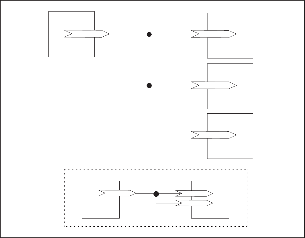
C-6
!
!
?
! +
?
?&
! /
?
! + !
NOT ALLOWED
?
?
?&
FIGURE C-4. ONE OUTPUT TO MULTIPLE INPUTS BINDING DIAGRAM
One Output to Multiple Inputs
When the one output is sent out on the network, all
of the inputs will receive it. The output is only sent
once (i.e. it is not sent out once for each input).
The only limitation or rule is that one output cannot
be connected to more than one input on one specif-
ic module. For example, the connections shown in
Table C-3 are NOT allowed. In this example the
same output from DIM1 is sent to two inputs on the
same module, CCM1.
Multiple Outputs to Multiple Inputs
This is not recommended due to the complications
involved in determining possible outcomes.
Redistribution or publication of this document,
by any means, is strictly prohibited.
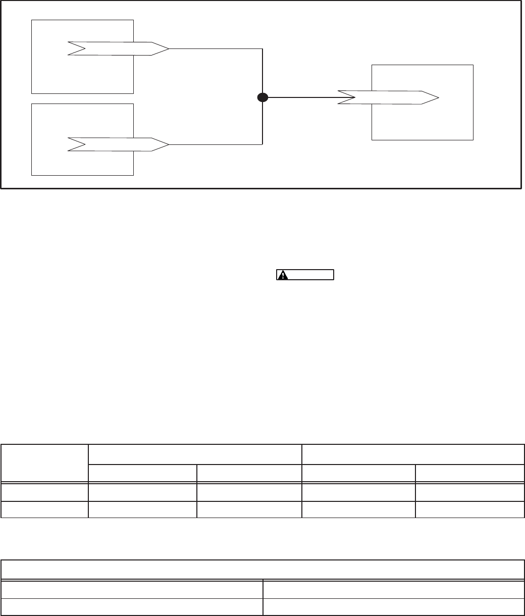
C-7
+
+
%C+
%C+
8CD
FIGURE C-5. TYPICAL MESSAGE TAG CONNECTIONS
Message Tag Connections
Message tag connections are a special class of
connections. In the PowerCommand Network, the
only purpose they serve is as the link for alarms to
be sent to PowerCommand Software through either
a local or a remote connection. The CCM and GCM
have message tag outputs. The NGM has a mes-
sage tag input. In order for alarm notification to
work, the tags must be connected using the Lon-
Maker installation tool.
Table C-4 shows a typical message tag output and
input for a dial out connection.
DO NOT connect message Tag out-
puts to more than one input. It is OK to connect
multiple message tag outputs to one message
input. The result of this restriction is that alarm
notification from a module can only go out
through ONE Network Gateway.
TABLE C-3. EXAMPLE OF ONE OUTPUT TO MULTIPLE INPUTS
ON THE SAME MODULE – THIS IS NOT ALLOWED
CONNECTION
NUMBER
FROM TO
NUMBER
MODULE NAME NV OUTPUT MODULE NAME NV INPUT
1 dim1 nvoCustInput1 ccm1 nviRelay1
2 dim1 nvoCustInput1 ccm1 nviRelay4
TABLE C-4. EXAMPLE OF A MESSAGE TAG CONNECTION FOR DIAL-OUT
MESSAGE TAG CONNECTION FOR DIAL–OUT
From Tag Output: (CCM, GCM) To Tag Input (NGM)
NGMTag1 msg_in
PowerCommand Software
PowerCommand Software does not participate in
network variable connections. If PowerCommand
Software has been used to start a genset, it is pos-
sible that another bound node may stop the genset
(if the node gets reset or otherwise has reason to
send a “0”).
Redistribution or publication of this document,
by any means, is strictly prohibited.

C-8
DETERMINING SENDER SETTINGS
The following examples can be used to determine
sender settings for unknown senders. Refer to the
service manual of the equipment being monitored
for important safety precautions.
Severe personal injury or death can
result from working on equipment while it is op-
erating. Refer to the service manual of the
equipment being monitored for important safe-
ty precautions.
Example 1: Unknown Coolant Temperature
Sender
The CCM’s Temperature 1 input will be monitoring
an unknown engine temperature sender. You would
like to find Sender Voltage, Meter Reading and
Sender Gain for the sender. The customer prefers
English (Imperial) units.
1. Start the genset (with no load).
2. Wait for the engine temperature to reach
steady–state.
3. Measure the DC voltage at the sender (VDC).
Voltage (no load) = 2.92 VDC
4. What is the engine temperature (degrees F)?
Temperature (no load) = 172_F
5. Increase the load on the genset to at least 50%
load.
6. Wait for the engine temperature to reach
steady–state.
7. Measure the DC voltage at the sender (VDC).
Voltage (load) = 3.23 VDC
8. What is the engine temperature (degrees F)?
Temperature (load) = 197_F
9. Enter the following values for Temperature 1:
Sender Voltage = Voltage (no load) = 2.92
Meter Reading = Temperature (no load) =172
Sender Gain = 80.65
TEMPERATURE (LOAD) – TEMPERATURE (NO LOAD) 197 – 172
SENDER GAIN = –––––––––––––––––––––––––––––––––––––––––––––– = ––––––––––– = 80.65
VOLTAGE (LOAD) – VOLTAGE (NO LOAD) 3.23 – 2.92
FIGURE C–6. DETERMINING TEMPERATURE SENDER SETTINGS (EXAMPLE 1)
Example 2: Unknown Oil Pressure Sender
The CCM’s Oil Pressure input will be monitoring an
unknown oil pressure sender. You would like to find
Sender Voltage, Meter Reading and Sender Gain
for the sender. The customer prefers Metric units.
1. With the genset not running, measure the DC
voltage at the sender (VDC).
Voltage (not running) = 5.71 VDC
2. Start the genset (no load).
3. Wait for the oil pressure to reach steady–state.
4. Measure the DC voltage at the sender (VDC).
Voltage (running) = 4.13 VDC
5. What is the oil pressure (kPa)?
Oil Pressure (running) = 360 kPa
7. Enter the following values for Oil Pressure:
Sender Voltage = Voltage (running) = 4.13
Meter Reading = Oil Pressure (running) = 360
Sender Gain = – 227.85
PRESSURE (RUNNING) – PRESSURE (NOT RUNNING) 360 – 0
SENDER GAIN = –––––––––––––––––––––––––––––––––––––––––––––– = –––––––––– = – 227.85
VOLTAGE (RUNNING) – VOLTAGE (NOT RUNNING) 4.13 – 5.71
FIGURE C–7. DETERMINING PRESSURE SENDER SETTINGS (EXAMPLE 2)
Redistribution or publication of this document,
by any means, is strictly prohibited.

C-9
Example 3: Unknown Oil Pressure Sender
The CCM’s Oil Pressure input will be monitoring an
unknown oil pressure sender. You would like to find
Sender Voltage, Meter Reading and Sender Gain
for the sender. The customer prefers English (Im-
perial) units.
1. With the genset running and the oil pressure at
30 psi, measure the DC voltage at the sender
(VDC).
Voltage (at 30 psi) = 4.7 VDC
2. With the genset running and the oil pressure at
50 psi, measure the DC voltage at the sender
(VDC).
Voltage (at 50 psi) = 2.5 VDC
3. Enter the following values for Oil Pressure:
Sender Voltage = Voltage (30 psi) = 4.7
Meter Reading = Oil Pressure = 30 (psi)
Sender Gain = – 9.1
PRESSURE (30 psi) – PRESSURE (50 psi) 30 – 50
SENDER GAIN = –––––––––––––––––––––––––––––––––––––––– = –––––––––– = – 9.1
VOLTAGE (30 psi) – VOLTAGE (50 psi) 4.7 – 2.5
FIGURE C–8. DETERMINING PRESSURE SENDER SETTINGS (EXAMPLE 3)
Example 4: Unknown Fuel Level Sender
The CCM’s Analog channel Spare 1 (0 to 5 volts) in-
put will be monitoring fuel level in a 100 gallon
(378.5 liter) fuel tank with an unknown sender. You
would like to find Sender Voltage, Meter Reading
and Sender Gain for the sender. The customer pre-
fers English (Imperial) units.
1. Measure the DC voltage at the sender (VDC).
Voltage with the fuel tank empty = 1.92 VDC
2. The fuel gauge reads 0 gallons (0 liters).
3. Fill the fuel tank with 100 gallon (378.5 liters) of
fuel and measure the DC voltage at the sender
(VDC).
Voltage (full tank) = 0.24 VDC
4. The fuel gauge reads 100 gallons (378.5 liters).
5. Enter the following values for Spare 1:
Sender Voltage = Voltage (full tank) = 0.24
Meter Reading = Fuel Gauge (full tank) =100
Sender Gain = – 59.5
FUEL LEVEL (EMPTY) – FUEL LEVEL (FULL) 0 – 100
SENDER GAIN = ––––––––––––––––––––––––––––––––––––––––––– = ––––––––––– = – 59.5
VOLTAGE (EMPTY) – VOLTAGE (FULL) 1.92 – 0.24
FUEL LEVEL
(PERCENT FULL)
VOLTS DC
0
100
50
012345
FIGURE C–9. DETERMINING SPARE 1 SENDER SETTINGS (EXAMPLE 4)
Redistribution or publication of this document,
by any means, is strictly prohibited.

C-10
CONNECTION TABLE EXAMPLES
The following connection tables are examples of
how network variable input and network variable
outputs are typically connected.
Automatic bindings are available to make some of
the common bindings easier to connect. Refer to
Table C-5 for a listing of the Auto-Bindings.
TABLE C-5. AUTO–BINDINGS (NML V1.10 )
Device Type Network Variable Device Type Network Variable Data Point
ccm v1.00 NGMTag1 ngm v1.00 msg_in Alarm Message
ccm /ats v1.00 NGMTag1 ngm v1.00 msg_in Alarm Message
ccm /gen v1.00 NGMTag1 ngm v1.00 msg_in Alarm Message
pcc w/gcm v1.00 NGMTag1 ngm v1.00 msg_in Alarm Message
pcc w/gcm v1.00 nvoRemoteAnnun1 nam v1.00 nviAllRelays NFPA 110 Annunciator
ccm /gen v1.00 nvoCustIn[28] nam v1.00 nviRelay[3] Genset Running
ccm /gen v1.00 nvoCustIn[27] nam v1.00 nviRelay[6] Pre–Low Oil Pressure
ccm /gen v1.00 nvoCustIn[25] nam v1.00 nviRelay[7] Low Oil Pressure
ccm /gen v1.00 nvoCustIn[26] nam v1.00 nviRelay[8] Pre–High Eng. Temp
ccm /gen v1.00 nvoCustIn[24] nam v1.00 nviRelay[9] High Engine Temp
ccm /gen v1.00 nvoCustIn[19] nam v1.00 nviRelay[10] Low Engine Temp
ccm /gen v1.00 nvoCustIn[23] nam v1.00 nviRelay[11] Overspeed
ccm /gen v1.00 nvoCustIn[22] nam v1.00 nviRelay[12] Overcrank
ccm /gen v1.00 nvoCustIn[29] nam v1.00 nviRelay[13] Switch in OFF
ccm /gen v1.00 nvoCustIn[18] nam v1.00 nviRelay[15] Low Fuel
ccm /gen v1.00 nvoCustIn[21] nam v1.00 nviRelay[16] Low Coolant Level
ccm /ats v1.00 nvoCustIn[8] nam v1.00 nviRelay[1] High Battery Voltage
ccm /ats v1.00 nvoCustIn[7] nam v1.00 nviRelay[2] Low Battery Voltage
ccm /ats v1.00 nvoCustIn[3] nam v1.00 nviRelay[4] Normal Utility Power
ccm /ats v1.00 nvoCustIn[4] nam v1.00 nviRelay[5] EPS Supplying Load
ccm /ats v1.00 nvoCustIn[10] nam v1.00 nviRelay[14] Bat. Chrgr. Malfunction
Note: Automatic connections must still be created in LonMaker using the Auto button (refer to the Connect
Procedure in Section 3).
Redistribution or publication of this document,
by any means, is strictly prohibited.

C-11
TABLE C-6. CONNECTING CCM-GENSET (DETECTOR/DK) AND CCM-ATS (OT/BT)
TO NETWORK ANNUNCIATOR (NFPA110)
FROM TO
Signal NV NV Indication
CCM Genset (Detector/DK) Network Annunciator Module (NFPA110)
Switch in Off nvoCustInput[29] nviRelay[13] Not In Auto
Low Fuel nvoCustInput[18] nviRelay[15] Low Fuel
Low Engine Temperature nvoCustInput[19] nviRelay[10] Low Engine Temp
Fault1 connected to a Low
Coolant Level Switch nvoCustInput[21] nviRelay[16] Low Coolant Level
Overcrank nvoCustInput[22] nviRelay[12] Overcrank
Overspeed nvoCustInput[23] nviRelay[11] Overspeed
High Coolant Temperature nvoCustInput[24] nviRelay[9] High Coolant Temp
Low Oil Pressure nvoCustInput[25] nviRelay[7] Low Oil Pressure
Pre–High Coolant Temperature nvoCustInput[26] nviRelay[8] Pre–High Coolant Temp
Pre–Low Oil Pressure nvoCustInput[27] nviRelay[6] Pre–Low Oil Pressure
Run nvoCustInput[28] nviRelay[3] Generator Running
CCM Transfer Switch (OT/BT)
Normal Connected nvoCustInput[3] nviRelay[4] Normal Utility Power
Emergency Connected nvoCustInput[4] nviRelay[5] EPS Supplying Load
Battery Charger Failure nvoCustInput[10] nviRelay[14] Bat Chgr Malfunction
Low Battery Voltage nvoCustInput[7] nviRelay[2] Low Battery Voltage
High Battery Voltage nvoCustInput[8] nviRelay[1] High Battery Votlage
Note1: The “Normal Battery” Indication is automatically illuminated whenever Low and High Battery Voltage are both
absent. Battery Voltage sensing is done by the battery charger in the Transfer Switch.
Note2: These bindings can be made automatically using the “Auto” button under Installation.
Redistribution or publication of this document,
by any means, is strictly prohibited.

C-12
TABLE C-7. CONNECTING PCC GENSET AND CCM-ATS TO NETWORK ANNUNCIATOR (NFPA110)
FROM TO
Signal NV NV Indication
PCC Genset Communications Module Network Annunciator Module (NFPA110)
Low Battery Voltage nvoRemoteAnnun1 nviAllRelays Low Battery Voltage
High Battery Voltage High Battery Votlage
Not in Automatic Not In Auto
Low Fuel Low Fuel
Low Engine Temperature Low Engine Temp
Low Coolant Level Low Coolant Level
Overcrank Overcrank
Overspeed Overspeed
High Coolant Temperature High Coolant Temp
Low Oil Pressure Low Oil Pressure
Pre–High Coolant Temperature Pre–High Coolant Temp
Pre–Low Oil Pressure Pre–Low Oil Pressure
Run Generator Running
CCM Transfer Switch (OT/BT)
Normal Connected nvoCustInput[3] nviRelay[4] Normal Utility Power
Emergency Connected nvoCustInput[4] nviRelay[5] EPS Supplying Load
Battery Charger Failure nvoCustInput[10] nviRelay[14] Bat Chgr Malfunction
Note: The “Normal Battery” Indication is automatically illuminated whenever Low and High Battery Voltage are both ab-
sent. Battery voltage sensing is done at the PowerCommand Control, not at the Annunciator.
TABLE C-8. CONNECTING CONTROLS COMMUNICATIONS MODULE TO
DIGITAL I/O MODULE
FROM TO
Signal NV NV Action
Controls Communications Module Digital I/O Module
dry contact closure input nvoCustInput[x] nviRelay[x] relay control
inputs 1 thru 16 nvoCustIn1_16 nviAllRelays controls all 16 relays
inputs 17 thru 32 nvoCustIn17_32 nviAllRelays controls all 16 relays
relay1 state indication nvoRelayState[X] nviRelay[x] relay control
Digital I/O Module Controls Communications Module
dry contact closure input nvoCustInput[X] nviRelayControl[X] relay control
Note: This table shows representaive connection possibilities
Redistribution or publication of this document,
by any means, is strictly prohibited.

C-13
TABLE C-9. CONNECTING DIGITAL I/O MODULE TO PCC GENSET
FROM TO
Signal NV NV Action
PCC Genset Communications Module Digital I/O Module
status/fault indications nvoRemoteAnnun nviAllRelays controls all 16 relays
Genset has run command nvoRunCmd nviRelay[x] relay control
Genset is running nvoRunning nviRelay[x] relay control
ready to load nvoReadyToLoad nviRelay[x] relay control
load dump nvoLoadDump nviRelay[x] relay control
common alarm nvoCommonAlarm nviRelay[x] relay control
customer fault nvoCustFault nviRelay[x] relay control
Digital I/O Module PCC Genset Communications Module
dry contact closure input nvoCustInput nviRunCmd run Genset
dry contact closure input nvoCustInput nviResetCmd reset fault
dry contact closure input nvoCustInput nviEmerStopCmd emergency stop
dry contact closure input nvoCustInput nviWakeUpCmd turn on PCC
dry contact closure input nvoCustInput nviLoadDemandCmd load demand shutdown
dry contact closure input nvoCustInput nviGenBrkrCtrl operate Genset breaker
dry contact closure input nvoCustInput nviCustFault* active Customer fault
Note: This table shows representative connection possibilities.
NETWORK DESIGN/INPUT FORMS
These forms are designed to serve as a means of
preparing information prior to the installation of a
network. The information will be used for LonMaker,
PowerCommand Configuration Tool, and Power-
Command Software. They will also serve as a pa-
per record for the site.
The “Site Form” contains information common to a
specific site. Fill in all the applicable blank fields in
the form and keep this information along with infor-
mation from the other forms as part of a permanent
record.
The “Binding Form” shows all network variable/
message tag bindings between pairs of modules. A
network installer using LonMaker will need this in-
formation to set up the manual connections be-
tween devices. You can enter this information either
before or after Lonmaker is attached to the network.
The “Module Forms” are customized for each mod-
ule type and contain all naming and configuration
information, etc.
Redistribution or publication of this document,
by any means, is strictly prohibited.

C-14
PowerCommandTM Network
SITE INFORMATION FORM Site ID: _________
Page ____ of ____
Site Name (16)
Site ID (8)
Domain Name (16)
Domain ID 00 hex
Domain Auth Key FFFFFFFFFFFF hex
Channel 1 Name (16)
Channel 1 Bus Length
Channel 1 Type (8) tp/xf–78
Channel 2 Name (16)
Channel 2 Bus Length
Channel 2 Type (8) tp/xf–78
Module Quantities by
Channel Channel 1 Channel 2
CCM
GCM
DIM
NAM
NGM
RTR
Total
NOTES:
Redistribution or publication of this document,
by any means, is strictly prohibited.

C-15
PowerCommandTM Network –– BINDING FORM Site ID: __________
Page ____ of ____
From nTo
Real World Function Module
Name Network Variable Network
Variable Module
Name Real World Function
Place a check in the center column when network variables are
bound.
Redistribution or publication of this document,
by any means, is strictly prohibited.

C-16
PowerCommandTM Network
DIGITAL I/O MODULE FORM: Part A Site ID: _________
page ____ of ____
Module Name (16)
Module Location (16)
Module Type DIM_____
Channel Name
Use a Channel Priority Slot? NO
Terminator Switch ____ ON (TERM) ____ OFF
NOTES:
Redistribution or publication of this document,
by any means, is strictly prohibited.

C-17
PowerCommandTM Network
DIGITAL I/O MODULE FORM: Part B Site ID: _________
page ____ of ____
Customer Inputs
Input
Number Name (16)
1
2
3
4
Relay Outputs
Relay
Number Name (16)
1
2
3
4
5
6
7
8
9
10
11
12
13
14
15
16
NOTES:
Redistribution or publication of this document,
by any means, is strictly prohibited.

C-18
PowerCommandTM Network
GENSET COMMUNICATIONS MODULE FORM Site ID: _________
page ____ of ____
Module Name (16)
Module Location (16)
Module Type GCM_____
Channel Name
Use a Channel Priority Slot?
Module to Dial–out On Events? If YES, bind NGMTag1 to msg_in on the
dial–out NGM. (Put on BINDING FORM)
Phase ____ Three ____ Single
Number of Dial Attempts
(1–255)
Redial Delay
(1–65535 seconds)
Terminator Switch ____ ON (Term) ____ OFF
NOTES:
Redistribution or publication of this document,
by any means, is strictly prohibited.

C-19
PowerCommandTM Network
CONTROLS COMMUNICATIONS MODULE FORM: Part A Site ID: _________
page ____ of ____
Module Name (16)
Module Location (16)
Module Type CCM_____
Channel Name
Use a Channel Priority Slot?
Module to Dial–out On Events? If YES, bind NGMTag1 to msg_in on the
dial–out NGM. (Put on BINDING
FORM)
Phase ____ Three ____ Single
Number of Dial Attempts
(1–255)
Redial Delay
(1–65535 seconds)
Terminator Switch ____ ON (Term) ____ OFF
Relays
Relay
Number Relay Type Name When
Energized Name When
De-energized MAINTAINED or
PULSED
11 Form C
21 Form C
31 Form A
41 Form A
NOTES:
Redistribution or publication of this document,
by any means, is strictly prohibited.

C-20
PowerCommandTM Network
CONTROLS COMMUNICATIONS MODULE
FORM: Part B
Site ID: _________
page ____ of ____
Discrete Customer Inputs
Input
Number Event Type
(Event, Warning,
Shutdown)
Active State
(Closed/Open) Notify
Dial–Out?
(Yes/No)
Event Text
Name (16)
1
2
3
4
5
6
7
8
9
10
11
12
13
14
15
16
NOTES:
Redistribution or publication of this document,
by any means, is strictly prohibited.

C-21
PowerCommandTM Network
CONTROLS COMMUNICATIONS MODULE
FORM: Part C
Site ID: _________
page ____ of ____
Discrete Customer Inputs
Input
Number Event Type
(Event, Warning,
Shutdown)
Active State
(Open/Closed) Notify
Dial–Out?
(Yes/No)
Event Text
Name (16)
17
18
19
20
21
22
23
24
25
26
27
28
29
30
31
32
NOTES:
Redistribution or publication of this document,
by any means, is strictly prohibited.

C-22
PowerCommandTM Network
CONTROLS COMMUNICATIONS MODULE FORM: Part D Site ID: _________
page ____ of ____
Analog Input Scaling/Offset
Voltage
Channels Primary Voltage
(System Line Volts) L–L or
L–N Secondary Voltage
(@CCM Terminals) L–L or
L–N
Phase A (A–B)
Phase B (B–C)
Phase C (C–A)
Current
Channels Primary Current
(System Line Current) Secondary Current
(thru CCM Terminals)
Phase A
Phase B
Phase C
Sensor
Channels Data Point Slope
Name (16) Sender
Voltage at
CCM (VDC)
Meter
Reading Meter
Units Sensor Gain
(Units/VDC)
Temp1 –34.5 (degF/V –– CCM Detector)
Temp2
Temp3
Oil Pressure –36.0 (psi/V –– CCM Detector)
Spare1
Spare2
Spare3
(Battery Volts)
Redistribution or publication of this document,
by any means, is strictly prohibited.

C-23
PowerCommandTM Network
NETWORK GATEWAY MODULE FORM Site ID: _________
page ____ of ____
Module Name (16)
Module Location (16)
Module Type NGM_____
Channel Name
Use a Channel Priority Slot?
Receives Module Dial–Outs? If YES, bind module Tags to
msg_in on the NGM. (Put on
BINDING FORM)
Connected to Modem?/Type?
Modem Phone Number
(Dial–in)
Dial–In Password
Dial–Out Prefix
Dial–Out Phone Number1
Modem Setup:
Initialization (String)
Hangup (string)
NOTES:
Redistribution or publication of this document,
by any means, is strictly prohibited.

C-24
PowerCommandTM Network
JUNCTION BOX/TERMINATOR MODULE FORM Site ID: _________
page ____ of ____
Module Name
Module Location
Channel Name
Terminate Switch (S1) ____ ON ____OFF
Local Loop/Pass Thru (S2) ______ Local Loop ______Pass Thru
From (Bus)
To (Bus)
From (Local Loop)
To (Local Loop)
To (Stub)
NOTES:
Redistribution or publication of this document,
by any means, is strictly prohibited.

D-1
) #$ 0&
INTRODUCTION
This section provides a troubleshooting information
to help diagnose PowerCommand Network prob-
lems. Refer the Error Message and Troubleshoot-
ing Section, in the LonMaker Users Guide, for prob-
lems with LonMaker that are not covered here.
The PowerCommand Network can be used to re-
motely operate power transfer equipment (e.g.,
transfer switches, paralleling systems) and start
and stop generator sets. All of the safety precau-
tions for that equipment must observed. Refer to the
Operator’s Manual for the equipment that is being
monitored and controlled by the network for impor-
tant safety precautions. Review the Safety Precau-
tions listed in the front of this manual for important
safety information.
Most network problems are related to poor or im-
proper wiring connections. Make a through inspec-
tion of the network wiring to make sure that good
connections are made and the modules are wired
correctly. Correct all wiring problems before pro-
ceeding with troubleshooting.
Refer to the Additional Installation Steps near the
end of Section 4. Make sure each of the modules
have been reset after using PCT for configuring the
network or making changes. Also make sure the
config.sys file has been edited to include the Instal-
lation Gateway driver (refer to Network Module Li-
brary Installation in Section 3).
Refer to specific module sections to review the LED
indicator location and descriptions. The SERVICE
and STATUS indicator LEDs can be used as a visu-
al aid in diagnosing problems.
Use the following troubleshooting Tables to help
diagnose PowerCommand Network problems. The
troubleshooting Tables are divided into sections
based on the symptom. Common problems are
listed with their possible causes. Refer to the cor-
rective action column for the appropriate proce-
dure.
Power equipment presents a shock
hazard that can cause severe personal injury or
death. The PowerCommand Network allows re-
mote operation of equipment. PowerCommand
Software for Windows can remotely start and
stop a genset or exercise a transfer switch. Net-
work modules can independently control other
network modules and operate other electrical
devices such as fans or pumps etc. Make cer-
tain that all appropriate personnel are notified
before remotely operating equipment and make
them aware of any equipment that can be ener-
gized automatically.
TABLE D-1. PCNET PROBLEMS/ERROR CODES
PROBLEM “MESSAGE” CORRECTIVE ACTION
1. “Bad command or file name” 1a. Make sure you are in the Onan directory.
1b. Make sure PCNET is in the \ONAN directory
1c. Make sure the Network Module Library installed without errors.
2. “Unable to create directory
‘[site_path]’.”
2a. PCNET is only able to create a sub-directory one level below an
existing directory.
(If ‘C:\ONAN\SITES’ is an existing path without a sub-directory
called ‘NEW_SITE’, then PCNET would be able to create a new
site at ‘C:\ONAN\SITES\NEW_SITE’ but not at
‘C:\ONAN\SITES\NEW_SITE\TEST’. The path
‘C:\ONAN\SITES\NEW_SITE’ must already exist to create the
sub-directory ‘TEST’.)
Redistribution or publication of this document,
by any means, is strictly prohibited.

D-2
TABLE D-2. LONMAKER PROBLEMS/ERROR CODES
PROBLEM “MESSAGE” CORRECTIVE ACTION
1. “WARNING: For access to
all LonMaker functions, an
additional xxK bytes of
memory...
– OR –
“LonMaker requires at least
xxK bytes of additional free
memory to operate.”
1a. Not enough conventional or lower memory. LonMaker requires
about 582K of conventional memory. Free up memory by:
1b. Loading drivers in upper memory: “DEVICEHIGH=C:\... ”
(Note: NOT ALL drivers can be loaded high.)
1c. Loading gateway driver in upper memory:
“DEVICEHIGH=C:\ONAN\BIN\LDVSLTA.SYS /M /B9600 /P1”
1d. Running DOS command MEMMAKER to optimize memory usage.
1e. Create an alternate boot up configuration to load only drivers
needed to run DOS and LonMaker.
1f. (Contact a PC service center for assistance if required.)
2. “Error opening database.”
(This comes after the Lon
Maker Introductory screen
and the “Initializing...”
screen.)
2a. The site path is more than 26 characters (including characters for
drive “C:” and backslashes “\”).
Move site directory to a location with a path less than 26
characters. (e.g. If the site directory is located at
“C:\ONAN\SITES\MINN\FRIDLEY\SITE_12” you would get this
error message since the path is 34 characters. Moving the
directory to “C:\ONAN\SITES\MN\SITE_12” would work.
2b. If LonMaker ended abruptly the last time you ran it for this site,
the LonMaker database may be corrupt. Try running “PCNET...”
again to the problem site directory and run LonMaker again. If
LonMaker still will not run, you’ll have to:
Delete the directory where the site database is located and
re-run “PCNET...” and define and install all the modules again.
3 “The Network interface could
not be initialized. Check ...”
(A 19)
(LonMaker could not attach
to the Network Installation
Gateway.)
3a. Make sure you are connected to the “Network Installation Gate
way”.
3b. Make sure the Gateway driver and settings are properly loaded
in CONFIG.SYS.
3c. During NML installation the LDVSLTA.SYS file moved from \NGM
to \ONAN\BIN. Your CONFIG.SYS file has to be updated to
reflect this.
(“DEVICEHIGH=C:\ONAN\BIN\LDVSLTA.SYS /B9600 /M /P1”)
3d. Make sure you are using the proper null-modem cable.
3e. Make sure the Installation Gateway has power. (The yellow
SERVICE LED will flash once when you cycle power.)
3f. Make sure you are attached to the correct COM port with
appropriate LDVSLTA.SYS setting (/P1,/P2).
3g. Verify the driver is in memory as follows:
At DOS prompt type “mem /c /p” and “LDVSLTA” module should
be in [upper] memory.
3h. Add /F setting to the driver in the CONFIG.SYS file, then reboot:
“DEVICEHIGH=C:\ONAN\BIN\LDVSLTA.SYS /B9600 /M /P1 /F”
4. “An error occurred while per
forming the requested
function.” (C 40)
4a. PCNET may not have run properly. At DOS prompt, re-run
“pcnet [site_path]”
Redistribution or publication of this document,
by any means, is strictly prohibited.

D-3
TABLE D-2. LONMAKER PROBLEMS/ERROR CODES – CONTINUED
PROBLEM “MESSAGE” CORRECTIVE ACTION
5. A message failed. Verify
that the network interface
and the target device are
properly ...” (C 27)
5a. Make sure you have continuity of data lines. Measure resistance
from Data1 to Data2. Resistance from Data1 to Data2 should be
less than 100 Ohms.
5b. Make sure network terminations are correct. Verify that only the
two ends of each channel are terminated.
5c. Make sure each ‘stub’ is less than 10 feet in length.
5d. Make sure module has adequate DC power (> 9 VDC).
5e. Make sure your are using Onan specified twisted-pair wire and
that the connections are good.
6. “The device whose service
pin was pressed (or NID...)
is not of the correct type...”
(C 22)”
– OR –
“The device type and the
selected hardware are not
compatible...” (C 60)
6a. Make sure your pressed the service pin of the module you
intended to install.
6b. Make sure the module you are installing was defined with the
correct Device Type. At Installation screen, press ‘Info’ or F7 to
view the Device Type.
TABLE D-3. POWERCOMMAND CONFIGURATION TOOL PROBLEMS/ERROR CODES
PROBLEM “MESSAGE” CORRECTIVE ACTION
1. [Installation] “You must
install a Gateway driver to
use the Configuration Tool.”
1a. The gateway driver has not been installed or is not properly
loaded in your CONFIG.SYS file.
1b. Make sure the driver has been added to your CONFIG.SYS file.
2. “The gateway is not
responding. The network
driver may not be installed.
ERROR CODE: 20”
2a. The gateway driver has not been installed or is not properly
loaded in your CONFIG.SYS file.
2b. Verify the Baud rate setting is /9600.
2c. Make the Installation Gateway is turned on.
3. “The gateway is not
responding. Make certain
the gateway is turned on and
connected.
ERROR CODE: 26”
(PCT could not attach to the
Network Installation
Gateway.)
3a. Make sure LonMaker has properly attached to the gateway at
least once.
3b. Make sure you are using the proper null-modem serial cable.
3c. Make sure the Installation Gateway has power. (The yellow
SERVICE LED will flash once when you cycle power.)
3d. Make sure you are attached to the correct COM port.
3e. Make sure the NGM driver is properly loaded in CONFIG.SYS,
verify /B9600, /M , /P1 settings.
3f. Verify driver is in memory. At DOS prompt type “mem /c /p” and
“LDVSLTA” module should be in [upper] memory.
3g. Add /F to the NGM driver and reboot.
( “DEVICEHIGH=C:\ONAN\BIN\LDVSLTA.SYS /B9600 /M /P1 /F”)
4. “The gateway is not
responding.
ERROR CODE: 29”
4a. The gateway driver has not been installed or is not properly
loaded in your CONFIG.SYS file.
4b. Verify the driver is loaded with setting /M.
Redistribution or publication of this document,
by any means, is strictly prohibited.

D-4
TABLE D-3. POWERCOMMAND CONFIGURATION TOOL PROBLEMS/ERROR CODES – CONTINUED
PROBLEM “MESSAGE” CORRECTIVE ACTION
5. “Error reading LON
Network variable.” 5a. Make sure module has power and network data lines are properly
connected.
5b. Make sure network data lines follows multidrop bus topology.
5c. Make sure Installation Gateway is powered and properly
connected to the Network.
5d. Module may be busy processing configuration updates.
Try operation again.
5e. For CCMs, press the hardware reset button and try writing again.
6. “Error writing LON Network
variable.” 6a. Make sure module has power and data lines are properly
connected.
6b. Make sure network data lines follows multidrop bus topology.
6c. Make sure Installation Gateway is powered and properly
connected to the Network.
6d. Module may be busy processing configuration updates.
Try operation again.
6e. For CCMs, press the hardware reset button and try writing again.
7. “Error writing LON Network
NGM variable.” 7a. Make sure NGM has power and data lines are properly
connected.
7b. Make sure network data lines follows multidrop bus topology.
7c. Make sure Installation Gateway is powered and properly
connected to the Network.
7d. Disconnect 9-pin serial cable from NGM and try writing again.
7e. Make sure NGM has power and data lines are properly
connected.
Redistribution or publication of this document,
by any means, is strictly prohibited.
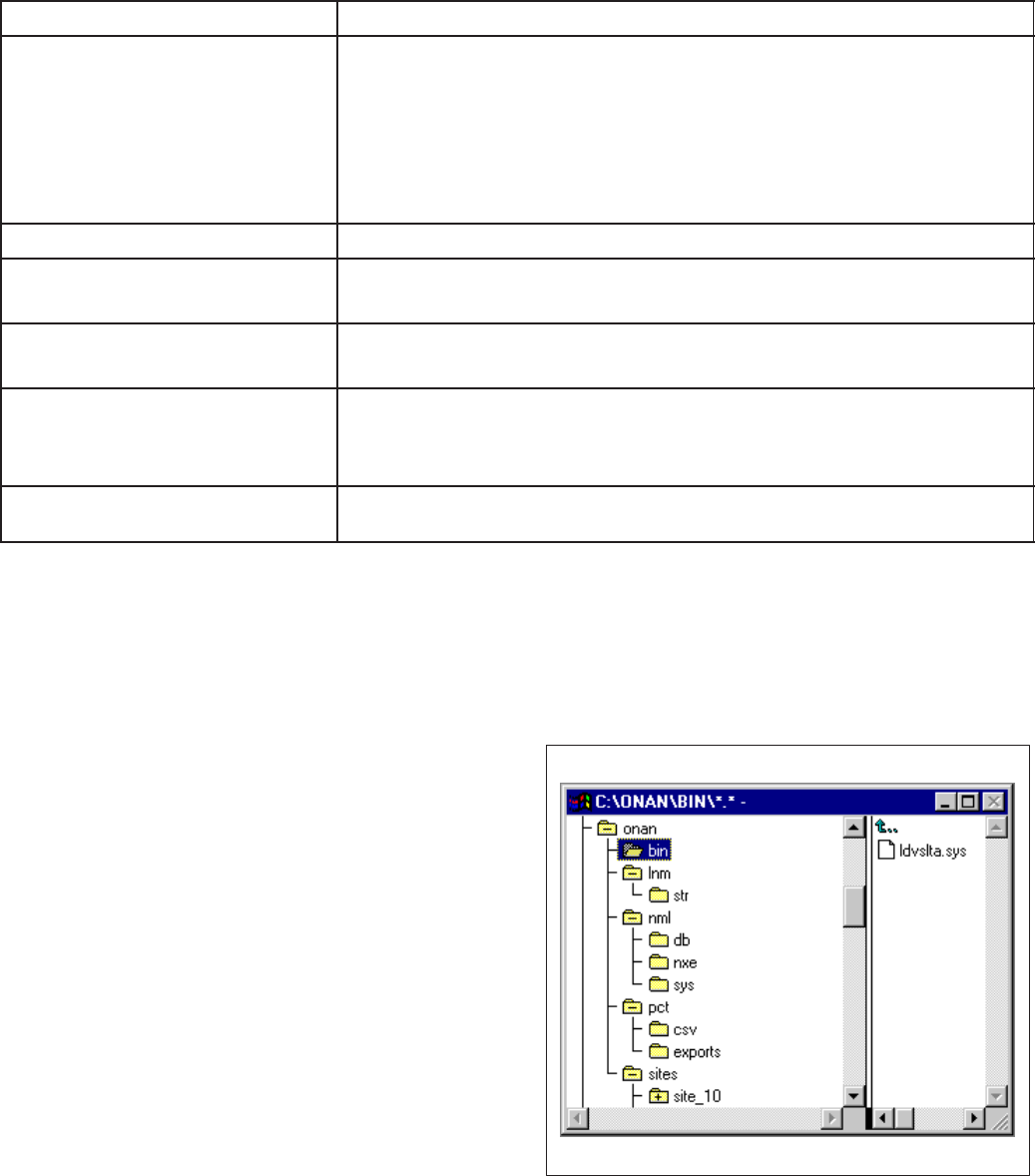
D-5
TABLE D-4. MODULES AND MISCELLANEOUS PROBLEMS/ERROR CODES
PROBLEM “MESSAGE” CORRECTIVE ACTION
1. Any Module type – Code
will not load into module
during install.
“The device whose service
pin was pressed (or NID...)
is not of the correct type...”
(C 22) – or similar message.
1a. Wrong module type.
1b. Pressing the wrong service pin.
1c. Cycle power to the module and retry install.
1d. Refer to LonMaker Users Guide, Error Message and
Troubleshooting section.
2. CCM Relays will not toggle. 2a. Reset the CCM.
3. CCM/GCM alarms not
dialing out. 3a. Check configuration in PCT.
3b. Reset module.
4. GCM not responding to
Start/Stop command. 4a. Reset the GCM.
5. NGM Password not working
(wrong/old password being
accepted by NGM.)
5a. Cycle power on the NGM to initialize the new password.
6. Site modem not answering. 6a. Write Modem Init string to NGM (with PCT). Make sure S∅=1
6b. Cycle power on NGM to initialize modem.
COM Port Connection Problems
Check the COM port connection. Verify that the
cable is attached to the correct COM port as speci-
fied when the driver was loaded in the config.sys file
(/p1, /p2, etc.). IF PCW is setup to use the same
COM port as PCT, make sure that PCW is not oper-
ating before attaching to the site with PCT.
A connection problem can occur with some comput-
ers when exiting PCT in Windows 95 to run Lon-
Maker. If LonMaker will not attach to the site, Win-
dows 95 may not be releasing the port.
If this occurs, the port will need to be disabled and
re-enabled. Use Device Manager, located in the
System folder of Control Panel, in Windows 95. Un-
der Ports, select the COM port that the NGM is at-
tached to and select Properties. Under Device
Usage, unselect the check box to disable the port,
then click OK. Repeat this procedure and click on
the check box to select it and enable the COM port,
then click OK.
File Directory
When the Network Module Library and the Power-
Command Configuration Tool software are installed
on the installation PC, the file directory structure
should appear as shown in Figure D-1.
FIGURE D-1. FILE DIRECTORY STRUCTURE
Redistribution or publication of this document,
by any means, is strictly prohibited.
D-6
Redistribution or publication of this document,
by any means, is strictly prohibited.

E-1
' & )&3
DRAWING
NUMBER DESCRIPTION PAGE
630-1670 PowerCommand Network Interconnect E-2. . . . . . . . . . . . . . . . . . . . . . . . . . . . .
630-1671 Controls Communications Module Interconnect E-5. . . . . . . . . . . . . . . . . . . . . . .
630-1672 Network Annunciator Module Interconnect E-7. . . . . . . . . . . . . . . . . . . . . . . . . . .
630-1673 Digital I/O Module Interconnect E-9. . . . . . . . . . . . . . . . . . . . . . . . . . . . . . . . . . . . .
630-1723 Controls Communications Module - ATS Interconnect E-10. . . . . . . . . . . . . . . .
630-1724 Controls Communications Module - Genset Interconnect E-14. . . . . . . . . . . . .
Redistribution or publication of this document,
by any means, is strictly prohibited.
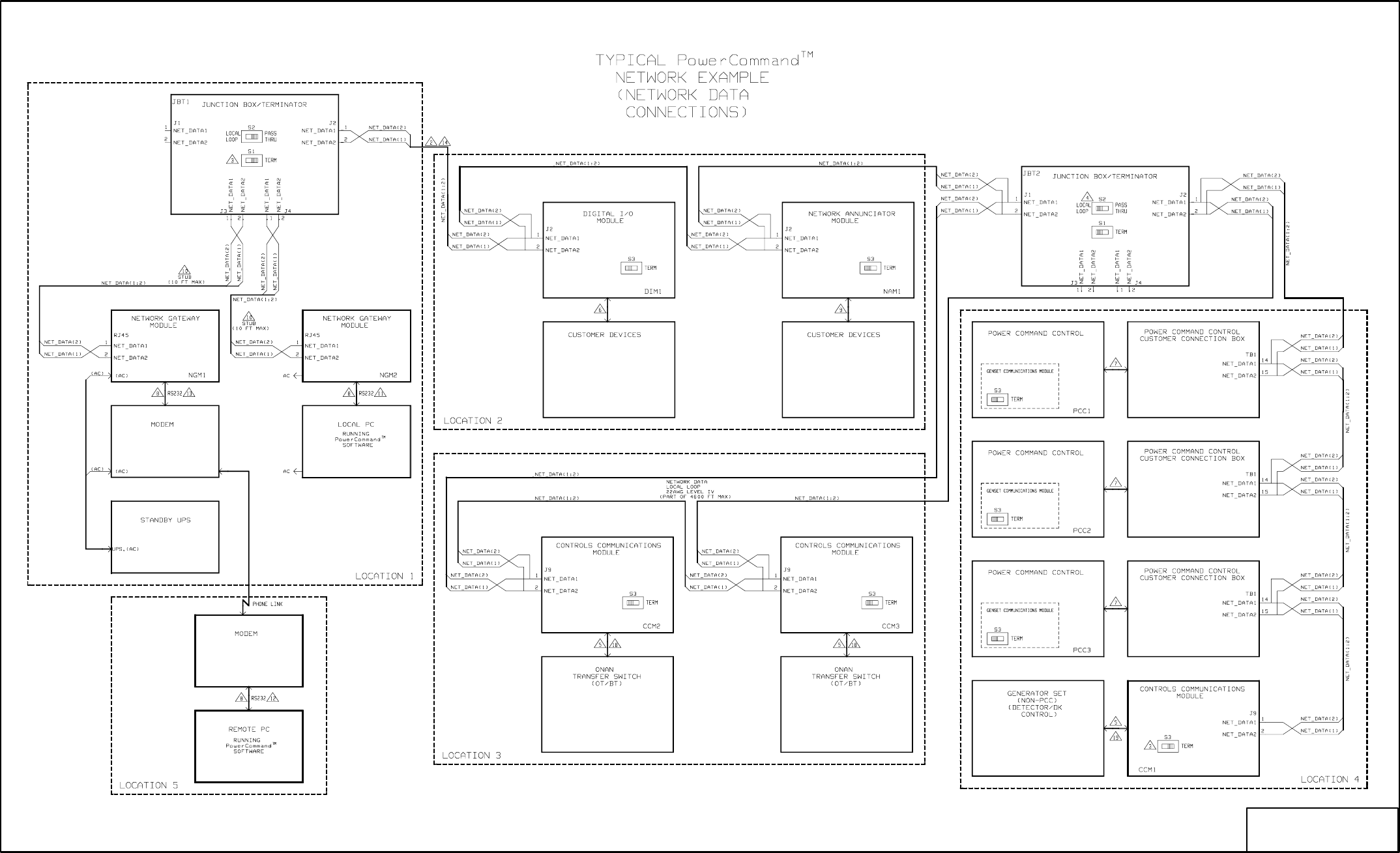
E-2
No. 630-1670 sh 1 of 3
Rev. C Sys: HP
Modified 797
(UPS)
(UPS)
FIGURE E-1. POWERCOMMAND NETWORK INTERCONNECT (1 of 3)
Redistribution or publication of this document,
by any means, is strictly prohibited.
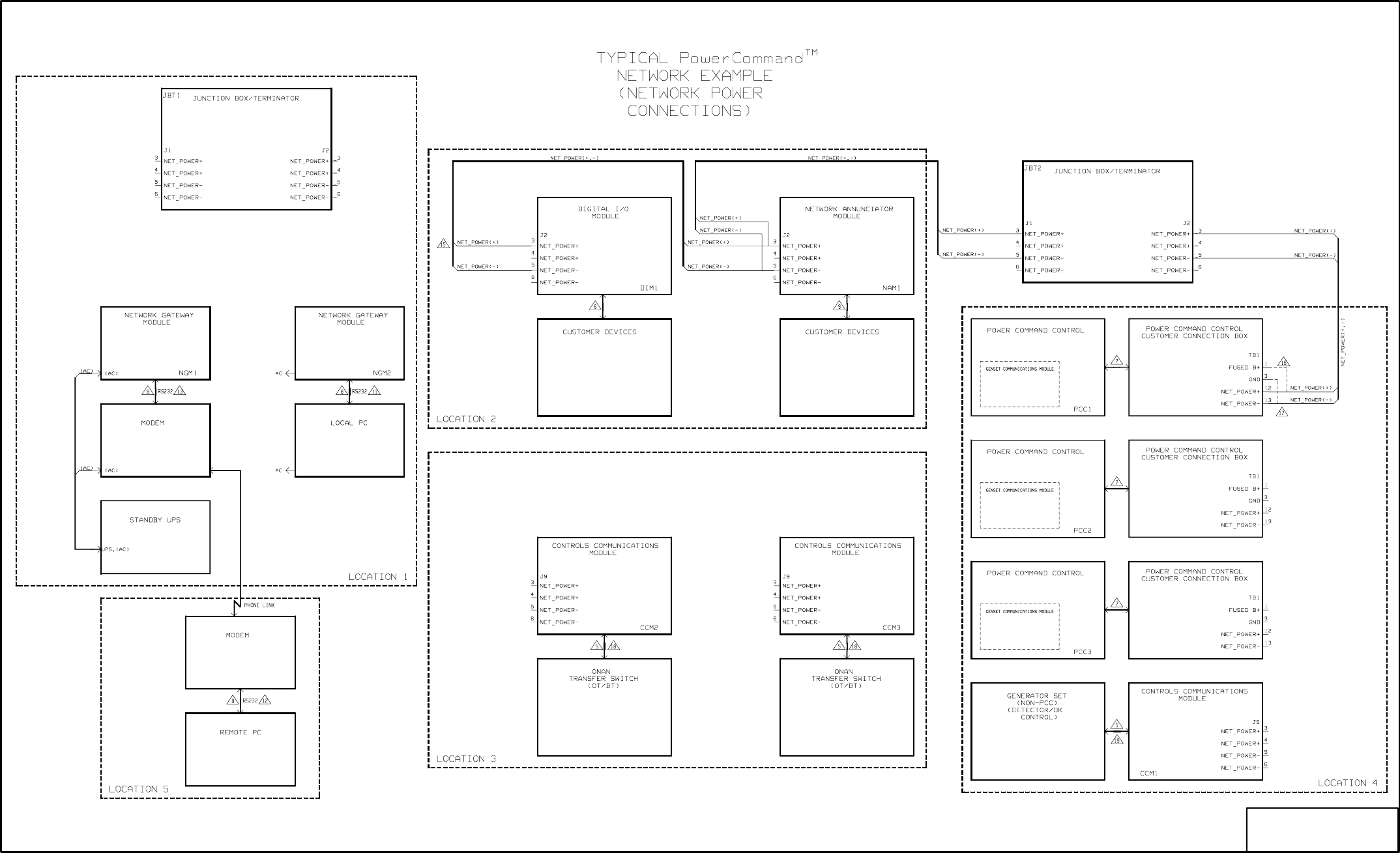
E-3
No. 630-1670 sh 2 of 3
Rev. C Sys: HP
Modified 7-97
(UPS)
(UPS)
FIGURE E-2. POWERCOMMAND NETWORK INTERCONNECT (2 of 3)
Redistribution or publication of this document,
by any means, is strictly prohibited.
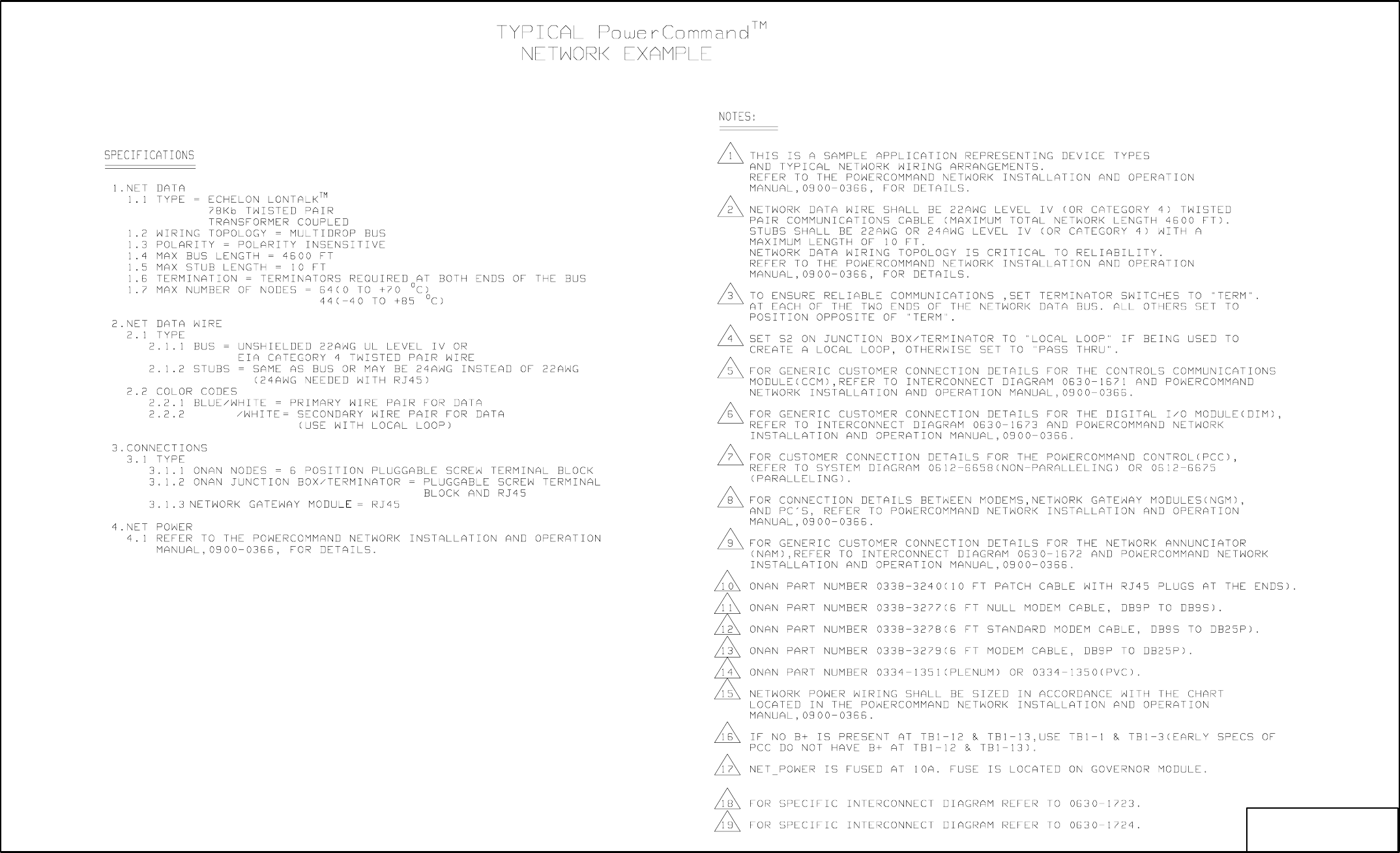
E-4
No. 630-1670 sh 3of 3
Rev. C Sys: HP
Modified 797
ORANGE
FIGURE E-3. POWERCOMMAND NETWORK INTERCONNECT (3 of 3)
Redistribution or publication of this document,
by any means, is strictly prohibited.

E-5
No. 630-1671 sh 1 of 2
Rev. B Sys: HP
Modified 4/97
FIGURE E-4 CONTROLS COMMUNICATIONS MODULE INTERCONNECT (1 of 2)
Redistribution or publication of this document,
by any means, is strictly prohibited.
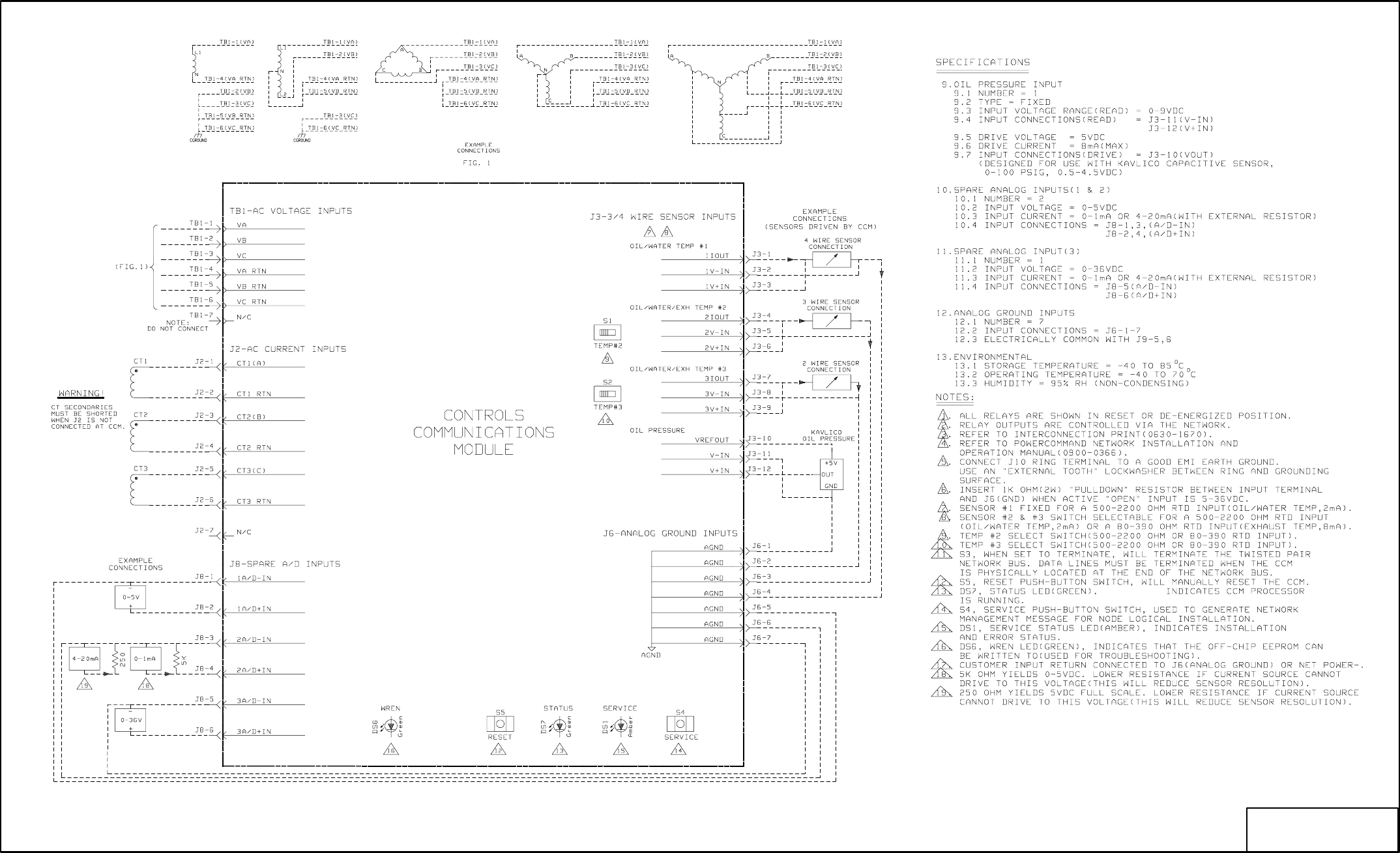
E-6
No. 630-1671 sh 2of 2
Rev. B Sys: HP
Modified 4/97
FLASHING
FIGURE E-5. CONTROLS COMMUNICATIONS MODULE INTERCONNECT (2 OF 2)
Redistribution or publication of this document,
by any means, is strictly prohibited.
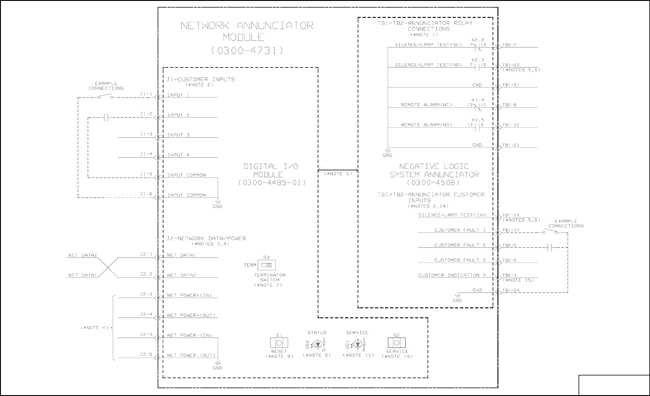
E-7
No. 630-1672 sh 1 of 2
Rev. A Sys: HP
Modified 9/11/95
FIGURE E-6. NETWORK ANNUNCIATOR MODULE INTERCONNECT (1 of 2)
Redistribution or publication of this document,
by any means, is strictly prohibited.
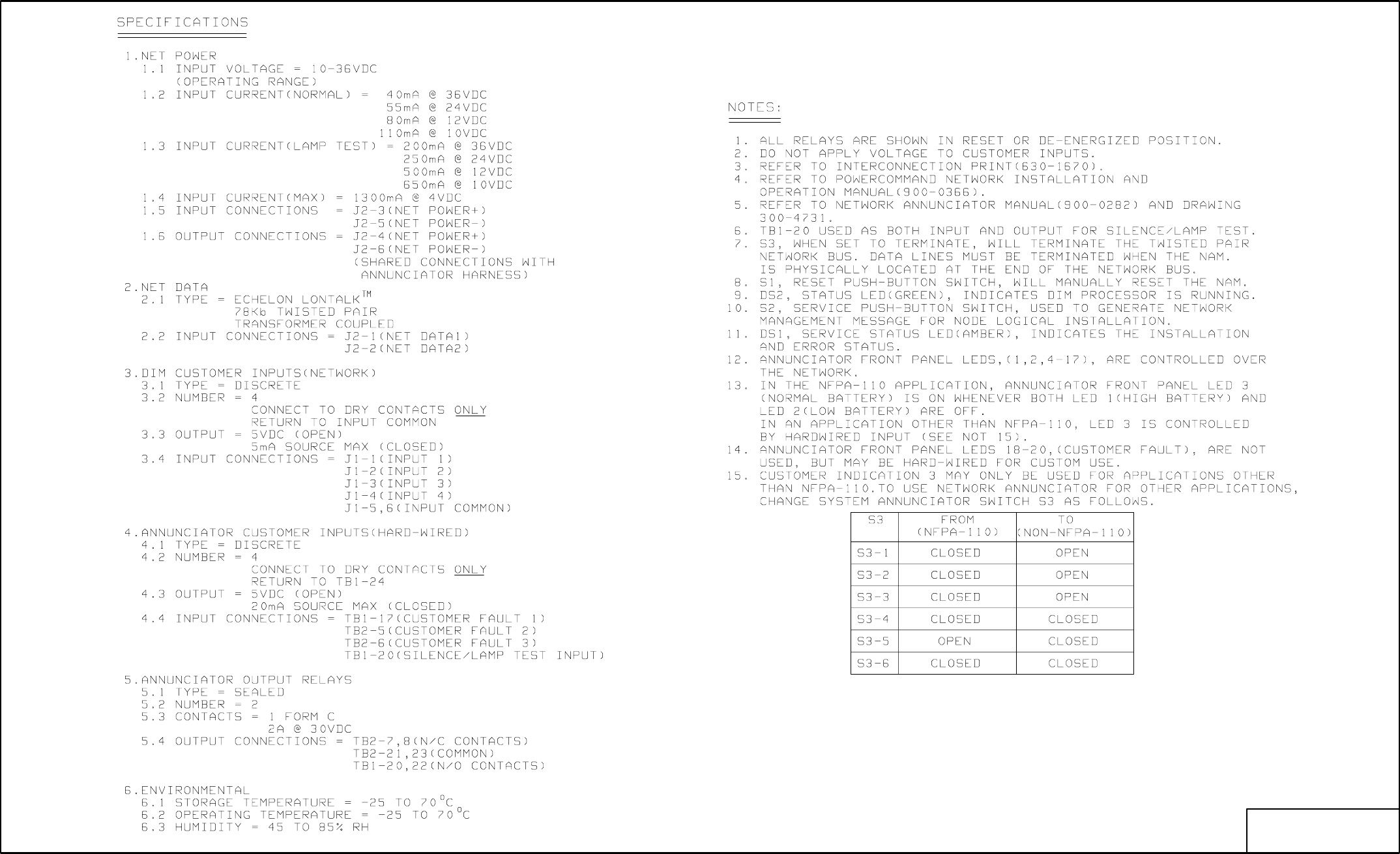
E-8
No. 630-1672 sh 2of 2
Rev. A Sys: HP
Modified 9/11/95
FIGURE E-7. NETWORK ANNUNCIATOR MODULE INTERCONNECT (2 of 2)
Redistribution or publication of this document,
by any means, is strictly prohibited.
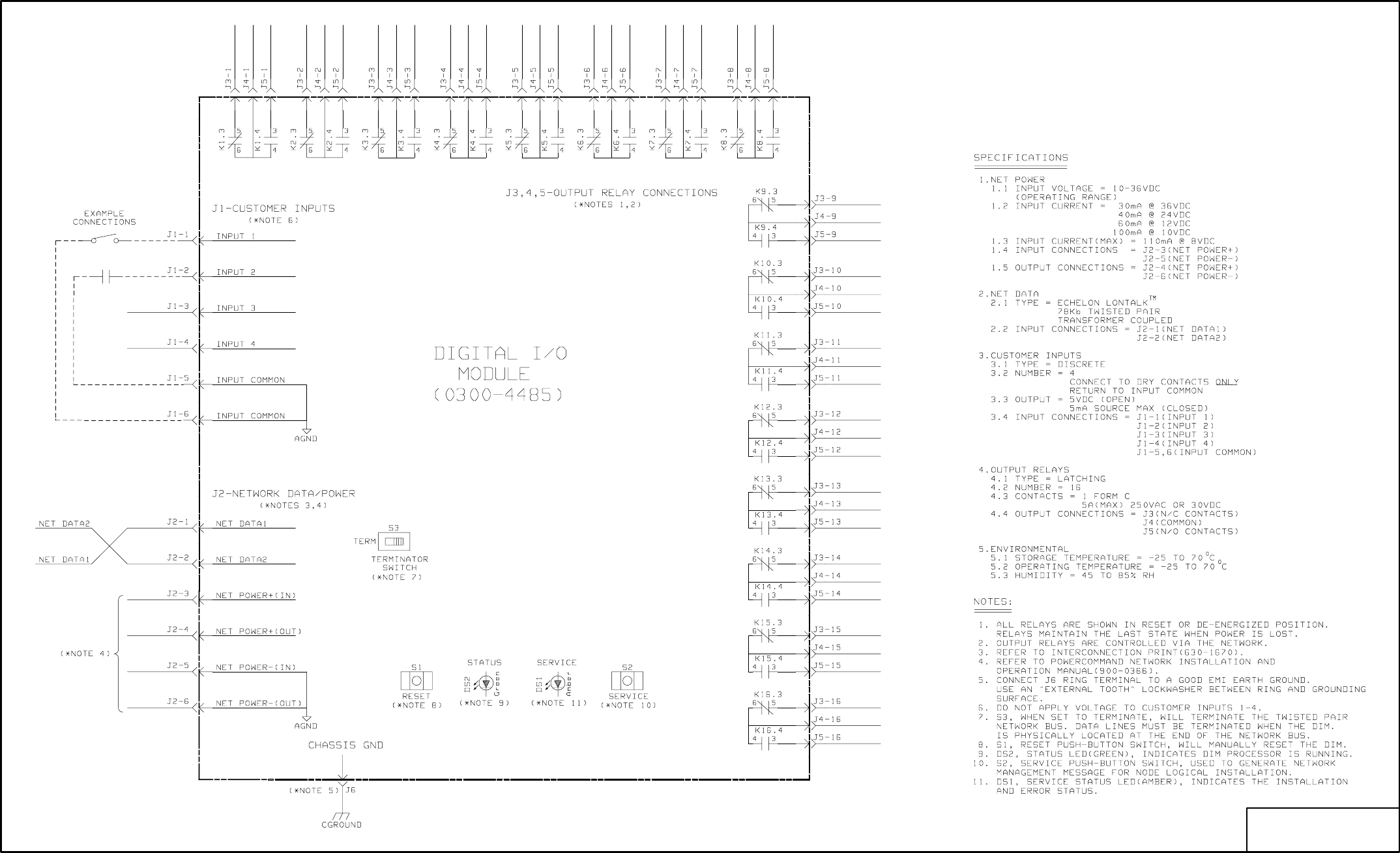
E-9
No. 630-1673 sh 1of 1
Rev. A Sys: HP
Modified 9/11/95
FIGURE E-8. DIGITAL I/O MODULE INTERCONNECT (1 of 1)
Redistribution or publication of this document,
by any means, is strictly prohibited.
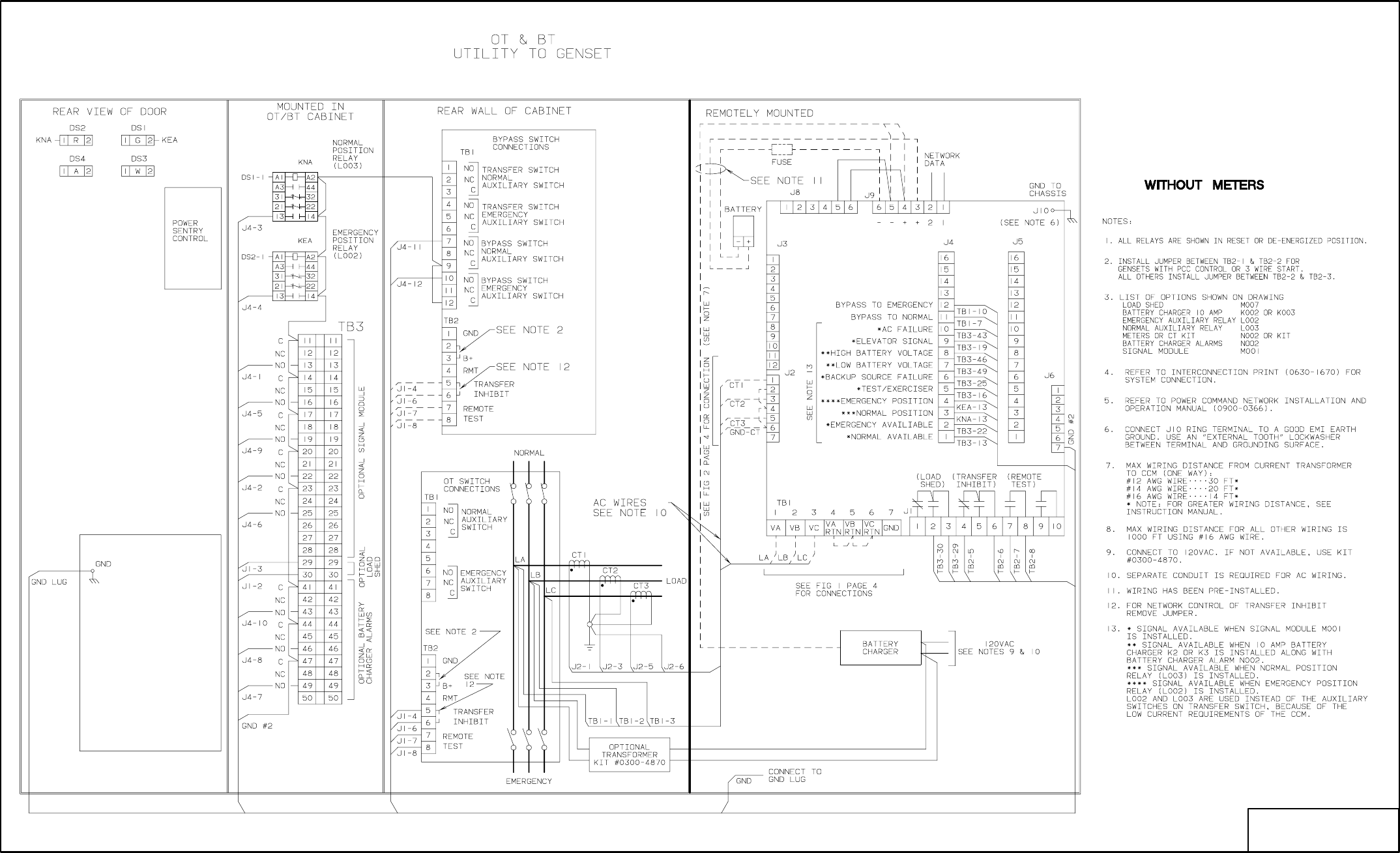
E-10
No. 630-1723 sh 1of 4
Rev. B Sys: CADAM
Modified 11/10/95
CCM
FIGURE E-9. CONTROLS COMMUNICATIONS MODULE - ATS INTERCONNECT (1 of 4)
Redistribution or publication of this document,
by any means, is strictly prohibited.

E-11
No. 630-1723 sh 2 of 4
Rev. B Sys: CADAM
Modified 11/10/95
CCM
SEE FIGURE E9
FOR NOTES
FIGURE E-10 CONTROLS COMMUNICATIONS MODULE - ATS INTERCONNECT (2 of 4)
Redistribution or publication of this document,
by any means, is strictly prohibited.
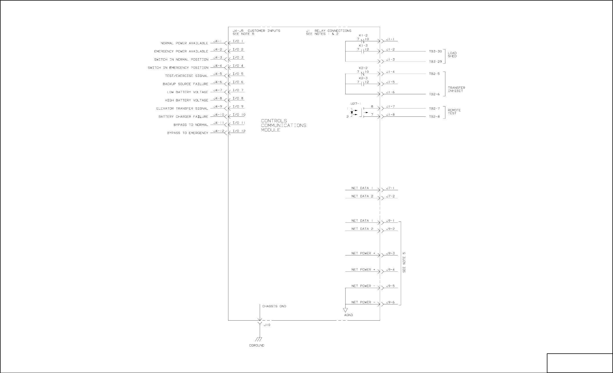
E-12
No. 630-1723 sh 3 of 4
Rev. B Sys: CADAM
Modified 11/10/95
SEE FIGURE E9
FOR NOTES
FIGURE E-11. CONTROLS COMMUNICATIONS MODULE - ATS INTERCONNECT (3 of 4)
Redistribution or publication of this document,
by any means, is strictly prohibited.
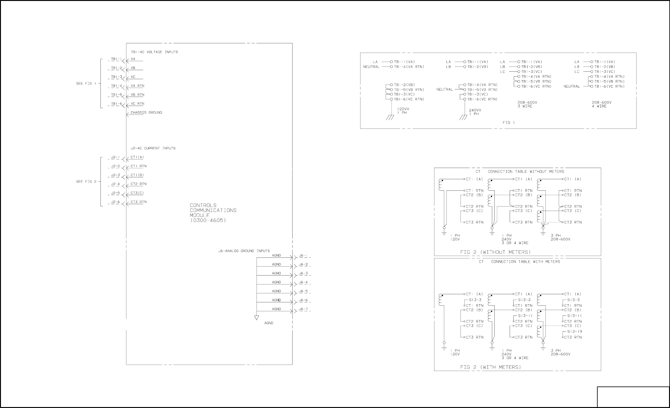
E-13
No. 630-1723 sh 4 of 4
Rev. B Sys: CADAM
Modified 11/10/95
SEE FIGURE E9
FOR NOTES
OUTPUT CONNECTIONS
FIGURE E-12. CONTROLS COMMUNICATIONS MODULE - ATS INTERCONNECT (4 of 4)
Redistribution or publication of this document,
by any means, is strictly prohibited.

E-14
No. 630-1724 sh 1of 2
Rev. B Sys: CADAM
Modified 4/97
FROM: TO:
CCM
(J10)
FIGURE E-13. CONTROLS COMMUNICATIONS MODULE - GENSET INTERCONNECT (1 of 2)
Redistribution or publication of this document,
by any means, is strictly prohibited.
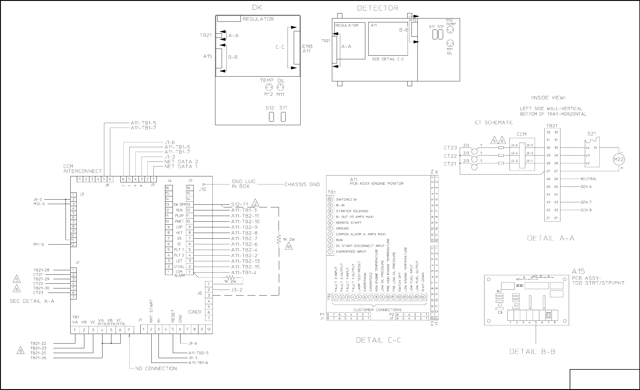
E-15
No. 630-1724 sh 2 fo 2
Rev. B Sys: CADAM
Modified 4/97
FIGURE E-14. CONTROLS COMMUNICATIONS MODULE - GENSET INTERCONNECT (2 of 2)
Redistribution or publication of this document,
by any means, is strictly prohibited.

F-1
+ !@
This section contains a partial index of terms that
are used when installing a network.
S
S .CSV File 3-2
S .PCT File 4-8
A
Address Table C-3
Analog Inputs – CCM 4-20
B
Back-up Site 3-21, 4-8, 4-32
Binding 3-2, C-1, C-10
Boolean Variables C-5
C
Cables 7-4
CCM (General) 4-16
CCM-ATS 11-1
CCM-GenSet 10-1
Channel – LonMaker 3-10, 12-6
COM Port D-5
Control – LonMaker 3-26
D
Device setup – LonMaker 3-14
Devicehigh or LoadHigh (DOS) 3-4, 4-2
DIM 6-1, 9-1, C-3
Discrete Inputs – CCM 4-24
Domain – LonMaker 3-8
E
Error Codes D-1
Event Type (PCT Discrete Inputs) 4-24
F
File Export/Import Site (PCT) 4-8
Forms C-13
G
GCM (PowerCommand Control) 4-26, 5-1
I
Installation (Binding) – LonMaker 3-17, 12-6
J
JBT 3-5, 8-1
L
ldvslta.sys 3-4
Load Factor 2-11
LoadHigh – LH... (DOS) 3-4, 4-2
Location – LonMaker 3-12
LonMaker 3-1, 3-5
M
Message Tag C-7
Modem 4-30, B-1
Multi-Site Communications Module B-1
N
NAM 9-1
Network Variables C-1, 5-13, 6-8, 7-5, 9-8, 10-12,
11-11
NGM 2-3, 3-5, 4-27, 7-1
NML – Network Module Library 3-4
P
Pairing Modules (PCT) 4-33
Password 4-27
PCT – PowerCommand Configuration Tool 4-1
R
Relays – CCM 4-19
Relays – DIM 6-2
Repair/Replace – LonMaker 3-28
Reset Network 4-32
RJ45 2-8
Router 3-16, 12-1
S
Sender Settings (Gain, etc.) C-8
Site 3-4, 4-12
T
Terminate network data lines 2-5, 5-7, 6-4, 8-3, 10-11,
11-10
Troubleshooting D-1
U
UPS (Uninterruptable Power Supply) B-1
W
Wire Color Code 2-6
Wire Conduit 6-6, 10-6, 11-6
Wire Lengths 2-5
Wire Size for CT’s 10-18, 11-8
Wire Size for DC power 2-11
Wire Type 2-6
Redistribution or publication of this document,
by any means, is strictly prohibited.
F-2
Redistribution or publication of this document,
by any means, is strictly prohibited.

Cummins Power Generation
1400 73rd Avenue N.E.
Minneapolis, MN 55432
1-800-888-6626
763-574-5000 International Use
Fax: 763-528-7229
Cummins is a registered trademark of Cummins Inc.
Onan and PowerCommand are registered trademarks of Cummins Inc.
The Power of One is a trademark of Cummins Inc.
Hayes is a registered trademark of Hayes Microcomputer Products Inc.
IBM is a registered trademark of IBM Corporation
LONWORKS is a trademark of Echelon Corporation
Microsoft is a registered trademark of Microsoft Corporation
Windows is a trademark of Microsoft Corporation
Redistribution or publication of this document,
by any means, is strictly prohibited.
