900 0520D 0520 Onan DFHA DFHB DFHC DFHD (spec A J) Genset Operators Manual (10 2011)
User Manual: 900-0520 Onan DFHA DFHB DFHC DFHD (spec A-J) Genset Operators manual (10-2011)
Open the PDF directly: View PDF ![]() .
.
Page Count: 219 [warning: Documents this large are best viewed by clicking the View PDF Link!]

Operator Manual
Generator Set
DFHA (Spec A−J)
DFHB (Spec A−J)
DFHC (Spec A−J)
DFHD (Spec A−J)
with PowerCommandR 3100 Controller
English − Original Instructions 10−2011 900−0520 (Issue 7)


i
Table of Contents
SECTION TITLE PAGE
IMPORTANT SAFETY INSTRUCTIONS iii. . . . . . . . . . . . . . . . . . . . . . . . . . . . . . .
1 INTRODUCTION
About this Manual 1-1. . . . . . . . . . . . . . . . . . . . . . . . . . . . . . . . . . . . . . . . . . . . . . .
Test Equipment 1-1. . . . . . . . . . . . . . . . . . . . . . . . . . . . . . . . . . . . . . . . . . . . . . . . . .
How To Obtain Service 1-1. . . . . . . . . . . . . . . . . . . . . . . . . . . . . . . . . . . . . . . . . . .
System Overview 1-2. . . . . . . . . . . . . . . . . . . . . . . . . . . . . . . . . . . . . . . . . . . . . . . .
Generator Set Control Function 1-2. . . . . . . . . . . . . . . . . . . . . . . . . . . . . . . . . . .
2 CONTROL OPERATION
General 2-1. . . . . . . . . . . . . . . . . . . . . . . . . . . . . . . . . . . . . . . . . . . . . . . . . . . . . . . .
Safety Considerations 2-1. . . . . . . . . . . . . . . . . . . . . . . . . . . . . . . . . . . . . . . . . . . .
Sequence of Operation 2-2. . . . . . . . . . . . . . . . . . . . . . . . . . . . . . . . . . . . . . . . . . .
PCC Power On/Standby Mode 2-2. . . . . . . . . . . . . . . . . . . . . . . . . . . . . . . . . . . .
Front Panel 2-4. . . . . . . . . . . . . . . . . . . . . . . . . . . . . . . . . . . . . . . . . . . . . . . . . . . . .
Menu Display and Switches 2-6. . . . . . . . . . . . . . . . . . . . . . . . . . . . . . . . . . . . . . .
Main Menu 2-6. . . . . . . . . . . . . . . . . . . . . . . . . . . . . . . . . . . . . . . . . . . . . . . . . . . . .
Engine Menu 2-8. . . . . . . . . . . . . . . . . . . . . . . . . . . . . . . . . . . . . . . . . . . . . . . . . . . .
Gen Menu 2-10. . . . . . . . . . . . . . . . . . . . . . . . . . . . . . . . . . . . . . . . . . . . . . . . . . . . .
3 CIRCUIT BOARDS AND MODULES
General 3-1. . . . . . . . . . . . . . . . . . . . . . . . . . . . . . . . . . . . . . . . . . . . . . . . . . . . . . . .
Digital Board (A32) 3-3. . . . . . . . . . . . . . . . . . . . . . . . . . . . . . . . . . . . . . . . . . . . . .
Engine Interface Board (A31) 3-4. . . . . . . . . . . . . . . . . . . . . . . . . . . . . . . . . . . . .
Analog Board (A33) 3-6. . . . . . . . . . . . . . . . . . . . . . . . . . . . . . . . . . . . . . . . . . . . . .
Digital Display Board (A35) 3-7. . . . . . . . . . . . . . . . . . . . . . . . . . . . . . . . . . . . . . .
Customer Interface Board (A34) 3-8. . . . . . . . . . . . . . . . . . . . . . . . . . . . . . . . . . .
PT/CT Board (A36) 3-10. . . . . . . . . . . . . . . . . . . . . . . . . . . . . . . . . . . . . . . . . . . . .
Bus PT Board (A39) 3-11. . . . . . . . . . . . . . . . . . . . . . . . . . . . . . . . . . . . . . . . . . . .
Genset Communications Module (A41) 3-12. . . . . . . . . . . . . . . . . . . . . . . . . . . .
Voltage Regulator Output Module (A37) 3-13. . . . . . . . . . . . . . . . . . . . . . . . . . .
Governor Output Module (A38) 3-14. . . . . . . . . . . . . . . . . . . . . . . . . . . . . . . . . . .
Master First Start Sensor 3-15. . . . . . . . . . . . . . . . . . . . . . . . . . . . . . . . . . . . . . . .
4 TROUBLESHOOTING
General 4-1. . . . . . . . . . . . . . . . . . . . . . . . . . . . . . . . . . . . . . . . . . . . . . . . . . . . . . . .
Safety Considerations 4-1. . . . . . . . . . . . . . . . . . . . . . . . . . . . . . . . . . . . . . . . . . . .
Status Indicators 4-2. . . . . . . . . . . . . . . . . . . . . . . . . . . . . . . . . . . . . . . . . . . . . . . .
Resetting the Control 4-2. . . . . . . . . . . . . . . . . . . . . . . . . . . . . . . . . . . . . . . . . . . .
Warning and Shutdown Codes 4-3. . . . . . . . . . . . . . . . . . . . . . . . . . . . . . . . . . . .
PCC Oil Pressure Warning and Shutdown Limits 4-12. . . . . . . . . . . . . . . . . . .
Troubleshooting Procedure 4-13. . . . . . . . . . . . . . . . . . . . . . . . . . . . . . . . . . . . . .
PCC Fuses 4-57. . . . . . . . . . . . . . . . . . . . . . . . . . . . . . . . . . . . . . . . . . . . . . . . . . . .
Rack Position Fault/Test Procedure 4-58. . . . . . . . . . . . . . . . . . . . . . . . . . . . . . .
Load Sharing Controls Troubleshoot Procedure 4-59. . . . . . . . . . . . . . . . . . . .

ii
SECTION TITLE PAGE
5 CONTROL SERVICE AND CALIBRATION
General 5-1. . . . . . . . . . . . . . . . . . . . . . . . . . . . . . . . . . . . . . . . . . . . . . . . . . . . . . . .
Circuit Board Removal/Replacement 5-1. . . . . . . . . . . . . . . . . . . . . . . . . . . . . . .
Initial Start Setup Menu 5-4. . . . . . . . . . . . . . . . . . . . . . . . . . . . . . . . . . . . . . . . . .
Adjust Menu 5-6. . . . . . . . . . . . . . . . . . . . . . . . . . . . . . . . . . . . . . . . . . . . . . . . . . . .
Setup and Calibration Menus 5-8. . . . . . . . . . . . . . . . . . . . . . . . . . . . . . . . . . . . .
Calibration Procedure 5-28. . . . . . . . . . . . . . . . . . . . . . . . . . . . . . . . . . . . . . . . . . .
Engine Torque Adjustment 5-30. . . . . . . . . . . . . . . . . . . . . . . . . . . . . . . . . . . . . . .
Accessory Box Control Components 5-31. . . . . . . . . . . . . . . . . . . . . . . . . . . . . .
Engine Sensors 5-44. . . . . . . . . . . . . . . . . . . . . . . . . . . . . . . . . . . . . . . . . . . . . . . .
Magnetic Speed Pickup Unit (MPU) Installation 5-45. . . . . . . . . . . . . . . . . . . . .
Current Transformer (CT) Installation 5-46. . . . . . . . . . . . . . . . . . . . . . . . . . . . . .
Digital Board (A32) Calibration 5-47. . . . . . . . . . . . . . . . . . . . . . . . . . . . . . . . . . .
6 SERVICING THE GENERATOR
General 6-1. . . . . . . . . . . . . . . . . . . . . . . . . . . . . . . . . . . . . . . . . . . . . . . . . . . . . . . .
Generator/PCC Control Isolation Procedure 6-2. . . . . . . . . . . . . . . . . . . . . . . . .
Testing the Generator 6-3. . . . . . . . . . . . . . . . . . . . . . . . . . . . . . . . . . . . . . . . . . . .
Exciter Stator 6-5. . . . . . . . . . . . . . . . . . . . . . . . . . . . . . . . . . . . . . . . . . . . . . . . . . .
Exciter Rectifier Bridge (Rotating Rectifier Assembly) 6-6. . . . . . . . . . . . . . . .
Exciter Rotor 6-7. . . . . . . . . . . . . . . . . . . . . . . . . . . . . . . . . . . . . . . . . . . . . . . . . . . .
Main Rotor (Generator Field) 6-8. . . . . . . . . . . . . . . . . . . . . . . . . . . . . . . . . . . . . .
Main Stator 6-9. . . . . . . . . . . . . . . . . . . . . . . . . . . . . . . . . . . . . . . . . . . . . . . . . . . . .
Testing the PMG 6-10. . . . . . . . . . . . . . . . . . . . . . . . . . . . . . . . . . . . . . . . . . . . . . . .
Bearing Inspection/Removal/Replacement 6-11. . . . . . . . . . . . . . . . . . . . . . . . .
Generator Disassembly 6-13. . . . . . . . . . . . . . . . . . . . . . . . . . . . . . . . . . . . . . . . .
Generator Reassembly 6-22. . . . . . . . . . . . . . . . . . . . . . . . . . . . . . . . . . . . . . . . . .
Aligning Generator with Engine 6-25. . . . . . . . . . . . . . . . . . . . . . . . . . . . . . . . . . .
7 DAY TANK FUEL TRANSFER PUMP AND CONTROL
Operation 7-2. . . . . . . . . . . . . . . . . . . . . . . . . . . . . . . . . . . . . . . . . . . . . . . . . . . . . . .
Wiring Connections 7-4. . . . . . . . . . . . . . . . . . . . . . . . . . . . . . . . . . . . . . . . . . . . . .
Fuel Transfer Pump Motor Connections 7-6. . . . . . . . . . . . . . . . . . . . . . . . . . . .
Testing the Float Switch Assembly 7-7. . . . . . . . . . . . . . . . . . . . . . . . . . . . . . . . .
8 INITIAL SYSTEM STARTUP
General 8-1. . . . . . . . . . . . . . . . . . . . . . . . . . . . . . . . . . . . . . . . . . . . . . . . . . . . . . . .
The Startup Process 8-1. . . . . . . . . . . . . . . . . . . . . . . . . . . . . . . . . . . . . . . . . . . . .
Equipment Application Review 8-1. . . . . . . . . . . . . . . . . . . . . . . . . . . . . . . . . . . .
Individual Generator Set Startup 8-2. . . . . . . . . . . . . . . . . . . . . . . . . . . . . . . . . . .
Manual System Operation 8-4. . . . . . . . . . . . . . . . . . . . . . . . . . . . . . . . . . . . . . . .
Automatic System Operation 8-7. . . . . . . . . . . . . . . . . . . . . . . . . . . . . . . . . . . . . .
Black Start Testing 8-8. . . . . . . . . . . . . . . . . . . . . . . . . . . . . . . . . . . . . . . . . . . . . . .
Test Reports and Acceptance 8-8. . . . . . . . . . . . . . . . . . . . . . . . . . . . . . . . . . . . .
On Site Power System Application Review
(Diesel/600VAC and Lower) 8-9. . . . . . . . . . . . . . . . . . . . . . . . . . . . . . . . . . . .
9 WIRING DIAGRAMS
General 9-1. . . . . . . . . . . . . . . . . . . . . . . . . . . . . . . . . . . . . . . . . . . . . . . . . . . . . . . .

LS-14L
iii
IMPORTANT SAFETY INSTRUCTIONS
SAVE THESE INSTRUCTIONS − This manual contains
important instructions that should be followed during
installation and maintenance of the generator and batter-
ies.
Before operating the generator set (genset), read the
Operator’s Manual and become familiar with it and the
equipment. Safe and efficient operation can be
achieved only if the equipment is properly operated
and maintained. Many accidents are caused by failure
to follow fundamental rules and precautions.
The following symbols, found throughout this manual,
alert you to potentially dangerous conditions to the oper-
ator, service personnel, or the equipment.
This symbol warns of immediate
hazards which will result in severe personal in-
jury or death.
WARNING This symbol refers to a hazard or un-
safe practice which can result in severe person-
al injury or death.
CAUTION This symbol refers to a hazard or un-
safe practice which can result in personal injury
or product or property damage.
FUEL AND FUMES ARE FLAMMABLE
Fire, explosion, and personal injury or death can result
from improper practices.
DO NOT fill fuel tanks while engine is running, un-
less tanks are outside the engine compartment.
Fuel contact with hot engine or exhaust is a potential
fire hazard.
DO NOT permit any flame, cigarette, pilot light,
spark, arcing equipment, or other ignition source
near the generator set or fuel tank.
Fuel lines must be adequately secured and free of
leaks. Fuel connection at the engine should be
made with an approved flexible line. Do not use zinc
coated or copper fuel lines with diesel fuel.
Be sure all fuel supplies have a positive shutoff
valve.
Be sure battery area has been well-ventilated prior
to servicing near it. Lead-acid batteries emit a highly
explosive hydrogen gas that can be ignited by arc-
ing, sparking, smoking, etc.
EXHAUST GASES ARE DEADLY
Provide an adequate exhaust system to properly
expel discharged gases away from enclosed or
sheltered areas and areas where individuals are
likely to congregate. Visually and audibly inspect
the exhaust daily for leaks per the maintenance
schedule. Make sure that exhaust manifolds are se-
cured and not warped. Do not use exhaust gases to
heat a compartment.
Be sure the unit is well ventilated.
Engine exhaust and some of its constituents are
known to the state of California to cause cancer,
birth defects, and other reproductive harm.
MOVING PARTS CAN CAUSE SEVERE
PERSONAL INJURY OR DEATH
Keep your hands, clothing, and jewelry away from
moving parts.
Before starting work on the generator set, discon-
nect battery charger from its AC source, then dis-
connect starting batteries, negative (−) cable first.
This will prevent accidental starting.
Make sure that fasteners on the generator set are
secure. Tighten supports and clamps, keep guards
in position over fans, drive belts, etc.
Do not wear loose clothing or jewelry in the vicinity of
moving parts, or while working on electrical equip-
ment. Loose clothing and jewelry can become
caught in moving parts.
If adjustment must be made while the unit is run-
ning, use extreme caution around hot manifolds,
moving parts, etc.
DO NOT OPERATE IN FLAMMABLE AND
EXPLOSIVE ENVIRONMENTS
Flammable vapor can cause an engine to overspeed and
become difficult to stop, resulting in possible fire, explo-
sion, severe personal injury and death. Do not operate a
genset where a flammable vapor environment can be
created by fuel spill, leak, etc., unless the genset is
equipped with an automatic safety device to block the air
intake and stop the engine. The owners and operators of
the genset are solely responsible for operating the gen-
set safely. Contact your authorized Cummins Power
Generation distributor for more information.

iv
ELECTRICAL SHOCK CAN CAUSE
SEVERE PERSONAL INJURY OR DEATH
Remove electric power before removing protective
shields or touching electrical equipment. Use rub-
ber insulative mats placed on dry wood platforms
over floors that are metal or concrete when around
electrical equipment. Do not wear damp clothing
(particularly wet shoes) or allow skin surface to be
damp when handling electrical equipment. Do not
wear jewelry. Jewelry can short out electrical con-
tacts and cause shock or burning.
Use extreme caution when working on electrical
components. High voltages can cause injury or
death. DO NOT tamper with interlocks.
Follow all applicable state and local electrical
codes. Have all electrical installations performed by
a qualified licensed electrician. Tag and lock open
switches to avoid accidental closure.
DO NOT CONNECT GENERATOR SET DIRECT-
LY TO ANY BUILDING ELECTRICAL SYSTEM.
Hazardous voltages can flow from the generator set
into the utility line. This creates a potential for elec-
trocution or property damage. Connect only
through an approved isolation switch or an ap-
proved paralleling device.
GENERAL SAFETY PRECAUTIONS
Coolants under pressure have a higher boiling point
than water. DO NOT open a radiator or heat ex-
changer pressure cap while the engine is running.
Allow the generator set to cool and bleed the system
pressure first.
Used engine oils have been identified by some state
or federal agencies as causing cancer or reproduc-
tive toxicity. When checking or changing engine oil,
take care not to ingest, breathe the fumes, or con-
tact used oil.
Keep multi-class ABC fire extinguishers handy.
Class A fires involve ordinary combustible materials
such as wood and cloth; Class B fires, combustible
and flammable liquid fuels and gaseous fuels; Class
C fires, live electrical equipment. (ref. NFPA No. 10).
Make sure that rags are not left on or near the en-
gine.
Make sure generator set is mounted in a manner to
prevent combustible materials from accumulating
under the unit.
Remove all unnecessary grease and oil from the
unit. Accumulated grease and oil can cause over-
heating and engine damage which present a poten-
tial fire hazard.
Keep the generator set and the surrounding area
clean and free from obstructions. Remove any de-
bris from the set and keep the floor clean and dry.
Do not work on this equipment when mentally or
physically fatigued, or after consuming any alcohol
or drug that makes the operation of equipment un-
safe.
Substances in exhaust gases have been identified
by some state or federal agencies as causing can-
cer or reproductive toxicity. Take care not to breath
or ingest or come into contact with exhaust gases.
Do not store any flammable liquids, such as fuel,
cleaners, oil, etc., near the generator set. A fire or
explosion could result.
Wear hearing protection when going near an oper-
ating generator set.
To prevent serious burns, avoid contact with hot
metal parts such as radiator, turbo charger and ex-
haust system.
LS-14L
iii
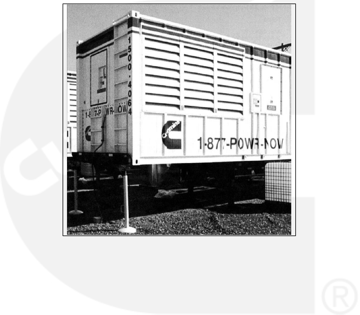
CONTAINERIZED RENTAL UNITS
POTENTIAL TIPPING PROBLEM
On all containerized rental equipment, there is a potential
problem of having the container tip forward over the land-
ing legs, pulling the axles off the ground when the con-
tainer is fully fueled without a semi-tractor under the king
pin. Jack stands for the front of the container are required
to mitigate this potential problem.
Note: The figure below shows the jack stands and
their placement at the nose of the container.
Jack Stands at Nose of Container
KEEP THIS MANUAL NEAR THE GENSET FOR EASY REFERENCE

iv
THIS PAGE LEFT INTENTIONALLY BLANK

1-1
1. Introduction
ABOUT THIS MANUAL
This manual provides troubleshooting and repair
information regarding the PowerCommand
Control 3100 (PCC) and generators for the
generator set (genset) models listed on the front
cover. Engine service instructions are in the
applicable engine service manual. Operating and
maintenance instructions are in the applicable
Operator’s Manual.
This manual does not have instructions for
servicing printed circuit board assemblies. After
determining that a printed circuit board assembly is
faulty, replace it. Do not repair it. Attempts to repair a
printed circuit board can lead to costly damage to
the equipment.
This manual contains basic (generic) wiring
diagrams and schematics that are included to help
in troubleshooting. Service personnel must use the
actual wiring diagram and schematic shipped with
each unit. The wiring diagrams and schematics that
are maintained with the unit should be updated
when modifications are made to the unit.
Read Important Safety Instructions and carefully
observe all instructions and precautions in this
manual.
TEST EQUIPMENT
To perform the test procedures in this manual, the
following test equipment must be available
True RMS meter for accurate measurement of
small AC and DC voltages. Fluke models 87 or
8060A are good choices.
Grounding wrist strap to prevent circuit board
damage due to electrostatic discharge (ESD).
Battery Hydrometer
Jumper Leads
Tachometer or Frequency Meter
Wheatstone Bridge or Digital Ohmmeter
Variac
Load Test Panel
Megger or Insulation Resistance Meter
PCC Service Tool Kit (Harness Tool and Sen-
sor Tool)
HOW TO OBTAIN SERVICE
Always give the complete Model, Specification and
Serial number of the generator set as shown on the
nameplate when seeking additional service
information or replacement parts. The nameplate is
located on the side of the generator output box.
WARNING Incorrect service or replacement of
parts can result in severe personal injury or
death, and/or equipment damage. Service per-
sonnel must be trained and experienced to per-
form electrical and mechanical service. Read
and follow Important Safety Instructions, on
pages iii and iv.
.
1-2
SYSTEM OVERVIEW
The PCC is a microprocessor-based control for
Onan generator sets. It provides fuel control and
engine speed governing, main alternator voltage
output regulation, and complete generator set
control and monitoring. It also provides controls for
automatic and semi-automatic synchronizing and
automatic load sharing controls for both isolated
bus or utility (mains) paralleling applications.
The operating software provides control of the
generator set and its performance characteristics,
and displays performance information on a digital
display panel. It accepts menu-driven control and
setup input from the push button switches on the
front panel.
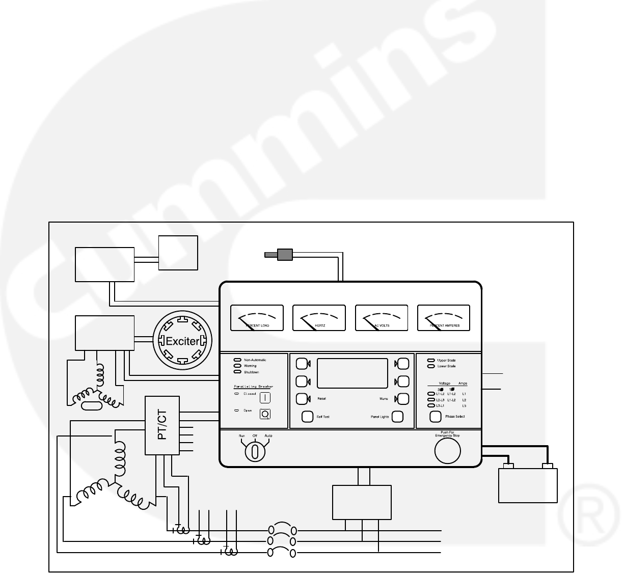
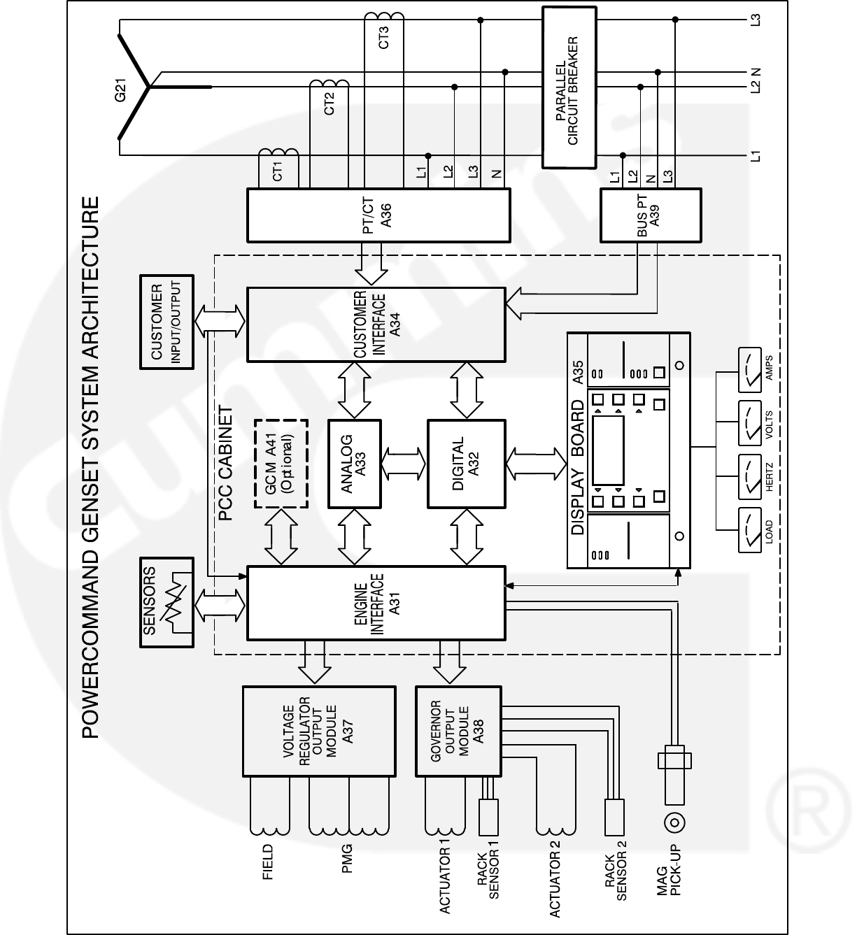
GENERATOR SET CONTROL FUNCTION
Figure1-1 shows some of the control functions. A
more complete block diagram is provided in Section
3. A system schematic is provided in Section 9.
The PCC monitors frequency from both the
magnetic pick-up (MPU) and the main stator inputs.
The control sends a low power pulse-width
modulated (PWM) signal to the governor output
module, which then sends an amplified signal to the
engine fuel control.
The Bus PT module reduces the bus voltage to
approximately 18 VAC and provides a signal to the
control for reference in synchronizing the generator
set to the system bus.
The external PT/CT module reduces generator
voltage to approximately 18 VAC, and produces a
representative AC voltage from CT output current.
The voltage regulation function sends a low power
PWM signal to the voltage regulator output module,
which then sends an amplified signal to the exciter
stator.
Oil, coolant, and exhaust temperatures are sensed
by variable resistance element sensors. Oil
pressure is sensed by a capacitive element active
sensor.
Sensors
Governor
Output
Output
MPU
NS
PMG
Battery
BT1
Fuel
Control
Bus PT
Module
Regulator
Load
To
1
1
234
2
3
4
FIGURE 1-1. GENERATOR SET CONTROL FUNCTIONS

2-1
2. Control Operation
GENERAL
The following describes the function and operation
of the PowerCommandgenerator set control. All in-
dicators, displays, meters and control switches are
located on the face of the control panel as illustrated
in Figure 2-1.
The PCC control cabinet must be opened only by
technically qualified personnel.
Normally, generator set configuration options are
set at the factory. When a new control is installed on
a generator set or when parts are replaced, the con-
trol must be configured for that generator set with
the use of the “Initial Start Setup” portion of the inter-
nal software. Setup and calibration procedures are
described in Section 5.
The automatic voltage regulator (AVR) and gover-
nor operation characteristic adjustments are also
described in Section 5.
SAFETY CONSIDERATIONS
AC power is present when the set is running. Do not
open the generator output box while the set is run-
ning.
WARNING Contacting high voltage compo-
nents can cause electrocution, resulting in se-
vere personal injury or death. Do not open the
generator output box while the set is running.
Read and observe all WARNINGS and CAU-
TIONS in your generator set manuals.
CAUTION The PCC control cabinet must be
opened only by technically qualified personnel.
Lower level voltages (18 VAC to 24 VDC) are
present in PCC control cabinet. These voltages
can cause electrical shock, resulting in person-
al injury.
Even with power removed, improper handling
of components can cause electrostatic dis-
charge and damage to circuit components.

2-2
SEQUENCE OF OPERATION
When the PowerCommand control is in the AUTO
mode, it will cause the generator set to start on re-
ceiving a signal from a remote device. The Power-
Command control will initiate a starter cranking sig-
nal and verify that the engine is rotating. The Power-
Command control will provide sufficient fuel to the
engine to accelerate to start disconnect speed. On
reaching that speed, the control will ramp the gener-
ator set to rated speed and voltage.
On reaching rated speed and voltage, the Power-
Command control checks the system bus voltage. If
no bus voltage is present, it will wait for a pulse from
a remote Master First Start Sensor. On receiving
that pulse, the control will signal the paralleling
breaker to close.
If bus voltage is present, the PowerCommand con-
trol will check for proper phase rotation, adjust the
generator set to the bus voltage and frequency lev-
el, and then synchronize the generator set to the
system bus. When a synchronous condition is
achieved, the control will send a signal to close the
paralleling breaker.
When the paralleling breaker is closed, the genera-
tor set will assume it’s proportional share of the total
load on the system bus.
PCC POWER ON / STANDBY MODE
Standby Mode
In the Standby (sleep) mode (selector switch S5 on
the Digital Board is set to the right and the generator
set is not running), the control’s operating software
is inactive and the LEDs and displays on front panel
are all off.
The operating software is initialized and the front
panel is turned on in response to a run signal or any
one of eight “wake up” inputs from remote sensing
switches.
The wake up signals are:
Emergency Stop
Low Coolant Level
Low Coolant Temperature
Low Fuel
Customer Fault Inputs 2 and 3
Run Selected on Run/Off/Auto Switch
Remote Start Signal in Auto Mode
Self Test switch
To activate and view the menu displays, press and
release the Self Test switch. The PCC will initialize
the operating software and permit operation of the
menu display panel. If no menu selections are
made, the power to the control panel will shut down
after 30 seconds.
Power On Mode
In the Power On (awake) mode (selector switch S5
on the Digital Board is set to the left), the PCC will
initialize the operating software and permit opera-
tion of the menu display panel. (See Figure 3-1 for
S5 location.) Power will stay on until switch (S5) is
set to the Standby mode. It is recommended that
switch S5 be left in the Power On mode in all ap-
plications, except those where auxiliary battery
charging is not available.
CAUTION Electrostatic discharge will damage
circuit boards. Always wear a grounding wrist
strap when touching or handling circuit boards
or socket-mounted ICs and when disconnect-
ing or connecting harness connectors.
2-3
ACTIVE SWITCH
INDICATOR
(1 of 6)
UPPER AND LOWER
SCALE INDICATOR
FREQUENCY
METER
KILOWATT
METER
(PERCENT LOAD)
PHASE SELECTOR
SWITCH AND
INDICATORS
RESET
SWITCH
NON-AUTOMATIC
WARNING
SHUTDOWN
STATUS INDICATORS
EMERGENCY
STOP PUSH
BUTTON
PANEL LAMP
SWITCH
SELF TEST
SWITCH
MENU
SWITCH
AC
VOLTMETER
(DUAL SCALE)
AC AMMETER
(PERCENT AMPS)
ALPHANUMERIC
DISPLAY
MENU
SELECTION
SWITCH
(1 of 4)
RUN/OFF/AUTO
SWITCH
PARALLELING
BREAKER
SWITCHES AND
INDICATORS
PCC 3100
LABEL
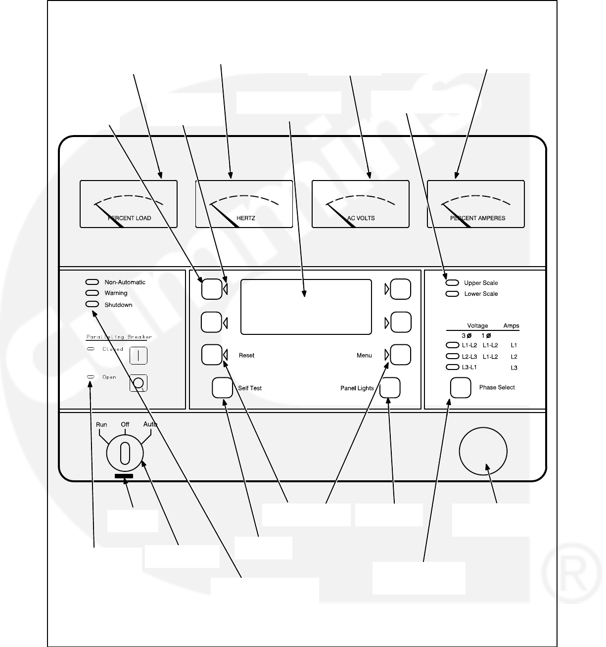
FIGURE 2-1. FRONT PANEL (PCC 3100)

2-4
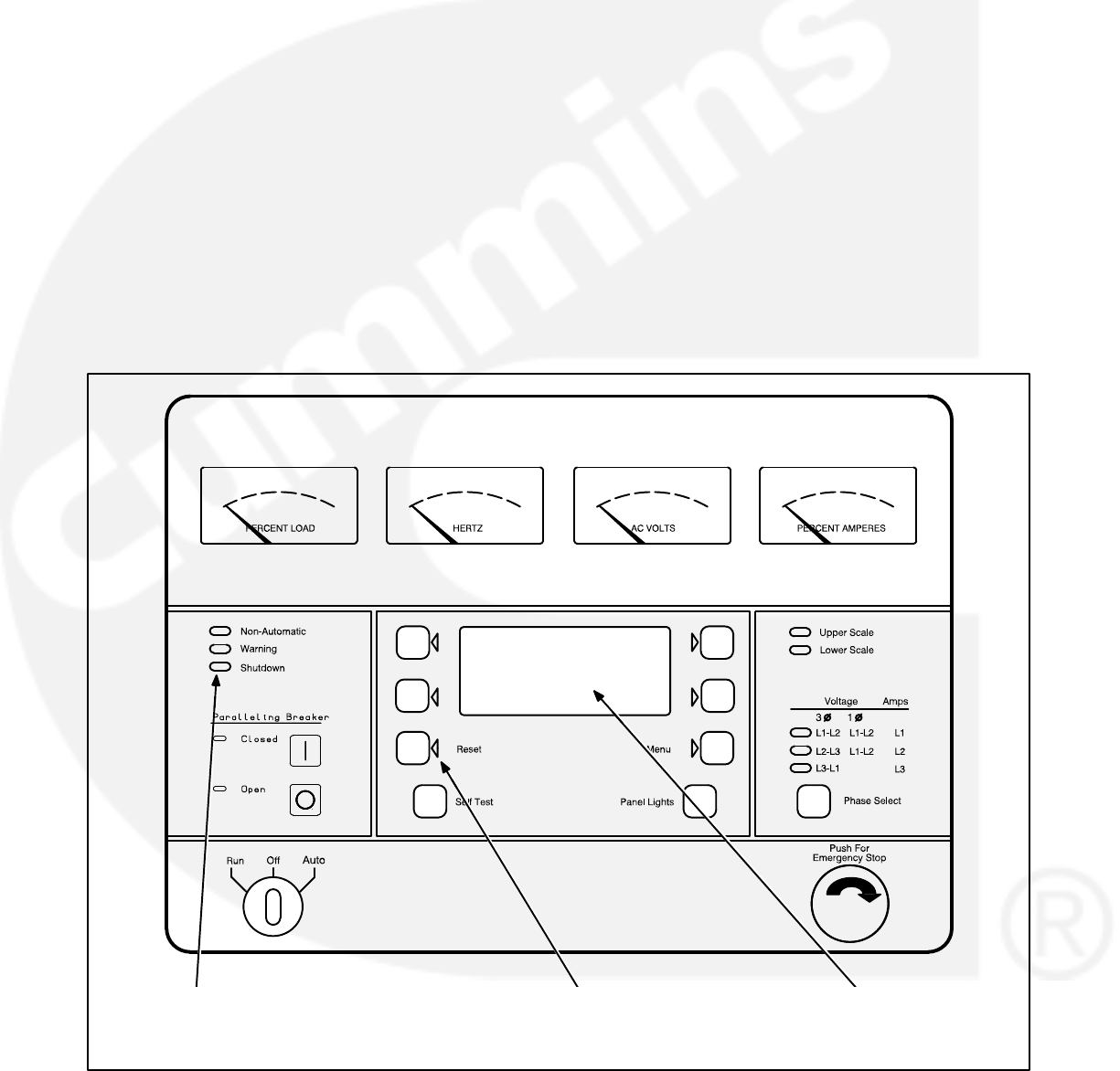
FRONT PANEL
Figure 2-1 shows the features of the front panel.
AC Voltmeter: Dual scale instrument indicates AC
voltage. Measurement scale in use is shown on
scale indicator lamp.
AC Ammeter: Indicates current output in percent of
maximum rated current. (Percent current is based
on .8 PF.)
Kilowatt Meter: Indicates 3-phase AC power out-
put as percent of rated load.
Frequency Meter: Indicates generator output fre-
quency in hertz.
Upper and Lower Scale Indicator Lamps: Indi-
cate AC voltmeter scale.
Digital Display: This two-line, 16-character per line
alphanumeric display is used in the menu-driven
operating system, in conjunction with the display
menu selection switches and the Menu switch. Re-
fer to the menu trees later in this section. The dis-
play is also used to show warning and shutdown
messages.
Display Menu Selection Switches: Four momen-
tary switches—two on each side of the digital dis-
play window—are used to step through the various
menu options and to adjust generator set parame-
ters. The green arrow adjacent to the switch is lit
when the switch can be used (switch is “active”).
Menu Switch: Press this switch to return the digital
display to the MAIN MENU. Refer to the menu trees
later in this section.
Reset Switch: Press this switch to reset warning
and shutdown messages after the condition has
been corrected. To reset a shutdown message with
the Reset switch, the Run/Off/Auto switch must be
in the Off position.
With the Run/Off/Auto switch in the Auto mode,
shutdown faults can be reset by removing the re-
mote start input and then cycling the remote reset
input.
Self Test Switch: Press and hold this switch to light
all front panel LEDs and cycle through all shutdown
and warning messages.
In the Standby (sleep) mode, with the generator set
not running, the control’s operating software is inac-
tive and the LEDs and displays on front panel are all
off.
To activate and view the menu displays without
starting the generator set, press and hold the Self
Test switch until the front panel LEDs light. The
PCC will initialize the operating software and permit
operation of the menu display panel. If no menu
selections are made, a software timer will shut
down the power after 30 seconds.
Panel Lights Switch: Press this switch to turn con-
trol panel illumination on and off. The illumination
will shut off after about eight minutes.
Phase Selector Switch and Indicators: Press this
momentary switch to select phases of generator
output to be measured by the analog AC voltmeter
and ammeter. LEDs indicate the selected phase.
Run/Off/Auto Switch: This switch starts and stops
the set locally, or enables start/stop control of the
engine from a remote location. (Ground to start.)

2-5
Emergency Stop Button: Push the switch in for
emergency shutdown of the engine.
Remote Reset switch will not reset emergency stop.
Can only be reset at the PCC front panel.
To reset:
1. Pull the button out or turn the switch clockwise
(button with arrow) and allow it to pop out.
2. Move the Run/Off/Auto switch to Off.
3. Press the front panel Reset switch.
4. Select Run or Auto, as required.
Non-Automatic Status Indicator: This red lamp
flashes continuously when the Run/Off/Auto switch
is not in the Auto position.
Warning Status Indicator: This yellow lamp is lit
whenever the control detects a warning condition.
After the condition is corrected, warning indicators
can be reset by pressing the Reset switch. (It is not
necessary to stop the generator set.)
With the Run/Off/Auto switch in the Auto mode,
warnings can also be reset by cycling the remote re-
set input after the condition is corrected.
Shutdown Status Indicator: This red lamp is lit
whenever the control detects a shutdown condition.
After the condition is corrected, shutdown indica-
tors can be reset by turning the Run/Off/Auto switch
to the Off position, and pressing the Reset switch.
In Auto mode, shutdowns can be reset by removing
the remote start input and then cycling the remote
reset input.
Emergency Stop shutdown status (Code 102) can be
reset only at the PCC front panel.
Paralleling Breaker Switches and Indicators:
These two switches are used to manually open or
close the paralleling breaker of the generator set.
The lamps are used to indicate the opened or
closed position of the paralleling breaker.
The Breaker Operation switches are operational only
when the Run/Off/Auto switch is in the Run position.
The breaker will close when the generator set is syn-
chronized with the system bus, or if the system bus
is de-energized.
2-6
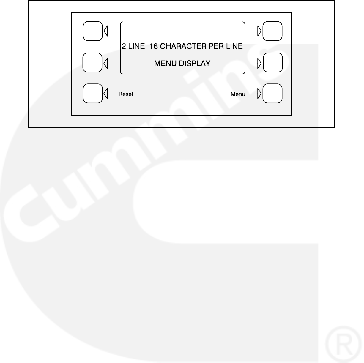
FIGURE 2-2. DIGITAL DISPLAY AND MENU SELECTION SWITCHES
MENU DISPLAY AND SWITCHES
Figure 2-2 shows the digital display and the menu
selection switches. Refer to heading “Front Panel”
which describes the menu display and switches.
In the Standby Mode, to activate and view the menu
displays without starting the generator set, press
and release the Self Test switch. This will initialize
the PCC operating software and permit operation of
the menu display panel. If no menu selections are
made, a software timer will shut down the power af-
ter 30 seconds. In the Power On Mode, power is
continuously supplied to the control panel. Display
will always remain on.
In the digital display, the “>>” symbol indicates that
selecting the adjacent button causes the operating
program to branch to the next menu display—as
shown in the menu diagrams.
In the digital display, the “<<” symbol indicates that
selecting the adjacent button causes the operating
program to go back to the previous menu display.
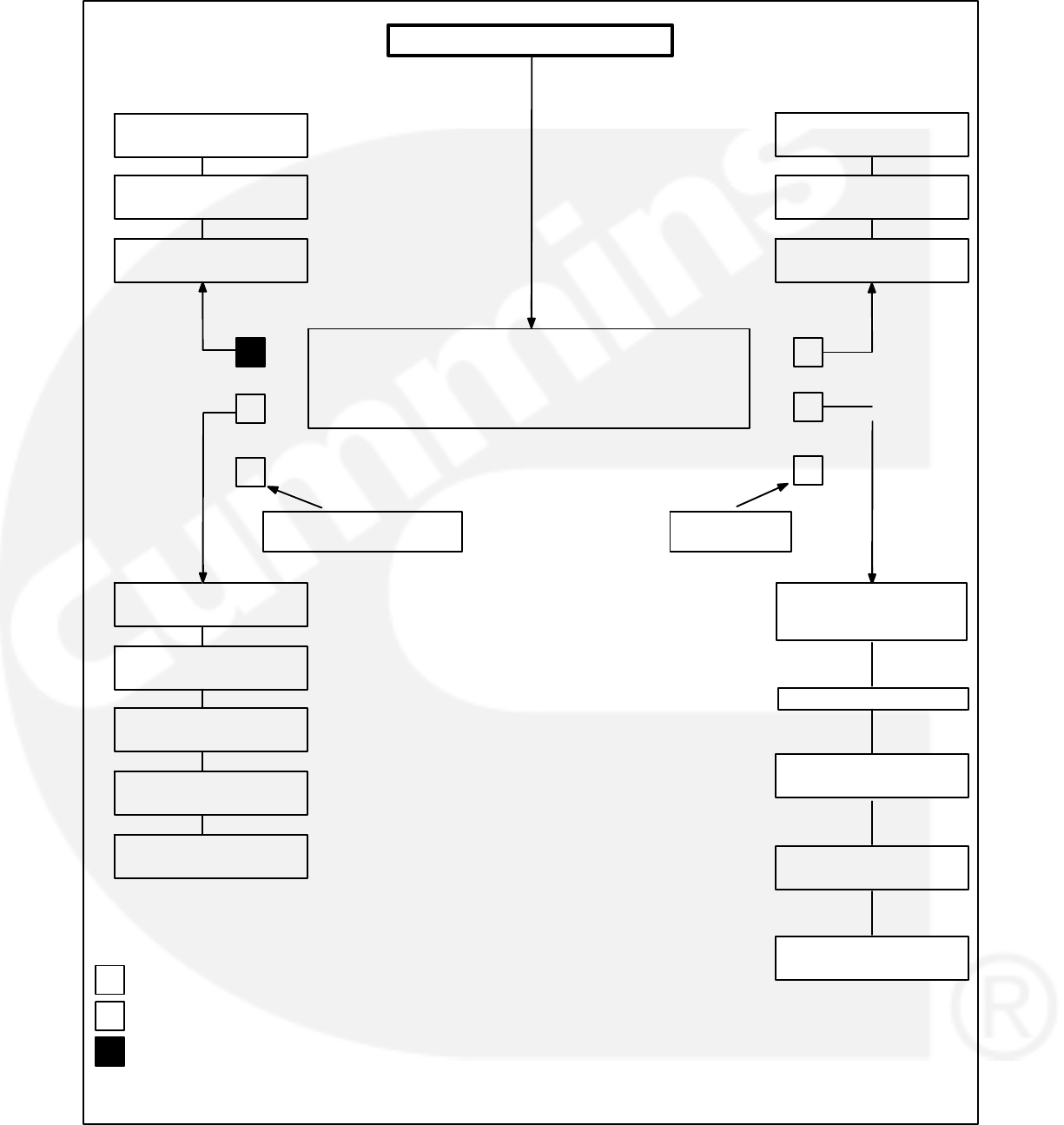
MAIN MENU
The facing page shows the main menu and a block
representation of the available submenus.
As shown in the diagram, the main menu can
branch into one of four directions.
To display engine parameters, such as oil pressure
and temperature, water temperature, engine speed
(RPM), and exhaust temperature, press the button
next to the word “ENGINE” in the display. Refer to
ENGINE MENU in this section.
To display generator parameters, such as volts,
amps, power (kW), and frequency, press the button
next to the word “GEN” in the display. Bus voltage,
frequency and a digital synchroscope can also be
viewed from this menu branch. Turn to the GEN
MENU in this section.
To adjust output voltage and frequency, or start and
stop delays, press the button next to the word “AD-
JUST” in the display. Refer to ADJUST MENU in
Section 5.
To display the selected generator set model and the
resident version software, press the button next to
the “>>” in the display. Refer to VERSION & DIS-
PLAYS MENUS in Section 5.
2-7
DISPLAY CAL <<
METERS >>
VOLTAGE
_______ >>
<>
<>
ENGINE GEN
ADJUST >>
< ACTIVE BUTTON
<ACTIVE BUTTON SELECTED
INACTIVE BUTTON
RESET MENU >
RETURN TO
MAIN MENU
CLEAR WARNING AND
SHUTDOWN MESSAGES
PAGES 2-8 & 2-9
MAIN MENU
(ACCESS CODE)
PAGES 2-10 & 2-11
OIL <<
COOLANT >>
BATTERY <<
HOURS >>
RPM <<
EXHAUST
FREQUENCY
_______ >>
START DELAY
_______ SEC >>
STOP DELAY
_______SEC >>
VOLTS <<
AMPS >>
POWER <<
KW HRS >>
%GOV / REG <<
FREQUENCY
SECTION 5
SECTION 5
SECTION 5
SECTION 5
RACKTEST <<
SECTION 5
IDLE SPEED
_______RPM >> GOV / REG <<
PARALLEL SETUP
VERSION
SETUP / CAL
HISTORY

2-8
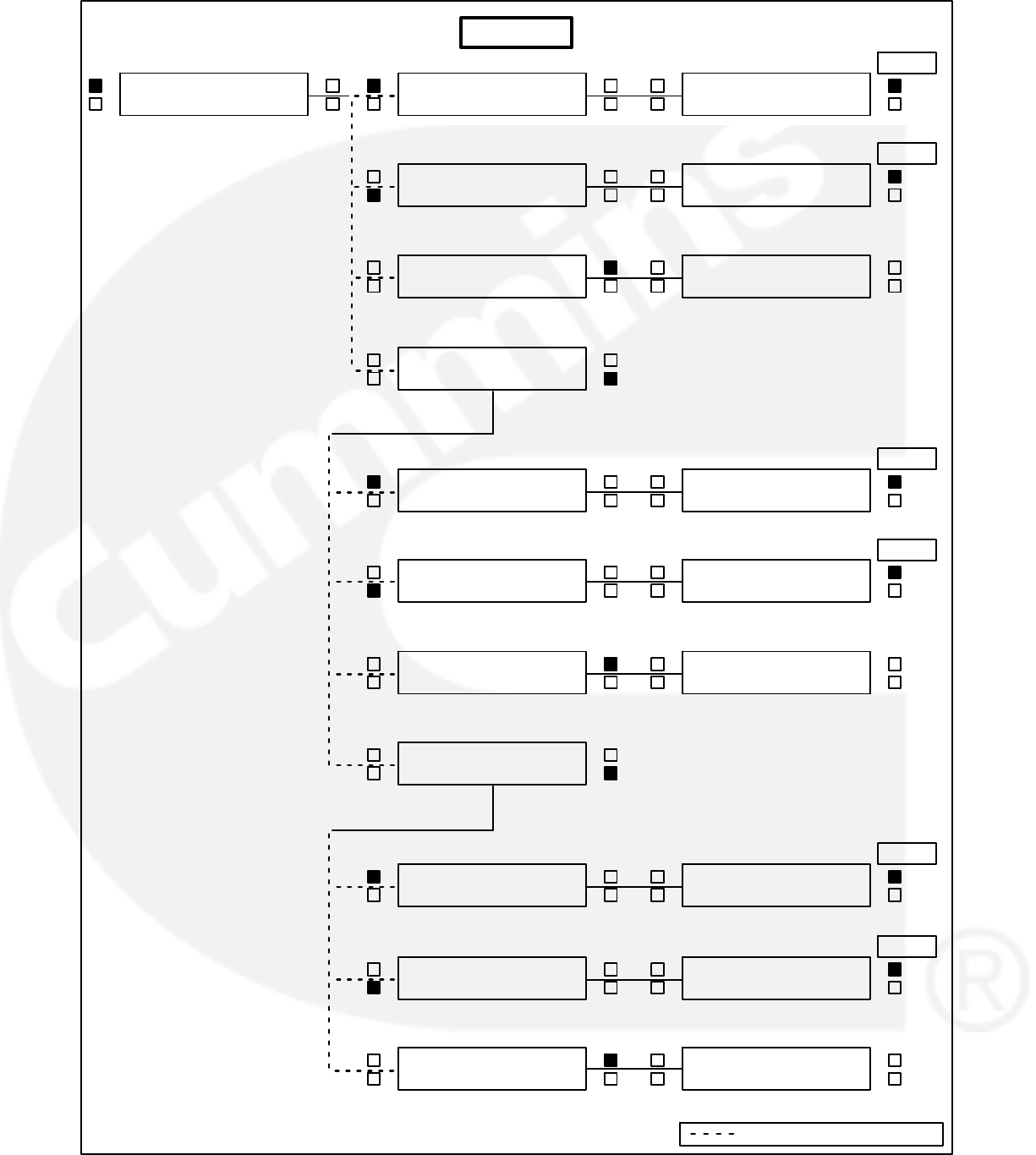
ENGINE MENU
The facing page shows a block representation of
the ENGINE menu. If you press the button next to
the word “ENGINE” in the display, the first ENGINE
submenu will appear.
As shown in the diagram, the ENGINE menu has
three submenus.
OIL/COOLANT submenu: This is the first subme-
nu. Select OIL for a display of oil pressure and oil
temperature. Select COOLANT for a display of
coolant temperature. When oil or coolant parame-
ters are displayed, pressing the button next to the
“<<” will return the display (“BACK”) to the OIL/
COOLANT submenu.
BATTERY/HOURS submenu: From the OIL/
COOLANT submenu, press the button next to the
“>>” in the display to move to the BATTERY/
HOURS submenu. Select BATTERY for a display
of battery voltage. Select HOURS for a display of
the number of starts and the running hours. When
battery or hours parameters are displayed, press-
ing the button next to the “<<” will return the display
(“BACK”) to the BATTERY/HOURS submenu.
RPM/EXHAUST submenu: From the BATTERY/
HOURS submenu, press the button next to the “>>”
in the display to move to the RPM/EXHAUST sub-
menu. Select RPM for a display of engine RPM.
Select EXHAUST for a display of the (optional) ex-
haust temperature. When RPM or exhaust param-
eters are displayed, pressing the button next to the
“<<” will return the display (“BACK”) to the RPM/EX-
HAUST submenu.
2-9
BATTERY <<
___
<>
<>
<>
<>
>
L___F / C<<
R___F / C (or N/A)
>
>
>
<>
<>
<>
<>
BATTERY <<
HOURS >>
>
<>
<>
<>
ENGINE GEN
ADJUST >>
<>
<>
OIL <<
COOLANT >>
<>
___PSI / KPA <<
___F / C
ENGINE GEN
ADJUST >>
<>
<>
<>
OIL <<
COOLANT >>
<>
<>
OIL <<
COOLANT >>
OIL <<
COOLANT >>
<>
>
<>
BATTERY <<
HOURS >>
STARTS ___ <<
HOURS ___
<>
<>
BATTERY <<
HOURS >>
<>
BATTERY <<
HOURS >>
L___F/C (or N/A) <<
R___F/C (or N/A)
<
RPM <<
EXHAUST
<>
<
RPM <<
EXHAUST
<>
<
RPM <<
EXHAUST
RPM <<
___
BATTERY <<
HOURS >>
<>
BACK
BACK
BACK
BACK
BACK
BACK
ENGINE
OIL <<
COOLANT >>
Indicates OR" Condition

2-10
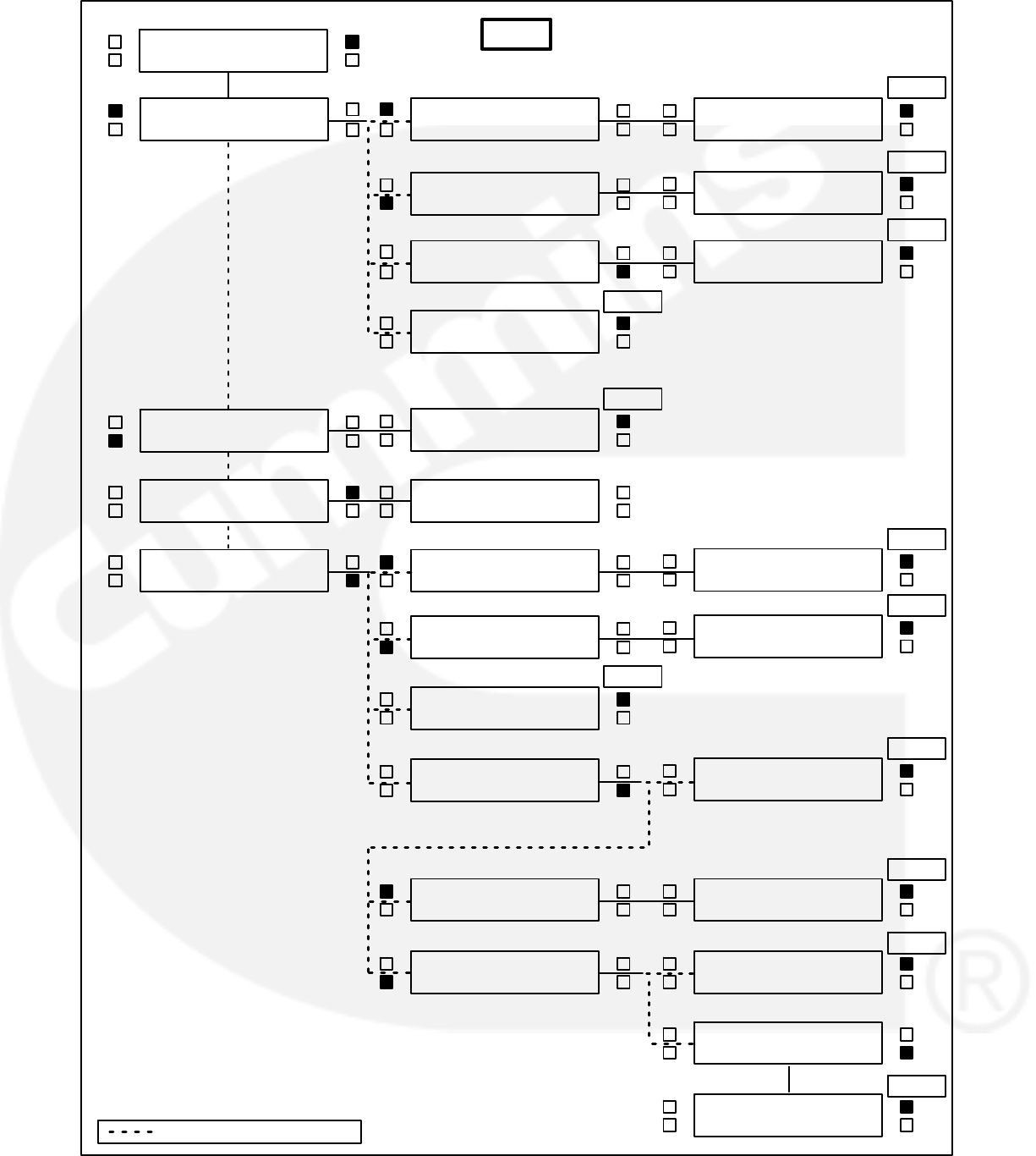
GEN MENU
The facing page shows a block representation of
the GEN menu. If you press the button next to the
word “GEN” in the display, the first GEN submenu
will appear.
As shown in the diagram, the GEN menu has three
submenus.
VOLTS/AMPS submenu: This is the first subme-
nu. Select VOLTS for a display of a line-to-line or
line-to-neutral selection, or for viewing of the sys-
tem bus line-to-line voltage. Select line-line or line-
neutral for the desired voltage display. Select
AMPS for a display of L1, L2, and L3 current in
amps. When voltage or current parameters are dis-
played, pressing the button next to the “<<” will re-
turn the display (“BACK”) to the L-L/L-N submenu.
If DELTA is selected in the Initial Start Setup subme-
nu, when selecting VOLTS, the “line-line” or “line-
neutral” submenus will not be displayed, only the
L12, L23, L31 submenu will be displayed.
POWER / KW HOURS submenu: From the
VOLTS/AMPS submenu, press the button next to
the “>>” in the display to move to the POWER/KW
HOURS submenu. Select POWER for a display of
power output in kilowatts and a power factor value.
Select KW HOURS for a display of kilowatt hours.
When power or kW hours parameters are dis-
played, pressing the button next to the “<<” will re-
turn the display (“BACK”) to the POWER/KW
HOURS submenu.
The PF reading will contain an asterisk if the power
factor is leading (for example, *.3PF).
Beginning Version 1.06, N/A is displayed in the PF
field when the generator set is not running.
%GOV/REG/FREQUENCY submenu: From the
POWER/KW HOURS submenu, press the button
next to the “>>” in the display to move to the %GOV/
REG/FREQUENCY submenu. Select %GOV/REG
for a display of voltage regulator and governor duty
cycle (drive) levels in percentage of maximum. Se-
lect FREQUENCY for a display of the generator
output frequency the bus frequency, or the digital
synchroscope. When voltage regulator and gover-
nor or frequency parameters are displayed, press-
ing the button next to the “<<” will return the display
(“BACK”) to the %GOV/REG/FREQUENCY sub-
menu.
Bus Frequency (Digital Synchroscope) subme-
nu: When the bus frequency (digital synchroscope)
information is displayed, the operator can observe
the generator set synchronizing with the system
bus. The display indicates bus frequency and num-
ber of degrees from synchronous condition (+ indi-
cates faster, − indicates slower). When the genera-
tor set is operating within the sync-check window,
an asterisk will indicate that the paralleling breaker
can be closed.
2-11
<
<>
<>
<>
<>
<>
<>
<>
<>
<>
<>
<>
<>
<>
<>
<
<>
><>
<<>
ENGINE GEN
ADJUST >>
<>
VOLTS <<
AMPS >>
L − L <<
L − N BUS
>
L12 L23 L31 <<
___ ___ ___
L1N L2N L3N <<
___ ___ ___
BACK
BACK
<
BACK
<>
<>
VOLTS <<
AMPS >>
>
L1 L2 L3 <<
___ ___ ___
BACK
VOLTS <<
AMPS >>
ENGINE GEN
ADJUST >>
<>
VOLTS <<
AMPS >>
POWER <<
KW HRS >>
>
___ KW <<
___ PF
BACK
<>
<>
POWER <<
KW HRS >>
>
KW HRS <<
____________
BACK
<>
POWER <<
KW HRS >>
POWER <<
KW HRS >>
%GOV / REG <<
FREQUENCY
BACK
<>
<
%GOV / REG <<
FREQUENCY
<>
<
%GOV / REG <<
FREQUENCY
>
GOV __ % <<
REG __ %
>
FREQUENCY <<
___ HZ BUS
BACK
BACK
BACK
GEN
L − L <<
L − N BUS
L − L <<
L − N BUS
><>
<
L − L <<
L − N BUS
L12 L23 L31 <<
___ ___ ___
BACK
>
FREQUENCY <<
___ HZ BUS
>
BUS FREQUENCY<<
___ HZ ___ DEG
BACK
Indicates OR" Condition

2-12
THIS PAGE LEFT INTENTIONALLY BLANK
3-1
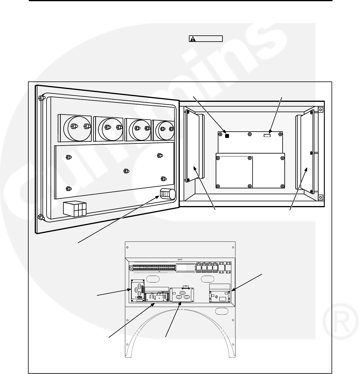
3. Circuit Boards and Modules
GENERAL
This section describes the function of the PCC cir-
cuit boards and modules that are contained in the
control panel (Figure 3-1) and the accessory box.
The block diagram in Figure 3-2, shows both inter-
nal and external components of the PCC system.
The system schematics are provided in Section 9 of
this manual.
CAUTION Electrostatic discharge will damage
circuit boards. Always wear a grounding wrist
strap when touching or handling circuit boards
or socket-mounted ICs.
PT/CT
BOARD
A36
VOLTAGE REGULATOR
OUTPUT MODULE
A37
GOVERNOR
OUTPUT MODULE
A38
BUS PT MODULE
A39
CUSTOMER INTERFACE
A34
ENGINE INTERFACE
A31
ANALOG
BOARD
A33
DIGITAL BOARD
A32
DISPLAY BOARD
A35
RUN/OFF/AUTO
SWITCH S12
S5 POWER ON/
STANDBY SWITCH
GENSET
COMM.
BOARD
A41
J1 (FOR INPOWER
SERVICE TOOL)
FIGURE 3-1. CIRCUIT BOARD LOCATIONS
3-2
FIGURE 3-2. BLOCK DIAGRAM
3-3
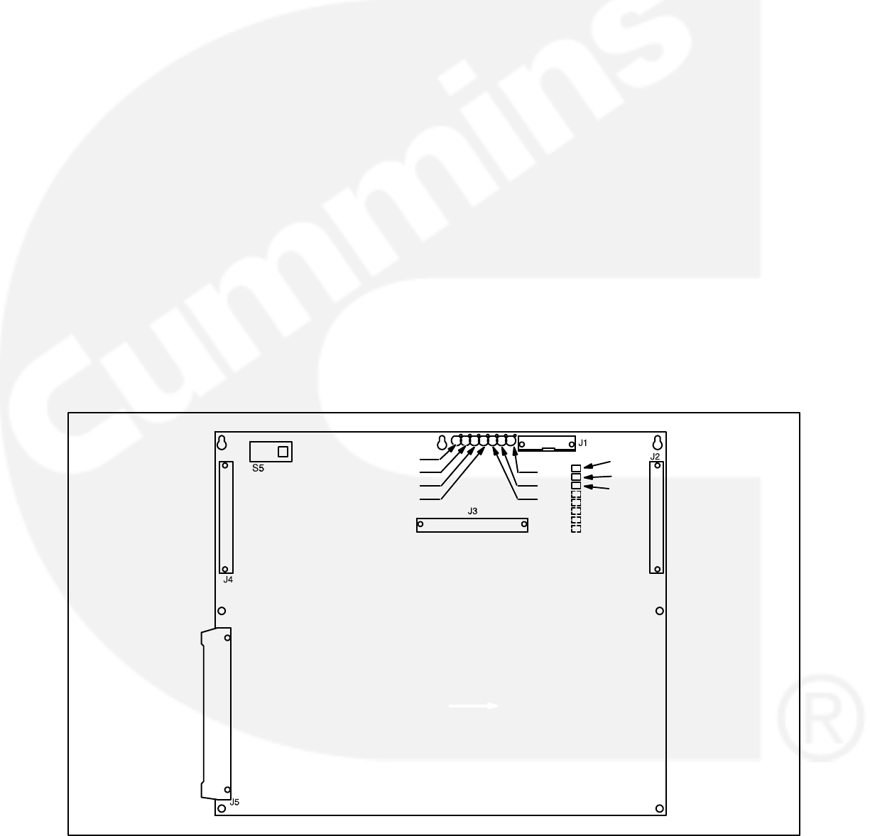
DIGITAL BOARD (A32)
The digital circuit board (Figure 3-3) contains the
microprocessor and the operational software for the
control. It connects to all other boards inside the
control. This board also provides the analog-to-digi-
tal conversions for the PCC.
Switch
S5 Slide the switch to the left to select the Power
On (awake) mode. Control panel power/oper-
ating software will remain on until the switch is
reset to the Standby mode. It is recom-
mended that switch S5 be left in the Power On
mode in all applications, except those where
auxiliary battery charging is not available.
Slide right to put the PCC in the Standby
(“sleep”) mode. In this mode, the PCC oper-
ating software will be initiated by selection of
Run on the front panel, by pressing the Self
Test switch, by a remote start input (in Auto
mode), or by any one of several “wake-up”
signals from external switches.
Connectors
The digital board has five connectors. They are:
J1 For InPower Service Tool
J2 Connects to J4 on A34 Customer Interface
board
J3 Connects to J2 on A33 Analog board
J4 Connects to J1 on A31 Engine Interface
board
J5 Connects to J5 on A35 Digital Display assem-
bly
LEDs
The digital board has seven LED’s that indicate the
following conditions:
DS1 Spare (Green)
DS2 Spare (Green)
DS3 +18 VDC supply OK (Green)
DS4 +5 VDC supply OK (Green)
DS5 Run (Flashes once per second if software
is running) (Green)
DS6 +24 VDC B+ supply OK (Green)
DS7 +12 VDC supply OK (Green)
Resistors
The three resistors (R36, R37 and R38) are used to
configure the digital board to the generator set mod-
el number. Refer to Digital Board (A32) Calibration
in Section 5, which provides a detailed description
of how to configure this board.
DS1
DS2
DS3
DS4
DS7
DS6
DS5
R36
R37
R38
FIGURE 3-3. DIGITAL BOARD (A32)

3-4
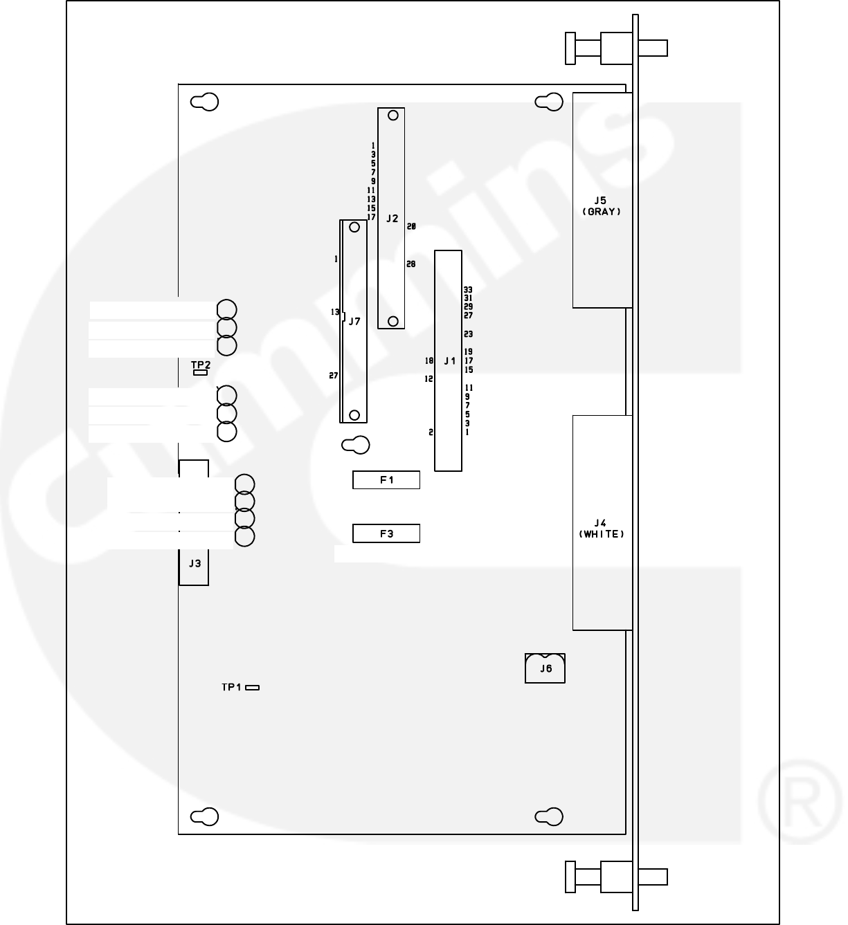
ENGINE INTERFACE BOARD (A31)
The engine interface board (Figure 3-4) reads user
control inputs, monitors engine, generator and sys-
tem status, and initiates the appropriate action for
normal operating and fault conditions (warning or
shutdown).
This board is connected to the engine sensors, bat-
tery, starter, governor output module, voltage regu-
lator output module, and the magnetic pick-up
(MPU).
The engine interface board can also be connected
to an optional network interface module for network
access.
During a typical start sequence the LED’s light as
follows:
1. DS11 lights when a remote run signal is re-
ceived and S12 is in the Auto possition, or S12
is moved to the Run position.
2. DS12 lights when the magnetic pick-up voltage
is sensed (engine is cranking). (When the en-
gine is cranking, the mag pickup output should
be a minimum of 1 volt.)
3. DS11 extinguishes, DS9 lights and DS10 is
dimly lit when the generator is running.
Connectors
The engine interface board has seven connectors
and one terminal strip. They are:
J1 Connects to J4 on A32 Digital board.
J2 Connects to J1 on A33 Analog board.
J3 Connects to display board, front panel
switches and meters.
J4 Connects to customer connections and to en-
gine harness which includes magnetic pick-
up.
J5 Connects to engine sensors.
J6 Connects to Genset Control module (GCM).
J7 Connects to Genset Control module (GCM).
Fuses
The engine interface board has two replaceable
fuses. They are:
F1 Control B+ (5 Amps)
F3 Aux. B+ (5 Amps). (Panel lamps and run/start
contacts).
LED’s
The engine interface board has 10 LED’s that indi-
cate the following conditions:
DS1 Low Fuel Alarm input (Red)
DS2 Low Coolant Level Alarm input (Red)
DS3 Low Engine Temperature Alarm input (Red)
DS4 S12 in Run position (Green). S12 is the Run/
Off/Auto switch.
DS5 S12 in Auto position (Green)
DS6 Emergency Stop (Red)
DS7 Not configured.
DS8 Not configured.
DS9 Automatic voltage regulator duty cycle
(Green). Brighter indicates larger duty
cycle.
DS10 Governor duty cycle (Green). Brighter indi-
cates larger duty cycle.
DS11 Start pilot relay output (Red)
DS12 Run pilot relay output (Red)
3-5
5A AUX B+
5A CNTRL B+
DS1 - LOW FUEL
DS2 - LO COOL
DS5 - AUTO
DS10 - GOV
DS11 - START
DS3 - LET
DS4 - RUN SW
DS6 - E-STOP
DS9 - REG
DS12 - RUN RLY
FIGURE 3-4. ENGINE INTERFACE BOARD
3-6
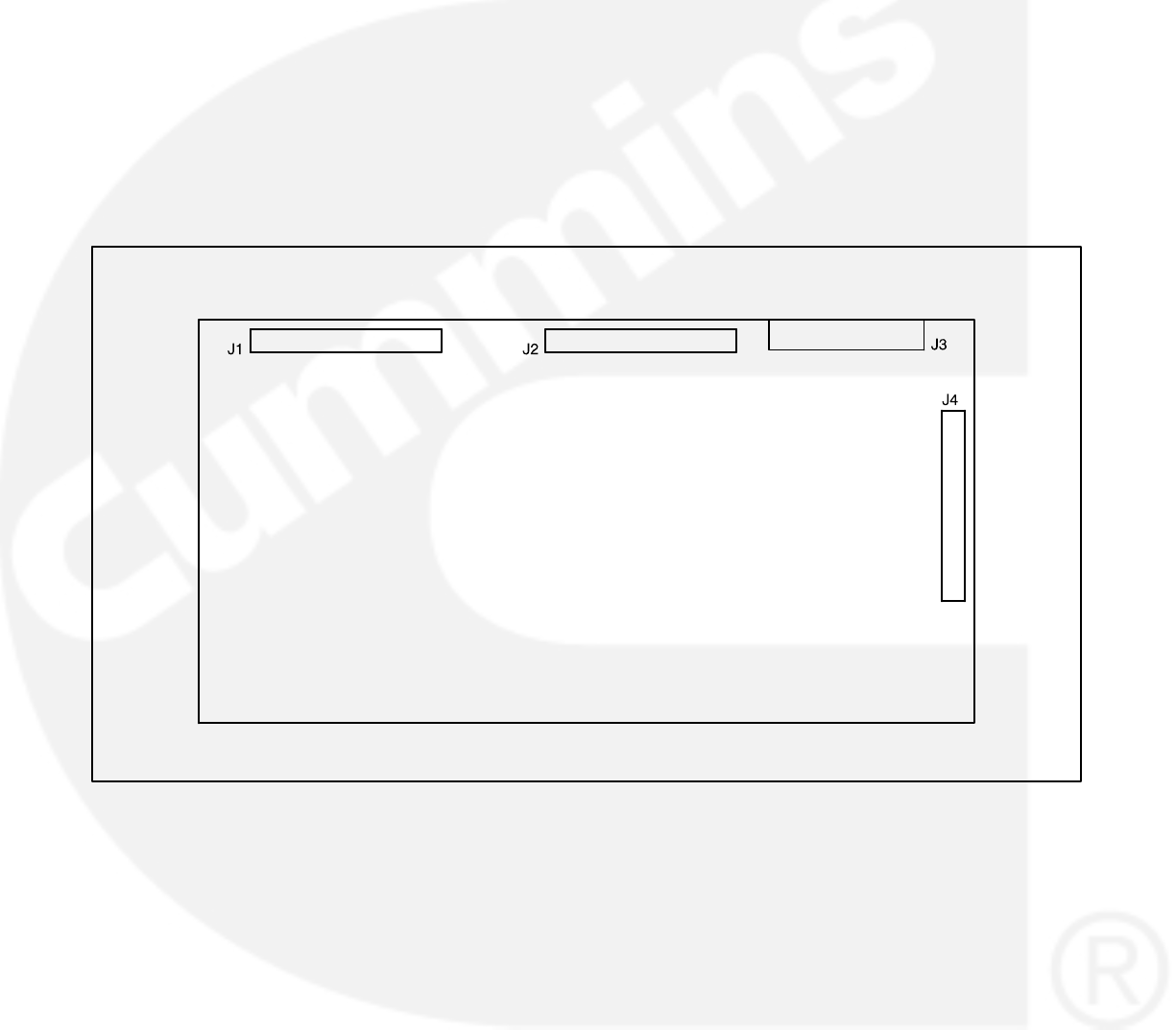
ANALOG BOARD (A33)
The analog board (Figure 3-5) is the only circuit
board inside the control that has no LED’s. There
are two versions of the analog board that are used
for paralleling and non-paralleling systems.
This board interprets all analog input signals and
converts the analog signals to 0−5 VDC for the digi-
tal board.
Connectors
The analog board has four connectors with ribbon
cables permanently soldered to them. They are:
J1 Connects to J2 on A31 Engine Interface
board
J2 Connects to J3 on A32 Digital board
J3 Spare analog inputs
J4 Connects to J1 on A34 Customer Interface
board
FIGURE 3-5. ANALOG BOARD
3-7
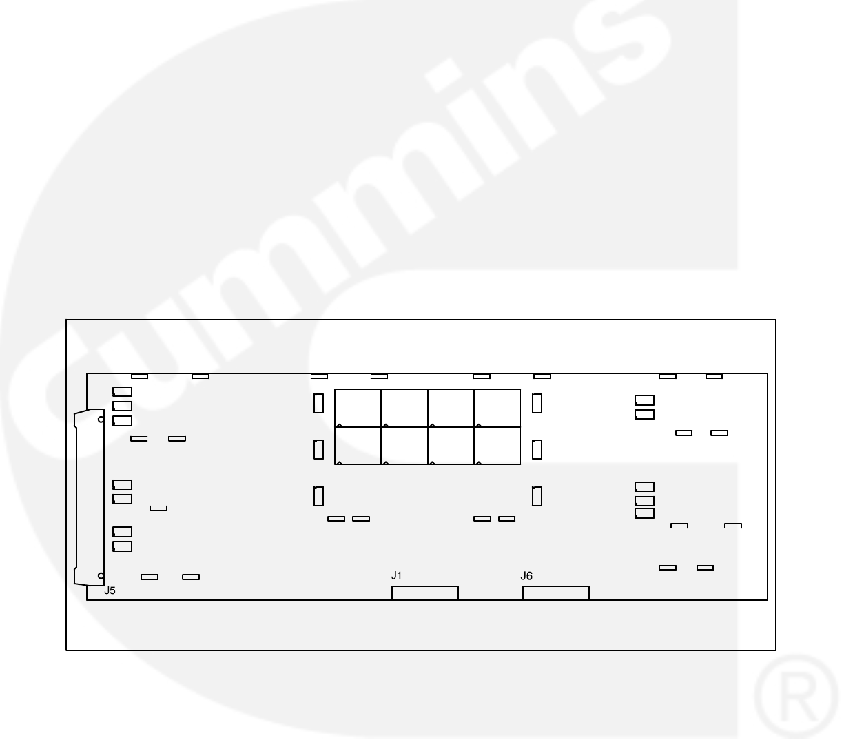
DIGITAL DISPLAY BOARD (A35)
The digital board (Figure 3-6) connects to all meters
and the LED display.
Connectors
The digital board has three connectors. They are:
J1 Connects to front panel membrane switches
J5 Connects to J2 on A32 Digital board. (With J5
disconnected, the display will be non-func-
tional, but the PCC will continue to operate.)
J6 Connects to meters, Run/Off/Auto switch, J3
on A31 Engine Interface board
LEDs
The digital board has 18 LED’s that are used to indi-
cate operational status of the generator set and
control panel mode/switch selections.
DS9 Not In Auto (Red)
DS10 Upper Scale (Green)
DS11 Left Top Arrow (Green)
DS12 Right Top Arrow (Green)
DS13 Warning (Amber)
DS14 Lower Scale (Green)
DS15 Shutdown (Red)
DS20 Left Bottom Arrow (Green)
DS21 Right Bottom Arrow (Green)
DS22 Automatic mains failure (AMF) or paralleling
application only: Breaker Closed (Red)
DS23 Phase A (Green)
DS24 Reset Arrow (Green)
DS25 Menu Arrow (Green)
DS26 AMF application only: Breaker Open
(Green)
DS27 Phase B (Green)
DS29 Phase C (Green)
DS36 AMF application: Breaker Closed (Red) − or
− paralleling application: Breaker Open
(Green)
DS37 AMF application only: Breaker Open
(Green)
DS29
DS27
DS23
DS15
DS13
DS9
DS24
DS11
DS20
DS25
DS12
DS21
DS14
DS10
DS26
DS22
DS37
DS36
FIGURE 3-6. DIGITAL DISPLAY BOARD

3-8
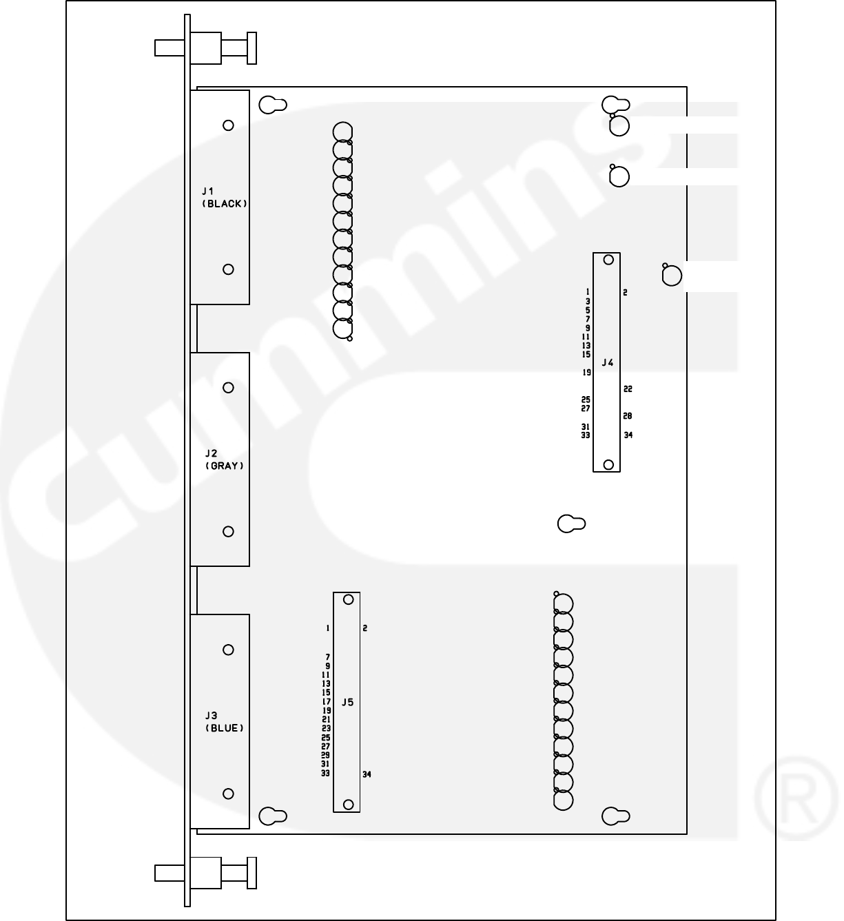
CUSTOMER INTERFACE BOARD (A34)
The customer interface board (Figure 3-7) connects
to the PT/CT board to bring in voltage and current. It
also connects to customer inputs and outputs. Note
that there are two versions of this board, for parallel
and non-parallel generator sets.
Connectors
The customer interface board has five connectors.
They are:
J1 Customer connections
J2 Customer connections
J3 A36 PT/CT Board and customer connections
J4 Connects to J2 on A32 Digital board
J5 Connects to J4 on A33 Analog board
LEDs
The customer interface board has 27 LED’s that in-
dicate the following conditions:
DS1 Master First Start Input (Green) − paralleling
application only
DS2 Pre low oil pressure output relay K14 (Red)
DS3 Customer Fault #4 Input (Red)
DS4 Customer Fault #1 Input (Red)
DS5 Low oil pressure output relay K15 (Red)
DS6 Fault Reset Input (Red)
DS7 Engine Idle (Green)
DS8 Paralleling Breaker Close Input (Green)
[paralleling function is load demand]
DS9 Paralleling Breaker Open Input (Green)
DS10 Paralleling Breaker Position Input (Green)
DS11 Customer Fault #2 input (Red)
DS12 Low coolant output relay K17 (Red)
DS13 Low Fuel Input (Red)
DS14 Remote Start input (Green)
DS15 Customer Fault #3 input (Red)
DS16 Paralleling Breaker Control input relay ener-
gized from Digital board (Green). This out-
put is activated to close the paralleling
breaker.
DS17 Common Alarm output relay energized from
Digital board (Green)
This output is activated only on a shut-
down condition.
DS18 Spare output relay energized from Digital
board (Green)
This output is activated only on a warn-
ing condition.
DS19 Load Dump output relay energized from
Digital board (Red)
If overload or underfrequency for 5 sec-
onds, this output is activated (before shut-
down).
DS20 Ready to Load output relay energized from
Digital board (Green)
This output is activated when AC voltage
and frequency exceed 90% of nominal.
DS21 Pre high engine temperature output relay
K8 (Red)
DS22 Not in auto output relay K6 (Red)
DS23 High engine temperature output relay K9
(Red)
DS24 Overspeed output relay K10 (Red)
DS25 Overcrank output relay K11 (Red)
DS26 Low engine temperature output relay K12
(Red)
DS27 Low fuel output relay K13 (Red)
3-9
DS1 - MA 1ST START
DS3 - CUST FAULT4
DS4 - CUST FAULT1
DS6 - FAULT RESET
DS7 - ENG IDLE
DS8 - LOAD DEMAND
DS9 - BRKR TRIP/INHBIT
DS10 - BRKR CLOSED
DS11 - CUST FAULT2
DS13 - LOW FUEL
DS14 - RMT START
DS15 - CUST FAULT3
DS2 - [K14] PRE-LOP
DS5 - [K15] LOP
DS12 - [K7]
LOW COOL
DS16 - CLOSE BKR
DS17 - COMMON SHTDN
DS18 - COMMON WARNING
DS19 - LOAD DUMP
DS20 - READY TO LOAD
DS21 - [K8] PRE-HET
DS22 - [K6] NOT IN AUTO
DS23 - [K9] HET
DS24 [K10] OVERSPEED
DS25 - [K11] OVERCRANK
DS26 - [K12] LET
DS27 - [K13] LOW FUEL
FIGURE 3-7. CUSTOMER INTERFACE BOARD
3-10
PT/CT BOARD (A36)
The PT/CT board (Figure 3-8) is mounted inside the
accessory box. This board converts generator out-
put voltage to approximately 18 VAC levels for the
analog board. It also converts CT .55 amp (at full
load) output to approximately 1.65 VAC (at full load)
input for the analog board.
There are three versions of this board. For proper
operation, the PT/CT board must be correctly
matched to the generator set.
In addition, there is a specific set of CTs for each
genset. For proper operation, the CTs must also be
correctly matched to the genset output current.
Connectors
The PT/CT board has two connectors. They are:
J8 Connects to J3 on A34 Customer Interface
board
J9 Connects to AC harness (generator output
voltage and CTs)
J9 wiring connections:
Yellow Gen. A In
Orange Gen. B In
Red Gen. C In
Brown Gen. Common In
White CT21 (+) In
Gray CT21 (common) In
Grn/Ylw CT22 (+) In
Black CT22 (common) In
Purple CT23 (+) In
Blue CT23 (common) In
J8
J9
FIGURE 3-8. PT/CT BOARD
3-11
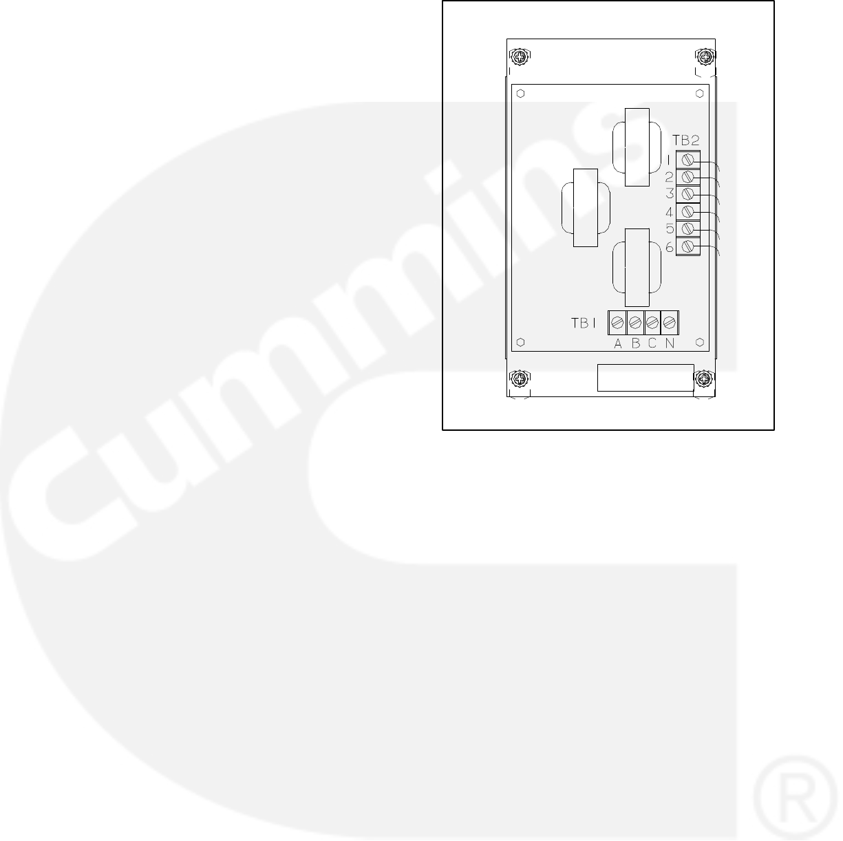
BUS PT MODULE (A39)
The bus PT module (Figure 3-9) is mounted inside
the accessory box. This module converts the bus
output voltage (from the load side of the paralleling
breaker) to 18 VAC and provides this to the analog
board. It provides a reference signal to the Power-
Command Control for synchronizing the generator
set output to a system bus. There are four versions
of this module, for primary voltages of 69, 120, 240
or 346 volts AC line to neutral. For proper operation,
the correct bus PT module must be installed in the
generator set. Correct phasing is also important as
the system uses the bus PT module output for both
protection and control of the generator set.
Connectors
The bus PT module has two terminal blocks. They
are:
TB1 Bus voltage connections.
N bus neutral
A bus A phase (U)
B bus B phase (V)
C bus C phase (W)
TB2 Bus PT output for PowerCommand control. FIGURE 3-9. BUS PT MODULE
3-12
GENSET COMMUNICATIONS MODULE
(A41)
The genset communications module (GCM) is re-
quired to connect the PCC to a PowerCommand
(LonWorks) network, and communicate with other
network modules. The GCM module is an optional
feature, and it is available as a field upgrade kit for
applications where the feature must be added in the
field. The PC must be operating with firmware ver-
sion 1.06 or later. For model DFH gensets only, firm-
ware must be version 1.04 or later.)
The GCM provides an interface for data transfer be-
tween the PowerCommand control and other mod-
ules on the network. It communicates with the PCC
through a serial port on the PCC, as well as monitor-
ing various PCC inputs to determine the operating
state of the control. For example, the GCM monitors
PCC data such as voltage, oil pressure, current, en-
gine speed, and not in auto status; and provides
that information to the network.
The GCM also facilitates remote monitoring and
limited remote control of the genset that PCC con-
trols. Outputs from the GCM can ’wake up’ the PCC
when needed, or issue start commands to the gen-
set. The GCM also includes a terminate circuit for
use at the end of a network data bus.
The GCM module is powered from the genset start-
ing batteries. It is operational at all times when pow-
ered, even if the PCC is asleep.
The GCM module is mounted on stand-off mount-
ing legs above the analog board (A33).
Refer to the Power Command Network Installation
and Operator’s Manual (900-0366) for information
on installation and use of the GCM module.
TERMINATE
SWITCH S3
SERVICE
SWITCH S1 RESET
SWITCH S2
BATTERY
VOLTAGE
SWITCH S4
J6 J7
FIGURE 3-10. GENSET COMMUNICATIONS MODULE
3-13
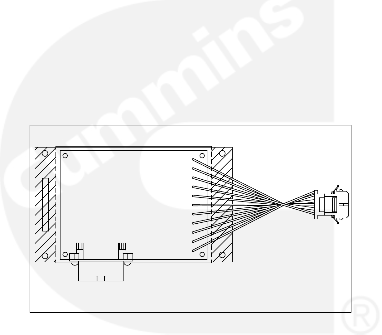
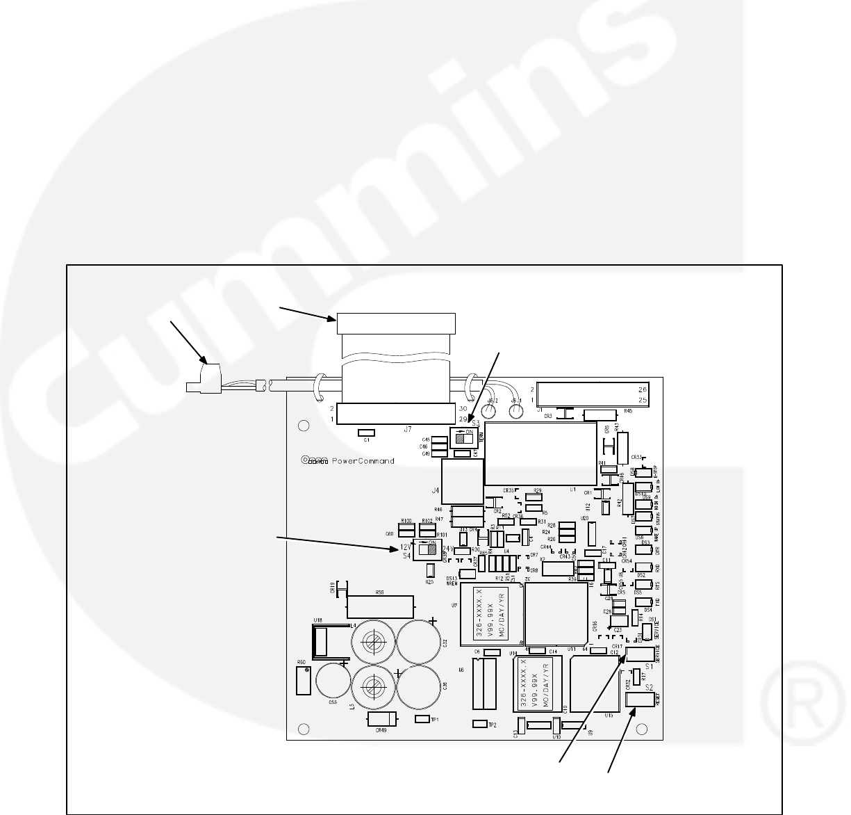
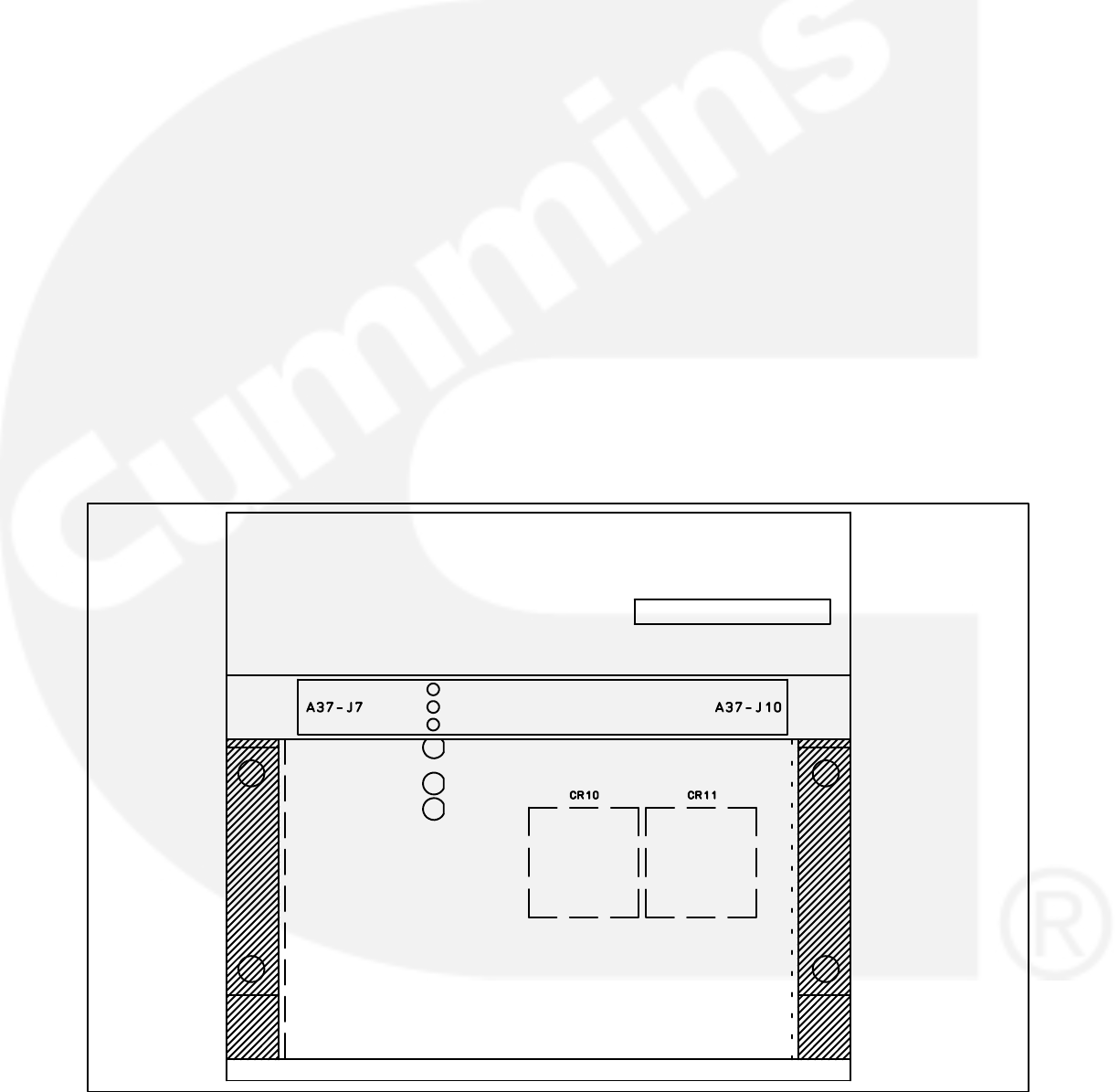
VOLTAGE REGULATOR OUTPUT MODULE
(A37)
The voltage regulator output module (Figure 3-11)
is a power amplifier. This board is used to amplify
the pulse-width modulated (PWM) signal from the
PCC to drive the exciter windings. Power from the
PMG is used by this board to amplify the PWM sig-
nal.
Connectors
The voltage regulator output module has two con-
nectors. They are:
J7 Connects to engine harness (control)
J7 wiring connections:
Gray Regulator Drive (+) Input
White Regulator Drive (-) Input
Blue B+ Input (RUN signal)
Purple Ground Input
Grn/Yel Start in
Black Start solenoid
J10 Connects to engine harness (power)
J10 wiring connections:
Green Phase A PMG power
Yellow Phase B PMG power
Orange Phase C PMG power
Red X (Field +) Output
Brown XX (Field −) Output
LEDs
The voltage regulator output module has 3 LED’s
that indicate the following conditions.
DS1 On when voltage regulator isolated supply is
operating (Green)
DS2 Output Duty Cycle − Brighter when load in-
creases − larger duty cycle (Amber). The duty
cycle range of the PWM signal is 0 - 60%. Be-
cause the normal duty cycle is less than 10%,
the output duty cycle LED, DS2 will normally
be very dimly lit.
DS3 Backup start disconnect − On when start dis-
connect is true (Green). The backup start dis-
connect is initiated at about 850 RPM, when
sensed PMG voltage is greater than 105 volts
RMS.
J10J7
DS1 - ISOLATED SUPPLY
DS2 - OUTPUT DUTY CYCLE
DS3 - BACKUP START DISCONNECT
FIGURE 3-11. VOLTAGE REGULATOR OUTPUT MODULE (A37)
3-14
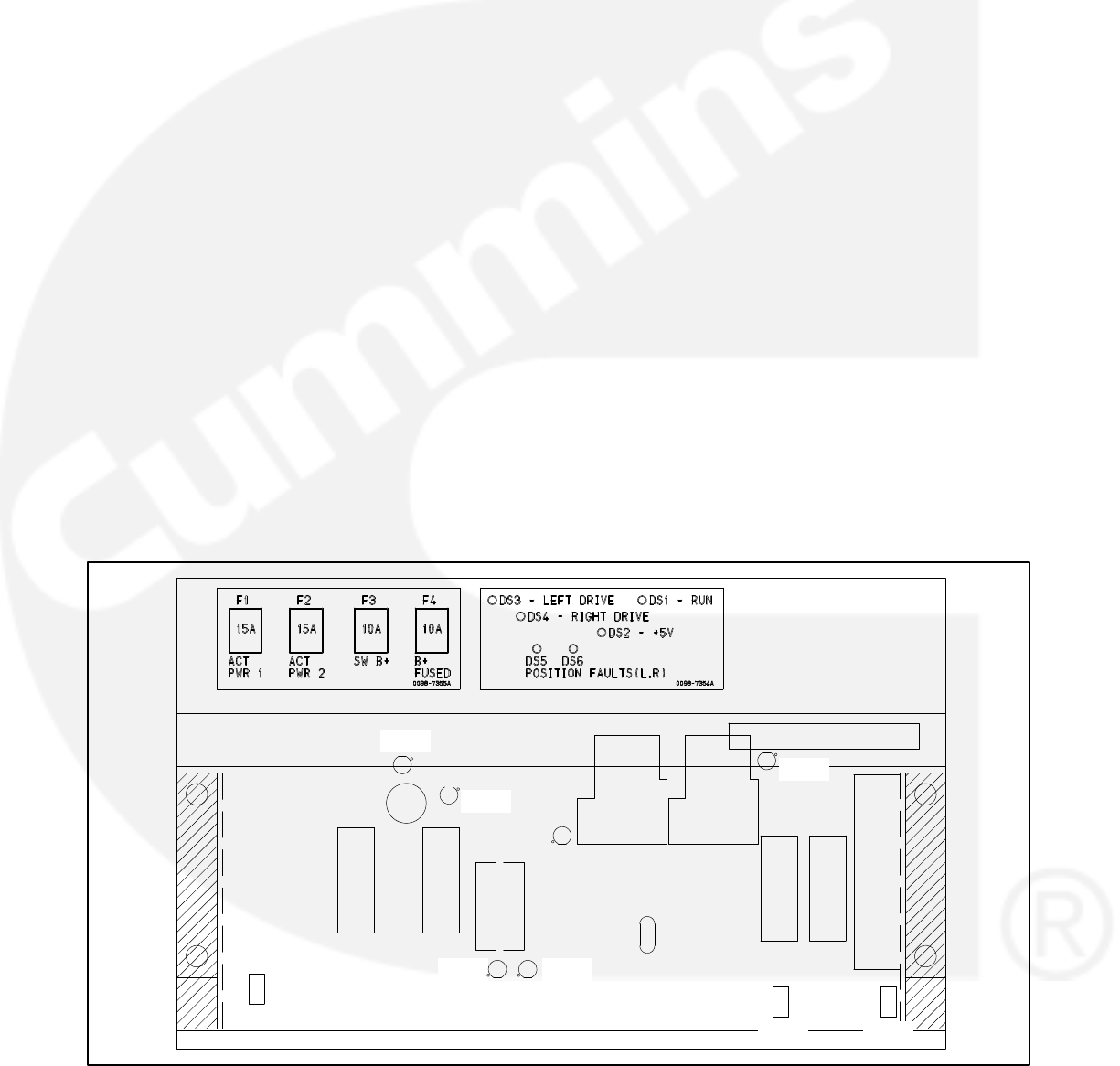
GOVERNOR OUTPUT MODULE (A38)
The governor output module (Figure 3-12) receives
a low power, 3 kHz pulse-width modulated (PWM)
command from the engine interface board (A31).
This module drives the two fuel actuators (right and
left) with a feed back-controlled, 200 Hz PWM pow-
er output stage. The governor module also has both
right and left 0-5 volt actuator position voltages
which are used for actuator diagnostics.
Connectors
The governor output module has two connectors.
They are:
J6
Inputs: Run Signal, B+, Governor Command (from
engine interface board)
Outputs: B+ (fused), SwB+, actuator position volt-
ages (R, L), and Rack Position Fault
J13
Inputs: (R, L) Actuator position sensing signals
Outputs: (R, L) Actuator drive
Fuses
The governor output module has four fuses to pro-
tect it from overloads and groundfaults. They are:
F1 Left Actuator Drive (15 Amps)
F2 Right Actuator Drive (15 Amps)
F3 Switched B+ (10 Amps)
F4 B+ Fused (10 Amps)
LEDs
The governor output module has six LED’s that indi-
cate the following conditions:
DS1 (Green) Run command signaling governor
module is active.
DS2 (Green) 5 volt power supply is active.
DS3 (Green) Left actuator drive is active. The PCC
duty cycle range is 25 - 93%. When running,
the maximum duty cycle is about 63%. Note
that the brighter the LED, the larger the duty
cycle.
DS4 (Green) Right actuator drive is active. See
DS3 description.
DS5 (Red) Left actuator fault indicator. If the actua-
tor is more than 1.5 mm form its commanded
position, the fault indicator will be ON. Note
that the actuator has maximum range of 0 −
21mm. During transients and starting se-
quences, the fault indicator will become ac-
tive for short (200 millisecond) periods.
DS6 (Red) Right actuator fault indicator. See DS5
description.
RH
LOOP
LH
LOOP
DS3
DS4
DS5 DS6
F1 F2
R54
DS2
K1 K2 F3 F4
X1
R63 R68
DS1
BANK TO
BANK
FIGURE 3-12. GOVERNOR OUTPUT MODULE (A38)

3-15
MASTER FIRST START SENSOR
The First Start Sensor System is an Onan control
sub-system which is used to sense when a genera-
tor set is ready to close to a de-energized system
bus and to prevent more than one generator set
from closing to a dead bus on automatic system
starting. The First Start Sensor System for Power-
Command generator sets is composed of control al-
gorithms within the PowerCommand control and a
Master First Start Sensor, which is usually mounted
in a remote master control panel.
The sequence of operation of the control system is
as follows: On a signal to start, all generator sets in a
system simultaneously start, and accelerate to
rated speed and voltage. The Master First Start
Sensor continuously provides pulses to each Pow-
erCommand control. When the PowerCommand
control receives the pulse from the Master First
Start Sensor, if it is ready to close to the bus, an in-
terlock signal is sent to all other controls to prevent
their respective paralleling breakers from closing. A
close signal is then provided to the generator set
paralleling breaker.

3-16
THIS PAGE LEFT INTENTIONALLY BLANK
4-1
4. Troubleshooting
GENERAL
The PowerCommand Control 3100 (PCC) contin-
uously monitors engine sensors for abnormal con-
ditions, such as low oil pressure and high coolant
temperature. If any of these conditions occur, the
PCC will light a yellow Warning lamp or a red Shut-
down lamp and display a message on the digital dis-
play panel.
In the event of a shutdown fault (red Shutdown
lamp), the PCC will stop the generator set (genset)
and close a set of contacts that can be wired to trip a
circuit breaker. If the genset is stopped for this rea-
son, the operator can restart the genset after mak-
ing adjustments or corrections.
This section contains the following information:
Table 4-1: Contains a list of all status codes, in-
cluding the displayed message and status indi-
cator. Also references the page number that
contains a description of each code.
Table 4-2: Describes each warning and shut-
down code, warning and shutdown limits
where applicable, and basic corrective actions,
such as, checking fluid levels, control reset
functions, battery connections, etc.
Table 4-3: Lists the PCC oil pressure warning
and shutdown limits.
Tables 4-4 through 4-36: Provide detailed
troubleshooting procedures.
Table 4-37: Describes the analog circuit board
inputs and outputs.
Table 4-38: Describes the location and func-
tion of each fuse.
SAFETY CONSIDERATIONS
WARNING Contacting high voltage compo-
nents can cause electrocution, resulting in se-
vere personal injury or death. Keep the output
box covers in place during troubleshooting.
High voltages are present when the genset is run-
ning. Do not open the generator output box while
the genset is running.
WARNING Ignition of explosive battery gases
can cause severe personal injury or death. Arc-
ing at battery terminals, light switch or other
equipment, flame, pilot lights and sparks can ig-
nite battery gas. Do not smoke, or switch
trouble light ON or OFF near battery. Discharge
static electricity from body before touching bat-
teries by first touching a grounded metal sur-
face.
Ventilate battery area before working on or near
battery—Wear goggles—Stop genset and dis-
connect charger before disconnecting battery
cables—Disconnect negative (−) cable first and
reconnect last.
CAUTION Disconnect battery charger from AC
source before disconnecting battery cables.
Otherwise, disconnecting cables can result in
voltage spikes damaging to DC control circuits
of the genset.
WARNING Accidental starting of the generator
set can cause severe personal injury or death.
Prevent accidental starting by disconnecting
the negative (−) cable from the battery terminal.
When troubleshooting a generator set that is shut
down, make certain the generator set cannot be ac-
cidentally restarted as follows:
1. Move the Run/Off/Auto switch on the control
panel to the OFF position.
2. Turn off or remove AC power from the battery
charger.
3. Remove the negative (−) battery cable from the
generator set starting battery.
4-2
STATUS INDICATORS
Non-Automatic Status Indicator: This red lamp
flashes continuously when the Run/Off/Auto switch
is in the Off position.
Warning Status Indicator: This yellow lamp is lit
whenever the control detects a warning condition.
After the condition is corrected, warning indicators
can be reset by pressing the Reset switch. (It is not
necessary to stop the generator set.) In auto mode,
warning indicators can also be reset by cycling the
remote reset input after the condition is corrected.
Shutdown Status Indicator: This red lamp is lit
whenever the control detects a shutdown condition.
Shutdown faults are latched. After the condition is
corrected, shutdown indicators can be reset by
turning the Run/Off/Auto switch to the Off position,
and pressing the Reset switch. In the Auto position,
shutdown faults can be reset by removing the re-
mote start input and then cycling the remote reset
input.
Emergency Stop shutdown status (Code 102) can be
reset only at the PCC front panel.
Digital Display: This two-line, 16-character per line
alphanumeric display is used in the menu-driven
operating system and to show shutdown and warn-
ing messages. Refer to Tables 4-1 and 4-2.
RESETTING THE CONTROL
Press the momentary Reset Switch to reset warn-
ing and shutdown messages after the condition has
been corrected. To reset a shutdown message with
the Reset switch, the Run/Off/Auto switch must be
in the Off Position. (The control cannot go into
Standby (sleep) mode until all faults have been
reset.)
In Auto mode, warning indicators can also be reset
by cycling the remote reset input after the condition
is corrected. Shutdown faults can be reset by re-
moving the remote start input and then cycling the
remote reset input.
ALPHANUMERIC
FAULT MESSAGE
DISPLAY
RESET
SWITCH
WARNING AND
SHUTDOWN
STATUS INDICATORS
FIGURE 4-1. CONTROL PANEL (PCC 3100)

4-3
TABLE 4-1. WARNING AND SHUTDOWN CODES
BASIC TROUBLE-
CODE MESSAGE STATUS LED CHECKS SHOOTING. . . . . . . . . . . . . . . . . . . . . . . . . . . . . . . . .
Blank LOAD DEMAND none 4-5. . . . . . . . . . . . . . . . . . . . . . . . . . . . . . . . . . . .
101 IDLE MODE none 4-5. . . . . . . . . . . . . . . . . . . . . . . . . . . . . . . . . . . . . . . .
102 EMERGENCY STOP Shutdown 4-5. . . . . . . . . . . . . . . . . . . . . . . . . . . . . .
200 LOW OIL PRESSURE Warning 4-5 4-24. . . . . . . . . . . . . . . . . . . . . . . . . . . . . . . . . . . . . .
201 LOW OIL PRESSURE Shutdown 4-5 4-24. . . . . . . . . . . . . . . . . . . . . . . . . . . . . . . . . . . . .
204 OIL PRES SENDER Warning 4-5 4-25. . . . . . . . . . . . . . . . . . . . . . . . . . . . . . . . . . . . . . .
210 LOW COOLANT TEMP Warning 4-6 4-26. . . . . . . . . . . . . . . . . . . . . . . . . . . . . . . . . . . . .
211 HIGH COOLANT TEMP Warning 4-6 4-27. . . . . . . . . . . . . . . . . . . . . . . . . . . . . . . . . . . .
212 HIGH COOLANT TEMP Shutdown 4-6 4-27. . . . . . . . . . . . . . . . . . . . . . . . . . . . . . . . . . .
213 COOLANT SENDER Warning 4-6 4-25. . . . . . . . . . . . . . . . . . . . . . . . . . . . . . . . . . . . . . .
214 LOW COOLANT LVL Warning 4-7 4-28. . . . . . . . . . . . . . . . . . . . . . . . . . . . . . . . . . . . . . .
215 LOW COOLANT LVL Shutdown 4-7 4-28. . . . . . . . . . . . . . . . . . . . . . . . . . . . . . . . . . . . . .
220 MAG PICKUP Shutdown 4-7 4-29. . . . . . . . . . . . . . . . . . . . . . . . . . . . . . . . . . . . . . . . . . . .
221 FAIL TO CRANK Shutdown 4-7 4-15, 4-23. . . . . . . . . . . . . . . . . . . . . . . . . . . . . . . . . . . . . . . . . .
222 OVERCRANK Shutdown 4-7 4-21. . . . . . . . . . . . . . . . . . . . . . . . . . . . . . . . . . . . . . . . . . . .
223 OVERSPEED Shutdown 4-7 4-30. . . . . . . . . . . . . . . . . . . . . . . . . . . . . . . . . . . . . . . . . . . .
224 FAIL TO SYNCHRONIZE Warning/Shutdown 4-8 4-31. . . . . . . . . . . . . . . . . . . . . . . . . .
226 FAIL TO CLOSE Warning/Shutdown 4-8 4-33. . . . . . . . . . . . . . . . . . . . . . . . . . . . . . . . . .
230 LOW DC VOLTAGE Warning 4-8 4-35. . . . . . . . . . . . . . . . . . . . . . . . . . . . . . . . . . . . . . . .
231 HIGH DC VOLTAGE Warning 4-8 4-35. . . . . . . . . . . . . . . . . . . . . . . . . . . . . . . . . . . . . . .
232 WEAK BATTERY Warning 4-8 4-35. . . . . . . . . . . . . . . . . . . . . . . . . . . . . . . . . . . . . . . . . .
240 LOW FUEL − DAY Warning 4-9 4-36. . . . . . . . . . . . . . . . . . . . . . . . . . . . . . . . . . . . . . . . .
241 LOW FUEL Warning 4-9 4-37. . . . . . . . . . . . . . . . . . . . . . . . . . . . . . . . . . . . . . . . . . . . . . .
250 EEPROM ERROR Shutdown 4-9 4-38. . . . . . . . . . . . . . . . . . . . . . . . . . . . . . . . . . . . . . . .
251 EEPROM ERROR Warning 4-9 4-38. . . . . . . . . . . . . . . . . . . . . . . . . . . . . . . . . . . . . . . . .
252 EEPROM ERROR Warning 4-9 4-38. . . . . . . . . . . . . . . . . . . . . . . . . . . . . . . . . . . . . . . . .

4-4
TABLE 4-1. WARNING AND SHUTDOWN CODES
BASIC TROUBLE-
CODE MESSAGE STATUS LED CHECKS SHOOTING. . . . . . . . . . . . . . . . . . . . . . . . . . . . . . . . .
260 RACK POSITION Warning/Shutdown 4-9 4-39. . . . . . . . . . . . . . . . . . . . . . . . . . . . . . . . .
261 GROUND FAULT*Warning/Shutdown 4-9/10 4-40. . . . . . . . . . . . . . . . . . . . . . . . . . . . .
262 DAY TANK*Warning/Shutdown 4-9/10 4-40. . . . . . . . . . . . . . . . . . . . . . . . . . . . . . . . . . .
263 HIGH GEN TEMP*Warning/Shutdown 4-9/10 4-40. . . . . . . . . . . . . . . . . . . . . . . . . . . . .
270 PHASE ROTATION Shutdown 4-10 4-41. . . . . . . . . . . . . . . . . . . . . . . . . . . . . . . . . . . . . .
272 FIRST START Warning 4-10 4-43. . . . . . . . . . . . . . . . . . . . . . . . . . . . . . . . . . . . . . . . . . . .
301 HIGH AC VOLTAGE Shutdown 4-10 4-44. . . . . . . . . . . . . . . . . . . . . . . . . . . . . . . . . . . . .
303 LOW AC VOLTAGE Shutdown 4-10 4-47. . . . . . . . . . . . . . . . . . . . . . . . . . . . . . . . . . . . . .
313 UNDER FREQUENCY Shutdown 4-10 4-49. . . . . . . . . . . . . . . . . . . . . . . . . . . . . . . . . . .
320 OVERCURRENT Warning 4-10 4-50. . . . . . . . . . . . . . . . . . . . . . . . . . . . . . . . . . . . . . . . .
321 OVERCURRENT Shutdown 4-11 4-50. . . . . . . . . . . . . . . . . . . . . . . . . . . . . . . . . . . . . . . .
322 SHORT CIRCUIT Shutdown 4-11 4-50. . . . . . . . . . . . . . . . . . . . . . . . . . . . . . . . . . . . . . . .
330 OVERLOAD Warning 4-11 4-50. . . . . . . . . . . . . . . . . . . . . . . . . . . . . . . . . . . . . . . . . . . . .
335 REVERSE POWER Shutdown 4-11 4-51. . . . . . . . . . . . . . . . . . . . . . . . . . . . . . . . . . . . . .
337 LOSS OF EXCITATION Shutdown 4-12 4-52. . . . . . . . . . . . . . . . . . . . . . . . . . . . . . . . . . .
None INVALID SETUP None 4-12. . . . . . . . . . . . . . . . . . . . . . . . . . . . . . . . . . . .
None INVALID CAL None 4-12. . . . . . . . . . . . . . . . . . . . . . . . . . . . . . . . . . . . . .
*Default message. Editable for customer site requirements. It is recommended that the bell alarm contacts of the
paralleling breaker be brought back to the control and indicate “Parallel CB Trip” as one customer fault.

4-5
TABLE 4-2. WARNING AND SHUTDOWN CODES
Hazards present in troubleshooting can cause equipment damage, severe personal
injury or death. Only trained and experienced service personnel with knowledge of fuels, electric-
ity, and machinery hazards should perform service procedures. Read Important Safety Instruc-
tions page and observe all instructions and precautions in this manual.
WARNING
SYMPTOM CORRECTIVE ACTION
MESSAGE:
LOAD DEMAND
The PowerCommand control has received a signal to shut down from a
remote device. This is a normal operation mode, which is typically used in
automatic control system to minimize generator set operation hours and
system fuel consumption. When the load demand signal is removed, the
generator set will automatically start, synchronize, and close to the sys-
tem bus.
MESSAGE:
IDLE MODE
101 − WARNING
Indicates that the engine is operating in idle mode. When the genset is op-
erating in the RUN mode, grounding the engine idle input causes genera-
tor build-up to be inhibited and the engine to be governed at 800 RPM.
When ground is removed from this input, the genset returns to normal
speed and voltage.When the engine idle function is enabled, the control
automatically gensets lower oil pressure warning and shutdown trip
points to reflect the lower operating speed. When the engine idle function
is removed and the genset reverts to normal operating speed, the control
automatically resets oil pressure warning and shutdown trip points to the
normal settings.
Shutdown lamp lights.
MESSAGE:
EMERGENCY STOP
102 − SHUTDOWN
Indicates local or remote Emergency Stop.
To reset the local/remote Emergency Stop button:
Pull the button out (button with arrow − turn clockwise to allow it to pop
out).
Move the Run/Off/Auto switch to Off.
Press the Reset switch.
Select Run or Auto, as required.
Warning lamp lights.
MESSAGE:
LOW OIL PRESSURE
200 − WARNING
Indicates engine oil pressure has dropped to an unacceptable lev-
el. If generator is powering critical loads and cannot be shut down,
wait until next shutdown period and then follow 201-SHUTDOWN
procedure.
To check oil pressure, access the Oil Pressure menu prior to clear-
ing the fault.
Shutdown lamp lights.
MESSAGE:
LOW OIL PRESSURE
201 − SHUTDOWN
Indicates engine oil pressure has dropped below the shutdown trip point.
Check oil level, lines and filters. If oil system is OK but oil level is low, re-
plenish. Reset control and restart. Oil pressure limits are listed in Table
4-3.
Warning lamp lights.
MESSAGE:
OIL PRES SENDER
204 − WARNING
Indicates that the control has sensed that the engine oil pressure sender is
out of its working range. Check that the engine oil pressure sender is prop-
erly connected.
4-6
TABLE 4-2. WARNING AND SHUTDOWN CODES (CONT.)
Hazards present in troubleshooting can cause equipment damage, severe personal
injury or death. Only trained and experienced service personnel with knowledge of fuels, electric-
ity, and machinery hazards should perform service procedures. Read Important Safety Instruc-
tions page and observe all instructions and precautions in this manual.
WARNING
SYMPTOM CORRECTIVE ACTION
Warning lamp lights.
MESSAGE:
LOW COOLANT TEMP
210 − WARNING
Set is not operating. Warning occurs
when engine coolant temperature is
70 F (21 C) or lower.
NOTE: In applications where the
ambient temperature falls below
40F (4C), Low Coolant Temp
may be indicated even though the
coolant heaters are operating.
Indicates engine coolant heater is not operating or is not circulating cool-
ant. Check for the following conditions:
a. Coolant heater not connected to power supply. Check for blown fuse
or disconnected heater cord and correct as required.
b. Check for low coolant level and replenish if required. Look for pos-
sible coolant leakage points and repair as required.
c. Open heater element. Check current draw of heater.
Warning lamp lights.
MESSAGE:
HIGH COOLANT TEMP
211 − WARNING
Indicates the engine coolant temperature is getting close to the recom-
mended maximum temperature limit:
215 F (102 C) − standby or 207 F (97 C) − prime.
If generator is powering non-critical and critical loads and cannot be shut
down, use the following:
a. Reduce load if possible by turning off non-critical loads.
b. Check air inlets and outlets and remove any obstructions to airflow.
If engine can be stopped, follow HIGH COOLANT TEMP 212 − SHUT-
DOWN procedure.
To check coolant temperature, access the coolant temperature
menu prior to clearing the fault.
Shutdown lamp lights.
MESSAGE:
HIGH COOLANT TEMP
212 − SHUTDOWN
Indicates engine has overheated (coolant temperature has risen above
the shutdown trip point:
223 F (106 C) − standby or 215 F (102 C) − prime. Allow engine to
cool down completely before proceeding with the following checks:
a. Check for obstructions to cooling airflow and correct as necessary.
b. Check fan belt and repair or tighten if necessary.
c. Check coolant mixture.
d. Check blower fan and circulation pumps on remote radiator installa-
tions.
e. Reset control and restart after locating and correcting problem.
Warning lamp lights.
MESSAGE:
COOLANT SENDER
213 − WARNING
Indicates that the resistance of the coolant temperature sender is out of
range. Check the resistance of the sender. Resistance should be 500 to
2k ohms.
4-7
TABLE 4-2. WARNING AND SHUTDOWN CODES (CONT.)
Hazards present in troubleshooting can cause equipment damage, severe personal
injury or death. Only trained and experienced service personnel with knowledge of fuels, electric-
ity, and machinery hazards should perform service procedures. Read Important Safety Instruc-
tions page and observe all instructions and precautions in this manual.
WARNING
SYMPTOM CORRECTIVE ACTION
Shutdown lamp lights.
MESSAGE:
LOW COOLANT LVL
214 − WARNING
or
LOW COOLANT LVL
215 − SHUTDOWN
Indicates engine coolant level has fallen below the trip point. Allow engine
to cool down completely before proceeding.
a. Check coolant level in both radiator and coolant recovery bottle and
replenish if low. Look for possible coolant leakage points and repair if
necessary.
b. If radiator level is low and coolant bottle level is correct, defective
coolant bottle hose or radiator cap.
c. Reset control and restart after locating and correcting problem.
LOW COOLANT LVL Shutdown will not occur if genset is in Idle
mode (low coolant warning only).
Shutdown lamp lights.
MESSAGE:
MAG PICKUP
220 − SHUTDOWN
Indicates mag pickup speed indication is not being sensed or does not
match generator set output frequency.
a. Restart and check RPM on the digital display.
Engine will not crank.
Shutdown lamp lights.
MESSAGE:
FAIL TO CRANK
221 − SHUTDOWN
Indicates possible fault with control or starting system. Check for the fol-
lowing conditions:
a. Check fuse F3 on the Engine Interface board.
b. Poor battery cable connections. Clean the battery cable terminals
and tighten all connections.
c. Discharged or defective battery. Recharge or replace the battery.
Shutdown lamp lights.
Engine stops cranking.
MESSAGE:
OVERCRANK
222 − SHUTDOWN
Indicates possible fuel system problem.
a. Check for empty fuel tank, fuel leaks, or plugged fuel lines and cor-
rect as required.
b. Check for dirty fuel filter and replace if necessary.
c. Check for dirty or plugged air filter and replace if necessary.
d. Reset the control and restart after correcting the problem.
Engine runs and then shuts down.
Shutdown lamp lights.
MESSAGE:
OVERSPEED
223 − SHUTDOWN
Indicates engine has exceeded normal operating speed. (115% 1% of
nominal).
4-8
TABLE 4-2. WARNING AND SHUTDOWN CODES (CONT.)
Hazards present in troubleshooting can cause equipment damage, severe personal
injury or death. Only trained and experienced service personnel with knowledge of fuels, electric-
ity, and machinery hazards should perform service procedures. Read Important Safety Instruc-
tions page and observe all instructions and precautions in this manual.
WARNING
SYMPTOM CORRECTIVE ACTION
Warning (or Shutdown) lamp
lights.
MESSAGE:
FAIL TO SYNCHRONIZE
224 − WARNING
or
FAIL TO SYNCHRONIZE
224
The generator set has not synchronized to the system bus within the al-
lowable time frame.
a. Check the governor system stability. Adjust governing and synchro-
nizer parameters as required.
b. Check for fuel system problems which can cause engine instability.
Synchronizing time can be improved by widening the synchronizing
window and reducing the acceptance time delay.
Warning lamp lights.
MESSAGE:
FAIL TO CLOSE
226 − SHUTDOWN
Indicates that the paralleling breaker has been given a signal to close, but
has not closed properly.
a. Verify that the charging mechanism of the paralleling breaker is func-
tioning properly.
b. Check the close signal to the breaker.
c. Verify that the auxiliary contact signals from the breaker to the Pow-
erCommand control are operational.
Warning lamp lights.
MESSAGE:
LOW DC VOLTAGE
230 − WARNING
Indicates battery voltage is below 10 VDC.
a. Discharged or defective battery.
Check the battery charger fuse.
Recharge or replace the battery.
b. Poor battery cable connections. Clean the battery cable terminals
and tighten all connections.
c. Check engine DC alternator. Replace engine DC alternator if normal
battery charging voltage is not obtained.
d. Check battery charge voltage float level if applicable (raise float lev-
el).
Warning lamp lights.
MESSAGE:
HIGH DC VOLTAGE
231 − WARNING
Indicates battery voltage exceeds 32 VDC.
Check voltage float level on battery charger if applicable (lower float lev-
el).
Check engine DC alternator. Replace engine DC alternator if normal bat-
tery charging voltage is not obtained.
Warning lamp lights.
MESSAGE:
WEAK BATTERY
232 − WARNING
Indicates battery voltage drops below 60% of nominal for two seconds,
during starting.
Discharged or defective battery.
See Warning message 230, LOW DC VOLTAGE.
4-9
TABLE 4-2. WARNING AND SHUTDOWN CODES (CONT.)
Hazards present in troubleshooting can cause equipment damage, severe personal
injury or death. Only trained and experienced service personnel with knowledge of fuels, electric-
ity, and machinery hazards should perform service procedures. Read Important Safety Instruc-
tions page and observe all instructions and precautions in this manual.
WARNING
SYMPTOM CORRECTIVE ACTION
Warning lamp lights.
MESSAGE:
LOW FUEL−DAY
240 − WARNING
or
LOW FUEL
241 − WARNING
Indicates day tank fuel supply is running low. Check fuel supply and re-
plenish as required.
Shutdown lamp lights.
MESSAGE:
EEPROM ERROR
250 − SHUTDOWN
Indicates PCC memory error. Data corruption of critical operating param-
eters.
Warning lamp lights.
MESSAGE:
EEPROM ERROR
251 − WARNING
or
252 − WARNING
Indicates PCC memory error. Data corruption of noncritical operating pa-
rameters.
Shutdown lamp lights.
MESSAGE:
RACK POSITION
260 − WARNING
Indicates that one or both of the fuel racks is not at the commanded posi-
tion.
a. Check fuel pump connections.
b. Check left and right actuator fuses (A38-F1 & F2) on the governor
output module.
Shutdown lamp lights.
MESSAGE:
GROUND FAULT
261 − SHUTDOWN
or
DAY TANK
262 − SHUTDOWN
or
HIGH GEN TEMP
263 − SHUTDOWN
When any one of these customer defined inputs is closed to ground, the
corresponding fault message is displayed. The nature of the fault is an op-
tional customer selection. These fault functions can be programmed to
initiate a shutdown or a warning.
As indicated by the Shutdown lamp, a shutdown response has been pre-
selected.
Note: Customer fault messages are editable. The message displayed for
the code shown (261 thru 263) may have been edited and may not appear
as shown in this table.
4-10
TABLE 4-2. WARNING AND SHUTDOWN CODES (CONT.)
Hazards present in troubleshooting can cause equipment damage, severe personal
injury or death. Only trained and experienced service personnel with knowledge of fuels, electric-
ity, and machinery hazards should perform service procedures. Read Important Safety Instruc-
tions page and observe all instructions and precautions in this manual.
WARNING
SYMPTOM CORRECTIVE ACTION
Warning lamp lights.
MESSAGE:
GROUND FAULT
261 − WARNING
or
DAY TANK
262 − WARNING
or
HIGH GEN TEMP
263 − WARNING
When any one of these customer defined inputs is closed to ground, the
corresponding fault message is displayed. The nature of the fault is an op-
tional customer selection. These fault functions can be programmed to
initiate a shutdown or a warning.
As indicated by the Warning lamp, a warning response has been prese-
lected.
Note: Customer fault messages are editable. The message displayed for
the code shown (261 thru 263) may have been edited and may not appear
as shown in this table.
Shutdown lamp lights.
MESSAGE:
PHASE ROTATION
270 − SHUTDOWN
The phase relationship between the generator set and the system bus is
not matched.
a. Using a phase rotation checker, verify that the generator set phase
rotation matches the phase orientation of the system bus.
b. Verify that control wiring to the bus PT module on the PowerCom-
mand control is properly connected.
Shutdown lamp lights.
MESSAGE:
FIRST START
272 − WARNING
The PowerCommand control is not receiving a proper signal from the sys-
tem master first start sensor. When this occurs, the control reverts to a fall-
back mode in which breaker closure is automatically allowed if bus is de-
energized. If bus voltage is sensed, the control will force the generator set
to synchronize to the system bus before breaker close signal is initiated.
Shutdown lamp lights.
MESSAGE:
HIGH AC VOLTAGE
301 − SHUTDOWN
Indicates that one or more of the phase voltages has exceeded 130% of
nominal, or has exceeded 110% of nominal for 10 seconds.
Shutdown lamp lights.
MESSAGE:
LOW AC VOLTAGE
303 − SHUTDOWN
Indicates that one or more of the phase voltages has dropped below 85%
of nominal for 10 seconds.
Shutdown lamp lights.
MESSAGE:
UNDER FREQUENCY
313 − SHUTDOWN
Indicates that engine speed has dropped below 90% of nominal for 10
seconds.
Note: Five seconds before shutdown, a Load Dump signal is initiated.
Check fuel supply, intake air supply and load.

4-11
TABLE 4-2. WARNING AND SHUTDOWN CODES (CONT.)
Hazards present in troubleshooting can cause equipment damage, severe personal
injury or death. Only trained and experienced service personnel with knowledge of fuels, electric-
ity, and machinery hazards should perform service procedures. Read Important Safety Instruc-
tions page and observe all instructions and precautions in this manual.
WARNING
SYMPTOM CORRECTIVE ACTION
Warning lamp lights.
MESSAGE:
OVERCURRENT
320 − WARNING
Indicates that generator output current has exceeded 110% of rated for 60
seconds.
Check load and load lead connections.
Shutdown lamp lights.
MESSAGE:
OVERCURRENT
321 − SHUTDOWN
Indicates that generator output current has exceeded 110% of rated, and
that a PCC time/current calculation has initiated an overcurrent shut-
down.
Check load and load lead connections.
Shutdown lamp lights.
MESSAGE:
SHORT CIRCUIT
322 − SHUTDOWN
Indicates that generator output current has exceeded 175% of rated.
Check load and load lead connections.
Warning lamp lights.
MESSAGE:
OVERLOAD
330 − WARNING
Indicates that three-phase power output exceeds 105% of standby (or
115% of prime) rating. After five seconds, the Load Dump output is acti-
vated. After 60 seconds, the OVERLOAD warning is activated.
Check load and load lead connections.
Shutdown lamp lights.
MESSAGE:
REVERSE POWER
335 − SHUTDOWN
Indicates that power is flowing into the generator set, rather than out from
the unit. This can be caused by engine failure, or inability to carry load, or
by a number of control or interconnection problems.
a. If problem occurs at initial startup, verify connection of generator set
CT’s, by applying load to the generator set while it is operating alone
while connected to bus.
b. Verify proper connection of load sharing lines.
c. Verify that the generator set is operating at the correct frequency and
voltage. The no-load voltage of the generator set and other genera-
tor sets should all be the same.
4-12
TABLE 4-2. WARNING AND SHUTDOWN CODES (CONT.)
Hazards present in troubleshooting can cause equipment damage, severe personal
injury or death. Only trained and experienced service personnel with knowledge of fuels, electric-
ity, and machinery hazards should perform service procedures. Read Important Safety Instruc-
tions page and observe all instructions and precautions in this manual.
WARNING
SYMPTOM CORRECTIVE ACTION
Shutdown lamp lights.
MESSAGE:
LOSS OF EXCITATION
337 − SHUTDOWN
Indicates that the alternator excitation system is improperly adjusted or has
failed. Loss of Excitation failure may also be caused by operation of filters
and power factor correction capacitors in the generator set loads when the
kW load level on the genset is low. The capacitors in the filters and power
factor correction equipment can present a leading power factor load to the
generator set, which (correctly) shuts down the generator set through the
loss of excitation fault. Leading power factor loads can cause the generator
set to lose control of the output voltage of the genset and can cause kVar
load sharing problems. Therefore, it is necessary to protect the genset from
excessive leading power factor and reverse Var conditions.
a. Start the generator set in the RUN mode and check output voltage
with both the control digital meter set and a calibrated meter. Cali-
brate voltage if necessary. Output voltage should be adjusted to the
same level as all other generator sets at no load. Make adjustments
as necessary to correct.
b. Check load sharing lines for proper interconnections.
c. See Section 6 of this manual “Servicing the Generator”, Exciter Rec-
tifier, and exciter Rotor.
MESSAGE:
INVALID SETUP
Indicates that the digital board is not properly calibrated for the generator
set model. Refer to Digital Board (A32) Calibration in Section 5.
MESSAGE:
INVALID CAL
Indicates that the digital board is not properly calibrated for the generator
set model. Refer to Digital Board (A32) Calibration in Section 5.
TABLE 4-3. PCC OIL PRESSURE WARNING & SHUTDOWN LIMITS
QST30 Engine: NORM 45-65 psi (310-448 kPa), IDLE 20 psi (138 kPa)
35 psi (241 kPa) shutdown limit - run mode value
40 psi (276 kPa) warning limit - run mode value
10 psi (69 kPa) shutdown limit - idle mode value
15 psi (103 kPa) warning limit- idle mode value
To check oil pressure or engine temperature during a warning, access the oil pressure or
coolant temperature menu prior to clearing the fault.

4-13
TROUBLESHOOTING PROCEDURE
The following tables are a guide to help you evalu-
ate problems with the generator set. You can save
time if you read through the manual ahead of time
and understand the system.
To determine the appropriate troubleshooting
procedure for the specific problem at hand, be
sure to refer to the “Indicators” column pro-
vided in each troubleshooting table.
Try to think through the problem. Go over what was
done during the last service call. The problem could
be as simple as a loose wire, an opened fuse or a
tripped circuit breaker. (Table 4-38 describes the
location and function of each fuse.)
Figure 4-2 shows the location of the components
within the control panel that are referenced in the
following troubleshooting procedures. Connector,
LED and switch locations for each circuit board and
module are provided in Section 3. The control wiring
and circuit board connections are shown in Section
9.
CAUTION Always set the Run/Off/Auto (S12)
switch to the Off position and the Power On/
Standby (S5) switch to the Standby position be-
fore disconnecting or connecting harness con-
nectors. Otherwise, disconnecting the harness
connectors can result in voltage spikes high
enough to damage the DC control circuits of the
genset.
CAUTION Electrostatic discharge will damage
circuit boards. Always wear a grounding wrist
strap when handling circuit boards or socket-
mounted IC’s and when disconnecting or con-
necting harness connectors.
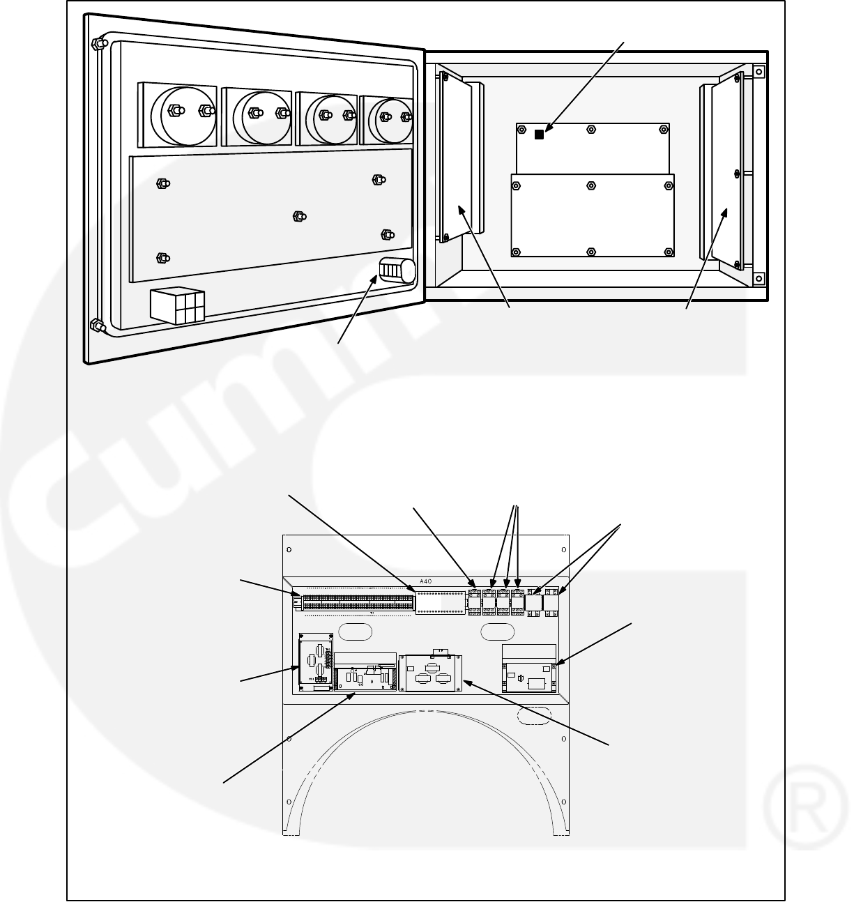
4-14
ACCESSORY BOX
(A40)
CUSTOMER INTERFACE
A34
ENGINE INTERFACE
A31
ANALOG BOARD
A33
DIGITAL BOARD
A32
DISPLAY BOARD
A35
RUN/OFF/AUTO
SWITCH S12
OPTIONAL RTD
RELAY
OPTIONAL
COMMON ALARM
RELAY K14
OPTIONAL RUN
RELAYS K11, K12 &
K13 OPTIONAL
THERMISTOR
RELAY 160/140 C
TB1-1 THROUGH 60
GOVERNOR
OUTPUT MODULE
A38
PT/CT BOARD A36
VOLTAGE
REGULATOR
OUTPUT MODULE
A37
S5 POWER ON/
STANDBY SWITCH
BUS PT MODULE
A39
FIGURE 4-2. CIRCUIT BOARD LOCATIONS

4-15
TABLE 4-4. ENGINE DOES NOT CRANK—LOCAL OR REMOTE RUN
WARNING Many troubleshooting procedures present hazards that can result in severe personal inju-
ry or death. Only trained and experienced service personnel with knowledge of fuels, electricity, and
machinery hazards should perform service procedures. Review Important Safety Instructions page.
Indicator(s) Possible Cause Corrective Action
“FAIL TO
CRANK”
(221)
message
Reset and
attempt to
start:
Start LED
DS11 on the
engine
interface board
turns on.
NOTE:
These two
indications
suggest that
the PCC has
received a
start signal
and has sent a
start command
to the start
output (J4-2)
on the engine
interface
board.
2. Starter could be bad.
5. If there is continuity at A37 J7-5/J7-6,
there may be an open between A37
and A31, an open between A37 and
K4, or A31 may be bad.
2. Reset the control. Attempt to start, and test for
B+ at the starter. If there is B+ at the starter, the
starter could be bad. Test starter (see engine
service manual). Replace the starter.
3. Reset the control. Attempt to start, and test for
B+ into and out of start solenoid contacts. If
there is B+ in, but not out, check for B+ at the
start solenoid coil. If there is B+ at the coil,
check ground connection. If ground connection
is good, the start solenoid is bad. Replace the
start solenoid.
If there is B+ into and out of the start solenoid
contacts, check for an open between the start
solenoid contacts and the starter. If there is no
B+, go to the next step.
3. If there is no B+ at the starter, start so-
lenoid K4 could be bad.
4. If there is no B+ at the start solenoid
coil (K4), the backup start disconnect
contacts in the regulator output mod-
ule (A37) could be open (indicating
that A37 is bad).
*4. Disconnect J7/P7 at the regulator output mod-
ule. Test for continuity at A37 J7-5/J7-6. If there
is no continuity, the regulator output module is
bad. Replace A37.
*5. If there is continuity at A37 J7-5/J7-6, reset the
control, attempt to start, and check for B+ at
A37 P7-5.
If there is B+ at P7-5, there may be an open be-
tween start solenoid coil (K4) and A37. If there
is no B+ at P7-5, check for B+ at J4-2 on the en-
gine interface board (A31) while attempting to
start.
If there is B+ at A31 J4-2, check for an open be-
tween A37 and A31.
If there is no B+ at A31 J4-2, (and DS11 is on)
the engine interface board is bad. Replace A31.
1a. Recharge or replace the battery. Specific gravi-
ty for a fully charged battery is approximately
1.260 at 80 F (27 C).
1b. Clean and tighten or replace the battery cable
connectors and cables at the battery and the
set.
1c. Adjust charge rate of battery charging circuit.
1d. Replace engine DC alternator if normal battery
charging voltage is not obtained.
1. Insufficient battery voltage. Check the
following conditions:
a. Batteries not charged.
b. Battery connections loose or
dirty.
c. Insufficient battery charging volt-
age.
d. Engine DC alternator could be
bad.
*CAUTION: Wearing wrist strap, set S12 to Off and A32 S5 to Standby before connecting/disconnecting harness plugs.
6. The mag pickup signal is not being
sensed.
6. Refer to the mag pickup shutdown message
(220).

4-16
TABLE 4-5. ENGINE DOES NOT CRANK—LOCAL OR REMOTE RUN
WARNING Many troubleshooting procedures present hazards that can result in severe personal inju-
ry or death. Only trained and experienced service personnel with knowledge of fuels, electricity, and
machinery hazards should perform service procedures. Review Important Safety Instructions page.
*1. Install harness tool between A31 J4/P4. Reset
the control. Attempt to start and check for B+ at
J4-2. If no B+, remove F3 and check continuity.
If open, replace the fuse with one of the same
type and amp rating (5 Amps). If F3 is OK,
check the B+ supply from the wiring harness.
1. Fuse F3 on the engine interface board
(A31) may be open, or B+ may not be
getting to F3.
Indicator(s) Possible Cause Corrective Action
“FAIL TO
CRANK”
(221)
message
Reset and
attempt to
start:
Start LED
DS11 on the
engine
interface board
does NOT
turn on.
NOTE:
These two
indications
suggest that
the PCC has
received a
start signal
and has NOT
sent a start
command to
the start output
(J4-2) on the
engine
interface
board.
2. To isolate:
Check for B+ at S13-1 and S13-2.
If there is B+ at S13-2, but not at S13-1
(and S13 is NOT in the emergency stop
position), then S13 is bad. Replace S13.
If there is no B+ at S13-2, disconnect
J3/P3, and check for B+ at A31 J3-2. If
there is no B+, replace A31.
If there is B+ at A31 J3-2, check continuity
from P3-2 to P3-6. If no continuity, repair
or replace as necessary.
2. Emergency Stop switch S13 or the
PCC door harness may be bad.
4. Engine interface board (A31) may be
bad.
*4. If there is a ground output at A32 J4-3, and yet
there is no B+ output at A31 J4-2; then A31 is
bad. Replace A31.
*3. Install harness tool between A32 J4/P4. Reset
the control. Attempt to start, and test for ground
output at A32 J4-3. If there is no ground output,
A32 is bad. Replace A32.
3. Digital board (A32) may be bad.
*CAUTION: Wearing wrist strap, set S12 to Off and A32 S5 to Standby before connecting/disconnecting harness plugs.

4-17
TABLE 4-6. ENGINE DOES NOT CRANK—REMOTE RUN
WARNING Many troubleshooting procedures present hazards that can result in severe personal inju-
ry or death. Only trained and experienced service personnel with knowledge of fuels, electricity, and
machinery hazards should perform service procedures. Review Important Safety Instructions page.
“FAIL TO
CRANK”
(221)
message
DOES NOT
appear on
digital display
−and:
Auto LED DS5
on the engine
interface board
(A31) is on −
RMT Start
LED DS14 on
the customer
interface board
(A34) is on −
NOTE:
This condition
suggests that
the PCC
processor
(digital board
−A32) has
NOT received
or recognized
a remote start
start signal.
*1. Install harness tool between A32 J4/P4. Check
for ground output at A32 J4-18.
If there is no ground output (but A31 DS5 is on)
engine interface board A31 is bad. Replace
A31.
If there is a ground output at A31 J1-18, pro-
ceed to the next step.
1. The Auto mode signal is not getting
from engine interface board A31 to
digital board A32, indicating that A31 is
bad.
Indicator(s) Possible Cause Corrective Action
2. The Remote run signal is not getting
from customer interface board A34 to
A32, indicating that A34 is bad.
*2. Install harness tool between A32 J4/P4. Reset
the control. Attempt to remote start, and check
for ground output at A32 J2-26. If no ground out-
put (but A34 DS14 is on) customer interface
board A34 is bad. Replace A34.
If there is a ground output at A32 J2-26, pro-
ceed to the next step.
*3. If, when attempting remote start, there is a
ground input at A32 J2-26, and a ground input
at A32 J4-18—and there is no “FAIL TO
CRANK” message—and the set does not
crank; A32 is bad. Replace, A32.
3. Digital board (A32) may be bad.
*CAUTION: Wearing wrist strap, set S12 to Off and A32 S5 to Standby before connecting/disconnecting harness plugs.

4-18
TABLE 4-7. ENGINE DOES NOT CRANK—REMOTE RUN
WARNING Many troubleshooting procedures present hazards that can result in severe personal inju-
ry or death. Only trained and experienced service personnel with knowledge of fuels, electricity, and
machinery hazards should perform service procedures. Review Important Safety Instructions page.
Indicator(s) Possible Cause Corrective Action
“FAIL TO
CRANK”
(221)
message
DOES NOT
appear on
digital display
−and:
Auto LED DS5
on the engine
interface board
(A31) is off −
RMT Start
LED DS14 on
the customer
interface board
(A34) is on −
NOTE:
This condition
suggests that
the engine
interface board
(A31) is NOT
enabling the
remote start
logic on the
digital board.
*2. Install harness tool between A32 J4/P4. Check
the 16 volt (nominal) supply at A32 J4-16.
If the voltage is present at A32 J4-16, and
ground is present at A31 P3-13—and yet A31
DS5 is off; then A31 is bad. Replace A31.
The Auto mode input is not getting from the
Auto select switch (S12) to engine interface
board A31 (indicating that S12, A31, or the
harness is bad.
1. S12 or the wiring harness may be bad. *1. Disconnect A31 J3/P3. Check continuity to
ground at A31 J3-11. (J3-11 is ground out to
S12. If ground is not present, replace A31. If
ground is present, place S12 in Auto and check
continuity from P3-11 to P3-13. If no continuity,
isolate to switch or wiring harness. Repair as
necessary. If there is continuity, A31 may be
bad. Reconnect J3/P3.
2. Engine interface board A31 may be
bad.
3. If there is no +16 volt supply voltage at A32
J4-16, A32 is bad. Replace A32.
3. Digital board A32 may be bad.
*CAUTION: Wearing wrist strap, set S12 to Off and A32 S5 to Standby before connecting/disconnecting harness plugs.

4-19
TABLE 4-8. ENGINE DOES NOT CRANK—REMOTE RUN
WARNING Many troubleshooting procedures present hazards that can result in severe personal inju-
ry or death. Only trained and experienced service personnel with knowledge of fuels, electricity, and
machinery hazards should perform service procedures. Review Important Safety Instructions page.
Indicator(s) Possible Cause Corrective Action
“FAIL TO
CRANK”
(221)
message
DOES NOT
appear on
digital display
−and:
Auto LED DS5
on the engine
interface board
(A31) is on −
RMT Start
LED DS14 on
the customer
interface board
(A34) is off
NOTE:
This condition
suggests that
the remote
start input is
NOT passing
through the
customer
interface board
(A34) to
enable the
remote start
logic on the
digital board.
2. If ground is present at A34 J1-13—and yet A34
DS14 is off, replace A34.
The remote start input is not getting from the
remote start switch to the output of the cus-
tomer interface board (A34) (indicating that
the switch, A34, or the harness is bad.
1. The remote start switch or the
wiring harness may be bad.
*1. Install harness tool between A34 J1/P1. Reset
the control. Attempt remote start and check for
ground at A34 J1-13. If ground level is not pres-
ent, isolate to the switch or the wiring harness
by checking for a start signal at TB1-5. Repair
as necessary.
2. Customer interface board A34
may be bad.
*CAUTION: Wearing wrist strap, set S12 to Off and A32 S5 to Standby before connecting/disconnecting harness plugs.

4-20
TABLE 4-9. ENGINE DOES NOT CRANK—LOCAL RUN
WARNING Many troubleshooting procedures present hazards that can result in severe personal inju-
ry or death. Only trained and experienced service personnel with knowledge of fuels, electricity, and
machinery hazards should perform service procedures. Review Important Safety Instructions page.
Indicator(s) Possible Cause Corrective Action
“FAIL TO
CRANK”
(221)
message
DOES NOT
appear on
digital display
−and:
Run LED DS4
on the engine
interface board
(A31) is off−
NOTE:
This condition
suggests that
the start input
is NOT getting
from the
Run/Off/ Auto
switch (S12) to
the engine
interface board
(A31) to
enable the
remote start
logic on the
digital board.
The start input is not getting from the Run/
Off/ Auto select switch (S12) to A31 (indi-
cating that S12, A31, or the harness is bad.
1. Run/Off/ Auto select switch S12 or the
wiring harness may be bad.
*1. Check continuity to ground at A31 J3-11. If
ground is not present, replace A31. If ground is
present, place S12 in Run and check continuity
from P3-11 to P3-12. If no continuity, isolate to
switch or wiring harness. Repair as necessary.
If there is continuity, A31 may be bad.
2. Engine interface board A31
may be bad.
*2. Install harness tool between A32 J4/P4. Check
the 16 volt (nominal) supply at A32 J4-16.
If the voltage is present at A32 J4-16, and
ground is present at A31 J3-12—and yet A31
DS5 is off, replace A31.
3. If there is no +16 volt supply voltage at A32
J4-16, replace A32.
3. Digital board A32 may be bad.
*CAUTION: Wearing wrist strap, set S12 to Off and A32 S5 to Standby before connecting/disconnecting harness plugs.

4-21
TABLE 4-10. ENGINE CRANKS BUT DOES NOT START
WARNING Many troubleshooting procedures present hazards that can result in severe personal inju-
ry or death. Only trained and experienced service personnel with knowledge of fuels, electricity, and
machinery hazards should perform service procedures. Review Important Safety Instructions page.
2. The mechanical fuel linkage could be
binding, loose, or damaged.
2. Inspect the mechanical fuel linkage, and repair
or replace as necessary.
Follow the procedure in the engine repair
manual to check the EFC for binding or dam-
age.
Disconnect the actuator connector, and con-
nect +12 VDC from the battery to the actuator.
The actuator should click upon application and
removal of the voltage.
If the actuator does not click, refer to the engine
manual.
If the actuator clicks, reconnect the wires to the
actuator.
1. Restricted fuel supply due to:
a. Fuel level below pickup tube in
tank.
b. Closed shutoff valve in supply
line.
c. Fuel injectors clogged.
d. Air in fuel system.
1a. Add fuel if low. Prime the fuel system.
1b. Open any closed shutoff valve in the fuel line
supplying the engine.
1c. Refer to engine service manual.
1d. Bleed air from fuel system. Refer to engine ser-
vice manual.
Indicator(s) Possible Cause Corrective Action
“OVERCRANK”
(222)
message
−and
While cranking,
Run LED DS12
on the
engine interface
board (A31)
is on.
and
While cranking,
Run LED DS2
on the
governor output
module (A38)
is on.
NOTE:
These
indications
suggest that the
PCC has sent a
run signal to the
fuel solenoid.
3. Fuel solenoid (K1) on the injection
pump not energized due to:
a. Open in fuel solenoid circuit or
defective governor module.
b. Defective fuel solenoid.
3a. Reset the control. Attempt to start and check for
B+ at the K1 fuel solenoid coil on the injection
pump and at output of governor module. Check
continuity from J6-20 and 21 to J6-19.
3b. Check wiring continuity of fuel solenoid circuit.
Test fuel solenoid.
Repair or replace as necessary.
5. Engine fuel injection or other engine
problem.
4. Fuel tank solenoid not energized due
to:
a. Open in fuel tank solenoid circuit.
b. Defective fuel tank solenoid.
5. Refer to the engine service manual.
4a. Check wiring continuity of fuel tank solenoid cir-
cuit.
4b. Test fuel tank solenoid.
Repair or replace as necessary.
Fuel supply or fuel delivery.
*CAUTION: Wearing wrist strap, set S12 to Off and A32 S5 to Standby before connecting/disconnecting harness plugs.

4-22
TABLE 4-11. ENGINE CRANKS BUT DOES NOT START
WARNING Many troubleshooting procedures present hazards that can result in severe personal inju-
ry or death. Only trained and experienced service personnel with knowledge of fuels, electricity, and
machinery hazards should perform service procedures. Review Important Safety Instructions page.
1. The run signal is not getting out of the
engine interface board (A31). A31
may be bad.
*1. Install harness tool between A31 J4/P4. Reset
the control. Attempt to start and check for B+ at
A31 J4-1. If there is no B+ at A31 J4-1, replace
A31.
Indicator(s) Possible Cause Corrective Action
“OVERCRANK”
(222)
message
−and
While cranking,
Run LED DS12
on the
engine interface
board (A31)
is on.
and
While cranking,
Run LED DS2
on the
governor output
module (A38)
is off.
NOTE:
These
indications
suggest that the
PCC has sent a
run signal to the
governor
module, but the
signal is not
getting through
the governor
module to the
fuel solenoid.
The run signal is not getting through the
governor module to the fuel solenoid.
Reset the control. Attempt to start and check for B+
at A31 J4-1.
2. There is an open between the engine
interface board (A31) and the gover-
nor output module (A38).
3. The run signal is not getting through
the governor output module (A38).
A38 may be bad.
*2. If there is B+ at A31 J4-1, install harness tool be-
tween A38 J6/P6. Check for B+ at
A38 J6-19, while attempting to crank. If there is
no B+ at A38 J6-19, isolate to connectors and
wiring. Repair or replace as necessary.
3. If there is B+ at A31 J4-1, and there is B+ at A38
J6-19, check continuity from A38 J6-15 to bat-
tery ground, if not continuity replace harness, if
continuity, replace A38.
*CAUTION: Wearing wrist strap, set S12 to Off and A32 S5 to Standby before connecting/disconnecting harness plugs.

4-23
TABLE 4-12. ENGINE CRANKS BUT DOES NOT START
WARNING Many troubleshooting procedures present hazards that can result in severe personal inju-
ry or death. Only trained and experienced service personnel with knowledge of fuels, electricity, and
machinery hazards should perform service procedures. Review Important Safety Instructions page.
*Install harness tool between A32 J4/P4. Attempt to
start and check for ground signal at A32 J4−8.
1. The run signal is not getting out of the
digital board (A32). A32 may be bad.
1. If there is no ground signal at A32 J4−8, replace
A32.
Indicator(s) Possible Cause Corrective Action
“OVERCRANK”
(222)
message
−and
Run LED DS12
on the
engine interface
board (A31)
is off.
NOTE:
These
indications
suggest that the
PCC has NOT
sent a run
signal −
(fuel solenoid
enable signal)
out to the
governor
module and the
fuel solenoid.
The run signal from the digital board (A32)
is not being processed by the engine inter-
face board (A31).
2. If there is a ground signal at A32 J4−8, replace
A31.
2. The run signal is not being processed
by the engine interface board (A31).
A31 may be bad.
“FAIL TO
CRANK”
(221)
message
NOTE:
The engine is
cranking but
shutting down
on a 221 fault.
The mag pickup signal is not being
sensed.
Refer to the mag pickup shutdown message
(220).
*CAUTION: Wearing wrist strap, set S12 to Off and A32 S5 to Standby before connecting/disconnecting harness plugs.

4-24
TABLE 4-13. LOW OIL PRESSURE WARNING (200) OR SHUTDOWN (201)
WARNING Many troubleshooting procedures present hazards that can result in severe personal inju-
ry or death. Only trained and experienced service personnel with knowledge of fuels, electricity, and
machinery hazards should perform service procedures. Review Important Safety Instructions page.
Indicator(s) Possible Cause Corrective Action
“LOW OIL
PRESSURE”
warning
(200) or
shutdown
(201)
message.
1. Low oil level. Clogged lines or filters.
2a. Sender or oil pump could be bad. Or
the generator set may be shutting
down on another fault.
1. Check oil level, lines and filters. If oil system is
OK but oil level is low, replenish. Oil pressure
limits are listed in Table 4-3.
2. Disconnect the oil pressure sender leads, and
connect an oil pressure sender simulator to the
harness.
a. If the control responds to the simulator, recon-
nect the sender, disconnect the run signal wire
at the fuel solenoid, and crank the engine.
Check the oil pressure reading on the digital
display.
If the display shows an acceptable oil pres-
sure, the problem may not be in the oil or oil
sensing system. The generator set may
be shutting down on another fault (out of
fuel, blown governor fuse, intermittent
connector). Restart the generator set and
monitor the PCC display panel for other
faults.
If the display does not show an acceptable
oil pressure, replace the sender. If the
PCC still doesn’t display an oil pressure
while cranking, the oil pump may be faulty.
Refer to the engine service manual.
*b. If the control does not respond to the simulator,
the PCC or the harness is bad. Install harness
tool between A31 J2/P2.
Check for +5 VDC at the sender (lead marked
E1-B). If there is no 5 VDC at the sender
Check for 5 VDC at A31 J5-18.
If yes, harness is bad. If no, check for 5
VDC at A31 J2-24.
If yes, A31 is bad. If no, A33 is bad.
If there is 5 VDC at the sender, use the sender
simulator to generate a signal to A31 J2-23. If
the pressure signal (.5 to 4.5 VDC) does not get
to A31 J2-23, isolate to the harness or A31. If
the pressure signal does get to A31 J2-23, refer
to the analog/digital troubleshooting procedure
(Table 4-36a/b).
2b. Harness or PCC circuit board could be
bad.
Isolate to the harness, engine inter-
face board (A31), analog board (A33),
or digital board (A32).
*CAUTION: Wearing wrist strap, set S12 to Off and A32 S5 to Standby before connecting/disconnecting harness plugs.

4-25
TABLE 4-14. SENDER WARNINGS (204 or 213)
WARNING Many troubleshooting procedures present hazards that can result in severe personal inju-
ry or death. Only trained and experienced service personnel with knowledge of fuels, electricity, and
machinery hazards should perform service procedures. Review Important Safety Instructions page.
Indicator(s) Possible Cause Corrective Action
“OIL
PRESSURE
SENDER”
warning
(204)
message.
1. The sender connections could be bad.
2. The sender, the harness, engine inter-
face board (A31), digital board (A32),
or analog board (A33) could be faulty.
1. Check the sender connections.
*2. Isolate to the sender, harness, engine interface
board (A31), analog board (A33), or digital
board (A32).
Disconnect the oil pressure sender leads, and
connect an oil pressure sender simulator to the
harness.
“OIL PRES SENDER” warning is displayed
after the fault condition is sensed for 10 sec-
onds.
a. If the control responds to the simulator, re-
place the sender.
*b. If the control does not respond to the simulator,
the PCC or the harness is bad. Install harness
tool between A31 J2/P2.
Check for +5 VDC at the sender (lead marked
E1-B). If there is no 5 VDC at the sender
Check for 5 VDC at A31 J5-18.
If yes, harness is bad. If no, check for 5
VDC at A31 J2-24.
If yes, A31 is bad. If no, A33 is bad.
If there is 5 VDC at the sender, use the sender
simulator to generate a signal to A31 J2-23. If
the pressure signal (.5 to 4.5 VDC) does not get
to A31 J2-23, isolate to the harness or A31. If
the pressure signal does get to A31 J2-23, refer
to the analog/digital troubleshooting procedure
(Table 4-36a/b).
“COOLANT
SENDER”
warning
(213)
message.
1. Check the sender connections.
*2. Isolate to the sender, harness, engine interface
board (A31), analog board (A33), or digital
board (A32).
Disconnect the sender, and plug in a resistive
sender simulator to isolate the fault.
a. If the control responds to the simulator, re-
place the sender.
b. If the control does not respond to the simu-
lator, refer to the high coolant temp trou-
bleshooting procedure.
1. The sender connections could be bad.
2. The sender, the harness, engine inter-
face board (A31), digital board (A32),
or analog board (A33) could be faulty.
*CAUTION: Wearing wrist strap, set S12 to Off and A32 S5 to Standby before connecting/disconnecting harness plugs.

4-26
TABLE 4-15. LOW ENGINE TEMPERATURE WARNING (210)
WARNING Many troubleshooting procedures present hazards that can result in severe personal inju-
ry or death. Only trained and experienced service personnel with knowledge of fuels, electricity, and
machinery hazards should perform service procedures. Review Important Safety Instructions page.
“LOW
COOLANT
TEMP”
warning
(210)
message.
Coolant level
is normal.
Heater is OK.
Coolant temp
on front panel
display is OK.
DS3 on the
engine
interface
board, A31,
is on.
Indicator(s) Possible Cause Corrective Action
DS3 / A31 is on, indicating that engine in-
terface board A31 is receiving a low cool-
ant temp from the sender.
The sender, the harness or A31 could be
bad.
Isolate the source of the signal.
Unplug the coolant temperature switch (S1) and re-
set the control.
1. If the 210 warning message drops out and does
not reappear, replace the sender.
*2. If the 210 warning message reappears and re-
mains after control reset, disconnect A31 J4
and check continuity from P4−13 to GND.
If there is continuity, replace the harness.
If there is no continuity, replace circuit
board A31.
DS3 / A31 is off, indicating that engine in-
terface board A31 is not receiving a low en-
gine temp signal from the sender—but the
210 message indicates that A32, the digital
board, is responding to a false low engine
temp signal.
A31, the engine interface board, or A32,
the digital board, could be bad.
Isolate the source of the signal.
Check J4−6/P4−6 on A32.
*1. Install harness tool between A32 J4/P4.
2. Open J4−6 and reset the control.
If fault drops out and does not return, re-
place A31.
If fault returns after resetting the control,
replace A32.
“LOW
COOLANT
TEMP”
warning
(210)
message.
Coolant level
is normal.
Heater is OK.
Coolant temp
on front panel
display is OK.
DS3 on the
engine
interface
board, A31,
is off.
*CAUTION: Wearing wrist strap, set S12 to Off and A32 S5 to Standby before connecting/disconnecting harness plugs.

4-27
TABLE 4-16. HIGH ENGINE TEMPERATURE WARNING (211) OR SHUTDOWN (212)
WARNING Many troubleshooting procedures present hazards that can result in severe personal inju-
ry or death. Only trained and experienced service personnel with knowledge of fuels, electricity, and
machinery hazards should perform service procedures. Review Important Safety Instructions page.
Indicator(s) Possible Cause Corrective Action
“HIGH
COOLANT
TEMP”
warning
(211) or
shutdown
(212)
message.
Coolant
mixture and
level is normal.
No airflow
obstructions.
Fan belt is OK.
1. Engine problem:
Coolant pump could be faulty.
Thermostat could be faulty.
There could be an obstruction in
the coolant flow.
External coolant pump (with re-
mote radiator) could be faulty.
External radiator fan motor (with
remote radiator) could be faulty.
2. The generator set may have been
overloaded.
3. Sender, harness or PCC circuit board
could be bad.
1. Refer to the engine service manual if there are
any physical indications of overheating.
2. Correct any overload condition.
3. If there are no physical indications of overheat-
ing, check to see if the PCC accurately displays
ambient engine temperature.
If the PCC ambient coolant temperature
reading is accurate, the engine may be
overheating. Refer to the engine service
manual.
If the PCC ambient coolant temperature
reading is not accurate, isolate to the
sender, harness, engine interface board
(A31), analog board, or digital board.
Disconnect the coolant temperature sender
leads, and connect an coolant temperature
sender simulator to the harness.
a. If the control responds to the simulator, re-
place the sender.
*b. If the control does not respond to the simu-
lator, install harness tool between A31
J5/P5. Connect the coolant temperature
sender simulator (and B+) to A31 J5.
If the control displays the correct simulated
temperature, replace the harness.
If the control does not display the correct
simulated temperature, install harness
tool at A31 J2/P2, and open lines 18/19
(and 14/15, if applicable). Check for conti-
nuity between A31 J2-18 to 19 (for coolant
temp L), and A31 J2-14 to 15 (for coolant
temp R).
If no continuity, then A31 is bad.
If continuity is OK, then send a simu-
lated temperature signal and mea-
sure the voltage out of A31 (A31
J2-18 to 19, and A31 J2-14 to 15).
If voltage is not OK (refer to the ana-
log board inputs and outputs, Table
4-37), replace A33.
If voltage is OK, refer to the analog/
digital troubleshooting procedure
(Table 4-36a/b).
*CAUTION: Wearing wrist strap, set S12 to Off and A32 S5 to Standby before connecting/disconnecting harness plugs.

4-28
TABLE 4-17. LOW COOLANT WARNING OR SHUTDOWN (214 / 215)
WARNING Many troubleshooting procedures present hazards that can result in severe personal inju-
ry or death. Only trained and experienced service personnel with knowledge of fuels, electricity, and
machinery hazards should perform service procedures. Review Important Safety Instructions page.
Indicator(s) Possible Cause Corrective Action
“LOW
COOLANT
LVL” warning
(214) or
shutdown
(215) message
Coolant level
is normal.
DS2 on the
engine
interface
board, A31,
is on.
DS2 on A31 is on, indicating that A31 is re-
ceiving a low coolant signal from the send-
er.
The sender, the harness or the A31 circuit
board could be bad.
If the coolant level is normal, isolate the source of the
low coolant signal. (This is a ground signal.)
Disconnect the signal lead at the sender and reset
the control.
1. If the 215 shutdown message drops out and
does not reappear, replace the sender.
*2. If the 215 shutdown message reappears and
remains after control reset, disconnect J4/A31
and check continuity from P4−7 to GND.
If there is continuity, replace the harness.
If there is no continuity, replace circuit
board A31.
“LOW
COOLANT
LVL” warning
(214) or
shutdown
(215) message
Coolant level
is normal.
DS2 on the
engine
interface
board, A31,
is off.
DS2 on A31 is off, indicating that A31 is not
receiving a low coolant signal from the
sender—but the 215 message indicates
that A32, the digital board, is responding to
a false low coolant signal.
A31, the engine interface board, or A32, the
digital board, could be bad.
If the coolant level is normal, isolate the source of the
low coolant signal.
Check J4−4/P4−4 on A32.
*1. Install harness tool between A32 J4/P4.
2. Open the J4-4 circuit and reset the control.
If the fault drops out and does not return,
replace A31.
If the fault returns after resetting the con-
trol, replace A32.
*CAUTION: Wearing wrist strap, set S12 to Off and A32 S5 to Standby before connecting/disconnecting harness plugs.

4-29
TABLE 4-18. MAG PICKUP SHUTDOWN (220)
WARNING Many troubleshooting procedures present hazards that can result in severe personal inju-
ry or death. Only trained and experienced service personnel with knowledge of fuels, electricity, and
machinery hazards should perform service procedures. Review Important Safety Instructions page.
Indicator(s) Possible Cause Corrective Action
“MAG
PICKUP”
shutdown
message (220)
This indicates that the PCC is not sensing
the mag pickup signal, or the mag pickup
frequency does not correspond (in propor-
tion) to the genset output frequency.
1. Check and correct setting if necessary.
2. Inspect the wires, and repair or replace as nec-
essary.
*3/4 To isolate the problem, reset the control and at-
tempt to start the set in idle mode.
a. If the engine displays a “FAIL TO CRANK” shut-
down message, or if the engine starts and idles,
but then shuts down on a MAG PICKUP fault,
the MPU sender could be bad. Remove the
MPU connectors and check for 3.5 to 15 VAC at
the MPU while cranking.
If no output, check for damage or debris.
Also check for improper adjustment of the
MPU. (Refer to Section 5.) If there is still
no output, replace the MPU sender.
If the MPU output is OK, install harness
tool between A32 J4/P4. Check for MPU
voltage at A32 J4-10 to 11, while cranking.
If OK, replace A32. If not OK, use continu-
ity checks to isolate to A31 or harness.
b. If the engine starts and idles, and does not dis-
play a fault, then there could be a frequency
mismatch problem.
Measure generator output frequency with
a digital multimeter and compare to the fre-
quency on the PCC display.
If they do match, multiply the frequency by
30 and compare this number to the RPM
on the PCC display. If these are not the
same, the MPU sender may be bad. Re-
place the MPU sender
If the multimeter and PCC frequencies do
not match, there is a frequency sensing
problem. Verify the accuracy of the PCC
L1N voltage, and then refer to the analog/
digital troubleshooting procedure (Table
4-36a/b).
1. The PCC may not be set for the correct
generator set.
2. Loose or damaged mag pickup wire.
3. Damaged mag pickup (MPU).
4. The harness, the engine interface
board (A31), the analog board (A33) or
the digital board (A32) could be bad.
*CAUTION: Wearing wrist strap, set S12 to Off and A32 S5 to Standby before connecting/disconnecting harness plugs.

4-30
TABLE 4-19. OVERSPEED SHUTDOWN (223)
WARNING Many troubleshooting procedures present hazards that can result in severe personal inju-
ry or death. Only trained and experienced service personnel with knowledge of fuels, electricity, and
machinery hazards should perform service procedures. Review Important Safety Instructions page.
Indicator(s) Possible Cause Corrective Action
“OVERSPEED”
shutdown
message (223)
1. Inspect the mechanical fuel linkage, and repair
or replace as necessary.
Follow the procedure in the engine repair
manual to check the EFC for binding or
damage.
Disconnect the actuator connector, and
connect +12 VDC from the battery to the
actuator. The actuator should click upon
application and removal of the voltage.
If the actuator does not click, refer to the
engine manual.
If the actuator clicks, reconnect the wires
to the actuator.
*2. Reset the control, and start the set while moni-
toring the PCC duty cycle display.
If the duty cycle goes high (above 40%) and the
set shuts down on overspeed, replace A32.
If the duty cycle goes to zero and the set shuts
down on overspeed, replace A38.
1. The mechanical fuel linkage could be
binding, loose, or damaged.
2. The governor output module (A38) or
the digital board (A32) could be bad.
*CAUTION: Wearing wrist strap, set S12 to Off and A32 S5 to Standby before connecting/disconnecting harness plugs.

4-31
TABLE 4-20a. FAIL TO SYNCHRONIZE (224)
WARNING Many troubleshooting procedures present hazards that can result in severe personal inju-
ry or death. Only trained and experienced service personnel with knowledge of fuels, electricity, and
machinery hazards should perform service procedures. Review Important Safety Instructions page.
Indicator(s) Possible Cause Corrective Action
“FAIL TO
SYNCHRO-
NIZE” warning
(224) or
shutdown
(224)
message.
1. Improper adjustment of bus or genera-
tor set voltage.
1. Verify that the bus voltage is within plus or mi-
nus 5% of the value which is programmed into
the PowerCommand control, and verify that the
generator set is operating at proper voltage and
frequency. Verify that the bus PT module is
properly calibrated. (Refer to Digital Bus Volt-
age Calibration in Section 5). Check the FAIL
TO SYNCHRONIZE time delay. It should be set
for approximately 120 seconds. Check parallel-
ing setup adjustments, particularly PERM WIN -
PHASE and PERM WIN - TIME. They are typi-
cally adjusted to 20 degrees and 0.5 seconds.
*CAUTION: Wearing wrist strap, set S12 to Off and A32 S5 to Standby before connecting/disconnecting harness plugs.
2. Generator set hunting due to improper
synchronizing adjustments.
3. Unstable or hunting generator set due
to governor component failure or mis-
adjustment.
Continued On Next Page...
2. Check synchronizer adjustments in the Power-
Command control set−up. If you are unsure of
proper adjustment procedure, returning the unit
to it’s default values should result in proper op-
eration. The default values are shown in the test
report which is shipped with the generator set.
In particular, check values for paralleling func-
tions, governing and voltage regulation.
3. Inspect generator set governing system for evi-
dence of binding or sticking linkages or other
components which are not operating correctly.
Verify that water jacket heaters are operational
and properly functioning. Check and adjust
governor settings as required.

4-32
TABLE 4-20b. FAIL TO SYNCHRONIZE (224) (Continued)
WARNING Many troubleshooting procedures present hazards that can result in severe personal inju-
ry or death. Only trained and experienced service personnel with knowledge of fuels, electricity, and
machinery hazards should perform service procedures. Review Important Safety Instructions page.
Indicator(s) Possible Cause Corrective Action
“FAIL TO
SYNCHRO-
NIZE” warning
(224) or
shutdown
(224)
message.
4. Unstable or hunting generator set due
to air entrained in the fuel system.
4. This problem is indicated in situations where
the generator set performs properly after the
generator set is up and running with load, but
experiences ”FAIL TO SYNCHRONIZE” alarms
after it has been shut down for several days.
Check the generator set fuel system for leaks or
cracks. If fuel filters have recently been
changed, air may be trapped in the fuel filter
heads. Check to be sure that there is a fuel head
on the engine fuel pump. Check fuel line routing
for overhead loops which could result in the
trapping of air in the system if the system sits
idle for some period of time. Parallel systems
should use option C174, the fuel pump feature
option. This feature is available as an aftermar-
ket accessory kit.
Note: The generator set will synchronize
faster as the synchronize acceptance win-
dow is widened (i.e., the value in the PERM
WIN−PHASE is increased) and as the accep-
tance time is minimized (the value in the
PERM WIN−TIME is minimized). Caution
should be taken in utility (mains) paralleling
applications to avoid damage to the genera-
tor set by inappropriate setting of these pa-
rameters.
*CAUTION: Wearing wrist strap, set S12 to Off and A32 S5 to Standby before connecting/disconnecting harness plugs.

4-33
TABLE 4-21a. FAIL TO CLOSE (226)
WARNING Many troubleshooting procedures present hazards that can result in severe personal inju-
ry or death. Only trained and experienced service personnel with knowledge of fuels, electricity, and
machinery hazards should perform service procedures. Review Important Safety Instructions page.
Indicator(s) Possible Cause Corrective Action
“FAIL TO
CLOSE”
warning (226)
or shutdown
(226)
message.
1. Check the paralleling breaker for indi-
cation that the breaker is tripped and
locked out from a signal issued from
it’s internal trip unit
1. If the breaker has tripped due to operation of it’s
internal trip unit, the alternator and electrical
distribution system connected to the alternator
should be carefully inspected for evidence of
burning or tracking, which might indicate that an
electrical fault has occurred. If no evidence of a
fault is found, reset the trip unit and verify that
the trip settings of the breaker are appropriate
for the application. Reset the fault on the Pow-
erCommand control and check the system op-
eration to verify that the failure to close fault
problem has been eliminated.
*CAUTION: Wearing wrist strap, set S12 to Off and A32 S5 to Standby before connecting/disconnecting harness plugs.
2. Breaker charge circuit is not operating
properly. (Power circuit breakers only.)
Continued On Next Page...
2. Check the circuit breaker status indicators and
verify that the breaker status indicates that the
breaker is properly charged. If it is, go on to step
3. If it is not charged, check the charge circuit for
proper operation. Switch the PowerCommand
control RUN/OFF/AUTO switch to OFF and
then manually recharge the paralleling breaker
according to the manufacturer’s instructions.
Switch the PowerCommand control RUN/OFF/
AUTO switch back to RUN. The generator set
should start and accelerate to rated speed and
voltage and the operator should be able to
manually control the circuit breaker from the
pushbuttons on the front panel of the Power-
Command control. In most cases the breaker
should automatically recharge on closing to the
system bus. If this does not occur, problem may
be in the control wiring to the breaker, or the
control power source.
NOTE: Some breakers are not able to be set
up to charge on closing (they will recharge
on opening). If this is the case with your
installation, it is critical that the generator
set be allowed to operate for a cooldown pe-
riod which is long enough for the breaker to
completely charge before the generator set
is shut down. If the generator set is shut
down on a fault condition, the breaker may
require manual recharge before the system
can be put back into automatic operation.

4-34
TABLE 4-21b. FAIL TO CLOSE (226) (Continued)
WARNING Many troubleshooting procedures present hazards that can result in severe personal inju-
ry or death. Only trained and experienced service personnel with knowledge of fuels, electricity, and
machinery hazards should perform service procedures. Review Important Safety Instructions page.
Indicator(s) Possible Cause Corrective Action
“FAIL TO
CLOSE”
warning (226)
or shutdown
(226)
message.
*CAUTION: Wearing wrist strap, set S12 to Off and A32 S5 to Standby before connecting/disconnecting harness plugs.
3. Breaker close signal has been issued
from the PowerCommand control, but
has not reached the breaker.
3. Disconnect breaker control wiring and verify
that the control is sending a close signal to the
breaker. If the breaker signal is present at the
generator set control, reconnect the control wir-
ing at the set, verify that it is present at the
breaker terminals.
Note that in Onan paralleling systems, DC pow-
er for operation of the relay comes from the gen-
erator control. Verify that the 20 amp customer
B+ fuse (F1 − engine harness assembly) is OK
and that the pilot relay operates properly.
4. Breaker status (open/close) signals
are not properly connected to the Pow-
erCommand control, or are not operat-
ing properly.
4. Verify that the breaker auxiliary contact wiring is
properly connected to the generator set. Verify
that the breaker is sending proper condition sig-
nals to the generator set, by disconnecting the
control wiring at the breaker and verifying that
the breaker auxiliary contacts change state
when breaker condition changes. If they are
functioning properly, verify that the signals are
reaching the generator set by reconnecting the
wiring and the breaker and checking for condi-
tion change at the generator set control acces-
sory box.

4-35
TABLE 4-22. DC (BATTERY) WARNINGS (230, 231, 232)
WARNING Many troubleshooting procedures present hazards that can result in severe personal inju-
ry or death. Only trained and experienced service personnel with knowledge of fuels, electricity, and
machinery hazards should perform service procedures. Review Important Safety Instructions page.
Indicator(s) Possible Cause Corrective Action
“LOW DC
VOLTAGE”
(230) or
“WEAK
BATTERY”
(232),
warning
message.
“HIGH DC
VOLTAGE”
(231)
warning
message.
But battery
voltage is OK.
1. Recharge or replace the battery. Specific gravi-
ty for a fully charged battery is approximately
1.260 at 80 F (27 C).
2. Replenish electrolyte and recharge battery.
3. Clean and tighten or replace the battery cable
connectors and cables at the battery and the
set.
4. Adjust charge rate of battery charging circuit,
according to manufacturers instructions.
5. Replace engine DC alternator if normal battery
charging voltage is not obtained.
*6. If the battery voltage, electrolyte, and connec-
tions are OK, check the battery voltage at A31
J5-17. If the voltage is not OK (same as battery
voltage), disconnect J5 and isolate to the har-
ness or A31.
If the voltage is OK, check battery voltage at
A33 J1-31. If the voltage is not OK, replace
A31. If the voltage at A33 J1-31 is OK, isolate to
A33 or A32 using the analog input troubleshoot-
ing procedure (Table 4-36a/b).
1. Weak or discharged battery.
2. Low electrolyte level in battery.
3. Battery connections loose or dirty.
4. Insufficient battery charging voltage.
5. Engine DC alternator could be bad.
6. If the batteries are OK, the problem
may be the harness, the engine inter-
face board (A31), the digital board
(A32), or the analog board (A33).
3. If the battery voltage is OK, the prob-
lem may be the engine interface board
(A31), the digital board (A32), or the
analog board (A33).
*3. Check the battery voltage at A31 J5-17. If the
voltage is not OK (same as battery voltage), dis-
connect J5 and isolate to the harness or A31.
If the voltage is OK, check battery voltage at
A33 J1-31. If the voltage is not OK, replace
A31. If the voltage at A33 J1-31 is OK, isolate to
A33 or A32 using the analog input troubleshoot-
ing procedure (Table 4-36a/b).
1. Adjust charge rate of battery charging circuit ac-
cording to manufacturers instructions.
1. Excessive battery charging voltage.
*CAUTION: Wearing wrist strap, set S12 to Off and A32 S5 to Standby before connecting/disconnecting harness plugs.
2. Replace engne DC alternator if normal battery
charging voltage is not obtained.
2. Engine DC alternator could be bad.

4-36
TABLE 4-23. LOW FUEL −DAY WARNING (240)
WARNING Many troubleshooting procedures present hazards that can result in severe personal inju-
ry or death. Only trained and experienced service personnel with knowledge of fuels, electricity, and
machinery hazards should perform service procedures. Review Important Safety Instructions page.
Indicator(s) Possible Cause Corrective Action
“LOW FUEL−
DAY”
warning
message (240)
Fuel level is
normal.
DS1 on the
engine
interface
board, A31,
is on.
DS1 on A31 is on, indicating that A31 is re-
ceiving a low fuel signal from the sender.
The sender, the harness or the A31 circuit
board could be bad.
If the fuel level is normal, isolate the source of the low
fuel signal.
Disconnect the signal lead at the sender and reset
the control.
1. If the 240 message drops out and does not re-
appear, replace the sender.
*2. If the 240 message reappears and remains af-
ter control reset, disconnect J4/A31 and check
continuity from P4−14 to GND.
If there is continuity, replace the harness.
If there is no continuity, replace circuit
board A31.
DS1 on A31 is off, indicating that the PCC is
not receiving a low fuel signal from the
sender—but the 240 message indicates
that A32, the digital board, is responding to
a false low fuel signal.
A31, the engine interface board, or A32, the
digital board, could be bad.
If the fuel level is normal, isolate the source of the low
fuel signal.
*1. Install a breakout connector at A32 J4.
2. Open the J4-15 circuit and reset the control.
If the fault drops out and does not return,
replace A31.
If the fault returns after resetting the con-
trol, go to step 3.
3. Install harness tool between A32 J2/P2.
4. Open the J2-19 circuit and reset the control.
If the fault drops out and does not return,
replace A31.
If the fault returns after resetting the con-
trol, replace A32..
“LOW FUEL−
DAY”
warning
message (240)
Fuel level is
normal.
DS1 (A31)
and DS13
(A34) are off.
*CAUTION: Wearing wrist strap, set S12 to Off and A32 S5 to Standby before connecting/disconnecting harness plugs.

4-37
TABLE 4-24. LOW FUEL WARNING (241)
WARNING Many troubleshooting procedures present hazards that can result in severe personal inju-
ry or death. Only trained and experienced service personnel with knowledge of fuels, electricity, and
machinery hazards should perform service procedures. Review Important Safety Instructions page.
DS13 on A34 is on, indicating that A34 is re-
ceiving a low fuel signal from the customer
circuit.
If there is no actual fault, the problem may
be a short to ground in the external wiring or
a bad customer interface board (A34).
Indicator(s) Possible Cause Corrective Action
DS13 on A34 is off, indicating that the PCC
is not receiving a low fuel signal from the
sender—but the 241 message indicates
that A32, the digital board, is responding to
a false low fuel signal.
A34, the customer interface board, or A32,
the digital board, could be bad.
If the fuel level is normal, isolate the source of the low
fuel signal.
*1. Install harness tool between A32 J2/P2.
2. Open the J2-19 circuit and reset the control.
If the fault drops out and does not return,
replace A34.
If the fault returns after resetting the con-
trol, replace A32.
“LOW FUEL”
warning
message (241)
Fuel level is
normal.
DS13 (A34) is
off.
“LOW FUEL”
warning
message (241)
Fuel level is
normal.
DS13 on the
customer
interface
board, A34, is
on.
If the fuel level is normal, isolate the source of the low
fuel signal.
Disconnect the signal lead near the control and reset
the control.
1. If the 241 message drops out and does not re-
appear, there is a short to ground in the external
wiring or a faulty sender.
*2. If the 241 message reappears and remains af-
ter control reset, disconnect J1/A34 and check
continuity from P1−5 to GND.
If there is continuity, find and repair a short
to ground in the external wiring.
If there is no continuity, replace circuit
board A34.
*CAUTION: Wearing wrist strap, set S12 to Off and A32 S5 to Standby before connecting/disconnecting harness plugs.

4-38
TABLE 4-25. EEPROM ERROR SHUTDOWN (250) OR WARNING (251, 252)
WARNING Many troubleshooting procedures present hazards that can result in severe personal inju-
ry or death. Only trained and experienced service personnel with knowledge of fuels, electricity, and
machinery hazards should perform service procedures. Review Important Safety Instructions page.
Indicator(s) Possible Cause Corrective Action
“EEPROM
ERROR”
shutdown
(250)
message.
The EE memory on the digital board (A32)
may be bad.
1. Perform the initial start setup procedure.
Turn the Run/Off/Auto switch to Off and reset
the control. Simultaneously press the RESET,
MENU, and PHASE SELECT keys to start the
setup.
Select the correct values, save your choices,
and attempt to start the set.
2. If the set shuts down on the same EEPROM
ERROR message, replace the digital board
(A32).
“EEPROM
ERROR”
warning
(251)
message.
The EE memory on the digital board (A32)
may be bad.
1. Perform the adjustment procedures (described
in Section 5). Save the adjustments.
Reset the control. Shut off and restart the set.
2. If the control generates the same EEPROM
ERROR message, perform the calibration pro-
cedures in Section 5.
Reset the control. Shut off and restart the set.
3. If the control generates the same EEPROM
ERROR message, replace the digital board
(A32).
“EEPROM
ERROR”
warning
(252)
message.
The EE memory on the digital board (A32)
may be bad.
1. If this message occurred during an adjustment,
option selection, or calibration of the PCC,
verify the values or choices selected and repeat
the save operation.
Reset the control. Shut off and restart the set.
2. If the control generates the same EEPROM
ERROR message, replace the digital board
(A32).
*CAUTION: Wearing wrist strap, set S12 to Off and A32 S5 to Standby before connecting/disconnecting harness plugs.

4-39
TABLE 4-26. RACK POSITION WARNING (260)
WARNING Many troubleshooting procedures present hazards that can result in severe personal inju-
ry or death. Only trained and experienced service personnel with knowledge of fuels, electricity, and
machinery hazards should perform service procedures. Review Important Safety Instructions page.
Indicator(s) Possible Cause Corrective Action
“RACK
POSITION”
warning
message (260)
*CAUTION: Wearing wrist strap, set S12 to Off and A32 S5 to Standby before connecting/disconnecting harness plugs.
PowerCommand control fault or defective
governor control circuitry.
Restart the generator set and monitor the fault LED’s
of the governor output module (A38). Refer to Sec-
tion 3 for LED descriptions.
1 LED’s (DS1 through DS4 are on and DS5 and
DS6 are off) do not indicate a fault, refer to “Cus-
tomer Fault 261, 262 & 263 for corrective ac-
tion.
2 LED’s (DS5 or DS6 are on) one or more indicate
a fault and the generator set shuts down after
restarting − perform the Rack Position Fault/
Test Procedure at the end of this section.
4-40
TABLE 4-27. CUSTOMER FAULTS (261, 262 or 263)
WARNING Many troubleshooting procedures present hazards that can result in severe personal inju-
ry or death. Only trained and experienced service personnel with knowledge of fuels, electricity, and
machinery hazards should perform service procedures. Review Important Safety Instructions page.
Indicator(s) Possible Cause Corrective Action
“CUSTOMER
FAULT
(261, 262 or
263) message.
And
corresponding
LED on
customer
interface board
A34 is on.
If the corresponding LED on the customer
interface board (A34) is on, then A34 is re-
ceiving a signal from the customer circuit.
If there is no actual fault, the problem may
be a short to ground in the external wiring or
a bad customer interface board (A34).
Isolate the source of the false signal.
Disconnect the signal lead near the control and reset
the control.
1. If the message drops out, there is a short to
ground in the external wiring.
2. If the message remains, replace A34.
“CUSTOMER
FAULT
(261, 262 or
263) message.
And
corresponding
LED on
customer
interface board
A34 is off.
Isolate the source of the false signal.
Check J2/P2 on A32.
*1. Install harness tool between A32 J2/P2.
2. Open the appropriate circuit J2-3, J2-24, J2-9,
or J2-15 and reset the control.
If the fault does not return, replace A34.
If the fault reappears, replace A32.
If the corresponding LED on the customer
interface board (A34) is off, then A34 is not
receiving a signal from the customer circuit.
The message indicates that A32, the digital
board, is responding to a false signal.
A34, the customer interface board, or A32,
the digital board, could be bad.
A 34
LED
A32
CONNECTOR
CUSTOMER
FAULT #
FAULT
CODE
DS4
DS11
DS15
DS3
J2-3
J2-24
J2-9
J2-15
Rack Position
2
3
4
260
261
262
263
*CAUTION: Wearing wrist strap, set S12 to Off and A32 S5 to Standby before connecting/disconnecting harness plugs.

4-41
TABLE 4-28a. PHASE ROTATION (270)
WARNING Many troubleshooting procedures present hazards that can result in severe personal inju-
ry or death. Only trained and experienced service personnel with knowledge of fuels, electricity, and
machinery hazards should perform service procedures. Review Important Safety Instructions page.
Indicator(s) Possible Cause Corrective Action
“PHASE
ROTATION”
shutdown
(270)
message.
*CAUTION: Wearing wrist strap, set S12 to Off and A32 S5 to Standby before connecting/disconnecting harness plugs.
2. Generator set output power feeders
are improperly connected.
Continued On Next Page...
2. Verify phase rotation of the generator set output
relative to the system bus. Correct wiring of
power output conductors if required. The phase
relationship between the generator set and the
system bus can be checked by either using a
phase rotation checker, or by using synchroniz-
ing lamps or two voltmeters. The procedure for
using voltmeters for checking phase relation-
ship is as follows:
Energize the system bus and start the genera-
tor set in question in the RUN mode, but do not
close the paralleling breaker. Connect each
voltmeter from the line to load side of a single
phase of the paralleling breaker (see Figure
8-1). If the generator set and bus have the same
phase rotation, the voltmeters should rise and
fall in voltage at the same time. If they are not in
phase, one will rise while the other falls.
1. Single phase bus condition. 1. Verify that bus voltage is proper and is not single
phased.

4-42
TABLE 4-28b. PHASE ROTATION (270) (Continued)
WARNING Many troubleshooting procedures present hazards that can result in severe personal inju-
ry or death. Only trained and experienced service personnel with knowledge of fuels, electricity, and
machinery hazards should perform service procedures. Review Important Safety Instructions page.
Indicator(s) Possible Cause Corrective Action
“PHASE
ROTATION”
shutdown
(270)
message.
*CAUTION: Wearing wrist strap, set S12 to Off and A32 S5 to Standby before connecting/disconnecting harness plugs.
3. Wiring to bus PT module is not correct. 3. If power conductors are properly phased, check
the phase rotation of the wiring to the generator
set CT/PT module (A36) and Bus PT module
(A39). This is done using voltmeters connected
as shown in Figure 8-1. Energize the system
bus and start the generator set being tested in
the RUN mode. Operate the display screen on
the PowerCommand control to show the digital
synchroscope (bus frequency). Observe the
voltmeter(s) and the synchronized indicator (*)
on the PowerCommand screen. When the volt-
age of the meter(s) approaches zero, the *
should be displayed. If the * is on when the volt-
meters are reading their highest value, the Bus
PT module or the genset CT/PT module is in-
correctly wired. If incorrect wiring is indicated,
switch off the power supply to the system bus
and manually close the paralleling breaker by
pushing the breaker close switch on the front of
the PowerCommand control. Check the voltage
between phase L1 of the generator CT/PT mod-
ule (J9-4 yellow) and phase L1 of the Bus PT
module (terminal TB1-1 on the module). If there
is voltage difference between these points, re-
verse the wiring between TB1-1 and TB1-3 on
the Bus PT module. Retest the system to be
certain that the phase relationship problem has
been corrected. If no voltage difference is
sensed at the input to the CT/PT module and
Bus PT module, the problem could be in the wir-
ing between the Bus PT module and the Power-
Command control. Reverse the connections
between terminals TB2-1, 2 with TB2-5, 6. Re-
test the system to make sure that the phase
relationship problem has been corrected.

4-43
TABLE 4-29. FIRST START (272)
WARNING Many troubleshooting procedures present hazards that can result in severe personal inju-
ry or death. Only trained and experienced service personnel with knowledge of fuels, electricity, and
machinery hazards should perform service procedures. Review Important Safety Instructions page.
Indicator(s) Possible Cause Corrective Action
“FIRST
START”
warning (272)
message.
*CAUTION: Wearing wrist strap, set S12 to Off and A32 S5 to Standby before connecting/disconnecting harness plugs.
1. Master First Start Sensor has failed. 1. Verify that the Master First Start Sensor is prop-
erly functioning. This can be accomplished by
connecting a DC voltmeter from ground to the
appropriate terminal on the Master First Start
Sensor to the PowerCommand Control. The
voltmeter should indicate a pulsing voltage
present on the terminal.
2. Interconnection between Master First
Start Sensor and the PowerCommand
control has failed.
2. Verify that the voltage pulse is present at the
PowerCommand Control (terminal TB1−50).
Check and repair any problems in the intercon-
nection wiring between the generator set and
the Master First Start Sensor.

4-44
TABLE 4-30a. HIGH AC VOLTAGE SHUTDOWN (301)
WARNING Many troubleshooting procedures present hazards that can result in severe personal inju-
ry or death. Only trained and experienced service personnel with knowledge of fuels, electricity, and
machinery hazards should perform service procedures. Review Important Safety Instructions page.
Indicator(s) Possible Cause Corrective Action
“HIGH AC
VOLTAGE ”
shutdown
(301)
message.
1. The problem may be in the PCC, the
alternator, or the interconnection be-
tween them.
Note 1: The PCC may indicate either
a low AC Voltage or High AC Voltage
shutdown due to the design of the
logic in the control.
You must first determine if the out-
put voltage the control sees is low
or high.
Note 2: Residual voltage is normally
5 to 10% of nominal output voltage.
For example, a genset with a 480
volt output, will have a residual volt-
age of 25 to 50 VAC at normal oper-
ating speed.
1. Set the display on the PCC to GEN, VOLTS,
L-N.
a. Start the genset and observe the voltage
displayed on the digital display.
b. If all phases of voltage are balanced and not
zero, but lower than normal, the alternator
and the input to the PCC are OK. The prob-
lem is in the excitation circuit for the alterna-
tor. Go to step 2.
c. If one or more phases of voltage are high or
the voltages are unbalanced, the PCC is not
measuring all phases of voltage and is re-
sponding to the low “average” of the three
phases of voltage. Go to step 3.
2. The problem may be the regulator
module (A37), the engine interface
board (A31), or the digital board (A32).
2. With DC power to the PCC and with the set not
running, check A31 DS9, the AVR duty cycle
LED. this LED should be off. If it si on, go to step
2d.
Isolate the genset output from the load. Discon-
nect A37 J10, and place the set in Idle mode. In
Idle mode the excitation circuit is disabled. Start
the set and monitor the AC output voltage with a
digital multimeter.
a. If output voltage is greater than residual (5%
of normal output), go to step 3.
b. If output voltage stays at 0 (or residual), and
DS2 on A37 is off, go to step 4.
c. If output voltage stays at 0 (or residual), and
DS2 on A37 is on, look at DS9 on A31.
If DS9 on A31 is off, replace A37.
d. If DS9 on A31 is on, connect a breakout con-
nector at A32 J4, and open J4-2.
If DS9 goes out, replace A32.
If DS9 stays on replace A31.
*CAUTION: Wearing wrist strap, set S12 to Off and A32 S5 to Standby before connecting/disconnecting harness plugs.
(Continued)

4-45
TABLE 4-30b. HIGH AC VOLTAGE SHUTDOWN (301) (Continued)
WARNING Many troubleshooting procedures present hazards that can result in severe personal inju-
ry or death. Only trained and experienced service personnel with knowledge of fuels, electricity, and
machinery hazards should perform service procedures. Review Important Safety Instructions page.
Indicator(s) Possible Cause Corrective Action
“HIGH AC
VOLTAGE ”
shutdown
(301)
message.
3. The problem may be the PT/CT mod-
ule (A36) or the interconnecting wiring
to the PT/CT module.
NOTE: To calculate the “expected A36
output” voltage range, do the follow-
ing:
Determine the ratio between the mea-
sured voltage and the expected volt-
age. The output (18 VAC) of the PT/CT
module will also be reduced by this ra-
tio.
*3. Before starting the generator set, discon-
nect the harness connector from the PT/CT
module (A36) and connect the harness tool
between A36 and its harness connector.
Check the output voltage at the alternator
output terminals and record the voltages.
a. If the voltages are not balanced, go to step 5.
b. If the voltages are balanced, calculate the
expected output voltage from the PT/C mod-
ule (see Note to the left). Measure and re-
cord the outputs from A36 J8 pins 6−5, 4−3,
and 2−1.
If the output voltage is proportional to the
alternator output voltage the A36 module
is OK. Go on to step 4.
If the voltages are not balanced, replace
A36.
*CAUTION: Wearing wrist strap, set S12 to Off and A32 S5 to Standby before connecting/disconnecting harness plugs.
4. The problem may be in the customer
interface board (A34) or the intercon-
necting wiring.
*4. Disconnect the plugs in the following steps
below with the set off then start the set in the
idle mode, and measure voltages with a digi-
tal multimeter.
a. Disconnect J3/P3 (blue) and insert the har-
ness tool. Check the voltage into the cus-
tomer interface board with the harness tool
at J3 terminals 4−6, 5−13, and 7−20. Re-
move the harness tool and reconnect J3 and
P3. These voltages should be the same val-
ues measured in step 3b.
If the voltages are balanced, continue in this
step. If the voltages are unbalanced, repair
the harness between the A36 module and
the A34 board.
b. Disconnect J5/P5 on the customer interface
board and insert the harness tool. Check the
voltage out of the customer interface board
at J5 terminals 24−28, 26−28, and 30−28.
These voltages should be the same values
measured in step 3b.
If the voltages are balanced, go to step 5. If
the voltages are unbalanced, replace the
customer interface board.
(Continued)

4-46
TABLE 4-30c. HIGH AC VOLTAGE SHUTDOWN (301) (Continued)
WARNING Many troubleshooting procedures present hazards that can result in severe personal inju-
ry or death. Only trained and experienced service personnel with knowledge of fuels, electricity, and
machinery hazards should perform service procedures. Review Important Safety Instructions page.
Indicator(s) Possible Cause Corrective Action
“HIGH AC
VOLTAGE ”
shutdown
(301)
message.
5. The problem may be the analog board
(A33).
NOTE: To determine the “3-phase
ave” signal voltage range for Step 3b,
use the following formula:
Vout 3-phase ave = Vin (2.9PT) 5%
Vin = Actual generator output voltage
(phase-to-neutral)
PT = PT primary (120, 240 or 346)
*5. Using the harness tool, check the “3-phase
ave” signal at A33 J2-18.
If the voltage is within the expected range,
replace A32. If the voltage is not within the
expected range, replace A33. See Note.
6. The problem may be in the generator
set itself.
6. Refer to the generator servicing procedures in
Section 6.
*CAUTION: Wearing wrist strap, set S12 to Off and A32 S5 to Standby before connecting/disconnecting harness plugs.

4-47
TABLE 4-31a. LOW AC VOLTAGE SHUTDOWN (303)
WARNING Many troubleshooting procedures present hazards that can result in severe personal inju-
ry or death. Only trained and experienced service personnel with knowledge of fuels, electricity, and
machinery hazards should perform service procedures. Review Important Safety Instructions page.
Indicator(s) Possible Cause Corrective Action
“LOW AC
VOLTAGE ”
shutdown
(303)
message.
1. PMG or field wiring could be faulty.
2. The rotating rectifier assembly (diodes
CR1 through CR6) is faulty.
3. Overload.
4. There may be a loose connector in the
control loop.
5a. The problem may be the analog board
(A33) or the digital board (A32).
5b. The problem may be the regulator
module (A37), the engine interface
board (A31), or the digital board (A32).
1. If output voltage is low and both A37/DS2 and
A31/DS10 are on, check and repair the PMG or
field wiring.
2. Check each diode according to Servicing the
Generator in Section 6. Service as necessary.
3. Check the load and correct any overload.
4. Check connectors J8 and J9 on A36, J3 and J5
on A34, and J7 on A37.
*5. Isolate the genset output from the load. Reset
the control, restart the set, and measure AC
output voltage with a multimeter.
a. If output voltage is high, refer to the trouble-
shooting section for High AC Voltage Shutdown
(301).
If output voltage is normal, the problem must be
in the voltage sensing circuitry (A32 or A33).
Isolate, using the analog input troubleshooting
procedure (Table 4-36a/b). Check the phase
that shows a low voltage on the PCC display.
*b. If output voltage is low, the control cannot drive
the output voltage high enough. The problem
could be A37, A31, or A32. Restart the set and
monitor isolated B+ supply LED A37/DS1,
output duty cycle LED A37/DS2, and
AVR duty cycle LED A31/DS10.
If A37/DS1 is not on, disconnect A3 J7/P7
and check for B+ at P7-1. (Control must be in
Run mode for B+ reading.)
If B+ is OK to A37, replace A37.
If A37/DS1 is on, check A31/DS10 (with the
set running).
If A31/DS10 is not on with set running, check
for continuity: A31 J1-2 to J4-10 and A31
J1-1 to J4-11 (270 ohms). If no continuity, re-
place A31.
If A31is OK, replace A32.
If A31/DS10 is on with set running and
A37/DS2 is not on, check the harness.
If the harness is OK, replace A37.
*CAUTION: Wearing wrist strap, set S12 to Off and A32 S5 to Standby before connecting/disconnecting harness plugs.
(Continued)

4-48
TABLE 4-31b. LOW AC VOLTAGE SHUTDOWN (303) (Continued)
WARNING Many troubleshooting procedures present hazards that can result in severe personal inju-
ry or death. Only trained and experienced service personnel with knowledge of fuels, electricity, and
machinery hazards should perform service procedures. Review Important Safety Instructions page.
Indicator(s) Possible Cause Corrective Action
“LOW AC
VOLTAGE ”
shutdown
(303)
message.
5c. The problem may be the PT/CT mod-
ule (A36), the analog board (A33), the
customer interface board (A34), or the
digital board (A32).
c. If the measured AC voltage is high, the control
must have lost AC sensing. Check PTs (primary
1K−2.5K ohms; secondary 140−225 ohms),
sensing harness wires, generator output con-
nections, and the customer interface board for
continuity. If these are OK, then check the ana-
log and digital boards, using the analog input
troubleshooting procedure (Table 4-36a/b).
*CAUTION: Wearing wrist strap, set S12 to Off and A32 S5 to Standby before connecting/disconnecting harness plugs.

4-49
TABLE 4-32. UNDER FREQUENCY SHUTDOWN (313)
WARNING Many troubleshooting procedures present hazards that can result in severe personal inju-
ry or death. Only trained and experienced service personnel with knowledge of fuels, electricity, and
machinery hazards should perform service procedures. Review Important Safety Instructions page.
Indicator(s) Possible Cause Corrective Action
“UNDER
FREQUENCY”
shutdown
(313)
message.
1. Improper setup.
2. Overload.
3. Fuel or air delivery problem.
4. The governor output module (A38),
the digital board (A32), or the engine
interface board (A31) could be bad.
1. Check Initial Setup (set size) and correct, if nec-
essary.
2. Check the load and correct any overload, if nec-
essary.
Disconnect the load. Reset the control and at-
tempt to restart the generator set.
3. If the engine starts and runs, refer to the engine
fuel/air delivery service procedures.
*4. Disconnect the wire to the fuel solenoid, reset
the control, and crank the set. DS2 on the gov-
ernor output module A38 should light.
If the duty cycle LED (DS1) on the governor out-
put module (A38) slowly becomes bright, the
governor output module(A38), the digital board
(A32), and the engine interface board (A31) are
functioning properly.
If DS1 does not light or instantly becomes
bright, A31, A32 or A38 may be bad.
A38 - Crank the set, and check the gover-
nor duty cycle on the PCC display. If the
duty cycle is OK (60% max), replace gov-
ernor output module (A38).
If the duty cycle is not OK, the digital board
(A32) or the engine interface board (A31)
may be bad.
A31 - Check for continuity: A31 J1-13 to
A31 J4-19 and A31 J1-14 to A31 J4-12. If
no continuity, replace A31.
A32 - If A31 is OK, replace A32
*CAUTION: Wearing wrist strap, set S12 to Off and A32 S5 to Standby before connecting/disconnecting harness plugs.

4-50
TABLE 4-33. OVERCURRENT WARNING (320) OR SHUTDOWN (321),
SHORT CIRCUIT SHUTDOWN (322), OR OVERLOAD WARNING (330)
WARNING Many troubleshooting procedures present hazards that can result in severe personal inju-
ry or death. Only trained and experienced service personnel with knowledge of fuels, electricity, and
machinery hazards should perform service procedures. Review Important Safety Instructions page.
Indicator(s) Possible Cause Corrective Action
“OVER-
CURRENT”
warning (320)
or shutdown
(321),
or
“SHORT
CIRCUIT”
shutdown
(322), or
OVERLOAD
warning (330)
message.
1. Short or Overload.
2. Incorrect CTs or CT connections.
3. The problem may be a bad PT/CT
module (A36).
4. The problem may be the customer in-
terface board (A34) or connections.
5. The problem may be the analog board
(A33) or the digital board (A32).
1. Check the load and load cables. Repair if nec-
essary.
2. Check CTs and CT connections. Correct if nec-
essary. Refer to Current Transfer Installation in
Section 5.
3. Disconnect the PT/CT module and check the
3-ohm resistors (J8-15 to 14, J8-22 to 23,
J8-7 to 8). Replace the module if necessary.
*4. Check continuity from A36—through A34—to
A33. Repair the connection or replace A34 if
necessary. Refer to Section 9 for pin reference.
5. Isolate, using the analog input troubleshooting
procedure (Table 4-36a/b). Check the bad
phase or phases.
*CAUTION: Wearing wrist strap, set S12 to Off and A32 S5 to Standby before connecting/disconnecting harness plugs.

4-51
TABLE 4-34. REVERSE POWER (335)
WARNING Many troubleshooting procedures present hazards that can result in severe personal inju-
ry or death. Only trained and experienced service personnel with knowledge of fuels, electricity, and
machinery hazards should perform service procedures. Review Important Safety Instructions page.
Indicator(s) Possible Cause Corrective Action
“REVERSE
POWER”
shutdown
(335)
message.
*CAUTION: Wearing wrist strap, set S12 to Off and A32 S5 to Standby before connecting/disconnecting harness plugs.
1. If this shutdown condition occurs when
a non-paralleled generator set is
loaded, it indicates that the generator
set output CT’s or PT’s are incorrectly
installed.
1. Verify proper CT orientation, wiring and con-
nections on the control system. Refer to Current
Transformer (CT) Installation in Section 5.
Make sure that the no load frequency matches
the bus frequency. Check metering calibration
for both generator set and bus.
2. Verify that the generator set is operat-
ing at the correct frequency and volt-
age. The bus voltage and frequency
should be the same as the no-load
generator set frequency and voltage.
2. Make adjustments as required for proper op-
eration.
3. The load sharing line connections and
orientation must be correctly accom-
plished for proper load sharing.
3. Verify that load sharing connections are made
as noted in the drawings and that there are no
damaged or disconnected wires.
4. If the alarm occurs when a large load is
added or shed, dissimilar transient re-
sponse of the generator sets in the
system may cause the reverse power
condition.
4. Apply various load steps to each generator set
in the system, noting the voltage and frequency
dips/surges and recovery times. The generator
sets should be adjusted so that transient load
performance is approximately the same in all
machines in the system.
5. Reverse power alarm can also indi-
cate that the generator set is unable to
carry load properly.
5. Verify that the generator set can pick up and
carry loads properly, up to the rated capacity of
the machine. Inability to carry load can be re-
lated to engine misadjustments, component
failures, or poor fuel quality. Check governing
system for binding or sticking. Check fuel filters
and fuel lines for cracks, leaks or dents. Check
air cleaner(s) for obstructions.

4-52
TABLE 4-35. LOSS OF EXCITATION (337)
WARNING Many troubleshooting procedures present hazards that can result in severe personal inju-
ry or death. Only trained and experienced service personnel with knowledge of fuels, electricity, and
machinery hazards should perform service procedures. Review Important Safety Instructions page.
Indicator(s) Possible Cause Corrective Action
“LOSS OF
EXCITATION”
shutdown
(337)
message.
*CAUTION: Wearing wrist strap, set S12 to Off and A32 S5 to Standby before connecting/disconnecting harness plugs.
1. Improper voltage adjustment of the
generator set relative to the system
bus.
1. Verify that the no load voltage of the generator
set matches the bus voltage. Check generator
set metering calibration for both generator set
and bus readings. If no problems are found,
check the paralleling adjustments in the Power-
Command control, to see if they match the de-
fault settings in the generator set test report.
2. Load sharing line mis-connection or
damage.
2. Verify load sharing line connections and condi-
tion. Make corrections as required.
3. If condition occurs when the generator
set is lightly loaded, leading power fac-
tor loads may cause this condition.
3. Loss of Excitation failure may also be caused by
operation of filters and power factor correction
capacitors in the generator set loads when the
kW load level on the genset is low. The capaci-
tors in the filters and power factor correction
equipment can present a leading power factor
load to the generator set, which (correctly)
shuts down the generator set through the loss
of excitation fault. Leading power factor loads
can cause the generator set to lose control of
the output voltage of the genset, and can cause
kVar load sharing problems, so it is necessary
to protect the genset from excessive leading
power factor and reverse var conditions.
For generator sets prior to the release of
version 2.0 firmware:
Check the load for devices which may apply
leading power factor loads to the generator set.
These include power factor correction capaci-
tors, input filter and some non-linear load de-
vices with internal voltage waveform correction
provisions. These devices may need to be dis-
connected from the bus until other loads are
added to the system.
For generator sets with version 2.0 and
higher firmware:
If there is a loss of excitation fault that cannot be
explained by genset component failures or mis-
adjustments, perform the following steps:
(Continued)

4-53
TABLE 4-35. LOSS OF EXCITATION (337) (Continued)
WARNING Many troubleshooting procedures present hazards that can result in severe personal inju-
ry or death. Only trained and experienced service personnel with knowledge of fuels, electricity, and
machinery hazards should perform service procedures. Review Important Safety Instructions page.
Indicator(s) Possible Cause Corrective Action
“LOSS OF
EXCITATION”
shutdown
(337)
message.
*CAUTION: Wearing wrist strap, set S12 to Off and A32 S5 to Standby before connecting/disconnecting harness plugs.
4. The generator set may be incapable of
carrying full reactive load due to com-
ponent failures.
4. See section 6 of this manual, “Servicing the
Generator, Exciter Rectifier and Exciter Rotor”.
See also repair and diagnosis process for ”Low
AC Voltage” in this section.
3. (continued) a. Start the generator set and apply system
loads in their normal operation sequence.
Observe the output voltage, power factor,
and % voltage regulation of the generator
set as the loads are applied. (This may
take more than one test.)
b. If the voltage does not rise and the % volt-
age regulation is greater than 0 as the sys-
tem loads are applied, extend the time
delay on loss of excitation shutdown and
repeat the load addition test.
c. If the increase in time delay does not re-
solve the shutdown condition, contact the
factory for the maximum permissible set-
ting of the loss of excitation shutdown set
points.
d. If the voltage rises or the % voltage regula-
tion value drops to 0 and does not rise as
load is applied, investigate means to re-
move leading power factor loads from the
genset bus.
5. If transient conditions result in this
alarm condition, the PowerCommand
control internal set points may need
adjustment.
5. Consult factory.

4-54
TABLE 4-36a. TROUBLESHOOTING ANALOG SIGNALS BETWEEN ANALOG AND DIGITAL
BOARDS
WARNING Many troubleshooting procedures present hazards that can result in severe personal inju-
ry or death. Only trained and experienced service personnel with knowledge of fuels, electricity, and
machinery hazards should perform service procedures. Review Important Safety Instructions page.
NOTE: Perform this procedure after you have isolated the problem to either the analog
board (A33) or to the digital board (A32). You must have schematics and wiring
diagrams to identify the various inputs and outputs.
*1. Check that the input to the analog board is correct. There are a few signals (e.g.: 3PH Ave, Line Freq,
Phase Angle 1 to 3, Lead Lag) that are derived from one or more input signals.
1a. To check the sensor input voltages into the analog board, connect the sender simulator and test the
voltage across the + and − inputs at A33 J1 using harness tool. (This assumes that you have verified
that the harness and the engine interface board is good.)
If the input voltage to the analog board is correct (refer to Table 4-36), go to step 2.
If the input voltage to the analog board is incorrect, check for 12 VDC at A32 J3-20 and 5 VDC at
A32 J3-12. Do this with the analog board connected to the digital (A32).
If the 12 VDC and 5 VDC voltages are OK, replace the analog board.
If the 12 VDC and 5 VDC voltages are not OK, disconnect A32 J3 and recheck for 12 VDC at
A32 J3-20 and 5 VDC at A32 J3-12.
If the 12 VDC and 5 VDC voltages are now OK, replace the analog board.
If the 12 VDC and 5 VDC voltages are still not OK, replace the digital board.
1b. To check the AC inputs into the analog board, drive the PT/CT inputs (voltage or current) and verify
that the input is correct.
If the input to the analog board is correct, go to step 2.
If the input to the analog board is incorrect, disconnect the ribbon cable at A34 J5 and check the volt-
age at A34 J5 again (Customer Interface).
If the voltage is now correct, replace the analog board.
If the voltage is still not correct, the problem is not on the analog or digital boards.
2. If the input to the analog board is correct, determine whether the signal is multiplexed (refer to Table
4-36). If the signal is not multiplexed, go to step 2a. If the signal is multiplexed, go to step 2b.
2a. This step is for non-multiplexed AC signals. Drive the input to the analog board with an AC source,
and test the signal level out of the analog board. You must calculate what the analog output voltage
should be (Table 4-36), assuming the analog board transfer function is linear.
If the signal level into the digital board is correct, the problem must be on the digital board. Replace
the digital board.
If the signal level into the digital board is incorrect, remove the ribbon cable connector at A32 J3, and
check the front panel digital display of the bad analog value.
If the display reads 0, replace the analog board.
If the display reads a value other than 0, replace the digital board.
*CAUTION: Wearing wrist strap, set S12 to Off and A32 S5 to Standby before connecting/disconnecting harness plugs.

4-55
TABLE 4-36b. TROUBLESHOOTING ANALOG SIGNALS BETWEEN ANALOG AND
DIGITAL BOARDS
WARNING Many troubleshooting procedures present hazards that can result in severe personal inju-
ry or death. Only trained and experienced service personnel with knowledge of fuels, electricity, and
machinery hazards should perform service procedures. Review Important Safety Instructions page.
NOTE: Perform this procedure after you have isolated the problem to either the analog
board (A33) or to the digital board (A32). You must have schematics and wiring
diagrams to identify the various inputs and outputs.
2b. This step is for multiplexed signals. Is more than one multiplexed signal reading bad?
No. If the input to the analog board is correct and only one multiplexed signal is reading bad, replace
the analog board.
Yes. If more than one multiplexed signal reading is bad, remove the ribbon cable connector at
A32 J3 and check the front panel digital display of the bad inputs. It should read 0 for all inputs ex-
cept the temperature inputs (which should read less than 32 F or less than 0 C) and power factor
(which should read “NA”).
If any values read incorrectly, replace the digital board.
If they all read correctly, measure voltages on the multiplexer control lines (with A32-J3 discon-
nected, measure from Digital board connector J3). Voltages should be:
A32-J3-23: 3.0 0.25 VDC
A32-J3-24: 2.4 0.25 VDC
A32-J3-27: 1.4 0.25 VDC
A32-J3-33: 3.0 0.25 VDC
A32-J3-34: 3.0 0.25 VDC
If these control (select) line voltages are not correct, replace the digital board.
If these control (select) line voltages are correct (and the input to the analog board is correct),
reconnect the ribbon cable connector (through harness tool) at A32 J3 and check the 5 VDC
reference at A32 J3-12 and the 12 VDC supply at A32 J3-20.
If the 5 VDC and the 12 VDC voltages are OK, replace the analog board.
If the 5 VDC and the 12 VDC voltages are not OK, disconnect A32 J3 and check the
voltages again (measured from Digital board side).
If the 5 VDC and the 12 VDC voltages are OK with A32 J3 disconnected, replace the
analog board.
If the 5 VDC and the 12 VDC voltages are not OK with A32 J3 disconnected, replace
the digital board.
*CAUTION: Wearing wrist strap, set S12 to Off and A32 S5 to Standby before connecting/disconnecting harness plugs.

4-56
TABLE 4−37. ANALOG CIRCUIT BOARD (A33) INPUTS AND OUTPUTS
Input Name Input
Connection
Input Signal
Range
Output Name1Output
Connection2
Output
Signal Range
L1 (0 to nominal) J4-24 to J4-28 0 to 18 VAC L10 (ACH1) J2-4 0 to 3.0 VDC
L2 (0 to nominal) J4-26 to J4-28 0 to 18 VAC L20 (ACH2) J2-13 0 to 3.0 VDC
L3 (0 to nominal) J4-37 to J4-28 0 to 18 VAC L30 (ACH3) J2-1 0 to 3.0 VDC
3PH ave (ACH0) J2-18 0 to 2.9 VDC
Line freq. (HSI.1) J2-21 0-5V sq wave @ L1 Hz
CT21 (0 to full load) J4-33 to J4-34 0 to 1.65 VAC C1 fltrd (ACH4) J2-3 0 to 1.0 VDC
CT22 (0 to full load) J4-32 to J4-34 0 to 1.65 VAC C2 fltrd (ACH5) J2-9 0 to 1.0 VDC
CT23 (0 to full load) J4-31 to J4-34 0 to 1.65 VAC C3 fltrd (ACH6) J2-17 0 to 1.0 VDC
C1 (ACH7) J2-7 0 to 1.0 VDC
C2 (ACH7) J2-7 0 to 1.0 VDC
C3 (ACH7) J2-7 0 to 1.0 VDC
(1 to 0.8 pf) Phase angle 1 (ACH7)3J2-7 0 to 1.0 VDC
(1 to 0.8 pf) Phase angle 2 (ACH7)3J2-7 0 to 1.0 VDC
(1 to 0.8 pf) Phase angle 3 (ACH7)3J2-7 0 to 1.0 VDC
(L1 vs CT21) Lead lag (P2A.1)) 3J2-29 0 or 5 VDC (digital)
Bus L1 (0 to nominal) 6J4-15 to J4-18 0 to 18 VAC Bus L1 (ACH7) J2-7 0 to 3.0 VDC
Bus L2 (0 to nominal) 6J4-16 to J4-18 0 to 18 VAC Bus L2 (ACH7) J2-7 0 to 3.0 VDC
Bus L3 (0 to nominal) 6J4-17 to J4-18 0 to 18 VAC Bus L3 (ACH7) J2-7 0 to 3.0 VDC
Bus freq (HS1.3) J2-22 0-5V sq wave @ Bus L1 Hz
Phase rot (P2A.0)5J2-26 0 or 5 VDC (digital)
Bus/gen phase dif (ACH7)5J2-7 0 to 5.0 VDC
Bus/gen phase (HS1.2)5J2-19 0-5V 120 Hz 0 to 100% DC
Synch (ACH7)5J2-7
Battery voltage J1-31 (+) to J1-30(−)0 to 32 VDC Battery voltage (ACH7) J2-7 0 to 2.9 VDC
Oil press (0 to 100 psi) (See note 4 )0.5 to 4.5 VDC Oil press (ACH7) J2-7 0.5 to 4.5 VDC
H2O 1 (6 to 230 F) J1-19/20 to J1-17/18 700 to 1800 H2O 1 (ACH7) J2-7 1.4 to 3.7 VDC
H2O 2 (6 to 230 F) J1-15/16 to J1-14/15 700 to 1800 H2O 2 (ACH7) J2-7 1.4 to 3.7 VDC
Oil temp (6 to 230 F) J1-11/12 to J1-9/10 700 to 1800 Oil temp (ACH7) J2-7 1.4 to 3.7 VDC
Exh temp 1 (32 to 1471 F) J1-7/8 to J1-5/6 100 to 376 Exh temp 1 (ACH7) J2-7 0.8 to 3.0 VDC
Exh temp 2 (32 to 1471 F) J1-3/4 to J1-1/2 100 to 376 Exh temp 2 (ACH7) J2-7 0.8 to 3.0 VDC
Notes:
1. All output signals on ACH7 are multiplexed.
2. All output voltages on A33 J2 are referenced to ground (J2-15 and J2-16).
3. Must have L1, L2, L3, CT21, CT22, and CT23 for these phase angle outputs.
4. J1-24 (5VDC), J1-23 (signal), J1-18 (return).
5. Must have L1, L2, L3, Bus L1, Bus L2, and Bus L3 for these outputs.
6. L1, L2, and L3 can be 0 to 180out of phase with Bus L1, Bus L2, and Bus L3, respectively.
4-57
TABLE 4-38. PCC FUSES
LOCATION
REFERENCE
DESIGNATION RATING FUNCTION
Engine Interface A31-F1 5 Amp PCC control B+
Engine Interface A31-F3 5 Amp Auxiliary B+ (for panel lights, run and start relays)
Governor Output
Module
A38-F4 10 Amp Network B+ (to TB1 customer terminal block)
Governor Output
Module
A38-F3 10 Amp Switched B+ (to TB1 customer terminal block)
Governor Output
Module
A38-F1 15 Amp Left actuator
TB-Bat (Engine
Harness Assembly)
F1 20 Amp Customer B+ (to TB1 customer terminal block)
Governor Output
Module
A38-F2 15 Amp Right actuator

4-58
RACK POSITION FAULT/TEST
PROCEDURE
The rack position fault/test procedure is a trouble-
shooting tool for the Rack Position (260) warning
message. This test will isolate the fault to one of
these components; fuel pump, governor output
module (A38), or the PowerCommand control.
Use a calibrated RMS multimeter for accurate mea-
surements. Fluke models 87 or 8060A are good
choices.
1. Move the Run/Off/Auto switch to the Off posi-
tion.
2. At the engine interface board (A31), place a
jumper wire from A31-TP1 to A31-TP2 (see
Figure 3-4 for test point location).
3. Select RACK TEST from the Setup Menu
(page 5-17) to initiate the fuel rack test. This will
apply power to the governor output module.
4. Are A38 DS1 (RUN) and A38 DS2 (VCC) LED’s
on?
Yes: Go to next step.
No: Possible control problem. Remove jum-
ber wires (Step 2). Restart set and follow
proper troubleshooting procedure.
5. Are fuses A38 F1 and F2 blown?
Yes: Replace blown fuse and restart set.
No: Go to next step.
6. Move both racks from 0mm to 19mm from the
“POS MM” menu (see Setup Menu). Periodi-
cally read the DC voltages from J11-B (left
position voltage) to J11-A and J11-C (right
position voltage) to J11-A. (J11 engine harness
connector is located at the bottom of the acces-
sory box.)
7. Do these voltages correspond to the voltage on
the display ( .25 VDC) ?
Yes: Test OK. Restart set and monitor
A38-DS5 (left position fault) and
A38-DS6 (right position fault).
No: Go to next step.
8. Are both left and right voltages out of toler-
ance?
Yes: Possible control or governor output mod-
ule problem. Check PWM signal (refer to
Step 4 of error Code 313 in Trouble-
shooting section).
No: Go to next step.
9. Move the racks to 0mm from the “POS MM”
menu. Monitor the position voltage of the side
that has the incorrect voltage.
10. Disconnect the fuel pump connector at the fuel
pump. Does the voltage rise up from approxi-
mately 1.3 .25 VDC to 4.5 .25 VDC ?
Yes: Replace defective fuel pump (refer to en-
gine service manual).
No: Replace defective governor output mod-
ule.
Engine Torque Adjustment procedure must be
performed after replacement of fuel pump or
governor output module. Refer to Section 5.

4-59
LOAD SHARING CONTROLS
TROUBLESHOOT PROCEDURE
The generator set load sharing settings in the Pow-
erCommand control are factory set and normally do
not require adjustment. The controls are designed
to cause generator sets in the paralleling system to
share load proportionally, based on the standby rat-
ings of the generator sets in the system.
When the system is operating normally, the genera-
tor sets in an isolated bus (not utility/mains paral-
leled) paralleling system will share both real (kW)
and reactive (amps) load equally, within plus or mi-
nus 5%. For example, if two 1000 kW generator
sets are paralleled and serving a 2000 kW load, the
generator sets should each carry between 950 and
1050 kW.
In actual practice, load sharing may be much more
precise than plus or minus 5%, but you should not
be concerned about operational problems unless
the load sharing is in error by more than 5%. If dis-
similar generator sets are used in a system, there
may be load sharing inequities for a short time when
loads are applied, but the steady state load sharing
should perform to the plus or minus 5% standard.
If the generator set is paralleled to a utility (mains)
gird, the amount of load on the generator set is pro-
grammed into the control in the setup mode or set
from a remote device. It is NOT a function of the load
sharing control system. See Section 5 for more in-
formation on load sharing set−up functions, and util-
ity (mains) paralleling set−up.
If the generator set is not sharing load properly, the
following procedure can be used to diagnose and
solve the problem:
1. The no load speed and voltage of the generator
set must be the same as the system bus. Mea-
sure the bus voltage and frequency, and the
generator set voltage and frequency with a true
RMS digital meter. Calibrate the voltage and
current sensing circuits of the control, and
make required adjustments to voltage and fre-
quency to match bus conditions. Adjusting the
voltage and frequency after the generator set is
paralleled to the bus will cause load sharing to
be unequal between generator sets.
2. Check to make sure that the load sharing con-
trol wiring is properly connected.
3. Check to make sure that each generator set in
the system is capable of carrying its rated load.
4. Fine adjustment to the amount of load carried
by each generator set can be made by adjust-
ing the KW BALANCE and KVAR BALANCE
settings under the paralleling setup menu
(Section 5).
5. If the generator sets share load approximately
equally, but there is an oscillating load circulat-
ing between the generator sets, the governor
gain may be set too high. Reduce the governor
gain (see Setup Menu, Section 5).
6. Consult factory for any other load sharing prob-
lems.

4-60
THIS PAGE LEFT INTENTIONALLY BLANK

5-1
5. Control Service and Calibration
GENERAL
This section contains circuit board removal and re-
placement procedures, calibration procedures for
the generator set control and test procedures for the
generator and engine components. Refer to the fig-
ures included with this information and also the Wir-
ing Diagrams section when instructed.
Before servicing the PCC, it is recommended that all
settings be recorded. This will make sure of correct
and complete readjustment of the PCC in the event
that all previous entries are lost during servicing.
CIRCUIT BOARD
REMOVAL/REPLACEMENT
No special tools (other than a grounding wrist strap)
are required to remove a circuit board from inside
the control panel or the accessory box.
There are several circuit boards, that when re-
placed, require you to recalibrate the control panel
functions. Table 5-1 lists the circuit boards and the
appropriate procedure to perform to recalibrate the
control panel. The circuit board locations are shown
in Figure 5-1.
Before you attempt to remove a circuit board, read
the Circuit Board Removal Safety Precautions in
this section.
TABLE 5-1. CONTROL PANEL RECALIBRATION
CIRCUIT BOARD/
DEVICE
Analog Board (A33)
ADJUSTMENT PROCEDURE / PAGE
1. Voltage, Current and PF.
2. Coolant Temperature L & R
Digital Board (A32) Must recalibrate all values, starting with
the Initial Start Setup procedure.
1. Initial Start Setup (Page 5-4).
2. Adjust Menu (Page 5-6).
3. Setup and Calibration Menus (Page
5-8).
PT/CT Board (A36) Voltage, Current and PF.
Setup and Calibration Menus (Page 5-8)
Setup and Calibration Menus (Page 5-8)
Governor Output
Module (A38)
Torque Adjustment % DC Engine Torque Adjustment (Page 5-30)
Fuel Pump Torque Adjustment % DC Engine Torque Adjustment (Page 5-30)
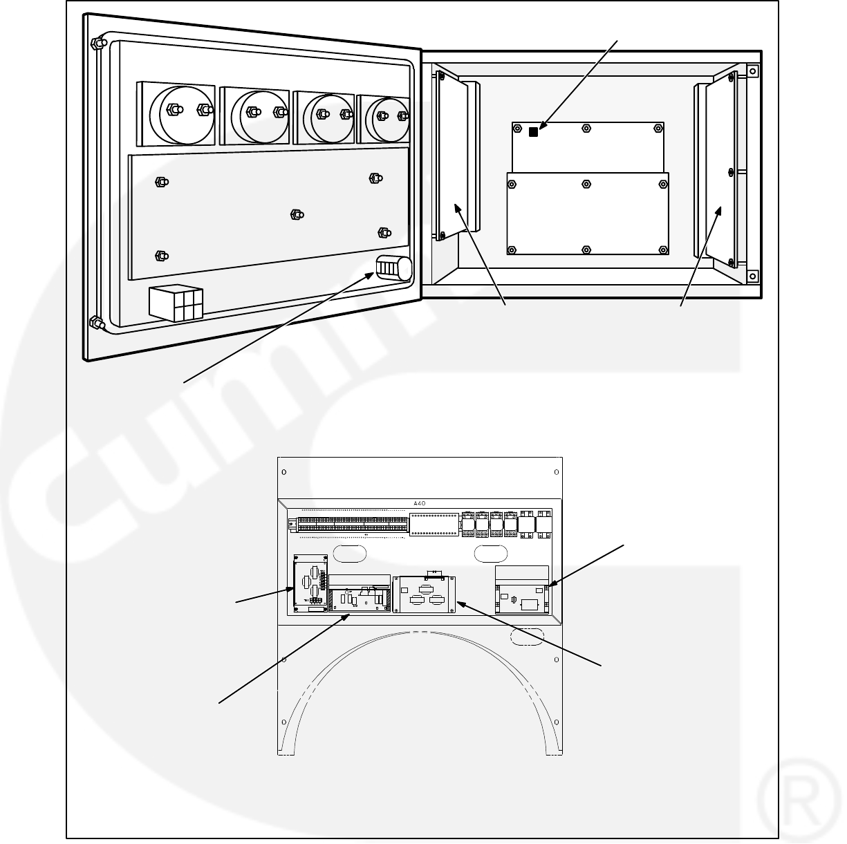
5-2
CUSTOMER INTERFACE
A34
ENGINE INTERFACE
A31
ANALOG BOARD
A33
DIGITAL BOARD
A32
DISPLAY BOARD
A35
RUN/OFF/AUTO
SWITCH S12
S5 POWER ON/
STANDBY SWITCH
ACCESSORY BOX
(A40)
GOVERNOR
OUTPUT MODULE
A38
PT/CT BOARD A36
VOLTAGE
REGULATOR
OUTPUT MODULE
A37
BUS PT MODULE
A39
FIGURE 5-1. CIRCUIT BOARD LOCATIONS
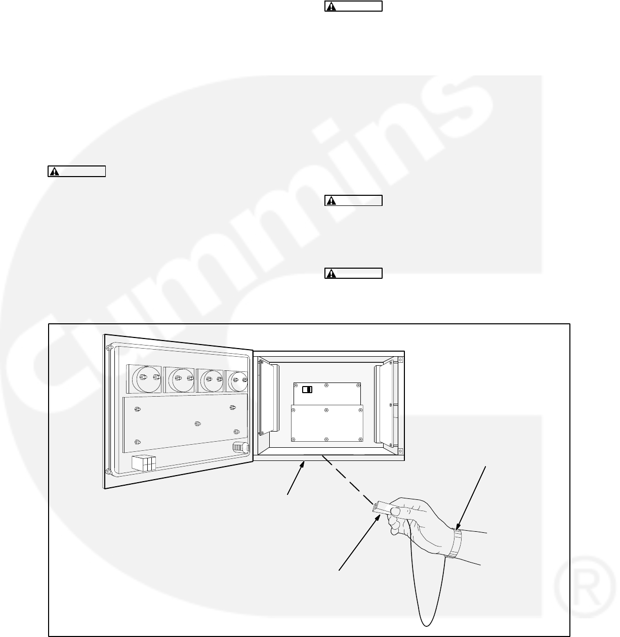
5-3
Circuit Board Removal Safety Precautions
To prevent circuit board damage due to electrostatic
discharge (ESD), a grounding wrist strap must be
worn when handling circuit boards or socket-
mounted IC’s. (The wrist strap does not provide a
direct short to ground, but is typically rated at
approximately 1 megohm to ground.)
Attach the clip to a non -painted surface of the con-
trol box and place the strap around your wrist before
handling a circuit board.
CAUTION Electrostatic discharge will damage
circuit boards. Always wear a grounding wrist
strap when handling circuit boards or socket-
mounted IC’s.
Turn off or remove AC power from the battery char-
ger and then remove the negative (−) battery cable
from the set starting battery. This is to make sure
that the set will not start while working on it and to
avoid circuit board damage, caused by voltage
spikes when removing and replacing circuit board
connectors.
WARNING Ignition of explosive battery gases
can cause severe personal injury or death. Arc-
ing at battery terminals, light switch or other
equipment, flame, pilot lights and sparks can ig-
nite battery gas. Do not smoke, or switch
trouble light ON or OFF near battery. Discharge
static electricity from body before touching bat-
teries by first touching a grounded metal sur-
face.
Ventilate battery area before working on or near
battery—Wear goggles—Stop genset and dis-
connect charger before disconnecting battery
cables—Disconnect negative (−) cable first and
reconnect last.
CAUTION Disconnect battery charger from AC
source before disconnecting battery cables.
Otherwise, disconnecting cables can result in
voltage spikes damaging to DC control circuits
of the set.
WARNING Accidental starting of the generator
set can cause severe personal injury or death.
Prevent accidental starting by disconnecting
the negative (−) cable from the battery terminal.
GROUND LEAD CLIP
WRIST STRAP
NON-PAINTED
SURFACE
FIGURE 5-2. WRIST STRAP

5-4
INITIAL START SETUP MENU
The facing page shows a block representation of
the INITIAL START SETUP menu.
CAUTION Selecting this menu resets all oper-
ating parameters to the default values for the
selected set. All previously selected setup and
adjustment settings will be lost. Therefore, this
procedure must be performed by technically
qualified personnel only.
This menu appears on the digital display when the
PCC has not been set up for use with a generator
set during factory test, or the digital board was re-
placed in the PCC.
When this display is showing, you must go through
the Initial Start Setup menu to select the operating
parameters for the generator set. These include
whether the set will be used for Prime Power or
Standby use, the Model Number of the generator
set, and its operating frequency and output voltage.
These choices must be saved into the PCC’s read-
only memory before the PCC will accept changes
made to other menus.
If the PCC is already set up to operate with a specific
generator set, this menu will not appear when power
is applied. To reset the control and display the Initial
Start Setup menu, you can press RESET, MENU, and
PHASE SELECT buttons at the same time.
If you choose to do this, the governor/regulator ad-
justments and the setup options will be reset to the
default settings (including the editable customer
fault messages). Display calibrations (volts, amps,
PF and coolant temperature) are retained (not reset).
To make sure correct and complete readjustment of
the PCC, it is suggested that all settings be recorded
before you perform the reset function.
CAUTION Improper setup, calibration, or ad-
justments can cause equipment malfunction or
damage. Setup, calibration, and adjustment
must be performed by technically qualified per-
sonnel only.
STANDBY/PRIME submenu: Use the buttons next
to the “” symbols to toggle the standby/prime op-
tion. Press the button next to the “>>” in the display
to move to the model select submenu.
MODEL select submenu: Use the buttons next to
the “” and “” symbols to select the correct genera-
tor set model number, frequency and power rating.
VOLTAGE SELECT submenu: Use the buttons
next to the “” and “” symbols to select the correct
generator set nominal line-to-line output voltage.
DELTA / WYE submenu: Use the buttons next to
the “” and “” symbols to select the delta or wye op-
tion.
SAVE submenu: From the model select submenu,
press the button next to the “>>” in the display to
move to the SAVE submenu. Select SAVE to save
your changes. The MAIN MENU will then be dis-
played.
If “INVALID SETUP” or “INVALID CAL” is displayed
after saving your changes, refer to Digital Board
(A32) Calibration at the end of this section.
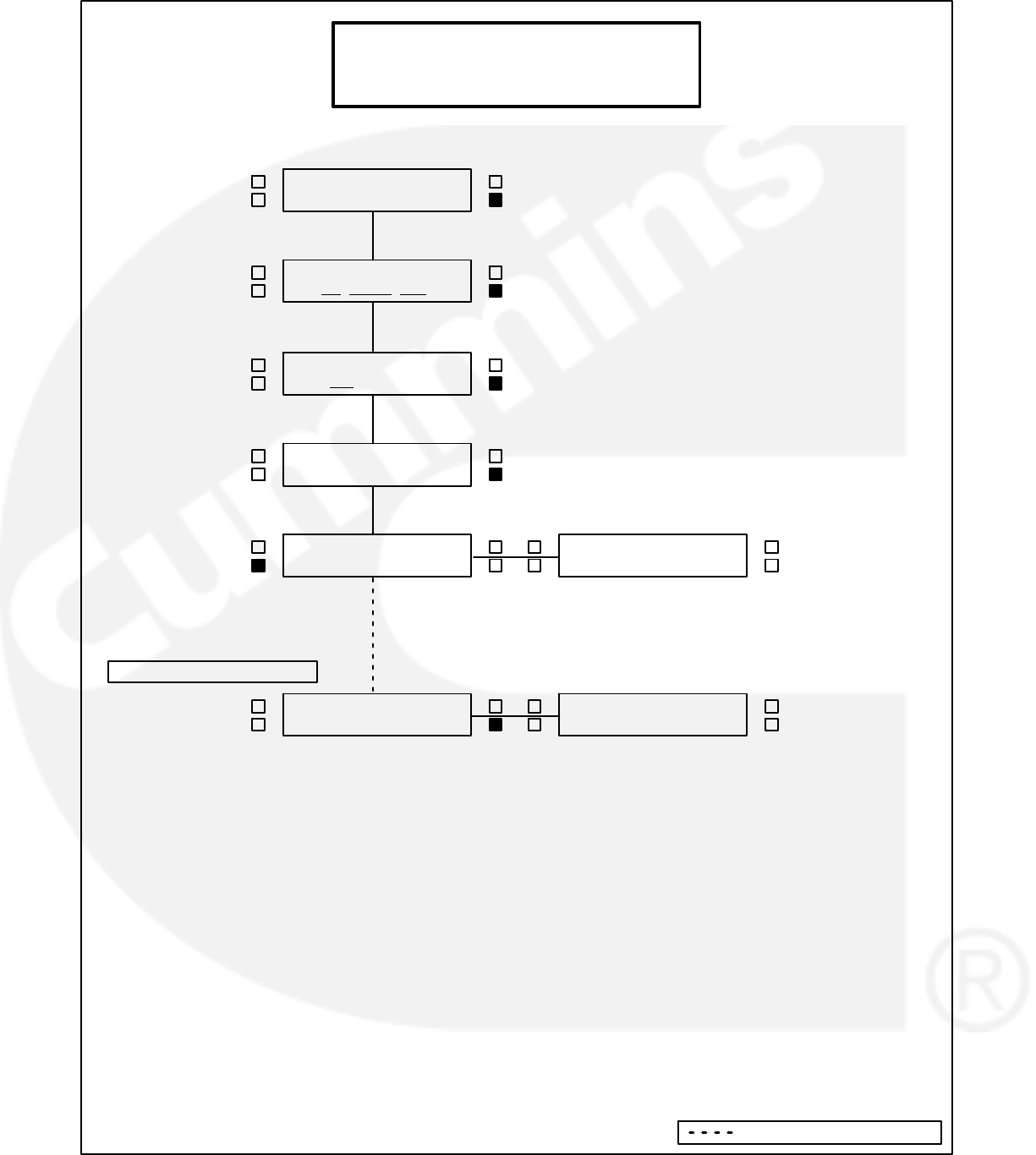
5-5
<>
<>
<>
<>
<
STANDBY/PRIME
_______ >>
MODEL
(kw mod# freq) >>
SAVE >> <>
<>
INITIAL START SETUP
(It can be invoked by simultaneously pressing
the Reset, Menu, and Phase Select keys.)
ENGINE GEN
ADJUST >>
SAVE >> <>
STANDBY/PRIME
_______ >>
TO LOOP BACK & CHECK:
<>
< VOLTAGE SELECT
(vac) L-L VAC >>
<>
DELTA / WYE
_______ >>
Indicates OR" Condition

5-6
ADJUST MENU
The ADJUST submenus permit adjustment of the
output voltage and frequency and the start and stop
delay times of the generator set.
The complete calibration procedure is described in
the Calibration Procedure in this section.
The facing page shows a block representation of
the ADJUST menu. If you press the button next to
the word “ADJUST” in the Main menu, the VOLT-
AGE ADJUST submenu will appear.
As shown in the diagram, the ADJUST menu has
five submenus, including a save/exit procedure.
Voltage and frequency can be adjusted only when
the generator set is running under normal operating
parameters (not in idle mode). For example, if volt-
age adjustment is selected when the set is in Idle
mode or not running, the digital display will be:
“ VOLTAGE ”
“ N/A >>”
VOLTAGE submenu: This is the first submenu.
Use the buttons next to the “” and “” symbols to
adjust output voltage 5%.
FREQUENCY submenu: From the VOLTAGE sub-
menu, press the button next to the “>>” in the dis-
play to move to the FREQUENCY submenu. Use
the buttons next to the “” and “” symbols to adjust
output frequency 5%.
START DELAY submenu: This delay applies only
to remote starting in the Auto mode. From the FRE-
QUENCY submenu, press the button next to the
“>>” in the display to move to the START DELAY
submenu. Use the buttons next to the “” and “”
symbols to set the start delay. The start delay ad-
justment range is 0 to 300 seconds.
STOP DELAY submenu: This delay applies only
to remote stopping in the Auto mode. From the
START DELAY submenu, press the button next to
the “>>” in the display to move to the STOP DELAY
submenu. Use the buttons next to the “” and “”
symbols to set the stop delay. The stop delay ad-
justment range is 0 to 600 seconds.
IDLE SPEED submenu: From the STOP DELAY
submenu, press the button next to the “>>” in the
display to move to the IDLE SPEED submenu. Use
the buttons next to the “” and “” symbols to set the
idle speed. The idle speed adjustment range is 800
RPM 100 RPM. (Default value is 800 RPM.)
The idle speed can be adjusted only when the gener-
ator set is running in the idle mode. When not in idle
mode, N/A is displayed in RPM field.
SAVE/EXIT submenu: From the STOP DELAY
submenu, press the button next to the “>>” in the
display to move to the SAVE/EXIT submenu. Select
SAVE to save your changes. At the CHANGES
SAVED submenu, select EXIT to return to the main
menu.
If you select SAVE, the adjustments will be retained
after shutdown, and will be in effect when the set is
restarted. If you select EXIT without saving first, the
adjustments will remain in effect until the generator
set is shut down, but will be reset (and will not be in
effect) when the set is restarted.
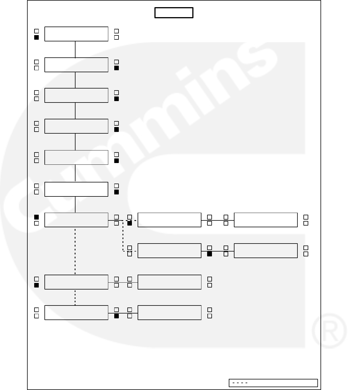
5-7
<><>
<>
<>
<>
<>
<
<
<>
<
<>
ENGINE GEN
ADJUST >>
<>
<>
VOLTAGE
_______ >>
<
FREQUENCY
_______ >>
START DELAY
_______ SEC >>
STOP DELAY
_______SEC >>
<SAVE
EXIT >>
<SAVE
EXIT >>
<>
<SAVE
EXIT >>
<>
CHANGES SAVED
EXIT >>
CHANGES SAVED
EXIT >>
< VOLTAGE
_______ >>
ENGINE GEN
ADJUST >>
<>
<>
<>
< VOLTAGE
_______ >>
ENGINE GEN
ADJUST >>
<>
<>
ADJUST
<>
< IDLE SPEED
_______RPM >>
Indicates OR" Condition

5-8
SETUP AND CALIBRATION MENUS
The setup and calibration menus allow you to cali-
brate the PCC with the reading from a calibrated
meter. There are four setup and calibration menus
that are selectable from the SETUP/CAL menu:
VERSION AND DISPLAYS
METERS
GOVERNOR/REGULATOR
SETUP
These four menus are intended for qualified service
personnel only. For this reason, a three-digit access
code must be entered before you can proceed to
those menus.
ENTER CODE submenu:
The access code for your PCC is: 5 7 4.
To enter the code:
1. Press the button next to the “” to increment the
first digit.
2. Press the button next to the “>>” to select the
second digit.
3. Press the button next to the “” to increment the
second digit.
4. Press the button next to the “>>” to select the
third digit.
5. Press the button next to the “” to increment the
third digit.
6. Press the button next to the “>>” to proceed to
the DISPLAYS/METERS submenu. (Pro-
vided, of course, that you have correctly en-
tered the access code.)
The following sub-sections describe how to select
and make changes to the setup and calibration me-
nus and save the changes made to these menus.
Version Menu
The VERSION menu allows you to verify the model
number and frequency of the generator set, the
date and version of the operating software and gen-
erator set configuration options. From the VER-
SION menu you can also review a History file, that
can contain up to 20 error messages.
The complete calibration procedure is described in
the Calibration Procedure in this section.
The facing page shows a block representation of
the VERSION submenus. If you press the button
next to the “>>” in the Main menu display, the VER-
SION/SETUP/CAL menu will appear.
CAUTION Improper calibration or adjustment
of the PowerCommand control can cause
equipment malfunction or damage. Calibration
and adjustment must be performed by techni-
cally qualified personnel only.
VERSION submenu: If you select VERSION, the
display will show the generator set model number,
frequency, and kW rating, and the date and version
of the operating software.
To display the generator set configuration options,
press the button next to the “>>” in the submenu that
displays the model number, frequency and etc. This
menu provides the following information:
Generator set voltage
WYE or DELTA
Standby or Prime
Parallel or Single
HISTORY: From the VERSION, SETUP/CAL
menu, press the button next to the “>>” in the dis-
play to move to the HISTORY submenu. Press the
button next to “HISTORY” to display the last (latest)
recorded error message.
The software will record (save) up to 20 error mes-
sages. The last error detected will always be dis-
played first. As each new error is detected, the old-
est error recorded after 20 will be deleted.
To view the generator set runtime at which the error
occurred and to scroll through the remaining re-
corded errors, press the button next to the “>>” in
the error message menu to display the RUNTIME,
NEWER/OLDER menu.
The buttons next to NEWER and OLDER are used
to scroll up and down through the error messages.
For example, pressing OLDER will display the next
oldest recorded error message. When pressing
NEWER and the last (newest) error message is dis-
played, or OLDER and oldest error is displayed, the
display will return to the HISTORY menu.
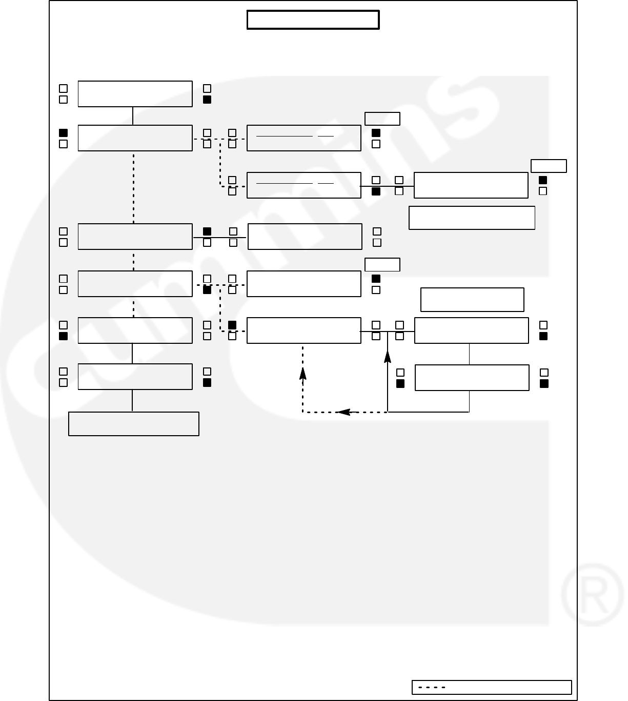
5-9
<>
<>
ENGINE GEN
ADJUST >>
<>
< ENTER CODE
__ __ __>>
VERSION MENUS
<>
<>
VERSION <<
SETUP/CAL >>
<>
>
>
(kW) (model) (hz) <<
______ V___.__ >>
BACK
ENGINE GEN
ADJUST >>
<>
<>
<>
VERSION <<
SETUP/CAL >>
<>
<>
VERSION <<
SETUP/CAL >>
>
>
(kW) (model) (hz) <<
______ V___.__ >>
_______ V ______<<
_______ ______
>
BACK
<>
<>
VERSION <<
SETUP/CAL >>
<>
HISTORY <<
BACK
<>
HISTORY << >
_________________
_________________ >>
<>
RUNTIME _________
NEWER OLDER
REFER TO FOLLOWING
MENUS IN THIS SECTION
DISPLAYS ERROR
MESSAGE AND CODE
DISPLAYS VOLTAGE & GEN
SET CONFIGURATION
Indicates OR" Condition

5-10
Displays Menu
The DISPLAYS submenus permit calibration of the
digital voltage, current, power factor (PF) and cool-
ant temperature displays. Calibration is accom-
plished by using this section of the menu software to
adjust the display so that it matches the reading tak-
en on an accurate, recently calibrated meter.
The complete calibration procedure is described in
the Calibration Procedure in this section.
The facing page shows a block representation of
the DISPLAYS submenus, which is the first of four
SETUP/CAL menus. If you press the button next to
the “>>” in the Main menu display, the VERSION/
SETUP/CAL menu will appear.
CAUTION Improper calibration or adjustment
of the PowerCommand control can cause
equipment malfunction or damage. Calibration
and adjustment must be performed by techni-
cally qualified personnel only.
DISPLAYS submenus: The DISPLAYS submenus
are intended for qualified service personnel only.
For this reason, a three-digit access code must be
entered before you can proceed to those menus.
Select SETUP/CAL. The display will show the EN-
TER CODE submenu. Enter access code (574) as
previously described in this section.
Select DISPLAYS to proceed to the DISPLAYS sub-
menus. Use the buttons next to the “” and “” sym-
bols to calibrate the selected voltage, current, PF or
coolant temperature reading. Press the button next
to the “>>” in the display to move to the next adjust-
ment.
“VOLTS L12,” “VOLTS L23,” and “VOLTS L31” refer
to voltages measured from L1 to L2, L2 to L3, and
L3 to L1, respectively. Note that the system includes
bus voltage reading provisions (“BUS VOLTS L12,”
“BUS VOLTS L23,” and “BUS VOLTS L31”), which
must be calibrated separately from the generator
set voltage settings.
“PF1, PF2 and PF3” will display N/A when the gen-
erator set is not running.
“COOLANT TEMP R” will display “N/A” if the genset
has only one sensor. To calibrate coolant tempera-
ture display, a precision resistor (provided in the en-
gine sensor tool) must be temporally substituted for
the temperature sender. Refer to Calibration Proce-
dure in this section.
SAVE/EXIT submenu: From the AMPS L3 subme-
nu, press the button next to the “>>” in the display to
move to the SAVE/EXIT submenu. Select SAVE to
save your changes. At the CHANGES SAVED sub-
menu, select EXIT to return to the DISPLAYS/ME-
TERS submenu.
If you select SAVE, the adjustments will be retained
after shutdown, and will be in effect when the set is
restarted. If you select EXIT without saving first, the
adjustments will remain in effect until the genset is
shut down, but will be reset (and will not be in effect)
when the set is restarted.
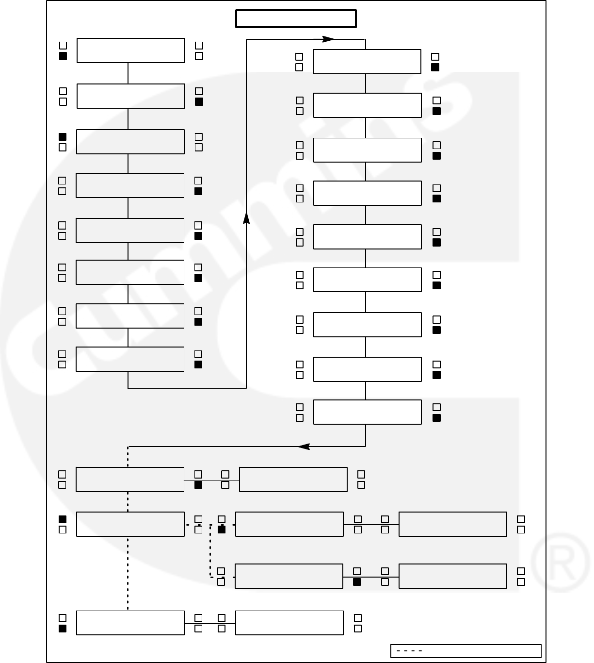
5-11
DISPLAYS MENU
<
<
<>
<
<
<
<>
<>
<>
<>
PF3
_______ >>
COOLANT TEMP R
_______F>>
COOLANT TEMP L
_______F>>
<>
<>
<>
<>
DISPLAY CAL <<
METERS >>
<
<>
VOLTS L12
_______ >>
<
<>
VOLTS L23
_______ >>
<
<>
VOLTS L31
_______ >>
<
<>
AMPS L1
_______ >>
<
<>
AMPS L2
_______ >>
<>
<SAVE
EXIT >> <>
CHANGES SAVED
EXIT >>
<><>
CHANGES SAVED
EXIT >>
< VOLTS L12
_______ >>
<SAVE
EXIT >> <>
< VOLTS L12
_______ >>
<SAVE
EXIT >> <>
<>
DISPLAY CAL <<
METERS >>
<>
<>
DISPLAY CAL <<
METERS >>
PF1
_______ >>
PF2
_______ >>
<
<>
AMPS L3
_______ >>
<>
< ENTER CODE
__ __ __>>
<>
<>VERSION <<
SETUP/CAL >>
<
<
<>
<>
BUS VOLTS L31
_______ >>
BUS VOLTS L23
_______ >>
<
<>
BUS VOLTS L12
_______ >>
Indicates OR" Condition

5-12
Meters Menu
The METERS submenus permit calibration of the
control’s analog meters to match the calibrated digi-
tal values. (Calibrate the digital display before cali-
brating the analog meters.) This calibration is ac-
complished by using this section of the menu soft-
ware to adjust the selected meter reading so that it
matches the reading provided on the digital display.
The complete calibration procedure is described in
the Calibration Procedure in this section.
The facing page shows a block representation of
the METERS submenus, which is the second of
four SETUP/CAL menus. If you press the button
next to the “>>” in the Main menu display, the VER-
SION/SETUP/CAL submenu will appear.
CAUTION Improper calibration or adjustment
of the PowerCommand control can cause
equipment malfunction or damage. Calibration
and adjustment must be performed by techni-
cally qualified personnel only.
METERS submenu: The METERS submenus are
intended for qualified service personnel only. For
this reason, a three-digit access code must be en-
tered before you can proceed to those menus.
Select SETUP/CAL. The display will show the EN-
TER CODE submenu. Enter access code (574) as
previously described in this section.
Select METERS to proceed to the METERS sub-
menus. Use the buttons next to the “” and “” sym-
bols to calibrate the selected meter to match the
“CAL TO:” value provided on the digital display.
Press the button next to the “>>” in the display to
move to the next calibration.
“VOLT METER” and “% AMPERES” calibration ref-
erence the phase that is indicated on the phase
selection LED’s.
NOTE: The % AMPERES meter scale is based on a 0.8
power factor. (100% of rated current is full load cur-
rent at 0.8 PF.)
SAVE/EXIT submenu: From the HERTZ subme-
nu, press the button next to the “>>” in the display to
move to the SAVE/EXIT submenu. Select SAVE to
save your changes. At the CHANGES SAVED sub-
menu, select EXIT to return to the DISPLAYS/ME-
TERS submenu.
If you select SAVE, the adjustments will be retained
after shutdown, and will be in effect when the set is
restarted. If you select EXIT without saving first, the
adjustments will remain in effect until the generator
set is shut down, but will be reset (and will not be in
effect) when the set is restarted.
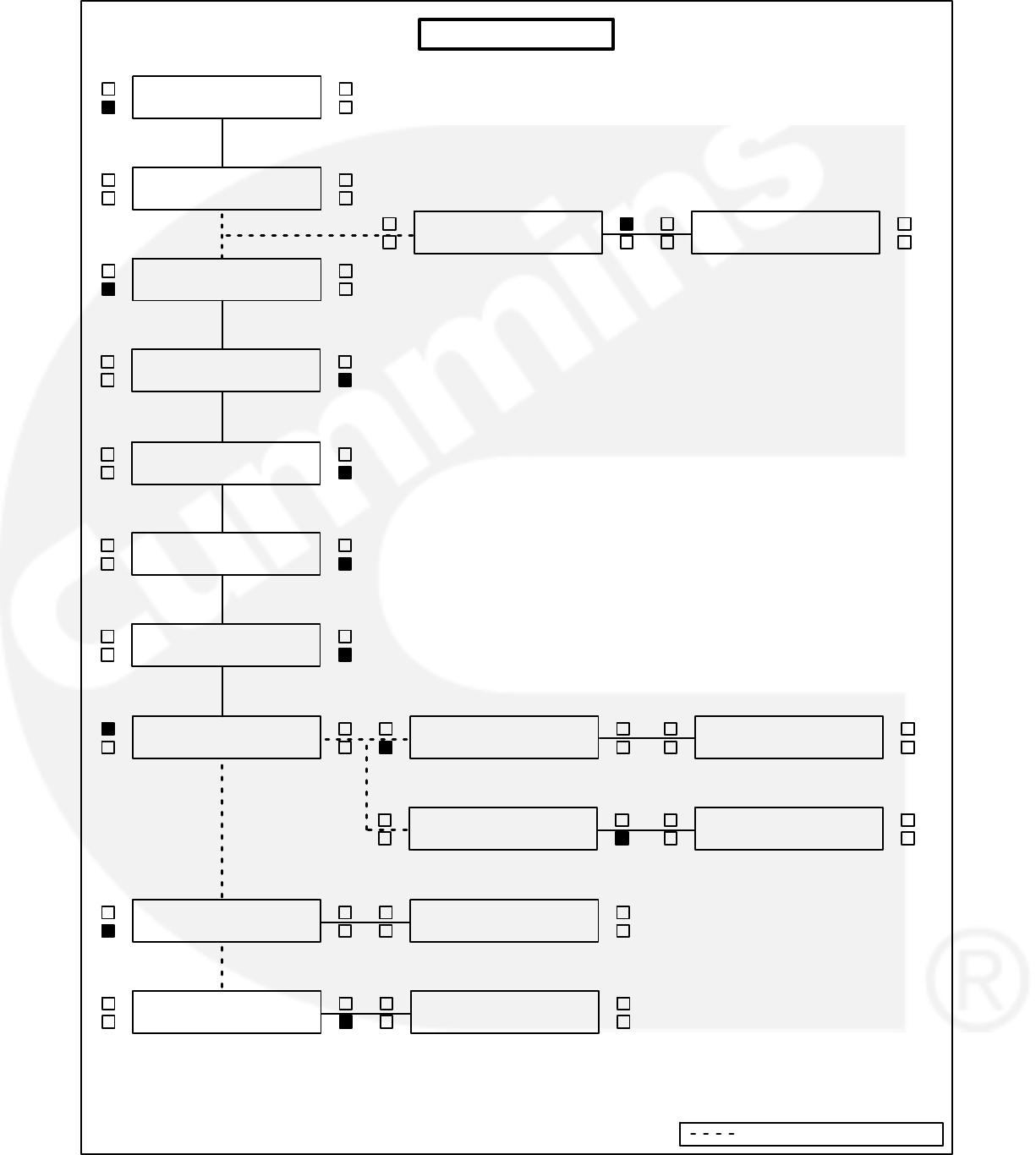
5-13
<>
<>
<>
<>
<>
<
<>
DISPLAY CAL <<
METERS >>
METERS MENU
<>
<>VERSION <<
SETUP/CAL >>
<
<>
AC VOLTS
CAL TO: ___ >>
<
<>
% AMPERES
CAL TO: ___ >>
<
<>
% LOAD
CAL TO: ___ >>
<
<>
HERTZ
CAL TO: ___ >>
<>
<SAVE
EXIT >> <>
CHANGES SAVED
EXIT >> <>
<>
DISPLAY CAL <<
METERS >>
<><>
CHANGES SAVED
EXIT >>
<
<SAVE
EXIT >> <>
<
<SAVE
EXIT >> <>
<>
DISPLAY CAL <<
METERS >>
<>
DISPLAY CAL <<
METERS >> <>
ENTER CODE
__ __ __>>
ENTER CODE
__ __ __>>
AC VOLTS
CAL TO: ___ >>
AC VOLTS
CAL TO: ___ >>
Indicates OR" Condition

5-14
Governor / Regulator Menu
The GOV/REG submenus permit adjustment of
voltage regulator and governor parameters.
All GOV/REG menu values, except for REG VHZ and
GOV RAMP, will display “100%”. The expression
“100%” represents the factory setting (default value)
for the selected set. When increasing or decreasing
the value, you are increasing or decreasing from the
factory default value. (For example, entering “200%”
will double the value; “50%” will decrease the value
by one half.)
Default values are preset by the factory. Due to site
variables, the default values may need to be adjusted
to attain peak performance.
The facing page shows a block representation of
the GOV/REG submenus, which is the third of four
SETUP/CAL menus. If you press the button next to
the “>>” in the Main menu display, the VERSION/
SETUP/CAL submenu will appear.
CAUTION Improper calibration or adjustment
of the PowerCommand control can cause
equipment malfunction or damage. Calibration
and adjustment must be performed by techni-
cally qualified personnel only.
GOV/REG submenu: The GOV/REG submenus
are intended for qualified service personnel only.
For this reason, a three-digit access code must be
entered before you can proceed to those menus.
Select SETUP/CAL. The display will show the EN-
TER CODE submenu. Enter the access code (574)
as previously described in this section.
From the DISPLAYS/METERS submenu, press the
button next to the “>>” in the display to move to the
GOV/REG/SETUP submenu. Select GOV/REG to
proceed to the GOV/REG submenus.
Use the buttons next to the “” and “” symbols to
adjust the selected governor and regulator parame-
ters. Press the button next to the “>>” in the display
to move to the next adjustment.
GOV GAIN: If the gain adjustment is set too high,
engine speed will “hunt” or oscillate. If gain is set too
low, the engine will respond too slowly to changes in
load—overspeed may result.
For paralleling applications, the default value for
governor gain is 70.
GOV INTEGRAL: If this adjustment is set too low,
the engine will respond too slowly to changes in
load. If it is set too high, engine response will be un-
stable.
GOV RAMP: This adjustment sets the time for the
engine to ramp to full operating speed. This adjust-
ment applies only to set start up and does not affect
the transient response. (Adjustable range: 0
through 10 seconds.)
REG GAIN: If the gain adjustment is set too high,
output voltage will be unstable. If gain is set too low,
the output voltage will respond sluggishly to
changes in load—overshoot may result.
REG INTEGRAL: If this adjustment is set too low,
the output voltage will respond sluggishly to
changes in load, resulting in a droop-type response
If it is set too high, output voltage will be unstable.
REG VHZ: This underfrequency roll-off adjustment
controls how much excitation is reduced in re-
sponse to underfrequency. If the value is set too
low, excitation will be cut too fast, and the voltage
will drop too much. If set too high, the generator set
may not be able to pick up rated load in one step.
(Adjustable range: 1 through 50; normal range 7
through 21.)
SAVE/EXIT submenu: From the REG VHZ subme-
nu, press the button next to the “>>” in the display to
move to the SAVE/EXIT submenu. Select SAVE to
save your changes. At the CHANGES SAVED sub-
menu, select EXIT to return to the DISPLAYS/ME-
TERS submenu.
If you select SAVE, the adjustments will be retained
after shutdown, and will be in effect when the set is
restarted. If you select EXIT without saving first, the
adjustments will remain in effect until the generator
set is shut down, but will be reset (and will not be in
effect) when the set is restarted.
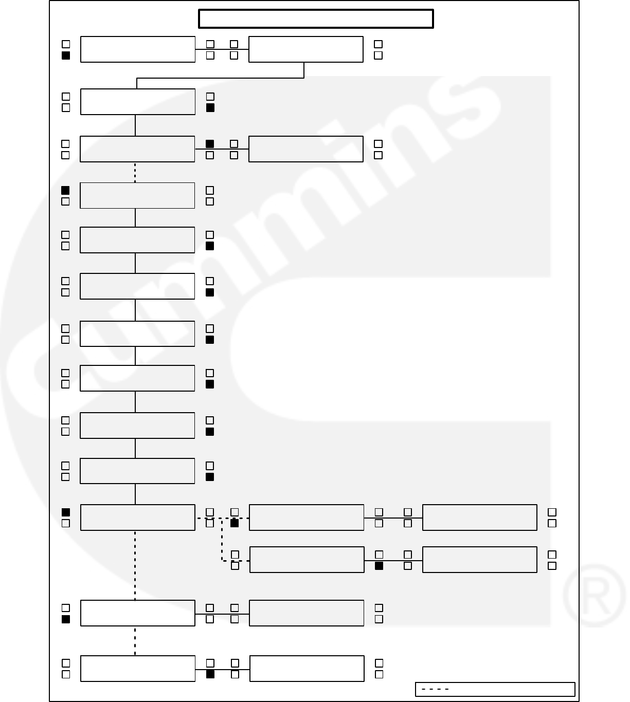
5-15
<>
<>
<>
<>
<>
<>
<>
DISPLAY CAL <<
METERS >>
GOVERNOR/REGULATOR MENU
<>
GOV / REG <<
SETUP >>
<
<>
GOV GAIN
_______% >>
<
<>
GOV INTEGRAL
_______% >>
<
<>
GOV RAMP
_______ >>
<>
<SAVE
EXIT >> <>
CHANGES SAVED
EXIT >> <>
<>
DISPLAY CAL <<
METERS >>
<><>
CHANGES SAVED
EXIT >>
<
<SAVE
EXIT >> <>
<
<SAVE
EXIT >> <>
<>
DISPLAY CAL <<
METERS >>
<
<>
REG GAIN
_______% >>
<
<>
REG INTEGRAL
_______% >>
<
<>
REG VHZ
_______ >>
GOV GAIN
_______% >>
GOV GAIN
_______% >>
<>
GOV / REG <<
SETUP >>
<>
DISPLAY CAL <<
METERS >>
<>
<
<>
<>VERSION <<
SETUP/CAL >>
ENTER CODE
__ __ __>>
Indicates OR" Condition

5-16
Setup Menu
The SETUP submenus permit selection of several
configuration and operation options. Setup option
defaults are listed in Table 5-2.
TABLE 5-2. SETUP DEFAULTS
SELECTION DEFAULT
CYCLE CRANK ON
SYSTEM OF UNITS IMPERIAL
*RACK POSITION (CF1) WARN
*GRND FAULT (CF2) WARN
*DAY TANK (CF3) WARN
*HIGH GEN TEMP (CF4) WARN
EGT L NO
EGT R NO
LOW COOLANT SHTD
LANGUAGE ENGLISH
*Default display messages for customer faults (CF) 1
through 4. To change the customer fault mes-
sage(s) or select the desired fault condition (WARN
or SHTD), refer to heading Edit Customer Fault
Messages.
The facing page shows a block representation of
the SETUP submenus, which is the fourth of four
SETUP/CAL menus. If you press the button next to
the “>>” in the Main menu display, the VERSION/
SETUP/CAL submenu will appear.
CAUTION Improper calibration or adjustment
of the PowerCommand control can cause
equipment malfunction or damage. Calibration
and adjustment must be performed by techni-
cally qualified personnel only.
SETUP submenu: The SETUP submenus are in-
tended for qualified service personnel only. For this
reason, a three-digit access code must be entered
before you can proceed to those menus.
Select SETUP/CAL. The display will show the EN-
TER CODE submenu. Enter the access code (574)
as previously described in this section.
From the DISPLAYS/METERS submenu, press the
button next to the “>>” in the display to move to the
GOV/REG/SETUP submenu. Select SETUP to
proceed to the SETUP submenus or “>>” to pro-
ceed to the RACK TEST submenus.
Use the buttons next to the “” symbols to toggle
the setup options. Press the button next to the “>>”
in the display to move to the next adjustment.
If the cycle cranking option is selected, the menu will
prompt for the selection of cycle number (3, 4, or 5)
and crank and rest times (7 to 20 seconds).
An in-line engine that has the EGT (exhaust gas
temp.) option, select “YES” for EGT L and ’NO” for
EGT R.
RACK TEST submenu: The RACK TEST subme-
nu is used to initiate the rack position diagnostic
test. This test is used to determine if the PCC is
properly controlling the rack position of the actua-
tors. To initiate this test, the Run/Off/Auto switch
must be set to the Off position.
When exiting this test or if the Run/Off/Auto switch
is moved to either the Run or Auto position, the PCC
software will re-initialize the governor duty cycle to 2
(0%) and allow the engine starting sequence to pro-
ceed as normal.
To perform the rack test, refer to the Rack Position
Fault/Test Procedure in Section 4.
TORQUE ADJ %DC submenu: This submenu is
used to adjust the engine torque through the digital
display to compensate for engine/electronic varia-
tions. If the generator set is not providing the name
plate kilowatt rating, the torque limit can be adjusted
at this menu. Refer to Engine Torque Adjustment in
this section for a detailed description of how to per-
form this adjustment.
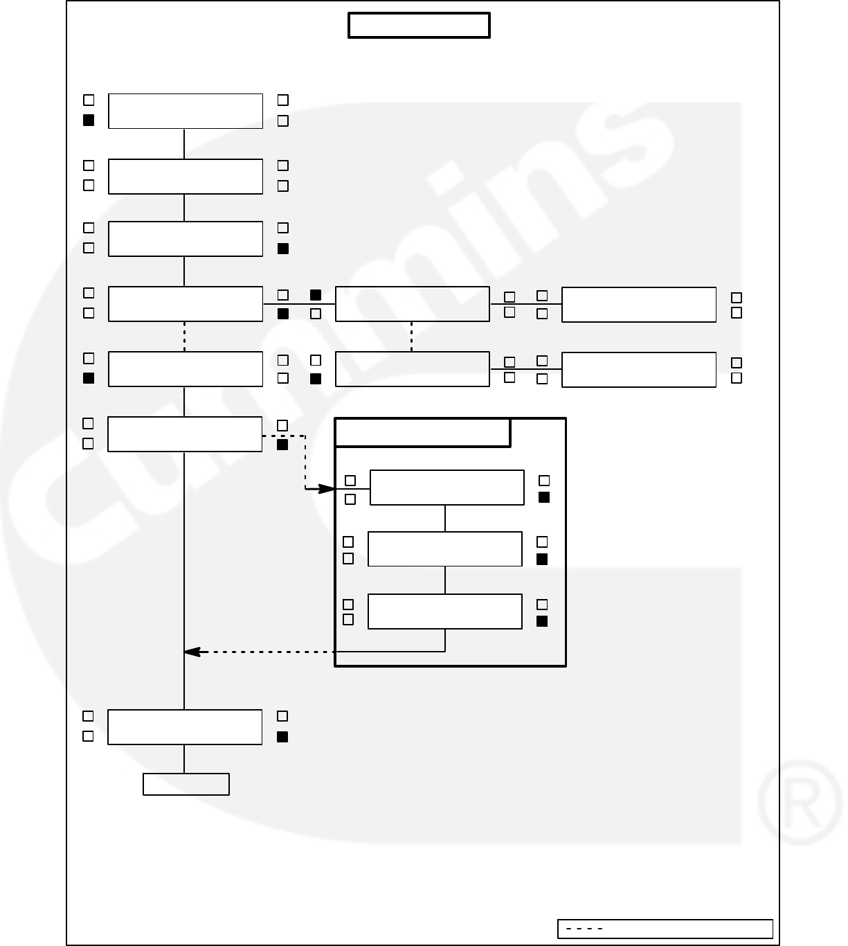
5-17
<>
<><>
<>
<
< REST TIME−SEC
(7 to 20) >>
<
DISPLAY CAL <<
METERS >>
< ENTER CODE
__ __ __>>
<>
SETUP MENU
<>
CYCLE CRANK
ON / OFF >>
<>
SYSTEM OF UNITS
MET or IMP>>
<>
<>VERSION <<
SETUP/CAL >>
<>
# OF CYCLE S
(3, 4, 5 or 6) >>
<>
CYCLE CRANK
ON / OFF >><>
CRANK TIME−SEC
(7 to 20) >>
IF CYCLE CRANK ON :
<>
<>
GOV / REG <<
SETUP >>
<>
<>
GOV / REG <<
SETUP >>
<>
RACK TEST <<
TORQUE
CONTINUED
Indicates OR" Condition
<<
___ POS_MM <<
___ POS_VOLT
<>
<>
RACK TEST <<
TORQUE
<<
TORQUE ADJ %DC<<
___ % DC
<>

5-18
Setup Menu (Cont.)
Edit Customer Fault Message(s): The four cus-
tomer fault messages shown in Table 5-2 are edit-
able. Customer Fault 1 is reserved for the RACK
POSITION fault. Do not modify this fault name or
change the fault condition (WARN to SHTD).
To enter the desired customer fault message, press
the button next to the “>>” in the display to display
the customer fault message to be changed, Cus-
tomer Fault 2, 3 or 4.
Press the upper-left button by the display to select
the desired character. Press the upper-right button
to move the cursor to the next character to be
changed. (Holding this button down will return the
cursor to the first position.) The message can be up
to 16 characters. The fault code number will remain
the same, this code cannot be edited.
If these messages are changed, you should note
these changes in the Troubleshooting section of the
Operator’s manual for this generator set.
SAVE/EXIT submenu: From the LANGUAGE sub-
menu, press the button next to the “>>” in the dis-
play to move to the SAVE/EXIT submenu. Select
SAVE to save your changes. At the CHANGES
SAVED submenu, select EXIT to return to the DIS-
PLAYS/METERS submenu.
If you select SAVE, the adjustments will be retained
after shutdown, and will be in effect when the set is
restarted. If you select EXIT without saving first, the
adjustments will remain in effect until the generator
set is shut down, but will be reset (and will not be in
effect) when the set is restarted.
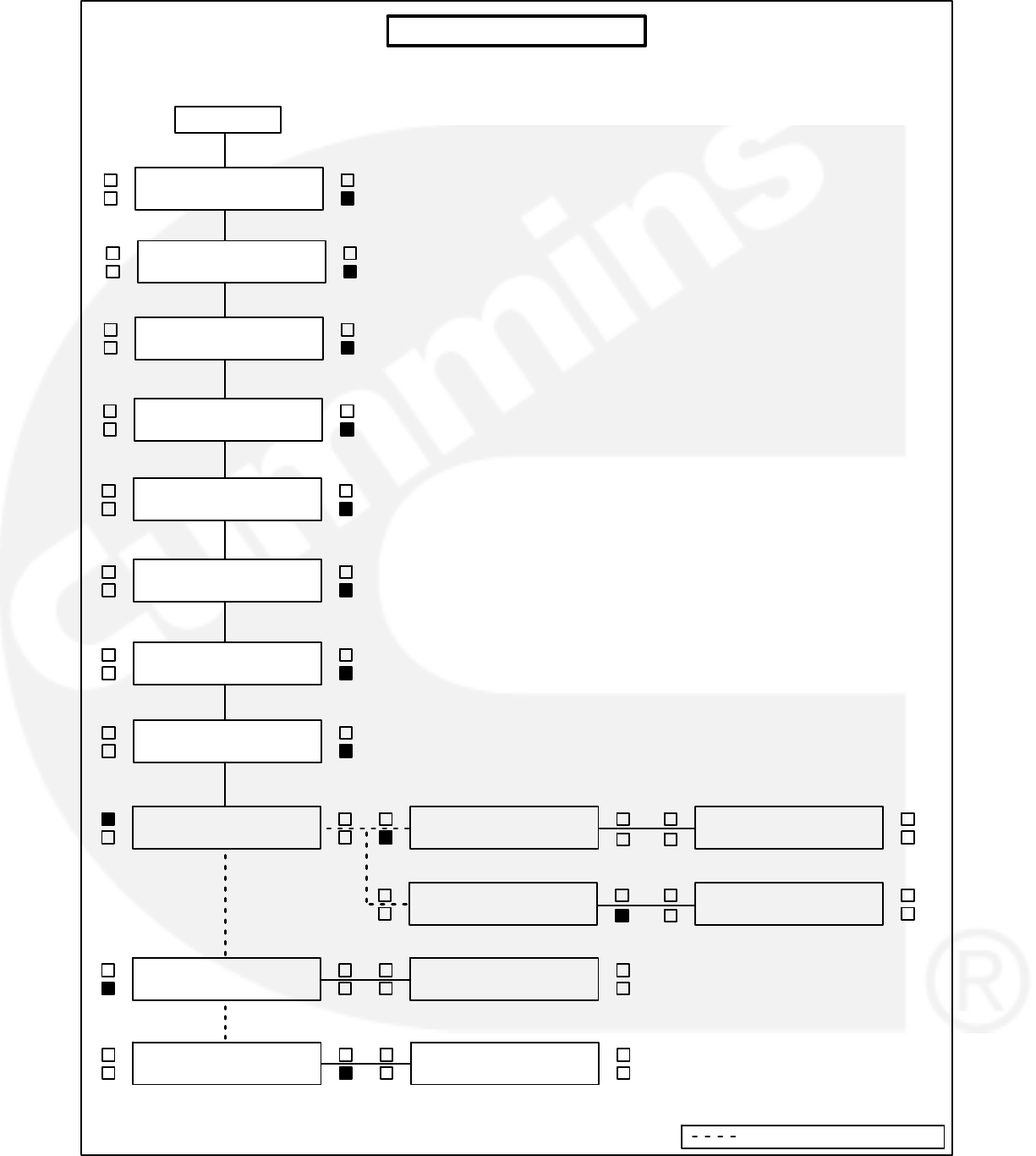
5-19
<>
< LANGUAGE
_______________>>
<>
<>
SETUP MENU (Cont.)
<>
<SAVE
EXIT >> <>
CHANGES SAVED
EXIT >> <>
<>
DISPLAY CAL <<
METERS >>
<><>
CHANGES SAVED
EXIT >>
<SAVE
EXIT >> <>
<SAVE
EXIT >> <>
<>
DISPLAY CAL <<
METERS >>
<>
LOW COOLANT LVL
SHTD or WARN
>>
<>
EGT L
YES / NO >>
<>
EGT R
YES / NO >>
CYCLE CRANK
ON / OFF >>
CYCLE CRANK
ON / OFF >>
<>
<>
HIGH GEN TEMP
SHTD / WARN >>
CONTINUED
<>
<>
<>
RACK POSITION
SHTD / WARN >>
<>
<>
<>
RUPTURE BASIN
SHTD / WARN >>
GROUND FAULT
SHTD / WARN >>
Indicates OR" Condition

5-20
Paralleling Setup Menu
The PARALLELING SETUP submenus adjust the
control parameters for generator set protection,
synchronizing and load sharing for both isolated
bus and utility (mains) paralleling applications. Util-
ity (mains) parallel applications may require adjust-
ment of both the “isolated bus” and “utility” branch
submenus.
The sync check (permissive) function is operational
in both automatic and manual (RUN) modes. The
control will make sure that the generator set is at
proper voltage, within the defined sync check win-
dow for the defined period of time and that phase
rotation is correct. When all criteria are met, the par-
alleling breaker is closed automatically by the con-
trol (auto mode), or by operation of the breaker
close switch by the operator (run mode).
The synchronizing function of the PowerCommand
control is enabled when the control has brought the
generator set to rated speed and voltage, and has
sensed that bus voltage is available. The control au-
tomatically adjusts the generator set speed and
voltage to match the bus frequency and voltage.
The control can force the generator set to match a
bus voltage and frequency in a range of minus 40%
to plus 10% of normal bus conditions. When the
paralleling breaker has closed, the control will bring
the generator set back to normal voltage and fre-
quency.
When the generator set is paralleled to another
generator set, the control provides automatic load
sharing functions for both real (kW) and reactive
(kVAR) loads. Load sharing is proportional between
generator sets based on their standby ratings. If two
generator sets of different sizes are paralleled, they
will assume the same percentage of the system
load automatically. This can easily be verified on the
analog % Load meters on the front of the Power-
Command control panel.
When the utility paralleling mode is enabled and the
generator set paralleling breaker is closed, the gen-
erator set will assume load based on external ana-
log input signal. The input signal must be calibrated
from 0−5 VDC. When the signal is at 0.5 to 1 VDC,
the control will operate the generator at no load in
parallel with the utility (mains) source. At 4.5 VDC
and greater, the control will operate the generator
set at 110% of the generator set base load setting.
When the load govern signal is between 1 VDC and
4.5 VDC the control will operate the generator set at
a load level which is determined by a linear relation-
ship between the kW reference and the load govern
signal.
ISOLATED BUS ADJUSTMENTS
SYNC TIME LIMIT: This parameter adjusts the time
delay in seconds before the Fail To Synchronize
alarm will operate.
− PWR LIMIT (%): Adjusts the reverse power set
point. For PowerCommand generator sets, a typical
set point is 10-15%.
− PWR LIMIT (TIME): Adjusts the reverse power
function time delay. A typical time delay which is
suitable for PowerCommand generator sets is 3
seconds.
Lower reverse power set points can result in nui-
sance reverse power shutdown faults.
PERM WIN-PHASE: Adjusts the width of the per-
missive (sync-check) acceptance window. The ad-
justment range is from five to twenty electrical de-
grees. Recommended set point is 20 degrees for
isolated bus applications, and 15 degrees for utility
(mains) paralleling applications.
PERM WIN-TIME: Adjusts the time period (in sec-
onds) for which the generator set must be synchro-
nized with the system bus, before a breaker close
signal is issued by the PowerCommand control.
Available range is 0.5 to 5 seconds. Recommended
value for PowerCommand generator sets is 0.5
seconds for isolated bus applications.
Adjusting the control for a smaller sync-check win-
dow or longer time delay will cause synchronizing
time to be extended.
SYNC GAIN: The sync gain adjustment controls
how quickly the governor will respond to try to mini-
mize the bus/generator phase difference. Increas-
ing the gain speeds up the response. If the gain is
too high instability can result.
SYNC INTEGRAL: The sync integral adjustment
controls the rate at which the governor will be ad-
justed to try to minimize the bus/generator phase
difference. The lower the number the slower the re-
sponse.
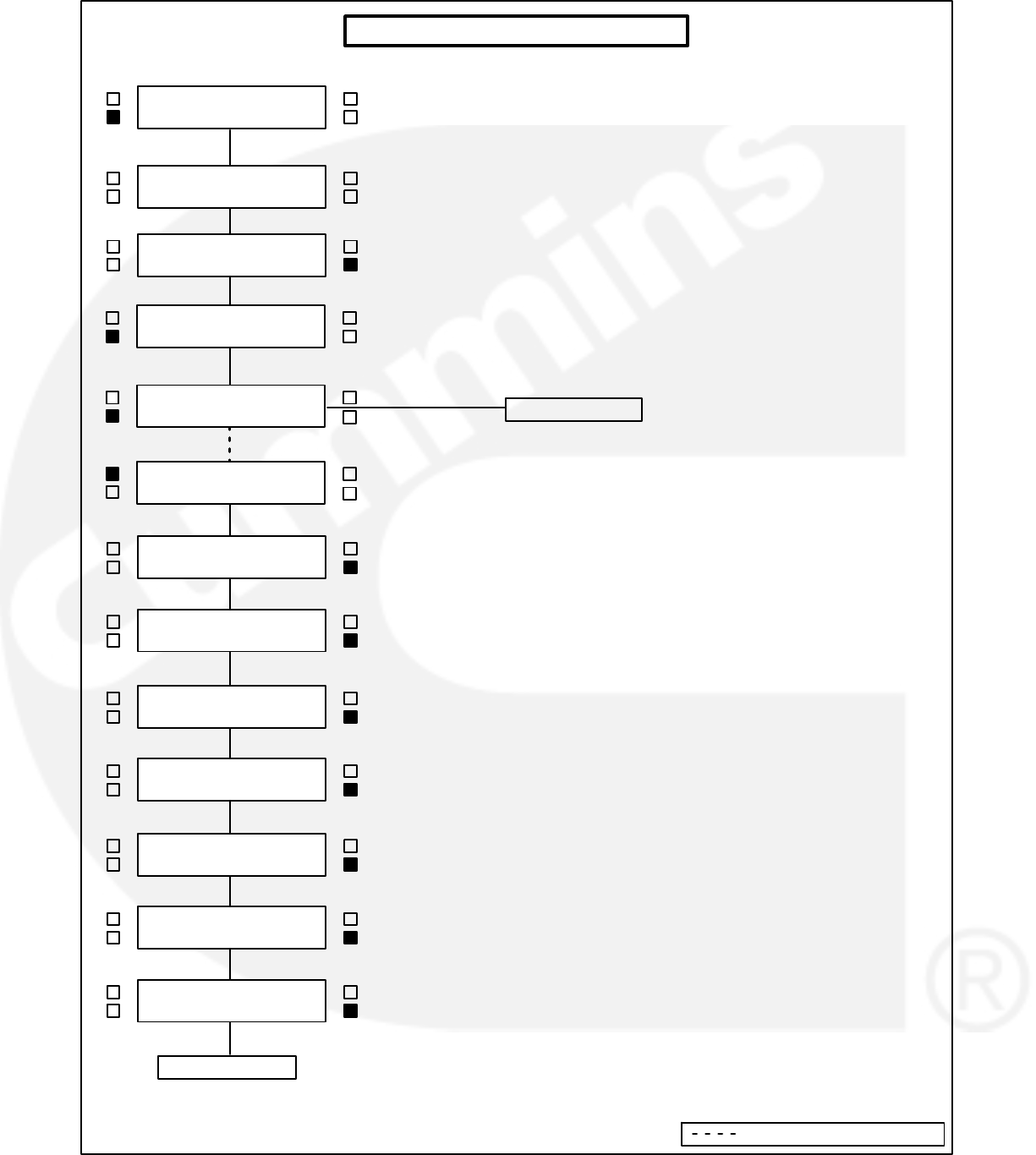
5-21
<>
<>
DISPLAY CAL <<
METERS >>
< ENTER CODE
__ __ __>>
<>
<>
PARALLELING SETUP MENU
<>
GOV / REG <<
PARALLEL SETUP
<
ISO BUS <<
UTILITY
<>
<>VERSION <<
SETUP/CAL >>
<>
<
ISO BUS <<
UTILITY
<>
< SYNC TIME LMT
120 >><>
< -PWR LMT (%)
10 >><>
< -PWR LMT (TIME)
3 >><>
< PERM WIN-PHASE
20 >>
<>
< PERM WIN-TIME
.5 >><>
< SYNC GAIN
95 >><>
B (CONTINUED)
< SYNC INTEGRAL
12 >><>
A (CONTINUED)
Indicates OR" Condition

5-22
ISOLATED BUS ADJUSTMENTS (Cont.) (A)
KW BALANCE: This function adjusts the kW load
sharing function of the generator set. Before adjust-
ing this value, all generator set calibrations should
be performed. If the total load on the system is not
shared proportionately, the kW Balance can be
used to adjust the generator set for more precise
load sharing. Increasing the kW Balance value will
cause the generator set to reduce the percentage of
the total kW load on that set.
KVAR BALANCE: This function adjusts the kVAR
load sharing function of the generator set. Before
adjusting this value, all generator set calibrations
should be performed. If the total load on the system
is not shared proportionately, the kVAR balance can
be used to adjust the generator set for more precise
load sharing. Increasing the kVAR balance value
will cause the generator set to reduce the percent-
age of the total kVAR load on that set.
KW GAIN: Adjusts the rate of change of kW load on
the generator set. With a constant load on the sys-
tem, if the generator set load is constantly chang-
ing, reduce the gain adjustment on the generator
set. This also allows modification of the rate of load
assumption on transient load change.
KVAR GAIN: Adjusts the rate of change of kVAR
load on the generator set. With a constant load on
the system, if the generator set load is constantly
changing, reduce the gain adjustment on the gener-
ator set. This also allows modification of the rate of
load assumption on transient load change.
1ST START FAIL: Time delay in seconds after a
signal from the first start master is not sensed by the
PCC that a FIRST START FAIL warning is dis-
played.
RAMP UNLD TIME: When a load demand stop in-
put is sensed the load is ramped down from the
present load level on the set to the ramp unload lev-
el in the time specified in seconds.
RAMP UNLD LEVEL: The load demand ramp un-
load function will ramp the load down from the pres-
ent level on the set to this level before opening the
set circuit breaker. Value shown is in % of genset
standby rating.
RAMP LOAD TIME: When the load demand stop
signal is removed the load is ramped from 0kW to
the load share level in the specified time after the
circuit breaker closes.
LOSS FIELD (LOSS OF EXCITATION) TIME and
LEVEL: Adjusts the time delay on the Loss of Ex-
citation fault. Generator sets with version 1.07 and
higher (9−26−96 and later) firmware may be ad-
justed for time delay on this condition. the default
value is 2 seconds.
Generator sets with version 2.0 and higher firmware
allow adjustment of both time delay and reverse
VAR set point. Default values are 10 seconds and
20%.
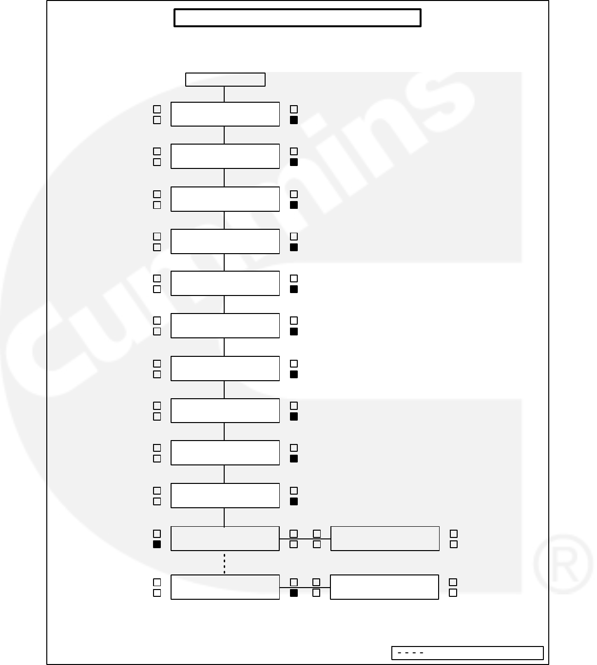
5-23
<>
<>
PARALLELING SETUP MENU (Cont.)
<SAVE
EXIT >>
<SAVE
EXIT >> <>
<>
DISPLAY CAL <<
METERS >>
< KW BALANCE
165 + ___% >><>
< KVAR BALANCE
0 + ___% >><>
< KW GAIN
6 >>
<>
< KVAR GAIN
300 >><>
A (CONTINUED)
< 1ST START FAIL
10 >>
<>
< RAMP UNLD TIME
10 >><>
< RAMP UNLD LEVEL
20 >><>
< RAMP LOAD TIME
10 >><>
Indicates OR" Condition
< LOSS FIELD TIME
2 >><>
< LOSS FLD LEVEL
20 >>
<>
<>
<>
GOV / REG <<
PARALLEL SETUP

5-24
UTILITY (MAINS) ADJUSTMENTS (B)
BASE LOAD (%): Controls the maximum kW load
level that the generator set will operate at when par-
alleled with the utility (mains). The value shown indi-
cates the steady state load on the generator as a
percent of the generator set standby rating.
Check generator set ratings for maximum load level
at which the generator set should operate when
paralleled with the utility (mains). Extended opera-
tion at load levels in excess of the generator set rat-
ing can cause abnormal engine wear or premature
engine failure.
PF LEVEL: Adjusts the power factor that the gener-
ator set will run at when paralleled to the utility
(mains). Recommended setting is 1.0.
KW GOVERN GAIN: Controls the rate that the gen-
erator set kW load is increased after the generator
set has closed to the system bus when utility
(mains) paralleled. Decreasing this value will result
in slower loading of the generator set.
KW INTEGRAL: The kW integral adjustment is
used to control the response of the generator set to
large load changes when utility (mains) paralleled.
Use of a higher integral value will result in slower re-
sponse, and reduced kW overshoot on load as-
sumption or rejection, especially on large system
load changes. Decreased integral values will also
result in slower load acquisition and rejection.
KVAR GOVERN GAIN: Controls the rate that the
generator set kVAR load is increased after the gen-
erator set has closed to the system bus when utility
(mains) paralleled. Decreasing this value will result
in slower loading of the generator set.
KVAR INTEGRAL: The kVAR integral adjustment
is used to control the response of the generator set
to large load changes when utility (mains) paral-
leled. Use of a higher integral value will result in
slower response and reduced kVAR overshoot on
load assumption or rejection, especially on large
system load changes. Decreased integral values
will also result in slower load acquisition and rejec-
tion.
RAMP LOAD TIME: This is the ramp time from
present set load to level determined by the load set
analog input. This is active when the control first en-
ters the load govern mode.
RAMP UNLD TIME: This is the ramp time from
present set load to the 0 kW. This ramp is active
when the load set analog input is less than 0.5 volts.
MULTIPLE/SINGLE: This selection modifies the se-
quence of operation and functions of the inputs and
outputs of the control on TB1 to allow for application
of the control in multiple generator set applications
(“Multiple” selection), where generator sets are par-
alleled to each other and may also be paralleled to a
utility (mains) service; or for applications where a
single generator set is used with a breaker pair for
closed transition power transfer functions (“Single”
selection). See Table 5-3 for a description of the op-
eration and use of TB1-51 input.
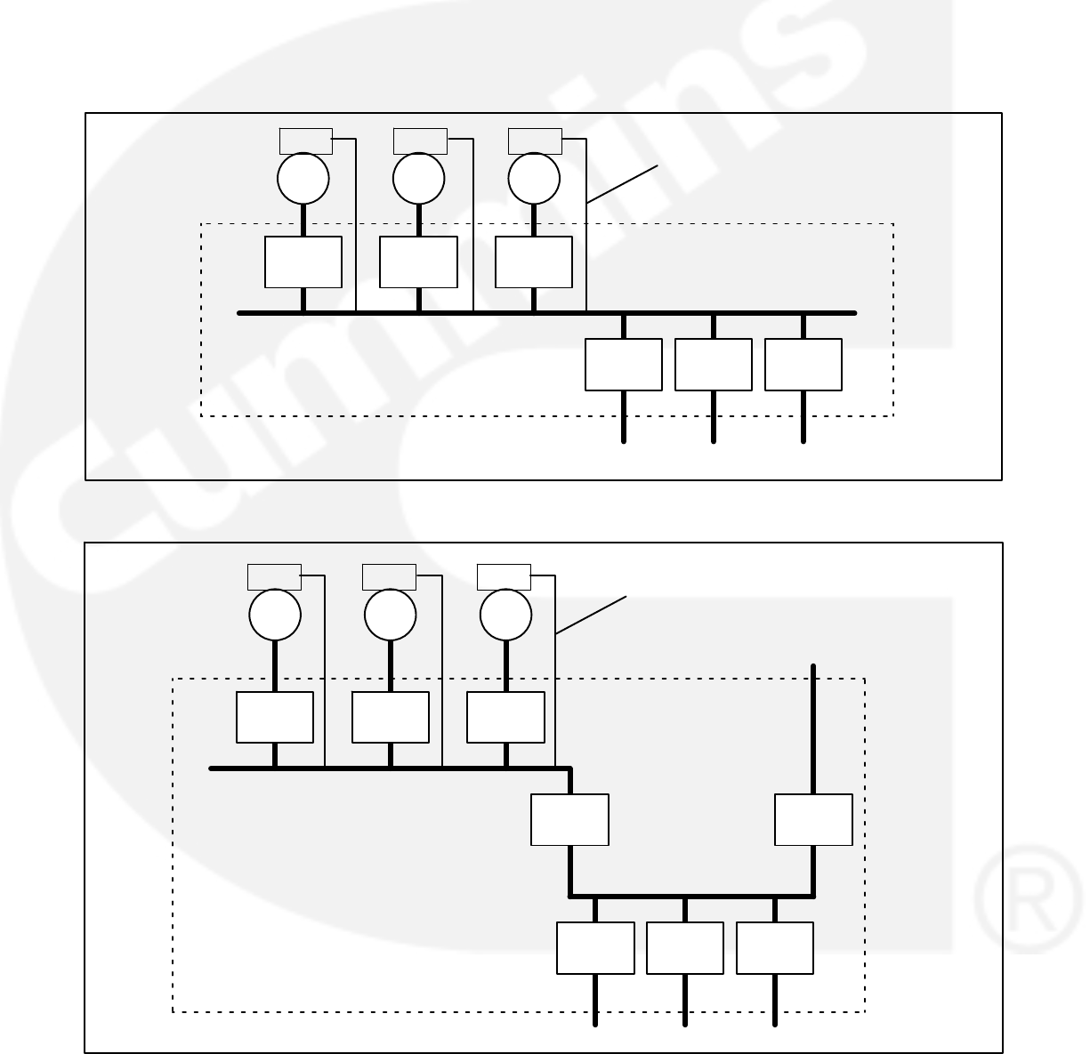
5-25
Multiple − In the MULTIPLE configuration, the con-
trol is set up for proper operation in a system where
the gensets are configured similar to that shown in
Figure 5-3 or 5-4. In these illustrations, 52-Gn are
the paralleling circuit breakers and 52-Fn are feeder
circuit breakers that provide generator set power to
load transfer devices. 52-U is a utility (mains) circuit
breaker and 52-GM is a generator bus main break-
er. 52-U and 52-GM provide power transfer func-
tions in the system.
Upon receiving a start signal, the gensets automati-
cally start, select one generator set in the system to
be the first one to close to the bus using the First
Start Sensor system, synchronize, and load share.
Upon receiving a signal to the control that the gen-
erator sets are closed to the utility (mains), the gen-
erator sets automatically ramp to their preset base
load level.
52-G1
G1
52-G2
G2
52-G3
G3
SWITCHGEAR
TO LOADS
52-F1 52-F1 52-F1
PCC PCC PCC BUS VOLT
SENSE
FIGURE 5-3. TYPICAL MULTIPLE CONFIGURATION
TO LOADS
52-G1
G1
52-G2
G2
52-G3
G3
SWITCHGEAR
52-F1 52-F1 52-F1
TO LOADS
52-GM 52-U
FROM
UTILITY (MAINS)
G3
PCC PCC PCC BUS VOLT
SENSE
FIGURE 5-4. TYPICAL MULTIPLE CONFIGURATION
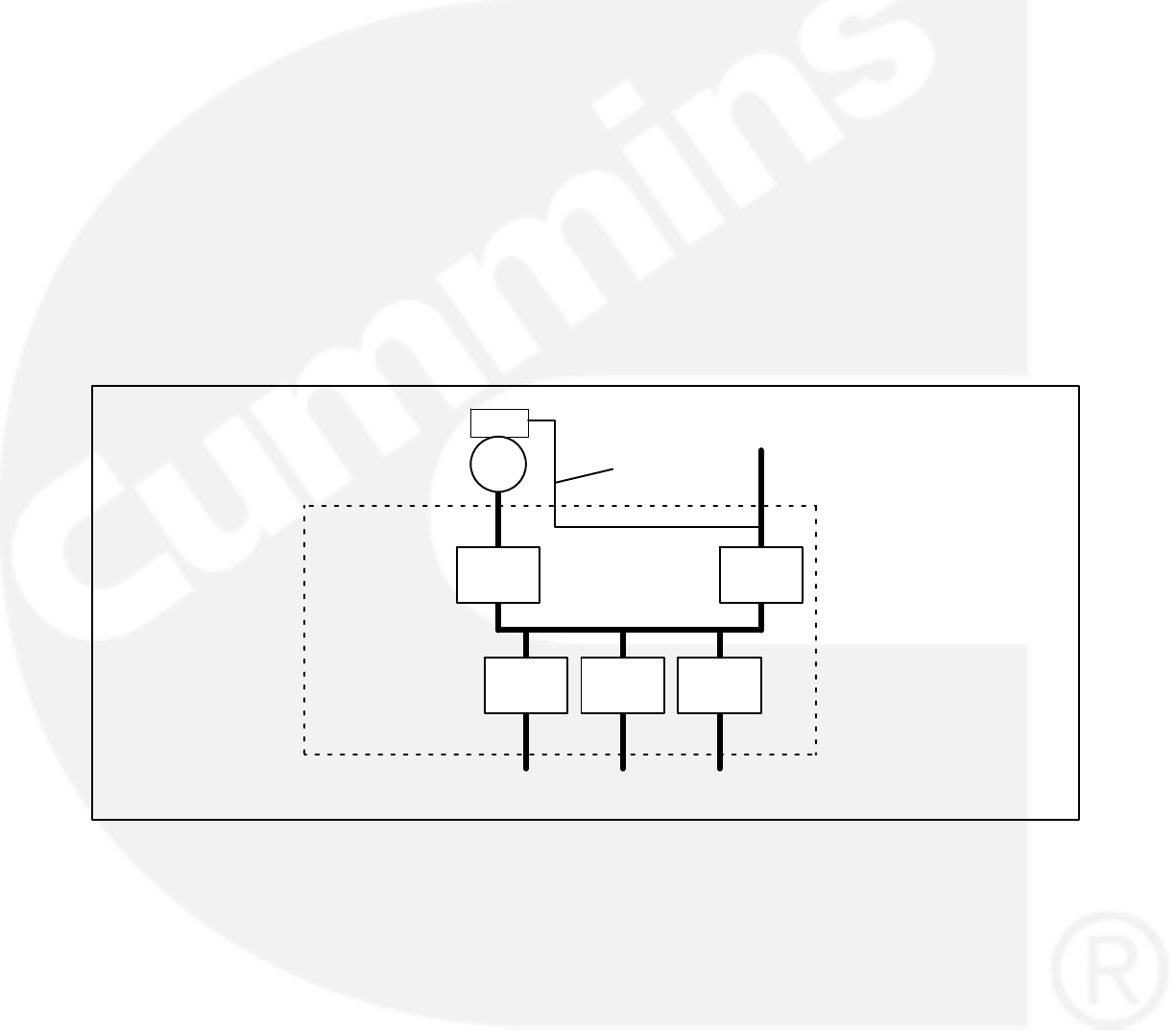
5-26
Single − The SINGLE configuration (limited to
ONLY the electrical configuration shown in Figure
5-5) allows for incorporation of a single PowerCom-
mand generator set in a power system that provides
load transfer functions and various utility paralleling
functions. In the SINGLE configuration, Power-
Command provides all the generator set control
functions including synchronizing, load govern (im-
port/export control and var/PF control), and genset
breaker control functions; equipment provided by
others provides utility (mains) breaker control, utility
source sensing, and other functions.
The PCC monitors the position of the generator set
breaker (52-G1) and the utility (mains) breaker
(52-U). In a black start condition, the generator set
receives a start signal from a remote device. If the
PCC senses no voltage available on the bus volt-
age connection and the utility (mains) breaker is
open, it closes the generator set breaker.
When utility (mains) power returns, the remote de-
vice turns on the synchronizer in the PCC, the PCC
synchronizes the genset-to-utility (mains) service,
and the remote device closes the utility (mains)
breaker (52-U). When the PCC senses that 52-U is
closed, it checks the voltage on the external load set
terminals (TB1-59 and 60) and ramps to the com-
manded load level. The remote device control sys-
tem determines when to open the genset breaker
by removing the start signal from the genset control.
When it is removed, the genset ramps down to zero
load and opens the genset breaker (52-G1).
If the generator set receives a start signal when the
utility (mains) service is available, the generator set
starts and accelerates to rated voltage and frequen-
cy. It automatically synchronizes and closes its
breaker. When the generator breaker is closed, the
generator set ramps to the load level commanded
by the signal on the external load set terminals
(TB1-59 and 60).
52-G1
G1
SWITCHGEAR
52-F1 52-F1 52-F1
TO LOAD(S)
(# LOADS OPTIONAL)
52-U
FROM
UTILITY (MAINS)
PCC
BUS VOLT
SENSE
FIGURE 5-5. UTILITY-SINGLE CONFIGURATION
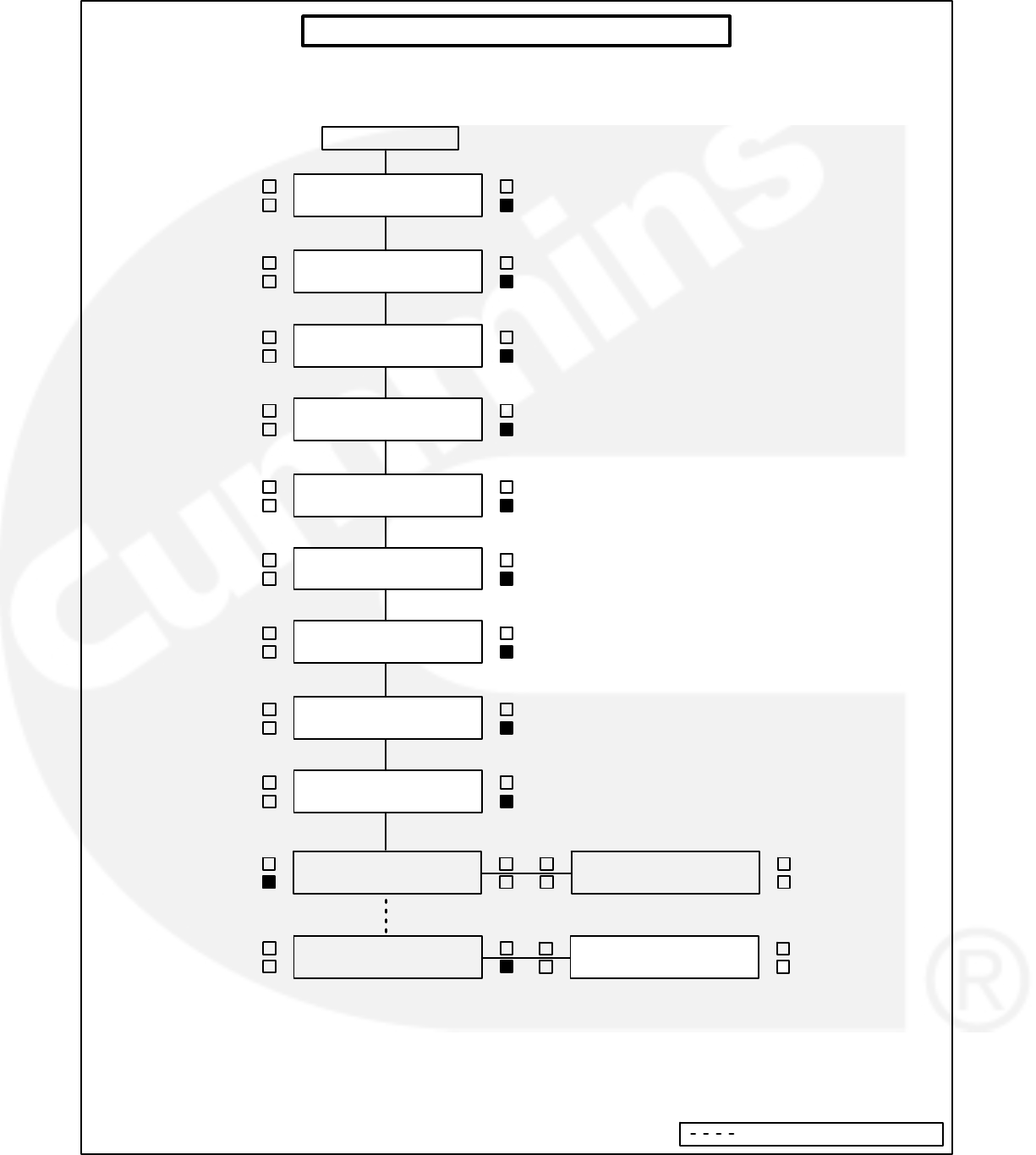
5-27
<>
PARALLELING SETUP MENU (Cont.)
<SAVE
EXIT >>
<>
<>
DISPLAY CAL <<
METERS >>
< BASE LOAD %
80 >><>
< PF LEVEL
1.00 >><>
< KW GOVERN GAIN
100 >>
<>
< KW INTEGRAL
4 >><>
< KVAR GOVERN GAIN
300 >>
<>
< KVAR INTEGRAL
200 >><>
B (CONTINUED)
< RAMP LOAD TIME
10 >><>
< RAMP UNLD TIME
10 >>
<>
< MULTIPLE/SINGLE
SINGLE>><>
Indicates OR" Condition
<>
<SAVE
EXIT >>
<>
<>
GOV / REG <<
PARALLEL SETUP

5-28
CALIBRATION PROCEDURE
WARNING Contacting high voltage compo-
nents can cause electrocution, resulting in se-
vere personal injury or death. Calibration and
adjustment must be performed by technically
qualified personnel only. Read and observe all
WARNINGS and CAUTIONS in your generator
set manuals.
CAUTION Improper calibration or adjustment
of the PowerCommand control can cause
equipment malfunction or damage. Calibration
and adjustment must be performed by techni-
cally qualified personnel only.
The calibration procedure is divided into 7 subsec-
tions, with the subsections arranged in a specified
order. If two or more of the following subsections are
required to calibrate the PCC, they must be com-
pleted in the order shown.
When removing and replacing a defective circuit
board, you may have to perform one or more of the
following subsections. Table 5-1 (Control Panel Re-
calibration) provides a list of the circuit boards that
require calibration when replaced and the calibra-
tion procedure(s) that must be performed.
Use a calibrated RMS multimeter for accurate mea-
surements. Fluke models 87 or 8060A are good
choices.
Initial Start Setup
1. Refer to Page 5-4, which describes how and
when you should perform this procedure.
To verify if the PCC is set to operate with a spe-
cific generator set, refer to the VERSION menu
(Page 5-9). This menu will show the generator
set model number, frequency, and kW rating. If
any of these values are incorrect, you must per-
form the Initial Start Setup procedure.
Voltage and Frequency Adjustment
2. With the generator set OFF, attach a calibrated
frequency/voltmeter to the AC output from L1
to L2.
3. Select ADJUST from the Main Menu (page 5-7)
to display the VOLTAGE adjust menu.
4. Start the generator set and allow the generator
set to reach normal operating speed.
5. Adjust VOLTAGE (generator set output volt-
age) so that the calibrated voltmeter reads the
desired voltage. (Use a calibrated voltmeter
because the value displayed on the PCC digital
display may not be calibrated at this time;
therefore, its accuracy is unknown.)
6 Select the Frequency adjust menu.
7. Verify that the frequency displayed on the cali-
brated meter is the desired frequency. If not,
adjust to the desired frequency. (Note: If the
frequency reading on the digital display is not
the same as frequency shown on calibrated
meter, there is an equipment malfunction.)
8. If no frequency or voltage adjustment was
made, select EXIT. If an adjustment was made,
SAVE, then EXIT.
Digital Voltage Display Calibration
The paralleling bus must be de-energized while
voltage calibrations are performed. If this is not
possible, disconnect and isolate bus voltage in-
puts to the Bus PT Module (A39) before attempt-
ing voltage calibration.
9. Select “>>” from the Main Menu (Page 5-9).
From this menu proceed to the VOLTS L12
menu (Page 5-11).
10. With the generator set OFF, attach a calibrated
frequency/voltmeter to the AC output from L1
to L2.
11. Start the generator set and allow it to reach
normal operating speed.
12. Calibrate voltage reading for VOLTS L12 so
that the reading on the digital display agrees
with the calibrated voltmeter.
13. Shut the generator set OFF.
14. Repeat steps 10 through 13 for L23 and L31.
(In step 10 attach meter to the AC output from
L2 to L3 to calibrate VOLTS L23 and then L3 to
L1 to calibrate VOLTS L31.)
15. If no calibration was made, select EXIT. If a cal-
ibration was made, SAVE, then EXIT.
Digital Ammeter Display Calibration
16. Select “>>” from the Main Menu (Page 5-9).
From this menu proceed to the AMPS L1 menu
(Page 5-11).
17. With the generator set OFF, attach a calibrated
ammeter to L1.

5-29
18. Start the generator set and allow it to reach
normal operating speed.
19. Load the generator set to maximum rated kVA
at rated voltage.
20. Calibrate the reading for AMPS L1 so that the
reading on the digital display agrees with cali-
brated ammeter.
21. Repeat steps 17 through 20 for L2 and L3. (In
step 17, attach meter to L2 to calibrate AMPS
L2 and then L3 to calibrate AMPS L3.)
22. If no calibration was made, select EXIT. If a cal-
ibration was made, SAVE, then EXIT.
Digital Power Factor Display Calibration
Power factor calibration is not required except in ap-
plications requiring a higher accuracy than 5%. If
the 5% accuracy is not acceptable, further calibra-
tion will require reactive load sufficient to reach 0.8
PF at rated load, and calibrated instruments with
1% accuracy or better. Typical load rack instru-
ments are not accurate enough to perform this pro-
cedure.
23. Select “>>” from the Main Menu (Page 5-9).
From this menu proceed to the PF1 menu
(Page 5-11).
24. With the generator set OFF, attach the power
factor meter to L1.
25. Start the generator set and allow it to reach
normal operating speed.
26. Load the generator set to maximum rated kVA
at rated voltage.
27. Calibrate the reading for PF1 so that the read-
ing on the digital display agrees with power fac-
tor meter.
28. Repeat steps 24 through 27 for L2 and L3. (In
step 24, attach meter to L2 to calibrate PF2 and
then L3 to calibrate PF3.)
29. If no calibration was made, select EXIT. If a cal-
ibration was made, SAVE, then EXIT.
Digital Coolant Temperature Display
Calibration
An engine sensor calibration tool is required to per-
form this procedure.
30. With the generator set OFF, replace the coolant
temperature sender with the precision resistor
provided in the calibration tool.
31. Select “>>” from the Main Menu (Page 5-9).
From this menu proceed to the COOLANT
TEMP L menu (5-11).
32. Calibrate the temperature reading to match the
temperature indicated on the calibration tool.
33. Repeat step 32 for COOLANT TEMP R if the
engine uses two sensors.
34. If no calibration was made, select EXIT. If a cal-
ibration was made, SAVE, then EXIT.
Digital Bus Voltage Calibration
35. Select “>>” from the Main Menu (Page 5-9).
From this menu proceed to the Bus Volts L12
menu (Page 5-11).
36. With the genset OFF, attach a calibrated fre-
quency/voltmeter to the alternator AC output
from L1 to L2.
The paralleling bus must be de-energized while
voltage calibrations are performed. If this is not
possible, disconnect and isolate bus voltage in-
puts to the Bus PT Module (A39) before attempt-
ing voltage calibration.
37. Start the genset and allow it to reach normal
operating speed and voltage.
38. Push the breaker close switch on the front of
the PowerCommand control and verify that the
paralleling breaker has closed by observing the
closed lamp on the control panel and physical
check of the breaker.
39. Calibrate the voltage reading for Bus Volts L12
so that the reading on the digital display
matches the reading on the calibrated meter.
40. Shut the generator set OFF.
41. Repeat steps 36 through 40 for Bus Volts L23
and Bus Volts L31.
42. If no calibration was made, select EXIT. If a cal-
ibration was made, SAVE, then EXIT.
Analog meter calibration
43. Select “>>” from the Main Menu (Page 5-9).
From this menu proceed to the A−C VOLTS
ADJ TO menu (Page 5-13).
44. Start the generator set and allow the generator
set to reach normal operating speed.
45. Calibrate the analog Voltmeter to the digitally
displayed value.
46. Calibrate the analog % Amps meter to the digi-
tally displayed value.
47. Calibrate the analog % Load meter to the digi-
tally displayed value.
48. Calibrate the analog Frequency meter to the
digitally displayed value.
49. SAVE, then EXIT.

5-30
ENGINE TORQUE ADJUSTMENT
The engine torque fuel limit is set in the PowerCom-
mand control. This limit is adjustable (0% to +1% of
duty cycle units, which corresponds approximately
to 0% to +2% engine horsepower) through the digi-
tal display to compensate for engine/electronic vari-
ation. If the generator set is not providing the name-
plate kilowatt rating, the torque limit can be adjusted
with the following procedure.
1. Select “>>” from the Main Menu (Page 5-9).
From this menu proceed to the Torque Adjust
%DC menu (Page 5-17).
2. Start the generator set and allow it to reach nor-
mal operating speed.
3. Load the generator set to maximum rated kVA
at rated voltage.
4. Adjust the torque limit up or down to achieve
the proper generator set frequency, under
maximum load.
If you select SAVE, the adjustments will be retained
after shutdown, and will be in effect when the set is
restarted. If you select EXIT without saving first, the
adjustments will remain in effect until the generator
set is shut down, but will be reset (and will not be in
effect) when the set is restarted.
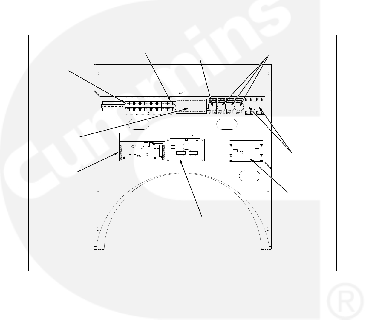
5-31
ACCESSORY BOX CONTROL
COMPONENTS
The generator set accessory box (Figure 5-6) which
is located on the backside of the control housing,
contains components that provide connection
points for remote control and monitor options. The
set can be equipped with one or more of the follow-
ing components (customer terminal block TB1 is
standard). Refer to Page 9-6 for typical connections
to TB1.
OPTIONAL RTD
RELAY
OPTIONAL RUN RELAYS
K11, K12 & K13
OPTIONAL
COMMON ALARM
RELAY K14
OPTIONAL
THERMISTOR
RELAY 160/140 C
TB1-1
TB1-40
GOVERNOR
OUTPUT MODULE
A38
PT/CT BOARD A36
VOLTAGE
REGULATOR
OUTPUT MODULE
A37
FIGURE 5-6. ACCESSORY BOX COMPONENTS

5-32
1, 2, 3, 4
TABLE 5-3. A39/A40 TB1 CUSTOMER INPUTS
A39/A40 TB1
TERMINAL # FUNCTION DESCRIPTION
Bus PT Input (On
Bus PT Module)
Phase to Neutral input voltages from system bus (load side of paralleling
breaker.
5Remote Start Close to ground to start generator set. (RUN/OFF AUTO switch must be
in AUTO position.)
41, 42 Common Alarm
Warning
Form C output contact for remote indication of warning condition on
generator set.
50 Master First
Start/Synchronizer
Enable
For isolated bus or multiple generator set utility (mains) applications, a
B+ signal from a remote Master First Start Sensor is applied on this
terminal. For single generator set utility (mains) parallel applications,
apply 24VDC to this terminal to enable synchronizer function in control.
16 − 19 Customer Fault Grounding these terminals initiates an alarm or shutdown condition in
the control.
20 Fault Reset Applying a momentary ground signal to this terminal clears warning or
shutdown faults in the control. (Except Emergency Stop.)
21 Engine Idle
Grounding this input activates the Low Fuel warning.
35 Rupture Basin
Alarm
Applying a ground signal to this point will cause the generator set to
annunciate a Rupture Basin Alarm.
46 Utility Parallel
Signal
Apply a 24VDC signal to terminal 46 to indicate to the control that it is
operating in parallel with a utility (mains) service.
47 Utility Parallel
Signal
Apply a ground signal to terminal 47 to indicate to the control that it is
operating in parallel with a utility (mains) service.
A39
A40
CONTINUED
6 Remote
Emergency Stop
Grounding this input causes an immediate shutdown.
22 Low Fuel
Applying a ground signal at this terminal will cause engine to run at
recommended idle speed. Voltage will be disabled.
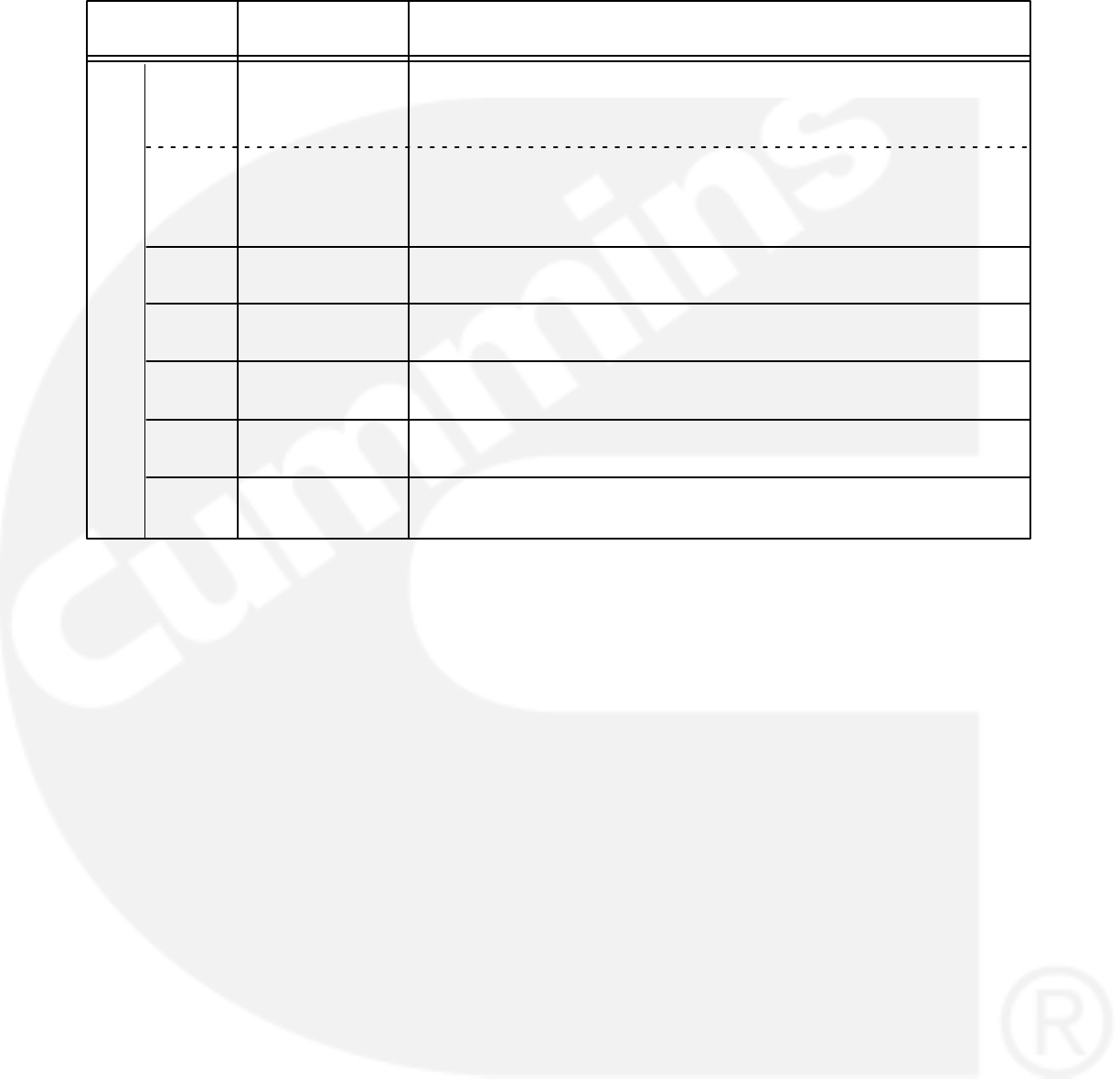
5-33
TABLE 5-3. A39/A40 TB1 CUSTOMER INPUTS (Cont.)
A39/A40 TB1
TERMINAL # FUNCTION DESCRIPTION
51 Load Demand Close to ground to initiate load demand mode in PowerCommand
control. (Select “Multiple” in Paralleling Setup Menu to enable load
demand mode.)
52 Breaker Open /
Inhibit
Close to ground to manually open the paralleling breaker or inhibit
breaker closure.
53 Breaker Position Close to ground to indicate breaker closed.
54, 55 kVAR Load
Share
Load Sharing Lines. Connect to load sharing lines in other generator
sets in the system.
56, 57 kW Load Share Load Sharing Lines. Connect to load sharing lines in other generator
sets in the system.
59, 60 External Load
Set
Analog 0 − 5 VDC input to control kW load level on generator set when
the generator set is paralleled to utility.
51 Utility Single
Verify
For single generator set utility (mains) applications (“SINGLE” selected
in the Paralleling Setup Menu), this terminal must be connected
[strapped] to ground to enable breaker closure. (Version 1.07, beginning
9-26-96 only.)
A40
Remote Start: When the Run/Off/Auto switch is in
the Auto position, grounding this input initiates the
engine cranking and start sequence. This circuit
must be opened to permit resetting a shutdown con-
dition with the Reset input.
Low Fuel: Grounding this input actuates the Low
Fuel warning. This input can be connected to a local
day tank or to a main fuel tank that is located on site.
When the switch grounds this designated input, the
input will “wake up” the control, if it is not operating,
and then initiate the fault.
Customer Fault Inputs 1 through 4: Grounding
any one of these inputs activates the corresponding
warning or shutdown sequence. Warning or shut-
down status is selected in the setup menu.
External sensing equipment must be connected to
the designated digital input.
The four customer fault messages can be separate-
ly edited in the setup menu to display any desired
message. This allows each customer “default” fault
message to be customized to represent the type of
device that is attached the the fault input.
Customer Fault 1 (A40 TB1-16) is reserved for the
RACK POSITION fault. Do not modify this fault name
or change the fault condition (Warning to Shut-
down).
The “default” message that is displayed, when
ground is applied to the input, is as follows:
Fault 1 = RACK POSITION
Fault 2 = GRND FAULT
Fault 3 = DAY TANK
Fault 4 = HIGH GEN TEMP
If Fault 2 or 3 input is grounded, the control will
“wake up” if it is not operating, and then initiate the
fault.
Fault Reset: When the Run/Off/Auto switch is in
the Auto position and the remote start switch is
open, grounding this input resets any warning and
latched shutdown fault (except Emergency Stop,
which must be reset at the front panel.)

5-34
Engine Idle: When the set is operating in the RUN
mode, grounding this input causes generator build
up to be inhibited and the engine to be governed at
800 RPM. When ground is removed from this input,
the set returns to normal speed and voltage.
Engine idle operation is applicable only in the RUN
mode. The PCC operating program does not permit
engine idle operation when the set is operating in
AUTO mode.
When the engine idle function is enabled, the con-
trol automatically sets lower oil pressure warning
and shutdown trip points to reflect the lower operat-
ing speed. When the engine idle function is re-
moved and the set reverts to normal operating
speed, the control automatically resets oil pressure
warning and shutdown trip points to the normal set-
tings.
Remote Emergency Stop: Grounding this input
causes an immediate shutdown. Emergency stop
must be reset at the front panel.
Master First Start/Synchronizer Enable: This in-
put is received from a Master First Start Sensor,
which is mounted remotely from the PowerCom-
mand control. The input is a pulsed signal which is
used by the PowerCommand control to enable safe
closing of the paralleling breaker when the system
bus is de-energized. the control will receive a pulse
from the Master First Start Sensor approximately
once per second. If the PowerCommand control
does not receive a pulse within the programmable
time delay (default is 10 seconds), the FIRST
START warning is displayed by the control and a
backup system is enabled by the control.
When the system is set up for paralleling a single
generator set with a utility (mains) bus, this input is
used to enable the synchronizer in the PowerCom-
mand control. (See Paralleling Setup Menu, path
B.) A 24VDC signal applied to the terminal will
cause the generator set to synchronize with the
voltage reference signal applied to the bus PT mod-
ule (A39).
All PCC’s in a system should be programmed to a dif-
ferent first start fail time. This will help prevent simul-
taneous closure of breakers in the event of a failure
of the master first start module
Load Demand: On receipt of a signal on the Load
Demand terminals (normally open, close to
ground), the generator set will ramp down to a mini-
mum load level and the paralleling breaker will
open. The generator set will run for a cool-down pe-
riod and shut down. LOAD DEMAND SHUTDOWN
will be displayed on the PowerCommand panel.
When the Load Demand input is removed, the gen-
erator set will start, synchronize and close to the
system bus and accept it’s proportional share of the
total load on the bus.
The Load Demand function of the PowerCommand
control is only active when the RUN/OFF/AUTO
switch is in the AUTO position and “PARALLEL” is
selected in the Paralleling Setup Menu.
Utility Single Verify: For single generator set utility
(mains) applications, this input must be strapped to
ground before the generator set breaker will close
when the utility breaker is opened.
The Load Demand function of the PowerCommand
control is only active when the RUN/OFF/AUTO
switch is in the AUTO position and “SINGLE” is se-
lected in the Paralleling Setup Menu.

5-35
Utility (Mains) Parallel Input: Closure of a normal-
ly open contact to ground on terminal 47 and apply-
ing a 24VDC signal to terminal 46 will cause the
PowerCommand control to begin operation in a util-
ity (mains) paralleling mode. The ground signal is
usually applied by operation of auxiliary contacts in
the utility paralleling breaker. In this operation
mode, the control will ignore inputs from the load
sharing lines and operate at the load level which is
determined by the magnitude of the Load Govern
signal and the base load adjustment in the control
setup.
Load Govern: This input is enabled when the con-
trol has received a utility (mains) parallel input. A
0−5V signal applied to terminals 59 and 60 will di-
rect the control to operate the genset at a fraction of
the preset base load (%). Operating load level is de-
termined by the formula:
31.4 * (Load Set Voltage – 1) = % kW load
For Load Set Voltage of 1.0 volts and lower, the gen-
set will ramp to no load. For Load Set Voltage levels
4.5 volts and higher, the genset will be controlled to
the preset base load.
A change in the Load Set Voltage will cause the
genset to ramp to the new commanded kW level.
Ramp rate is controlled by Ramp Load Time and
Ramp Unload Time. (See Utility (Mains) Adjust-
ments elsewhere in this section.) In the load govern
state, kVar load is always a function of the preset
power factor and the % kW load.
Parallel Breaker Open/Close Inhibit: This func-
tion is operational only when the RUN/OFF/AUTO
switch is in the AUTO position. Closing a normally
open contact to ground on this contact will cause
the paralleling breaker to open if it is closed, or pre-
vent it from closing if it is open. Removing the
ground signal will cause the PowerCommand con-
trol to return to normal operation.

5-36
Operating PowerCommand in Droop Mode
The PowerCommand control is designed to operate
isochronously (with no intended droop) so that volt-
age and frequency are as constant as possible
when the generator set is paralleled to other Power-
Command generator sets. In certain situations,
however, such as paralleling with other generators
that are operating in droop mode, it may be neces-
sary to operate the control in a droop mode for fre-
quency, voltage, or both.
Note that when the generator set is paralleled to a
utility (mains) service it is recommended that the
control be operated in its utility parallel mode, rather
than in droop, even if other generator sets in the
system operate in droop for that function. The droop
mode in PowerCommand will only work when all the
other generator sets in the system are operating in
droop and the system bus voltage and frequency
change with load.
PowerCommand controls that are set up to operate
in droop mode must include the paralleling option
(H532). The generator set should be set up for mul-
tiple unit paralleling, but load sharing interconnect-
ing wiring is not used. Connect a 5K resistor across
terminal A40-TB1-54 and 55 (KVAR) to cause volt-
age to droop. A 5K resistor across terminal
A40-TB1-56 and 57 (KW) will cause frequency to
droop. Resistors can be used on one or both of the
load sharing terminal connections, depending on
the needs of the application.
Complete all start up procedures as described in
Section 8 of this manual up to the point that you are
ready to make load sharing adjustments. To set the
governor and voltage regulation system droop lev-
el:
1. Set the no load speed and voltage at the de-
sired level. Bus must be de-energized when
this setting is made, or disconnect Bus PT
module.
2. Apply 100% load to the generator set, and ad-
just the KW load sharing gain to obtain the de-
sired full load operating frequency. Adjust the
KVAR load sharing gain to obtain the desired
full load operating voltage. Refer to Figure 5-7
for typical gain settings for specific droop lev-
els.
3. Repeat the process for other generator sets in
the system.
4. When initial settings have been made, test the
system with all available load, and verify that
the generator sets share load approximately
equally at no load and maximum available
load.
Proper adjustment of load sharing in droop opera-
tion requires use of both real and reactive load
banks. It is possible that precise load sharing will not
be possible with all generator sets in the system at all
load levels, due to the non-linearity of the droop
characteristic of some generator sets. In that case, it
is generally best to set up the system so that avail-
able load is equally shared at the maximum load level
expected on the system. Note also that the synchro-
nizer is active and functional in PowerCommand
even when the system is set up for droop load shar-
ing. Manual paralleling and system synchronizing
should be performed by the PowerCommand con-
trol. It is recommended that paralleling breakers be
electrically operated by the PowerCommand con-
trol.
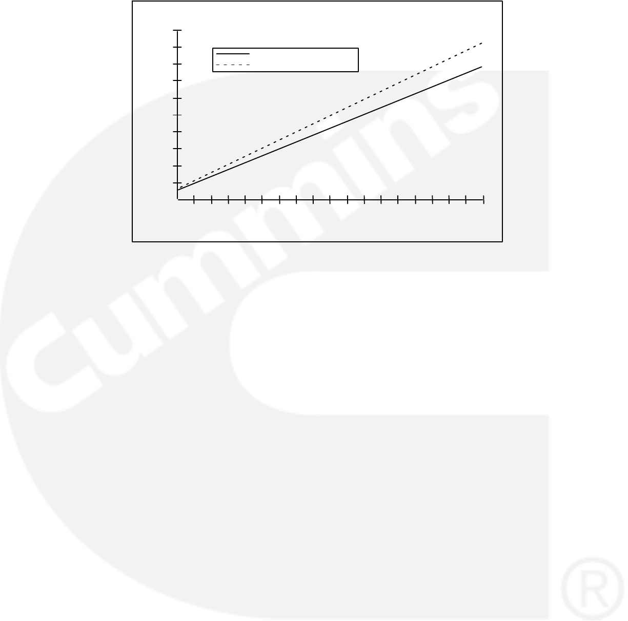
5-37
9.00
8.00
7.00
6.00
5.00
3.00
2.00
1.00
0.00
4.00
12345
LOAD SHARE GAIN
% DROOP
% DROOP @1800 RPM
% DROOP @1500 RPM
7689101112 13 14 15 16 17 18 19
FIGURE 5-7. PERCENT SPEED DROOP VERSUS KW LOAD SHARE GAIN

5-38
TB1 Customer Outputs
Refer to Page 9-9 for typical connections to TB1.
1
TABLE 5-4. TB1 CUSTOMER OUTPUTS
TB1
TERMINAL # FUNCTION DESCRIPTION
B+ Auxiliary Power 24 VDC control power supply, fused at 20 amps.
2Switched B+
Auxiliary Power
24 VDC control power available when genset is running, fused at 10
amps.
3, 4 Ground
7, 8, 9 Common
Shutdown
Form C contact set to indicate to a remote device that a generator set
shutdown fault has occurred.
10, 11
N-K20
Parallel Breaker
Close Signal
Normally open contact which closes to close a remote paralleling
breaker.
14, 15 Network Data Terminations for network data twisted pair, operational when generator
set is equipped with generator control module (GCM).
38, 40 Ready to Load Indicates that the generator set is at rated frequency and voltage and is
ready to accept load. Normally open contact between 38 and 40, which
is common.
39, 40 Load Dump Normally open contact which closes to indicate that the generator set is
overloaded.
41, 42 Common Warning Normally open contact that closes to indicate a warning condition on the
generator set.
43, 44 Common Warning Normally closed contact that opens to indicate a warning condition on
the generator set
48, 49
N-K21
Parallel Breaker
Open Signal
Normally closed contact which opens to close the paralleling breaker.
23−32, 33 NFPA Fault
Contacts
Normally open contact which closes to indicate that a specific fault has
occurred in the generator set. Common is terminal 33.

5-39
Paralleling Breaker Control: Contacts are pro-
vided to allow the PowerCommand control to oper-
ate a remote paralleling circuit breaker. A normally
open contact will close to signal the paralleling
breaker to close. A normally closed contact will
open to open the paralleling breaker.
When the RUN/OFF/AUTO switch is in the RUN
position the breaker signals will be initiated on op-
eration of the paralleling breaker control switches
on the front panel of the PowerCommand control.
The breaker control switches on the front panel of
the control are not operational in other control op-
eration modes.
When the RUN/OFF/AUTO switch is in the AUTO
position, the PowerCommand control will automati-
cally close the paralleling breaker if the system bus
is de-energized and the master first start sensor
pulse is received, or if synchronous condition with
the bus is achieved.
Warning Alarm: One set of normally open (NO)
and one set of normally closed (NC), rated for 2
amps at 30 VDC. Any warning causes the warning
alarm relay (labeled Spare Relay on Customer In-
terface board) to be energized. This output is often
used to energize an audible alarm.
Common Alarm: One set of form-C contacts, rated
for 2 amps at 30 VDC. Any shutdown causes the
common alarm relay to be energized. This output is
often used to energize an audible alarm.
Load Dump: One set of normally open (NO) con-
tacts, rated for 2 amps at 30 VDC. If an overload oc-
curs which causes generator set frequency to drop
more than 3 hertz below nominal for more than 3
seconds, or a load of more than 105% of the stand-
by rating is applied to the generator set for more
than 60 seconds, the normally open load dump con-
tacts are closed. This relay is energized before
shutdown (for overload or underfrequency) occurs.
Ready To Load: One set of normally open (NO)
contacts, rated for 2 amps at 30 VDC. This output is
activated whenever AC voltage and frequency ex-
ceed 90% of nominal.
Switched B+: This is a fused 10 amp, 24 volt
switched output. This output is activated by the run
pilot signal, at the governor output module. (Fuse is
located on Governor Output Module.)
B+: This is a fused 20 amp, 24 volt output. (Fuse is
located on TB-BAT terminal block of the engine har-
ness.)
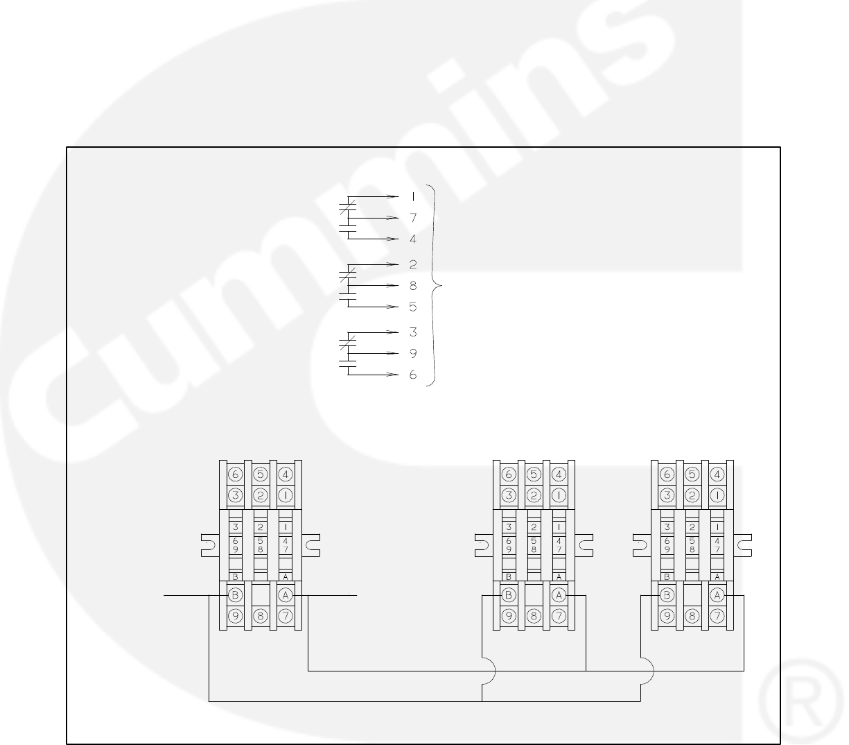
5-40
Run Relays (K11, K12, 13)
The optional run relays are rail mounted inside the
accessory box (Figure 5-6). The rail mount allows
you to easily remove and replace the snap-on re-
lays. The generator set can be equipped with one,
two or three run relays.
The three-pole, double-throw run relays (Figure
5-8) are used to control auxiliary equipment such as
fans, pumps and motorized air dampers. The run
relays are energized when the generator set reach-
es operating speed.
The contacts are rated:
10 amps at 28 VDC or 120 VAC, 80%PF
6 amps at 240 VAC, 80%PF
3 amps at 480/600 VAC, 80%PF
CUSTOMER
CONNECTIONS
A40-TB1-4
(B-)
A40-TB1-2
(SWITCHED B+)
NO
COIL
COM
NC
K11, K12, K13
K11
RUN RELAY
K11, K12, K13
K11, K12, K13
K12
RUN RELAY
K13
RUN RELAY
NO
NC
NO
NC
FIGURE 5-8. OPTIONAL RUN RELAYS (K11, K12, K13)
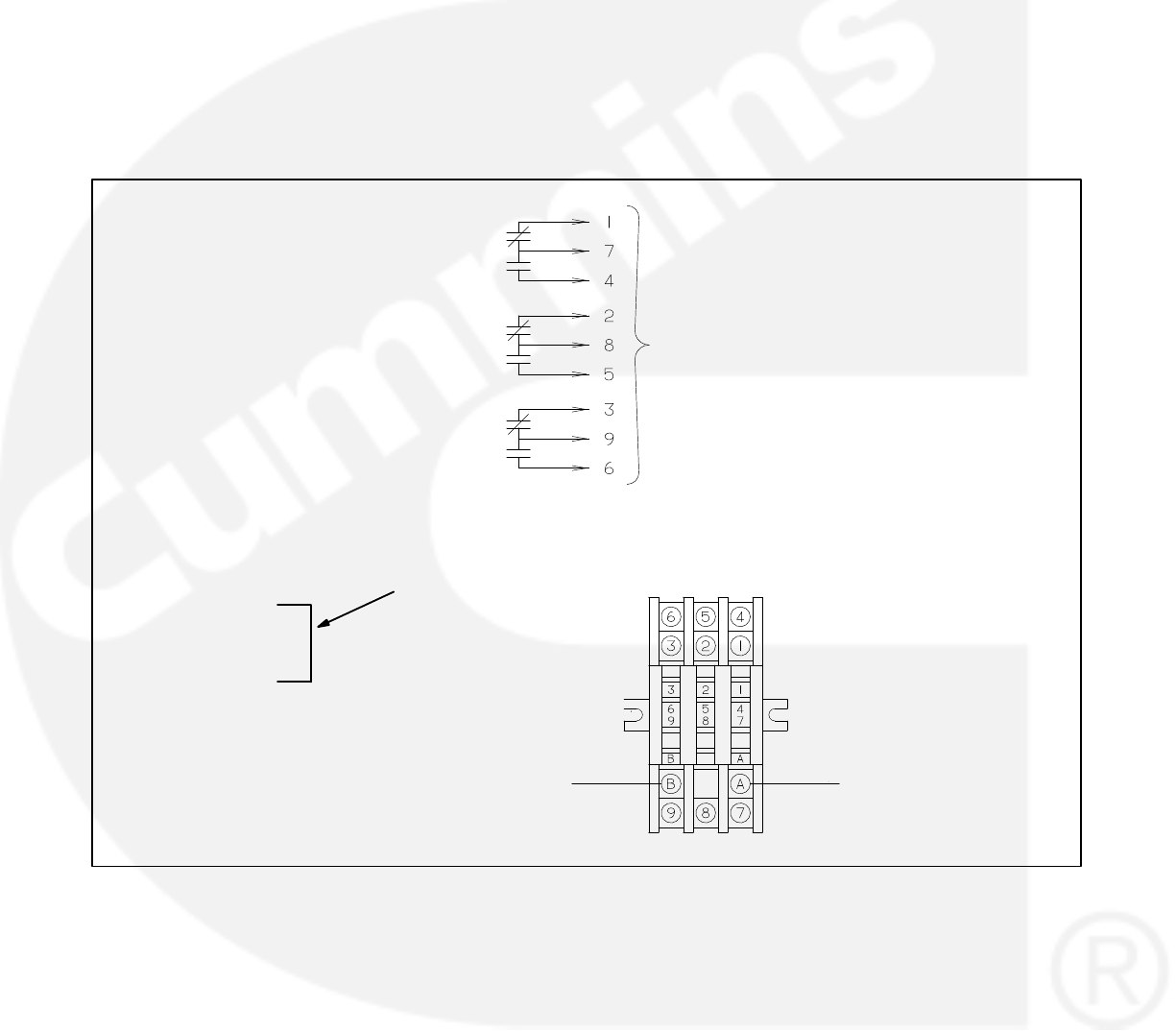
5-41
Shutdown Alarm Relay (K14)
The optional shutdown alarm relay is rail mounted
inside the accessory box (Figure 5-6). The rail
mount allows you to easily remove and replace the
snap-on relay.
The three-pole, double-throw shutdown alarm relay
(Figure 5-9) is often used to energize warning de-
vices such as audible alarms. Any generator set
shutdown will energize the alarm relay.
The contacts are rated:
10 amps at 28 VDC or 120 VAC, 80%PF
6 amps at 240 VAC, 80%PF
3 amps at 480/600 VAC, 80%PF
CUSTOMER
CONNECTIONS
A40-TB1-7
(COMMON SHUTDOWN
ALARM)
A40-TB1-1
(B+)
NO
COIL
COM
NC
K14
K14
K14
K14
COMMON SHUTDOWN
ALARM
A40-TB1-4
A40-TB1-8
JUMPER WIRE
REQUIRED FOR K14
RELAY OPTION
(GND)
(COMMON
SHUTDOWN ALARM)
FIGURE 5-9. OPTIONAL SHUTDOWN ALARM RELAY (K14)
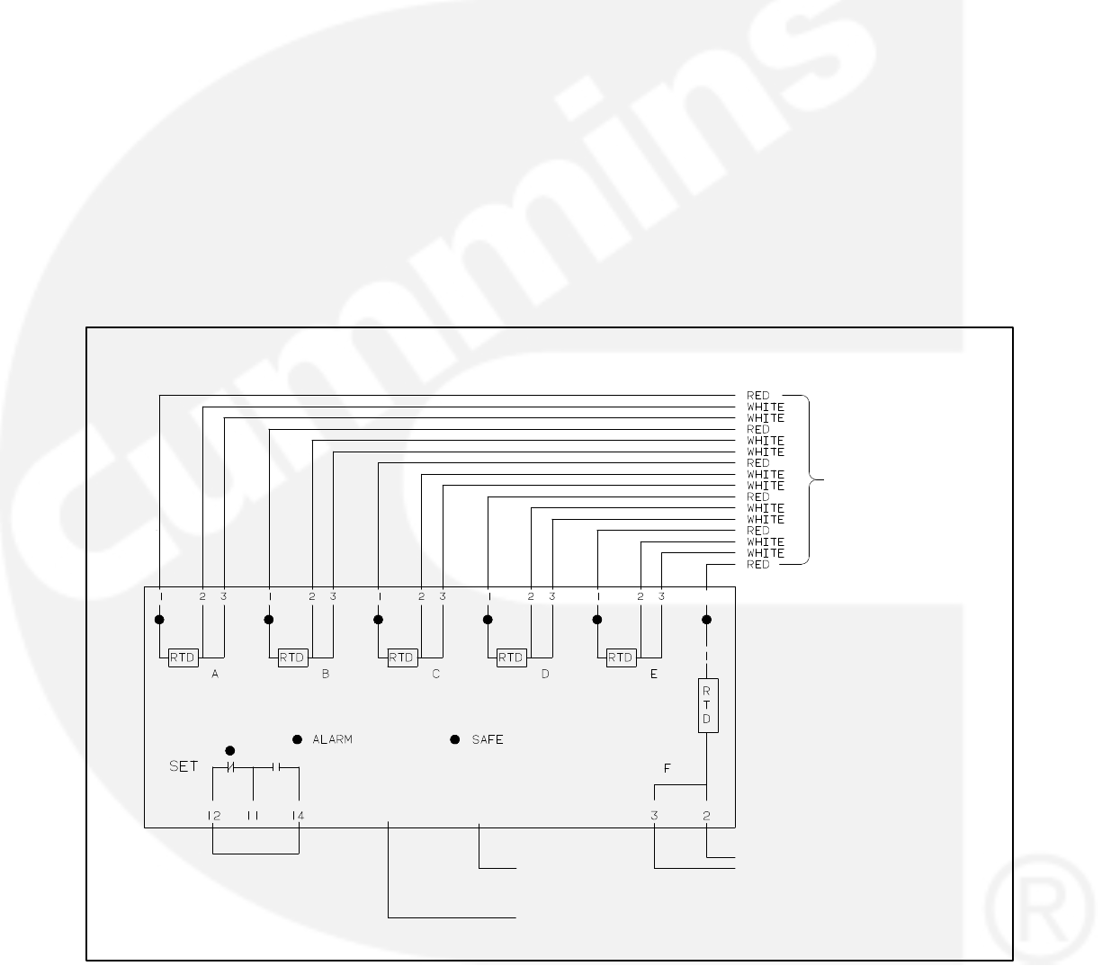
5-42
RTD Relay (Optional)
The optional RTD relay is rail mounted inside the
accessory box (Figure 5-6). This relay is used to
monitor six separate temperature zones in the gen-
erator windings using resistive temperature detec-
tors (RTDs). The relay determines the sensed tem-
perature and acts to isolate, alarm, or initiate cor-
rective action.
The RTD relay (Figure 5-10) compares the six in-
puts to the predetermined setpoint (temperature
setpoint is factory adjusted). If one or more of the in-
puts exceed the setpoint, the output relay is ener-
gized. LED’s indicate the state of the output relay
(green for normal, red for tripped). Additional red
LED’s are used to indicate which inputs exceed the
setpoint.
The relay terminals 11, 12 and 14 are for customer
connection. These terminals can be attached to any
one of the four Customer Fault inputs on TB1 to pro-
vide a warning/shutdown condition or to other cus-
tomer warning devices. (Refer to Setup Menu in
Section 7, which describes how to modify the cus-
tomer fault message and to select a warning or
shutdown condition.)
The contacts are rated:
240 VAC, 5 amps non-inductive
24 VDC, 25 amps resistive
OUTPUT RELAY
(CUSTOMER USE)
A40TB1-4
(GROUND)
WHITE
WHITE
TO RTD TERMINAL
BLOCK
TEMPERATURE RELAY CONNECTIONS
(+) PWR (−)
A40TB1-2
(SWITCHED B+)
24 VDC
FIGURE 5-10. RTD RELAY (OPTIONAL)
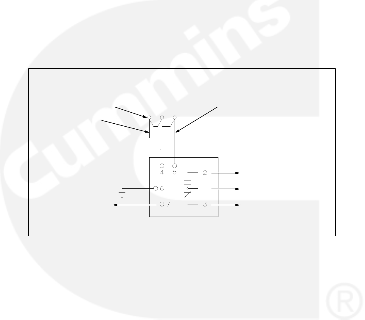
5-43
Thermistor Relay (Optional)
The optional thermistor relays are rail mounted in-
side the accessory box (Figure 5-6). Each relay
monitors three thermistors (one per phase) that are
connected in series inside the generator. One se-
ries or chain of thermistors are rated at 140 C and
the other at 160 C. The 140 C relay is commonly
used in a pre-alarm circuit and the 160 C relay in a
shut-down circuit. The relay will energize (trip)
when the thermistor chain resistance reaches 3000
500 ohms.
The relay terminals 1, 2 and 3 are for customer con-
nection and are normally connected to a breaker
shunt trip or a load shed circuit (Figure 5-11).
The contacts are rated:
3 amps at 250 VAC
1 amp at 480 VAC
A40-TB1-4
(GROUND)
WHITE/RED
THERMISTORS A BC
A40-TB1-2
(SWITCHED B+)
BLUE
FAULT CHANNELS
(CUSTOMER
CONNECTIONS)
RELAY CONTACTS
FIGURE 5-11. THERMISTOR RELAY (OPTIONAL)
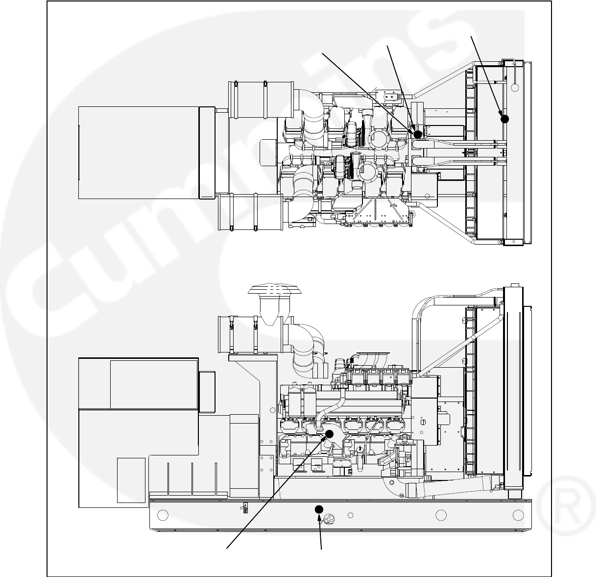
5-44
ENGINE SENSORS
Figures 5-12 shows the locations of the oil and cool-
ant temperature and oil pressure senders to which
the PCC responds. The switches function by clos-
ing the fault or warning circuit to the engine chassis
ground (battery negative [−]). The low coolant level
switch has its own ground wire.
LOW COOLANT
LEVEL SWITCH
LOW COOLANT
TEMPERATURE
SWITCH
COOLANT TEMPERATURE
SENDER
OIL TEMPERATURE
SENDER (FAR SIDE)
OIL PRESSURE
SENDER (FAR SIDE)
FIGURE 5-12. ENGINE SENSOR LOCATIONS
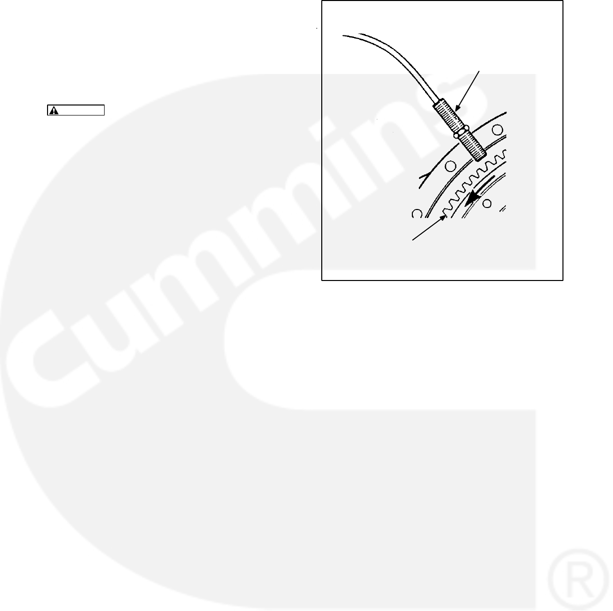
5-45
MAGNETIC SPEED PICKUP UNIT (MPU)
INSTALLATION
To install the MPU sensor, bar the engine until a
gear tooth on the flywheel lines up in the center of
the mounting hole. Thread the sensor in gently by
hand until it just touches the gear tooth. Back it out
one quarter turn and set the locknut.
CAUTION Do not use fan blade to bar over en-
gine. That can damage blades and cause prop-
erty damage and personal injury.
MPU
SENSOR
ENGINE
FLYWHEEL
RING GEAR
FIGURE 5-13. MPU SENSOR

5-46
CURRENT TRANSFORMER (CT)
INSTALLATION
Current transformers (CT’s) are required on gener-
ator sets that contain AC meters. The CT’s must be
installed as noted in the following CT Installation
Requirements. Improper installation of CT’s will
cause a “335 Reverse Power” shutdown error.
Refer to the Reconnection Diagram to identify the
output leads/phase that must be routed through
each CT, and also appropriate transformer post
selection for meter sensing leads. The transformers
are labeled CT21, CT22 and CT23 on the recon-
nection wiring diagram. (The Reconnection Dia-
gram is located on the upper side cover of the con-
trol housing.)
CT Installation Requirements
A. The CT has a dot on one side. This dot must be
facing toward the generator (conventional cur-
rent flowing into the dot). A dot is also used to
indicate pin 1 of the CT.
B. CT21 − U load leads (A phase)
CT22 − V load leads (B phase)
CT23 − W load leads (C phase)
C. Route the appropriate leads through each CT.
6 lead generator sets − generator output
leads are routed through the CT’s.
12 lead generator sets − load wires are
routed through the CT’s.
D. Reconnectable generator sets (12 leads) have
dual secondary CT’s (3 pins). The CT secon-
dary wire marked 1 is connected to pin 1 of the
CT. CT secondary wire marked 2/3 is con-
nected to pin 2 for high voltage generator sets
or to pin 3 for low voltage generator sets. (Refer
to Reconnection Diagram.)
Non-reconnectable generator sets (6 leads)
have single secondary CT’s (2 pins).
The lead from CT terminal #1 connects to
the metering circuitry.
The lead from CT terminal #2/3 connects
to ground.

5-47
DIGITAL BOARD (A32) CALIBRATION
The digital board (Figure 5-14) contains three resis-
tors that are used to calibrate the digital board for
different generator set models. One of these resis-
tors may need to be removed in order to calibrate/
initialize the PowerCommand control to the genera-
tor set model. Table 5-5 provides the necessary in-
formation to determine which resistor that may
need to be cut to select the desired generator set
model.
To find the exact genset model, spec. level and en-
gine rating, refer to the engine data tag on the left
bank intake manifold.
After the appropriate resistor selection is made, the
PowerCommand control must be re-initialized. Re-
fer to Initial Start Setup Menu in this section to initial-
ize the PowerCommand control. When the initial
setup save button is pushed, the PowerCommand
control will compare the calibration selection (cut
resistor) to the initial setup and perform one of the
following:
1. If the model numbers corresponding to the cut
resistor and the initial setup are compatible, ac-
cording to Table 5-5, the calibration is vali-
dated. The control will store the appropriate in-
formation based on calibration and initial setup
data in EEProm. The initial setup is now com-
plete and the control can start the engine.
2. If the model number corresponding to the cut
resistor and the initial setup are not compatible
the control will display the fault “INVALID SET-
UP” (fault code 401). No initial setup data is
saved and the control will not leave the initial
setup menu until this fault condition is cor-
rected.
3. If the control senses that more than one resis-
tor has been cut, the control will display the
fault “INVALID CAL” (fault code 402). No initial
setup data is saved and the control will not
leave the initial setup menu until this fault con-
dition is corrected.
TABLE 5-5. DIGITAL BOARD (A32) CALIBRATION
STANDBY MODEL
ENGINE RATING
EPROM KIT P/N RESISTOR
STANDBY MODEL
NUMBERS
ENGINE RATING
SINGLE PARALLEL
RESISTOR
REMOVED
1000DFHD-60/900DFHD-50 QST30-G4 0300-4721-04 0300-4721-16 R38
1000DFHD-60/900DFHD-50 QST30-G5-NR1 0300-4721-04 0300-4721-16 R38
900DFHC-60/800DFHC-50 SPEC A-C QST30-G3 0300-4721-35 0300-4721-40 NONE
900DFHC-60/800DFHC-50 SPEC D QST30-G3 0300-4721-35 0300-4721-40 R38
800DFHB-60/700DFHB-50 SPEC A-D QST30-G2 0300-4721-04 0300-4721-16 R36
800DFHB-60/700DFHB-50 SPEC E QST30-G2 0300-4721-35 0300-4721-40 R37
800DFHB-60/700DFHB-50 SPEC E QST30-G2-NR1 0300-4721-35 0300-4721-40 R37 & R38
750DFHA-60/620DFHA-50 SPEC A-D QST30-G1 0300-4721-04 0300-4721-16 NONE
750DFHA-60/620DFHA-50 SPEC E QST30-G1 0300-4721-35 0300-4721-40 R36
750DFHA-60/620DFHA-50 SPEC E QST30-G1-NR1 0300-4721-35 0300-4721-40 R36 & R37
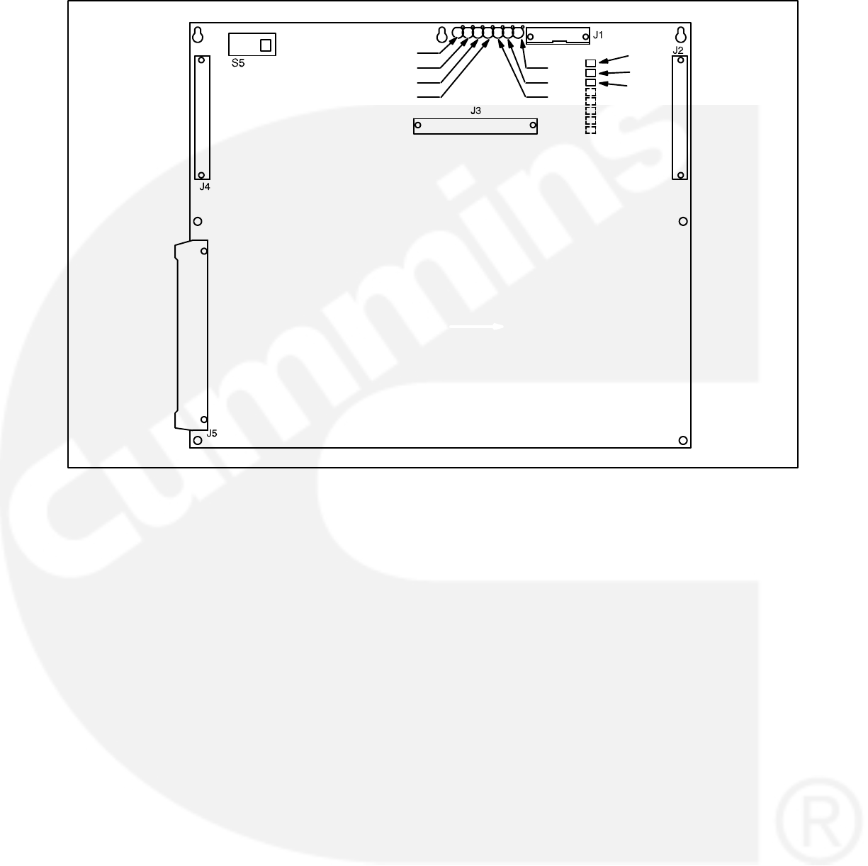
5-48
DS1
DS2
DS3
DS4
DS7
DS6
DS5
R36
R37
R38
FIGURE 5-14. DIGITAL BOARD (A32)
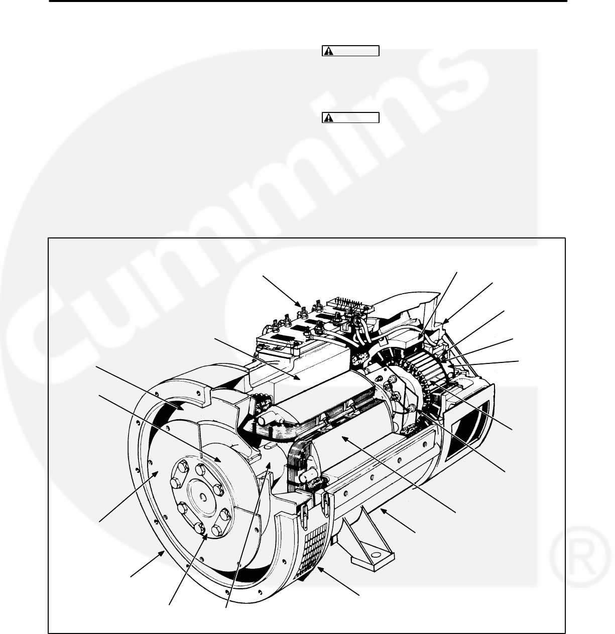
6-1
6. Servicing the Generator
GENERAL
This section describes how to isolate a high AC volt-
age fault to the PCC control circuitry or generator,
and the procedures to test, disassemble and re-
assemble the generator (Figure 6-1).
WARNING Incorrect service or replacement of
parts can result in severe personal injury or
death, and/or equipment damage. Service per-
sonnel must be trained and experienced to per-
form electrical and mechanical service.
WARNING HAZARDOUS VOLTAGE. The
PCC1301 control box must be opened only by
technically qualified personnel. Voltages of up
to 600 VAC are present in the PCC box. These
voltages can cause electrical shock, resulting
in personal injury.
RECONNECTION
TERMINALS
STATOR
BLOWER
COUPLING
DRIVE
DISCS
ROTOR
SHAFT
AIR DISCHARGE
COVERS
FRAME
ROTATING
RECTIFIER
ASSEMBLY
PMG
STATOR
EXCITER
ROTOR
END BRACKET
PMG
ROTOR
EXCITER
STATOR
END BRACKET/ENGINE
ADAPTOR
ROTOR
END
BEARING
PRESSURE
PLATE
FIGURE 6-1. TYPICAL GENERATOR

6-2
GENERATOR/PCC CONTROL ISOLATION
PROCEDURE
The following procedure is used to determine if the
generator or the PCC control circuitry is causing a
high AC voltage shutdown fault.
1. Throw the line circuit breaker OFF and shut
down the set.
CAUTION This test involves unregulated ex-
citation of the generator. To prevent damage to
the generator due to overcurrent, make sure
that all loads have been disconnected and that
all faults have been cleared from the power out-
put terminals of the generator.
2. Remove the housing cover of the accessory
box and remove plug P10 from connector J10
of the voltage regulator output module (A37).
See Figure 3-9.
3. Prepare to measure output voltage across the
generator terminals while the set is running.
4. Bring two jumpers from a 12 volt battery for
connection to the X (Field +) and XX (Field −)
pins of plug P10.
X = Red wire of P10-6
XX = Brown wire of P10-3
Connect the jumper from the positive (+) post
of the battery to the X pin (red wire) of P10-6.
Be prepared to connect the jumper from the
negative (−) post of the battery to the XX pin
(brown wire) of P10-3. If one of the 12 volt
cranking batteries is used, bring the jumpers
from the battery connected on the grounded
side of the system to avoid inadvertently im-
posing 24 volts on the system.
5. Check polarity again. Polarity must be correct
or this test will be inconclusive because the in-
duced and residual magnetic polarities in the
exciter stator will be opposed.
WARNING HAZARDOUS VOLTAGE. Touching
uninsulated high voltage parts inside the con-
trol box can result in severe personal injury or
death. Measurements and adjustments must be
done with care to avoid touching hazardous
voltage parts.
For your protection, stand on a clean dry wood-
en platform or clean rubber insulating mat,
make sure your clothing and shoes are dry, re-
move jewelry and use tools with insulated han-
dles.
6. Start the set and connect the jumper from the
battery negative (−) terminal to the XX lead.
7. The generator circuitry is probably okay if rated
output voltage or higher is obtained and the
voltages for all phases are balanced when the
exciter is powered by a 12 volt battery. Refer to
Section 4 to troubleshoot the PCC control cir-
cuitry. (Normal excitation voltage ranges from
approximately 10 VDC at no-load to approxi-
mately 40 VDC at full−load.)
8. If the voltages are unbalanced, troubleshoot
the main stator first. If the voltages are uniform-
ly low, troubleshoot the exciter and field circuits
first. Perform the Winding Resistance Test pro-
cedure for the desired windings as noted in this
section.
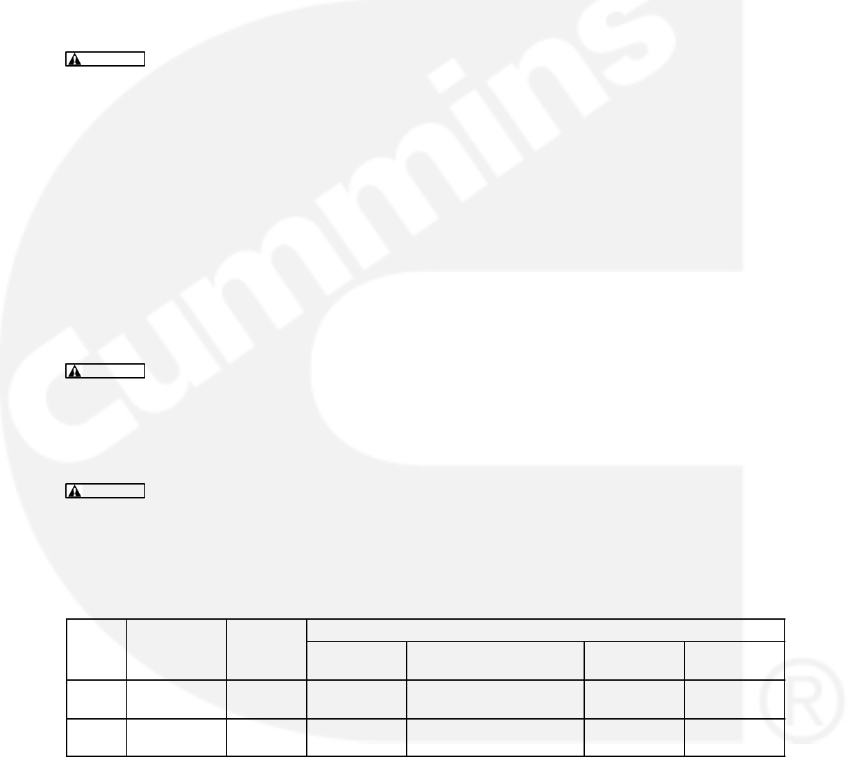
6-3
TESTING THE GENERATOR
These tests can be performed without removing the
generator. Before starting tests, disconnect the
negative (−) cable from the battery to make sure the
engine will not start while performing these tests.
WARNING Ignition of explosive battery gases
can cause severe personal injury or death. Arc-
ing at battery terminals, light switch or other
equipment, flame, pilot lights and sparks can ig-
nite battery gas. Do not smoke, or switch
trouble light ON or OFF near battery. Discharge
static electricity from body before touching bat-
teries by first touching a grounded metal sur-
face.
Ventilate battery area before working on or near
battery—Wear goggles—Stop genset and dis-
connect charger before disconnecting battery
cables—Disconnect negative (−) cable first and
reconnect last.
CAUTION Disconnect battery charger from AC
source before disconnecting battery cables.
Otherwise, disconnecting cables can result in
voltage spikes damaging to DC control circuits
of the set.
WARNING Accidental starting of the generator
set can cause severe personal injury or death.
Prevent accidental starting by disconnecting
the negative (−) cable from the battery terminal.
Insulation Resistance Testing
The insulation resistance test should be performed
before the initial start-up of the generator set or
when low insulation is suspected, e.g. damp or wet
windings.
A 500 VAC megger is recommended for insulation
testing. A test consists of applying the test potential
between the winding and ground (winding lamina-
tions).
The highest resistance values shown in Table 6-1
should be obtained for a new generator with dry
windings. For a set that has been in service, the re-
sistance reading should not be less than the lower
value shown.
If low readings are obtained, the cause should be in-
vestigated and corrected before the generator set is
returned to service.
If moisture is determined to be the cause of low test
readings, a winding drying process will be required.
1. Disconnect plug J10 from the voltage regulator
output stage module.
2. Disconnect the AC control input leads from the
generator output terminals. The AC control
leads are marked 5, 6, 7 and 8. Refer to the ap-
propriate Reconnection Diagram in Section 8.
3. If the RTD (resistive thermal device) option is
installed, ground all six RTD temperature
leads. Each RTD has three leads, one red and
two white leads. Total of 18 leads must be
grounded.
4. Perform the Insulation Resistance Test proce-
dure for the desired windings as noted in this
section.
TABLE 6-1. GENERATOR INSULATION RESISTANCE
FRAME
GENERATOR
MEGGER MINIMUM RESISTANCE (MEG)
FRAME
SIZE
GENERATOR
VOLTAGE
MEGGER
VDC
SETTING
MAIN
STATOR MAIN ROTOR PMG EXCITER
STATOR
P7 600 VAC or
less
500 10.0 − 1.0 10.0 − 1.0 10.0 − 1.0 10.0 − 1.0
HC6 600 VAC or
less
500 5.0 − 1.0 5.0 − 1.0 5.0 − 1.0 5.0 − 1.0

6-4
Drying the Windings
If low readings are obtained and moisture is deter-
mined to be the problem, the windings should be
dried out and the test repeated. Use the generator
heaters or blow warm air through the generator with
a fan. A more effective way is to use a bolted
3-phase short across the generator terminals. This
procedure must be done as described or equipment
damage can result. To do this:
1. Bolt the generator three phase output termi-
nals together. See the reconnection diagrams
in Section 8.
2. Remove the housing cover of the accessory
box and remove plug P10 from connector J10
of the voltage regulator output module (A37).
See Figure 3-11.
3. Connect the positive and negative leads of a
variable 12 VDC source to P10 as follows:
Positive lead − Red wire of P10-6 (X)
Negative lead − Brown wire of P10-3 (XX)
CAUTION Voltage must begin at zero
volts and be gradually increased or equip-
ment damage will result. The current will in-
crease rapidly and it must be monitored to
prevent exceeding the generator rating.
4. Attach a clamp-on ammeter to the generator
leads to measure generator current, adjust the
12 VDC source for zero voltage, start the set
and very slowly increase the excitation voltage.
Obtain the highest current possible without ex-
ceeding generator rating.
5. Run the genset for approximately one hour,
then repeat the insulation resistance tests. If
further drying time is indicated, continue the
drying process.
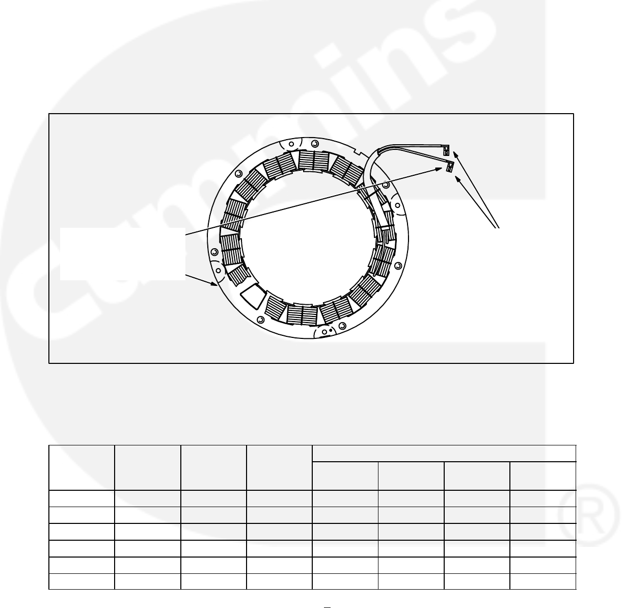
6-5
EXCITER STATOR
Testing Winding Resistance: Measure winding
resistance with a Wheatstone bridge or digital ohm-
meter. Replace the stator if winding resistance is
not as specified by Table 6-2.
Before performing the following insulation resist-
ance test, refer to the Insulation Resistance Test pro-
cedure at the beginning of this section.
Testing Winding Insulation Resistance: Discon-
nect exciter stator leads F1 and F2 from their con-
nectors in the AC generator wiring harness and iso-
late them from ground.
Connect the megger between one of the leads and
ground and conduct the test as instructed under In-
sulation Resistance testing.
MEASURE WINDING
INSULATION RESISTANCE
BETWEEN EITHER LEAD
AND THE STATOR
LAMINATIONS
MEASURE WINDING RESISTANCE
BETWEEN THE TWO STATOR
LEADS, F1 (X) AND F2 (XX)
FIGURE 6-2. TESTING THE EXCITER STATOR
TABLE 6-2. WINDING RESISTANCE VALUES*
FRAME
EXCITER
EXCITER
MAIN
MAIN STATOR
FRAME
SIZE
EXCITER
STATOR
EXCITER
ROTOR
MAIN
ROTOR WINDING
11
WINDING
12
WINDING
17
WINDING
07
P7B 17.5 0.048 1.67 N/A 0.0016 N/A 0.0026
P7C 17.5 0.048 1.85 N/A 0.00126 N/A 0.002
6G 17 0.158 1.44 0.0037 0.0148 N/A 0.011
6H 17 0.158 1.54 0.0027 0.0108 N/A 0.0072
6J 17 0.158 1.73 0.0024 0.0096 N/A 0.006
6K 17 0.158 1.95 0.0019 0.0076 N/A 0.0052
* Resistance figures are approximates, at 68 F (20C) + 10%.
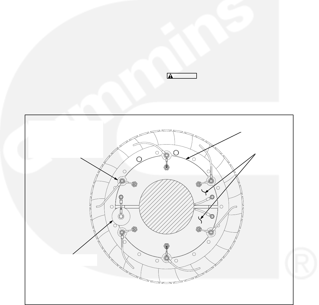
6-6
EXCITER RECTIFIER BRIDGE (ROTATING
RECTIFIER ASSEMBLY)
The exciter rectifier bridge is mounted on the exciter
rotor, inboard, facing the main rotor. It consists of a
positive plate and a negative plate, split diametrical-
ly. Each carries three diodes, three terminal posts
for connecting exciter rotor leads to the diode pig-
tails and a terminal for the main rotor (generator
field) lead. A surge suppresser is connected across
the two plates to prevent transient voltages that
could damage the diodes.
Testing Diodes: Disconnect the diode pigtails from
the terminal posts. Using an ohmmeter, measure
electrical resistance between each diode pigtail and
the plate on which the diode is mounted. Reverse
the meter test probes and repeat the tests. The
electrical resistance across each diode should be
high in one direction and low in the other. If the re-
sistance is high or low in both directions, replace the
diode.
Replacing Diodes: Make sure the replacement
diode is of the correct polarity. Disconnect the pigtail
from the terminal post and unscrew the old diode.
Apply heat-sink compound under the head of the
diode. Make sure the compound does not get on the
threads. Torque the diodes to 36 to 42 in-lbs (4 to 4.8
Nm) and the pigtail terminals to 24 in-lbs (2.7 Nm)
when reassembling.
Surge Suppresser Testing and Replacement:
Remove the suppresser. Replace the suppresser if
it appears to have overheated or if ohmmeter read-
ings indicate less than infinite resistance (end of
scale) in both directions. Torque the terminals to 24
in-lbs (2.7 Nm) when reassembling.
CAUTION Layers of dust can cause diodes to
overheat and fail. Brush dust off regularly.
TERMINAL
(ONE OF SIX)
DIODE (ONE OF SIX)
DISCONNECT THE DIODE
PIGTAIL FROM THE TERMINAL
AND MEASURE ELECTRICAL
RESISTANCE BETWEEN THE
PIGTAIL AND THE METAL
PLATE UNDER THE DIODE
SURGE SUPPRESSER
REMOVE TO TEST
DIODE PLATES
(TWO)
FIGURE 6-3. TESTING THE ROTATING RECTIFIER ASSEMBLY
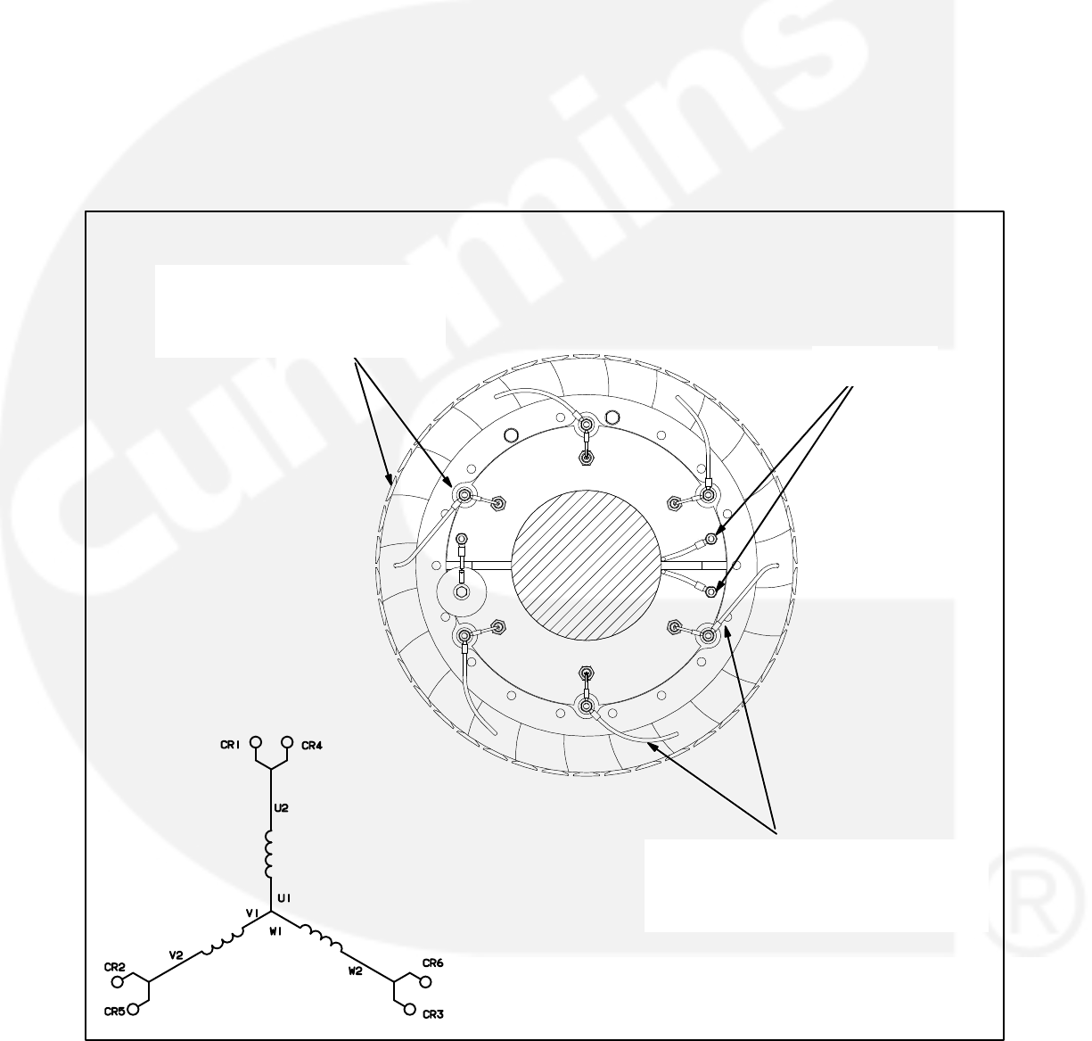
6-7
EXCITER ROTOR
Testing Winding Resistance: Disconnect the six
rotor winding leads from the terminal posts on the
rectifier assembly. With a Wheatstone bridge, mea-
sure electrical resistance across each pair of rotor
windings: U (CR1 or CR4) and V (CR2 or CR5), V
(CR2 or CR5) and W (CR3 or CR6), W (CR3 or
CR6) and U (CR1 or CR4). See the winding sche-
matic. Replace the whole rotor shaft assembly if the
resistance of any winding is not as specified in Table
6-2.
Before performing the following insulation resist-
ance test, refer to the Insulation Resistance Test pro-
cedure at the beginning of this section.
Testing Winding Insulation Resistance: Discon-
nect all six exciter rotor leads from diode terminals
CR1 through CR6 and isolate them from ground.
Connect the megger between one of the leads and
ground and conduct the test as instructed under In-
sulation Resistance testing.
WINDING SCHEMATIC
MEASURE WINDING INSULATION
RESISTANCE BETWEEN ANY LEAD
OR THE TERMINAL TO WHICH IT IS
CONNECTED AND THE ROTOR
LAMINATIONS
DISCONNECT THE SIX ROTOR WINDING
LEADS FROM THEIR TERMINALS AND
MEASURE ELECTRICAL RESISTANCE
ACROSS EACH PAIR OF WINDINGS: U-V,
V-W, W-U
MAIN ROTOR
LEADS
FIGURE 6-4. TESTING THE EXCITER ROTOR
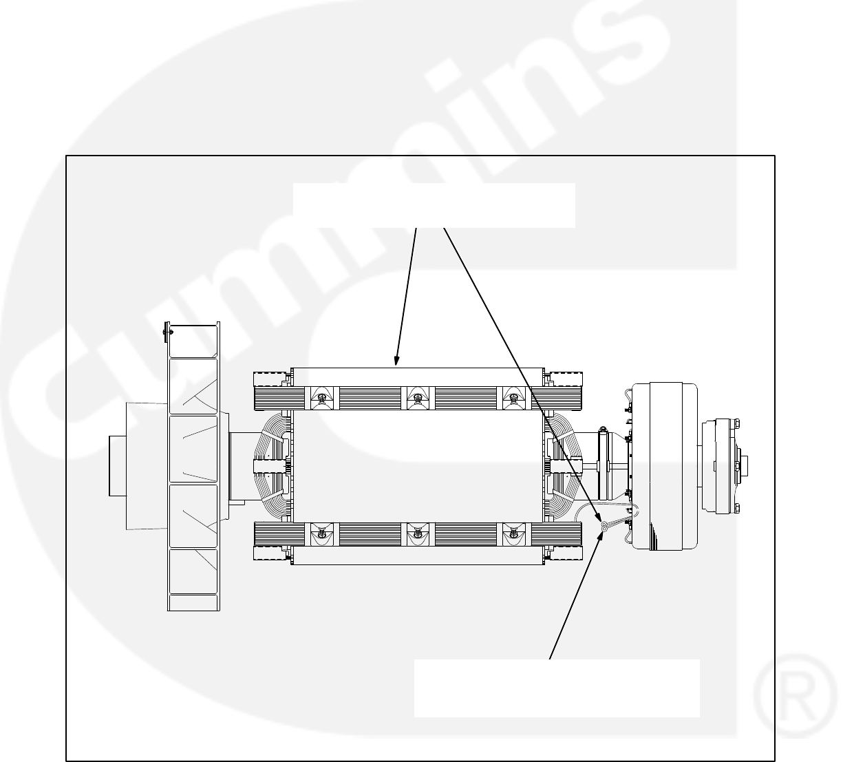
6-8
MAIN ROTOR (GENERATOR FIELD)
Testing Winding Resistance: Disconnect the two
leads of the main rotor from the terminals on the ro-
tating rectifier assembly. See Figure 6-5. Measure
electrical resistance between the two leads with a
Wheatstone bridge or digital ohmmeter. Replace
the rotor if the resistance is not as specified in Table
6-2. Connect the rotor leads and torque the termi-
nals to 23 in-lbs (3.3 Nm) when reassembling.
Before performing the following insulation resist-
ance test, refer to the Insulation Resistance Test pro-
cedure at the beginning of this section.
Insulation Resistance and PI Test: Disconnect
the main rotor and voltage suppressor leads from
terminals F1+ and F2− on the rotating rectifier as-
semblies and isolate them from ground. Tag and
mark each lead with its terminal number (F1+ or
F2−).
Connect the megger between one of the rotor leads
and ground and conduct the test as instructed un-
der Insulation Resistance testing.
DISCONNECT THE MAIN ROTOR LEADS
FROM THE ROTATING RECTIFIER ASSEMBLY
AND MEASURE THE WINDING RESISTANCE
BETWEEN THEM
MEASURE WINDING INSULATION
RESISTANCE BETWEEN EITHER ROTOR
LEAD AND THE ROTOR LAMINATIONS
FIGURE 6-5. TESTING THE MAIN ROTOR
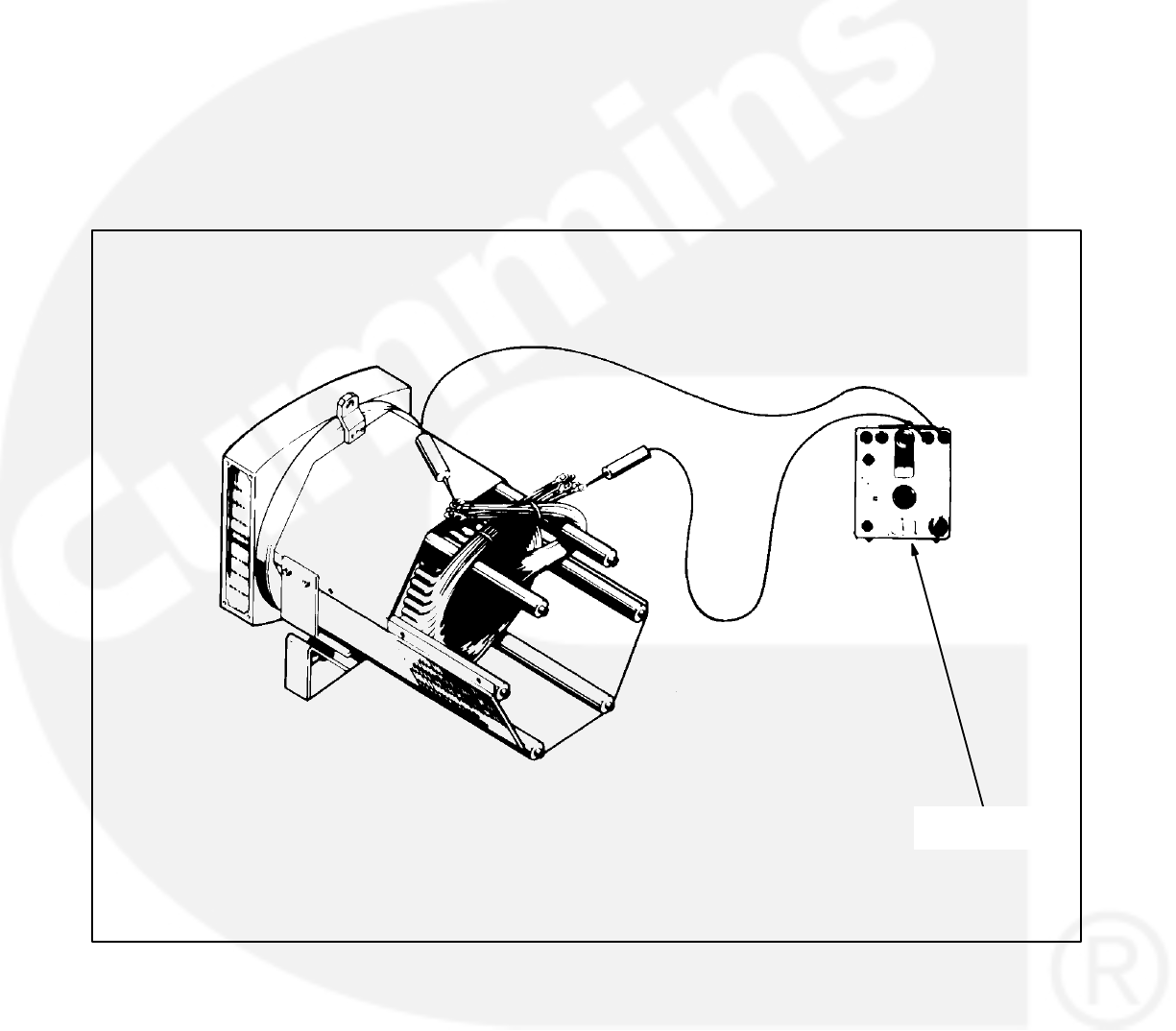
6-9
MAIN STATOR
Testing Main Stator Winding Resistance: Dis-
connect all stator leads from the terminals to which
they are connected. Using a Wheatstone bridge
having at least 0.001 ohm precision, measure elec-
trical resistance across each pair of stator leads:
U1-U2, V1-V2, W1-W2, U5-U6, V5-V6 and W5-W6.
Replace the stator if the resistance of any winding is
not as specified in Table 6-2.
Before performing the following insulation resist-
ance test, refer to the Insulation Resistance Test pro-
cedure at the beginning of this section.
Insulation Resistance and PI Test: Remove and
separate all leads of the generator from the genera-
tor load terminal block. Number of neutral leads
(three or six) to remove will vary between low and
medium voltage generators.
Connect the megger between one phase of the sta-
tor and ground while grounding the other two
phases and conduct the test as instructed under In-
sulation Resistance testing.
Repeat this step in turn for the other two phases.
WHEATSTONE
BRIDGE
FIGURE 6-6. TESTING THE GENERATOR STATOR

6-10
TESTING THE PMG
WARNING HAZARDOUS VOLTAGE. Touching
uninsulated high voltage parts inside the con-
trol box can result in severe personal injury or
death. Measurements and adjustments must be
done with care to avoid touching hazardous
voltage parts.
For your protection, stand on a clean dry wood-
en platform or clean rubber insulating mat,
make sure your clothing and shoes are dry, re-
move jewelry and use tools with insulated han-
dles.
1. Disconnect plug J10 from the voltage regulator
output stage module.
2. Start the engine at the set and let the speed sta-
bilize.
3. Measure voltage across lead pairs J10-1 &
J10-4, J10-4 & J10-5, and J10-5 & J10-1. Volt-
age should be at least 150 VAC for 50 Hz sets
and at least 180 VAC for 60 Hz sets, and should
be approximately the same for each set of
leads. If the voltages are low or uneven, check
all the leads and connections between the volt-
age regulator output stage module and the
PMG and repair as necessary before disas-
sembling the PMG.
4. Stop the set and measure electrical resistance
across lead pairs J10-1 & J10-4, J10-4 &
J10-5, and J10-5 & J10-1 with a Wheatstone
bridge or digital ohmmeter. The resistance
should be 2.6 10% ohms for frame size P7
and HC6.

6-11
BEARING
INSPECTION/REMOVAL/REPLACEMENT
The end bearing is enclosed in a pre-packed ma-
chined cartridge.
Bearing Inspection: If a situation occurs which al-
lows an opportunity to visually inspect the end bear-
ing with it installed, check the color of the grease.
The color of the grease is the only indication that
can be used to determine if the bearing is defective.
New grease is a whitish-beige color but some mild
discoloration will occur with use. If the grease
shows signs of gross discoloration, the bearing
should be replaced.
Bearing Removal: The bearing is press fitted onto
the shaft and can be removed with standard work-
shop tools (i.e., two or three legged manual or hy-
draulic bearing pullers). The bearing should only be
removed for replacement (bearing is destroyed dur-
ing removal and must be replaced).
The end bearing is enclosed in a pre-packed car-
tridge housing and must only be dismantled as nec-
essary for relubrication, replacement, or when a
major overhaul is carried out on the generator set.
P7 Bearing Removal
1. Remove the endbracket (complete steps 1
through 16 of the Main Stator and Rotor Re-
moval (P7) procedure.
2. Remove the four screws holding bearing cap.
3. Remove cap.
4. Remove circlip.
5. Remove bearing cartridge housing complete
with bearing.
P7 Bearing Replacement
The instruction sheet provided with the bearing kit is
required to complete the following procedure.
P7 generator component parts cannot be ordered
from Cummins. Refer to the Newage nameplate
and supply all available information. Contact your
nearest Newage distributor for assistance in order-
ing component parts.
1. Lift slightly on end of rotor shaft and install
wooden shims to hold rotor on center with sta-
tor.
2. Install bearing onto rotor shaft. Refer to bearing
kit instruction sheet.
3. Install two threaded studs into end bearing car-
tridge to aid subsequent procedures. Position
the end bearing cartridge assembly close to
proper position for hole alignment with end-
bracket.
4. Install endbracket to the stator frame using the
proper screws and lock washers, but do not
tighten securely as yet.
5. Insert and start the threads of the bearing car-
tridge fasteners, and remove threaded align-
ment studs, through the endbracket into the
cartridge housing.
6. Lift slightly on endbracket and remove wooden
shims holding rotor on center with stator.
7. Securely tighten the endbracket fasteners.
8. Tighten the bearing cartridge fasteners to 4.5
ft-lbs. (6 Nm) torque.
9. Install the PMG assembly. Refer to Permanent
Magnet (PMG) Installation procedure.
P7 Bearing Lubrication
A grease fitting is provided to allow re-greasing of
the bearing with a grease gun (see Operator’s
manual for grease quantities/type, maintenance in-
tervals, and procedure).

6-12
HC6 Bearing Removal
1. Remove the endbracket (complete steps 1
through 16 of the Main Stator and Rotor Re-
moval (P7) procedure.
2. Remove the four screws holding bearing cap
3. Remove cap.
4. Remove circlip.
5. Remove bearing cartridge housing complete
with bearing.
HC6 Bearing Replacement
When replacing bearing onto rotor shaft, be sure to
apply pressing force to the inner face of the bearing
only.
HC6 Bearing Lubrication
Bearing Lubrication: When re-lubricating or re-
placing the bearing, review the following.
Recommended Lubricant: Lithium based
grease, Mobilux No. 2 or Shell Alvania R3.
Temperature Range: -22F to +248F (-30C to
+120C).
Quantity: 2.74 oz. (81 ml). The grease should
be equally divided between the bearing, the
bearing cap cavity, and the bearing cartridge
cavity.

6-13
GENERATOR DISASSEMBLY
The following procedures provide information for
removal and reassembly of the generator PMG ex-
citer, control housing, and stator/rotor assemblies.
Be sure to read through this section first, before per-
forming procedures listed, to determine the steps
most appropriate for the service attention required.
Two types of generators (P7 or HC6) are used with
these generator set models. The major difference
between these two generators is the lifting eye loca-
tions on the generator and the type of control hous-
ing. The control housing for the HC6 generator is
shown in Figure 6-7 and the control housing for the
P7 generator is shown in Figure 6-8. In the following
procedures, if the step only applies to a particular
control housing or generator, it will be noted at the
beginning of the step (e.g., HC6 control housing, P7
generator, etc.)
Permanent Magnet (PMG) Removal
WARNING Ignition of explosive battery gases
can cause severe personal injury or death. Arc-
ing at battery terminals, light switch or other
equipment, flame, pilot lights and sparks can ig-
nite battery gas. Do not smoke, or switch
trouble light ON or OFF near battery. Discharge
static electricity from body before touching bat-
teries by first touching a grounded metal sur-
face.
Ventilate battery area before working on or near
battery—Wear goggles—Stop genset and dis-
connect charger before disconnecting battery
cables—Disconnect negative (−) cable first and
reconnect last.
CAUTION Disconnect battery charger from AC
source before disconnecting battery cables.
Otherwise, disconnecting cables can result in
voltage spikes damaging to DC control circuits
of the set.
WARNING Accidental starting of the generator
set can cause severe personal injury or death.
Prevent accidental starting by disconnecting
the negative (−) cable from the battery terminal.
1. Disconnect the negative (-) battery cable to
prevent accidental starting of the generator set
while servicing.
2. HC6 Control Housing: Remove the control
housing grille and access covers (see Figure
6-7).
3. Remove the three M5X12mm capscrews and
lockwashers from the PMG cover, and remove
cover.
4. Disconnect the PMG wiring harness connector.
5. Remove the four bolts and clamps retaining the
exciter stator housing to the endbracket.
6. Tap the stator housing out of its spigot, and
carefully remove from generator endbracket.
The highly magnetic rotor will attract the stator
core; care must be taken to avoid any contact
which may damage the windings.
7. Remove the hex head through-bolt from the ro-
tor shaft and firmly pull the complete rotor as-
sembly from its location. Keep the rotor clean
by avoiding contact with metal dust or particles.
CAUTION The rotor assembly must not be
dismantled, or the magnetic properties will
be destroyed.
Permanent Magnet (PMG) Installation
1. Install the complete rotor assembly to the end
of the main rotor shaft using the hex head
through-bolt. Keep the rotor clean by avoiding
contact with metal dust or particles.
2. Carefully locate the stator housing to position
on the generator endbracket. Fasten in place
using the 4 bolts and clamps, and tighten se-
curely.
The highly magnetic rotor will attract the stator
core, care must be taken to avoid any contact
which may damage the windings.
3. Connect the PMG wiring harness connector.
4. Install the PMG assembly cover using the three
M5x12mm capscrews and lockwashers, and
tighten securely.
5. HC6 Control Housing: Install the control hous-
ing grille and access covers (see Figure 6-7).
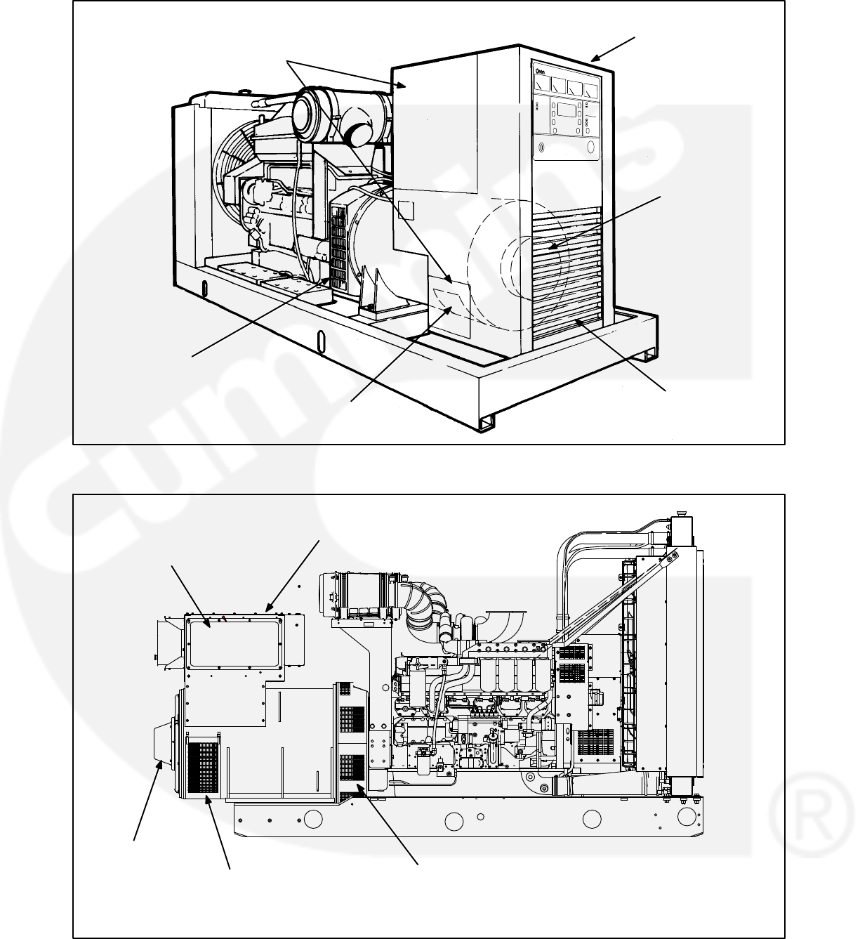
6-14
CONTROL HOUSING
ACCESS COVERS
(BOTH SIDES)
GENERATOR
AIR DISCHARGE
COVERS
CONTROL HOUSING
PMG ASSEMBLY
CONTROL HOUSING
GRILLE
GENERATOR AIR INLET
COVER (ROTATING
RECTIFIER ACCESS)
FIGURE 6-7. HC6 GENERATOR AND CONTROL HOUSING ASSEMBLY
CONTROL HOUSING
ACCESS COVERS
(BOTH SIDES)
GENERATOR
AIR DISCHARGE
COVERS
CONTROL HOUSING
PMG
ASSEMBLY
GENERATOR AIR INLET
COVER (ROTATING
RECTIFIER ACCESS)
FIGURE 6-8. P7 GENERATOR AND CONTROL HOUSING ASSEMBLY
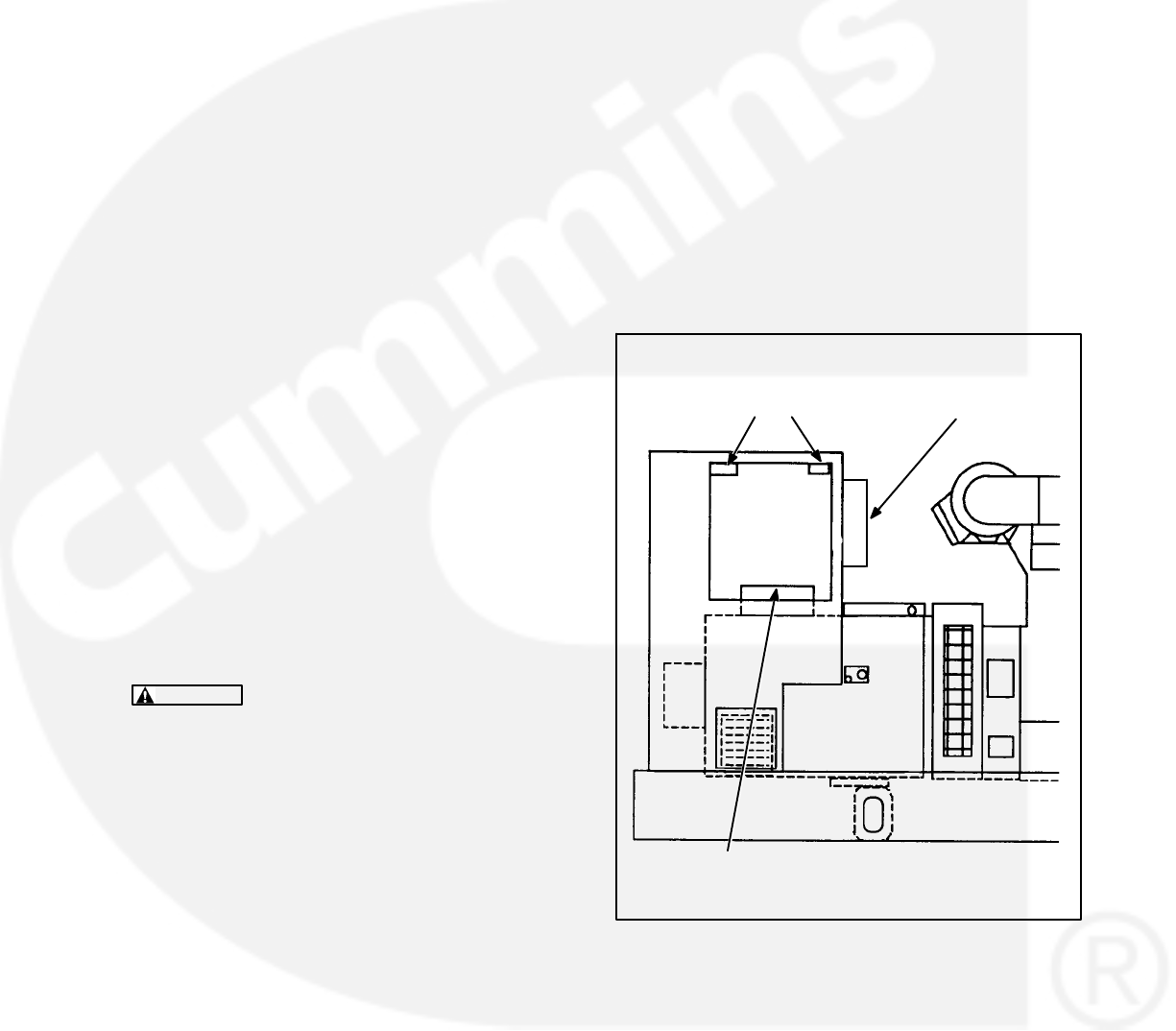
6-15
Main Stator and Rotor Removal
1. Remove the PMG, refer to Permanent Magnet
PMG Removal, earlier this section.
2. Remove the air inlet and discharge panels and
access covers from control housing and gener-
ator (see Figure 6-7 or 6-8).
3. Disconnect all load wires from the reconnec-
tion terminal block assembly. If equipped with
the circuit breaker option, disconnect load
wires from circuit breaker. Check that all leads
are labeled to ease reassembly.
4. Disconnect the remote control wiring and con-
duit from the accessory box. For reconnections
later, make sure each wire is clearly marked to
indicate the correct terminal.
5. Disconnect the engine harness connectors
and remove harness assembly from the control
housing:
P4 and P5 from the back side of the control
panel box.
PMG2 through PMG4, F1 and F2 genera-
tor leads located inside the control hous-
ing assembly.
P6 (Governor Output Module), P7 and
P10 (Voltage Regulator OUtput Module)
and J12 (from P12 of the rail assembly), lo-
cated inside the accessory box.
6. Use a hoist or similar lifting device to support
the control housing assembly (see Figure 6-9).
WARNING To prevent personal injury, use
adequate lifting devices to support heavy
components. Keep hands and feet clear
while lifting.
7. HC6 Control Housing Removal:
a. Loosen the fasteners that secure the con-
trol housing side and bottom panels to
generator. Make sure that hoisting device
is controlling weight of control housing as-
sembly.
b. Remove control housing fasteners, and
remove the control housing assembly
from the generator. Replace panel fasten-
ers to their respectable positions for safe
keeping, and tighten finger-tight.
c. Remove control housing mounting brack-
ets from both sides of generator, and as-
semble lifting eyes to generator.
8. P7 Control Housing Removal:
a. Loosen the fasteners that secure the con-
trol housing side panels to generator.
Make sure that hoisting device is control-
ling weight of control housing assembly.
b. Remove control housing fasteners, and
remove the control housing assembly
from the generator. Replace panel fasten-
ers to their respectable positions for safe
keeping, and tighten finger-tight.
PLACE SLING STRAPS
THROUGH HOUSING
(P7 OR HC6 HOUSING)
RECONNECTION
TERMINALS
ACCESSORY
BOX
FIGURE 6-9. REMOVING CONTROL HOUSING
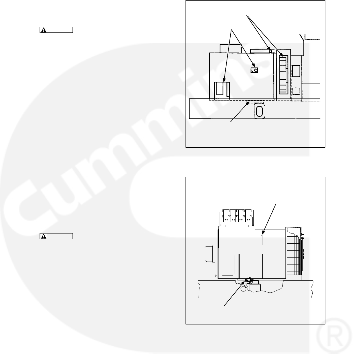
6-16
9. Remove as necessary, air intake components
to engine that may interfere with disassembly
and reassembly of generator.
CAUTION Do not use fan blade to bar over
engine. That can damage blades and cause
property damage and personal injury.
10. Crank or bar the engine/generator to position
the rotor such that a full pole face is at the bot-
tom of the main stator core. Proper positioning
can be viewed through the generator access
openings. Refer to engine service manual for
proper cranking or barring procedure.
To remove the stator and rotor at the same time, refer
to step 28. To remove the stator and rotor individual-
ly, continue with step 11.
11. Remove the four bolts retaining the bearing
cartridge housing in the endbracket (outer four
bolts).
12. Remove the eight bolts holding the endbracket
to the generator housing.
13. Insert two bolts (M10) in the two holes provided
for “jacking” purposes, on the endbracket cen-
ter line. Screw bolts in until endbracket spigot
is clear of locating recess.
14. Carefully tap the whole assembly off the bear-
ing cartridge housing, ensuring the endbracket
is supported to prevent the exciter stator from
damaging the windings on the exciter rotor.
WARNING To prevent personal injury, use
adequate lifting devices to support heavy
components. Keep hands and feet clear
while lifting.
15. The exciter stator is now accessible for inspec-
tion and removal from endbracket/engine
adaptor.
16. The end bearing can now be removed if re-
quired. Refer to Bearing Inspection/Removal/
Replacement in this section.
17. Remove the fasteners from the two generator
mounting feet brackets.
18. Attach cables of lifting device to generator lift-
ing points (Figures 6-10 or 6-11).
GENERATOR
LIFTING
POSITIONS
MOUNTING FEET
BRACKETS
FIGURE 6-10. HC6 GENERATOR LIFTING
POSITIONS
GENERATOR
LIFTING EYE
LOCATION
MOUNTING FEET
BRACKET
FIGURE 6-11. P7 LIFTING POSITION
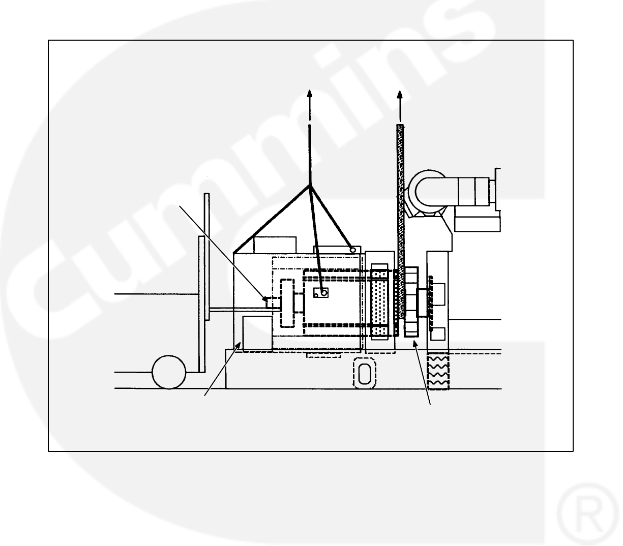
6-17
19. Using an adequate lifting device, lift the gener-
ator (at lifting eyes provided, and main stator
housing) until the mounting feet brackets are
clear of the frame member (see Figure 6-12 or
6-13).
20. Disconnect the grounding strap from the fly-
wheel housing.
21. Using a forklift, position a lifting bar of the forklift
(inside and inline with the generator) under the
rotor shaft. Lift the rotor shaft slightly so that ro-
tor is not resting on inside of stator assembly.
See Figure 6-12 or 6-13.
STATOR
ASSEMBLY
LIFT
ROTOR
ASSEMBLY
LIFT
STATOR
ASSEMBLY ROTOR
ASSEMBLY
USE FORKLIFT OR
OTHER ADEQUATE
LIFTING DEVICE TO
SLIGHTLY LIFT ROTOR
SHAFT UNTIL ROTOR
CAN BE SUPPORTED
BY HOIST/SLING.
FIGURE 6-12. REMOVING HC6 STATOR ASSEMBLY
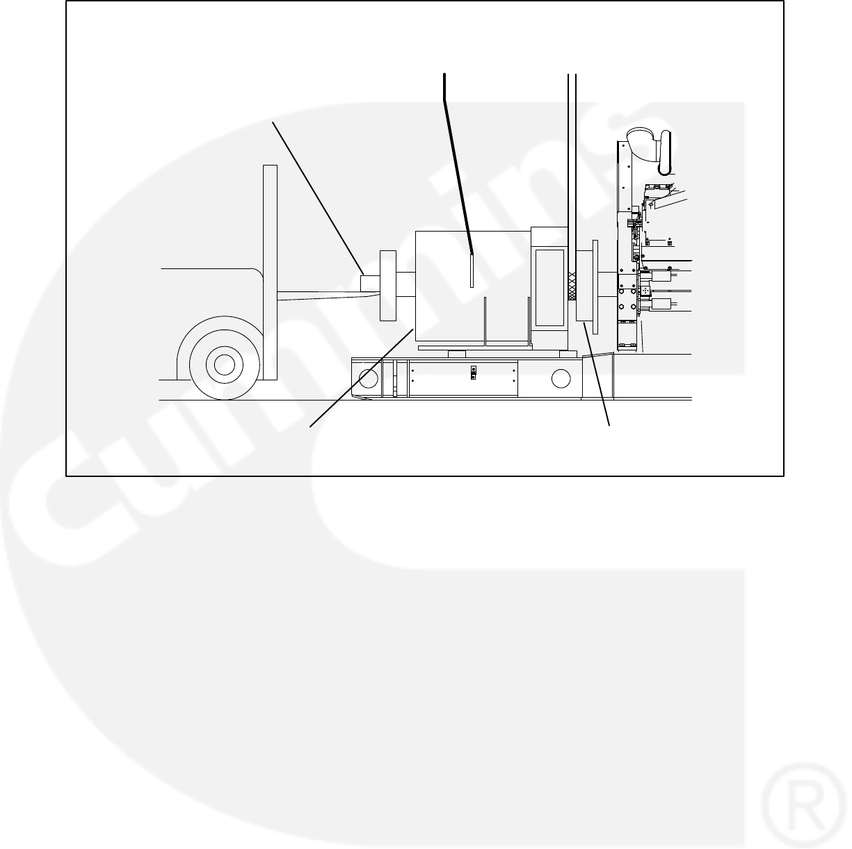
6-18
STATOR
ASSEMBLY
LIFT
ROTOR
ASSEMBLY
LIFT
STATOR
ASSEMBLY
ROTOR
ASSEMBLY
USE FORKLIFT OR
OTHER ADEQUATE
LIFTING DEVICE TO
SLIGHTLY LIFT ROTOR
SHAFT UNTIL ROTOR
CAN BE SUPPORTED
BY HOIST/SLING.
FIGURE 6-13. REMOVING P7 STATOR ASSEMBLY

6-19
22. Verify that the stator is adequately supported
and then carefully remove the capscrews from
the stator attachment ring.
WARNING To prevent personal injury, use
adequate lifting devices to support heavy
components. Keep hands and feet clear
while lifting.
CAUTION Improper stator assembly rig-
ging and handling can result in damage to
stator and rotor assemblies. Lifting eyes
may not be at center-of-gravity position of
stator assembly. Therefore, lifting and mov-
ing the stator assembly alone, by hoisting
at lifting eyes only, presents the hazard of
load imbalance; allowing one end to drop
and other end to rise. Make sure the stator
is adequately hooked/strapped to maintain
level control of stator assembly while lifting
and moving.
23. Being careful not to drag the windings on the
rotor, move the stator assembly sufficiently
away from engine to sling and support the rotor
assembly. Do not allow rotor assembly to hang
on engine flywheel.
CAUTION Drive disc damage can be
caused by allowing the rotor assembly to
hang on flywheel. Use adequate hoist and
sling to support the rotor assembly.
24. Reposition or add hoist and sling support for
the main rotor, and remove the forklift. See Fig-
ure 6-14, Rotor Lift detail.
WARNING To prevent personal injury, use
adequate lifting devices to support heavy
components. Keep hands and feet clear
while lifting.
25. Remove the stator assembly, being careful not
to drag the windings on the rotor. Place stator
assembly away from the chassis in the horizon-
tal position.
26. Using the hoist and sling to support the rotor,
carefully remove the capscrews and flat wash-
ers that secure the drive discs to the engine fly-
wheel.
WARNING To prevent personal injury, use
adequate lifting devices to support heavy
components. Keep hands and feet clear
while lifting.
27. Remove the rotor assembly and place it on
wood blocks in the horizontal position. To avoid
possible distortion, do not allow the drive discs
and fan to rest on anything.
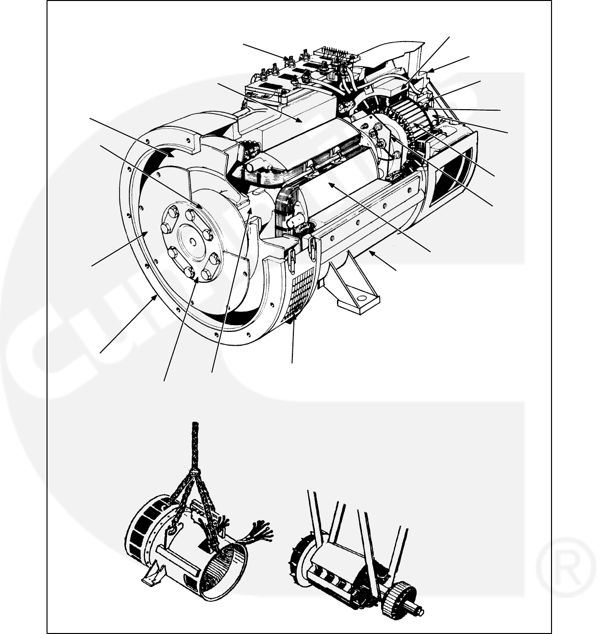
6-20
ROTOR LIFT
(EXAMPLE)
STATOR LIFT
(EXAMPLE)
RECONNECTION
TERMINALS
STATOR
BLOWER
COUPLING
DRIVE
DISCS
ROTOR
SHAFT
AIR DISCHARGE
COVERS
FRAME
ROTATING
RECTIFIER
ASSEMBLY
PMG
STATOR
EXCITER
ROTOR
ENDBRACKET
PMG
ROTOR
EXCITER
STATOR
ENDBRACKET/ENGINE
ADAPTOR
ROTOR
END
BEARING
PRESSURE
PLATE
FIGURE 6-14. TYPICAL GENERATOR ASSEMBLY

6-21
Generator Assembly Removal
28. Remove the fasteners from the two generator
mounting feet brackets.
29. Attach cables of lifting device to generator lift-
ing points (Figures 6-10 or 6-11).
30. Using an adequate lifting device, lift the gener-
ator (at lifting eyes provided, and main stator
housing) until the mounting feet brackets are
clear of the frame member.
31. Disconnect the grounding strap from the fly-
wheel housing.
32. Carefully remove the capscrews and flat wash-
ers that secure the drive discs to the engine fly-
wheel.
33. Verify that the generator assembly is ade-
quately supported. Carefully remove the caps-
crews securing the engine adaptor endbracket
to the engine flywheel housing.
WARNING To prevent personal injury, use
adequate lifting devices to support heavy
components. Keep hands and feet clear
while lifting.
CAUTION Improper generator assembly
rigging and handling can result in damage
to stator and rotor assemblies. Lifting eyes
may not be at center-of-gravity position of
stator assembly. Therefore, lifting and mov-
ing the generator by hoisting at lifting eyes
only, presents the hazard of load imbal-
ance; allowing one end to drop and other
end to rise. Make sure the generator is ade-
quately hooked/strapped to maintain level
control of assembly while lifting and mov-
ing.
34. Remove the generator assembly away from
engine. Place generator assembly on floor with
a piece of wood beneath the stator housing (to-
ward PMG end) to allow for endbracket remov-
al, if desired.

6-22
GENERATOR REASSEMBLY
Generator reassembly is the reverse of disassem-
bly procedure.
To assemble the stator and rotor at the same time,
continue with step 1. To assemble the stator and ro-
tor individually, skip to step 16.
1. Using an adequate lifting device, locate the
generator assembly into position near the en-
gine flywheel housing. Align the holes of the ro-
tor drive discs with the holes of the engine fly-
wheel. Install the capscrews and flat washers
that secure the drive discs to the engine fly-
wheel, hand tighten.
WARNING To prevent personal injury, use
adequate lifting devices to support heavy
components. Keep hands and feet clear
while lifting.
CAUTION Improper generator assembly
rigging and handling can result in damage
to stator and rotor assemblies. Lifting eyes
may not be at center-of-gravity position of
stator assembly. Therefore, lifting and mov-
ing the generator by hoisting at lifting eyes
only, presents the hazard of load imbal-
ance; allowing one end to drop and other
end to rise. Make sure the generator is ade-
quately hooked/strapped to maintain level
control of assembly while lifting and mov-
ing.
2. Align the holes of the engine adaptor endbrack-
et with the holes in the flywheel housing and
install the capscrews and lock washers. Tight-
en fasteners to 95−105 ft-lbs. (129−142 Nm).
3. Secure the rotor assembly to the flywheel.
Tighten fasteners to 150−180 ft-lbs.
(204−245Nm).
4. Connect the grounding strap to the flywheel
housing using a capscrew and EIT locking
washer; and tighten securely.
5. Install the mounting feet bracket fasteners; and
tighten securely.
If endbracket has been removed, continue with
step 6, otherwise skip to step 15.
6. Lift slightly on end of rotor shaft and install
wooden shims to hold rotor on center with sta-
tor.
7. If removed, install end bearing. Refer to Bear-
ing Inspection/Removal/Replacement proce-
dure in this section.
8. Install two threaded studs into end bearing car-
tridge to aid subsequent procedures. Position
the end bearing cartridge assembly close to
proper position for hole alignment with end-
bracket.
9. Assemble exciter stator, if removed, to inside of
endbracket. Tighten fasteners to 4.5 ft-lbs. (6
Nm) torque.
10. Install endbracket to the stator frame using the
proper capscrews and lock washers, but do not
tighten securely as yet.
11. Insert and start the threads of the bearing car-
tridge fasteners, and remove threaded align-
ment studs, through the endbracket into the
cartridge housing.
12. Lift slightly on endbracket and remove wooden
shims holding rotor on center with stator.
13. Securely tighten the endbracket fasteners.
14. Tighten the bearing cartridge fasteners to 4.5
ft-lbs. (6 Nm) torque.

6-23
15. Install the PMG assembly, if removed. Refer to
Permanent Magnet (PMG) Installation.
Perform the ‘Aligning Generator with Engine’
procedures, later in this section, then return to
the following steps.
To assemble the control housing, skip to step
35.
To assemble the stator and rotor individually be-
gin here.
16. If removed, replace exciter rotor and rotating
rectifier assembly to main rotor shaft. Recon-
nect main rotor wire leads to positive and nega-
tive terminals of rectifier assembly.
17. If removed, install the drive disk spacer, drive
disc and pressure plate on the rotor shaft.
Install the cap screws and flat washers and
tighten to 607 ft-lbs. (822 Nm).
18. Using a hoist and sling to support the rotor,
align the holes in the drive disc with the corre-
sponding holes in the flywheel.
WARNING To prevent personal injury, use
adequate lifting devices to support heavy
components. Keep hands and feet clear
while lifting.
19. Secure the rotor assembly drive disc to the fly-
wheel using appropriate capscrews and flat
washers. Tighten fasteners to 150−180 ft-lbs.
(204−245Nm) Do not allow rotor assembly to
hang on engine flywheel.
CAUTION Drive disc damage can be
caused by allowing the rotor assembly to
hang on flywheel. Use adequate hoist and
sling to support the rotor assembly.
20. Reassemble engine adaptor endbracket to
stator frame if removed. Using an adequate lift-
ing device, carefully move the stator into posi-
tion over the rotor assembly, being careful not
to drag the windings on the rotor.
WARNING To prevent personal injury, use
adequate lifting devices to support heavy
components. Keep hands and feet clear
while lifting.
CAUTION Improper stator assembly rig-
ging and handling can result in damage to
stator and rotor assemblies. Lifting eyes
may not be at center-of-gravity position of
stator assembly. Therefore, lifting and mov-
ing the stator assembly alone, by hoisting
at lifting eyes only, presents the hazard of
load imbalance; allowing one end to drop
and other end to rise. Make sure the stator
is adequately hooked/strapped to maintain
level control of stator assembly while lifting
and moving.
21. Using a forklift, position a lifting bar of the forklift
(inside and inline with the generator) under the
rotor shaft. Lift the rotor shaft slightly so that ro-
tor is not resting on inside of stator assembly.
22. Remove the hoist/sling support of the rotor as-
sembly. Align the holes of the engine adaptor
endbracket with the holes in the flywheel hous-
ing and install the capscrews and lock wash-
ers. Tighten fasteners to 95−105 ft-lbs.
(129−142 Nm).

6-24
23. Connect the grounding strap to the flywheel
housing using a capscrew and EIT locking
washer; and tighten securely.
24. Install the mounting feet bracket fasteners; and
tighten securely.
25. Lift slightly on end of rotor shaft and install
wooden shims to hold rotor on center with sta-
tor.
26. If removed, install end bearing. Refer to Bear-
ing Inspection/Removal/Replacement proce-
dure in this section.
27. Install two threaded studs into end bearing car-
tridge to aid subsequent procedures. Position
the end bearing cartridge assembly close to
proper position for hole alignment with end-
bracket.
28. Assemble exciter stator, if removed, to inside of
endbracket. Tighten fasteners to 4.5 ft-lbs. (6
Nm) torque.
29. Install endbracket to the stator frame using the
proper capscrews and lock washers, but do not
tighten securely as yet.
30. Insert and start the threads of the bearing car-
tridge fasteners, and remove threaded align-
ment studs, through the endbracket into the
cartridge housing.
31. Lift slightly on endbracket and remove wooden
shims holding rotor on center with stator.
32. Securely tighten the endbracket fasteners.
33. Tighten the bearing cartridge fasteners to 4.5
ft-lbs. (6 Nm) torque.
34. Install the PMG assembly, if removed. Refer to
Permanent Magnet (PMG) Installation.
Perform the ‘Aligning Generator with Engine’
procedures, later in this section, then return to
step 35.
35. HC6 Control Housing: Remove generator lift-
ing eyes. Reassemble control housing mount-
ing brackets to sides of generator and fasten
securely.
WARNING To prevent personal injury, use
adequate lifting devices to support heavy
components. Keep hands and feet clear
while lifting.
36. Use an adequate lifting device to lift the control
housing in position for mounting to the stator
frame. Replace the capscrews and lock wash-
ers and tighten to 20 ft-lbs. (27 Nm) torque.
37. Connect all control wires and generator leads
using the proper generator set AC and DC wir-
ing diagram/schematic.
38. Reassemble any engine air intake compo-
nents removed during generator disassembly.
39. Reassemble the covers over the generator air
discharge openings and fasten securely.
40. Refer to Permanent Magnet (PMG) Installation
procedure in this section.
41. If equipped with the circuit breaker option, re-
connect load wires to circuit breaker. Recon-
nect all lead wires to the terminal block assem-
bly using proper reconnection diagram in Sec-
tion 9.
42. Verify that all connections are proper and se-
cure and then install the air inlet panel and ac-
cess covers to control housing.
43. Connect the negative (-) battery cable and test
the generator set for operation.

6-25
ALIGNING GENERATOR WITH ENGINE
Proper alignment of the generator and engine as-
semblies is necessary to avoid premature wear and
improper operation of the genset. Review the fol-
lowing alignment conditions and procedures for
aligning the generator assembly to engine flywheel
housing.
Angular Misalignment: Is the result of the genera-
tor bearing center axis not aligning with axis of the
engine crankshaft. This condition creates an angle
between the generator shaft axis and the crank-
shaft axis. The cause of this type of misalignment is
usually shimming error.
Axial Misalignment: Is the result of the generator
shaft axis not aligning with engine crankshaft axis.
The tolerances in the bolted flywheel and drive disc
connection may add up to displace the generator
axially relative to the crankshaft axis.
Misalignment Symptoms: If the assembly is al-
lowed to run under these conditions, the discs must
flex in alternate directions twice for each engine rev-
olution. It is important to minimize the amount of
disc flexing since, if it is excessive, the drive disc will
crack. Although perfect bearing alignment is desir-
able, it is more important to keep disc deflection to
the minimum possible. This procedure assumes
that the pilot bore of the drive discs are in the exact
center and the flywheel counterbore (pilot) has no
practical runout. Under these conditions, perfect
Angular alignment will be attained when no deflec-
tion of the disks is measured.
Excessive Axial misalignment will cause more gen-
erator vibration than Angular misalignment.
Axial misalignment needs to be checked only when
an objectionable vibration is present.
Either type of misalignment may be present in a
generator set assembly, with angular misalignment
being the most common problem. Angular align-
ment may also be effected by set installation condi-
tions and/or mishandling during shipping of the gen-
set.
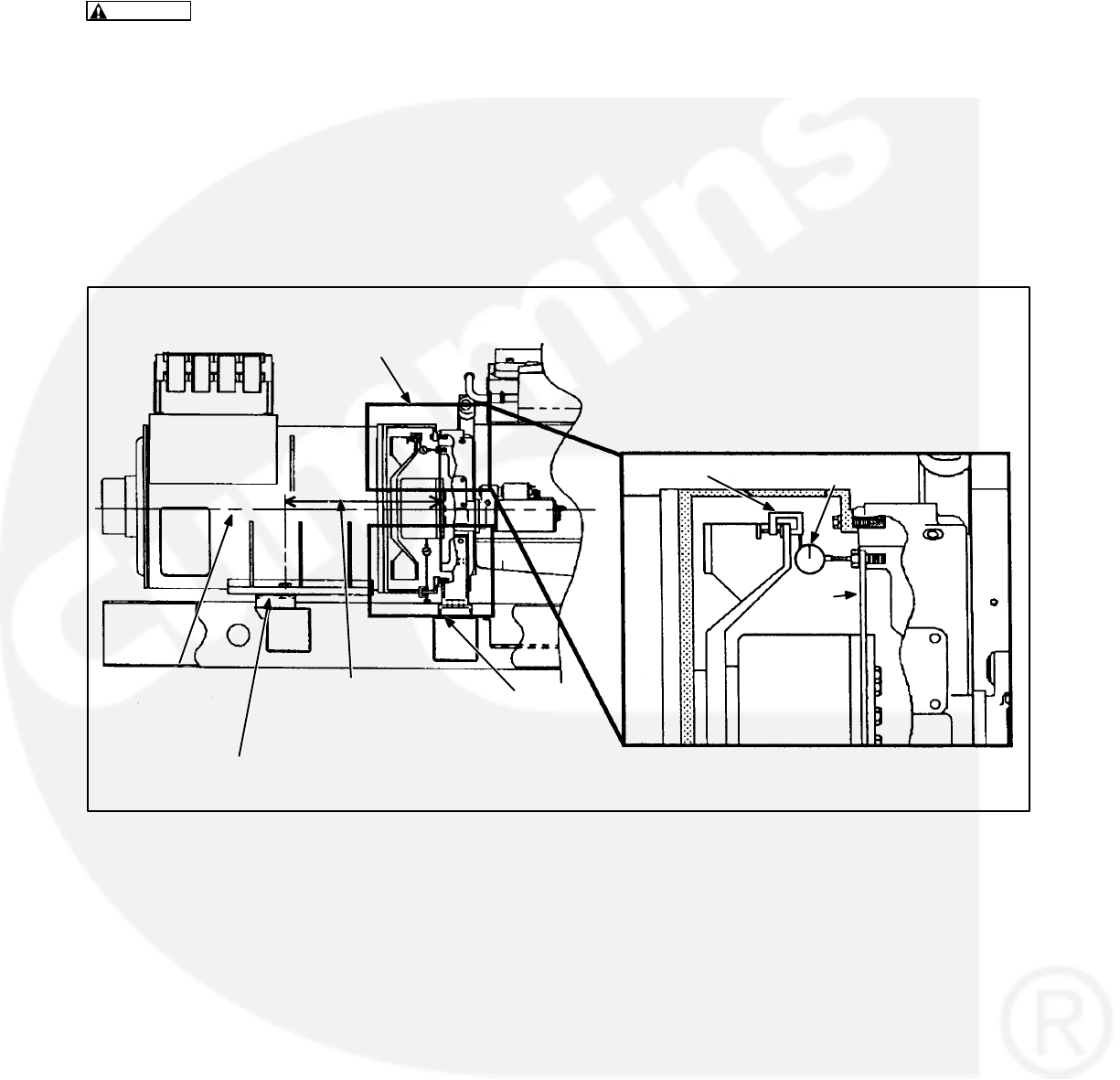
6-26
Angular Alignment Procedure
WARNING Accidental starting of the generator
set during this procedure presents the hazard
of severe personal injury or death. Make sure to
disconnect the negative (-) battery cable(s) be-
fore beginning.
Fasten a dial indicator to either the generator shaft
or the cooling fan with the sensing point resting on
the capscrew head or the flat surface of the drive
disc at the bolt circle diameter, see Figure 6-15. Bar
the engine over in a clockwise rotation as viewed
from engine flywheel. Do not allow it to roll back on
compression at the end of the travel of each read-
ing. It is unnecessary to zero the indicator since the
total indicator reading (T.I.R.) of the deflection mea-
surement to the bolt heads is what is required. T.I.R.
will be the sum of the maximum positive and nega-
tive dial indicator readings as the engine completes
one revolution.
MOUNTING BOLT
TO DISC
MEASUREMENT
SEE DETAIL A
CLAMP DIAL
INDICATOR
FLEX
DISCS
AXIAL
ALIGNMENT, SEE
FIGURE 6-17
GENERATOR AND
ENGINE
CRANKSHAFT
CENTERLINE
SHIMS
DETAIL A
FIGURE 6-15. ANGULAR ALIGNMENT MEASUREMENT
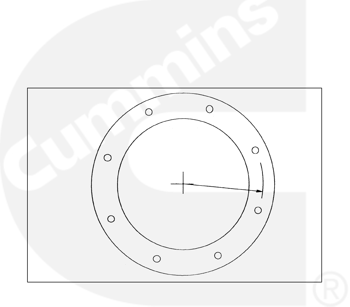
6-27
Sample Generator Runout Readings
When taking the deflection readings described,
make a diagram similar to the example shown in
Figure 6-16, where a total indicator reading of .025”.
(The highest positive value of +.010 and the largest
negative value of -.015”.) The indicator is closer to
the top and further away at the bottom. This exam-
ple indicates that the generator bearing is high.
Since the side readings are equal, the generator is
centered side to side. To lower the generator, re-
move equal shims from under both generator
mounting feet. To approximate the amount of shims
to remove or add:
1. Measure the distance between the center of
the generator shaft to the point the indicator is
measuring at. (For example; a SAE 18 Disc
coupling distance is 10.7”).
2. Measure the distance from the generator side
of the flex discs to the center of the generator
mounting bolt, refer to Figure 6-15. (For exam-
ple; a HC6 Frame’s distance is 28.4”.)
3. Compare the distance measured in steps 1 and
2. (28.4” vs 10.7” or a 2.65 to 1 ratio.) Multiply
this ratio times one half the T.I.R. (In our exam-
ple, .025” divided by 2 is .0125”. This, times
2.65 equals .033”. Therefore, remove .033” of
shims from under both mounting feet.)
In general, the T.I.R. should not be more than .001”
for each inch of radius (center of shaft to indicator
axis). If we use our example of 10.7”, then the maxi-
mum T.I.R. would be .011”. This would only require
a correction of .014” from the T.I.R. of .025”. (A read-
ing of +.002 at the top and -.009 at the bottom would
fall within the satisfactory range.)
+.010 +.010
-.002
MEASURED AT
BOLT CIRCLE
DIAMETER
-.010
10.7 IN.
-.015
-.015
-.010
-.004
FIGURE 6-16. ANGULAR ALIGNMENT MEASUREMENT READINGS (Example)
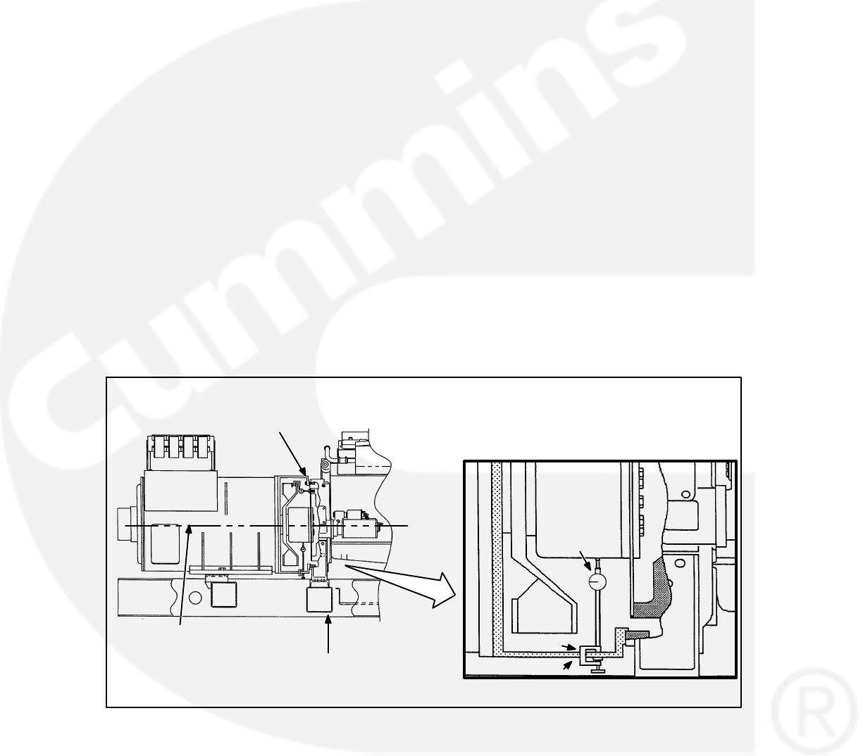
6-28
HC6 Axial Alignment Procedure
Axial misalignment needs to be checked only when
an objectionable vibration is present.
If excessive vibration remains after the angular
alignment, check for concentric alignment of the
generator shaft/engine crankshaft axes.
Fasten dial indicator holding device to skid base,
engine block, or generator shell with a magnetic
base or clamp and position so the sensor point of in-
dicator rests on the generator shaft hub, see Figure
6-15. Bar the engine over in a clockwise rotation as
viewed from engine flywheel, through a couple of
rotations. Record indicator readings in eight equally
spaced points around the shaft diameter. This will
provide a T.I.R. for Axial shaft misalignment.
The maximum allowable T.I.R. runout is subjective,
the optimal T.I.R. for runout would be .000”, howev-
er, that may not be attainable. The recommendation
of this procedure will be to reduce the measured
T.I.R. runout by one half. Specific out-of-tolerance
runout levels are difficult to establish due to the
varying surface quality of the generator shaft’s drive
disc mountain hub.
The goal of the Axial realignment is to reduce the
vibration level of the genset while it is operating. A
small improvement in the T.I.R. runout may have
dramatic effects in the mechanically measured or
physically observed vibration levels.
To correct for an out of tolerance T.I.R. indication,
remove the capscrews connecting drive discs and
flywheel. Mark the drive discs and flywheel with re-
spect to each other. Rotate either the engine or gen-
erator so that drive discs holes are repositioned
180 degrees from their original location. Put the
drive discs capscrews back in and retorque. Re-
check shaft alignment as before. If shaft T.I.R. run-
out remains unchanged then the discs should be ro-
tated to either 30, 60, or 90 degrees from original
location to correct the out of tolerance condition. If
the T.I.R. does not improve after repositioning, a
closer inspection of the flywheel pilot and drive disc
runouts is required. This will help determine the
cause of the Axial misalignment.
GENERATOR
AND ENGINE
CRANKSHAFT
CENTERLINE
ANGULAR ALIGNMENT,
SEE FIGURE 6-15
DETAIL A
SEE DETAIL A FAN HOUSING
CLAMP
GENERATOR
SHAFT HUB
DIAL
INDICATOR
FIGURE 6-17. HC6 AXIAL ALIGNMENT MEASUREMENT

6-29
P7 Axial Alignment Procedure
Axial misalignment needs to be checked only when
an objectionable vibration is present.
If excessive vibration remains after the angular
alignment, concentric alignment of the generator
shaft/engine crankshaft axes may be at fault.
The goal of the axial realignment is to reduce the
vibration level of the genset while it is operating. A
small improvement in the axial alignment may have
dramatic effects in the measured or physically ob-
served vibration levels.
To correct for possible axial misalignment, remove
the capscrews connecting drive discs and flywheel.
Mark the drive discs and flywheel with respect to
each other. Rotate either the engine or generator so
that drive discs holes are repositioned two bolt
holes from their original location. Put the drive discs
capscrews back in and retorque. Recheck/record
vibration levels as before. Repeat this test until the
drive discs holes are repositioned 180 degrees from
their original location.
Review vibration data and position drive disc in low-
est recorded level location.

6-30
THIS PAGE LEFT INTENTIONALLY BLANK
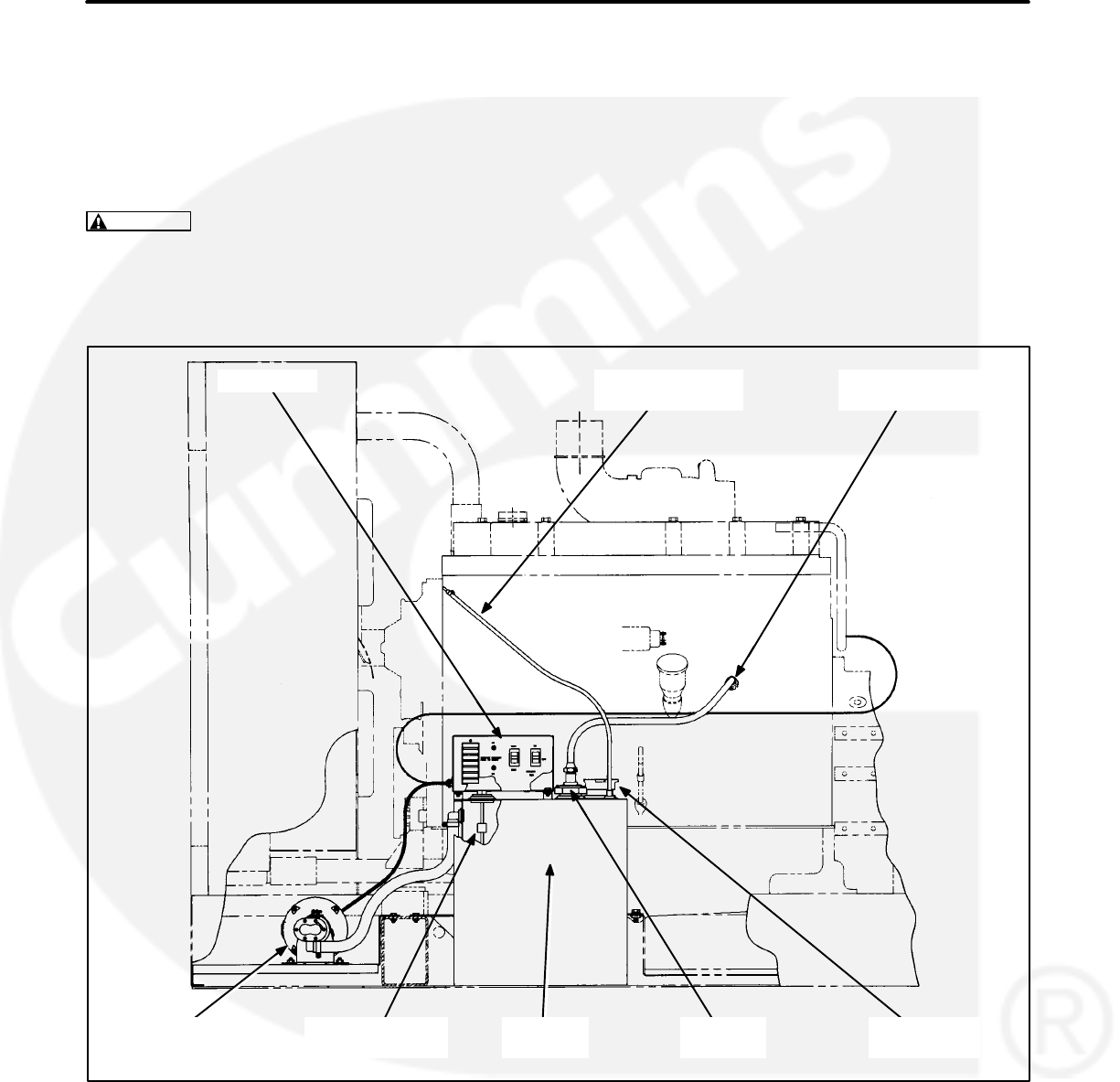
7-1
7. Day Tank Fuel Transfer Pump and Control
A fuel transfer pump and control are available when
a sub-base or in-skid day tank are provided. the au-
tomatic control operates the fuel pump to maintain a
reservoir of fuel in the day tank.
WARNING Diesel fuel is highly combustible.
Improper installation of this kit can lead to spill-
age of large quantities of fuel and loss of life and
property if the fuel is accidentally ignited. Instal-
lation and service must be performed by quali-
fied persons in accordance with the applicable
codes, including environmental regulations.
Do not smoke near fuel and keep flames, sparks
and other sources of ignition well away.
CONTROL
FUEL
GAUGE
FLEXIBLE FUEL
SUPPLY LINE
FLEXIBLE FUEL
RETURN LINE
DAY
TANK
FLOAT SWITCH
ASSEMBLY
FUEL FILL
CAP
FUEL PUMP
AND MOTOR
FIGURE 7-1. TYPICAL IN-SKID DAY TANK INSTALLATION
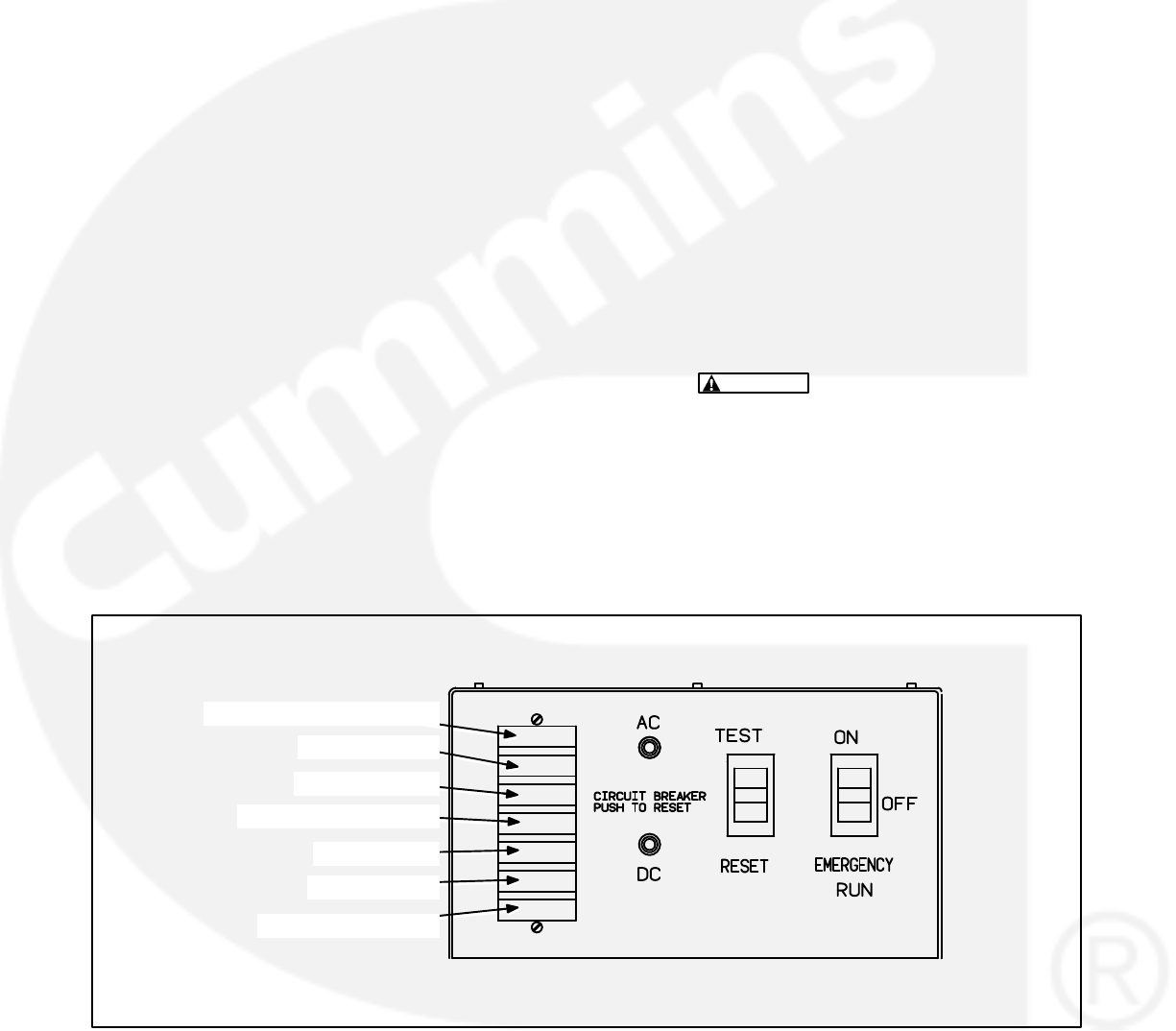
7-2
OPERATION
1. Push the control switch to the ON position for
automatic operation. The green SYSTEM
READY light will come on and the pump will fill
the tank if AC power is available for pumping
and DC power is available for the internal logic
circuits. The level of fuel in the tank will be auto-
matically kept between a set of pump-on and
pump-off float switches.
When filling an empty tank, the red LO SHUT-
DOWN and LO FUEL lights will come on when
the control switch is pushed to the ON position.
This is normal. Push the panel RESET switch to
turn off the red lights after the tank has been
filled.
If the SYSTEM READY light does not come on,
check for correct AC and DC power connec-
tions. See Wiring Connections and Fuel Pump
Motor Connections below.
2. The green PUMP ON light indicates when the
pump is running. It will come on and go off as
fuel is pumped to maintain the proper level in
the tank.
3. Push the control switch to the EMERGENCY
RUN position (momentary contact) to pump
fuel into the tank if the control fails to operate
the pump automatically.
The green PUMP ON light does not come on
when the switch is in the EMERGENCY RUN
position.
4. The red lights indicate fault conditions and the
need for service. The control panel includes the
following lights:
A. HI FUEL: The fuel in the tank has reached
an abnormally high level, indicating pos-
sible failure of the pump-off float switch.
The high-fuel float switch takes over as the
automatic pump-off switch. The HI FUEL
light stays on. The light can be RESET with
the panel switch when the fuel level drops
to normal, but will come back on again dur-
ing the next pumping cycle if the fault re-
mains.
WARNING Continued operation with a
HI FUEL fault present can lead to spill-
age of large quantities of fuel if the
high-fuel float switch fails. Spilled fuel
can cause loss of life and property if it
is accidentally ignited, or environmen-
tal damage.
HI FUEL (RED)
LO FUEL (RED)
LO SHUTDOWN (RED)
BASIN (RED)
BLANK (RED)
SYSTEM READY (GREEN)
PUMP ON (GREEN)
FIGURE 7-2. FUEL PUMP CONTROL PANEL

7-3
B. LO FUEL: The fuel in the tank has
dropped to an abnormally low level, indi-
cating possible failure of the pump-on float
switch. The lo-fuel float switch takes over
as the automatic pump-on switch. The LO
FUEL light stays on. The light can be RE-
SET with the panel switch when the fuel
level rises to normal, but will come back on
again during the next pumping cycle if the
fault remains.
C. LO SHUTDOWN: The fuel has dropped to
a level near the bottom of the tank, indicat-
ing an empty main fuel tank, pump failure
or possible failure of both the pump-on and
low-fuel level float switches. Further op-
eration will allow air to enter the engine fuel
unit, causing shutdown and the necessity
to bleed the fuel unit to start up the engine
again. Connections should have been
made to Terminals TB1-14 and TB1-15 to
shut down the engine automatically (to
ground one of four customer fault inputs
on terminals A40-TB1-16, 17, 18, or 19). If
the light comes on, check the fuel level in
the main fuel tank and fill it if necessary. As
the day tank is refilling, RESET the light
with the panel switch.
To restore engine operation following this
fault, both the pump control and the PCC
have to be RESET.
D.BASIN: Fuel has overflowed into the rup-
ture basin (if provided), indicating possible
failure of both the pump-off and hi-fuel lev-
el float switches, or a leak in the day tank.
RESET the control after the fuel in the ba-
sin has been safely disposed of and the
cause of the overflow corrected.
E.BLANK: For customer use.
The control fault circuits will trip and latch,
requiring RESET, even if AC power is lost.
5. Press the TEST switch to test the indicator
lights and pump operating circuits. Replace
any light that does not come on. The pump will
stop automatically after it has filled the tank to
the normal pump-off fuel level.
6. Press the reset button of the AC or DC circuit
breaker if either has tripped.

7-4
WIRING CONNECTIONS
See Day Tank Pump Control Wiring diagram in Sec-
tion 8 when making connections at the control box
terminal board. The following should be noted.
1. The control can be powered by 120 VAC or 240
VAC. The control is set up at the factory for con-
nection to 240 VAC.
To convert the day tank controller from 240
VAC to 120 VAC, perform the following steps.
A. Remove the two jumpers between termi-
nals TB1-6 and TB1-7 in the control box
and connect one between terminals
TB1-5 and TB1-6 and the other between
terminals TB1-7 and TB1-8.
B. Move selector switch S103 on the control
PCB to the up position for 120V.
C. If the control is equipped with a transform-
er, remove the two jumpers between ter-
minals H2 and H3 and connect one
between H1 and H3 and the other be-
tween H2 and H4.
To convert the day tank controller from 120
VAC to 240 VAC, perform the following steps.
A. Remove the jumpers between terminals
TB1-5 and TB1-6, and TB1-7 and TB1-8
in the control box and connect the two
jumpers between terminals TB1-6 and
TB1-7.
B. Move selector switch S103 on the control
PCB to the down position for 240 VAC.
C. If the control is equipped with a transform-
er, remove the jumpers between terminals
H1 and H3, and H2 and H4 and connect
the two jumpers between H2 and H3.
2. Attach a tag to the control box indicating the
supply voltage.
3. If a two lead wiring harness is provided, the
control does not include a power transformer.
To provide 24 VDC for the control circuit, con-
nect terminal TB1-19 to the positive (+) termi-
nal of the 24 V starter motor solenoid and
terminal TB-20 to the negative (-) terminal.
4. To immediately shut down the engine when the
LO SHUTDOWN light comes on, connect ter-
minal TB1-14 to a good grounding point on the
engine block and terminal TB1-15 to terminal
A40-TB2-16, 17, 18, or 19 (Customer Fault in-
puts). The customer fault input selected, must
be set for a shutdown operation (refer to SET-
UP MENU in Section 5).
5. Terminals TB1-10 through TB1-17 and TB2-23
through TB2-27 are available for connections
to remote annunciators or to any one of the four
customer fault inputs of the PCC.
6. Terminal TB2-22 is available for connection of
a grounding signal to activate the blank red
light.
7. Terminals TB1-8 and TB1-5 are available for
connection of a 120 or 240 VAC electric fuel
shutoff valve rated not more than 0.5 amps.
The voltage rating of the valve must corre-
spond with the voltage utilized for the pump.
See Item 2 above.
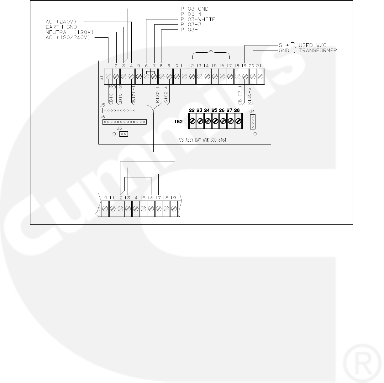
7-5
GND
TO A40-TB1-22 (LOW FUEL)
TO A40-TB1-16,17,18, or 19 (RUPTURE BASIN)
USE WITH PCC,
SEE DETAIL A
DETAIL A
FIGURE 7-3. FUEL PUMP CONTROL TERMINAL BOARD
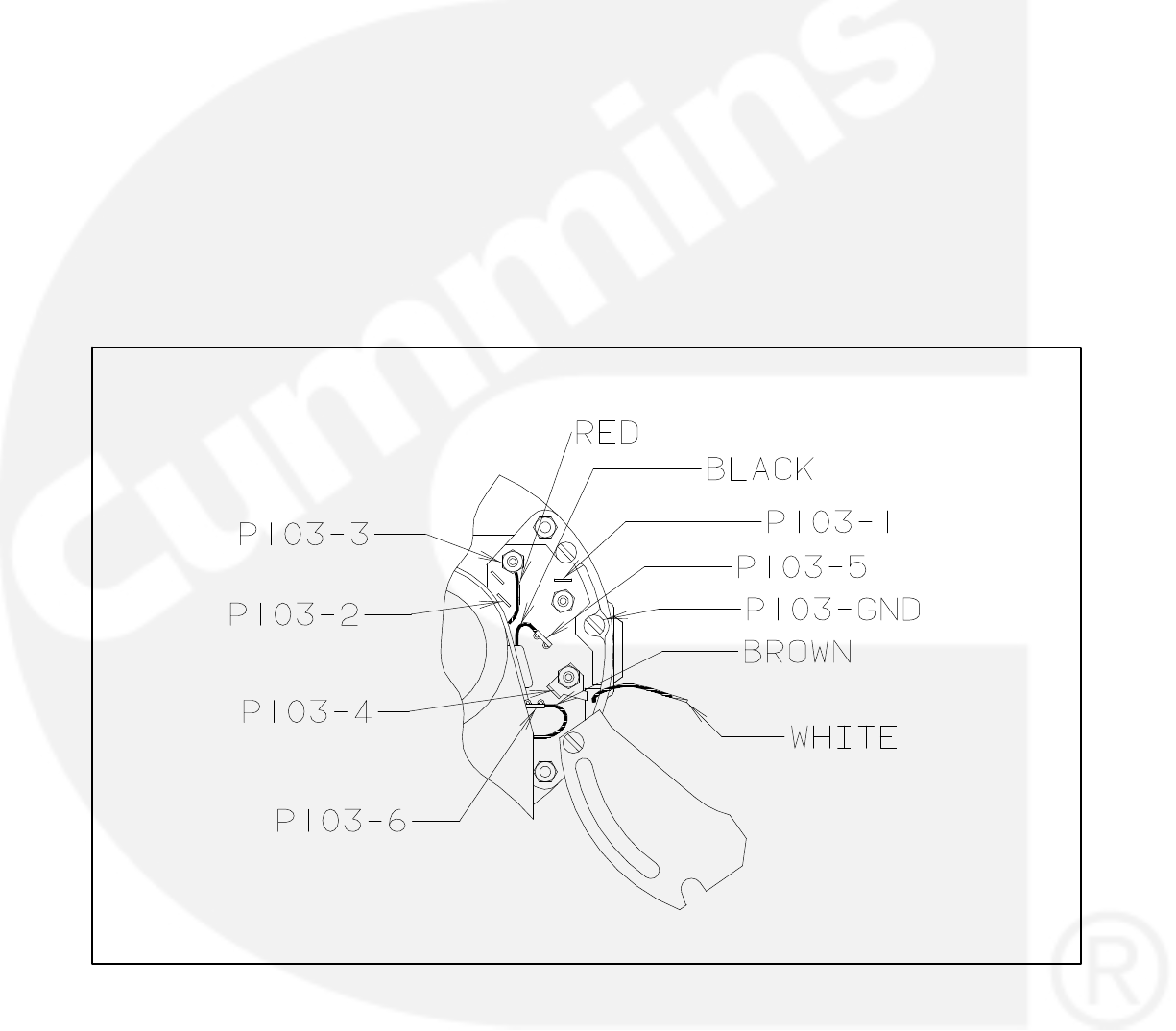
7-6
FUEL TRANSFER PUMP MOTOR
CONNECTIONS
Connect a replacement fuel transfer pump motor as
follows.
1. Remove the end bell cover for access to the
motor wiring terminals.
2. Disconnect the brown lead from motor terminal
P103-3 and connect it to terminal P103-6. (Ter-
minal P103-6 is an insulated receptacle for se-
curing the end of the lead so that it cannot move
and touch the motor frame or a live terminal
and cause a short circuit.)
3. Disconnect the red lead from motor terminal
P103-2. It will be connected to the piggy-back
terminal on the lead connected at motor termi-
nal P103-3.
4. Cut the white lead from its ring connector at
motor terminal P103-4. Strip 1/2 inch (12 mm)
of insulation from the end of the white motor
lead for splicing to the wire harness lead
marked P103-WHITE.
5. Connect each lead of the five-lead wiring har-
ness to the motor terminal or lead marked on it.
6. Connect the red motor lead to the piggy-back
terminal at motor terminal P103-3.
7. Secure the end bell cover.
FIGURE 7-4. FUEL TRANSFER PUMP MOTOR CONNECTIONS
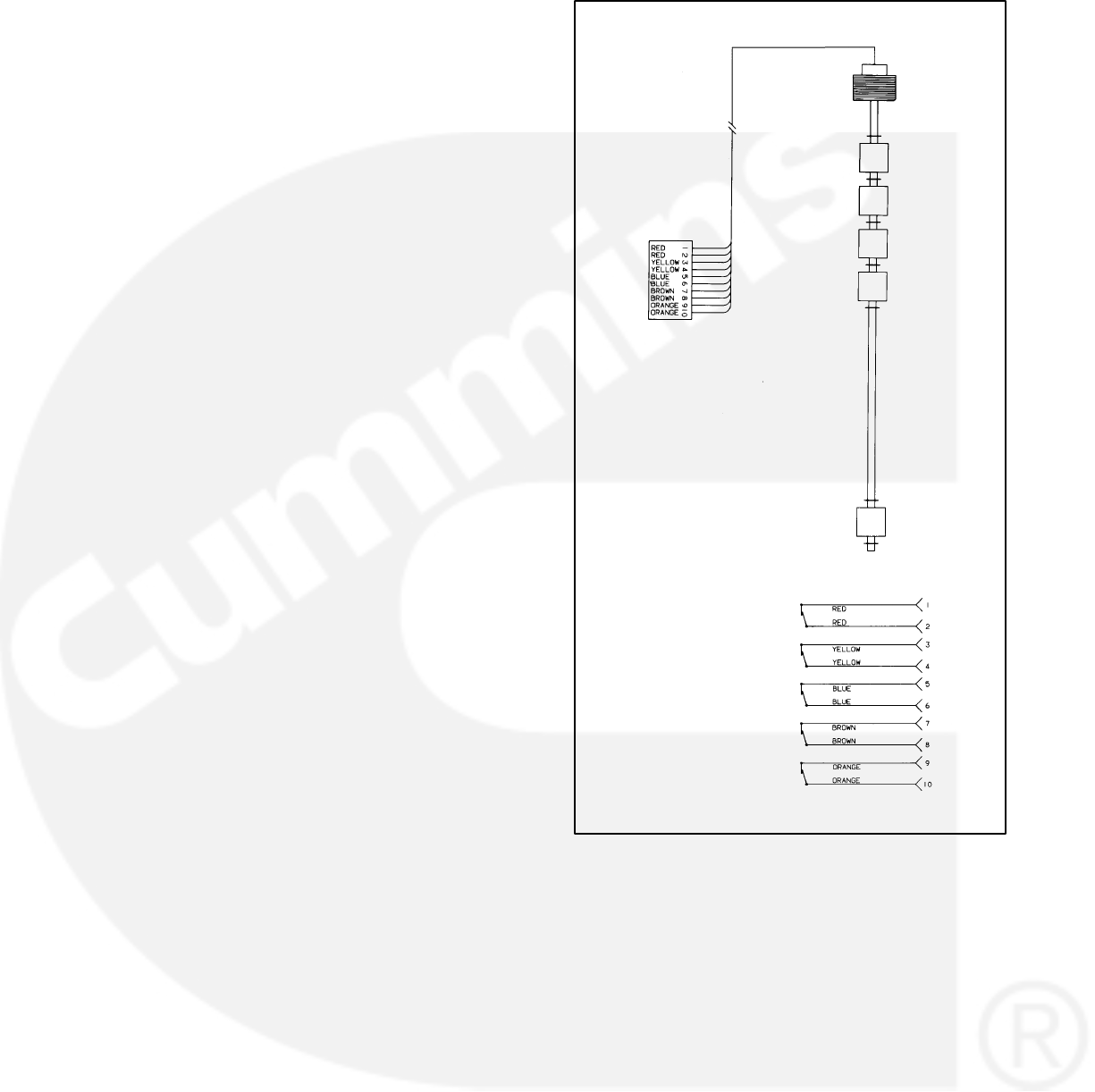
7-7
TESTING THE FLOAT SWITCH ASSEMBLY
The float switch assembly consists of 5 switches.
Each switch has a pair of color coded leads con-
nected to a common jack.
To test the float switches, remove the fuel pump
control cover, disconnect the wiring jack and un-
screw the assembly from the top of the day tank.
Test as follows:
1. With an ohmmeter, test for electrical continuity
(switch closed) between each pair of colored
leads, while holding the assembly vertical. Re-
place the assembly if any switch is open (all the
readings should be zero).
2. Lift each float, in turn, to 1/8 inch (3 mm) below
the C-clip stop above it (use a feeler gauge)
and test for electrical continuity. Replace the
assembly if any switch does not open (all the
readings should be infinity).
3. Use pipe thread sealant when replacing the as-
sembly.
SWITCH 1 − SHUTDOWN
SWITCH 2 − LOW FUEL
SWITCH 3 − PUMP ON
SWITCH 4 − PUMP OFF
SWITCH 5 − HI FUEL
SWITCH 5
SWITCH 4
SWITCH 3
SWITCH 1
SWITCH 2
J5
J5
FIGURE 7-5. FLOAT SWITCH ASSEMBLY

7-8
THIS PAGE LEFT INTENTIONALLY BLANK

8-1
8. Initial System Startup
GENERAL
Do not perform any procedure in
this section on medimum voltage (601 through
15,000 volts) generator sets. Special equipment
and training is required to work on or around
medium voltage equipment. Operation and
maintenance must be done only by persons
trained and qualified to work on such devices.
Improper use or procedures will result in severe
personal injury or death.
This section describes a process which can be used
in the initial startup and test of generator sets which
are paralleled using PowerCommand Digital Paral-
leling controls. PowerCommand Digital Paralleling
systems have many functions which are common to
traditional paralleling systems, but they are com-
pletely different in the way that these functions are
supplied in the system. The intent of this section is
to provide you with guidance in the initial running of
the equipment, so that you can perform this function
with as safe and efficient procedures as possible.
The accessory box of the Power-
Command Control contains high voltages when
the generator set is running. It can be energized
from the system bus and contain high voltages
even when the generator set is not running.
Contacting these high voltage components will
cause severe injury or death. Do not attempt to
service, operate or adjust the control unless
you have been trained in proper service tech-
niques.
THE STARTUP PROCESS
The startup process described in this section is typi-
cal for paralleling systems which utilize PowerCom-
mand Digital Paralleling equipment. Every parallel-
ing system is different in its design and application,
so portions of the recommended procedures may
be inappropriate for your application, or some pro-
cedures may be needed which are not described in
this section. Use your experience as the best guide
for enhancing these general guidelines to provide
the best process for the specific site which you are
servicing.
In general, the startup process contains these ma-
jor steps:
Installation design review, including mechani-
cal and electrical support systems for the gen-
erator sets and paralleling equipment.
Individual generator set preparation, operation
and performance review.
Manual system operation.
Automatic system operation and adjustments.
Black start testing of system.
Customer acceptance testing.
Customer training.
Issuing an installation report showing the work
done, system performance and customer ac-
ceptance.
EQUIPMENT APPLICATION REVIEW
The purpose of the equipment application review is
to visually inspect the installation to confirm that the
equipment has been installed within specified pa-
rameters and that the equipment can be started as
specified. Cummins technical application manuals
T-030 Liquid-Cooled Generator Sets and T-016
Paralleling and Paralleling Switchgear provide
guidance in evaluating installation requirements. It
is recommended that you use an installation review
report form, included at the end of this section, to
avoid missing any major points in the equipment re-
view and simplify reporting of problem areas to the
installer or customer.
The system startup process should not proceed un-
til the inspection and review are complete and all is-
sues resolved.
8-2
INDIVIDUAL GENERATOR SET STARTUP
The generator set should be properly serviced, with
proper levels of coolant and lubricants in the sys-
tem. Care should be taken to remove all shipping
blocks and braces from the equipment. Complete
all pre-start service and checks as for a standard
non-paralleled generator set.
Equipment needed to perform the startup:
Two properly calibrated hand-held digital me-
ters.
Be certain that the meters are rated for use on a
circuit operating at proper voltage.
Phase rotation meter.
PowerCommand service tool kit.
Individual generator set and system drawings,
specific to the project being installed. Opera-
tor’s manual, including PC program documen-
tation, if available.
A two channel strip chart recorder with voltage and
frequency modules is helpful, but not required for
the startup.
Operate the generator set RUN/OFF/AUTO switch
to the OFF position. Connect the generator set
starting and control batteries at their proper loca-
tions and verify that no fuses are blown (indicating
improper connections in the system). Verify that the
stationary battery chargers are properly installed
and wired and turn them on.
If the system includes a master control panel, verify
that control power is present in the master control
and operate the system mode select switch to the
manual operation position, so that the system does
not inadvertently receive a start signal. If the system
includes a touchscreen, PLC bridge/MUX or net-
work interconnections, verify that these are all func-
tional.
Check the settings of the paralleling control func-
tions. Typical values for these functions are shown
in Table 8-1. If the generator set was tested in paral-
lel at the factory, do not modify these adjustments at
this time. Check the factory test report to verify that
the settings of the control match the test report.
For paralleling applications, the default value of the
governor gain should be set to 70. See Section 5 −
Governor/Regulator menu for more information.
Generator sets that are shipped from the factory
without Cummins parallel gear are set up as single
units. For multiple unit paralleling applications you
must reconfigure the control. See Section 5 − Paral-
leling Setup menu.
TABLE 8-1. TYPICAL PARALLEL SET-UP
PARAMETERS
FUNCTION TYPICAL SETTING
ISOLATED BUS PARAMETERS
SYNC TIME LIMIT 120 seconds
− PWR LIMIT 10 percent
− PWR LIMIT (TIME) 3 seconds
PERM WIN-PHASE 20 degrees (ISO bus)
15 degrees (utility)
PERM WIN-TIME 0.5 seconds
SYNC GAIN 95
SYNC INTEGRAL 12
KW BALANCE 165
KVAR BALANCE 0
KW GAIN 6
KVAR GAIN 300
1ST START FAIL 10 seconds
RAMP UNLD TIME 30 seconds
RAMP UNLD LEVEL 20 percent
RAMP LOAD TIME 30 seconds
LOSS FIELD TIME 2 seconds
UTILITY PARAMETERS
BASE LOAD % 80 percent
PF LEVEL 1.00
KW GOVERN GAIN 100
KW INTEGRAL 4
KVAR GOVERN GAIN 300
KVAR INTEGRAL 200
RAMP LOAD TIME 10 seconds
RAMP UNLD TIME 10 seconds

8-3
Connect a jumper to the idle terminals of the gener-
ator set in the accessory box, so that it will start and
run initially at idle speed.
Verify that starting the generator set and energizing
the system bus will not cause hazards to other per-
sons working in the vicinity of the equipment, or di-
rectly on the equipment or anything electrically con-
nected to the equipment. Notify responsible per-
sons in the building that the equipment may be en-
ergized and operating at any time.
Start the generator set by operating the RUN/OFF/
AUTO switch to the RUN position. The generator
set should start and accelerate to idle speed. An idle
mode alarm should appear on the generator set dig-
ital display panel. Allow the generator set to run at
idle, taking care to note unusual noises or vibration
from the engine or alternator, leaking fluids or ex-
haust connections. Run the generator set at idle un-
til the coolant temperature is greater than 100 de-
grees F (40 degrees C) Make any corrections nec-
essary prior to continuing with the startup process.
Stop the generator set and remove the idle speed
jumper from the accessory box interconnection ter-
minal block. Start the generator set by operating the
RUN/OFF/AUTO switch to the RUN position and
observe it accelerating to rated frequency and volt-
age. Calibrate and adjust all generator set metering
(if necessary) using the hand-held digital meter and
the procedure in Section 5 of this manual. Adjust the
generator set to proper voltage and frequency. Re-
cord the values of voltage and frequency so that all
units can be adjusted to the same values. Remem-
ber to save all changes and adjustments prior to
switching off the generator set.
Make sure that the paralleling breaker is charged
and ready to close (power circuit breakers only) and
that the paralleling bus is de-energized. If the break-
er is not charged, manually charge the breaker.
Manually close the paralleling breaker for the gen-
erator set. Most paralleling breakers will automati-
cally re-charge on closing (power circuit breakers
only). When the charging cycle is complete, electri-
cally open the breaker using the breaker open con-
trol switch on the front of the PowerCommand con-
trol. Close the breaker using the breaker close
switch on the front of the PowerCommand control.
Verify proper functioning of the breaker open and
close lamps on the PowerCommand Control and
proper operation of the manual breaker control
switches on the PowerCommand control.
Use extreme caution when perform-
ing phase relationship testing. The system is
energized and dangerous voltages are present
in many locations. Contact with energized parts
will cause serious injury or death. Do not at-
tempt these tests unless you have proper
equipment for testing and are trained in its safe
use.
Verify that the phase rotation of the generator set
matches the phase rotation of the utility service at
each transfer switch or breaker power transfer pair.
Correct generator set phase rotation to match utility
condition, if required, by reversing the phase L1 (A
or U) and L2 (C or W) connections on the generator
set output.
Note: The purpose of this procedure is to make sure
that the generator set output matches the bus phase
relationship. Later in the startup process the wiring
and interconnection of the bus and generator set PT
modules will be verified. Note that the PT/CT module
phases must be matched to the generator set phase
changes, or a FAIL TO SYNCHRONIZE alarm will oc-
cur.
If a master control is used in the system, make sure
that the main bus metering is functioning and prop-
erly calibrated.
Using the load bank or available load on the system,
check the generator set load carrying ability and the
transient performance of the generator set. Adjust
as necessary for proper generator set operation.
Disconnect the load from the system.
Make sure that all alarm and shutdown circuits in
the generator set are functioning properly. Shut
down the generator set by switching the RUN/OFF/
AUTO switch to OFF.
Repeat the process described in this section for
each generator set in the system before moving on
to the next step of the startup process.

8-4
MANUAL SYSTEM OPERATION
Once all generator sets in the system have been
successfully run individually, the generator sets are
ready for verification of manual paralleling capabili-
ty.
Make sure that all generator set RUN/OFF/AUTO
control switches are placed in the OFF position and
that the master control switch (if used) is also in the
manual mode position.
Operate the control switch of one generator set to
the RUN position and allow the generator set to
start and accelerate to rated speed and voltage.
Manually close the paralleling breaker on this gen-
erator set by pushing the breaker close pushbutton
on the front face of the PowerCommand control. Al-
low the generator set to run at no load for the first
phase of the manual paralleling test.
Use extreme caution when perform-
ing phase relationship testing. The system is
energized and dangerous voltages are present
in many locations. Contact with energized parts
will cause serious injury or death. Do not at-
tempt these tests unless you have proper
equipment for testing and are trained in its safe
use.
Check the phase relationship of the generator set
output to its Bus PT module. The voltage difference
between the L1 phase on the input to the Bus PT
board and the generator set PT/CT board should be
zero. Repeat this process for each generator set in
the system.
Make sure that all generator set RUN/OFF/AUTO
control switches are placed in the OFF position and
that the master control switch (if used) is also in the
manual mode position.
Operate the control switch of one generator set to
the RUN position and allow the generator set to
start and accelerate to rated speed and voltage.
Manually close the paralleling breaker on this gen-
erator set by pushing the breaker close pushbutton
on the front face of the PowerCommand control.
Check the phase relationship of the generator set
which is closed to the bus, with each individual gen-
erator set. This can be accomplished by starting the
second generator set in the system by operating the
RUN/OFF/AUTO control switch to the RUN position
and allow the generator set to start and accelerate
to rated speed and voltage. When generator set fre-
quency and voltage have stabilized, operate the
display screen of the PowerCommand control to the
voltage and frequency screens and use the digital
display to verify that the generator set voltage and
frequency matches the bus voltage and frequency.
Switch the display screen to the digital synchro-
scope (bus frequency) screen and observe the con-
trol phase relationship between the generator set
and the bus. When the phase relationship of the on-
coming generator set is within the acceptance pa-
rameters programmed into the control, an asterisk
(*) will be displayed on the screen next to the phase
difference display.
When the asterisk is displayed on the control panel,
check the phase relationship between the genera-
tor set and the bus. With the hand-held digital volt-
meter, check the voltage from the line side to the
load side for each phase of the open paralleling
breaker on two phases simultaneously (Figure 8-1).
If the phase relationship is proper, the voltage
across the breaker (with the breaker open) should
be zero, or nearly zero on both phases when the
”synchronized” indicator lamp is on. The voltage of
the two meters should rise and fall at approximately
the same time.
Note: If the generator set output phase rotation
matches the bus and a PHASE ROTATION warning
appears when you attempt to close the paralleling
breaker, you should check the generator set and Bus
PT boards for proper wiring and interconnection.
Both the primary and secondary wiring in the Bus PT
board should be checked. See Table 4-28.
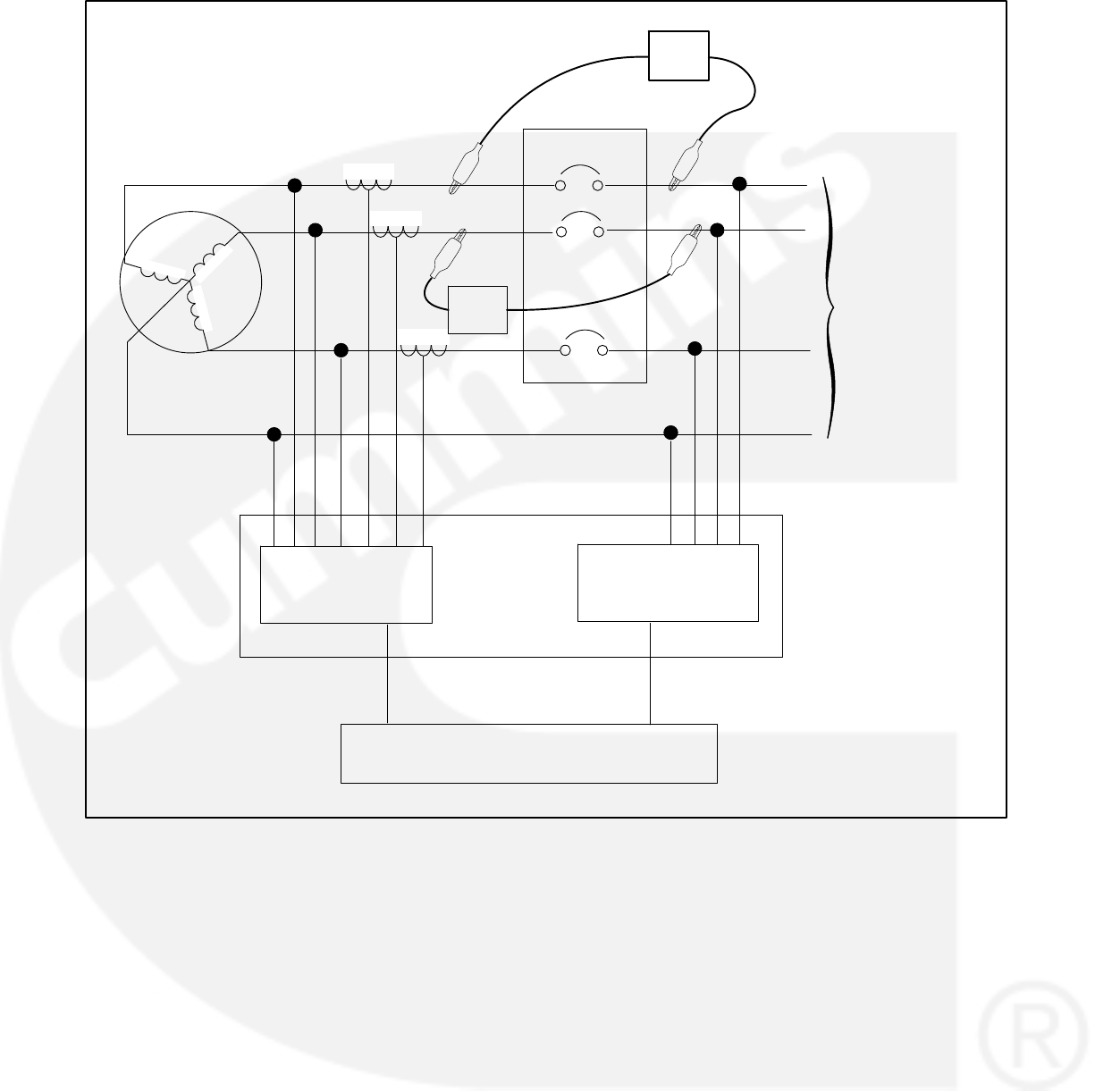
8-5
Power Command Control
Accessory Box
Bus PT
Board (A39)
PT/CT
Board (A36)
VM2
VM1
CB
(Open)
To Load Bus
FIGURE 8-1. CHECKING PHASE RELATIONSHIP BETWEEN GENERATOR SET AND SYSTEM BUS
Note: For applications where a wye connected gen-
erator set is paralleled to a delta connected bus, the
generator neutral bus must be floating and the neu-
tral connection to the bus PT module must not be
used.

8-6
Make sure that the “charged” flag is present on the
paralleling breaker and push the breaker close
pushbutton on the PowerCommand Control to
manually close the oncoming set paralleling break-
er and paralleling the generator set to the system
bus.
Note: The breaker close function operates through a
permissive relay function in the PowerCommand
Control, so the paralleling breaker will not close un-
less the generator set is properly synchronized with
the system bus.
Perform the phase rotation verification on each
generator set in the system, prior to attempting to
close it to the live parallel bus for the first time.
When all generator sets have been closed to the
bus, observe the voltage, frequency, amp load and
kilowatt load on each generator set metering set.
The metering should indicate identical voltage and
frequency readings on all generator sets in the sys-
tem. Amp and kilowatt readings should all be zero.
With no load on the system, a positive amp load
reading on generator sets indicates a voltage differ-
ence between the generator sets in the system. A
positive kilowatt reading on any generator set indi-
cates a frequency misadjustment on at least one
generator set. Perform adjustments necessary to
eliminate circulating currents and kilowatt loads.
Save the generator set adjustments made prior to
switching off the generator set.
With all generator sets running in parallel in manual
(RUN) mode, apply available load to the system.
Observe load sharing levels on the generator sets.
The units should share load proportionally. (The
%load and %amps meters on the PowerCommand
control should all read within plus or minus 5% of
each other.)
Adjust load sharing parameters within control sys-
tem to achieve proper load sharing. Save all
changes.
If possible, operate the system at various load lev-
els and verify proper operation at each level.
Remove all load from the system and return the
generator sets to their normal automatic mode by
placing the RUN/OFF/AUTO switch in the AUTO
position.

8-7
AUTOMATIC SYSTEM OPERATION
If the system includes a master control panel, move
the mode selection switch on that panel to the full
automatic position. Operate the test switch to cause
the system to automatically start and parallel all
generator sets.
The generator sets should automatically start, ac-
celerate to rated speed and voltage, synchronize
and parallel on the system bus. As the generator
sets synchronize and close to the system bus, ob-
serve the operation of the load adding (priority) con-
trol relays in the master control. (If load add control
relays are provided.) Observe and record the time
to synchronize for each generator set.
With all the generator sets running and closed to the
system bus, apply load to the running generator
sets, but at a low enough level that all the generator
sets need not be running in order to carry the bus
load. On one generator set, ground the Load De-
mand contact in the accessory box. The following
sequence should then occur:
The ”LOAD DEMAND” shutdown message
should be displayed on the PowerCommand
digital display panel.
The load should ramp down on the generator
set to its minimum set point level.
The generator set paralleling breaker should
open.
The generator should run for its normal cool-
down period and then shut down.
When the unit has shut down, remove the ground
signal on the Load Demand termination point. The
generator set should start, build up to rated frequen-
cy and voltage, synchronize and parallel to the sys-
tem bus. When it has closed to the bus, it should
ramp up to its proportional share of the total bus
load.
Repeat the load demand test for each of the gener-
ator sets in the system.
Switch off the test switch in the master control. All
the paralleling breakers should simultaneously
open and the generator sets should run for a cool-
down period and shut down.
Simulate a remote start in the master control. The
generator sets should automatically start, acceler-
ate to rated speed and voltage, synchronize and
parallel on the system bus. Remove the remote
start jumper on the master control. The generator
set paralleling breakers should all open and the
generator sets should run for a cooldown period
and shut down.
At this point the various control functions of the
master control can be tested and verified. Consult
the project drawings and specifications or approved
submittal documents for details on master control
functions and requirements.

8-8
BLACK START TESTING
The black start testing process is designed to dem-
onstrate that the entire on-site power system is
installed correctly and that system support equip-
ment, such as day tanks, fuel pumps, or supple-
mental ventilation equipment, is designed and
installed correctly. It is primarily used in applications
where the paralleling system is intended to provide
emergency power in the event of a normal utility
(mains) power failure. The black start testing pro-
cess is performed after the entire on-site power sys-
tem is installed. This testing process is often per-
formed in conjunction with the customer approval
testing, since it may be disruptive to the operation of
the facility and demand special arrangements to
avoid potentially dangerous or costly power failures
in the facility.
The specific details of this testing process are very
dependent on the design of the electrical and me-
chanical systems of the facility. In general the steps
in this process are as follows:
A power failure is simulated in the facility by
opening the main power feeder in the building.
It is desirable to do this to be certain that critical
loads such as fuel pumps are fed from both the
generator and utility (mains) bus.
The generator sets start and parallel. The time
required for the generator sets to start and par-
allel should be recorded and noted on the final
test report for the system.
Observe operation of all power transfer de-
vices, noting the time required to transfer.
The generator sets should be run in parallel
with all available load in the building, at a mini-
mum of approximately 30% of their standby
KW rating. The duration of the test should be
sufficient for the generator sets to reach their
normal operating temperatures. The load de-
mand system (if provided in the system master
control) should be shut down until all generator
sets in the system have reached normal opera-
tion temperatures and their operation tempera-
tures have stabilized. During this process, data
should be gathered to demonstrate the load
applied and the operational performance of the
system. It is customary to document the gener-
ator set performance during this period, by re-
cording all values on all meters and engine
monitors every 15 minutes.
When all required customer testing and verifi-
cations have been performed, return the sys-
tem to normal power by restoring utility (mains)
power at the point where it was disconnected.
Verify that the generator sets and power trans-
fer devices all return to their normal ready-to-
start states.
TEST REPORTS AND ACCEPTANCE
The technician performing the system startup
should issue a start up and test report to document
the work performed and demonstrate that the sys-
tem is functional and operational. The exact re-
quirements of this report will vary depending on
customer requirements, but should include, as a
minimum:
The application and review and evaluation. A
copy of the site review checklist performed at
the start of the testing process might be in-
cluded to document this step of the process.
A copy of the startup check list (a typical check
list is included at the end of this section), docu-
menting the functions tested and that each
function performed properly.
Test data sheets documenting results of load
testing.
List of all the settings of each generator set
control.
Black start test results.
Certification that the system is operational and
ready to run.
It is customary for an owner’s representative to
review and sign all test documents, indicating
acceptance of the test data and system perfor-
mance.

8-9
ON SITE POWER SYSTEM APPLICATION REVIEW (DIESEL/600VAC AND LOWER)
Date: ___________ Location: __________________________________________________________
Owner/Operator: ______________________________________________________________________
Generator Set Model: ____________________ Serial Number: ____________________
Transfer Switch Model: ____________________ Serial Number: ____________________
Project/Order Number: ________________________________________
Review Performed By: _____________________________
Mounting/Noise/Isolation
[ ] Flexible power output conduit, supported by bldg.
[ ] Isolators/pad (integral to set)
[ ] Isolators/pad (external to set)
[ ] Isolators/spring-pad, adjusted correctly
[ ] Flexible stainless steel exhaust connection
[ ] Flexible fuel lines (supply& return), secured
[ ] Flexible power output conduit, supported by bldg.
[ ] Flexible auxiliary power connections
[ ] Flexible control connections
[ ] Flexible exhaust air duct
[ ] Seismic restraints (where required)
[ ] Provisions for draining oil/coolant
[ ] Clearance around genset (3ft/1 meter min.)
[ ] Fire alarm provisions
[ ] System covers/shields all in place
Exhaust
[ ] Silencer close to genset
[ ] Exhaust connections sealed
[ ] Exhaust insulated
[ ] Proper personnel protection provided
[ ] Exhaust run slopes away from genset
[ ] Condensate trap with valve on exhaust silencer
[ ] Provisions for thermal expansion
[ ] Raincap/birdscreen on exterior of building
[ ] Exhaust thimble
[ ] Correct pipe size, supported by building
[ ] Facility vent air intake, windows, doors not close to
exhaust outlet
[ ] No combustible materials, or fire system
components near uninsulated pipe
Cooling System
[ ] Filled with soft water/E.G./DCA mixture
[ ] Jacket water heater provided
[ ] Valves to isolate jacket water heater
[ ] Power supply to heater from normal power
Ventilation System
[ ] Inlet air duct properly sized (approx. 1.5x radiator)
[ ] Exhaust air duct properly sized (effective open area
not less than radiator area)
[ ] Heat sources in room insulated
[ ] Recirculation of radiator exhaust air unlikely
[ ] Access door to room opens in (or vented)
[ ] Vent dampers powered from emergency power
supply
[ ] Direction of prevailing winds
Fuel System
[ ] Piping is not galvanized or copper
[ ] Manual shut-off valve
[ ] Solenoid valve on fuel supply, power from set
[ ] Fuel returns to main tank
[ ] Fuel line size adequate
[ ] Fuel line high loops
[ ] Day tank/vent at highest point
[ ] Day tank/location below return lines
[ ] Day tank/strainer-filter
[ ] Day tank/level alarms
[ ] Main fuel tank below set
[ ] Fuel transfer pump/power from genset
[ ] Main fuel tank above set
[ ] Solenoid valve
[ ] Sub-base tank
[ ] Level gage
[ ] Vent
Electrical System
[ ] Control connections isolated from power
[ ] Control connections use stranded wire
[ ] Conductor size OK (power & control)
[ ] Proper battery size/filled with electrolyte
[ ] Battery rack isolated from floor
[ ] Battery charger/power from utility
[ ] Start signal wired to ATS
[ ] Generator frame grounded (bonded)
[ ] Neutral connection (where/how)
[ ] Power/control conductors torqued
[ ] Wiring accuracy/matches drawings
Other
[ ] Oil installed in engine
[ ] Posted operating instructions
[ ] Generator/ATS manuals, drawings provided
[ ] Generator room/control boxes cleaned

8-10
THIS PAGE LEFT INTENTIONALLY BLANK

9-1
9. Wiring Diagrams
GENERAL
This section consists of the schematic and connec-
tion wiring diagrams referenced in the text. The fol-
lowing drawings are included.
Page 9-2 and 9-3, AC Reconnect Wiring Dia-
gram
Page 9-4, Block Diagram (12 Lead)
Page 9-5, Block Diagram (6 Lead)
Page 9-6, Customer Connections
Page 9-7, Engine Interface Board (A31)
Page 9-8, Digital board (A32)
Page 9-9, Analog board (A33)
Page 9-10, Customer Interface Board (A34)
Page 9-11, Display Board (A35)
Page 9-12, PC/CT Board (A36)
Page 9-13,Voltage Regulator Output Module
(A37)
Page 9-14, Governor Output Board (A38)
Page 9-15, PT/CT Wiring Harness
Page 9-16, Engine Wiring Harness
Page 9-17, Accessory Box Interconnection
Harness Diagram
Page 9-18, Day Tank Pump Control Wiring
Page 9-19 Accessory Interconnect Diagram
Page 9-20, Sequence of Operation (Local Start
and Run)
Page 9-21, Sequence of Operation (Local
Stop)
Page 9-22, Sequence of Operation (Local
Emergency Stop)

9-2
THIS PAGE LEFT INTENTIONALLY BLANK
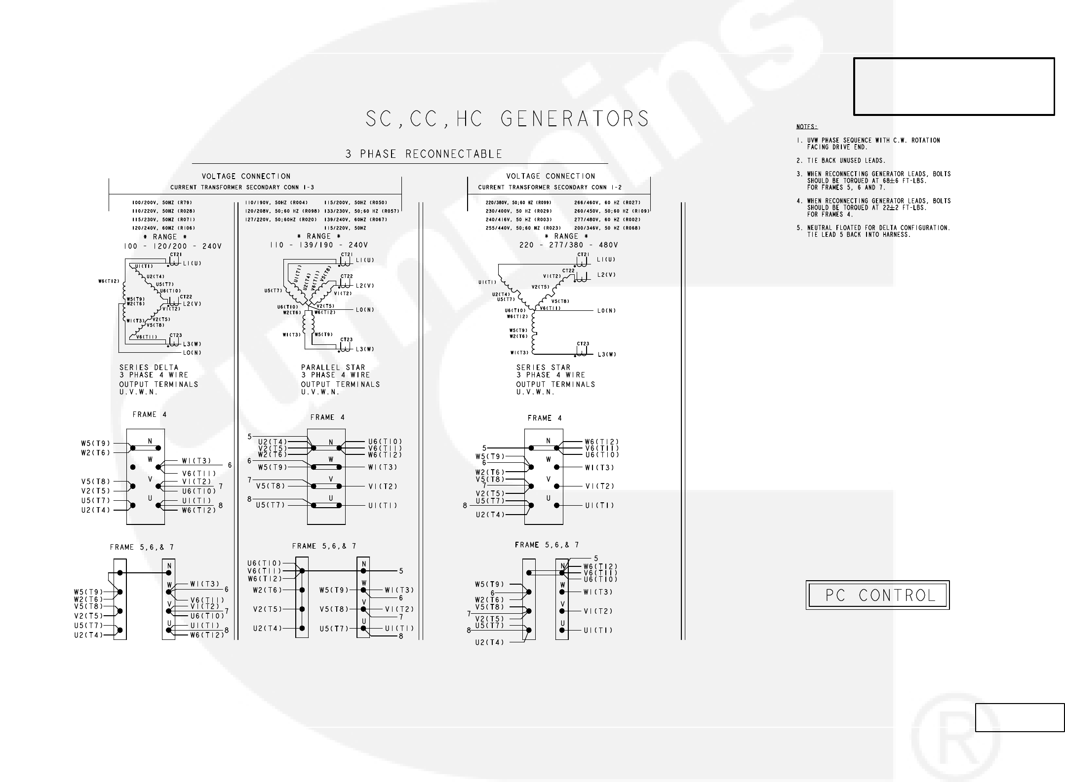
AC RECONNECT WIRING DIAGRAM (SHEET 1 OF 2)
9-2
No. 625−3100 sh1 of 2
Rev. H Sys:CADAM
Modified 2/2011
THIS IS A REPRESENTATIVE (GENERIC)
SCHEMATIC/WIRING DIAGRAM. FOR
TROUBLESHOOTING, REFER TO THE
WIRING DIAGRAM PACKAGE THAT WAS
INCLUDED WITH YOUR GENSET.
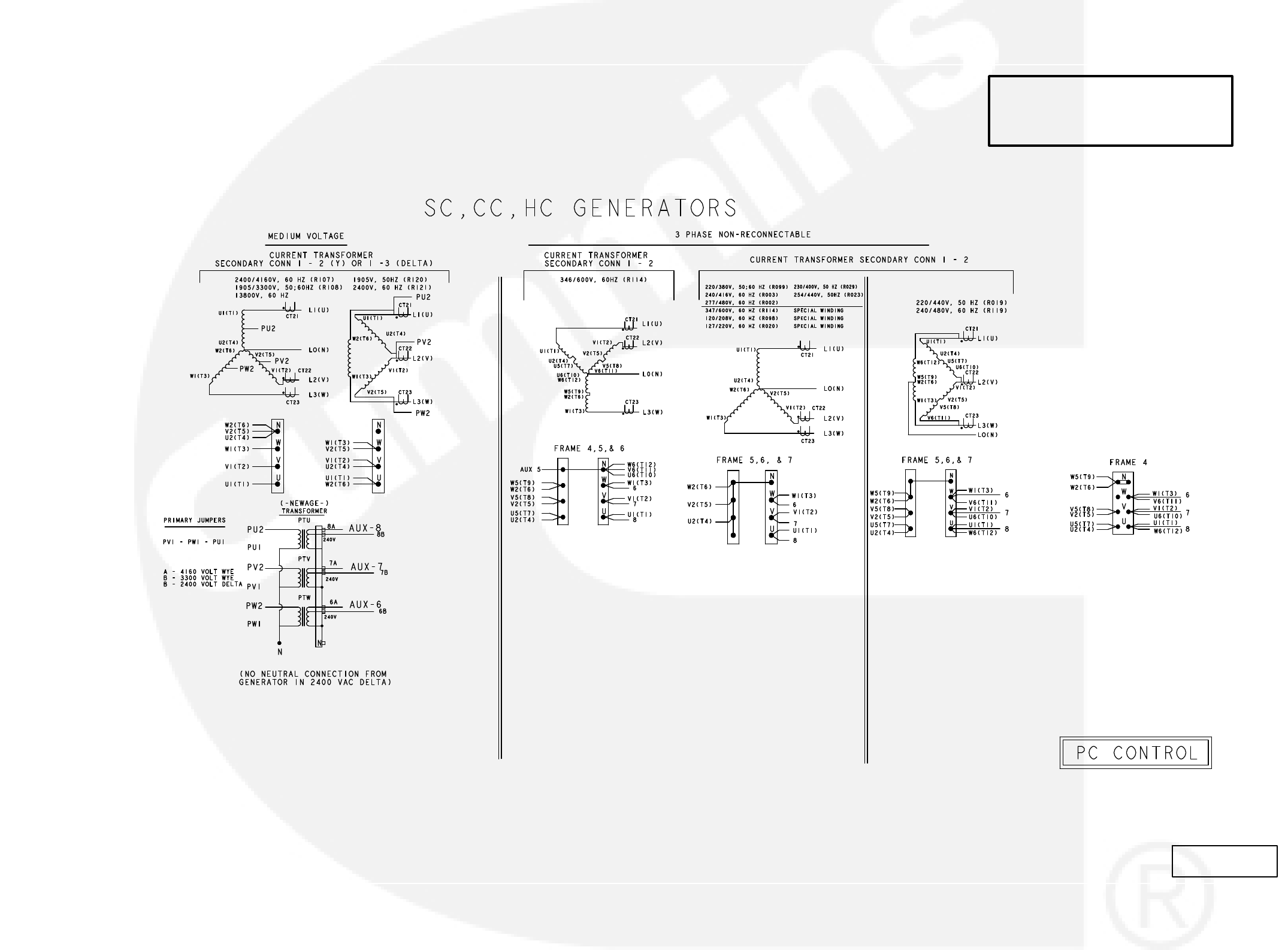
AC RECONNECT WIRING DIAGRAM (SHEET 2 OF 2)
9-3
No. 625−3100 sh 2 of 2
Rev. H Sys:CADAM
Modified 2/2011
THIS IS A REPRESENTATIVE (GENERIC)
SCHEMATIC/WIRING DIAGRAM. FOR
TROUBLESHOOTING, REFER TO THE
WIRING DIAGRAM PACKAGE THAT WAS
INCLUDED WITH YOUR GENSET.
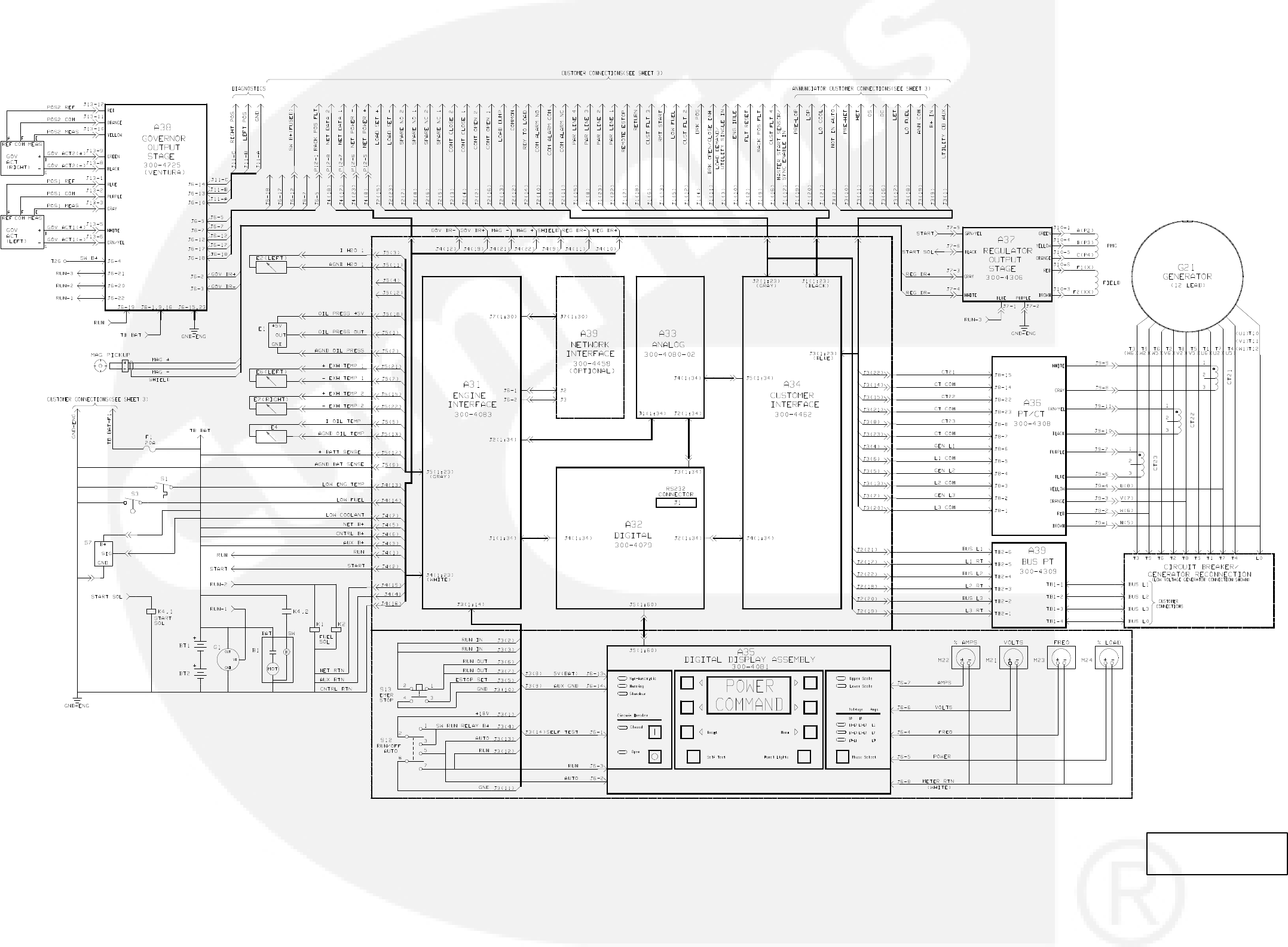
9-4
BLOCK DIAGRAM (12 LEAD)
No. 612−6701 sh 1of 3
Rev. B Sys: HP
Modified 12/1996
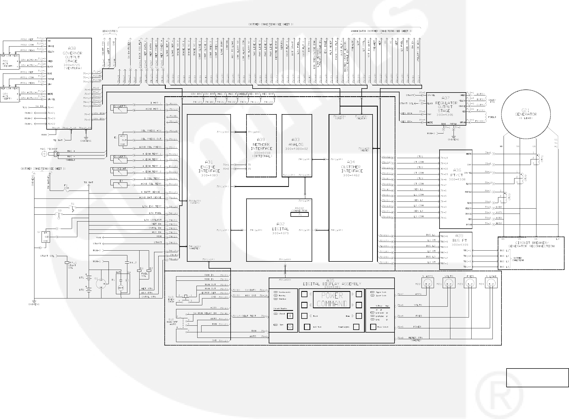
BLOCK DIAGRAM (6 LEAD)
9-5
No. 612−6701 sh 2of 3
Rev. B Sys: HP
Modified 12/1996
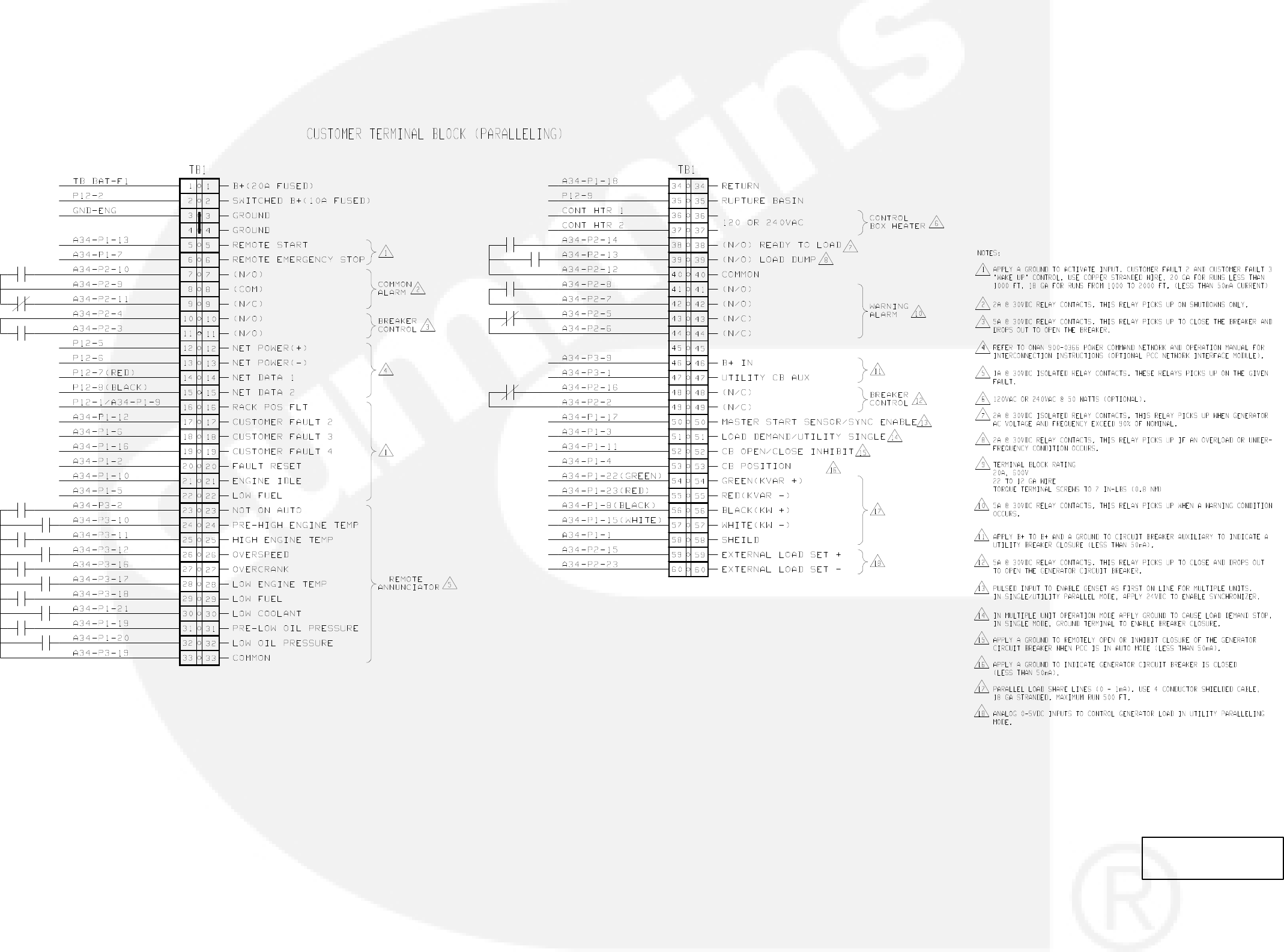
9-6
PCC CUSTOMER CONNECTIONS
No. 612−6701 sh 3of 3
Rev. B Sys: hp
Modified 12/1996
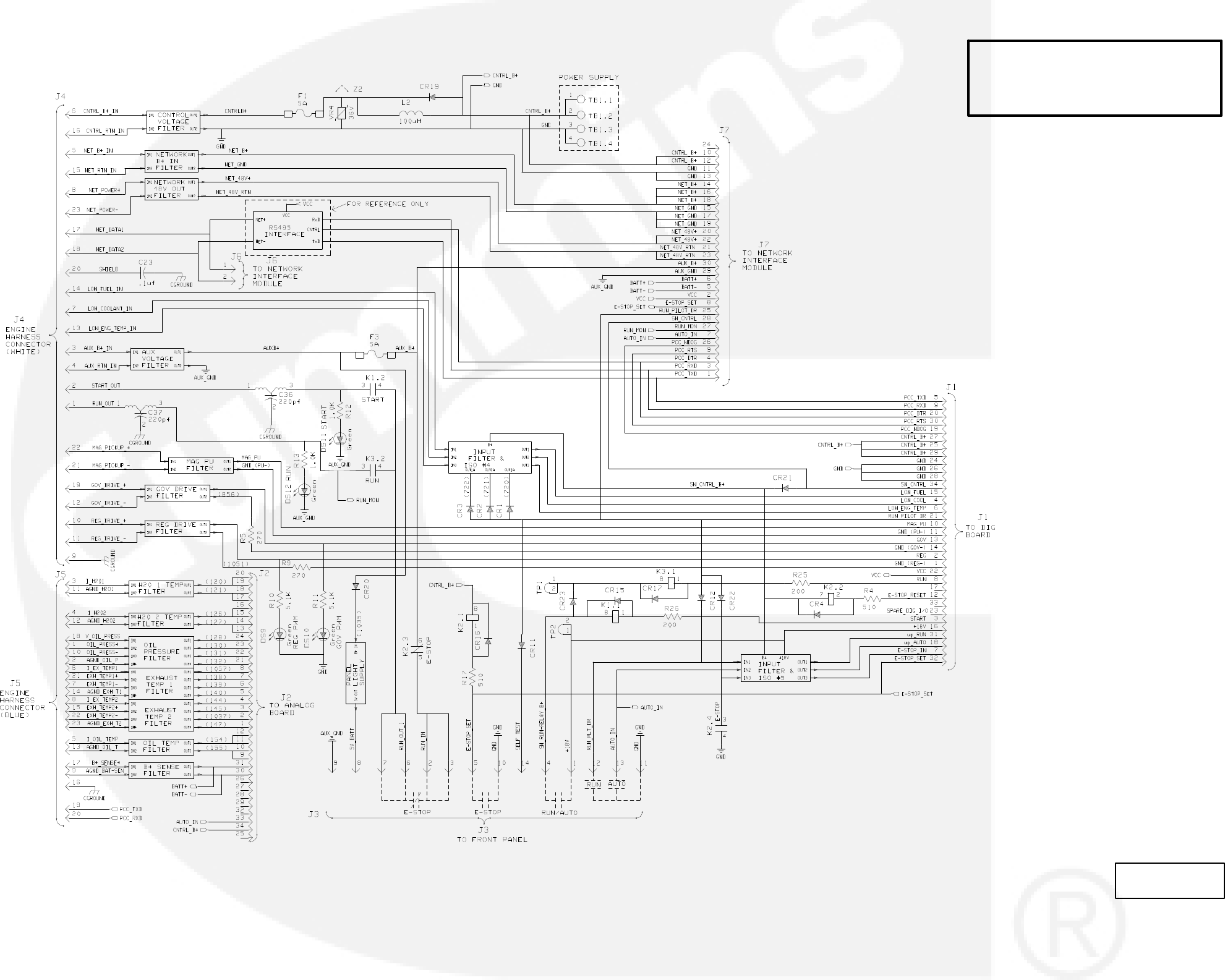
ENGINE INTERFACE BOARD (31)
9-7
NO. 300-4819 sht 1 of 4
REV. B
MODIFIED 8/2008
THIS IS A REPRESENTATIVE (GENERIC)
SCHEMATIC/WIRING DIAGRAM. FOR
TROUBLESHOOTING, REFER TO THE
WIRING DIAGRAM PACKAGE THAT WAS
INCLUDED WITH YOUR GENSET.
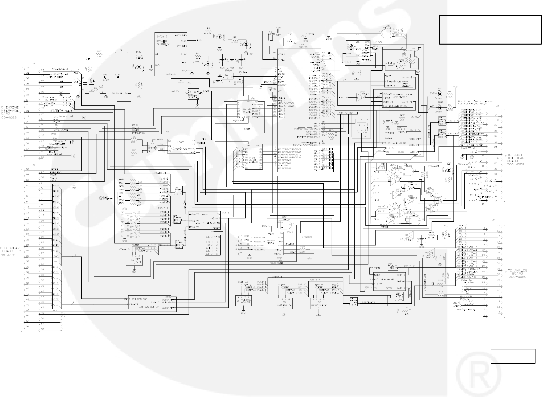
9-8
DIGITAL BOARD (A32)
NO. 300−4079
REV. N
MODIFIED 4/2006
THIS IS A REPRESENTATIVE (GENERIC)
SCHEMATIC/WIRING DIAGRAM. FOR
TROUBLESHOOTING, REFER TO THE
WIRING DIAGRAM PACKAGE THAT WAS
INCLUDED WITH YOUR GENSET.
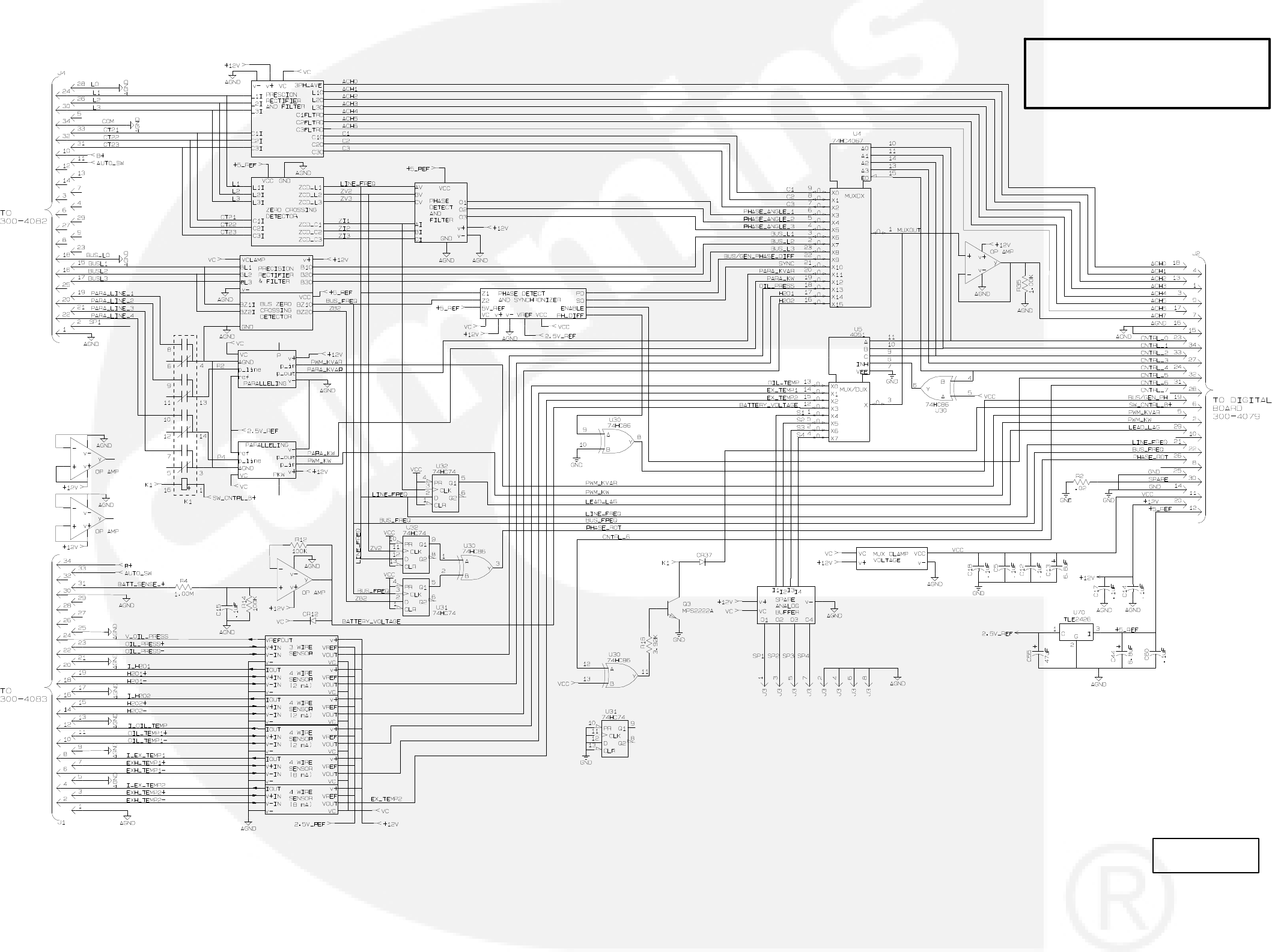
ANALOG BOARD (A33)
9-9
NO. 300−4080
REV.e
MODIFIED 11/2000
THIS IS A REPRESENTATIVE (GENERIC)
SCHEMATIC/WIRING DIAGRAM. FOR
TROUBLESHOOTING, REFER TO THE
WIRING DIAGRAM PACKAGE THAT WAS
INCLUDED WITH YOUR GENSET.
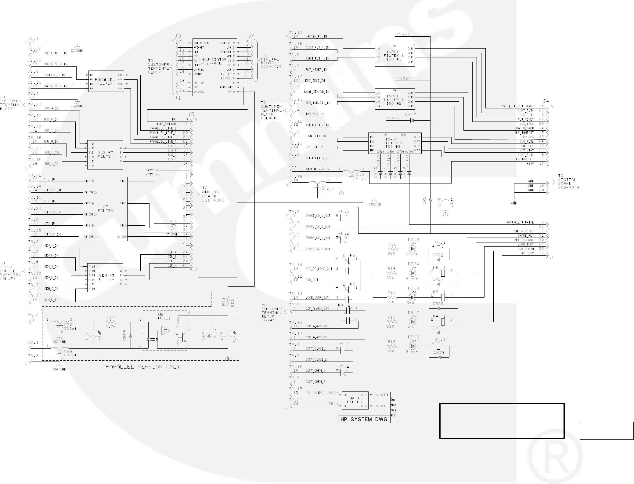
9-10
CUSTOMER INTERFACE BOARD (A34)
NO. 300−4462 sh1
REV. J
MODIFIED 8/2008
THIS IS A REPRESENTATIVE (GENERIC)
SCHEMATIC/WIRING DIAGRAM. FOR
TROUBLESHOOTING, REFER TO THE
WIRING DIAGRAM PACKAGE THAT WAS
INCLUDED WITH YOUR GENSET.
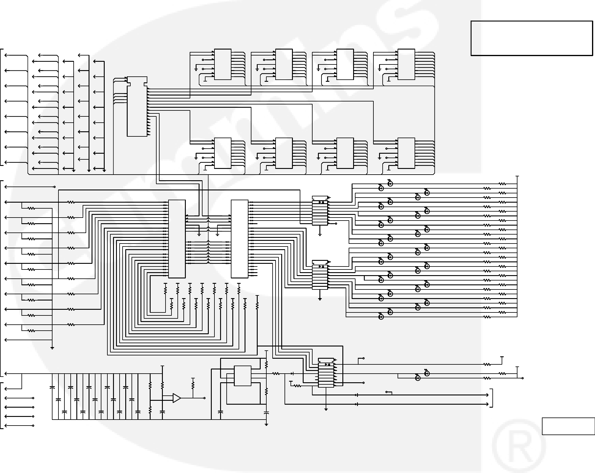
9-11
DISPLAY BOARD (A35)
NO. 300−4286 sh 1
REV. M Sys. HP
MODIFIED 1/2008
THIS IS A REPRESENTATIVE (GENERIC)
SCHEMATIC/WIRING DIAGRAM. FOR
TROUBLESHOOTING, REFER TO THE
WIRING DIAGRAM PACKAGE THAT WAS
INCLUDED WITH YOUR GENSET.
+
+
DWG
QTY
BA12
BA2
BA3
BA4
BA5
BAD2
BAD3
BAD4
BAD5
BAD6
BAD7
BA1
BA2
BA3
BA4
BA5
BA6
BA7
BA8
BA9
BA10
BA11
BA12
BWR
BRD
BCS7
BAD0 BA0
BAD1
BCS7
BWRBWRBWRBWR
BA0
BA1
BAD0
BAD1
BAD2
BAD3
BAD4
BAD5
BAD6
BA0
BA1
BAD0
BAD1
BAD2
BAD3
BAD4
BAD5
BAD6
BA0
BA1
BAD0
BAD1
BAD2
BAD3
BAD4
BAD5
BAD6
BA0
BA1
BAD0
BAD1
BAD2
BAD3
BAD4
BAD5
BAD6
BWR BWR BWR BWR
BA0
BA1
BAD0
BAD1
BAD2
BAD3
BAD4
BAD5
BAD6
BA0
BA1
BAD0
BAD1
BAD2
BAD3
BAD4
BAD5
BAD6
BA0
BA1
BAD0
BAD1
BAD2
BAD3
BAD4
BAD5
BAD6
BA0
BA1
BAD0
BAD1
BAD2
BAD3
BAD4
BAD5
BAD6
SELF_TEST
MENU
DISPLAY(RT_BOTTOM)
DISPLAY(RT_TOP)
DISPLAY(LF_BOTTOM)
DISPLAY(LF_TOP)
CB_OPEN
CB_CLOSED
PHASE_SELECT
GND
VCC
VCC
RESET_
BRD
BWR
BA0
BA1
BAD0
BAD1
BAD2
BAD3
BAD4
BAD5
BAD6
BAD7
BRD
BWR
BA0
BA1
BAD0
BAD1
BAD2
BAD3
BAD4
BAD5
BAD6
BAD7
SELF_TEST
ARROW_RIGHT_BOTTOM
NON−AUTO
WARNING
ARROW_MENU
ARROW_RIGHT_TOP
ARROW_RESET
ARROW_LEFT_BOTTOM
ARROW_LEFT_TOP
SHUTDOWN
GENERATOR_CLOSED
UTILITY_CLOSED
PHASE_C
PHASE_B
PHASE_A
LOWER_SCALE
UPPER_SCALE
J1
2
B+
U7
1K
56
J5
36
U5
10K
@VCC
5
R7
220
VCC
J5
25
J5
4
GND
BL
VCC
GND
DS21 Green
34
C8
.1uF
J5
54
J1
7
VCC
J5
30
C13
.1uF
U25
74HC154
CS1
18
CS2
19
A0
23
A1
22
A2
21
A3
20
Y01
Y12
Y23
Y34
Y45
Y56
Y67
Y78
Y89
Y910
Y1011
Y1113
Y1214
Y1315
Y1416
Y1517
U12
10K
@VCC
4
U12
10K
@VCC
9
R14
220
J5
3
U4
DLG2416
CE1
1
CE2
2
CLR
3
CUE
4
BL
18
WR
6
CU
5
A08
A17
D011
D112
D213
D314
D417
D516
D615
DS25 Green
34
R13
220
J5
24
C17
.01uF
J5
53
J5
45
+5V_BAT
DS10 Green
12
R3
220
U5
10K
@VCC
7
CLR
J5
34
J6
2
U12
10K
@VCC
10
J5
14
U14
1K
78
C5
.1uF
C3
.1uF
J5
22
CLR
R10
220
GND
+5V_BAT
GND
J5
55
R19
220
VCC
U6
1K
12
DS11 Green
34
CR6
BL
J5
39
R12
220
J5
40
VCC
J5
31
U20
8255
PA3
1PA2
2PA1
3PA0
4
‘RD 5
‘CS 6
A1 8
A0 9
PC7
10 PC6
11 PC5
12 PC4
13
PC0
14
PC1
15
PC2
16
PC3
17
PB0
18
PB1
19
PB2
20
PB3
21
PB4
22
PB5
23
PB6
24
PB7
25
D7 27
D6 28
D5 29
D4 30
D3 31
D2 32
D1 33
D0 34
RESET 35
‘WR 36
PA7
37 PA6
38 PA5
39 PA4
40
VCC
R24
220
GND
U10
DLG2416
CE1
1
CE2
2
CLR
3
CUE
4
BL
18
WR
6
CU
5
A08
A17
D011
D112
D213
D314
D417
D516
D615
DS27 Green
34
R35
220
GND
C12
.1uF
C6
.1uF
R18
220
U15
1K
12
J5
47
C15
.1uF
U26
1K
12
GND
DS21 Green
12
C22
22uF
J5
15
R30
220
R20
220
U13
2803A
1
2
3
4
5
6
7
8
CLAMP
10
11
12
13
14
15
16
17
18
GND
9R1
220
DS20 Green
34
J5
2
J1
14
J5
46
C2
.1uF
J5
37
U11
DLG2416
CE1
1
CE2
2
CLR
3
CUE
4
BL
18
WR
6
CU
5
A08
A17
D011
D112
D213
D314
D417
D516
D615
DS11 Green
12
U6
1K
78
J1
12
R15
220
CR2
J5
10
GND
DS27 Green
12
BL
J5
7
U9
DLG2416
CE1
1
CE2
2
CLR
3
CUE
4
BL
18
WR
6
CU
5
A08
A17
D011
D112
D213
D314
D417
D516
D615
R34
10K
U24
7555
B−
1
TRIG
2OUT
3
RST
4
CV
5THOLD
6
DISC
7
B+8
J5
35
J5
27
J6
1
R51
4.7K
U14
1K
34
DS12 Green
12
J5
12
BL
GND
U2
DLG2416
CE1
1
CE2
2
CLR
3
CUE
4
BL
18
WR
6
CU
5
A08
A17
D011
D112
D213
D314
D417
D516
D615
C1
.1uF
J5
19
U6
1K
34
CLR
U6
1K
56
GND
U12
10K
@VCC
5
DS29 Green
12 R21
220
R49
1.8M
VCC
LP_OFF
DS24 Green
34
C7
.1uF
U15
1K
78
DS23 Green
34
R41
220
SELF_TEST
U23
2803A
1
2
3
4
5
6
7
8
CLAMP
10
11
12
13
14
15
16
17
18
GND
9
J5
33
CLR
R23
220
U12
10K
@VCC
7
CR3
J5
11
VCC
U12
10K
@VCC
6
DS36 Green
34
J5
44
J1
6
J5
18
CLR
J1
3
J1
11
J5
23
DS10 Green
34
J5
41
R47
4.7M
VCC
GND
CLR
R31
220
J5
26
U21
2803A
1
2
3
4
5
6
7
8
CLAMP
10
11
12
13
14
15
16
17
18
GND
9
RESET
DS23 Green
12
U22
8255
PA3 1
PA2 2
PA1 3
PA0 4
‘RD
5‘CS
6
A1
8A0
9
PC7 10
PC6 11
PC5 12
PC4 13
PC0 14
PC1 15
PC2 16
PC3 17
PB0 18
PB1 19
PB2 20
PB3 21
PB4 22
PB5 23
PB6 24
PB7 25
D7
27 D6
28 D5
29 D4
30 D3
31 D2
32 D1
33 D0
34
RESET
35 ‘WR
36 PA7 37
PA6 38
PA5 39
PA4 40
J5
29
U15
1K
56
J5
21
CLR
U5
10K
@VCC
6
U7
1K
12
J5
8
U12
10K
@VCC
8
J5
56
DS25 Green
12
R39
10K
GND
J5
51
R17
220
U5
10K
@VCC
3
C4
.1uF
U7
1K
34
R9
220
J1
9
U12
10K
@VCC
2
J5
16
R5
220
J5
43
R2
220
J5
32
U12
10K
@VCC
3
J5
9
J1
10
C18
.1uF
U8
DLG2416
CE1
1
CE2
2
CLR
3
CUE
4
BL
18
WR
6
CU
5
A08
A17
D011
D112
D213
D314
D417
D516
D615
+5V_BAT
GND
U5
10K
@VCC
4
R32
100K
J5
17
BL
J1
5
DS14 Green
34
U26
1K
34
J5
48
R40
220
R29
220
DS24 Green
12
J5
13
GND
R4
220
U7
1K
78
J5
6
CLR
J5
20
U15
1K
34
U14
1K
56
J5
1
RESET
VCC
C11
22uF
R6
220
J1
13
GND
U1
DLG2416
CE1
1
CE2
2
CLR
3
CUE
4
BL
18
WR
6
CU
5
A08
A17
D011
D112
D213
D314
D417
D516
D615
DS12 Green
34
BL
VCC
DS36 Green
12
GND
U3
DLG2416
CE1
1
CE2
2
CLR
3
CUE
4
BL
18
WR
6
CU
5
A08
A17
D011
D112
D213
D314
D417
D516
D615
R28
220
VCC
BL
C10
.1uF
R8
220
R16
220
J5
38
R22
220
U14
1K
12
+5V_REF
BL
DS20 Green
12
C20
.1uF
J5
42
GND
J5
28
SELF_TEST
BL
C19
.1uF
DS29 Green
34
J1
4
J5
5
U16
3302
+
5
−
42
+12V
CLR
U5
10K
@VCC
2
R11
220
R37
100K
GND
DS14 Green
12
VCC
R36
220
R50
100
R25
4.7K
DS13 Amber
12
DS13 Amber
34
DS22 Red
12
DS15 Red
12
DS15 Red
34
DS9 Red
34
DS22 Red
34
DS9 Red
12
TO
DIGITAL BOARD
TO
DIGITAL BOARD
TO
MEMBRANE SWITCH
TO
RUN/STOP/REMOTE
SWITCH
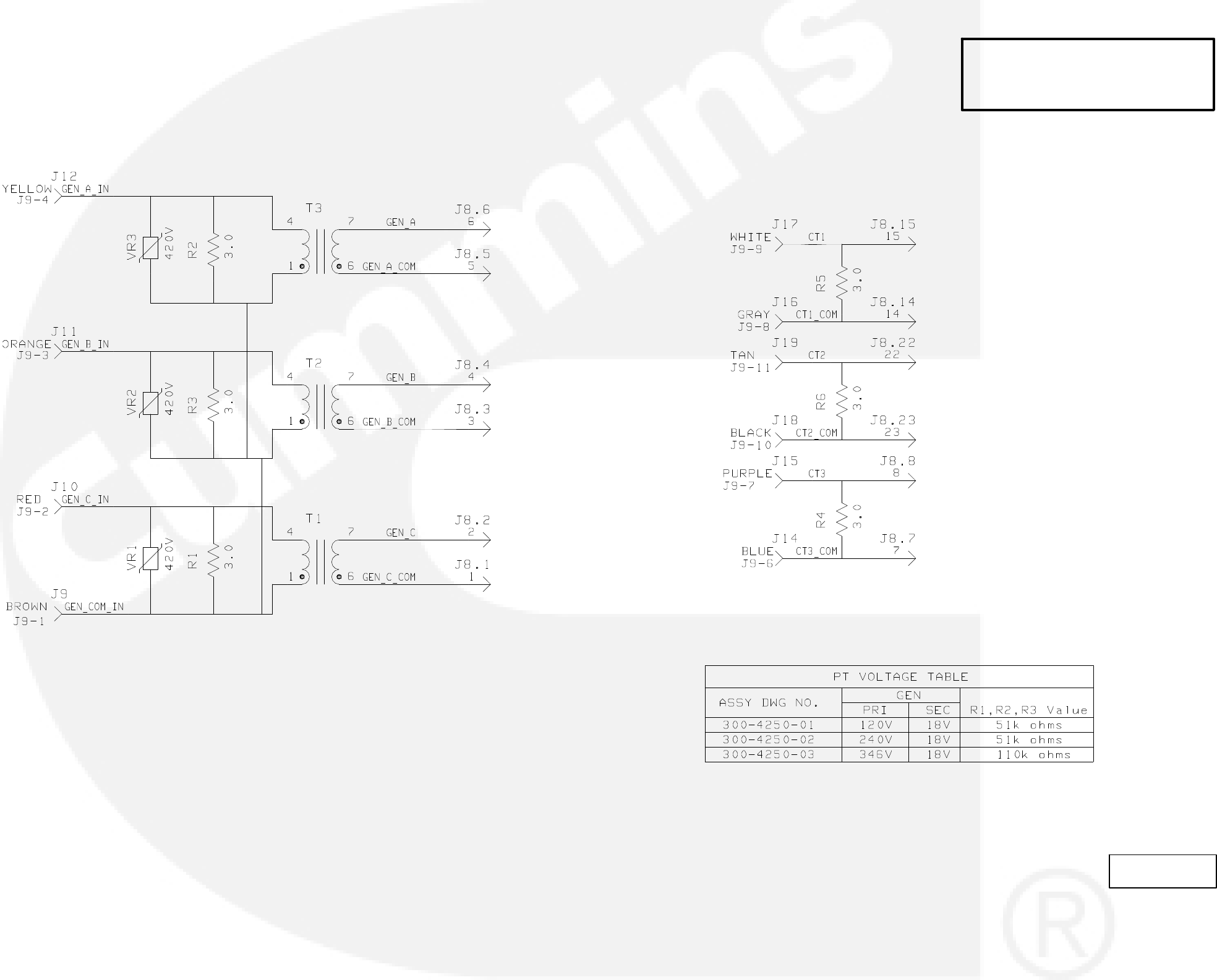
9-12
PC/CT BOARD (A36)
NO. 300−4250 sh1
REV. C SYS. HP
MODIFIED 1/24/95
THIS IS A REPRESENTATIVE (GENERIC)
SCHEMATIC/WIRING DIAGRAM. FOR
TROUBLESHOOTING, REFER TO THE
WIRING DIAGRAM PACKAGE THAT WAS
INCLUDED WITH YOUR GENSET.
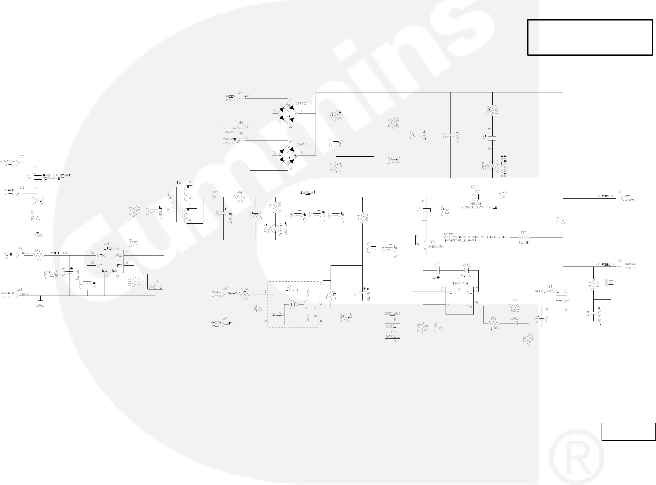
VOLTAGE REGULATOR OUTPUT MODULE (A37)
9-13
NO. 300−4085 sh1
REV. L
MODIFIED 10/2002
THIS IS A REPRESENTATIVE (GENERIC)
SCHEMATIC/WIRING DIAGRAM. FOR
TROUBLESHOOTING, REFER TO THE
WIRING DIAGRAM PACKAGE THAT WAS
INCLUDED WITH YOUR GENSET.
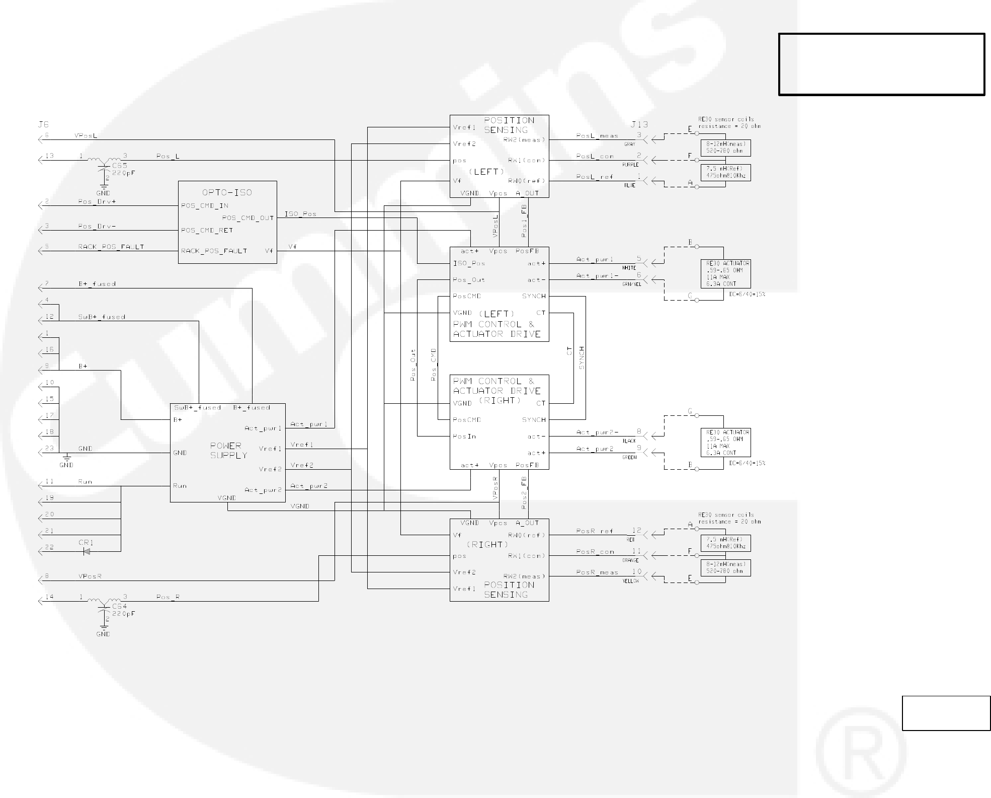
9-14
GOVERNOR OUTPUT BOARD (A38)
NO.300-4724 sh1
REV. J
MODIFIED 9/2005
THIS IS A REPRESENTATIVE (GENERIC)
SCHEMATIC/WIRING DIAGRAM. FOR
TROUBLESHOOTING, REFER TO THE
WIRING DIAGRAM PACKAGE THAT WAS
INCLUDED WITH YOUR GENSET.
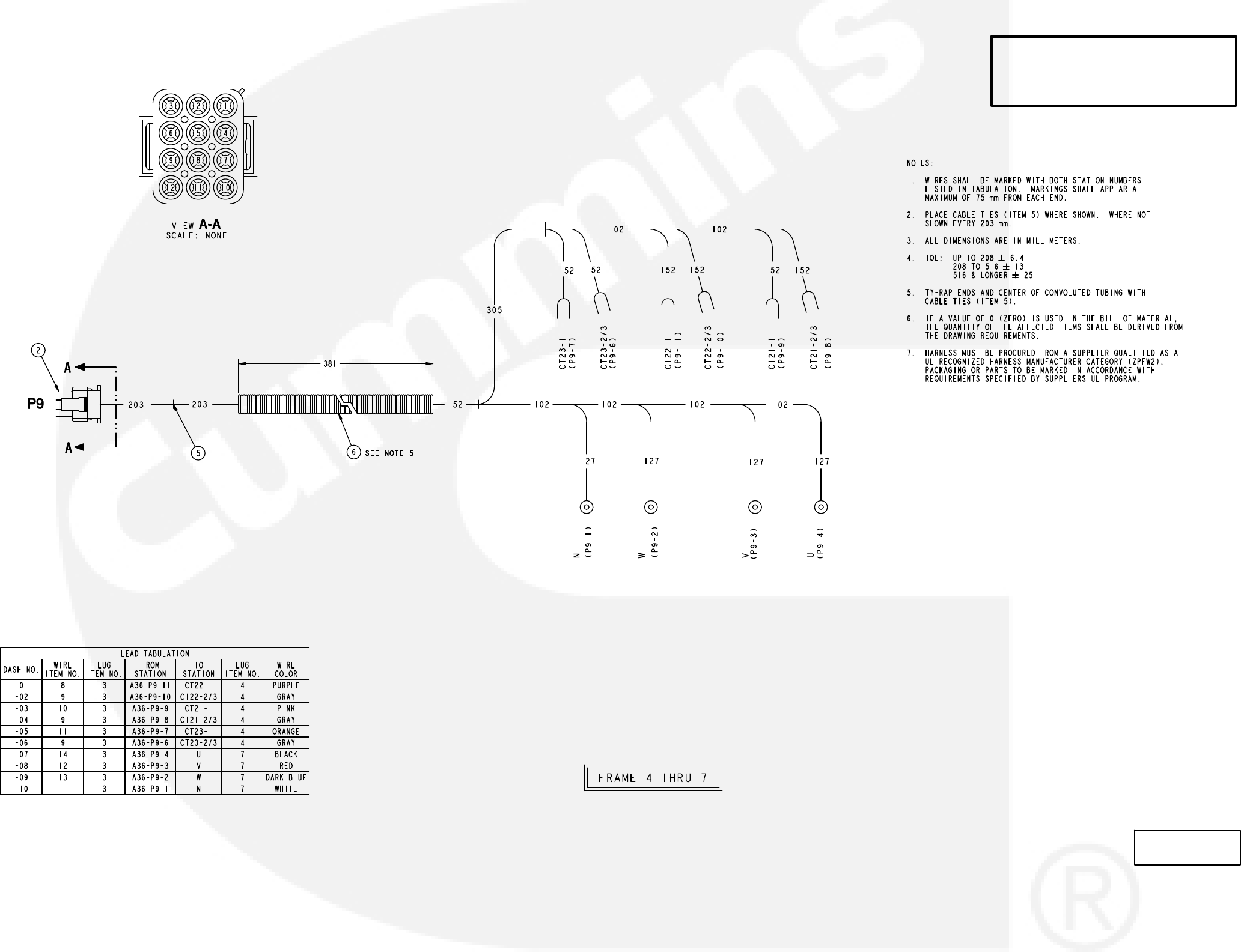
PT/CT WIRING HARNESS
9-15
NO. 338−3019 sh1
REV. T
MODIFIED 9/2011
THIS IS A REPRESENTATIVE (GENERIC)
SCHEMATIC/WIRING DIAGRAM. FOR
TROUBLESHOOTING, REFER TO THE
WIRING DIAGRAM PACKAGE THAT WAS
INCLUDED WITH YOUR GENSET.
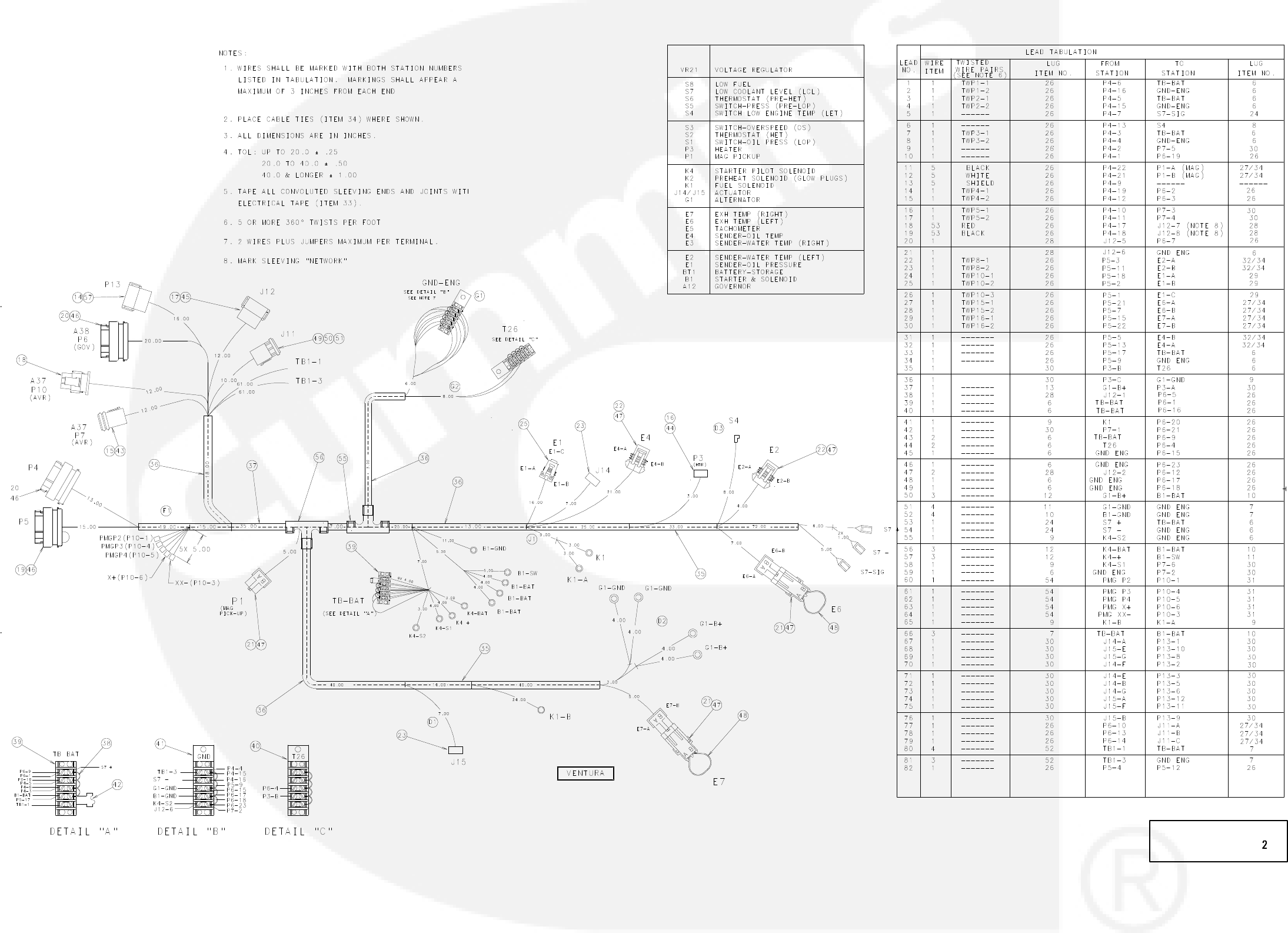
9-16
ENGINE WIRING HARNESS
No. 338−3377 sh 2of 2
Rev. J Sys: revisio
Modified 4/2002
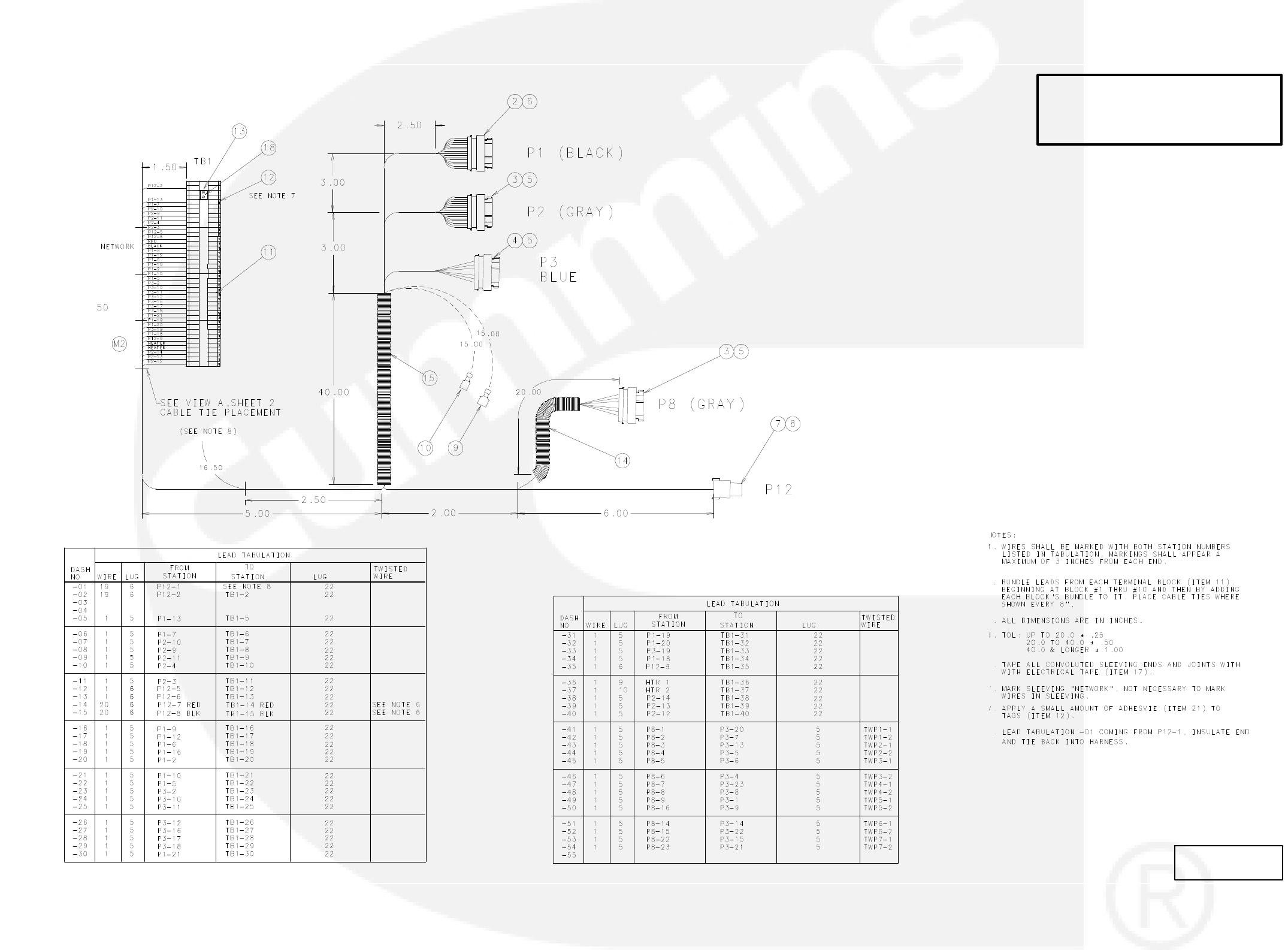
9-17
ACCESSORY BOX INTERCONNECTION HARNESS DIAGRAM
No. 338−3199 sh1
Rev. M Sys:CADAM
Modified 8/2003
THIS IS A REPRESENTATIVE (GENERIC)
SCHEMATIC/WIRING DIAGRAM. FOR
TROUBLESHOOTING, REFER TO THE
WIRING DIAGRAM PACKAGE THAT WAS
INCLUDED WITH YOUR GENSET.
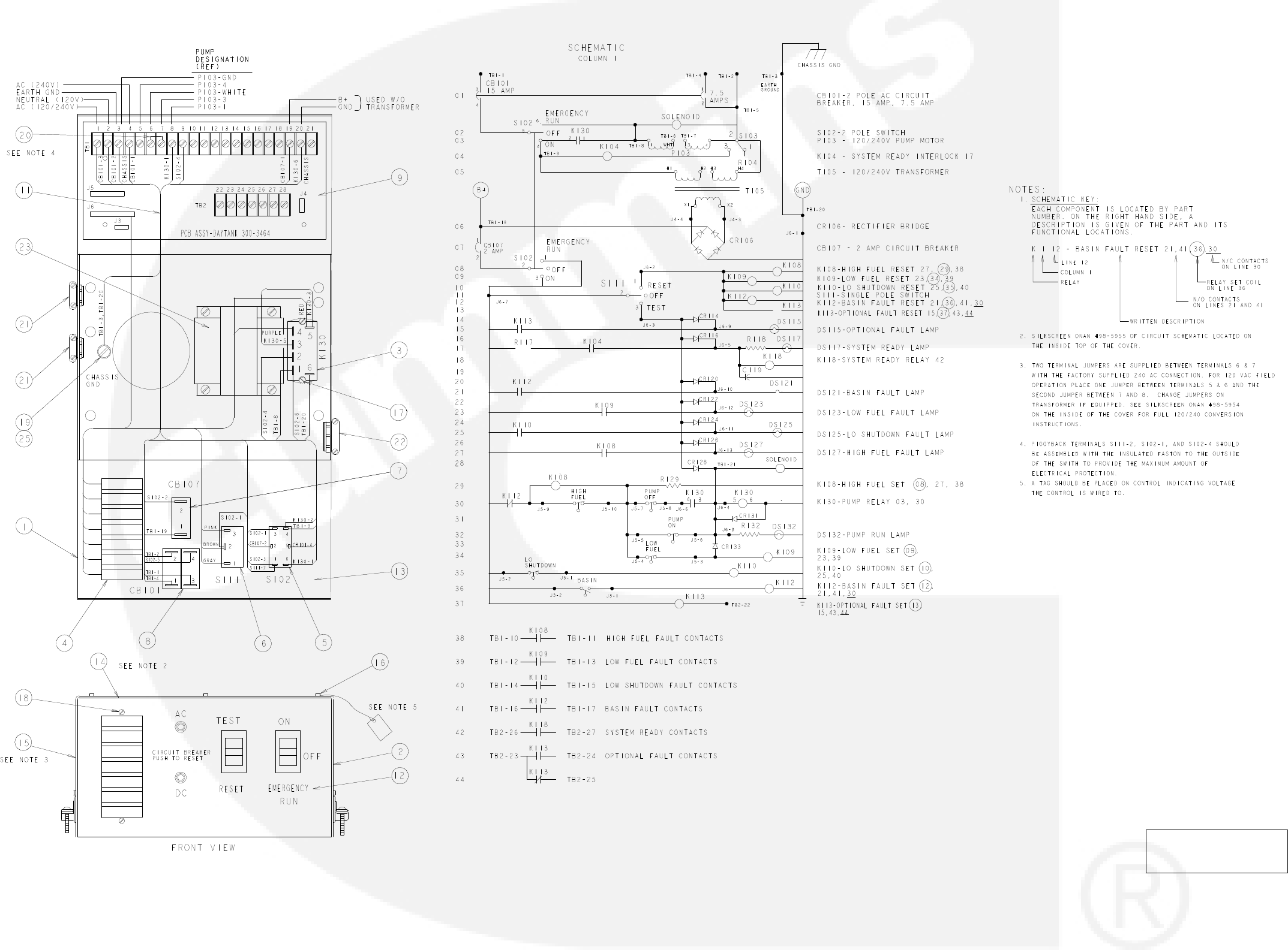
9-18
DAY TANK PUMP CONTROL WIRING
NO. 625-2141
REV. R
MODIFIED 3/2006
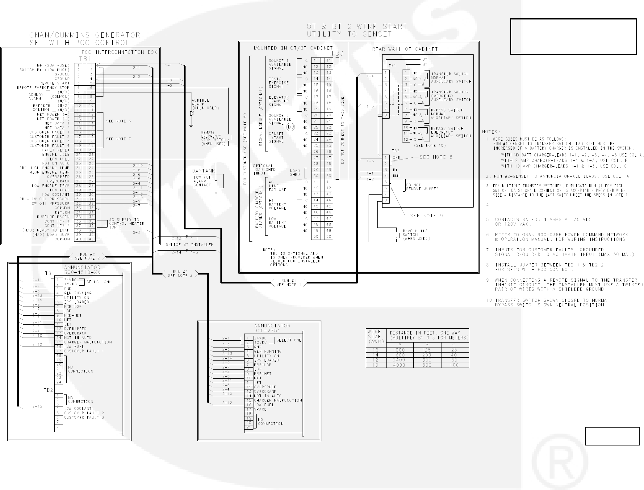
ACCESSORY INTERCONNECT DIAGRAM
9-19
NO.630−1345 sh1
REV. j
MODIFIED 11/1996
THIS IS A REPRESENTATIVE (GENERIC)
SCHEMATIC/WIRING DIAGRAM. FOR
TROUBLESHOOTING, REFER TO THE
WIRING DIAGRAM PACKAGE THAT WAS
INCLUDED WITH YOUR GENSET.
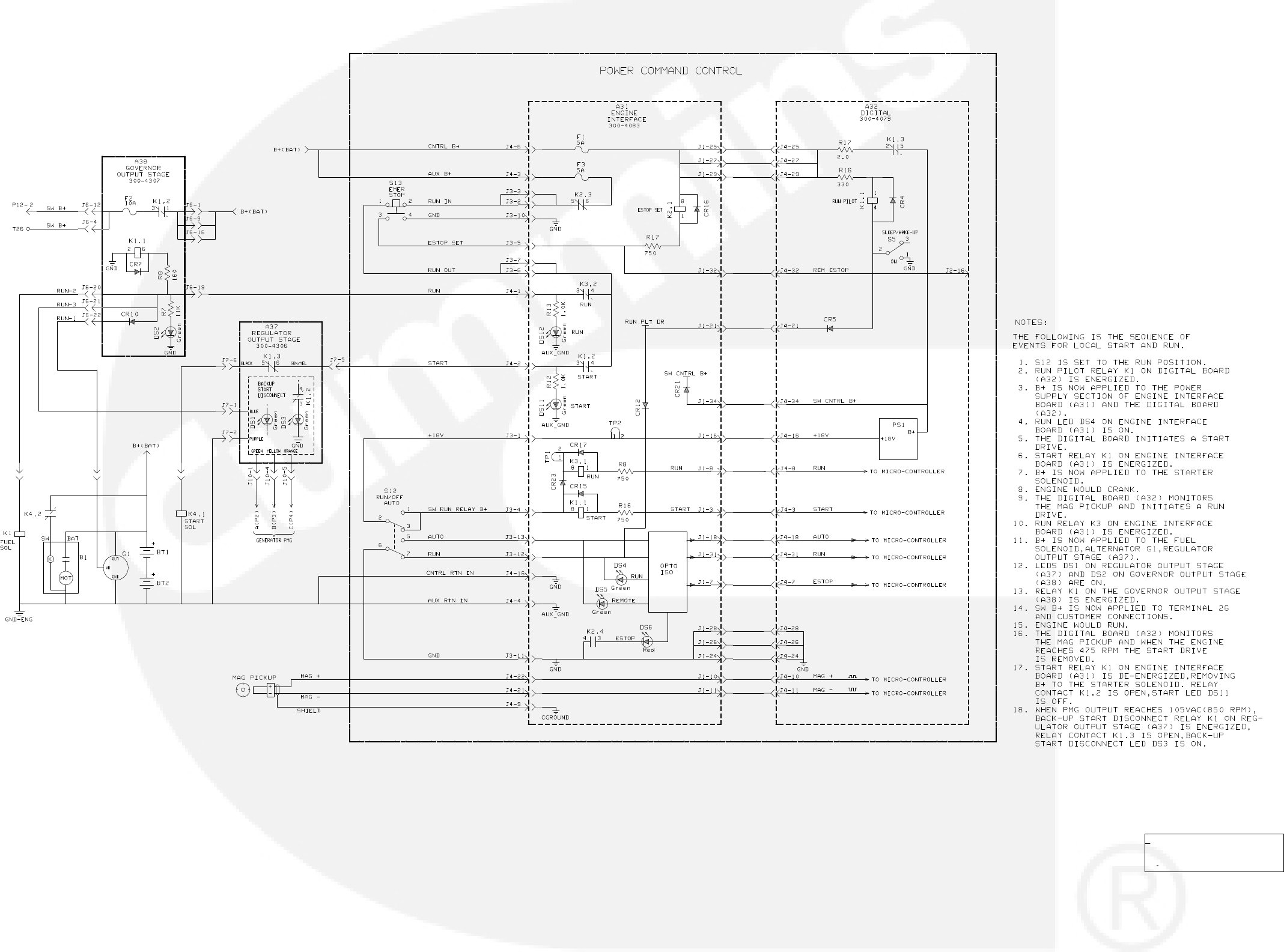
9-20
SEQUENCE OF OPERATION (LOCAL START AND RUN)
No. 612-6679 sh 1 of 2
Rev. B Sys: HP
Modified 11/21/95
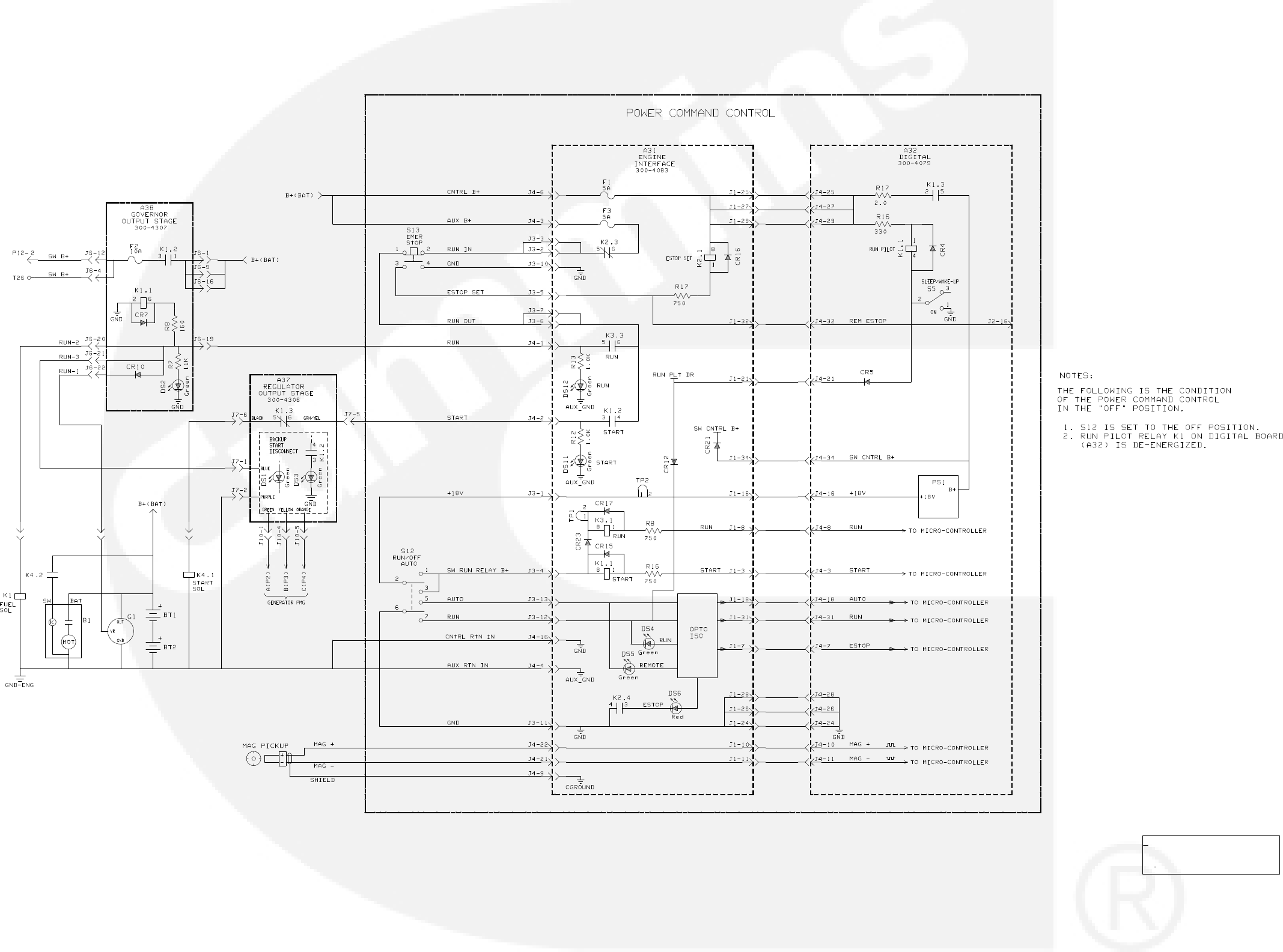
SEQUENCE OF OPERATION (LOCAL STOP)
9-21
No. 612-6679 sh 2 of 2
Rev. B Sys: HP
Modified 11/21/95
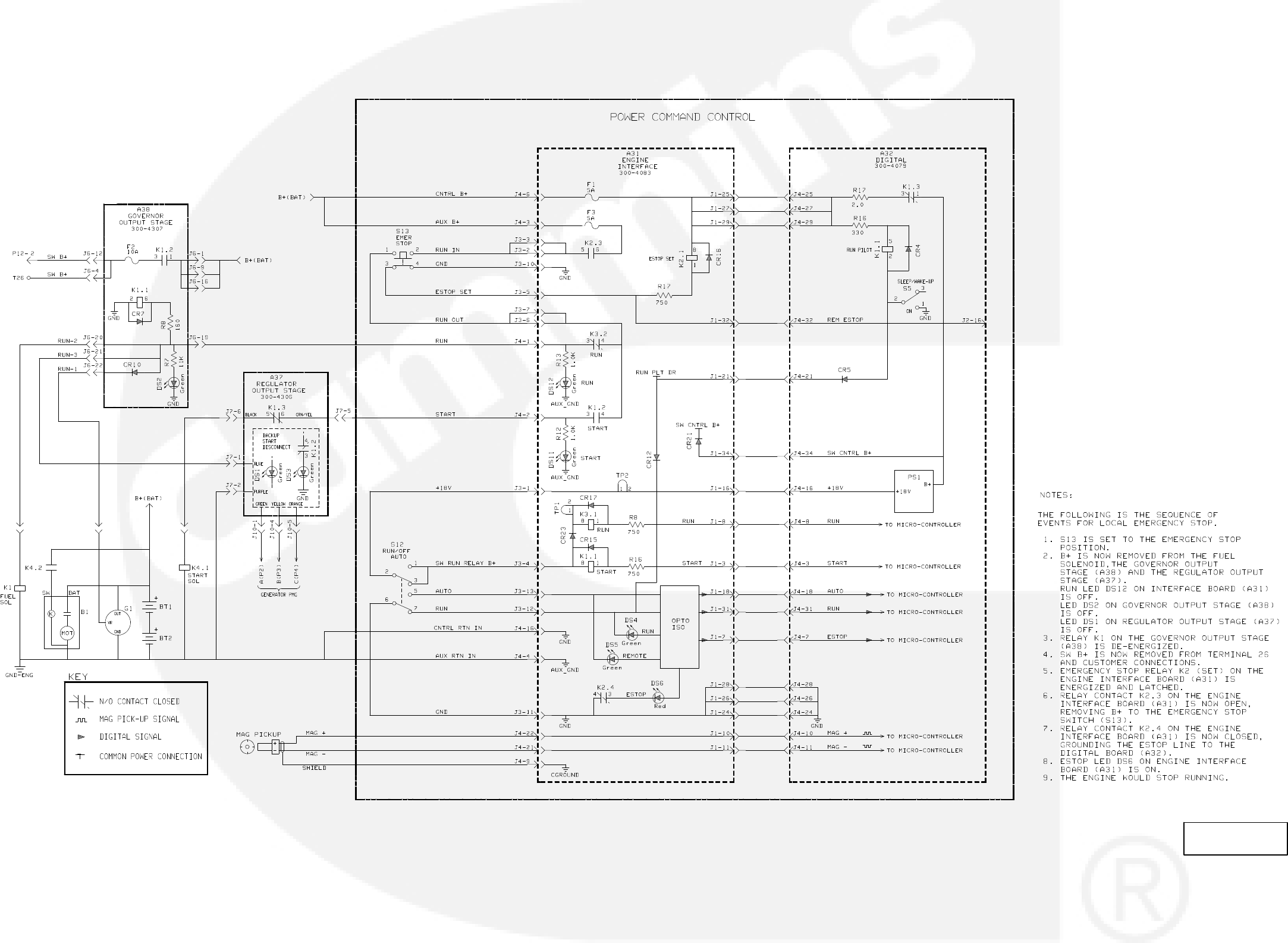
9-22
SEQUENCE OF OPERATION (LOCAL EMERGENCY STOP)
NO.612−6680 sh10f1
REV. A
MODIFIED 8/25/94


Cummins Power Generation
1400 73rd Ave. NE
Minneapolis, MN 55432 USA
Phone 1 763 574 5000
Toll-free 1 800 888 6626
Fax 1 763 574 5298
Email ask.powergen@cummins.com
www.cumminspower.com
CumminsR, the “C” logo, and “Our energy working for you.”
are trademarks of Cummins Inc.
E2011 Cummins Power Generation, Inc. All rights reserved.
