900 0661_I10(AG) 0661 Onan Power Command PCC1302 Controller Owners Manual (06 2014)
User Manual: 900-0661 Onan PowerCommand PCC1302 Controller Owners manual (06-2014)
Open the PDF directly: View PDF ![]() .
.
Page Count: 224 [warning: Documents this large are best viewed by clicking the View PDF Link!]

Owners Manual
Operator/Installation
Controller
PowerCommand1302
English
Original Instructions 6-2014 900−0661 (Issue 10)
58
“Intentionally Left Blank”

i
Table of Contents
SECTION TITLE PAGE
Foreword viii . . . . . . . . . . . . . . . . . . . . . . . . . . . . . . . . . . . . . . . . . . . . . . . . . . . . . . . . . . . . . . . . . . . . . . .
Warranty viii . . . . . . . . . . . . . . . . . . . . . . . . . . . . . . . . . . . . . . . . . . . . . . . . . . . . . . . . . . . . . . . . . . . . . . . .
Important Safety Instructions ix . . . . . . . . . . . . . . . . . . . . . . . . . . . . . . . . . . . . . . . . . . . . . . . . . . . . . .
1. Introduction 1-1 . . . . . . . . . . . . . . . . . . . . . . . . . . . . . . . . . . . . . . . . . . . . . . . . . . . . . . . . . . .
About This Manual 1-1 . . . . . . . . . . . . . . . . . . . . . . . . . . . . . . . . . . . . . . . . . . . . . . . . . . . . .
System Overview 1-1. . . . . . . . . . . . . . . . . . . . . . . . . . . . . . . . . . . . . . . . . . . . . . . . . . . . . .
Certifications 1-1. . . . . . . . . . . . . . . . . . . . . . . . . . . . . . . . . . . . . . . . . . . . . . . . . . . . . . . . . .
Connector Seal Standards 1-1. . . . . . . . . . . . . . . . . . . . . . . . . . . . . . . . . . . . . . . . . . . . . .
How to Obtain Service 1-1. . . . . . . . . . . . . . . . . . . . . . . . . . . . . . . . . . . . . . . . . . . . . . . . .
2. Description 2-1. . . . . . . . . . . . . . . . . . . . . . . . . . . . . . . . . . . . . . . . . . . . . . . . . . . . . . . . . . . .
Overview 2-1. . . . . . . . . . . . . . . . . . . . . . . . . . . . . . . . . . . . . . . . . . . . . . . . . . . . . . . . . . . . .
Kit Description 2-1. . . . . . . . . . . . . . . . . . . . . . . . . . . . . . . . . . . . . . . . . . . . . . . . . . . . . . . .
Additional Equipment 2-2. . . . . . . . . . . . . . . . . . . . . . . . . . . . . . . . . . . . . . . . . . . . . . . . . .
1302 Control Features 2-3. . . . . . . . . . . . . . . . . . . . . . . . . . . . . . . . . . . . . . . . . . . . . . . . .
Current Requirements 2-3. . . . . . . . . . . . . . . . . . . . . . . . . . . . . . . . . . . . . . . . . . . . . . . . . .
1302 Control System 2-3. . . . . . . . . . . . . . . . . . . . . . . . . . . . . . . . . . . . . . . . . . . . . . . . . . .
Control Module 2-3. . . . . . . . . . . . . . . . . . . . . . . . . . . . . . . . . . . . . . . . . . . . . . . . . . . . . . . .
Control Run/Off/Auto Switch 2-3. . . . . . . . . . . . . . . . . . . . . . . . . . . . . . . . . . . . . . . . . . . .
Operator Panel 2-4. . . . . . . . . . . . . . . . . . . . . . . . . . . . . . . . . . . . . . . . . . . . . . . . . . . . . . . .
Operator Panel Connections 2-4. . . . . . . . . . . . . . . . . . . . . . . . . . . . . . . . . . . . . . . . . . . .
Control Inputs and Outputs 2-5. . . . . . . . . . . . . . . . . . . . . . . . . . . . . . . . . . . . . . . . . . . . .
Control Inputs 2-5. . . . . . . . . . . . . . . . . . . . . . . . . . . . . . . . . . . . . . . . . . . . . . . . . . . . . . . . .
Control Outputs 2-5. . . . . . . . . . . . . . . . . . . . . . . . . . . . . . . . . . . . . . . . . . . . . . . . . . . . . . .
Protection and Faults 2-6. . . . . . . . . . . . . . . . . . . . . . . . . . . . . . . . . . . . . . . . . . . . . . . . . .
Fault Codes 2-6. . . . . . . . . . . . . . . . . . . . . . . . . . . . . . . . . . . . . . . . . . . . . . . . . . . . . . . . . . .
Genset Protective Functions 2-6. . . . . . . . . . . . . . . . . . . . . . . . . . . . . . . . . . . . . . . . . . . .
Engine Protection 2-6. . . . . . . . . . . . . . . . . . . . . . . . . . . . . . . . . . . . . . . . . . . . . . . . . . . . . .
Alternator Protection 2-7. . . . . . . . . . . . . . . . . . . . . . . . . . . . . . . . . . . . . . . . . . . . . . . . . . .
Current Draw 2-7. . . . . . . . . . . . . . . . . . . . . . . . . . . . . . . . . . . . . . . . . . . . . . . . . . . . . . . . .
Running Mode 2-7. . . . . . . . . . . . . . . . . . . . . . . . . . . . . . . . . . . . . . . . . . . . . . . . . . . . . . . .
Parade Rest Mode 2-7. . . . . . . . . . . . . . . . . . . . . . . . . . . . . . . . . . . . . . . . . . . . . . . . . . . . .
Sleep Mode 2-7. . . . . . . . . . . . . . . . . . . . . . . . . . . . . . . . . . . . . . . . . . . . . . . . . . . . . . . . . . .
3. Installation 3-1. . . . . . . . . . . . . . . . . . . . . . . . . . . . . . . . . . . . . . . . . . . . . . . . . . . . . . . . . . . .
Mounting Guidelines 3-1. . . . . . . . . . . . . . . . . . . . . . . . . . . . . . . . . . . . . . . . . . . . . . . . . . .
Environmental Capability 3-2. . . . . . . . . . . . . . . . . . . . . . . . . . . . . . . . . . . . . . . . . . . . . . .
1302 Main Control Board 3-2. . . . . . . . . . . . . . . . . . . . . . . . . . . . . . . . . . . . . . . . . . . . . . .

ii
SECTION TITLE PAGE
1302 Operator Panel 3-2. . . . . . . . . . . . . . . . . . . . . . . . . . . . . . . . . . . . . . . . . . . . . . . . . . .
Control Wiring Information 3-2. . . . . . . . . . . . . . . . . . . . . . . . . . . . . . . . . . . . . . . . . . . . . .
Guidelines for Current Transformers 3-3. . . . . . . . . . . . . . . . . . . . . . . . . . . . . . . . . . . . .
Current Transformer Selection 3-3. . . . . . . . . . . . . . . . . . . . . . . . . . . . . . . . . . . . . . . . . .
Example of CT Sizing − Two Lead CT 3-3. . . . . . . . . . . . . . . . . . . . . . . . . . . . . . . . . . . .
Example of CT Sizing − Three Lead CT 3-4. . . . . . . . . . . . . . . . . . . . . . . . . . . . . . . . . .
Current Transformer Setup 3-4. . . . . . . . . . . . . . . . . . . . . . . . . . . . . . . . . . . . . . . . . . . . .
Two Lead CT Setup Example: 3-4. . . . . . . . . . . . . . . . . . . . . . . . . . . . . . . . . . . . . . . . . . .
Three Lead CT Setup Example 3-8. . . . . . . . . . . . . . . . . . . . . . . . . . . . . . . . . . . . . . . . . .
Battery Charging Alternator Connections 3-8. . . . . . . . . . . . . . . . . . . . . . . . . . . . . . . . .
Denso Type Charging Alternators 3-8. . . . . . . . . . . . . . . . . . . . . . . . . . . . . . . . . . . . . . . .
Bosch Type Charging Alternators 3-8. . . . . . . . . . . . . . . . . . . . . . . . . . . . . . . . . . . . . . . .
Alternator Connections 3-9. . . . . . . . . . . . . . . . . . . . . . . . . . . . . . . . . . . . . . . . . . . . . . . . .
Series Star 3-9. . . . . . . . . . . . . . . . . . . . . . . . . . . . . . . . . . . . . . . . . . . . . . . . . . . . . . . . . . .
Series Delta 3-9. . . . . . . . . . . . . . . . . . . . . . . . . . . . . . . . . . . . . . . . . . . . . . . . . . . . . . . . . .
Parallel Star 3-9. . . . . . . . . . . . . . . . . . . . . . . . . . . . . . . . . . . . . . . . . . . . . . . . . . . . . . . . . .
Double Delta 3-10. . . . . . . . . . . . . . . . . . . . . . . . . . . . . . . . . . . . . . . . . . . . . . . . . . . . . . . . .
Single Phase 3-10. . . . . . . . . . . . . . . . . . . . . . . . . . . . . . . . . . . . . . . . . . . . . . . . . . . . . . . . .
Guidelines for Engine Sensors 3-11. . . . . . . . . . . . . . . . . . . . . . . . . . . . . . . . . . . . . . . . .
Coolant Temperature Sensors 3-11. . . . . . . . . . . . . . . . . . . . . . . . . . . . . . . . . . . . . . . . . .
Oil Pressure Sensors 3-11. . . . . . . . . . . . . . . . . . . . . . . . . . . . . . . . . . . . . . . . . . . . . . . . .
Lube Oil Pressure Switch 3-12. . . . . . . . . . . . . . . . . . . . . . . . . . . . . . . . . . . . . . . . . . . . . .
Control Board Connections 3-14. . . . . . . . . . . . . . . . . . . . . . . . . . . . . . . . . . . . . . . . . . . .
Electronic Governor Connections 3-19. . . . . . . . . . . . . . . . . . . . . . . . . . . . . . . . . . . . . . .
Kit Installation 3-20. . . . . . . . . . . . . . . . . . . . . . . . . . . . . . . . . . . . . . . . . . . . . . . . . . . . . . . .
Setup, Trims, and Adjustments 3-26. . . . . . . . . . . . . . . . . . . . . . . . . . . . . . . . . . . . . . . . .
Alternator Control Adjustments 3-34. . . . . . . . . . . . . . . . . . . . . . . . . . . . . . . . . . . . . . . . .
AVR Enable/Disable Feature 3-35. . . . . . . . . . . . . . . . . . . . . . . . . . . . . . . . . . . . . . . . . . .
Digital Output Voltage Regulation 3-35. . . . . . . . . . . . . . . . . . . . . . . . . . . . . . . . . . . . . . .
Torque-Matched Volts/Hz Overload Control 3-35. . . . . . . . . . . . . . . . . . . . . . . . . . . . . .
Battleshort Mode 3-35. . . . . . . . . . . . . . . . . . . . . . . . . . . . . . . . . . . . . . . . . . . . . . . . . . . . .
Genset Tuning 3-36. . . . . . . . . . . . . . . . . . . . . . . . . . . . . . . . . . . . . . . . . . . . . . . . . . . . . . .
V/Hz Curve 3-36. . . . . . . . . . . . . . . . . . . . . . . . . . . . . . . . . . . . . . . . . . . . . . . . . . . . . . . . . .
Governor 3-37. . . . . . . . . . . . . . . . . . . . . . . . . . . . . . . . . . . . . . . . . . . . . . . . . . . . . . . . . . . .
Governor Tuning 3-37. . . . . . . . . . . . . . . . . . . . . . . . . . . . . . . . . . . . . . . . . . . . . . . . . . . . .
Engine Startup 3-37. . . . . . . . . . . . . . . . . . . . . . . . . . . . . . . . . . . . . . . . . . . . . . . . . . . . . . .
Alternator Startup 3-37. . . . . . . . . . . . . . . . . . . . . . . . . . . . . . . . . . . . . . . . . . . . . . . . . . . . .
Setup for Gain Tuning 3-37. . . . . . . . . . . . . . . . . . . . . . . . . . . . . . . . . . . . . . . . . . . . . . . . .
Gain Tuning Parameters 3-38. . . . . . . . . . . . . . . . . . . . . . . . . . . . . . . . . . . . . . . . . . . . . . .
Controller Calibration 3-41. . . . . . . . . . . . . . . . . . . . . . . . . . . . . . . . . . . . . . . . . . . . . . . . .
1302 Control Functions 3-46. . . . . . . . . . . . . . . . . . . . . . . . . . . . . . . . . . . . . . . . . . . . . . . .
Remote Start Mode 3-46. . . . . . . . . . . . . . . . . . . . . . . . . . . . . . . . . . . . . . . . . . . . . . . . . . .
Remote Emergency Stop 3-46. . . . . . . . . . . . . . . . . . . . . . . . . . . . . . . . . . . . . . . . . . . . . .
Local Emergency Stop 3-46. . . . . . . . . . . . . . . . . . . . . . . . . . . . . . . . . . . . . . . . . . . . . . . .

iii
SECTION TITLE PAGE
Emergency Stop 3-46. . . . . . . . . . . . . . . . . . . . . . . . . . . . . . . . . . . . . . . . . . . . . . . . . . . . . .
12/24V Battery 3-46. . . . . . . . . . . . . . . . . . . . . . . . . . . . . . . . . . . . . . . . . . . . . . . . . . . . . . .
Engine Starting 3-46. . . . . . . . . . . . . . . . . . . . . . . . . . . . . . . . . . . . . . . . . . . . . . . . . . . . . . .
Cycle Cranking 3-46. . . . . . . . . . . . . . . . . . . . . . . . . . . . . . . . . . . . . . . . . . . . . . . . . . . . . . .
Spark Ignition Power/Glow Plug Control 3-47. . . . . . . . . . . . . . . . . . . . . . . . . . . . . . . . .
Glow Plug Control 3-47. . . . . . . . . . . . . . . . . . . . . . . . . . . . . . . . . . . . . . . . . . . . . . . . . . . .
Preheat Processing 3-47. . . . . . . . . . . . . . . . . . . . . . . . . . . . . . . . . . . . . . . . . . . . . . . . . . .
Glow Plug Output Logic 3-48. . . . . . . . . . . . . . . . . . . . . . . . . . . . . . . . . . . . . . . . . . . . . . .
Start and Stop Time Delays (Cool Down) 3-48. . . . . . . . . . . . . . . . . . . . . . . . . . . . . . . .
Electronic Governor 3-48. . . . . . . . . . . . . . . . . . . . . . . . . . . . . . . . . . . . . . . . . . . . . . . . . . .
Engine Speed Sensing 3-49. . . . . . . . . . . . . . . . . . . . . . . . . . . . . . . . . . . . . . . . . . . . . . . .
Speed Governor Algorithm and Adjustment 3-49. . . . . . . . . . . . . . . . . . . . . . . . . . . . . .
Real Time Clock 3-50. . . . . . . . . . . . . . . . . . . . . . . . . . . . . . . . . . . . . . . . . . . . . . . . . . . . . .
Excerise Scheduler 3-51. . . . . . . . . . . . . . . . . . . . . . . . . . . . . . . . . . . . . . . . . . . . . . . . . . .
ATS Control 3-53. . . . . . . . . . . . . . . . . . . . . . . . . . . . . . . . . . . . . . . . . . . . . . . . . . . . . . . . . .
Dual Fuel 3-55. . . . . . . . . . . . . . . . . . . . . . . . . . . . . . . . . . . . . . . . . . . . . . . . . . . . . . . . . . . .
Battle Short Mode Option 3-55. . . . . . . . . . . . . . . . . . . . . . . . . . . . . . . . . . . . . . . . . . . . . .
Installations With an Operator Panel 3-55. . . . . . . . . . . . . . . . . . . . . . . . . . . . . . . . . . . .
Installations Without an Operator Panel 3-57. . . . . . . . . . . . . . . . . . . . . . . . . . . . . . . . .
Battle Short Mode 3-57. . . . . . . . . . . . . . . . . . . . . . . . . . . . . . . . . . . . . . . . . . . . . . . . . . . .
Installations with an Operator Panel 3-57. . . . . . . . . . . . . . . . . . . . . . . . . . . . . . . . . . . . .
Installations without an Operator Panel 3-58. . . . . . . . . . . . . . . . . . . . . . . . . . . . . . . . . .
4. Operator Panel Operation 4-1. . . . . . . . . . . . . . . . . . . . . . . . . . . . . . . . . . . . . . . . . . . . . .
Introduction 4-1. . . . . . . . . . . . . . . . . . . . . . . . . . . . . . . . . . . . . . . . . . . . . . . . . . . . . . . . . . .
Local Status Output Indicator 4-1. . . . . . . . . . . . . . . . . . . . . . . . . . . . . . . . . . . . . . . . . . .
Operating Modes 4-2. . . . . . . . . . . . . . . . . . . . . . . . . . . . . . . . . . . . . . . . . . . . . . . . . . . . . .
Off Mode 4-2. . . . . . . . . . . . . . . . . . . . . . . . . . . . . . . . . . . . . . . . . . . . . . . . . . . . . . . . . . . . .
Manual Run Mode 4-2. . . . . . . . . . . . . . . . . . . . . . . . . . . . . . . . . . . . . . . . . . . . . . . . . . . . .
Auto Mode 4-2. . . . . . . . . . . . . . . . . . . . . . . . . . . . . . . . . . . . . . . . . . . . . . . . . . . . . . . . . . . .
Emergency Stop Mode 4-2. . . . . . . . . . . . . . . . . . . . . . . . . . . . . . . . . . . . . . . . . . . . . . . . .
Sleep Mode 4-2. . . . . . . . . . . . . . . . . . . . . . . . . . . . . . . . . . . . . . . . . . . . . . . . . . . . . . . . . . .
Installations with an Operator Panel 4-3. . . . . . . . . . . . . . . . . . . . . . . . . . . . . . . . . . . . . .
Installations with a Manual Run/Off/Auto Switch 4-3. . . . . . . . . . . . . . . . . . . . . . . . . . .
Operator Panel 4-3. . . . . . . . . . . . . . . . . . . . . . . . . . . . . . . . . . . . . . . . . . . . . . . . . . . . . . . .
Graphical Display 4-3. . . . . . . . . . . . . . . . . . . . . . . . . . . . . . . . . . . . . . . . . . . . . . . . . . . . . .
Display Text / Symbolic Versions 4-3. . . . . . . . . . . . . . . . . . . . . . . . . . . . . . . . . . . . . . . . .
Display Menu Selection Buttons 4-4. . . . . . . . . . . . . . . . . . . . . . . . . . . . . . . . . . . . . . . . .
Previous Main Menu Button 4-4. . . . . . . . . . . . . . . . . . . . . . . . . . . . . . . . . . . . . . . . . . . . .
Off Button 4-5. . . . . . . . . . . . . . . . . . . . . . . . . . . . . . . . . . . . . . . . . . . . . . . . . . . . . . . . . . . .
Not In Auto Indicator 4-5. . . . . . . . . . . . . . . . . . . . . . . . . . . . . . . . . . . . . . . . . . . . . . . . . . .
Shutdown Indicator 4-5. . . . . . . . . . . . . . . . . . . . . . . . . . . . . . . . . . . . . . . . . . . . . . . . . . . .
Warning Indicator 4-5. . . . . . . . . . . . . . . . . . . . . . . . . . . . . . . . . . . . . . . . . . . . . . . . . . . . . .
Remote Start Indicator 4-5. . . . . . . . . . . . . . . . . . . . . . . . . . . . . . . . . . . . . . . . . . . . . . . . .

iv
SECTION TITLE PAGE
Auto Indicator 4-5. . . . . . . . . . . . . . . . . . . . . . . . . . . . . . . . . . . . . . . . . . . . . . . . . . . . . . . . .
Manual Run Indicator 4-5. . . . . . . . . . . . . . . . . . . . . . . . . . . . . . . . . . . . . . . . . . . . . . . . . .
Operator Panel System Messages 4-6. . . . . . . . . . . . . . . . . . . . . . . . . . . . . . . . . . . . . . .
Communication Messages 4-6. . . . . . . . . . . . . . . . . . . . . . . . . . . . . . . . . . . . . . . . . . . . . .
Event Messages 4-6. . . . . . . . . . . . . . . . . . . . . . . . . . . . . . . . . . . . . . . . . . . . . . . . . . . . . . .
Status Messages 4-6. . . . . . . . . . . . . . . . . . . . . . . . . . . . . . . . . . . . . . . . . . . . . . . . . . . . . .
Fault Messages 4-6. . . . . . . . . . . . . . . . . . . . . . . . . . . . . . . . . . . . . . . . . . . . . . . . . . . . . . .
Fault Reset / Acknowledgement 4-7. . . . . . . . . . . . . . . . . . . . . . . . . . . . . . . . . . . . . . . . .
Fault/Status Codes 4-8. . . . . . . . . . . . . . . . . . . . . . . . . . . . . . . . . . . . . . . . . . . . . . . . . . . .
Adjusting Default Settings 4-17. . . . . . . . . . . . . . . . . . . . . . . . . . . . . . . . . . . . . . . . . . . . .
Saving Your Changes 4-17. . . . . . . . . . . . . . . . . . . . . . . . . . . . . . . . . . . . . . . . . . . . . . . . .
Operator Menus 4-17. . . . . . . . . . . . . . . . . . . . . . . . . . . . . . . . . . . . . . . . . . . . . . . . . . . . . .
Engine Status Menu 4-17. . . . . . . . . . . . . . . . . . . . . . . . . . . . . . . . . . . . . . . . . . . . . . . . . .
Alternator Status Menu 4-17. . . . . . . . . . . . . . . . . . . . . . . . . . . . . . . . . . . . . . . . . . . . . . . .
Alternator Line-to-Line Voltage Menu 4-17. . . . . . . . . . . . . . . . . . . . . . . . . . . . . . . . . . . .
Alternator Line-to-Neutral Voltage Menu 4-18. . . . . . . . . . . . . . . . . . . . . . . . . . . . . . . . .
Alternator Single Phase Voltage Menu 4-18. . . . . . . . . . . . . . . . . . . . . . . . . . . . . . . . . .
Alternator Amperage Menu 4-18. . . . . . . . . . . . . . . . . . . . . . . . . . . . . . . . . . . . . . . . . . . .
Selecting Auto, Manual Run, and Off Modes 4-19. . . . . . . . . . . . . . . . . . . . . . . . . . . . .
Entering the Mode Change Access Code 4-19. . . . . . . . . . . . . . . . . . . . . . . . . . . . . . . .
Selecting Auto Mode 4-21. . . . . . . . . . . . . . . . . . . . . . . . . . . . . . . . . . . . . . . . . . . . . . . . . .
Selecting Manual Run Mode 4-23. . . . . . . . . . . . . . . . . . . . . . . . . . . . . . . . . . . . . . . . . . .
Aborting the Transition to Auto or Manual Run Mode 4-23. . . . . . . . . . . . . . . . . . . . . .
Selecting Off Mode 4-23. . . . . . . . . . . . . . . . . . . . . . . . . . . . . . . . . . . . . . . . . . . . . . . . . . .
Service Menus 4-24. . . . . . . . . . . . . . . . . . . . . . . . . . . . . . . . . . . . . . . . . . . . . . . . . . . . . . .
Status Menu 4-24. . . . . . . . . . . . . . . . . . . . . . . . . . . . . . . . . . . . . . . . . . . . . . . . . . . . . . . . .
Network Status Menus 4-24. . . . . . . . . . . . . . . . . . . . . . . . . . . . . . . . . . . . . . . . . . . . . . . .
History / About Menus 4-26. . . . . . . . . . . . . . . . . . . . . . . . . . . . . . . . . . . . . . . . . . . . . . . . .
History Submenu 4-26. . . . . . . . . . . . . . . . . . . . . . . . . . . . . . . . . . . . . . . . . . . . . . . . . . . . .
About Genset Submenus 4-26. . . . . . . . . . . . . . . . . . . . . . . . . . . . . . . . . . . . . . . . . . . . . .
About Control Submenu 4-26. . . . . . . . . . . . . . . . . . . . . . . . . . . . . . . . . . . . . . . . . . . . . . .
About Display Submenu 4-26. . . . . . . . . . . . . . . . . . . . . . . . . . . . . . . . . . . . . . . . . . . . . . .
Fault History Menu 4-28. . . . . . . . . . . . . . . . . . . . . . . . . . . . . . . . . . . . . . . . . . . . . . . . . . . .
Screen Adjust Menu 4-30. . . . . . . . . . . . . . . . . . . . . . . . . . . . . . . . . . . . . . . . . . . . . . . . . .
Adjusting Values/Parameters 4-30. . . . . . . . . . . . . . . . . . . . . . . . . . . . . . . . . . . . . . . . . . .
Screen Adjust Menu 4-30. . . . . . . . . . . . . . . . . . . . . . . . . . . . . . . . . . . . . . . . . . . . . . . . . .
5. 1302 Control Panel Service Menus 5-1. . . . . . . . . . . . . . . . . . . . . . . . . . . . . . . . . . . . . .
Service Menus 5-1. . . . . . . . . . . . . . . . . . . . . . . . . . . . . . . . . . . . . . . . . . . . . . . . . . . . . . . .
Setup Menus 5-3. . . . . . . . . . . . . . . . . . . . . . . . . . . . . . . . . . . . . . . . . . . . . . . . . . . . . . . . . .
Genset Service Menus 5-4. . . . . . . . . . . . . . . . . . . . . . . . . . . . . . . . . . . . . . . . . . . . . . . . .
Viewing Only 5-4. . . . . . . . . . . . . . . . . . . . . . . . . . . . . . . . . . . . . . . . . . . . . . . . . . . . . . . . . .
Menu Navigation 5-4. . . . . . . . . . . . . . . . . . . . . . . . . . . . . . . . . . . . . . . . . . . . . . . . . . . . . .
Viewing and Adjusting 5-6. . . . . . . . . . . . . . . . . . . . . . . . . . . . . . . . . . . . . . . . . . . . . . . . . .

v
SECTION TITLE PAGE
Setup Password Submenu 5-6. . . . . . . . . . . . . . . . . . . . . . . . . . . . . . . . . . . . . . . . . . . . . .
Adjusting Values/Parameters 5-6. . . . . . . . . . . . . . . . . . . . . . . . . . . . . . . . . . . . . . . . . . . .
Genset Service Submenus 5-8. . . . . . . . . . . . . . . . . . . . . . . . . . . . . . . . . . . . . . . . . . . . .
Genset Menu, Part 1 5-8. . . . . . . . . . . . . . . . . . . . . . . . . . . . . . . . . . . . . . . . . . . . . . . . . .
Genset Menu, Part 2 5-8. . . . . . . . . . . . . . . . . . . . . . . . . . . . . . . . . . . . . . . . . . . . . . . . . . .
Fuel System 5-8. . . . . . . . . . . . . . . . . . . . . . . . . . . . . . . . . . . . . . . . . . . . . . . . . . . . . . . . . .
Start/Stop Delay Menu 5-8. . . . . . . . . . . . . . . . . . . . . . . . . . . . . . . . . . . . . . . . . . . . . . . . .
Cycle Crank Menu 5-11. . . . . . . . . . . . . . . . . . . . . . . . . . . . . . . . . . . . . . . . . . . . . . . . . . . .
Battle Short Menu 5-11. . . . . . . . . . . . . . . . . . . . . . . . . . . . . . . . . . . . . . . . . . . . . . . . . . . .
AVR Setup Menu 5-11. . . . . . . . . . . . . . . . . . . . . . . . . . . . . . . . . . . . . . . . . . . . . . . . . . . . .
Electronic Governer Menu, Part 1 5-13. . . . . . . . . . . . . . . . . . . . . . . . . . . . . . . . . . . . . . .
Electronic Governer Menu, Part 2 5-13. . . . . . . . . . . . . . . . . . . . . . . . . . . . . . . . . . . . . . .
Genset Number Menu 5-13. . . . . . . . . . . . . . . . . . . . . . . . . . . . . . . . . . . . . . . . . . . . . . . . .
Display Setup Menu 5-15. . . . . . . . . . . . . . . . . . . . . . . . . . . . . . . . . . . . . . . . . . . . . . . . . .
Volts and Hertz Menu 5-15. . . . . . . . . . . . . . . . . . . . . . . . . . . . . . . . . . . . . . . . . . . . . . . . .
Automatic Voltage Regular Submenus 5-17. . . . . . . . . . . . . . . . . . . . . . . . . . . . . . . . . .
Volts/Hz Rolloff Menu 5-17. . . . . . . . . . . . . . . . . . . . . . . . . . . . . . . . . . . . . . . . . . . . . . . . .
Regulator Gains Menu 5-17. . . . . . . . . . . . . . . . . . . . . . . . . . . . . . . . . . . . . . . . . . . . . . . .
Regulator Gains Menu 5-16. . . . . . . . . . . . . . . . . . . . . . . . . . . . . . . . . . . . . . . . . . . . . . . .
Electronic Governor Submenus 5-19. . . . . . . . . . . . . . . . . . . . . . . . . . . . . . . . . . . . . . . .
Governor Crank Fuel Menu 5-19. . . . . . . . . . . . . . . . . . . . . . . . . . . . . . . . . . . . . . . . . . . .
Electronic Governor Regulator Menu 5-19. . . . . . . . . . . . . . . . . . . . . . . . . . . . . . . . . . . .
Electronic Governor Menu 5-19. . . . . . . . . . . . . . . . . . . . . . . . . . . . . . . . . . . . . . . . . . . . .
Electronic Governor Enable Speed Menu 5-19. . . . . . . . . . . . . . . . . . . . . . . . . . . . . . . .
Customer I/O Submenus 5-21. . . . . . . . . . . . . . . . . . . . . . . . . . . . . . . . . . . . . . . . . . . . . .
Fault Input Function Selection 5-21. . . . . . . . . . . . . . . . . . . . . . . . . . . . . . . . . . . . . . . . . .
Customer Inputs 5-21. . . . . . . . . . . . . . . . . . . . . . . . . . . . . . . . . . . . . . . . . . . . . . . . . . . . . .
Fault Input Active State Selection 5-21. . . . . . . . . . . . . . . . . . . . . . . . . . . . . . . . . . . . . . .
Customer Outputs 5-25. . . . . . . . . . . . . . . . . . . . . . . . . . . . . . . . . . . . . . . . . . . . . . . . . . . .
Metering Submenus 5-27. . . . . . . . . . . . . . . . . . . . . . . . . . . . . . . . . . . . . . . . . . . . . . . . . .
Meter Calib Menu 5-27. . . . . . . . . . . . . . . . . . . . . . . . . . . . . . . . . . . . . . . . . . . . . . . . . . . . .
Freq. Adjust Menu 5-27. . . . . . . . . . . . . . . . . . . . . . . . . . . . . . . . . . . . . . . . . . . . . . . . . . . .
Metering Voltage Adjust Menu 5-27. . . . . . . . . . . . . . . . . . . . . . . . . . . . . . . . . . . . . . . . . .
Metering Current Adjust Menu 5-27. . . . . . . . . . . . . . . . . . . . . . . . . . . . . . . . . . . . . . . . . .
Annunciator Submenus 5-29. . . . . . . . . . . . . . . . . . . . . . . . . . . . . . . . . . . . . . . . . . . . . . .
Annunciator Inputs 5-29. . . . . . . . . . . . . . . . . . . . . . . . . . . . . . . . . . . . . . . . . . . . . . . . . . . .
Annunciator Outputs 5-31. . . . . . . . . . . . . . . . . . . . . . . . . . . . . . . . . . . . . . . . . . . . . . . . . .
ModBus Submenus 5-33. . . . . . . . . . . . . . . . . . . . . . . . . . . . . . . . . . . . . . . . . . . . . . . . . . .
ModBus Enable 5-33. . . . . . . . . . . . . . . . . . . . . . . . . . . . . . . . . . . . . . . . . . . . . . . . . . . . . .
ModBus Setup 5-33. . . . . . . . . . . . . . . . . . . . . . . . . . . . . . . . . . . . . . . . . . . . . . . . . . . . . . .
Genset Setup Submenus 5-35. . . . . . . . . . . . . . . . . . . . . . . . . . . . . . . . . . . . . . . . . . . . . .
Viewing Only 5-35. . . . . . . . . . . . . . . . . . . . . . . . . . . . . . . . . . . . . . . . . . . . . . . . . . . . . . . . .
Menu Navigation 5-35. . . . . . . . . . . . . . . . . . . . . . . . . . . . . . . . . . . . . . . . . . . . . . . . . . . . .
Viewing and Adjusting 5-37. . . . . . . . . . . . . . . . . . . . . . . . . . . . . . . . . . . . . . . . . . . . . . . . .

vi
SECTION TITLE PAGE
Genset Setup Password Submenu 5-37. . . . . . . . . . . . . . . . . . . . . . . . . . . . . . . . . . . . . .
Adjusting Values/Parameters 5-37. . . . . . . . . . . . . . . . . . . . . . . . . . . . . . . . . . . . . . . . . . .
Genset Menus 5-39. . . . . . . . . . . . . . . . . . . . . . . . . . . . . . . . . . . . . . . . . . . . . . . . . . . . . . .
Genset Menu 1 5-39. . . . . . . . . . . . . . . . . . . . . . . . . . . . . . . . . . . . . . . . . . . . . . . . . . . . . . .
Genset Menu 2 5-39. . . . . . . . . . . . . . . . . . . . . . . . . . . . . . . . . . . . . . . . . . . . . . . . . . . . . . .
Application Rating Select Menu 5-39. . . . . . . . . . . . . . . . . . . . . . . . . . . . . . . . . . . . . . . .
Standby kVA Rating Menu 5-39. . . . . . . . . . . . . . . . . . . . . . . . . . . . . . . . . . . . . . . . . . . . .
Prime kVA Rating Menu 5-41. . . . . . . . . . . . . . . . . . . . . . . . . . . . . . . . . . . . . . . . . . . . . . .
Battery Select Menu 5-41. . . . . . . . . . . . . . . . . . . . . . . . . . . . . . . . . . . . . . . . . . . . . . . . . .
Battery Threshold Menu 5-41. . . . . . . . . . . . . . . . . . . . . . . . . . . . . . . . . . . . . . . . . . . . . . .
Battery Delay Setup Menu 5-43. . . . . . . . . . . . . . . . . . . . . . . . . . . . . . . . . . . . . . . . . . . . .
Oil Pressure Setup Menus 5-43. . . . . . . . . . . . . . . . . . . . . . . . . . . . . . . . . . . . . . . . . . . . .
Battery Select Menu 5-40. . . . . . . . . . . . . . . . . . . . . . . . . . . . . . . . . . . . . . . . . . . . . . . . . .
Battery Thresholds Menu 5-40. . . . . . . . . . . . . . . . . . . . . . . . . . . . . . . . . . . . . . . . . . . . . .
Battery Delay Setup Menu 5-42. . . . . . . . . . . . . . . . . . . . . . . . . . . . . . . . . . . . . . . . . . . . .
Oil Pressure Setup Menus 5-42. . . . . . . . . . . . . . . . . . . . . . . . . . . . . . . . . . . . . . . . . . . . .
Voltage Protection Submenus 5-45. . . . . . . . . . . . . . . . . . . . . . . . . . . . . . . . . . . . . . . . . .
High AC Voltage Menu 5-45. . . . . . . . . . . . . . . . . . . . . . . . . . . . . . . . . . . . . . . . . . . . . . . .
Low AC Voltage Menu 5-45. . . . . . . . . . . . . . . . . . . . . . . . . . . . . . . . . . . . . . . . . . . . . . . . .
Overfrequency Menu 5-45. . . . . . . . . . . . . . . . . . . . . . . . . . . . . . . . . . . . . . . . . . . . . . . . . .
Underfrequency Menu 5-45. . . . . . . . . . . . . . . . . . . . . . . . . . . . . . . . . . . . . . . . . . . . . . . .
Alternator Protection 5-47. . . . . . . . . . . . . . . . . . . . . . . . . . . . . . . . . . . . . . . . . . . . . . . . . .
Current Protection Submenus 5-47. . . . . . . . . . . . . . . . . . . . . . . . . . . . . . . . . . . . . . . . . .
High AC Current Menu 5-47. . . . . . . . . . . . . . . . . . . . . . . . . . . . . . . . . . . . . . . . . . . . . . . .
Engine Protection Submenus 5-49. . . . . . . . . . . . . . . . . . . . . . . . . . . . . . . . . . . . . . . . . .
Engine Protection Overspeed Menu 5-49. . . . . . . . . . . . . . . . . . . . . . . . . . . . . . . . . . . . .
Engine Protection Speed/Frequency Menu 5-49. . . . . . . . . . . . . . . . . . . . . . . . . . . . . . .
Low Oil Pressure Warning Menu 5-49. . . . . . . . . . . . . . . . . . . . . . . . . . . . . . . . . . . . . . . .
Low Oil Pressure Shutdown Menu 5-51. . . . . . . . . . . . . . . . . . . . . . . . . . . . . . . . . . . . . .
High Coolant Temperature Warning Menu 5-51. . . . . . . . . . . . . . . . . . . . . . . . . . . . . . .
High Coolant Temperature Shutdown Menu 5-51. . . . . . . . . . . . . . . . . . . . . . . . . . . . . .
Engine Protection Low Coolant Temperature and Battery Charger Menus 5-53. . . .
6. Troubleshooting 6-1. . . . . . . . . . . . . . . . . . . . . . . . . . . . . . . . . . . . . . . . . . . . . . . . . . . . . . .
Introduction 6-1. . . . . . . . . . . . . . . . . . . . . . . . . . . . . . . . . . . . . . . . . . . . . . . . . . . . . . . . . . .
PC Based Service Tool 6-1. . . . . . . . . . . . . . . . . . . . . . . . . . . . . . . . . . . . . . . . . . . . . . . . .
Network Applications and Configurable Inputs 6-1. . . . . . . . . . . . . . . . . . . . . . . . . . . . .
Safety Considerations 6-1. . . . . . . . . . . . . . . . . . . . . . . . . . . . . . . . . . . . . . . . . . . . . . . . . .
Reading Fault Codes 6-2. . . . . . . . . . . . . . . . . . . . . . . . . . . . . . . . . . . . . . . . . . . . . . . . . .
Reading Fault Codes Using Optional Operator Panel 6-2. . . . . . . . . . . . . . . . . . . . . . .
Reading Fault Codes Using the Control Switch Indicator 6-2. . . . . . . . . . . . . . . . . . . .
Troubleshooting Procedures 6-2. . . . . . . . . . . . . . . . . . . . . . . . . . . . . . . . . . . . . . . . . . . .
Voltage/Continuity Testing 6-2. . . . . . . . . . . . . . . . . . . . . . . . . . . . . . . . . . . . . . . . . . . . . .

vii
7. Wiring Diagrams 7-1. . . . . . . . . . . . . . . . . . . . . . . . . . . . . . . . . . . . . . . . . . . . . . . . . . . . . . .
Appendix A. 1302 Menu System Maps A-1
Appendix B. Index B-1
General Information B-1. . . . . . . . . . . . . . . . . . . . . . . . . . . . . . . . . . . . . . . . . . . . . . . . . . . . . .
General Information B-2. . . . . . . . . . . . . . . . . . . . . . . . . . . . . . . . . . . . . . . . . . . . . . . . . . . .
General Information B-3. . . . . . . . . . . . . . . . . . . . . . . . . . . . . . . . . . . . . . . . . . . . . . . . . . . .

viii
Foreword
The purpose of this manual is to provide the users with general control operation and fault code information.
Refer to the equipment manufacturer’s product support manuals for important safety precautions.
Manufacturers applying this control are respectfully advised that it is their responsibility to employ compe-
tent persons to carry out any installation work in the interests of good practice and safety. It is essential that
the utmost care is taken with the application of this control device.
Warranty
Warranty: This manual is published solely for information purposes and should not be considered all inclu-
sive. Sale of product shown or described in this literature is subject to terms and conditions outlined in ap-
propriate Cummins Power Generation selling policies or other contractual agreement between the parties.
This literature is not intended to and does not enlarge or add to any such contract. The sole source govern-
ing the rights and remedies of any purchaser of this equipment is the contract between the purchaser and
Cummins Power Generation.
NO WARRANTIES, EXPRESSED OR IMPLIED, INCLUDING WARRANTIES OF FITNESS FOR A PAR-
TICULAR PURPOSE OR MERCHANTABILITY, OR WARRANTIES ARISING FROM COURSE OF DEAL-
ING OR USAGE OF TRADE, ARE MADE REGARDING THE INFORMATION, RECOMMENDATIONS,
AND DESCRIPTIONS CONTAINED HEREIN.
In no event will Cummins Power Generation be responsible to the purchaser or user in contract, in tort (in-
cluding negligence), strict liability or otherwise for any special, indirect, incidental, or consequential damage
or loss whatsoever, including but not limited to damage or loss of use of equipment, plant or power system,
cost of capital, loss of power, additional expenses in the use of existing power facilities, or claims against the
purchaser or user by its customers resulting from the use of the information, recommendations, and de-
scriptions contained herein.

ix
IMPORTANT SAFETY INSTRUCTIONS
SAVE THESE INSTRUCTIONS − This manual contains
important instructions that should be followed during
installation and maintenance of the generator and bat-
teries.
Before operating the generator set (genset), read the
Operator’s Manual and become familiar with it and the
equipment. Safe and efficient operation can be
achieved only if the equipment is properly operated
and maintained. Many accidents are caused by failure
to follow fundamental rules and precautions.
The following symbols, found throughout this manual,
alert you to potentially dangerous conditions to the oper-
ator, service personnel, or the equipment.
DANGER This symbol warns of immediate
hazards which will result in severe personal in-
jury or death.
WARNING This symbol refers to a hazard or
unsafe practice which can result in severe per-
sonal injury or death.
CAUTION This symbol refers to a hazard or
unsafe practice which can result in personal in-
jury or product or property damage.
FUEL AND FUMES ARE FLAMMABLE
Fire, explosion, and personal injury or death can result
from improper practices.
DO NOT fill fuel tanks while engine is running, un-
less tanks are outside the engine compartment.
Fuel contact with hot engine or exhaust is a poten-
tial fire hazard.
DO NOT permit any flame, cigarette, pilot light,
spark, arcing equipment, or other ignition source
near the generator set or fuel tank.
Fuel lines must be adequately secured and free of
leaks. Fuel connection at the engine should be
made with an approved flexible line. Do not use
zinc coated or copper fuel lines with diesel fuel.
Be sure all fuel supplies have a positive shutoff
valve.
Be sure battery area has been well-ventilated prior
to servicing near it. Lead-acid batteries emit a high-
ly explosive hydrogen gas that can be ignited by
arcing, sparking, smoking, etc.
EXHAUST GASES ARE DEADLY
Provide an adequate exhaust system to properly
expel discharged gases away from enclosed or
sheltered areas and areas where individuals are
likely to congregate. Visually and audibly inspect
the exhaust daily for leaks per the maintenance
schedule. Make sure that exhaust manifolds are
secured and not warped. Do not use exhaust
gases to heat a compartment.
Be sure the unit is well ventilated.
Engine exhaust and some of its constituents are
known to the state of California to cause cancer,
birth defects, and other reproductive harm.
MOVING PARTS CAN CAUSE SEVERE
PERSONAL INJURY OR DEATH
Keep your hands, clothing, and jewelry away from
moving parts.
Before starting work on the generator set, discon-
nect battery charger from its AC source, then dis-
connect starting batteries, negative (−) cable first.
This will prevent accidental starting.
Make sure that fasteners on the generator set are
secure. Tighten supports and clamps, keep guards
in position over fans, drive belts, etc.
Do not wear loose clothing or jewelry in the vicinity
of moving parts, or while working on electrical
equipment. Loose clothing and jewelry can be-
come caught in moving parts.
If adjustment must be made while the unit is run-
ning, use extreme caution around hot manifolds,
moving parts, etc.
DO NOT OPERATE IN FLAMMABLE AND
EXPLOSIVE ENVIRONMENTS
Flammable vapor can cause an engine to overspeed
and become difficult to stop, resulting in possible fire, ex-
plosion, severe personal injury and death. Do not oper-
ate a genset where a flammable vapor environment can
be created by fuel spill, leak, etc., unless the genset is
equipped with an automatic safety device to block the air
intake and stop the engine. The owners and operators of
the genset are solely responsible for operating the gen-
set safely. Contact your authorized Cummins Power
Generation distributor for more information.
LS-14L

x
ELECTRICAL SHOCK CAN CAUSE
SEVERE PERSONAL INJURY OR DEATH
Remove electric power before removing protective
shields or touching electrical equipment. Use rub-
ber insulative mats placed on dry wood platforms
over floors that are metal or concrete when around
electrical equipment. Do not wear damp clothing
(particularly wet shoes) or allow skin surface to be
damp when handling electrical equipment. Do not
wear jewelry. Jewelry can short out electrical con-
tacts and cause shock or burning.
Use extreme caution when working on electrical
components. High voltages can cause injury or
death. DO NOT tamper with interlocks.
Follow all applicable state and local electrical
codes. Have all electrical installations performed
by a qualified licensed electrician. Tag and lock
open switches to avoid accidental closure.
DO NOT CONNECT GENERATOR SET DIRECT-
LY TO ANY BUILDING ELECTRICAL SYSTEM.
Hazardous voltages can flow from the generator
set into the utility line. This creates a potential for
electrocution or property damage. Connect only
through an approved isolation switch or an ap-
proved paralleling device.
GENERAL SAFETY PRECAUTIONS
Coolants under pressure have a higher boiling
point than water. DO NOT open a radiator or heat
exchanger pressure cap while the engine is run-
ning. Allow the generator set to cool and bleed the
system pressure first.
Used engine oils have been identified by some
state or federal agencies as causing cancer or re-
productive toxicity. When checking or changing
engine oil, take care not to ingest, breathe the
fumes, or contact used oil.
Keep multi-class ABC fire extinguishers handy.
Class A fires involve ordinary combustible materi-
als such as wood and cloth; Class B fires, combus-
tible and flammable liquid fuels and gaseous fuels;
Class C fires, live electrical equipment. (ref. NFPA
No. 10).
Make sure that rags are not left on or near the gen-
erator.
Make sure generator set is mounted in a manner to
prevent combustible materials from accumulating
under the unit.
Remove all unnecessary grease and oil from the
unit. Accumulated grease and oil can cause over-
heating and engine damage which present a po-
tential fire hazard.
Keep the generator set and the surrounding area
clean and free from obstructions. Remove any de-
bris from the set and keep the floor clean and dry.
Do not work on this equipment when mentally or
physically fatigued, or after consuming any alcohol
or drug that makes the operation of equipment un-
safe.
Substances in exhaust gases have been identified
by some state or federal agencies as causing can-
cer or reproductive toxicity. Take care not to breath
or ingest or come into contact with exhaust gases.
Do not store any flammable liquids, such as fuel,
cleaners, oil, etc., near the generator set. A fire or
explosion could result.
Wear hearing protection when going near an oper-
ating generator set.
To prevent serious burns, avoid contact with hot
metal parts such as radiator, turbo charger and ex-
haust system.
KEEP THIS MANUAL NEAR THE GENSET FOR EASY REFERENCE
LS-14L

1-1
1. Introduction
ABOUT THIS MANUAL
This manual provides installation and operation in-
formation regarding the 1302 series control. This
manual includes information for the following types
of installations.
Kit 541−1414−01 is for Hydro Mechanical
(HM) engines.
Kit 541−1414−02 is for Full Authority Elec-
tronic (FAE) engines. FAE engines have an
external Electronic Control Module (ECM).
This manual does not have instructions for servic-
ing printed circuit board assemblies. After deter-
mining that a printed circuit board assembly is
faulty, replace it. Do not repair it. Attempts to repair
a printed circuit board can lead to costly equipment
damage.
This manual contains basic (generic) wiring dia-
grams and schematics that are included to help in
troubleshooting. Service personnel must use the
actual wiring diagram and schematic shipped with
each unit. The wiring diagrams and schematics
that are maintained with the unit should be updated
when modifications are made to the unit.
Read Important Safety Precautions and careful-
ly observe all instructions and precautions in this
manual.
SYSTEM OVERVIEW
The 1302 series control is a microprocessor-based
control. All generator set control functions are con-
tained on one circuit board. The circuit board pro-
vides engine speed governing (optional, when the
governor output module and appropriate engine
equipment is provided), main alternator voltage
output regulation, and complete generator set con-
trol protection and monitoring.
The operating software provides control of the gen-
erator set and its performance characteristics, and
displays performance information on an optional
operator panel. It accepts menu-driven control and
setup input from the push button switches on the
operator panel.
CERTIFICATIONS
The 1302 series control meets or exceeds the re-
quirements of the following codes and standards.
NFPA110 for level 2 or 3 systems
ISO 8528−4: 1993 Compliance, Controls
and Switchgear
CE Marking: The control system is suitable
for use on generator sets to be CE−marked
EN 50081−1,2 Residential/Light Industrial
emissions or Industrial Emissions
EN 50082−1,2 Residential/light industrial or
Industrial susceptibility
ISO 7637−2, level 2; DC supply surge volt-
age test
Mil Std 202C, Method 101 and ASTM B117:
Salt Fog test
This control is suitable for use on generator sets
that are UL2200 listed.
Connector Seal Standards
The following standards apply to the connector
seals used with the 1302 series control.
J11, J25, and J20 − AMP 794758-1
J12 − AMP 794275−1 Interface seal and
AMP 794276−1 Wire seal (both are re-
quired)
J17 − AMP 794269−1 Interface seal and
AMP 794276−1 Wire seal (both are re-
quired)
J18 − AMP 794271−1 Interface seal and
AMP 794276−1 Wire seal (both are re-
quired)
HOW TO OBTAIN SERVICE
Contact your generator set manufacturer when
seeking additional service information or replace-
ment parts. Provide model and serial number infor-
mation.
WARNING Incorrect service or replacement of
parts can result in severe personal injury or
death, and/or equipment damage. Service per-
sonnel must be qualified to perform electrical
and mechanical service. Read and follow Im-
portant Safety Precautions, on pages v and vi.

1-2
THIS PAGE LEFT INTENTIONALLY BLANK
2-1
2. Description
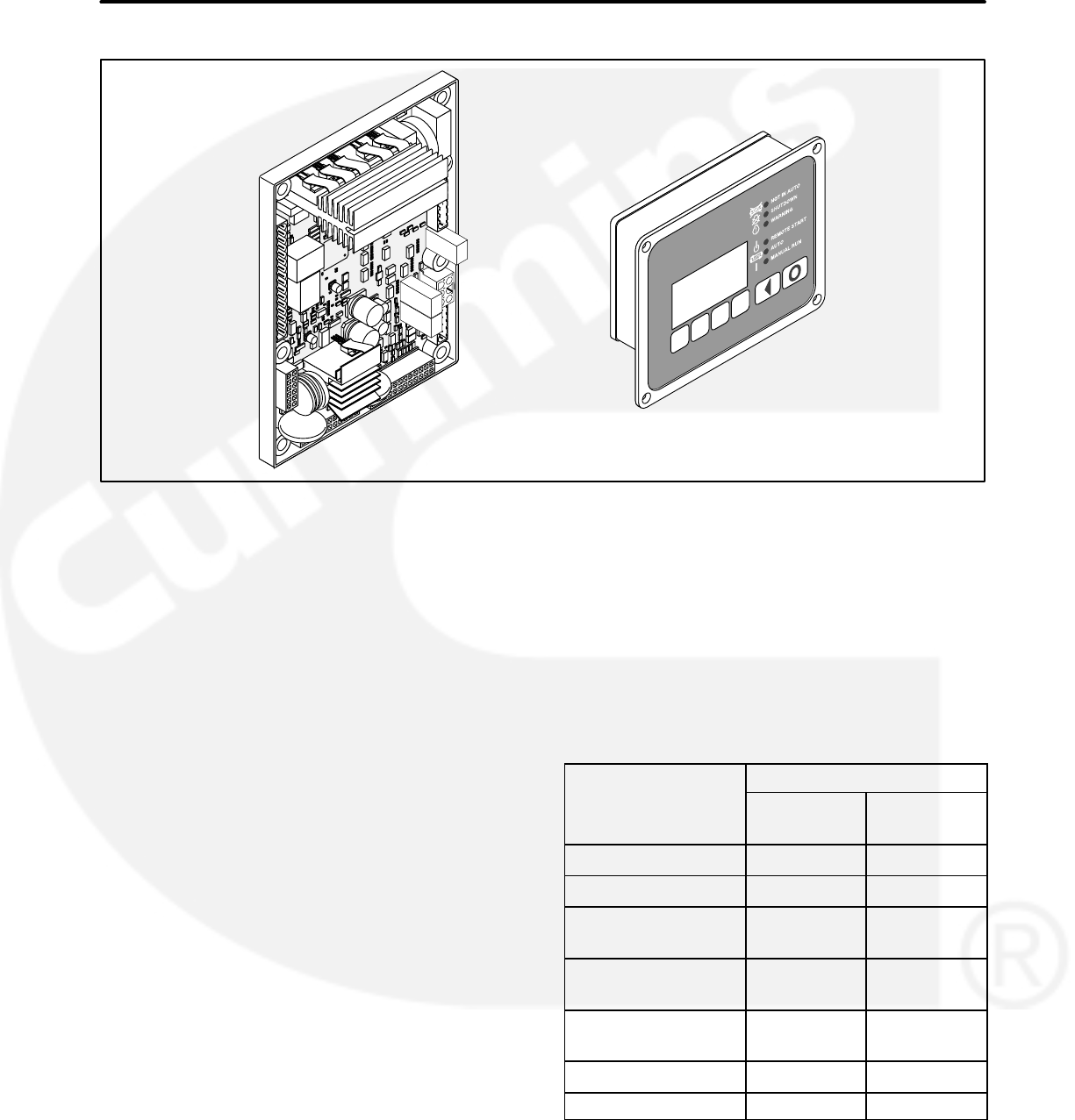
FIGURE 2-1. 1302 MAIN CONTROL BOARD AND OPERATOR PANEL (HMI211)
OVERVIEW
The PCC1302 controller is a microprocessor−
based generator set (genset) monitoring, meter-
ing, and control system. The control provides a
simple operator interface to the genset’s digital
voltage regulation, engine speed governing, re-
mote start / stop control, and protective functions.
The PCC1302 control is suitable for use on hydro
mechanical or FAE engines. It can be used in non-
paralleling applications and it is compatible with re-
connectable alternators up to 600VAC. The control
can also be configured for various frequency (50 /
60 Hz operation), voltage, and power connection
configurations from 190−600 VAC L-L.
The control is designed for mounting on the gener-
ator set. The 1302 series control is usually pow-
ered from the generator set starting batteries and
works over a voltage range from 8 to 30 VDC.
The 1302 series control meets NFPA 110 require-
ments (with appropriate accessories) and is de-
signed for connection to a 12 or 24 VDC control
system.
An optional operator panel can be used as a user
interface.
KIT DESCRIPTION
The 1302 genset control kits include the 1302 con-
trol board (12/24V control assembly with run and
start relay drivers) and the operator panel shown in
Figure 2-1. Also included in these kits are the fol-
lowing sensors and harnesses.
Quantity
Description HM Kit
541−1414−01
FAE Kit
541−1414−02
Oil Pressure Sensor 1 —
Temperature Sensor 1 —
Coolant Temperature
Sensor Harness 1 —
Oil Pressure Sensor
Harness 1 —
Control Panel to
PCC1302 Harness 1 1
Engine Harness 1 1
Genset AC Harness 1 1
2-2
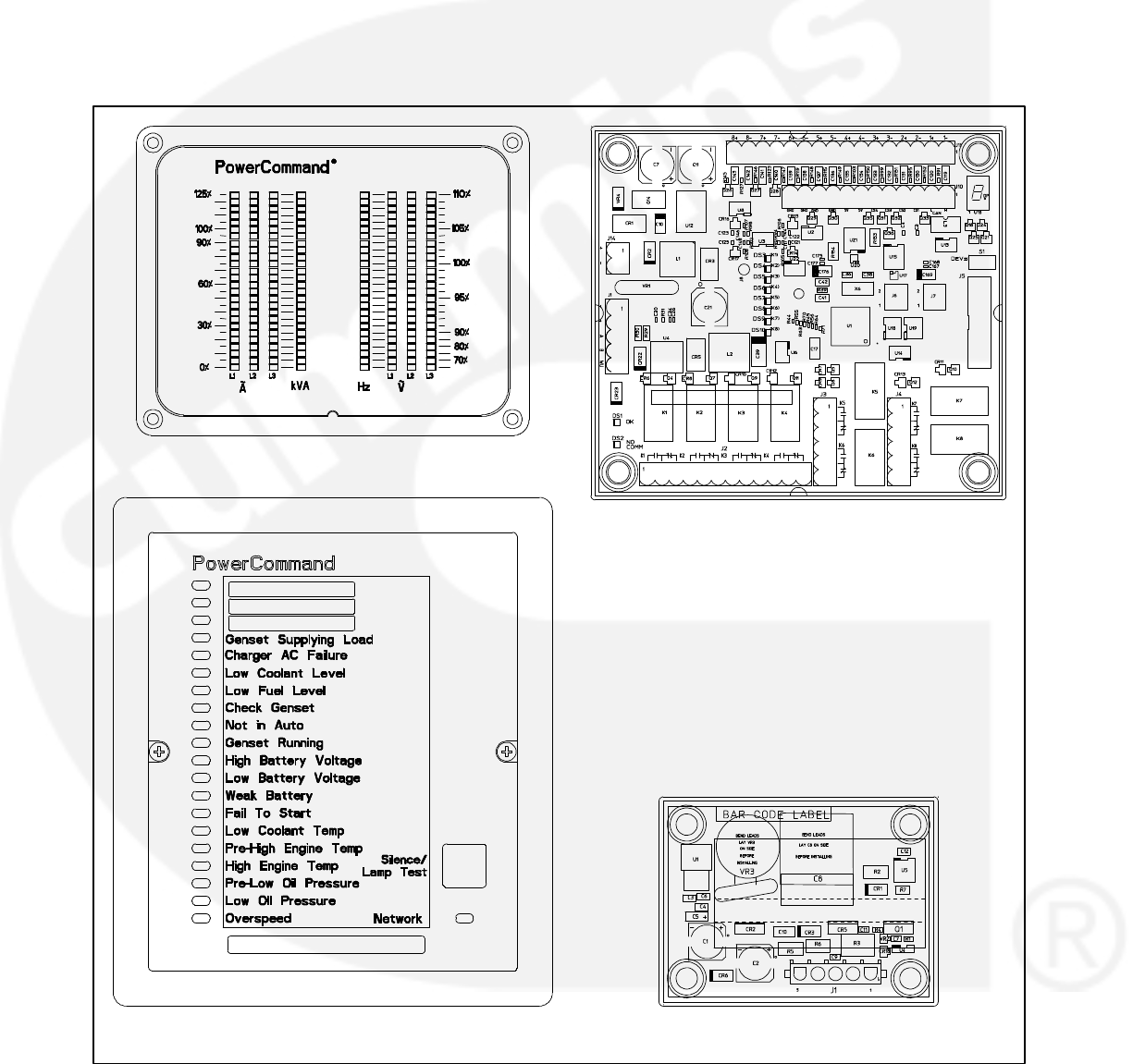
ADDITIONAL EQUIPMENT
Figure 2-1 shows the 1302 control module (327−
1617−01) and the optional HMI211 digital display
panel (300−6014). If your installation is to include
any additional equipment (see Figure 2-2), the ap-
propriate kit(s) must be purchased separately.
HMI112 LED Bargraph − Kit 541−1319 (In-
cludes Instruction Sheet C697)
HMI113 Universal Annunciator − Kit
300−5929 (Includes Operator’s Manual
900−0301)
AUX101 System I/O Module − Kit 541−1291
(Includes Instruction Sheet C693)
AUX104 External Governor Power Module −
Kit 541−1231 (Includes Instruction Sheet
C689)
HMI113 UNIVERSAL ANNUNCIATOR
(300−5929)
HMI112 LED BARGRAPH
(300−6050−02)
AUX104 EXTERNAL GOVERNOR
POWER MODULE (327−1507)
AUX101 SYSTEM I/O MODULE
(327−1536)
FIGURE 2-2. ADDITIONAL EQUIPMENT

2-3
1302 CONTROL FEATURES
The 1302 series controller includes the following
features.
Operates on 12 or 24 VDC.
Electronic Governor Enable/Disable (via an
external Governor Power Module).
FAE Engine support utilizing partial PGI CAN
protocol support.
Automatic Voltage Regulator (AVR) Enable/
Disable.
PMG or Shunt Excitation methods supported.
PCCNet Communications.
ModBus Communications.
Digital speed governing.
Digital voltage regulation.
Low power sleep mode, with configurable
Wake-In-Auto mode.
Phase voltage and current sensing. Wye and
Delta voltage sensing single phase. Current
sensing with an external 0−5 amp current
transformers.
Engine relay drivers.
Generator set monitoring. Display status of all
critical engine and alternator generator set
functions.
Genset protection – Engine and Alternator
protection features.
Operator Panel Display (optional). Provides
easy to use operator display of critical genset
parameters and operating history.
Advanced serviceability using a PC based
software service tool.
Environmental protection. The control system
is designed for reliable operation in harsh en-
vironments. The core control board is potted
module that is fully protected from the ele-
ments.
Configurable Inputs and Outputs. Four dis-
crete configurable inputs and two dry contact
relay outputs.
Relay driver output for glow plug or spark igniter
controller, switched B+, FSO, Starter, Ready to
Load, Local Status, and Keyswitch control.
Current Requirements
The 1302 series control consumes 0.150 Amps of
current while in idle mode. While in the running
mode, it consumes 0.75 Amps of current. This
doesn’t include other application specific devices
such as the optional operator panel, external
actuators, relay coils, or display lamps.
1302 CONTROL SYSTEM
Control Module
The basic control system for the generator set
consists of a single control board with an external
control switch and status indicator.
The control board includes all the functions
necessary to locally or remotely start and stop the
Genset, provide digital voltage regulation, and
protect the Genset.
To use the electronic governor feature, an external
governor power stage may be required to drive the
fuel actuator.
Control Run/Off/Auto Switch
Off Mode − If the control is in the OFF mode, the
generator set is immediately shut down (if running)
and can’t be started. When in OFF mode, all active
faults are reset.
Run Mode − If the control is in the RUN mode, the
generator set will execute its start sequence and
operate at rated speed and voltage.
Auto Mode − If the control is in AUTO mode, the
generator set can be started with a start signal from
a remote device, such as an automatic transfer
switch by accepting a ground signal.
Fault Reset − Placing the switch in the OFF posi-
tion also resets the active/inactive faults in the con-
trol.
2-4
OPERATOR PANEL
The 1302 series control is provided with an optional
operator panel that may be either locally or
remotely mounted. The operator menus are made
up of English or internationally accepted symbols
so translations are not required. The display is
composed of an adjustable contrast backlit LCD
display, with a series of 6 generator status LED
lamps. The display is accompanied by a set of six
tactile feel membrane switches that are used by the
operator to navigate through control menus, and to
make control adjustments. It is configurable for
units of measurement.
The Run/Off/Auto switch function is integrated into
the operator panel; therefore an external switch is
not required when a operator panel is installed. The
operator panel displays current active faults, and a
time-ordered history of previous faults.
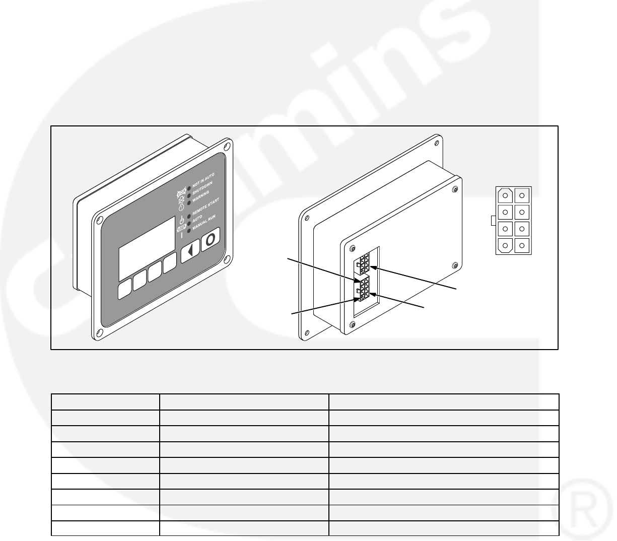
Operator Panel Connections
Two connectors (J1 and J2) are located on the
back of the operator panel (see Figure 2-3).
Connections are listed in Table 2-1.
NOTE: J1 and J2 are identical. Either one can be
used for the harness connection between
the main control board and the operator
panel.
J1
J2
J1-4
PIN 1 J1 or J2
1
2
3
4
5
6
7
8
FIGURE 2-3. 1302 OPERATOR PANEL
TABLE 2-1. OPERATOR PANEL CONNECTIONS
Connector Pin Signal Name Connect To / Comments
J1-1 RS-485 Data A Network Data A
J1-2 RS-485 Data B Network Data B
J1-3 B+ Network Supply
J1-4 PCCNet System Wake Up System Wakeup
J1-5 Return Network Supply Return
J1-6 Run Output
J1-7 Auto Output
J1-8

2-5
CONTROL INPUTS AND OUTPUTS
Control Inputs
Input signals to the main control board are:
Run/Off/Auto switch
Remote start signal
Remote emergency stop
Local emergency stop
Coolant temperature signal
Lube oil pressure signal
Battery voltage signal
PCCNet System Wake Up Input
Magnetic pick up signal
Starter disconnect signal
Single or three-phase current transformers
(CTs)
Single or three phase line-to-neutral voltage
Configurable inputs – The control includes
four inputs that have configurable functions.
Once mapped, each configurable input can be
used as a fault input, remote fault reset input,
battleshort input, or disabled.
Control Outputs
Output signals from the control are:
Control status lamp.
Configurable relay outputs (OUT1_NO and
OUT2_NO) − The control includes two relay
outputs rated at two amps. These outputs can
be configured to activate on any control warn-
ing or shutdown fault as well as ready to load,
not in auto, common alarm, common warning,
and common shutdown.
Ready to load (generator set running) signal –
This output pin goes low when the genset is
capable of supporting a load. The genset
speed and voltage output are what determines
the state of this pin.
Communications connections − The control
includes two RS-485 ports.
−PC Tool Interface – This communication
port (TB15) allows the control to com-
municate with a personal computer run-
ning a PC based service tool. This port
also allows the control to communicate
with external devices, such as a Pro-
grammable Logic Controller (PLC) via
the ModBus protocol.
−PCCNet − This communications port
(TB1) allows for connection from the
control to the optional operator panel,
universal annunciator, LED bargraph,
and system I/O module.
Local status – Refer to “Local Status Output In-
dicator” on page 4-1.
Battery charging alternator – Alternator flash
connection
Fuel shut-off relay driver
Starter relay driver
Keyswitch relay driver
Glow plug relay driver
Governor drive PWM command
Field coil − AVR PWM command
Excitation source − Input power for field coil
Alternator line voltage sensing − 600 VAC
RMS max
Switched B+ driver

2-6
PROTECTION AND FAULTS
The 1302 series control features genset protection
functions and fault detection.
Upon operation of a protective function, the control
will indicate a fault by flashing the fault code on the
local status lamp driver (J25−1). On systems with
an optional operator panel, the warning or
shutdown LED lights and the fault symbol and code
is displayed on the display. The nature of the fault
and time of occurrence is logged in the control. The
service manual and PC based service tool provide
service keys and procedures based upon the
service codes provided.
Fault Codes
A list of fault/status codes is included in Section 4.
Shutdown faults will shutdown the genset. Warning
faults are issued to notify the genset operator of the
problem but the 1302 series control will not shut-
down the genset when they occur.
Genset Protective Functions
The control provides the following system protec-
tive functions:
Configurable Alarm and Status Inputs – The
1302 series control accepts up to four alarm or
status inputs (configurable contact closed to
ground or open) to indicate customer-speci-
fied conditions. The control is programmable
for warning, shutdown, or status indication,
and for labeling the input.
Emergency Stop − Annunciated whenever the
emergency stop signal is received from an ex-
ternal switch.
Engine Protection
Overspeed Shutdown – The engine over-
speed default setting is 115% of the rated en-
gine speed nominal. The control includes time
delays to prevent nuisance shutdown signals.
Low Lube Oil Pressure Warning/Shutdown
− The level is preset (configurable with a PC
based service tool or through the display panel
menus) to match the capabilities of the engine
used. The control includes time delays to pre-
vent nuisance warning/shutdown signals.
High Engine Temperature Warning/Shut-
down − The level is preset (configurable with
PC based service tool or through the display
panel menus) to match the capabilities of the
engine used. The control includes time delays
to prevent nuisance warning/shutdown sig-
nals.
Low Coolant Temperature Warning − This
warning indicates that the engine temperature
may not be high enough for a 10-second start
or proper load pickup. The level is preset (con-
figurable with a PC based service tool or
through the display panel menus) to match the
capabilities of the engine used. The control in-
cludes time delays to prevent nuisance warn-
ing signals.
Low Battery Voltage Warning − This warning
indicates a battery charging system failure by
continuously monitoring battery voltage. The
control includes time delays to prevent nui-
sance warning signals.
High Battery Voltage Warning – This warn-
ing indicates that the battery charging system
is of a high level by continuously monitoring
battery voltage. The control includes time de-
lays to prevent nuisance warning signals.
Weak Battery Voltage Warning − The control
system tests the battery bank each time the
generator set is signaled to start. A warning is
announced if the generator set battery indi-
cates impending failure. The control includes
time delays to prevent nuisance warning sig-
nals.
Dead Battery Voltage Shutdown −Indicates
battery voltage drop during cranking which re-
sets control for three consecutive times (This
feature is available in 1302 calibration version
3.0 onwards )
Fail to Start (Overcrank) Shutdown.
Fail to Crank Shutdown − This shutdown in-
dicates that the control signaled the starter to
crank the engine but the engine did not rotate.
Cranking Lockout − The control will not allow
the starter to attempt to engage or to crank the
engine when the engine is rotating (when the
control senses the valid engine RPM above
the noise threshold value.)
Sensor Failure Indication – An out-of-range
high or low diagnostic logic is provided on the
base control to detect analog sensor or inter-
connecting wiring failures.
2-7
Alternator Protection
High/Low AC Voltage Shutdown − The high
voltage default setting is 110% of the rated
voltage with a 10 second time delay. The
instantaneous voltage default setting is 130%
of the rated voltage. The low AC voltage de-
fault setting is 85% of the rated voltage with a
10 second time delay.
Overcurrent Warning/Shutdown − Imple-
mentation of the thermal damage curve with
an instantaneous trip level is calculated based
on the Current Transformer Ratio and the Ap-
plication Power Rating (see Figure 2-4).
10
1
0.03
101
Seconds
Amps (x rated)
Instantaneous
Trip Point
Overcurrent
Protection
Curve
Alternator
Thermal
Damage Curve
FIGURE 2-4. ALTERNATOR PROTECTION
THERMAL DAMAGE CURVE
Under/Overfrequency − The underfrequen-
cy default is − 6Hz of the 50 Hz / 60 Hz frequen-
cy with a 10 second time delay. The overfre-
quency default is + 6Hz of the 50 Hz / 60 Hz fre-
quency with a 10 second time delay.
Loss Of Sensing AC Voltage Shutdown –
Loss of sensing AC voltage detects the loss of
voltage sensing or senses the loss of zero
crosses. This fault will also be the primary way
to detect short circuit conditions.
Overexcitation Shutdown – Overexcitation
is used to detect short circuit alternator faults.
CURRENT DRAW
The current draw information below is for the 1302
series control only. It does not include current draw
for other application specific devices, such as the
optional operator panel, external actuators, relay
coils, or display lamps.
Running Mode
When in Running mode, the 1302 series control
consumes .750 amps of current.
Parade Rest Mode
Parade Rest mode is when the 1302 series control
is waiting for a start command (for example, the
genset is not running). During Parade Rest mode,
the control consumes 150 milliamps of current.
Sleep Mode
The 1302 series control enters Sleep mode after
five minutes in the Off or Auto mode. During Sleep
mode, the control consumes 60 milliamps of cur-
rent.

2-8
THIS PAGE INTENTIONALLY LEFT BLANK

3-1
3. Installation
Read these instructions completely and become
familiar with safety warnings, cautions, and proce-
dures before starting the installation.
WARNING Incorrect installation, service, or
replacement of parts can result in severe per-
sonal injury or death and/or equipment dam-
age. Only trained and experienced personnel
are to perform the following procedures.
CAUTION A generator set control must be
serviced only by technically qualified person-
nel. High voltages are present. These voltages
can cause electrical shock, resulting in person-
al injury.
Even with power removed, improper handling
of components can cause electrostatic dis-
charge and damage to circuit components.
WARNING AC voltages and currents present
an electrical shock hazard that can cause se-
vere personal injury or death. Incorrect instal-
lation, service, or parts replacement can result
in severe personal injury, death, and/or equip-
ment damage.
Turn off or remove AC power from the battery char-
ger (if present) and then remove the negative (−)
battery cable from the set starting battery. This is to
make sure the genset will not start while working on
it and to avoid circuit board damage, caused by
voltage spikes when removing and replacing circuit
board connectors.
CAUTION If present, always disconnect a bat-
tery charger from its AC source before discon-
necting the battery cables. Otherwise, discon-
necting the cables can result in voltage spikes
high enough to damage the DC control circuits
of the generator set.
WARNING Accidental starting of the genera-
tor set while working on it can cause severe
personal injury or death. Prevent accidental
starting by disconnecting the starting battery
cables (negative [−] first).
Make certain the battery area has been well-
ventilated before servicing the battery—Wear
goggles—Stop the genset and disconnect the
charger before disconnecting battery cables.
Arcing can ignite explosive hydrogen gas giv-
en off by batteries, causing severe personal in-
jury. Arcing can occur when a cable is removed
or re-attached, or when the negative (−) battery
cable is connected and a tool used to connect
or disconnect the positive (+) battery cable
touches the frame or other grounded metal part
of the generator set. Always remove the nega-
tive (−) cable first, and reconnect it last. Make
certain hydrogen from the battery, engine fuel,
and other explosive fumes are fully dissipated.
This is especially important if the battery has
been connected to a battery charger.
WARNING Ignition of explosive battery gases
can cause severe personal injury or death. Arc-
ing at battery terminals, light switch or other
equipment, flame, pilot lights and sparks can
ignite battery gas. Do not smoke, or switch
trouble light ON or OFF near a battery. Dis-
charge static electricity from body before
touching batteries by first touching a grounded
metal surface.
MOUNTING GUIDELINES
The main control board and the optional operator
panel are suitable for non-engine mounting. As
such, they should not be directly mounted on the
engine.
The control and operator panel may be mounted on
one of the following.
A suitable frame on top of the alternator
A frame supported from the genset base rail
A stand-alone mounting frame isolated from
the vibration of the genset
Appropriate vibration isolators should be used to
make sure that neither the main control board, the
operator panel, nor customer wiring are subjected
to vibration levels beyond their capability.
To prevent the control board and the optional oper-
ator panel from being exposed to conditions be-
yond their specifications, care should be taken not
to mount them close to the engine exhaust pipes.
Mounting them in a manner that would expose
3-2
them to direct sunlight or rain/snow should also be
avoided.
It is recommended that the control board be
mounted with the longer side horizontal and the
shorter side vertical so as to allow air to move freely
upwards through the heat sink channels. Mounting
the control board with the short side horizontal and
the longer side vertical should be avoided.
ENVIRONMENTAL CAPABILITY
The control system is specifically designed and
tested for resistance to RFI / EMI and to resist the
effects of vibration to provide a long reliable life
when mounted on a generator set. The control in-
cludes transient voltage surge suppression to pro-
vide compliance to referenced standards.
1302 Main Control Board
The main control board is designed to withstand
vibration levels of 50 mm / sec in the 20−100 Hz
range and of 3.3 G in the 100−2000 Hz range.
The main control board is designed for proper op-
eration without recalibration in ambient tempera-
tures from –40 to +70 Deg C, and for storage from
–55 to +80 Deg C. The control is designed to oper-
ate with humidity up to 95%, non-condensing, and
at an altitude up to 13,000 feet (5000 meters).
The main control board is fully encapsulated to pro-
vide resistance to the effects of dust and moisture.
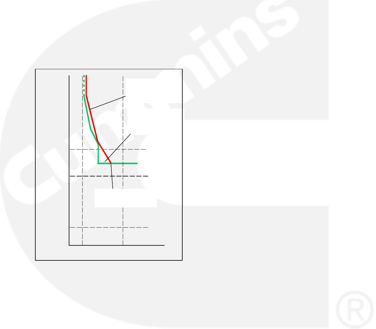
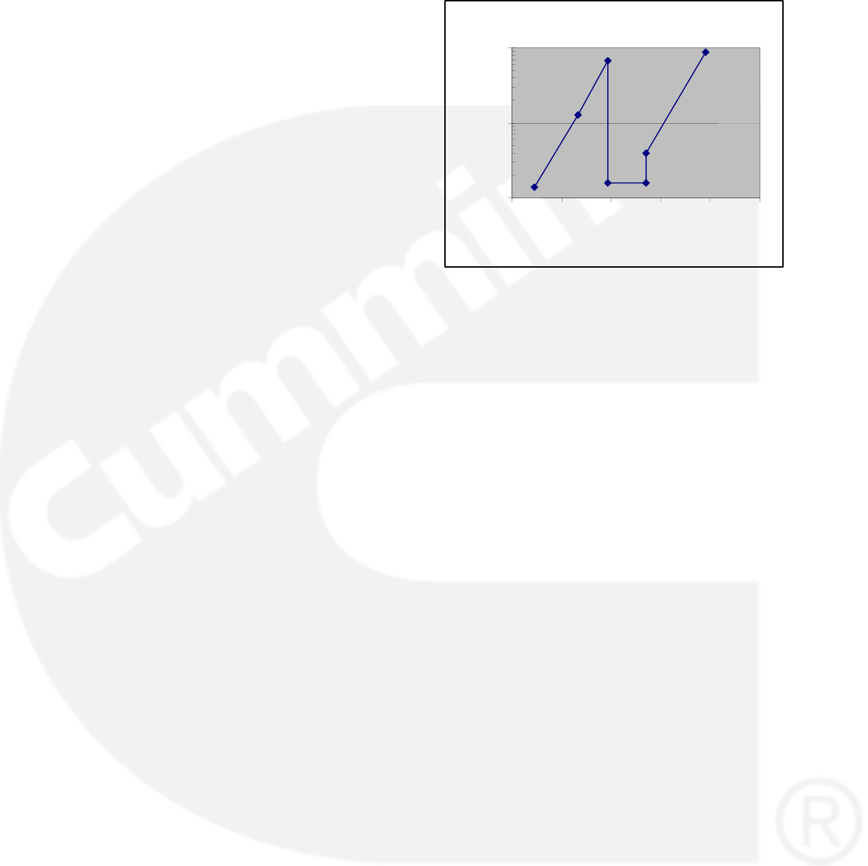
1302 Operator Panel
The optional operator panel is designed to with-
stand vibration levels of 40 mm / sec in the 4−100
Hz range and the engine vibration levels shown in
Figure 3-1.
The operator panel is designed for proper opera-
tion in ambient temperatures from −4 to 158 Deg F
(–20 to +70 Deg C) and for storage, from −22 to 176
Deg F (–30 to +80 Deg C).
The operator panel has a single membrane sur-
face, which is impervious to the effects of dust,
moisture, oil, and exhaust fumes.
0.1
1
10
0 50 100 150 200 250
Frequency (Hz)
Amplitude (Gs) LCD Vibration Profile
FIGURE 3-1. OPERATOR PANEL VIBRATION
LIMITS
CONTROL WIRING INFORMATION
For connecting the Magnetic Pickup, use mini-
mum 0.8 sq. mm (18 gage), 2 conductors,
twisted shielded cable. Connect the shield at
J11-8 and leave the shield un-connected at the
magnetic pickup side of the cable.
For connection the ECM CAN, use minimum
0.8 sq. mm (18 gage), 2 conductors, twisted
shielded cable. Connect the shield at
J11-17and leave the shield un-connected at
the ECM side of the cable.
For connecting the PCCNet, use minimum 0.8
sq. mm (18 gage), 2 conductors, twisted
cable.
For connecting the battery supply, use two
twisted pair wires (16 AWG).
For connecting current transformers, use
three twisted pair wires minimum (16 AWG).
For all other connections, use minimum 0.8 sq
mm (18 gauge) wires.
The Electronic Governor feature typically re-
quires an external Governor Output Module
Kit. Governor PWM output from the 1302 se-
ries control board is connected as input to the
Governor Power Module by a minimum 0.8 sq.
mm (18 gage), 2 conductors, twisted shielded
cable.

3-3
GUIDELINES FOR CURRENT
TRANSFORMERS
All current transformers (CTs) used with a 1302 se-
ries control must conform to the following specifica-
tions.
Continuous rated full load secondary output
current: 5 amps at 50 or 60Hz
Total burden VA rating: at least 2.5 VA
Output terminals between which current is
drawn in high and low ranges on tapped CTs.
Maximum allowable ratio error at rated output:
+/−1%
Maximum allowable phase error at rated out-
put: +/−1
10-second overload output current in rated
metering load: 10 Amps
Maximum allowable ratio error at overload
output: +/−1%
Ambient temperature rating: −40 to 176 Deg F
(−40 to +80 Deg C)
System voltage rating − 600VAC
NOTE: in PCC1302,if trim parameter
Current Multiplier 2X Enable is
enabled and only one of the two
alternator winding phase cables
is routed through CT, then the cur-
rent measurement calculation will
be multiplied by 2 to show the cor-
rect reading of the load current.
Current Transformer Selection
Current transformers (CTs) used in 1302 control
applications are ideally sized to produce rated CT
secondary amps at twice rated generator (full
200% range) output amperes. In other words,
when the generator is producing 100% output am-
peres, the secondary current of the CTs is 2.5 am-
peres per phase. This requirement determines a
lower bound of the CT ratio. An upper bound is de-
termined by requiring that, at 100% rated output
current, the CTs secondary current is at least 1 am-
pere. The purpose of this is to maintain sufficient
metering resolution. The lower and upper bound of
the CT limits are prescribed by the following two
formulas.
Minimum CT Ratio = 2 * Max_Rated_Current
5
Maximum CT Ratio = 5 * Min_Rated_Current
5
In non-reconnectable genset applications, the
Max_Rated_Current and Min_Rated_Current are
the same. In reconnectable genset applications,
they are different.
Example of CT Sizing − Two Lead CT
A 250kVA rated genset application at 240V pro-
duces rated output current of 602 amps/phase.
This yields a Minimum CT Ratio of 1204:5 and a
Maximum CT Ratio of 3010:5. Any CT with a ratio
between these two values would be sufficient for
this application.
3-4
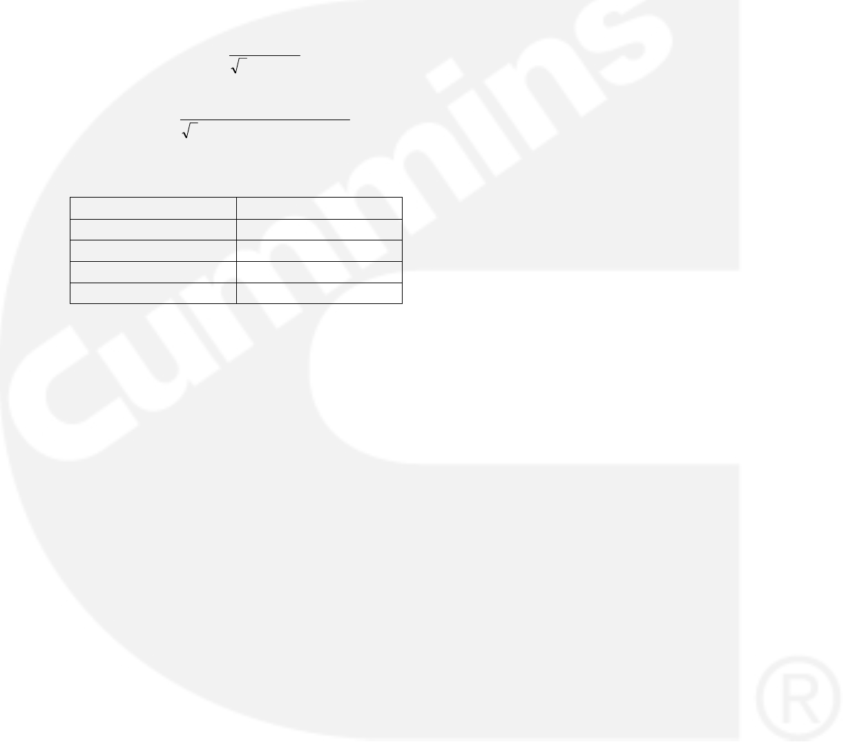
Example of CT Sizing − Three Lead CT
A reconnectable generator capable of 208−240/
416−480V outputs with a 125 kVA 3-phase only rat-
ing.
You first need to find the current in each phase for
each output voltage. This is done using the follow-
ing formula:
Voltage
VAPower
Current
*3
)(
or
VoltageFactorPower
WPower
Current
*_*3
)(
Using the above equation, the current in each
phase is computed as shown below.
Voltage (V) Output Current (A)
208 346.376
240 300.192
416 173.188
480 150.096
The next step is to use the equations on page 3-3
to find the lower and upper bound for the CT ratios
for each voltage configuration.
For a 208−240 voltage configuration:
96.1500192.300*5
Maximum CT Ratio
752.692376.346*2
Minimum CT Ratio
For a 416−480 voltage configuration:
8.754096.150*5
Maximum CT Ratio
376.346188.173*2
Minimum CT Ratio
For three-tap CTs, it would be advisable to choose
a CT with a 1500/750:5 ratio.
For the 208−240 voltage configuration, connect
the CT leads to the 1st and 3rd CT connections,
leaving the center tap disconnected.
For the 416−480 voltage configuration, use the
same 1500/750:5 ratio CT, but this time connect
the CT leads to the first and second (center-tap)
connections on the CT, leaving the third tap uncon-
nected.
Current Transformer Setup
After the 1302 series control kit has been installed,
the controller must be programmed to use the CT
by one of the following methods.
1. Enter an appropriate value in the CT ratio pa-
rameter on the operator panel.
2. Select a feature to be downloaded using the
Manufacturing Tool.
3. Program an appropriate value in the Primary
CT Current parameter using a PC-based ser-
vice tool (for example, InPower).
NOTE: To check the actual genset output, True
(calibrated) RMS meter should be
usedThe 1302 series control automatically
doubles the entered CT ratio when switch-
ing from high nominal voltage (above
300V) to lower nominal voltage (below
300V).
When entering a CT ratio the following rules apply:
Two Lead CT, above 300V application − Enter
CT ratio as read from the CT.
Two Lead CT, below 300V applications − Enter
HALF of the CT Ratio as read from the CT.
Three Lead CT (Center Tapped) – Enter the
SMALLER of the two ratios as read from the
CT.
Two Lead CT Setup Example:
For this example, assume a CT with a 1500:5 ratio
is being used.
Operator Panel
Above 300V applications − Enter 1500 into the
CT ratio parameter on the operator panel.
Below 300 V applications − Enter 750 into the
CR ratio parameter on the operator panel.
Manufacturing Tool
Above 300V applications − Select a feature
corresponding to 1500:5 to download using
the Manufacturing Tool.
Below 300 V applications − Select a feature
corresponding to 750:5 to download using the
Manufacturing Tool.
PC-Based Service Tool
Above 300V applications − Enter 1500 into the
Primary CT Current parameter, using the PC-
based service tool (e.g. InPower).
Below 300V applications − Enter 750 into the
Primary CT Current parameter, using the PC-
based service tool (e.g. InPower).

3-5
In PCC1302 Control, Voltage Calibration
procedure is divided into three processes
as described below:
1. Meter Calibration: There are two sets of AC in-
puts on the 1302: L1−N, L2−N, and L3−N (or
L1−2, L2−3, L3−1 for delta) AND 3 phase aver-
age voltage. The metering calibration will cali-
brate L1−N, L2−N, L3−N., which is used for
display and diagnostic purposes. Method:
Verify each phase on PCC matches external
calibrated meter. This calibration should be
done first.
2. Regulation Calibration: This calibrates the 3
phase average voltage, which is used for reg-
ulation. Method: Verify the 3 phase average
voltage of the genset matches an external me-
ter’s voltage. Special note: When changing
the regulation feedback calibration, the PCC’s
feedback will appear to say the same, and the
external meter’s value will change. This is be-
cause the PCC regulator is active, and is mak-
ing what the PCC sees be the PCC’s Setpoint.
3. Voltage Adjust: Once both the metering and
voltage calibration is done, you use the volt-
age adjust to modify the PCC’s voltage Set-
point ( i.e. for example: If the user wants the
PCC to output 215VAC instead of 220VAC)
Procedure of calibrating the Alternator
Voltages is as follows:
Safety Precautions:
1. Contacting high voltage components can
cause electrocution, resulting in severe per-
sonal injury or death. Calibration and adjust-
ment must be performed by technically quali-
fied personnel only. Read and observe all the
Warnings and Cautions in your generator set
manuals.
2. Improper calibration and adjustment of the
PCC can cause equipment malfunction or
damage. Calibration and adjustment must be
performed by technically qualified personnel
only.
One or more of the PCC’s internal circuits may
need to be calibrated, in which case you should cal-
ibrate the internal circuits in the following order
listed in the table shown below:
NOTE: To check the actual genset output, True
(calibrated) RMS meter should be used.

3-6
TABLE 3-1. CALIBRATION
Component to be calibrated Calibration method
p
PC based service tool Operating panel
Meter Calibration or Voltage mea-
surement for display
1. Connect to the control with your
PC based service tool.
2. Verify the nominal voltage trim is
set to the desired value. The trim Al-
ternator Nominal Voltage is available
at Adjustments −> AC Measurement
Calibrations −> Voltage Measure-
ment for Regulation. Set the Alterna-
tor Nominal Voltage to the voltage
that the genset will generate.
3. With the genset OFF, attach a cali-
brated Voltmeter to the AC Output
from L1 to L2. (L1 to Neutral for
single phase alternators).
4. Start the genset and allow it to
reach normal operating speed.
5. Calibrate voltage reading for L1 by
adjusting the trim Alternator L1−N
50Hz Voltage Display Adjust or Alter-
nator L1−N 60Hz Voltage Display
Adjust trim for your application, so
that the reading on the display
agrees with the calibrated voltmeter.
6. Shut the generator set OFF.
7. Repeat Step 3 to Step 6 for L2
and L3 (In Step 3 attach meter to the
AC output from L2 to L3 to calibrate
L2 and L3 to L1 to calibrate L3) by
adjusting the trims Alternator L2−N
50Hz Voltage Display Adjust or Alter-
nator L2−N 60Hz Voltage Display
Adjust trim and Alternator L3−N
50Hz Voltage Display Adjust or Alter-
nator L3−N 60Hz Voltage Display
Adjust trim respectively.
8. Save the adjustments by doing a
Save Trims with your PC based ser-
vice tool.
1. View the service menu by holding
down the ”up” and ”down” arrow keys
on any of the operating menus.
2. Select item 1, ”Setup Menu”.
3. Enter Setup menu password
”574”.
4. Select item 1, ”Genset Service”.
5. Select item 1, and verify the ”Volts
AC” setting is correct for your ap-
plication. If necessary press the ”Ad-
just” button and change the setting,
and press the ”Save” button.
6. Press the back button to return to
service menu.
7. With the genset OFF, attach a cali-
brated Voltmeter to the AC Output
from L1 to L2. (L1 to Neutral for
single phase alternators).
8. Start the genset and allow it to
reach normal operating speed.
9. Select item 3, ”Meter Calib”.
10. Press the down arrow twice to
scroll down to the ”Metering Voltage
Adjust”
11. Adjust the three parameters one
by one listed so that the reading on
the display agrees with the calibrated
voltmeter.
12. Shut the generator set OFF.
13. Repeat Step 7 to Step 12 for L2
and L3 (In Step 3 attach meter to the
AC output from L2 to L3 to calibrate
L2 and L3 to L1 to calibrate L3) by
adjusting the trims Alternator L2−N
50Hz Voltage Display Adjust or Alter-
nator L2−N 60Hz Voltage Display
Adjust trim and Alternator L3−N
50Hz Voltage Display Adjust or Alter-
nator L3−N 60Hz Voltage Display
Adjust trim respectively.
14. Save the adjustment by pressing
the ”Save” button.

3-7
Regulation Calibration or Voltage
measurement for regulation
1. Connect to the control with your
PC based service tool.
2. Verify the nominal voltage trim is
set to the desired value.
3. With the genset OFF, attach a cali-
brated Voltmeter to the AC Output
from L1 to L2.
4. Start the genset and allow it to
reach normal operating speed.
5. Adjust the trim Voltage Regulation
Calibration 50Hz or Voltage Regula-
tion Calibration 60Hz for your desired
application. The effect of this trim is
Inverse on the regulated voltage. In-
creasing the trim will lower the regu-
lated voltage, and decreasing the
trim will raise the regulated voltage.
The monitored Regulated Voltage
will match with the reading on the at-
tached external calibrated meter and
the Regulated Feedback Voltage (Al-
ternator Voltage) matches the de-
sired Nominal voltage.
6. Shut the generator set OFF.
7. Save the adjustments by doing a
Save Trims with your PC based ser-
vice tool.
1. View the service menu by holding
down the ”up” and ”down” arrow keys
on any of the operating menus.
2. Select item 1, ”Setup Menu”.
3. Enter Setup menu password
”574”.
4. Select item 1, ”Genset Service”.
5. Select item 1, and verify the ”Volts
AC” setting is correct for your ap-
plication. If necessary press the ”Ad-
just” button and change the setting,
and press the ”Save” button.
6. Press the back button to return to
service menu.
7. Start the genset and allow it to
reach normal operating speed.
8. Select item 3, ”Meter Calib”.
9. Press the ”Adjust” button and
change the ”Reg Volt Adj” value. The
effect of this trim is Inverse on the
regulated voltage. Increasing the trim
will decrease the regulated voltage.
Decreasing the trim will increase the
regulated voltage.
10. Save the adjustment by pressing
the ”Save” button.
Voltage Setpoint Adjustment 1. Connect to the control with your
PC based service tool.
2. Verify the nominal voltage trim is
set to the desired value.
3. With the genset OFF, attach a cali-
brated Voltmeter to the AC Output
from L1 to L2.
4. Start the genset and allow it to
reach normal operating speed.
5. Adjust the trim Voltage Adjust
which shall move the voltage Set-
point either in positive direction or in
negative direction as per your re-
quirement.
Not Applicable.
NOTE:
1. Meter Calibration is what all the diagnostics use and the display shows, while Regulator Calibration it the
feedback going to the AVR. Thus Meter Calibration and the Regulator calibration shall be done when the
PCC1302 control is initially calibrated or if the boards are swapped / replaced with the new ones.
2.Voltage Setpoint adjustment shall be carried out as and when required to move the voltage Setpoint.
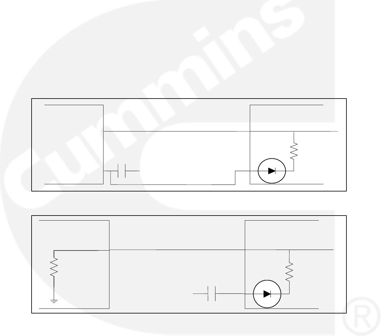
3-8
Three Lead CT Setup Example
For this example, assume that a CT with a
1500/750:5 ratio is being used.
Operator Panel
Enter 750 into the CT Ratio parameter on the
Operator Panel.
Manufacturing Tool
Select a feature corresponding to 750:5 to
download using the Manufacturing Tool.
PC-Based Service Tool
Enter 750 into the Primary CT Current param-
eter using a PC based service tool (e.g. In-
Power).
BATTERY CHARGING ALTERNATOR
CONNECTIONS
The 1302 series control currently supports the fol-
lowing charging alternator types.
Denso Type Charging Alternators
A Denso charging alternator with IG and L (failure
lamp) connection points is shown in Figure 3-2.
This configuration is used to produce a start dis-
connect signal and to indicate a failed battery
charging alternator.
Bosch Type Charging Alternators
A Bosch charging alternator with D+ (flash input)
connection point is shown in Figure 3-3. This con-
figuration is used to produce a start disconnect sig-
nal and to indicate a failed charging alternator.
Battery Charging
Alternator Input
Denso Type
Charging Alternator
L
IG
RUN
1302 Series Control
B+
J20−22
J20−11
FIGURE 3-2. DENSO CHARGING ALTERNATOR WIRING DIAGRAM
Bosch Type
Charging Alternator
D+
RUN
1302 Series Control
B+
J20−22
J20−11
Battery Charging
Alternator Input
Approx, 5 Ohm
input impedance
FIGURE 3-3. BOSCH CHARGING ALTERNATOR WIRING DIAGRAM
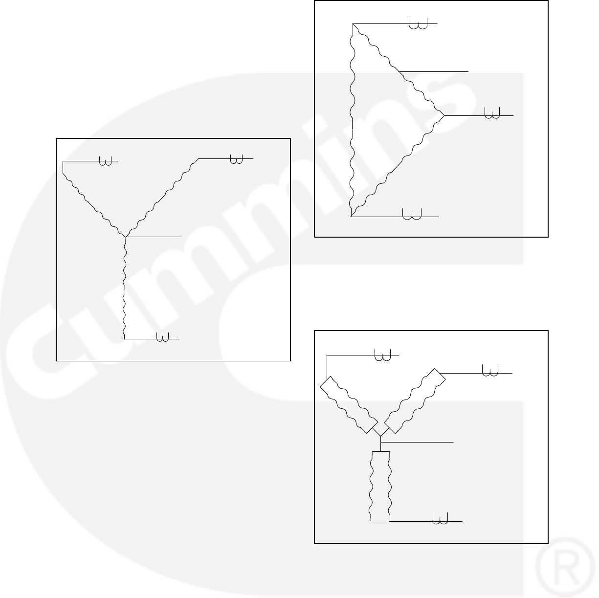
3-9
ALTERNATOR CONNECTIONS
A fast acting UL certified ceramic fuse with a rating
of ten amperes shall be placed inline with the Ex-
citation Inputs J18-1 and J18-2.
Series Star
Series star connection yields an output voltage of
220−277/380−480 volts. Figure 3-4 shows the cor-
rect series−star alternator connections.
CT3
CT1 CT2
J12-1 J12-4 J12-2 J12-5
V2: J22-2
VN: J22-4
V3: J22-3
V5 (T8)
W6 (T12)
W5 (T9)
W2 (T6)
W1 (T3)
V2 (T5)
V1 (T2)
V6 (T11)
U1 (T1)
U2 (T4)
U5 (T7)
U6 (T10)
J12-3 J12-6
V1: J22-1
FIGURE 3-4. SERIES STAR CONNECTIONS
Series Delta
Series delta provides for an output voltage of
110−120/220−240 volts. Figure 3-5 shows the cor-
rect series delta connections.
NOTE: To check the actual genset output, True
(calibrated) RMS meter should be
usedSense N must not be connected in
three phase delta connections.
Parallel Star
Parallel star alternator configuration yields an out-
put voltage of 110−139/190−240 volts. Figure 3-6
illustrates the correct parallel star connections.
CT3
CT1
CT2
VN: J22-4
V2: J22-2
V3: J22-3
V1: J22-1
J12-1 J12-4
J12-2 J12-5
J12-3 J12-6
W6 (T12)
W5 (T9)
W2 (T6)
W1 (T3)
U6 (T10)
V5 (T8)
V2 (T5)
V1 (T2)
V6 (T11)
U1 (T1)
U2 (T4)
U5 (T7)
FIGURE 3-5. SERIES DELTA CONNECTIONS
CT3
CT1
CT2
J12-2 J12-5
J12-3 J12-6
J12-1 J12-4
V1: J22-1
V2: J22-2
V3: J22-3
U6 (T10)
V1 (T2)
VN: J22-4
V5 (T8)
V2 (T5)
W1 (T3)
V6 (T11)
U2 (T4)
U5 (T7)
W5 (T9)
W2 (T6)W6 (T12)
U1 (T1)
FIGURE 3-6. PARALLEL STAR CONNECTIONS
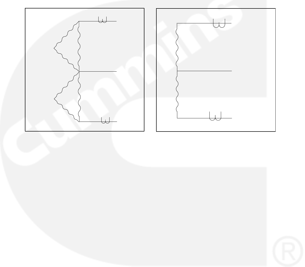
3-10
Double Delta
The double delta alternator configuration yields an
output voltage of 110−120/220−240 volts. Correct
double delta connections are illustrate in Figure
3-7.
CT1
CT2
VN: J22-4
V2: J22-2
V1: J22-1
J12-1 J12-4
J12-2 J12-5
V1 (T2)
W6 (T12)
W5 (T9)
W1 (T3)
V2 (T5)
U2 (T4)
U5 (T7)
U6 (T10)
V6 (T11) U1 (T1)
V5 (T8)
W2 (T6)
FIGURE 3-7. DOUBLE DELTA CONNECTIONS
Single Phase
Single phase provides for an output voltage of
110−120/220−240 volts. Single phase alternator
connections are shown in Figure 3-8.
CT2
J12-2 J12-5
CT1
J12-1 J12-4
VN: J22-4
V2: J22-2
V1: J22-1
U2 (T4)
U1 (T1)
U5 (T7)
U6 (T10)
FIGURE 3-8. SINGLE PHASE CONNECTIONS
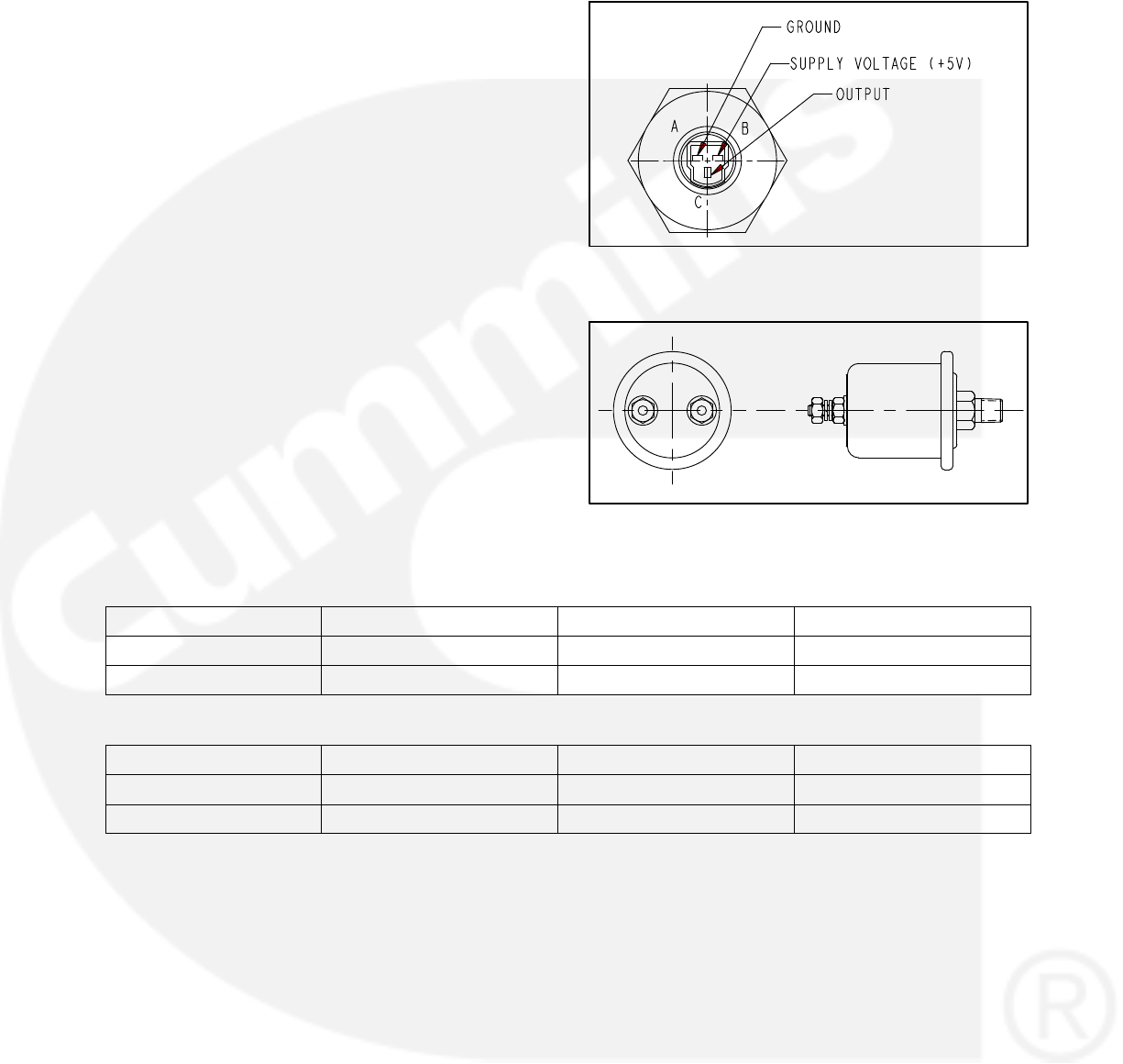
3-11
GUIDELINES FOR ENGINE SENSORS
The engine sensors included in this kit are:
Coolant Temperature Sensor 193−0529−01
Oil Pressure Sensor 193−0444
This section provides information on these plus
additional engine sensors that can be used with
1302 series controllers.
Coolant Temperature Sensors
The coolant temperature sensors that are avail-
able from Cummins Power Generation (CPG) are
listed in Table 3-1.
The coolant temperature sensor connectors that
are available from CPG are listed in Table 3-2.
Oil Pressure Sensors
The 1302 series control can be programmed for ei-
ther oil pressure sensors or switches. The trim pa-
rameter for this is: Lube Oil Pressure Sensor Type
= Sensor, Switch. If the type is set to Sensor, the
control can also be programmed for either 3-wire or
2-wire sensors. The trim parameter for this is Oil
Pressure Sender Type = 3-wire, 2-wire. Available
switch and sensors are listed in Table 3-3.
For information on setting the oil pressure sender
type using the display panel, see page 5-43.
FIGURE 3-9. THREE-WIRE PRESSURE SENSOR
CONNECTIONS
FIGURE 3-10. TWO-WIRE PRESSURE SENSOR
CONNECTIONS
TABLE 3-1. COOLANT TEMPERATURE SENSORS
CPG P/N Manufacturer / P/N Resistive Temp Range Threading
0193−0529−01 AirPax / 5024−0250 −40 to +230 F 3/8 “NPTF
0193−0529−02 AirPax / 5024−0274 −40 to +230 F M14 X 1.5 with “O” Ring
TABLE 3-2. TEMPERATURE SENSOR CONNECTORS
CPG P/N Manufacturer Manufacturer P/N Comments
0323−1755 Packard 121621893 Plastic shell with seal
0323−1818 Delphi 12124075 Socket Connector
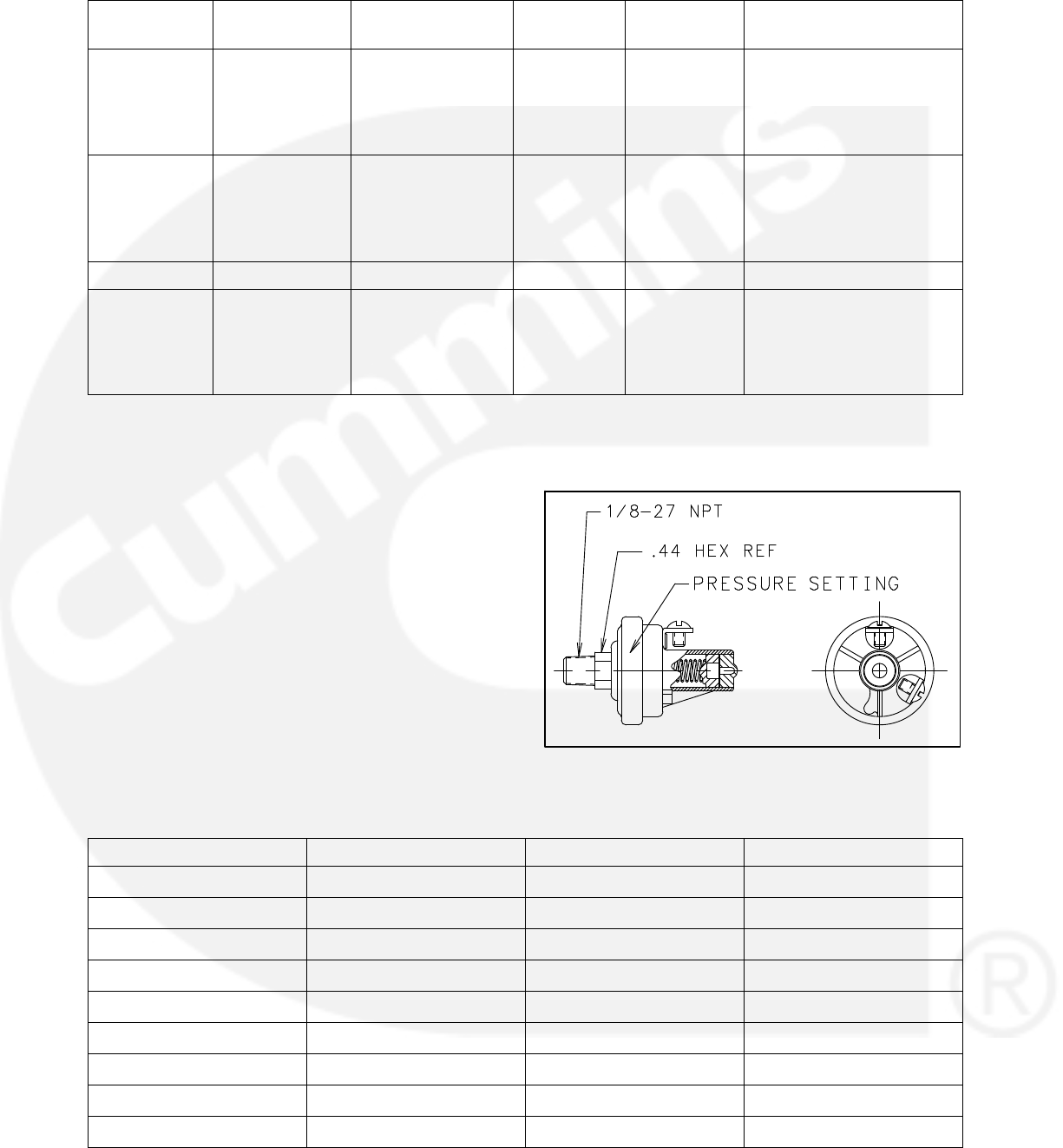
3-12
TABLE 3-3. OIL PRESSURE SENSORS AND SWITCH
CPG P/N Manufacturer /
P/N Sensor Type Range /
Unit
Resistance /
Voltage Comments
193−0430−02 F.W. Murphy
ED2P-100
2-Wire Standard
Resistive Sender
0−100 PSIG 240−33
Ohms
Includes 10-32 hex nut
connectors, 1/8” NPTF dry
sealing threading, and a
diaphragm operated resis-
tive sensing element
193−0444 Kavlico
P165−5110
3-Wire Active
Sender
(Capacitive)
0−100 PSIG 0−5 VDC Mating Connector
326−1666 (Packard
12065287) includes
323−1667 socket termi-
nals (Packard 12103881)
309−0641−XX Stewart Warner Pressure Switch (See the following page)
A028X493 Kavlico
P4055−5001−1
3-Wire Active
Sender
(Capacitive)
0−100 PSIG 0−5 VDC Mating Connector
326−1666 (Packard
12065287) includes
323−1667 socket termi-
nals (Packard 12103881)
Lube Oil Pressure Switch
The part number for the Lube Oil Pressure Switch
is 309−0641−XX. The XX portion of the number is
dependent the trip pressure point. Refer to Table
3-4 to select an appropriate lube oil pressure
switch.
If an oil pressure switch is used, the active state
(active high or active low) of the switch must be
configured using a PC based service tool or
through the menus available with the operator pan-
el. A software setting allows for selection of the ac-
tive state of the switch. The Lube Oil Pressure
Switch Polarity can be set to Active High or Active
Low.
For information on setting the oil pressure switch
polarity using the display panel, see page 5-43.
FIGURE 3-11. PRESSURE SWITCH
TABLE 3-4. AVAILABLE PRESSURE SWITCHES (309−0641)
Part No. Set Point Contact (At Rest) No. of Terminals
309−0641−01 14 2.0 PSI Closed 1
309−0641−02 14 2.0 PSI Open 2
309−0641−03 14 2.0 PSI Closed 2
309−0641−04 9 1.5 PSI Open 2
309−0641−05 9 1.5 PSI Closed 1
309−0641−06 10 1.5 PSI Open 2
309−0641−07 20 2.0 PSI Closed 1
309−0641−08 20 2.0 PSI Closed 2
309−0641−10 20 3.0 PSI Closed 2

3-13
309−0641−13 30 3.0 PSI Closed 1
309−0641−14 4 1.0 PSI Open 2
309−0641−15 5 1.0 PSI Open/Closed 3
309−0641−16 5 1.0 PSI Closed 1
309−0641−17 5 1.0 PSI Open 1
309−0641−18 5 1.0 PSI Open 2
309−0641−19 14 2.0 PSI Closed 2
309−0641−20 20 2.0 PSI Closed 1
All pressure switches have steel base and nipple construction.
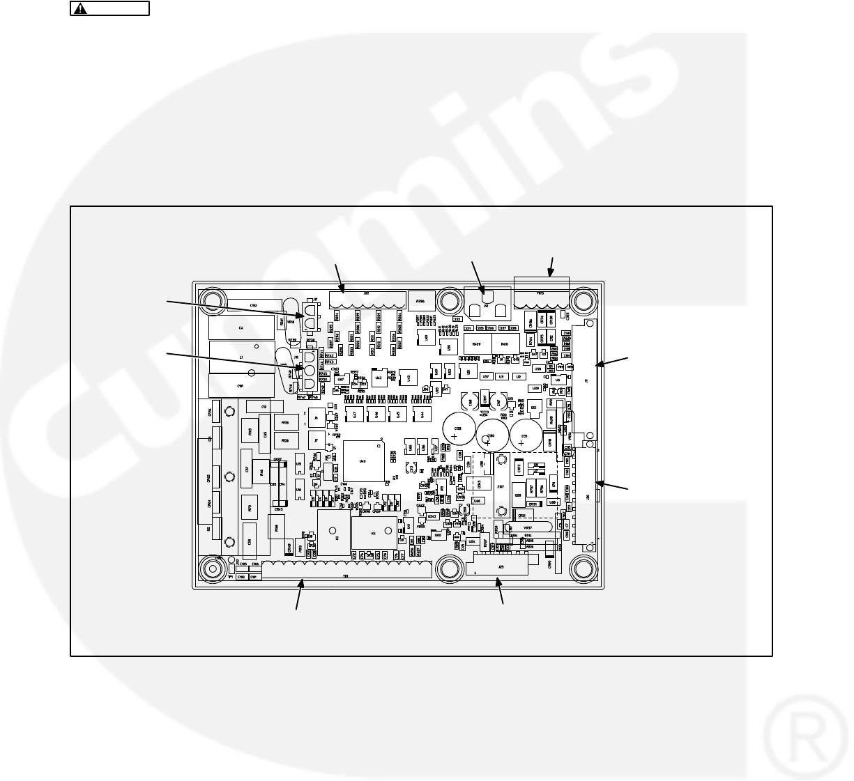
3-14
CONTROL BOARD CONNECTIONS
The 1302 control board includes the following
connectors (see Figure 3-12).
CAUTION Reversing the power supply con-
nections on TB1 and/or TB15 can permanently
damage the control. Refer to drawing 630−3270
for proper connections.
TB1 − Customer connections (see Table 3-5
and sheet 3 of Figure 7-1)
TB15 − Tools interface connections (see Table
3-6 and sheet 3 of Figure 7-1)
J11 − Engine connections (see Table 3-7)
J12 − Genset CT connections (see Table 3-8)
J17 − Field winding connections (see Table
3-9)
J18 − Field power connections (see Table
3-10)
J20 − Genset connections (see Table 3-11)
J22 − Alternator voltage sense connections
(see Table 3-12)
J25 − Display connections (see Table 3-13)
Mating connector and connector pin part numbers
for the control board are listed in Table 3-14.
J25 (DISPLAY
CONNECTIONS)
TB1 (CUSTOMER
CONNECTIONS)
J12 (CT
CONNECTIONS)
J11 (ENGINE
CONNECTIONS)
J18 (FIELD
POWER)
J20 (GENSET
CONNECTIONS)
TB15 (PC BASED
SERVICE TOOL)
J17 (FIELD
POWER)
J22 (ALTERNATOR
VOLTAGE SENSE)
FIGURE 3-12. CONTROL BOARD CONNECTIONS
3-15
TABLE 3-5. TB1 − CUSTOMER CONNECTIONS
Pin Signal Name Connect To
TB1-1 PCCNet A Network Data A
TB1-2 PCCNet B Network Data B
TB1-3 PCCNet Shield / B+ Return
TB1-4 Ready to Load 20ma Low Side Relay Driver
TB1-5 B+ Output (5A)
TB1-6 Configurable Relay 1 − A
TB1-7 Configurable Relay 1 − B
TB1-8 Configurable Relay 2 − A
TB1-9 Configurable Relay 2 − B
TB1-10 Remote Start Return
TB1-11 Remote Start
TB1-12 Configurable Input 1 Pull to TB1-13 to activate input. Remove from TB1-13 to
deactivate input.
TB1-13 Configurable Input − Common Common for the two fault inputs
TB1-14 Configurable Input 2 Pull to TB1-13 to activate input. Remove from TB1-13 to
deactivate input.
TB1-15 Remote E-STOP Return Remote normally closed E-STOP switch
TB1-16 Remote E-STOP Remote normally closed E-STOP switch
TABLE 3-6. TB15 − TOOLS INTERFACE CONNECTIONS
Connector
Pin
Signal Name Connect To
TB15-1 Return Network Power Supply Return
TB15-2
TB15-3 RS-485 Data A Network Data A
TB15-4 RS-495 Data B Network Data B
TB15-5 PCCNet System Wakeup

3-16
TABLE 3-7. J11 − ENGINE CONNECTIONS
Connector Pin Signal Name Connect To
J11-1 Oil Pressure Sender (Active) +5V
J11-2 Oil Pressure Sender or Switch Re-
turn
J11-3 Oil Pressure Sender
J11-4 Governor Drive −Governor PWM low side driver
J11-5 Governor Drive + Governor drive + (for low side driver)
J11-6 Relay Coil B+ Coil for glow plug relay
J11-7 Glow Plug / Ignition Control Relay
Driver
Low side of the relay coil
J11-8 Magnetic Pickup Shield
J11-9 Magnetic Pickup Supply
J11-10 Magnetic Pickup Return
J11-11 Coolant Temperature Sender
J11-12 Coolant Temperature Sender Re-
turn
J11-13 NA
J11-14 NA
J11-15 NA
J11-16 NA
J11-17 ECM CAN Shield
J11-18 B+ Return for ECM
J11-19 ECM CAN Low
J11-20 ECM CAN High
J11-21 Keyswitch Low Side Driver Low side of keyswitch relay coil
J11-22 Keyswitch Relay Coil B+ High side of keyswitch relay coil
J11-23 NA
J11-24 NA
TABLE 3-8. J12 − GENSET CT CONNECTIONS
Connector Pin Signal Name Connect To
J12-1 CT1
J12-2 CT2
J12-3 CT3
J12-4 CT1 Common
J12-5 CT2 Common
J12-6 CT3 Common
3-17
TABLE 3-9. J17 − FIELD WINDING CONNECTIONS
Connector Pin Signal Name Connect To
J17-1 Field + X+ (F1)
J17-2 Field −XX− (F2)
TABLE 3-10. J18 − FIELD POWER CONNECTIONS
Connector Pin Signal Name Connect To
J18-1 PMG 1 / Shunt L1 240 Vmax Excitation Source
J18-2 PMG 2 / Shunt L2 240 Vmax Excitation Source
J18-3 NC
TABLE 3-11. J20 − GENSET CONNECTIONS
Connector Pin Signal Name Connect To
J20-1 Chassis ground
J20-2 B+ Return
J20-3 Switched B+ Low Side Driver
J20-4 B+ Return
J20-5 Discrete Input Return
J20-6 Discrete Input Return
J20-7 B+ Return
J20-8 Discrete Input Return
J20-9 B+ Input
J20-10 B+ Input
J20-11 Starter Disconnect Input Charging alternator
J20-12 B+ Return
J20-13 Relay Coil B+ Supply Switched B+ (Switched B+ might be connected to
E−Stop B+ instead)
J20-14 FSO Relay Driver Low Side of FSO Relay Coil
J20-15 Starter Relay Driver Low Side of Starter Relay Coil
J20-16 NA
J20-17 Configurable Input #3 Defaulted to Low Coolant Level Switch
J20-18 Configurable Input #4 Defaulted to Low Fuel Level Switch
J20-19 NA
J20-20 B+ Input
J20-21 B+ Input
J20-22 Alt Flash Input
TABLE 3-12. J22 − GENSET VOLTAGE SENSING CONNECTIONS
Connector Pin Signal Name Connect To
J22-1 L1 600 Vmax L1 Source
J22-2 L2 600 Vmax L2 Source
J22-3 L3 600 Vmax L3 Source
J22-4 LN 600 Vmax LN Source
3-18
TABLE 3-13. J25 − DISPLAY CONNECTIONS
Connector Pin Signal Name Connect To
J25-1 Local Status Low side of local status lamp
J25-2 Local E-Stop Normally closed local E-Stop switch
J25-3 PCCNet B Network Data B
J25-4 PCCNet A Network Data A
J25-5 System wakeup
J25-6 Discrete Input Return
J25-7 Discrete Input Return
J25-8 B+ Return
J25-9 B+ Return / PCCNet
J25-10 Manual
J25-11 Auto
J25-12 B+
TABLE 3-14. CONNECTOR PART NUMBERS
Connector
Connector Housing Connector Pins
C
onnector CPG P/N Man/Man P/N CPG P/N Man/Man P/N
J11 323−2161 Amp/Tyco / 790587−1 323−2466 Amp/Tyco / 770904−1/
770988−1/171637−1
J12 323−1932 Amp/Tyco / 1−480704−0 323−1200 Amp/Tyco / 350536−1/350550−1
J17 323−2098 Amp/Tyco / 1−480698−0 323−1200 Amp/Tyco / 350536−1/350550−1
J18 323−2444 Amp/Tyco / 1−480700−0 323−1200 Amp/Tyco / 350536−1/350550−1
J25 323−2445 Amp/Tyco / 770581−1 323−2466 Amp/Tyco / 770904−1/
770988−1/171637−1
J22 323−2226−03 Amp/Tyco / 282809−4
J20 323−2466 Amp/Tyco / 770586−1 323−2466 Amp/Tyco / 770904−1/
770988−1/171637−1
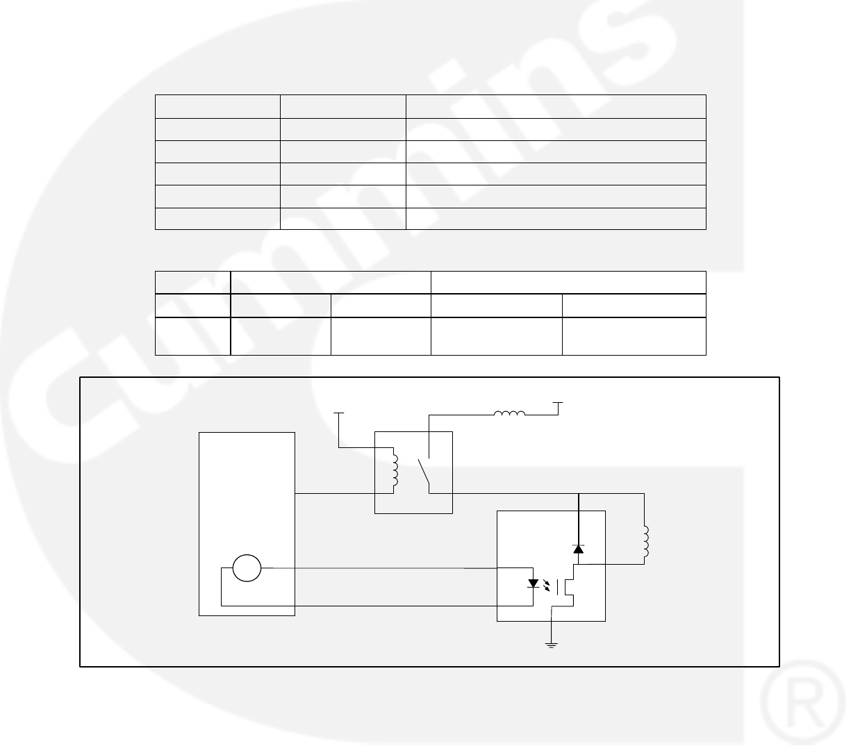
3-19
ELECTRONIC GOVERNOR
CONNECTIONS
This section describes the installation of the option-
al Electronic Governor Power Module.
A description of the Governor Power Module con-
nections are listed in Table 3-15. Module connector
pat numbers are listed in Table 3-16.
The electronic fuel actuator is driven by the output
of the Governor Power Module. Use twisted pair
wires minimum 1 sq mm (16 Gage). Power to the
Governor Power Module is derived from the genset
starting battery but should be connected to the
Governor Power Module as indicated in the dia-
grams “Applications without FSO” (see Figure
3-13) and “Applications with FSO” (see Figure
3-14) as appropriate.
TABLE 3-15. GOVERNOR MODULE CONNECTIONS
Connector Pin Signal Name Comments
P1-1 Gov drive −
P1-2 Gov drive +
P1-3 B+ Battery +
P1-4 Actuator Low side of actuator
P1-5 Return GND
TABLE 3-16. CONNECTOR PART NUMBERS FOR THE GOVERNOR MODULE CONNECTIONS
Connector Housing Connector Pins
Ref Internal P/N Man / P/N Internal P/N Man / P/N
P1 0323−2216 Amp/Tyco /
1−480763−0
0323−1200 Amp/Tyco /
770008−3
1302 Series
Control
FSO
PWM
Fuel
Actuator
B+
GND
Governor
Power Stage
Relay
J20−14
J11−5
J11−4
Fuse
E−Stop B+
FIGURE 3-13. ELECTRONIC GOVERNOR CONNECTIONS FOR APPLICATIONS WITHOUT FSO

3-20
1302 Series
Control
FSO
PWM
B+
GND
Governor
Power Stage
Relay
J20−14
J11−5
J11−4
E−Stop B+
FSO
FIGURE 3-14. ELECTRONIC GOVERNOR CONNECTIONS FOR APPLICATIONS WITH FSO
KIT INSTALLATION
Refer to the control wiring diagram included in
Section 7 when installing the items included in this
kit. This wiring diagram also includes information
on wiring items (annunciator, I/O module, and gov-
ernor power module) not included in this kit.
While the harnesses included in this kit should be
long enough for all types of installations, it is a good
idea to make sure that the distance between two
connecting parts does not exceed the length of the
harness. Excess wiring may be trimmed if it inter-
feres with your installation.
NOTE: To check the actual genset output, True
(calibrated) RMS meter should be
usedMounting hardware for the 1302 con-
trol and the operator panel is not included
in this kit. The instructions below include
suggested hardware sizes.
1. Make sure the generator set is shut down and
disabled:
a. The generator set Run/Off/Auto switch is
in the Off position and the generator is
cool (to the touch).
b. The battery charger (if equipped) is
turned off and disconnected.
c. The negative (−) cable from the battery is
disconnected to prevent accidental start-
ing.
2. Select a suitable location (see “Mounting
Guidelines” on page 3-1) and mount the
1302 control board using M4 hardware. Figure
3-15 shows the control board dimensions. The
outside dimensions do not include necessary
clearance for wire connections.
DIMENSIONS ARE IN MILLIMETERS
FIGURE 3-15. 1302 CONTROL FOOTPRINT
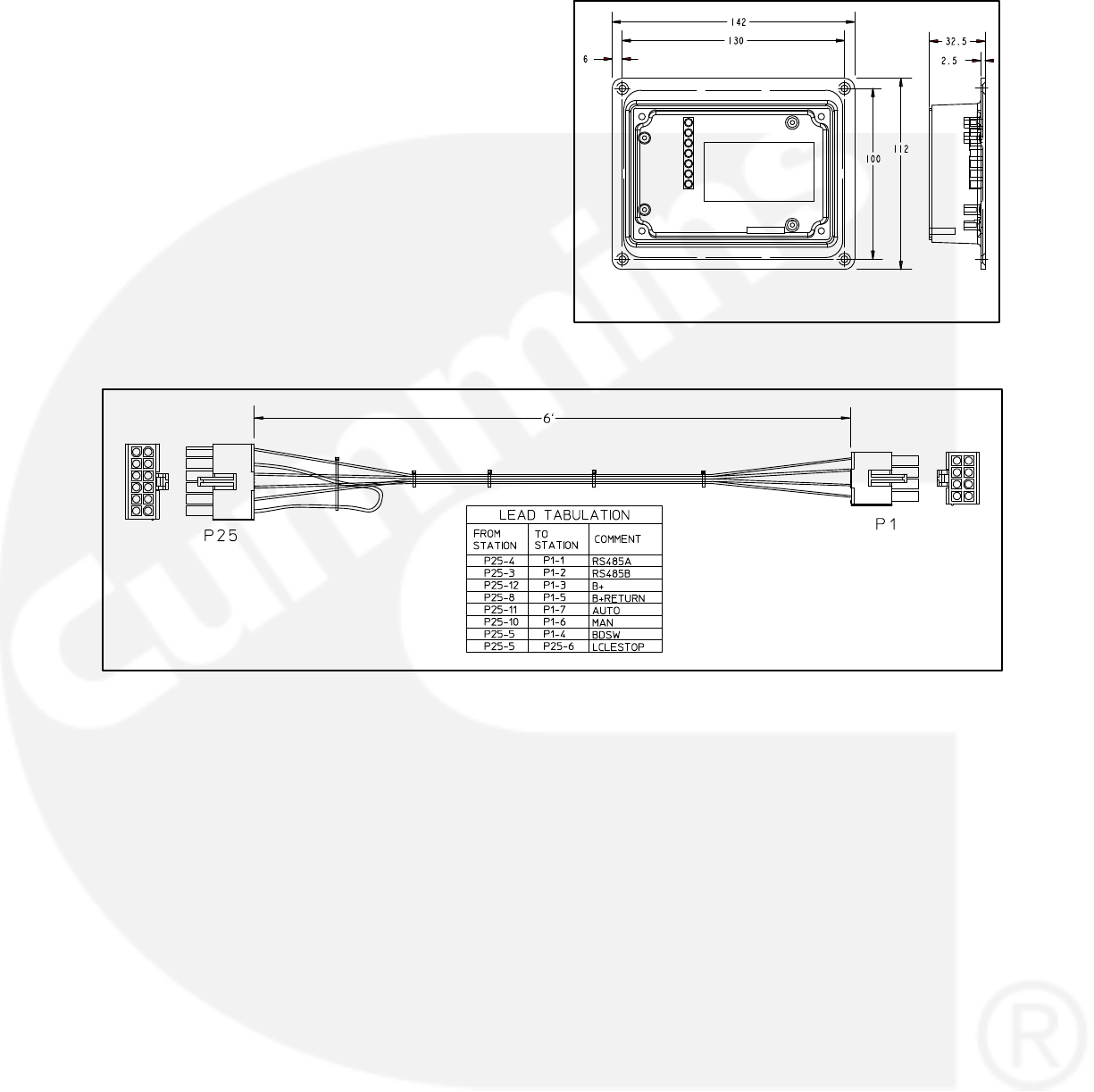
3-21
3. Install the operator panel and operator panel
harness.
a. Select a suitable location and mount the
panel using #6−32 hardware. Figure 3-16
shows the operator panel dimensions.
The operator panel must be mounted
within 72 inches (1828.8 mm) of the con-
trol board.
b. Install the operator panel harness (see
Figure 3-17). Plug the P1 connector into
the display (either J1 or J2) and plug the
P25 connector into the J25 connector on
the control board.
DIMENSIONS ARE IN MILLIMETERS
FIGURE 3-16. OPERATOR PANEL FOOTPRINT
DIMENSIONS ARE IN FEET
FIGURE 3-17. OPERATOR PANEL HARNESS
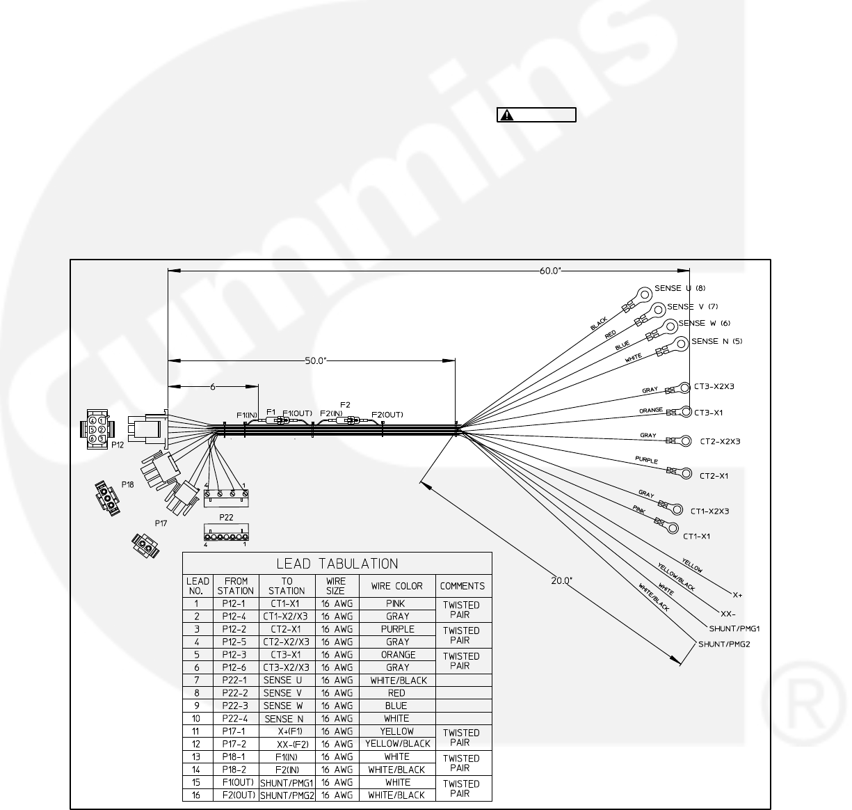
3-22
4. Install the genset harness (see Figure 3-18).
a. Make sure the current transformers in-
stalled are appropriate for use with a 1302
series control. Refer to the “Guidelines for
Current Transformers” subsection, start-
ing on page 3-3.
b. Make sure the battery charging alternator
installed is one of the types listed in the
“Battery Charger Alternator Connec-
tions” subsection, starting on page 3-8.
c. Make sure the alternator connections are
appropriate for your installation (see “Al-
ternator Connections” on page 3-9).
d. Connect the six harness CT wires to the
current transformers.
e. Connect the four harness sense wires to
the alternator.
f. Connect the harness X+ and XX− wires to
the generator field windings.
g. Make the connections for the excitiation
source (shunt or PMG). For shunt ap-
plications, connect J18-1 and J18-2 to the
low side of L1 and L2. For PMG applica-
tions, connect J18-1, J18-2, and 18-3 to
P2, P3, and P4 on the permanent magnet.
J18-1 and J18-2 are 240V maximum in-
puts.
CAUTION Do not connect J18-1 di-
rectly to L1 in 480V applications. Mak-
ing this connection will blow up the
1302 control board.
h. Connect the harness P12, P17, P18, and
P22 connectors to the mating connectors
on the 1302 control board.
DIMENSIONS ARE IN INCHES
FIGURE 3-18. GENSET HARNESS
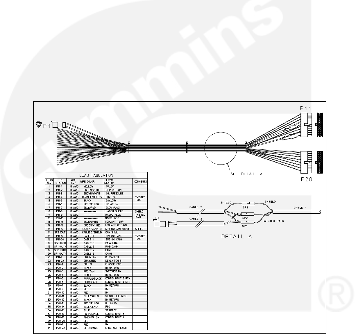
3-23
5. Install the engine harness.
a. Connect the engine harness wires
marked P11-2 and P11-3 to the oil pres-
sure harness wires marked J11-5, J11-6,
and J11-17 (see Figure 3-20).
b. Connect the engine harness wires
marked P11-11 and P11-12 to the coolant
temperature sensor harness wires
marked P11-11 and P11-12 (see Figure
3-21).
c. If installed, connect the engine harness
wires marked P11-8, P11-9, and P11-10
to the magnetic pickup sensor on the en-
gine. If not installed, tie the wires back.
d. Connect the remaining engine harness
wires to the appropriate locations indi-
cated in Figure 3-19.
NOTE: If your installation does not in-
clude an electronic governor, tie
back the wires marked P11-4 and
P11-5.
e. Connect the engine harness P11 and P20
connectors to the 1302 control board J11
and J20 connectors.
6. Install the oil pressure sensor and harness.
a. Install the sensor on the engine.
b. Connect the harness connector to the oil
pressure sensor.
FIGURE 3-19. ENGINE HARNESS
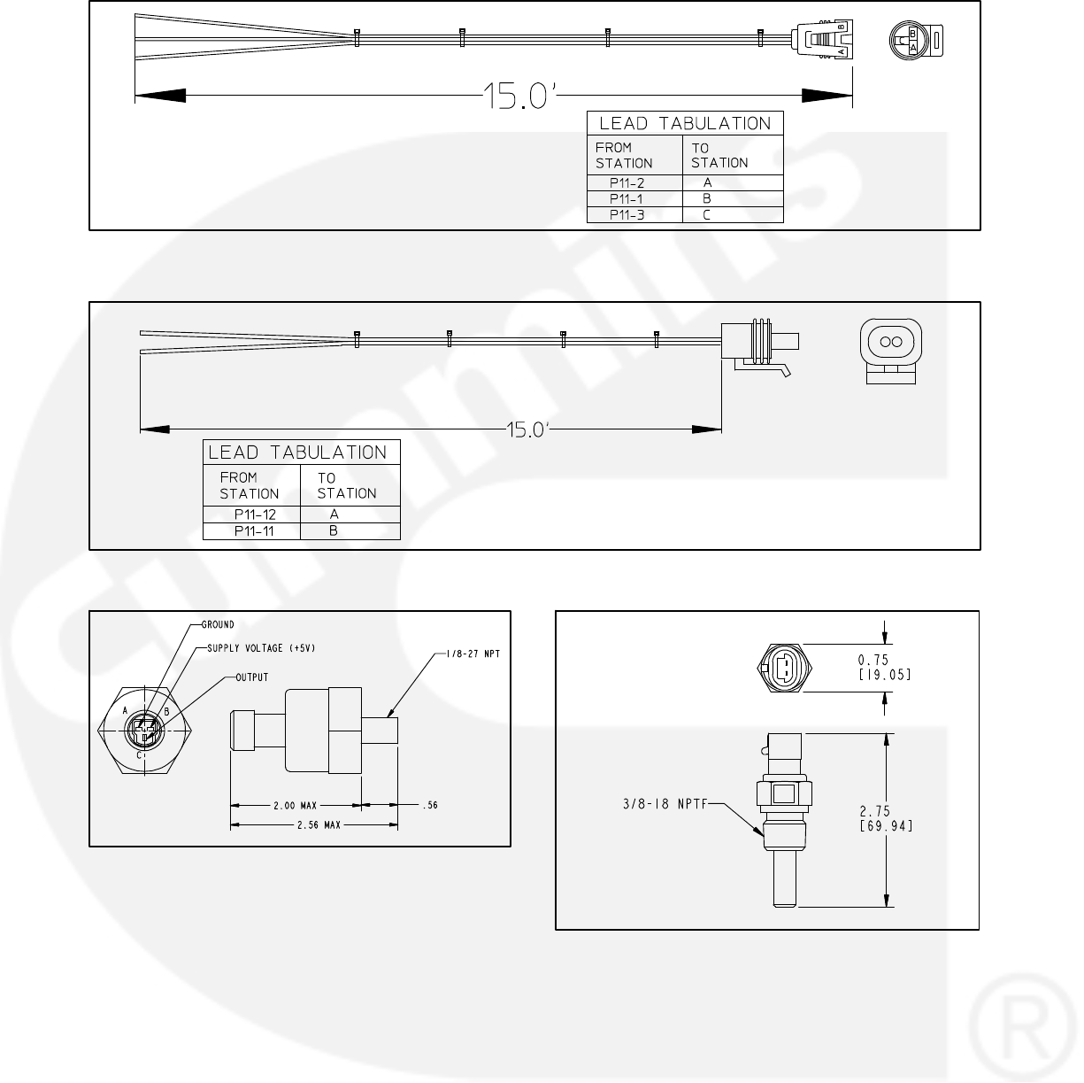
3-24
DIMENSIONS ARE IN FEET
FIGURE 3-20. OIL PRESSURE SENSOR HARNESS
DIMENSIONS ARE IN FEET
FIGURE 3-21. COOLANT TEMPERATURE SENSOR HARNESS
FIGURE 3-22. OIL PRESSURE SENSOR
7. Install the coolant temperature sensor and
harness.
a. Install the sensor on the radiator.
b. Connect the harness connector to the
temperature sensor.
8. Reconnect the generator starting battery
cables (positive [+] cable first).
9. Connect the battery charger (If equipped).
10. Press any button on the operator panel to
“wake up” the control.
FIGURE 3-23. COOLANT TEMPERATURE SENSOR
11. Use the operator panel to access the Service
menus (see Section 5) and/or a PC service
tool to adjust the appropriate control parame-
ters.
a. For general information on all available
parameters that can be adjusted, see
“Setup, Trims, and Adjustments” on page
3-26.

3-25
b. Follow the setup procedures for current
transformers listed on page 3-4.
c. For information on alternator control ad-
justments, see page 3-36.
d. For information on genset tuning, see
page 3-36.
e. For information on other control functions,
see page 3-46. These include:
−Remote start mode
−Remote emergency stop
−12V/24V batteries
−Engine starting
−Cycle cranking
−Spark ignition power/Glow plug
control
−Genset cooldown start and stop
time delays
f. For information on the Battle Short option,
see page 3-55.
12. Place the generator set Run/Off/Auto switch in
the desired position.
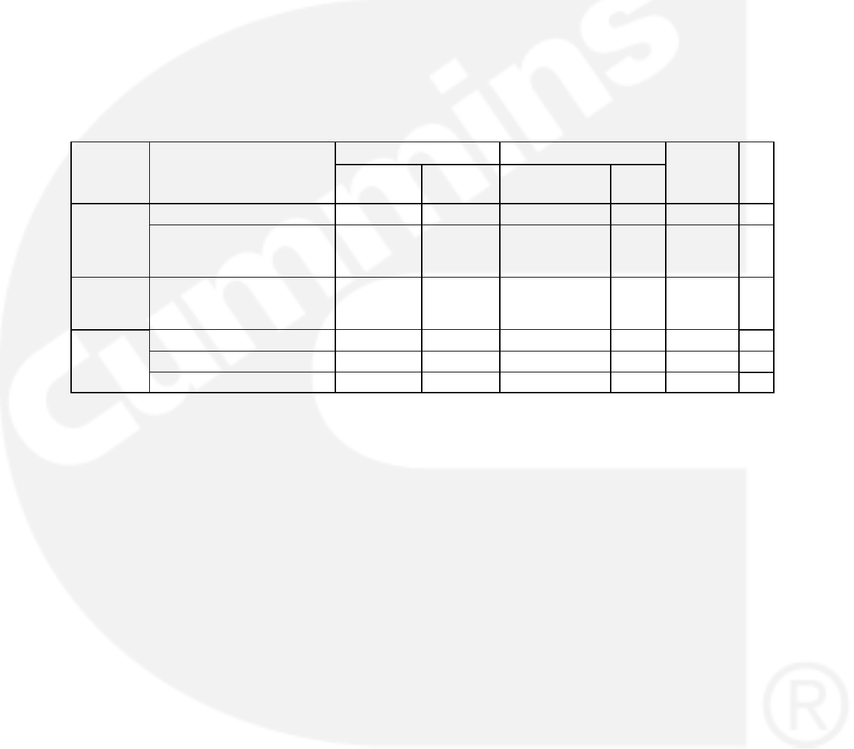
3-26
SETUP, TRIMS, AND ADJUSTMENTS
While applying a 1302 series control to a new ap-
plication, make sure the parameters listed in Table
3-17 have appropriate values. Many of these can
be adjusted using the operator panel but some re-
quire use of a genset Manufacturing Tool or a PC
based service tool.
NOTE: To check the actual genset output, True
(calibrated) RMS meter should be
usedSection 5 includes information on all
of the Service menus that are used to ad-
just parameters using the 1302 operator
panel. The last column in Table 3-17 lists
the page references in Section 5 where you
can find information on how to adjust each
parameter.
Configurable / Model Specific features like nominal
voltage, frequency, KVA rating, Engine protection
values Alternator Protection values, AVR and Gov-
ernor Gains, CT Ratio, etc have to be assigned ap-
propriate values at manufacturing time.
TABLE 3-17. 1302 CONTROL PARAMETERS
Adjusted Using Limits
Pg
Group Parameter Name PC Based
Service Tool
Operator
Panel Lower Limit Upper
Limit
Units
P
g
Ref
Adjust- Voltage Adjust X−5 5 % —
j
ment Start Time Delay (V2.79
and prior with HMI211 7.10
or prior)
X X 0 300 Sec 5-8
Start Time Delay (V2.80
and later with HMI211 7.20
or later)
X X 0 3600 Sec 5−8
Adjust- Stop Time Delay X X 0 600 Sec 5-8
j
ment V/Hz Knee Frequency X X 0 10 Hz 5-17
V/Hz Rolloff Slope X X 0 5 % 5-17
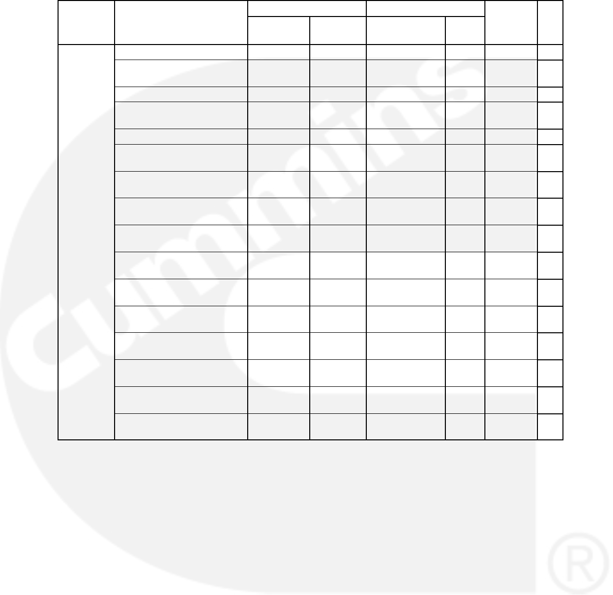
3-27
TABLE 3-17. 1302 CONTROL PARAMETERS (CONT.)
Group Pg
Ref
Units
LimitsAdjusted Using
Parameter Name
Group Pg
Ref
Units
Upper
Limit
Lower Limit
Operator
Panel
PC Based
Service Tool
Parameter Name
Setup –
G
Nominal Battery Voltage X X 12 24 VDC 5-41
p
Genset AVR Enable X X Enable or
Disable
NA NA 5-11
Excitation Source X X Shunt or PMG 5-39
Excitation / Line Frequency
Gain
X X 1,2,4 5-39
Nominal Voltage X X 190 480 V AC 5-8
Alternator Nominal
Frequency
X X 50 or 60 N/A Hz 5-8
Single Phase 60Hz Standby
kVA Rating
X X 0 2000 KVA 5-39
Three Phase 60Hz Standby
kVA Rating
X X 0 2000 KVA 5-39
Single Phase 50Hz Standby
kVA Rating
X X 0 2000 KVA 5-39
Three Phase 50Hz Standby
kVA Rating
X X 0 2000 KVA 5-39
Single Phase 60Hz Prime
kVA Rating
X X 0 2000 KVA 5-41
Three Phase 60Hz Prime
kVA Rating
X X 0 2000 KVA 5-41
Single Phase 50Hz Prime
kVA Rating
X X 0 2000 KVA 5-41
Three Phase 50Hz Prime
kVA Rating
X X 0 2000 KVA 5-41
Frequency to Speed Gain
Select
X X 20, 30, or 60 N/A RPM/Hz 5-39
Oil Pressure Switch Polarity X Active Low or
Active High
N/A N/A 5-43
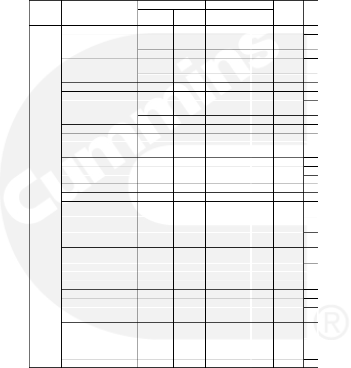
3-28
TABLE 3-17. 1302 CONTROL PARAMETERS (CONT.)
Group Pg
Ref
Units
LimitsAdjusted Using
Parameter Name
Group Pg
Ref
Units
Upper
Limit
Lower Limit
Operator
Panel
PC Based
Service Tool
Parameter Name
Setup –
G
Oil Pressure Sensor Type X X 2 or 3 wire N/A N/A 5-43
p
Genset
(Contin-
ued)
Electronic Governor Enable XEnable or
Disable
NA NA —
ue
d)
XYes or No N/A N/A 5-11
Glow Plug Enable XEnable or
Disable
N/A N/A —
XYes or No N/A N/A 5-8
Fuel System X X Diesel or Gas N/A N/A 5-8
Fuel Burn Time Delay X X 0 10 Sec 5-8
Magnetic Pickup Enable XEnable or
Disable
None N/A —
XYes or No None N/A 5-13
Flywheel Teeth X X 0 255 Teeth 5-39
Dither Factor X X 0 30 % 5-19
Maximum Governor Duty
Cycle
X X 0 100 % 5-19
AVR Gain Adjust X X 5 1000 % 5-17
AVR K2 Gain Adjust X X 5 1000 % 5-17
AVR D Gain Adjust X X 95 105 % 5-17
K1 (Regulator Gain 50Hz) X 0 65535 NA —
K1 (Regulator Gain 60Hz) X 0 65535 NA —
K2 (Regulator Integral
50Hz)
X 0 65535 NA —
K2 (Regulator Integral
60Hz)
X 0 65535 NA —
K3 (Regulator K3 Gain
50Hz)
X 0 65535 NA —
K3 (Regulator K3 Gain
60Hz)
X 0 65535 NA —
Damping Effect (60Hz) X 0.2 0.99 NA —
Damping Effect (50Hz) X 0.2 0.99 NA —
Cycle Crank Attempts X X 1 7 Attempts 5-11
Cycle Crank Engage Time X X 3 30 Sec 5-11
Cycle Crank Rest Time X X 0 60 Sec 5-11
Remote / Local Display N/A X Remote or
Local
N/A N/A 5-15
Battle Short Enable XEnable or
Disable
NA NA 5-11
Battle Short Switch Input X X Configurable
input 1−4 or
operator panel
N/A N/A 5-11
Governor Ramp Time X X 0 30 Sec 5-19
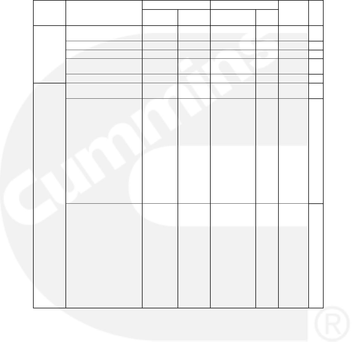
3-29
TABLE 3-17. 1302 CONTROL PARAMETERS (CONT.)
Group Pg
Ref
Units
LimitsAdjusted Using
Parameter Name
Group Pg
Ref
Units
Upper
Limit
Lower Limit
Operator
Panel
PC Based
Service Tool
Parameter Name
Setup –
ECM CAN
ECM CAN Enabled XDisable, J1939,
PGI
—
Keyswitch Reset Delay X 1 10 Sec —
Keyswitch On Time Delay X 1 10 Sec —
CAN Datalink Failure
Retries
X 0 10 Times —
ECM Datasave Time X 30 60 Sec —
Setup −
Configur-
bl I/O
Configurable Input #1−4
Function
X X Active open or
Active closed
N/A 5-21
g
able I/O
Configurable I/P #1
AnnActive LED
X NO_ANNUN_M
APPING,
CUSTOMER_F
AULT_1,
CUSTOMER_F
AULT_2,
CUSTOMER_F
AULT_3,
GEN_SUPPLY
_LOAD,
CHARGER_AC
_FAIL,
LOW_COOLAN
T_LEVEL,
LOW_FUEL_L
EVEL
N/A 5-21
Configurable I/P #2
AnnActive LED
X NO_ANNUN_M
APPING,
CUSTOMER_F
AULT_1,
CUSTOMER_F
AULT_2,
CUSTOMER_F
AULT_3,
GEN_SUPPLY
_LOAD,
CHARGER_AC
_FAIL,
LOW_COOLAN
T_LEVEL,
LOW_FUEL_L
EVEL
N/A 5-21

3-30
TABLE 3-17. 1302 CONTROL PARAMETERS (CONT.)
Group Pg
Ref
Units
LimitsAdjusted Using
Parameter Name
Group Pg
Ref
Units
Upper
Limit
Lower Limit
Operator
Panel
PC Based
Service Tool
Parameter Name
Configurable I/P #3
AnnActive LED
X NO_ANNUN_M
APPING,
CUSTOMER_F
AULT_1,
CUSTOMER_F
AULT_2,
CUSTOMER_F
AULT_3,
GEN_SUPPLY
_LOAD,
CHARGER_AC
_FAIL,
LOW_COOLAN
T_LEVEL,
LOW_FUEL_L
EVEL
N/A 5-21
Configurable I/P #4
AnnActive LED
X NO_ANNUN_M
APPING,
CUSTOMER_F
AULT_1,
CUSTOMER_F
AULT_2,
CUSTOMER_F
AULT_3,
GEN_SUPPLY
_LOAD,
CHARGER_AC
_FAIL,
LOW_COOLAN
T_LEVEL,
LOW_FUEL_L
EVEL
N/A 5-21
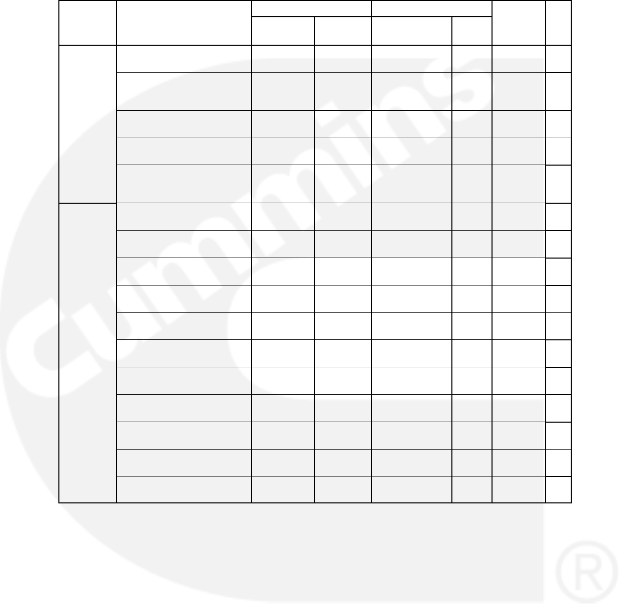
3-31
TABLE 3-17. 1302 CONTROL PARAMETERS (CONT.)
Group Pg
Ref
Units
LimitsAdjusted Using
Parameter Name
Group Pg
Ref
Units
Upper
Limit
Lower Limit
Operator
Panel
PC Based
Service Tool
Parameter Name
Setup −
Configur-
bl I/O
Configurable Fault Input
#1−4 Active State Select
X X Active open or
Active closed
N/A 5-21
g
able I/O
Configurable Fault Input
#1−4 Fault Level Response
X X Warning,
Shutdown, or
None
5-21
Configurable #1−4 Input
Text Line 1
X X 5-21
Configurable #1−4 Input
Text Line 2
X X 5-21
Customer Output 1/2 Event X X 0 9999 Fault
Code
Numbers
5-25
Regulated
Voltage
Adj t
Voltage Regulator
Calibration 50Hz
X X 0.9 1.1 % 5-27
g
Adjust Voltage Regulator
Calibration 60Hz
X X 0.9 1.1 % 5-27
Alternator L1−N 50Hz
Voltage Display Adjust
X X 0.8 1.1 % 5-27
Alternator L2−N 50Hz
Voltage Display Adjust
X X 0.8 1.1 % 5-27
Alternator L2−N 50Hz
Voltage Display Adjust
X X 0.8 1.1 % 5-27
Alternator L1−N 60Hz
Voltage Display Adjust
X X 0.8 1.1 % 5-27
Alternator L2−N 60Hz
Voltage Display Adjust
X X 0.8 1.1 % 5-27
Alternator L2−N 60Hz
Voltage Display Adjust
X X 0.8 1.1 % 5-27
Alternator L1 50Hz Current
Adjust
X X 0.8 1.2 % 5-27
Alternator L2 50Hz Current
Adjust
X X 0.8 1.2 % 5-27
Alternator L2 50Hz Current
Adjust
X X 0.8 1.2 % 5-27
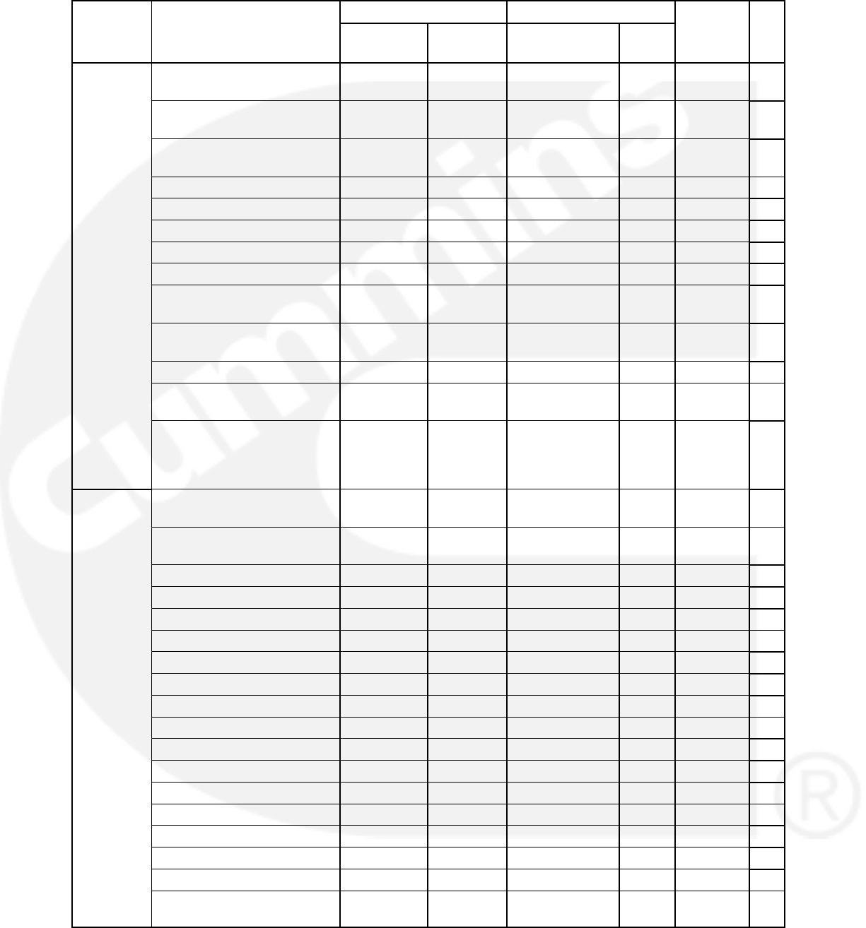
3-32
TABLE 3-17. 1302 CONTROL PARAMETERS (CONT.)
Group Pg
Ref
Units
LimitsAdjusted Using
Parameter Name
Group Pg
Ref
Units
Upper
Limit
Lower Limit
Operator
Panel
PC Based
Service Tool
Parameter Name
Regulated
Voltage
Adj t
Alternator L1 60Hz Current
Adjust
X X 0.8 1.2 % 5-27
g
Adjust
(Contin-
ued)
Alternator L2 60Hz Current
Adjust
X X 0.8 1.2 % 5-27
u
ed)
Alternator L2 60Hz Current
Adjust
X X 0.8 1.2 % 5-27
High AC Voltage Threshold X X 105 125 % 5-45
High AC Voltage Delay X X 1 10 Sec 5-45
Low AC Voltage Threshold X X 50 95 % 5-45
Low AC Voltage Delay XX 2 20 Sec 5-45
Under Frequency Threshold X X 2 10 Hz 5-45
Under Frequency Delay X X 500 2000 1/2
cycles
5-45
Overfrequency Enable XEnable or
Disable
N/A NA —
Overfrequency Threshold X X 2 10 Hz 5-45
Overfrequency Delay X X 100 2000 1/2
cycles
5-45
High AC Current Shutdown
Delay
X X 2 60 Sec 5-45
Protection
– Engine
Overspeed Shutdown
Threshold 50Hz
X X 0 8192 Rpm 5-49
g
Overspeed Shutdown
Threshold 60Hz
X X 0 8192 Rpm 5-49
LOP Shutdown Threshold X X 0 100 Psig 5-51
LOP Shutdown Delay X X 2 15 Sec 5-51
LOP Warning Threshold X X 0 100 Psig 5-49
LOP Warning Delay X X 2 15 Sec 5-49
LCT Warning Threshold X X 32 100 deg f 5-53
HCT Shutdown Threshold X X 180 300 deg f 5-51
HCT Shutdown Delay X X 2 10 Sec 5-51
HCT Warning Threshold X X 150 290 deg f 5-51
HCT Warning Delay X X 2 10 sec 5-51
12V Low Battery Threshold X X 11 13 VDC 5-41
24V Low Battery Threshold X X 22 27 VDC 5-41
Low Battery Fault Delay X X 2 60 Sec 5-43
High Battery Fault Delay X X 14 17 VDC 5-41
24V High Battery Threshold X X 28 34 VDC 5-41
12V High Battery Threshold X X 2 60 Sec 5-43
12V Weak Battery
Threshold
X X 6 10 VDC 5-41
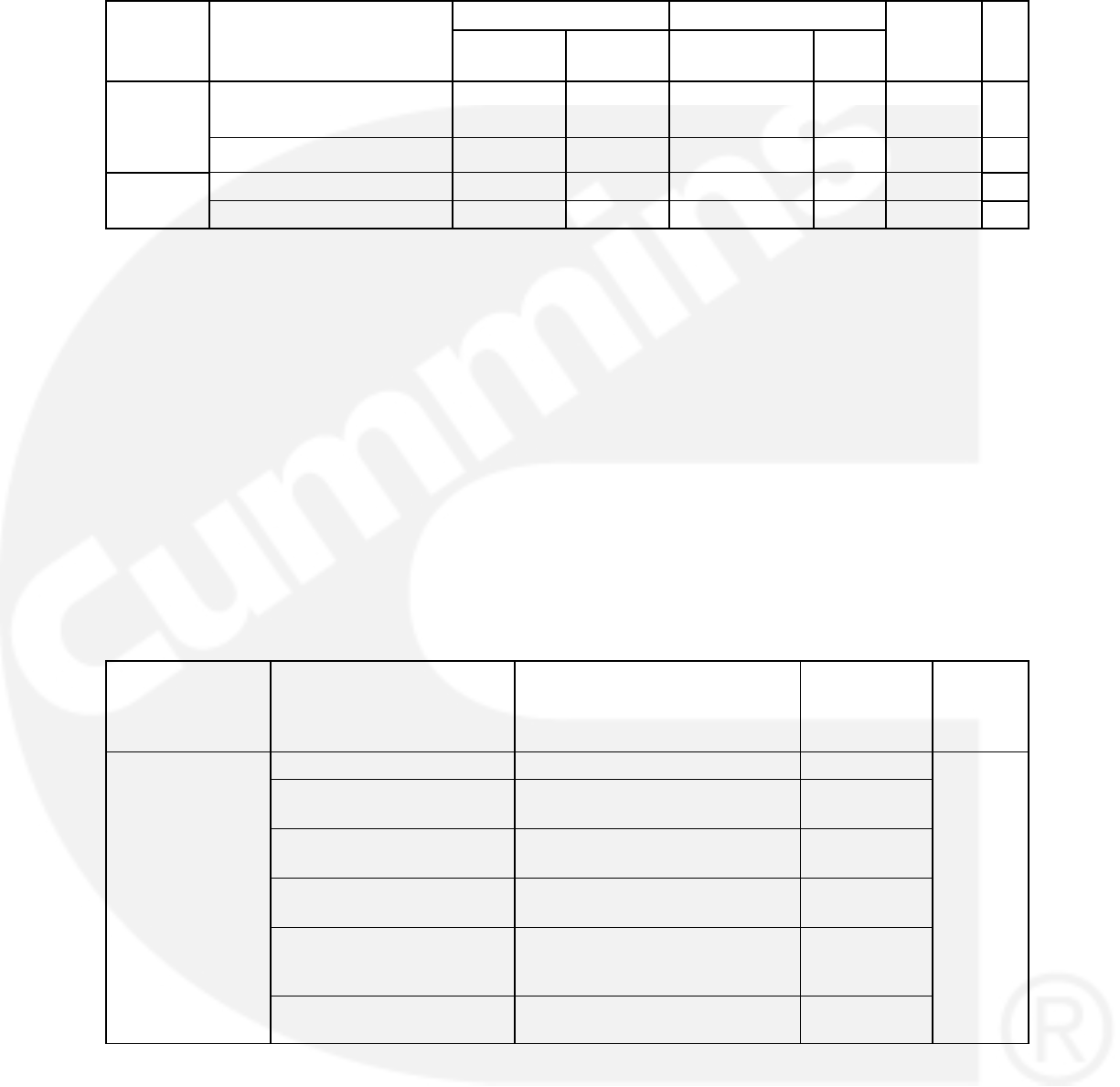
3-33
TABLE 3-17. 1302 CONTROL PARAMETERS (CONT.)
Group Pg
Ref
Units
LimitsAdjusted Using
Parameter Name
Group Pg
Ref
Units
Upper
Limit
Lower Limit
Operator
Panel
PC Based
Service Tool
Parameter Name
Protection
– Engine
(Contin-
24V Weak Battery
Threshold
X X 18 21 VDC 5-41
(C
on
ti
n-
ued) Weak Battery Fault Delay X X 1 5 sec 5-43
Fault
Hi
Reset Runs X —
History Reset Start Attempts X —
NFPA 110 Status Logical Bits 1−7, Annunciator
Discrete Signals (Configurable via PCC1302
A universal annunciator connected in a network in-
dicates and annunciates the active faults received
from the PCC1302. The NFPA 110 Status Logical
bits 1 to 7 (i.e. LEDs) of an annunciator can be
mapped to indicate and annunciate the active
faults corresponding to each of the four configur-
able inputs of PCC1302 as defined by the user. For
this, the (trim) ”Configurable Input #n Function” (n =
1, 2, 3, or 4) should be set as ”Fault Input” and the
LED should be mapped through (trim) ”Configur-
able I/P# n Ann Active LED” (n = 1,2,3 or 4), where,
”Configurable I/P# 1 Ann Active LED”) is applica-
ble only for ”Configurable Input #1 Function”.
”Configurable I/P# 2 Ann Active LED” is applicable
only for ”Configurable Input #2 Function”.
”Configurable I/P# 3 Ann Active LED” is applicable
only for ”Configurable Input #3 Function”.
”Configurable I/P# 4 Ann Active LED” is applicable
only for ”Configurable Input #4 Trim Function”
Each active fault corresponding to the respective
configurable input of PCC1302 is annunciated and
indicated according to the LEDs mapped by the
user to the ”Configurable Input #n Function” (n = 1,
2, 3, or 4) set as ”Fault Input”:
Refer the table below for more information on setup
and expected observations:
TABLE 3-18. 1302 CONTROL SETUP
Input #
”Configurable I/P# n Ann
Active LED” (n =
1,2,3 or 4) set to one of
the following
Active Condition (LED#
indication) on Annunciator
Active Fault
Condition
Active
FC#
”Configurable In-
# F i ”
NO_ANNUN_MAPPING No bit set = NONE None 1311
g
put #1 Function” =
Fault Input and
”
Configurable
CUSTOMER_FAULT_1 Bit 1 set = LED 1 Annunciator
Fault 1
”C
on
fi
gura
bl
e
I/P# 1 Ann Active
LED”
CUSTOMER_FAULT_2 Bit 1 set = LED 2 Annunciator
Fault 2
LED
CUSTOMER_FAULT_3 Bit 1 set = LED 3 Annunciator
Fault 3
GEN_SUPPLY_LOAD Bit 1 set = LED 4 Genset
Supplying
Load
CHARGER_AC_FAIL Bit 1 set = LED 5 Charger AC
Failure
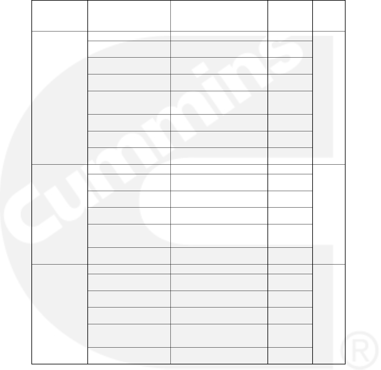
3-34
TABLE 3-18. 1302 CONTROL SETUP (CONT.)
Input # Active
FC#
Active Fault
Condition
Active Condition (LED#
indication) on Annunciator
”Configurable I/P# n Ann
Active LED” (n =
1,2,3 or 4) set to one of
the following
”Configurable In-
#1 F i ”
NO_ANNUN_MAPPING No bit set = NONE None 1312
g
put #1 Function” =
Fault Input and
”
Configurable
CUSTOMER_FAULT_1 Bit 1 set = LED 1 Annunciator
Fault 1
”C
on
fi
gura
bl
e
I/P# 1 Ann Active
LED”
CUSTOMER_FAULT_2 Bit 1 set = LED 2 Annunciator
Fault 2
LED
CUSTOMER_FAULT_3 Bit 1 set = LED 3 Annunciator
Fault 3
GEN_SUPPLY_LOAD Bit 1 set = LED 4 Genset
Supplying
Load
CHARGER_AC_FAIL Bit 1 set = LED 5 Charger AC
Failure
LOW_COOLANT_LEVEL Bit 1 set = LED 6 Low Coolant
Level
LOW_FUEL_LEVEL Bit 1 set = LED 7 Low Fuel
Level
”Configurable In-
# F i ”
NO_ANNUN_MAPPING No bit set = NONE None 1317
g
put #1 Function” =
Fault Input and
”
Configurable
CUSTOMER_FAULT_1 Bit 1 set = LED 1 Annunciator
Fault 1
”C
on
fi
gura
bl
e
I/P# 1 Ann Active
LED”
CUSTOMER_FAULT_2 Bit 1 set = LED 2 Annunciator
Fault 2
LED
CUSTOMER_FAULT_3 Bit 1 set = LED 3 Annunciator
Fault 3
GEN_SUPPLY_LOAD Bit 1 set = LED 4 Genset
Supplying
Load
CHARGER_AC_FAIL Bit 1 set = LED 5 Charger AC
Failure
”Configurable In-
#1 F i ”
NO_ANNUN_MAPPING No bit set = NONE None 1318
g
put #1 Function” =
Fault Input and
”
Configurable
CUSTOMER_FAULT_1 Bit 1 set = LED 1 Annunciator
Fault 1
”C
on
fi
gura
bl
e
I/P# 1 Ann Active
LED”
CUSTOMER_FAULT_2 Bit 1 set = LED 2 Annunciator
Fault 2
LED
CUSTOMER_FAULT_3 Bit 1 set = LED 3 Annunciator
Fault 3
GEN_SUPPLY_LOAD Bit 1 set = LED 4 Genset
Supplying
Load
CHARGER_AC_FAIL Bit 1 set = LED 5 Charger AC
Failure
ALTERNATOR CONTROL ADJUSTMENTS
The 1302 series control includes an integrated line-
to-line sensing voltage regulation system that is
compatible with shunt or PMG excitation systems.
The voltage regulation system is SCR type. Excita-
tion power is derived either directly from the genset
terminals or from a PMG stator. Power from either
source is fed into the control thru J18. Positive volt-

3-35
age build up from residual levels is ensured by the
use of efficient semiconductors in the power circuit-
ry.
AVR Enable/Disable Feature
The 1302 series control provides automatic
voltage regulating capability for the generator set
when the AVR feature is enabled on the genset. It
has a field adjustment trim to enable or disable the
AVR feature. The trim parameter for this is AVR
Enable = Enable / Disable.
For information on enabling/disabling the AVR fea-
ture using the operator panel, see page 5-11.
Digital Output Voltage Regulation
The 1302 series control supports digital output
voltage regulation as defined below.
Voltage setpoint algorithm sets the level of the
automatic voltage regulation. It is adjustable.
The maximum allowed rated current for the
field coil for the regulation is 4.0 Amps RMS
and maximum 6.0 Amps for 10 seconds.
The control provides voltage ramping at start-
up if the AVR algorithm is enabled, such that
voltage overshoot can be controlled. AVR boot
enable logic supports the step by step voltage
ramping.
A PC based service tool allows the operator to
adjust the output voltage within plus or minus
5.0% of rated voltage.
Torque-Matched Volts/Hz Overload
Control
A frequency measuring circuitry monitors the
generator output and provides output underspeed
protection of the excitation system, by reducing the
output voltage proportionally with speed.
The voltage rolloff set point and rate of decay (i.e.,
the slope of the volts/hertz curve) is adjustable in
the control.
Major system features include.
%Volts/Hz rolloff supports the engine speed
recovery under block loading. The slope set-
ting (%volts/Hz) range is 0.0−5.0% of rated
with 0.1% increment.
The knee frequency range is 0.0−10.0Hz less
than the nominal frequency with 0.1 Hz incre-
ment.
For information on adjusting rolloff and knee fre-
quency settings using the operator panel, see page
5-17.
Battleshort Mode
The 1302 series control can be programmed to
work in battleshort mode by loading the battleshort
feature with a manufacturing tool or PC based ser-
vice tool.
The controller then can accept Configurable Input
1−4 as battle short switch inputs. If an operator
panel is used, it can be also selected as a source of
input by selecting appropriate input source value
for the trim.
Battleshort mode is designed to work only in critical
load circumstances. While in battleshort mode the
1302 series control will ignore most warnings and
shutdowns and will continue to operate as if no fault
or shutdown exists on the system.
For information on enabling/disabling the battle-
short feature using the operator panel, see page
5-11.

3-36
GENSET TUNING
The 1302 series control uses a standard 4 coeffi-
cient PID algorithm running at an execution rate of
once per zero cross of the generator AC waveform.
Standard values for the K1−K4 and damping terms
for both 60 and 50Hz are listed in Table 3-19.
Consider the following before making any adjust-
ments.
The values of K3, K4, and the damping factor
are set for basic stability reasons and should
not need to be adjusted, but they can be ad-
justed if necessary.
The useful range of values for K2 is 200 to
1500. The value of 1500 for K2 can be a little
too high or aggressive for some applications
and cause “ringing” upon recovering from a
load acceptance or offload transient situation.
A value of K2 below 200 can cause the regula-
tor to hit an integrator windup limit and should
be avoided if possible. Set the correct value for
the application.
The value of K1 should be adjusted to meet the
specification for percent off rated voltage dur-
ing a load acceptance, and prevent large volt-
age overshoots during offloads and during en-
gine/alternator startup.
The value of K2 should be adjusted to control
the recovery characteristics of the voltage dur-
ing large load acceptance and rejection tran-
sients. Values of K2 which are too high can
cause unstable voltage performance and val-
ues too low can cause slow performance or
steady state voltage offset errors.
In general, K1 increases and K2 decreases in val-
ue with increasing generator size, but can vary in
different applications.
V/Hz Curve
The 1302 series control uses a simple breakpoint
and slope approach to the V/Hz curve to allow for
the matching of the torque curve of the engine dur-
ing a large transient load acceptance. The two ad-
justment points are the V/Hz Knee Frequency
which set the point at which the V/Hz curve starts,
and the V/Hz Roll−off Slope which sets the roll−off
slope of the voltage setpoint as a function of fre-
quency error.
The default V/Hz settings are:
Parameter Default Value
V/Hz Knee Frequency 0.5 Hz
V/Hz Roll-off Slope 2.2 %V/Hz
The voltage set point command is calculated from
the frequency error between commanded frequen-
cy and the actual frequency. For example, a volt-
age set point of 93.4% of nominal would be com-
manded if there is a frequency error of 3.5Hz under
nominal. There is no offset to voltage for errors
above nominal frequency.
NOTE: To check the actual genset output, True
(calibrated) RMS meter should be
usedNote: There are only one V/Hz set-
tings per calibration so the values must be
used for both 50 and 60Hz operation. If a
particular application requires vastly differ-
ent V/Hz settings for 50Hz and 60Hz op-
eration, it will be required to create sepa-
rate software features for those applica-
tions.
For information on how to adjust the slope and
knee frequency using the operator panel, see page
5-17.
TABLE 3-19. GOVERNOR GAINS FOR SMALL
ENGINES
Newage BC/UC Generators Under 200Kw
60Hz 50Hz
K1 = 1000 K1 = 1000
K2 = 650 K2 = 650
K3 = 10000 K3 = 10000
K4 = 36429 K4 = 36429
Damping = 0.8 Damping = 0.8

3-37
Governor
The 1302 series control’s governor also uses the 4
coefficient PID algorithm. There are gains for use
at 50 and 60Hz operation. Standard values for the
K1−K4 and damping terms for both 60 and 50 Hz
for engines in the Cummins 4B3.9 and 6B5.9 range
are listed in Table 3-20.
TABLE 3-20. GOVERNOR GAINS FOR SMALL
ENGINES
60Hz 50Hz
GK1 = 1696 GK1 = 1200
GK2 = 240 GK2 = 300
GK3 = 28,800 GK3 = 28,800
GK4 (calc) = 7424 GK4 (calc) = 7424
Governor Damping =
0.936
Governor Damping =
0.936
Governor Tuning
A good starting point for any new engine applica-
tion is to start with a set of released gains for an en-
gine of a similar type and size should they already
exist.
If a set of pre−developed gains are not available,
the gains listed above should work well enough to
start most engines and to allow them to run
smoothly.
The value of GK1 should be adjusted to meet the
specification for percent off rated voltage during a
load acceptance, to prevent large voltage over-
shoots during offloads, and during engine/alterna-
tor startup.
The value of GK2 should be adjusted to control the
recovery characteristics of the engine during large
load acceptance and rejection transients. GK2 is a
true integral type gain and is applied to the gover-
nor output as GK2 times the sum of all the previous
governor error. Values of GK2 which are too high
can cause unstable voltage performance and val-
ues too low can cause slow performance or steady
state voltage offset errors.
The values of GK3, GK4 and the Damping factor
are used to set the basic steady state stability of the
engine, but also influence the overall speed of re-
sponse of the governor in transient situations. Ad-
justment of GK3 and the Damping factor is an itera-
tive process started by finding the engine load level
which produces the worst steady state engine per-
formance (note: GK1 and GK2 may have to be ad-
justed first to allow the engine to be transitioned
smoothly into this) and adjusting GK3 until the best
performance is observed, then doing the same for
the Damping factor. Repeat this process at least
once to ensure that the best possible values for
GK3 and the Damping term have been determined.
For information on how to adjust the GK1and GK2
values and the damping factor using the operator
panel, see page 5-17.
Engine Startup
The 1302 series control applies fuel to the engine
as described in the Speed Governor Algorithm and
Adjustment section.
Alternator Startup
The alternator will be started up and brought to
rated voltage when the engine speed reaches
rated speed. The PWM command to the field coil
will now be stepped through an AVR Boot Table un-
til the sensed voltage goes above the value of the
AVR Boot Threshold trim and if AVR feature is en-
abled. The regulator will now bring the voltage up to
rated voltage.
The purpose of the AVR Boot Table is to aid alterna-
tor startup whilst preventing overvoltage condi-
tions. The value of the AVR Boot Table and the AVR
Boot Threshold can be set to bring the voltage up
both as quickly and as smoothly as possible, but
should already be set in the calibration to their ideal
values. The AVR Boot Table has different values
depending on value of the Excitation Source trim.
Setup for Gain Tuning
In order to properly set up engine and alternator
control parameters it is convenient to setup the PC
based service tool to be used to monitor.
The following are step-by-step procedures for de-
termining engine and alternator control parame-
ters.
1. Determine 60Hz governor gains, regulator
gains, and V\Hz curve values with PMG ex-
citation.
a. Start the genset, bring it to rated speed
and temperature, and adjust the GK3 and
damping factor for 60Hz operation to al-
low the engine to run smoothly in steady
state operation.
NOTE: GK1 and/or GK2 may need to be
adjusted to allow this to happen.
Apply various loads up to 100% rated and
verify the steady state operation at all load

3-38
levels. Most engines have some load lev-
el which is inherently less stable than oth-
ers and must be found to determine the
correct value for GK3 and the damping
factor.
NOTE: It is important to control the
steady state performance of the
engine. Unstable engine perfor-
mance is carried over into the
generator output voltage. Very
fast increases or decreases in en-
gine speed, even if the magnitude
of the increase or decrease is
small, tend to be carried into the
alternator voltage as large in-
creases and decreases in voltage
at the same frequency as the en-
gine speed changes.
b. Do a series of load steps to determine the
transient characteristics of the genset.
Tuning of the governor GK1 and GK2 val-
ues, the settings of the V/Hz curve, and
the values of K1 and K2 (mostly K1) for
the regulator must be done concurrently.
In general, these values should be ad-
justed to achieve the maximum possible
performance from both the engine and
the alternator. A production test spec (if
available) should give the full load step
transient performance levels for any giv-
en genset model. This is a very iterative
process and many require some time to
find the best combination of gains to fit the
application. In general, adjust GK1 to con-
trol the peak frequency during transients
and adjust GK2 to control the recovery
shape of the frequency transient. A V/Hz
slope too steep causes the engine to re-
cover too quickly and recovers to nominal
speed very poorly. A V/Hz curve too shal-
low causes a very slow engine recovery
from a transient.
c. Re-verify steady state voltage and gover-
nor performance.
2. Determine 50Hz governor gains, Regulator
gains, and V/Hz curve values. Follow the
same process as used at 60Hz. The order of
50Hz vs 60Hz testing can be reversed.
3. Determine the correct values for the governor
startup parameters (see “Speed Governor Al-
gorithm and Adjustment” below).
a. Adjust the Initial Crank Fueling Com-
mand, Initial Crank Fueling Period, Crank
Fueling Ramp Rate, and Max Crank Fuel-
ing Command parameters to control the
way the engine transitions through the
cranking stage of the engine startup. The
controls default values should work well.
b. The value of the Crank Exit Fueling Com-
mand parameter should be set to the gov-
ernor duty at which the engine runs when
at rated speed, or to a value slightly high-
er.
Gain Tuning Parameters
This is a list of all of the parameters which affect
genset performance. A correct value should be de-
termined for each of the parameters listed.
NOTE: To check the actual genset output, True
(calibrated) RMS meter should be
usedFor any parameters that have some-
thing listed in the “Value” column, it is
recommended that the parameter stay at
that value during testing. Some parame-
ters should never be changed during test-
ing and are listed as never to be changed.

3-39
TABLE 3-21. GAIN TUNING PARAMETERS
Parameter Value Comments
AVR Parameters
K1 (50Hz) Sets overall AVR gain in 50Hz applications. This is a true
proportional gain which is multiplied against the voltage
error signal.
K2 (50Hz) Controls the recovery shape of voltage transients in 50Hz
applications. This is a true integral gain which is multiplied
against the sum of all previous errors.
K3 (50Hz) Affects high frequency characteristics of the AVR algorithm
in 50Hz applications. Adjust for voltage stability reasons.
Damping Effect (50Hz) Affects high frequency characteristics of the AVR algorithm
in 50Hz applications. Adjust for voltage stability reasons.
K1 (60Hz) Sets overall AVR gain in 60Hz applications. This is a true
proportional gain which is multiplied against the voltage
error signal.
K2 (60Hz) Controls the recovery shape of voltage transients in 60Hz
applications. This is a true integral gain which is multiplied
against the sum of all previous errors.
K3 (60Hz) Affects high frequency characteristics of the AVR algorithm
in 60Hz applications. Adjust for voltage stability reasons.
Damping Effect (60Hz) Affects high frequency characteristics of the AVR algorithm
in 60Hz applications. Adjust for voltage stability reasons.
Engine Governing Parameters
GK1 (50Hz) Sets overall governor gain in 50Hz applications. This is a
true proportional gain which is multiplied against the fre-
quency error signal.
GK2 (50Hz) Controls the recovery shape of speed transients in 50Hz
applications. This is a true integral gain which is multiplied
against the sum of all previous errors.
GK3 (50Hz) Affects high frequency characteristics of the governor algo-
rithm in 50Hz applications. Adjust for frequency stability
reasons.
Governor Damping Effect
(50Hz)
Affects high frequency characteristics of the governor algo-
rithm in 50Hz applications. Adjust for frequency stability
reasons.
GK1 (60Hz) Sets overall governor gain in 60Hz applications. This is a
true proportional gain which is multiplied against the speed
error signal.
GK2 (60Hz) Controls the recovery shape of frequency transients in
60Hz applications. This is a true integral gain which is mul-
tiplied against the sum of all previous errors.
GK3 (60Hz) Affects high frequency characteristics of the governor algo-
rithm in 60Hz applications. Adjust for frequency stability
reasons.
Governor Damping Effect
(60Hz)
Affects high frequency characteristics of the governor algo-
rithm in 60Hz applications. Adjust for frequency stability
reasons.

3-40
TABLE 3-21. GAIN TUNING PARAMETERS (CONT.)
Parameter CommentsValue
Engine Starting Parameters
Initial Crank Fueling Duty
Cycle
The initial value assigned to Governor Duty Cycle at entry
in Crank State
Initial Crank Fueling Period The period for which the value of Initial Crank Fuel Duty
Cycle is assigned to Governor Duty Cycle after entry in
Crank State
Crank Fueling Ramp Rate The Rate at which the value of Governor Duty Cycle is
ramped up by during Crank State after expiration of the
Initial Crank Fueling Period
Maximum Crank Fueling The level to which the Governor Duty Cycle is limited dur-
ing Crank State
Crank Exit Fueling
Command
The Value at which the Governor Duty Cycle is held after
disengaging the starter until the Governor is enabled.
Governor Enable Speed The Value of speed above which the electronic governor
starts controlling the value of Governor Duty Cycle
Governor Ramp Time Sets the minimum governor speed reference ramp rate

3-41
Controller Calibration
The internal circuitry of the 1302 series control may
need to be calibrated. There are three different
components which may need this. They are:
Voltage measurement for display
Voltage measurement for regulation
Current measurement for display
The internal circuits must be calibrated in the order
listed in Table 3-22.
TABLE 3-22. CONTROLLER CALIBRATIONS FOR GENSETS
Component to be Calibration Method
Component to be
Calibrated PC Based Service Tool Operator Panel
Voltage Measurement for
Regulation
The goal of this is to cali-
brate the regulation cir-
cuitry so it regulates the
genset to the desired
nominal voltage.
1. Connect to the control with your PC
based service tool.
2. Verify the Nominal Voltage Trim is
set to the desired value.
3. Adjust the trim Voltage Regulation
Calibration 50Hz or Voltage Regu-
lation Calibration 60Hz for your
desired application. The effect of
this trim is inverse on the regu-
lated voltage. Increasing the trim,
well lower the regulated voltage,
and decreasing the trim will raise
the regulated voltage. Adjust the
trim so regulated voltage matches
the desired nominal voltage mea-
sured with a known calibrated
voltage meter.
4. Save the adjustments by doing a
Save Trims with your PC based
service tool.
1. View the Service Menu by holding
down the “up” and “down” arrow keys
on any of the operator menus (see Fig-
ure 3-24).
2. Select item 1, “Setup Menus”.
3. Enter setup menu password 574.
4. Select item 1, “Genset Service”.
5. Select item 1, and verify the “Volts AC”
setting is correct for your application.
If necessary, press the “Adjust” button
and change the setting. and press the
“Save” button.
6. Press the back button to return to the
service menu.
7. Select item 3, “Meter Calib.”
8. Press the “Adjust” button and change
the “Reg Volt Adj:” value. The effect of
this trim is inverse on the regulated
voltage. Increasing the percentage will
decrease the regulated voltage. De-
creasing the percentage will increase
the regulated voltage.
9. Save the adjustments by pressing the
“Save” button.
Voltage Measurement for
Display
1. Connect to the control with your PC
based service tool.
2. Verify the Nominal Voltage Trim is set
to the desired value. The trim Alterna-
tor Nominal Voltage is available at Ad-
justments AC Measurement Cal-
ibrations Voltage Measurement for
Regulation. Set the Alternator Nomi-
nal Voltage to the voltage that the gen-
set will generate.
3. Adjust the trim Alternator LX−N 50Hz
Voltage Display Adjust or Alternator
LX−N 60Hz Voltage Display Adjust
trim for your application. Each line will
need to be adjusted independently.
The goal is to have the value read by
the PC based service tool correspond
to the actual voltage being produced.
4. Save the adjustments by doing a Save
Trims with your PC based service tool.
1. View the Service Menu by holding
down the “up” and “down” arrow keys
on any of the operator menus (see Fig-
ure 3-25).
2. Select item 1, “Setup Menus”.
3. Enter setup menu password 574.
4. Select item 1, “Genset Service”.
5. Select item 3, “Meter Calib.”
6. Press the down arrow twice to scroll
down to the “Metering Voltage Adjust”
7. Adjust the three parameters listed so
the display voltage matches the volt-
age being produced by the genset.
8. Save the adjustments by pressing the
“save” button.
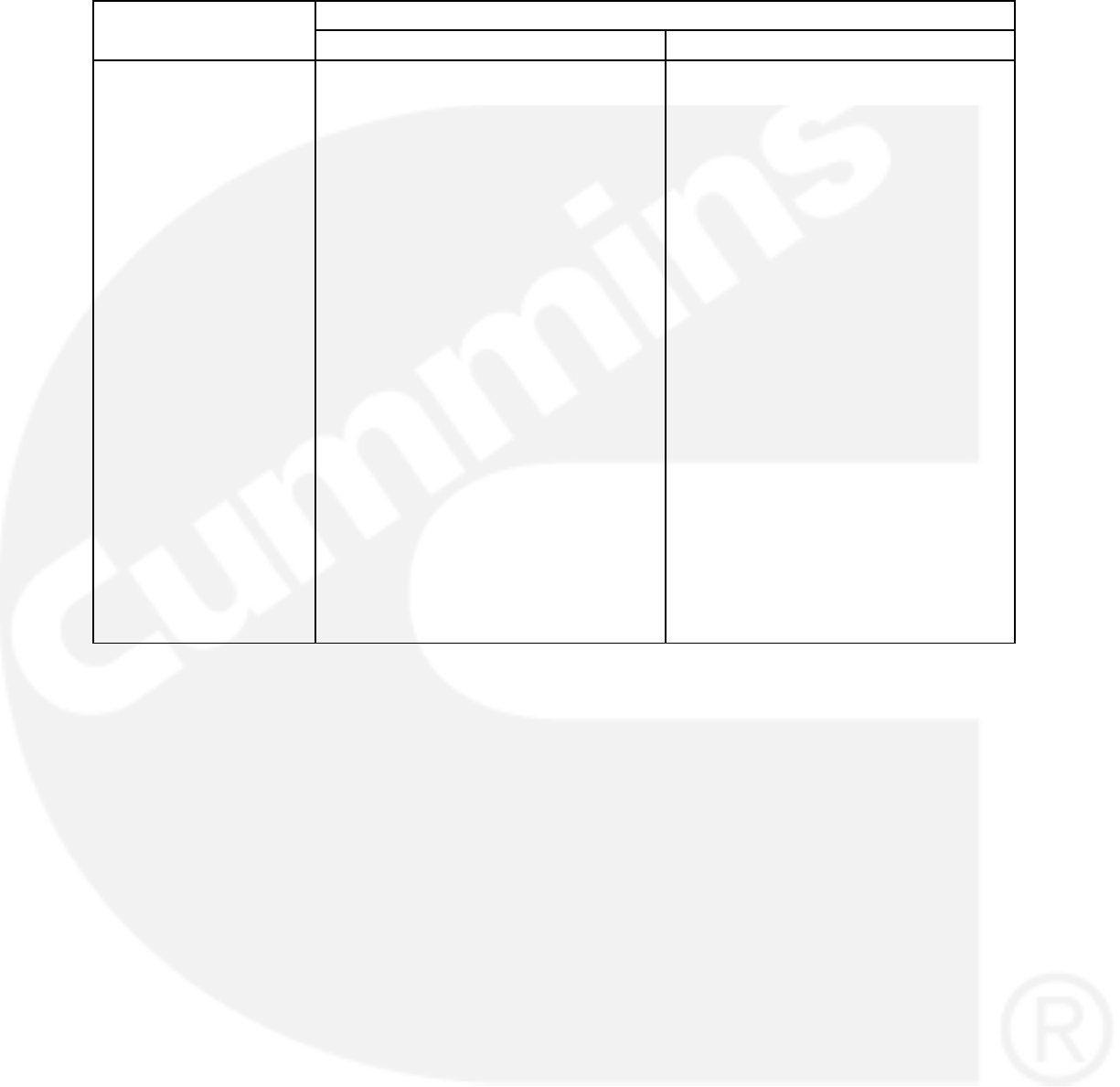
3-42
TABLE 3-22. CONTROLLER CALIBRATIONS FOR GENSETS (CONT.)
Component to be
Calibrated
Calibration Method
Component to be
Calibrated Operator PanelPC Based Service Tool
Current Measurement for
Display
1. Apply a load to the genset and monitor
the current with a calibrated current
meter.
2. Connect to the control with your PC
based service tool.
3. Verify the CT ratio settings and power
ratings are correct for your application.
The Power Rating of the alternator is
configurable with the trims located in
Genset Power Ratings menu. The CT
ratio adjustable trim is available at
Features Genset Setup.
4. Adjust the LX 50Hz Current Adjust or
LX 60Hz Current Adjust trim for your
current application so the 1302 series
control measured current matches the
current read by the know current me-
ter. Each of the three lines will have to
be adjusted independently of each
other.
5. Save the adjustments by doing a save
trims with your PC based service tool.
1. View the Service Menu by holding
down the “up” and “down” arrow keys
on any of the operator menus (see Fig-
ure 3-26).
2. Select item 1, “Setup Menus”.
3. Enter service menu password 574.
4. Select item 2, “Genset Setup”.
5. Enter the setup menu password 1209.
6. Verify with the display that the CT ra-
tios and power rating are correct by
scrolling through the available
screens.
7. Return to the Setup Menu screen by
press the back arrow twice.
8. Select item 1, “Genset Service”.
9. Select item 3, “Meter Calib.”
10. Press the down arrow three times to
scroll down to Metering Current Ad-
just.
11. Adjust the three parameters to match
the current being displayed by the
known current meter.
12. Save the adjustments by pressing the
“Save” button.
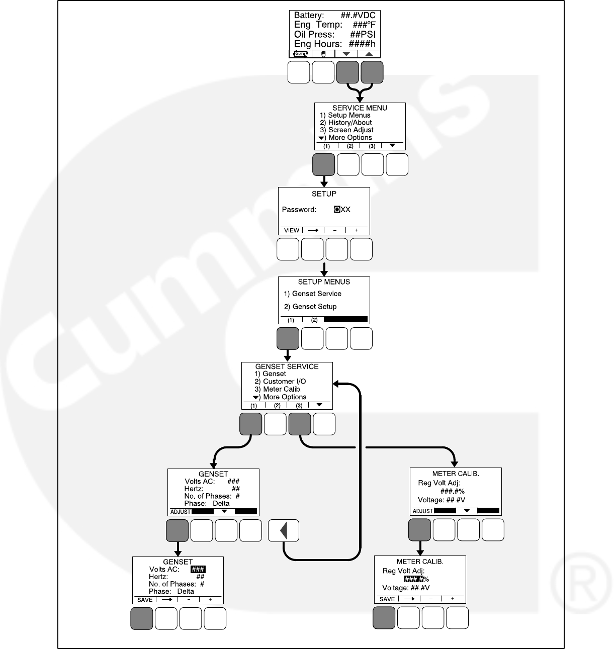
3-43
ENTER “574”
ENTER VOLTS
AC VALUE AND
PRESS THE
SAVE BUTTON
ENTER REG
VOLT ADJ VALUE
AND PRESS THE
SAVE BUTTON
(1)
(2)
(3)
(4)
(5)
(5)
(5)
(6)
(7)
(8)
(9)
(5)
NOTE: THE NUMBERS IN PARENTHESIS
MATCH THE STEPS INCLUDED
IN THE PROCEDURE LISTED IN
TABLE 3-22.
FIGURE 3-24. OPERATOR PANEL MENUS FOR CALIBRATING VOLTAGE MEASUREMENT FOR REGULA-
TION
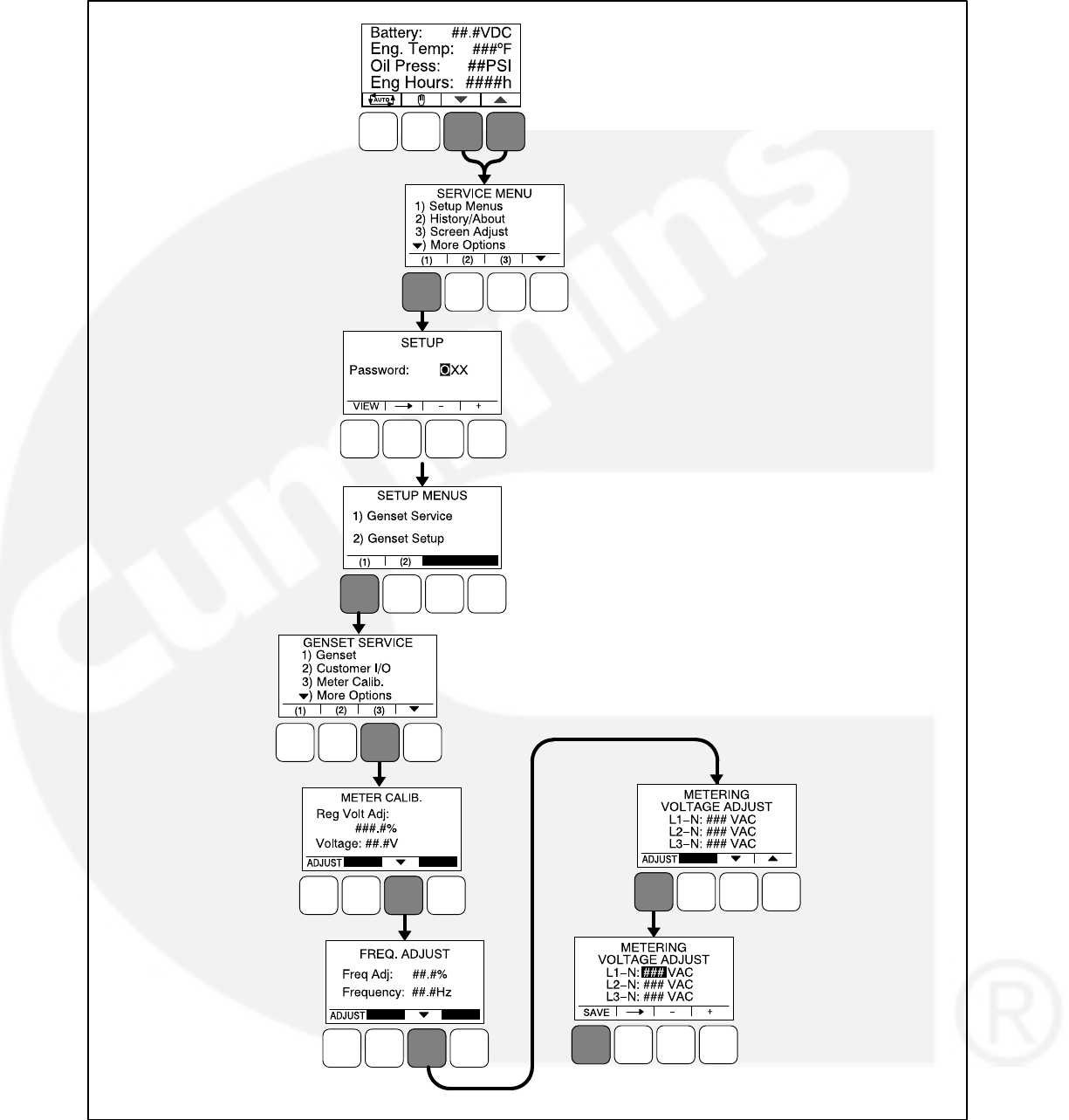
3-45
NOTE: THE NUMBERS IN PARENTHESIS
MATCH THE STEPS INCLUDED
IN THE PROCEDURE LISTED IN
TABLE 3-22.
ENTER
“574”
ENTER
“1209”
ADJUST ALL THREE
PARAMETERS AND
PRESS THE SAVE
BUTTON
(1)
(2)
(3)
(4)
(5)
(6)
(9)
(11)
(6)
(6)
(6)
(6)
(7)
(10)
(10)
(10)
(10)
(8)
(12)
(6)
FIGURE 3-26. OPERATOR PANEL MENUS FOR CALIBRATING CURRENT MEASUREMENT FOR DISPLAY
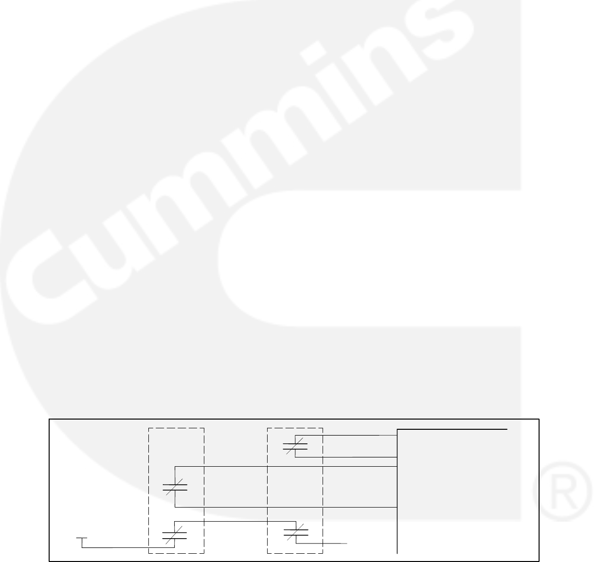
3-46
1302 CONTROL FUNCTIONS
Remote Start Mode
The 1302 series control accepts a ground signal
from remote devices to automatically start the
generator set and immediately accelerate to rated
speed and voltage. The control can incorporate a
time delay start.
For information on how to set a start time delay
using the operator panel, see page 5-8.
Remote Emergency Stop
For operation of the genset, a closed relay contact
between TB1-15 and TB1-16 must be present. The
control enters an emergency stop mode when the
short is removed. Before the genset can be
restarted, the control must be manually reset by
re-applying the short and acknowledging the fault.
The E-stop circuit contains two parallel paths. One
path is fed into the micro-processor for status
processing. The second path is fed directly into the
relay drivers, disabling them when an E-stop is
present.
Local Emergency Stop
For operation of the genset, a short between J25-2
and J25-6 must be present. The control enters an
emergency stop mode when the short is removed.
Before the genset can be restarted, the control
must be manually reset by re-applying the short
and acknowledging the fault. The E-stop circuit
contains two parallel paths. One path is fed into the
micro-processor for status processing. The sec-
ond path is fed directly into the relay drivers, disab-
ling them when an E-stop is present.
Emergency Stop
It is also required that there be a physical interrup-
tion of the FSO and the starter (and, optionally,
switched B+) when an emergency stop is active. In
order to do this, add a second E-stop contact in se-
ries with B+ and the FSO relay coil. Figure 3-27 il-
lustrates one possible way to do this. Power to the
fuel shutoff valve is provided serially through one
contact of the two contact E-stop switch. The con-
nection point is called E−Stop B+.
Referring to wiring diagram: 630−3270 for com-
plete illustration.
12/24V Battery
The 1302 series control provides 12 and 24 VDC
battery operation capability for genset system. It
requires battery voltage input from the genset
starter batteries.
The control system provides a field adjustable trim
to select either 12V/24V battery operations for
selection of the internal thresholds to this feature.
The trim parameter for this is Nominal Battery Volt-
age and the default trim is set at 12 VDC.
For information on how to set the nominal battery
voltage using the operator panel, see page 5-41.
Engine Starting
The control system supports automatic engine
starting. Primary and backup start disconnects are
achieved by one of the following three methods:
magnetic pickup, battery charging alternator
feedback, or main alternator output frequency.
Cycle Cranking
The 1302 series control can be configured for the
number of starting cycles (1 to 7) and duration of
crank and rest periods. The control includes starter
protection algorithms to prevent the operator from
specifying a starting sequence that might be
damaging.
B+
1302 Series Control
Remote
E−Stop
Contact 1
Remote
E−Stop
Contact 2
Local
E−Stop
Contact 1
Local
E−Stop
Contact 2 E−Stop B+
(To Relay
Contacts)
Local
E−Stop
Switch
Remote
E−Stop
Switch
FIGURE 3-27. EMERGENCY STOP CONTACTS
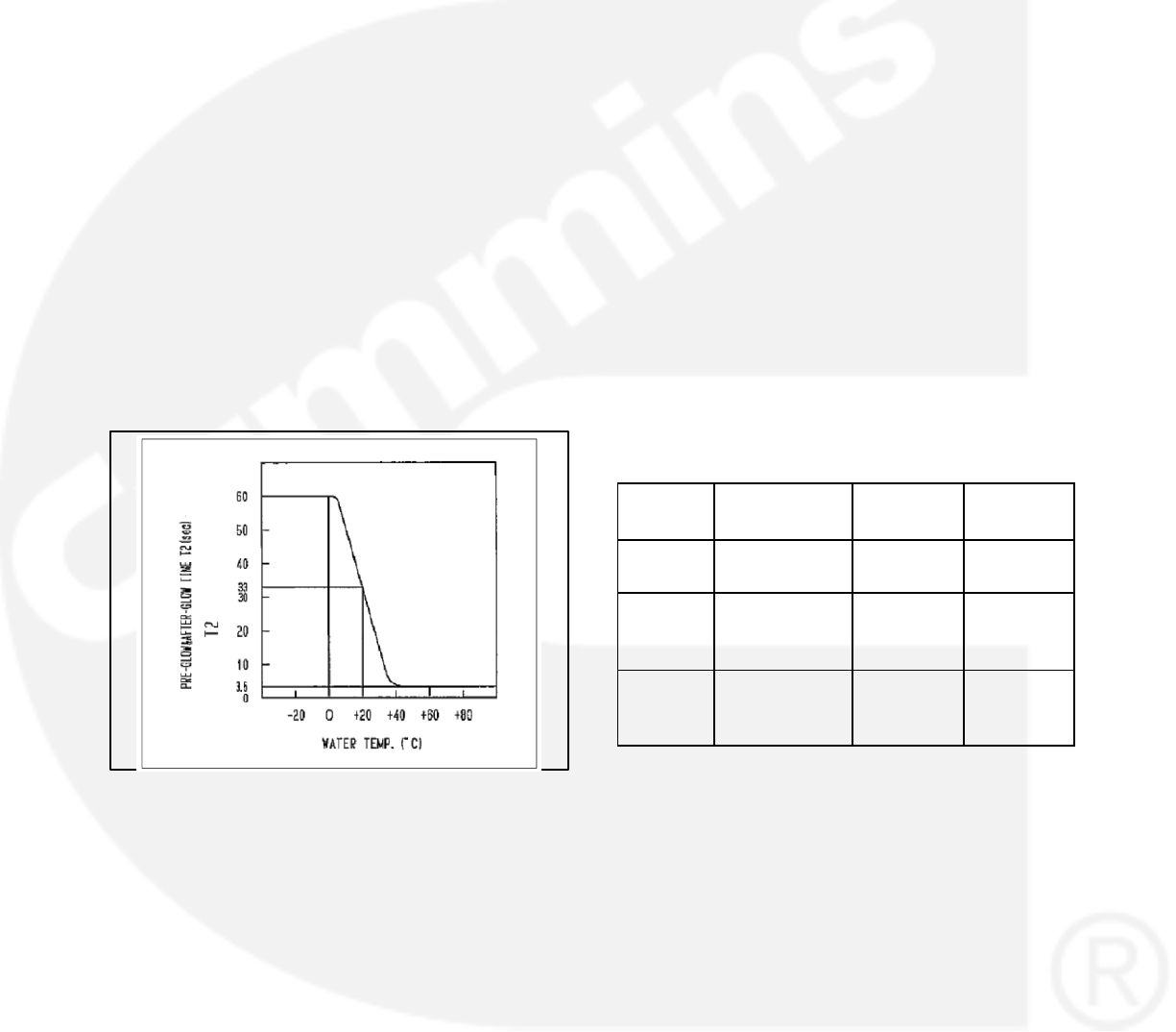
3-47
For information on how to set the cycle crank
attempts using the operator panel, see page 5-11.
Spark Ignition Power/Glow Plug Control
Pin J11-7 on the 1302 series control is dual
purpose.
Glow Plug Control
Glow plug is used as a Cold starting aid. Glow plugs
heat up the air going in for combustion for Diesel
Engine. Glow plug is used to improve the starting
ability of engines and to reduce the white smoke
during cold start.
In PCC1302 when Glow Plug Enable = Enabled
and Fuel System = Diesel the Glow Plug Function
is enabled and control will preheat the engine
starting glow plugs. Pin J11−7 on the PCC1302
control can be used to drive Glow Plugs via
external Relay.
Setting Glow Plug Enable = Disabled or Fuel
System = Gas, disables the Glow Plug Function.
FIGURE 3-28. PRE−GLOW MEASUREMENT
Glow Plug Control implemented in PCC1302 con-
sists of the following two processes:
a. Preheat Process (Pre−Glow Process)
b. Total Glow Process
Preheat Glow Time and Total Glow Time are deter-
mined by linear interpolation of Preheat Time and
Total Glow Time respectively based on reading of
Engine Coolant Temperature as shown in the
graph above. Cranking will start after the Preheat
Time has expired. The Glow Plug Output will re-
main on until the Total Glow Time has expired. The
Control commands the glow plugs to enable when
the control.
a. Detects that the genset has received a
valid start command.
b. Determines teh preheat time and total
glow times as the function of the Engine
Coolant Temperature.
c. Turns off the glow plug during the normal
stop or during the fault shutdown or during
the cyclical crank attempts or if the total
glow time has expired.
Preheat Processing
Preheat processing logic has three associated
trims as shown in Table 3−22
TABLE 3-23. PREHEAT PROCESSING TRIMS
TABLE
Sr. No Name of the
Trims
Default
Value
Range
1Preheat Time
(Trim)(sec)
15 (sec) 0−30 (sec)
2
Preheat Tem-
perature
(Trim)(_F)
70 (_F) 0−100 (_F)
3
Preheat Knee
Point
(Trim)(_F)
0 (_F) 0−70 (_F)
Preheat Time = controls how many seconds the
glow plug will preheat before cranking the engine.
Preheat Temperature = controls at which temper-
ature the control defines a non−cold engine. The
glow plugs will not preheat for engine coolant tem-
peratures above the Preheat Temperature.
Total Glow Processing:
Total Glow processing logic has three associated
trims as shown in Table 3−23.

3-48
TABLE 3-24. TOTAL GLOW PROCESSING TRIMS
TABLE
Sr. No Name of the
Trims
Default
Value
Range
1
Total Glow
Time
(Trim)(sec)
0 (sec) 0−60 (sec)
2
Total Glow
Temperature
(Trim)(_F)
70 (_F) 0−110 (_F)
3
Total Glow
Knee Point
(Trim)(_F)
0 (_F) 0−32 (_F)
Glow Plug Output Logic:
In PCC1302, Glow Plug Output depends upon To-
tal Glow Time Value (Mon). The Glow Plug Output
turns on when Fuel System (Trim) = Diesel and To-
tal Glow Time Value (Mon) > 0. Glow Plug Driver
Command remains on until the Total Glow Time
Value (Mon) has expired. Glow Plug Output turns
off, if any of the following conditions is valid:
a. When Total Glow Tiem Value (Mon) ex-
pires.
b. When Generator Set Control stops nor-
mally.
c. When Generator Set Control stops during
emergency.
d. When Generator Set Control performs cy-
clical crank process.
When the trim parameter Fuel Type is set to Diesel
and Glow Plug is Enabled, the control preheats the
engine starting glow plugs. Two trim parameters
may need to be adjusted in order for the glow plug
preheat control logic to work effectively. The trim
parameter Preheat Time = seconds controls how
many seconds the glow plugs will preheat before
cranking the engine. The trim parameter Preheat
Temperature = degrees Fahrenheit controls at
which temperature the control defines a non-cold
engine. The glow plugs will not preheat for engine
coolant temperatures above the Preheat Tempera-
ture. Adjusting both of the trims will allow for tailor-
ing of the glow plug preheat logic for specific en-
gine applications. Setting Glow Plug = Disabled
disables the glow plug preheat logic.
When the trim parameter Fuel Type = Gas, pin
J11-7 can be used to control an external spark igni-
tion control module. Pin J11-7 is turned on simulta-
neously with the fuel solenoid and held on as long
as the genset is running. Both drivers stay on while
the engine speed is above 150 RPM. When a shut-
down command is received, the fuel solenoid is
disabled but the ignition control module driver
stays on until the Fuel Burn Off Time delay timer ex-
pires. By running the ignition system off of this
delayed output, all of the fuel downstream of the
fuel solenoid is burned following a genset stop /
shutdown. This removes the occasional fuel flash
in the exhaust system after a stop / shutdown.
Refer to the wiring diagram for more information on
how to configure the Remote Emergency Stop
Switch for gas gensets to interrupt the ignition sys-
tem power.
For information on how to set the Fuel Type, enable
a Glow Plug, and set a Fuel Burn Time Delay using
the operator panel, see page 5-8.
Start and Stop Time Delays (Cool Down)
The 1302 series control is configurable for a time
delay of 0−300 seconds prior to starting after
receiving a remote start signal, and for a time delay
of 0−600 seconds prior to shut down after signal to
stop in normal operation modes. The default for
both time delay periods is 0.
0−3600 seconds (fron 1302 calibration version
2.80 and HMI211 calibration version 7.20). Earlier
versions have 0−300 seconds.
For information on how to set a start or stop time
delay using the operator panel, see page 5-8.
Electronic Governor
The 1302 series control provides electronic gov-
erning capability for a generator set when a elec-
tronic governor option is installed on the genset. It
has a field adjustment trim to enable or disable the
electronic governing feature. It supports isochro-
nous speed governing as defined below.
The maximum allowed rated current for the
actuator drive for the governor power stage is
6.0A continuous max; 10 Amps for 1 second.
The governing system is suitable for use with
Gensets using Cummins EFC normally closed
actuators, Woodward, FORD Gas, or Barber-
Coleman actuators with similar drive charac-
teristics.
It provides speed governor setpoints of 1500
RPM and 1800 RPM. The governor setpoint is
a field adjustment (50 Hz or 60 Hz).

3-49
The optional display allows the operator to ad-
just frequency within plus or minus 5% of rated
speed.
The controller provides ramping at startup and
an ability to program the cranking fueling be-
fore the governor algorithm is enabled.
Engine Speed Sensing
For electronically governed gensets, the 1302 se-
ries control requires an engine speed input from a
magnetic pickup speed sensor. The magnetic pick-
up signal needs to be calibrated for number of en-
gine flywheel teeth. The table shown below lists the
number of flywheel teeth for some common engine
types.
TABLE 3-25. FLYWHEEL TEETH REQUIREMENTS
Engine Type Number of
Flywheel Teeth
Cummins 4B, 6B 159
Cummins 4C 138
Ford 4cycl Gas 104
Kubota Engines 105
Cummins L10, NT855 118
Komatsu 3.3L 110
Cummins V28, K19,
K38, K50
142
Ford V6 and V10 gas 133
For non-electronically governed gensets, the mag-
netic pickup is optional. If it is not used, engine
speed is calculated from the alternator output fre-
quency.
Speed Governor Algorithm and
Adjustment
The 1302 series control supports the following
speed governor algorithm characteristics:
It uses a four-coefficient field adjustable
closed loop PID control algorithm (Proportion-
al−Integral−Derivative).
It allows field tuning of the speed coefficients.
The 1302 series control provides a dither fea-
ture. Dither is a method of introducing small
amounts of noise into the speed governing
system. The purpose of this feature is to pre-
vent the fuel actuators from becoming stuck.
Therefore dither should be used in applica-
tions where the fuel actuators are prone to
sticking. This feature has adjustable dither
amplitude (0% to 30% of governor duty cycle).
The dither function is enabled by selecting a
dither factor. The dither function is disabled by
setting the dither factor to 0%.
The following cranking fuel control characteristics
are also provided to “tune up” the genset startup to
suit the application. Cold weather applications
might need a longer cranking period and/OR high-
er levels of cranking fuel. Following parameters
should be chosen to make sure the genset starts
up quickly enough but does not overshoot or pro-
duces excessive smoke at startup.
The initial cranking fuel duty cycle can be cho-
sen to suit the engine / application.
The initial cranking fuel period can be chosen
to suit the application.
The cranking fuel is ramped up during crank-
ing after initial cranking fueling period is over.
The rate of ramping up of fueling can be cho-
sen to suit the application.
The maximum crank fuel duty cycle can be
chosen to suit the application. During cranking
the duty cycle of the PWM, output to the actua-
tor will be limited to this value.
The crank exit fuel duty cycle can be chosen
to suit the application. After the engine fires,
the fueling level will return to this value before
the 4 coefficient algorithm takes over the con-
trol of the PWM output to the actuator.
Fueling is initially set to the Initial Crank Fueling
Duty Cycle value and remains at that value for the
Initial Crank Fueling Period. After this period ex-
pires, the fuel command is ramped at the Crank
Fueling Ramp Rate until the Maximum Crank Fuel-
ing limit is reached. Upon reaching the Starter Dis-
connect Speed, the fueling command is pulled
back to the Crank Exit Fueling Duty Cycle value un-
til the Governor Enable Engine Speed is reached.
When the Governor Enable Engine Speed is
reached, the governor is enabled, the speed set-
point is set to the sensed engine speed value at this
point, and the setpoint is ramped to rated speed in
a time equal to the Governor Ramp Time. The dia-
gram below illustrated these setpoints.
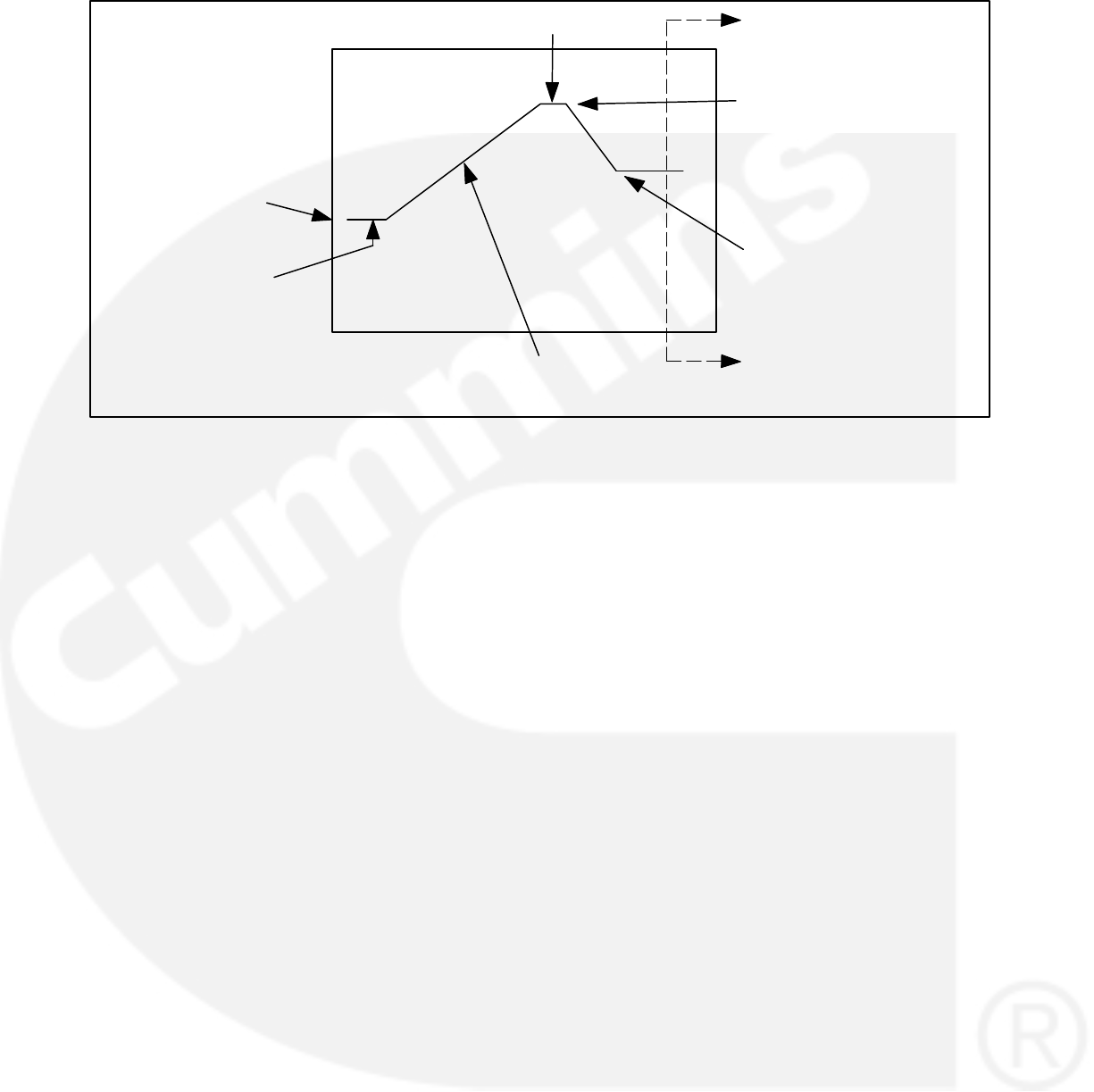
3-50
Initial Crank Fuel
Duty Cycle
Crank Fuel
Ramp Rate
Initial Crank
Fueling Period
Crank Fuel Duty Cycle
Max Crank Fuel
Duty Cycle
Crank Exit Fuel
Duty Cycle
Closed Loop Operation
FIGURE 3-29. GOVERNOR RAMP TIME SETPOINTS
REAL TIME CLOCK
The PCC1302 control system includes a Real Time
Clock (RTC) function used for automatic scheduler
(exercise scheduler) feature. The Real Time Clock
(RTC) in PCC1302 is NOT used for calculating
controller on time, or for recording fault occurrence
times, or for supporting factory test. Once
PCC1302 is programmed and given a power cycle,
the user should enter the correct time, date and
clock cycle (AM/PM). Based on the time and date
saved by the user, the real time clock accurately*
calculates seconds, minutes, hours, date of the
month, month, day of the week, and year with leap
year compensation. The clock operates in 12 hour
format with support for AM/PM.
When battery power is removed or the PCC1302
controller goes in sleep mode, the RTC parameters
get reset to 00:00 (HH:MM) for Time and 00/00/00
(MM/DD/YY) for Date and AM for Clock Cycle. Un-
der this condition, and with Scheduler Prog x En-
able trim Enabled and Clock Diagnostic Enable
trim Enabled, FC 1689 (Clock Not Set) will become
active indicating that the date, time and AM/PM
needs to be set by the user.
The RTC also supports Daylight Savings Time
(DST), which is a convention used to advance the
time by one hour so that afternoons have more
daylight than mornings. The DST logic adds the
DST Adjustment time to the current time when the
current time is equal to the DST Start Time. The
DST logic subtracts the DST Adjustment time from
the current time when the current time is equal to
the DST End Time. To enable DST, the trim Day-
light Savings Time Enable needs to be set to En-
abled. To setup DST, specify the values for the fol-
lowing trims. These trims can be set via PCTools or
HMI211 or HMI211RS or via Modbus utility.
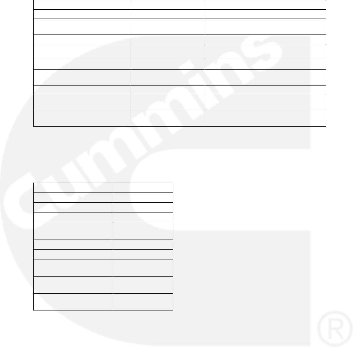
3-51
TABLE 3-26. TRIM RANGE VALUES
Trim Range Meaning
Daylight Savings End Day Monday − Sunday Calendar Day in which DST Ends
Daylight Savings End Hour 01− 12 hours (it is always
AM)
Hour (12 Hr) in which DST Ends
Daylight Savings End Month 1 − 12 months Month in which DST Ends
Daylight Savings End Week Occ
Month
Default − Fifth Occurrence Occurrence of Daylight Savings End Day in
which DST Ends
Daylight Savings End Day Monday − Sunday Calendar Day in which DST Starts
Daylight Savings End Hour 01− 12 hours (it is always
AM)
Hour (12 Hr) in which DST Ends
Daylight Savings Start Month 1 − 12 months Month in which DST Starts
Daylight Savings Start Week Occ
Month
Default − Fifth Occurrence Occurrence of Daylight Savings End Day in
which DST Starts
Daylight Savings Time Adjustmenty 0 − 120 minutes Amount of time to be added or subtracted
from current time for DST adjustment.
For Example: If DST Ends on the 1st Wednesday in
April at 02:00 AM every year, and DST Starts on the
2nd Thursday in September at 3:00 AM every year,
and DST Adjusts the clock by 1 hour each time, the
parameters should be set to the following values.
TABLE 3-27. TRIM VALUES
Trim Value
Daylight Saving End Day Wednesday
Daylight Saving End Hour 02
Daylight Saving End Month 4
Daylight Saving End Week
Occurrence in Month
First Occurrence
Daylight Saving Start Day Thursday
Daylight Saving Start Hour 3
Daylight Saving Start
Month
9
Daylight Saving Start
Week Occurrence in Month
Second Occur-
rence
Daylight Saving Time Ad-
justment
60
NOTE: The software accuracy of real time
clock is +/− hour over a period of 1 cal-
endar year. The real time clock func-
tion is available from 1320 calibration
version 2.76 and above and HMI211
calibration version 6.90 and above.
EXERCISE SCHEDULER
The exercise scheduler is a feature that automati-
cally starts the genset for exercise. This feature
prevents common problems which result from me-
chanical equipment being not in operation for long
periods of time. In order for the automatic exerciser
to work, the PCC1302 control system needs to be
in ’Auto’ mode, the RTC needs to be set (Fault 1689
is not active), and the trim Scheduler Prog x Enable
needs to be set to Enable.
SLEEP mode will be disabled if the user enables
the exercise scheduler. This is because sleep
mode will reset the clock (RTC) in PCC 1302 and
exercise function will not work.
The PCC1302 can be programmed to run only 1
program, which is a repeating event. Furthermore,
the program can be programmed to exercise the
genset at rated condition and at ’No Load’ condi-
tion. No exceptions can be set in PCC1302.
The exercise program has the following trims
which establish its behavior where currently x al-
ways denotes 1.
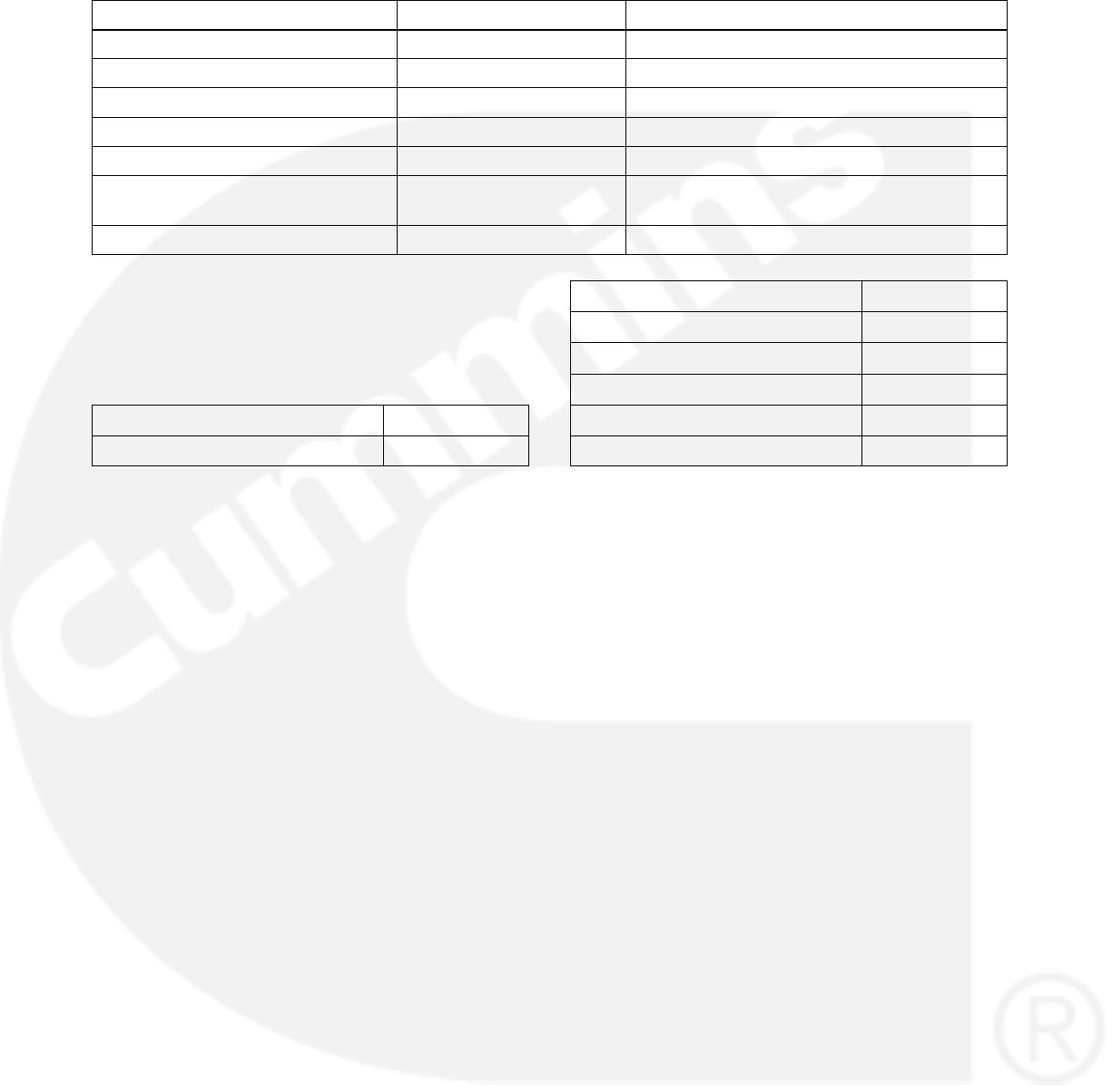
3-52
TABLE 3-28. TRIM SCHEDULE VALUE
Trim Value Meaning
Scheduler Prog x Enable Enable − Disable Enables or Disables Schedule x=1
Scheduler Prog Start Minute 0 − 59 Specifies at what minute Program with start
Scheduler Prog Start Hour 1 − 12 Specifies at what hour Program will start
Scheduler Prog Start Day Monday − Sunday Specifies at what day Program will start
Scheduler Prog Start Period AM − PM Specifies at what period Program will start
Scheduler Prog Repeat Interval Weekly,Bi_Monthly,Month-
ly,Quarterly,Semi−Annual
Specifies the repeating behavior of Program
Scheduler Prog Duration (Mins) 5 − 15 Specifies how many minutes Program will run
For example, if it was desired to have a Program
that ran on every Monday at 8:12 AM for 15
Minutes, the trims should be defined in Table 3−28
TABLE 3-29. EXAMPLE TRIM VALUE
Trim Value
Scheduler Prog x Enable Enable
Scheduler Prog Start Minute 12
Scheduler Prog Start Hour 8
Scheduler Prog Start Day Monday
Scheduler Prog Start Period AM
Scheduler Prog Repeat Interval Weekly
Scheduler Prog Duration (Mins) 15

3-53
TABLE 3-30. EXCERISER SCHEDULE
Scheduler
Program
Enable
Scheduler
Program
Start Day
Start Time Scheduler
Program
Duration
Schedular
Program
Start Period
AM/PM
Schedule Re-
peat Interval
Hr Min Min Weekly Bi−
monthy,
Monthly,
Quarterly
Semi−Annual
Program 1
The following are the set of rules for
exercise scheduler
1. While in Exercise mode, genset will start if in
AUTO mode, and run at rated condition and at
’No Load’
2. While in Exercise mode, ’Exercise Scheduler
On’ message will be displayed on both HMI
211 and HMI 211 RS.
3. This message screen will be displayed for 1
sec when in Info screens of the HMI and will
toggle with the Info screens at a frequency of
3 sec.
4. While in Exercise mode, the user cannot edit
the Clock parameters, the Exercise Scheduler
parameters and the Daylight Savings parame-
ters except for the trim ”Scheduler Prog x En-
able”.
5. If the user tries to edit these trims except
”Scheduler Prog x Enable”, following mes-
sage, ”Can Not Edit Exercise On” will be dis-
played on both HMI 211 and HMI 211 RS.
While in exercise scheduler mode, i.e. a scheduled
program is active and control system is in ’Auto’
mode, if the PC1.1 control system receives a
remote start command via HMI or from PCTools or
from external transfer switch, the exercise
scheduler mode will be terminated and the
Scheduler Prog Duration (Mins) timer will become
0. However, the genset will continue to run in ’Auto’
mode and will follow ATS operation if ATS
functionality is enabled. If remote start command is
removed then the genset will stop running.
NOTE: The excerise scheduler function is
available from 1320 calibration ver-
sion 2.76 and above and HMI211 cal-
ibration version 6.90 and above.
ATS Control
Automatic Transfer Switch is used to transfer pow-
er from Utility to Genset and vice−versa. A trim
Auto Mains Failure Enable is provided to enable/
disable the ATS functionality in PCC1302. There
are settable delay timers incorporated for transfer-
ring and re−transferring the load from Utility to
Genset and vice−versa. In addition, diagnostic
faults of ATS functionality and its corresponding
FCs/ symbols are supported in HMI211 and
HMI211RS.
PCC 1302 has four configurable inputs, out of
which two Configurable Inputs can be used for
checking the feedback of the switch positions i.e.
on Genset side or Utility side. The configurable in-
puts will remain locked for ATS functionality when
AMF feature is enabled and the trim Transfer
Switch Feedback Enable is enabled.
TABLE 3-31. CONFIGURABLE INPUTS
Pin Signal Name
TB1−12 Configurable Input 1
TB1−13 Configurable Input 1 − Common
TB1−14 Configurable Input 2
Configurable Input 1 is used for Utility switch posi-
tion status and Configurable Input 2 is used for
Genset switch position status.
For transferring the load from Utility to Genset or
vice−versa, PCC1302 will use low side driver
Ready to Load/ ATS Output only.
ATS functionality will only be enabled when Auto
Mains Failure Enable is enabled with the condition
that Genset control is running in Auto mode.
NOTE: When Exercise is active and if Utility
lost condition is received (remote start
signal is active), Genset Control dis-
cards the Exercise and continues with
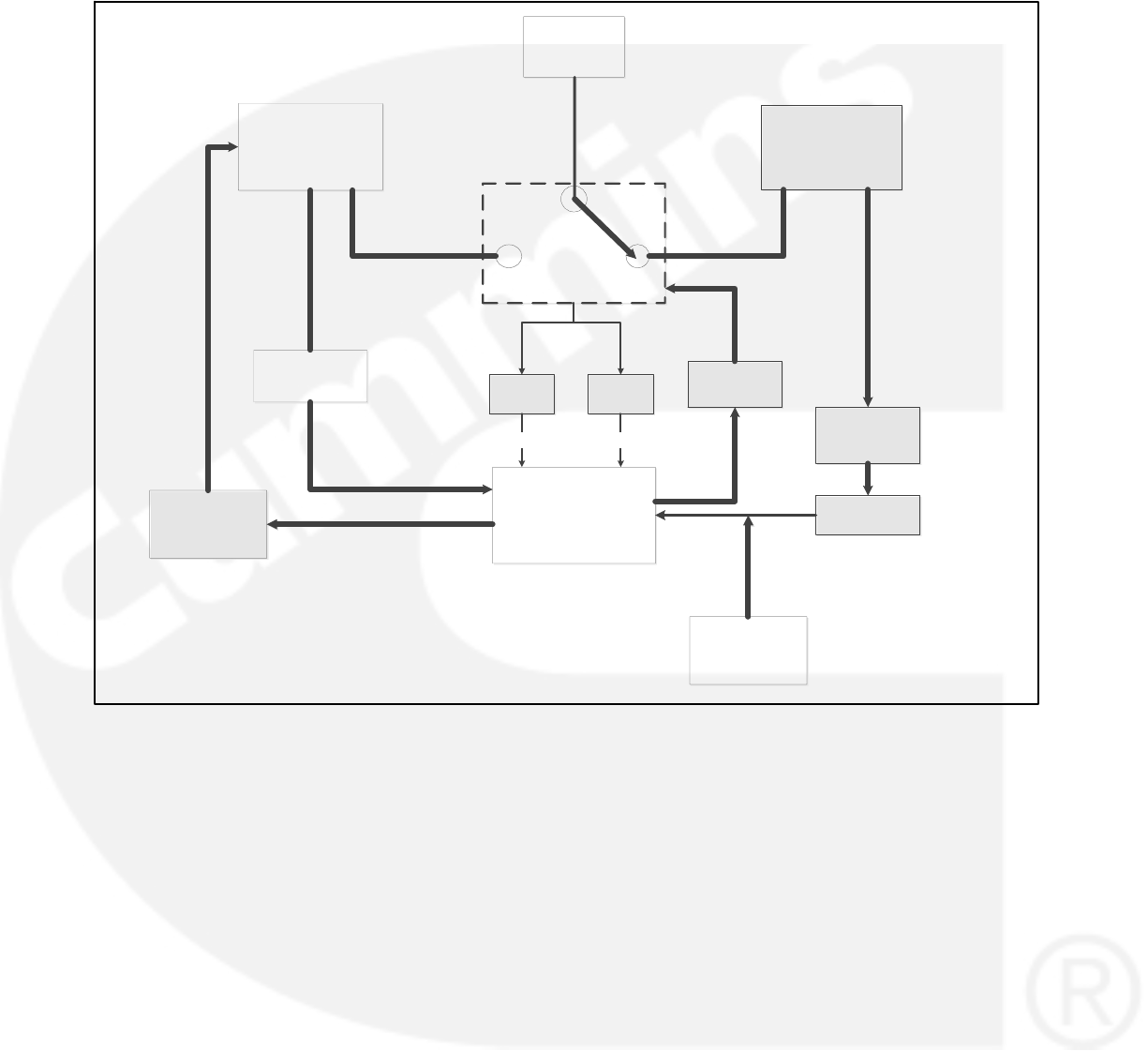
3-54
the ATS functionality. The excerise
scheduler function is available from
1320 calibration version 2.76 and
above and HMI211 calibration version
6.90 and above.
GENSET CONTROL
TRANSFER SWITCH
LOAD
SOURCE 2
GENSET
SOURCE 1
UTILITY
GENSET
FEEDBACK
UTILITY
FEEDBACK
Ready to Load/
ATS Output
UTILITY VOLTAGE
MONITORING
SENSOR
REMOTE START
COMMAND
READY TO LOAD
CONDITION
START/STOP
OPERATION
Config I/P 2 Config I/P 1
Remote HMI
TB1−14 TB1−12
TB1−4
TB1−10
FIGURE 3-30. PCC1302 BLOCK DIAGRAM
As per the block diagram shown above,
Genset Control (PCC1302) monitors the sta-
tus of the Utility (Failing and Returning con-
dition) directly through Remote Start Com-
mand (Active or Inactive) condition.
When Utility voltage monitoring sensor
senses that the voltage has gone below
Drop−out Voltage, it will activate the Remote
Start Command input.
When Utility voltage monitoring sensor
senses that the voltage has gone above the
Pickup Voltage, it will de−activate the Re-
mote Start Command input.
When Genset control receives the Remote
Start active input command, the control will
do the following when Control Switch Posi-
tion is in Auto.
a. Genset Control gives the start command
to Genset after the Start Time delay is
completed.
b. After starting the Genset, when Genset
Control reaches the ”Running” condition,
it starts the Transfer Delay (trim) if Auto
Mains Failure Enable is enabled.
c. When Genset Control reaches the Ready
to Load condition and Auto Mains Failure
Enable is enabled and Transfer Delay is
completed, Genset Control will activate
the Ready to Load/ATS output (Customer
Ready to load driver output) to initiate the

3-55
transfer process of the load from Utility
source to Genset source.
d. After activating the Ready to Load/ATS
output, Genset Control starts Transfer
Delay Timer. Genset control will check for
Configurable Input 1 Status = Inactive
(Utility Open) and Configurable Input 2
Status = Active (Genset Close) feedback.
If the feedback is not received for speci-
fied period of time (Transfer to Genset
Delay Timer), Genset Control will declare
the Shutdown fault ”Genset Failed To
Close”.
When Genset Control receives the Remote
Start Inactive Input Command, the Control will
do the following
a. When Genset Control receives the Re-
mote Start Inactive Input Command and
Auto Mains Failure Enable is enabled,
Genset Control starts Re−Transfer Delay
(Trim).
b. When Genset Control receives the Re-
mote Start Inactive Input Command and
Auto Mains Failure Enable is enabled,
Genset Control starts Re−Transfer Delay
(Trim).
c. After de−activating the output and Auto
Mains Failure Enable is enabled, Genset
Control will check for the Configurable In-
put 2 Status = Inactive (Genset Open) and
Configurable Input 1 Status = Active (Util-
ity Close) feedback. If the feedback is not
received for specified period of time (Re−
Transfer to Utility Delay Timer), Genset
Control will declare the Warning fault ”Util-
ity Failed To Close”.
d. Genset Control will initiate the Stop Time
delay only when the feedback is received
otherwise Genset will continue to be in
running state. After the completion of the
Stop Time delay, Genset Control will give
the command to stop the Genset.
If Transfer Switch is at unknown position, Gen-
set Control will declare the Warning fault
”Transfer Switch Status Unknown Position”.
NOTE: In Genset Control, if Auto Mains Fail-
ure Enable = Enabled and Transfer
Switch Feedback Enable = Enabled,
then transferring and retransferring
process depends upon Feedback
Logic and Ready to Load/ ATS Output
automatically. In Genset Control, if
Auto Mains Failure Enable = Enabled
and Transfer Switch Feedback En-
able = Disabled, then transferring and
retransferring process depends upon
Ready to Load / ATS Output status
only.
NOTE: The ATS control function is available
from 1320 calibration version 2.76 and
above and HMI211 calibration version
6.90 and above.
Dual Fuel
The PCC1302 has the ability to determine the sta-
tus of the Fuel System and notify the user and the
ECM.
When Fuel Type = Gas and Engine Application
Type = FAE (ECM CAN Enable = Enabled), user
will be able to set the trim parameter Gas Fuel Type
as Natural Gas (Default) or Propane or Dual.
When Gas Fuel Type is selected as Dual, the con-
trol system has the ability to transfer the fuel source
from Natural Gas to Propane in case a low fuel con-
dition is sensed for Natural Gas.
BATTLE SHORT MODE OPTION
The 1302 series control can be programmed to
work in battle short mode.
The PC service tool is required to enable the Battle
Short feature. If the operator panel is not installed,
the PC service tool is also required to enable the
external Battle Short switch.
The controller then can accept Configurable Input
1 as battle short switch inputs. If an operator panel
is used, it can be also selected as a source of input
by selecting the appropriate input source value for
the trim.
Installations With an Operator Panel
To activate the Battle Short feature for installations
that include the operator panel (see Figure 3-31),
1. Use the PC service tool to enable the Battle
Short mode feature. Contact an authorized
service center for assistance.
2. View the Service Menu by simultaneously
holding down the “up” and “down” arrow keys.
3. Select item 1, “Setup Menus”.

3-56
4. Enter setup menu password 574.
5. Select item 1, “Genset Service”.
6. Select item 1, “Genset”.
7. Press the selection button five times to
view the “Battleshort” menu.
NOTE: This menu is displayed only if the
Battle Short mode feature has been
enabled with the PC service tool.
8. Press the ADJUST button.
−If you want the operator panel to be the
activation source of this feature, change
the “Switch Input:” setting to “Operator
Panel.”
NOTE: When Switch Input is set to “Op-
erator Panel”, the “Battle Short:
Active/Inactive” subject is dis-
played. Battle Short should not
be set to “Active” until it is needed
by the customer.
−If you want a customer input to be the
activation source of this feature, change
the “Switch Input:” setting to “Customer
Input 1” or “Customer Input 2.” Refer to
page 5-21 for information on setting up
customer inputs.
9. Save the adjustments by pressing the “Save”
button.
For more information on the Battle Short feature,
see Section 4.

3-57
Installations Without an Operator Panel
Installations without a operator panel require the
following.
A Manual Run/Off/Auto switch must be con-
nected to the control harness.
A status indicator lamp must be installed to
flash shutdown fault codes.
An external On/Off switch must be con-
nected to one of the customer configured
inputs on the control board.
The PC service tool must be used to enable
the Battle Short mode feature.
The PC service tool must be used to enable
the external Battle Short On/Off switch.
Contact an authorized service center for assis-
tance. For more information on the Battle Short
feature, see Section 4.
Battle Short Mode
Battle Short mode is designed to work only in criti-
cal load circumstances and is used to satisfy local
code requirements, where necessary. This feature
can only be used if the necessary software was
installed at the factory when the 1302 control was
purchased or if it was installed by an authorized
customer service representative.
Battle Short mode prevents the genset from being
shutdown by all but a select few critical shutdown
faults. All shutdown faults, including those
overridden by Battle Short, must be acted upon
immediately to ensure the safety and well being
of the operator and the genset.
WARNING Use of the Battle Short mode fea-
ture can cause a fire or electrical hazard, result-
ing in severe personal injury or death and/or
property and equipment damage. Operation of
the genset must be supervised during Battle
Short operation.
This feature must only be used during supervised,
temporary operation of the genset. The faults that
are overridden when in Battle Short mode are
faults that can affect genset performance or cause
permanent engine, alternator, or connected
equipment damage. Operation may void the
generator set warranty if damage occurs that
relates to the fault condition(s).
Before the Battle Short feature can be used, it must
first be enabled. Only trained and experienced ser-
vice personnel should enable this feature. When
shipped from the factory, this feature is disabled.
Installations with an Operator Panel
Battle Short can be enabled or disabled (set to Ac-
tive or Inactive) using the operator panel.
The PC service tool is required to enable the
Battle Short mode feature. Contact an autho-
rized service center for assistance.
Before Battle Short can be used on installations
with the operator panel, the Switch Input setting on
the Battle Short submenu must be set to “Operator
Panel” (see page 5-12). In addition, Battle Short
mode must be enabled (set to Active) in the Battle
Short submenu (see page 5-12).
When Battle Short mode is enabled, the Warning
status indicator lights, and Fault Code 1131 −
Battle Short Active is displayed.
When Battle Short mode is enabled and an over-
ridden shutdown fault occurs, the shutdown
lamp remains lit even though the genset continues
to run. Fault Code 1416 − Fail to Shut Down is
displayed. If the , , or button is pressed to
acknowledge the fault, the fault message is cleared
from the display but remains in the Fault History file
with an asterisk sign (* indicates an active fault) as
long as Battle Short mode is enabled.
Battle Short is suspended and a shutdown occurs
immediately if:
Any of the following shutdown faults occurs.
−Overspeed − Fault Code 234, Fault Code
1992 and Fault Code 3131
−Emergency Stop − Fault Code 1433 or
1434
−Speed Signal Lost (Loss of Speed
Sense) − Fault Code 121
−Excitation Fault (Loss of Voltage
Sense) − Fault Code 2335
Battle Short mode is disabled after an over-
ridden shutdown fault occurred while in
Battle Short mode. To disable Battle Short
mode, navigate to the Battle Short submenu
(see page 5-12) and select “Inactive.” Fault
Code 1123 − Shutdown After Battle Short
is then displayed.

3-58
Installations without an Operator Panel
A Manual Run/Off/Auto switch must be installed in
installations that do not include a operator panel.
Battle Short can be turned on or off with a customer
installed external switch connected to one of the
two customer configured inputs.
The PC service tool is required to enable the
Battle Short mode feature and to enable the ex-
ternal Battle Short switch using one of the two
available customer inputs. Contact an autho-
rized service center for assistance.
When Battle Short mode is enabled and an overrid-
den shutdown fault occurs, the genset continues to
run and the status indicator lamp flashes the shut-
down fault code. See “Local Status Output” on page
4-1 for information on interpreting the status indica-
tor light.
Battle Short is suspended and a shutdown occurs
immediately if:
Any of the following shutdown faults occurs.
−Overspeed − Fault code 234 or 1992 or
3131
−Emergency Stop − Fault code 1433 or
1434
−Speed Signal Lost (Loss of Speed
Sense) − Fault code 121
−Excitation Fault (Loss of Voltage
Sense) − Fault code 2335
The external Battle Short switch is moved to
the OFF position after an active but overrid-
den shutdown fault occurred while in Battle
Short mode. The status indicator lamp then
flashes Fault Code 1123 − Shutdown After
Battle Short.
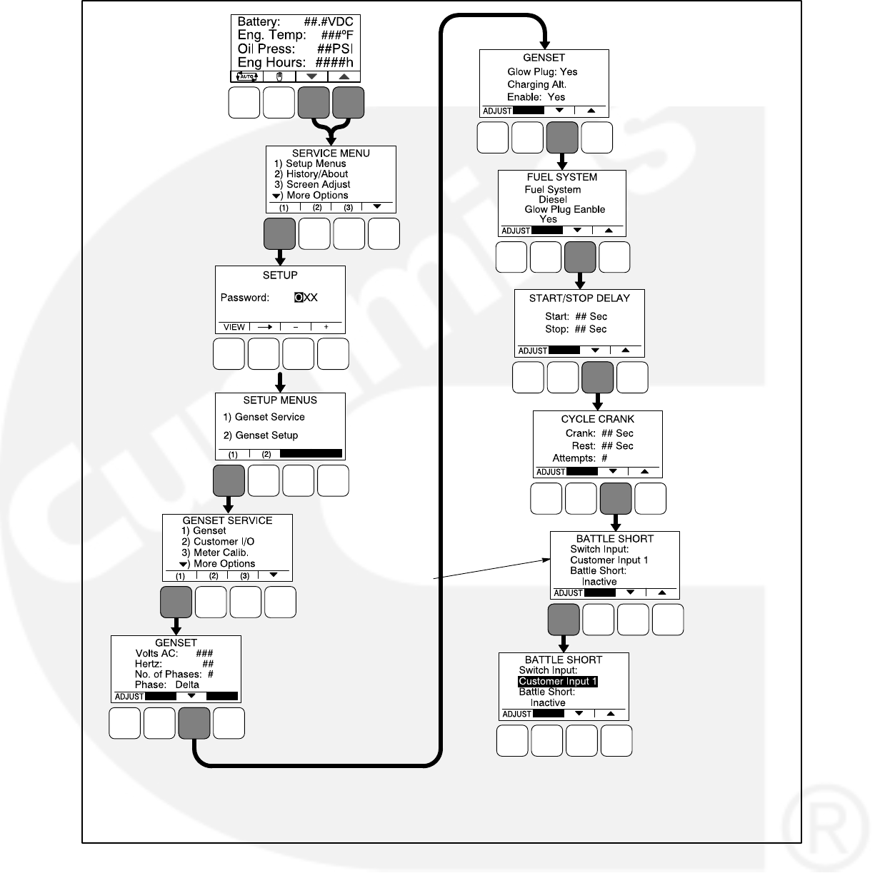
3-59
ENTER “574”
(2)
(3)
(4)
(5)
(6)
(8)
(7)
NOTE: THE NUMBERS IN PARENTHESIS
MATCH THE STEPS INCLUDED IN THE
PROCEDURE LISTED ON PAGE 3-55.
THIS SUBMENU IS ONLY
DISPLAYED IF THE
BATTLE SHORT FEATURE
HAS BEEN ENABLED
USING THE PC SERVICE
TOOL
“BATTLE SHORT:
ACTIVE / INACTIVE”
IS ONLY DISPLAYED
IF THE SWITCH
INPUT IS SET TO
“OPERATOR PANEL”
(7)
(7)
(7)
(7)
(7)
FIGURE 3-31. OPERATOR PANEL MENUS FOR CALIBRATING BATTLE SHORT MODE

3-60
THIS PAGE INTENTIONALLY LEFT BLANK
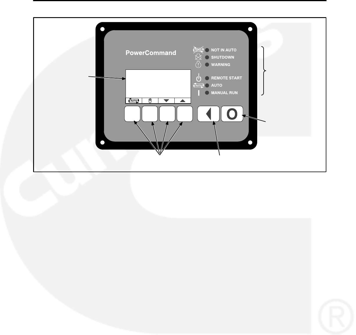
4-1
4. Operator Panel Operation
PREVIOUS MENU
LEVEL BUTTON
GRAPHICAL
DISPLAY
OFF MODE
BUTTON
DISPLAY MENU
SELECTION BUTTONS
LED
INDICATORS
HMI1211
FIGURE 4-1. 1302 OPTIONAL OPERATOR PANEL
INTRODUCTION
This section includes information on the following.
Local Status Output Indicator
Operating Modes
Operator Panel Description
Operator Panel System Messages
Description of Fault and Status Codes
Adjusting Values and Saving the Changes
Basic Operator Menus
Selecting Auto, Manual Run, and Off Modes
Service Menus
History/About Menus
Fault History Menu
Screen Adjust Menu
LOCAL STATUS OUTPUT INDICATOR
If your installation includes a status indicator lamp
that flashes genset status and shutdown fault
codes, the following describes how to interpret the
status indicator light.
Constant Fast Flashing = This occurs during
preheat (when used) and while the generator
set is starting.
Constant On = The genset is running.
Intermittent Flashing = A genset shutdown
fault condition exists. All of the shutdown
faults described in Table 4-2 can be an-
nounced with a status indicator lamp.
For four-digit shutdown fault codes, the first
digit in the code is flashed, followed by a half-
second pause, then the second digit is flashed,
followed by a half-second pause, then the third
digit is flashed, followed by a half-second
pause, and then the fourth digit is flashed, fol-
lowed by a two-second pause.
NOTE: Only the last shutdown fault is flashed.
When a fault is corrected, the Manual Run/Off/
Auto switch must be placed in the Off position
to reset the control.
Under all other indications, the status lamp is
off.
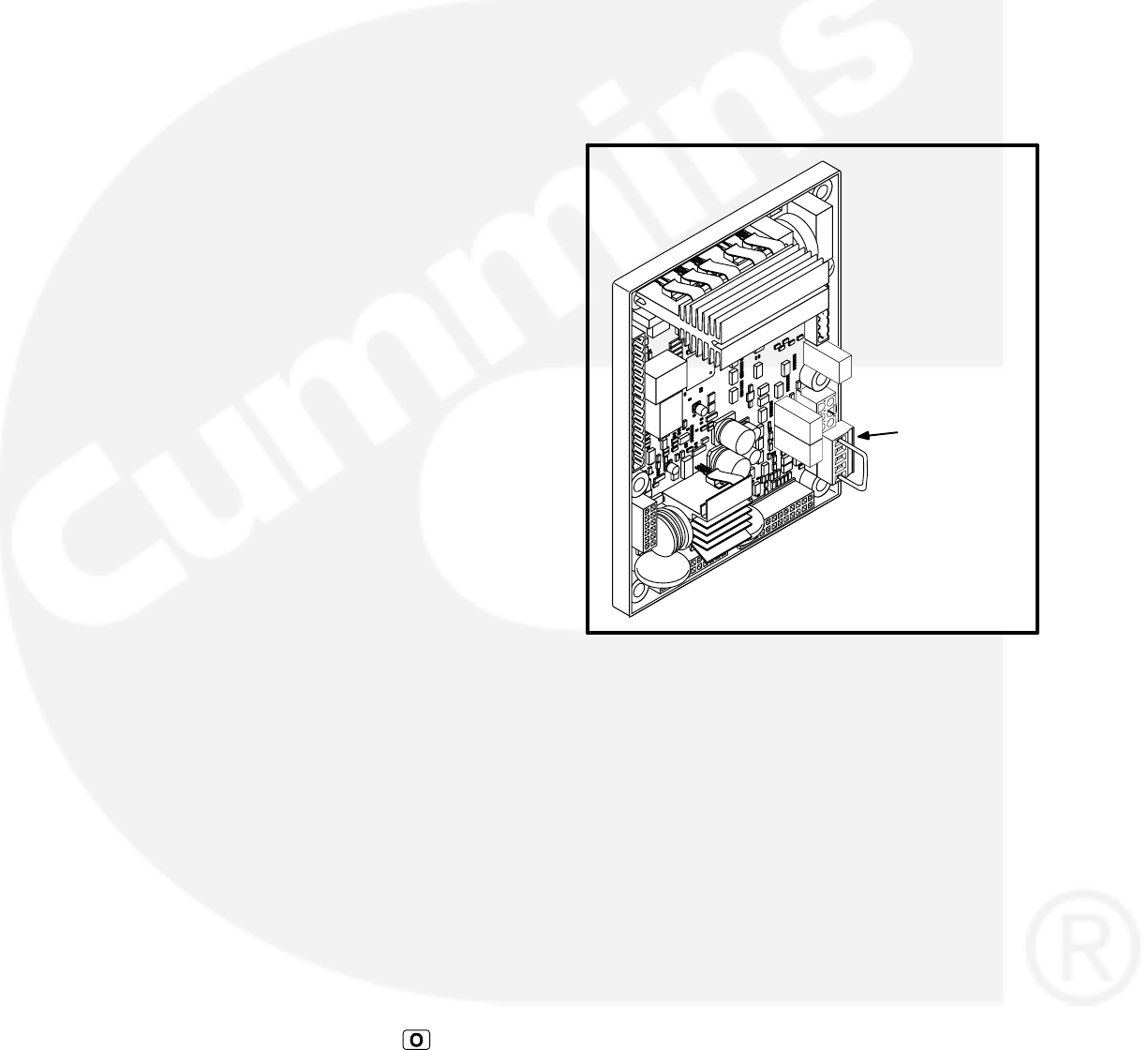
4-2
OPERATING MODES
The 1302 control works with a Manual Run/Off/Auto
switch, used to control genset operating modes.
This capability is located either in the harness
(switch) or is integrated into the operator panel in-
cluded in this kit.
Off Mode
When in Off mode, the control does not allow the
genset to start. If the genset is already running and
the control is set to Off, it initiates a normal shut-
down sequence. When in Off mode, all active faults
are reset.
Manual Run Mode
When in Manual Run mode, the genset starts and
continues to run until the control is put into the Off
mode. While in Manual Run mode, any remote start
signal is ignored.
Auto Mode
When in Auto mode, the control allows the genset
to be started with a remote start signal only.
When in Auto mode, the genset can start at any
time. When a remote start signal is received, the
genset starts after the time delay start and time
delay preheat (if programmed) are completed.
If the genset is running in Auto mode and the Off
button is pressed, the control immediately stops
the genset and the control transitions to the Off
mode.
When all remote start signals are removed, the
control performs a normal shutdown sequence
which may include a time delay stop.
Emergency Stop Mode
When the optional emergency stop button is used,
it immediately shuts down the generator set, by-
passing any time delay stop. The red Shutdown
LED lights and Fault Code 1433 or 1434 − Emer-
gency Stop is either displayed (installations with a
operator panel) or flashed (installations with a sta-
tus indicator lamp).
To reset the control, close (disable) the emergency
stop button and either press the (Off) button
(installations that include a operator panel) or move
the control switch to the OFF position (installations
with a Manual Run/Off/Auto switch).
Sleep Mode
The 1302 series control enters a low power (sleep)
mode of operation where the current draw is not
greater than 60 milliamps (DC) at normal battery
voltage levels. The control is set to enter sleep
mode after five minutes in the Off or Auto mode
(configurable).
Sleep mode can only be disabled by installing a
jumper between TB15-1 and TB15-5 (the TB15
connector is shown in Figure 4-2).
TB15
CONNECTOR
FIGURE 4-2. TB15 CONNECTOR WITH JUMPER
The control will not enter the sleep mode if there are
any active, unacknowledged shutdown faults, if the
control is in the Manual Run mode.
Once in sleep mode, the 1302 series control will
wake up when one of the following wakeup signals
are received.
Local E-Stop − Active when switch is open
Remote E-Stop − Active when switch is open
Manual Start
PCCNet System Wakeup
Remote Start
Auto Mode (If Configured)
Configurable Input #3
Configurable Input #4
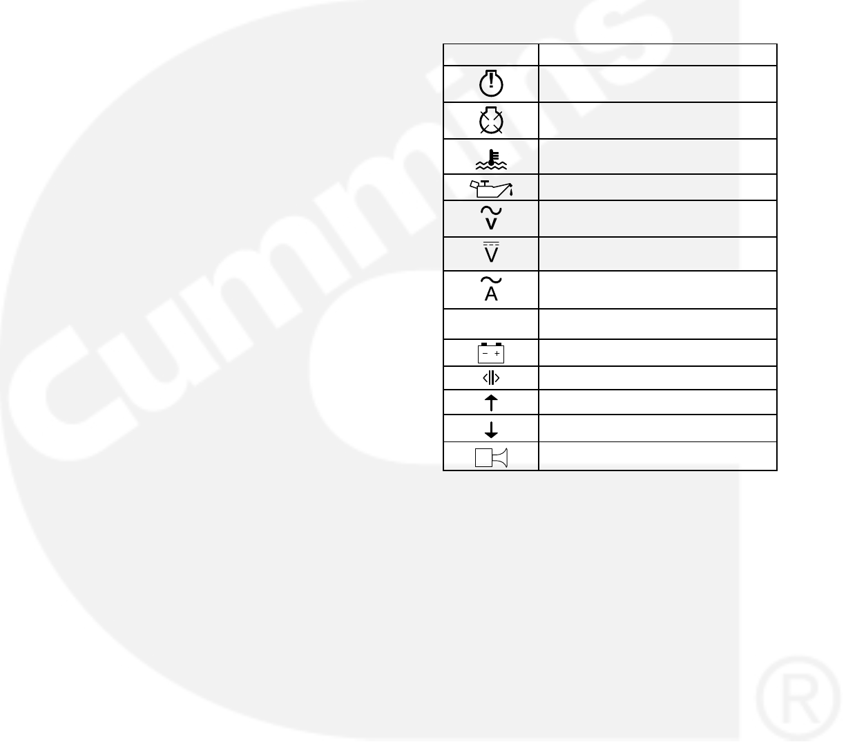
4-3
Installations with an Operator Panel
Sleep mode is automatically enabled on the opera-
tor panel. To awaken the operator panel, press any
button.
Installations with a Manual Run/Off/Auto
Switch
For installations that utilize an Manual Run/Off/Auto
switch located in the harness, the control awakes
from sleep mode if Manual Run or Auto mode (if
configured) is selected.
OPERATOR PANEL
Figure 4-1 shows the front of the optional operator
panel. It includes six LED indicators, the graphical
display, and six buttons used to navigate through
the menus and adjust parameters.
Graphical Display
This graphical display is used to view menus of the
menu-driven operating system. The bottom of the
graphical display indicates the functions that are
available by pressing the four selection buttons.
Refer to the menu trees later in this section.
System messages (communication, event, status,
and fault) are also shown on the graphical display.
For more information, see page 4-6.
Display Text / Symbolic Versions
Using the Display Setup Service submenu (see
page 5-15), the graphical display can be set up to
show either text or symbolic versions of fault mes-
sages, some Operator menus, and the Mode
Change menu. A description of commonly used
symbols used are included in Table 4-1. Combina-
tions of symbols are used to display some fault con-
ditions. Additional specialized symbols are also
used for some faults (see Table 4-2).
TABLE 4-1. SYMBOLS
SYMBOL DESCRIPTION
Generator Warning Fault
Generator Shutdown Fault
Coolant Temperature
Oil Pressure
Voltage Alternating Current (VAC)
Voltage Direct Current (VDC)
AC Current
Hz Frequency
Battery
Out of Range
High or Pre-High
Low or Pre-Low
Annunciator

4-4
Display Menu Selection Buttons
Four momentary soft-key buttons are used to step
through the various menus and to adjust parame-
ters. These selection buttons are “active” when a
word or symbol in the graphical display is shown
above the button. Some submenus do not include
any active buttons.
The function of the four selection buttons varies
with each menu.
When the symbol is displayed, the
selection button can be used to switch to
Auto mode.
When the symbol is displayed, the selec-
tion button can be used to switch to Manual
Run mode.
When the up and down triangles ( and )
are displayed, the selection buttons are used
to navigate between a series of submenus.
NOTE: When any Operator menu is dis-
played, a series of Service menus can
be viewed by simultaneously pressing
the and selection buttons for two
seconds (see page 4-24).
NOTE: When a fault is displayed, it can be
cleared from the front panel by press-
ing the or button.
When a symbol is displayed, the selection
button can be used to abort the Auto or
Manual Run mode and return to the Opera-
tor menu that was displayed before the Auto
or Manual Run mode was selected.
When ADJUST is displayed, the selection
button is used to display an adjustable
menu. When the ADJUST button is pressed,
the first adjustable parameter or value in the
submenu is highlighted.
When the symbol is displayed, the
selection button is used to navigate to an
editable field within a menu.
When the + and − symbols are displayed,
the selection buttons are used to increase or
decrease a parameter or value shown on the
screen.
When changing values, pressing the button
below the + symbol increase the value and
pressing the button below the − symbol de-
creases the value.
When SAVE is displayed, the selection but-
ton is used to save changes made in a sub-
menu. If the Previous Menu button is
pressed before pressing SAVE, the
changes are not saved.
Some menus include a list of numbered sub-
jects. These menus include numbers in pa-
renthesis (for example, (1)) displayed above
the selection buttons. The selection buttons
are then used to display submenus of the
subjects included in the list.
When a black box is displayed, the
selection button has no function.
Previous Main Menu Button
Press the button to view the previous main
menu.
NOTE: In the Screen Adjust menu, settings are not
saved when the button is pressed.
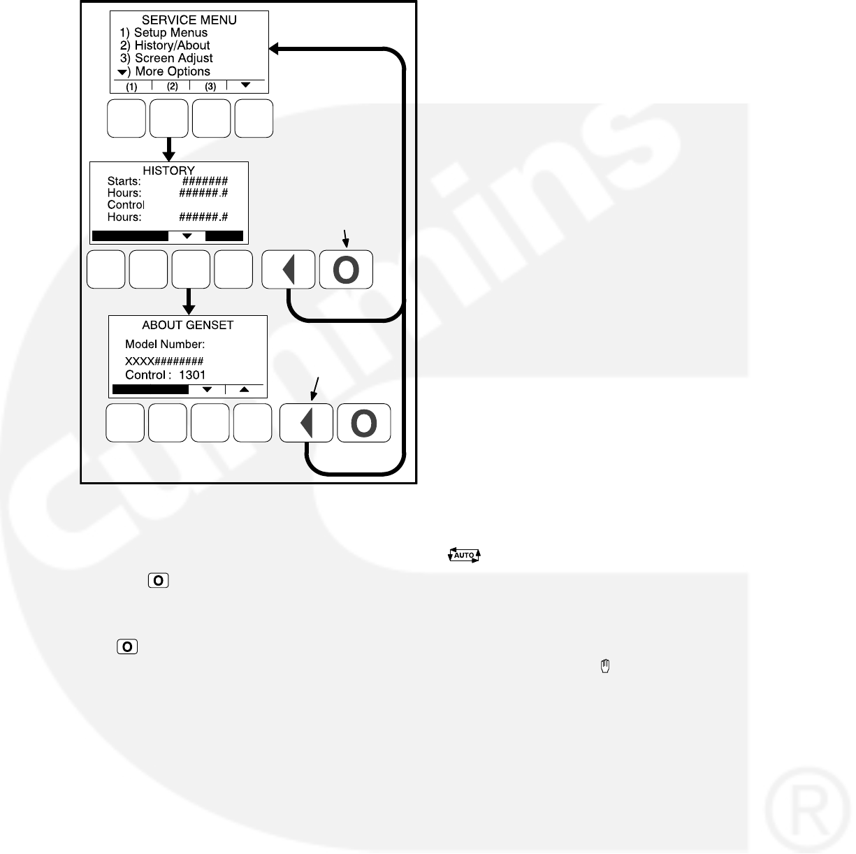
4-5
PREVIOUS MAIN
MENU BUTTON
OFF
BUTTON
FIGURE 4-3. PREVIOUS MAIN MENU AND OFF
BUTTONS
Off Button
Press the button to switch to the Off mode. The
Off mode disables the control Auto or Manual Run
modes.
If the button is pressed during genset operation
(manual or remote start), the engine immediately
shuts down and the control enters the Off mode. If
possible, this hot shutdown should be avoided to
help prolong the reliability of the genset.
Not In Auto Indicator
This red lamp is lit when the control is not in the
Auto mode.
Shutdown Indicator
This red lamp is lit when the control detects a Shut-
down condition. The generator set cannot be
started when this lamp is on. After the condition is
corrected, the lamp can be reset by performing a
fault reset. When Battle Short mode is enabled and
an overridden shutdown fault occurs, the Shut-
down lamp is lit even though the genset continues
to run.
Warning Indicator
This yellow lamp is lit whenever the control detects
a warning condition. This lamp is automatically
shut off when the warning condition no longer ex-
ists.
Remote Start Indicator
This green lamp indicates the control is receiving a
remote start signal.
Auto Indicator
This green lamp indicates the control is in Auto
mode. Auto mode can be selected by pressing the
selection button from any of the Operator me-
nus (see page 4-22).
Manual Run Indicator
This green lamp indicates the control is in the
Manual Run mode. Manual Run mode can be se-
lected by pressing the selection button from any
of the Operator menus (see page 4-22).
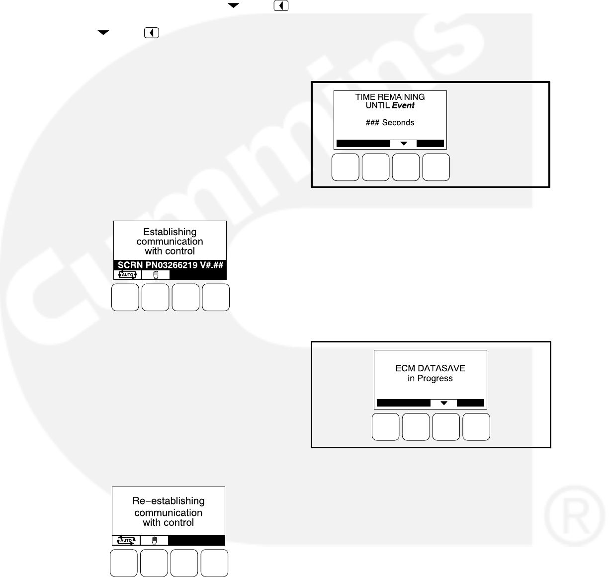
4-6
OPERATOR PANEL SYSTEM MESSAGES
A system pop-up message is displayed when the
event it is displaying becomes active. These pop-
up messages remain displayed until pre-empted by
another pop-up message or until the or the
display buttons is pressed or the event has expired.
Once the or the button is pressed, the pre-
vious screen is redisplayed.
Communication Messages
System messages are displayed for initial power-
up or when there is a subsequent loss of commu-
nications. Auto and Manual Run modes can also be
selected when communication messages are dis-
played (for more information, see page 4-22).
Upon initial power-up, the message “Establishing
communication with control” is displayed (see Fig-
ure 4-4). This menu also displays the screen’s soft-
ware number and version.
FIGURE 4-4. ESTABLISHING COMMUNICATIONS
MESSAGE
When the display detects that it is no longer com-
municating with the control, the Shutdown, Warn-
ing, and Remote Start LEDs are turned off.
If communications are lost, the message “Re-es-
tablishing communication with control” is displayed
until communications have been re-established
(see Figure 4-5). The LEDs then return to the state
determined by the control.
FIGURE 4-5. RE-ESTABLISHING
COMMUNICATIONS MESSAGE
If either communication message remains dis-
played (cannot view other menus), this is an in-
dication that communications between the op-
erator panel and the control logic is lost. Con-
tact an authorized service center for service.
Event Messages
When pre-set events (start or stop) are activated,
Event messages are displayed showing the time
remaining until the event occurs (see Figure 4-6).
Event = START,
or STOP
FIGURE 4-6. EVENT MESSAGE
Status Messages
Status messages for some events are displayed on
the optional control panel with a code number but
are not announced with a lamp indicator. Text sta-
tus messages include the event code, a short de-
scription, and the time the event occurred. Symbol-
ic status messages include the event code and
symbols to indicate the type of event that occurred.
FIGURE 4-7. DATASAVE STATUS MESSAGE
On Full Authority Electronic engines, the engine
controller saves data after each run. During this
time, the display displays the message shown in
Figure 4-7. The generator can still be started while
the ECM Datasave is in progress.
Fault Messages
A Fault message is an indicator of a Warning or
Shutdown condition that is also announced with a
lamp indicator. Text fault messages include the
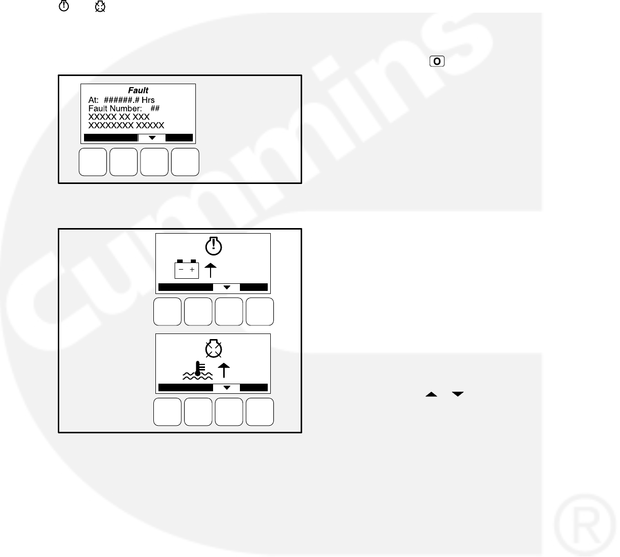
4-7
fault code number, a short description, and when
the fault occurred (see Figure 4-8). Symbolic fault
messages include the fault code number and sym-
bols, indicating the type of fault (see Figure 4-9).
With the symbolic versions of fault messages, the
and symbols flash.
Five of the most recent faults are saved in a file and
can be viewed using the Fault History Menus (see
page 4-28).
Fault = WARNING
or SHUTDOWN
FIGURE 4-8. FAULT MESSAGE − TEXT VERSION
1
214
EXAMPLE OF
A SYMBOLIC
WARNING
FAULT
EXAMPLE OF
A SYMBOLIC
SHUTDOWN
FAULT
FIGURE 4-9. FAULT MESSAGES − SYMBOLIC
VERSION
Fault Reset / Acknowledgement
Shutdown faults must be acknowledged after the
fault condition has been corrected. Shutdown
faults are usually acknowledged by one of the fol-
lowing methods.
If the control is equipped with an operator
panel, press the button.
If the control is not equipped with and opera-
tor panel, place the Auto/Off/Manual Run
switch in the Off position.
Shutdown faults can also be acknowledged when
in Auto mode by using an external customer-sup-
plied remote fault reset switch. This ability must be
enabled by setting the Remote Fault Reset En-
abled trim to “Enabled” (disabled by default) using
InPower.
The remote fault reset switch must be wired into
one of the four configurable inputs. The chosen
configurable input should have its function mapped
to the “Fault Reset” function. To reset the fault, the
remote start command must be removed prior to
the remote fault reset switch being activated.
Faults are removed from the display when they are
cleared.
NOTE: Pressing the or button also clears the
fault from the front panel display.
Faults are re-announced if they are detected again
after being acknowledged.
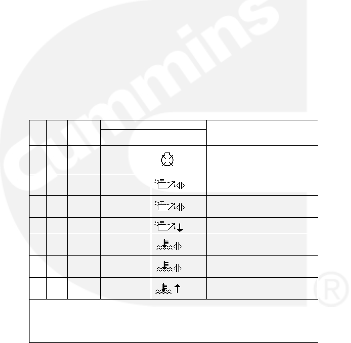
4-8
FAULT/STATUS CODES
Table 4-2 provides a list of fault and status codes,
types, displayed messages/symbols, descriptions,
and fault categories (CTG).
Category A Fault Codes: Pertain to engine or al-
ternator shutdown faults that require immediate re-
pair by trained and experienced service personnel
(generator set non-operational). The control pre-
vents the generator set from being restarted if a
shutdown fault is not corrected.
Category B Fault Codes: Consist of faults that
can affect generator set performance or can cause
engine, alternator, or connected equipment
damage. Operate the genset only when it is power-
ing critical loads and cannot be shut down. Catego-
ry B faults require repair by trained and experi-
enced service personnel.
Category C Fault Codes: Consist of faults that do
not affect generator set performance but require
qualified service personnel to repair. These codes
indicate a defective harness or wiring problem.
These codes can also indicate a defective engine
sensor, leaving no ingine protection. (Engine dam-
age can occure without detection.) Continued op-
eration may void the generator set warranty if
damage occures that relates to the fault condi-
tion.
Category D Fault Codes: Consist of faults that are
repairable by site personnel. Service will be re-
quired by trained and experienced service person-
nel if site personnel cannot resolve the problem.
Category E Fault Codes: Indicates non-critical
operational status of generator set, external faults,
or customer fault inputs. These faults require repair
by trained and experienced service personnel.
TABLE 4-2. FAULT AND STATUS CODES
DISPLAYED MESSAGE/SYMBOLS
CTG CODE LAMP TEXT VERSION SYMBOLIC
VERSION
DESCRIPTION
A 121 Shutdown SPEED SIGNAL
LOST 121
Indicates that no magnetic pickup pulses
were sensed for a Loss of Speed delay. If
a magnetic pickup is disabled, this fault is
not activated.
C 135 Warning OIL PRESS
SENSOR OOR
HIGH 135 Indicates the oil pressure sensor output is
out of range (OOR), high.
C 141 Warning OIL PRESS
SENSOR OOR
LOW 141 Indicates the oil pressure sensor output is
out of range (OOR), low.
B143 ** Warning PRE-LOW OIL
PRESSURE 143 Indicates that the engine oil pressure is
approaching an unacceptable level.
C 144 Warning COOLANT
SENSOR OOR
LOW 144
Indicates the coolant temperature sensor
output is out of range (OOR), low.
C 145 Warning COOLANT
SENSOR OOR
HIGH 145
Indicates the coolant temperature sensor
output is out of range (OOR), high.
C146 ** Warning PRE-HIGH
COOLANT TEMP 146 Indicates that the engine has begun to
overheat and the engine coolant tempera-
ture has risen to an unacceptable level.
NOTE: Shutdown fault codes can also be announced with a local status lamp indicator.
* For more information on these events, refer to the Battle Short Mode description on page 3-57.
** Any values listed in the Description column for these faults are default values. If authorized, these values
can be changed using the Genset Setup menus (see page 5-37).
^These faults are available only if your installation includes the optional I/O Module (Kit 541−1291).
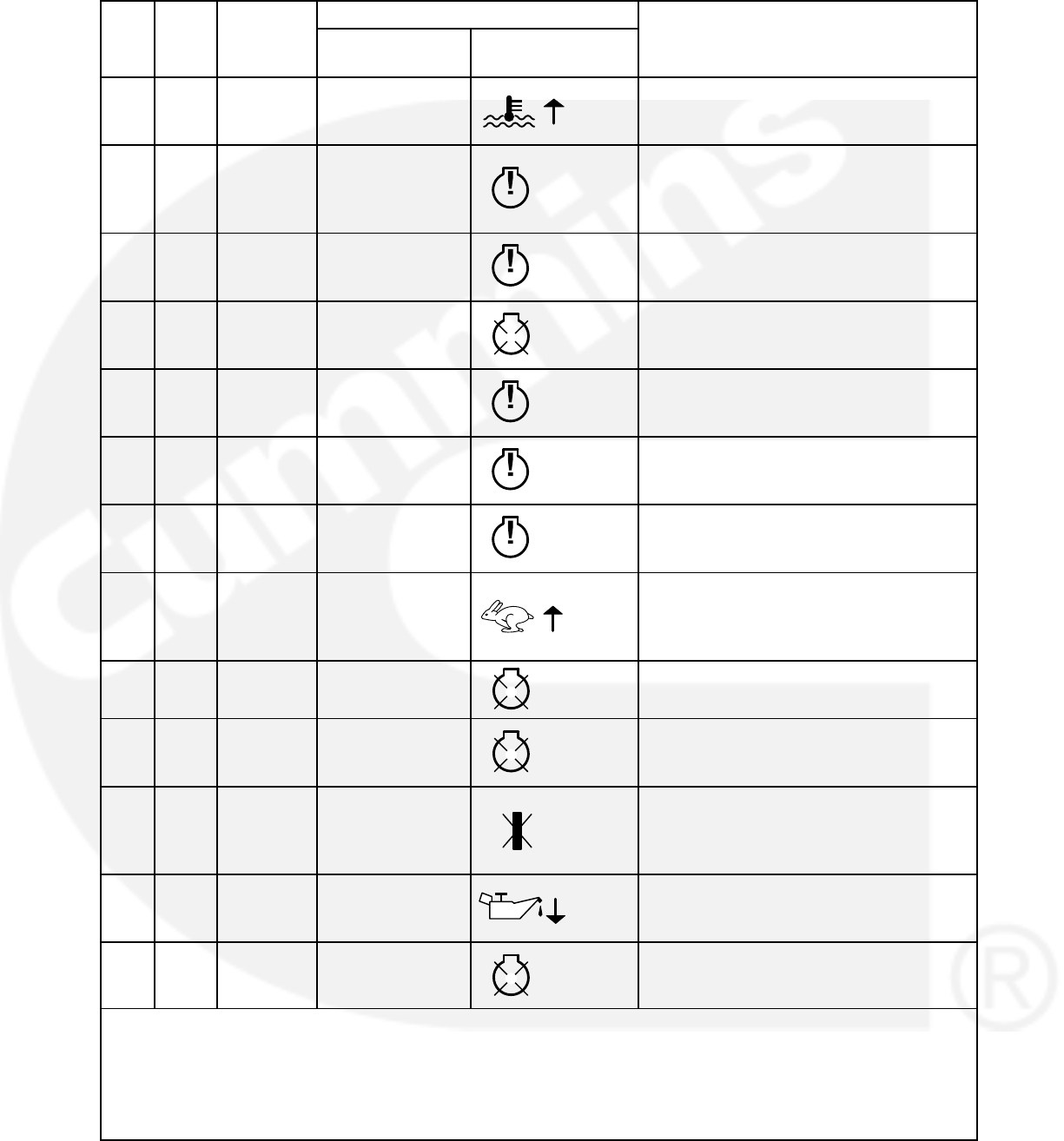
4-9
TABLE 4-2. FAULT AND STATUS CODES (CONT.)
CTG DESCRIPTION
DISPLAYED MESSAGE/SYMBOLS
LAMPCODE
CTG DESCRIPTION
SYMBOLIC
VERSION
TEXT VERSION
LAMPCODE
D151 ** Shutdown HIGH COOLANT
TEMP 151 Indicates that the engine coolant tempera-
ture is above normal and has reached the
shutdown trip point.
C 153 Warning INTAKE
MANIFOLD
TEMP OOR
HIGH 153
Indicates the intake manifold temperature
sensor is out of range (OOR), high.
C 154 Warning INTAKE
MANIFOLD
TEMP OOR LOW 154 Indicates the intake manifold temperature
sensor is out of range (OOR), low.
D 155 Shutdown INTAKE
MANIFOLD
TEMP HIGH 155 Indicates that the intake manifold
temperature is above normal and has
reached the shutdown trip point.
D 195 Warning COOLANT
LEVEL OOR
HIGH 195 Indicates that a sensor on the radiator has
detected that the coolant level is out of
range (OOR), high.
D 196 Warning COOLANT
LEVEL OOR
LOW 196 Indicates that a sensor on the radiator has
detected that the coolant level is out of
range (OOR), low.
D 197 Warning COOLANT
LEVEL LOW 197 Indicates that a sensor on the radiator has
detected that the coolant level is below
normal.
A 234 ** Shutdown OVERSPEED
234
Indicates that the engine has exceeded
normal operating speed. The default
thresholds are 1725 RPM (50 Hz) or 2075
RPM (60 Hz).
A 285 Shutdown ECM PGN
TIMEOUT 285 Datalink failure. PCC control not
responding to the engine control module.
A 286 Shutdown ECM
CONFIGURABLE
ERROR 286 Indicates an engine control module
configuration error − out of calibration.
D 359 Shutdown FAIL TO START
359
The genset has failed to start after a set
number of crank attempts. This indicates a
possible fuel system problem (engine
cranks but fails to start).
A 415 Shutdown LOW OIL
PRESSURE 415
Indicates the engine oil pressure has
dropped below normal and has reached
the shutdown trip point.
C 421^Shutdown OIL TEMP HIGH 421 Indicates that the engine oil temperature is
above normal and has reached the
shutdown trip point. (I/O Module option)
NOTE: Shutdown fault codes can also be announced with a local status lamp indicator.
* For more information on these events, refer to the Battle Short Mode description on page 3-57.
** Any values listed in the Description column for these faults are default values. If authorized, these values
can be changed using the Genset Setup menus (see page 5-37).
^These faults are available only if your installation includes the optional I/O Module (Kit 541−1291).
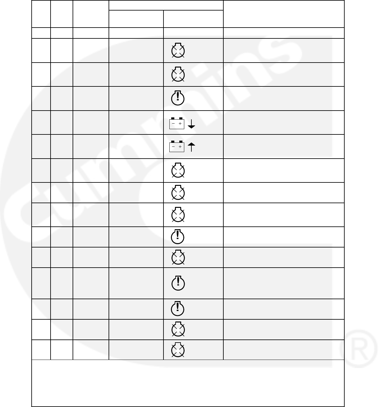
4-10
TABLE 4-2. FAULT AND STATUS CODES (CONT.)
CTG DESCRIPTION
DISPLAYED MESSAGE/SYMBOLS
LAMPCODE
CTG DESCRIPTION
SYMBOLIC
VERSION
TEXT VERSION
LAMPCODE
−− 418 NONE N / A N/A Indicates water in fuel
B 425^Shutdown OIL TEMP OOR 425 Indicates the oil temperature sensor output
is out of range (OOR), high or low. (I/O
Module option)
A 426 Shutdown DATA LINK
ERROR 426 Datalink failure. No communications
between the PCC control and the engine
control module.
A 427 Warning CAN LINK LOST 427 Datalink fault. Indicates that important data
was lost between the PCC control and the
engine control module.
D441 ** Warning LOW BATTERY
441
Indicates battery voltage supply to the con-
trol is approaching a low level at which un-
predictable operation can occur.
D442 ** Warning HIGH BATTERY 442 Indicates battery voltage supply to the con-
trol is approaching a high level at which
damage to the control can occur.
D 488^Shutdown INTAKE
MANIFOLD
TEMP HIGH 488 Indicates the intake manifold temperature
is above normal and has reached the
shutdown trip point. (I/O Module option)
A 689 Shutdown ENGINE SPEED
ERRATIC 689 Indicates a fault condition in the engine
crankshaft sensor circuit.
A 781 Shutdown CAN LINK LOST 781 Datalink failure. No communications
between the PCC control and the engine
control module.
D1117 Warning ECM POWER
LOST 1117 Indicates battery voltage supply to the
engine control module was lost.
B 1123
*
Shutdown SHUTDOWN
AFTER BS 1123 A shutdown fault occurred while the Battle
Short mode was enabled.
D 1131
*
Warning BATTLE SHORT
ACTIVE 1131
Indicates that the control is in Battle Short
mode − used to bypass several fault shut-
downs for genset operation during emer-
gencies.
C 1246 Warning GENERIC
ENGINE FAULT 1246 Engine control fault code not recognized
by the PCC control.
E 1311 Configur-
able
Customer Fault
Input 1 1311 The nature of the fault is an optional cus-
tomer selection.
E 1312 Configur-
able
Customer Fault
Input 2 1312 The nature of the fault is an optional cus-
tomer selection.
NOTE: Shutdown fault codes can also be announced with a local status lamp indicator.
* For more information on these events, refer to the Battle Short Mode description on page 3-57.
** Any values listed in the Description column for these faults are default values. If authorized, these values
can be changed using the Genset Setup menus (see page 5-37).
^These faults are available only if your installation includes the optional I/O Module (Kit 541−1291).
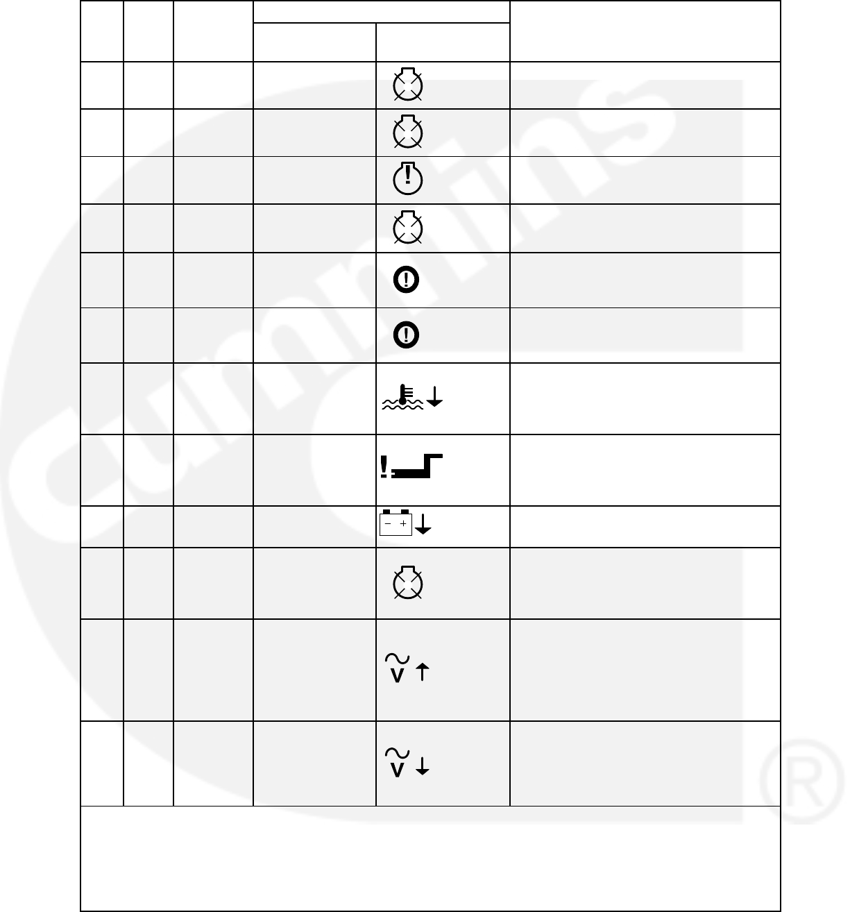
4-11
TABLE 4-2. FAULT AND STATUS CODES (CONT.)
CTG DESCRIPTION
DISPLAYED MESSAGE/SYMBOLS
LAMPCODE
CTG DESCRIPTION
SYMBOLIC
VERSION
TEXT VERSION
LAMPCODE
E 1317 Configur-
able
Customer Fault
Input 3 1317 The nature of the fault is an optional cus-
tomer selection.
E 1318 Configur-
able
Customer Fault
Input 4 1318 The nature of the fault is an optional cus-
tomer selection.
B 1416
*
Warning FAIL TO
SHUTDOWN 1416 Indicates that a shutdown fault is active,
but is being bypassed by Battle Short.
A 1417 Shutdown FAILURE TO
POWER DOWN 1417 Indicates the control is powered up after
attempting to go to sleep.
D 1433 Shutdown LOCAL
EMERGENCY
STOP 1433 Indicates a Local Emergency Stop has
been activated.
D 1434 Shutdown REMOTE
EMERGENCY
STOP 1434 Indicates a Remote Emergency Stop has
been activated.
D 1435
**
Warning LOW COOLANT
TEMP 1435
Indicates that the engine coolant tempera-
ture is below the adjusted setpoint. This
may indicate that the coolant heater is not
operating or is not circulating coolant.
D 1438 Shutdown FAIL TO CRANK
1438
The genset has failed to sense rotation for
two start attempts. This indicates a pos-
sible fault with the control, speed sensing,
or the starting system.
D 1442
**
Warning WEAK BATTERY 1442
Indicates that the genset battery voltage is
below battery thresholds during cranking.
A 1443 Shutdown DEAD BATTERY
1443
Indicates during cranking battery voltage
has dropped below operating voltage of
control resetting the control for three con-
secutive times.
A 1446
**
Shutdown HIGH AC
VOLTAGE
1446
Indicates that the one or more measured
AC output voltages has exceeded the
threshold for longer than a specified time
limit. The threshold and time limits are
130% of nominal for 0 seconds or 110% of
nominal for 10 seconds.
A 1447
**
Shutdown LOW AC
VOLTAGE
1447
Indicates that the measured AC output
voltage is below the threshold for longer
than a specified time limit. The threshold
and time limits are 85% of nominal for 10
seconds.
NOTE: Shutdown fault codes can also be announced with a local status lamp indicator.
* For more information on these events, refer to the Battle Short Mode description on page 3-57.
** Any values listed in the Description column for these faults are default values. If authorized, these values
can be changed using the Genset Setup menus (see page 5-37).
^These faults are available only if your installation includes the optional I/O Module (Kit 541−1291).
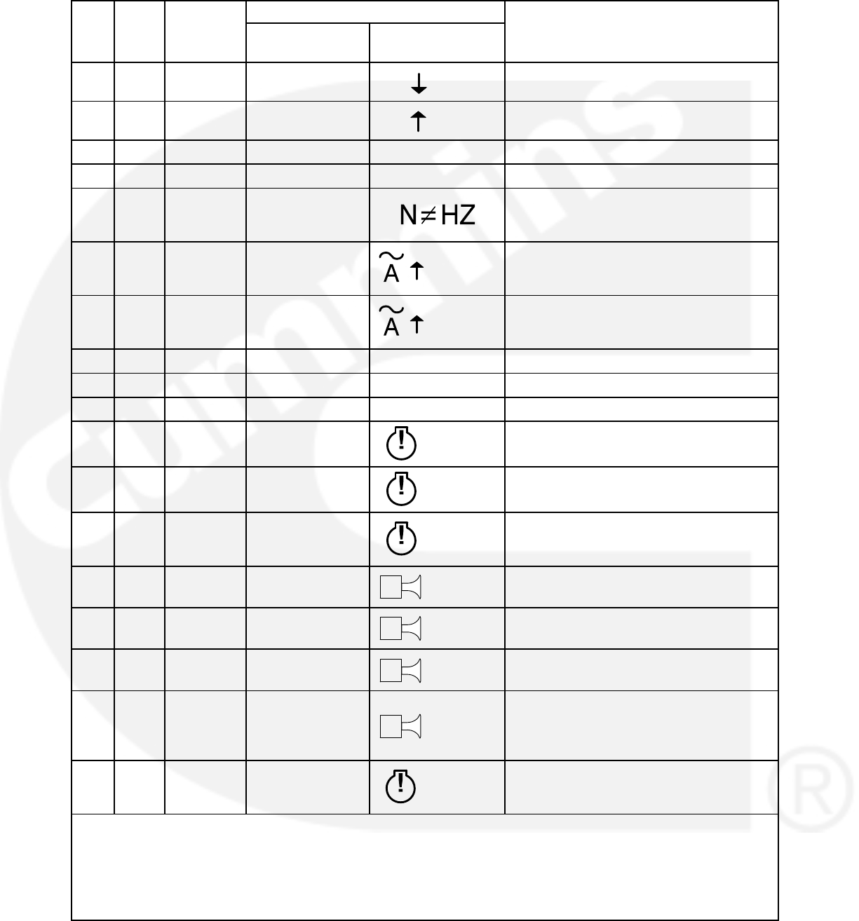
4-12
TABLE 4-2. FAULT AND STATUS CODES (CONT.)
CTG DESCRIPTION
DISPLAYED MESSAGE/SYMBOLS
LAMPCODE
CTG DESCRIPTION
SYMBOLIC
VERSION
TEXT VERSION
LAMPCODE
A 1448
**
Shutdown UNDER
FREQUENCY 1448Hz Indicates that the alternator frequency is 6
hertz under nominal frequency.
A 1449
**
Shutdown OVER
FREQUENCY 1449Hz Indicates that the alternator frequency is 6
hertz above nominal frequency.
−− 1463 NONE N /A N/A Indicates Not in Auto.
−− 1468 NONE N / A N/A Indicates Ready to Load.
A 1469
**
Shutdown SPEED HZ
MATCH
Indicates that measured engine speed and
measured alternator AC output frequency
do not agree.
B 1471*
*
Warning HIGH AC
CURRENT 1471 Indicates that the alternator output current
(one or more phases) has exceeded safe
operating limits.
A 1472
**
Shutdown HIGH AC
CURRENT 1472 Indicates that alternator output current
(one or more phases) has exceeded the
alternator’s current rating.
−− 1483 NONE N/ A N/A Indicates Common Alarm.
−− 1540 NONE N/ A N/A Indicates Common Warning.
−− 1541 NONE N/ A N/A Indicates Common Shutdown.
C 1845 Warning WATER IN FUEL
OOR HIGH 1845 Indicates the water in fuel sensor is out of
range (OOR), high.
C 1846 Warning WATER IN FUEL
OOR LOW 1846 Indicates the water in fuel sensor is out of
range (OOR), low.
D 1852 Warning WATER IN FUEL 1852 Indicates that the water in fuel is above
normal and has reached the warning trip
point.
E 1853 Configur-
able
Annunciator Fault
21853 The nature of the annunciator fault is an
optional customer selection.
E 1854 Configur-
able
Annunciator Fault
31854 The nature of the annunciator fault is an
optional customer selection.
E 1855 Configur-
able
Annunciator Fault
11855 The nature of the annunciator fault is an
optional customer selection.
E 1944 Warning ANNUNCIATOR
OUTPUT CON-
FIGURATION
ERROR 1944
Indicates a mismatch in the configuration
of one of the annunciator relay outputs.
D 1965
^
Warning EXHAUST
TEMPERATURE
OOR 1965 Indicates the exhaust temperature sensor
is out of range (OOR), high or low. (Aux
101 I/O option).
NOTE: Shutdown fault codes can also be announced with a local status lamp indicator.
* For more information on these events, refer to the Battle Short Mode description on page 3-57.
** Any values listed in the Description column for these faults are default values. If authorized, these values
can be changed using the Genset Setup menus (see page 5-37).
^These faults are available only if your installation includes the optional I/O Module (Kit 541−1291).
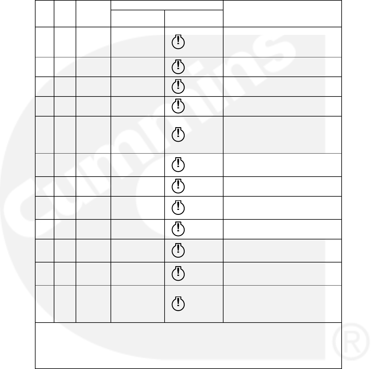
4-13
TABLE 4-2. FAULT AND STATUS CODES (CONT.)
CTG DESCRIPTION
DISPLAYED MESSAGE/SYMBOLS
LAMPCODE
CTG DESCRIPTION
SYMBOLIC
VERSION
TEXT VERSION
LAMPCODE
B 1992 Warning ENGINE
OVERSPEED 1992
Indicates that the engine has exceeded
normal operating speed. The default
thresholds are 1725 RPM (50 Hz) or 2075
RPM (60 Hz). (ECM fault code).
B 1689 Warning CLOCK NOT
SET 1689 Indicates real time clock is not set with
exercise scheduler function enabled.
B 5186 Warning GENSET FAILED
TO CLOSE 5186 Indicates transfer switch has failed to close
on generator side.
B 5187 Warning UTILITY FAILED
TO CLOSE 5187 Indicates transfer switch has failed to close
on utility side.
B 5188 Warning TRANSFER
SWITCH
STATUS
UNKNOW
POSITION
5188
Indicates transfer switch position is not
known.
B 5365 Warning ON
SECONDARY
SOURCE 5365 Indicates genset is running on secondary
fuel source in dual fuel application.
B 2118 Warning LOW FUEL
PRESSURE 2118 Indicates low fuel pressure sensed for
gaseous application.
B 5134 Warning UNKNOWN
SHUTDOWN AT
IIDLE 5134 Indicates genset having ECM has
shutdown with unknown fault before
reaching rated condition.
B 254 Warning FSO DRIVER
FAILED 254 Engine Fuel Shutoff Valve Driver Circuit −
Voltage Below Normal or Shorted.
B 1847 Warning HIGH
TEMPERATURE
FAULT 1847 Indicates that engine coolant temperature
is above normal and has reached the
shutdown trip point.
B 1517 Warning FAILED
MODULE
SHUTDOWN 1517 At least One Module of a Multi−module
system has a severe fault.
B 1921 Warning REGEN
MANDATORY
HIGH LEVEL 1921
Aftertreatment Diesel Particulate Filter
Differential Pressure − Data Valid But
Above Normal Operating Range −
Moderately Severe Level. Need to initiate
DPFprocess.
NOTE: Shutdown fault codes can also be announced with a local status lamp indicator.
* For more information on these events, refer to the Battle Short Mode description on page 3-57.
** Any values listed in the Description column for these faults are default values. If authorized, these values
can be changed using the Genset Setup menus (see page 5-37).
^These faults are available only if your installation includes the optional I/O Module (Kit 541−1291).
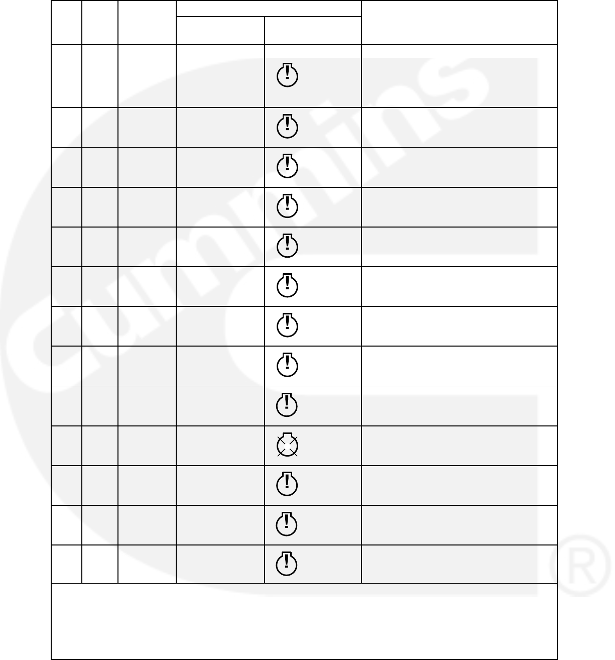
4-14
TABLE 4-2. FAULT AND STATUS CODES (CONT.)
CTG DESCRIPTION
DISPLAYED MESSAGE/SYMBOLS
LAMPCODE
CTG DESCRIPTION
SYMBOLIC
VERSION
TEXT VERSION
LAMPCODE
B 1922 Warning GENSET
CRITICAL CALL
TECHNICIAN 1922
Aftertreatment Diesel Particulate Filter
Differential Pressure − Data Valid But
Above Normal Operating Range − Most
Severe Level. Need to call Cummins
technician to clear the fault.
B 175 Warning AIR THROT
DRIVE CCT
OORH 175 Electronic Throttle Control Actuator Driver
Circuit − Voltage Above Normal or Shorted
to High Source.
B 176 Warning AIR THROT
DRIVE CCT
OORH 176 Electronic Throttle Control Actuator Driver
Circuit − Voltage Below Normal or Shorted
to Low Source.
B 177 Warning AIR THROT
DRIVE MECH
SYS ERROR 177 Electronic Throttle Control Actuator −
Mechanical System Not Responding or
Out of Adjustment.
B 3539 Warning AIR THROT
POSN SENSOR
OORH 3539 Engine Intake Throttle Actuator Position
Sensor Circuit − Voltage Above Normal or
Shorted to High Source.
B 3541 Warning AIR THROT
DRIVE CCT
OORL 3541 Engine Intake Throttle Actuator Position
Sensor Circuit − Voltage Below Normal or
Shorted to Low Source.
B 3542 Warning AIR THROT
POSN SENS
DATA INCORR 3542 Engine Intake Throttle Actuator Position
Sensor − Data Erratic, Intermittent, or
Incorrect.
B 5669 Warning ENGINE
COMBUSTION
FAULT 5669 Intake Manifold Over Pressure − Condition
Exists.
C 2224
^
Warning FUEL LEVEL
OOR 2224 Indicates the fuel level sensor is out of
range (OOR), high or low. (Aux 101 I/O
option).
A 2335 Shutdown EXCITATION
FAULT 2335 Indicates that a loss of voltage or frequen-
cy sensing from the generator has oc-
curred.
C 2398
^
Warning AMBIENT
TEMPERATURE
OOR 2398 Indicates the ambient temperature sensor
is out of range (OOR), high or low. (Aux
101 I/O option).
C 2542
^
Warning VOLTAGE BIAS
OOR 2542 Indicates the voltage bias circuit output is
out of range (OOR), high or low. (Aux 101
I/O option).
A 2545 Shutdown KEYSWITCH
RESET
REQUIRED 2545 Indicates a datalink failure. Communica-
tions are lost between the PCC control and
the engine control module.
NOTE: Shutdown fault codes can also be announced with a local status lamp indicator.
* For more information on these events, refer to the Battle Short Mode description on page 3-57.
** Any values listed in the Description column for these faults are default values. If authorized, these values
can be changed using the Genset Setup menus (see page 5-37).
^These faults are available only if your installation includes the optional I/O Module (Kit 541−1291).
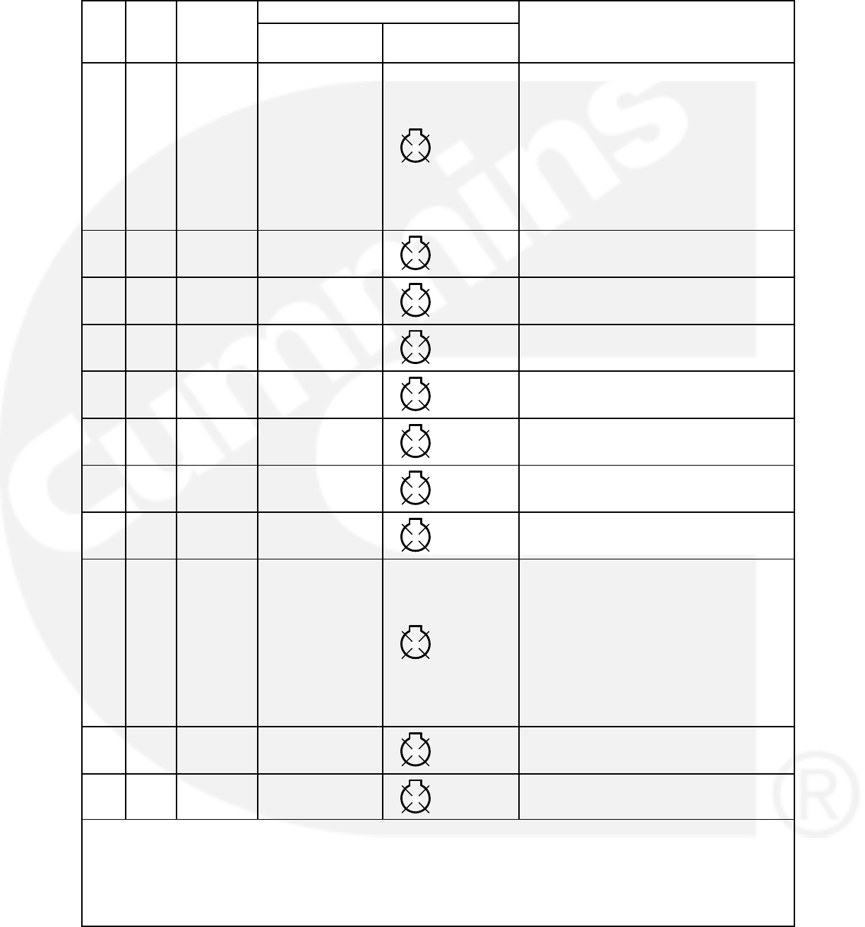
4-15
TABLE 4-2. FAULT AND STATUS CODES (CONT.)
CTG DESCRIPTION
DISPLAYED MESSAGE/SYMBOLS
LAMPCODE
CTG DESCRIPTION
SYMBOLIC
VERSION
TEXT VERSION
LAMPCODE
E 2619
^
Diagnos-
tic
AUX101 ANA-
LOG INPUT 1
2619
The nature of the Base I/O Module event
is an optional customer selection. (Aux101
I/O Module option)
Each event function can be programmed
(using InPower service tool or access to
the Setup menu), as follows:
Change display name using up to 32
characters.
Select active low or high input.
E 2621
^
Diagnos-
tic
AUX101 ANA-
LOG INPUT 2 2621 See code 2619.
E 2622
^
Diagnos-
tic
AUX101 ANA-
LOG INPUT 3 2622 See code 2619.
E 2623
^
Diagnos-
tic
AUX101 ANA-
LOG INPUT 4 2623 See code 2619.
E 2624
^
Diagnos-
tic
AUX101 ANA-
LOG INPUT 5 2624 See code 2619.
E 2625
^
Diagnos-
tic
AUX101 ANA-
LOG INPUT 6 2625 See code 2619.
E 2626
^
Diagnos-
tic
AUX101 ANA-
LOG INPUT7 2626 See code 2619.
E 2627
^
Diagnos-
tic
AUX101 ANA-
LOG INPUT 8 2627 See code 2619.
E 2628
^
Diagnos-
tic
AUX102 DIGITAL
INPUT 9
2628
The nature of the Aux I/O Module event is
an optional customer selection. (Aux102
I/O Module option)
Each event function can be programmed
(using InPower service tool or access to
the Setup menu), as follows:
Change display name using up to 32
characters.
Select active low or high input.
E 2629
^
Diagnos-
tic
AUX102 DIGITAL
INPUT 10 2629 See code 2628.
E 2631
^
Diagnos-
tic
AUX102 DIGITAL
INPUT 11 2631 See code 2628.
NOTE: Shutdown fault codes can also be announced with a local status lamp indicator.
* For more information on these events, refer to the Battle Short Mode description on page 3-57.
** Any values listed in the Description column for these faults are default values. If authorized, these values
can be changed using the Genset Setup menus (see page 5-37).
^These faults are available only if your installation includes the optional I/O Module (Kit 541−1291).
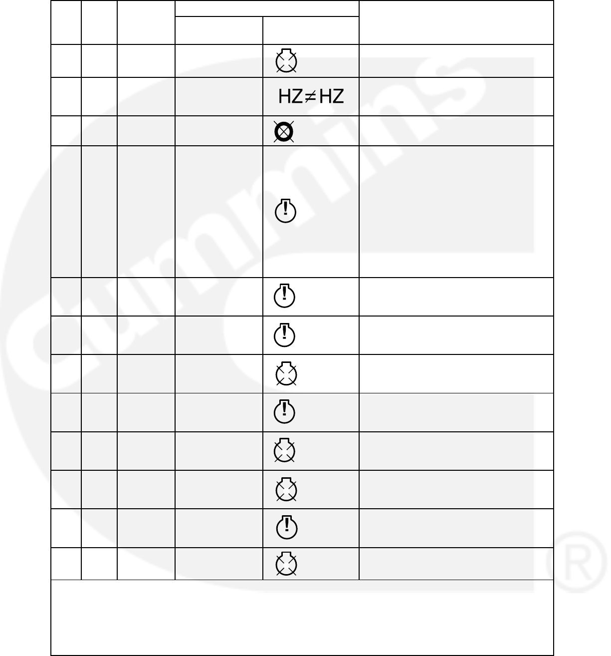
4-16
TABLE 4-2. FAULT AND STATUS CODES (CONT.)
CTG DESCRIPTION
DISPLAYED MESSAGE/SYMBOLS
LAMPCODE
CTG DESCRIPTION
SYMBOLIC
VERSION
TEXT VERSION
LAMPCODE
E 2632
^
Diagnos-
tic
AUX102 DIGITAL
INPUT 12 2632 See code 2628.
A 2676 Shutdown ALTERNATOR
FREQUENCY
CONFLICT
Indicates the measured alternator line fre-
quency and measured alternator excitation
frequency do not agree.
A 2677 Shutdown FAIL TO STOP 2677 The genset continues to run after receiving
a stop command from the controller.
B 2678
**
Warning CHARGER
FAILURE
2678
Indicates the battery charging alternator
has not reached a acceptable voltage
range within the selected time period (de-
fault = 120 seconds).
This warning is also displayed if your alter-
nator is a type that does not support the
control’s charging alternator logic function-
ality. If this occurs, this warning can be dis-
abled if the Charging Alt. Enable setting is
set to “No.” See the Genset Service sub-
menus on page 5-8.
C 2693
^
Warning SPEED BIAS
OOR 2693 Indicates the speed bias circuit output is
out of range (OOR), high or low. (Aux 101
I/O Module option).
C 2694
^
Warning ALTERNATOR
RTD OOR 2694 Indicates the alternator RTD sensor is out
of range (OOR), high or low. (Aux 101 I/O
Module option).
A 2696
^
Shutdown ALTERNATOR
RTD TEMP HIGH 2696 Indicates the alternator temperature is
above normal and has reached the
shutdown trip point. (I/O Module option)
C 2729
^
Warning I/O MODULE
LOST 2729 Indicates an intermittent data link between
the I/O module and the PCC control. (Aux
101 I/O Module option).
C 2731 Shutdown I/O MODULE
LOST 2731 Indicates the data link between the I/O
module and the PCC control is lost. (Aux
101 I/O Module option).
A 2897 Shutdown FACTORY
BLOCK
CORRUPT 2897 Indicates a fatal software error occurred in
the PCC control.
A 2898 Warning PERIODIC/
FAULT
CORRUPT 2898 Indicates a fatal software error occurred in
the PCC control.
A 2899 Shutdown USER BLOCK
CORRUPT 2899 Indicates a fatal software error occurred in
the PCC control.
NOTE: Shutdown fault codes can also be announced with a local status lamp indicator.
* For more information on these events, refer to the Battle Short Mode description on page 3-57.
** Any values listed in the Description column for these faults are default values. If authorized, these values
can be changed using the Genset Setup menus (see page 5-37).
^These faults are available only if your installation includes the optional I/O Module (Kit 541−1291).
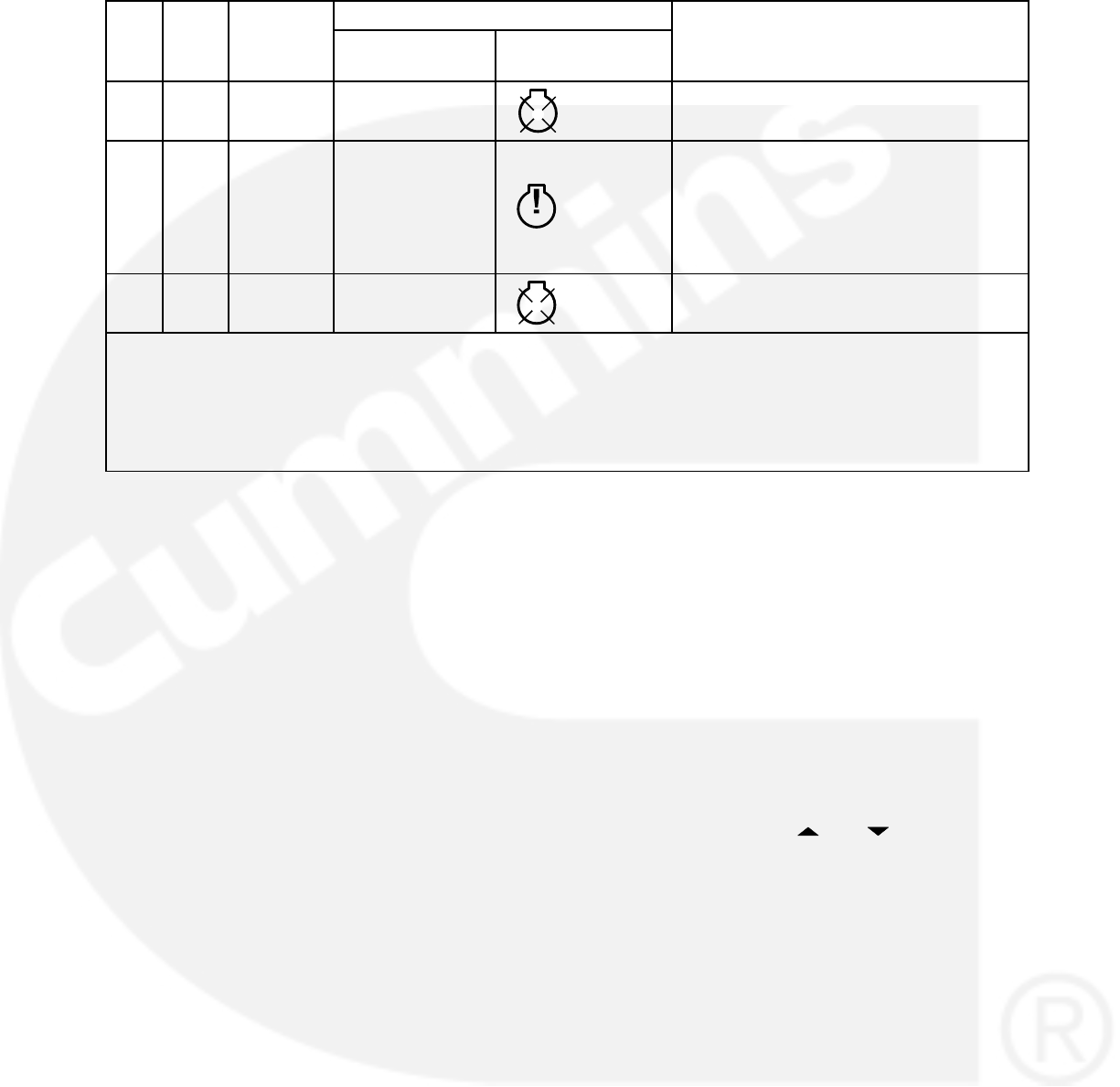
4-17
TABLE 4-2. FAULT AND STATUS CODES (CONT.)
CTG DESCRIPTION
DISPLAYED MESSAGE/SYMBOLS
LAMPCODE
CTG DESCRIPTION
SYMBOLIC
VERSION
TEXT VERSION
LAMPCODE
A 2911 Shutdown TRIM BLOCK
CORRUPT 2911 Indicates a fatal software error occurred in
the PCC control.
D 2964 Warning INTAKE
MANIFOLD
TEMPERATURE
HIGH 2964
Indicates engine has begun to overheat
(intake manifold temperature has risen to
an unacceptable level). Increase in load or
higher ambient temperature may cause
Intake Manifold Temp High (code 155)
shutdown.
A 2972
**
Shutdown FIELD
OVERLOAD 2972 Indicates that the Field Voltage has been
above 70V for 8 seconds.
NOTE: Shutdown fault codes can also be announced with a local status lamp indicator.
* For more information on these events, refer to the Battle Short Mode description on page 3-57.
** Any values listed in the Description column for these faults are default values. If authorized, these values
can be changed using the Genset Setup menus (see page 5-37).
^These faults are available only if your installation includes the optional I/O Module (Kit 541−1291).
ADJUSTING DEFAULT SETTINGS
The optional operator panel can be set up to dis-
play with SAE or SI units of measurement.
For more information, see the Adjust Screen menu
shown on page 4-30.
SAVING YOUR CHANGES
All adjustments made to menus are temporary until
the SAVE button is pressed. If the SAVE button is
pressed and the engine is running, the adjustments
are not saved until after the engine speed is zero. If
power is lost to the control before a SAVE is execut-
ed, all temporary adjustments are lost.
Adjustments to the following are stored in flash
memory in the optional operator panel.
Contrast
Brightness
Units
Local or remote display
Symbols or text displayed
Access code required for mode change to
Auto or Manual Run
All other adjustments are stored in the control
board.
When the SAVE button is pressed, the previous
menu is redisplayed.
OPERATOR MENUS
Figures 4-10 and 4-11 show block representations
of the following Operator menus.
Engine Status
Alternator Status
Line-to-Line Voltage
Line-to-Neutral Voltage
Alternator Amperage
To navigate between the Operator menus, press
the buttons next to the and symbols in the
graphical display.
The Operator menus can be used to select Auto or
Manual Run modes (see page 4-22).
Engine Status Menu
This menu displays the engine starting battery volt-
age, engine coolant temperature, engine oil pres-
sure, and hours of engine operation.
Alternator Status Menu
This menu displays genset load (in kVA), frequen-
cy, and engine speed (RPM).
Alternator Line-to-Line Voltage Menu
This menu displays L1-L2, L2-L3, and L3-L1 line-
to-line voltages for three phase applications only.

4-18
Alternator Line-to-Neutral Voltage Menu
This menu displays line-to-neutral voltages for L1,
L2, and L3 for three phase wye configurations only.
In delta configurations, this menu is not shown.
Alternator Single Phase Voltage Menu
This menu displays L1-N, L2-N, and L1-L2 volt-
ages for single phase applications only.
Alternator Amperage Menu
For applications that include current transformers,
this menu displays L1, L2, and L3 current sense
amperage.
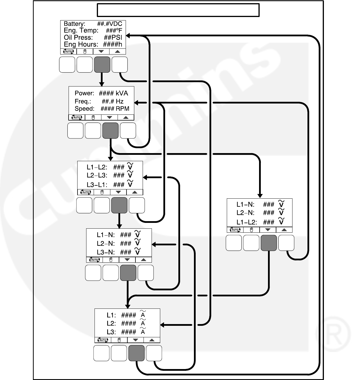
4-19
OPERATOR MENUS − Text Version
THREE PHASE
ONLY
THREE PHASE
WYE ONLY
CURRENT SENSE
AMPERAGE
SINGLE
PHASE
ONLY
FIGURE 4-10. OPERATOR MENUS (TEXT VERSION)
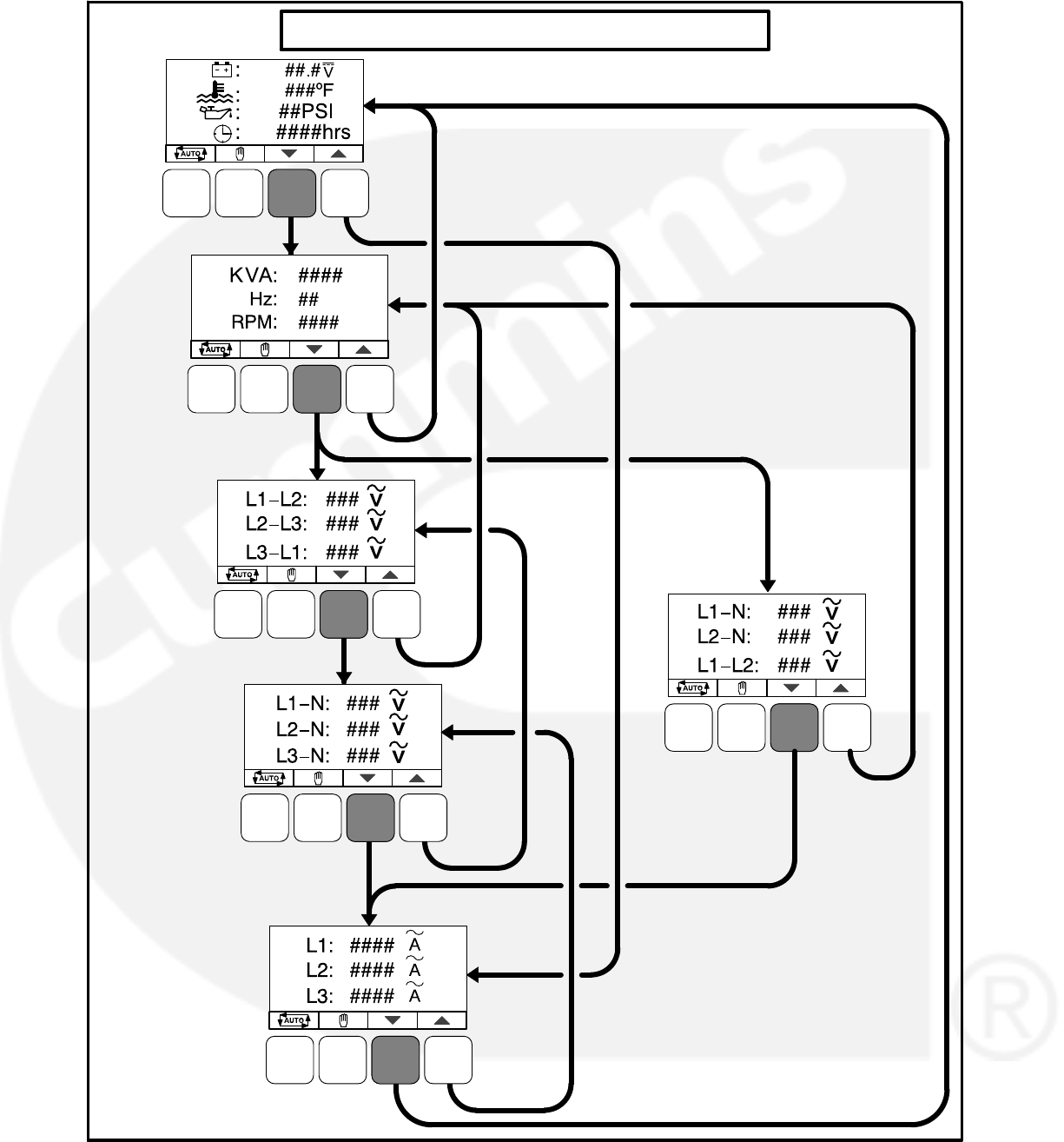
4-20
CURRENT SENSE
AMPERAGE
OPERATOR MENUS − Symbolic Version
THREE PHASE
ONLY
THREE PHASE
WYE ONLY
SINGLE
PHASE
ONLY
FIGURE 4-11. OPERATOR MENUS (SYMBOLIC VERSION)
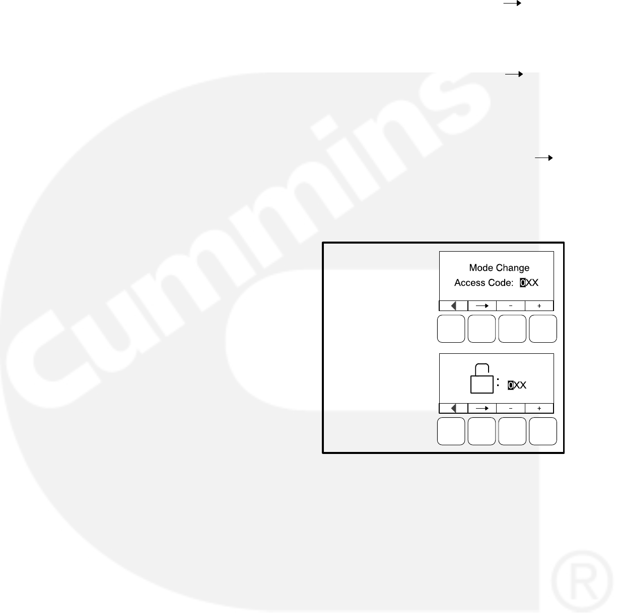
4-21
SELECTING AUTO, MANUAL RUN, AND
OFF MODES
Auto, Manual Run, and Off modes can be selected:
From any of the Operator menus
When the message “Establishing commu-
nication with control” is displayed
When the message “Re-establishing com-
munication with control” is displayed
Switching to Auto, Manual Run, or Off mode can be
restricted to authorized personnel. If a operator
panel is set up with the mode change access code
feature enabled, an access code must first be en-
tered before the mode can be changed. The mode
change access code feature is enabled through the
Display Setup submenu (see page 5-15).
The Auto or Off mode switch status is saved in non-
volatile memory when it changes. When the control
panel powers up (after sleeping or upon battery re-
moval), the switch status is restored to its previous
saved state.
Entering the Mode Change Access Code
If the mode change feature access code is en-
abled, an access code must be entered to switch to
Auto, Manual Run, or Off modes. The text and sym-
bolic versions of the Mode Change menu are
shown in Figure 4-12.
To enter the mode change access code,
1. With the first character highlighted, press the
button below to the + or − symbols until the val-
ue reads “1.”
2. Press the arrow selection button to move
to the next numeric character.
3. Press the button below the + or − symbols until
the value reads “2.”
4. Press the arrow selection button to move
to the next numeric character.
5. Press the button below the + or − symbols until
the value reads “1.”
6. After you have completed entering the pass-
word, press the arrow selection button .
NOTE: If an incorrect password is entered,
the Operator menu that was displayed
before Auto, Manual Run, or Off mode
was selected is redisplayed.
TEXT VERSION
SYMBOLIC VERSION
FIGURE 4-12. MODE CHANGE MENU
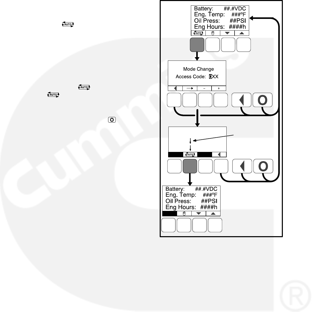
4-22
Selecting Auto Mode
To switch to Auto mode (see Figure 4-13),
1. Press the button on any of the Operator
menus or the “Establishing/Re-establishing
communication with control” menus.
2. If the mode change access code feature is en-
abled, the Mode Change Access Code menu
is displayed. Enter the mode change access
code as described above.
3. A menu with alternating arrows is displayed
above a second symbol. Press the sec-
ond button. The Operator menu that was
displayed before Auto mode was selected is
redisplayed.
To disable Auto mode, press the button.
NOTE: Manual Run mode can also be selected
while in Auto mode.
ALTERNATING
ARROWS ARE
DISPLAYED
AUTO MODE
SELECTED
THIS MENU IS
DISPLAYED ONLY IF
THE MODE CHANGE
ACCESS CODE
FEATURE IS ENABLED
FIGURE 4-13. SELECTING AUTO MODE
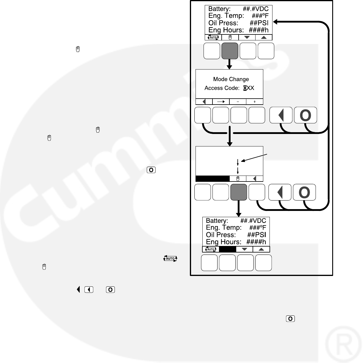
4-23
Selecting Manual Run Mode
To switch to Manual Run mode (see Figure 4-14),
To switch to Manual Run mode,
1. Press the button on any of the Operator me-
nus or the “Establishing/Re-establishing com-
munication with control” menus.
2. If the mode change access code feature is en-
abled, the Mode Change Access Code menu
is displayed. Enter the mode change access
code as described on the previous page.
3. A menu with alternating arrows is displayed
above a second symbol. Press the second
button. The Operator menu that was dis-
played before Manual Run mode was selected
is redisplayed.
To disable Manual Run mode, press the button.
NOTE: Auto mode can also be selected while in
Manual Run mode. Switching to Auto mode
may result in the generator set shutting
down.
Aborting the Transition to Auto or Manual
Run Mode
If the Mode Change Access Code menu or the
menu showing alternating arrows above the
or buttons is displayed, the transition to Auto or
Manual Run mode is aborted when:
Either the , , or button is pressed.
A selection button is not pressed within ten
seconds.
If the transition to Auto or Manual Run mode is
aborted, the Operator menu that was displayed be-
fore Auto or Manual Run mode was selected is re-
displayed
MANUAL
RUN MODE
SELECTED
ALTERNATING
ARROWS ARE
DISPLAYED
THIS MENU IS
DISPLAYED ONLY IF
THE MODE CHANGE
ACCESS CODE
FEATURE IS ENABLED
FIGURE 4-14. SELECTING MANUAL RUN MODE
Selecting Off Mode
To switch to Off mode, press the button. If the
genset is running and Off mode is selected, a nor-
mal shutdown sequence is initiated. More informa-
tion on the use of the Off button is included on page
4-5.

4-24
SERVICE MENUS
Figure 4-15 shows a block representation of the
menus available from the Service Menus.
The first Service Menu can be viewed from any of
the Operator menus by simultaneously pressing
the and selection buttons for two seconds.
The first Service Menu provides access to the fol-
lowing menus:
Setup Menus − Used by Service personnel.
Adjusting the Setup menus is restricted by a
password and is described in the Control
Service section. To view the Setup menus
only, press the VIEW button on the Setup
password menu.
History / About − see page 4-26
Screen Adjust − see page 4-30
To return to the Operator menu that was displayed
prior to viewing the Service Menu, press the
button.
The second Service Menu can be viewed by press-
ing the selection button on the first Service
Menu. The second Service Menu provides access
to the following menus:
Fault History − see page 4-28
Status − see below
Lamp Test − The six LEDs on the control
panel should light as long as the button (6) is
pressed.
The third Service Menu can be viewed by pressing
the selection button on the second Service
Menu. The third Service Menu provides access to
the Network Status menus.
Status Menu
The Status menu is displayed when the (5) button
is pressed on the second Service Menu. The Sta-
tus menu shows the following:
Voltage regulator (drive) level, in percentage
of duty cycle.
Governor regulator (drive) level, in percent-
age of duty cycle. This value is only dis-
played if the governor is enabled.
Network Status Menus
The Network Status menus are displayed when the
(7) button is pressed on the third Service Menu.
Two menu are used to display the quantity of the
following devices that are connected to the net-
work.
Universal Annunciators
Bar graphs
Battery chargers
Controls
I/O modules
Operator panels (any type)
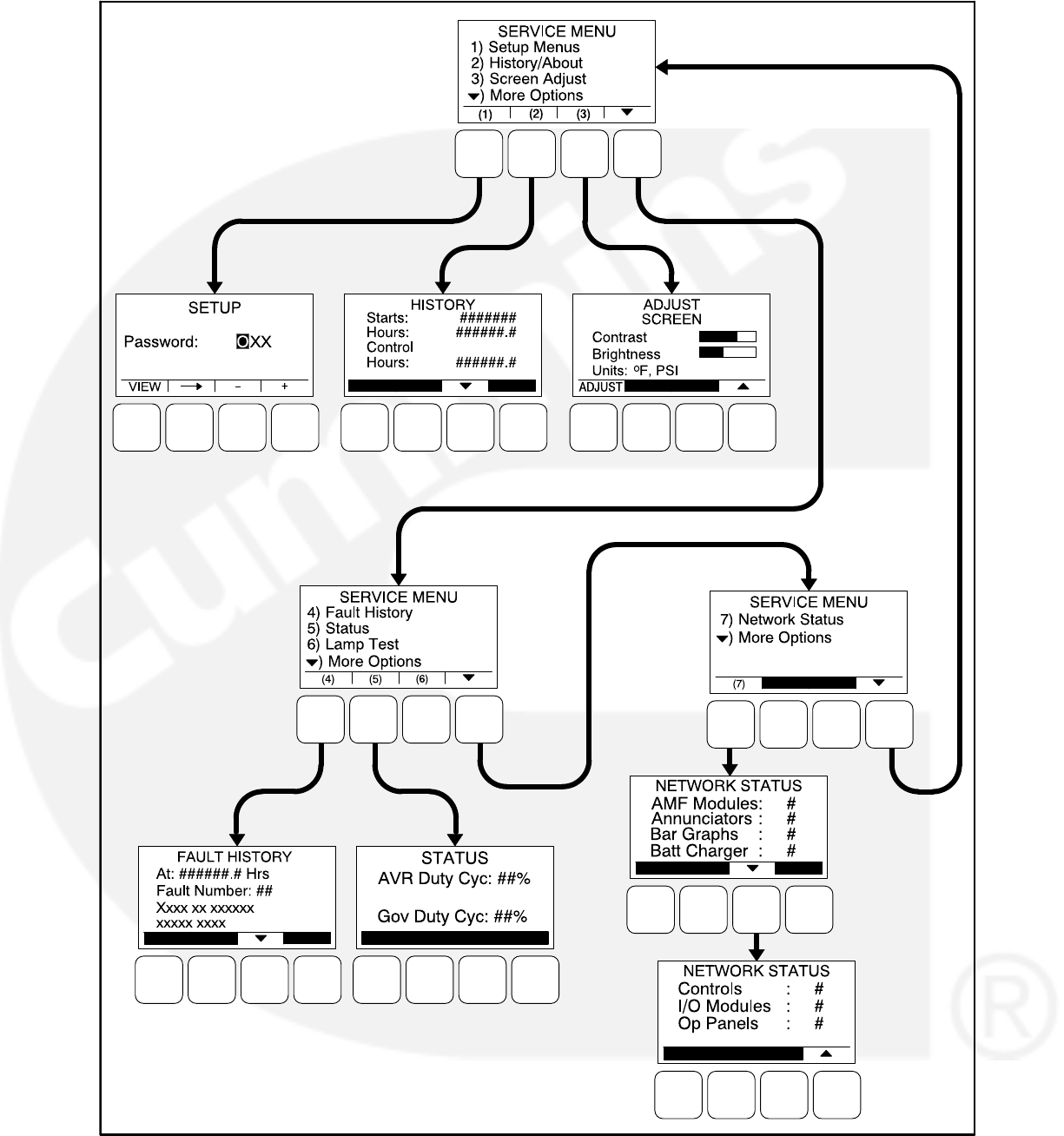

4-26
HISTORY / ABOUT MENUS
Figure 4-16 shows a block representation of the
History / About menus. The first History / About
submenu is displayed when the (2) button is
pressed on the Service Menu (see Figure 4-15).
Press the buttons next to the and symbols in
the graphical display to navigate between the His-
tory / About submenus. Press the button to re-
turn to the Service Menu.
History Submenu
This submenu displays the number of engine
starts, hours of operation for the engine, and hours
of operation for the control.
About Genset Submenus
Two submenus display the generator set model
number, control number, and genset application
frequency rating.
About Control Submenu
This submenu displays the control’s part number,
serial number (up to 11 characters), software part
number (up to 9 characters), and software version.
About Display Submenu
This submenu displays the optional control panel
software part number, software version, screen
part number, and screen version of the display.
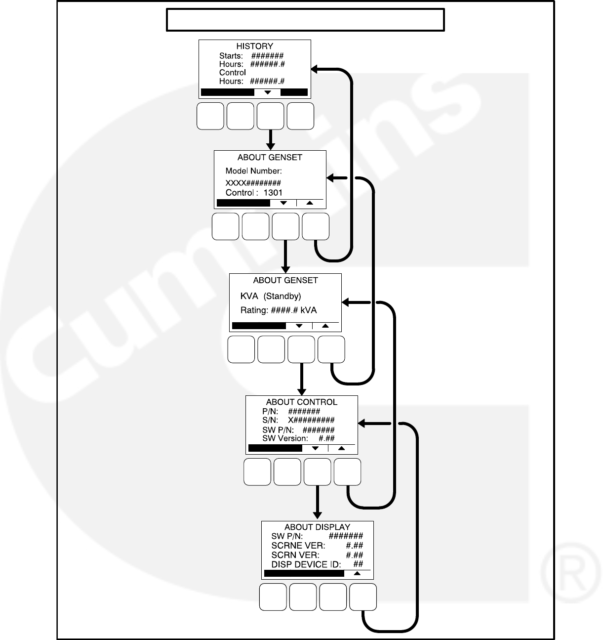
4-27
HISTORY / ABOUT MENUS
FIGURE 4-16. HISTORY / ABOUT MENUS
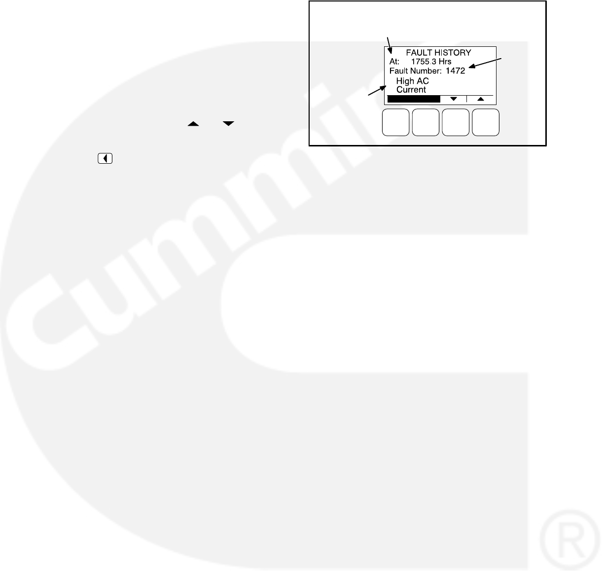
4-28
FAULT HISTORY MENU
Figure 4-18 shows a block representation of the
Fault History menu. The first Fault menu is dis-
played when the (4) button is pressed on the sec-
ond Service Menu (see Figure 4-15). If there are
any active fault submenus, an “Active Fault” head-
ing is displayed for the most recent active fault. All
other fault submenus display a “Fault History”
heading. Five of the most recent faults can be
viewed. An example of how a fault code is dis-
played is shown in Figure 4-17.
Press the buttons next to the and symbols in
the graphical display to navigate between menus.
Press the button to return to the Service Menu.
Information on faults is included in Table 4-2 on
page 4-8.
FAULT
CODE
FAULT
DESCRIPTION
TIME FAULT
OCCURRED
FIGURE 4-17. FAULT HISTORY MENU EXAMPLE
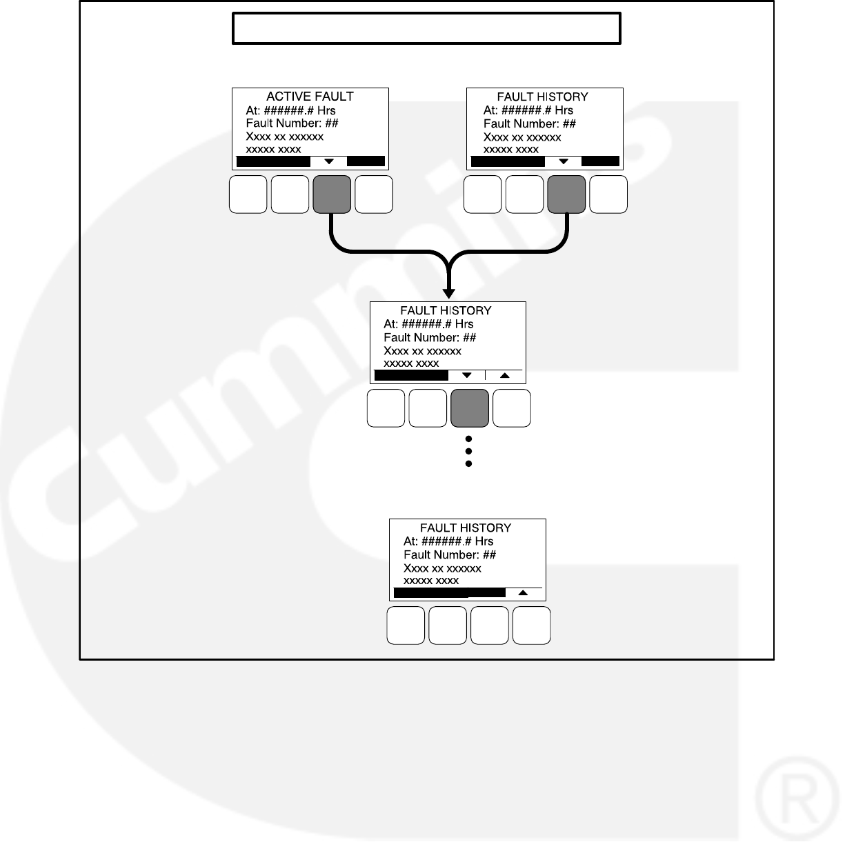
4-29
FAULT HISTORY MENU
Fault 1
Fault 2
Oldest Fault
(Maximum of 5)
Active Fault
OR
FIGURE 4-18. FAULT HISTORY MENU
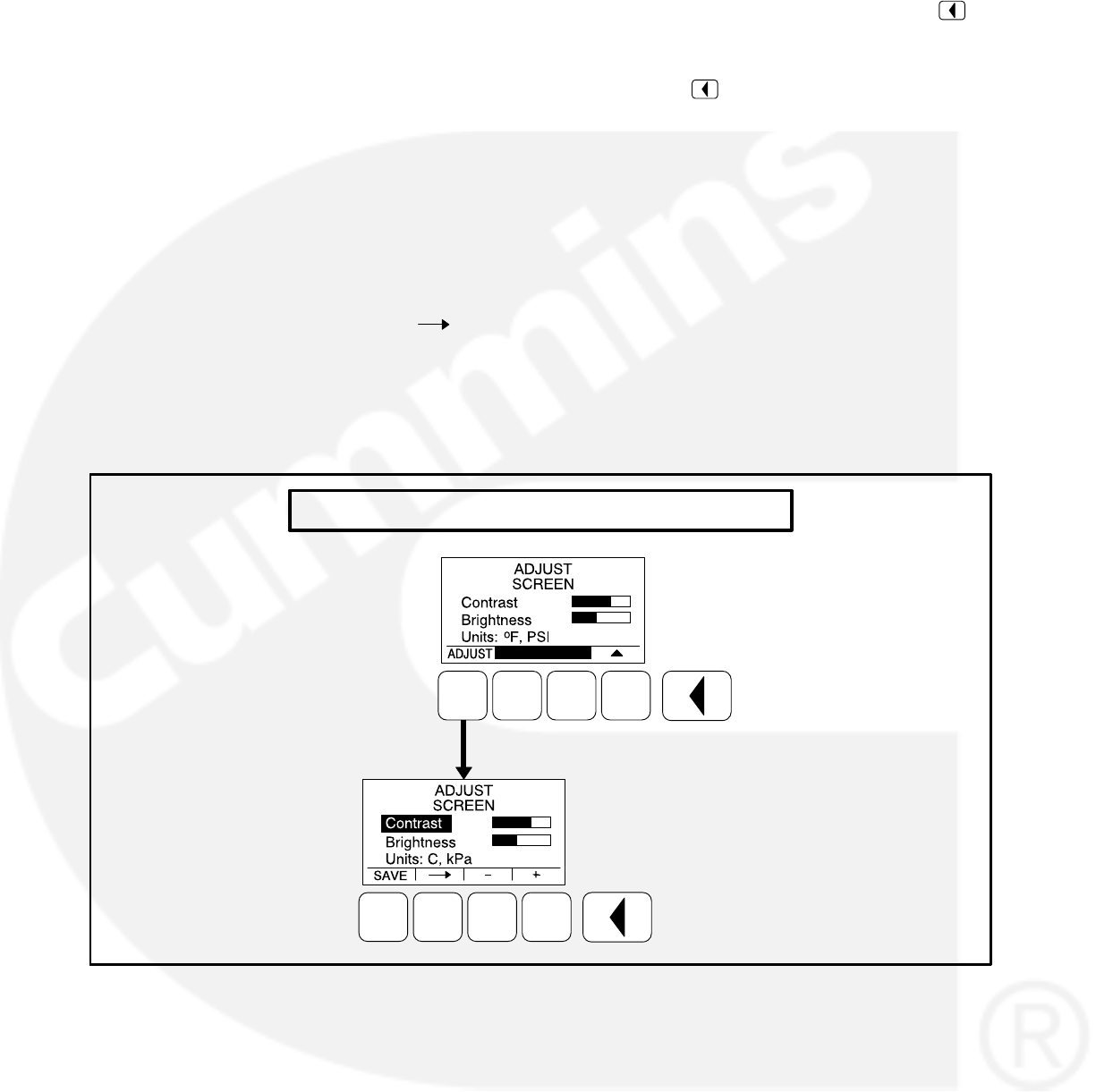
4-30
SCREEN ADJUST MENU
Figure 4-19 shows a block representation of the
Screen Adjust menu. The Screen Adjust menu is
displayed when the (3) button is pressed in the first
Service Menu (see Figure 4-15).
Adjusting Values/Parameters
1. Press the ADJUST selection button to select
the first parameter or value to be changed.
2. Press the + or − selection buttons to adjust val-
ues or select parameters.
3. Press the arrow selection button to navi-
gate to the next or previous adjustable value or
parameter.
4. After adjusting values/selecting parameters,
press the SAVE button to save your settings.
NOTE: If the Previous Menu button is
pressed before pressing the SAVE
button, the changes are not saved.
5. Press the button to return to the Service
Menu.
Screen Adjust Menu
This menu allows for adjusting the screen’s con-
trast and brightness and for selecting the units of
measurement (SAE or SI) to be displayed.
Contrast and Brightness: Press the + or −
selection buttons to adjust the screen’s con-
trast and brightness. Changing the bright-
ness setting also affects the brightness of
the LEDs on the operator panel.
Units: Press the + or − selection buttons to
select SAE (_F, PSI) or SI (C, kPa) units of
measurement to be displayed.
SCREEN ADJUST MENU
FIGURE 4-19. SCREEN ADJUST MENU

5-1
5. 1302 Control Panel Service Menus
SERVICE MENUS
NOTE: When using any PCCNet device on a gen-
set control application, the wiring used to
connected ALL devices in the network
must be Belden 9729 Two Pair, Stranded,
Shielded Twisted Pair Cable (24 AWG).
CAUTION Incorrect settings can result in
equipment malfunction and damage. Only
trained and experienced personnel should be
authorized to change the settings.
The Service Menus shown in this section can be
viewed and, if the correct password(s) are entered,
modified. Changing the settings should be re-
stricted to trained and experienced installation and
service personnel.
Figure 5-1 shows a block representation of the me-
nus available from the Service Menu.
The first Service Menu can be viewed from any of
the Operator menus by simultaneously pressing
the and selection buttons for two seconds.
The first Service Menu provides access to the fol-
lowing menus:
Setup Menus − See page 5-3
History / About − See page 4-27
Screen Adjust − See page 4-30
Changes can be made to Adjust submenus without
entering a password. However, a password is re-
quired to change any of the Setup submenus.
To return to the Operator menu that was displayed
prior to viewing the Service Menu, press the
button.
The second Service Menu can be viewed by press-
ing the selection button on the first Service
Menu. The second Service Menu provides access
to the following menus:
Fault History
Status
Lamp Test − The six LEDs on the control
panel should light as long as the button (6) is
pressed.
The third Service Menu can be viewed by pressing
the selection button on the second Service
Menu. The third Service Menu provides access to
the Network Status menus. The Network Status
menus are displayed when the (7) button is
pressed on the third Service Menu. Two menu are
used to display the quantity of the following devices
that are connected to the network.
Universal Annunciators
Bar graphs
Battery chargers
Controls
I/O modules
Operator panels
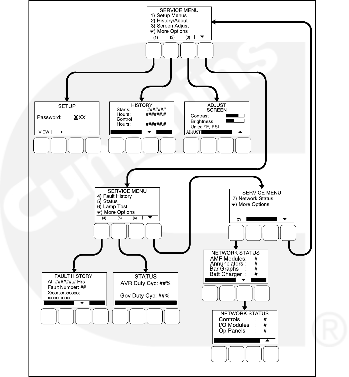
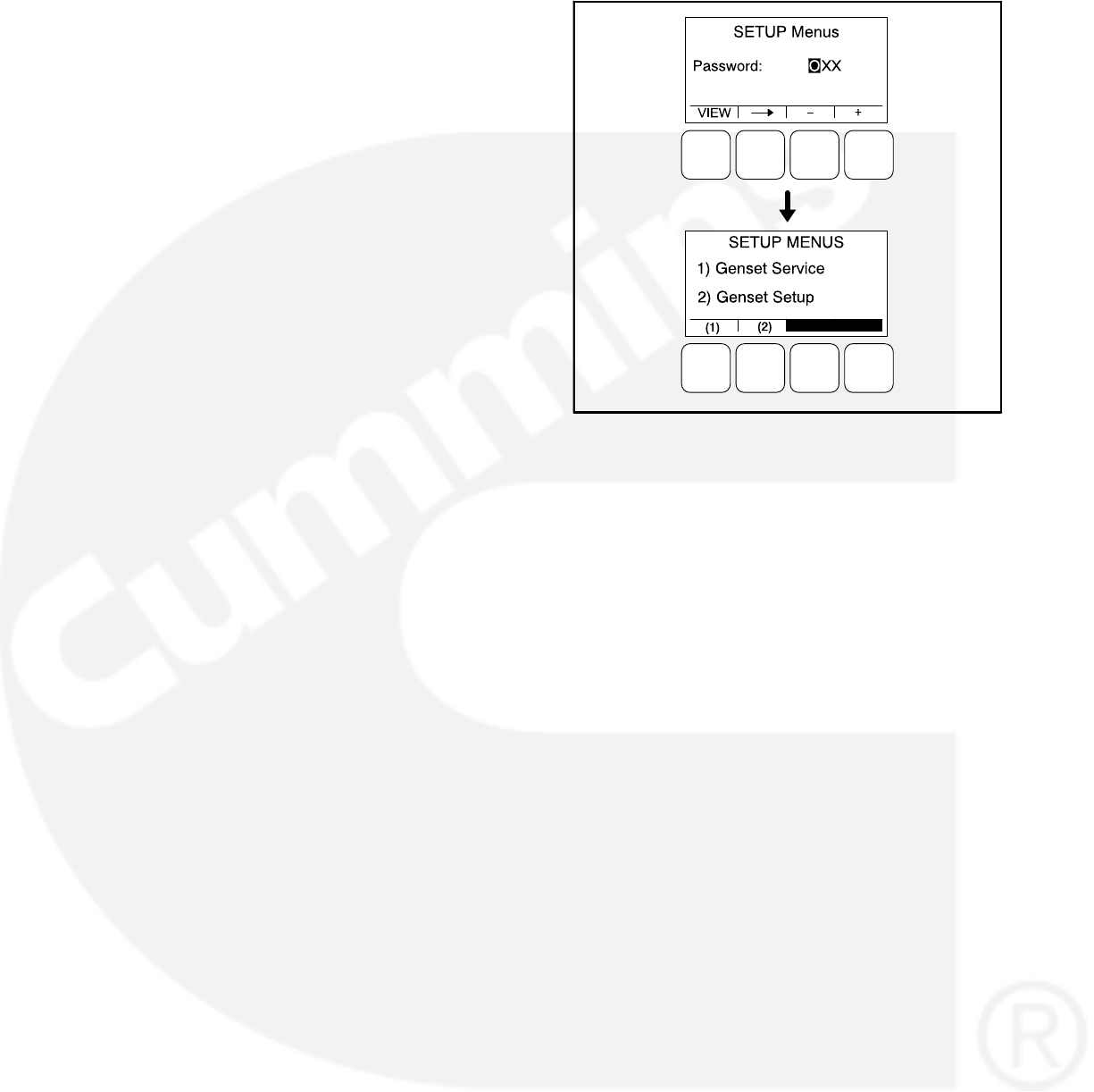
5-3
SETUP MENUS
The Setup menus are available by pressing the (1)
button on the first Service menu (see Figure 5-1).
The Setup Menus (see Figure 5-2) provide access
to genset menus with settings that can be viewed
and, if a password is entered, adjusted.
The first Setup menu is displayed when the (1) but-
ton is pressed on the Service Menu. From the Set-
up Password menu, a second Setup menu is dis-
played that provides access to the following two
categories of genset menus.
Genset Service menus
Genset Setup menus − Go to page 5-35
FIGURE 5-2. SETUP MENUS

5-4
GENSET SERVICE MENUS
The first Genset Service menu is available by
pressing the (1) button on the Setup Menus menu
(see Figure 5-2).
This section covers Genset Service menus only.
For information on Genset Setup menus, go to
page 5-35.
If a password is entered, the settings in the Genset
Service menus can be adjusted. However, if a
password is not entered, these menus can still be
viewed.
Viewing Only
Figure 5-3 is a block representation of the Genset
Service menus that are available when a password
is not entered (or an incorrect password is entered)
in the Setup Password menu.
The first Genset Service Menu provides access to
the following menus:
Genset
Customer I/O
Meter Calibration
The second Genset Service Menu provides access
to the following menus:
Annunciator
ModBus
The Genset Service menus can be viewed by se-
lecting the VIEW button on the Setup Password
menu and then selecting (1) on the second Setup
menu. When the VIEW button is selected without
entering the correct password, the ADJUST button
is not displayed on any of the Genset Service me-
nus; therefore, no adjustments can be made.
Menu Navigation
1. Press the buttons above the and sym-
bols in the digital display to navigate between
submenus.
2. To return to the genset Setup Menus menu
from any of the submenus, press the but-
ton.
3. To return to the Service Menu from the genset
Setup Menus menu, press the button.
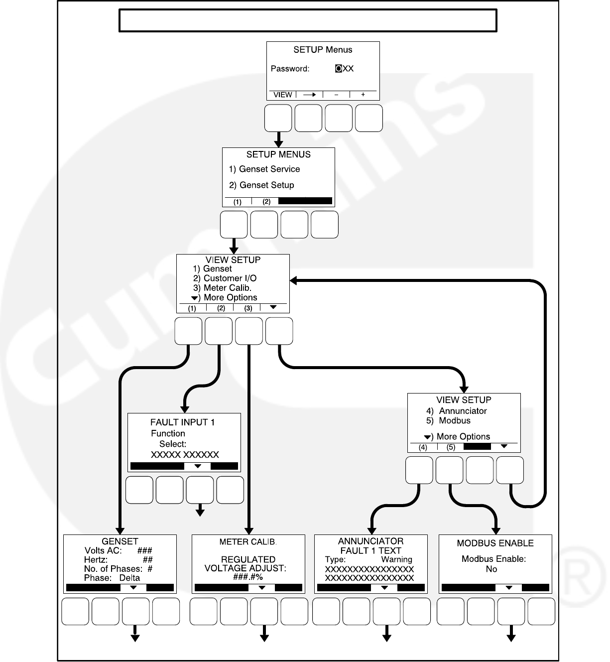
5-5
GENSET SERVICE MENUS (Viewing Only)
SEE PAGE 5-8
SEE PAGE 5-21
SEE PAGE 5-27 SEE PAGE 5-29
NOTE: When the VIEW button is selected
from the Setup Password menu with-
out entering a password, the AD-
JUST button is not available on any of
the menus shown in Figures 5-5 thru
5-14.
1ST VIEW
GENSET
SERVICE
MENU
2ND VIEW
GENSET
SERVICE
MENU
SEE PAGE 5-34
FIGURE 5-3. VIEWING GENSET SERVICE MENUS WITHOUT ENTERING A PASSWORD

5-6
Viewing and Adjusting
Figure 5-4 is a block representation of the Genset
Service menus that are available from the Setup
Menus menu after the correct password has been
entered. The ADJUST button is available on these
submenus; therefore, adjusting the settings is al-
lowed.
The first Genset Service Menu provides access to
the following menus:
Genset
Customer I/O
Meter Calibration
The second Genset Service Menu provides access
to the following menus:
Annunciator
ModBus
Setup Password Submenu
Adjusting the Genset Service menus is restricted to
service personnel and a password must be entered
to modify these menus.
When the Password menu is displayed, the first nu-
meric character (0) is highlighted (see Figure 5-4).
NOTE: When selected (highlighted), each charac-
ter initially turns to “0” and the remaining
characters turn to “X”.
NOTE: Make sure that each numeric character is
correct before you move to the next char-
acter. If a wrong character is entered, you
will not be able to go back and correct it. If
the wrong password is entered, you will be
able to view the Genset Service menus but
you won’t be able to change them.
To enter the password:
1. With the first character highlighted, press the
button below to the + or − symbols until the val-
ue reads “5.”
2. Press the arrow selection button to move
to the next numeric character.
3. Press the button below the + or − symbols until
the value reads “7.”
4. Press the arrow selection button to move
to the next numeric character.
5. Press the button below the + or − symbols until
the value reads “4.”
6. After you have completed entering the pass-
word, press the arrow selection button .
The first main Setup menu is displayed.
After the correct password is entered, it will be re-
membered until five minutes of button inactivity has
elapsed. If five minutes of button inactivity has
elapsed, you will have to re-enter the password to
access and change Setup menus.
Adjusting Values/Parameters
Once the correct password has been entered and
Genset Service (1) is selected on the Setup Menus
menu, the first Genset Service submenu is dis-
played.
1. Press the buttons above the and sym-
bols in the digital display to navigate between
submenus.
2. Press the ADJUST selection button to select
the first parameter or value to be changed.
3. Press the + or − selection buttons to adjust val-
ues or select parameters.
4. Press the arrow selection button to navi-
gate to the next or previous adjustable value
or parameter.
5. After adjusting values/selecting parameters,
press the SAVE button to save your settings.
NOTE: If the button is pressed before
pressing the SAVE button, the
changes are not saved.
6. Press the button to return to the Service
Menu.
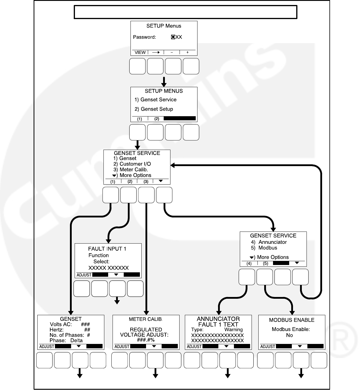

5-8
Genset Service Submenus
The Genset Service submenus are available by
pressing the (1) button on the first Genset Service
menu (see Figure 5-3 or Figure 5-4).
The Genset Service submenus consist of ten basic
submenus.
Genset, Part 1
Genset, Part 2
Fuel System
Start/Stop Time Delays
Cycle Crank
Battle Short (if enabled)
Automatic Voltage Regulator Setup*
Electronic Governor*
Genset Model and Serial Number
Display Setup
Volts and Hz Password
* If enabled, the Automatic Voltage Regulator has
two additional submenus and the Electronic Gov-
ernor has five additional submenus.
Genset Menu, Part 1
The first genset menu displays the preset AC Volt-
age, genset frequency, number of phases, and
phase type.
Volts AC: Displays the AC voltage (190, 200,
208, 220, 230, 240, 380, 400, 416, 440, 460,
480, or 600 VAC, default = 208).
Hertz: Displays the genset frequency (50 or
60 Hz, default = 60 Hz). The control selects
limits, gains, and frequency values based
upon this selection.
No. of Phases: Displays the number of
phases (1 or 3, default = 3).
Phase: Displays the phase type (Delta or
Wye default = Wye).
Genset Menu, Part 2
The second genset menu allows for enabling or
disabling charging alternators.
Charging Alt. Enable:
A starter disconnect will occur whenever any
one of the following three possible signals
reaches its disconnect setpoint.
−The average engine speed (if a mag-
netic pickup unit is installed)
−The average frequency
−The charging alternator voltage (if the
Charging Alt feature is enabled)
The Charging Alt. Enable menu is used to en-
able or disable the Charging Alt feature. While
the default setting is “Yes,” this menu provides
a means to disable the control’s charging alter-
nator logic if it is not supported by your alterna-
tor. If your alternator does not support this
functionality, the Charger Failure warning
(fault code 2678) will constantly be displayed
unless this setting is changed to “No.” When
disabled (set to “No”), the start disconnect sig-
nal is based only on the average engine speed
or frequency and the Charger Failure warning
is disabled.
Fuel System
The Fuel System menu allows for selecting fuel
type and, depending on the type selected, enab-
ling/disabling glow plugs or setting a fuel burn time
delay.
Fuel System: Allows for selecting the fuel
type (Diesel or Gas, default = Diesel).
If Fuel System is set to “Diesel”
Glow Plug Enable: Allows control of Glow
Plugs for a particular genset (Yes or No, de-
fault = No).
If Fuel System is set to “Gas”
Fuel Burn Delay: After the genset receives a
stop signal, this feature allows for setting a
fuel time delay from 0 to 10 seconds (default
= 5 seconds) in which the ignition remains
on so that any fuel down stream of the in-
take manifold is burned.
Start/Stop Delay Menu
The time delay after receiving a valid start signal,
until the genset starts, can be adjusted. The time
delay that the genset is allowed to ruin at rated
speed after receiving a stop signal, until the genset
stops, can also be adjusted. These time delays do
not apply to manual start/runs.
Start: The genset start time delay can be ad-
justed from 0 to 300 seconds (default = 0
seconds) or 0 to 3600 seconds from 1320
calibration version 2.80, HMI211 calibration
version 7.20 onwards.

5-9
Stop: The genset stop time delay can be
adjusted from 0 to 600 seconds (default = 0
seconds).
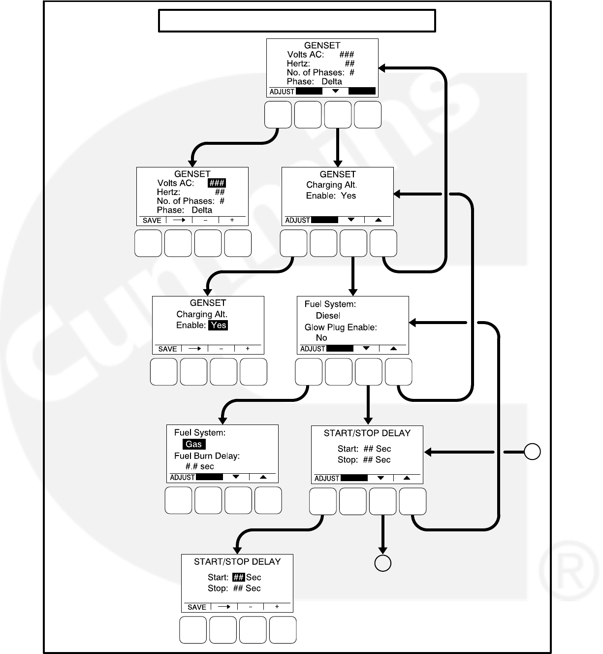

5-11
Cycle Crank Menu
The Cycle Crank menu allows for configuring the
generator for all starting modes (manual and re-
mote), as follows:
Crank: The cranking period can be set from
3 to 30 seconds (default = 15 seconds). This
time limit is used to determine a Fail to Start
status.
Rest: The minimum amount of time between
crank attempts can be set from 0 to 60 sec-
onds (default = 30 seconds).
Attempts: The maximum number of times
the starter can be engaged when attempting
to start the engine with cycle cranking can
be set from 1 to 7 attempts (default = 3).
Battle Short Menu
This menu is displayed only if the PC service tool
has been used to enable the Battle Short feature
(see page 3-57 for more Battle Short information).
Before the Battle Short feature can be used, one of
three available activation sources must be se-
lected. If the activation source switch input is set to
“Operator Panel,” then Battle Short functionality
can be enabled or disabled with this menu.
Switch Input: The Switch Input can be set for
Configurable Input 1, Configurable Input 2,
Operator Panel, or None (default = None).
Battle Short: Battle Short functionality can be
enabled or disabled (set to Active or Inac-
tive), (default = Inactive). This subject will
only be displayed if the switch input is set to
“Operator Panel.”
AVR Setup Menu
The AVR Setup menu is used to enable or disable
the automatic voltage regulator (default = Yes). If
enabled, two additional menus are displayed that
can be used to adjust the AVR settings (see page
5-18).
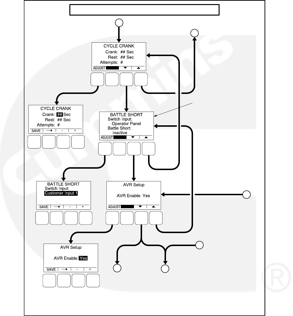
5-12
GENSET SERVICE SUBMENUS (Continued)
RETURN TO
PAGE 5-10
B
THIS SUBMENU IS ONLY
DISPLAYED IF THE BATTLE
SHORT FEATURE HAS BEEN
ENABLED USING THE PC
SERVICE TOOL
“BATTLE SHORT: ACTIVE /
INACTIVE” IS ONLY DISPLAYED
IF THE SWITCH INPUT IS SET
TO “OPERATOR PANEL”
A
OR
YES NO
CE
F
GO TO AVR
SETUP MENUS
ON PAGE 5-18
CONTINUED
ON PAGE 5-14
K
FIGURE 5-5. GENSET SERVICE SUBMENUS (SHEET 2 OF 4)

5-13
Electronic Governor Menu, Part 1
The engine Electronic Governor Enable menu is
used to enable or disable the electronic governor
on gensets with electronic governors and magnetic
pickup sensors (default = Yes). If enabled (set to
“Yes”), four additional menus are displayed that
can be used to adjust governor settings (see page
5-20).
Electronic Governor Menu, Part 2
The Pre-Load Offset menu is used to enter a per-
centage of governor duty cycle that is first used
when exiting cranking.
Genset Number Menu
The Genset Number menu is used to enter the gen-
set’s model and serial numbers. Each allow up to
16 characters to be entered.
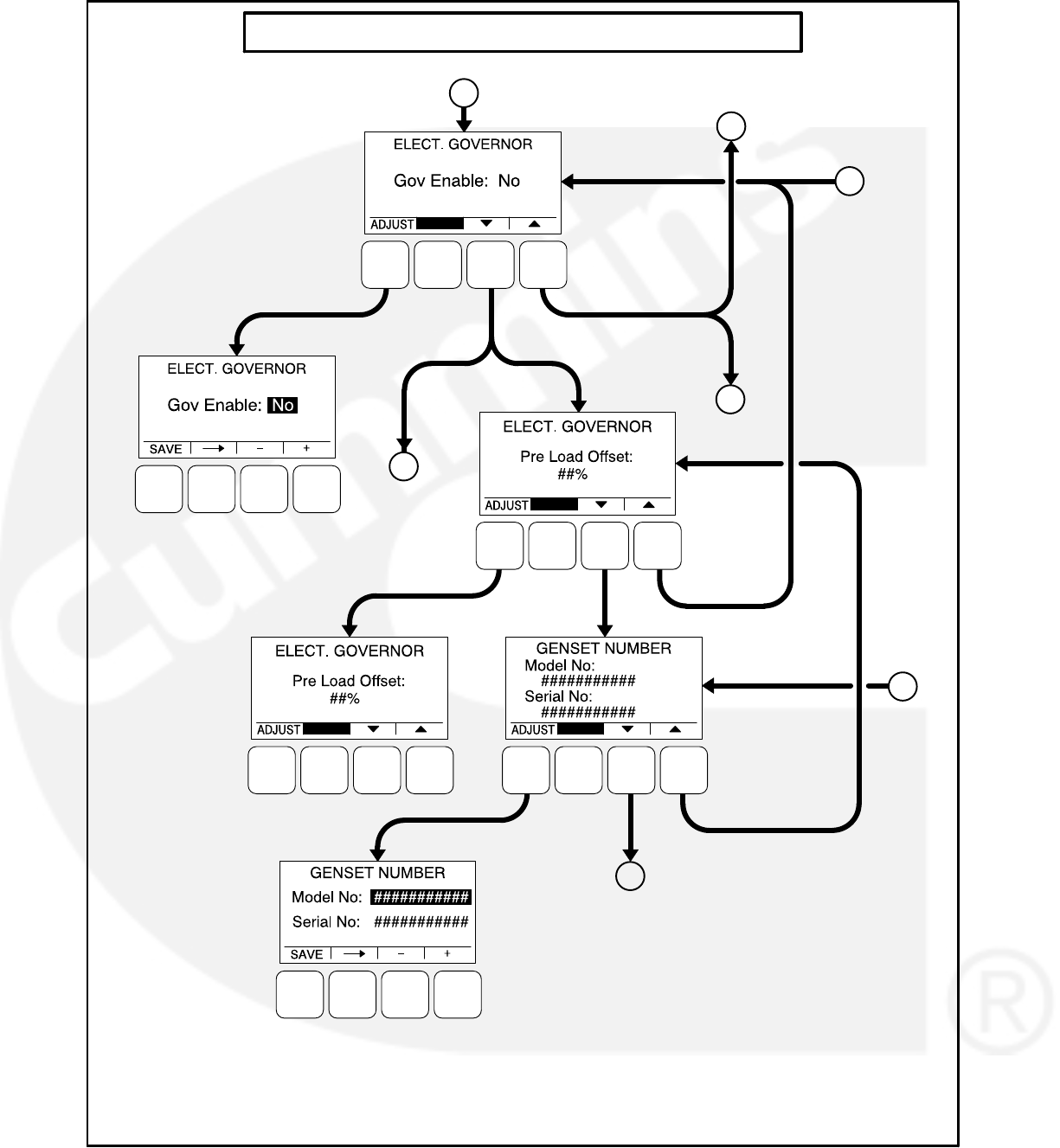

5-15
Display Setup Menu
The Display Setup menu is used to set the display
for Local (Auto/Off/Manual Run switch functions
on the operator panel are turned on) or Remote
(Auto/Off/Manual Run switch functions on the op-
erator panel are turned off).
Connection: A display can be set up to be
Local or Remote (default = Local).
Access Code: A display can be set up to re-
quire or not require entering the mode (Auto,
Manual Run, or Off) change access code
(default = No).
Symbols: A display can be set up to display
international symbols on the Operator me-
nus (default = Yes).
Volts and Hertz Menu
The Volts and Hertz menu is used to select whether
or not a password is required in order to change
voltage and hertz settings outside of the Genset
Service menus (default = Required).
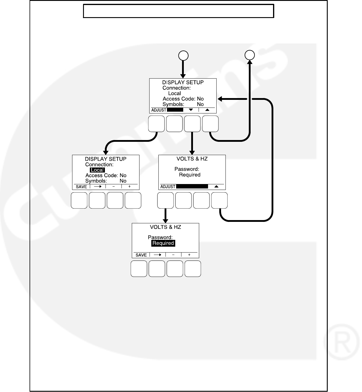
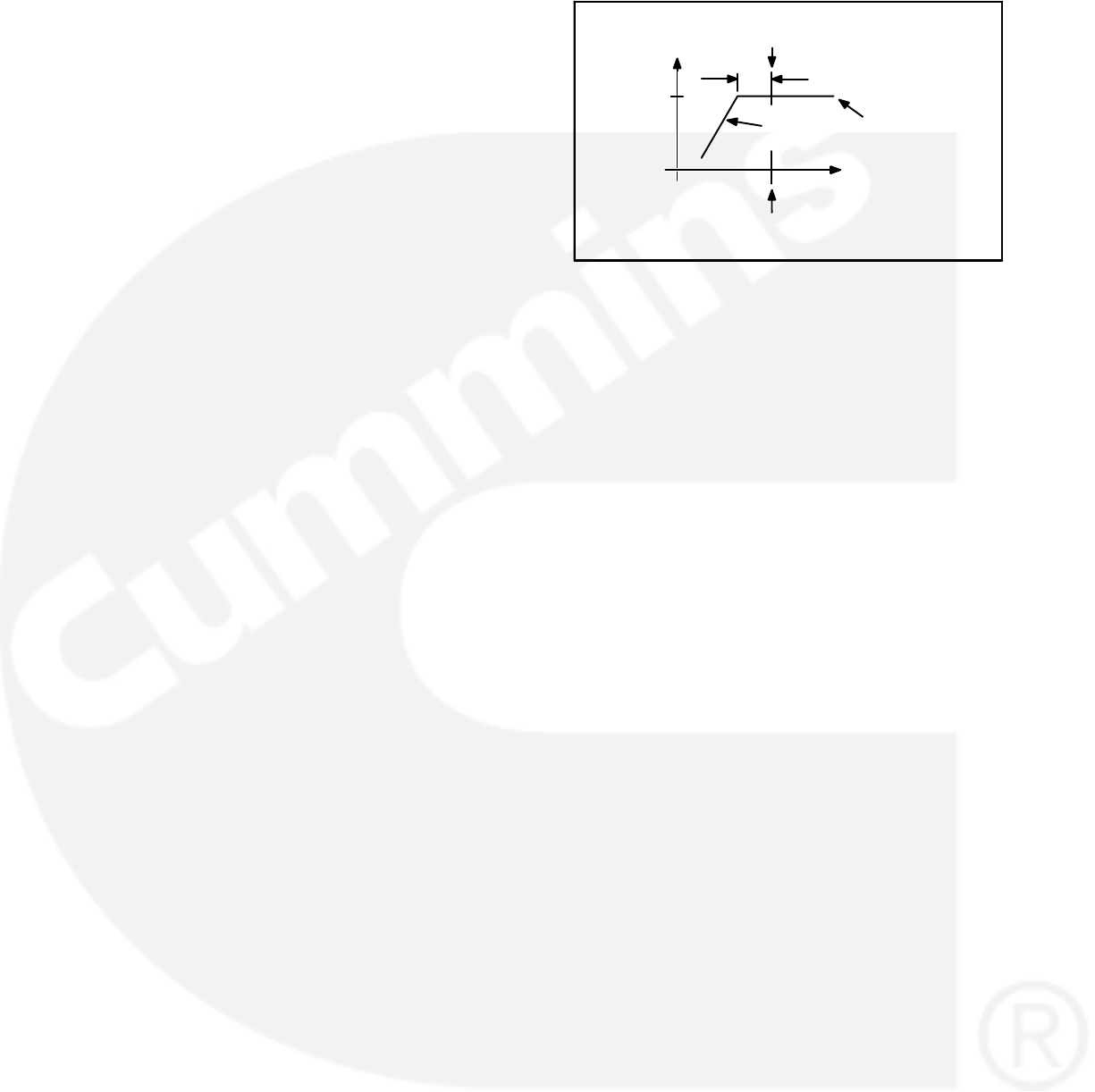
5-17
Automatic Voltage Regulator Submenus
The Automatic Voltage Regulator (AVR) subme-
nus are available only if the AVR is enabled (see
page 5-12).
Two Automatic Voltage Regulator (AVR) subme-
nus (see Figure 5-7) can be used to adjust Volts/Hz
Rolloff and Regulator Gains settings.
Volts/Hz Rolloff Menu
The Volts/Hz Rolloff function helps optimize the
genset’s response to added load. If the engine
speed drops below nominal frequency, the control
automatically drops the voltage until the engine
speed starts to recover.
This menu allows for adjusting the knee frequency
and voltage setpoint slope parameters. The knee
frequency is the value below nominal frequency at
which the rolloff function begins. For example, if the
knee frequency is set to 5 Hz on a 60 Hz genset,
this function begins when the frequency drops be-
low 55 Hz.
Slope refers to how fast the voltage is rolled off be-
low the knee frequency. The voltage is rolled off the
slope percent setting for every 1 Hz below the
knee. For example, on a 60 Hz genset, if the slope
is set to 5% and the knee frequency is set to 5 Hz,
then if the frequency drops to 54 Hz, the voltage set
point is reduced 5%. If the frequency drops to 53
Hz, the voltage set point is reduced 10%, etc.
FREQUENCY
NOMINAL
VOLTAGE
SLOPE
KNEE FREQUENCY
VOLTAGE
NOMINAL
(100%) VOLTAGE SET-
POINT CURVE
NOMINAL
FREQUENCY
FIGURE 5-6. KNEE FREQUENCY AND SLOPE
V/Hz Knee: The Knee Frequency can be ad-
justed from 0.0 to 10.0 Hertz in 0.1 Hz incre-
ments (default = 1.0 Hz). When generator set
speed decreases by more than the value of
the knee frequency, the generator set voltage
decreases by the %/Hz value.
V/Hz Rolloff: The Rolloff setting can be ad-
justed from 0.0 to 5.0 percent of rated volt-
age, in 0.1% increments (default = 2.0%).
Regulator Gains Menu
The Regulator menu allows for setting proportional
Gain, Integral Gain, and Damping values.
Gain: The proportional Gain (K1) multiplier
can be set from 5 to 1000% (default =
100%). This allows for a scale factor of 0.05
to 10.0.
Int: The Integral Gain (K2) multiplier can be
set from 5 to 1000% (default = 100%).
D: The Damping adjustment can be set from
95 to 105% (default = 100%).
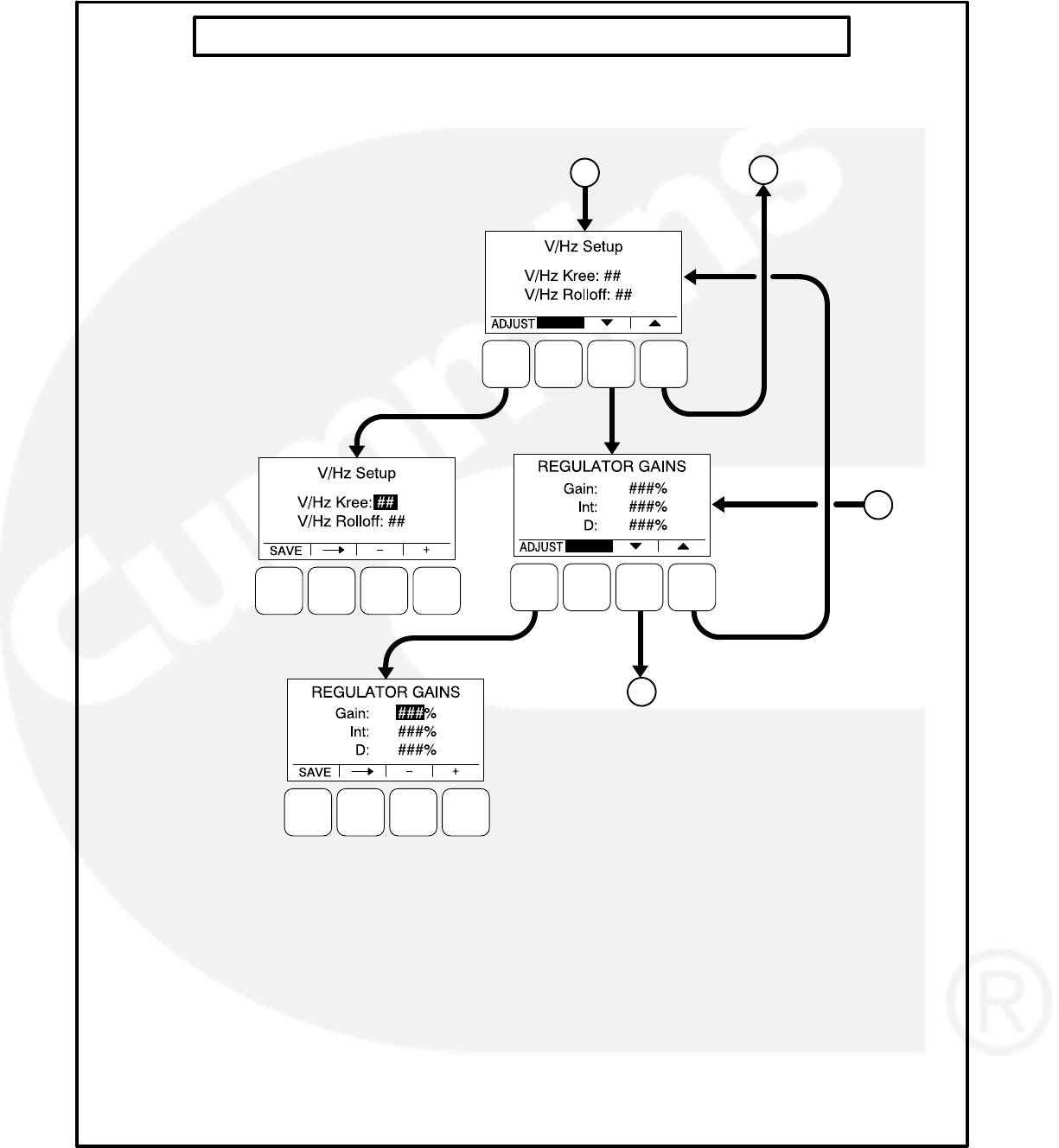

5-19
Electronic Governor Submenus
The Electronic Governor submenus are available
only if the governor is enabled (see page 5-12).
Four Electronic Governor submenus (see Figure
5-8) can be used to adjust governor settings.
Governor Crank Fuel Menu
The Governor Crank Fuel menu allows for setting
the Initial Crank Fuel Duty Cycle, the Initial Crank
Fueling Period, the Crank Fuel Ramp Rate, and the
Maximum Crank Fuel Duty Cycle.
Initial DC: The Initial Crank Fuel Duty Cycle
is the initial value assigned to the Governor
Duty Cycle parameter when cranking be-
gins. This value can be set from 0 to 50 per-
cent (default = 25%).
Initial Time: The Initial Crank Fueling Period
is the amount of time for which the value of
Initial Crank Fuel Duty Cycle is assigned to
the governor duty cycle after cranking be-
gins. This value can be set from 0 to 10 sec-
onds (default = 2 seconds).
Ramp Rate: The Crank Fuel Ramp Rate is
the rate at which the value of the Governor
Duty Cycle is ramped up by during the
Crank State, after expiration of the Initial
Crank Fueling Period. This value can be set
from 5 to 100 (default = 25).
Max DC: The Maximum Crank Fuel Duty
Cycle is the maximum level to which the
Governor Duty Cycle should be limited to
during a crank state. This value can be set
from 50 to 100% (default = 100%).
Electronic Governor Regulator Menu
The Electronic Governor Regulator menu allows
for setting proportional Gain, Integral Gain, and
Damping values.
Gain: The proportional governor gain (K1)
multiplier can be set from 5 to 1000% (de-
fault = 100%). This allows for a scale factor
of 0.05 to 10.0.
Int: The integral governor gain (K2) multiplier
can be set from 5 to 1000% (default =
100%).
D: The governor Damping adjustment can
be set from 95 to 105% (default = 100%).
Electronic Governor Menu
The Electronic Governor menu allows for setting
Crank Exit Fuel DC, Dither Factor, and Damping
values. This menu is displayed only if the governor
has been enabled with the Engine Electronic Gov-
ernor Enable menu.
Crank Exit Fuel DC: The Crank Exit Fuel
Duty Cycle is the value at which the gover-
nor duty cycle is held after disengaging the
starter until the governor is enabled. This
value can be set from 0 to 100% (default =
25%).
Dither Factor: Dither is a signal that is super-
imposed on the PWM (pulse with modula-
tion) duty cycle to prevent the actuator valve
from sticking. The Dither Factor is the dither
percent added to the current duty cycle. The
Dither Factor can be set from 0 to 30% (de-
fault = 15%). The dither function is disabled
when the dither factor is set to 0%.
Ramp Time: This feature is used to set the
minimum governor speed reference ramp
rate. The governor Ramp Time can be set
from 0.00 to 30.0 seconds, in 0.01 second
increments (default = 0.25 seconds).
Electronic Governor Enable Speed Menu
These menus allow for setting the minimum and
maximum governor duty cycle.
Min. Gov DC: The Minimum Governor Duty
Cycle can be set from 0 to 100% (default =
5%).
Max. Gov DC: The Maximum Governor Duty
Cycle (with dithered value) can be set from 0
to 100% (default = 95%).
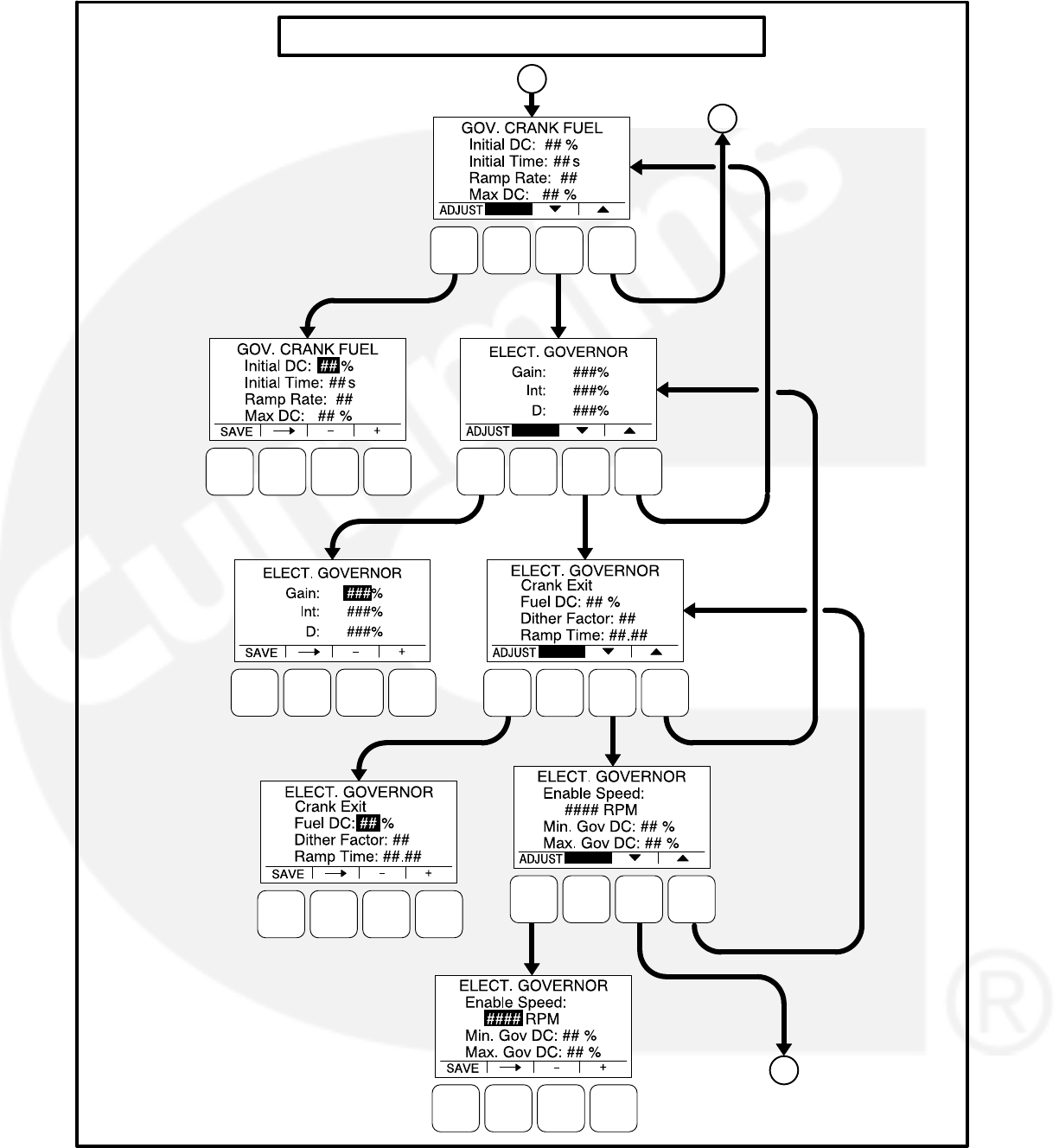

5-21
Customer I/O Submenus
The Customer I/O menus are available by pressing
the (2) button on the first Genset Service menu
(see Figure 5-3 or Figure 5-4).
The Customer I/O menus (see Figures 5-9 thru
5-12) can be used to define customer input mes-
sages and output maps. The Customer I/O menus
consist of four Fault Input Function Selection me-
nus, four Customer Input Test message menus,
four Fault Input Active State Selection menus, and
two Customer Output Map menus.
Fault Input Function Selection
Each of the four configurable input functions can be
set to Disabled, Fault Input, Fault Reset or Battle
Short (the default is different for each input). See
Figure 5-9.
Customer Inputs
The Customer Input Text message menus are
used to enter an event type and description for up
to four events. See Figure 5-10.
Type: Enter the event type (Warning, Shut-
down or Event, default = Warning).
Enter a brief description of the event (up to
32 characters).
Fault Input Active State Selection
Each of the four fault input active states can be set
to Active Closed or Active Open, (default = Active
Open). See Figure 5-11.
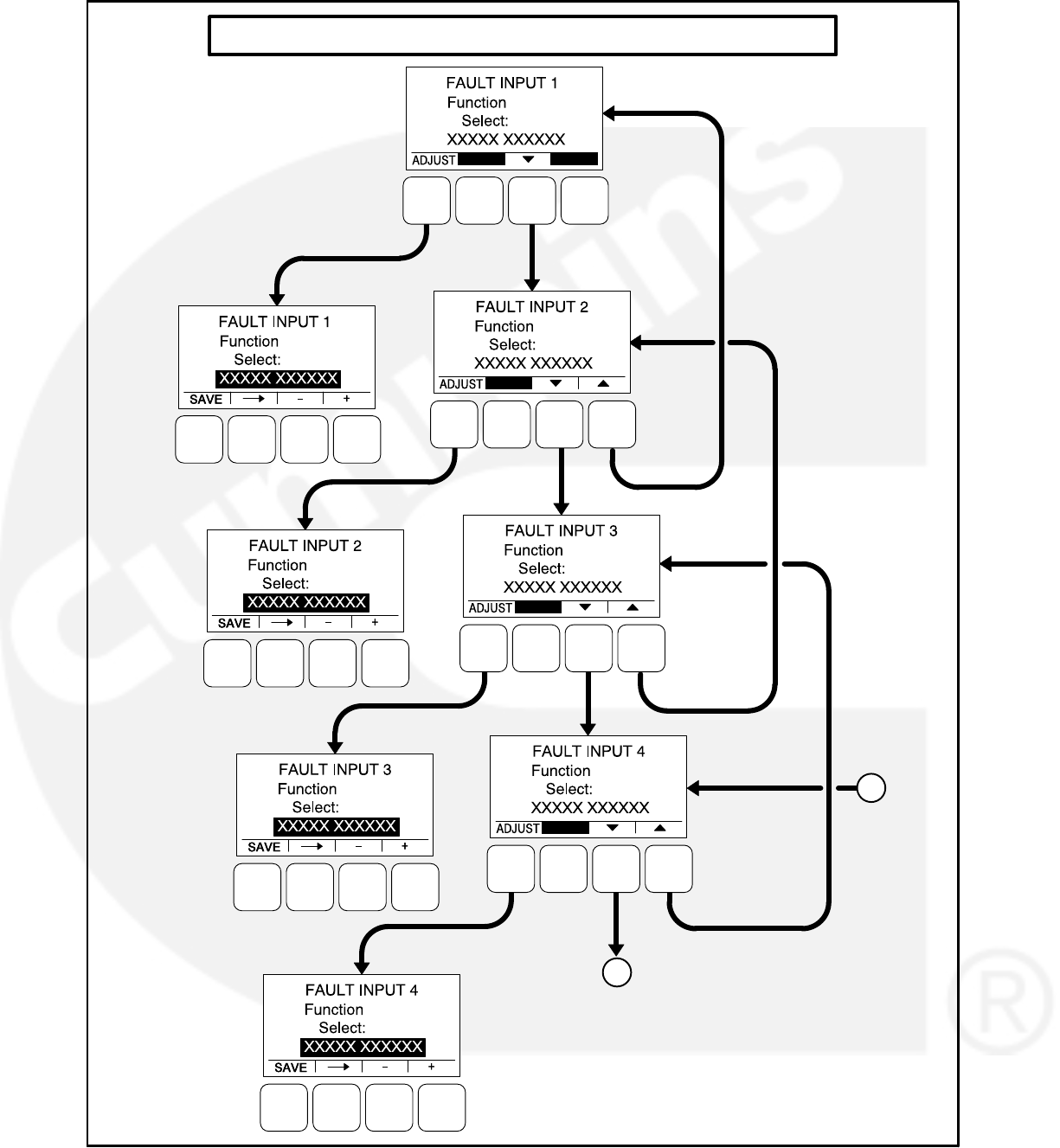

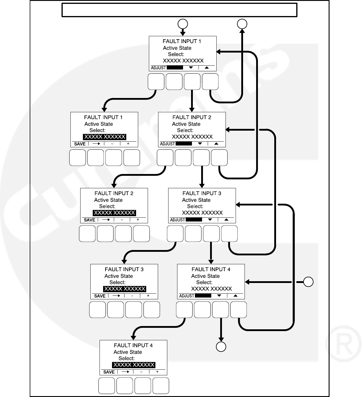

5-25
Customer Outputs
Two Customer Outputs are configurable to display
common warning alarms. The two Customer Out-
put Map menus allow for entering a fault number
and fault name to be displayed for the two configur-
able customer outputs. See Figure 5-12.
Number: Enter a valid code number
(0−65535, default = 0) for the event.
A brief description of the event is automati-
cally displayed.
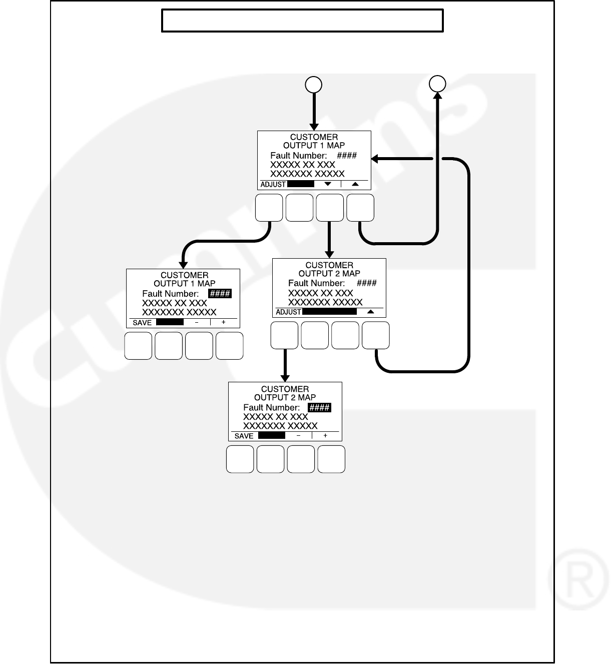

5-27
Metering Submenus
The Metering submenus are available by pressing
the (3) button on the first Genset Service menu
(see Figure 5-3 or Figure 5-4).
Three Metering submenus (see Figure 5-13) can
be used to adjust regulated voltage, frequency,
line-to-neutral voltage, and line current settings.
Meter Calib Menu
The Meter Calib menu allows for adjusting the ac-
tual output voltage of the genset. The percentage
can be set from 90 to 110% (default = 100%). The
alternator voltage is also shown on this menu.
Freq. Adjust Menu
The Frequency Adjust menu allows for adjusting
the genset frequency. The frequency can be adjust
from −6.0 to +6.0 Hz (default = 0.0 Hz). The actual
frequency is also shown on this menu.
Metering Voltage Adjust Menu
The Metering Voltage Adjust menu allows for ad-
justing metered line voltage.
Metering Current Adjust Menu
The Metering Current Adjust menu allows for ad-
justing metered amps.
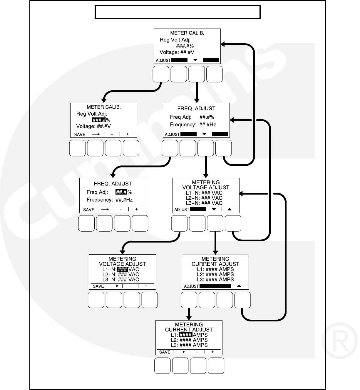
5-28
METERING SUBMENUS
FIGURE 5-13. METERING SUBMENUS

5-29
Annunciator Submenus
The Annunciator submenus are available by press-
ing the (4) button on the second Genset Service
menu (see Figure 5-3 or Figure 5-4).
Seven annunciator submenus (see Figure 5-14)
can be used to define three Annunciator Fault Text
messages and four Annunciator Output Maps.
Annunciator Inputs
The annunciator has three possible customer-de-
fined fault conditions that can be shown on the
1302 series control display. The Annunciator Fault
Text message menus are used to enter an event
type and description for those three customer-de-
fined annunciator faults.
Type: Enter the event type (Warning, Shut-
down, or Event, default = Warning).
Enter a brief description of the event (up to
32 characters).
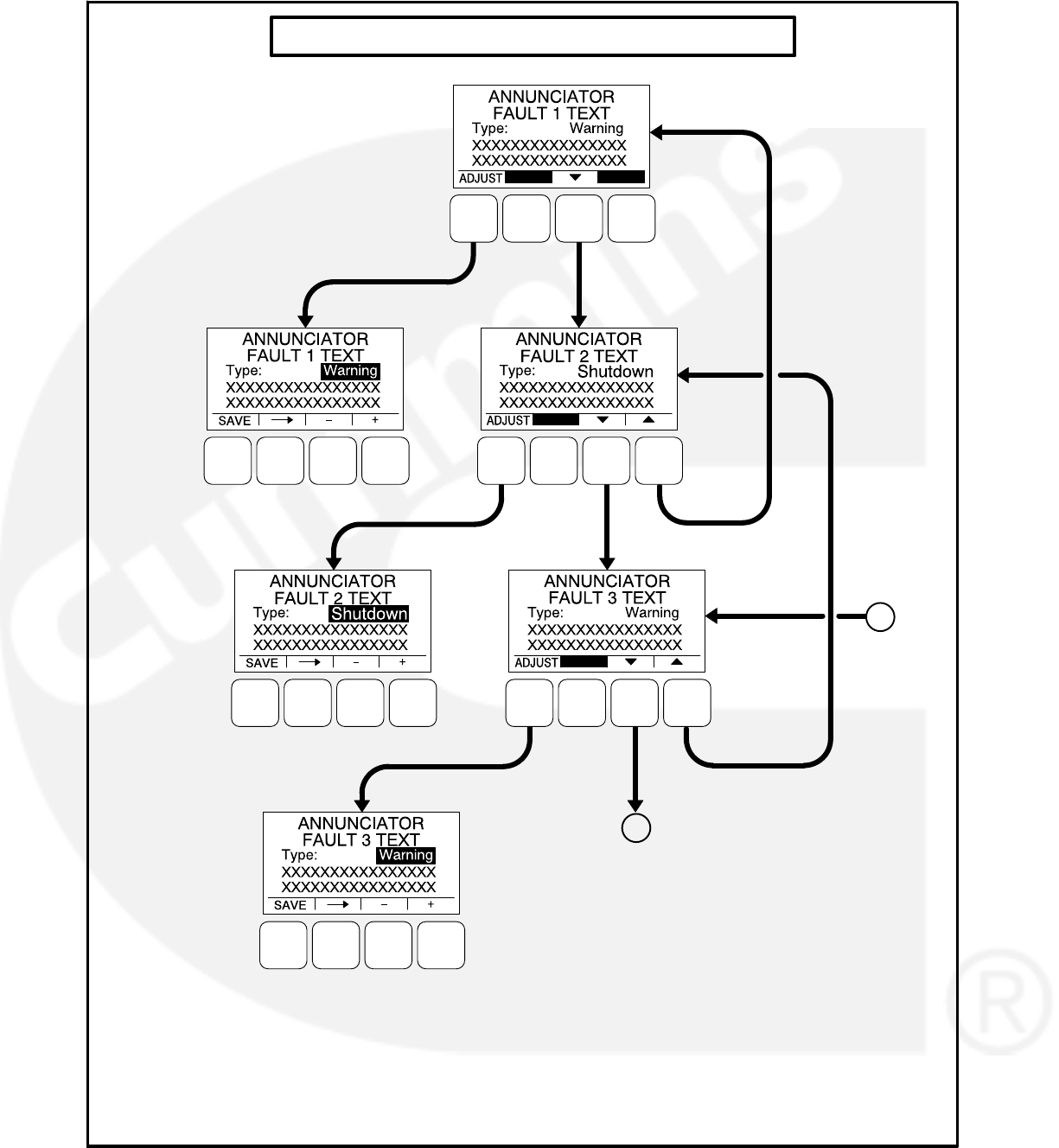

5-31
Annunciator Outputs
An annunciator has four custom (N.O.) relays that
can be controlled by the PCC 1302. When a speci-
fied event becomes active, a message can be sent
by the PCC 1302 to the annunciator to turn the
relay on or off. Only one event per relay is allowed.
The four annunciator outputs of the 1302 series
control are configurable to display common warn-
ing alarms. The four Annunciator Output Map me-
nus allow for entering a fault number and fault
name to be displayed for the configurable annun-
ciator outputs.
Number: Enter a valid code number
(0−65535, default = 0) for the event.
A brief description of the event is automati-
cally displayed.
NOTE: Output relays can be configured for events
that are not displayed by the operator pan-
el. If one of the events listed in the following
table is configured, it will activate the relay
when the event occurs.
TABLE 5-1. EVENT AND CODES
EVENT CODE
Water In Fuel 418
Not In Auto 1463
Ready to Load 1468
Common Alarm 1483
Common Warning 1540
Common Shutdown 1541
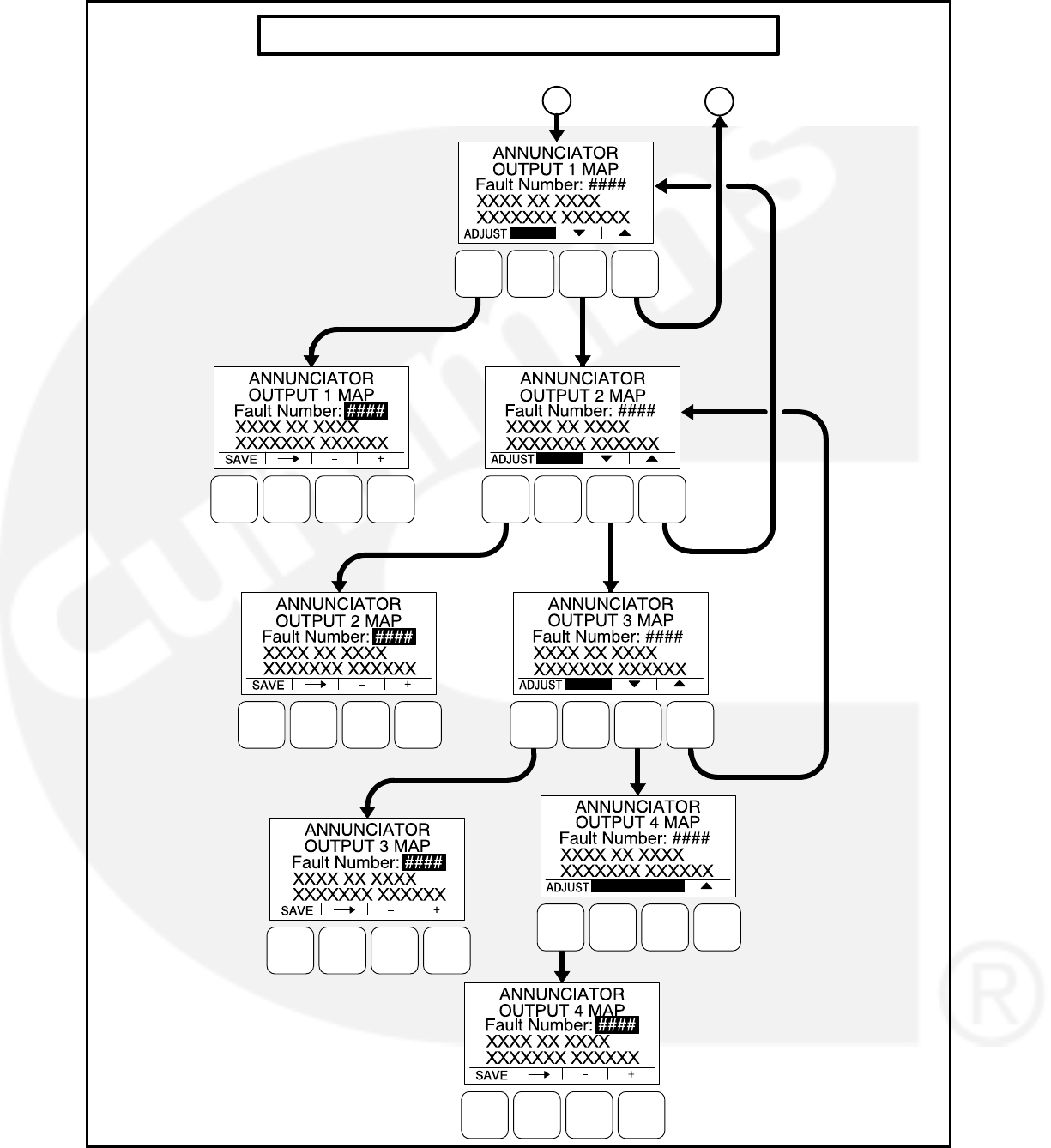

5-33
ModBus Submenus
The ModBus submenus are available by pressing
the (5) button on the second Genset Service menu
(see Figure 5-3 or Figure 5-4).
ModBus Enable
The ModBus menu is used to enable or disable the
ModBus feature (default = No).
ModBus Setup
The ModBus Setup menu is used to set the ad-
dress, baud rate, and parity.
Address: Enter the address of the control on
the ModBus register (default = 1).
Baud Rate: Enter the appropriate baud rate
− 2400, 4800, 9600, or 19200 (default =
9600).
Parity: The parity can be set to either odd or
even (default = even).
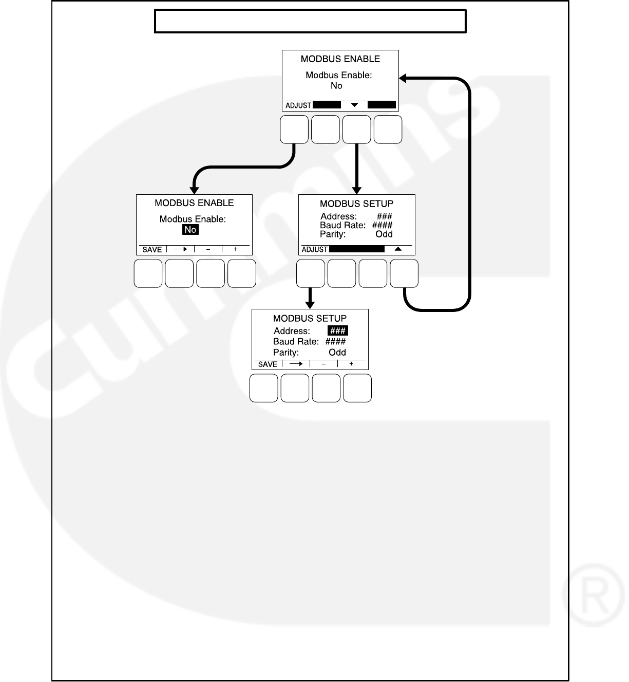
5-34
MODBUS SUBMENUS
FIGURE 5-15. MODBUS SUBMENUS
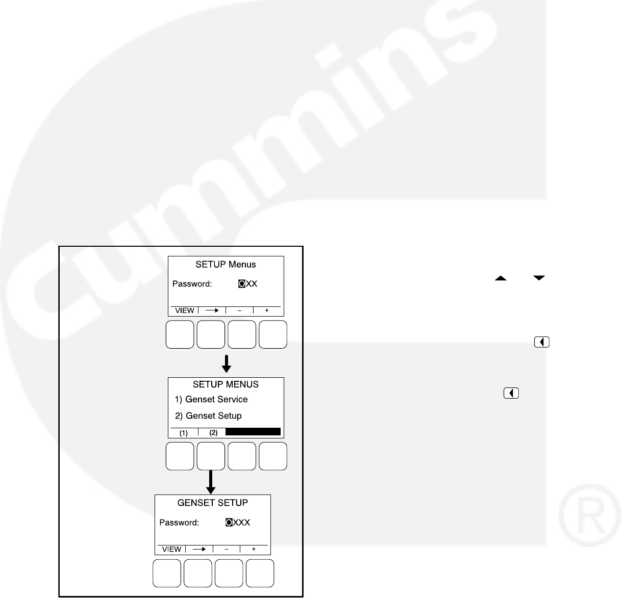
5-35
GENSET SETUP SUBMENUS
The first Setup menu is displayed when the (1) but-
ton is pressed on the Service Menu. From the Set-
up Password menu, a Setup Menus menu is dis-
played that provides access to the following two
categories of genset menus.
Genset Service menus − Go to page 5-3
Genset Setup menus
This section covers Genset Setup menus only. A
password does not need to be entered on the Set-
up Password menu in order to view or adjust the
Genset Setup submenus.
When the (2) button is selected to access Genset
Setup menus, a second password menu (Genset
Setup Password) is displayed (see Figure 5-16). If
a password is entered on the Genset Setup Pass-
word, the settings in the Genset Setup menus can
be adjusted. However, if a password is not entered,
these menus can still be viewed.
SETUP
PASSWORD
MENU
GENSET SETUP
PASSWORD
MENU
SETUP
MENUS
MENU
FIGURE 5-16. SETUP PASSWORD MENUS
Viewing Only
Figure 5-17 is a block representation of the Genset
Setup menus that are available when a password
is not entered (or an incorrect password is entered)
in the Genset Setup Password menu.
The first Genset Setup Menu provides access to
the following menus:
Genset
Voltage Protection
Current Protection
The second Genset Setup Menu provides access
to the following menu:
Engine Protection
The Genset Setup submenus can be viewed by se-
lecting the VIEW button on the Genset Setup Pass-
word menu. When the VIEW button is selected
without entering the correct password, the AD-
JUST button is not displayed on any of the Genset
Setup menus; therefore, no adjustments can be
made.
Menu Navigation
1. Press the buttons above the and sym-
bols in the digital display to navigate between
submenus.
2. To return to the genset Setup Menus menu
from any of the submenus, press the but-
ton.
3. To return to the Service Menu from the genset
Setup Menus menu, press the button.
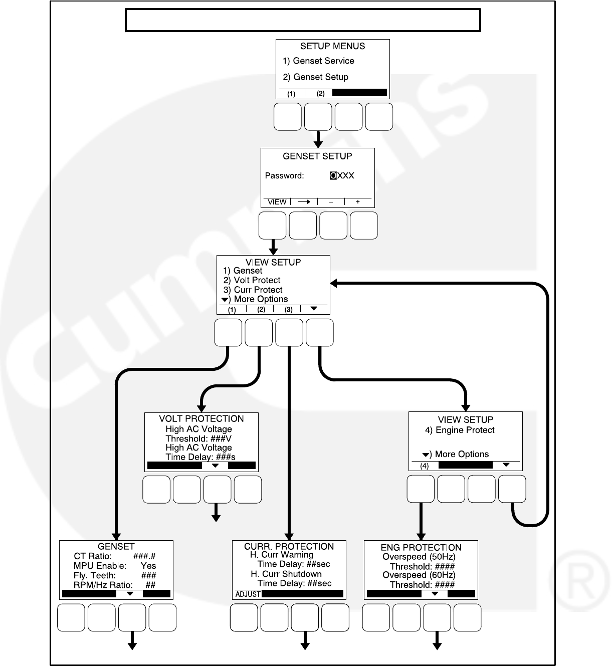
5-36
GENSET SETUP MENUS (Viewing Only)
NOTE: When the VIEW button is selected from
the Genset Setup Password menu with-
out entering a password, the ADJUST
button is not available on any of the me-
nus shown in Figures 5-19 thru 5-22.
SEE PAGE 5-40
SEE PAGE 5-46
SEE PAGE 5-50SEE PAGE 5-48
1ST
GENSET
SETUP
MENU
2ND
GENSET
SETUP
MENU
AVAILABLE ONLY IF THE ECM
CAN FEATURE IS DISABLED
FIGURE 5-17. GENSET SETUP MENUS (VIEWING ONLY)

5-37
Viewing and Adjusting
Figure 5-18 is a block representation of the Genset
Setup menus that are available after the correct
password has been entered in the Genset Setup
Password menu. The ADJUST button is available
on these submenus; therefore, adjusting the set-
tings is allowed.
The first Genset Setup Menu provides access to
the following menus:
Genset
Voltage Protection
Current Protection
The second Genset Setup Menu provides access
to the following menu:
Engine Protection
Genset Setup Password Submenu
Adjusting the Genset Setup menus is restricted to
service personnel and a password must be entered
to modify these menus.
Once the Genset Setup button (2) is selected on
the Setup Menus menu, the Genset Setup Pass-
word menu is displayed.
When the Genset Setup Password menu is dis-
played, the first numeric character (0) is highlighted
(see Figure 5-18).
NOTE: When selected (highlighted), each charac-
ter initially turns to “0” and the remaining
characters turn to “X”.
NOTE: Make sure that each numeric character is
correct before you move to the next char-
acter. If a wrong character is entered, you
will not be able to go back and correct it. If
the wrong password is entered, you will be
able to view the Genset Setup menus but
you won’t be able to change them.
To enter the password:
1. With the first character highlighted, press the
button below to the + or − symbols until the val-
ue reads “1.”
2. Press the arrow selection button to move
to the next numeric character.
3. Press the button below the + or − symbols until
the value reads “2.”
4. Press the arrow selection button to move
to the next numeric character.
5. Press the button below the + or − symbols until
the value reads “0.”
6. Press the arrow selection button to move
to the next numeric character.
7. Press the button below the + or − symbols until
the value reads “9.”
8. After you have completed entering the pass-
word, press the arrow selection button .
The first main Setup menu is displayed.
After the correct password is entered, it will be re-
membered until five minutes of button inactivity has
elapsed. If five minutes of button inactivity has
elapsed, you will have to re-enter the password to
access and change Genset Setup menus.
Adjusting Values/Parameters
Once the correct password has been entered on
the Genset Setup Password menu, the first Genset
Setup submenu is displayed.
1. Press the buttons above the and sym-
bols in the digital display to navigate between
submenus.
2. Press the ADJUST selection button to select
the first parameter or value to be changed.
3. Press the + or − selection buttons to adjust val-
ues or select parameters.
4. Press the arrow selection button to navi-
gate to the next or previous adjustable value
or parameter.
5. After adjusting values/selecting parameters,
press the SAVE button to save your settings.
NOTE: If the button is pressed before
pressing the SAVE button, the
changes are not saved.
6. Press the button to return to the genset
Setup Menus menu.
7. To return to the Service Menu from the genset
Setup Menus menu, press the button.
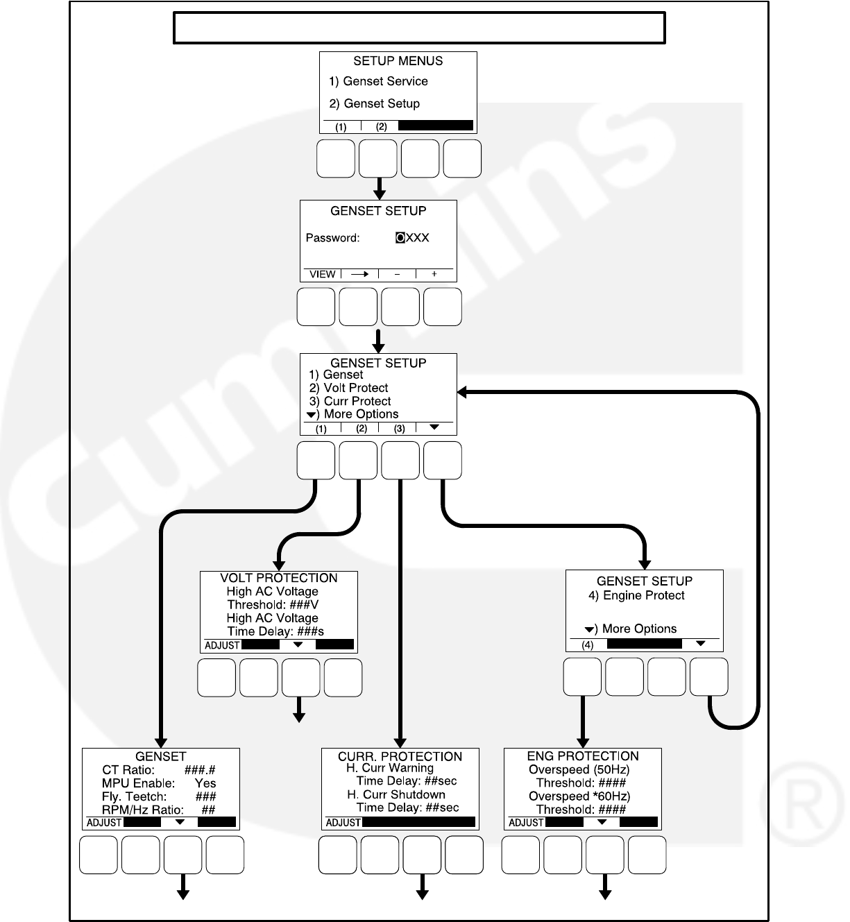

5-39
Genset Menus
The Genset submenus are available by pressing
the (1) button on the first Genset Setup menu (see
Figure 5-17 or Figure 5-18).
Genset Menu 1
The first Genset Setup menu is used to set the CT
Ratio, enable the Magnetic Pickup Unit (MPU), set
the number of teeth pulses per revolution on the
Flywheel, and set the Speed/Frequency Ratio.
CT Ratio: The CT Ratio value must be set to
match the CT Ratio of the current transform-
ers on the genset (default = 150:5).
MPU Enable: Displays whether or not the
Magnetic Pickup Unit is installed (Yes or No,
default = No).
Fly. Teeth: The total number of teeth pulses
per revolution on the flywheel (used for elec-
tronic governed systems) can be set from 0
to 256 (default = 110).
RPM/Hz Ratio: Allows for setting the Speed/
Frequency Ratio to 20, 30, or 60 RPM/Hz
(default = 30).
Genset Menu 2
The second Genset Setup menu is used to set the
excitation source and the excitation/line frequency
gain.
Excitation Source: Select Shunt or PMG Ex-
citation, depending upon your application.
Excitation/Line Freq. Gain: If the excitation
source is set to “Shunt,” this value is auto-
matically set to 1. If the excitation source is
set to “PMG,” the value that should be en-
tered is the excitation frequency multiplier of
the PMG system. For example, enter a “2” if
the PMG output is twice the main generator
frequency (120 Hz excitation frequency).
Application Rating Select Menu
The genset application rating can be set to either
Standby or Prime (default = Standby).
Standby kVA Rating Menu
The kVA Rating menu displays the kVA rating of
single-phase or three-phase, 50 or 60 hertz stand-
by genset systems. These value are used by the
control to determine what is 100% load. The values
must match the kVA rating of the genset application
and cannot be more than 2000 kVA.
3Ph/50Hz: The three phase, 50 Hertz rating
can be set from 0 to 2000 kVA (default = 25
kVA).
3Ph/60Hz: The three phase, 60 Hertz rating
can be set from 0 to 2000 kVA (default = 25
kVA).
1Ph/50Hz: The single phase, 50 Hertz rating
can be set from 0 to 2000 kVA (default = 25
kVA).
1Ph/60Hz: The single phase, 60 Hertz rating
can be set from 0 to 2000 kVA (default = 25
kVA).
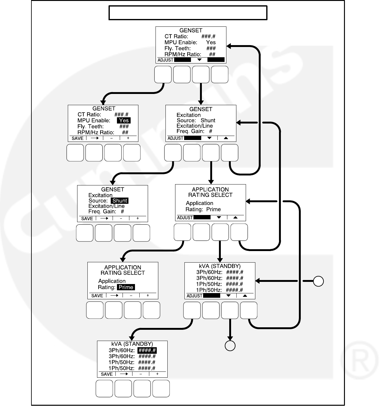

5-41
Prime kVA Rating Menu
The kVA Rating menu displays the kVA rating of
single-phase or three-phase, 50 or 60 hertz prime
genset systems. These value are used by the con-
trol to determine what is 100% load. The values
must match the kVA rating of the genset application
and cannot be more than 2000 kVA.
3Ph/50Hz: The three phase, 50 Hertz rating
can be set from 0 to 2000 kVA (default = 25
kVA).
3Ph/60Hz: The three phase, 60 Hertz rating
can be set from 0 to 2000 kVA (default = 25
kVA).
1Ph/50Hz: The single phase, 50 Hertz rating
can be set from 0 to 2000 kVA (default = 25
kVA).
1Ph/60Hz: The single phase, 60 Hertz rating
can be set from 0 to 2000 kVA (default = 25
kVA).
Battery Select Menu
The Battery Select menu is used to set the nominal
battery voltage.
Nominal Battery Voltage: Allows for setting
the nominal battery voltage (12 or 24V, de-
fault = 12V).
Battery Thresholds Menu
The Battery Thresholds menu is used to set the low
and high voltage values to determine when the bat-
tery voltage is out of the set range during normal
operation. This menu is also used to determine
when the battery voltage is below weak battery
thresholds during cranking. The Battery Thresh-
olds menu that is displayed is dependent upon the
battery voltage entered in the Battery Select menu.
Low Batt: The low battery voltage threshold
can be set from 11.0 to 13.0 VDC for 12 volt
batteries (default = 12.0 VDC) and from 22.0
to 27.0 VDC for 24 volt batteries (default =
24.0 VDC), in 0.1 VDC increments.
High Batt: The high battery voltage threshold
can be set from 14.0 to 17.0 VDC for 12 volt
batteries (default = 16.0 VDC) and from 28.0
to 34.0 VDC for 24 volt batteries (default =
32.0 VDC), in 0.1 VDC increments.
Weak Batt: The weak battery voltage thresh-
old can be set from 6.0 to 10.0 VDC for 12
volt batteries (default = 8.0 VDC) and from
12.0 to 16.0 VDC for 24 volt batteries (de-
fault = 14.4 VDC), in 0.1 VDC increments.
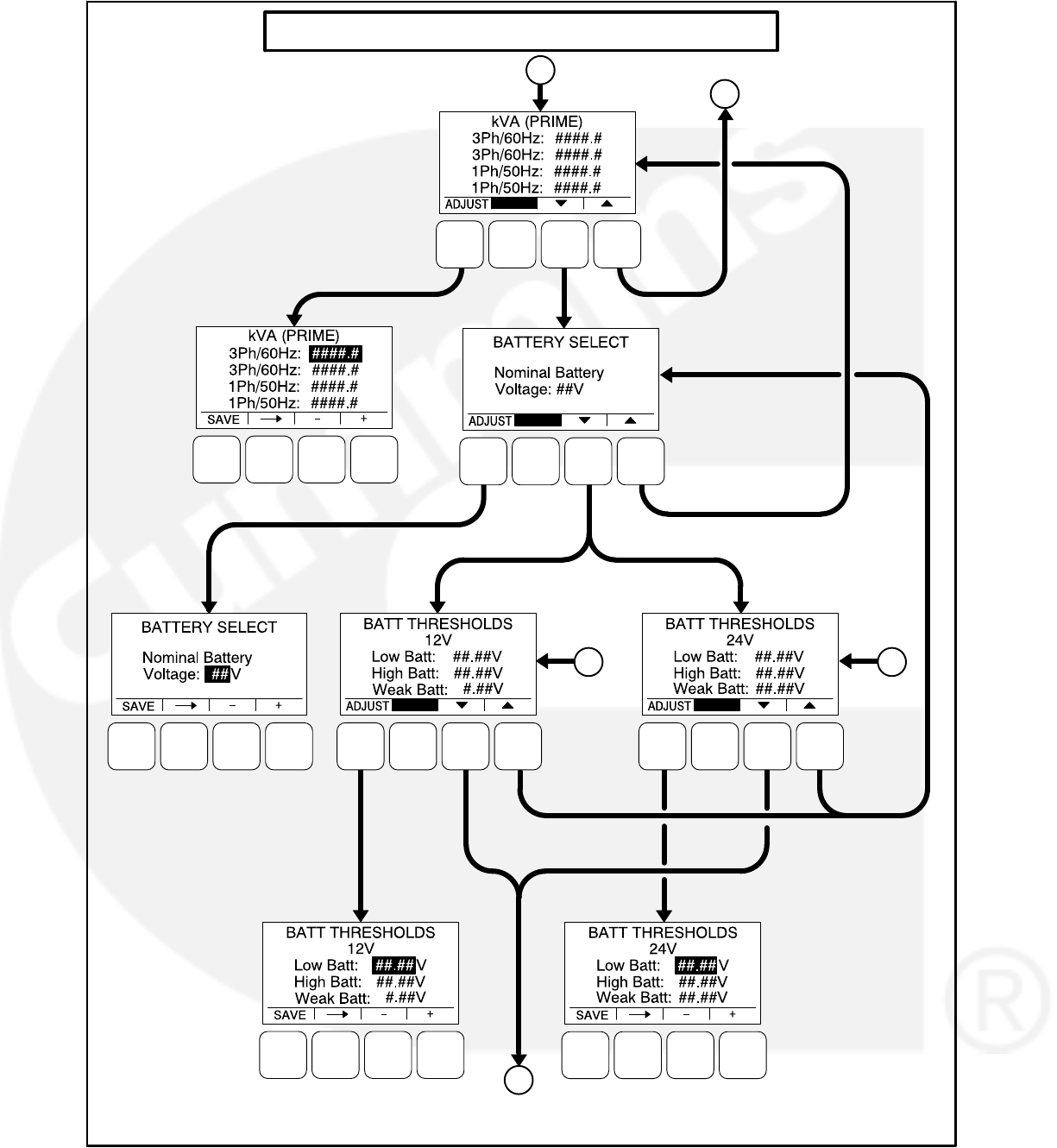

5-43
Battery Delay Setup Menu
This menu is used to determine when, after deter-
mining that the battery condition is out of the preset
operating range, a warning message is an-
nounced.
L. Batt TD: A time delay from 2 to 60 sec-
onds (default = 60 seconds) can be set be-
fore the Low Battery warning message
(Fault Code 441) is announced.
H. Batt TD: A time delay from 2 to 60 sec-
onds (default = 60 seconds) can be set be-
fore the High Battery warning message
(Fault Code 442) is announced.
Wk Batt TD: A time delay from 1 to 5 sec-
onds (default = 2 seconds) can be set before
the Weak Battery warning message (Fault
Code 1442) is announced.
Oil Pressure Setup Menus
NOTE: The following menus are only available if
the the ECM CAN feature is disabled.
A menu is available to set the sensor type. If the
sensor type is Switch, then another menu is avail-
able to set the sensor polarity. If the sensor type is
Sender, then another menu is available to set the
sender type.
Sensor Type: The sensor type can be set for
either Switch or Sender (default = Switch).
Sensor Polarity: This menu is displayed only
if the sensor type is set to Switch. Sensor
polarity can be set to either Active Low or
Active High (default = Active Low).
Sender Type: This menu is displayed only if
the sensor type is set to Sender. The sender
type can be set to either 2 Wire or 3 Wire
(default = 2 Wire).
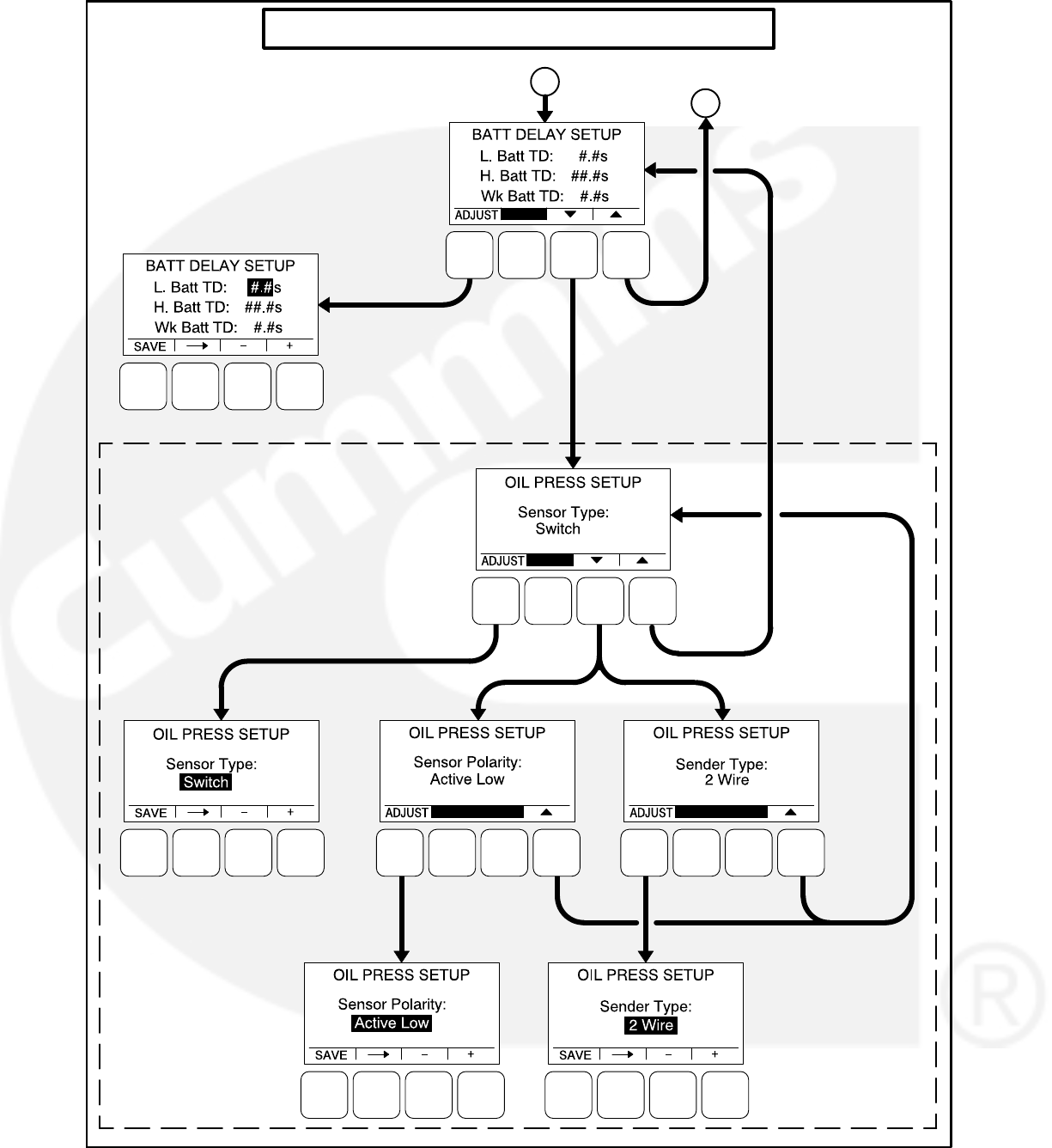

5-45
Voltage Protection Submenus
The Voltage Protection submenus are available by
pressing the (2) button on the first Genset Setup
menu (see Figure 5-17 or Figure 5-18).
Figure 5-20 is a block representation of the four
Voltage Protection submenus that are available.
High AC Voltage Menu
This menu is used to determine when a high AC
voltage fault condition exists and for how long the
fault condition should be present before the engine
is shut down.
High AC Voltage Threshold: This threshold
is used to set the percentage of desired volt-
age necessary to activate a High AC Voltage
fault condition. This value can be set from
105 to 125% (default = 110%).
High AC Voltage Time Delay: A time delay of
1 to 10 seconds (default = 10 seconds) must
expire before the engine shuts down be-
cause of a high AC voltage fault condition. If
the fault condition is active for the duration of
this time delay, the engine shuts down and
the High AC Voltage shutdown message
(Fault Code 1446) is announced.
Low AC Voltage Menu
This menu is used to determine when a low AC
voltage fault condition exists and for how long the
fault condition should be present before the engine
is shut down.
Low AC Voltage Threshold: This threshold is
used to set the percentage of desired volt-
age necessary to activate a Low AC Voltage
fault condition. This value can be set from 50
to 95% (default = 85%).
Low AC Voltage Time Delay: A time delay of
2 to 20 seconds (default = 10 seconds) must
expire before the engine shuts down be-
cause of a low AC voltage fault condition. If
the fault condition is active for the duration of
this time delay, the engine shuts down and
the Low AC Voltage shutdown message
(Fault Code 1447) is announced.
Overfrequency Menu
This menu is used to determine when an overfre-
quency fault condition exists and for how long the
fault condition should be present before the engine
is shut down.
Overfrequency Threshold: This threshold is
used to set the amount of Hertz that the al-
ternator line frequency can be over to acti-
vate an Overfrequency fault condition. This
value can be set from 2 to 10 Hz (default = 6
Hz).
Overfrequency Delay: A time delay of 100 to
2000 half cycles (default = 1100 half cycles)
must expire before the engine shuts down
because of an overfrequency fault condition.
If the fault condition is active for the duration
of this time delay, the engine shuts down
and the Overfrequency shutdown message
(Fault Code 1449) is announced.
Underfrequency Menu
This menu is used to determine when an underfre-
quency fault condition exists and for how long the
fault condition should be present before the engine
is shut down.
Underfrequency Threshold: This threshold is
used to set the Hertz number that the alter-
nator line frequency can be under to activate
an Underfrequency fault condition. This val-
ue can be set from 2 to 10 Hz (default = 6
Hz).
Underfrequency Time Delay: A time delay of
500 and 2000 half cycles (default = 1100 half
cycles) must expire before the engine shuts
down because of an underfrequency fault
condition. If the fault condition is active for
the duration of this time delay, the engine
shuts down and the Underfrequency shut-
down message (Fault Code 1448) is an-
nounced.
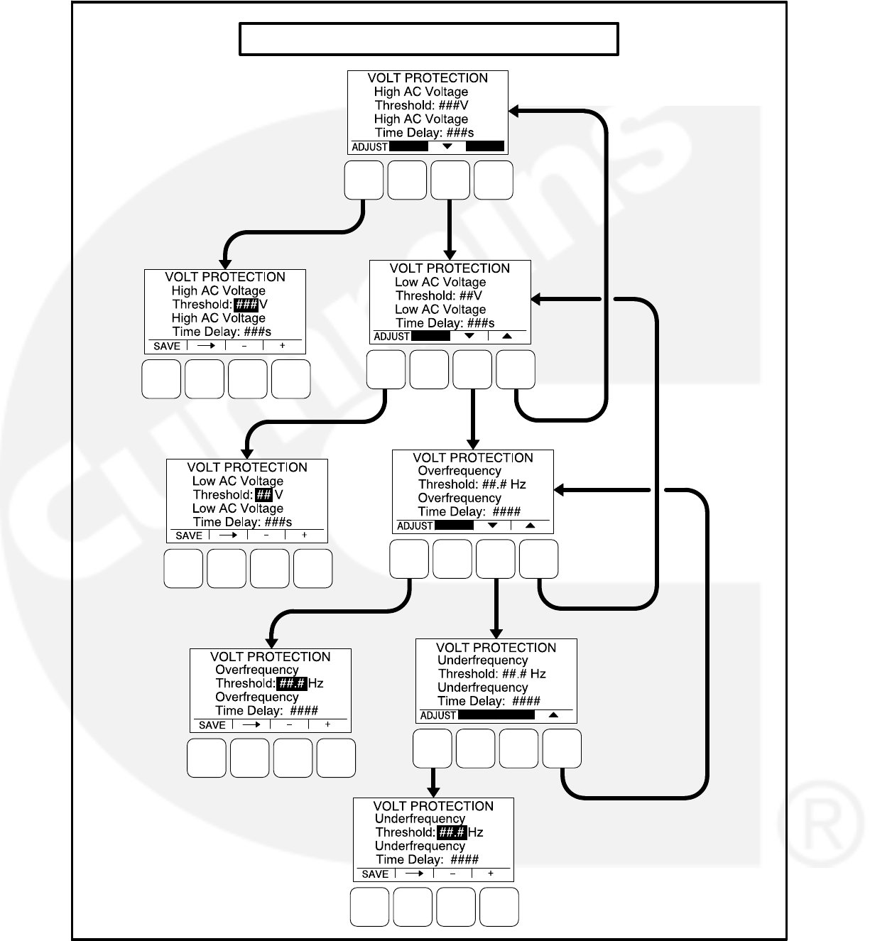
5-46
VOLTAGE PROTECTION SUBMENUS
FIGURE 5-20. VOLTAGE PROTECTION SUBMENUS

5-47
Alternator Protection
The alternator protection feature protects the alter-
nator as well as connected loads from conditions of
High AC Voltage, Low AC Voltage, Loss of AC
Sense, Field Overcurrent, Overfrequency, Under-
frequency, and High AC Current.
Current Protection Submenus
The Current Protection submenus are available by
pressing the (3) button on the first Genset Setup
menu (see Figure 5-17 or Figure 5-18).
Figure 5-21 is a block representation of the Current
Protection submenu.
High AC Current Menu
This menu is used to determine how long the fault
condition should be present before the warning
message is displayed and, if necessary, the shut-
down message is displayed and the engine is shut
down.
NOTE: If both the High Current Warning and High
Current Shutdown faults are active at the
same time, the High Current Shutdown
fault is displayed.
H. Curr Shutdown Time Delay: The High
Current Shutdown Time Delay sets how long
before the fault is greater than the instanta-
neous threshold. If the fault condition is ac-
tive for the duration of this time delay (2 to
60 seconds, default = 10 seconds), the en-
gine shuts down and the High AC Current
shutdown message (Fault Code 1472) is
announced.
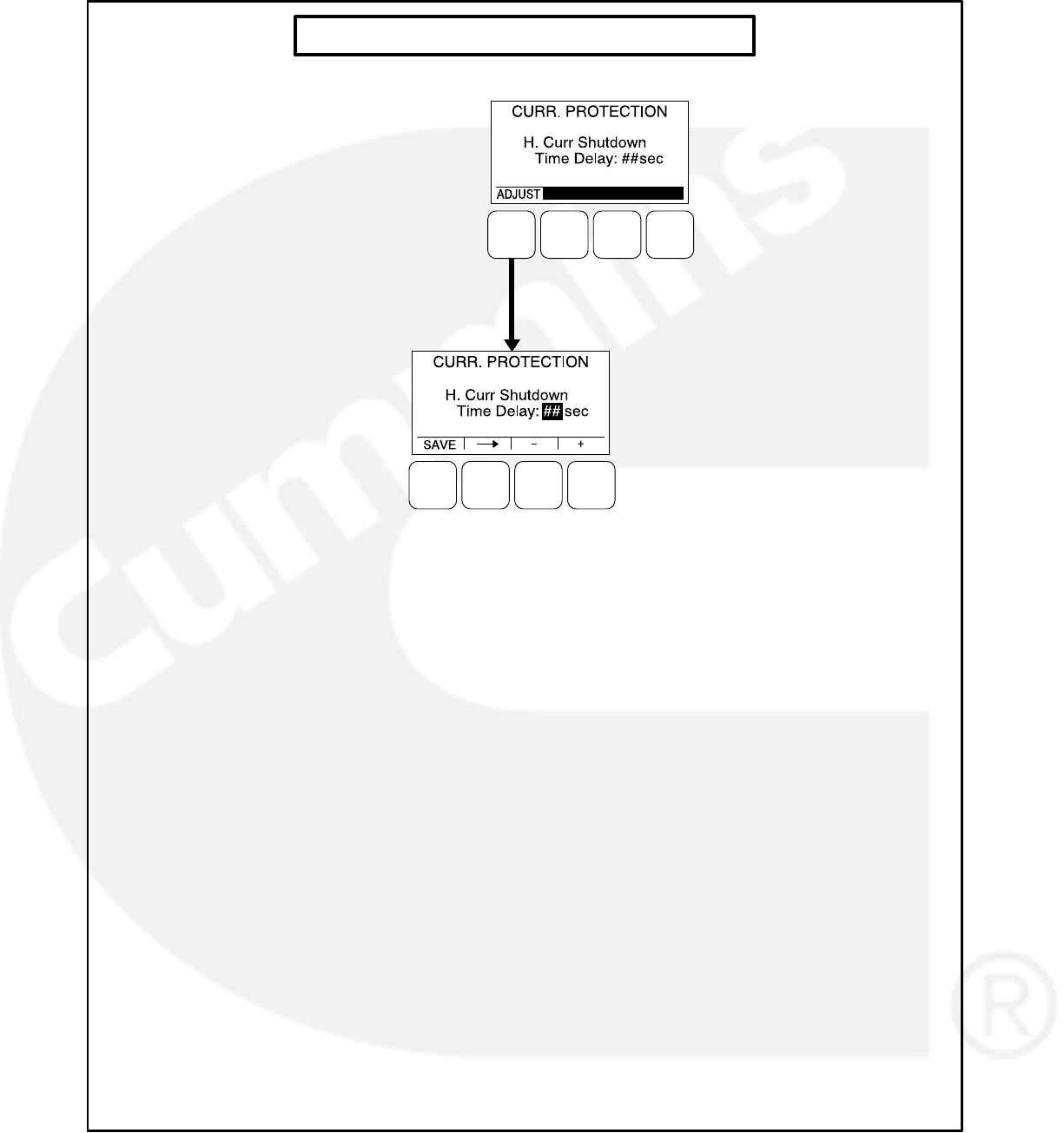
5-48
CURRENT PROTECTION SUBMENUS
FIGURE 5-21. CURRENT PROTECTION SUBMENUS

5-49
Engine Protection Submenus
The Engine Protection submenus are available by
pressing the (4) button on the second Genset Set-
up menu (see Figure 5-17 or Figure 5-18).
The Engine Protection submenus (see Figure
5-22) are used to set thresholds to determine when
engine fault conditions exist and time delays to de-
termine how long a fault condition is present before
the fault message is announced and, if necessary,
shut down the engine.
Engine Protection Overspeed Menu
This menu is used to set the value necessary to
shut down the genset and activate an Overspeed
shutdown message (Fault Code 234) on 50 and 60
Hz gensets, indicating that the engine has exceed-
ed normal operating speed.
Overspeed (50Hz) Threshold: This threshold
is used to set the overspeed value neces-
sary to activate an Overspeed shutdown
fault condition on 50 Hz gensets. This value
can be set from 0 to 8192 RPM, in 25 RPM
increments (default = 1725 RPM).
Overspeed (60Hz) Threshold: This threshold
is used to set the overspeed value neces-
sary to activate an Overspeed shutdown
fault condition on 60 Hz gensets. This value
can be set from 0 to 24,096 RPM, in 25
RPM increments (default = 2075 RPM).
Engine Protection Speed/Frequency Menu
This menu is used to determine when a speed/fre-
quency conflict shutdown fault condition exists and
for how long the fault condition should be present
before the engine is shut down.
Speed/Freq Fault Threshold: This threshold
is used to set the value necessary to acti-
vate the speed/frequency conflict shutdown
fault condition. This value can be set from
0.1 to 20.0 Hz (default = 2.0 Hz).
Speed/Freq Fault Time Delay: A time delay
of 0.2 to 10.0 seconds (default = 1 second)
must expire before the warning message is
announced because of a speed/frequency
conflict shutdown fault condition. If the fault
condition is active for the duration of this
time delay, the genset is shut down and the
Speed Hz Match shutdown message (Fault
Code 1469) is announced.
Low Oil Pressure Warning Menu
This menu is used to determine when a low oil
pressure warning fault condition exists and for how
long the fault condition must be present before the
warning message is announced.
LOP Warning Threshold: This threshold is
used to set the oil pressure value necessary
to activate a Pre-Low Oil Pressure warning
fault condition. This value can be set from 0
to 100 PSig (default = 35 PSig).
LOP Warning Time Delay: A time delay of 2
to 15 seconds (default = 8 seconds) must
expire before the warning message is an-
nounced because of a low oil pressure warn-
ing fault condition. If the fault condition is ac-
tive for the duration of this time delay, the
Pre-Low Oil Pressure warning message
(Fault Code 143) is announced.
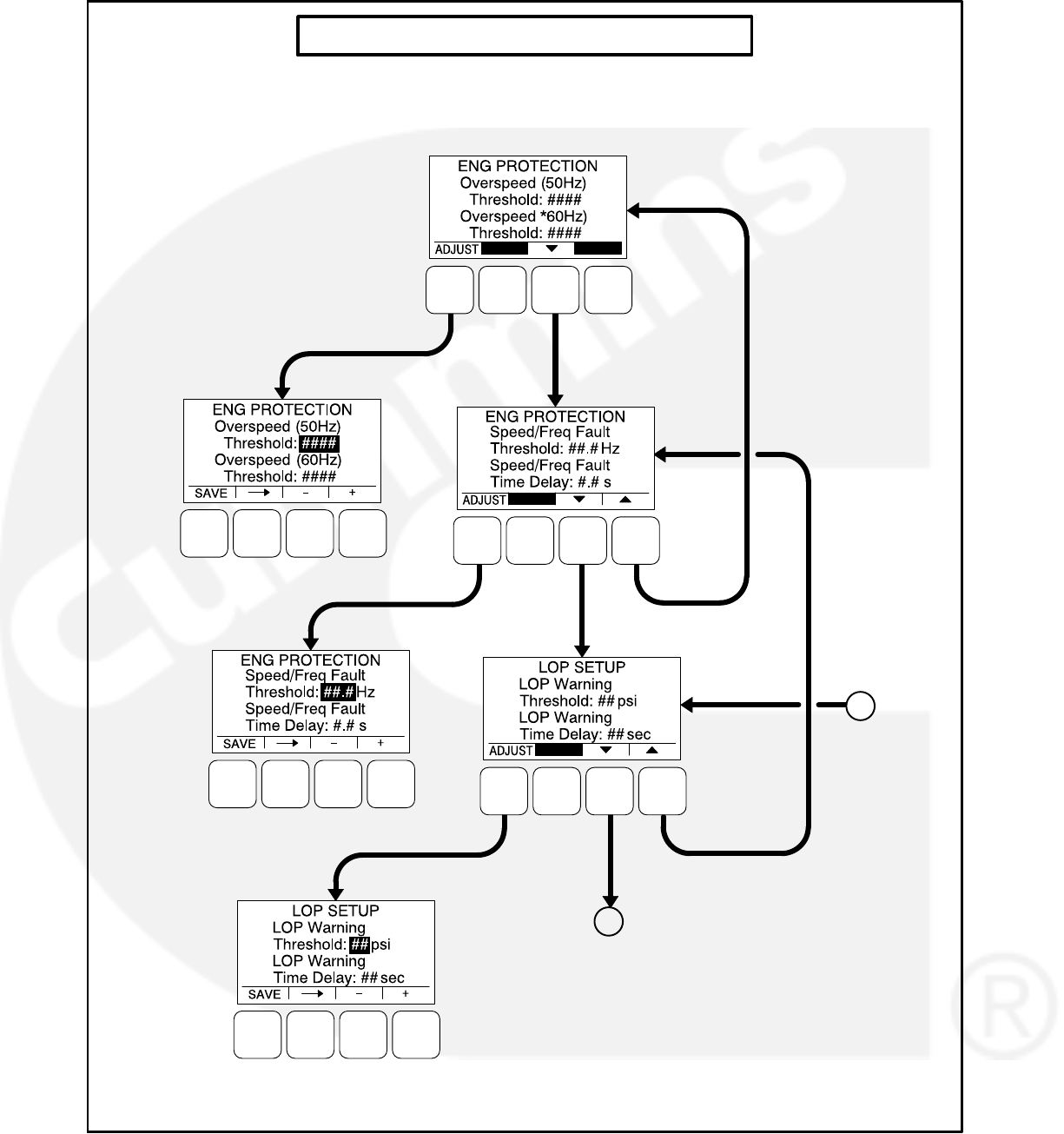

5-51
Low Oil Pressure Shutdown Menu
This menu is used to determine when a low oil
pressure shutdown fault condition exists and for
how long the fault condition should be present be-
fore the engine is shut down.
LOP Shutdown Threshold: This threshold is
used to set the oil pressure value necessary
to activate a Low Oil Pressure Shutdown
fault condition. This value can be set from 0
to 100 PSig (default = 30 PSig).
LOP Shutdown Time Delay: A time delay of
2 to 15 seconds (default = 8 seconds) must
expire before the engine shuts down be-
cause of a low oil pressure fault condition. If
the fault condition is active for the duration of
this time delay, the engine shuts down and
the Low Oil Pressure shutdown message
(Fault Code 415) is announced.
High Coolant Temperature Warning Menu
This menu is used to determine when a high cool-
ant temperature warning fault condition exists and
for how long the fault condition should be present
before the warning message is announced.
HCT Warning Threshold: This threshold is
used to set the temperature value necessary
to activate a High Coolant Temperature
Warning fault condition. This value can be
set from 150 to 290 degrees F (default = 215
degrees F).
HCT Warning Time Delay: A time delay of 2
to 10 seconds (default = 2 seconds) must
expire before the warning message is an-
nounced. If the fault condition is active for
the duration of this time delay, the High
Coolant Temperature warning message
(Fault Code 146) is announced.
High Coolant Temperature Shutdown Menu
This menu is used to determine when a high cool-
ant temperature shutdown fault condition exists
and for how long the fault condition should be pres-
ent before the engine is shut down.
HCT Shutdown Threshold: This threshold is
used to set the temperature value necessary
to activate a High Coolant Temperature
Shutdown fault condition. This value can be
set from 180 to 300 degrees F (default = 223
degrees F).
HCT Shutdown Time Delay: A time delay of
2 to 10 seconds (default = 2 seconds) must
expire before the engine shuts down be-
cause of a high coolant temperature fault
condition. If the fault condition is active for
the duration of this time delay, the engine
shuts down and the High Coolant Tempera-
ture shutdown message (Fault Code 151) is
announced.
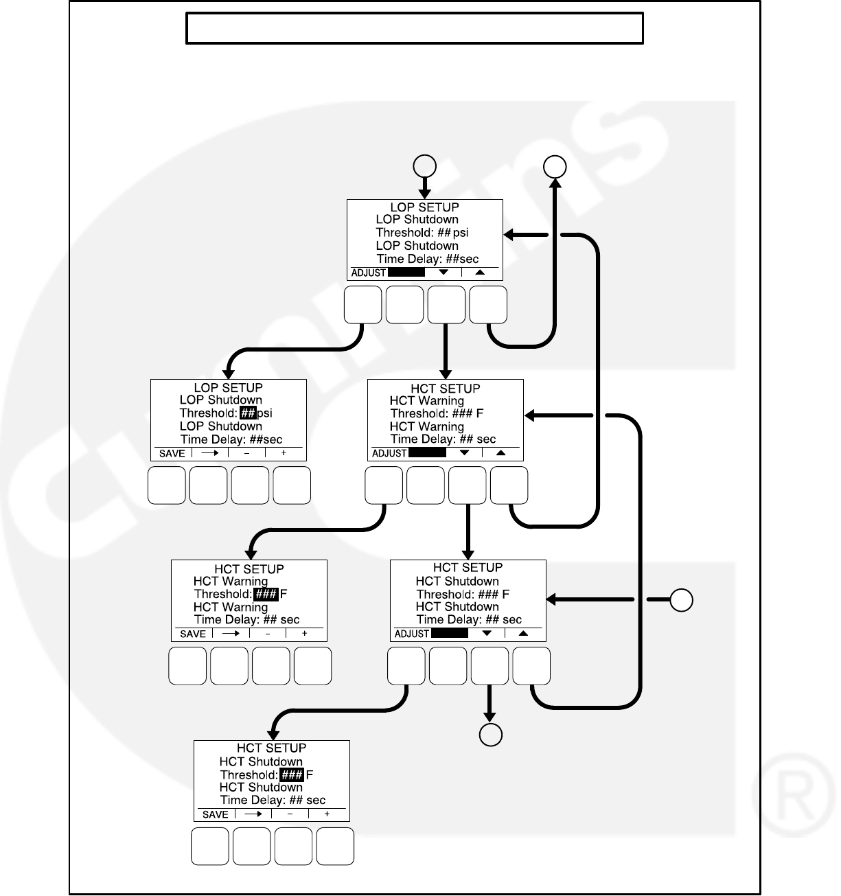

5-53
Engine Protection Low Coolant Temperature
and Battery Charger Menus
The low coolant temperature menu is used to de-
termine when the genset’s coolant temperature is
too low and a Low Coolant Temperature warning
message (Fault Code 1435) is announced. This
warning message is not announced unless the
coolant temperature has been determined to be
low for one minute.
LCT Warning Threshold: This threshold is
used to set the temperature value necessary
to activate a Low Coolant Temperature
Warning fault condition. This value can be
set from 32 to 100 degrees F (default = 70
degrees F).
The battery charger menu is used to determine
when the alternator charger failure condition exists
and when the warning message should be an-
nounced. The fault condition exists when either the
low or high threshold is reached.
Charger Failed H Threshold: This threshold
is used to set the high charging alternator
voltage value. This value can be set from
13.0 to 20.0 VDC (default = 18.0 VDC) for
12V units and from 25.0 to 40.0 VDC (de-
fault = 32.0 VDC) for 24V units.
Charger Failed L Threshold: This threshold
is used to set the low charging alternator
voltage value. This value can be set from 2.0
to 13.0 VDC (default = 5.0 VDC) for 12V
units and from 2.0 to 25.0 VDC (default =
10.0 VDC) for 24V units.
Charger Failed Time Delay: A time delay of
2 to 300 seconds (default = 120 seconds)
must expire before the warning message is
announced. If the fault condition is active for
the duration of this time delay, the Charger
Failure warning message (Fault Code 2678)
is announced.
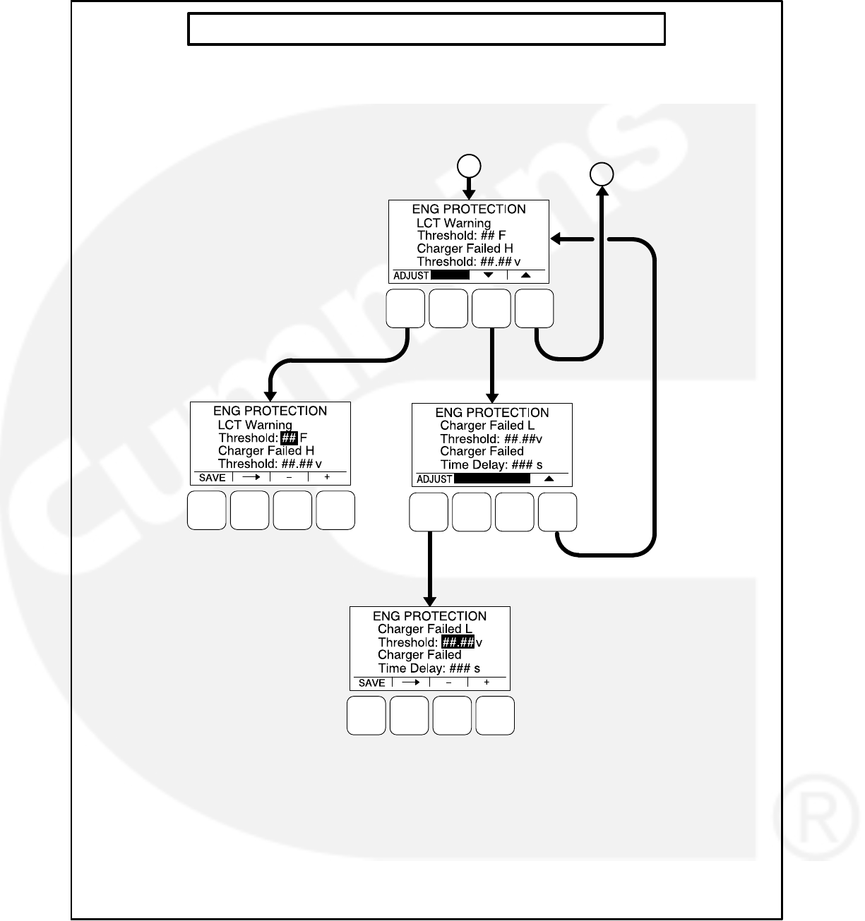
6-1
6. Troubleshooting
INTRODUCTION
The 1302 series control continuously monitors en-
gine sensors for abnormal conditions, such as low
oil pressure and high coolant temperature. If any of
these conditions occur, the control (with graphical
display) will light a yellow warning lamp or a red
shutdown lamp and display a message on the
graphical display. A control without the graphical
display indicates a shutdown condition by intermit-
tent flashing of the status indicator.
When the control is paired with a Cummins ECM on
Full Authority Electronic the local engine inputs are
ignored. Instead, the control receives all engine re-
lated faults and messages from the ECM. Fault
codes are still shown on the HMI or status indicator
as if they were local to the PCC1302 controller.
PC BASED SERVICE TOOL
The PC based service tool can be used in trouble-
shooting to perform tests, verify control inputs and
outputs, and test protective functions.
When used improperly, a PC based service tool
can cause symptoms like warnings and shutdowns
that appear to be a defective base board. When
these problems occur, always verify that a self-test
or fault simulation (override) have not been left en-
abled with the tool. If you do not have a PC based
service tool, or the enabled fault simulation(s) can
not be found using the tool, disconnect battery
power to disable the test or override condition.
Make sure that parameter adjustments and time
delays, related to the fault condition, have been ap-
propriately set for the application. It may be neces-
sary to write the initial capture file to the device or
update the calibration file. Updating a calibration
file requires the a pro version of many of PC based
service tools. Confirm that the installed calibration
part number matches the serial plate information.
CAUTION Using the wrong calibration file
can result in equipment damage. Do not swap
Base boards from another genset model and
only use the calibration file shown on the
nameplate.
Some features are not available until the hardware
for that feature is installed and the PC based ser-
vice tool is used to update (enable) that feature.
Confirm that the feature is installed and enabled
prior to troubleshooting the base board for symp-
toms related to a feature.
NETWORK APPLICATIONS AND
CONFIGURABLE INPUTS
In applications with networks and remote configur-
able inputs, the genset may start unexpectedly or
fail to crank as a result of these inputs. These
symptoms may appear to be caused by the base
board. Verify that the remote input is not causing
the symptom or isolate the control from these in-
puts before troubleshooting the control.
SAFETY CONSIDERATIONS
WARNING Contacting high voltage compo-
nents can cause electrocution, resulting in se-
vere personal injury or death. Keep the output
box covers in place during troubleshooting.
WARNING Ignition of explosive battery gases
can cause severe personal injury or death. Arc-
ing at battery terminals, light switch or other
equipment, flame, pilot lights and sparks can
ignite battery gas. Do not smoke, or switch
trouble light ON or OFF near battery. Discharge
static electricity from body before touching
batteries by first touching a grounded metal
surface.
Ventilate battery area before working on or
near battery—Wear goggles—Stop genset and
disconnect charger before disconnecting bat-
tery cables—Disconnect negative (−) cable
first and reconnect last.
CAUTION Disconnect battery charger from
AC source before disconnecting battery
cables. Otherwise, disconnecting cables can
result in voltage spikes damaging to DC control
circuits of the genset.
WARNING Accidental starting of the genera-
tor set can cause severe personal injury or
death. Prevent accidental starting by discon-
necting the negative (−) cable from the battery
terminal.
When troubleshooting a generator set that is shut
down, make certain the generator set cannot be
accidentally restarted as follows:

6-2
1. For installations without the optional operator
panel: Move the Start/Off/Auto switch on the
control panel to the OFF position.
2. For installations with the optional operator
panel: Press the button (0) to switch the con-
trol into the Off mode.
3. Turn off or remove AC power from the battery
charger.
4. Remove the negative (−) battery cable from
the generator set starting battery.
READING FAULT CODES
If the genset contains the graphical display and a
fault occurs, the fault code/message can be viewed
in the display. If the control does not contain the
graphical display, the fault code is read from the
control switch indicator.
After the fault is acknowledged and corrected, the
recorded fault will be deleted from the control panel
memory, but will remain in a data log to maintain a
fault code history and fault code occurrence table.
A PC-based service tool is required to view this
data log.
Reading Fault Codes Using Optional
Operator Panel
The warning or shutdown LED will light and the
fault symbol, and code will be displayed on the dis-
play. Refer to the Fault Code List in the Protection
and Faults section for the exact name of the fault.
Reading Fault Codes Using the Control
Switch Indicator
1302 series control without display): The control
panel rocker switch contains a status indicator
lamp. This lamp is used to flash genset status and
shutdown fault codes. (Only the last shutdown fault
code is flashed.)
Warning fault codes are not displayed by the status
indicator lamp. A PC based service tool is needed
to read warning fault codes.
The following describes how to interpret the status
indicator light.
Do not move the control switch to the OFF posi-
tion before interpreting the fault code. Moving
the switch to OFF will clear the fault indication.
Constant Rate Flashing = Engine preheat
/genset starting.
Constant On = Genset running.
Variable Rate Flashing = A genset Shutdown
fault condition exists (Warning conditions are
not displayed). All of the Shutdown faults
described in section 14 can be announced
with the status indicator lamp.
An example of a four digit fault code − first digit in
the code is flashed, followed by a half−second
pause, and then the second digit is flashed, fol-
lowed by a half−second pause, followed by a half−
second pause, and then the third digit is flashed,
followed by a half−second pause, and then the
fourth digit is flashed, followed by a one second
pause.
TROUBLESHOOTING PROCEDURES
The following tables are a guide to help you evalu-
ate problems with the generator set. You can save
time if you read through the manual ahead of time
and understand the system.
Voltage/Continuity Testing
Voltage and continuity tests are required in the fol-
lowing tables. In some cases, it is necessary to re-
move a plug to complete the test. Where required,
the corrective action will mention when it is neces-
sary to remove a plug for testing. In other cases,
the plug cannot be removed for testing. When plug
removal is not mentioned, testing must be per-
formed by inserting a narrow meter probe into the
back of the plug.
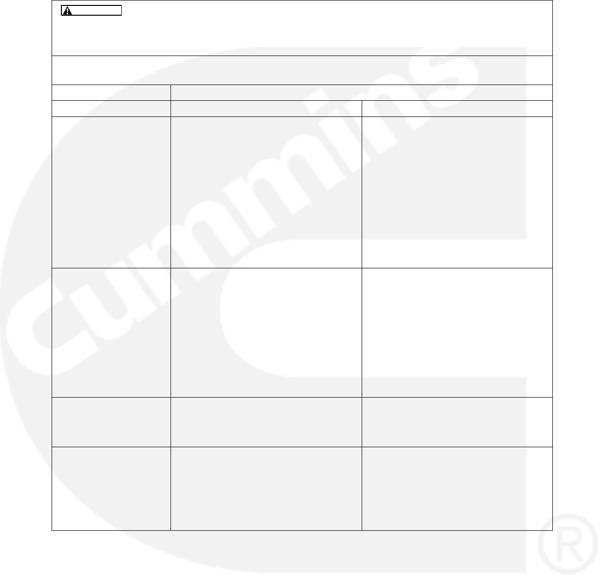
6-3
TABLE 6-1. ENGINE DOES NOT CRANK IN MANUAL MODE (NO FAULT MESSAGE)
Hazards present in troubleshooting can cause equipment damage, severe person-
al injury or death. Only trained and experienced service personnel with knowledge of fuels, elec-
tricity, and machinery hazards should perform service procedures. Read Important Safety In-
structions pages and observe all instructions and precautions in this manual.
WARNING
Reason: This indicates that the control has not received or recognized a manual start signal.
Effect: Engine will not start.
POSSIBLE CAUSE CORRECTIVE ACTION
ENGINE PLATFORM FAE Engines HM Engines
No power supplied to the
control due to poor bat-
tery cable connections.
Clean the battery cable
terminals and tighten all
connections.
1. Check wakeup conditions.
2. Check for poor battery cable connec-
tions. Clean the battery cable termi-
nals and tighten all connections.
3. Remove connector P20 and check for
B+ at P20-9 and P20-10 and GND at
P20-2 and P20-4. If B+ or ground is
missing, isolate to the harness and
the TB BAT terminal mounted on the
engine block. If B+ and ground check
OK, cycle power to Base board by re-
connecting P20 and retry operation.
1. Check wakeup conditions.
2. Check for poor battery cable connec-
tions. Clean the battery cable termi-
nals and tighten all connections.
3. Remove connector P20 and check for
B+ at P20 and P20-10 and GND at
P20-2. If B+ or ground missing, iso-
late to harness and TB BAT terminal
mounted on engine block. If B+ and
ground check OK, cycle power to
Base board by reconnecting P20 and
retry operation.
1302 series control
with display: No power
supplied to front mem-
brane panel.
Check for B+ at TB1-5 and GND at
TB1-3. If ground is missing, the Base
board is defective and must be replaced.
If B+ is missing, then:
1. If B+ and ground check are OK, re-
move P1 from the back of the front
membrane panel.
2. Check for B+ at P1-3 and ground at
P1-5. If B+ or ground is missing, re-
pair the harness.
Base board not properly
calibrated or corrupt cal-
ibration.
Confirm that the installed calibration part
number matches the serial plate informa-
tion. Re-enter the calibration file if neces-
sary.
Confirm that the installed calibration part
number matches the serial plate informa-
tion. Re-enter the calibration file if neces-
sary.
The Remote Emergency
Stop switch or wiring is
defective.
With Emergency Stop push button not ac-
tivated (switch closed), remove configur-
able leads from TB1-15 and TB1-16 and
check for continuity between these two
leads. If circuit is open, isolate to Emer-
gency Stop switch and wiring. If there is
continuity, go to the next step.
With Emergency Stop push button not ac-
tivated (switch closed), remove configur-
able leads from TB1-15 and TB1-16 and
check for continuity between these two
leads. If circuit is open, isolate to Emer-
gency Stop switch and wiring. If there is
continuity, go to the next step.
6-4
TABLE 6-1. ENGINE DOES NOT CRANK IN MANUAL MODE (NO FAULT MESSAGE) (CONT.)
Hazards present in troubleshooting can cause equipment damage, severe person-
al injury or death. Only trained and experienced service personnel with knowledge of fuels, elec-
tricity, and machinery hazards should perform service procedures. Read Important Safety In-
structions pages and observe all instructions and precautions in this manual.
WARNING
Reason: This indicates that the control has not received or recognized a manual start signal.
Effect: Engine will not start.
POSSIBLE CAUSE CORRECTIVE ACTION
ENGINE PLATFORM HM EnginesFAE Engines
The Local Emergency
Stop switch or wiring is
defective.
1302 series control
without display: The
Manual input signal is not
getting from the Manual
select switch (S12) to the
Base board, indicting that
the S12, Base board, or
the harness is defective.
1302 series control
with display: The menu
display Manual Run but-
ton, harness, or the Base
board is defective.
With the Emergency Stop push button not
activated (switch closed), check for conti-
nuity between J25-2 and J25-6. If the cir-
cuit is open, isolate to the Emergency
Stop switch and wiring. If there is continu-
ity, go to the next step.
Remove connector P25 from the Base
board. With Start switch in the Manual
position, check for continuity between
P25-10 (RUN) to P25-8 (GND). If there is
no continuity, isolate to the switch and
wiring. If there is continuity, the Base
board is defective and needs to be re-
placed.
Check for continuity between P25-10
(RUN) to P25-8. If there is no continuity
when pressing the Manual Run button,
isolate to the front membrane panel and
wiring. If there is continuity, the Base
board is defective and needs to be re-
placed.
With the Emergency Stop push button not
activated (switch closed), check for conti-
nuity between J25-2 and J25-6. If the cir-
cuit is open, isolate to the Emergency
Stop switch and wiring. If there is continu-
ity, go to the next step.
Remove connector P25 from the Base
board. With the Start switch in the Manual
position, check for continuity between
P25-10 (RUN) to P25-8 (GND). If there is
no continuity, isolate to the switch and
wiring. If there is continuity, the Base
board is defective and needs to be re-
placed.
Check for continuity between P25-10
(RUN) to P25-8. If there is no continuity
when pressing the Manual Run button,
isolate to the front membrane panel and
wiring. If there is continuity, the Base
board is defective and needs to be re-
placed.
Oil Pressure switch or
wiring is defective
1. Remove the P11 connection and
check wiring between P11-2 and
P11-3 to the switch.
2. Verify control is configured for the
type of switch installed.
3. Verify proper operation of the switch.
Oil Pressure sender, set-
up on wiring is defective.
1. Remove the P11 connection and
check wiring between P11-1, P11-2,
and P11-3 (for 3-wire sender) to the
sender.
2. Verify that the control is configured for
the correct type of sender (see Figure
5-19, sheet 3).
3. Verify operation of the sender.
CAN Datalink Failed Refer to Fault Code 427 or 781.

6-5
TABLE 6-2. ENGINE DOES NOT CRANK IN REMOTE MODE (NO FAULT MESSAGE)
Hazards present in troubleshooting can cause equipment damage, severe person-
al injury or death. Only trained and experienced service personnel with knowledge of fuels, elec-
tricity, and machinery hazards should perform service procedures. Read Important Safety In-
structions pages and observe all instructions and precautions in this manual.
WARNING
Reason: This indicates that the 1302 series control has not received or recognized a remote start signal.
Effect: Engine will not start in Remote mode, but starts in manual mode.
POSSIBLE CAUSE CORRECTIVE ACTION
The remote start switch or confi-
gurable wiring is defective.
1. Reset the control. Attempt to start the engine and check for ground at
TB1-11.
2. If ground level is not present, isolate to the remote switch or configurable
wiring. Repair as necessary.
3. If ground is present, go to the next step.
1302 series control without
display: The Auto mode input is
not getting from the Auto Select
switch to the Base board, indict-
ing that S12, the Base board, or
the harness is defective.
1. Remove connector P11 from the Base board.
2. With S12 in Auto position, check for continuity from P25-11 (AUTO) to
P25-8 (GND).
3. If there is no continuity, isolate to the switch or the wiring harness. If there
is continuity, the Base board is defective and must be replaced.
1302 series control with dis-
play: The menu display Auto
button, harness, or the Base
board is defective.
1. Check for continuity between P25-11 (AUTO) and P25-8 (GND).
2. If there is no continuity when pressing the menu display Auto button, iso-
late to the front membrane panel or the wiring harness. If there is continu-
ity, the Base board is defective and must be replaced.
For more information, see Table 6-1, Will Not Crank in Manual Mode.
6-6
TABLE 6-2. WARNING AND SHUTDOWN CODES
Hazards present in troubleshooting can cause equipment damage, severe person-
al injury or death. Only trained and experienced service personnel with knowledge of fuels, elec-
tricity, and machinery hazards should perform service procedures. Read Important Safety In-
structions pages and observe all instructions and precautions in this manual.
WARNING
FAULT CODE CORRECTIVE ACTION
ENGINE PLATFORM FAE Engines HM Engines
121
SPEED SIGNAL LOST
Lamp: Shutdown
Not applicable on FAE engines. Indicates that no magnetic pickup pulses
are sensed for a Loss of Speed delay. If a
magnetic pickup is not installed, then
speed sensing is performed by monitoring
AC line frequency and this fault cannot
occur.
141. 135
OIL PRESS SENSOR
OOR L/H
Lamp: Warning
Indicates that the engine controller has
sensed that the engine oil pressure sen-
sor output is out of range (high or low).
Consult the engine service manual and
check the sender/connectors/wires.
Indicates that the control has sensed that
the engine oil pressure sensor output is
out of range (high or low). Check the
sender/connectors/wires. This warning
will only occur if the genset is equipped
with an oil pressure sender.
143
PRE-LOW OIL
PRESSURE
Lamp: Warning
Indicates the engine oil pressure has
dropped below the warning trip point pro-
grammed into the engine controller. If the
generator is powering critical loads and
cannot be shut down, wait until the next
shutdown period and then follow the
Fault Code 415 procedure.
Indicates the engine oil pressure has
dropped below the warning trip point. If
the generator is powering critical loads
and cannot be shut down, wait until the
next shutdown period and then follow the
Fault Code 415 procedure. This warning
will only occur if the genset is equipped
with an oil pressure sender.
144, 145
COOL SENSOR OOR
LOW/HIGH
Lamp: Warning
Indicates that the engine controller has
sensed that the engine coolant tempera-
ture sensor output is out of range (high or
low). Consult the engine service manual
and check the sender/connectors/wires.
Indicates that the control has sensed that
the engine coolant temperature sensor
output is out of range (high or low). Check
the sender/connectors/wires.
146
PRE-HIGH COOL TMP
Lamp: Warning
Indicates the engine is operating near its
cooling system capacity. An increase in
load or higher ambient temperature may
cause a High Coolant Temp shutdown.
Review Fault Code 151 correction list for
other possible causes.
Indicates the engine is operating near its
cooling system capacity. An increase in
load or higher ambient temperature may
cause a High Coolant Temp shutdown.
Review Fault Code 151 correction list for
other possible causes.

6-7
TABLE 6-2. WARNING AND SHUTDOWN CODES (CONT.)
Hazards present in troubleshooting can cause equipment damage, severe person-
al injury or death. Only trained and experienced service personnel with knowledge of fuels, elec-
tricity, and machinery hazards should perform service procedures. Read Important Safety In-
structions pages and observe all instructions and precautions in this manual.
WARNING
FAULT CODE CORRECTIVE ACTION
ENGINE PLATFORM HM EnginesFAE Engines
151
HIGH COOLANT TEMP
Lamp: Shutdown
Indicates the engine has overheated
(coolant temperature has risen above the
shutdown trip point set at the engine con-
troller).
Allow the engine to cool down completely
before proceeding with the following
checks:
1. Consult the engine service manual
and reset the PCC1302.
2. Restart the generator after locating
and correcting the problem.
Indicates the engine has overheated
(coolant temperature has risen above the
shutdown trip point).
Allow the engine to cool down completely
before proceeding with the following
checks:
1. Check the coolant level and replenish
if low. Look for possible coolant leak-
age points and repair if necessary.
2. Check for obstructions to the cooling
airflow and correct as necessary.
3. Check the fan belt and repair or tight-
en if necessary.
4. Check the blower fan and circulation
pumps on remote radiator installa-
tions.
5. Reset the control and restart the gen-
erator after locating and correcting
the problem.
415
LOW OIL PRESSURE
Lamp: Shutdown
Indicates the engine oil pressure has
dropped below the shutdown trip point
programmed into the engine controller.
1. Consult the engine service manual
and reset the control.
2. Restart the generator after locating
and correcting the problem.
Indicates the engine oil pressure has
dropped below the shutdown trip point.
1. Check the oil level, lines, and filters.
2. If the oil system is OK but the oil level
is low, replenish.
3. Reset the control and restart the gen-
set.
4. If an oil switch is used, check switch
performance.
234
OVERSPEED
Lamp: Shutdown
Indicates the engine has exceeded nor-
mal operating speed. The default thresh-
olds are preprogrammed in the engine
controller. An engine service tool such as
Insite or CalTerm III is required to change
threshold settings.
Possible causes are single step large
block load removal or flammable vapors
drawn into the intake air passage. Reset
the control and restart after locating and
correcting the problem.
Indicates engine has exceeded normal
operating speed. The default thresholds
are 1725 RPM (50 Hz) or 2075 RPM (60
Hz).
Possible causes are single step large
block load removal or flammable vapors
drawn into the intake air passage. Reset
the control and restart after locating and
correcting the problem.

6-8
TABLE 6-2. WARNING AND SHUTDOWN CODES (CONT.)
Hazards present in troubleshooting can cause equipment damage, severe person-
al injury or death. Only trained and experienced service personnel with knowledge of fuels, elec-
tricity, and machinery hazards should perform service procedures. Read Important Safety In-
structions pages and observe all instructions and precautions in this manual.
WARNING
FAULT CODE CORRECTIVE ACTION
ENGINE PLATFORM HM EnginesFAE Engines
359
FAIL TO START
Lamp: Shutdown
Indicates a possible fuel system or air in-
duction problem. (Engine cranks but fails
to start)
Consult the engine service manual for
possible causes / solutions.
Indicates a possible fuel system or air in-
duction problem. (Engine cranks but fails
to start)
1. Check for an empty fuel tank, fuel
leaks, or plugged fuel lines and cor-
rect as required.
2. Check for a dirty fuel filter and re-
place if necessary.
3. Check for a dirty or plugged air filter
and replace if necessary.
4. Reset the control and restart after
correcting the problem.
441
LOW BATTERY
Lamp: Warning
Indicates the battery voltage supply to the control is approaching a low level at which
an unpredictable operation will occur.
1. Discharged or defective battery.
Check the battery charger fuse.
Recharge or replace the battery.
2. Check for poor battery cable connections. Clean the battery cable terminals and
tighten all connections.
3. Check the battery wiring/calibration.
4. Check the engine DC alternator. Replace the engine DC alternator if normal bat-
tery charging voltage is not obtained.
5. Check the battery charge voltage float level if applicable (raise float level).
442
HIGH BATTERY
Lamp: Warning
Indicates the battery voltage supply to the control is approaching a high level at which
damage to the control can occur. Check the float level on the battery charger if appli-
cable (lower float level).
Check battery wiring/calibration.
1123
SHUTDOWN AFTER
BATTLESHORT
Lamp: Shutdown
A shutdown fault occurred while the Battle Short mode was enabled. Check the fault
history (see Figure 4-18) for faults that may have been bypassed.
1131
BATTLE SHORT
ACTIVE
Lamp: Warning
Indicates that the control is in Battle Short mode − used to bypass several fault shut-
downs, therefore allowing genset operation during emergencies.
1311, 1312, 1317, 1318
CONFIGURABLE INPUT
1, 2, 3, 4
Lamp: Configurable
The nature of the fault is an optional configurable selection. Example inputs: Low Fuel
Day Tank, Water In Fuel, Ground Fault, etc.
Each of the fault functions can be programmed (using a service tool or the operator
panel), as follows:
Event or Warning or Shutdown level if Function Select = Fault Input
Change the display name using up to 32 characters.

6-9
TABLE 6-2. WARNING AND SHUTDOWN CODES (CONT.)
Hazards present in troubleshooting can cause equipment damage, severe person-
al injury or death. Only trained and experienced service personnel with knowledge of fuels, elec-
tricity, and machinery hazards should perform service procedures. Read Important Safety In-
structions pages and observe all instructions and precautions in this manual.
WARNING
FAULT CODE CORRECTIVE ACTION
ENGINE PLATFORM HM EnginesFAE Engines
1416
FAIL TO SHUTDOWN
Lamp: Warning
The genset continues to run after receiving a shutdown command from the controller.
The Battle Short feature is enabled − this is used to bypass several critical fault shut-
downs, therefore allowing genset operation during emergencies.
1433
REMOTE EMERGENCY
STOP
Lamp: Shutdown
Indicates a Remote Emergency Stop. To reset the Remote Emergency Stop button:
1. Close (disable) the remote Emergency Stop button.
2. Move the control switch to the OFF position or press the OFF button.
3. Select the desired operating mode (Manual or Auto).
If the application has a remote fault reset, the fault can also be reset by closing the
fault reset switch.
1434
LOCAL EMERGENCY
STOP
Lamp: Shutdown
Indicates a Local Emergency Stop. To reset the Local Emergency Stop button:
1. Close (disable) Local Emergency Stop button.
2. Move the control switch to the OFF position or press the OFF button.
3. Select the desired operating mode (Manual or Auto).
If the application has a remote fault reset, the fault can also be reset by closing the
fault reset switch.
1435
LOW COOLANT TEMP
Lamp: Warning
Set is not operating.
Warning occurs when en-
gine coolant temperature
is 70_F (21_C) or lower.
NOTE: In applications
where the ambient tem-
perature falls below
40_F (4_C), Low Cool-
ant Temp may be indi-
cated even though the
coolant heaters are op-
erating.
Indicates the engine coolant heater is not operating or is not circulating coolant.
Check for the following conditions:
The coolant heater is not connected to the power supply. Check for a blown fuse
or a disconnected heater cord and correct as required.
Check for low coolant level and replenish if required. Look for possible coolant
leakage points and repair as required.
Check for an open heater element. Check the heater’s current draw.
The coolant temperature must be below 70_F (default setting) for one minute to acti-
vate a warning and must be above 70_F for one minute before the warning is cleared.
1438
FAIL TO CRANK
Lamp: Shutdown
The control has failed to receive engine
speed from ECM during cranking. Consult
the engine service manual for MPU diag-
nostic. See Fault Code 427 or 781 for
datalink health diagnostic.
The genset has failed to sense rotation
for two start attempts. This indicates a
possible fault with the control, speed
sensing, or starting system. This fault can
only occur in gensets with a magnetic
pickup installed and enabled.
1442
WEAK BATTERY
Lamp: Warning
Indicates that during cranking, the battery voltage is at or below the weak battery
warning trip point for a time greater than or equal to the weak battery set time.
1446
HIGH AC VOLTAGE
Lamp: Shutdown
Indicates that one or more of the line-to-neutral phase voltages has exceeded 130%
of nominal for 0 second, or has exceeded high AC voltage threshold of nominal for
time delay seconds.
6-10
TABLE 6-2. WARNING AND SHUTDOWN CODES (CONT.)
Hazards present in troubleshooting can cause equipment damage, severe person-
al injury or death. Only trained and experienced service personnel with knowledge of fuels, elec-
tricity, and machinery hazards should perform service procedures. Read Important Safety In-
structions pages and observe all instructions and precautions in this manual.
WARNING
FAULT CODE CORRECTIVE ACTION
ENGINE PLATFORM HM EnginesFAE Engines
1447
LOW AC VOLTAGE
Lamp: Shutdown
Indicates that one or more of the line-to-neutral phase voltages has dropped below
low the AC voltage threshold for time delay seconds.
1448
UNDER FREQUENCY
Lamp: Shutdown
Indicates that the genset frequency has dropped below 90% of nominal for approxi-
mately 10 seconds.
Check the fuel supply, intake air supply, and load.
1449
OVER FREQUENCY
Lamp: Shutdown
Indicates frequency is 10% above base frequency for approximately 10 seconds.
1469
SPEED HZ MATCH
Lamp: Shutdown
Not Applicable on FAE engines. Indicates that the measured speed and
the measured AC output frequency do not
agree.
Check the genset setup for number of fly-
wheel teeth (see Figure 5-19, sheet 1).
1471
HIGH AC CURRENT
Lamp: Shutdown
Indicates that an individual phase of alternator output current has exceeded the high
current threshold of the rated output current continuously for more than the set time
delay.
Check the load and load lead connections.
1472
HIGH AC CURRENT
Lamp: Warning
Indicates that one or more of the phase currents has exceeded the high AC warning
threshold for the set time delay seconds.
Check the load and load lead connections.
1853, 1854, 1855
ANNUNCIATOR
FAULT 1, 2, 3
Lamp: Configurable
The nature of the annunciator fault is an optional configurable selection.
1944
ANNUNCIATOR OUT-
PUT CONFIGURATION
ERROR
Lamp: Warning
Indicates a mismatch in the configuration of one of the annunciator relay outputs.
2335
LOSS OF AC SENSE
Lamp: Shutdown
Indicates a loss of zero cross detection. Check alternator voltage sense and excitation
leads for shorts or opens. Check load for shorts.
2676
ALTERNATOR FRE-
QUENCY CONFLICT
Lamp: Shutdown
Indicates the alternator line frequency and alternator excitation frequency do not
match.
1. Check the Alternator Frequency Gain trim using the Operator Panel (see Figure
5-19, sheet 1) or InPower.
2. Measure the alternator line frequency (J22-1 to J22-4). Measure the alternator
excitation frequency (J18-1 to J18-2). The alternator line frequency * Alternator
Frequency Gain should equal the excitation frequency. The alternator line fre-
quency and alternator excitation frequency are also viewable with InPower.
3. Check voltage sense leads and excitator power lead for open or shorts.
6-11
TABLE 6-2. WARNING AND SHUTDOWN CODES (CONT.)
Hazards present in troubleshooting can cause equipment damage, severe person-
al injury or death. Only trained and experienced service personnel with knowledge of fuels, elec-
tricity, and machinery hazards should perform service procedures. Read Important Safety In-
structions pages and observe all instructions and precautions in this manual.
WARNING
FAULT CODE CORRECTIVE ACTION
ENGINE PLATFORM HM EnginesFAE Engines
2677
FAIL TO STOP
Lamp: Shutdown
Genset continues to run after receiving
shutdown command from the controller.
The keyswitch relay is the what the
PCC1302 uses to tell the engine control-
ler to stop. Check the keyswitch relay op-
eration and make sure it isn’t stuck
closed. Activating either emergency stop
switch should open the keyswitch relay.
Consult the engine service manual for
other possible causes / solutions.
Genset continues to run after receiving a
shutdown command from the controller.
Check for a stuck fuel actuator and fuel
shutoff valve.
2678
CHARGER FAILURE
Lamp: Warning
Indicates the battery charging alternator has not reached an acceptable voltage range
within the selected period (default = 120 seconds). Refer to the engine service manu-
al if this fault occurs. If not failed, check wiring.
2972
FIELD OVERLOAD
Lamp: Shutdown
Indicates that the Field AVR Duty Cycle has been at the maximum for at least 15 sec-
onds.

6-12
TABLE 6-3. CODE 121 − SPEED SIGNAL LOST (SHUTDOWN) − GENSETS WITH MPU
Hazards present in troubleshooting can cause equipment damage, severe person-
al injury or death. Only trained and experienced service personnel with knowledge of fuels, elec-
tricity, and machinery hazards should perform service procedures. Read Important Safety In-
structions pages and observe all instructions and precautions in this manual.
WARNING
Reason: This indicates that the control is not sensing the magnetic pickup signal.
Effect: Engine will shut down.
POSSIBLE CAUSE CORRECTIVE ACTION
1. There are loose or
damaged magnetic
pickup (MPU) wires/
connector pins.
Inspect the wires/connector pins and repair or replace as necessary.
2. The magnetic pickup,
harness or Base
board is defective.
To isolate the problem, reset the control and attempt to start the genset.
If Fault Code 1438 (Fail To Crank) is displayed, or if the engine starts, but then shuts
down on Fault Code 121 (Speed Signal Lost), the MPU sender could be defective.
Remove the MPU connectors and check for 3.5 to 15 VAC at the MPU while cranking.
If there is no output, check for damage or debris. Also check for improper adjust-
ment of the MPU. If there is still no output, replace the MPU sender.
If the MPU output is OK, check for MPU voltage at P11-9 (MAG PICK+) to P11
10 (MAG PICK−) while cranking. If OK, replace the Base board. If not OK, use
continuity checks to isolate connectors/harness.
If the engine starts and idles, and does not display a fault, then there could be a fre-
quency mismatch problem. Measure the generator output frequency with a digital
multimeter and compare to the frequency shown on the operator panel or the PC
based service tool.
Verify that the number of flywheel teeth has been correctly configured (see Fig-
ure 5-19, sheet 1 for information on how to adjust the flywheel tooth setting using
the operator panel).
If they do match, multiply the frequency by Speed/Freq Gain Select trim (typically
30) and compare this number to the RPM on the operator panel or PC based
service tool. If these are not the same, the MPU sender may be defective. Re-
place the MPU sender.
If the multimeter and control frequencies do not match, there is a frequency
sensing problem within the Base board. Replace the Base board.
3. Restricted fuel sup-
ply. The engine may
fire once during
cranking which could
cause the engine to
speed up past the
starter disconnect
speed. Due to the re-
stricted fuel supply,
the engine will not
turn over anymore
and the 1302 control
panel will display
fault code 121 once
the engine stops
spinning.
In order to fix the problem, you need to make sure that there is an adequate fuel sup-
ply that is free of clogs or leaks.
6-13
TABLE 6-4. CODE 135/141 − OIL PRESSURE SENSOR OOR HIGH/LOW (WARNING)
Hazards present in troubleshooting can cause equipment damage, severe person-
al injury or death. Only trained and experienced service personnel with knowledge of fuels, elec-
tricity, and machinery hazards should perform service procedures. Read Important Safety In-
structions pages and observe all instructions and precautions in this manual.
WARNING
Reason: This indicates that the engine oil pressure sensor signal is out of range − shorted high or low.
Effect: There is no engine protection for oil pressure during genset operation.
POSSIBLE CAUSE CORRECTIVE ACTION
ENGINE PLATFORM FAE Engines HM Engines
The sensor connections
could be defective.
Consult the engine service manual. Inspect the sensor and engine harness
connector pins. Repair or replace as nec-
essary.
The sensor could be de-
fective.
Consult the engine service manual. Disconnect the oil pressure sensor leads
and connect an oil pressure sensor simu-
lator to the harness.
An “OIL PRESSURE SENSOR OOR”
warning is displayed after the fault
condition is sensed for 10 seconds.
If the control responds to the simulator,
replace the sensor. If the control does not
respond, go to the next step.
The harness could be
defective.
Consult the engine service manual. 1. Remove connector P11 from the
Base board and the connector from
the sensor.
2. Check P11-1, 2 & 3 as follows:
Check for a short circuit from pin
to pin (more than 200k ohms is
OK).
Check for an open circuit (10
ohms or less is OK).
3. Repair or replace as necessary.
The Base board could be
defective.
Consult the engine service manual. With all connectors attached, check the
pressure signal (.5 to 4.5 VDC) at P11-3
(OP OUT) and P11-2 (OP COM). If within
range, replace the Base board.
TABLE 6-5. CODE 143 − PRE-LOW OIL PRESSURE (WARNING)
Hazards present in troubleshooting can cause equipment damage, severe person-
al injury or death. Only trained and experienced service personnel with knowledge of fuels, elec-
tricity, and machinery hazards should perform service procedures. Read Important Safety In-
structions pages and observe all instructions and precautions in this manual.
WARNING
Reason: The engine oil pressure has dropped below the warning/shutdown threshold for pre-low oil pressure.
Effect: No action is taken by the control.
POSSIBLE CAUSE CORRECTIVE ACTION
Refer to Fault Code 415.Refer to Fault Code 415.
6-14
TABLE 6-6. CODE 143/415 − LOW OR PRE-LOW OIL PRESSURE (WARNING/SHUTDOWN)
Hazards present in troubleshooting can cause equipment damage, severe person-
al injury or death. Only trained and experienced service personnel with knowledge of fuels, elec-
tricity, and machinery hazards should perform service procedures. Read Important Safety In-
structions pages and observe all instructions and precautions in this manual.
WARNING
Reason: Engine oil pressure has dropped below the warning/shutdown threshold for low/high oil pressure.
Effect: Calibration-dependent. No action is taken by the Control for Fault Code 143. Engine will shut down for
Fault Code 415.
POSSIBLE CAUSE CORRECTIVE ACTION
ENGINE PLATFORM FAE Engines HM Engines
Fault simulation was en-
abled with a PC based
service tool.
With a PC based service tool, verify that the fault simulation is not enabled for the oil
pressure sensor.
If you do not have a PC based service tool, remove battery power from the control to
disable the fault simulation overrides.
Low oil level. Clogged
lines or filters.
Check the oil level, lines, and filters. If the oil system is OK but the oil level is low, re-
plenish.
The sensor or oil pump
could be defective. Or
the generator set may be
shutting down on another
fault.
Consult the engine service manual. Disconnect the oil pressure sensor leads
and connect an oil pressure sensor simu-
lator to the harness.
1. If the control responds to the simula-
tor, reconnect the sensor, disconnect
the + signal wire at the fuel solenoid,
and crank the engine.
Check the oil pressure reading on the
digital display.
If the display shows an accept-
able oil pressure, the problem
may not be in the oil or oil sens-
ing system. The genset may be
shutting down on another fault
(out of fuel, intermittent connec-
tor). Restart the genset and
monitor the display panel for oth-
er faults.
If the display does not show an
acceptable oil pressure, replace
the sensor. If the Control still
doesn’t display an oil pressure
while cranking, the oil pump may
be defective. Refer to the engine
service manual.
2. If the control does not respond to the
simulator, go to the next step.
6-15
TABLE 6-6. CODE 143/415 − LOW OR PRE-LOW OIL PRESSURE (WARNING/SHUTDOWN) (CONT.)
Hazards present in troubleshooting can cause equipment damage, severe person-
al injury or death. Only trained and experienced service personnel with knowledge of fuels, elec-
tricity, and machinery hazards should perform service procedures. Read Important Safety In-
structions pages and observe all instructions and precautions in this manual.
WARNING
Reason: Engine oil pressure has dropped below the warning/shutdown threshold for low/high oil pressure.
Effect: Calibration-dependent. No action is taken by the Control for Fault Code 143. Engine will shut down for
Fault Code 415.
POSSIBLE CAUSE CORRECTIVE ACTION
ENGINE PLATFORM HM EnginesFAE Engines
Harness or Base board
could be defective.
Consult the engine service manual. If the control does not respond to the sim-
ulator, the Base board or the harness is
defective.
Check for +5 VDC at the sensor
(lead marked S1). If there is no
5 VDC at the sensor:
Check for 5 VDC at P11-1.
If present, the harness is defective and
must be replaced. If not present, the
Base board is defective and must be re-
placed.
If there is 5 VDC at the sensor, use the
sensor simulator to generate a signal to
P11-3 (Oil Sense) and P11-2 (Oil
Comm.). If the pressure signal (0.5 to
4.5 VDC) does not get to P11, isolate to
the harness. If the pressure signal does
go to P11, the Base board is defective
and must be replaced.
Low Oil Pressure fault
set points could be incor-
rect.
Consult the engine service manual. Verify set points against the normal oper-
ating pressures of the engine. Refer to
the engine service manual.
TABLE 6-7. CODE 145/144 − COOLANT SENSOR OOR HIGH/LOW (WARNING)
Hazards present in troubleshooting can cause equipment damage, severe person-
al injury or death. Only trained and experienced service personnel with knowledge of fuels, elec-
tricity, and machinery hazards should perform service procedures. Read Important Safety In-
structions pages and observe all instructions and precautions in this manual.
WARNING
Reason: This indicates that the coolant temperature sensor signal is out of range − shorted high or low.
Effect: No engine protection for coolant temperature during genset operation. Possible white smoke.
POSSIBLE CAUSE CORRECTIVE ACTION
ENGINE PLATFORM FAE Engines HM Engines
The sensor connections
could be defective.
Consult the engine service manual. Inspect the sensor and engine harness
connector pins. Repair or replace as nec-
essary.
6-16
TABLE 6-7. CODE 145/144 − COOLANT SENSOR OOR HIGH/LOW (WARNING) (CONT.)
Hazards present in troubleshooting can cause equipment damage, severe person-
al injury or death. Only trained and experienced service personnel with knowledge of fuels, elec-
tricity, and machinery hazards should perform service procedures. Read Important Safety In-
structions pages and observe all instructions and precautions in this manual.
WARNING
Reason: This indicates that the coolant temperature sensor signal is out of range − shorted high or low.
Effect: No engine protection for coolant temperature during genset operation. Possible white smoke.
POSSIBLE CAUSE CORRECTIVE ACTION
ENGINE PLATFORM HM EnginesFAE Engines
The sensor could be de-
fective.
Consult the engine service manual. Disconnect the sensor and plug in a resis-
tive sensor simulator to isolate the fault.
If the control responds to the simulator,
replace the sensor. If control does not re-
spond, go to the next step.
The harness or Base
board could be defective.
Consult the engine service manual. 1. Remove connector P11 from the
Base board and disconnect the sen-
sor. Check pins P11-11 (H20) and
P11-12 (H20 COM) for a short circuit
as follows:
Check for a short circuit to the
engine block ground (more than
200k is ohms OK).
Check for a short circuit from pin
to pin (more than 200k ohms is
OK).
Repair or replace as necessary.
2. Measure the resistance of the coolant
sensor and reconnect the harness to
the sensor. Remove connector P11
from the Base board and check re-
sistance between pins P11-11 (H20)
and P11-12 (H20 COM).
If resistance is not the same, the
harness is defective and must be
replaced.
If resistance is the same, the
Base board is defective and
must be replaced.
TABLE 6-8. CODE 146 − PRE-HIGH COOLANT TEMP (WARNING)
Hazards present in troubleshooting can cause equipment damage, severe person-
al injury or death. Only trained and experienced service personnel with knowledge of fuels, elec-
tricity, and machinery hazards should perform service procedures. Read Important Safety In-
structions pages and observe all instructions and precautions in this manual.
WARNING
Reason: The engine coolant temperature has exceeded the warning threshold for pre-high coolant temperature.
Effect: No action is taken by the control.
POSSIBLE CAUSE CORRECTIVE ACTION
Refer to Fault Code 151.Refer to Fault Code 151.
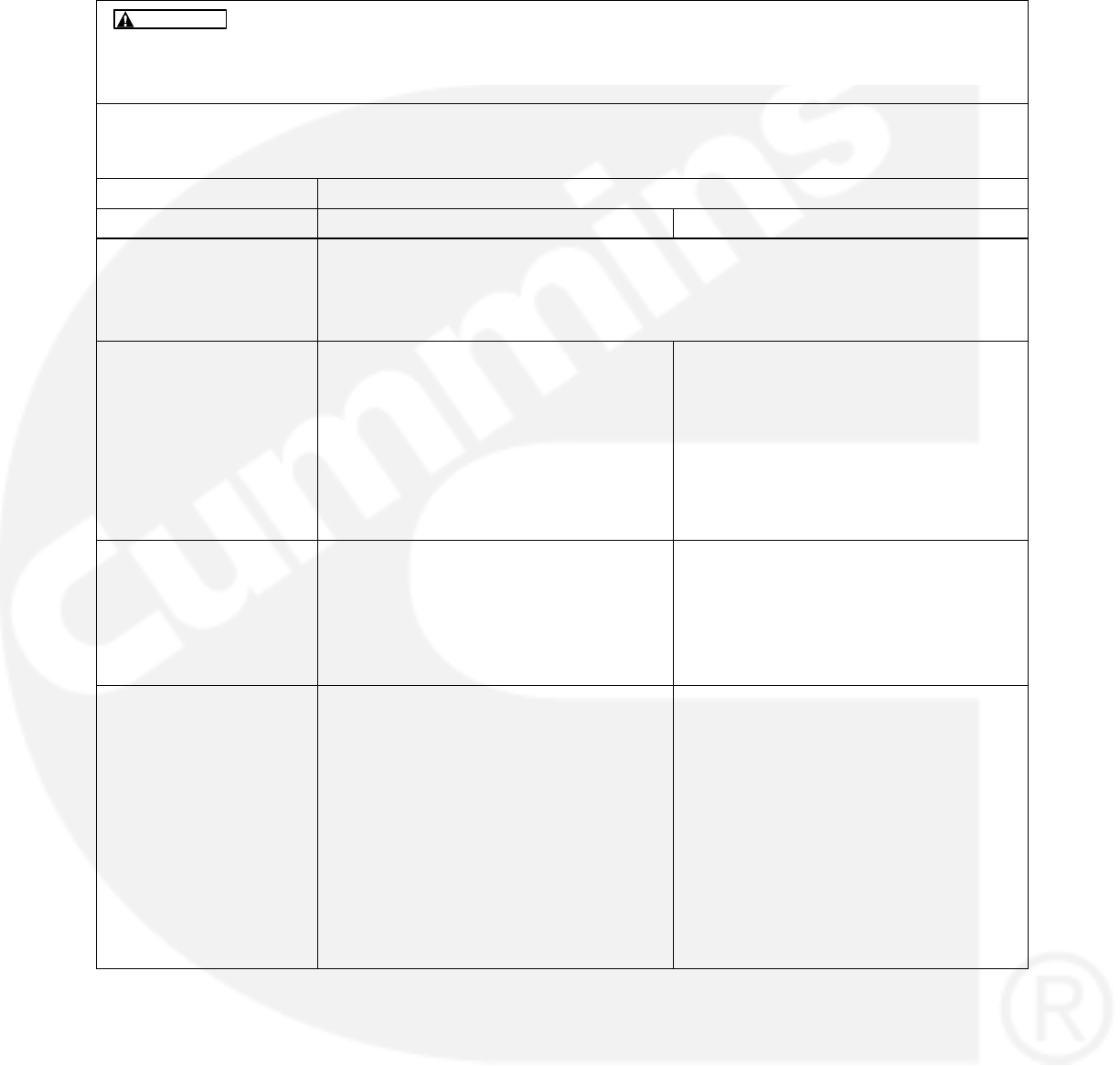
6-17
TABLE 6-9. CODE 146/151 − HIGH OR PRE-HIGH COOLANT TEMPERATURE
(WARNING/SHUTDOWN)
Hazards present in troubleshooting can cause equipment damage, severe person-
al injury or death. Only trained and experienced service personnel with knowledge of fuels, elec-
tricity, and machinery hazards should perform service procedures. Read Important Safety In-
structions pages and observe all instructions and precautions in this manual.
WARNING
Reason: Engine coolant temperature has exceeded the warning threshold for pre-high/high coolant temperature.
Effect: Calibration-dependent. No action is taken by the Control for Fault Code 146. Engine will shut down for
Fault Code 151.
POSSIBLE CAUSE CORRECTIVE ACTION
ENGINE PLATFORM FAE Engines HM Engines
Fault simulation was en-
abled with a PC based
service tool.
With a PC based service tool, verify that the fault simulation is not enabled for the
coolant sensor.
If you do not have a PC based service tool, remove battery power from the control to
disable fault simulation overrides.
Engine or sensor circuitry
problem.
Refer to the engine service manual. Check sensor accuracy with a thermocou-
ple or similar temperature probe.
If the coolant temperature reading is
accurate, the engine may be over-
heating. Refer to the engine service
manual.
If the coolant temperature reading is
not accurate, go to the next step.
The sensor could be de-
fective.
Refer to engine service manual. Disconnect the sensor and connect a
coolant temperature sensor simulator to
the harness.
If the control responds to the simulator,
replace the sensor. If the control does not
respond, go to the next step.
The harness or Base
board could be defective.
Not applicable. Measure the resistance of the coolant
sensor and reconnect the harness to the
sensor. Remove connector J11 from the
Base board and check resistance be-
tween pins P11-11 (H20) and P11-12
(H20 COM).
If resistance is not the same, the har-
ness is defective and must be re-
placed.
If resistance is the same, the Base
board is defective and must be re-
placed.
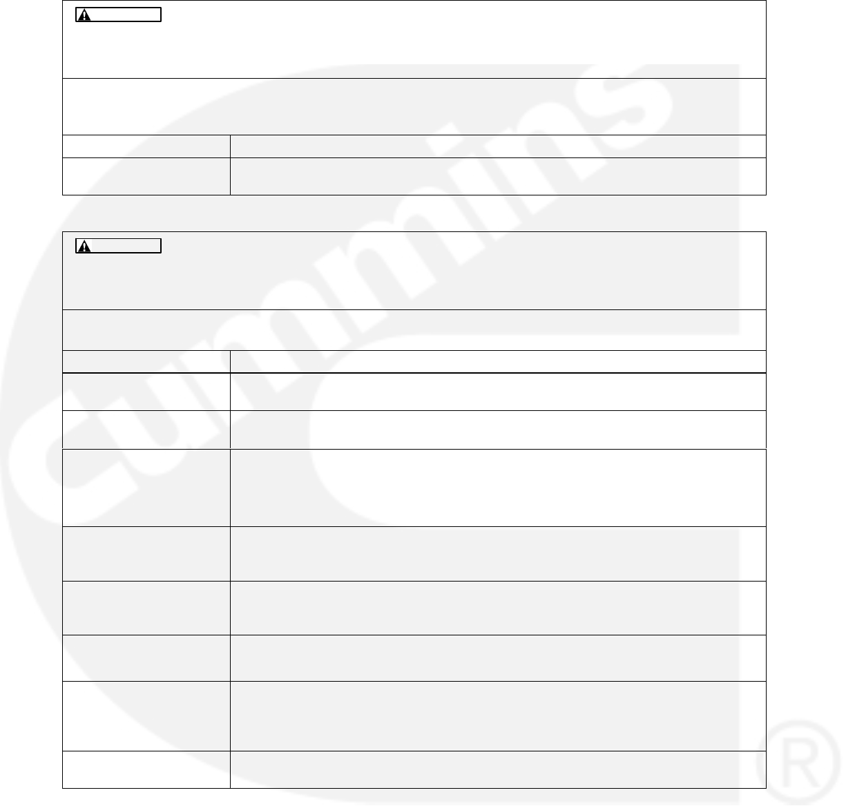
6-18
TABLE 6-10. CODE 153, 154, 155, 195, 196, 197, 285, 286, 418, 426, 1845, 1846, 1852, 1992, 2964 − ENGINE
FAULTS ANNOUNCED BY THE PCC1302 (EVENT/WARNING/SHUTDOWN)
Hazards present in troubleshooting can cause equipment damage, severe person-
al injury or death. Only trained and experienced service personnel with knowledge of fuels, elec-
tricity, and machinery hazards should perform service procedures. Read Important Safety In-
structions pages and observe all instructions and precautions in this manual.
WARNING
Reason: The engine controller has sensed a fault condition and is broadcasting the fault message. The PCC1302 is
uniquely announcing the fault code.
Effect: Event, Shutdown, or Warning
POSSIBLE CAUSE CORRECTIVE ACTION
Consult the engine
service manual.
Consult the engine service manual.
TABLE 6-11. CODE 234 − OVERSPEED (SHUTDOWN)
Hazards present in troubleshooting can cause equipment damage, severe person-
al injury or death. Only trained and experienced service personnel with knowledge of fuels, elec-
tricity, and machinery hazards should perform service procedures. Read Important Safety In-
structions pages and observe all instructions and precautions in this manual.
WARNING
Reason: Engine speed signal indicates an engine speed greater than shutdown threshold.
Effect: Engine will shut down.
POSSIBLE CAUSE CORRECTIVE ACTION
The engine is cold (no
coolant heaters)
Overspeed can occur when starting a very cold engine. Clear the fault and restart the
genset.
There is a single step
large block load removal.
Clear the fault and restart the genset.
A fault simulation was
enabled with a PC based
service tool.
With a PC based service tool, verify that the fault simulation is not enabled for the
coolant sensor.
If you do not have PC based service tool, remove battery power from the control to
disable fault simulation overrides.
The fault threshold is not
set correctly with the PC
based service tool.
Reset the threshold to the highest allowable setting. Determine the required operating
range before adjusting the threshold.
Monitor the engine RPM
using a PC based service
tool.
If the RPM is not correct, refer to Fault Code 121 for corrective action.
There is a governor fault. 1. Check the fuel shutoff solenoid adjustment.
2. Replace the defective injection pump unit.
The flywheel tooth count
is incorrect.
For gensets with a magnetic pickup installed, verify that the flywheel tooth count is
correct for the engine type. Refer to Table 3-25 for a list of flywheel teeth require-
ments and Figure 5-19, sheet 1 for information on how to adjust the flywheel tooth
setting using the operator panel.
The mechanical fuel sys-
tem setup is incorrect.
Verify that the fuel stop settings are correct for your application.

6-19
TABLE 6-12. CODE 359 − FAIL TO START (SHUTDOWN)
Hazards present in troubleshooting can cause equipment damage, severe person-
al injury or death. Only trained and experienced service personnel with knowledge of fuels, elec-
tricity, and machinery hazards should perform service procedures. Read Important Safety In-
structions pages and observe all instructions and precautions in this manual.
WARNING
Reason: This indicates that the engine failed to start after expiration of the last crank time.
Effect: Engine will not start.
POSSIBLE CAUSE CORRECTIVE ACTION
Restricted fuel supply be-
cause:
1. The fuel level is be-
low the pickup tube
in the tank.
2. There is a closed
shutoff valve in the
supply line.
3. The fuel injectors are
clogged.
4. There is air in the
fuel system.
1. Add fuel if low. Prime the fuel system.
2. Open any closed shutoff valve in the fuel line supplying the engine.
3. Refer to the engine service manual.
4. Bleed air from fuel system. Refer to the engine service manual.
Glow plugs are not heat-
ing because:
1. The glow plug(s) is
defective.
2. The Base board is
defective.
3. The glow plug relay
is defective.
The Base board determines at what temperature and duration of time that the glow
plugs are energized. Using sensed coolant temperature, the glow plugs are energized
at 77_F (25_C) and colder. The glow plugs are energized for up to 15 seconds when
the coolant temperature is −5_F (−20.5_C) or colder. The time duration (15−0 sec-
onds) is linear between −5_F and 77_F.
With the coolant temperature colder than 77_F (25_C):
1. Each glow plug should be warm to the touch if the engine has just been cranking.
First clean and tighten the terminal of any cold glow plug and then replace it if
necessary.
2. Install a harness tool between the Base board P11 connector. Attempt to start the
engine and check for B+ at P11-6 (RELAY COIL B+) and GND at P11-7 (GLOW
PLUG SOL).
If B+ / GND is not present, the Base board is defective and must be re-
placed.
If B+ / GND is present, go to step 3.
3. Check for B+ at the glow plug relay. If not present, check for an open circuit.
If there is B+ at the glow plug relay, attempt to start and test for B+ at the other end of
the glow plug relay.
If B+ is not present, the glow plug relay is defective and must be replaced.
If B+ is present, check for an open circuit between the glow plug relay con-
tact and the glow plugs.
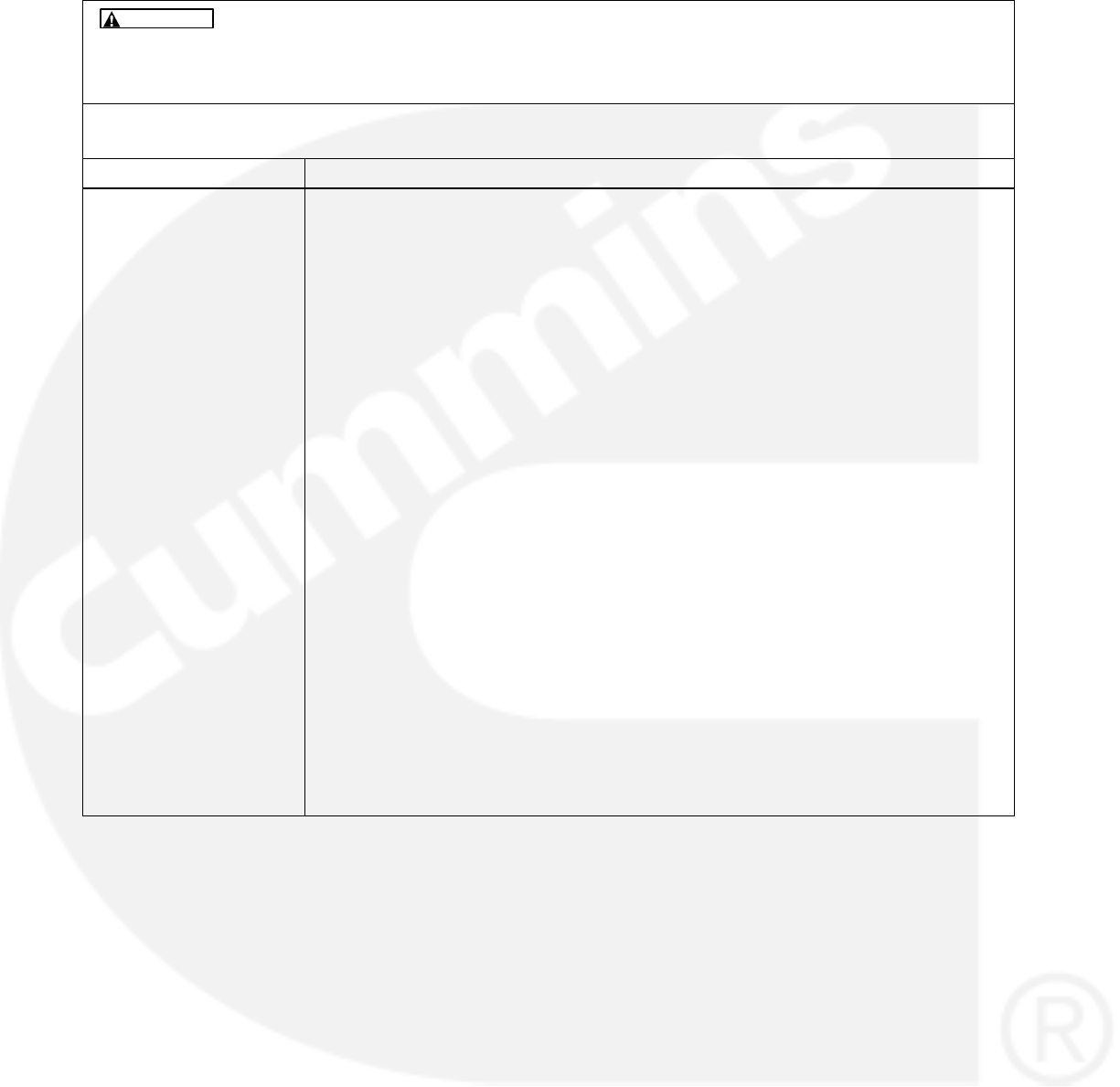
6-20
TABLE 6-12. CODE 359 − FAIL TO START (SHUTDOWN) (CONT.)
Hazards present in troubleshooting can cause equipment damage, severe person-
al injury or death. Only trained and experienced service personnel with knowledge of fuels, elec-
tricity, and machinery hazards should perform service procedures. Read Important Safety In-
structions pages and observe all instructions and precautions in this manual.
WARNING
Reason: This indicates that the engine failed to start after expiration of the last crank time.
Effect: Engine will not start.
POSSIBLE CAUSE CORRECTIVE ACTION
The fuel solenoid on the
injection pump is not en-
ergized because:
1. The fuse is open.
2. The fuel solenoid is
defective.
3. The Base board/K8
fuel relay is defec-
tive.
Isolate to the fuse, fuel relay, fuel solenoid, or the Base board.
1. Remove the fuse (if installed) and check continuity. If open, replace the fuse with
one of the same type and amp rating. If the fuse reopens, check wiring continuity
of the fuel solenoid circuit/test fuel solenoid.
Binding in the solenoid linkage can prevent activation of the hold coil circuitry in the
solenoid. Make sure the solenoid shaft moves completely in and out freely. (Applies
to solenoids with both Pull and Hold coils.)
2. Attempt to start the engine and check for B+ at the fuel solenoid coil.
If B+ is present, the fuel solenoid is defective and must be replaced.
If B+ is not present, go to step 3.
3. Check wiring continuity/test K8 relay or fuel pilot:
Remove the lead from FUEL RELAY−COM (fuel pilot). Attempt to start the engine
and check for B+ at lead COM.
If there is no B+, check for an open circuit between K8-COM and fuse.
If B+ is present, reconnect lead COM to the relay. Remove the lead from the
N/O connection. Attempt to start the engine and check for B+ at the terminal
N/O connection.
If B+ is present, check for an open circuit between the N/O connection and
the fuel solenoid (+).
If B+ is not present, check to make sure the E-stop switches are inactive,
then check for a ground signal at J11-14. If not, the Base board is defective
and must be replaced.

6-21
TABLE 6-12. CODE 359 − FAIL TO START (SHUTDOWN) (CONT.)
Hazards present in troubleshooting can cause equipment damage, severe person-
al injury or death. Only trained and experienced service personnel with knowledge of fuels, elec-
tricity, and machinery hazards should perform service procedures. Read Important Safety In-
structions pages and observe all instructions and precautions in this manual.
WARNING
Reason: This indicates that the engine failed to start after expiration of the last crank time.
Effect: Engine will not start.
POSSIBLE CAUSE CORRECTIVE ACTION
The injection pump ac-
tuator is not energized
due to the harness, gov-
ernor actuator, governor
module, or the Base
board is defective.
Isolate to the harness, governor actuator, or the Base board.
1. Display the “Governor Duty Cycle” menu. Attempt to start and check for duty
cycle (44% is about average). If the percentage of duty cycle is displayed before a
shutdown, the harness, actuator governor, or output circuit of the control is defec-
tive Go to step 2. (Duty cycle displayed indicates the processor is functioning, but
the output circuitry of the Base board could still be defective.) If the duty cycle is
not displayed, the control is defective or is configured incorrectly. Check the con-
figuration.
2. Remove connector P11 from the control and check wiring continuity of the actua-
tor circuit. Check P11 5 (GOV−DR+) and P11-4 (GOV−DR−) to the appropriate
+/− terminals of the governor module and between J1-4 on the governor module
and the actuator. If continuity is OK, go to step c.
3. Disconnect the two leads attached to the injection pump actuator. Measure the
resistance across the two actuator terminals. A reading of 2.3 ohms indicates that
the actuator circuit is OK. (This test only shows that the actuator circuit is not
opened or shorted, but not if there is binding.) Replace the actuator assembly if
an open or short is measured. If the actuator is OK, go to step 4.
4. Remove power from the control for one minute. Put power back on the control
and check for B+ at P11-5. If not present, the control is defective and must be re-
placed. If present, go to step 5.
5. Attempt to start and check for CNTL B+ at terminal lead ACT + of the governor
actuator (use the engine block for metering ground). If not present, check the wir-
ing or SW B+ control function and J1-3 of the governor module.
6. If CNTL B+ is present, attempt to start the engine and check for a GOV PWM
(pulse wide modulated) signal (measure across the terminals of the actuator and
across J1-2 to J1-1 of the governor module). If not present on J1, the control is
defective and must be replaced.
7. If not present on the actuator, governor module is defective and must be replaced.
The engine fuel system is
worn or malfunctioning or
it has lost prime (fuel lift
pump, injection pump, in-
jectors, timing).
Service according to the engine service manual.
The engine is worn or is
malfunctioning mechani-
cally.
Service according to the engine service manual.
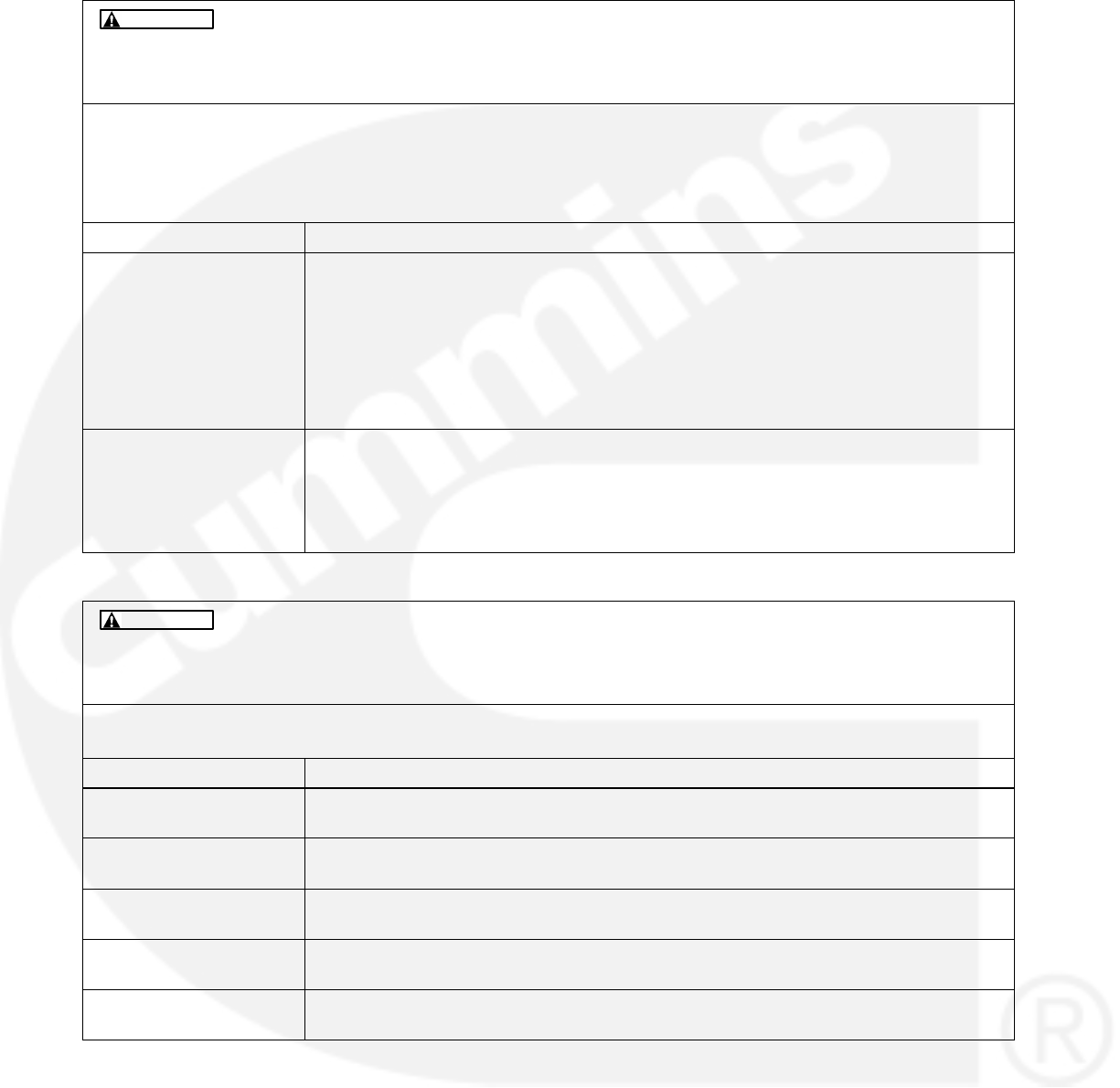
6-22
TABLE 6-13. CODE 427/781 − CAN DATALINK LOST (WARNING/SHUTDOWN)
Hazards present in troubleshooting can cause equipment damage, severe person-
al injury or death. Only trained and experienced service personnel with knowledge of fuels, elec-
tricity, and machinery hazards should perform service procedures. Read Important Safety In-
structions pages and observe all instructions and precautions in this manual.
WARNING
Reason: Indicates that the communication link between the engine controller and genset controller is lost.
Effect: Warning – The control issues a warning level fault if the CAN datalink is lost and while there is no engine
speed or no start command.
Shutdown – The control issues a shutdown level fault if the CAN datalink is lost while there is a non-zero
engine speed or a start command is active.
POSSIBLE CAUSE CORRECTIVE ACTION
The networking harness
is defective.
1. Check the datalink between the ECM and the GCS. Check for open or shorts be-
tween the following:
J11-20 (CANH)
J11-19 (CANL)
J11-17 (CAN Shield)
2. Also check to make sure that there is 60 Ohms resistance between J11-20 and
J11-19. If not, the harness is defective; repair the harness.
The ECM is powered
down.
1. With the control powered, check for the B+ on the positive side of the keyswitch
pilot relay coil. Check for GND on the negative side of the keyswitch relay coil.
2. If B+ doesn’t exist, the harness is defective. If GND doesn’t exist, check for GND
on P11-21 (Keyswitch LS Out). If GND does exist, the harness is defective, repair
harness. If GND doesn’t exist, the Base board is defective and must be replaced.
TABLE 6-14. CODE 441 − LOW BATTERY (WARNING)
Hazards present in troubleshooting can cause equipment damage, severe person-
al injury or death. Only trained and experienced service personnel with knowledge of fuels, elec-
tricity, and machinery hazards should perform service procedures. Read Important Safety In-
structions pages and observe all instructions and precautions in this manual.
WARNING
Reason: Low voltage has been detected for the battery.
Effect: The control’s voltage supply approaches a level at which unpredictable operation may occur.
POSSIBLE CAUSE CORRECTIVE ACTION
Weak or discharged bat-
tery.
Recharge or replace the battery. Specific gravity for a fully charged battery is approxi-
mately 1.260 at 80_F (27_C).
Low electrolyte level in
the battery.
Replenish electrolyte and recharge the battery.
Battery connections are
loose or dirty.
Clean and tighten or replace the battery cable connectors and cables at the battery
and the genset.
Insufficient battery charg-
ing voltage.
Adjust the charge rate of the AC powered battery charging circuit, according to
manufactures instructions.
Engine DC alternator
could be defective.
Replace the engine DC alternator if the normal battery charging voltage (12 to 14
VDC for 12VDC system, 24 to 27 VDC for 24VDC system) is not obtained.
6-23
TABLE 6-14. CODE 441 − LOW BATTERY (WARNING) (CONT.)
Hazards present in troubleshooting can cause equipment damage, severe person-
al injury or death. Only trained and experienced service personnel with knowledge of fuels, elec-
tricity, and machinery hazards should perform service procedures. Read Important Safety In-
structions pages and observe all instructions and precautions in this manual.
WARNING
Reason: Low voltage has been detected for the battery.
Effect: The control’s voltage supply approaches a level at which unpredictable operation may occur.
POSSIBLE CAUSE CORRECTIVE ACTION
If the batteries are OK,
the problem may be with
the harness or the Base
board.
Remove connector P11 from the Base board and check battery voltage at
P20-9,10,20,21 (B+) to P20-10 2,4,7,12(GND).
If the voltage at P11 is not the same as the battery voltage, the harness is defec-
tive and must be replaced.
If the voltage at P11 is OK, the Base board is defective and must be replaced.
Fault threshold could be
incorrect.
Check the fault threshold against the requirement of the application.
TABLE 6-15. CODE 442 − HIGH BATTERY VOLTAGE (WARNING)
Hazards present in troubleshooting can cause equipment damage, severe person-
al injury or death. Only trained and experienced service personnel with knowledge of fuels, elec-
tricity, and machinery hazards should perform service procedures. Read Important Safety In-
structions pages and observe all instructions and precautions in this manual.
WARNING
Reason: High voltage has been detected for the battery.
Effect: Control damage will occur.
POSSIBLE CAUSE CORRECTIVE ACTION
Excessive battery charg-
ing voltage.
Adjust the charge rate of the AC powered battery charging circuit according to the
manufacturer’s instructions.
Engine DC alternator
could be defective.
Replace the engine DC alternator if the normal battery charging voltage (12 to 14
VDC) is not obtained.
Fault threshold could be
incorrect.
Check the fault threshold against the requirement of the application.
TABLE 6-16. CODE 1311, 1312, 1317, 1318 − CONFIGURABLE INPUT (WARNING/SHUTDOWN)
Hazards present in troubleshooting can cause equipment damage, severe person-
al injury or death. Only trained and experienced service personnel with knowledge of fuels, elec-
tricity, and machinery hazards should perform service procedures. Read Important Safety In-
structions pages and observe all instructions and precautions in this manual.
WARNING
Reason: The nature of the fault is an optional configurable selection.
Effect: Shutdown.
POSSIBLE CAUSE CORRECTIVE ACTION
If there is no actual fault,
the problem may be an
external wiring problem.
If the Fault Input Active State select is set to active close, check to see if GND is at
the fault input terminal. If GND is at the fault input terminal, check the external wiring.
If the Fault Input Active State select is set to active open, check to see if GND is not
at the fault input terminal. If GND is not at the fault input terminal, check the external
wiring.
6-24
TABLE 6-17. CODE 1426 − GENERIC ENGINE FAULT (WARNING)
Hazards present in troubleshooting can cause equipment damage, severe person-
al injury or death. Only trained and experienced service personnel with knowledge of fuels, elec-
tricity, and machinery hazards should perform service procedures. Read Important Safety In-
structions pages and observe all instructions and precautions in this manual.
WARNING
Reason: The PCC1302 has received a fault code from the engine control module that it doesn’t uniquely recognize.
Effect: Warning.
POSSIBLE CAUSE CORRECTIVE ACTION
The engine controller has
broadcasted a fault that
the PCC1302 control
doesn’t recognize.
Use an engine service tool (Insite or InPower) to view the active fault messages being
sent by the engine controller. Consult the engine service manual for a Fault Code
mapping and a procedure to cure the problem.
TABLE 6-18. CODE 1443 − DEAD BATTERY
Hazards present in troubleshooting can cause equipment damage, severe person-
al injury or death. Only trained and experienced service personnel with knowledge of fuels, elec-
tricity, and machinery hazards should perform service procedures. Read Important Safety In-
structions pages and observe all instructions and precautions in this manual.
WARNING
Reason: Indicates during cranking battery voltage has dropped below operating voltage of control resetting the con-
trol for three consecutive times.
Effect: Shutdown.
POSSIBLE CAUSE CORRECTIVE ACTION
Weak or discharged bat-
tery.
Measure the voltage of battery with voltmeter. Battery voltage should be 12VDC or
greater for 12 VDC system and 24VDC or greater for 24VDC system.
If battery voltage is low, check the electrolyte level.
Replenish electrolyte level if low and recharge the battery
( specific gravity of fully charged lead acid battery is approximately 1.26 at 80 F ( 27
C).
If battery cannot hold adequate voltage, replace battery.
Battery connections are
loose or dirty.
Clean and tighten battery terminals and battery cable connector.
If battery cable connectors are cracked or worn out then replace.
Insufficient battery charg-
ing voltage.
Ensure external battery charger is charging the battery at an acceptable rate. Adjust
the rate if the rate is below the recommendation of the manufacturer.
If battery is located at a far distance from the battery charger, ensure that adequate
wire gauge is used to compensate the voltage drop.
Faulty engine DC alter-
nator.
Replace engine DC alternator if normal battery charging voltage (12 to 14 VDC for
12VDC system , 24 to 27 VDC for 24VDC system) is not obtained.
Faulty Harness. Measure the battery voltage at battery terminals when genset is cranking. Then mea-
sure battery voltage at base board input while genset is cranking ( at J20−9, J20−10,
J20−20,J20−21 for B+ve and J20−2, J20−4, J20−7, J20−12 for B−ve).
If voltage at battery terminals and control is not the same, check harness and replace
if necessary.
6-25
TABLE 6-19. CODE 1435 − LOW COOLANT TEMPERATURE (WARNING)
Hazards present in troubleshooting can cause equipment damage, severe person-
al injury or death. Only trained and experienced service personnel with knowledge of fuels, elec-
tricity, and machinery hazards should perform service procedures. Read Important Safety In-
structions pages and observe all instructions and precautions in this manual.
WARNING
Reason: The engine coolant temperature has dropped below the warning threshold for low coolant temperature.
Effect: No action is taken by the control. The engine may not start because of a slow cranking speed.
POSSIBLE CAUSE CORRECTIVE ACTION
ENGINE PLATFORM FAE Engines HM Engines
A fault simulation was
enabled with a PC based
service.
With the PC based service tool, verify that the fault simulation is not enabled for the
coolant sensor.
If you do not have a based service tool, remove battery power from the control to dis-
able the fault simulation overrides.
The fault threshold was
not set correctly with a
PC based service tool.
Reset the threshold to the lowest allowable setting. Determine the required operating
range before adjusting the threshold.
The engine coolant heat-
er could be defective.
(Radiant heat should be
felt when your hand is
held close to the outlet
hose.)
The coolant heater is not operating because:
The coolant heater is not connected to power. Check for a blown fuse, or discon-
nected the heater cord and correct as required.
There is a low coolant level. Look for possible coolant leakage points and repair
as required.
There is a defective heater element/thermostat. With the coolant heater removed
from the engine and power disconnected, flush with cold tap water for two min-
utes to close the internal heater thermostat (opens at 100_F and closes at 80_F).
Check resistance across the input power leads:
a. Open − replace the coolant heater.
b. Closed − coolant heater OK (coil resistance of 10 to 60 ohms)
The sensor connections
could be defective.
Inspect the sensor and engine harness connector pins. Repair or replace as neces-
sary.
The sensor could be de-
fective.
Disconnect the sensor and plug in a resistive sensor simulator to isolate the fault.
If the control responds to the simulator, replace the sensor. If control does not re-
spond, the harness or Base board are defective and must be replaced.
6-26
TABLE 6-19. CODE 1435 − LOW COOLANT TEMPERATURE (WARNING) (CONT.)
Hazards present in troubleshooting can cause equipment damage, severe person-
al injury or death. Only trained and experienced service personnel with knowledge of fuels, elec-
tricity, and machinery hazards should perform service procedures. Read Important Safety In-
structions pages and observe all instructions and precautions in this manual.
WARNING
Reason: The engine coolant temperature has dropped below the warning threshold for low coolant temperature.
Effect: No action is taken by the control. The engine may not start because of a slow cranking speed.
POSSIBLE CAUSE CORRECTIVE ACTION
ENGINE PLATFORM HM EnginesFAE Engines
The harness or Base
board could be defective.
Measure the resistance of the coolant temperature sensor and reconnect the harness
to the sensor. Remove connector P11 from the Base board and check resistance be-
tween pins P11-11 (H20) and P11-12 (H20 COM).
If resistance is not the same, the harness is defective and must be replaced.
If resistance is the same, the Base board is defective and must be replaced.
TABLE 6-20. CODE 1438 − FAIL TO CRANK (SHUTDOWN)
Hazards present in troubleshooting can cause equipment damage, severe person-
al injury or death. Only trained and experienced service personnel with knowledge of fuels, elec-
tricity, and machinery hazards should perform service procedures. Read Important Safety In-
structions pages and observe all instructions and precautions in this manual.
WARNING
Reason: This indicates that the engine failed to crank after the control received a start signal.
Effect: Engine will not start.
POSSIBLE CAUSE CORRECTIVE ACTION
ENGINE PLATFORM FAE Engines HM Engines
1. The starter is defec-
tive.
Refer to the engine service manual.
Reset the control. Attempt to start and test for B+ at the starter. If there is B+ at the
starter, the starter could be defective. Test the starter (see the engine service manual)
and, if necessary, replace the starter. If B+ is not present at the starter, go to the next
step.
2. The starter relay is
defective.
Check wiring continuity/test starter relay.
Remove the lead from the starter relay−COM and check for B+ at the lead COM (di-
rectly connected to battery B+).
If there is no B+, check for an open circuit between starter relay−COM and the
battery B+.
If B+ is present, reconnect the lead COM to the starter relay. Remove the lead
from the starter relay−N/O. Attempt to start and check for B+ at the terminal start-
er relay−N/O.
If B+ is present, check for an open circuit between starter relay−N/O and the SW
terminal of the starter.
If B+ is not present, the Base board/starter relay is defective.
3. Either the Emergen-
cy Stop switch or the
wiring is defective.
With the Emergency Stop push button not activated, remove the configurable leads
from TB1-15 and TB1-16 and check for continuity between these two leads. If the cir-
cuit is open, isolate to the Emergency Stop switch and wiring. With the Local Emer-
gency Stop push button not activated, remove P25 from the Base board. Check for
continuity between J25-2 and J25-6. If there is continuity, go to the next step.
4. The MPU/circuit or
Base board is defec-
tive.
Refer to the engine service manual. Refer to the Fault Code 121 instructions.
6-27
TABLE 6-21. CODE 1442 − WEAK BATTERY (WARNING)
Hazards present in troubleshooting can cause equipment damage, severe person-
al injury or death. Only trained and experienced service personnel with knowledge of fuels, elec-
tricity, and machinery hazards should perform service procedures. Read Important Safety In-
structions pages and observe all instructions and precautions in this manual.
WARNING
Reason: Low voltage has been detected for the battery.
Effect: The control’s voltage supply is approaching a level at which unpredictable operation may occur.
POSSIBLE CAUSE CORRECTIVE ACTION
Refer to Fault Code 441.Refer to Fault Code 441.
TABLE 6-22. CODE 1446 − HIGH AC VOLTAGE (SHUTDOWN)
Hazards present in troubleshooting can cause equipment damage, severe person-
al injury or death. Only trained and experienced service personnel with knowledge of fuels, elec-
tricity, and machinery hazards should perform service procedures. Read Important Safety In-
structions pages and observe all instructions and precautions in this manual.
WARNING
Reason: One or more of the phase voltages has exceeded 130% of nominal for 1 seconds, or has exceeded the
High AC Voltage Threshold for the High AC Voltage Delay seconds.
Effect: Engine will shut down.
POSSIBLE CAUSE CORRECTIVE ACTION
Fault simulation was en-
abled with a PC based
service tool.
With a PC based service tool, verify that the related fault simulation is not enabled.
If you do not have a PC based service tool, remove battery power from the control to
disable the fault simulation overrides.
Single step large block
load removal.
Clear the fault and restart the genset.
Fault threshold is not set
correctly with the PC
based service tool.
Reset the threshold to the highest allowable setting. Determine the required operating
range before adjusting the threshold.
The Base board or gen-
erator is defective.
Refer to the Generator/Base Board Isolation Procedure in the Service Manual to de-
termine if the Base board is causing the high AC voltage shutdown fault.
The voltage sense con-
nections/set up could be
incorrect.
Refer to the Generator/Base Board Isolation Procedure in the generator Service
Manual to determine if the Base board is causing the high AC voltage shutdown fault.
TABLE 6-23. CODE 3539, 3541,3542, 5669 − ENGINE FAULTS ANNOUNCED BY PCC1302
Hazards present in troubleshooting can cause equipment damage, severe person-
al injury or death. Only trained and experienced service personnel with knowledge of fuels, elec-
tricity, and machinery hazards should perform service procedures. Read Important Safety In-
structions pages and observe all instructions and precautions in this manual.
WARNING
Reason: The engine controller has sensed a fault condition and is broadcasting the fault message. The PCC1302 is
uniquely announcing the fault code.
Effect: Event,Shutdown,Warning.
POSSIBLE CAUSE CORRECTIVE ACTION
Consult Engine Service
Manual.
Consult Engine Service Manual.

6-28
TABLE 6-24. CODE 1447 − LOW AC VOLTAGE (SHUTDOWN)
Hazards present in troubleshooting can cause equipment damage, severe person-
al injury or death. Only trained and experienced service personnel with knowledge of fuels, elec-
tricity, and machinery hazards should perform service procedures. Read Important Safety In-
structions pages and observe all instructions and precautions in this manual.
WARNING
Reason: One or more of the phase voltages has dropped below the Low AC Voltage Threshold for Low AC Voltage
Delay seconds.
Effect: Engine will shut down.
POSSIBLE CAUSE CORRECTIVE ACTION
A fault simulation was
enabled with a PC based
service tool.
With a PC based service tool, verify that the related fault simulation is not enabled.
If you do not have a PC based service tool, remove battery power from the control to
disable fault simulation overrides.
The fault threshold is not
set correctly with a PC
based service tool.
Reset the threshold to the lowest allowable setting. Determine the required operating
range before adjusting the threshold.
There is an overload. Check the load and correct any overload. Check operation by disconnecting the load
and restarting the generator set.
Improper connections
have been made at the
generator output termi-
nals.
Reconnect according to the appropriate reconnection diagram.
The voltage sense or set-
up wiring connection
could be incorrect.
Verify that excitation inputs P18-1 and P18-2 are connected to the correct generator
outputs.
The rotating rectifier as-
sembly (diodes CR1
through CR6) is faulty.
Check each diode. See the genset service manual
There is a loose connec-
tor or the Base board is
defective.
Repair connections (P18) or replace the Base board if necessary.
The voltage sense con-
nections/setup could be
incorrect.
See Section 7 for proper connections.
TABLE 6-25. CODE 1448 − UNDER FREQUENCY (SHUTDOWN)
Hazards present in troubleshooting can cause equipment damage, severe person-
al injury or death. Only trained and experienced service personnel with knowledge of fuels, elec-
tricity, and machinery hazards should perform service procedures. Read Important Safety In-
structions pages and observe all instructions and precautions in this manual.
WARNING
Reason: Generator AC output frequency is low.
Effect: Generator set will shut down.
POSSIBLE CAUSE CORRECTIVE ACTION
The fault threshold is not
set correctly with PC
based service tool.
Reset the threshold to the lowest allowable setting. Determine the required operating
range before adjusting the threshold.
There is an overload. Check the load and correct any overload. Check operation by disconnecting the load
and restarting the generator set.
There is a fuel or air de-
livery problem
Refer to the engine service manual.
6-29
TABLE 6-25. CODE 1448 − UNDER FREQUENCY (SHUTDOWN) (CONT.)
Hazards present in troubleshooting can cause equipment damage, severe person-
al injury or death. Only trained and experienced service personnel with knowledge of fuels, elec-
tricity, and machinery hazards should perform service procedures. Read Important Safety In-
structions pages and observe all instructions and precautions in this manual.
WARNING
Reason: Generator AC output frequency is low.
Effect: Generator set will shut down.
POSSIBLE CAUSE CORRECTIVE ACTION
There is a governor fault Check the fuel shutoff solenoid adjustment.
There is a loose connec-
tor or the Base board is
defective
Repair connections (P22/P18) or replace the Base board if necessary.
TABLE 6-26. CODE 1449 − OVER FREQUENCY (SHUTDOWN)
Hazards present in troubleshooting can cause equipment damage, severe person-
al injury or death. Only trained and experienced service personnel with knowledge of fuels, elec-
tricity, and machinery hazards should perform service procedures. Read Important Safety In-
structions pages and observe all instructions and precautions in this manual.
WARNING
Reason: Generator AC output frequency is high.
Effect: Generator set will shut down.
POSSIBLE CAUSE CORRECTIVE ACTION
The fault threshold is not
set correctly with PC
based service tool.
Reset the threshold to the highest allowable setting. Determine the required operating
range before adjusting the threshold.
There is a fuel or air de-
livery problem.
Refer to the engine service manual.
There us a loose connec-
tor or the Base board is
defective.
Repair connections (P22/P18) or replace the Base board if necessary.
TABLE 6-27. CODE 1471/1472 − HIGH AC CURRENT (SHUTDOWN/WARNING)
Hazards present in troubleshooting can cause equipment damage, severe person-
al injury or death. Only trained and experienced service personnel with knowledge of fuels, elec-
tricity, and machinery hazards should perform service procedures. Read Important Safety In-
structions pages and observe all instructions and precautions in this manual.
WARNING
Reason: This indicates that the indicated generator output current has exceeded at least110% of rated current.
Effect: No action is taken by the control for Fault Code 1472. Engine will shut down for Fault Code 147.
POSSIBLE CAUSE CORRECTIVE ACTION
1. Short or Overload Check the load and load cables. Repair if necessary. Check operation by disconnect-
ing the load and restarting the generator set.
2. Incorrect CTs, CT
connections, or CT
setup.
Check CTs and CT connections. Correct if necessary. Refer to Current Transformer
Setup on page 3-4.
6-30
TABLE 6-27. CODE 1471/1472 − HIGH AC CURRENT (SHUTDOWN/WARNING) (CONT.)
Hazards present in troubleshooting can cause equipment damage, severe person-
al injury or death. Only trained and experienced service personnel with knowledge of fuels, elec-
tricity, and machinery hazards should perform service procedures. Read Important Safety In-
structions pages and observe all instructions and precautions in this manual.
WARNING
Reason: This indicates that the indicated generator output current has exceeded at least110% of rated current.
Effect: No action is taken by the control for Fault Code 1472. Engine will shut down for Fault Code 147.
POSSIBLE CAUSE CORRECTIVE ACTION
1. The problem may be
the Base board or
harness connections.
Remove connector P12 from the Base board. Check continuity from P12 to the CTs.
P12-1 (CT1) to P12-4 (CT1-COM)
P12-2 (CT2) to P12-5 (CT2-COM)
P12-3 (CT3) to P12-6 (CT3-COM)
Repair connections.
2. There may be an in-
correct rating setup.
Check the rating setup in the control. Correct if necessary.
TABLE 6-28. CODE 1689 − CLOCK NOT SET
Hazards present in troubleshooting can cause equipment damage, severe person-
al injury or death. Only trained and experienced service personnel with knowledge of fuels, elec-
tricity, and machinery hazards should perform service procedures. Read Important Safety In-
structions pages and observe all instructions and precautions in this manual.
WARNING
Reason: ’Exercise Scheduler’ function is enabled and real time clock (RTC) is not set.
Effect: Warning. Exercise function will not work.
POSSIBLE CAUSE CORRECTIVE ACTION
Battery power recycled
with ’Exercise Scheduler’
function enabled.
If exercise scheduler function is not required, disable the function via HMI211 or ser-
vice tool.
If exercise scheduler function is required, set and save the real time clock.
RTC not set after enab-
ling exercise function.
Set and save the real time clock.
TABLE 6-29. CODE 1944 − ANNUNCIATOR OUTPUT CONFIGURATION ERROR (WARNING)
Hazards present in troubleshooting can cause equipment damage, severe person-
al injury or death. Only trained and experienced service personnel with knowledge of fuels, elec-
tricity, and machinery hazards should perform service procedures. Read Important Safety In-
structions pages and observe all instructions and precautions in this manual.
WARNING
Reason: Indicates that more then one network device is configured to activate one of the Annunciator output relays.
Effect: Warning
POSSIBLE CAUSE CORRECTIVE ACTION
Network configuration is
incorrect.
Check setup of the devices on the network against duplicate use of the same Annun-
ciator relay output.
There is a defective de-
vice on the network.
Troubleshoot the network for malfunctioning devices.
6-31
TABLE 6-30. CODE 2118 − LOW FUEL PRESSURE
Hazards present in troubleshooting can cause equipment damage, severe person-
al injury or death. Only trained and experienced service personnel with knowledge of fuels, elec-
tricity, and machinery hazards should perform service procedures. Read Important Safety In-
structions pages and observe all instructions and precautions in this manual.
WARNING
Reason: Low pressure sensed for gaseous fuel application.
Effect: Warning ( configurable to shutdown )
POSSIBLE CAUSE CORRECTIVE ACTION
Fuel source level is low
or exhausted.
Check primary fuel source level.
If refill is required, stop the genset, and refill.
Fuel Pressure switch is
faulty.
Refer engine manual for pressure switch check. Replace if faulty.
TABLE 6-31. CODE 2335 − LOSS OF AC SENSE (SHUTDOWN)
Hazards present in troubleshooting can cause equipment damage, severe person-
al injury or death. Only trained and experienced service personnel with knowledge of fuels, elec-
tricity, and machinery hazards should perform service procedures. Read Important Safety In-
structions pages and observe all instructions and precautions in this manual.
WARNING
Reason: This indicates that the control has loss voltage sensing or it has lost zero cross sensing.
Effect: Generator set will shutdown.
POSSIBLE CAUSE CORRECTIVE ACTION
1. There may be prob-
lems with the load.
Verify that the load contains no shorts. Using a DMM check for shorts between each
of the J22 pins. It also may be helpful to disconnect all load lines and start the genset.
If the genset runs with no load, that could be load lines are shorted.
Refer to the reconnection drawings in Section 7 as a reference.
2. The wire harness is
defective.
Remove the AC Sense harness (J22) and check continuity of all wires. Repair the
harness as needed, reset the control, and restart the genset.
Check continuity between the following leads. If resistance is greater than 200 Ohms,
repair the harness.
J22 Pin 4 and VN terminal
J22 Pin 3 and V3 terminal
J22 Pin 2 and V2 terminal
J22 Pin 1 and V1 terminal
Check continuity between the following leads. If resistance is greater than 200 Ohms,
repair the harness.
J17 Pin 1 and Field Coil +.
J17 Pin 2 and Field Coil −.
Check continuity between the following leads, if resistance is greater than 200 Ohms,
repair the harness:
J18 Pin 1 and V1 terminal (shunt) or PMG 1 terminal (PMG)
J18 Pin 2 and V2 terminal (shunt) or PMG 2 terminal (PMG)
6-32
TABLE 6-31. CODE 2335 − LOSS OF AC SENSE (SHUTDOWN) (CONT.)
Hazards present in troubleshooting can cause equipment damage, severe person-
al injury or death. Only trained and experienced service personnel with knowledge of fuels, elec-
tricity, and machinery hazards should perform service procedures. Read Important Safety In-
structions pages and observe all instructions and precautions in this manual.
WARNING
Reason: This indicates that the control has loss voltage sensing or it has lost zero cross sensing.
Effect: Generator set will shutdown.
POSSIBLE CAUSE CORRECTIVE ACTION
3. The excitation coil
isn’t charged.
The excitation coil may need to be flashed:
1.. Remove the Field Coil + and Field Coil – leads from the alternator.
2.. Using a 12 VDC power supply, touch the positive supply terminal to the Field Coil
+ and the negative supply terminal to the Field Coil −. Remove after brief contact.
Repeat this procedure three times.
3.. Reconnect the Field Coil + and the Field Coil – leads to the alternator.
4.. Reset the control, and restart the genset.
5.. If the genset fails to operate correctly, repeat steps 1−4 with a 24 VDC power sup-
ply.
4. The excitation coil is
defective.
Remove the Field Coil + and the Field Coil – leads from the alternator.
Check continuity between Field Coil + and Field Coil −.
Verify that the reading is within alternator specifications. If so, continue to step 4.
5. Verify the genset set-
up.
Verify that the genset is capable of reaching rated speed by manually running the
genset. Some potential problems could be: clogged fuel filter, incorrect fuel stop posi-
tion, malfunctioning fuel actuators, etc. If the genset is not capable of reaching rated
speed: correct the problem, reset the control, and restart the genset.
6. The control board is
defective.
Replace the control board module.
6-33
TABLE 6-32. CODE 2545 − KEYSWITCH RESET REQUIRED (SHUTDOWN)
Hazards present in troubleshooting can cause equipment damage, severe person-
al injury or death. Only trained and experienced service personnel with knowledge of fuels, elec-
tricity, and machinery hazards should perform service procedures. Read Important Safety In-
structions pages and observe all instructions and precautions in this manual.
WARNING
Reason: After sensing a CAN datalink failed condition (Fault Code 781), the PCC1302 has tried unsuccessfully to
restore communications by toggling power to the ECM.
Effect: Shutdown.
POSSIBLE CAUSE CORRECTIVE ACTION
The networking harness
is defective.
1. Check the datalink between the ECM and the GCS. Check for open or shorts be-
tween the following:
J11-20 (CANH)
J11-19 (CANL)
J11-17 (CAN Shield)
2. Also check to make sure that there is 60 ohms resistance between J11-20 and
J11-19. If not, the harness is defective; repair the harness.
The ECM is powered
down.
With the control powered, check for B+ on the positive side of the keyswitch pilot relay
coil. Check for GND on the negative side of the keyswitch relay coil.
If B+ doesn’t exist, the harness is defective. If GND doesn’t exist, check for GND on
P11-21 (Keyswitch LS Out). If GND does exist, the harness is defective; repair the
harness. If GND doesn’t exist, the Base board is defective and must be replaced.
The keyswitch minimum
on-time is set too short.
This time delay sets how long the control waits for the ECM to come online during a
power cycle before it determines that the datalink is down and does another power
cycle.
Using InPower, increase the keyswitch minimum on-time trim to the highest possible
value. Reset the fault.
the keyswitch reset time
is set too short.
This time delay sets how long it takes for the keyswitch circuits to turn off.
Using InPower, increase the keyswitch reset time delay to the highest possible value.
Reset the fault.
The number of CAN
datalink retries is set too
low.
This sets how many times the control power cycles the ECM before it declares Fault
Code 2545.
Use InPower to increase this number to the highest possible setting.
TABLE 6-33. CODE 2972 − OVER EXCITATION (SHUTDOWN)
Hazards present in troubleshooting can cause equipment damage, severe person-
al injury or death. Only trained and experienced service personnel with knowledge of fuels, elec-
tricity, and machinery hazards should perform service procedures. Read Important Safety In-
structions pages and observe all instructions and precautions in this manual.
WARNING
Reason: The control has sensed an over-excitation caused by an AVR duty cycle greater then 46% (60 Hz) for 8
seconds, or 55% (50 Hz) for 8 seconds.
Effect: Shutdown.
POSSIBLE CAUSE CORRECTIVE ACTION
The load is too large Check to make sure load is with genset capabilities.
The load is faulty. Check for shorts in the load.
The field winding / har-
ness may be faulty
1. Check for shorts or opens between the two field coils (J18-1 and J18-2) leads. If
resistance is less then 20 Ohm or greater then 200 Ohms, the field winding or
field winding harness may be defective.
2. Check both 10 amp fuses on J17-1 and J17-2.
6-34
TABLE 6-34. CODE 5134 − UNKNOWN SHUTDOWN AT IDLE
Hazards present in troubleshooting can cause equipment damage, severe person-
al injury or death. Only trained and experienced service personnel with knowledge of fuels, elec-
tricity, and machinery hazards should perform service procedures. Read Important Safety In-
structions pages and observe all instructions and precautions in this manual.
WARNING
Reason: Genset has shutdown with unknown fault before reaching rated conditions ( for engines with ECM only).
Effect: Shutdown.
POSSIBLE CAUSE CORRECTIVE ACTION
Genset failed to reach
rated conditions and
shutdown because of un-
known reasons.
Check engine service manual.
TABLE 6-35. CODE 5186 − GENERATOR SET FAILED TO CLOSE
Hazards present in troubleshooting can cause equipment damage, severe person-
al injury or death. Only trained and experienced service personnel with knowledge of fuels, elec-
tricity, and machinery hazards should perform service procedures. Read Important Safety In-
structions pages and observe all instructions and precautions in this manual.
WARNING
Reason: Transfer switch has failed to close on generator side.
Effect: Shutdown.
POSSIBLE CAUSE CORRECTIVE ACTION
Mechanical failure of
transfer switch.
Check the transfer switch manual.
Transfer switch transi-
tioned to genset side, but
feedback is lost.
Check for loose connection of the feedback wire connected to TB1−14 from auxiliary
contact of transfer switch. Tighten the same.
Faulty auxiliary contact. Check and replace the auxiliary contact of transfer switch.
TABLE 6-36. CODE 5187 − UTILITY FAILED TO CLOSE
Hazards present in troubleshooting can cause equipment damage, severe person-
al injury or death. Only trained and experienced service personnel with knowledge of fuels, elec-
tricity, and machinery hazards should perform service procedures. Read Important Safety In-
structions pages and observe all instructions and precautions in this manual.
WARNING
Reason: Transfer switch has failed to close on utility side.
Effect: Warning.
POSSIBLE CAUSE CORRECTIVE ACTION
Mechanical failure of
transfer switch.
Check the transfer switch manual.
Transfer switch transi-
tioned to utility side, but
feedback is lost.
Check for loose connection of the feedback wires connected to TB1−12 and TB1−14
from auxiliary contact of transfer switch. Tighten the same.
Faulty auxiliary contacts. Check and replace the auxiliary contact of transfer switch.
6-35
TABLE 6-37. CODE 5365 − ON SECONDARY SOURCE
Hazards present in troubleshooting can cause equipment damage, severe person-
al injury or death. Only trained and experienced service personnel with knowledge of fuels, elec-
tricity, and machinery hazards should perform service procedures. Read Important Safety In-
structions pages and observe all instructions and precautions in this manual.
WARNING
Reason: Genset is running on secondary fuel source in dual fuel application.
Effect: Warning.
POSSIBLE CAUSE CORRECTIVE ACTION
Primary fuel source level
is low or exhausted and
genset is transitioned to
run on secondary fuel
source.
Check primary fuel source level.
If refill is required, stop the genset, and refill.
Fuel Pressure switch is
faulty.
Refer engine manual for pressure switch check. Replace if faulty.
TABLE 6-38. CODE 5188 − TRANSFER SWITCH UNKNOWN POSITION
Hazards present in troubleshooting can cause equipment damage, severe person-
al injury or death. Only trained and experienced service personnel with knowledge of fuels, elec-
tricity, and machinery hazards should perform service procedures. Read Important Safety In-
structions pages and observe all instructions and precautions in this manual.
WARNING
Reason: Transfer switch position is not known.
Effect: Warning.
POSSIBLE CAUSE CORRECTIVE ACTION
Mechanical failure of
transfer switch. Feed-
back indicating as, it is
neither at utility side nor
at genset side OR feed-
back is indicating it is at
genset as well as at utility
side at the same time.
Check the transfer switch manual.
Transfer switch is either
at genset side or utility
side, but respective feed-
back is lost or both side
feedbacks are available.
Check for loose connection of the feedback wire connected to TB1−12 from auxiliary
contact of transfer switch. Tighten the same.
Faulty auxiliary contact. Check and replace the auxiliary contact of transfer switch.

6-36
THIS PAGE LEFT INTENTIONALLY BLANK

Foreword vii . . . . . . . . . . . . . . . . . . . . . . . . . . . . . . . . . . . . . . . . . . . . . . . . .
Warranty vii . . . . . . . . . . . . . . . . . . . . . . . . . . . . . . . . . . . . . . . . . . . . . . . . .
Important Safety Instructions ix . . . . . . . . . . . . . . . . . . . . . . . . . . . . . .
1. Introduction 1-1 . . . . . . . . . . . . . . . . . . . . . . . . . . . . . . . . . . . . . . . . . . . . . . . . . . . . .
About This Manual 1-1 . . . . . . . . . . . . . . . . . . . . . . . . . . . . . . . . . . . . . . . . . . . . . . . . .
System Overview 1-1 . . . . . . . . . . . . . . . . . . . . . . . . . . . . . . . . . . . . . . . . . . . . . . . . . .
Certifications 1-1 . . . . . . . . . . . . . . . . . . . . . . . . . . . . . . . . . . . . . . . . . . . . . . . . . . . . . . .
Connector Seal Standards 1-1 . . . . . . . . . . . . . . . . . . . . . . . . . . . . . . . . . . . . . . . . . . .
How to Obtain Service 1-1 . . . . . . . . . . . . . . . . . . . . . . . . . . . . . . . . . . . . . . . . . . . . . .
2. Description 2-1 . . . . . . . . . . . . . . . . . . . . . . . . . . . . . . . . . . . . . . . . . . . . . . . . . . . . . .
Overview 2-1 . . . . . . . . . . . . . . . . . . . . . . . . . . . . . . . . . . . . . . . . . . . . . . . . . . . . . . . . . .
Kit Description 2-1 . . . . . . . . . . . . . . . . . . . . . . . . . . . . . . . . . . . . . . . . . . . . . . . . . . . . .
Additional Equipment 2-2 . . . . . . . . . . . . . . . . . . . . . . . . . . . . . . . . . . . . . . . . . . . . . . .
1302 Control Features 2-3 . . . . . . . . . . . . . . . . . . . . . . . . . . . . . . . . . . . . . . . . . . . . . .
Current Requirements 2-3 . . . . . . . . . . . . . . . . . . . . . . . . . . . . . . . . . . . . . . . . . . . . . .
1302 Control System 2-3 . . . . . . . . . . . . . . . . . . . . . . . . . . . . . . . . . . . . . . . . . . . . . . .
Control Module 2-3 . . . . . . . . . . . . . . . . . . . . . . . . . . . . . . . . . . . . . . . . . . . . . . . . . . . . .
Control Run/Off/Auto Switch 2-3 . . . . . . . . . . . . . . . . . . . . . . . . . . . . . . . . . . . . . . . . .
Operator Panel 2-4 . . . . . . . . . . . . . . . . . . . . . . . . . . . . . . . . . . . . . . . . . . . . . . . . . . . . .
Operator Panel Connections 2-4 . . . . . . . . . . . . . . . . . . . . . . . . . . . . . . . . . . . . . . . . .
Control Inputs and Outputs 2-5 . . . . . . . . . . . . . . . . . . . . . . . . . . . . . . . . . . . . . . . . . .
Control Inputs 2-5 . . . . . . . . . . . . . . . . . . . . . . . . . . . . . . . . . . . . . . . . . . . . . . . . . . . . . .
Control Outputs 2-5 . . . . . . . . . . . . . . . . . . . . . . . . . . . . . . . . . . . . . . . . . . . . . . . . . . . .
Protection and Faults 2-6 . . . . . . . . . . . . . . . . . . . . . . . . . . . . . . . . . . . . . . . . . . . . . . .
Fault Codes 2-6 . . . . . . . . . . . . . . . . . . . . . . . . . . . . . . . . . . . . . . . . . . . . . . . . . . . . . . .
Genset Protective Functions 2-6 . . . . . . . . . . . . . . . . . . . . . . . . . . . . . . . . . . . . . . . . .
Engine Protection 2-6 . . . . . . . . . . . . . . . . . . . . . . . . . . . . . . . . . . . . . . . . . . . . . . . . . .
Alternator Protection 2-7 . . . . . . . . . . . . . . . . . . . . . . . . . . . . . . . . . . . . . . . . . . . . . . . .
Current Draw 2-7 . . . . . . . . . . . . . . . . . . . . . . . . . . . . . . . . . . . . . . . . . . . . . . . . . . . . . .
Running Mode 2-7 . . . . . . . . . . . . . . . . . . . . . . . . . . . . . . . . . . . . . . . . . . . . . . . . . . . . .
Parade Rest Mode 2-7 . . . . . . . . . . . . . . . . . . . . . . . . . . . . . . . . . . . . . . . . . . . . . . . . .
Sleep Mode 2-7 . . . . . . . . . . . . . . . . . . . . . . . . . . . . . . . . . . . . . . . . . . . . . . . . . . . . . . .
3. Installation 3-1 . . . . . . . . . . . . . . . . . . . . . . . . . . . . . . . . . . . . . . . . . . . . . . . . . . . . . .
Mounting Guidelines 3-1 . . . . . . . . . . . . . . . . . . . . . . . . . . . . . . . . . . . . . . . . . . . . . . . .
Environmental Capability 3-2 . . . . . . . . . . . . . . . . . . . . . . . . . . . . . . . . . . . . . . . . . . . .
1302 Main Control Board 3-2 . . . . . . . . . . . . . . . . . . . . . . . . . . . . . . . . . . . . . . . . . . . .
1302 Operator Panel 3-2 . . . . . . . . . . . . . . . . . . . . . . . . . . . . . . . . . . . . . . . . . . . . . . . .
Control Wiring Information 3-2 . . . . . . . . . . . . . . . . . . . . . . . . . . . . . . . . . . . . . . . . . . .
Guidelines for Current Transformers 3-3 . . . . . . . . . . . . . . . . . . . . . . . . . . . . . . . . . .
Current Transformer Selection 3-3 . . . . . . . . . . . . . . . . . . . . . . . . . . . . . . . . . . . . . . .
Example of CT Sizing − Two Lead CT 3-3 . . . . . . . . . . . . . . . . . . . . . . . . . . . . . . . . .
Example of CT Sizing − Three Lead CT 3-4 . . . . . . . . . . . . . . . . . . . . . . . . . . . . . . .
Current Transformer Setup 3-4 . . . . . . . . . . . . . . . . . . . . . . . . . . . . . . . . . . . . . . . . . .
Two Lead CT Setup Example: 3-4 . . . . . . . . . . . . . . . . . . . . . . . . . . . . . . . . . . . . . . . .
In PCC1302 Control, Voltage Calibration procedure is divided into three processes as de-
scribed below: 3-5 . . . . . . . . . . . . . . . . . . . . . . . . . . . . . . . . . . . . . . . . . . . . . . . . . .
Procedure of calibrating the Alternator Voltages is as follows: 3-5 . . . . . . . . . . . .
Safety Precautions: 3-5 . . . . . . . . . . . . . . . . . . . . . . . . . . . . . . . . . . . . . . . . . . . . . . . . .
Three Lead CT Setup Example 3-8 . . . . . . . . . . . . . . . . . . . . . . . . . . . . . . . . . . . . . . .

Battery Charging Alternator Connections 3-8 . . . . . . . . . . . . . . . . . . . . . . . . . . . . . .
Denso Type Charging Alternators 3-8 . . . . . . . . . . . . . . . . . . . . . . . . . . . . . . . . . . . . .
Bosch Type Charging Alternators 3-8 . . . . . . . . . . . . . . . . . . . . . . . . . . . . . . . . . . . . .
Alternator Connections 3-9 . . . . . . . . . . . . . . . . . . . . . . . . . . . . . . . . . . . . . . . . . . . . . .
Series Star 3-9 . . . . . . . . . . . . . . . . . . . . . . . . . . . . . . . . . . . . . . . . . . . . . . . . . . . . . . . .
Series Delta 3-9 . . . . . . . . . . . . . . . . . . . . . . . . . . . . . . . . . . . . . . . . . . . . . . . . . . . . . . .
Parallel Star 3-9 . . . . . . . . . . . . . . . . . . . . . . . . . . . . . . . . . . . . . . . . . . . . . . . . . . . . . . .
Double Delta 3-10 . . . . . . . . . . . . . . . . . . . . . . . . . . . . . . . . . . . . . . . . . . . . . . . . . . . . . . .
Single Phase 3-10 . . . . . . . . . . . . . . . . . . . . . . . . . . . . . . . . . . . . . . . . . . . . . . . . . . . . . .
Guidelines for Engine Sensors 3-11 . . . . . . . . . . . . . . . . . . . . . . . . . . . . . . . . . . . . . . .
Coolant Temperature Sensors 3-11 . . . . . . . . . . . . . . . . . . . . . . . . . . . . . . . . . . . . . . . .
Oil Pressure Sensors 3-11 . . . . . . . . . . . . . . . . . . . . . . . . . . . . . . . . . . . . . . . . . . . . . . .
Lube Oil Pressure Switch 3-12 . . . . . . . . . . . . . . . . . . . . . . . . . . . . . . . . . . . . . . . . . . . .
Control Board Connections 3-14 . . . . . . . . . . . . . . . . . . . . . . . . . . . . . . . . . . . . . . . . . .
Electronic Governor Connections 3-19 . . . . . . . . . . . . . . . . . . . . . . . . . . . . . . . . . . . . .
Kit Installation 3-20 . . . . . . . . . . . . . . . . . . . . . . . . . . . . . . . . . . . . . . . . . . . . . . . . . . . . . .
Setup, Trims, and Adjustments 3-26 . . . . . . . . . . . . . . . . . . . . . . . . . . . . . . . . . . . . . . .
Alternator Control Adjustments 3-34 . . . . . . . . . . . . . . . . . . . . . . . . . . . . . . . . . . . . . . .
AVR Enable/Disable Feature 3-35 . . . . . . . . . . . . . . . . . . . . . . . . . . . . . . . . . . . . . . . . .
Digital Output Voltage Regulation 3-35 . . . . . . . . . . . . . . . . . . . . . . . . . . . . . . . . . . . . .
Torque-Matched Volts/Hz Overload Control 3-35 . . . . . . . . . . . . . . . . . . . . . . . . . . . .
Battleshort Mode 3-35 . . . . . . . . . . . . . . . . . . . . . . . . . . . . . . . . . . . . . . . . . . . . . . . . . . .
Genset Tuning 3-36 . . . . . . . . . . . . . . . . . . . . . . . . . . . . . . . . . . . . . . . . . . . . . . . . . . . . .
V/Hz Curve 3-36 . . . . . . . . . . . . . . . . . . . . . . . . . . . . . . . . . . . . . . . . . . . . . . . . . . . . . . . .
Governor 3-37 . . . . . . . . . . . . . . . . . . . . . . . . . . . . . . . . . . . . . . . . . . . . . . . . . . . . . . . . . .
Governor Tuning 3-37 . . . . . . . . . . . . . . . . . . . . . . . . . . . . . . . . . . . . . . . . . . . . . . . . . . .
Engine Startup 3-37 . . . . . . . . . . . . . . . . . . . . . . . . . . . . . . . . . . . . . . . . . . . . . . . . . . . . .
Alternator Startup 3-37 . . . . . . . . . . . . . . . . . . . . . . . . . . . . . . . . . . . . . . . . . . . . . . . . . .
Setup for Gain Tuning 3-37 . . . . . . . . . . . . . . . . . . . . . . . . . . . . . . . . . . . . . . . . . . . . . . .
Gain Tuning Parameters 3-38 . . . . . . . . . . . . . . . . . . . . . . . . . . . . . . . . . . . . . . . . . . . .
Controller Calibration 3-41 . . . . . . . . . . . . . . . . . . . . . . . . . . . . . . . . . . . . . . . . . . . . . . .
1302 Control Functions 3-46 . . . . . . . . . . . . . . . . . . . . . . . . . . . . . . . . . . . . . . . . . . . . .
Remote Start Mode 3-46 . . . . . . . . . . . . . . . . . . . . . . . . . . . . . . . . . . . . . . . . . . . . . . . . .
Remote Emergency Stop 3-46 . . . . . . . . . . . . . . . . . . . . . . . . . . . . . . . . . . . . . . . . . . . .
Local Emergency Stop 3-46 . . . . . . . . . . . . . . . . . . . . . . . . . . . . . . . . . . . . . . . . . . . . . .
Emergency Stop 3-46 . . . . . . . . . . . . . . . . . . . . . . . . . . . . . . . . . . . . . . . . . . . . . . . . . . .
12/24V Battery 3-46 . . . . . . . . . . . . . . . . . . . . . . . . . . . . . . . . . . . . . . . . . . . . . . . . . . . . .
Engine Starting 3-46 . . . . . . . . . . . . . . . . . . . . . . . . . . . . . . . . . . . . . . . . . . . . . . . . . . . .
Cycle Cranking 3-46 . . . . . . . . . . . . . . . . . . . . . . . . . . . . . . . . . . . . . . . . . . . . . . . . . . . . .
Spark Ignition Power/Glow Plug Control 3-47 . . . . . . . . . . . . . . . . . . . . . . . . . . . . . . .
Glow Plug Control 3-47 . . . . . . . . . . . . . . . . . . . . . . . . . . . . . . . . . . . . . . . . . . . . . . . . . .
Preheat Processing 3-47 . . . . . . . . . . . . . . . . . . . . . . . . . . . . . . . . . . . . . . . . . . . . . . . . .
Total Glow Processing: 3-47 . . . . . . . . . . . . . . . . . . . . . . . . . . . . . . . . . . . . . . . . . . . . . .
Glow Plug Output Logic: 3-48 . . . . . . . . . . . . . . . . . . . . . . . . . . . . . . . . . . . . . . . . . . . . .
Start and Stop Time Delays (Cool Down) 3-48 . . . . . . . . . . . . . . . . . . . . . . . . . . . . . .
Electronic Governor 3-48 . . . . . . . . . . . . . . . . . . . . . . . . . . . . . . . . . . . . . . . . . . . . . . . .
Engine Speed Sensing 3-49 . . . . . . . . . . . . . . . . . . . . . . . . . . . . . . . . . . . . . . . . . . . . . .
Speed Governor Algorithm and Adjustment 3-49 . . . . . . . . . . . . . . . . . . . . . . . . . . . .
real time clock 3-50 . . . . . . . . . . . . . . . . . . . . . . . . . . . . . . . . . . . . . . . . . . . . . . . . . . . . .
exercise scheduler 3-51 . . . . . . . . . . . . . . . . . . . . . . . . . . . . . . . . . . . . . . . . . . . . . . . . .
The following are the set of rules for exercise scheduler 3-53 . . . . . . . . . . . . . . . . .

ATS Control 3-53 . . . . . . . . . . . . . . . . . . . . . . . . . . . . . . . . . . . . . . . . . . . . . . . . . . . . . . .
Dual Fuel 3-55 . . . . . . . . . . . . . . . . . . . . . . . . . . . . . . . . . . . . . . . . . . . . . . . . . . . . . . . . . .
Battle Short Mode Option 3-55 . . . . . . . . . . . . . . . . . . . . . . . . . . . . . . . . . . . . . . . . . . . .
Installations With an Operator Panel 3-55 . . . . . . . . . . . . . . . . . . . . . . . . . . . . . . . . . .
Installations Without an Operator Panel 3-57 . . . . . . . . . . . . . . . . . . . . . . . . . . . . . . .
Battle Short Mode 3-57 . . . . . . . . . . . . . . . . . . . . . . . . . . . . . . . . . . . . . . . . . . . . . . . . . .
Installations with an Operator Panel 3-57 . . . . . . . . . . . . . . . . . . . . . . . . . . . . . . . . . . .
Installations without an Operator Panel 3-58 . . . . . . . . . . . . . . . . . . . . . . . . . . . . . . . .
4. Operator Panel Operation 4-1 . . . . . . . . . . . . . . . . . . . . . . . . . . . . . . . . . . . . . . . . .
Introduction 4-1 . . . . . . . . . . . . . . . . . . . . . . . . . . . . . . . . . . . . . . . . . . . . . . . . . . . . . . . .
Local Status Output Indicator 4-1 . . . . . . . . . . . . . . . . . . . . . . . . . . . . . . . . . . . . . . . .
Operating Modes 4-2 . . . . . . . . . . . . . . . . . . . . . . . . . . . . . . . . . . . . . . . . . . . . . . . . . . .
Off Mode 4-2 . . . . . . . . . . . . . . . . . . . . . . . . . . . . . . . . . . . . . . . . . . . . . . . . . . . . . . . . . .
Manual Run Mode 4-2 . . . . . . . . . . . . . . . . . . . . . . . . . . . . . . . . . . . . . . . . . . . . . . . . . .
Auto Mode 4-2 . . . . . . . . . . . . . . . . . . . . . . . . . . . . . . . . . . . . . . . . . . . . . . . . . . . . . . . .
Emergency Stop Mode 4-2 . . . . . . . . . . . . . . . . . . . . . . . . . . . . . . . . . . . . . . . . . . . . . .
Sleep Mode 4-2 . . . . . . . . . . . . . . . . . . . . . . . . . . . . . . . . . . . . . . . . . . . . . . . . . . . . . . .
Installations with an Operator Panel 4-3 . . . . . . . . . . . . . . . . . . . . . . . . . . . . . . . . . . .
Installations with a Manual Run/Off/Auto Switch 4-3 . . . . . . . . . . . . . . . . . . . . . . . .
Operator Panel 4-3 . . . . . . . . . . . . . . . . . . . . . . . . . . . . . . . . . . . . . . . . . . . . . . . . . . . . .
Graphical Display 4-3 . . . . . . . . . . . . . . . . . . . . . . . . . . . . . . . . . . . . . . . . . . . . . . . . . .
Display Text / Symbolic Versions 4-3 . . . . . . . . . . . . . . . . . . . . . . . . . . . . . . . . . . . . .
Display Menu Selection Buttons 4-4 . . . . . . . . . . . . . . . . . . . . . . . . . . . . . . . . . . . . . .
Previous Main Menu Button 4-4 . . . . . . . . . . . . . . . . . . . . . . . . . . . . . . . . . . . . . . . . . .
Off Button 4-5 . . . . . . . . . . . . . . . . . . . . . . . . . . . . . . . . . . . . . . . . . . . . . . . . . . . . . . . . .
Not In Auto Indicator 4-5 . . . . . . . . . . . . . . . . . . . . . . . . . . . . . . . . . . . . . . . . . . . . . . . .
Shutdown Indicator 4-5 . . . . . . . . . . . . . . . . . . . . . . . . . . . . . . . . . . . . . . . . . . . . . . . . .
Warning Indicator 4-5 . . . . . . . . . . . . . . . . . . . . . . . . . . . . . . . . . . . . . . . . . . . . . . . . . . .
Remote Start Indicator 4-5 . . . . . . . . . . . . . . . . . . . . . . . . . . . . . . . . . . . . . . . . . . . . . .
Auto Indicator 4-5 . . . . . . . . . . . . . . . . . . . . . . . . . . . . . . . . . . . . . . . . . . . . . . . . . . . . . .
Manual Run Indicator 4-5 . . . . . . . . . . . . . . . . . . . . . . . . . . . . . . . . . . . . . . . . . . . . . . .
Operator Panel System Messages 4-6 . . . . . . . . . . . . . . . . . . . . . . . . . . . . . . . . . . . .
Communication Messages 4-6 . . . . . . . . . . . . . . . . . . . . . . . . . . . . . . . . . . . . . . . . . . .
Event Messages 4-6 . . . . . . . . . . . . . . . . . . . . . . . . . . . . . . . . . . . . . . . . . . . . . . . . . . .
Status Messages 4-6 . . . . . . . . . . . . . . . . . . . . . . . . . . . . . . . . . . . . . . . . . . . . . . . . . . .
Fault Messages 4-6 . . . . . . . . . . . . . . . . . . . . . . . . . . . . . . . . . . . . . . . . . . . . . . . . . . . .
Fault Reset / Acknowledgement 4-7 . . . . . . . . . . . . . . . . . . . . . . . . . . . . . . . . . . . . . .
Fault/Status Codes 4-8 . . . . . . . . . . . . . . . . . . . . . . . . . . . . . . . . . . . . . . . . . . . . . . . . .
Adjusting Default Settings 4-17 . . . . . . . . . . . . . . . . . . . . . . . . . . . . . . . . . . . . . . . . . . .
Saving Your Changes 4-17 . . . . . . . . . . . . . . . . . . . . . . . . . . . . . . . . . . . . . . . . . . . . . . .
Operator Menus 4-17 . . . . . . . . . . . . . . . . . . . . . . . . . . . . . . . . . . . . . . . . . . . . . . . . . . . .
Engine Status Menu 4-17 . . . . . . . . . . . . . . . . . . . . . . . . . . . . . . . . . . . . . . . . . . . . . . . .
Alternator Status Menu 4-17 . . . . . . . . . . . . . . . . . . . . . . . . . . . . . . . . . . . . . . . . . . . . . .
Alternator Line-to-Line Voltage Menu 4-17 . . . . . . . . . . . . . . . . . . . . . . . . . . . . . . . . . .
Alternator Line-to-Neutral Voltage Menu 4-18 . . . . . . . . . . . . . . . . . . . . . . . . . . . . . . .
Alternator Single Phase Voltage Menu 4-18 . . . . . . . . . . . . . . . . . . . . . . . . . . . . . . . .
Alternator Amperage Menu 4-18 . . . . . . . . . . . . . . . . . . . . . . . . . . . . . . . . . . . . . . . . . .
Selecting Auto, Manual Run, and Off Modes 4-21 . . . . . . . . . . . . . . . . . . . . . . . . . . .
Entering the Mode Change Access Code 4-21 . . . . . . . . . . . . . . . . . . . . . . . . . . . . . .
Selecting Auto Mode 4-22 . . . . . . . . . . . . . . . . . . . . . . . . . . . . . . . . . . . . . . . . . . . . . . . .
Selecting Manual Run Mode 4-23 . . . . . . . . . . . . . . . . . . . . . . . . . . . . . . . . . . . . . . . . .

Aborting the Transition to Auto or Manual Run Mode 4-23 . . . . . . . . . . . . . . . . . . . .
Selecting Off Mode 4-23 . . . . . . . . . . . . . . . . . . . . . . . . . . . . . . . . . . . . . . . . . . . . . . . . .
Service Menus 4-24 . . . . . . . . . . . . . . . . . . . . . . . . . . . . . . . . . . . . . . . . . . . . . . . . . . . . .
Status Menu 4-24 . . . . . . . . . . . . . . . . . . . . . . . . . . . . . . . . . . . . . . . . . . . . . . . . . . . . . . .
Network Status Menus 4-24 . . . . . . . . . . . . . . . . . . . . . . . . . . . . . . . . . . . . . . . . . . . . . .
History / About Menus 4-26 . . . . . . . . . . . . . . . . . . . . . . . . . . . . . . . . . . . . . . . . . . . . . .
History Submenu 4-26 . . . . . . . . . . . . . . . . . . . . . . . . . . . . . . . . . . . . . . . . . . . . . . . . . . .
About Genset Submenus 4-26 . . . . . . . . . . . . . . . . . . . . . . . . . . . . . . . . . . . . . . . . . . . .
About Control Submenu 4-26 . . . . . . . . . . . . . . . . . . . . . . . . . . . . . . . . . . . . . . . . . . . . .
About Display Submenu 4-26 . . . . . . . . . . . . . . . . . . . . . . . . . . . . . . . . . . . . . . . . . . . . .
Fault History Menu 4-28 . . . . . . . . . . . . . . . . . . . . . . . . . . . . . . . . . . . . . . . . . . . . . . . . .
Screen Adjust Menu 4-30 . . . . . . . . . . . . . . . . . . . . . . . . . . . . . . . . . . . . . . . . . . . . . . . .
Adjusting Values/Parameters 4-30 . . . . . . . . . . . . . . . . . . . . . . . . . . . . . . . . . . . . . . . . .
Screen Adjust Menu 4-30 . . . . . . . . . . . . . . . . . . . . . . . . . . . . . . . . . . . . . . . . . . . . . . . .
5. 1302 Control Panel Service Menus 5-1 . . . . . . . . . . . . . . . . . . . . . . . . . . . . . . . . .
Service Menus 5-1 . . . . . . . . . . . . . . . . . . . . . . . . . . . . . . . . . . . . . . . . . . . . . . . . . . . . .
Setup Menus 5-3 . . . . . . . . . . . . . . . . . . . . . . . . . . . . . . . . . . . . . . . . . . . . . . . . . . . . . .
Genset Service Menus 5-4 . . . . . . . . . . . . . . . . . . . . . . . . . . . . . . . . . . . . . . . . . . . . . .
Viewing Only 5-4 . . . . . . . . . . . . . . . . . . . . . . . . . . . . . . . . . . . . . . . . . . . . . . . . . . . . . .
Menu Navigation 5-4 . . . . . . . . . . . . . . . . . . . . . . . . . . . . . . . . . . . . . . . . . . . . . . . . . . .
Viewing and Adjusting 5-6 . . . . . . . . . . . . . . . . . . . . . . . . . . . . . . . . . . . . . . . . . . . . . . .
Setup Password Submenu 5-6 . . . . . . . . . . . . . . . . . . . . . . . . . . . . . . . . . . . . . . . . . .
Adjusting Values/Parameters 5-6 . . . . . . . . . . . . . . . . . . . . . . . . . . . . . . . . . . . . . . . . .
Genset Service Submenus 5-8 . . . . . . . . . . . . . . . . . . . . . . . . . . . . . . . . . . . . . . . . . .
Genset Menu, Part 1 5-8 . . . . . . . . . . . . . . . . . . . . . . . . . . . . . . . . . . . . . . . . . . . . . . .
Genset Menu, Part 2 5-8 . . . . . . . . . . . . . . . . . . . . . . . . . . . . . . . . . . . . . . . . . . . . . . . .
Fuel System 5-8 . . . . . . . . . . . . . . . . . . . . . . . . . . . . . . . . . . . . . . . . . . . . . . . . . . . . . . .
Start/Stop Delay Menu 5-8 . . . . . . . . . . . . . . . . . . . . . . . . . . . . . . . . . . . . . . . . . . . . . .
Cycle Crank Menu 5-11 . . . . . . . . . . . . . . . . . . . . . . . . . . . . . . . . . . . . . . . . . . . . . . . . . .
Battle Short Menu 5-11 . . . . . . . . . . . . . . . . . . . . . . . . . . . . . . . . . . . . . . . . . . . . . . . . . .
AVR Setup Menu 5-11 . . . . . . . . . . . . . . . . . . . . . . . . . . . . . . . . . . . . . . . . . . . . . . . . . . .
Electronic Governor Menu, Part 1 5-13 . . . . . . . . . . . . . . . . . . . . . . . . . . . . . . . . . . . .
Electronic Governor Menu, Part 2 5-13 . . . . . . . . . . . . . . . . . . . . . . . . . . . . . . . . . . . .
Genset Number Menu 5-13 . . . . . . . . . . . . . . . . . . . . . . . . . . . . . . . . . . . . . . . . . . . . . .
Display Setup Menu 5-15 . . . . . . . . . . . . . . . . . . . . . . . . . . . . . . . . . . . . . . . . . . . . . . . .
Volts and Hertz Menu 5-15 . . . . . . . . . . . . . . . . . . . . . . . . . . . . . . . . . . . . . . . . . . . . . . .
Automatic Voltage Regulator Submenus 5-17 . . . . . . . . . . . . . . . . . . . . . . . . . . . . . . .
Volts/Hz Rolloff Menu 5-17 . . . . . . . . . . . . . . . . . . . . . . . . . . . . . . . . . . . . . . . . . . . . . . .
Regulator Gains Menu 5-17 . . . . . . . . . . . . . . . . . . . . . . . . . . . . . . . . . . . . . . . . . . . . . .
Electronic Governor Submenus 5-19 . . . . . . . . . . . . . . . . . . . . . . . . . . . . . . . . . . . . . .
Governor Crank Fuel Menu 5-19 . . . . . . . . . . . . . . . . . . . . . . . . . . . . . . . . . . . . . . . . . .
Electronic Governor Regulator Menu 5-19 . . . . . . . . . . . . . . . . . . . . . . . . . . . . . . . . . .
Electronic Governor Menu 5-19 . . . . . . . . . . . . . . . . . . . . . . . . . . . . . . . . . . . . . . . . . . .
Electronic Governor Enable Speed Menu 5-19 . . . . . . . . . . . . . . . . . . . . . . . . . . . . . .
Customer I/O Submenus 5-21 . . . . . . . . . . . . . . . . . . . . . . . . . . . . . . . . . . . . . . . . . . . .
Fault Input Function Selection 5-21 . . . . . . . . . . . . . . . . . . . . . . . . . . . . . . . . . . . . . . . .
Customer Inputs 5-21 . . . . . . . . . . . . . . . . . . . . . . . . . . . . . . . . . . . . . . . . . . . . . . . . . . .
Fault Input Active State Selection 5-21 . . . . . . . . . . . . . . . . . . . . . . . . . . . . . . . . . . . . .
Customer Outputs 5-25 . . . . . . . . . . . . . . . . . . . . . . . . . . . . . . . . . . . . . . . . . . . . . . . . . .
Metering Submenus 5-27 . . . . . . . . . . . . . . . . . . . . . . . . . . . . . . . . . . . . . . . . . . . . . . . .
Meter Calib Menu 5-27 . . . . . . . . . . . . . . . . . . . . . . . . . . . . . . . . . . . . . . . . . . . . . . . . . .

Freq. Adjust Menu 5-27 . . . . . . . . . . . . . . . . . . . . . . . . . . . . . . . . . . . . . . . . . . . . . . . . . .
Metering Voltage Adjust Menu 5-27 . . . . . . . . . . . . . . . . . . . . . . . . . . . . . . . . . . . . . . .
Metering Current Adjust Menu 5-27 . . . . . . . . . . . . . . . . . . . . . . . . . . . . . . . . . . . . . . .
Annunciator Submenus 5-29 . . . . . . . . . . . . . . . . . . . . . . . . . . . . . . . . . . . . . . . . . . . . .
Annunciator Inputs 5-29 . . . . . . . . . . . . . . . . . . . . . . . . . . . . . . . . . . . . . . . . . . . . . . . . .
Annunciator Outputs 5-31 . . . . . . . . . . . . . . . . . . . . . . . . . . . . . . . . . . . . . . . . . . . . . . . .
ModBus Submenus 5-33 . . . . . . . . . . . . . . . . . . . . . . . . . . . . . . . . . . . . . . . . . . . . . . . . .
ModBus Enable 5-33 . . . . . . . . . . . . . . . . . . . . . . . . . . . . . . . . . . . . . . . . . . . . . . . . . . . .
ModBus Setup 5-33 . . . . . . . . . . . . . . . . . . . . . . . . . . . . . . . . . . . . . . . . . . . . . . . . . . . . .
Genset Setup Submenus 5-35 . . . . . . . . . . . . . . . . . . . . . . . . . . . . . . . . . . . . . . . . . . . .
Viewing Only 5-35 . . . . . . . . . . . . . . . . . . . . . . . . . . . . . . . . . . . . . . . . . . . . . . . . . . . . . .
Menu Navigation 5-35 . . . . . . . . . . . . . . . . . . . . . . . . . . . . . . . . . . . . . . . . . . . . . . . . . . .
Viewing and Adjusting 5-37 . . . . . . . . . . . . . . . . . . . . . . . . . . . . . . . . . . . . . . . . . . . . . . .
Genset Setup Password Submenu 5-37 . . . . . . . . . . . . . . . . . . . . . . . . . . . . . . . . . . .
Adjusting Values/Parameters 5-37 . . . . . . . . . . . . . . . . . . . . . . . . . . . . . . . . . . . . . . . . .
Genset Menus 5-39 . . . . . . . . . . . . . . . . . . . . . . . . . . . . . . . . . . . . . . . . . . . . . . . . . . . . .
Genset Menu 1 5-39 . . . . . . . . . . . . . . . . . . . . . . . . . . . . . . . . . . . . . . . . . . . . . . . . . . . .
Genset Menu 2 5-39 . . . . . . . . . . . . . . . . . . . . . . . . . . . . . . . . . . . . . . . . . . . . . . . . . . . .
Application Rating Select Menu 5-39 . . . . . . . . . . . . . . . . . . . . . . . . . . . . . . . . . . . . . .
Standby kVA Rating Menu 5-39 . . . . . . . . . . . . . . . . . . . . . . . . . . . . . . . . . . . . . . . . . . .
Prime kVA Rating Menu 5-41 . . . . . . . . . . . . . . . . . . . . . . . . . . . . . . . . . . . . . . . . . . . . .
Battery Select Menu 5-41 . . . . . . . . . . . . . . . . . . . . . . . . . . . . . . . . . . . . . . . . . . . . . . . .
Battery Thresholds Menu 5-41 . . . . . . . . . . . . . . . . . . . . . . . . . . . . . . . . . . . . . . . . . . . .
Battery Delay Setup Menu 5-43 . . . . . . . . . . . . . . . . . . . . . . . . . . . . . . . . . . . . . . . . . . .
Oil Pressure Setup Menus 5-43 . . . . . . . . . . . . . . . . . . . . . . . . . . . . . . . . . . . . . . . . . . .
Voltage Protection Submenus 5-45 . . . . . . . . . . . . . . . . . . . . . . . . . . . . . . . . . . . . . . . .
High AC Voltage Menu 5-45 . . . . . . . . . . . . . . . . . . . . . . . . . . . . . . . . . . . . . . . . . . . . . .
Low AC Voltage Menu 5-45 . . . . . . . . . . . . . . . . . . . . . . . . . . . . . . . . . . . . . . . . . . . . . .
Overfrequency Menu 5-45 . . . . . . . . . . . . . . . . . . . . . . . . . . . . . . . . . . . . . . . . . . . . . . .
Underfrequency Menu 5-45 . . . . . . . . . . . . . . . . . . . . . . . . . . . . . . . . . . . . . . . . . . . . . .
Alternator Protection 5-47 . . . . . . . . . . . . . . . . . . . . . . . . . . . . . . . . . . . . . . . . . . . . . . . .
Current Protection Submenus 5-47 . . . . . . . . . . . . . . . . . . . . . . . . . . . . . . . . . . . . . . . .
High AC Current Menu 5-47 . . . . . . . . . . . . . . . . . . . . . . . . . . . . . . . . . . . . . . . . . . . . . .
Engine Protection Submenus 5-49 . . . . . . . . . . . . . . . . . . . . . . . . . . . . . . . . . . . . . . . .
Engine Protection Overspeed Menu 5-49 . . . . . . . . . . . . . . . . . . . . . . . . . . . . . . . . . . .
Engine Protection Speed/Frequency Menu 5-49 . . . . . . . . . . . . . . . . . . . . . . . . . . . . .
Low Oil Pressure Warning Menu 5-49 . . . . . . . . . . . . . . . . . . . . . . . . . . . . . . . . . . . . .
Low Oil Pressure Shutdown Menu 5-51 . . . . . . . . . . . . . . . . . . . . . . . . . . . . . . . . . . . .
High Coolant Temperature Warning Menu 5-51 . . . . . . . . . . . . . . . . . . . . . . . . . . . . .
High Coolant Temperature Shutdown Menu 5-51 . . . . . . . . . . . . . . . . . . . . . . . . . . . .
Engine Protection Low Coolant Temperature and Battery Charger Menus 5-53 . .
6. Troubleshooting 6-1 . . . . . . . . . . . . . . . . . . . . . . . . . . . . . . . . . . . . . . . . . . . . . . . . . .
Introduction 6-1 . . . . . . . . . . . . . . . . . . . . . . . . . . . . . . . . . . . . . . . . . . . . . . . . . . . . . . . .
PC Based Service Tool 6-1 . . . . . . . . . . . . . . . . . . . . . . . . . . . . . . . . . . . . . . . . . . . . . .
Network Applications and Configurable Inputs 6-1 . . . . . . . . . . . . . . . . . . . . . . . . . .
Safety Considerations 6-1 . . . . . . . . . . . . . . . . . . . . . . . . . . . . . . . . . . . . . . . . . . . . . . .
Reading Fault Codes 6-2 . . . . . . . . . . . . . . . . . . . . . . . . . . . . . . . . . . . . . . . . . . . . . . .
Reading Fault Codes Using Optional Operator Panel 6-2 . . . . . . . . . . . . . . . . . . . .
Reading Fault Codes Using the Control Switch Indicator 6-2 . . . . . . . . . . . . . . . . .
Troubleshooting Procedures 6-2 . . . . . . . . . . . . . . . . . . . . . . . . . . . . . . . . . . . . . . . . .
Voltage/Continuity Testing 6-2 . . . . . . . . . . . . . . . . . . . . . . . . . . . . . . . . . . . . . . . . . . .

7. Wiring Diagrams 7-1 . . . . . . . . . . . . . . . . . . . . . . . . . . . . . . . . . . . . . . . . . . . . . . . . .
Appendix A. 1302
Menu System Maps A-1 . . . . . . . . . . . . . . . . . . . . . . . . . . . . . . . . .
Appendix B. Index . .
B-1
General Information B-1 . . . . . . . . . . . . . . . . . . . . . . . . . . . . . . . . . . . . . . . . . . . . . . . .
General Information B-2 . . . . . . . . . . . . . . . . . . . . . . . . . . . . . . . . . . . . . . . . . . . . . . . .
General Information B-3 . . . . . . . . . . . . . . . . . . . . . . . . . . . . . . . . . . . . . . . . . . . . . . . .


7-2
THIS PAGE INTENTIONALLY LEFT BLANK
7-3
No. 630-3270 Sh 1 of 4
Rev. − Sys: ProE
Modified
PCC1302 Baseboard
Alternator
Terminal Block
PMG
(optional)
L1 L2 L3 LN
Shunt Applications
PMG Applications
+
−
L−L 600 Volt Max
Field Winding
20 Amp
Configurable Input
#4, Fuel Level Switch
(Wake−up)
PCC 1302 OEM Genset
ECM Engine Connection
Use alternator center taps
or a transformer
if LL voltage > 240 VAC
J25 − Display
Battery
−+
Fused B+
B+ Return
Switches OEM
connected OR
Terminal blocks for
customer connections
FSO
Control
E−stop B+
Power
J20 − 14
Pilot Relay
Starter
Control
E−stop B+
Power
J20 − 15
Switched B+
(Run) Control
E−stop B+
Power
J20 − 3
J20 − 1
Chassis Ground
Battery
Charging
Alternator
(IC Regulator
Type/
Kubota)
Battery Charger
Alternator
Flash/ Failed
J20−22
Lamp
Failed
Output
IC
Regulator
Power
Battery
Charging
Alternator
(Non−IC Regulator
Type/
Bosch)
Battery Charger
Alternator
Flash/ Failed
J20 − 22
Field
Flash
J20 − Genset
J20 − 9
J20 − 10
J20 − 20
J20 − 21
J20 − 2
J20 − 4
J20 − 7
J20 − 12
J18 − 1
J18 − 2
J18 − 3
10 Amp
P2
P3
P4
J17 −2
J17 −1
J12 − 1
J12 − 4
J12 − 2
J12 − 5
J12 − 3
J12 − 6
J22 − 1
J22 − 2
J22 − 3
J22 − 4
J12 − Genset Current
J22 − Genset Voltage
5A
CT s,
Switched
B+
J20 − 11
J20 −18
J20 − 6
Input
Return
Configurable Input
#3, Coolant Level
Switch
(Wake−up)
J20 −17
J20 − 5
Input
Return
OR
OR
Keyswitch
Control
J11 − 21
Pilot Relay
E−stop B+
Power
LS Out
J11 − Engine
J17 − AVR Control
J18 −AVR Power
Switched
B+
LS Out
LS Out
LS Out
Driver
Rating:
4 Amps
Peak: 6
Amps
Relay B+ internally
fused at 1.85A
B.C. Alt. Flash
internally fused at
1.5A
ECM
(PGI
Compliant)
Keyswitch
(FSO
optionally)
Some ECM s integrate
the FSO with the
Keyswitch operation.
Use a dedicated FSO if
application s ECM does
not provide FSO
operation.
J1939 (+)
J1939 (−)
J1939 (+)
J1939 (−)
J1939 (Shield)
120
Ohm
120 ohm terminated
Only terminate shield
on one end
J11 − 20
J11 − 19
J11 − 17
Use L1/L2/N
for 1 phase
applications
Don t connect
N in Delta
configuration
HMI Fused B+ and
Customer Fused B+
share a common 4.5A
fuse.
HMI Fused B+ is
assumed to consume
no more than 1.5A
Part numbers
J11 Mate: 0323−2161
Sockets: 0323−2466
Part numbers
J25 Mate: 0323−2445
Sockets: 0323−2466
Part numbers
J20 Mate: 0323−2446
Sockets: 0323−2466
Part numbers
J22 Mate: 0323−2226−03
Part numbers
J12 Mate: 0323−1932
Sockets: 0323−1200
Part numbers
J17 Mate: 0323−2098
Sockets: 0323−1200
Part numbers
J18 Mate: 0323−2444
Sockets: 0323−1200
Part numbers
PCC 1302: 0327−1617−01
Fused B+
These signals
go to the
display but
don t go
through the
PCC controller.
Terminal
Block
J20
Harness
Remote E−stop
PB (B)
Basic
Customer
Fused B+
These signals
go to the
engine but
don t go
through the
PCC controller.
Terminal
Block
J20
Harness
Fused B+
These signals
go to the
genset but
don t go
through the
PCC controller.
Terminal
Block
J11, J25
Harness
Basic
Customer
E−stop B+ Power
Fused B+
Local
E−stop
PB
Input (Wake−up on open)
Return
J25 − 2
J25 − 6
Remote E−stop PB (B)
A
B
Fused B+
HMI2xx
or HMI3xx
Display
HMI Fuse B+
B+ Return
PCC Net A (+)
PCC Net B (−)
Run (Wake−up)
Auto
(Configurable Wake−up)
System Wake−up
J25−10
J25−11
J25−4
J25−3
J25−5
J25−12
J25−8
Use Shielded Twisted Pair for PCC Net
Only terminate shield on one end
Part numbers
HMI 220:
0300−6314
HMI 320:
0300−6315
J28 Mate:
0323−2091
J29 Mate:
0323−2456
Sockets: 0323−2466
J29 − 6
J29 − 4
J29 − 1
J29 − 2
J29 − 3
J28 − 1
J28 − 2
HMI 114
Bargraph
HMI Fuse B+
B+ Return
PCC Net A(+)
PCC Net B (−)
System Wake−up
J25−4
J25−3
J25−5
J25−12
J25−8
Part numbers
HMI 114:
0300−????
J1 & J6 Mate:
0323−2011
Sockets: 0323−2466
J1 − 3
J1 − 4
J1 − 5
J6 − 1
J6 − 2
Locate near
mounting screw
chassis.
HMI211
Display
HMI Fuse B+
B+ Return
PCC Net A (+)
PCC Net B (−)
Manual (Wake−up)
Auto (Configurable Wake−up)
J1 −6
J1 −7
System Wake−up
J1 − 1
J1 − 2
J1 − 4
J1 − 3
J1 − 5
J25−10
J25−11
J25−4
J25−3
J25−5
J25−12
J25−8
Part numbers
HMI211:
0300−6014
OR
Local
FIGURE 7-1. 1302 CONTROL WIRING DIAGRAM
(SHEET 1 OF 4)
7-4
No. 630-3270 Sh 2 of 4
Rev. − Sys: ProE
Modified
Local
E−stop
PB
PCC1302 Baseboard
Alternator
Terminal Block
PMG
(optional)
L1 L2 L3 LN
Shunt Applications
PMG Applications
+
−
L−L600 Volt Max
Field Winding
AUX 104
GOVERNOR POWER STAGE
Active Oil
Pressure Sender
Use Shielded Twisted Pair for Mag PU
OR
20 Amp
Configurable Input
#4, Fuel Level Switch
(Wake−up)
PCC 1302 OEM Genset
Hydro−mechanical Engine
Connection
Use alternator center taps
or a transformer
if LL voltage > 240 VAC
J25 − Display
Input (Wake−up on open)
Return
J25 −2
J25 −6
Remote E−stop PB (B)
Battery
−+
Fused B+
B+ Return
Switches OEM
connected OR
Terminal blocks for
customer connections
FSO
Control
E−stop B+
Power
J20 − 14
Pilot Relay
Starter
Control
E−stop B+
Power
J20 − 15
Switched B+
(Run) Control
E−stop B+
Power
J20 − 3
J20 − 1
Chassis Ground
Battery
Charging
Alternator
(IC Regulator
Type/
Kubota)
Battery Charger
Alternator
Flash/ Failed
J20−22
Lamp
Failed
Output
IC
Regulator
Power
Battery
Charging
Alternator
(Non−IC Regulator
Type/
Bosch)
Battery Charger
Alternator
Flash/ Failed
J20 − 22
Field
Flash
J20 − Genset
J20 − 9
J20 − 10
J20 − 20
J20 − 21
J20 − 2
J20 − 4
J20 − 7
J20 − 12
J18 − 1
J18 − 2
J18 − 3
10 Amp
P2
P3
P4
J17 −2
J17 −1
J12 − 1
J12 − 4
J12 − 2
J12 − 5
J12 − 3
J12 − 6
J22 − 1
J22 − 2
J22 − 3
J22 − 4
J12 − Genset Current
J22 − Genset Voltage
5A
CT s,
Switched
B+
J20 − 11
J20 −18
J20 − 6
Input
Return
Configurable Input
#3, Coolant Level
Switch
(Wake−up)
J20 −17
J20 − 5
Input
Return
J11 − 1
+5V
J11 −3
Sense
J11 −2
Return
Passive Oil
Pressure Sender
J11 −3
Sense
J11 −2
Return
Coolant
Temperature
Sensor
(Onan Type)
J11 −11
Sense
J11 −12
Return
OR
OR
Glow Plug
Control
J11 − 7
Pilot Relay
Ignition
Module
Control
J11 − 7
J11 − 6
J11 − 6
OR
Relay B+
Relay B+
LS Out
LS Out
J11 − 9
+
J11 − 10
−
J11 − 8
Shield
Mag
Pick−up
J11 − Engine
J11 − 4
J11 − 5
OR
Governor PWM +
Governor PWM −
3rd Party
Fuel Actuator
Module
(20mA Max)
J11 − 4
J11 −5Governor PWM +
Governor PWM −
J1 − 2
J1 − 1 J1 −4Act. LS Driver
Fuel
Actuator
(6 Amps Max)
J1 −3
J1 −5
Gov PS Power
J1−Gov PS
A
B
J17 − AVR Control
J18 −AVR Power
Switched
B+
LS Out
LS Out
LS Out
Driver
Rating:
4 Amps
Peak: 6
Amps
Relay B+ internally
fused at 1.85A
OR
Low Oil Pressure
Switch
J11 − 3
J11 − 2
Input
Return
Relay B+ internally
fused at 1.85A
B.C. Alt. Flash
internally fused at
1.5A
Use L1/L2/N
for 1 phase
applications
Don tconnect
N in Delta
configuration
HMI Fused B+ and
Customer Fused B+
share a common 4.5A
fuse.
HMI Fused B+ is
assumed to consume
no more than 1.5A
Part numbers
J25 Mate: 0323−2445
Sockets: 0323−2466
Part numbers
J11 Mate: 0323−2161
Sockets: 0323−2466
Part numbers
J20 Mate: 0323−2446
Sockets: 0323−2466
Part numbers
J12 Mate: 0323−1932
Sockets: 0323−1200
Part numbers
J22 Mate: 0323−2226−03
Part numbers
J17 Mate: 0323−2098
Sockets: 0323−1200
Part numbers
J18 Mate: 0323−2444
Sockets: 0323−1200
Part numbers
PCC 1302: 0327−1617−01
Part numbers
Aux 104: 0327−1507
J1 Mate: 0323−2216 : Sockets: 0323−1200
Fused B+
These signals
go to the
display but
don tgo
through the
PCC controller.
Terminal
Block
J20
Harness
Remote E−stop
PB (B)
Basic
Customer
Fused B+
Fused B+
These signals
go to the
engine but
don t go
through the
PCC controller.
Terminal
Block
J20
Harness
B+ Return J20
Harness
Fused B+
B+ Return
Gov PS Power
Fused B+
Fused B+
These signals
go to the
genset but
don t go
through the
PCC controller.
Terminal
Block
J11
Harness
B+ Return
J11, J25
Harness
Basic
Customer
E−stop B+ Power
HMI2xx
or HMI3xx
Display
HMI Fuse B+
B+ Return
PCC Net A (+)
PCC Net B (−)
Run (Wake−up)
Auto
(Configurable Wake−up)
System Wake−up
J25−10
J25−11
J25−4
J25−3
J25−5
J25−12
J25−8
Use Shielded Twisted Pair for PCC Net
Only terminate shield on one end
Part numbers
HMI 220:
0300−6314
HMI 320:
0300−6315
J28 Mate:
0323−2091
J29 Mate:
0323−2456
Sockets: 0323−2466
J29 −6
J29 −4
J29 −1
J29 −2
J29 −3
J28 −1
J28 −2
HMI 112
Bargraph
HMI Fuse B+
B+ Return
PCC Net A (+)
PCC Net B (−)
System Wake−up
J25−4
J25−3
J25−5
J25−12
J25−8
Part numbers
HMI 112:
0300−6050−02
J1 & J6 Mate:
0323−2011
Sockets: 0323−2466
J1 − 3
J1 − 4
J1 − 5
J6 − 1
J6 − 2
Locate near
mounting screw
chassis.
HMI211
Display
HMI Fuse B+
B+ Return
PCC Net A (+)
PCC Net B (−)
Manual (Wake−up)
Auto (Configurable Wake−up)
J1 − 6
J1 − 7
System Wake−up
J1 − 1
J1 − 2
J1 − 4
J1 − 3
J1 − 5
J25−10
J25−11
J25−4
J25−3
J25−5
J25−12
J25−8
Part numbers
HMI211:
0300−6014
OR
Local
FIGURE 7-1. 1302 CONTROL WIRING DIAGRAM (SHEET 2 OF 4)
7-5
No. 630-3270 Sh 3 of 4
Rev. − Sys: ProE
Modified
PCC1302
Baseboard
Battery
Charger
Customer Fused B+
B+ Return
Customer Fused B+
B+ Return
PCC Net A (+)
PCC Net B (−)
System Wake−up
PCC Net A (+)
PCC Net B (−)
System Wake−up
PCC 1302 Customer Connections:
PCC Net Devices
TB1 −1
TB1 −2
TB15 −5
TB1 −5
TB1 −3
TB1 −1
TB1 − 2
TB15 − 5
TB1 − 5
TB1 − 3
TB 1
HMI2xx
and
HMI3xx
Display
Customer Fused B+
B+ Return
PCC Net A (+)
PCC Net B (−)
System Wake−up
TB1 −1
TB1 −2
TB15 −5
TB1 −5
TB1 −3
Use Shielded Twisted Pair for PCC Net
Only terminate shield on one end, to
prevent ground loops
J1 −3
J1 −4
J1 −5
J14 − 1
J14 − 2
Discrete Input (Sense)
Return
Aux 101
Relay 1
Output
J2 − 1
J2 − 3
Relay NO
J2 − 2 Relay Com
Relay NC
Aux 101
Relay 2
Output
J2 − 4
J2 − 6
Relay NO
J2 − 5 Relay Com
Relay NC
Aux 101
Relay 3
Output
J2 − 7
J2 − 9
Relay NO
J2 − 8 Relay Com
Relay NC
Aux 101
Relay 4
Output
J2 − 10
J2 − 12
Relay NO
J2 − 11 Relay Com
Relay NC
Aux 101
Relay 5
Output
J3 − 1
J3 − 3
Relay NO
J3 − 2 Relay Com
Relay NC
Aux 101
Relay 6
Output
J3 − 4
J3 − 6
Relay NO
J3 − 5 Relay Com
Relay NC
Aux 101
Relay 7
Output
J4 − 1
J4 − 3
Relay NO
J4 − 2 Relay Com
Relay NC
Aux 101
Relay 8
Output
J4 − 4
J4 − 6
Relay NO
J4 − 5 Relay Com
Relay NC
J11 − 1
J11 − 2
AND/
OR
J11 − 3
J11 − 4
Input #1 Input #2
+/−5V Analog
Input
Sense
Return
Oil
Temperature
RTD
Sensor
J11 − 5
Sense
J10 − 3
Current source
AND
/OR
J11 −7
J10 − 4
Input #3 Input #4
J11 −9
J10 − 5
Input #5
J11 −11
J10 − 6
Input #6
J10 − 9
Current return
J11 − 6
Sense return
J10 − 10
J11 − 8
J10 − 11
J11 − 10
J10 − 12
J11 − 12
Exhaust Stack
Temperature #1
RTD
Sensor
Sense
Current source
Current return
Sense return
Ambient
Temperature
RTD
Sensor
Sense
Current source
Current return
Sense return
Fuel Level
Sensor
RTD
Sensor
Sense
Current source
Current return
Sense return
Intake Manifold
Temperature
RTD
Sensor
Sense
Current source
Current return
Sense return
0−5VAnalog Input
Sense
Sense return
0−38V Analog
Input
J11 −13
Sense
J11 − 14
Return
AND
/OR
J11 − 15
J11 − 16
Input #7 Input #8
Gnd must be
wired in
Customer
Fused B+
Discrete Input (Sense)
Return
Gnd must be
wired in
OR
OR
OR
OR
OR
OR
OR
Discrete Input (Sense)
Return
Gnd must be
wired in
Customer
Fused B+
Discrete Input (Sense)
Return
Gnd must be
wired in
OR
OR
Discrete Input (Sense)
Return
Gnd must be
wired in
Customer
Fused B+
Discrete Input (Sense)
Return
Gnd must be
wired in
OR
OR
Aux 102
Remote I/O
J6
J1
Aux 102
Relay 9
Output
J1 − 1
J3 − 1
Relay NO
J2 − 1 Relay Com
Relay NC
Aux 102
Relay 10
Output
J1 − 2
J3 − 2
Relay NO
J2 − 2 Relay Com
Relay NC
Aux 102
Relay 11
Output
J1 − 3
J3 − 3
Relay NO
J2 − 3 Relay Com
Relay NC
Aux 102
Relay 12
Output
J1 − 4
J3 − 4
Relay NO
J2 − 4 Relay Com
Relay NC
Aux 102
Relay 13
Output
J1 − 5
J3 − 5
Relay NO
J2 − 5 Relay Com
Relay NC
Aux 102
Relay 14
Output
J1 − 6
J3 − 6
Relay NO
J2 − 6 Relay Com
Relay NC
Aux 102
Relay 15
Output
J1 − 7
J3 − 7
Relay NO
J2 − 7 Relay Com
Relay NC
Aux 102
Relay 16
Output
J1 − 8
J3 − 8
Relay NO
J2 − 8 Relay Com
Relay NC
J2
J3
Chassis Ground
Mounting screw
Maximum
of 2 Aux
101 &
102’s can
be used
per
genset
J11
J10
J4
J3
J2
TB1
5
Use a local, floating (non−grounded)
DC power supply if B+ line has high
resistance (>1 ohm) due to long runs,
to prevent brief power outages during
genset starts
PCC Net must use a daisy chain
topology only
HMI 113
Annunciator Customer Fused B+
B+ Return
PCC Net A (+)
PCC Net B (−)
TB1 −1
TB1 −2
TB1 −5
TB1 −3
HMI 112
Bargraph Customer Fused B+
B+ Return
PCC Net A (+)
PCC Net B (−)
System Wake−up
TB1 −1
TB1 −2
TB15 −5
TB1 −5
TB1 −3
J2−3
J2−4
TB1−16
TB1−15
J1−5
J1−3
J1−4
J6−1
J6−2
J4
J4 −1
J4 − 2
Input
Return
Input #9
J4 −3
J4 − 4
Return
Input #10
Input
J4 −5
J4 − 6
Return
Input #11
Input
J4 −7
J4 − 8
Return
Input #12
Input
J10 − 7
J10 − 9
5VDC Supply #1
(20 mA max)
+
Return
J10 −8
J10 − 10
5VDC Supply #2
(20 mA max)
+
Return
J10
Part numbers
Aux 102:
0327−1265
Part numbers
w/o enclosure:
300−5929−01
w/ enclosure:
300−5929−02
Part numbers
HMI 112: 0300−6050−02
Aux 102
Relay Output
Ratings:
2 A,
30VDC,
250VAC
Aux 101
Relay Output
Ratings:
30VDC,
250VAC
NO: 5A
NC: 3A
AND
/OR
AND
/OR
Part numbers
Aux 101 mates:
J1: 0323−2192−04
J14: 0323−1678−02
Others: come w/ board
Aux 102 mates:
J1, J2, J3: 0323−1678−08
J4: 0323−1678−07
Others: come w/ board
Refer to the PCCNet Spec Sheet for
further details on PCCNet
HMI211
Customer Fused B+
B+ Return
PCC Net A (+)
PCC Net B (−)
System Wake−up
TB1 − 1
TB1 − 2
TB15 − 5
TB1 − 5
TB1 − 3
Remote Start TB1−10
J1 − 7
J1 − 4
J1 − 1
J1 − 2
J1 − 3
J1 − 5
Remote
Part numbers
HMI211:
0300−6014
J29 − 3
J29 − 1
J29 − 2
J28 − 1
J28 − 2
Aux 101
Remote I/O
J5
Part numbers
Aux 101:
0327−1536
FIGURE 7-1. 1302 CONTROL WIRING DIAGRAM
(SHEET 3 OF 4)
7-6
No. 630-3270 Sh 4 of 4
Rev. − Sys: ProE
Modified
PCC 1302 Baseboard
CCS WD
PCC 1302 Customer Connections:
Relay Output
Ratings:
3.5 A,
30VDC,
250VAC
Customer
Output #1
TB1 − 6 Relay NO
TB1 − 7 Relay Com
See Application Notes
section for high level
E−stop circuit
TB1 −Basic
TB1 − 11
TB1 − 10
Input
Return
Remote
Start
(Wake−up)
TB1 − 12
TB1 − 13
Return
Customer
Input #1
Input
TB1 − 14
TB1 − 15
Return
Customer
Input #2
Input
TB1 − 5
TB1 −10
Customer fused
Battery Supply
(3A max)
+
Return
Customer
Output #2
TB1 −8Relay NO
TB1 −9Relay Com
Battery
+−
Remote
E−stop
PB
(Remove jumper
if not used)
Input (Wake−up on open)
Return
TB1 − 16
TB1 − 15
E−stop B+ Power
A
B
Local E−stop PB (B)
PCC Net
Devices
(See Customer −
PCC Net page)
PCC Net A (+) −RS485
PCC Net B (−)−RS485
TB1 −1
TB1 −2
PCC Net B Shield
TB1 −3
TB1 − 4 Ready To
Load Output
Low Side Driver
Items in dashed lines
represent internal
PCC circuitry.
System Wake−up
TB15 − 5
TB15 − Modbus/PC Tool
Modbus
System Wakeup:
Ground if the PCC
control system is to
always stay awake.
(+)
(−)
RS485 (+)
RS485 (−)
Shield
120
Ohm
120 ohm terminated
Only terminate shield
on one end
TB15 − 3
TB15 − 4
TB15 − 1
PCC Net
Devices
(See Customer −
PCC Net page)
PC Tool Harness PC Tool
OR
Part numbers
TB 15 Mate: 0323−2192−04
Part numbers
TB 8 Mate: 0323−2325−03
Part numbers
TB 1 Mate: 0323−2434
Part numbers
PC Tool Harness kit: 0541−1199
E−stop B+ Power
These signals
go to the
customer but
don t go
through the
PCC controller.
Terminal
Block
J20
Harness
Local E−stop PB
(B)
J25
Harness
0630−3270 WD−CONTROL
(WD−CONTROL 1302)
FRD24967
FIGURE 7-1. 1302 CONTROL WIRING DIAGRAM (SHEET 4 OF 4)

A-1
Appendix A. 1302 Menu System Maps
The illustrations in this section show an overview of
menu navigation. These illustrations can also be
used to locate a submenu and determine how to ac-
cess it.
The first illustration shows the basic Operator Me-
nus. The remaining two illustrations show the Ser-
vice, Genset Setup, and Genset Service menus.
The illustrations only show the text versions of the
menus. In addition, the menus shown in the setup
and service menus reflect what is displayed if the
appropriate passwords are entered for viewing and
changing the menus.
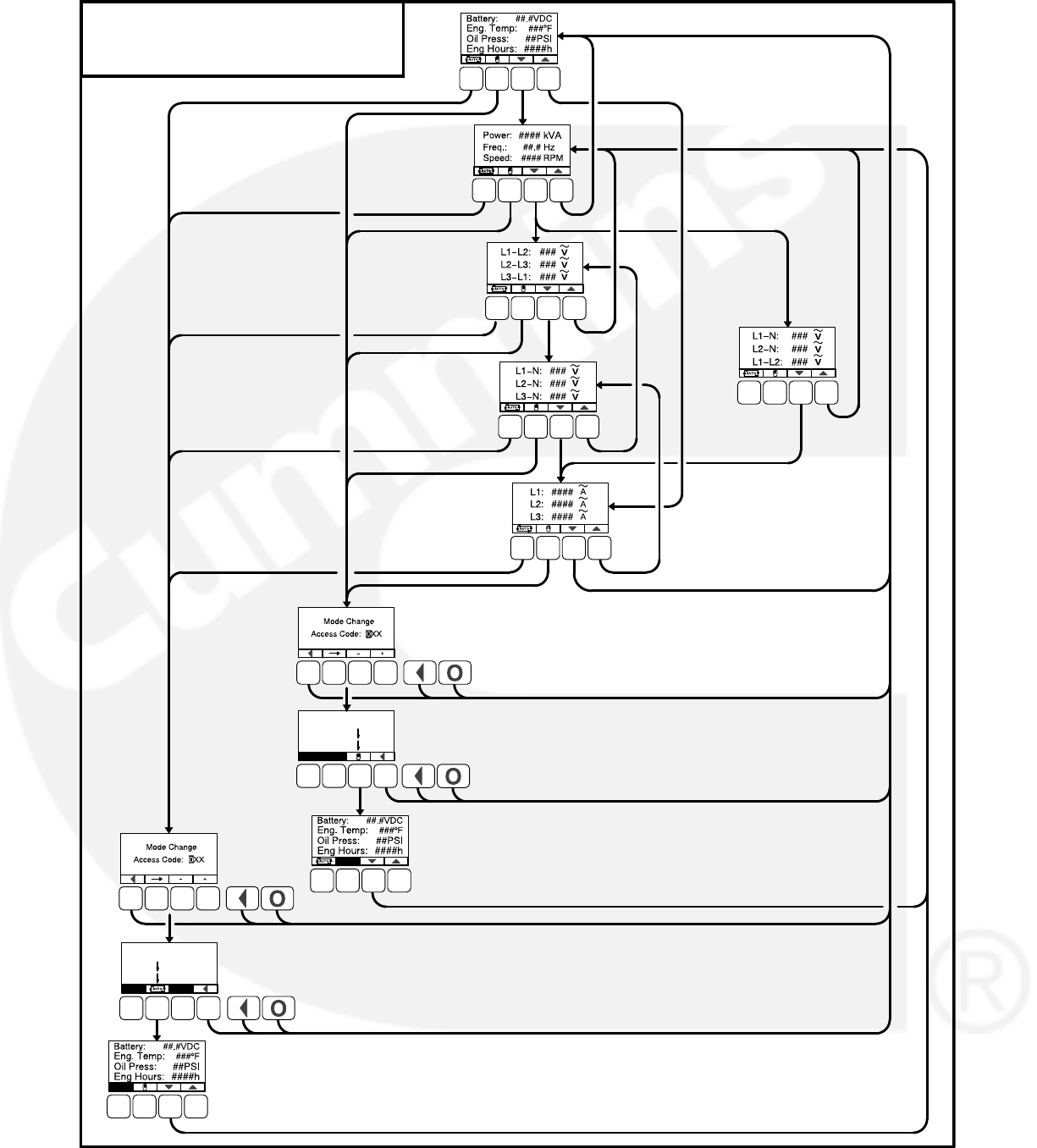
A-2
THREE
PHASE
ONLY
THREE
PHASE
WYE ONLY
CURRENT
SENSE
AMPERAGE
SINGLE
PHASE
ONLY
OPERATOR MENUS
TEXT VERSION
AUTO MODE
SELECTED
MANUAL
RUN MODE
SELECTED
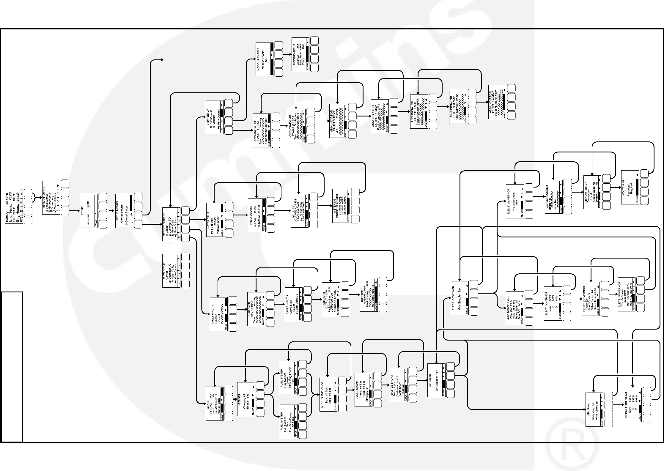
A-3
OR
OR
YES NO
YES NO
OR
IF AVR IS
NOT
ENABLED
IF AVR IS
ENABLED
GO TO GENSET
SETUP AND
SERVICE MENUS
ON PAGE A-4
GENSET SERVICE MENUS
OR
VIEWING ONLY VIEWING AND
ADJUSTING
OR
*
*
*
*ONLY ONE OF THE FOUR
AVAILABLE INPUT MENUS
IS SHOWN.
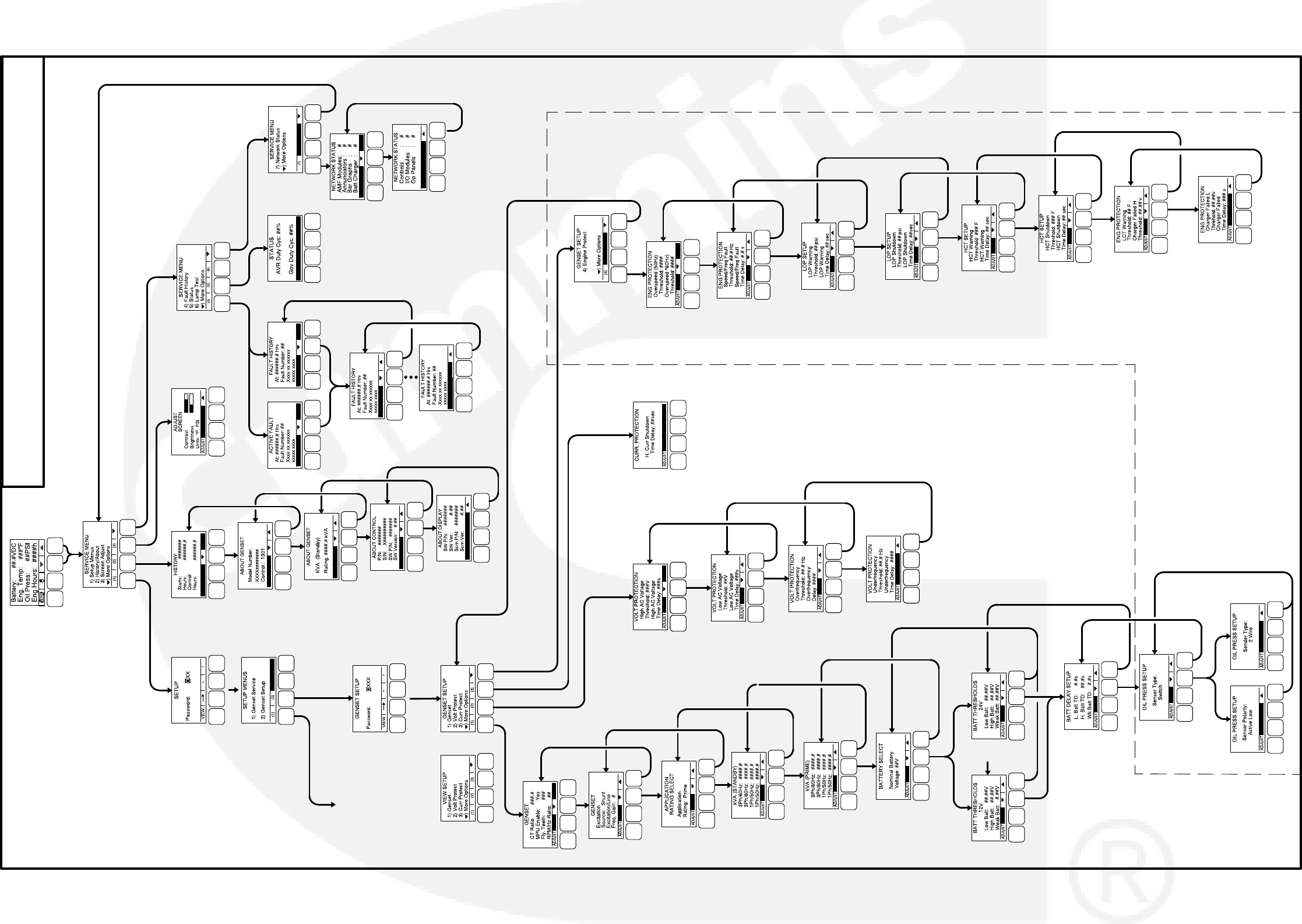
A-4
GENSET SETUP AND SERVICE MENUS
OR
12V 24V
OR
SWITCH SENDER
OR
OR
GO TO GENSET
SERVICE MENUS
ON PAGE A-3
OR
VIEWING ONLY
VIEWING AND
ADJUSTING
THESE MENUS ARE AVAILABLE ONLY
IF ECM CAN FEATURE IS DISABLED

B-1
Appendix B. Index
GENERAL INFORMATION
A
Alternator
Adjustments, 3-26
AVR Enable/Disable, 3-26
Bosch Type, 3-5
Connections
Double Delta, 3-7
Parallel Star, 3-6
Series Delta, 3-6
Series Star, 3-6
Single Phase, 3-7
Denso Type, 3-5
Digital Output Voltage Regulation, 3-26
Torque−Matched Volts/Hz Overload Control, 3-26
Auto Mode, 2-3, 4-2
B
Battery Selection, 3-37
Battle Short
Installations with Operator Panel, 3-40
Installations without Operator Panel, 3-41
Mode, 3-41
Battleshort Mode, 3-26
C
Control
Inputs, 2-5
Outputs, 2-5
Control Board
Connections, 3-10
J11 (Engine), 3-12
J12 (Genset CT), 3-12
J17 (Field Windings), 3-13
J18 (Field Power), 3-13
J20 (Genset), 3-13
J22 (Genset Voltage Sensing), 3-13
J25 (Display), 3-14
TB1 (Customer), 3-11
TB15 (Tools Interface), 3-11
Connector Part Numbers, 3-14
Footprint, 3-16
General Information, 3-2
Current Draw
Parade Rest Mode, 2-7
Running Mode, 2-7
Sleep Mode, 2-7
Current Transformers, 3-3
Selection, 3-3
Setup, 3-4
Three Lead, 3-5
Two Lead, 3-4
Sizing
Three Lead, 3-4
Two Lead, 3-3
Cycle Cranking, 3-37
E
Electronic Governor
Connections, 3-15
Module Connections, 3-15
Part Numbers, 3-15
Emergency Stop
Local, 3-37
Remote, 3-37
Emergency Stop Mode, 4-2
Engine Speed Sensing, 3-39
Engine Starting, Automatic, 3-37
Environment Information, 3-2
Equipment
Basic, 2-1
Optional, 2-2
F
Fault, No Message, 6-3
Fault Code
1117 − ECM Power Lost, Warning, 4-10
1123 − Shutdown After Battleshort, Shutdown, 3-41,
3-42, 4-10, 6-8
1131 − Battle Short Active, Warning, 3-41, 4-10, 6-8
121 − Speed Signal Lost, Shutdown, 3-41, 3-42, 4-8,
6-6, 6-12
1246 − Generic Engine Fault, Warning, 4-10
1311 and 1312 − Configurable Input 1, 2, Warning/
Shutdown, 4-10, 6-8, 6-23
1317 and 1318 − Configurable Input 3, 4, Warning/
Shutdown, 4-11, 6-8, 6-23
135 − Oil Pressure Sensor OOR High, Warning, 4-8
141 − Oil Pressure Sensor OOR Low, Warning, 4-8,
6-6, 6-13
1416 − Failure to Shutdown, Warning, 3-41, 4-11,
6-9
1417 − Failure to Power Down, Shutdown, 4-11
142 − Oil Pressure Sensor OOR High, Warning, 6-6,
6-13

B-2
GENERAL INFORMATION
1426 − Generic Engine Fault, Warning, 6-24
143 − Pre−Low Oil Pressure, Warning, 4-8, 5-48,
6-6, 6-13, 6-14
1433 − Remote Emergency Stop, Shutdown, 3-41,
3-42, 4-11, 6-9
1434 − Local Emergency Stop, Shutdown, 3-41,
3-42, 4-11, 6-9
1435 − Low Coolant Temperature, Warning, 4-11,
5-52, 6-9, 6-24
1438 − Fail to Crank, Shutdown, 4-11, 6-9, 6-25
144 − Coolant Sensor OOR Low, Warning, 4-8, 6-6,
6-15
1442 − Weak Battery, Warning, 4-11, 5-42, 6-9, 6-26
1443 − Dead Battery, Warning, 4-11, 6-24
1446 − High AC Voltage, Shutdown, 4-11, 5-44, 6-9,
6-26
1447 − Low AC Voltage, Shutdown, 4-11, 5-44, 6-10,
6-27
1448 − Under Frequency, Shutdown, 4-11, 5-44,
6-10, 6-27
1449 − Over Frequency, Shutdown, 4-11, 5-44, 6-10,
6-28
145 − Coolant Sensor OOR High, Warning, 4-8, 6-6,
6-15
146 − Pre−High Coolant Temperature, Warning, 4-8,
5-50, 6-6, 6-16, 6-17
1469 − Speed Hz Match, Shutdown, 4-12, 5-48, 6-10
1471 − High AC Current, Shutdown, 4-12, 6-10, 6-28
1472 − High AC Current, Warning, 4-12, 5-46, 6-10,
6-28
151 − High Coolant Temp, 4-9, 5-50, 6-7, 6-17
1517 − Failed Module Shutdown, Warning 4-13
153, 154, and 155 − Engine Fault, Event, Warning,
or Shutdown, 4-9, 6-18
1678 − Charger Failure, Warning, 6-11
1689 − Clock Not Set, Warning, 4-13, 6-30
1845 and 1846 − Engine Fault, Event, Warning, or
Shutdown, 4-12, 6-18
1847 − High Temperature Fault, Warning, 4-13
1852 − Engine Fault, Event, Warning, or Shutdown,
4-12, 6-18
1853, 1854, and 1855 − Configurable Annunciator
Fault 3, 4, Warning/Shutdown, 4-12, 6-10
1944 − Annunciator Output Configuration Error,
Warning, 4-12, 6-10, 6-29
195, 196, and 197 − Engine Fault, Event, Warning,
or Shutdown, 4-9, 6-18
1965 − Exhaust Temperature OOR, Warning, 4-12
1992 − Engine Fault, Event, Warning, or Shutdown,
4-12, 6-18
2118 − Low Fuel Pressure, Warning, 4-13, 6-31
2224 − Fuel Level OOR, Warning, 4-13
2335 − Loss of AC Sense, Shutdown, 3-41, 3-42,
4-13, 6-10, 6-30
234 −Overspeed, Shutdown, 3-41, 3-42, 4-9, 5-48,
6-7, 6-18
2398 − Ambient Temperature OOR, Warning, 4-13
2542 − Voltage Bias OOR, Warning, 4-13
2545 − Keyswitch Reset Required, Shutdown, 6-31
2619, 2621, 2622, 2623, 2624, 2625, 2626, and
2628 − AUX101 Analog Inputs 1−8, Diagnostic,
4-13
2628, 2629, 2631, and 2632 − AUX101 Digital Inputs
1−4, Diagnostic, 4-14
2676 − Alternator Frequency Conflict, Shutdown,
4-14, 6-10
2677 − Fail to Stop, Shutdown, 4-14, 6-11
2678 − Battery Charging Failure, Warning, 4-14, 5-8,
5-52
2693 − Speed Bias OOR, Warning, 4-14
2694 − Alternator RTD Temp OOR, Warning, 4-14
2696 − Alternator RTD Temp High, Shutdown, 4-14
2729 − I/O Module Lost, Warning, 4-15
2731 − I/O Module Lost, Warning, 4-15
285, and 286 − Engine Fault, Event, Warning, or
Shutdown, 4-9, 6-18
2897 − Factory Block Corrupt, Shutdown, 4-15
2898 − Periodic Fault Corrupt, Warning, 4-15
2899 − User Block Corrupt, Shutdown, 4-15
2911 − Trim Block Corrupt, Shutdown, 4-15
2964 − Engine Fault, Event, Warning, or Shutdown,
4-15, 6-18
2972 − Field Overload, Shutdown, 4-15, 6-11, 6-31
359 − Fail to Start, Shutdown, 4-9, 6-8, 6-19
415 − Low Oil Pressure, Shutdown, 4-9, 5-50, 6-7,
6-14
418 − Engine Fault, Event, Warning, or Shutdown,
(Not Displayed), 6-18
421 − Oil Temperature High, Shutdown, 4-9
424 − Oil Temperature OOR, Shutdown, 4-10
426 − Engine Fault, Event, Warning, or Shutdown,
4-10, 6-18
427 − CAN Datalink Lost, Warning, 6-22
427 − CAN Link Lost, Warning, 4-10
441 − Low Battery, Warning, 4-10, 5-42, 6-8, 6-22
442 − High Battery, Warning, 4-10, 5-42, 6-8, 6-23
488 − Intake Manifold Temperature High, Shutdown,
4-10
689 − Engine Speed Erratic, Shutdown, 4-10
781 − CAN Datalink Lost, Shutdown, 4-10, 6-22
5134 − Unknown Shutdown at Iidle, Warning, 4-13,
6-34
5186 − Genset Failed to Close, Warning, 4-13, 6-34
5187 − Utility Failed to Close, Warning, 4-13, 6-34
5188 − Transfer Switch Status Unknown Position,
Warning, 4-13, 6-35
5365 − On Secondary Source, Warning, 4-13, 6-35
Fault Codes
Reading Using the Control Switch Indicator, 6-2
Reading Using the Operator Panel, 6-2
Fault Reset, 2-3
Faults
Alternator Protection, 2-7

B-3
Engine Protection, 2-6
Genset Protection, 2-6
G
Genset
Adjustments
Alternator Startup, 3-28
Gain Tuning, 3-28
Governor, 3-28
Voltage/Frequency, 3-27
Engine Startup, 3-28
GENERAL INFORMATION
Tuning, 3-27
Glow Plug, 3-38
Governor
Algorithm and Adjustment, 3-39
Electronic, 3-38
H
Harness
Coolant Temperature Sensor, 3-20
Engine, 3-19
Genset, 3-18
Oil Pressure Sensor, 3-20
Operator Panel, 3-17
L
Local Emergency Stop, 3-37
Local Status Output Indicator, 4-1
M
Manual Run Mode, 4-2
Module, Control, 2-3
Mounting Installation, 3-1
O
Off Mode, 2-3, 4-2
Operating Modes
Auto Mode, 2-3, 4-2
Battle Short, 3-41
Emergency Stop Mode, 4-2
Manual Run Mode, 4-2
Off Mode, 2-3, 4-2
Run Mode, 2-3
Sleep Mode, 4-3
Operator Panel, 2-4
Connections, 2-4
Footprint, 3-17
General Information, 3-2
Harness, 3-17
P
Parade Rest Mode, 2-7
R
Remote Emergency Stop, 3-37
Remote Start, 3-37
Run Mode, 2-3
Run/Off/Auto Switch, 2-3
Running Mode, 2-7
S
Sensor
Coolant Temperature, 3-20
Oil Pressure, 3-20
Sensors
Coolant Temperature, 3-8
Lube Oil Pressure Switch, 3-9
Oil Pressure, 3-8
Setup, Trims, and Adjustments, 3-22
Sleep Mode, 2-7, 4-3
Spark Ignition, 3-38
T
Time Delay
Preheat, 4-2
Start, 3-38, 4-2
Stop, 3-38, 4-2
W
Wiring Diagram, 7-3
Wiring Information, 3-2

B-4
THIS PAGE INTENTIONALLY LEFT BLANK
58
“Intentionally Left Blank”

Cummins Power Generation
1400 73rd Ave. NE
Minneapolis, MN 55432 USA
Phone 1 763 574 5000
Toll-free 1 800 888 6626
Fax 1 763 574 5298
Email ask.powergen@cummins.com
www.cumminspower.com
CumminsR, the “C” logo, and “Our energy working for you.”
are trademarks of Cummins Inc.
E2014 Cummins Power Generation, Inc. All rights reserved.
