IMarc SLV SNMP Reference 9000 A2 GB32 20
9000-A2-GB32-20 9000-A2-GB32-20
User Manual: 9000-A2-GB32-20
Open the PDF directly: View PDF ![]() .
.
Page Count: 194 [warning: Documents this large are best viewed by clicking the View PDF Link!]
- Contents
- About This Guide
- MIB Detail Specification
- 1. MIB Detail
- 1.1 Standard RFC MIBs
- 1.1.1 RFC 1213-MIB Module
- 1.1.1.1 System Group (mib-2)
- 1.1.1.2 Interfaces Group (mib-2)
- 1.1.1.2.1 “ifNumber” Object (interfaces 1)
- 1.1.1.2.2 ifTable (interfaces 2)
- 1.1.1.2.2.1 “ifIndex” Object (ifEntry 1)
- A. Paradyne IfIndexes are determined using the following decimal format:
- 1. T1 type
- 2. DSX-1 type
- 3. Sync Data type
- 4. COM type
- 5. Modem type
- 6. Ethernet type
- 7. Voice FXS type
- 8. Voice E&M type
- 9. Voice FXO type
- 10. BRI type
- 11. PRI type
- 12. OCU type
- 13. Digital Packet Voice type
- 14. Unassigned
- 15. Frame Relay Logical Link on T1s
- 16. Frame Relay Logical Link on Sync Data Ports
- 17. Frame Relay Logical Link on PRI
- 18. Frame Relay Logical Link on BRI
- 19. ISDN S/T type
- 20. SDSL type
- 21. DDS type
- 22. Frame Relay Logical Link on ISDN S/T
- 23. Frame Relay Logical Link on SDSL
- 24. Frame Relay Logical Link on DDS
- 25. Frame Relay Bundle (Multi Link Frame Relay)
- 26. T3 type
- 27. Frame Relay Logical Link on T3s
- 28. ATM Cell Logical Link on SDSL
- 29. B-Channel on PRI interface
- 30. B-Channel on BRI interface
- 31. IDSL type
- 32. Frame Relay Logical Link on IDSL
- 33. SHDSL Type
- 34. Frame Relay Logical Link on SHDSL
- 35. ATM Cell Logical Link on SHDSL
- 36. PPP Logical Link on T1s
- 37. PPP Logical Link on Sync Data Ports
- 38. PPP Logical Link on PRI
- 39. PPP Logical Link on BRI
- 40. PPP Logical Link on DDS
- 41. PPP Logical Link on T3s
- 42. PPP Logical Link on IDSL
- 43. PPP Logical Link on SDSL
- 44. PPP Logical Link on SHDSL
- B. NetScout’s IfIndexes are broken down into four groups: Physical Interfaces, Logical Interfaces, RMON Virtual Interfaces, and RMON Virtual Logical Interfaces. The following ifIndex assignment only applies to Paradyne devices that support Ne...
- 1. Frame Relay 1 Network
- 2. Frame Relay 2 Unassigned
- 3. Frame Relay 3 Sync Data Port 1
- 4. Frame Relay 4 Sync Data Port 2 or Network V.35/X.21
- 5. Frame Relay 5 Unassigned
- 6. Frame Relay 6 Unassigned
- 7. Frame Relay 7 Unassigned
- 8. Frame Relay 8 Unassigned
- 9. Frame Relay 9 Unassigned
- 10. Frame Relay 10 Unassigned
- 11. Physical T1-A/T3
- 12. Physical SDSL
- 13. Physical Sync Data Port1
- 14. Physical Sync Data Port2
- 15. Physical DDS
- 16. Physical ISDN S/T
- 17. Physical IDSL
- 1.1.1.2.2.2 “ifDescr” Object (ifEntry 2)
- 1.1.1.2.2.3 “ifType” Object (ifEntry 3)
- 1.1.1.2.2.4 “ifMtu” Object (ifEntry 4)
- 1.1.1.2.2.5 “ifSpeed” Object (ifEntry 5)
- 1.1.1.2.2.6 “ifAdminStatus” Object (ifEntry 7)
- 1.1.1.2.2.7 “ifOperStatus” Object (ifEntry 8)
- 1.1.1.2.2.8 “ifLastChange” Object (ifEntry 9)
- 1.1.1.2.2.9 Input Counters (objects ifEntry 10 to ifEntry 15)
- 1.1.1.2.2.10 Output Counters (objects ifEntry 16 to ifEntry 20)
- 1.1.1.2.2.11 “ifSpecific” Object (ifEntry 22)
- 1.1.1.2.2.1 “ifIndex” Object (ifEntry 1)
- 1.1.2 IF-MIB Module
- 1.1.2.1 Extension to Interface Table Group (mib-2)
- 1.1.2.2 Interface Stack Group (ifMib)
- 1.1.2.3 Interface Test Group (ifMib)
- 1.1.2.4 IP Group (mib-2)
- 1.1.2.4.1 “ipForwarding” Object (ip 1)
- 1.1.2.4.2 “ipAddrTable” Object (ip 20)
- 1.1.2.4.3 “ipRouteTable” Object (ip 21)
- 1.1.2.4.3.1 “ipRouteDest” Object (ipRouteEntry 1)
- 1.1.2.4.3.2 “ipRouteIfIndex” Object (ipRouteEntry 2)
- 1.1.2.4.3.3 “ipRouteMetric2-5” Object (ipRouteEntry 4-7)
- 1.1.2.4.3.4 “ipRouteType” Object (ipRouteEntry 8)
- 1.1.2.4.3.5 “ipRouteProto” Object (ipRouteEntry 9)
- 1.1.2.4.3.6 “ipRouteAge” Object (ipRouteEntry 10)
- 1.1.2.4.4 “ipNetToMediaTable” Object (ip 22)
- 1.1.2.4.5 “ipForward” Group (ip 24)
- 1.1.2.5 ICMP Group (mib-2)
- 1.1.2.6 TCP Group (mib-2)
- 1.1.2.7 UDP Group (mib-2)
- 1.1.2.8 Transmission Group (mib-2)
- 1.1.2.9 SNMP Group (mib-2)
- 1.1.3 EtherLike-MIB Module (dot3)
- 1.1.4 RFC1406-MIB Module (DS1/E1 MIB)
- 1.1.4.1 Near End Group (ds1)
- 1.1.4.1.1 DS1 Configuration Table (dsx1ConfigTable 1)
- 1.1.4.1.1.1 “dsx1TimeElapsed” Object (dsx1ConfigEntry 3)
- 1.1.4.1.1.2 “dsx1ValidIntervals” Object (dsx1ConfigEntry 4)
- 1.1.4.1.1.3 “dsx1LineType” Object (dsx1ConfigEntry 5)
- 1.1.4.1.1.4 “dsx1LineCoding” Object (dsx1ConfigEntry 6)
- 1.1.4.1.1.5 “dsx1SendCode” Object (dsx1ConfigEntry 7)
- 1.1.4.1.1.6 “dsx1CircuitIdentifier” Object (dsx1ConfigEntry 8)
- 1.1.4.1.1.7 “dsx1LoopbackConfig” Object (dsx1ConfigEntry 9)
- 1.1.4.1.1.8 “dsx1LineStatus” Object (dsx1ConfigEntry 10)
- 1.1.4.1.1.9 “dsx1SignalMode” Object (dsx1ConfigEntry 11)
- 1.1.4.1.1.10 “dsx1TransmitClockSource” Object (dsx1ConfigEntry 12)
- 1.1.4.1.1.11 “dsx1Fdl” Object (dsx1ConfigEntry 13)
- 1.1.4.1.2 The DS1 Current Table objects (dsx1CurrentEntry)
- 1.1.4.1.3 The DS1 Interval Table objects (dsx1IntervalEntry)
- 1.1.4.1.4 The DS1 Total Table objects (dsx1TotalEntry)
- 1.1.4.1.1 DS1 Configuration Table (dsx1ConfigTable 1)
- 1.1.4.2 Far End Group (ds1)
- 1.1.4.3 The DS1 Fractional Group (ds1)
- 1.1.4.1 Near End Group (ds1)
- 1.1.5 DS3/E3 MIB - RFC 2496
- 1. DS3/E3 Near End Group - Fully Supported by SLV OS R2.1.
- 2. DS3 Far End Group - Not supported for SLV OS R2.1.
- 3. DS3/E3 Fractional Group - Not supported since SLV OS R2.1 supports only unchannelized T3.
- 1.1.5.1 Near End Group, DS3/E3 MIB
- 1.1.5.1.1 DS3/E3 Configuration Table (ds3 5)
- 1.1.5.1.1.1 “dsx3LineType” (dsx3ConfigEntry 5)
- 1.1.5.1.1.2 “dsx3LineCoding” (dsx3ConfigEntry 6)
- 1.1.5.1.1.3 “dsx3SendCode” (dsx3ConfigEntry 7)
- 1.1.5.1.1.4 “dsx3LoopbackConfig” (dsx3ConfigEntry 9)
- 1.1.5.1.1.5 “dsx3TransmitClockSource” (dsx3ConfigEntry 11)
- 1.1.5.1.1.6 “dsx3InvalidIntervals” (dsx3ConfigEntry 12)
- 1.1.5.1.1.7 “dsx3LineLength” (dsx3ConfigEntry 13)
- 1.1.5.1.1.8 “dsx3LoopbackStatus” (dsx3ConfigEntry 16)
- 1.1.5.1.1.9 “dsx3Channelization” (dsx3ConfigEntry 17)
- 1.1.5.1.1.10 “dsx3Ds1ForRemoteLoop” (dsx3ConfigEntry 18)
- 1.1.5.1.1 DS3/E3 Configuration Table (ds3 5)
- 1.1.6 FRAME-RELAY-DTE-MIB Module (Frame Relay DTEs MIB)
- 1.1.6.1 The DLCMI Group (frameRelayDTE)
- 1.1.6.1.1 “frDlcmiState” Object (frDlcmiEntry 2)
- 1.1.6.1.2 “frDlcmiAddress” Object (frDlcmiEntry 3)
- 1.1.6.1.3 “frDlcmiAddressLen” Object (frDlcmiEntry 4)
- 1.1.6.1.4 LMI Parameters (objects frDlcmiEntry 5 to frDlcmiEntry 8)
- 1.1.6.1.5 “frDlcmiMaxSupportedVCs” Object (frDlcmiEntry 9)
- 1.1.6.1.6 “frDlcmiMultiCast” Object (frDlcmiEntry 10)
- 1.1.6.1.7 “frDlcmiStatus” Object (frDlcmiEntry 11)
- 1.1.6.1.8 “frDlcmiRowStatus” Object (frDlcmiEntry 12)
- 1.1.6.2 The Circuit Group (frameRelayDTE)
- 1.1.6.2.1 “frCircuitDlci” Object (frCircuitEntry 2)
- 1.1.6.2.2 “frCircuitState” Object (frCircuitEntry 3)
- 1.1.6.2.3 Circuit statistics objects (objects frCircuitEntry 4 to frCircuitEntry 9)
- 1.1.6.2.4 “frCircuitCommittedBurst” Object (frCircuitEntry 12)
- 1.1.6.2.5 “frCircuitExcessBurst” Object (frCircuitEntry 13)
- 1.1.6.2.6 “frCircuitThroughput” Object (frCircuitEntry 14)
- 1.1.6.2.7 “frCircuitMulticast” Object (frCircuitEntry 15)
- 1.1.6.2.8 “frCircuitType” Object (frCircuitEntry 16)
- 1.1.6.2.9 “frCircuitLogicalIfIndex” Object (frCircuitEntry 20)
- 1.1.6.2.10 “frCircuitRowStatus” Object (frCircuitEntry 21)
- 1.1.6.3 The Error Group (frameRelayDTE)
- 1.1.6.4 Data Link Connection Management Interface Related Traps Group (frameRelayDTE)
- 1.1.6.5 Frame Relay Trap Control Group (frameRelayDTE)
- 1.1.6.1 The DLCMI Group (frameRelayDTE)
- 1.1.7 FRNETSERV-MIB Module (Frame Relay Service MIB)
- 1.1.7.1 The Logical Port Group (frnetservMIB)
- 1.1.7.1.1 “frLportNumPlan” Object (frLportEntry 1)
- 1.1.7.1.2 “frLportContact” Object (frLportEntry 2)
- 1.1.7.1.3 “frLportLocation” Object (frLportEntry 3)
- 1.1.7.1.4 “frLportType” Object (frLportEntry 4)
- 1.1.7.1.5 “frLportAddrDLCILen” Object (frLportEntry 5)
- 1.1.7.1.6 “frLportVCSigProtocol” Object (frLportEntry 6)
- 1.1.7.2 The Management VC Signaling Group (frnetservMIB)
- 1.1.7.2.1 “frMgtVCSigProced” Object (frMgtVCSigEntry 1)
- 1.1.7.2.2 DTE Side LMI Parameters (frMgtVCSigEntry 2 - 5)
- 1.1.7.2.3 Service Side LMI Parameters (frMgtVCSigEntry 6 - 8, 10)
- 1.1.7.2.4 DTE Side Error Statistics (frMgtVCSigEntry 11 - 13)
- 1.1.7.2.5 Service Side Error Statistics frMgtVCSigEntry 14 - 15)
- 1.1.7.3 The PVC End-point Group (frnetservMIB)
- 1.1.7.3.1 PVC End-Point Table
- 1.1.7.3.1.1 “frPVCEndptDLCIIndex” Object (frPVCEndptEntry 1)
- 1.1.7.3.1.2 Max Frame Size Objects
- 1.1.7.3.1.3 Committed Burst Size Objects
- 1.1.7.3.1.4 Excess Burst Size Objects
- 1.1.7.3.1.5 Committed Information Rate Objects
- 1.1.7.3.1.6 “frPVCEndptConnectIdentifier” (frPVCEndptEntry 10)
- 1.1.7.3.1.7 “frPVCEndptRowStatus” (frPVCEndptEntry 11)
- 1.1.7.3.1.8 “frPVCEndptRcvdSigStatus” (frPVCEndptEntry 12)
- 1.1.7.3.1.9 Circuit statistics (objects frPVCEndptEntry 13 - 20)
- 1.1.7.3.1 PVC End-Point Table
- 1.1.7.4 PVC Connect Status Change Trap - frPVCConnectStatusChange
- 1.1.7.1 The Logical Port Group (frnetservMIB)
- 1.1.8 ATM MIB (RFC 2515)
- 1.1.8.1 ATM Interface Configuration Parameters Table
- 1.1.8.1.1 “atmInterfaceMaxVpcs” (atmInterfaceConfEntry 1)
- 1.1.8.1.2 “atmInterfaceMaxVccs” (atmInterfaceConfEntry 2)
- 1.1.8.1.3 “atmInterfaceMaxActiveVpiBits” (atmInterfaceConfEntry 5)
- 1.1.8.1.4 “atmInterfaceMaxActiveVciBits” (atmInterfaceConfEntry 6)
- 1.1.8.1.5 “atmInterfaceMyNeighborIpAddress” (atmInterfaceConfEntry 11)
- 1.1.8.1.6 “atmInterfaceMyNeighborIfName” (atmInterfaceConfEntry 12)
- 1.1.8.2 ATM Interface Virtual Channel Link (VCL) Table
- 1.1.8.2.1 “atmVclAdminStatus” (atmVclEntry 3)
- 1.1.8.2.2 “atmVccAalType” (atmVclEntry 8)
- 1.1.8.2.3 “atmVccAal5CpcsTransmitSduSize” (atmVclEntry 9)
- 1.1.8.2.4 “atmVclAal5CpcsReceiveSduSize” (atmVclEntry 10)
- 1.1.8.2.5 “atmVclEncapsType” (atmVclEntry 11)
- 1.1.8.2.6 “atmVclCrossConnectIdentifier” (atmVclEntry 12)
- 1.1.8.2.7 “atmVclCastType” (atmVclEntry 14)
- 1.1.8.2.8 “atmVclConnKind” Object (atmVclEntry 15)
- 1.1.8.1 ATM Interface Configuration Parameters Table
- 1.1.9 FR/ATM Service Interworking MIB (experimental 97)
- 1.1.10 RS-232-MIB Module (RS-232-Like MIB)
- 1.1.10.1 “rs232Number” Object (rs232 1)
- 1.1.10.2 General Port Table, RS-232-like MIB
- 1.1.10.2.1 “rs232PortType” Object (rs232PortEntry 2)
- 1.1.10.2.2 “rs232PortInSigNumber” Object (rs232PortEntry 3)
- 1.1.10.2.3 “rs232PortOutSigNumber” Object (rs232PortEntry 4)
- 1.1.10.2.4 “rs232PortInSpeed” Object (rs232PortEntry 5)
- 1.1.10.2.5 “rs232PortOutSpeed” Object (rs232PortEntry 6)
- 1.1.10.2.6 “rs232PortInFlowType” Object (rs232PortEntry 7)
- 1.1.10.2.7 “rs232PortOutFlowType” Object (rs232PortEntry 8)
- 1.1.10.3 Asynchronous Port Table, RS-232-like MIB
- 1.1.10.4 Synchronous Port Table, RS-232-like MIB
- 1.1.10.4.1 rs232SyncPortClockSource (rs232SyncPortEntry 2)
- 1.1.10.4.2 rs232SyncPortRole (rs232SyncPortEntry 8)
- 1.1.10.4.3 rs232SyncPortEncoding (rs232SyncPortEntry 9)
- 1.1.10.4.4 rs232SyncPortRTSControl (rs232SyncPortEntry 10)
- 1.1.10.4.5 rs232SyncPortRTSCTSDelay (rs232SyncPortEntry 11)
- 1.1.10.4.6 rs232SyncPortMode (rs232SyncPortEntry 12)
- 1.1.10.4.7 rs232SyncPortIdlePattern (rs232SyncPortEntry 13)
- 1.1.10.4.8 rs232SyncPortMinFlags (rs232SyncPortEntry 14)
- 1.1.10.5 Input Signal Table, RS-232-like MIB (All MIB’s objects in this table are read-only)
- 1.1.10.6 Output Signal Table, RS-232-like MIB (All MIB’s objects in this table are read-only)
- 1.1.11 The RMON Version 1 MIB - RFC 1757
- 1.1.12 The RMON Version 2 MIB - RFC 2021
- 1.1.13 The Dial Control MIB - RFC 2128
- 1. dialCtlConfiguration Group - Holds objects to control general configuration of the MIB.
- 2. dialCtlPeer Group - Contains two tables, dialCtlPeerCfgTable and dialCtlPeerStatsTable, that contain for groups of dial peers (MFRs) configuration information and statistics respectively.
- 3. callActive Group - Contains a table of active calls.
- 4. callHistory Group - Contains a call history table along with two objects to control it.
- 1.1.13.1 The dialControlConfiguration Group
- 1.1.13.2 The dialCtlPeer Group
- 1.1.13.3 The callActive Group
- 1.1.13.4 The callHistoryGroup
- 1.1.14 ADSL-LINE-MIB (adslMIB)
- 1.1.15 hdsl2ShdslMIB (transmission 48)
- 1.1.16 Bridge MIB, RFC 1493 (dot1)
- 1.1.1 RFC 1213-MIB Module
- 1.2 Paradyne Enterprise MIBs
- 1.2.1 Device Configuration, pdn-devConfig (pdn-common 7)
- 1.2.2 DDS Interface Specific Definitions, dds, (pdn-interfaces 2)
- 1.2.2.1 DDS Status Table - ddsAlarm Status (ddsStatusEntry 4)
- 1.2.2.2 DDS Configuration Group, ddsClearChannelDataScrambling (ddsConfigEntry 3)
- 1.2.2.3 DDS Configuration Group, ddsInBandManagementChannel(ddsConfigEntry 4)
- 1.2.2.4 DDS Configuration Group, ASCII Alarm Controls (ddsConfigEntry 5 - ddsConfigEntry 10)
- 1.2.2.5 DDS Configuration Group - ddsLineRateAdmin (ddsConfigEntry 11)
- 1.2.2.6 DDS Test Table - ddsTestStatus (ddsTestEntry 2)
- 1.2.2.7 DDS Test Table - ddsTestStart (ddsTestEntry 3)
- 1.2.2.8 DDS Test Table - ddsTestStop (ddsTestEntry 4)
- 1.2.2.9 DDS Test Table - ddsTestCode (ddsTestEntry 5)
- 1.2.2.10 DDS Statistics Table -- ddsClearStatistics (ddsStatisticsEntry 11)
- 1.2.3 Port Usage, pdn-devPortUsage (pdn-interfaces 3)
- 1.2.4 Voice Configuration, voice, (pdn-interface 4)
- 1.2.5 Synchronous Data Port Configuration, syncPort (pdn-interfaces 6)
- 1.2.6 OCU Port Configuration, ocuPort (pdn-interfaces 10)
- 1.2.7 DS1 Extension Configuration, ent-ds1, (pdn-interfaces 5)
- 1.2.7.1 DS1 Performance Statistics Group, DS1PerfStats, (ent-ds1 4)
- 1.2.7.2 DS1 Test Group, devDS1Test (ent-ds1 1)
- 1. In order to run a user-defined pattern test, both the pattern (devDS1TestArgument) and the control (devDS1TestControl) must be set in the same PDU.
- 2. Remote loopback test (llbup and llbdown) are not supported on the DSX-1 interface.
- 3. The interface must be enabled when starting a test and the test combination must be valid or a general failure will be returned.
- 1.2.8 DS3 Extension, pdnDs3MIB (pdn-interfaces 14)
- 1.2.9 Channel Configuration, crossConnect, (pdn-interfaces 7)
- 1.2.10 Device Security, pdn-security (pdn-common 8)
- 1.2.11 Device Traps, pdn-traps (pdn-common 9)
- 1.2.12 Device Control, pdn-control (pdn-common 10)
- 1.2.13 Device Health and Status, devStatus(pdn-devStatus 1)
- 1.2.14 Frame Relay PVC Cross Connect, pvcXconnect (crossConnect 3)
- 1.2.15 The pvcXconnect table (devPVCXconnect.mib) is used to manage PVC connections. This table is fully supported in SLV OS R2.1. Frame Relay PVC Test, devPVCTest (pdnFrameRelay 3)
- 1.2.16 IP Route Extension, devIPRouteTable (pdn-ip 1)
- 1.2.17 Frame Relay Extension, devFrExt (pdnFrameRelay 4)
- 1.2.17.1 Frame Relay DLCI Table, devFrExtDlciTable (devFrExt 1)
- 1.2.17.2 Frame Relay DLCI Status Table, devFrExtDlciStsTable (devFrExt 2)
- 1.2.17.3 The Latency Table, devFrExtLatencyTable (devFrExt 3)
- 1.2.17.4 The Frame Size Group, devFrExtFrameSize (devFrExt 4)
- 1.2.17.5 The Burst Group, devFrExtBurst (devFrExt 5)
- 1.2.17.6 The Far End Information Table, devFrExtFarEndInfoTable (devFrExt 6)
- 1.2.17.7 The Link Table, devFrExtLinkTable (devFrExt 7)
- 1.2.17.7.1 devFrExtLinkTxDiscards (devFrExtLinkEntry 14)
- 1.2.17.7.2 devFrExtLinkRxDiscards (devFrExtLinkEntry 15)
- 1.2.17.7.3 devFrExtLinkRxIlFrames (devFrExtLinkEntry 18)
- 1.2.17.7.4 devFrExtLinkTotTxErrs (devFrExtLinkEntry 19)
- 1.2.17.7.5 devFrExtLinkTotRxErrs (devFrExtLinkEntry 20)
- 1.2.17.7.6 devFrExtLinkTotalLMIErrs (devFrExtLinkEntry 32)
- 1.2.17.7.7 devFrExtLinkExtendedDdrCollection (devFrExtLinkEntry 33)
- 1.2.17.8 The Link Configuration, devFrExtLinkConfig (devFrExt 8)
- 1.2.17.9 The BackUp Status, devFrExtBackUpStatus (devFrExt 9)
- 1.2.17.10 The Link Utilization Group, devFrExtLinkUtil (devFrExt 10)
- 1.2.18 Device Identity, devID (pdn-common 5)
- 1.2.19 The RMON Extension, devRmonExt (pdn-common 13)
- 1.2.20 The IF-MIB Extension, pdnIfExt (pdn-interfaces 12)
- 1.2.21 The ISDN Extension, pdnIsdn (pdn-interfaces 16)
- 1.2.22 The ATM Extension, pdnAtm (pdn-interfaces 11)
- 1.2.23 The Management Link, pdnMgmtLink (pdn-interfaces 17)
- 1.2.24 Paradyne Feature Group (pdn-common 15)
- 1.2.25 Dial Control Extension MIB
- 1.2.26 ATM M4 Extension MIB
- 1.2.27 IP Ping Test, devIPPingTest (pdn-ip 2)
- 1.2.27.1 devIPPingTestNextIndex (devIPPingTest 1)
- 1.2.27.2 devIPPingTestOwner (devIPPingTestEntry 2)
- 1.2.27.3 devIPPingTestDestIntf (devIPPingTestEntry 4)
- 1.2.27.4 devIPPingTestCktId (devIPPingTestEntry 5)
- 1.2.27.5 devIPPingTestSubCktId (devIPPingTestEntry 6)
- 1.2.27.6 devIPPingTestTimeStamp (devIPPingTestEntry 23)
- 1.2.27.7 devIPPingTestTOSId (devIPPingTestEntry 24)
- 1.2.27.8 devIPPingTestTOSByte (devIPPingTestEntry 25)
- 1.2.28 IP SLV Configuration, devIpSLVConfig (pdn-ip 3)
- 1.2.29 IP SLV Performance Statistics, devIpSLVPerfStats (pdn-ip 4)
- 1.3 Internet Drafts
- 1.4 Other Enterprises
- 1.1 Standard RFC MIBs
- SNMP Trap Specification
- 2. SNMP Traps
- 2.1 Trap Background
- 2.2 Standard Traps
- 2.2.1 Warm Start Trap
- 2.2.2 Authentication Failure Trap
- 2.2.3 Link Up and Link Down Traps
- 2.2.3.1 Network, PRI and DSX-1 T1 Interfaces, Physical Sublayer
- 2.2.3.2 DDS Network, Physical Sublayer
- 2.2.3.3 T3, Physical Sublayer
- 2.2.3.4 Synchronous Data Port, Physical Sublayer
- 2.2.3.5 OCU Ports, Physical Sublayer
- 2.2.3.6 BRI, Physical Sublayer
- 2.2.3.7 DSL, Physical Sublayer
- 2.2.3.8 ISDN S/T, Physical Sublayer
- 2.2.3.9 Ethernet, Physical Sublayer
- 2.2.3.10 Frame Relay Logical Link Sublayer
- 2.2.3.11 ATM, Logical Sublayer
- 2.3 Enterprise Specific Traps
- 2.4 Enterprise MIB Traps
- 2.5 RMON Specific Traps
- 2.6 Dial Control MIB Traps
- 2.7 Trap Priority Due to Resource Limitation
- 2.8 Trap Strings
- RMON Support Specification
- 3. RMON Overview
- 3.0.1 RMON History
- 3.0.2 RMON Future
- 3.1 Supported RMON Groups
- 3.2 Relation to ifMIB
- 3.3 Manipulation of Rows in RMON Tables.
- 3.4 RMON Groups Behavior and Defaults
- 3.4.1 Alarm Group Behavior and Defaults
- 3.4.1.1 Alarm Behavior
- 3.4.1.1.1 General Alarm Behavior
- 1. If the value or change in value of the variable is below the falling threshold the first time the value is read or the change is calculated and falling events are desired, the falling event is triggered.
- 2. If the value or change in value of the variable is above the rising threshold the first time the value is read or the change is calculated and rising events are desired, rising event is triggered.
- 3. Falling alarms trigger an event when the trigger is cleared, the value or change in value of the variable is less than or equal to the falling threshold, the previous value or change in value of the variable was above the falling threshold...
- 4. Rising alarms trigger an event when the trigger is cleared, the value or change in value of the variable is greater than or equal to the rising threshold, the prior value or change in value of the variable was below the rising threshold an...
- 5. After an alarm triggers an event, it will not trigger again until it is cleared as explained in steps 6 and 7 below.
- 6. Falling alarms are cleared when the value or change in value of the variable rises above the falling threshold and reaches or rises above the rising threshold
- 7. Rising alarms are cleared when the value or change in value of the variable falls below the rising threshold and reaches or falls below the falling threshold.
- C. The first time through, a falling event is triggered.
- D. The rising event is triggered and the falling event is cleared.
- E. The falling event is triggered again and the rising event is cleared.
- F. The rising event is triggered again and the falling event is cleared.
- G. NOTE: A potential problem of the alarm group is that the actual value of the variable can pass the rising threshold and fall below again between polls. If this occurs, no event will be triggered and nothing will be cleared. It is up to the...
- 3.4.1.1.2 Setting Alarms
- 3.4.1.1.3 Alarm Permanence
- 1. The event fields, alarmRisingEvent and alarmFallingEvent, will be reset to the defaults if they are set to nonzero values. (See “Event Defaults” on page 140.)
- 2. The owner string, alarmOwner, will be set to the last owner string set by the management station which “owns” the alarm. Only ten owner strings are stored on the device. If more than ten management stations perform sets, the owner strings ...
- 3. Default alarms that are reset or altered by the user will be set to the user configured values on Startup.
- 3.4.1.1.1 General Alarm Behavior
- 3.4.1.2 Alarm Defaults
- 1. alarmStartupAlarm is risingAlarm(1)
- 2. alarmSampleType is delta(2) except where noted.
- 3. alarmFallingIndex is 0.
- 4. alarmOwner is “monitor”.
- 5. alarmStatus is valid(1).
- 3.4.1.2.1 RMON Alarms -- Frame Relay Link Defaults
- 3.4.1.2.2 RMON Alarms -- Frame Relay DLCI Defaults
- 3.4.1.2.3 User Configured Alarms
- 3.4.1.1 Alarm Behavior
- 3.4.2 Event Group Behavior and Defaults
- 3.4.3 Protocol Directory Group Behavior and Defaults
- 3.4.4 Protocol Distribution Group Behavior and Defaults
- 3.4.5 Network Layer Host Group Behavior and Defaults
- 3.4.6 User History Behavior and Defaults
- 3.4.6.1 User History Behavior
- 3.4.6.1.1 General User History Behavior
- 3.4.6.1.2 Setting User History
- 3.4.6.1.2.1 Recommendations on Setting User History
- 1. The device is out of resources.
- 2. A variable defined by usrHistoryObjectVariable does not exist or is non-integer.
- 1. Divide the variables defining usrHistoryObjectVariable that are to be set into groups such that no group would result in a PDU sized greater than 1400 bytes and all of the variables in each individual group exhibit the same existence behav...
- 2. In a single PDU, set usrHistoryControlStatus to createAndWait(5), and set usrHistoryControlObjects, usrHistoryControlBucketsRequested, usrHistoryControlInterval and usrHistoryControlOwner to the desired values. If the resulting size of the...
- 3. If step 2 failed, clean up by setting usrHistoryControlStatus to destroy(6) and quit trying for this control. The attribute that failed can be traced by looking at the variable that failed in the PDU. Further steps may be required to assig...
- 4. While there are nonessential groups, add each group by setting usrHistoryObjectVariable and usrHistoryObjectSampleType for all variables in a single PDU. Failures can be ignored in that these variables are not essential.
- 5. While there are essential groups, add each group by setting usrHistoryObjectVariable and usrHistoryObjectSampleType for all variables in a single PDU. Immediately go to step six on failure.
- 6. If step 5 failed, clean up by setting usrHistoryControlStatus to destroy(6) and quit trying for this control.
- 7. Set usrHistoryControlStatus to active(1) to activate the control. This PDU can be combined with the last PDU in either step 5 or step 6 above if there is room.
- 8. If step 7 failed, clean up by setting usrHistoryControlStatus to destroy(6) and quit trying for this control.
- 3.4.6.1.2.1 Recommendations on Setting User History
- 3.4.6.1.3 User History Permanence
- 1. The owner string, usrHistoryControlOwner, will be set to the last owner string set by the management station which “owns” the group. Only ten owner strings are stored in the device. If more than ten management stations perform sets, the ow...
- 2. Default user history groups that are reset by the user will be set to the user configured values on start-up.
- 3.4.6.1.4 Retrieving User History
- 3.4.6.1.4.1 Using SNMP to Retrieve User History
- 1. It may be desirable to check if the configuration has changed. If this is the case, the NMS should perform a get containing all of the variables in the usrHistoryControlTable and a walk on the usrHistoryObjectTable for the usrHistoryContro...
- 2. The usrHistoryTable is indexed by usrHistoryControlIndex, usrHistorySampleIndex, and usrHistoryObjectIndex. In order to find the correct starting index, perform a getNext on usrHistoryIntervalStart, usrHistoryIntervalEnd, usrHistoryAbsValu...
- 3. Inspect the result of the value returned. If it does not apply to the usrHistoryControlIndex desired, simply quit in that there is no history for that variable. If the associated usrHistorySampleIndex is less than the last known value and ...
- 4. Using the starting index, package a getNext PDU for usrHistoryIntervalStart, usrHistoryIntervalEnd, usrHistoryAbsValue and usrHistoryValStatus for each usrHistoryObjectIndex that can fit into a 1000 byte PDU. It may take multiple PDUs to g...
- 5. Repeat step 4 until the information for any row points to an object that does not apply to the current usrHistoryControlIndex.
- 6. Note that it is possible to miss a bucket of history using this method. Care should be taken in the storing of all of the information such that it is aligned with the start and end times correctly.
- 3.4.6.1.4.1 Using SNMP to Retrieve User History
- 3.4.6.1.5 User History Synchronization
- 1. RMON will assume that the Time of Day is always the Network Reference Time.
- 2. User history groups share timers. This means that if a user history group is defined with the same usrHistoryControlInterval as a existing user history group, its first interval will begin the next time the existing user history group’s timer expires.
- 3. If usrHistoryControlInterval is less than 24 hours and is evenly divisible into 24 hours and this is the first group at that interval, the first interval will begin at the next multiple of the period based on the current network reference ...
- 4. If usrHistoryControlInterval is greater than 24 hours and this is the first group at that interval, the first interval will begin at midnight based on the network reference time at the time of creation.
- 5. If usrHistoryControlInterval does not evenly divide into 24 hours and this is the first group at that interval, the first interval will begin immediately.
- 6. Synchronization will only occur within a 24 hour period. If the period defined by usrHistoryControlInterval is greater than 24 hours, the resynchronization WILL NOT ensure that it starts on the exact same day as every device in the network.
- 7. Intervals will be resynchronized at midnight, based on the network reference time at either creation or the last resynchronization, if usrHistoryControlInterval is less than 24 hours. It will occur at the end of each interval in all other cases.
- 8. Resynchronization will adjust the interval such that the next interval is not more than 50 percent different than usrHistoryControlInterval. This means that a 15 minute interval can be between 7.5 minutes and 22.5 minutes immediately after...
- 3.4.6.2 User History Defaults
- 3.4.6.2.1 User History Row Creation Defaults
- 3.4.6.2.2 User History Interface Specific Defaults
- 1. The value of usrHistoryControlIndex is calculated based on the RMON Indexes (see Table 3-2, “RMON ifIndex Scheme,” on page 127), and the RMON Mapped Indexes (Table 3-3, “RMON Index Mapping,” on page 128), that is to be monitored.
- 2. usrHistoryControlOwner is “monitor”.
- 3. usrHistoryControlStatus is active(1).
- 3.4.6.2.2.1 User History Physical Interface Defaults
- 3.4.6.2.2.2 User History Frame Relay Link Interface Defaults
- 3.4.6.2.2.3 User History Network DLCI Defaults
- 3.4.6.2.2.4 User History PPP Link Interface Defaults
- 3.4.6.2.2.5 User History IP SLV Defaults
- 3.4.6.2.2.6 User History Application Defaults
- 3.4.6.1 User History Behavior
- 3.4.7 Probe Configuration Behavior and Defaults
- 3.4.1 Alarm Group Behavior and Defaults
- 3.5 Paradyne RMON Extensions Information
- 3.6 Paradyne User History Bulk Collector
- Index

iMarc™ SLV
SNMP Reference
Document No. 9000-A2-GB32-20
October 2003

- Page A -
Copyright © 2003 Paradyne Corporation.
All rights reserved.
Printed in U.S.A.
Notice
This publication is protected by federal copyright law. No part of this publication may be copied or distributed,
transmitted, transcribed, stored in a retrieval system, or translated into any human or computer language in any form or
by any means, electronic, mechanical, magnetic, manual or otherwise, or disclosed to third parties without the express
written permission of Paradyne Corporation, 8545 126th Ave. N., Largo, FL 33773.
Paradyne Corporation makes no representation or warranties with respect to the contents hereof and specifically
disclaims any implied warranties of merchantability or fitness for a particular purpose. Further, Paradyne Corporation
reserves the right to revise this publication and to make changes from time to time in the contents hereof without
obligation of Paradyne Corporation to notify any person of such revision or changes.
Changes and enhancements to the product and to the information herein will be documented and issued as a new
release to this manual.
Warranty, Sales, Service, and Training Information
Contact your local sales representative, service representative, or distributor directly for any help needed. For additional
information concerning warranty, sales, service, repair, installation, documentation, training, distributor locations, or
Paradyne worldwide office locations, use one of the following methods:
Internet: Visit the Paradyne World Wide Web site at www.paradyne.com. (Be sure to register your warranty at
www.paradyne.com/warranty.)
Telephone: Call our automated system to receive current information by fax or to speak with a company
representative.
— Within the U.S.A., call 1-800-870-2221
— Outside the U.S.A., call 1-727-530-2340
Document Feedback
We welcome your comments and suggestions about this document. Please mail them to Technical Publications,
Paradyne Corporation, 8545 126th Ave. N., Largo, FL 33773, or send e-mail to userdoc@paradyne.com. Include the
number and title of this document in your correspondence. Please include your name and phone number if you are
willing to provide additional clarification.
Trademarks
ACCULINK, COMSPHERE, FrameSaver, Hotwire, MVL, NextEDGE, OpenLane, and Performance Wizard are
registered trademarks of Paradyne Corporation. GranDSLAM, GrandVIEW, iMarc, ReachDSL, and TruePut are
trademarks of Paradyne Corporation. All other products and services mentioned herein are the trademarks, service
marks, registered trademarks, or registered service marks of their respective owners.
Patent Notification
iMarc products are protected by U.S. Patents: 5,550,700 and 5,654,966. Other patents are pending.

-Page i -
Contents
About This Guide
Purpose and Intended Audience . . . . . . . . . . . . . . . . . . . . . . . . . . . . . . . . . . . v
Document Organization . . . . . . . . . . . . . . . . . . . . . . . . . . . . . . . . . . . . . . . . . . v
Product-Related Documents. . . . . . . . . . . . . . . . . . . . . . . . . . . . . . . . . . . . . . . vi
1 MIB Detail Specification
1. MIB Detail . . . . . . . . . . . . . . . . . . . . . . . . . . . . . . . . . . . . . . . . . . . . . . . . . . . 1
1.1. Standard RFC MIBs . . . . . . . . . . . . . . . . . . . . . . . . . . . . . . . . . . . . . . 1
1.1.1. RFC 1213-MIB Module . . . . . . . . . . . . . . . . . . . . . . . . . . . . . . . 1
1.1.2. IF-MIB Module . . . . . . . . . . . . . . . . . . . . . . . . . . . . . . . . . . . . . 35
1.1.3. EtherLike-MIB Module (dot3) . . . . . . . . . . . . . . . . . . . . . . . . . . 44
1.1.4. RFC1406-MIB Module (DS1/E1 MIB) . . . . . . . . . . . . . . . . . . . . 46
1.1.5. DS3/E3 MIB - RFC 2496. . . . . . . . . . . . . . . . . . . . . . . . . . . . . . 50
1.1.6. FRAME-RELAY-DTE-MIB Module (Frame Relay DTEs MIB) . 52
1.1.7. FRNETSERV-MIB Module (Frame Relay Service MIB) . . . . . . 57
1.1.8. ATM MIB (RFC 2515) . . . . . . . . . . . . . . . . . . . . . . . . . . . . . . . . 61
1.1.9. FR/ATM Service Interworking MIB (experimental 97). . . . . . . . 63
1.1.10. RS-232-MIB Module (RS-232-Like MIB). . . . . . . . . . . . . . . . . 64
1.1.11. The RMON Version 1 MIB - RFC 1757. . . . . . . . . . . . . . . . . . 70
1.1.12. The RMON Version 2 MIB - RFC 2021. . . . . . . . . . . . . . . . . . 70
1.1.13. The Dial Control MIB - RFC 2128 . . . . . . . . . . . . . . . . . . . . . . 70
1.1.14. ADSL-LINE-MIB (adslMIB) . . . . . . . . . . . . . . . . . . . . . . . . . . . 73
1.1.15. hdsl2ShdslMIB (transmission 48) . . . . . . . . . . . . . . . . . . . . . . 74
1.1.16. Bridge MIB, RFC 1493 (dot1) . . . . . . . . . . . . . . . . . . . . . . . . . 74
1.2. Paradyne Enterprise MIBs . . . . . . . . . . . . . . . . . . . . . . . . . . . . . . . . . 79
1.2.1. Device Configuration, pdn-devConfig (pdn-common 7) . . . . . . 79
1.2.2. DDS Interface Specific Definitions, dds, (pdn-interfaces 2) . . . 81
1.2.3. Port Usage, pdn-devPortUsage (pdn-interfaces 3). . . . . . . . . . 83
1.2.4. Voice Configuration, voice, (pdn-interface 4) . . . . . . . . . . . . . . 83
1.2.5. Synchronous Data Port Configuration, syncPort (pdn-interfaces 6)
83
1.2.6. OCU Port Configuration, ocuPort (pdn-interfaces 10) . . . . . . . 83
1.2.7. DS1 Extension Configuration, ent-ds1, (pdn-interfaces 5) . . . . 83
1.2.8. DS3 Extension, pdnDs3MIB (pdn-interfaces 14) . . . . . . . . . . . 83
1.2.9. Channel Configuration, crossConnect, (pdn-interfaces 7) . . . . 84
1.2.10. Device Security, pdn-security (pdn-common 8) . . . . . . . . . . . 84
Contents
- Page ii -
1.2.11. Device Traps, pdn-traps (pdn-common 9) . . . . . . . . . . . . . . . 84
1.2.12. Device Control, pdn-control (pdn-common 10) . . . . . . . . . . . . 84
1.2.13. Device Health and Status, devStatus(pdn-devStatus 1). . . . . 84
1.2.14. Frame Relay PVC Cross Connect, pvcXconnect (crossConnect 3)
84
1.2.15. The pvcXconnect table (devPVCXconnect.mib) is used to manage
PVC connections. This table is fully supported in SLV OS R2.1. Frame
Relay PVC Test, devPVCTest (pdnFrameRelay 3) . . . . . . . . . . . . 84
1.2.16. IP Route Extension, devIPRouteTable (pdn-ip 1) . . . . . . . . . . 84
1.2.17. Frame Relay Extension, devFrExt (pdnFrameRelay 4) . . . . . 85
1.2.18. Device Identity, devID (pdn-common 5) . . . . . . . . . . . . . . . . . 88
1.2.19. The RMON Extension, devRmonExt (pdn-common 13) . . . . . 88
1.2.20. The IF-MIB Extension, pdnIfExt (pdn-interfaces 12). . . . . . . . 88
1.2.21. The ISDN Extension, pdnIsdn (pdn-interfaces 16) . . . . . . . . . 89
1.2.22. The ATM Extension, pdnAtm (pdn-interfaces 11). . . . . . . . . . 89
1.2.23. The Management Link, pdnMgmtLink (pdn-interfaces 17) . . . 89
1.2.24. Paradyne Feature Group (pdn-common 15). . . . . . . . . . . . . . 89
1.2.25. Dial Control Extension MIB . . . . . . . . . . . . . . . . . . . . . . . . . . . 89
1.2.26. ATM M4 Extension MIB . . . . . . . . . . . . . . . . . . . . . . . . . . . . . 89
1.2.27. IP Ping Test, devIPPingTest (pdn-ip 2). . . . . . . . . . . . . . . . . . 90
1.2.28. IP SLV Configuration, devIpSLVConfig (pdn-ip 3) . . . . . . . . . 91
1.2.29. IP SLV Performance Statistics, devIpSLVPerfStats (pdn-ip 4) 91
1.3. Internet Drafts . . . . . . . . . . . . . . . . . . . . . . . . . . . . . . . . . . . . . . . . . . . 92
1.3.1. The Circuit Identifier MIB (draft-ietf-frnetmib-frsi-00.txt) . . . . . . 93
1.4. Other Enterprises . . . . . . . . . . . . . . . . . . . . . . . . . . . . . . . . . . . . . . . . 93
1.4.1. ATM Forum . . . . . . . . . . . . . . . . . . . . . . . . . . . . . . . . . . . . . . . . 93
2 SNMP Trap Specification
2. SNMP Traps . . . . . . . . . . . . . . . . . . . . . . . . . . . . . . . . . . . . . . . . . . . . . . . . . 99
2.1. Trap Background. . . . . . . . . . . . . . . . . . . . . . . . . . . . . . . . . . . . . . . . . 99
2.1.1. Use of Traps . . . . . . . . . . . . . . . . . . . . . . . . . . . . . . . . . . . . . . . 99
2.1.2. Trap Identification . . . . . . . . . . . . . . . . . . . . . . . . . . . . . . . . . . . 100
2.2. Standard Traps . . . . . . . . . . . . . . . . . . . . . . . . . . . . . . . . . . . . . . . . . . 100
2.2.1. Warm Start Trap . . . . . . . . . . . . . . . . . . . . . . . . . . . . . . . . . . . . 100
2.2.2. Authentication Failure Trap. . . . . . . . . . . . . . . . . . . . . . . . . . . . 100
2.2.3. Link Up and Link Down Traps. . . . . . . . . . . . . . . . . . . . . . . . . . 101
2.3. Enterprise Specific Traps . . . . . . . . . . . . . . . . . . . . . . . . . . . . . . . . . . 103
2.4. Enterprise MIB Traps . . . . . . . . . . . . . . . . . . . . . . . . . . . . . . . . . . . . . 106
2.5. RMON Specific Traps . . . . . . . . . . . . . . . . . . . . . . . . . . . . . . . . . . . . . 106
2.6. Dial Control MIB Traps . . . . . . . . . . . . . . . . . . . . . . . . . . . . . . . . . . . . 106
2.7. Trap Priority Due to Resource Limitation . . . . . . . . . . . . . . . . . . . . . . 107
2.8. Trap Strings. . . . . . . . . . . . . . . . . . . . . . . . . . . . . . . . . . . . . . . . . . . . . 109
Contents
-Page iii -
3 RMON Support Specification
3. RMON Overview. . . . . . . . . . . . . . . . . . . . . . . . . . . . . . . . . . . . . . . . . . . . . . 125
3.0.1. RMON History. . . . . . . . . . . . . . . . . . . . . . . . . . . . . . . . . . . . . . 125
3.0.2. RMON Future . . . . . . . . . . . . . . . . . . . . . . . . . . . . . . . . . . . . . . 126
3.1. Supported RMON Groups. . . . . . . . . . . . . . . . . . . . . . . . . . . . . . . . . . 126
3.2. Relation to ifMIB . . . . . . . . . . . . . . . . . . . . . . . . . . . . . . . . . . . . . . . . . 127
3.3. Manipulation of Rows in RMON Tables. . . . . . . . . . . . . . . . . . . . . . . . 129
3.3.1. RFC 1757 Row Status Mechanism. . . . . . . . . . . . . . . . . . . . . . 130
3.3.2. SMIv2 Row Status Mechanism (used in RFC 2021). . . . . . . . . 130
3.4. RMON Groups Behavior and Defaults . . . . . . . . . . . . . . . . . . . . . . . . 131
3.4.1. Alarm Group Behavior and Defaults . . . . . . . . . . . . . . . . . . . . . 131
3.4.2. Event Group Behavior and Defaults . . . . . . . . . . . . . . . . . . . . . 139
3.4.3. Protocol Directory Group Behavior and Defaults . . . . . . . . . . . 142
3.4.4. Protocol Distribution Group Behavior and Defaults . . . . . . . . . 144
3.4.5. Network Layer Host Group Behavior and Defaults . . . . . . . . . . 145
3.4.6. User History Behavior and Defaults . . . . . . . . . . . . . . . . . . . . . 145
3.4.7. Probe Configuration Behavior and Defaults . . . . . . . . . . . . . . . 172
3.5. Paradyne RMON Extensions Information . . . . . . . . . . . . . . . . . . . . . . 173
3.5.1. Paradyne IP Top N Behavior . . . . . . . . . . . . . . . . . . . . . . . . . . 173
3.5.2. Paradyne User History Extensions . . . . . . . . . . . . . . . . . . . . . . 173
3.5.3. Paradyne Path Alarm Group. . . . . . . . . . . . . . . . . . . . . . . . . . . 174
3.6. Paradyne User History Bulk Collector. . . . . . . . . . . . . . . . . . . . . . . . . 174
3.6.1. User History Bulk Collector Stream Details . . . . . . . . . . . . . . . 174
Index
Contents
- Page iv -
- Page v -
About This Guide
Purpose and Intended Audience
This document describes support for MIBs, SNMP traps, and RMON in SLVOS,
the Service Level Verifier software that runs in iMarc products, Release 2.1.
Document Organization
A master glossary of terms and acronyms used in Paradyne documents is
available on the World Wide Web at www.paradyne.com. Select Support →
Technical Manuals →Technical Glossary.
Section Description
Chapter 1, MIB Detail
Specification
Describes MIB support in iMarc products.
Chapter 2, SNMP Trap
Specification
Describes SNMP traps used in iMarc products.
Chapter 3, RMON Support
Specification
Describes RMON support in iMarc products.
Index Lists key terms, acronyms, concepts, and sections.

About This Guide
- Page vi -
Product-Related Documents
Complete Paradyne documentation for this product is available at
www.paradyne.com. Select Support →Technical Manuals →iMarc IP/Frame
Relay Devices.
Document
Number Document Title
The iMarc SLV reference library contains:
9000-A2-GB30 iMarc SLV Technical Description
Describes the features, interfaces, and cables for iMarc SLV
CSU/DSUs and routers.
9000-A2-GB31 iMarc SLV Configuration Reference
Lists and describes the configuration options available for
iMarc SLV CSU/DSUs and routers.
9000-A2-GB32 iMarc SLV SNMP Reference
Describes MIB details, SNMP traps, and RMON data collection
used for iMarc SLV CSU/DSUs and routers.
9000-A2-GB33 iMarc SLV Operations Guide
Explains how to operate and troubleshoot iMarc SLV CSU/DSUs
and routers.
9000-A2-GB34 iMarc SLV Router Command Line Interface
Describes special configuration procedures and the command line
interface for iMarc SLV routers.
Other iMarc model-specific documentation includes:
9000-A2-GN19 iMarc SLV ISDN Installation Instructions
9000-A2-GN1D 9000 Series Access Carrier Installation Instructions
9123-A2-GN10 iMarc FLEX 9123 Installation Instructions
9123-A2-GN11 iMarc FLEX 9123 Router Installation Instructions
9126-A2-GN11 iMarc SLV 9126-II 1-Slot Unit Installation Instructions
9126-A2-GN12 iMarc SLV 9126-II Router Installation Instructions
9128-A2-GN10 iMarc SLV 9128 1-Slot Housing-to-9000 Series Access Carrier
Upgrade Instructions
9128-A2-GN11 iMarc SLV 9128/9128-II Network Access Module (NAM) Installation
Instructions
9128-A2-GN12 iMarc SLV 9128/9128-II 1-Slot Unit Installation Instruction
9520-A2-GN10 iMarc SLV 9520 Installation Instructions
9520-A2-GN11 iMarc SLV 9520-ILM Installation Instructions
9623-A2-GN10 iMarc FLEX 9623 Installation Instruction
9623-A2-GN11 iMarc FLEX 9623 Router Installation Instruction

About This Guide
- Page vii -
To order a paper copy of a Paradyne document, or to speak with a sales
representative, please call 1-727-530-2000.
9626-A2-GN10 iMarc SLV 9626 Installation Instructions
9720-A2-GN10 iMarc DSL 9720 CSU/DSU Installation Instructions
9720-A2-GN11 iMarc DSL 9720 Router Installation Instructions
9783-A2-GN10 iMarc DSL 9783 CSU/DSU Installation Instructions
9783-A2-GN11 iMarc DSL 9783 Router Installation Instructions
9788-A2-GN10 iMarc DSL 9788 CSU/DSU Installation Instructions
9788-A2-GN11 iMarc DSL 9788 Router Installation Instructions
9820-A2-GN10 iMarc SLV, Models 9820-2M and 9820-8M, Installation Instructions
9820-A2-GN11 iMarc SLV, Model 9820-45M, Installation Instructions
Document
Number Document Title
About This Guide
- Page viii -

- Page 1 -
1
MIB Detail Specification
1. MIB Detail
This section describes the standards compliance and any special operational features / options for the SNMP MIBs
supported by SLV OS R2.1.
1.1 Standard RFC MIBs
1.1.1 RFC 1213-MIB Module
The objects defined by MIB-II are organized into 10 different groups. SLV OS R2.1 implements only those groups in
which the semantics of the group are applicable to the implementation of a SLV OS R2.1 (e.g. if EGP is not
implemented then the EGP group will not be supported). Objects not mentioned are supported as described in
RFC 1213. The MIB-II object groups supported by SLV OS R2.1 are as follows:
System Group Supported.
Interfaces Group Supported using the Evolution of the Interfaces Group of MIB-II (RFC 1573).
AT Group Supported read-only on the Ethernet interfaces.
IP Group Supported.
ICMP Group Supported.
TCP Group Supported.
UDP Group Supported.
EGP Group Not supported.

MIB Detail Specification SLVOS R2.1 February 2003
- Page 2 -
Transmission Group Supported on the T1 or PRI interfaces using the DS1/E1 MIB and the Frame
Relay DTEs or Frame Relay Services MIB and the T1 Enterprise MIB.
Supported on the synchronous data port or HSSI port using the RS-232-like
MIB and the Frame Relay DTEs or Frame Relay Services MIB. Supported on
the COM port and Modem port using the RS-232-like MIB. Supported on the
BRI using the Frame Relay DTEs or Frame Relay Services MIB. Supported on
the T3 interfaces using the DS3 MIB. ISDN Calls are supported through the
Dial Control MIB. Supported on ethernet ports using the Ether-like MIB.
Partially supported on DSL interfaces using the ADSL MIB.
SNMP Group Supported.
1.1.1.1 System Group (mib-2)
The System Group Objects are fully supported by SLV OS R2.1. The following sections provide clarification for
objects contained in the System Group when it is not clear how the object definition in MIB-II is related to SLV OS
R2.1.
1.1.1.1.1 “sysDescr” Object (system 1)
This object provides the full name and version identification for the system’s hardware and software. This object will
be set to display the following string:
“PARADYNE type iMarc family; Model: device-name; S/W Release: sw-version; NAM CCA number: hw-version;
Serial number: serial-number”
Where:
“type” represents the NAM type. See Table 1-1, “Device names with NAM type and
sysObjectID assignments,” on page 3.
“family” represents the iMarc family. See Table 1-1, “Device names with NAM type
and sysObjectID assignments,” on page 3.
“device-name” represents the device name of the unit. See Table 1-1, “Device names with
NAM type and sysObjectID assignments,” on page 3.
“sw-version” represents the software revision number of the NAM. Note that this string will
appear, by convention, as “MM.mm.bb” in the release version of the
software; however, this string may be any string up to eight characters long
in pre-released versions of the software, especially those used in-house. The
Caribbean convention for software revision is as follows. MM is the major
release, mm the minor release and bb the build / ptf number. Each release
increments the previous release’s major release number (01.00.00 if the first
release). The first digit of the major number is a “d” for development releases.
The build number for each development build of increments by one and will
skip a number for each official release. The “d” is dropped when the firmware
is officially released, and the ptf number is incremented by one from the
previous official release (01.00.00 if it is the first release).
“hw-version” represents the hardware revision number for the NAM. Note that the revision
numbers can be any string up to four characters long, a hyphen, followed by
any string up to three characters long.
“serial-number” represents the serial number for the unit. It can be any character string up to
seven characters long.

February 2003 MIB Detail Specification SLVOS R2.1
- Page 3 -
1.1.1.1.2 “sysObjectID” Object (system 2)
This object provides the authoritative identification of the network management subsystem contained in the unit. This
object will be set to display one the following object identifiers based on the type of device.
Table 1-1. Device names with NAM type and sysObjectID assignments
Device
Name
Model/
Feature Description
NAM
Type
Frame-
Saver
Family sysObjectID
9123
9123-SLV
9123-C
9123-CSLV
9123-A1-213
9123-A1-223
9123-A1-215
9123-A1-225
64 PVCs, No RMON
64 PVCs, RMON
120 PVCs, No RMON
120 PVCs, RMON
T1 Flex * .1.3.6.1.4.1.1795.1.14.2.4.4.11.1
.1.3.6.1.4.1.1795.1.14.2.4.4.11.2
.1.3.6.1.4.1.1795.1.14.2.4.4.11.1
.1.3.6.1.4.1.1795.1.14.2.4.4.11.2
9124-OS 9124-A1-201 64 PVCs, RMON T1 SLV .1.3.6.1.4.1.1795.1.14.2.4.4.12
9124-C
9124-II
9124-A2-404
9124-A2-201
120 PVCs
64 PVCs
T1 SLV .1.3.6.1.4.1.1795.1.14.2.4.4.9
.1.3.6.1.4.1.1795.1.14.2.4.4.9
9124-L 9124-A2-221 No RMON T1 SLV .1.3.6.1.4.1.1795.1.14.2.4.4.10
9126
9126-SLV
....
9126-II
9126-IISLV
....
9126-A1-211
9126-A1-201
9126-A1-202
9126-A2-211
9126-A2-201
9126-A2-202
---- without Ethernet ----
without BRI, no RMON
without BRI, with RMON
with BRI, with RMON
---- with Ethernet --------
without BRI, no RMON
without BRI, with RMON
with BRI, with RMON
T1 SLV ** .1.3.6.1.4.1.1795.1.14.2.4.4.7.1
.1.3.6.1.4.1.1795.1.14.2.4.4.7
.1.3.6.1.4.1.1795.1.14.2.4.4.7
.1.3.6.1.4.1.1795.1.14.2.4.4.7.1
.1.3.6.1.4.1.1795.1.14.2.4.4.7
.1.3.6.1.4.1.1795.1.14.2.4.4.7
9126-IIR
9126-IIRSLV
9126-A2-214
9126-A2-224
---- with Ethernet --------
Router - No RMON
Router - RMON
T1 SLV ** .1.3.6.1.4.1.1795.1.14.2.4.11.4.1
.1.3.6.1.4.1.1795.1.14.2.4.11.4
* When the last component of the sysObjectID is a 1 or 2, it represents the feature group supported by the device. 1 represents
that the unit is configured to support feature group 1 features, and 2 represents that the unit is configured to support feature group
2 features. This applies only to iMarc Flex and DSL Families.
For example, a possible value for the 9623 device sysObjectID could be 1.3.6.1.4.1.1795.1.14.2.4.1.7.2. In this case, 2 specifies
that the device is enabled for feature group 2.
** When the last component of the sysObjectID is a 1, it represents that the unit is configured to support feature group 1 features.
If nothing is appended to the sysObjectID it represents that the unit is configured to support feature group 2 features. This applies
only to the 9126, 9128 and 9626 families.
For example, a possible value for the 9126 device sysObjectID could be .1.3.6.1.4.1.1795.1.14.2.4.4.7.1. In this case, 1 specifies
that the device is enabled for feature group 1. If the sysObjectID is .1.3.6.1.4.1.1795.1.14.2.4.4.7 it indicates that the device is
enabled for feature group 2.

MIB Detail Specification SLVOS R2.1 February 2003
- Page 4 -
9128-SLV
.....
9128-II
9128-IISLV
.....
9128-A1-202
9128-A1-204
9128-A2-211
9128-A2-202
9128-A2-204
---- without Ethernet ----
with PRI, with RMON
without PRI, with RMON
---- with Ethernet ----
without PRI, no RMON
with PRI, with RMON
without PRI, with RMON
T1 SLV ** .1.3.6.1.4.1.1795.1.14.2.4.4.8
.1.3.6.1.4.1.1795.1.14.2.4.4.8
.1.3.6.1.4.1.1795.1.14.2.4.4.8.1
.1.3.6.1.4.1.1795.1.14.2.4.4.8
.1.3.6.1.4.1.1795.1.14.2.4.4.8
9192 9192-A1-201 single T1, two slots T1 SLV .1.3.6.1.4.1.1795.1.14.2.4.6.1
9195
.....
.....
.....
9195-A1-201
9195-A1-209
9195-A1-501
9195-A1-509
five-slot, Table, 120V
five-slot, Rack, 120V
five-slot, Table, DC
five-slot, Rack, DC
T1 SLV .1.3.6.1.4.1.1795.1.14.2.4.6.2
.....
.....
.....
9520
9520-II
9520-A1-429
9520-A2-429
T3 SLV .1.3.6.1.4.1.1795.1.14.2.4.5.3
.....
9520-ILM
9520-ILMII
9520-A1-499
9520-A2-499
T3 SLV .1.3.6.1.4.1.1795.1.14.2.4.5.2
9623
9623-SLV
9623-A1-211
9623-A1-221
No RMON
RMON
DDS Flex * .1.3.6.1.4.1.1795.1.14.2.4.1.7.1
.1.3.6.1.4.1.1795.1.14.2.4.1.7.2
9624-OS 9624-A1-201 DDS SLV .1.3.6.1.4.1.1795.1.14.2.4.1.8
9626
9626-SLV
.....
9626-A1-211
9626-A1-201
9626-A1-202
without BRI, no RMON
without BRI, with RMON
with BRI, with RMON
DDS SLV ** .1.3.6.1.4.1.1795.1.14.2.4.1.6.1
.1.3.6.1.4.1.1795.1.14.2.4.1.6
.1.3.6.1.4.1.1795.1.14.2.4.1.6
9664 9664-A1-442 LL S/T SLV .1.3.6.1.4.1.1795.1.14.2.4.10.1
Table 1-1. Device names with NAM type and sysObjectID assignments (Continued)
Device
Name
Model/
Feature Description
NAM
Type
Frame-
Saver
Family sysObjectID
* When the last component of the sysObjectID is a 1 or 2, it represents the feature group supported by the device. 1 represents
that the unit is configured to support feature group 1 features, and 2 represents that the unit is configured to support feature group
2 features. This applies only to iMarc Flex and DSL Families.
For example, a possible value for the 9623 device sysObjectID could be 1.3.6.1.4.1.1795.1.14.2.4.1.7.2. In this case, 2 specifies
that the device is enabled for feature group 2.
** When the last component of the sysObjectID is a 1, it represents that the unit is configured to support feature group 1 features.
If nothing is appended to the sysObjectID it represents that the unit is configured to support feature group 2 features. This applies
only to the 9126, 9128 and 9626 families.
For example, a possible value for the 9126 device sysObjectID could be .1.3.6.1.4.1.1795.1.14.2.4.4.7.1. In this case, 1 specifies
that the device is enabled for feature group 1. If the sysObjectID is .1.3.6.1.4.1.1795.1.14.2.4.4.7 it indicates that the device is
enabled for feature group 2.

February 2003 MIB Detail Specification SLVOS R2.1
- Page 5 -
1.1.1.1.3 “sysServices” Object (system 7)
This object provides a value which indicates the set of services that are potentially offered by the SLV OS R2.1. Only
the following value is supported by SLV OS R2.1
• physical(1) - Layer 1 functionality for all interfaces
• datalink/subnetwork(2) -Layer 2 functionality (Frame Relay, ATM, SLIP, PPP).
• internet(4) -Layer 3 functionality (IP) for all management links.
• end-to-end(8) -Layer 4 functionality (TCP/UDP) for all management links.
9720
9720-SLV
9720-A1-211
9720-A1-221
No RMON
RMON
IDSL DSL * .1.3.6.1.4.1.1795.1.14.2.4.9.3.1
.1.3.6.1.4.1.1795.1.14.2.4.9.3.2
9783
9783-SLV
9783-C
9783-CSLV
9783-A1-211
9783-A1-221
9783-A1-213
9783-A1-223
16 PVCs, No RMON
16 PVCs, RMON
64 PVCs, No RMON
64 PVCs, RMON
SDSL DSL * .1.3.6.1.4.1.1795.1.14.2.4.9.2.1
.1.3.6.1.4.1.1795.1.14.2.4.9.2.2
.1.3.6.1.4.1.1795.1.14.2.4.9.2.1
.1.3.6.1.4.1.1795.1.14.2.4.9.2.2
9783-Rtr
9783-RtrSLV
9783-A1-214
9783-A1-224
No RMON
RMON
SDSL DSL * .1.3.6.1.4.1.1795.1.14.2.4.11.1.1
.1.3.6.1.4.1.1795.1.14.2.4.11.1.2
9788
9788-SLV
9788-A1-211
9788-A1-221
No RMON
RMON
SHDS
L
DSL * .1.3.6.1.4.1.1795.1.14.2.4.9.4.1
.1.3.6.1.4.1.1795.1.14.2.4.9.4.2
9788-Rtr
9788-RtrSLV
9788-A1-214
9788-A1-224
Router - No RMON
Router - RMON
SHDS
L
DSL * .1.3.6.1.4.1.1795.1.14.2.4.11.3.1
.1.3.6.1.4.1.1795.1.14.2.4.11.3.2
9820 9820-A2-443 DP SLV .1.3.6.1.4.1.1795.1.14.2.4.7.1
9820-2M 9820-A2-444 DP SLV .1.3.6.1.4.1.1795.1.14.2.4.7.2
9820-8M 9820-A2-445 DP SLV .1.3.6.1.4.1.1795.1.14.2.4.7.3
9820-45M
9820-45MII
9820-A2-429
9820-A3-429
DP SLV .1.3.6.1.4.1.1795.1.14.2.4.7.4
Table 1-1. Device names with NAM type and sysObjectID assignments (Continued)
Device
Name
Model/
Feature Description
NAM
Type
Frame-
Saver
Family sysObjectID
* When the last component of the sysObjectID is a 1 or 2, it represents the feature group supported by the device. 1 represents
that the unit is configured to support feature group 1 features, and 2 represents that the unit is configured to support feature group
2 features. This applies only to iMarc Flex and DSL Families.
For example, a possible value for the 9623 device sysObjectID could be 1.3.6.1.4.1.1795.1.14.2.4.1.7.2. In this case, 2 specifies
that the device is enabled for feature group 2.
** When the last component of the sysObjectID is a 1, it represents that the unit is configured to support feature group 1 features.
If nothing is appended to the sysObjectID it represents that the unit is configured to support feature group 2 features. This applies
only to the 9126, 9128 and 9626 families.
For example, a possible value for the 9126 device sysObjectID could be .1.3.6.1.4.1.1795.1.14.2.4.4.7.1. In this case, 1 specifies
that the device is enabled for feature group 1. If the sysObjectID is .1.3.6.1.4.1.1795.1.14.2.4.4.7 it indicates that the device is
enabled for feature group 2.

MIB Detail Specification SLVOS R2.1 February 2003
- Page 6 -
Therefore this object will be set to the value of 1 + 2 + 4 + 8, i.e. 15.
1.1.1.2 Interfaces Group (mib-2)
The interfaces group consists of an object indicating the number of interfaces supported by the unit and an interface
table containing an entry for each interface. Since RFC 1573 is an SNMPv2 MIB it will be converted to SNMPv1 for
support by SLV OS R2.1. SLV OS R2.1 provides an entry in the interface table for the T1/T3 interfaces, DDS, DSL,
Frame Relay links, ATM logical links, PPP links, synchronous data ports, HSSI ports, Voice, OCU, BRI, PRI, ISDN
S/T, ISDN B-Channels, ethernet, COM port and Modem port. Additionally, the logical interfaces will be extended to
be compliant with NetScout Systems probe software. The following sections provide clarification for objects contained
in the Interface Group when it is not clear how the object definition in RFC 1573 is related to SLV OS R2.1. Objects
not mentioned are supported as described in RFC 1573.
1.1.1.2.1 “ifNumber” Object (interfaces 1)
The ifNumber will be supported as specified in the Evolution MIB and will specify the number of rows in the ifTable
for this particular device.
1.1.1.2.2 ifTable (interfaces 2)
1.1.1.2.2.1 “ifIndex” Object (ifEntry 1)
This object provides the index into the ifTable and typically into tables in other MIBs as well. Most Paradyne SLM
devices support the Netscout NMS; therefore, a separate range of ifIndexes will be maintained. The NetScout ifIndex
range will be between 1 and 99,999,999 while the Paradyne SLM range will be greater than 99,999,999. For speed of
discovery, it recommended that NMS software disregard any ifIndex at or below 99,999,999. This can be
accomplished by starting the walk with a getNext operation with an index subidentifier of 99999999.
A. Paradyne IfIndexes are determined using the following decimal format:
where:
ss is the slot number: 1-5
c is the child card on a slot
•c = 1 if child card
•c = 0 if not child card
tt is the type of the Interface:
1. T1 type
2. DSX-1 type
3. Sync Data type
4. COM type
5. Modem type
6. Ethernet type
7. Voice FXS type
8. Voice E&M type
9. Voice FXO type
1 S S C T T N N N

February 2003 MIB Detail Specification SLVOS R2.1
- Page 7 -
10. BRI type
11. PRI type
12. OCU type
13. Digital Packet Voice type
14. Unassigned
15. Frame Relay Logical Link on T1s
16. Frame Relay Logical Link on Sync Data Ports
17. Frame Relay Logical Link on PRI
18. Frame Relay Logical Link on BRI
19. ISDN S/T type
20. SDSL type
21. DDS type
22. Frame Relay Logical Link on ISDN S/T
23. Frame Relay Logical Link on SDSL
24. Frame Relay Logical Link on DDS
25. Frame Relay Bundle (Multi Link Frame Relay)
26. T3 type
27. Frame Relay Logical Link on T3s
28. ATM Cell Logical Link on SDSL
29. B-Channel on PRI interface
30. B-Channel on BRI interface
31. IDSL type
32. Frame Relay Logical Link on IDSL
33. SHDSL Type
34. Frame Relay Logical Link on SHDSL
35. ATM Cell Logical Link on SHDSL
36. PPP Logical Link on T1s
37. PPP Logical Link on Sync Data Ports
38. PPP Logical Link on PRI
39. PPP Logical Link on BRI
40. PPP Logical Link on DDS
41. PPP Logical Link on T3s
42. PPP Logical Link on IDSL
43. PPP Logical Link on SDSL
44. PPP Logical Link on SHDSL

MIB Detail Specification SLVOS R2.1 February 2003
- Page 8 -
nnn is the particular interface number for a slot and interface type.
The following tables show the IfIndex assignment per product
9123
9123-SLV
9123-C
9123-CSLV
9123 Interfaces
ifIndex Description
101001001 Network T1
101003001 Sync Data Port 1
101004001 COM Port
101006001 Ethernet
101015001 Frame Relay Logical on Network T1
101016001 Frame Relay Logical on Sync Data Port1
101036001 PPP Logical Link on T1
101037001 PPP Logical on Sync Data Port1
9124-OS
9124-II
9124 A1, A2 Interfaces
ifIndex Description
101001001 Network T1
101002001 DSX-1
101003001 Sync Data Port 1
101004001 COM Port
101015001 Frame Relay Logical on Network T1
101016001 Frame Relay Logical on Sync Data Port1

February 2003 MIB Detail Specification SLVOS R2.1
- Page 9 -
9124-L
9124-L Interfaces
ifIndex Description
101001001 Network T1
101003001 Sync Data Port 1
101004001 COM Port
101015001 Frame Relay Logical on Network T1
101016001 Frame Relay Logical on Sync Data Port1
9124-C
9124-C Interfaces
ifIndex Description
101001001 Network T1
101002001 DSX-1
101003001 Sync Data Port 1
101004001 COM Port
101015001 Frame Relay Logical on Network T1
101016001 Frame Relay Logical on Sync Data Port1

MIB Detail Specification SLVOS R2.1 February 2003
- Page 10 -
9126
9126-SLV
9126 Interfaces
ifIndex Description
101001001 Network T1
101002001 DSX-1
101003001 Sync Data Port
101004001 COM Port
101005001 Modem Port
101015001 Frame Relay Logical on Network T1
101016001 Frame Relay Logical on Sync Data Port1
101018001 -
101018120
Frame Relay Logical on BRI (optional)
101025001 -
101025120
Frame Relay Bundle (optional)
101110001 BRI type (optional)
101130001 -
101130002
B-Channel on BRI (optional)

February 2003 MIB Detail Specification SLVOS R2.1
- Page 11 -
9126-II
9126-IISLV
9126 With Ethernet Interfaces
ifIndex Description
101001001 Network T1
101002001 DSX-1
101003001 Sync Data Port
101004001 COM Port
101005001 Modem Port
101006001 Ethernet
101015001 Frame Relay Logical on Network T1
101016001 Frame Relay Logical on Sync Data Port1
101018001 -
101018120
Frame Relay Logical on BRI (optional)
101025001 -
101025120
Frame Relay Bundle (optional)
101010001 BRI type (optional)
101130001 -
101130002
B-Channel on BRI (optional)
101036001 PPP Logical Link on T1
101037001 PPP Logical on Sync Data Port1
9126-IIR
9126-
IIRSLV
9126 Router version with Ethernet Interfaces
ifIndex Description
101001001 Network T1
101002001 DSX-1
101003001 Sync Data Port
101004001 COM Port
101005001 Modem Port
101006001 Ethernet
101015001 Frame Relay Logical on Network T1
101016001 Frame Relay Logical on Sync Data Port1
101036001 PPP Logical Link on T1
101037001 PPP Logical on Sync Data Port1

MIB Detail Specification SLVOS R2.1 February 2003
- Page 12 -
9128-SLV
9128 Interfaces
ifIndex Description
101001001 Network T1
101002001 DSX-1
101003001 Sync Data Port 1
101003002 Sync Data Port 2
101004001 COM Port
101005001 Modem Port
101015001 Frame Relay Logical on Network T1
101016001 Frame Relay Logical on Sync Data Port1
101016002 Frame Relay Logical on Sync Data Port2
101017001 -
101017120
Frame Relay Logical on PRI (optional)
101018001 -
101018120
Frame Relay Logical on BRI (optional)
101025001 -
101025120
Frame Relay Bundle (optional)
101110001 BRI (optional)
101111001 PRI (optional)
101130001 -
101130002
B-Channel on BRI (optional)
101129001 -
101129023
B-Channel on PRI (optional)

February 2003 MIB Detail Specification SLVOS R2.1
- Page 13 -
9128-II
9128-IISLV
9128 With Ethernet Interfaces
ifIndex Description
101001001 Network T1
101002001 DSX-1
101003001 Sync Data Port 1
101003002 Sync Data Port 2
101004001 COM Port
101005001 Modem Port
101006001 Ethernet
101015001 Frame Relay Logical on Network T1
101016001 Frame Relay Logical on Sync Data Port1
101016002 Frame Relay Logical on Sync Data Port2
101017001 -
101017120
Frame Relay Logical on PRI (optional)
101018001 -
101018120
Frame Relay Logical on BRI (optional)
101025001 -
101025120
Frame Relay Bundle (optional)
101110001 BRI (optional)
101111001 PRI (optional)
101130001 -
101130002
B-Channel on BRI (optional)
101129001 -
101129023
B-Channel on PRI (optional)

MIB Detail Specification SLVOS R2.1 February 2003
- Page 14 -
9192
9195
Single T1/DSX with 2 and 5 Slots Interfaces
ifIndex Description
101001001 Network T1
101002001 DSX-1
101003001 Sync Data Port 1
101003002 Sync Data Port 2
101004001 COM Port
101005001 Modem Port
101015001 Frame Relay Logical on Network T1
101016001 Frame Relay Logical on Sync Data Port1
101016002 Frame Relay Logical on Sync Data Port2 (optional)
101017001 -
101017120
Frame Relay Logical on PRI (optional)
101018001 -
101018120
Frame Relay Logical on BRI (optional)
101025001 -
101025120
Frame Relay Bundle (optional)
101110001 BRI (optional)
101111001 PRI (optional)
101130001 -
101130002
B-Channel on BRI (optional)
101129001 -
101129023
B-Channel on PRI (optional)

February 2003 MIB Detail Specification SLVOS R2.1
- Page 15 -
9520
9520-II
9520 Interfaces
ifIndex Description
101003001 Sync Data Port 1
101003002 Sync Data Port 2
101004001 COM Port
101005001 Modem Port
101006001 Ethernet
101016001 Frame Relay Logical on Sync Data Port1
101016002 Frame Relay Logical on Sync Data Port2
101026001 Network T3
101027001 Frame Relay Logical on Network T3
101037001 PPP Logical on Sync Data Port1
101037002 PPP Logical on Sync Data Port2
101041001 PPP Logical on Network T3
9520-ILM
9520-ILMII
9520-ILM Interfaces
ifIndex Description
101004001 COM Port
101005001 Modem Port
101006001 Ethernet
101026001 Network T3
101026002 User T3
101027001 Frame Relay Logical on Network T3
101027002 Frame Relay Logical on User T3
101041001 PPP Logical on Network T3
101041002 PPP Logical on UserT3

MIB Detail Specification SLVOS R2.1 February 2003
- Page 16 -
9623
9623-SLV
9623 Interfaces
ifIndex Description
101003001 Sync Data Port 1
101004001 COM Port
101006001 Ethernet
101016001 Frame Relay Logical on Sync Data Port1
101021001 Network DDS
101024001 Frame Relay Logical on Network DDS
9624-OS
9624-OS Interfaces
ifIndex Description
101003001 Sync Data Port 1
101004001 COM Port
101021001 Network DDS
101024001 Frame Relay Logical on Network DDS
101016001 Frame Relay Logical on Sync Data Port1

February 2003 MIB Detail Specification SLVOS R2.1
- Page 17 -
9626
9626-SLV
9626 Interface
ifIndex Description
101003001 Sync Data Port 1
101004001 COM Port
101005001 Modem Port
101016001 Frame Relay Logical on Sync Data Port1
101018001 -
101018120
Frame Relay Logical on BRI (optional)
101021001 Network DDS
101024001 Frame Relay Logical on Network DDS
101025001 -
101025120
Frame Relay Bundle (optional)
101010001 BRI (optional)
101030001 -
101030002
B-Channel on BRI (optional)
9664
9664 Interfaces
ifIndex Description
101003001 Sync Data Port 1
101004001 COM Port
101016001 Frame Relay Logical on Sync Data Port1
101022001 Frame Relay Logical on ISDN S/T
101119001 Network ISDN S/T

MIB Detail Specification SLVOS R2.1 February 2003
- Page 18 -
9720
9720-SLV
9720 Interfaces
ifIndex Description
101003001 Sync Data Port
101004001 COM Port
101006001 Ethernet
101016001 Frame Relay Logical on Sync Data Port
101031001 Network IDSL
101032001 Frame Relay Logical on Network IDSL
9783
9783-SLV
9783-C
9783-CSLV
9783 Interfaces
ifIndex Description
101003001 Sync Data Port
101004001 COM Port
101006001 Ethernet
101016001 Frame Relay Logical on Sync Data Port
101020001 Network SDSL
101023001 Frame Relay Logical on Network SDSL
101028001 ATM Cell Logical on Network SDSL
9783-Rtr
9783-
RtrSLV
9783 Router Interfaces
ifIndex Description
101004001 COM Port
101006001 Ethernet
101020001 Network SDSL
101023001 Frame Relay Logical on Network SDSL
101028001 ATM Cell Logical on Network SDSL

February 2003 MIB Detail Specification SLVOS R2.1
- Page 19 -
9788
9788-SLV
9788 Interfaces
ifIndex Description
101003001 Sync Data Port
101004001 COM Port
101006001 Ethernet
101016001 Frame Relay Logical on Sync Data Port
101033001 Network SHDSL
101034001 Frame Relay Logical on Network SHDSL
101035001 ATM Cell Logical on Network SHDSL
9788-Rtr
9788-
RtrSLV
9788 Router Interfaces
ifIndex Description
101004001 COM Port
101006001 Ethernet
101033001 Network SHDSL
101034001 Frame Relay Logical on Network SHDSL
101035001 ATM Cell Logical on Network SHDSL
9820
9820-2M
9820-8M
9820 Interfaces
ifIndex Description
101003001 Sync Data Port
101003002 Network Sync Data Port
101004001 COM Port
101016001 Frame Relay Logical on Sync Data Port
101016002 Frame Relay Logical on Network Sync Data Port
101036001 PPP Logical on Sync Data Port
101036002 PPP Logical on Network Sync Data Port

MIB Detail Specification SLVOS R2.1 February 2003
- Page 20 -
B. NetScout’s IfIndexes are broken down into four groups: Physical Interfaces, Logical Interfaces, RMON
Virtual Interfaces, and RMON Virtual Logical Interfaces. The following ifIndex assignment only applies to
Paradyne devices that support NetScout’s Probe Capabilities.
9820-45M
9820-45M Interfaces
ifIndex Description
101003001 Sync Data Port
101003002 Network Sync Data Port
101004001 COM Port
101005001 Modem Port
101006001 Ethernet
101016001 Frame Relay Logical on Sync Data Port
101016002 Frame Relay Logical on Network Sync Data Port
101036001 PPP Logical on Sync Data Port
101036002 PPP Logical on Network Sync Data Port
Table 1-2. APM Interfaces
APM ifIndex Description
Sync Data 101003001 -
101003004
Sync Data Port 1 - 4
FXS Voice 101007001 -
101007008
FXS Voice Port 1 - 8
E&M Voice 101008001 -
101008008
E&M Voice Port 1 - 8
FXO Voice 101009001 -
101009008
FXO Voice Port 1 - 8
DXS-1 101002001 -
101002002
DSX-1 Port 1 - 2
DDS OCU 101012001 -
101012002
DDS OCU Port 1 - 2

February 2003 MIB Detail Specification SLVOS R2.1
- Page 21 -
• “Physical Interfaces” (range 1-17):
1. Frame Relay 1 Network
2. Frame Relay 2 Unassigned
3. Frame Relay 3 Sync Data Port 1
4. Frame Relay 4 Sync Data Port 2 or Network V.35/X.21
5. Frame Relay 5 Unassigned
6. Frame Relay 6 Unassigned
7. Frame Relay 7 Unassigned
8. Frame Relay 8 Unassigned
9. Frame Relay 9 Unassigned
10. Frame Relay 10 Unassigned
11. Physical T1-A/T3
12. Physical SDSL
13. Physical Sync Data Port1
14. Physical Sync Data Port2
15. Physical DDS
16. Physical ISDN S/T
17. Physical IDSL
• “Logical Interfaces” (range 18-48). Only available in Layer 3 devices. These values will be calculated
as (ifIndex - 1) * 2 + 18 for DTE, and DCE will be the DTE value + 1.
• “RMON Virtual Interfaces” (range 65-512 for Layer 3 devices, and 65-99,999,999 for Layer 2 devices).
These values will be calculated based on the device’s internal circuit index. They will have the value
(circuit index + 65).
• “RMON Virtual Logical Interfaces” (range 513-1023). Only available in Layer 3 devices. These values
will be calculated as (Virtual Interface ifIndex - 65) * 2 + 513 for DTE, and DCE will be the DTE value
+ 1.
1.1.1.2.2.2 “ifDescr” Object (ifEntry 2)
This object provides the textual information about the interface. Each interface will be assigned a text string as
specified below:
Physical Layer
Physical
Interface
Type Description
Network T1 Network T1; $cardString; Hardware Version: zzzz-zzz
Dual Network T1 Network T1 interface n; $cardString; Hardware Version: zzzz-zzz
Network T3 Network T3; $cardString; Hardware Version: zzzz-zzz

MIB Detail Specification SLVOS R2.1 February 2003
- Page 22 -
User T3 User T3; $cardString; Hardware Version: zzzz-zzz
DSX-1 T1:(NAM) DSX-1 T1; $cardString; Hardware Version: zzzz-zzz
DSX-1 T1:(APM) DSX-1 T1, Slot: s, Port: p; $cardString; Hardware Version: zzzz-zzz
Com COM Port; $cardString; Hardware Version: zzzz-zzz
Modem Modem Port; $cardString; Hardware Version: zzzz-zzz
Ethernet Ethernet Port; $cardString; Hardware Version: zzzz-zzz
Sync Data Ports
(NAM)
Synchronous Data Port, Slot: s, Port: n; $cardString; Hardware Version:
zzzz-zzz
Network Sync Data
Port (NAM)
Network Synchronous Data Port, Slot: s, Port: n; $cardString; Hardware
Version: zzzz-zzz
Sync Data Port
(APM)
Synchronous Data Port, Slot: s, Port: p; $cardString; Hardware Version:
zzzz-zzz; Serial number: sssssss
FXS Voice Ports Voice Port, Slot: s, Port: p; $cardString; S/W Release: yy.yy.yy;
Hardware Version: zzzz-zzz; Serial number: sssssss
FXO Voice Ports Voice Port, Slot: s, Port: p; $cardString; S/W Release: yy.yy.yy;
Hardware Version: zzzz-zzz; Serial number: sssssss
E&M Voice Ports Voice Port, Slot: s, Port: p; $cardString; S/W Release: yy.yy.yy;
Hardware Version: zzzz-zzz; Serial number: sssssss
OCU Ports DDS OCU Port, Slot: s, Port: p; $cardString; S/W Release: yy.yy.yy;
Hardware Version: zzzz-zzz; Serial number: sssssss
BRI
(Integrated)
ISDN BRI DBM; $cardString; Hardware Version: zzzz-zzz
BRI
(Child Card)
ISDN BRI DBM; Child Card: $cardString; S/W Release: yy.yy.yy;
Hardware Version: zzzz-zzz
PRI ISDN PRI DBM; Child Card: $cardString; S/W Release: yy.yy.yy;
Hardware Version: zzzz-zzz
DDS Network DDS; $cardString; Hardware Version: zzzz-zzz
SDSL Network SDSL; $cardString; Hardware Version: zzzz-zzz
ISDN S/T Network ISDN S/T; Child Card: $cardString; S/W Release: yy.yy.yy;
Hardware Version: zzzz-zzz
SHDSL Network SHDSL; $cardString; Hardware Version: zzzz-zzz
IDSL Network IDSL; $cardString; Hardware Version: zzzz-zzz
Physical Layer (Continued)
Physical
Interface
Type Description

February 2003 MIB Detail Specification SLVOS R2.1
- Page 23 -
Physical Logical Layer
Logical
Interface
Type Description
MFR FR Bundle, Profile: $profileName; $cardString; Hardware Version: zzzz-
zzz
Frame Relay Logical Layer
Physical
Interface
Type Personality Description
Network T1 DTE Network T1 of FR DTE; $cardString; Hardware Version:
zzzz-zzz
DCE Network T1 of FR SERVICE; $cardString; Hardware
Version: zzzz-zzz
Dual
Network T1
User Side Network T1 interface n of FR DTE; $cardString; Hardware
Version: zzzz-zzz
Network Side Network T1 interface n of FR SERVICE; $cardString;
Hardware Version: zzzz-zzz
Network T3 DTE Network T3 of FR DTE; $cardString; Hardware Version:
zzzz-zzz
DCE Network T3 of FR SERVICE; $cardString; Hardware
Version: zzzz-zzz
User T3 DTE User T3 of FR DTE; $cardString; Hardware Version: zzzz-
zzz
DCE User T3 of FR SERVICE; $cardString; Hardware Version:
zzzz-zzz
Sync Data
Port: (NAM)
User Side Synchronous Data Port of FR DTE, Slot: s, Port: p;
$cardString; Hardware Version: zzzz-zzz
Network Side Synchronous Data Port of FR SERVICE, Slot: s, Port: p;
$cardString; Hardware Version: zzzz-zzz
Sync Data
Port: (Net
Sync)
User Side Network Synchronous Data Port of FR DTE, Slot: s, Port: p;
$cardString; Hardware Version: zzzz-zzz
Network Side Network Synchronous Data Port of FR SERVICE, Slot: s,
Port: p; $cardString; Hardware Version: zzzz-zzz

MIB Detail Specification SLVOS R2.1 February 2003
- Page 24 -
Sync Data
Port (APM)
User Side Synchronous Data Port of FR DTE, Slot: s, Port: p;
$cardString; Hardware Version: zzzz-zzz; Serial number:
sssssss
Network Side Synchronous Data Port of FR SERVICE, Slot: s, Port: p;
$cardString; Hardware Version: zzzz-zzz; Serial number:
sssssss
BRI
(Integrated)
User Side ISDN BRI DBM of FR DTE, Profile: $profileName;
$cardString; Hardware Version: zzzz-zzz
Network Side ISDN BRI DBM of FR SERVICE, Profile: $profileName;
$cardString; Hardware Version: zzzz-zzz
BRI
(Child Card)
User Side ISDN BRI DBM of FR DTE, Profile: $profileName; Child
Card: $cardString; S/W Release: yy.yy.yy; Hardware
Version: zzzz-zzz
Network Side ISDN BRI DBM of FR SERVICE, Profile: $profileName;
Child Card: $cardString; S/W Release: yy.yy.yy; Hardware
Version: zzzz-zzz
PRI User Side ISDN PRI DBM of FR DTE, Profile: $profileName; Child
Card: $cardString; S/W Release: yy.yy.yy; Hardware
Version: zzzz-zzz
Network Side ISDN PRI DBM of FR SERVICE, Profile: $profileName;
Child Card: $cardString; S/W Release: yy.yy.yy; Hardware
Version: zzzz-zzz
DDS User Side Network DDS of FR DTE; $cardString; Hardware Version:
zzzz-zzz
Network Side Network DDS of FR SERVICE; $cardString; Hardware
Version: zzzz-zzz
SDSL User Side Network SDSL of FR DTE; $cardString; Hardware Version:
zzzz-zzz
Network Side Network SDSL of FR SERVICE; $cardString; Hardware
Version: zzzz-zzz
ISDN S/T User Side Network ISDN S/T of FR DTE; Child Card: $cardString; S/W
Release: yy.yy.yy; Hardware Version: zzzz-zzz
Network Side Network ISDN S/T of FR SERVICE; Child Card: $cardString;
S/W Release: yy.yy.yy; Hardware Version: zzzz-zzz
SHDSL User Side Network SHDSL of FR DTE; $cardString; Hardware Version:
zzzz-zzz
Network Side Network SHDSL of FR SERVICE; $cardString; Hardware
Version: zzzz-zzz
Frame Relay Logical Layer (Continued)
Physical
Interface
Type Personality Description

February 2003 MIB Detail Specification SLVOS R2.1
- Page 25 -
IDSL User Side Network IDSL of FR DTE; $cardString; Hardware Version:
zzzz-zzz
Network Side Network IDSL of FR SERVICE; $cardString; Hardware
Version: zzzz-zzz
PPP Logical Layer
Physical
Interface
Type Personality Description
Network T1 DTE Network T1 of PPP DTE; $cardString; Hardware Version:
zzzz-zzz
DCE Network T1 of PPP SERVICE; $cardString; Hardware
Version: zzzz-zzz
Dual
Network T1
User Side Network T1 interface n of PPP DTE; $cardString; Hardware
Version: zzzz-zzz
Network Side Network T1 interface n of PPP SERVICE; $cardString;
Hardware Version: zzzz-zzz
Sync Data
Port: (NAM)
User Side Synchronous Data Port of PPP DTE, Slot: s, Port: p;
$cardString; Hardware Version: zzzz-zzz
Network Side Synchronous Data Port of PPP SERVICE, Slot: s, Port: p;
$cardString; Hardware Version: zzzz-zzz
Sync Data
Port: (Net
Sync)
User Side Network Synchronous Data Port of PPP DTE, Slot: s, Port:
p; $cardString; Hardware Version: zzzz-zzz
Network Side Network Synchronous Data Port of PPP SERVICE, Slot: s,
Port: p; $cardString; Hardware Version: zzzz-zzz
Sync Data
Port (APM)
User Side Synchronous Data Port of PPP DTE, Slot: s, Port: p;
$cardString; Hardware Version: zzzz-zzz; Serial number:
sssssss
Network Side Synchronous Data Port of PPP SERVICE, Slot: s, Port: p;
$cardString; Hardware Version: zzzz-zzz; Serial number:
sssssss
Frame Relay Logical Layer (Continued)
Physical
Interface
Type Personality Description
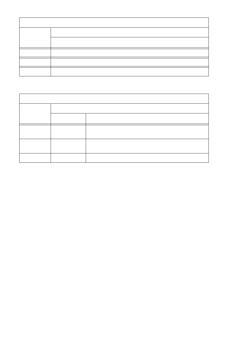
MIB Detail Specification SLVOS R2.1 February 2003
- Page 26 -
RMON Physical Interfaces:
IN/OUT: “RMON (IN/OUT); $parentString”.
RMON Logical Interfaces (Layer 3 Devices Only):
IN: “RMON (IN); $parentString”.
OUT: “RMON (OUT); $parentString”.
Where $parentString is the ifDescr of the associated parent interface.
RMON Virtual Interfaces:
IN/OUT: “VIRTUAL PVC i j ALL”
RMON Virtual Logical Interfaces (Layer 3 Devices Only):
IN: “VIRTUAL PVC i j DTE”
OUT: “VIRTUAL PVC i j DCE”
Where:
“zzzz-zzz” represents the hardware version number (CCA Number). Note that the revision
numbers can be any string up to four characters long, a hyphen, followed by any
string up to three characters long.
“sssssss” represents the serial number for the NAM. It can be any character string up to seven
characters long
ATM Cell Logical Layer
Physical
Interface
Type Description
SDSL Network SDSL of ATM; $cardString; Hardware Version: zzzz-zzz
SHDSL Network SHDSL of ATM; $cardString; Hardware Version: zzzz-zzz
IDSL Network IDSL of ATM; $cardString; Hardware Version: zzzz-zzz
ISDN B-Channels
Physical
Interface
Type Card Type Description
PRI Child ISDN B-Channel n; Child Card: $cardString; S/W Release:
yy.yy.yy; Hardware Version: zzzz-zzz
BRI Child ISDN B-Channel n; Child Card: $cardString; S/W Release:
yy.yy.yy; Hardware Version: zzzz-zzz
BRI Integrated ISDN B-Channel n; $cardString; Hardware Version: zzzz-zzz

February 2003 MIB Detail Specification SLVOS R2.1
- Page 27 -
iis the interface number for associated with the virtual interface
jis the DLCI number associated with the virtual interface
sis the slot number
pis the port number
cis the channel number
n is the interface number
$profileName Frame Relay profile name string
$cardString:
“T1 NAM”
“Dual T1 NAM”
“T3 NAM”
“DP NAM”
“DDS NAM”
"DSL NAM"
“DSL FR-ATM NAM”
“SDSL NAM”
“LL S/T NAM”
“LL S/T NIM”
“DSX-1 APM”
“Sync Data APM”
“FXS Voice APM”
“FXO Voice APM”
“E&M Voice APM”
“OCU (2 or 6) APM”
“ISDN-BRI DBM”
“ISDN-PRI DBM”
“IDSL NAM”
1.1.1.2.2.3 “ifType” Object (ifEntry 3)
This object identifies the type of the interface based on the physical/link protocol(s) immediately below the network
layer. Only the following values are supported by SLV OS R2.1.
ifType Description
other(1) Used for DDS Network, for DDS OCU port
ethernetCsmacd(6) Ethernet port when configured for Ethernet Version 2 Mode

MIB Detail Specification SLVOS R2.1 February 2003
- Page 28 -
iso88023Csmacd(7) Ethernet port when configured for IEEE 802.3 Mode
ds1(18) Used for the Network and DSX-1 T1 interfaces
basicISDN(20) Used for the BRI
primary ISDN(21) Used for the PRI interface
ppp (23) Used for the PPP interface
ds3(30) Used for T3 interfaces
frame-relay(32) Used for the Frame Relay Sublayers when configured for the DTE
Side of the Frame Relay UNI or when no LMI is configured.
Used for all RMON logical and virtual interfaces
Used for FR Bundle.
rs232(33) Used for the COM port
atm(37) Used for ATM Cell Logical Layers
frameRelayService(44) Used for the Frame Relay Sublayers when configured for the Service
Side of the Frame Relay UNI
v35(45) Used for the synchronous data ports when configured as V.35 or EIA-
530A
hssi(46) Used for HSSI interfaces
modem(48) Used for the Modem port when the port is not configured as a network
communication link
v11(64) Used for the synchronous data ports when configured as X.21
isdns(75) Used for ISDN S/T interfaces
ds0(81) Used for ISDN B-Channel interfaces (per RFC 2127)
sdsl(96) Used for Network SDSL interfaces
voiceEM(100) Used for E&M voice ports
voiceFXO(101) Used for FXO voice ports
voiceFXS(102) Used for FXS voice ports
idsl(154) Used for Network IDSL interfaces
shdsl(169) Used for Network SHDSL interfaces
ifType Description

February 2003 MIB Detail Specification SLVOS R2.1
- Page 29 -
1.1.1.2.2.4 “ifMtu” Object (ifEntry 4)
This object identifies the largest datagram, associated with a management link, which can be sent/received on the
interface. ifMTU will have the following values:
1.1.1.2.2.5 “ifSpeed” Object (ifEntry 5)
This object provides the interfaces’ maximum attainable bandwidth in bits per second. The value of this object for each
interface is specified as follows:
Interface ifMtu
T1 interfaces 1500
T3 interfaces 1500
Sync Data Ports 1500
HSSI Ports 1500
COM Port variable (usually 1500)
OCU Port 1500
Modem Port variable (usually 1500)
Ethernet 1500 (Version2)
1492 (IEEE 802.3)
Frame Relay Sublayers 8 K
PPP variable (negotiated)
ISDN BRI 1500
ISDN S/T 1500
DDS 1500
SDSL 1500
FR Bundle 8 K
ISDN B-Channel 1500
SHDSL 1500
IDSL 1500
All other 0
Interface ifSpeed
T1 (Network T1, DSX-1, PRI) 1,544,000 bps
T3 44,736,000 bps
Com Port The currently configured data rate for the port

MIB Detail Specification SLVOS R2.1 February 2003
- Page 30 -
1.1.1.2.2.6 “ifAdminStatus” Object (ifEntry 7)
This object is used to specify the desired state (configuration) of the interface. Only the following values are supported:
Modem The currently negotiate data rate for the modem port
Ethernet 10,000,000 or 100,000,000 bps
Sync Data Ports The currently configured data rate for the port
HSSI Ports The currently configured data rate for the port
FR UNI Peak data rate available based on the physical sublayer (FT1, sync data port, BRI or
PRI). For the T1 physical sublayer, this is the number of DS0s associated with the port
multiplied by the configured speed of a DS0 (either 56,000bps or 64,000 bps). For the
BRI and PRI, it is the currently negotiated speed
RMON Logical Peak data rate available based on the physical sublayer (FT1, sync data port, BRI or
PRI)
RMON Virtual CIR of the associated DLCI
Voice Port (FSX, FXO, E&M)
64,000bps
DDS OCU Port The current configured data rate for the port -56000 for 56k and SW56, or 64000 for 64K
Clear Channel
BRI The current configured data rate for the port.
ISDN S/T The current configured data rate for the port.
DDS 56,000 bps or 64,000 bps reflecting the line rate detected
SDSL Negotiated Link Rate
MFR The current configured data rate for the port.
ISDN B-Channel 56,000 bps or 64,000 bps reflecting the connection speed detected
ATM The rate of the physical sublayer.
SHDSL Negotiated Link Rate
IDSL The current configured data rate for the port.
PPP Peak data rate available based on the physical sublayer.
Interface ifAdminStatus
T1 up(1) - The T1 interface is always up
T3 up(1) - The T3 interface is always up
Com Port up(1) - The Com port interface is always up
Modem up(1) - The Modem interface is always up
Interface ifSpeed

February 2003 MIB Detail Specification SLVOS R2.1
- Page 31 -
Ethernet up(1) - The Ethernet interface is always up
Sync Data Port For 9820 and 9820-2M only, Sync Data Ports are always up.
up(1) - The interface is up.
down(2) - The interface is disabled
HSSI up(1) - The interface is up.
down(2) - The interface is disabled
FR UNI (standard) up(1) - Frame Relay logical interfaces are always up
FR UNI (BRI or PRI) up(1) - The ifAdminStatus of the ISDN BRI or PRI interface is up
down(2) - The ifAdminStatus of the ISDN BRI or PRI interface is
down.
PPP up(1) - PPP logical interfaces are always up
RMON Logical up(1) - The interface is up
down(2) - The interface is disabled
RMON Virtual up(1) - The interface is up
down(2) - The interface is disabled
Voice Port up(1) - The interface is up
down(2) - The interface is disabled
DDS OCU Port up(1) - The interface is up
down(2) - The interface is disabled
BRI up(1) - The interface is up
down(2) - The interface is disabled
ISDN S/T up(1) - The ISDN S/T interface is always up
ISDB B Channel up(1) - The interface is up
down(2) - The interface is disabled
DDS up(1) - The DDS interface is always up
SDSL up(1) - The SDSL interface is always up
MFR up(1) - The interface is up
down(2) - The interface is disabled
ISDN B-Channel up(1) - A call is desired or active on the channel
down(2) - No calls active or desired
ATM up(1) - ATM logical interfaces always have an ifAdminStatus of up.
SHDSL up(1) - The SHDSL interface is always up
Interface ifAdminStatus

MIB Detail Specification SLVOS R2.1 February 2003
- Page 32 -
1.1.1.2.2.7 “ifOperStatus” Object (ifEntry 8)
This object is used to specify the current operational state of the interface. The value of this object for each interface
will be defined as follows:
IDSL up(1) - The IDSL interface is always up
Interface ifOperStatus
T1 Interfaces This include Network, DSX-1 and PRI.
up(1) - when no alarm conditions exist.
down(2) - when an alarm condition exists, or when it is disabled.
testing(3) - when a test is active on the interface.
T3 Interfaces up(1) - when no alarm conditions exist.
down(2) - when an alarm condition exists.
testing(3) - when a test is active on the interface.
Com Port When configured as a network communication link, up and down are
based on the current state of the link layer protocol and control leads.
Otherwise, the interface is always up(1).
The interface is never in the testing(3) state.
Sync Data Ports The status of this type of interface is based on alarm conditions on the
interface. CTS and DSR alarms are supported on all products. 9820
supports additional alarms for RLSD and Test Mode on V.35 or EIA-
530 as well as Indication on X.21. CTS, DSR, and RLSD alarms may
be disabled and no alarms will be asserted.
up(1) - when no alarms exist and the interface is enabled.
down(2) - when the port is disabled, unassigned, or alarms exist.
testing(3) - when a test is active on the interface.
HSSI up(1) - when no alarms exist and the interface is enabled.
down(2) - when the port is disabled, unassigned, or alarms exist.
testing(3) - when a test is active on the interface.
Modem Port up(1) - when modem is active
down(2) - when modem is inactive
Ethernet Port up(1) - always active
Voice Ports up(1) - when it is enabled.
down(2) - when it is disable.
testing(3) - when a test is active.
Interface ifAdminStatus

February 2003 MIB Detail Specification SLVOS R2.1
- Page 33 -
OCU Ports up(1) - when it is enable and no alarm conditions exist.
down(2) - when an alarm condition exists or it is disable.
testing(3) - when a test is active.
BRI (DBM) up(1) - when no alarm conditions exist.
down(2) - when the port is disabled or no call is active.
testing(3) - when a test is active on the interface
ISDN S/T up(1) - when no alarm conditions exist.
down(2) - when an alarm condition exists, or when it is disabled.
testing(3) - when a test is active on the interface.
DDS up(1) - when no alarm conditions exist.
down(2) - when an alarm condition is active.
testing(3) - when a test is active on the interface.
SDSL up(1) - when no alarm conditions exist.
down(2) - when an alarm condition is active.
testing(3) - when a test is active on the interface.
Frame Relay DTE Side up(1) - when the LMI is up and the Frame Relay link is enabled.
down(2) - when the LMI is down or the Frame Relay link is disabled.
testing(3) - when a test is active for any DLCI on the Frame Relay
link.
dormant(5) - when the link is not attached to a physical interface.
This only occurs for constituent links that do not have an active call.
Frame Relay Service
Side
up(1) - when the LMI is up and the Frame Relay link is enabled.
down(2) - when the LMI is down or the Frame Relay link is disabled.
testing(3) - when a test is active for any DLCI on the Frame Relay
link.
dormant(5) - when the link is not attached to a physical interface.
This only occurs for constituent links that do not have an active call.
MFR up(1) - when the LMI is up and the MFR is enabled.
down(2) - when the LMI is down or the MFR Bundle is disabled.
testing(3) - when a test is active for any DLCI on the MFR.
dormant(5) - when all constituent links are dormant.
RMON Interfaces The interface reports the same value as its corresponding Frame
Relay interface.
PPP up(1) - when the PPP link is enabled.
down(2) - when the PPP link is disabled.
Interface ifOperStatus

MIB Detail Specification SLVOS R2.1 February 2003
- Page 34 -
1.1.1.2.2.8 “ifLastChange” Object (ifEntry 9)
This object contains the value of “sysUpTime” at the time the interface entered its current operational state. It will
return 0 for RMON associated ifIndexes.
1.1.1.2.2.9 Input Counters (objects ifEntry 10 to ifEntry 15)
The objects used to collect statistics on the data received by an interface apply to the Communication port, Modem
port, the ethernet port, the PPP Logical link, the Frame Relay Logical link sublayer on the T1 network interfaces, T3
interfaces, synchronous data ports, DSL, BRI, and PRI when they are configured as a network communication link.
When the Communication port, Modem port are not configured as a communication link these statistics will not be
provided and will return an error status if access is attempted. Additionally, all RMON associated ifIndexes will return
0. The objects used to collect input statistics are listed below:
• ifInOctets (ifEntry 10)
• ifInUcastPkts (ifEntry 11)
• ifInNUcastPkts (ifEntry 12)
• ifInDiscards (ifEntry 13)
• ifInErrors (ifEntry 14)
• ifInUnknownProtos (ifEntry 15)
1.1.1.2.2.10 Output Counters (objects ifEntry 16 to ifEntry 20)
The objects used to collect statistics on the data sent by an interface apply to the Communication port, Modem port,
the ethernet port, the PPP Logical link, the Frame Relay Logical link sublayer on the T1 network interfaces, T3
interfaces, synchronous data ports, DSL, BRI, and PRI when they are configured as a network communication link.
When the Communication port, Modem port are not configured as a network communication link these statistics will
not be provided and will return an error status if access is attempted. Additionally, all RMON associated ifIndexes will
return 0. The objects used to collect output statistics are listed below:
• ifOutOctets (ifEntry 16)
• ifOutUcastPkts (ifEntry 17)
• ifOutNUcastPkts (ifEntry 18)
ISDN B-Channel up(1) - when a call is active on the interface
down(2) - when no call is active on the interface
ATM up(1) - when no alarm conditions exist and the link is enabled.
down(2) - when an alarm condition is active or the link is disabled.
testing(3) - when a test is active on the interface.
SHDSL up(1) - when no alarm conditions exist.
down(2) - when an alarm condition is active.
testing(3) - when a test is active on the interface.
IDSL up(1) - when no alarm conditions exist.
down(2) - when an alarm condition exists, or when it is disabled.
testing(3) - when a test is active on the interface.
Interface ifOperStatus

February 2003 MIB Detail Specification SLVOS R2.1
- Page 35 -
• ifOutDiscards (ifEntry 19)
• ifOutErrors (ifEntry 20)
• ifOutQLen(ifEntry 21)
1.1.1.2.2.11 “ifSpecific” Object (ifEntry 22)
This object will be supported for the RMON interfaces only in order to maintain compatibility with the RMON NMS.
The returned value will always be .0.0.
1.1.2 IF-MIB Module
1.1.2.1 Extension to Interface Table Group (mib-2)
The Extension to the interface table contains additional objects for the interface table.
1.1.2.1.1 ifXTable (ifMIBObjects 1)
Only the following objects in the Extension to the Interface Table will be supported by SLV OS R2.1:

MIB Detail Specification SLVOS R2.1 February 2003
- Page 36 -
1.1.2.1.1.1 “ifName” Object (ifXEntry 1)
The ifName object provides the name of the interface. For each interface, the ifName text string will be as follows:
Interface ifName
Network T1 “Network T1”
Dual Network T1 “Network T1 interface n”
Network T3 “Network T3”
Network DDS “Network DDS”
Network SDSL “Network SDSL”
User T3 “T3”
DSX-1 T1: (NAM) “DSX-1 T1”
DSX-1 T1: (APM) “DSX-T1 SssPp” (where ss is the slot number and p is the port number)
Com “COM”
Modem “Modem”
Ethernet “Ethernet”
FXS “Voice FXS SssPp”
FXO “Voice FXO SssPp”
E&M “Voice E&M SssPp”
OCU “DDS OCU SssPp”
Sync Data Ports “Sync Data Port SssPp”
Network Sync Data Port “Network Sync Data Port SssPp”
BRI “ISDN BRI DBM”
PRI T1 “ISDN PRI DBM”
ISDN S/T “Network ISDN S/T”
Frame Relay Logical Link
Sublayers
“FR UNI”
PPP Logical link “PPP UNI”
MFR “FR Bundle”
RMON Interfaces Not Supported
ISDN PRI B-Channel “ISDN PRI DS0”
ISDN BRI B-Channel “ISDN BRI DS0”
ATM “ATM”
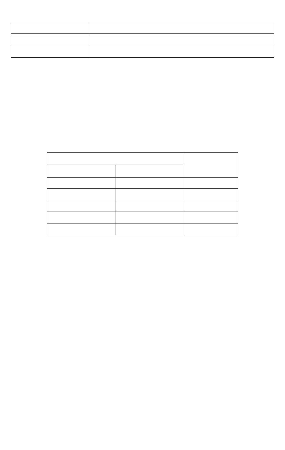
February 2003 MIB Detail Specification SLVOS R2.1
- Page 37 -
1.1.2.1.1.2 “ifLinkUpDownTrapEnable” Object (ifXEntry 14)
This object is used to indicate whether linkUp / linkDown or enterpriseSpecific traps should be generated for all
physical interfaces as well as Frame Relay Logical Sublayer and the PPP Logical link on the physical interfaces. This
object is not supported for the COM port, Modem Port, ISDN B-Channels or Voice ports. This object is supported
read-only.
Note: SNMP traps must be enabled on the device via the setting of the SNMP trap enable configuration to enabled for
changes in this object to take effect.
1.1.2.1.1.3 “ifHighSpeed” Object (ifXEntry 15)
This object is a read-only value and will be set based on the value of ifSpeed for the interface as follows:
This object is not supported for RMON Interfaces.
1.1.2.1.1.4 “ifConnectorPresent” Object (ifXEntry 17)
This object indicates whether there is a physical connector for the interface. The object will always have the value
true(1) for the Network T1, T3 interfaces, Network DDS, DSX-1, COM, Modem, Ethernet, DSL, BRI, PRI, ISDN S/
T, OCU port, Voice port and the Sync Data Ports, and will always have the value false(2) for all other interfaces. It is
not supported for RMON Interfaces.
1.1.2.2 Interface Stack Group (ifMib)
The interface stack group consists of an object containing information on the relationships between the multiple sub-
layers of network interfaces. In SLV OS R2.1 the interface stack group will be used to show the relationship between
a logical interface (i.e. Frame Relay DTE Side Logical Link Sublayer, Frame Relay Service Side Logical Link
Sublayer, or MFR) and the physical interface (i.e. Network T1, T3 interfaces, Network DDS, DSL, BRI, PRI, ISDN
S/T, or synchronous data ports).
1.1.2.2.1 ifStackTable (ifMIBObjects 2)
The ifStackTable is supported read-only in SLV OS R2.1.
Network SHDSL “Network SHDSL”
Network IDSL “Network IDSL”
ifSpeed (bps)
ifHighSpeedFrom To
0 499,999 0
500,000 1,499,999 1
1,500,000 2,499,999 2
... ... ...
(1,000,000 n) - 500,000 (1,000,000 n) + 499,999 n
Interface ifName

MIB Detail Specification SLVOS R2.1 February 2003
- Page 38 -
1.1.2.2.1.1 “ifStackHigherLayer” Object (ifStackEntry 1)
This object provides the ifIndex corresponding to the higher sub-layer running ‘on top of’ the interface specified in
ifStackLowerLayer. For ifStackLowerLayers that correspond to physical interfaces (Network T1, T3 interfaces,
Network DDS, DSL, BRI, PRI, ISDN S/T, or synchronous data ports), the ifStackHigherLayer is set to the ifIndex of
the corresponding higher layer (i.e. ATM, Frame Relay Logical Link Sublayer, PPP Logical link, or MFR). For
ifStackLowerLayers that correspond to a logical interfaces (i.e. ATM, Frame Relay DTE Side Logical Link Sublayer,
Frame Relay Service Side Logical Link Sublayer, or MFR) this object may have a value of 0 if there is no higher
interface. However, the ISDN B-Channels and Frame Relay Links may have higher layers. All other ifIndex objects
will have a value of 0.
1.1.2.2.1.2 “ifStackLowerLayer” Object (ifStackEntry 2)
This object provides the ifIndex corresponding to the lower sub-layer running ‘below’ the interface specified in the
corresponding ifStackHigherLayer. For ifStackHigherLayers that correspond to physical interfaces (Network T1, T3
interfaces, Network DDS, DSL, BRI, PRI, ISDN S/T, or synchronous data ports) the ifStackLowerLayer object will
have a value of 0 since there is no lower interface. For ifStackHigherLayers that correspond to logical interfaces (i.e.
ATM, Frame Relay DTE Side Logical Link Sublayer, Frame Relay Service Side Logical Link Sublayer, PPP Logical
link, or MFR) the ifStackLowerLayer object is set to the ifIndex of either the corresponding physical port (Network or
synchronous data port) or the lower logical link. All other ifIndex objects will have a value of 0.
1.1.2.2.1.3 “ifStackStatus” Object (ifStackEntry 3)
This object is supported as a read-only variable by SLV OS R2.1. The criteria used for determining the value of
ifStackStatus for the ATM and Frame Relay Logical Link Sublayers (if enabled) is the ANDing of the ifOperStatus of
the Higher Layer object (ATM, Frame Relay DTE Side Logical Link Sublayer, Frame Relay Service Side Logical Link
Sublayer, PPP Logical link, or MFR) with the ifOperStatus of the Lower Layer object (T1 Network Interface, T3
interfaces, Network DDS, DSL, BRI, PRI, ISDN S/T, or Synchronous Data Ports). A value of “up” or “testing” for
ifOperStatus will map to an ifStackStatus of “active”, and an ifOperStatus of “down” will map to an ifStackStatus
value of “not in service”. Only the ifOperStatus will be used to determine the value assigned to physical interfaces.
1.1.2.3 Interface Test Group (ifMib)
1.1.2.3.1 Interface Test Table (ifMIBObjects 3)
The interface test table is used to provide access to additional tests (loopbacks and pattern tests) that are not provided
for in the interfaces group of MIB-II. It is supported on the non-network Data Ports only.
1.1.2.3.1.1 “ifTestID” Object (ifTestEntry 1)
This object provides a unique identifier for the current invocation of a test on an interface. It is set by an SNMP
Manager (which causes the previous value to be incremented by SLV OS R2.1) before the test is started. It should then
be checked after the test is completed to assure that the results of the test correspond to the appropriate test invocation.
This handles the rare condition where another SNMP Manager starts a test right after completion of the previous test,
but before the previous test results are retrieved by the first SNMP Manager.
1.1.2.3.1.2 “ifTestStatus” Object (ifTestEntry 2)
This object indicates the test status of the interface. The test status is set to inUse(2) by an SNMP Manager before a
test is started, and set to notInUse(1) by SLV OS R2.1 when the test has completed. In the event that an SNMP Manager
fails to set an ifTestType within 5 minutes, SLV OS R2.1 will set the test status to notInUse(1).
1.1.2.3.1.3 “ifTestType” Object (ifTestEntry 3)
This object is a control variable used to start and stop operator initiated tests on the interface. It provides the capability
to:

February 2003 MIB Detail Specification SLVOS R2.1
- Page 39 -
• Start/stop data port loopback
The following object identifiers will be used to control the tests on the interface. The “noTest” object identifier is
defined in the Evolution of the Interfaces Group of MIB-II, the other object identifiers are defined here.
• noTest Stops the test in progress on the interface.
• testLoopExternalDTE Initiates an External DTE loopback on the interface. Only supported for the non-
network data ports.
Where these object identifiers are defined as follows:
• noTest OBJECT IDENTIFIER:= [0 0]
• testLoopExternalDTE OBJECT IDENTIFIER:= [ifTestType 2]
It should be noted that attempting to start a test that is already started will not affect the test that is currently running,
but it will not a return an error. In the same manner, no error is returned when attempting to stop a test that is already
stopped.
1.1.2.3.1.4 “ifTestCode” Object (ifTestEntry 5)
This object contains a code which contains more specific information on the test result. This object will be defined as
an OBJECT IDENTIFIER. Only the following values are supported by SLV OS R2.1.
• none No further information is available. Used for the send pattern/code and loopback
tests.
Where these object identifiers are defined as follows:
• none OBJECT IDENTIFIER:= [ifTestCode 1]
1.1.2.3.1.5 “ifTestOwner” Object (ifTestEntry 6)
This object is used by an SNMP Manager to identify the current owner of the test for the interface. The SNMP Manager
sets the object to its IP address when setting ifTestID and ifTestStatus.
1.1.2.4 IP Group (mib-2)
The IP Group Objects are supported by SLV OS R2.1 for all data paths which currently are configured to carry IP data
to or from SLV OS R2.1, including the COM port, Modem port, ethernet port and Management PVCs. The objects in
the IP Group are supported as described below. The IP Address Translation table (ipNetToMediaTable) does not apply
to non-router SLV OS R2.1 and will be empty (i.e. have zero entries), but for router products, it will contain ARP
information for only the ethernet port.
The following sections provide clarification for objects contained in the IP Group when it is not clear how the object
definition in MIB-II is related to SLV OS R2.1. Objects not mentioned are supported as described in MIB-II.
1.1.2.4.1 “ipForwarding” Object (ip 1)
This object is used to specify whether the unit is acting as an IP gateway in respect to the forwarding of datagram
received by but not addressed to this unit. Only the following value is supported by SLV OS R2.1:
• forwarding(1) - The unit is acting as a gateway.
1.1.2.4.2 “ipAddrTable” Object (ip 20)
The address table will be supported by SLV OS R2.1.
1.1.2.4.2.1 “ipAdEntAddr” Object (ipAddrEntry 1)
The ipAdEntAddr object is an IP address supported by the device and serves as the index to the address table. Since
indexes for tables must be unique, only one ifIndex may be displayed for each IP address supported by the device. If

MIB Detail Specification SLVOS R2.1 February 2003
- Page 40 -
the user has configured the same IP address for multiple interfaces or for default IP addresses, the user will not see all
interfaces that support a particular IP address upon display of the ipAddrTable.
1.1.2.4.3 “ipRouteTable” Object (ip 21)
This table IS NOT supported in router devices. Instead the ipCidrRouteTable should be used. All management routes
should be contained in the Paradyne IP Route Table.
The routing table used by SLV OS R2.1 is supported as a read/write table when there is no router on the device. Entries
in this table may be added, deleted or changed. The User should exercise great caution when adding or modifying
routes in the ipRoutingTable. In general, it should not be necessary for the user to add/modify routes in SLV OS
R2.1. In those cases where it is deemed necessary, the routes should only be added to the connected device (i.e.,
the device closest to the destination). Internal routing mechanisms will propagate the route to the other devices.
Routes over management PVCs will not appear in the ipRouteTable. Those routes can be accessed via the Paradyne
enterprise routing table (devIPRouteTable).
An existing route may be effectively deleted by setting the ipRouteType object to “invalid” of the entry to be deleted.
An existing route may be modified by changing fields in the desired entry (indexed by ipRouteDest) of the routing
table. A new route may be added by specifying values for a table entry for which the index (“ipRouteDest”) doesn’t
already exist.
In order to add a route using an SNMP set, there is a group of minimal objects that must be specified. These variable
bindings must be contained in a single PDU. The objects are described in more detail in the following sections. The
minimal set consists of:
• ipRouteDest
• ipRouteIfIndex
The following objects will be defaulted if not specified in the set PDU used to add a route.
• ipRouteMetric1 - defaulted to 1 hop
• ipRouteType - defaulted to direct
• ipRouteMask - defaulted as specified in the MIB description
• ipRouteMetric2 - defaulted to current slot for nest devices and -1 for standalone devices.
The following read-only objects must not be specified in the set PDU used to add a route.
• ipRouteMetric3, ipRouteMetric4, ipRouteMetric5 - defaulted to -1 as specified in the MIB
• ipRouteNextHop - defaulted to 0.0.0.0
• ipRouteProto - will be set to netmgmt(3) by software
• ipRouteAge - defaulted to 999 (permanent)
• ipRouteInfo - will be set to OBJECT IDENTIFIER [0 0] since it is unused
1.1.2.4.3.1 “ipRouteDest” Object (ipRouteEntry 1)
The ipRouteDest object serves as the index to the routing table. Since indexes for tables must be unique, only one route
per destination may appear in the table. To ensure that no duplicate destinations appear in the routing table, the
ipRouteDest object of the ipRouteTable will be treated as described in RFC 1354 (IP Forwarding Table MIB) and
described below:
“The destination IP address of this route. An entry with a value of 0.0.0.0 is considered a default route. This
object may not take a Multicast (Class D) address value. Any assignment (implicit or otherwise) of an

February 2003 MIB Detail Specification SLVOS R2.1
- Page 41 -
instance of this object to a value x must be rejected if the bitwise logical-AND of x with the value of the
corresponding instance of the ipForwardMask object is not equal to x.”
1.1.2.4.3.2 “ipRouteIfIndex” Object (ipRouteEntry 2)
When the routing table is displayed, the ipRouteIfIndex object for some entries may have a value greater than
ifNumber. In these cases, the ipRouteIfIndex refers to a proprietary interface which is not currently implemented by
the interface group of MIB-II. Route entries with unrecognized ipRouteIfIndex values should NOT be deleted.
When setting this object via SNMP, the ipRouteIfIndex value can only assume an appropriate value of ifIndex defined
for the particular device type.
1.1.2.4.3.3 “ipRouteMetric2-5” Object (ipRouteEntry 4-7)
In SLV OS R2.1, ipRouteMetric2, ipRouteMetric3, ipRouteMetric4, and ipRouteMetric5 are not used and will always
return -1.
When adding a route to the routing table using SNMP, the user should not specify a value for these objects.
1.1.2.4.3.4 “ipRouteType” Object (ipRouteEntry 8)
The ipRouteType object can be used to delete a route by setting its value to invalid(2). No other values will be accepted.
1.1.2.4.3.5 “ipRouteProto” Object (ipRouteEntry 9)
The ipRouteProto object is a read-only object and may have the following values in SLV OS R2.1:
• other(1) - temporary route added by IP
• local(2) - route added or modified as a result of User configuration
• netmgmt(3) - route added or modified by means of an SNMP set
• icmp(4) - route added or modified by ICMP
• rip(8) - route added or modified by RIP (or similar proprietary protocol)
1.1.2.4.3.6 “ipRouteAge” Object (ipRouteEntry 10)
The ipRouteAge object is implemented as a read-only object in SLV OS R2.1. On SLV OS R2.1, the ipRouteAge object
reflects the value of the time-to-live for the route in seconds. When displayed, a value of 999 is used to represent a
route that will be retained permanently. For temporary routes, the ipRouteAge object will decrement over time. All
routes added via an SNMP set of the ipRouteTable are considered permanent routes. These routes will not age and will
remain in the table unless deleted via SNMP.
1.1.2.4.4 “ipNetToMediaTable” Object (ip 22)
The IP address translation table will be supported by SLV OS R2.1 read-only for router products only. It will contain
only ARP information from the ethernet port.
1.1.2.4.5 “ipForward” Group (ip 24)
The IP Forward group is defined in RFC 2096, the IP Forwarding MIB. This MIB replaces the routing table from MIB-
II with a table that is indexed in a more manageable way. This group is supported on router products only and will only
show information on routes known to the router. It will not be able to show management routing information. The
ipForwardNumber and ipForwardTable are obsolete and replaced by the ipCidrRouteNumber and ipCidrRouteTable.
Both of the later are fully supported. The following information expands on the level of support for this group.

MIB Detail Specification SLVOS R2.1 February 2003
- Page 42 -
1.1.2.4.5.1 “ipCidrRouteTable” (ipForward 4)
Object Name Description
Default
Value Support
ipCidrRouteTable This table acts as both the forwarding and the routing
table. Only user data is controlled by this table. It does not
control management traffic. It is indexed by
ipCidrRouteDest, ipCidrRouteMask, ipCidrRouteTos and
ipCidrRouteNextHop.
ipCidrRouteDest The destination IP address of this route. read-only
ipCidrRouteMask The mask to be logical-ANDed with the destination
address before being compared to the value of
ipCidrRouteDest. Only left justified masks are supported.
read-only
ipCidrRouteTos The policy specifier. It can contain even values between
zero and 30 where zero indicates the default path if no
more specific policy applies. Only zero is supported.
0 read-only
ipCidrRouteNextHop If the route is a remote route, the value indicates the next
system in route. Otherwise, this value will be 0.0.0.0.
read-only
ipCidrRouteIfIndex The ifIndex value which identifies the local interface
through which the next hop of this route should be
reached. Only non-management frame relay DLCIs and
the ethernet port are valid. This should report 0 whenever
ipCidrRouteNextHop is 0.
read-
create
ipCidrRouteType The type of the route. Valid values are other(1), reject(2),
local(3), and remote(4). All static routes will be defined as
local(3) when ipCidrRouteNextHop is .0.0.0.0. Otherwise,
they will be defined as remote(4). Users can only create
local(3) or remote(4) routes.
read-
create
ipCidrRouteProto The routing mechanism through which this route was
learned. Valid values are other(1), local(2), netmgmt(3),
icmp(4), egp(5), ggp(6), hello(7), rip(8), isIs(9),
ciscoIgrp(11), bbnSpfIgp(12), ospf(13), bgp(14), idpr(15)
and ciscoEigrp(16).
read-only
ipCidrRouteAge The number of seconds since this route was last updated.
Static routes will always report 0.
0 read-only
ipCidrRouteInfo This object points to the table which shows protocol
specific details for a particular route protocol
(ipCidrRouteProto). SLV OS R2.1 will only support .0.0.
.0.0 read-only
ipCidrRouteNextHopAs The Autonomous System Number of the Next Hop.
SLV OS R2.1 will only support 0.
0 read-
create
ipCidrRouteMetric1 This object will support any value inclusively between 1
and 255 or negative 1. However, RouterWare will change it
to as required when the route is active. In this way, the
value set may not be the value reported or used.
-1 read-
create

February 2003 MIB Detail Specification SLVOS R2.1
- Page 43 -
1.1.2.5 ICMP Group (mib-2)
The ICMP Group Objects are fully supported by SLV OS R2.1. For router products, it will contain only information
coming from the embedded router, and it will ignore all management traffic that does not pass through the router.
1.1.2.6 TCP Group (mib-2)
The TCP Group Objects are fully supported by SLV OS R2.1, with the exception of tcpConnState object which will be
read-only since deleteTCB(12) (the only value which may be set) is not supported. For router products, it will contain
only information coming from the embedded router, and it will ignore all management traffic that does not pass
through the router.
1.1.2.7 UDP Group (mib-2)
The UDP Group Objects are fully supported by SLV OS R2.1. For router products, it will contain only information
coming from the embedded router, and it will ignore all management traffic that does not pass through the router.
1.1.2.8 Transmission Group (mib-2)
Objects in the Transmission Group are supported on the Network, PRI and DSX-1 T1 interfaces, T3 interfaces, the
synchronous data ports, ethernet, as well as the COM port and Modem port. The objects in the transmission group are
not defined within MIB-II but rather through other Internet-standard MIB definitions. The following transmission
group objects are supported by SLV OS R2.1.
• dot3 (transmission 7) - The transmission object supported on the Ethernet-like interfaces.
• ds1 (transmission 18) - The transmission object supported on the T1 interfaces.
ipCidrRouteMetric2 This object will support any value greater or equal to
negative 1. However, RouterWare will change it to as
required when the route is active. In this way, the value set
may not be the value reported or used.
-1 read-
create
ipCidrRouteMetric3 This object will support any value greater or equal to
negative 1. However, RouterWare will change it to as
required when the route is active. In this way, the value set
may not be the value reported or used.
-1 read-
create
ipCidrRouteMetric4 This object will support any value greater or equal to
negative 1. However, RouterWare will change it to as
required when the route is active. In this way, the value set
may not be the value reported or used.
-1 read-
create
ipCidrRouteMetric5 This object will support any value greater or equal to
negative 1. However, RouterWare will change it to as
required when the route is active. In this way, the value set
may not be the value reported or used.
-1 read-
create
ipCidrRouteStatus The row status of an IP route. All dynamic routes will have
a status of active(1). Only static routes will be destroyed by
setting them to destroy(6) and setting them to
notInService(2) has the same effect on routing as setting
them to destroy(6).
read-
create
Object Name Description
Default
Value Support

MIB Detail Specification SLVOS R2.1 February 2003
- Page 44 -
• rs232 (transmission 33) - The transmission object supported on the synchronous data ports, COM port
and Modem port.
• frame-relay (transmission 32) - The transmission object supported on “DTE Side” Frame Relay
interfaces.
• frameRelayService (transmission 44) - The transmission object supported on “Service Side” Frame
Relay interfaces.
• ds3 (transmission 30) - The transmission object supported on the T3 interfaces.
• dial interfaces (transmission 21) - The transmission object supported for ISDN PRI and BRI calls.
• adsl (transmission 94) - The transmission object partially supported for DSL interfaces.
The ds1 object is defined by the DS1 MIB. The rs232 transmission object is defined by the RS-232-like MIB.
Enterprise specific objects for the T1 interfaces are provided by the Paradyne T1 Interface MIB. The frame-relay object
is defined by the Frame Relay for DTEs MIB. The frameRelayService transmission object is defined by the Frame
Relay Service MIB.The ds3 object is defined by the DS3 MIB. The dial control transmission object is defined by the
Dial Control MIB. The ethernet object is defined in the Ether-like MIB. The adsl object is defined in the ADSL MIB.
1.1.2.9 SNMP Group (mib-2)
The SNMP Group Objects that apply to a management agent are fully supported by the SLV OS R2.1. The following
objects apply only to an NMS and return a zero value if accessed.
• snmpInTooBigs (snmp 8)
• snmpInNoSuchNames (snmp 9)
• snmpInBadValues (snmp 10)
• snmpInReadOnlys (snmp 11)
• snmpInGenErrs (snmp 12)
• snmpInGetResponses (snmp 18)
• snmpInTraps (snmp19)
• snmpOutGetRequests (snmp 25)
• snmpOutGetNexts (snmp 26)
• snmpOutSetRequests (snmp 27)
1.1.3 EtherLike-MIB Module (dot3)
The “EtherLike” object defined in RFC 2665 is supported for the ethernet interfaces. Only the dot3StatsTable contains
information that is accessible to the chipset supported by SLV OS R2.1. Further, support for this table is all that is
required to be fully compliant with the MIB. For these reasons, it is the only table supported.

February 2003 MIB Detail Specification SLVOS R2.1
- Page 45 -
1.1.3.1 “dot3StatsTable” (dot3 2)
Object Name Description Support
dot3StatsTable This table contains statistics for the ethernet interfaces. It
is indexed by dot3StatsIndex.
dot3StatsIndex An index that uniquely identifies this interface. This value
will be populated with the ifIndex of the ethernet
interface(s).
read-only
dot3StatsAlignmentErrors The number of frames received on a particular interface
that are not an integral number of octets in length and don’t
pass the FCS check.
read-only
dot3StatsFCSErrors The number of frames received on a particular interface
that are an integral number of octets in length but don’t
pass the FCS check. This count does not include the
frame-too-long or frame-too-short errors.
read-only
dot3StatsSingleCollisionFrames The number of successfully transmitted frames on a
particular interface for which transmission was inhibited by
exactly one collision. This counter does not increment in
full duplex mode.
read-only
dot3StatsMultipleCollisionFrames The number of successfully transmitted frames on a
particular interface for which transmission was inhibited by
more than one collision. This counter does not increment
in full duplex mode.
read-only
dot3StatsSQETestErrors The number of times that the SQE TEST ERROR
message is generated by the PLS sublayer for a particular
interface.
read-only
dot3StatsDeferredTransmissions The number of frames for which the first transmission
attempt on a particular interface is delayed because the
medium was busy. This counter does not increment in full
duplex mode.
read-only
dot3StatsLateCollisions The number of times that a collision is detected on a
particular interface later than one slotTime into the
transmission of the packet. This counter does not
increment in full duplex mode.
read-only
dot3StatsExcessiveCollisions The number of frames for which transmission on a
particular interface fails due to excessive collisions. This
counter does not increment in full duplex mode.
read-only
dot3StatsInternalMacTransmitErrors The number of frames for which transmission failed due to
an internal MAC sublayer transmit error.
read-only
dot3StatsCarrierSenseErrors The number of times that the carrier sense condition was
lost or never asserted when attempting to transmit frames.
This counter does not increment in full duplex mode.
read-only
dot3StatsFrameTooLongs The number of frames received that exceeded the
maximum permitted frame size.
read-only

MIB Detail Specification SLVOS R2.1 February 2003
- Page 46 -
1.1.4 RFC1406-MIB Module (DS1/E1 MIB)
The “ds1” object defined by RFC 1406 is supported for the Network, PRI, and DSX-1 T1 interfaces. The DS1 Near
End Group, and DS1 Fractional Group will be supported for three interfaces, the Far End Group will be supported for
Network and PRI T1 only.
1.1.4.1 Near End Group (ds1)
The DS1 Near End Group consists of the following four tables:
• DS1 Configuration
•DS1 Current
•DS1 Interval
•DS1 Total
1.1.4.1.1 DS1 Configuration Table (dsx1ConfigTable 1)
The DS1 Configuration table is supported for Network, PRI, and DSX-1 T1 interfaces. The DS1 Current, DS1 Interval,
DS1 Total tables are supported only for Network and PRI T1 interfaces. The following sections provide clarification
for objects contained in the Near End Group when it is not clear how the object definition in the DS1/E1 MIB is related
to SLV OS R2.1.
1.1.4.1.1.1 “dsx1TimeElapsed” Object (dsx1ConfigEntry 3)
This is applicable to the Network and PRI T1 interfaces only, since statistics are not kept on the DSX-1 T1 interface.
1.1.4.1.1.2 “dsx1ValidIntervals” Object (dsx1ConfigEntry 4)
This is applicable to the Network and PRI T1 interfaces only, since statistics are not kept on the DSX-1 T1 interface.
1.1.4.1.1.3 “dsx1LineType” Object (dsx1ConfigEntry 5)
This object corresponds to the Line Framing Format configuration options for all T1 interfaces on the SLV OS R2.1.
Only the following values are supported by SLV OS R2.1.
• dsx1ESF(2) - Indicates ESF framing
• dsx1D4(3) - Indicates D4 framing
1.1.4.1.1.4 “dsx1LineCoding” Object (dsx1ConfigEntry 6)
This object corresponds to the Line Coding Format configuration options for all T1 interfaces on SLV OS R2.1. Only
the following values are supported by SLV OS R2.1.
• dsx1B8ZS(2) - Indicates B8ZS line coding
dot3StatsInternalMacReceiveErrors The number of frames for which reception fails due to an
internal MAC sublayer receive error.
read-only
dot3StatsEtherChipSet This object is deprecated. not-
supported
dot3StatsSymbolErrors The number of times there was an invalid data symbol
when a valid carrier was present. This item is not
supported by the current chip set.
not-
supported
dot3StatsDuplexStatus The duplex status of the interface. The valid values are:
unknown(1), halfduplex(2), and fullduplex(3).
read-only
Object Name Description Support

February 2003 MIB Detail Specification SLVOS R2.1
- Page 47 -
• dsx1AMI(5) - Indicates AMI line coding
1.1.4.1.1.5 “dsx1SendCode” Object (dsx1ConfigEntry 7)
This object specifies the test patterns/codes being sent over all T1 interfaces. Only the following values are supported
by SLV OS R2.1.
• dsx1SendNoCode(1) - Specifies that the interface is sending data. Setting the T1 Interface to this value
will stop an active “send pattern” test on the interface. However, dsx1SendLineCode(2) and
dsx1SendResetCode(4) may not be stopped. They will run for exactly 10 seconds and stop on there
own.
• dsx1SendLineCode(2) - Specifies that the T1 interface is sending a Remote Loopback (Rlpbk) LLBUP
code. The code will be sent for 10 seconds. This value is not supported by the DSX-1 T1 interface.
• dsx1SendResetCode(4) - Specifies that the T1 interface is sending Remote Loopback (Rlpbk) LLBDN
code. The code will be sent for 10 seconds. This value is not supported by the DSX-1 T1 interface.
• dsx1SendQRS(5) - Specifies that the interface is sending a QRSS test pattern. The pattern will be sent
until the test is halted (i.e. setting to dsx1SendNoCode).
• dsx1Send511Pattern(6) - Specifies that the T1 interface is sending a 511 test pattern. The pattern will be
sent until the test is halted (i.e. setting to dsx1SendNoCode).
• dsx1Send3in24Pattern(7) - Specifies that the T1 interface is sending a 3-in-24 test pattern. The pattern
will be sent until the test is halted (i.e. setting to dsx1SendNoCode).
• dsx1SendOtherTestPattern(8) - Specifies that the T1 interface is sending a test pattern other than those
listed above. The pattern will be sent until the test is halted (i.e. setting to dsx1SendNoCode). This value
is supported as read-only.
It should be noted that attempting to start a test that is already started will not affect the test that is currently running,
but it will not a return an error. In the same manner, no error is returned when attempting to stop a test that is already
stopped.
1.1.4.1.1.6 “dsx1CircuitIdentifier” Object (dsx1ConfigEntry 8)
This object is only supported on the Network and PRI T1 Interfaces.
1.1.4.1.1.7 “dsx1LoopbackConfig” Object (dsx1ConfigEntry 9)
This object specifies the loopback state of all T1 interfaces. Only the following values are supported by SLV OS R2.1.
• dsx1NoLoop(1) - The T1 interface is not in a loopback state
• dsx1PayloadLoop(2) - Specifies that a Payload Loopback (PLB) is active for this T1 interface.
• dsx1LineLoop(3) - Specifies that a Line Loopback (LLB) is active for this T1 interface.
• dsx1OtherLoop(4) - Specifies that a Repeater Loopback (RLB) is active for this T1 interface.
It should be noted that attempting to start a test that is already started will not affect the test that is currently running,
but it will not a return an error. In the same manner, no error is returned when attempting to stop a test that is already
stopped.
1.1.4.1.1.8 “dsx1LineStatus” Object (dsx1ConfigEntry 10)
This object specifies the line (alarm) status of all T1 interfaces. Only the following values are supported by SLV OS
R2.1. More than one value may be active at a time.
• dsx1NoAlarm(1) - No alarm present
• dsx1RcvFarEndLOF(2) - A yellow alarm signal is being received.
• dsx1RcvAIS(8) - An Alarm Indication Signal (AIS) is being received

MIB Detail Specification SLVOS R2.1 February 2003
- Page 48 -
• dsx1LossOfFrame(32) - An Out Of Frame condition has persisted for more that 2.5 seconds (i.e. Red
Alarm)
• dsx1LossOfSignal(64) - A Loss of Signal condition has persisted for more that 2.5 seconds (i.e. Red
Alarm)
• dsx1LoopbackState(128) - The near end of the T1 interface is in a loopback state
• dsx1Other Failure(4096) - An Excessive Error Rate (EER) has been detected on the T1 interface.
1.1.4.1.1.9 “dsx1SignalMode” Object (dsx1ConfigEntry 11)
This object specifies whether Robbed Bit Signaling (RBS) is in use. This object differs from the MIB definition in that
it is “read-only” (not read/write) for SLV OS R2.1. Only the following values are supported by SLV OS R2.1.
• none(1) - No signaling is in use on this interface.
• robbedBit(2) - Robbed Bit Signaling is being used on at least one DS0 on this T1 interface.
1.1.4.1.1.10 “dsx1TransmitClockSource” Object (dsx1ConfigEntry 12)
This object specifies the timing source for the transmit clock for this T1 interfaces. This object differs from the MIB
definition in that it is “read-only” (not read/write) for SLV OS R2.1. Only the following values are supported by SLV
OS R2.1.
• loopTiming(1) - The recovered receive clock is used as the transmit clock (An interface is used as clock
source).
• localTiming(2) - The SLV OS R2.1’s internal clock is used as the transmit clock
1.1.4.1.1.11 “dsx1Fdl” Object (dsx1ConfigEntry 13)
This object specifies how the Facility Data Link is being used. Only the following values are supported by SLV OS
R2.1. More than one value may be active at a time.
• dsx1Ansi-T1-403 (2) - ANSI PRMs are support on the PRI and Network T1 interfaces as specified by
ANSI T1.403
• dsx1Att-54016(4) - The FDL supports the requirements specified by AT&T publication TR54016
• dsx1Fdl-none(8) - Indicates that the device does not use the FDL. This value applies to the DSX-1 T1
interface
The rules that apply to the setting of these variables are as follows:
• The dsx port may only be set to dsx1Fdl-none(8). The same is true when the PRI and T1 port has a
dsx1Type of dsx1D4(3).
• When the PRI and T1 ports has a dsx1Type of dsx1ESF(2) it must be either dsx1Att-54016(4) or both
dsx1Ansi-T1-403(2) and dsx1Att-54016(4). Any other combination will result in a badValue.
1.1.4.1.2 The DS1 Current Table objects (dsx1CurrentEntry)
The following DS1 current table objects are provided for the Network and PRI T1 interfaces only1. Objects in the table
that are not listed are not supported and will return an error status if access is attempted.
• dsx1CurrentIndex - The index that identifies the T1 interface
• dsx1CurrentESs - Errored Seconds for the current interval
• dsx1Current SESs - Severely Errored Seconds for the current interval
• dsx1CurrentUASs - Unavailable Seconds for the current interval
1. The performance statistics accessed through the DS1 MIB are equivalent to the Carrier Network Interface Registers
(Telco), the User Network Interface Registers (User) are not accessible through the DS1 MIB.

February 2003 MIB Detail Specification SLVOS R2.1
- Page 49 -
• dsx1CurrentCSSs - Controlled Slip Seconds for the current interval
• dsx1Current BESs - Bursty Errored Seconds for the current interval
1.1.4.1.3 The DS1 Interval Table objects (dsx1IntervalEntry)
The following DS1 interval table objects are provided for the Network and PRI T1 interfaces only1. Objects in the table
that are not listed are not supported and will return an error status if access is attempted.
• dsx1IntervalIndex - The index that identifies the T1 interface
• dsx1IntervalNumber - The interval number (1 to 96)
• dsx1IntervalESs - Errored Seconds for the interval
• dsx1Interval SESs - Severely Errored Seconds for the interval
• dsx1IntervalUASs - Unavailable Seconds for the interval
• dsx1IntervalCSSs - Controlled Slip Seconds for the interval
• dsx1Interval BESs - Bursty Errored Seconds for the interval
1.1.4.1.4 The DS1 Total Table objects (dsx1TotalEntry)
The following DS1 total table objects are provided for the Network and PRI T1 interfaces only1. Objects in the table
that are not listed are not supported and will return an error status if access is attempted.
• dsx1TotalIndex - The index that identifies the T1 interface
• dsx1TotalESs - The 24 hour total Errored Seconds
• dsx1Total SESs - The 24 hour total Severely Errored Seconds
• dsx1TotalUASs - The 24 hour total Unavailable Seconds
• dsx1TotalCSSs - The 24 hour total Controlled Slip Seconds
• dsx1Total BESs - The 24 hour total Bursty Errored Seconds
1.1.4.2 Far End Group (ds1)
The DS1 Far End Group consists of the following three tables:
• DS1 Far End Current
• DS1 Far End Interval
• DS1 Far End Total
These tables are not supported for DSX-1 T1 interfaces. Only supported for Network, PRI T1 interface.
1.1.4.2.1 The DS1 Current Table objects (dsx1CurrentEntry)
The following DS1 current table objects are provided for the Network and PRI T1 interfaces1. Objects in the table that
are not listed are not supported and will return an error status if access is attempted.
• dsx1FarEndCurrentIndex - The index that identifies the T1 interface
• dsx1FarEndTimeElapsed - The number of seconds for the current error-measurement period
• dsx1FarEndValidIntervals - The number of previous intervals for which valid data was collected
• dsx1FarEndCurrentESs - Errored Seconds for the current interval
• dsx1FarEndCurrent SESs - Severely Errored Seconds for the current interval
• dsx1FarEndCurrentUASs - Unavailable Seconds for the current interval
• dsx1FarEndCurrentCSSs - Controlled Slip Seconds for the current interval
1. The performance statistics accessed through the DS1 MIB are equivalent to the Carrier Network Interface Registers
(Telco), the User Network Interface Registers (User) are not accessible through the DS1 MIB.

MIB Detail Specification SLVOS R2.1 February 2003
- Page 50 -
• dsx1FarEndCurrent BESs - Bursty Errored Seconds for the current interval
1.1.4.2.2 The DS1 Interval Table objects (dsx1IntervalEntry)
The following DS1 interval table objects are provided for the Network and PRI T1 interfaces only1. Objects in the table
that are not listed are not supported and will return an error status if access is attempted.
• dsx1FarEndIntervalIndex - The index that identifies the T1 interface
• dsx1FarEndIntervalNumber - The interval number (1 to 96)
• dsx1FarEndIntervalESs - Errored Seconds for the interval
• dsx1FarEndInterval SESs - Severely Errored Seconds for the interval
• dsx1FarEndIntervalUASs - Unavailable Seconds for the interval
• dsx1FarEndIntervalCSSs - Controlled Slip Seconds for the interval
• dsx1FarEndInterval BESs - Bursty Errored Seconds for the interval
1.1.4.2.3 The DS1 Total Table objects (dsx1TotalEntry)
The following DS1 total table objects are provided for the Network and PRI T1 interfaces only1. Objects in the table
that are not listed are not supported and will return an error status if access is attempted.
• dsx1FarEndTotalIndex - The index that identifies the T1 interface
• dsx1FarEndTotalESs - The 24 hour total Errored Seconds
• dsx1FarEndTotalSESs - The 24 hour total Severely Errored Seconds
• dsx1FarEndTotalUASs - The 24 hour total Unavailable Seconds
• dsx1FarEndTotalCSSs - The 24 hour total Controlled Slip Seconds l
• dsx1FarEndTotalBESs - The 24 hour total Bursty Errored Seconds l
1.1.4.3 The DS1 Fractional Group (ds1)
The DS1 Fractional Group consists of the DS1 fractional table. This table (dsx1FracTable) is supported read-only by
SLV OS R2.1. The dsx1FracTable allows channel (time slots) to be mapped between the T1 interfaces. If an invalid
channel map (e.g. two interfaces mapped to a single time slot, one interface mapped to two T1s, etc.) is received, an
error will be returned to the SNMP manager. SLV OS R2.1 will validate all channel configurations before applying
them.
Operational Note: The fractional T1 group only allows specification of an entire interface to a particular time slot on
another interface (i.e. a time slot on one interface cannot be mapped to a time slot on another interface). This prevents
complete mapping of time slots on the DSX-1 T1 interface to time slots on the network T1 interfaces. For mapping
time slots between the network and DSX-1 T1 interfaces the following convention will be used. Time slots on the T1
interface that are mapped to another T1 interface (i.e. not a data port) will be connected in ascending order. For
example if the fractional table for the network T1 interfaces maps time slots 1,3 and 5 to the DSX-1 T1 interface and
the DSX-1 T1 interface maps time slots 10, 11 and 15 to the network the following time slots will be connected: N1 -
D10, N3 - D11, and N5 to D15.
In order to specify that a timeslot is to be used for Frame Relay, map the channel to the ifIndex of the Frame Relay
Logical Link Sublayer on the Network Interface.
Editor’s Note: Support of this group is provided for compliance with the DS1/E1 MIB. However, it is recommended
that the Enterprise Cross Connect MIB be used since it provides a much more robust interface.
1.1.5 DS3/E3 MIB - RFC 2496
The “ds3” object defined by RFC 2496 is supported for the T3 interfaces. Three Groups are defined in RFC 2496:

February 2003 MIB Detail Specification SLVOS R2.1
- Page 51 -
1. DS3/E3 Near End Group - Fully Supported by SLV OS R2.1.
2. DS3 Far End Group - Not supported for SLV OS R2.1.
3. DS3/E3 Fractional Group - Not supported since SLV OS R2.1 supports only unchannelized T3.
1.1.5.1 Near End Group, DS3/E3 MIB
The DS3/E3 Near End Group consists of the following four tables:
• DS3 Configuration (ds3 5) - Supported with some limitations.
• DS3 Current (ds3 6) - Fully supported.
• DS3 Interval (ds3 7) - Fully supported.
• DS3 Total (ds3 8) - Fully supported.
All four tables are supported for the T3 interfaces. The following sections provide clarification for objects contained
in the Near End Group when it is not clear how the object definition in the DS3/E3 MIB is related to SLV OS R2.1.
1.1.5.1.1 DS3/E3 Configuration Table (ds3 5)
1.1.5.1.1.1 “dsx3LineType” (dsx3ConfigEntry 5)
This object corresponds to the Line Framing Format configuration options for the T3 interfaces on SLV OS R2.1
devices. SLV OS R2.1 supports only one value:
• dsx3CbitParity(4) - Indicates C-Bit Parity via ANSI T1.107a-1989.
1.1.5.1.1.2 “dsx3LineCoding” (dsx3ConfigEntry 6)
This object corresponds to the Line Coding Format configuration options for the T3 interfaces on SLV OS R2.1 devices.
SLV OS R2.1 supports only one value:
• dsx3B3ZS(2) - Indicates B3ZS line coding
1.1.5.1.1.3 “dsx3SendCode” (dsx3ConfigEntry 7)
This object specifies the test patterns/codes being sent over the Network T3 interface. This object is not supported on
SLV OS R2.1.
1.1.5.1.1.4 “dsx3LoopbackConfig” (dsx3ConfigEntry 9)
This object represents the desired loopback configuration of the T3 interface. Possible values are as follows:
• dsx3NoLoop(1) - Specifies that the T3 interface is Not in the loopback state.
• dsx3LineLoop(3) - Specifies that the received signal at this interface does not go through the device
(minimum penetration) but is looped back out.
1.1.5.1.1.5 “dsx3TransmitClockSource” (dsx3ConfigEntry 11)
This object specifies the timing source for the transmit clock for this T3 interface. SLV OS R2.1 supports this object as
read-only and only supports one value:
• localTiming(2) - The device’s internal clock is used as the transmit clock
1.1.5.1.1.6 “dsx3InvalidIntervals” (dsx3ConfigEntry 12)
This object specifies the number of intervals in the range from 0 to dsx3ValidIntervals for which no data is available.
This object will typically be zero except in cases where the data for some intervals are not available (e.g., in proxy
situations). In SLV OS R2.1 this object will always return 0.

MIB Detail Specification SLVOS R2.1 February 2003
- Page 52 -
1.1.5.1.1.7 “dsx3LineLength” (dsx3ConfigEntry 13)
This object specifies the length of the ds3 line in meters. This object is not supported in SLV OS R2.1.
1.1.5.1.1.8 “dsx3LoopbackStatus” (dsx3ConfigEntry 16)
This object represents the current state of the loopback on the T3 interface. It contains information about loopbacks
established by a manager and remotely from the far end. The status can represent multiple loopbacks simultaneously.
SLV OS R2.1 supports only the following values:
• dsx3NoLoopback(1) - Indicates that the interface is sending data.
• dsx3NearEndLineLoopback(4) - Specifies that the received signal at this interface does not go through
the device but is looped back out.
1.1.5.1.1.9 “dsx3Channelization” (dsx3ConfigEntry 17)
This object specifies whether this DS3 is channelized or unchannelized. SLV OS R2.1 supports only one value:
• disabled(1) - Indicates that the DS3 is unchannelized.
1.1.5.1.1.10 “dsx3Ds1ForRemoteLoop” (dsx3ConfigEntry 18)
This object specifies which DS1 on this DS3 will be indicated in the remote DS1 loopback request. This object is
supported read-only and it will always return the value of 29 (all ds1s/e1s will be looped) by SLV OS R2.1.
1.1.6 FRAME-RELAY-DTE-MIB Module (Frame Relay DTEs MIB)
The “frame-relay” object defined by RFC 2115 is supported for the Network, BRI, PRI and Synchronous Data ports
when the interface is configured to support the “DTE” side of the Frame Relay UNI. An interface is considered to
support the “DTE” side when the “LMI Personality” is configured for “User Side”.
The Frame Relay DTEs MIB is composed of a single trap and four groups as defined in the SNMPv2 conformance
statement as the Port Group, Circuit Group, Error Group and Trap Group. Neither the trap nor the Trap Group are
supported in SLV OS R2.1.
RFC 2115 is an enhancement of RFC 1315. It upgrades the MIB from V1 to V2 and adds several new objects. All of
the new objects that are not in the Trap Group are supported to the extent described below. The new variables were
added in such a way that RFC 1315 is a proper subset of RFC 2115. The SNMPv2 conformance statement describes
the minimum needed subset of support of the MIB. SLV OS R2.1 exceeds the level of compliance required.
1.1.6.1 The DLCMI Group (frameRelayDTE)
The DLCMI Group consists of a single table, the Data Link Connection Management Interface Table. The following
sections provide clarification for objects contained in the DLCMI Table when it is not clear how the object definition
in the Frame Relay DTEs MIB is related to SLV OS R2.1.
1.1.6.1.1 “frDlcmiState” Object (frDlcmiEntry 2)
This object corresponds to the “LMI Protocol” configuration option for the Frame Relay interfaces. The following
values are supported by SLV OS R2.1. The DCLI used to support the LMI is determined indirectly, based on the
protocol supported. Changing this value may also change frLportVCSigProtocol in the Frame Relay Service MIB.
• noLmiConfigured(1)An LMI is not supported on this interface. This value cannot be set.
• LMIRev1 (2) - The standard LMI is supported on this interface.
• ansiT1-617-D (3) The LMI supported on this interface complies with ANSI T1.617, Annex D.
• itut933A (5) The LMI supported on this interface complies with CCITT Q.933, Annex A.

February 2003 MIB Detail Specification SLVOS R2.1
- Page 53 -
1.1.6.1.2 “frDlcmiAddress” Object (frDlcmiEntry 3)
This object describes the address format in use on the Frame Relay interface. For SLV OS R2.1, only the following
value is supported.
• q922(4) -Indicates the address format specified by the final Q.922 standard.
1.1.6.1.3 “frDlcmiAddressLen” Object (frDlcmiEntry 4)
This object describes the address length in use on the Frame Relay interface. For SLV OS R2.1, only the following
value is supported.
• two-octets(2) -Indicates the address length is two octets as specified by the final Q.922 standard.
1.1.6.1.4 LMI Parameters (objects frDlcmiEntry 5 to frDlcmiEntry 8)
These objects contain the protocol parameters that control the LMI link for the Frame Relay interface.
If an LMI is configured on the interface, the objects will return the configured values specified below.
• frDlcmiErrorPollingInterval (frDlcmiEntry 5) - “LMI Heartbeat (T1)” configuration item. Valid values
are between 5 and 30 inclusive in increments of 5.
• frDlcmiFullEnquiryInterval (frDlcmiEntry 6) - “LMI Status Enquiry (N1)” configuration item. Valid
values are between 1 and 255 inclusive.
• frDlcmiErrorThreshold (frDlcmiEntry 7) - “LMI Error Event(N2)” configuration item. Valid values
are between 1 and 10 inclusive. Changing this value will also change frMgtVCSigNetN392 in the
Frame Relay Service MIB.
• frDlcmiMonitoredEvents (frDlcmiEntry 8) - “LMI Clearing Events (N3)” configuration item. Valid
values are between 1 and 10 inclusive. Changing this value will also change frMgtVCSigNetN393 in
the Frame Relay Service MIB.
1.1.6.1.5 “frDlcmiMaxSupportedVCs” Object (frDlcmiEntry 9)
This object contains the maximum number of Virtual Circuits allowed for this Frame Relay interface. For all Frame
Relay interfaces this object is supported read-only.
Device
Name
Maximum Number of VCs
User Network
9123 65 65
9123-C 121 121
9124-OS 65 65
9124-II 65 65
9124-C 121 121
9124-L 9 9
9126 34 17
9126-II 130 65
9126-IIR 9 9
9128 363 121

MIB Detail Specification SLVOS R2.1 February 2003
- Page 54 -
1.1.6.1.6 “frDlcmiMultiCast” Object (frDlcmiEntry 10)
This object indicates whether the Frame Relay interface is using a multicast service. For SLV OS R2.1, only the
following value is supported.
• nonBroadcast(1) -Indicates that only point-to-point connections are supported.
1.1.6.1.7 “frDlcmiStatus” Object (frDlcmiEntry 11)
This object indicates status of the Frame Relay interface as determined by the performance of the LMI. The followed
values can be returned for this object:
• running(1) This indicates that the Frame Relay interface is running based on the performance of
the LMI.
• fault(2) This indicates that the Frame Relay interface is either effectively down due to the
performance of the LMI or the LMI is not running due to a test on the physical
interface.
• initializing(3) This indicates that the Frame Relay interface is in the process of initialization. For
SLV OS R2.1, this value is not supported.
9128-II 363 121
9192 363 121
9195 363 121
9520 513 513
9520-ILM 513 513
9623 17 17
9624-OS 9 9
9626 18 9
9664 17 17
9720 9 9
9783-C 65 65
9783-Rtr 9 9
9788 65 65
9788-Rtr 9 9
9820 17 17
9820-2M 121 121
9820-8M 251 251
9820-45M 513 513
Device
Name
Maximum Number of VCs
User Network

February 2003 MIB Detail Specification SLVOS R2.1
- Page 55 -
1.1.6.1.8 “frDlcmiRowStatus” Object (frDlcmiEntry 12)
This object indicates that status of the row in the table. It is designed to allow users to add, modify or delete interfaces
in the table. This feature is not supported in SLV OS R2.1 so this object will be supported read-only and will always
return active(1) to gets on valid table rows.
1.1.6.2 The Circuit Group (frameRelayDTE)
The Circuit Group consists of a single table, the Circuit Table. The circuit table contains an entry for each virtual circuit
(identified by DLCI number) supported on a specific Frame Relay interface (identified by ifEntry). This table will
contain an entry for a specific DLCI only when a DLCI record has been created for the DLCI. The following
sections provide clarification for objects contained in the Circuit Table when it is not clear how the object definition
in the Frame Relay DTEs MIB is related to SLV OS R2.1. Objects not mentioned are supported as described in
RFC 2115.
Note: This version of SLV OS does not support constituent DLCIs in this table. A constituent DLCIs is a DLCI on a
constituent frame relay interface which is under a multi-link frame relay interface.
1.1.6.2.1 “frCircuitDlci” Object (frCircuitEntry 2)
This object contains the DLCI number for a virtual circuit on the Frame Relay interface. On ESLV, it is supported as
an index and a read-only table value. It corresponds to the “DLCI Number” configuration option and can range from
16 to 1007 for SLV OS R2.1. Only DLCI’s with a configured “DLCI Record” are supported.
1.1.6.2.2 “frCircuitState” Object (frCircuitEntry 3)
This object is used to set the desired status of a DLCI. It can be used to enable or disable a DLCI, but it cannot be used
to add or delete a circuit. Additionally, it does not reflect the operational status of the PVC associated with the DLCI.
Only the following values are supported read-only by SLV OS R2.1.
• active(2) - The circuit is enabled. Data can be transferred if it is associated with an active PVC.
• inactive(3) -The circuit is disabled. Data can not be transferred on the associated PVC.
1.1.6.2.3 Circuit statistics objects (objects frCircuitEntry 4 to frCircuitEntry 9)
These objects contain the statistics for a particular circuit. All of these statistics are kept from the time the circuit was
created. They cannot be reset, and the counters will wrap if the number increments beyond 32 bits. The MIB objects
and their corresponding SLV OS R2.1 statistics are listed below.
• frCircuitReceivedFECNs (frCircuitEntry 4) - “FECNs Received” statistic.
• frCircuitReceivedBECNs (frCircuitEntry 5) - “BECNs Received” statistic.
• frCircuitSentFrames (frCircuitEntry 6) - “Frames Sent” statistic.
• frCircuitSentOctets (frCircuitEntry 7) - “Characters Sent” statistic.
• frCircuitReceivedFrames (frCircuitEntry 8) -“Frames Received” statistic.
• frCircuitReceivedOctets (frCircuitEntry 9) - “Characters Received” statistic.
• frCircuitDiscards (frCircuitEntry 17) - “Frames Discarded” statistic.
• frCircuitReceivedDEs (frCircuitEntry 18) - “DE Frames Received” statistic.
• frCircuitSentDEs (frCircuitEntry 19) - “DE Frames Sent” statistic.
1.1.6.2.4 “frCircuitCommittedBurst” Object (frCircuitEntry 12)
This object indicates the maximum amount of data, in bits, that the network agrees to transfer under normal conditions,
during the measurement interval (Tc). If this object was previously set to a value equal to the CIR and a LMI message
is received with a new CIR value, this object will be set to the new CIR.

MIB Detail Specification SLVOS R2.1 February 2003
- Page 56 -
1.1.6.2.5 “frCircuitExcessBurst” Object (frCircuitEntry 13)
This object indicates the maximum amount of uncommitted data bits that the network will attempt to deliver over the
measurement interval (Tc). If Bc was previously set to a value equal to the CIR and a LMI message is received with a
new CIR value, this object will be set to (old Be + old Bc) - new Bc. The new Bc is equal to the new CIR.
1.1.6.2.6 “frCircuitThroughput” Object (frCircuitEntry 14)
This object represent the committed information rate (CIR) measured over the measurement interval (Tc).
1.1.6.2.7 “frCircuitMulticast” Object (frCircuitEntry 15)
This object indicates whether the Frame Relay circuit is using a multicast service. For SLV OS R2.1, only the following
value is supported.
• unicast(1) -Indicates that only point-to-point connections are supported.
1.1.6.2.8 “frCircuitType” Object (frCircuitEntry 16)
This object indicates whether the Circuit was discovered dynamically or statically entered. This item is not fully
supported for SLV OS R2.1, and it will return static(1) for any valid circuit.
1.1.6.2.9 “frCircuitLogicalIfIndex” Object (frCircuitEntry 20)
This object allows circuits to be bundled into virtual interfaces. This functionality is not supported on the SLV OS R2.1,
so this item will always be the same as frCircuitIfIndex.
1.1.6.2.10 “frCircuitRowStatus” Object (frCircuitEntry 21)
This object indicates that status of the row in the table. It is designed to allow users to add, modify or delete interfaces
in the table. This feature is fully supported in SLV OS R2.1.
1.1.6.3 The Error Group (frameRelayDTE)
The Error Group consists of a single table, the Error Table. The error table contains an entry for each Frame Relay
interface that describes errors encountered on each interface. The following sections provide clarification for objects
contained in the Error Table when it is not clear how the object definition in the Frame Relay DTEs MIB is related to
SLV OS R2.1. Objects not mentioned are supported as described in RFC 2115.
1.1.6.3.1 “frErrType” Object (frErrEntry 2)
This object indicates the type of error that was last seen on this Frame Relay. Only the following values are supported
by SLV OS R2.1.
• unknownError(1)
• receiveShort(2)
• receiveLong(3)
• illegalAddress(4)
• unknownAddress(5)
• dlcmiProtoErr(6)
• dlcmiUnknownIE(7)
• dlcmiSequenceErr(8)
• dlcmiUnknownRPT(9)
• noErrorSinceReset(10)
NOTE: These values are not counters. They simply yield the last error encountered on the device.

February 2003 MIB Detail Specification SLVOS R2.1
- Page 57 -
1.1.6.3.2 “frErrData” Object (frErrEntry 3)
This object contains an octet string that is up to 4 bytes long. This string represents the first 4 bytes of the last frame
that was in error.
1.1.6.3.3 “frErrTime” Object (frErrEntry 4)
This object contains the value of sysUpTime at which the error was detected.
1.1.6.3.4 “frErrFaults” Object (frErrEntry 5)
This object contains the of number times the operational state of the interface changed from active to inactive.
1.1.6.3.5 “frErrFaultTime” Object (frErrEntry 6)
The value of sysUpTime at the time when the interface went down due to excessive errors.
1.1.6.4 Data Link Connection Management Interface Related Traps Group (frameRelayDTE)
1.1.6.4.1 DLCI Status Change Trap - “frDLCIStatusChange”
The Frame Relay DLCI status change trap is not supported by SLV OS R2.1.
1.1.6.5 Frame Relay Trap Control Group (frameRelayDTE)
1.1.6.5.1 Frame Relay Trap State - “frTrapState”
This object specifies whether the system produces a trap when a DLCI status change occurs. These traps (for internal
DLCI Status changes only) are not supported. This object is therefore not supported by SLV OS R2.1, the value of this
object will always be equal to noSuchName.
1.1.6.5.2 Frame Relay Trap Maximum Rate - “frTrapMaxRate”
This variable indicates the number of milliseconds that must elapse between trap emissions. If events occur more
rapidly, the implementation may simply fail to trap, or may queue traps until an appropriate time. This object is not
supported by SLV OS R2.1.
1.1.7 FRNETSERV-MIB Module (Frame Relay Service MIB)
The “frameRelayService” object defined by RFC 1604 is supported when the interface is configured to support the
“Service” side of the Frame Relay UNI. Since RFC 1604 is an SNMPv2 MIB it will be converted to SNMPv1 for
support by SLV OS R2.1. An interface is considered to support the “Service” side when one of the “LMI Personality”
is configured for “Network Side”.
The Frame Relay Service MIB is composed of five groups and an object: The Logical Port Group, the Management
VC Signaling Group, the PVC End-Point Group, the PVC Connection Group, the Accounting Group, and the
frPVCConnectIndexValue object. The Logical Port, Management VC Signaling and PVC End-Point Groups are
supported for service side Frame Relay Interfaces on SLV OS R2.1. The PVC Connection Group and the Accounting
Group are not supported. The frPVCConnectIndexValue object is not supported.
1.1.7.1 The Logical Port Group (frnetservMIB)
The Logical Port Group consists of a single table, the “Frame Relay Logical Port Information” table. The following
sections provide clarification for objects contained in the Port Information Table when it is not clear how the object
definition in the Frame Relay Service MIB is related to SLV OS R2.1. Objects not mentioned are supported as
described in RFC 1604.
1.1.7.1.1 “frLportNumPlan” Object (frLportEntry 1)
This object identifies the network address number plan for the UNI/NNI logical port. SLV OS R2.1 does not support a
number plan for the physical interfaces. For SLV OS R2.1, only the following value is supported.

MIB Detail Specification SLVOS R2.1 February 2003
- Page 58 -
• none(4) There is no ifPhysAddress, the agent will return an octet string of zero length for
ifPhysAddress.
1.1.7.1.2 “frLportContact” Object (frLportEntry 2)
This object identifies the network contact for this UNI logical port. SLV OS R2.1 does not support a different contact
per interface, the value returned for this object will be the information contained in the “System Contact” object of
MIB-II.
1.1.7.1.3 “frLportLocation” Object (frLportEntry 3)
This object identifies the Frame Relay network location for this UNI Frame Relay interface. SLV OS R2.1 does not
support a different location per interface, the value returned for this object will be the information contained in the
“System Location” object of MIB-II.
1.1.7.1.4 “frLportType” Object (frLportEntry 4)
This object identifies the type of network interfaces for this Frame Relay interface. Since SLV OS R2.1 does not support
a Network-to-Network Interfaces (NNI), only the following value is supported.
• uni(1) The Frame Relay interface supports the service side of the User-to-Network Interfaces (UNI).
1.1.7.1.5 “frLportAddrDLCILen” Object (frLportEntry 5)
This object identifies the Q.922 Address field length and the DLCI length for this Frame Relay interface. For SLV OS
R2.1, only the following value is supported.
• twoOctets10Bits(1)The Frame Relay address field length is two octets and the DLCI length is 10 bits.
1.1.7.1.6 “frLportVCSigProtocol” Object (frLportEntry 6)
This object identifies the Local In-Channel Signaling Protocol that is used for this Frame Relay interface. It
corresponds to the “LMI Protocol” configuration option for the Frame Relay interface. The value returned is the same
as that returned by frDlcmiState in the Frame Relay DTE MIB. The following values are supported by SLV OS R2.1.
• none(1) - No LMI is supported on this interface.
• lmi(2) - The standard LMI is supported on this interface.
• ansiT1617D (3) The LMI supported on this interface complies with ANSI T1.617, Annex D.
• ccittQ933A (5) The LMI supported on this interface complies with CCITT Q.933, Annex A.
1.1.7.2 The Management VC Signaling Group (frnetservMIB)
The Management VC Signaling Group consists of a single table, the “Frame Relay Management VC Signaling” table.
The following sections provide clarification for objects contained in the VC Signaling Table when it is not clear how
the object definition in the Frame Relay Service MIB is related to SLV OS R2.1. Objects not mentioned are
supported as described in RFC 1604.
1.1.7.2.1 “frMgtVCSigProced” Object (frMgtVCSigEntry 1)
This object identifies Local In-Channel Signaling Procedure that is used for this Frame Relay interface. For SLV OS
R2.1, only the following value is supported.
• u2nnet(1) - Only User-to-Network, Service side procedures are performed.
1.1.7.2.2 DTE Side LMI Parameters (frMgtVCSigEntry 2 - 5)
The DTE Side protocol parameters are not supported since this MIB is only supported for the Service-Side LMI.
Therefore, the value of the following MIB objects is equal to noSuchName.
• frMgtVCSigUserN391 (frMgtVCSigEntry 2)

February 2003 MIB Detail Specification SLVOS R2.1
- Page 59 -
• frMgtVCSigUserN392 (frMgtVCSigEntry 3)
• frMgtVCSigUserN393 (frMgtVCSigEntry 4)
• frMgtVCSigUserT391 (frMgtVCSigEntry 5)
1.1.7.2.3 Service Side LMI Parameters (frMgtVCSigEntry 6 - 8, 10)
These objects identify the Service Side protocol parameters that control the operation of the LMI link for the Frame
Relay interface. The MIB objects and their corresponding SLV OS R2.1 configuration items are listed below.
• frMgtVCSigNetN392 (frMgtVCSigEntry 6) - “LMI Error Event(N2)” configuration item. This value
will be the same as that reported by frDlcmiErrorThreshold in the Frame Relay DTE MIB.
• frMgtVCSigNetN393 (frMgtVCSigEntry 7) - “LMI Clearing Events (N3)” configuration item. This
value will be the same as that reported by frDlcmiMonitoredEvents in the Frame Relay DTE MIB.
• frMgtVCSigNetT392 (frMgtVCSigEntry 8) - “LMI Inbound Heartbeat (T2)” configuration item.
• frMgtVCSigNetnN4 (frMgtVCSigEntry 9) - “LMI Max Network Status Enquiries (N4)”
configuration item. This object only applies when the LMI protocol is set to Standard.
• frMgtVCSigNetnT3 (frMgtVCSigEntry 10) - “LMI N4 Measurement Period(T3)” configuration item.
This object only applies when the LMI protocol is set to Standard.
1.1.7.2.4 DTE Side Error Statistics (frMgtVCSigEntry 11 - 13)
The DTE Side Error statistics are not supported since this MIB is only supported for the Service-Side LMI. Therefore,
the value of the following MIB objects is equal to noSuchName.
• frMgtVCSigUserLinkRelErrors (frMgtVCSigEntry 11)
• frMgtVCSigUserProtErrors (frMgtVCSigEntry 12)
• frMgtVCSigUserChanInactive (frMgtVCSigEntry 13)
1.1.7.2.5 Service Side Error Statistics frMgtVCSigEntry 14 - 15)
These objects contain the error statistics for a particular circuit. All of these statistics are kept from the time the circuit
was created. The MIB objects and their corresponding SLV OS R2.1 statistics are listed below.
• frMgtVCSigNetLinkRelErrors (frMgtVCSigEntry 14) - “Reliability Errors” statistic.
• frMgtVCSigNetProtErrors (frMgtVCSigEntry 15) - “Protocol Errors” statistic.
• frMgtVCSigNetChanInactive (frMgtVCSigEntry 16) - “Number of Inactives” statistic.
1.1.7.3 The PVC End-point Group (frnetservMIB)
The PVC End-Point Group consists of a single table, the PVC End-Point Table. This table contains an entry for each
virtual circuit (identified by DLCI number) supported on a specific Frame Relay interface (identified by ifIndex). This
table will contain an entry for a specific DLCI only when a DLCI record has been created for the DLCI. The
following sections provide clarification for objects contained in the Circuit Table when it is not clear how the object
definition in the Frame Relay DTEs MIB is related to SLV OS R2.1. Objects not mentioned are supported as
described in RFC 1604.
Note: This version of SLV OS does not support constituent DLCIs in this group. A constituent DLCIs is a DLCI on a
constituent frame relay interface which is under a multi-link frame relay interface.
1.1.7.3.1 PVC End-Point Table
1.1.7.3.1.1 “frPVCEndptDLCIIndex” Object (frPVCEndptEntry 1)
This object contains the DLCI number for a virtual circuit on the Frame Relay interface. It corresponds to the “DLCI
number” configuration option and can range from 16 to 1007 for SLV OS R2.1. Only DLCI’s with a configured “DLCI
Record” are supported.

MIB Detail Specification SLVOS R2.1 February 2003
- Page 60 -
In SLV, it is a non-accessible index. Since frPVCEndptDLCI Index is not-accessible and the ifIndex is not part
of the table, the application must use “getnext” to obtain the first object supported. With the returned OID, it
can use “getnext” for the rest of the objects. A “get” will only return the first object.
1.1.7.3.1.2 Max Frame Size Objects
There are two MIB objects for Maximum Frame Size, one for the ingress (into the FR network) direction and one for
the egress direction. Since SLV OS R2.1 only supports a single Maximum Frame size for both directions, these objects
will contain the same value. The maximum Frame Size for SLV OS R2.1 will always be 8192 bytes. The MIB object
names are as follows.
• frPVCEndptInMaxFrameSize (frPVCEndptEntry 2)
• frPVCEndptOutMaxFrameSize (frPVCEndptEntry 6)
1.1.7.3.1.3 Committed Burst Size Objects
There are two MIB objects for Committed Burst Size, one for the ingress (into the FR network) direction and one for
the egress direction. Since SLV OS R2.1 only supports a single Committed Burst size, these objects will contain the
same value. This variable indicates the maximum amount of data, in bits, that the network agrees to transfer under
normal conditions over the measured interval (Tc). The MIB object names are as follows.
• frPVCEndptInBc (frPVCEndptEntry 3)
• frPVCEndptOutBc (frPVCEndptEntry 7)
If this object was previously set to a value equal to the CIR and a LMI message is received with a new CIR value, this
object will be set to the new CIR.
1.1.7.3.1.4 Excess Burst Size Objects
There are two MIB objects for Excess Burst Size, one for the ingress (into the FR network) direction and one for the
egress direction. This variable indicates the maximum amount of uncommitted data bits that the network will attempt
to deliver over the measured interval (Tc). The MIB object names are as follows.
• frPVCEndptInBe (frPVCEndptEntry 4)
• frPVCEndptOutBe (frPVCEndptEntry 8)
If Bc was previously set to a value equal to the CIR and a LMI message is received with a new CIR value, this object
will be set to (old Be + old Bc) - new Bc. The new Bc is equal to the new CIR.
1.1.7.3.1.5 Committed Information Rate Objects
There are two MIB objects for Committed Information Rate (CIR), one for the ingress (into the FR network) direction
and one for the egress direction. Since SLV OS R2.1 only supports a single CIR, these objects will contain the same
value. The MIB object names are as follows.
• frPVCEndptInCIR (frPVCEndptEntry 5)
• frPVCEndptOutCIR (frPVCEndptEntry 9)
1.1.7.3.1.6 “frPVCEndptConnectIdentifier” (frPVCEndptEntry 10)
This object is used to associate PVC end-points as being part of one PVC segment connection, it is an index into the
PVC connection table. Since the PVC connection table is not supported by SLV OS R2.1, the value of this object will
always be equal to noSuchName.

February 2003 MIB Detail Specification SLVOS R2.1
- Page 61 -
1.1.7.3.1.7 “frPVCEndptRowStatus” (frPVCEndptEntry 11)
This object is used to create, modify, and delete rows in the PVC end-point table. This object is fully supported by SLV
OS R2.1.
1.1.7.3.1.8 “frPVCEndptRcvdSigStatus” (frPVCEndptEntry 12)
This object identifies the PVC status received via the local in-channel signaling procedures for this PVC end-point.
For SLV OS R2.1, only the following value is supported.
• none(4) - Only choice available when service side procedures are being performed.
1.1.7.3.1.9 Circuit statistics (objects frPVCEndptEntry 13 - 20)
These objects contain the statistics for a particular circuit. All of these statistics are kept from the time the circuit was
created. The MIB objects and their corresponding SLV OS R2.1 statistics are listed below.
• frPVCEndptInFrames (frPVCEndptEntry 13) - “Frames Received” statistic.
• frPVCEndptOutFrames (frPVCEndptEntry 14) - “Frames Sent” statistic.
• frPVCEndptInExcessFrames (frPVCEndptEntry 16)
• frPVCEndptInDEFrames (frPVCEndptEntry 15)
• frPVCEndptOutExcessFrames (frPVCEndptEntry 17)
• frPVCEndptInDiscards (frPVCEndptEntry 18)
• frPVCEndptInOctets (frPVCEndptEntry 19) - “Characters Received” statistic.
• frPVCEndptOutOctets (frPVCEndptEntry 20) - “Characters Sent” statistic.
1.1.7.4 PVC Connect Status Change Trap - frPVCConnectStatusChange
The Frame Relay PVC connection status change trap is not supported by SLV OS R2.1
1.1.8 ATM MIB (RFC 2515)
The ATM mib provides objects for management of the ATM Cell and AAL5 interfaces. Although primary associated
with mib-2.37, RFC 2515 also provides guidance for the ifTable. RFC 2515, section 5.2.1 provides ifTable
interpretation for the ATM cell layer, while RFC 2515, section 7.3 provides interpretation for AAL5.
RFC 2515 provides 8 tables for support of ATM. They are as follows:
ATM Interface Configuration table - Supported
ATM Interface DS3 PLCP table - Not Supported
ATM Interface TC Sublayer table - Not Supported
ATM Traffic Descriptor table - Not Supported
ATM Interface VPL Configuration table - Not Supported
ATM Interface VCL Configuration table - Supported
ATM VP Cross Connect table - Not Supported
ATM VC Cross Connect table - Not Supported
ATM Interface AAL5 VCC Performance Statistics table - Not Supported
The following sections provide clarification for objects contained in the ATM MIB when it is not clear how the object
definition is related to SLV OS R2.1.

MIB Detail Specification SLVOS R2.1 February 2003
- Page 62 -
1.1.8.1 ATM Interface Configuration Parameters Table
This group contains ATM specific configuration information in ATM Interface Control Table.
1.1.8.1.1 “atmInterfaceMaxVpcs” (atmInterfaceConfEntry 1)
This object contains the maximum number of VPCs supported at this ATM interface. SLV OS R2.1 supports this object
as read-only and the value returned will always be 0.
1.1.8.1.2 “atmInterfaceMaxVccs” (atmInterfaceConfEntry 2)
This object contains the maximum number of VCCs supported at this ATM interface. SLV OS R2.1 supports this object
as read-only and the value returned will always be 66.
1.1.8.1.3 “atmInterfaceMaxActiveVpiBits” (atmInterfaceConfEntry 5)
This object contains the maximum number of active VPI bits configured for use at this ATM interface. SLV OS R2.1
supports this object as read-only and the value returned will always be 4. This value allows for VPIs in the range 0
through 15.
1.1.8.1.4 “atmInterfaceMaxActiveVciBits” (atmInterfaceConfEntry 6)
This object contains the maximum number of active VCI bits configured for use at this ATM interface. SLV OS R2.1
supports this object as read-only and the value returned will always be 8. This value allows for VCIs in the range 1
through 255. But only VCIs in the range 32 through 255 will be supported.
1.1.8.1.5 “atmInterfaceMyNeighborIpAddress” (atmInterfaceConfEntry 11)
This object is not supported in SLV OS R2.1.
1.1.8.1.6 “atmInterfaceMyNeighborIfName” (atmInterfaceConfEntry 12)
This object is not supported in SLV OS R2.1.
1.1.8.2 ATM Interface Virtual Channel Link (VCL) Table
This table contains the configuration and state information for bi-directional Virtual Channel Links.
1.1.8.2.1 “atmVclAdminStatus” (atmVclEntry 3)
The value of this object specifies the desired administrative state of the VCL. SLV OS R2.1 only supports the following
value:
• up(1) - State that indicates that the traffic flow is enabled.
1.1.8.2.2 “atmVccAalType” (atmVclEntry 8)
This object identifies the type of AAL used with the VCC. SLV OS R2.1 only supports the following value:
• aal5(3) - AAL5 is used.
1.1.8.2.3 “atmVccAal5CpcsTransmitSduSize” (atmVclEntry 9)
This object contains the maximum AAL5 CPCS SDU size in octets that is supported on the transmit direction of this
VCC. SLV OS R2.1 will support this object read-only and it will always return the value of 8192.
1.1.8.2.4 “atmVclAal5CpcsReceiveSduSize” (atmVclEntry 10)
This object contains the maximum AAL5 CPCS SDU size in octets that is supported on the receive direction of this
VCC. SLV OS R2.1 will support this object read-only and it will always return the value of 8192.

February 2003 MIB Detail Specification SLVOS R2.1
- Page 63 -
1.1.8.2.5 “atmVclEncapsType” (atmVclEntry 11)
This object identifies the type of data encapsulation used over the AAL5 SSCS layer. SLV OS R2.1 supports the
following values:
• multiprotocolFrameRelaySscs(8) - Used with Frame Relay Endpoints.
1.1.8.2.6 “atmVclCrossConnectIdentifier” (atmVclEntry 12)
This object is not supported since SLV OS R2.1 does not cross-connect VCLs.
1.1.8.2.7 “atmVclCastType” (atmVclEntry 14)
This object identifies the connection topology type. SLV OS R2.1 only support the following value:
• p2p(1) - Point-to-point connection.
1.1.8.2.8 “atmVclConnKind” Object (atmVclEntry 15)
This object identifies the use of call control. SLV OS R2.1 only support the following value:
• pvc(1) - Virtual link of a PVC.
1.1.9 FR/ATM Service Interworking MIB (experimental 97)
This MIB is used for monitoring and controlling a service interworking function (IWF) for Permanent Virtual
Connections (PVC) between Frame Relay and Asynchronous Transfer Mode (ATM) technologies.
This MIB contains three groups. They are as follows:
Service IWF group - Supported
Service IWF Connection Descriptor group- Supported.
Augmentation of ATM MIB VCL Endpoint Table - Supported
The following sections provide clarification for objects contained in the FR/ATM Service Interworking MIB when it
is not clear how the object definition is related to SLV OS R2.1.
1.1.9.1 FR/ATM PVC Service IWF Group
This group contains all connections utilizing the FR/ATM interworking function. All objects in this group are fully
supported, except for the following:
• frAtmIwfConnFailedFrameTranslate (frAtmIwfConnectionEntry 14)
• frAtmIwfConnOverSizedFrames (frAtmIwfConnectionEntry 15)
• frAtmIwfConnFailedAal5PduTranslate (frAtmIwfConnectionEntry 16)
• frAtmIwfConnOverSizedSDUs (frAtmIwfConnectionEntry 17)
• frAtmIwfConnCrcErrors (frAtmIwfConnectionEntry 18
• frAtmIwfConnSarTimeOuts (frAtmIwfConnectionEntry 19
1.1.9.1.1 “frAtmIwfConnAdminStatus” (frAtmIwfMIBObjects 8)
The value of this object specifies the desired administrative state of the FR/ATM interworking connection. SLV OS
R2.1 only supports the following value:
• up(1) - State that indicates that the FR/ATM traffic flow is enabled.

MIB Detail Specification SLVOS R2.1 February 2003
- Page 64 -
1.1.9.2 FR/ATM PVC Service IWF Connection Descriptor Group
This group contains a table that describes all the connection descriptor for the FR/ATM interworking function. SLV
OS R2.1 supports only one connection descriptor, therefore the table in this group contains only one entry and it is
supported read-only.
1.1.9.2.1 “frAtmIwfConnectionDescriptorIndexNext” (frAtmIwfMIBObjects 3)
This object contains an appropriate value to be used for frAtmIwfConnectionDescriptorIndex when creating entries in
the frAtmIwfConnectionDescriptorTable. The value 0 indicates that no unassigned entries are available. Since the
frAtmIwfConnectionDescriptorTable table is supported read-only in SLV OS R2.1, this object will always return 0.
1.1.9.2.2 “frAtmIwfConnectionDescriptorTable” (frAtmIwfMIBObjects 4)
1.1.10 RS-232-MIB Module (RS-232-Like MIB)
The “rs232” object defined by RFC 1659 is supported for all of the synchronous data ports, COM port and Modem
port. Since RFC 1659 is an SNMPv2 MIB it will be converted to SNMPv1 for support by SLV OS R2.1. The rs-232-
like MIB consists of one object, five tables and one group, as follows:
• Number of RS232-like ports
• The General Port Table
• The Asynchronous Port Table
• The Synchronous Port Table
• The Input Signal Table
• The Output Signal Table
• The Conformance group (not supported)
The Asynchronous Port Table is not supported by SLV OS R2.1 for the synchronous data ports. The Input Signal and
Output Signal Tables are not supported for the COM port and Modem port. The following sections provide
clarification for objects contained in the rs-232-like MIB when it is not clear how the object definition in the MIB is
related to SLV OS R2.1. Objects not mentioned are supported as described in RFC 1659 except for the
conformance group which is not supported.
Object Value
frAtmIwfConnectionDescriptorInde
x
1
frAtmIwfConnDescriptorRowStatus active(1)
frAtmIwfConnDeToClpMappingMode mode1(1)
frAtmIwfConnClpToDeMappingMode mode1(1)
frAtmIwfConnCongestionMappingMode mode1(1)
frAtmIwfConnEncapsulationMappingMo
de
transparentMode(1)
frAtmIwfConnEncapsulationMappings none(0)
frAtmIwfConnFragAndReassEnabled enabled(1)
frAtmIwfConnArpTranslationEnabled disabled(2)

February 2003 MIB Detail Specification SLVOS R2.1
- Page 65 -
Note: Port descriptions of DTE or DCE refer to whether the port is acting as a DTE or DCE, not what the port is
connected to.
1.1.10.1 “rs232Number” Object (rs232 1)
The number of rs232-like ports is set to the number of COM port, Modem port and one for each synchronous data port.
1.1.10.2 General Port Table, RS-232-like MIB
The general port table contains general configuration objects for the rs-232-like interfaces. Sets to this table are not
supported on either the COM or modem ports when the Router Assist Mode is enabled.
1.1.10.2.1 “rs232PortType” Object (rs232PortEntry 2)
This object is used to identify the port’s hardware type. Only the following values are supported by SLV OS R2.1.
• other(1) -Used to identify synchronous data ports that are configured as HSSI, and the Modem port.
• rs232(2) -Used to identify the COM port.
• rs422(3) -Used to identify synchronous data ports that are configured as RS449.
• v35(5) -Used to identify synchronous data port that is configured as V.35 or EIA-530A.
• x21(6) -Used to identify synchronous data port that is configured as X.21.
1.1.10.2.2 “rs232PortInSigNumber” Object (rs232PortEntry 3)
This object contains the number of input signals contained in the input signal table. This is the number of signals that
can be detected.
1.1.10.2.3 “rs232PortOutSigNumber” Object (rs232PortEntry 4)
This object contains the number of output signals contained in the output signal table. This is the number of signals
that can be asserted.
Interface rs232PortInSigNumber
COM 0
Modem 0
V.35 and EIA 530 (DCE) 2 (RTS, DTR)
V.35 and EIA 530 (DTE) 3 (CTS, DSR, DCD)
X.21 (DCE) 1 (RTS)
X.21 (DTE) 1 (DCD)
HSSI (DCE) 1 (DTR)
HSSI (DTE) 1 (DSR)
Interface rs232PortOutSigNumber
COM 0
Modem 0
V.35 and EIA 530 (DCE) 3 (CTS, DSR, DCD)

MIB Detail Specification SLVOS R2.1 February 2003
- Page 66 -
1.1.10.2.4 “rs232PortInSpeed” Object (rs232PortEntry 5)
This object contains the port’s input speed in bits per second. For SLV OS R2.1, the rs232PortInSpeed object has the
same value as the rs232PortOutSpeed object. The input speed of a synchronous data port is determined either by the
channel configuration or an auto-rate algorithm and cannot be changed through this object. Thus, for the synchronous
data port, this object is read-only. However, it is fully supported on HSSI ports. The input speed COM port and Modem
port report the currently configured speed. Setting of this value for the COM port will cause the configured port speed
to be changed, but it is read-only for the Modem port. The valid rates are documented in the SLV OS R2.1 Operational
Specification.
Com Ports (Asynchronous Mode) in Bps:
9600, 14400, 19200, 28800, 38400, 57600, 115200
Port rates of 57600 and 115200 are not supported in 9820-45M, 9520 HSSI, or 9520 T3.
1.1.10.2.5 “rs232PortOutSpeed” Object (rs232PortEntry 6)
This object contains the port’s output speed in bits per second. For SLV OS R2.1, the rs232PortOutSpeed object has
the same value and behavior as the rs232PortInSpeed object (see section 1.1.10.2.4 above).
1.1.10.2.6 “rs232PortInFlowType” Object (rs232PortEntry 7)
This object contains the port’s type of input flow control. The following values will be supported:
• none(1) - indicates no flow control.
• ctsRts(2) - indicates that RTS is being used for flow control. This value is not supported for the Com
and Modem ports.
• dsrDtr(3) - indicates that only DTR is being used for flow control. This value is not supported for the
Modem port.
NOTE: Since the above settings are mutually exclusive, there is no way to set the value “Both” to ignore both control
leads. If “Both” is the current setting in the device, the value returned for this object will be ctsRts(2). Additionally,
RLSD is completely ignored by this object.
1.1.10.2.7 “rs232PortOutFlowType” Object (rs232PortEntry 8)
This object contains the port’s type of output flow control. Only the following value is supported:
• none(1) - indicates no flow control
1.1.10.3 Asynchronous Port Table, RS-232-like MIB
The asynchronous port table will contain an entry for the COM port when the port is configured for asynchronous
operation. For SLV OS R2.1 the entries in the table that are counters (rs232AsyncPortEntry 6-8) are used to collect
V.35 and EIA 530 (DTE) 2 (RTS, DTR)
X.21 (DCE) 1 (DCD)
X.21 (DTE) 1 (RTS)
HSSI (DCE) 1 (DSR)
HSSI (DTE) 1 (DTR)
Interface rs232PortOutSigNumber

February 2003 MIB Detail Specification SLVOS R2.1
- Page 67 -
statistics and are not supported. Sets to this table are not supported on either the COM port or the modem port when
the Router Assist Mode is enabled.
1.1.10.3.1 rs232AsyncPortBits (rs232AyncPortEntry 2)
This object specifies the number of bits in a character. Only the following values are supported by SLV OS R2.1.
• 7 - 7 bit characters. (NOTE: This should only be used when Port Use is “Alarm” and it is not supported
in 9820-45M, 9520 HSSI, or 9520 T3).
• 8 - 8 bit characters.
1.1.10.3.2 rs232AsyncPortStopBits (rs232AyncPortEntry 3)
This object specifies the number of stop bits supported. Only the following values are supported by SLV OS R2.1.
• one(1) - One stop bit.
• two(2) - Two stop bits.
1.1.10.3.3 rs232AsyncPortParity (rs232AyncPortEntry 4)
This object specifies the type of parity used by the port. Only the following values are supported by SLV OS R2.1.
• none(1) - No parity bit.
• odd(2) - Odd parity.
• even(3) - Even Parity.
1.1.10.3.4 rs232AsyncPortAutoBaud (rs232AyncPortEntry 5)
This object specifies the ability to automatically sense the input speed of the port. Only the following values are
supported by SLV OS R2.1.
• enabled(1) - Autobaud is supported on Modem port only.
• disabled(2) - Autobaud is not supported on COM port only.
1.1.10.4 Synchronous Port Table, RS-232-like MIB
The synchronous port table will contain an entry for each of the synchronous data ports. For SLV OS R2.1 the entries
in the table that are counters (rs232SyncPortEntry 3 - 7) are used to collect statistics and are not supported. Sets to this
table are not supported on either the COM port or the modem port when the Router Assist Mode is enabled.
1.1.10.4.1 rs232SyncPortClockSource (rs232SyncPortEntry 2)
This object specifies the clock source for the port. Only the following values are supported by SLV OS R2.1.
• internal(1) - The port uses an internal clock. This value is not supported for network sync data ports.
• external(2) - The port uses an external clock
1.1.10.4.2 rs232SyncPortRole (rs232SyncPortEntry 8)
This object specifies whether this interface on the device is a DTE or DCE.
• dte(1) - The port acts as a DTE. This value is only supported on the network synchronous data ports.
• dce(2) - The port acts as a DCE. This is the only value supported non-network synchronous data ports.
1.1.10.4.3 rs232SyncPortEncoding (rs232SyncPortEntry 9)
This object specifies the bit stream encoding technique used by this port.
• nrz(1) - The port uses Non-return to zero encoding.

MIB Detail Specification SLVOS R2.1 February 2003
- Page 68 -
• nrzi(2) - The port uses Non-return to zero inverted encoding. This corresponds to when the transmit and
received data are inverted. This feature apply for synchronous data port without Frame Relay ports.
1.1.10.4.4 rs232SyncPortRTSControl (rs232SyncPortEntry 10)
This object specifies the method used to control the RTS signal. For the synchronous data port, this corresponds to the
“Control Leads Supported” option, except that “Both” (i.e. “RTS” and “DTR”) cannot be represented, nor can “DTR”
only.
• controlled(1) - For the User Data Port, this value will be returned when the port is configured for “RTS”
enabled. Setting this value is equivalent to configuring the port for “RTS”.
• constant(2) - For the User Data Port, this value is returned when the port is configured for either only
“DTR” enabled or both “DTR” and “RTS” disabled. Setting this value is equivalent to configuring the
port for both disabled.
1.1.10.4.5 rs232SyncPortRTSCTSDelay (rs232SyncPortEntry 11)
This object specifies the interval in milliseconds that the DCE must wait after it sees RTS asserted before asserting
CTS.
• 0 - Port does not have to wait.
1.1.10.4.6 rs232SyncPortMode (rs232SyncPortEntry 12)
This object specifies the mode of operation of the port with respect to the direction and simultaneity of data transfer.
• fdx - The port is full duplex.
1.1.10.4.7 rs232SyncPortIdlePattern (rs232SyncPortEntry 13)
This object specifies the bit pattern used to indicate an idle line. SLV OS R2.1 does not support this object since flags
(xFE) are used as IDLE and the only choices in the MIB are mark or space.
1.1.10.4.8 rs232SyncPortMinFlags (rs232SyncPortEntry 14)
This object specifies the minimum number of flag patterns the port needs in order to recognize the end of one frame
and the start of another.
• 1- The minimum number of flags for all ports on SLV OS R2.1. This is the only valid value.
1.1.10.5 Input Signal Table, RS-232-like MIB (All MIB’s objects in this table are read-only)
This table contains entries for the input signals that can be detected by SLV OS R2.1 for the synchronous data port.
1.1.10.5.1 rs232InSigName (rs232InSigEntry 2)
This object contains the identification of a hardware input signal.
Signal
V.35 and EIA 530 X.21 HSSI
DCE DTE DCE DTE DCE DTE
rts(1)SUSUUU
cts(2)USUUUU
dsr(3)USUUUS
S = Supported, U = Unsupported

February 2003 MIB Detail Specification SLVOS R2.1
- Page 69 -
1.1.10.5.2 rs232InSigState (rs232InSigEntry 3)
This object contains the current signal state. Only the following values are supported by SLV OS R2.1.
• on(2) - The signal is asserted
• off(3) - The signal is de-asserted.
1.1.10.5.3 rs232InSigChanges (rs232InSigEntry 4)
This object indicates the number of times the signal has changed from ‘on’ to ‘off’ or from ‘off’ to ‘on’. The object is
incremented each time the signal is sampled (every 100 milliseconds) and the signal state is different from the previous
state.
1.1.10.6 Output Signal Table, RS-232-like MIB (All MIB’s objects in this table are read-only)
This table contains entries for the output signals that can be asserted by the unit for the synchronous data port.
1.1.10.6.1 rs232OutSigName (rs232OutSigEntry 2)
This object contains the identification of a hardware output signal.
1.1.10.6.2 rs232OutSigState (rs232OutSigEntry 3)
This object contains the current signal state. Only the following values are supported by SLV OS R2.1.
• on(2) - The signal is asserted
• off(3) - The signal is de-asserted.
1.1.10.6.3 rs232OutSigChanges (rs232OutSigEntry 4)
This object indicates the number of times the signal has changed from ‘on’ to ‘off’ or from ‘off’ to ‘on’. The object is
incremented each time the signal is sampled (every 100 milliseconds) and the signal state is different from the previous
state.
dtr(4)SUUUSU
dcd(6)USUSUU
Signal
V.35 and EIA 530 X.21 HSSI
DCE DTE DCE DTE DCE DTE
rts(1)USUSUU
cts(2)SUUUUU
dsr(3)SUUUSU
dtr(4)USUUUS
dcd(6) S U S U U U
S = Supported, U = Unsupported
Signal
V.35 and EIA 530 X.21 HSSI
DCE DTE DCE DTE DCE DTE
S = Supported, U = Unsupported

MIB Detail Specification SLVOS R2.1 February 2003
- Page 70 -
1.1.11 The RMON Version 1 MIB - RFC 1757
See Chapter 3, RMON.
1.1.12 The RMON Version 2 MIB - RFC 2021
See Chapter 3, RMON.
1.1.13 The Dial Control MIB - RFC 2128
The Dial Control MIB is designed to provide configuration and statistics for dial out devices. SLV OS R2.1 devices
that allow dial backup support this MIB.
The MIB consists for the following groups which will be discussed in the sections to follow.
1. dialCtlConfiguration Group - Holds objects to control general configuration of the MIB.
2. dialCtlPeer Group - Contains two tables, dialCtlPeerCfgTable and dialCtlPeerStatsTable, that contain for
groups of dial peers (MFRs) configuration information and statistics respectively.
3. callActive Group - Contains a table of active calls.
4. callHistory Group - Contains a call history table along with two objects to control it.
1.1.13.1 The dialControlConfiguration Group
The group consists of the following two objects as described in the following sections.
1.1.13.1.1 dialCtlAcceptMode (dialControlConfiguration 1)
This object controls the security level of all incoming calls. In that SLV OS R2.1 devices always enforce caller ID, only
acceptKnown(3) will be supported.
1.1.13.1.2 dialCtlTrapEnable (dialControlConfiguration 2)
This object controls whether dial control traps will be sent. It is fully supported.
1.1.13.2 The dialCtlPeer Group
This group consists of two tables as described in the sections below.
1.1.13.2.1 The Peer Configuration Table (dialCtlPeerCfgTable)
This table contains configuration information for the “peers”. In SLV OS R2.1, a “peer” can be either the constituent
link or the ISDN physical interface. One row will appear in this table per constituent frame relay link that exists in the
device, and one additional row will contain the ISDN physical interface.
The objects in this table are supported as described in the table below.

February 2003 MIB Detail Specification SLVOS R2.1
- Page 71 -
Object Name Description
Default
Value Support
dialCtlPeerCfgId A unique identifier for a Peer Group. Peer groups
are analogous to Call profiles in the device. Each
group is associated with the ifIndices of its
constituent links. This means that each group will
exist across up to 23 rows for PRI and 2 rows for
BRI. The value of this ID matches the ifIndex of the
MFR Link. The ifIndex associated with each row will
be associated with the constituent link.
There will be an additional row created for call
rejection statistics. This row will map to the ifIndex
of the physical ISDN link.
as stated not-
accessible
dialCtlPeerIfType The ifType of the physical line that the call is made
on. This is effectively the D-Channel of the ISDN
interface.
isdn(63) read-
create of
only
isdn(63)
dialCtlPeerLowerIf The ifIndex of the interface that the call is on. This
will be the ifIndex of the B-Channel. The device will
dynamically allocate B-Channels to frame relay
links for each call, so this object will always have a
value of zero.
0 read-
create of
only 0.
dialCtlPeerCfgOriginateAddres
s
This is the phone number to dial out if dial out is
supported. In this release, all peers will have the
same phone number.
““ read-
create
changes all
in peer
group.
dialCtlPeerCfgAnswerAddress This is the phone number reported to the caller.
For PRI, there is only one number.
For BRI, this is the primary number.
““ read-
create
changes all
for the
device.
dialCtlPeerCfgSubAddress This has no meaning in SLV OS R2.1. ““ read-
create of
only ““
dialCtlPeerCfgClosedUserGro
up
The X.25 CUG value. Not supported in SLV OS
R2.1.
““ read-
create of
only ““
dialCtlPeerCfgSpeed This MIB will report the speed of the B-Channel.
This will be either 56,000 or 64,000 depending on
the configuration.
64,000 read-
create of
only the
current
value.

MIB Detail Specification SLVOS R2.1 February 2003
- Page 72 -
dialCtlPeerCfgInfoType The type of data that is sent on this peer. This
depends on the speed of the DS0. The only valid
values are unrestrictedDigital(3) or
unrestrictedDigital56(4).
unrestricte
dDigital(3)
read-
create of
current
value.
dialCtlPeerCfgPermission Originate(1), answer(2), both (3) or none(5).
The device does not support callback(4).
both(3) read-
create
changes all
in peer
group.
dialCtlPeerCfgInactivityTimer This is a timer that states that the call will be shut
down when no useful data is moving across the
peer for a certain amount of time. It is not supported
in SLV OS R2.1.
0 read-
create only
of the
value 0.
dialCtlPeerCfgMinDuration This is a minimum call duration. This will also set
the value of the Backup De-activation Timeout.
0 read-
create in
range of 0
to 3600
sets all in
peer
group.
dialCtlPeerCfgMaxDuration This value has no meaning in SLV OS R2.1 and will
be set to zero to signify unlimited.
0 read-
create of
only 0
dialCtlPeerCfgCarrierDelay This value has no meaning in SLV OS R2.1 and will
be set to zero to signify unlimited.
0 read-
create of
only 0
dialCtlPeerCfgCallRetries The number of retries. 0 read-
create of
only 0
dialCtlPeerCfgRetryDelay The time to wait before trying again. The calls can
retry immediately if necessary.
0 read-
create of
only 0
dialCtlPeerCfgFailureDelay The time to wait after all retries have been used
before trying again.
0 read-
create of
only 0
dialCtlPeerCfgTrapEnable Local control of traps. This will affect all dial control
traps on the device. Changing this has the same
effect as changing dialCtlTrapEnable.
enabled(1) read-
create
changes all
on device.
dialCtlPeerCfgStatus This is the row status of the peer configuration
group. Row creation or deletion are not supported
in this release. For this reason, all rows will be
automatically generated with a value of active(1)
active(1) read-
create of
only
active(1)
Object Name Description
Default
Value Support

February 2003 MIB Detail Specification SLVOS R2.1
- Page 73 -
1.1.13.2.2 The Peer Statistics Table (dialCtlPeerStatsTable)
This table contains all of the call statistics for each peer. It is supported as stated in the document with the exception
that dialCtlPeerStatsChargedUnits will always report 0.
1.1.13.3 The callActive Group
This group contains one table, the callActiveTable. The table is fully supported with the exceptions that
callActiveSubAddress will always report an empty string and callActiveChangedUnits will always report 0.
1.1.13.4 The callHistoryGroup
This group contains two objects and a table as described in the sections below.
1.1.13.4.1 callHistoryTableMaxLength (callHistory 1)
This object controls the maximum length of the table. Only the values between 0 and 200 are support on BRI devices
and 0 to 4600 on PRI devices. Setting this object to a number less than the current amount of history will cause some
history to be erased.
1.1.13.4.2 callHistoryRetainTimer (callHistory 2)
This object controls the amount of time an entry will remain in the history table. The device will default to 10080
minutes (1 week). However, it will inclusively accept values between 0 and 357913 minutes. A value of zero means
that no history will be maintained.
1.1.13.4.3 callHistoryTable (callHistory 3)
This table contains a historical log of the calls made by each of the peers. It is fully support in SLV OS R2.1 with the
exception of callHistoryChargedUnits which will always report 0.
1.1.14 ADSL-LINE-MIB (adslMIB)
The ADSL-LINE-MIB is defined in RFC 2662 for the purposes of containing objects for ADSL devices. However,
the objects are useful for other types of DSL as well. We are not claiming compliance to the ADSL-LINE-MIB;
however, we are taking advantage of the fact that some of the objects that we need are defined within. The only table
that is supported is the adslAturPhysTable in which information about the physical line of an ATUR DSL device is
stored.

MIB Detail Specification SLVOS R2.1 February 2003
- Page 74 -
1.1.14.1 “adslAturPhysTable” (adslMibObjects 3)
1.1.15 hdsl2ShdslMIB (transmission 48)
1.1.15.1 hdsl2ShdslMibObjects (hdsl2ShdslMIB 1)
The following objects from the table hdsl2ShdslEndpointCurrTable are supported - hdsl2ShdslEndpointES,
hdsl2ShdslEndpointSES, hdsl2ShdslEndpointCRCanomalies, hdsl2ShdslEndpointLOSWS and
hdsl2ShdslEndpointUAS. This table is not supported in SLV OS R2.0 and earlier releases.
1.1.16 Bridge MIB, RFC 1493 (dot1)
The Bridge MIB specifies objects containing statistics and configuration information concerning bridges. This group
is only supported on router interfaces. Only the tables described below are supported. The supported tables are such
that SLV OS R2.1 is compliant with the RFC.
Object Name Description Support
adslAturPhysTable This table contains physical parameters for the ATUR. It is
indexed by the ifIndex of the DSL interface.
adslAturInvSerialNumber This object would report the serial number of the chipset if
supported. SLV OS R2.1 will return ““.
read-only
adslAturInvVendorID This object would report the vendor ID of the chipset if
supported. SLV OS R2.1 will return ““.
read-only
adslAturInvVersionNumber This object would report the version of the chipset if
supported. SLV OS R2.1 will return ““.
read-only
adslAturCurrSnrMgn The Noise Margin as seen by this ATU with respect to its
received signal in tenth dB.
read-only
adslAturCurrAtn Measured difference in the total power transmitted by the
peer ATU and the total power received by this ATU. This
value is reported in tenth dB.
read-only
adslAturCurrStatus A bitmask to show the status of the line. The following are
the bit values: noDefect(0), lossOfFraming(1),
lossOfSignal(2), lossOfPower(3), lossOfSignalQuality(4).
SLV OS R2.1 will only support noDefect(0),
lossOfSignal(2) and lossOfSignalQuality(4).
read-only
adslAturCurrOutputPwr Measured total output power transmitted by this ATU. This
is the measurement that was reported during the last
activation sequence.
read-only
adslAturCurrAttainableRate Indicates the maximum currently attainable data rate by
the ATU. This value will be equal or greater than the
current line rate.
read-only

February 2003 MIB Detail Specification SLVOS R2.1
- Page 75 -
1.1.16.1 The dot1dBaseGroup, dot1dBase (dot1dBridge 1)
The base group contains the basic objects that span an entire bridge device.
1.1.16.1.1 The Bridge Port Table, dot1dBasePortTable (dot1dBase 4)
This table contains the basic information about every bridge port that the bridge device knows about.
Object Name Description
Default
Value Support
dot1dBaseBridgeAddress This object contains the MAC address used by this bridge
when it must be referred to in a unique fashion.
InSLV OS R2.1, this will contain the MAC address of the
ethernet port.
MAC
address of
ethernet
read-only
dot1dBaseNumPorts The number of ports controlled by this bridging entity.
The SLV OS R2.1 routers can bridge the network DLCIs to
the ethernet. A port is any logical entity that is bridged.
This includes both the non-management circuits and the
ethernet port.
Number of
non-
manageme
nt network
DLCIs + 1.
read-only
dot1dBaseType This object reports the type of bridging that is supported on
the device. The possible values are unknown(1),
transparent-only(2), sourceroute-only(3), and srt(4). SLV
OS R2.1 will support only sourceroute-only(2).
soureroute
-only(3)
read-only
Object Name Description Support
dot1dBasePortTable This table contains information about every port that is
associated with this bridge. It is indexed by the
dot1dBasePort.
dot1dBasePort The port number to use for management purposes. The
values are in the range of 1 through 65535.
In SLV OS R2.1, this number is assigned by the
RouterWare code.
read-only
dot1dBasePortIfIndex The ifIndex of the logical port associated with the particular
port. If the port is a DLCI, this will report the ifIndex of the
frame relay link.
read-only
dot1dBasePortCircuit The object identifier of the lexicographically lowest
instance describing the circuit or .0.0 for ports without
circuits. For DLCIs, this value will be the same as that
contained in ciCircuitObject defined above. For the
ethernet port, this object will report .0.0.
read-only
dot1dBasePortDelayExceededDiscard
s
A counter of the number of frames discarded due to
excessive transit delay.
read-only

MIB Detail Specification SLVOS R2.1 February 2003
- Page 76 -
1.1.16.2 The STP Group, dot1dStp (dot1dBridge 2)
This group contain information concerning the Spanning Tree Protocol when it is supported by a bridge port.
dot1dBasePortMtuExceededDiscards A counter of the number of frames discarded due to
excessive size.
read-only
Object Name Description
Default
Value Support
dot1dStpProtocolSpecific
ation
This object reports the type of the algorithm used to
perform the Spanning Tree Protocol (STP). The options
are unknown(1), decLb100(2), and ieee8021d(3). It will not
be support when STP is not enabled.
ieee8021d
(2)
read-only
dot1dStpPriority This is the value of the alterable portion of the Bridge ID. It
will not be support when STP is not enabled..
read-write
dot1dStpTimeSinceTopol
ogyChange
The time in centiseconds since the last topology change
was detected. It will not be support when STP is not
enabled.
read-only
dot1dStpTopChanges The total number of topology changes detected. It will not
be support when STP is not enabled.
read-only
dot1dStpDesignatedRoot The bridge identifier of the root of the spanning tree as
determined by the STP on this node. It will not be support
when STP is not enabled.
read-only
dot1dStpRootCost The cost of the path to the root as seen from this bridge. It
will not be support when STP is not enabled.
read-only
dot1dStpRootPort The port number of the port which offers the lowest cost
path from this bridge to the root bridge. It will not be
support when STP is not enabled.
read-only
dot1dStpMaxAge The maximum age in centiseconds of STP information
learned from the network on any port before it is discarded.
It will not be support when STP is not enabled.
read-only
dot1dStpHelloTime The amount of time in centiseconds between transmission
of configuration PDUs when it is or is trying to become the
root. It will not be support when STP is not enabled.
read-only
dot1dStpHoldTime The time in centiseconds during which the transmission of
configuration PDUs is limited to two. It will not be support
when STP is not enabled.
read-only
dot1dStpForwardDelay The amount of time in centiseconds the bridge stays in
each internal listening and learning state. These states
precede the forwarding state. As such, there is an effective
delay in forwarding. This value is also used for topology
changes.
read-only
Object Name Description Support

February 2003 MIB Detail Specification SLVOS R2.1
- Page 77 -
1.1.16.2.1 The STP Port Table, dot1dStpPortTable (dot1dStp 15)
This table contains information on each port that is currently supporting the Spanning Tree Protocol.
dot1dStpBridgeMaxAge The value that all bridges use for MaxAge when this bridge
is acting as the root. It will not be support when STP is not
enabled. While this value is designated as read-write, SLV
OS R2.1 will support it as read-only.
20 read-only
dot1dStpBridgeHelloTime The value that all bridges use for HelloTime when this
bridge is acting as the root. It will not be support when STP
is not enabled. While this value is designated as read-
write, SLV OS R2.1 will support it as read-only.
2 read-only
dot1dStpBridgeForwardD
elay
The value that all bridges use as ForwardDelay when this
bridge is acting as the root. It will not be support when STP
is not enabled. While this value is designated as read-
write, SLV OS R2.1 will support it as read-only.
15 read-only
Object Name Description
Default
Value Support
dot1dStpPortTable This table contains port-specific information concerning the
Spanning Tree Protocol (STP). It will only be supported
when STP is enabled.
dot1dStpPort The port number for which this entry contains STP
management information. Only those ports supporting STP
will appear in this table.
read-only
dot1dStpPortPriority This object contains the priority field of the port. While this
value is designated as read-write,SLV OS R2.1 will support
it as read-only.
128 read-only
dot1dStpPortState This object shows the current state of an STP bridge port.
The valid states are: disabled(1), blocking(2), listening(3),
learning(4), forwarding(5), and broken(6).
read-only
dot1dStpPortEnable The administrative status of STP bridging on this port.
While this value is designated as read-write, SLV OS R2.1
will support it as read-only.
read-only
dot1dStpPortPathCost The contribution of this port to the path cost. While this
value is designated as read-write, SLV OS R2.1 will
support it as read-only.
read-only
dot1dStpPortDesignated
Root
The unique bridge identifier of the bridge recorded as the
root.
read-only
dot1dStpPortDesignated
Cost
The path cost of the Designated Port of the segment
connected to this port.
read-only
dot1dStpPortDesignated
Bridge
The bridge identifier of the bridge which this port considers
to be the Designated Bridge.
read-only
Object Name Description
Default
Value Support
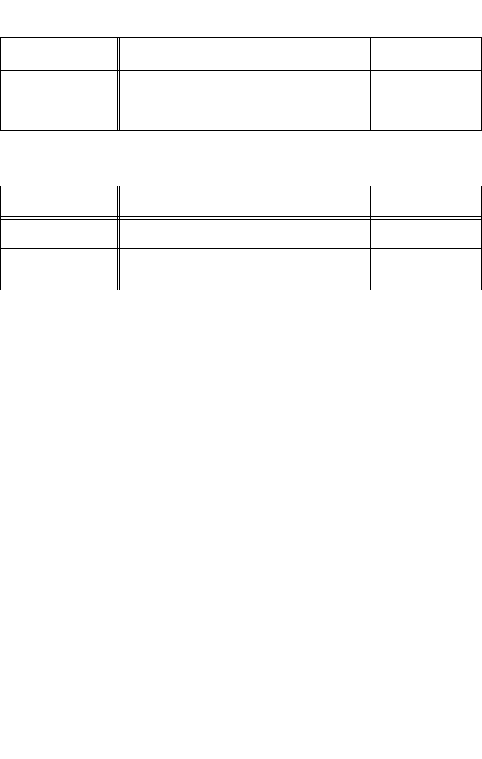
MIB Detail Specification SLVOS R2.1 February 2003
- Page 78 -
1.1.16.3 The Transparent Port Group, dot1dTp (dot1dBridge 4)
This group contains information concerning the transparent bridging mode.
dot1dStpPortDesignated
Port
The port identifier of the port on the designated bridge. read-only
dot1dStpPortForwardTra
nsitions
The number of times this port has transitioned from
Learning state to the Forwarding state.
read-only
Object Name Description
Default
Value Support
dot1dTpLearnedEntryDis
cards
The number of Forwarding Database entries discarded
due to lack of storage space.
read-only
dot1dTpAgingTime The time-out period in seconds for aging out dynamically
learned information. This item corresponds to the aging
time in the bridge CLI command.
300 read-write
Object Name Description
Default
Value Support

February 2003 MIB Detail Specification SLVOS R2.1
- Page 79 -
1.1.16.3.1 The Forwarding Database for Transparent Bridges Table, dot1dTpFdbTable (dot1dTp 3)
1.1.16.3.2 The Transparent Port Table, dot1dTpPortTable (dot1dTp 4)
1.2 Paradyne Enterprise MIBs
The following sections describe the Paradyne Enterprise groups and specific MIB objects that will be supported by
SLV OS R2.1.
1.2.1 Device Configuration, pdn-devConfig (pdn-common 7)
The device configuration MIB (devConfig.mib) provides support for manipulating configuration areas as well as
device wide configuration items.
1.2.1.1 Copy Configuration Area, devConfigArea (pdn-devConfig 1)
This group provides a variable which allows the entire contents of one configuration area to be copied into another
configuration area: only the following values are supported by the SLV OS R2.1.
• noOp(1) A “get” of this object will always return noOp.
Object Name Description Support
dot1dTpFdbTable This table contains information about unicast entries for
which the bridge has forwarding or filtering information.
dot1dTpFdbAddress The MAC address for which the bridge has the forwarding
or filtering information.
read-only
dot1dTpFdbPort The object is either zero or the port number of the port on
which a frame having a source address equal to the value
of the corresponding instance of dot1dTpFdbAddress has
been seen.
read-only
dot1dTpFdbStatus The status of this entry as follows: other(1), invalid(2),
learned(3), self(4), mgmt(5).
read-only
Object Name Description
Default
Value Support
dot1dTpPortTable This table contains information about every port
associated with a transparent bridge.
dot1dTpPort The port number of the port for which this entry contains
transparent bridging information.
read-only
dot1dTpPortMaxInfo The maximum size of the INFO field that this port will
receive or transmit.
1518 read-only
dot1dTpPortInFrames The number of frames that have been received by this port
from its segment.
read-only
dot1dTpPortOutFrames The number of frames that have been transmitted by this
port to its segment.
read-only
dot1dTpPortInDiscards The number of received frames discarded by the
Forwarding Process.
read-only

MIB Detail Specification SLVOS R2.1 February 2003
- Page 80 -
• active-to-customer1(2) Copy from current area to customer 1 area.
• active-to-customer2(3) Copy from current area to customer 2 area.
• customer1-to-active(4) Copy from customer 1 area to current area.
• customer1-to-customer2(5)Copy from customer 1 area to customer 2 area.
• customer2-to-active(6) Copy from customer 2 area to current area.
• customer2-to-customer1(7)Copy from customer 2 area to customer 1 area.
• factory1-to-active(8) Copy from factory area to current area. (NOTE: there is only 1 factory area
for SLV OS R2.1)
• factory1-to-customer1(9) Copy from factory area to customer 1 area.
• factory1-to-customer2(10) Copy from factory area to customer 2 area.
Note: In SLVOS R2.0 and later releases, the customer2 configuration area is renamed to scratchpad configuration and
will be lost upon loss of power. Upon power up, scratchpad will contain the default factory configuration.
1.2.1.2 The Clock Source, devConfigClockSrc (pdn-devConfig 3)
This group provides a table through which the clock source of the network T1 port can be set. This table is fully
supported with the following limitations.
1.2.1.2.1 Clock Source, devCfgClkSource (devConfigClockSrcEntry 2)
This variable allows specifies the source of the network T1 clock. Only the following variables are supported for SLV
OS R2.1.
• internal(1) The source selected provide synchronization for all the timing within the device.
• interface(3) The specific interface used as the master clock source is specified using
devCfgClkIfIndex.
Only one of the clock sources may be set to interface at a time. If either the primary or the secondary clock source is
set to interface(3), setting the other to interface(3) will yield badValue. However, both may be set to internal at the
same time.
1.2.1.2.2 Clock Interface, devCfgClkIfIndex (devConfigClockSrcEntry 3)
This variable shows the ifIndex of the interface that is providing the clock. If devCfgClkSource is set to internal(1),
this value will always be 0. If devCfgClkSource is set to interface(3), this value will always be that of the ifIndex for
the interfaces which is Network1, Network2, Dsx-1 and DBM for SLV OS R2.1.
1.2.1.3 Card Type Configuration, devConfigCardType (pdn-devConfig 6)
This table is used by multi-slot devices. It shows what type of card has been configured to occupy each slot in the
chassis, and what card type is actually present in the chassis. The following values are supported by the SLV OS R2.1:
• devCfgCardSlot devConfigCardTypeEntry 1
The slot number which this card occupies in the chassis.
• devCfgCardConfig devConfigCardTypeEntry 2
The type of card which has been configured for this slot.
• devCfgCardActual devConfigCardTypeEntry 3
The type of card which is present in this slot.
• devCfgCardAction devConfigCardTypeEntry 4

February 2003 MIB Detail Specification SLVOS R2.1
- Page 81 -
Writing accept(2) to this object changes the configured card type to match the type of card currently
present in the slot. Reading this object always returns noOp(1)
1.2.1.4 Configuration Change Keys, devConfigChangeKeys (pdn-devConfig 9)
This group provides a list of keys associated with each non-volatile, user configurable database in the device.
1.2.1.4.1 Configuration Change Keys Table, devConfigChangeKeysTable (devConfigChangeKeys 1)
1.2.2 DDS Interface Specific Definitions, dds, (pdn-interfaces 2)
The DDS Interface Specific Definitions contain objects that are used to manage the DDS Network Interface. All
objects are fully supported by SLV OS R2.1 except as stated in the following sections.
1.2.2.1 DDS Status Table - ddsAlarm Status (ddsStatusEntry 4)
This object is a bit map represented as a sum, which can represent multiple conditions simultaneously. Only the
following conditions are supported by SLV OS R2.1:
1 operational
2 crossPairDetected
4 noSignal
8outOfService
16 outOfFrame
32 excessiveBPVs
1.2.2.2 DDS Configuration Group, ddsClearChannelDataScrambling (ddsConfigEntry 3)
This object is not supported by SLV OS R2.1.
1.2.2.3 DDS Configuration Group, ddsInBandManagementChannel(ddsConfigEntry 4)
This object is not supported by SLV OS R2.1.
1.2.2.4 DDS Configuration Group, ASCII Alarm Controls (ddsConfigEntry 5 - ddsConfigEntry 10)
These objects are not supported on SLV OS R2.1.
1.2.2.5 DDS Configuration Group - ddsLineRateAdmin (ddsConfigEntry 11)
This option allows reading configuration settings of the information rate for the DDS interface. This object is read-
only. Allowed rates are 56000 and 64000.
Note: rate 64000 is used only in LADS mode. It must be set/unset using the Transmit Timing option on the User
Interface.
Object Name Description Support
devConfigChangeKeysTable This table contains a list of keys for each non-volatile
database the user can access..
devConfigChangeKeysDbType This object will be a unique index defining a device
database. The following values are defined:
generalConfig(1), rmonAlarm(2), rmonUserHistory(3),
routerConfig(4).
not-accessible
devConfigChangeKeysDbKey This value is a key that will change each time the
contained in the database changes.
read-only

MIB Detail Specification SLVOS R2.1 February 2003
- Page 82 -
1.2.2.6 DDS Test Table - ddsTestStatus (ddsTestEntry 2)
This object is a bit map represented as a sum, which can represent multiple conditions simultaneously. Only the
following conditions are supported by SLV OS R2.1:
1 csuLoopback
2 dsuLoopback
8 nonLatchingCSULoopback
16 nonLatchingDSULoopback
32 sending511Pattern
64 monitoring511Pattern
1.2.2.7 DDS Test Table - ddsTestStart (ddsTestEntry 3)
This object is a bit map represented as a sum, which can represent multiple conditions simultaneously. Only the
following conditions are supported by SLV OS R2.1:
1 csuLoopback
2 dsuLoopback
4 remoteDSULoopback
16 send511
32 monitor511
It should be noted that attempting to start a test that is already started will not affect the test that is currently running,
but it will not a return an error. In the same manner, no error is returned when attempting to stop a test that is already
stopped.
1.2.2.8 DDS Test Table - ddsTestStop (ddsTestEntry 4)
This object is a bit map represented as a sum, which can represent multiple conditions simultaneously. It is used to stop
specific tests. Only the following conditions are supported by SLV OS R2.1:
1 csuLoopback
2 dsuLoopback
4 send511
8 monitor511
Performing a get on this object will always yield 0. It should be noted that attempting to start a test that is already
started will not affect the test that is currently running, but it will not a return an error. In the same manner, no error is
returned when attempting to stop a test that is already stopped.
1.2.2.9 DDS Test Table - ddsTestCode (ddsTestEntry 5)
This object contains a read-only code containing more specific information concerning test pattern monitoring results.
The following are the valid values:
• none(1) no further information is available or no monitor tests are running.
• inSyncNoBitErrors(2) the monitor pattern test has synchronized without bit errors.
• inSyncWithBitErrors(3)the monitor pattern test has synchronized with bit errors.
• notInSync(4) the monitor pattern test has not synchronized.
1.2.2.10 DDS Statistics Table -- ddsClearStatistics (ddsStatisticsEntry 11)
This object is not supported on SLV OS R2.1.

February 2003 MIB Detail Specification SLVOS R2.1
- Page 83 -
1.2.3 Port Usage, pdn-devPortUsage (pdn-interfaces 3)
This table (devPortUsage.mib) will be supported for the COM port and Modem port only. It specifies whether the port
is configured for Async Terminal Interface or as an IP management link. The values ascii(1) and other(4) are not
supported.
1.2.4 Voice Configuration, voice, (pdn-interface 4)
The Voice Interface Specific Definitions (devVoice.mib) contain objects that are used to manage the voice interface.
This object is fully supported only on those devices with voice interfaces, such as voiceEM, voiceFXO, and voiceFXS.
Refer to the Test Branch in the Operational Specification for details pertaining to valid test combinations.
1.2.5 Synchronous Data Port Configuration, syncPort (pdn-interfaces 6)
The Synchronous Data Port Configuration Group (devDataPortConfig.mib) is used to manage the synchronous data
ports. This group is fully supported only on data ports configured as TDM. Refer to the Test Branch in the Operational
Specification for details pertaining to valid test combinations.
1.2.6 OCU Port Configuration, ocuPort (pdn-interfaces 10)
The OCU Port Configuration Group (devOcu.mib) is used to manage the OCU ports. This object is fully supported
only on those devices with OCU interfaces.
1.2.7 DS1 Extension Configuration, ent-ds1, (pdn-interfaces 5)
The DS1 Interface Configuration Table (devDS1Config.mib) contains objects that are used to configure the DS1
related items. This object is fully supported by SLV OS R2.1 for the Network, PRI and DSX-1 T1 interfaces.
1.2.7.1 DS1 Performance Statistics Group, DS1PerfStats, (ent-ds1 4)
The DS1 Performance Statistics Group (devDS1PerfStats.mib) contains objects that are used to access the Telco
registers maintained for the Network and PRI T1 Interface. The Telco-related objects are extensions to the DS1/E1
MIB (RFC 1406) which include only an entries for the Loss of Frame Count at this time. Only the Telco-related tables,
including the Free Run Telco table, of this object are fully supported by SLV OS R2.1.
1.2.7.2 DS1 Test Group, devDS1Test (ent-ds1 1)
The DS1 Test Group (devDS1Config.mib) contains tables that are used to start, stop, monitor and set arguments of
tests on the Network, PRI and DSX-1 T1 interfaces. These tables are fully supported with the following exceptions
and notes.
1. In order to run a user-defined pattern test, both the pattern (devDS1TestArgument) and the control
(devDS1TestControl) must be set in the same PDU.
2. Remote loopback test (llbup and llbdown) are not supported on the DSX-1 interface.
3. The interface must be enabled when starting a test and the test combination must be valid or a general failure
will be returned.
It should be noted that attempting to start a test that is already started will not affect the test that is currently running,
but it will not a return an error. In the same manner, no error is returned when attempting to stop a test that is already
stopped.
1.2.8 DS3 Extension, pdnDs3MIB (pdn-interfaces 14)
1.2.8.1 DS3 Performance Statistics Group, devDs3FreeRunTable (pdnDs3MIB.devDs3Objects 5)
This table has the free running counters of the DS3 physical statistics. This table is not supported in SLV OS R2.0 and
earlier releases.

MIB Detail Specification SLVOS R2.1 February 2003
- Page 84 -
1.2.9 Channel Configuration, crossConnect, (pdn-interfaces 7)
The Channel Configuration Group (devCrossConnect.mib) contains two tables, the DS1 Fractional Table and the
Synchronous Data Port Assignment Table. These objects are used to manage cross connections between the interfaces.
Both tables are supported as read-only by SLV OS R2.1.
Operational note: In order to designate a channel on the network T1 as being allocated for frame relay, assign that
channel to the ifIndex of the Frame Relay Logical Link Sublayer on the Network Interface.
1.2.10 Device Security, pdn-security (pdn-common 8)
The Device Security Table (devSecurity.mib) is used to control the number of SNMP managers that may access SLV
OS R2.1, as well as the access level (read or read/write). This object is fully supported by SLV OS R2.1 with the
exception of the new security manager table (newSecurityMgrTable) and the telnet source validation object
(devSecurityTelnetSourceValidation) which are not.
1.2.11 Device Traps, pdn-traps (pdn-common 9)
The Device Traps Table (devTrapMgr.mib) is used to manage the SNMP managers to whom SLV OS R2.1 will report
traps. This object is fully supported by SLV OS R2.1.
1.2.12 Device Control, pdn-control (pdn-common 10)
The devControlReset object (devControl.mib) is used to cause a reset of the device, perform a lamp test, select which
executable image to execute and enable or disable RMON. This object is fully supported by SLV OS R2.1 with the
exception of devControlRMONAdminStatus which is supported read-only.
1.2.13 Device Health and Status, devStatus(pdn-devStatus 1)
The devStatus object (devHealthAndStatus.mib) is used to report the health and status messages and self test result
messages from the device. This object is fully supported by SLV OS R2.1 with the exception of the devAbortStatus,
devSNMPSetStatusTable, and devAuthenticationFailureIpAddress items. The Health and Status variable is formatted
as a series of “non-NMS” defined strings that are separated by semicolons.
1.2.14 Frame Relay PVC Cross Connect, pvcXconnect (crossConnect 3)
1.2.15 The pvcXconnect table (devPVCXconnect.mib) is used to manage PVC connections. This table is fully
supported in SLV OS R2.1. Frame Relay PVC Test, devPVCTest (pdnFrameRelay 3)
The pvcTest group (devPVCtest.mib) is used to start and stop tests on DLCIs, as well as monitor test results. This
group is fully supported by SLV OS R2.1, with the exception that the devPVCActiveTestDisruptive object is supported
as read-only and the devPVCExtMomResultTable is not supported.
It should be noted that attempting to start a test that is already started will not affect the test that is currently running,
but it will not a return an error. In the same manner, no error is returned when attempting to stop a test that is already
stopped.
Note: This version of SLV OS does not support constituent DLCIs in this table. A constituent DLCIs is a DLCI on a
constituent frame relay interface which is under a multi-link frame relay interface.
1.2.16 IP Route Extension, devIPRouteTable (pdn-ip 1)
The devIPRouteTable is used to manage IP routes. All routes will appear in this table. It should be noted that this table
is designed for management support only, Customer information is not routed. This table is fully supported, with the
following exceptions.

February 2003 MIB Detail Specification SLVOS R2.1
- Page 85 -
1.2.16.1 devIPRouteType (devIPRouteEntry 8)
The devIPRouteType object can be used to delete a route by setting its value to invalid(2). No other values will be
accepted.
1.2.16.2 devIPRouteAge (devIPRouteEntry 10)
The devIPRouteAge object is supported read-only.
1.2.16.3 devIPRouteNestSlot (devIPRouteEntry 6)
The devIPRouteNestSlot will always return -1. Additionally, it is supported read-only.
1.2.17 Frame Relay Extension, devFrExt (pdnFrameRelay 4)
The frame relay extension group contains information, not contained in one or both of the standard frame relay MIBs,
about the frame relay interfaces. This group contains five tables and two internal groups that each contain a single
table. The tables include statistics and configuration for DLCI configuration statistics and status information, latency
statistics, burst statistics, frame size statistics and link statistics as described below. This product does not support the
NNI statistics, so all of the Inf, Inr, Exf and Exr variables in any of the Group will return 0 or the equivalent for queries.
Note: This version of SLV OS does not support constituent DLCIs in this MIB. A constituent DLCIs is a DLCI on a
constituent frame relay interface which is under a multi-link frame relay interface.
1.2.17.1 Frame Relay DLCI Table, devFrExtDlciTable (devFrExt 1)
This table contains statistical and configuration information which in not available through either RFC1604, RFC2115
or both for each DLCI. This table is fully supported, with the following exceptions.
1.2.17.1.1 devFrExtDlciAdminState (devFrExtDlciEntry 10)
The DLCI administration status represents the desired operation state of the DLCI. A value of active(2) indicates that
it is desired that data can be transmitted or received through the DLCI if it is used as a PVC endpoint. A value of
inactive(3) will disable the DLCI. This item is supported read-only on SLV OS R2.1.
1.2.17.1.2 devFrExtDlciPriority (devFrExtDlciEntry 11)
This object is fully supported in all SLV OS R2.1 devices with the exception of 9820-45M and 9520 where the only
value supported is high(3).
1.2.17.1.3 devFrExtDlciNetDrop[Fr | Octets] (devFrExtDlciEntry [20 | 21])
The network dropped counters keep the number of either the frames or the octets dropped by the network. This differs
from the frames or characters dropped by the device in that it actually counts the number of frames or octets that were
not received by the device but sent by the remote end. The device will attempt to update this information every SLV
cycle. These items are supported for multiplexed DLCIs only and will otherwise return 0.
1.2.17.1.4 devFrExtDlciType (devFrExtDlciEntry 12)
The DLCI Multiplexing type object informs the user whether the DLCI is standard(1), multiplexed(2), or ipenabled(3).
This object is fully supported by SLV OS R2.1.
1.2.17.1.5 devFrExtDlciCircuitId (devFrExtDlciEntry 65)
A string of characters that identifies a particular DLCI circuit. This object is only supported on network interfaces.
1.2.17.2 Frame Relay DLCI Status Table, devFrExtDlciStsTable (devFrExt 2)
This table contains information operational status of each DLCI. This includes time statistics for various items
concerning line connection and activity.

MIB Detail Specification SLVOS R2.1 February 2003
- Page 86 -
1.2.17.3 The Latency Table, devFrExtLatencyTable (devFrExt 3)
This table contains latency information for the link which involves the DLCI that the table is indexed by. Latency is
kept as both an average and a maximum over time for a specific sliding window. The width of the window is defined
as the number of time slices that are used in determining the average. If the DLCI is either not multiplexed or disabled
at the time that collection is scheduled, “noSuchName” will be returned. Additionally, a zero value in either the
average or the maximum means that collection has not run long enough from the time the last time the collection
information was reset to give useful information. This will occur automatically if the DLCI is inactive at the time the
device attempts to collect the information. This table is fully supported with the following exception.
1.2.17.3.1 devFrExtLatencyWidth (devFrExtLatencyEntry 3)
The number of time slices that make up the sliding window used to collect latency information. This can also be viewed
as the number of latency values used to determine the average. This object is supported read-only.
1.2.17.3.2 devFrExtLatencyTimeSlice (devFrExtLatencyEntry 4)
The amount of time in seconds that makes up one time slice in the window. This object is supported fully supported
with the exception that its value must be in the 10 to 3600 range.
1.2.17.3.3 devFrExtLatencyPacketSz (devFrExtLatencyEntry 8)
The size of the packet used to collect the latency information. This object is supported fully supported with the
exception that its value must be in the 64 to 2048 range.
1.2.17.4 The Frame Size Group, devFrExtFrameSize (devFrExt 4)
This group consists of a table and a count of the rows in the table. Each row in the table represents a bucket, and each
bucket holds the number of frames transmitted that have sizes within the specified range. This group is fully supported
in SLV OS R2.1 with the exception of devFrExtFrameSzTblCnt which is supported read-only. The number of buckets
is set to five.
1.2.17.5 The Burst Group, devFrExtBurst (devFrExt 5)
This group consists of a table and a count of the rows in the table. Each row in the table represents a bucket, and each
bucket holds both the number of frames and the number of octets that were transmitted with an information rate that
fits in the specified range. This group is fully supported in SLV OS R2.1 with the exception of devFrExtBurstTblCnt
which is supported read-only. The number of buckets is set to five and the default ranges are automatically set to the
following by the device.
• If the CIR is Zero, or if the CIR is equal to the Port Rate, the intervals will be 1/5 of the Port Rate.
• If the CIR is greater than Zero and the difference between the CIR and the Port Rate is greater than 5
times the CIR, the intervals will be equal to the CIR.
• If the CIR is greater than Zero and the difference between the CIR and the Port Rate is less than 5 times
the CIR, the intervals will be 1/5 of the difference.
NOTE!
The value set will be adjusted to the lower byte boundary, so the value read may not exactly match the value set.
1.2.17.6 The Far End Information Table, devFrExtFarEndInfoTable (devFrExt 6)
This table contains the node IP address and the DLCI or VPI/VCI number of the remote device.
1.2.17.7 The Link Table, devFrExtLinkTable (devFrExt 7)
This table contains statistics about each Frame Relay link on the device.

February 2003 MIB Detail Specification SLVOS R2.1
- Page 87 -
1.2.17.7.1 devFrExtLinkTxDiscards (devFrExtLinkEntry 14)
This is the total number of frames in the transmit direction that were discarded due to resource errors. The only
outbound resource error that occurs on the SLV OS R2.1 is an Under run flush.
1.2.17.7.2 devFrExtLinkRxDiscards (devFrExtLinkEntry 15)
This is the total number of received frames that were discarded due to resource errors. The inbound resource errors for
SLV OS R2.1 are:
• Receiver overrrun events
• Frames received when link is down
• DLCI inactive
• DLCI unconnected
• Unknown EDLCI
• Destination DLCI inactive
1.2.17.7.3 devFrExtLinkRxIlFrames (devFrExtLinkEntry 18)
This is the total number of illegal frames received on the link. A frame is illegal when one of the following errors
occurs:
• Too Short
• Too Long
• Invalid DLCI
• Unknown DLCI
• Unknown Error
1.2.17.7.4 devFrExtLinkTotTxErrs (devFrExtLinkEntry 19)
This is the total number of transmit errors seen on the link. The errors counted in this counter are:
• Discarded Frames
• Underrun Events
1.2.17.7.5 devFrExtLinkTotRxErrs (devFrExtLinkEntry 20)
This is the total number of errors that occurred on the link in the receive direction. These are:
• Received Illegal Frames
• Received Discards
• Received Link Errors (CRC, Non-Octet Frames, Overrun Events)
1.2.17.7.6 devFrExtLinkTotalLMIErrs (devFrExtLinkEntry 32)
This is the total number of LMI related errors that occurred on the link. These are:
• Reliability Errors
• Protocol Errors
• Unknown Report Types
• Unknown Information Elements

MIB Detail Specification SLVOS R2.1 February 2003
- Page 88 -
• Sequence Errors
1.2.17.7.7 devFrExtLinkExtendedDdrCollection (devFrExtLinkEntry 33)
This object enables or disables the collection of extended FDR and DDR statistics. These statistics include frames and
octets either offered or dropped by the remote device that are either within or exceeding CIR. This object is supported
read-only in SLV OS R2.1.
1.2.17.8 The Link Configuration, devFrExtLinkConfig (devFrExt 8)
This group contain information regarding Frame Relay Links configuration.
1.2.17.9 The BackUp Status, devFrExtBackUpStatus (devFrExt 9)
This group contains objects regarding BackUp operations.
1.2.17.10 The Link Utilization Group, devFrExtLinkUtil (devFrExt 10)
This group consists of two objects and one table and it id used to track the percentage of utilization for Frame Relay
Link interfaces. This group is fully supported, with the following exceptions.
1.2.17.10.1 devFrExtLinkUtilTimePeriod (devFrExtLinkUtil 1)
Time period in seconds. The line utilization is calculated after this amount of time, for tx, based on the number of octets
transmitted in this time period, and for rx, based on the number of octets received in this time period. This object is
supported read-only.
1.2.17.10.2 devFrExtLinkUtilTblCnt (devFrExtLinkUtil 2)
The number of buckets in the link utilization table. On initialization, the last range value will be set to 100% and the
remaining range values will be set to valid values automatically. This is device dependent and can be anything from a
numeric sequence to random values that fit the rules defined for range. The indices of the buckets will be automatically
set to the numeric sequence starting at one and ending at the bucket count. This object is supported read-only.
1.2.17.10.3 devFrExtLinkUtilTable (devFrExtLinkUtil 3)
A table containing a bucketed % utilization of the information transmitted and received through the Link. The index
is changed to {ifIndex, devFrExtLinkUtilIndex} for SLV OS R2.1.
1.2.18 Device Identity, devID (pdn-common 5)
The device identity group consists of one item. This item contains the Software Revision Number of the NAM. Note
that this string will appear, by convention, as “MM.mm.bb” in the release version of the software; however, since this
string may be any string up to eight characters long in pre-released versions of the software, especially those used in-
house, a value of “d9.99.99” will be returned for all unrecognized formats. The SLV OS R2.1 convention for software
revision is as follows. MM is the major release, mm the minor release and bb the build/ptf number. Each release starts
one higher than previous release’s number (00.00.00 if the first release) and the first digit of the major number is
changed to a “d”. The “d” is dropped when the firmware is officially released.
1.2.19 The RMON Extension, devRmonExt (pdn-common 13)
See Chapter 3, RMON.
1.2.20 The IF-MIB Extension, pdnIfExt (pdn-interfaces 12)
This group is intended to augment the ifEntry table like ifTestEntry and ifXEntry do. This group has two groups, the
pdnIfExtConfig group and the pdnIfExtTestConfig group. Only the pdnIfExtTable in the pdnIfExtConfig group is
supported by SLV OS R2.1.

February 2003 MIB Detail Specification SLVOS R2.1
- Page 89 -
1.2.20.1 Paradyne IF-MIB Table Augment
This table augments the ifEntry table. Only the following objects are supported by SLV OS R2.1.
1.2.20.1.1 “pdnIfExtTotalUASs” Object (pdnIfExtEntry 4)
This object is used to retrieve the number of unavailable seconds encountered by a physical interface.
1.2.21 The ISDN Extension, pdnIsdn (pdn-interfaces 16)
This group provides extensions to the RFC 2127 (ISDN) MIB that will provide the user with additional configuration,
status, and test options for ISDN interfaces.
1.2.21.1 ISDN Test Call Table (pdnIsdn 1)
This group is fully supported by SLV OS R2.1 only in those devices with ISDN backup interfaces.
1.2.21.2 ISDN Status Table (pdnIsdn 2)
This group is fully supported by SLV OS R2.1 only in those devices with ISDN S/T or IDSL interfaces.
1.2.22 The ATM Extension, pdnAtm (pdn-interfaces 11)
This ATM Extension Group consists of the following sub-groups:
• devAtmSlv (pdnAtm 1) - Not supported.
• devAtmPVCTest (pdnAtm 2) - Not supported.
• devAtmMgnt (pdnAtm 3) - Fully supported.
1.2.22.1 ATM Management Connection, devAtmMgnt (pdnAtm 3)
This group is used to manage native ATM management links. This group is fully supported by SLV OS R2.1.
1.2.23 The Management Link, pdnMgmtLink (pdn-interfaces 17)
This group is fully supported by SLV OS R2.1.
1.2.24 Paradyne Feature Group (pdn-common 15)
The feature group is supported by the FLEX products, DSL products, and selected SLV products to allow on demand
changing of the software features. It provides two objects: devFeatureGrpKeyVerify and devFeatureGrpKeyActivate.
The verify function verifies that a specific key is valid for the device. The activate function activates a feature group
based on the key and resets the device.
1.2.25 Dial Control Extension MIB
This MIB contains information about the dial control devices. It is fully support on all devices in SLV OS R2.1 which
support ISDN backup.
1.2.26 ATM M4 Extension MIB
This MIB contains extensions to the M4 MIB defined by the ATM forum. Only the following tables are supported/

MIB Detail Specification SLVOS R2.1 February 2003
- Page 90 -
1.2.26.1 The VC Single Cell Loop Table, pdnAtmfM4Vc1CellLoopTable (pdnAtmfM4ExtObjects 5)
1.2.26.2 The Loopback Location Table, pdnAtmfM4LoopbackLocationTable (pdnAtmfM4ExtObjects 6)
1.2.27 IP Ping Test, devIPPingTest (pdn-ip 2)
The devIPPingTest is used for verifying connectivity and measuring roundtrip response times. It is fully supported in
SLV OS R2.1.
1.2.27.1 devIPPingTestNextIndex (devIPPingTest 1)
This object is not supported in SLV OS R1.7.
1.2.27.2 devIPPingTestOwner (devIPPingTestEntry 2)
This object is not supported in SLV OS R1.7.
1.2.27.3 devIPPingTestDestIntf (devIPPingTestEntry 4)
The valid values for this object are useInternalRoute(1), net1(2), net2(3), s1Port1(4), s1Port2(5) in SLV OS R2.1.
Object Name Description Support
pdnAtmfM4Vc1CellLoopTable This table contains extra information for each single cell
loopback test. The value of atmfM4TestResult will point to
a row in this table to show which row contains the test
information. It augments the atmfMrTestTable.
pdnAtmfM4Vc1CellLoopRTDelay The latency in ms of the last executed loopback test on the
specified interface. A value of zero means that no
information has been attained.
read-only
pdnAtmfM4Vc1CellLoopReported
Location
The segment identifier returned by the far end of the last
executed test. A value of all 0’s means that no identifier
was reported.
read-only
pdnAtmfM4Vc1CellLoopErrorCod
e
The error associated with the last attempt to start a test on
this interface. Valid values are noError(0), badIfIndex(1),
noVccFound(2), notOwner(3),noResourceAvailable(4),
noLoopbackAllocated(5), testCompleted(6), or
testTimeOut(7).
SLV OS R2.1 will not support the notOwner(3) error in that
it is not enforceable on NAT networks or over ILMI.
read-only
Object Name Description Support
pdnAtmfM4LoopbackLocationTabl
e
This table allows the loopback location code to be
configured as defined in the M4 documentation. It is
indexed by the ifIndex of the ATM cells interface.
pdnAtmfM4LoopbackLocationCod
e
This object will allow the 16 octet string for the location
code of an ATM interface to be set. It cannot be set to all
zeroes, all ones or all 0x6A.
read-write

February 2003 MIB Detail Specification SLVOS R2.1
- Page 91 -
1.2.27.4 devIPPingTestCktId (devIPPingTestEntry 5)
This object is renamed to the above name from devIPPingTestDlciOrVpi in SLV OS R 2.0 and SLV OS R1.7.
1.2.27.5 devIPPingTestSubCktId (devIPPingTestEntry 6)
This object is renamed to the above name from devIPPingTestEdlciOrVci in SLV OS R 2.0 and SLV OS R1.7.
1.2.27.6 devIPPingTestTimeStamp (devIPPingTestEntry 23)
This object is not supported in SLV OS R1.7
1.2.27.7 devIPPingTestTOSId (devIPPingTestEntry 24)
This object is not supported in SLV OS R2.0 and earlier releases.
1.2.27.8 devIPPingTestTOSByte (devIPPingTestEntry 25)
This object is not supported in SLV OS R2.0 and earlier releases.
1.2.28 IP SLV Configuration, devIpSLVConfig (pdn-ip 3)
This group is used for setting IP Service Level Verification (SLV) configuration options. It is fully supported in SLV
OS R2.1.
1.2.28.1 SLV Configuration Interval, devSLVConfigInterval (devSLVConfig 1)
This object sets the time interval in seconds between inband SLV communications between iMarc SLV devices.
1.2.28.2 SLV Configuration Table, devSLVCfgTable (devSLVConfig 2)
This table contains the SLV configuration options for Standard Frame Relay and Class of Services.
1.2.28.3 SLV Class of Service Map Table, devSLVCOSMapTable (devSLVConfig 3)
This table contains the SLV Class of Service (COS) mappings. One or more code points may be assigned to the Class
of Service type identified by the COS ID. With one or more Code Points assigned, the COS type will be used with
Latency and Availability measurements when the Measure Latency and Availability object in the SLV Configuration
Table is set to enabled. There are 64 code points (0 to 63), each of which may be assigned to one of 7 COS IDs. Each
COS ID may be assigned to one or more Code Points.
1.2.28.4 SLV Static IP Path Table, devSLVStaticIPPathTable (devSLVConfig 4)
This table is used to configure a list of static IP Addresses which make up a list of paths explicitly known by the iMarc
unit.
1.2.28.4.1 devSLVStaticIPPathCktId (devSLVStaticIPPathEntry 1)
This object is part of the Index for this table and specifies the circuit id.
1.2.28.4.2 devSLVStaticIPPathCktType (devSLVStaticIPPathEntry 4)
This object specifies the circuit type - fr(1), atm(2).
1.2.29 IP SLV Performance Statistics, devIpSLVPerfStats (pdn-ip 4)
This group is used for retrieving the IP Service Level Verification (SLV) performance statistics. It is fully supported
in SLV OS R2.1.
1.2.29.1 IP SLV Path Connect Table, devSLVIPPathConnectTable (devIpSLVPerfStats 1)
This table has the list of paths (i.e. IP addresses of other iMarc or third party devices reachable via IP address for
Service Level Management purposes) and their connection status for a selected Circuit configured on a selected link.

MIB Detail Specification SLVOS R2.1 February 2003
- Page 92 -
1.2.29.1.1 devSLVIPPathConnectCktId (devSLVIPPathConnectEntry 2)
This object is part of the Index for this table and specifies the circuit id.
1.2.29.1.2 devSLVIPPathConnectInactiveSecs (devSLVIPPathConnectEntry 14)
The object specifies the cumulative number of seconds during which the status was found to be inactive. This object
is not supported in SLV OS R2.0 and earlier releases.
1.2.29.2 IP SLV Path Statistics by COS Table, devSLVIPPathStatByCOSTable (devIpSLVPerfStats 2)
This table has the performance latency statistics (Round Trip Time Latency) for an IP path by Class of Service.
1.2.29.2.1 devSLVIPPathStatByCOSCktId (devSLVIPPathStatByCOSEntry 1)
This object is part of the Index for this table and specifies the circuit id.
1.2.29.3 IP SLV Circuit Statistics Table, devSLVIPCktStatTable (devIpSLVPerfStats 3)
This table has the statistics for a circuit that is IP enabled. There are a total of 9 entries (7 Class of Service plus NON-
IP plus UNKNOWN) for each circuit.
1.2.29.3.1 devSLVIPCktStatCktId (devSLVIPCktStatEntry 1)
This object is part of the Index for this table and specifies the circuit id.
1.3 Internet Drafts
The following sections contain information on MIBs that are defined in Internet Drafts that have not become RFCs.
These MIBs are copied into the Paradyne Enterprise MIB under the branch entitled “pdn-ietf-drafts”.

February 2003 MIB Detail Specification SLVOS R2.1
- Page 93 -
1.3.1 The Circuit Identifier MIB (draft-ietf-frnetmib-frsi-00.txt)
1.4 Other Enterprises
SLV OS R2.1 is currently supporting MIBs that are defined by other enterprises. The following sections describe these
MIBs.
1.4.1 ATM Forum
SLV OS R2.1 is using two MIBs that are controlled by the ATM Forum. These MIBs are the ILMI MIB and the ATM
M4 MIB.
Object Name Description Support
ciCircuitTable This table contains a mapping of circuits to their respective
ifEntries. It is indexed by ciCircuitObject and ciCircuitFlow.
ciCircuitObject This object points to the lexicographically lowest
accessible object that defines the circuit. For theSLV OS
R2.1 devices, this will be defaulted to hold all of the
network DLCIs.
not-accessible
ciCircuitFlow This object contains the flow direction of the new interface.
It can be transmit(1), receive(2), or both(3). For SLV OS
R2.1, both(3) will be the only value shown when the device
does not support layer 3 monitoring.
not-accessible
ciCircuitStatus This is the row status object. Rows are automatically
added to this table in SLV OS R2.1, so row creation/
deletion is not supported.
read-only
ciCircuitIfIndex This object contains the ifIndex the device assigns to the
circuit. In SSLV OS R2.1, this item will be populated with
the NetScout compliant ifIndex for the DLCIs.
read-only
ciCircuitCreateTime This object contains the time stamp at which the row was
created.
read-only
ciIfMapTable This table is the inverse mapping from ifIndex back to the
circuit that defines it. It is indexed by ifIndex.
ciIfMapObject This object maps the ifIndex back the lexicographically
lowest accessible OID defining the circuit.
read-only
ciIfMapFlow This object maps the ifIndex to the particular flow type. read-only

MIB Detail Specification SLVOS R2.1 February 2003
- Page 94 -
1.4.1.1 The ILMI MIB, af-ilmi-0065.000
Object Name Description
Default
Value Support
atmfPortTable This table contains physical layers descriptions indexed by
an arbitrary ATM port index.
Only
those
values
that are
not
obsolete
or
deprecate
d are
supported
.
atmfPortIndex The index of the port that is being described. This will
be the
ifIndex of
the ATM
interface.
atmfPortMyIfName The textual name of this interface. This value will always
return the ifName of the interface. For SLV OS R2.1, this
value will be “ATM”.
“ATM” read-only
atmfPortMyIfIdentifier The unique value for the ATM interface. This value will
always be the ifIndex of the ATM interface specified.
read-only
atmfMyIpNmAddress The IP address to which a Network Management Station
can send messages to manage the local ATM device.
This object will report the node IP address, the IP address
of the ethernet port, or the first IP address of a
management link in order depending upon configuration. If
no IP address exists for any of the above, 0.0.0.0 will be
returned.
0.0.0.0 read-only
atmfMyOsiNmNsapAddre
ss
An NSAP Address to which a Network Management
Station can send messages to manage the local ATM
device.
0.0.0.0 0.0.0.0
atmfMySystemIdentifier The 48 bit identifier taken from the MAC address space.
This object will always report the MAC address of the
device.
MAC
address
MAC
address

February 2003 MIB Detail Specification SLVOS R2.1
- Page 95 -
1.4.1.2 The ATM M4 MIB, AF-NM-0095.001
Object Name Description
Default
Value Support
atmfM4AtmLayerTable This table controls the segment information. It is indexed
by the ifIndex of the ATM interface.
atmfM4IfType Type of ATM cell layer interface. Can be none(0), uni(1),
bici(2), or bissi(3). For SLV OS R2.1, only uni(1) is
supported.
uni(1) read-write
of only
uni(1)
atmfM4IfLoopbackLocatio
nCode
This is the code that is sent as the Location Identifier
(segment ID). This object is actually of the wrong type. It
should be a 16 byte OCTET STRING. In that we only have
4 bytes here, we can only show the first 4 bytes of the
string. When setting this object, the following behavior will
be observed.
1) If the number set matches the first 4 bytes of the current
segment ID, no change will occur.
2) If the number is different, the 4 byte string will be
duplicated 4 times to make a 16 byte string.
0 read-write
of
Integer32
atmfM4SubscriberAddres
s
Specifies a newline-delimited list of addresses assigned to
the UNI.
““ read-write
of only ““
atmfM4IfPreferredCarrier Specifies the name of the default carrier to use when one
is not explicitly identified in the call set-up message. This
object is not supported due to the fact that SVCs are not
supported.
noSuchNa
me
not
supported
atmfM4IfFarEndCarrierN
etwork
Specifies the adjacent carrier to which the B-ICI
transmission path is connected. This object is not
supported due to the fact that B-ICI SVCs are not
supported.
noSuchNa
me
not
supported
atmfM4VcTestTable This table is used to start and stop tests on the ATM
interface. It is indexed by the ifIndex of the ATM interface,
VPI, VCI and atmfM4VcTestObject.
atmfM4VcTestObject This object specifies whether the test applies to a VCL or
to a VCC. For SLV OS R2.1, this value will always be
vclTp(1).
vclTp(1) not-
accessible

MIB Detail Specification SLVOS R2.1 February 2003
- Page 96 -
atmfM4TestId This object identifies the current invocation of the
interface’s test.
read-write
will result
in a value
on one
greater
when
setting to
current
value.
Otherwise
,
noSuchNa
me.
atmfM4TestStatus Reports the status of the test as either notInUse(1) or
inUse(2).
read-write
of
inUse(2)
only when
currently
notInUse(
1)
atmfM4TestType The OID of the test to run. The defined tests are:
atmfM4TestOAMLoopbackSeg[.segment]
atmfM4TestOAMLoopbackE2E
.0.0 (No Test -- Used to abort running tests)
The segment portion of the atmfM4TestOAMLoopbackSeg
must be 16 octets and may not be either all zeroes or all
0x6A.
Unsupported tests will still be set; however, the value of
atmfM4TestResult will be set to notSupported(4).
When setting a valid test on a device that does not have a
valid segment identifier configured, the value of
atmfM4TestResult will be set to notSupported(4).
.0.0 read-write
atmfM4TestResult This object reports the result of the test operations as:
none(1), success(2), inProgress(3), notSupported(4),
unAbleToRun(5), aborted(6), failed(7).
The value notSupported(4) will be returned whenever the
value of atmfM4TestType is not valid or if a segment test is
requested and the device does not have a valid segment
configured.
none(1) read-only
atmfM4TestCode This object reports the results. When results exist, it will
point to a row in pdnAtmfM4Vc1CellLoopTable. Otherwise,
it will report .0.0.
.0.0 read-only
Object Name Description
Default
Value Support
February 2003 MIB Detail Specification SLVOS R2.1
- Page 97 -
1.4.1.2.1 Using the M4 MIB and Extensions to Perform Tests
The ATM Forum chose to create a model that mimicked the now obsolete ifTestTable. The following
procedure defines how to start a test.
1. Perform a get on atmfM4TestStatus for the circuit of interest.
4. If the result is inUse(2), delay a short period (not more than 5 seconds) and go to step 1.
5. Perform a get on atmfM4TestId and store the return.
6. Perform a set of atmfM4TestId, atmfM4TestStatus and atmfM4TestOwner in a single PDU. The values
should respectively be set to: the value returned in step 3; inUse(2); and a string identifying the manage-
ment station.
7. If step 4 fails, go to step 1.
8. Perform a set on atmfM4TestType. It should be set to the OID representing the test that is desired.
9. Perform a get on atmfM4TestResult.
10. If the value returned in step 7 is neither inProgress(3) nor success(2), the test failed.
11. Results and failure information can be found by performing a get on atmfM4TestCode.
12. If the value returned in step 9 is .0.0, no further results are available. Quit.
13. The value returned in step 10 should point to a row in the pdnAtmfM4Vc1CellLoopTable. Perform a get
on pdnAtmfM4Vc1CellLoopRTDelay, pdnAtmfM4Vc1CellLoopReportedLocation, and
pdnAtmfM4Vc1CellLoopErrorCode.
14. If the value returned for pdnAtmfM4Vc1CellLoopErrorCode is noError(0), delay a short period (not
more than 5 seconds) and go to step 11.
15. The values of pdnAtmfM4Vc1CellLoopRTDelay and pdnAtmfM4Vc1CellLoopReportedLocation
returned in step 11 should only be displayed by the NMS to the user when the value of
pdnAtmfM4Vc1CellLoopErrorCode is testCompleted(6). Otherwise, the error code should be inter-
preted and either a retry or error message should be displayed.
atmfM4TestOwner The owner of the test as set by the NMS. read-write
Object Name Description
Default
Value Support

MIB Detail Specification SLVOS R2.1 February 2003
- Page 98 -

- Page 99 -
2
SNMP Trap Specification
2. SNMP Traps
This section describes the support for SNMP traps in SLVOS Release 2.1.
2.1 Trap Background
2.1.1 Use of Traps
SNMP traps are used to notify a manager that an event has occurred. This is the only way that an agent can send
unsolicited information to a manager in SNMPv1. The other SNMP operations (GET, GETN, and SET) are all initiated
by a manager. This notification is an attempt to reduce the amount of time between an occurrence of an event and when
it is noticed by a manager.
The SNMP management model is made up of a number of agents being managed by one or more managers. The
managers use polling to obtain information from the agents. This information is used to determine the proper course
of action to be taken based upon agent status. It is desirable to keep this polling to a minimum to reduce the amount of
management traffic on the network. Longer polling intervals also mean that more devices may potentially be managed
by a single manager. The existence of traps allows managers’ polling intervals to be increased in duration without
sacrificing network event reaction time.
Managers use traps to indicate which devices and MIB objects need immediate attention without having to wait until
the next poll to determine which events have occurred. That is managers use traps as hints to modify their polling
schedules. This is known as “trap directed polling” which is the intended purpose of traps. They are not intended to be
used as the primary method of data transfer from the agent to the manager.
It should further be noted that there is currently no other standard mechanism to determine the active alarms on the
device. Most often, there is no indication of why an alarm occurred after it has cleared. A method of historically

SNMP Trap Specification SLVOS R2.1 February 2003
- Page 100 -
viewing the alarms on a network device may be helpful in debugging network problems. Traps provide such an alarm
mechanism and allow the manager to display and react to specific alarm events.
2.1.2 Trap Identification
The SNMP standard defines a trap notification sent to a manager as a protocol data unit (PDU) with the fields indicated
in Figure 1.
Figure 1: SNMP Trap Packet
• PDU type - identifies the packet as a trap notification.
•enterprise oid - is the vendor identification (OID) for the system/network management subsystem that
generated the trap. All traps generated by SLV OS products have the value of sysObjectId for generic
traps and the enterprise specific traps listed in this document. Some RMON enterprise specific traps
have MIB defined enterprises that are used instead.
•agent address - is the IP address of the node where the trap was generated.
•generic-trap-- an enumerated integer whose value is one of warmStart(1), linkDown(2), linkUp(3),
authenticationFailure(4), or enterpriseSpecific(6). A generic-trap value of anything other than
enterpriseSpecific(6) indicates an SNMPv1 standard trap. A value of enterpriseSpecific(6) has no
standard interpretation in SNMP. The interpretation of the trap depends upon the value in the specific-
trap type field.
•specific-trap-- is a number that further specifies the nature of the event that generated the trap; zero for
generic-traps 1 thru 4, the trap number for enterpriseSpecific traps. For enterpriseSpecific traps
generated by the SLV OS products, the values in the specific-trap type field are those indicated in Table
1: Enterprise Specific Trap Values. For MIB defined traps, the value corresponds to the value defined
in the MIB (See 2.5 RMON Specific Traps) (See 2.6 Dial Control MIB Traps).
•timestamp - is the length of time between the last re-initialization of the agent that issued the trap and
the time at which the trap was issued.
•variable-bindings - provide additional information pertaining to the trap.This field consists of name/
value pairs. The content of the variable bindings in enterpriseSpecific traps generated by SLV OS
products is determined by the Paradyne MIB definitions. The variable bindings are specified in Table 6:
Trap Variable Bindings.
2.2 Standard Traps
2.2.1 Warm Start Trap
The warmStart trap signifies that the unit has reinitialized itself but the configuration of the device has not been lost.
This trap is sent after the unit has been reset (either because of a reset command or as the result of a power disruption)
and the unit has stabilized.
2.2.2 Authentication Failure Trap
The authenticationFailure trap signifies an event for which access to SLV OS has failed due to lack of authentication.
There are several conditions that can cause an Authentication Failure trap, as follows:
• The unit is the addressee of an SNMP protocol message that is not properly authenticated.
PDU type enterprise oid agent
address
generic-
trap
specific-
trap
timestamp variable-
bindings

February 2003 SNMP Trap Specification SLVOS R2.1
- Page 101 -
• A login has been attempted through either the asynchronous Terminal interface or a Telnet session and
the user could not provide a correct login ID / password combination within three attempts.
• IP address security is enabled and a message was received from an SNMP manager whose address was
not on the list of approved managers.
• A call is received on the ISDN Backup interface but is rejected for any reason. Typically, this is due to
invalid caller-id.
2.2.3 Link Up and Link Down Traps
The linkDown trap signifies that the unit has recognized a failure on one of the communication interfaces. A linkUp
trap signifies that the unit recognized that one of the communication interfaces has come up. These traps are supported
on SLV OS on the following interfaces:
• The physical sublayer interface.
• The Frame Relay Logical Link Sublayers.
The conditions that define “link up” and “link down” for each interface are described in the following sections.
2.2.3.1 Network, PRI and DSX-1 T1 Interfaces, Physical Sublayer
The network, PRI and DSX-1 T1 interfaces (physical sublayer) are each represented by an entry in the MIB-II
interfaces table and are supported by the DS1 MIB.
The interface is down and a linkDown trap is issued whenever there are one or more alarm conditions active on the
interface. The alarm condition for the T1 interfaces are: Loss of Signal (LOS), Out of Frame (OOF), Alarm Indication
Signal (AIS), Excessive Error Rate (EER), and Yellow Alarm. The interface is up and a linkUp trap is issued whenever
there are no alarm conditions on the interface.
2.2.3.2 DDS Network, Physical Sublayer
The DDS network interface (physical sublayer) is represented by an entry in the MIB-II interfaces table and is
supported by the media specific DDS Enterprise MIB.
The interface is down and a linkDown trap is issued whenever there are one or more alarm conditions active on the
interface. The alarm condition for the DDS interface are: No signal, Out of Service, Out of Frame, Cross Pair Detected,
In-band Framing Error and Excessive BiPolar Violations (BPVs). The interface is up and a linkUp trap is issued when
the alarm state changes such that there are no alarm conditions on the interface.
2.2.3.3 T3, Physical Sublayer
The T3 interface (physical sublayer) is represented by an entry in the MIB-II interfaces table and is supported by the
standard ds3 MIB.
The interface is down and a linkDown trap is issued whenever there are one or more alarm conditions active on the
interface. The alarm condition for the T3 interface are: Loss of signal (LOS), Alarm Indication Signal (AIS), Loss of
Frame (LOF), and Yellow alarm. The interface is up and a linkUp trap is issued when the alarm state changes such that
there are no alarm conditions on the interface.
2.2.3.4 Synchronous Data Port, Physical Sublayer
Each synchronous data port (physical sublayer) is represented by entry in the MIB-II interfaces table and is supported
by the media specific RS232-Like MIB. As with the RS232-Like MIB the port types DCE and DTE refer to ports
acting as a DCE or DTE not what they are connected to.
The interface is down and a linkDown trap is issued whenever there are one or more alarm conditions active on the
interface. The interface is up and a linkUp trap is issued whenever there are no alarm conditions on the interface. The

SNMP Trap Specification SLVOS R2.1 February 2003
- Page 102 -
following is a table showing the supported input control leads for each supported RS232-Like interface type. For X.21
physical interfaces, the control signals “Control” and “Indication” map to RTS and RLSD respectively.
Note: A linkDown/linkUp trap will be generated for the interface based on a lead’s state only if the lead is supported
by the interface (controlled by the “Control Leads Supported” configuration option).
2.2.3.5 OCU Ports, Physical Sublayer
Each OCU port is represented by entry in the MIB-II interfaces table.
The interface is down and a linkDown trap is issued whenever there are one or more alarm conditions active on the
interface. The interface is up and a linkUp trap is issued whenever there are no alarm conditions on the interface.
2.2.3.6 BRI, Physical Sublayer
The BRI is represented by entry in the MIB-II interfaces table.
The interface is down and a linkDown trap is issued whenever there are one or more alarm conditions active on the
interface. The interface is up and a linkUp trap is issued whenever there are no alarm conditions on the interface.
2.2.3.7 DSL, Physical Sublayer
The DSL interface is represented by entry in the MIB-II interfaces table.
The interface is down and a linkDown trap is issued whenever there are one or more alarm conditions active on the
interface. The alarm conditions for the DSL interfaces are: Loss of Signal (LOS) and/or S/N Net Margin Threshold
Exceeded. The interface is up and a linkUp trap is issued whenever there are no alarm conditions on the interface.
2.2.3.8 ISDN S/T, Physical Sublayer
The ISDN S/T interface is represented by entry in the MIB-II interfaces table.
The interface is down and a linkDown trap is issued whenever there are one or more alarm conditions active on the
interface. The alarm condition for the ISDN S/T interfaces is Loss of Signal (LOS). The interface is up and a linkUp
trap is issued whenever there are no alarm conditions on the interface.
2.2.3.9 Ethernet, Physical Sublayer
The ethernet interface is represented by an entry in the MIB-II interfaces table. The interface is down and a linkDown
trap is issued whenever the ability to communicate over the ethernet interface is lost. The interface is up and a linkUp
trap is issued whenever the ability to communicate via the ethernet interface is established.
Signal
V.35 and EIA 530 X.21 HSSI
DCE DTE DCE DTE DCE DTE
RTSSUSUUU
CTSUSUUUU
DSRUSUUUS
DTRSUUUSU
RLSD
(DCD)
USUSUU
S = Supported, U = Unsupported

February 2003 SNMP Trap Specification SLVOS R2.1
- Page 103 -
2.2.3.10 Frame Relay Logical Link Sublayer
Each Frame Relay link on a physical interface is represented by entry in the MIB-II interfaces table and is supported
by a combination of the Frame Relay Extension MIB and either the media specific Frame Relay Services MIB or
Frame Relay DTEs MIB.
The interface is down and a linkDown trap is issued whenever the LMI transitions to down (i.e. per the specific
configured LMI protocol) or the Frame Relay link is Disabled. The interface is up and a linkUp trap is issued whenever
the LMI transitions to up and the Frame Relay link is Enabled. If an LMI protocol is not configured, the interface
linkUp / linkDown traps are based solely on whether the link is disabled or enabled. For the case of ISDN Multi-Link
Frame Relay, the linkDown trap is issued only when all constituent links are down and the linkUp trap is issued when
one or more constituent links are up.
2.2.3.11 ATM, Logical Sublayer
Each ATM interface is represented by entry in the MIB-II interfaces table. The interface is down and a linkDown trap
is issued whenever the physical interface for the logical interface is down or, there is a ‘Loss of Cell Delineation’ alarm
on the interface. The interface is up and a linkUp trap is issued whenever the physical interface for the logical interface
is up and there are no alarms on the interface.
2.3 Enterprise Specific Traps
The enterpriseSpecific traps signify that the unit has recognized enterprise specific events. The “specific-trap” field
identifies the particular trap that has occurred. The following is a table of the enterprise specific traps that are
supported.
Table 2-1. Enterprise Specific Trap Values
Name
Specific
No. Description
enterprisePrimaryClo
ckFail
1 A failure of the currently configured primary clock source for the unit has
been detected.
enterpriseSelfTestFail 2 A hardware failure of the unit was detected as part of the unit’s selftest. This
trap will be generated after the unit has completed initialization
enterpriseSecondary
ClockFail
4 A failure of the currently configured secondary clock source for the unit has
been detected.
enterpriseTestStart 5 An enterpriseTestStart trap is issued when a test becomes active, and
enterpriseTestStop trap is issued when a test is terminated. The tests that
affect the enterpriseTestStart / enterpriseTestStop trap and the resulting trap
string are different for each particular interface. Diagnostic tests are only
supported on the physical network interfaces, ISDN PRI and BRI interfaces,
synchronous data ports, OCU ports, voice ports, frame relay links and logical
virtual circuits.
enterpriseConfig-
Change
6 The configuration has changed via the user interface or an SNMP Manager.
To allow for configuration changes made via an SNMP Manager, the trap will
be sent when 60 seconds has elapsed without a change. This will suppress
the sending of numerous traps when multiple changes are made in a short
period of time, as is typically the case when changing configuration options

SNMP Trap Specification SLVOS R2.1 February 2003
- Page 104 -
enterprisePowerSupp
ly
7 The power supply output voltage has dropped below the specified tolerance
level for the system. The 14 slot Nest device cannot distinguish between a
power supply failure and a fan failure. Therefore, in the 14 slot Nest device
this trap indicates either a power supply failure or a fan failure.
enterpriseModuleMis
Config
8 A module misconfiguration error has been detected on the unit. This trap
indicates that an APM is installed in a slot that previously contained another
type of APM.
enterpriseAPMFailed 9 A failure has been detected on an APM or the APM has been removed.
enterpriseDLCIDown 11 The DLCI for an interface supporting one side of the UNI is down. Each
virtual circuit on a Frame Relay link is represented by an entry in the Frame
Relay Extension MIB’s DLCI Table. All of the virtual circuits for a Frame
Relay link share the link’s entry in the MIB-II interfaces table (i.e. the same
ifIndex). This entry is referenced in the DLCI Table. The virtual circuit is down
and an enterpriseDLCIDown trap is issued whenever the “DLCI Status” is set
to Inactive. For the case of an aggregate DLCIs of ISDN Multi-Link Frame
Relay, this trap is issued when all constituent DLCIs are down. Note that this
trap is not applicable when the device is in PPP mode.
enterpriseDLCIUp 12 The DLCI for an interface supporting one side of the UNI is up. Each virtual
circuit on a Frame Relay link is represented by an entry in the Frame Relay
Extension MIB’s DLCI Table. All of the virtual circuits for a Frame Relay link
share the link’s entry in the MIB-II interfaces table (i.e. the same ifIndex).
This entry is referenced in the DLCI Table. The interface is up and an
enterpriseDLCIUp trap is issued whenever the “DLCI Status” is set to Active.
For the case of an aggregate DLCIs of ISDN Multi-Link Frame Relay, this
trap is issued when one or more of the aggregate DLCI’s constituent DLCIs
are up. Note that this trap is not applicable when the device is in PPP mode.
enterpriseRMONRes
etToDefault
13 All user configurable RMON information has been reset to the default device
configuration.
enterpriseLinkSpeed
Change
14 The speed of the frame relay link has been changed by the autorate
algorithm. (Elba Corsica, Bimini, Goto).
enterpriseCIRChange 15 The CIR has been changed by the network. Note that this trap is not
applicable when the device is in PPP mode.
Table 2-1. Enterprise Specific Trap Values
Name
Specific
No. Description

February 2003 SNMP Trap Specification SLVOS R2.1
- Page 105 -
enterpriseMissedSLV
Down
16 SLV on the DLCI has been declared down due to missed SLV packets. This
trap is issued when the specified number of SLV packets was missed
consecutively on the DLCI. The enterpriseMissedSLVUp trap is issued
whenever the specified number of SLV packets has arrived. Each virtual
circuit on a Frame Relay link is represented by an entry in the Frame Relay
Extension MIB’s DLCI Table. All of the virtual circuits for a Frame Relay link
share the link’s entry in the MIB-II interfaces table (i.e. the same ifIndex).
This entry is referenced in the DLCI Table. For ISDN MFR, SLV is supported
on aggregate DLCIs only.
If the virtual circuit is multiplexed, has not detected a hardware bypass
capable device at the other end, and the user configured it to be declared
down due to missed SLV packets, full LMI status responses will indicate the
DLCI is inactive to downstream devices and normal traffic flow will be
terminated. Note that this trap is not applicable when the device is in PPP
mode.
enterpriseDLCIdelete 17 The DLCI has been deleted by the Auto-DLCI delete system. Note that this
trap is not applicable when the device is in PPP mode.
enterpriseFanFailure 18 One of the fans has a failure.
enterprisePathDown 19 This trap, which only applies to the network interface, indicates that a Path is
unavailable.
enterprisePathUp 20 This trap, which only applies to the network interface, indicates that a Path is
available.
enterpriseLatencyExc
eeded
21 This trap, which only applies to the network interface, indicates that an IP
SLV Latency threshold has been exceeded for the specified Class of Service
(COS) of the path.
enterprisePrimaryClo
ckFailClear
101 A failure of the currently configured primary clock source for the unit has
cleared.
enterpriseSecondary
ClockFailClear
104 A failure of the currently configured secondary clock source for the unit has
cleared.
enterpriseTestStop 105 An enterpriseTestStart trap is issued when a test becomes active, and
enterpriseTestStop trap is issued when a test is terminated. The tests that
affect the enterpriseTestStart / enterpriseTestStop trap and the resulting trap
string are different for each particular interface. Diagnostic tests are only
supported on the physical network interfaces, ISDN PRI and BRI interfaces,
synchronous data ports, OCU ports, voice ports, frame relay links and logical
virtual circuits.
enterprisePowerSupp
lyClear
107 The power supply output voltage has returned to tolerance levels. The 14
slot Nest device cannot distinguish between a power supply failure and a fan
failure. Therefore, in the 14 slot Nest device this trap indicates that there is
no longer a power supply failure or a fan failure on the device.
enterpriseModuleMis
ConfigClear
108 A module misconfiguration error condition has cleared.
Table 2-1. Enterprise Specific Trap Values
Name
Specific
No. Description

SNMP Trap Specification SLVOS R2.1 February 2003
- Page 106 -
2.4 Enterprise MIB Traps
MIB defined traps are traps that are defined in MIB documentation. This is a more standard and user friendly way to
define traps than those defined above. The definition is parsable by an SNMP manager. For this reason, the trap can
be supported automatically simply by compiling the MIB.
There is currently one supported enterprise MIB trap. This trap is defined in the Dial Control Extension MIB as the
dialCtlPeerCallRejected trap. It is generated whenever an outgoing call on the ISDN backup interface (PRI or BRI) is
rejected by the far end.
2.5 RMON Specific Traps
Two traps are defined with the RMON MIB for support of the Alarm and Event groups of RMON. These are the
risingAlarm and the fallingAlarm. They are generated when a user configured event occurs and may be enabled or
disabled through the User Interface.
2.6 Dial Control MIB Traps
There are two standard traps defined in the Dial Control MIB. These are the dialCtlPeerCallSetup trap and the
dialCtlPeerCallInformation trap. They are generated when a call on the ISDN backup interface (PRI or BRI) is
respectively either initiated or terminated.
enterpriseAPMFailed
Clear
109 A failure on an APM has cleared.
enterpriseMissedSLV
-Up
116 SLV on the DLCI has been declared up due to received SLV packets. This
trap is issued when the specified number of SLV packets have arrived on the
DLCI and an enterpriseMissedSLVDown trap has previously been issued.
The enterpriseMissedSLVDown trap is issued whenever the specified
number of SLV packets are missed consecutively on the DLCI. Each virtual
circuit on a Frame Relay link is represented by an entry in the Frame Relay
Extension MIB’s DLCI Table. All of the virtual circuits for a Frame Relay link
share the link’s entry in the MIB-II interfaces table (i.e. the same ifIndex).
This entry is referenced in the DLCI Table. For ISDN MFR, SLV is supported
on aggregate DLCIs only.
If the normal data flow on the virtual circuit was terminated when SLV went
down, due to the reasons described in the trap enterpriseMissedSLVDown
description, full LMI status responses will indicate the DLCI is active to
downstream devices and normal data flow on the PVC will be restored. Note
that this trap is not applicable when the device is in PPP mode.
enterpriseFanFailure
Clear
118 All fan failures have been cleared.
enterpriseLatencyRe
stored
121 This trap, which only applies to the network interface, indicates that an IP
SLV Latency threshold has been restored for the specified Class of Service
(COS) of the path.
Table 2-1. Enterprise Specific Trap Values
Name
Specific
No. Description

February 2003 SNMP Trap Specification SLVOS R2.1
- Page 107 -
2.7 Trap Priority Due to Resource Limitation
The device has limited resources in which to store traps. There are times during which more traps occur than either the
device or the network can handle. To handle these situations, a priority scheme is enforced based on the type of trap.
New traps can only replace traps in the outbound queue with priority levels less than or equal to their own. In such
cases, the oldest trap in the queue at the lowest priority level will be replaced. This method prevents loss of “important”
traps as well as loss due to flooding of the network.
There is an exception in the case of “old” medium priority traps. If the trap queue is full and there is an “old” trap of
medium priority, a new low priority trap will be allowed to replace it. The criteria for an “old” trap is one that has been
on the queue for more than one 24 hour period.
Only the latest config change message will be queued.

SNMP Trap Specification SLVOS R2.1 February 2003
- Page 108 -
The priority scheme is as follows:
Table 2-2. Trap Priority Table
Trap Priority Trap Priority
Warm Start Trap High enterpriseAPMFailed Medium
enterpriseSelfTestFail High enterpriseAPMFailedClear Medium
enterpriseConfigChange High enterpriseLinkSpeedChange Medium
enterpriseRMONResetToDefault High enterpriseCIRChange Medium
Link Up Trap Medium dialCtlPeerCallRejected Medium
Link Down Trap Medium dialCtlPeerCallSetup Medium
Authentication Failure Trap Medium dialCtlPeerCallInformation Medium
enterprisePowerSupply Medium enterpriseDLCIUp Low
enterprisePowerSupplyClear Medium enterpriseDLCIDown Low
enterpriseFanFailure Medium enterpriseMissedSLVDown Low
enterpriseFanFailureClear Medium enterpriseMissedSLVUp Low
enterpriseTestStart Medium enterpriseDLCIdelete Low
enterpriseTestStop Medium enterprisePathDown Low
enterprisePrimaryClockFail Medium enterprisePathUp Low
enterpriseSecondaryClockFail Medium enterpriseLatencyExceeded Low
enterprisePrimaryClockFailClear Medium enterpriseLatencyRestored Low
enterpriseSecondaryClockFailClear Medium
RMON risingAlarm Medium
RMON fallingAlarm Medium
enterpriseModuleMisConfig Medium
enterpriseModuleMisConfigClear Medium

February 2003 SNMP Trap Specification SLVOS R2.1
- Page 109 -
2.8 Trap Strings
All traps have an associated string to help the users decipher the meaning of the trap. This string often requires interface
information. The strings associated with the interfaces will have the following format:
‘DLCI $dlciNumber “$circuitId” of $ifName frame relay link “$linkName”.’
The following rules apply to the interface string:
• The string will be referred to as $ifString.
• ‘DLCI $dlciNumber $circuitId of ’ will only exist if there is a DLCI associated with the trap.
• $dlciNumber is the DLCI number.
• “$circuitId” will only appear if a circuit ID has been configured (e.g. “Chicago to New York”). It can be
a non-empty string up to 64 bytes in length only for network side DLCIs.
• ‘ frame relay‘ will only exist if the trap is associated with a frame relay link.
• $linkName is the textual name of the given link.
• ‘ link “$linkName”’ will only exist if there is both a defined link name and more than one possible link
on the given physical interface. The PRI which allows up to 23 links is one example of a physical
interface that requires a $linkName.
• $ifName is the string returned for the SNMP variable ifName for the given physical interface.
• The first letter will always be capitalized when it is the beginning of a new sentence.
Examples of valid $ifStrings are:
• ‘DLCI 100 of Sync Data Port S01P1 frame relay’
• ‘PRI Frame relay link “Chicago”’
• ‘DSX-1’
This table lists the variable bindings and trap string/s for all traps discussed above.
Table 2-3. Trap Strings
Trap String
Warm Start Trap ‘Unit reset.’
Authentication Failure Trap
Bad password on COM port terminal ‘Unauthorized access attempted from COM port.’
Bad password on modem port terminal ‘Unauthorized access attempted from modem port.’
Bad password through telnet. ‘Unauthorized access attempted from telnet user at $ipAddress.’
SNMP bad community, unauthorized IP
address, or unauthorized operation.
‘Unauthorized access attempted from SNMP user at $ipAddress.’
ISDN Backup Call that is rejected for
any reason.
‘Bad Caller ID $phone.” where $phone is either the phone number
or ‘no number’ depending on the information available.

SNMP Trap Specification SLVOS R2.1 February 2003
- Page 110 -
Link Up and Link Down Traps
Network, PRI and
DSX-1 T1 Interfaces,
Physical Sublayer
linkUp traps ‘$ifString up.’
linkDown traps
when the
ifAdminStatus
is down
‘$ifString administratively shut down.’
linkDown traps
when no
alarms exist
‘$ifString down.’
Table 2-3. Trap Strings
Trap String

February 2003 SNMP Trap Specification SLVOS R2.1
- Page 111 -
Link Up and Link Down Traps (continued)
Network, PRI and
DSX-1 T1 Interfaces,
Physical Sublayer
(continued)
linkDown traps
when one or
more alarms
exist
‘$ifString down due to $alarmString.’
$alarmString will be one or more of the following separat-
ed by commas and a final ‘and’ as required:
• ‘LOS’ for Loss of Signal
• ‘OOF’ for Out of Frame
• ‘AIS’ for Alarm Indication Signal
• ‘EER’ for Excessive Error Rate
• ‘yellow alarm’
Examples of this trap string:
• ‘PRI down due to LOS, OOF and AIS.’
• ‘Network T1 down due to yellow alarm.’
DDS Network,
Physical Sublayer
linkUp traps ‘$ifString up.’
linkDown traps
when the
ifAdminStatus
is down
‘$ifString administratively shut down.’
linkDown traps
when no
alarms exist
‘$ifString down.’
linkDown traps
when one or
more alarms
exist
‘$ifString down due to $alarmString.’
$alarmString will be one or more of the following
separated by commas and a final ‘and’ as required:
• ‘NOS’ for No Signal
• ‘LOF’ for Loss of Frame
• ‘OOS’ for Out of Service
• ‘cross pair’ for Cross Pair Detected
• ‘BPVs’ for excessive BPVs
Examples of this trap string:
• ‘Network DDS down due to LOF, OOS and BPVs.’
• ‘Network DDS down due to NOS and cross pair.’
Table 2-3. Trap Strings
Trap String

SNMP Trap Specification SLVOS R2.1 February 2003
- Page 112 -
Link Up and Link Down Traps (continued)
T3, Physical
Sublayer
linkUp traps ‘$ifString up.’
linkDown traps
when the
ifAdminStatus
is down
‘$ifString administratively shut down.’
linkDown traps
when no
alarms exist
‘$ifString down.’
linkDown traps
when one or
more alarms
exist
‘$ifString down due to $alarmString.’
$alarmString will be one or more of the following separat-
ed by commas and a final ‘and’ as required:
• ‘LOS’ for Loss of Signal
• ‘LOF’ for Loss of Frame
• ‘AIS’ for Alarm Indication Signal
• ‘yellow alarm’
Examples of this trap string:
• ‘Network T3 down due to LOS, OOF and AIS.’
• ‘Network T3 down due to yellow alarm.’
Synchronous Data
Port, Physical
Sublayer
linkUp traps ‘$ifString up.’
linkDown traps
when the
ifAdminStatus
is down
‘$ifString administratively shut down.’
Table 2-3. Trap Strings
Trap String

February 2003 SNMP Trap Specification SLVOS R2.1
- Page 113 -
Link Up and Link Down Traps (continued)
Synchronous Data
Port, Physical
Sublayer (continued)
linkDown traps
when one or
more alarms
exist
‘$ifString $alarmString down.’
For DCE interfaces $alarmString will be one or more of
the following separated by commas and a final ‘and’ as
required:
• ‘DTR’ - DTR is required and down
• ‘RTS’ - RTS is required and down
• ‘’ - DTR and RTS aren’t required but the
link is down
For DTE interfaces $alarmString will be one or more of the
following separated by commas and a final ‘and’ as
required:
• ‘DSR’ - DSR is required and down
• ‘CTS’ - CTS is required and down
• ‘RLSD’ - RLSD is required and down
• ‘’ - DSR, CTS, and RLSD aren’t required
but the link is down
Examples of this trap string:
• ‘Sync Data Port S01P1 DTR down.’
• ‘Sync Data Port S01P2 DTR and RTS down.’
OCU Ports, Physical
Sublayer
linkUp traps ‘$ifString up.’
linkDown traps
when the
ifAdminStatus
is down
‘$ifString administratively shut down.’
linkDown traps
when there are
alarms on the
interface
‘$ifString down.’
BRI, Physical
Sublayer
linkUp traps ‘$ifString up.’
linkDown traps
when the
ifAdminStatus
is down
‘$ifString administratively shut down.’
BRI, Physical
Sublayer (continued)
linkDown traps
when there are
alarms on the
interface
‘$ifString down.’
Table 2-3. Trap Strings
Trap String

SNMP Trap Specification SLVOS R2.1 February 2003
- Page 114 -
Link Up and Link Down Traps (cont.)
DSL, Physical
Sublayer
linkUp traps ‘$ifString up.’
linkDown traps
when the
ifAdminStatus
is down
‘$ifString administratively shut down.’
linkDown traps
when no
alarms exist
‘$ifString down.’
linkDown traps
when one or
more alarms
exist
‘$ifString down due to $alarmString.’
$alarmString will be one or more of the following separat-
ed by commas and a final ‘and’ as required:
• ‘LOS’ for Loss of Signal
• ‘S/N Net Margin Threshold exceeded’
Examples of this trap string:
• ‘Network DSL down due to LOS.’
• ‘Network DSL down due to S/N Net Margin
Threshold exceeded.’
ISDN S/T, Physical
Sublayer
linkUp traps ‘$ifString up.’
linkDown traps
when the
ifAdminStatus
is down
‘$ifString administratively shut down.’
linkDown traps
when LOS
alarm exists
‘$ifString down due to LOS.’
Example of this trap string:
• ‘Network ISDN S/T down due to LOS.’
Ethernet, Physical
Sublayer
linkUp traps ‘$ifString up.’
linkDown traps
when the
ifAdminStatus
is down
‘$ifString administratively shut down.’
linkDown traps
when the
ifAdminStatus
is up
‘$ifString down.’
Table 2-3. Trap Strings
Trap String

February 2003 SNMP Trap Specification SLVOS R2.1
- Page 115 -
Link Up and Link Down Traps (cont.)
Frame Relay Logical
Link Sublayer
linkUp traps ‘$ifString up.’
linkDown traps
when the
ifAdminStatus
is down
‘$ifString administratively shut down.’
linkDown traps
when the
physical link is
down
‘$ifString down.’
linkDown traps
when the LMI
is down
‘$ifString LMI down.’
Examples of this trap string:
• ‘Frame relay link “Chicago” on PRI LMI down.’
ATM Logical Link
Sublayer
linkUp traps ‘$ifString up.’
linkDown traps
when the
ifAdminStatus
is down
‘$ifString administratively shut down.’
linkDown traps
when the
physical link is
down
‘$ifString down.’
linkDown traps
when alarms
exist
‘$ifString down due to $alarmString.’
$alarmString will be the following:
• ‘Loss of Cell Delineation’
Enterprise Specific Traps
enterprisePrimaryClockFail ‘Primary clock failed.’
enterprisePrimaryClockFailClear ‘Primary clock restored.’
enterpriseSelfTestFail ‘Self test failed: $s’ Where $s is the contents of devSelfTestResult.
enterpriseSecondaryClockFail ‘Secondary clock failed.’
enterpriseSecondaryClockFailClear ‘Secondary clock restored.’
enterpriseTestStart ‘$testString test started on $ifString.’ (Where $testString defined in
the table below-- Table 2-5, “Test Strings,” on page 121)
enterpriseTestStop ‘$testString test stopped on $ifString.’ (Where $testString defined in
the table below--Table 2-5, “Test Strings,” on page 121)
enterpriseConfigChange ‘Device configuration change.’
Table 2-3. Trap Strings
Trap String

SNMP Trap Specification SLVOS R2.1 February 2003
- Page 116 -
Enterprise Specific Traps (continued)
enterprisePowerSu
pply
All devices
except the
Nest
‘Power supply failed.’
14 slot Nest
device
‘Power supply/fan tray failed.’
enterprisePowerSu
pplyClear
All devices
except the
Nest
‘Power supply restored.’
14 slot Nest
device
‘Power supply/fan tray restored.’
enterpriseModuleMisConfig ‘Misconfiguration occurred on module in slot X.’ Where X is the slot
number.
enterpriseModuleMisConfigClear ‘Misconfiguration cleared on module in slot X.’ Where X is the slot
number.
enterpriseAPMFailed ‘APM failure on module in slot X.’ Where X is the slot number.
enterpriseAPMFailedClear ‘APM failure cleared on module in slot X.’ --X is the slot number.
enterpriseDLCIUp ‘$ifString up.’
enterpriseDLCI-
Down
DLCI is
administrativel
y down
‘$ifString administratively shut down.’
DLCI is down
due to FR link
down.
‘$ifString down.’
enterpriseRmonResetToDefault ‘RMON database reset to defaults.’
enterpriseLinkSpeedChange ‘Speed of $ifName changed to $ifSpeed bps.’
enterpriseCIRChange ‘CIR on $ifString changed to $CIR bps.’
enterpriseMissedSLVUp ‘SLV up on $ifString because SLV communication was
reestablished. Total SLV packets lost is $numLost.’
enterpriseMissedSLVDown ‘SLV down on $ifString due to excessive SLV packet loss. Total SLV
packets lost is $numLost.’
enterpriseDLCIdelete ‘$ifString deleted by Auto-DLCI delete.’
enterpriseFanFailure ‘Fan failed.’
enterpriseFanFailureClear ‘Fan restored.’
Table 2-3. Trap Strings
Trap String

February 2003 SNMP Trap Specification SLVOS R2.1
- Page 117 -
enterprisePathDown ‘Path xxx.xxx.xxx.xxx, Down, Net1, DLCI nnnn’
‘Path xxx.xxx.xxx.xxx, Down, Port1, DLCI nnnn’
‘Path xxx.xxx.xxx.xxx, Down, Port2, DLCI nnnn’
When the device is in PPP mode, note that the DLCI Id is not
applicable.
enterprisePathUp ‘Path xxx.xxx.xxx.xxx, Up, Net1, DLCI nnnn’
‘Path xxx.xxx.xxx.xxx, Up, Port1, DLCI nnnn’
‘Path xxx.xxx.xxx.xxx, Up, Port2, DLCI nnnn’
When the device is in PPP mode, note that the DLCI Id is not
applicable.
enterpriseLatencyExceeded ‘Latency exceeded xxx.xxx.xxx.xxx, COS nn, Net1, DLCI nnnn’
‘Latency exceeded xxx.xxx.xxx.xxx, COS nn, Port1, DLCI nnnn’
‘Latency exceeded xxx.xxx.xxx.xxx, COS nn, Port2, DLCI nnnn’
When the device is in PPP mode, note that the DLCI Id is not
applicable.
enterpriseLatencyRestored ‘Latency restored xxx.xxx.xxx.xxx, COS nn, Net1, DLCI nnnn’
‘Latency restored xxx.xxx.xxx.xxx, COS nn, Port1, DLCI nnnn’
‘Latency restored xxx.xxx.xxx.xxx, COS nn, Port2, DLCI nnnn’
When the device is in PPP mode, note that the DLCI Id is not
applicable.
Table 2-3. Trap Strings
Trap String

SNMP Trap Specification SLVOS R2.1 February 2003
- Page 118 -
RMON Specific Traps
RMON risingAlarm ‘Change in $variableName $typeString threshold of
$alarmRisingThreshold by $(alarmValue - alarmRisingThreshold).’
Where the following rules apply:
• $variableName is a name specified for the OID that
is monitored.
• 'Change in ' will only appear if the alarm is of type
delta.
• The first letter is always capitalized.
• $typeString is 'rose to' if alarmValue equals
alarmRisingThreshold, and 'exceeded' otherwise
• ' by $(alarmValue - alarmRisingThrehold)' will only
appear if associated with 'exceeded'.
Examples:
Change in Octets Received on DLCI 500 of Network T1
frame relay exceeded threshold of X by Y.
Octets Received on Network T1 frame relay rose to
threshold of X.
RMON fallingAlarm ‘Change in $variableName $typeString threshold of
$alarmRisingThreshold by $(alarmFallingThreshold - alarmValue).’
Where the following rules apply:
• $variableName is a name specified for the OID that
is monitored.
• 'Change in ' will only appear if the alarm is of type
delta.
• The first letter is always capitalized.
• $typeString is 'fell to' if alarmValue equals
alarmFallingThreshold, and 'fell below' otherwise
• ' by $(alarmFallingThrehold - alarmValue)' will only
appear if associated with 'fell below'.
Examples:
Change in Octets Received on DLCI 500 of Network T1
frame relay fell below threshold of X by Y.
Octets Received on Network T1 frame relay fell to
threshold of X.
Dial Cntl Ext
dialCtlPeerCallRejected ‘Call on $ifString using B-Chnl $channel rejected by remote.’
Table 2-3. Trap Strings
Trap String

February 2003 SNMP Trap Specification SLVOS R2.1
- Page 119 -
The following table contains the possible values of $causeString appearing in the trap string for
dialCtlPeerCallInformation.
Dial Cntl
dialCtlPeerCallSetup ‘Call sequence on $ifString [using B-Chnl $channel] initiated
[remotely | locally].’
Where ‘using B-Chnl $channel’ will only appear if the B-Chnl is
known.
dialCtlPeerCallInformation ‘Call sequence on $ifString [using B-Chnl $channel] terminated due
to $causeString.’
Where ‘using B-Chnl $channel’ will only appear if the B-Chnl is
known.
$causeString is a string describing the cause value it is defined in
Table 2-4, “Cause Strings,” on page 119
Table 2-4. Cause Strings
$causeString
None Outgoing Calls Barred-52
Unallocated Number-1 Incoming Calls Barred-54
No route to specify transit network-2 Bearer capability not authorized-57
No destination route-3 Bearer capability not presently available-58
Channel unacceptable-6 Service/option unavailable, unspecified-63
Call awarded and being delivered in est chnl-7 Bearer capability not implemented-65
Normal call clearing-16 Channel type not implemented-66
User Busy-17 Requested facility not implemented-69
No user responding-18 Only restricted bearer capability available-70
User alerting, no answer-19 Service/option not implemented-79
Call rejected-21 Invalid call reference value-81
Number changed-22 Identified channel does not exist-82
Non-selected user clearing-26 Suspended call exists, but not call id-83
Destination out of order-27 No call suspended-85
Invalid number format - incomplete address-28 Call with requested call id has been cleared-86
Table 2-3. Trap Strings
Trap String

SNMP Trap Specification SLVOS R2.1 February 2003
- Page 120 -
Facility rejected-29 Incompatible destination-88
Response to STATus ENQuiry-30 Invalid transit network selection-91
Normal, unspecified-31 Invalid message, unspecified-95
No circuit/channel available-34 Mandatory information element missing-96
Network out of order-38 Msg type nonexistent or unimplemented-97
Temporary failure-41 Msg nonexistent-98
Switching equipment congestion-42 Info element nonexistent or unimplemented-99
User access information discarded-43 Invalid info element contents-100
Requested channel not available-44 Message not compatible with call state-101
Pre-empted-45 Recovery of timer expired-102
Resource unavailable, unspecified-47 Protocol error, unspecified-111
Quality of Service unavailable-49 networking, unspecified-127
Requested facility not subscribed-50
Table 2-4. Cause Strings
$causeString

February 2003 SNMP Trap Specification SLVOS R2.1
- Page 121 -
The following table contains the possible values for $testString appearing in the trap string for enterpriseTestStart/
enterpriseTestStop traps:
Tabl e 2-5. Test S tri ngs
$testString
DCE External Loopback Send Pattern Monitor 2E20-1
Line Loopback Monitor Pattern Send User Defined
Payload Loopback ISDN Circuit Test Monitor User Defined
Repeater Loopback Send QRSS Disruptive Send Pattern
DTE External Loopback Monitor QRSS Non-disruptive Send Pattern
DTE Initiated External
Loopback
Send all zeros Non-disruptive PVC Loopback
Data Channel Loopback Monitor all zeros Network Initiated ISDN BRI
Data Terminal Payload
Loopback
Monitor all ones Send Remote Line Loopback [Up | Down]
Non-latching OCU Loopback Send all ones Send Remote Line Loopback [Up | Down]
Latching Loopback Send 1 in 8 Send Remote Line Loopback [Up | Down]
Latching OCU Loopback Monitor 1 in 8 Send Remote Payload Loopback [Up | Down]
Non-latching CSU Loopback Send 3 in 24 Send Remote Loopback [Up | Down]
Latching CSU Loopback Monitor 3 in 24 Remote Latching Loopback [Up | Down]
Non-latching DSU Loopback Send 63 Send Remote Latching OCU Loopback [Up | Down]
Latching DSU Loopback Monitor 63 Send Remote Latching CSU Loopback [Up | Down]
Data Loopback Send 511 Send Remote Latching DSU Loopback [Up | Down]
OCU Loopback Monitor 511 Send Remote Non-latching OCU Loopback [Up |
Down]
DS-0 Loopback Send 2047 Send Remote Non-latching CSU Loopback [Up |
Down]
Voice Digital Loopback Monitor 2047 Send Remote Non-latching DSU Loopback [Up |
Down]
Voice Analog Loopback Send 2E15-1 Network Initiated Data Channel Loopback
Voice Forced Signal Monitor 2E15-1 Connectivity
Disruptive PVC Loopback Send 2E20-1

SNMP Trap Specification SLVOS R2.1 February 2003
- Page 122 -
Trap Variable Bindings
Table 2-6. Trap Variable Bindings
Trap Variable Bindings
Warm Start Trap devLastTrapString (devHealthAndStatus.mib)
Authentication Failure Trap devLastTrapString (devHealthAndStatus.mib)
Link Up and Link Down Traps ifIndex (RFC 1573)
ifAdminStatus (RFC 1573)
ifOperStatus (RFC 1573)
devLastTrapString (devHealthAndStatus.mib)
Enterprise Specific Traps
enterprisePrimaryClockFail /
enterprisePrimaryClockFailClear
devLastTrapString (devHealthAndStatus.mib)
enterpriseSelfTestFail devLastTrapString (devHealthAndStatus.mib)
enterpriseSecondaryClockFail /
enterpriseSecondaryClockFailClear
devLastTrapString (devHealthAndStatus.mib)
enterpriseTest
Start/
enterpriseTest
Stop
Network and DSX-1 Interfaces, ISDN,
Voice Ports, Synchronous Data Ports,
Frame Relay Links (LMI) and OCU
Ports
ifIndex (RFC 1573)
.0.0
devLastTrapString (devHealthAndStatus.mib)
Virtual Circuits (LMI Interfaces) devFrExtDlciIfIndex (devFrExt.mib)
devFrExtDlciDlci (devFrExt.mib)
devLastTrapString (devHealthAndStatus.mib)
enterpriseConfigChange devLastTrapString (devHealthAndStatus.mib)
enterprisePowerSupply / enterprisePowerSupplyClear devLastTrapString (devHealthAndStatus.mib)
enterpriseModuleMisConfig /
enterpriseModuleMisConfigClear
devLastTrapString (devHealthAndStatus.mib)
enterpriseAPMFailed / enterpriseAPMFailedClear devLastTrapString (devHealthAndStatus.mib)
enterpriseDLCIDown / enterpriseDLCIUp devFrExtDlciIfIndex (devFrExt.mib)
devFrExtDlciDlci (devFrExt.mib)
devLastTrapString (devHealthAndStatus.mib)
enterpriseRmonResetToDefault devLastTrapString (devHealthAndStatus.mib)
enterpriseLinkSpeedChange (Elba Only) ifIndex (RFC 1573)
ifSpeed (RFC 1573)
devLastTrapString (devHealthAndStatus.mib)

February 2003 SNMP Trap Specification SLVOS R2.1
- Page 123 -
Enterprise Specific Traps (cont.)
enterpriseCIRChange devFrExtDlciIfIndex (devFrExt.mib)
devFrExtDlciDlci (devFrExt.mib)
devFrExtDlciCIR (devFrExt.mib)
devLastTrapString (devHealthAndStatus.mib)
enterpriseMissedSLVUp / enterpriseMissedSLVDown devFrExtDlciIfIndex (devFrExt.mib)
devFrExtDlciDlci (devFrExt.mib)
devFrExtDlciMissedSLVs (devFrExt.mib)
devLastTrapString (devHealthAndStatus.mib)
enterpriseDLCIdelete devFrExtDlciIfIndex (devFrExt.mib)
devFrExtDlciDlci (devFrExt.mib)
devLastTrapString (devHealthAndStatus.mib)
enterpriseFanFailure/Clear devLastTrapString (devHealthAndStatus.mib)
enterprisePathDown ifIndex (RFC 1573)
devLastTrapString (devHealthAndStatus.mib)
enterprisePathUp ifIndex (RFC 1573)
devLastTrapString (devHealthAndStatus.mib)
enterpriseLatencyExceeded ifIndex (RFC 1573)
devLastTrapString (devHealthAndStatus.mib)
enterpriseLatencyRestored ifIndex (RFC 1573)
devLastTrapString (devHealthAndStatus.mib)
RMON Specific Traps
RMON risingAlarm alarmIndex (RFC 1757)
alarmVariable (RFC 1757)
alarmSampleType (RFC 1757)
alarmValue (RFC 1757)
alarmRisingThreshold (RFC 1757)
devLastTrapString (devHealthAndStatus.mib)
RMON fallingAlarm alarmIndex (RFC 1757)
alarmVariable (RFC 1757)
alarmSampleType (RFC 1757)
alarmValue (RFC 1757)
alarmFallingThreshold (RFC 1757)
devLastTrapString (devHealthAndStatus.mib)
Table 2-6. Trap Variable Bindings
Trap Variable Bindings

SNMP Trap Specification SLVOS R2.1 February 2003
- Page 124 -
Dial Cntl Ext
dialCtlPeerCallRejected callHistoryPeerId (RFC 2128)
callHistoryPeerIfIndex (RFC 2128)
callHistoryLogicalIfIndex (RFC 2128)
callHistoryPeerAddress (RFC 2128)
devLastTrapString (devHealthAndStatus.mib)
Dial Cntl
dialCtlPeerCallSetup callActivePeerId (RFC 2128)
callActivePeerIfIndex (RFC 2128)
callActiveLogicalIfIndex (RFC 2128)
ifOperStatus (RFC 1573)
callActivePeerAddress (RFC 2128)
callActivePeerSubAddress (RFC 2128)
callActiveInfoType (RFC 2128)
callActiveCallOrigin (RFC 2128)
devLastTrapString (devHealthAndStatus.mib)
dialCtlPeerCallInformation callHistoryPeerId (RFC 2128)
callHistoryPeerIfIndex (RFC 2128)
callHistoryLogicalIfIndex (RFC 2128)
ifOperStatus (RFC 1573)
callHistoryPeerAddress (RFC 2128)
callHistoryPeerSubAddress (RFC 2128)
callHistoryDisconnectCause (RFC 2128)
callHistoryConnectTime (RFC 2128)
callHistoryDisconnectTime (RFC 2128)
callHistoryInfoType (RFC 2128)
callHistoryCallOrigin (RFC 2128)
devLastTrapString (devHealthAndStatus.mib)
Table 2-6. Trap Variable Bindings
Trap Variable Bindings

- Page 125 -
3
RMON Support Specification
3. RMON Overview
This section describes support for remote monitoring in SLVOS Release 2.2.
3.0.1 RMON History
RMON, or Remote Network Monitoring, currently consists of three IETF standards (defined as RFCs) designed
around the discovery and collection of protocol and application specific information. The original design of RMON
centered solely around Ethernet networks. This design can be found in RFC 1271 which was later obsoleted by
RFC 1757 with no major additions. This was obsoleted by RFC 2819 which advanced RMON-I to standard (STD 59)
and converted the MIB to SMIv2. It provides a set of basic Ethernet statistics and the ability to maintain a history of
such statistics, the ability to look at host MAC addresses and conversations between MAC address pairs, and the ability
to display the most active MAC addresses. In addition to the strictly Ethernet information, it provides a facility to
capture Ethernet packets, a filter mechanism to limit the capture based on bit masks within the packets, and a
mechanism to poll MIB variables for the purpose of either logging events or sending SNMP traps based on specific
thresholds.
The first improvement to the RMON group came in the form of token ring additions defined in RFC 1513. This
addition did nothing but mirror the Ethernet statistics and history with some augmentations specific to token ring
networks.
It soon became obvious that the utility of RMON must extend far beyond the MAC layer of Ethernet networks. The
industry in general wanted information about all seven layers of the OSI stack. RMON was again extended to provide
improved functionality in RFC 2021, or RMON-II. This RFC added the ability to monitor specific protocols and
applications, display the N most active network layer hosts, applications and host-to-host conversations. In addition to
the protocol and application information, two utility groups were added. The first group added the ability to generate

RMON Support Specification SLVOS R2.2 February 2003
- Page 126 -
user defined studies of groups of SNMP MIBs and store a specified amount of the historical information concerning
the study. The second group provided a set of configuration utilities designed around stand-alone network probes.
The three RFCs (RFC 1513, RFC 2819, and RFC 2021) combine to form what is commonly called RMON.
A fourth document in the RMON family is RFC 2613. This document defines the SMON augmentation to RMON. It
provides the ability to monitor switches. It increased the data sources of RMON to include vlans and entity physical
objects such as back planes.
3.0.2 RMON Future
Work is continuing in the area of high capacity RMON. This is centered around the ability to monitor devices capable
of speeds that will force 32 bit counters to roll over too quickly. However, it also adds the concept of media
independent statistics allowing more than just Ethernet or token ring.
The current focus of the RMON Working Group at the IETF is Application Monitoring. RMON-III will give the ability
to monitor application performance and attempt to aggregate statistics to the users perspective.
Additional work is proceeding in the area of interface parameter top N tables, RMON for differentiated services and
additional data source types.
3.1 Supported RMON Groups
Following is a description of the behavior of the groups that Paradyne supports. Currently there is support for the
following groups:
Table 3-1. Supported RMON Groups
Group Name RFC OID Reference Notes
Alarm 1757 alarm (rmona 3)
a. rmon is the OID .1.3.6.1.2.1.16
SLM packets supported only
Event 1757 event (rmon 9)
Protocol Directory 2021 protocolDir (rmon 11) Layer 3 or higher products
only. Not supported when
the device is in PPP mode.
Protocol Distribution 2021 protocolDist (rmon 12) Layer 3 or higher products
only. Not supported when
the device is in PPP mode.
Network Layer Host 2021 nlHost (rmon 14) Layer 3 or higher products
only. Not supported when
the device is in PPP mode.
User History 2021 usrHistory (rmon 18)
Probe Configuration 2021 probeConfig (rmon 19)
Paradyne IP Top N enterprise devRmonIpTopN
(pdnRmonb 1)
b. pdnRmon is the OID .1.3.6.1.4.1.1795.2.24.2.13
Layer 3 or higher products
only. Not supported when
the device is in PPP mode.
Paradyne User History
Extensions
enterprise devRmonUsrHist (pdnRmon
2)
SLM packets supported only

February 2003 RMON Support Specification SLVOS R2.2
- Page 127 -
3.2 Relation to ifMIB
RMON uses the concept of data sources. According to the RFCs, RMON data sources must contain an ifIndex in the
ifTable. For this reason, all monitored interfaces, including DLCIs and Paths, must have an ifIndex. The RMON code
will assign interfaces to ranges of those ifIndexes and assigning a meaning to each range.
NOTE: The Alarm, User History, Event, Probe Configuration and Paradyne User History Extensions have no concept
of ifIndexes. They are not directly associated with any interface and SHOULD NOT require knowledge of
this indexing scheme.
The Ifindex table also has many interfaces defined above the value of 10,000,000. This mappng is described in the
MIB Detail Specification. Since these Interfaces exceed the 65535 RMON limit they must be remapped to new RMON
Indexes.
Table 3-2. RMON ifIndex Scheme
Range Name Meaning Calculation
10000 thru
14998
Layer 2
Interfaces
The logical extensions of the “physical”
interfaces, i.e. DLCIs or VPI/VCIs. They
represent either the complete interface
(both directions) or the Tx or Rx Direction.
((Internal Index - 1) * 3) * 10000
will be the complete interface
(((Internal Index - 1) * 3) * 10000)
+ 1 will be the Tx interface
(((Internal Index - 1) * 3) * 10000)
+ 2 will be the Rx interface
10000 thru
10002
Layer 2
Interfaces
The virtual network PPP circuit when in
PPP mode. They represent either the
complete interface (both directions) or the
Tx or Rx Direction.
((Internal Index - 1) * 3) * 10000
will be the complete interface
(((Internal Index - 1) * 3) * 10000)
+ 1 will be the Tx interface
(((Internal Index - 1) * 3) * 10000)
+ 2 will be the Rx interface
20000 thru
24998
Layer 3
Interfaces
The Path Interfaces as defined by IP
address.
NOTE: This index will apply to layer 3 or
higher products only.
((Internal Index - 1) * 3) * 20000
will be the complete interface
(((Internal Index - 1) * 3) * 20000)
+ 1 will be the Tx interface
(((Internal Index - 1) * 3) * 20000)
+ 2 will be the Rx interface

RMON Support Specification SLVOS R2.2 February 2003
- Page 128 -
Table 3-3. RMON Index Mapping
Following is the behavior of the RMON specific objects in the ifMIB
Range Name Meaning Calculation
1 thru 10 Logical
Interfaces
Frame Relay Logical Links Typically:
Network XX of FR DTE = 1
Synchronous Data Port1 FR = 3
Synchronous Data Port2 FR = 4
See MIB Detail Specifications for
product specific definitions
XX = Physical Interface Type
11 thru 20 Physical
Interfaces
These will represent the various physical
Interfaces found in the ifIndex table that
RMON will use.
T1 or T3 Physical = 11
SDSL = 12
Synchronous Data Port1 = 13
Synchronous Data Port2 = 14
DDS = 15
ISDN S/T = 16
IDSL = 17
DSX-1 = 18
Table 3-4. ifMIB Items (1 of 2)
Name Notes
ifIndex See Above.
ifDescr Layer 2 :- “Frame Relay PVC i; $parentString”.
Layer 2 :- “Frame Relay PVC i TX; $parentString”.
Layer 2 :- “Frame Relay PVC i RX; $parentString”.
Layer 2 :- “PPP Circuit; $parentString”.
Layer 2 :- “PPP Circuit TX; $parentString”.
Layer 2 :- “PPP Circuit RX; $parentString”.
Layer 3:- “IP Path j; $parentString”.
Layer 3:- “IP Path j TX; $parentString”.
Layer 3:- “IP Path j RX; $parentString”.
Where,
iDLCI
j IP Address

February 2003 RMON Support Specification SLVOS R2.2
- Page 129 -
3.3 Manipulation of Rows in RMON Tables.
RMON added the concept of row status in its initial release. This allowed users to add, disable and delete rows as
needed. When SMIv2 was developed, the developers used the tested concepts and knowledge to add a standard textual
convention for row status. In other words, all supported groups from RFC 1757 use a different row status mechanism
than the groups from RFC 2021.
ifType frame-relay(32):
ip (126):
ifMtu 0
ifSpeed Logical: Same as parent.
Virtual: CIR
ifPhysAddress Nothing.
ifAdminStatus Same as parent
ifOperStatus Same as parent
ifLastChange 0
ifInOctets Same as parent
ifInUcastPkts Same as parent
ifInNUcastPkts Same as parent
ifInDiscards Same as parent
ifInErrors Same as parent
ifInUnknownProto
s
Same as parent
ifOutOctets Same as parent
ifOutUcastPkts Same as parent
ifOutNUcastPkts Same as parent
ifOutDiscards Same as parent
ifOutErrors Same as parent
ifOutQLen Same as parent
ifSpecific noSuchName
Table 3-4. ifMIB Items (2 of 2)
Name Notes
RMON Support Specification SLVOS R2.2 February 2003
- Page 130 -
3.3.1 RFC 1757 Row Status Mechanism
Following are the capabilities of the RMON-I row status mechanism (TC EntryStatus).
• Addition of rows is performed by setting the row status object to createRequest(2).
• Deletion of rows is performed by setting the row status object to invalid(4).
• Activation can be performed on any row currently in the underCreation(3) state by setting the row status
object to valid(1).
• Rows that are active (valid) may be deactivated but not deleted by setting the row status object to
underCreation(3) (NOTE: The OEM RMON code does not allow this, so it is only provided for the
Alarm and Event groups which use Paradyne code).
The following shows the state transition diagram of the RMON 1 row status mechanism.
3.3.2 SMIv2 Row Status Mechanism (used in RFC 2021)
Following are the capabilities of the SMIv2 and RMON-II row status mechanism (TC RowStatus).
• Addition of rows is performed by either setting the row status object to createAndWait(5) or to
createAndGo(6). The later requires that all other information required for the row is in the same PDU.
• Deletion of rows is performed by setting the row status object to destoy(6).
• Activation of rows may only be performed when all of the data in the row is ready. Attempts to active
can be performed by setting a nonexistent row status object to createAndGo(6) or a non-active, ready
row status object to active(1).
• Rows that are active may be deactivated but not deleted by setting the row status object to
notInService(2). (NOTE: The OEM RMON code does not allow this, so it is only provided for the User
History group which uses Paradyne code).
Not
Existent
valid(1)
createRequest(2)
invalid(4) valid
under
invalid(4)
underCreation(3)
creation
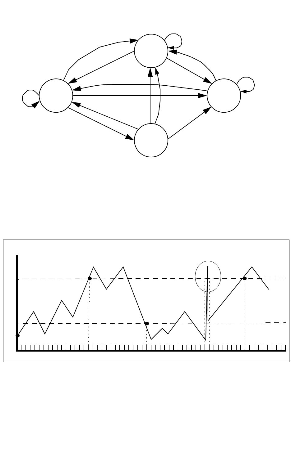
February 2003 RMON Support Specification SLVOS R2.2
- Page 131 -
The following shows the state transition diagram of the SMIv2 row status mechanism.
3.4 RMON Groups Behavior and Defaults
3.4.1 Alarm Group Behavior and Defaults
3.4.1.1 Alarm Behavior
3.4.1.1.1 General Alarm Behavior
The alarm group allows an NMS to define variables to be monitored. When the monitored variable passes a threshold,
user specified events are Triggered. See “Event Group Behavior and Defaults” on page 139. The events cannot be
triggered again by the same alarm until the monitored variable passes through the opposite threshold.
The diagram above shows the behavior of an RMON alarm. The following rules apply:
1. If the value or change in value of the variable is below the falling threshold the first time the value is read or
the change is calculated and falling events are desired, the falling event is triggered.
active
notInService
createAndGo
createAndWait (not ready)
destroy Not
Existent
Not
Ready
Not In
Service
Active
destroy
destroy
destroy
notInService
active
notInService
createAndWait (ready)
(set to other variable
in row makes ready)
active
Time
Value of Variable
RMON ALARM BEHAVIOR
Falling Threshold
Rising Threshold
C
A
BD
E

RMON Support Specification SLVOS R2.2 February 2003
- Page 132 -
2. If the value or change in value of the variable is above the rising threshold the first time the value is read or
the change is calculated and rising events are desired, rising event is triggered.
3. Falling alarms trigger an event when the trigger is cleared, the value or change in value of the variable is less
than or equal to the falling threshold, the previous value or change in value of the variable was above the
falling threshold and falling events are desired.
4. Rising alarms trigger an event when the trigger is cleared, the value or change in value of the variable is
greater than or equal to the rising threshold, the prior value or change in value of the variable was below the
rising threshold and rising events are desired.
5. After an alarm triggers an event, it will not trigger again until it is cleared as explained in steps 6 and 7
below.
6. Falling alarms are cleared when the value or change in value of the variable rises above the falling threshold
and reaches or rises above the rising threshold
7. Rising alarms are cleared when the value or change in value of the variable falls below the rising threshold
and reaches or falls below the falling threshold.
Applying the rules above to the diagram, the following points of interest are noted:
C. The first time through, a falling event is triggered.
D. The rising event is triggered and the falling event is cleared.
E. The falling event is triggered again and the rising event is cleared.
F. The rising event is triggered again and the falling event is cleared.
G. NOTE: A potential problem of the alarm group is that the actual value of the variable can pass the rising
threshold and fall below again between polls. If this occurs, no event will be triggered and nothing will be
cleared. It is up to the user to define a polling interval that make sense for the data that is being collected. It
is far less likely for this type of problem to occur if delta values are used.
3.4.1.1.2 Setting Alarms
Setting alarms requires a minimum of two sets. One set must change alarmStatus variable to createRequest(2), and the
other must set the alarmStatus variable to valid(1). All other variables can be set individually or in either of the two
PDUs previously described. The following should be noted:
• It is not valid to set alarmVariable to an SNMP variable that does not exist. Should this occur, a result of
badValue will be returned.
• The value of alarmOwner defaults to “monitor”. While it is not enforced by the device, user defined
alarms should use some other string.
• Both alarmRisingThreshold and alarmFallingThreshold should be set to allow the alarm to work
properly. Otherwise, the alarm will only be triggered once during the existence of that alarm.
• Setting either alarmRisingEventIndex or alarmFallingEventIndex to 0 or some nonexistent event is
valid. However, the corresponding rising or falling events will not be triggered should this be the case.
• When the alarmStatus is set to valid(1), the only variables that may be set are alarmStatus and
alarmOwner. Attempting to set any other variable will result in a badValue error.
3.4.1.1.3 Alarm Permanence
All user configured alarms that have an alarmStatus of valid(1) are stored through power cycles. Due to memory
restrictions, some values will be altered on start-up.
The behavior is as follows:

February 2003 RMON Support Specification SLVOS R2.2
- Page 133 -
1. The event fields, alarmRisingEvent and alarmFallingEvent, will be reset to the defaults if they are set to
nonzero values. (See “Event Defaults” on page 140.)
2. The owner string, alarmOwner, will be set to the last owner string set by the management station which
“owns” the alarm. Only ten owner strings are stored on the device. If more than ten management stations
perform sets, the owner strings of only the first ten stations that still “own” alarms or user history will be
stored. The owner strings for all other stations will be set to their respective IP addresses. Ownership of an
alarm is altered by either setting the alarm to valid or successfully performing a set on any alarm variable
while the alarm is valid.
3. Default alarms that are reset or altered by the user will be set to the user configured values on Startup.
3.4.1.2 Alarm Defaults
The RMON alarm defaults are divided into two areas. Due to the limits Netscout Manager enforces on alarms, all
alarms under 9000 must follow the Netscout indexing rules. In that it is sometimes necessary to exceed the 8 alarms
per interface allowable in the Netscout area, additional alarms will be added starting at 9001. These additional alarms
cannot be modified using Netscout software.
For all default alarms, the following is true:
1. alarmStartupAlarm is risingAlarm(1)
2. alarmSampleType is delta(2) except where noted.
3. alarmFallingIndex is 0.
4. alarmOwner is “monitor”.
5. alarmStatus is valid(1).
The following symbols are used in all of the alarm default tables:
•IThe interface index of the applicable interface. In all circumstances, the interface index DOES
NOT refer to the RMON specific interface index.
•DThe DLCI number.
•RThe default Rising Event (See “Event Defaults” on page 140.)

RMON Support Specification SLVOS R2.2 February 2003
- Page 134 -
3.4.1.2.1 RMON Alarms -- Frame Relay Link Defaults
The following alarms apply to all non-backup frame relay link interfaces. Note that this table does not apply when the
device is in PPP mode.
Table 3-5. Frame Relay Link Defaults (1 of 2)
Index Item Tag/OID Interval
R
i
s
i
n
g
T
h
r
e
s
h
o
l
d
F
a
ll
i
n
g
T
h
r
e
s
h
o
l
d
R
i
s
i
n
g
E
v
e
n
t
9002+ (RMON
Mapped ifIndex) *
12
Invalid Frames devFrExtLinkRxIlFrames
.1.3.6.1.4.1.1795.2.24.2.6.9.4.7.
1.18.I
900 3 1 R
9003 + (RMON
Mapped ifIndex) *
12
Short Frames devFrExtLinkRxShort
.1.3.6.1.4.1.1795.2.24.2.6.9.4.7.
1.6.I
900 3 1 R
9004 + (RMON
Mapped ifIndex) *
12
Long Frames devFrExtLinkRxLong
.1.3.6.1.4.1.1795.2.24.2.6.9.4.7.
1.7.I
900 3 1 R
9005 + (RMON
Mapped ifIndex) *
12
Rx Discards devFrExtLinkRxDiscards
.1.3.6.1.4.1.1795.2.24.2.6.9.4.7.
1.15.I
900 3 1 R
9006 + (RMON
Mapped ifIndex) *
12
Tx Discards devFrExtLinkTxDiscards
.1.3.6.1.4.1.1795.2.24.2.6.9.4.7.
1.14.I
900 3 1 R
9007 + (RMON
Mapped ifIndex) *
12
Rx Total Errors devFrExtLinkTotRxErrs
.1.3.6.1.4.1.1795.2.24.2.6.9.4.7.
1.20.I
900 3 1 R
9008 + (RMON
Mapped ifIndex) *
12
Tx Total Errors devFrExtLinkTotTxErrs
.1.3.6.1.4.1.1795.2.24.2.6.9.4.7.
1.19.I
900 3 1 R

February 2003 RMON Support Specification SLVOS R2.2
- Page 135 -
NOTE: For the RX and TX utilization alarms, the uppermost bucket of the devFrExtLinkUtilTable should be used. It
is assumed that the network manager will add this alarm as required by the customer.
9009 + (RMON
Mapped ifIndex) *
12
Rx Overruns devFrExtLinkRxOverruns
.1.3.6.1.4.1.1795.2.24.2.6.9.4.7.
1.28.I
900 3 1 R
9010 + (RMON
Mapped ifIndex) *
12
Tx Underruns devFrExtLinkTxUnderruns
.1.3.6.1.4.1.1795.2.24.2.6.9.4.7.
1.29.I
900 3 1 R
9011 + (RMON
Mapped ifIndex) *
12
Rx Non-octet Aligns devFrExtLinkRxNonOctet
.1.3.6.1.4.1.1795.2.24.2.6.9.4.7.
1.16.I
900 3 1 R
9012 + (RMON
Mapped ifIndex) *
12
Rx CRC Errors devFrExtLinkRxCrcErr
.1.3.6.1.4.1.1795.2.24.2.6.9.4.7.
1.17.I
900 3 1 R
9013 + (RMON
Mapped ifIndex) *
12
Total LMI Errors devFrExtLinkTotalLMIErrs
.1.3.6.1.4.1.1795.2.24.2.6.9.4.7.
1.32.I
900 3 1 R
Table 3-5. Frame Relay Link Defaults (2 of 2)
Index Item Tag/OID Interval
R
i
s
i
n
g
T
h
r
e
s
h
o
l
d
F
a
ll
i
n
g
T
h
r
e
s
h
o
l
d
R
i
s
i
n
g
E
v
e
n
t

RMON Support Specification SLVOS R2.2 February 2003
- Page 136 -
3.4.1.2.2 RMON Alarms -- Frame Relay DLCI Defaults
The following alarms apply to all DLCIs on the Network interface Note that this table does not apply when the device
is in PPP mode.
Table 3-6. Frame Relay DLCI Defaults
Index Item Tag/OID Interval
R
i
s
i
n
g
T
h
r
e
s
h
o
l
d
F
a
ll
i
n
g
T
h
r
e
s
h
o
l
d
R
i
s
i
n
g
E
v
e
n
t
9050 + (Internal
circuit index * 8)
DLCI Inactive Seconds devFrExtDlciStsInactiveSecs
.1.3.6.1.4.1.1795.2.24.2.6.9.4.2.
1.2.I.D
900 5 1 R
9051 + (Internal
circuit index * 8)
Missing Latency Responses devFrExtDlciMissedSLVs
.1.3.6.1.4.1.1795.2.24.2.6.9.4.1.
1.23.I.D
900 5 5 R
9052 + (Internal
circuit index * 8)
Rx FECNs frCircuitReceivedFECNs
.1.3.6.1.2.1.10.32.2.1.4.I.D
60 3 1 R
9053 + (Internal
circuit index * 8)
Rx BECNs frCircuitReceivedBECNs
.1.3.6.1.2.1.10.32.2.1.5.I.D
60 3 1 R
9054+ (Internal
circuit index * 8)
Congested Seconds devFrExtDlciStsConjestedSecs
.1.3.6.1.4.1.1795.2.24.2.6.9.4.2.
1.6.I.D
60 5 5 R
9055 + (Internal
circuit index * 8)
Frames Dropped By
Network
devFrExtDlciNetDropFr
.1.3.6.1.4.1.1795.2.24.2.6.9.4.1.
1.20.I.D
60 3 1 R

February 2003 RMON Support Specification SLVOS R2.2
- Page 137 -
The following alarms apply to all DLCIs on the Network interface. However, these are put into the “Netscout area” if
the device supports layer 3 or higher monitoring. Otherwise, the grouped with the previous group Note that this table
does not apply when the device is in PPP mode.
3.4.1.2.3 User Configured Alarms
3.4.1.2.3.1 Next available alarmIndex
There are no default alarms created for the Path/COS latency. These alarms can be configured externally by the user.
However, there is a block of indexes allocated for this purpose. The new mib object devRmonPathAlarmNextIndex is
used to to get the next available alarmIndex to be used at the time of alarm creation. This object indicates the next
available alarmIndex. Return of zero indicates that there are no more alarms allowed. The OID of this object is
.iso.org.dod.internet.private.enterprises.pdyn.pdn-mgmt.paradyne.pdn-common.pdn-
rmon.devRmonPathAlarm.devRmonPathAlarmNextIndex. (.1.3.6.1.4.1.1795.2.24.2.13.3.1)
3.4.1.2.3.2 Path Alarm Index Mapping
A new table devRmonPathAlarmMapTable is created to map the alarmIndex from the alarmTable to the Path/COS.
The fields with an “*” form the index of the table. This table will become part of paradyne Rmon extension group. The
OID for this table is .iso.org.dod.internet.private.enterprises.pdyn.pdn-mgmt.paradyne.pdn-common.pdn-
rmon.devRmonPathAlarm.devRmonPathAlarmMapTable.devRmonPathAlarmMapEntry
(.1.3.6.1.4.1.1795.2.24.2.13.3.2.1). The following table describes the objects.
Table 3-7. Network DLCI Defaults
Index Item Tag/OID Interval
R
i
s
i
n
g
T
h
r
e
s
h
o
l
d
F
a
ll
i
n
g
T
h
r
e
s
h
o
l
d
R
i
s
i
n
g
E
v
e
n
t
9056 + (Internal
circuit index * 8)
Rx DLCI Link Utilization
(NOTE: The thresholds will
change every time the link
speed changes)
frCircuitReceivedOctets
.1.3.6.1.2.1.10.32.2.1.9.I.D
60 8
5
%
6
5
%
R
9057 + (Internal
circuit index * 8)
Tx DLCI Link Utilization
(NOTE: The thresholds will
change every time the link
speed changes)
frCircuitSentOctets
.1.3.6.1.2.1.10.32.2.1.7.I.D
60 8
5
%
6
5
%
R

RMON Support Specification SLVOS R2.2 February 2003
- Page 138 -
3.4.1.2.3.3 Alarms Creation
To create an alarm for the Path/COS latency -
1. Get the value of the object devRmonPathAlarmNextIndex. This object returns the next available index.
2. Use this value as an Index for creating an entry to the alarm table. Any latency object id - min, max, average or last
can be used for the alarmVariable.
Example -
All the alarms are created in the table - .iso.org.dod.internet.mgmt.mib-2.rmon.alarm.alarmTable.alarmEntry
1. Get the next available Index as described above.
2. Set the object alarmStatus of the alarmEntry to 2 (createRequest) using the above Index as alarmIndex
3. Set the alarmInterval - in seconds.
4. Set the object to be monitored - alarmVariable, with the object id. The OID for the object
devSLVIPPathStatByCOSLastRTT in the devSLVIPPathStatByCOSTable is .1.3.6.1.4.1.1795.2.24.2.12.4.2.1.7
For example, for the path with DLCI 100 and IPaddr 10.1.100.102 and the COS Id 1 set the alarmVariable =
.1.3.6.1.4.1.1795.2.24.2.12.4.2.1.7.101015001.100.2147483647.10.1.100.102.1
Table 3-8. Path Alarm Index Mapping
Object Name Description Default value Support
ifIndex* value of ifIndex from the
Interfaces table of MIB II.
read-only
Integer
devRmonPathAlarmMapCktId* This object indicates the
circuit Id either DLCI or VPI.
read-only
Integer
devRmonPathAlarmMapCktSubId* This object indicates the
circuit Sub Id either EDLCI
or VCI.
2147483647 read-only
Integer
devRmonPathAlarmMapIpAddr* Specifies the IP Address of
the path.
read-only
IpAddress
devRmonPathAlarmMapCosId* This object indicates the
COS Id.
read-only
Integer
devRmonPathAlarmMapAlarmIndex This object indicates the
alarmIndex from the
alarmTable.
read-only
Integer
devRmonPathAlarmMapRisingThreshold This object indicates the
alarmRisingThreshold from
the alarmTable.
read-only
Integer
devRmonPathAlarmMapFallingThreshold This object indicates the
alarmFallingThreshold from
the alarmTable.
read-only
Integer

February 2003 RMON Support Specification SLVOS R2.2
- Page 139 -
Note that any of the other object Min or Max or Avg could be also used.
5. Set the alarmSampleType to absolute(1) or delta(2).
6. Set the alarmStartupAlarm to rising(1) or falling(2) or risingOrFalling(3).
7. Set the alarmRisingThreshold to the desired value.
8. Set the alarmRisingEventIndex to 65533 if you want the traps to be sent out or to zero if no traps need to be sent out.
9. Set the alarmOwner to a string for identification.
10. Set the object alarmStatus of the alarmEntry to valid(1).
This will create an entry in the alarmTable and make it active.
3.4.1.2.3.4 Alarms Modification
The entries in the alarmTable can be modified by the user.
1. Get the value of the object devRmonPathAlarmMapAlarmIndex from the above table for the Path.
2. Set the object alarmStatus of the alarmEntry to 3 (underCreation).
3. Modify any object.
4. Set the object alarmStatus of the alarmEntry to valid(1).
3.4.1.2.3.5 Alarms Deletion
The alarms are deleted automatically when the path is deleted. Note that the dynamically learned paths are temporary.
The entries in the alarmTable can also be deleted by the user as described below.
1. Get the value of the object devRmonPathAlarmMapAlarmIndex from the above table for the Path.
2. Set the object alarmStatus of the alarmEntry to 4 (invalid).
3.4.2 Event Group Behavior and Defaults
3.4.2.1 General Event Behavior
The event group allows the user to define specific events that are associated with alarms. These events when triggered
can send an SNMP trap, log the occurrence, both or neither. It is further legal to define non-RMON, device specific
events such as the events used to log all non-RMON alarm related SNMP traps. These non-RMON events can only be
created by the device as defaults and may never be created or destroyed by an end user.
The row status (eventStatus) of all default events cannot be changed and will result in a badValue if attempted. In this
way, the default events will always exist. However, the eventType can change. Those events that are already associated
with SNMP traps, not including RMON event generated traps, can still be set to either trap or log-and-trap; however,
they will not generate traps in that this would cause a endless loop.
WARNING: Information within this table will be reset to the default values on start-up.
3.4.2.2 Setting Events
Setting events requires a minimum of two sets. One set must change the eventStatus variable to createRequest(2), and
the other must set the eventStatus variable to valid(1). All other variables can be set individually or in either of the
previously described PDUs. The following should be noted:
• The value of eventOwner defaults to “monitor”. While it is not enforced by the device, user defined
events should use some other string.
• The event community has no meaning. It will always report “public” and not report errors if set to
anything else.

RMON Support Specification SLVOS R2.2 February 2003
- Page 140 -
3.4.2.3 Event Defaults
3.4.2.3.1 RMON Alarm Related Events
For all default RMON Alarm related events, the following is true:
1. eventType is set to log-and-trap(4).
2. eventOwner is “monitor”.
3. eventStatus is valid(1) and cannot be altered.
The following are the default RMON Alarm related events.
3.4.2.3.2 SNMP Trap Related Events
Default events are defined in the device to log all non-RMON alarm related SNMP traps. These events will be triggered
each time a trap is generated whether or not traps are enabled in the device. However, the device can still configure
whether a specific trap can be generated. If it is the case that the device is configured not to generate a specific trap
type, it is also the case that the associated event will not be triggered.
The SNMP trap related event defaults are as follows:
1. eventType is set to log(2).
2. eventOwner is set to “monitor”.
3. eventStatus is valid(1) and cannot be altered.
The value of eventIndex for the SNMP standard traps will be calculated using the following formula:
eventIndex = 64000 + generic-trap
The value of eventIndex for the enterprise specific traps is calculated using the following formula:
eventIndex = 65000 + specific-trap
Table 3-9. RMON Alarm Related Events
Index Name eventDescription
65533 Default Rising Event “Default SLV Rising Event”
65534 Default Falling Event “Default SLV Falling Event”

February 2003 RMON Support Specification SLVOS R2.2
- Page 141 -
The value of event Index for non-RMON MIB defined traps are as follows:
This yields the following default values:
Table 3-10. Event Index for Non-RMON MIB-Defined Traps
Trap Name eventIndex
dialCtlPeerCallInformation 63001
dialCtlPeerCallSetup 63002
dialCtlPeerCallRejected 63003
Table 3-11. Default Index Values (1 of 2)
Index Name eventDescription
63001 dialCtlPeerCallInformation “Call Information Trap”
63002 dialCtlPeerCallSetup “Call Setup Trap”
63003 dialCtlPeerCallRejected “Call Rejected Trap”
64001 warmStart “Warm Start Trap”
64002 linkDown “Link Down Trap”
64003 linkUp “Link Up Trap”
64004 authenticationFailure “Authentication Failure Trap”
65001 enterprisePrimaryClockFail “Primary Clock Fail Trap”
65002 enterpriseSelfTestFail “Self Test Fail Trap”
65004 enterpriseSecondaryClockFail “Secondary Clock Fail Trap”
65005 enterpriseTestStart “Test Start Trap”
65006 enterpriseConfigChange “Configuration Change Trap”
65007 enterprisePowerSupply “Power Supply Failure Trap”
65008 enterpriseModuleMisConfig “Module Misconfiguration Trap”
65009 enterpriseAPMFailed “APM Failure Trap”
65011 enterpriseDLCIDown “DLCI Down Trap”
65012 enterpriseDLCIUp “DLCI Up Trap”
65013 enterpriseRMONResetToDefault “RMON Reset To Defaults Trap”
65014 enterpriseLinkSpeedChange “Link Speed Change Trap”
65015 enterpriseCIRChange “CIR Change Trap”

RMON Support Specification SLVOS R2.2 February 2003
- Page 142 -
3.4.2.4 The Event Log
The event log is a log of the events that have been triggered on the device. The minimum number of event entries
supported by the device is equal to 8 times the maximum number of circuits allowed on the device. This is not to say
that only 8 event entries are supported per circuit. In fact, there is no limit to how the entries are distributed amongst
the circuits. When the resources required to store a new entry are depleted, the oldest entries will be eliminated such
that new entries will fit in memory. Further, each midnight network time all event log entries older than one year will
be eliminated.
The entries in the log table are indexed by the eventIndex and a local logIndex per event. They are not directly ordered
in the sequence in which they occurred, but this can be derived by inspecting the local order of each event and the time
at which it occurred. In that no event will be older than a year, it can be assumed that the clock has wrapped when the
difference between any two entries is greater than a year.
3.4.3 Protocol Directory Group Behavior and Defaults
3.4.3.1 Protocol Directory Description
The main purpose of the protocol directory group is to control the the protocols or applications monitored by the
device. It is defaulted to the Non IP - Directory Local Index 1, IP - Directory Local Index 2, Other IP - Directory Local
Index 3, TCP- Directory Local Index 4, UDP - Directory Local Index 5, Other TCP - Directory Local Index 6 and Other
UDP - Directory Local Index 7. These default values can not be changed. However the user can configure up to 10
new protocols to monitor. Note that this group does not apply when the device is in PPP mode
The defaults for the protocolDirTable Items (protocolDir 2) are as follows:
65016 enterpriseMissedSLVDown “SLV Down Trap”
65017 enterpriseDLCIDelete “DLCI Deleted Trap”
65018 enterpriseFanFailure “Fan Failure Trap”
65019 enterprisePathDown “Path Down Trap”
65020 enterprisePathUp “Path Up Trap”
65021 enterpriseLatencyExceeded “Latency Exceeded Trap”
65101 enterprisePrimaryClockFailClear “Primary Clock Restored Trap”
65104 enterpriseSecondaryClockFailClear “Secondary Clock Restored Trap”
65105 enterpriseTestStop “Test Stop Trap”
65107 enterprisePowerSupplyClear “Power Supply Restored Trap”
65108 enterpriseModuleMisConfigClear “Misconfiguration Corrected Trap”
65109 enterpriseAPMFailedClear “APM Restored Trap”
65116 enterpriseMissedSLVUp “SLV Up Trap”
65118 enterpriseFanFailureClear “Fan Restored Trap”
65121 enterpriseLatencyRestored “Latency Restored Trap”
Table 3-11. Default Index Values (2 of 2)
Index Name eventDescription

February 2003 RMON Support Specification SLVOS R2.2
- Page 143 -
• protocolDirAddressMapConfig is notSupported(1).
• protocolDirMatrixConfig is notSupported(1).
• protocolDirLocalIndex is the internal index of the defined protocol.(1 thru 12)
• protocolDirOwner is “monitor”
• protocolDirStatus is active(1).
• all other values are described in the table below.
3.4.3.2 Protocol Directory Examples
The user can configure up to 10 protocols to monitor. Some well known protocols are listed below as examples. The
protocolDirDescr is a user defined string of ten bytes in length. The values below would be examples.
Table 3-12. Defaults for protocolDirTable Items
DirLocalIndex
protocolDirID and
Parameters
protocol
DirDescr
protocol
DirType
protocol
DirHost
Config
1 8.1.0.0.2.255.255.247.255.2.0.0 Non-IPv4 ““ notSupported(1)
2 8.1.0.0.2.0.0.8.0 2.0.0 IPv4 0x40 supportedOn(3)
3 12.1.0.0.2.0.0.8.0 0.0.0.0.3.0.0.0 Other-IPv4 ““ notSupported(1)
4 12.1.0.0.2.0.0.8.0 0.0.0.6.3.0.0.0 TCP ““ notSupported(1)
5 12.1.0.0.2.0.0.8.0 0.0.0.17.3.0.0.0 UDP ““ notSupported(1)
6 16.1.0.0.2.0.0.8.0.0.0.0.6.0.0.0.0.4.0.0.0.0 Other-TCP ““ notSupported(1)
7 16.1.0.0.2..0.0.8.0.0.0.0.17.0.0.0.0.4.0.0.0.0 Other-UDP ““ notSupported(1)
Table 3-13. Protocol Directory Examples
Name protocolDirID and Parameters protocol DirDescr
protocolDirHost
Config
OSPF 12.1.0.0.2.0.0.8.0.0.0.0.89.3.0.0.0 IP.OSPF notSupported(1)
BGP 16.1.0.0.2.0.0.8.0.0.0.0.6.0.0.0.179.4.0.0.0.0 TCP.BGP notSupported(1)
FTP-data 16.1.0.0.2.0.0.8.0.0.0.0.6.0.0.0.20.4.0.0.0.0 TCP.FTP-D notSupported(1)
HTTP 16.1.0.0.2.0.0.8.0.0.0.0.6.0.0.0.80.4.0.0.0.0 TCP.HTTP notSupported(1)
HTTPS 16.1.0.0.2.0.0.8.0.0.0.0.6.0.0.1.187.4.0.0.0.0 TCP.HTTPS notSupported(1)
RTSP 16.1.0.0.2.0.0.8.0.0.0.0.6.0.0.2.10.4.0.0.0.0 TCP.RTSP notSupported(1)
RIP 16.1.0.0.2.0.0.8.0.0.0.0.17.0.0.2.8.4.0.0.0.0 UDP.RIP notSupported(1)
SMTP 16.1.0.0.2.0.0.8.0.0.0.0.6.0.0.0.25.4.0.0.0.0 TCP.SMTP notSupported(1)
SNMP 16.1.0.0.2.0.0.8.0.0.0.0.17.0.0.0.161.4.0.0.0.0 UDP.SNMP notSupported(1)
TELNET 16.1.0.0.2.0.0.8.0.0.0.0.6.0.0.0.23.4.0.0.0.0 TCP.TELNET notSupported(1)

RMON Support Specification SLVOS R2.2 February 2003
- Page 144 -
As shown in the examples above, the user can configure a protocol to monitor by defining the protocol ID from the IP
header or the user can configure a port (or range of ports) to monitor for either TCP or UDP. Any IP packet which does
not match one of the user defined protocols will be counted in the Other IP directory.
The protocol encoding for the HTTP shown above is broken down as follows:
• protocolDirID nd parameter for this table entry is 16.1.0.0.2.0.0.8.0.0.0.0.6.0.0.0.80.4.0.0.0.0
• 16 = Number of bytes in the protocol ID (1.0.0.2.0.0.8.0.0.0.0.6.0.0.0.80). L2 protocol is = 1.0.0.2. =
f.op1.op2.m where:f =1 this protocol entry will match any base-layer encapsulation of the same network
layer protocol. op1 and op2 are not used so they are zero and m = specified base layer encapsulation 2 =
LLC.
• Layer 3 = .0.0.8.0 = 0.0.a.b where a.b = 16 bit value of L3 protocol as specified in MAC header type
0x0800 is IP.
• Layer 4 = 0.0.0.6 = 0.0.0.a where a is protocol field in the IP header for layer 4 TCP = 6, UDP = 17
• Layer 5 = 0.0.0.80 = a.b.c.d. where a.b is the lower value for the port or 0 and c.d is the upper value of
the port. (a and c are MSB and b and d are LSB)
• 4 = Number of Parameter bytes (one parameter for each layer protocol encoded)
•0.0.0.0 = Parameter byte values - no parameters are specifiedfor any protocol layer.
Example: Protocol XYZ uses TCP ports 100-110 and 50000 and UDP ports 100-110. The user would have to define
three protocols
1. TCP Ports 100-110: 16.1.0.0.2.0.0.8.0.0.0.0.6.0.100.0.110.4.0.0.0.0
2. TCP Port 50000: 16.1.0.0.2.0.0.8.0.0.0.0.6.0.0.195.80.4.0.0.0.0
3. UDP Port 100-110: 16.1.0.0.2.0.0.8.0.0.0.0.17.0.100.0.110.4.0.0.0.0
Encoding for port 50000 is as follows
• 50000 = 0xc350
• 0xc3 = 195
• 0x50 = 80
• Network byte order encoding = 0.0.195.80
3.4.3.3 Protocol Directory Creation
For the user to configure a protocol directory from SNMP the following steps are used
• Enter into the protocolDirStatus the value createAndWait (5) for the protocolDirID and Parameter value
whcih describes what is to be monitored.
• Enter a protocolDirDescr string for the same protocolDirID and Parameter value.
• Enter into the protocolDirStatus the value Active(1) for the protocolDirID and Parameter value which
describes what is to be monitored.
At this point the protocol should have been added. A Local Index will have been assigned to the protocolDirID and
Parameter value. There are 10 available Local Indices for the user to configure.
3.4.4 Protocol Distribution Group Behavior and Defaults
The main purpose of the protocol distribution group is to display statistics concerning the protocol information on
specific interfaces for those protocols defined in the protocol directory group above (Protocol Directory Group
Behavior and Defaults on page 142). Note that this group does not apply when the device is in PPP mode.

February 2003 RMON Support Specification SLVOS R2.2
- Page 145 -
The protocol distribution Group uses the RMON ifIndex associated with the network link and DLCIs. There are three
RMON ifIndexes for each DLCI. The first is the bidirectional interface, the second is the transmit half of the interface
and th third is the recieve half of the interface. So for the first DLCI in the device the ifIndices of 10000, 10001 and
10002 would be used to find the protocol distribution for RX+TX, TX only and RX only respectively.
The following are the defaults found in the protocolDistControlTable that are installed for each RMON ifIndex:
• protocolDistControlIndex is set to RMON ifIndex. These values are for DLCIs and Paths as defined in
the Table 3-2, “RMON ifIndex Scheme,” on page 127.
• protocolDistControlDataSource is set to the OID of the RMON ifIndex of interest.
• protocolDistControlOwner is “monitor”
• protocolDistControlStatus is active(1).
NOTE: ProtocolDistControlDroppedFrames will always be zero.
3.4.5 Network Layer Host Group Behavior and Defaults
The purpose of this group is to control the collection of network and application layer host information and to display
the network layer host information. Further information is tied to the matrix groups and the application layer host
groups, but these groups are not supported by Paradyne and are ignored. This group can enable the monitoring of hosts
and addresses of all protocols that are defined in the protocol directory group (Protocol Directory Group Behavior and
Defaults on page 142) with any of protocolDirAddressMapConfig, protocolDirHostConfig, protocolDirMatrixConfig
set to supportedOn(3). It is defaulted to supportedOn for the Other-IPv4 Protocol and is not intended to be altered by
the user. Note that this group does not apply when the device is in PPP mode.
The network Layer Host Group uses the RMON ifIndex associated with the network link and DLCIs. There are three
RMON ifIndexes for each DLCI. The network Layer Host Group only uses the first interface defined for each DLCI.
The first interface is the bidirectional interface. (The second is the transmit half of the interface and the third is the
recieve half of the interface.) So for the first DLCI in the device the ifIndex of 10000 would be used to find the Network
Layer Host information.
The following are the defaults found in the hlHostControlTable that are installed for each RMON ifIndex associated
with the network links and DLCIs:
• hlHostControlIndex is RMON ifIndex. These values are for combined DLCIs and Paths as defined in
the Table 3-2, “RMON ifIndex Scheme,” on page 127
• hlHostControlDataSource is set to the OID of the RMON ifIndex of interest.
• hlHostContolNlMaxDesiredEntries is set to 2000.
• hlHostControlAlMaxDesiredEntries is set to 0.
• hlHostControlOwner is “monitor”.
• hlHostControlStatus is active(1).
Note: Only values actively being counted will be returned for the nlHostTable.nlHostEntry.
3.4.6 User History Behavior and Defaults
3.4.6.1 User History Behavior
3.4.6.1.1 General User History Behavior
It should be noted up front that user history has no concept of ifIndex, DLCI or VPI/VCI. All it knows about are
SNMP OIDs. There is no mechanism to enforce that a logical grouping of OIDs all apply to the same interface, and
there is no standard indexing mechanism to give meaning to the group. ALL indexing and interface recognition

RMON Support Specification SLVOS R2.2 February 2003
- Page 146 -
schemes that don’t rely solely on the OIDs and knowledge of the MIBs are proprietary. It is up to the designer of the
groups and the NMS manager to give meaning to the information. When all of the OIDs in a group apply to the same
ifIndex, DLCI or VPI/VCI, the code is able to figure out the correct relationship such that the group can be removed
if the circuit is removed.
The user history group allows the user to collect “bucketized” data from supported integer based MIB values. It is
divided into three tables: usrHistoryControlTable, usrHistoryObjectTable, and usrHistoryTable. The first table,
usrHistoryControlTable, is the general control for all three tables. It allows the user to define a “group” controller. This
controller is added to the table in the form of a row in the table. This table is a one-dimensional table in which each
row controls the configuration of a group of user history “buckets”. The creation of a row in this table will generate
the creation of row(s) in the usrHistoryObjectTable. The user specifies the number of objects to monitor, the number
of “buckets” to keep, and the interval at which to poll the device to fill the buckets. A “bucket” is an individual sample
of an SNMP variable. Note that the number of buckets generated depends on the memory resources available at the
time of activation. The Paradyne code defaults new rows in such a way that the status can never be notReady(3). On
setting a row to active(1), the buckets are allocated and collection begins. On successfully moving a row from active(1)
to any other value, the buckets are de-allocated and the history is lost.
The second table, usrHistoryObjectTable, contains the set of SNMP objects that are to be monitored. This is a two-
dimensional table in which the items being collected for each bucket group are defined. The first dimension being the
bucket group index and the second dimension being the object indexed in the group. Only variables that result in
ASN.1 integers may be sampled, and the object supplied for the variable name must be available at the time of the set
operation or a badValue will be returned. On row creation from the usrHistoryControlTable, rows are added to this
table. The number of rows associated with a specific row in the usrHistoryControlTable that exist in this table may
increase or decrease as the variable usrHistoryControlObjects changes. If the number decreases, rows will be deleted
from the table. If the number increases, rows will be added to the table and the variables defined by
usrHistoryObjectVariable for the new rows will all be set to .0.0. Note that .0.0 is the only legal non-integer,
nonexistent variable that can be set as it is used as a place holder to be filled in later by the user.
The third table, usrHistoryTable, contains the actual history. This is a three-dimensional table that relates a history
group, a history object, and the sample number to the actual history data and the time it was collected. It should be
noted that the index, usrHistorySampleIndex, is incremented once for each sample taken for a specific object. It will
only wrap when the 31 bit index actually wraps. Also, no rows exist in this table until the first time interval expires.
3.4.6.1.2 Setting User History
Setting user history requires a minimum of only one set. However, this is not recommended in that sets to
usrHistoryObjectVariable can fail. The one set method requires setting all of the information in the same PDU as
setting usrHistoryControlStatus to createAndGo(4). The multi-step (dribble) method requires two sets to
usrHistoryControlStatus. One set at the beginning of the creation process sets usrHistoryControlStatus to
createAndWait(5). The other sets it to active(1). All other variables in both the control and object tables can be set as
desired by the NMS in between or with either of the other two set operations. The following should be noted:
• It is not valid to set usrHistoryObjectVariable to an SNMP variable that either does not exist or is not an
integer. Should this occur, a result of badValue will be returned.
• The value of usrHistoryControlOwner defaults to “monitor”. While it is not enforced by the device, user
defined user history should use some other string.
• It is legal to set usrHistoryObjectVariable to .0.0. This is the only non-integer or nonexistent variable
that can be set.
• Rows are automatically added to the usrHistoryObjectTable on creation of a row in the
usrHistoryControlTable.

February 2003 RMON Support Specification SLVOS R2.2
- Page 147 -
• Setting usrHistoryControlObjects changes the number of rows in the usrHistoryObjectTable. It is
possible to lose information by making this number smaller than it already is. If this number is
increased, defaulted rows will be added to the table.
• When the usrHistoryControlStatus is set to active(1), the only variables that may be set in any of the
associated tables are usrHistoryControlBucketsRequested, usrHistoryControlOwner and
usrHistoryControlStatus. Attempting to set any other variable will result is a badValue error.
• Since it is possible to change usrHistoryControlBucketsRequested when the group is active, there is
only one set required to change the amount of history desired. For example, changing this value from 96
to 192 when usrHistoryControlInterval is set to 900 seconds will change the amount of history from one
day to two days. If the value is decreased, the oldest buckets will be eliminated from the table, but
history will still exist. If the value is increased, new buckets will be added as they become available.
• Sets to usrHistoryControlBucketsRequested are not guaranteed to work. The actual number of buckets
allocated when the row is set to active(1) are reported in usrHistoryControlBucketsGranted. This is
determined solely by the amount of memory that is free at the time of allocation.
• Existing active rows may be changed by setting usrHistoryControlStatus to notInService(2). This is the
recommended method of adding or removing variables from a group. At the end of the changes,
usrHistoryControlStatus should be returned to active(1).
3.4.6.1.2.1 Recommendations on Setting User History
It is important to recognize that sets to the user history control structures can fail. The failures are for the following
two reasons:
1. The device is out of resources.
2. A variable defined by usrHistoryObjectVariable does not exist or is non-integer.
The simplest way for an NMS to avoid doing rework when a failure occurs is to perform all of the sets in single object
PDUs. However, this is not realistic in that it can be very time consuming and increases the amount of network traffic
required to create a row. For this reason, it is the least favored method of setting user history.
Accepting the fact that no sets can occur if the device is out of resources, the first failure mode mentioned above can
be ignored in the generation of an algorithm to efficiently set user history. The second failure mode has two causes:
the variable does not exist or the variable is non-integer. It is up to the user to make sure that all the variables are of
type integer, and it can be assume that it is a user error to do otherwise. This mode of failure can be ignored in the
algorithm as well in that the device cannot stop the users from being human.
The only mode of failure left is that the variable does not exist. If the user groups the variables that are to be set into
groups such that all the variables in a group exist if one variable in the group exists, the number of set operations can
be reduced to the number of groups of variables with unique existence behaviors. In other words, it is up to the NMS
to group the variables logically such that the time required and the amount network traffic is minimized.
A quick algorithm that requires a minimum of two PDUs and a maximum number of PDUs equal to three plus the
number of variable groups can be defined. Using the knowledge stated above, the quick user history set algorithm is
as follows:
1. Divide the variables defining usrHistoryObjectVariable that are to be set into groups such that no group
would result in a PDU sized greater than 1400 bytes and all of the variables in each individual group exhibit
the same existence behavior within that group. Note that it would generally be good to further subdivide the
groups into those variables that are absolutely required and those that are not always required. In this way,
failure can be more graceful.
2. In a single PDU, set usrHistoryControlStatus to createAndWait(5), and set usrHistoryControlObjects,
usrHistoryControlBucketsRequested, usrHistoryControlInterval and usrHistoryControlOwner to the desired

RMON Support Specification SLVOS R2.2 February 2003
- Page 148 -
values. If the resulting size of the PDU after adding the smallest single group that is absolutely required to
this PDU would be less than 1400 bytes, also set the values of usrHistoryObjectVariable and
usrHistoryObjectSampleType for that group in the same PDU.
3. If step 2 failed, clean up by setting usrHistoryControlStatus to destroy(6) and quit trying for this control. The
attribute that failed can be traced by looking at the variable that failed in the PDU. Further steps may be
required to assign blame, but blame is beyond the scope of this algorithm.
4. While there are nonessential groups, add each group by setting usrHistoryObjectVariable and
usrHistoryObjectSampleType for all variables in a single PDU. Failures can be ignored in that these
variables are not essential.
5. While there are essential groups, add each group by setting usrHistoryObjectVariable and
usrHistoryObjectSampleType for all variables in a single PDU. Immediately go to step six on failure.
6. If step 5 failed, clean up by setting usrHistoryControlStatus to destroy(6) and quit trying for this control.
7. Set usrHistoryControlStatus to active(1) to activate the control. This PDU can be combined with the last
PDU in either step 5 or step 6 above if there is room.
8. If step 7 failed, clean up by setting usrHistoryControlStatus to destroy(6) and quit trying for this control.
3.4.6.1.3 User History Permanence
All user configured user history groups that have a usrHistoryControlStatus of active(1) are stored through power
cycles. Due to memory restrictions, some values will be altered on start-up.
The behavior is as follows:
1. The owner string, usrHistoryControlOwner, will be set to the last owner string set by the management
station which “owns” the group. Only ten owner strings are stored in the device. If more than ten
management stations perform sets, the owner strings of only the first ten stations that still “own” either
alarms or user history will be stored. The owner strings for all other stations will be set to their IP address.
Ownership of user history is altered by either setting the group to active or successfully performing a set on
any user history variable while the group is active.
2. Default user history groups that are reset by the user will be set to the user configured values on start-up.
3.4.6.1.4 Retrieving User History
Due to the amount of information that is contained in user history, it is not realistic on a WAN network to collect either
all of the historical information using SNMP get operations or even the configuration. It is a difficult task that basically
requires that the NMS performs walks on the user tables using the last known valid index. To remedy this, Paradyne
includes a bulk collector that generates an file at the time of collection through FTP. This is file is far smaller and can
be retrieved quicker due to the connection oriented protocol. See “Paradyne User History Bulk Collector” on page 174.
3.4.6.1.4.1 Using SNMP to Retrieve User History
While SNMP is not the best mechanism to retrieve all user history information, there are some cases, especially those
for which a specific individual control’s information is required, where it may be desired. The only information
required to retrieve usrHistory through SNMP is the value of usrHistoryControlIndex for the history group that is
desired. A method can be devised that requires less network traffic than a simple MIB walk. With
usrHistoryControlIndex information, the following quick retrieval algorithm can be used.
1. It may be desirable to check if the configuration has changed. If this is the case, the NMS should perform a
get containing all of the variables in the usrHistoryControlTable and a walk on the usrHistoryObjectTable
for the usrHistoryControlIndex of interest.
2. The usrHistoryTable is indexed by usrHistoryControlIndex, usrHistorySampleIndex, and

February 2003 RMON Support Specification SLVOS R2.2
- Page 149 -
usrHistoryObjectIndex. In order to find the correct starting index, perform a getNext on
usrHistoryIntervalStart, usrHistoryIntervalEnd, usrHistoryAbsValue, and usrHistoryValStatus filling in the
only the usrHistoryControlIndex desired.
3. Inspect the result of the value returned. If it does not apply to the usrHistoryControlIndex desired, simply
quit in that there is no history for that variable. If the associated usrHistorySampleIndex is less than the last
known value and the difference is less than the number of buckets, note the starting index as one greater than
the last known value. Otherwise, the starting index is this index.
4. Using the starting index, package a getNext PDU for usrHistoryIntervalStart, usrHistoryIntervalEnd,
usrHistoryAbsValue and usrHistoryValStatus for each usrHistoryObjectIndex that can fit into a 1000 byte
PDU. It may take multiple PDUs to get all of the information for one bucket group.
5. Repeat step 4 until the information for any row points to an object that does not apply to the current
usrHistoryControlIndex.
6. Note that it is possible to miss a bucket of history using this method. Care should be taken in the storing of
all of the information such that it is aligned with the start and end times correctly.
3.4.6.1.5 User History Synchronization
User history data will be synchronized as best as possible to the network reference time. The following rules apply:
1. RMON will assume that the Time of Day is always the Network Reference Time.
2. User history groups share timers. This means that if a user history group is defined with the same
usrHistoryControlInterval as a existing user history group, its first interval will begin the next time the
existing user history group’s timer expires.
3. If usrHistoryControlInterval is less than 24 hours and is evenly divisible into 24 hours and this is the first
group at that interval, the first interval will begin at the next multiple of the period based on the current
network reference time at the time of creation..
4. If usrHistoryControlInterval is greater than 24 hours and this is the first group at that interval, the first
interval will begin at midnight based on the network reference time at the time of creation.
5. If usrHistoryControlInterval does not evenly divide into 24 hours and this is the first group at that interval,
the first interval will begin immediately.
6. Synchronization will only occur within a 24 hour period. If the period defined by usrHistoryControlInterval
is greater than 24 hours, the resynchronization WILL NOT ensure that it starts on the exact same day as
every device in the network.
7. Intervals will be resynchronized at midnight, based on the network reference time at either creation or the
last resynchronization, if usrHistoryControlInterval is less than 24 hours. It will occur at the end of each
interval in all other cases.
8. Resynchronization will adjust the interval such that the next interval is not more than 50 percent different
than usrHistoryControlInterval. This means that a 15 minute interval can be between 7.5 minutes and 22.5
minutes immediately after resynchronization. After which, all other intervals will be
usrHistoryControlInterval and align to network reference time as describe above. This resynchronization
will account for both time changes and slip.

RMON Support Specification SLVOS R2.2 February 2003
- Page 150 -
3.4.6.2 User History Defaults
3.4.6.2.1 User History Row Creation Defaults
To ensure ease of use, the values of the user history tables are defaulted such that the row is always valid. Following
is the default behavior:
3.4.6.2.2 User History Interface Specific Defaults
Again, it should be noted up from that user history has no concept of ifIndex, DLCI or VPI/VCI. All it knows about
are SNMP OIDs. Any indexing scheme placed on user history is proprietary.
For all default user history groups, the following is true:
1. The value of usrHistoryControlIndex is calculated based on the RMON Indexes (see Table 3-2, “RMON
ifIndex Scheme,” on page 127), and the RMON Mapped Indexes (Table 3-3, “RMON Index Mapping,” on
page 128), that is to be monitored.
The Internal Index is (((i - 10000) / 3)+1) for a ifIndex in the range of 10000 - 19998.
The Internal Index is (((i - 20000) / 3)+1) for a ifIndex in the range of 20000 - 29998.
A Path is defined a IP Address on a DLCI.
Table 3-14. User History Row Creation Defaults
Object Variable Default
usrHistoryControlObjects Set to 1
usrHistoryControlBucketsRequested Set to 50
usrHistoryControlBucketsGranted Reports 0
usrHistoryControlInterval Set to 1800
usrHistoryControlOwner Set to ““
usrHistoryObjectVariable Set to .0.0
usrHistoryObjectSampleType Set to deltaValue(2)
Table 3-15. User History Interface Specific Defaults (1 of 2)
IfIndex Name
usrHistoryControlIndex -
24 Hour collector
usrHistoryControlIndex -
15 Minute collector
1 thru 10 Logical
Interfaces
RMON Mapped Index RMON Mapped Index +100
11 thru 20 Physical
Interfaces
RMON Mapped Index RMON Mapped Index + 100
10000 thru
14998
DLCI ((Internal Index -1)*3) +10000 (((Internal Index -1)*3) +10000) + 1

February 2003 RMON Support Specification SLVOS R2.2
- Page 151 -
Therefore for a simple configuration with one DLCI (100), two Paths (IP address 1.1.1.1 and 1.1.1.2) and the
default COS, the following ifIndexes would exist:
• 10000 - DLCI 101 TX and RX
• 10001 - DLCI 101 TX
• 10002 - DLCI 101 RX
• 20000 - Path DLCI 101 IP address 1.1.1.1 TX and RX
• 20001 - Path DLCI 101 IP address 1.1.1.1 TX
• 20002 - Path DLCI 101 IP address 1.1.1.1 RX
• 20003 - Path DLCI 101 IP address 1.1.1.2 TX and RX
• 20004 - Path DLCI 101 IP address 1.1.1.2 TX
• 20005 - Path DLCI 101 IP address 1.1.1.2 RX
• 101001001 : Network T1
• 101003001 : Synchronous Data Port
• 101015001 : Network T1 of FR
• 101016001 : Synchronous Data Port of FR
For the UserHistory Indices the follow Items would exist which means that a user history group has been
established to collect data.
• 1 - Frame Relay Network Port 24 Hour Collector
• 3 - Frame Relay Data Port 24 Hour Collector
• 11 - Physical T1 Port 24 Hour Collector
• 101 - Frame Relay Network Port 15 Minute Collector
10000 thru
14998
DLCI/
Application
((Internal Index -1)*3) + 15000 (((Internal Index -1)*3) +15000) + 1
10000 thru
14998
DLCI/COS ((Internal Index -1) * (2 * MAX_COS)) +
COS + 30000
((Internal Index -1) * (2 * MAX_COS)) +
COS + MAX_COS + 30000
20000 thru
24998
PATH ((Internal Index -1)*3) +20000 (((Internal Index -1)*3) + 20000) + 1
20000 thru
24998
PATH/
Application
((Internal Index -1)*3) +25000 (((Internal Index -1)*3) + 25000) + 1
20000 thru
24998
PATH/COS ((Internal Index -1) * (2 * MAX_COS)) +
COS + 40000
((Internal Index -1) * (2 * MAX_COS)) +
COS + MAX_COS + 40000
Table 3-15. User History Interface Specific Defaults (2 of 2)
IfIndex Name
usrHistoryControlIndex -
24 Hour collector
usrHistoryControlIndex -
15 Minute collector

RMON Support Specification SLVOS R2.2 February 2003
- Page 152 -
• 103 - Frame Relay Data Port 15 Minute Collector
• 111 - Physical T1 Port 15 Minute Collector
• 10000 - DLCI 101 24 Hour Collector
• 10001 - DLCI 101 15 Minute Collector
• 15000 - DLCI 101 24 Hour Application Collector
• 15001 - DLCI 101 15 Minute Application Collector
• 20000 - Path DLCI 101 IP address 1.1.1.1 24 Hour Collector
• 20001 - Path DLCI 101 IP address 1.1.1.1 15 Minute Collector
• 20003 - Path DLCI 101 IP address 1.1.1.2 24 Hour Collector
• 20004 - Path DLCI 101 IP address 1.1.1.2 15 Minute Collector
• 25000 - Path DLCI 101 IP address 1.1.1.1 24 Hour Application Collector
• 25001 - Path DLCI 101 IP address 1.1.1.1 15 Minute Application Collector
• 25003 - Path DLCI 101 IP address 1.1.1.2 24 Hour Application Collector
• 25004 - Path DLCI 101 IP address 1.1.1.2 15 Minute Application Collector
• 30000 - DLCI 101 COS 0 24 Hour Collector
• 30007 - DLCI 101 COS 7 24 Hour Collector
• 30008 - DLCI 101 COS 8 24 Hour Collector
• 30009 - DLCI 101 COS 0 15 Minute Collector
• 30016 - DLCI 101 COS 7 15 Minute Collector
• 30017 - DLCI 101 COS 8 15 Minute Collector
• 40000 - PATH DLCI 101 IP address 1.1.1.1 COS 0 24 Hour Collector
• 40007 - PATH DLCI 101 IP address 1.1.1.1 COS 7 24 Hour Collector
• 40008 - PATH DLCI 101 IP address 1.1.1.1 COS 8 24 Hour Collector
• 40009 - PATH DLCI 101 IP address 1.1.1.1 COS 0 15 Minute Collector
• 40016 - PATH DLCI 101 IP address 1.1.1.1 COS 7 15 Minute Collector
• 40017 - PATH DLCI 101 IP address 1.1.1.1 COS 8 15 Minute Collector
• 40018 - PATH DLCI 101 IP address 1.1.1.2 COS 0 24 Hour Collector
• 40025 - PATH DLCI 101 IP address 1.1.1.2 COS 7 24 Hour Collector
• 40026 - PATH DLCI 101 IP address 1.1.1.2 COS 8 24 Hour Collector
• 40027 - PATH DLCI 101 IP address 1.1.1.2 COS 0 15 Minute Collector
• 40034 - PATH DLCI 101 IP address 1.1.1.2 COS 7 15 Minute Collector
• 40035 - PATH DLCI 101 IP address 1.1.1.2 COS 8 15 Minute Collector
2. usrHistoryControlOwner is “monitor”.
3. usrHistoryControlStatus is active(1).

February 2003 RMON Support Specification SLVOS R2.2
- Page 153 -
The following symbols are used in all of the default tables:
•IThe interface index of the applicable interface. In all circumstances, the interface index DOES
NOT refer to the RMON specific interface index.
•DThe DLCI number.
•HThe Host Control Index
•NAn addition numeric index used by tables like frame size and burst size.
•PThe protocol index.
•TThe time mask.
•UUnit Id - Standard mode(2), back-to-back(1).
•SReference Side- Network(1), Customer(2).
•WWire Pair - wirePair1(1), wirePair2(2).
•Sub Sub Circuit Id - always 0x7fffffff.
•Ip Ip address of the path.
•Cos Cos Id.
3.4.6.2.2.1 User History Physical Interface Defaults
The following user history group definition applies only to the Network T1 interface (when applicable). .
Table 3-16. T1 Group (1 of 2)
Number of Default Groups for this Interface 2
Value of usrHistoryControlBucketsRequested for each group 5, 96
Value of usrHistoryControlInterval for each group 86400 (24 hours), 900 (15 minutes)
usrHistory
Object
Index Name
usrHistoryObect
SampleType Tag / OID
1 Unavailable Seconds (near) deltaValue(2) devTelcoFreeRunUASs
.1.3.6.1.4.1.1795.2.24.2.6.5.4.8.1.2.I
2 Errored Seconds (near) deltaValue(2) devTelcoFreeRunESs
.1.3.6.1.4.1.1795.2.24.2.6.5.4.8.1.3.I
3 Severely Errored Seconds
(near)
deltaValue(2) devTelcoFreeRunSESs
.1.3.6.1.4.1.1795.2.24.2.6.5.4.8.1.4.I
4 Controlled Slip Seconds
(near)
deltaValue(2) devTelcoFreeRunCSSs
.1.3.6.1.4.1.1795.2.24.2.6.5.4.8.1.5.I
5 Bursty Errored Seconds
(near)
deltaValue(2) devTelcoFreeRunBESs
.1.3.6.1.4.1.1795.2.24.2.6.5.4.8.1.6.I

RMON Support Specification SLVOS R2.2 February 2003
- Page 154 -
The following user history group applies only to the Network DDS interface (when applicable). .
6 Loss Of Frame Count (near) deltaValue(2) devTelcoFreeRunLOFC
.1.3.6.1.4.1.1795.2.24.2.6.5.4.8.1.7.I
7 Unavailable Seconds (far) deltaValue(2) devTelcoFreeRunFarUASs
.1.3.6.1.4.1.1795.2.24.2.6.5.4.8.1.8.I
8 Errored Seconds (far) deltaValue(2) devTelcoFreeRunFarESs
.1.3.6.1.4.1.1795.2.24.2.6.5.4.8.1.9.I
9 Severely Errored Seconds
(far)
deltaValue(2) devTelcoFreeRunFarSESs
.1.3.6.1.4.1.1795.2.24.2.6.5.4.8.1.10.I
10 Controlled Slip Seconds (far) deltaValue(2) devTelcoFreeRunFarCSSs
.1.3.6.1.4.1.1795.2.24.2.6.5.4.8.1.11.I
11 Bursty Errored Seconds (far) deltaValue(2) devTelcoFreeRunFarBESs
.1.3.6.1.4.1.1795.2.24.2.6.5.4.8.1.12.I
12 Loss Of Frame Count (far) deltaValue(2) devTelcoFreeRunFarLOFC
.1.3.6.1.4.1.1795.2.24.2.6.5.4.8.1.13.I
Table 3-17. DDS Group (1 of 2)
Number of Default Groups for this Interface 2
Value of usrHistoryControlBucketsRequested for each group 5, 96
Value of usrHistoryControlInterval for each group 86400 (24 hours), 900 (15 minutes)
usrHistory
Object
Index Name
usrHistoryObect
SampleType Tag / OID
1 Unavailable Seconds deltaValue(2) ddsUnavailableSecs
.1.3.6.1.4.1.1795.2.24.2.6.2.1.1.9.I
2 No Signal Counter deltaValue(2) ddsNoSignalCntr
.1.3.6.1.4.1795.2.24.2.6.2.3.1.2.I
Table 3-16. T1 Group (2 of 2)
Number of Default Groups for this Interface 2
Value of usrHistoryControlBucketsRequested for each group 5, 96
Value of usrHistoryControlInterval for each group 86400 (24 hours), 900 (15 minutes)
usrHistory
Object
Index Name
usrHistoryObect
SampleType Tag / OID
February 2003 RMON Support Specification SLVOS R2.2
- Page 155 -
The following user history group definition applies only to the Network Synchronous Data Port interface (when
applicable).
3 Out Of service Counter deltaValue(2) ddsOutOfServiceCntr
.1.3.6.1.4.1795.2.24.2.6.2.3.1.4.I
4 Out Of Frame Counter deltaValue(2) ddsOutOfFrameCntr
.1.3.6.1.4.1795.2.24.2.6.2.3.1.6.I
5 Excessive BPV Counter deltaValue(2) ddsExcessiveBPVCntr
.1.3.6.1.4.1795.2.24.2.6.2.3.1.8.I
6 Invalid BPV Counter deltaValue(2) ddsBPVCntr
.1.3.6.1.4.1795.2.24.2.6.2.3.1.10.I
Table 3-18. Synchronous Port Group
Number of Default Groups for this Interface 2
Value of usrHistoryControlBucketsRequested for each group 5, 96
Value of usrHistoryControlInterval for each group 86400 (24 hours), 900 (15 minutes)
usrHistory
Object
Index Name
usrHistoryObect
SampleType Tag / OID
1 Unavailable Seconds deltaValue(2) devSyncPortStatsUASs
.1.3.6.1.4.1.1795.2.24.2.6.6.5.1.1.2.I
Table 3-17. DDS Group (2 of 2)
Number of Default Groups for this Interface 2
Value of usrHistoryControlBucketsRequested for each group 5, 96
Value of usrHistoryControlInterval for each group 86400 (24 hours), 900 (15 minutes)
usrHistory
Object
Index Name
usrHistoryObect
SampleType Tag / OID

RMON Support Specification SLVOS R2.2 February 2003
- Page 156 -
The following user history group definition applies only to all Network physical interfaces that are anything other than
a T1, a DDS or a Synchronous Data Port interface (when applicable).
The following user history group applies only to the SDSL interface (when applicable). .
The following user history group applies only to the SHDSL interface (when applicable). .
Table 3-19. Network Group
Number of Default Groups for this Interface 2
Value of usrHistoryControlBucketsRequested for each group 5, 96
Value of usrHistoryControlInterval for each group 86400 (24 hours), 900 (15 minutes)
usrHistory
Object
Index Name
usrHistoryObect
SampleType Tag / OID
1 Unavailable Seconds deltaValue(2) pdnIfExtTotalUASs
.1.3.6.1.4.1.1795.2.24.2.6.12.1.1.1.4.I
Table 3-20. SDSL Group
Number of Default Groups for this Interface 2
Value of usrHistoryControlBucketsRequested for each group 5, 96
Value of usrHistoryControlInterval for each group 86400 (24 hours), 900 (15 minutes)
usrHistory
Object
Index Name
usrHistoryObect
SampleType Tag / OID
1 Unavailable Seconds deltaValue(2) pdnIfExtTotalUASs
.1.3.6.1.4.1.1795.2.24.2.6.12.1.1.1.4.I
2 SDSL Interface Rate deltaValue(2) ifSpeed
.1.3.6.1.2.1.2.2.1.5.I
Table 3-21. SHDSL Group (1 of 2)
Number of Default Groups for this Interface 2
Value of usrHistoryControlBucketsRequested for each group 5, 96
Value of usrHistoryControlInterval for each group 86400 (24 hours), 900 (15 minutes)
usrHistory
Object
Index Name
usrHistoryObect
SampleType Tag / OID
1 Unavailable Seconds deltaValue(2) hdsl2ShdslEndpointUAS
.1.3.6.1.2.1.10.48.1.5.1.8.I.U.S.W
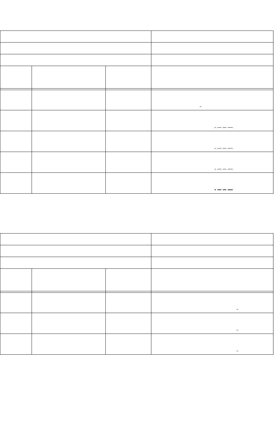
February 2003 RMON Support Specification SLVOS R2.2
- Page 157 -
The following user history group applies only to the T3 interface (when applicable).
2 Interface Rate deltaValue(2) ifSpeed
.1.3.6.1.2.1.2.2.1.5.I
3 Errored Seconds deltaValue(2) hdsl2ShdslEndpointES
.1.3.6.1.2.1.10.48.1.5.1.4.I.U.S.W
4 Severely Errored Seconds deltaValue(2) hdsl2ShdslEndpointSES
.1.3.6.1.2.1.10.48.1.5.1.5.I.U.S.W
5 CRC anomalies deltaValue(2) hdsl2ShdslEndpointCRCanomalies
.1.3.6.1.2.1.10.48.1.5.1.6.I.U.S.W
6 Loss of Sync Word (LOSW)
Seconds
deltaValue(2) hdsl2ShdslEndpointLOSWS
.1.3.6.1.2.1.10.48.1.5.1.7.I.U.S.W
Table 3-22. T3 Group (1 of 2)
Number of Default Groups for this Interface 2
Value of usrHistoryControlBucketsRequested for each group 5, 96
Value of usrHistoryControlInterval for each group 86400 (24 hours), 900 (15 minutes)
usrHistory
Object
Index Name
usrHistoryObect
SampleType Tag / OID
1 Unavailable Seconds deltaValue(2) devDs3FreeRunUAS
.1.3.6.1.4.1795.2.24.2.6.14.1.5.1.4.I
2 P bit Errored Seconds deltaValue(2) devDs3FreeRunPES
.1.3.6.1.4.1795.2.24.2.6.14.1.5.1.1.I
3 P bit Severely Errored
Seconds
deltaValue(2) devDs3FreeRunPSES
.1.3.6.1.4.1795.2.24.2.6.14.1.5.1.2.I
Table 3-21. SHDSL Group (2 of 2)
Number of Default Groups for this Interface 2
Value of usrHistoryControlBucketsRequested for each group 5, 96
Value of usrHistoryControlInterval for each group 86400 (24 hours), 900 (15 minutes)
usrHistory
Object
Index Name
usrHistoryObect
SampleType Tag / OID

RMON Support Specification SLVOS R2.2 February 2003
- Page 158 -
3.4.6.2.2.2 User History Frame Relay Link Interface Defaults
This table does not apply when the device is in PPP mode. The following user history group definition applies to all
non-backup frame relay link interfaces.
4 Severely Errored Frame
Seconds
deltaValue(2) devDs3FreeRunPSEFS
.1.3.6.1.4.1795.2.24.2.6.14.1.5.1.3.I
5 Line Coding Violations deltaValue(2) devDs3FreeRunLCV
.1.3.6.1.4.1795.2.24.2.6.14.1.5.1.5.I
6 P bit Coding Violations deltaValue(2) devDs3FreeRunPCV
.1.3.6.1.4.1795.2.24.2.6.14.1.5.1.6.I
7 Line Errored Seconds deltaValue(2) devDs3FreeRunLES
.1.3.6.1.4.1795.2.24.2.6.14.1.5.1.7.I
8 C bit Coding Violations deltaValue(2) devDs3FreeRunCCV
.1.3.6.1.4.1795.2.24.2.6.14.1.5.1.8.I
9 C bit Errored Second deltaValue(2) devDs3FreeRunCES
.1.3.6.1.4.1795.2.24.2.6.14.1.5.1.9.I
10 C bit Severely Errored
Seconds
deltaValue(2) devDs3FreeRunCSES
.1.3.6.1.4.1795.2.24.2.6.14.1.5.1.10.I
Table 3-22. T3 Group (2 of 2)
Number of Default Groups for this Interface 2
Value of usrHistoryControlBucketsRequested for each group 5, 96
Value of usrHistoryControlInterval for each group 86400 (24 hours), 900 (15 minutes)
usrHistory
Object
Index Name
usrHistoryObect
SampleType Tag / OID

February 2003 RMON Support Specification SLVOS R2.2
- Page 159 -
Table 3-23. Frame Relay Group
Table 3-24. Frame Relay Group (1 of 2)
Number of Default Groups for this Interface 2
Value of usrHistoryControlBucketsRequested for each group 5, 96
Value of usrHistoryControlInterval for each group 86400 (24 hours), 900 (15 minutes)
usrHistory
Object
Index Name
usrHistoryObect
SampleType Tag / OID
1 LMI Unavailable Seconds deltaValue(2) devFrExtLinkNoLMISecs
.1.3.6.1.4.1.1795.2.24.2.6.9.4.7.1.2.I
2 ALL DLCI + LMI Rx Octets deltaValue(2) ifInOctets
.1.3.6.1.2.1.2.2.1.10.I
3 ALL DLCI + LMI Tx Octets deltaValue(2) ifOutOctets
.1.3.6.1.2.1.2.2.1.16.I
4 Total Rx Errors deltaValue(2) devFrExtLinkTotRxErrs
.1.3.6.1.4.1.1795.2.24.2.6.9.4.7.1.20.I
5 Total Tx Errors deltaValue(2) devFrExtLinkTotTxErrs
.1.3.6.1.4.1.1795.2.24.2.6.9.4.7.1.19.I
6 Total Rx CRC Errors deltaValue(2) devFrExtLinkRxCrcErr
.1.3.6.1.4.1.1795.2.24.2.6.9.4.7.1.17.I
7 Total LMI Errors deltaValue(2) devFrExtLinkTotalLMIErrs
.1.3.6.1.4.1.1795.2.24.2.6.9.4.7.1.32.I
8 Rx Long Frames deltaValue(2) devFrExtLinkRxLong
.1.3.6.1.4.1.1795.2.24.2.6.9.4.7.1.7.I
9 Rx Short Frames deltaValue(2) devFrExtLinkRxShort
.1.3.6.1.4.1.1795.2.24.2.6.9.4.7.1.6.I
10 Rx Discards deltaValue(2) devFrExtLinkRxDiscards
.1.3.6.1.4.1.1795.2.24.2.6.9.4.7.1.15.I
11 Rx Illegal Frames deltaValue(2) devFrExtLinkRxIlFrames
.1.3.6.1.4.1.1795.2.24.2.6.9.4.7.1.18.I
12 LMI Sequence Errors deltaValue(2) devFrExtLinkSeqErr
.1.3.6.1.4.1.1795.2.24.2.6.9.4.7.1.11.I
13 - 16 Port Burst Upper Limits 1 - 4
Network Interface Only
absoluteValue(1) devFrExtLinkUtilUpLimit
.1.3.6.1.4.1.1795.2.24.2.6.9.4.10.3.1.2.I.N

RMON Support Specification SLVOS R2.2 February 2003
- Page 160 -
NOTE: All items after usrHistoryControlIndex 12 and before 28 will apply to the Network Interface only.
3.4.6.2.2.3 User History Network DLCI Defaults
This table does not appy when the device is in PPP mode. The following user history group definition applies to all
DLCIs on the network interface when the device supports Layer 3 or higher that support SLM packets.
17 - 21 Rx Port Burst Octets 1 - 5
Network Interface Only
deltaValue(2) devFrExtLinkUtilRxOctets
.1.3.6.1.4.1.1795.2.24.2.6.9.4.10.3.1.3.I.N
22 - 26 Tx Port Burst Octets 1 - 5
Network Interface Only
deltaValue(2) devFrExtLinkUtilTxOctets
.1.3.6.1.4.1.1795.2.24.2.6.9.4.10.3.1.4.I.N
27 Link Speed
Network Interface Only
absoluteValue(1) ifSpeed
.1.3.6.1.2.1.2.2.1.5.I
28 or 13 Received Frames deltaValue(2) ifInUcastPkts
.1.3.6.1.2.1.2.2.1.11.I
29 or 14 Sent Frames deltaValue(2) ifOutUcastPkts
.1.3.6.1.2.1.2.2.1.17.I
Table 3-25. Network DLCI Group (Layer 3) (1 of 4)
Number of Default Groups for this Interface 2
Value of usrHistoryControlBucketsRequested for each group 5, 96
Value of usrHistoryControlInterval for each group 86400 (24 hours), 900 (15 minutes)
usrHistory
Object
Index Name
usrHistoryObect
SampleType Tag / OID
1 Inactive Seconds deltaValue(2) devFrExtDlciStsInactiveSecs
.1.3.6.1.4.1.1795.2.24.2.6.9.4.2.1.2.I.D
2 Rx Frames deltaValue(2) frCircuitReceivedFrames
.1.3.6.1.2.1.10.32.2.1.8.I.D
3 Tx Frames deltaValue(2) frCircuitSentFrames
.1.3.6.1.2.1.10.32.2.1.6.I.D
Table 3-24. Frame Relay Group (2 of 2)
Number of Default Groups for this Interface 2
Value of usrHistoryControlBucketsRequested for each group 5, 96
Value of usrHistoryControlInterval for each group 86400 (24 hours), 900 (15 minutes)
usrHistory
Object
Index Name
usrHistoryObect
SampleType Tag / OID

February 2003 RMON Support Specification SLVOS R2.2
- Page 161 -
4 Rx Frames Above CIR deltaValue(2) devFrExtDlciRxFrOutCIR
.1.3.6.1.4.1.1795.2.24.2.6.9.4.1.1.18.I.D
5 Tx Frames Above CIR deltaValue(2) devFrExtDlciTxFrOutCIR
.1.3.6.1.4.1.1795.2.24.2.6.9.4.1.1.17.I.D
6 Rx BECNs deltaValue(2) frCircuitReceivedBECNs
.1.3.6.1.2.1.10.32.2.1.5.I.D
7 Rx FECNs deltaValue(2) frCircuitReceivedFECNs
.1.3.6.1.2.1.10.32.2.1.4.I.D
8 Rx DEs deltaValue(2) devFrExtDlciRxDE
.1.3.6.1.4.1.1795.2.24.2.6.9.4.1.1.22.I.D
9 Network Frames Lost deltaValue(2) devFrExtDlciNetDropFr
.1.3.6.1.4.1.1795.2.24.2.6.9.4.1.1.20.I.D
10 Average Latency absoluteValue(1) devFrExtLatencyAvg
.1.3.6.1.4.1.1795.2.24.2.6.9.4.3.1.5.I.D
11 Maximum Latency absoluteValue(1) devFrExtLatencyMax
.1.3.6.1.4.1.1795.2.24.2.6.9.4.3.1.6.I.D
12 - 17 IP Top Listeners (1 - 6) absoluteValue(1) devRmonIPTopNDstIP
.1.3.6.1.4.1.1795.2.24.2.13.1.2.1.4.H.T.N
18 - 23 IP Top Talkers (1 - 6) absoluteValue(1) devRmonIPTopNSrcIP
.1.3.6.1.4.1.1795.2.24.2.13.1.2.1.6.H.T.N
24 Network Frames Lost Above
CIR
deltaValue(2) devFrExtDlciRmtDropFrOutCir
.1.3.6.1.4.1.1795.2.24.2.6.9.4.1.1.45.I.D
25 Network Frames Offered deltaValue(2) devFrExtDlciRmtOffFr
.1.3.6.1.4.1.1795.2.24.2.6.9.4.1.1.37.I.D
26 Network Frames Offered
Above CIR
deltaValue(2) devFrExtDlciRmtOffFrOutCir
.1.3.6.1.4.1.1795.2.24.2.6.9.4.1.1.43.I.D
Table 3-25. Network DLCI Group (Layer 3) (2 of 4)
Number of Default Groups for this Interface 2
Value of usrHistoryControlBucketsRequested for each group 5, 96
Value of usrHistoryControlInterval for each group 86400 (24 hours), 900 (15 minutes)
usrHistory
Object
Index Name
usrHistoryObect
SampleType Tag / OID

RMON Support Specification SLVOS R2.2 February 2003
- Page 162 -
27 Network Frames Offered In
CIR
deltaValue(2) devFrExtDlciRmtOffFrInCir
.1.3.6.1.4.1.1795.2.24.2.6.9.4.1.1.39.I.D
28 Network Frames Dropped In
CIR
deltaValue(2) devFrExtDlciDropOffFrInCir
.1.3.6.1.4.1.1795.2.24.2.6.9.4.1.1.41.I.D
29 Tx Octets deltaValue(2) frCircuitSentOctets
.1.3.6.1.2.1.10.32.2.1.7.I.D
30 Rx Octets deltaValue(2) frCircuitReceivedOctets
.1.3.6.1.2.1.10.32.2.1.9.I.D
31 DLCI CIR absoluteValue(1) devFrExtDlciCIR
.1.3.6.1.4.1.1795.2.24.2.6.9.4.1.1.3.I.D
32 - 36 Burst Upper Limit (1 - 5) absoluteValue(1) devFrExtBurstUpLimit
.1.3.6.1.4.1.1795.2.24.2.6.9.4.5.2.1.2.I.D.N
37 - 41 Burst Frames (1 - 5) deltaValue(2) devFrExtBurstFrames
.1.3.6.1.4.1.1795.2.24.2.6.9.4.5.2.1.4.I.D.N
42 - 46 Burst Octets (1 - 5) deltaValue(2) devFrExtBurstOctets
.1.3.6.1.4.1.1795.2.24.2.6.9.4.5.2.1.3.I.D.N
47 Tx DEs deltaValue(2) devFrExtDlciTxDE
.1.3.6.1.4.1.1795.2.24.2.6.9.4.1.1.7.I.D
484 Tx BECNs deltaValue(2) devFrExtDlciTxBECN
.1.3.6.1.4.1.1795.2.24.2.6.9.4.1.1.8.I.D
49 DLCI EIR absoluteValue(1) devFrExtDlciEir
.1.3.6.1.4.1.1795.2.24.2.6.9.4.1.1.63.I.D
50 Network Frames Offered
Above CIR Within EIR
deltaValue(2) devFrExtDlciOfferedFrCirToEir
.1.3.6.1.4.1.1795.2.24.2.6.9.4.1.1.55.I.D
51 Network Frames Offered
Above EIR
deltaValue(2) devFrExtDlciOfferedFrOverEir
.1.3.6.1.4.1.1795.2.24.2.6.9.4.1.1.59.I.D
Table 3-25. Network DLCI Group (Layer 3) (3 of 4)
Number of Default Groups for this Interface 2
Value of usrHistoryControlBucketsRequested for each group 5, 96
Value of usrHistoryControlInterval for each group 86400 (24 hours), 900 (15 minutes)
usrHistory
Object
Index Name
usrHistoryObect
SampleType Tag / OID

February 2003 RMON Support Specification SLVOS R2.2
- Page 163 -
The following user history group definition applies to all DLCIs on the network interface when the device supports
only Layer 2 statistics and does not support SLM packets.
52 Network Frames Dropped
Above CIR Within EIR
deltaValue(2) devFrExtDlciRxFrNetDropCirToEir
.1.3.6.1.4.1.1795.2.24.2.6.9.4.1.1.57.I.D
53 Network Frame Dropped
Above EIR
deltaValue(2) devFrExtDlciRxFrNetDropOverEir
.1.3.6.1.4.1.1795.2.24.2.6.9.4.1.1.61.I.D
54 Latency Packet Size absolute(1) devFrExtLatencyPacketSz
.1.3.6.1.4.1.1795.2.24.2.6.9.4.3.1.8.I.D
55 - 59 Frame Size Upper Limit absolute(1) devFrExtFrameSzUpLimit
.1.3.6.1.4.1.1795.2.24.2.6.9.4.4.2.1.2.I.D.N
60 - 64 Frame Size Count deltaValue(2) devFrExtFrameSzCount
.1.3.6.1.4.1.1795.2.24.2.6.9.4.4.2.1.3.I.D.N
65 Backup Count
Devices with Backup Only
deltaValue(2) devFrExtDlciStsBackupCnt
.1.3.6.1.4.1.1795.2.24.2.6.9.4.2.1.8.I.D
66 Backup Time
Devices with Backup Only
deltaValue(2) devFrExtDlciStsBackupTime
.1.3.6.1.4.1.1795.2.24.2.6.9.4.2.1.9.I.D
Table 3-26. Network DLCI Group (Layer 2 no SLM) (1 of 3)
Number of Default Groups for this Interface 2
Value of usrHistoryControlBucketsRequested for each group 5, 96
Value of usrHistoryControlInterval for each group 86400 (24 hours), 900 (15 minutes)
usrHistory
Object
Index Name
usrHistoryObect
SampleType Tag / OID
1 Inactive Seconds deltaValue(2) devFrExtDlciStsInactiveSecs
.1.3.6.1.4.1.1795.2.24.2.6.9.4.2.1.2.I.D
2 Rx Frames deltaValue(2) frCircuitReceivedFrames
.1.3.6.1.2.1.10.32.2.1.8.I.D
Table 3-25. Network DLCI Group (Layer 3) (4 of 4)
Number of Default Groups for this Interface 2
Value of usrHistoryControlBucketsRequested for each group 5, 96
Value of usrHistoryControlInterval for each group 86400 (24 hours), 900 (15 minutes)
usrHistory
Object
Index Name
usrHistoryObect
SampleType Tag / OID
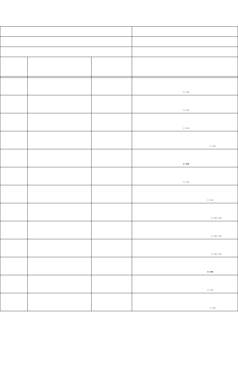
RMON Support Specification SLVOS R2.2 February 2003
- Page 164 -
3 Tx Frames deltaValue(2) frCircuitSentFrames
.1.3.6.1.2.1.10.32.2.1.6.I.D
4 Rx BECNs deltaValue(2) frCircuitReceivedBECNs
.1.3.6.1.2.1.10.32.2.1.5.I.D
5 Rx FECNs deltaValue(2) frCircuitReceivedFECNs
.1.3.6.1.2.1.10.32.2.1.4.I.D
6 Rx DEs deltaValue(2) devFrExtDlciRxDE
.1.3.6.1.4.1.1795.2.24.2.6.9.4.1.1.22.I.D
7 Tx Octets deltaValue(2) frCircuitSentOctets
.1.3.6.1.2.1.10.32.2.1.7.I.D
8 Rx Octets deltaValue(2) frCircuitSentOctets
.1.3.6.1.2.1.10.32.2.1.9.I.D
9 DLCI CIR absoluteValue(1) devFrExtDlciCIR
.1.3.6.1.4.1.1795.2.24.2.6.9.4.1.1.3.I.D
10 - 14 Burst Upper Limit (1 - 5) absoluteValue(1) devFrExtBurstUpLimit
.1.3.6.1.4.1.1795.2.24.2.6.9.4.5.2.1.2.I.D.N
15 - 19 Burst Frames (1 - 5) deltaValue(2) devFrExtBurstFrames
.1.3.6.1.4.1.1795.2.24.2.6.9.4.5.2.1.4.I.D.N
20 - 24 Burst Octets (1 - 5) deltaValue(2) devFrExtBurstOctets
.1.3.6.1.4.1.1795.2.24.2.6.9.4.5.2.1.3.I.D.N
25 Tx DEs deltaValue(2) devFrExtDlciTxDE
.1.3.6.1.4.1.1795.2.24.2.6.9.4.1.1.7.I.D
26 Tx BECNs deltaValue(2) devFrExtDlciTxBECN
.1.3.6.1.4.1.1795.2.24.2.6.9.4.1.1.8.I.D
27 DLCI EIR absoluteValue(1) devFrExtDlciEir
.1.3.6.1.4.1.1795.2.24.2.6.9.4.1.1.63.I.D
Table 3-26. Network DLCI Group (Layer 2 no SLM) (2 of 3)
Number of Default Groups for this Interface 2
Value of usrHistoryControlBucketsRequested for each group 5, 96
Value of usrHistoryControlInterval for each group 86400 (24 hours), 900 (15 minutes)
usrHistory
Object
Index Name
usrHistoryObect
SampleType Tag / OID

February 2003 RMON Support Specification SLVOS R2.2
- Page 165 -
The following user history group definition applies to all DLCIs on the network interface when the device supports
Layer 3 or Layer 2 statistics and supports SLM packets.
28 - 32 Frame Size Upper Limit absolute(1) devFrExtFrameSzUpLimit
.1.3.6.1.4.1.1795.2.24.2.6.9.4.4.2.1.2.I.D.N
33 - 37 Frame Size Count deltaValue(2) devFrExtFrameSzCount
.1.3.6.1.4.1.1795.2.24.2.6.9.4.4.2.1.3.I.D.N
38 Backup Count
Devices with Backup Only
deltaValue(2) devFrExtDlciStsBackupCnt
.1.3.6.1.4.1.1795.2.24.2.6.9.4.2.1.8.I.D
39 Backup Time
Devices with Backup Only
deltaValue(2) devFrExtDlciStsBackupTime
.1.3.6.1.4.1.1795.2.24.2.6.9.4.2.1.9.I.D
Table 3-27. Network DLCI Group (Layer 2 with SLM) (1 of 4)
Number of Default Groups for this Interface 2
Value of usrHistoryControlBucketsRequested for each group 5, 96
Value of usrHistoryControlInterval for each group 86400 (24 hours), 900 (15 minutes)
usrHistory
Object
Index Name
usrHistoryObect
SampleType Tag / OID
1 Inactive Seconds deltaValue(2) devFrExtDlciStsInactiveSecs
.1.3.6.1.4.1.1795.2.24.2.6.9.4.2.1.2.I.D
2 Rx Frames deltaValue(2) frCircuitReceivedFrames
.1.3.6.1.2.1.10.32.2.1.8.I.D
3 Tx Frames deltaValue(2) frCircuitSentFrames
.1.3.6.1.2.1.10.32.2.1.6.I.D
4 Rx Frames Above CIR deltaValue(2) devFrExtDlciRxFrOutCIR
.1.3.6.1.4.1.1795.2.24.2.6.9.4.1.1.18.I.D
5 Tx Frames Above CIR deltaValue(2) devFrExtDlciTxFrOutCIR
.1.3.6.1.4.1.1795.2.24.2.6.9.4.1.1.17.I.D
Table 3-26. Network DLCI Group (Layer 2 no SLM) (3 of 3)
Number of Default Groups for this Interface 2
Value of usrHistoryControlBucketsRequested for each group 5, 96
Value of usrHistoryControlInterval for each group 86400 (24 hours), 900 (15 minutes)
usrHistory
Object
Index Name
usrHistoryObect
SampleType Tag / OID

RMON Support Specification SLVOS R2.2 February 2003
- Page 166 -
6 Rx BECNs deltaValue(2) frCircuitReceivedBECNs
.1.3.6.1.2.1.10.32.2.1.5.I.D
7 Rx FECNs deltaValue(2) frCircuitReceivedFECNs
.1.3.6.1.2.1.10.32.2.1.4.I.D
8 Rx DEs deltaValue(2) devFrExtDlciRxDE
.1.3.6.1.4.1.1795.2.24.2.6.9.4.1.1.22.I.D
9 Network Frames Lost deltaValue(2) devFrExtDlciNetDropFr
.1.3.6.1.4.1.1795.2.24.2.6.9.4.1.1.20.I.D
10 Average Latency absoluteValue(1) devFrExtLatencyAvg
.1.3.6.1.4.1.1795.2.24.2.6.9.4.3.1.5.I.D
11 Maximum Latency absoluteValue(1) devFrExtLatencyMax
.1.3.6.1.4.1.1795.2.24.2.6.9.4.3.1.6.I.D
12 Network Frames Lost Above
CIR
deltaValue(2) devFrExtDlciRmtDropFrOutCir
.1.3.6.1.4.1.1795.2.24.2.6.9.4.1.1.45.I.D
13 Network Frames Offered deltaValue(2) devFrExtDlciRmtOffFr
.1.3.6.1.4.1.1795.2.24.2.6.9.4.1.1.37.I.D
14 Network Frames Offered
Above CIR
deltaValue(2) devFrExtDlciRmtOffFrOutCir
.1.3.6.1.4.1.1795.2.24.2.6.9.4.1.1.43.I.D
15 Network Frames Offered In
CIR
deltaValue(2) devFrExtDlciRmtOffFrInCir
.1.3.6.1.4.1.1795.2.24.2.6.9.4.1.1.39.I.D
16 Network Frames Dropped In
CIR
deltaValue(2) devFrExtDlciDropOffFrInCir
.1.3.6.1.4.1.1795.2.24.2.6.9.4.1.1.41.I.D
17 Tx Octets deltaValue(2) frCircuitSentOctets
.1.3.6.1.2.1.10.32.2.1.7.I.D
18 Rx Octets deltaValue(2) frCircuitSentOctets
.1.3.6.1.2.1.10.32.2.1.9.I.D
Table 3-27. Network DLCI Group (Layer 2 with SLM) (2 of 4)
Number of Default Groups for this Interface 2
Value of usrHistoryControlBucketsRequested for each group 5, 96
Value of usrHistoryControlInterval for each group 86400 (24 hours), 900 (15 minutes)
usrHistory
Object
Index Name
usrHistoryObect
SampleType Tag / OID

February 2003 RMON Support Specification SLVOS R2.2
- Page 167 -
19 DLCI CIR absoluteValue(1) devFrExtDlciCIR
.1.3.6.1.4.1.1795.2.24.2.6.9.4.1.1.3.I.D
20 - 24 Burst Upper Limit (1 - 5) absoluteValue(1) devFrExtBurstUpLimit
.1.3.6.1.4.1.1795.2.24.2.6.9.4.5.2.1.2.I.D.N
25 - 29 Burst Frames (1 - 5) deltaValue(2) devFrExtBurstFrames
.1.3.6.1.4.1.1795.2.24.2.6.9.4.5.2.1.4.I.D.N
30 - 34 Burst Octets (1 - 5) deltaValue(2) devFrExtBurstOctets
.1.3.6.1.4.1.1795.2.24.2.6.9.4.5.2.1.3.I.D.N
35 Tx DEs deltaValue(2) devFrExtDlciTxDE
.1.3.6.1.4.1.1795.2.24.2.6.9.4.1.1.7.I.D
36 Tx BECNs deltaValue(2) devFrExtDlciTxBECN
.1.3.6.1.4.1.1795.2.24.2.6.9.4.1.1.8.I.D
37 DLCI EIR absoluteValue(1) devFrExtDlciEir
.1.3.6.1.4.1.1795.2.24.2.6.9.4.1.1.63.I.D
38 Network Frames Offered
Above CIR Within EIR
deltaValue(2) devFrExtDlciOfferedFrCirToEir
.1.3.6.1.4.1.1795.2.24.2.6.9.4.1.1.55.I.D
39 Network Frames Offered
Above EIR
deltaValue(2) devFrExtDlciOfferedFrOverEir
.1.3.6.1.4.1.1795.2.24.2.6.9.4.1.1.59.I.D
40 Network Frames Dropped
Above CIR Within EIR
deltaValue(2) devFrExtDlciRxFrNetDropCirToEir
.1.3.6.1.4.1.1795.2.24.2.6.9.4.1.1.57.I.D
41 Network Frame Dropped
Above EIR
deltaValue(2) devFrExtDlciRxFrNetDropOverEir
.1.3.6.1.4.1.1795.2.24.2.6.9.4.1.1.61.I.D
42 Latency Packet Size absolute(1) devFrExtLatencyPacketSz
.1.3.6.1.4.1.1795.2.24.2.6.9.4.3.1.8.I.D
43 - 47 Frame Size Upper Limit absolute(1) devFrExtFrameSzUpLimit
.1.3.6.1.4.1.1795.2.24.2.6.9.4.4.2.1.2.I.D.N
Table 3-27. Network DLCI Group (Layer 2 with SLM) (3 of 4)
Number of Default Groups for this Interface 2
Value of usrHistoryControlBucketsRequested for each group 5, 96
Value of usrHistoryControlInterval for each group 86400 (24 hours), 900 (15 minutes)
usrHistory
Object
Index Name
usrHistoryObect
SampleType Tag / OID

RMON Support Specification SLVOS R2.2 February 2003
- Page 168 -
3.4.6.2.2.4 User History PPP Link Interface Defaults
The following user history group definition applies only when the device is in PPP mode.
48 - 52 Frame Size Count deltaValue(2) devFrExtFrameSzCount
.1.3.6.1.4.1.1795.2.24.2.6.9.4.4.2.1.3.I.D.N
53 Backup Count
Devices with Backup Only
deltaValue(2) devFrExtDlciStsBackupCnt
.1.3.6.1.4.1.1795.2.24.2.6.9.4.2.1.8.I.D
54 Backup Time
Devices with Backup Only
deltaValue(2) devFrExtDlciStsBackupTime
.1.3.6.1.4.1.1795.2.24.2.6.9.4.2.1.9.I.D
Table 3-28. Network PPP Group (1 of 2)
Number of Default Groups for this Interface 2
Value of usrHistoryControlBucketsRequested for each group 5, 96
Value of usrHistoryControlInterval for each group 86400 (24 hours), 900 (15 minutes)
usrHistory
Object
Index Name
usrHistoryObect
SampleType Tag / OID
1 Unavailable Seconds deltaValue(2) pdnIfExtTotalUASs
.1.3.6.1.4.1.1795.2.24.2.6.12.1.1.1.4.I
2 Total Rx Octets deltaValue(2) ifInOctets
.1.3.6.1.2.1.2.2.1.10.I
3 Total Tx Octets deltaValue(2) ifOutOctets
.1.3.6.1.2.1.2.2.1.16.I
4 Received Frames deltaValue(2) ifInUcastPkts
.1.3.6.1.2.1.2.2.1.11.I
5 Sent Frames deltaValue(2) ifOutUcastPkts
.1.3.6.1.2.1.2.2.1.17.I
Table 3-27. Network DLCI Group (Layer 2 with SLM) (4 of 4)
Number of Default Groups for this Interface 2
Value of usrHistoryControlBucketsRequested for each group 5, 96
Value of usrHistoryControlInterval for each group 86400 (24 hours), 900 (15 minutes)
usrHistory
Object
Index Name
usrHistoryObect
SampleType Tag / OID
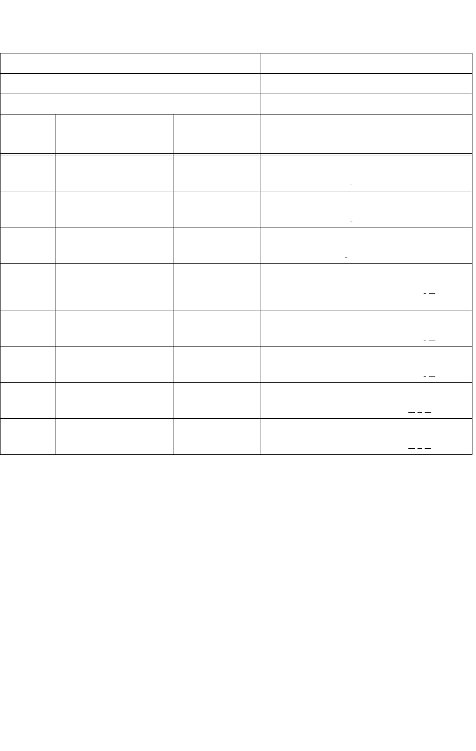
February 2003 RMON Support Specification SLVOS R2.2
- Page 169 -
3.4.6.2.2.5 User History IP SLV Defaults
Ip SLV statistics are available on a per COS and per Path basis. There may be multiple paths created on one circuit.
As paths and COS Ids are added, it is very hard to come up with a clean mapping of user history indices to the circuit/
path. The user history indices starting from 20000 onwards are used for IP SLV statistics.
6 Rx Errors deltaValue(2) ifInErrors
.1.3.6.1.2.1.2.2.1.14.I
7 Tx Errors deltaValue(2) ifOutErrors
.1.3.6.1.2.1.2.2.1.20.I
8Link Speed
Network Interface Only
absoluteValue(1) ifSpeed
.1.3.6.1.2.1.2.2.1.5.I
9 - 12 Port Burst Upper Limits 1
- 4
Network Interface Only
absoluteValue(1) devFrExtLinkUtilUpLimit
.1.3.6.1.4.1.1795.2.24.2.6.9.4.10.3.1.2.I.N
13 - 17 Rx Port Burst Octets 1 - 5
Network Interface Only
deltaValue(2) devFrExtLinkUtilRxOctets
.1.3.6.1.4.1.1795.2.24.2.6.9.4.10.3.1.3.I.N
18 - 22 Tx Port Burst Octets 1 - 5
Network Interface Only
deltaValue(2) devFrExtLinkUtilTxOctets
.1.3.6.1.4.1.1795.2.24.2.6.9.4.10.3.1.4.I.N
23 - 28 IP Top Listeners (1 - 6) absoluteValue(1) devRmonIPTopNDstIP
.1.3.6.1.4.1.1795.2.24.2.13.1.2.1.4.H.T.N
29 - 34 IP Top Talkers (1 - 6) absoluteValue(1) devRmonIPTopNSrcIP
.1.3.6.1.4.1.1795.2.24.2.13.1.2.1.6.H.T.N
Table 3-28. Network PPP Group (2 of 2)
Number of Default Groups for this Interface 2
Value of usrHistoryControlBucketsRequested for each group 5, 96
Value of usrHistoryControlInterval for each group 86400 (24 hours), 900 (15 minutes)
usrHistory
Object
Index Name
usrHistoryObect
SampleType Tag / OID
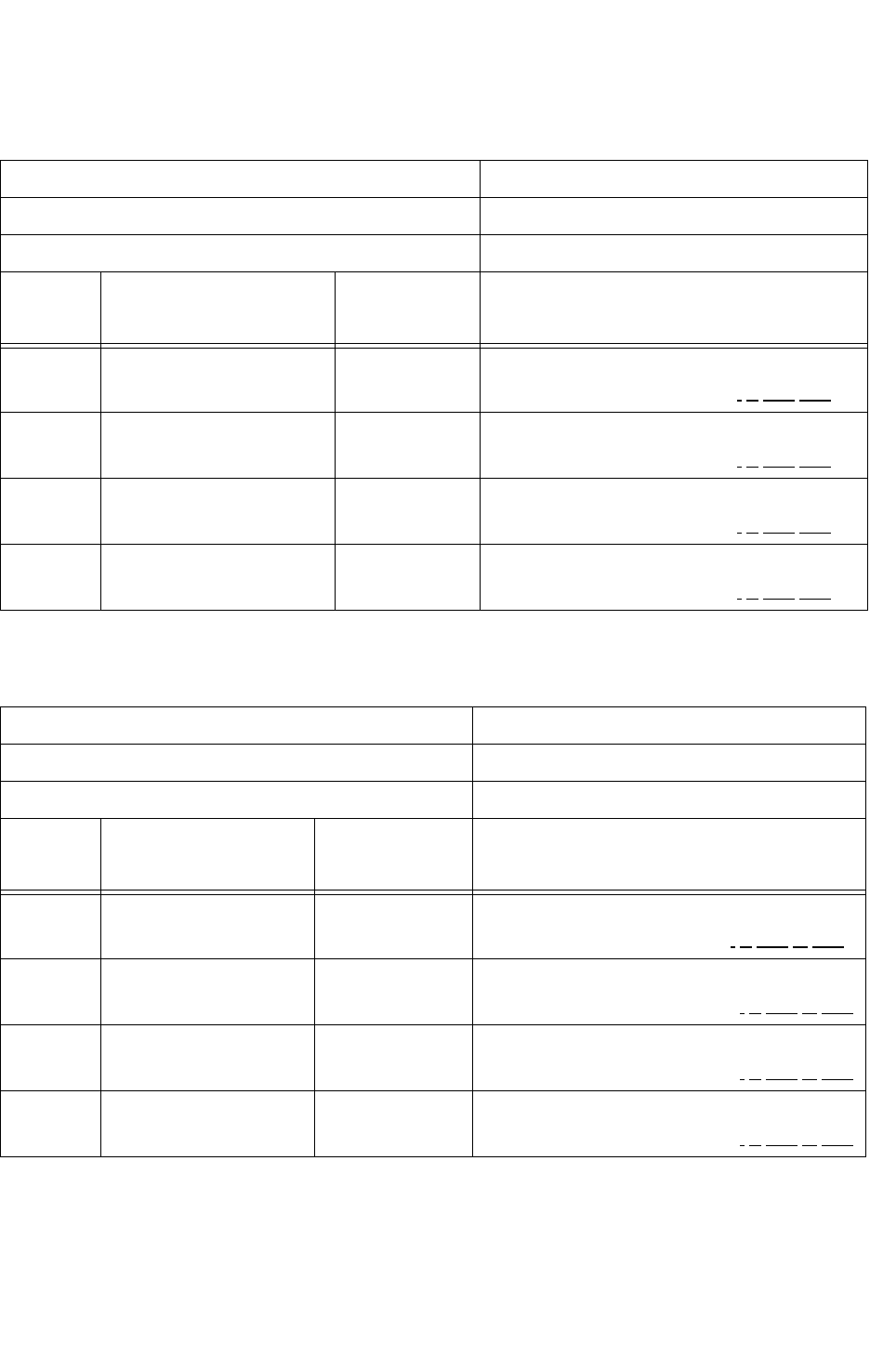
RMON Support Specification SLVOS R2.2 February 2003
- Page 170 -
The following user history group has the Tx/Rx packets for a Circuit and a COS Id.. Note that the COS Id includes
upto 7 COS Ids, Unknown and Non-Ip. When the device is in PPP mode, the Circuit Id will be set to Zero.
The following user history group has the Path latency statistics.
Table 3-29. Network Circuit Class of Service Group
Number of Default Groups for this Interface 2
Value of usrHistoryControlBucketsRequested for each group 5, 96
Value of usrHistoryControlInterval for each group 86400 (24 hours), 900 (15 minutes)
usrHistory
Object
Index Name
usrHistoryObect
SampleType Tag / OID
1 Tx packets per Circuit per
COS
deltaValue(2) devSLVIPCktStatTxPkts
.1.3.6.1.4.1795.2.24.2.12.4.3.1.5.I.D.Sub.Cos
2 Tx octets per Circuit per
COS
deltaValue(2) devSLVIPCktStatTxOctets
.1.3.6.1.4.1795.2.24.2.12.4.3.1.6.I.D.Sub.Cos
3 Rx packets per Circuit per
COS
deltaValue(2) devSLVIPCktStatRxPkts
.1.3.6.1.4.1795.2.24.2.12.4.3.1.7.I.D.Sub.Cos
4 Rx octets per Circuit per
COS
deltaValue(2) devSLVIPCktStatRxOctets
.1.3.6.1.4.1795.2.24.2.12.4.3.1.8.I.D.Sub.Cos
Table 3-30. Path Class of Service Group (1 of 2)
Number of Default Groups for this Interface 2
Value of usrHistoryControlBucketsRequested for each group 5, 96
Value of usrHistoryControlInterval for each group 86400 (24 hours), 900 (15 minutes)
usrHistory
Object
Index Name
usrHistoryObect
SampleType Tag / OID
1 Average RTT per Path per
COS
absoluteValue(1) devSLVIPPathStatByCOSAvgRTT
.1.3.6.1.4.1795.2.24.2.12.4.2.1.9.I.D.Sub.Ip.Cos
2 Maximum RTT per Path
per COS
absoluteValue(1) devSLVIPPathStatByCOSMaxRTT
.1.3.6.1.4.1795.2.24.2.12.4.2.1.10.I.D.Sub.Ip.Cos
3 COS Unavailable
Seconds
deltaValue(2) devSLVIPPathStatByCOSUas
.1.3.6.1.4.1795.2.24.2.12.4.2.1.18.I.D.Sub.Ip.Cos
4 Tx packets per Path per
COS
deltaValue(2) devSLVIPPathStatByCOSTxPkts
.1.3.6.1.4.1795.2.24.2.12.4.2.1.12.I.D.Sub.Ip.Cos

February 2003 RMON Support Specification SLVOS R2.2
- Page 171 -
The following user history group has the Path availability statistics.
3.4.6.2.2.6 User History Application Defaults
Application statistics are available on a per Circuit basis and a per Path basis. There may be multiple paths created on
one circuit. The user history indices starting from 15000 to 19998 are used for per circuit application user history. The
user history indices starting from 25000 29998 are used for per circuit application user history
The following user history group has the Tx/Rx octects for an each defined application. Note that the size of the table
will be based on the number of application configured to be monitored. There are 7 applications that are always
defaulted on and 10 others that the user can configure. The P field in the OID indicates what the protocol is. Also
5 Rx packets per Path per
COS
deltaValue(2) devSLVIPPathStatByCOSRxPkts
.1.3.6.1.4.1795.2.24.2.12.4.2.1.14.I.D.Sub.Ip.Cos
6 Dropped packets per Path
per COS
deltaValue(2) devSLVIPPathStatByCOSDropPkts
.1.3.6.1.4.1795.2.24.2.12.4.2.1.16.I.D.Sub.Ip.Cos
7 Tx octets per Path per
COS
deltaValue(2) devSLVIPPathStatByCOSTxOctets
.1.3.6.1.4.1795.2.24.2.12.4.2.1.13.I.D.Sub.Ip.Cos
8 Rx octets per Path per
COS
deltaValue(2) devSLVIPPathStatByCOSRxOctets
.1.3.6.1.4.1795.2.24.2.12.4.2.1.15.I.D.Sub.Ip.Cos
9 Dropped octets per Path
per COS
deltaValue(2) devSLVIPPathStatByCOSDropOctets
.1.3.6.1.4.1795.2.24.2.12.4.2.1.17.I.D.Sub.Ip.Cos
Table 3-31. Path of Service Group
Number of Default Groups for this Interface 2
Value of usrHistoryControlBucketsRequested for each group 5, 96
Value of usrHistoryControlInterval for each group 86400 (24 hours), 900 (15 minutes)
usrHistory
Object
Index Name
usrHistoryObect
SampleType Tag / OID
1 Path Inactive Seconds deltaValue(2) devSLVIPPathConnectInactiveSecs
.1.3.6.1.4.1795.2.24.2.12.4.1.1.14.I.D.Sub.Ip
Table 3-30. Path Class of Service Group (2 of 2)
Number of Default Groups for this Interface 2
Value of usrHistoryControlBucketsRequested for each group 5, 96
Value of usrHistoryControlInterval for each group 86400 (24 hours), 900 (15 minutes)
usrHistory
Object
Index Name
usrHistoryObect
SampleType Tag / OID

RMON Support Specification SLVOS R2.2 February 2003
- Page 172 -
understand that when a protocol is added or deleted, all of these groups will be deleted and re-acquired. therefore user
history is lost on a configuration of the protocols/application.
3.4.7 Probe Configuration Behavior and Defaults
This group provides probe specific configuration items. The only item that is supported in this group is the
probeCapabilities (probeConfig 1). It describes which tables and items are supported by the device. The value is a
bitmask with the following legal values:
• etherStats 0x80000000
• historyControl 0x40000000
• etherHistory 0x20000000
• alarm 0x10000000
• hosts 0x08000000
• hostTopN 0x04000000
• matrix 0x02000000
• filter 0x01000000
• capture 0x00800000
• event 0x00400000
• tokenRingMLStats 0x00200000
• tokenRingPStats 0x00100000
• tokenRingMLHistory0x00080000
• tokenRingPHistory 0x00040000
• ringStation 0x00020000
• ringStationOrder 0x00010000
• ringStationConfig 0x00008000
• sourceRouting 0x00004000
Table 3-32. Network Circuit Class of Service Group
Number of Default Groups for this Interface 2
Value of usrHistoryControlBucketsRequested for each group 5, 96
Value of usrHistoryControlInterval for each group 86400 (24 hours), 900 (15 minutes)
usrHistory
Object
Index Name
usrHistoryObect
SampleType Tag / OID
odd Protocol Octets TX
(for up to 17 protocols)
deltaValue(2) protocolDistStatsOctets
.1.3.6.1.4.1795.2.24.2.13.4.1.1.9.P
.I.x.D.0.Ip.0
even Protocol Octets RX
(for up to 17 protocols)
deltaValue(2) protocolDistStatsOctets
.1.3.6.1.4.1795.2.24.2.13.4.1.1.10.P.I.x.D.0.Ip.0

February 2003 RMON Support Specification SLVOS R2.2
- Page 173 -
• protocolDirectory 0x00002000
• protocolDistribution0x00001000
• addressMapping 0x00000800
• nlHost 0x00000400
• nlMatrix 0x00000200
• alHost 0x00000100
• alMatrix 0x00000080
• usrHistory 0x00000040
• probeConfig 0x00000020
The value will be reported as 0x10400060, 0x00400060 or 0x10403460 respectively for layer 2 only with SLM, layer
2 only without SLM and layer 3 and above devices.
3.5 Paradyne RMON Extensions Information
3.5.1 Paradyne IP Top N Behavior
The Paradyne IP Top N Group uses the information from the nlHostTable (Network Layer Host Group Behavior and
Defaults on page 145) to calculate the top N talkers. The value N is defined by devRmonIPTopNCount. It is set to 6
and is currently not adjustable.
Rows can only be added to this table when it is referenced internally. This means that the user would have to add it to
user history to get it to work. It should be noted that the value of devRmonIPTopNTime should exactly match that of
usrHistoryControlInterval or it will not update properly.
3.5.2 Paradyne User History Extensions
The User History extensions group currently provides a mechanism to help the User History Bulk Collector (Paradyne
User History Bulk Collector on page 174). It can be used to set filter conditions, control whether history data is desired,
and get information about the upload.
3.5.2.1 RMON Extensions UHBC Filter Variables
Four specific variables are provided to control the filtering of data. The have the following behavior:
Table 3-33. UHBC Filter Variables (1 of 2)
Object Filter Behavior
devRmonUHBCFilter When set to controlAndObjectsOnly(1), this causes the file to contain only the
configuration information with NO history.
When set to smartHistory(2), this causes the file to only include the configuration
information when the configuration has changed. At the request of the NMS group,
configuration for all groups will be returned if any one item in any one group has
changed.
devRmonUHBCBaseTime This filter only applies if it is both greater than zero and the key filter,
devRmonUHBCKey, does not override it. If the any RMON control has been modified
since the time in devRmonUHBCBaseTime, all controls will be returned. Otherwise,
no controls will be returned. The history data returned will only include that history
that has an end time, usrHistoryIntervalEnd, greater than the time filter.

RMON Support Specification SLVOS R2.2 February 2003
- Page 174 -
3.5.2.2 RMON Extensions UHBC Upload Information
If at any point an upload fails while in progress, the NMS should check the value contained in
devRmonUHBCReasonCode. This can provide more information about why the device thinks that it quit sending the
data.
3.5.3 Paradyne Path Alarm Group
The path alarm group is a table containing mapping entries for the alarms created for the path latency.
3.6 Paradyne User History Bulk Collector
The user history bulk collector is a virtual file provided to the end user through the FTP interface. The file is generated
during the process of uploading in such a way that it requires very little internal memory and produces accurate, up-
to-date information.
The read-only file can be found at:
/data/uhbcfull.dat
Performing an FTP get operation will transparently cause the file to be generated. To the user, it will appear that the
entire file exists on the device.
3.6.1 User History Bulk Collector Stream Details
The file data delivered through this process is in the format of the syntax specified below. This syntax is designed to
be parsed easily with at most one character look ahead, to reduce the total amount of data generated, and to cover all
possible results.
Syntax Rules
The syntax is described in the form of a pseudo BNF grammar for which each major piece of the grammar is handled
by a state described above. The following definitions apply.
<...> represents exactly one instance of the contents
[...] represents zero or one instance of the contents
{...} represents zero or more instances of the contents
::= represents a syntax assignment operation which assigns the left part of the operator to the right
(...) represents the name for the instance immediately to the left
=> represents the semantic definition associated with the suffix
devRmonUHBCKey A key is kept in nonvolatile RAM to let the user known when the RMON database has
been reset. If devRmonUHBCKey is set to a value other than zero, the collection will
ignore any time filter that is set and return all of the information.
devRmonUHBCOwner This filter is applied after the time filter, devRmonUHBCBaseTime, is applied and is
only valid when the length of the string to filter is greater than zero. This filter limits
the data returned to only that which is contained in controls with owner strings that
match the string set here.
Table 3-33. UHBC Filter Variables (2 of 2)
Object Filter Behavior

February 2003 RMON Support Specification SLVOS R2.2
- Page 175 -
Syntax Definition
•stream ::= <streamVersion><rmonKey><sysUpTime>{rowData}[networkTime]<eot>
=>
This is the complete data stream for all the information. Zero or more row data objects are included in
the stream. How it is determined which row is put into the stream is implementation specific. For this
implementation, this is determined through an enterprise MIB (See “RMON Extensions UHBC Filter
Variables” on page 173.) If no rows exist, no rows will be returned in the stream; however, the network
time, system up time, and RMON key will be returned.
NOTE: The networkTime item is new for version 2 of the stream. It is put at the end of the stream to
reduce the impact of its addition on older versions of the NMS.
•streamVersion ::= <octet>
=>
This is a byte defining the version of the syntax used to define the stream. For this release is, it defined
as version 2.
•rmonKey ::= <integer32>
=>
This is a key that represents the global version of the data in user history. This key increments each time
user history as a whole is reset. It will never equal 0. A change to the key means that ALL of the user
history information, including configuration, for every row MAY have changed.
•sysUpTime ::= <integer32>
=>
The current 32 bit integer value of the RFC 1213 defined variable sysUpTime for the device.
•rowData ::= <tag(rowData)><rowUpSince><rowIfIndex><rowDLCI/VPI>
<rowUHIndex><ctlInterval>[rowVCI][ctlData][objData][historyData]
=>
A row in the user history tables. Where each row has a control, a set of objects associated with the control,
and a set of history associated with the objects. It should be noted that none of the ctlData, objData and
historyData objects are required by the syntax. Filters may be applied to the data such that some or all of
these objects are not returned.
NOTE: The rowDLCI name has changed to rowDLCI/VPI and the optional field rowVCI has been
added for ATM support. This addition affects only version 2 of the stream.
•rowUpSince ::= <int>
=>
This is the value of the RFC 1213 defined variable sysUpTime at the time the row defined by
rowUHIndex was last modified.
•rowIfIndex ::= <int> | <unavailable>
=>
The value of the RFC 1213 defined ifIndex associated with the row defined by rowUHIndex or
unavailable if this is not known.

RMON Support Specification SLVOS R2.2 February 2003
- Page 176 -
•rowDLCI/VPI ::= <int> | <unavailable>
=>
The DLCI or VPI number associated with the row defined by rowUHIndex or unavailable if this is not
known.
•rowVCI ::= <int>
=>
The VCI number associated with the row defined by rowUHIndex. If this number is not known or not
applicable, this field will simply not show up in the stream.
NOTE: This item is added as part of version 2 of the stream. It is designed to help with ATM devices
and should not affect any frame relay devices.
•rowUHIndex ::= <int>
=>
The value of the RFC 2021 defined variable usrHistoryControlIndex for the row of interest.
•ctlData ::= <tag(ctlData)><ctlObjects><ctlBuckets><ctlOwner>
=>
The control data for the row of interest.
•ctlObjects ::= <int>
=>
The value of the RFC 2021 defined variable usrHistoryControlObjects for the row of interest.
•ctlBuckets ::= <int>
=>
The value of the RFC 2021 defined variable usrHistoryControlBucketsGranted for the row of interest.
•ctlInterval ::= <int>
=>
The value of the RFC 2021 defined variable usrHistoryControlInterval for the row of interest.
•ctlOwner ::= <string>
=>
The value of the RFC 2021 defined variable usrHistoryControlOwner for the row of interest.
•objData ::= <tag(objData)>{oidData}
=>
The object data for the row of interest. This will be a list of one oidData element for each row in the
usrHistoryObject table for the rowUHIndex. The index, usrHistoryObjectIndex, is one plus the distance
of the oidData element from the first oidData element.
•oidData ::= <tag(oidData)><berOID>
=>
The object identifier information for the object of interest. The value of tagInfo for this object is used as
follows to map the value of the RFC 2021 defined variable usrHistoryObjectSampleType:
0x1 = absoluteValue
0x2 = deltaValue

February 2003 RMON Support Specification SLVOS R2.2
- Page 177 -
•historyData ::= <tag(historyData)>{historyItem}
=>
The history data for the usrHistoryTable associated with rowUHIndex. There will be one historyItem for
each object in the usrHistoryObject table. These will be ordered exactly the same as the objData.
•historyItem ::= <tag(historyObjects)><historyIndex><historyStartTime>{historyObject}
=>
The history data specific to the usrHistoryObject of interest. There will be one historyObject per known
index after some specified starting index.
•historyIndex ::= <int>
=>
The value of the RFC 2021 defined variable usrHistorySampleIndex that marks the start of a collection
group.
•historyStartTime ::= <int>
=>
The time history collection started for the index of interest.
•historyObject ::= [timeDelta]<historyValue>
=>
This is the actual data in a history row. The timeDelta will only be present if it is required. The base for
the timeDelta will be the last start time + (interval * 100).
•historyValue ::= <unchanged> | <unavailable> | <int>
=>
The value of the history data for the interval of interest. A value of unchanged means that the value has
not changed since the previously known interval. A value of unavailable means that the value is not
available for the interval of interest.
•unchanged ::= <tag(unchanged)>
=>
A representation of a value that has not changed since the previously known representation of the same
object.
•int ::= <tag(integer)><octet(1)>[<octet(2)>[...[<octet(n)>]]]
=>
A signed integer that requires n octets to contain its value. The value of n is defined as the length portion
of the tagLength. The value of the integer is calculated as follows (ANSI C):
(sign) * ((octet(1) << ((length - 1) << 3)) | (octet(2) << ((length -2) << 3)) | ... | octet(n))
•unavailable ::= <tag(unavailable)>
=>
A representation of a value that is not currently available or is unknown.
•string ::= <tag(string)><berString>
=>
An octet string.

RMON Support Specification SLVOS R2.2 February 2003
- Page 178 -
•berString ::= <BER encoded string>
=>
All strings are represented as BER type encoded strings. This object follows the BER rules for encoding
octet strings as defined in SMIv1.
•berOID ::= <BER encoded OID>
=>
All OIDs are represented as BER type encoded OIDs. This object follows the BER rules for encoding
OIDs as defined in SMIv1.
•timeDelta ::= <tag(timeDelta)><octet(1)>[<octet(2)>.[..[<octet(n)>]]]
=>
The value of the change between the current time value and the previously know time value. This is
represented as a signed integer that requires n octets to contain its value. The value of n is defined as the
length portion of the tagLength. The value of the integer is calculated as follows (ANSI C):
(sign) * ((octet(1) << ((length - 1) << 3)) | (octet(2) << ((length -2) << 3)) | ... | octet(n))
•eot ::= <tag(eot)>
=>
A special tag used to mark the end of transmission.
•tag ::= <tagName><tagLength> | <tagName><tagInfo> | <tagName><emptyNibble>
=>
A tag identifying a region of the stream. The tag itself has two parts: a name and some other piece of
information. The additional information is either a length, some specific piece of data, or nothing.
•tagName ::= <nibble>
=>
The name of a specific tag. The following names are defined in this version of the syntax:
tag(valueUnchanged) ::= 0x0
tag(integer) ::= 0x1
tag(unavailable) ::= 0x2
tag(string) ::= 0x3
tag(timeDelta) ::= 0x4
tag(rowData) ::= 0x5
tag(ctlData) ::= 0x6
tag(objData) ::= 0x7
tag(historyData) ::= 0x8
tag(historyObjects) ::= 0x9
tag(oidData) ::= 0xA
tag(nrt) ::= 0xB
tag(eot) ::= 0xF

February 2003 RMON Support Specification SLVOS R2.2
- Page 179 -
•tagLength ::= <nibble>
=>
A sign bit followed by the length of the data that follows minus 1. A length of zero is not valid in that
this is equivalent to unavailable. If the sign bit is 1, the value is negative. This value only has meaning
for the specific tagName objects tag(integer), tag(nrt) and tag(timeDelta).
•tagInfo ::= <nibble>
=>
A nibble which contains a value which has a use defined in the semantics of the object using it. For this
version of the stream, the only tag object using this is tag(oidData).
•emptyNibble ::= <nibble>
=>
A special case for a nibble which is always equal to 0x0.
•octet ::= 0x00 | 0x01 | ... | 0xFF
=>
An 8 bit integer.
•nibble ::= 0x0 | 0x1 | ... | 0xF
=>
A 4 bit integer. Two nibbles make one octet.
•integer32 ::= <octet(1)><octet(2)><octet(3)><octet(4)>
=>
A 32 bit integer whose value in ANSI C notation is:
(octet(1) << 24) | (octet(2) << 16) | (octet(3) << 8) | octet(4)
•networkTime ::= <tag(nrt)t>[<octet(2)>[...[<octet(n)>]]]
=>
This is the time that the device believes is the network reference time. It is reported as the number of
seconds past midnight and will never be greater than 86399 to keep within 24 hours of user history
synchronization. If the sign of the integer is negative, than the device is not synchronized and the absolute
value of the integer represents the device local time. Otherwise, the value of the integer is the network
reference time and the device thinks that the network is synchronized. The value of the integer is
calculated as follows (ANSI C):
(sign) * ((octet(1) << ((length - 1) << 3)) | (octet(2) << ((length -2) << 3)) | ... | octet(n))
4. NOTE: This item is new for version 2 of the stream. It is added to help synchronize the data from several
devices in the network.

RMON Support Specification SLVOS R2.2 February 2003
- Page 180 -

- Page 181 -
Index
A
ADSL-LINE-MIB, 73
af-ilmi-0065.000, 94
af-nm-0095.001, 95
alarms
Alarm Group behavior and defaults in RMON, 131
defaults, 133
setting, 132
ATM
Cell Logical Layer ifDescr, 26
Extension, 89
Forum MIBs, 93
FR/ATM Service Interworking MIB, 63
Interface Configuration Parameters Table, 62
M4 Extension, 89
M4 MIB, 95
MIB, 61
Authentication Failure Trap, 100
B
Bridge MIB, 74
C
Card Type Configuration, 80
Cause Strings, 119
Channel Configuration, 84
Circuit Group, 55
Circuit Identifier MIB, 93
Clock Interface, 80
Clock Source, 80
Copy Configuration Area, 79
copyrights, A
counters
input, 34
output, 34
D
Data Link Connection Management Interface Related
Traps Group, 57
DDS Interface Specific Definitions, 81
Device
Configuration MIB, 79
Control, 84
Health and Status, 84
Identity, 88
names, 3
Security, 84
Traps, 84
Dial Control
Extension, 89
MIB, 70
MIB Traps, 106
DLCI Table, 85
DLCMI Group, 52
dot3StatsTable, 45
Drafts, RFC, 92
DS1
Extension Configuration, 83
Far End Group, 49
Fractional Group, 50
Near End Group, 46
DS3 Extension, 83
DS3/E3
MIB, 50
Near End Group, 51
E
Enterprise
MIB Traps, 106
MIBs, 79
RMON extensions, 173
Specific Traps, 103
Error Group, 56
EtherLike-MIB, 44
event log, 142
F
Far End Group (DS1), 49
Feature Group, 89
FR/ATM
PVC Service IWF Connection Descriptor Group, 64
PVC Service IWF Group, 63
Service Interworking MIB, 63
Index
- Page 182 -
Frame Relay
DLCI Table, 85
Extension, 85
Logical Layer, ifDescr, 23
PVC Cross Connect, 84
PVC Test, 84
Trap Control Group, 57
FRAME-RELAY-DTE-MIB, 52
frDlcmiMaxSupportedVCs, 53
FRNETSERV-MIB, 57
G
glossary, v
I
ifAdminStatus, 30
ifConnectorPresent, 37
ifDescr, 21
ifHighSpeed, 37
ifIndex, 6
in RMON, 127–128
ifLastChange, 34
ifLinkUpDownTrapEnable, 37
IF-MIB, 35
Extension, 88
ifMIB, in RMON, 127
ifMtu, 29
ifName, 36
ifNumber, 6
ifOperStatus, 32
ifSpecific, 35
ifSpeed, 29
ifStackTable, 37
ifTable, 6
ifType, 27
ILMI MIB, 94
input counters, 34
Interface Stack Group, 37
Interface Test Group, 38
Interfaces Group, 6
Internet Drafts, 92
IP Ping Test, 90
IP Route Extension, 84
IP SLV Configuration, 91
ISDN
B-Channel ifDescr, 26
Extension, 89
L
Latency Table, 86
Link Up and Link Down Traps, 101
LMI Parameters, 53
Logical Port Group, 57
M
Management VC Signaling Group, 58
maximum number of VCs, 53
MIB-II, 1
model/feature numbers, 3
N
NAM types, 3
Near End Group
DS1, 46
DS3/E3, 51
NetScout
ifIndex, 20
Network Layer Host Group, 145
O
OCU Port Configuration, 83
organization of this document, v
output counters, 34
Overview
RMON, 125
Traps, 99
P
Paradyne
Enterprise MIBs, 79
RMON extensions, 173
patents, A
Peer Configuration Table, 70
Physical Layer ifDescr, 21
Physical Logical Layer ifDescr, 23
Ping Test, 90
PPP Logical Layer ifDescr, 25
product-related documents, vi
Protocol Directory Group, 142
Protocol Distribution Group, 144
PVC End-point Group, 59
R
RFC 1213, 1
RFC 1406, 46
RFC 1493, 74
RFC 1513, 126
RFC 1604, 57
RFC 1659, 64
RFC 1757, 70, 130
RFC 2021, 70, 126, 130
RFC 2115, 52
RFC 2128, 70
Index
- Page 183 -
RFC 2496, 50
RFC 2515, 61
RFC 2613, 126
RFC 2662, 73
RFC 2665, 44
RFC 2819, 126
RFC MIBs, 1
RMON
alarm behavior, 131
Extension, 88
future, 126
groups supported, 126
Paradyne extensions, 173
relation to ifMIB, 127
RMON-II, 126
RMON-III, 126
row status mechanism, 130
Specific Traps, 106
Version 1 MIB, 70
Version 2 MIB, 70
row status mechanism, 130
RS-232-MIB, 64
S
Service, A
SLV Configuration, 91
SMIv2
row status mechanism, 130
SMON, 126
SNMP
trap-related events, 140
SNMP Group, 44
STP Group, 76
suggestions, user documentation, A
Synchronous Data Port Configuration, 83
sysDescr, 2
sysObjectID, 3
sysServices, 5
System Group (mib-2), 2
T
Test
Strings, 121
using the M4 MIB for, 97
testString, 121
testString Table, 121
trademarks, A
Training, A
Transmission Group, 43
Trap
Identification, 100
Overview, 99
Packet, 100
Priority, 107
Strings, 109
Variable Bindings, 122
trap-related events, 140
U
UHBC
Filter Variables, 173
Upload Information, 174
User History
behavior, 145
Bulk Collector, 174
Defaults, 150
retrieving, 148
setting, 146
V
Variable Bindings, 122
VCs, maximum number of, 53
Voice Configuration, 83
W
Warm Start Trap, 100
warranty, A
Website
access to documentation, vi
glossary, v
Index
- Page 184 -
