Tek_Pubs 908 0106 Cummins QSK78 Genset Installation & Alignment Manual (10 2009)
User Manual: 908-0106 Cummins QSK78 Genset Installation & Alignment manual (10-2009)
Open the PDF directly: View PDF ![]() .
.
Page Count: 32
- 1 Safety
- 2 Preparation
- 3 Alignment Procedure
- 4 Final Assembly
- 5 Illustrations
- 5.1 Alignment of Flexible Coupling to Engine Flywheel – Tolerance Information
- Alignment of Flexible Coupling to Engine Flywheel – Clock Gauge Set up
- Radial Alignment of Gearbox to Engine Calculation
- Angular Alignment of Gearbox to Engine (Calculation Sheet 1 of 2)
- 5.5 Angular Alignment of Gearbox to Engine (Calculation Sheet 2 of 2)
- 5.6 Gearbox Shear Pin Coupling – Component Identification
- Gearbox Shear Pin Coupling – Disassembly and Re-Assembly
- 5.8 Roller Bearing Assembly
- 5.9 Alternator to Gearbox Axial Alignment in Vertical/Horizontal Axis
- 5.10 Alternator to Gearbox Alignment – Angular Alignment

English – Original Instructions 10-2009 0908-0106 (Issue 2)
Installation and Alignment Procedure
QSK78 Generator Set
for Eickhoff ANO 110 Gearbox


Eickhoff ANO 110 Gearbox Publication 0908-0106
Installation and Alignment Issue 2 – 10-2009
FOREWORD
This document details the work procedure for the coupling and alignment of a QSK78 generating set with a
Frame 8 HV Alternator via the single stage helical gearbox using dial gauge indicators. This instruction
should be read in accordance with the operating manual provide by the gearbox manufacturer. The tasks in
this manual are to be undertaken by suitably trained and qualified service personnel only.
This manual should form part of the publication package supplied by Cummins Power Generation Limited
with specific generator sets. In the event that this manual has been supplied in isolation please refer to other
Cummins Power Generation Limited literature, in particular the Health and Safety Manual (0908-0110-00),
Product Operation and Maintenance, and Engine Operation Manuals regarding all aspects of the equipment.
The purpose of this manual is to provide the users with sound, general information. It is for guidance and
assistance with recommendations for correct and safe procedures. Cummins Power Generation Limited
cannot accept any liability whatsoever for problems arising as a result of following recommendations in this
manual.
The information contained within the manual is based on information available at the time of going to print. In
line with Cummins Power Generation Limited policy of continuous development and improvement,
information may change at any time without notice. The users should therefore ensure that before
commencing any work, they have the latest information available.
Users are respectfully advised that it is their responsibility to employ competent persons to carry out any
installation work in the interests of good practice and safety.
Should you require further assistance contact: -
Cummins Power Generation
1400 73rd Avenue NE
Minneapolis
MN 55432
USA
Tel:+1 (763) 574-5000
Fax:+1 (763) 574-5298
e-mail: pgamail@cummins.com
Cummins Power Generation
Columbus Avenue
Manston Park
Manston
Ramsgate
Kent CT12 5BF
United Kingdom
Tel:+44 (0) 1843 255000
Fax:+44 (0) 1843 255902
e-mail: cpgk.uk@cummins.com
Cummins Power Generation
10 Toh Guan Road #07-01
TT International Tradepark
Singapore 608838
Tel: (65) 6417 2388
Fax:(65) 6417 2399
e-mail: cpg.apmktg@cummins.com
Web: www.cumminspower.com Web: www.cumminspower.com Web: www.cumminspower.com
Cummins Power Generation
35A/1/2, Erandawana
Pune 411 038
India
Tel.: (91 020) 6602 7525
Fax: (91 020) 6602 8090
e-mail: cpgindia@cummins.com
Cummins Power Generation
Rua Jati, 310 - Cumbica
Guarulhos –SP
Brazil
CEP: 07180-900
Tel.: (55 11) 2186 4195
Fax: (55 11) 2186 4729
e-mail: falecom@cumminspower.com.br
Web: www.cumminspower.com Web: www.cumminspower.com

Publication 0908-0106 Eickhoff ANO 110 Gearbox
Issue 2 – 10-2009 Installation and Alignment
THIS IS A BLANK PAGE

Eickhoff ANO 110 Gearbox Publication 0908-0106
Installation and Alignment Issue 2 – 10-2009
Contents Page i
CONTENTS
Section Title Page
1 Safety................................................................................................................................. 1-1
2 Preparation........................................................................................................................ 2-1
2.1 Preparation of Flexible Coupling................................................................................................. 2-1
2.2 Preparation of bedframe ............................................................................................................. 2-2
2.3 Preparation of gearbox coupling .................................................................................................2-2
2.3.1 Disassembly ......................................................................................................................... 2-2
2.4 Fitment of Alternator Hub ............................................................................................................ 2-2
2.4.1 Fitment of Gearbox Hub ....................................................................................................... 2-3
3 Alignment Procedure .......................................................................................................3-1
3.1 Gearbox to Engine Coupling ....................................................................................................... 3-1
3.1.1 Radial Alignment (Vertical/Horizontal).................................................................................. 3-1
3.1.2 Angular Alignment ................................................................................................................ 3-2
3.2 Alternator to Gearbox Coupling................................................................................................... 3-3
3.2.1 Radial Alignment (Vertical & Horizontal) .............................................................................. 3-3
3.2.2 Angular Alignment ................................................................................................................ 3-3
3.2.3 Lubrication ............................................................................................................................ 3-3
4 Final Assembly .................................................................................................................4-1
4.1 Special Tools Required: .............................................................................................................. 4-1
5 Illustrations ....................................................................................................................... 5-1
5.1 Alignment of Flexible Coupling to Engine Flywheel – Tolerance Information............................. 5-1
5.2 Alignment of Flexible Coupling to Engine Flywheel – Clock Gauge Set up ............................... 5-2
5.3 Radial Alignment of Gearbox to Engine Calculation................................................................... 5-3
5.4 Angular Alignment of Gearbox to Engine (Calculation Sheet 1 of 2)......................................... 5-4
5.5 Angular Alignment of Gearbox to Engine (Calculation Sheet 2 of 2).......................................... 5-5
5.5.1 Calculation of Angular Alignment ......................................................................................... 5-5
5.6 Gearbox Shear Pin Coupling – Component Identification .......................................................... 5-7
5.7 Gearbox Shear Pin Coupling – Disassembly and Re-Assembly ................................................ 5-8
5.8 Roller Bearing Assembly............................................................................................................. 5-9
5.9 Alternator to Gearbox Axial Alignment in Vertical/Horizontal Axis............................................ 5-11
5.10 Alternator to Gearbox Alignment – Angular Alignment ............................................................. 5-12

Publication 0908-0106 Eickhoff ANO 110 Gearbox
Issue 2 – 10-2009 Installation and Alignment
Page ii Contents
THIS IS A BLANK PAGE

Eickhoff ANO 110 Gearbox Publication 0908-0106
Installation and Alignment Issue 2 – 10-2009
Section 1 –Safety Page 1-1
SECTION 1 – SAFETY
1 Safety
The tasks in this manual are to be undertaken by suitably trained and qualified service personnel
only.
Before commencing work, the following instructions should be read:
1. Ensure all personnel not working on the coupling installation and alignment are kept safely
away from immediate area.
2. Read and understand all procedure instructions before coupling installation and alignment.
3. Components should be supported during handling and wrapped for protection.

Publication 0908-0106 Eickhoff ANO 110 Gearbox
Issue 2 – 10-2009 Installation and Alignment
Page 1-2 Section 1–Safety
THIS IS A BLANK PAGE
Eickhoff ANO 110 Gearbox Publication 0908-0106
Installation and Alignment Issue 2 – 10-2009
Section 2 – Preparation Page 2-1
SECTION 2 - PREPARATION
2 Preparation
Note: This task is to be undertaken by suitably trained and qualified service personnel only.
2.1 Preparation of Flexible Coupling
Before the installation begins the flexible coupling can be prepared for installation:
1. The flexible coupling is inspected disassembled.
2. The coupling hub is lifted into the oven and heated to 250oC/482oF for three hours to give
sufficient clearance when it is installed on the gearbox shaft.
3. Fit coupling hub on gearbox shaft and allow to cool.
4. Bolt up hub to the rubber disc with vulcanised metal sleeve. Torque settings for hub bolts on
the AC 11 F2 coupling are for M24 bolts (grade 8.8) 710 Nm.
5. The flange which connects the rubber disk to the flywheel joins by means of an internally
toothed aluminium ring. The torque settings for the bolts securing the SAE 21 flange to the
flywheel are M16 (grade 12.9) 210 Nm.
Note: To carry out the gearbox to engine alignment checks the flange should be dismounted
off the rubber disk, therefore do not bolt up the flange to the flywheel disk at present –
leave it hanging from the coupling hub/gearbox shaft.
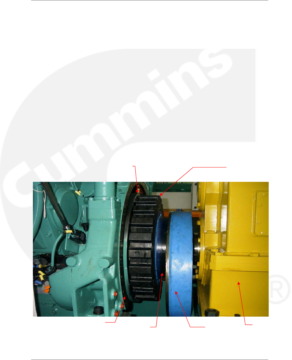
Flywheel Vulcanised Rubber
Coupling
Coupling Hub Coupling Flange
Flywheel Horseshoe Gearbox

Publication 0908-0106 Eickhoff ANO 110 Gearbox
Issue 2 – 10-2009 Installation and Alignment
Page 2-2 Section 2– Preparation
2.2 Preparation of bedframe
To ensure that the engine/gearbox/alternator are accurately aligned the anti vibration spring
mounts must be installed and set-up before commencing the alignment procedure, as detailed
below:
1. Lift engine onto bedframe using appropriate lifting equipment.
2. Line engine square to the bedframe and fit bolts.
3. Tighten bolts to correct torque setting. M24 bolts (grade 8.8) are set to 670Nm.
2.3 Preparation of gearbox coupling
The gearbox coupling is supplied completely assembled with protecting grease on the gear mesh
which should be removed before assembly.
2.3.1 Disassembly
For the disassembly procedure there are two sections to refer to, depending on reader’s
preference. Refer to either Section 5.6 (gearbox shear pin coupling component) or Section 5.7
(gearbox shear pin coupling disassembly and re-assembly instructions). A summary of the
disassembling process for the coupling is as follows:
1. Loosen the nuts (19) and remove bolts (18).
2. Remove screws (21) and sleeve (3).
3. Remove the retainer ring (27) and the wire that connects all the shear pins (8) so that the
shear pins can be removed.
4. Remove retainer ring (24).
5. Remove the cover (28) by pulling the screw installed in the central hole in the cover (28). The
thread size is M10.
6. Remove the retainer ring (23).
7. Using pulling equipment remove the assembly, which houses the inner bearings (4, 9, 11, 12,
13, 20, 22, 31) – see Section 5.8.
8. The shaft (6) is joined to the rigid hub (5) by means of screws (25). Remove the screws (25)
in order to have the rigid hub (5) free for installation on the alternator shaft.
2.4 Fitment of Alternator Hub
1. Check that the coupling hubs and shafts are free from nicks and burrs. Check that the bore
and shaft are clean and are the correct dimensions.
2. Install the rigid hub (5) on the alternator shaft. For an interference fit ISO H7/m6
(0.005inch/inch) the hub requires to be heated to at least 110°C/230°F. The hub should be
heated for 1½ to 2 hours to provide sufficient clearance for fitting, but this is only an
approximate guideline. Install the hub (5) and check that the shaft is flush with counterbore of
the hub.
3. Install stub shaft (6) to the hub (5) and torque the screws/washers (25, 26) to 79 Nm using a
torque wrench.
4. Install the assembly (4, 9, 11, 12, 13, 20, 22, 31) and sleeve (3) onto the shaft (6). Install the
inner retainer ring (23) in the groove of the shaft (6). Install the assembly cover (28) by
pressing it into the hub (4).
5. Install the outer retainer ring (24) in the internal groove of the hub (4).
6. Insert the shear pins (8), which join the hubs (4 and 5) together. Join the shear pins using the
place wire supplied. Install the retainer rings (27) to lock the shear pins in place.
7. Place the cover (7) on the gearbox shaft prior to the installation of the gearbox hub (1).

Eickhoff ANO 110 Gearbox Publication 0908-0106
Installation and Alignment Issue 2 – 10-2009
Section 2 – Preparation Page 2-3
2.4.1 Fitment of Gearbox Hub
1. Heat the gearbox hub (1). For an interference fit ISO H7/m6 (0.005inch/inch) the hub requires
to be heated to at least 110°C/230°F. The hub should be heated for 1½ to 2 hours to provide
sufficient clearance for fitting, but this is only an approximate guideline. Install the hub (1) with
the longest chamfer hub end towards the gearbox bearing. The hub face must be flush with
the end of the shaft. Fit the O-Ring (17) on the hub only after it has cooled down to avoid
damage to the O-Ring and seal (17, 15).
Note: Note do not use an open flame burner to heat hub.
2. Allow the hub to cool before installing the sleeve cover.
3. With the longest chamfer hub end towards the gearbox bearing. Hub face has to be flush with
shaft end. Place ring (17) on the hub only after it cooled down in order to avoid damage of the
seal (15).
4. Allow the hub (1) to cool before installing the sleeve (2).
5. Install the sleeve (3) on hub (4) and cover (29).
6. Install and align machines in place.

Publication 0908-0106 Eickhoff ANO 110 Gearbox
Issue 2 – 10-2009 Installation and Alignment
Page 2-4 Section 2– Preparation
THIS IS A BLANK PAGE

Eickhoff ANO 110 Gearbox Publication 0908-0106
Installation and Alignment Issue 2 – 10-2009
Section 3 – Alignment Procedure Page 3-1
SECTION 3 – ALIGNMENT PROCEDURE
3 Alignment Procedure
Note: This task is to be undertaken by suitably trained and qualified service personnel only.
Radial, angular and axial alignment of the gearbox and alternator in the horizontal axis can be
adjusted by turning the horizontal jacking screws, which are fitted at each corner of the gearbox
and alternator feet. Radial and angular alignment in the vertical axis can be adjusted by adjusting
the vertical jacking screws and shimming under the gearbox and/or alternator.
3.1 Gearbox to Engine Coupling
3.1.1 Radial Alignment (Vertical/Horizontal)
1. Refer to Sections 5.1 to 5.3 for alignment information, clock gauge set up illustrations and an
illustrated demonstration of how to carryout and calculate the coupling alignment.
2. Lift gearbox onto bedframe using appropriate lifting equipment.
3. Set-up the clock gauge as in Section 5.2 with the gauge attached to the coupling hub (fitted
on the gearbox shaft) and the probe in contact with the outer diameter of the flywheel at TDC
(top dead centre). There should be enough clearance to attach the clock gauge and just
enough surface on the outside diameter of the flywheel for the probe to make contact. Zero
the gauge at this point.
4. Rotate the flywheel via the barring gear using a ¾ inch drive ratchet (the flywheel rotates and
coupling hub remains stationary). Rotate one complete revolution taking readings at four
points 90° apart (these readings include the zero reading already taken).
5. Calculate any radial misalignment in the vertical and horizontal axes.
6. Depending on the misalignment offsets calculated, align the gearbox to engine as
appropriate. It may be preferable to align in the horizontal axis to start with by turning one set
of jacking screws (there are two screws/plates for each direction) simultaneously. The vertical
alignment is obtained by adjusting the vertical jacking screws and shimming the gearbox as
necessary.
Publication 0908-0106 Eickhoff ANO 110 Gearbox
Issue 2 – 10-2009 Installation and Alignment
Page 3-2 Section 3– Alignment Procedure
3.1.2 Angular Alignment
1. Refer to Sections 5.1, 5.2, 5.3 and 5.4 for alignment information, clock gauge set up
illustrations and an illustrated demonstration of how to carryout and calculate the coupling
alignment.
2. With the clock gauge still attached to the coupling hub, place the probe so that it makes
contact with the flywheel face (on the outer edge of the face) near TDC (top dead centre) of
the flywheel.
3. Rotate the flywheel as before taking four readings (zero at 0/360°, 90°, 180° and 270°).
4. From the readings at 0/360° and 180° calculate the angular alignment in the vertical axis, and
from the readings at 90° and 270° calculate the angular alignment in the horizontal axis. An
example follows (also see Sections 5.4 and 5.5 for calculation illustrations).
5. The example shows that the angular misalignment was within tolerance and no further
adjustment/shimming was necessary. If the angular alignment is out off tolerance then
shimming or jacking of the gearbox may be required.
6. Once the radial and angular alignment checks have been completed on the gearbox, torque
the holding bolts to their correct settings to firmly secure the gearbox in place using Loctite
242 on bolts.
7. Recheck the alignment once the bolts have been tightened down and if it is still within
tolerance connect the coupling flange back onto the rubber disk and bolt onto flywheel.
Reading Value
1 0/360° 0 (zeroed clock gauge)
2 90° - 0.205 mm
3 180° - 0.050 mm
4 270° - 0.022 mm
Parameter Value
Diameter of measured
surface (flywheel) 1367 mm
Vertical Misalignment inv. tan(reading 1 – reading 3)/(0.5 x dia)
= inv. tan(0 – 0.050)/(0.5 x 1367) = 0.004°
Horizontal Misalignment Inv. tan(reading 2 – reading 4)/(0.5 x dia)
= inv. tan(0.205 – 0.022)/(0.5 x 1367) = 0.0153°
Permissible Misalignment 0.3°
Eickhoff ANO 110 Gearbox Publication 0908-0106
Installation and Alignment Issue 2 – 10-2009
Section 3 – Alignment Procedure Page 3-3
3.2 Alternator to Gearbox Coupling
The better the alignment the longer the coupling life, with the exception that a slight angular
misalignment (0.05°) is advised in order to have good lubrication conditions.
3.2.1 Radial Alignment (Vertical & Horizontal)
1. Section 5.9 illustrates the set up of the clock gauge for measuring any radial misalignment.
Attach the gauge to the hub (4) with the probe contacting the opposite hub (1) alignment
surface. Rotate the hub on which the clock gauge is attached and take four readings 90°
apart. The vertical and horizontal offsets should be less than 0.15 mm (0.006 inch).
2. Using the alignment plates and jacking screws, which are mounted around the alternator,
align/shim the alternator to the gearbox to meet or better the specified offset.
3.2.2 Angular Alignment
1. Section 5.10 illustrates the set up of the clock gauge for measuring the angular misalignment.
2. Attach the gauge to the hub (4) with the probe contacting the opposite hub face (1) surface.
Rotate the hub on which the clock gauge is attached and take four readings 90° apart to
measure the Z and Y offsets shown. The difference between Y – Z should be less than 0.20
mm (0.008 inches). Align by jacking/shimming alternator as required.
3.2.3 Lubrication
1. Once the coupling has been aligned it must be lubricated before operations can commence.
2. Before bolting up the sleeves (2 & 3), approximately 70% of the gear mesh grease is to be
hand packed between the hub (4), the sleeve teeth and surrounding area. Cummins part
number for the grease, its grade and supplier brand name is given below:
Cummins Part Number 550226
Supplier Brand Name Mobil XTC
Grade NLGI No.1 Lithium Soap Base
Quantity used 1.12 kg
3. After tightening the sleeve bolts (18 & 19) the remaining 30% of the grease is pumped into the
sleeve injection holes (14). Both the lubrication plugs at 180° must be removed to vent the
inner space (fill from one to evacuate the air from the other). An air lock can result in
incomplete filling or in damage to the seals.
4. After lubrication tighten the lubrication plugs to 25 Nm.
5. The purpose of lubricating the bearings is to have a good rotating surface whenever the shear
pins might break. The type of grease and Cummins part number is given below.
Cummins Part Number 550224
Supplier Brand Name Valvoline or other
Grade EP2
Quantity used 0.09 kg minimum

Publication 0908-0106 Eickhoff ANO 110 Gearbox
Issue 2 – 10-2009 Installation and Alignment
Page 3-4 Section 3– Alignment Procedure
THIS IS A BLANK PAGE

Eickhoff ANO 110 Gearbox Publication 0908-0106
Installation and Alignment Issue 2 – 10-2009
Section 4 – Final Assembly Page 4-1
SECTION 4 – FINAL ASSEMBLY
4 Final Assembly
Note: This task is to be undertaken by suitably trained and qualified service personnel only.
1. Install the sleeves (2 & 3), gaskets/o-ring (16), and tighten bolts (18 & 19) to a torque of
328 Nm.
4.1 Special Tools Required:
1. ¾” inch ratchet.
2. Circlip pliers
3. Alignment clock gauge/dial indicator that can magnetically attach to a hub.
Note: Once the generator set has been lifted into its final working position, the alignment
should be rechecked to ensure that there has been no movement during transit.

Publication 0908-0106 Eickhoff ANO 110 Gearbox
Issue 2 – 10-2009 Installation and Alignment
Page 4-2 Section 4– Final Assembly
THIS IS A BLANK PAGE
Eickhoff ANO 110 Gearbox Publication 0908-0106
Installation and Alignment Issue 2 – 10-2009
Section 5 – Illustrations Page 5-1
SECTION 5 – ILLUSTRATIONS
5 Illustrations
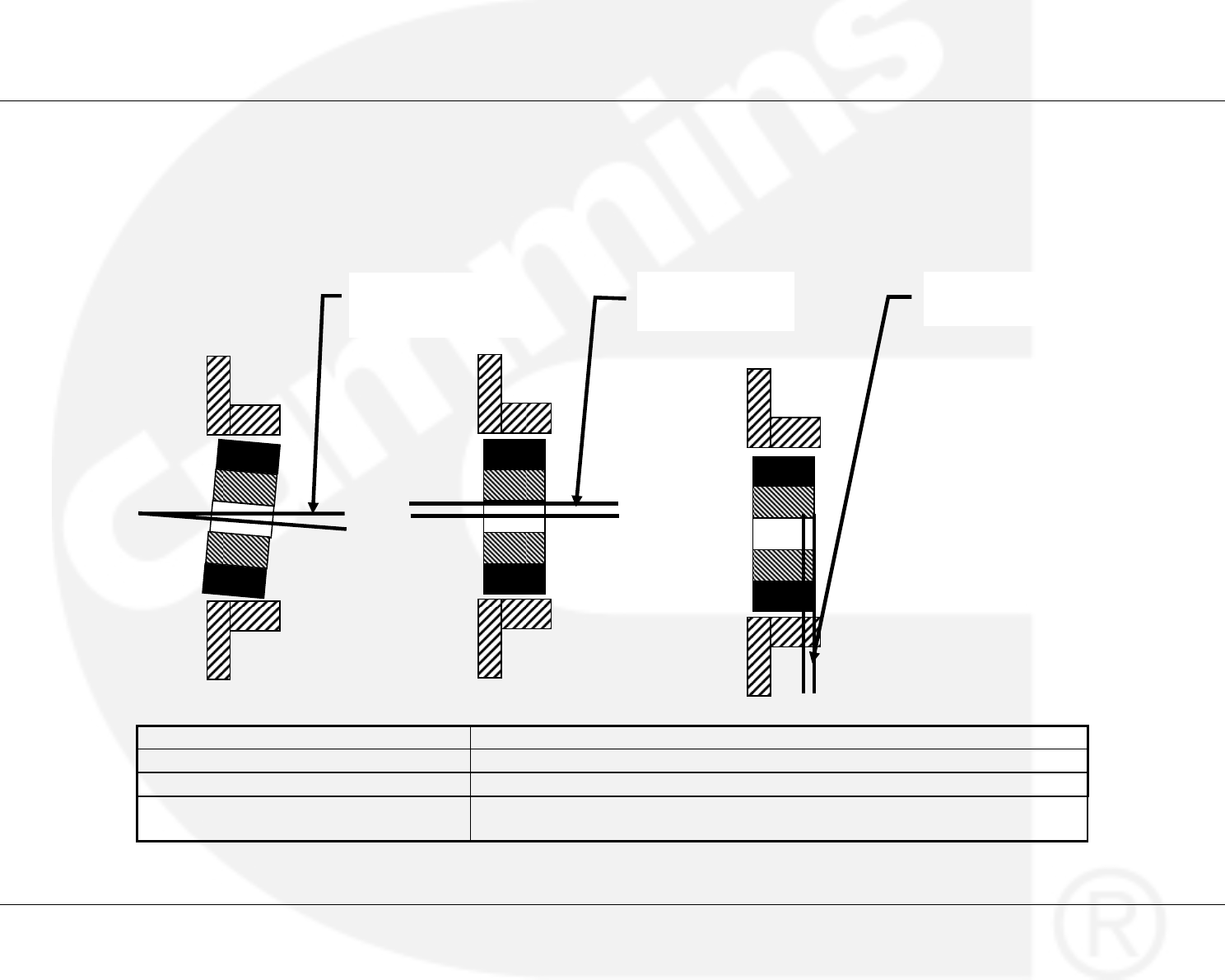
5.1 Alignment of Flexible Coupling to Engine Flywheel – Tolerance Information
Arcusaflex Size AC 11
Permissible radial misalignment Kr 1.5 - 1.0 mm
Permissible angular misalignment degree 0.3°
Permissible axial misalignment Ka Several millimeters, but whole tooth depth of the rubber element must be in contact
(see table dimensions in supplier's manual).
A
ngular misalignment
angle α
Radial misalignment
DKr
A
xial misalignment
DKa
Publication 0908-0106 Eickhoff ANO 110 Gearbox
Issue 2 – 10-2009 Installation and Alignment
Page 5-2 Section 5– Illustrations
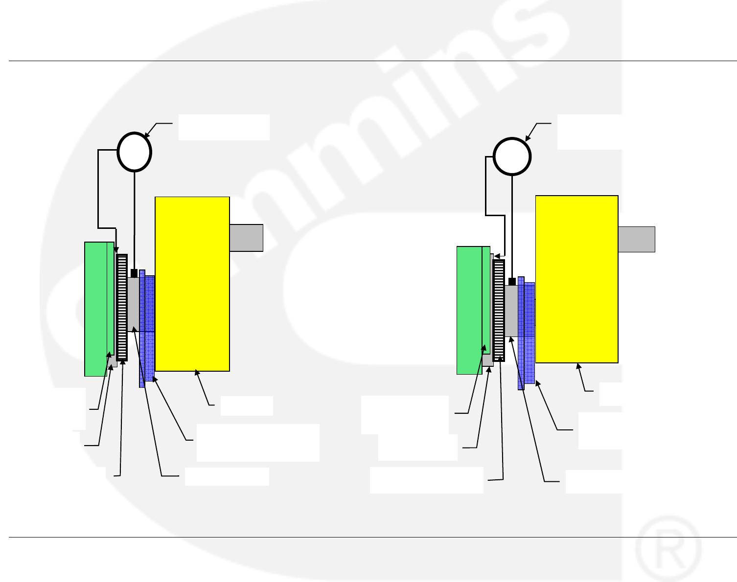
5.2 Alignment of Flexible Coupling to Engine Flywheel – Clock Gauge Set up
Couplin
g
Hub
Clock Gauge
Gearbox
Flywheel Housing
Horseshoe
Flexible Coupling Flange -
Unbolted and pulled back
Vulcanized Rubber Disk Coupling Hub
Clock Gauge
Gearbox
Flywheel Housing
Horseshoe Flexible Coupling Flange -
Unbolted and pulled back
Vulcanized Rubber Disk
Engine Flywheel Engine Flywheel
Eickhoff ANO 110 Gearbox Publication 0908-0106
Installation and Alignment Issue 2 – 10-2009
Section 5 – Illustrations Page 5-3
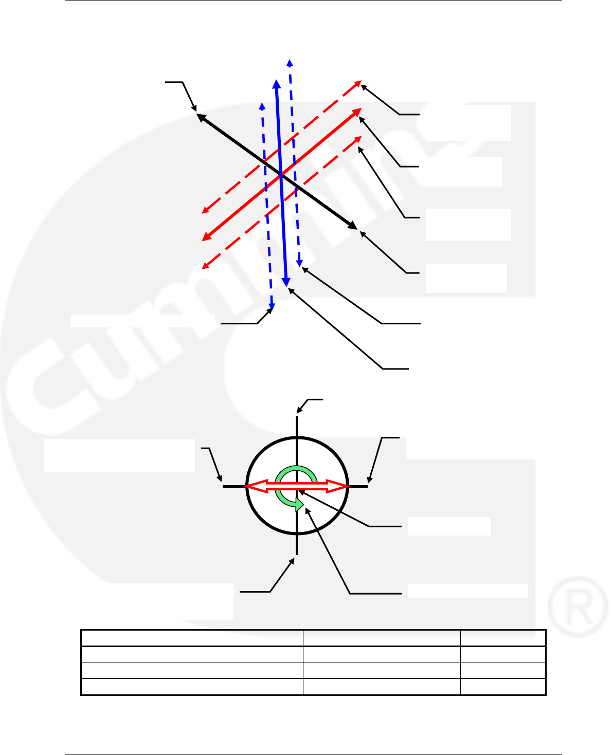
5.3 Radial Alignment of Gearbox to Engine Calculation
Arcusaflex Size AC 11 Result
Permissible radial misali
g
nment Kr 1.5 - 1.0 mm
Calculated Radial misalignment vertical axis 0 - 0.076 = 0.076 mm Approved
Calculated Radial misalignment horizontal axis 1.277 - (-0.692) = 1.969 mm Adjust
A
xial Direction -
Alternator End
Engine Flywheel End
V
ertical Axis
Centreline
Horizontal Axis
+ve misalignment
Horizontal Axis -ve misalignment
Horizontal Axis Centreline
Vertical Axis
-ve misalignment
Vertical Axis
+ve misalignment
Bar Flywheel to 180° from top
and take 2nd reading 0.076 mm
Set up and zero clock gauge at top 0 mm
Bar Flywheel to 90° from top and
take 1st reading -0.692 mm
Bar Flywheel to 270° from top
and take 3rd reading 1.277 mm
Diameter 660 mm
Flywheel Barring Rotation
Publication 0908-0106 Eickhoff ANO 110 Gearbox
Issue 2 – 10-2009 Installation and Alignment
Page 5-4 Section 5– Illustrations
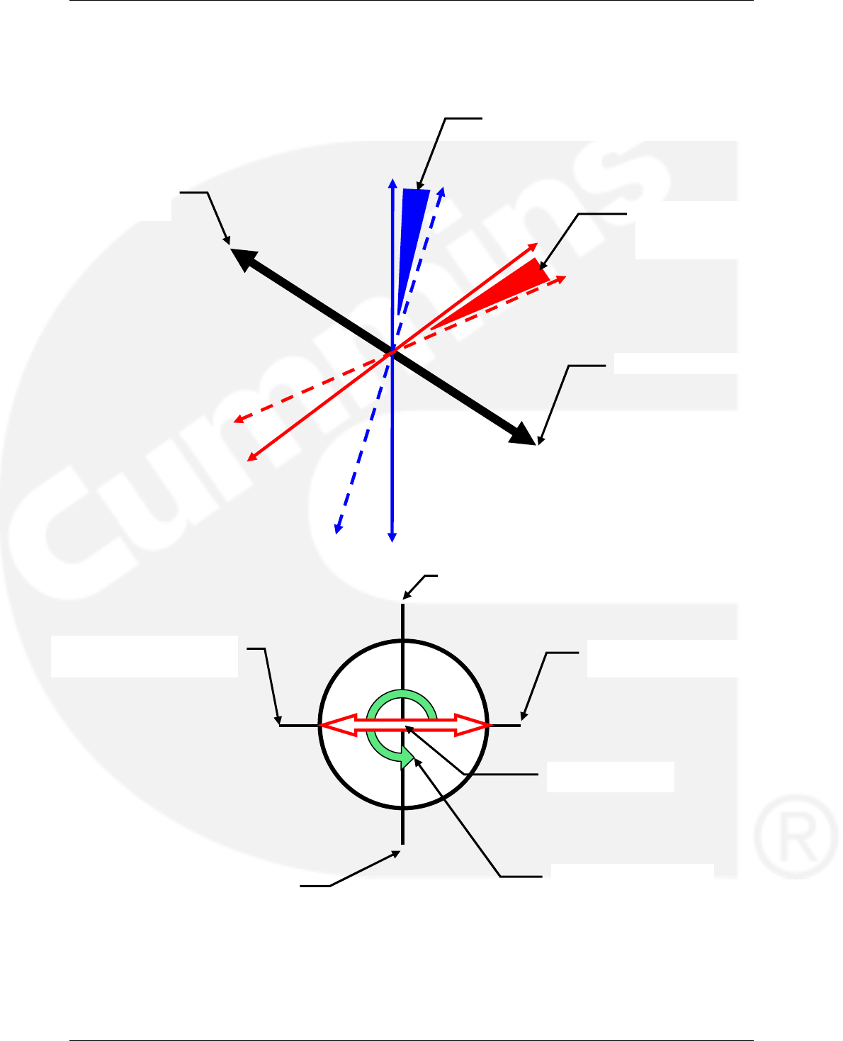
5.4 Angular Alignment of Gearbox to Engine
(Calculation Sheet 1 of 2)
A
xial Direction - Alternator End
A
ngle a of misalignment in the vertical axis
A
ngle a of misalignment in the
horizontal axis -
see calculation below
Engine
Flywheel End
Bar Flywheel to 180° from top and
take 2nd reading -0.050 mm
Set up and zero clock gauge on flywheel face
at top dead centre 0 mm
Bar Flywheel to 90° from top
and take 1st reading -0.205 mm Bar Flywheel to 270° from top
and take 3rd reading -0.022 mm
Flywheel Barring Rotation
Diameter 660 mm
Eickhoff ANO 110 Gearbox Publication 0908-0106
Installation and Alignment Issue 2 – 10-2009
Section 5 – Illustrations Page 5-5
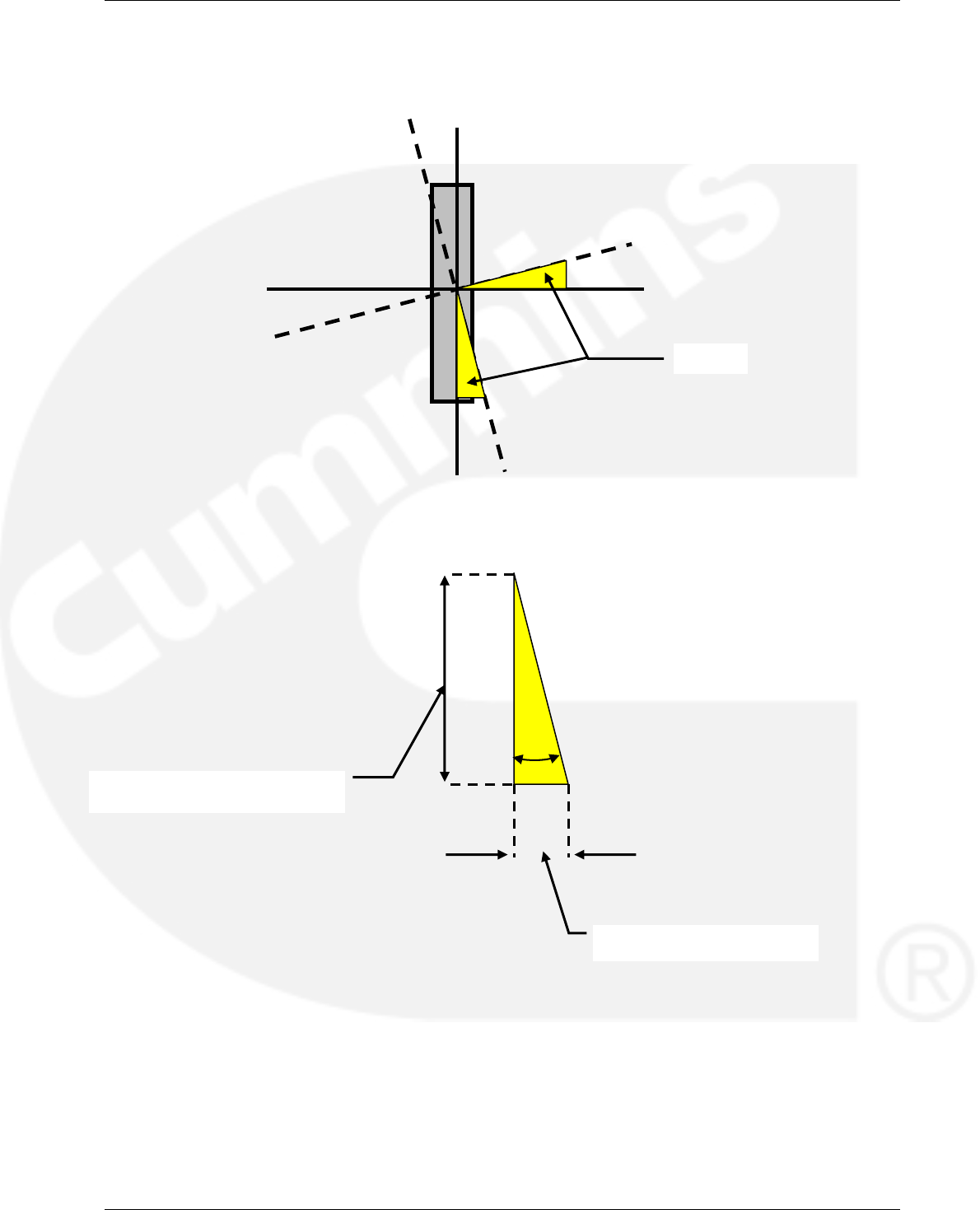
5.5 Angular Alignment of Gearbox to Engine
(Calculation Sheet 2 of 2)
5.5.1 Calculation of Angular Alignment
Calculation:
Vertical Angle a = inv tan{(0 - 0.05)/(660/2)} = 0.0087°
Horizontal Angle a = inv tan{(0.205 - 0.022)/(660/2)} = 0.032°
Therefore both angles within 0.3° tolerance as per manufacturer's instructions
A
lignment Offset e.g.
0mm
(
1st readin
g)
- 0.05mm
1/2 of face diameter e.g. for flexi
coupling = 1/2 of 660mm = 330 mm
A
ngle a

Publication 0908-0106 Eickhoff ANO 110 Gearbox
Issue 2 – 10-2009 Installation and Alignment
Page 5-6 Section 5– Illustrations
THIS IS A BLANK PAGE
Eickhoff ANO 110 Gearbox Publication 0908-0106
Installation and Alignment Issue 2 – 10-2009
Section 5 – Illustrations Page 5-7
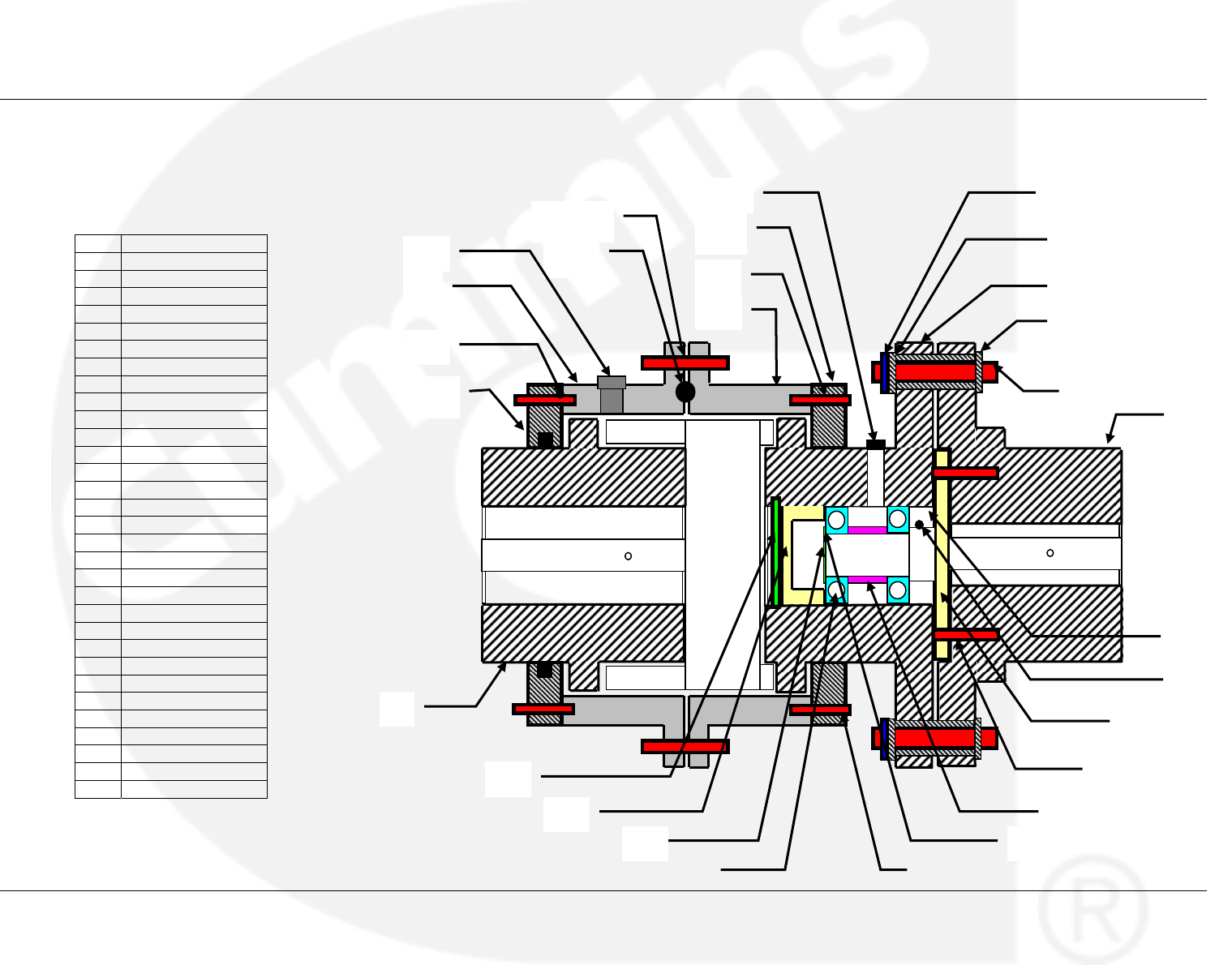
18/19
1
5
8
25-26
2
3
4
6
7
10
13
17
16
21
22
23
24
27
28
29
30
31
11
12
14
20
9
5.6 Gearbox Shear Pin Coupling – Component Identification
Item Description
1. Hub
2. Sleeve
3. Sleeve
4. Hub
5. Rigid Hub
6. Shaft
7. Cover
8. Shear Pin
9. Bushing
10. Bushing
11. Bushing
12. Washer
13. Washer
14. Oil Nipple
15. Seal
16. O-Ring
17. O-Ring
18. Bolt
19. Nut
20. Lubricator
21. Screw
22. Ball Bearing
23. Retainer Ring
24. Retainer Ring
25. Screw
26. Gromer Washer
27. Retainer Ring
28. Cover
29. Cover
30. Screw
31. O-Ring
Publication 0908-0106 Eickhoff ANO 110 Gearbox
Issue 2 – 10-2009 Installation and Alignment
Page 5-8 Section 5– Illustrations
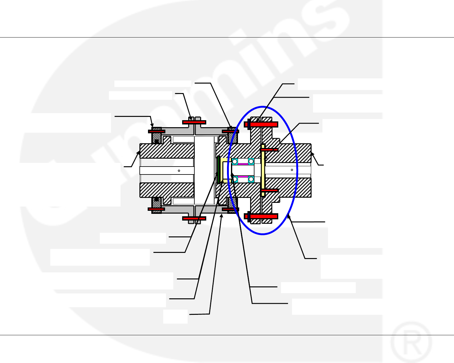
5.7 Gearbox Shear Pin Coupling – Disassembly and Re-Assembly
2. Remove Screws & Sleeve
1. Remove Nuts & Bolts
6. Remove retainer rin
g
8. Alternator Rigid Hub. Heat prior to installation.
For an interference fit ISO H7/m6 (0.005
inch/inch), at least 110°C (230°F) is required.
Install ensuring that the shaft is flush with the
counterbore of the hub.
7. By means of pulling equipment remove the
bearing assembly (shown ringed) that
remains together and is composed of the
items shown in Section 5.8
Sleeve
5. Remove cover by pulling with a screw installed in the
central hole in the cover - Thread size M10
12. Re-install cover by pressing it into the hub
10. Re-install assembly and
sleeve onto the stub shaft
13. Re-install retainer ring into the
internal
g
roove of the hub
14. Re-install shear pins, wire and retaining ring
15. Place cover on the gearbox
shaft prior to the installation o
f
the
g
earbox hub
16. Heat gearbox hub (do not use open
flame burner). Install hub on shaft with
the longest chamfer hub end towards the
gearbox bearing. Hub face has to be
flush with shaft end. Fit O-ring on the hub
only after it has cooled down
4. Remove retainer ring
11. Re-install retainer ring in the shaft groove
9. Install stub shaft and tighten screws and
lock washers to 79 Nm (700 lb/in) using a
torque wrench
3. Remove shear pin retaining ring, wire that
connects shear pins, and shear pins
Eickhoff ANO 110 Gearbox Publication 0908-0106
Installation and Alignment Issue 2 – 10-2009
Section 5 – Illustrations Page 5-9
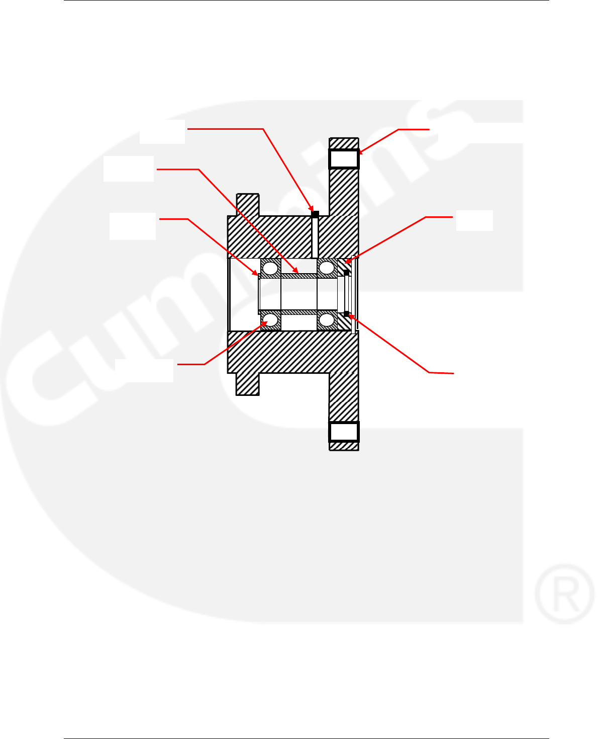
5.8 Roller Bearing Assembly
Bushing for shear pin
Washe
r
Ball Bearing
Bushing
O-Ring
Washer
Lubricator

Publication 0908-0106 Eickhoff ANO 110 Gearbox
Issue 2 – 10-2009 Installation and Alignment
Page 5-10 Section 5– Illustrations
THIS IS A BLANK PAGE
Eickhoff ANO 110 Gearbox Publication 0908-0106
Installation and Alignment Issue 2 – 10-2009
Section 5 – Illustrations Page 5-11
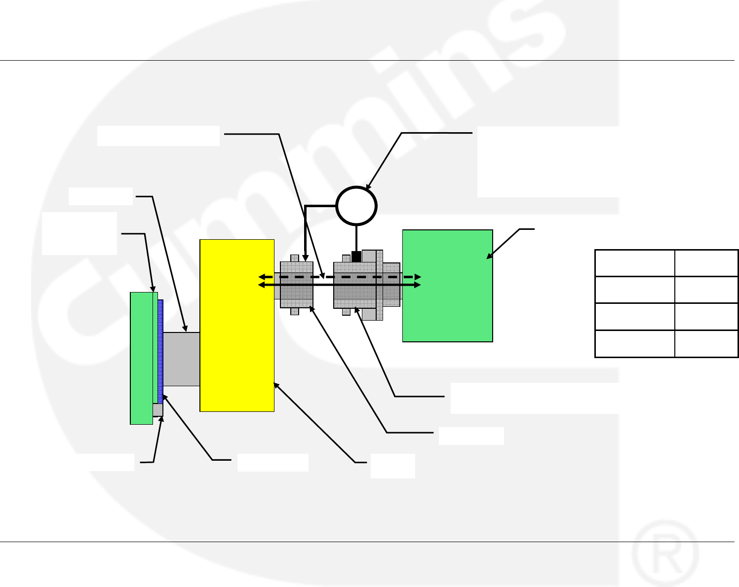
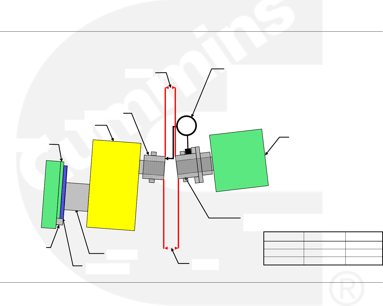
5.9 Alternator to Gearbox Axial Alignment in Vertical/Horizontal Axis
Coupling Size X max
MTBR 185 0.15 mm
Vertical X max Accepted
Horizontal
X max Accepted
Radial Misalignment X max
Flywheel Housing
Horseshoe
Cou
p
lin
g
Hub
En
g
ine Fl
y
wheel Gearbox
Gearbox hub
Shear Pin Coupling - Alternator/Rolle
r
bearing assembly hub
A
lte
r
nato
r
Flexible Cou
p
lin
g
Clock Gauge - Attach gauge to alternator/rolle
r
bearing assembly hub.
With the probe in contact with the top of the
gearbox hub surface, zero the gauge, rotate the
alternator hub taking readings at four points 90°
apart (including the initial zero reading)
Publication 0908-0106 Eickhoff ANO 110 Gearbox
Issue 2 – 10-2009 Installation and Alignment
Page 5-12 Section 5– Illustrations
5.10 Alternator to Gearbox Alignment – Angular Alignment
Coupling Size y - z max (mm) y - z min (mm)
MTBR 185 0.2 0.008
Vertical Axis Accepted Accepted
Horizontal Axis Accepted Accepted
Flexible Coupling
En
g
ine Fl
y
wheel
Flywheel Housing
Horseshoe
Clock Gauge - Attach gauge to alternator/roller bearing
assembly hub.
With the probe in contact with the outer edge of the hub
face, zero the gauge, rotate the alternator hub taking
readings at four points 90° apart (including the initial zero
reading).
Calculate y-z in vertical and horizontal axis and compare
with max/min values of allowable y-z
A
lternato
r
Shear Pin Coupling - Alternator/Roller
bearing assembly hub
Coupling Hub
Gearbox
Gearbox hub
Distance y
Distance z


Cummins Power Generation
1400 73rd Avenue NE
Minneapolis
MN 55432
USA
Tel:+1 (763) 574-5000
Fax:+1 (763) 574-5298
e-mail: pgamail@cummins.com
Cummins Power Generation
Columbus Avenue
Manston Park
Manston
Ramsgate
Kent CT12 5BF
United Kingdom
Tel:+44 (0) 1843 255000
Fax:+44 (0) 1843 255902
e-mail: cpgk.uk@cummins.com
Cummins Power Generation
10 Toh Guan Road #07-01
TT International Tradepark
Singapore 608838
Tel: (65) 6417 2388
Fax:(65) 6417 2399
e-mail: cpg.apmktg@cummins.com
Web: www.cumminspower.com Web: www.cumminspower.com Web: www.cumminspower.com
Cummins Power Generation
35A/1/2, Erandawana
Pune 411 038
India
Tel.: (91 020) 6602 7525
Fax: (91 020) 6602 8090
e-mail: cpgindia@cummins.com
Cummins Power Generation
Rua Jati, 310 - Cumbica
Guarulhos –SP
Brazil
CEP: 07180-900
Tel.: (55 11) 2186 4195
Fax: (55 11) 2186 4729
e-mail: falecom@cumminspower.com.br
Web: www.cumminspower.com Web: www.cumminspower.com
Cummins®, the “C” logo, and “Our energy working for you.”
are trademarks of Cummins Inc.
©2009 Cummins Power Generation, Inc. All rights reserved
