9100 Program Translator
User Manual: 9100 Program Translator
Open the PDF directly: View PDF ![]() .
.
Page Count: 84
- Introduction
- Getting Started
- How to Use the Translator
- OVERVIEW 3.1.
- CREATE A UUT DIRECTORY ON THE 9100A HARD DISK 3.2.
- COPY THE TRANSLATOR PROGRAMS INTO THE UUT 3.3.
- TRANSFER PROGRAMS FROM THE 9010A TO THE 9100A 3.4.
- TRANSLATE THE 9010A PROGRAMS TO TL/1 3.5.
- COPY THE TRANSLATOR OUTPUT TO TL/1 PROGRAM FILES 3.6.
- REVIEW THE TRANSLATOR ERRORS AND COMPLETE THE TRANSLATION 3.7.
- EXECUTE THE TRANSLATED PROGRAM 3.8.
- Language Reference
- Translator Output
- Translator Errors
- Helpful Information

9100 Series
9100A-030
9010A To 9100A
Program Translator
P/N 877696
December 1989
©1989, John Fluke Mfg. Co., Inc.
All rights reserved. Litho in U.S.A.
LIMITED WARRANTY
Fluke warrants to the original purchaser that the medium on which the 9010A
to 9100A Program Translator is furnished will be free from material defects
and workmanship for 90 days from the date of shipment. This warranty does
not apply to media which, in Fluke’s opinion, have been subject to misuse, al-
teration, accident or abnormal conditions of operation or handling. Your
software program is provided "AS IS" and Fluke does not warrant that it will be
error free, operate without interruption or that all errors will be corrected.
For warranty service on your media, contact your nearest Fluke Service
Center or send the media with the description of the difficulty, postage pre-
paid, to the nearest Fluke Service Center. Fluke assumes no risk for dam-
age in transit.
Fluke will replace, free of charge, media which fail to meet this warranty.
However, if Fluke determine that the failure was caused by misuse, alter-
ation, accident or abnormal conditions of operation or handling, you will be
billed for the replacement. The new media will be sent to you, transportation
prepaid. If Fluke is unable, within a reasonable time, to replace your media,
your purchase price will be reimbursed to you when you return them to Fluke.
THIS WARRANTY IS EXCLUSIVE AND IS IN LIEU OF ALL OTHER WAR-
RANTIES, EXPRESS OR IMPLIED, INCLUDING BUT NOT LIMITED TO
ANY IMPLIED WARRANTY OF MERCHANTABILITY OR FITNESS FOR A
PARTICULAR PURPOSE OR USE. FLUKE WILL NOT BE LIABLE FOR
ANY SPECIAL, INDIRECT, INCIDENTAL, OR CONSEQUENTIAL DAM-
AGES OR LOSS, INCLUDING LOSS OF DATA, WHETHER IN CONTRACT,
TORT, OR OTHERWISE. IF FLUKE IS HELD TO BE LIABLE, FOR ANY
REASON, ITS MAXIMUM LIABILITY SHALL NOT EXCEED FIVE TIMES
THE PRICE OF THE SOFTWARE.

i
Contents
Section Title Page
1. Introduction ............................................................................. 1-1
1.1. GENERAL DESCRIPTION ........................................... 1-1
1.2. PRODUCT DESCRIPTION .......................................... 1-2
1.3. OPERATION ................................................................. 1-3
1.4. TRANSLATOR EFFICIENCY ....................................... 1-4
1.5. OPERATIONAL DIFFERENCES BETWEEN
THE 9010A AND 9100A/9105A .................................... 1-4
1.5.1. Arithmetic Underflow ................................................ 1-6
1.5.2. Probe Transition Count ............................................ 1-6
1.5.3. Probe Pulser ............................................................ 1-6
1.5.4. Special Addresses ................................................... 1-7
1.6. HOW TO USE THIS MANUAL ..................................... 1-7
1.7. ORGANIZATION OF MANUAL .................................... 1-8
2. Getting Started ........................................................................ 2-1
2.1. OVERVIEW .................................................................. 2-1
2.2. HARDWARE REQUIREMENTS ................................... 2-1
2.3 BACKING UP THE DISKETTE ..................................... 2-2
2.4 CONNECTING THE 9010A TO THE 9100A ................ 2-3
ii
Section Title Page
3. How to Use the Translator ..................................................... 3-1
3.1. OVERVIEW .................................................................. 3-1
3.2. CREATE A UUT DIRECTORY ON THE
9100A HARD DISK ....................................................... 3-2
3.3. COPY THE TRANSLATOR PROGRAMS
INTO THE UUT ............................................................ 3-5
3.4. TRANSFER PROGRAMS FROM THE
9010A TO THE 9100A .................................................. 3-5
3.4.1. Load the 9010A Programs to be Translated ............ 3-6
3.4.2. Initiate Data Transfer on the 9100A ......................... 3-7
3.4.3. Initiate Data Transfer on the 9010A ......................... 3-8
3.4.4. Terminate Data Transfer on the 9100A ................... 3-10
3.5. TRANSLATE THE 9010A PROGRAMS TO TL/1 ......... 3-10
3.6. COPY THE TRANSLATOR OUTPUT TO TL/1
PROGRAM FILES ........................................................ 3-14
3.7. REVIEW THE TRANSLATOR ERRORS AND
COMPLETE THE TRANSLATION ............................... 3-15
3.8. EXECUTE THE TRANSLATED PROGRAM ................ 3-16
3.8.1. The Debugger Method ............................................. 3-17
3.8.2. The Operator’s Keypad Method ............................... 3-18
3.8.3. Program Execution .................................................. 3-19
4. Language Reference .............................................................. 4-1
4.1. OVERVIEW .................................................................. 4-1
4.2. ADDRESS DESCRIPTORS ......................................... 4-1
4.3. SETUP INFORMATION ............................................... 4-2
4.3.1. Statements That Are Not Translated ....................... 4-4
4.4. 9010A PROGRAMS ..................................................... 4-7
4.4.1. Statements That Are Not Translated ....................... 4-10
4.4.2. Statements That Are Partially Translated ................ 4-14
4.5. BINARY PROGRAMS .................................................. 4-17
4.5.1. Statements That Are Not Translated ....................... 4-18
iii
Section Title Page
Appendices
A. Translator Output ................................................................... A-1
A.1. OVERVIEW .................................................................. A-1
A.2. 9100A MONITOR OUTPUT .......................................... A-2
A.2.1. The Startup Message ............................................... A-2
A.2.2. The Error Message .................................................. A-3
A.2.3. The Termination Message ....................................... A-4
A.3. OPERATOR'S DISPLAY OUTPUT .............................. A-4
A.4. LOG FILE OUTPUT ...................................................... A-5
A.5. TL/1 OUTPUT ............................................................... A-6
A.5.1. Global Variable Declarations ................................... A-9
A.5.2. Functions ................................................................. A-10
A.5.3. The 9010exec Function ........................................... A-10
A.5.4. The async_input( ) Function .................................... A-10
A.5.5. The Main Program ................................................... A-11
B. Translator Errors .................................................................... B-1
B.1. OVERVIEW .................................................................. B-1
B.2. ERRORS WHILE TRANSFERRING FROM THE
9010A TO THE 9100A .................................................. B-1
B.3. ERRORS WHILE TRANSLATING ................................ B-2
B.4. ERRORS WHILE COPYING TO TL/1 .......................... B-4
B.5. EXECUTION ERRORS ................................................ B-4
C. Helpful Information ................................................................. C-1
C.1. OVERVIEW .................................................................. C-1
C.2. OPTIMIZING THE 9010EXEC () FUNCTION ............... C-1
C.3. AUX PORT SELECTION AND PORT PARAMETERS . C-2
C.4. 9LC COMPATIBILITY ................................................... C-3
C.5. PROBE PULSER .......................................................... C-3
C.6. SPECIAL ADDRESSES ............................................... C-4
C.7. TRANSLATING IN BATCH MODE ............................... C-6
iv

v
Figures
Figure Title Page
2-1 RS-232-C Wiring Diagram ...................................................... 2-3
3-1. The Translation Process ......................................................... 3-3
3-2. UUT Directory ......................................................................... 3-4
3-3. Monitor Display Showing Receiving Status Message ............. 3-8
3-4. Setup Information on 9100A Monitor ...................................... 3-9
3-5. 9100A Monitor with a INFILE Argument Prompt ..................... 3-13
A-1. Example of 9100A Monitor Output .......................................... A-2
A-2. Translator Error Message Example ........................................ A-3
A-3. Operator's Display Output Example ........................................ A-5
A-4. TL/1 Output File Example ....................................................... A-6
vi

vii
Tables
Table Title Page
1-1. Non-translated or Partially Translated 9100A Statements . 1-5
2-1. Ordering Information .......................................................... 2-2
2-2. RS-232-C Parameter Settings ............................................ 2-4
4-1. Mapping between 9010A Address Descriptors
and TL/1 Functions ............................................................. 4-2
4-2. Mapping between 9010A Setup Statements
and TL/1 Functions ............................................................. 4-3
4-3. Mapping between 9010A Program Statements
and TL/1 Functions ............................................................. 4-8
4-4. Comparison of 9010A and 9100A Input Values for Keys ... 4-13
4-5. Mapping Between 9010A Binary Programs
and TL/1 Programs ............................................................. 4-18
B-1. Possible Errors Issued By The Translator .......................... 4-3
viii

1-1
Section 1
Introduction
GENERAL DESCRIPTION 1.1.
The 9100A-030 9010A to 9100A Program Translator (referred to in
this manual as the translator) is a program that converts 9010A
programs to the 9100A TL/1 programming language. These
translated TL/1 programs can be executed on either the 9100A or
9105A. The translator program is written in the TL/1 language and
executes only on a 9100A with a programmer’s station.
The translator allows an existing base of 9010A programs to be
used on a 9100A or 9105A. The translator is also a valuable
teaching tool for test engineers and programmers familiar with the
9010A and with little or no 9100A experience.

9000A-030
1-2
PRODUCT DESCRIPTION 1.2.
The translator consists of this User’s Manual and a 3.5-inch
diskette. The diskette contains programs in a UUT (Unit Under
Test) directory named TRANSLATE. The following is a list of files
contained on the diskette:
PROGRAM DESCRIPTION
TRANSLATE The 9010A to 9100A Program Translator.
9010TAPE A sample 9010A program that can be translated
and executed.
9010RDPROB TL/1 version of 9010A READ PROBE.
9010INPUT TL/1 version of 9010A DPY input.
9010ROMTST TL/1 version of 9010A ROM TEST.
9010ADD32 TL/1 version of 9010A 32-bit unsigned add
(binary program).
9010SUB32 TL/1 version of 9010A 32-bit unsigned subtract
(binary program).
9010FREQ TL/1 version of 9010A probe frequency (binary
program).
9010PULSER TL/1 version of 9010A probe pulser (binary
program).
9010SETUP TL/1 version of 9010A setup program (binary
program).

9000A-030
1-3
OPERATION 1.3.
The 9010A is able to read and write test programs via its auxiliary
RS-232-C interface. The entire contents of the 9010A program
memory (including setup parameters and address space descriptors)
can be transferred through the serial interface to the 9100A as
ASCII text.
Once the program transfer is made to the 9100A, the translator
processes the input file containing the 9010A programs and
generates an output text file containing the TL/1 version of the
programs. Finally, the 9100A COPY command converts the
translated program from the text file into an executable TL/1
program file. Section 3 contains step-by-step procedures on how to
transfer, translate, and convert programs to TL/l.
The following is an example of an output file from the translator.
This example is a 9010A program that has been translated into TL/
1. The original 9010A statements are included as comments in the
TL/1 program by the translator.
function P_10 ! PROGRAM 10 78 BYTES
declare
global numeric array [0:$F] reg
global numeric dpy
global numeric aux
global numeric syncmode
end declare
reg[1] = $8000 ! REG1 = 8000
L_1: ! 1:LABEL 1
reg[$F] = reg[$1] ! READ @ REG1
reg[$E] = readvirtual extaddr 0, addr reg[$F]
reg[8] = $20 ! REG8 = 20
’9010exec’ (40) ! EXECUTE PROGRAM 40
if reg[$1] = $801F then goto L_2 ! IF REG1 = 801F GOTO 2
reg[1] = reg[1] + 1 ! INC REG1
goto L_1 ! GOTO 1
L_2: ! 2:LABEL 2
print using "-COMPLETE", on dpy! ! DPY-+COMPLETE
end function

9000A-030
1-4
TRANSLATOR EFFICIENCY 1.4.
9010A source files can contain address space information, setup
information, 9010A programs, and binary programs. The translator
can convert 81% of these statements into TL/l. An additional 12%
can be partially translated or can be set manually from the
operator’s keypad on the front panel of the 9100A/9105A. For
typical 9010A programs, more than 95% of the statements are
translated.
The 9010A statements in Table 1-1 are not translated. For
information on how to manually complete the translation of these
statements, refer to Section 4.
When the translator encounters a statement that cannot be
converted to TL/1, the translator inserts the statement into the TL/1
program as a comment and displays an error message. The error
messages are also written to a log file that can be reviewed later.
OPERATIONAL DIFFERENCES BETWEEN
THE 9010A AND 9100A/9105A 1.5.
There are differences between the 9010A and 9100A/9105A that
may affect the operation of the translated programs. Arithmetic
underflow, probe transition counts, use of the probe pulser, and
special addresses are differences that cannot be detected by the
translator and are described in the following paragraphs

9000A-030
1-5
.
Table 1-1. Non-translated or Partially Translated 9100A Statements
SETUP
STATEMENTS
PROGRAM
STATEMENTS BINARY PROGRAMS
BEEP ON ERR TRANSITION-
<YES/NO>
ROM TEST‡ Merge Tape
EXERCISE ERRORS-
< YES/NO>*
AUTO TEST‡ Pod Self-Test Program
STALL <hex number> RUN UUT† Pod Setup Program£
UNSTALL <hex number> ASYNCHRONOUS
INPUT (with the DPY
statement)§
9000A-006 Programs
(Asynchronous Signature
Probe Option)
TRAP ILLEGAL ADDRESS LEARN
LINESIZE <decimal number>
NEWLINE <hex number>
NOTES
Most of the setup items do not affect program operation.
* Can be set from the front panel of the 9100A/9105A
‡ Partially translated. The translation can be completed after the ROM signatures have been relearned on
the 9100A/9105A. For more information, see Section 4.
† Partially translated. The translation can be completed by adding a haltuut () statement to the TL/1
program. For more information, see Section 4.
§ This manual describes a workaround for asynchronous input. For more information, see Section 4.
£ This program is partially translated.

9000A-030
1-6
Arithmetic Underflow 1.5.1.
The 9010A ignores arithmetic underflow and decrements from 0 to
FFFFFFFF. The 9100A/9105A detects and reports arithmetic
underflow errors during TL/1 program execution. Comparisons that
depend on the underflow wraparound will not work. The following
are examples of 9010A and 9100A/9105A subtraction:
9010A subtraction: 0 - 1 = FFFFFFFF
9100A/9105A subtraction: 0 - 1 = arithmetic overflow error
Probe Transition Count 1.5.2.
The 9010A counts high to low transitions, but the 9100A counts
low to high transitions. This condition can cause a difference of one
count.
Transition counts are asynchronous and the number of counts
depends on the number of transitions that occur between two
READ PROBE statements. The timing of this window is different
on the 9010A and 9100A and can cause the counts to be different
on nodes where there is asynchronous activity.
Probe Pulser 1.5.3.
9010A programs control the probe pulser with operator prompts to
press the PULSE HIGH or PULSE LOW keys during program
execution. On the 9100A/9105A, the operator cannot change the
probe pulser mode while a TL/1 program is running. Instead, the
program uses the TL/1 pulser function to control the probe pulser
directly.
The difference in the way the probe pulser is controlled affects any
9010A program that prompts the operator to change the probe
pulser mode. Refer to Appendix C for instructions on how to
complete the translation.

9000A-030
1-7
Special Addresses 1.5.4.
Special addresses are addresses that are outside the normal address
space of a microprocessor. Some 9010A programs use special
addresses to access other address spaces (such as I/0), or to access
pod special functions. The 9100A built-in tests do not accept
special addresses. Instead, the TL/1 function setspace sets the
address space before calling these tests.
This situation affects any 9010A program that uses special
addresses with BUS TEST, RAM SHORT, RAM LONG, ROM
TEST, IO TEST, and AUTO TEST. Refer to Appendix C for
instructions on how to complete the translation.
HOW TO USE THIS MANUAL 1.6.
This manual is the reference source for the 9010A to 9100A
Program Translator. The manual is written with the assumption that
you are already familiar with the operation of the 9010A Micro-
System Troubleshooter and have some TL/1 programming
experience.
A good source of reference for answering 9100A/9105A questions
is the 9100-Series Manual Set. Information on how to use the
9100A/9105A is located in the 9100-Series Technical User’s
Manual, and programming information is located in the 9100-
Series Programmer’s and 9100-Series TL/1 Reference Manuals.

9000A-030
1-8
ORGANIZATION OF MANUAL 1.7.
The 9010A to 9100A Program Translator User’s Manual is
organized as follows:
•Section 1
Introduction
Introduces the translator and
describes the basic features.
•Section 2
Getting Started
Describes what you need to get
started. Before using the
translator, it is essential that you
read this section to avoid
problems. This section shows
how to hook up the 9010A to the
9100A and lists other hardware
requirements.
•Section 3
How To Use
The Translator
Provides step-by-step guide
through the entire translator
process with figures to compare
your progress with the manual.
•Section 4
Language Reference
Provides quick reference for
mapping between 9010A
statements and TL/1 with
workarounds for non-translated
and partially translated
statements.
•Appendices A - C Provides detailed information of
the different types of translator
program output, how to handle
errors during translation, and
additional information on related
subjects not covered in previous
sections of the manual.

2-1
Section 2
Getting Started
OVERVIEW 2.1.
Section 2 contains information required to operate the translator.
The following topics are covered in this section:
• Hardware Requirements
• Backing Up the Translator Diskette
• Hooking Up the System
HARDWARE REQUIREMENTS 2.2.
The following hardware is required to operate the translator:
• A Fluke 9100A Digital Test System with 4M bytes of mem-
ory, version 4.0 or later 9100A software, and a 9100A-004
Programmer's Station
• Fluke 9010A Micro-System Troubleshooter with Option
9010A-001 (RS-232-C interface)
• Null modem RS-232-C cable
Refer to Table 2-1 for ordering information necessary to obtain the
required components for translator operation. These items may be
ordered from John Fluke Mfg. Co., Inc. or an authorized
representative by using the Fluke order number.

9000A-030
2-2
NOTE
4M bytes of memory is only required to translate the
9010A programs to TL/1 programs. Translated TL/1
programs can be executed on 9100A/9105As with less
memory.
BACKING UP THE DISKETTE 2.3.
Before using the translator program, you should make a copy of the
translator diskette. This copy should be used for normal day- to-day
operations, while the original diskette should be kept in a safe place
as a backup so that the working copy can be restored if it is ever
damaged.
Table 2-1. Ordering Information
Description Order Number
9100A Programmer's Station 9100A-004
Software Upgrade Kit 9100A-003
Software Upgrade w/Programmer's Kit 91004-904
Null Modem RS-232 Cable (4 meter)
or
Null Modem RS-232 Cable (1 foot)
or
Null Modem RS-232 Cable (2 meter)
Y1703
Y1705
Y1702
9010A to 9100A Program Translator 9100A-030
NOTE
If your 9100A does not have 4M bytes of memory, contact your local Fluke Technical
Service Center for ordering information.

9000A-030
2-3
For instructions on how to duplicate the diskette, refer to Typical
9100A/9105A Operations located in the 9100-Series Technical
User's Manual.
CONNECTING THE 9010A TO THE 9100A 2.4.
Transferring data between the 9010A and the 9100A requires an
RS-232-C cable connected to either RS-232-C Port 1 or 2 of the
9100A and the RS-232-C port of the 9010A. Refer to Figure 2-1 for
the correct wiring configuration of the cable.
Figure 2-1. RS-232-C Wiring Diagram

9000A-030
2-4
Connect the cable to the 9010A and the 9100A, and set the RS-
232-C parameters on the rear panel of the 9010A as shown in Table
2-2. Set the parameters of the 9100A serial port (under the SETUP
MENU key) to correspond to those of the 9010A.
NOTE
The 9100A software handshaking protocol
(XON/XOFF) must be enabled for compatibility
between the 9010A and the 9100A.
Table 2-2. RS-232-C Parameter Settings
9010A 9100A
Baud: 9600 (switch setting 7) Baud: 9600
Parity: odd Parity: odd
Data bits: 7 Data bits: 7
Stop bits: 1 Stop bits: 1
Parity: on XON/XOFF: enable
Clear to send: disable
Newline: CRLF

3-1
Section 3
How to Use the Translator
OVERVIEW 3.1.
Section 3 contains procedures on creating a UUT directory for
storage of 9010A programs, transferring programs to the 9100A,
translating the programs into TL/1 as text files, and converting the
files into executable TL/1 program files.
The translator process requires the following steps:
1. Creating a new UUT directory on the 9100A hard disk.
2. Copying the translator programs into the UUT directory.
3. Transferring programs from the 9010A to the 9100A
into the UUT directory.
4. Translating the 9010A programs to TL/1, producing a
text file.
5. Copying the text file to an executable TL/1 program file.
6. Editing the program file for statements that are not
translated and completing the translation.
7. Executing the translated programs.

9000A-030
3-2
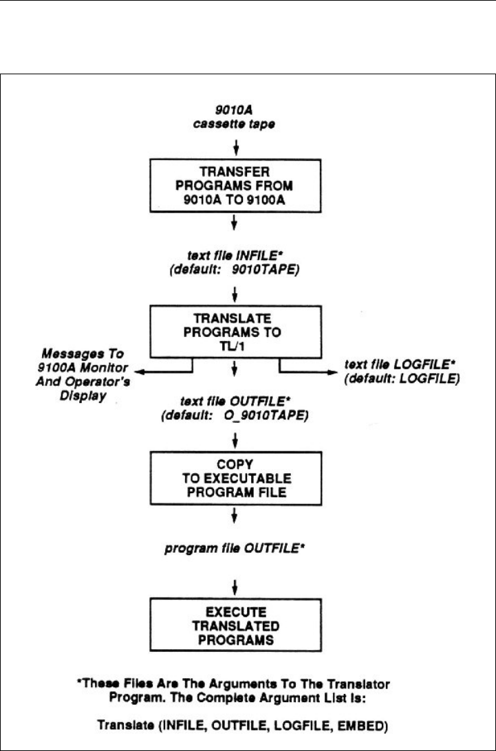
Figure 3-1 shows the translation process. The boxes represent
translation steps and the arrows determine if the file is an input or
output file. A file following an arrow going into a box (step) is an
input file. An arrow coming out of a box (step) points to an output
file.
CREATE A UUT DIRECTORY ON THE
9100A HARD DISK 3.2.
Before the translation process begins, the 9100A should be
powered up and operational. If this is not the case, refer to the
9100-Series Getting Started for power-up information. For more
information on using the 9100A Editor, refer to the 9100-Series
Programmer’s Manual.
To create a UUT directory:
1. Start the Editor by pressing the EDIT key on the opera-
tor’s keypad. The 9100A prompts you to name the UUT.
(For demonstration purposes the UUT directory name is
9010UUT.)
2. Type /HDR/9010UUT at the "EDIT NAME" prompt,
and press the Return key.
3. Press the 9100A Field-Select key on the programmer’s
keyboard to scroll through the Reply field at the bottom-
right of the 9100A monitor.
4. Select UUT by pressing the Return key when UUT is
shown in the Reply field.
9000A-030
3-3
Figure 3-1. The Translation Process
9000A-030
3-4
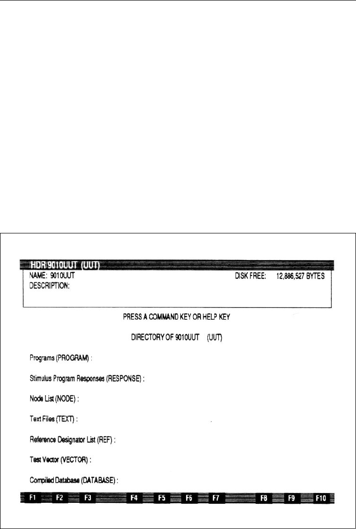
The UUT directory is now created and should be similar to the
monitor display shown in Figure 3-2.
NOTE
It is recommended that you create a new UUT
directory. Allowing the translator to operate in a new
(empty) UUT, prevents overwriting any existing UUT
text files or TL/1 programs.
If a mistake is made at the prompt, press the 9100A
Quit key to return you to where you were before the
prompt.
Figure 3-2. UUT Directory

9000A-030
3-5
COPY THE TRANSLATOR PROGRAMS
INTO THE UUT 3.3.
To copy all of the translator programs into the UUT directory:
1. Insert the translator disk into the 9100A floppy disk
drive (/DR1). Make sure that you are in your empty
UUT directory and press the COPY (F4) softkey.
2. Enter /DR1/TRANSLATE/* at the "FROM NAME"
prompt, then press the Return key.
3. Use the Field-Select key to choose "PROGRAM" in the
Reply field, and press the Return key.
4. Enter /HDR/9010UUT at the "TO NAME" prompt, and
press the Return key.
5. Use the Field-Select key to choose UUT in the Reply
field, and press the Return key.
A status message appears on the bottom of the 9100A monitor. The
message lists each translator program as it is copied into the UUT
directory. The softkey labels return to the monitor display when the
copy process is complete.
TRANSFER PROGRAMS FROM THE
9010A TO THE 9100A 3.4.
To transfer the 9010A address descriptors, setup information, and
programs to the 9100A through the RS-232-C interface:
1. Load the programs to be translated into the 9010A.
2. Initiate the data transfer (receive) on the 9100A.
3. Initiate the data transfer (send) on the 9010A.
4. Terminate the data transfer on the 9100A.

9000A-030
3-6
NOTE
Before transferring programs, the 9100A and 9010A
should be powered up, connected together with the RS-
232-C cable, and the port parameters should be set, as
described in Table 2-2.
Load the 9010A Programs to be Translated
into the 9010A 3.4.1.
To load the 9010A programs to be translated into the 9010A:
1. Insert the cassette into the 9010A and press the READ
TAPE key.
2. When the READ TAPE operation is complete (the
9010A displays the message "READ TAPE OK"),
change the 9010A serial port setup parameters (under
the SETUP key) to the following values (these
parameters can change each time a tape is read):
NEWLINE 00000D0A
STALL 13
UNSTALL 11
LINESIZE 255
NOTE
To avoid a Syntax Error during translation, set the
linesize value to 255. The 9010A’s linesize default
value is 79. If LINESIZE is not increased to 255, the
9010A splits long lines as they are sent out the serial
port. Each partial line causes a "Syntax Error" during
translation. LINESIZE is reset each time a 9010A
READ TAPE operation is performed.
For more information on changing the 9010A Setup
parameters, refer to the 9010A Operator’s Manual.

9000A-030
3-7
Initiate Data Transfer on the 9100A 3.4.2.
The 9100A terminal emulator allows the 9100A to receive data
from the 9010A and store it in a text file. To initiate the data receive
operation on the 9100A:
1. Edit the UUT directory.
2. Press the TERM (F5) softkey and use the Field- Select
key to choose "/PORT1" or "/PORT2" depending on
which RS-232-C port you connected the cable to, then
press the Return key.
3. Press the 9100A Info key. The information window
appears at the top of the monitor display, and softkey
labels appear at the bottom.
4. Press the RECEIVE (F4) softkey and at the "RECEIVE
NAME" prompt, enter a name (for demonstration
purposes 9010TAPE is used) for the text file receiving
the data.
5. Press the Return key twice. The second Return
acknowledges that the data received is text.
NOTE
If the text file name already exists, a prompt asks if the
existing file should be replaced. Use the Field- Select
key to respond. Entering no aborts the data receive
operation.
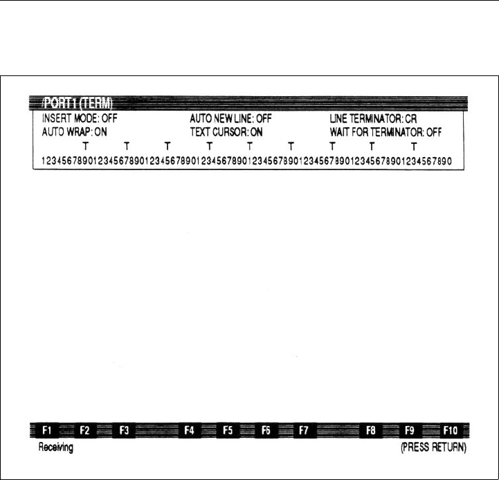
The status message "RECEIVING" appears on the bottom of the
monitor display as shown in Figure 3-3, indicating that the 9100A
is ready to receive data. Press the Return key to acknowledge the
message. The 9100A monitor displays data as it is received on the
RS-232-C port.
9000A-030
3-8
Figure 3-3. Monitor Display Showing Receiving Status Message
Initiate Data Transfer on the 9010A 3.4.3.
The 9010A AUX I/F key allows address descriptors, setup
information, and programs to be sent from the 9010A.
NOTE
All the information on the 9010A tape should be
transferred to the 9100A.
The address descriptors and setup information should be sent
before the programs. The address descriptors and setup information
provide information that is used by the translator when converting
the program statements.
9000A-030
3-9
To initiate the data send operation on the 9010A:
1. Send the address descriptors by pressing the AUX I/F
key followed by the LEARN key.
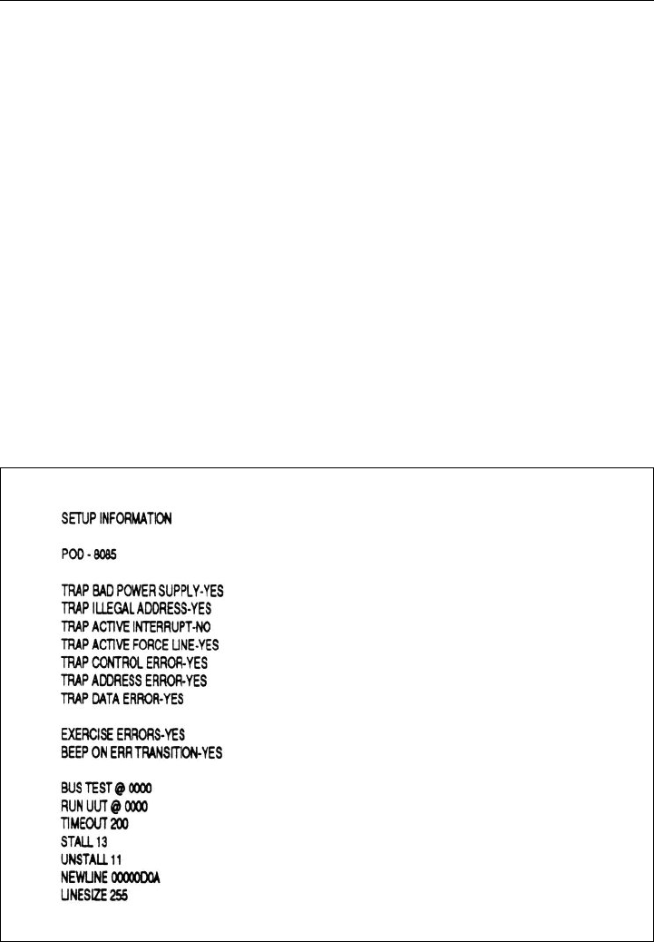
2. Send the setup information by pressing the AUX I/F key
followed by the SETUP key. Figure 3-4 shows the
9100A monitor when the setup information is received.
3. Send all the programs contained in the 9010A memory
(do not send the programs individually) by pressing the
AUX I/F key followed by the PROGM key.
The data is displayed on the 9100A monitor as it is received from
the 9010A.
Figure 3-4. Setup Information on 9100A Monitor

9000A-030
3-10
Terminate Data Transfer on the 9100A 3.4.4.
To terminate the data receive operation on the 9100A, press the
9100A Quit key. A status message is displayed at the bottom of the
9100A monitor indicating that the Receive operation is complete.
Press the Return key to acknowledge the message and exit the
terminal emulator. The 9100A monitor now displays the UUT
directory.
You can verify the data transfer by looking at the monitor where the
text file name "9010TAPE" appears below the Text Files (TEXT):
line. For more information on the terminal emulator, refer to the
Terminal Emulator section of the 9100-Series Programmer’s
Manual.
TRANSLATE THE 9010A PROGRAMS TO TL/1 3.5.
The following group of procedures requires you to create several
types of files for translation to take place. After the 9010A
programs are translated, the 9100A monitor, the operator’s display,
the log file, and the TL/1 output file contains startup, error, and
termination information about the translation. Appendix A contains
descriptions of the different types of messages and the contents of
the TL/1 output file.
To begin translation of the 9010A programs (you must be in your
UUT directory):
1. Press the 9100A Edit key. Enter Translate at the "EDIT
NAME" prompt, and press the Return key.
2. Press the Field-Select key until "PROGRAM" appears
in the Reply field and press the Return key. There is a
slight delay while the 9100A loads the Translate
program. When the Translate program is successfully
loaded, the first part of the Translate program appears on
the 9100A monitor.

9000A-030
3-11
3. Press the DEBUG (F3) softkey. There is a slight delay
while the 9100A loads the debugger program. For more
information on the debugger program, see the 9100-
Series Programmer’s Manual.
4. Execute the Translate program by pressing the
EXECUTE (F4) softkey. The 9100A prompts for the
program name.
5. Enter Translate, and press the Return key. The default
may be Translate; in that case, press the Return key.
Before translation begins, you are prompted for the fol-
lowing program arguments:
•INFILE: This is the input file to the translator that
contains the 9010A address descriptors, setup infor-
mation, and/or programs to be translated. Enter a file
name at the "INFILE" prompt. This name must be
the same as the file name you previously used for
the text file to receive the 9010A programs, or an
error message appears after all of the arguments
have been prompted for. (The default name is:
9010TAPE. For demonstration purposes the default
name is used.) Figure 3-5 shows an example of the
9100A monitor with an "INFILE" prompt. Press the
Return key.
•OUTFILE: This is the output file generated by the
translator that contains the TL/1 translation. Enter a
file name at the "OUTFILE" prompt. An existing
file with the same name is overwritten. (The default
name is: O_9010TAPE. For demonstration purposes
the default name is used.) Press the Return key.

9000A-030
3-12
•LOGFILE: This is the log file that errors are
recorded in. Enter a file name at the "LOGFILE"
prompt. An existing file with the same name is over-
written. (The default name is: LOGFILE. For dem-
onstration purposes the default name is used.) Press
the Return key.
•EMBED: Enter Y (YES) to instruct the translator to
output the 9010A statements as comments in the
TL/1 code. Enter N (NO) if the 9010A statements
should not appear in the TL/1 code. (The default is:
Y. For demonstration purposes the default is used.)
Press the Return key.
Figure 3-1 shows the relationship between these program
arguments and the translation process.
When all of the arguments have been supplied, the translator begins
processing the input file. The translator displays status messages on
the operator’s display and error messages on the 9100A monitor as
it is running. The error messages are also sent to the log file for
future reference. For more information on log file output and error
messages, see Appendices A and B.
At the completion of the translation process, the 9100A monitor
redisplays the Translate program and the message "COMPLETE,
STATUS = PASS" appears at the bottom of the 9100A monitor. The
message "Translation Complete" appears on the operator’s display.

9000A-030
3-13
Figure 3-5. 9100A Monitor with a INFILE Argument Prompt
6. Use the MSGS key to toggle between the debugger and
the error message list.
NOTE
If the Scroll Lock key is not active, the error messages
will scroll off the monitor. The entire list of error
messages can be seen by editing the log file.

9000A-030
3-14
7. To exit the debugger and return to the Editor, press the
9100A Quit key. You are now looking at the Translate
program.
8. To return to your UUT directory, press the 9100A Quit
key.
COPY THE TRANSLATOR OUTPUT TO
TL/1 PROGRAM FILES 3.6.
After the 9010A programs are translated to TL/1, the translator
OUTFILE text file is converted to an actual TL/1 program that can
be executed. This process changes the disk storage format of the
programs to a format that is unique to TL/1 programs.
To copy the translator output to a TL/1 program file (you must be in
your UUT directory):
1. Press the COPY (F4) softkey. Enter your translator out-
put file name (for demonstration purposes,
O_9010TAPE is used) to be copied at the "FROM
NAME" prompt, and press the Return key. This name
must be the same as the file name you used as the OUT-
FILE argument to the translator.
2. Use the Field-Select key to specify "TEXT" in the Reply
field, and press the Return key.
3. Enter the name of the translator output file
(O_9010TAPE) again at the "TO NAME" prompt and
press the Return key.
4. Use the Field-Select key to specify "PROGRAM" in the
Reply field and press the Return key.

9000A-030
3-15
NOTE
The COPY destination file must be given the same
name as he COPY source file that is being copied. If
you give a destination file name that is different from
the source file name, an error message appears when
you try to execute the TL/1 program.
A status message appears on the bottom of the 9100A monitor
indicating that the copy is in progress. When the copy is complete,
the 9100A monitor displays the UUT directory. No errors should be
reported during the copy.
REVIEW THE TRANSLATOR ERRORS AND
COMPLETE THE TRANSLATION 3.7.
As the translator input file is converted to TL/1, statements that
could not be translated are displayed on the 9100A monitor, sent to
the log file, and embedded in the output file as comments. This list
of statements must be examined to determine if the errors affect the
operation of TL/1 program.
To examine the log file (you must be in your UUT directory):
1. Press the 9100A Edit key.
2. Enter your translator log file name (for demonstration
purposes, LOGFILE is used) at the "EDIT NAME"
prompt and press the Return key.
3. Press the Field-Select key until TEXT appears and press
the Return key. You are now editing the log file.
4. To return to your UUT directory, press the 9100A Quit
key.

9000A-030
3-16
If you are not sure whether a statement affects program operation,
refer to the 9010A Operator’s Manual and the 9010A
Programmer’s Manual to review the function of the 9010A
statement. Also refer to Section 4 of this manual and review the
comments about that particular statement.
Normally, statements that appear in 9010A programs do affect the
operation of your TL/1 program. However, many statements in the
setup information do not affect program operation. For example,
LINESIZE, NEWLINE, STALL, and UNSTALL all pertain to the
RS-232-C port. If your program does not use the port, the
statements that were not translated do not affect your program.
If a statement does not affect program operation, you can ignore
that error message and no further action is required. If a statement
does affect program operation, you must complete the translation of
that statement. To do this, edit the TL/1 program file and make your
changes in that file. Refer to the Section 4 for workarounds and
instructions on how to complete the translation of each statement.
Refer to the Editor in Section 2 and the Overview of TL/1 in
Section 3 of the 9100-Series Programmer’s Manual for more
information on how to edit the TL/1 program file.
EXECUTE THE TRANSLATED PROGRAM 3.8.
The translated program can be executed from the operator’s keypad
or from the debugger. The following paragraphs describe the
debugger method and the operator’s keypad method. If you choose
to use the debugger method, disregard the operator’s keypad
method and continue to the Program Execution paragraphs.

9000A-030
3-17
The Debugger Method 3.8.1.
The debugger method operates by executing the translated program
from the 9100A Debugger.
From your UUT directory:
1. Press the 9100A Edit key.
2. At the "EDIT NAME" prompt, enter the name of the
OUTFILE, and press the Return key.
3. Press the 9100A Field-Select key until "PROGRAM"
appears in the Reply field, and press the Return key. You
are now editing the translated program.
4. Press the (F3) DEBUG softkey.
5. When the debugger program is loaded, press the
EXECUTE (F4) softkey.
6. At the "EXECUTE" prompt, enter the translated
OUTFILE name, and press the Return key.
During program execution, EXECUTING appears on the 9100A
monitor and EXECUTE PROGRAM on the operator’s display.
Continue by referring to the Program Execution paragraphs that
follow.

9000A-030
3-18
The Operator’s Keypad Method 3.8.2.
The operator’s keypad method operates when the operator’s keypad
is active and the programmer’s keyboard is inactive. If you are in
the Editor:
1. Press the 9100A Shift and Quit keys on the program-
mer’s keyboard together to quit the Editor. The opera-
tor’s keypad is now active and the following message
appears on the operator’s display:
2. Press the operator’s keypad EXEC key. You are
prompted for the UUT directory and OUTFILE name.
3. Enter the UUT directory name and use the RIGHT
ARROW key to move the cursor to access the
PROGRAM name field.
4. Enter the OUTFILE name and press the ENTER key.
There is a slight delay while the program is loaded and
then the message "EXECUTE PROGRAM" appears on
the operator’s display.
You can avoid entering each character of a UUT or program name
by using the HELP key. After you press the EXEC key from the
previous Step 2:
1. Press the HELP key. A list of your UUT directories
should appear on the operator’s display.
2. Use the ARROW keys to move through the display
fields to select the name of your UUT directory.

9000A-030
3-19
3. Once the correct name is highlighted, press the ENTER
key. This copies the selected name into the UUT name
field.
4. Use the RIGHT ARROW key to access the PROGRAM
name field. Press the HELP key, and use the ARROW
keys to move through the display fields to select the
OUTFILE name.
5. Press the ENTER key twice to begin execution.
NOTE
For more information on the HELP key, refer to
Section 5 of the 9100-Series Technical User’s Manual.
Program Execution 3.8.3.
When the program begins executing, it goes into a loop that
simulates the 9010A EXECUTE key. The message "EXECUTE
PROGRAM" is displayed on the operator’s display prompting for a
9010A program number.
Use the operator’s keypad to:
1. Enter the program number and press the ENTER key.
The TL/1 version of the specified program is then exe-
cuted. At the completion of the program the STOPPED
LED comes on.
2. Press the CONT key on the operator’s keypad to
continue. The message "EXECUTE PROGRAM" is
displayed again.

9000A-030
3-20
3. Enter the number of the next program to be executed.
The program remains in this loop (prompting for a
program number and then executing it), until the STOP
key is pressed (if the program was executed from the
operator’s keypad).
NOTE
If the program was executed from the debugger, use the
9100A Quit key to get out of the program loop.
Using the CONT key ensures that you have the opportunity to read
the final message displayed by the 9010A program before it is
overwritten by the "EXECUTE PROGRAM" message.
To execute the translated programs on another 9100A/9105A
system, copy the following programs to a UUT on that system:
• The translated TL/1 program (OUTFILE).
• All external TL/1 programs that are required by your program.
• The translator’s termination message lists the external pro-
grams that are required. This message is sent to the 9100A
monitor and the log file. For example, the following termina-
tion message indicates that external TL/1 programs are
required:
The following external TL/1 programs are required:
9010input, 9010rdprob, 9010add32, 9010pulser
The external programs are provided on the translator diskette.

4-1
Section 4
Language Reference
OVERVIEW 4.1.
Section 4 provides a quick reference for the mapping between
9010A statements and TL/1. It also contains workarounds for the
statements that cannot be translated to TL/1 and statements that are
partially translated.
ADDRESS DESCRIPTORS 4.2.
Address descriptors describe the UUT memory map. Each
descriptor identifies a contiguous block of RAM, ROM, or I/0.
Address descriptors are not translated directly, but are used as
default address ranges when a ROM TEST, RAM SHORT, RAM
LONG, or IO TEST statement is encountered in a 9010A program.
If any of these statements defaults the address range, the translator
generates a TL/1 statement for each corresponding address block
that is defined with a descriptor. Table 4-1 summarizes the mapping
between 9010A address descriptors and TL/1 functions.

9000A-030
4-2
SETUP INFORMATION 4.3.
Setup information allows you to control the reporting of UUT
errors, enable microprocessor lines, and configure operating
parameters. Table 4-2 summarizes the mapping between 9010A
setup statements and TL/1 functions.
Table 4-1. Mapping between 9010A Address Descriptors and TL/1 Functions
9010A Address Descriptor TL/1 Function
RAM @ <addr1> - <addr2> testramfast, testramfull
ROM @ <addr1> - <addr2> SIG <hex number> testromfull
I/0 @ <addr1> - <addr2> BITS <bitmask> testramfast

9000A-030
4-3
Table 4-2. Mapping between 9010A Setup Statements and TL/1 Functions
9010A Statement TL/1 Function
BEEP ON ERR TRANSITION not translated
BUS TEST no code generated, address saved
for later use
ENABLE <forcing line> podsetup
EXERCISE ERRORS not translated
LINESIZE not translated
NEWLINE not translated
POD - <pod name> no code generated, name saved
for later use
RUN UUT no code generated, address saved
for later use
STALL not translated
TIMEOUT podsetup
UNSTALL not translated

9000A-030
4-4
Statements That Are Not Translated 4.3.1.
Statements that cannot be performed through TL/1 and are not
translated are described in the following paragraphs. A workaround
for each statement is included.
• BEEP ON ERR TRANSITION - <YES/NO>
The 9100A/9105A does not support this feature. This does not
affect the function of your program.
Workaround: When the program is looping on a fault, you
can detect a transition by the changing
messages on the operator's display.
• EXERCISE ERRORS - < YES/NO>
This statement can be set manually from the MAIN MENU
key on the operator's keypad. (MAIN MENU - MODE menu).
Workaround: Set the mode from the operator's keypad
before executing your program. To exercise
errors, set the mode to: DIAGNOSE. To
continue on errors, set the mode to: TEST and
select NONE, PORT1, or PORT2 for error
logging.
NOTE
This item is part of the system settings that can be
saved on disk (SETUP - SAVE menu). All the saved
system settings can be restored manually in a single
operation (SETUP - RESTORE menu). For more
information, refer to Section 5 of the 9100-Series
Technical User's Manual.

9000A-030
4-5
• LINESIZE <decimal number>
The translator does not support this feature. Linesize sets the
maximum length of lines sent out the RS-232-C port. This
statement does not affect the operation of your program unless
you use the 9010A AUX statement.
Workaround: To format lines to a maximum length, edit the
TL/1 program generated by the translator.
Search for all places where data is sent out the
RS-232-C ports. (Search for print using
statements that use channel aux.) If any of
these statements send a message that is too
long, insert an \nl\0A in the format string
where the line should be split.
For example, to force a maximum linesize of 25, change:
from: print using "THIS LINE IS TOO LONG AND SHOULD BE
SPLIT UP\nl\0A"
to: print using "THIS LINE IS TOO LONG
AND\nl\0ASHOULD BE SPLIT UP\nl\0A"

9000A-030
4-6
• NEWLINE <hex number>
The translator does not support the NEWLINE feature.
Newline sets the line terminator sequence and delay for lines
sent out the RS-232-C port. This statement does not affect the
operation of your program unless you use the 9010A AUX
statement. The translator uses CRLF as the newline sequence.
NOTE
TL/1 uses \nl instead of \0D to represent a carriage
return (CR).
Workaround: To change the terminator sequence, edit the
TL/1 program generated by the translator.
Search for all places where data is sent out the
RS-232-C ports. (Search for print using
statements that use channel aux.) Change each
occurrence of \nl\0A to the desired sequence.
For example, to change the terminator sequence to a carriage
return and two linefeeds, change:
from: print using "TESTING VIDEO CONTROLLER\nl\0A"
to: print using "TESTING VIDEO CONTROLLER\nl\0A\0A"

9000A-030
4-7
• STALL <hex number>
The 9100A default (CTRL-S) cannot be overridden.
Workaround: If possible, change the communication
protocol of the instrument connected to the
9100A RS-232-C port to also use CTRL-S and
CTRL-Q.
• UNSTALL <hex number>
The 9100A default (CTRL-Q) cannot be overridden.
Workaround: If possible, change the communication
protocol of the instrument connected to the
9100A RS-232-C port to also use CTRL-S and
CTRL-Q
9010A PROGRAMS 4.4.
Programs are sequences of 9010A tests, functions, and operations.
Any of the built-in tests or troubleshooting functions may be
included in programs, as well as the Learn, Read Probe, and
Arithmetic operations. In addition, test sequencing keys are
available to help direct the flow of the programs, and allow the
construction of conditional and unconditional branches.
Table 4-3 summarizes the mapping between 9010A program
statements and TL/1 functions. It also identifies which 9010A
registers are modified by each statement. The translator uses an
array named reg[ ] to simulate the 9010A register set.

9000A-030
4-8
Table 4-3. Mapping between 9010A Program Statements
and TL/1 Functions
9010A
Statement TL/1 Function
9010A
Register
Usage
ATOG toggleaddr* D,E,F
AUTO TEST testbus, testramfast, testromfull
(partially translated)
E,F
AUX print using ---
BUS TEST testbus E,F
DPY print using
(asynchronous input not translated)
---
DTOG @ <addr> toggledata* D,E,F
DTOG @ CTL toggledata* C,D
EXECUTE execute ---
GOTO goto ---
IF if ---
IO TEST testramfast A,F
LABEL <label:> ---
LEARN not translated
LOOP loop ---
PROBE arm, readout 0
RAM LONG testramfull E,F

9000A-030
4-9
RAM SHORT testramfast E,F
RAMP rampdata* E,F
READ @ <addr> readvirtual E,F
READ @ STS readstatus C
REG <variable=> ---
REPT loop ---
ROM TEST testromfull (partially translated) B, E, F
RUN UUT runuutvirtual (partially translated) F
STOP input using ---
SYNC sync ---
UNARY
CPL <variable = ~-variable> ---
DEC <variable = variable - 1 ---
INC <variable = variable + 1> ---
SHL <variable = variable << 1> ---
SHR <variable = variable >> 1> ---
Table 4-3. Mapping between 9010A Program Statements
and TL/1 Functions (cont)
9010A
Statement TL/1 Function
9010A
Register
Usage

9000A-030
4-10
Statements That Are Not Translated 4.4.1.
The following statements are not translated to TL/1. Included with
the statements are workarounds to help you complete the
translation.
• LEARN
LEARN generates address descriptors. The 9100A/9105A
does not support this feature.
Workaround: None
WALK rotate* E,F
WRITE@ <addr> writevirtual E,F
WRITE @ CTL writecontrol C
NOTE
* The translator uses readvirtual and writevirtual functions to support 9010A special
addresses.
Table 4-3. Mapping between 9010A Program Statements
and TL/1 Functions (cont)
9010A
Statement TL/1 Function
9010A
Register
Usage

9000A-030
4-11
• DPY (asynchronous input)
The 9100A/9105A does not support asynchronous input.
Workaround: The 9100A supports polling a channel for
input. If your 9010A programs use
asynchronous input, the translator inserts a
TL/1 async_input function in the output file
with your programs. This function is given a
register number (0 through $F). The function
polls the keyboard for input. If a key has been
pressed, the function reads the key and places
the key's value in the specified register. If a
key has not been pressed, the register contents
are unaltered.
To complete the translation, analyze your program flow to
determine where the value of the register that was enabled for async
input is checked. At each of these locations, insert a call to the
async_input function.
For example, the following 9010A program enables REG1 for
asynchronous input and loops until you press a key.
PROGRAM 4
REG1 = 40
DPY-+%1
1: LABEL 1
IF REG1 = 40 GOTO 1
The value of REG1 is checked in the if statement. Change the code
generated by the translator as follows:
from: if reg[1] = $40 then goto L_1 ! if REG1 = 40 GOTO 1
to: if (async_input (1) = $40) then goto L_1

9000A-030
4-12
Also, the 9010A and 9100A/9105A return different hex values
when a key is pressed. For example, the key value for CLEAR/NO
is 1D (hex) on the 9010A, but is 7F (hex) on the 9100A/9105A. If
your program checks for a particular key value, edit the TL/1
program generated by the translator, and change the key value to
the value returned by the 9100A/9105A.
For example, the following 9010A program loops until you press
the READ or WRITE key.
PROGRAM 5
REG2 = 40
DPY-+%2
DPY-SELECT TEST (READ/WRITE)
1: LABEL 1
IF REG2 = 1F GOTO 2 ! READ KEY
IF REG2 = 20 GOTO 3 ! WRITE KEY
GOTO 1
2: LABEL 2
DPY-READ TEST SELECTED
GOTO F
3: LABEL 3
DPY-WRITE TEST SELECTED
F: LABEL F
The READ and WRITE key values are checked in the two if
statements. Change the code generated by the translator as follows:
from: if reg[2] = $1F then goto L_2 ! If REG2 = 1F GOTO 2
if reg[2] = $20 then goto L_3 ! If REG2 = 20 GOTO 3
to: if reg[2] = $4A then goto L_2
if reg[2] = $4F then goto L_3
You could also modify the async_input() function so that it remaps
the key codes. Table 4-4 compares the key values for the 9010A
and 9100A.

9000A-030
4-13
Table 4-4. Comparison of 9010A and 9100A Input Values
for Keys
9010A 9100A 9010A 9100A
VALUE KEY KEY VALUE VALUE KEY KEY VALUE
00 03020WRITEWRITE4F
11 13121RAMP
22 23222WALK
3 3 3 33 23 TOGGLE
ADDR
4 4 4 34 24 TOGGLE
DATA
5 5 5 35 25 CONT CONT 20
6 6 6 36 26 REPEAT REPEAT 5F
7 7 7 37 27 LOOP LOOP 5A
8 8 8 38 28 (not used)
9 9 9 39 29 RUN UUT RUN UUT 59
A A A 41 2A PROGM
B B B 42 2B LABEL
CC C432CGOTO
DD D442DIF
EE E452E>
FF F462F=
10 LEARN 30 AND
11 RAM VIEW 31 OR
12 I/O VIEW 32 SHIFT
LEFT
13 ROM VIEW 33 SHIFT
RIGHT
14 AUTO TEST 34 INCR
15 BUSTEST BUS 49 35 DECR
16 ROM TEST ROM 47 36 COMPL
17 RAM LONG 37 EXEC EXEC 47
18 RAM SHORT 38 REG
19 I/O TEST 39 READ
PROBE
PROBE 48
1A PRIOR 3A READ
TAPE
1B MORE 3B WRITE
TAPE
1C ENTER/YES ENTER/YES \nl 3C SYNC SYNC 57
1D CLEAR/NO CLEAR/NO 7F 3D SETUP
1E STS/CTL 3E DISPL
1F READ READ 4A 3F AUXI/F
9000A-030
4-14
Statements That Are Partially Translated 4.4.2.
The following statements are partially translated to TL/l. Included
with the statements are workarounds to complete translation.
• AUTO TEST
The TL/1 equivalent of AUTO TEST performs a bus test
(testbus), RAM test (testramfast), and ROM test (testromfull).
Because the 9010A ROM signatures cannot be used on the
9100A/9105A, the translator does a partial translation of the
testromfull.
Workaround: Refer to ROM TEST below for instructions on
how to complete the translation.
Table 4-4. Comparison of 9010A and 9100A Input Values
for Keys (cont)
INPUT VALUES for 9100A SOFTKEYS
KEY VALUE
F1
F2
F3
F4
F5
81
82
83
84
85
NOTE
All input values are hex. Refer to Appendix C of the TL/1 Reference Manual for a complete list of
input values for the 9100A keys.

9000A-030
4-15
•ROM TEST
The 9010A and 9100A use different algorithms to compute
ROM signatures. The signatures from the 9010A are not
compatible with the 9100A. Because the 9010A ROM
signature cannot be used on the 9100A/9105A, the translator
does a partial translation and generates a testromfull statement
using a signature of 0000.
Workaround: To complete the translation, relearn the ROM
signatures on the 9100A/9105A, edit the TL/1
program, and correct the signature argument
(sig) to each testromfull statement.
For example, the following 9010A program performs a ROM
TEST:
PROGRAM 35
ROM TEST @ 8000 - 9FFF SIG AFC7
If the 9100A ROM signature is ABCD, change the following:
from: testromfull addr $8000, upto $9FFF, mask m,
addrstep s, sig $0000
to: testromfull addr $8000, upto $9FFF, mask m,
addrstep s, sig $ABCD

9000A-030
4-16
To relearn ROM signatures, use a known-good UUT to learn
the ROM signatures on the 9100A/9105A. ROM signatures
are learned through the operator's keypad ROM TEST key
(ROM TEST - GETSIG menu). ROM signatures can also be
learned using the TL/1 getromsig() function.
Correct the TL/1 program by editing the TL/1 program and
finding each testromfull statement. Complete the TL/1
statement by correcting the signature.
For information on how to learn a ROM signature, refer to the
Keypad Reference section of the 9100-Series Technical User's
Manual.
• RUN UUT
The 9010A halts an active RUNUUT before doing a pod
access. The 9100A/9105A does not halt an active RUNUUT,
and a runtime error (RUNUUT active) occurs. Program
execution cannot be continued after this error.
Workaround: Analyze your program flow to locate the first
pod access after a runuutvirtual statement.
Edit the TL/1 program, and insert a haltuut()
statement right before the first pod access.

9000A-030
4-17
For example, the following program performs a RUNUUT.
The first pod access after the RUNUUT is a write.
program P_6 ! PROGRAM 6
runuutvirtual addr $5B00 ! RUN UUT @ 5BOO
if reg[$E] = $20 then goto L_F ! IF REGE = 20 GOTO F
reg[$E] = $B ! WRITE @ 10050 = B
reg[$F] = $10050
writevirtual extaddr O,addr reg[$F], data reg[$E]
Insert a haltuut() statement before the WRITE is performed.
Change the following:
from: if reg[$E] = $20 then goto L_F reg[$E] = $B
to: if reg[$E] = $20 then goto L_F haltuut()
reg[$E] = $B
BINARY PROGRAMS 4.5.
A binary program is a program compiled into Z-80 machine code
for execution in the 9010A/9005A. Binary programs were
distributed on the 9000A Utility Programs tape (9000A-910).
The translator package includes several TL/1 programs that
simulate the actions of the 9010A binary programs. Table 4-5
summarizes the mapping between 9010A binary programs and
TL/1 programs.

9000A-030
4-18
When the translator detects a binary program in the input file, it
generates a call to the corresponding TL/l program.
Statements That Are Not Translated 4.5.1.
The following binary programs cannot be translated to TL/1.
Workarounds to complete the translation are included with the
programs.
• Merge Tape
N/A for the 9100A (allows 9010A cassette tapes to be
merged).
Workaround: None.
Table 4-5. Mapping Between 9010A Binary Programs
and TL/1 Programs
9010A Program TL/1 Program
Merge Tape not translated
Unsigned 32-bit Add program 9010ADD32
Unsigned 32-bit Subtract program 9010SUB32
Frequency Counter program 9010FREQ
Setup program 9010SETUP
Probe Pulser program 9010PULSER
Pod Self-Test not translated

9000A-030
4-19
• Pod Self Test Program
The Pod self test cannot be performed from TL/l.
Workaround: The self test can be done from the front panel
MAIN MENU key (MAIN MENU -
SELFTEST).
• 9010A-006 Programs (Asynchronous Signature Probe Option)
Workaround: The ability to take asynchronous probe
measurements is built into the 9100A. The
TL/1 language contains several statements to
configure the probe and take measurements
with the probe. For more information, refer to
Section 3 of the 9100-Series Programmer's
Manual.

9000A-030
4-20

A-1
Appendix A
Translator Output
OVERVIEW A.1.
During the translation of 9010A programs to TL/1, the translator
outputs information in the following formats:
• Startup, error, and termination messages to the 9100A moni-
tor.
• Startup and progress messages to the operator's display.
• Startup, error, and termination messages to a text log file.
• A TL/1 text output file containing the translated address
descriptors, setup information, and translated 9010A pro-
grams.
The following paragraphs describe the different types of translator
output. Also included are explanations of the different type of
messages and a breakdown of the TL/1 output file.
9000A-030
A-2
9100A MONITOR OUTPUT A.2.
The start-up message, error messages, and termination message are
displayed on the 9100A monitor during the processing of input file.
The following paragraphs describe each of the displayed messages.
Figure A-1 shows these messages on the 9100A monitor. Use the
9100A Scroll Lock key to stop the messages from scrolling off the
9100A monitor.
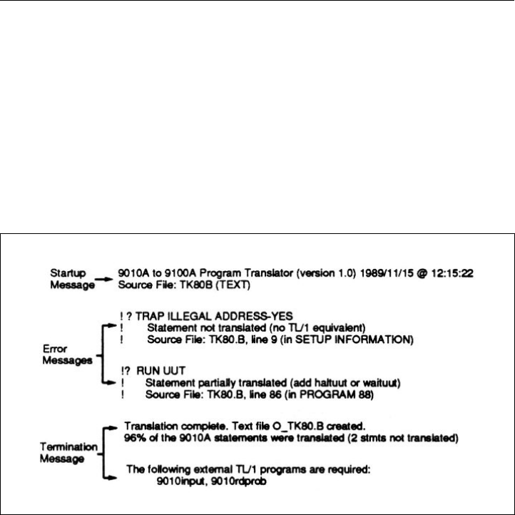
Figure A-1. Example of 9100A Monitor Output
The Startup Message A.2.1.
The startup message displays the version number of the translator,
the date and time, and the name of the input file.
9000A-030
A-3
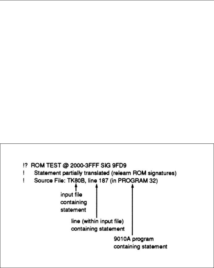
The Error Message A.2.2.
Each error message identifies a 9010A statement that could not be
translated to TL/1. Error messages are also written to the TL/1
output file. Refer to Figure A-2 for an example of an error message.
Each three-line error message has the following format:
• The first line contains the 9010A statement that was not trans-
lated.
• The second line explains why the statement was not trans-
lated.
• The third line identifies where the 9010A statement appeared
in the input file.
Figure A-2. Translator Error Message Example

9000A-030
A-4
NOTE
Each time an error is found, an error message is
written to the monitor.
The Termination Message A.2.3.
The termination message indicates that the translation is complete
and identifies the percentage of 9010A statements that are
successfully translated. The termination message also identifies the
external TL/1 programs that are required by your translated
program. These programs are provided on the translator disk. A
copy of these programs must be present on all 9100A/9105A
systems that your translated programs will be executed on.
If less than 100% of the statements are translated, there may be
differences in the execution of the 9010A and the 9100A programs.
Each statement that is not translated should be examined. In most
cases, there are workarounds that allow the 9100A program to
match the 9010A program. These workarounds are described in
Section 4. Many of the Setup Information statements do not affect
program operation.
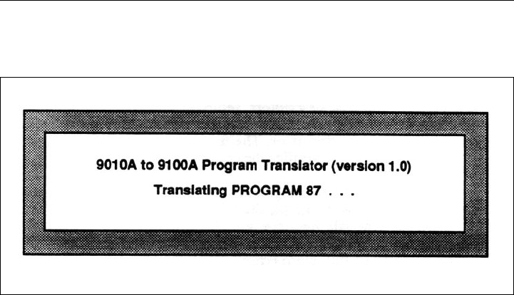
OPERATOR'S DISPLAY OUTPUT A.3.
The translator displays the startup and progress messages on the
operator's display. The startup message contains the translator
version number, and the progress message identifies the program
that is currently being translated. Each time the translator
encounters a new 9010A program in the input file, the display is
updated. An example of the operator's display output is shown in
Figure A-3.
9000A-030
A-5
Figure A-3. Operator's Display Output Example
LOG FILE OUTPUT A.4.
All of the information that appears on the monitor is also sent to a
text log file. The log file contains the translator start-up message,
error messages, and termination message. When the translation is
complete, the log file can be edited and reviewed. For information
on editing the log file, refer to Review the Translator Errors and
Complete the Translation, in Section 3. The name of the log file is
specified with the LOGFILE argument to the translator.

9000A-030
A-6
TL/1 OUTPUT A.5.
The translator generates a text output file containing the translated
address descriptors, setup information, and programs. The name of
the text file is specified with the OUTFILE argument to the
translator. The termination message printed to the 9100A monitor
verifies the creation of this file.
The output file contains global variable declarations, a function for
each 9010A program, the 9010exec function, and a main program.
The file may contain an async_input function. The TL/1 output file
also contains the translator errors embedded as comments. To find
these errors, use the 9100A editor SEARCH (F9) softkey. Each
error is prefixed with the characters "!?", and this string can be
searched for.
Figure A-4 shows two 9010A programs and the translated TL/1
version of these programs. Program 2 prompts for a number,
multiplies it by 2 and displays the result. Program 3 prompts for a
number, divides it by 2 and displays the result.
These 9010A programs are provided on the Translator diskette.
They are in the file /DR1/TRANSLATE/9010TAPE. To familiarize
yourself with the translation steps, it is recommended that you
translate this file and execute the resulting TL/1 program
9010A PROGRAMS
PROGRAM 2 48 BYTES
DPY-ENTER A DECIMAL NUMBER \8
REG9 = REG8 SHL
DPY-@8 * 2 = @9
PROGRAM 3 48 BYTES
DPY-ENTER A DECIMAL NUMBER \8
REG9 = REG8 SHR
DPY-@8 / 2 = @9
Figure A-4. TL/1 Output File Example

9000A-030
A-7
TL/1 TRANSLATED PROGRAMS
program 0_9010TAPE
declare
global numeric array [0:$F] reg
global numeric dpy
global numeric aux
global numeric dpy_in
global numeric aux_in
global numeric syncmode
end declare
!-------------------------- PROGRAM 2 --------------------
!
function P_2 ! PROGRAM 2 48 BYTES
declare
global numeric array [0:$F] reg
global numeric dpy
global numeric aux
global numeric syncmode
end declare
! DPY-ENTER A DECIMAL
! NUMBER \8
print using "\nl\lB[KENTER A DECIMAL NUMBER ", on dpy
'9010input' (10, $8)
reg[$9] = (reg[$8]) << 1 ! REG9 = REG8 SHL
! DPY-@8 * 2 = @9
print using "\nl\lB[K?@ * 2 = ?@", on dpy, reg[$8], reg[$9]
end function
!-------------------------- PROGRAM 3 --------------------
!
function P_3 ! PROGRAM 3 48 BYTES
declare
global numeric array [0:$F] reg
global numeric dpy
global numeric aux
global numeric syncmode
end declare
Figure A-4. TL/1 Output File Example (cont)

9000A-030
A-8
! DPY-ENTER A DECIMAL
! NUMBER \8
print using "\nl\1B[KENTER A DECIMAL NUMBER ", on dpy
'9010input' (10, $8)
reg[$9] = (reg[$8]) >> 1 ! REG9 = REG8 SHR
! DPY-@8 / 2 = @9
print using "\nl\1B[K?@ # 2 = ?@", on dpy, reg[$8], "/", reg[$9]
end function
!------------------------ 9010exec() ---------------------
!
function '9010exec' (prognum)
declare
numeric prognum
global numeric array [0:$F] reg
global numeric array [0:10,0:7] lreg
global numeric lreg_depth
end declare
! push local registers
if (lreg_depth = 10) then
fault 'FATAL-DEPTH EXCEEDED' ! 9010 programs nested
! too deeply
end if
lreg_depth = lreg_depth + 1
loop for i = 0 to 7
lreg[lreg_depth, i] = reg[i]
reg[i] = 0
end loop
if (prognum = 2) then
P_2()
else if (prognum = 3) then
P_3()
end if
! pop local registers
loop for i = 1 to 7
reg[i] = lreg[lreg_depth, i]
end loop
lreg_depth = lreg_depth - 1
end function
Figure A-4. TL/1 Output File Example (cont)

9000A-030
A-9
!------------------ main program starts here ------------------
dpy = open device "/term1", as "output", mode "unbuffered"
aux = open device "/port2", as "output", mode "unbuffered",
speed 9600, bits 7, stop 1, parity "odd", stall "on"
dpy_in = open device "/term1", as "input", mode "unbuffered"
aux_in = open device "/port2", as "input", mode "unbuffered",
speed 9600, bits 7, stop 1, parity "odd", stall "on"
syncmode = 0
lreg_depth = 0
loop while (1)
print using "\nl\1B[KEXECUTE PROGRAM ", on dpy
tmp = reg[0]
'9010input' (10, 0)
prognum = reg[0] \ reg[0] = tmp
'9010exec' (prognum)
end loop
end program
Figure A-4. TL/1 Output File Example (cont)
Descriptions of the contents of the TL/1 output file are found in the
following paragraphs.
Global Variable Declarations A.5.1.
The global variables include an array (reg) that simulates the
9010A register set, several numerics that are I/O channels (dpy, dpy
in, aux and aux_in), and a numeric (syncmode) that keeps track of
the current syncmode. The I/0 channels are used by the translated
DPY and AUX statements. Syncmode is used by the translated
READ PROBE statement.

9000A-030
A-10
Functions A.5.2.
Each 9010A program is translated into a TL/1 function. Each
program number is prefixed with "P_" to form the TL/1 function
name. For example, function P_15 is the TL/1 translation of
PROGRAM 15. Execution of these functions is controlled by the
main program.
The 9010exec Function A.5.3.
The 9010exec function is passed the number of a 9010A program
by translator generated TL/1 code and maps it onto the TL/1
function that should be executed. This function is called by the
main program, and the function is optimized by the translator to
recognize only program numbers that appeared in the input file.
Refer to the Appendix C for instructions on how to further optimize
this function.
The async_input () Function A.5.4.
The async_input function is included if your 9010A programs used
asynchronous input in a DPY statement. Refer to Section 4 for
instructions on how to use this function to complete the translation
of DPY statements.

9000A-030
A-11
The Main Program A.5.5.
The main program configures the Pod using several podsetup
statements if your input file contained setup information. The main
program opens I/O channels to the display, keypad, and RS-232-C
port. The 9100A has two RS-232-C ports, and the translator
assumes that /port2 should be used for AUX I/0. The following are
defaults to the port parameters:
port: /port2, baud rate: 9600, data bits: 7, stop bits: 1,
parity: odd, XON/XOFF: enabled
NOTE
If the port selection or parameters are incorrect for
your application, refer to Appendix C for instructions
on how to change them.
After opening the I/O channels, the main program goes into a loop
that simulates the 9010A EXECUTE key. The main program
prompts for a program number, then calls the 9010exec function to
execute the translated version of the 9010A program When the
current program terminates, the STOPPED LED turns on. Press the
CONT key on the 9100A operator's keypad to continue. When the
CONT key is pressed, the message "EXECUTE PROGRAM" is
displayed. The main program prompts for the next program to be
executed. To exit the main program, press the 9100A Stop key.

9000A-030
A-12

B-1
Appendix B
Translator Errors
OVERVIEW B.1.
This appendix describes the errors that can occur during the
translation process. Included with the error are possible remedies or
instructions to locate further information to eliminate these errors.
ERRORS WHILE TRANSFERRING FROM THE
9010A TO THE 9100A B.2.
Data is transferred from the 9010A to the 9100A through the RS-
232-C ports. As data is received by the 9100A, the terminal
emulator echoes the data on the 9100A monitor, allowing you to
watch the transfer. If nothing appears on the 9100A monitor or if
the data is garbled, a data transfer error has occurred.
Data transfer errors are most likely caused by problems with the
RS-232-C cable wiring or port configuration. Refer to Section 2 for
a description of the cable wiring and recommended port settings.

9000A-030
B-2
ERRORS WHILE TRANSLATING B.3.
Each time the translator encounters a line in the input file that
cannot be translated to TL/1, it displays an error message on the
9100A monitor. Each three-line error message has the following
format:
• The first line contains the 9010A statement that was not trans-
lated.
• The second line explains why the statement was not trans-
lated.
• The third line identifies where the 9010A statement appeared
in the input file.
For an example of an error message, see 9100A Monitor Output in
Appendix A. Table B-1 contains possible errors issued by the
translator.

9000A-030
B-3
Table B-1. Possible Errors Issued By The Translator
MESSAGE
Statement not translated (syntax error)*
Statement not translated (no address descriptors defined)§
Statement not translated (no TL/1 equivalent)†
Statement not translated (too many TRAP or ENABLE statements, maximum is 15
statements)£
Statement not translated (no TL/1 equivalent for asynchronous input)†
Statement not translated (unrecognized binary program)†
Statement not translated (no TL/1 equivalent for Merge Tape)†
Statement not translated (no TL/1 equivalent for PodSelfTest)†
Statement partially translated (add haltuut or waituut statement)†
Statement partially translated (relearn ROM signatures)†
Warning: Statement partially translated (if special address is used)‡
NOTES
* The translator does not recognize the input line as a valid 9010A statement.
If LINESIZE was not set to 255 when the 9010A programs were transferred to the 9100A, a
long line could have been split in two during the transfer. This would result in two
syntactically incorrect lines in the input file. If this was the case, edit the input file (INFILE),
join the two lines, and repeat the translation.
§ The input file did not contain address descriptors. Section 3 contains instructions on how to
transfer all the information on the 9010 tape. Transfer the data again and repeat the
translation.
£ The input file contained more than 15 TRAP or ENABLE statements. This can happen if
the setup information was sent more than once. Transfer the data again and repeat the
translation.
† Section 4 provides a workaround, or instructions on how to complete the translation.
‡ Appendix C provides instructions on how to complete the translation.

9000A-030
B-4
ERRORS WHILE COPYING TO TL/1 B.4.
No errors should occur during the copy. A copy error means that the
text file contained a line that was not valid TL/1 syntax.
EXECUTION ERRORS B.5.
If an error occurs when your translated TL/1 program is running, an
error message is displayed on the operator's display, and the
program terminates. Some possible errors are described below:
program '<program name>' is not on disk
Your translated program called a program or function that could not
be found. If a 9010A program is being called, add that program to
the translator's input file (INFILE) and repeat the translation. If an
external program is being called, copy the program from the
translator disk into the UUT.
program name doesn't match object name <name>
The name of a TL/1 program contained inside a file must be the
same as the file name. The translator checks that the TL/1 program
it generates has the same name as the output file it generates. If you
used a different destination name when copying the translator
output file from TEXT to PROGRAM, this error occurs at runtime.
Edit the program and change the program name to match the
filename.
cannot run program '<program name>' due to check errors
This error can result if the name of a program inside a file does not
match the filename. This was described for the previous error. If
this is not the problem, edit the program and press the CHECK
softkey. Check inserts error messages in the program as TL/1
comments. Each error message is prefixed with "+++". Use the
Editor SEARCH softkey to find this string.

C-1
Appendix C
Helpful Information
OVERVIEW C.1.
Appendix C contains additional information that may aid in
understanding the translator and reinforce what has been presented
in this manual.
OPTIMIZING THE 9010EXEC () FUNCTION C.2.
The translator generates a 9010exec() function. This function is the
entry-point to the execution of your 9010A programs. It is passed a
9010A program number, and maps that onto the TL/1 function to be
executed.
The following is a portion of this function:
function ’9010exec’ (prognum)
:
if (prognum = 0) then
P_0() ! execute function P_0
else if (prognum = 1) then
P_l() ! execute function P_l
else if (prognum = 3) then
P_3() ! execute function P_3
else if (prognum = 5) then
P_5() ! execute function P_5
end if
:
end function

9000A-030
C-2
This function is optimized to compare only against program
numbers that appeared in your 9010A input file.
NOTE
The program numbers are compared in numerical
order.
A significant speed improvement can be made by editing the TL/1
program and reordering the if-then-else statements so that the
program numbers are ordered from most commonly executed to
least commonly executed. For example, program 5 may be a delay
loop that is executed more than any other program. In this case, you
would want the first comparison to be against program number 5
rather than 0.
AUX PORT SELECTION AND
PORT PARAMETERS C.3.
The 9100A/9105A have two serial ports named /port1 and /port2.
On the 9010A, the baud rate, parity, number of data bits and stop
bits were set with switches on the rear panel of the instrument. The
translator assumes that /port2 should be used for AUX statements
and inserts two TL/1 statements into your program to open the port:
aux = open device "/port2", as "output", mode
"unbuffered", speed 9600, bits 7, stop 1, parity "odd",
stall "on"
aux_in = open device "/port2", as "input", mode
"unbuffered", speed 9600, bits 7, stop 1, parity "odd",
stall "on"
If you want to use /port1 or the speed, bits, stop, parity, or stall
parameters are configured incorrectly, edit the program and modify
both open statements to reflect the desired port and port parameters.
Use the 9100A Editor SEARCH softkey to find the open
statements. Refer to the 9100-Series TL/1 Reference Manual for
details on the TL/1 open statement.

9000A-030
C-3
9LC COMPATIBILITY C.4.
The translator can convert 9010A programs that were originally
written on a PC with the 9010A Language Compiler (9LC). 9LC
programs are translated like any other 9010A program. The
compiled programs are first transferred from the PC to the 9010A,
and then they are transferred to the 9100A for translation.
The translator cannot process the 9LC source directly because it
does not accept the 9LC language extensions. 9LC extended the
9010A language to include program comments, keyword
abbreviations, optional keywords, shorthand notation for unary
operators, symbolic register, program, and label names, and
includes files and lower-case alphabetics.
PROBE PULSER C.5.
9010A programs control the probe pulser by prompting you to
press the PULSE HIGH or PULSE LOW keys during program
execution. On the 9100A/9105A the probe pulser mode cannot be
changed from the operator’s keypad while a TL/1 program is
running. Instead, the program uses the TL/1 pulser function to
control the probe pulser directly.
To complete the translation:
1. Edit the TL/1 program file and find all places where you
are prompted to change the probe pulser mode.
2. Replace each prompt with the appropriate TL/1
statement:
pulser mode "high" ! to pulse the probe high
pulser mode "low" ! to pulse the probe low
pulser mode "toggle" ! to pulse the probe high
! and low
pulser mode "off" ! to turn the probe pulser
! off

9000A-030
C-4
SPECIAL ADDRESSES C.6.
Special addresses are addresses that are outside the normal address
space of a microprocessor. Some 9010A programs use special
addresses to access other address spaces (such as I/O), or to access
pod special functions. The 9100A/9105A built-in tests require valid
addresses, and an "Illegal Address" error will occur at runtime if a
special address is used.
To execute a built-in test at a special address on the 9100A/9105A,
the 9010A special address should be split into its two components:
the address space and the valid address. The TL/1 setspace function
is called to set the address space. Then the built-in test is called,
using only the valid portion of the address.
Each time the translator encounters a built-in test (BUS TEST,
RAM SHORT, RAM LONG, ROM TEST, IO TEST, or AUTO
TEST) in the 9010A program being translated, the program
translates the statement and issues the following warning message:
Warning: Statement partially translated (if special address
used)
To determine if the translation is complete, examine the address
used in the 9010A built-in test. If it is not a special address, the
translation is complete and no further action is required. You can
safely ignore the warning message. If you are not sure if it is a
special address, refer to your pod manual.
However, if a special address was used in the built-in test, you must
complete the translation. To do this, edit the TL/1 program file and
find the built-in test using the special address. Split the special
address into its two components (address space and valid address).
The following changes are required:
• Use the TL/1 getspace and setspace functions to set the
address space before the built-in test is called.

9000A-030
C-5
• Modify the address used by the built-in test to only use the
valid portion of the address.
• Use the TL/1 getspace and setspace functions to reset the
address space to MEMORY after the built-in test is called.
This ensures that later pod accesses will operate in the correct
address space.
For example, on the Z-80 pod, hexadecimal 0000 to FFFF are valid
addresses. The address 100C3 is a special address that refers to
address 00C3 in I/O space. The 9010A statement:
IO TEST @ 100C3 BTS 3D
is translated as follows:
s = podinfo addrinc
testramfast addr $100C3, upto $100C3, mask $3D, addrstep s
This translation is incomplete because $100C3 is a special address.
To complete the translation, insert a getspace and setspace
command and modify the address used in the testramfast built-in
test as follows:
s2 = getspace space "I/O"
setspace space s2
s = podinfo addrinc
testramfast addr $00C3, upto $00C3, mask $3D, addrstep s
s2 = getspace space "MEMORY"
setspace space s2
Refer to the getspace and setspace commands in the 9100-Series
TL/1 Reference Manual for more information

9000A-030
C-6
TRANSLATING IN BATCH MODE C.7.
If you have several 9010A tapes to be translated, you can create a
TL/1 batch file to do the translation. A batch file allows you to do
other things while the translator processes all the tapes. You start up
the TL/1 batch file program and then return when it is complete.
Although the early 9100A monitor output has scrolled off the
screen, the translation results can be seen by reviewing the log file
for each tape.
For example, assume you have five 9010A tapes to be translated.
All five tapes have been transferred into the UUT directory on the
9100A. The tapes were transferred into text files named TAPE1,
TAPE2, TAPE3, TAPE4, and TAPE5. The following TL/1 program
translates all five tapes in batch mode:
! This program is a "batch file" to translate five 9010A
! tapes. The output file names are unique. The TL/1 output
! files are prefixed with "0_" and the log file names are
! prefixed with "L_".
program batch
! The translator arguments are:
! translate (infile, outfile, logfile, embed)
translate ("TAPE1", "O_TAPE1", "L_TAPE1", "Y")
translate ("TAPE2", "O_TAPE2", "L_TAPE2", "Y")
translate ("TAPE3", "O_TAPE3", "L_TAPE3", "Y")
translate ("TAPE4", "O_TAPE4", "L_TAPE4", "Y")
translate ("TAPE5", "O_TAPE5", "L_TAPE5", "Y")
end program
