91sxh C Spec P Manual
User Manual: 91sxh-c-spec-p-manual
Open the PDF directly: View PDF ![]() .
.
Page Count: 21
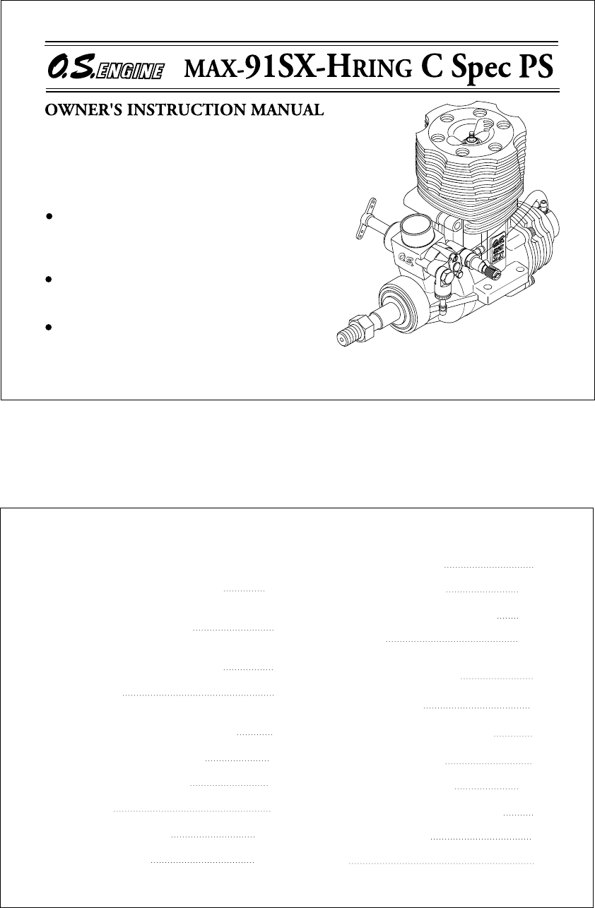
It is of vital importance, before attempting to
operate your engine, to read the general
'SAFETY INSTRUCTIONS AND WARNINGS'
section on pages 2-5 of this booklet and to strictly
adhere to the advice contained therein.
Also, please study the entire contents of this
instruction manual, so as to familiarize yourself
with the controls and other features of the
engine.
Keep these instructions in a safe place so that
you may readily refer to them whenever
necessary.
It is suggested that any instructions supplied
with the model, radio control equipment, etc.,
are accessible for checking at the same time.
1
CONTENTS
SAFETY INSTRUCTIONS AND
WARNINGS ABOUT YOUR O.S. ENGINE
NOTES ON INSTALLING,
COOLING-FAN AND CLUTCH
NOTES ON INSTALLING THE ENGINE,
NOTES ON HEATING THE GLOW PLUG
INTRODUCTION
BASIC ENGINE PARTS,
INSTALLATION OF THE CARBURETOR
INSTALLATION OF THE ENGINE
ABOUT THE PUMP SYSTEM
CARE OF FUEL PUMP
FUEL TANK AND PIPING
BEFORE STARTING
2-5
6
9
11
12
16-18
19
20-21
28
31
FACTS ABOUT GLOWPLUG
CARBURETOR CONTROLS
STARTING, RUNNING-IN ("Breaking-in")
ADJUSTMENT
SUBSEQUENT READJUSTMENTS
CARBURETOR CLEANLINESS
ADJUSTMENT CHART
INSTALLATION OF THROTTLE SERVO
CARE AND MAINTENANCE
EXPLODED VIEW & PARTS LIST
O.S. GENUINE PARTS & ACCESSORIES
THREE VIEW DRAWING
MEMO
7
8
13-16
30
10
36
22-24
24-27
29
32-35
37
38
2
Remember that your engine is not a "toy", but a highly efficient internal-
combustion machine whose power is capable of harming you, or others, if it is
misused.
As owner, you, alone, are responsible for the safe operation of your engine, so act
with discretion and care at all times.
If at some future date, your O.S. engine is acquired by another person, we would
respectfully request that these instructions are also passed on to its new owner.
SAFETY INSTRUCTIONS AND WARNINGS ABOUT YOUR O.S. ENGINE
The advice which follows is grouped under two headings according to the
degree of damage or danger which might arise through misuse or neglect.
WARNINGS NOTES
These cover events which
might involve serious (in
extreme circumstances, even
fatal) injury.
These cover the many other
possibilities, generally less obvious
sources of danger, but which, under
certain circumstances, may also
cause damage or injury.
3
WARNINGS
Never touch, or allow any
object to come into contact
with, the rotating parts.
Model engine fuel is poison-
ous. Do not allow it to come
into contact with the eyes or
mouth. Always store it in a
clearly marked container and
out of the reach of children.
Model engine fuel is also
highly flammable. Keep it
away from open flame,
excessive heat, sources of
sparks, or anything else which
might ignite it. Do not smoke
or allow anyone else to smoke,
near to it.
Model engines generate
considerable heat. Do not
touch any part of your
engine until it has cooled.
Contact with the muffler
(silencer), cylinder head or
exhaust header pipe, in
particular, may result in a
serious burn.
Never operate your engine in an en-
closed space. Model engines, like auto-
mobile engines, exhaust deadly carbon-
monoxide. Run your engine only in an
open area.
4
NOTES
These engine were designed for model
helicopters. Do not attempt to use it for any
other purpose.
Mount the engine in your model securely, fol-
lowing the manufacturers' recommendations,
using appropriate screws and locknuts.
Install an effective silencer (muffler). Frequent
close exposure to a noisy exhaust (especially
in the case of the more powerful high-speed
engines) may eventually impair your hearing
and such noise is also likely to cause
annoyance to others over a wide area.
Check the linkage to the throttle arm before
each flight.
Avoid sudden high r.p.m. immediately after the
engine is started, as the clutch will engage and
you may be struck by the rotor.
After starting the engine, carry out any needle-
valve readjustments after stopping the rotor by
closing the throttle to the lowest r.p.m..
Stop the engine before attempting to make
other adjustments to the carburetor.
Use an electric starter. The wearing of safety
glasses is also strongly recommended.
Press the rotor head down securely.
Take care that the glow plug clip or battery
leads do not come into contact with rotating
parts.
Adjust the throttle linkage so that the engine
stops when the throttle stick and trim lever on
the transmitter are fully retarded. Alternatively,
the engine may be stopped by cutting off the
fuel supply. Never try to stop the engine
physically.
5
NOTES
Take care that loose clothing (ties, shirt sleeves,
scarves etc.) do not come into contact with the
rotor. Do not carry loose objects (such as pen-
cils, screwdrivers, etc.) in a shirt pocket from
where they could fall through the rotor disc.
For their safety, keep all onlookers (especially
small children) well back (at least 20 feet or 6
meters) when preparing your model for flight. If
you have to carry the model to the take-off point
with the engine running, be especially cautious.
Hold the rotor securely and keep well clear of
spectators.
Warning! lmmediately after a glowplug-ignition
engine has been run and is still warm,
conditions sometimes exist whereby it is just
possible for the engine to restart when turned
over WITHOUT the glowplug battery being
reconnected. Remember this if you wish to
avoid the risk of accidents.
6
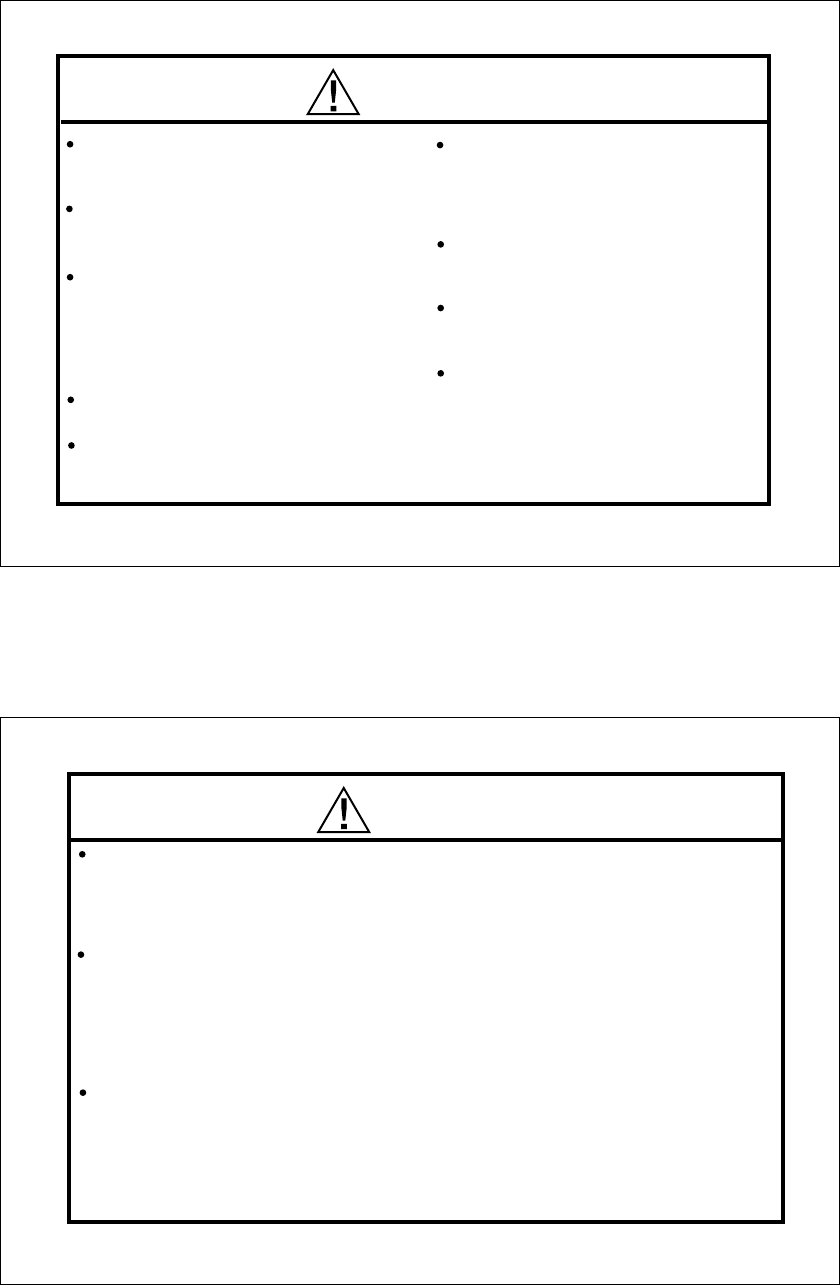
Notes on installing cooling fan and clutch
Do not use a tool which
locks piston when
installing a cooling-fan
and clutch, or top of
the piston may be
damaged. Also, do not
insert a screw driver or
the similar into the
exhaust port.
It is recommended to use Crankshaft
Clamp 7091 (Code No.71530500) available
as an optional tool.
It is made of durable engineering plastic
and locks the crankshaft without risk of
damage to any part of the engine.
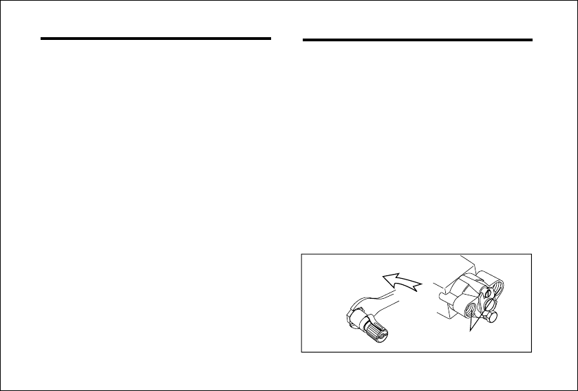
Application is as follows:
Remove the crankcase rear cover plate from the
engine and rotate the crankshaft to the bottom
dead center (BDC) position.
Insert the crankshaft clamp so that its grooved
portion surrounds the crankpin and lower end of
the connecting rod and securely tighten the fan
or clutch onto the crankshaft.
Insert this groove onto
the connecting rod.
BDC position
Rotate the crankshaft so that the
connecting rod comes to this position.
7
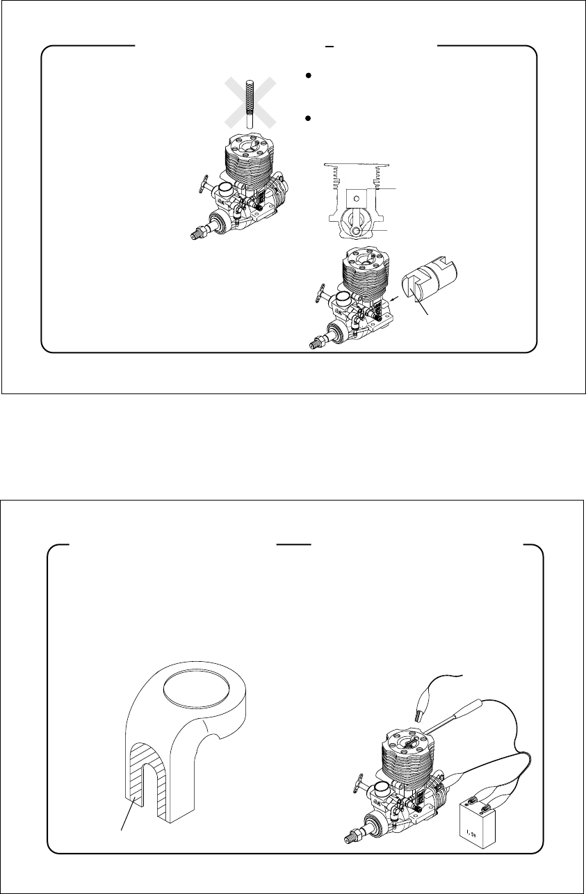
Note on installing the engine Note on heating the glow plug
Cooling fan cover from some
helicopter models interferes the
heatsink head.
In this case, cut out the cover as
illustrated.
Example
Cut out according to the heatsink head.
Heatsink head, crankcase and cover
plate of the engine are treated with
Alumite which does not conduct
current. Therefore, when heating a
glow plug, connect one lead to the
glow plug and the other to the head
of cover plate fitting screw.
Example
8
Because of initial tightness, a standard
electric starter may have difficulty in
rotating the engine when cold, before it
has been adequately run-in. In this
case, use a high-torque type starter.
DO NOT, however, confuse tightness
with the symptoms of hydraulic lock
caused by an excess of fuel within the
cylinder - often the result of over-
priming.
Attempting to force the engine to turn
over in this condition may cause
internal damage. Instead, remove the
glowplug, invert the engine and eject
surplus fuel from the combustion-
chamber.
Note:
This is a pumped version of the 91SX-H
RING C Spec. Pump and muffler
pressurized fuel system ensure stable fuel
supply irrespectire of model attitude and
fuel level in the tank. Return system in the
carburetor ejects the excess fuel and
avoids getting rich at around idling. Easy to
adjust single needly Type 60M carburetor
incorporates a check valve which controls
the fuel supply at any r.p.m. range.
INTRODUCTION
As delivered, the carburetor is not fit to
the engine.
Standard accessories
Glow Plug No.8 Woodruff Key
Needle Adjusting Screw (M2.6x5 1pc.)
Silicone tube
Note:
Carburetor Complete 60M
T nipple
Instruction manual
( 2.5x 5.5xL300mm)
9
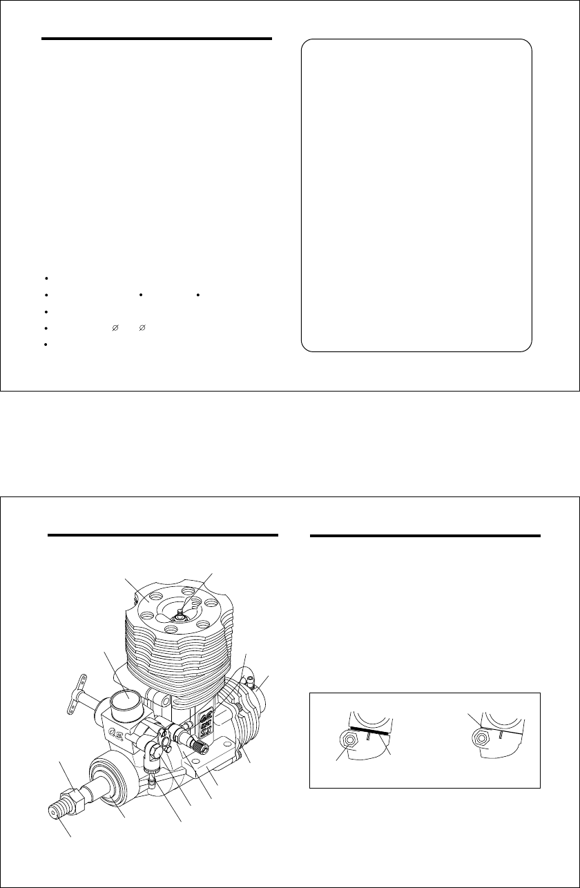
BASIC ENGINE PARTS
Heatsink Head
Carburetor
Typr 60M
Crankshaft
Propeller nut
Crankcase
Thrust Washer
Glowplug
Beam Mount
Pump
As delivered, the carburetor is not fit to the engine.
Secure it as follows.
INSTALLATION OF THE CARBURETOR
Retainer Nut
Carburetor Rubber
Gasket
0.2mm gap
Loosen the retainer nut, press the carburetor well
down into the intake boss, compressing the rubber
gasket as shown in the sketch, before re-tightening
Nut.
Rotate the retainer nut gently until it stops, then
tighten a further 90-120 degrees. Do not over-
tighten the screw as this will damage the carburetor
body.
1.
2.
Pump Holder
60M One-way Valve
Return Screw
Cover Plate
Press down until the gasket becomes almost invisible.
10
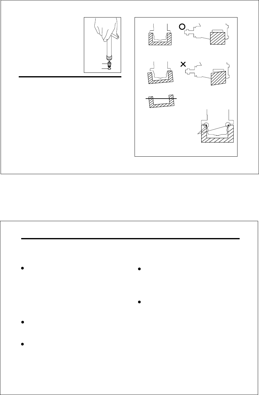
INSTALLING THE GLOWPLUG
Install the washer on the
glowplug and screw
carefully into cylinder-
head, making sure that it
is not cross-threaded
before tightening firmly.
Glow plug
Washer
INSTALLATION OF THE ENGINE
The under-surfaces of all O.S. engine beam
mounting lugs are precision machined flat and
exactyly parallel to the engine's horizontal axis. It is
essential that the engine mounts in the model are
also accurately made and aligned. If they are not,
they will cause stress and distortion within the engine
itself, probably resulting in loss of performance and
internal damage.
The recommended screws for securing the engine to
the engine mounts in the model are 4mm or 4-40
steel Allen type. It is also advisable to use lock
washers or LOCTITE to prevent nuts from loosening.
Front view
CORRECT
Side view
Top surfaces are in the same plane.
Re-align the surfaces as necessary
INCORRECT
Top surfaces are not
in the same plane. Top surfaces are not in the
same plane.
Engine does not rest firmly.
Make sure that only the under-
surfaces of the engine’s mounting
lugs are in contact with the engine
mount.
11
ABOUT THE PUMP SYSTEM
Please understand the pump construction before
piping.
Pump functions in accordance with the engine
r.p.m. Rotating the engine by an electric starter
without connecting battery to a plug sucks fuel.
Prolenged this action may result in over priming.
Attempt to start the engine with over-priming may
result in bending a connecting rod and damaging
the engine.
NOTE:
Fuel is pumped from the tank and delivered to the
carburetor. Set the main needle a little rich at early
stage.
With this system the pump delivers the fuel at
constant pressure even at idling. Then,
unconsumed fuel is returned to the tank ria one-
way valve which avoids getting rich at around
idling.
If the main needle is set correctly, fuel return will
stop at around 60% throttle opening. Therefore, in
the high air flight that requires wider throttle
opening the engine runs under the effects of
muffler pressure, pump pressure and main needle.
During hovering that requires around half throttle
the engine runs under the effects of muffler
pressure, main needle, mixture control and retur
fuel volume.
12
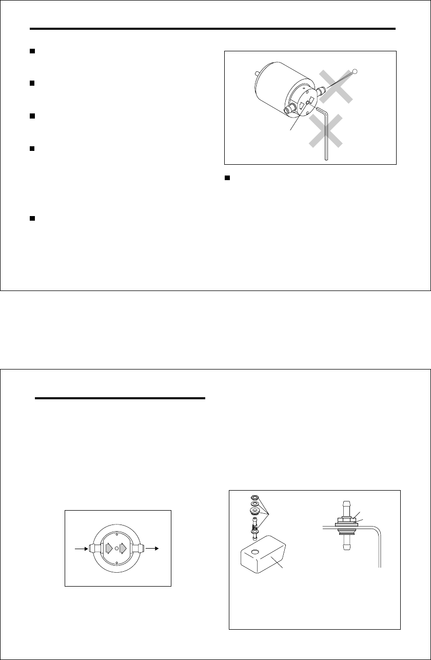
CARE OF FUEL PUMP
NEVER disassemble the fuel pump or pressure
regulator. Their original performance may not be
restored after reassembly.
NEVER insert anything into the inlet or outlet
nipples in an attempt to clear a suspected
obstruction.
ALWAYS use fuel filters. Keep the fuel tank
scrupulously clean and filter all fuel as it enters the
tank (e.g.via an O.S.'Super-Filter' Code
No.72403050) and use a good quality in-line filter
between the tank and pump. Remember to inspect
filter screens at regular intervals and rinse clean as
necessary.
Do not clean the pump with organic solvent such
as kerosene, light machine oil, gasoline, thinner or
crc or the silicone rubbur parts inside is
detoriorated. Be sure to use methanol or fuel.
Do not more the pump adjusting screw at the
center a the adjustment gets out of order and the
parts inside is damaged.
Do not remain fuel in the pump. After finishing the
day's flight session, be sure to use out the fuel in
the pump. Stop the fuel flow to the pump with the
stopper and run the engine at idling to use out the
fuel in the pump. After stopping the engine, rotate
the engine by electric starter to eject fuel inside the
engine.
Pressure adjusting screw
13
IN OUT
FUEL TANK AND PIPING
Install the engine and a muffler according to the
instructions supplied with the model. Then, connect
piping between tha muffler and fuel tank for muffler
pressurized fuel feed. Then, cut the silicone tube
supplied to 96mm and connect the pump and
carburetor with it.
Pump has fuel flow direction as shown in the sketch.
Be sure to connect between out nipple and carburetor
inlet nipple.
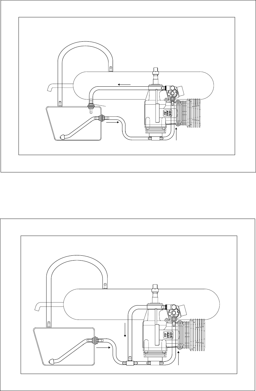
Next, connect piping from one-way valve for fuel
retur. There are two ways.
To return the fuel to the tank.
1.
Connect between one-way valve and fuel tank. Fit a
nipple on the tank. This system ensures stable fuel
supply even with the 3D flight which requires
successire big throttle works.
Clear the burr, if any, off the hole to fit the nipple
with a cutter knife. Also clean the tank with
methanol to remove the dust or tank cut-off
particle.
Fuel tank
Commercialy
available nipple
Nut
Washer
14
To return the fuel to the tank
muffler pressure
Silencer
Fuel tank
Fuel flow
Pump
Commercialy
available nipple
1.
15
2. To return the fuel in front the pump
using the T nipple.
muffler pressure
Silencer
Fuel tank
Fuel flow
Pump
In this case, fitting an additional nipple on the tank is
not required. However, pumped out fuel pressure is
increased, and the main needle needs to be closed
further, which results in a sensitive needle reaction
and mixture gets lean at halh throttle with some
types mufflers. In this case, it is suggested to use
yhe pattern 1.
T nipple
16
BEFORE STARTING
Tools, accessories, etc.
The following items are necessary for operating the
engine.
1 Fuel
Select, by practical tests, the most suitable fuel from
among the best quality fuels available in your country
for helicopter use. For the best throttle response, a
fuel containing 10% to 30% nitromethane is
preferable. Lubricants may be either castor-oil or a
suitable synthetic oil (or . a blend of both) provided
that they are always of top quality. For consistent
performance and long engine life, it is essential to use
fuel containing AT LEAST 18% lubricant by volume.
Some fuels containing coloring additives tend to
deterriorate and may adversely affect running
qualities. If in doubt compare to a fuel known to be
good.
Model engine fuel is poisonous. Do not allow
it to come into contact with the eyes or
mouth. Always store it in a clearly marked
container and out of the reach of children.
Reminder!
The pump requires running-in as with the engine. Be
sure to check the silicone tubes and connections
carefully for any cracks on the tubes and loose
connections as the engine runs ejecting excess fuel.
17
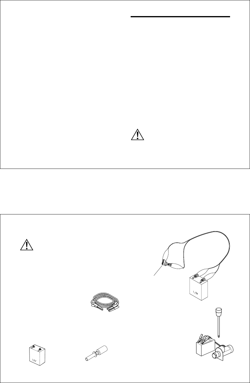
4 Glowplug battery
The power source for heating the glowplug may be
either a large heavy-duty 1.5volt dry cell, Ni-cd battery
or battery integrated booster.
1.5 volt dry cell
2 Glowplug
O.S. No.8 glowplug is installed in the engine.
3 Battery leads
These are used to conduct current
from the battery to the glowplug.
Basically, two leads, with clips, are
required, but, for greater conve-
nience, twin leads with special
glowplug connectors, as shown on
the right, are commercially available.
Model engine fuel is also highly flammable.
Keep it away from open flame, excessive
heat, sources of sparks, or anything else
which might ignite it. Do not smoke, or allow
anyone else to smoke, near to it.
Battery Integrated booster
Battery leads
Make sure glowplug element
glows bright red inside room
or shadow.
Battery leads
12V Battery Starter
6 Electric starter and starter
battery
An electric starter is recom-
mended for starting.
5 Hexagon starting shaft
This shaft mounted on an
electric starting motor is driven
into the shaft cup to turn the
engine.
In case of 1.5volt dry cell
18
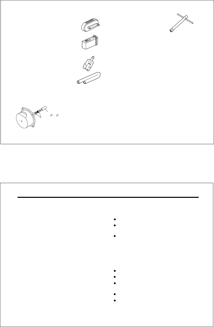
10 Plug wrench
Used for tightening glowplug. The
O.S. long plug wrench is available
as an optional accessory.
7 Fuel pump
For filling the fuel tank one of the
purpose-made manual or electric fuel
pumps may be used to transfer fuel
directly from your fuel container to the
fuel tank.
For tightening
glowplug
Manual
Electric
Fuel pumps
Fuel Can Filter
8 Fuel container filter
Install a filter on the outlet tube of your
refuelling container to prevent entry of
foreign matter into the fuel tank
9 Silicone tubing
This is required for the connection
between the fuel tank and engine.
ID 2.5mm and OD 5-5.5mm one
would be suitable.
Silicone tubing
2x 5xL12mm
Silicone Tube
Joint Nipple
(Joint nipple and silicone tube are fit
on the cover plate.)
If the silicone tube on the cover plate is damaged,
use commercially available 2mm ID and 5mm OD
silicone tube by cutting to 12mm length.
19
FACTS ABOUT GLOWPLUGS
The role of the glowplug
Glowplug life
Particularly in the case of very high performance
engines,
glowplugs must be regarded as expendable
items.
With a glowplug engine, ignition is initiated by the
application of a 1.5-volt power source. When the
battery is disconnected, the heat retained within the
combustion chamber remains sufficient to keep the
plug filament glowing, thereby continuing to keep the
engine running. Ignition timing is 'automatic' : under
reduced load, allowing higher rpm, the plug becomes
hotter and, appropriately, fires the fuel/air charge
earlier; conversely, at reduced rpm, the plug become
cooler and ignition is retarded.
Since the compatibility of glowplug and fuel may have
a marked effect on performance and reliability, it may
be worthwhile to choose the R/C type plug found
most suitable after tests. Recommended O.S. plugs
are No.8 and A5. Carefully install plug finger-tight,
before final tightening with the correct size plug
wrench.
Install a plug suitable for the engine.
Use fuel containing a moderate percentage of
nitromethane.
Do not run the engine too lean and do not leave the
battery connected while adjusting the needle.
However, plug life can be extended and engine
performance maintained by careful use, i.e.:
Apart from when actually burned out, a plug may
need to be replaced because it no longer delivers its
best performance, such as when:
When to replace the glowplug
Filament surface has roughened and turned white.
Filament coil has become distorted.
Foreign matter has adhered to filament or plug
body has corroded.
Engine tends to cut out when idling.
Starting qualities deteriorate.
20
CARBURETOR CONTROLS
With a fixed-wing model, power failure is rarely a
serious threat to the safety of the aircraft since it can
usually glide down to a safe landing. In a helicopter,
on the other hand, it is vitally imporant that the engine
keeps running and that there is a quick and reliable
response to the throttle in order to ensure safe ascent
and descent of the model.
The High-Speed (Main) Needle Valve
When set to produce maximum power at full
throttle, this establishes the basic fuel/air mixture
strength. This is then maintained by the carburetor's
automatic mixture control system to cover the
engine's requirements at reduced throttle settings.
The Idle Mixture Control Screw
This provides the means of manually adjusting the
60K's mixture control valve. By setting the Mixture
Control Screw for the best idling performance, the
mixture control valve automatically ensures that fuel is
accurately metered to maintain the correct mixture
strength as the throttle is opened.
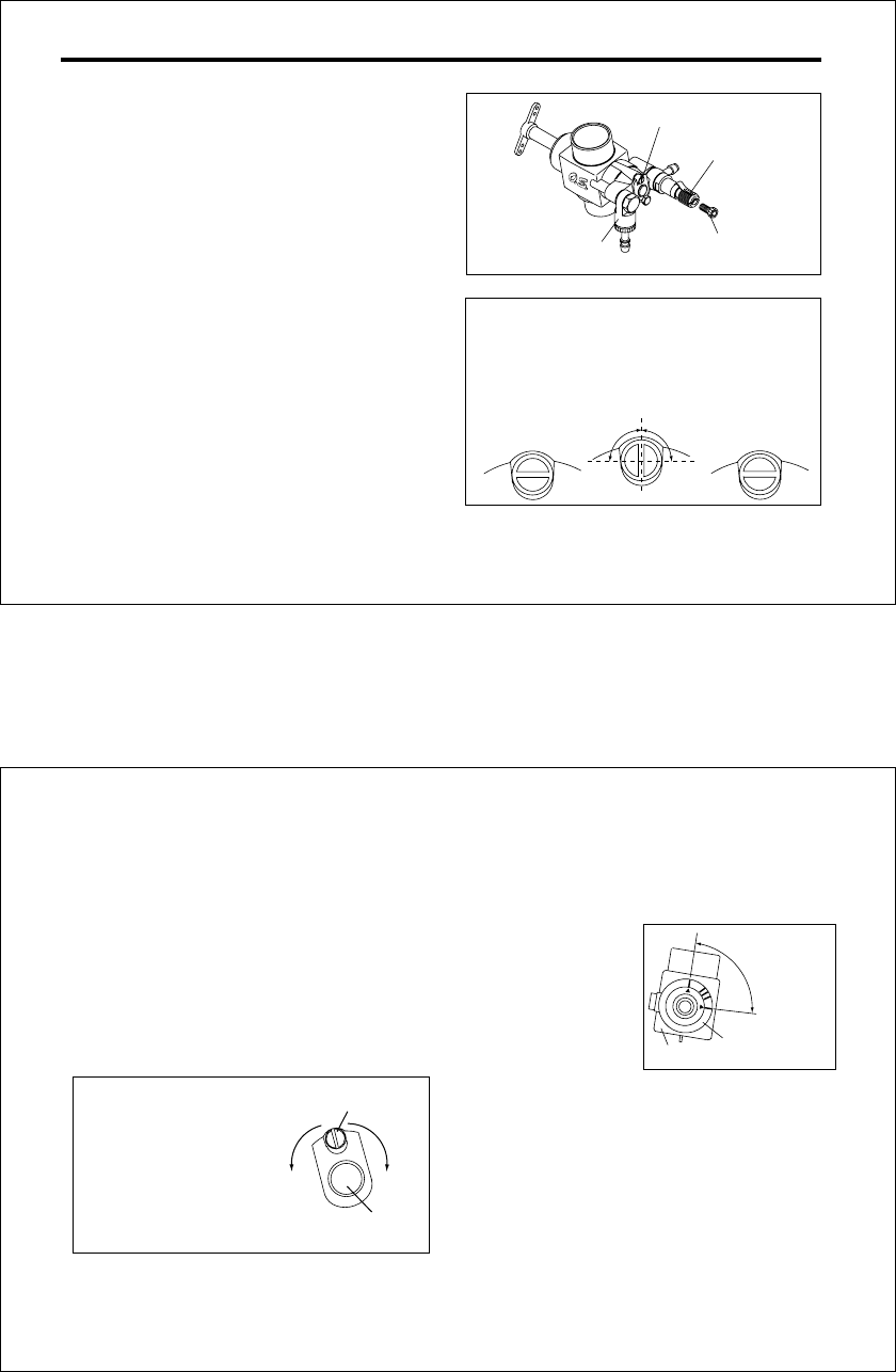
Two adjustable mixture controls are incorporated in the
Type 60M. They are as follows.
A
B
Idle MIxture Control Screw
High Speed Needle Valve
(Main Needle)
Needle
Adjusting screw
As the idle mixture control screw is applied with LOC-
TITE, at first times it is felt stiff, and it is suggested to
use a littli oversized screwdriver. The screw can be
turned only 90 degrees either way. Do not force to turn
further, or it may break or cause trouble.
NOTE
90 degrees
90 degrees
one-way valve
21
BASIC POSITION OF MIXTURE CONTROL VALVE
(Mixture Control Screw)
Thick
Mixture Control Valve
MIxture Control Screw
Lean
With a model helicopter, adjustments may vary due to
various factors such as climatic conditions, fuel,
muffler, main rotor, weight of the model, gear ratio, etc.
89 degrees
When the triangle mark on the carburetor rotor meets
the far right mark, the throttle is fully closed. When the
triangle mark meets the top mark, the throttle is fully
open. The range is 89 degrees. You may use the other
three marks as the reference marking of throttle
opening to your preference when hovering.
WARNING!
Never try to check the triangle mark position while
the engine is running and rotor is
rotating, or you may be hit by rotating rotor which
results in serious injury. Stop the engine and rotor
before checking the triangle mark position.
Graduations on the carburetor body
Carburetor Rotor
Carburetor Body
Fully closed
position
Fully opened position
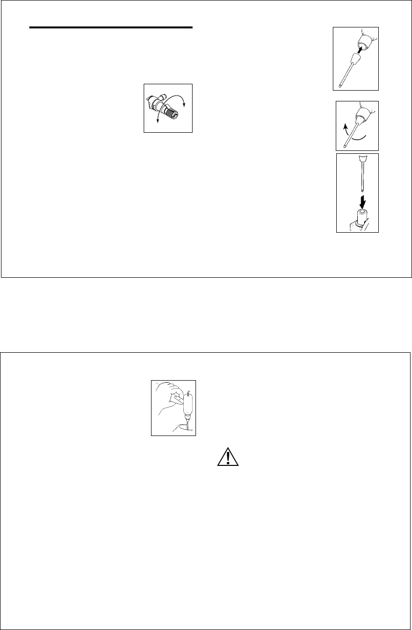
HEX KEY NEEDLE ADJUSTMENT
The knurled head of the main needle valve (High-Speed)
is provided with diagonal slots for use with a screwdriver.
Alternatively, formore positive location via an Allen
hexagonal key, these heads also have M2.6 internal
threads, into which M2.6x5mm Allen cap-head screw
may be fitted. To avoid risk of damage to the fuel
passages when tightening these screws, remove the
needle valves from the carburetor and use 'Loctite'
thread-lock compound to secure the screw.
As delivered, the Mixture
Control Screw is positioned
at the center as shown in the
sketch. Mixture gets lean
when the Mixture Control
Screw is turned right, while
mixture gets rich when the
Mixture Control Screw is
turned left.
Therefore, the Mixture Control Screw position will
vary with each model and set- up, and it is normal if
the Mixture Control Screw position is off center.
As shown in the sketch,
the carburetor has
graduation marks.
22
STARTING
Close
Open
Be sure to use a muffler pressurized fuel feed. Use
the same fuel as you intend to employ for actual
operation of your model.
1.
2.
Opening and closing of the Needle-Valve
Turn the needle clockwise to
close the needle-valve, and turn
the needle counter-clockwise to
open the needle-valve as shown
in the sketch.
High Speed needle-valve:
exactly two turns open from the fully closed
position.(Note: If a different muffler is used, this
setting may require readjustment)
Idle Mixture Control Screw:
at basic position when the engine leaves the
factory.
4.
5.
6.
Checking the rotating direction of the starter
Make sure that the starter rotates
to the direction shown in the
sketch. If the direction is reverse,
reverse the leads on battery.
Inserting the starter shaft
Insert the starting shaft into the
shaft cup securely.
Priming
Without energizing the glowplug,
open the throttle a little from the
idling position. Turn the engine
over using the starter until the fuel
is seen to reach carburetor.
3. Preparation of the starter
Install the starting shaft to the
starter securely.
Improper installation will allow the
shaft to swing creating a
dangerous situation.
23
In case the engine does not stop.
Hold the rotor head, and pinch the fuel line to stop the
fuel supply. If it still does not stop, pull off the fuel line
from the carburetor.
It is necessary to readjust the throttle linkage so that
the carburetor rotor is fully closed when the throttle
stick and throttle trim on the transmitter are fully
pulled Down.
Stopping the engine
Fully pull down the throttle trim on the transmitter.
Starting
Connect the battery to the glowplug and start the
engine by applying the starter. When started, switch
off the starter and withdraw the starting shaft after
making sure the rotation of the starter shaft stops.
Preparation of starting
Make sure that the transmitter
throttle stick is at the fully closed
position and the throttle trim at center
position, and make sure that idle-up
switch on the transmitter is off. Hold
the rotor head by hand so that rotor
cannot rotate when the engine is Started. Also, steady
the model with a foot on the landing gear skid.
7.
8.
9.
NOTE:
If the throttle response is poor or the engine
stops due to a temporarily over-rich mixture im-
mediately after the engine is started, pinch the
fuel line for one or two seconds until the engine
r.p.m. increase and the engine runs steadily.
Reminder!
Never touch, or allow any object to
come into contact with, the rotating
rotor.

24
All internal-combustion engines benefit, to some
degree, from extra care when they are run for the first
few times known as running-in or breaking-in.
This is allows the working parts to mate together
under load at operating temperature.
However, because O.S. engines are made with the
aid of the finest modern precision machinely and from
the best and most suitable materrials, only a very
short and simple running-in procedure is required and
can be carried out with the engine installed in the
model. For the first few flights with a new engine i.e.
while the engine is being run-in set the needle-
valve for a slightly rich mixture not excessively rich
as this may result in poor throttle response and cause
the engine to stope. About one half turn open from
the nomal setting will usually suffice.
RUNNING-IN ("Breaking-in")
ー
ADJUSTMENT
Please observe the following before beginning to
make any adjustment.
High-Speed Needle Valve. Turn this approximately
30 degrees (3 to 4 click) at a time, when making
initial adjustments; then in steps of approximately
15 degrees (1 to 2 clicks) when making final
adjustments.
Idle Mixture Control Screw. Turn approximately 10
degrees at a time. It turns approximately 90
degrees both side from the center. Turn left to
enrich the idle mixture and turn right to lean the idle
mixture.
25
The general course of adjustment procedure is
shown in the ADJUSTING CHART and is correct
for a fuel containing 20% lubricant and 15-30%
nitromethane.
Bear in mind that fuels containing relatively large
percentages of power-boosting nitromethane operate
at richer mixture settings than are needed for mild
fuels and will, therefore, require the High-Speed
Needle Valve to be readjusted accordingly. The type
and percentage of lubricant used is also a factor
here, as noted later in these instructions.
As a safety measure, first check the transmitter
controls, including the throttle stick and trim lever
positions, and hold the main rotor securely before
starting the engine.
This carburetor is not equipped with a throttle
stop screw. Instead, idling speed is adjusted
by means of the throttle trim lever on the
transmitter.
Warm the engine by allowing it to idle for about 30
seconds. If the engine stops, advance the throttle
trim lever slightly to increase the idle rpm. Then
open the throttle sufficiently to 'float' the model
above the ground. lf, at this time, the engine is
slow to pick up and produces an excess of
exhaust smoke, the mixture is too rich. Correct
this condition by turning the Mixture Control Screw
clockwise 10 degrees. lf the mixture is extremely
rich, engine rpm will become unstable: opening
the throttle will produce a great deal of smoke and
rpm may drop suddenly or the engine may stop.
This condition may also be initiated by an
excessively prolonged warming-up period. lf, on
the other hand, the mixture is too Iean, this wiIl be
indicated by a marked lack of exhaust smoke and
a tendency for the engine to cut out when the
throttle is opened. ln this case, turn the Mixture
Control Screw counter-clockwise 10 degrees to
enrich the mixture.
ADJUSTMENT PROCEDURE
1.

26
Having provisionally set the idle mixture, the next
step is to adjust the mixture for hovering flight.
Hover the model and actuate the throttle to observe
response over the medium speed range. lf the
engine smokes excessiveIy and throttle response is
poor, the mixture is too rich ; in which case, land the
model and turn the High-Speed Needle Valve
clockwise. Do not close the High-Speed NeedIe
Valve more than the recommended initial
adjustment (3 to 4 clicks) at a time, keeping it a little
on the rich side at this stage.
lf, on the other hand, hovering is not stable and
response to the throttIe is over-sensitive, or if the
engine tends to overheat, this indicates that the
mixture is too lean and should be corrected by
turning the High-Speed Needle Valve counter-
clockwise.
2. After about 10 seconds of idling, open the throttle to
'float' the model. lf the transition is smooth, the idle
mixture is O.K. If the symptoms of either rich or Iean
running are
observed, readjust the Idle Mixture
Control Screw accordingly.
When satisfactory hovering flight has been achieved,
land the modeI again and re-check the engine's idle
qualities.
27
For helicopters, good throttle response at medium
r.p.m. (e.g. hovering speeds) is most important,
since this is a power range widely used in
helicopter flight. The optimum fuel / air nixture
strength at medium speeds is dependent on
obtaining balanced adjustment of both the Needle
Valve and the Mixture Control Valve.
Now adjust the High-Speed Needle Valve to
achieve the best performance when the model is
flying at full throttle. lf, at full throttle, acceleration
is poor, the exhaust unduly smoky and the model
fails to reach expected straight line speed, the
mixture is too rich and the High-Speed Needle
Valve setting will need to be reduced.
lf, however, after smoothly acceIerating to
satisfactory high-speed straight and level flight,
power is lost when the model is puIled up into a
climb, the mixture is too lean. ln this case, land the
model immediately and readjust thw High-Speed
Needle Valve to a richer setting.
3.
4. Having now found the optimum setting for the
High-Speed Needle Valve, re-check the engine's
idle performance, fine tuning the Idle Mixture
Control Screw, if necessary, to perfect the idle.
If both controls are alreday at their optimum setting,
some modification to these settings may be
necessary to achieve satisfactory mid-range throttle
response, but such readjustments should only be
made within the rarge where idling reliability and high
speed performance are not undnly compromised.
28
CARBURETOR CLEANLINESS
The correct functioning of the carburetor depends on
its small fuel orifices remaining clear.
The minute particles of foreign matter that are present
in any fuel can easily partially obstruct these orifices
and upset mixture strength so that engine
performance becomes erratic and unreliable.
It is recommended that fuel is passed through a filter
when the tank is filled and that a good in-line filter is
installed between the fuel tank and carburetor and,
furthermore, that this filter is frequently cleaned to
remove dirt and lint that accumulates on the filter
screen.
Finally, occasionally remove the needle-valve holder
from the carburetor as shown in Photo and extract
any remaining foreign matter that may have lodged in
the location shown in the sketch.
Remove this with
an 8mm spanner
Dirt and fbrous matter
mostly accumulate here
SUBSEQUENT READJUSTMENTS
Once the engine has been run-in and the carburetor
controls properly set up, it should be unnecessary to
alter the mixture settings, except to make minor
changes to the Main (High-Speed) Needle Valve
occasionally, to take account of differences in climatic
condisitions.
However, as previously mentioned, the use of a
different fuel, particularly one containing more, or
less, nitromethane and / or a different type or
proportion of lubricating oil, is likely to call for some
modification to the High-Speed Needle-Valve
adjustment.
As a safety measure, it is advisable to increase the
High-Speed Needle Valve setting by an extra half-turn
counter-clockwise, prior to establishing the new
setting. The same applies if the silencer type is
changed. A different silencer may alter the exhaust
pressure applied to the fuel feed and call for a revised
Needle-Valve setting.
The use of a different glowplug, or changes to the
main rotor and its pitch angles may also require
compensating carburetor readjustments.
29
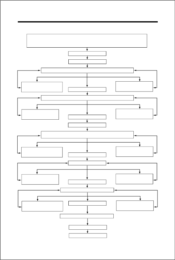
ADJUSTING CHART
High Speed Needle Valve - 2 turns opened from fully closed position.
Idle Mixture Control Screw - 2 turns opened from fully closed position.
Start the engine
Warm up the engine
Observe the mixture condition while "floating" the model
Turn the Idle Mixture
Control Screw counter-
clockwise 10 degrees Idling OK
Turn the Idle Mixture
Control Screw
clockwise 10 degrees
Lean mixture Rich mixture
Observe the hovering mixture condition
Open the High Speed
Needle Valve
(Turn counter-clockwise)
Hovering OK
Lean mixture Rich mixture
Close the High Speed
Needle Valve
(Turn clockwise)
Land the model
Idle for approx: 10 seconds, then reopen throttle to
observe transition ("Float" the model)
Idling OK
Lean mixture Rich mixture
High Speed Flight
Lean mixture Rich mixture
High Speed Flight OK
Fine tuning of hovering mixture
Hovering OK
Adjustment completed
Open the High Speed
Needle Valve
(Turn counter-clockwise)
Close the High Speed
Needle Valve
(Turn clockwise)
Fine tuning of idling mixture
Lean mixture Rich mixture
Idling OK
Turn the Idle Mixture
Control Screw
clockwise 10 degrees
Turn the Idle Mixture
Control Screw
clockwise 10 degrees
Turn the Idle Mixture
Control Screw counter-
clockwise 10 degrees
Turn the Idle Mixture
Control Screw counter-
clockwise 10 degrees
30
INSTALLATION OF THROTTLE SERVO
After the engine is installed in the helicopter, please
observe the following recommendations when linking
the throttle servo to the carburetor.
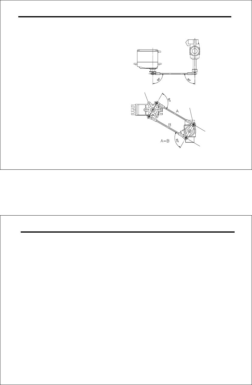
Locate the servo so that its output arm and the
throttle pushrod are, as close as possible, di-
rectry in line with carburetor's throttle arm, as
shown.
Servo output arm
Throttle control rod A and B should be equal
length. Set the linkage so that the servo output
arm and throttle arm are parallel when the
throttle stick on the transmitter is at middle
position. If differential throttle movement is re-
quired, make necessary adjustment at the
transmitter.
Throttle arm
27mm
31
CARE AND MAINTENANCE
The minute particles of foreign matter, that are
present in any fuel may, by accumulating and
partially obstructing fuel flow, cause engine
performance to become erratic and unreliable.
O.S. 'Super-Filters' (large and small)are available,
as optional extras, to deal with this problem.
One of these filters, installed in the outlet tube
inside your refueling container, will prevent the
entry of foreign material into the fuel tank. It is also
recommended that a good in-line filter be installed
between the tank and carburetor.
1. Finally, inject some after-run oil into the engine. Rotate
the engine a few times by hand, to make sure that it
is free, and then with an electric starter for 4 to 5
seconds to distribute the oil to all the working parts.
These procedures will reduce the risk of starting
difficulties and of internal corrosion after a period of
storage.
Do not inject after-run oil into the carburetor as this may
cause the O-rings inside the carburetor to deteriorate.
Note:
2.
3.
4.
Do not forget to clean the filters regularly to remove
dirt and lint that accumulate on the filter screens.
Also, clean the carburetor itself occasionally.
At the end of each operating session, drain out any
fuel that may remain in the fuel tank. Next, energize
the glowplug and try ot restart the engine to burn off
any fuel that may remain inside the engine.
Repeat this procedure until the engine fails to fire.
Remove the glowplug and eject any remaining fuel/oil
residue by rotating the engine with an electric starter
for 4 to 5 seconds while the engine is still warm.
32
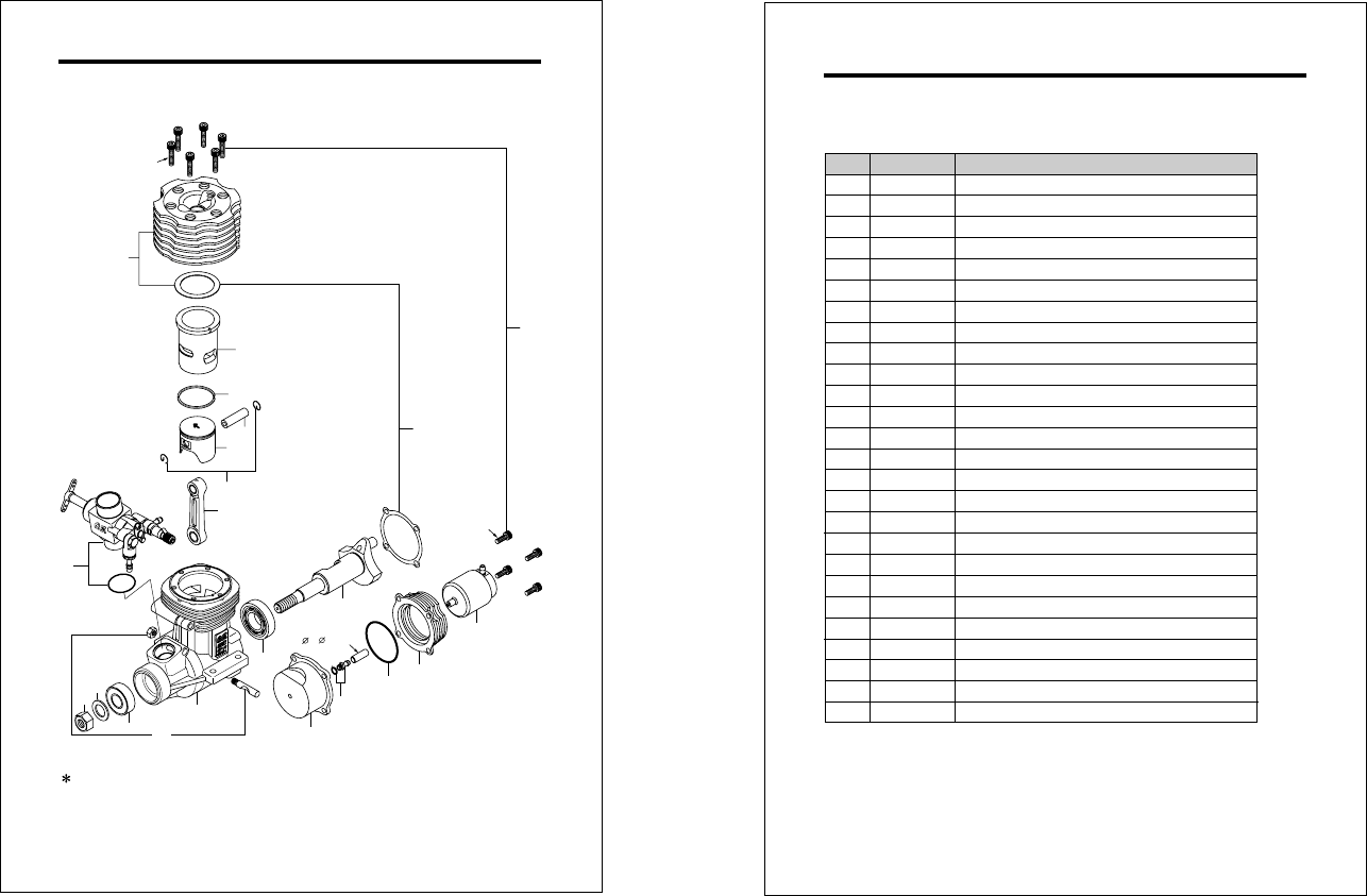
ENGINE EXPLODED VIEW
Type of screw
C...Cap Screw M...Oval Fillister-Head Screw
F...Flat Head Screw N...Round Head Screw S...Set Screw
C.M3x15
C.M3.5x10
1
2
3
4
5
6
7
8
910
11 12
13
14
15
16
17
22
18
19 20
21
2x 5xL12mm
33
The specifications are subject to alteration for improvement without notice.
ENGINE PARTS LIST
Screw Set
Cover Plate
Gasket Set
Crankshaft
Crankshaft Ball Bearing (Rear)
Crankcase
Crankshaft Ball Bearing (Front)
Thrust Washer
Propeller Nut
Carburetor Retainer Assembly
Carburetor Complete 60M
Connecting Rod
Piston Pin
Cylinder Liner
Heatsink Head
No. Description
Piston Ring
Piston
Piston Pin Retainer (2pcs.)
Woodruff Key
Glow Plug No.8
1
2
3
4
5
6
7
8
9
10
11
12
13
14
15
16
17
18
19
20
21
22
29054200
29053100
29503400
29053210
27006000
27917000
29505010
29084000
45010002
46120000
26731002
29081719
29051010
27930000
29052100
29514000
29057020
22681953
29057110
29057100
72509000
29513000
71608001
27708200
29084610
Code No.
Needle Adjusting Screw (M2.6x5) (1pc.)
Joint Nipple (No.1)
Holder "O" Ring
Pump Holder
Pump
T Nipple
34
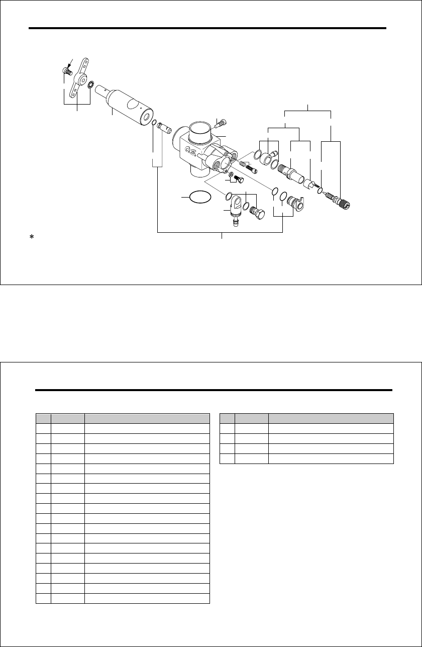
CARBURETOR EXPLODED VIEW
Type of screw
C...Cap Screw M...Oval Fillister-Head Screw
F...Flat Head Screw N...Round Head Screw S...Set Screw
C.M3x8
1
1-1
2
3
3-1
3-2
3-3
4
5
6
7
8
8-1
8-2
8-3
8-4 8-5
8-6
9
10
11
35
The specifications are subject to alteration for improvement without notice.
CARBURETOR PARTS LIST
No. Description
Code No.
1
1-1
2
3
3-1
3-2
3-3
4
5
6
7
8
8-1
8-2
8-3
8-4
8-5
8-6
27381410
22826131
29084200
29084800
27881810
27881800
27881820
45581820
29084100
27881330
27681340
27081900
27981910
24981837
46181940
46181941
26711305
46181950
Ratchet Spring
Needle
Needle Valve Assembly
Fuel Inlet
Rotor Guide Screw
"O"Ring (L) (2pcs.)
Carburetor Body
Mixture Control Valve Assembly
Carburetor Rotor
Throttle Lever Retaining Screw (2pcs.)
Throttle Lever Assembly
Mixture Control Screw
Mixture Control Valve Stopper
Needle Valve Holder Assembly
"O"Ring (L) (2pcs.)
"O"Ring (S) (2pcs.)
"O"Ring (2pcs.)
Needle Valve Holder
9
10
11
29084440
29084500
29015019 Carburetor Rubber Gasket
Return Screw
No. Description
Code No.
One-way Valve
Needle Adjusting Screw (M2.6x5) (1pc.)
36
(71608001)
(71521000)
(L)
No.8
(71605100)
A5
(72403050)
(71705000)
(55500003)
(27708010)
LONG SOCKET WRENCH
WITH PLUG GRIP
SUPER FILTER
O.S. GLOW PLUGS IN-FLIGHT CONTROL
NEEDLE VALVE
LOCK WASHER
M4
O.S. GENUINE PARTS & ACCESSORIES
DRIVE HUB
CRANKSHAFT
CLAMP
(10set)
Cap Screw Set
M2.6x5
(10pcs. set)
(79871010)
M3.5x10
(79871070)
7091
(71530500)
(For 70SZ-H, 91SX-H)
Needle Adjusting
Screw
(5pcs.)
M2.6x5 (41621100)
37
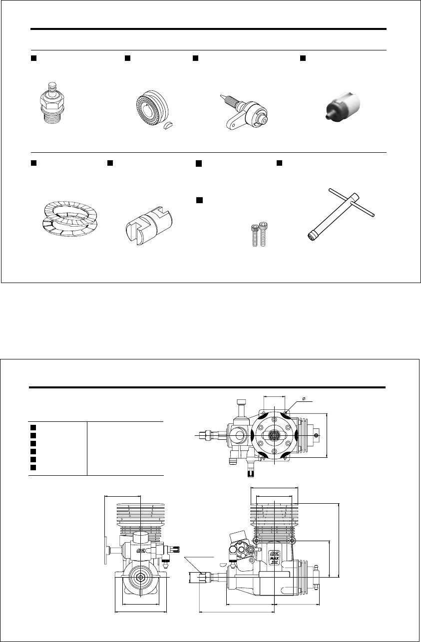
THREE VIEW DRAWING
Displacement
Bore
Stroke
Practical R.P.M.
Power output
Weight
SPECIFICATIONS
Dimensions(mm)
14.95 cc (0.912 cu.in.)
27.7mm (1.091 in.)
24.8mm (0.976 in.)
2,000-16,000 r.p.m.
3.1 ps / 15,000 r.p.m.
581g(20.5oz.)
JAPAN
25 4- 4.2
52
42.5
42.6
61
UNF 5/16-24
53
88.7
56.4
43.5
87.4
42
56
12

38
MEMO
C
Copyright 2003 by O.S.Engines Mfg. Co., Ltd. All rights reserved. Printed in Japan.
TEL. (06) 6702-0225
FAX. (06) 6704-2722
6-15 3-Chome Imagawa Higashisumiyoshi-ku
Osaka 546-0003, Japan
URL : http://www.os-engines.co.jp
U
N
E
Q
U
A
L
L
E
D
Q
U
A
L
I
T
Y
P
R
E
C
I
S
I
O
N
&
P
E
R
F
O
R
M
A
N
C
E
E
S
T
A
B
L
I
S
H
I
N
G
T
H
E
S
T
A
N
D
A
R
D
S
O
F
E
X
C
E
L
L
E
N
C
E
60091420 090301
