Lfm3250 927 0251 Onan CCKB (20HP Tractor) Engine Major Service Manual & Parts W 1116 Supl (06 1974)
User Manual: 927-0251 Onan CCKB (20HP Tractor) Engine Major Service manual & Parts w-927-1116 supl (06-1974)
Open the PDF directly: View PDF ![]() .
.
Page Count: 55
The following catalog
has gaps in its page
numbers, or doesn’t
have any numbers.
We have chosen to
leave the page
numbering in the
order that Acrobat
assigns it.
.
MAdOR SERVICE MANUAL
AND PARTS CATALOG
?FOR
,PRO?E’I?TY .
f?~
DO NOT R~MfJIYE
ONAN
20 HP CCKB ENGINE
FOR
GARDEN TRACTOR
SERVICE
,.
)’
.
?
...
,, ,
.% J
●
BASIC MODELS
CCKB-MS/24201+
CCKB-MS/2440H
CCKB=MS/2733J
.,.
FORM NUMBER ISSUE OATE
927–0251 6HJ74
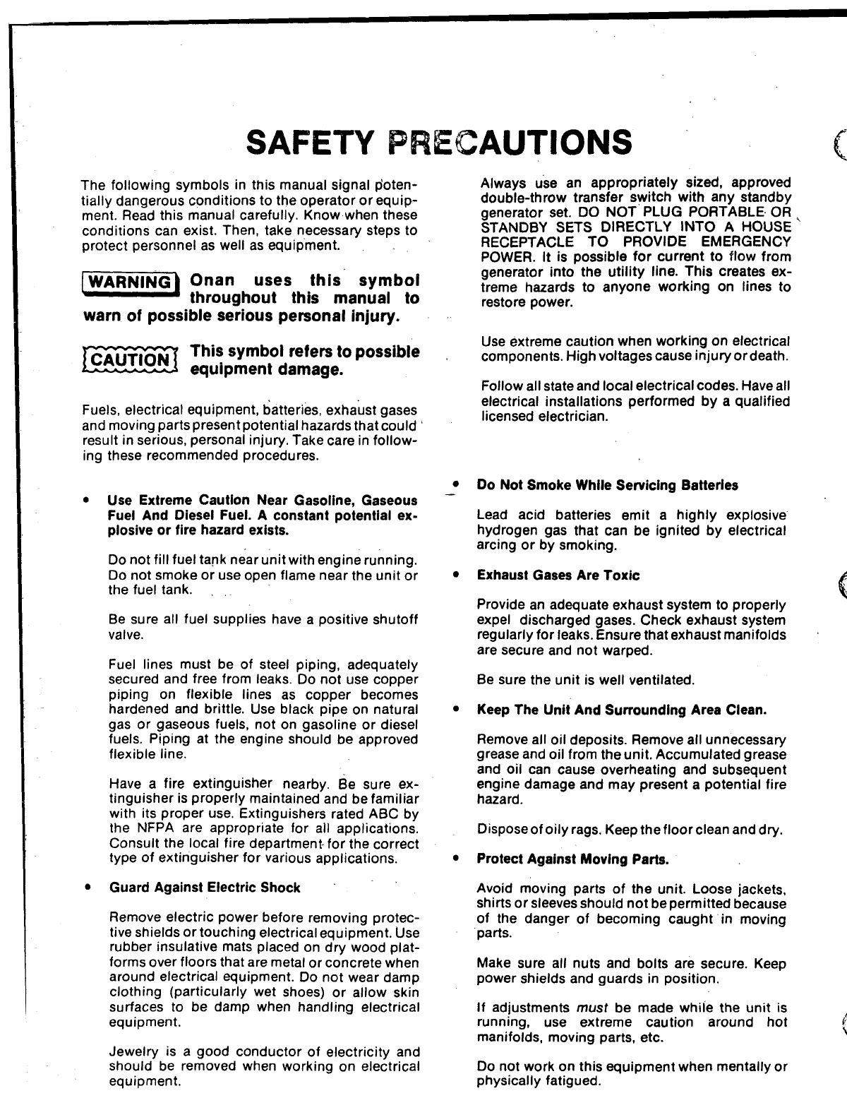
SAFETY PRECAUTIONS
The following symbols in this manual signal @pote-
ntiallydangerous conditions to the operator or equip-
ment. Read this manual carefully. Know when these
conditions can exist. Then, take necessary steps to
protect personnel as well as equipment.
Onan uses this symbol
throughout this manual to
warn of possible serious personal injury.
IEQiimThis symbol refers to possible
equipment damage.
Fuels, electrical equipment, batteries, exhaust gases
and moving parts present potential hazards that could’
result in serious, personal injury. Take care in follow-
ing these recommended procedures.
●Use Extreme Caution Near Gasoline, Gaseous
Fuel And Diesel Fuel. Aconstant potential ex-
plosive or fire hazard exists.
Do not fill fuel tank near unit with engine running.
Do not smoke or use open flame near the unit or
the fuel tank.
Be sure all fuel supplies have apositive shutoff
valve.
Fuel lines must be of steel piping, adequately
secured and free from leaks. Do not use copper
piping on flexible lines as copper becomes
hardened and brittle. Use black pipe on natural
gas or gaseous fuels, not on gasoline or diesel
fuels. Piping at the engine should be approved
flexible line.
Have afire extinguisher nearby. 6e sure ex-
tinguisher is properly maintained and be familiar
with its proper use. Extinguishers rated ABC by
the NFPA are appropriate for all applications.
Consult the local fire department for the correct
type of extinguisher for various applications.
sGuard Against Electric Shock
Remove electric power before removing protec-
tive shields or touching electrical equipment. Use
rubber insulative mats placed on dry wood plat-
forms over floors that are metal or concrete when
around electrical equipment. Do not wear damp
clothing (particularly wet shoes) or allow skin
surfaces to be damp when handling electrical
equipment.
Jewelry is agood conductor of electricity and
should- be removed when working on electrical
equipment.
●
●
●
●
Always use an appropriately sized, approved
double-throw transfer switch with any standby
generator set. DO NOT PLUG PORTABLE OR
STANDBY SETS DIRECTLY INTO AHOUSE ‘
RECEPTACLE TO PROVIDE EMERGENCY
POWER. It is possible for current to flow from
generator into the utility line. This creates ex-
treme hazards to anyone working on lines to
restore power.
Use extreme caution when working on electrical
components. High voltages cause injury or death.
Follow all state and local electrical codes. Have all
electrical installations performed by aqualified
licensed electrician.
Do Not Smoke While Sewicing Batteries
Lead acid batteries emit ahighly explosive
hydrogen gas that can be ignited by electrical
arcing or by smoking.
Exhaust Gases Are Toxic
c
,
Provide an adequate exhaust system to properly
“
expel discharged gases. Check exhaust system
regularly for leaks. Ensure that exhaust manifolds
are secure and not warped.
Be sure the unit is well ventilated.
Keep The Unit”And Surrounding Area Clean.
Remove all oil deposits. Remove all unnecessary
grease and oil from the unit. Accumulated grease
and oil can cause overheating and subsequent
engine damage and may present apotential fire
hazard.
Dispose of oily rags. Keep the floor clean and dry.
Protect Against Moving Parts.
Avoid moving parts of the unit. Loose jackets,
shirts or sleeves should not be permitted because
of the danger of becoming caught in moving
parts.
Make sure all nuts and bolts are secure. Keep
power shields and guards in position.
If adjustments must be made whiie the unit is
running, use extreme caution around hot i
manifolds, moving parts, etc.
\.
Do not work on this equipment when mentally or
physically fatigued.
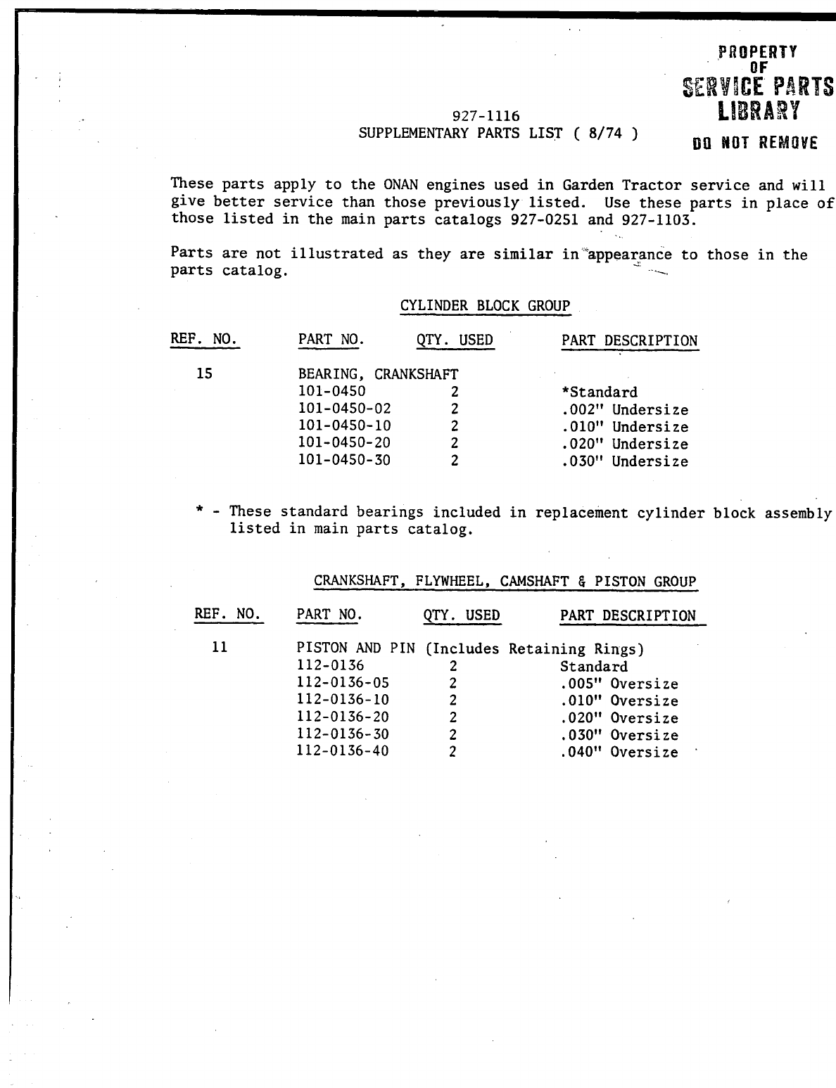
These parts apply to the ONAN engines used in Garden Tractor service and will
give better service than those previously listed. Use these parts in place of
those listed in the main parts catalogs 927-02S1 and 927-1103.
.,.
Parts are not illustrated as they are similar in’”appearanceto those in the
parts catalog. .....
CYLINDER BLOCK GROUP
REF. NO. PART NO. QTY. USED PART DESCRIPTION
15 BEARING, CRANKSHAFT
101-0450 2*Standard
101-0450-02 2 .002” Undersize
101-0450-10 2 .010” Undersize
101-0450-20 2.020” Undersize
101-0450-30 2 .030” Undersize
*- These standard
listed in main
bearings included in replacement cylinder block assembly
parts catalog.
CRANKSHAFT, FLYWHEEL, CAMSHAFT & PISTON GROUP
REF. NO. PART NO. QTY. USED PART DESCRIPTION
11 PISTON AND PIN (Includes Retaining Rings)
112-0136 2Standard
112-0136-05 2.005” Oversize
112-0136-10 2.010” Oversize
112-0136-20 2 .020” Oversize
112-0136-30 2.030” Oversize
112-0136-40 2.040” Oversize
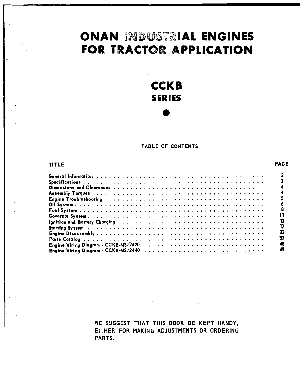
ONAN INDUSTRIAL ENGINES
.,.“.”’
,, \FOR TRACTOR APPLICA’I’ION
.
.,
---
CCKB
SERIES
●
TABLE OF CONTENTS
TITLE
General Information . . . . . . . . . . . . . . . . . . . . . . . . . . . . . . . . . . . . . . .
Specifieatians . . . . . . . . . . . . . . . . . . . . . . . . . . . . . . . . . . . . . . . . . .
Dimensions and ClearcrneeS . . . . . . . . . . . . . . . . . . . . . . . . . . . . . . . . . . .
Assembly Torques ........................................
Engine Troubleshooting . . . . . . . . . . . . . . . . . . . . . . . . . . . . . . . . . . . . .
Oil System . . . . . . . . . . . . . . . . . . . . . . . . . . . . . . . . . . . . . . . . . . . .
Fuel System . . . . . . . . . . . . . . . . . . . . . . . . . . . . . . . . . . . . . . . . . . .
Governor System . . . . . . . . . . . . . . . . . . . . . . . . . . . . . . . . ..+.....*
ignition and Battery Charging. . . . . . . . . . . . . . . . . . . . . . . . . . . . . . . . . .
Starting System . . ..o ............................00 ..o””o
Engine Disassembly . . . . . . . . . . . . . . . . . . . . . . ...0 . . . . . . . . . . . . .
Parts Catalog . . . . . . . . . . . . . . . . . . . . . . . . . . . . . . . . . . . . ...000
EngineWiringDiagram-CCKB-MS/z420 . . . . . . . . . . . . . . . . . . . . . . . ..*.o
EngineWiringDiagram-CCKB-MS/2440 . . . . . . . . . . . . . . . . . . . . . . . . . . . .
PAGE
2
3
4
4
5
6
8
11
:;
22
32
48
49
WE SUGGEST THAT THIS BOOK BE KEPT HANDY,
EITHER FOR MAKING ADJUSTMENTS OR ORDERING
PARTS.
-—
GENERAL INFORMATION
SERVICE MANUAL MODEL DESIGNATION
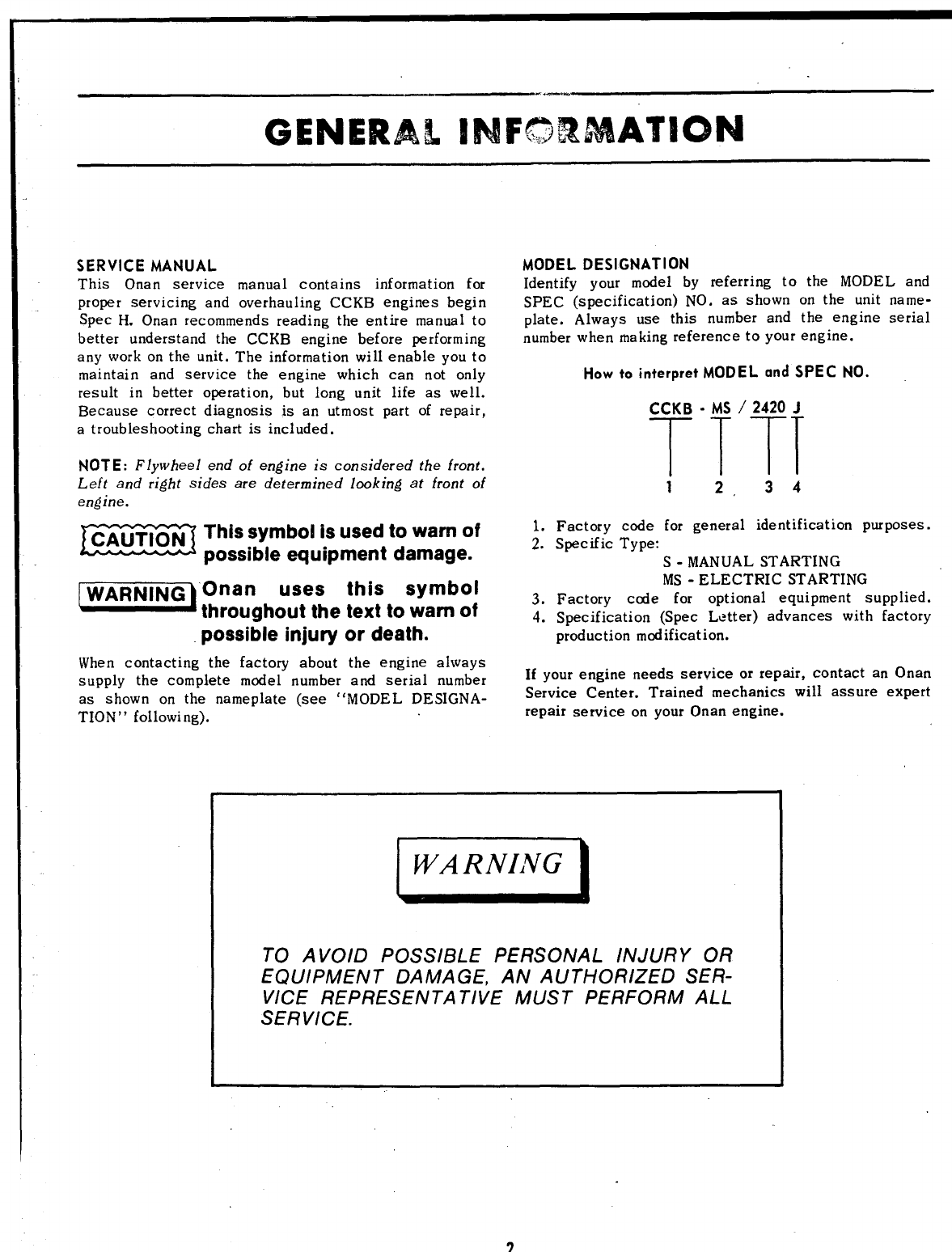
This Onan service manual contains information for Identify your model by referring to the MODEL and
proper servicing and overhauling CCKB engines begin SPEC (specification) NO. as shown on the unit name-
Spec H. Onan recommends reading the entire manual to plate. Always use this number and the engine serial
better understand the CCKB engine before performing number when making reference to your engine.
any work on the unit. The information will enable you to
maintain and service the engine which can not only
result in better operation, but long unit life as well.
Because correct diagnosis is an utmost part of repair,
atroubleshooting chart is included.
NOTE: Flywheel end of engine is considered the front.
Left and right sides are determined looking at front of
engine.
This symbol is used to warn of ~;
possible equipment damage.
uses this symbol
throughout the text to warn of ~:
possible injury or death.
How to interpret MODEL and SPEC NO.
CCKB -MS /2420 J
TTTT
12.34
Factory code for general identification purposes.
Specific Type:
S-MANUAL STARTING
MS -ELECTRIC STARTING
Factory cede for optional equipment supplied.
Specification (Spec Letter) advances with factory
production mod ificat ion.
When contacting the factory about the engine always
supply the complete model number and serial number If your engine needs service or repair, contact an Onan
as shown on the nameplate (see “MODEL DE SIGNA- Service Center. Trained mechanics will assure expert
TION” following). repair service on your Onan engine.
@El
TO AVOID POSSIBLE PERSONAL INJURY OR
EQUIPMENT DAMA GE, AN AUTHORIZED SER-
VICE REPRESENTATIVE MUST PERFORM ALL
SERVICE.
2
,,’ -, SPECIFICATIONS
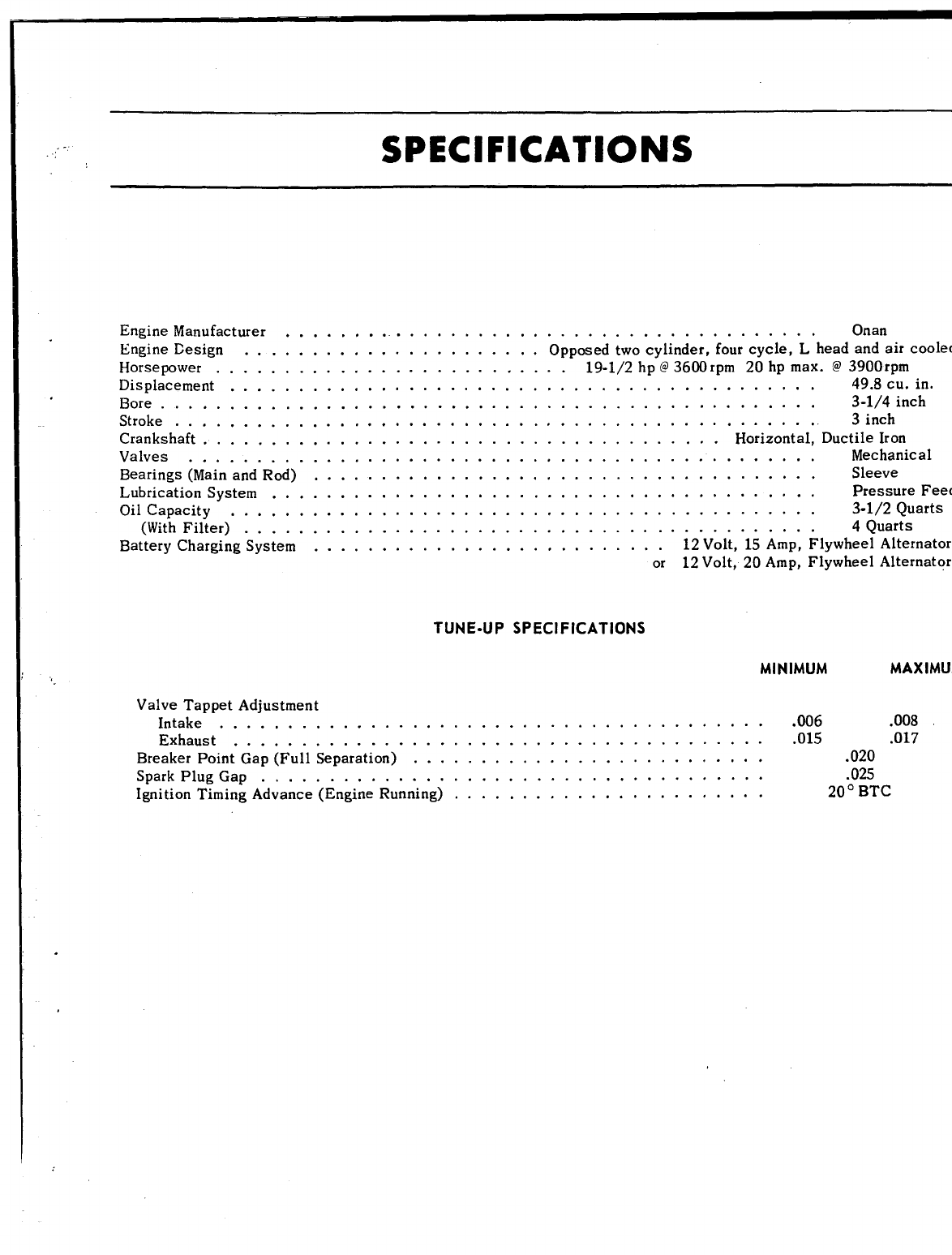
Engine Manufacturer . . . . . . . . . . . . . . . . . . . . . . . . . . . . . . . . . . . . . . . . Onan
Engine Ensign . . . . . . . . . . . . . . . . . . . . . . Opposed two cylinder, four cycle, Lhead and air cooled
Horsepower . . . . . . . . . . . . . . . . . . . . . . . . . . 19-1/2 hp @3600 rpm 20 hp max. @3900rpm
Displacement . . . . . . . . . . . . . . . . . . . . . . . . . . . . . . . . . . . . . . . . . . . 49.8 cu. in.
Bore . . . . . . . . . . . . . . . . . . . . . . . . . . . . . . . . . . . . . . . . . . . . . . . . 3-1/4 inch
Stroke . . . . . . . . . . . . . . . . . . . . . . . . . . . . . . . . . . . . . . . . . . . . . . . . 3inch
Crankshaft ................................. . . . .. Horizont=d.Ductilelmrr
Valves . . . . . . . . . . . . . . . . . . . . . . . . . . . . . . . . . . . . . . . . . . . . .
Bearings(MainandRod) . . . . . . . . . . . . . . . . . . . . . . . . . . . . . . . . . . . .
Lubrication System . . . . . . . . . . . . . . . . . . . . . . . . . . . . . . . . . . . . . . .
Oil Capacity . . . . . . . . . . . . . . . . . . . . . . . . . . . . . . . . . . . . . . . . . .
(With Filter) . . . . . . . . . . . . . . . . . . . . . . . . . . . . . . . . . . . . . . . . .
BatteryChargingSystem . . . . . . . . . . . . . . . . . . . . . . . . . . 12Volt,15Amp,
or 12Volt,20Amp,
Mechanical
.Sleeve
Pressure Feed
.3-1/2 Quarts
.4Quarts
Flywheel Alternator
Flywheel Alternator
TUNE-UP SPECIFICATIONS
MINIMUM
MAXIMUM
Valve Tappet Adjustment
Intake . . . . . . . . . . . . . . . . . . . . . . . . . . . . . . . . . . . . . . . . .006 .008
Exhaust . . . . . . . . . . . . . . . . . . . . . . . . . . . . . . . . . . . . . . . .015 .017
Breaker Point Gap (Full Separation) . . . . . . . . . . . . . . . . . . . . . . . . . . .020
Spark Plug Gap . . . . . . . . . . . . . . . . . . . . . . . . . . . . . . . . . . . . . .025
Ignition Timing Advance (Engine Running) . . . . . . . . . . . . . . . . . . . . . . . 20° BTC
.
DIMENSIONS AND CLEARANCES
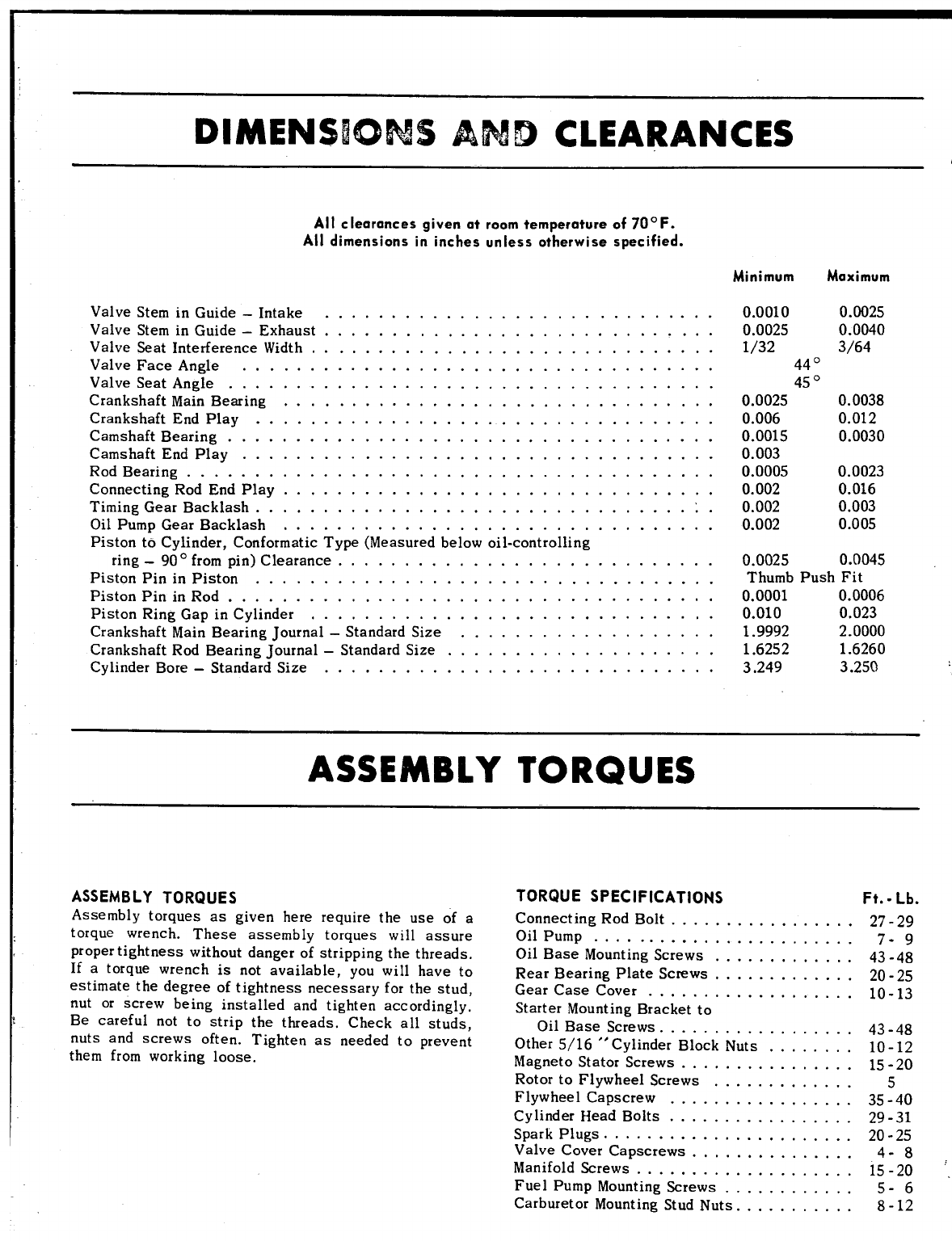
All cIearances given at room temperature of 70° F.
All dimensions in inches unless otherwise specified.
Minimum Maximum
Valve Stem in Guide –Intake. . . . . . . . . . . . . . . . . . . . . . . . . . . . .
Valve Stemin Guide –Exhaust. . . . . . . . . . . . . . . . . . . . . . . . . . . . .
Valve Seat Interference Width... . . . . . . . . . . . . . . . . . . . . . . . . . . .
Valve Face Angle . . . . . . . . . . . . . . . . . . . . . . . . . . . . . . . . . . .
Valve Seat Angle . . . . . . . . . . . . . . . . . . . . . . . . . . . . . . . . . . . .
Crankshaft Main Bearing . . . . . . . . . . . . . . . . . . . . . . . . . . . . . . . .
Crankshaft End Play . . . . . . . . . . . . . . . . . . . . . . . . . . . . . . . . . .
Camshaft Bearing . . . . . . . . . . . . . . . . . . . . . . . . . . . . . . . . . . . .
Camshaft End Play . . . . . . . . . . . . . . . . . . . . . . . . . . . . . . . . . . .
Rod Bearing . . . . . . . . . . . . . . . . . . . . . . . . . . . . . . . . . . . . . . .
Connecting Rod End Play . . . . . . . . . . . . . . . . . . . . . . . . . . . . . . . .
Timing Gear Backlash . . . . . . . . . . . . . . . . . . . . . . . . . . . . . ...1.
Oil Pump Gear Backlash . . . . . . . . . . . . . . . . . . . . . . . . . . . . . . . .
Piston to Cylinder, Conformat ic Type (Measured below oil-cent rolling
ring -90 °frompin) Clearance.. ..........................
Piston Pin in Piston . . . . . . . . . . . . . . . . . . . . . . . . . . . . . . . . . .
Piston Pin in Rod . . . . . . . . . . . . . . . . . . . . . . . . . . . . . . . . . . . .
Piston Ring Gap in Cylinder.. . . . . . . . . . . . . . . . . . . . . . . . . . . . .
Crankshaft Main Bearing Journal –Standard Size . . . . . . . . . . . . . . . . . . .
Crankshaft Rod Bearing Journal –Standard Size . . . . . . . . . . . . . . . . . . . .
Cylinder Bore -Standard Size. . . . . . . . . . . . . . . . . . . . . . . . . . . . .
0.0010
0.0025
1/32
440
450
0.0025
0.006
0.0015
0.003
0.0005
0.002
0.002
0.002
0.0025
0.0040
3/64
0.0038
0.012
0.0030
0.0023
0.016
0.003
0.005
0.0025 0.0045
Thumb Push Fit
0.0001 0.0006
0.010 0.023
1.9992 2.0000
1.6252 1.6260
3.249 3.250
ASSEMBLY TORQUES
ASSEMBLY TORQUES
Assembly torques as given here require the use of a
torque wrench. These assembly torques will assure
proper tightness without danger of stripping the threads.
If atorque wrench is not available, you will have to
estimate the degree of tightness necessary for the stud,
nut or screw being installed and tighten accordingly.
Be careful not to strip the threads. Check all studs,
nuts and screws often. Tighten as needed to prevent
them from working loose.
TORQUE SPECIFICATIONS Ft. -Lb.
Connecting Rod Bolt . . . . . . . . . . . . . . . . . 27-29
Oil Pump . . . . . . . . . . . . . . . . ........ 7-9
Oil Base Mounting Screws . . . . . . . . . . . . . 43.48
Rear Bearing Plate Screws . . . . . . . . . . . . . 2(I .25
Gear Case Cover . . . . . . . . . . . . . . . . . . . 10-13
Starter Mounting Bracket to
Oil Base Screws . . . . . . . . . . . . . . . . . . 43.48
Other 5/16 “Cylinder Block Nuts . . . . . . . . 10-12
hlagneto Stator Screws ................ 15-20
Rotor to Flywheel Screws ............. 5
Flywheel Capscrew . . . . . . . . . . . . . . . . . 35-40
Cylinder Dead bolts . . . . . . . . . . . . . . . . . 29-31
Spark Plugs . . . . . . . . . . . . . . . . . . . . . . . 20-25
Valve Cover Capscrews . . . . . . . . . . . . . . . 4.8
Manifold Screws .................... 15-20
‘.
Fuel Pump Mounting sCrews . . . . . . . . . . . . 5- 6
Carburetor Mounting Stud Nuts . . . . . . . . . , . 8-12
...
,.
r. ENGINE TROUBLESHOOTING
.
‘,..
.
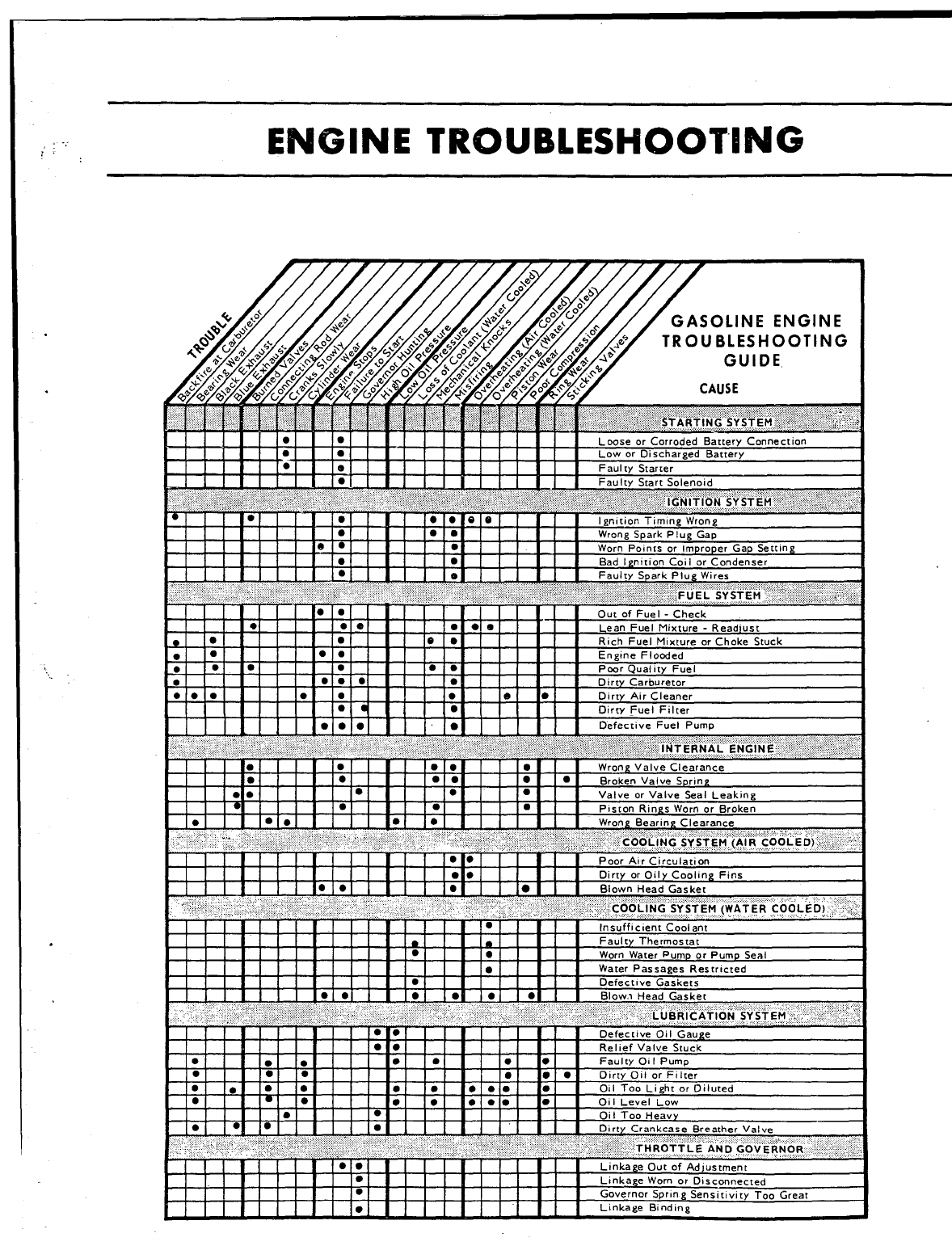
GASOLINE ENGINE
TROUBLESHOOTING
GUIDE
1~1 10 III1].[ Ir] Ie 1.1 I I I1IIRich Fuel Mixture or Choke Stuck
10 II1I I I I IOlolol
g
ILeak)ng
ton
rd”,,~ ,,Ierr,, ”,ca,
lii!!iii!ill!!-ll!!if~~~
wworn water PumD or Pump Seal
●Water Passages Restricted
●m–. –. 7––.
WC ICL L?.= VI! u’lugc
Rellef Valve Stuck
Faulty Oil Pump
Oirty Oil or Filter
011 Too Light or Diluted
Oi ILevel Low
Oil Too Heavy
O!ls SYSTEM
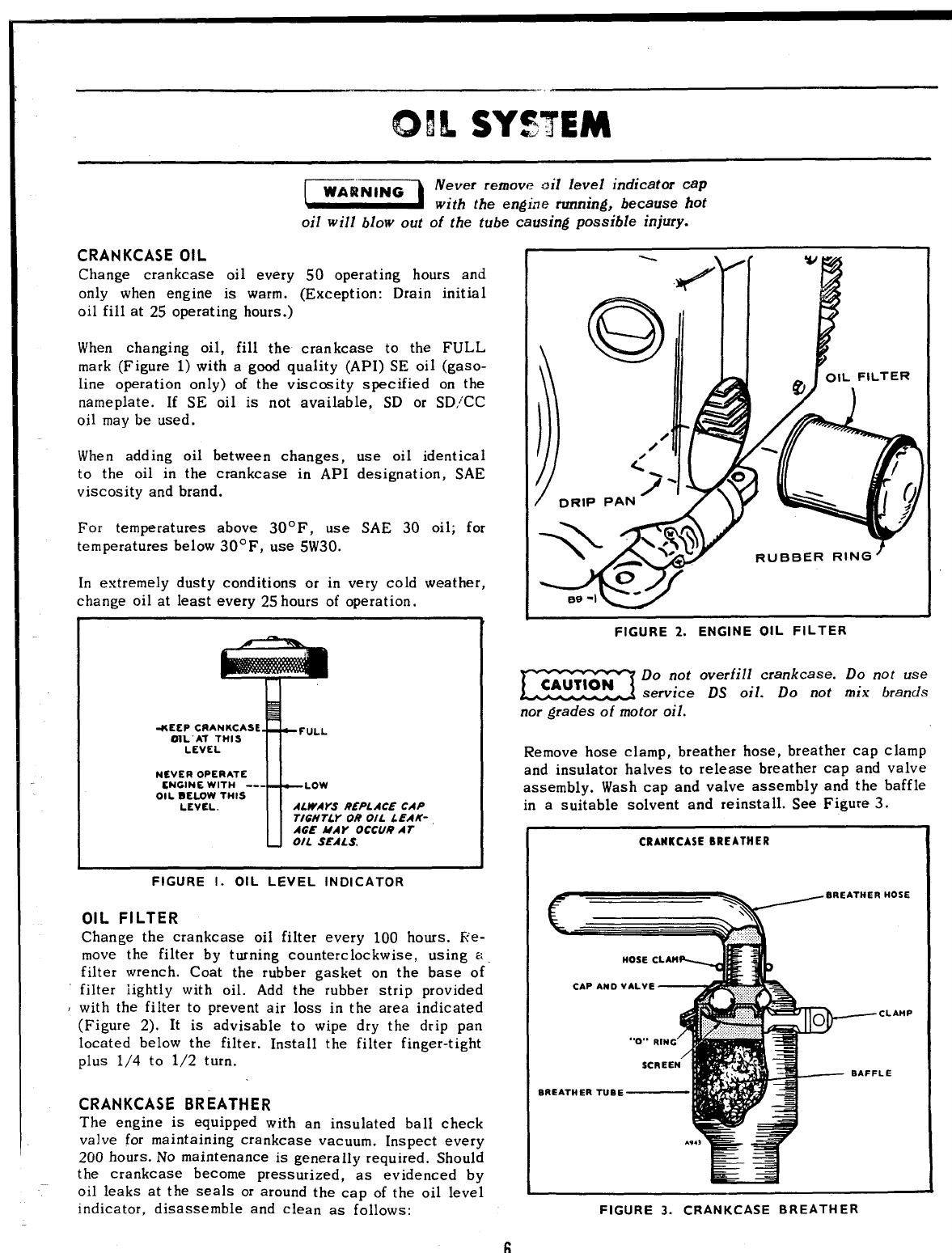
EisEil Never remove oil level indicator cap
with the engirre rurrning, because hot
oil will blow out of the tube causing possible injury.
CRANKCASE OIL
Change crankcase oil every .s0 operating hours and
only when engine is warm. (Exception: Drain initial
oil fill at 25 operating hours.)
When changing oil, fill the crankcase to the FULL
mark (Figure 1) with agood quality (API) SE oil (gaso-
line operation only) of the viaccsity specified on the
nameplate. If SE oil is not available, SD or SD/CC
oil may be used.
When add ing oil between changes,
to the oil in the crankcase in API
viscosity and brand.
For temperatures above 30”F, use
temperatures below 30° F, use 5W30.
use oil identical
designation, SAE
SAE 30 oil; for
In extremely dusty conditions or in very cold weather,
change oil at least every 25 hours of operation.
T
-KEEP CRANKCASE
OIL AT THIS FULL
LEVEL
NEVER OPERATE
ENGINE WITH --- LOW
OIL SELOW THIS
LEVEL. ALWAYS REPLACE CAP
TIGHTLY OR OIL LEAK-
AGE MAY OCCU@ AT
OIL SEALS.
FIGURE 1. OIL LEVEL INDICATOR
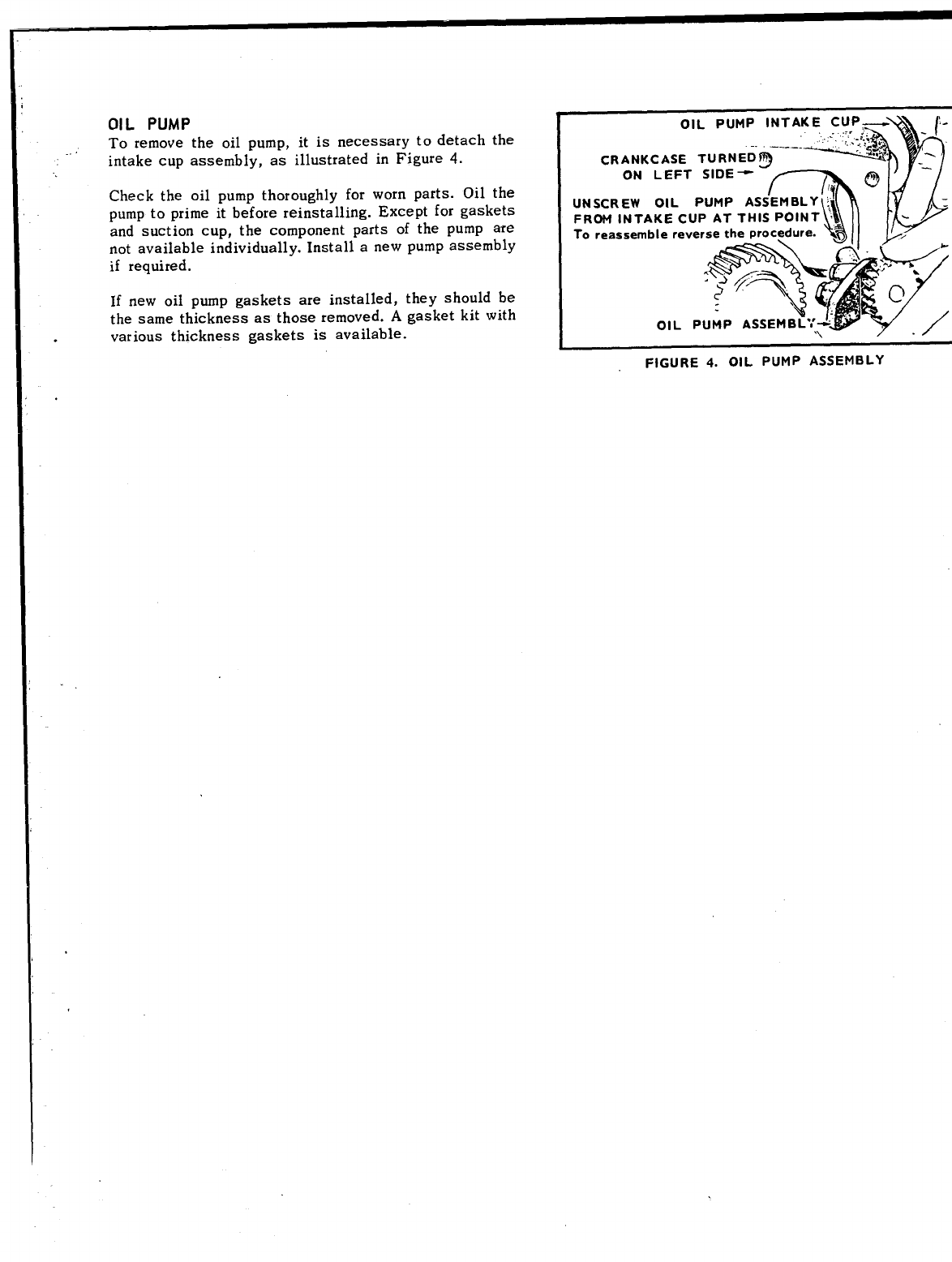
OIL FILTER
Change the crankcase oil filter every 100 hours. Re-
move the filter by turning counterclockwise, using a
filter wrench. Coat the rubber gasket on the base of
filter iightly with oil. Add the rubber strip provided
with the filter to prevent air loss in the area indicated
(Figure 2). It is advisable to wipe dry the drip pan
located below the filter. Install the filter finger-tight
plus 1/4 to 1/2 turn.
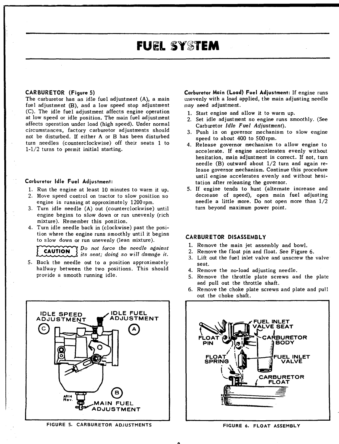
CRANKCASE BREATHER
The engine is equipped with an insulated ball check
valve for maintaining crankcase vacuum. Inspect every
200 hours. NO maintenance is generally required. Should
the crankcase become pressurized, “as evidenced by
oil leaks at the seals or around the cap of the oil level
indicator, disassemble and clean as follows:
FIGURE 2. ENGINE OIL FILTER
Emzi Do not overfill crankcase. Do not use
service DS oil. Do not mix brands
nor grades of motor oil.
Remove hose clamp, breather hose, breather cap clamp
and insulator halves to release breather cap and valve
assembly. Wash cap and valve assembly and the baffle
in asuitable solvent and reinstall. See Figure 3.
CRANKCASEEREATtlER
waREATH
CAP AND VALVE -A
““O”’RING
!
SCREEN
BREATHERTUBE —1
—cLAMP
BAFFLE
FIGURE 3. CRANKCASE BREATHER
6
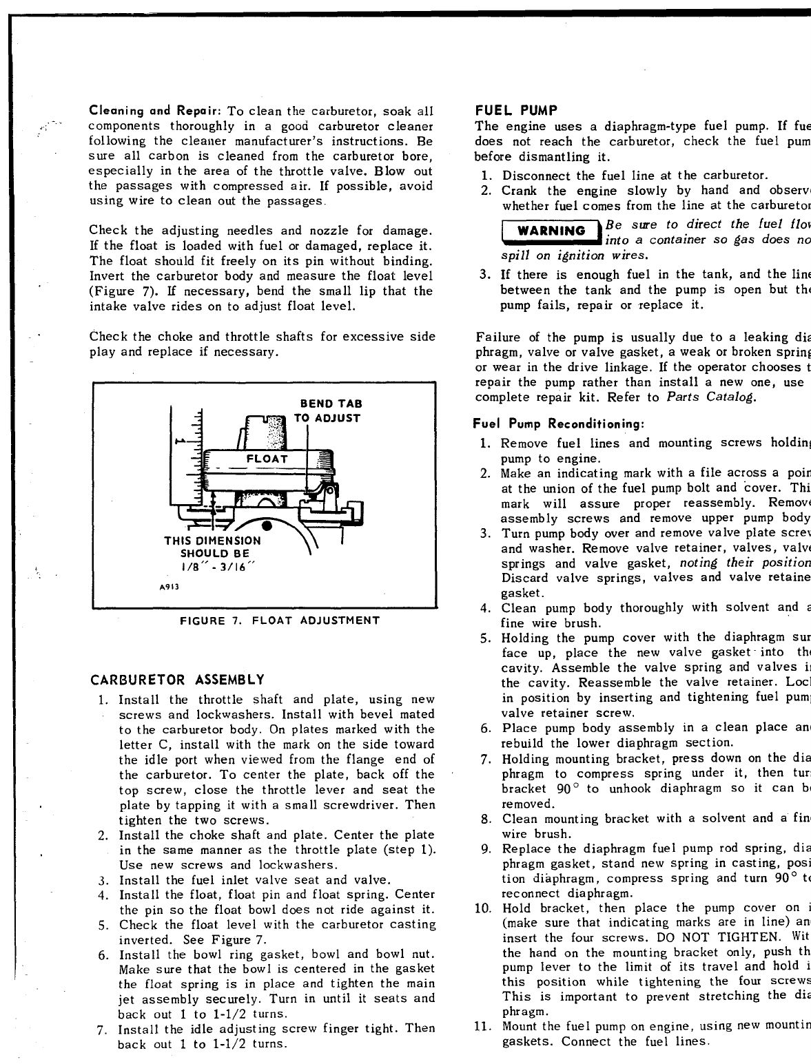
OIL PUMP
To remove the oil pump, it is necessary to detach the
intake cup assembly, as illustrated in Figure 4.
Check the oil pump thoroughly for worn parts. Oil the
pump to prime it before reinstalling. Except for gaskets
and suction cup, the component parts of the pump are
not available individually. Install anew pump assembly
if required.
If new oil pump gaskets are installed, they should be
the same thickness as those removed. Agasket kit with
.various thickness gaskets is available.
------- . . . .
CRANKCASE TURNED~
ON LEFT SIDE -
.\
FIGURE 4. OIL pUMp ASSEMBLY
FUEL5iW’$i$TEM
CARBURETOR (Figure 5)
The carburetor has an idle fuel adjustment (A), amain
fuel adjustment (B), and alow speed stop adjustment
(C). The idle fuel adjustment affects engine operation
at low speed or idle position. The main fuel adjustment
affects operation under load (high speed). Under normal
circumstances, factory carburetor adjustments should
not be disturbed. If either Aor Bhas been disturbed
turn needles (counterclockwise) off their seats 1to
1-1/2 turns to permit initial starting.
Carburetor Idle Fuel Adjustment:
1. Run the engine at least 10 minutes to warm it up.
2. Move speed control on tractor to slow position so
engine is running at approximately 1200 rpm.
3. Turn idle needle (A) out (counterclockwise) until
engine begins to slow down or run unevenly (rich
mixture). Remember this position.
4. Turn idle needle back in (clockwise) past the posi-
tion where the engine runs smoothly until it begins
to slow down or run unevenly (lean mixture).
m
Do not force the needle against
its seat; doing so will damage it.
5. Back the needle out to aposition approximately
halfwa~ between the two positions. This should
provide asmooth running idle.
Yo
B
A914
Rev. MAIN FUEL
ADuJUSTMEIUT
Carburetor Main (Load) Fuel Adjustment: If engine runs
unevenly with aload applied, the main adjusting needle
may need adjustment.
1.
2.
3.
4.
5.
Start engine and allow it to warm up.
Set idle adjustment so engine runs smoothly. (See
Carburetor Idle Fuel Adjustment).
Push in on governor mechanism to slow engine
speed to about 400 to 500 rpm.
Release governor mechanism to aHow engine to
accelerate. If engine accelerates evenly wit bout
hes itat ion, main adjustment is correct. If not, turn
needle (B) outward about 1/2 turn and again re-
lease governor mechanism. Continue this procedure
until engine accelerates evenly and without hesi-
tation after releasing the governor.
If engine tends to hunt (alternate increase and
decrease of speed),
needle alittle more.
turn beyond maximum
open main fuel adjusting
Do not open more than 1/2
power point.
CARBURETOR DISASSEMBLY
1. Remove the main jet assembly and bowl.
2. Remove the float pin and float. See Figure 6.
3. Lift out the fuel inlet valve and unscrew the valve
seat.
4. Remove the no-load adjusting needle.
5. Remove the throttle plate screws and the plate
and pull out the throttle shaft.
6. Remove the choke plate screws and plate and pull
out the choke shaft.
i&#-– FUEL INLET
‘~c:~;EToR
FIGURE 5. CARBURETOR ADJUSTMENTS FIGURE 6. FLOAT ASSEMBLY
4’:
,-“.
Cleaning and Repair: To clean the carburetor, soak all
components thoroughly in agood carburetor cleaner
following the cleaner manufact urer’s instruct ions. Be
sure all carbon is cleaned from the carburetor bore,
especially in the area of the throttle valve. Blow out
the passages with compressed air. If possible, avoid
using wire to clean out the passages.
Check the adjusting needles and nozzle for damage.
If the float is loaded with fuel or damaged, replace it.
The float should fit freely on its pin without binding.
Invert the carburetor body and measure the float level
(Figure 7). If necessary, bend the small lip that the
intake valve rides on to adjust float level.
Check the choke and throttle shafts for excessive side
play and replace if necessary.
BEND TAB
THIS DIMENSION
SHOULD BE
)- I
1/8’’ -3/16”
A913
FIGURE 7. FLOAT ADJUSTMENT
CARBURETOR ASSEMBLY
1. Install the throttle shaft and plate, using new
2.
3.
4.
5.
6.
7.
screws and lockwashers. Install with bevel mated
to the carburetor body. On plates marked with the
letter C, install with the mark on the side toward
the idle port when viewed from the flange end of
the carburetor. To center the plate, back off the
top screw, close the throttle lever and seat the
plate by tapping it with asmall screwdriver. Then
tighten the two screws.
Install the choke shaft and plate. Center the plate
in the same manner as the throttle plate (step 1).
Use new screws and lockwashers.
Install the fuel inlet valve seat and valve.
Install the float, float pin and float spring. Center
the pin so the float bowl does not ride against it.
Check the float level with the carburetor casting
inverted. See Figure 7.
Install the bowl ring gasket, bowl and bowl nut.
Make sure that the bowl is centered in the gasket
the float spring is in place and tighten the main
jet assembly securely. Turn in until it seats and
back out 1to 1-1/2 turns.
Install the idle adjusting screw finger tight. Then
back out 1to 1-1/2 turns.
FUEL PUMP
The engine uses adiaphragm-type fuel pump. If
fuel
does not reach the carburetor, check the fuel
pump
before dismantling it.
1.
2.
3.
Disconnect the fuel line at the carburetor.
Crank the engine slowly by hand and observe
whether fuel comes from the line at the carburetor.
EEiiia Be sure to direct the fuel flow
rnto acontainer so gas does
not
spill on ignition wires.
If there is enough fuel in the tank, and the line
between the tan~ and the pump is open but the
pump fails, repair or replace it.
Failure of the pump is usually due to aleaking
dia-
phragm, valve or valve gasket, aweak or broken spring,
or wear in the drive linkage. If the operator chooses
to
repair the pump rather than install anew one, use
complete repair kit. Refer to Parts Catalog.
Fuel Pump Reconditioning:
1.
2.
3.
4.
5.
6.
7.
8.
9.
10.
11.
Remove fuel lines and mounting screws holding
pump to engine.
Make an indicating mark with afile across apoint
at the union of the fuel pump bolt and cover. This
mark will assure proper reassembly.
Remove
assembly screws and remove upper pump body.
Turn pump body over and remove valve plate screw
and washer. Remove valve retainer, valves, valve
springs and valve gasket, noting their position.
Discard valve springs, valves and valve retainer
gasket.
Clean pump body thoroughly with solvent and
a
fine wire brush.
Holding the pump cover with the diaphragm sur-
face up, place the new valve gasket into the
cavity. Assemble the valve spring and valves
in
the cavity. Reassemble the valve retainer. Lock
in position by inserting and tightening fuel
pump
valve retainer screw.
Place pump body assembly in aclean place
and
rebuild the lower diaphragm section.
Holding mounting bracket, press down on the dia-
phragm to compress spring under it, then
turn
bracket 900 to unhook diaphragm so it can
be
removed.
Clean mounting bracket with asolvent and afine
wire brush.
Replace the diaphragm fuel pump rod spring, dia-
phragm gasket, stand new spring in casting, posi-
tion diaphragm, compress spring and turn 90°
to
reconnect diaphragm.
Hold bracket, then place the pump cover on
i
(make sure that indicating marks are in line)
and
insert the four screws. DO NOT TIGHTEN.
With
the hand on the mounting bracket only, push
the
pump lever to the limit of its travel and hold
in
this position while tightening the four screws.
This is important to prevent stretching the
dia-
phragm.
Mount the fuel pump on engine, using new mounting
gaskets. Connect ~he fuer lines.
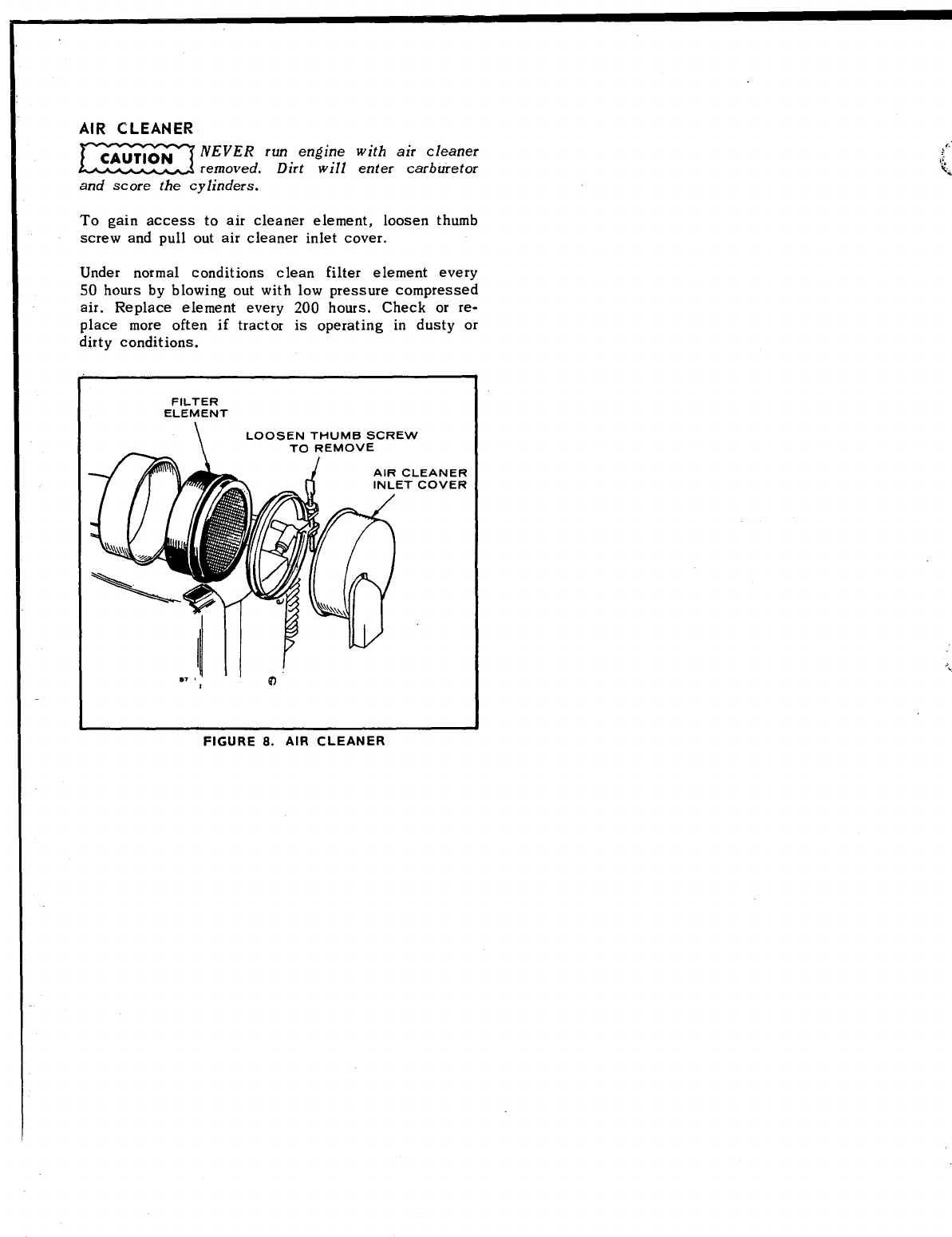
AIR CLEANER
EE!KI NEVER run engine with air cleaner
removed. Dirt will enter carburetor
and score the cylinders.
To gain access to air cleaner element, loosen thumb
screw and pull out air cleaner inlet cover.
Under normal conditions clean filter element every
50 hours by blowing out with low pressure compressed
air. Replace element every 200 hours. Check or re-
place more often if tractor is operating in dusty or
dirty conditions.
FILTER
ELEMENT
\LOOSEN THUMB SCREW
—TO REMOVE
w,V* I
10
-
;
‘“
J:,
‘t<
FIGURE 8. AIR CLEANER
,.”
,, GOVEW+!X!2RSYSTEM
\.
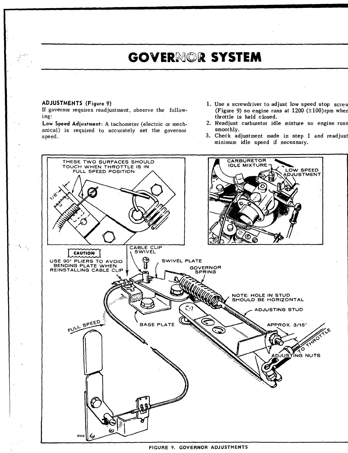
ADJUSTMENTS (Figure 9) 1.
If governor requires readjustment, observe the foHow-
ing:
Low Speed Adjustment: Atachometer (electric or mech- 2.
anical) is required to accurately set the governor
speed. 3.
Use a screwdriver to adjust low speed stop screw
(Figure 9) so engine runs at 1200 (t 100)rpm when
throttle is held closed.
Readjust carburetor idle mixture so engine runs
smoothly.
Check adjustment made in step 1and readjust
minimum idle speed if necessary.
THESE TWO SURFACES SHOULD
TOUCH WHEN THROTTLE IS IN
FULL SPEED POSITION A
IzEE3 l\
C&wL~v ::1 P
uSE 90° PLIERS TO AVOID @.SWIVEL PLATE
.
FIGURE
9.
GOVERNOR ADJUSTMENTS
High Speed and Cable Adjustment:
1.
2.
3.
Move engine speed control on tractor to “fast”
position.
With speed control in “fast” position, the speed
control cable should be holding governor swivel
plate against stop on governor base plate
(Figure 9).
If speed adjustment is necessary, remove cable
clip and loosen swivel screw. Hold end of cable
housing 1/8 inch from base plate mounting edge
and using a900 pliers reinstall cable clip.
EEEcI Bending the base plate will cause
misalignment between swivel plate and
the edge of base plate.
4.
5.
6.
7.
Back off from “fast” posit ion on throttle cent rol
arm until inner cable moves forward about 1/16
inch.
Hold the swivel plate against the stop edge and
tighten the swivel screw. Recheck to see if con-
trol pulls swivel plate against the base plate.
With engine running, loosen stud adjusting nuts
and turn toward spring (left) to increase or away
from spring (right) to decrease the high speed.
Tighten nuts and check speed.
Top speed at no load should be 3850 (f 100) rpm.
CLEANING
Inspect the governor linkage, springs, etc. for binding
or wear. Clean otlen in dusty conditions.
1“
\
Ka’w’mml Ar’+m BATTERY CHARGING
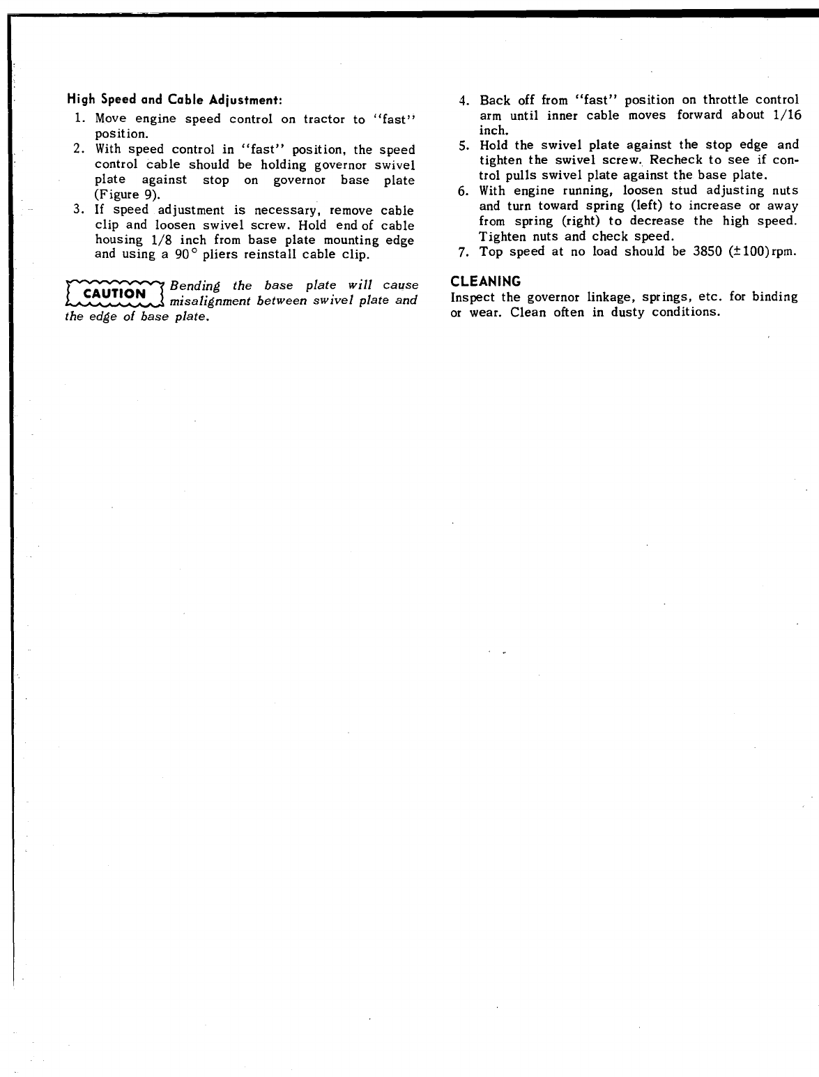
BREAKER POINTS
To maintain maximum efficiency from the engine,
change the breaker points every 200 hours of operation.
Proceed as follows:
1,
2
3.
4.
5.
6.
7.
Remove the two screws and the cover on the
breaker box.
Remove the two spark plugs so engine can be
easily rotated by hand. If plugs have not been
changed within the last 100 hours, replace them
with new ones after setting the breaker points.
Remove the two mounting screws (A) and pull the
points out of the box- just far enough so screw (B)
can be removed. See Figure 10. Replace points
with anew set but do not completely tighten
mounting screws (A).
Remove and replace condenser with anew one.
Rotate the engine clockwise (facing flywheel) by
hand until points are fully open. Turn screw (C)
until point gap measures .020 inch with aflat
thickness gauge.
Tighten mounting screws and recheck gap.
Proceed to Ignition Timing.
NOT E: Each time rrew breaker points are installed,
place a drop of oil on the point’s pivot point
(Figure 10).
PLACE DROP OF OIL ON PIVOT POINT
WHENEVER NEW POINTS ARE
INSTALLED.
REFER s
APPROXIMATE TIMING TO ADVANCE OR RE;ARD~
I
FIGURE 10. BREAKER POINTS
&TIMING ADJUSTMENT
IGNITION TIMING
Ignition Timing –Engine Running
4
Always check timing after replacing ignition points
or if noticing poor engine performance. Proceed as
follows:
1. To accurately check the ignition timing, use a
timing light when engine is running. Connect the
timing light according to its manufacturer’s in-
structions. Either spark plug can be used as they
fire simultaneously.
2.
3.
4.
5.
6.
Clean off the timing mark on the timing bracket
(located on rear bearing plate) and also clean the
200 mark on the front clutch. (For safety turn off
front clutch and if possible remove belt from front
clutch pulley. )
Start engine and check for alignment of these two
marks.
If misaligned, loosen the mounting screws on
breaker box (Figure 10) and move breaker box left
to advance, or to the right to retard the timing,
Tighten breaker box screws and recheck timing.
Replace breaker box cover and any other hardware
removed.
Ignition Timing -Engine Not Running
1.
2.
3.
4.
5.
Connect acontinuitytest lamp set across the igni-
tion breaker points. Touch one test prod to the
breaker box terminal to which the coil lead is
connected and touch the other test prod to agood
ground on the engine.
Turn crankshaft against rotation (counterclock-
wise) until the points close. Then slowly turn the
crankshaft with rotation (clockwise).
As the points begin to open the light will flicker
or go out. At this time the ‘timing marks should be
aligned. If not, adjustment is necessary.
Align timing marks and loosen breaker box screws
(Figure 10). Move breaker box to the left (advance)
or to the right (retard) until the light flickers.
Tighten the breaker box screws and recheck timingl
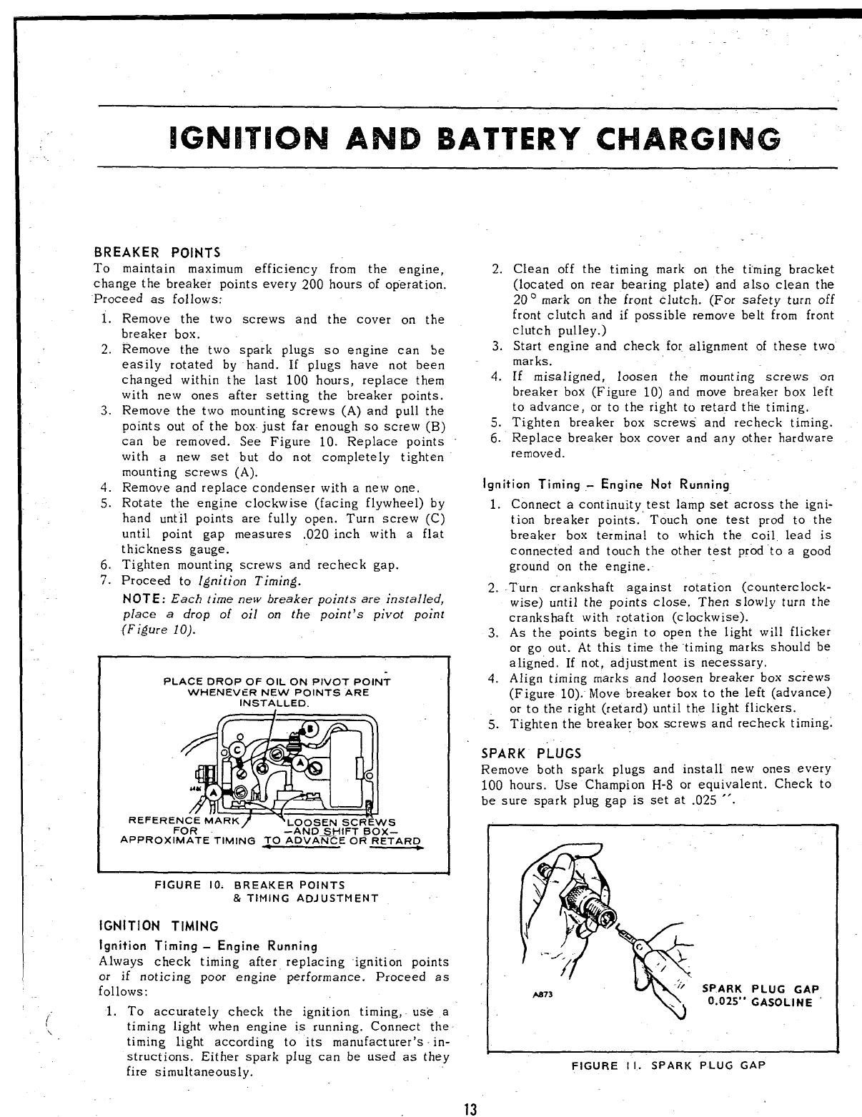
SPARK PLUGS
Remove both spark plugs and install new ones every
100 hours. Use Champion H-8 or equivalent. Check to
be sure spark plug gap is set at .025 “.
SPARK
0.025’” PLUG GAP
GASOLINE
FIGURE I1. SPARK “PLUG GAP
13
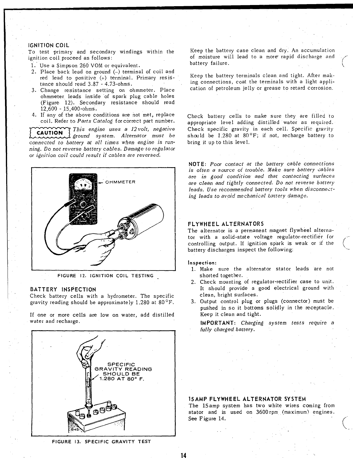
IGNITION COIL
To test primary and secondary windings within the
ignition coil .proceed as follows:
1.
2.
3.
4.
Use aSimpson 260 VOM or equivalent.
Place back lead on ground (-) terminal of coil and
red lead to positive (+) terminal. Primary resis-
tance should read 3.87 -4.73-ohms.
Change resistance setting on ohmmeter. Place
ohmmeter leads inside “of spark plug cable holes
(Figure 12). Secondary resistance should read
12,600- 15,400-ohms.
If any of the above conditions are not met, replace
coil. Refer to Parts Catalog for correct part number.
=&round
This engine uses a 12 volt, negative
system. Alternator must be
connected to battery at all times when engine is run-
ning. Do not reverse battery cables. Damageto regulator
Keep the battery case clean and dry. An accumulation
of moisture will lead to amore- rapid discharge and
battery failure.
Keep the battery terminals clean and tight. After mak-
ing connections, coat the terminals with alight appli-
cation of petroleum jelly or grease to retard corrosion.
Check battery cells to make sure they are filled to
appropriate level adding distilled water as required.
Check specific gravity in each cell. Specific gravity
shald be 1,280 at 80° F; if not, recharge battery to
bring it up to this level.
or [gnition coil could result if cables are reversed.
NOT E: Poor contact at the battery cable connections
is often a source ot’ trouble. Make sure battery <ables
are in good condition and that contacting surfaces
are clean and tightly connected. Do not reverse battery
leads. Use recommended battery tools when disconne<t-
in,g leads to avoid mechanical battery damage.
FIGURE 12. IGNITION COIL TESTING
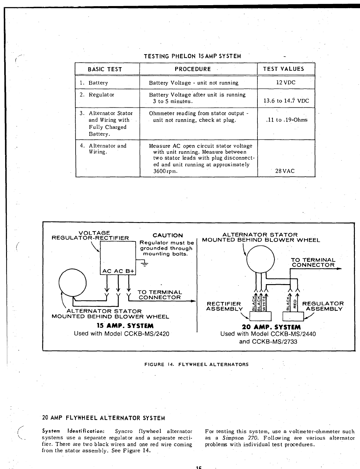
BATTERY INSPECTION
Check battery cells with ahydrometer, The specific
gravity reading should be approximately 1.280 at 80 CF.
If one or more cells are low on water, add distilled
water and recharge.
““”~”’
%2
. .,
. . SPECIFIC
GRAVITY READING
r--
SHOULD BE
1.280 AT 80” F.
&
...,.-i.:~
FIGURE 13. SPECIFIC GRAVITY TEST
FLYWHEEL ALTERNATORS
The alternator is apermanent magnet flywheel alterna-
tor with asolid-state voltage regulator-rectifier for
controlling output. If ignition spark is weak or if the
battery discharges inspect the following:
Inspection:
1.
2.
3.
Make sure the alternator stator leads are not
shorted together.
Check mounting of regulator-rectifier case to unit.
It should provide agood electrical ground with
clean, bright surfaces.
Output control plug or plugs (connector) must be
pushed in so it bottoms solidly in the receptacle.
Keep it clean and. tight.
IMPORTANT: Charging
fully charged battery.
system tests require a
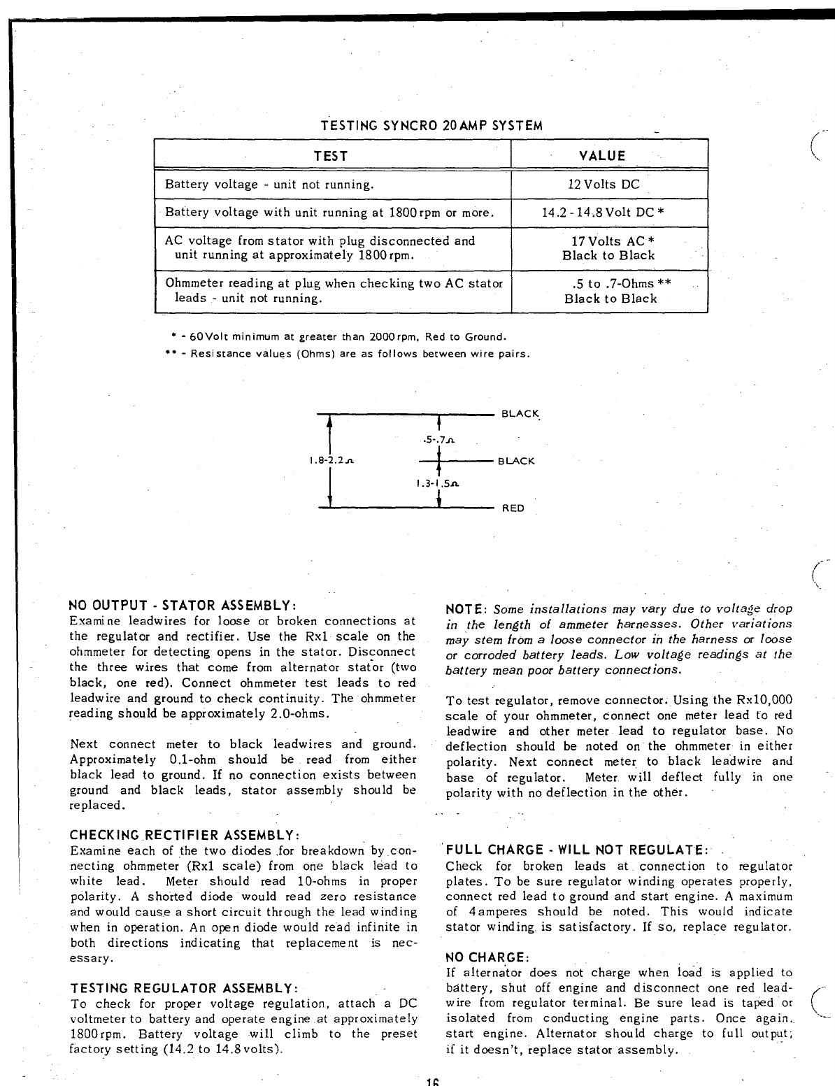
15 AMP FLYWHEEL ALTERNATOR SYSTEM
The 15amp system has two white wires coming from
stator and is used on 3600rpm (maximum) engines.
See Figure 14.
14
,/-
(
(’‘-
,.
,.-.
,-
(.
,,-
i
(’
(’
\
TESTING PHELON 15AMP SYSTEM
BASIC TEST PROCEDURE
I1. Battery IBattery Voltage -unit notrunning
2. Regulator Battery Voltage ”after unit is running
3to5 minutes.
3. Alternator Stator Ohmmeter reading from stator output -
and Wiring with unit not running, check at plug.
Fully Charged
Battery.
4. Alternator and Measure AC open circuit stator voltage
Wiring. with unit running. Measure between
two stator leads with plug disconnect-
ed and unit running at approximately
3600rpm.
II
TEST VALUES I
i
12 vDC I
I
13.6 to 14.7 VDC I
5
.11 to .19-Ohms
28 VAC
VOLTAGE
REGULATOR-RECTIFIER CAUTION
\
Regulator must be
n
grounded through
mounting bolts.
=
QwTOTERIVIINAL ~
CONNECTOR
\~ALTERNATOR STATOR
MOUNTED BEHIND BLOWER WHEEL
15 AMP. SYSTEM
Used with Model CCKB-MS/2420
ALTERNATOR STATOR
MOUNTED BEHIND BLOWER WHEEL
\
TO TERMINAL
CONNECTOR
J!!!!
!!!iY”
RECTIFIER
ASSEMBLY
20 AMP. SYSTEM
Used with Model CCKB-MS/2440
and CCKB-MS/2733
FIGURE 14. FLYWHEEL ALTERNATORS
20 AMP FLYWHEEL ALTERNATOR SYSTEM
System Identification: Syncro flywheel alternator For testing this system, use avoltmeter-ohmmeter such
~...systems use aseparate regulator and aseparate recti- as aSimpson 270. Following are various alternator
tier. There are two black wires and one red wire coming problems with individual test procedures.
from the stator assembly. See Figure 14.
15
TESTING SYNCRO 20 AMP SYSTEM .-
TEST (
VALUE I,,
Battery voltage -unit not running. 12 Volts DC
Battery voltage with unit running at 1800rpm or more. 14.2 -14-.8 Volt DC *
AC voltage from stator with plug disconnected and 17 Volts AC *
unit running at approximately 1800 rpm. Black to Black J
Ohmmeter reading at plug when checking two AC stator .5 to .7-Ohms **
leads -unit not running. Black to Black
*-60 Volt minimum at greater than 2000rpm, Red to Ground.
●*-Resistance values (Ohms) are as follows berween wire pairs.
~“::
1.8-2.2A BLA
ARED
NO OUTPUT -STATOR ASSEMBLY: NOT E: Some installations may vary due to voltage drop
Exarni ne Ieadwires for loose or broken connections at
the regulator and rectifier. Use the Rxl scale on the in the length of ammeter harnesses. Other variations
may stem from a loose connector in the harness or loose
ohmmeter for detecting opens in the stator. Disconnect
the three wires that come from alternator stat_or (two or corroded battery leads. Low voltage readings at the
batterv mean Door batterv connections.
black, one red). Connect ohmmeter test leads to red . . . .
leadwire and ground to check continuity. The ohmmeter To test regulator, remove connector. Using the Rx1O,OOO
reading should be approximately 2.()-ohms. scale of your ohmmeter, connect one meter lead to red
leadwire and other meter lead to regulator base. No
Next connect meter to black leadwires and ground. deflection should be noted on the ohmmeter in either
Approximately O.1-ohm should be read from either polarity. Next connect meter, to black
black lead to ground. If no connection exists between base of regulator. Meter will deflect
ground and black leads, stator assembly should be
replaced. polarity with no deflection in the other.
. .
CHECKING RECTIFIER ASSEMBLY:
Examine each of the two diodes for breakdowri by con- ‘FULL CHARGE -WILL NOT REGULATE:
netting ohmmeter (Rxl scale) from one black lead to Check for broken leads at connection
white lead. Meter should read 10-ohms in proper
polarity. Ashorted diode would read zero resistance
and would cause ashort circuit through the lead winding
when in operation. An open diode would re”ad infinite in
both directions indicating that replacement is nec-
essary.
TESTING REGULATOR ASSEMBLY:
To check for proper voltage regulation, attach aDC
voltmeter to battery and operate engine at approximately
1800rpm. Battery voltage will climb to the preset
factory setting (14.2 to 14.8volts).
leadwire and
fully in one
to regulator
plates. To be sure regulator winding operates properly,
connect red lead to ground and start engine. Amaximum
of 4amperes should be noted. This would indicate
stator winding. is satisfactory. If so, replace regulator.
NO CHAR,GE:
If alternator does not charge when load is applied to
battery, shut off engine and disconnect one red lead- -
wire from regulator terminal. Be sure lead is taped or (
isolated from conducting engine parts. Once again,. ‘---
start engine. Alternator should charge to full output;
if it doesn’t, replace stator assembly.
16
STARTING SYSTEM -
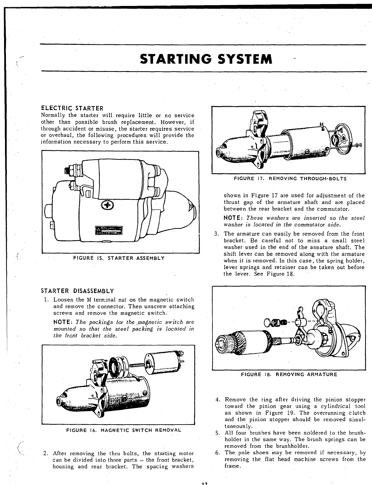
ELECTRIC STARTER
Normally the starter will require little or no service
other than possible brush replacement. However, if
through accident or misuse, the starter requires service
or overhaul, the following procedures will provide the
information necessary to perform this service.
—.
FIGURE 15. ST ART.ER ASSEMBLY
STARTER DISASSEMBLY
1. Loosen the Mterminal nut on the magnetic switch
and remove the connector. Then unscrew attaching
screws and remove the magnetic switch.
NOTE: The packings for the magnetic switch are
mounted so that the steel packing is located in
FIGURE 17. REMOVING THROUGH-BOLTS
shown in Figure 17 are used for adjustment of the
thrust gap of the armature shaft and are placed
between the rear bracket and the commutator.
NOT E: These washers are inserted so the steel
washer is located in the commutator side.
3. The armature can easilv be removed from the front
bracket. Be careful nit to miss asmall steel
washer used in the end of the armature shaft. The
shift lever can be reirroved along with the armature
when it is removed. In this case, the spring holder,
lever springs and retainer can be taken out before
the lever. See Figure 18.
the front bracket side.
FIGURE 18. REMOVING ARMATURE
FIGURE 16. MAGNETIC SWITCH REMOVAL
2. After removing the thru bolts, the starting motor
can be divided into three parts –the front bracket,
housing and rear bracket. The spacing washers
4. Remove the ring after driving tlie pinion stopper
toward the pinion gear using acylindrical tool
as shown in Figure 19. The overrunning cIutch
and the pinion stopper should be removed simul-
taneously.
5. All four brushes have been soldered to the brush-
holder in the same way. The brush springs can be
removed from the brushholder.
6. The pole shoes may be removed if necessary, by
removing the flat head machine screws from the
frame.
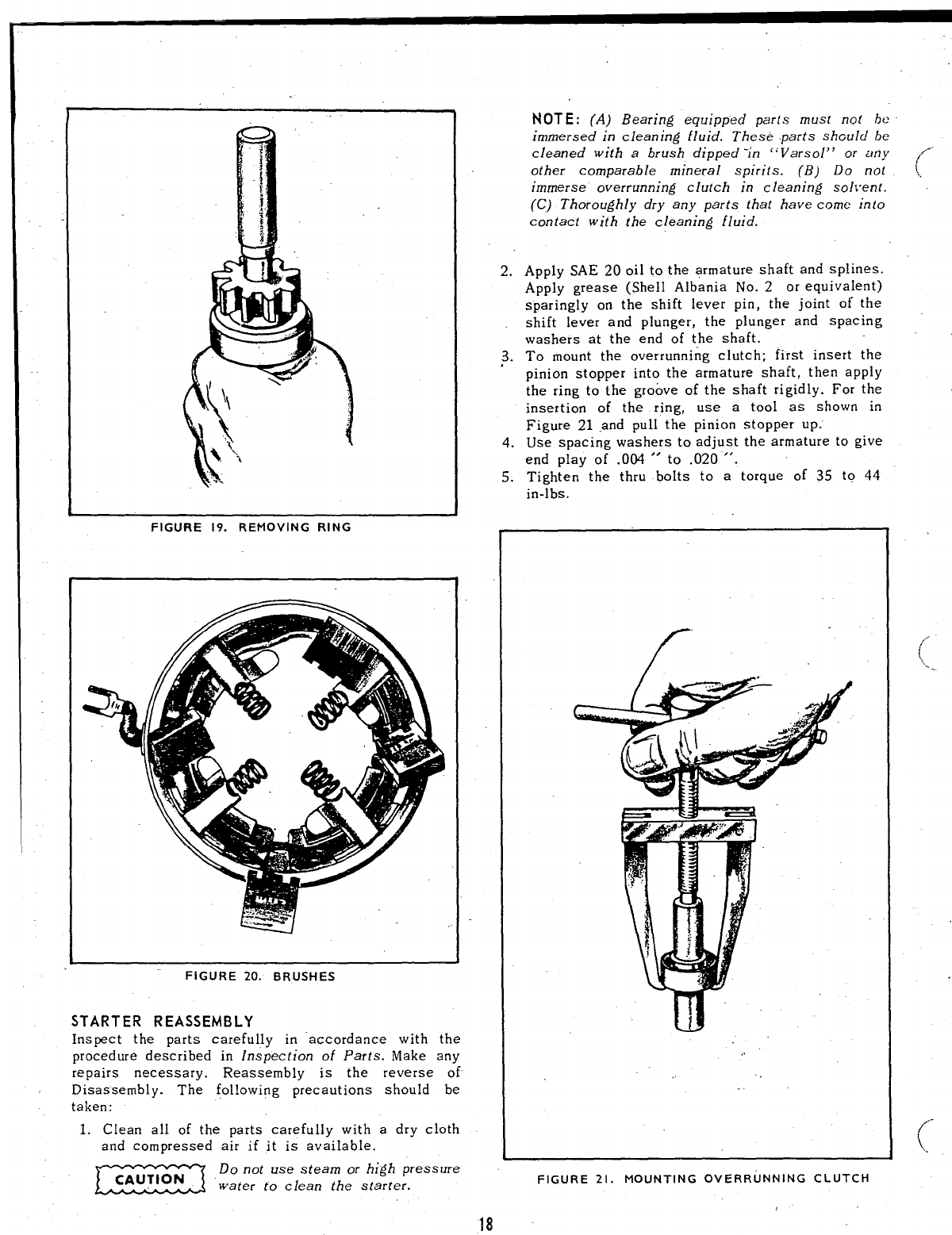
FIGURE 19. REMOVING RING
FIGURE 20. BRUSHES
STARTER REASSEMBLY
Inspect the parts carefully in ‘accordance with the
procedure described in Inspection of Parts. Make any
repairs necessary. Reassembly is the reverse of
Disassembly. The following precautions should be
taken:
1. Clean all of the parts carefully with adry cloth
and compressed air if it is available.
Eiii53 Do not use steam or high pressure
water to clean the starter,
2.
~.
4.
5.
NOT E: (A) Bearing equipped parts must not ht:
immersed in cleaning fluid. These parts shGuid be
cleaned with a brush dipped ‘in “Varsol” or any
other comparable mineral spirits. (B) Do not
immerse overrunning clutch in cleaning sol~”ent.
(C) Thoroughly dry any parts that have come into
contact with the cleaning fluid.
Apply SAE 20 oil to the armature shaft and splines.
Apply grease (Shell Albania No. 2or equivalent)
sparingly on the shift lever pin, the joint of the
shift lever and plunger, the plunger and spacing
washers at the end of the shaft.
To mount the overrunning clutch; first insert the
pinion stopper into the armature shaft, then apply
the ring to the groove of the shaft rigidly. For the
insertion of the ring, use atool as shown in
Figure 21 and pull the pinion stopper UP.”
Use spacing washers to adjust the armature to give
end play of .004 “to .020 “.
Tighten- the thru bolts to atorque of 35 to 44
in-lbs.
.’
FIGURE 21. MOUNTING OVERRUNNING CLUTCH
18
(-
-.-
(_
(“
\
,/ -
/
\-.
-f’””
\..
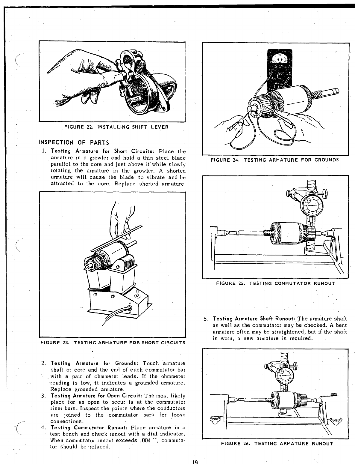
FIGURE 22. INSTALLING SHIFT LEVER
INSPECTION OF PARTS
1. Testing Armature for Short Circuits: place the
armature in agrowler and hold athin steel blade
parallel to the core and just above it” while slowly
rotating the armature in the growler. Ashorted
armature will cause the blade to vibrate and be
attracted to the core. Replace shorted armature.
FIGURE 23. TESTING ARMATURE FOR SHORT CIRCUITS
.
2%
3.
4.
Testing Armature for Grounds: Touch armature
shaft or core and the end of each commutator bar
with apair of ohmmeter leads. If the ohmmeter
reading is low, it indicates agrounded armature.
Replace grounded armature.
Testing Armature for Open Circuit: The most likely
place for an open to occur is at the commutator
riser bars. Inspect the points where the conductors
are joined to the commutator bars for loose
connections.
Testing Commutator Runout: Place armature in a
test bench and check runout with adial indicator.
When commutator runout exceeds .004 “, commuta-
tor should be refaced.
FIGURE 24. TESTING ARMATURE FOR GROUNDS
FIGURE 25. TESTING COMMUTATOR RUNOUT
5. Testing Armature Shaft Runout: The armature shaft
as well as the commutator mav be checked. Abent
armature often may be straightened, but if the shaft
is worn, anew armature is required.
FIGURE 26. TESTING ARMATURE RUNOUT
19
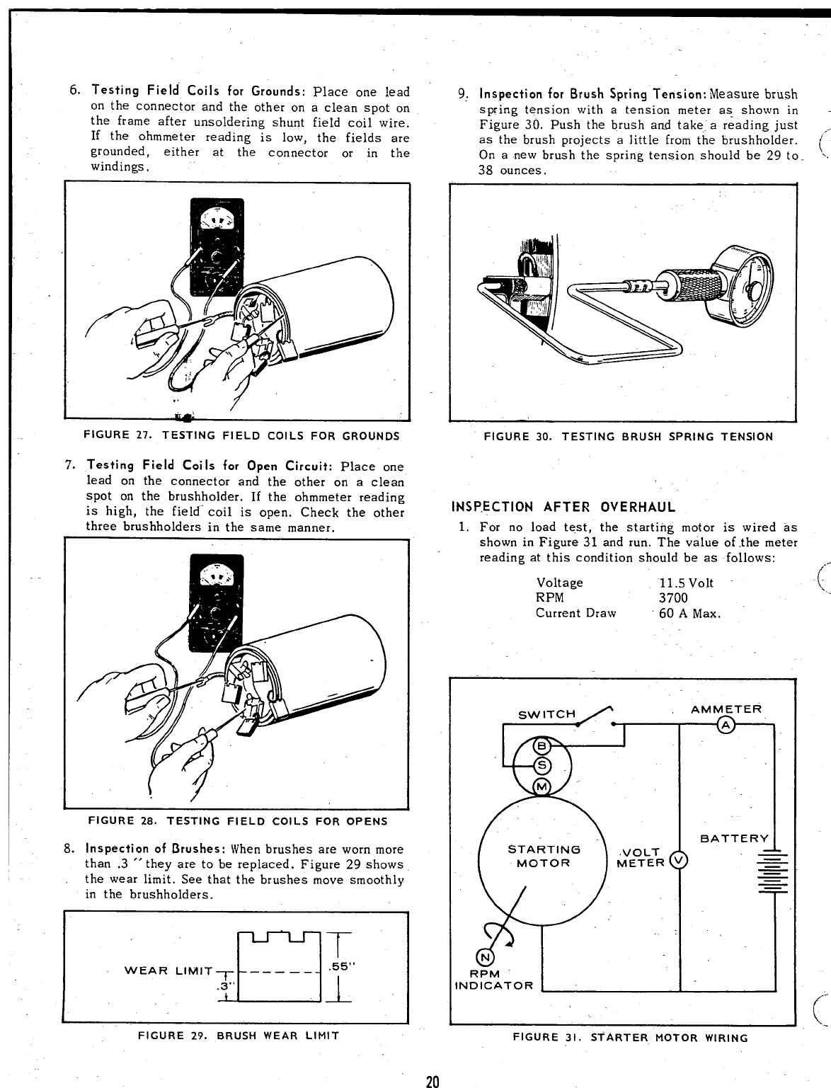
6. Testing Field Coils for Grounds: Place one lead
on the connector and the other on aclean spot on
the frame after unsoldering shunt field coil wire.
If the ohmmeter reading is low, the fields are
grounded, either at the connector or in the
windings.
FIGURE 27. TESTING FIELD COILS FOR GROUNDS
7. Testing Field Coils for Open Circuit: Place one
lead on the connector and the other on aclean
spot on the brushholder. If the ohmmeter reading
is high, the field” coil is open. Check the other
three brushholders in the same manner.
FIGURE 28. TESTING FIELD COILS FOR OPENS
8. Inspection of Brushes: When brushes are worn more
than .3 “they are to be replaced. Figure 29 shows
the wear limit. See that the brushes move smoothly
in the brushholders.
,u“
T
WEAR LINll TT –____ .55”
.3”
-L
FIGURE 29. BRUSH WEAR LIMIT
20
9, Inspection for Brush Spring Tension: Measure brush
spring tension with atension meter as shown in
Figure 30. Push the brush and take” areading just ,,
as the brush projects alittle from the brushholder. (’
On anew brush the spring tension should be 29 to.
‘~.
38 ounces.
FIGURE 30. TESTING BRUSH SPRING TENSION
INSPECTION AFTER OVERHAUL
1. For no load test, the starting motor is wired as
shown in Figure 31 and run. The value of the meter
reading at this condition should be as follows:
Voltage 11.svolt .(--
‘>.
-
RPM 3700
Current Draw 60 AMax.
sWITCH AMMETER
I
~1
BATTERY
MvEOTLETRv~
=
~
~—
RPM
ND ICATOR
.—
FIGURE 31. STARTER MOTOR WIRING
.-
,/
(..
STARTING \
J
MOTOR BATTERY
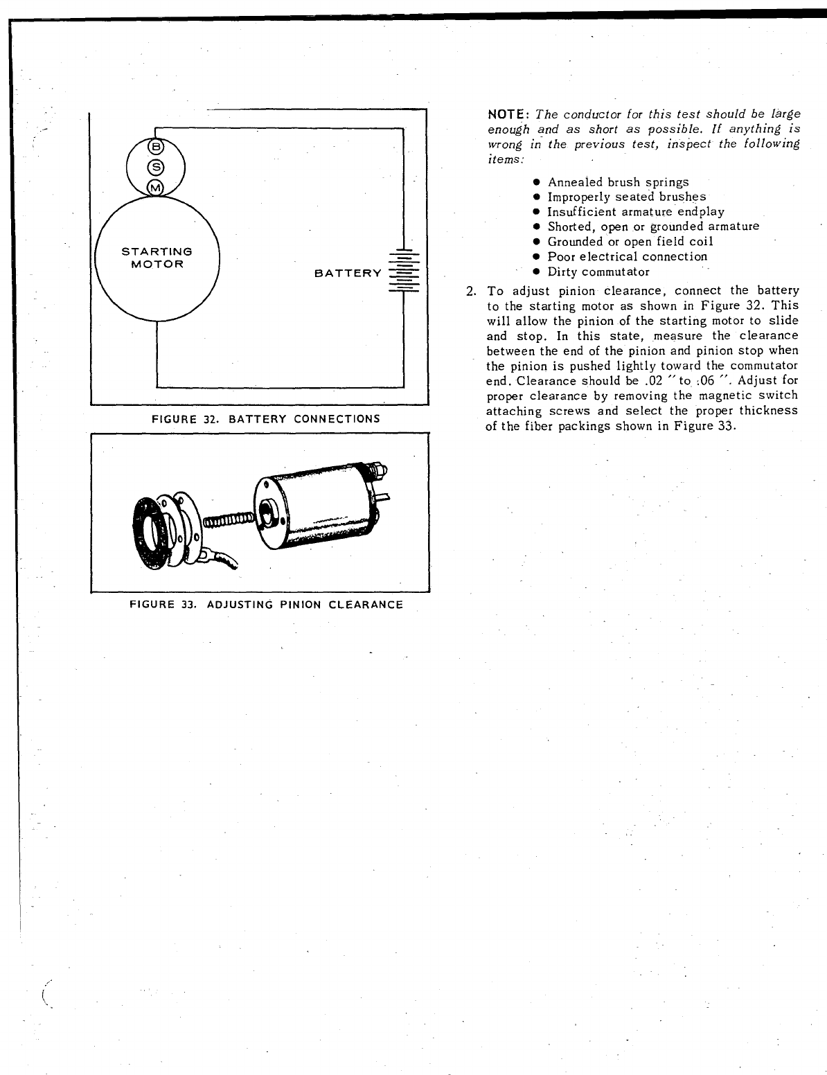
FIGURE 32. BATTERY CONNECTIONS
FIGURE 33, ADJUSTING PINION CLEARANCE
2.
NOTE: The conductor for this test should be large
enough and as short as possible, If anything is
wrong in
items:
o
e
●
●
●
●
●
the previous test, inspect the following
Annealed brush springs
Improperly seated brushes
Insufficient armature “end play
Shorted, open or grounded armature
Grounded or open field coil
Poor electrical connection
Dirty commutator
To adjust pinion clearance, connect the battery
to the starting motor as shown in Figure 32. This
will allow the pinion of the starting motor to slide
and stop. In this state, measure the clearance
between the end of the pinion and pinion stop when
the pinion is pushed lightly toward the commutator
end. Clearance should be .02 “to :06 “. Adjust for
proper clearance by removing the magnetic switch
attaching screws and select the proper thickness
of the fiber packings shown in Figure 33.
ENGINE DISASSEMBLY ,-
(
-.
If engine disassembly is necessary, first remove all
the complete assemblies (e.g. manifold with carburetor
and cartridge air cleaner. Individual assemblies, as the
car buretor, ”can be removed and serviced later, if
necessary. Any special assembly instructions for a
particular group are included in the applicable section.
When reassembling, check each section for these
special assembly instructions or procedures.
FLYWHEEL
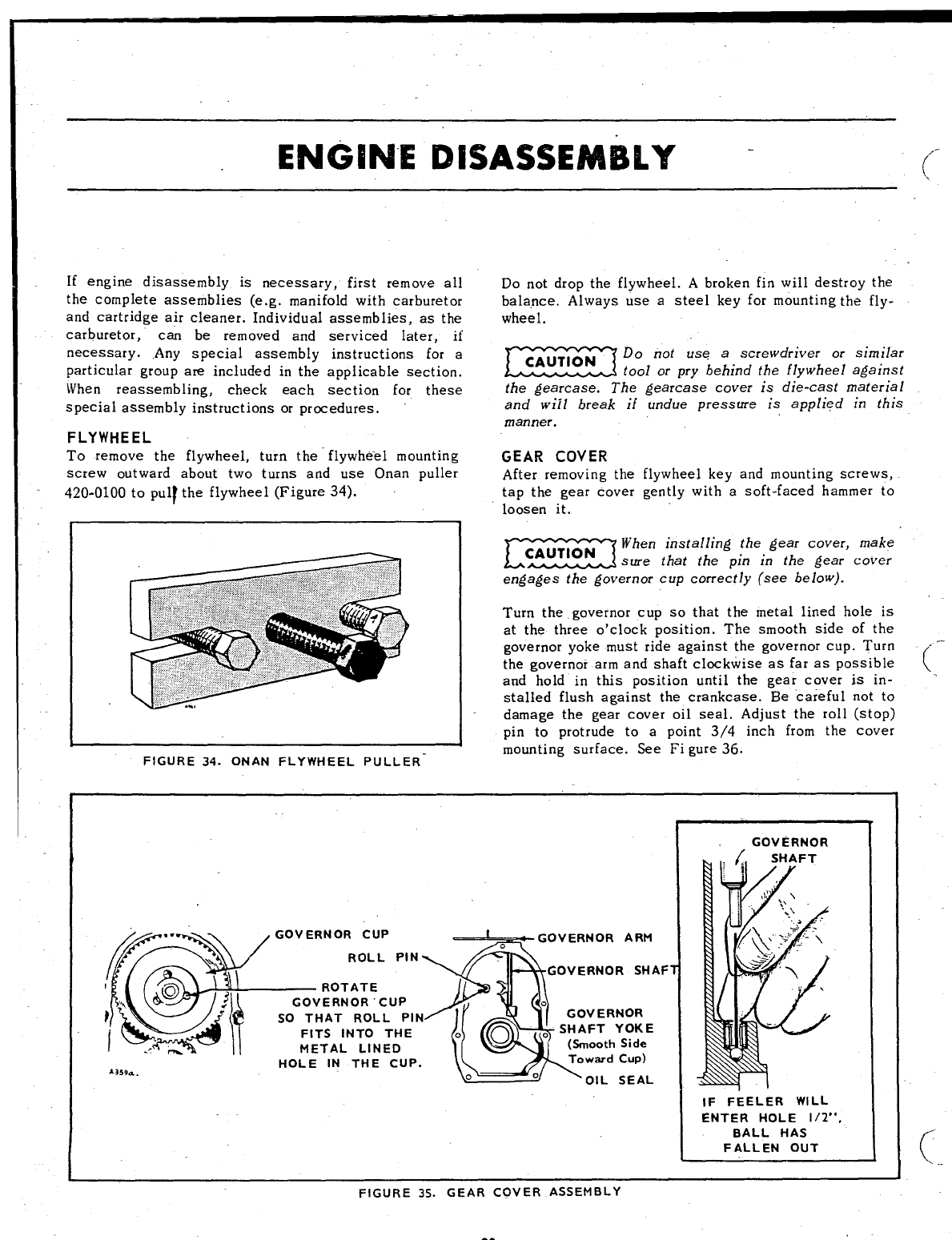
To remove the flywheel, turn the flywhe”el mounting
screw outward about two turns and use Onan puller
420-0100 to pull the flywheel (Figure 34). -
FIGURE 34. ONAN FLYWHEEL PULLER-
Do not drop the flywheel. Abroken fin will destroy the
balance. Always use asteel key for mounting the fly-
wheel,
Emit’Do not use ascrewdriver or similar
tool or pry behind the flywheel against
the gearcase. The gearcase cover is die-cast material
and will break if undue pressure is applied in this
manner.
GEAR COVER
After removing the flywheel key and mounting screws,
tap the gear cover gently with asoft-faced hammer to
loosen it.
EziiEcI
When installing the gear cover, make
sure that the pin in the gear cover
engages the governor cup correctly (see below).
Turn the governor cup so that the metal lined hole is
at the three o’clock position. The smooth side of the
governor yoke must ride against the governor cup. Turn - ‘-
the governor arm and shaft clockwise as far as possible (
and hold in this position until the Rear cover is in- -
stalled flush against the crankcase. ‘Be “careful not to
damage the gear cover oil seal. Adjust the roll (stop)
pin to protrude to apoint 3/4 inch from the cover
mounting surface. See Figure 36.
ARM
RSHAF
NOR
YOKE
Side
cup)
SEAL
GOVERNOR
IF FEELER WILL
ENTER HOLE 1/29’,
BALL HAS
FALLEN OUT (’
\.
FIGURE 35. GEAR COVER ASSEMBLY
,.
;
[
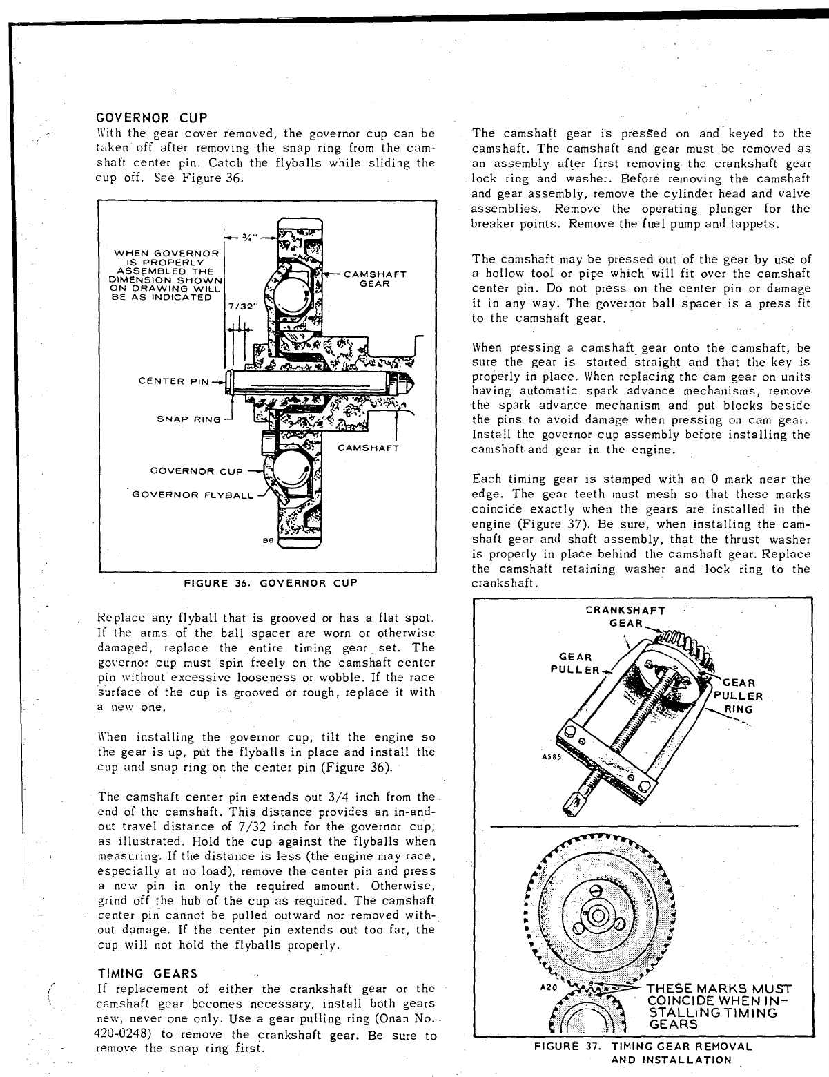
GOVERNOR CUP
\Vith the gear cover removed, the governor cup can be
taken off after removing the snap ring from the cam-
shaft center pin. Catch “the flyballs while sliding the
cup off. See Figure 36,
t--k
*
#“,;,,
WHEN GOVERNOR
IS PROPERLY
AS SE ME LEO THE
DIMENSION SHOWN CAMSHAFT
ON ORAWING wlLL .. GEAR
BE AS INDICATED ‘?’
CENTER PIN
sr+AP RINGJ b
3
GOVERNOR CUP ‘/
‘,
GOVERNOR FLYBALL Al
>?.-
Iwiiii
[W?&d
“em
FIGURE 36. GOVERNOR CUP
Replace any flyball that is grooved or has aflat spot.
If the arms of the ball spacer are worn or otherwise
damaged, replace the entire timing gear .set. The
governor cup must spin freely on the camshaft center
pin [vithout excessive looseness or wobble. If the race
surface of the cup is grooved or rough, replace it with
anew one.
\~hen installing the governor cup, tilt the engine so
the gear is up, put the flyballs in place and install the
cup and snap ring on the center pin (Figure 36).
The camshaft center pin extends out 3/4 inch from the
end of the camshaft. This distance provides an in-and-
out travel distance of 7/32 inch for the governor cup,
as illustrated. Hold the cup against the fly balls when
measuring. If the distance is less (the engine may race,
especially at no load), remove the center pin and press
anew pin in only the required amount. Otherwise,
grind off the hub of the cup as required. The camshaft
center piri cannot be pulled outward nor removed with-
out damage. If the center pin extends out too far, the
cup will not hold the flyballs properly,
TIMING GEARS
If replacement of either the crankshaft gear or the
camshaft gear becomes necessary, install both gears
new, never one only. Use agear pulling ring (Onan No.
420-0248) to remove the crankshaft gear. Be sure to
remove the snap ring first.
The camshaft gear is pres=ed on and keyed to the
camshaft. The camshaft and gear must be removed as
an assembly aft,er first removing the crankshaft gear
lock ring and washer. Before removing the camshaft
and gear assembly, remove the cylinder head and valve
assemblies. Remove the operating plunger for the
breaker points. Remove the fuel pump and tappets.
The camshaft may be pressed out of the gear by use of
ahollow tool or pipe which will fit over the camshaft
center pin. Do not press on the center pin or damage
it in any way. The governor ball spacer is apress fit
to the camshaft gear.
When pressing acamshaft gear onto the camshaft, be
sure the gear is started straight and that the key is
properly in place. When replacing the cam gear on units
having automatic spark advance mechanisms, remove
the spark advance mechanism and put blocks beside
the pins to avoid damage when pressing on cam gear.
Install the governor cup assembly before installing the
camshaft and gear in the engine.
Each timing gear is stamped with an Omark near the
edge. The gear teeth must mesh so that these marks
coincide exactly when the gears are installed in the
engine (Figure 37). Be sure, when installing the cam-
shaft gear and shaft assembly, that the thrust washer
is properly in place behind the camshaft gear. Replace
the camshaft retaining washer and lock ring to the
crankshaft.
FIGURE 37. TIMING GEAR REMOVAL
AND INSTALLATION
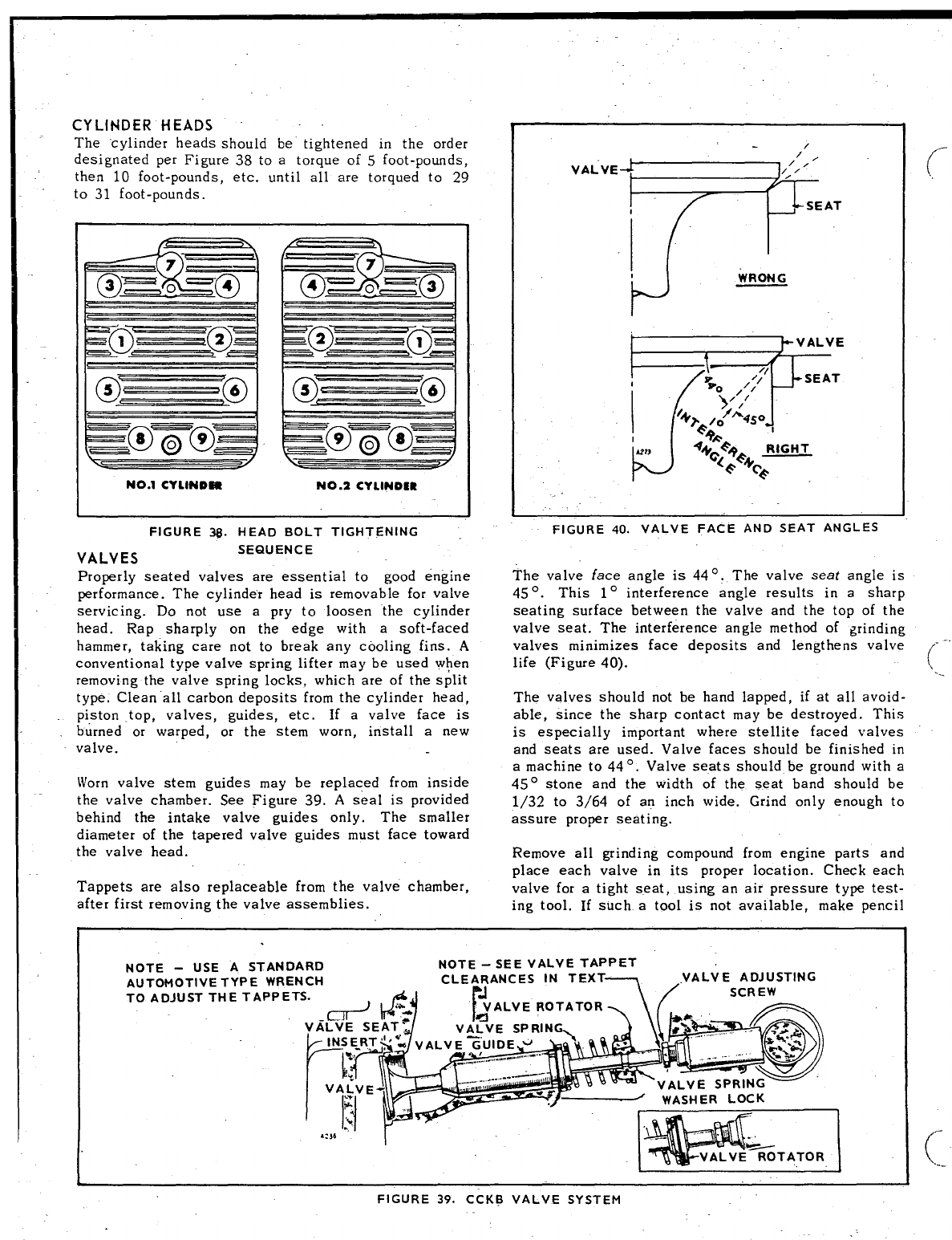
CYLINDER HEADS
The ‘cylinder heads should be tightened in the order
designated per Figure 38 to atorque of 5foot-pounds,
then 10 foot-pounds, etc. until all are torqued to 29
to 31 foot-pounds,
I0. .0I
5===== 6
NO.1 CYLlNDF41 NO.2 CYL8NDSR
VALVES
FIGURE 3B. HEAD BOLT TIGHTENING
SEQUENCE
Properly seated valves are essential to good engine
performance. The cylinder head is removable for valve
servicing. Do not use apry to loosen ‘the cylinder
head. Rap sharply on the edge with asoft-faced
hammer, taking care not to break any cooling fins. A
conventional type valve spring lifter may be used when
removing the valve spring locks, which are of the split
type. Clean “all carbon deposits from the cylinder head,
piston top, valves, guides, etc. If avalve face is
burned or warped, or the stem worn, install anew
valve.
Worn valve stem guides may be replaced from inside
the valve chamber. See Figure 39. Aseal is provided
behind the intake valve guides only. The smaller
diameter of the tapered valve guides must face toward
the valve head.
Tappets are also replaceable from the valve chamber,
after first removing the valve assemblies.
/
“’VEF7
FIGURE 40. VALVE FACE AND SEAT ANGLES
The valve face angle is 440. The valve seat angle is
45°. This 1° interference angle results in asharp
seating surface between the valve and the top of the
valve seat. The interference angle method of grinding
valves minimizes face deposits and lengthens valve
life (Figure 40). (-’
...
The valves should not be hand lapped, if at all avoid-
able, since the sharp contact may be destroyed. This
is especially important where stellite faced valves
and seats are used. Valve faces should be finished in
amachine to 440. Valve seats should be ground with a
45° stone and the width of the seat band should be
1/32 to 3/64 of an inch wide. Grind only enough to
assure proper seating.
Remove all grinding compound from engine parts and
place each valve in its proper location. Check each
valve for atight seat, using an air pressure type test-
ing tool. If such atool is not available, make pencil
I
I
f
i,
NOTE -USE ASTANDARD NOTE -SEE VALVE TAPPET
AUTOMOTIVE TYPE WRENC
TO ADJUST THE TAPPETS.
IL1
FIGURE 39. CCKE VALVE SYSTEM
L
_
. .
..
-1’
(,
marks at intervals across the valve face and observe
it’ the marks rub off uniformly when the valve is rotated
part of aturn against the seat.
Lightly oil the valve stems and reassemble all parts
removed. Adjust the valve clearance (see Tappet
Adjust ment).
The positive type valve rotocoils serve to prolong
valve life and decrease valve repairs. Check the roto-
coils periodically by removing the cylinder heads and
cranking the engine. When functioning properly, the
valve is rotated afraction of aturn each time it opens.
If rotocoils are faulty, install new ones.
TAPPET ADJUSTMENT
The engine is equipped with adjustable tappets. To
make avalve adjustment, remove the valve covers.
Crank the engine over slowly by hand until the left
hand intake valve, when facing the flywheel, opens
and closes. Continue about 1/4 turn until the correct
timing marks align. This should place the left hand
piston at the top of its compression stroke, the posi-
tion it must be in to get proper valve adjustment for
the left hand cylinder. Clearances are shown in
Dimensions and Clearances section. For each valve,
the gauge should just pass between the valve stem
and valve tappet (Figure 41).
To correct the valve clearance, turn the adjusting
screw as needed to obtain the right clearance. The
screw is self-locking.
To adjust the valves on the right hand cylinder, crank
the engine over one complete revolution and again
line up the correct timing marks. Then follow the
adjustment. given for the valves of the. left hand
cylinder.
INTAKE AND EXHAUST VALVES
(SEE TABLE OF CLEARANCES) /
FIGURE 41. ADJUSTING TAPPETS
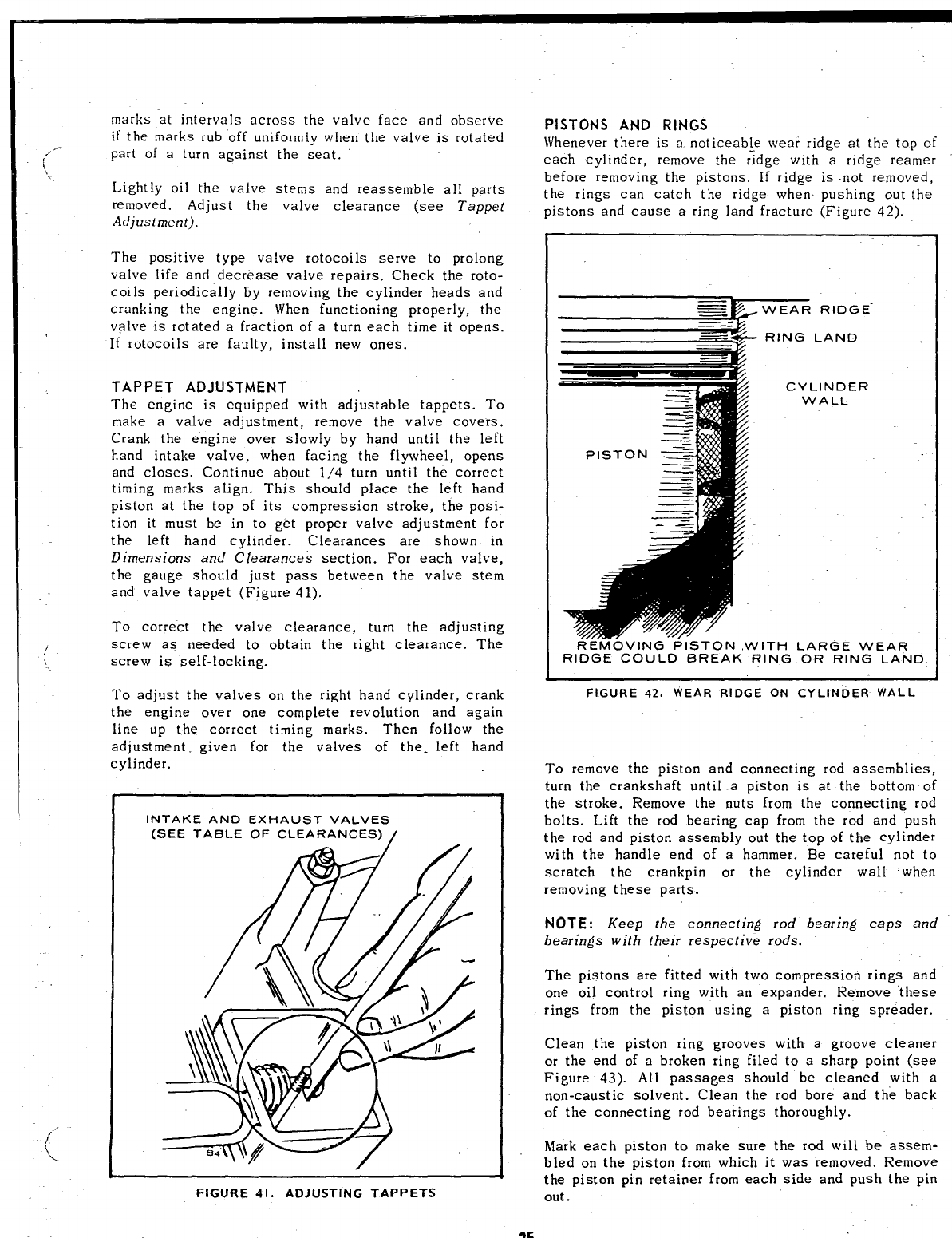
PISTONS AND RINGS
Whenever there is anoticeable wear ridge at the top of
each cylinder, remove the ridge with aridge reamer
before removing the pistons. If ridge is -not removed,
the rings can catch the ridge when pushing out the
pistons and cause aring land fracture (Figure 42).
WEAR RIDGE”
—
-
—
PISTON S
RING LAND
CYLINDER
WALL
....-. .
REk40v ING PISTON ,WITH LARGE WEAR
RIDGE COULD BREAK RING OR RING LAND.
FIGURE 42. WEAR RIDGE ON CYLINDER WALL
To remove the piston and connecting rod assemblies,
turn the crankshaft until apiston is at the bottom of
the stroke. Remove the nuts from the connecting rod
bolts. Lift the rod bearing cap from the rod and push
the rod and piston assembly out the top of the cylinder
with the handle end of ahammer. Be careful not to
scratch the crankpin or the cylinder wall when
removing these parts.
NOTE: Keep the connecting rod bearing caps and
bearings with their respective rods.
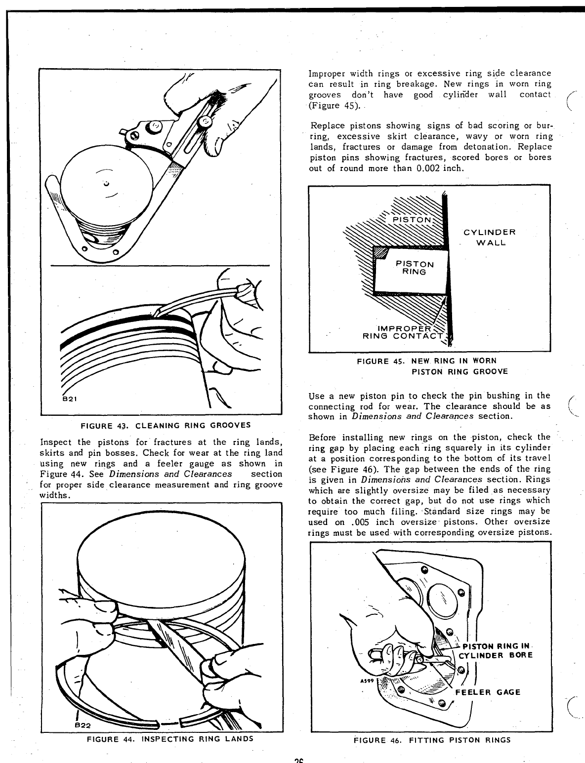
The pistons are fitted with two compression rings and
one oil control ring with an expander. Remove ‘these
rings from the piston using apiston ring spreader.
Clean the piston ring grooves with agroove cleaner
or the end of abroken ring filed to asharp point (see
Figure 43). All passages should be cleaned with a
non-caustic solvent. Clean the rod bore and the back
of the connecting rod bearings thoroughly.
Mark each piston to make sure the rod will be assem-
bled on the piston from which it was removed. Remove
the piston pin retainer from each side and push the pin
out .
25
B21
FIGURE 43. CLEANING RING GROOVES
Inspect the pistons for” fractures at the ring lands,
skirts and pin bosses. Check for wear at the ring land
using new rings and afeeler gauge as showrr in
Figure 44. See Dimensions and Clearances section
for proper side clearance measurement and ring groove
widths.
Improper width rings or excessive ring side clearance
can result in ring breakage. New rings in worn ring
grooves don’t have good cylirider wall contact
(Figure 45).
Replace pistons showing signs of bad scoring or bur-
ring, excessive skirt clearance, wavy or worn ring
lands, fractures or damage from detonation. Replace
piston pins showing fractures, scored bores or bores
out of round more than 0.002 inch.
CYLINDER
WALL
... ...-—.
FIGURE 45. NEW RING IN WORN
PISTON RING GROOVE
Use anew piston pin to check the pin bushing in the
connecting rod for wear. The clearance should be as
shown in Dimensions and Clearances section.
Before installing new rings on the piston, check the
ring gap by placing each-ring squarely in its cylinder
at aposition corresponding to the bottom of its travel
(see Figure 46). The gap between the ends of the ring
is given in Dimensions and Clearances section. Rings
which are slightly oversize may be filed as necessary
to obtain the correct gap, but do not use rings which
require too much filing. Standard size rings may be
used on .005 inch oversize pistons. Other oversize
rings must be used with corresponding oversize pistons.
RING IN
RBORE
GAGE
w
f’
ix....
-(”
‘k.,..
FIGURE 44. INSPECTING RING LANDS FIGURE 46. FITTING PISTON RINGS
Rings of the tapered type are usually marked top on
one side, or identified in some other manner and the
/“ ring must be installed with this mark toward the closed
“,, end of the piston.
Space each ring gap one third of the way around the,
piston from the preceding one, with no gap directly
in line with the piston. pin. The bottom piston ring
groove should be fitted with an expander and an oil
control ring and the two upper grooves fitted with
compression rings: If achrome faced ring is used, it
will be in the top groove. The oil control ring is select-
ed for best performance in regard to the correct unit
pressure characteristics.
The piston is fitted with afull-floating type piston
pin. The pin is kept in place by two lock rings in the
piston, one at each side. Be sure these lock rings are
properly in place before installing the piston and con-
necting rod in the engine. Refer to Dimensions and
Clearances section for the correct piston-to-cylinder
clearance.
CONNECTING RODS
The connecting rods should be serviced at the same
time the pistons or rods are serviced. Rods must be
removed with the piston. Replaceable bushings and
bearings are used. See Parts Catalog section for
available undersize and standard size bearings.
Proper clearance is obtained by replacing the pin
(’ bushing and the bearings. The rod bearings are pre-
cision size and require no reaming.
Install the connecting rods and caps with raised lines
(witness marks) aligned and with the caps facing toward
the oil base. The rod and cap numbered 2fits on the
crankshaft journal nearest the bearing pla~e. Coat the
crankshaft journal bearing surfaced with oil before
installing the rods. Crank the engine by hand to see
that the rods are free. If necessary, rap the connecting
rod cap screws sharply with asoft-faced hammer to
set the rod square on the journal.
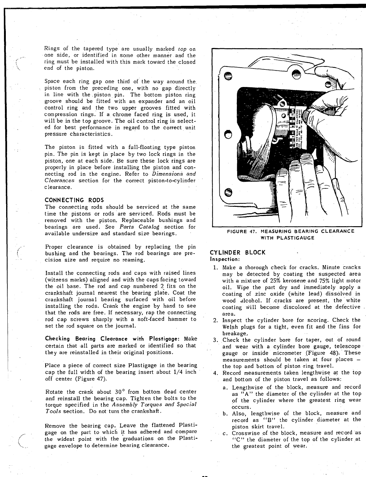
Checking Bearing Clearance with Plastigage: Make
certain that all parts are marked or identified so that
they are reinstalled in their original positions.
Place apiece of correct size Plastigage in the bearing
cap the full width of the bearing insert about 1/4 inch
off center (Figure 47),
Rotate the crank about 30° from bottom dead center
and reinstall the bearing cap. Tighten the bolts to the
torque specified in the Assembly Torques and Special
Tools section. Do not turn the crankshaft,
Remove the bearing cap. Leave the flattened Plasti-
,{. gage on the part to which i! has adhered and compare
~.. .
the widest point with the graduations on the Plasti-
gage envelope to determine bearing clearance.
FIGURE 47. MEASURING BEARING CLEARANCE
WITH PLASTIGAUGE
CYLINDER BLOCK
Inspection:
1.
2.
3.
4.
Make athorough check for cracks. Minute cracks
may be detected by coating the suspected area
with amixture of 25% kerosene and 75% light motor
oil. Wipe the part dry and immediately apply a
coating of zinc oxide (white lead) dissolved in
wood ~lcohol. If cracks are present, the white
coating will become discolored at the defective
area.
Inspect the cylinder bore for scoring. Check the
Welsh plugs for atight, even fit and the fins for
breakage..
Check the cylinder bore for taper, out of round
and wear with acylinder bore gauge, telescope
gauge or inside micrometer {Figure 48). These
measurements should be taken at four places –
the top and bottom of piston -ring travel.
Record measurements taken lengthwise at the top
and bottom of the piston travel as follows:
a.
b.
c.
Lengthwise of the block, measure and record
as “A” the diameter of the cylinder at the top
of the cylinder where the greatest ring wear
occurs.
Also, lengthwise of the block, measure and
record as ‘‘B” the cylinder diameter at the
piston skirt travel.
Crosswise of the block, measure and record “as
“C” the diameter of the top of the cylinder at
the greatest point of wear.
27
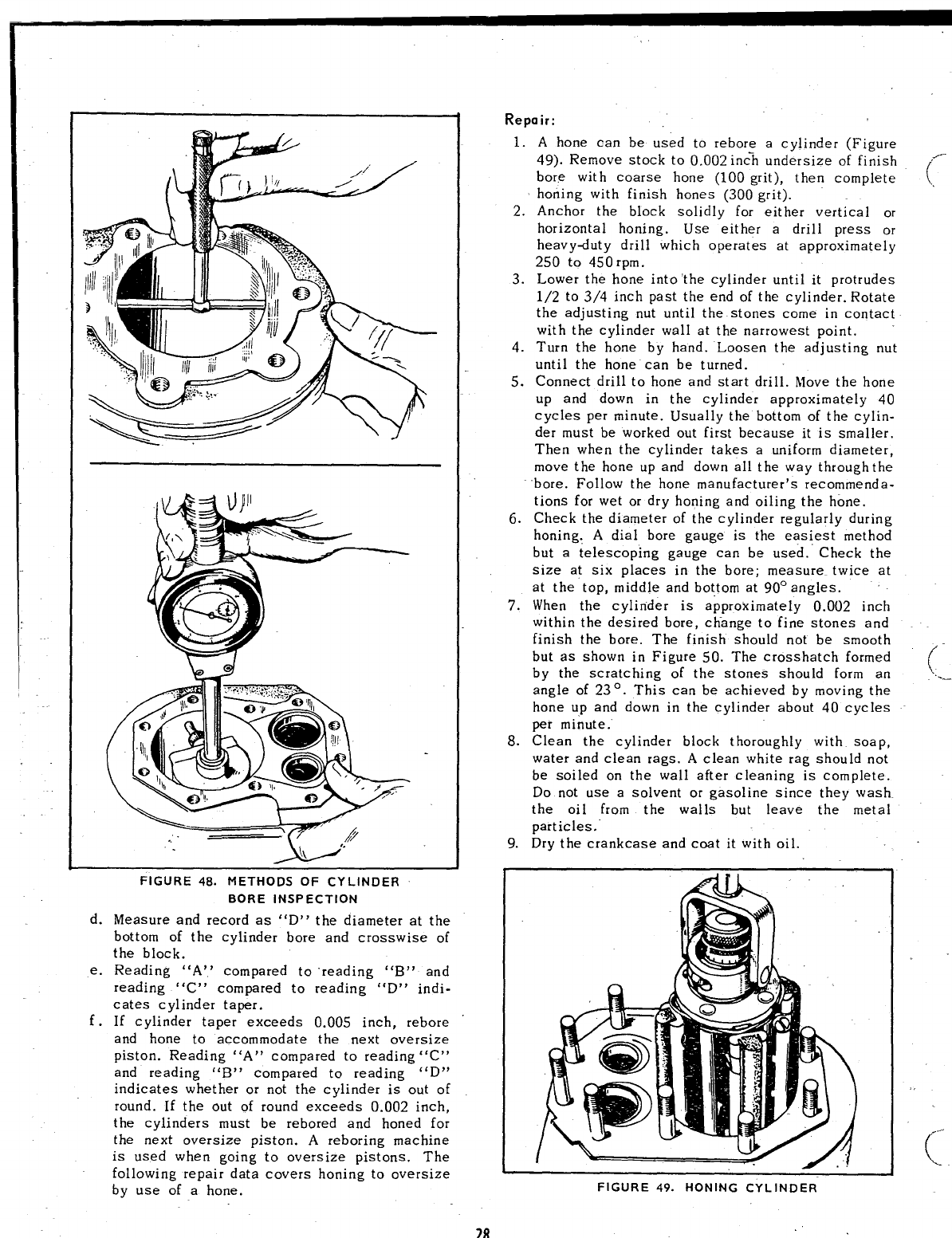
FIGURE 48. METHODS OF CYLINDER
BORE INSPECTION
d. Measure and record as “D” the diameter at the
bottom of the cylinder bore and crosswise of
the block.
e. Reading “A” compared to reading “B” and
reading “C” compared to reading “D” indi-
cates cylinder taper.
f.If cylinder taper exceeds 0.005 inch, rebore
and hone to accommodate the next oversize
piston. Reading “A” compared to reading “C”
and reading “B” compared to reading “D”
indicates whether or not the cylinder is out of
round. If the out of round exceeds 0.002 inch,
the cylinders must be rebored and honed for
the next oversize piston. Areboring machine
is used when going to oversize pistons. The
following repair data covers honing to oversize
by use of ahone.
28
Repair:
1.
2.
3.
4.
5.
6.
7.
8.
9.
Ahone can be used to rebore acylinder (Figure
49). Remove stock to 0.002 inc% undersize of finish
bore with coarse hone (100 grit), then complete
honing with finish hones (300 grit).
Anchor the block solidly for either vertical or
horizontal honing. Use either adrill press or
heavyduty drill which operates at approximately
250 to 450 rpm.
Lower the hone into “the cylinder until it protrudes
1/2 to 3/4 inch past the end of the cylinder. Rotate
the adjusting nut until the stones come in contact
with the cylinder wall at the narrowest point.
Turn the hone by hand. Loosen the adjusting nut
until the hone can be turned.
Connect drill to hone and start drill. Move the hone
up and down in the cylinder approximately 40
cycles per minute. Usually the bottom of the cylin-
der must be worked out first because it is smaller.
Then when the cylinder takes auniform diameter,
move the hone up and down all the way through the
bore. Follow the hone manufacturer’s recommenda-
tions for wet or dry honing and oiling the hone.
Check the diameter of the cylinder regularly during
honing: Adial bore gauge is the easiest method
but atelescoping gauge can be used. ”Check the
size at six places in the bore; measure twice at
at the top, middle and bottom at 90° angles.
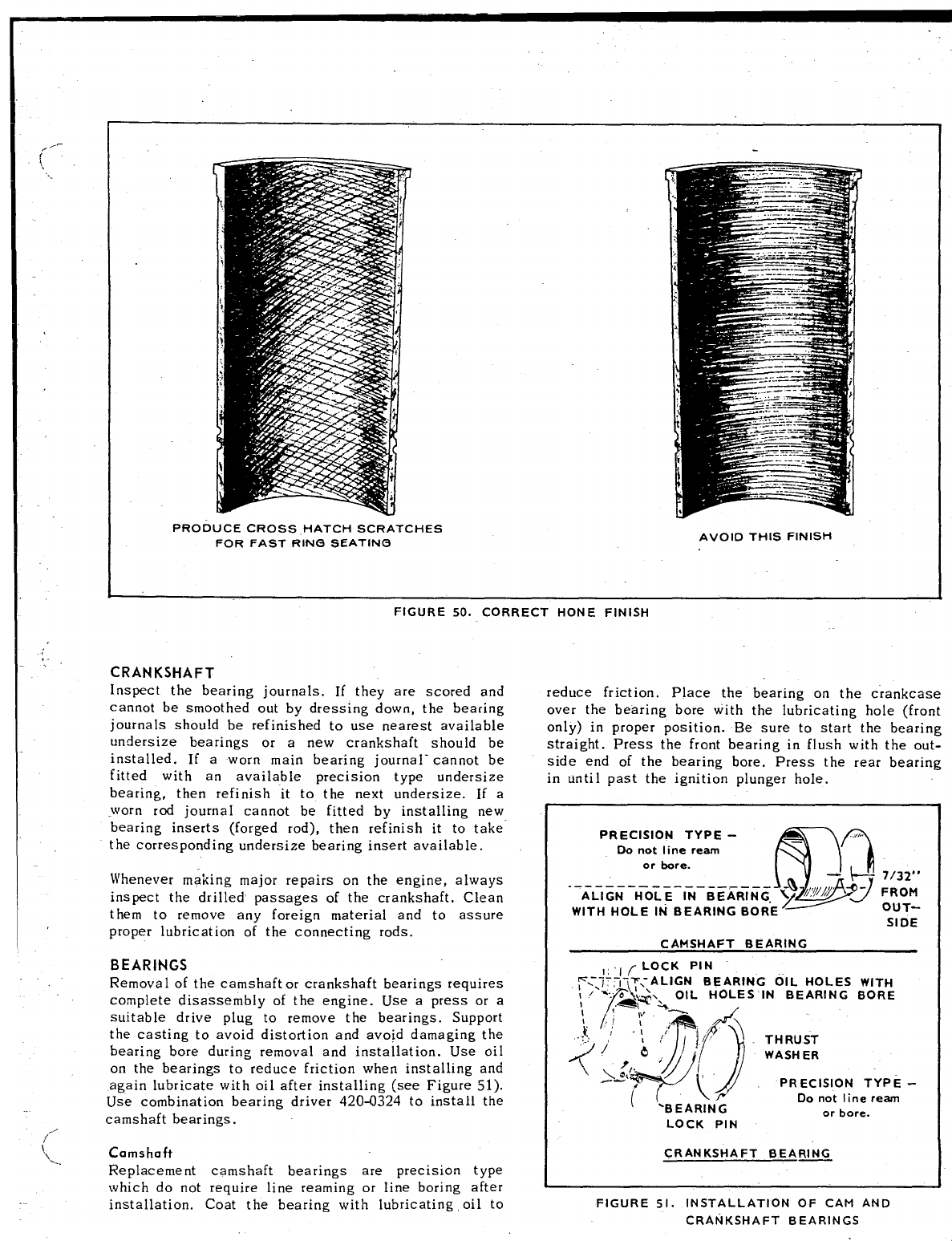
When the cylinder is approximately 0.002 inch
within the desired bore, ch-ange to fine stones and
finish the bore. The finish should not be smooth
but as shown in Figure 50. The crosshatch formed (
by the scratching of the stones should form an .._
angle of 230. This can be achieved by moving the
hone up and down in the cylinder about 40 cycles
per minute.”
Clean the cylinder block thoroughly with soap,
water and clean rags. Aclean white rag should not
be soiled on the wall after cleaning is complete.
Do not use asolvent or gasoline since they wash.
the oil from the walls but leave the metal
particles, ”
Dry the crankcase and coat it with oil.
FIGURE 49. HONING CYLINDER
,,-
~.,
...
PRODUCE CROSS HATCH SCRATCHES
FOR FAST RING SEATING AVOID THIS FINISH
FIGURE 50. CORRECT HONE FINISH
,-
CRANKSHAFT
Inspect the bearing journals. If they are scored and
cannot be smoothed out by dressing down, the bearing
journals should be refinished to use nearest available
undersize bearings or anew crankshaft should be
installed. If aworn main bearing journal- cannot be
fitted with an available precision type undersize
bearing, then refinish it to the next undersize. If a
-worn rod journal cannot be fitted by installing new
bearing inserts (forged rod), then refinish it to take
the corresponding undersize bearing insert available.
Whenever making major repairs on the engine, always
inspect the drilled passages of the crankshaft. Clean
them to remove any foreign material and to assure
proper lubrication of the connecting rods.
BEARINGS
Remova1of the camshaft or crankshaft bearings requires
complete disassembly of the engine. Use apress or a
suitable drive plug to remove the bearings. Support
the casting to avoid distortion and avoid damaging the
bearing bore during removal and installation. Use oil
on the bearings to reduce friction wherr installing and
again lubricate with oil after installing (see Figure 51).
Use combination bearing driver 420-0324 to install the
camshaft bearings.
..-
,
\,
k.. Camshaft
Replacement camshaft bearings are precision type
which do not require line reaming or line boring after
installation. Coat the bearing with lubricating oil to
reduce friction. Place the bearing on the crankcase
over the bearing bore with the lubricating hole (front
only) in proper position. Be sure to start the bearing
straight. Press the front bearing in flush with the out-
side end of the bearing bore. Press the rear bearing
in until past the ignition plunger hole.
PRECISION TYPE -
~~
.,,,,.
—
Do not line ream
or bore. :~k 7/329’
.--- —__________ _____
ALIGN HOLE IN BEARING, ~
)*J Y“?.
WITH HOLE IN BEARING BORE SIOE
CAMSHAFT BEARING
,;l (LOCK PIN
~:,7-7-TCALIGN BEARING OIL HOLES WITH
I . ‘,&,& OIL HOLES IN BEARING SORE
f
.\: /j ,: ,T
To
j/ ).
~,i THRUST
&:/ WASH ER
fynl)~.~ PRECISION TYPE -
Do not line ream
‘BEARING or bore.
-. _—._
LOCK PIN
CRANKSHAFT BEARING
FIGURE 51. INSTALLATION OF CAM AND
CRANKSHAFT BEARINGS
.
Crankshaft
New crankshaft main bearings are precision type which
do not require line reaming or line boring after install-
ation. See Parts Catalog section for standard size and
undersizes available.
Before putting in the main bearings, expand the bearing
bore by placing the casting in hot water or in an oven
heated to 200°F. If practical, cool the precision bear-
ing to shrink it.
For putting in either the front or rear main bearing,
using instructions following, always align the oil
hole(s) in the bearing with the oil hole(s) in the bearing
bore. The oil passage must be at least 1/2 open. The
cold oiled precision bearing should require only light
taps to position it. Install the bearing flush with the
inside end of the bore. If the head of alock pin is
damaged, use side cutters or “Easy -Out’’tool to re-
move pin. Then install anew lock pin. Apply oil to the
thrust washers to hold in place when the crankshaft
is installed. The oil grooves in the thrust washer
bearings must face the crankshaft. Be sure two notches
fit over lock pins.
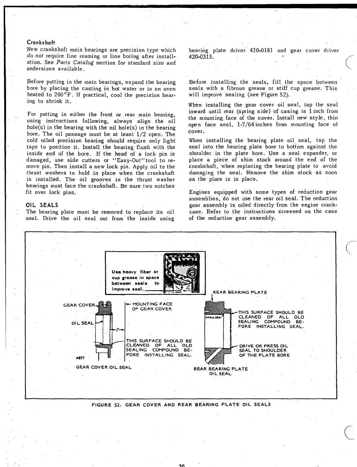
OIL SEALS
The bearing plate must be removed to replace its oil
bearing plate driver 420-0181 and gear cover driver
420-0313.
Before installing the seals, fill the space between
seals with afibrous grease or stiff cup grease, This
will improve sealing (-see Figure 52).
When installing the gear cover oil seal, tap the seal
inward until rear (spring side) of casing is 1inch from
the mounting face of the cover. Install new style, thin
open face seal, 1-7/64 inches from mounting face ot’
cover.
When installing the bearing plate oil seal, tap the
seal into the bearing plate bore to bottom against the
shoulder in the plate bore. Use aseal expander, or
place apiece of shim stock around the end of the
crankshaft, when replacing the bearing plate to avoid
damaging the seal. Remove the shim stock as soon
as the plate is in place.
Engines equipped with some types of reduction gear
assemblies, do not use the rear oil seal. The reduction
gear assembly is oiled directly from the engine crank-
case. Refer to the instructions Screened on the case
seal. Drive the oil seal out from the inside using of the reduction gear assembly.
“[ J
Use heavy fiber or
cup grease in space
between seals to
improve seal. I,REAR BEARING PLATE
GE
THIS SURFACE SHOULD BE
CLEANED OF ALL OLD
SEALING COMPOUND BE-
FORE INSTALLING SEAL.
DRIVE OR PRESS OIL
SEAL TO SHOULDER
OF THE PLATE BORE
GEAR COVER OIL” SEAL REAR BEARING PLATE
OIL SEAL
~...
(.,
FIGURE 52. GEAR COVER AND REAR BEARING PLATE OIL SEALS
30
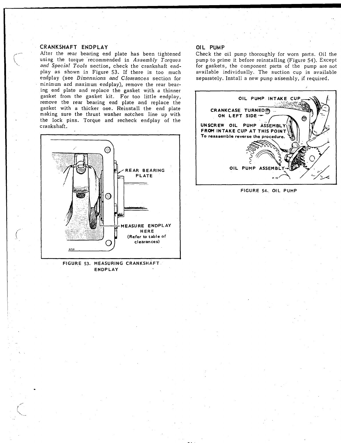
CRANKSHAFT ENDPLAY
After the rear bearing end plate has been tightened
using the torque recommended in Assembly Torques
and Special Tools section, check the crankshaft end-
play as shown in Figure 53. If there is too much
endplay (see Dimensions and Clearances section for
minimum and maximum endplay), remove the rear bear-
ing end plate and replace the gasket with athinner
gasket from the gasket kit. For too little endplay,
remove the rear bearing end plate and replace the
gasket with athicker one. Reinstall the end plate
making sure the thrust washer notches line up with
the lock pins. Torque and recheck endplay of the
crankshaft.
~.,..
~h--
!~ REAR BEARING
PLATE
1, ~,,,,
,,,
)Ik
pl!!!-
., MEASURE EN DPLAY
“’”J !
HERE
.: ..,,.
,,, ,,:...:. (Refer to table of
ocIearan ces)
FIGURE 53. MEASURING CRANKSHAFT.
EN DPLAY
.,
OIL PUMP
Check the oil pump thoroughly for worn parts. Oil the
pump to prime it before reinstalling (Figure 54). Except
for gaskets, the component parts of the pump are not
available individually. The suction cup is available
separately. Install anew pump as”sembly, if required.
CR
UNSCR
FRU4 I
To reas
FIGURE 54.. OIL PUMP
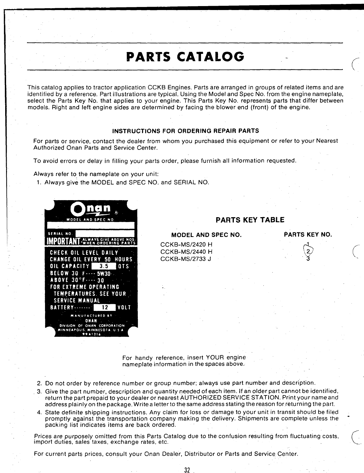
PARTS CATALOG -
This catalog applies to tractor application CCKB Engines. Parts are arranged in groups of related items and are
identified by areference. Part illustrations are typical. Using the Model and Spec No. from the engine nameplate,
select the Parts Key No. that applies to your engine. This Parts Key No. represents parts that differ between
models. Right and left engine sides are determined by facing the blower end (front) of the engine.
INSTRUCTIONS FOR ORDERING REPAIR PARTS
For parts or service, contact the dealer from whom you purchased this equipment or refer to your Neares
Authorized Onan Parts and Service Center.
To avoid errors or delay in filling your parts order, please furnish all information requested.
Always refer to the nameplate on your unit:
1.
2.
.3.
4.
Always give the MODEL and SPEC NO. and SERIAL NO.
PARTS KEY TABLE
MODEL AND SPEC NO. PARTS KEY NO.
CCKB-MS/2420 H,+
CCKB-MS/2440 H,~,2]
CCKB-MS/2733 J3
For handy reference, insert YOUR engine
nameplate information in the spaces above.
Do not order by reference number or group number; always use part number and description.
Give the part number, description and quantity needed of each item. If an older part cannot be identified,
return the part prepaid to your dealer or nearest AUTHORIZED SERVICE STATION. Print your name and
address plainlyon the package. Write aIettertothe same address stating the reason for returning the part.
State definite shimin~ instructions. Any claim for loss or damage to your unit in transit should be filed
(-.
promptly against’ ihe ~ransportation company making the delivery. Shipments are complete unless the “
packing list indicates items are back ordered.
Prices are purposely omitted from this Parts Catalog due to the confusion resulting from fluctuating costs,
import duties, sales taxes, exchange rates, etc. c-.
For current parts prices, consult your Onan Dealer, Distributor or Parts and Service Center.
32.
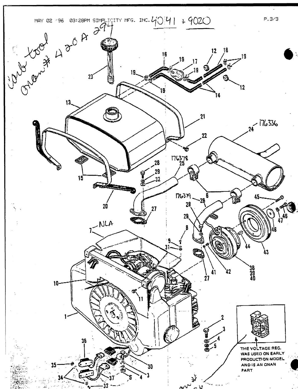
-.\. ..
,’,.
.,.,,
,.
.. . . .
.. ..
P. 3.’3
~
w.r
w————
THE vOLTAGE REG.
uVASUSE130fUEARL’f
p=:. =--’+% ;.. .
.,i,,. I‘.
,ke’ ‘“’
;.~,~ ‘:. $@J
\\
30 ‘.:“
.,,
>~j’ ““’:5 4 3 $-
.7
PR(XX.I~13N MOQEL :
‘“”
AND IS AN ONA$J -*%
PART
:
‘.,.
..
.
;
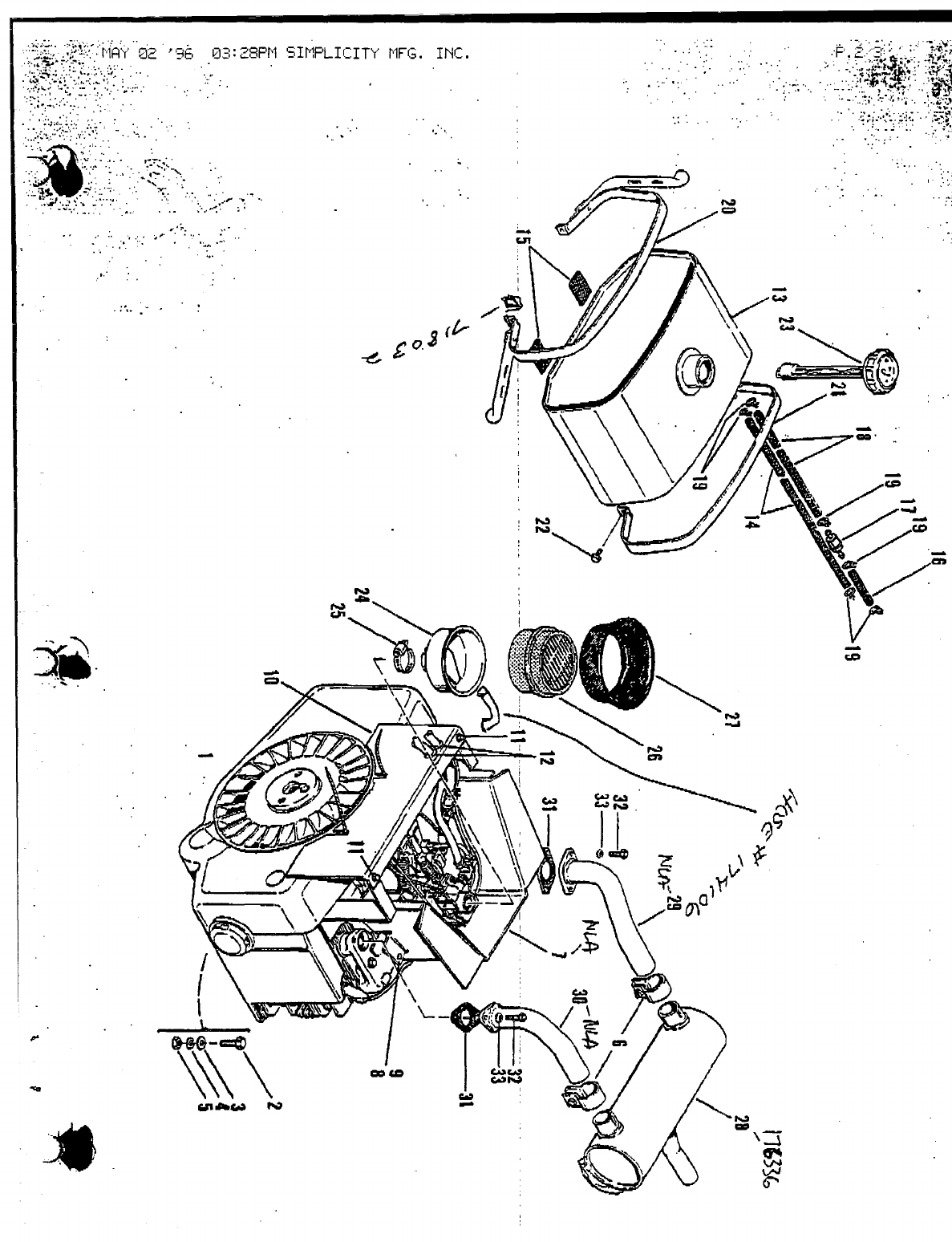
+
.,.
... ,
.. -.,
..;. :.%?- .’..
:L~+ “;:..:‘:: ‘,.., “,,.“’.
%,..,-, ...
.+.!::: :’:”:’”, ;.,,; :.* .-:’-“’
., ...,. .. . . .- . .
,.,,. ...
..,, ... ,,,,,,+ ... ,.. ,,
. .. ... . ..”,, .-,
..”. ,,. :..
,,..
...’..- “,,
“’ -)
qil(il-
;’. .
*
,.
v
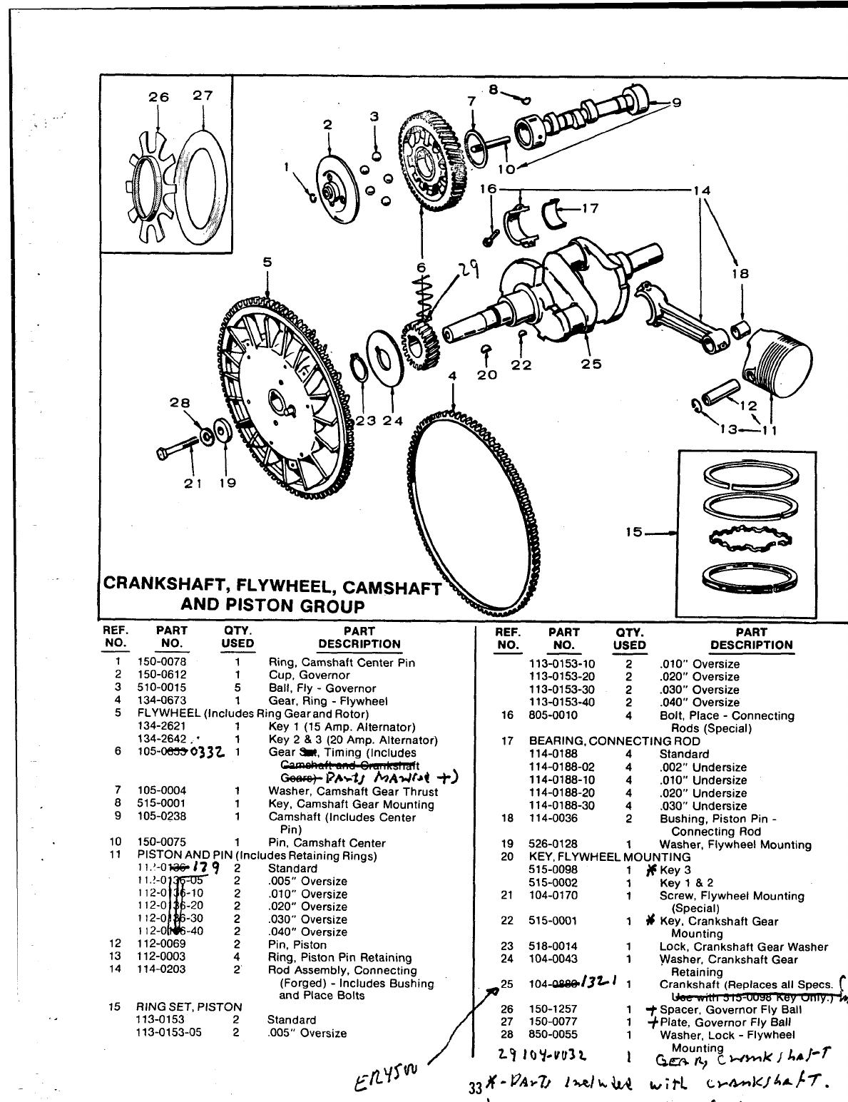
.:
26 27 I
___u “II
DRANKSHAFT, FLYWHEEL, CAMSHAFT
AND PISTON GROUP
--- - --- -—.
Htt. PAH 1UTY. PART
NO. NO. USED DESCRIPTION
7150% TRing, Camshaft Center Pin
2150-0612 1Cup, Governor
3510-0015 5Ball, Fly-Governor
4134-0673 1Gear, Ring -Flywheel
5FLYWHEEL (Includes Ring Gear and Rotor)
134-2621 1Key 1(15 Amp. Alternator)
134-2642. “Key 2&3(20 Amp. Alternator)
6105-rx%zE3033Z jGear ~, Timing (Includes
~t
7105-0004 GeeI@- i%-’iJ hAIJtd +)
1Washer, Camshaft Gear Thrust
8515-0001 1Key, Camshaft Gear Mounting
9105-0238 1Camshaft (Includes Center
Pin)
10 150-0075 1Pin, Camshaft Center
11 PISTON AND PIN (Includes Retaining Rings)
l!.’-O*I79 ‘2 Standard
K
11,~-o -2.005” Oversize
112-0 -lo 2.01 O“ Oversize
112-0 -20 2.020” Oversize
1I2-o -30 2.030” Oversize
1I2-o -40 2.040” Oversize
12 112-0069 2Pin, Piston
13 112-0003 4Ring, Piston Pin Retaining
14 114-0203 z. Rod Assembly, Connecting
(Forged) -Includes Bushing
and Place Bolts
15 RING SET, PISTON
113-0153 2Standard
113-0153-05 2.005” Oversize /
REF.
NO.
16
17
18
19
20
21
22
23
24
PART OTY. PART
NO. USED DESCRIPTION
113ZXZ-10 Y.01 0“ Oversize
113-0153-20 2.020” Oversize
113-0153-30 2.030” Oversize
113-0153-40 2.040” Oversize
805-0010 4Bolt, Place -Connecting
Rods (Special)
BEARING, CONNECTING ROD
114-0188 4Standard
114-0188-02 4.002” Undersize
114-0188-10 4.010” Undersize
114-0188-20 4.020” Undersize
114-0188-30 4.030” Undersize
114-0036 2Bushing, Piston Pin -
Connecting Rod
526-0128 Washer, Flywheel Mounting
KEY, FLYWHEEL ~OUNTING
515-0098 1#Key3
515-0002 1Key l&2
104-0170 1Screw, Flywheel Mounting
(Special)
515-0001 1 # Key, Crankshaft Gear
Mounting
518-0014 1Lock, Crankshaft Gear Washer
104-0043 1Washer, Crankshaft Gear
Retaining
F
25 104-CilW13~ i1Crankshaft (Replaces all SpeCS. (’
Key
26 150-1257 1+Spacer, Governor Fly Ball~~
27 150-0077
28 850-0055 1~Plate, Governor Fly Ball
1Washer, Lock -Flywheel
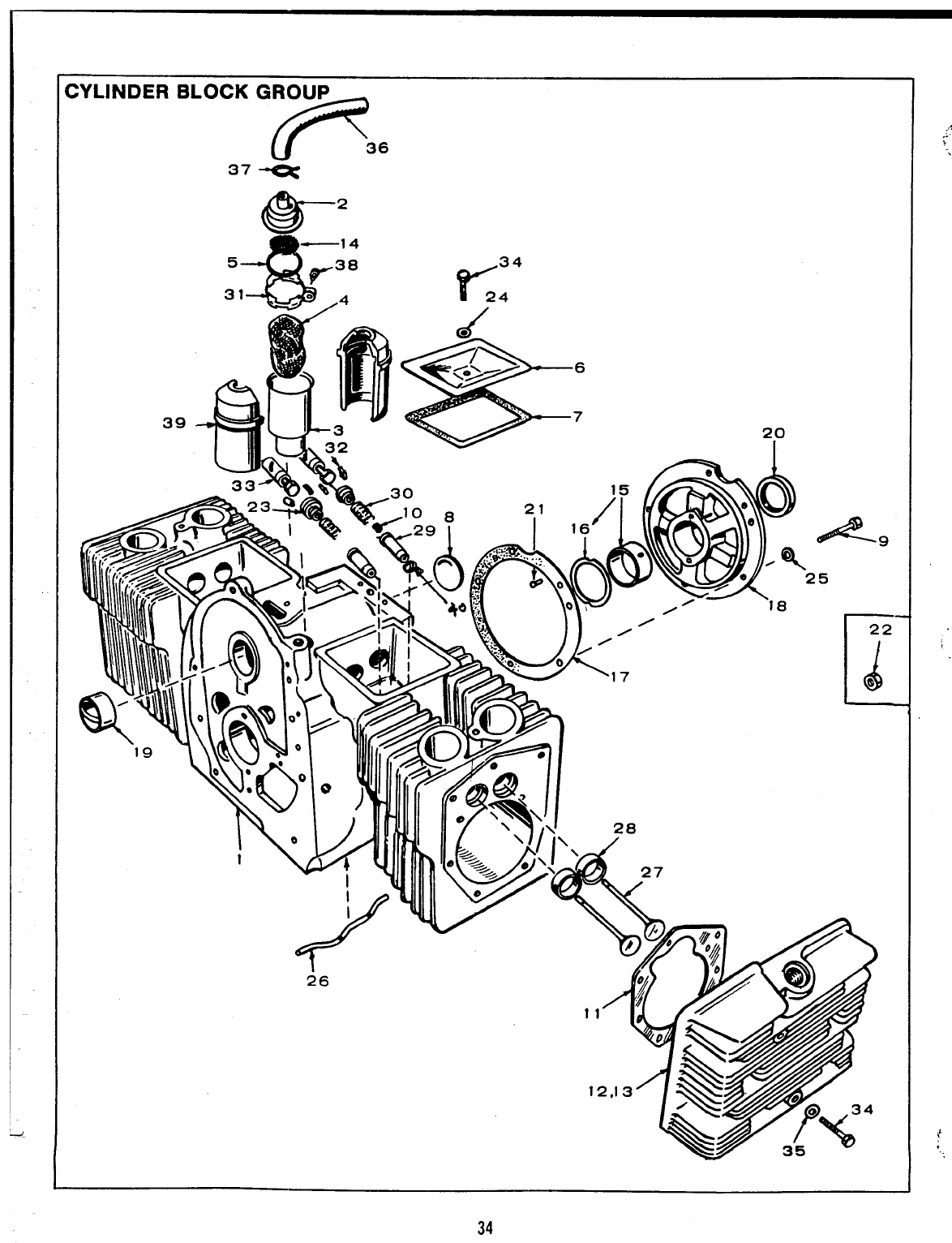
CYLINDER BLOCK GROU~
37 -F 36
6a-2
s
—14
5
r38
r
34
31 -o
/4 24
/
20
,,/-
I22
34
;@
>
>.
-.
.
{’
,“..
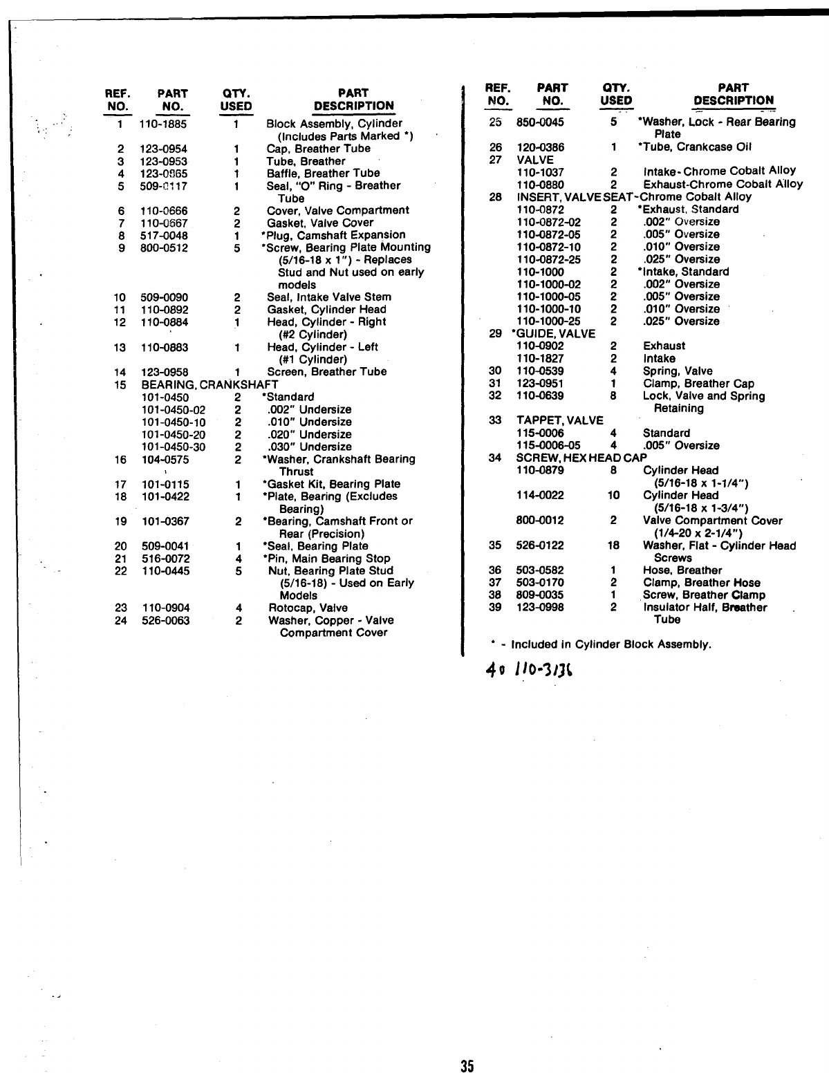
REF. PART
NO. NO.
7110-1885
2123-0954
3123-0953
4123-0865
5509+? 117
6110-0666
7110-0867
QTY.
USED
1
1
1
1
1
2
2
PART
DESCRIPTION
Block Assembly, Cylinder
(Includes Parts Marked ●)
Cap, Breather Tube
Tube, Breather
Baffle, Breather Tube
Seal, “O” Ring -Breather
Tube
Cover, Valve Compartment
Gasket, Valve Cover
8517-0048 1●Plug, Camshaft Expansion
9800-0512 5●Screw, Bearing Plate Mounting
(5/16-18 x1”) -Replaces
Stud and Nut used on early
models
10 509-0090 2Seal, Intake Valve Stem
11 110-0892 2Gasket, Cylinder Head
12 110-0884 1Head, Cylinder -Right
(W?Cylinder)
13 110-0883 1Head, Cylinder -Left
(#1 Cylinder)
14 123-0958 1Screen, Breather Tube
15 BEARING, CRANKSHAFT
16
17
18
19
20
21
22
23
24
101-0450
101-0450-02
101-0450-10
101-0450-20
101-0450-30
104-0575
101-0115
101-0422
101-0367
509-0041
516-0072
110-0445
110-0904
526-0063
2
2
2
2
2
2
1
1
2
1
4
5
4
2
‘Standard
.002” Undersize
.010” Undersize
.020” Undersize
.030” Undersize
●Washer, Crankshaft Bearing
Thrust
●Gasket Kit, Bearing Plate
‘Plate, Bearing (Excludes
Bearing)
●Bearing, Camshaft Front or
Rear (Precision)
●Seal, Bearing Plate
“pin, Main Bearing Stop
Nut, Bearing Plate Stud
(5/16-18) -Used on Early
Models
Rotocap, Valve
Washer, Copper -Valve
Compartment Cover
REF. PART QTY. PART
NO. NO. USED DESCRIPTION
—— -..
25
26
27
28
29
30
31
32
33
34
35
850-0045 5“Washer, Lock -Rear Bearing
Plate
120-0386 1●Tube, Crankcase Oil
VALVE
110-1037 2Intake- Chrome Cobalt Alloy
110-0860 2Exhaust-Chrome Cobalt Alloy
INSERT, VALVE SEAT-Chrome Cobalt Alloy
11O-I3872 2●Exhaust, Standard
110-0872-02 2.002” Oversize
11O-O872-O5 2.005” Oversize
110-0872-10 2.010” Oversize
110-0872-25 .025” Oversize
110-1000 ;“Intake, Standard
110-1000-02 2.002” Oversize
110-1000-05 2.005” Oversize
110-1000-10 2.01 O“ Oversize
110-1000-25 2.025” Oversize
●GUIDE, VALVE
110-0902 2Exhaust
110-1827 2Intake
110-0539 4Spring, Valve
123-0951 Clamp, Breather Cap
110-0639 ;Lock, Valve and Spring
Retaining
TAPPET, VALVE
115-0006 4Standard
115-0006-05 .005” Oversize
SCREVV, HEX HEA’& CAP
110-0879 6Cylinder Head
(5/16-18 X1-1/4”)
114-0022 10 Cylinder Head
(5/16-18 X1-3/4”)
800-0012 2Valve Compartment Cover
(1/4-20 X2-1/4”)
526-0122 16 Waaher, Flat -Cylinder Head
Screws
503-0582 Hose, Breather
503-0170 ;Clamp, Breather Hose
809-0035 Screw, Breather Ofamp
123-0998 1Insulator Half, Braather
Tube
●-Included in Cylinder Block Assembly.
35
40 l/o-3J3t
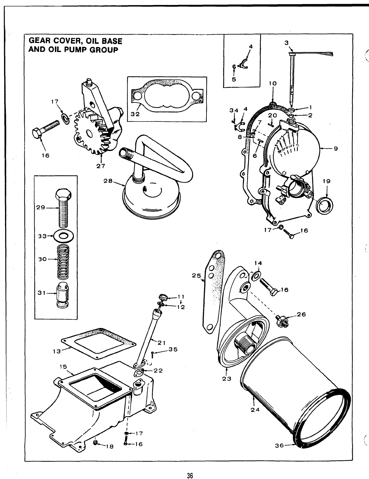
GEAR COVER, OIL BASE
AND OIL PUMP GROUP
/7
I I
Al 3.
9
“.
-.
,,,
,
36
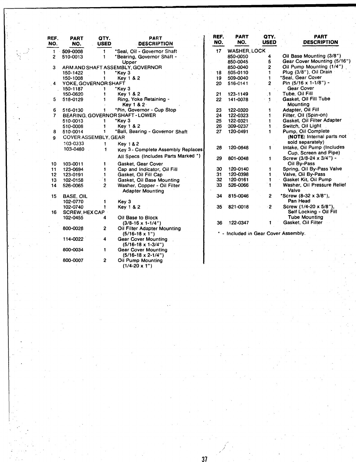
;-
-,
.
REF. PART PART
NO. NO. :SXD DESCRIPTION
7- 509= 1‘Seal, Oil -Governor Shaft
2510-0013 1“Bearing, Governor Shaft -
Upper
3ARM AND SHAFT ASSEM13LY, GOVERNOR
150-1422 1“Key 3
150-1008 1Key l&2
,4 YOKE, GOVERNOR SHAFT
150-1187 1●Key 3
150-0620 1Key l&2
5518-0129 1Ring, Yoke Retaining -
Keyl &2
6516-0130 1●Pin, Governor -Cup Stop
7BEARING, GOVERNOR SHAFT-LOWER
510-0013 1“Key 3
510-0008 1Key l&2
8510-0014 1●Ball, Bearing -Governor Shaft
9COVER ASSEMBLY, GEAR
?(]3-0333 1
103-0480 1
10 103-0011 1
11 123-0694 1
12 123-0191 1
13 102-0158 “1
14 526-0065 2
15 BASE, OIL
102-0770 1
102-0740 1
16 SCREW, HEX CAP
102-0455 4
800-0028 2
114-0022 4
800-0034 1
800-0007 2
Key l&2
Key 3- Complete Assembly Replace!
All Specs (includes Parts Marked*)
Gasket, Gear Cover
Cap and Indicator, Oil Fill
Gasket, Oil Fill Cap
Gasket, Oil Base Mounting
Washer, Copper-Oil Filter
Adapter Mounting
Key 3
Key l&2
Oil Base to Block
(3/8-16 X1-1/4”)
Oil Filter Adapter Mounting
(5/16-18 X1“)
Gear Cover Mounting
(5/16-18 X1-3/4”)
Gear Cover Mounting
(5/16-18 X2-1/4”)
Oil Pump Mounting
(1/4-20 Xl“)
37
REF. PART QTY.
NO. NO. USED
—— —
17
18
19
20
21
22
23
24
25
26
27
WASHER, LOCK
850+050 4
850-0045 5
850-0040 2
505-0110 1
509-0040
516-0141 ;
123-1149 .1
141-0078 1
122-0320 1
122-0323 1
122-0321 1
309-0237 1
120-0491 1
28 120-0648 1
29 801-0048 1
30 120-0140 1
31 120-0398 1
32 120-0161 1
33 526-0066 1
34 815-0046 2
35 ‘821-0018 2
36 122-0347 1
PART
DESCRIPTION
011 Base Mounting (3/8” )
Gear Cover Mounting (5/16”)
Oil Pump Mounting (l/4’r)
Plug (3/8”), Oil Drain
“Seal, Gear Cover
Pin (5/16 xl-I/8”) -
Gear Cover
Tube, Oil Fill
Gasket, Oil Fill Tube
Mounting
Adapter, C)il fill
Filter, Oil (Spin-on)
Gasket, Oil Filter Adapter
Switch, Oil Light
Pump, Oil Complete
(NOTE: Internal parts not
sold separately)
Intake, Oil Pump (Includes
Cup, Screen and Pipe)
Screw (3/6-24 x3/4”) -
Oil By-Pass
Spring, Oil By-Pass Valve
Valve, Oil By-Pass
Gasket Kit, Oil Pump
Washer, Oil Pressure Relief
Valve
“Screw (8-32 x3/8”),
Pan Head
Screw (1/4-20 x5/8”),
Self Locking -Oil Fill
Tube Mounting
Gasket, Oil Filter
“-Included in Gear Cover Assembly.
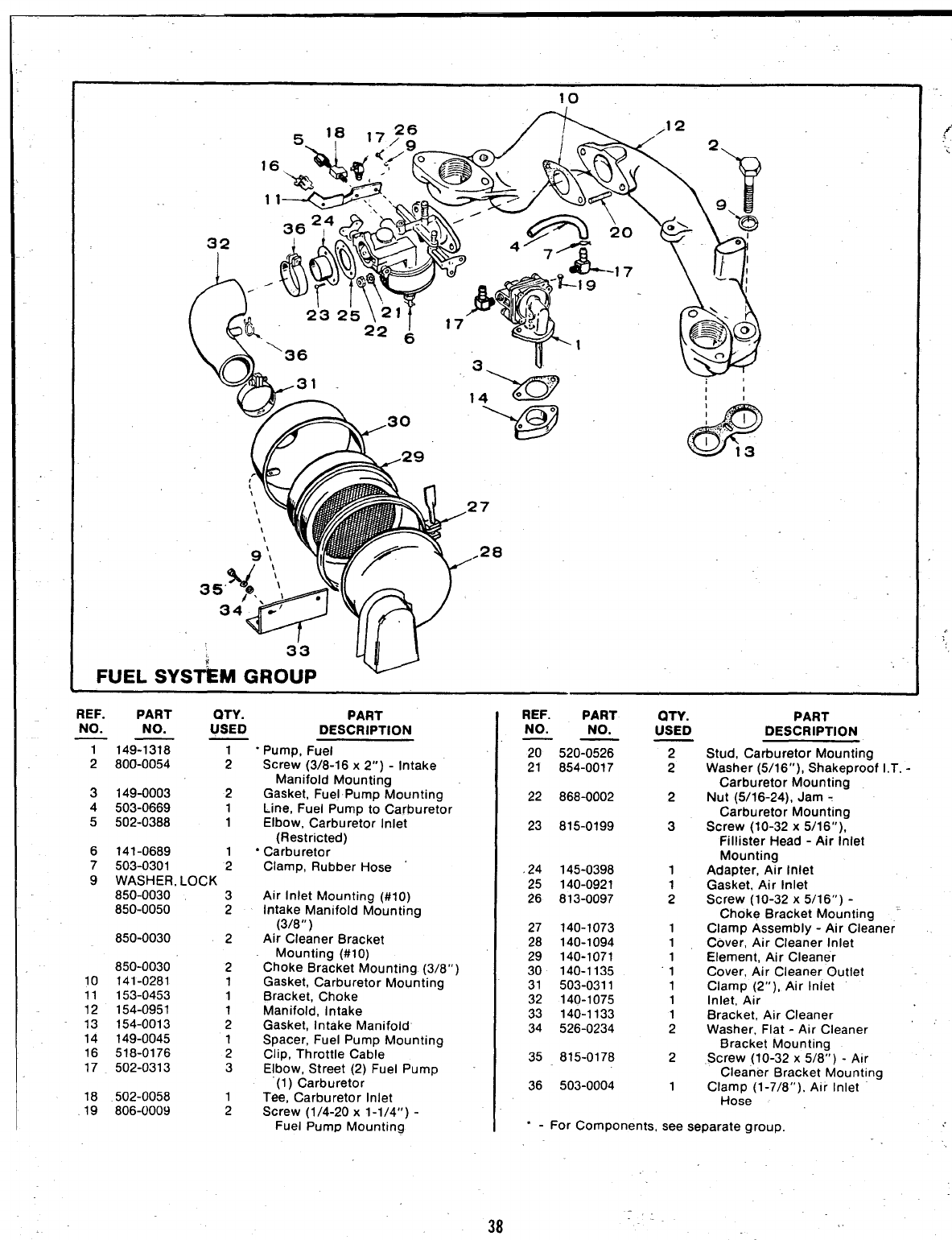
10
,12
1 1~
@
362,4 .“
32 1Aam:
4W
‘@
7
28
II
1,
e
‘% 1“
.‘. ......
I‘“’ 13
FUEL
REF. PART
NO. NO.
——
20 520-0526
21 654-0017
QTY.
USED
REF. PART QTY. PART PART
DESCRIPTION
Stud, Carburetor Mounting
Washer (5/16”), Shakeproof I.T. -
Carburetor Mounting
Nut (5/16-24), Jam -
Carburetor Mounting
Screw (10-32 x5/16”),
Fillister Head -Air Inlet
Mounting
Adapter, Air Inlet
Gasket, Air Inlet
Screw (10-32 x5/16”) -
Choke Bracket Mounting ‘
Clamp Assembly -Air Cleaner
Cover, Air Cleaner Inlet
Element, Air Cleaner
Cover, Air Cleaner Outlet
Clamp (2”), Air Inlet
Inlet, Air
Bracket, Air Cleaner
Washer, Flat -Air Cleaner
Bracket Mounting
Screw (10-32 x5/8”) -Air
Cleaner Bracket Mounting
Clamo (1-7/8”), Air Inlet
NO. NO. USED DESCRIPTION
——
T149-1318 1“PumD. Fuel 2
2
2800-0054 2
3149-0003 2
4503-0669 1
5502-0388 1
6141-0689 1
7503-0301 2
9WASHER, LOCK
850-0030 3
850-0050 2
850-0030 2
Screw (3/8-16 x2“) -Intake
Manifold Mounting
Gasket, Fuel Pump Mounting
Line, Fuel Pump to Carburetor
Elbow, Carburetor Inlet
(Restricted)
‘Carburetor
Clamp, Rubber Hose
22 868-0002 2
23 815-0199 3
.24 145-0398
25 140-0921
26 813-0097
1
1
2
Air Inlet Mounting (#lo)
Intake Manifold Mounting
(3/8” )
Air Cleaner Bracket
Mounting (#10)
Choke Bracket Mounting (3/8”)
Gasket, Carburetor Mounting
Bracket, Choke
Manifold, Intake
Gasket, Intake Manifold’
Spacer, Fuel Pump Mounting
Clip, Throttle Cable
Elbow, Street (2) Fuel Pump
(1) Carburetor
Tee, Carburetor Inlet
Screw (1/4-20 x1-1/4”) -
Fuel Pump Mounting
27 140-1073
28 140-1094
29 140-1071
30 140-1135
31 503-0311
32 140-1075
33 140-1133
34 526-0234
1
1
1
1
1
1
1
2
850-0030
10 141-0281
11 153-0453
12 154-0951
13 154-0013
14 149-0045
16 518-0176
17 502-0313
2
1
1
1
2
1
2
335 815-0178 2
36 503-0004 1
18 502-0058
19 806-0009 1
2Hose’ ‘,
“-For Components, see separate group.
38

-. ,,’
;
.,
;- .
.’
FUEL PUMP PARTS GROUP
REF.
NO.
4
5
6
;
9
10
11
12
13
14
15
16
17
18
PART
NO.
149-1318
149-0526
815-0148
815-0147
149-0096
149-0095
149-0562
149-0672
140-0539
149-0675
516-0113
149-0710
149-0858
149-1042”
509-0065
149-1044
149-0003
518-0129
(xv. PART
USED DESCRIPTION
TPump, Fuel (Complete)
1Repair Kit (Includes Parts
Marked ‘)
1Body (Not Sold Separately)
4Screw (#8-32 x7/8”),
Machine
2Screw (#6-32 x5/8”),
Phillips -Retainer
2‘Valve and Cage
2●Gasket, Valve
1●Diaphragm Assembly
1“Spring
1Retainer, Valve Cage
1“Spring
1Pin, Rocker Arm
1Body (Not Sold Separately)
1Link and Arm, Rocker (Sold
only as a set)
1*Gasket, Diaphragm -Lower
Side
1ALever, Primer
2ASeal, “O” Ring
1ASpring, Primer Lever
1‘Gasket, Pump Mounting
1ARing, Retainer -Primer
Lever
“-Parts Included in Repair Kit.
A-Not used Key 3.
,.
,,.
39”
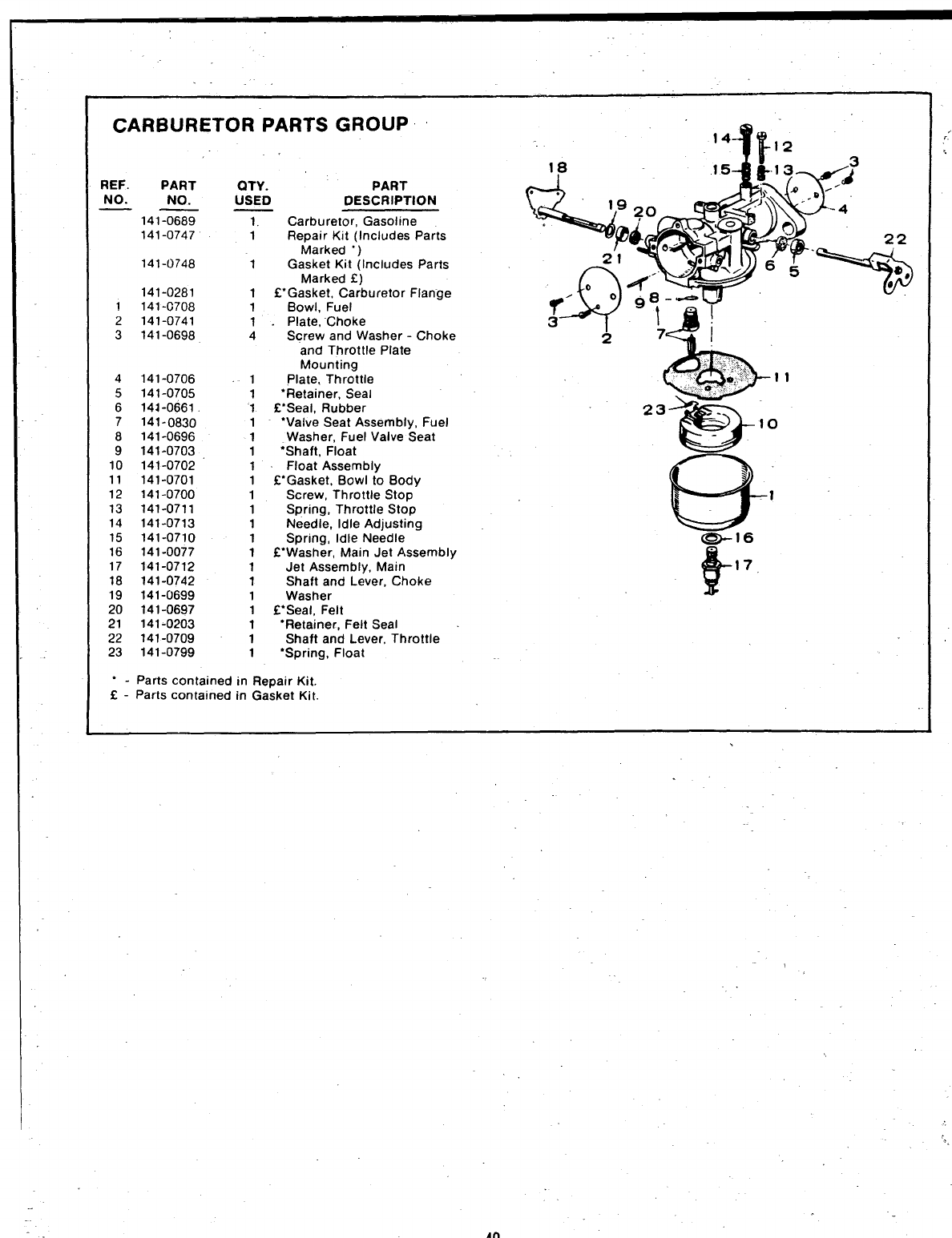
.
CARBURETOR PARTS GROUP
REF. PART
NO. NO.
——
141-0689
141-0747
141-0748
141-0281
1 141 -G708
2141-0741
3141-0698
4
5
6
7
8
9
10
11
12
13
14
15
16
17
18
19
20
21
22
23
141-0706
141-0705
141-0661.
141-0830
141-0696
141-0703
141-0702
141-0701
141-0700
141-0711
141-0713
141-0710
141-0077
141-0712
141-0742
141-0699
141-0697
141-0203
141-0709
141-0799
QTY. PART
USED DESCRIPTION
1. Carburetor, Gasoline
1Repair Kit (Includes Parts
Marked “)
1Gasket Kit (Includes Parts
Marked E)
1CGasket, Carburetor Flange
1Bowl, Fuel
1.Plate, ”Choke
4Screw and Washer -Choke
and Throttle Plate
Mounting
1Plate, Throttle
1‘Retainer, Seal
1Z’Seal, Rubber
1“Valve Seat Assembly, Fuel
1Washer, Fuel Valve Seat
1“Shaft, Float
1Float Assembly
1VGasket, Bowl to Body
1Screw, Throttle Stop
1Spring, Throttle Stop
1Needle, Idle Adjusting
1Spring, Idle Needle
1f“Washer, Main Jet Assembly
1Jet Assembly, Main
1Shaft and Lever, Choke
1Washer
1~Seal, Felt
1“Retainer, Felt Seal
1Shaft and Lever, Throttle
1“Spring, Float
&
17,
“-Parts contained in Repair Kit.
f - Parts contained in Gasket Kit.
,
,
?.
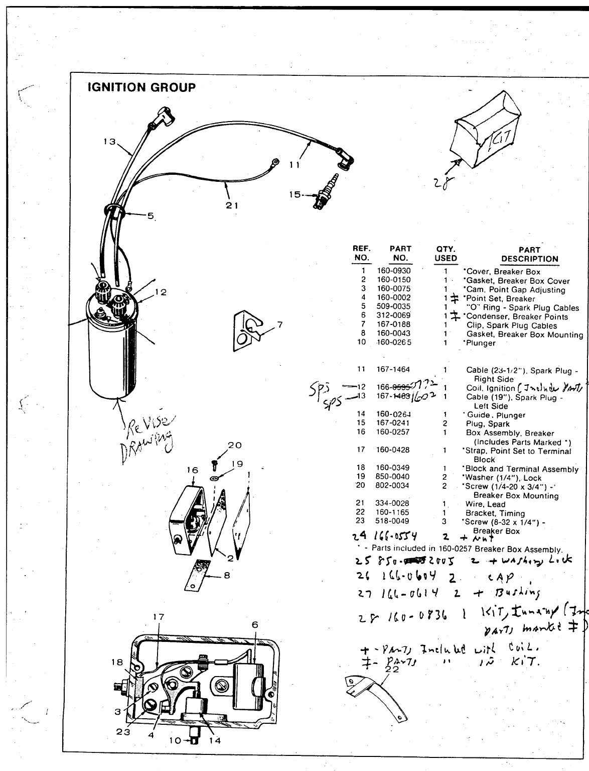
,-
,..
.-
<.,
.!
/-
. ...
-..._.
IGNITION GROUP -/’+’
4
‘u /12
,\
REF. PA RT
NO. NO.
—_
1160-0930
2160-0150
3160-0075
4160-0002
5509-0035
P
17
6312-0069
7167-0188
08160-0043
10 160-0265
QTY. PART
USED DESCRIPTION
1“Cover, Breaker Box
1“Gasket, Breaker Box Cover
1“Cam, Point Gap Adjusting
1 $ .Point Set, Breaker
1“’O”’Ring -Spark Plug Cables
1~“Condenser, Breaker Points
1Clip, Spark Plug Cables
1Gasket, Breaker Box Mounting
1.Plunger
11 167-1464 1Cable (23-1,2”), Spark Plug -
y
,- )—1 2
..
..A< -’3
.7~ Right Side
166-135#fl (Coil, Ignition [~~c!hb YA#Z/
167-t463@~ ;Cable (19”), Spark Plug -
-&/>
dLeft Side
14 160-0264 1“Guide. plunger
15 167-0241 2Plug, Spark
16 160-0257 1BOX Assembly, Breaker
(Includes Parts Marked “)
17 160-0428 1‘Strap, Point Set to Terminal
Block
18 160-0349 1.Block and Terminal Assembly
19 850-0040 2.Washer (1/4’’ ),. Lock
’20 802-0034 2.. Screw(1/4-20 x3/4”) -’
Breaker Box Mounting
21 334-0028 1Wire, Lead
22 160-1165 1Bracket, Timing
23 518-0049 3%crew (8-32 x1/4”) -
Brea er Box
Z4 14[”baY z+~h !
“-Parts included in 160-0257 Breaker Box Assembly.
L5 P5u+?s@32tuz L+Whfhq~ Luk
2{ ILL-u l#9Y 2. t~p ”,’
trJ; L#
)ci’7.
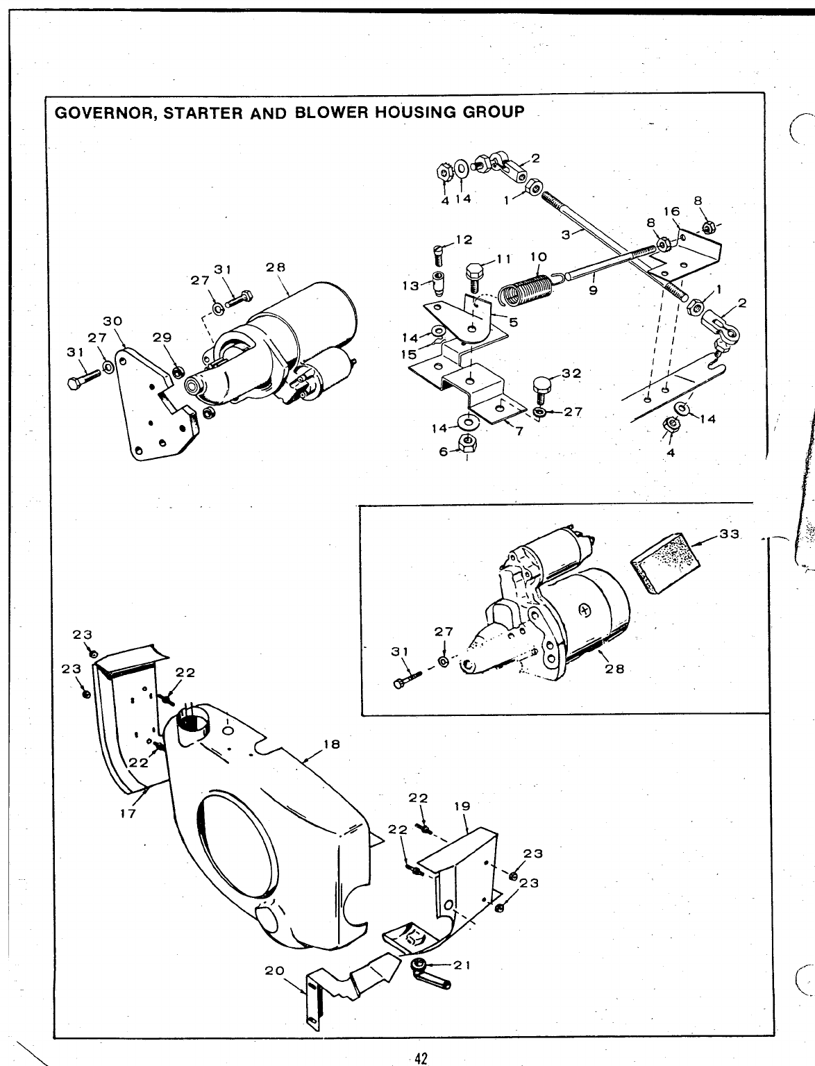
iOVERNOR, STARTER AND BLOWER HOUSING GROUP
23
31
&
‘=42
,,..
(
\.
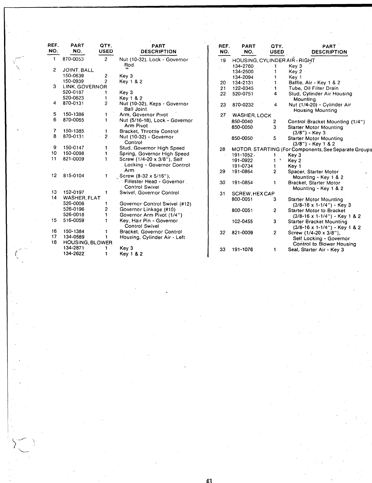
REF. PART QTY. “PART
NO. NO. USED DESCRIPTION
—— _
-----
., 1870-0053 2
‘.. 2
3
4
5
6
7
8
9
10
11
12
13
14
15
16
17
18
(,”
JOINT, BALL
150-0639 2
150-0939 2
LINK, GOVERNOR
520-0187 1
520-0623 1
870-0131 2
150-1386 1
870-0065 1
150-1385 1
870-0131 2
150-0147 1
150-0098 1
821-0009 1
815-0104 1
152-0197 1
WASHER, FLAT
526-0006 1
526-0196 2
526-0018 1
516-0059 1
150-1384 1
134-0589
HOUSING, BLOWgR
134-2871 1
134-2622 1
Nut (10-32), Lock -Governor
;od
Key 3
Key l&2
Key 3
Key l&2
Nut (10-32), Keps -Governor
Ball Joint
Arm, Governor Pivot
Nut (5/16-18), Lock -Governor
Arm Pivot
Bracket, Throttle Control
Nut (10-32) -Governor
Control
Stud, Governor High Speed
Spring, Governor High Speed
Screw (1/4-20 x3/8”), Self
Locking -Governor Control
Arm
,Screw (8-32 x5/16”),
Fillester Head -Governor
Control Swivel
Swivel, Governor Control
Governor Control Swivel (#1z)
Governor Linkage (#10)
Governor Arm Pivot (1/4”)
Key, Hair Pin -Governor
Control Swivel
Bracket, Governor Control
Housing, Cylinder Air -Left
Key 3
Key l&2
REF. PART QTY. PART
NO. NO. USED DESCRIPTION
—— —-
19 HOUSING, CYLINDER Al~-RIGHT
134-2760 1Key 3
134-2500 1Key 2
134-2094 1Key 1
20 134-2131 1Baffle, Air -Key 1&2
21 122-0345 1Tube, Oil Filter Drain
22 520-0751 4Stud, Cylinder Air Housing
Mounting
23 870-0232 4Nut (1/4-20) -Cylinder Air
Housing Mounting
27 WASHER, LC)CK
850-0040 2Control Bracket Mounting (1/4”)
850-0050 3Starter Motor Mounting
(3/8” ) - Key 3
850-0050 5Starter Motor Mounting
(3/8”) -Key 1&2
28 MOTOR, STARTING (For Components, See Separate
Groups)
191-1052. 1
191-0922 1“
191-0734 1
29 191-0864 2
30 191-0854 1
31 SCREW, HEX CAP
800-0051 3
800-0051 2
102-0455 3
32 821-0009 2
33 191-1076 1
Key 3
Key 2
Key 1
Spacer, Starter Motor
Mounting -Key 1&2
Bracket, Starter Motor
Mounting”- Key 1&2
Starter Motor Mounting
(3/t3-16x 1-1/4”) -Key 3
Starter Motor to Bracket
(3/8-16 x1-1/4”) -Key 1&2
Starter Bracket Mounting
(3/8-16 x1-1/4”) -Key 1&2
Screw (1/4-20 x3/8”),
Self Locking -Governor
Control to Blower Housing
Seal, Starter Air -Key 3
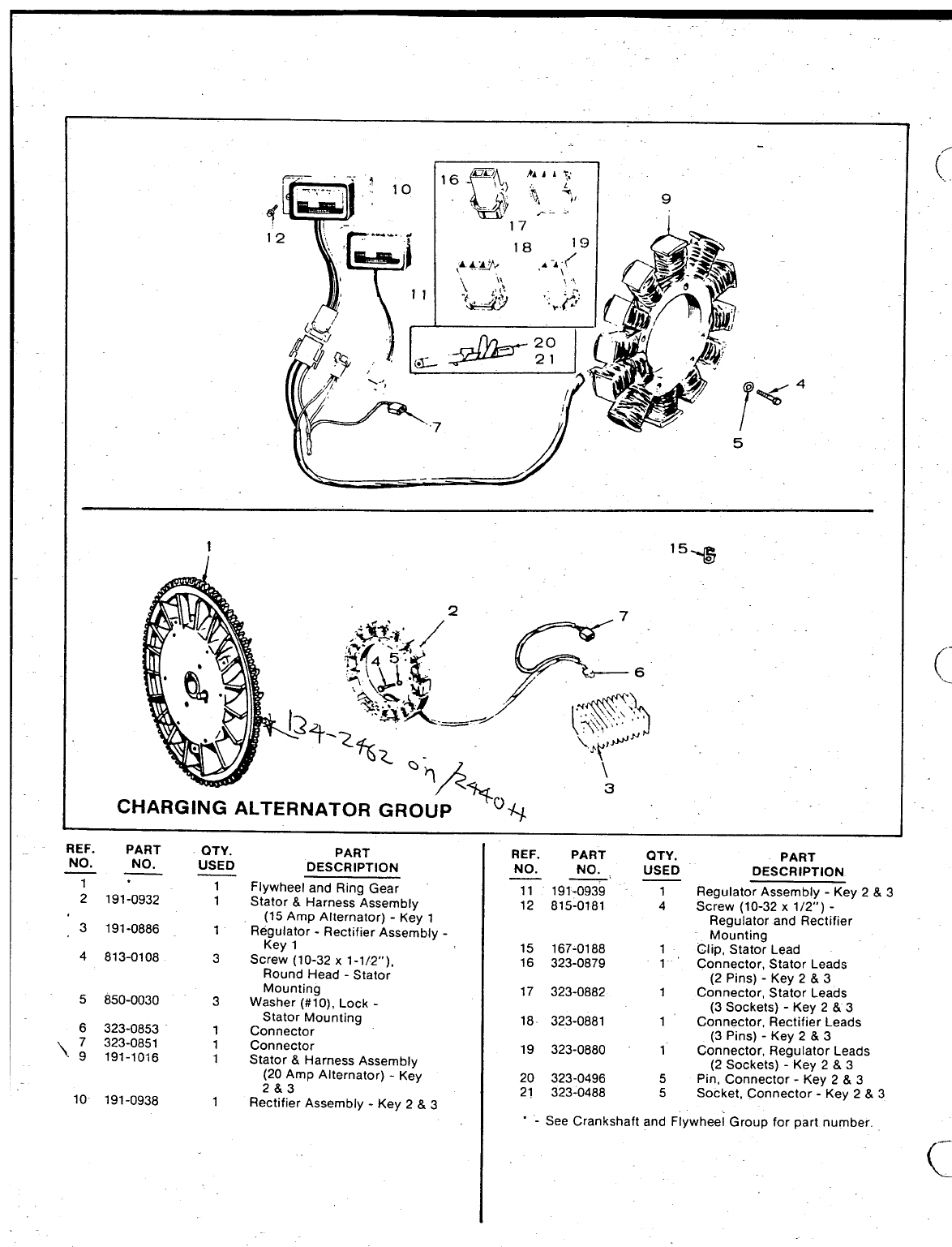
T.
(.
(“
.
\.L
\
12 “,
T’
%“
I=-
.‘a$4$ 4
ft
,. /
5
;‘%
REF. PART
NO. NO.
1-
2191-0932
QTY.
USED PART
DESCRIPTION REF. PART QTY. PART
NO. ~. USED DESCRIPTION
1
1Flywheel and Ring Gear
Stator &Harness Assembly
(15 Amp Alternator) -Key 1
Regulator -Rectifier Assembly -
Key 1
Screw (10-32 x1-1/2”),
Round Head -Stator
Mounting
Washer (#1 O), Lock -
Stator Mounting
Connector
Connector
Stator &Harness Assemblv
11 191-0939 1Regulator Assembly -Key 2&3
12 815-0181 4Screw (10-32 x1/2”) -
Regulator and Rectifier
/-
3191-0886 1
3
Mo;nting
15 167-0188 1Clio, Stator Lead
4813-0108 16 323-0879 1’ Connector, Stator Leads
(2 Pins) -Key 2&3
17 323-0882 1Connector, Stator Leads
(3 Sockets) -Key 2&3
18. 323-0881 1Connector, Rectifier Leads
(3 Pins) -Key 2&3
19 323-0880 1Connector, Regulator Leads
(2 Sockets) -Key 2&3
20 323-0496 5Pin, Connector -Key 2&3
21 323-0488 5Socket, Connector -Key 2&3
5850-0030 3
6323-0853
7323-0851
~9191-1016
1
1
1
(20 Amp Alternator) -Key
2&3
10 191-0938 1Rectifier Assembly -Key 2&3
“-See Crankshaft and Flywheei Group for part number.
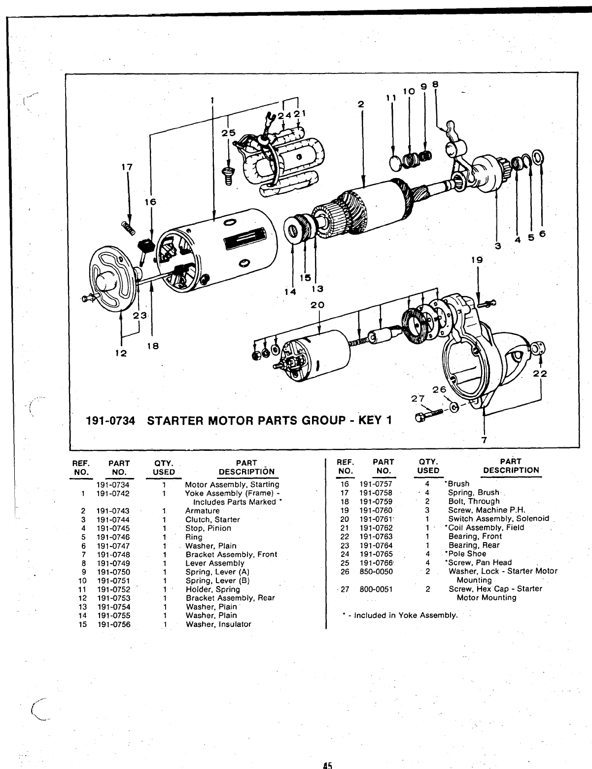
(“””--
,..
[L
1/11
I16 l— A
C2-)1 H
g8
19
1A 13 ~l. .
20 0
I18
12
191-0734 STARTER MOTOR PARTS GROUP -KEY 1~r
REF. PART
NO. NO.
—191-0734
1191-0742
2
3
4
5
6
7
8
9
10
11
12
13
14
15
191-0743
191-0744
191-0745
191-0746
191-0747
191-0748
191-0749
191-0750
191-0751
191-0752
191-0753
191-0754
191-0755
191-0756
QTY. PART
USED DESCRIPTION
1
1
1
1
1
1
1
1
1
1
1
,.
1
1
1
1
Motor Assembly, Starting
Yoke Assembly (Frame) -
Includes Parts Marked “
Armature
Clutch, Starter
Stop, Pinion
Ring
Washer, Plain
Bracket Assembly, Front
Lever Assembly
Spring, Lever (A)
Spring, Lever (B)
Holder, Spring
Bracket Assembly, Rear
Washer, Plain
Washer, Plain
Washer, Insulator
REF. PART QTY. PART
NO. NO. USED DESCRIPTION
T191=
17 191-0758
18 191-0759
19 191-0760
20 191-0761”
21 191-0762
22 191-0763
23 191-0764
24 191-0765
25 191-0766
26 850-0050
27 800-0051
4“Brush
.4 Spring, Brush
2Bolt, Through
3Screw, Machine P.H.
1Switch Assembly, Solenoid
1- “Coil Assembly, Field
1Bearing, Front
1Bearing, Rear
4“Pole Shoe
4‘Screw, Pan Head
2Washer, Lock -Starter Motor
Mounting
2Screw, Hex Cap -Starter
Motor Mounting
‘-Included in Yoke Assembly.
45
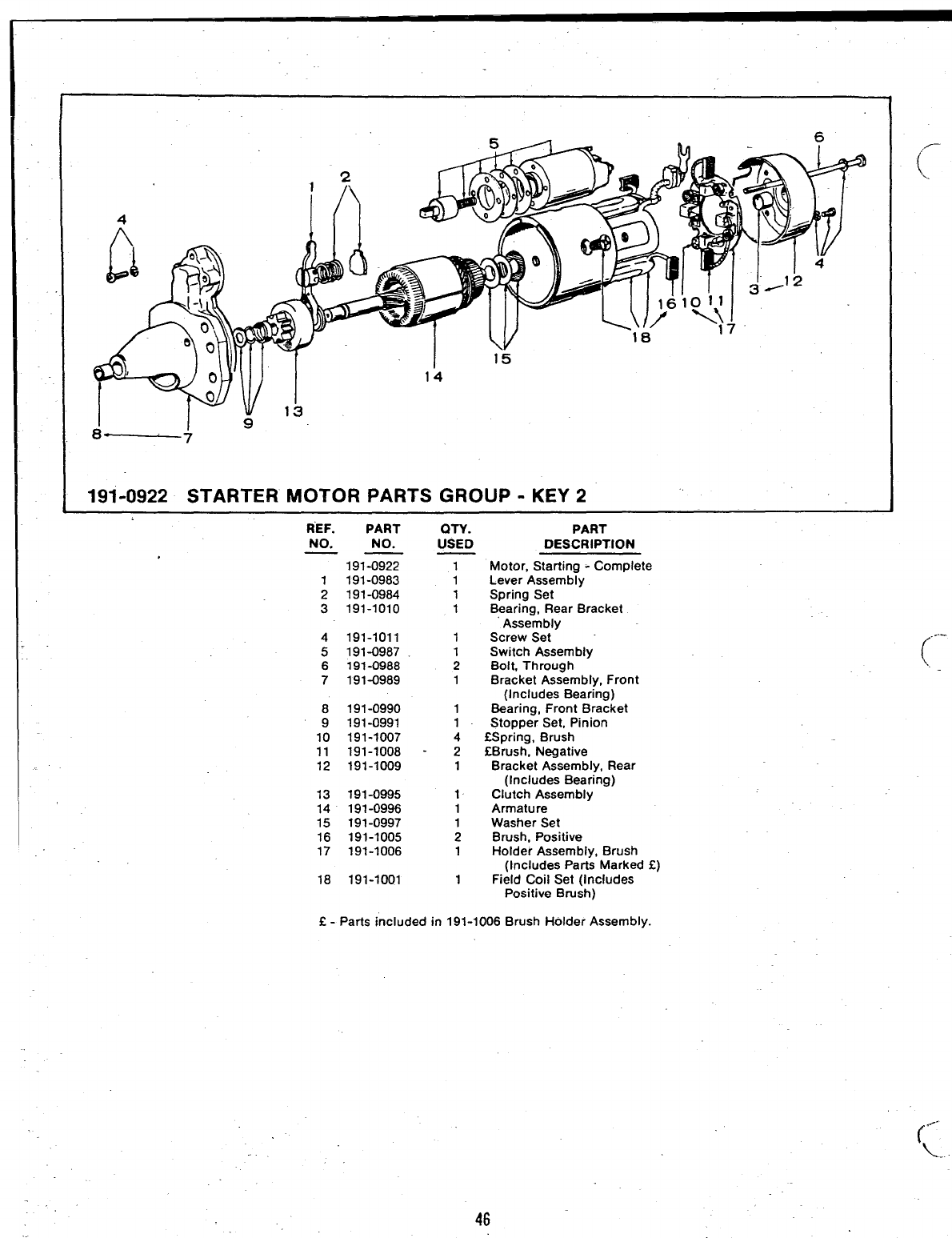
191-0922 STARTER MOTOR PARTS GROUP -KEY 2
REF. PART QTY. PART
NO. NO.
——
191-0922
1191-0983
2191-0984
3191-1010
4191-1011
5191-0987
USED DESCRIPTION
1Motor, Starting -Complete
1Lever Assembly
1Spring Set
1Bearing, Rear Bracket
Assembly
1Screw Set
1Switch Assembly
6191-0988 2Bolt, Through k. _
7191-0989 1Bracket Assembly, Front
(Includes Bearing)
8191-0990 1Bearing, Front Bracket
9191-0991 1Stopper Set, Pinion
10 191-1007 4SSpring, Brush
11 191-1008 -2fBrush. N@ative
12 191-1009 1Bracket A;sembly, Rear
(Includes Bearing)
13 191-0995 1Clutch Assembly
14 191-0996 1Armature -
15 191-0997 1Washer Set
16 191-1005 2Brush, Positive
17 191-1006 1Holder Assembly, Brush
(Includes Parts Marked E)
18 191-1001 1Field Coil Set (Includes
Positive Brush)
f - Parts included in 191-1006 Brush Holder Assembly.
46
f
..-
\.
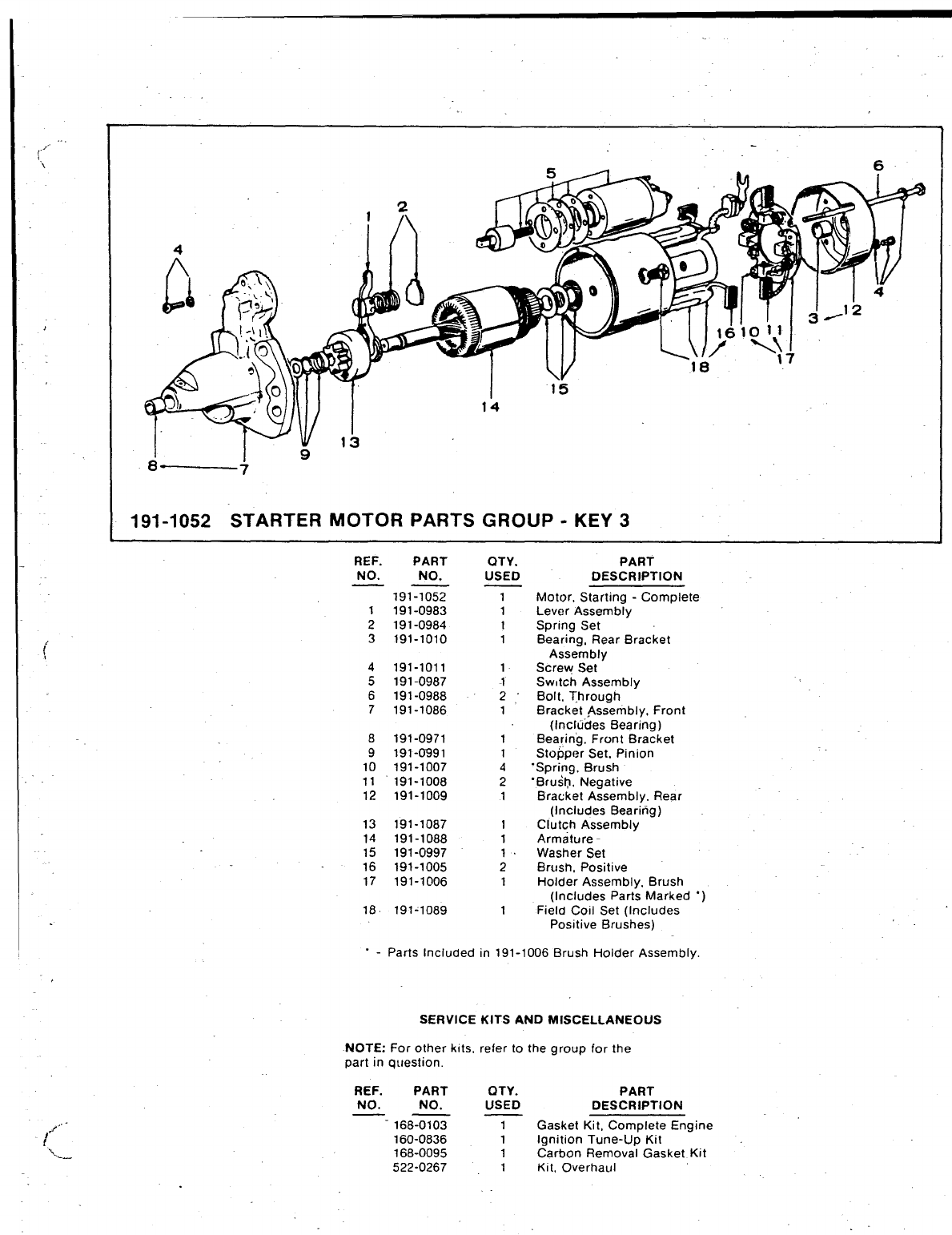
191-1052 STARTER MOTOR PARTS GROUP -KEY 3
REF. PART QTY. PART
NO. NO. USED DESCRIPTION
—— _
191-1052
191-0983
191-0984
191-1010
1
1
1
1
Motor, Starting -Complete
Lever Assembly
Spring Set
1
2
3Beari;g, Rear Bracket
Assembly
Screw Set
Swdch Assembly
Bolt, Through
4
5
6
7
191-1011
191-0987
191-0988
191-1086
1
1
2
1BracketAss>mbly, Front
(Includes Bearing)
Bearing, Front Bracket
Stopper Set. Pinion
“Spring, Brush
“Bru&~, Negative
Bracket Assembly. Rear
(Includes Bearing)
Clutch Assembly
Armature -
Washer Set
Brush, Positive
Holder Assembly, Brush
(Includes Parts Marked “)
Field Coil Set (Includes
Positive Brushes)
8
9
10
11
12
191-0971
191-0991
191-1007
191-1008
191-1009
1
1
4
2
1
191-1087
191-1088
191-0997
191-1005
191-1006
13
14
15
16
17
1
1
1
2
1
18 191-1089 1
.-Parts Included in 191-1006 Brush Holder Assembly,
SERVICE KITS AND MISCELLANEOUS
NOTE: For other kits. refer to the group for the
part in question.
REF. PART OTY. PART
NO. NO. USED
—— — DESCRIPTION
Gasket Kit, Compfete Engine
Ignition Tune-Up Kit
Carbon Removal Gasket Kit
-168-0103 1
160-0836 1
168-0095 1
522-0267 1Kit, Overhaul
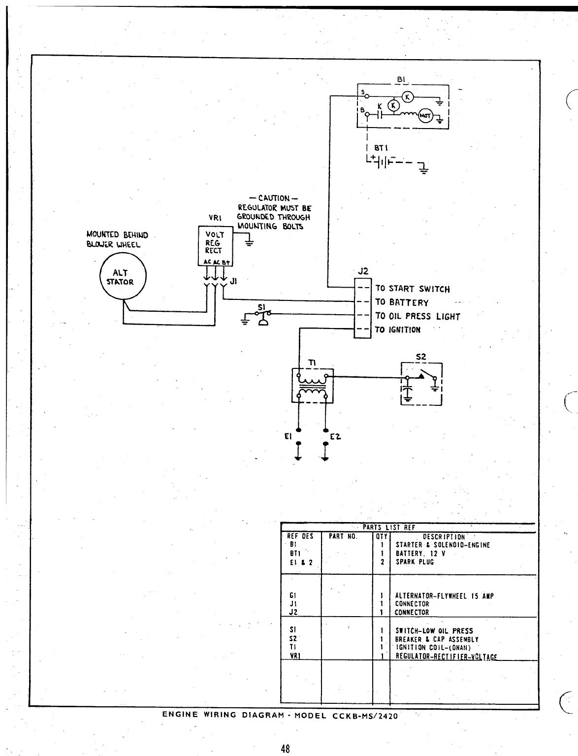
-CAmlON –
REGULXTORMUST BE
VR1 GROUNOLDTHROUGH
MOUNTING OOLTs
MOuKrED8WIMD
q
VOLT
OLM:R UWXL REG ~
RFLT
.“Q*, ”;
M.ALm’
ALT J2
SfATOR JI -- TO
SI -- TO
-- TO
=-- To
START SWITCH
BATTERY --
OIL PRESS LIGHT
IGNITION ‘
-n
T-.-— F:y
~~-j
--
El n
J.1
.
●PARTs LIST REF
REF OES PARTNO. OTY DESCRIPTION”
81 1STARIERLSOLENOIO-Et/GINE
BT1 1BATTERY.12 V
Elt2 2SPARKPLIM
GI 1ALTERNATOR-FLYWHEEL15 AsIP
ICONN[C1OR
:; 1CONNECTOR
SI ISW ITCH-LOW OIL PRESS
S2 IBREAKER & CAP ASSEMBLY
TI 1 IGNITION COIL-(ONAN)
VR1 1“ fl[GuLATOR-flfCTIF IER-VOllAE
FNCINF WI QIMc nlACOAM .unmet --”r. ,... i-n .-n
C
.-
-------- .. .... ..- w,r-l~ m-,-, -*.l WUI=L LLKD-m>f L-i Lu
48
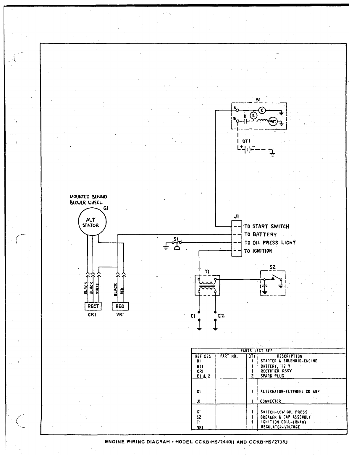
. .
----
1
i,
,-.
I
/-
~
\--
MouKKD iWWAEI
OLWER UHECL
JI
I-- -TO START SWITCH
-- TO BRTTERY
SI -- ‘TO OIL PRESS LIGHT
=.-- TO IGNITION
AA TI
BL -
@
A
xx IL
=sb
g-l= ;.
~~ ‘&j”-’”
.-
RECT REG
CRI VRI El C2
11
. .
PARTS LIST REF
R[F 0[S PARTtAO. OTY OISCRIPTION
81 1STARTERLSOLENOiO-ENGINE
ETI 1EATT[RY, 12 V
tRl \RECTIFIERRSSY
EIL2 2SPARKPLUG
IALTERNATI)R-FLYIHEEL20 AUP
ICONNECTOR
ISWITCH-LOW”OIL PRESS
16REAKERtCkF’ASSEUEIY
1IGNITION COIL-( ONAN)
IffESUIATOR-V0L7Alc[
E
G1
JI
SI
S2
TI
VR
ENGINE WIRING DIAGRAM -MODEL CC KB-t4S/2440H AND CC KB-MS!2733J
