927 0253 Onan CCK CCKA (spec A J) Industrial Engine Parts Manual (06 1986)L
User Manual: 927-0253 Onan CCK CCKA (spec A-J) Industrial Engine Parts Manual (06-1986)L
Open the PDF directly: View PDF ![]() .
.
Page Count: 52
.
●
Paws
Manual
mwcma
Industrial
Engine
927-0253
6-86 (SPEC A-J)
‘* %
“T*9°
Repla;es 6-81 (Spe& A-J)
Printed in U.SA
MODEL IDENTIFICATION SAFETY PRECAUTIONS
To avoid errors or delay in filling your parts order, The following symbols are used in Onan manuals
always give the MODEL, SPEC NO. and SERIAL to alert users to the potentially dangerous condi-
NO. from the Onan nameplate. tions relating to maintenance of equipment and re- 9
placement of parts. Please read and observe.
For handy reference, insert your nameplate in-
formation in the spaces below.
~
MODEL AND SPEC NO.
@@@@
SERIAL NO.
DIGITAL CONTROL SOFTWARE VERSION lAcAuTION I
AND DATE (IF APPLICABLE)
PRODUCT
—. ,J
This symbol warns of immedi-
ate hazards which will result in
severe personal injury or death.
This symbol refers to a hazard
or unsafe practice which can re-
sult in severe personal injury or
death. -
.-
This symbol refers to a hazard
or unsafe practice which can re-
sult in severe personal injury or
product or property damage.
SAFETY PRECAUTIONS
MM!!!!@
Service and repair of Onan equipment must be performed by trained, experienced personnel only. lm-
proper service orrepairmay result in propetiy damage, severe personal injury or death. Do not use thi
*
catalog as aguide to servicing your equipment. Read and follow the IMPORTANT SAFETY INSTRU
TIONS in the Service Manual appropriate for the equipment you are working on.
IAWAFINING I
Contact with USED ENGINE OILS has been identifiedbya United States federalagencyand some USA
state agencies as causing CANCER or REPRODUCTIVE TOXICITY When checking or changing engine
oils take all necessary precautions not to ingest, breathe the fumes or contact the used oil.
IAV4ARNING I
Contact with ASBESTOS has been identified by aUnited States federal agency and some USA state
agencies as causing CANCER or REPRODUCTIVE TOXICITY When handling engine gaskets take all
necessary precautions not to ingest, breathe or contact the dust from the gaskets! Use adequate ven-
tilation and wear protective gloves, masks and clothing!
E!miEEI
Contact with BENZINE and LEAD, found in gasoline, fuel additives and solvents has been identified )
by aUnited States federal agency and some USA state agencies as causing CANCER or REPRODUC-
17VE TOXICITY When checking, draining or adding gasoline and fuel additives or using solvents take ~
allnecessaryprecautions not to ingest, breathe the fumes or contact the liquids. Use adequate ventila-
tion and wear protective gloves, masks and protective clothing!
PSP-I a
General Information
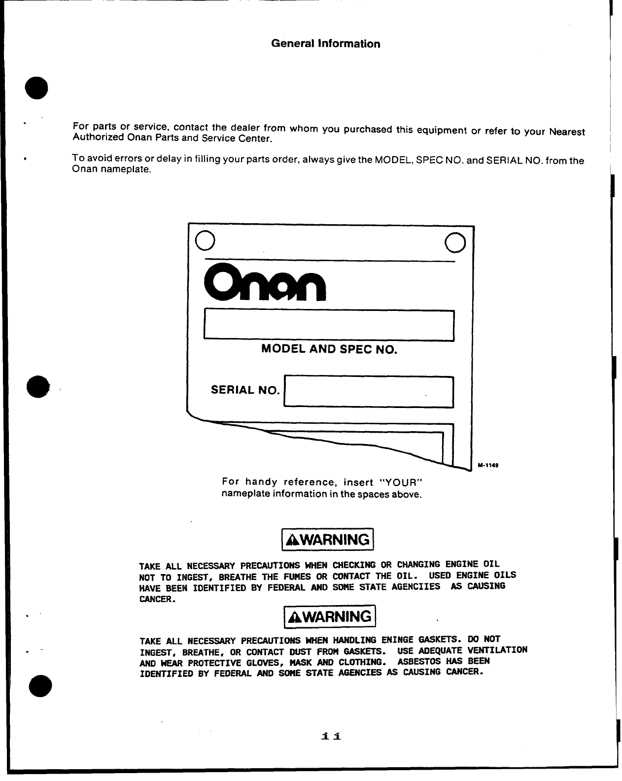
For parts or service, contact the dealer from whom you purchased this equipment or refer to your Nearest
Authorized Onan Parts and Service Center.
●To avoid errors or delay in filling your parts order, always give the MODEL, SPEC NO. and SERIAL NO. from the
Onan nameplate.
o0
SERIAL
MODEL AND SPEC NO.
N“*~
For handy reference, insert “YOUR”
nameplate information in the spaces above.
I
M-1149
@!!EN!w
TAKE ALL NECESSARY PRECAUTIONS WHEN CHECKING OR CHANGING ENGINE OIL
NOT TO INGEST, BREATHE THE FUMES OR CONTACT THE OIL. USED ENGINE OILS
HAVE BEEN IDENTIFIED BY FEDERAL AND SOME STATE AGENCIIES AS CAUSING
CANCER. 1
k!Yw!EJ
TAKE ALL NECESSARYPRECAUTIONS WHEN HANDLING ENINGE GASKETS. DO NOT
INGEST, BREATHE,OR CONTACT DUST FROM GASKETS. USE ADEQUATE VENTIMTION
AND WEAR PROTECTIVE GLOVES, NASK AND CLOTHING. ASBESTOS HAS BEEN
IDENTIFIED BY FEOERAL ANO SOME STATE AGENCIES AS CAUSING CANCER.
.
.-
0
ii
INDEX
. .
.
Adapter, Exhaust (Flange Type) 48
Arm and Shaft, Governor 6
Arm, Extension - Governor 48
Armature, Starter 16, 17,28,29
Baffle, Breather Tube 4
Base, Air Cleaner 4,48
Base, Oil 3
Bearing, Camshaft 4
Bearing, Crankshaft 4
Block, Cylinder 4
Box, Breaker 13, 14, 15,20,21
Bracket, Governor Control 15,38
Bracker, Ignition Coil 14,48
Brush, Ground-Starter 16,17,28,29
Cable, Spark Plug 13,14,48
Camshaft 6,48
Cap, Breather 4,48
Cap, Fuel Tank 35
Carburetor, Gasoline 12,30,32,34
Clamp, Coil 14,48
Clamp, Muffler 48
Coil, Ignition 13, 14
Cover, Air-Cleaner 10
Cover, Breaker Box 15,20,21
Cover, Valve 4
Crankshaft 7
Element, Air Cleaner 10
Filter, Fuel 37
Filter, Oil (Spin-On) 43
Filter, Oil (Cartridge Type) 43
Flywheel 7,22,23,24
Gasket, Breaker Box 13,14,15,20,21
Gasket, Cylinder Head 4
Gasket, Oil Base 3
Gasket, Valve Cover 4
Gear, Cam Shaft 6,48
Gear, Crankshaft 7
Gear, Ring 7,22,23,24,44
Gearcase 6,23,48
Governor 38
Guard, Flywheel 48
Guide, Valve 48
Head, Cylinder 4
Heater, Oil Base 48
Holder, Brush 16
Hose, Breather 10,48
Hose, Fuel 30,31,47
Housing, Blower 18,44
Housing, Cylinder 18
Line, Fuel—Gasoline 11, 30, 31, 35, 36
Line, Oil 3,39,43,48
Manifold, Exhaust 48
Manifold, intake 10
Muffler, Exhaust 10,48
Piston 8, 48
Plate, Bearing—Rear 4
Plug, Spark 13,14
Pump, Fuel—Manual 9, 10
Pump, Fuel—Vacuum Pulse 47
Pump, Oil 3
Regulator, Voltage 22,24,25,26,27
Ring, Piston 8
Rod, Connecting 8
Rod, Control 15
Seal, Air 43
Seal, Oil 4,6,48
Seat, Valve 4,48
Solenoid, Start 28,29, 48
Starter, Electric 16,17,28,29
Starter, Redi-Pull 45
Stator 22,23,24
Strap, Fuel Tank 35
Switch, Ignition 14,48
Switch, Pressure—Oil 48
Switch, Stop 13,39,48
Tank, Fuel 35
Tappet, Valve 4
Tube, Breather 4,10,37,48
Tube, Oil 4,43
Valve, Exhaust 4
Valve, Intake 4,48
Valve, Shut-Off 35
Wrapper, Air Cleaner Element 48
INTRODUCTION
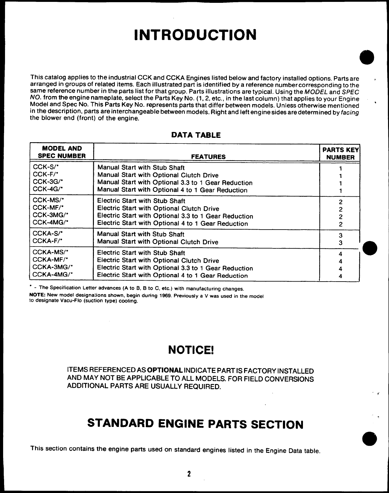
This catalog applies to the industrial CCK and CCKA Engines listed below and factory installed options. Parts are +
arranged in groups of related items. Each illustrated part is identified by areference number corresponding to the
same reference number in the parts list for that group. Parts illustrations are typical. Using the MODEL and SPEC
NO. from the engine nameplate, select the Parts Key No. (1, 2, etc., in the last column) that applies to your Engine ,
Model and Spec No. This Parts Key No. represents parts that differ between models. Unless otherwise mentioned
in the description, parts are interchangeable between models. Riqht and left engine sides are determined by facing
the blower end (front) of the engine.
DATA TABLE
MODEL AND
SPEC NUMBER
CCK-S/*
CCK-F/*
ccK-3G/*
CC K-4G/*
CCK-MS/*
CCK-MF/*
ccK-3MG/*
ccK-4MG/*
CCKA-S/*
CCKA-F/*
CCKA-MW*
CCKA-MF/*
ccKA-3MG/*
ccKA-4MG/*
FEATURES
Manual Start with Stub Shaft
Manual Start with Optional Clutch Drive
Manual Start with Optional 3.3 to 1Gear Reduction
Manual Start with Optional 4 to 1Gear Reduction
Electric Start with Stub Shaft
Electric Start with Optional Clutch Drive
Electric Start with Optional 3.3 to 1Gear Reduction
Electric Start with Optional 4 to 1Gear Reduction
Manual Start with Stub Shaft
Manual Start with Optional Clutch Drive
Electric Start with Stub Shaft
Electric Start with Optional Clutch Drive
Electric Start with Optional 3.3 to 1Gear Reduction
Electric Start with Optional 4 to 1Gear Reduction
●-The Specification Letter advances (A to B, Bto C, etc.) with manufacturing changes,
NOTE New model designations shown, begin during 1969. Previously a V was used in the model
to designate Vacu-Flo (suction type) cooling.
NOTICE!
ITEMS REFERENCED AS OPTIONAL INDICATE PART IS FACTORY iNSTALLED
AND MAY NOT BE APPLICABLE TO ALL MODELS. FOR FIELD CONVERSIONS
ADDITIONAL PARTS ARE USUALLY REQUIRED.
STANDARD ENGINE PARTS SECTION
PARTS KEY
NUMBER
1
1
1
1
2
2
2
2
3
3
4●
4
4
This section contains the engine parts used on standard engines listed in the Engine Data table.
2
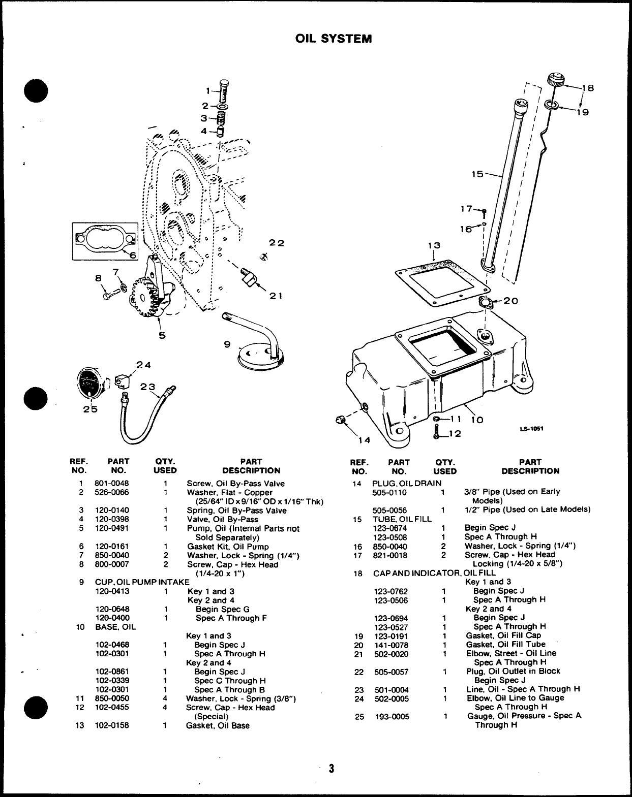
OIL SYSTEM
.
... -:;:.:;..’
.! z--
,:.:-
“.:./>.. . t .- -’
///< A- #
..,//< ,
, .+<.-,
;.’,.-..,
;) / ---”.::
:,,, /....7<+: 1---
‘## : .. ‘,:.<.~/
,,, ,-.-,:, ., ‘... I
/:; :.gT!j;: . .... :-.
‘.,.‘.. --< f$~ - : :
;(, ,:: A’
,,. ,.,,!..,4,, : :, : !.:..<
!::
REF. PART QTY.
NO. NO. USED
1801-0048 1
2526-0086 1
3120-0140 1
4120-0398 1
5120-0491 1
6120-0161 1
7850-0040 2
8800-0007 2
15
J’/
‘7-? ~
q /
13 t/
PART
DESCRIPTION
Screw. Oil By-Pass Valve
Washer, Flat -Copper
(25/84” ID x9/16 OD Xl/16’’Thk)
Spring, Oil By-Pass Valve
Valve, Oil By-Pass
Pump, Oil (Internal Parts not
Sold Separatei y)
Gasket Kit, Oil Pump
Washer. Lock -Spring (1/4’)
Screw, Cap -Hex Head
(1/4-20 X l“)
9CUP. OIL PUMP INTAKE
120-0413 1Key 1and 3
Key 2and 4
120-0648 1Begin Spec G
120-0400 1Spec AThrough F
10 BASE, OIL
.’ Key 1and 3
102-046s 1Begin Spec J
102-0301 1Spec AThrough H
Key 2and 4
. . 102-0861 1Begin SpeC J
102-0339 1Spec CThrough H
102-0301 1Spec AThrough B
●11 850-0050 4Washer, Lock -Spring (3/8”)
12 102-0455 4Screw. Cap -Hex Head
(Special)
13 102-0158 1Gasket, 011 Base
REF.
NO.
14
15
16
17
18
19
20
21
22
23
24
25
w
PART OTY. PART
NO. USED DESCRIPTION
PLUG, OIL DRAIN
505-0110 13/8 Pipe (Used on Early
Models)
505-0056 11/2 Pipe (Used on Late Models)
TUBE, OIL FILL
123-0674 1Begin Spec J
123-0508 1Spec AThrough H
850-0040 2Washer, Lock -Spring (1/4)
821-0018 2Screw, Cap -Hex Head
Locking (1/4-20 x5/8”)
CAP AND INDICATOR, OIL FILL
Key 1and 3
123-0762 1Begin Spec J
123-0506 1Spec AThrough H
Key 2and 4
123-0694 1Begin Spec J
123-0527 1Spec AThrough H
123-0191 1Gasket, Oil Fill Cap
141-0078 1Gasket, Oil Fill Tube
502-0020 1Elbow, Street -011 Line
Spec AThrough H
505-0057 1Plug, Oil Outlet in Block
Begin Spec J
501-0004 1Line, Oil -Spec AThrough H
502-0005 1Elbow, Oil L!ne to Gauge
Spec AThrough H
193-0005 1Gauge, 011 Pressure -Spec A
Through H
“3
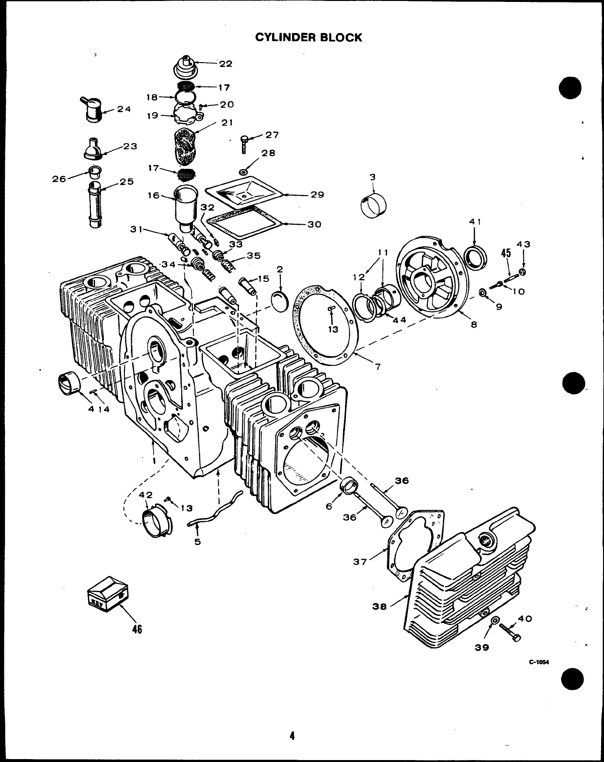
CYLINDER BLOCK
>
B-24
&
23
46
6!a-
22
17
18
20
19
21
“r’
27
28
.- /
C-1054
4
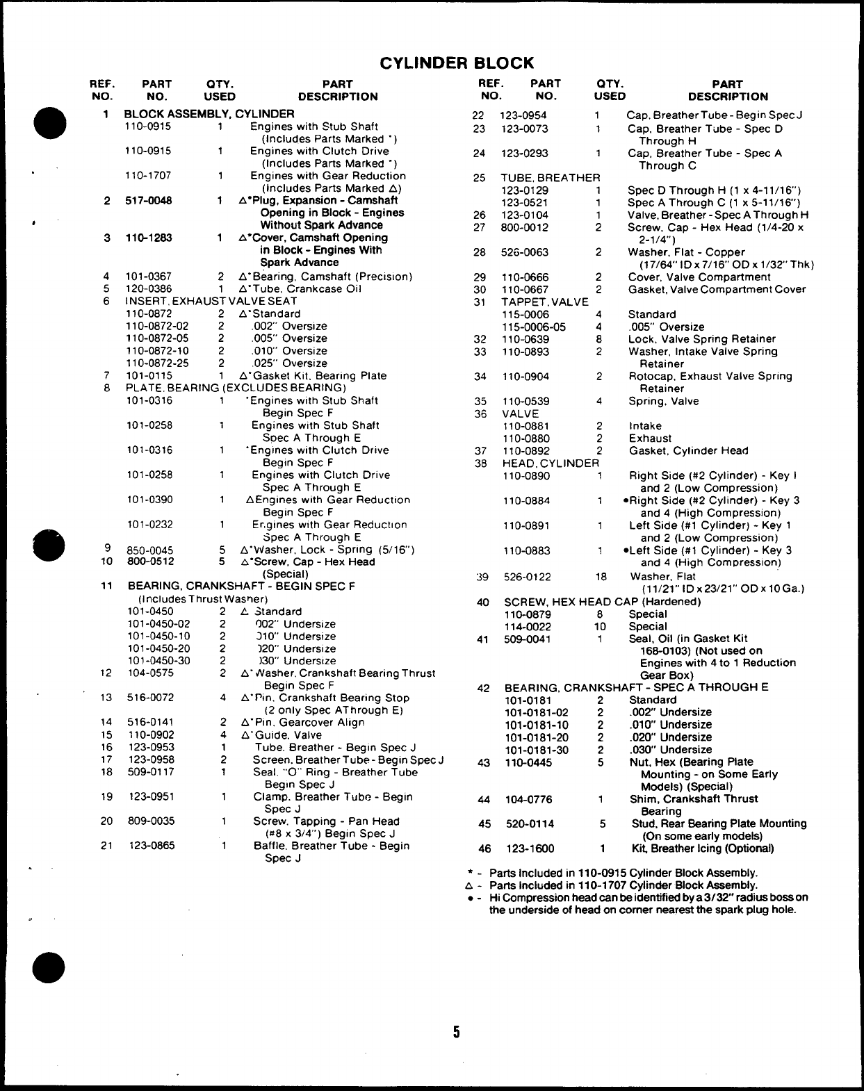
CYLINDER BLOCK
REF.
NO.
a
1
PART QTY. PART
NO. USED DESCRIPTION
BLOCK ASSEMBLY, CYLINDER
110-0915 1Engines with Stub Shaft
(Includes Parts Marked “)
110-0915 1Engines with Clutch Drive
(Includes Parts Marked “)
110-1707 1Engines with Gear Reduction
(Includes Parts Marked A)
517-0048 1A* Plug, Expansion -Camshaft
Opening in Block - Engines
Without Spark Advance
110-1263 1A* Cover, Camshaft Opening
in Block - Engines With
Spark Advance
101-0367 2A“Bearing, Camshaft (Preclslon)
120-0386 1A“Tube, Crankcase Oil
INSERT, EXHAUST VALVE SEAT
110-0872 2A“Standard
110-0872-02 2.002” Oversize
110-0872-05 2.005” Oversize
110-0872-10 2.010” Oversize
110-0872-25 2.025” Oversize
101-0115 1A“Gasket Kit. Bearing Plate
PLATE, BEARING (EXCLUDES BEARING)
101-0316 1“Engines with Stub Shaft
Begin Spec F
101-0258 1Engines with Stub Shaft
Soec AThrough E
101-0316 1“Engines with Clutch Drive
Begin Spec F
101-0258 1Engines with Clutch Drive
Spec AThrough E
101-0390 1AEnglnes with Gear Reduction
Begin Spec F
101-0232 1Er,glnes w!th Gear Reduction
Spec AThrough E
850-0045 5 A“Vtiasher, Lock -SPrln9 (5/16’)
800-0512 5&“Screw, Cap -Hex Head
(Special)
BEARING, CRANKSHAFT -BEGIN SPEC F
(includes Thrust Wasner)
REF. PART al-y. PART
NO. NO. USED DESCRIPTION
Cap, BreatherTube -Begin Spec J
Cap, Breather Tube -Spec D
Through H
Cap, Breather Tube -Spec A
Through C
Spec DThrough H(1 x4-11/16’)
Spec AThrough C(1 x5-11/16’)
Valve, Breather -Spec A Through H
Screw, Cap -Hex Head (1/4-20 x
2-1/4”)
Washer, Flat -Copper
(17/64” lDx7/16° ODx l/32’ Thk)
Cover, Valve Compartment
Gasket, Valve Compartment Cover
Standard
.005” Oversize
Lock, Valve Spring Retainer
Washer, Intake Valve Spring
Retainer
Rotocap, Exhaust Valve Spring
Retainer
Spring, Valve
Intake
Exhaust
Gasket, Cylinder Head
Right Side (#2 Cylinder) -Key I
and 2(Low Compression)
●Right Side (#2 Cylinder) -Key 3
and 4(High Compression)
Left Side (#l Cylinder) -Key 1
and 2(Low Compression)
●Left Side (#l Cylinder) -Key 3
and 4(High Com Dresslon)
Washer. Flat
22
23
123-0954 1
123-0073 1
123-0293 1
TUBE, BREATHER
123-0129 1
123-0521 1
123-0104 1
800-0012 2
52&O063 2
24
25
2
26
27
4“
3
28
4
5
6
29
30
31
110-0666 2
110-0667 2
TAPPET, VALVE
115-0006 4
115-0006-05 4
110-0639 8
110-0893 2
32
33
7
8
110-0904 2
34
35
36
110-0539 4
VALVE
110-0881 2
110-0880 2
110-0892 2
HEAD. CYLINDER
110-0890 1
110-0884 1
37
38
110-0891 1
99
10
110-0883 1
39 526-0122 18
11 (11/21’’ lDx23/21’’ ODxlOG).)
40 SCREW, HEX HEAD CAP (Hardened)
110-0879 8Specisl
114-0022 10 Special
41 509-0041 1Seal, Oil (in Gasket Kit
166-0103) (Not used on
Engines with 4to 1Reduction
Gear Box)
42 BEARING, CRANKSHAFT -SPEC ATHROUGH E
101-0181 2Standard
101-0181-02 2.002 Undersize
101-0181-10 2.010 Undersize
101-0181-20 2.020 Undersize
101-0181-30 2.030’ Undersize
43 110-0445 5Nut, Hex (Bearing Plate
Mounting -on Some Early
Models) (Special)
44 104-0776 1Shim, Crankshaft Thrust
Bearing
45 520-0114 5Stud, Rear Bearing Plate Mounting
(On some early models)
46 123-1600 1Kit, Breather Icing (Optional)
101-0450
101-0450-02
101-0450-10
101-0450-20
101-0450-30
104-0575
2
2
AStandard
002” Undersize
210’ Unders!ze
120” Undersize
)30” Undersze
A- Washer. Crankshaft Bearing Thrust
Begin Spec F
A“Ptn. Crankshaft Bearing Stop
(2 only Spec AThrough E)
A“Pln, Gearcover Align
A“Gulde. Valve
Tube, Breather -Begin Spec J
Screen. Breather Tube- Begin Spec J
Seal. ““O””Ring -Breather Tube
Begin Spec J
Clamp. Breather Tube -Begin
SPec J
Screw. Tapping -Pan Head
($z8x3/4”) Begin Spec J
Baffle. Breather Tube -Begin
Spec J
2
2
2
2
12
13 516-0072 4
14
15
16
17
18
516-0141
110-0902
123-0953
123-0958
509-0117
2
4
1
2
1
19 123-0951 1
20 809-0035
21 123-0865 1
●-Parts Included in 110-0915 Cylinder Block Assembly.
A- Parts Included in 110-1707 Cylinder Block Assembly.
●-Hi Compression head can be identified by a 3132” radius boss on
the underside of head on comer neareat the spark plug hole.
5
1
‘k
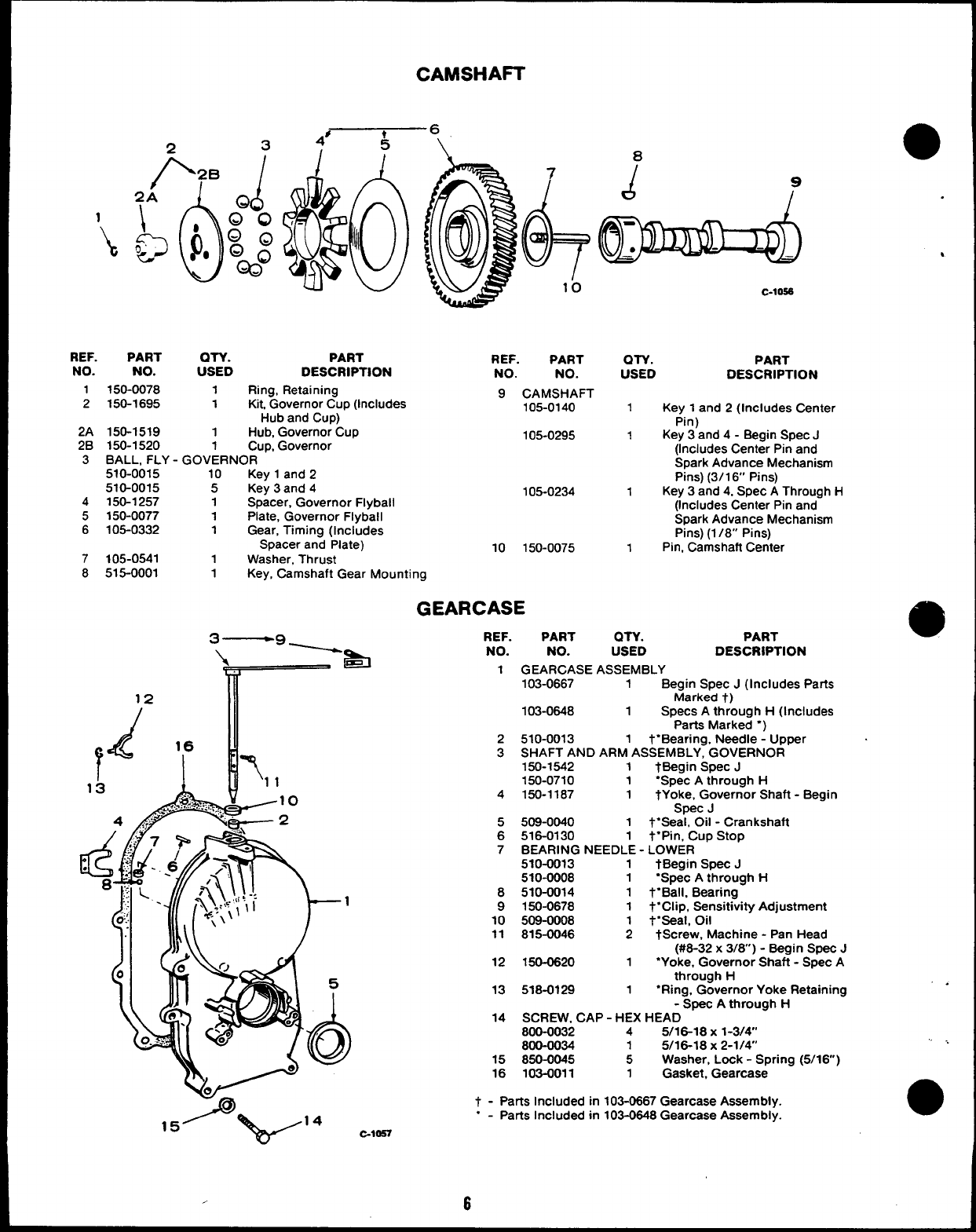
CAMSHAFT
234’
1k6\ e
10
0
J7
-●
c-loss
REF. PART OTY. PART
NO.
REF.
NO. USED
PART
DESCRIPTION NO. NO.
1150-0078 1Ring, Retaining
2150-1695 1Kit Governor Cup (Includes
9CAMSHAFT
105-0140
Hub and Cup)
2A 150-1519 1Hub, Governor Cup
2B 150-1520 1Cup, Governor
105-0295
3BALL, FLY -GOVERNOR
510-0015 10 Key 1and 2
510-0015 5Key 3and 4
4150-1257 1Spacer, Governor Flyball
105-0234
5150-0077 1Plate, Governor Flyball
6105-0332 1Gear, Timing (Includes
Spacer and Plate)
7105-0541
10 150-0075
1Washer, Thrust
8515-0001 1Key, Camshaft Gear Mounting
QTY. PART
USED DESCRIPTION
1Key 1and 2(Includes Center
Pin)
1Key 3and 4- Begin Spec J
(Includes Center Pin and
Spark Advance Mechanism
Pins) (3/1 6“ Pins)
1Key 3and 4, Spec AThrough H
(Includes Center Pin and
Spark Advance Mechanism
Pins) (1 /8” Pins)
1Pin, Camshaft Center
GEARCASE
3—9 ~REF. PART an. PART
\&
NO. NO. USED DESCRIPTION
r
1GEARCASE ASSEMBLY
103-0667 1Begin Spec J(Includes Parts
12 Marked t)
d
103-0648 1Specs Athrough H(Includes
Parts Marked “)
r
16 2510-0013 1t“Bearing, Needle -Upper
&
T
3SHAFT AND ARM ASSEMBLY, GOVERNOR
150-1542 1tBegin Spec J
13 11 150-0710 1“Spec Athrough H
.,.‘+;:%.:>,, 10 4150-1187 1tYoke, Governor Shaft -Begin
4.,rn& 2
Spec J
5509-0040 1t“Seal, Oil -Crankshaft
6516-0130 1t“pin, Cup Stop
7BEARING NEEDLE -LOWER
510-0013 1tBegin Spec J
510-0008 1“Spec Athrough H
8510-0014 1t“Ball, Bearing
9150-0678 1t“Clip, Sensitivity Adjustment
10 509-0008 1t“seal, Oil
11 815-0046 2tScrew, Machine -Pan Head
(#6-32 x3/W) -Begin Spec J
12 150-0620 1“Yoke, Governor Shaft -Spec A
through H
T
13 518-0129 1‘Ring, Governor Yoke Retaining
-Screc Athrouah H
14 SCREW, CAP -HEX HEAD “
800-0032 45/16-18 X1-3/4’
800-0034 15/16-18 X2-1/4”
15 850-0045 5Washer, Lock -Spring (5/16)
16 103-0011 1Gasket, Gearcase
t - Parts Included in 103-0667 Gearcase Assembly.
“ - Parts Included in 103-0648 Gearcase Assembly.
. ..
●
C-1OS7
,6
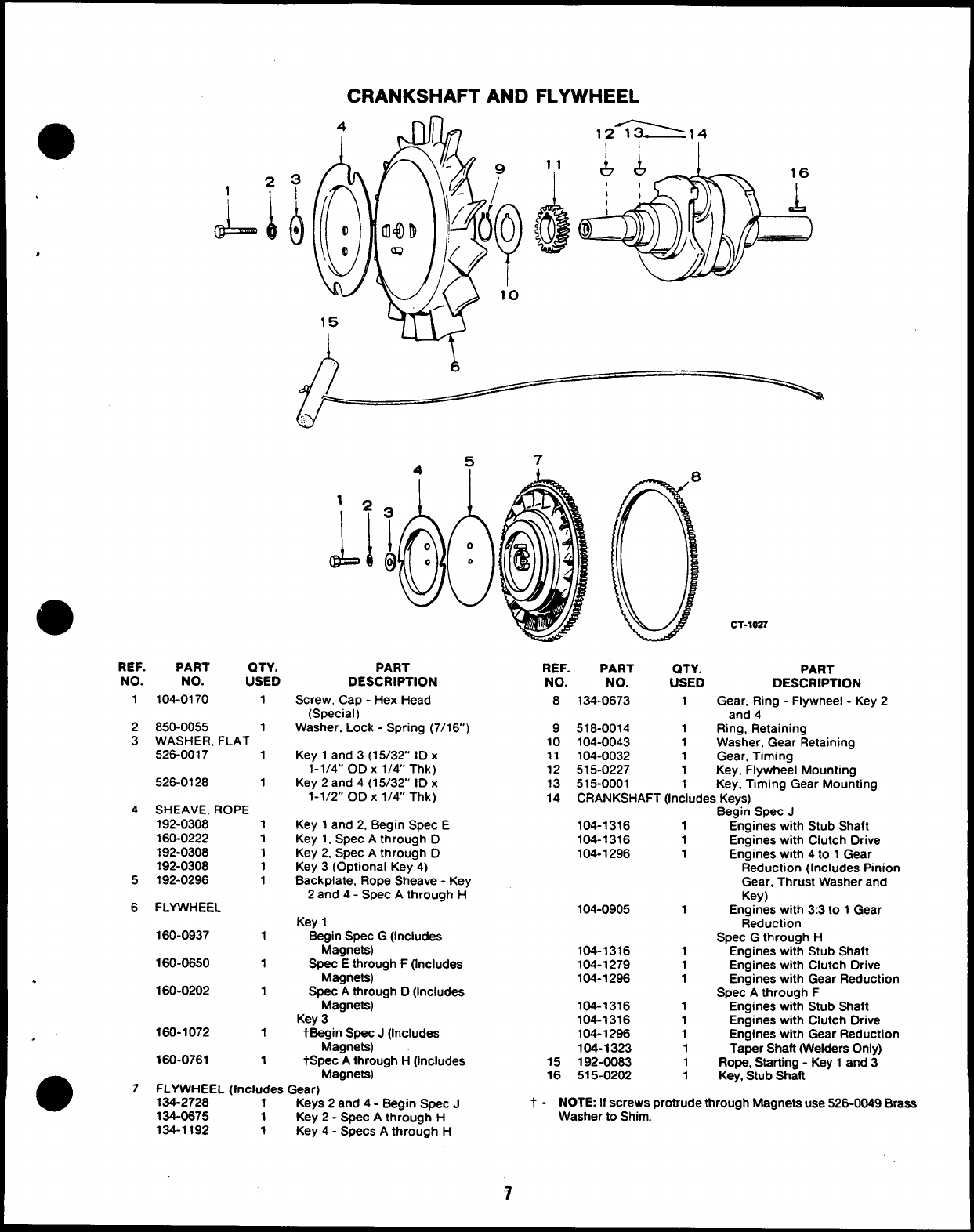
CRANKSHAFT AND FLYWHEEL
12_~14
1
A
*
@
REF. PART QTY.
NO. NO. USED
1104-0170 1
2850-0055 1
3WASHER, FLAT
526-0017 1
526-0128 1
4SHEAVE. ROPE
192-0308 1
160-0222 1
192-0308 1
192-0308 1
5192-0296 1
6FLYWHEEL
160-0937 1
160-0650 1
.
160-0202 1
160-1072 1
.’
160-0761 1
5
4, 7
1
1*
JJ
PART
DESCRIPTION
Screw, Cap -Hex Head
(Special)
Washer. Lock -Spring (7/16)
Key 1and 3(15/32 ID x
1-1/4” OD X1/4” Thk)
Key 2and 4(15/32” ID x
1-1/2” OD X1/4” Thk)
Key 1and 2, Begin Spec E
Key 1. Spec Athrough D
Key 2. Spec Athrough D
Key 3(Optional Key 4)
Back plate, Rope Sheave -Key
2and 4- Spec Athrough H
Key 1
Beg:gpe.=y G(Includes
Spec Ethrough F(Includes
Magneta)
Spec Athrough D(Includes
Magnets)
Key 3
tBeg~g~~&; J(Includes
tSPec Athrough H(Includes
oMagnets)
7FLYWHEEL (Includes Gear)
134-2728 1Keys 2and 4- Begin Spec J
134-0675 1Key 2- Spec Athrough H
134-1192 1Key 4- Specs Athrough H
CT-1OS7
REF. PART QTY. PART
NO. NO. USED DESCRIPTION
8134-0673 1Gear, Ring -Flywheel -Key 2
and 4
9518-0014 1Ring, Retaining
10 104-0043 1Washer, Gear Retaining
11 104-0032 1Gear, Timing
12 515-0227 1Key, Flywheel Mounting
13 515-0001 1Key, Timing Gear Mounting
14 CRANKSHAFT (Includes Keys)
Begin Spec J
104-1316 1Engines with Stub Shaft
104-1316 1Engines with Clutch Drive
104-1296 1Engines with 4to 1Gear
Reduction (Includes Pinion
Gear, Thrust Washer and
Key)
104-0905 1Engines with 3:3 to 1Gear
Reduction
Spec Gthrough H
104-1316 1Engines with Stub Shaft
104-1279 1Engines with Clutch Drive
104-1296 1Engines with Gear Reduction
Spec Athrough F
104-1316 1Engines with Stub Shaft
104-1316 1Engines with Clutch Drive
104-1296 1Engines with Gear Reduction
104-1323 1Taper Shaft (Welders Only)
15 192-0083 1Rope, Starting -Key 1and 3
16 515-0202 1Key, Stub Shaft
t- NOTE If screws protrude through Magneta use 526-0049 Braas
Washer to Shim.
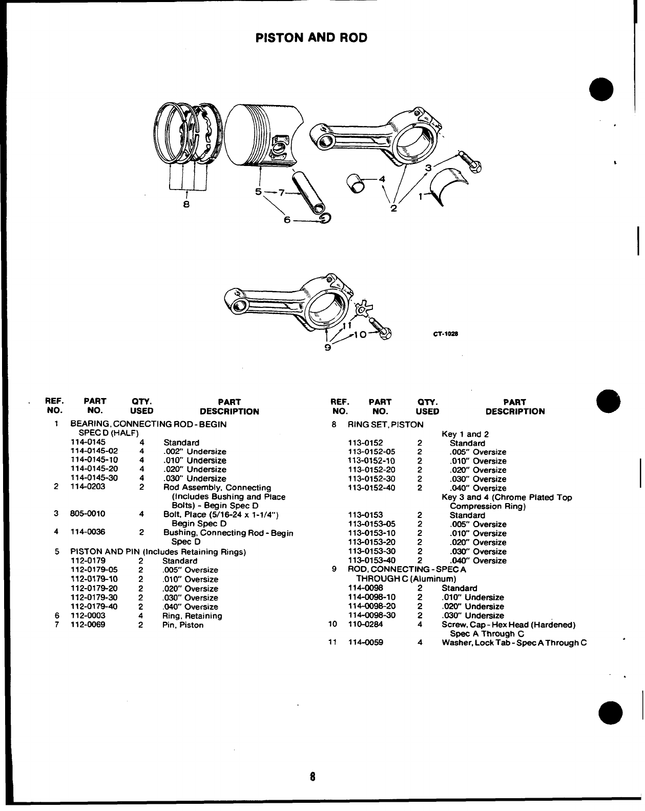
PISTON AND ROD
a
cl-loss
REF. PART QTY. PART
NO. NO. USED DESCRIPTION
1BEARING, CONNECTING ROD-BEGIN
SPEC D(HALF)
114-0145 “‘4 Standard
114-0145-02 4.002 Undersize
714-0145-10 4.010” Undersize
114-0145-20 4.020 Undersize
114-0145-30 4.030” Undersize
2114-0203 2Rod Assembly, Connecting
(Includes Bushing and Place
Bolts) -Begin Spec D
3805-0010 4Bolt, Place (5/18-24 x 1-1/4”)
Begin Spec D
4114-0036 2Bushing, Connecting Rod -Begin
Spec D
5 PISTON AND PIN (Includes Retaining Rings)
112-0179 2Standard
112-0179-05 2.005 Oversize
112-0179-10 2.010 Oversize
112-0179-20 2.020 Oversize
112-0179-30 2.030” Oversize
112-0179-40 2.040” Oversize
6112-0003 4Ring, Retaining
7112-0069 2Ptn, Piston
REF. PART aTY. PART
NO. NO. USED DESCRIPTION
8RING SET, PISTON
Key 1and 2
113-0152 2Standard
113-0152-05 2.005” Oversize
113-0152-10 2.010” Oversize
113-0152-20 2.020” Oversize
113-0152-30 2.030 Oversize
113-0152-40 2.040” Oversize
Key 3and 4(Chrome Plated Top
Compression Ring)
113-0153 2Standard
113-0153-05 2.005” Oversize
113-0153-10 2.010 Oversize
113-0153-20 2.020” Oversize
113-0153-30 2.03& Oversize
113-0153-40 2.040” Oversize
9ROD, CONNECTING -SPECA
THROUGH C(Aluminum)
114-0098 2Standard
114-0098-10 2.010 Undersize
114-0098-20 2.02W Undersize
114-0098-30 2.030 Undersize
10 110-0284 4Screw, Cap -Hex Head (Hardened)
Spec AThrough C
11 114-0059 4Washer, Lock Tab -Spec AThrough C
.>
0
%
a
z
,
17 E
?
-7
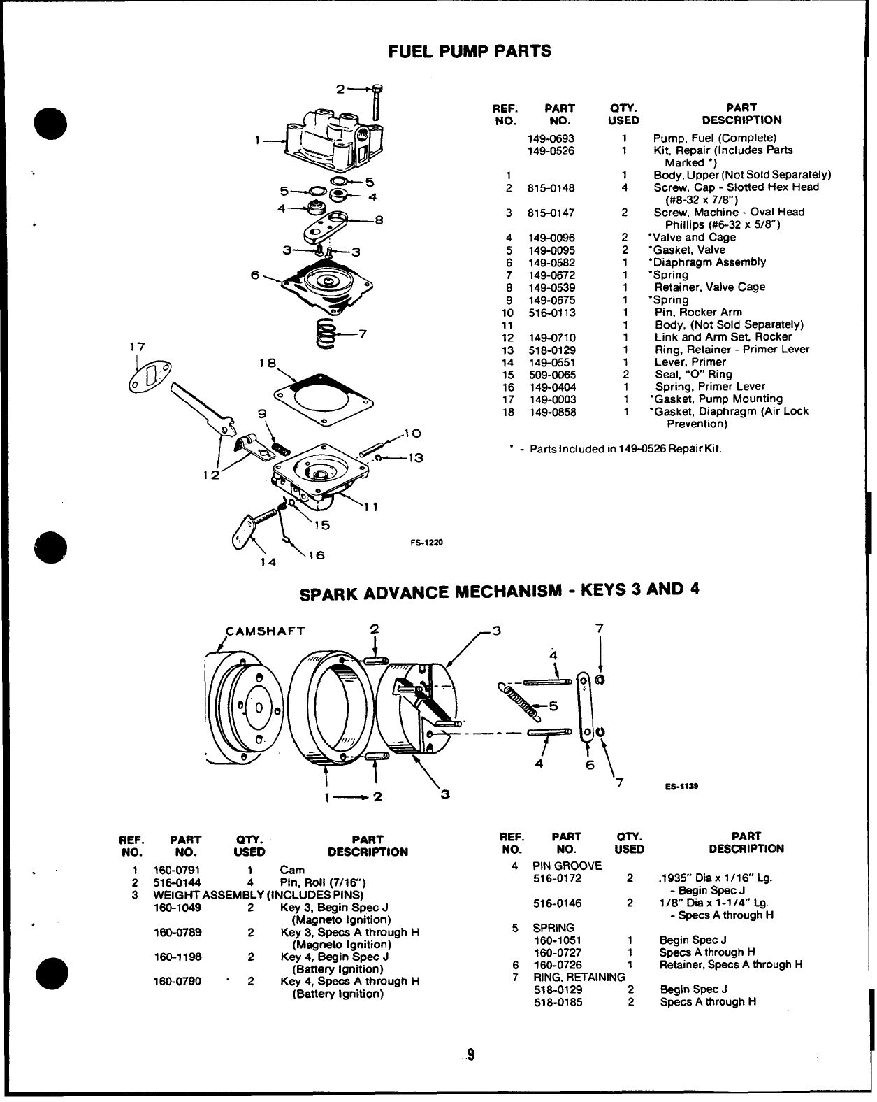
FUEL PUMP PARTS
REF.
.’ 1
2
3
.
REF.
No.
PART
NO.
149-0693
149-0526
1
2
3
4
5
6
7
8
9
10
11
12
13
14
15
16
17
18
815-0148
815-0147
149-0096
149-0095
149-0582
149-0872
149-0539
149-0675
516-0113
148-0710
518-0129
149-0551
508-0065
149-0404
149-0003
149-0858
QTY.
USED
1
1
1
4
2
2
2
1
1
1
1
1
1
1
1
1
1
1
1
PART
DESCRIPTION
Pump, Fuel (Complete)
Kit, Repair (Includes Parts
Marked “)
Body, Upper (Not Sold Separately)
Screw, Cap -Slotted Hex Head
(#8-32 X7/8)
Screw, Machine -Oval Head
Phillips (#6-32 x5/8)
“Valve and Cage
“Gasket, Valve
“Diaphragm Assembly
“Spring
Retainer, Valve Cage
‘Spring
Pin, Rocker Arm
Body, (Not Sold Separately)
Link and Arm Set, Rocker
Ring, Retainer -Primer Lever
Lever, Primer
Seal, “’O Ring
Spring, Primer Lever
‘Gasket, Pump Mounting
“Gasket, Diaphragm (Air Lock
Prevention)
“ - Parts Included in 149-0526 Repair Kit.
w\,=
14
FS-12Z0
SPARK ADVANCE MECHANISM -KEYS 3AND 4
CAMSHAFT 2-3 7
ll\ ‘7
l— 2‘3 ES-llSS
PART PART
NO. :STD DESCRIPTION
160-0791 1Cam
516-0144 4Pin, Roll (7/l&’)
WEIGHT ASSEMBLY (INCLUDES PINS)
160-1049 2Key 3, Begin Spec J
(Magneto Ignition)
160-0789 2Key 3, Specs Athrough H
(Magneto Ignition)
160-1198 2Key 4, Begin Spec J
(Battery Ignition)
180-0790 - 2 Key 4, Specs Athrough H
(Battery Ignition)
REF. PART OTY.
NO. NO. USED
4PIN GROOVE
516-0172 2
516-0146 2
5SPRING
160-1051 1
180-0727 1
6160-0726 1
7RING, RETAINING
518-0129 2
518-0185 2
.9
PART
DESCRIPTKDN
.1935” Dia x 1/16” Lg.
-Begin Spec J
I/a Dia x1-7/4” Lg.
-Specs Athrough H
Begin Spec J
Specs Athrough H
Retainer, Specs Athrough H
Begin Spec J
Specs Athrough H
EXHAUST AND FUEL SYSTEM
13 —“”.
$~
0-
/
u% 1
40 -.
,,, ,,, . . .. . .
-42
2
-“-7-via -
so
G---lo
20 21
//
22
/
18 r&d
J!q!qfp
21 43
19
14
I!#d 1
J?—
G36 EXS-1045
.:.
4
?’
,
●
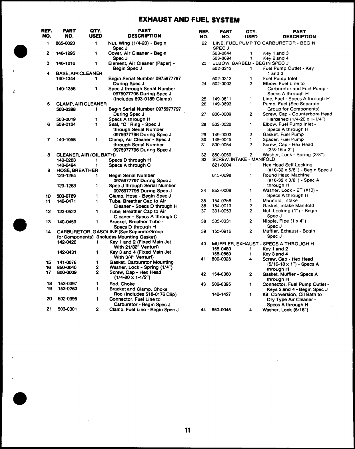
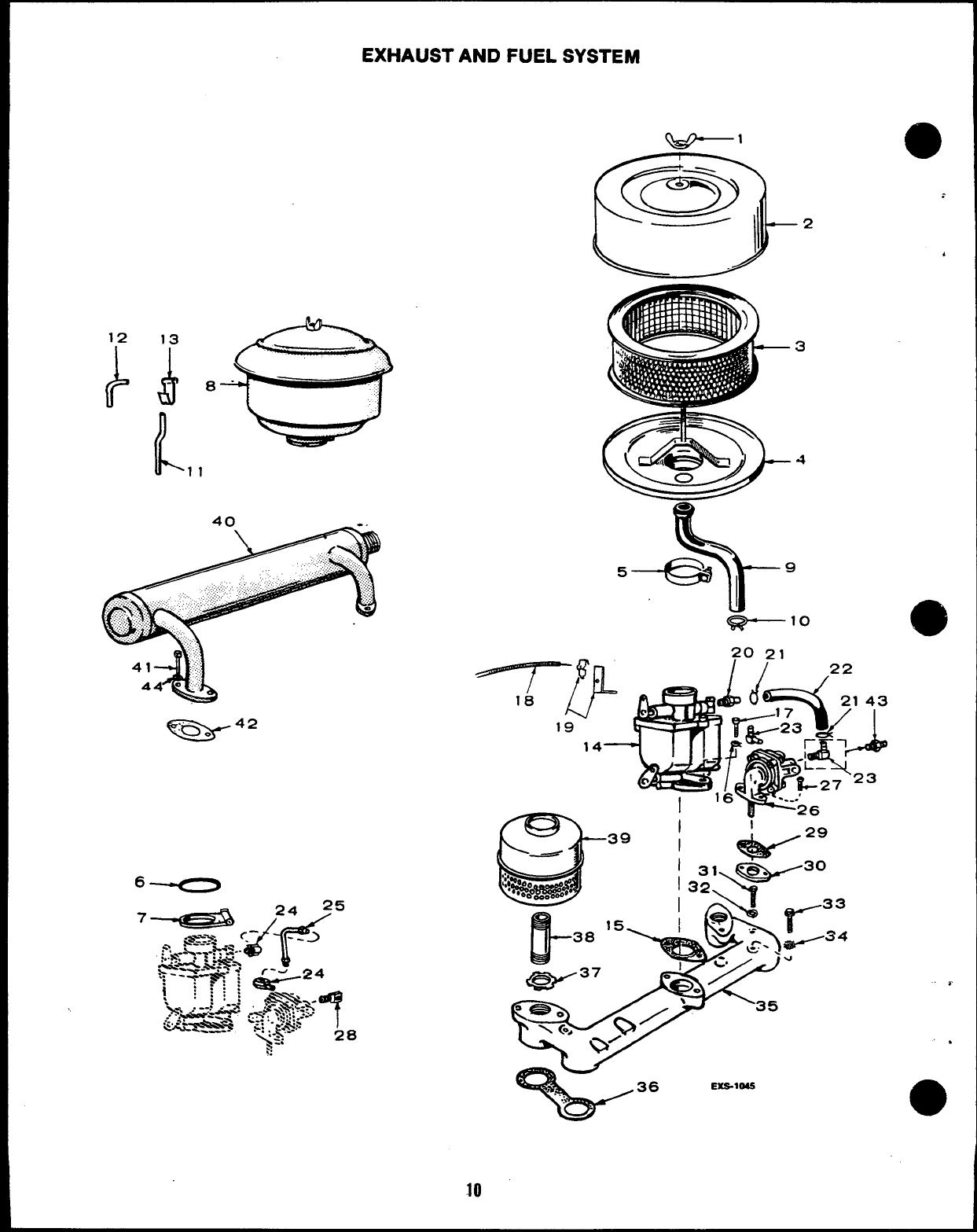
EXHAUST AND FUEL
REF.
NO.
1
2
3
4
;
5
6
7
8
9
10
11
12
14
PART QTY. PART
NO. USED DESCRIPTfON
865-0020 1Nut, Wh’ig (1/4-20)-Begin
Spec J
140-1295 1Cover, Air Cleaner -Begin
Spec J
140-1216 1Element, Ah Cleaner (Paper) -
Begin Spec J
BASE, AIR CLEANER
140-1344 1Begin Serial Number 0975977797
During Spec J
140-1356 1Spec Jthrough Serial Number
0975977796 During Spec J
(Includes 503-0189 Clamp)
CLAMP, AIR CLEANER
503-0396 1Begin Serial Number 0975977797
During Spec J
503-0019 1Specs Athrough H
509-0124 1Seal, “O” Ring -Spec J
through Serial Number
0975977796 During Spec J
140-1058 1Clamp, Air Cleaner -Spec J
through Serial Number
0975977796 During Spec J
CLEANER, AIR (OIL BATH)
140-0263 1Specs Dthrough H
140-0494 1Specs Athrough C
HOSE, BREATHER
123-1264 1Begin Serial Number
0975977797 During Spec J
123-1263 1Spec Jthrough Serial Number
0975977796 During Spec J
503-0769 1Clamp, Hose -Begin Spec J
140-0471 1Tube, Breather Cap to Air
Cleaner -Specs Dthrough H
123-0522 1Tube, Breather Cap to Air
Cleaner -Specs Athrough C
140-0459 1Bracket, Breather Tube -
Specs Dthrough H
CARBURETOR, GASOLINE (See Separate Group
for Components) (Includes Mounting Gasket)
142-04%
142-0431
15 141-0078
16 650-0040
17 8@OO09
18 153-0097
19 153-0263
20 502-0395
21 503-0301
iKey 1and 2-( Fixed Main Jet
1
1
2
2
1
1
1
2
With 21/32 Venturi)
Key 3and 4(Fixed Main Jet
With 3/~ Venturi)
Gasket, Carburetor Mounting
Washer, Lock -Spring (1/4)
Screw, Cap -Hex Head
(1/4-20x 1-1/2)
Rod, Choke
Bracket and Clamp, Choke
Rod (Includes 516-0176 Clip)
Connector, Fuel Line to
Carburetor -Begin Spec J
Clamp, Fuel Line -Begin Spec J
REF.
NO.
22
23
24
25
26
27
28
29
30
31
32
33
34
35
36
37
38
39
40
41
42
43
44
PART QTY. PART
NO. USED DESCRIPTION
LINE, FUEL PUMP TO CARBURETOR -BEGIN
SPEC J
503-0644 1Key 1and 3
503-0694 1Key 2and 4
ELBOW, BARBED -BEGIN SPEC J
502-0313 1Fuel Pump Outlet -Key
1and 3
502-0313 1Fuel Pump Inlet
502-0002 2Elbow, Fuel Line to
Carburetor and Fuel Pump -
Specs Athrough H
149-0611 1Line, Fuel -Specs Athrough H
149-0693 1Pump, Fuel (See Separate
Group for Components)
806-0009 2Screw, Cap -Counterbore Head
Hardened (1/4-20 x1-1/4”)
502-0020 1Elbow, Fuel Pump Inlet -
Specs Athrough H
149-0003 2Gasket, Fuel Pump
149-0045 1Spacer, Fuel Pump
800-0054 2Screw, Cap -Hex Head
(3/8-16 X2)
850-0050 Washer, Lock -Spring (3/8”)
SCREW, INTAKE -2MANIFOLD
821-0004 1Hex Head Self Locking
(#10-32 x5/8”) -Begin Spec J
813-0098 1Round Head Machine
(#10-32 x3/8”) -Spec A
through H
853-0008 1Washer, Lock -ET (#10) -
Specs Athrough H
154-0356 1Manifold, Intake
154-0013 2Gasket, Intake Manifold
331-0053 2Nut, Locking (l”) -Begin
Spec J
505-0331 2Nipple, Pipe (1 x4“)
Spec J
155-0916 2Muffler, Exhaust -Begin
Spec J
MUFFLER, EXHAUST -SPECS ATHROUGH H
155-0480 1Key 1and 2
155-0860 1Key 3and 4
800-0028 4Screw, Cap -Hex Head
(5/16-18 x l“) -Specs A
through H
154-0360 2Gasket, Muffler -Specs A
through H
502-0395 1Connector, Fuel Pump Outlet -
Keys 2and 4- Begin Spec J
140-1427 1Kit, Conversion, 011 Bath to
Dry Type Alr Cleaner-
Specs Athrough H
850-0045 4Washer, Lock (5/16)
..
.
11
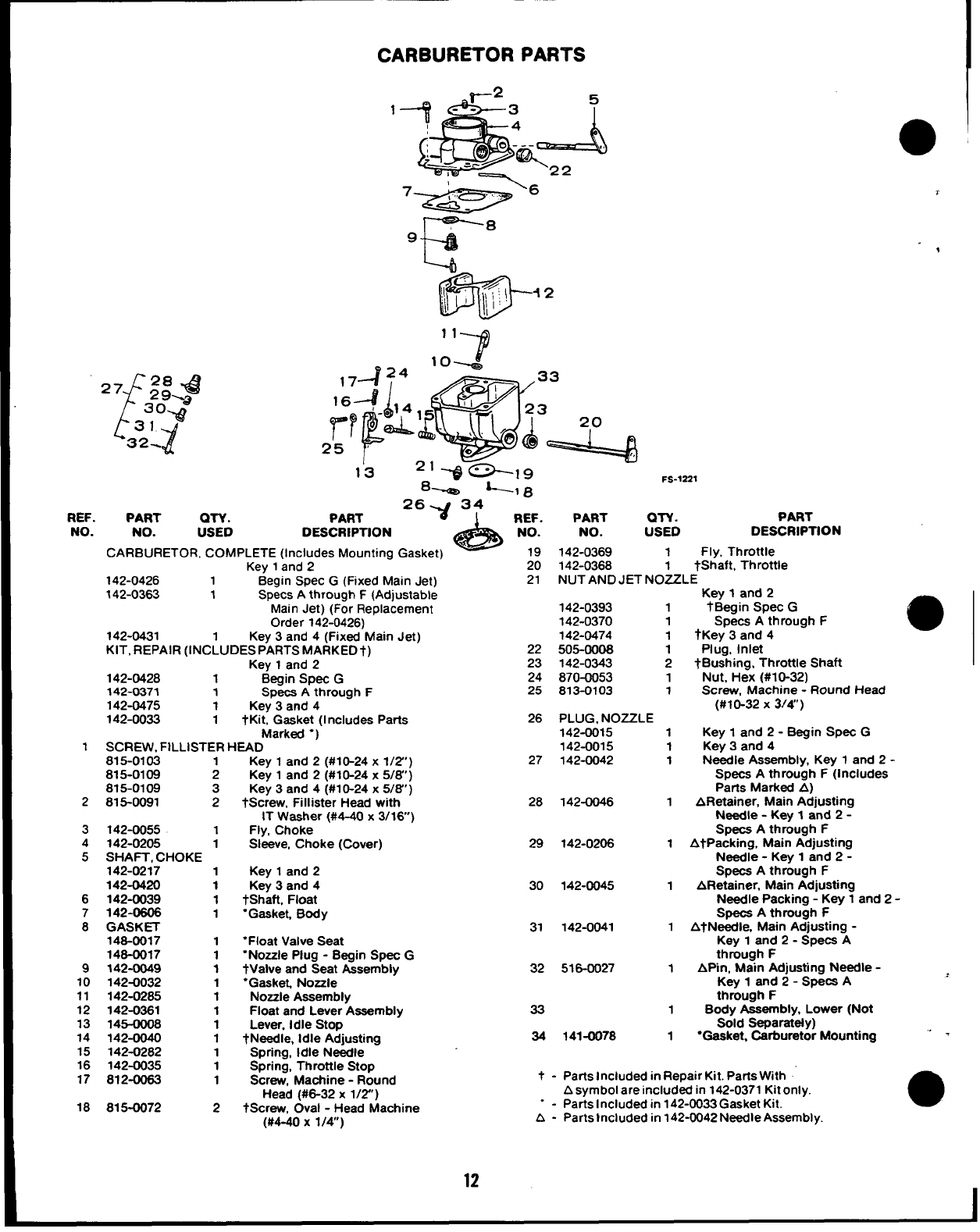
CARBURETOR PARTS
“72
‘f
27 28 .& ,7424 ‘omg
29%,,
3o.@ 1
16+- ,4
31
Y
32-
P
~r ~
25 8
13 FS-1221
‘-I 8
REF. PART QTY. PART
2t~34 REF.
A
PART QTY. PART
NO. NO. USED DESCRIPTION NO. NO. USED DESCRIPTION
CARBURETOR, COMPLETE (Includes Mounting Gasket) 19 142-0369 1Fly, Throttle
Key 1and 220 142-0368 1
142-0426 1Begin SPec G(Fixed Main Jet)
tShaft, Throttle
21 NUT AND JET NOZZLE
142-0363 1Specs Athrough F(Adjustable Key 1and 2
Main Jet) (For Replacement 142-0393 1tBegin Spec G
Order 142-0426) 142-0370 1Specs Athrough F
142-0431 Key 3and 4(Fixed Main Jet) 142-0474 1tKey 3and 4
KIT, REPAIR (lNC~UDESPARTSMARKED+) 22 505-0006 1Plug, Inlet
Key 1and 223 142-0343 2tBushing, Throttle Shaft
142-0428 1Begin Spec G24 870-0053 1Nut, Hex (#10-32)
142-0371 1Specs Athrough F25 813-0103 1Screw, Machine -Round Head
142-0475 1Key 3and 4(#10-32 X3/4”)
142-0033 1tKit, Gasket (1ncludes Parts 26 PLUG, NOZZLE
Marktxf “) 142-0015 1Key 1and 2- Begin Spec G
1SCREW. FtLLISTER HEAD 142-0015 1Key 3and 4
815-0103 1
815-0109 2
815-0109 3
2815-0091 2
3142-0055 1
4142-0205 1
5SHAFT, CHOKE
142-0217 1
142-0420 1
6142-0039 1
7142-0606 1
8GASKET
146-0017 1
146-0017 1
9142-0049 1
10 142-0032 1
11 142-0265 1
12 142-0361 1
13 145-oo06 1
14 142-0040 1
15 142-0282 1
16 142-0035 1
17 812-0063 1
18 815-0072 2
Key 1and 2(#10-24x 1/2”)
Key 1and 2(#10-24x 5/6”)
Key 3and 4(#1 O-24x 5/6”)
tscrew, Fillister Head with
IT Washer (#4-40 x3/16)
Fly, Choke
Sleeve, Choke (Cover)
Key 1and 2
Key 3and 4
&haft, Float
“Gasket, Body
“Float Valve Seat
“Nozzle Plug -Begin Spec G
tValve and Seat Aasemblv
27 142-0042 1N&die Assembly, Key 1and 2-
Specs Athrough F(Includes
Parts Marked A)
28 142-0046 1ARetainer, Main Adjusting
Needle -Key 1and 2-
Specs Athrough F
29 142-0206 1AtPacking, Main Adjusting
Needle -Key 1and 2-
Spaca Athrough F
30 142-0045 1ARetainer, Main Adjusting
Needle Packing -Key 1and 2-
Specs Athrough F
31 142-0041 1AtNeedle, Main Adjusting -
Key 1and 2- Specs A
through F
32 516-0027 1Af%n, Main Adjusting Needle -
“Gasket, Nozzle -
Nozzle Aaaembfy
Float and Lever Assembly 33
Lever, Idle Stop
tNeedle, Idle Adjusting 34
Spring, Idle Needle
Spring, Throttle Stop
Screw, Machine -Round t-
Head (#6-32 x1/2’)
tScrew, Oval -Head Machine --
(#4-40 x1/4) A-
9
Key 1and 2- Sp&a A
through F
1Body Assembly, Lower (Not
Sold Separately)
141-0078 1“Gasket, Carburetor Mounting ‘ -
Parts Included in Repair Kit. Parts With
Asymbol are included in 142-0371 Kit only.
Parts Included in 142-0033 Gasket Kit. ●
Parts included in 142-0042 Needle Assembly.
12
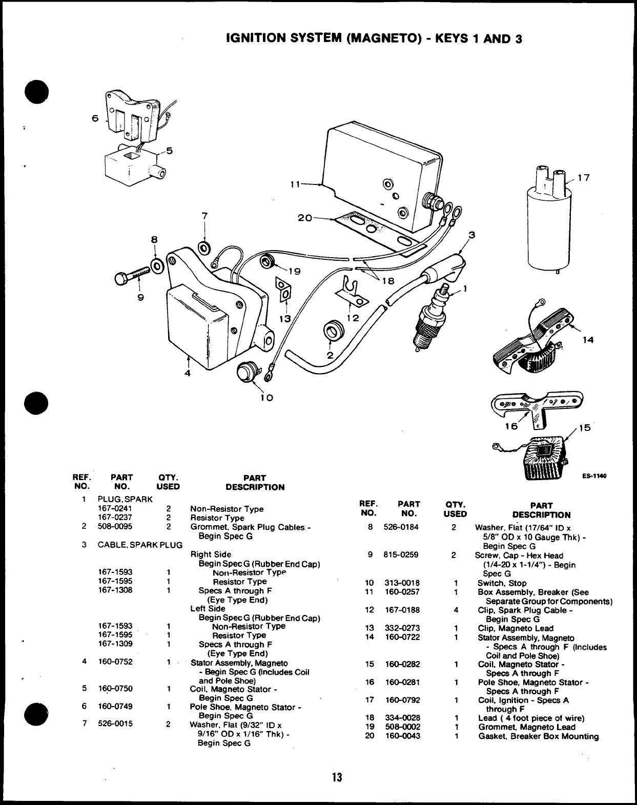
IGNITION SYSTEM (MAGNETO) -KEYS 1AND 3
6
17
14
1140
io
REF.
NO.
1
PART OTY.
NO. USED
PLUG, SPARK
167-0241 2
167-0237 2
508-0095 2
PART
DESCRIPTION
REF.
NO.
8
PART
NO.
526-0184
OTY.
USED
PART
DESCRIPTION
Non-Resistor Type
Resistor Type
Grommet, Spark Plug Cables -
Begin Spec G
2
3
2
2
1
1
4
1
1
1
1
1
1
1
1
Washer, Flat (17/64” ID x
5/8 OD x10 Gauge Thk) -
Begin SpeC G
Screw, Cap -Hex Head
(1/4-20 x1-1/4) -Begin
Spec G
Switch, Stop
Box Assembly, Breaker (See
Separate Group for Components)
Clip, Spark Plug Cable -
Begin Spec G
Clip, Magneto Lead
Stator Assembly, Magneto
-Specs Athrough F(Includes
Coil and Pole Shoe)
Coil, Magneto Stator -
Specs Athrough F
Pole Shoe, Magneto Stator -
Specs Athrough F
Coil, Ignition -Specs A
through F
Lead ( 4 foot piece of wire)
Grommet, Magneto Lead
Gasket, Breaker Box Mounting
CABLE, SPARK PLUG
Right Side
Begin Spec G(Rubber End Cap)
Non-Resistor Type
Resistor Type
Specs Athrough F
(Eye Type End)
Left Side
Begin Spec G(Rubber End Cap)
Non-Resistor Type
Resistor Type
Specs Athrough F
(Eye Type End)
Stator Assembly, Magneto
-Begin Spec G(Includes Coil
and Pole Shoe)
Coil, Magneto Stator -
Begin SpeC G
Pole Shoe, Magneto Stator -
Begin Spec G
Washer, Flat (9/32” ID x
9/16 OD X 1/16 Thk) -
Begin Spec G
9815-0259
167-1593 1
167-1595 1
167-1308 1
10
11
313-0018
160-0257
12 167-0188
167-1593 1
167-1595 1
167-1309 1
13
14
332-0273
160-0722
.
160-0752 1
4
5
15 160-0282
16
17
160-0281
16.0-0750 1
160-0749 1
526-0015 2
160-0792
e6
718
19
20
334-0028
508-0002
160-0043
13
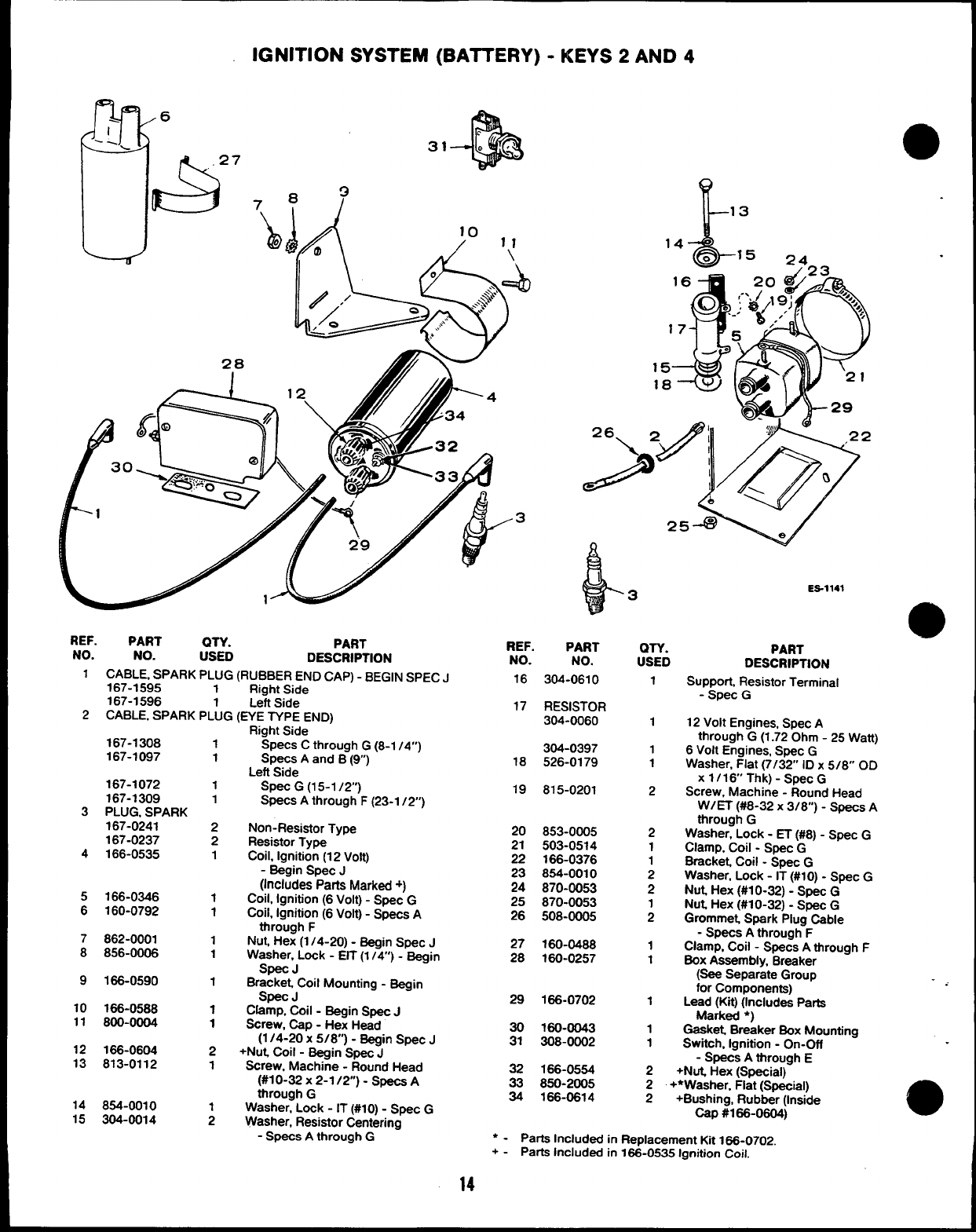
IGNITION SYSTEM (BATTERY) -KEYS 2AND 4
31
8?
&i!i
(i
/10 ,,
Q) /,
o
.\ ==$)
?2> /
‘
“F
&,.
REF. PART QTY.
NO.
PART
NO. USED DESCRIPTION
1CABLE, SPARK PLUG (RUBBER END CAP) -BEGIN SPEC J
167-1595 1Right Side
167-1596 1Left Side
2CABLE, SPARK PLUG (EYE TYPE END)
167-1308 1
167-1097 1
167-1072 1
167-1309 1
3PLUG, SPARK
167-0241 2
167-0237 2
4166-0535 1
5166-0346 1
6160-0792 1
7862-0001 1
8856-0006 1
9166-0590 1
10 166-0588 1
11 800-0004 1
12 166-0604 2
13 813-0112 1
14 854-0010
15 304-0014 ;
Right Side ‘
Spats C through G(8-1 /4”)
Spats A and B(9)
Left Side
Spat G(15-1 /2”)
Specs Athrough F(23-1 /2)
Non-Resistor Type
Resistor Type
Coil, Ignition (12 Volt)
-Begin Spec J
(Includes Parts Marked +)
Coil, Ignition (6 Volt) -Spat G
Coil, Ignition (6 Volt) - Spats A
through F
Nut, Hex (1/4-20) -Begin Spec J
Washer, Lock -EIT (1 /4) -Begin
Spec J
Bracket, Coil Mounting -Bagin
Spec J
Clamp, Coil -Begin Spec J
Screw, Cap -Hex Head
(1/4-20 x5/8”) -Begin Spat J
+Nut, Coil -Begin Spec J
Screw, Machine -Round Head
(#10-32 X2-1 /2) -Specs A
through G
Washer, Lock -IT (#10) -Spec G
Washer, Resistor Centering
-Specs Athrough G
.3
REF,
NO.
16
17
IL
13
&
i3
PART
NO.
304-0610
RESISTOR
304-0060
304-0397
18 526-0179
19 815-0201
20 853-0005
21 503-0514
22 166-0376
23 854-0010
24 870-0063
25 870-0053
26 508-0005
27 160-0488
28 160-0257
29 166-0702
30 160-0043
31 308-0002
32 166-0554
33 850-2005
34 166-0614
QTY.
USED
1
1
1
1
2
2
1
1
2
2
1
2
1
1
1
1
1
ES-1141
PART
DESCRIPTION
Support, Resistor Terminal
-Spec G
12 Volt Engines, Spec A
through G(1.72 Ohm -25 Watt)
6Volt Engines, Spec G
Washer, Flat (7/32” ID x5/8” OD
xl/16 Thk)-Spec G
Screw, Machine -Round Head
W/ET (#8-32 X3/8”) -specs A
through G
Washer, Lock -ET (#8) -Spec G
Clamp, Coil -Spec G
Bracket, Coil -Spec G
Washer, Lock -IT (#10) -Spec G
Nut Hex (#10-32) -Spec G
Nut, Hex (#10-32) -Spec G
Grommet, Spark Plug Cable
-Specs Athrough F
Clamp, Coil -Specs Athrough F
BOX Assembly, Breaker
(sea Separate Group
for Components)
Lead (Kit) (Includes Parts
Marked ●)
Gaal@ Breaker Box Mounting
Switch, Ignition -On-Off
- Spats A through E
2+Nut, Hex (Special)
2+*Washer, Flat (Special)
2+Bushing, Rubbar (Inside
cap #166-0604j
‘ - Parts Included in Replacement Kit 166-0702.
+ - Parts Included in 1%-0535 Ignition Coil:
14
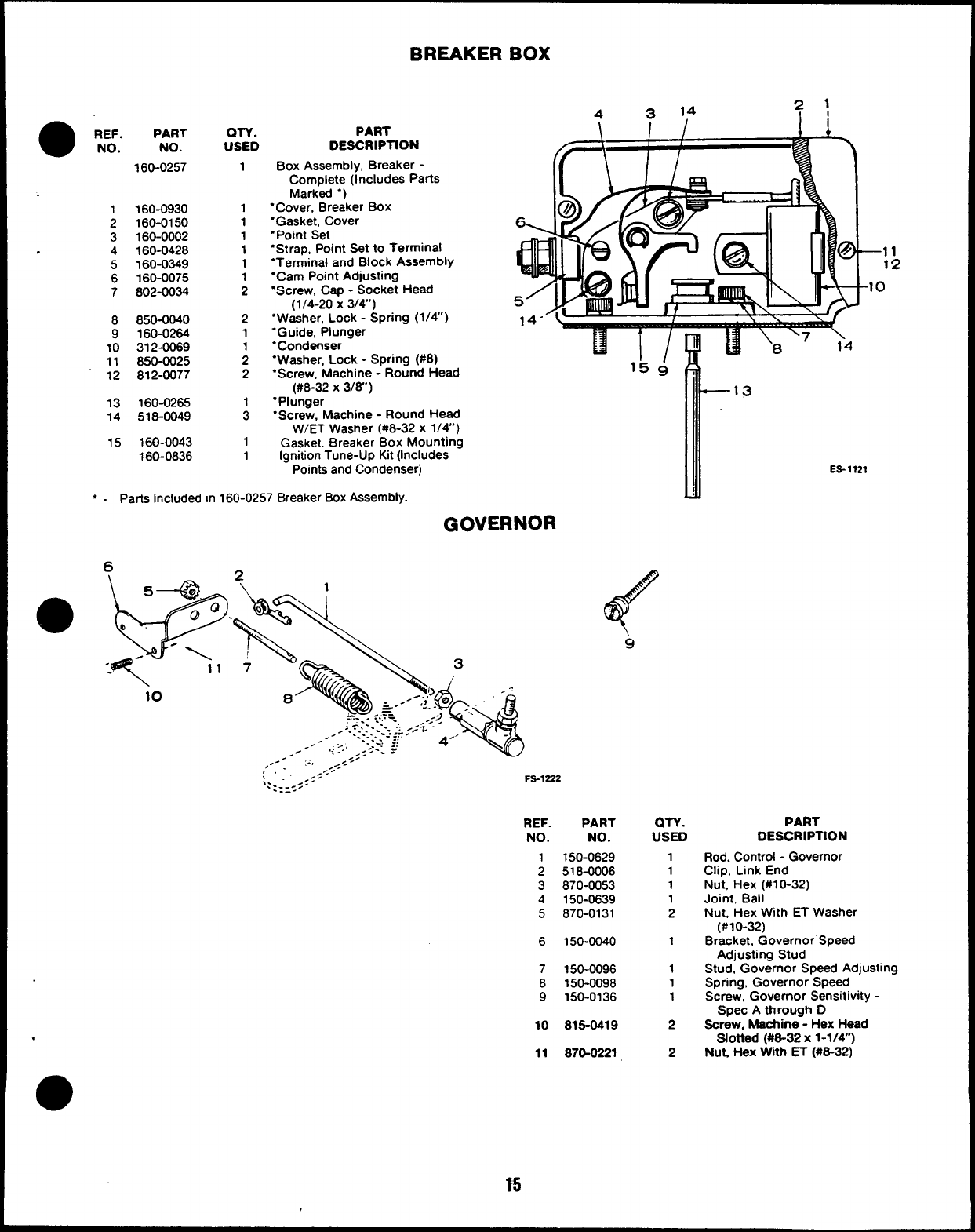
●REF.
NO.
1
2
3
.4
5
6
7
8
9
10
11
12
13
14
15
PART
NO.
160-0257
160-0930
160-0150
160-0002
160-0428
160-0349
160-0075
802-0034
850-0040
160-0264
312-0069
850-0025
812-0077
160-0265
518-0049
160-0043
160-0836
QTY.
USED
1
1
1
1
1
1
;
2
1
;
2
1
1
PART
DESCRIPTION
Box Assembly, Breaker -
Complete (Includes Parts
Marked “)
“Cover, Breaker BOX
“Gasket, Cover
“Point Set
“St rap, Point Set to Terminal
“Terminal and Block Assembly
“Cam Point Adjusting
“Screw, Cap -Socket Head
(1/4-20 X3/4)
“Washer, Lock -Spring (1/4)
“Guide, Plunger
“Condenser
“Washer, Lock -Spring (#8)
“Screw, Machine -Round Head
(#8-32 X 3/8)
“Plunger
“Screw, Machine -Round Head
W/ET Washer (#8-32 x1/4)
Gasket. Breaker Box Mounting
Ignition Tune-Up Kit (Includes
4314
–11
12
0
15 &
Points and Condenser)
●-Parts included in 160-0257 Breaker Box Assembly.
GOVERNOR
9
,---
:’..-::.
\.
.: :=5.
FS-1222
REF.
NO.
1
2
3
4
5
6
7
8
9
10
.
11
PART
NO.
150-0629
518-0006
870-0053
150-0639
870-0131
150-0040
150-0096
150-0098
150-0136
816-0419
87G0221
(MY.
USED
1
1
1
1
2
1
1
1
1
2
2
—13
ES-1121
PART
DESCRIPTION
Rod, Control -Governor
Clip, Link End
Nut, Hex (#10-32)
Joint, Ball
Nut, Hex With ET Washer
(#10-32)
Bracket, Governor”Speed
Adjusting Stud
Stud, Governor Speed Adjusting
Spring, Governor Speed
Screw, Governor Sensitivity -
Spec Athrough D
Screw, Machine -Hex Head
Slotted (#8-32 x1-1/4”)
Nut, t+eX With ET (#6-32)
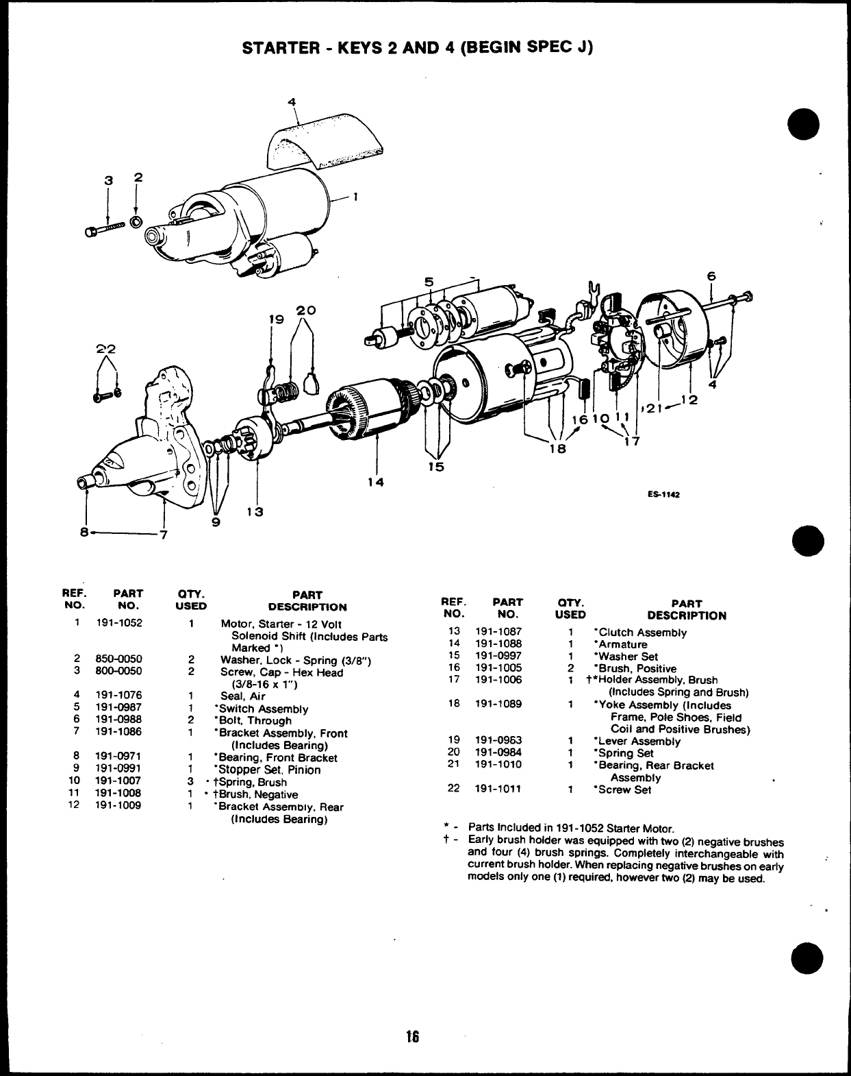
STARTER -KEYS 2AND 4(BEGIN SPEC J)
4
D..
.,,..:,
.~:
,.. ,,, ...
., ~,,
”.. .r ----
8— 7
REF. PART an. PART
NO. NO. USED DESCRIPTION
1191-1052 1Motor, Starter -12 Volt
2850-0050
3800-0050
4191-1076
5191-0987
6191-0988
7191-1086
8191-0971
9191-0991
10 191-1007
11 191-1008
12 191-1009
I15
14
REF. PART
NO. NO.
Solenoid Shift (Includes Parts 13
. .
Marked “)
2Washer, Lock -Spring (3/8)
2Screw, Cap -Hex Head
(3/8-16 Xl“)
1Seal, Air
1“Switch Assembly
2“Bolt, Through
1“Bracket Assembly, Front
(Includes Bearing)
1●Bearing, Front Bracket
1“Stopper Set, Pinion
3“tSPring, Brush
1“tBrush, Negative
1“Bracket Assemrx y, Rear
(Includes Bearing)
18
19
20
21
22
191-1087
191-1088
191-0997
191-1005
191-1006
191-1089
191-0963
191-0984
191-1010
191-1011
18 . .
ES%~42
OTY. PART
USED DESCRIPTION
1“Clutch Assembly
1“Armature
1“Washer Set
2‘Brush, Positive
1 t ●Holder Assembly, Brush
(Includes Spring and Brush)
1“Yoke Assembly (Includes
Frame, Pole Shoes, Field
coil and Positive Brushes)
1“Lever Assembly
1“Spring Set
1“Bearing, Rear Bracket
Assembly
1“Screw Set
Parta Included in 191-1052 Statier Motor.
Early brush holder was equipped with two (2) negative brushes
and four (4) brush springs. Completely interchangeable with
current brush holder. When replacing negative brushes on early -
models only one (1) required, however two (2) may be used.
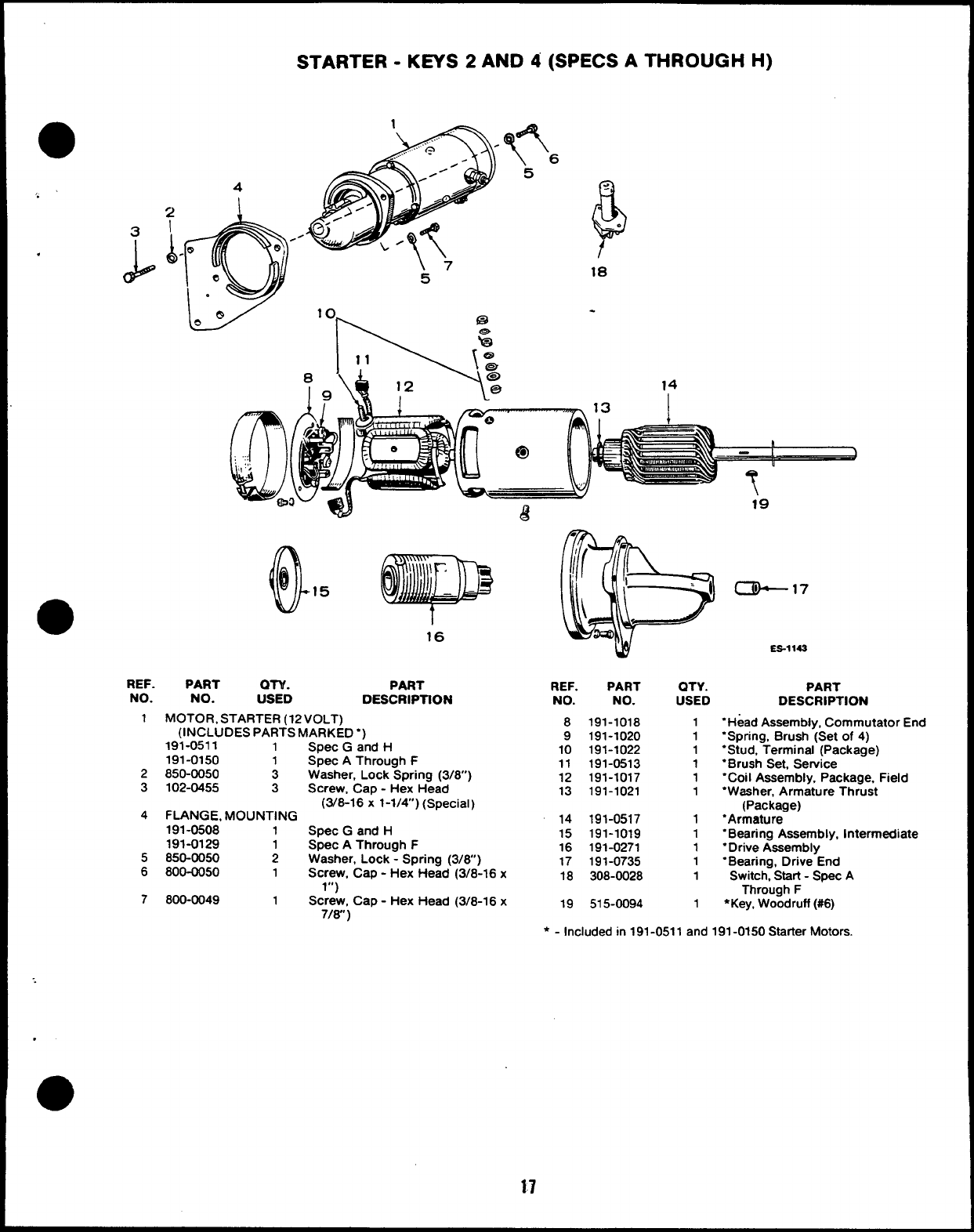
STARTER -KEYS 2AND 4(SPECS ATHROUGH H)
F
<
—.
18
14
!
.
REF. PART OTY. PART
NO. NO. USED DESCRIPTION
1MOTOR, STARTER (12 VOLT)
(INCLUDES PARTS MARKED “)
191-0511 1
191-0150
2850-0050 ;
3102-0455 3
4FLANGE, MOUNTING
191-0508 1
191-0129 1
5850-0050 2
6800-0050 1
7800-0049 1
Spec Gand H
Spec AThrough F
Washer, Lock Spring (3/8”)
Screw, Cap -Hex Head
(3/8-16 x1-1/4) (Special)
Spec Gand H
Spec AThrough F
Washer, Lock -Spring (3/6” )
Screw, Cap -Hex Head (3/8-16 x
1“)
Screw, Cap -Hex Head (3/8-16 x
7/w )
czk-17
ES-1 143
REF. PART QTY. PART
NO. NO. USED DESCRIPTION
8
9
10
11
12
13
14
15
16
17
18
19
191-1018
191-1020
191-1022
191-0513
191-1017
191-1021
191-0517
191-1019
191-0271
191-0735
308-0028
515-0094
1
1
1
1
1
1
1
1
1
1
1
1
“Head Assembly, Commutator End
‘Spring, Brush (Set of 4)
“Stud, Terminal (Package)
“Brush Set, Service
“Coil Assembly, Package, Field
“Washer, Armature Thrust
(Package)
“Armature
“Bearing Assembly, Intermediate
“Drive Assembly
“Bearing, Drive End
Switch, Start -Spec A
Through F
●Key, Woodruff (#6)
* - Included in 191-0511 and 191-0150 Starter Motors.
17
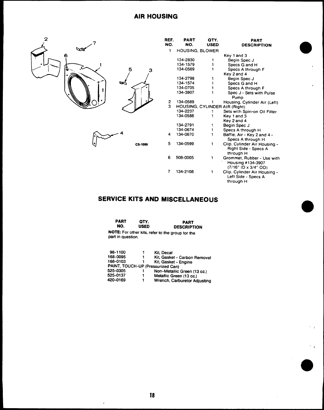
AIR HOUSING
2
6
““ 1’
%3/7
6
53
REF. PART QTY.
NO. NO. USED
1HOUSING, BLOWER
134-2830 1
134-1579 1
134-0569 1
Q$
J.
--
.134-2798 1
134-1574 1
134-0705 1
134-3907 1
PART
DESCRIPTION
Key 1and 3
Begin Spec J
Specs Gand H
Specs Athrough F
Key 2and 4
Begin Spec J
Specs Gand H
Specs Athrough F
Spec J - Sets with Pulse
Pump
2134-0589 1Housing, Cylinder Air (Left)
3HOUSING, CYLINDER AIR (Right)
134-2237
134-0588
1Sets wi;h Spin-on Oil Filter
1Key 1and 3
Key 2and 4
134-2791 1Begin Spec J
134-0674 1Specs Athrough H
4134-0670 1Baffle, Air -Key 2and 4-
Specs Athrough H
Ca-lass 5134-0599 1Clip, Cylinder Air Housing -
Right Side -Specs A
through H
6508-0005 1Grommet, Rubber -Use with
Housing #134-3907
(7/16” ID X3/4” OD)
7134-2108 1Clip, Cylinder Air Housing -
Left Side -Specs A
through H
SERVICE KITS AND MISCELLANEOUS
PART
NO.
PART
:SYD DESCRIPTION
NOTE For other kita, refer to the group for the
part in question.
98-1100 1Kit, Decal
168-0095 1Kit, Gasket -Carbon Removal
168-0103 1Kit, Gasket -Engine
PAINT, TOUCH-UP (Pressurized Can)
525-0305 1Non-Metallic Green (13 oz.)
525-0137 1Metallic Green (13 oz.)
420-0169 1Wrench, Carburetor Adjusting
This section contains illustrated parts listing of factory installed options for these Industrial
Engines. Options may not be applicable to all models; for field conversions additional parts are
usually required. Some parts listed in the standard engine parts section for parts keys 3and 4
are also applicable as optional parts for parts keys 1and 2. Optional parts listed in this section
are in addition or in place of those shown in the standard engine parts section.
e
OPTIONAL EQUIPMENT PARTS SECTION
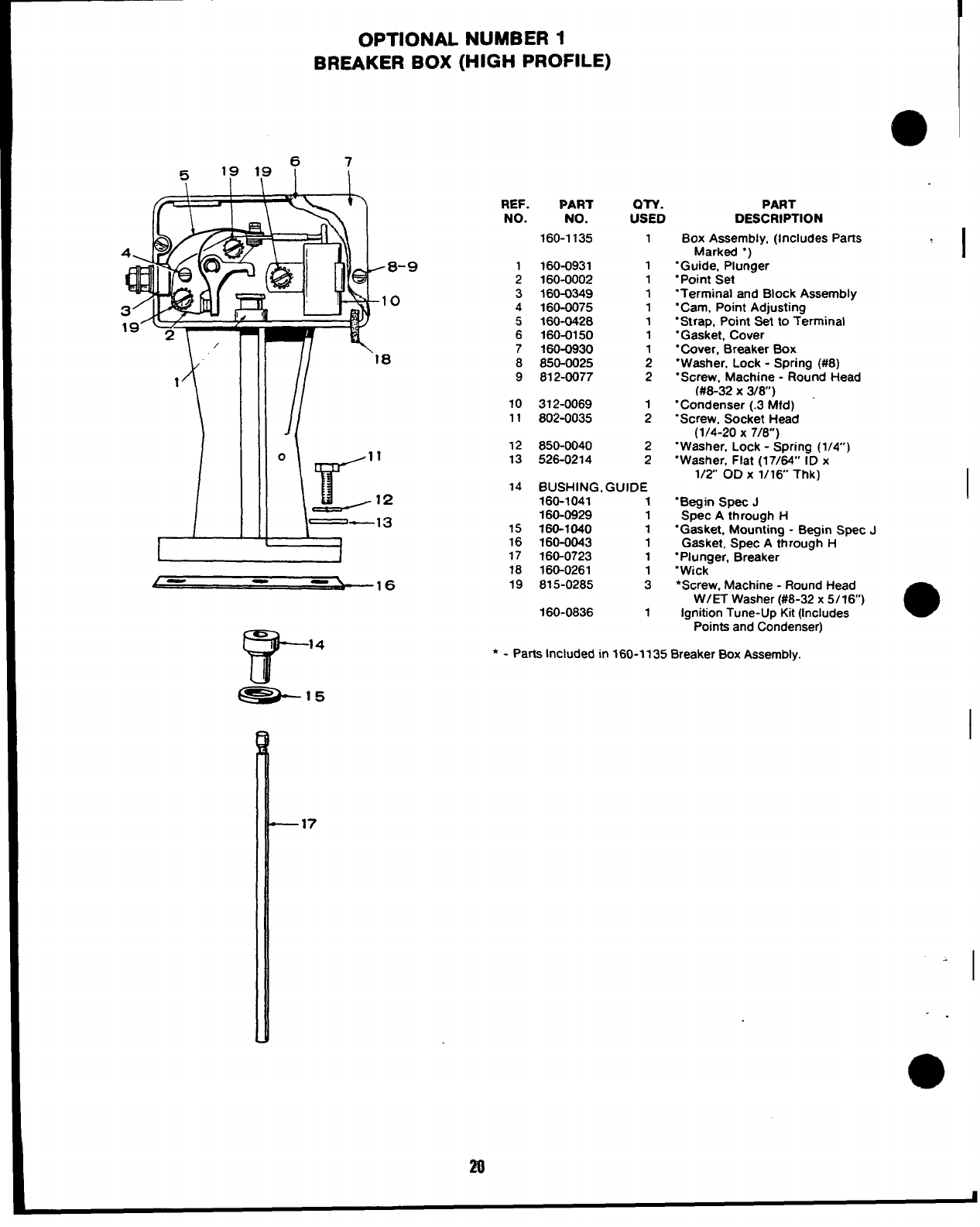
OPTIONAL NUMBER 1
BREAKER BOX (HIGH PROFILE)
REF.
NO.
;
3
4
5
6
7
8
9
10
11
12
13
Mm
NO.
160-1135
160-0931
160-0002
160-0349
160-0075
160-0428
160-0150
160-0930
850-0025
812-0077
312-0069
802-0035
850-0040
526-0214
OTY.
USED
1
1
1
1
1
1
1
1
2
2
1
2
2
2
14 BUSHING, GUIDE
160-1041 1
160-0929 1
15 160-1040 1
16 160-0043 1
17 160-0723 1
18 160-0261 1
19 815-0285 3
160-0836 1
PART
DESCRIPTION
Box Assembly, (Includes Parts
Marked “)
‘Guide, Plunger
“Point Set
‘Terminal and Block Assembly
“Cam, Point Adjusting
“Strap, Point Set to Terminal
“Gasket, Cover
“Cover, Breaker Box
“Washer, Lock -Spring (#8)
“Screw, Machine -Round Head
(#8-32 X3/6”)
“Condenser (.3 Mfd)
“Screw, Socket Head
(1/4-20 X7/8)
“Washer, Lock -Spring (1/4)
‘Washer, Flat (17/64” ID x
1/2 OD X 1/16 Thk)
“Begin Spec J
Spec Athrough H
“Gasket, Mounting -Begin Spec J
Gasket, Spec Athrough H
“Plunger, Breaker
“Wick
*Screw, Machine -Round Head
W/ET Washer (#8-32 x5/16)
Ignition Tune-Up Kit (Includes a
Points and Condenser)
* - Parts Included in 160-1135 Breaker Box Assembly.
I
I
I
—17
I
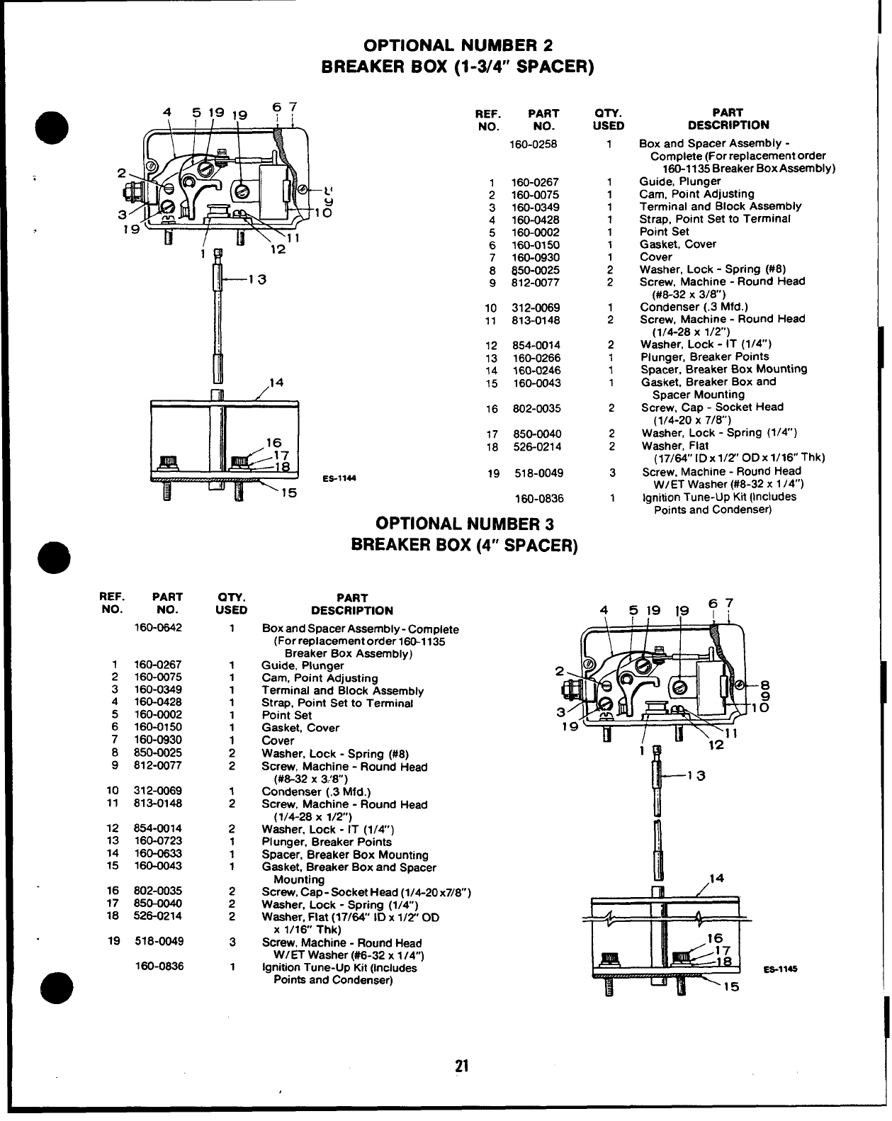
OPTIONAL NUMBER 2
BREAKER BOX (1-3/4’ SPACER)
m/“
REF. PART
NO. NO.
160-0258
1160-0267
2160-0075
3160-0349
4160-0428
5
6
7
8
9
10
11
12
13
14
15
160-0002
160-0150
160-0930
850-0025
812-0077
312-0069
813-0148
854-0014
160-0266
360-0246
160-0043
I Ill /’
1II 116 802-0035
REF. PART
NO. NO.
160-0642
1
2
3
4
5
6
7
8
9
160-0267
160-0075
160-0349
160-0428
160-0002
160-0150
160-0930
850-0025
812-0077
10 3124069
11 813-0148
12 854-0014
13 160-0723
14 160-0633
15 160-0043
16 802-0035
17 850-0040
18 526-0214
19 518-0049
160-0836
m
QTY.
USED
1
1
1
1
1
1
1
1
2
2
;
2
1
1
1
2
2
2
3
1
17 850-0040
18 526-0214
ES-1144 19 518-0049
160-0836
OPTIONAL NUMBER 3
BREAKER BOX (4” SPACER)
PART
DESCRIPTION
Box and Spacer Assembly -Complete
(For replacement order 160-1135
Breaker Box Assembly)
Guide, Plunger
Cam, Point Adjusting
Terminal and Block Assembly
Strap, Point Set to Terminal
Point Set
Gasket, Cover
Cover
Washer, Lock -Stxina f#8)
Screw, Machine -“Ro;nd Head
(#8-32 X3!8”)
Condenser (.3 Mfd.)
Screw, Machine -Round Head
(1/4-28 X1/2”)
Washer, Lock -IT (1/4”)
PI unger, Breaker Points
Spacer, Breaker Box Mounting
Gasket, Breaker Box and Spacer
Mounting
Screw, Cap- Socket Head (1/4-20x7/8)
Washer, Lock -Spring (1/4)
Washer, Flat (17/64” ID x1/2” OD
X1/16 Thk)
Screw, Machine -Round Head
W/ET Washer (#6-32 x1/4”)
Ignition Tune-Up Kit (includes
Points and Condenser)
QTY.
USED
1
1
1
1
1
1
1
;
2
1
2
2
1
1
1
2
2
2
3
1
PART
DESCRIPTION
Box and Spacer Assembly -
Complete (For replacement order
160-1135 Breaker Box Assembly)
Guide, Plunger
Cam, Point Adjusting
Terminal and Block Assembly
Strap, Point Set to Terminal
Point Set
Gasket, Cover
Cover
Washer, Lock -Spring (#8)
Screw, Machine -Round Head
(#8-32 X3/8)
Condenser (.3 Mfd.)
Screw, Machine -Round Head
(1/4-28 X 1/2”)
Washer, Lock -IT (1/4)
Plunger, Breaker Points
Spacer, Breaker Box Mounting
Gasket, Breaker Box and
Spacer Mounting
Screw, Cap -Socket Head
(1/4-20 X7/8)
Washer, Lock -Spring (1/4”)
Washer, Flat
(17/64’’ lDxl/2’’ ODx16Thk)k)
Screw, Machine -Round Head
W/ET Washer (#8-32 x 1 /4”)
lanition Tune-Up Kit (Includes
-Points and Condenser)
451919 ?7
l--
13
l.!
ES-114S
21
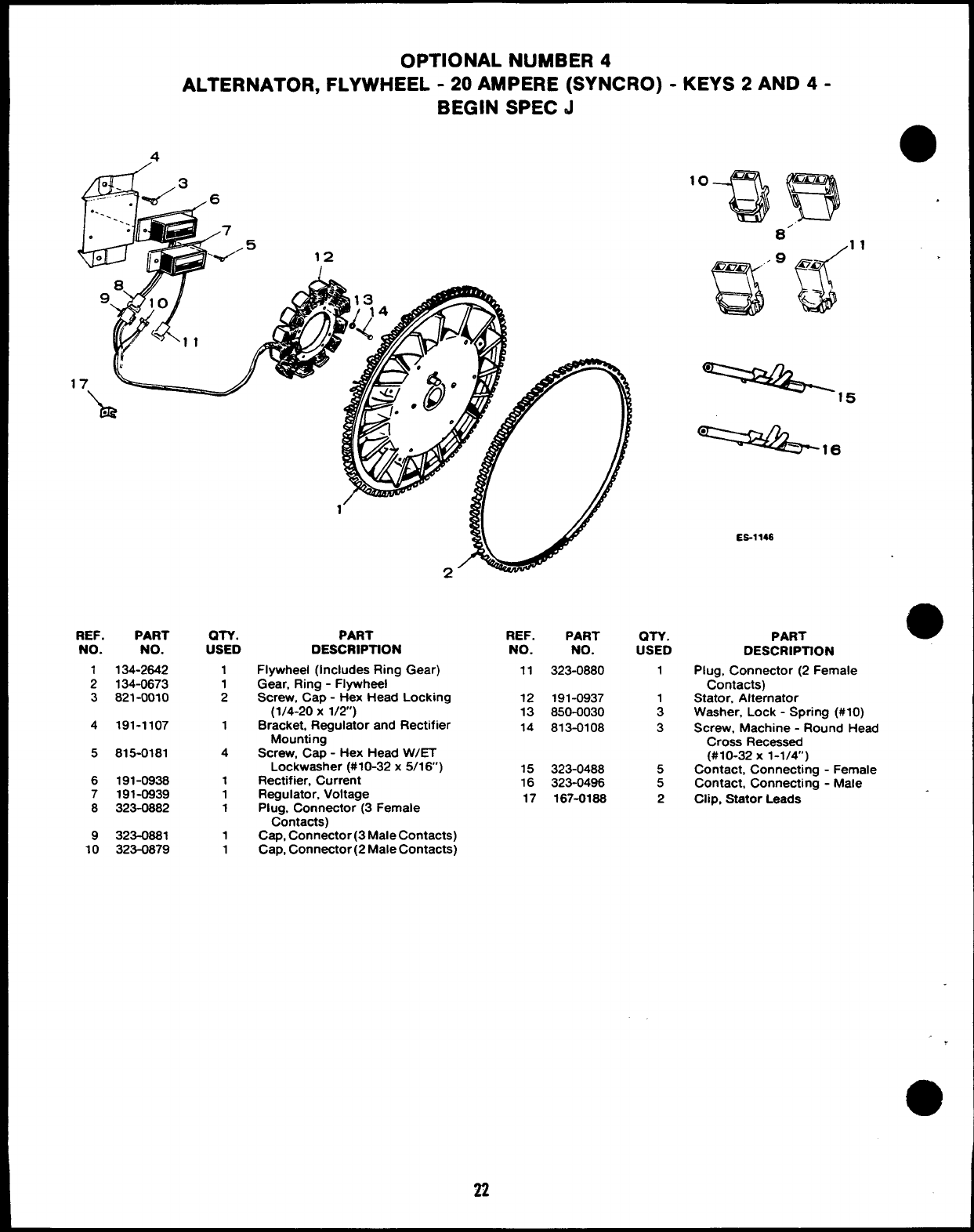
OPTIONAL NUMBER 4
ALTERNATOR, FLYWHEEL -20 AMPERE (SYNCRO) -KEYS 2AND 4-
BEGIN SPEC d
4
clii
---::. %/3 6
. . ----
:.
.7
..5
00‘%-’ 12
/
‘o%)B
8’
9
auf
Onm ‘no
&.-
-=2+5
==&-
REF. PART
NO. NO.
1134-2642
2134-0673
3821-0010
4191-1107
5815-0181
6191-0936
7191-0939
8323-0882
9323-0881
10 323-0879
QTY.
USED
1
1
2
1
4
1
1
1
1
1
PART
DESCRIPTION
Flywheel (Includes Ring Gear)
Gear, Ring -Flywheel
Screw, Cap -Hex Head Locking
(1/4-20 X1/2)
Bracket, Regulator and Rectifier
Mounting
Screw, Cap -Hex Head WET
Lockwaaher (#10-32x 5/16’)
Rectifier, Current
Regulator, Voltage
Plug, Connector (3 Female
Contacts)
Cap, Connector (3 Male Contacts)
Cap, Connector (2 Male Contacts)
22
REF.
NO.
11
12
13
14
15
16
17
PART
NO.
323-0880
191-0937
850-0030
813-0108
323-0488
323-0496
167-0186
on.
USED
1
A
3
5
5
2
ES-114S
PART
6
1
●✎
0
DESCRIPllON
Plug, Connector (2 Female
Contacts)
Stator, Alternator
Washer, Lock -Spring (#10)
Screw, Machine -Round Head
Cross Recessed
(#10-32 X 1-1/4”)
Contact, Connecting -Female
Contact, Connecting -Male
Clip, Stator Leads
o
,
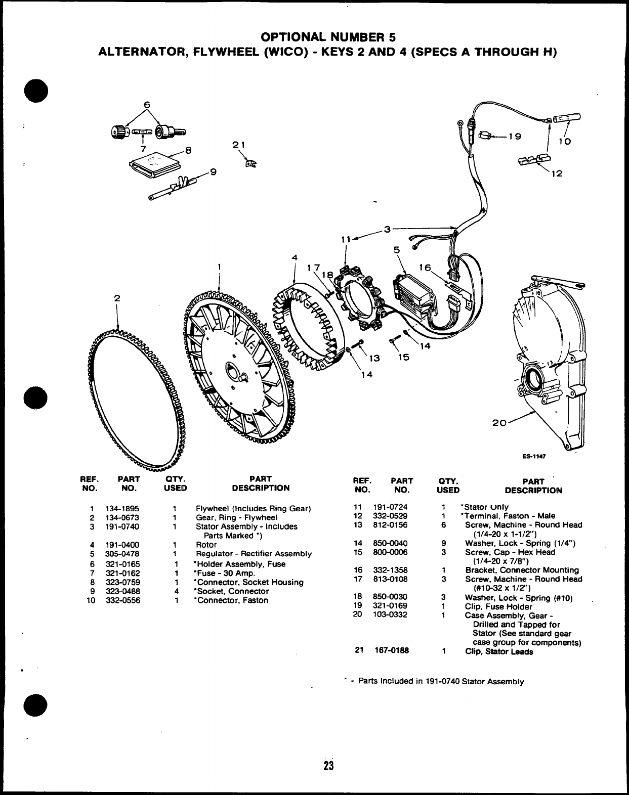
OPTIONAL NUMBER 5
ALTERNATOR, FLYWHEEL (WICO) -KEYS 2AND 4(SPECS ATHROUGH H)
1
I
.
2
REF. PART OTY.
NO. NO. USEID
1134-1895 1
2134-0673 1
3191-0740 1
4191-0400 1
5305-0478 1
6321-0165 1
7321-0162 1
8323-0759 1
9323-0468 4
10 332-0556 1
PART
DESCRIPTION
Flywheel (Includes Ring Gear)
Gear, Ring -Flywheel
Stator Assembly -Includes
Parts Marked “)
Rotor
Regulator -Rectifier Assembly
“Holder Assembly, Fuse
“Fuse -30 Amp.
“Connector, Socket Housing
“Socket, Connector
“Connector. Faston
REF. PART
NO. NO.
11 191-0724
12 332-0529
13 812-0156
14 850-0040
15 8oo-ooo6
16 332-1358
17 813-0108
18 850-0030
19 321-0169
20 103-0332
21 167-0188
20
‘
N)
-t
ES-1147
QN. PART “
USED DESCRIPTION
1‘Stator Unly
1“Terminal, Faston -Male
6Screw, Machine -Round Head
(1/4-20 X 1-1/2’)
9Washer, Lock -Spring (1/4”)
3Screw, Cap -Hex Head
(1/4-20 x7/8)
1Bracket, Connactor Mounting
3Screw, Machine -Round Head
(#10-32 X 1/2”)
3Washer, Lock -Spring (#10)
1Clip, Fuse Holder
1Case Assembly, Gear -
Drilled and Tapped for
Stator (See standard gear
case group for components)
1Clip, Stator Leads
.
“ - patis Included in 191-0740 Stator Assembly,
23
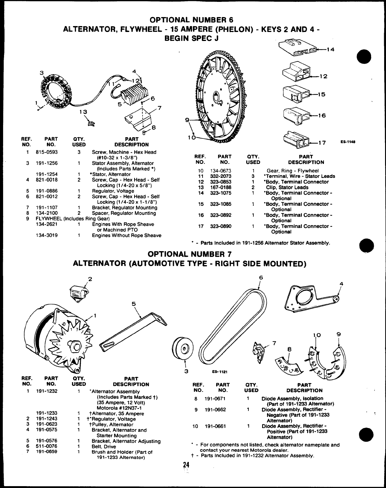
OPTIONAL NUMBER 6
ALTERNATOR, FLYWHEEL -15 AMPERE (PHELON) -KEYS 2AND 4-
BEGIN SPEC J
k=--” a
ES-114S
1
7
‘h
.
=
- ..
<-...
\17
REF. PART QTV. PART
NO. NO. USED DESCRIPTION
1
3
815-0593 3Screw, Machine -Hex Head
(#10-32 X 1-3/8”)
191-1256 1Stator Assembly, Alternator
(Includes Parts Marked ●)
191-1254 ●Stator, Alternator
821-0018 ;Screw, Cap -Hex Head -Self
Locking (1 /4-20x 5/8’)
191-0886 Regulator, Voltage
821-0012 1Screw, Cap -Hex Head -Self
Locking (1 /4-20x 1-1 /8”)
191-1107 1Bracket, Regulator Mounting
134-2100 2Spacer, Regulator Mounting
FLYWHEEL (Includes Ring Gear)
134-2621 1Engines Wtth Rope Sheave
or Machined PTO
REF. PART
NO. NO.
QTY. PART
USED DESCRIPTION
Gear, Ring -Flywheel
“Terminal, Wire -Stator Leads
●Body, Terminal Connector
Clip, StatorLeads
“Body, Terminal Connector -
Optional
“Body, Terminal Connector -
Optional
●Body, Terminal Connector -
Optional
●Body, Terminal Connector -
Optional
10 134-0673
11 332-2073
12 323-0853
13 167-0188
14 323-1075
4
5
6
15 323-1065 1
7
8
916 323-0892 1
17 323-0890 1
134-3019 1Engines Without Rope Sheave
●-Parts Included in
OPTIONAL NUMBER 7
ALTERNATOR (AUTOMOTIVE TYPE -RIGHT
191-1256 Alternator Stator Assembly.
SIDE MOUNTED)
6
w
4
ES- llZl
REF. PART QTV.
NO. NO. USED
PART
DESCRIPTION REF. PART QTY. PART
NO. NO. USED DESCRWTION
8191-0671 1DMe Assembly, Isolation
(Part of 191-1233 Alternator)
9191-0662 1Dkxie Assembly, Rectiier -
Neoative (Pati of 191-1233
.,
a
1191-1232 1“Alternator Assembly
(Includes Parts Marked t)
(35 Ampere, 12 Volt)
Motorola #12 N37-1
191-1233 1tAlternator, 35 Ampere
2191-1243 1t“Regulator, Voltage
3191-0623 1_/Pulley, Alternator
4191-0575 1Bracket, Alternator and
Starter Mountina
Alt&nator)
10 191-0661 1Dkxfe Assembly, Rectifier -
Positive (part of 191-1233
Altamator)
5191-0576 1Bracket, Alternate; Adjusting
6511-0076 1Belt, Drive “ - For components not listed, check alternator nameplate and
7191-0659 1Brush and Holder (Part of contact your nearest Motorola dealer.
191-1233 Alternator) t - Parts Included in 191-1232 Alternator Assembly.
24
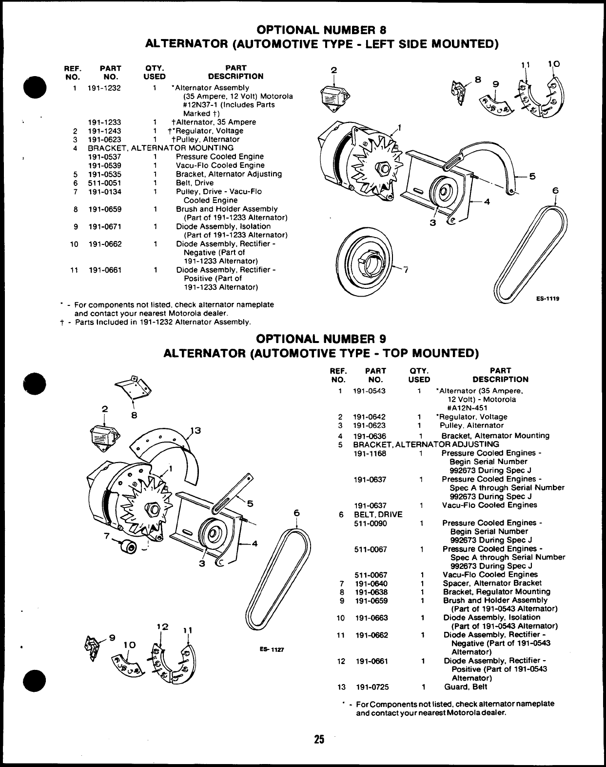
OPTIONAL NUMBER 8
ALTERNATOR (AUTOMOTIVE TYPE -LEFT SIDE MOUNTED)
REF. PART OTY. PART
NO. NO. USED DESCRIPTION
1191-1232 1‘Alternator Assembly
(35 Ampere, 12 Volt) Motorola
#12 N37-1 (Includes Parts
Marked t)
191-1233 1tAlternator, 35 Ampere
2191-1243 1t“Regulator, Voltage
3191-0623 1tPulley, Alternator
4BRACKET, ALTERNATOR MOUNTING
191-0537 1Pressure Cooled Engine
191-0539 1Vacu-Flo Cooled Engine
5191-0535 1Bracket, Alternator Adjusting
6511-0051 1Belt, Drive
7191-0134 1Pulley, Drive -Vacu-Flo
Cooled Engine
8191-0659 1Brush and Holder Assembly
(Part of 191-1233 Alternator)
9191-0671 1Diode Assembly, Isolation
(Part of 191-1233 Alternator)
10 191-0662 1Diode Assembly, Rectifier -
Negative (Parf of
191-1233 Alternator)
11 191-0661 1Diode Assembly, Rectifier -
Positive (Part of
191-1233 Alternator)
‘ - For components not listed, check alternator nameplate
and contact your nearest Motorola dealer.
t - Parts Included in 191-1232 Alternator Assembly.
OPTIONAL NUMBER 9
ALTERNATOR (AUTOMOTIVE TYPE -TOP MOUNTED)
REF. PART QTY. PART
?>
.NO. NO. USED
.DESCRIPTION
.
. . 1191-0543 1“Alternator (35 Ampere,
\
12 Volt) -Motorola
2#A12N-451
18 2191-0642 1‘Regulator, Voltage
3191-0623 1Pulley, Alternator
4191-0636 1Bracket, Alternator Mounting
5BRACKET, ALTERNATOR ADJUSTING
191-1168 1
191-0637
191-0637
6BELT, DRIVE
511-0090
511-0067
511-0067
7191-0640
8191-0638
9191-0659
10 191-0663
11 191-0662
ES- 11S7
12 191-0661
13 191-0725
1
1
1
1
1
1
1
1
1
1
1
1
Pressure Cooled Engines -
Begin Serial Number
992673 During Spec J
Pressure Cooled Engines -
Spec Athrough Serial Number
982673 During Spec J
Vacu-Flo Cooled Engines
Pressure Cooled Engines -
Begin Serial Number
992673 During Spec J
Pressure Cooled Engines -
Spec Athrough Serial Number
992673 During Spec J
Vacu-Flo Cooled Engines
Spacer, Alternator Bracket
Bracket, Regulator Mounting
Brush and Holder Assembly
(Part of 191-0643 Alternator)
Diode Assembly, Isolation
(Part of 191-0643 Alternator)
Diode Assembly, Rectifier -
Negative (Part of 191-0543
Alternator)
D&fe Assembly, Rectifier -
Positive (Pati of 191-0643
Alternator)
Guard, Belt
“ - For Components not listed, check alternator nameplate
and contact your neareat Motorola dealer.
25
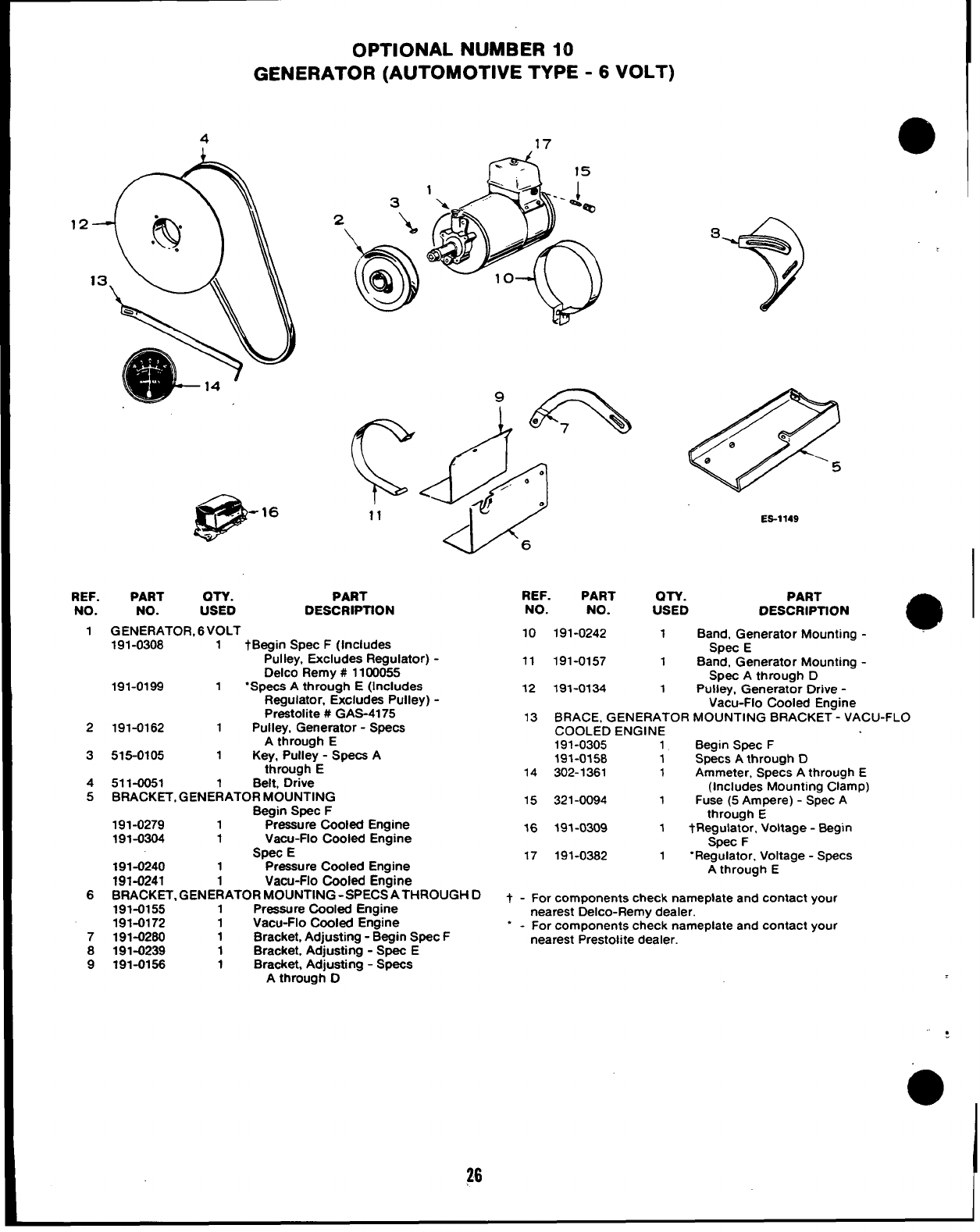
OPTIONAL NUMBER 10
GENERATOR (AUTOMOTIVE TYPE -6 VOLT)
417
12
@
. . -16
.
REF. PART OTY.
NO. NO. USED
1GENERATOR, 6VOLT
PART
DESCRIPTION
2
3
4
5
6
7
8
9
191-0308 1tBegin Spec F(Includes
Pulley, Excludes Regulator) -
Delco Remy #1100055
191-0199 1“Specs Athrough E(Includes
Regulator. Excludes Pulley) -
Preatolite #GAS-41 75
191-0162 1Pulley, Generator -Specs
Athrough E
515-0105 1Key, Pulley -Specs A
through E
511-0051 Belt, Drive
BRACKET, GENE~ATOR MOUNTING
Begin Spec F
191-0279 1Pressure Cooled Engine
191-0304 1Vacu-Flo Cooled Engine
Spec E
191-0240 1Pressure Cooled Engine
191-0241 1Vacu-Flo Cooled Engine
BRACKET, GENERATOR MOUNTING -SPECS ATHROUGH D
191-0155 1Pressure Cooled Engine
191-0172 1Vacu-Fio Cooled Engine
191-0260 1Bracket, Adjusting -Begin Spec F
191-0239 1Bracket, Adjusting -Spec E
191-0156 1Bracket, Adjusting -Specs
Athrough O
@
/o,
e
0‘5
ES-1149
REF. PART
NO. NO.
10 191-0242
11 191-0157
12 191-0134
QTY. PART
USED DESCRIPTION
1Band, Generator Mounting -e
SPec E
1Band, Generator Mounting -
Spec Athrough D
1Pulley, Generator Drive -
Vacu-Flo Cooled Engine
13 BRACE, GENERATOR MOUNTING BRACKET -VACU-FLO
COOLED ENGINE
191-0305 1Begin Spec F
191-0158 1Specs Athrough D
14 302-1361 1Ammeter, Specs Athrough E
(Includes Mounting Clamp)
15 321-0094 1Fuse (5 Ampere) -Spec A
through E
16 191-0309 1tFlegulator, Voltage -Begin
Spec F
17 191-0382 1“Regulator, Voltage -Specs
Athrough E
t - For components check nameplate and contact your
nearest Delco-Remy dealer.
“ - For components check nameplate and contact your
nearest Prestolite dealer.
—— — —
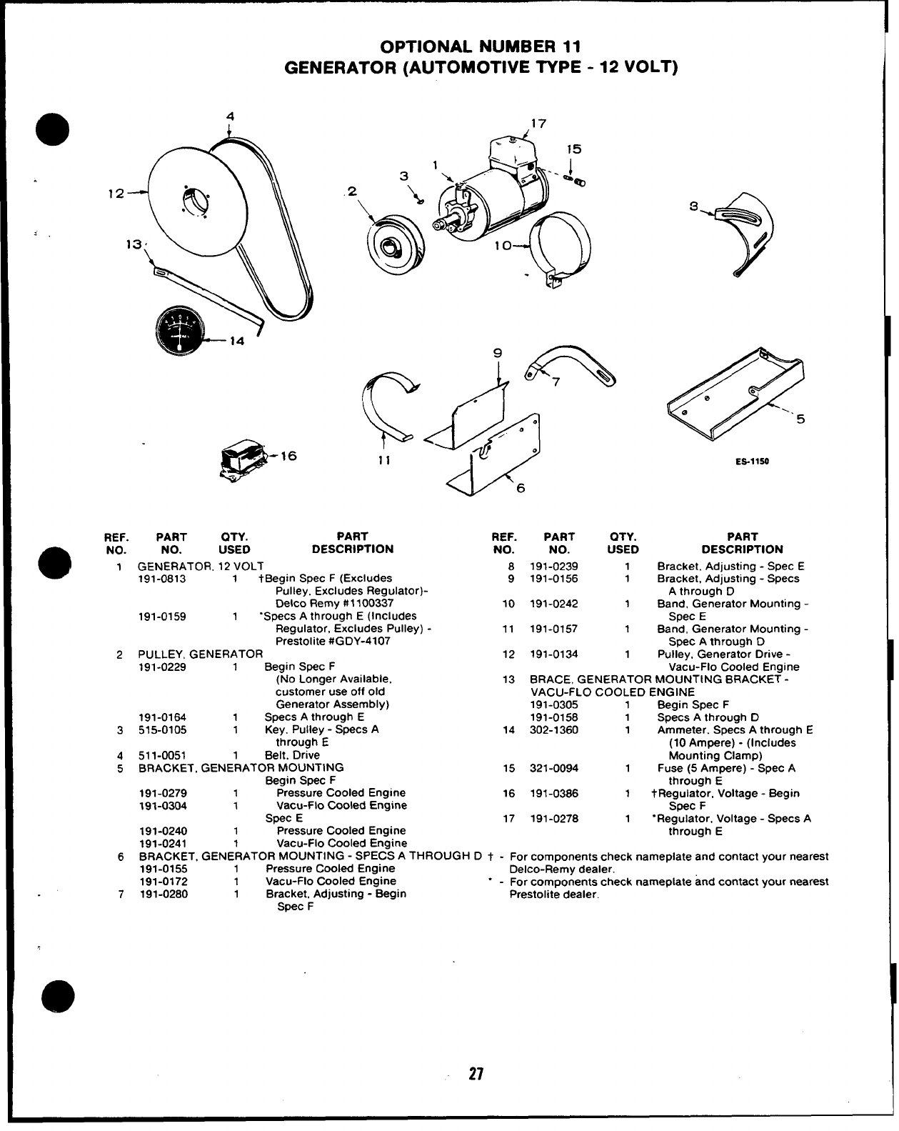
OPTIONAL NUMBER 11
GENERATOR (AUTOMOTIVE TYPE -12 VOLT)
.
4
12
13
@
-16
.
3
11
REF. PART QTY. PART
a
NO. NO. USED DESCRIPTION
1GENERATOR, 12 VOLT
191-0813 1tBegin Spec F(Excludes
Pulley, Excludes Regulator)-
Delco Remy#1100337
191-0159 1“Specs Athrough E(Includes
Regulator, Excludes Pulley) -
Prestolite #GDY-4107
2PULLEY, GENERATOR
191-0229 1Begin Spec F
(No Longer Available,
customer use off old
Generator Assembly)
191-0164 1Specs Athrough E
3515-0105 1Key. Pulley -Specs A
through E
4511-0051 1Belt. Drive
5BRACKET, GENERATOR MOUNTING
Begin Spec F
191-0279 1Pressure Cooled Engine
191-0304 1Vacu+lo Cooled Engine
Spec E
191-0240 1Pressure Cooled Engine
‘6+?!)
d
.
do
0
/
?0
6
REF. PART
NO. NO.
8191-0239
9191-0156
10 191-0242
11 191-0157
12 191-0134
QTY.
USED
1
1
1
1
1
3
?
/
@
/e>
e
e=.
5
ES-llSO
PART
DESCRIPTION
Bracket, Adjusting -Spec E
Bracket, Adjusting -Specs
Athrough D
Band, Generator Mounting -
Spec E
Band, Generator Mounting -
Spec Athrough D
Pulley. Generator Drive -
Vacu-Flo Cooled Engine
13 BRACE, GENERATOR MOUNTING BRACKET -
VACU-FLO COOLED ENGINE
191-0305 1Begin Spec F
191-0158 1Specs Athrough D
14 302-1360 1Ammeter. Specs Athrough E
(10 Ampere) -(Includes
Mounting Clamp)
15 321-0094 1Fuse (5 Ampere) -Spec A
through E
16 191-0386 1tRegulator, Voltage -Begin
Spec F
17 191-0278 1“Regulator, Voltage -Specs A
through E
191-0241 1Vacu-Flo Cooled Engine
6BRACKET, GENERATOR MCIUNTING -SPECS ATHROUGH D t - For components check nameplate and contact your nearest
191-0155 1Pressure Cooled Engine Delco-Remy dealer.
191-0172 1Vacu-Flo Cooled Engine
7191-0280
“ - For components check nameplate and contact your nearest
1Bracket, Adjusting -Begin Prestolite dealer.
Spec F
27
7
(3$@
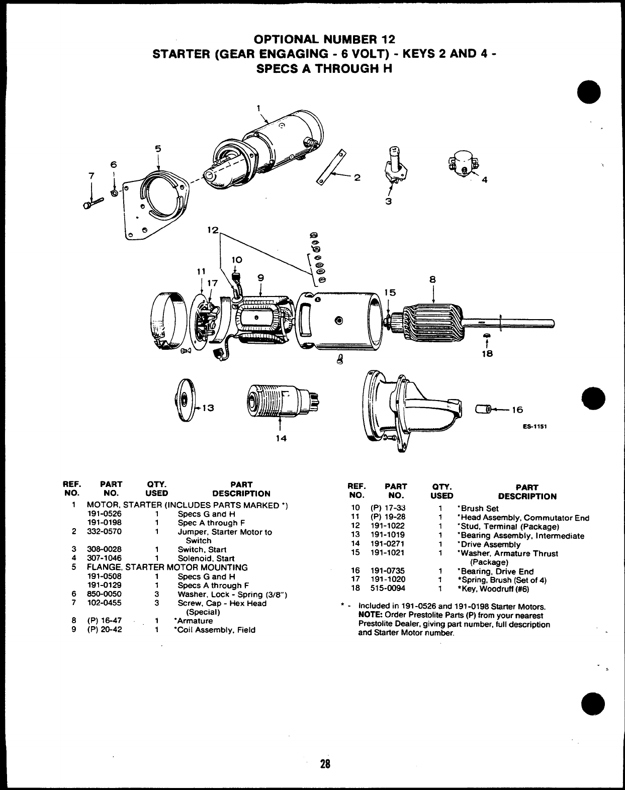
OPTIONAL NUMBER 12
STARTER (GEAR ENGAGING -6 VOLT) -KEYS 2AND 4-
SPECS ATHROUGH H
.
5
6
I
A
~. 2&Q4
.t
3
0
..
.,.
,:.,,,
\, !,,
o
14
REF. PART QTY. PART
NO. NO. USED DESCRIPTION
1MOTOR, STARTER (INCLUDES PARTS MARKED “)
191-0526 1Specs Gand H
191-0198 1Spec Athrough F
2332-0570 1Jumper, Starter Motor to
Switch
3308-0028 1Switch, Start
4307-1046 Solenoid, Start
5FLANGE, START;R MOTOR MOUNTING
191-0508 1Specs Gand H
191-0128 1Specs Athrough F
6850-0050 3Washer, Lock -Spring (3/8)
7102-0455 3Screw, Cap -Hex Head
(Special)
8(P) 18-47 1“Armature
9(P) 20-42 1“Coil Assembly, Field
~16 a
ES-1151
REF. PART
NO. NO.
10 (P) 17-33
11 (P) 19-28
12 191-1022
13 191-1019
14 191-0271
15 191-1021
● ✍
16 191-0735
17 191-1020
18 515-0094
OTY. PART
USED DESCRIPTION
1
1
1
1
1
1
1
1
1
“Brush Set
“Head Assembly, Commutator End
“Stud, Terminal (Package)
“Bearing Assembly, Intermediate
‘Drive Assembly
“Washer, Armature Thrust
(Package)
“Bearing, Drive End
*Spring, Brush (Set of 4)
●Key, Woodruff (#6)
Included in 191-0526 and 191-0198 Starter Motors.
NOTE Order Prestolite Parts (P) from your nearest
Prestoiite Dealer, giving part number, full description
and Starter Motor number.
28
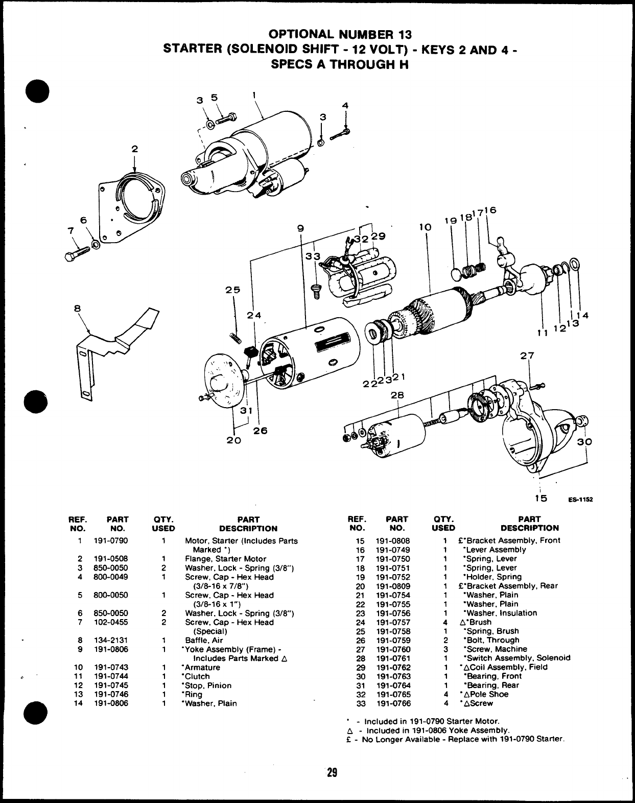
OPTIONAL NUMBER 13
STARTER (SOLENOID SHIFT -12 VOLT) -KEYS 2AND 4-
SPECS ATHROUGH H
35 1
\ \
A
REF.
NO.
2
1
2
3
4
5
6
7
8
9
10
~’ 11
12
13
e14
PART
NO.
191-0790
191-0508
850-0050
800-0049
800-0050
850-0050
102-0455
134-2131
191-0806
191-0743
191-0744
191-0745
191-0746
191-0806
.,716
10 ‘ml
QTY. PART REF. PART
USED DESCRIPTION NO. NO.
1
1
2
1
1
2
2
1
1
1
1
1
1
1
Motor, Starter (Includes Parts
Marked “)
Flange, Starter Motor
Washer. Lock -Spring (3/8”)
Screw, Cap -Hex Head
(3/8-16 X7/8)
Screw. Cap -Hex Head
(3/6-16 Xl“)
Washer, Lock -Spring (3/6”)
Screw, Cap -Hex Head
(Special)
Baffle, Air
“Yoke Assembly (Frame) -
Includes Parts Marked A
“Armature
“Clutch
“Stop, Pinion
“Ring
“Washer, Plain
15
16
17
18
19
20
21
22
23
24
25
26
27
28
29
30
31
32
33
191-0808
191-0749
191-0750
191-0751
191-0752
191-0809
191-0754
191-0755
191-0756
191-0757
191-0758
191-0759
191-0760
191-0761
191-0762
191-0763
191-0764
191-0765
191-0766
15 ES-11S2
am. PART
USED DESCRIPTION
1f“Bracket Assembly, Front
1“Lever Assembly
1‘Spring, Lever
1“Spring, Lever
1“Holder, Spring
1C“Bracket Assembly, Rear
1“Washer. Plain
1“Washer, Plain
1“Washer, Insulation
4A“Brush
“Spring, Brush
;“Bolt, Through
3“Screw, Machine
1“Switch Assembly. Solenoid
1“ACoii Assembly, Field
1“Bearing, Front
1“Bearing, Rear
4‘APole Shoe
4 “AScrew
“ - Included in 191-0790 Starter Motor.
A - Included in 191-0806 Yoke Assembly.
f - No Longer Available -Replace with 191-0790 Starter.
29
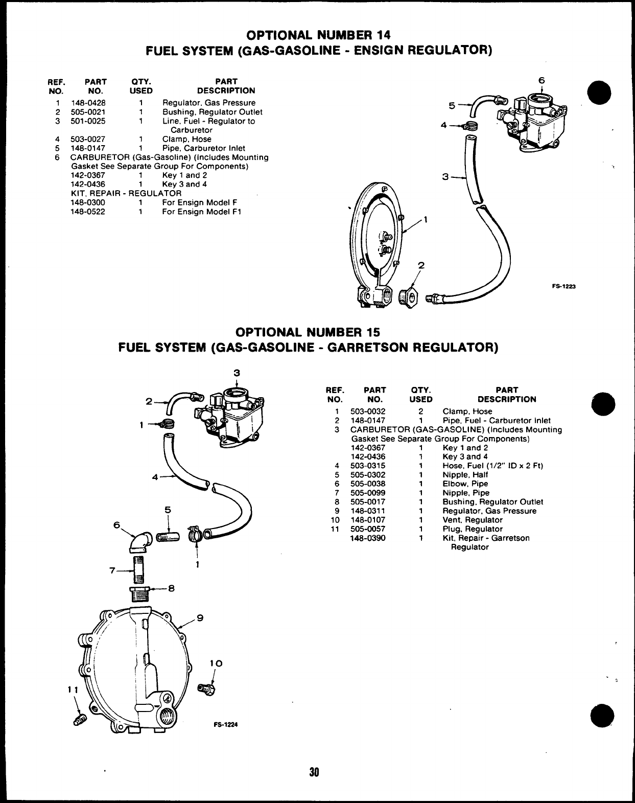
OPTIONAL NUMBER 14
FUEL SYSTEM (GAS-GASOLINE -ENSIGN REGULATOR)
REF. PART QTY.
NO. NO. USED
1148-0428 1
2505-0021 1
3501-0025 1
4503-0027 1
PART
DESCRIPTION
Regulator, Gas Pressure
Bushing, Regulator Outlet
Line, Fuel -Regulator to
Carburetor
Clamp, Hose
5148-0147 1Pipe, “Carburetor Inlet
6CARBURETOR (Gas-Gasoline) (Includes Mounting
Gasket See Separate Group For Components)
142-0367 1Kev 1and 2
142-0436 1Ke~ 3and 4
KIT, REPAIR -REGULATOR
148-0300 1For Ensign Model F
148-0522 1For Ensign Model F1
>
FS-1222
OPTIONAL NUMBER 15
FUEL SYSTEM (GAS-GASOLINE -GARRETSON REGULATOR)
3
1
REF.
NO.
1
2
3
4
5
6
7
8
9
10
11
PART QTY. PART
NO. USED DESCRIPTION
503-0032 2Clamp, Hose
148-0147 1Pipe, Fuel -Carburetor Inlet
CARBURETOR (GAS-GASOLINE) (Includes Mounting
Gasket See Separate Group For Components)
142-0367 1Key 1and 2
142-0436 1Key 3and 4
503-0315 1 Hose, Fuel (1/2” ID x 2 Ft)
505-0302 1Nipple, Half
505-0038 1Elbow, Pipe
505-0099 1Nipple, Pipe
505-0017 1Bushing, Regulator Outlet
148-0311 1Regulator, Gas Pressure
148-0107 1Vent, Regulator
505-0057 1Plug, Regulator
148-0390 1Kit, Repair -Garretson
Regulator
10
d
..,
FS-1224 a
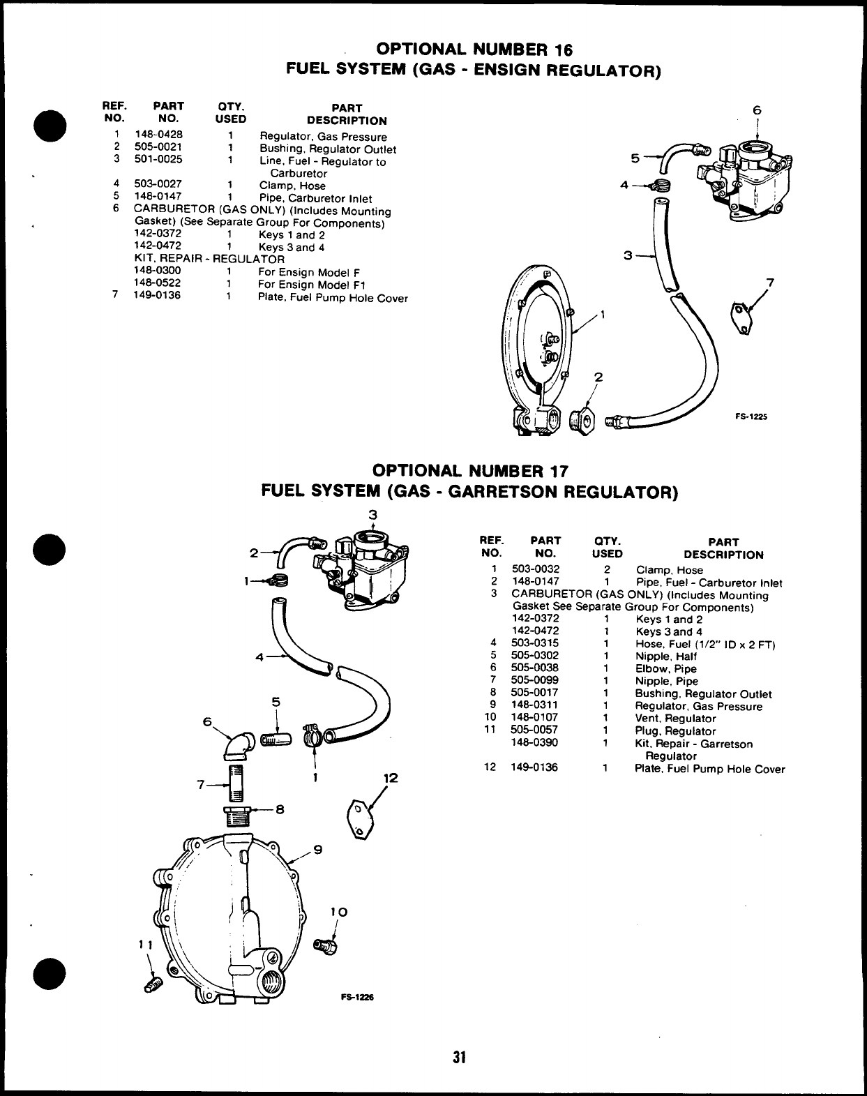
REF.
a
PART QTY.
NO. NO. USED
1148-0428 1
2505-0021 1
3501-0025 1
.
4503-0027 1
5148-0147 1
OPTIONAL NUMBER 16
FUEL SYSTEM (GAS -ENSIGN REGULATOR)
PART
DESCRIPTION
Regulator, Gas Pressure
Bushing, Regulator Outlet
Line, Fuel -Regulator to
Carburetor
Clamp, Hose
pipe, Carburetor Inlet
6CARBURETOR (GAS ONLY) (Includes Mounting
Gasket) (See Separate Group For Components)
,142-0372 1Kevs 1and 9
--, ------ _
142-0472 1Keys 3and 4
KIT, REPAIR -REGULATOR
146-0300 1For Ensign Model F
148-0522 1For Ensign Model F1
7149-0136 1Plate, Fuel Pump Hole Cover
6
4
3--J\
OPTIONAL NUMBER 17
FUEL SYSTEM (GAS -GARRETSON REGULATOR)
3
h
1
1
3CARBURETOR (
Gas
A- REF. PART QTY. PART
NO. NO. USED DESCRIPTION
I503-0032 2Clamp, Hose
2148-0147 1Pipe, Fuel -Carburetor Inlet
GAS ONLY) (Includes Mounting
sket See Separate Group For Components)
142-0372 1Keys 1and 2
10
/
d
Fs-1225
4
5
6
7
8
9
10
11
12
142-0472
503-0315
505-0302
505-0038
505-0099
505-0017
146-0311
148-0107
505-0057
146-0390
149-0136
1
1
1
1
1
1
1
1
1
1
1
Keys 3and 4
Hose, Fuel (1/2” ID x2FT)
Nipple, Half
Elbow, Pipe
Nipple, Pipe
Bushing, Regulator Outlet
Regulator, Gas Pressure
Vent, Regulator
Plug, Regulator
Kit, Repair -Garretson
Regulator
Plate, Fuel Pump Hole Cover
31
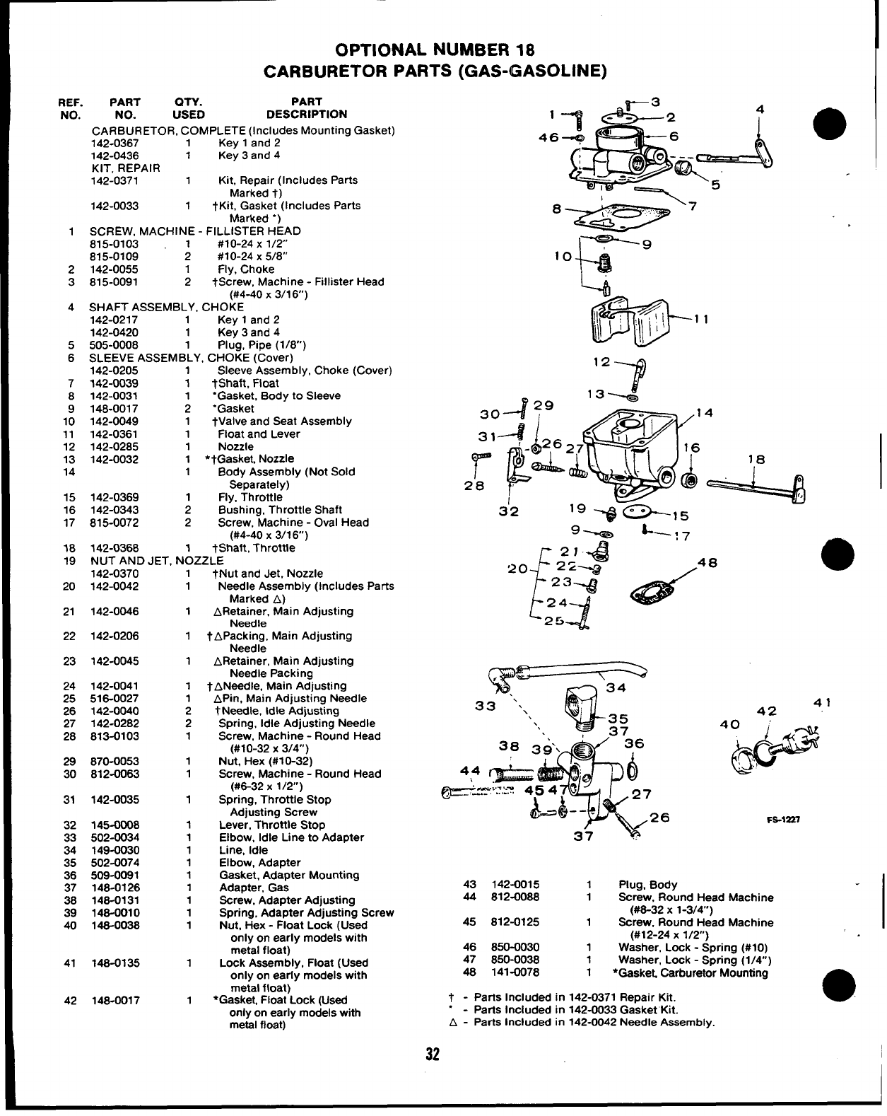
OPTIONAL NUMBER 18
CARBURETOR PARTS (GAS-GASOLINE)
REF.
NO.
1
2
3
4
5
6
7
8
9
10
11
12
13
14
15
16
17
18
19
20
21
22
23
24
25
26
27
28
29
30
31
32
E
35
36
37
38
39
40
41
42
PART QTY. PART
NO. USED DESCRIPTION
CARBURETOR, COMPLETE (Includes Mounting Gasket)
142-0367 1Key 1and 2
142-0436 1Key 3and 4
KIT, REPAIR
142-0371 1Kit, Repair (Includes Parts
Marked t)
142-0033 1tKit, Gasket (Includes Parts
Marked “)
SCREW, MACHINE -FILLISTER HEAD
815-0103 1#10-24 X1/2”
815-0109 2#10-24 X5/8”
142-0055 1Fly, Choke
815-0091 2tScrew, Machine -Fillister Head
(#4-40 x3/16)
SHAFT ASSEMBLY, CHOKE
142-0217 1Key 1and 2
142-0420 1Key 3and 4
505-0008 1Plug, Pipe (1/8)
SLEEVE ASSEMBLY, CHOKE (Cover)
142-0205 1Sleeve Assembly, Choke (Cover)
142-0039 1*Shaft, Float
142-0031 ‘Gasket, Body to Sleeve
148-0017 ;“Gasket
142-0049 1tValve and Seat Assembly
142-0361 1Float and Lever
142-0285 1Nozzle
142-0032 1*tGasket. Nozzle
1Body Assembly (Not Sold
Separately)
142-0369 1Fly, Throttle
142-0343 2Bushing, Throttle Shaft
815-0072 2Screw, Machine -Oval Head
(#4-40 X3/16”)
142-0368 1tShaft, Throttle
NUT AND JET, NOZZLE
142-0370
142-0042
142-0046
142-0206
142-0045
142-0041
516-0027
142-0040
142-0282
813-0103
870-0053
812-0063
142-0035
145-0008
502-0034
149-0030
502-0074
509-0081
148-0126
148-0131
148-0010
148-0038
148-0135
148-0017
1tNut and Jet. Nozzle
1
1
1
1
1
1
2
2
1
1
1
1
1
1
1
1
1
1
1
1
1
1
1
Needle Assembly (Includes Parts
Marked A)
ARetainer, Main Adjusting
Needle
tAp;$;~ Main Adjusting
ARetainer, Main Adjusting
Needle Packing
tANeedle, Main Adjusting
APin, Main Adjusting Needle
tNeedle, Idle Adjusting
Spring, Idle Adjusting Needle
Screw, Machine -Round Head
(#10-32 X3/4)
Nut, Hex (#10-32)
Screw, Machine -Round Head
(#6-32 X1/2”)
Spring, Throttle Stop
Adjusting Screw
Lever, Throttle Stop
Elbow, Idle Line to Adapter
Line, Idle
Elbow, Adapter
Gasket, Adapter Mounting
Adapter, Gas
Screw, Adapter Adjusting
Spring, Adapter Adjusting Screw
Nut, Hex -Float Lock (Used
only on early models with
metal float)
Lock Assembly, Float (Used
only on early models with
metal float)
*Gasket. Float Lock (Used
only on early models with
metal float)
, ~
F
.g-
34
33 “.\ ‘;
\35
‘. 37
41
42
40&
d
.’!
FS-1227
43 142-0015 1Plug, Body
44 812-0088 1Screw, Round Head Machine
(#6-32 X1-3/4”)
45 812-0125 1Screw, Round Head Machine
(#12-24 X1/2)
46 850-0030 1Washer, Lock -Scrrirm (#10)
47 850-0038 1Washer. Lock -Sprin~ (1/4;)
48 141-0078 1*GaskeL Carburetor Mounting
t-Parts Included in 142-0371 Repair Kit. a
.-Parts Included in 142-0033 Gasket Kit.
A - Parts Included in 142-0042 Needle Assembly.
32
I
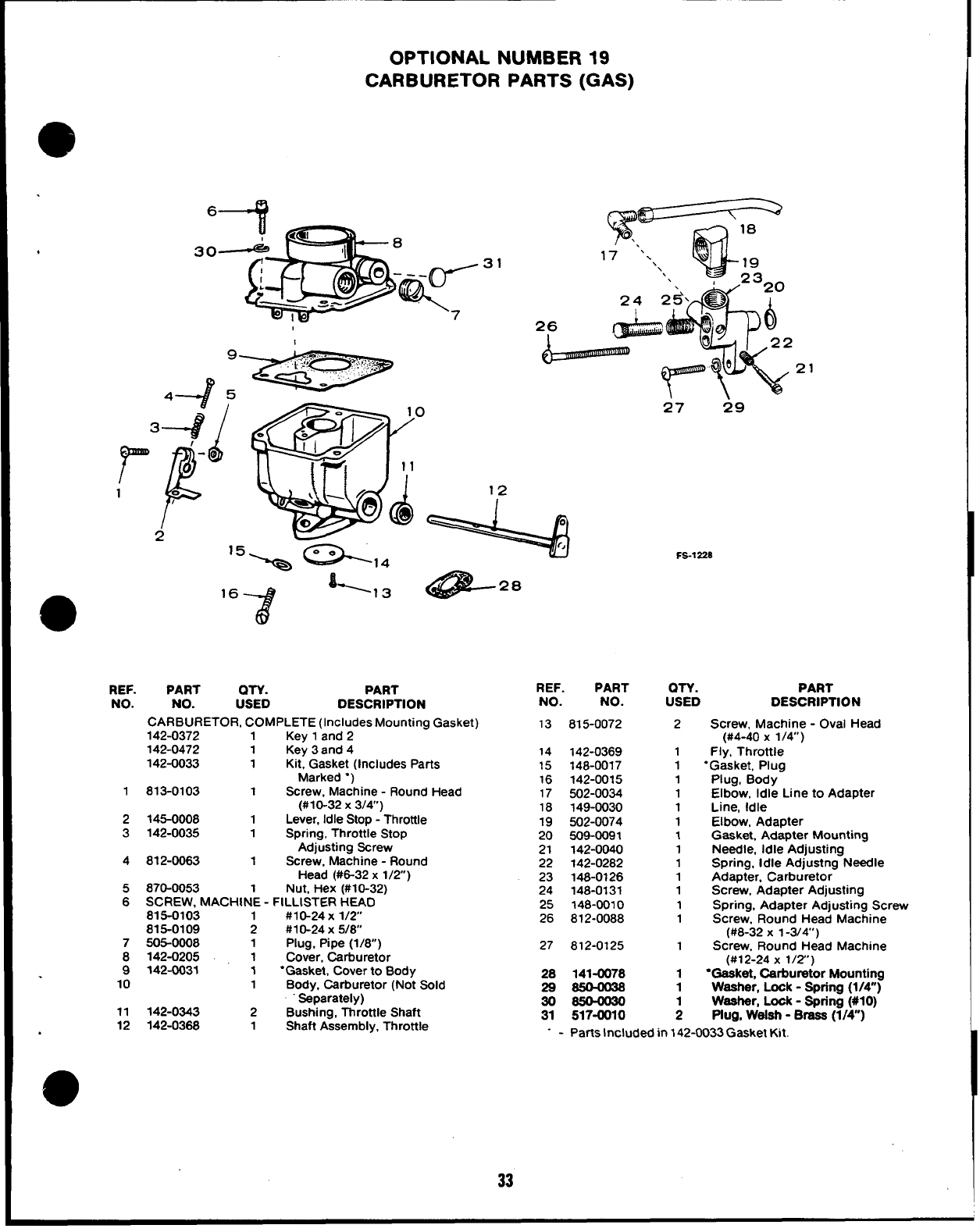
OPTIONAL NUMBER 19
CARBURETOR PARTS (GAS)
REF.
NO.
1
2
3
4
5
6
7
8
9
10
11
12
%r \---=
W
18
‘.
17 ‘.
‘\ 19
\\23
26
21
QTY. PART
USED DESCRIPTION
PART
NO.
CARBURETOR, COMPLETE (Includes Mounting Gasket)
142-0372 1Key 1and 2
142-0472 1Key 3and 4
142-0033 1Kit, Gasket (Includes Parts
Marked “)
813-0103 1Screw, Machine -Round Head
(#10-32 X3/4)
145-0008 1Lever, Idle Stop -Throttle
142-0035 1Spring, Throttle Stop
Adjusting Screw
812-0063 1Screw, Machine -Round
Head (#6-32 x1/2)
870-0053 Nut, Hex (#10-32)
SCREW, MACHIN’E -FILLISTER HEAD
815-0103 #10-24 X 1/2
815-0109 ;#1 O-24X 5/8
505-0008 1Plug, Pipe (1/8)
142-0205 1Cover, Carburetor
142-CW31 1“Gasket, Cover to Body
1Body, Carburetor (Not Sold
Separately)
142-0343 2Bushing, Throttle Shaft
142-0368 1Shaft Assembly, Throttle
27 29
FS-1228
REF. PART OTY. PART
NO. NO. USED DESCRIPTION
13 815-0072 2Screw, Machine -Oval Head
(#4-40 x1/4”)
14 142-0369 1Fly, Throttle
15 148-0017 1“Gasket, Plug
16 142-0015 1Plug, Body
17 502-0034 1Elbow, Idle Line to Adapter
18 149-0030 1Line, Idle
19 502-0074 1Elbow, Adapter
20 509-0091 1Gasket, Adapter Mounting
21 142-0040 1Needle, Idle Adjusting
22 142-0282 1Spring, Idle Adjustng Needle
23 148-0126 1Adapter. Carburetor
24 148-0131 1Screw, Adapter Adjusting
25 ?48-0010 1Spring, Adapter Adjusting Screw
26 812-0088 1Screw, Round Head Machine
(#8-32 X 1-3/4’)
27 812-0125 1Screw, Round Head Machine
(#12-24 X1/2’)
28 141-0078 1●Gaeket, Carburetor Mounting
29 S50—0@8 1Washer, Look -Spring (1/4”)
30 S504030 Weeher, Look -Spring (#IO)
31 517-0010 ;Plug, Weleh -Braaa (1/4”)
- - Parts Included in 142-0033 Gasket Kit.
33
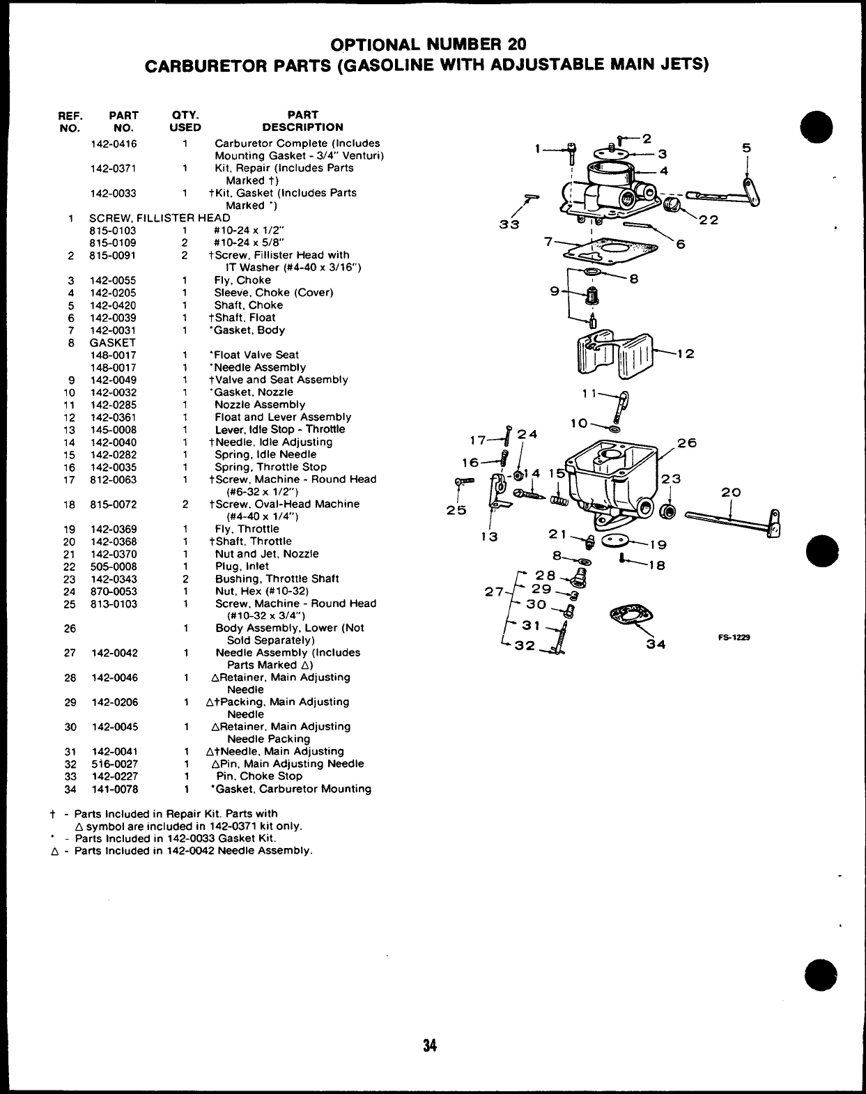
OPTIONAL NUMBER 20
CARBURETOR PARTS (GASOLINE WITH ADJUSTABLE MAIN JETS)
REF. PART QTY. PART
NO. NO. USED DESCRIPTION
142-0416 1Carburetor Complete (Includes
Mounting Gasket -3/4” Venturi)
142-0371 1Kit, Repair (Includes Parts
Marked t)
142-0033 1tKit, Gasket (Includes Parts
Marked “)
1SCREW, FILLISTER HEAD
815-0103
815-0109
2815-0091
3142-0055
4142-0205
5142-0420
6142-0039
7142-0031
8GASKET
148-0017
148-0017
9142-0049
10 142-0032
11 142-0285
12 142-0361
13 145-0008
14 142-0040
15 142-0282
16 142-0035
17 812-0063
18 815-0072
19 142-0369
20 142-0368
21 142-0370
22 505-0008
23 142-0343
24 870-0053
25 813-0103
26
27 142-0042
28 142-0046
29 142-0206
30 142-0045
31 142-0041
32 5i6-0027
33 142-0227
34 141-0078
;
2
1
1
1
1
1
1
1
1
1
1
1
1
1
1
1
1
2
1
1
1
1
2
1
1
1
1
1
1
1
1
1
1
1
#10-24 X1/2”
#10-24 X5/8”
tScrew, Fillister Head with
IT Washer (#4-40x 3/16’)
Fly, Choke
Sleeve, Choke (Cover)
Shaft, Choke
tShaft, Float
“Gasket, Body
“Float Valve Seat
“Needle Assembly
tValve and Seat Assembly
“Gasket, Nozzle
Nozzle Assembly
Float and Lever Assembly
Lever, Idle Stop -Throttle
tNeedle, Idle Adjusting
Spring, Idle Needle
Spring, Throttle Stop
tScrew, Machine -Round Head
(#6-32 X1/2)
tScrew. Oval-Head Machine
(#4-40 x1/4”)
Fly. Throttle
tShaft, Throttle
Nut and Jet, Nozzle
Plug, inlet
Bushing, Throttle Shaft
Nut, Hex (#10-32)
Screw, Machine -Round Head
(#10-32 X3/4”)
Body Assembly, Lower (Not
Sold Separately)
Needle Assembly (Includes
Parts Marked A)
ARetainer. Main Adjusting
Needle
AtPacking, Main Adjusting
Needle
ARetainer, Main Adjusting
Needle Packing
AtNeedle, Main Adjusting
APin, Main Adjusting Needle
Pin, Choke Stop
“Gasket, Carburetor Mounting
t - Parts Included in Repair Kit. Parts with
Asymbol are included in 142-0371 kit only.
.-Parts Included in 142-0033 Gasket Kit.
A - Parts Included in 142-0042 Needle Assembly.
34
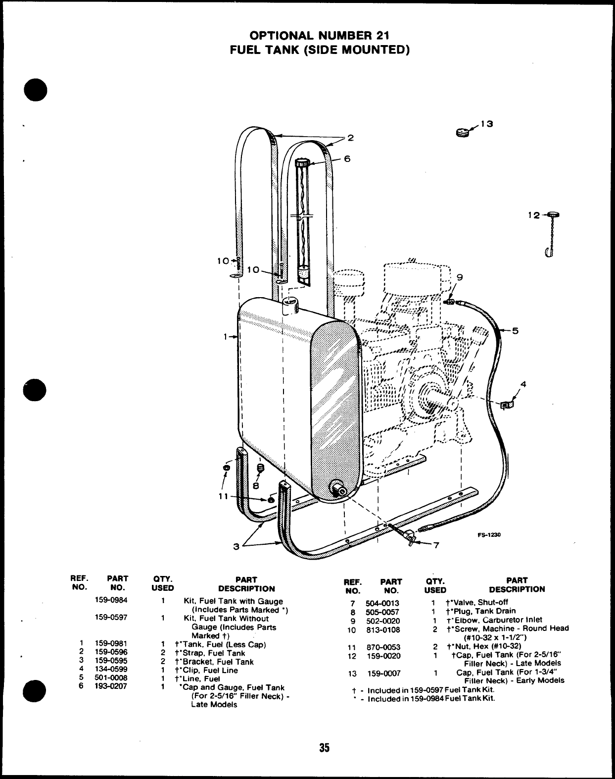
OPTIONAL NUMBER 21
FUEL TANK (SIDE MOUNTED)
REF. PART
NO. NO.
159-0964
159-0597
159-0981
;159-0596
3159-0595
4134-0599
5501-0006
m
6193-0207
r
,.:;,
......
......
......
......
:,::,
,....
.;..;
>.;,
q
,.:
10.
I
k-
Gi3”3
/’
-6
12
T
<41
1........- ,
e.
---
”
----
:
-
.=..;...,
, . . ... . . . ..
.. , 1’
I t, , . . 9
OTY. PART
USED DESCRIPTION
1Ktt, Fuel Tank with Gauge
(Includes Paris Marked “
1Kit. Fuel Tank Wtthout
Gauge (Includes Parts
Marked t)
1t“Tank, Fuel (Leas Cap)
2t“Strap. Fuel Tank
2t. Bracket, Fuel Tank
1t“Clip, Fuel Line
1t“Line, Fuel
4
REF. PART OTY. PART
NO. NO. USED DESCRIPTION
7504-0013 1 t“Valve, Shut-off
8505-0057 1t“ptug, Tank Drain
9502-0020 1T“Elbow, Carburetor Inlet
10 813-0108 2t“Screw, Machine -Round Head
(#10-32 X1-1/2”)
11 870-0053 2t.Nut, Hex (#10-32)
12 159-0020 1tCap, Fuel Tank (For 2-5/16”
Filler Neck) - Late Models
13 159-0007 1Cap, Fuel Tank (For 1-3/4
1“Cap and Gauge, Fuel Tank Filler Neck) - Early Models
(For 2-5/16 Filler Neck) - t - Included in 159-0597 Fuel Tank Kit.
Late Models “ - Included in 159-0964Fuel Tank Kk.
35
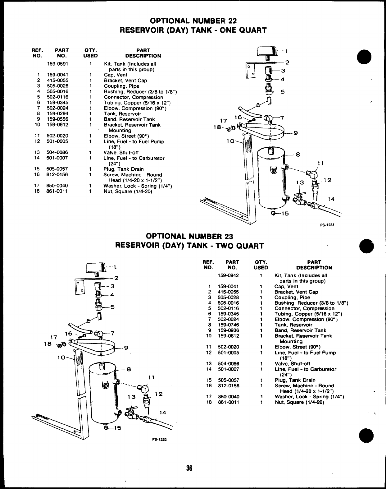
OPTIONAL NUMBER 22
RESERVOIR (DAY) TANK -ONE QUART
REF.
NO.
1
2
3
4
5
6
7
8
9
10
11
12
13
14
15
16
17
18
PART
NO.
159-0591
159-0041
415-0055
505-0028
505-0016
502-0116
159-0345
502-0024
159-0294
159-0556
159-0612
502-0020
501-0005
504-0086
501-0007
505-0057
812-0156
850-0040
861-0011
QTV.
USED
1
1
1
1
1
1
1
1
1
1
1
1
1
1
1
1
1
1
1
PART
DESCRIPTION m’
Kit, Tank (Includes all
parts in this group)
Cap, Vent
Bracket, Vent Cap
Coupling, Pipe
Bushing, Reducer (3/8 to 1/8)
Connector, Compression
Tubing, Copper (5/16 x12)
Elbow, Compression [90° )
Tank, Rese~oir ‘
Band, Reservoir Tank
Bracket, Reservoir Tank
Mounting
Elbow, Street (80° )
Line, Fuel -to Fuel Pump
(18”)
Valve. Shut-off
Line, Fuel -to Carburetor
(24”)
Plug, Tank Drain
Screw, Machine -Round
Head (1/4-20 x1-1/2)
~
Washer, Lock -Spring (1/4)
Nut, Square (1/4-20) r\
OPTIONAL NUMBER 23
RESERVOIR (DAY) TANK -TWO QUART
,.
3
–0
-—-
@‘----- ,“
\Q
13 12
&!
e-l 5%“
Fs-1232
REF. PART
NO. NO.
159-0942
1159-0041
2415-0055
3505-0028
4505-0016
5502-0116
6159-0345
7502-0024
8158-0746
9159-0936
10 159-0612
11 502-0020
12 501-0005
13 504-0086
14 501-0007
15 505-0057
16 812-0156
17 850-0040
18 881-0011
m-v.
USED
1
1
1
1
1
1
1
1
1
1
1
1
1
1
1
1
1
1
1
FS-1231
PART
DESCRIPTION
Kit, Tank (Includes all
parts in this group)
Cap, Vent
Bracket, Vent Cap
Coupling, Pipe
Bushing, Reducer (3/8 to 1/8)
Connector, Compression
Tubing, Copper (5/16 x12)
Elbow, Compression (90” )
Tank, Reservoir
Band, Reaewoir Tank
Bracket, Reservoir Tank
Mounting
Elbow, Street (90° )
Line, Fuel -to Fuel Pump
(18”)
Valve, Shut-off
Line, Fuel -to Carburetor
(24”)
Plug, Tank Orain
Screw, Machine -Round
Head (1/4-20 x1-1/2)
Washer, Lock -Spring (1/4”)
Nut, Square (1/4-20)
@
<
e
a
36
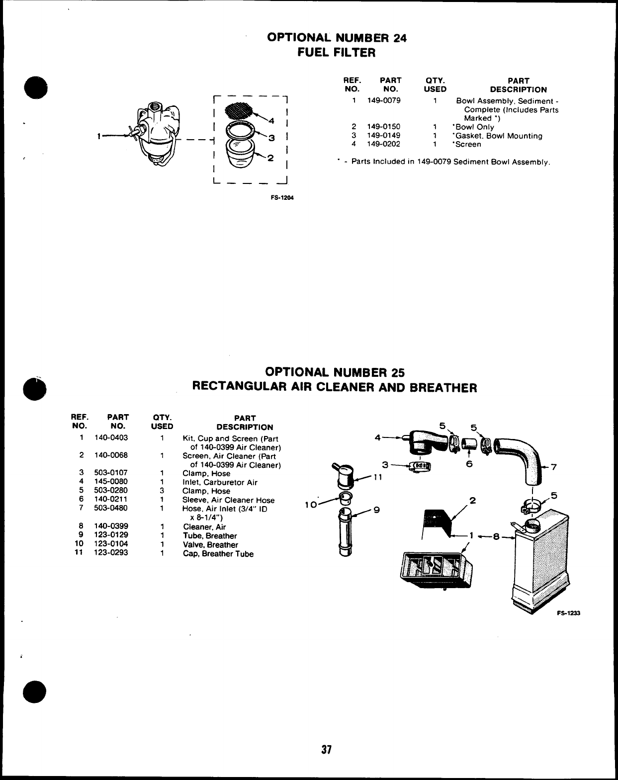
r——— —1
I
:%
I
I
41
1;:3,
1—— -i
w
~
I
1= 21
REF. PART
NO. NO.
1140-0403
2140-0068
3503-0107
4145-0080
5503-0280
6140-0211
7503-0480
8140-0399
9123-0129
10 123-0104
11 123-0293
OTY.
USED
1
1
1
1
3
1
1
1
1
1
1
OPTIONAL NUMBER 24
FUEL FILTER
REF. PART QTY. PART
NO. NO. USED DESCRIPTION
1149-0079 1Bowl Assembly, Sediment -
Complete (Includes Parts
Marked “)
2149-0150 1.Bowl Only
3149-0149 1“Gasket. Bowl Mounting
4149-0202 1.Screen
“ - Parts Included in 149-0079 Sediment Bowl Assembly.
L——— -1
FS-1204
OPTIONAL NUMBER 25
RECTANGULAR AIR CLEANER AND BREATHER
PART
DESCRIPTION
Kit, Cup and Screen (part
of 140-0399 Air Cleaner)
Screen, Alr Cleaner (Part
of 140-0399 Air Cleaner)
Clamp, Hose
Inlet, Carburetor Air
Clamp, Hose
Sleeve, Air Cleaner Hose
Hose, Air Inlet (3/4” ID
x8-1/4”)
Cleaner, Air
Tube, Breather
Valve, Breather
Cap, Breather Tube
T$-
,.”--9
r’9
i
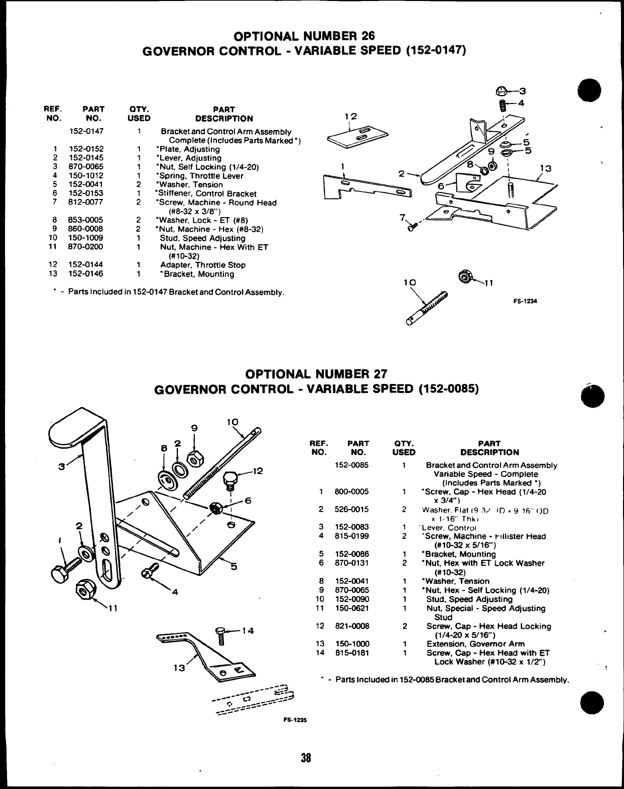
9
e
,
,.
9
.
OPTIONAL NUMBER 26
GOVERNOR CONTROL -VARIABLE SPEED (152-0147)
REF. PART
NO. NO.
152-0147
1152-0152
2152-0145
3870-0065
4150-1012
5152-0041
6152-0153
7612-0077
8853-0005
9860-0008
10 150-1009
11 870-0200
12 152-0144
13 152-0146
QTY. PART
USED DESCRIPTfON 12 A:-
Bracket and Control Arm Assembly
Complete (Includes Parts Marked”)
“Plate, Adjusting
“Lever, Adjusting
“Nut, Self Locking (1/4-20)
“Spring, Throttle Lever
“Washer, Tension
“Stiffener, Control Bracket
‘Screw, Machine -Round Head
(#8-32 X3/8”)
“Washer, Lock -ET (#8)
“Nut, Machine -Hex (#8-32)
Stud, Speed Adjusting
Nut, Machine -Hex W!th ET
(#10-32)
Adapter, Throttle Stop
“Bracket, Mounting
1
1
1
1
;
1
2
2
2
1
1
1
1
l--k==’”““8’
4!&,,
10
.-Parts Included in 152-0147 Bracket and Control Assembly.
FS-1234
OPTIONAL NUMBER 27
GOVERNOR CONTROL -VARIABLE SPEED (152-0085)
REF. PART
NO. NO. iTiD
1
PART
DESCRIPTtON
Bracket and Control Arm Assembly
Variable Speed -Complete
(Includes Parts Marked “)
‘Screw, Cap -Hex Head (1/4-20
x3/4’)
“Washer. Flat 19 3/ IIT . ~ Irj’ OD
X1,16’ Thk)
Lever. Controi
‘Screw, Machine -t!llister Head
(#10-32 X5/16)
“Bracket, Mounting
“Nut, Hex with ET Lock Washer
(#10-32)
“Washer, Tension
“Nut, Hex -Self Locking (1/4-20)
Stud, Speed Adjusting
Nut, Special -Speed Adjusting
Stud
Screw, Cap -Hex Head Locking
(1/4-20 x5/16)
Extension, Governor Arm
Screw. CaD - Hex Head with ET
152-0085
1800-0005 1
2526-0015 2
3
4
152-0083
815-0199 ;
5
6
152-0086
870-0131 ;
8
9
10
11
152-0041
870-0065
152-0090
150-0621
1
1
1
1
12 821-0008 2
r14
%
..-.0 -
13 ~s
“ - Parta Included in 152-0085 Bracket and Control Arm Assemblv.
13
14
150-1000
815-0181
1
1
Lock W&her (#10-32 x1/2”)
38
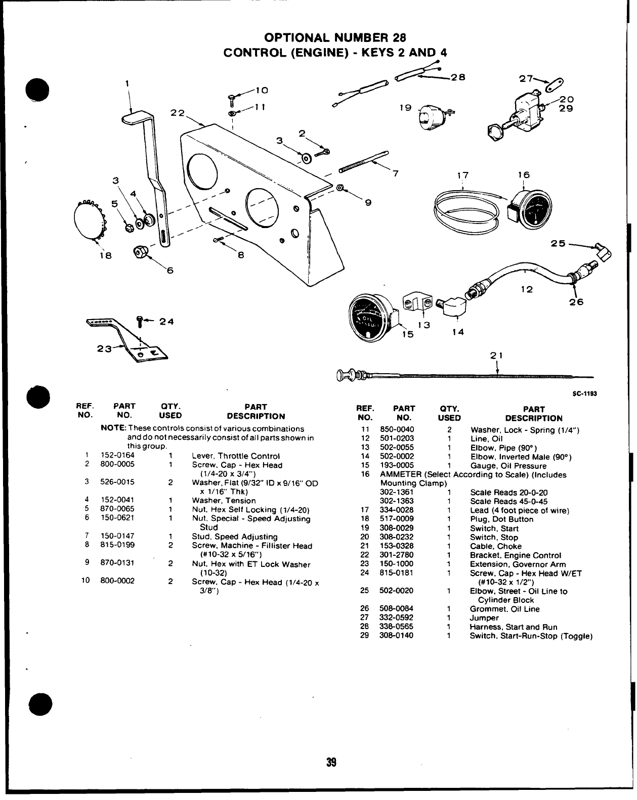
.
,
1
\
OPTIONAL NUMBER 28
CONTROL (ENGINE) -KEYS 2AND 4
./—2. 271A
?’ 10
/1 12-,.. ‘w
a/2 o
.>’ -n
\.. \.- ‘7 17 16
T
l’a v
o
6
x“
*REF.
NO.
1
2
3
4
5
6
7
8
9
10
PART QTY. PART
NO.
REF.
USED
PART QTY.
DESCRIPTION NO. NO. USED
NOTE. These controls consist of various combinations 11 850-0040 2
and do not necessarily consmt of all parts shown in 12 501-0203 1
this group. 13 502-0055 1
152-0164
800-0005
526-0015
152-0041
870-0065
150-0621
150-0147
815-0199
870-0131
800-0002
1Lever, Throttle Control 14 502-0002 1
1Screw. Cao -Hex Head 15 193-0005 1
2
1
1
1
2
2
SC-1193
PART
DESCRIPTION
Washer, Lock -Spring (1/4”)
Line, Oil
Elbow, Ptpe (90”)
Elbow, Inverted Male (90° )
Gauge, Oil Pressure
(1/4-20 x3/4”) 16 AMMETER (Select Accordina to Scale) (Includes
Washer, Flat (9/32’ ID x9/16’ OD
X 1/16 Thk)
Washer, Tension
Nut, Hex Self Locking (1/4-20)
Nut. Special -Speed Adjusting
Stud
Stud, Speed Adjusting
Screw. Machine -Fillister Head
(#10-32 X5/16)
Nut, Hex with ET Lock Washer
(1 O-32)
Screw, Cap -Hex Head (1/4-20 x
3/8’)
17
18
19
20
21
22
23
24
25
Mounting Clamp)
302-1361 1
302-1363 1
334-0028 1
517-0009 1
308-0029 1
308-0232 1
153-0328 1
301-2780 1
150-1000 1
815-0181 1
502-0020 1
,.-
Scale Reads 20-0-20
Scale Reads 45-O-45
Lead (4 foot piece of wire)
Plug, Dot Button
Switch, Start
Switch, Stop
Cable, Choke
Bracket, Engine Control
Extension, Governor Arm
Screw, Cap -Hex Head W/ET
(#10-32 X 1/2)
Elbow. Street -Oil Line to
.
Cylinder Block
26 506-0064 1Grommet. Oil Line
27 332-0592 1Jumper
28 336-0565 1Harness, Start and Run
29 308-0140 1Switch, Start-Run-Stop (Toggle)
39
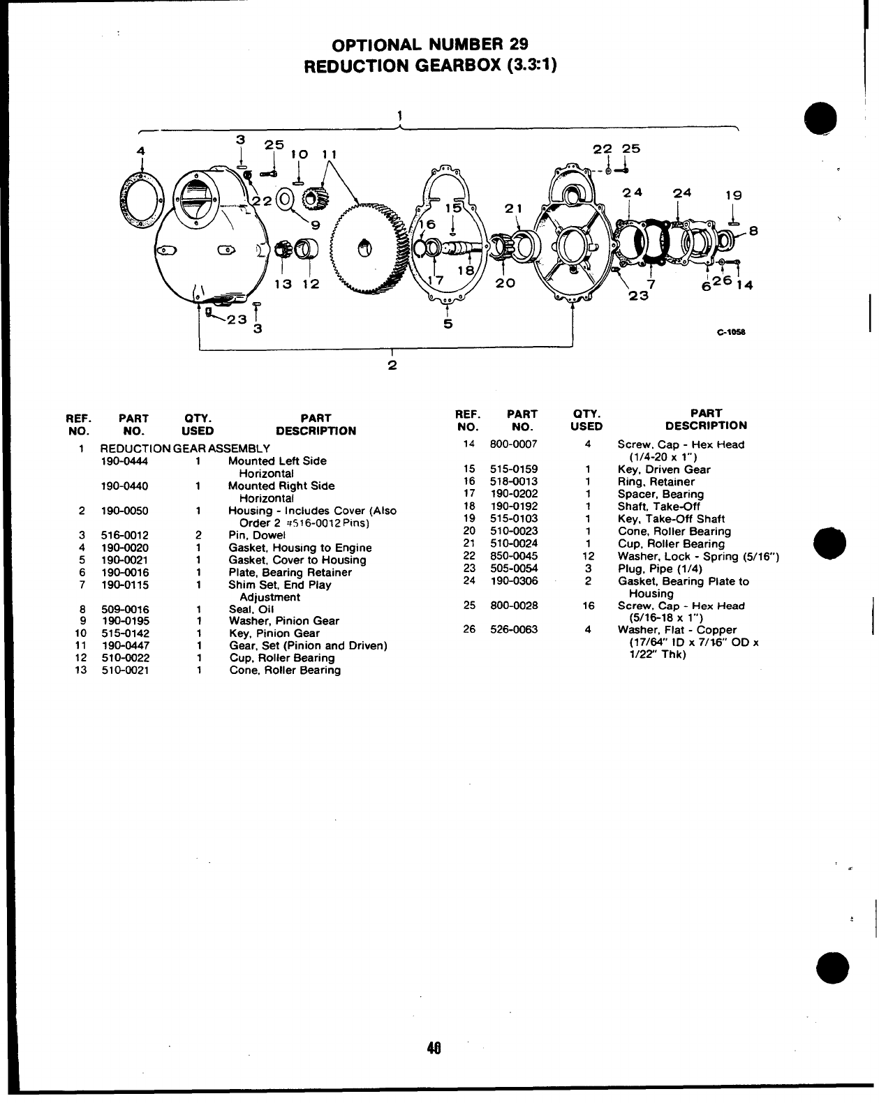
OPTIONAL NUMBER 29
REDUCTION GEARBOX (3.31)
1
-1
@
325
4I10 11 22 25
I
C-1OS8
1J
I
2
REF. PART OTY. PART REF. PART
NO. NO. USED DESCRIPTION NO. NO.
QTY.
USED
4
1
1
1
1
1
1
1
12
3
2
16
4
PART
DESCRIPTION
Screw, Cap -Hex Head
(1/4-20 Xl“)
Key, Driven Gear
Ring. Retainer
Spacer, Bearing
Shaft, Take-Off
Key, Take-Off Shaft
Cone, Roller Bearing
Cup, Roller Bearing
Washer, Lock -Spring (5/16)
Plug, Pipe (1/4)
Gasket, Bearing Plate to
Housing
Screw, Cap -Hex Head
(5/16-18 X l“)
Washer. Flat -Comer
1REDUCTION GEAR ASSEMBLY 14 800-0007
190-0444 1Mounted Left Side
Horizontal
Mounted Right Side
Horizontal
Housing -Includes Cover (Also
Order 2 w516-0012 Pins)
Pin, Dowel
Gasket, Housing to Engine
Gasket, Cover to Housing
Plate, Bearing Retainer
Shim Set, End Play
Adjustment
Seal. Oil
Washer, Pinion Gear
Key, Pinion Gear
Gear, Set (Pinion and Driven)
Cup, Roller Bearing
Cone. Roller Bearing
15
16
17
18
19
20
21
515-0159
518-0013
190-0202
190-0192
515-0103
510-0023
510-0024
850-0045
505-0054
190-0306
190-0440 1
2190-0050 1
3
4
5
6
7
516-0012
190-0020
190-0021
190-0016
190-0115
2
1
1
1
1
22
23
24
25 800-0028
8
9
10
11
12
13
509-00J6
190-0195
515-0142
190-0447
510-0022
510-0021
1
1
1
1
1
1
26 526-0063
(17/&” ID X7/;6 OD X
1/22” Thk)
I
4
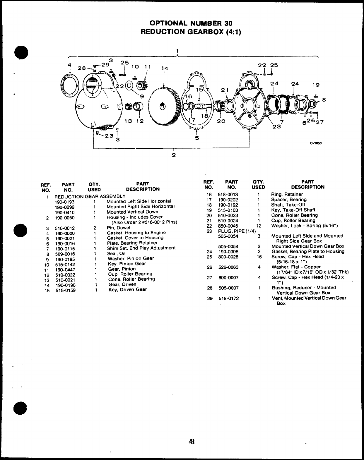
OPTIONAL NUMBER 30
REDUCTION GEARBOX (41)
—
.
,
L
-23 I
3k
I
2
REF. PART QTY. PART
NO. NO. USED DESCRIPTION
2
e3
4
5
-.
1REDUCTION GEAR ASSEMBLY
Mounted Left Side Horizontal
Mounted Right Side Horizontal’
Mounted Vertical Down
Housing -Includes Cover
(Also Order 2 #516-0012 Pins)
Pin, Dowel
Gasket, Housing to Engine
Gasket. Cover to Housing
6
7
8
9
10
11
12
13
14
15
190-0193
190-0299
190-0410
190-0050
516-0012
190-0020
190-0021
190-0016
190-0115
509-0016
190-0195
515-0142
190-0447
510-0022
510-0021
190-0190
515-0159
1
1
1
1
2
1
1
1
1
1
1
1
1
1
1
1
1
REF. PART QTY.
NO. NO. USED
16
17
18
19
20
21
22
23
518-0013 1
190-0202 1
190-0192 1
515-0103 1
510-0023 1
510-0024 1
850-0045 12
PLUG, PIPE (1/4)
505-0054 3
Plate, Bearing Retainer
Shim Set, End Play Adjustment 505-0054 2
Seal, Oil 24 190-0306 2
Washer. Pinion Gear 25 800-0028 16
Key. Pinion Gear
Gear, Pinion 26 526-0063 4
Cup, FloIler Bearing
Cone, Roller Bearing 27 600-0007 4
Gear, Driven
Key, Driven Gear 28 505-0007 1
29 518-0172 1
c-loe9
PART
DESCRIPTION
Ring, Retainer
Spacer, Bearing
Shaft, Take-Off
Key, Take-Off Shaft
Cone, Roller Bearing
Cup, Roller Bearing
Washer, Lock -Spring (5/16’)
Mounted Left Side and Mounted
Right Side Gear Box
Mountad Vertical Down Gear Box
Gasket, Bearing Plate to Housing
Screw, Cap -Hex Head
(5/16-18 X l“)
Washer, Flat -Copper
(17/64” ID x7/160D Xl/32Thk)
Screw, Cap -Hex Head (1/4-20 x
1“)
Bushing, Reducer -Mounted
Vertical Down Gear Box
Vent, Mounted Vefiical Down Gear
Box
41 .
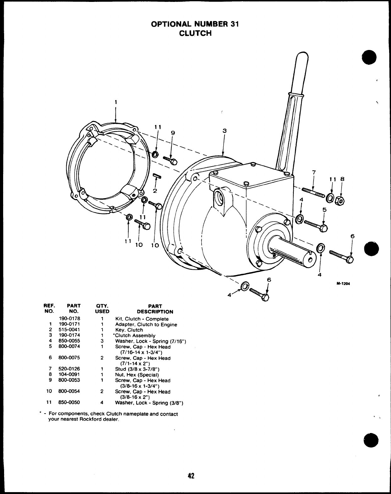
OPTIONAL NUMBER 31
CLUTCH
REF. PART
NO. NO.
190-0178
1190-0171
2515-0041
3190-0174
4850-0055
5800-0074
6800-0075
7520-0126
8104-0091
9800-0053
10 800-0054
11 850-0050
an.
USED
1
1
1
:
1
2
1
1
1
2
4
IIllllli ilf ///-\’
‘‘1’0 1’0
‘Q\
v
\I
*‘\
R, \\\
PART
DESCRIPTION
Kit, Clutch -Complete
Adapter, Clutch to Engine
Key, Clutch
“Clutch Assembly
Washer, Lock -Spring (7/16)
Screw, Cap -Hex Head
(7/16-14 x 1-3/4)
Screw, Cap -Hex Head
(7/1-14 x2)
Stud (3/8 X3-7/8)
Nut, Hex (Special)
Screw, Cap -Hex Head
(3/8-16 X1-3/4”)
Screw, Cap -Hex Head
(3/8-16x2)
Washer, Lock -Spring (3/8)
-y- 6
P~
\
4
M.1204
.
‘,,
“ - For components, check Clutch nameplate and contact
your nearest Rockford dealer.
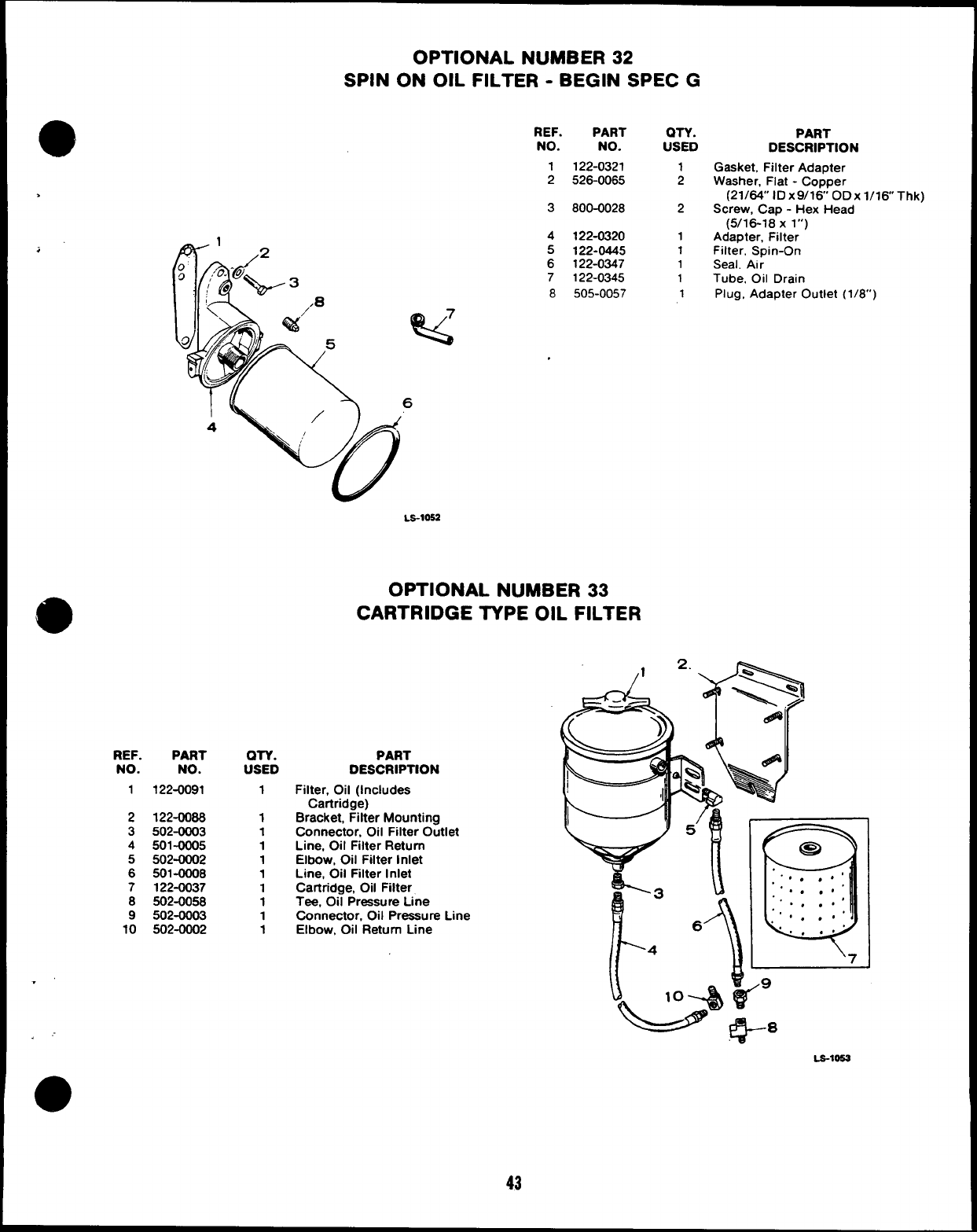
OPTIONAL NUMBER 32
SPIN ON OIL FILTER -BEGIN SPEC G
REF.
NO.
1
2
>
3
.
;
REF. PART
NO. NO.
1122-0091
2122-0088
3502-0003
4501-0005
5502-0002
6 501-00Q8
7122-0037
8502-0058
9502-0003
10 502-0002
.’
. ,“
o
QTY.
USED
1
1
1
1
1
1
1
1
1
1
4
5
6
7
8
PART
NO.
122-0321
526-0065
800-0028
122-0320
122-0445
122-0347
122-0345
505-0057
LS-1OSZ
OPTIONAL NUMBER 33
CARTRIDGE TYPE OIL FILTER
PART
DESCRIPTION
Filter, Oil (Includes
Cartridge)
Bracket, Filter Mounting
Connector, Oil Filter Outlet
Line, Oil Filter Return
Elbow, Oil Filter Inlet
Line, Oil Filter Inlet
Cartridge, Oil Filter
Tee, Oil Pressure Line
Connector, Oil Pressure Line
Elbow, Oil Return Line
43
on. PART
USED DESCRIPTION
1Gasket, Filter Adapter
2Washer, Flat -Copper
(21/64” lDx9/16 ODX l/16 Thk)
2Screw, Cap -Hex Head
(5/16-18 X l“)
1Adapter, Filter
1 Filter, Spin-On
1Seal, Air
1Tube, Oil Drain
1Plug, Adapter Outlet (1/8”)
LS-10!53
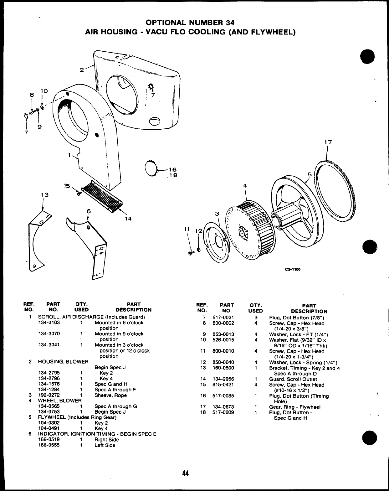
19
7
OPTIONAL NUMBER 34
AIR HOUSING -VACU FLO COOLING (AND FLYWHEEL)
1
13
(
.< 4
-.‘“
.
0
G16
18
REF.
NO.
1
2
3
4
5
6
PART OTY. PART
NO. USED DESCRIPTION
SCROLL, AIR DISCHARGE (Includes Guard)
134-3103 1Mounted in 6o’clock
position
134-3070 1Mounted in 9o’clock
position
134-3041 1Mounted in 3o’clock
position or 12 o’clock
position
HOUSING, BLOWER
Begin Spec J
134-2795 1Key 2
134-2796 1Key 4
134-1576 1Spec Gand H
134-1264 1Spec Athrough F
192-0272 1Sheave, Rope
WHEEL, BLOWER
134-0565 1Spec Athrough G
134-0753 1Begin Spec J
FLYWHEEL (Includes Ring Gear)
104-0302 1Key 2
104-0491 Key 4
INDICATOR, IGN;TION TIMING -BEGIN SPEC E
166-0519 1Right Side
166-0555 1Left Side
,
.
17
REF.
NO.
7
8
9
10
11
12
13
14
15
16
17
18
Ca-lloo
PART
NO.
517-0021
800-0002
853-0013
526-0015
800-0010
850-0040
160-0500
134-2956
815-0421
517-0035
134-0673
517-0009
QTY.
USED
3
4
4
4
4
4
1
1
4
1
1
1
PART
DESCRIPTION
Plug, Dot Button (7/6”)
Screw, Cap -Hex Head
(1/4-20 X3/8)
Washer, Lock -ET (1/4”)
Washer, Flat (9/32 ID x
9/16 OD X1/16 Thk)
Screw, Cap -Hex Head
(1/4-20 X1-3/4”)
Washer, Lock -Spring (1/4”)
Bracket, Timing -Key 2and 4
Spec Athrough D
Guard, Scroll Outlet
Screw, Cap -Hex Head
(#10-16x 1/2”)
Plug, Dot Button (Timing
Hole)
Gear, Ring -Flywheel
Plug, Dot Button -
Spec Gand H
.
.>
44
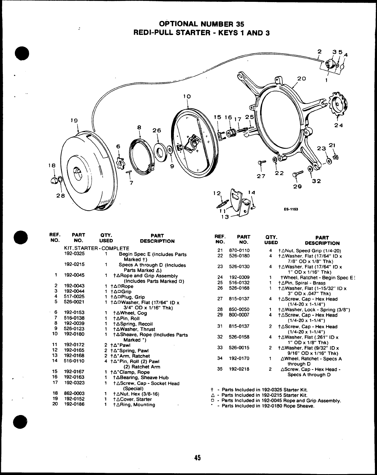
OPTIONAL NUMBER 35
REDI-PULL STARTER -KEYS 1AND 3
aREF. PART QTV.
NO.
PART
NO. USED DESCRIPTION
KIT, STARTER -COMPLETE
1
2
3
4
5
6
7
8
9
10
11
12
13
14
15
.’ 16
17
18
,- 19
20
192-0325
192-0215
192-0045
192-0043
192-0044
517-0025
526-0021
192-0153
516-0138
192-0039
526-0123
192-0180
192-0172
192-0165
192-0168
516-0110
192-0167
192-0163
192-0323
862-0003
192-0152
192-0188
1Begin Spec E(Includes Parts
Marked t)
1Specs Athrough D(Includes
Parts Marked A)
1tARope and Grip Assembly
(Includes Parts Marked 0)
1fAORope
1tAOGrip
1tAOPlug, Grip
1 tAOWasher, Fiat (17/64” ID x
3/4” OD X1/16 Thk)
1tAWheeL Cog
1TAPin, Roll
1tASpring, Recoil
1tAWasher, Thrust
1tASheave, Rope (Includes Parts
Marked “)
2tA”Pawl
2tA”Spring, Pawl
2tA”Arm, Ratchet
4tA”Pin, RoII (2) Pawl
(2) Ratchet Arm
1tA”Clamp, Rope
1tABearing, Sheave Hub
1 t AScrew, Cap -Socket Head
(Special)
1tANut, Hex (3/8-16)
1 t ACover, Starter
1tARing, Mounting
REF. PART
NO. NO.
21 870-0110
22 526-0180
23 526-0130
24 192-0309
25 516-0132
26 526-0168
27 815-0137
28 850-0050
29 800-0007
31 815-0137
32 526-0158
33 526-0015
34 192-0170
35 192-0218
29
ES-llSS
QTY. PART
USED DESCRIPTION
4tANut, Speed Grip (1/4-20)
4tAWasher, Flat (17/64” ID x
7/8” OD X1/6” Thk)
4tAWasher, Flat (17/64” ID x
1“ ODx 1/16 Thk)
1tWheel, Ratchet -Begin Spec
1tAPin, Spiral -Brass
1tAWasher, Flat (1-15/32” ID x
3“ OD X.047” Thk)
4tAScrew, Cap -Hex Head
(1/4-20 X1-1/4)
1tAWasher, Lock -Spring (3/8”
4tAScrew, Cap -Hex Head
(1/4-20 X1-1/4”)
2 t AScrew, Cap -Hex Head
(1/4-20 X1-1/4)
4tAWasher. Flat (.261” ID x
1“ OD X1/6” Thk)
2 t AWasher, Flat (9/32 ID x
9/16 OD X1/16 Thk)
1AWheel, Ratchet -Specs A
through D
2AScrew, Cap -Hex Head -
Specs Athrough D
t-Parts Included in 192-0325 Starter Kit.
A - Parts Included in 192-0215 Starter Kit.
o-Parts Included in 192-0045 Rope and Grip Assembly.
.-Parts Included in 192-0180 Rope Sheave.
45
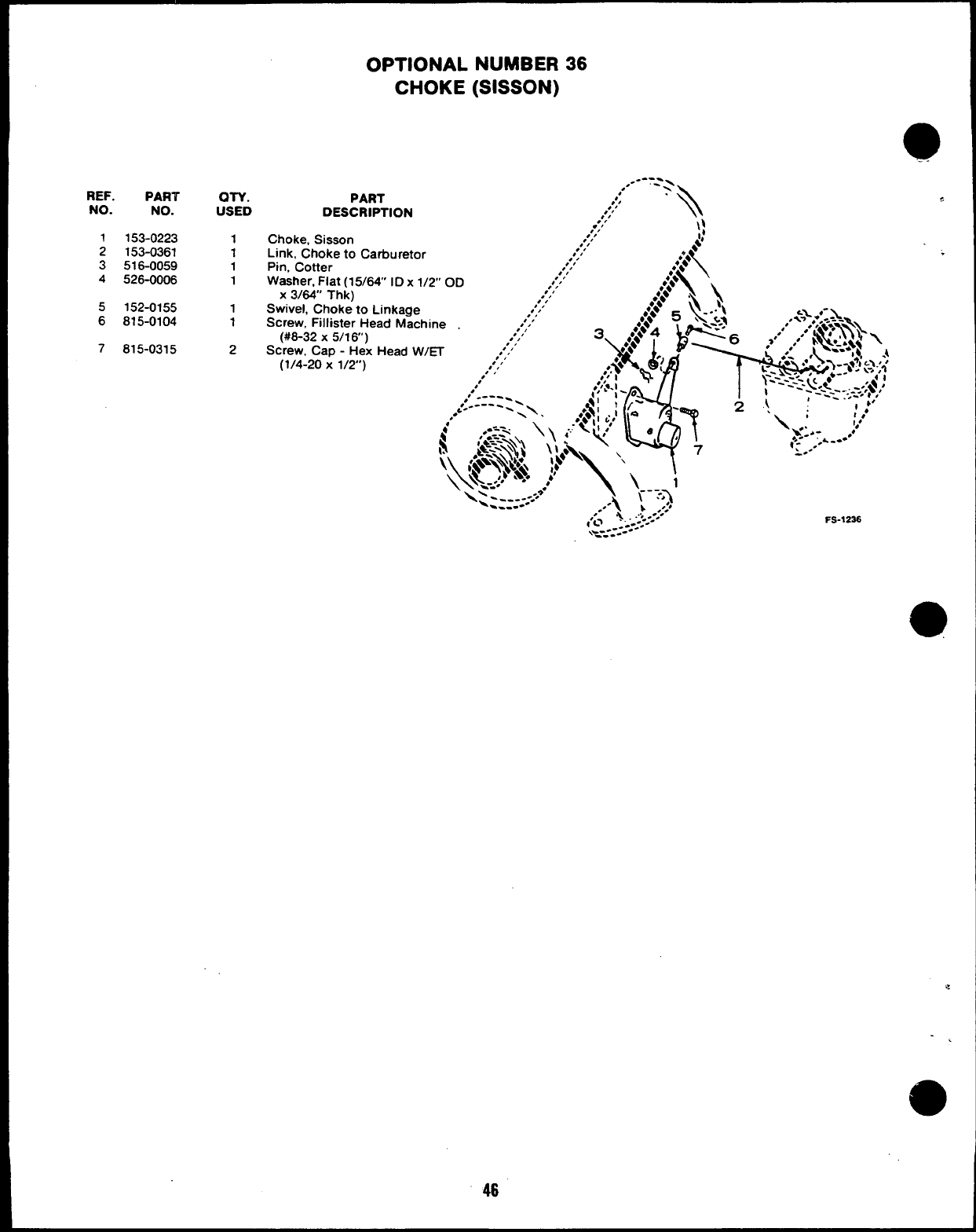
REF. PART
NO. NO.
1153-0223
2153-0361
3516-0059
4526-0006
5152-0155
6815-0104
7815-0315
OTY.
USED
1
1
1
1
1
1
2
OPTIONAL NUMBER 36
CHOKE (SISSON)
----
,.- - ,-
PART ,
,,;/
DESCRIPTION ,’,’ ‘\
.“,‘\:
Choke, Sisson ,’/’
Link, Choke to Cafiuretor ,’/’ $
,’/’
\
●*;*
Pin, Cotter ,’/’
.,.,.*A
Washer, Fiat (15/64
X3/64’ Thk)
IDx
Swivel, Choke to Linkage
Screw, Fillister Head Machine
(#8-32 X5/1 6“)
Screw, Cap -Hex Head W/~
(1/4-20 X1/2’)
FS-1236
46
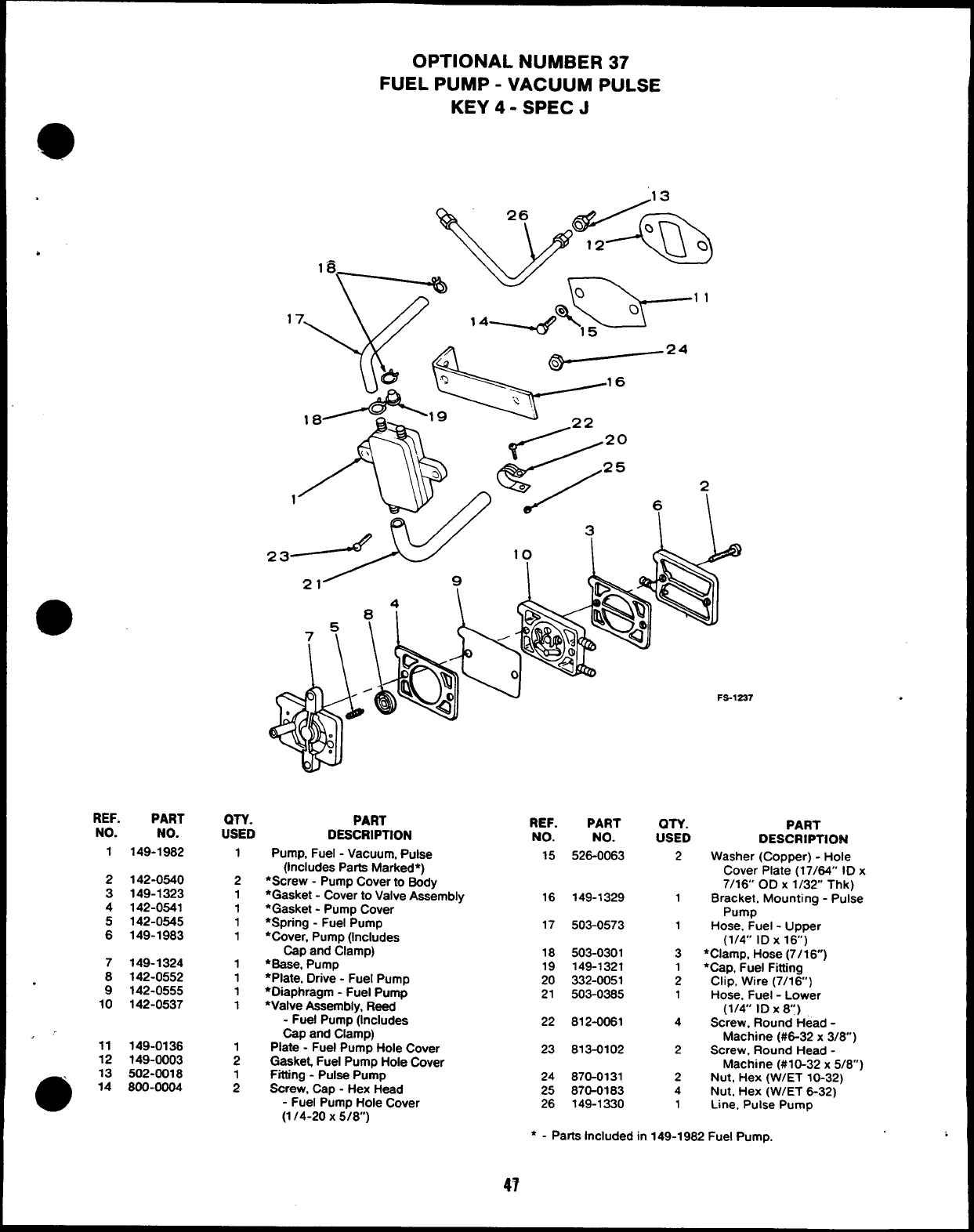
OPTIONAL NUMBER 37
FUEL PUMP -VACUUM PULSE
KEY 4- SPEC J
.13
Ck
2
6A /~
wk;.–”
/22 20
/25
/
P
6
\\&
+
.
REF.
NO.
1
2
3
4
:
PART
NO.
149-1982
142-0540
149-1323
142-0541
142-0545
149-1983
QTY. PART
USED DESCRIPTION
1
REF.
NO.
15
PART
NO.
528-0063
QTY.
USED
PART
DESCRIPTION
Washer (Copper) -Hole
Cover Plate (17/64” ID x
7/16’ OD X1/32 Thk)
Bracket, Mounting -Pulse
Pump
Hose, Fuel -Upper
(1/4” ID X16”)
●Clamp, Hose (7/ 16)
●Cap, Fuel Fitting
Clip, Wtre (7/16)
Hose, Fuel -Lower
(1/4” ID X8)
Screw, Round Head -
Machine (#6-32 x3/8)
Screw. Round Head -
Machine (#10-32 x5/8”)
Nut, Hex (W/ET 10-32)
Nut, Hex (W/ET 8-32)
Line. Pulse Pump
Pump, Fuel -Vacuum, Pulse
(Includes Parts Marked*)
●Screw -Pump Cover to Body
●Gasket -Cover to Valve Assembly
*Gasket -Pump Cover
●Spring -Fuel Pump
*Cover, Pump (Includes
Cap and Clamp)
‘Base, Pump
●Plate, Drive -Fuel Pump
*Olaphragm -Fuel Pump
●Valve Assembly, Reed
-Fuel Pump (Includes
Cap and Clamp)
Plate -Fuel Pump Hole Cover
Gasket Fuel Pump Hole Cover
Fting -Pulse Pump
Screw, Cap -Hex Head
-Fuel Pump Hole Cover
(1 /4-20X 5/8)
2
2
1
1
1
1
16 149-1329 1
503-0573
17 1
18
19
20
21
503-0301
149-1321
332-0051
503-0385
3
1
2
1
7
8
9
10
149-1324
142-0552
142-0555
142-0537
1
1
1
1
22 812-0061 4
11
12
13
14
149-0138
149-0003
502-0018
800-0004
23 813-0102 2
24
25
26
870-0131
870-0183
149-1330
2
4
1
●-Parts Included in 149-1982 Fuel Pump.
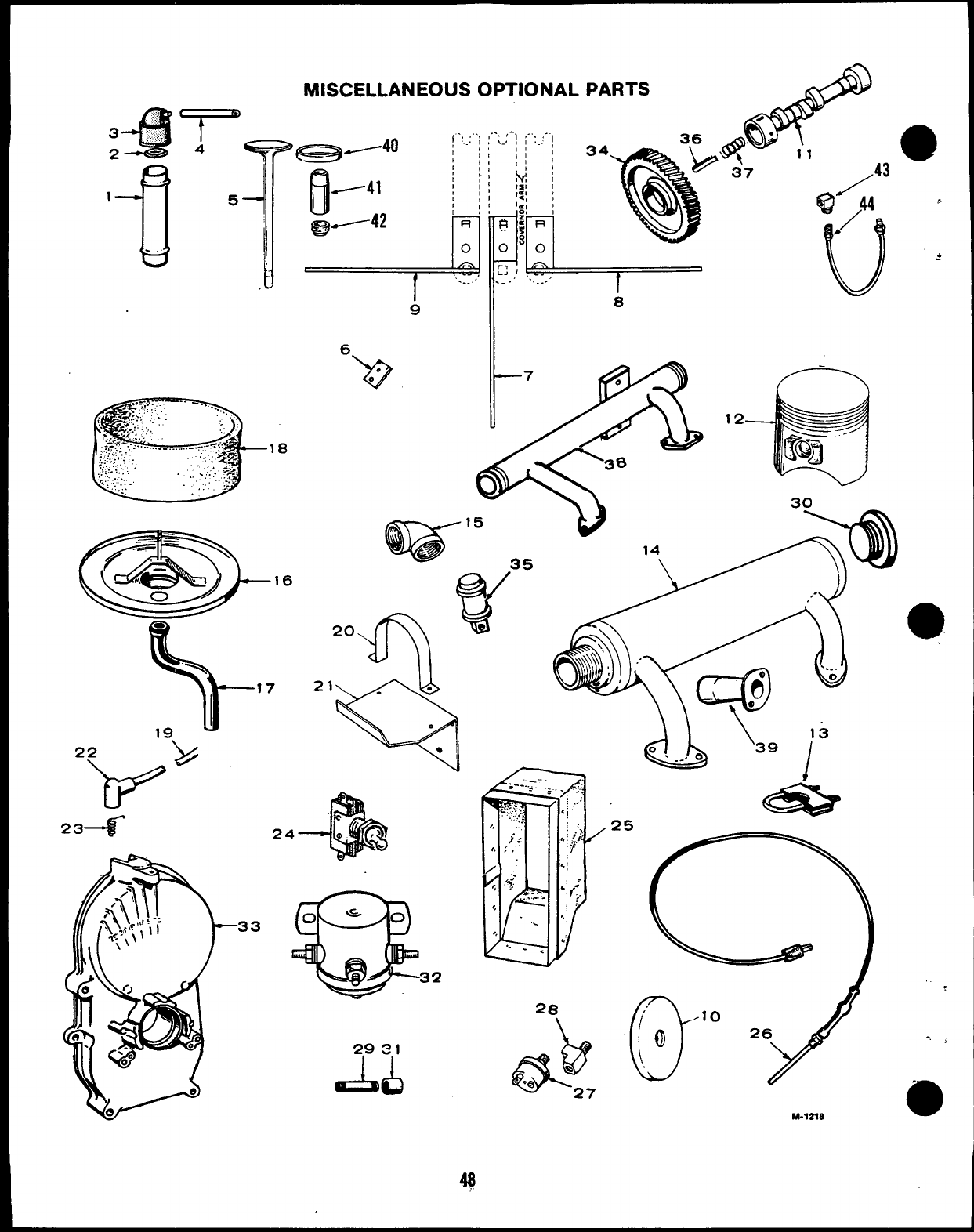
MISCELLANEOUS OPTIONAL PARTS
16
\
17
19,
234
29S1
AL)
.. - R
q’””11
!
oa
37
Qji43 ‘
u
*
8
(j’” 26~
M-72X8
,
-, >
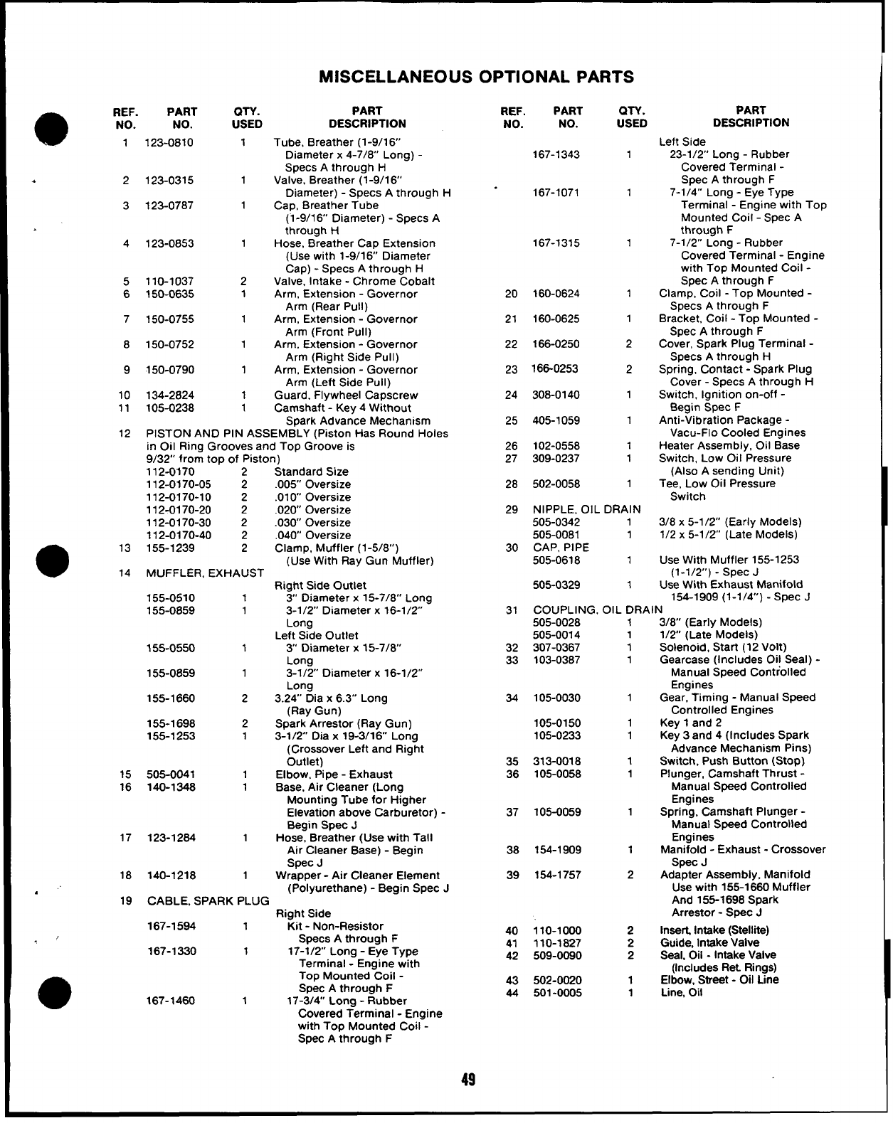
MISCELLANEOUS OPTIONAL PARTS
aREF. PART
NO. NO.
1
.2
3
5
6
7
8
9
10
11
12
@
13
14
15
16
17
18
.’
19
123-0810
123-0315
123-0787
123-0853
110-1037
150-0635
150-0755
150-0752
150-0790
134-2824
105-0238
(N-Y.
USED
1
1
1
1
2
1
1
1
1
1
1
PART
DESCRIPTION
Tube, Breather (1-9/1 6’
Diameter x4-7/8’ Long)-
Specs Athrough H
Valve. Breather (1-9/16’
Diameter) -Specs Athrough H
Cap, Breather Tube
(1-9/1 6Diameter) -Specs A
through I-1
Hose, Breather Cap Extension
(Use with 1-9/16’ Diameter
Cap) -Specs Athrough H
Valve, Intake -Chrome Cobalt
Arm, Extension -Governor
Arm (Rear Pull)
Arm, Extension -Governor
Arm (Front Pull)
Arm, Extension -Governor
Arm (Right Side Pull)
Arm, Extension -Governor
Arm (Left Side Pull)
Guard, Flywheel Capscrew
Camshaft -Key 4Without
Spark Advance Mechanism
PISTON AND PIN ASSEMBLY (Piston Has Round Holes
in Oil Ring Grooves and Top Groove is
9/32’ from top of Piston)
112-0170 2Standard Size
112-0170-05 2.005” Oversize
112-0170-10 2.010 Oversize
112-0170-20 2.020 Oversize
112-0170-30 2.030 Oversize
112-0170-40 2.040” Oversize
155-1239 2Clamp, Muffler (1-5/8”)
(Use With Ray Gun Muffler)
MUFFLER, EXHAUST
Right Side Outlet
155-0510 13“ Diameter x15-7/8” Long
155-0859 13-1/2” Diameter x16-1/2”
Long
Left Side Outlet
155-0550 1 3 Diameter x15-7/8
Long
155-0859 13-1/2” Diameter x16-1/2”
Long
155-1660 23.24” Dia x6.3” Long
(Ray Gun)
155-1698 2Spark Arrestor (Ray Gun)
155-1253 13-1/2’ Dia x19-3/16 Long
(Crossover Left and Right
Outlet)
505-0041 1Elbow, Pipe -Exhaust
140-1348 1Base, Air Cleaner (Long
Mounting Tube for Higher
Elevation above Carburetor) -
Begin Spec J
123-1284 1Hose, Breather (Use with Tall
Air Cleaner Base) - Begin
Spec J
140-1218 1Wrapper -Air Cleaner Element
(Polyurethane) -Begin Spec J
CABLE, SPARK PLUG
Right Side
167-1584 1Kit -Non-Resistor
Specs Athrough F
167-1330 117-1/2 Long -Eye Type
Terminal -Engine with
Top Mounted Coil -
Spec Athrough F
167-1460 117-3/4” Long -Rubber
— —
Covered Termmal -Engine
with Top Mounted Coil -
Spec Athrough F
49
REF. PART
NO. NO.
167-1343
167-1071
167-1315
20 160-0624
21 160-0625
22 166-0250
23 166-0253
24 308-0140
25 405-1059
26 102-0558
27 309-0237
28 502-0058
QTY.
USED
1
1
1
1
1
2
2
1
1
1
1
1
29 NIPPLE, OIL DRAIN
505-0342 1
505-0081 1
30 CAP, PIPE
505-0618 1
505-0329 1
1
1
1
1
1
1
1
1
1
1
1
2
2
2
2
1
1
PART
DESCRIPTION
Left Side
23-1/2” Long -Rubber
Covered Terminal -
Spec Athrough F
7-1 /4” Long -Eye Type
Terminal -Engine with Top
Mounted Coil -Spec A
through F
7-112” Long -Rubber
Covered Terminal -Engine
with Top Mounted Coil -
Spec Athrough F
Clamp, Coil -Top Mounted -
Specs Athrough F
Bracket, Coil -Top Mounted -
Spec Athrough F
Cover, Spark Plug Terminal -
Specs Athrough H
Spring, Contact -Spark Plug
Cover -Specs Athrough H
Switch, Ignition on-off -
Begin Spec F
Anti-Vibration Package -
Vacu-Flo Cooled Engines
Heater Assembly, Oil Base
Switch, Low Oil Pressure
(Also Asending Unit)
Tee. Low Oil Pressure
Switch
31 COUPLING, OIL DRAIN
505-0028
505-0014
32 307-0367
33 103-0387
34 105-0030
105-0150
105-0233
35 313-0018
36 105-0058
37 105-0059
38 154-1909
39 154-1757
40 110-1000
41 110-1827
42 509-0090
43 502-0020
44 501-0005
3/8 x5-1/2” (Early Models)
1/2 x5-1/2” (Late Models)
Use With Muffler 155-1253
(1-1/2”) -Spec J
Use With Exhaust Manifold
154-1909 (l-1 /4”) -Spec J
3/8” (Early Models)
1/2 (Late Models)
Solenoid, Start (12 Volt)
Gearcase (Includes Oil Seal) -
Manual Speed Controlled
Engines
Gear, Timing -Manual Speed
Controlled Engines
Key 1and 2
Key 3and 4(Includes Spark
Advance Mechanism Pins)
Switch, Push Button (Stop)
Plunger, Camshaft Thrust -
Manual Speed Controlled
Engines
Spring, Camshaft Plunger -
Manual Speed Controlled
Engines
Manifold -Exhaust -Crossover
Spec J
Adapter Assembly, Manifold
Use with 155-1660 Muffler
And 155-1698 Spark
Arrestor -Spec J
Insert, Intake (Stellite)
Guide, Intake Valve
Seal, Oil -Intake Valve
(Includes Ret Rings)
Elbow, Street -Oil Line
Line, 011
