934 0124 Onan MDL3 MDL4 MDL6 Marine Genset Operator's Manual (03 1992)
User Manual: 934-0124 Onan MDL3 MDL4 MDL6 Marine Genset Operator's manual (03-1992)
Open the PDF directly: View PDF ![]() .
.
Page Count: 28
MDL3
MDL4
MDL6
I
I-
Printed
in
USA.
3-92
934-01
24
lnsp
ctiuel
system
before
eachoperat;onand
periodically
;~,uh
5:.
running.
EXHAUST
GASES
ARE
DEAQLY
ELECTRICAL
SH8
M
WILL
CfiUSE
SEVERE
PERSONAL
INJURY
OR
OEATH
opy
and
post
these
suggestions
In
potential
hazard
arms
81
the
vessel.
Redistribution or publication of this document,
by any means, is strictly prohibited.
Table
of
Contents
SECTION
TITLE
PAGE
SAFETY PRECAUTIONS
..............................
Inside
Front
Cover
1
INTRODUCTION
...................................................
1-1
About This Manual
................................................
1-1
How
to Obtain Service
.............................................
1-1
2
SPEC1 FlCATlONS
..................................................
2-1
MDL3
..........................................................
2-1
MDL4
..........................................................
2-2
MDL6
..........................................................
2-3
3
OPERATION
......................................................
3-1
General
.........................................................
3-1
Pre-Start Checks
.................................................
3-1
ControlPanel
....................................................
3-2
Starting
.........................................................
3-3
Stopping
........................................................
3-3
Operating Recommendations
........................................
3-4
Troubleshooting
..................................................
3-4
MAINTENANCE
....................................................
4-1
General
.........................................................
4-1
Periodic Maintenance Schedule
......................................
4-1
Setlnspection
....................................................
4-2
LubncationSystem
................................................
4-2
Cooling System
..................................................
4-3
Fuelsystem
.....................................................
4-5
ValveClearance
..................................................
4-7
Battery
.........................................................
4-7
AC
Generator
....................................................
4-8
Out-of-Service Protection
...........................................
4-8
4
i
Redistribution or publication of this document,
by any means, is strictly prohibited.

Redistribution or publication of this document,
by any means, is strictly prohibited.
Section
1
Introduction
ABOUT
THIS
MANUAL
RECREATIONAL VEHICLES-EQUIPMENT,
This manual provides information for operating and
maintaining the genset. Study this manual carefully and
observe all warnings and cautions. Using the genset
properly and following a regular maintenance schedule
will contribute
to
longer unit life, better performance, and
safer operation.
HOW
TO OBTAIN
SERVICE
When the genset requires servicing, contact your near-
est dealer or distributor. Factory-trained Parts and Serv-
ice representatives are ready to handle all your service
needs.
If
unable
to
locate a dealer or distributor, consult the Yel-
low Pages. Typically, our distributors are listed under:
GENERATORS-ELECTRIC,
ENGINES-GASOLINEOR DIESEL, OR
PARTS AND SERVICE.
For the name of your local Cummins/Onan
or
Onan-only
distributor in the United States or Canada, call
1
-800-888-ONAN (This automated service utilizes
touch-tone phones only). By entering your area code
and the first three digits of your local telephone number,
you will receive the name and telephone number of the
distributor nearest you.
For the name of your
local
Cummins-only distributor, or
if
you need more assistance, please call Onan Corpora-
tion,
1-612-574-5000,
7:30
AM
to
4:OO
PM, Central
Standard Time, Monday through Friday.
When contacting your distributor, always supply the
complete Model Number and Serial Number as shown
on the genset nameplate.
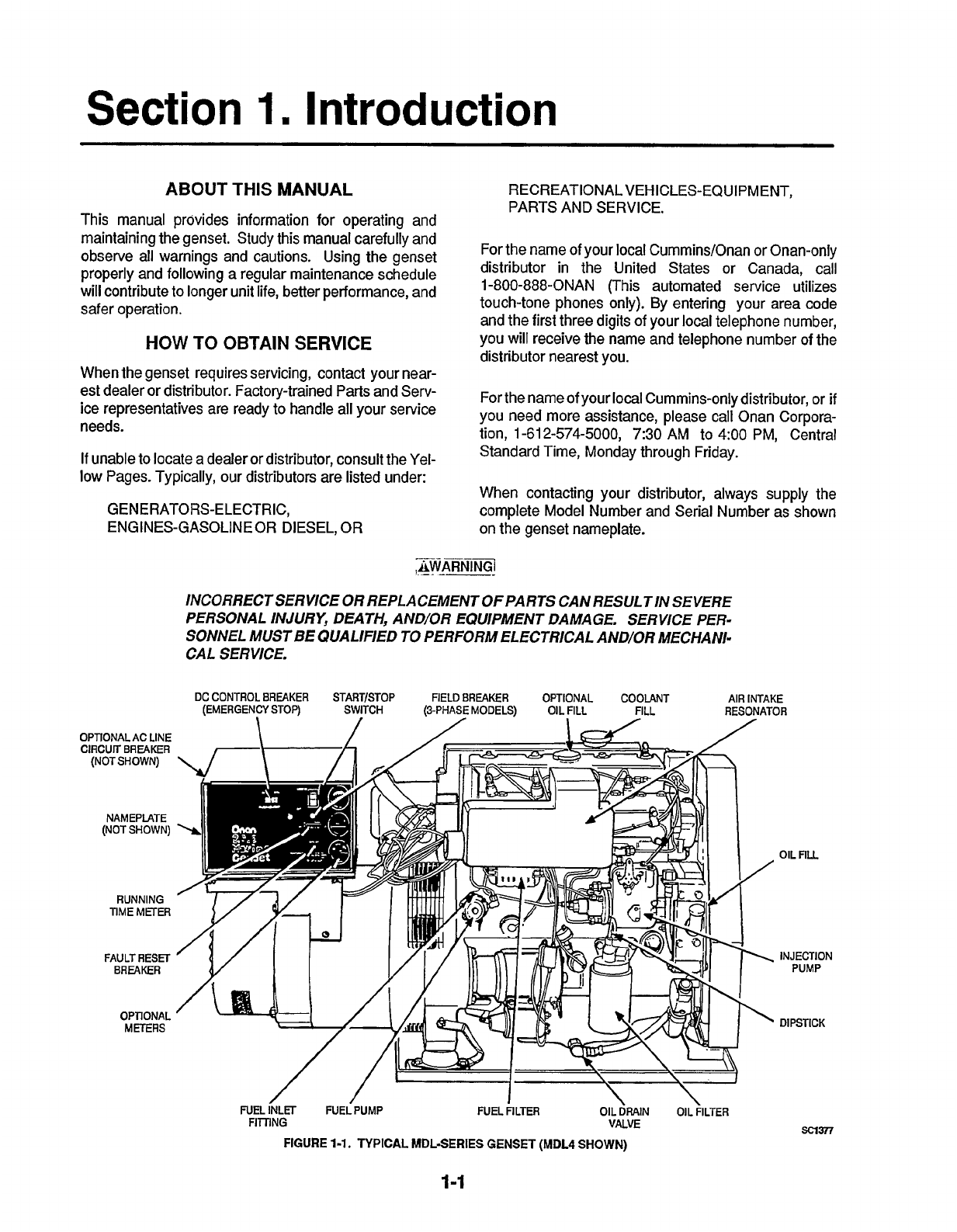
INCORRECTSERVICE
OR
REPLACEMENTOFPARTS CAN RESULTIN SEVERE
PERSONAL
INJURY,
DEATH,
AND/OR
EQUIPMENT DAMAGE. SERVICE PER-
SONNEL
MUST
BE
QUALIFIED
TO
PERFORM ELECTRICAL AND/OR MECHANI-
CAL SERVICE.
OPTIONAL
AC
LINE
CIRCUIT
BREAKER
(NOT
SHOWN)
NAMEPLATE
(NOT
SHOWN)
RUNNING
TIME
METER
FAULT
RESET
BREAKER
OPTIONAL
METERS
DC
CONTROL
BREAKER
START/STOP
FIELD
BREAKER
OPTIONAL
COOLANT
AIR
INTAKE
(EMERGENCY
STOP)
SWITCH
(3-PHASE
MODELS)
OIL
FILL
FILL
RESONATOR
OIL
nu
INJECTION
PUMP
DIPSTICK
FUEL INLET
FUELPUMP
FUEL
FILTER
OIL
DRAIN
OIL
FILTER
sa377
FlmNG
VALVE
FIGURE
1-1.
TYPICAL
MDL-SERIES GENSET
(MDL4
SHOWN)
1-1
Redistribution or publication of this document,
by any means, is strictly prohibited.

Redistribution or publication of this document,
by any means, is strictly prohibited.
Section
2.
Specifications
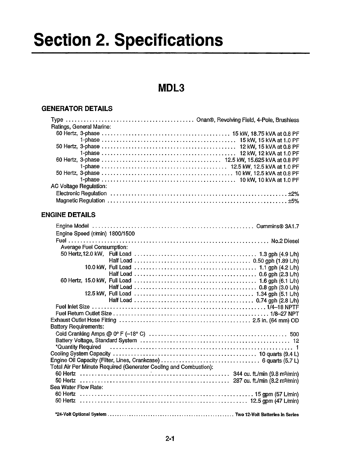
MDL3
GENERATOR DETAILS
Type
...........................................
Onan@, Revolving Field, %Pole, Brushless
Ratings, General Marine:
60
Hertz, 3-phase
...........................................
15
kW,
18.75
kVA at
0.8
PF
l-phase
.............................................
15
kW, 15 kVA at 1.0 PF
50
Hertz, 3-phase
.............................................
12 kW, 15 kVA at
0.8
PF
l-phase
.............................................
12 kW, 12 kVA at 1.0 PF
60
Hertz, 3-phase
........................................
12.5 kW, 15.625 kVA
at
0.8
PF
l-phase
..........................................
12.5 kW, 12.5 kVA at
1.0
PF
50
Hertz, 3-phase
............................................
10 kW, 12.5 kVA at
0.8
PF
1-phase
.............................................
10
kW, 10 kVA at 1.0 PF
Electronic Regulation
...........................................................
~2%
AC Voltage Regulation:
MagneticRegulation
............................................................
*5%
ENGINE
DETAILS
Engine Model
......................................................
CumminsQ 3A1.7
Engine Speed (r/min) 1 800/1500
Fuel
...................................................................
No.2Diesel
Average Fuel Consumption:
50 Hertz,12.0 kW, Full Load
.........................................
1.3
gph
(4.9
Uh)
10.0
kW, Full Load
.........................................
1.1 gph (4.2
Uh)
Half Load
.........................................
0.6
gph (2.3 Uh)
60
Hertz, 15.0 kW, Full Load
.........................................
1.6
gph (6.1
Uh)
Half Load
.........................................
0.8
gph (3.0 Uh)
12.5
kW, Full Load
........................................
1.34 gph (5.1 Uh)
Half Load
........................................
0.74
gph (2.8 Uh)
Fuel Inlet Size
.........................................................
.1/4-18
NPTF
Fuel Return Outlet Size.
...................................................
1/8-27 NPT
Exhaust Outlet
Hose
Fitting
............................................
2.5 in.
(64
mm)
OD
Battery Requirements:
Cold Cranking Amps,
@
Oo
F
(-1
8'
C)
..............................................
500
Battery Voltage, Standard System
..................................................
12
Cooling System Capacity
................................................
10
quarts
(9.4
L)
Engine Oil Capacity (Filter, Lines, Crankcase)
.................................
6
quarts
(5.7
L)
Total
Air Per Minute Required (Generator Cooling and Combustion):
60
Hertz
...................................................
344 cu. ft./min
(9.8
rn3/min)
50
Hertz
..................................................
287
cu. ft./min
(8.2
rn3/rnin)
Sea Water
Flow
Rate:
60Hertz
..........................................................
15gpm(57Umin)
50
Hertz
........................................................
12.5
gpm
(47
Urnin)
Half Load
..........
,
............................
0.50
gph
(1.89
Uh)
*QuantityRequired
.............................................................
1
'24-Votl
Optional
System
.....................................................
Two
12-VoIt
Batteries
In
Series
2-1
Redistribution or publication of this document,
by any means, is strictly prohibited.
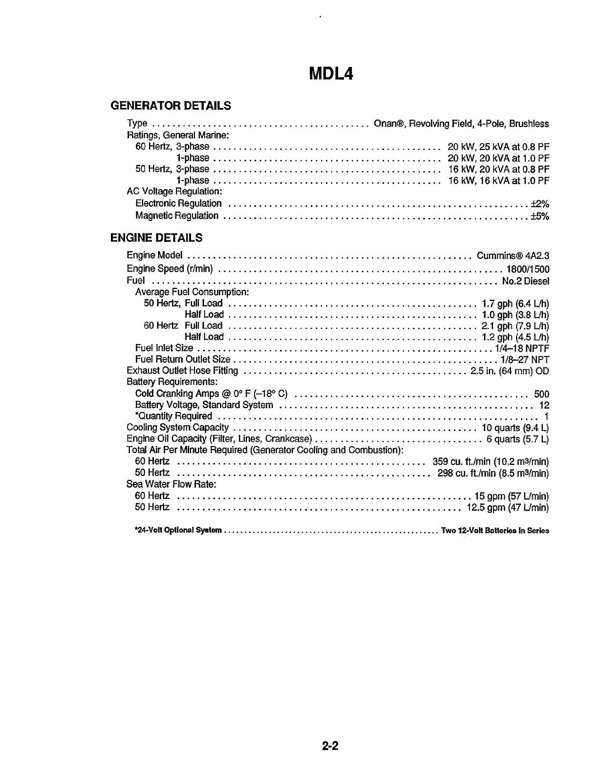
MDL4
GENERATOR
DETAl
LS
Type
...........................................
Onan@, Revolving Field, 4-Pole, Brushless
Ratings, General Marine:
60 Hertz, 3-phase
.............................................
20 kW, 25 kVA at 0.8 PF
1-phase
.............................................
20 kW, 20 kVA at 1.0 PF
50
Hertz, 3-phase
.............................................
16 kW, 20 kVA at 0.8 PF
1-phase
.............................................
16 kW, 16 kVAat 1.0 PF
AC Voltage Regulation:
ElectronicRegulation
...........................................................
.%
MagneticRegulation
............................................................
*
5%
ENGINE
DETAILS
Engine Model
........................................................
Cummins@ 4A2.3
EngineSpeed(r/min)
........................................................
1800/1500
Fuel
....................................................................
No.2Diesel
50
Hertz, Full Load
.................................................
1.7 gph (6.4 Uh)
Half Load
.................................................
1.0 gph (3.8 Uh)
60
Hertz Full Load
.................................................
2.1 gph (7.9 Uh)
Half Load
.................................................
1.2 gph (4.5 Uh)
Fuel Inlet Size
..........................................................
1
/4-18 NPTF
Fuel Return Outlet Size.
...................................................
1/8-27 NPT
Exhaust Outlet Hose Fitting
............................................
2.5 in. (64 mm)
OD
Battery Requirements:
Cold Cranking Amps
@
Oo
F (-1 8" C)
..............................................
500
Battery Voltage, Standard System
..................................................
12
Cooling System Capacity
................................................
10 quarts (9.4 L)
Engine Oil Capacity (Filter, Lines, Crankcase)
.................................
6 quarts (5.7 L)
Total Air Per Minute Required (Generator Cooling and Combustion):
60 Hertz
.................................................
359
cu. ft./min (1
0.2
m3/min)
50
Hertz
..................................................
298
cu. ft./min
(8.5
m3/min)
Sea
Water Flow Rate:
50
Hertz
........................................................
12.5 gpm (47 Umin)
Average Fuel Consumption:
*QuantityRequired
...............................................................
1
60Hertz
..........................................................
15gpm(57Umin)
*24Volt
Optional
System
.....................................................
Two
12-Volt
Batteries
In
Series
2-2
Redistribution or publication of this document,
by any means, is strictly prohibited.
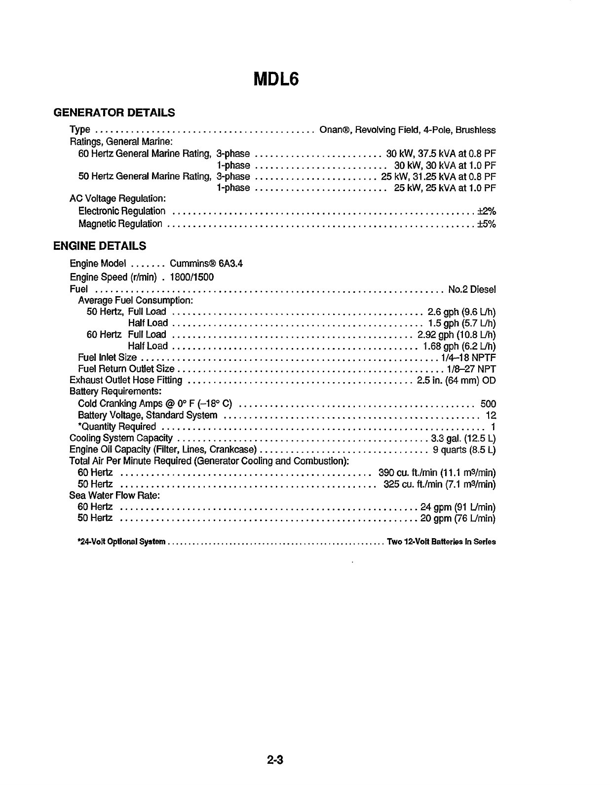
MDL6
GENERATOR DETAILS
Type
...........................................
Onan@, Revolving Field, 4-Pole, Brushless
Ratings, General Marine:
60 Hertz General Marine Rating, 3-phase
.........................
30
kW,
37.5
kVA
at
0.8
PF
l-phase
..........................
30
kW,
30
kVA at
1.0 PF
50
Hertz General Marine Rating, 3-phase
........................
25
kW,
31.25 kVA at
0.8
PF
l-phase
..........................
25
kW,
25
kVA at 1.0 PF
Electronic Regulation
...........................................................
k2%
MagneticRegulation
............................................................
*
5%
AC Voltage Regulation:
ENGINE
DETAILS
Engine Model
.......
CumminsB 6A3.4
Engine Speed (r/min)
.
1800/1500
Fuel
....................................................................
No.2Diesel
50
Hertz, Full Load
.................................................
2.6
gph
(9.6
Uh)
Half Load
.................................................
1.5
gph (5.7 Uh)
60
Hertz Full Load
...............................................
2.92 gph (10.8 Uh)
Half Load
................................................
1.68 gph (6.2
Uh)
Fuel Inlet Size
..........................................................
1
/4-18
NPTF
Fuel Return Outlet Size.
...................................................
1/8-27
NPT
Exhaust Outlet Hose Fitting
............................................
2.5 in. (64 mm)
OD
Battery Requirements:
Cold Cranking Amps
@
0"
F (-1
8"
C)
..............................................
500
Battery Voltage, Standard System
..................................................
12
*Quantity Required
...............................................................
1
Cooling System Capacity
................................................
.3.3 gal. (12.5
L)
Engine
Oil
Capacity (Filter, Lines, Crankcase)
.................................
9 quarts
(8.5
L)
Total Air Per Minute Required (Generator Cooling and Combustion):
60Hertz
.................................................
390cu.ft./min
(11.1
mVrnin)
50
Hertz
..................................................
325
cu.
ft./min (7.1 m3/min)
Sea Water Flow Rate:
60Hertz
..........................................................
24gpm(91 Umin)
50Hertz
..........................................................
20gpm(76Umin)
Average Fuel Consumption:
*24-VoR
Optlonal
System
.....................................................
Two
12-Volt
Batteries
In
Series
2-3
Redistribution or publication of this document,
by any means, is strictly prohibited.

Redistribution or publication of this document,
by any means, is strictly prohibited.
Section
3.
Operation
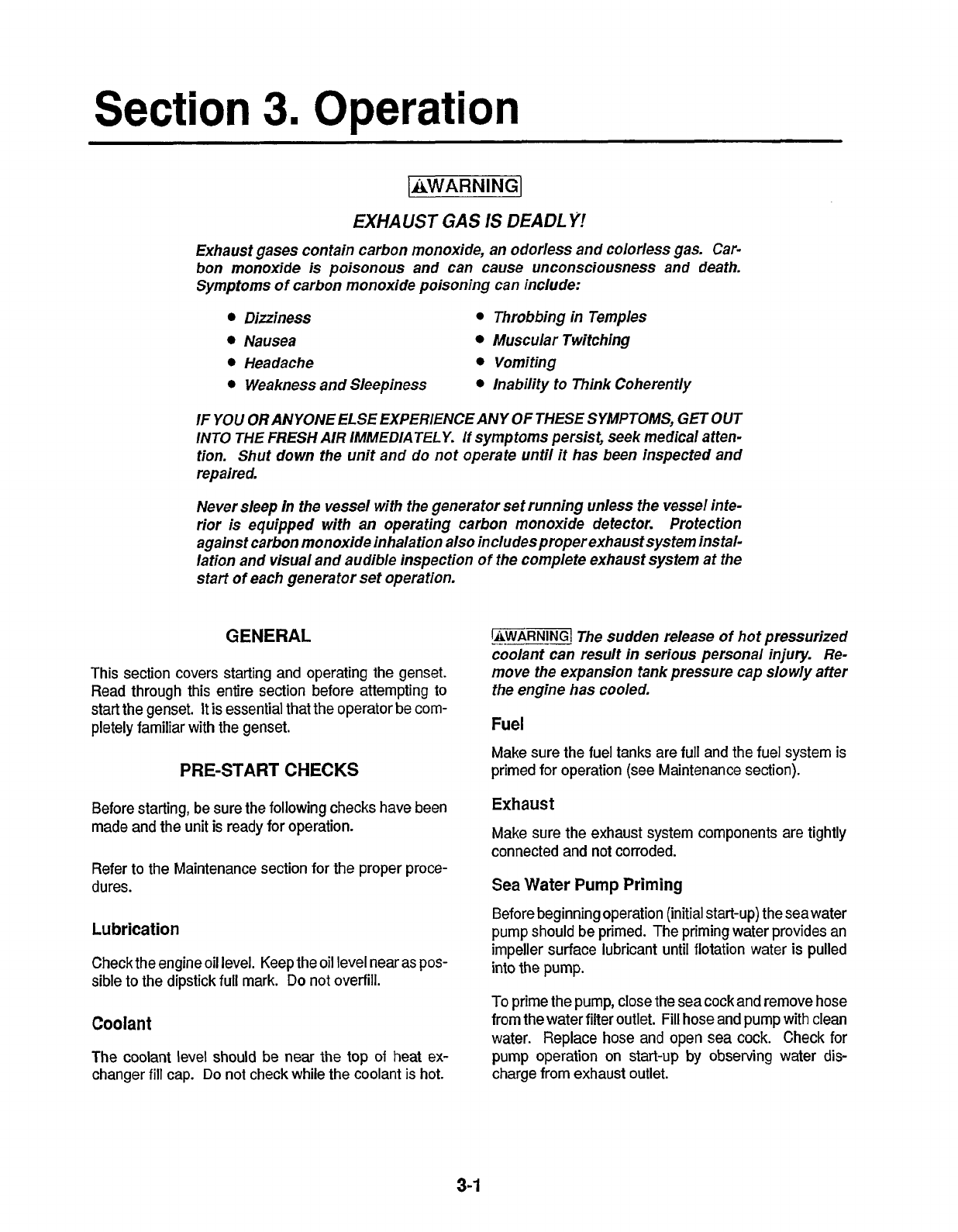
IAWARNING]
EXHAUST
GAS
IS
DEADLY!
Exhaust gases contain carbon monoxide, an odorless and colorless gas. Car-
bon monoxide is poisonous and can cause unconsciousness and death.
Symptoms
of
carbon monoxide poisoning can include:
Dizziness
Nausea Muscular Twitching
Headache Vomiting
Weakness and Sleepiness
Throbbing in Temples
lnability to Think Coherently
IF
YOU
ORANYONEELSE EXPERIENCEANY
OF
THESE SYMPTOMS,
GETOUT
INTO THE
FRESH
AIR IMMEDIATELY.
If
symptoms persist, seek medical atten-
tion. Shut down the unit and do not operate until it has been inspected and
repaired.
Never sleep in the vessel with the generator sef running unless the vessel inte-
rior
is
equipped with an operating carbon monoxide defector. Protection
against carbon monoxide inhalation also includesproperexhausf system instal-
lation and visual and audible inspection
of
the complete exhaust system at the
start
of
each genera tor set operation.
GENERAL
This section covers starting and operating the genset.
Read through this entire section before attempting to
start the genset.
It
is essential that the operator be com-
pletely familiar with the genset.
PRE-START
CHECKS
Before starting, be sure the following checks have been
made and the unit is ready for operation.
Refer to the Maintenance section for the proper proce-
dures.
Lubrication
Check the engine oil level. Keep the oil level near as pos-
sible to the dipstick full mark.
Do
not overfill.
Coolant
The coolant level should
be
near the top
of
heat ex-
changer
fill
cap.
Do
not check while the coolant
is
hot.
WAR”GI
The sudden release
of
hot pressurized
coolant can result
in
serious personal injury. Re-
move the expansion tank pressure cap slowly after
the engine has cooled.
Fuel
Make sure the fuel tanks are full and the fuel system is
primed for operation (see Maintenance section).
Exhaust
Make sure the exhaust system components are tightly
connected and not corroded.
Sea
Water Pump
Priming
Before beginning operation (initial start-up) the seawater
pump should be primed. The priming water provides an
impeller surface lubricant until flotation water is pulled
into the pump.
To
prime the pump, close the sea cock and remove hose
from the water filter outlet.
Fill
hose and pump with clean
water. Replace hose and open sea cock. Check
for
pump operation on start-up
by
observing water dis-
charge from exhaust outlet.
3-1
Redistribution or publication of this document,
by any means, is strictly prohibited.
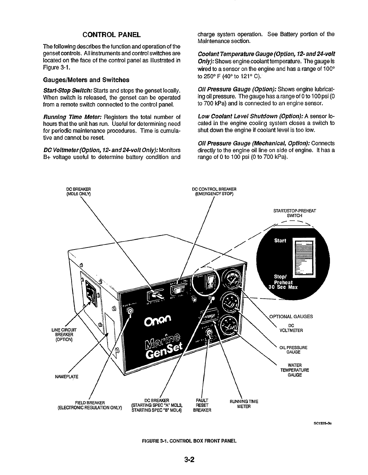
CONTROL
PANEL
The following describes the function and operation
of
the
genset controls.
All
instruments and control switches are
located on the face of the control panel as illustrated
in
Figure
3-1.
GaugedMeters
and
Switches
Start-Stop Switch:
Starts and stops the genset locally.
When switch is released, the genset can be operated
from a remote switch connected to the control panel.
Running Time Meter:
Registers the total number of
hours that the unit has run. Useful for determining need
for periodic maintenance procedures. Time is cumula-
tive and cannot be reset.
DC
Voltmeter (Option, 12- and 24-volt
Only): Monitors
B+ voltage useful to determine battery condition and
DC
BREAKER
(MDLG
ONLY)
\
charge system operation. See Battery portion
of
the
Maintenance section.
Coolant Temperature Gauge (Option,
12-
and
24-volt
0nly):Shows engine,coolant temperature. The gauge
is
wired to a sensor on the engine and has a range of
100"
to
250°
F
(40"
to
121"
C).
Oil Pressure Gauge (Option):
Shows engine lubricat-
ing oil pressure. The gauge has a range
of
0
to
100
psi
(0
to
700
kPa) and is connected to an engine sensor.
Low Coolant Level Shutdown (Option):
A
sensor
lo-
cated in the engine, cooling system closes a switch to
shut down the engine
if
coolant level is too low.
Oil Pressure
Gauge
(Mechanical, Option):
Connects
directly to the engine oil line on side of engine. It has a
range
of
0
to
100
psi
(0
to
700
kPa).
DC
CONTROL
BREAKER
(EMERGENCY STOP)
/
I
START/STOP-PREH
EAT
SWITCH
FIELD
BREAKER
DC
BREAKER
FAULT
RUNNiNGTlME
(ELECTRONIC
REGULATION
ONLY)
~!$~~~","pp,E,",~,"~~$
METER
FIGURE
3-1.
CONTROL
BOX
FRONT
PANEL
3-2
Redistribution or publication of this document,
by any means, is strictly prohibited.
Circuit
Breakers
Fault Reset;A
manual reset breaker that shuts down the
engine for low oil pressure, high coolant temperature,
high exhaust temperature, overspeed (optional for
MDL3),
and
optional low-coolant level.
Ambient
Temperature
Above
86"
F
(30"
C)
Between
SO"
to
86"
F
(IO"
to
30"
C)
Emergency
Stop
DC
Control Breaker:
A
15-ampere
breaker providing protection to the control box wiring and
remote wiring from short circuits or overload.
Also
serves as an emergency stop switch and control disable
for service.
Preheat Time
Abuut
10
seconds
About
15
seconds
Line Circuit Breakers (Option):
Protects generator
from ashort circuit
or
other overload. When furnished by
Onan, they mount on the control box. Replacements
must meet ABYC specs for proper protection.
Field Breaker (Electronic Regulators Only):
A
3
am-
pere breaker providing generator field protection
if
the
voltage regulator fails.
(0"
to
1
0"
C)
Below
32"
F
(0"
C)
DC
Breaker;
Connects
B+
to the control and trips if a
short
or
overload occurs. Model MDL6 gensets have the
breaker located on the left side of the control panel be-
cause of its physical size and larger ampere rating. On
Model
MDL4
Spec
"A"
gensets, the DC breaker was re-
placed by a fuse holder located between the starter
terminal and the control box.
About
30
seconds
STARTING
This section covers starting
of
the genset at the control
panel and the remote panel (when used).
Starting
at
Control
Panel
The following steps outline the correct procedures for
starting the genset at the genset control panel, or from a
remote control location. The
DC
Breaker must be
in
ON
position.
1,
Hold the Start-Stop switch in the Stop/Preheat posi-
tion for
10
to
30
seconds depending upon
temperature as shown below in Table
3-1.
Do
not
exceed 30 seconds.
lacnvnol\r]
Preheat time longer than
30
sec-
onds may damage glow plugs.
TABLE
3-1.
PREHEAT
TIME
VS
TEMPERATURE
2.
3.
4.
Release switch and press the Start position.
This
activates the engine control, glow plugs and starting
system. The starter will crank and after
a
few sec-
onds the engine should start.
The
starter
will
disconnect
if
switch is released, or when the genera-
tor
AC
voltage reaches about
90
volts AC.
If
the engine does not start after cranking
30
see
onds, release the Start switch. Wait
two
minutes and
then repeat Steps
1
and
2.
-1
Excessive
cranklng periods can
o
werheat and damage the starter.
Do
not engage
starter
for
periods longer than
30
seconds
with-
out
allowing
two
minutes for cooling.
If
the engine does not start on second try, check the
fuel supply and be sure the fuel system has been
primed.
If
the genset runs out
of
fuel, the fuel system
may need priming before it will start. See Fuel Sys-
tem in the Maintenance Section.
Start-up
Checks
Check optional gauges on the control after the engine
has started. Observe the oil pressure gauge immedi-
ately.
Oil
Pressure Gauge:
The oil pressure should be in the
range of
30
to
55
psi
(207
to
380
kPa) when the engine is
at operating temperature.
DC
Voltmeter:
Battery voltage during operation is de-
pendent upon battery state-of-charge, but should be
13.5
to
15
volts on a 12-volt system;
27
to
30
volts on a
24-volt system
.
Wafer Temperature Gauge:
The water temperature
should be in the range of 165" to195"
F
(74"
to 91
O
C) de-
pending on the load and ambient temperature.
STOPPING
Before
Stopping
Run the genset at no
load
for three to five minutes before
stopping. This allows the lubricating oil and engine cool-
ant
to carry heat away from the combustion chambers
and bearings;
-1
Failure to allow running .time
for
engine
cooling without load can result in engine damage.
Make
sure the generafor set runs unloaded
for
at
least three minutes.
To
Stop:
Hold the Start-Stop/Preheat switch,
or
the re-
mote control switch in the Stop position.
3-3
Redistribution or publication of this document,
by any means, is strictly prohibited.
OPERATING
RECOMMENDATIONS
B
rea k-In
Drain and replace the crankcase oil and reset the valve
lash after the first
50
hours of operation on new gensets.
Refer to the Maintenance Section of this manual.
No-Load Operation
Hold periods of genset no-load operation
to
a minimum
and avoid
if
possible. No-load operation (other than be-
fore stopping after delivering load) allows combustion
chamber temperatures
to
drop
so
low
that the fuel does
not bum completely. This results in carbon deposits
which can clog injectors, cause piston rings and valves
to
stick, and can cause cylinderglazing. If it
is
necessary
to
run the engine for long periods, connect an electrical load
to the generator.
Exercise
Period
To
avoid some engine wear, exercise the genset a mini-
mum of
30
minutes at least once a week. Run the genset
with a load applied to allow the engine
to
reach normal
operating temperature. Exercising will keep the engine
parts lubricated, maintain fuel prime, and prevent relay
contacts from oxidizing. Top
off
the fuel tank after each
exercise period.
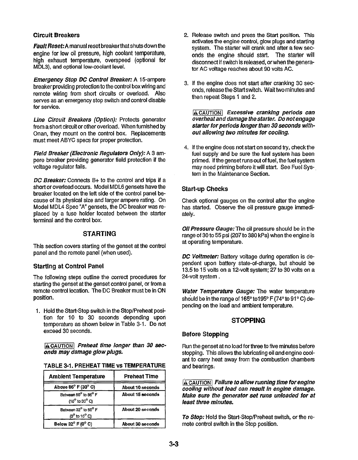
TROUBLESHOOTING
DC Control
The DC control has a number of sensors that continu-
ously monitor the engine for abnormal conditions such as
low
oil pressure, high coolant temperature, high exhaust
temperature, overspeed (option on
MDL3),
and Iow-
coolant level (option).
If
any one of these conditions
occur, the fault breaker trips and stops the genset. See
Figure 3-2.
The following sections describe operation of the fault
systems and suggested items the operator can check.
If
a major problem
is
indicated, contact an Onan Dealer or
Distributor for help
or
service.
The control panel Fault reset breaker will trip for any one
of
the fault conditions described separately in the follow-
ing text. The white breaker reset button pops out about
1/4
inch
(6
mm) when a fault occurs. Locate the problem
and make necessary corrections before resetting the
breaker and starting the genset.
All
fault shutdowns ex-
cept high exhaust temperature and overspeed are
delayed
5
seconds
to
avoid nuisance tripping.
Low
Oil
Pressure:
Remove dipstick and check
oil
level.
If
low, add oil
to
bring level up
to
the full mark. Inspect
engine exterior for leaks and repair as necessary. The oil
pressure switch actuates the fault circuit
if
pressure
drops below
14
psi
(97
kPa).
High
Coolanf
Temperature:
If
fault occurred during op-
eration, observe Coolant Temperature Gauge (option)
for indication
of
temperature over
222"
F
(106O
C).
The
coolant thermostat switch closes at this temperature and
actuates the fault circuit.
Check
coolant
level in the expansion tank alter allowing
the engine
to
cool.
Check condition
of
the pump belt and that it has proper
tension. The sea water flow at the exhaust outlet should
be as shown
in
the Specifications Section.
Also
check
the cooling system cleanliness (freedom from contami-
nants, rust, sludge build-up, etc).
MDL3
MDL6
*LOW
COOLANT
LEVEL
SENSOR
SURE
SWITCH
MDL4
SC13TI-2
*HIGH
WHAUST
TEMP.
SWITCH
\'
OPTIONAL
OVERSPEED
SWITCH (UNDER
ENDBELL
COVER)
FAUL?
RESET
BREAKER
*SAME
LOCATION
ALL
MODELS
FIGURE
3-2.
FAULT SENSOR
LOCATION
3-4
Redistribution or publication of this document,
by any means, is strictly prohibited.
High Exhaust Temperature:
The high exhaust tem-
perature switch
is
mounted on the exhaust elbow and
closes
on
temperature
nse
above
190"
F
(88"
C).
It
will
open again when temperature reaches about
165"
F
(74'
C)
and functions to protect exhaust system hoses.
1-1
inhalation
of
exhaustgas can cause se-
rious personal injury
or
death.
Do
not disconnect or
bypass fhe exhaust elbow switch. Excessive heat
caused
by
a sea water flow malfunction will damage
the exhausthoses andcause exhaustgasleakage. If
exhaust
hose
Is damaged, shut
off
the generator set
immediately and do not operate until hose
is
re-
paired.
cient or lackof seawaterflow. Referto thespecifications
Overspeed(0pfion
ForMDL3):This switch is mounted
on the front of the engine crankshaft.
It
is factory ad-
justed to shut down
60
hertz gensets at
2150
to
2200
r/min,
50
hertz gensets at
1800
to
1850
r/min. After cor-
recting the problem, press the Fault Reset breaker.
Low Coolant Level (Option):
This electronic sensor
completes the fault circuit
if
coolant level falls below the
sensor's location in the cooling system. It provides an
added level of engine protection.
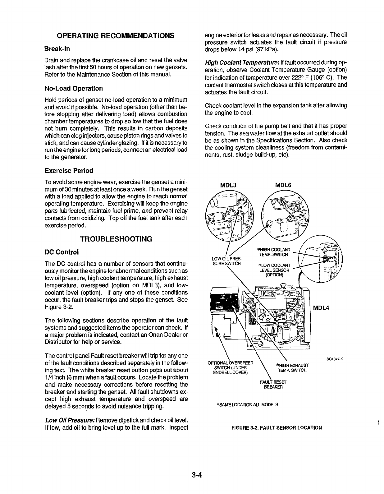
AC
Control
The AC control may use
two
circuit breakers on the con-
trol box depending upon purchased options. See figure
3-3. If either one trips, it results in
loss
of generator AC
power output. They function as follows:
i
High exhaust elbow temperature is caused by insuffi-
Section for the proper sea water flow rate.
I
Field Breaker (Electronic Regulafor
0nly):This
3-am-
pere breaker
is
located on the control side panel.
It
is in
the regulator
AC
input circuit and protects the generator
field
if
the voltage regulator
fails
and
places
abnormal
de-
mands on it. If resetting the breaker returns power only
momentarily, then trips again, consult an Onan dealer or
distributor for service.
Line Circuit Breakers (Option):
When supplied by
Onan, these breakers are mounted on the control side
panel. They are connected in series with the load.
*LINE
CIRCUIT
*FIELD
BREAKER
REGULATORS ONLY)
*SAME
LOCATION
ALL
GENSET MODELS
SG13753r
FIGURE
3-3.
AC CONTROL BREAKERS
3-5
Redistribution or publication of this document,
by any means, is strictly prohibited.

J
i
Redistribution or publication of this document,
by any means, is strictly prohibited.
Section
4.
Maintenance
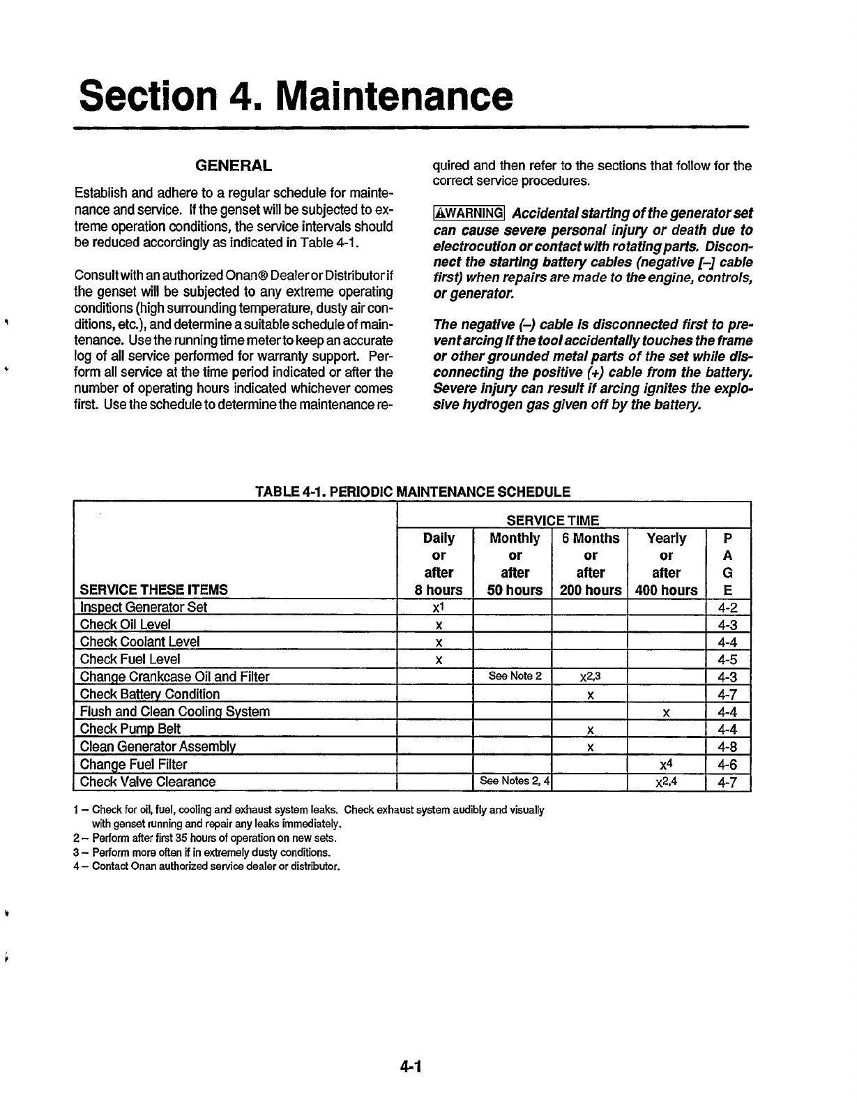
GENERAL
Establish and adhere to a regular schedule for mainte-
nance and service.
If
the genset will be subjected to
ex-
treme operation conditions, the service intervals should
be reduced accordingly as indicated in Table 4-1.
Consult with an authorized Onan@ Dealer
or
Distributor
if
the genset will be subjected
to
any extreme operating
conditions (high surrounding temperature, dusty air con-
ditions, etc.), and determine a suitable schedule of main-
tenance. Use the running time meterto keep an accurate
log of all service performed
for
warranty support. Per-
form all service at the time period indicated
or
after the
number
of
operating hours indicated whichever comes
first. Use the schedule to determine the maintenance re-
9
*
quired and then
refer
to the sections that follow
for
the
correct service procedures.
71
Accidental startlng
of
the generator set
can cause severe personal injury or death due
tu
electrocution or contact with rotatingparfs. Discon-
nect the starting battery cables (negative
[-I
cable
first) when repairs are
made
to
the engine,
controls,
or generator.
The negative
(-)
cable is disconnected firsf to pre-
venf arcing If the tool accidentally touches the frame
or
other grounded metal parts of the
set
while dis-
connecting the positive
(i)
cable from the battery.
Severe injury can result if arcing ignites the explo-
sive hydrogen gas given
off
by
the battery.
TABLE
4-1.
PERIODIC MAINTENANCE SCHEDULE
I
I
"
Check Valve Clearance
I
I
See
Notes
2,41
I
x2,4
P
A
G
E
4-2
4-3
4-4
4-5
4-3
4-7
4-4
4-4
4-8
4-6
4-7
1
-
Check
for
oil, fuel, cooling and exhaust system leaks. Check exhaust system audibly and visually
2-
Perform after first
35
hours
of
operation
on
new sets.
3
-
Perform more often
if
in extremely
dusty
conditions.
4
-
Contact Onan authorized
service
dealer or distributor.
with genset running
and
repair any
leaks
immediately.
c
4-1
Redistribution or publication of this document,
by any means, is strictly prohibited.
SET
INSPECTION
During operation, be alert for mechanical problems that
could create unsafe
or
hazardous conditions. The fol-
lowing sections cover several areas that should be fre-
quently inspected for continued safe operation.
Engine Gauges
Check the following while the genset is operating.
011
Pressure Gauge
(Option):
The oil pressure should
be in the range of
30
to
55
psi (207 to 380 kPa) when the
engine is at operating temperature.
Coolant Temperature Gauge (Option):
The water tem-
perature should be in the range of 165O to
195O
F
(74" to
91
O
C) depending on the load and ambient temperature.
DC
Voltmeter (Option):
Normal battery voltage during
operation should be 13.5 to 15 volts on a 12-volt system;
and 27 to
30
volts on a 24-volt system.
Exhaust System
With the genset operating, inspect the entire exhaust
system including the exhaust manifold, exhaust elbow,
muffler and exhaust pipe. Check sea water pump opera-
tion by observing sea water discharge from the exhaust
outlet (see Specifications section
for
flow rate). Visually
and audibly check for leaks at all connections, welds,
gaskets, and joints.
If
any leaks are detected, have them
corrected immediately.
71
Inhalation
of
exhaust gases can result
In severe personal injury or death. Inspect exhaust
system audibly and visually for leaks daily. Repair
any leaks immediately.
Fuel System
With the genset operating, inspect the fuel supply lines,
return lines, filters, and fiiings for leaks. Check flexible
sections
for
cuts,
cracks and abrasions
so
they are not
rubbing against anything that could cause breakage.
-1
Fuel leakage will create a fire hazard
whlch can result in severe personal injury or death
if
ignlted.
Whlle
checking for leaks, do not smoke or
allow any spark, flame, pilot light or other ignltion
source In the area.
If
any
leaks are detected, have
them corrected immediately.
DC
Electrlcal System
With the genset
off,
checkthe terminals on the battery for
clean and tight connections. Loose
or
corroded connec-
tions create resistance which can hinder or prevent start-
ing. Clean and reconnect the terminals
if
loose. Always
disconnect the negative
(-)
battery cable first, and con-
nect it last
to
reduce the possibility
of
arcing.
lgnitlon
of
explosive battery gases can
cause severe personal injuty.
Do
not smoke. Wear
goggles and protective, rubber gloves and apron
when servicing batteries.
Mechanical
With
the genset stopped, checkfor loose belt and fittings,
leaking gaskets and hoses,
or
any signs
of
mechanical
damage. If any problems are found, have them
cor-
rected immediately. With the genset running, listen for
any unusual noises that may indicate mechanical prob-
lems and check the oil pressure frequently. Investigate
anything that indicates possible mechanical problems.
LUBRICATION
SYSTEM
The engine oil was drained
from
the crankcase prior to
shipment. Before the initial start, the lubrication system
must be filled with oil of the recommended classification
and viscosity. Refer
to
the Specifications section for the
lubricating oil capacity.
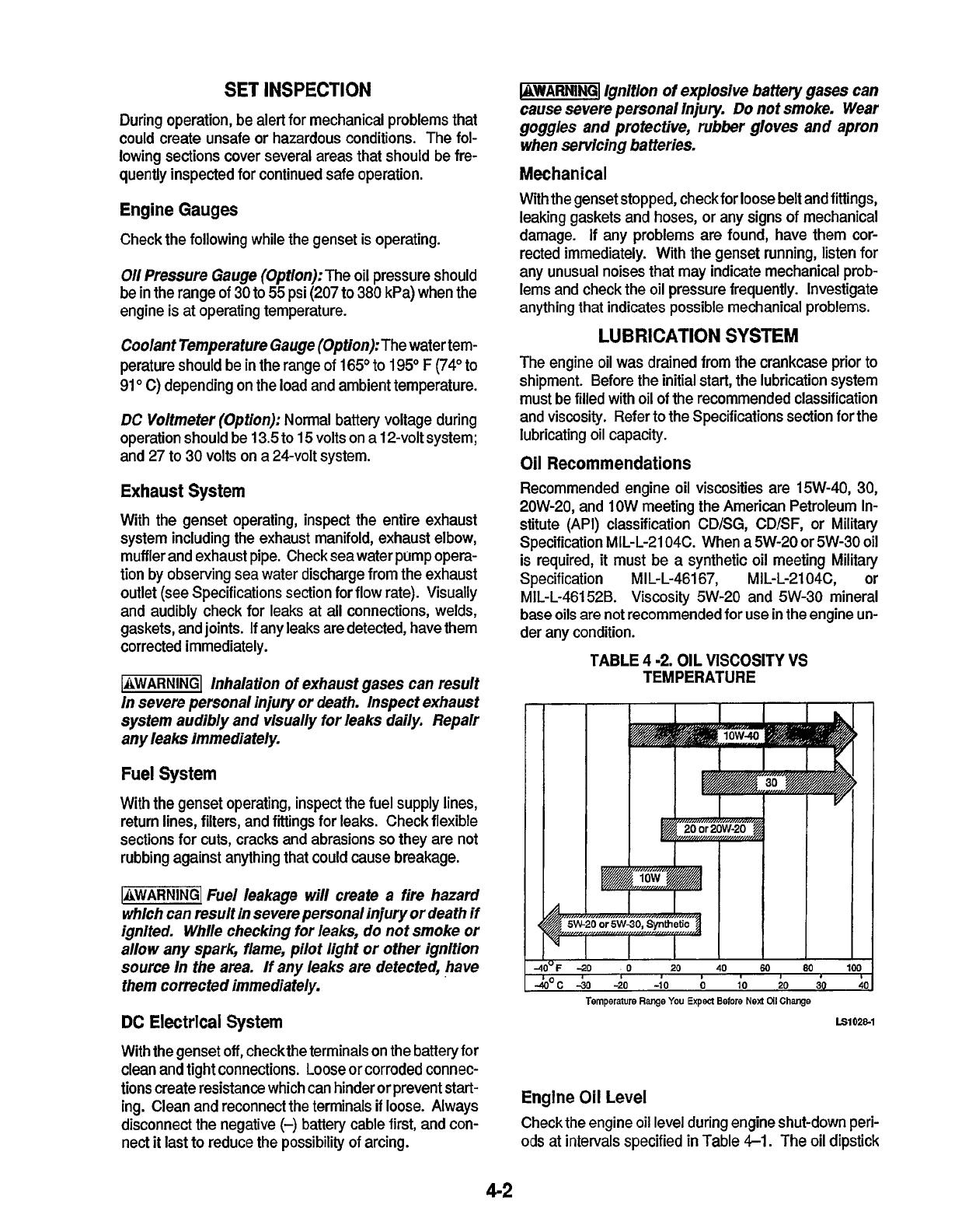
Oil
Recommendations
Recommended engine oil viscosities are 15W-40,
30,
2OW-20, and 1OW meeting the American Petroleum In-
stitute (API) classification CD/SG, CD/SF,
or
Military
Specification MlL-L-2104C. When a 5W-20
or
5W-30 oil
is required, it must be a synthetic oil meeting Military
Specification MIL-L-46167, MIL-L-2104C,
or
MIL-L-46152B. Viscosity 5W-20 and 5W-30 mineral
base
oils
are not recommended for use
in
the engine un-
der any condition.
TABLE
4
-2.
OIL
VISCOSITY VS
TEMPERATURE
i
El
0281
Engine
Oil
Level
Check the engine oil level during engine shut-down peri-
ods
at intervals specified
in
Table
4-1.
The
oil
dipstick
4-2
Redistribution or publication of this document,
by any means, is strictly prohibited.
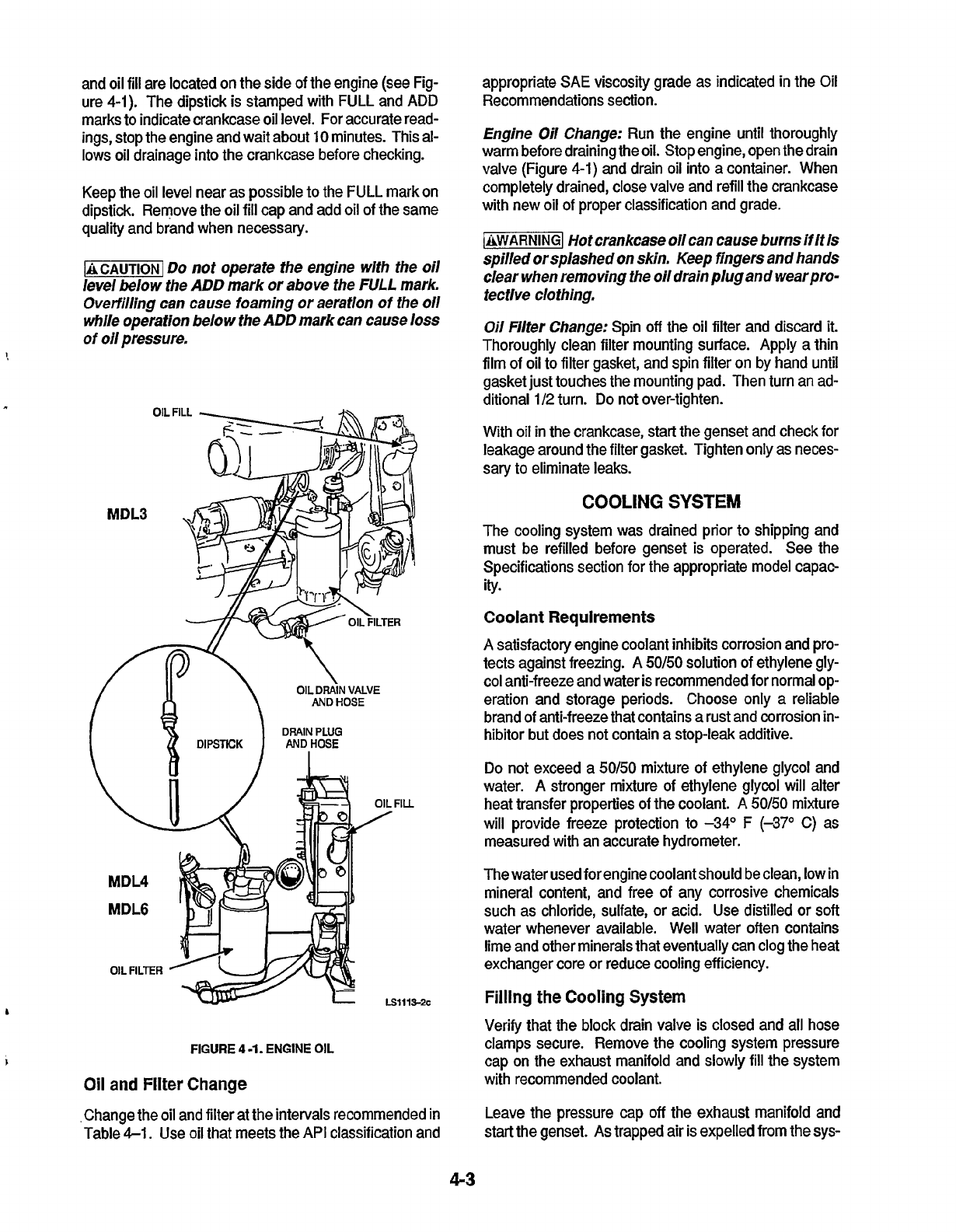
and oil
fill
are located on the side of the engine (see Fig-
ure
4-1).
The dipstick is stamped with FULL and ADD
marks to indicate crankcase oil level.
For
accurate read-
ings, stop the engine and wait about
10
minutes. This
al-
lows oil drainage into the crankcase before checking.
Keep the oil level near as possible
to
the FULL mark on
dipstick. Remove the oil fill cap and add oil of the same
quality and brand when necessary.
-1
Do
not operate the engine
wlfh
the
oil
/eve/
below the
ADD
mark or above the
FULL
mark.
0verf;lling can cause foaming
or
aeration
of
the
011
while operation below the
ADD
mark can cause
loss
of
oil
pressure.
!
b
FIGURE
4
-1.
ENGINE
OIL
1
Oil
and
Filter
Change
appropriate SAE viscosity grade as indicated in the Oil
Recommendations section.
Engine
Oil
Change:
Run the engine until thoroughly
warm before draining the oil. Stop engine, open the drain
valve (Figure
4-1)
and drain oil into a container. When
completely drained, close valve and refill the crankcase
with new oil of proper classification and grade.
-1
Hot crankcase
oil
can cause burns
if
It
Is
spil/ed
orsplashed on skin. Keep flngers and hands
clear when removing the
oil
drain
plug
and wearpro-
tecflve clothing.
Oil
Filter Change:
Spin
off
the oil filter and discard
it.
Thoroughly clean filter mounting surface. Apply a thin
film of oil to filter gasket, and spin filter on by hand until
gasket just touches the mounting pad. Then turn an ad-
ditional
1/2
turn.
Do
not over-tighten.
With oil in the crankcase, start the genset and check for
leakage around the filter gasket. Tighten only as neces-
sary to eliminate leaks.
COOLING
SYSTEM
The cooling system was drained prior
to
shipping and
must be refilled before genset is operated. See the
Specifications section for the appropriate model capao
ity.
Coolant
Requirements
A
satisfactory engine coolant inhibits corrosion and pro-
tects against freezing. A
50/50
solution of ethylene gly-
col anti-freeze and water is recommended for normal
op-
eration and storage periods. Choose only a reliable
brand of anti-freeze that contains a rust and corrosion in-
hibitor but does not contain a stop-leak additive.
Do not exceed a
50/50
mixture of ethylene glycol and
water.
A
stronger mixture of ethylene glycol will alter
heat transfer properties of the coolant.
A
50/50
mixture
will provide freeze protection to
-34"
F
(-37O
C)
as
measured with an accurate hydrometer.
The water used for engine coolant should be clean, low in
mineral content, and free of any corrosive chemicals
such as chloride, sulfate,
or
acid. Use distilled
or
soft
water whenever available. Well water often contains
lime and other minerals that eventually can clog the heat
exchanger core
or
reduce cooling efficiency.
Filling
the
Cooling
System
Verify that the block drain valve is closed and all hose
clamps secure. Remove the cooling system pressure
cap on the exhaust manifold and
slowly
fill
the system
with recommended coolant.
Change the oil and filter at the intervals recommended
in
Table
4-1.
Use oil that meets the API classification and
Leave the pressure cap
off
the exhaust manifold and
start the genset. As trapped air is expelled from the sys-
4-3
Redistribution or publication of this document,
by any means, is strictly prohibited.
tem, the coolant level may drop and additional coolant
can be added. Replace the pressure cap when coolant
level is stable. Any excess coolant will be expelled
through the overflow hose and into the recovery tank.
Coolant Recovery Tank:
Fill the recovery tank with
coolant mixture to the COLD mark. Operate the genset
until normal operating temperature is maintained as ob-
served on the temperature gauge (option), or about
15
minutes of operation. Stop the genset and let cool.
Add
coolant into the recovery tank (if needed) to the COLD
mark. The level should stabilize after several operation
cycles.
Coolant
Level
Check the coolant level daily as specified in Maintenance
Table
4-1.
Add the required coolant
if
needed as speci-
fied above.
71
Contact with hot coolant can result In
serious burns.
Do
not bleed hot, pressurized cool-
ant from
a
closed cooling system.
-1
The
high
engine temperature switch
will
shut down the engine in an overheat condition
onlylfthe coolantlewells
high
enough to cunfactthe
switch.
Loss
of
coolant willallowengine to overheat
without shutdown protection, thereby causing se-
vere damage to
the
engine.
lf
is
imperative that ade-
quate engine coolant levels
be
maintained for opera-
tion lntegrlfy
of
the cooling system and coolant
shutdown protection-
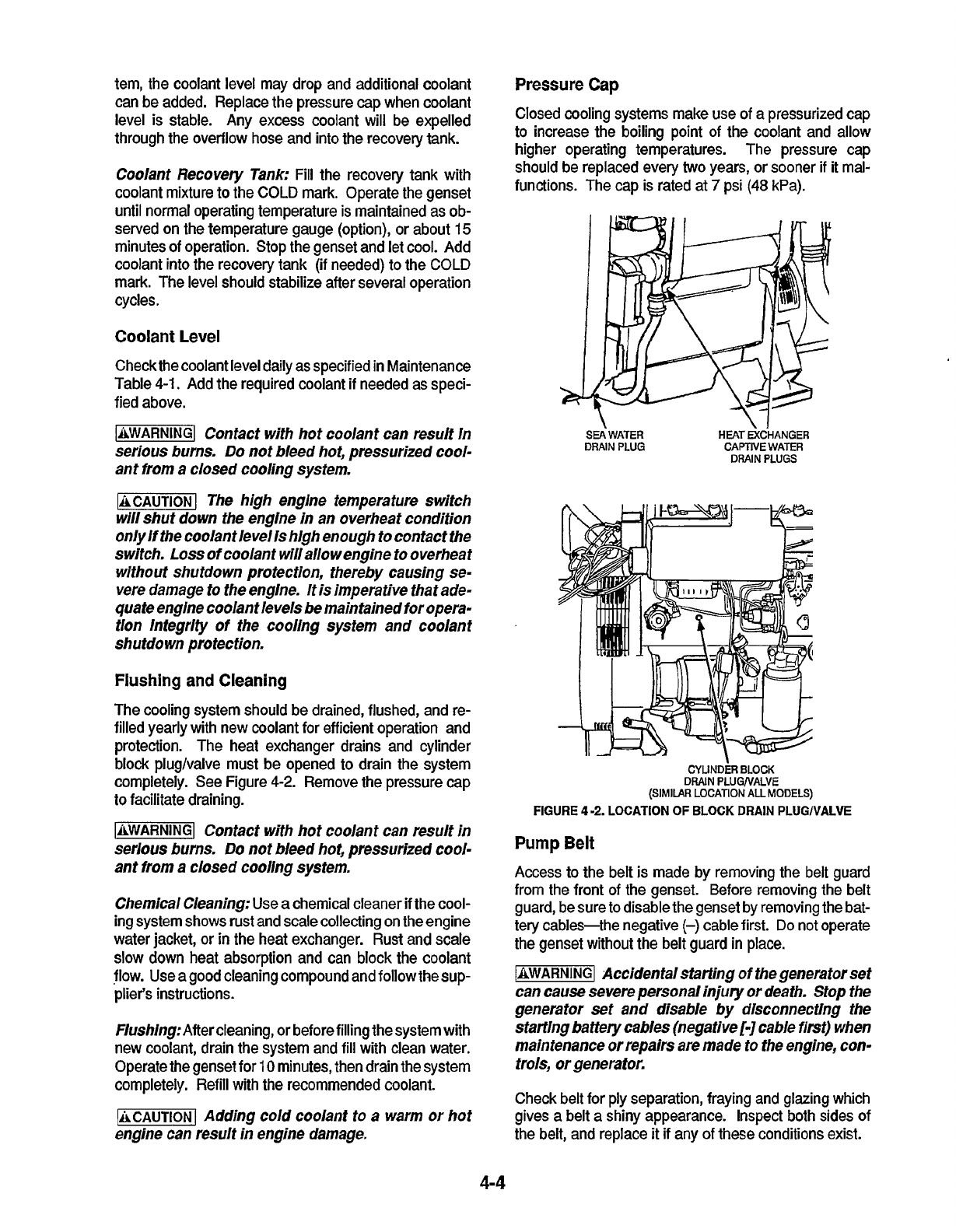
Flushing and Cleaning
The cooling system should be drained, flushed, and re-
filled yearly with new coolant for efficient operation and
protection. The heat exchanger drains and cylinder
block pluglvalve must be opened to drain the system
completely. See Figure
4-2.
Remove the pressure cap
to
facilitate draining.
1-1
Contact with hot coolant can result in
serious burns.
Do
not bleed
hot,
pressurized cool-
ant from
a
closed cooling system.
Chemical Cleaning:
Use a chemical cleaner if the cool-
ing system shows
rust
and scale collecting on the engine
water jacket, or
in
the heat exchanger. Rust and scale
slow down heat absorption and can block the coolant
flow. Use a good cleaning compound and
follow
the sup-
plier's instructions.
Flush1ng:After
cleaning, or before filling the system with
new coolant, drain the system and
fill
with clean water.
Operate the genset for
10
minutes, then drain the system
completely. Refill with the recommended coolant.
-1
Adding cold coolant
to
a
warm or
hot
engine can result in engine damage.
Pressure
Cap
Closed cooling systems make use of a pressurized cap
to increase the boiling point of the coolant and allow
higher operating temperatures. The pressure cap
should be replaced every
lwo
years, or sooner
if
it mal-
functions. The cap is rated at
7
psi
(48
kPa).
'a
SEA'
WATER
HEAT
MCHANGER
DRAIN
PLUG
CAPTIVE
WATER
DRAIN
PLUGS
CYLINDER
BLOCK
DRAIN
PLUGNALVE
(SIMILAR
LOCATION
ALL
MODELS)
FIGURE
4
-2.
LOCATION
OF
BLOCK
DRAIN
PLUGNALVE
Pump
Belt
Access
to the belt is made by removing the belt guard
from the front of the genset. Before removing the belt
guard, be sure to disable the genset by removing the bat-
tery cables-the negative
(-)
cable first.
Do
not operate
the genset without the belt guard in place.
-1
Accidental starting
of
the generator set
can cause severe personal injury or death. Stop the
generator set and disable
by
disconnecting the
starting battery cables (negative[-] cable
first)
when
maintenance or repairs
are
made to the engine, con-
trols, or generator.
Check belt for ply separation, fraying and glazing which
gives a belt a shiny appearance. Inspect both sides of
the belt, and replace
it
if
any of these conditions exist.
Redistribution or publication of this document,
by any means, is strictly prohibited.
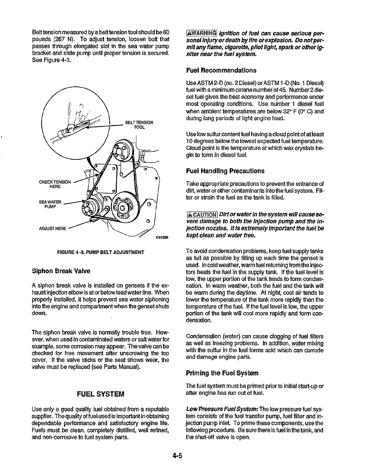
Belt tension measured by a belt tension tool should be
60
pounds
(267
N).
To
adjust tension, loosen bolt that
passes through elongated
slot
in
the
sea water pump
bracket and slide pump until proper tension is secured.
See Figure
4-3.
CHECK
TENSION
3
m39
ADJUSTHERE
FIGURE
4
3.
PUMP
BELT ADJUSTMENT
Siphon Break Valve
A
siphon break valve is installed on gensets
if
the ex-
haust injection elbow is at or below load water line. When
properly installed, it helps prevent sea water siphoning
into the engine and compartment when the genset shuts
down.
The siphon break valve is normally trouble free. How-
ever, when used in contaminated waters or salt water for
example, some corrosion may appear. The valve can be
checked for free movement after unscrewing the top
cover.
If
the valve sticks or the seat shows wear,
the
valve must be replaced (see Parts Manual).
FUEL SYSTEM
Use only a good quality fuel obtained from a reputable
supplier. The quality of fuel used is important in obtaining
dependable performance and satisfactory engine life.
Fuels must be clean, completely distilled, well refined,
and non-corrosive
to
fuel system parts.
1-1
ignition
of
fuel can cause serious per-
sonal Injury or death by fire or explosion.
Do
notper-
mit any flame, cigarette, pllot light, spark or other Ig-
nifer near the fuel system.
Fuel Recommendations
Use ASTM 2-D (no.
2
Diesel) or
ASTM
l-D
(No.
1
Diesel)
fuel with a minimum cetane number of
45.
Number
2
die-
sel fuel gives the best economy and performance under
most operating conditions. Use number
1
diesel fuel
when ambient temperatures are below
32"
F
(0"
C) and
during long periods
of
light engine load.
Use low sulfur content fuel having acloud point of at least
10
degrees below the lowest expected fuel temperature.
Cloud point is the temperature at which wax crystals be-
gin
to
form in diesel fuel.
Fuel Handling Precautions
Take appropriate precautions
to
prevent the entrance of
dirt, water or other contaminants into the fuel system. Fil-
ter or strain the fuel as the tank is filled.
-1
Dirt or water in the system will cause se-
vere damage to both the injection pump and the in-
jection nodes. It is extremelyimporfant the fuel
be
kept clean and wafer free.
To
avoid condensation problems, keep fuel supply tanks
as full as possible by filling up each time the genset is
used.
In
cold weather, warm fuel returning from the injeo
tors heats the fuel in the supply tank.
If
the fuel level is
low, the upper portion of the tank tends to form conden-
sation. In warm weather,
both
the fuel and the tank will
be warm during the daytime. At night, cool air tends
to
lower the temperature of the tank more rapidly than the
temperature of the fuel.
If
the fuel level is low, the upper
portion of the tank will
cool
more rapidly and form con-
densation.
Condensation (water) can cause clogging of fuel filters
as well
as
freezing problems.
In
addition, water mixing
with the sulfur in the fuel forms acid which can corrode
and damage engine parts.
Priming the
Fuel
System
The fuel system must be primed prior
to
initial start-up or
after engine has run out of fuel.
Low
Pressure
Fue/Sysfem:The low pressure fuel sys-
tem consists of the fuel transfer pump, fuel filter and in-
jection pump inlet. To prime these components, use the
following procedure.
Be
sure there is fuel in the tank,
and
the shut-off valve is open.
4-5
Redistribution or publication of this document,
by any means, is strictly prohibited.
3.
Tighten the fuel line
at
the injection pump inlet.
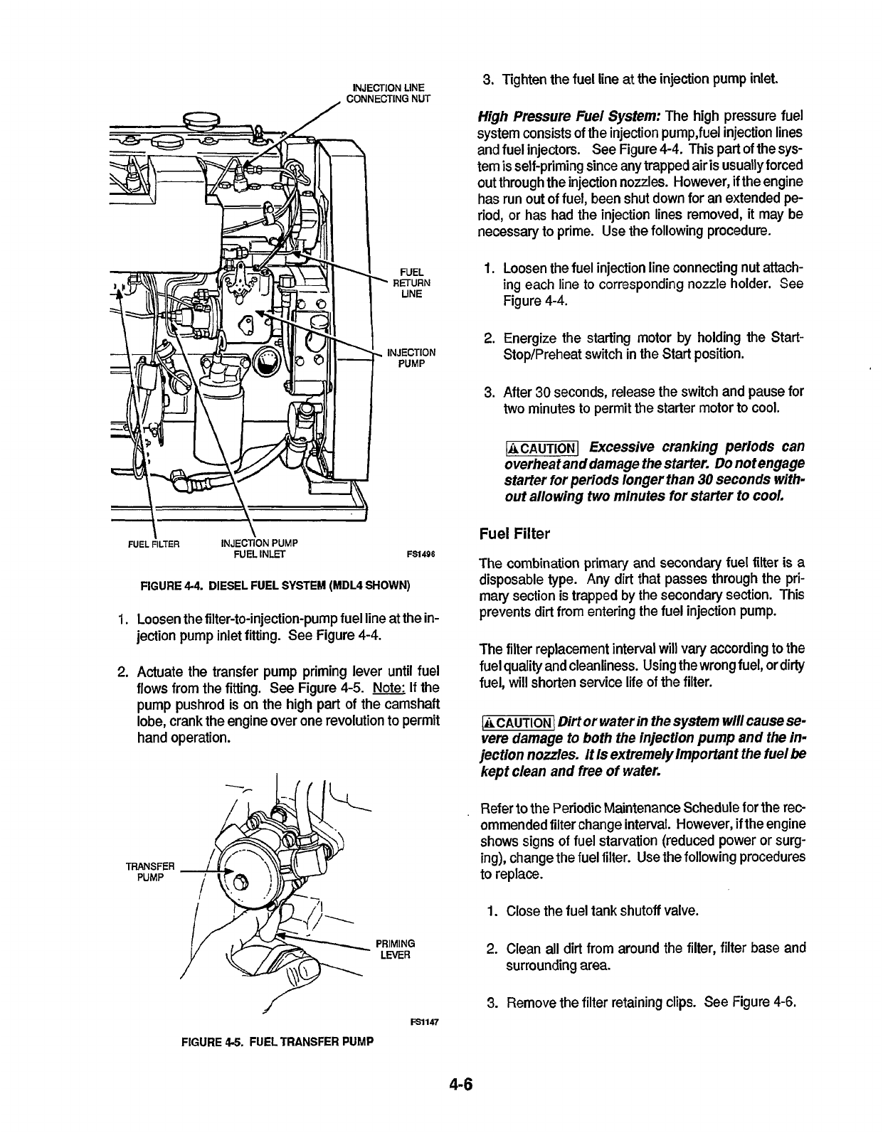
High Pressure Fuel System:
The high pressure fuel
system consists of the injection pump,fuel injection lines
and fuel injectors. See Figure
4-4.
This part of the sys-
tem is self-priming since any trapped air is usually forced
out through the injection nozzles. However, if the engine
has run
out
of fuel, been shut down for an extended pe-
riod,
or
has had the injection lines removed, it may be
necessary to prime. Use the following procedure.
INJECTION
LINE
CONNECTING
NUT
FUEL
RETURN
1.
Loosen the fuel injection line connecting nut attach-
ing each line
to
corresponding nozzle holder. See
Figure
4-4.
LINE
2.
Energize the starting
motor
by holding the Start-
Stop/Preheat switch
in
the Start position.
INJECTION
PUMP
3.
After
30
seconds, release the switch and pause
for
two
minutes to permit the starter motor to cool.
-1
Excessive cranking periods can
overheat anddamage the starter.
Do
not engage
starter for periods longer than
30
seconds with-
out allowing
two
minutes for staffer to cool.
Fuel
Filter
FUEL
FILTER
INJECTION
PUMP
1.
2.
FUEL
INLET
FSl496
FIGURE 4-4. DIESEL FUEL SYSTEM (MDL4
SHOWN)
Loosen the filter-to-injection-pump fuel line at the in-
jection pump inlet fitting. See Figure
4-4.
Actuate the transfer pump priming lever until fuel
flows
from the fitting. See Figure
4-5.
Note:
If
the
pump pushrod is on the high part
of
the camshaft
lobe, crank the engine over one revolution to permit
hand operation.
The combination primary and secondary fuel filter is a
disposable type. Any dirt that passes through the pri-
mary section
is
trapped by the secondary section. This
prevents dirt from entering the fuel injection pump.
The filter replacement interval will vary according
to
the
fuel quality and cleanliness. Using the wrong fuel, or dirty
fuel, will shorten service life of the filter.
lCAUTloN(
Dirt or waterin the system
will
cause se-
vere damage
to
both the injection pump and the in-
jection nozzles. It Is extremely Important the fuel
be
kept clean and free of water.
.
Refer to the Periodic Maintenance Schedule for the rec-
ommended filter change interval. However, if the engine
shows signs of fuel starvation (reduced power or surg-
ing), change the fuel filter. Use the following procedures
TRANSFER
PUMP
to replace.
1.
Close the fuel tank shutoff valve.
2.
Clean all dirt from around the filter, filter base and
PRIMING
LEVER
surrounding area.
3.
Remove the filter retaining clips. See Figure
4-6.
m147
FIGURE
4.5.
FUEL TRANSFER
PUMP
4-6
Redistribution or publication of this document,
by any means, is strictly prohibited.
tering the cells. After cleaning, flush the outside of the
battery and the surrounding areas with clean water.
Keep the battery terminals clean and tight. After making
connections, coat the terminals with a light application of
non-conductive grease
or
petroleum jelly
to
retard corro-
sion.
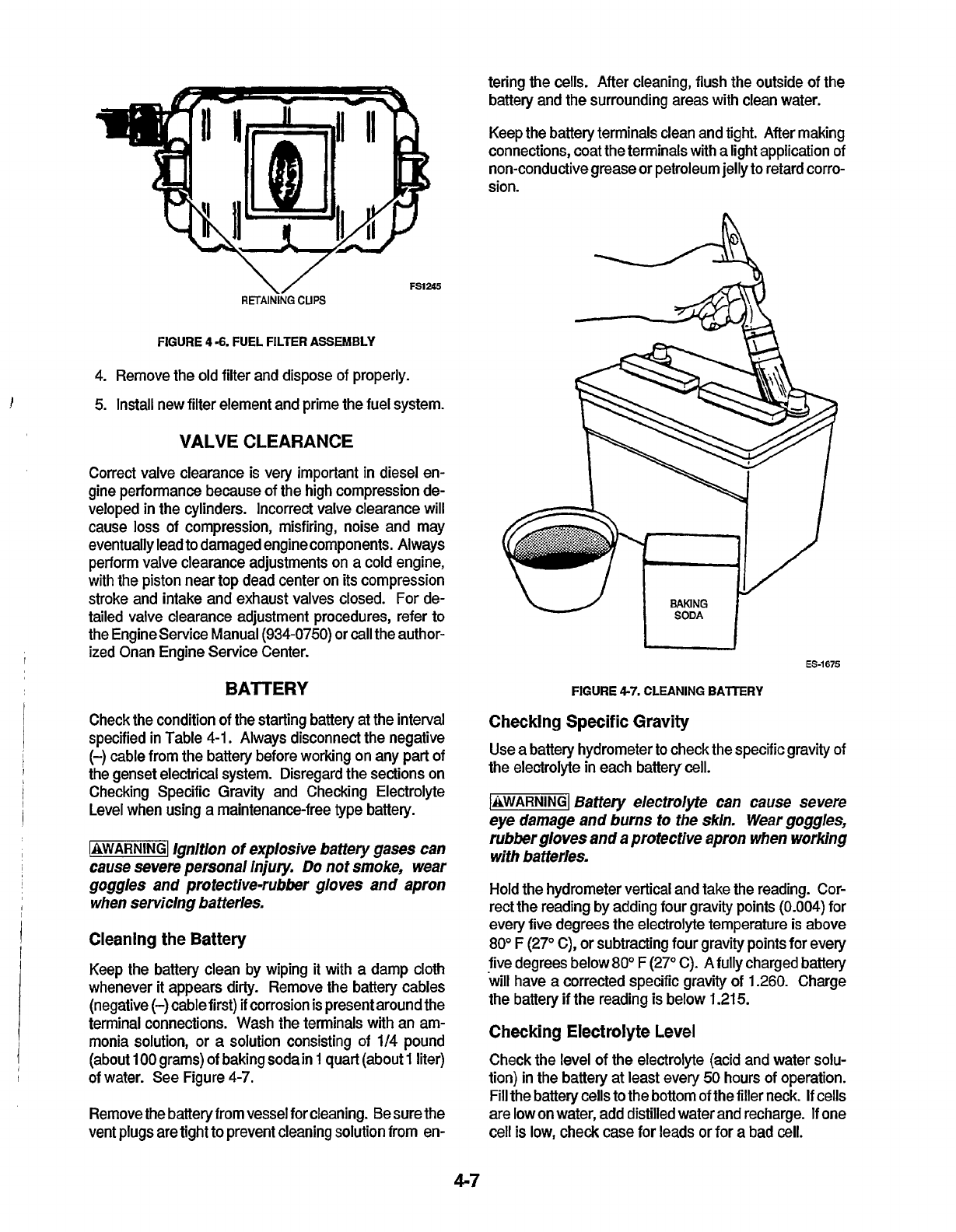
FSl245
RETAINING
CUPS
FIGURE
4
-6.
FUEL FILTER ASSEMBLY
4.
Remove the old filter and dispose
of
properly.
5.
Install new filter element and prime the fuel system.
VALVECLEARANCE
Correct valve clearance is very important
in
diesel en-
gine performance because of the high compression de-
veloped
in
the cylinders. Incorrect valve clearance will
cause
loss
of compression, misfiring, noise and may
eventually lead to damaged enginecomponents. Always
perform valve clearance adjustments on a cold engine,
with the piston near
top
dead center on its compression
stroke and intake and exhaust valves closed. For de-
tailed valve clearance adjustment procedures, refer to
the Engineservice Manual
(934-0750)
or
call
the author-
ized Onan Engine Service Center.
BATTERY
Check the condition of the starting battery at the interval
specified in Table
4-1,
Always disconnect the negative
(-)
cable from the battery before working on any part of
the genset electrical system. Disregard the sections on
Checking Specific Gravity and Checking Electrolyte
Level when using a maintenance-free type battery.
(QWARNINGI
lgnltlon
of
explosive battery gases can
cause severe personal injury.
Do
not smoke, wear
goggles and protective-rubber gloves and apron
when serviclng bafterles.
Cleaning
the Battery
Keep the battery clean by wiping it with a damp cloth
whenever it appears dirty. Remove the battery cables
(negative
(-)
cable first)
if
corrosion is present around the
terminal connections. Wash the terminals with an am-
monia solution,
or
a
solution consisting of
114
pound
(about
100
grams) of baking soda in
1
quart (about
1
liter)
of water. See Figure
4-7.
Remove the battery from vessel for cleaning. Be sure
the
vent
plugs
are tight
to
prevent cleaning solution from en-
I
ES-1675
FIGURE
4-7.
CLEANING
BATTERY
Checking
Specific
Gravity
Use a battery hydrometer
to
check the specific gravity of
the electrolyte in each battery cell.
JhWARNINGI
Sattery electrolfle can cause severe
eye damage and burns
to
the skin. Wear goggles,
rubber gloves and a protective apron when working
with batterfes.
Hold the hydrometer vertical and take the reading. Cor-
rect the reading by adding four gravity points
(0.004)
for
every five degrees the electrolyte temperature
is
above
80"
F
(2P
C),
or subtracting four gravity points for every
five degrees below
80'
F
(27"
C). Afully charged battery
will have a corrected specific gravity of
1.260.
Charge
the battery if the reading is below
1.21
5.
Checking
Electrolyte Level
Check the level of the electrolyte (acid and water solu-
tion) in the battery at least every
50
hours of operation.
Fill the battery cells
to
the bottom of the filler neck.
If
cells
are low on water, add distilled water and recharge. If one
cell is low, check case for leads
or
for a bad
cell.
4-7
Redistribution or publication of this document,
by any means, is strictly prohibited.
Do
not add waterln freezlng weather un-
leSS
wlll
run
long enough
(two
to
three
trolyte.
Keep the battery case clean and dry.
An
accumulation of
moisture will lead to battery discharge and failure.
GmWator Bearing
Inspect the bearing for evidence of outer case rotation
placed every five years. Deterioration
of
the bearing
grease due to oxidation makes this replacement neces-
sary. If the generator requires major repair or service,
contact an authorized Onan dealer
or
distributor.
hours)toprovide thoroughmixlng
Of
water
andele&
every
1000
hours of use. The bearing should be re-
ACGENERATOR
OUT-OF-SERVICE
PROTECTION
The inherent lubricating qualities of
No.
2
diesel fuel
should protect the cylinders of a diesel engine
for
at least
30
days when not in service.
io
protect an engine that
will
be out
of
sewice
for
more than
30
days, proceed
as
follows:
There
are
no
brushes,
brush
springs
Or
collector
rings
On
the generator, therefore it requires very little mainte-
nance. Periodic inSpeCtiOnS,
to
coincide with engine
Oil
changes, will help provide good performance.
-1
Accidental starting
of
the generator
set
can cause severe personal Injury or death. Move the
Operation Selector switch
to
STOP
and dlsconnect
the startlng baffery (negative
1-1
lead flrst) before In-
specting the rotating rectifier assem6ly.
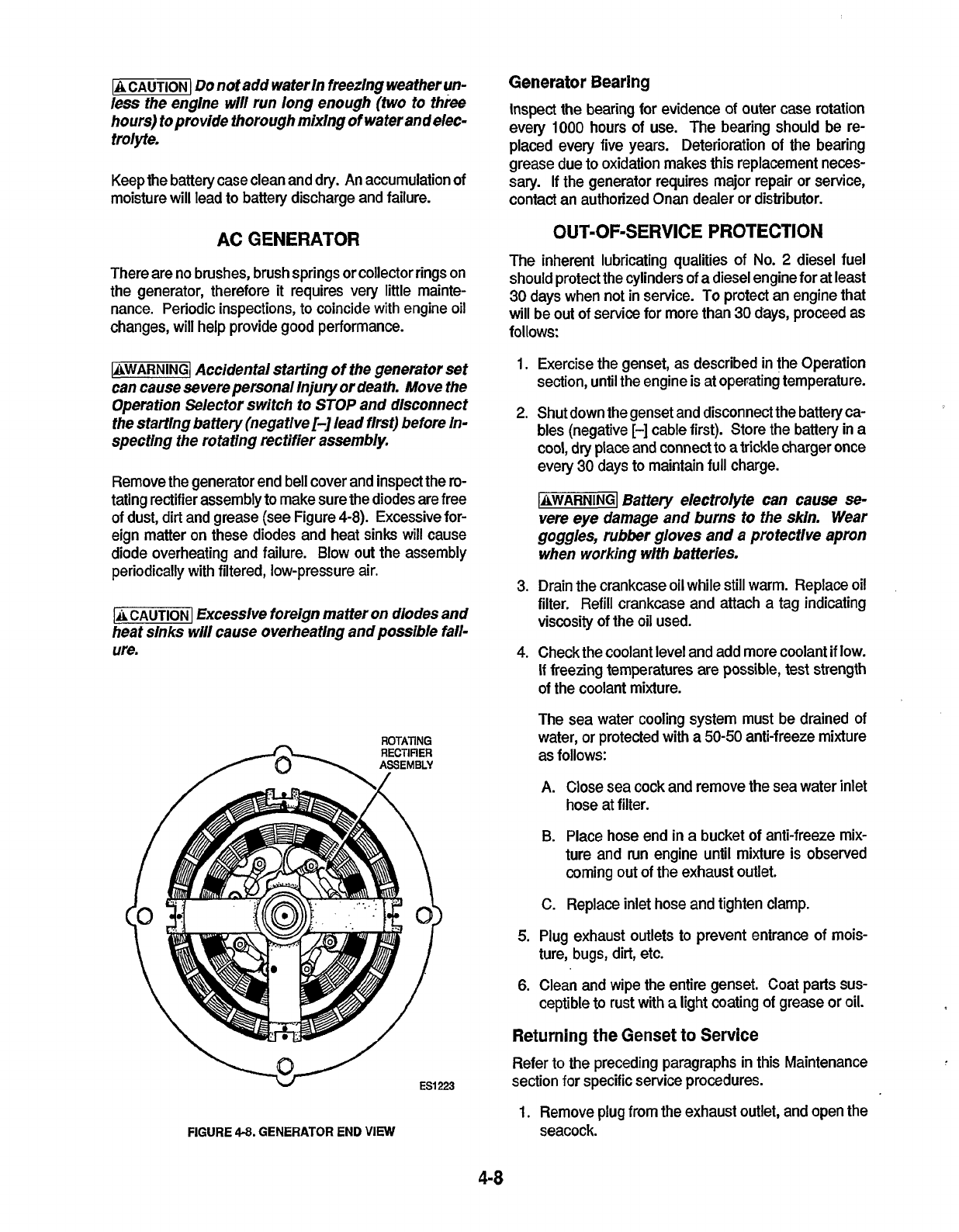
Remove the generator end bell cover and inspect the
ro-
tating rectifier assembly
to
make sure the diodes are free
of dust, dirt and grease (see Figure
4-8).
Excessive
for-
eign matter on these diodes and heat sinks will cause
diode overheating and failure. Blow out the assembly
periodically with filtered, low-pressure air.
-1
Excessive
foreign matter on
diodes
and
heat slnks will cause overheating and possible
fall-
ure.
ROTATING
RECTIFIER
ASSEMBLY
v
ESI
223
FIGURE
4-8.
GENERATOR
END
VIEW
1.
Exercise the genset, as described in the Operation
section, until the engine is at operating temperature.
2.
Shut down the genset and disconnect the battery ca-
bles (negative
[-]
cable first). Store the battery in a
cool, dry place and connect to atrickle charger once
every
30
days to maintain full charge.
-1
Baffery electrolyfe can cause
se-
vere
eye damage and burns to the skin. Wear
goggles, rubbef gloves and
a
protectlve apron
when working wlth batteries.
3.
Drain the crankcase oil while still warm. Replace oil
filter. Refill crankcase and attach a tag indicating
viscosity of the oil used.
4.
Check the coolant level and add more coolant
if
low.
If
freezing temperatures are possible, test strength
of the coolant mixture.
The sea water cooling system must be drained of
water,
or
protected with a
50-50
anti-freeze mixture
as follows:
A.
Close sea cock and remove the sea water inlet
hose at filter.
B. Place hose end
in
a bucket
of
anti-freeze mix-
ture and run engine until mixture is observed
coming out
of
the exhaust outlet.
C.
Replace inlet hose and tighten clamp.
5.
Plug exhaust outlets to prevent entrance of mois-
ture, bugs, dirt, etc.
6.
Clean and wipe the entire genset. Coat parts sus-
ceptible to rust with
a
light coating
of
grease
or
oil.
Returning the
Genset
to
Service
Refer to the preceding paragraphs in this Maintenance
section
for
specific service procedures.
1.
Remove plug from the exhaust outlet, and open the
seacock.
4-8
Redistribution or publication of this document,
by any means, is strictly prohibited.
2. Shut down the genset and disconnect the battery
(negative
[-I
lead first). Store the battery in a
cool,
dry place and connect to
a
trickle charger once every
30
days
to
maintain full charge.
Check the tag on the oil base and verify that the oil
viscosity is still correct for existing ambient tempera-
ture.
3.
Clean and check the battery. Measure the electro-
lyte specific gravity with a hydrometer
(1.260
@
80"
F
[27" C]) and verify proper level.
If
the specific
gravity is
low,
charge the battery until correct value is
obtained. If level is
low,
add distilled water and
charge until the specific gravity reading
is
correct.
-1
Battery e/ectrolyte can cause
se-
were eye damage and
bums
to
the skin. Wear
gogg/es,
rubber
gloves and a protective apron
when worklng with batteries.
4.
Prime the fuel system.
5.
Connect the starting battery, the negative
(-)
cable
last.
6.
Remove all loads before starting the genset.
7. After starting, apply load of at least
50
percent rated
8.
Check all gauges for normal readings. Genset
is
capacity.
ready
for
operation.
49
Redistribution or publication of this document,
by any means, is strictly prohibited.

Notes
Redistribution or publication of this document,
by any means, is strictly prohibited.

Redistribution or publication of this document,
by any means, is strictly prohibited.
Calif
orn
ia
Proposition
65
Warning
Diesel engine exhaust and some of its constituents are known
to the State of California to cause cancer, birth defects, and
other reproductive harm.
Redistribution or publication of this document,
by any means, is strictly prohibited.
