Hyl2211 940 0223 Onan NH (spec A R) Genset Parts Manual (10 1990)
User Manual: 940-0223 Onan NH (spec A-R) Genset Parts Manual (10-1990)
Open the PDF directly: View PDF ![]() .
.
Page Count: 76
The following catalog
has gaps in its page
numbers, or doesn’t
have any numbers.
We have chosen to
leave the page
numbering in the
order that Acrobat
assigns it.
940-0223
IQ-949 (sp@e A-R)
Replecee 2-M [Spat A-R)
Printed in U.S.A.
Pam
Manual
NM
GenSet
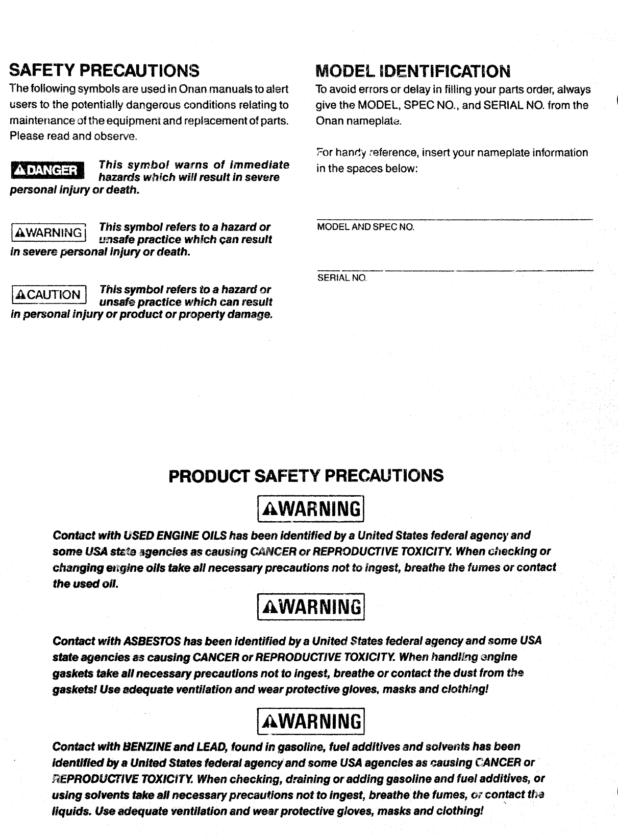
SAFETY PRECAUTIONS
The fcdhwirq syrnim!s are used irl f3r)an manuah $0alert
users to the potentially dangerous conditions reiating to
rnaintertance of the equipment and replacement of parts.
Please read and observe.
This symbol warns of immediate
Ixwm#s which W@result in severe
personal injwy or death.
12Eimi@
This symhoJ refers to ahazard or
unsafe practice which can result
hsevere personal injury or death.
!z@@mlThis symbol refers to ahazard or
w?safs practice whjch can result
in personal injury or product or property damage.
MODEL IDENTIFICATION
To avoid errors or deiay in fiiiing your parts order, aiways
give the MODEL, SPEC NO., and SEF3iAL NO. from the
a
Onan narnepiak.
For handy reference, insert your nameplate information
in the spaces Ix3iow:
MODEL AND SPEC NO. —
—..—
=A=O.
SAFETY PRECAUTIONS
[AWARNiNGl
~—.~
Cont&?ctwith USED ENG/PfEOILS has been identifkd by a?Jnited States federal agency and
some USA sfa$s %gemies mcausi~g CMW2H?or REPIWMJCTWE TOXIC1’TYWhen checking or
char@ng e~rgine UMStake aii necessary jmcautions rmt 8Singest, breathe the fumes or contact
the used oil. &*
IAWARNINGI
~J
Contact with ASBESTOShas been identified by aUnited States federal agency and some USA
state agencies as causing CANCER or F?EPF?ODLKX?VETOXICITY When handling $w@ne
gaskets take all necessary precautions not to Jngest, breathe or contact the dust from the
gaskets! Use adequate ventflafion and wear protective g/eves, masks and clothing!
* *
l~WARNINGl
L..~
Co~n&fa”twffh k?EMUNEand LEAD, found in gaso/in& fuel addftives and scdvefits has been
identified by aUnited States federal agermyand some USA agencies as zxwsing CANCER or
?%iPRQIX.@’TIVE70X#CfTY When checking, d.ssining or adding gaso/ine and fuel addjtives, or
using solvents take Mnecessary precautions not to ingest, breathe the fumes, wcontact tha
(iqulds. (fse adequate ventilation and wwwprotectim gloves, masks and elothlngf
Adapter, Oil filter A14
!3ase, oil -Spec A-N A15
Base, Oil -Begin Spec PA16
Bearing, Ct-ankshaft A9
Black, Cylinder Al’
Board, control “- Spec D-K D12
Board, D~~con~ect Adagter -Spec D-K E3
Bear-d, Start Adapter -Soec D-K E2
Booster, Vacuum Speed -$pec A-F C9
Box, Breaker -Spec A-K Clo
Box, Br’eaker -Begin Spec LCll
BOX Componer,ts, Breaker -s~ec A-K Clo
Box Components
Spec LC12
Cable. Battery
Cable, Battery
Cable, Saark ?
CaE!e, Spark P’
Camshaft All
Cap and Va!vez
Breaker -Begin
-Spec A-C Dll
-Spec D-K 012
Gg -Spec A-K Clo
Ug -13egin Spec LCll
Breather A?
Carburetor -Spec A-K B?
Ca~buret~r -Begin Spec LB9
Carb~r@fQr -Beg~n Spec PBll
Carburetor Components -Gas -Begin
Spec i(24
Carburetor Components -Gas and
Gas-Gasoline -Spec A-K. C2
Carburetor Components -Gas-Gasoline
Elegiri Spec !.. C!5
Carburetor Components -Gasol ine -
Spec A-K Cl
Carburetor Components -Gasoline -
Begin Spec LC3
Carb/!reter Components -Gasoline -
13eg~fi Spec RC6
Choke, E?ectr;c -Beg{n Spec PC7
Chokez Thermo-Mzgnetic -Spec A-5 C8
G]eaner, Air -Spec A-K B7
Cleaner, Air -Begin Spec LB!)
C?eaner, Air -Begin Spec P%11
Coil, Ig!!ition -Spec A-K Clo
Coil, Ignition -Begin Spec LCll
Control, AC -Spec A-C !)10
Gontrol, AC -Spec D-K Dll
Control ,AC -Begic Spec LD12
Cover ,Fuel Pump Hole -Spec A-K R7
cover, F~e~ pump Hole -Begin Spec L
Cover, Valve A9
Crankshaft A12
cup, Oil Intake A14
Head: Cvlinder A’1
Hose, ~i: D~ajn -Spec A-K C13
Hose, Regulator to Carburetor -
Spec A-K B7
Hose, Regulator to Carburetor -Begin
Spec LB9
i?ousinq, Air -Spec A-K C13
Housing, Air -Standard -Begin
Spec LC14
Housing, Air -With Vacu-Flo -
Spec L-N ~1
Housing, Air -With Vacu-Flo -Begin
S~ec PD2
,. --
ignition -Spec A-K Clo
Ignition -Begin Spec LCll
Index, Numerics? Fl, F2, F3, F4,F!j,F6,F7,F8
Indicator, Oi? Level -Spec A-N BI
It?dicator, Oil Lev&l -Begin
Spec Pi12
Kit, Decal E4
Kit, Gasket -Carbon Removal E4
Kit, Gasket -Complete Engine E4
Kit, Gasket -Gas Carburetor -Begin
Spec L(24
Kit, Gasket -Gas and I
Car-buretor -Spec A-K
Kit, Gasket -Gasoline
Spec A-K Cl
Kit, Gasket -Gasoline
Beg;n Spec LC3
Kit, Gasket -Gas-Gaso
Begin Spec Lc~
Kit, Gasket -Oil ~um~
as-Gasoline
C2
Carburetor -
Carburetor -
ine Carburetor -
447.4
Kit, Ignition Tune-Up” -Spec A-K C1.o
Kit, Ignition Tune-Up -Begin
$pe?. LciL2
Kit, Repair -Gas and G&s-Gasoline
Carburetor -Spec A-K C2
Kit, Repair -Gasoline Carburetor -
Spec A-K c1
Kit, Repair -Gasoline Carburetor -
Begin Spec LC3
Kit, Repair -Gaa-Gasoline Carbut-etor -
13eQin Spec LC!5
Kit, Repair -Mechanical Fuel Pump -
Spec A-K B13
B9 Kit, Repair -Mechanical Fuel Pump -
$pec L-P B14
Line. Fuel -Spec A-K B’?
Line, Fuel -S~ec L-N %9
Elbow, Air Inlet -Spec A-K B?
Element, Air Cleaner -SDec A-K B7
Line, Fuel -Begin Spec PBll
Linkage, Governor -Spec A-K B4
E;ement, Air Clearier -B&gin Spec LB9 Linkage, Governor -Begin Spec L 05
Element, Air Cleaner -Begin Spec PBll
Exhaust System -Spec A-K 37 Ma~ifold, Exhaust -Snec A-K B7
Exhaust System -B&gin Spec LD3
Extension, Governor Arm B3
Filter, Fuel $T
Filter, Oil A14
Flywheel A12
Fuel System -Spec A-K B7
Fuel System -Begin Spec LB9
Gear, Camshaft All
Gea?, Crankshaft A12
Gearcase B3
Generator -Spec A-C !?5
Generator -Begin Spec Cl L)’?
Manifold; Exhaust -B&gin Spec I.. D3
Manifold, Intake -Spec A-K By
Manifold, Intake -Begin Spec LD3
Mo(!nting, Hardware -Generator Set -
Spec A-N B1
Mounting Hardware -Generator Set -
Begin Spec PB2
Muffler, Exhaust -Sp@c A-K B7
Muffler, Exhaust -Begin Spec L 133
Index
pair’1~, T-ouch up E$ CONTRACTOR N?OIIELS
Pan, oil Base B2
pjn, Gearcase Alignment A? .Booster, Vacuum Speed
Piston A13
Plate, Rear Bearing A7
Plug, Cable,
Spark -~pec A-K Battery
Clo Ell
Plug, Cam8haft E6
Spark -t)egin Spec LCll Control Ell
Pump Compone~t.s, Fuel -Mechanical -
Spec A-K 813 Exhaust System E7
Pump Components, Fuel -Mechanical -
Spec L-P E114 Flywheei Es
pump, Fuel -Eiectric -~egjn Spec LB~ Frame,
Puwp, Fue? Carrying -Spec A-P E’13
-Electric -Begin Spec PBll Frame, Carrying -Begin Spec RE14
Pump, Fuel -Mechanical -S~ec A-K $’T Fuel System E?
09
Gauge, Oil E9
Generator EIO
Housing, Air E9
Ignition ES
Pump< Fuel -Mechanical -SpeC L-P
Pump, Oil A14
Regulator: Gas -Spec A-K B7
Regu]srar, Gas -Begin Spec LBQ
Rod, Conneccirig A13
Rope, Manual Starting A12
Shaft and Arm, Governor q~
Sheave, Rope A12
Switch, Hjgh Temperature -Spec A-K
~w~:c,+, tiigh Temperature -Spec L--H
SwiTch< High Temperature –Be~in
Spec Pi12
Switch, Oil Pressure A14
Switch, Vacuum Regulator -Spec A-K
Switch, Vdcuurn %egulator -%egifi
Spec LB9
Tappet, Ve?ve A7
Tube, Breather -Crankcase A?
Tube, Exhaust -Flexible -Spec
Tube, Exhzust -Pipe -Spec A-K
Valve A?
Valve, Oil Bypass Al&
Wheel ,Blower A12
Wire, Choke Lock -Spec A-K B’?
Wire, Choke i-ock -Begin Spec 1.
Yoke, Governor Sha+t 83
A-K
B7
B9
Mounting Hardware -Generator Set E.5
C13 Tank, Fuel -Spec A-P
01 E13
Tank, Fuel -Begin Spec RE14
B?
B7
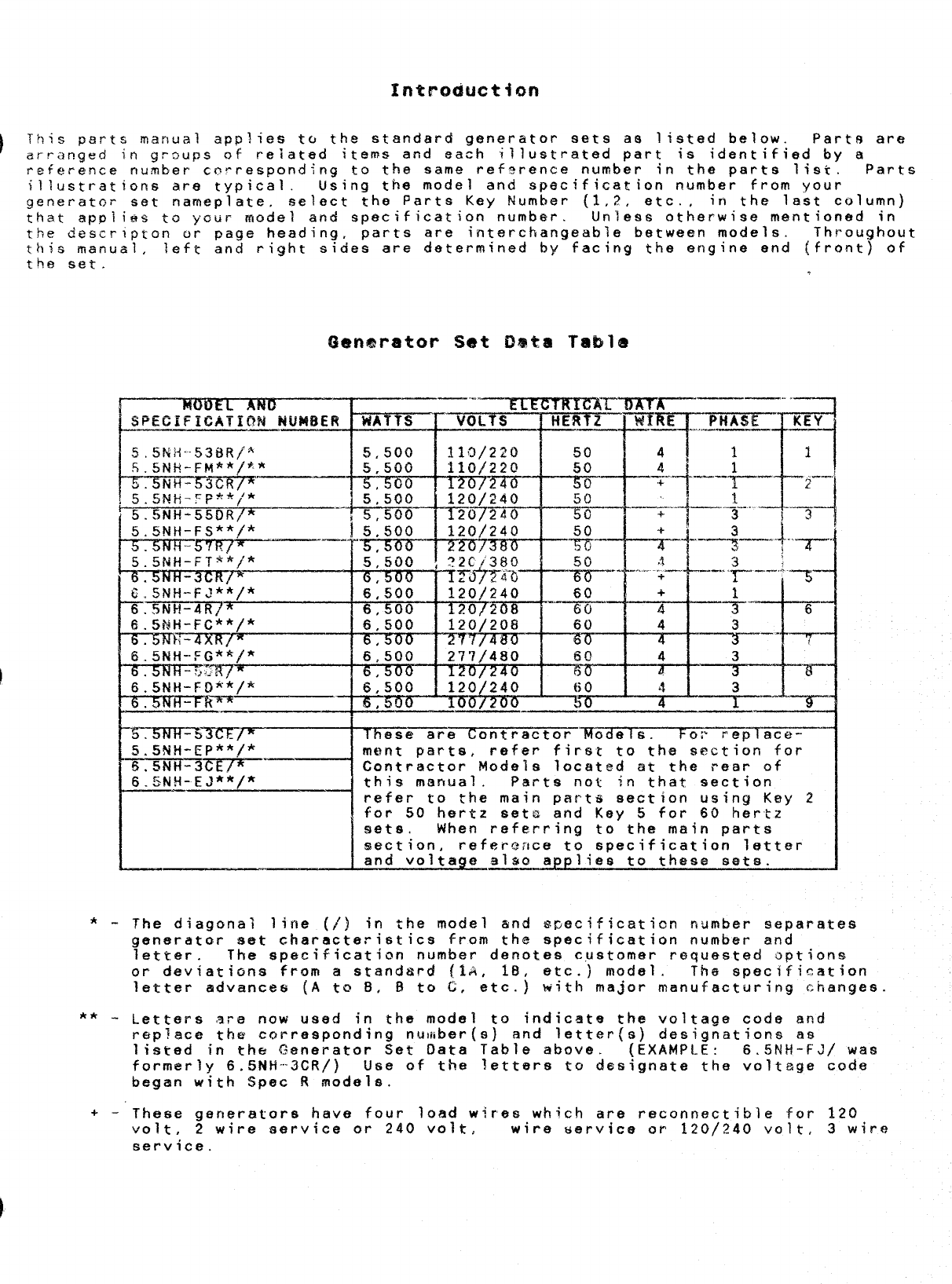
Introduction
):::;J:;’? manual applies to the standard generator sets as listed below. Parts are
xn grsups of reiated items and ~ach illustrated part is identified by a
refe~ence rtusber cn!-respond~ng to the same ref~rence number in the parts list. Parts
illustrations are typical. Using the model and specification number from your
Qenerator set nameplate, select the Parts Key Number (1,2, etc., in the last column)
that app~ies to Ycur model and specification number. Unless otherwise mentioned in
the descr?stcn or Daae headina, Darts are interchangeable between models. Throughout
,-
rhis manual, left an~ right s;des are determined by-facing the engine end (front} “
the set. or
5.5NH-F5** *
/
5%FJ?f’=m/ “.—.
5.5NH-FT**/*
6.5NH-3CR/%
6.5titi-FC**/*
‘67573%-4XR/*
f$.5t’4H-!=G**/*
.-
5N H-I-R**
-..—
rmrw=%bm~
5.!5NH-EP**f”*
%-zmiT=mF—————————
6.5Nti-EJ**/*
—- —
——— ..— ——-,. ,.—
WATTS IVOLTS F~-F*F
5,500 I12
110/220 I50 411
~1
1
5,5CJ0 110/220 50
Orzf’zi ‘!)0 –+”” :-–””-+—--’ r-
5:5:0
5
120/240 50
r-t “1
5,500 207240 50 . . .... —.-.. .. ..—
+
+
3
,5,500 120/240 +“
%“ -1-...—+..——— /;
5:500 I
:~ . . ... .&_+”_+_
6:500 120/240 60 +
6,500 120/208
1
60 4
I;1; :+
+6
6,500 120/208 60 4 —. f
277/480 6c! 4 3
“T3---
6:500 t,io4 3
%--Yi3O
,U !) ----&--
~e are Contractor ‘%odels. For replace-
mt~nt parts, refer first to the section for
Contractor Modele located at the rear of
this manual. Parts not in that section
refer to the main parts section using Key 2
for 50 hertz sets and Key 5for 60 hertz
sets. When referring to the main parts
section, reference to specification letter
and voltage also ap plies to these sets.
*-The diagonal line (/) in the model and %Oecificstion number separates
generator set characteristics from the specification number and
letter. The specification number denotes c,ustomer requested options
or deviati~ns from astandard (1A, lB, etc.) model. The specification
letter advances (A to 3, Bto C, etc.) with ma~or manufacturing changes
** -Letters are now used in the model to indicate the voltage code and
rep?ace the corresponding nu~!iber{s) and letter(s) designation as
listed in the Generator Set Data Table above. (EXAMpLE: 6.5Rli-FJ/ Was
formerly 6.5NH-3CR/) Use of the letters to designate the voltage cod%
began with !Spec Rmodels.
+-- These generators have four load wjres which are reconnectable for 120
volt, 2wire service or 240 volt, wire service or 120/240 volt, 3wire
service.
51
Mounting
2-1/16”
REF PART
HO. No.
Qw PART
USED DESCRIPTION
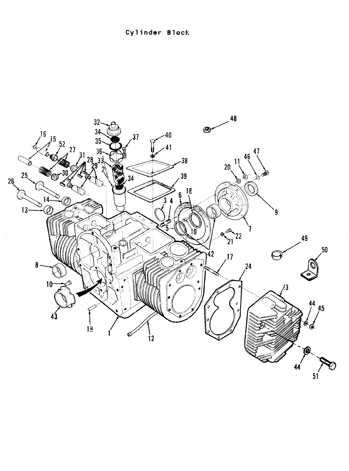
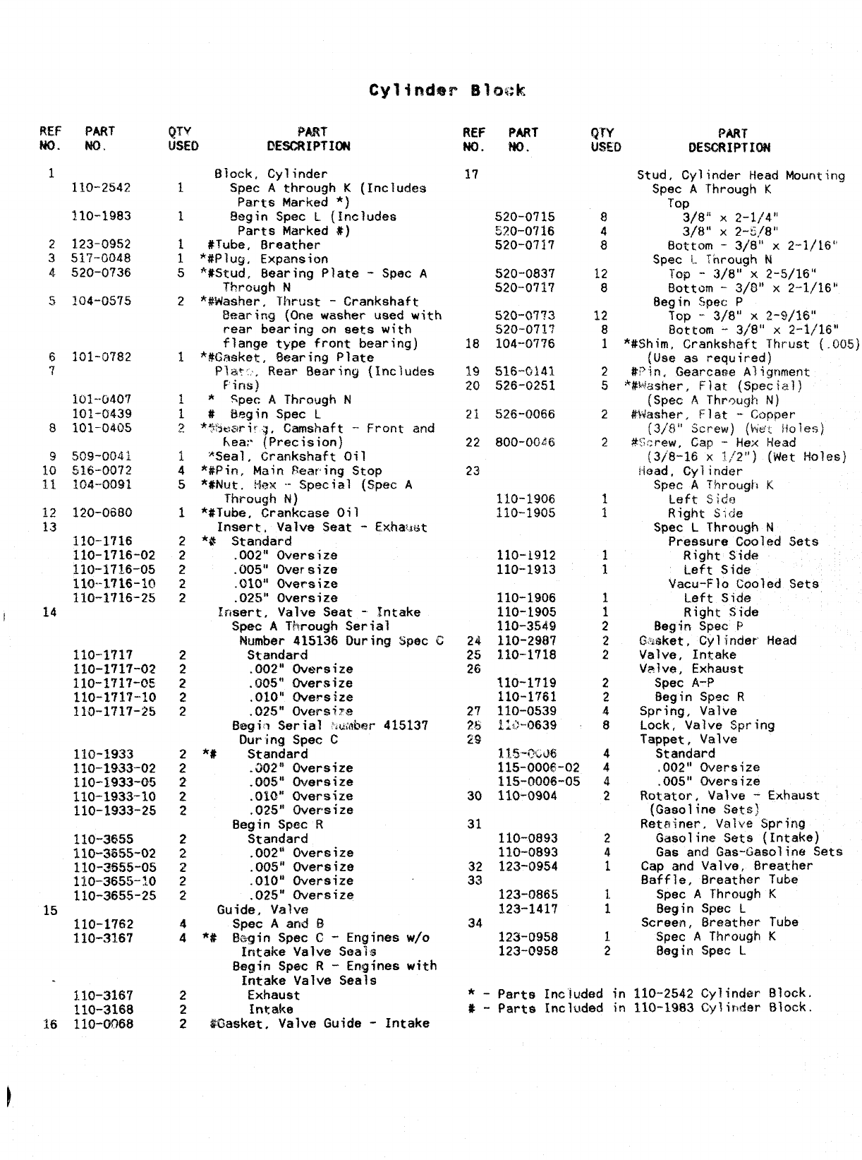
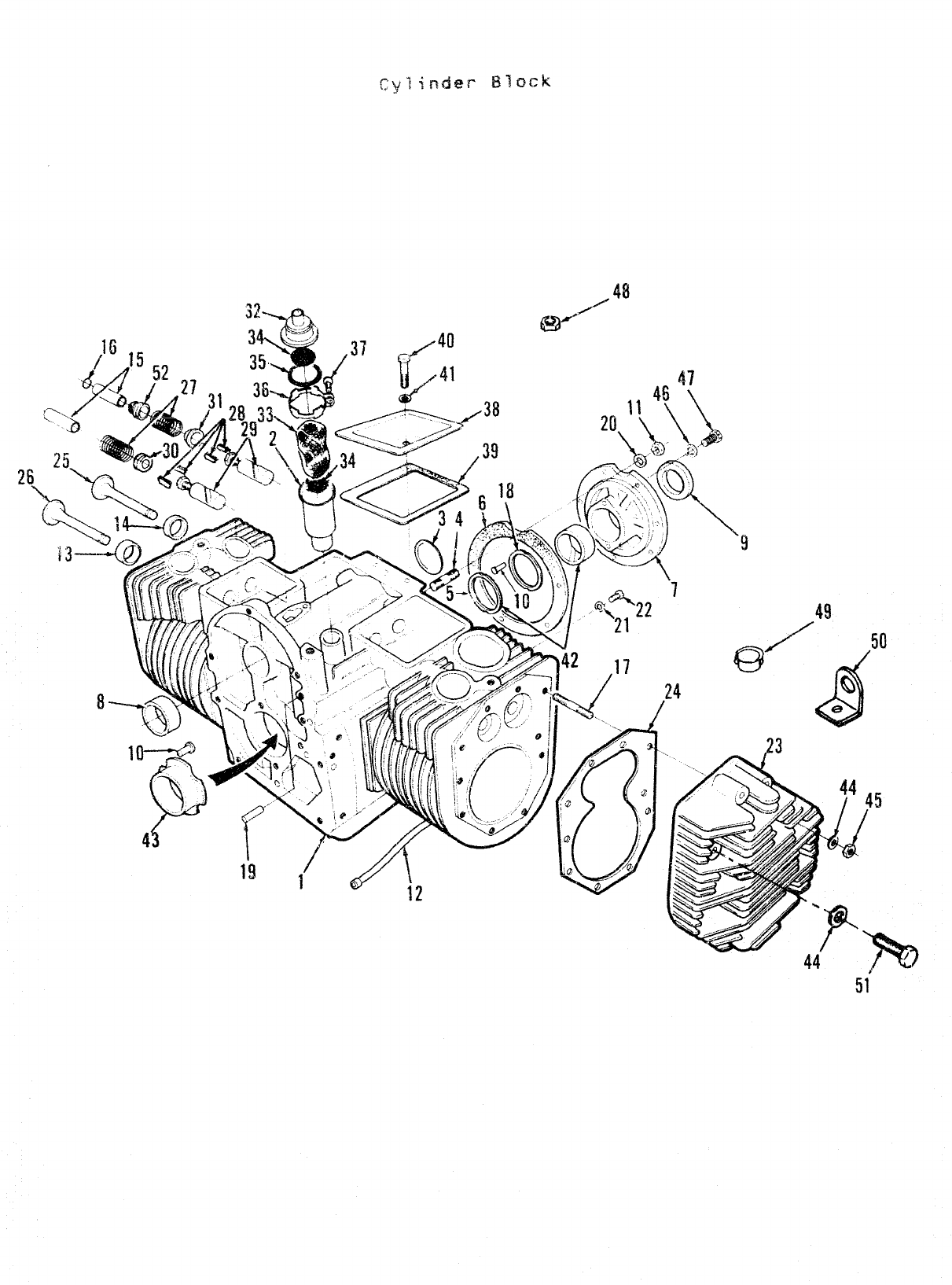
$Ioek, Cylinder
1Spec Athrough K(Includes
Parts Marked *)
1!%gin Spec L(Includes
Parts Marked #)
1#Tube, Breather
1*#Plug, Exp.ansit)n
5*#Stud, Bearing Plate -Spec A
Through N
2*#Washer, Thrust -Crankshaft
Bearing (One washer used with
rear bearing on sets with
flange type front bearing)
1*#Gasket, Bearing Plate
PlaT:, Rear Bearing (Includes
Fins)
~*Spec AThrough N
1#Eleg!n Spec L
p*WwsriuV, Camshaft -Front and
hear (Precision)
1‘Seal, Crankshaft Oil
4*#Pin, Main Peacing Stop
5*#Nut, %x .- Special (Spec A
Through N)
1*#Tube, Crankcase Oi?
Insert, Valve Seat -Exhawt
2*8 Standard
2.002” Oversize
2.005” oversize
2.~~otl Oversize
2.025” Oversize
Insert, Valve Seat -Intake
Spec AThrough Serial
$iumber 415136 During Spec C
2Standard
2.002” Oversize
2.005” Oversize
2.010” Oversize
2.025” (iversi~e
Begil Serial ‘iumkwar 415137
During Spec C
2*# Standard
2.J02:; Oversize
2.005” Oversize
2.010” Oversize
2.025” oversize
Begin Spec R
2Standard
2.002” Oversize
2.005” Oversize
p.010” Oversize
2.025” Oversize
Guide, Valve
4Spec Aand 8
4*# Bc,gin Spec C-Engines w/o
Intake Valve Sea”is
Begin Spec R-Engines with
Intake Valve Seals
2Exhaust
2Intake
2$K3asket, Valve Guide -Intake
REF PART
NO. ?$0.
QTY PART
USED L?E%X?IPTXON
Stud, Cylinder Head
Spec AThrough K
Top
3/8” X2-1/4”
3/~” x2-S,/8”
Bottom -3/8” x
Spec i- Through h
1110-2542 17
110-1983 520-0715
520-0716
520-0717
8
4
8
12
8
12
8
1
2
5
2
2
1
1
1
1
1
1
2
2
2
2
2
4
8
4
4
4
2
2
4
1
1
1
1
2
2123-0952
351’7-0048
4. 520-0?36 520-0837
520-0717 Top -3/8”-x 2-5/16”
Bottom -3/8” X2-1/16”
Begin Spec P
Top -- 3/8” X2-9/16”
Bottom -3/8” .x 2-1/’16”
*#Shim, Crankshaft Thrust (.005)
(Use as required)
#?’in, GearcaQe Aliqnment
520-0773
520-0717
18 104-0776
6
71OI-O782 19 516--Oi4l
20 526-0251 *#Wisher, Flat. {Sipeiiial)
(Spec AThrough N)
Washert Flat -Gopfmr
(3/8” Screw) (biet H01i3sj
#S;;rew, cap -Hex Head
(3/8-16 x?~2i’) (Wet Holes)
Head. cyl incier
Spec A?htrougl~ K
Left side
Right Side
Spec LThrough N
Pressure Cooled Sets
Right Side
Left Side
101--0407
101-0439
101-0405822 8oo-oG~6
23
11(3-1906
110-190.5120-0680
110-1716
110-1716-02
110-1716-05
110-1.716-10
110-1716-2S
24
110-i912
110-1913
Vacu-Flo Cooled Sets
LeIft Side
Right Side
Begin Spec P
CLusket, Cylinder
Valve, Intake
Valve, Exhaust
Spec A-P
Eegin Spsc R
Spring, Valve
Lock, Valve Spring
Tappet, Valve
Standard
,002” Oversize
.005” Oversize
Rotator, Valve -Exhaust
(Gasoline Sets)
Retainer, Valve Spring
Gasoline Sets (Intake)
Gas and Gas-6asolinc+ Sets
Cap and Valve, Breather
Baffle, Breather
Spec AThrough
Begin Spec L
Screen, Breather
Spec AThrough
8egin Spec L
110-1906
110-1905
110-3549
110-2987
110-1718
I14
Head
110-1717
110-1717-02
110-1717-05
110-1717-10
110-1717-25
25
26 110-1719
110-1761
110-0539
1;+0639
l.li!j-?x’d(i
115-0006-02
115-0006-05
110-0904
110-1933
110-1933-02
11O-I933+35
110-1933-10
110-1933-25 30
31
110-0893
110-0893
123-0954
110-3655
110-3855-02
110-3s55-05
110-3655-?0
110-3655-25
15 110-1762
110-3167
32
33 Tube
K
123-0865
123-1417 Tube
K
34 123-t9958
123-0958
110-3167 Block.
Block.
*_parte Included in 110-2542 Cylinder
#- Parts Included in 110-1983 Cylir-der
110-3168
16 110-0068
48
51
Cylimhr EI1OGI4
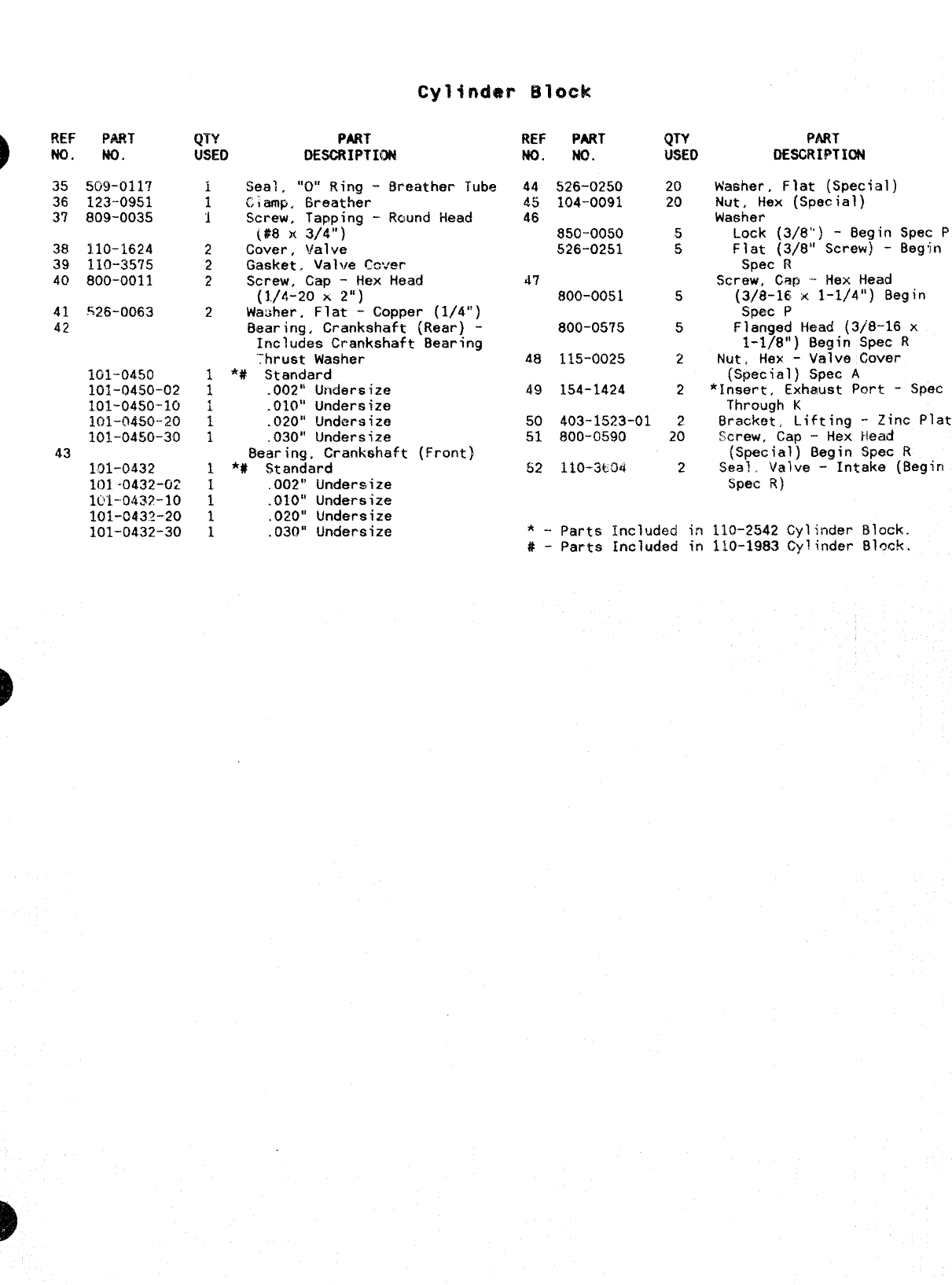
35 509-011?
36 123-0951
3? 809-0035
38 110-1624
39 110-3575
40 800-0011
41 ~26-0063
42
101-0450
101-0450-02
101-0450-10
~Q~-Q&j~-~~
101-0450-30
43
191-0432
101-0432-02
1OI-O432-1O
101-C432-20
101-0432-30
(p-%’
UsEl)
i
1
1
2
2
2
2
PART
DESCRIPTION
Seal ,“O” Ring -Breather Tube
Liemp, Breather
Screw, Tapping -Round Head
(#8 x3/4”)
Cover, valve
Gasket. Valve C%.’er
Screw, Cap -Hex Head
(1./4-20 x2“)
Wauher, Flat -Copper (1/4”)
Bearing, Crankshaft (Rear) -
Includes Crankshaft Bearing
“;hrust Washer
1*# Standard
1.002” Undersize
1.010” Undersize
i.020” Undersize
1.030” Undersize
Bearing, Crankshaft (Front}
1*# Standard
1.002” Undersize
1.O~O” LJndersi~e
1.020” Undersize
1.030” !Jndersize
REF PART
No. M?.
44 526-0250
45 104-0091
46
850-0050
526-0251
47
800-0051
800-05’75
48 115-0025
49 1S4-1424
QTY
USE(I
20
20
5
5
5
5
2
2
50 403-1523-01 2
51 800-0590 20
52 llo-3Lo@ 2
PART
DESCRIPTION
Washer, Flat (Special)
Nut, Hex (Special)
Washer
Lock (3/8”) -Begin Spec
F’
Flat (3/8” Screw) -Begin
Spec R
Screw, Cep -Hex Head
(3/8-16 x1-1/4”] Begin
Spec P
Flanged Head (3/8-16 x
1-1./8”) Begin Spec R
Nut, Hex -Valve Cover
(Special) Spec A
*Insert, Exhaust Port -Spec
Through K
Bracket, Lifting -Zinc
Plated
screw, Cap -Hex Head
(SpecJ~~~eBegin Spec R
Sea? .-Intake (Begin
Spec R)
*-Parts Included in 110-2542 Cylinder Block.
#- Parts Included in 110-1983 Cylinder Block.
REF PAfm
Nf3. m.
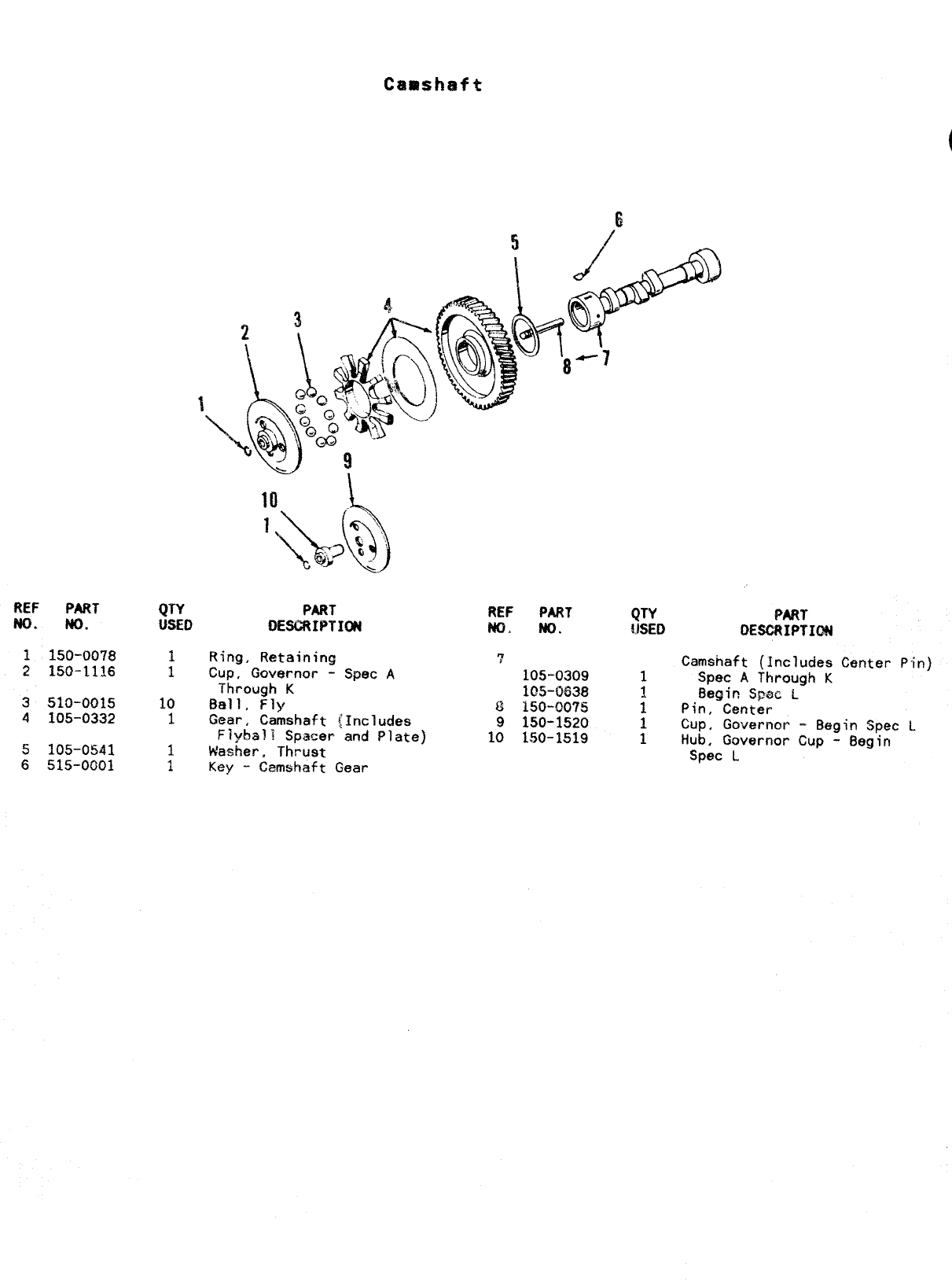
1150-0078
2150-1116
3510-0015
4105-0332
.5 105-0541
6515-0001
QTY
W5Eo
1
1
10
1
PART
DESCRIPTION
Ring, RetaininG
Cup, Governor -
Through K
Ball, Fly
Gear, Camshaft
Flyball Spacer
Washer, Thrust
Spec ,4
Includes
and Plate)
Key -Camshaft Gear
REF PART
w. No,
‘7
105-0309
105-CM38
8150-0075
9150-1520
10 150-1519
(JTY PART
WED CHCRIPTIQN
Camshaft (Includes Center Pin)
1Spec AThrough K
~Begic Spsc L
1Pin, Center
1Cup, Go~ernor -Begin Spec L
1Hub, Governor Cup -Begin
Spec L
Crankshaft
\
7
I
1
‘N
iWEF PiUkT
m. tm.
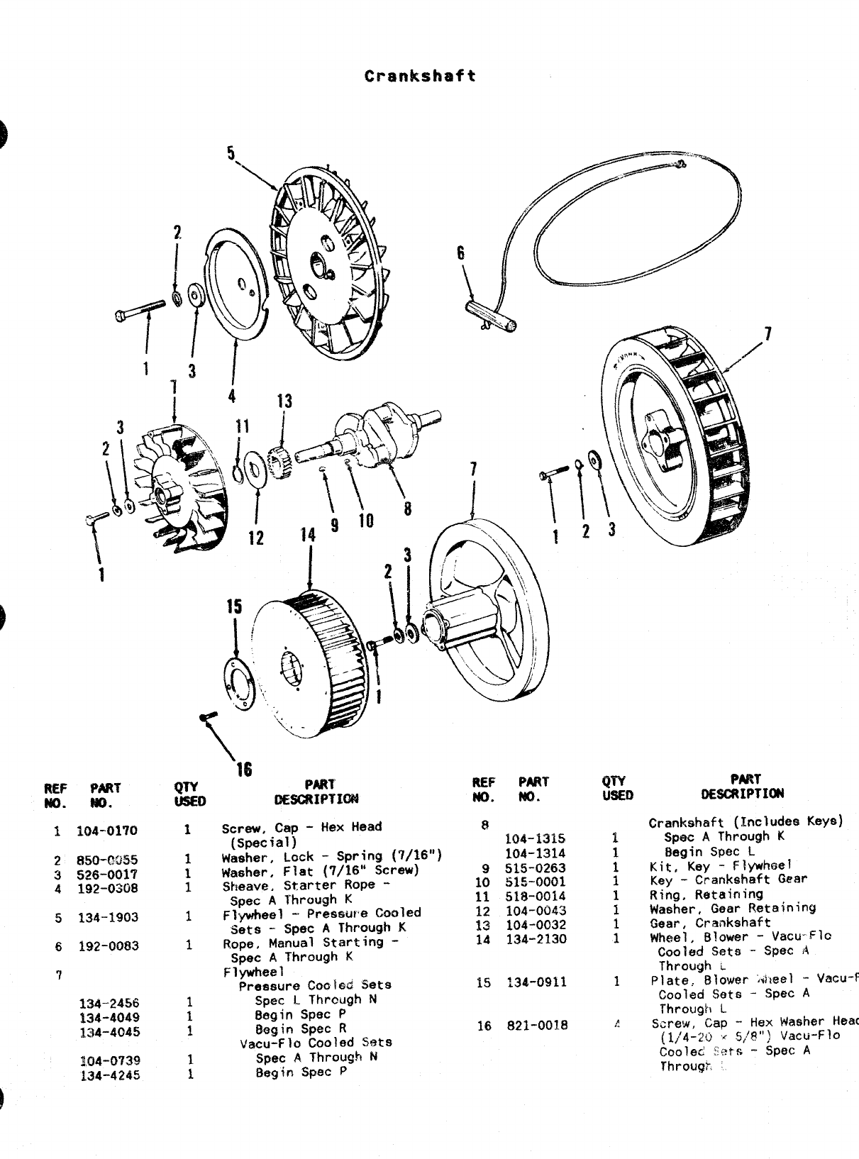
1104-01?0
2850-0055
3526-001’?
4192-0308
5134-1903
6192-0083
7
134-2456
134-4049
134-4045
~,04-073Q
134-4245
PAW
0HZRIFTKE4
screw, Cap -Hex Head
(Special)
Washer. Lock -Spring (7/16”)
Washer, Flat (7/16” Screw)
?Meave, Starter Rope -
Spec AThrough K
Flywheel -preseu~e cooled
Sets -Spec AThrough K
Rope, Manual Starting -
Spec AThrough K
Flywheel
Pressure Cooled Sets
spec LThrough N
Begin Spec P
Begin Spec R
Vacu-Flo Cooled Sets
fipec AThrough R
Begin Spec P
REF PART
m. Ml.
8
104-131.5
104-1314
9515-0263
10 515-0001
11 518-0014
12 104-0043
IS 104-0032
14 134-2130
15 134-0911
16 821-0018
PART
DESCRIPTION
Crankshaft (Includes Keys)
spec AThrough K
Begin Spec L
Kit, Key -Flywh@el
Key -Crankshaft Gear
Ring, Retaining
Washer, Gear Retaining
Gear, Crankshaft
Wheel, B!ower -Vacu-FIC
Cooled %ta -Spec A
Through L
Plate, Blower Aeel -
Vacu-Flo
Cooled Sets -Spec A
Through L
Screw, Gap -Hex Washer
Head
(1/’4-20 ~5/S”) Vacti-Flo
cooled :i{?$& -Spec A
Throug? ‘
REF PART
NO. NO.
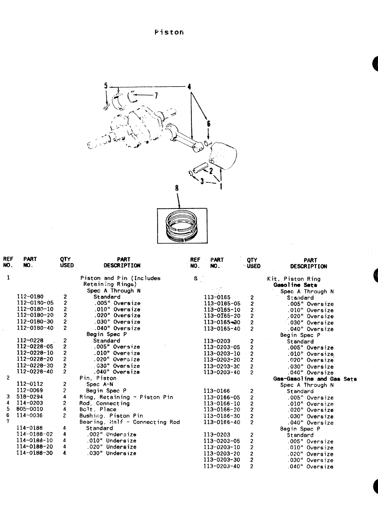
1
112-0180
112-0180-05
112-0180-10
112-0180-20
112-0180--30
112-0180-40
112+3228
lM-022f3-0s-
112-0228-10
112-0228-20
112-0228-30
112-0228-40
2112-0112
112-0069
3518-0294
4114-0203
5805-0010
6114-0036
T114-0188
114-018$3-02?
114-oli3a-lo
~14+18&.~()
114-0188-30
Q1-f
USED
2
2
2
2
2
2
2
2
2
2
2
2
2
2
4
2
4
2
4
4
4
4
4
PART
K8CRIPTION
Piston and Pin (Includes
%tain;ng Rincjs)
Spec AThrough N
Standard
.005” Oversize
,010” Oversize
.020” Oversize
.030” Oversize
.040” Oversize
Begin Spec P
Standard
.005” Over$ize
.010” overlg~ize
.020” Overwize
030” Oversize
.040” Oversize
Pin, Piston
Spec A-td
Begin Spec P
Ring, Retaining -Piston Pin
Rod. Connecting
Bc?t, Place
%ushit;cj. Piston Pin
Eearirig, Half -Connecting Rod
Standard
.002” Uoderajze
.010” Undersize
.020” Undersize
.030” Undersize
REF PART
No. No.
~’
113-~165
11.3-0165-05
113-01.65-10
113-0f65-20
113-0165+0
113-0165-40
113-0203
113-0203-05
113-0203-10
113-0203-20
113-0203-3!?
113-0203-40
113-0166
113-0166-05
113-0156-10
113-0166-20
113-0166-30
113-0166-40
113-020:3
113-0203-05
113-O2O3-1O
113-0203-20
113-0203-30
113-0203-40
$n’o
2
2
2
2
2
2
:
2
2
~
2
2
2
2
2
2
2
2
2
2
;
2
PART
DESC%PTI(N
Kit, Piston Ring
Waolil?a 8ete
Spec AThroug
Standard
.005” Over-s
.010” Overs
,.020” Over&
.030” Overs
.040” Overs
N
ze
ze
ze
ze
ze
Begin Spec P
Standard
.005” Oversize
.01.0” oversizq
,020” oversize
.030” Oversize
.040” Oversize
(hrOatwline and Oaa %ta
Spec AThrough N
Standard
.005” Oversize
.010” Oversize
.020” Oversize
.030” Oversize
.040” Oversize
Begin Spec P
Standard
.005” Oversize
,010” Oversize
.020” Oversize
.030” Oversize
.040” Oversize
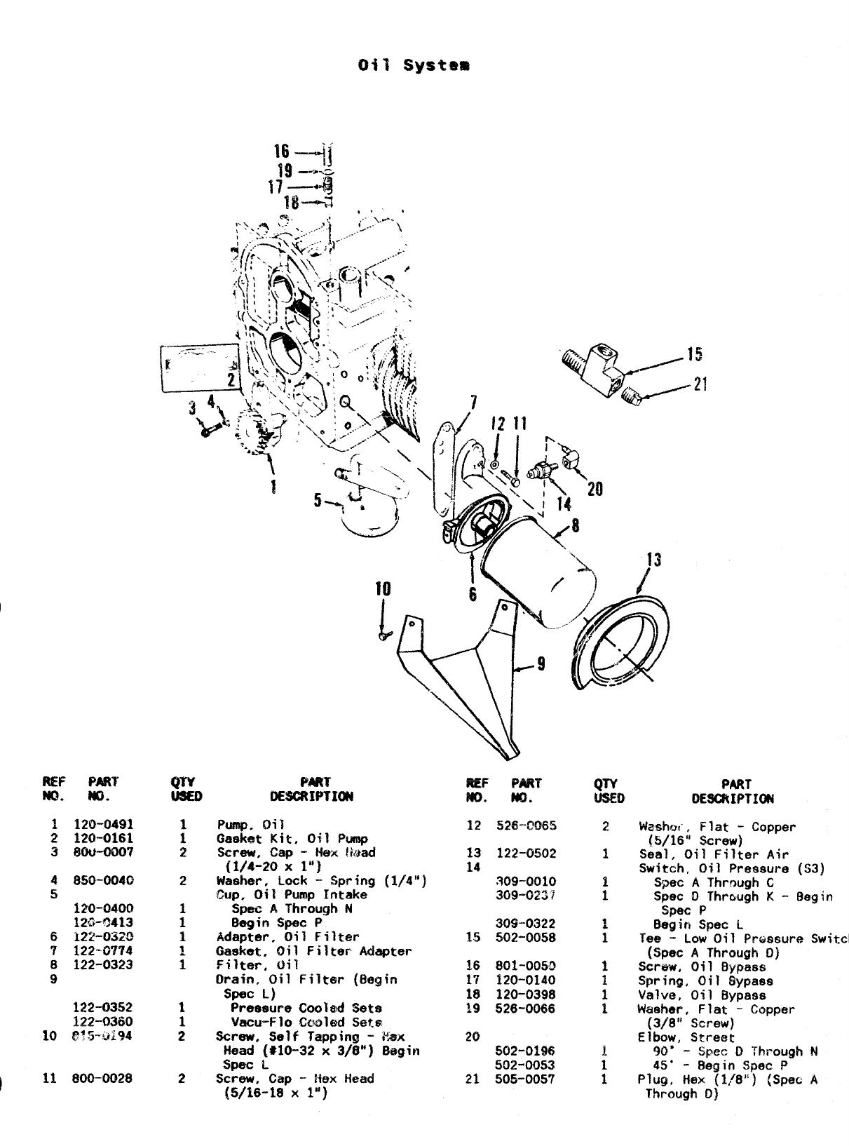
031 Syst.flm
R!Ii= PART
No. m.
1129-0491
2120-0161
3#ou-ooo7
48S0-0040
5~~o-040Q
12G-C413
6122-03?$3
?122-0774
8122-0323
9
122-(3352
122-Q36Q
10 e!3--+>i94
;:–+jj
-ti%..~
m-—-43
Iti---a,, ,
2
1
1
2
2
fwiiu
OESCRIPTIOU
=-([ ‘., 13
Pump, Oil
Gasket Kit, Oi? Pump
Screw, Cap -Hex Med
(1/4-20 X1“)
Washer, Lock -Spring (1/4”)
CUP, Oil Pump Intake
Spae AThrough N
8egin Spec P
Adapter, Oil Filter
Gasket, Oil Filter Adapter
Filter, Oil
Drain, Oil Filter (8egin
Spec L)
Pressure ChOl*d %&s
%CU-F]O cooled Sete
Screw, Self Tapping -i%x
Head (#10-32 x3/S”) E%gin
Spat L
Screw, Cap -!fex Head
[5/16-18 X~“)
REF WRY
?m. No.
12 526-C’065
13 122-0502
14
309-0010
309-0237
309-0322
15 502-0058
~,6 801-f)05~
17 120-0140
18 120-0398
19 526-0066
20
S02-0196
502-0053
21 50!5-0057
PART
0ESCRIPTIU4
W~#mi, Flat -Copper
(5/16” Screw)
Seal, Oil Filter Air
Switch, Oil Pressure (S3)
Spec AThrough C
Spec OThraugh K-Begin
Spat P
8egiri Spec L
Tee -Low Oil Pressure Switch
(Spec AThrough O)
Screw, Oil Bypass
Spring, Oil Bypass
Valve, Oil Bypass
Washer, Flat -Copper
(3/8” Screw)
Elbow, Street
90’ -Spec DThrough N
459 -Begin Spec P
Plugj, Hex (1/8”) (Spec A
Through D)
2
/
REF $&m
No. NO.
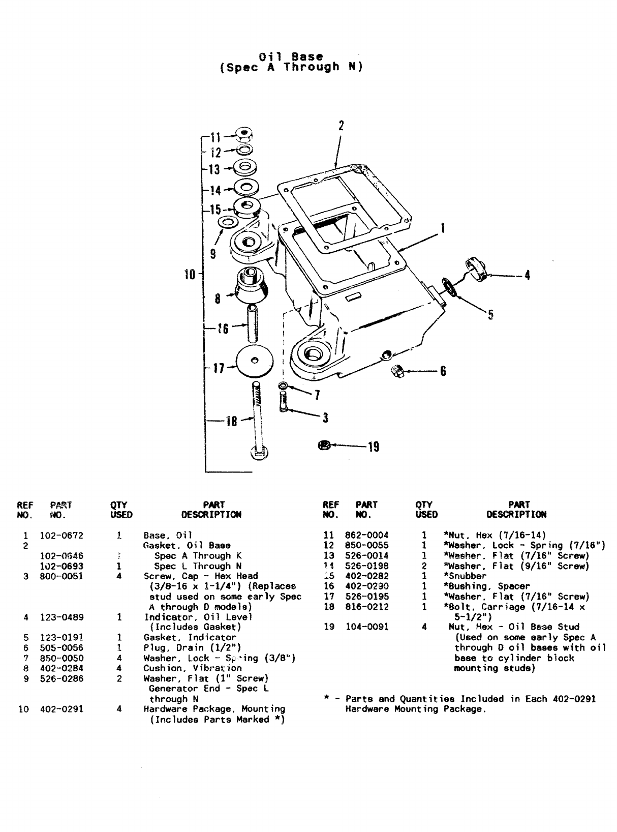
1102-0672
2
102-0646
1~2-0693
3800-0051
4123-0489
!5 123-0191
6505-0056
?850-0050
8402-0284
9526-0286
10 402-0291
QTY
1
1
4
1
1
1
4
4
2
4
I
PAW
OESCRIPTIffl
Base, oil
Gasket, Oil Base
Spec AThrough K
Spec LThrough N
Screw, Cap -Hex Head
{3/0-16 x1-1/4”) (l?eplace&
stud used on some early Spec
Athrough Dmodels)
Indicator, Oil Level
(Includes Gasket)
Gasket, Indicator
Plug, Drain (1/2”)
Washer, Lock -Sg’ing (3/8”)
Cushion, Vibration
Washer, Flat (l” Screw)
Generator End -Spec L
through N
Hardware Package, Mounting
(Includes Parts Marked *)
“
e—lg
REF PAN f& PART
No. No. OE$CJ?IPTIOM
862-0004 1
?)50-0055 1
526-0014 ~
c*k.n*an
“.” “.-w 2
402-0282 1
402-0290 1
526-0195 I
816-0212 1
104-0091 4
*Nut, Hex (7!16-14)
Washer, Lock -Spring (7/16”)
*~a~h~r, F1.st {7/16” scr~)
%Mher, Flat (9/16” Screw)
*Snubber
*Bushing, Spacer
%hmher. Flat {7/16” Screw)
*fJolt, Carriage (7/16-14 x
5-1/2”)
Nut, Hex -Oil Bme Stud
(Used on some early Spec A
through Ooil baees with oil
base tc cylinder block
mounting studs)
*-Parts and Quantities Included in Each 402-0291
Hardware Mounting Package.
REF PWF
m. m.
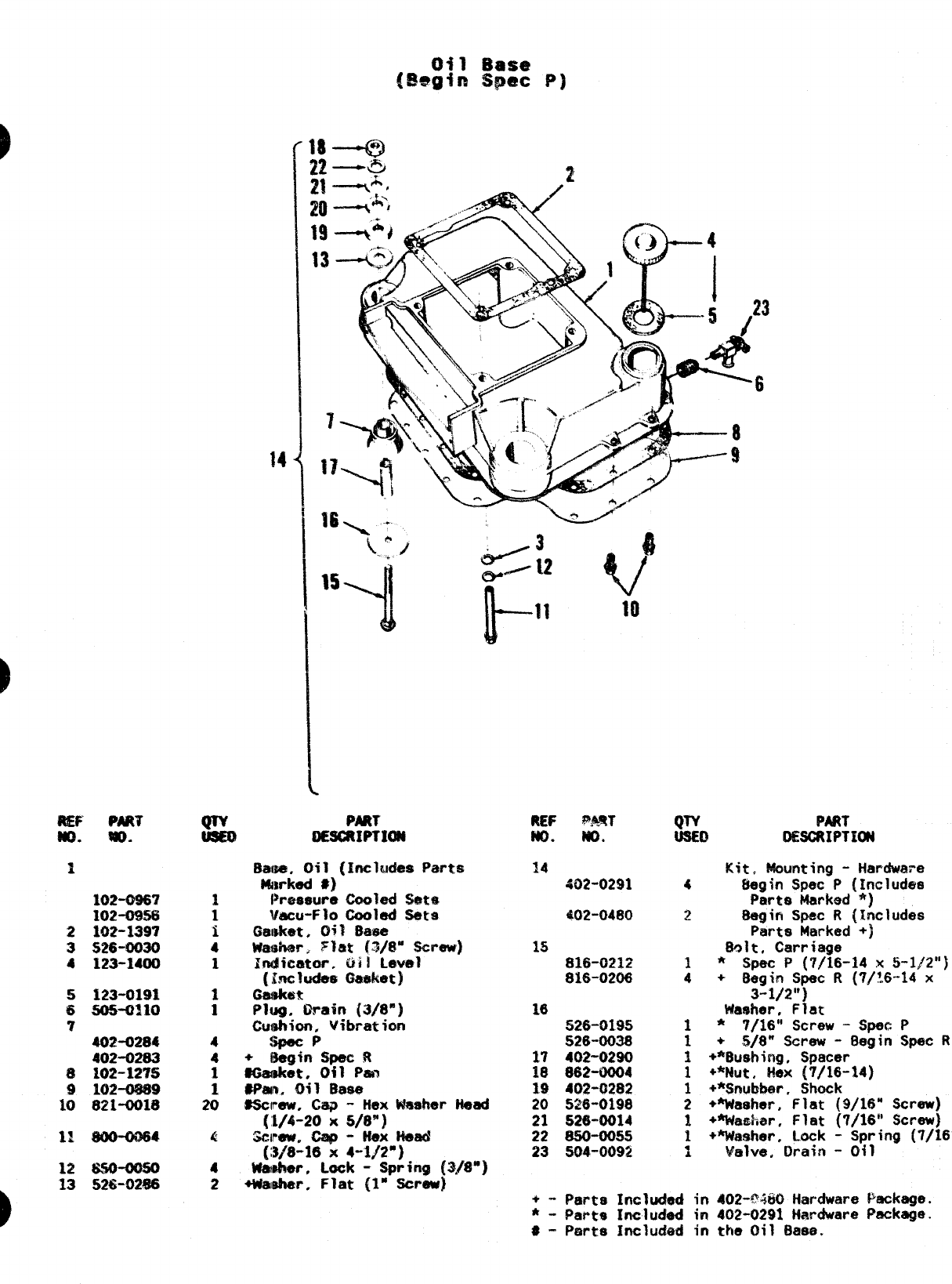
1
102-0%?
102-OW3
2102-1397
3S26-0030
4123-1400
5123-0191
650S+310
7
4W13284
402-0283
8102-1275
9102-0689
10 821-OOIB
11 800-0064
12 WO-omo
13 52tW)2@6
15
‘!
gPART
0E8C81PTION
4
4
1
1
20
4
2
REF @JflT
lm. m.
14
402-0291
402-0480
15
81$-0212
816-0206
16
526-0195
S26-0036
17 402-0290
18 862-0004
IS 402-0282
esclrew, cap -Hex Mmher Head 20 526-0190
[:i/4-20 x5/8”) 21 526”0014
Screw, C+ -Hex Need 22 8$0-00s5
(:3/8-16x 4-1/2”) 23 S04-0092
Wmher, Lock -Spring (3,/8”)
+Wsher. Flat {1” Screw]
Kit, Mounting -Hardware
4Begin Spec P(Includes
F@rts Marked *)
~8egin Spec R(Includes
Parts Marked +)
Bolt, Carriage
*SPaC P(7/16-14 x5-1/2”)
:+Segin Spec R(7/16-14 x
3-1/2”)
Washer, Flat
1*7/16” Screw -Spec P
1+5/8” Screw -Begin Spec R
1+*Bushing, Spacer
1+*Nut, ~e~ (7/16-~4)
1+*Snub&ar. Shock
2+Washer, flat (9/16” screw)
1+W.mhar, Flat (7/16” Screw)
~+’~saher, Lock -Spring (7/16”)
●
AValve, Drata -Otl
.+- Parts Includad in 402-PMO Hardware Package.
*- Pa& Included in 402-0291 Hardware Packa&.
*- Pmte Includ@d in the Oil 13aea.
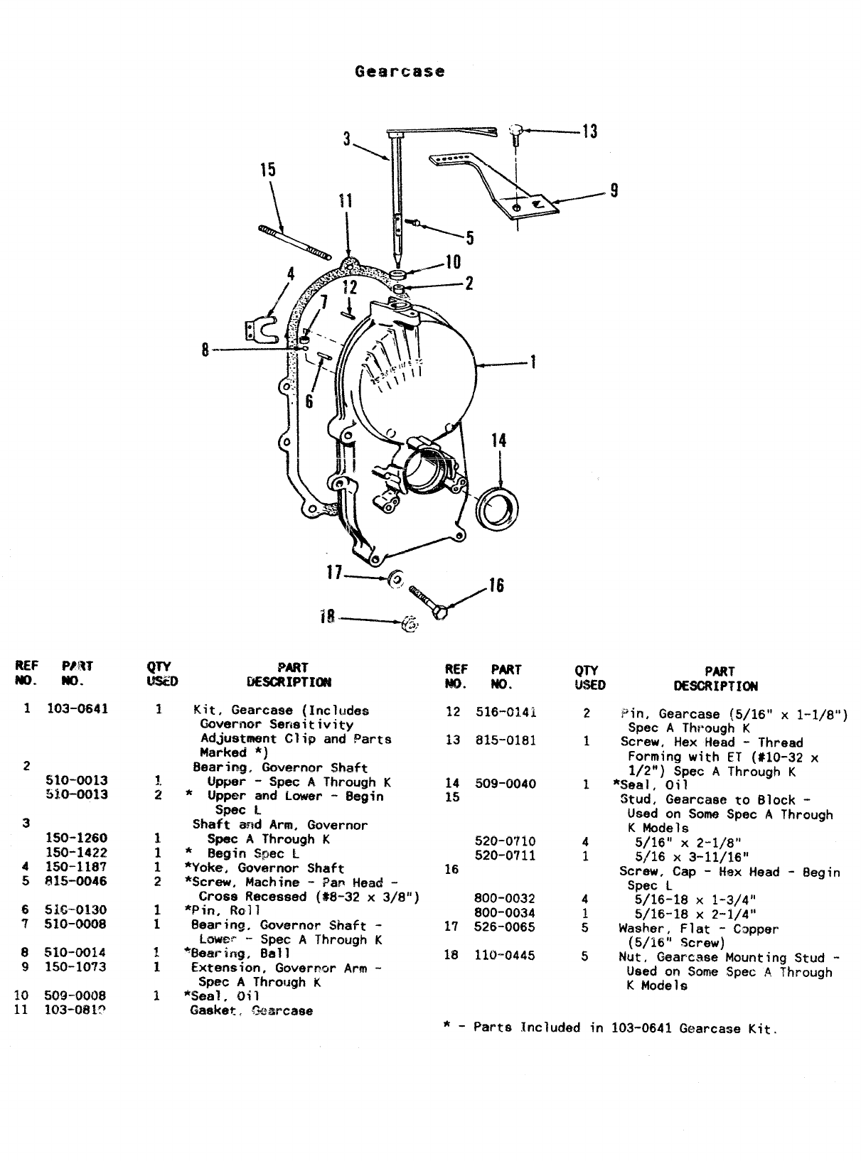
2
510-0013
510-0013
3
150-1260
150-1422
4150-1,187
5815-0046
651G-0130
7510-0008
8510-0014
9150-1073
10 50!3-0008
11 1(33-081?
8-
a. iHt!
QTY PART
L!?$i3J DHCRIPTI(X4
Kit, Gearcase {Includes
GOverncm Semitivity
Adjustment C?ip and Parts
Marked *)
Bearingz Governor Shaft
upper -Spec AThrough K
*Upper and Lower -Begin
Spec L
Shaft and Arm, Governor
Spec AThrough K
*Begin Spec L
*Yoke, Governor Shaft
*Screw, Machine -Pap Head -
Crass Recessed (*8-32 x3/8”)
*Pin, Roll
Bearing. Governor Shaft -
Lowef’ -Spec AThrough K
%esrimg, Ball
Extension, Governor Arm -
Spec AThrough K
‘%eal, Oil
Gasket. !3earcase
REF PART
Bm. No.
12 516-01.41
13 815-0181
14 509-0040
15
520-0”[10
520-0711
16
800-0032
800-0034
17 526-0065
18 110-0445
QTY PART
USED oEsoRIPTmN
2
1
1
4
1
4
1
5
5
Pin, Gearcase (5/16” x1-1/8”)
Spec AThrough K
Screw, Hex Head -Thread
Forming with ET (#10-32 x
1/2”) Spec AThrough K
*Seal, Oil
Stud, Gearcase to Block -
Used on Some Spec AThrough
KModels
5/16” X2-1/8”
5/16 X3-11/16”
Screw, Cap -Hex Head -flegjn
Spec L
5/16-18 X1-3/4”
5/16-18 X2-1/4”
Washer, Flat -Copper
(5/16” Screw)
Nut, Gearcase Mounting Stud -
Used on Some Spec AThrough
KModels
*-Parts Included in 103-0641 Gearcase Kit.
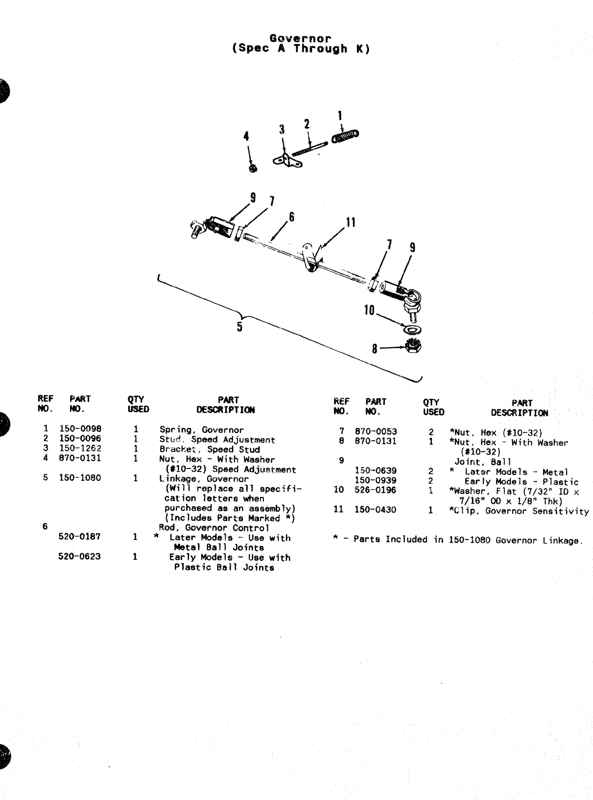
FW P%RT
No. NC).
3150-1252
4870-0131
5150-1080
6
520-0187
520-0623
tJTY PAk?T
OESCRIPTICN
Spring, Governor
Stti8, Speed Adjustment
Bracket, Speed Stud
Nut, Hex -With Washer
(#M3-32) Speed Adjus&ment
Linkage. Governor
(Will replace all specifi-
cation letters when
purchased as an assembly)
(Includes Parts Marked *}
Rod. Governor Central
*Later Models -Use with
Metal Ball Joints
REF PART QTY
MO. No. USED
7870-0053 2*$Jut, Hex (#10-32}
8870-0131 1‘%ut, Hex -With Washm
(#10-32)
9Joint, 8all
150-0639 2*
1s0-0939 Later Models -Metal
2Early kiode?s -Plastic
10 526-0196 s*Washer, Flat (7/32” ID x
7/16” 00 X1/8” Thk)
11 150-0430 1*Clip, Governor Sensitivity
*-Parts Included in 150-1080 Governor Linkage,
Early Models -lJse with
Plastic Ball Joints
10+
/
9
P
-
2
PART
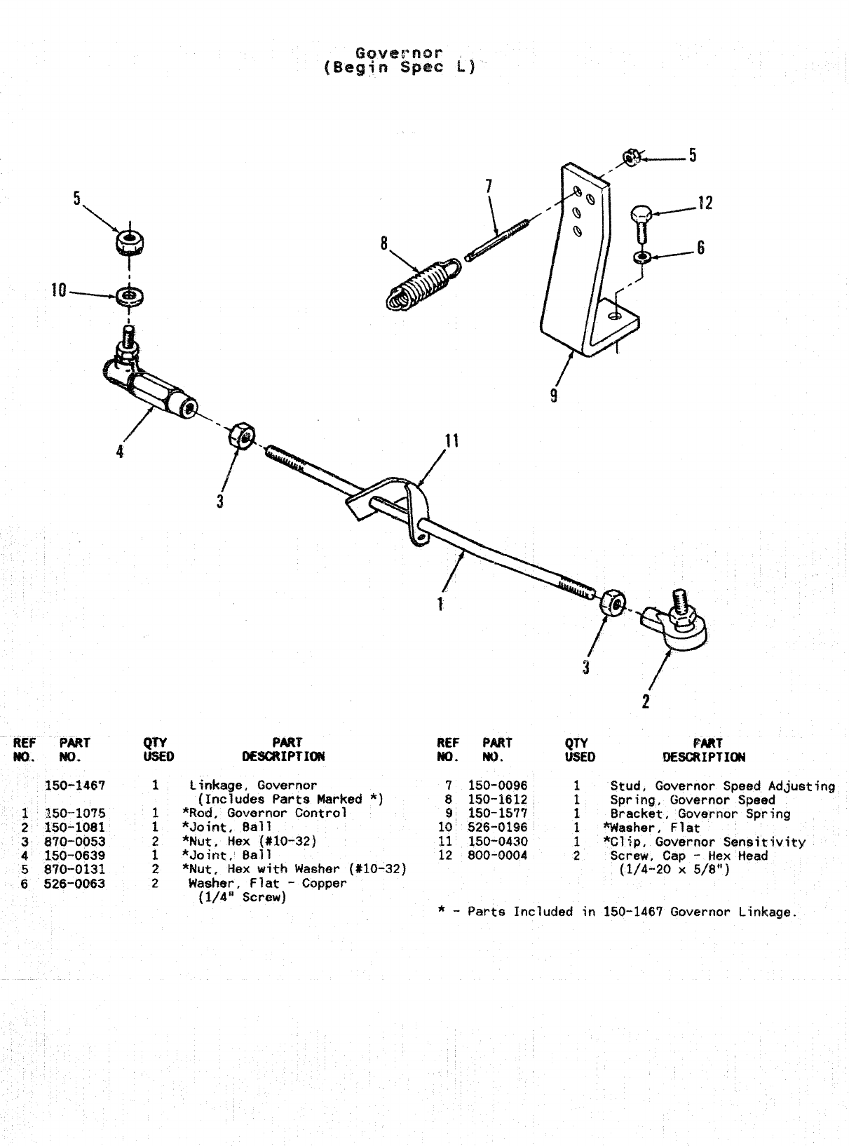
REF PART
w.. No.
150-146T
QTY PART REF PART
WED OESCRIPTICIN Ml. No. DESCRIPTICM
1Linkage, Governor 7150-0696
(Includes Parts Marked *) 8150-1612
*Rod, Governor control 9, 150-1577
;*Joint, 5all 10 526-0196
2*Nut. Hex (#10-32) 11 150-0430
1*Joint; 8all 12 800-0004
2*Nut. Hex with Washer #10-32)
2Washer, Flat -Copper
(1/4” Screw) *-Parts Included in
Stud, Governor Speed Adjusting
Spring, Governor Speed
Bracket, Governor Spring
Washer, Flat
*Clip, Governor Sensitivity
Screw, Cap -Hex Head
(1/4-20 X5/8”)
~y.~o-~~?~
21!50”1081
3870-0053
4150-0639
5870-0131
6526-(?063
150-1467 Governor Linkage.
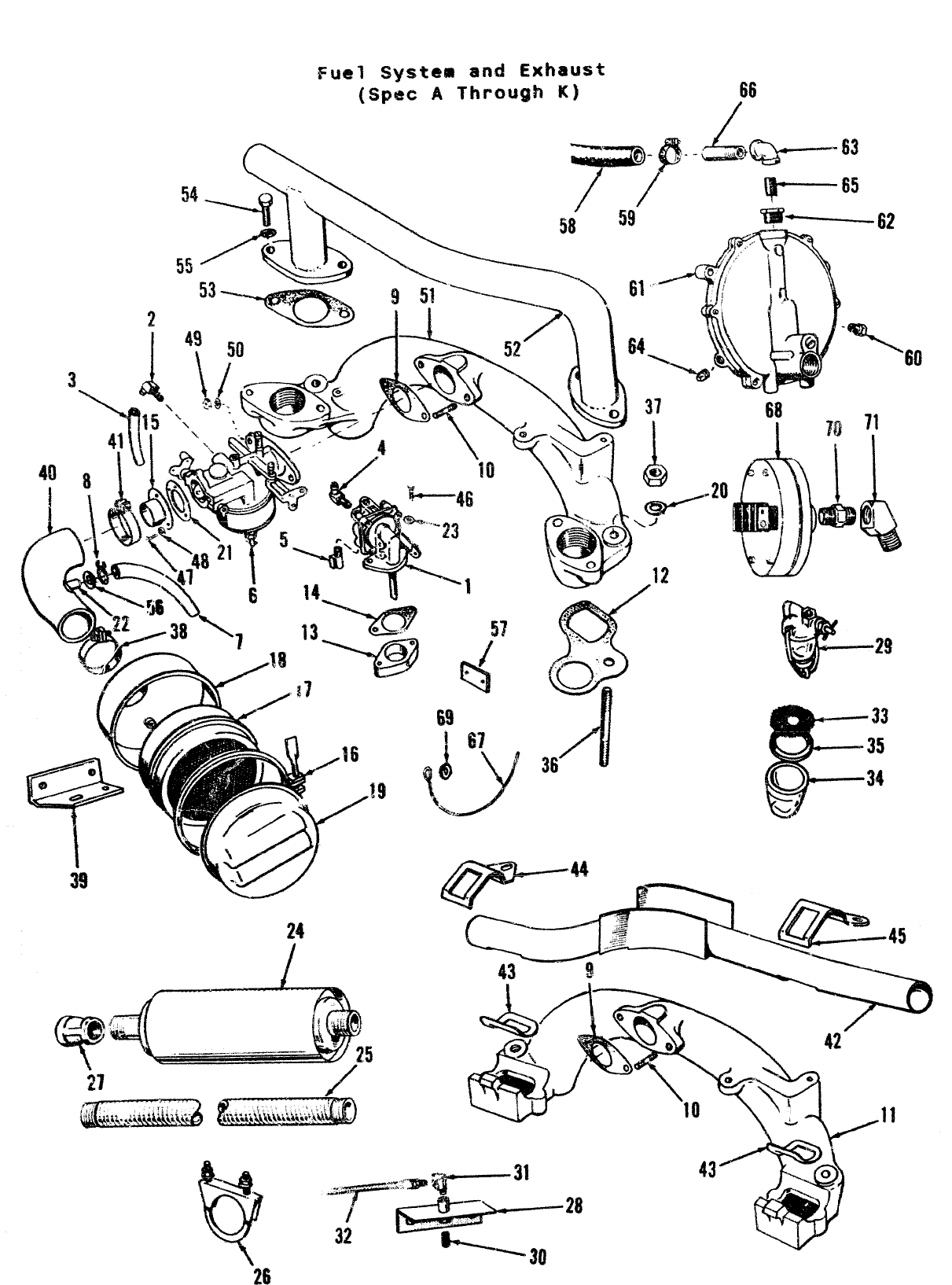
Fuel Systeat and Exhaust
(Spec AThrough it] 66
4
~+- @- -Lmw.Q—’- ~~
\.—— ...-.———-
\-v2’ y)--k /w’Adz-i .
26
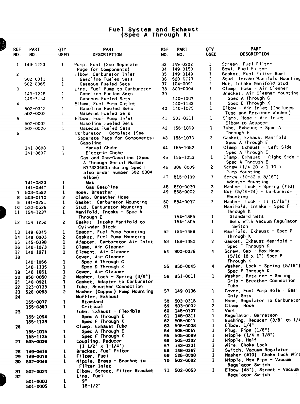
DREF PART
N(I+ MO
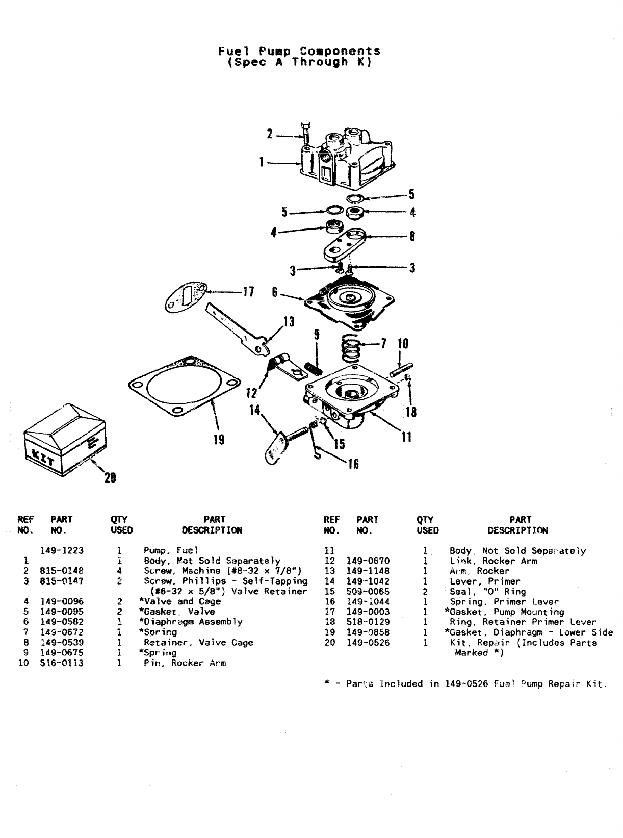
1
i149--1223
2
502-0313
502-0065
3
149-1228
149-!:!i4
d502-0313
502-0002
5502-0002
502-0020
6
141-0808
141-0807
7
8
9
154-1250
149-0045
149-0003
145-0398
140-1073
140-10’71
155-0077
155+360
25
26
27
28
29
30
31
D32
155-1015
15s-1135
505-0038
149-0816
149-0079
—--
WX?-0M6
502”OGXJ
5o1-ooo3
501-0005
PART
DESCRIPTION
Pump, Fuel (See Separate
Page for Components)
~l~ow, carbure~or Inlet
Gasoline Fueled Sets
Gaseous Fueled Sets
Line, Fuel Pump to Carburetor
Gasoline Fueled Sets
Gaseous Fueled Sets
Elbow, Fuel P’mp Outlet
Gasoline Fueled Sets
Gaseous Fueled Sets
EIbow. Fu~~ Wimp Inlet
Gasoline waled Sets
Gaseous Fueled Sets
Carburetor -Complete (See
Separate Page for Components)
Gasa;trie
Marwal Choke
Electric Choke
Gas and Gas-Gasclir@ (Spec
AThrough Serial Number
6773234835 daring Spec F
also order number 502-0304
elbow)
Gas
Gas-Gasoline
t{ose. 8reather
Clmp, Breather Hose
Gasket, Carburetor Mounting
Stud. Carbureto~ Hounting
Manifold. Intake -SPec A
ThY’Qu@! E
GaSktXt, Intake Manifold tQ
Cyi~nder Block
~pace~, Fuel Pump Mounting
~asket, FLWI Pump Mounting
&:3apteF. Carburetor Air Inlet
Cl-, Air Cleaner
Element, Air Cleaner
(kwer, Air Cleaner
Spec AThrough C
=- Qi“hrfi~,m!> K
v~-- .... ---- ..
Cover, Air Gleaner
Washer. Lack -Spring [3/8”)
Gasket, kdapter to Carburetor
Tube. 8reather Connectim
Washer {Copper) Pump Mounting
Muffler, Exhaust
Standard
Critical
Tuba, Exhaust -Flexible
Spec AThrough E
Spec FThrough K
Clasp. Exhaust Tub@
Spec AThrough E
Spec FThrough K
Coupling, Reducer
[1-1/2” x1-1/4”)
6racket. Fuel Filter
Filter, Fuel
Mipp?e, 8rass -Bracket to
Filter Inl*t
E’lbow, Street, Filter Bracket
Lina. Fuel
9“
18-1#2”
REF PART
ND. No.
33 149-0202
34 149-0150
35 149-0149
36 520-0?i3
37 104-0031
38 503-0004
39 140-1067
140-1133
40 140-10’?5
41 503-0311
42 155-1069
43 1M-107C
44 155-10!52
&5 155-10s3
46 806-0009
~~ 815-0199
48 850-0030
49 868-0002
50 854-0017
51
1S4-1385
154-1505
~z 154-1386
53 154-1383
54 800-0028
5S 850-0045
!i6 851-0011
.. . a<-,.
57 ie~-ukao
58 503-0315
59 503-0032
60 148-0107
61 148-0311
62 505-0017
63 !505-0038
64 505-00547
65 505-0099
66 505-0302
67 143-0231
68 148-0367
69 526-0008
70 502-0082
71 502-0053
PART
DESCRIPTION
Screen. Fuel Filter
80W1, Fuel Filter
Gasket, Fuel Filter @owl
Stud, Intake Manifold Mounting
Nut ,Intake Manifold Stud
Clamp, Hose -Air Cleaner
Bracket. Air Cleaner Mounting
Spec AThrough C
Spec DThrough K
Elbow -Air Inlet (Includes
Tube and Retainer Washer)
Clamp, liose -Air inlet
Elbow to Adapter
Tube, Exhaust -Spt?c A
Through E
Gasket, Exhaust Manifold -
Spec AThrough E
Clamp. Exhaust -Left Side -
Spec AThrough E
Clamp, Exhaust -Right Side -
Spec ATrwcugh E
Screw (1/4-20 x1.10”)
Pimp Mounting
Screw (1$-.12 x5/16”)
Adap\?r Mounting
Washer, Lock -Spring (*1O)
Nut (5/16-24} -Carburetor
WQunt ing
Washer. Lock -It {5/16”)
Manifold, Intake -Spec F
Through K
Standard Sets
Sets With Vacuum Regulator
Switch
Manifold, Exhaust -Spec F
Through K
Gasket, Exhaust Manifold -
Spec FThrough K
Screw, Cap -Hex Head
(!5/16-18 xl“) S@ec F
Through K
Washer, Lock -Spring (5/16”]
Spec FThrough K
Washer. Retainer -Spring
Grip -Breather Connection
Tube
~QV~ r,Fuel Pump Hole -Gas
Only Sets
Hose, Regulator ta Cwburetor
Clamp, Hose
Verw
Regulator, Garretson
Bushing. Reducer (3/8” to
1/4”
Elbow, 1/4”
Plug, Pipe (1/8”)
Nipple (1/4 x7/8”)
Nipple, Half
Wire, Ch&e Lock
Switch, Vacuum Regulator
Washer (#lO), Choke Lock Wire
Nipple, Hex Pipe -Vacuum
Regulator Switch
Elbow (4S”), Street -v=~~
Regulator Switch
Q&%———— 22
58
,$
53
$-F, 5; y
P.—-—
~-
‘?%
II
AI
/1 I
II
I\
L–_. ___. ____-l
/38
/
.-’
/
/
\/ -yj
30 27-’’’4!@
-.- “C’ II
57
No.
1
2
3
4
5
6
7
14
15
16
17
18
)19
2’0
21
22
23
24
25
PART
No.
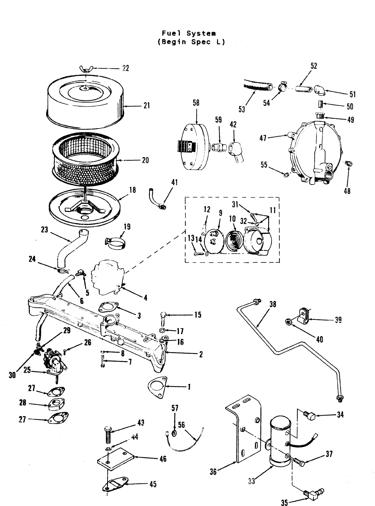
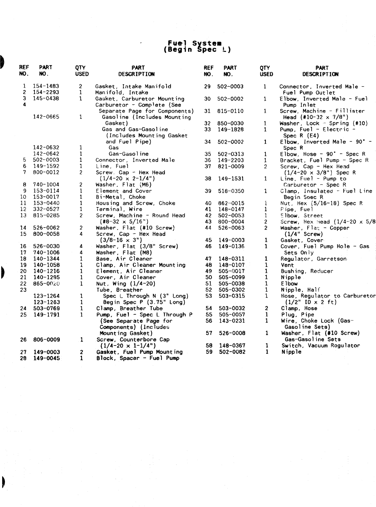
154-1483
154-2293
145-0438
142-0665
142-0632
j42–0642
502-0003
149-1592
800-0012
740-1004
153-0114
153-0017
153-0440
332-052?
815-0285
526-0062
800-0058
526-0030
740-1006
140-1344
140-1058
140-1216
140-1295
fj65-@-?>~
123-1264
123-1253
.503-0769
149-1791
806-0009
149-0003
149-0045
PART
DESCRIPTION
Gasket, Intake Manifold
Manifold, Intake
Gasket, Car-bur-etor Mounting
Carburetor -Complete (See
Separate Page for Components)
Gasoline (includes Mounting
Gasket )
Gas and Gas-Gasoline
(Includes Mounting Gasket
and Fuel Pipe)
Gas
Gas-Gasoline
Connector, Inverted Male
Lirre, Fuel
Screw, Cap -Hex Head
(1/4-20 X2-1/4”)
Washer, Flat (M6)
Element and Cover
%i-Metal, Choke
Housing and Screw, Choke
Terminal, Wire
Screw. Machine -Rotind Head
(#8--32 X5/16”)
Washer, Flat (#10 Screw)
Screw, Cap -Hex Head
(3/8-16 x3“)
Washer, Flat (3/8” Screw)
Masher. Flat (M8)
Base. Air Cleaner
Clamp, Air Cleaner Mounting
Element, Air Cleaner
Cover, Air Cleaner
Nut, Wing (1/4-20)
Tube. Breather
Spec LThrough N(3” Long)
Begin Spec P(3.75” Long)
Clamp, Breather Tube
Pump, Fuel -%pec LThrough P
(See Separate Page for
Components) (Includes
Mounting Gasket)
Screw. Counterbore Cap
(1/4-20 X1-1/4”)
Gasket, Fuel Pump Mounting
Block, Spacer -Fuel Pump
REF PART
No. No.
29 502-0003
30 502-0002
31 815-0110
32 850-0030
33 149-1828
34 502-0002
35 502-0313
36 149-2203
37 821-0009
38 149-1531
39 518-0350
40 862-0015
41 148-0147
42 502-0053
43 800-0004
44 526-0063
45 149-0003
46 149-0136
47 148-0311
48 148-0107
49 505-0017
50 505-0099
51 505-0038
52 505-0302
53 503-0315
54 503-0032
55 505-0057
56 143-0231
57 526-0008
58 148-036’?
59 502-0082
PART
DESCRIPTION
Connector, Inverted Male -
Fuel Pump Outlet
Elbow, Inverted Male -Fuel
Pump Inlet
Screw, Machine -Fitlister
Head (#10-22 x7/8”)
Washer, Lock -Spring (#10)
Pump, Fuel -Electric -
Spec R(E4)
Elbow, Inverted Male -90” -
Spec R
Elbow, Hose -90” -Spec R
Bracket, Fuel Pump -Spec R
Screw, Cap -Hex Head
(1/4-20 x3/8”) Spec R
Line, Fuel -Pump to
Carburetor -Spec R
Clamp, Insulated -Fuel Line
Begin Soec R
Nut, Hex (5/16-18) Spec R
Pipe, Fuel
Elbow, Street
Screw, Hex ‘lead (1/4-20 x
5/8”)
Washer, Flat -Copper
(1/4” Screw)
Gasket, Cover
Cover, Fuel Pump Hole -Gas
Sets Only
Regulator, Garretson
Vent
Bushing, Raducer
Nipple
E1bow
Nipple, Half
Hose, Regulator to Carburetor
(1/2” IO X2ft)
Clamp, Hose
Plug, Pipe
Wire, Choke Lock (Gas-
Gasoline Sets)
Washer, Flat (#10 Screw)
Gas-Gasoline Sets
Switch, Vacuum Regulator
Nipple
36
33
35
li- 18
19
-20
44 J
\
G
c
‘-21
0
)REF
No.
1
2
3
4
6
7
8
PART
No.
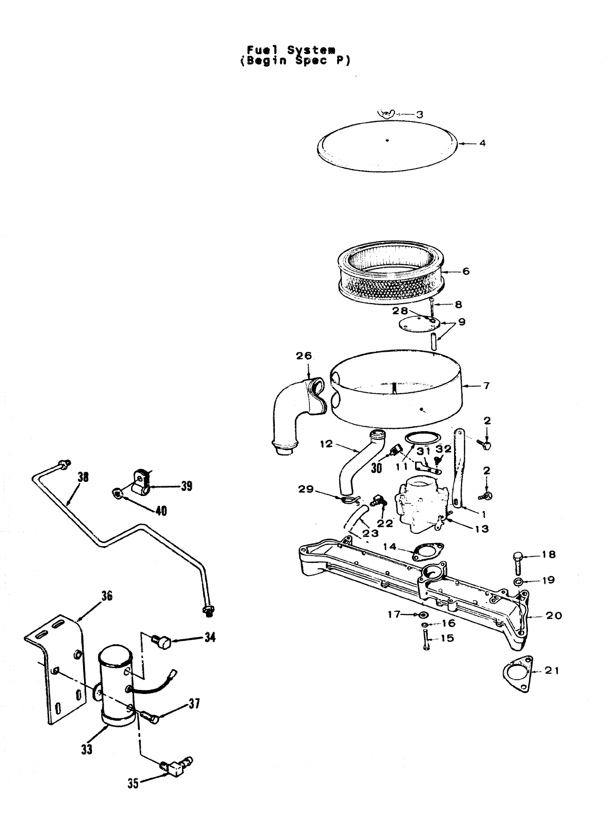
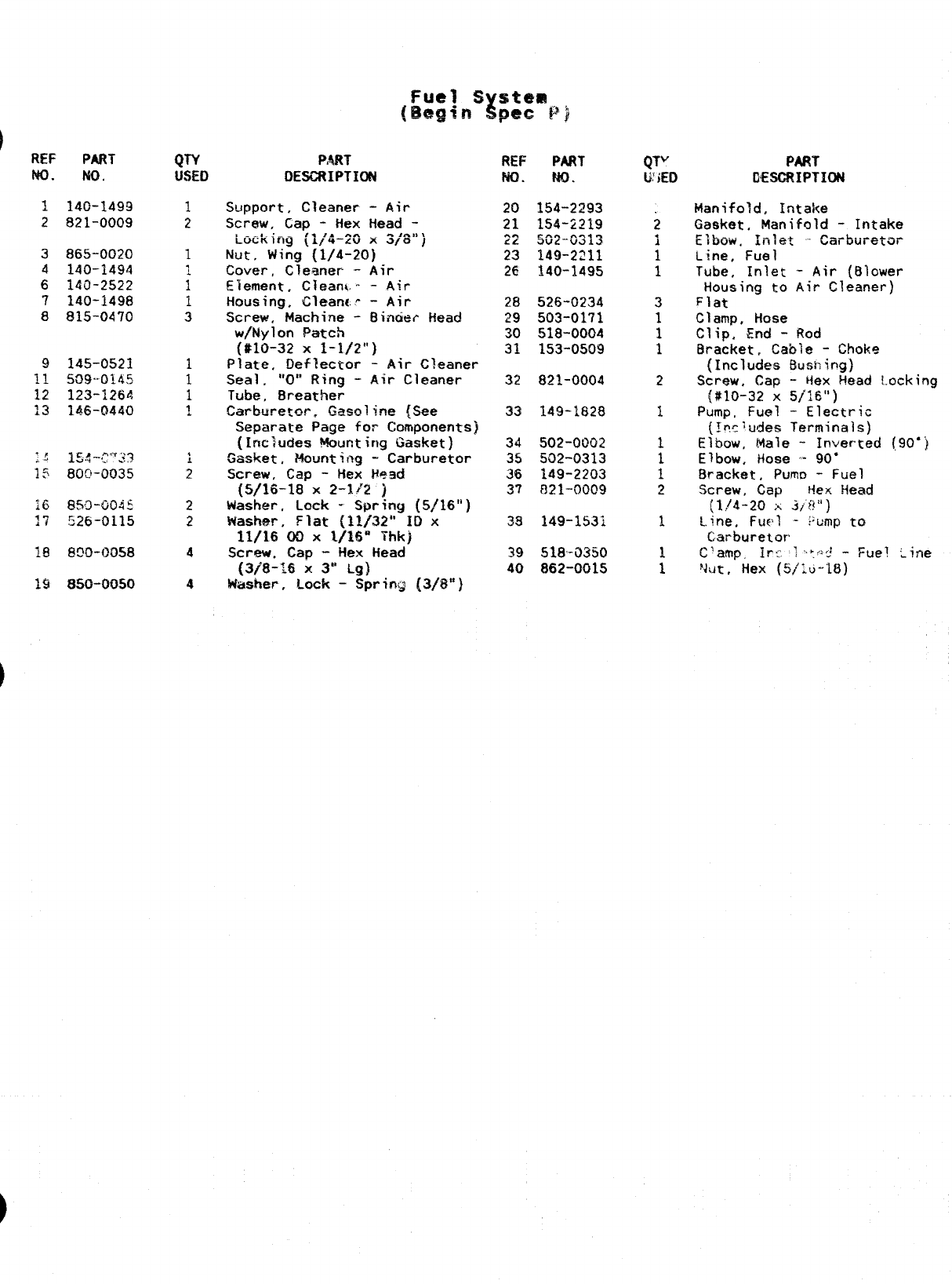
140-1499
821-0009
865-0020
140-1494
140-2522
140-1498
815-0470
18 13WHXXN3
19 85CI-(M350
PAR?
DESCRIPTION
Support, Gleaner -Air
Screw, Cap -Hex Head -
bckifiig {1/4-20 x3/8’lj
Nut, Wing {1/4-20)
Cover, Cleaner -Air
Element, Clean{- -Air
Housing, Clean<.? -Air
Screw, Machine -i3incit?~ Head
w/Nylon Patch
($10-32 X1-1/2”)
Plate, Deflector -Air Cleaner
Seal .‘,O:P Ring -Air Cleaner
Tube, Breather
Carbcretm. Ga~~lin~ {See
Separate Page for Ccunponents]
([ncJudes Mounting Gasket)
%sket, ?+wnting -Carburetor
Screw, Cap -Hex Head
(5/16-18 X2-1$2 )
Washer, Lock -Spring (5/16”)
washer ,Flat (]~/32° ~~ x
11/16 00 X1/16” Thk)
Screw. Cap -Hex Head
(3/8-16 X3“ Lg)
~dl~F .Lock -Spring [3/8”)
REF PART
NO. NO.
20 154-2293
21 154-2219
22 5G-2-CX313
23 149-2211
26 340-1495
28 526-G234
29 503-0171
30 518”0004
31 153-0509
32 821-0004
33 149-1828
34 502-0002
35 532-0313
36 149-2203
37 021-0009
33 149-153i
39 518-D350
40 862-0015
PART
DESCRIPTION
Manifold, Intake
Gasket, Manifold -Intake
ElbOw, Inlet -Carburetor
Line, Fuel
Tube, Inlet -Air (Blower
Housing to Air Cleaner)
Flat
Clamp, Hose
Clip+ End -Rod
Bracket, Cable -Choke
(Includes Eusn!rKJ)
Screw, Cao -Hex Head l.ockina
[#10-32 x5/16”)
Pump, Fuel -Electric
(It?c~udes Terminals)
Elbow, Male -Inverted
Elbow, Hose -90”
Bracket, Pumo -Fuel
Screw, Cap tie~ Head
(lj4-20 ;.+ .3/8”)
Line, FIJ~~] -!~ump to
Carburetor
f90*]
Rw PART
MO. No.
149-1223
1
2815-(9148
3815-014’?
4149-0096
5149-0095
6149-05$2
714$-0672
8149-0539
9169-0675
10 516-0113
$s2———— 3
‘i’ 8
*
PUmp, Fuel
$ody. Nrzt Sold Separately
Screw. Mwchine [#$-32 x7/8”]
$icrw, Phillips -Self-Tapping
(#6-32 x5/8”) Valve Retainer
*Valve and Cage
*Gasket, Valve
‘%iaphrugm Assembly
*SPr ing
Retainer. Valve Cage
*5pr irig
Pin, Rocker Arm
REF PART
W. w.
11
12 149-0670
13 149-1148
14 149-1042
15 5@3-oo&5
16 149-1044
17 149-0003
18 S18-0129
19 149-0858
20 149-0526
QTY PART
USED DESCRIPTION
Body. Not Sold Sepwately
Link, Rocker Arm
Arm,. Rocker
Lever, Primer
Seal, ?’01! Ring
Spring, Primer Lever
*Gasket, Pump Mounting
Ring, Retainer Primer Lever
“Gasket, I)iaphragm -Lower Side
Kit, Repair (Includes Parts
Marked *)
*-Part~ Included in 149-0526 Fual %mp Repair Kit.
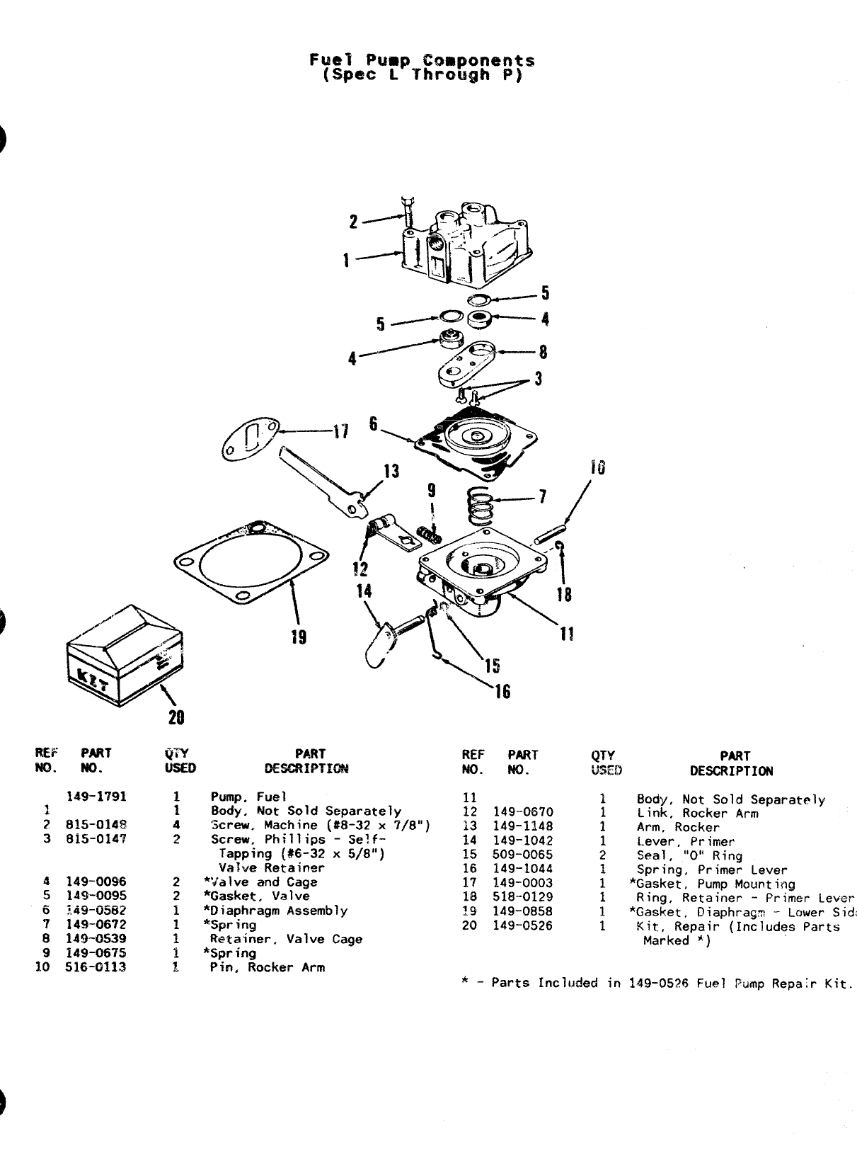
20
4149-00$6 2
5149-0095 2
6?.49-0582 1
7149-0672
8149-0539 ;
9149-0675 ~
10 516-CI113 1
Pump. Fuel
Body, Not Sold Separately
‘screw, Machine (#8-32 x7/8”)
Screw. Phillips -5e!f-
Tapping (W-32 x5/8”)
Valve Retainw
*“Jalve and Cage
*Gasket, Valve
*Diaphragm Assembly
*Spring
Retainer, Valve Cage
*Spring
PiKI, Rocker Arm
’16
REF PART
w. NO.
11
12 149-0670
13 149-1148
14 149-1042
3.5 509-0065
16 149-1044
17 149-0003
18 518--0129
19 149-0858
20 149-0526
QTY PART
WED DESCRIPTION
1Body, Not Sold Separately
Link, Rocker Arm
:Arm, Rocker
1Lever, Primer
2Seal ,“O” Ring
Spring, Primer Lever
:*Gasket, Pump Mounting
1Ring, Retainer -Primer Lever
1*Gasket, lliaphrag~ -Lower Sidz
1Kit,, Repair (Includes Parts
Marked *)
*-Parts Incl~,ided in 149-0526 Fuel Pump Repa;r Kit.
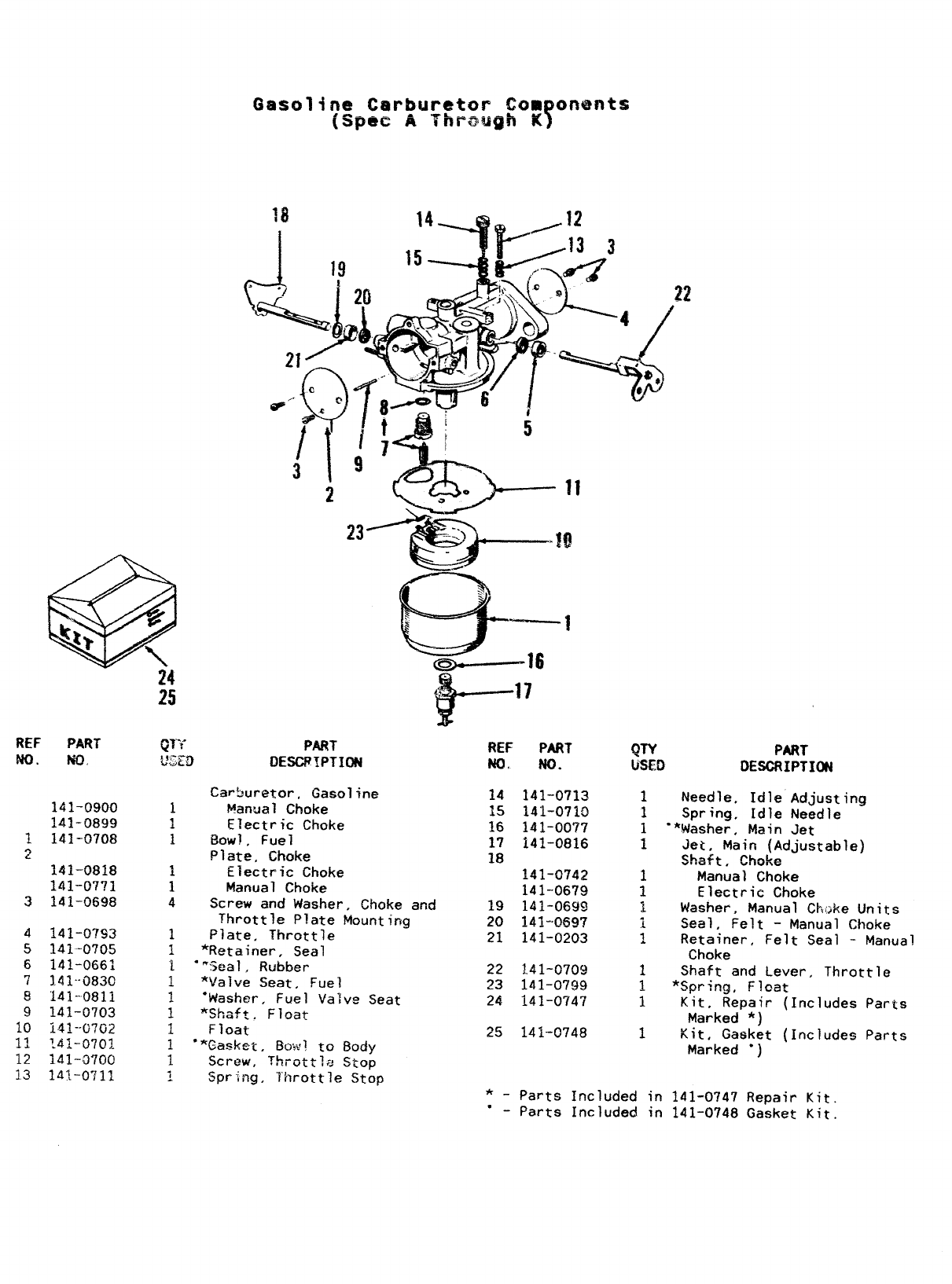
REF PART
ND. No,
141-0900
141-0899
1141-0708
~
141-0818
141-0771
3141-0698
4141-0793
5141-0705
6141-0661
7].41--0830
8141-0811
9141-0703
10 141--07(32
11 TL~~.-oyo;-
12 141-0700
13 141-0”;11
J&
qn- PART
*}.-7
b.dc DDESCFTPTIm
Carburetor, Gasoline
1h!anual Choke
1Electric Choke
1BowI, Fuel
Plate, Choke
iElectric Choke
1Manual Choke
4Screw and Washer, Choke and
Mounting
Throttle Plate
1Plate, Throttle
1*Retainer, Seal
1““Seal, Rubber
~*Va]ve Seat, Fue”
1‘Washer, Fuel Va’
1*Shsft, Float
1Float
ve Seat
1‘*Gasket, Bow! EO Body
1Screw, ?hrottle s~op
~Spr ing, Throttle Stop
REF PART
Nar NO.
14 141-0713
15 141-0710
16 141-0077
17 141-0816
18 ~4~-Q74~
141--0679
19 141-0699
20 141-0697
21 141-0203
22 1,41-0709
23 141-0799
24 141-0747
25 141-0748
QTY PART
llsf41 DESCRIPTI(Mi
Needle, Idle Adjusting
Spring, Idle Needle
*Nasher, Main Jet
Jet, Main (Adjustable)
shaft, choke
Manual Choke
Electric Choke
Washer, Manual Chf,;Re Units
Seal. Felt -Manual Choke
Retainer, Felt Seal -Manual
Choke
Shaft and Lever, Throttle
*spring, Float
Kit, Repair (Includes Parts
Marked *)
Kit, Gasket (Includes Parts
Marked “)
*_parts Included in 141-0747 RePair Kit
“ - Parts Included in 141-0748 Gasket Kit.
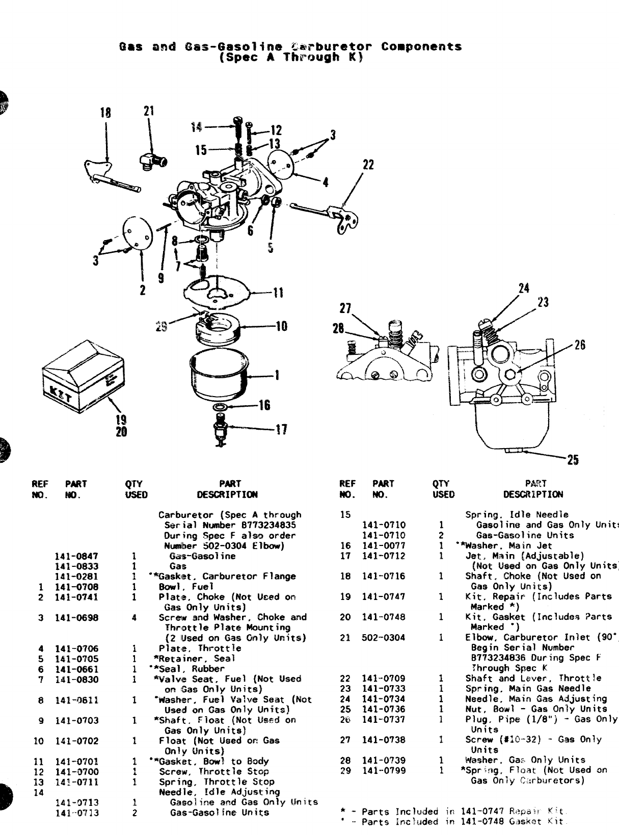
m= PART
NO. w).
3141-0698
4141-0706
5141-0’?05
6141-0661
7141-0830
9141-0703
10 141-0702
Ill
ml
Qw
Wsm
PART
OE8GRIPT3W
Carburetor {Spec Athrough
Serial Numbe~ 8773234835
During Spec Falso order
Nus&r 502-0304 Elbow)
Gas-Gasoline
Gas
●*G%&et~u:buretor Flange
#
Plat[e. Choke (Not Wed on
Gas Only Units]
Screw and Washer, Choke and
Throgt?e Plate Mounting
(2 lu~d on @~(jn~y ~fiit~)
Plate. Throttle
*Retainer, Seal
**Seal, Rubber
%falve Seat, Fuel (Not Used
on Gas Only Units}
“’Washer. Fuel Valve Seat (Not
Used on Gas Only Umtts]
*Shaft, Float (Nc)t U=d on
Gas Only Units)
Float [Not LJmd on Gas
Only Units)
“*Gasket. 80wl to Body
Screw, Throttle Stop
Spring, Throttle Stop
Needle, Idle Adjusting
Gasoline and Gas Only Units
Gas-Gasoline Units
REF PART
MOm No.
15 141-0710 1
141-0710 2
16 141-00?7 1
i7 141-0712 1
18 141-0716 1
19 141-0747 1
20 141-0748 1
21 502-0304 1
22 141-0709 1
23 141-0733
24 141-0734 :
25 141-0736 1
26 141-0737 1
2’7 141-0738 1
28 141-0?3$ 1
29 141-0799 1
Spring, idle Needle
Gasoline and Gas Only Units
Gas-Gasoline Units
“Washer. Main Jet
Jet, Main (Adjustable)
(Not Used on Gas Only Units)
Shaft. Chcke {Not Used on
Gas Only Units)
Kit, Repair (Includes Parts
Marked *)
Kit. Gasket {Includes Parts
Marked ‘)
Elbow, Carburetor Inlet (90”)
Begin Serial Number
B773234836 During Spec F
:hrough Spec K
Shaft and Lever, Throttle
Spring, Main Gas Needle
Needle, Main Gas Adjusting
Hutf Bowl -Gas Only Units
Plug. Pipe (1/8”) -Gas Only
Units
Screw (#10-32) -Gas Only
Units
Washer. Ga$ Only Units
*Spr~:ig, Fl(Yat (Not Used on
Gas Only llM”bUrfXOrS)
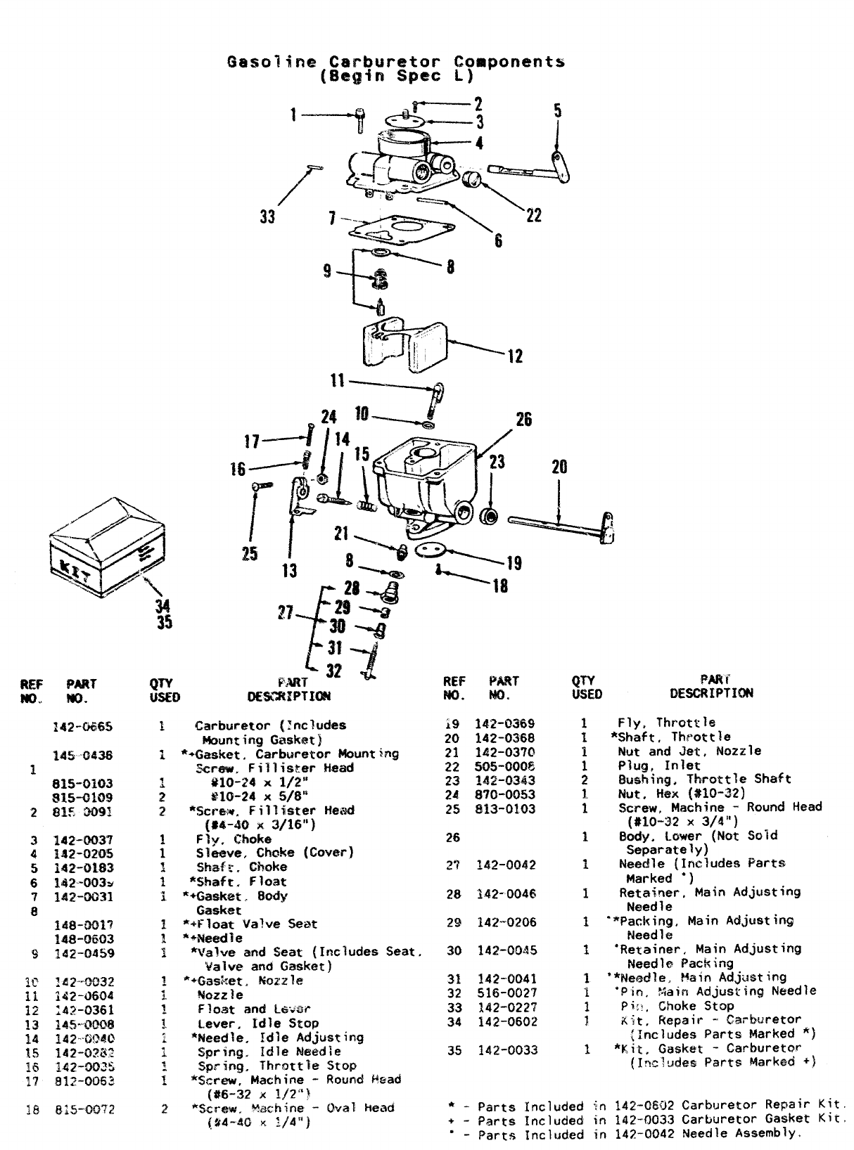
Gasoline Carburetor Components
[8@gin spec L)
—9
33
+-p+&_-: ‘
..
.
74---i
““ ====4
Cb”a-,
/-$--- ..-------:
=7
142-W65
3142-0Q3’?
4142-0205
5142-0183
6162-003>
7142-0031
8148-0017
148-0603
9ld2-0459
2
Carburetor (Includes
Mounting Gasket)
**Gasket, Carburetor Mounting
.%few. Fillister !-Lead
#lo-24 x1/2”
gIO-24 x5/6”
%crew. Fillister i+~i.d
(#4-40 x3/16”]
Flyr Choke
Sleave, Choke (Cover)
shafr. Choke
*Shaft. Float
*+Gask@t, Body
Gasket.
*+Float Va?ve Seat
**Need~e
*va~ve and $eat (Includes Seat.
Valve and Gasket)
**Gasket. Nozzle
Mozz ie
F~o~t and L&:~P
Lever, Idle Stop
‘Needle, Idle &djusting
spr?ng, Idle Needle
Spring, Throttle Stop
%craw, Machine -Round f+ead
(#6-32 x1/2”1
*c&8.~w, ~~~~~~ -Oval head
(%4-40 K1/4”)
REF P&iT
No. NO.
i9 142-0369
20 142-0368
21 142-0370
22 505-0005
23 ~~~-~~h~
24 870-0053
25 S13-0103
26
,*j
L~4~-~062
28 3.42-0046
29 142--O2O6
30 142-0045
31 142-’0041
32 516-0027
33 142-0227
34 142-0602
35 142-0033
Fly, Throttle
*Shaft, Throttle
Nut and Jet, Nozzle
Plug, Inlet
Bush4ng, Throttle Shaft
Nut, Hex (#10-32)
Screw, Machine -Round Head
(#lo-32 3( 3/4”)
Body. Lower (Not Sold
Separately)
Needle (Includes Parts
Marked ●)
Retainer, Main Adjusting
Need 1e
“*Paci<ing, Main Adjusting
Need 1e
“Retainer, Main Adjusting
Needle Packing
**Nemdle, Main Adjusting
‘Pin. %ain Adjusting Needle
pi::, Choke s~~p
Kit, Repair -Carburetor
[includes Parts Marked *]
*Kit, Gasket -Ca~buretor
(Inclde$ Parts Marked +)
*- Parts Included in 142-0802 Carburetor RePair Kit.
+-parts included {n 142-003.3 Carburetor Gasket Kit.
“ - Parts Inclt~ded in 142-0042 Needle Assembly
&------\ “
T.,
62
,/‘
\+ /g
%. “ .
‘%L=/\ \
\j?
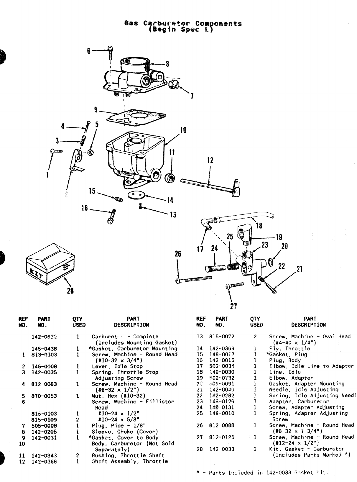
QTY P~T REF PART
W51ED DESCRIPTION NO. NO.
QTY PART
USED DESCRIPTION
REF PART
m. MD.
Carburetc- -tomplete
(Includes Mounting Gasket)
*Gasket, Carburetor Mounting
Screw, Machine -Round Head
(#10-32 X3/4”)
Lever. Idle Stop
Spring, Throttle Stop
Adjusting Screw
Screw. Machine -Round Head
13 815-00’?2 Screw, Machine -Oval Head
(#4-40 x1/4”)
Fly, Throttle
*Gasket, Plug
Plug, Body
Elbow, Idle Line to Adapter
Line. Idle
142-0369
148-0017
142-0015
502-0034
:49-0030
502-0732
‘.X2-M91
2145-0008
3142-0035 Elbo&, Adapter
Gasket, Adapter Mounting
Needle, Idle Adjusting
Spring, Idle Adjusting Needle
Adapter, Carburetor
Screw, Adapter Adjusting
Spring, Adapter Adjusting
Screw
Screw, Machine -Round Head
(#?3-32 x1“-3/4”)
Screw, Machine -Round Head
(#12-24 X1/’2”)
Kit, Gasket -Carburetor
4812-Q063 (#6-32 X1/2”)
Nut, Hex (#10-32)
Screw. Machine -Fillister
Head
*1O-24 x1/2”
#10--24 x5/8”
Plug. Pipe -1/8”
Sleeve, Choke (Caver)
*@@a:, cover to tlody
9ody, Carburetor (Not Sold
Separately)
Bushing, Throttle Shaft
Shaft Assembly, Throttle
21 142-0040
22 1~2-02E12
23 143-0126
24 148-0!.31
25 148-0010
26 812-0088
27 812-0125
28 142-0033
5870-0053
6
815-0103
815-0109
7505-0008
6i42-D205
9142-0031
10
(~nclude~ Parts Marked *)
11 142-0343
12 142-0368
*_parts Included in 142-.0033 :?;~sket “it.
fzma /jpii
—
.—- /
18
I
‘n-
l—
2’%43 f} L. ii
‘=/ --w
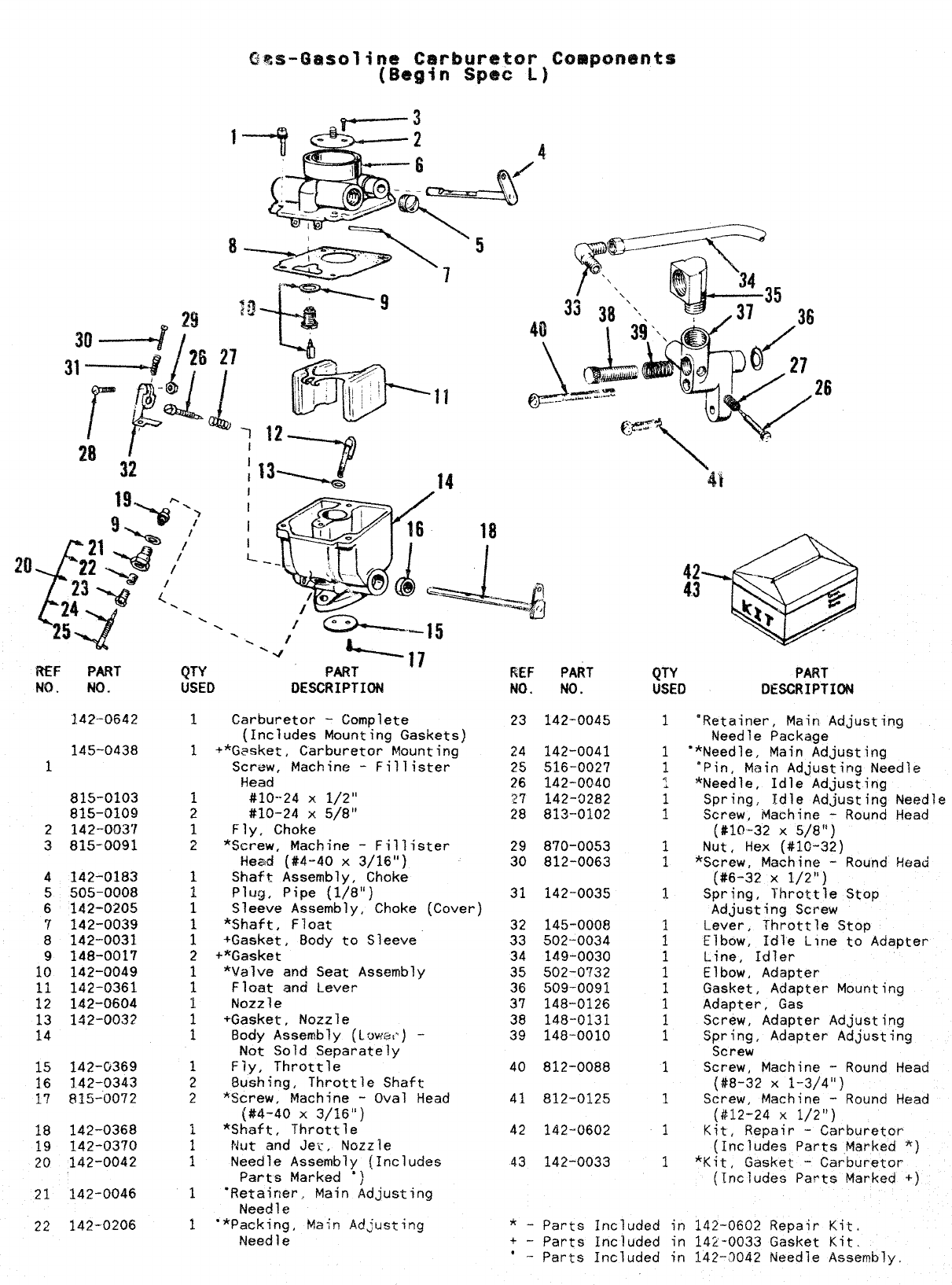
QTY PART
USED DESCRIPTION QTY PART
USED DESCRIPTION
iWF PART
NO. NO. PiEF
NO.
PART
No.
1.42-0642 1Carburetor -Complete
(Includes Mounting Gaskets)
1+*G~sket, Carburetor Mounting
Screw, Machine -Fill ister
iiead
1#10--24 X1/2”
2#10-24 x5/8”
1Fly, Choke
2*Screw, Machine -Fillister
Head (#4-4o x3/16”)
1Shaft Assembly, Choke
1Plug, Pipe (1/8’1)
1Sleeve Assembly, Choke (Cover)
*Shaft, Float
:+Gasket, Body to Sleeve
2+*Gasket
1*Valve and Seat Assembly
1Float and Lever
~Nozzle
1+Gasket, Nozzle
1Body Assembly (Low:,%) -
Not Sold Separately
1Fly, Throttle
2Bushing, Throttle Shaft
2*Screw. Machine -Oval Head
23 142-0045 “Retainer, Main Adjusting
Needle Package
‘*Needle, Main Adjusting
‘Pin, Main Adjusting Needle
*Needle, Idle Adjusting
Spring, Idle Adjusting Needle
Screw, Machine -Round Head
(#10-32 X5/8”)
Nut. %?X [#10-32)
145-0438
1
24
25
26
’27
28
142-0041
516-0027
142-0040
142-0282
813-0102
815-0103
815-0109
2142-003’/
3815-0091 29
30 870-0053
812-0063 *Screw, ?&hine -’Round head
(#6-32 X1/2”)
4142-0183
5505-0008
6142-0205
7142-0039
8142-0031
9148-0017
10 142-0049
11 142-0361
12 142-0604
13 142-0032
14
31 142-0035 Spring, Throttle Stop
Adjusting Screw
Lever, Throttle Stop
Elbow, Idle L~ne to Adapter
Line, Idler
Elbow, Adapter
Gasket, Adapter Mounting
Adapter, Gas
Screw, Adapter Adjusting
Spring, Adapter Adjusting
Screw
Screw, Machine -Round Head
{#8-32 X1-3/4”)
Screw, Machine -Round Head
(#12-24 x1/2”)
32
33
34
35
36
37
38
39
145-0008
502-0034
149-0030
502-0732
509-0091
148-0126
148-0131
148-0010
15 142-0369
16 1.42-0343
17 835-0072
40 812-0088
812-0125
(#4-40 X3/161’)
1*Shaft, Throttle
1Nut and Jer, Nozzle
1Needle Assembly (Includes
Parts Marked “)
1“Retainer, Main Adjusting
Needle
1“*Packing, Main Adjusting
Need 1e
K{t, Repair :C&rburetor
(Includes Parts Marked *)
*Kit, Gasket -Carburetor
(Includes Parts Marked +)
18 142-0368
~~ 142-~370
20 142-0042
21 142-0046
22 142-0206
42 142-0602
43 142-0033
*-parts Included in 142-0602 Repair Kit.
+- Parts Included in 142-0033 Gasket Kit,
*-Parts Included in 142-’3042 Needle Assembly,
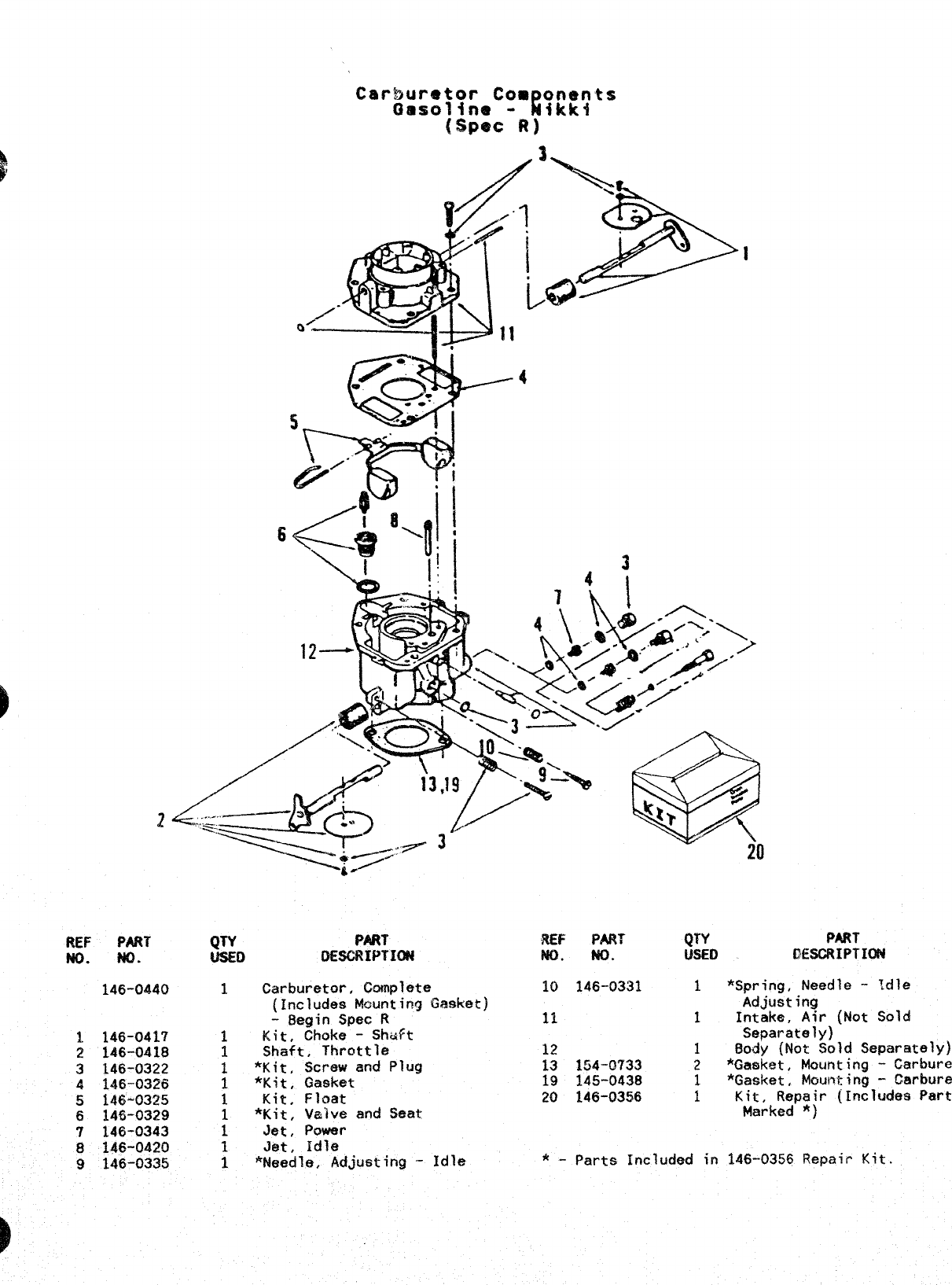
REF PART
?40. Ho.
146-0440
1146-0417
2146-0418
3146-0322
4146-0326
5146-0325
6146-0329
7146-0343
8146-0420
9146-0335
QTY PART REF PART QTY PART
USED IIE6CRIPTION No. NO. WEO WWRIPTION
1Carburetor, Complete 10 146-0331 1*Spring, Needle -tdle
(Includes Mounting Gasket] Ad$mting
-Begin Spec R11 1Intake, Air (Not Sold
1Kit, Choke -Shaft Separately)
1Shaft, Throttle 12 1BOdy (Not Sold Separately)
1*Kit, Screw and Plug 13 154”0733 2*Gasket, Mounting -
Carbureto
1*Kit, Gasket 19 145-0438 1*Gasket, M@mting -
Carburet
1Kit, Float 20 146-0356 IKit, Repair (Includes Parts
1*Kit, Valve and Seat Marked *)
1Jet, Power
1Jet, Idle
1*t4eedle, Adjusting -Idle *-Parts Included in 146-0355 Repair Kit.
I
4
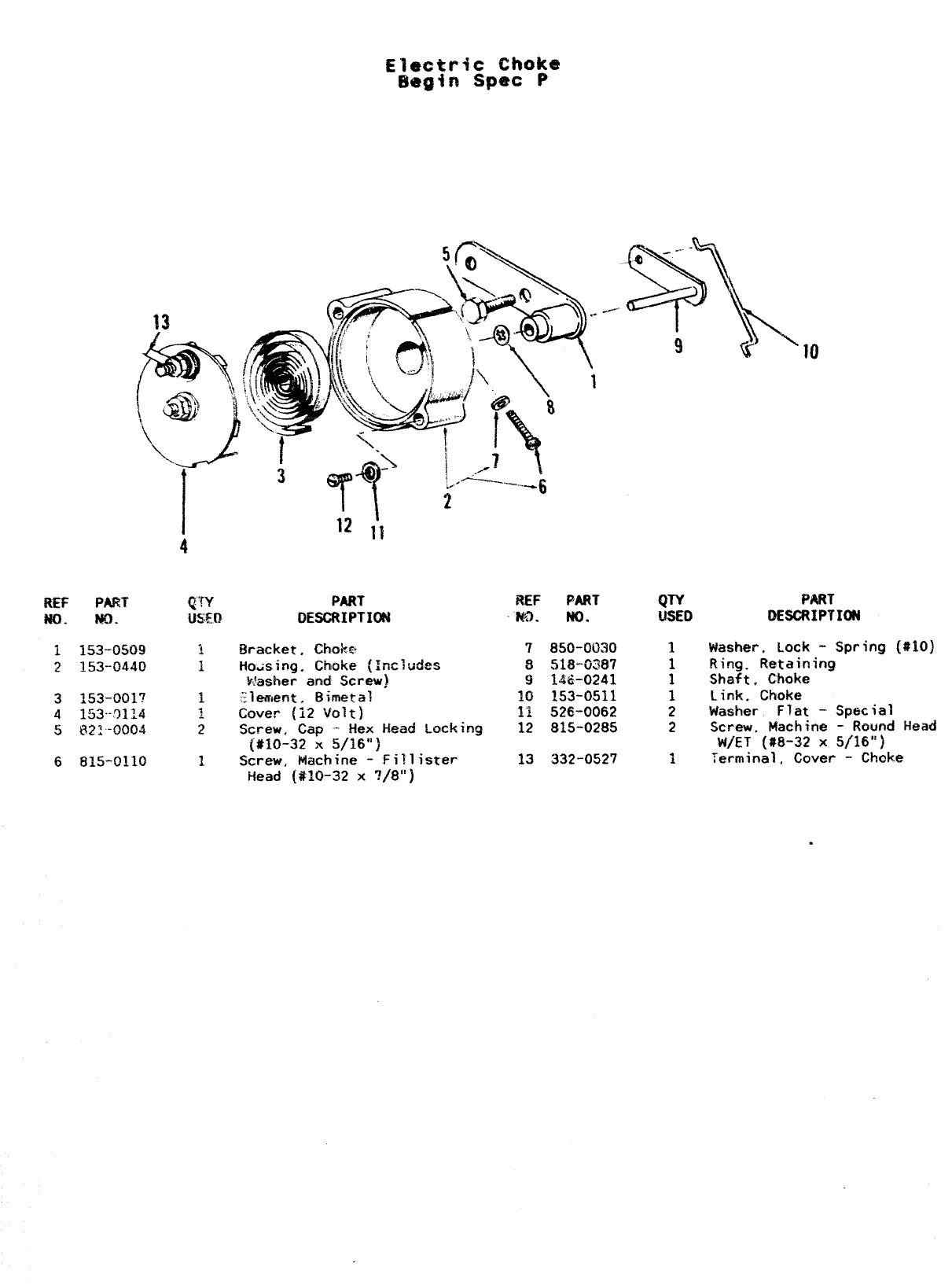
REF PART qTY PART REF PART
m. w. IJsm DESCRIPTION w). No.
1153-”0509 1Bracket, Choke
2153-0440 IHousing. Choke (Inc]udes
Washer and Screw)
3153-oa17 1?lemefit, Bimetal
4153--qll4 ~Cover (12 Volt}
5822’-0004 2Screw, Cap -Hex Head Locking
(#10-32 x5/16”)
681!5-0110 1Screw. Machine -Fill ister
Head (#10-32 x?/8’1)
QTY PART
WED DESCRIPYIDN
7850-0030 1Washer, Lock -Spring (#IO)
8518-0387 1Ring. Retaining
9146-0241 1Shaft, Choke
10 153-0511 1Link, Choke
11 526-0062 2Washer Flat -Special
12 815-0285 2Screw, Machine -Round Head
W/ET (#8-32 X5/16”)
13 332-0527 1Terminal, Cover -Choke
.
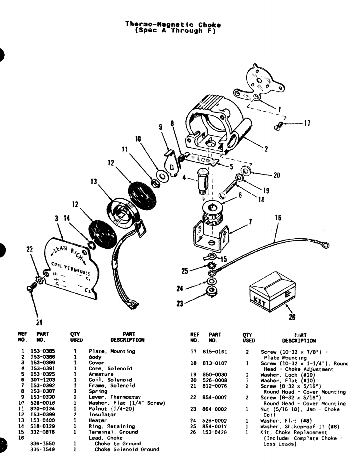
1 153’’4)385
2 r53-m86
3 153”0389
4153-0391
5153-0395
6307-1203
7153-0392
81s3-0387
9153-0330
b? 526-00i6
1: 870-0134
12 153-0399
13 153-0400
14 518-0129
15 332-0876
16 336-1550
336-1549
mR7
oEsc?wTIm
Plate, Mounting
cover
Core, Solenoid
Armature
Coil. Solenoid
Frame. Solenoid
Spring
Lever, Thermostat
Washer. Flat (1/4” Screw)
Palnut ~!/4-20)
Insulator
Heater
Ring, Retaining
Terminal, Ground
Lead. Choke
Choke to Ground
Choke Solenoid Ground
ftEF PART
w. NO.
17 815”0161
18 813-0107
19 850-0030
20 526-0008
21 812-(?076
22 8S4-000?
23 864-0002
24 526-0CM12
25 854-0017
26 1,53-0429
2
2
1
PART
OESCRIPTNBd
Straw (10-32 x7/8”) -
Plate Wounting
Screw (10-32 x1-1/4”), Round
Head -Choke Adjustment
Washer, Lock (#10)
Washer, Flat ($10)
Screw {8-32 x5/16”)
Round Head -Cover Mouwing
Screw [8-32 x5/16”)
Round Head -Cover kfo~!nting
Nut (5/16-18), Jam -Choke
coil
Washer. Fli% (88)
Washer, S~’,keproof iT ($8)
Kit, Choke Replacement
(Include! Complete Choke -
Less LAS}
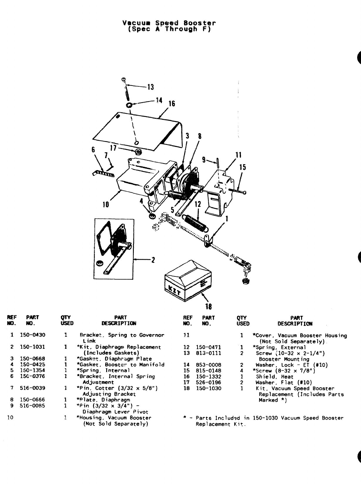
v8cL4um spw!ld moister
(Spec AThrough F)
REF PART
m. WO.
3350-0430
2150-1031
3150-0668
~~5&~4~5
5$ 150-1354
615C-0376
7516-0039
8150-0666
9516”0085
10
la
REF PAUT QTV PART
P&o. w. D!ESORIPTX!N
:!3racke-t,, Spring to Governor ?1 1*Cover. Vacuum Booster Housinu
Link
‘Kit, Oiaphragm Replacement
(Inc 1udes Gaskets)
*Gaskwi Diaphragm Plate
*Gasket, Boosts. to Manifold
*Spring. Internal
‘Bracket, Internal Spring
Adjustmatat
*Pin, Cotter (3/32 x5/S”)
Adjusting Bracket
*plate. Diaphragm
*$in [3/32 x3/4”) -
Diaphragm Lever Pivot
*Housing, Vacuum Booster
(Not Sold Separately)
{Not Sold Separately), “
12 150-04’?1 1*Spring, External
13 813-0111 2Screw ~10-32 x2-1/4”)
Booster Mounting
14 853-0008 2Washer, Lock -E?’ (#10)
15 815-0148 4*Screw {8-32 x7/8”)
16 150-1332 1Shield, Heat
17 526-0196 2Washer, Flat (#10)
1$ 150-1030 1Kit, Vacuum Speed Booster
Replacement (Includes Parts
Marked *)
*-Parts Includsd in 150-1030 Vacuum Speed Booster
Replacement Kit.
1
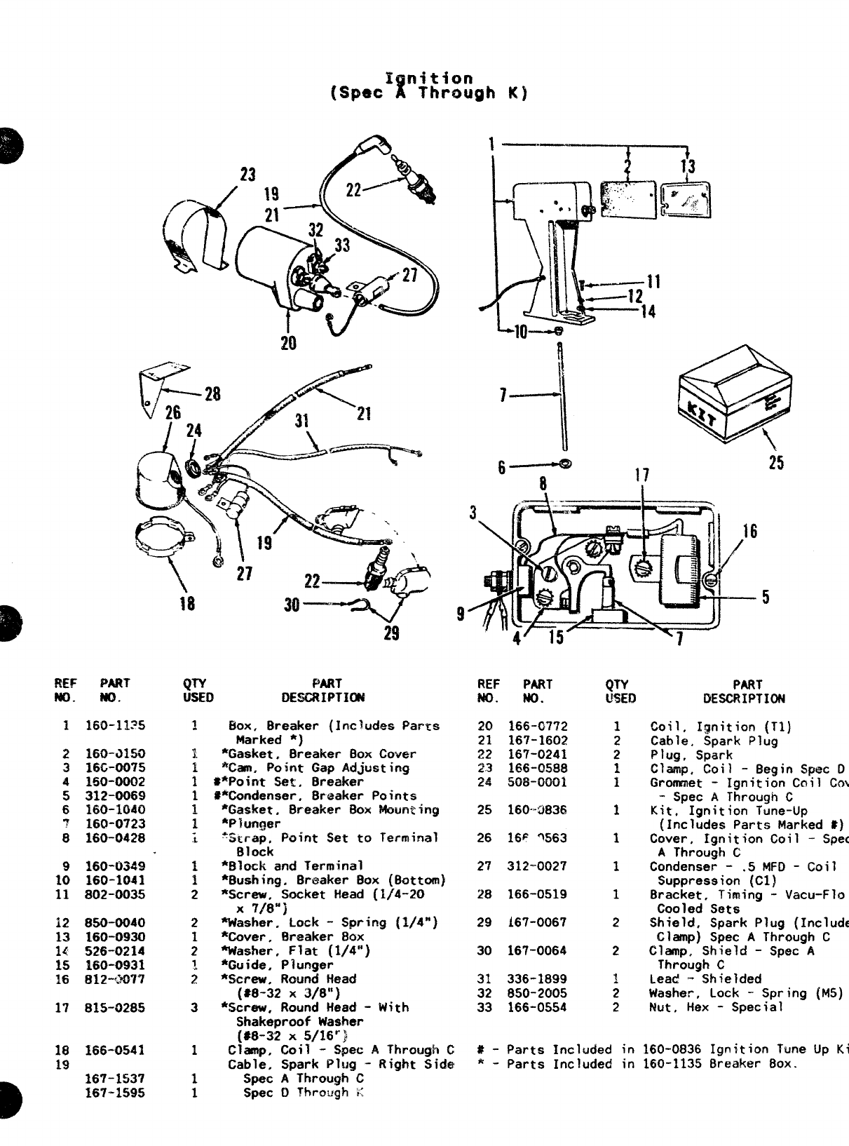
I‘-–73
R~F PART
MO. No.
2160-T3150
316G-0075
4 I!30-0002
5 312”0069
6160-1040
7160-0723
8160-0423
9160-0349
10 160-1041
11 802-0035
12 850-0040
13 160-0930
14 526-0214
15 160-0931
16 812-.2’077
17 815-0285
18 166-0541
19
D16?-1537
167-1595
29
QTY PART
usEr3 OESCRIPTIW
Box, Breaker (Jncludes Parxs
Marked *)
*Gasket, Breaker Box Cover
*Casi. Point Gap Adjusting
#*Point Set, 8reaker
#*Condenser, Breaker Points
*Gasket, Breaker BOX Mounting
*Plunger
*S~rap. Point Set to Terminal
Block
*Block and Terminal
‘Bushing. Brt+aker Box (Battom)
*Screw, Socket Head (1/4-20
X718”]
Washer. Lock -Spring [1/4”)
*Cover, Breaker 89x
‘Washer, Flat (1/4”)
*Guide. Plunger
*Screw, Round Head
(S8-32 x3/8”)
*Screw. Round Head -With
Shakemroof Washer
(#8-3~ X5/16”)
Clanp, Coil -Spec AThrough C
Cable, Spark Pl!Jg -Right Side!
Spec AThrough C
Spec t) Throi~gh K
25
5
9
REF PART
NO. NO.
20 166-G772
21 167-1602
22 167-0241
2.3 166-0588
24 508”0001
25 160-3836
26 16F %63
2’? 312-0027
28 166-0519
29 i67-0067
30 167-0064
31 336-1899
32 850-2005
33 166-0554
PART
DESCRIPTION
Coil, Ignition (Tl)
Cable. Spark Plug
Plug, Spark
Pl—
“V=,lp, Coil -Begin Spec D
Grommet -Ignition Coil
Cov
-Spec AThrough C
Kit, Ignition Tune-Up
(Includes Parts Marked #)
Ct3ver, Ignition Coil -
Spec
AThrough C
Condenser -.5 MFD -Coil
Suppression (Cl)
Bracket, Timing -Vacu-Flo
Cooled Sets
Shield, Spark Plug (Includes
Clamp) Spec AThrough C
Clamp, Shield -Spec A
Through C
Lead -Shielded
Washer, Lock -Spring {MS)
Nut, Hex -Spec ia 1
#- Parts Included in 160-0836 Ignition Tune Up
Kit
*-Parts Included in 160-1135 Breaker 80X.
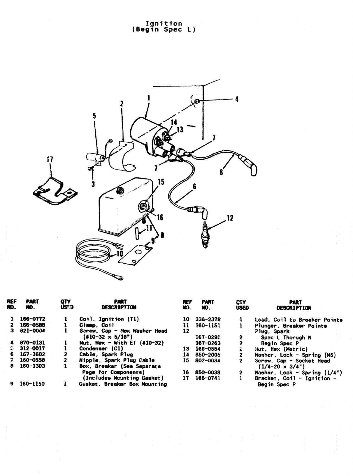
R!EF
#m.
1166-0772
2166-05S8
3521+XW
4 a70-o131
3312-0017
6167-1602
?160-0558
@160-1303
9160-1150 i
nts
(#10-32 X5/16”)
Nut, ~% -With ET {MO-32)
COndenaar (Cl)
Cable, Spark Plug
Nipple. Spark Plug t%bh
8ox, Breaker (See Separate
Page for Components)
(Includasthmting Gtwket)
Gasket, Breaker’ 8ox Mounting
167-0292 2SE;c iThorugh N
IW=G263’ 2Mgfn Spec P
13 166-0554 ‘“’
cNut. Hex (Metric)
14 850-2005 Wmahar. Lock -Spring (M5)
%5 602-0034 :Screw, Cap -Socket Head
[1/4-20 X3/4”)
16 850-0038 2Washer. Lock -Spring (1/4”)
37 166-0741 1Bracket, Coil -Ignition -
Segin Spec P
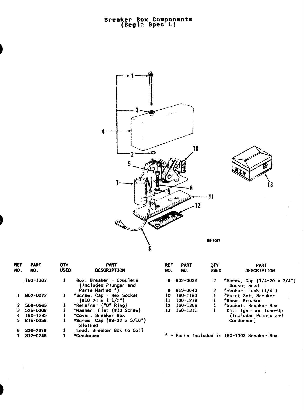
REF PART
m. NO.
2509-0065
3526-0008
4360-lZiKi
5815-0358
6336-2378
7312-C246
QTY PART
DESCRIPTION
1%x. Breaker -Cml?g>?ete
(Includes iitmgw and
Parts MaFled *)
1%creu, Cap -Hex Socket
(*1O-?4 x1-1/2”)
1*Retainel:” [“0” Ring),
1washer, ~~at (#lo $jcr~)
1*COver, Breaker BOX
1*Screuf Cap [$S-32 x5/16”)
$?otted
1L@ed, Breaker %x to Co?}
1%ondenser
13
“11
Es. 1ss7
REF PART QTY PART
NO. NO. IJSEQ DESCRIPTION
6002-0034 2*Screw. Cap (1/4-20 x3/4”)
Socket Head
9850-0C40 2*k&sher, Lock (1/4”)
iO 16G-IIS3 i*Feint Set, Breaker
11 160-1219 1*9ase, Breaker
1.2 ~60-136g *Gasket. Breaker Box
13 160-1311 :Kit, Ignition Tune-Up
{includes Points and
Condenser)
*-Parts Included in 160-1303 Breaker Box.
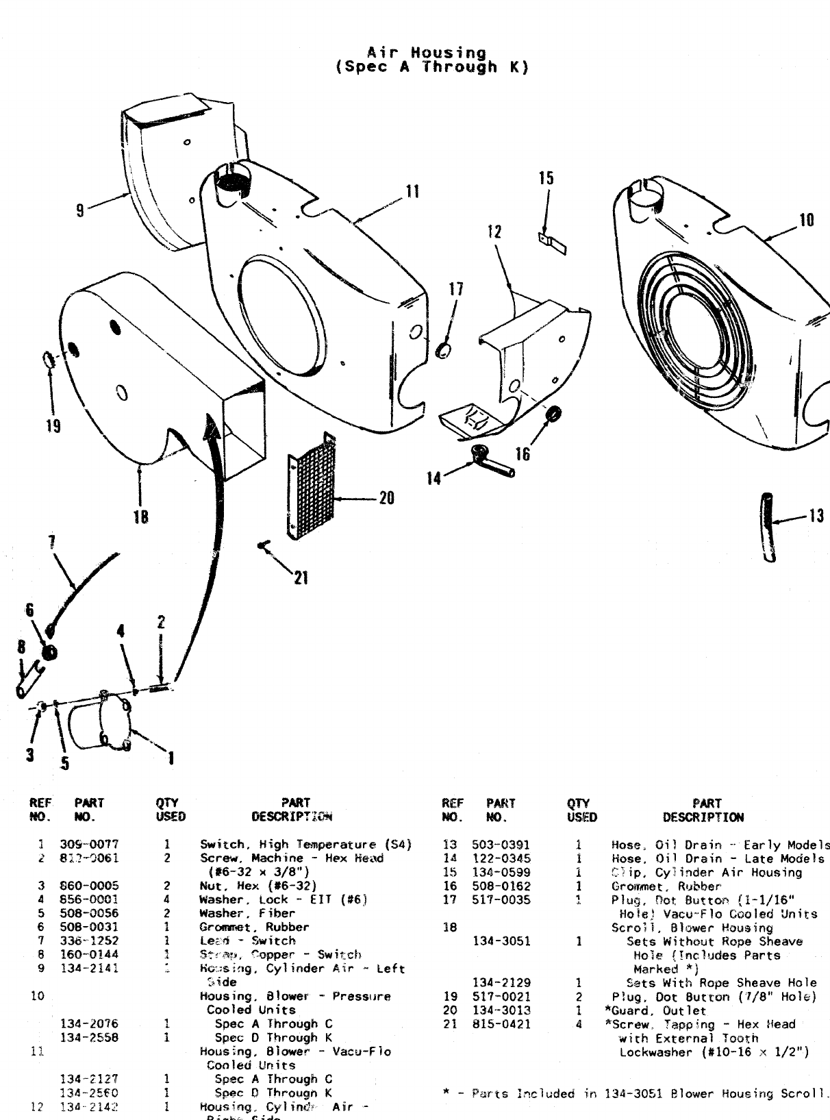
l\Q
-\*l
PART
~~~p~~~
Switch, High Tampwatufe (S4]
Screw. Machine -Hex Iiewd
(#6-32 X 3/8”)
Nut, Hex (#6-32)
Washer. Lock -EIT (#6J
Washer, fiber
Grommet. Rubber
Lez?l -switch
S:<,3:Y, %pper -Switch
HGx9if3g, Cylinder Air -Left
2ide
Musing, Blower -PressIme
Cooled Units
Spec AYhrough C
Spec DThrough K
Housing, Blower -Vacu-Flo
15
c
K
Air -
‘+4&”
PART
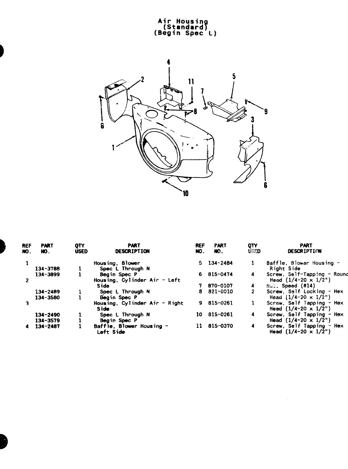
REF PMT
m. m.
1134-3?88
134-3899
2
134-2490
134-3579
4134-248?
4
‘Ml
QTY PRRT
OE=IPTXM
Housing, Blower
Spec LThraugh N
:8egin Spec P
Housing. Cylinder Air -Left
S$de
1ScLThrough N
1Gin Spec P
Housing, Cy?hder Air -Right
Side
‘-C L Through N
:!kgin Spec P
1!hss~eif~ower Housing -
R& PART
No. ?m.
5134-2484
6815-0474
7870-0107
8821-0910
9815-0261
10 81.5-C261
11 815-0370
QTY PART
~!y~ OESCRIPTUM
1Baffle, Blcmm Housing -
Right Side
4screw, Self-Tapping -Round
Head (1/4-20 x1/2”)
4%.:, Speed (#14)
2Screw, Self Locking -
Head (1/4-20 X1/2”)
1Screw, Self Tapping -
Head (1/4-20 x1/2”)
~Straw, Self Tapping -
Head (1/4-20 x1/2”)
4Screw, Self Tapping -
Head (1/4-20 x1/2”)
Hex
Hex
Hex
Hex
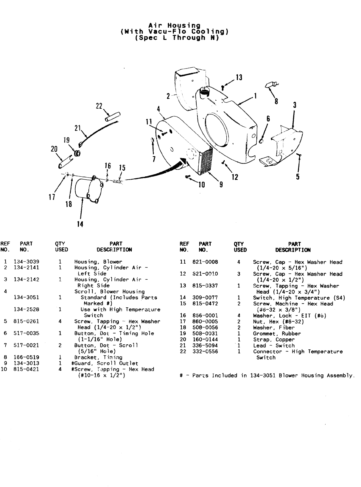
REF PART
No. w.
1134-3039
2134-2141
3134-2142
4
134-3051
134-2528
5815-0261
651?-0035
T!517-0021
8166-0519
9134-3013
10 815-0421
Air Housing
(ldith wacu-Flo Cooling]
[S~eC LThrough N)
2
14
QTY PART REF PART Qw PART
USED LXWX.IPTIDN NO, ND. WED DESCRIPTIWi
!-lousing, Blower
Housing, Cylinder Air -
Left Side
Housing, Cylinder Air -
Right Side
Scroll, Bl&~er Housing
Standard (Includes Parts
Marked #)
Use with High Temperzrture
Switch
Screw, Tapping -- Hex Washer
Head (1/4-20 x1/2”)
Sutton, Dot -Timing Hole
(1-1/16” Hole)
Button, Dot -Scroll
{5/15” Hole)
Bracket, Tim~ng
#Guard, Scroll Out]et
#Screw, Tapping -Hex Head
(#lo-16 x1/2”)
11
13
14
15
16
17
18
19
20
21
22
#-
821-0008
521-001.0
815-0337
309-0077
815-0472
$356”-0001
860-0005
508-0056
50&003i
160-0144
336-5094
332-0556
4
3
1
2
4
2
2
1
1
1
i
Screw, Cap -Hex Washer Head
(1/4-20 X5/16”)
Screw, Cap -Hex Washer Head
(1/4-20x 1/2”)
Screw, Tapping -Hex Washer
Head (1/4-20 x3/4”)
Switch, High Temperature (S4)
Screw, Machine -Hex Head
{$6-32 X3/73”)
Washer, Lock -EIT (#6)
Nut, Hex (#6-32)
Washer, Fiber
Grommet, Rubber
Strap, Copper
Lead -Switch
Connector -High Temperature
Switch
Parts Included in 134-3051 Blower Housing Assembly.
23
D
3
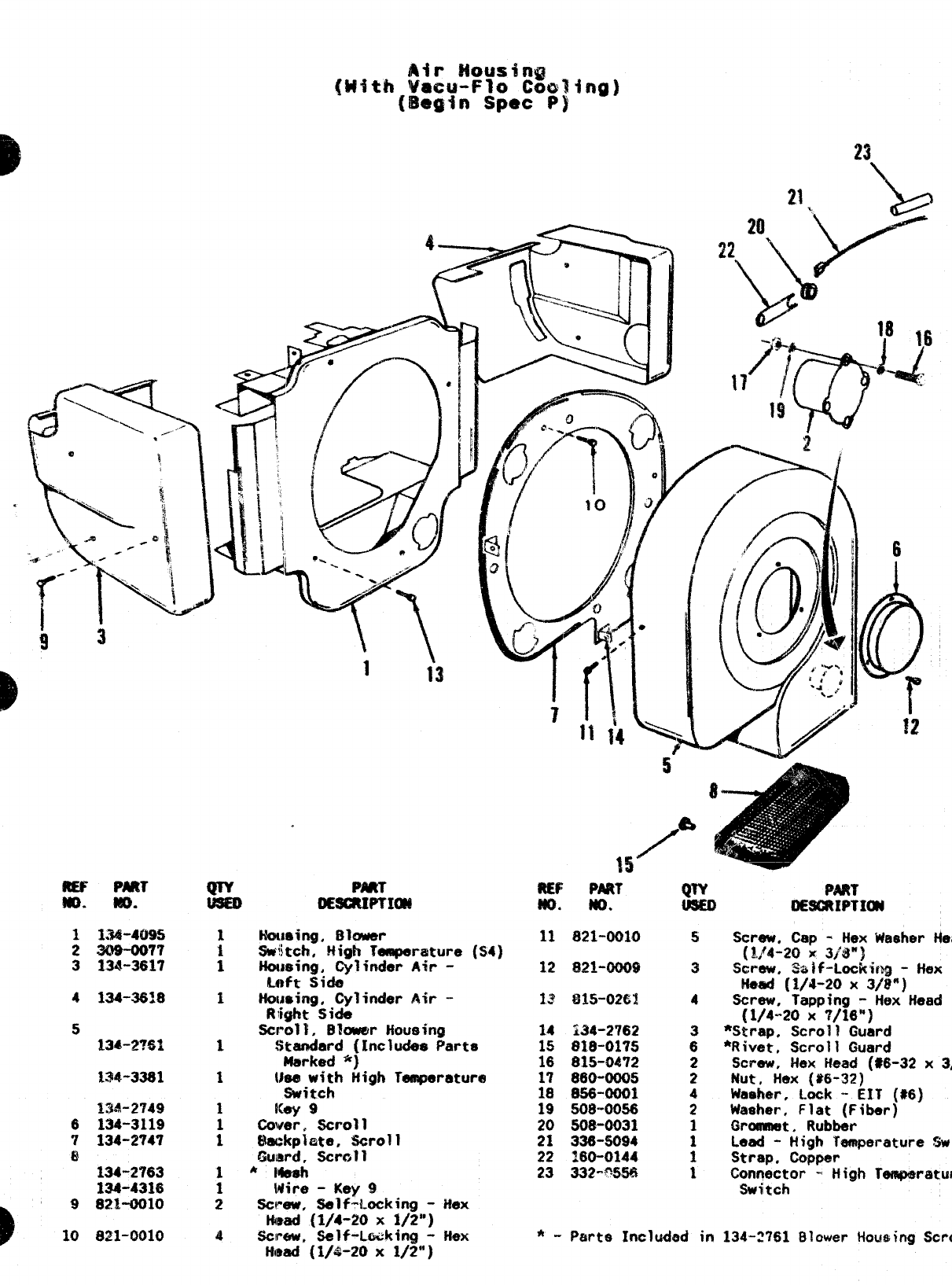
WPART
MO. w.
1134-4095
2 3M-007T
3134-3617
4134-3618
5134-2?62
134-3381
~34-2749
6134-3119
7134-2747
8134-2763
134-4316
9821-0010
10 821-0010
1i3
hbming. Bluwer
Switch, High Tamparature
Homing, Cylinder Air -
Loft Side
Ntmsing, Cylinder &ir -
Right Sidu
Swell. Bkwer Housiwa
(s4]
f
to
$tamiard (Includes parts
Marked ‘i}
Uea with High Temperature
Switch
ICay 9
ti~yer, Scroll
Elmgkplate, Scroll
~u~rd, ~ral~
AMeuh
Mire -Key 9
~1~~, *1~-Ltiking -H&x
mad (1/4-20 x1/2”)
Screw, Self-L-king -Hex
limad (1/4-20 x1/2”)
6
R& PNtT
m, NO.
11 821-0010
%2 JM-oom
Is $335+V~3
14 ;34-2762
15 818-0175
16 815-0472
17 860-oooti
18 8S8-0001
19 508-0056
20 508-0031
21 336-SO$J4
22 :6~0~44
23 332-0S56
y& PART
lMGltlPTI~
4
Screw, Cap -Hex Waeher
Hea
(l,f4-20 x3/$3”)
Screw, 3$$if-Lochinfj -Hex
Head (1/4-20 x3/!!”)
Screw, Tapping -Hex Head
(1/4-20 X7/16”)
*Strap, Scroll Guard
*Rivet, Scroll Guard
Screw, Hex Head (#6-32 x
3/
Nut, Hex ($6-32)
Waehm. Lock -EIT ($16)
Washer, Flat (Fiber)
Wxwnet, Rubbar
Lead -High Temperature
Wit
Strapc Copper
Connector -+ High Tempwature
Switch
*-P&rte Included in 134-2761 Blower iiou$ing
Scrol
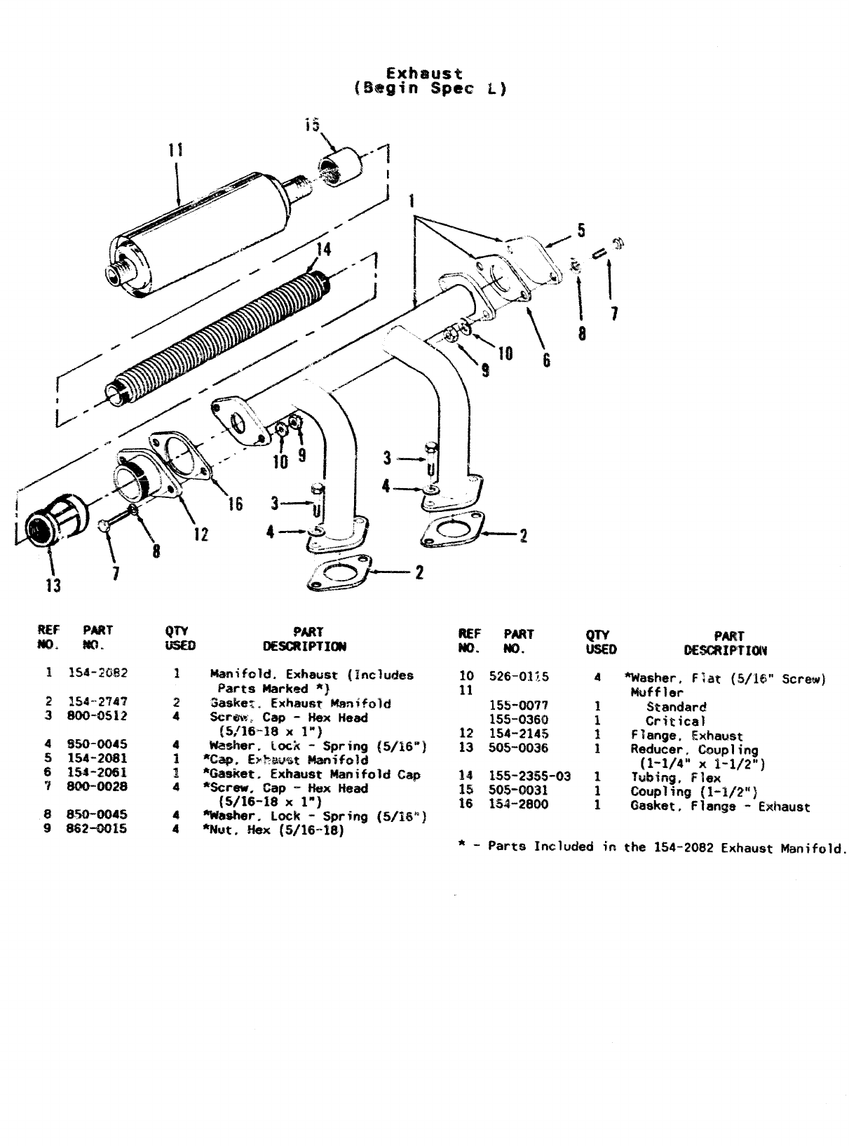
2154””2747
3800-0512
4&jo-oo45
5154-2081
6154-20S1
7800-0028
8$.%0”0045
9$62-0015
QTY W?T
OESCRIPTIt,X$ REF PART
m. m.
10 526-0115
11 15s-007?
155-0360
12 1!$4-214!5
13 505-0036
14 1s5-2355-03
15 50s-0031
16 134-2800
QKY PART
USED GEsmwmw
4! %tasher. F;at (!S/l@” Screw)
Muffler
Standard
Critical
Flange. Exh&ust
Reducer, Coupling
(1-1/4” x1-1/2”)
?ubifig, Flex
coupling {1-1/2”}
Gasket, Flange -Exhaust
*-Parts Inuluded in the 154-2082 Exhaust Manifold.
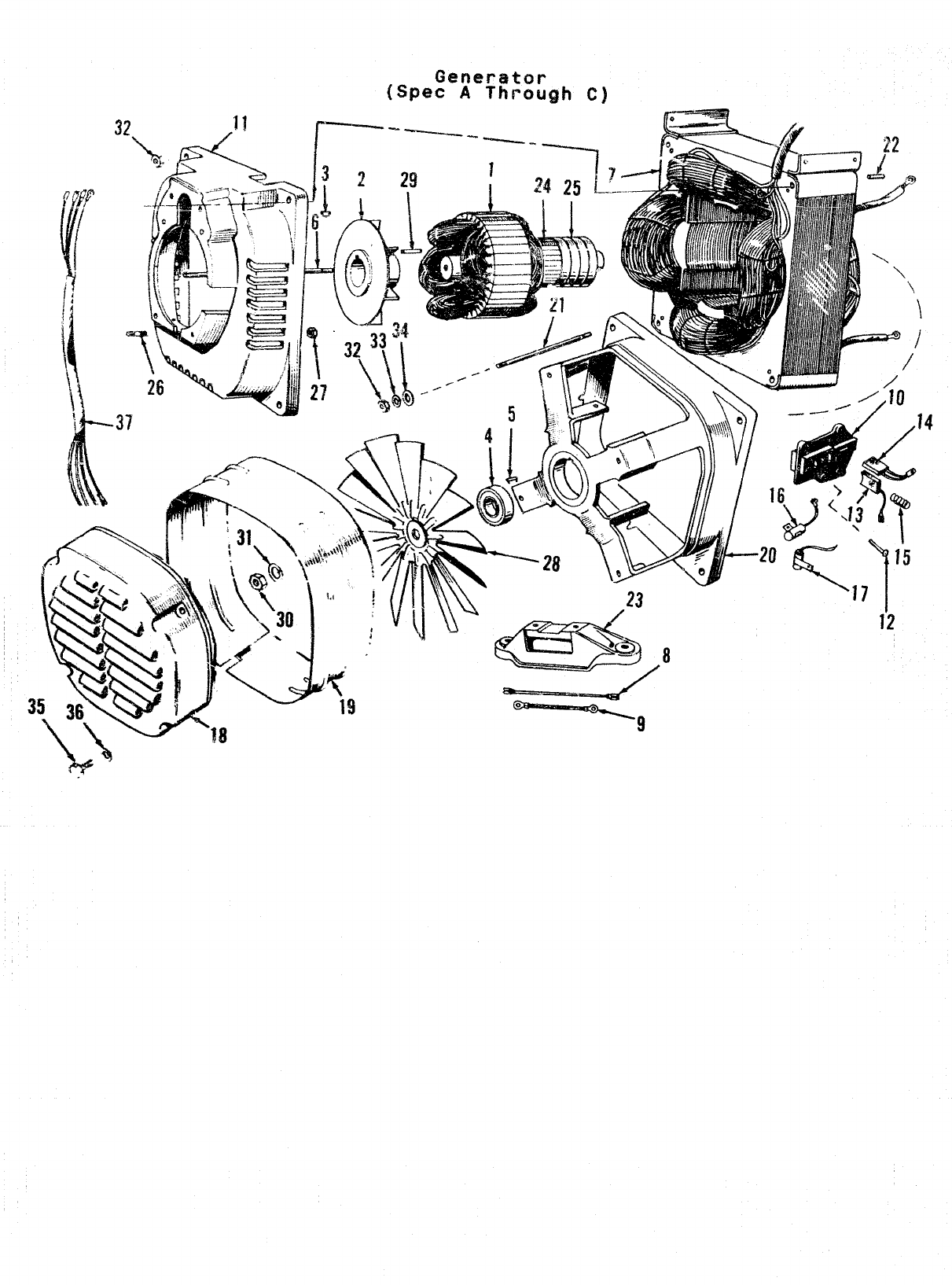
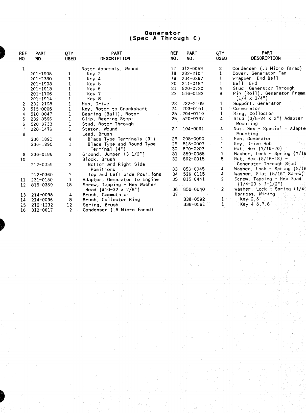
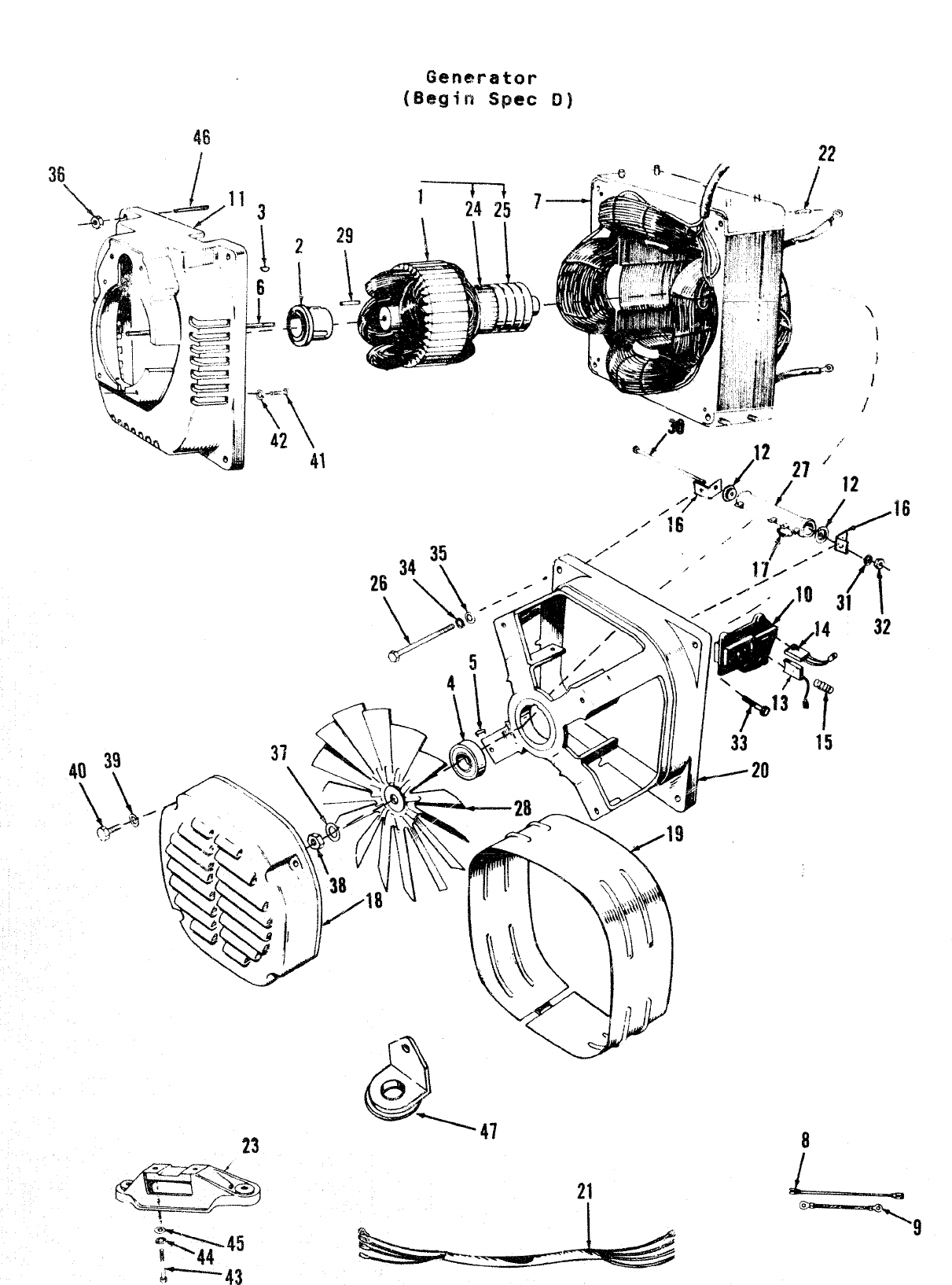
Generator
(S~ee AThrough C)
‘4
i2
)REF PART
!40 .
3.
2
3
4
!3
6
?
8
1:
11
12
13
14
15
16
b
B
No.
201-1905
201-2330
201-1$03
201-1913
201-1706
201-1914
232-2108
515-0006
510-004’7
232--0596
520-0733
220--14’76
336-1891
336-1890
336-0186
212-Q359
212-0360
231-0150
815-9359
214-0095
214-0096
212-1232
312-0017
Rotor
Key
Key
Key
Key
Key
Key
PART
DESCRIPTION
Assembly, Hound
2
4
5
6
7
8
!iub,” Drive
Key, Rotor to Crankshaft
Bearing (Ball), Rotor
clip, Bearing Stop
Stud, Rotor Through
Statoi-, Wound
Lead, 8rush
Blade Type Terminals (9”)
Blade Type and Round Type
Terminal (4”)
Ground, Jumper {3-1/2”)
Block, Brush
Bottom and Right Side
Positions
Top and Left Side Positions
Adapter, Ge%erator to Engine
Screw, Tapping -Hex Washer
Head (#10-32 x7/8”)
Brush, Commutator
Brush, Collector Ring
Spring, Brush
Condenser [.5 Micro farad)
REF PART
NO. No.
17 312-0058
18 232-2107
19 234-0362
20 211-0187
21 52@-0730
22 516-0182
23 232-2109
24 203-0151
25 204-0110
26 520-0737
27 104-OO9I
28 205-0090
29 515-0007
30 870-0203
31 850-0055
32 8S2-0015
33 850-0045
34 526-0115
35 815-0441
36 850-0040
37
338-0592
338-0592
ijTY
USED
3
1
1
1
4
8
1
1
1
4
4
1
1
1
1
8
4
4
2
2
1
1
Condenser (.1 Micro farad)
Cover, Generator Fan
Wrapper, End Bell
Bell, End
Stud, Gener.star Through
pin (RoI~), Generator Frame
(1/4 x3/4”)
Support, Generator
Commutator
Ring, Collector
Stud {3/8-24 x2“) Adapter
Mounting
Nut, Hex -Special -Adapter
Mounting
Fan, Generator
Key, Drive Hub
Nut, Hex (7/16-20)
Washer, Lock -Spring
(’7/16”)
Ni./t, Hex (5/16-18) -
Generator Through Stud
Washer, Lock -Spring
{5/16”)
Washer, Flat ~5/1.6° Scvew]
Screw, TapD <cg -ti~x Head
(1/4-20x ‘.-1}2”)
Washer, Lock -Spring (1/4”)
tiarness, Wiring
Key 2,5
Key 4,6,7,8
22
DREF PART
w. m.
QTY
USED
PART
0E5CftIPTItM
w!=
No.
WRT
0ESCRIPTM2H
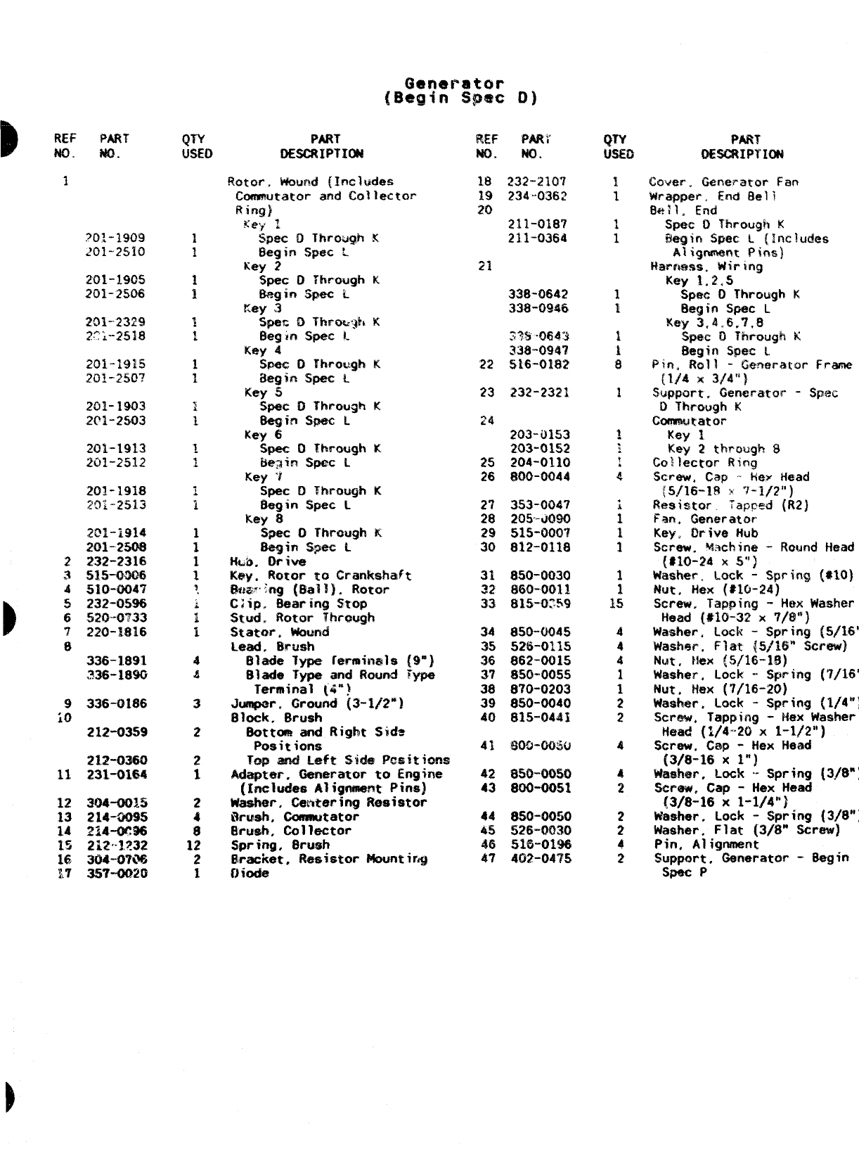
!lOtcw. wound (Includes
Commutator and Collector
Ring)
Key 1
SpeC DThro@ K
Begin Spec L
Key 2
Spec DThrough K
8egin $pec L
Key 3
Spat DThro!qh K
Begin Spec L
Key 4
%l%c 0Thrcqh K.
aegin S*G L
Key 5
Spec aThrclugh K
8egin Spec L
Key 6
Spec DThrough K
L$qis S*C L
Key ‘t
Spec DThrough K
tlegin Spec L
Key 8
Spec DThrough K
flegirh $pec L
Hkb. Drive
Key, Rotor to Grztnkshaft,
i.b!w’:ng (Ball}. Rotor
Clip. Baaring STop
Stud, Rotiar Through
Stator. Wound
Lead. Brush
Blade Type ferrninals {9”)
Blade Type and Round Type
Terminal (4”!
Jumper. Ground (3-1/2”)
Block. Brush
8ottom and Right Sida
Positions
?* *~~f~ Cil+m ooei+ifi~~
-.— .WV. . .W
Adapter. Oeneratcir to Engine
(Includes Alignmem Pins]
Washer, Cmtering Ra$istor
Wmh, Coms@ator
Brush, Collector
Spring. $rtmh
@racket, Resistor Mounting
Uioda
18
19
20
Cover, (kmeratcw Fart
wrapper, End Bell
Be:], End
Spec 0Through K
Begin !A+@mL(Includes
~lignmen~ Pins]
tiamess. Wiring
Key 1.2,S
Sp@c OT“hrcwgh K
Begin S@c L
Key 3<4,,6.7.8
Spec 0Through K
Begin .SKM$C1
Pin’ Roll -Generator Frame
{1/4 x3/4”)
.%pport, Generatov -Spec
DThrough K
Conmmtator
Key 1
Key 2ttwough $
Collector Ring
Screw, Cap -tiex Head
(5{16-18 :x 7-3/2”}
Resistor. Tapped (R2)
F+In, Generator
Key, Drive Hub
Screw. W:9chine -Round Head
(# N1-24 xs“]
Washer. Lock -Spring (#IO)
Nut. Hex (*IO-24)
Screw, Tapping -Hex Washer
Head (#15-32 X7/8”]
Washer. Lock -Spring (5/16”)
WAWW=, Flat ~,5/16” Screw)
Nut. Hex (5/16-18)
Washer. Lock -Spring (7/16”)
I’Jut. Hex (7/16-20}
Washer, Lock -spring [1/4”]
Screw, Tapping -Hex Washer
head (1/4-20 X1-112”)
Screw, Cap -Hex Head
(3/8-16 x1“]
Was!mr, Lock -- Spring (3/8”)
Smww. Cap -Hex Head
{3/8-16 X1-1/4”}
Washer, Lock -Spring (3/8”)
Washer, Flat (3/8” Screw)
Pin. Alignment
support, Omerator -8egin
Spec P
338-0642
338-0946
22
23
24
232-2321
201-1903
201-2503
203-9153
203-01s2
204-0110
800-0044
25
26
27
28
29
30
Wio-oixio
$60-0011
815-0:59
850-0045
526-0115
862-0015
850-0055
870-0203
850-0040
815”0441
34
35
36
37
38
39
40
336-1891
336-1$93
9
iO
336-0186
212-0359
Ww-citw
21.2-0380
231-0164 42
43
12
13
14
15
16
1,7
8S0-0050
%?6-0030
516-0198
402-04’?5
46
22
,’
,1Q?’
—-de
-’--%*
ont-L-
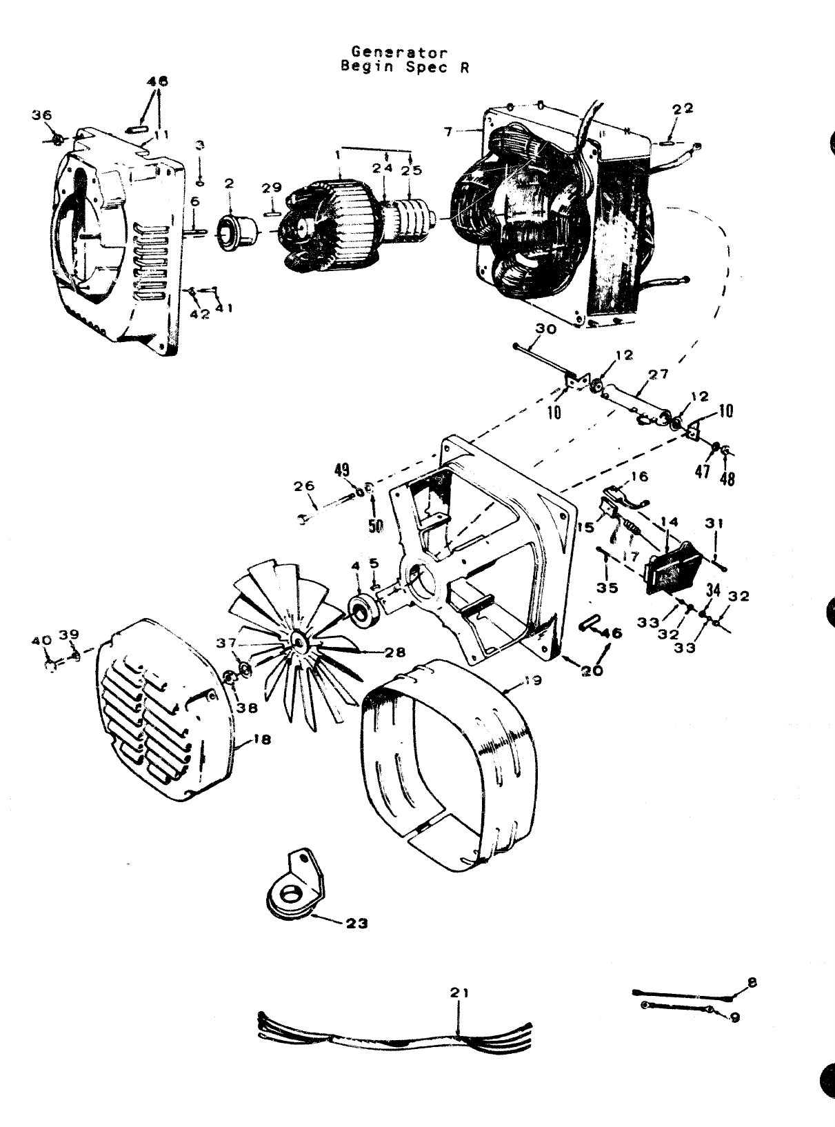
nLr PART
No. No.
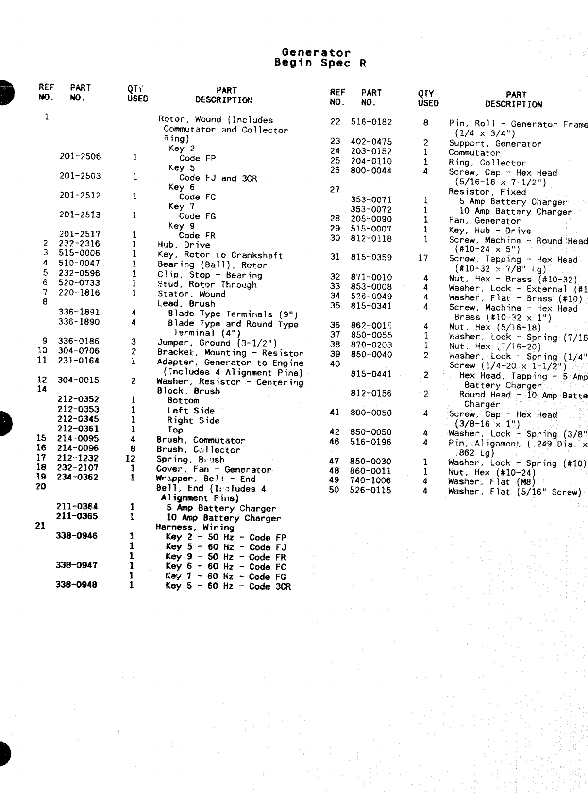
1
201-250s
201-2563
201-2512
20~-25~7
2232-2316
3515-0006
4510-0047
5232-0596
6520-0’?33
7220-1816
8
336-1891
336-1890
9336-9186
:0 304-0706
11 231-0164
12 304-0015
14
2~2-f1352
D
212-0353
212-034!5
212-0361
15 214-0095
16 214-0096
17 212-1232
18 232-2107
19 234-0362
20
211-0364
211-0365
21
338-0946
338-0947
338-0948
D
QTY PART
mm DE.SCRIPTICNJ
Rotor. Wound (Includes
Commutator and Collector
Ring)
Key 2
Code FP
Key 5
Code FJ and 3CR
Key 6
Code FC
Key 7
Code FG
Key 9
Code FR
Hub. Drive
Key. Rotor to Crankshaft
Generator
!Begifl Spec R
Bearing {f3a~~), Rotor
Clip, Stop -Bearing
Stud. Rotor Thra15gh
Stator, Wound
Lead, Brush
Blade Type Termir+als
Blade Type and Round “
Terminal (4”)
Jumper, Ground (3-1/2”)
Bracke$, Mcxmtina -Res stor
Adapter, Generat~r to Engine
(Zncludes 4Alignment Pins)
Washer, Resistor-- Centering
Block. Brush
Bottom
Left Side
Right Side
Top
Brush, Commutator
Brush, C(,llector
Spring, fl,t~sh
Cover, Fan -Generator
Wr%pper,, Be]? -End
Bell, End (I; ;ludes 4
Alignment Pi,ts)
5Amp Battery Charger
10 Amp Battery Charger
Harriess, Wiring
Key 2-50 Hz -Code FP
Key 5-60 Fiz -Code FJ
Key 9-50Hz -Code FR
Key 6-60 Hz -Code FC
Key ‘i -60 tfZ -Code FG
Key 5-60 Hz -Code 3CR
REF PART
NO. NO.
22 516-0182
23 402-0475
24 203-0152
25 ?Q4-()~lQ
26 800-0044
27
353-0071
353-0072
28 205-0090
29 515-0007
30 812-0118
31 815-0359
32 871-0010
33 ~53-0()()8
34 5?6-0949
35 815-0341
36 862-001!:
37 850-005!5
38 8’?0-0203
39 850-0040
40
815-0441
812-0156
41 800-0050
42 850-00S0
46 516-0196
47 850-0030
48 860-0011
49 740-1006
50 526-0115
QT’Y
USED
8
2
i
4
1
1
1
1
1
17
4
4
4
4
4
1
i
9
.
2
2
4
4
4
1
1
4
4
PART
DESCRIPTION
Pin, Roll -Generator Frame
(1/4 x3/4”)
Support, Generator
Commutator
Ring, Collector
Screw, Cap -Hex l-lead
(5/16-18 X7-1/2”)
Resistor, Fixed
5Amp Battery Charger
10 Amp Oattery Charger
Fan, Generator
Key, Hub -Drive
Screw, Machine -Round Head
(#10-24 X.5”)
Screw, Tapping -Hex Head
(#10-32 X7/8” Lg)
Nut, Hex -Brass (#10-32)
Washer, Lock -External
(#10
Washer, Flat -Braas (#IO)
Screw, Machine -Hex Head
Brass (#10-32 x1“)
Nut, Hex (5/16-18)
washer Lock -Spring (7/16”)
Nut, Hex \Yi’1.5-20)
‘Washer, Lock -Spring (1/4”)
Screw (1/4-20 x1-1/2”)
Hex Head, Tapping -5
Amp
Battery Charger
Round Head -10 Amp
Battery
Charger
Screw, Cap -}iex Head
(3/8-16 x1“)
Washer, Lock -Spring (3/8”)
Pin, Alignment (.249 Dia. x
.862 Lg)
Washer, Lock -Spring (#IO)
Nut, tiex (#~0-24)
Washer, Flat (148)
Washer, Flat (5/16” Screw)

2
%
3 \,.
o
14
/
REF PART
w. w.
1301-3301
2301-3302
3307-0845
4312-005?
5353-0006
304-0251
6304-0632
?’ 332-0745
8332-1321
9308-0154
10 416-0004
11 30’?-1052
.2 30.5-0383
:3 508-0001
.4 416-0077
.5 307-1070
.6
323-0803
9
I
130x, Control
Cower, Control 80X
Solenoid, Start
Condenser (1.0 Mfd.) -
Suppression
Resistor, Fixed
6-ohm, 50 watt
30-Ohmt 5Watt
Resistor, Adjustable
(6-ohM, 100 watt)
Block, Terminal
Strip, Marker
Switch, Stsrt/Stop
Cable, Battery Jumper -
Optional
Relay, Stop
Relay, Voltage Ragulator
Grommet. For 1-1/16” Hole
Cable, Battery (28”)
Relay, Start Disconnect
Socket and Chassis Assembly,
@
24
REF PART
NO. w.
17 300-0734
:;
20
21
22
23
24
25
26
27
28
359-0028
350-0979
350-09B5
350-0397
362-0010
331-0088
508-0160
338-0561
301-3306
301-3307
332-0142
302-0058
%3\.
QTY PART
USED QESCRIPTIm
Amplifier Assembly, Start
Disconnect (Includes Psrts
Marked *)
*Diode, Zener
*Resistor -470-Ohm, 2Watt
*Resistor -820-Ohm, 2Watt
*Resistor -2700-Ohm, 1/2 Watt
*Transistor
8ushing (Nylon)
1-3/32” Mounting Hole
1/2” Mounting Hole
Harness, Wiring
Spring, Relay Holddown
Spacer, Relay to Amplifier
Terminal, Solderless (Use as
Reauired)
Amm&er, Charge (lo-o-loj
*-Parta Included in 300-0734 Amplifier Assembly.
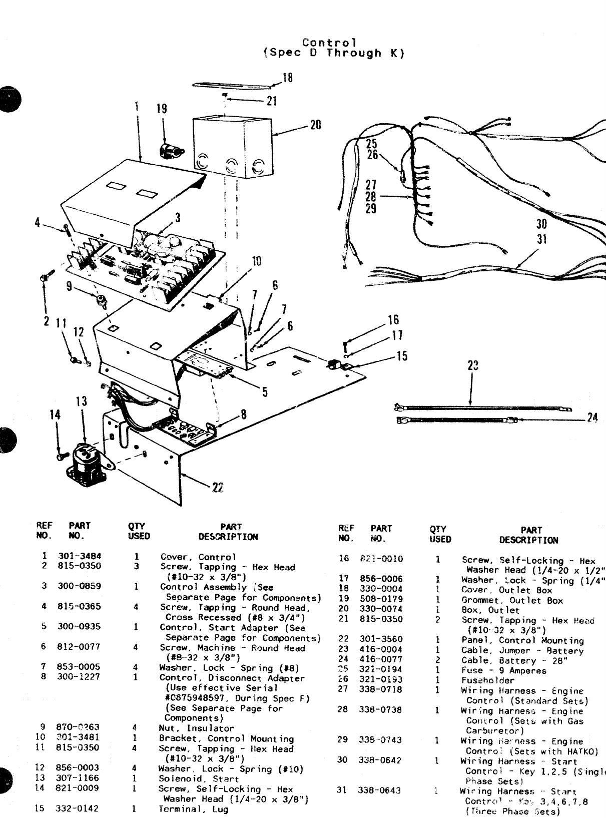
MF PART
NO. w.
1301-3484
2815-0350
3300-0859
481.5-0365
5300-0935
6812-00’?7
7853-0005
8300-2227
9870-??63
10 30~-3481
11 815-0350
12 856-0003
13 307-1166
1.4 821-0009
15 332-0142
PAN
DESCRIPTIW
(2wer. Control
Screu, Tapping -Hex Head
[#10-32 X3/8”)
Control Assembly /.See
Separate Page for Componertts]
Screw, rapping -Roth Head,
Cross Recessed (#$ x3/4”)
Control, Start Adapter (See
Separate Page for Components)
Screw, Machine -Round Head
(#8-32 X3/8”)
Washer, Lock -Spring (*8)
Control, Disconnect Adapter
(Use effective Serial
#05?5948S97, During Spec F)
(See Separate Page for
Components)
Nut, Insulator
Bracket, Control Mounting
Screw, Tapping -Hex Head
(#10-32 x3/8”)
Washer, Lock -Spring (#IO)
$ioienoid. Start
Screw, Self-Locking -Hex
Washer Head (1/4-20 x3/8”}
Terminal, Lug
R$!! PART
NO. m.
16 821-0010
;; 856”0006
2Q&.nnl%A
“w” ““”.
i; !308-0179
20 330-0074
21 815-0350
22 301-3560
23 416-0004
24 416-0077
?.S 32~-0~94
16 321-0i93
27 338-0718
28 338-0738
29 33&~743
30 338-0642
31 338-0643
(JTY
USED
1
1
PART
OESCRIPTI(N
Screw, Self-Locking -Hex
Washer Head (1/4-20 x1/2”)
Washer,, Lock -Spring (1/4”)
Cover. Outlet f.hx
Grommet, Outlet Box
Box, outlet
Screw. Tapping -Hex Head
(#lo-X! x3/8”)
Panel, Control Mounting
Cable, Jumper -%ttery
Cable, Battery -28”
Ftise -9Amperes
Fusehclrjer
Wiring Harness -engine
Control (Srandar$ Sets)
Wiring harnesz -Engine
Cor~trol (Sets with Gas
Carburetor)
Wiring ti;3. ww5 -Engine
Controt (Sets with HArKO]
Wiring Harness .Start
Control -Key 1,2,5 (Single
Phase %ts}
Wiring Harness .St<w-K
Contr(}~ ‘- ~:e, 3,4.6,7,8
{Three Phase <jets]
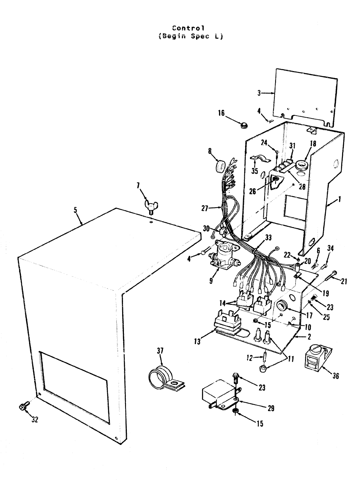
’15
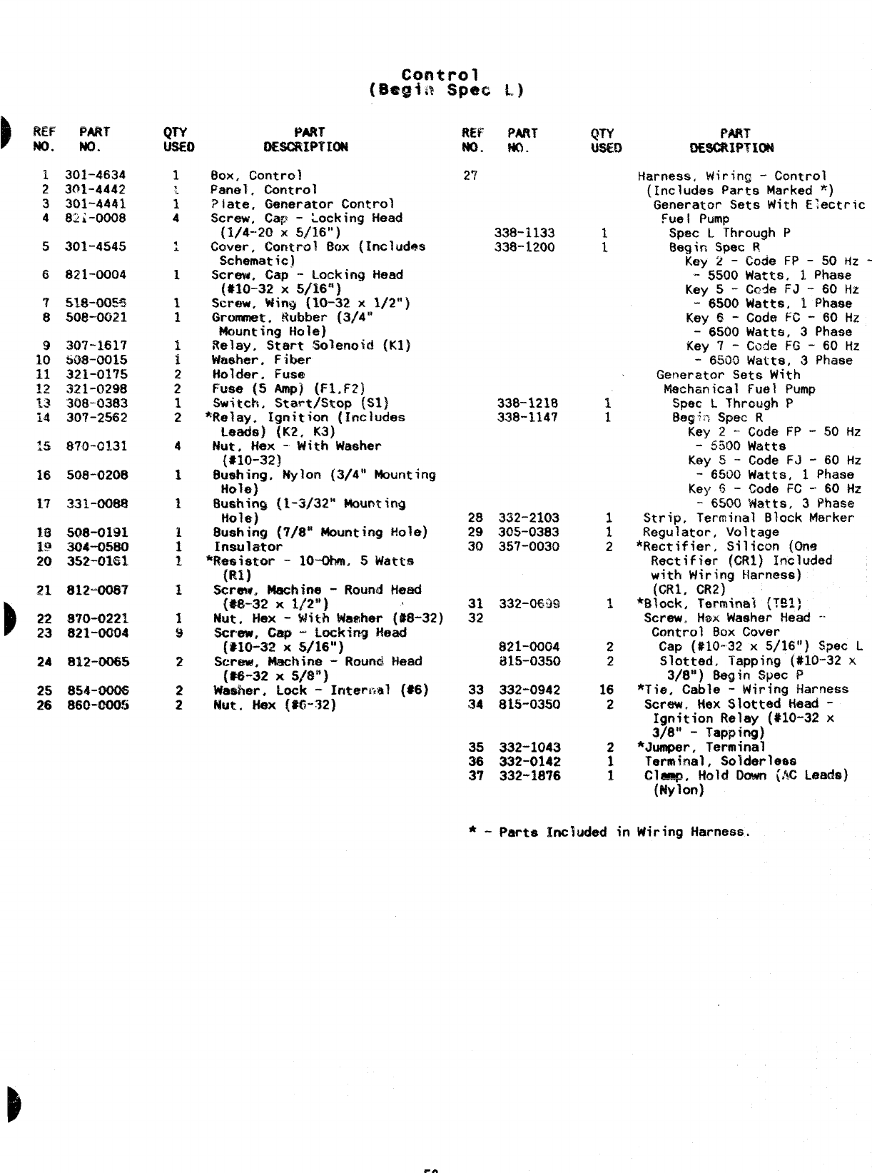
----- .
{Ehl@b?Spec L.)
)REF
No. PART
No. Mm
oEsGTaPTmN REF PART
w. NO. PART
0E8CRWTXW
Harness, Wiring -Control
(Includes Parts Marked *)
Generator Sets With E;ectric
Fuel Pump
Spec LThrough P
E3eain SDec 1?
Box, Control
Panel, Control
Plate, Generator Control
.Screw, Ca~> -Locking Head
(1/4-20x 5/16”)
Cover, Control 80X (Includes
Schematic)
Screw. Cap -Locking Head
(#10-32 X5/16”)
Screw, Wing (10-32 x1/2”}
Grcnwnet. Rubber (3/4”
Mounting Hole)
Relay, Start Solenoid (Klj
Washer. Fiber
tiolder. Fuse
Fuse (5 fwsp} (F1.F2)
Switch, Start/Stop {S1)
~’ftelay. Ignition (Irwludes
!JWMk){K2, K3)
Nut, Hex -With Washer
{S10-32)
Rushing, Nylon (3/4” Mounting
Hole)
Bushir4g (1-3/32” MouGting
Hole)
Bushing (7/8” Mounting Hole)
Insulator
*Resistor -10+, 5Watts
(RI)
Screw. Machine -Round Head
{#8-32 xl\2° )‘
Nut. Hex -With Waaher (#8-32)
screw, cap “LmCidr?gMad
{~ltl-~~X5/16”)
%:rew, Machine -Round Head
(*-32 X5/8”)
Washer, Lock -Irmerml (#6)
Nut, *X (*$3-32)
301-4634
301-4442
301-4441
82i-ooo8
27
5301-4545 key 2’-
-5500
Key 5-
-6500
Key 6-
-6500
Key 7-
-6530
Cotie FP -50 Hz -
Watts, 1Phase
Cede FJ -60 Hz
Watts, 1Phase
Code FC -60 Hz
Watts, 3Phase
Code FG -60 Hz
Watts, 3Phase
6821-0004
307-1617
508-0015
321-01’75
321-0298
308-0383
307-2562
Generator Sets With
Mechanical Fuel Pump
Spec LThrough P
Beg+n Spec R
Key 2-Code FP -50 Hz
-5300 watts
Key 5-Code FJ -60 Hz
-6500 Watts, 1Phase
Key $-Code FC -60 HZ
-6500 ‘Watta, 3Phase
Strip, Terminal Block Marker
Regulator, Voltage
*Rectifier, Silicm (One
Rectifier (CRI) Included
with Wiring Harness)
(CR1, CR2) .
*Block, Term~nal (?91)
Screw. H*x Washer Head -
Control Box Cover
Cap (#10-32 x5/16”) Spec L
Slotted, Tapping (#10-32 x
3/8”) 8egin Spec P
*Tie, Cable -Wiring Harness
Screw, Hex Slotted Head -
Ignition Relay (#10-32 x
3/811 -Tapping}
*Jumper, Terminal
Terminal, Solderless
Clamp, Hold Down (AC Leads)
338-1218
338-1147
!.5
508-0208
331-0088 28 332-2103
29 305-0383
30 357-0030
508-0191
304-0580
352-0161
21 81’2-0087 31 332-0639
32
b22
23 W?O-0221
321-0004 821-0004
815-0350
812-0065
854-00G6
860-OOOS
33 332-0942
34 815-0350
25
26
35 332-1043
36 332-0142
37 332-1876
(Nylon]
*-Parts Included in Wiring Harness.
53
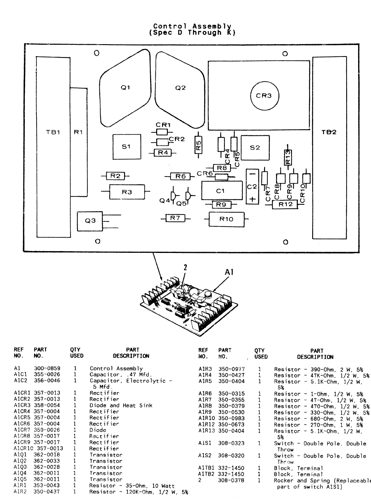
Control Assembl Z
[Spec DThrough )
c1 c)
Al
ftEF PART QTY PART REF PART
MO. No. QT-’f
USED PART
DESCRIPTION NO. MO. ,USED DESCRIPTION
Al 300-0859
AIC1 355-0026
A1C2 356-0046
AICRI 357-0013
A1CR2 357-0013
AICR3 358-G054
A1CR4 357-0004
A1CF?5 357-0004
A1CR6 357-0004
AICR7 359-0026
AI{CR8 357-0017
A1CR9 357-001?
AICRIC 357-GC13
AIQ1 362-0018
A1Q2 362-0033
A1Q3 362-0028
AIQ4 362-0011
A1Q5 362-0011
AIRI 353-0043
A1R2 350-0437
Control Assembly
Capacitor, .47 Mfd.
Capacitor, Electrolytic -
5Mfd..
Rectifier
Rectifier
Diode and Heat Sink
Rectifier
Rectifier
,RectiFier
Diode
Rectifier
Rectifier
Rectifier
Transistor
Transistor
Transistor
Transistor
Trane,istor
Res~stor -35-Ohm, 10 Watt
Resistor -120K-Ohm, 1/2 W, 5%
AIR3 350-097’!
AIR4 350-0427
A1R5 350-0404
A1R6 350-0315
A1R7 350-0355
A1R8 350-0379
A1R9 350-0530
A1R1O 350-0983
A1R12 350-0673
A1R13 350--0404
AISl 308-0323
A1S2 308-0320
AITB1 332-1450
A1TB2 332-1450
2300-0378
;
1
1
1
1
1
1
1
1
1
Resistor -390-Ohm, 2W, 5%
Resistor -47K-Ohm, 1/2 W, 5%
Resistor -5.lK-Chm, 1/2 W,
5%
Resistor -I-Ohm, 1/2 W, 5%
Resistor -47-Ohm, 1/2 W, 5%
Resistor -470-Ohm, 1/2 W, 5%
Resistor -330-Ohm, 1/2 W,
.5%
Resistor -680-Ohm, 2W, 5%
Resistor -270-Ohm, 1W, 5%
Resistor -5.lK-Ohm, 1/2 W,
5%
Switch -Double Pole, Double
Throw
Switch -- Double Pole, Double
Tbrow
Block, Terminal
Block, Terminal
Rocker and Spring (Replaceable
part of switch AIS1)
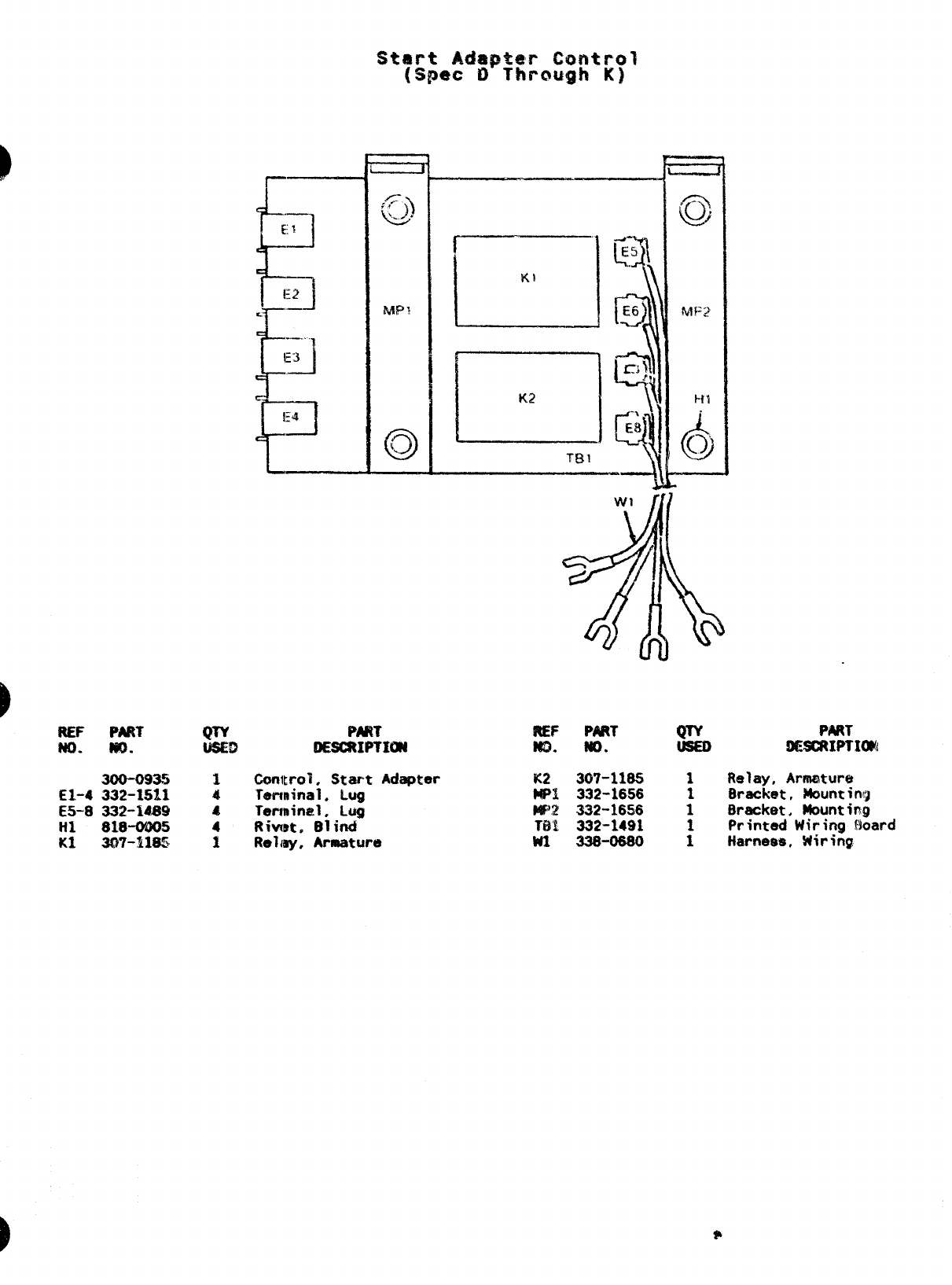
REF PART QTY Pm7
No- m. USED QE6C4UPTI~
300-093!! 1Chntml. W-art hdaprsr
EI-4 332-1511 4Terminal. Lug
E5-8 332-14S9 4Terminal. Lug
Ill 818-0005 4Rivet. Blind
KI 3$37-~~~, ~Relmy, Armature
i-----
L--!
Kt
,
L..-_
la
--l!
C?EF P4RT QTY PART
m. Ho. ilE3CRKPTIWJ
W307-1185 1Relay, Armature
WRl 332-1656 Bracket, Mow!tinq
MW 332-16S6 ;Bracket. Mounting
TBI 332-1491 Printed Wiring f~oard
W1 338-0680 :Harnees, wiring
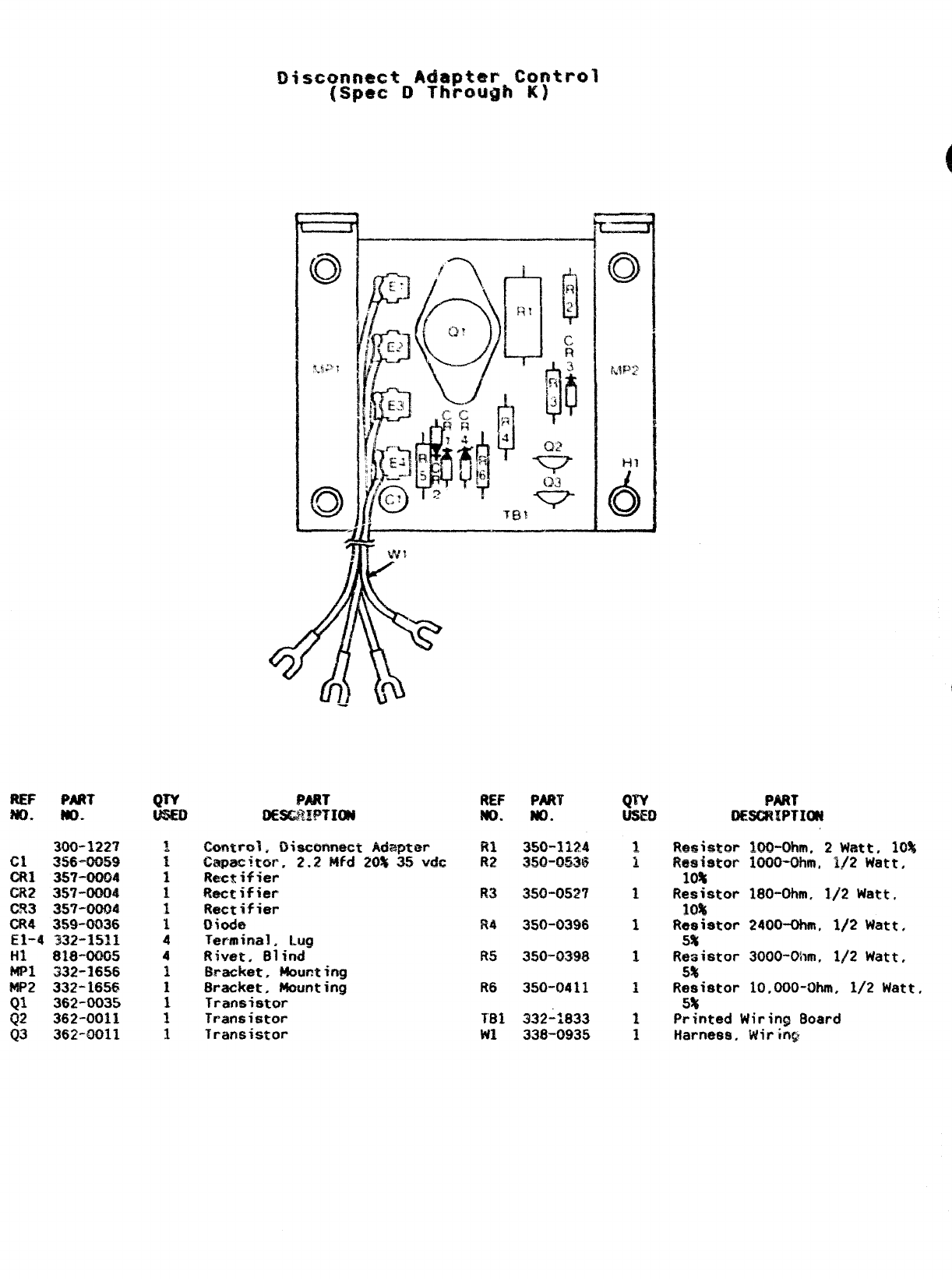
REF PART
MO. MO. PART
DESCRW?ION REF
w. PAM
No. PAN
flEWRIPTICXd
300-1227
cl ~~-~~g
ml 357-0004
CR? 35T-0004
CR3 357-0004
CR4 359-0036
E1-4 332-1511
HI 818-0005
MPl 332-1656
MP2 332-1656
01 362-0035
02 362-0011
(J3 362-0011
Ck#nzml ,Disconnect Adapter
Capecitur, 2.2 Mfd 20% 35 wde
Rectifier
Rectifier
Rectifier
llbde
Terminal. Lug
Rivet, Blind
Bracket. hlcnmting
Bracket, Mounting
Transistor
Transistor
Transistor
Ri
R2 350-3124
WJ-omj Resistor NxHMlm, 2wRtt. 10%
Resistor 1000-Ohm, 1!2 Watt,
10%
Resistor 180-Ohm, 1/2 Watt.
10%
Resistor 2400-Ohm, 1/2 Watt,
5%
Resistor 3000-Ohm, 1/2 Watt,
5%
Resistor 10.000-tNun, 1/2 Watt,
5%
Printed Wiring Board
Harness, Wirin~
R3 3s0-0527 1
R4 350-0396 1
350-0398
R6 350-0411
332-;833
338-0935
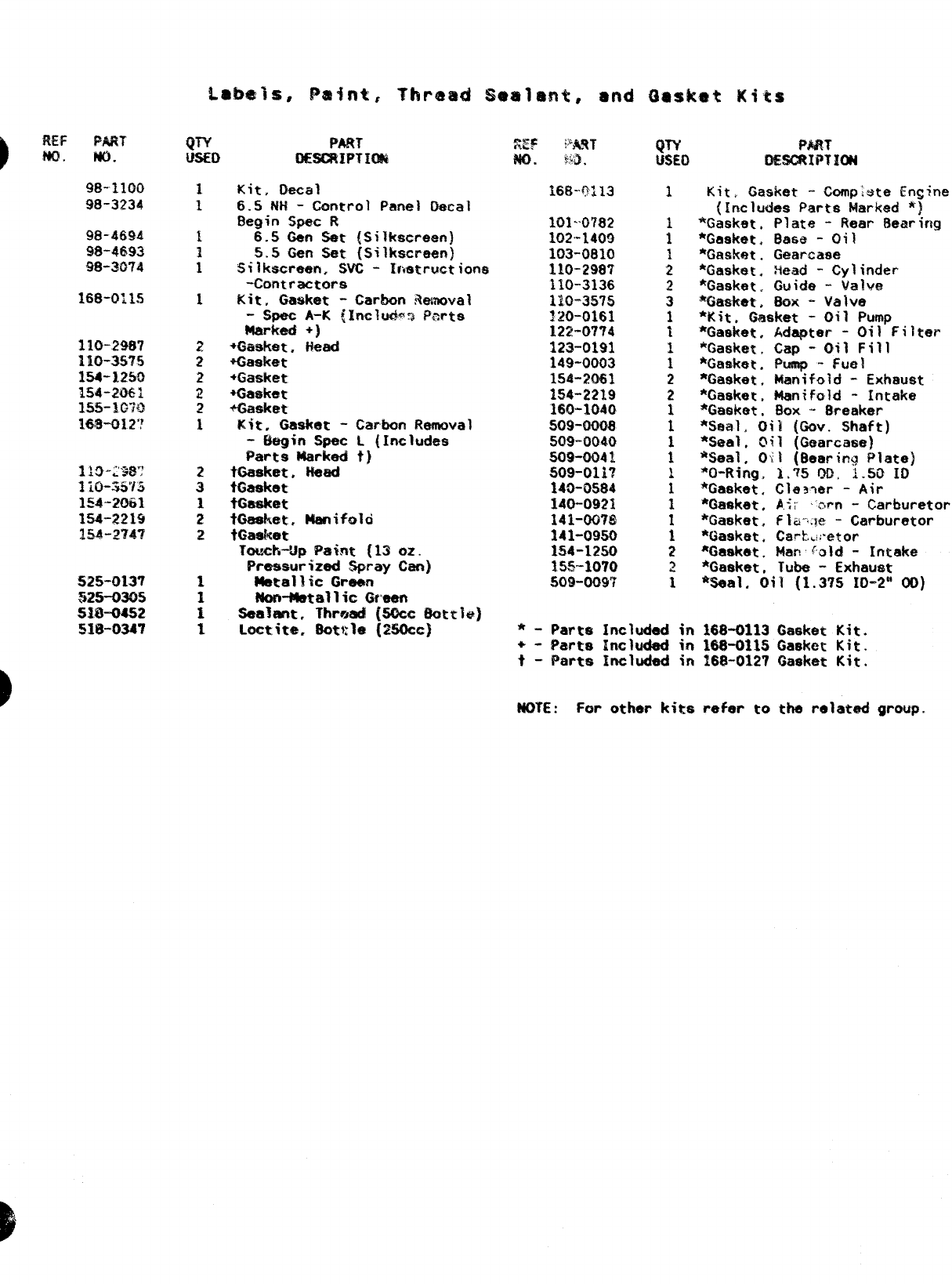
REF PART
m. w.
9!?- 1100
98-3234
98-.4694
98-4693
98-3074
525-013?
325-0305
51.8-Q*2
51W3347
Kit, Decal
6.sFlti -Control Panel Decal
Begin Spec R
6.5Gen Set {Silkscreen)
5.5 Gen Set {Silkscreen)
Silkscreen, SVC -Irmtructiorm
-contractors
Kit, Gasket -Car-bon $%mOval
-Spec A-K ~lnclr.&% Parts
Marked +]
+Gmket. Head
+Gasket
+Gasket
+Gaskmt
+&mket
Kite Gasket - Carbon Remwal
-Eiagin Spat 1. (Includes
Parts Mark@” t)
tGasket, Head
tGasket
fiasket
ieeeket, Manifold
fGadmt
TOu&dJp Paint {13 oz.
Pressurized Spray Cam)
@i8t81~iC Grew
Non-Metallic (Mean
Sealant. Thrmad (50ce 8ottle]
Loctit** 8ottle (MOcc)
~-p %%!!T
w. fi:a .
168-.0313
101-’0782
102-1409
103-0810
110-298’/
110-3136
110-35?5
120-0161
122-07?4
123”0191
149-0003
154”2061
1!54-2219
160-1040
509-0008
509”0040
509-0041
509-011’?
140-0584
140-0921
141-00?8
141-09!$0
1S4-12!S0
IW-107(9
509-009’?
*-Parts Included in
+- $h3rts Included in
t- Parts Included in
MOTE:For other kiws
Kit, Gasket -Compiste En~ine
(Includes Parts Marked ‘]
‘%asket, Plate -Rear Bearing
*Gasket. B&&e -Oil
*Gasket. Geiarcase
*Gasket. %ead -Cylinder
*Gasket. Guide -valve
%h3eket, Box -Valve
*Kit, Gasket -Oil Pump
*Gasket. Adapter -Oil Filter
*Gaskmt, Cap -Oil Fill
*Gasket. Pump -~u~~
*G&sket, k%mifold -Exhau@t
*Gasket, Manifold -Intake
*Gasket, $OX -8reaker
*Saal. Oil {Gov. Shaft)
%eal. Oil (Gearcaee)
*%41. Oil (Bearin9 Plate}
*0-Rirtg, 1.~50il, 1.50 10
*Gasket, Cla~wr -Air
*Gasket. h.<: ‘c$rn -Carburetor
*Gasket, Flti-,:je -Carburetor
*Gasket. Cavh.!mtor
%aeket. 14an~~ld -Intake
*Gaeket, T@e -Exhaust
*Seal. Oil (1.37S IO-2” 00)
168-0113 Gasket Kit.
1$8-011S Gasket Kit.
168-0129 Gasket Kit.
refer to the related group.
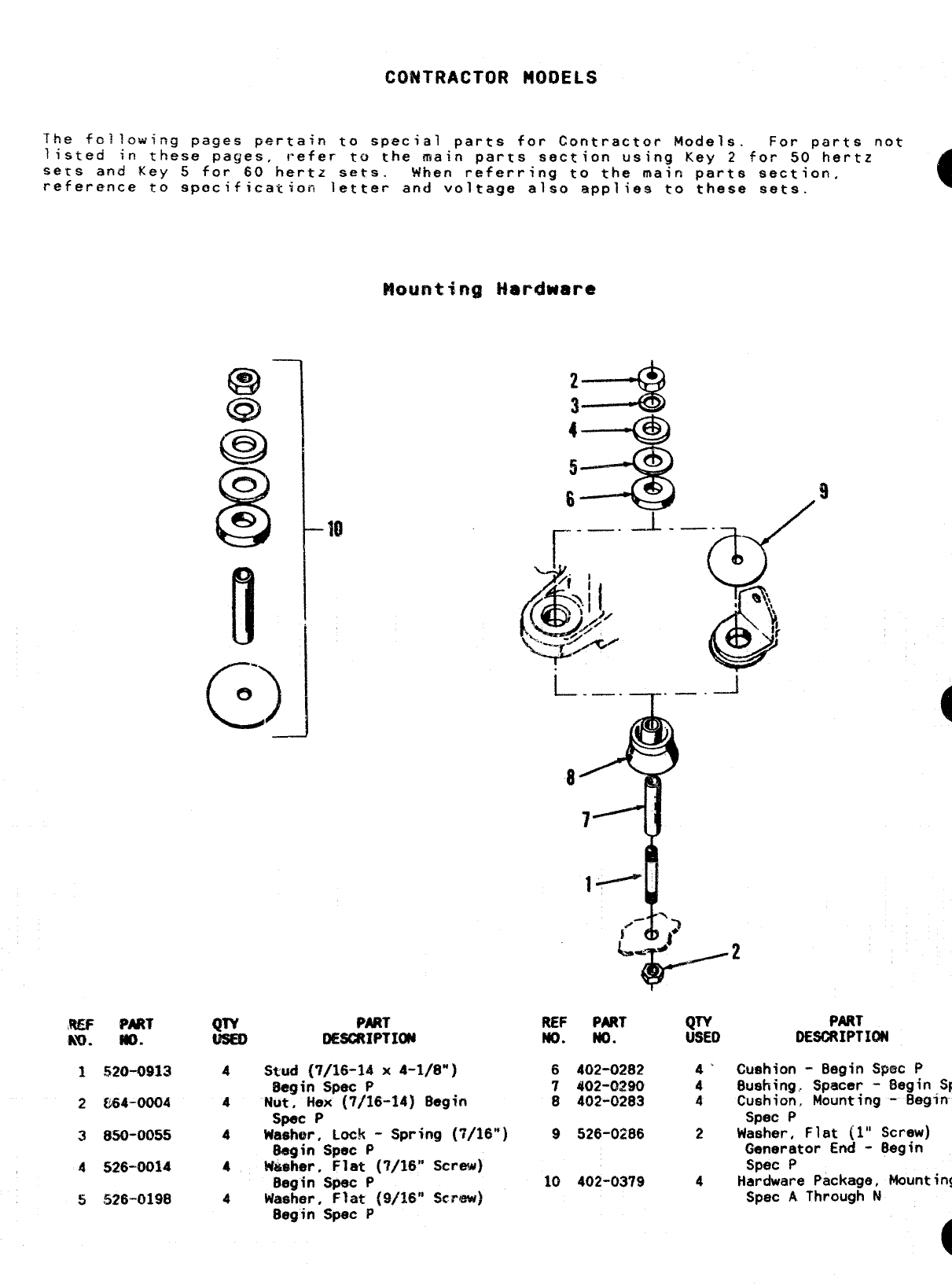
CONTRACTOR S401)ELS
The fo::ow;cg pages pertain to special parts for Contractor Models. For parts not
listed in these pages, refer to the main parts section using Key 2for 50 hertz
sers and Key 5for 60 hertz sets. When referring to the main parts section,
reference to specification letter and voltage also applies to these sets. o
Mounting i+ardware
R& PART
NJ. WI.
1520-0913
2864-0004
3850-0055
4526-0014
S526-0198
Ill
c)
.
uI
-1
Q& PART
DESORIPTIW
4stud {7/16-14 x4-1/8”]
Begin Spec P
aNut, iiex (7/16-34) Begin
Spec P
4Washar, Lock -Spring (7116”)
8egin Spec P
4t4u@her, Flat (’?/16” Screw)
Begin Spec P
4Waehar, F?at (9/16” Scrww)
8egin Spec P
r..—.-L.
L._.T._.i
8
4
7
REF PAJiT &TD
m. No.
6402-0282 4’
7402-0290 4
8402-0283 4
9526-0286 2
10 402-0379 4
9
PART
DESCRIPTION
Cushion -Begin Spec P
Bushing,. Spacer -Begin
Sp
Cushion., Mountfng -Beg?n
Spec P
Washer, Flat (1” Screw)
Generator End -Begin
Spec P
Hardware Package, Mounting
Spec AThrough N
o
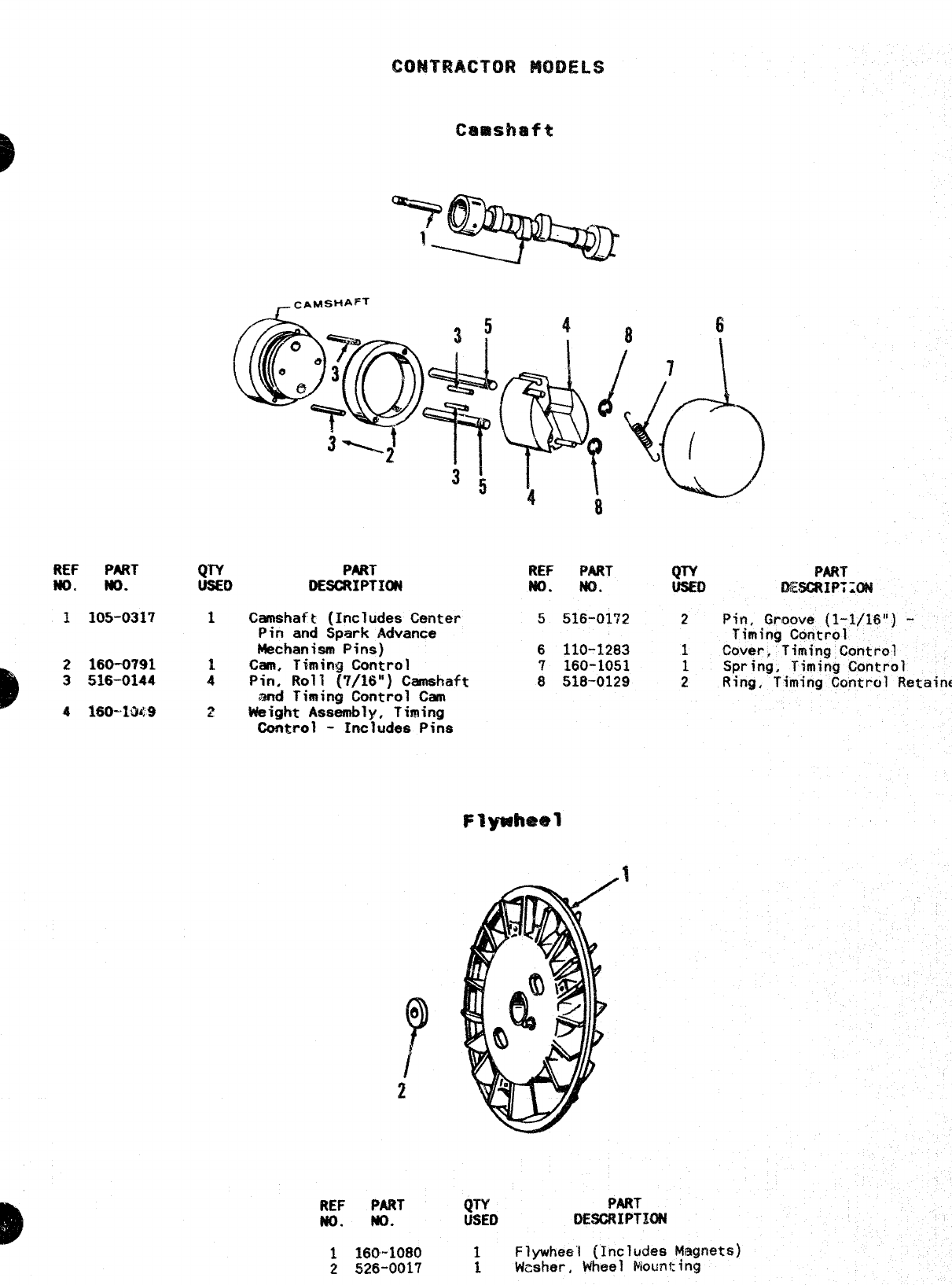
REF PART
m. m.
1105-0317
B2160-0791
3516-0144
4160-IW!9
P
QTY
USED
1
2
-cAMSHAFT
Camshaft (Includes Ceritei-
Pin and Spark Advance
Mechanism Pins)
Cam, liming Control
Pin, Roll (7/16”) Camshaft
and Timing Control Can
Weight Assembly, Timing
Comro i-Includes Pins
REF PART
No. No.
1160-1080
2526-0017
REF PART mPAN
NO. No. UsEo wfsmIP:z3N
5516-0172 2Pin, Groove (1-1/16”) -
Timing Control
6110-1283 1Cover, Timing Control
7160-1051 1Spring, Timing Control
8518-0129 2Ring, Timing Contro~ Retainer
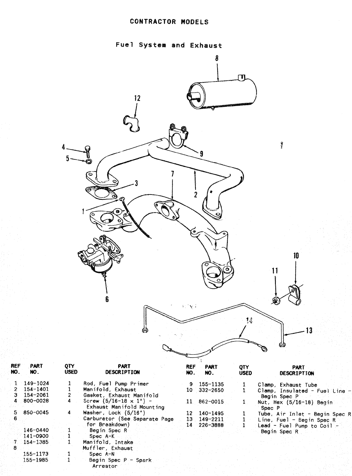
REF PART
w. NO.
1149-1924
2154--1401
3154-2061
4800”0028
5850-0045
G
146-0440
?.41-0900
?154-1385
8
Fuel Systea and Exhaust
8
:
2
4
4
i-
REF PART qTY PART
m. NC). USED OE~IPTIW
Rod, Fuel Pump Primer 9155-1135 1Clamp, Exhaust Tube
Manifold, Exhaust 10 332-2650 ~Clamp, Insulated -Fuel Line -
Gasket .Exhalj~t Manif~~d Begin Spec P
Screw (5/16-18 x1“) -11 882-0015 1Nut, Hex (5/16-18) Begin
Exhaust Manifold Mounting Spec P
Washer, Lock (5/16”) 12 140-1495 1Tube, Air Inlet -Begin Spec R
Carburetor (See Separate Page 13 149-2211 Line, Fuel
for Breakdown) -Begin Spec R
14 226-3888 :Lead -
Begin Spec RFuel Pump to Coil -
Begin Spec R
Spec A-K
Manifold, Intake
Muffler, Exhaust
Spec 8,-N
Begin $pec P-Spark
Arrestor
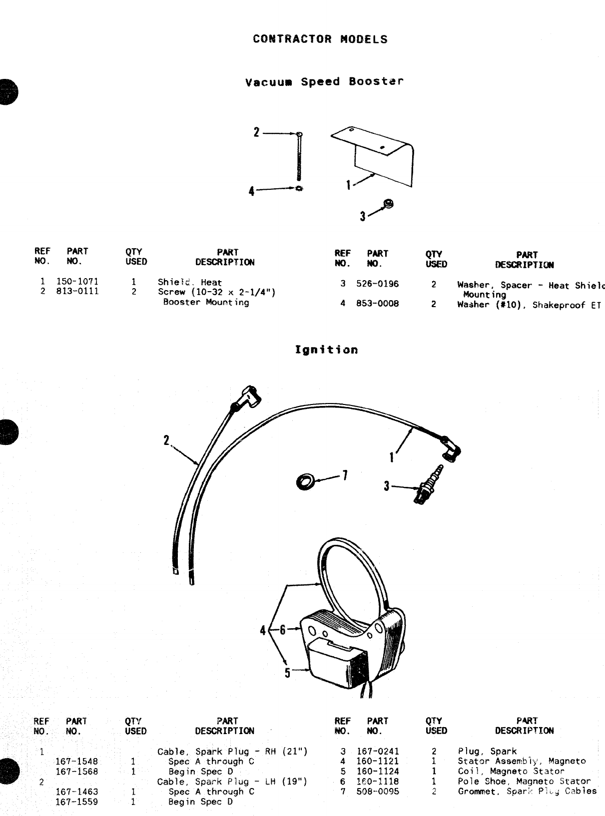
REF PART’ QTY PkRT
m. w. USED DESCRIPTION
1150-1071 1Shie$ti. Heat
2813-0111 2Screw (10-32 x2-1/4”)
Booster Mounting
FIEF PART
iw. w.
1
m‘167-1548
167-1568
2~67-~&j3
REF PART QTY PART
No. NQ. USEo OESCRIPTICW
3525-0196 2Washer, Spacer -Heat Shield
Mount ing
4853-0008 2Washer (#lO), Shakeproof ET
PART
DESCRIPTION
Cable, Spark Plug -RH (21”)
Spec Athrwgh C
Begin ‘5pec D
Cable, Spark Plug -i-t! (19”)
.Spec Athrough C
Begin Spec D
REF PART QTY PART
w. w. u$~D DESCRIPTICNt
3167-0241 2Plug, Spark
4160-1121 IStator Assemb”l}’, Magneto
5160-1124 Coil, Magneto Stator
6IEO-1118 :Pole Shoe, Magaeto Stator
7508--00% ~Grommet, $pari: P;:..Y Cables
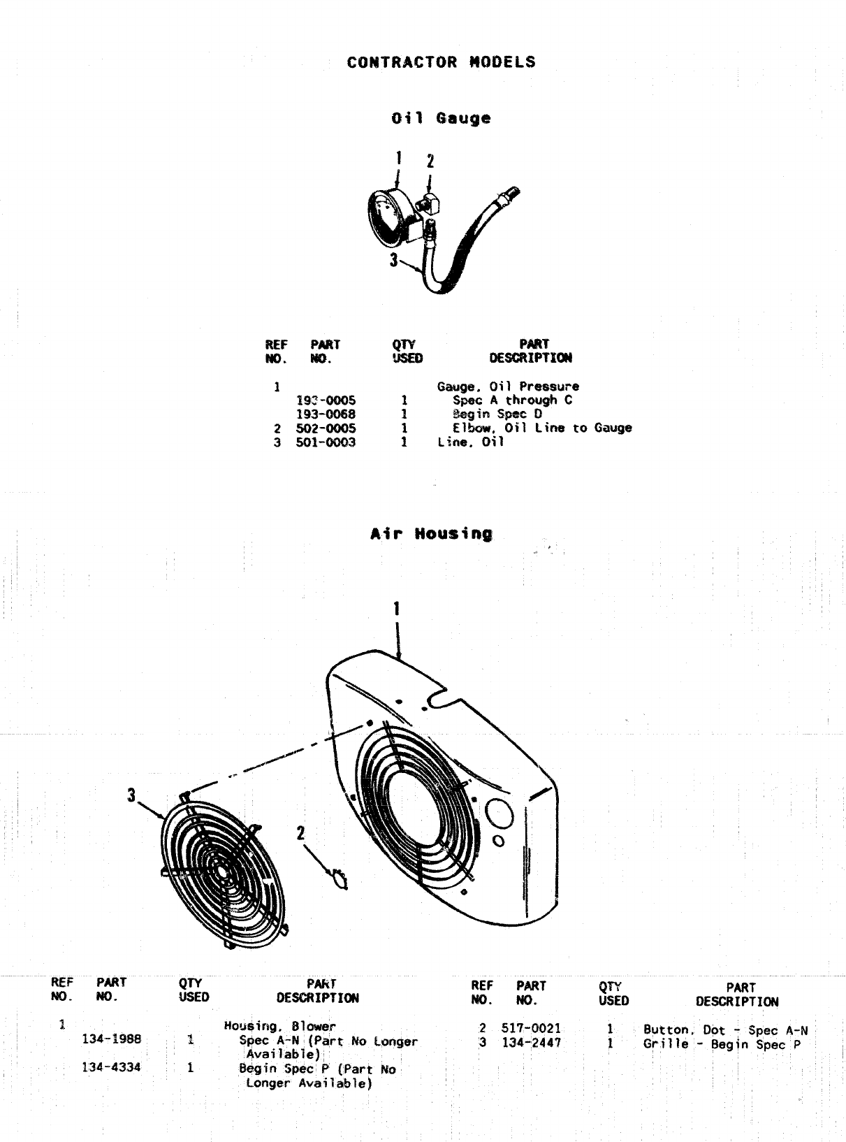
CONTRACTOR WIDELS
12
REF P&RT
No” W).
11$$2-ms
193=-0W8
25D2-0005
3 sol”oom El~. ~il Line to Gauge
;Line. Oil
,, 2
REF
No.
PART QW PART
USED OESGRIPTIOtd REF PART
w. No. QTY
14SED
1
?
PART
DESCRIPTION
No.
134”19S8
134-4334
i-lousing, Blower 2517-0021
3S@ec A-N: (Part No Longer 3134-2447
Available); ,
1ii~gin Speic P[Part No
Longer Available)
!luttor?, Dot -Spec A-N
Grille -~egfn Spec P

REF PART
NO. MD.
1 403–0934
2800-0029
3850-0045
4232-2207
5
201-1905
201-1903
:TO1-2503
PART
1Bracket, Lifting
4Screw (5/16-18 x1-1/8”) -
Lifting Bracket Mounting
4Washer, Lock (5/16”)
1Cover, Gewnrator Stator
R~to~, Gertevator
1
1
1
1
3.
Spec AThrouah c
50 Hertz S&.s
60 Hertz Sets
8egin Spec O
50 Hertz Sets
60 Hertz Sets
8egin Spec R
60 Hertz Sets
/
REF
Ho.
s
7
PART
NO.
220-1476
220-1816
338-0649
338-0648
QTY PART
USED DE8CRIPTK)N
Stator, Generator
1Spec AThrough C
1Begin Spec D
Harness, Wiring -SpeC r?
1Standard Contractor Mode
iCanadian Standards
Association Approved
Contractor Models
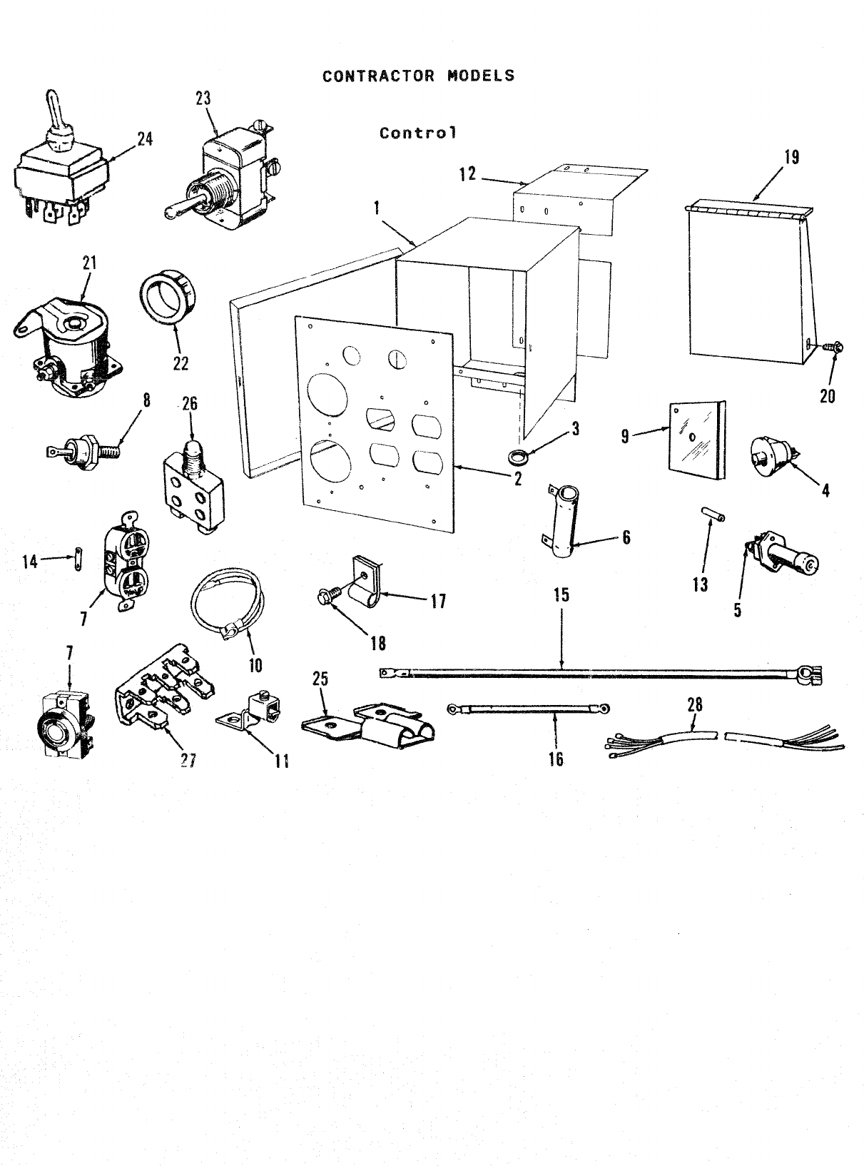
CONTRACTOR MODELS
23
7
1
16—
.
L
“-’)
=-----
.—
-1
1
7
0
/
:,/3
c!=’”
-------*
JT----
.
..
88
..
P
I
I
b
20
‘P
/0
‘@
13 5
17
L__--L-~
-’- ‘;[--””&”–==
1
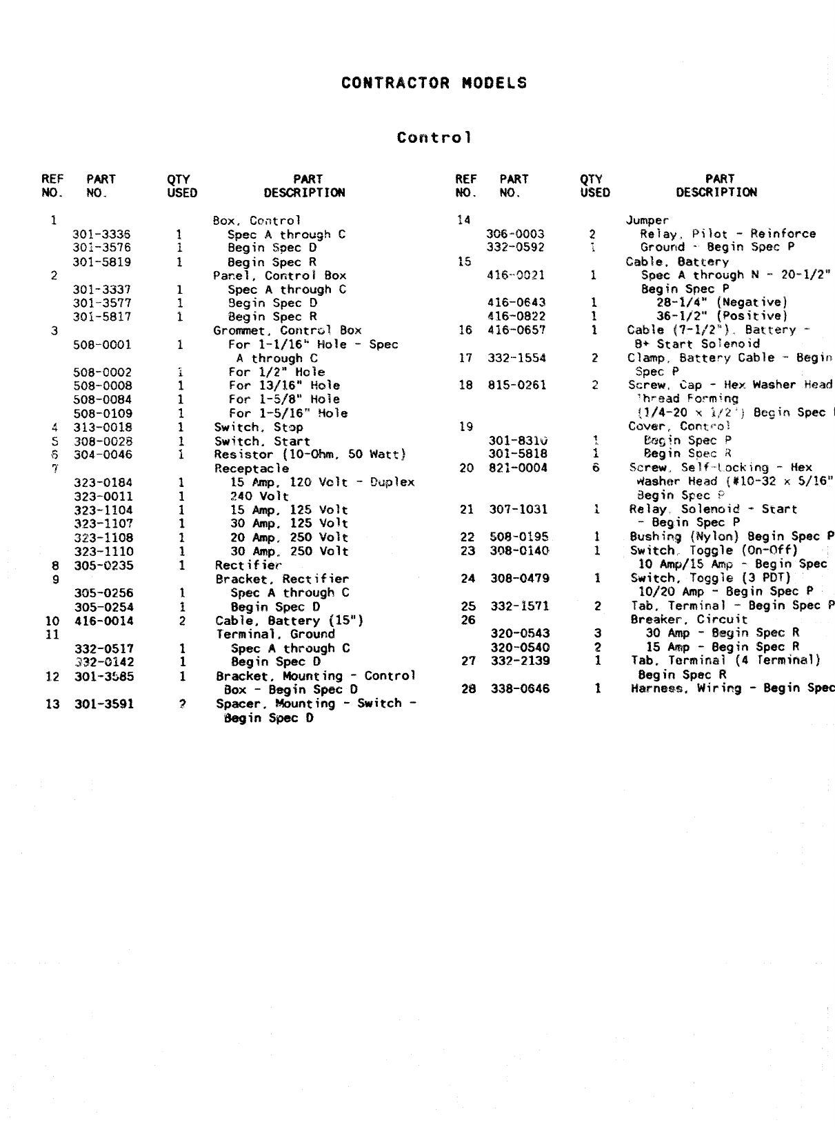
CONTRACTOR MOOELS
co~tr-ol
PART
NO.
301-3336
301-3576
301-5819
2301-3337
301-3577
301-5817
3508-0001
8
9
10
11
508-0002
508-0008
508-0084
508-0109
313-0018
308-0023
304-0046
323-0184
323-0011
323-1104
323-1107
323-1108
323-1110
305-0235
305-0256
305-0254
416-0014
332-0517
.232-0142
301-3585
301-3591
PART
DESCRIPTION
Box, Ccntrol
Spec Athrcu~h C
8egin Spec D
Begin Spec R
Panel, Controi Box
Spec Athrough G
9egin Spec D
Begin Spec R
Grommet, Ccmtral Box
For 1-1/16” Hole -Spec
Athrough C
For 1/2” Hole
REF PART
NO. NO.
14
3G6”O063
332-0592
15 416-’9821
416-0643
416-0822
16 416-065?
17 332-15S4
For 1~/16° Hole 18 815-0261
For 1-5/8” tiO]?
For 1-5/16” !40’
Switch. St9p
Switch. Start
Resistor (lO-Ohm,
Receptacle
15 Amp. 120 Va’
?40 volt
e
50 Watt)
t-Duplex
15 Amp, 125 volt
30 Amp. 125 Volt
20 Amp, 250 volt
30 Amp. 250 Volt
Rectifier
Eracket. Rectifier
Spec Athrough C
Begin Spec D
Cable, Battery (15”)
Terminal, Ground
Spec Athraugh C
Begin Spec D
Bracket, Mounting -Control
Box -Begin Spec 0
Spacer, Mounting -Switch -
Begin Spec O
19
301-831v
301-5818
20 821-0004
21 307-1031
22 sotl-o195
23 308-0140
24 308-0479
25 332-15”11
26 320-0543
320-0540
2T 332-2139
28 338-0646
PART
DESCRIPTION
Bushi;g (Nylon) ~egin Spec
P
Switch, Toggle (CWv@f]
10 Am@/15 Amp -8egin Spec
W&TC#e (3 PDT)
-Begin Spec P
Tab, Terminal -Begin fipec
P
Breaker, Circuit
3oAmp- 8egin Sp@@R
15 Amip -Begin $pec R
Tab. Termina? (4 Terminal)
Begin Spec R
HarnesB, Wiring -Begin Spec
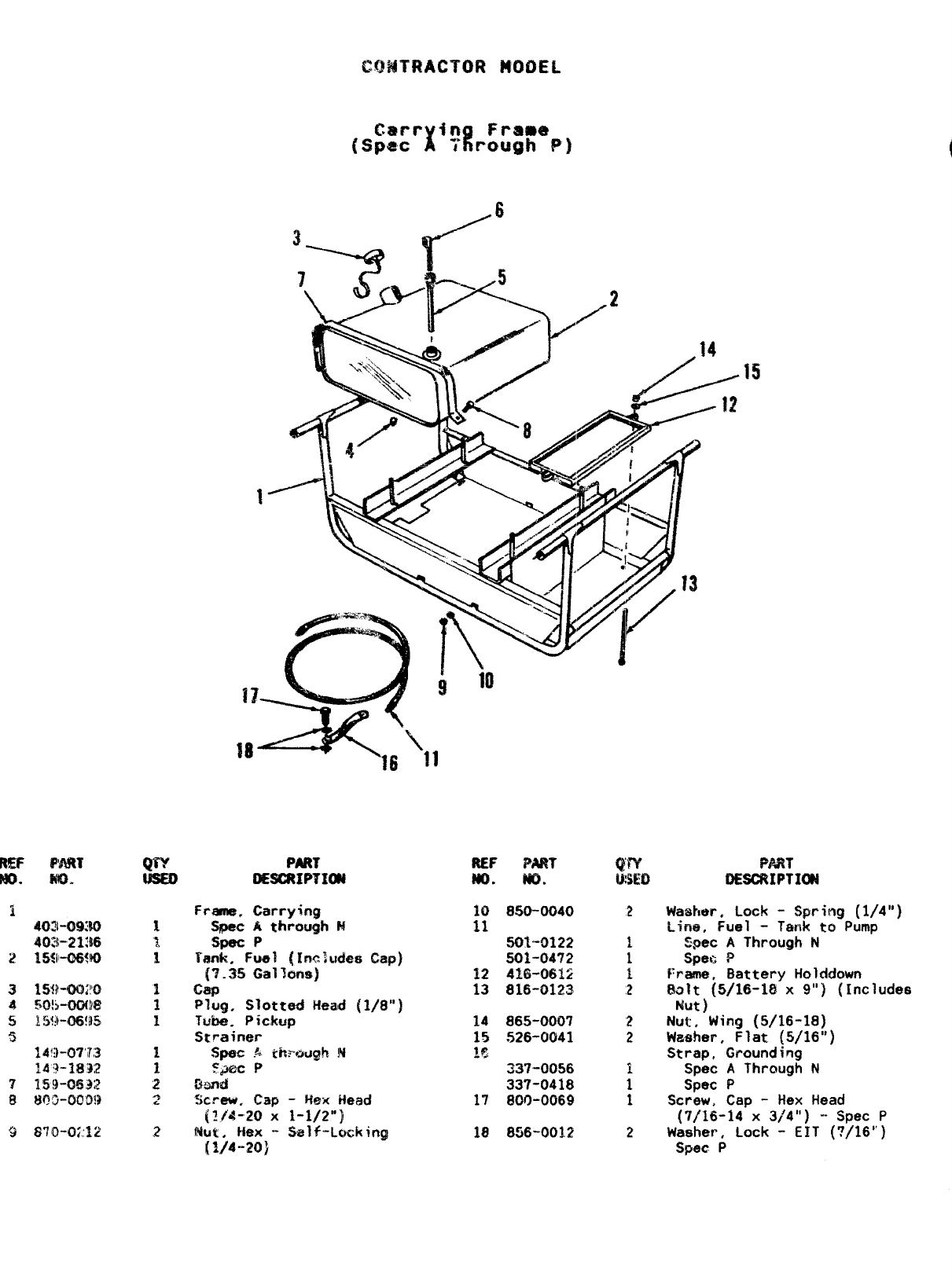
REF F’MT
m. m. @“Y
2
3-----42r’”
REF PART
m. w.
10 850-0040
11 501-0122
501-0472
12 41f3-06Ki
13 816-0123
14 865-0007
15 526-0041
Iz
337-0056
337-0418
17 800-0069
18 856-0012
2
2
2
%WT
OESGRIPTIOW
Washer, Lock -Spring (1/4”)
Line. Fuel -T&nk to Pump
Zpec AThrough N
Spe{> P
Frame, Battery Holcldown
$alt (5/16-18 x9“) (Includes
Nut )
Nut, Wing (5/16-18)
Washer, Flat (5/16”)
Strap, Grounding
Spec AThrough N
Spec P
Screw, Cap -Hex Head
(7116-14 x3/4”) -- Spec P
Washer, Lock -EIT (7/16”)
Spec P
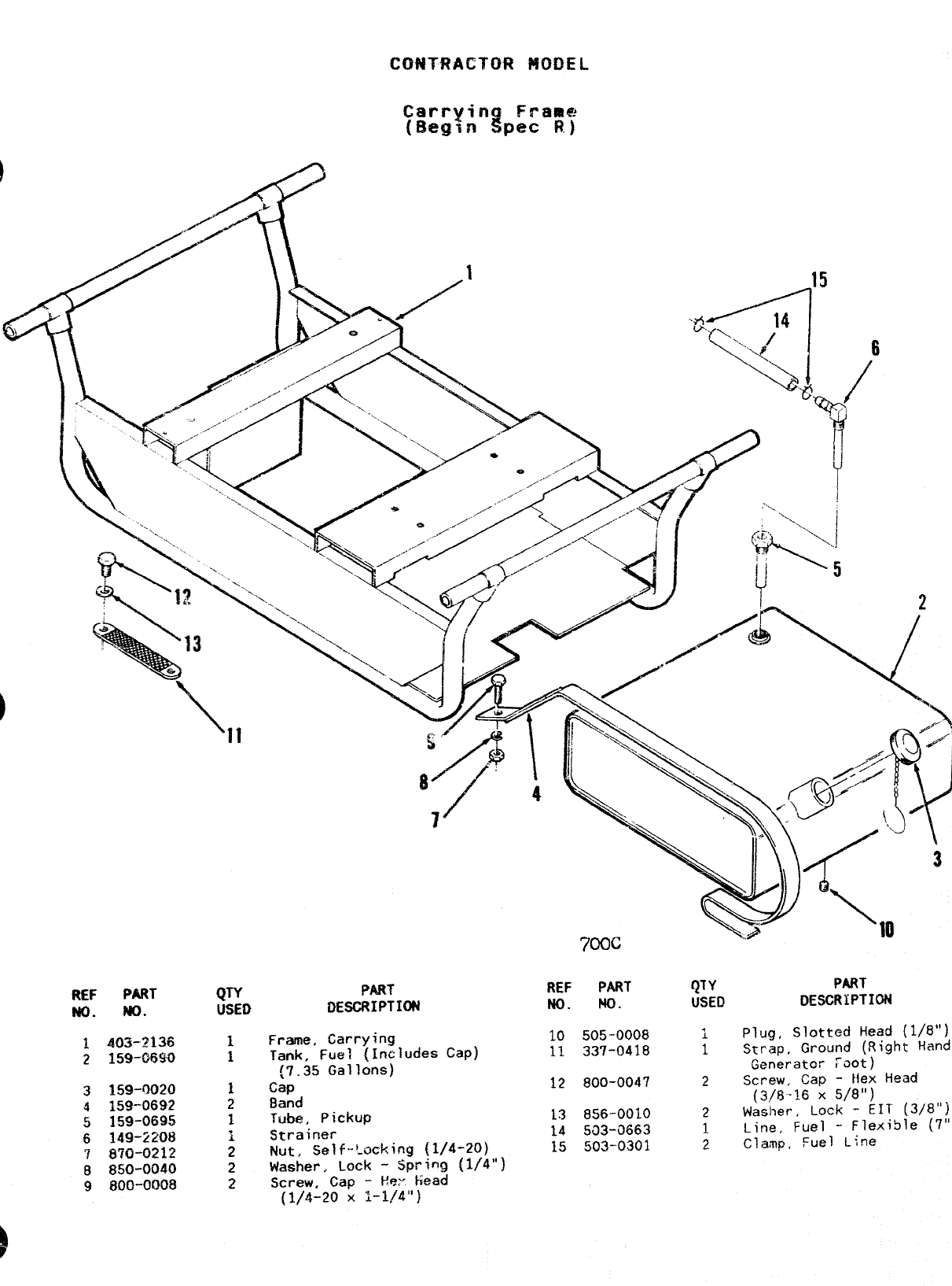
CONTRACTOR $400EL
/’”
/
/
REF PART
No. w.
L? 159-0020
4159-0692
5159-0695
$149-2208
7870-0212
8850-0040
9800-0008
QTY
USED
1
1
1
2
1
1.
2
2
2
PART
DESCRIPTION
Freme, Carry<ng
Tank, Fuel (includes Cap)
[7.35 Gallons)
Cap
Band
Tube, Pickup
Strainer
Nut, Self-’:acking (1/4-20)
Washer, Lock -Spring (1/4”)
Screw, Cap -E=’ kead
{1/4-20 x1-1/4”)
700C
REF PART
No. No.
10 505-0008
11 337-0418
12 800-0047
13 8!56-0010
14 593-3663
15 !303”0301
QTY
USED
PART
LXSCRIPTION
iPlug, Slotted Head (1/8”)
1Strap, Ground (Right Hand
Generator ~OOt)
2Screw, Cap -Hex Head
(3/8-16 X5/8”)
2Washer, Lock -EIT (3/8”)
1Line, Fuel -Flexible (7”)
2Clamp, Fuel Line
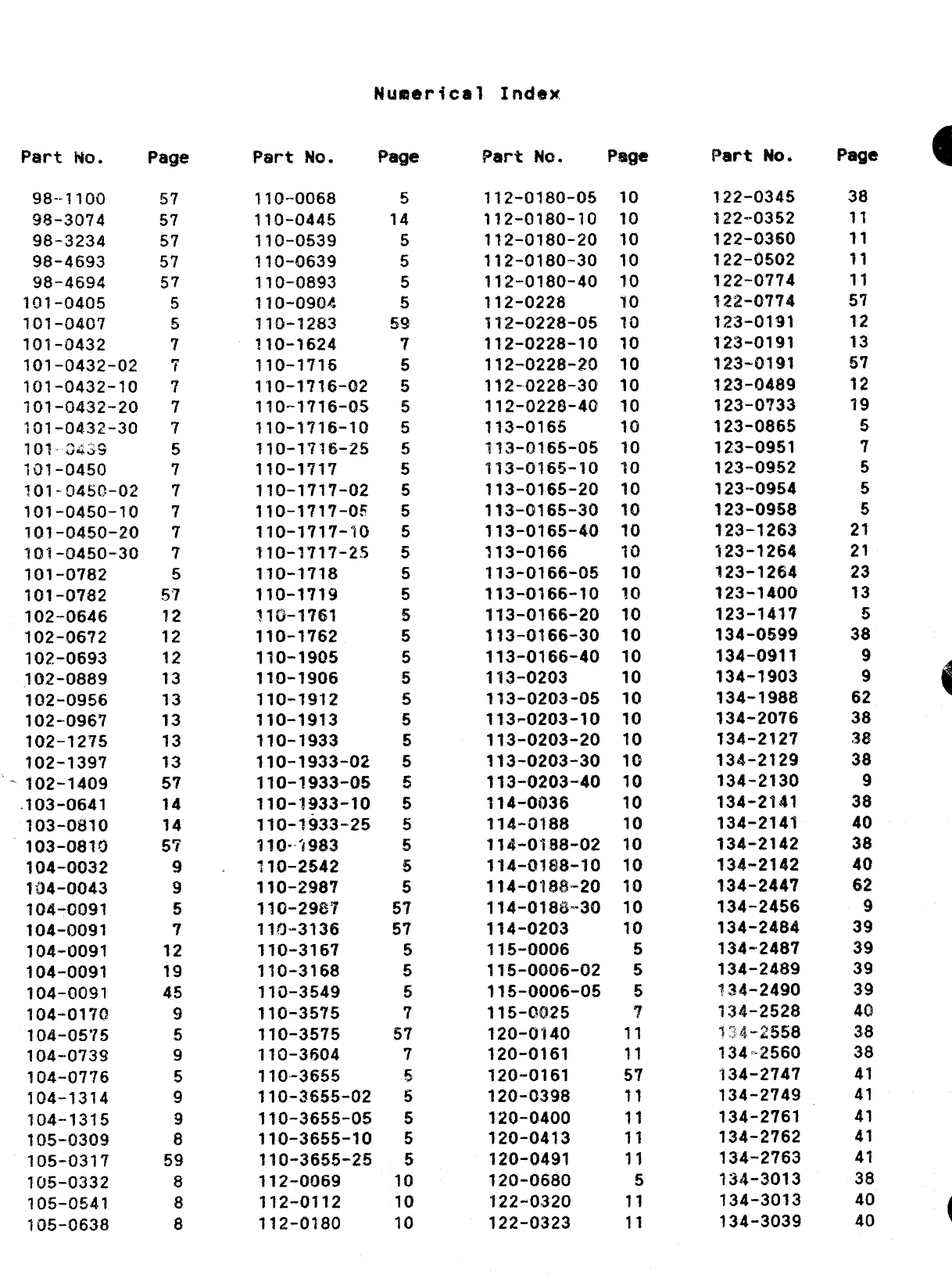
Pal-t w. Page
98--I1OCI
93-3074
98-3234
98-4693
98-4694
101-0405
701-040’7
101-0432
101-0432-02
101-0432-10
101-0432-20
101-04.32-30
101”8439
101-0450
101-0450-02
101-0450-10
101-0450-20
101-0450-30
101-0782
101-0782
102-0646
102-06?2
102-0693
102-0889
102-0956
102-0967
102-1275
102-1397
‘102-1409
.103-0641
103-0/310
103-0810
104-0032
104-0043
104-0091
104-0091
104-0091
104-0091
104-QO9I
104-0170
104-0575
104-0739
104-07?6
104-1314
104-1315
~~5-~309
105-0317
105-0332
105-0541
105-0638
57
57
57
57
57
5
5
7
‘i
7
7
‘1
5
7
7
7
7
?
5
57
12
12
12
13
13
13
13
13
57
14
14
5’?
9
9
5
7
12
19
45
9
5
9
5
9
9
8
59
8
8
8
Part W. Page
110-0068
110-0445
110-0539
110-0639
110-0893
11O-OWM
110-1283
110-1624
11O-I7T6
110-1?16-02
110-1716-05
110-1716-10
110-1716-25
110-1717
110-1717-02
110-1717-05
110-1717-10
310-171’?-25
110-1718
110-1719
fl&17r51
110-1762
110-1905
110-1906
110-1912
110-1913
110-1933
?10-1933-02
110-1933-05
110-1933-10
110-1933-25
?~().~g~~
110-2542
110-2987
110-2987
110-3136
110-3167
110-3168
110-3549
11(s-3575
110-3575
110-3604
110-3655
110-3655-02
110-3655-05
110-3655-10
110-3655-25
112-0069
112-0112
112-0180
5
14
5
5
5
5
59
7
5
5
5
5
5
5
5
5
5
5
5
5
5
5
5
!5
5
5
5
5
5
5
5
5
5
5
57
57
5
5
5
7
57
7
~
5
5
5
5
10
10
10
Part No. Page
l~z-fj~so-o~
112-0180-10
112-0180-20
112-0180-30
112-0180-40
112-0228
112-0228-05
112-0228-10
!12-0228-20
112-0228-30
112-0228-40
113-0165
113-0165-05
113-0165-10
113-0165-20
113-(9165-30
113-0165-40
113-0166
113-0166-0!5
113-0166-10
113-0166-20
113-0166-30
113-0166-40
113-0203
113-0203-05
113-0203-10
113-0203-20
113-0203-30
113-0203-40
114-0036
114-0188
114-0188-02
114-0188-10
114-0188-20
114-0188-30
114-0203
115-0006
115-0006-02
115-0006-05
115-cm25
120-0140
120-0161
120-0161
120-0398
120-0400
120-0413
120-0491
120-0680
122-0320
122-0323
10
10
10
10
10
10
70
10
10
10
10
10
10
10
10
10
10
10
10
10
10
10
10
10
10
10
10
10
10
10
10
10
10
10
10
10
5
5
5
7
11
11
57
11
11
11
11
5
11
11
Part No.
122-0345
1~2-0352
122-0360
122-0502
122-0774
122-0774
123-0191
123-0191
123-0191
123-04$9
123-0?33
123-0865
123-0951
123-0952
123-0954
123-0958
123-1263
123-1264
123-1264
123-1400
123-1417
134-0599
134-0911
134-1903
134-1988
134-2076
134-2127
134-2129
134-2130
134-2?41
134-2141
134-2142
134-2142
134-244’?
134-2456
134-2484
134-2487
134-2489
?34-2490
134-2528
1~4-~?j58
134=2560
334-2747
134-2749
134-2761
134-2762
134-2763
134-3013
134-3013
134-3039
Page m
38
11
11
11
11
57
12
13
57
12
19
5
7
5
5
5
21
21
23
13
!5
38
38
38
38
9
38
40
38
40
62
9
39
39
39
39
40
38
38
41
41
41
41
41
38
40
40
a
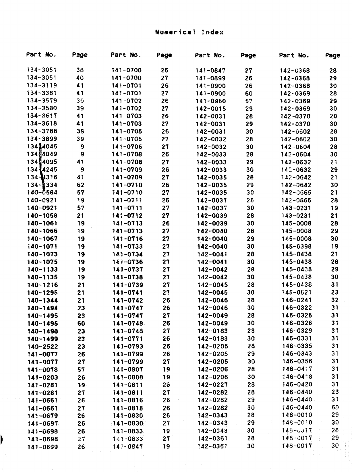
Part ?40.
134”3051
134-3051
734-3119
134-3381
?34-35’?9
134-3580
134-35??
134-3618
134-3788
134-389!3
4
134 4045
134 4049
1344095
134 4245
134 316
134- .334
14Q-B584
14i3-~g21
140-0921
140-1058
140-1061
140-1066
140-1067
140-1071
S4O-10?3
140-1075
140-1333
140-1135
140-7Z76
140-1295
140-1344
140-7494
140-1495
140-1495
140-1498
140-1499
14Q-2SZ2
141-0077
141-0077
141”0078
141-0203
141-0281
141-0281
141-UG61
141-0661
~~~-fj~~g
141-0697
lJtl-06~8
74~-~~9f3
141-0699
Page
38
40
41
41
39
39
g?
41
3!3
3!3
9
9
43
9
41
62
57
19
57
21
19
79
19
19
19
19
19
19
21
21
21
23
23
60
23
23
23
26
27
!5T
26
*9
2’?
26
27
26
26
26
e,*
;;
Part ~.
141”0700
141-0700
147--0701
141-0701
141-0702
141-0702
14T-Q703
141-0’/03
141-0705
141-0705
141-0’706
141-0?08
141-WI08
141-0709
141-0709
141-0710
141-0?10
141-0711
141-0711
141-0712
141-0713
141-0713
141-0716
141-0733
%41-W?34
~Q~-~736
141-0737
141-0738
141-0739
141-0741
141-0742
IA1-.O74?
141-0?47
141-0748
141-0748
141-0771
141-0793
141-0799
141-0799
141-0807
141-0808
141-0811
141-0011
141-0816
141-0818
141-0830
141-0830
141-0833
?41-0833
14’i-’o$47
Page
26
27
26
27
26
27
26
27
26
27
2?
26
27
26
27
26
27
26
27
27
?6
27
27
27
27
27
27
27
2?
27
26
26
27
26
27
26
26
26
27
19
19
26
27
26
26
26
2?
19
27
19
Pam MQ*
141-0847
141-0699
141-0900
141-0900
141-0950
?42-0015
142-0031
142-0031
142-0031
142-0032
142-0032
142-0033
T4,2-0033
142-0033
1412-0035
142-0035
142-0035
142-0037
142-0037
142-0039
142-0039
142-0040
142-o040
142-0040
142-0041
142-0041
142-0042
142-0042
142-0045
142-0046
T42-Q046
142-0046
142-0049
142-0049
142-0183
~~~-~~~~
142-0205
142-0205
142-0205
142-0206
142-0206
142-0227
142-0282
142-0282
142-0282
142-0343
142-0343
142-0G43
142-0361
142-0361
Paga
2?
26
26
60
57
29
28
29
30
28
30
28
29
30
28
29
~Q
28
30
28
30
28
29
30
28
30
28
30
28
30
28
.30
m
30
28
30
28
29
30
28
30
2$
~~
29
30
28
29
30
28
30
Part $&).
142-.0368
142-0368
~4~.>03~~
142-s0369
142-’0369
142-0369
142--0370
142-0370
T4~-@5~2
142’”0602
142-0604
142-0604
142-0632
14:.-0632
142-0642
142-0642
14;2-0665
14’2-0665
143-0231
143-0231
145-0008
145-0008
1415-0008
145-0398
145-0438
145-0438
145-0438
145-G43&!
145-0438
145-0U21
“146-0241
‘146-0322
146-0325
146-0326
146-0329
146-0331
146-0335
146-0343
146-0356
146-041’7
146-0418
146-0420
146-0440
146-0440
‘?46-0440
148-0010
14$-0010
1,10-UJ17
148””0017
148-001’7
Page
28
29
30
28
29
30
28
30
28
30
28
30
21
29
21
30
21
2%
19
21
28
29
30
19
21
28
29
30
31
23
32
31
31
31
31
31
31
31
31
31
31
31
23
31
60
29
30
28
29
30
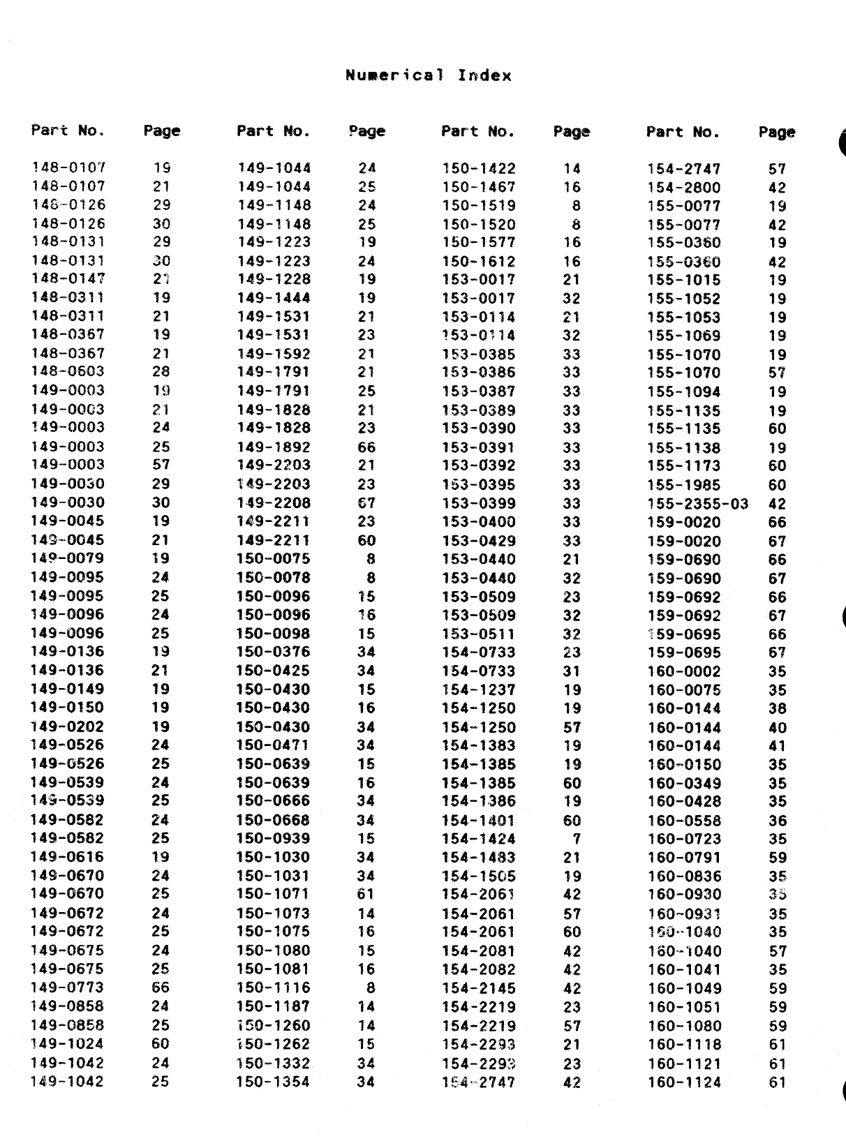
Part w.
148-010’/
148-0107
14s-0126
148-0126
148-0131
148-0131
148-0143
?48-0311
148-0311
148-036’?
148-0367
148-0603
149-0003
149-0003
749-~(303
149-0003
149-0003
149-0030
149-0030
149-0045
14%-0G45
l*Q-~07g
149-0095
149-0095
149-0096
149-0096
‘149-0136
149-0136
149-0149
149-0150
149-0Z02
?49-f)t5~b
149-0!526
149-0539
149-0539
149-0582
14$1-0!58Z
149-0616
lA!ii-0670
149-0670
149-0672
149-06’12
14!3-06’?5
149-0675
149-0?73
149-0858
149-0858
‘149-1024
149-1042
149-1042
Page
19
21
29
30
29
30
27
?9
21
19
21
*e
&w
7g
~,
24
25
57
29
30
19
21
19
24
25
24
25
19
21
19
19
19
24
25
24
25
24
25
19
24
25
24
25
24
25
66
24
25
60
24
25
Part m.
149-1044
149-1044
149-1148
149-1148
149-1223
149-1223
149-1228
149-1444
149-1531
149-1!531
749-1592
149-1791
149-1791
149-1828
149-1828
149-1892
149-2203
169-2203
14!+2208
14.9-2211
149-2211
150-0075
150-0078
150-0096
150-0096
150-0098
150-0376
150-0425
150-0430
150-0430
150-0430
150-04?1
150-0639
150-0639
150-0666
150-066$
150-0939
150-1030
150-1031
150-1071
150-1073
150-1075
150-1080
150-1081
150-1116
150-1187
150-1260
i50-T262
150-1332
150-1354
Page
24
~~
24
25
19
24
19
19
21
23
21
21
25
21
23
66
21
23
67
23
60
8
8
15
IS
15
34
34
15
16
34
34
15
16
34
34
15
34
34
61
14
16
15
16
8
14
14
15
34
34
Part ?&$.
?50-1422
150-1467
‘f50-1519
150-1520
150-15’77
150-1612
153-~()~7
153-0017
153-0314
?53-0714
?53-0385
153-0386
153-0387
153-Q389
153-0390
153-0391
153-0392
153-0395
153-0399
153-0400
153-0429
153-0440
153-0440
153-0509
153-0509
153-0511
154-0733
154-0733
154-1237
154-1250
154-1250
154-1383
154-138!5
154-1385
!54-1.386
154-14!21
154-1424
154-3483
354-15C$5
154-2061
154-2061
154-2061
154-2081
154-2082
154-2145
154-2219
154-2219
154-2293
154-2293
1~,4,,274~
Page
14
16
8
8
16
16
21
32
21
32
33
33
33
33
33
33
33
33
33
33
33
21
32
23
32
32
23
31
19
19
57
19
~g
60
19
en
Ww
7
21
19
42
57
60
42
42
42
23
57
21
23
42
Part NO.
154-2747
154-2800
155-0077
155-00’?7
155-03$50
~~!j_fj=J@=J
155-1015
155-1052
155-1053
155-1069
155-1070
155-1070
155-1094
?55-1135
155-1135
155-1?38
155-1173
155-1985
?55-2355-03
159-0020
159-0020
?59-0690
159-0690
159-0692
159-0692
%59-0695
159-0695
160-0002
160-0075
160-0144
160-0144
160-0144
~60..ol5o
160-0349
160-0428
160-0558
160-0723
160-07S?1
160-0836
760-0930
160-0931
~fi!Q..l@$()
160’””’to40
160-1041
160-1049
150-1051
160-1080
160-1118
160-1121
160-1124
57
42
19
42
19
42
19
19
19
1?3
19
57
19
19
60
19
60
60
42
66
67
66
67
66
67
66
a
6?
35
35
38
40
41
35
35
35
36
35
59
35
35
35
35
57
35
59
59
59
61
61
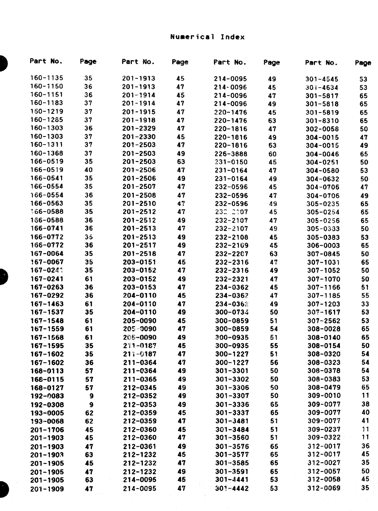
Part No.
160-1?35
160-1150
160-1151
160-1183
1$50-1219
160-1285
160-1303
160-1303
160-1311
16Q-1368
?55-0519
166-0519
166-0541
166-0554
166-0554
166-0563
166-0588
1$56-0588
156-0741
166-0772
1{56-0772
167-0064
167-0067
?67-02#t
167-0241
167-0263
167-0292
16’?-1463
167-153?
167-1548
167-1559
16?-1568
167-1595
167-1602
16’?-1602
168-0113
168-0115
168-0127
192-0083
192-0308
193-0005
393-0Q68
201-%706
201-1903
201-1903
2(11-19Q3
201-1905
201-1905
201-1905
201-1909
Page’
35
36
36
37
37’
37
~~
3’?
3?
37
35
40
35
35
36
35
35
36
36
35
36
35
-S
:5
61
36
36
61
35
61
61
61
35
35
3$
57
5?
57
9
9
62
62
45
45
47
63
45
47
63
47
P%rt M.
201-1913
201-1913
201-3914
201-1914
201-19?5
201-1918
201-2329
201-2330
201-2503
201-2503
201-2503
201-25L16
201-2506
2Y31-2507
201-2508
2~1-2510
20T-2512
201-2!512
201-2513
201-2513
201-2517
201-2518
203-0151
203-0152
203-0152
203-0153
204-0110
204-0110
204-0110
205-0090
2(N50090
25$4)090
.———
2“j&..9f~7
21”;.ljJf37
211-0364
211-0364
211-0365
212-0345
212-0352
212-0353
212-0359
212-0359
212-0360
212-0360
212-0361
212-1232
212-1232
212-1232
214-0095
214-0095
Page
45
47
45
47
47
47
47
45
47
49
63
47
49
4?
47
47
47
49
47
49
49
47
45
4?
49
47
45
47
49
45
47
69
45
47
47
49
49
49
49
49
45
47
45
47
49
45
47
49
45
47
Part No=
214-0095
214-0096
214-0096
214-0096
~20-~476
220-14’/6
220-1816
220-1816
220-1816
226-3888
231-0150
231-0164
231-0164
~3~-0596
232-0596
232-0596
23: 2:07
232-2107
232-210’?
232-2108
232-2169
232-2207
232-2316
232-2316
232-2321
234-0362
234-036!?
234-0302
300-0734
300-0859
300-0859
30(’)-0935
300-0935
300-1227
300-1227
301-3301
301-3302
301-3306
301-3307
301-3336
301-3337
301-3481
3al-3484
301-3560
301-3576
301-”3577
301”-3585
301-”3591
301-4441
$o~.,#442
P-
49
45
47
49
45
63
47
49
63
60
45
4?
49
45
4’7
’49
45
47
49
45
45
63
47
49
47
45
47
49
50
51
54
~1
55
51
56
50
50
50
50
65
65
51
51
51
65
65
65
65
53
53
Part w.
301-4545
30/-4634
301-5817
301-5818
301-5819
301-8310
302-0058
304-0015
304-0015
304-0046
304-0251
304-0580
304-0632
304-0706
304-0706
305-0235
305-0254
305-0256
305-0333
305-0383
306-0003
307-0845
307-1031
307-1052
307-1070
30?-1!66
307-1185
307-1203
307-1617
307-2562
308-0028
308-0140
308-0154
308-0320
308-0323
308-0378
308-0383
308-0479
309-0010
309-0077
309-0077
309-0077
309-0237
309-(?322
3?2-0017
312-001?
312-002?
312-0057
312-0058
312-0069
Page
53
53
65
65
65
65
50
47
49
65
50
53
50
4?
49
65
65
65
50
53
65
50
65
50
50
51
55
33
53
53
65
65
50
!54
54
54
53
65
11
38
40
41
11
11
36
45
35
50
45
35
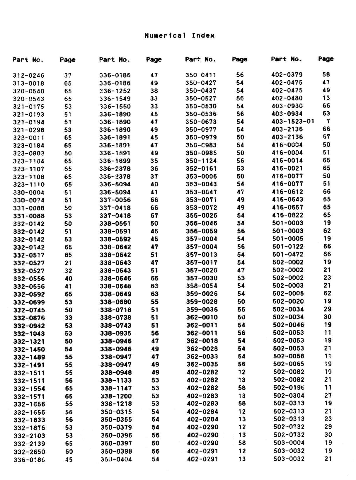
!&mmricz?$l Index
Part ?&3.
312-0246
313-0018
320-0540
320-0543
321-0175
321-0193
321-0194
321-0298
323-0011
323-0184
323-0803
323-1104
323-1107
323-1108
323-1110
330-0004
~~Q.Qg~g
331-0088
331-0088
33’2-0142
332-0142
332-0142
332-0142
332-053?
332-0527
332-0527
332-0556
332-0556
332-0592
332-0699
332-0745
332-0876
332-0942
332-1043
332-!321
‘332’”1450
332-1489
332-1491
332-1511
332-1511
332-1554
332-1571
332-1S56
332-1656
332-1833
~~~=l~?~
332-2103
332-2139
332-2650
336-0:8G
Pa$e
37
65
65
65
53
51
51
53
65
65
50
65
65
65
65
51
51
5!3
53
50
51
53
65
65
21
32
40
41
65
53
50
33
53
53
50
54
55
55
55
56
65
65
55
56
56
53
53
65
60
45
RN-t MO.
336-0186
336-0186
33G-1252
336-1549
336-1550
336-IWO
336-1890
336-1890
336-’1891
336””l!19’!
33G-lMI1
33~-1~99
336-2378
336-J2378
336-5094
336-5094
337-0056
337-0418
337-0418
338-0!561
338-0591
338-0592
338-0642
33$-0642
338-0643
338-0643
338-0646
338-0648
338-0649
338-0680
338-0718
~~~.~?~~
338-0743
338-0936
338-0946
338-0946
338-0947
338-0947
338-0948
338-1133
338-114?
~~8-1200
338-1218
350-0315
350-0355
350-0379
3/50-0396
350-0397
350-0398
35’1-0404
Pa@
47
49
38
33
33
45
47
49
45
47
49
35
36
3?
40
41
66
66
67
50
45
45
47
51
47
51
65
63
63
55
51
c1
W*
51
56
47
49
47
49
49
53
53
53
53
54
54
54
56
W
56
54
Part W.
350-0411
350-0427
350-043?
350-0527
350-0530
350-0536
350-0673
350-0977
350-0979
~50-C983
350-0985
350-1124
352-0161
353-0006
353-0043
353-0047
353-007”i
353-0072
355-0026
356-0046
356-0059
357-0004
357”0004
357-0013
357-0017
357-0020
357-0030
358-00$4
359”0026
359-0028
359-0036
362-0010
3~~-QQ?l
362-0011
362-00?8
362-0026
362-0033
362-0035
402-0282
402-0282
402-0282
402-C)283
402-0283
402-0284
402-0284
402-0290
402-0290
402-0290
402-0291
402-0291
Page
56
54
54
~~
54
56
54
54
50
54
50
56
53
50
54
47
49
49
54
54
56
54
56
54
54
47
53
54
54
50
56
50
54
56
54
54
54
56
12
33
58
13
58
12
13
12
13
58
12
13
Part No. Page
402-0379 58
402-0475 47
402-0475 49
402-0480 13
403-0930 66
403-0934 63
403-1523-01 7
403-2136
403-2136
416-0004
4?6-0004
416-0014
416-0021
416-0077
416-0077
416-0612
416-0643
416-0657
416-0822
501-0003
501-0003
501-0005
501-0122
501-0472
502-0002
502-0002
502-0002
502-0003
502-0005
‘502-0020
502-0034
502-0034
502-0046
!502-0053
502-0053
502-0053
502-0058
502-0065
502-0082
502-0082
502-0196
502-0304
502-0313
502-0313
502-0313
502-0?32
50~-0732
503-0004
503-0032
503-0032
66
67
50
51
65
65
50
51
66
65
65
65
19
62
19
66
66
19
21
23
21
62
19
29
30
19
11
19
21
f~
‘t9
~g
21
11
2?
19
21
23
29
30
19
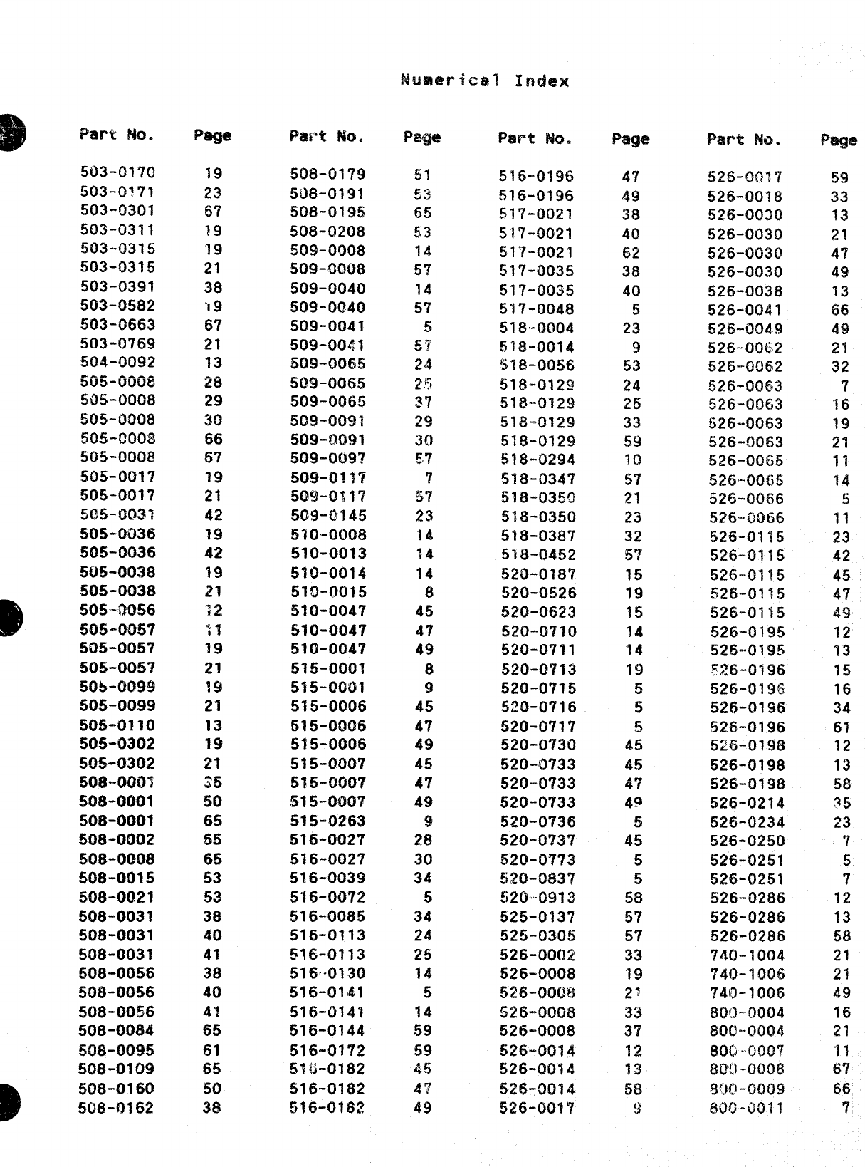
503-0170
503-0171
503-030!
503-0311
503-0315
503-0315
503-0393
503-0582
503-(?663
503-0769
504-0092
.*. A.-.
su3-lwu&7
505-0008
505-0008
505-0008
505-000/3
505-0017
50s-0017
5Q5-WM3
505-0036
505-0036
505-0038
505-0038
D
505-00!56
505-0057
505-0057
505-0057
505-0099
505-0099
505-0110
505-0302
505-0302
508-0001
508-0001
508-0001
508-0002
508-0008
508-0015
508-0021
508-0031
508-0031
508-0031
508-0056
M18-0056
508-0056
508-0084
508”0095
508-0109
)
508-0160
508-0162
I%g’e
19
23
67
?9
19
21
38
‘19
67
21
13
m
29
30
66
67
19
21
42
19
42
19
21
?2
17
19
21
19
21
13
19
21
35
50
65
$5
65
53
53
38
40
41
38
40
4!
65
61
65
50
38
F%M’t MO*
508-0179
508-0191
508-0195
50$-0208
509_0008
509-0008
509-0040
509-0040
509-0041
509-0041
509-0065
509-0065
509-0065
509-0091
509-0091
509-0097
509-013?
5Q9-o~~7
509-0!45
510-0008
510-0013
510-0014
51O-W)I5
510-0047
510-0047
510-0047
515-0001
5?5-0001
515-0006
515-0006
515-0006
515-0007
515”0007
!515-0007
515-0263
516-0027
516-0027
516-0039
516-0072
516-0085
516-0113
516-0113
516-0130
516-0141
516-0141
516-0144
516-0172
516-0182
!516-0182
516-018?
Page
51
tj~
65
53
14
57
14
57
5
!jY
24
25
37
yJ
~{)
~,7
7
57
23
14
14
14
8
45
47
49
8
9
45
47
49
45
4?
49
9
28
30
34
5
34
24
25
14
5
14
59
59
45
4?
49
Part No.
516-0196
S16-0196
5~7-oo21
5’!7-0021
51’?-0021
517-0035
517-0035
517-0048
51$-0004
518-0014
518-0056
518-0129
51%-0129
~18-o~2~
518-0129
518-0294
518-0347
518-0350
5’i8-0350
518-0387
518-0452
520-0187
520_0526
520-0623
520-0710
520-0711
520-0713
520-0715
5~o-0716
520-0717
520-0730
520-Q733
520-0733
520-0733
520-0736
52G-G737
520-0773
520-0837
520”0913
!525-0137
525-0305
526-0002
526-0008
526-0008
525.oo(-jfj
526-0008
526-0014
526-0014
526-0014
526-0017
Page
47
49
38
40
62
38
40
5
23
9
53
24
25
33
59
10
57
21
23
32
5?
15
19
45
14
14
19
5
5
5
45
45
47
49
5
45
5
5
58
57
57
33
19
z?
33
37
12
13
58
(J
526-0017
526-0018
526-0030
526-0030
526-0030
526-0030
526-0038
526-0041
526-0049
526-’0062
526-0062
526-0063
526-0063
526-0063
526-0063
526-0065
526-0065
526-0066
526-0066
526-0115
526-0115
526-0115
526-0115
526-0115
526-0195
526-0195
‘?.26-0196
526-0196
526-0196
.526-0196
526-0198
526-0198
526-0198
526-0214
526-0234
526-0250
526-0251
526-0251
526-0286
526-0286
526-0286
740-1004
740-1006
740-1006
80(3’”-0004
800-0004
800-0007
80:)-0008
8(](;1-0009
$~~-i-j~”l~
Page
59
33
13
21
47
49
13
66
49
21
32
7
16
19
21
11
f14
5
11
23
42
45
47
49
12
13
15
16
34
61
12
13
58
35
23
7
5
7
12
13
58
21
21
49
16
21
11
67
66
7
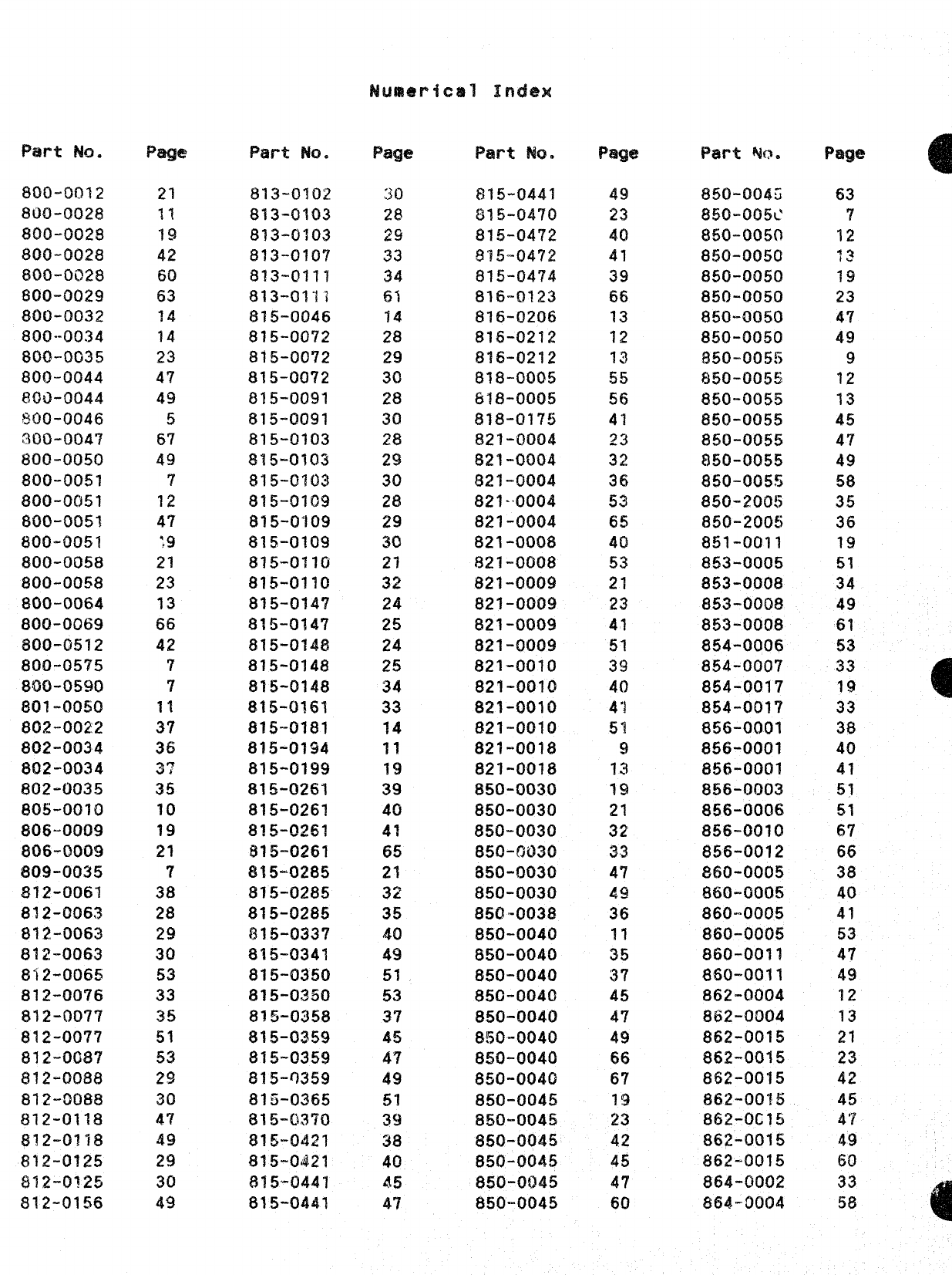
Part h.
$00-0012
800-0028
800-0028
$00-0028
aoo-oi?28
800”0029
800-0032
8m3--oo34
800-0035
800-0044
800-0044
800-0046
000-0047
800-0050
800-0051
800-0051
800-005?
800-0051
800-0058
800-0058
800-0064
800-0069
800-0512
800-0575
800-0590
80?”0050
802-0022
802-0034
802-0034
802-0035
80s-0070
805-0009
806-0009
809-0035
812-0061
812-0063
812-0063
812-0063
812-0065
812-0076
812-0077
812-007?
812-0087
812-0088
812-0088
812-0118
8!2-0?18
812-0125
812-0?25
812-0156
Pqe
21
11
19
42
60
63
14
14
23
47
49
5
67
49
7
12
47
:.9
21
23
~3
66
42
7
?
11
37
36
3?
35
10
19
21
7
38
28
29
30
53
33
35
51
53
29
30
47
49
29
30
49
m-t ml.
813-0102
813-0103
813-0?03
813-0107
813-0111
813-0111
815-0046
815-0072
815-0072
815-0072
815-0091
?315-0091
815-0103
815-0103
815-0103
815-0109
815-0’109
815-0109
815-0110
815-0110
815-014’?
815-0147
815-0148
815-0148
815-0148
815-0161
8?5-0181
815-0194
815-01!39
815-0261
815-0261
f315-Q~6~
$1!5-0261
815-0285
815-0285
815-0285
815-0337
815-0341
815-0350
8~5-o~50
815-03!58
815-0359
815-0359
%15-Q359
815-0365
815-C4370
815-0421
815-0421
8?5’-0441
815-0441
Page
30
28
~g
33
34
61
14
28
29
3C
28
30
28
29
30
28
29
30
21
32
24
25
24
25
34
33
14
11
19
39
40
4?
65
21
32
35
40
49
51
53
37
45
47
49
51
39
38
40
45
47
Par-t No.
815-0441
815-0470
815-04’72
9’?5-0472
815-0474
816””0123
816-0206
816-0212
816-0212
81$-0005
818-0005
818-0175
821-0004
821-0004
821-0004
821-0004
821-0004
821-000$
821-0008
821-000!?
821-0009
821-0009
821-0009
821-0010
821-0010
821-0010
821-0010
821-0018
821-0018
850-0030
850-0030
850-0030
850-(W30
850-0030
850-0030
8?50-0038
850-0040
850-0040
850-0040
850-0040
850-0040
850-0040
850-0040
850-0040
850-0045
850-0045
850-0045
850-0045
850-0045
850-0045
Page
49
23
40
41
39
66
13
12
13
55
56
47
~~
32
36
53
65
40
53
21
23
41
51
39
40
4“1
51
9
13
19
21
32
33
47
49
36
11
35
37
45
47
49
66
67
19
23
42
45
47
60
Pa-t $40.
850-0043
850-005C
850-0050
850-0050
850-0050
850-0050
850-0050
850-0050
850-0055
a50-oo55
850-0055
$50-0055
850-0055
850-0055
850-0055
850-200!5
850-2005
851-0011
853-0005
853-0008
853-0008
853-0008
854-0006
854-0007
854-0017
854-001’?
856-0001
856-0001
856-0001
856-0003
856-0006
856-0010
856-0012
860-0005
860-0005
860””0005
860-0005
860-0011
860-0011
862-0004
862-0004
862-0015
862-0015
862-0015
862-0015
862-0C15
862-0015
862-0015
864-0002
864-0004
63
7
12
~~
19
23
47
49
9
12
13
45
47
49
58
35
36
19
51
34
49
61
53
38
40
41
51
51
67
66
38
40
41
53
47
49
12
13
21
23
42
45
47
49
60
33
58
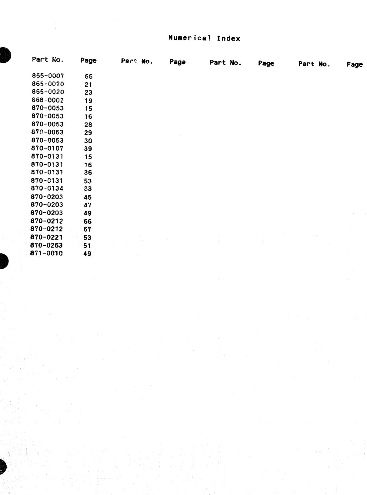
Numerical Index
oPat-t ?&2,
8155-oo~7
865-0020
865-0020
868-0002
8?0-00S3
870-0053
870”0053
87!?-0053
870-0053
870-0107
870-0131
870-0131
f370-o131
870-0131
870-0134
870-0203
870-0203
870-0203
870-0212
870-0212
870-0221
870-0263
D871-0010
66
21
23
19
15
16
9?a
x
30
39
15
16
36
53
33
45
47
49
66
67
53
51
49
Page Part No. Page Part M. Page
