Manual For The 94436 1/2 In. Hammer Drill
User Manual: Manual for the 94436 1/2 in. Hammer Drill 1/2 Hammer Drill
Open the PDF directly: View PDF ![]() .
.
Page Count: 12
Visit our website at: http://www.harborfreight.com
Email our technical support at: productsupport@harborfreight.com
Owner’s Manual & Safety Instructions
Save This Manual Keep this manual for the safety warnings and precautions, assembly,
operating, inspection, maintenance and cleaning procedures. Write the product’s serial number in the
back of the manual near the assembly diagram (or month and year of purchase if product has no number).
Keep this manual and the receipt in a safe and dry place for future reference. 17e
When unpacking, make sure that the product is intact
and undamaged. If any parts are missing or broken,
please call 1-888-866-5797 as soon as possible.
Copyright© 2006 by Harbor Freight Tools®. All rights reserved.
No portion of this manual or any artwork contained herein may be reproduced in
any shape or form without the express written consent of Harbor Freight Tools.
Diagrams within this manual may not be drawn proportionally. Due to continuing
improvements, actual product may differ slightly from the product described herein.
Tools required for assembly an d se rv ic e may n ot b e in cl uded.
Read this material before using this product.
Failure to do so can result in serious injury.
SAVE THIS MANUAL.
Page 2 For technical questions, please call 1-888-866-5797. Item 94436
SAVE THIS MANUAL
Keep this manual for the safety warnings
and precautions, assembly, operating,
inspection, maintenance and cleaning
procedures. Write the product’s serial number
in the back of the manual near the assembly
diagram (or month and year of purchase if
product has no number). Keep this manual
and the receipt in a safe and dry place for
future reference.
IMPORTANT SAFETY
INFORMATION
In this manual, on the labeling, and
all other information provided with
this product:
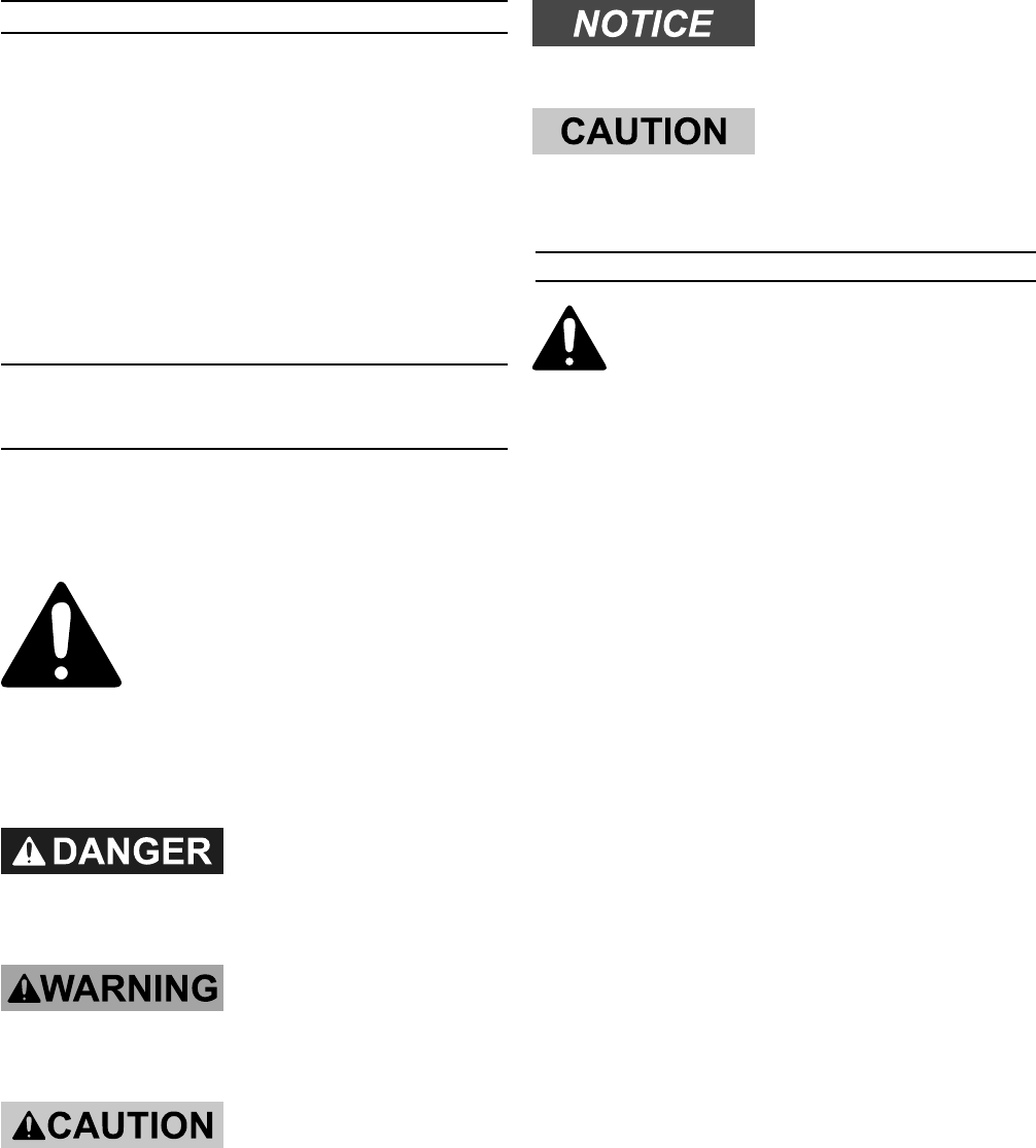
This is the safety alert
symbol. It is used to alert
you to potential personal
injury hazards. Obey all
safety messages that follow
this symbol to avoid possible
injury or death.
DANGER indicates a
hazardous situation
which, if not avoided, will result
in death or serious injury.
WARNING indicates a
hazardous situation
which, if not avoided, could
result in death or serious injury.
CAUTION, used with
the safety alert
symbol, indicates a hazardous
situation which, if not avoided,
could result in minor or moderate
injury.
NOTICE is used to
address practices not
related to personal injury.
CAUTION, without the
safety alert symbol, is
used to address practices not
related to personal injury.
General Power Tool Safety Warnings
WARNING Read all safety warnings
and instructions. Failure to follow the
warnings and instructions may result
in electric shock, fire and/or serious
injury.
Save all warnings and instructions
for future reference.
The term ″power tool″ in the warnings
refers to your mains-operated (corded)
power tool or battery-operated
(cordless) power tool.
1. Work area safety
a. Keep work area clean and well lit.
Cluttered or dark areas invite accidents.
b. Do not operate power tools in
explosive atmospheres, such as in
the presence of flammable liquids,
gases or dust. Power tools create
sparks which may ignite the dust or
fumes.
c. Keep children and bystanders
away while operating a power tool.
Distractions can cause you to lose
control.
2. Electrical safety
a. Power tool plugs must match the
outlet. Never modify the plug in
any way. Do not use any adapter
plugs with grounded power tools.
Unmodified plugs and matching outlets
will reduce risk of electric shock.
b. Avoid body contact with grounded
surfaces such as pipes, radiators,
Page 3For technical questions, please call 1-888-866-5797.Item 94436
ranges and refrigerators. There is an
increased risk of electric shock if your
body is grounded.
c. Do not expose power tools to rain
or wet conditions. Water entering
a power tool will increase the risk of
electric shock.
d. Do not abuse the cord. Never use
the cord for carrying, pulling or
unplugging the power tool. Keep
cord away from heat, oil, sharp
edges or moving parts. Damaged
or entangled cords increase the risk of
electric shock.
e. When operating a power tool
outdoors, use an extension cord
suitable for outdoor use. Use of a
cord suitable for outdoor use reduces
the risk of electric shock.
f. If operating a power tool in a damp
location is unavoidable, use a
Ground Fault Circuit Interrupter
(GFCI) protected supply. Use of a
GFCI reduces the risk of electric shock.
3. Personal safety
a. Stay alert, watch what you are
doing and use common sense when
operating a power tool. Do not use
a power tool while you are tired or
under the influence of drugs, alcohol
or medication. A moment of inattention
while operating power tools may result
in serious personal injury.
b. Use personal protective equipment.
Always wear eye protection. Safety
equipment such as dust mask, non-
skid safety shoes, hard hat, or hearing
protection used for appropriate
conditions will reduce personal injuries.
c. Prevent unintentional starting.
Ensure the switch is in the off-
position before connecting to power
source and/or battery pack, picking
up or carrying the tool. Carrying
power tools with your finger on the
switch or energizing power tools that
have the switch on invites accidents.
d. Remove any adjusting key or wrench
before turning the power tool on.
A wrench or a key left attached to a
rotating part of the power tool may result
in personal injury.
e. Do not overreach. Keep proper
footing and balance at all times. This
enables better control of the power tool
in unexpected situations.
f. Dress properly. Do not wear loose
clothing or jewelry. Keep your hair,
clothing and gloves away from
moving parts. Loose clothes, jewelry
or long hair can be caught in moving
parts.
g. If devices are provided for the
connection of dust extraction and
collection facilities, ensure these are
connected and properly used. Use of
these devices can reduce dust-related
hazards.
h. Only use safety equipment that has
been approved by an appropriate
standards agency. Unapproved
safety equipment may not provide
adequate protection. Eye protection
must be ANSI-approved and breathing
protection must be NIOSH-approved for
the specific hazards in the work area.
4. Power tool use and care
a. Do not force the power tool. Use
the correct power tool for your
application. The correct power tool will
do the job better and safer at the rate
for which it was designed.
b. Do not use the power tool if the
switch does not turn it on and off.
Any power tool that cannot be controlled

Page 4 For technical questions, please call 1-888-866-5797. Item 94436
with the switch is dangerous and must
be repaired.
c. Disconnect the plug from the power
source and/or the battery pack from
the power tool before making any
adjustments, changing accessories,
or storing power tools. Such
preventive safety measures reduce
the risk of starting the power tool
accidentally.
d. Store idle power tools out of the
reach of children and do not allow
persons unfamiliar with the power
tool or these instructions to operate
the power tool. Power tools are
dangerous in the hands of untrained
users.
e. Maintain power tools. Check for
misalignment or binding of moving
parts, breakage of parts and any
other condition that may affect the
power tool’s operation. If damaged,
have the power tool repaired before
use. Many accidents are caused by
poorly maintained power tools.
f. Keep cutting tools sharp and clean.
Properly maintained cutting tools with
sharp cutting edges are less likely to
bind and are easier to control.
g. Use the power tool, accessories
and tool bits etc. in accordance
with these instructions, taking into
account the working conditions and
the work to be performed. Use of
the power tool for operations different
from those intended could result in a
hazardous situation.
5. Service
a. Have your power tool serviced by a
qualified repair person using only
identical replacement parts. This will
ensure that the safety of the power tool
is maintained.
Drill and Impact Drill Safety
Warnings
1. Wear ear protectors with impact drills.
Exposure to noise can cause hearing
loss.
2. Use auxiliary handles supplied with
the tool. Loss of control can cause
personal injury.
3. Hold power tools by insulated
gripping surfaces when performing
an operation where the cutting tool
may contact hidden wiring or its own
cord. Contact with a ″live″ wire will make
exposed metal parts of the tool ″live″ and
shock the operator.
4. Let bit cool before touching, changing
or adjusting it. Bits heat up dramatically
while in use, and can burn you.
5. If the drill bit jams, release the trigger
immediately; drill torque can cause injury
or break bit.
6. Maintain labels and nameplates on
the tool. These carry important safety
information. If unreadable or missing,
contact Harbor Freight Tools for a
replacement.
7. Avoid unintentional starting. Prepare to
begin work before turning on the tool.
8. Do not lay the tool down until it has come
to a complete stop. Moving parts can
grab the surface and pull the tool out of
your control.
9. When using a handheld power tool,
maintain a firm grip on the tool with both
hands to resist starting torque.
10. Do not leave the tool unattended when
it is plugged into an electrical outlet.
Turn off the tool, and unplug it from its
electrical outlet before leaving.

Page 5For technical questions, please call 1-888-866-5797.Item 94436
11. This product is not a toy. Keep it out of
reach of children.
12. People with pacemakers should
consult their physician(s) before use.
Electromagnetic fields in close proximity
to heart pacemaker could cause
pacemaker interference or pacemaker
failure. In addition, people with
pacemakers should:
• Avoid operating alone.
• Do not use with power switch locked
on.
• Properly maintain and inspect to avoid
electrical shock.
• Any power cord must be properly
grounded. Ground Fault Circuit
Interrupter (GFCI) should also be
implemented – it prevents sustained
electrical shock.
13. The warnings, precautions, and
instructions discussed in this instruction
manual cannot cover all possible
conditions and situations that may occur.
It must be understood by the operator
that common sense and caution are
factors which cannot be built into this
product, but must be supplied by the
operator.
Vibration Safety
This tool vibrates during use. Repeated
or long-term exposure to vibration may
cause temporary or permanent physical
injury, particularly to the hands, arms
and shoulders. To reduce the risk of
vibration-related injury:
1. Anyone using vibrating tools regularly
or for an extended period should first
be examined by a doctor and then have
regular medical check-ups to ensure
medical problems are not being caused
or worsened from use. Pregnant
women or people who have impaired
blood circulation to the hand, past hand
injuries, nervous system disorders,
diabetes, or Raynaud’s Disease
should not use this tool. If you feel any
symptoms related to vibration (such as
tingling, numbness, and white or blue
fingers), seek medical advice as soon as
possible.
2. Do not smoke during use. Nicotine
reduces the blood supply to the hands
and fingers, increasing the risk of
vibration-related injury.
3. Wear suitable gloves to reduce the
vibration effects on the user.
4. Use tools with the lowest vibration when
there is a choice.
5. Include vibration-free periods each day
of work.
6. Grip tool as lightly as possible (while still
keeping safe control of it). Let the tool
do the work.
7. To reduce vibration, maintain the tool
as explained in this manual. If any
abnormal vibration occurs, stop use
immediately.
SAVE THESE
INSTRUCTIONS.
GROUNDING
TO PREVENT
ELECTRIC SHOCK
AND DEATH FROM INCORRECT
GROUNDING WIRE
CONNECTION:
Check with a qualified electrician
if you are in doubt as to whether
the outlet is properly grounded.
Do not modify the power cord
plug provided with the tool.
Never remove the grounding
Page 6 For technical questions, please call 1-888-866-5797. Item 94436
prong from the plug. Do not use
the tool if the power cord or plug
is damaged. If damaged, have it
repaired by a service facility
before use. If the plug will not fit
the outlet, have a proper outlet
installed by a qualified
electrician.
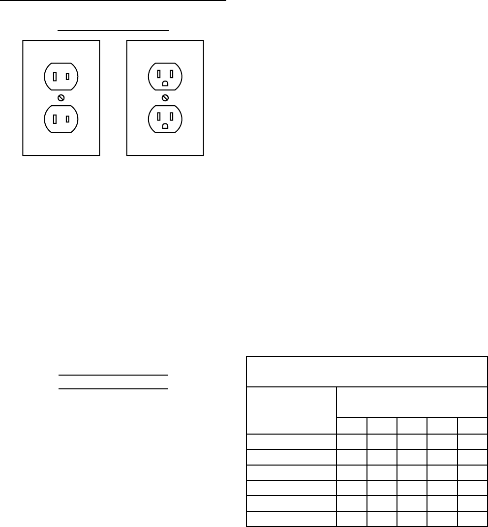
Double Insulated Tools: Tools with
Two Prong Plugs
Outlets for 2-Prong Plug
1. Tools marked “Double Insulated” do not
require grounding. They have a special
double insulation system which satisfies
OSHA requirements and complies with
the applicable standards of Underwriters
Laboratories, Inc., the Canadian
Standard Association, and the National
Electrical Code.
2. Double insulated tools may be used in
either of the 120 volt outlets shown in the
preceding illustration. (See Outlets for
2-Prong Plug.)
Extension Cords
1. Grounded tools require a three wire
extension cord. Double Insulated
tools can use either a two or three wire
extension cord.
2. As the distance from the supply outlet
increases, you must use a heavier gauge
extension cord. Using extension cords
with inadequately sized wire causes a
serious drop in voltage, resulting in loss
of power and possible tool damage.
(See Table A.)
3. The smaller the gauge number of the
wire, the greater the capacity of the cord.
For example, a 14 gauge cord can carry
a higher current than a 16 gauge cord.
(See Table A.)
4. When using more than one extension
cord to make up the total length, make
sure each cord contains at least the
minimum wire size required. (See Table
A.)
5. If you are using one extension cord for
more than one tool, add the nameplate
amperes and use the sum to determine
the required minimum cord size. (See
Table A.)
6. If you are using an extension cord
outdoors, make sure it is marked with the
suffix “W-A” (“W” in Canada) to indicate it
is acceptable for outdoor use.
7. Make sure the extension cord is properly
wired and in good electrical condition.
Always replace a damaged extension
cord or have it repaired by a qualified
electrician before using it.
8. Protect the extension cords from sharp
objects, excessive heat, and damp or
wet areas.
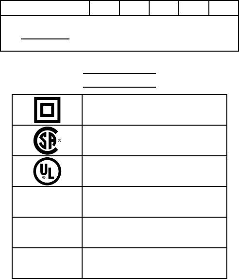
RECOMMENDED MINIMUM WIRE GAUGE
FOR EXTENSION CORDS* (120/240 VOLT)
NAMEPLATE
AMPERES
(at full load)
EXTENSION CORD
LENGTH
25’ 50’ 75’ 100’ 150’
0 – 2.0 18 18 18 18 16
2.1 – 3.4 18 18 18 16 14
3.5 – 5.0 18 18 16 14 12
5.1 – 7.0 18 16 14 12 12
7.1 – 12.0 18 14 12 10 -
12.1 – 16.0 14 12 10 - -
Page 7For technical questions, please call 1-888-866-5797.Item 94436
16.1 – 20.0 12 10 - - -
TABLE A
* Based on limiting the line volt-
age drop to ve volts at 150% of
the rated amperes.
Symbology
Double Insulated
Canadian Standards Association
Underwriters Laboratories, Inc.
VAC Volts Alternating Current
AAmperes
n0 xxxx/min. No Load Revolutions per Minute
(RPM)
Page 8 For technical questions, please call 1-888-866-5797. Item 94436
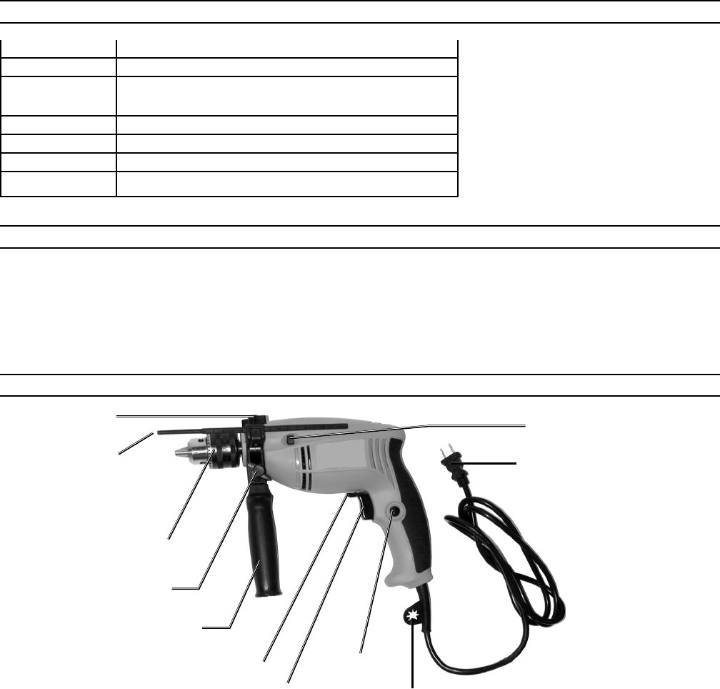
SPECIFICATIONS
Input 120 VAC, 60 Hz, 4.2 A
Motor 2,800 RPM; double insulated
Impact
Performance
44,800 BPM
Trigger forward / reverse lever; Trigger lock button
Chuck Keyed, 1/16″ to 1/2″ capacity
Side Handle Adjustable 360°; Adjustable depth rod
Power Cord Six feet long, 2-prong polarized plug
UNPACKING
When unpacking, check to make sure that the following parts are included: Impact Drill,
Side Handle, Chuck Key, and Depth Rod. Refer to the Assembly section, and the Assembly
Drawing and Parts List at the end of this manual. If any parts are missing or broken, please
call Harbor Freight Tools at the number on the cover of this manual as soon as possible.
CONTROLS AND INDICATORS
Depth Rod (30)
Chuck (3)
Side Handle (31)
Adjustment Knob
Side
Handle (31)
Forward / Reverse Lever
Trigger
Switch (23)
Lock-on
Button
Two-prong Power Cord (27)
Drill / Impact Button (15)
Chuck Key
Holder
Depth Rod Nut

Page 9For technical questions, please call 1-888-866-5797.Item 94436
ASSEMBLY INSTRUCTIONS
Side Handle Assembly
1. Slide the Side Handle (31) over the front housing until it rests behind the Chuck (3).
2. When required for exact depth drilling, insert the Depth Rod (30) into the Side Handle.
Adjust distance as necessary using the Depth Rod Nut.
3. Turn the Side Handle (31) to the desired position for operation, then securely tighten the
Handle Adjusting Knob.
Inserting Drill Bits
1. Locate the Chuck Key (32) and place the end into the Chuck (3). Turn counterclockwise
until the Chuck opening is sufficient to place the bit.
2. With the drill or impact bit in place, turn the Chuck Key clockwise until the Chuck tightens
securely over the bit.
3. Remove the Chuck Key (32) and place it in the Chuck Key holder on the Power Cord.
OPERATING INSTRUCTIONS
1. Press the Forward/Reverse Lever to correct position for the current job.
Right position: drill or fasten (clockwise). Left position: removing fasteners or freeing bits
(counterclockwise).
2. Press in (left side) the Drill / Impact Button (15) for normal drilling, or press in (opposite
side) hammer (impact) drilling. The impact drill setting (indicated by a hammer symbol) is
typically used for drilling cement or other masonry materials.
Caution: Do not attempt to switch from drilling mode to Impact mode with the
motor running. This can damage the internal gears.
3. For precision depth drilling, loosen (counterclockwise) the Depth Rod Nut and move the
Depth Rod (30) to the desired position. Retighten the Depth Rod Nut.
4. Verify that the bit is securely tightened in the Chuck.
5. Press (and hold) the Trigger Switch (23) to turn drill On.
6. Optionally, after pressing in the Trigger Switch in, you can press the Lock-on Button to
keep the drill running without keeping your finger on the Trigger Switch. Use this function
when drilling soft materials only.
Warning: Do not drill or hammer-drill hard, brittle materials such as steel or
concrete with the Trigger Switch Lock-on Button pressed in (ON). If the drill bit
catches on the material, the high torque of the drill will cause the tool body to twist
around without stopping. This violent action could cause injuries to your hands
and arms. It could also damage the Impact Drill.
7. When drilling is completed, release the Trigger Switch (23).
If the Lock-on Button was used, squeeze the Trigger Switch, then release it to turn the
Impact Drill off.

Page 10 For technical questions, please call 1-888-866-5797. Item 94436
TROUBLESHOOTING
Problem Possible Cause Probable Solution
Drill does not turn on
when Trigger Switch
squeezed.
1. Drill Power Cord not plugged in or
other power source problem.
2. Forward/Reverse Lever not properly
set.
1. Check power source and connection
at receptacle.
2. Push lever completely to left or right.
Drill loses power
or stops during
operation.
Motor Carbon Brushes dirty or need
replacement.
Have a qualied technician clean or
replace brushes.
Grinding noise
when Trigger Switch
squeezed.
1. Drill / Impact Button not pushed in all
the way.
2. Internal gears damaged.
1. Push Drill / Impact Button all the way
in.
2. Have a qualied technician repair or
replace gears.
INSPECTION, MAINTENANCE, AND CLEANING
WARNING! Make sure the Trigger Switch of the Impact Drill is in its “OFF” position
and that the tool is unplugged from its electrical outlet before performing any inspection,
maintenance, or cleaning procedures.
1. Before each use, inspect the general condition of the Impact Drill. Check for loose
screws, misalignment or binding of moving parts, cracked or broken parts, damaged
electrical wiring, and any other condition that may affect its safe operation. If abnormal
noise or vibration occurs, have the problem corrected before further use. Do not use
damaged equipment.
2. Periodically recheck all nuts, bolts, and screws for tightness.
3. Keep tool clean by wiping with a clean, damp cloth. Never use caustic agents to clean
plastic parts.
4. Store tool in a clean and dry location when not in use.
5. Periodically, using a rag and light oil, wipe drill bits and other steel parts of the drill to keep
them from rusting.
6. Periodically blow out the motor air vents of dust and debris using compressed air.
7. Over time, if the performance of the tool diminishes, or it stops working completely, it may
be necessary to replace the motor’s Carbon Brushes (18). The brushes are accessed by
removing Brush Cover (20). This procedure must be completed by a qualified technician.

Page 11For technical questions, please call 1-888-866-5797.Item 94436
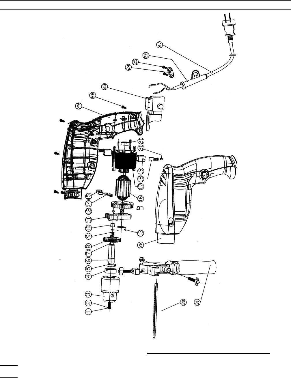
Part Description Q’ty
1 Chuck Screw (left-hand) M5x22 1
2 Washer, Spring, Ø5 1
3 Chuck 1
4 Bearing, 6001 1
5 Fender Ring, Ø12 1
6 Spindle, Output 1
7 Steel Ball, Ø3 1
8 Gear 1
9 Spring, Small 1
10 Steel Sleeve 1
11 Impact Block 1
12 Steel Ball, Ø5 1
13 Bearing, 608 1
14 Slip Slice 1
15 Drill Impact Button 1
16 Armature 1
Part Description Q’ty
17 Stator 1
18 Carbon Brush 2
19 Brush Holder 2
20 Brush Cover 2
21 Bearing, 626 1
22 Lower Motor Housing 1
23 Switch, Trigger 1
24 Cable Clip 1
25 Screw, Tap, 4x14 2
26 Guard, Power Cord 1
27 Power Cord 1
28 Screw, M4x18 10
29 Upper Motor Housing 1
30 Depth Rod 1
31 Side Handle 1
32 Chuck Key (not shown) 1
PARTS LIST
PLEASE READ THE FOLLOWING CAREFULLY
THE MANUFACTURER AND/OR DISTRIBUTOR HAS PROVIDED THE PARTS LIST AND ASSEMBLY DIAGRAM
IN THIS MANUAL AS A REFERENCE TOOL ONLY. NEITHER THE MANUFACTURER OR DISTRIBUTOR MAKES
ANY REPRESENTATION OR WARRANTY OF ANY KIND TO THE BUYER THAT HE OR SHE IS QUALIFIED TO
MAKE ANY REPAIRS TO THE PRODUCT, OR THAT HE OR SHE IS QUALIFIED TO REPLACE ANY PARTS OF THE
PRODUCT. IN FACT, THE MANUFACTURER AND/OR DISTRIBUTOR EXPRESSLY STATES THAT ALL REPAIRS
AND PARTS REPLACEMENTS SHOULD BE UNDERTAKEN BY CERTIFIED AND LICENSED TECHNICIANS,
AND NOT BY THE BUYER. THE BUYER ASSUMES ALL RISK AND LIABILITY ARISING OUT OF HIS OR HER
REPAIRS TO THE ORIGINAL PRODUCT OR REPLACEMENT PARTS THERETO, OR ARISING OUT OF HIS OR
HER INSTALLATION OF REPLACEMENT PARTS THERETO.
LIMITED 90 DAY WARRANTY
Harbor Freight Tools Co. makes every effort to assure that its products meet high quality and durability
standards, and warrants to the original purchaser that this product is free from defects in materials and
workmanship for the period of 90 days from the date of purchase. This warranty does not apply to damage due
directly or indirectly, to misuse, abuse, negligence or accidents, repairs or alterations outside our facilities, criminal
activity, improper installation, normal wear and tear, or to lack of maintenance. We shall in no event be liable
for death, injuries to persons or property, or for incidental, contingent, special or consequential damages arising
from the use of our product. Some states do not allow the exclusion or limitation of incidental or consequential
damages, so the above limitation of exclusion may not apply to you. THIS WARRANTY IS EXPRESSLY
IN LIEU OF ALL OTHER WARRANTIES, EXPRESS OR IMPLIED, INCLUDING THE WARRANTIES OF
MERCHANTABILITY AND FITNESS.
To take advantage of this warranty, the product or part must be returned to us with transportation charges
prepaid. Proof of purchase date and an explanation of the complaint must accompany the merchandise. If our
inspection verifies the defect, we will either repair or replace the product at our election or we may elect to refund
the purchase price if we cannot readily and quickly provide you with a replacement. We will return repaired
products at our expense, but if we determine there is no defect, or that the defect resulted from causes not within
the scope of our warranty, then you must bear the cost of returning the product.
This warranty gives you specific legal rights and you may also have other rights which vary from state to
state.
3491 Mission Oaks Blvd. • PO Box 6009 • Camarillo, CA 93011 • 1-888-866-5797
Page 12 For technical questions, please call 1-888-866-5797. Item 94436
ASSEMBLY DRAWING
Record Product’s Serial Number Here:
Note: If product has no serial number, record month and year of purchase instead.
Note: Some parts are listed and shown for illustration purposes only, and are not available
individually as replacement parts.
