Tmp_lVvvW3 962 0132 Onan OTPC (40 4000 Amp) Transfer Switch Operators Manual (02 2014)
User Manual: 962-0132 Onan OTPC (40-4000 Amp) Transfer Switch Operators manual (02-2014)
Open the PDF directly: View PDF ![]() .
.
Page Count: 132 [warning: Documents this large are best viewed by clicking the View PDF Link!]
- Table of Contents
- 1. Safety Precautions
- 2. Introduction
- 2.1 Operator Manual
- 2.2 How to Obtain Service
- 2.3 Model Identification
- 2.4 Transfer Switch Application
- 2.5 Specifications
- 2.6 Automatic Transfer Switch Typical Function
- 2.7 Utility‐to‐Generator Set Operation
- 2.8 Utility‐to‐Utility Operation
- 2.9 Generator‐to‐Generator Operation
- 2.10 Control Level 1 and Level 2
- 3. Description
- 3.1 Cabinet
- 3.2 Protective Relay
- 3.3 Transfer Switch Components
- 3.4 Electronic Control System
- 3.4.1 Time Delays
- 3.4.2 System Sensors
- 3.4.3 Transfer Modes
- 3.4.4 Front Panel Test - Sequence of Events
- 3.4.4.1 Transfer from Source 1 to Source 2 (Front Panel Test)
- 3.4.4.2 Transfer from Source 2 to Source 1 (Front Panel Test)
- 3.4.4.3 Test With or Without Load
- 3.4.4.4 Programmable Generator Exerciser
- 3.4.4.5 Real‐Time Clock
- 3.4.4.6 Sleep Mode
- 3.4.4.7 Remote Test Switch
- 3.4.4.8 Remote Test Input
- 3.4.4.9 Transfer Inhibit (PowerCommand Control)
- 3.4.4.10 Retransfer Inhibit (PowerCommand Control)
- 3.4.4.11 Transfer Times
- 3.5 Options
- 3.5.1 Battery Charger Options
- 3.5.2 PowerCommand Network Interface Option
- 3.5.3 Load Sequencing Option
- 3.5.4 Load Current and Power Sensor Option
- 3.5.5 Source 1 and Source 2 Connected Relays
- 3.5.6 Source 1 and Source 2 Available Relays
- 3.5.7 Test or Exercise Active Relay
- 3.5.8 Load Shed Relay
- 3.5.9 Fail to Transfer/Retransfer Relay
- 3.5.10 Fail to Synchronize Relay
- 3.5.11 Fail to Disconnect Relay
- 3.5.12 Elevator Pre-Transfer Delay Relay
- 3.5.13 Not-in-Auto Relay
- 3.6 Control Panel (PowerCommand Control)
- 4. Operation
- 5. Digital Display Menu System
- 5.1 Main Menus
- 5.2 Password and Setup Menus
- 5.3 Navigation
- 5.4 Main Menu Descriptions
- 5.4.1 First Main Menu
- 5.4.2 Second Main Menu
- 5.4.3 Third Main Menu
- 5.4.4 Setup Menu Navigation and Description
- 5.4.4.1 Setup Group 1
- 5.4.4.2 Setup Group 2
- 5.4.4.2.1 Time Delay Submenus (Prior to Software Version 1.12)
- 5.4.4.2.2 Time Delay Submenus (Software Version 1.12 and Greater)
- 5.4.4.2.3 Test Submenus
- 5.4.4.2.4 Exerciser Submenus (Software Versions Prior to 1.5.190)
- 5.4.4.2.5 Exerciser Submenus (Software Versions 1.5.190 and Greater)
- 5.4.4.2.6 Exerciser Exceptions Submenus (Software Versions 1.5.190 and Greater)
- 5.4.4.2.7 Exerciser Submenus (Software Versions 1.12-1.13.244)
- 5.4.4.2.8 Exerciser Exceptions Submenus (Software Versions 1.13.244-1.5.190)
- 5.4.4.3 Setup Group 3
- 5.4.4.4 Changing Setup Parameters (Software Prior to Version 1.12)
- 5.4.4.5 Changing Setup Parameters (Software Version 1.12 and Greater)
- 6. Wiring Considerations for Closed Transition Switches
- 7. Troubleshooting
- 7.1 Control Module LED Indicators and Switch
- 7.2 Fault Flash‐Out
- 7.3 Exerciser Enable/Disable Switch
- 7.4 Troubleshooting Transfer Switch With the Digital Display
- 7.5 Fault Event Definitions
- 7.6 15/12‐Amp Battery Charger Troubleshooting and Faults
- 7.7 Code 101 – Source 1 Connected (Event)
- 7.8 Code 102 – Source 1 Available (Event)
- 7.9 Code 103 – Source 2 Connected (Event)
- 7.10 Code 104 – Source 2 Available (Event)
- 7.11 Code 105 – Emergency Start A (Event)
- 7.12 Code 106 – Test Start A (Event)
- 7.13 Code 107 – Emergency Start B (Event)
- 7.14 Code 108 – Test Start B (Event)
- 7.15 Code 109 – Time Delay Engine Start A (Event)
- 7.16 Code 111 – Time Delay Engine Start B (Event)
- 7.17 Code 112 – Time Delay Transfer (Event)
- 7.18 Code 113 – Time Delay Retransfer (Event)
- 7.19 Code 114 – Engine Cool-Down A (Event)
- 7.20 Code 115 – Program Transition (Event)
- 7.21 Code 116 – Transfer Pending (Event)
- 7.22 Code 117 – Test in Progress (Event)
- 7.23 Code 118 – Exercise Active (Event)
- 7.24 Code 119 – Sync Check (Event)
- 7.25 Code 121 – S1 Under Voltage (Event)
- 7.26 Code 122 – S1 Over Voltage (Event)
- 7.27 Code 123 – S1 Frequency Fail (Event)
- 7.28 Code 124 – S1 Loss Phase (Event)
- 7.29 Code 125 – S1 Imbalance Fail (Event)
- 7.30 Code 126 – S2 Under Voltage (Event)
- 7.31 Code 127 – S2 Over Voltage (Event)
- 7.32 Code 128 – S2 Frequency Fail (Event)
- 7.33 Code 129 – S2 Loss Phase (Event)
- 7.34 Code 131 – S2 Imbalance Fail (Event)
- 7.35 Code 132 – Phase Rotation Failure (Event)
- 7.36 Code 133 – Motor Disconnect (Event)
- 7.37 Code 134 – Load Shed (Event)
- 7.38 Code 135 – Transfer Inhibit (Event)
- 7.39 Code 136 – Retransfer Inhibit (Event)
- 7.40 Code 137 – Bypassed to S1 (Event)
- 7.41 Code 138 – Bypassed to S2 (Event)
- 7.42 Code 139 – Not in Auto (Fault)
- 7.43 Code 141 – Service Tool (Event)
- 7.44 Code 143 – Sync Enable (Event)
- 7.45 Code 144 – Speed Adjust (Event)
- 7.46 Code 145 – Fail to Sync (Event)
- 7.47 Code 146 – Sequencer Output 1-8 (Event)
- 7.48 Code 155 – Network Wink (Event)
- 7.49 Code 156 – Common Alarm A (Event)
- 7.50 Code 157 – Common Alarm B (Event)
- 7.51 Code 158 – Loss of Power (Event)
- 7.52 Code 159 – TD Stop B (Event)
- 7.53 Code 161 – High Neutral Amps (Event)
- 7.54 Code 162 –Preferred Source 1 (Event)
- 7.55 Code 163 –Preferred Source 2 (Event)
- 7.56 Code 164 – Source 1 Stopped (Event)
- 7.57 Code 165 – Source 2 Stopped (Event)
- 7.58 Code 167 – Control Lockout (Event)
- 7.59 Code 168 – Panel Lock (Event)
- 7.60 Code 169 – Max Parallel Time Exceeded (Event)
- 7.61 Code 441 – Low Controller Battery (Event)
- 7.62 Code 597 –Battery Charger Malfunction (Fault)
- 7.63 Code 1113 – ATS Fail to Close: Transfer (Fault)
- 7.64 Code 1114 – ATS Fail to Close: RE-Transfer (Fault)
- 7.65 Code 1121 – ATS Fail to Disconnect (Fault)
- 7.66 Code 1452 – Fail to Close S2 (Fault)
- 7.67 Code 1453 – Failed to Open S2 (Fault)
- 7.68 Code 1468 – Network Communications Error (Fault)
- 7.69 Code 2396 – Failed to Close S1 (Fault)
- 7.70 Code 2397 – Fail to Open S1 (Fault)

OperatorOperator ManualManual
Transfer Switch
40-4000 Amps
OTPCA (Spec A)
OTPCB (Spec A)
OTPCC (Spec A)
OTPCD (Spec A)
OTPCE (Spec A-C)
OTPCF (Spec A-B)
OTPCG (Spec A-B)
OTPCH (Spec A-B)
OTPCJ (Spec A)
English
Original Instructions 02-2014 962-0132 (Issue 8)

Table of Contents
1. SAFETY PRECAUTIONS .............................................................................................................. 1
1.1 Electrical Shock and Arc Flash Can Cause Severe Personal Injury or Death ....................... 1
1.2 General Precautions ............................................................................................................... 1
2. INTRODUCTION............................................................................................................................ 3
2.1 Operator Manual ..................................................................................................................... 3
2.2 How to Obtain Service ............................................................................................................ 3
2.3 Model Identification ................................................................................................................. 4
2.4 Transfer Switch Application .................................................................................................... 4
2.5 Specifications.......................................................................................................................... 4
2.5.1 Model OTPC ................................................................................................................ 4
2.6 Automatic Transfer Switch Typical Function........................................................................... 5
2.6.1 Open Transition with Sync Check................................................................................ 6
2.6.2 Programmed Transition................................................................................................ 6
2.6.3 Closed Transition ......................................................................................................... 6
2.7 Utility-to-Generator Set Operation .......................................................................................... 6
2.8 Utility-to-Utility Operation ........................................................................................................ 6
2.9 Generator-to-Generator Operation ......................................................................................... 6
2.9.1 Prime Power (Plant-to-Plant) Operation ...................................................................... 7
2.9.2 Dual Stand-By Operation ............................................................................................. 9
2.10 Control Level 1 and Level 2................................................................................................ 10
3. DESCRIPTION............................................................................................................................. 11
3.1 Cabinet.................................................................................................................................. 11
3.2 Protective Relay.................................................................................................................... 11
3.3 Transfer Switch Components................................................................................................ 14
3.3.1 Contact Assemblies ................................................................................................... 14
3.3.2 Linear Actuator........................................................................................................... 14
3.3.3 Motor Disconnect Switch (150-1000 Amp Switches)................................................. 15
3.3.4 Motor Disconnect Switch (1200-4000 Amp Switches)............................................... 15
3.3.5 Auxiliary Contacts ...................................................................................................... 15
3.4 Electronic Control System..................................................................................................... 15
3.4.1 Time Delays ............................................................................................................... 16
3.4.2 System Sensors......................................................................................................... 18
3.4.3 Transfer Modes.......................................................................................................... 24
3.4.4 Front Panel Test - Sequence of Events..................................................................... 29
3.5 Options.................................................................................................................................. 39
3.5.1 Battery Charger Options ............................................................................................ 39
3.5.2 PowerCommand Network Interface Option ............................................................... 47
3.5.3 Load Sequencing Option ........................................................................................... 51
3.5.4 Load Current and Power Sensor Option.................................................................... 51
3.5.5 Source 1 and Source 2 Connected Relays................................................................ 52
962-0132 (Issue 8) i

Table of Contents 02-2014
3.5.6 Source 1 and Source 2 Available Relays .................................................................. 52
3.5.7 Test or Exercise Active Relay.................................................................................... 52
3.5.8 Load Shed Relay ....................................................................................................... 52
3.5.9 Fail to Transfer/Retransfer Relay............................................................................... 52
3.5.10 Fail to Synchronize Relay ........................................................................................ 52
3.5.11 Fail to Disconnect Relay .......................................................................................... 52
3.5.12 Elevator Pre-Transfer Delay Relay .......................................................................... 53
3.5.13 Not-in-Auto Relay..................................................................................................... 53
3.6 Control Panel (PowerCommand Control) ............................................................................. 53
3.6.1 Bar Graph Meter Panel .............................................................................................. 53
3.6.2 Switch Panel .............................................................................................................. 54
3.6.3 Digital Display ............................................................................................................ 55
3.6.4 Time Delay Glossary.................................................................................................. 56
4. OPERATION ................................................................................................................................ 59
4.1 Manual Operation ................................................................................................................. 59
4.1.1 Manual Operation - 40 to 1000 Amp Switches .......................................................... 59
4.1.2 Manual Operation - 1200 to 4000 Amp Switches ...................................................... 59
4.2 Automatic Operation ............................................................................................................. 61
4.2.1 Motor Disconnect Switch ........................................................................................... 61
4.3 System Testing ..................................................................................................................... 62
4.3.1 Generator Set Manual Start Test............................................................................... 62
4.3.2 With-Load Standby System Test ............................................................................... 62
4.4 Generator Set Exercise......................................................................................................... 62
4.5 Planned Maintenance ........................................................................................................... 63
5. DIGITAL DISPLAY MENU SYSTEM............................................................................................ 65
5.1 Main Menus .......................................................................................................................... 65
5.2 Password and Setup Menus................................................................................................. 65
5.3 Navigation ............................................................................................................................. 65
5.4 Main Menu Descriptions ....................................................................................................... 66
5.4.1 First Main Menu ......................................................................................................... 66
5.4.2 Second Main Menu .................................................................................................... 68
5.4.3 Third Main Menu ........................................................................................................ 69
5.4.4 Setup Menu Navigation and Description ................................................................... 72
6. WIRING CONSIDERATIONS FOR CLOSED TRANSITION SWITCHES ................................... 85
6.1 Application Considerations for Closed Transition Transfer Switches ................................... 85
6.2 Re-transfer and transfer inhibit functions.............................................................................. 85
6.3 Fail to disconnect.................................................................................................................. 87
7. TROUBLESHOOTING ................................................................................................................. 89
7.1 Control Module LED Indicators and Switch .......................................................................... 89
7.2 Fault Flash-Out ..................................................................................................................... 90
7.3 Exerciser Enable/Disable Switch .......................................................................................... 90
7.4 Troubleshooting Transfer Switch With the Digital Display.................................................... 90
7.4.1 Fault Events ............................................................................................................... 91
ii 962-0132 (Issue 8)

02-2014 Table of Contents
7.5 Fault Event Definitions.......................................................................................................... 92
7.5.1 Controller Checksum Error ........................................................................................ 92
7.5.2 Low Controller Battery ............................................................................................... 92
7.5.3 ATS Fail to Close: Transfer ....................................................................................... 92
7.5.4 ATS Fail to Close: Re-Transfer.................................................................................. 92
7.5.5 Battery Charger Malfunction ...................................................................................... 92
7.5.6 Network Battery Low.................................................................................................. 92
7.5.7 Network Communications Error ................................................................................. 93
7.6 15/12-Amp Battery Charger Troubleshooting and Faults ..................................................... 93
7.6.1 Clearing Faults........................................................................................................... 93
7.6.2 Fault Alarm Output Connector ................................................................................... 93
7.7 Code 101 – Source 1 Connected (Event)............................................................................. 94
7.8 Code 102 – Source 1 Available (Event) ............................................................................... 94
7.9 Code 103 – Source 2 Connected (Event)............................................................................. 94
7.10 Code 104 – Source 2 Available (Event) ............................................................................. 95
7.11 Code 105 – Emergency Start A (Event) ............................................................................. 95
7.12 Code 106 – Test Start A (Event) ........................................................................................ 96
7.13 Code 107 – Emergency Start B (Event) ............................................................................. 96
7.14 Code 108 – Test Start B (Event) ........................................................................................ 97
7.15 Code 109 – Time Delay Engine Start A (Event)................................................................. 97
7.16 Code 111 – Time Delay Engine Start B (Event)................................................................. 98
7.17 Code 112 – Time Delay Transfer (Event)........................................................................... 98
7.18 Code 113 – Time Delay Retransfer (Event) ....................................................................... 99
7.19 Code 114 – Engine Cool-Down A (Event) ........................................................................ 100
7.20 Code 115 – Program Transition (Event) ........................................................................... 100
7.21 Code 116 – Transfer Pending (Event) .............................................................................. 100
7.22 Code 117 – Test in Progress (Event) ............................................................................... 101
7.23 Code 118 – Exercise Active (Event) ................................................................................. 101
7.24 Code 119 – Sync Check (Event) ...................................................................................... 102
7.25 Code 121 – S1 Under Voltage (Event) ............................................................................. 102
7.26 Code 122 – S1 Over Voltage (Event) ............................................................................... 103
7.27 Code 123 – S1 Frequency Fail (Event) ............................................................................ 103
7.28 Code 124 – S1 Loss Phase (Event) ................................................................................. 103
7.29 Code 125 – S1 Imbalance Fail (Event)............................................................................. 104
7.30 Code 126 – S2 Under Voltage (Event) ............................................................................. 104
7.31 Code 127 – S2 Over Voltage (Event) ............................................................................... 105
7.32 Code 128 – S2 Frequency Fail (Event) ............................................................................ 105
7.33 Code 129 – S2 Loss Phase (Event) ................................................................................. 106
7.34 Code 131 – S2 Imbalance Fail (Event)............................................................................. 106
7.35 Code 132 – Phase Rotation Failure (Event)..................................................................... 107
7.36 Code 133 – Motor Disconnect (Event) ............................................................................. 107
7.37 Code 134 – Load Shed (Event) ........................................................................................ 107
7.38 Code 135 – Transfer Inhibit (Event) ................................................................................. 108
7.39 Code 136 – Retransfer Inhibit (Event) .............................................................................. 108
7.40 Code 137 – Bypassed to S1 (Event) ................................................................................ 109
7.41 Code 138 – Bypassed to S2 (Event) ................................................................................ 109
962-0132 (Issue 8) iii

Table of Contents 02-2014
7.42 Code 139 – Not in Auto (Fault)......................................................................................... 110
7.43 Code 141 – Service Tool (Event) ..................................................................................... 110
7.44 Code 143 – Sync Enable (Event) ..................................................................................... 111
7.45 Code 144 – Speed Adjust (Event) .................................................................................... 111
7.46 Code 145 – Fail to Sync (Event)....................................................................................... 111
7.47 Code 146 – Sequencer Output 1-8 (Event) ...................................................................... 112
7.48 Code 155 – Network Wink (Event) ................................................................................... 112
7.49 Code 156 – Common Alarm A (Event) ............................................................................. 113
7.50 Code 157 – Common Alarm B (Event) ............................................................................. 113
7.51 Code 158 – Loss of Power (Event)................................................................................... 114
7.52 Code 159 – TD Stop B (Event)......................................................................................... 114
7.53 Code 161 – High Neutral Amps (Event) ........................................................................... 115
7.54 Code 162 –Preferred Source 1 (Event) ............................................................................ 115
7.55 Code 163 –Preferred Source 2 (Event) ............................................................................ 115
7.56 Code 164 – Source 1 Stopped (Event)............................................................................. 116
7.57 Code 165 – Source 2 Stopped (Event)............................................................................. 116
7.58 Code 167 – Control Lockout (Event) ................................................................................ 116
7.59 Code 168 – Panel Lock (Event)........................................................................................ 117
7.60 Code 169 – Max Parallel Time Exceeded (Event)............................................................ 117
7.61 Code 441 – Low Controller Battery (Event)...................................................................... 118
7.62 Code 597 –Battery Charger Malfunction (Fault) ............................................................... 118
7.63 Code 1113 – ATS Fail to Close: Transfer (Fault) ............................................................. 119
7.64 Code 1114 – ATS Fail to Close: RE-Transfer (Fault) ....................................................... 119
7.65 Code 1121 – ATS Fail to Disconnect (Fault) .................................................................... 120
7.66 Code 1452 – Fail to Close S2 (Fault) ............................................................................... 121
7.67 Code 1453 – Failed to Open S2 (Fault)............................................................................ 121
7.68 Code 1468 – Network Communications Error (Fault)....................................................... 122
7.69 Code 2396 – Failed to Close S1 (Fault) ........................................................................... 122
7.70 Code 2397 – Fail to Open S1 (Fault)................................................................................ 123
iv 962-0132 (Issue 8)
1 Safety Precautions
This manual includes the following symbols to indicate potentially dangerous conditions. Read
the manual carefully and know when these conditions exist. Then, take the necessary steps to
protect personnel and the equipment.
DANGER
This symbol warns of immediate hazards that will result in severe personal
injury or death.
WARNING
This symbol refers to a hazard or unsafe practice that can result in severe personal
injury or death.
CAUTION
This symbol refers to a hazard or unsafe practice that can result in personal injury or
product or property damage.
1.1 Electrical Shock and Arc Flash Can Cause Severe
Personal Injury or Death
High voltage in transfer switch components presents serious shock hazards that can result in
severe personal injury or death. Read and follow these suggestions:
• The Operator must always keep the transfer switch cabinet closed and locked.
• Make sure only authorized personnel have the cabinet keys.
• All service and adjustments to the transfer switch must be performed only by an electrician
or authorized service representative.
NOTICE
Whenever closed transition is used, approval to parallel with the local electric utility
must be obtained.
1.2 General Precautions
Refer to NFPA 70E Standard for Electrical Safety in the Workplace to be sure the proper
personal protective equipment (PPE) is worn around this product.
Follow these guidelines while working on or around electrical equipment.
• Place rubber insulated mats on dry wood platforms over metal or concrete floors when
working on any electrical equipment.
• Do not wear damp clothing (particularly wet shoes) or allow skin surfaces to be damp when
handling any electrical equipment.
962-0132 (Issue 8) 1

1. Safety Precautions 02-2014
• Remove all jewelry when working on electrical equipment.
• Wear safety glasses whenever servicing the transfer switch.
• Do not smoke near the batteries.
• Do not work on this equipment when mentally or physically fatigued, or after consuming
alcohol or any drug that makes the operation of equipment unsafe.
WARNING
Incorrect service or replacement of parts can result in death, severe personal injury,
and/or equipment damage. Service personnel must be qualified to perform electrical
and/or mechanical service.
2962-0132 (Issue 8)

2 Introduction
2.1 Operator Manual
This manual covers models produced under the Cummins®and Cummins Power Generation
(CPG) brand names.
The information contained within the manual is based on information available at the time of
going to print. In line with Cummins Power Generation policy of continuous development and
improvement, information may change at any time without notice. The users should therefore
make sure that before commencing any work, they have the latest information available. The
latest version of this manual is available on QuickServe Online
(https://qsol.cummins.com/info/index.html).
This Operator Manual provides information necessary for the operation of the transfer switch(es)
identified on the cover of this manual. The transition capabilities of the transfer switch(es) are
identified in the following sections.
2.2 How to Obtain Service
When the transfer switch requires servicing, contact your nearest Cummins Power Generation
distributor. Factory-trained Parts and Service representatives are ready to handle all of your
service needs.
To contact your local Cummins Power Generation distributor in the United States or
Canada:
• Call 1-800-888-6626 (this automated service utilizes touch-tone phones only).
• Select Option 1 (press 1) and you will be automatically connected to the distributor nearest
you.
If you are unable to contact a distributor using the automated service, consult the Yellow
Pages. Typically, distributors are listed under one of the following:
• Generators-Electric
• Engines-Gasoline
• Engines-Diesel
• Recreational Vehicles-Equipment
• Parts and Service
For outside North America:
• Call Cummins Power Generation at 1-763-574-5000, 7:30 AM to 4:00 PM Central Standard
Time, Monday through Friday.
OR
• Send a fax to Cummins Power Generation using the fax number, 1-763-574-5298.
When contacting your distributor, always supply the complete model, specification and serial
number as shown on the generator set nameplate.
962-0132 (Issue 8) 3
2. Introduction 02-2014
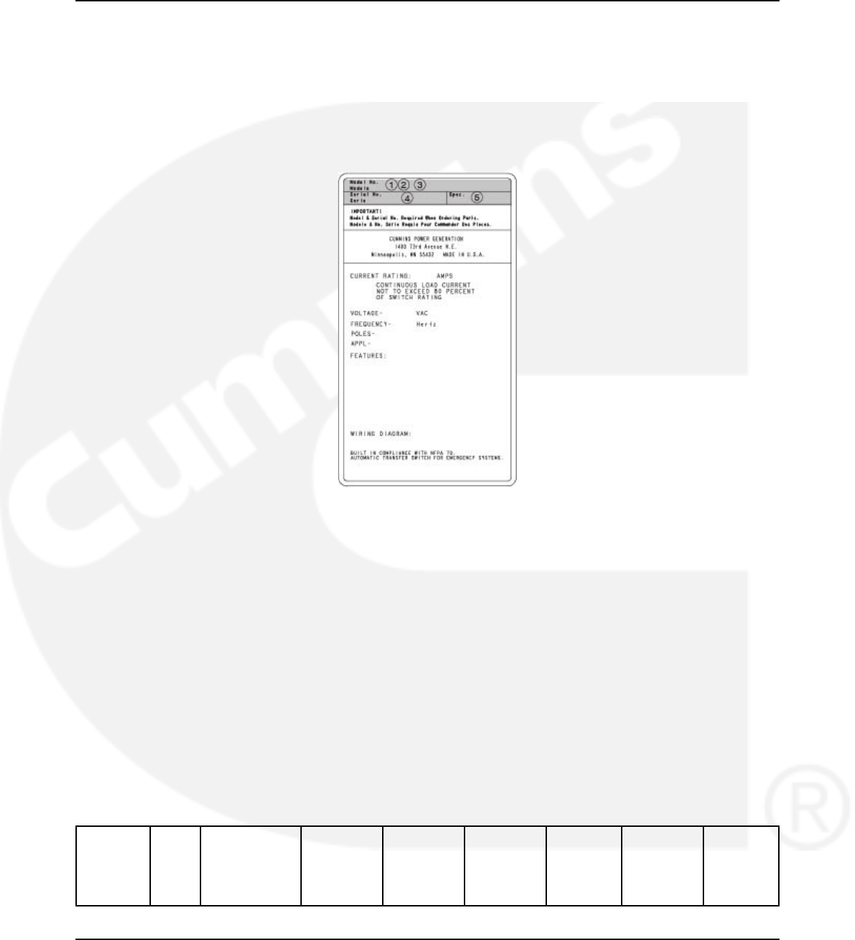
2.3 Model Identification
If the transfer switch ever needs to be serviced, the distributor will need this information in order
to properly identify your unit from the many types manufactured:
• Model No. (Product Model)
• Serial No. (Product Serial Number)
• Spec. (Product Specification Letter)
FIGURE 1. CONTROL NAMEPLATE
2.4 Transfer Switch Application
Transfer switches are an essential part of a building's standby or emergency power system. The
utility line (normal power), is backed up by a generator set (emergency power). The transfer
switch automatically switches the electrical load from one source to the other.
If utility power is interrupted, the load is transferred to the generator set (genset). When utility
power returns, the load is retransferred to the utility. The transfer and retransfer of the load are
the two most basic functions of a transfer switch.
2.5 Specifications
2.5.1 Model OTPC
Transfer Switch Model OTPC Specifications:
Model Amps Cabinet Types Util-to-Gen Gen-to-Gen Util-to-Gen Dual Plant-to- Transfer
& Util-to- Standby Plant Modes
(Level 1 & (Level 2) Util
2) (Prime
(Level 1 & Power)
2)
4962-0132 (Issue 8)

02-2014 2. Introduction
OTPCA 40 All Amps: OT
70 4, 3R, 1, 12, 4x X X X X PT
125
OTPCB 150 150-225 Amp OT
(3 & 4-Pole):
225 PT
1, 3R, 12, 4x
260
150-225 Amp
(3 pole):
4X X X X
260 Amp (3 &
4-Pole):
1, 3R, 12, 4x
260 Amp (3
pole):
4
OTPCC 300 All Amps: OT
400 1, 3R, 12, 4, 4x X X X X PT
600
OTPCD 800 All Amps (3 & OT
4-Pole):
1000 PT
1, 3R, 12, 4x X X X X
All Amps (3-
Pole):
4
OTPCE 1000 All Amps: OT
1200 1, 3R, 12, 4, 4x X X X X X PT
CT
OTPCF 1600 1, 3R, 12, 4 OT
X X X X X PT
CT
OTPCG 2000 1, 3R, 12, 4 OT
X X X X X PT
CT
OTPCH 3000 1, 3R OT
X X X X X PT
CT
OTPCJ 4000 1, 3R OT
X X X X X PT
CT
2.6 Automatic Transfer Switch Typical Function
Automatic transfer switches perform the basic function of transferring the load to the available
power source. The controller monitors each source for allowable voltage and frequency range.
The transfer switch(es) identified on the cover of this manual are designed for each, all or a
combination of the following applications (If you are unsure which of these your transfer switch
uses, refer to the Specifications section of this manual):
962-0132 (Issue 8) 5

2. Introduction 02-2014
2.6.1 Open Transition with Sync Check
Open transition with sync check executes an open transition (OT) transfer when both sources of
power are within specified tolerances of frequency, voltage and relative phase difference. If both
sources meet the tolerances, a fast transfer occurs.
2.6.2 Programmed Transition
Programmed transition executes a programmed transition (PT) transfer by disconnecting the
load from the source of power, pausing in the neutral position of the transfer switch (between
switched positions) to allow transient voltages from the load to diminish, and then the load is
switched to the other source.
2.6.3 Closed Transition
Closed transition executes a load transfer by momentarily paralleling both sources (a maximum
of 100ms) before switching sources.
2.7 Utility-to-Generator Set Operation
In utility-to-generator set applications, the transfer switch performs the following functions:
1. Senses the interruption of the Source 1 power (Utility).
2. Sends a start signal to the generator set (Source 2).
3. Transfers the load to the Source 2 power.
4. Senses the return of Source 1 (Utility).
5. Retransfers the load to Source 1.
6. Sends a stop signal to the generator set.
2.8 Utility-to-Utility Operation
In utility-to-utility applications, the transfer switch performs the following functions:
1. Senses the interruption of the Source 1 power (Utility).
2. Transfers the load to the Source 2.
3. Senses the return of Source 1 (Utility).
4. Retransfers the load to Source 1.
2.9 Generator-to-Generator Operation
In generator-to-generator applications, there are two possible configurations.
• Prime Power (Plant-to-Plant) Operation - Two generator sets provide all of the power
(utility power is not available).
• Dual Standby - Two generator sets are used to back up utility power.
6962-0132 (Issue 8)
02-2014 2. Introduction
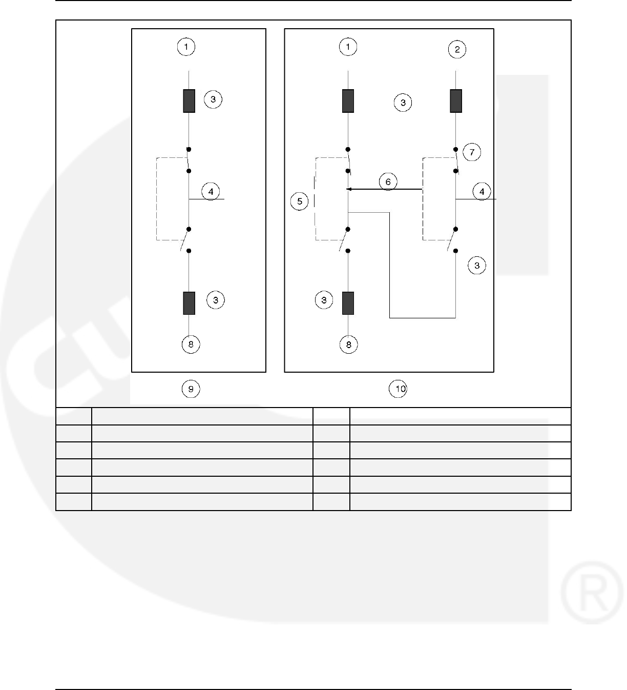
No. Description No. Description
1 Generator set B 6 Standby start signal
2 Utility 7 Utility-to-Gen ATS
3 Over current protective device 8 Generator set A
4 Load 9 Gen-to-Gen configuration in Prime Power mode
5 Gen-to-Gen ATS 10 Gen-to-Gen configuration in Dual Standby mode
FIGURE 2. GENERATOR-TO-GENERATOR CONFIGURATION IN PRIME POWER AND DUAL
STANDBY MODES
2.9.1 Prime Power (Plant-to-Plant) Operation
In prime power applications, utility power is not available. The system includes one transfer
switch and two generator sets. One generator set is always running and supplying power to the
load while the other generator set is the backup generator set. An external power supply is not
needed in this application.
962-0132 (Issue 8) 7
2. Introduction 02-2014
2.9.1.1 Preferred Source Selection
Under normal operation, one genset is designated as the preferred source and supplies power
to the load. The second genset is the backup power source. If the preferred genset fails, the
backup genset starts and the transfer switch transfers the load to the backup genset.
At any time, the PC service tool or the Test sub-menu can be used to designate either genset
(Source 1 or Source 2) as the preferred genset. The Preferred Source menu is included in the
Test submenus.
If the preferred genset is changed and the backup genset becomes the preferred genset, the
transfer switch transfers the load to the new preferred genset when it becomes available. The
unit that is carrying the load is always considered the preferred source.
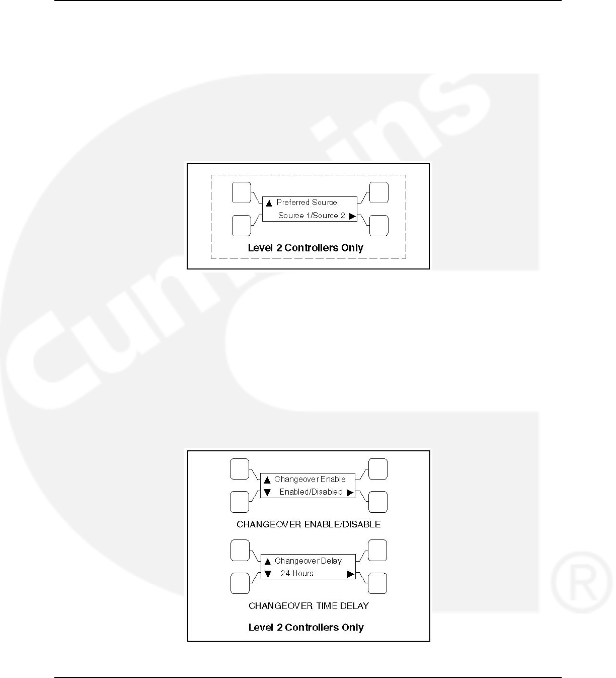
FIGURE 3. PREFERRED SOURCE SUBMENU
2.9.1.2 Automatic Changeover
The transfer switch can be set up to change the preferred source automatically by enabling the
changeover timer. The Time Delay submenus under Setup or the PC service tool can be used
to enable the changeover timer and specify a changeover delay time period. The Changeover
menus are included in the Time Delay submenus.
The automatic changeover timer automatically changes the preferred source and transfers the
load to the new preferred genset after a TDEN time delay. After the transfer is complete, the
control initiates a cool-down period (TDEC) on the old preferred genset before shutting it down.
The old preferred genset is now the new backup genset. The changeover timer is now timing for
the next changeover and the cycle continues as long as the changeover timer is enabled.
FIGURE 4. CHANGEOVER SUBMENUS
8962-0132 (Issue 8)

02-2014 2. Introduction
2.9.2 Dual Stand-By Operation
In dual stand-by applications, utility power is available. The system includes two transfer
switches (a Utility-to-Generator ATS and a Generator-to-Generator ATS) and two generator
sets. Utility power supplies power to the load and both generator sets are backup generator
sets.
Under normal operation, the utility is supplying power to the load through the lead transfer
switch. The lead transfer switch is a utility-to-generator set switch. The two generator sets are
connected to the generator set-to-generator set transfer switch. The load side of this switch is
connected to the generator set side of the lead transfer switch.
Upon loss of utility power to the lead transfer switch, a standby start signal is sent to the
generator set-to-generator set transfer switch to start the preferred generator set. When the lead
transfer switch senses generator voltage, it transfers the load to that generator set. If the
preferred generator set fails to start, a signal is sent to the backup generator set to start. The
PC Service tool or the Test sub-menu on the generator set-to-generator set transfer switch can
be used to set the preferred source.
If the Stand-By Start is inactive, upon initial power–up (or reset), or during software initialization,
the transfer switch control will not start either generator set. When a Stand-By Start command is
received by the Generator-to-Generator ATS from a Utility-to-Generator ATS (or other device),
the preferred generator set immediately starts. If the preferred generator set does not start, the
control starts the backup generator set. The load is connected to the generator set when it
becomes available.
If the preferred generator set becomes available while the backup generator set is active, a time
delay re-transfer (TDEN) period is initiated and the load is re-transferred back to the preferred
generator set. A time delay cool-down (TDEC) period is initiated before turning off the backup
generator set. When the Stand-By Start becomes deactivated, a TDEC period is initiated and
the active generator is turned off.
2.9.2.1 Preferred Source Selection
Under normal operation, one genset is designated as the preferred source and the second
genset is designated as the backup power source. If both the utility power and the preferred
genset fails, the backup genset starts and the genset-to-genset transfer switch transfers the
load to the backup genset.
At any time, the PC service tool or the Test sub-menu on the genset-to-genset transfer switch
can be used to designate either genset (Source 1 or Source 2) as the preferred genset. If the
preferred genset is changed and the backup genset becomes the preferred genset, the transfer
switch transfers the load to the new preferred genset if it is needed and when it becomes
available.
2.9.2.2 Alternating Preferred Source
In an attempt to keep the running time equally distributed between both generator sets, the
control can be set to alternate between the generator sets when utility power fails. The selected
preferred generator set starts with the first power outage. The second power outage starts the
backup generator set, which now becomes the preferred generator set. Upon subsequent
outages, the preferred generator set alternates.
962-0132 (Issue 8) 9
2. Introduction 02-2014
Only utility outages and tests or exercises initiated at the lead transfer switch result in the
generator sets being alternated. The designated preferred generator set will not change if it fails
and the backup generator set takes over the load. This alternating preferred source can only be
enabled with the PC Service tool. When enabled, a generator set can be designated as the
preferred source for a maximum of two weeks. Time adjustments can be made in one-hour
increments with the Test submenu.
2.10 Control Level 1 and Level 2
Two controls are available. The type of power source switched and the desired features
determine the control levels available.
The control board level can be viewed, using the digital display. This menu is included in the
About submenus.
NOTICE
The digital display comes standard with level 2 controls and is optional with level 1
controls.
FIGURE 5. CONTROL LEVEL SUBMENU
10 962-0132 (Issue 8)

3 Description
3.1 Cabinet
Cabinets are available in various configurations that meet UL and National Electrical
Manufacturer's Association (NEMA) requirements. Each cabinet includes an identification label.
The standard cabinet offerings are:
• Type 1 Indoor - general purpose
• Type 3R Outdoor - rainproof
• Type 4 Outdoor - watertight
• Type 4X Outdoor - watertight, stainless steel
• Type 12 Indoor - dust tight
3.2 Protective Relay
This section describes the solid state relays designed for use in single- or three-phase systems
to protect equipment against overpower and/or under-power conditions.
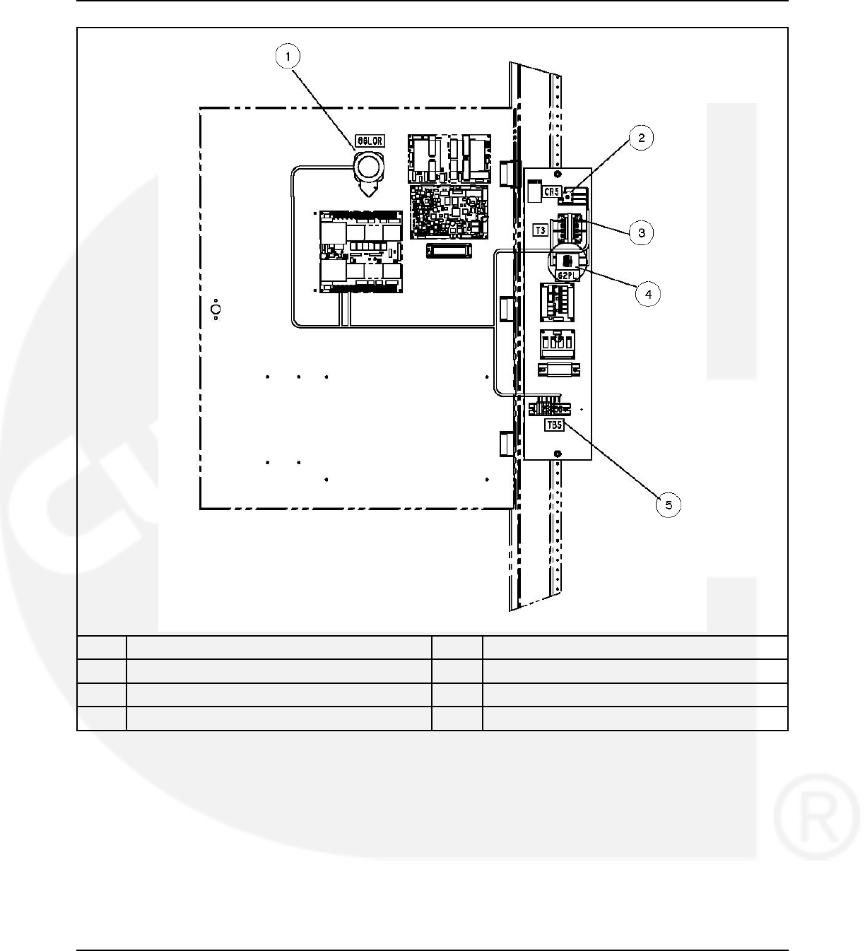
To increase the level of protection in our closed transition switches we have included a lock out
relay (86) that can trip from two different signals. It can trip from the K32R directional relay when
it senses reverse power is exported to utility or when the 62PL parallel timer has detected that
two sources have been connected for more than the predefined time (not the same as
“Maximum Parallel Timer" in the digital board).
The 86 lockout relay trips when the internal 24VDC relay coil is energized, and it is always
required to manual reset the relay. NC and NO dry contacts are provided for customer wiring
which are rated for 20A 600V. Factory settings for the 62PL are 1 and 3 closed (ON), 2 and 4-
10 open (OFF), for 500mS delay.
962-0132 (Issue 8) 11
3. Description 02-2014
No. Description No. Description
1 Lockout relay 2 Rectifier
3 Transformer 4 Relay
5 Terminal blocks
FIGURE 6. RELAY INSTALLATION M036/M038
12 962-0132 (Issue 8)
02-2014 3. Description
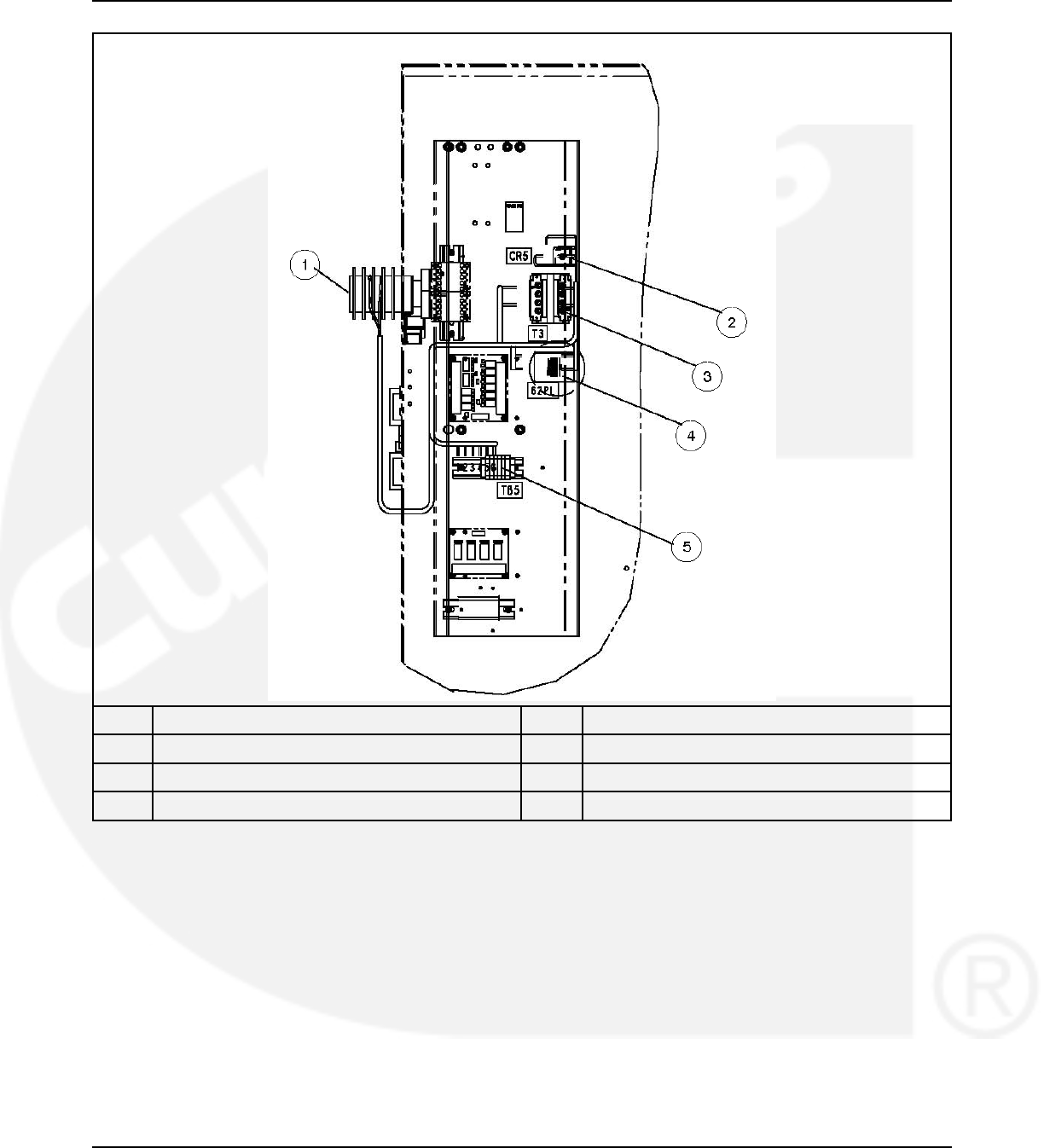
No. Description No. Description
1 Lockout relay 2 Rectifier
3 Transformer 4 Relay
5 Terminal Blocks
FIGURE 7. RELAY INSTALLATION M036/M038
962-0132 (Issue 8) 13
3. Description 02-2014
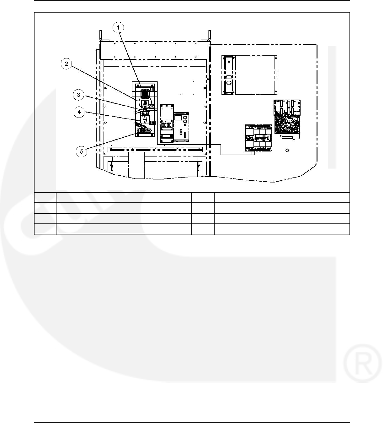
No. Description No. Description
1 Transformer 2 Relay
3 Rectifier 4 Lockout relay
5 Terminal blocks
FIGURE 8. RELAY INSTALLATION M036/M038
3.3 Transfer Switch Components
The transfer switch opens and closes the contacts that transfer the load between the power
sources (Source 1 and Source 2). The switch is mechanically interlocked to prevent
simultaneous closing to both power sources (except in switches capable of closed transitions).
3.3.1 Contact Assemblies
The automatic transfer switch has either three or four poles. Three pole transfer switches are
provided with a neutral bar. The contact assemblies make and break the current flow. When
closed to either power source the contacts are mechanically held. A mechanical interlock
prevents them from closing to both power sources at the same time.
3.3.2 Linear Actuator
The linear actuator moves the contact assemblies between the contacts of both power sources.
Linear actuator operation is initiated automatically by the transfer switch control. Manual
operation of the switch is also possible.
14 962-0132 (Issue 8)
02-2014 3. Description
3.3.3 Motor Disconnect Switch (150-1000 Amp Switches)
Moving the Draw out lever to the Release position disables the linear actuator. The Not In Auto
indicator on the front panel will light and the display indicates a motor disconnect event.
3.3.4 Motor Disconnect Switch (1200-4000 Amp Switches)
The Motor Disconnect toggle switch on the accessory control plate enables and disables the
linear actuator.
• Placing the switch in the AUTO position enables the linear actuator.
• Placing the switch in the OFF position disables the linear actuator. When placed in the
OFF position, the Not In Auto indicator on the front panel will light and the display indicates
a motor disconnect event.
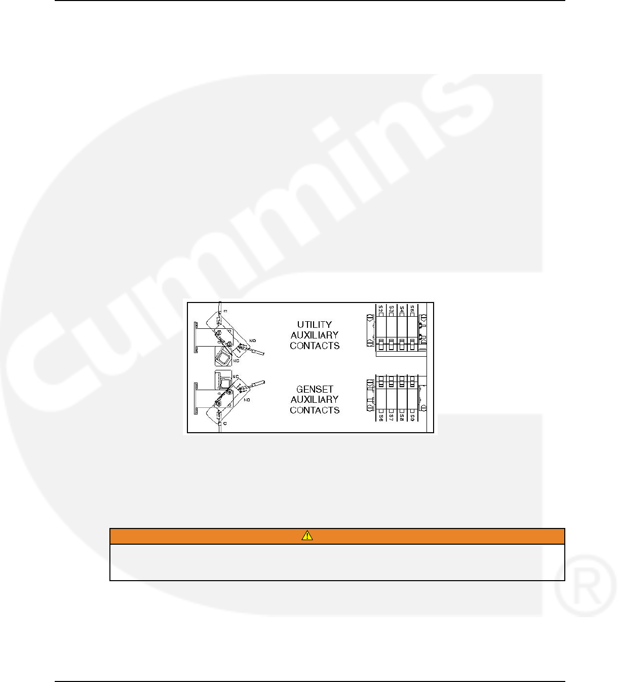
3.3.5 Auxiliary Contacts
Auxiliary contacts are provided on the utility and genset sides of the transfer switch. They are
actuated by operation of the transfer switch during transfer and retransfer. The utility auxiliary
contact switch is actuated when the transfer switch is connected to the utility. The genset
auxiliary contact switch is actuated when the transfer switch is connected to the genset. The
auxiliary contacts have current ratings of 10 amperes at 250 VAC. The contacts are wired to
terminal block TB1.
FIGURE 9. AUXILIARY CONTACTS
3.4 Electronic Control System
This section describes the standard and optional components of the electronic control system.
WARNING
Improper calibration or adjustment of electronic control modules can cause death, severe
personal injury, and equipment or property damage. Calibration and adjustment of these
components must be performed by technically qualified personnel only.
For further information regarding installation, calibration and adjustment of these components,
refer to the:
• Installation Manual (shipped with the product)
• Service Manual (available through your distributor)
962-0132 (Issue 8) 15
3. Description 02-2014
WARNING
Accidental actuation of the linear motor could cause severe personal injury. Before making any
adjustments, place the Motor Disconnect Switch in the OFF position. Return the switch to the
Auto position after adjustments are completed.
WARNING
AC power within the cabinet and the rear side of the cabinet door presents a shock hazard that
can cause severe personal injury or death. When the cabinet door is open, use extreme caution
to avoid touching electrical contacts with body, tools, jewelry, clothes, hair, etc.
3.4.1 Time Delays
3.4.1.1 Time Delay Engine Start (TDES-A and TDES-B)
Time Delay Default: 3 seconds (for both TDES-A and TDES-B)
Adjustable: The value is set with the InPower service tool or the digital display.
• Adjustable from 0-15 seconds in 1 second increments on Level 1 controls.
• Adjustable from 0-120 seconds on Level 2 controls.
• Values up to 20 seconds are adjustable in 1 second increments.
• Values over 20 seconds are adjustable in 5 second increments.
Purpose: Prevents the generator set from starting during short power interruptions.
Sequence of Events: Timing begins at the Source 1 power interruption (or the preferred source
interruption on gen-to-gen units). If the duration of interruption exceeds the delay time, the
control system starts the generator.
NOTICE
For long engine start time delays (over 15 seconds) a remote battery source must be
used.
For Genset-to-Genset applications: TDES-A is the start time delay to start the Source 2 genset
and TDES-B is the start time delay to start the Source 1 genset.
For Utility-to-Utility applications: TDES-A and TDES-B are not available.
3.4.1.2 Time Delay Engine Cool-down (TDEC-A and TDEC-B)
Time Delay Default: 10 minutes
Adjustable: Adjustable from 0-30 minutes, in 1 minute increments. The value is set with the
InPower service tool or the digital display.
Purpose: Allows the generator set to cool without load before stopping.
Sequence of Events: Timing begins when the load is retransferred to Source 1 (or to the
preferred source on gen-to-gen units). At the end of the delay, the stop signal is sent to the
generator set. During this time delay, the generator set cools down without load before stopping.
For Genset-to-Genset applications: TDEC-A is the stop time delay to stop Source 2 genset and
TDEC-B is the stop time delay to stop Source 1 genset.
For Utility-to-Utility applications: TDEC-A and TDEC-B are not available.
16 962-0132 (Issue 8)

02-2014 3. Description
3.4.1.3 Time Delay Normal to Emergency (TDNE)
Time Delay Default: 5 seconds
Adjustable: Adjustable from 0-120 seconds, in 1 second increments. The value is set with the
InPower service tool or the digital display.
Purpose: Allows the generator set to stabilize before the load is applied.
Sequence of Events: Timing begins when:
• Source 2 voltage and frequency reaches the settings of the control.
• Preferred source voltage (on gen-to-gen units) and frequency reaches the settings of the
control.
• Preferred utility becomes available (on utility-to-utility units).
After the delay, the transfer switch transfers the load to Source 2.
3.4.1.4 Time Delay Emergency to Normal (TDEN)
Time Delay Default: 10 minutes
Adjustable: Configurable for 0 (disabled), 0.1, 5, 10, 15, 20, 25 or 30 minutes.
Purpose: Allows utility power to stabilize before retransfer. This delay also allows the generator
to operate under load for a minimum amount of time before transferring back to utility power.
Sequence of Events: Timing begins with the transfer switch connected to the generator and
after the utility becomes available following an outage (the green Utility Power Available LED is
lit). This time delay also starts when an active test or exercise period has ended. After the delay,
the transfer switch can retransfer the load to the utility power source.
• If the utility fails any time during this time delay, the control resets the timer and restarts it
once utility power becomes available.
• If the generator fails at any time during this time delay, the timer expires and the normal
retransfer sequence takes place.
• If the Override pushbutton is pressed or the Override input is grounded while the TDEN
timer is active, the TDEN timer immediately expires.
• The TDEN timer will not begin if a Retransfer Inhibit input is active.
3.4.1.5 Time Delay Elevator (TDEL)
Time Delay Default:0 seconds
Adjustable: Adjustable from 0-60 seconds, in 1 second increments. The value is set with the
InPower service tool or the digital display.
Purpose: Allows an elevator to come to a complete stop before the switch transfers.
Sequence of Events: Timing begins after the transfer or retransfer timing ends. TDEL only
times when transferring between two live sources.
3.4.1.6 Time Delay Programmed Transition (TDPT)
Time Delay Default:0 seconds
Adjustable: Configurable for 0 (disabled), 0.5, 1, 2, 3, 4, 6 or 10 seconds.
962-0132 (Issue 8) 17

3. Description 02-2014
Purpose: Allows the transfer switch to pause in the Neutral position for an adjustable period of
time whenever there is a transfer from one source to another.
• This intentional delay allows the residual voltage of an inductive load to sufficiently decay
before connecting it to another power source.
• This delay prevents potentially damaging voltage and current transients in the customer's
power system.
Sequence of Events: Timing begins whenever the transfer switch has disconnected from one
source and is in the Neutral position.
• If TDPT is set to zero, then the transfer switch transfers from one source to the other with
no neutral position delay.
• The control also detects if the transfer switch has disconnected from the first source before
connecting it to the second one.
• If there is a power source failure while the TDPT is active, the control only transfers to the
remaining active power source.
• The control does not terminate the TDPT timer if either source fails while the transfer
switch is in the Neutral position.
3.4.2 System Sensors
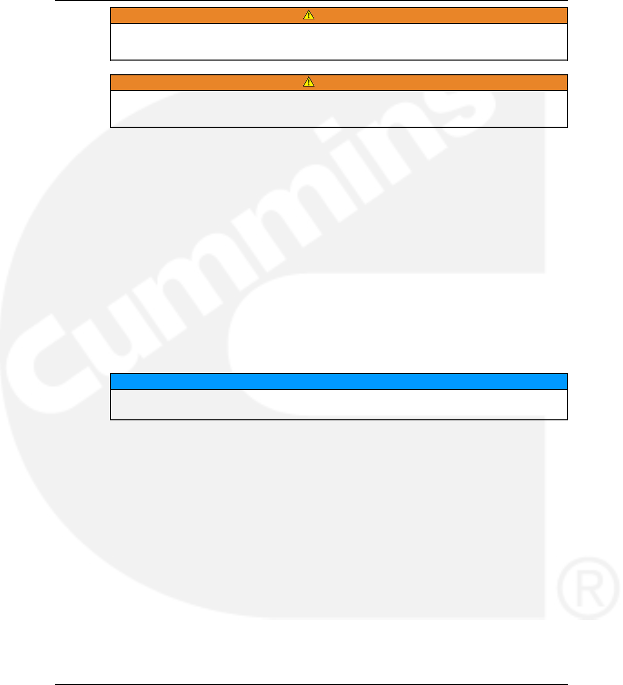
3.4.2.1 Under-Voltage Sensing
All controls include under-voltage sensors for Source 1 and Source 2.
Default Value:
• Pick-up: 90%
• Drop-out: 90% of the pick-up setting
Range:
• The pick-up range for a rising voltage is 85 to 100% of the nominal voltage set point.
• The under-voltage sensing range for a falling voltage (drop-out) is 75 to 98% of the pick-up
voltage setting.
Default Delay Time: 0.5 second
Adjustable: The adjustable range for the time delay period is 0.1 to 1.0 seconds in 0.1 second
increments. These values are set with the PC service tool or the digital display.
Sequence of Events:
• When a sensor detects a voltage below the set drop-out voltage for a period longer than
the time delay, it deems the voltage as unacceptable.
• When the sensor detects a voltage at or above the set pick-up point, it deems the voltage
as acceptable.
18 962-0132 (Issue 8)
02-2014 3. Description
FIGURE 10. UNDER-VOLTAGE SENSING SUBMENUS
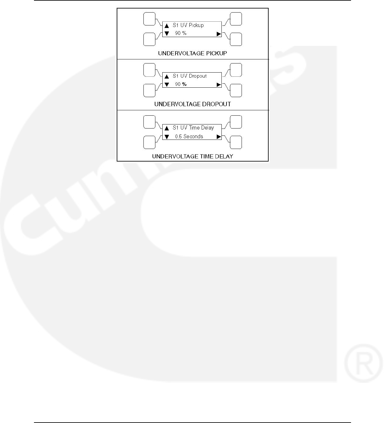
3.4.2.2 Over-Voltage Sensing
All controls include over-voltage sensors for Source 1 and Source 2 that can be disabled and
not used. The over-voltage sensing feature is enabled by default.
Default Value:
• Over-voltage (drop-out) sensing range: 110%
• Pick-up range: 95%
Range:
• The over-voltage sensing range (drop-out) for a rising voltage is 105 to 135% of the
nominal voltage set point.
• The pick-up range for a falling voltage is 95 to 99% of the drop-out setting.
Default Delay Time: 3.0 seconds
Adjustable: The adjustable range for the delay time period is 0.5 to 120.0 seconds in 1 second
intervals. These values are set with the PC service tool or the digital display.
Sequence of Events:
• When a sensor detects a voltage above the set dropout voltage for a period longer than
the time delay, it deems the voltage as unacceptable.
• When the sensor detects a voltage at or below the set pickup point, it deems the voltage
as acceptable.
962-0132 (Issue 8) 19
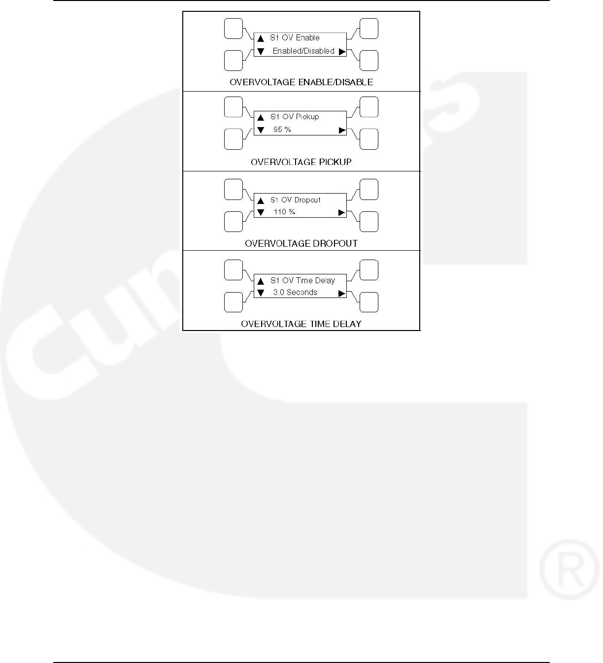
3. Description 02-2014
FIGURE 11. OVER-VOLTAGE SENSING SUBMENUS
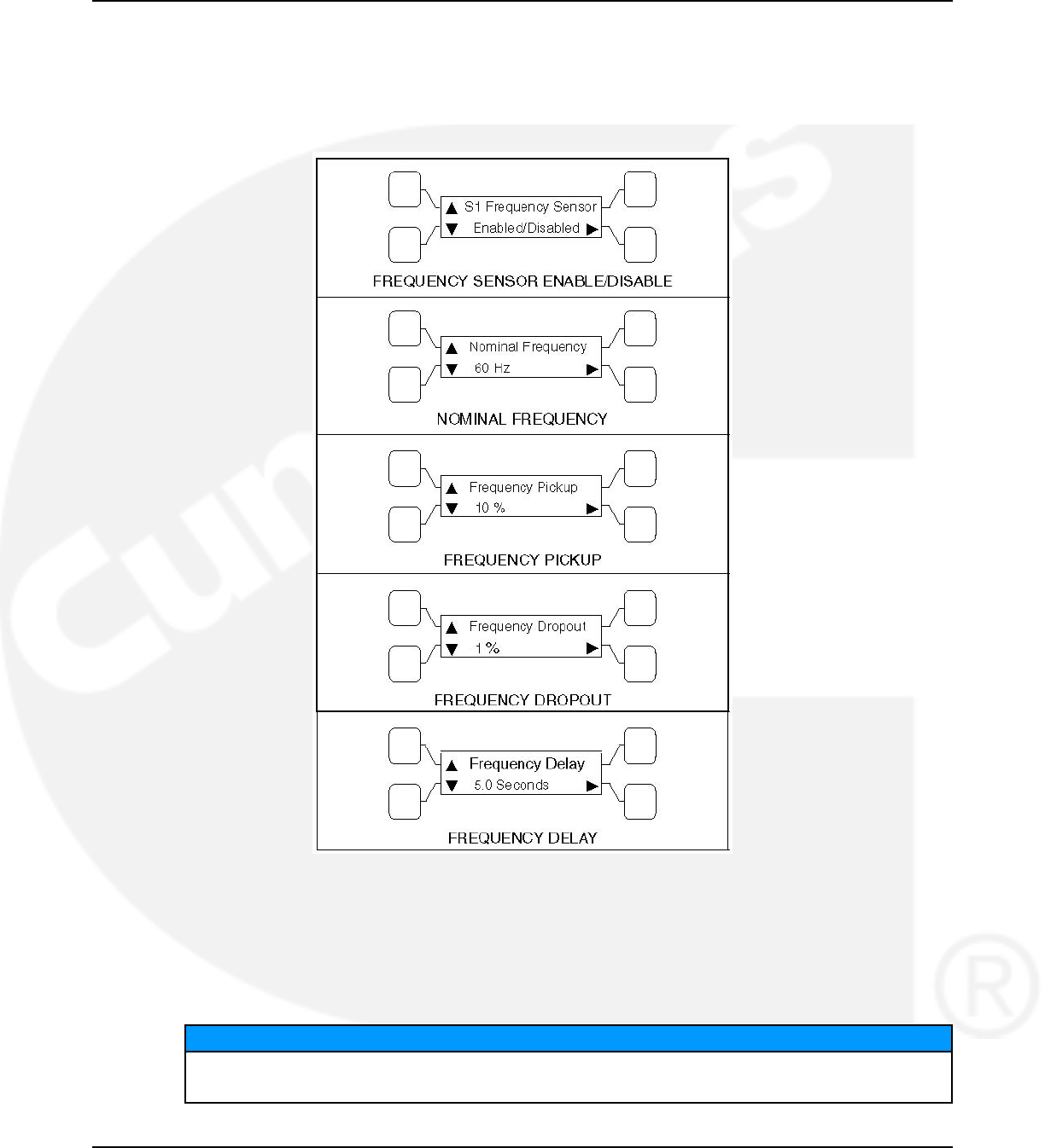
3.4.2.3 Frequency Sensing
All controls include frequency sensors for Source 1 and Source 2 that can be disabled and not
used.
Default Value:
• Nominal frequency: 60 Hz
• Frequency pick-up bandwidth: ±10%
• Frequency drop-out: 1% beyond pick-up bandwidth setting
Range:
• The nominal frequency can be set between 45.0 and 60.0 Hz in 0.1 Hz increments.
• The acceptable frequency bandwidth (pick-up) is ±5 to ±20% of the nominal frequency set
point.
• The drop-out frequency is 1 to 5% beyond the pick-up.
The frequency sensing feature is enabled by default.
Default Delay Time: 1.0 second
Adjustable: The adjustable range for the time delay period is 0.1 to 15 seconds.
20 962-0132 (Issue 8)
02-2014 3. Description
Sequence of Events:
• When a sensor detects a frequency outside the dropout bandwidth for a period longer than
the time delay, it deems the frequency as unacceptable.
• When the sensor detects a frequency within the pickup bandwidth, it deems the frequency
as acceptable.
FIGURE 12. FREQUENCY SUBMENUS
3.4.2.4 Voltage Imbalance Sensing
Three phase Level 2 controllers include a voltage imbalance sensor for both Source 1 and
Source 2. This feature informs the operator when there is significant voltage imbalance between
the phases of Source 1 or Source 2. This feature is used for equipment protection.
NOTICE
This sensor is inactive for single phase systems and indicates no failures. To prevent
nuisance faults, the setting can be increased up to 10% of the nominal voltage.
962-0132 (Issue 8) 21

3. Description 02-2014
This sensor can be enabled using the PC service tool or the digital display Setup submenus.
Default Value: 10%
Range:
• The maximum deviation from the average voltage is greater than a user-specified value
between 2 and 10% (dropout) of the average voltage in 1% increments.
• The pickup value is fixed at 10% of the dropout.
Default Delay Time: 10 seconds
Adjustable: The adjustable range for the time delay period for the imbalance sensor drop-out is
2 to 20 seconds.
Sequence of Events: A voltage imbalance is typically caused by severe single phase loading.
The sensor indicates a failure when the maximum deviation from the average voltage is greater
than a user-specified value (dropout) of the average voltage.
FIGURE 13. VOLTANGE IMBALANCE SENSOR SUBMENUS
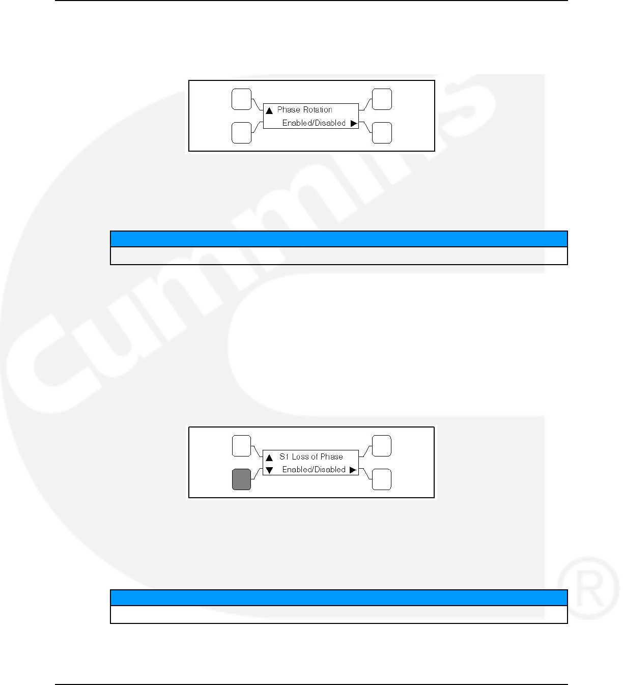
3.4.2.5 Phase Rotation Sensing
Three phase Level 2 controllers include a phase rotation sensor.
This feature monitors the phase rotation of the source opposite from the connected source. Both
voltage sources must be applied in order to check phase rotation.
This feature protects against equipment damage by preventing transfer to a source that is out of
phase. This generally occurs on new installations or after storm damage or generator rewiring.
This feature is required in fire pump applications.
CAUTION
Level 1 controls do not support three-phase sensing on Source 2. Do not select the three-phase
option for the Source 2 Sensing adjustment with Level 1 controls, even if the system is three
phase. This setting will prevent Source 2 from becoming available.
22 962-0132 (Issue 8)
02-2014 3. Description
Default Value: Disabled
Adjustable: The adjustable range for phase rotation sensing is Enabled or Disabled (On or Off).
Sequence of Events: When the alternate source is out of phase rotation with the connected
source, transfer is inhibited.
FIGURE 14. PHASE ROTATION SENSING SUBMENU
3.4.2.6 Loss of Single Phase Sensing
Three phase Level 2 controllers include a loss of single phase sensor.
NOTICE
This sensor is inactive for single phase systems and indicates no failures.
This feature initiates a transfer from a source that has lost a single phase and prevents a
transfer to a source that has lost a single phase. This is generally caused by a single phase to
line ground or open.
This feature is mainly used to protect three phase devices, such as motors.
Default Value: Disabled
Adjustable: The adjustable range for loss of single phase sensing is Enabled or Disabled (On
or Off).
Sequence of Events: The controller indicates a fault when the relative phase angle between
any line-to-line phase angle drops to less than 90 degrees.
FIGURE 15. LOSS OF PHASE SENSING SUBMENU
3.4.2.7 Transfer Times
The controller senses and records the time it takes for the transfer switch to break from one
source and reconnect to the other source.
NOTICE
Transfer times are not recorded if Programmed Transition delay is in use.
962-0132 (Issue 8) 23
3. Description 02-2014
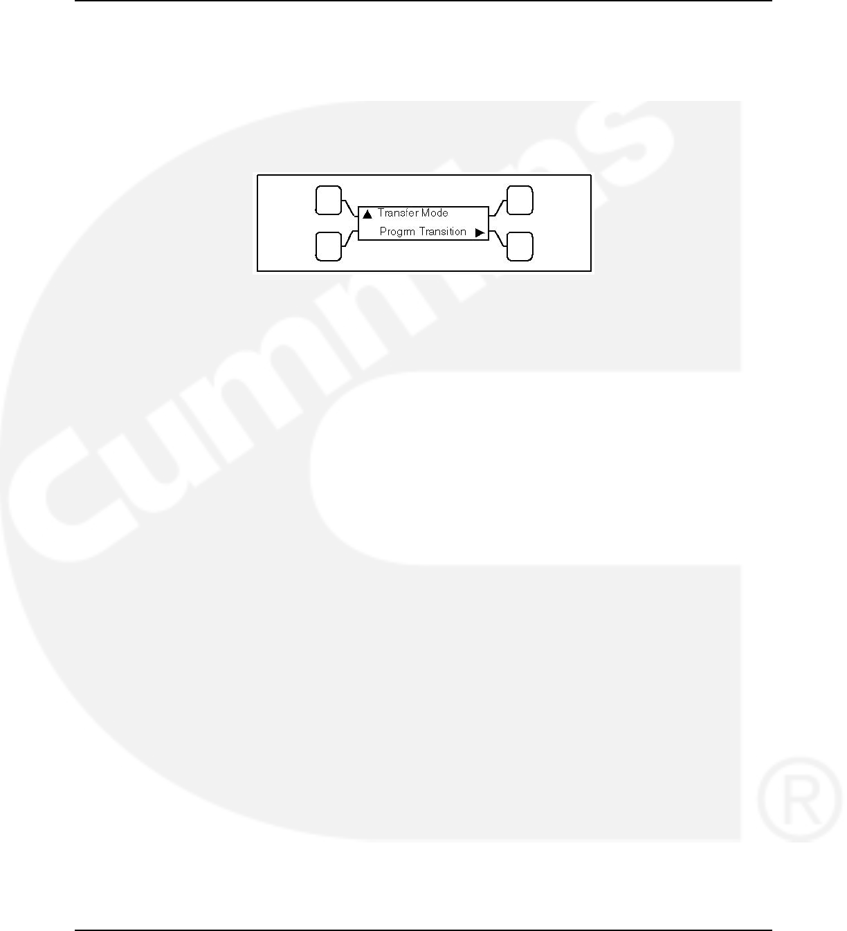
3.4.3 Transfer Modes
A transfer mode can be selected from the front panel digital display.
Since not all automatic transfer switches are configured the same, some may not have access
to all transition mode types. The transfer modes available on your transfer switch are identified
in the following section.
The transfer switch mode setting can be changed with the PC service tool or with the digital
display.
FIGURE 16. TRANSFER MODE SUBMENU
3.4.3.1 Available Transfer Modes
• Open Transition (OT) with Sync Check
• Programmed Transition (PT)
• Closed Transition (CT)
3.4.3.2 Open Transition with Sync Check
Open transition with sync check executes an open transition (OT) transfer when both sources of
power are within specified tolerances of frequency, voltage and relative phase difference. If both
sources meet the tolerances, a fast transfer occurs.
3.4.3.2.1 Transfer from Source 1 to Source 2 (OT)
This sequence begins with Source 1 supplying power to the load. The Source 1 Available and
Source 1 Connected indicators are lit. The sequence ends with Source 2 (generator) assuming
the load.
1. When Source 1 goes “out of spec," the control starts a Time Delay to Engine Start (TDES)
timer and the Source 1 Available indicator goes out.
2. If the TDES expires without a return to acceptable Source 1 power, the genset receives a
remote start signal. The engine starts and accelerates to rated speed.
3. When the alternator output reaches the “pickup" level, the Source 2 Available indicator is
lit. The control starts the Time Delay Normal to Emergency (TDNE) timer.
3.4.3.2.2 Transfer from Source 2 to Source 1 (OT)
This sequence begins with Source 2 supplying power to the load. The Source 2 Available and
Source 2 Connected indicators are lit. The sequence ends with Source 1 (utility) assuming the
load.
1. When Source 1 returns to “in spec," the Source 1 Available indicator is lit and the control
starts the Time Delay Emergency to Normal (TDEN) timer. When this time is complete, the
controller starts monitoring both live sources looking for when they are in sync
24 962-0132 (Issue 8)
02-2014 3. Description
2. When both sources are in sync, the switch transfers the load to Source 1. However, if the
two sources fail to synchronize and the “Return PT Enabled" feature is active, the switch
executes a programmed transition by stopping in the Neutral position and transferring the
load to Source 1. If Source 2 goes offline while the controller is trying to synchronize the
two sources, the controller executes a Programmed Transition and transfers the load to
Source 1.
3. A Time Delay Engine Cool-down (TDEC) for the genset is activated. When the engine cool-
down delay expires, the genset shuts down and the Source 2 Available indicator goes out.
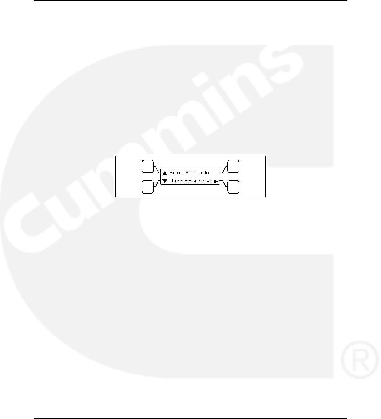
3.4.3.2.3 Return PT Enable
A feature included with controls that have a Sync Check sensor is Return to Programmed
Transition.
Adjustable: This feature can be enabled and disabled with the PC service tool or with the digital
display, if available.
Sequence of Events: If the two sources fail to synchronize within two minutes, a Failed to
Synchronize event occurs. If the Return to Programmed Transition feature is enabled, the
control reverts to transferring the transfer switch to the programmed transition mode.
FIGURE 17. RETURN TO PROGRAMMED TRANSITION SUBMENU
3.4.3.2.4 Sync Check Sensor
Sync Check is used to determine when both sources of power are within specified tolerances of
frequency, voltage, and relative phase difference. If both sources are within this range, a fast or
synchronized transfer occurs.
The transfer switch controller measures non-programmed transition transfer times from one
source to another. It takes into account relay coils and solenoids energizing.
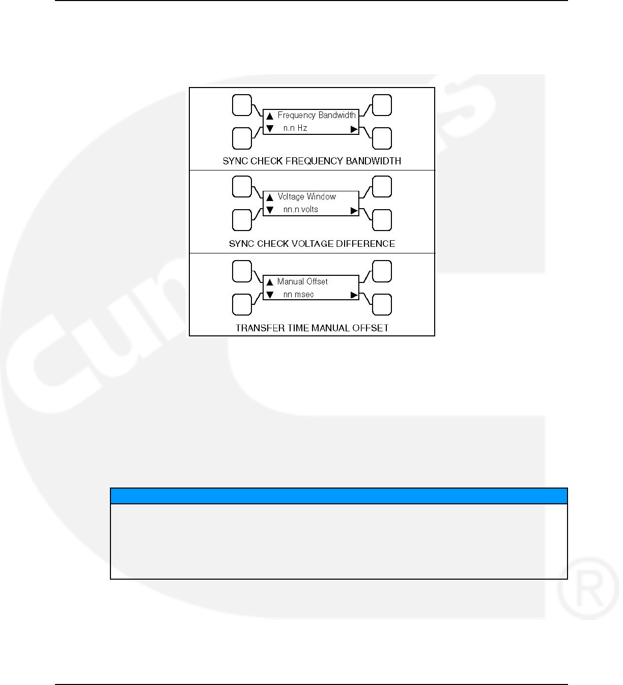
Default Value:
• Frequency bandwidth: 1.0 Hz
• Voltage: 10 V
• Offset: 0 milliseconds
Range:
• The frequency bandwidth range is from 0.1 and 1.0 Hz.
• The frequency difference between the sources must be equal to or less than the set
value in order for transfer to occur.
• The voltage window is from 5 and 25 volts.
• The average voltage difference between the two sources must be equal to or less
than the set value in order for transfer to occur.
• The manual offset range is from -25 to +25 milliseconds.
962-0132 (Issue 8) 25
3. Description 02-2014
Adjustable: Synchronicity parameters are adjustable. The transfer switch mode setting can be
changed with the PC service tool or with the digital display, if available.
Sequence of Events: If enabled, the Sync Check sensor overrides programmed transition
whenever transferring between two live sources. If only one power source is available,
programmed transition overrides the Sync Check sensor.
FIGURE 18. SYNCHRONICITY PARAMETER SUBMENUS
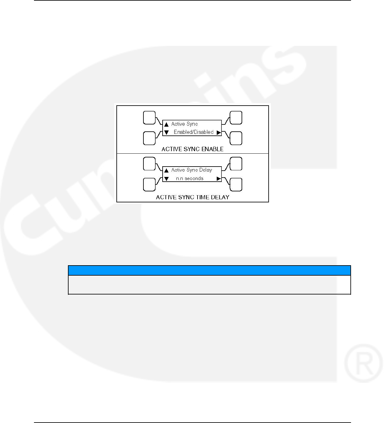
3.4.3.2.5 Active Sync Feature
When the transfer switch is configured to transfer in closed transition mode it is recommended
to use the active sync feature. When the active sync feature is enabled,
the transfer switch control can send a Sync Enable command to the genset to synchronize with
the utility. This command is activated just before the Sync Check sensor is activated.
To use the Active Sync feature, it must first be enabled. The Active Sync feature can be
enabled with the PC service tool or the digital display, if available.
NOTICE
The active sync feature may be used with a non-paralleling genset control as well as a paralleling
control. A non-paralleling genset control will not synchronize the genset to the utility but
enabling the active sync feature will impose the active sync time delay so that the two source
must remain synchronized for the set time period maximizing the reliability of the transfer. When
using a non-paralleling genset with this feature it is recommended to set the generator set
frequency to 0.1 Hz higher than the utility to make sure that the generator set will come into sync
with the utility.
Default Value: 0.5 seconds
Range: The Active Sync Time Delay is adjustable from 0 to 5 seconds in 0.1 second
increments.
Default Delay Time:
26 962-0132 (Issue 8)
02-2014 3. Description
Adjustable: The Active Sync Delay timer can be set with the PC service tool or the digital
display.
Sequence of Events: When the Active Sync feature is enabled, the control runs an Active Sync
Time Delay (if greater than 0) and sends the Sync Enable command to the genset. The Active
Sync Time Delay is used to check the stability of the system before transferring to the other
source. The two sources must remain synchronized for this period of time period before a
transfer command is given.
When a paralleling genset control receives a Sync Enable command and detects the Source 1
bus voltages, the genset control automatically synchronizes its speed and phase to match the
Source 1 bus. The Sync Check sensor monitors both sources. When they are synchronized, a
transfer or retransfer command is initiated.
FIGURE 19. ACTIVE SYNC SUBMENUS
3.4.3.2.6 Speed Adjust
If a PowerCommand transfer switch and a non-paralleling genset are networked together, the
transfer switch control can send a Speed Adjust command to the genset to increase its speed
just enough to increase its frequency by 0.5 Hz.
NOTICE
The genset must be capable of reacting to a Speed Adjust command. This feature is
only available if a PowerCommand network is installed.
Default Value: Speed Adjust is always enabled unless Active Sync is enabled.
Sequence of Events: The command is activated just before the Sync Check sensor is
activated. It is used when the genset takes a long time to drift in sync with the utility. This
increases the number of “in-phase" opportunities to satisfy the Sync Check sensor.
3.4.3.3 Programmed Transition
Programmed transition executes a programmed transition (PT) transfer by disconnecting the
load from the source of power, pausing in the neutral position of the transfer switch (between
switched positions) to allow transient voltages from the load to diminish, and then the load is
switched to the other source.
962-0132 (Issue 8) 27

3. Description 02-2014
3.4.3.3.1 Transfer from Source 1 to Source 2 (PT)
This sequence includes a programmed transition and begins with Source 1 supplying power to
the load. The Source 1 Available and Source 1 Connected indicators are lit. The sequence ends
with Source 2 (generator) assuming the load.
1. When source 1 goes “out of spec," the control starts a Time Delay Engine Start (TDES)
timer and the Source 1 Available indicator goes out.
2. If the TDES expires without a return to acceptable Source 1 power, the genset receives a
remote start signal. The engine starts and accelerates to rated speed.
3. When the alternator output reaches the “pickup" level, the Source 2 Available indicator
lights. The transfer switch starts the Time Delay Normal to Emergency (TDNE) timer. When
this time is complete, the switch moves to the Neutral position. The Source 1 Connected
indicator goes out.
4. The transfer switch stops in the Neutral position for the Time Delay Programmed Transition
(TDPT) and then completes its transition to the Source 2 position. The Source 2 Connected
indicator lights.
3.4.3.3.2 Transfer from Source 2 to Source 1 (PT)
This sequence begins with Source 2 supplying power to the load. The Source 2 Available and
Source 2 Connected indicators are lit. The sequence ends with Source 1 (utility) assuming the
load.
1. When Source 1 returns to “in spec," the Source 1 Available indicator lights and the digital
board starts the Time Delay Emergency to Normal (TDEN) timer. When this time is
complete, the switch moves to the neutral position (the Source 2 indicator goes out).
2. If there is a programmed transition delay, the transfer switch stops in the Neutral position
for the Time Delay Programmed Transition (TDPT) and then completes its transition to the
Source 1 position. The Source 1 Connected indicator lights and the Time Delay Engine
Cooldown (TDEC) timer starts.
3. When the engine cool-down delay expires, the genset shuts down and the Source 2
Available indicator goes out.
3.4.3.4 Closed Transition
Closed transition executes a load transfer by momentarily paralleling both sources (a maximum
of 100ms) before switching sources.
3.4.3.4.1 Transfer from Source 1 to Source 2 (CT)
This sequence begins with Source 1 supplying power to the load. The Source 1 Available and
Source 1 Connected indicators are lit. The sequence ends with Source 2 (generator) assuming
the load.
1. When Source 1 goes “out of spec," the digital board starts a Time Delay to Engine Start
(TDES) timer and the Source 1 Available indicator goes out.
2. If the TDES expires without a return to acceptable Source 1 power, the genset receives a
remote start signal, the engine starts and accelerates to rated speed.
3. When the alternator output reaches the “pickup" level, the Source 2 Available indicator is
lit. The transfer switch starts the Time Delay Normal to Emergency (TDNE) timer. When
this time is complete, the switch moves to the Neutral position. The Source 1 Connected
indicator goes out.
28 962-0132 (Issue 8)
02-2014 3. Description
4. If there is a programmed transition delay, the transfer switch stops in the Neutral position
for the Time Delay Programmed Transition (TDPT) and then completes its transition to the
Source 2 position. The Source 2 Connected indicator is lit.
3.4.3.4.2 Transfer from Source 2 to Source 1 (CT)
This sequence begins with Source 2 supplying power to the load. The Source 2 Available and
Source 2 Connected indicators are lit. The sequence ends with Source 1 (utility) assuming the
load.
1. When Source 1 returns to “in spec," the Source 1 Available indicator is lit and the digital
board starts the Time Delay Emergency to Normal (TDEN) timer. When this time is
complete, the controller starts monitoring both live sources until they are in phase.
2. When they are in phase, the controller closes the Source 1 contact and allows Source 1
and Source 2 to simultaneously feed the load for a maximum of 100ms.
3. After the 100ms timer expires, the controller opens the Source 2 contacts.
4. A Time Delay Engine Cool-down (TDEC) for the genset is activated. When the engine cool-
down delay expires, the genset shuts down and the Source 2 Available indicator goes out.
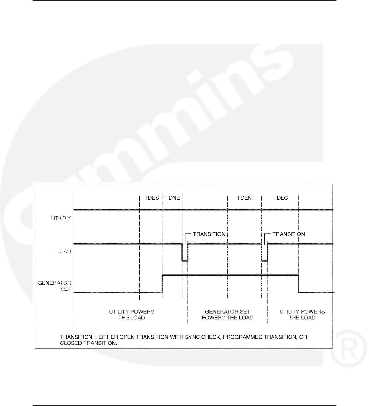
3.4.4 Front Panel Test - Sequence of Events
If the test button is pushed on the Front Panel, then the controller simulates a Source 1 or Utility
failure and proceeds to transfer the load to the generator.
FIGURE 20. FRONT PANEL TEST SEQUENCE OF OPERATION
962-0132 (Issue 8) 29

3. Description 02-2014
3.4.4.1 Transfer from Source 1 to Source 2 (Front Panel Test)
This sequence begins with Source 1 supplying power to the load continuously. The Source 1
Available and Source 1 Connected indicators are lit. The sequence ends with Source 2
(generator) assuming the load.
1. When the operator holds the Test button on the front panel for at least two seconds, the
digital board starts a Time Delay to Engine Start (TDES) timer.
2. When the TDES timer expires, the genset receives a remote start signal. The engine starts
and accelerates to rated speed.
3. When the alternator output reaches the "pickup" level, the Source 2 Available indicator
lights. The transfer switch starts the Time Delay Normal to Emergency (TDNE) timer. When
this time is complete, the controller proceeds to transfer the load in accordance with how it
is configured.
• If the controller is configured for OT with Sync Check, it monitors the two sources until
they are in phase and transfers the load to Source 2. The Source 2 Connected
indicator lights.
• If the controller is configured for Programmed Transition and there is a programmed
transition delay, the transfer switch stops in the Neutral position for the Time Delay
Programmed Transition (TDPT) and then completes its transition to the Source 2
position. The Source 2 Connected indicator lights.
• If the controller is configured for Closed Transition, it monitors the two sources until
they are in phase, close Source 2 for a maximum of 100ms, and open Source 1. The
Source 2 Connected indicator lights.
3.4.4.2 Transfer from Source 2 to Source 1 (Front Panel Test)
This sequence begins with Source 2 supplying power to the load. The Source 2 Available and
Source 2 Connected indicators are lit. The sequence ends with Source 1 (utility) assuming the
load.
1. When the operator pushes the Test button on the Front Panel, the digital board starts the
Time Delay Emergency to Normal (TDEN) timer.
2. When the TDEN is complete, the controller proceeds to transfer the load in accordance
with how it is configured.
• If the controller is configured for OT with Sync check, it monitors the two sources until
they are in phase and transfers the load to Source 1. The Source 1 Connected
indicator lights.
• If the controller is configured for Programmed Transition and there is a programmed
transition delay, the transfer switch stops in the Neutral position for the Time Delay
Programmed Transition (TDPT) and then completes its transition to the Source 1
position. The Source 1 Connected indicator lights.
• If the controller is configured for Closed Transition, it monitors the two sources until
they are in phase, closes Source 1 for a maximum of 100ms, and opens Source 2.
The Source 1 Connected indicator lights.
3. A Time Delay Engine Cool-down (TDEC) for the genset is activated. When the engine cool-
down delay expires, the genset shuts down and the Source 2 Available indicator goes out.
30 962-0132 (Issue 8)
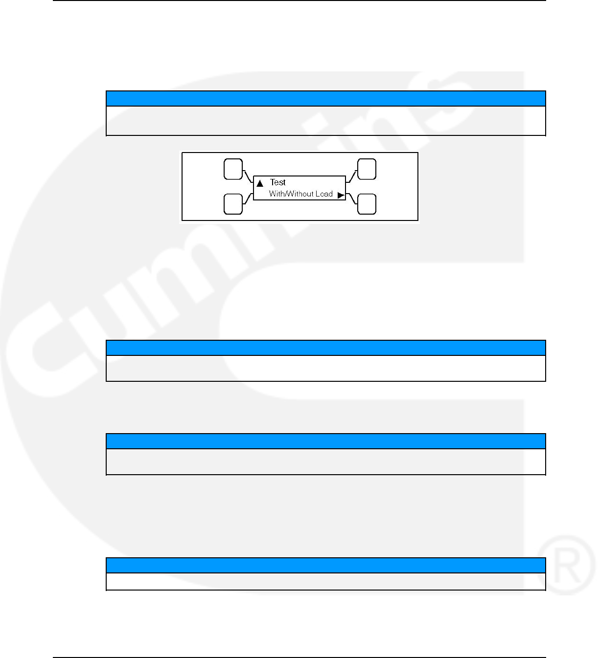
02-2014 3. Description
3.4.4.3 Test With or Without Load
The operator can test the transfer switch, generator, and power system locally. The operator
can choose to transfer the load during the test or only test the generator. A test sequence can
be activated either through the switch panel push button or through the PowerCommand
network.
NOTICE
The Test button does not function unless the Front Panel Security Switch is in the
Program position.
FIGURE 21. TEST WITH OR WITHOUT LOAD SUBMENU
3.4.4.4 Programmable Generator Exerciser
Programmable generator exercises and exercise exceptions are generally programmed to be
recurring. They can be programmed from the PC service tool or the digital display, if available.
Level 1 controllers include two programmable generator exercises and two programmable
exercise exceptions. All events can be set using the PC service tool or the digital display.
NOTICE
Early versions of software on Level 1 controllers allow for setting only one exercise period and
one exercise exception using the digital display.
Level 2 controllers include eight programmable generator exercises and eight programmable
exercise exceptions. All events can be set using the PC service tool or the digital display.
NOTICE
Early versions of software on Level 2 controllers allow for setting only two exercise periods and
two exercise exceptions using the digital display.
All controllers have a push-button switch on the digital module that enables and disables the
exerciser clock. The Real-Time clock must be set before exercise programs are entered.
For utility-to-genset configurations: the exerciser clock initiates genset start and run cycles at
specified intervals for specified durations.
NOTICE
The exerciser is not used in utility-to-utility or genset-to-genset configurations.
962-0132 (Issue 8) 31
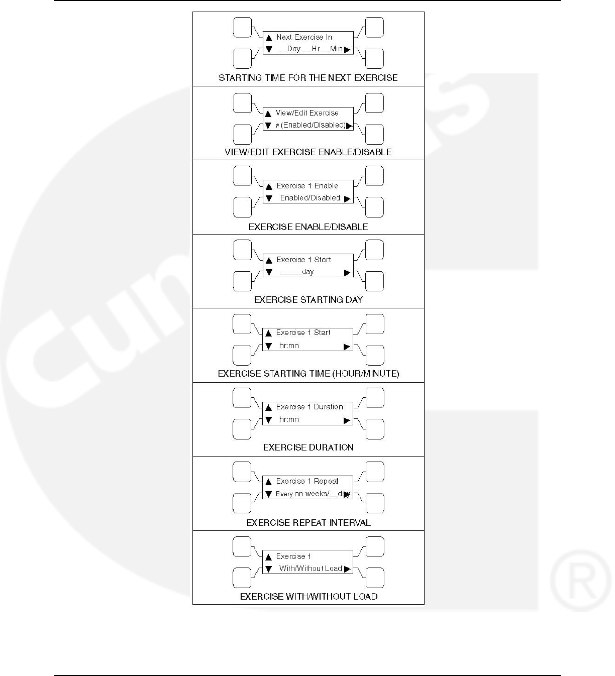
3. Description 02-2014
FIGURE 22. EXERCISE SUBMENUS
32 962-0132 (Issue 8)
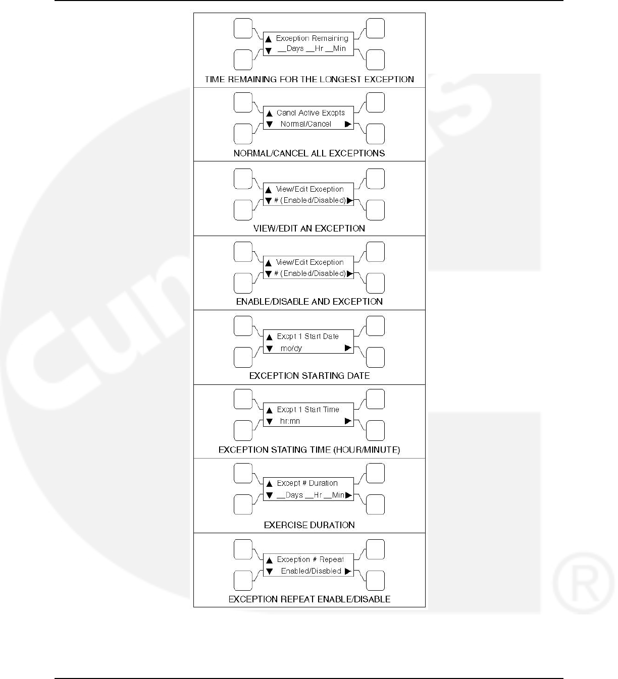
02-2014 3. Description
FIGURE 23. EXERCISE EXCEPTIONS SUBMENUS
962-0132 (Issue 8) 33
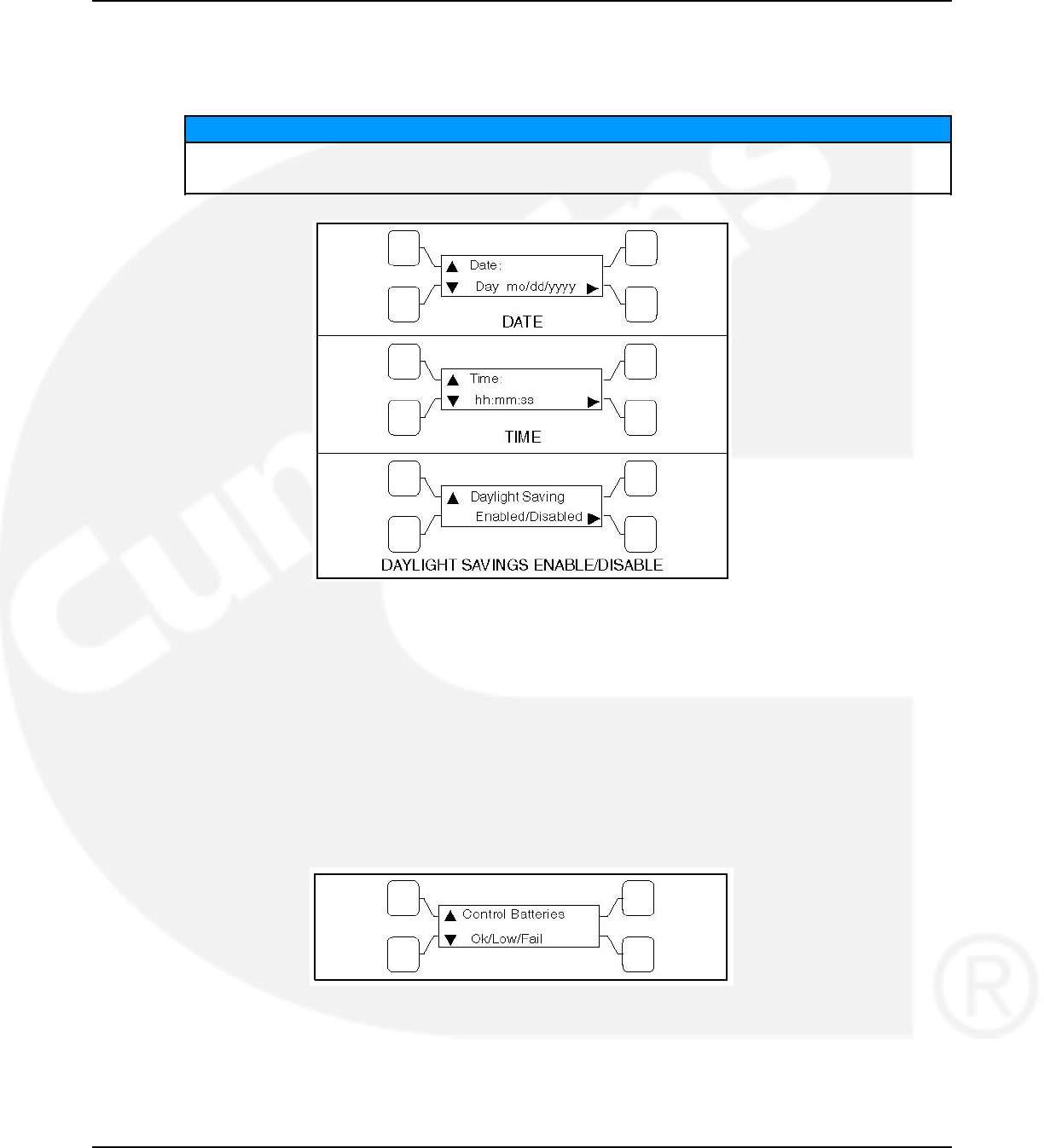
3. Description 02-2014
3.4.4.5 Real-Time Clock
All controllers have a real-time clock that keeps track of the time and date. The controller uses
the real-time clock to time and date stamp all events.
NOTICE
The clock is not set at the factory. To set the clock, use the PC service tool or the
digital display.
FIGURE 24. CLOCK SUBMENUS
3.4.4.6 Sleep Mode
After a period of screen inactivity (35 minutes), the digital display goes blank. Screen inactivity is
when there is no user interaction with the menu system and when there are no events. The
digital display is reactivated when an event occurs or when an operator touches one of the
menu buttons.
In order to conserve controller battery power, the loss of utility power also causes the digital
display to go blank. The digital display is reactivated when a second power source becomes
available.
The status of the controller batteries can be viewed using the digital display.
FIGURE 25. CONTROLLER BATTERIES STATUS SUBMENU
3.4.4.7 Remote Test Switch
The transfer switch can be wired with a remote test switch.
34 962-0132 (Issue 8)
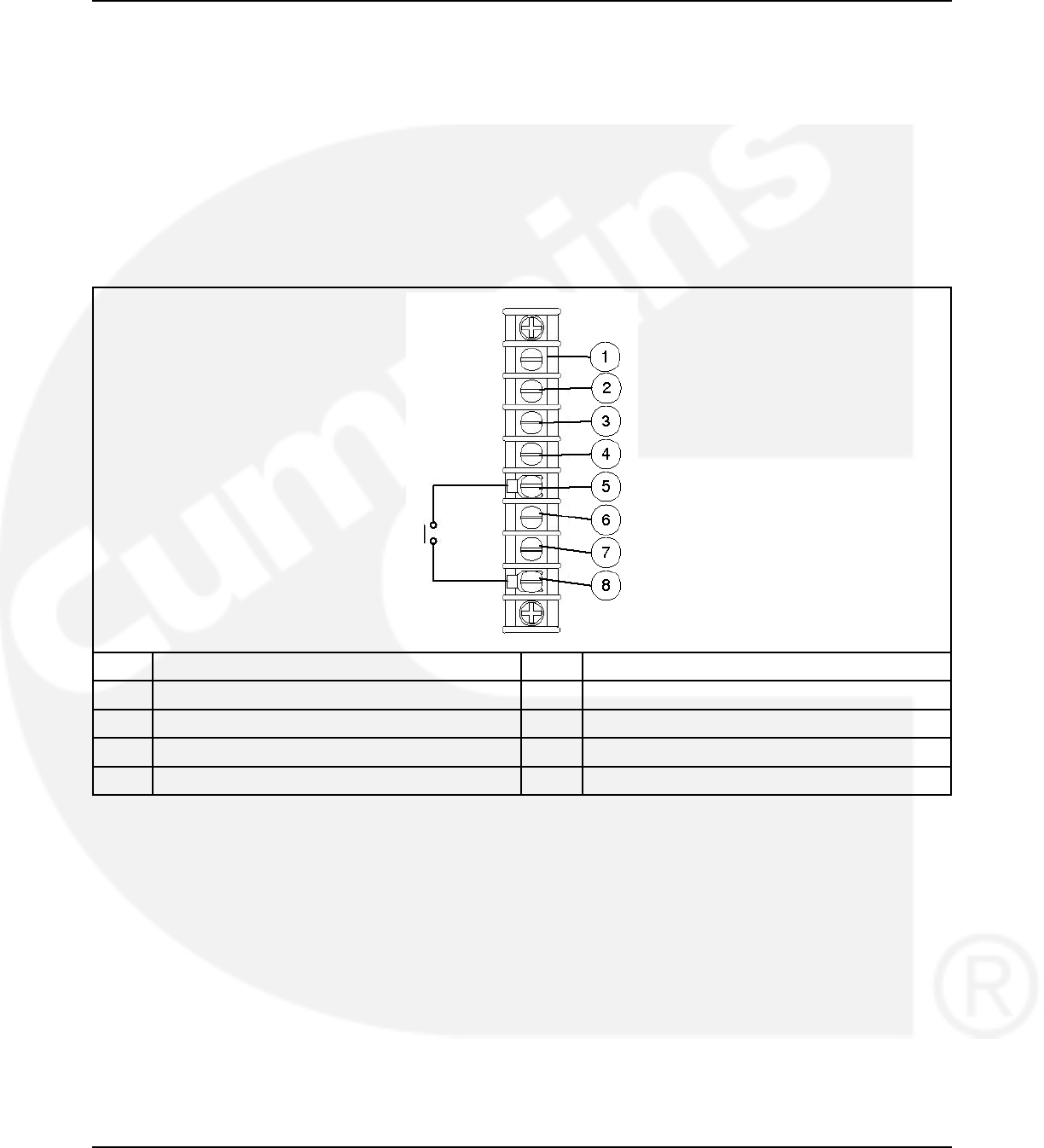
02-2014 3. Description
For utility-to-genset applications, closure of a set of contacts across the remote test transfer
input (TB2-5 and TB2-8) causes the transfer switch to sense a simulated utility power failure
and sends a start/run signal to the generator set and transfers the load to the genset when it
becomes available.
For utility-to-utility applications, closure of a set of contacts across the remote test transfer
input causes the transfer switch to sense a simulated power failure of the primary source and
transfers the load to the backup source.
Opening a set of contacts across the remote test transfer input causes the transfer switch to
sense that the primary source has been restored and transfers the load back to the primary
source (Source 1).
No. Description No. Description
1 GND 2 2
3 B+ 4 RMT
5 Remote Test 6 Transfer Inhibit
7 Load Shed (Optional) 8 Common
FIGURE 26. TB2 CONNECTIONS FOR REMOTE TEST TRANSFER
3.4.4.8 Remote Test Input
The transfer switch may be wired for a remote test input. The switch is used to start and stop
manually initiated system tests. As with the control panel Test pushbutton, the remote test input
can be configured to test with or without load.
A remote test input is set up by connecting a dry (voltage free) contact between TB2-5 and TB2-
8. Closing the contact starts a test and opening the contact cancels the test. The Test LED
flashes to signify the start of a test and stays on during the test.
Closing the contact causes the transfer switch to sense a (simulated) utility power failure and
sends a start/run signal to the genset. If the control is set up to test with load, the load is
transferred to the genset when the genset becomes available. The Utility Power Available LED
remains on to show that the utility did not fail.
962-0132 (Issue 8) 35
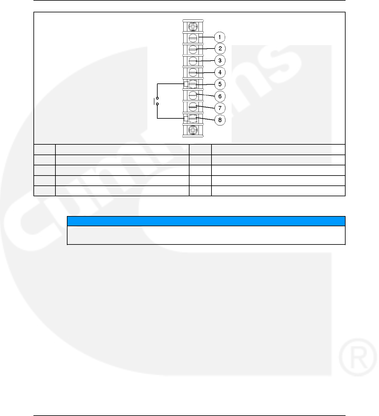
3. Description 02-2014
No. Description No. Description
1 GND 5 Remote test
2 2 6 Transfer inhibit
3 B+ 7 Retransfer Inhibit
4 RMT 8 Common
FIGURE 27. TB2 CONNECTIONS FOR REMOTE TEST TRANSFER
NOTICE
TB1 and TB2 will accept 22 AWG - 12 AWG wire with 3/8 inch (10 mm) strip. Torque to 9
in-lbs.
3.4.4.9 Transfer Inhibit (PowerCommand Control)
This feature is used to control load transfer to generator sets. When activated, load transfer will
not take place unless the Override button on the switch panel is pressed or the transfer inhibit
input is disabled. Transfer Inhibits are set up by connecting a remote contact between TB2-6
and TB2-8. Closing the contact enables the feature and opening the contact disables it.
In systems that have multiple closed transition transfer switches the transfer inhibit function
should be used to make sure that multiple switches don't transfer at the same time. Refer to the
section on closed transition ATS considerations.
36 962-0132 (Issue 8)
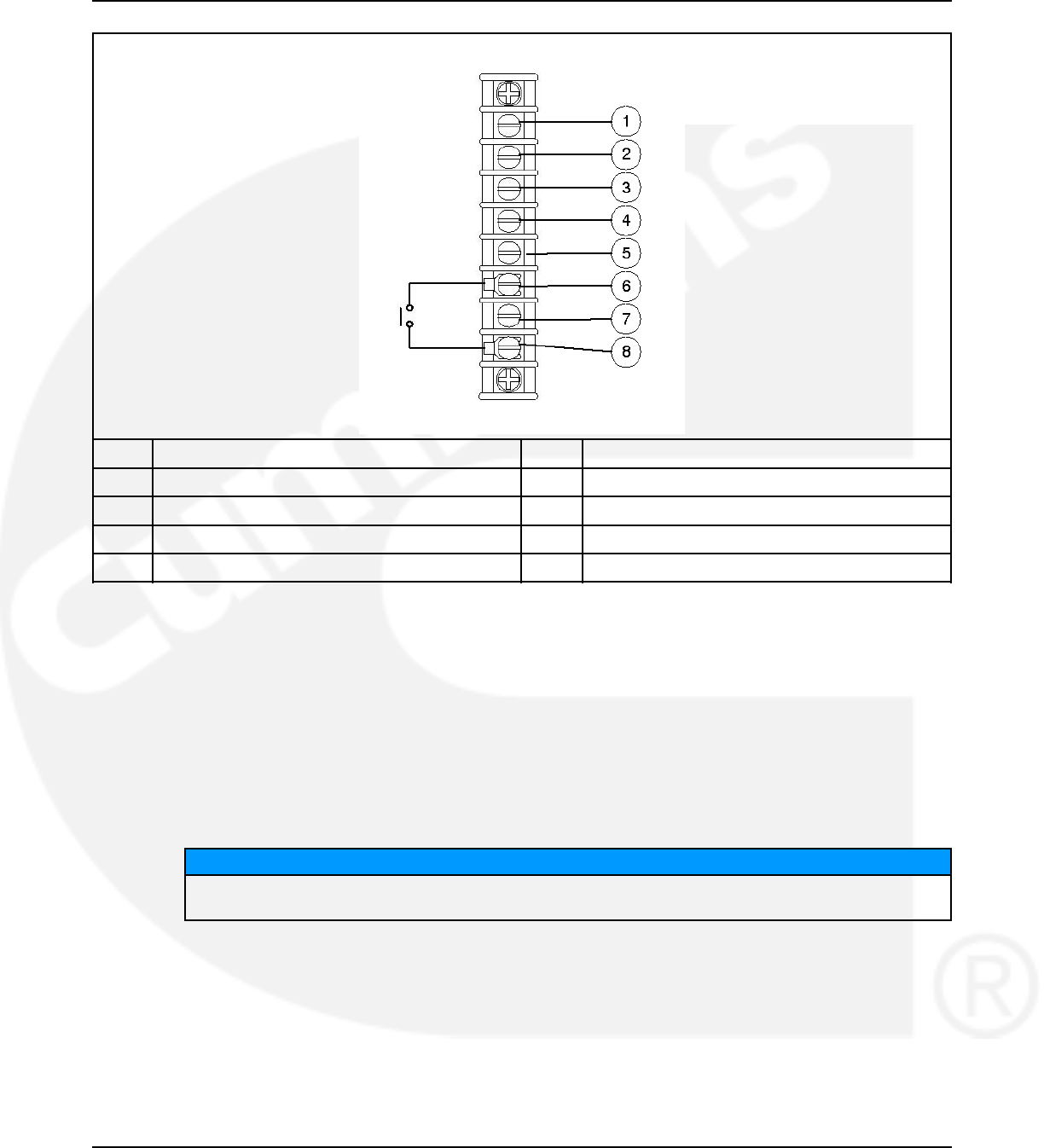
02-2014 3. Description
No. Description No. Description
1 GND 2 2
3 B+ 4 RMT
5 Remote test 6 Transfer inhibit
7 Load Shed (Optional) 8 Common
FIGURE 28. TB2 CONNECTIONS FOR TRANSFER INHIBIT
3.4.4.10 Retransfer Inhibit (PowerCommand Control)
This feature is used to prevent the ATS from automatically transferring the load back to Source
1 (or the preferred source in genset-to-genset applications). When activated, load transfer will
not take place unless the Override button on the switch panel is pressed, the retransfer inhibit
input is disabled, or Source 2 (or the backup source in genset-to-genset applications) fails.
In systems that have multiple closed transition transfer switches the retransfer inhibit function
should be used to make sure that multiple switches don't transfer at the same time. Refer to the
section on closed transition ATS considerations.
NOTICE
If Source 2 (or the backup source in genset-to-genset applications) fails, the Retransfer Inhibit is
ignored.
Retransfer Inhibits are set up by connecting a remote contact between TB3-53 and TB3-54.
Closing the contact enables the feature and opening the contact disables it. When enabled, the
event is displayed on the front panel.
962-0132 (Issue 8) 37
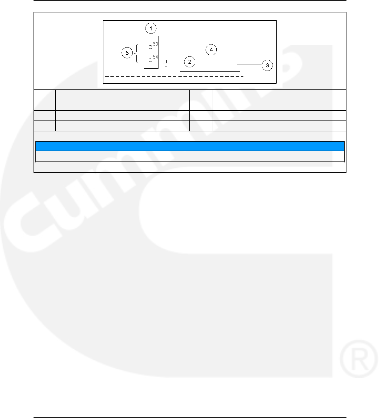
3. Description 02-2014
No. Description No. Description
1 TB3 2 J27-1
3 Digital Module 4 Retransfer Inhibit
5 Retransfer Inhibit
NOTICE
Connect a jumper or closed contact between TB353 and TB354 to inhibit retransfer.
FIGURE 29. TB3 CONNECTIONS FOR RETRANSFER INHIBIT
3.4.4.11 Transfer Times
The controller senses and records the time it takes for the transfer switch to break from one
source and reconnect to the other source.
The controller keeps track of open transition transfer times and provides an average open
transition transfer time. The controller records the transfer time if the transition mode is an open
transition with Sync Check or when a Programmed Transition is used and the Programmed
Transition time delay is zero.
38 962-0132 (Issue 8)
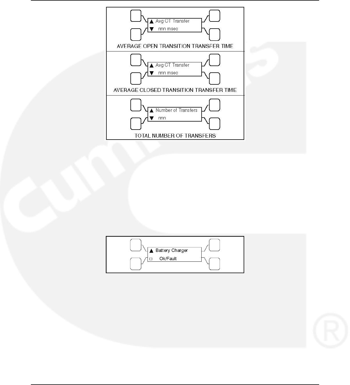
02-2014 3. Description
FIGURE 30. TRANSFER SUBMENUS
3.5 Options
3.5.1 Battery Charger Options
Two battery chargers are available. One battery charger is rated for 2 amperes at 12 or 24
VDC. The other battery charger is rated for 15 amperes at 12 VDC or 12 amperes at 24 VDC.
A float-charge battery charger regulates its charge voltage to continuously charge without
damage to the battery. As the battery approaches full charge, the charging current automatically
tapers to zero amperes or to steady-state load on the battery.
FIGURE 31. BATTERY CHARGER STATUS SUBMENU
3.5.1.1 2-Amp/10-Amp Float Battery Charger Option
A float-charge battery charger regulates its charge voltage to continuously charge without
damage to the battery. As the battery approaches full charge, the charging current automatically
tapers to zero amperes or to steady-state load on the battery.
Two chargers were available. One battery charger is rated for 10 amperes at 12 or 24 VDC. The
other battery charger is rated for 2 amperes at 12 or 24 VDC.
• The 2-ampere battery charger has an ammeter to indicate charging current and a fuse to
protect the battery charger circuit.
• The 10-ampere battery charger has three fuses (two on the AC input and one on the DC
output), three fault display LEDs, and an ammeter for indication of charging current.
962-0132 (Issue 8) 39
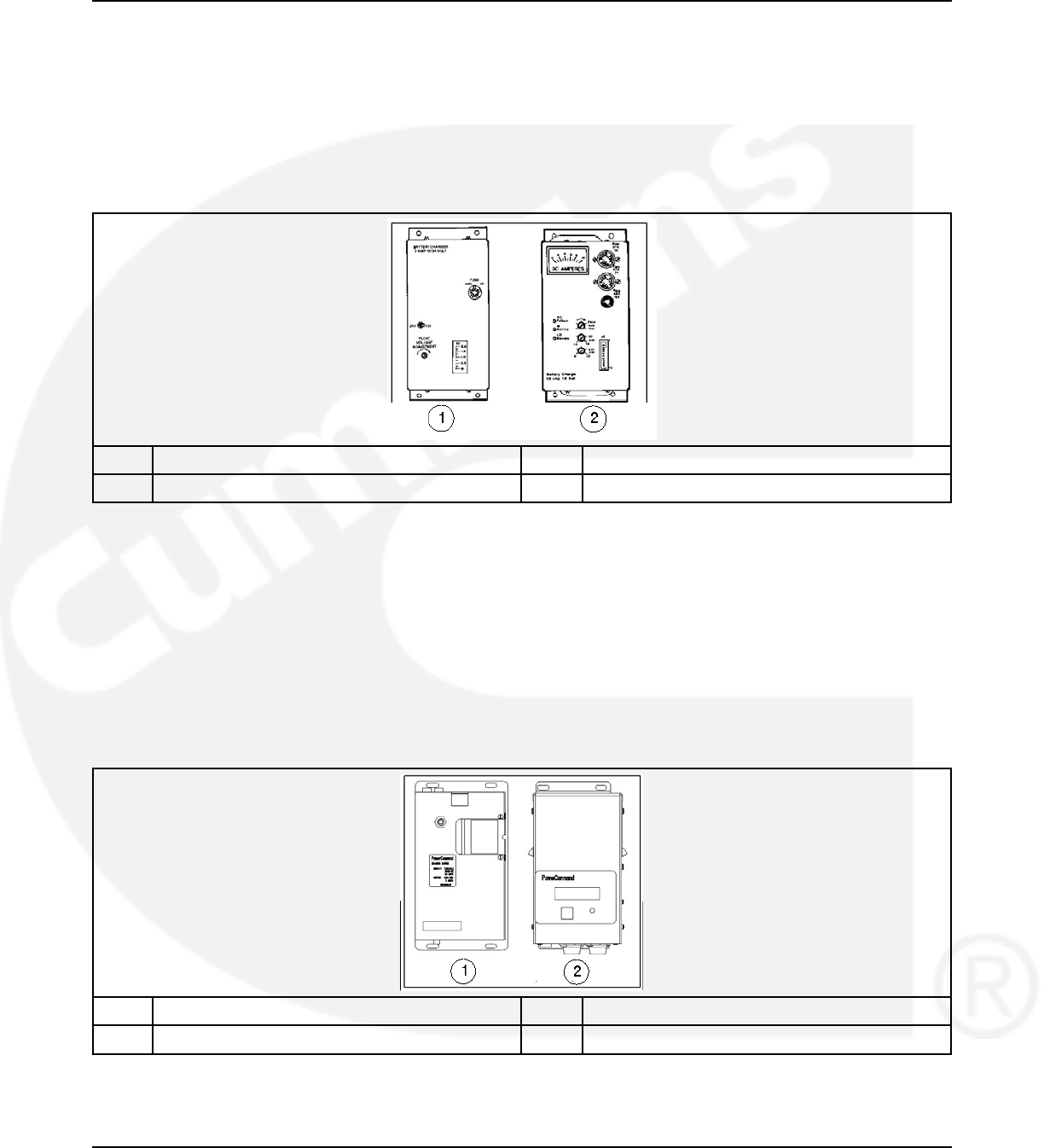
3. Description 02-2014
On the 10-ampere charger, three sets of (Form-C) alarm contacts (corresponding to the three
fault LEDs) are also available. Using an optional alarm contact harness, these contacts can be
wired by the installer to activate other audible or visual alarms.
Under normal operating conditions, the Low Bat and AC Fail relays are energized and the High
Bat relay is de-energized. In response to a Low Bat or AC Fail condition, the appropriate
normally energized relay (Low Bat or AC Fail) drops out. In response to a High Bat condition,
the normally de-energized High Bat relay is energized.
No. Description No. Description
1 2-Amp charger 2 10-Amp charger
FIGURE 32. 2-AMP AND 10-AMP FLOAT BATTERY CHARGERS
3.5.1.2 2-Amp/15-Amp (12VDC), 12-Amp (24VDC) Float Battery Charger
Option
A float-charge battery charger regulates its charge voltage to continuously charge without
damage to the battery. As the battery approaches full charge, the charging current automatically
tapers to zero amperes or to steady-state load on the battery.
Two battery chargers are available. One battery charger is rated for 2 amperes at 12 or 24VDC.
The other battery charger is rated for 15 amperes at 12 VDC or 12 amperes at 24 VDC.
No. Description No. Description
1 2-Amp charger 2 15-Amp (12 Volt), 12-Amp (24 Volt) charger
FIGURE 33. 2-AMP (12 OR 24VDC) AND 15-AMP (12VDC, OR 12-AMP (24VDC))
40 962-0132 (Issue 8)
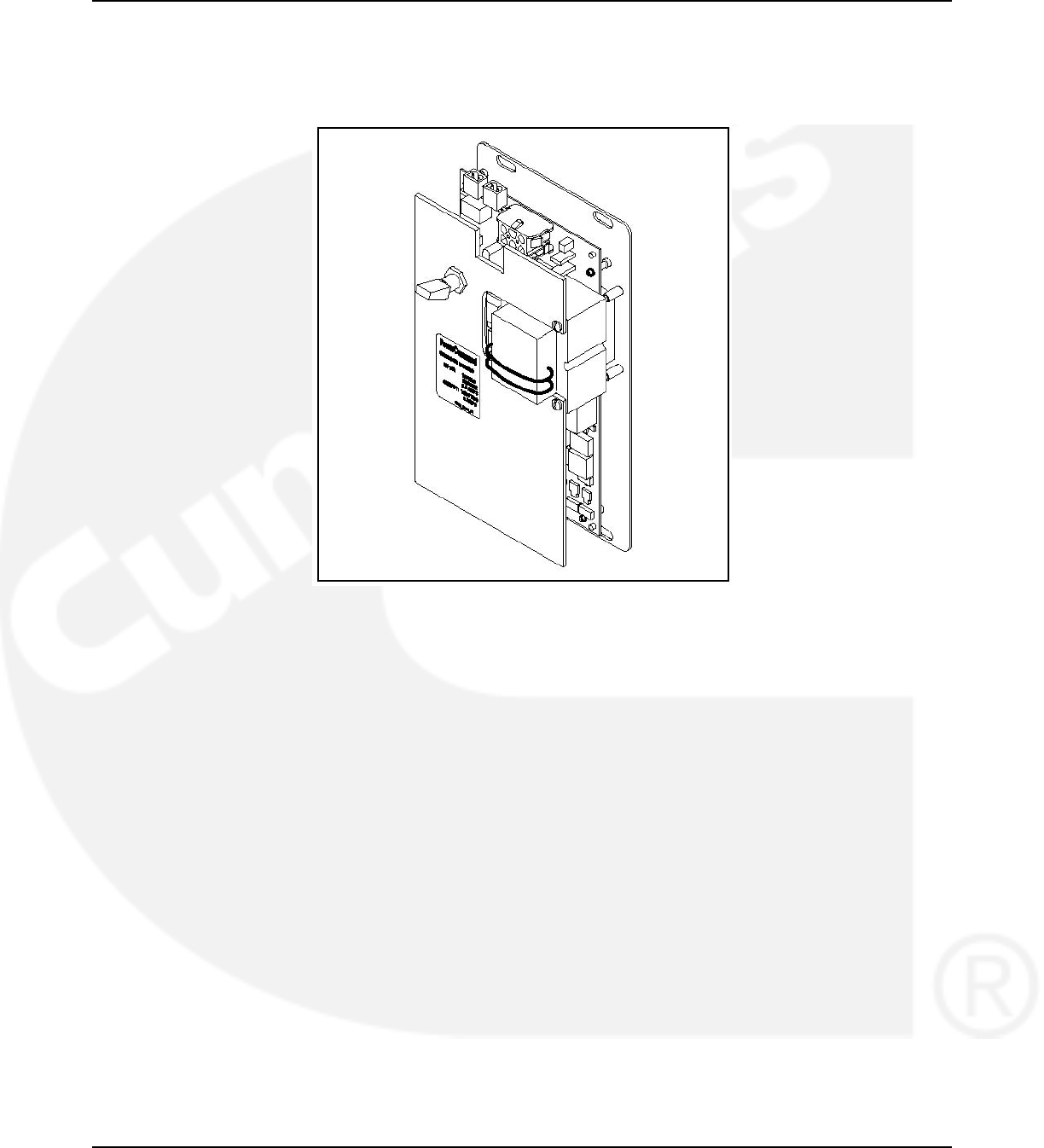
02-2014 3. Description
3.5.1.3 2-Amp Battery Charger
The 2-ampere battery charger has a 5 amp DC output circuit breaker switch on the front of the
battery charger. The charger also includes a 5 amp AC fuse to protect the battery charger
circuit.
FIGURE 34. 2-AMP POWERCOMMAND BATTERY CHARGER
3.5.1.3.1 2-Amp Control Panel
The 2-amp battery charger control panel includes a digital display, a RESET button and an LED
status indicator.
• The 2-line x 16-character digital display displays menus and faults.
• The RESET button is used to select menu options and to clear fault messages.
• The status LED displays the appropriate color for the following conditions.
•Green - On solid indicates unit is charging
•Red - On solid indicates a fault condition. The fault number is shown on the digital
display.
962-0132 (Issue 8) 41
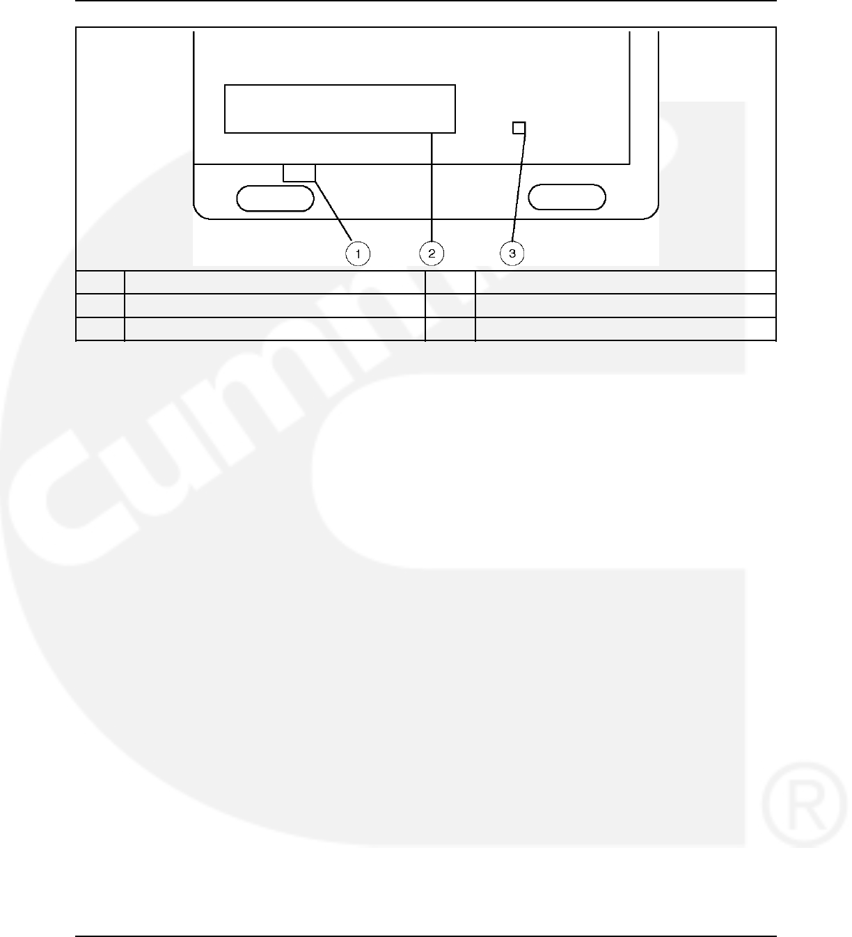
3. Description 02-2014
No. Description No. Description
1 Reset button 3 LED status indicator
2 Digital display
FIGURE 35. 2-AMP BATTERY CHARGER CONTROL PANEL
3.5.1.3.2 2-Amp Battery Charger Configuration
The RESET button on the control panel is used to configure the battery charger for the correct
battery voltage. (More information on Setup menus is included in the Battery Charger Operator
Manual.)
3.5.1.4 15/12-Amp Battery Charger
There are two types of 15/12-amp PowerCommand battery chargers. All 15/12-amp battery
chargers have a 20 amp DC circuit breaker switch on the bottom of the battery charger.
•The 120, 208, and 240 VAC battery chargers include:
• Two 10-Amp AC circuit breaker switches
• A circuit breaker guard
•The 277, 380, 416, and 600 VAC battery chargers include:
• Two AC fuse holders
42 962-0132 (Issue 8)
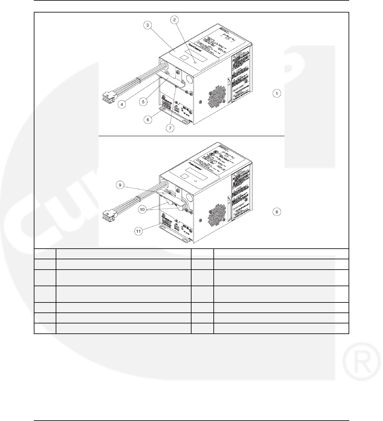
02-2014 3. Description
No. Description No. Description
1 120, 208 and 240 VAC battery chargers 7 AC input breaker
2 Status LED 8 227, 380, 416, 480 and 600 VAC battery
chargers
3 Control panel 9 20-Amp DC output circuit breaker switch (shown
in ON position)
4 DC output breaker 10 AC input fuse holders
5 Circuit breaker guard 11 Optional battery temperature sensor connector
6 Fault alarm output connector
FIGURE 36. 15/12-AMP POWERCOMMAND BATTERY CHARGERS
3.5.1.4.1 Control Panel
The 15/12-amp charger control panel includes a digital display, a Reset button, and an LED
status indicator.
• The 2-line x 16-character digital display displays menus and faults.
• The Reset button is used to select menu options and to clear fault messages.
962-0132 (Issue 8) 43
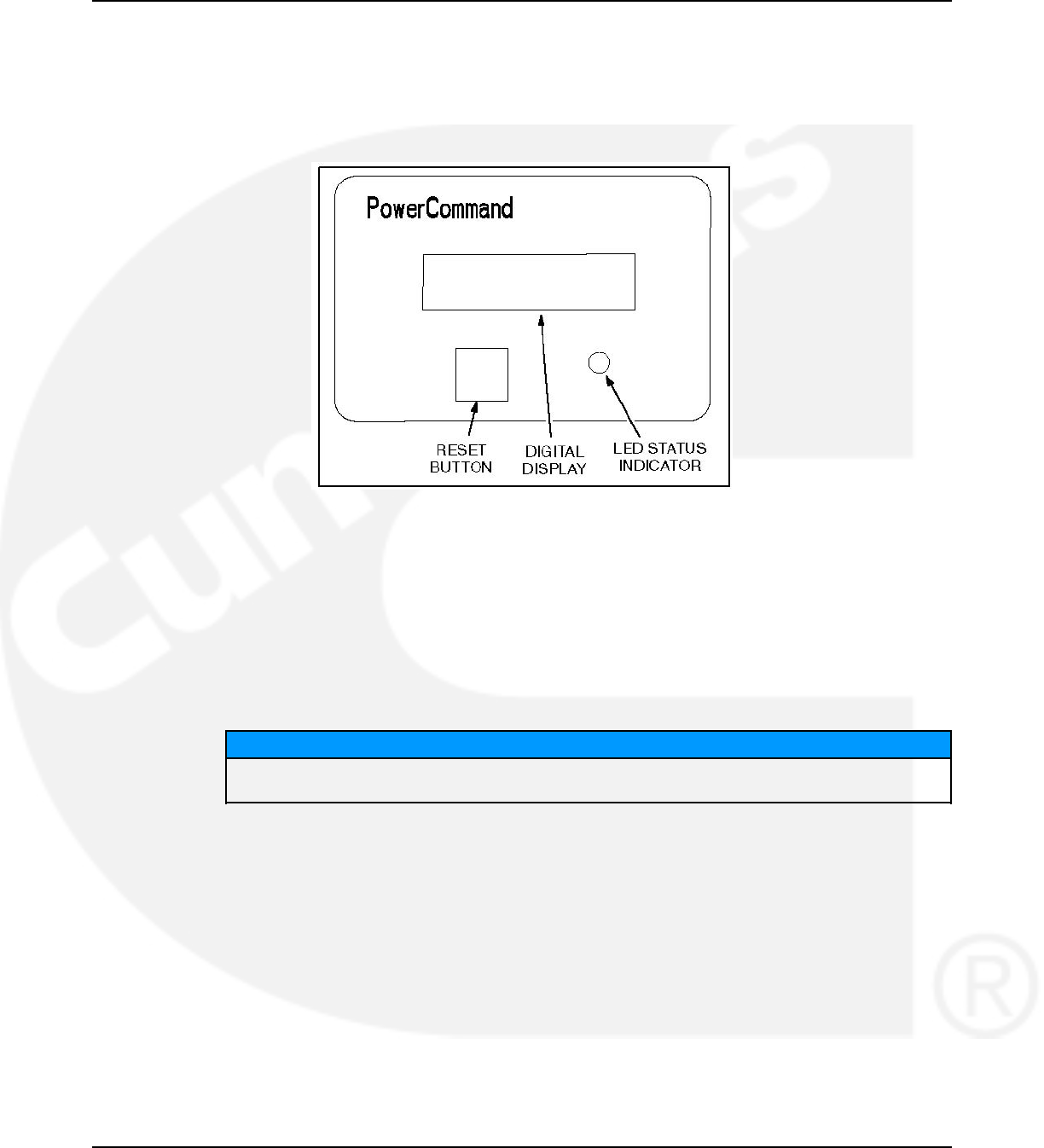
3. Description 02-2014
• The status LED is displays the appropriate color for the following conditions.
•Green - On solid indicates unit is charging
•Amber - On solid indicates Equalizing
•Red - On solid indicates a fault condition. The fault number is shown on the digital
display.
FIGURE 37. 15/12-AMP CHARGER CONTROL PANEL
3.5.1.4.2 Battery Charger Configuration
The RESET button on the control panel is used to configure the battery charger. (More
information on Setup menus is included in the Battery Charger Operator Manual.)
•Battery Voltage and Type - The battery charger must be correctly configured, using the
Setup menus, for the correct battery voltage and type before it is connected to the battery.
The battery voltage can be set for 12 or 24 VDC (default = 12 VDC). The battery type can
be set for Lead-Acid, Gel, or AGM batteries (default = Lead-Acid).
NOTICE
A factory installed battery charger is set up for the proper DC battery voltage requested on
the production order, with the Lead-Acid battery type selected as the default.
•Battery Equalization - Battery equalization is available for lead-acid batteries that are
completely charged, using the Equalize Battery screen in the Setup menus. When battery
equalization is in process, the LED status indicator turns amber.
3.5.1.4.3 Optional Battery Temperature Sensor
A connector for an optional battery temperature sensor is located on the bottom of the battery
charger. When used to monitor battery temperature, the optional battery temperature sensor is
connected from the battery charger to the positive terminal of the battery. A fault message (fault
code 2263) is displayed if the battery temperature is too high (reaches 131 °F (55 °C)).
3.5.1.5 Battery Charger Alarm Contacts Options
The optional 10-ampere battery charger can include three sets of Form-C relay contacts, as an
additional option.
44 962-0132 (Issue 8)
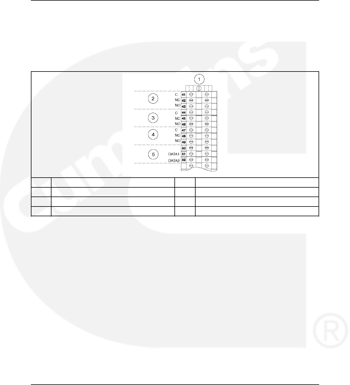
02-2014 3. Description
Under normal operating conditions, the Low Bat and AC Fail relays are energized and the High
Bat relay is de-energized. In response to a Low Bat or AC Fail condition, the appropriate
normally energized relay (Low Bat or AC Fail) drops out. In response to a High Bat condition,
the normally de-energized High Bat relay is energized.
The contacts are rated for 4 amperes at 120 VAC or 30 VDC. Connections to these contacts are
made at terminals 41-42-43 (AC Failure), 44-45-46 (High Battery Voltage) and 47-48-49 (Low
Battery Voltage) of TB3.
No. Description No. Description
1 TB3 2 AC Line Failure
3 High Battery Voltage 4 Low Battery Voltage
5 Network Data
FIGURE 38. BATTERY CHARGER STATUS SUBMENU
3.5.1.5.1 Relay Module Option
The Relay Module provides nine sets of Form-C contacts and two sets of normally open
contacts that are rated for 2 Amps at 30 VDC or 0.60 Amps at 120 VAC. The module includes
the Elevator Pre-Transfer Delay Signal. The relay contacts may be used with other applications.
The Relay Module is located on the left inside wall of the transfer switch enclosure.
The Fail to Disconnect relay is active when the transfer switch remains connected to both
sources for more than 100 msec during a closed transition transfer. It should be wired to the
shunt trip of the breaker feeding the ATS on either the normal or the emergency side. Refer to
the section on closed transition ATS wiring considerations.
The status of the relay module (OK or Not Installed) can be viewed with the digital display. This
menu is included in the About submenus.
962-0132 (Issue 8) 45
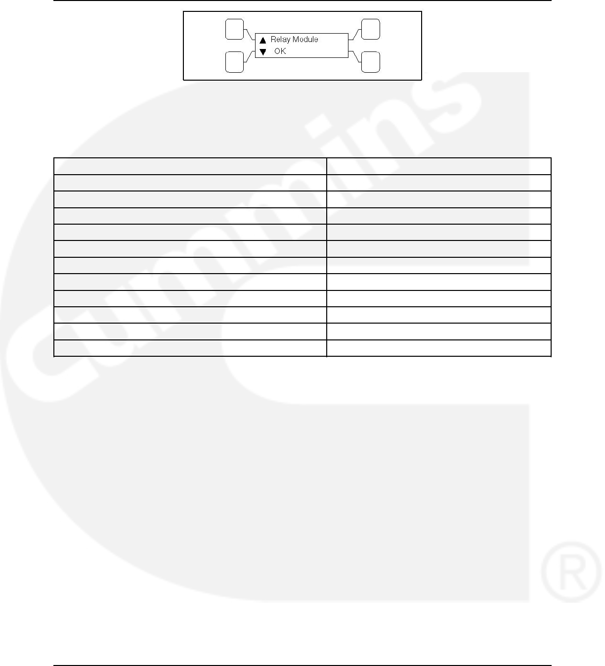
3. Description 02-2014
FIGURE 39. RELAY MODULE STATUS SUBMENU
3.5.1.5.2 Relay Signal Module
TABLE 1. RELAY SIGNAL MODULE
Relay Signal Control Type
Source 1 Connected Level 1 and Level 2
Source 1 Available Level 1 and Level 2
Source 2 Connected Level 1 and Level 2
Source 2 Available Level 1 and Level 2
Test/Exercise Active Level 1 and Level 2
Load Shed Active Level 1 and Level 2
Fail to Transfer/Retransfer Level 2
Fail to Synchronize Level 2
Fail to Disconnect Closed Transition Level 2
Elevator Pre-Transfer Level 1 and Level 2
Transfer Switch Not In Auto Level 1 and Level 2
3.5.1.5.3 Auxiliary Relays Option
Auxiliary relays provide contacts for energizing external alarms, remote indicators and control
equipment such as louver motors and water pumps.
All relays have two normally open and two normally closed contacts that are rated for 10 Amps
at 600 VAC. Connections to the auxiliary relays are made directly to the relay terminals.
There are two types of auxiliary relay coils:
• 12 VDC
• 24 VDC
46 962-0132 (Issue 8)
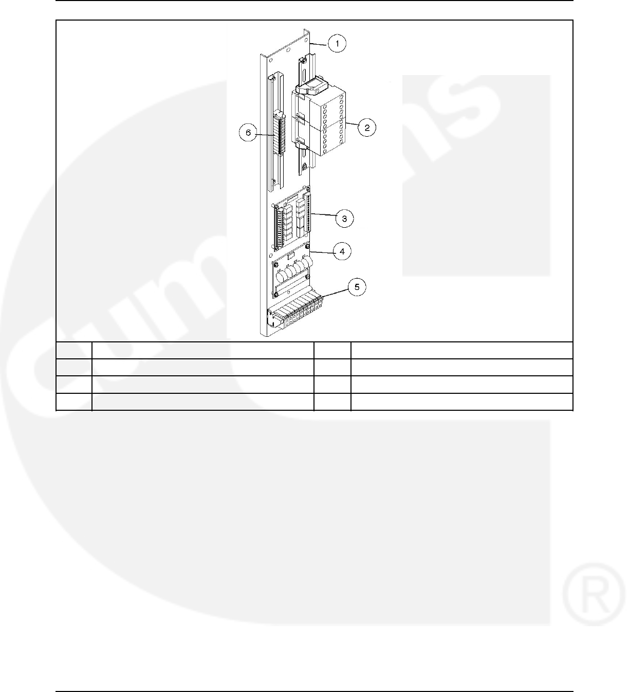
02-2014 3. Description
No. Description No. Description
1 Mounting panel 4 Current module
2 Auxiliary relays 5 TB4
3 Relay module 6 TB3
FIGURE 40. CONTROL WIRING CONNECTIONS
3.5.2 PowerCommand Network Interface Option
The PowerCommand® network interface option includes a PowerCommand Network
Communications Module (NCM) that provides a connection to the PowerCommand network.
The module is LonWorks compatible for integration into customer monitoring strategy.
The Network Interface Module is only enabled with the PC service tool.
For installations that include an NCM, stranded twisted pair network cable is connected to the
left side of terminals 51 and 52 on TB3. The NCM is located on the left side of the digital
module.
962-0132 (Issue 8) 47
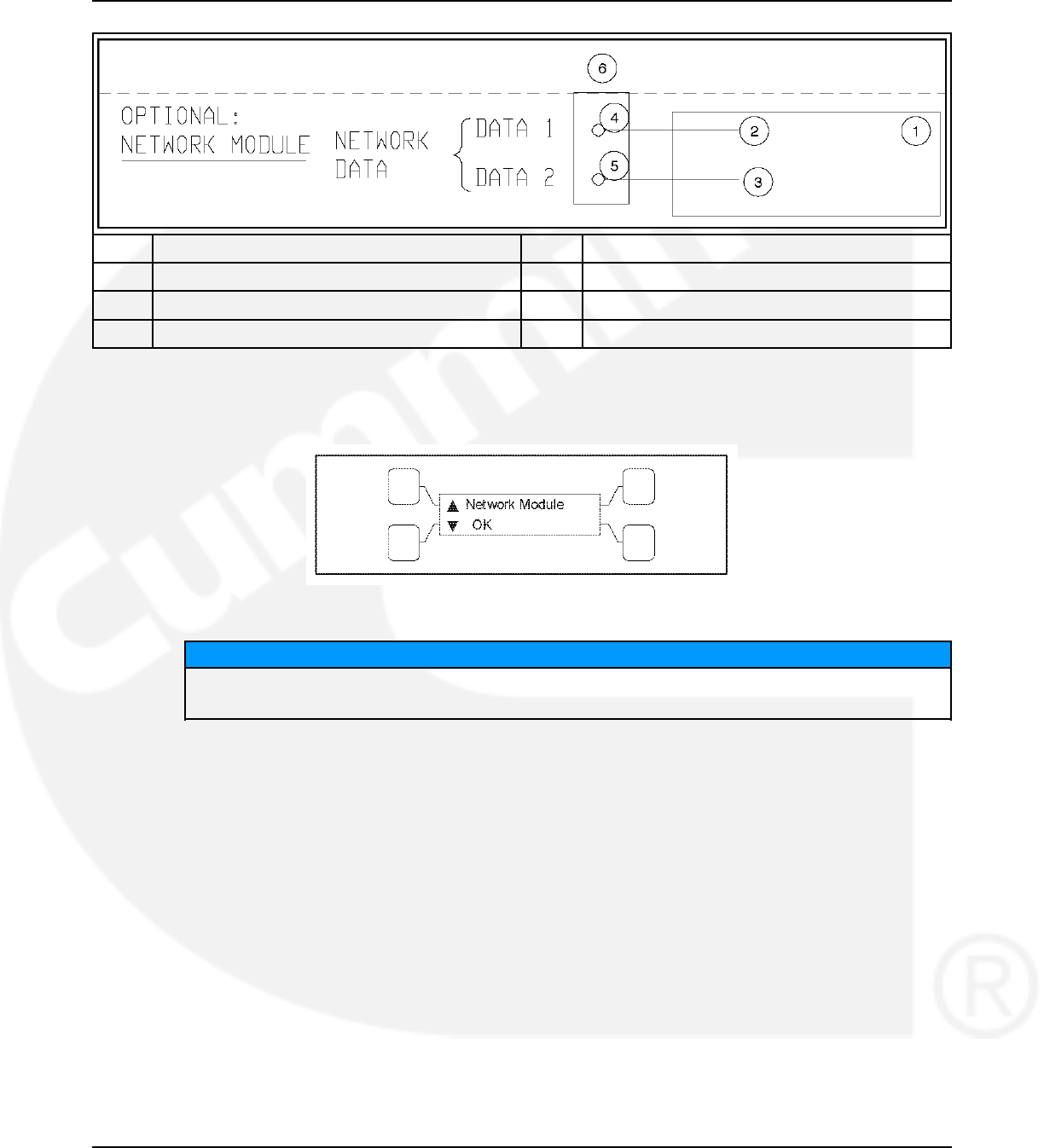
3. Description 02-2014
No. Description No. Description
1 Network Module 2 Data 1 (J30-1)
3 Data 2 (J30-2) 4 51
5 52 6 TB3
FIGURE 41. NETWORK COMMUNICATIONS MODULE CONNECTIONS
The status of the NCM (OK, Not Installed, Not Enabled or Not Available) can be viewed with the
digital display. This menu is located in the About submenus.
FIGURE 42. NETWORK MODULE STATUS SUBMENU
NOTICE
Early production NCMs included two Lithium batteries and a battery hold-down bracket.
Current production NCMs no longer use batteries.
3.5.2.1 Network Sequencer
When an NCM is installed, controllers can include up to eight timed network variables to use for
turning on loads in sequence after a transfer, a retransfer or both. Each variable can be delayed
up to 60 seconds for each of the outputs. The network variables are intended to activate relays
on the Network Digital Input/Output Module (DIM). The DIM is located remotely from the transfer
switch.
The Sequencer feature allows the user to send a predetermined sequence of network event
announcements. The announcements are sent in a timed, sequential order and are used to turn
ATS loads off and on. When used, a few seconds should be allowed between load steps to
allow the generator voltage and frequency to stabilize.
The Sequencer submenus, available through the digital display, can only be viewed if the NCM
is installed and enabled. These menus allow the user to enable/disable the feature, set the
operational mode, activate up to eight relay output signals, and set an output time delay from 0
to 60 seconds for each of the outputs. Additional information on how to adjust these values is
included in the Network Manual.
48 962-0132 (Issue 8)
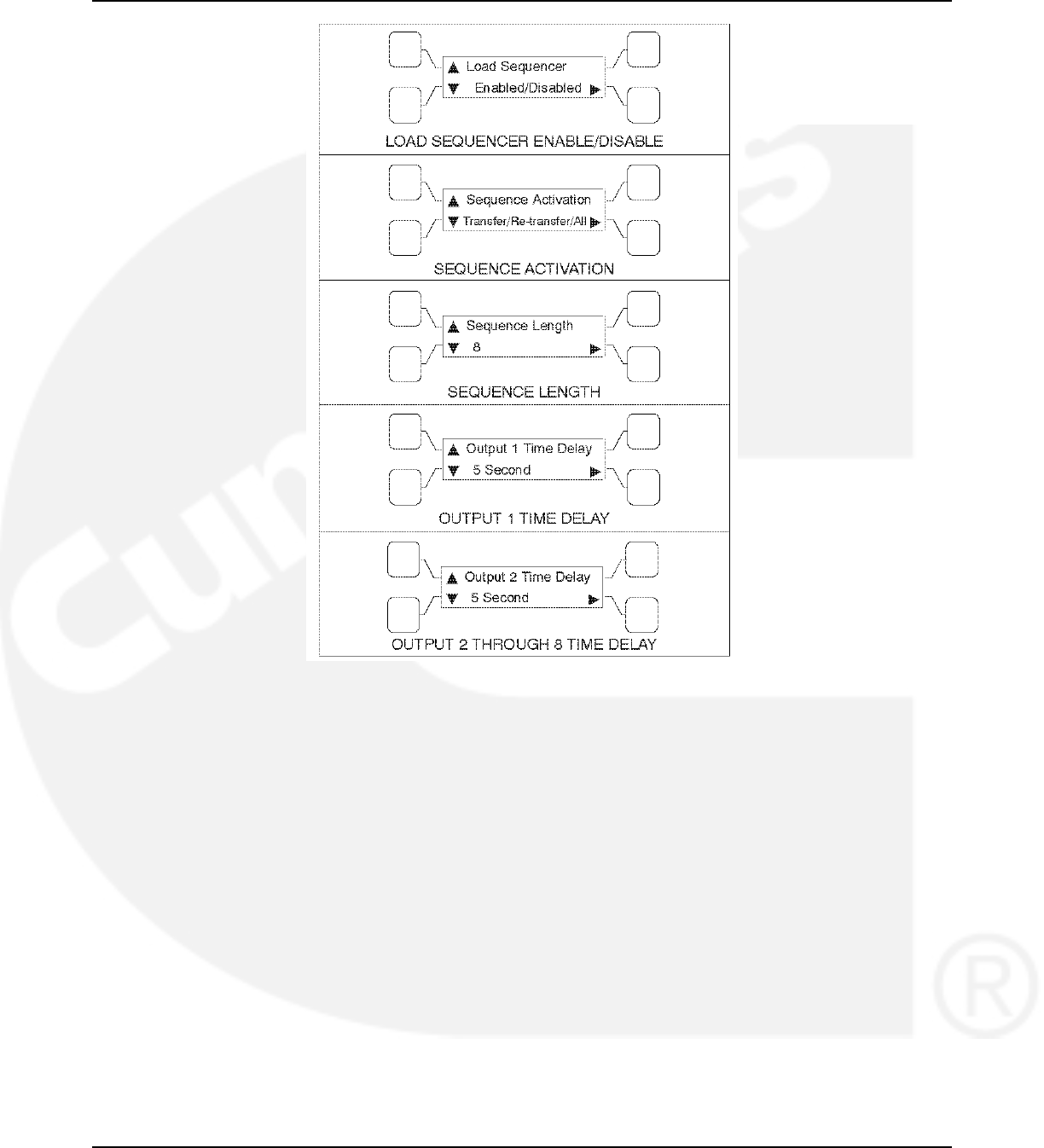
02-2014 3. Description
FIGURE 43. SEQUENCER SUBMENUS
3.5.2.2 Network System Device Status
If an NCM is installed, the user can view the status of up to 32 LonWorks networked devices
through the digital display. The status of networked generator sets, additional ATSs, and the
Master Control (if connected) can be viewed.
962-0132 (Issue 8) 49
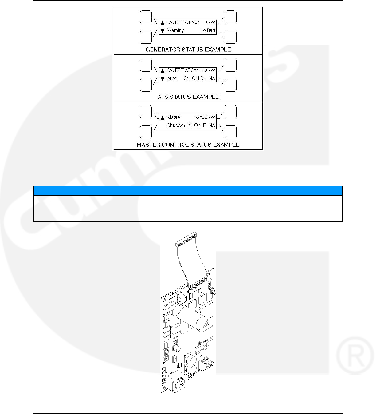
3. Description 02-2014
FIGURE 44. SYSTEM SUBMENUS
3.5.2.3 Network Communications Module (NCM)
NOTICE
The current Network Communications Module being used on OTPC transfer switches includes a
self-installation feature. To self-install, press and hold the Service button (S3) for at least two
seconds until the Node "OK" LED (DS3) begins flashing
FIGURE 45. NETWORK COMMUNICATIONS MODULE (NCM)
50 962-0132 (Issue 8)
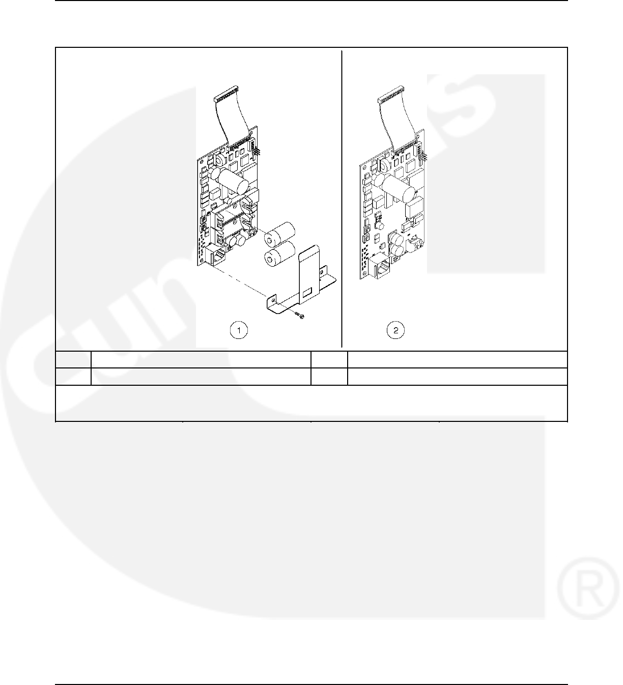
02-2014 3. Description
3.5.2.4 Network Communications Module (NCM)
No. Description No. Description
1 Early production version 2 Current production version
The current Network Communications Module being used on OTPC transfer switches includes a self-installation
feature. To self-install, press and hold the Service button (S3) for at least two seconds until the Node "OK" LED (DS3)
begins flashing.
FIGURE 46. NETWORK COMMUNICATIONS MODULE (NCM)
3.5.3 Load Sequencing Option
Controllers can include up to eight timed network variables to use for turning on loads in
sequence after a transfer, a retransfer, or both. The Network Communications Module (NCM)
must be installed. Each variable can be delayed up to 60 seconds after the preceding variable.
The network variables are intended to activate relays on the Network Digital Input/Output
Module (DIM). The DIM is located remotely from the transfer switch.
3.5.4 Load Current and Power Sensor Option
Three-phase Level 2 controllers can include a load current and power sensor (Current Module).
The control senses the four load currents (three line currents and the neutral current), three load
voltages, and three power factor angles. The control calculates the real load power and the
apparent load power.
The load current sensing feature is active on Level 2 controllers when the Current Module is
installed and connected to the Digital Module.
962-0132 (Issue 8) 51
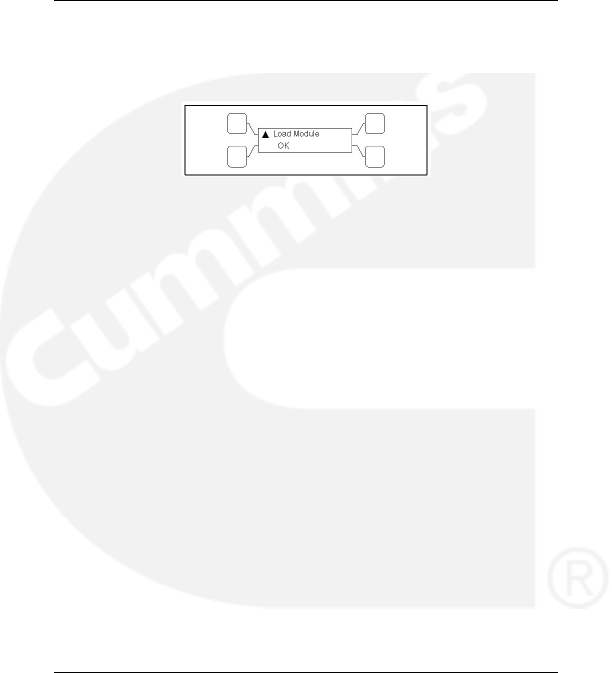
3. Description 02-2014
The control issues a warning when the neutral current exceeds a user specified value between
100 and 150% of the rated current during a specified time period between 10 and 60 seconds.
The warning threshold (100 - 150%) and time delay (10 - 60 sec) can only be set with the PC
service tool.
The status of the load current module (OK or Not Installed) can be viewed with the digital
display. This menu is included in the About submenus.
FIGURE 47. LOAD CURRENT MODULE STATUS SUBMENU
3.5.5 Source 1 and Source 2 Connected Relays
The Source 1 and Source 2 Connected relays are energized when their respective power
sources are available, ready to produce power and connected to the load.
These relays are latching relays and will retain their last state in case of a complete loss of
power.
3.5.6 Source 1 and Source 2 Available Relays
The Source 1 and Source 2 Available relays are energized when their respective power sources
are producing power.
3.5.7 Test or Exercise Active Relay
The Test or Exercise Active relay is energized when the system is in test or exercise mode.
3.5.8 Load Shed Relay
The Load Shed relay is active when the transfer switch has been commanded to disconnect the
load from power Source 2.
3.5.9 Fail to Transfer/Retransfer Relay
The Fail to Transfer/Retransfer relay is energized whenever the transfer switch does not open
or close within a set time interval after the command to transfer or retransfer.
3.5.10 Fail to Synchronize Relay
The Fail to Synchronize relay is energized when the two power sources did not come into
synchronicity (frequency, voltage, phase) within a two-minute limit; during a transfer between
two live sources.
3.5.11 Fail to Disconnect Relay
The Fail to Disconnect relay (causes a fault) is used only in closed transition modes. The relay
is energized whenever the two sources remain parallel longer than a set time limit.
52 962-0132 (Issue 8)

02-2014 3. Description
3.5.12 Elevator Pre-Transfer Delay Relay
The Elevator Pre-Transfer Delay signal delays transfer (or retransfer) for a specified time to
give warning to an elevator control that a transfer (or retransfer) is about to occur.
This time delay (TDEL) is adjustable over a range of 0 to 60 seconds. The default value is 0
seconds. The value is set with the PC service tool or the digital display, if available.
3.5.13 Not-in-Auto Relay
The ATS Not-In-Auto relay is energized when any one of the following occurs:
• Motor Disconnect Switch is set to Off
• Wiring harness is disconnected from J12 on the Power Module
• Controller is set to Offline
3.6 Control Panel (PowerCommand Control)
The PowerCommand control features are divided into three groups:
•Bar graph meter panel - is not available on Level 1 and is optional on Level 2 controls.
•Switch panel - is standard on all transfer switches.
•Digital display - is standard on Level 2 controls and is optional on Level 1 controls.
3.6.1 Bar Graph Meter Panel
The bar graph meter panel is not available on Level 1 controls and is optional on Level 2
controls.
This feature includes:
•A three phase AC ammeter -displays percent of full load currents in amperes (1-125%).
•A power meter - displays the real power in percent of full load in kilowatts (0-125%).
•A power factor meter - displays the real power delivered to the load (1.0 - 0.6 lagging)
and (1.0 - 0.9 leading).
•A frequency meter - displays the output frequency (percent of nominal frequency), of the
power source connected to the load (70-110%).
•A three phase AC voltmeter - displays percent of line to neutral voltages of the power
source connected to the load (70-110%).
962-0132 (Issue 8) 53
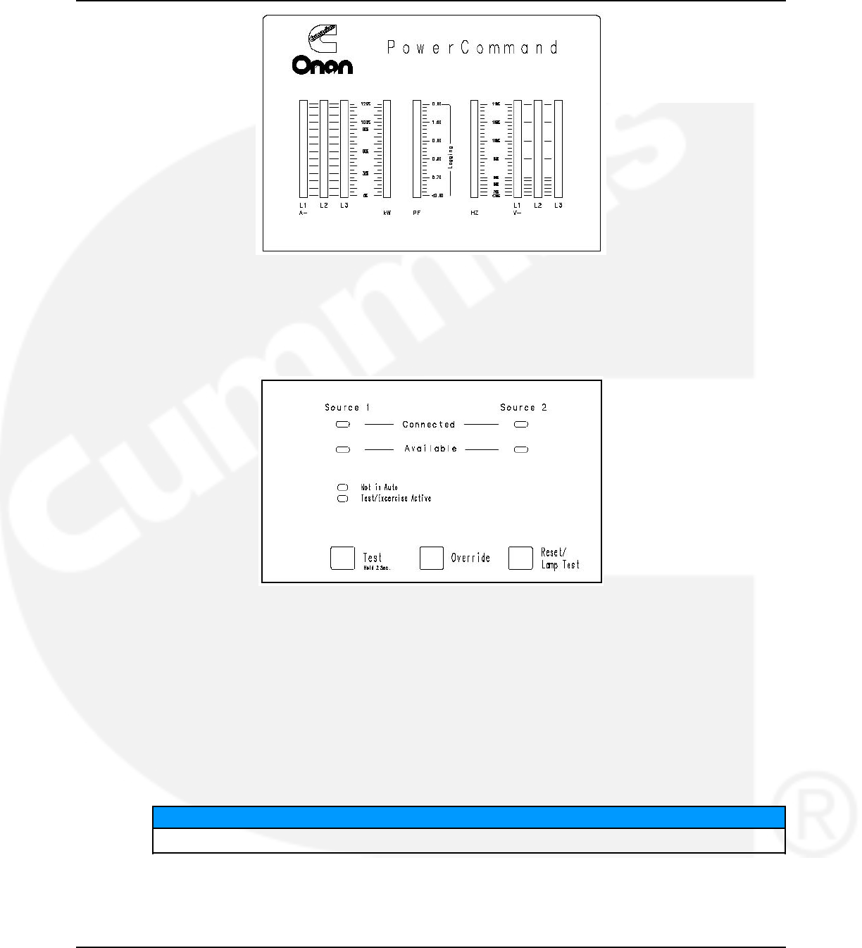
3. Description 02-2014
FIGURE 48. BAR GRAPH METER PANEL
3.6.2 Switch Panel
The switch panel is a standard feature on all PowerCommand controlled (PC) transfer switches.
It contains six indicator lamps and three membrane switches.
FIGURE 49. SWITCH PANEL
Source 1 Available and Source 2 Available: These indicators are lit when the corresponding
sources have acceptable output voltage and/or frequency. These indicators can be lit
simultaneously.
Source 1 Connected: This indicator is lit when the transfer switch is in the normal position and
Source 1 is supplying power to the load.
Source 2 Connected: This indicator is lit when the transfer switch is in the emergency position
and Source 2 is supplying power to the load.
Not in Auto: For all configurations, this indicator flashes when the transfer switch is not in Auto.
NOTICE
The transfer switch is not in Auto when any of the following signals are active:
• Motor Disconnect Switch is set to OFF
• Wiring harness is disconnected from J12 on the power module
54 962-0132 (Issue 8)

02-2014 3. Description
• Controller is set to OFFLINE
Test/Exercise Active: The Test/Exercise Active indicator is lit when the transfer switch has a
test or exercise in progress.
Test: For utility-to-genset applications, the Test switch sends a start signal to the generator set
designated Source 2 and blinks the Test/Exercise Active indicator.
After the start and transfer time delays or source synchronization, Source 2 starts and assumes
the load (if the With Load option is selected).
• Press the Test switch again to end the test; the Test/Exercise Active indicator goes out and
Source 1 resumes as the source of power.
Override: The Override switch terminates most system time delays.
NOTICE
The Program Transition (TDPT), Elevator Signal (TDEL) and Engine Cool Down (TDEC)
are not affected by this switch.
• If you press this switch while the Transfer Inhibit input is active, the switch proceeds to
transfer the load.
• If you press this switch while the Retransfer Inhibit input is active, the switch proceeds to
retransfer the load.
Reset/Lamp Test: The Reset/Lamp Test switch turns on all control panel indicators. This switch
also acknowledges events.
3.6.2.1 Security Key Switch Option
The optional security key switch is located on the front panel. When it is in the Panel Lock
position, it disables the front panel input switches, Test and Override. It also prevents changes
to the digital display from the setup menus; however, the current values are displayed. Changes
can be made when the switch is in the Program position.
FIGURE 50. SECURITY KEY SWITCH
3.6.3 Digital Display
The digital display is standard on Level 2 controls and optional on Level 1 controls. It contains a
2-line by 20-character digital display module and 6 momentary contact membrane switches. The
module displays the menu system. The switches are used to navigate through the menu
system.
962-0132 (Issue 8) 55
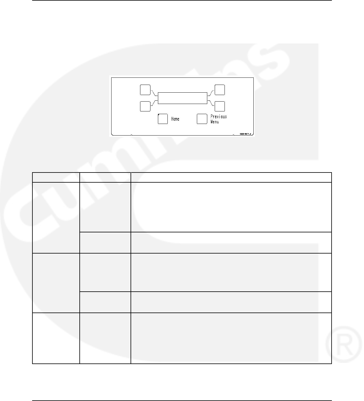
3. Description 02-2014
Each menu indicates the function of the four buttons at the sides of the display module. Not all
buttons are active for each menu.
Sleep Mode: After a period of screen inactivity (no user interaction with the menu system and
no occurring events), the digital display goes blank. The digital display is reactivated when an
event occurs or when an operator touches one of the menu buttons.
In order to conserve controller battery power, the loss of utility power also causes the digital
display to go blank. The digital display is reactivated when a second power source becomes
available.
FIGURE 51. DIGITAL DISPLAY
3.6.4 Time Delay Glossary
Time Delay Abbreviation Definition
Start Time Delay TDES This delay is adjustable from 0 to 15 seconds in 1 second increments on
Level-1 controls and from 0 to 120 seconds in 1 second increments on Level-
2 controls. The default value is 3 seconds for both. This brief time delay
prevents the generator set from starting during short power interruptions.
Timing starts at the Source 1 power interruption. If the duration of interruption
exceeds the delay time, the control system signals the generator set to start.
The value is set with the PC service tool or the digital display when it is
available.
TDES-A and For genset-to-genset applications, TDES-A is the start time delay to start
TDES-B Source 2 genset and TDES-B is the start time delay to start Source 1 genset.
For utility-to-utility applications, TDES-A and TDES-B are not available.
Stop Time Delay TDEC This delay is adjustable from 0 to 30 minutes in 1 minute increments. The
(Cool-down) default value is 10 minutes. It begins timing when the load is retransferred to
Source 1. At the end of the delay, the stop signal is sent to the generator set.
During this time delay, the generator set cools down at no load before
stopping. The value is set with the PC service tool or the digital display when
it is available.
TDEC-A and For genset-to-genset applications, TDEC-A is the stop time delay to stop
TDEC-B Source 2 genset and TDEC-B is the stop time delay to stop Source 1 genset.
For utility-to-utility application, TDEC-A and TDEC-B are not available.
Transfer Time TDNE This delay begins when Source 2 (typically the generator) voltage and
Delay frequency reach the settings of the control. After the delay, the transfer switch
transfers the load to Source 2. This brief time delay allows the generator set
to stabilize before the load is applied. It has an adjustable range of 0 to 120
seconds in 1 second increments. The default value is 10 seconds. The value
is set with the PC service tool or the digital display when it is available.
TDNE is the delay from preferred source to backup source in utility-to-utility
applications and gen-to-gen applications.
56 962-0132 (Issue 8)
02-2014 3. Description
Time Delay Abbreviation Definition
Retransfer Time TDEN This delay begins the moment Source 1 line voltage and frequency return to
Delay specified values. After the delay, the transfer switch can retransfer the load to
Source 1. The delay allows the Power Source 1 to stabilize before retransfer.
It has an adjustable range of 0 to 30 minutes in 1 minute increments. The
default value is 10 minutes. The value is set with PC service tool or the digital
display when it is available.
TDEN is the delay from backup source to preferred source in utility-to-utility
applications and gen-to-gen applications.
Programmed TDPT This delay is the time that the switch spends in the neutral position, when
Transition Time neither source is connected to the load, during a transfer or a retransfer. It
Delay begins when the switch moves to the neutral position and opens the contacts
of the switch connected to the load. After the delay the control transfers the
load. This time delay allows residual voltage of inductive loads to decay
sufficiently before connecting it to another source. It is adjustable from 0 to 60
seconds in 1 second increments. The default value is 0 seconds. The proper
adjustment is a function of the load. This feature is enabled by default. The
value is set with the PC service tool or the digital display when it is available.
Elevator TDEL The Elevator Pre-Transfer Delay Signal delays transfer (or retransfer) for a
Pretransfer Time specified time to give warning to an elevator control that a transfer (or
Delay retransfer) is about to occur. It is adjustable from 0 to 60 seconds in 1 second
increments. The default value is 0 seconds. This feature is enabled by default.
The value is set with the PC service tool or the digital display when it is
available.
962-0132 (Issue 8) 57

3. Description 02-2014
This page is intentionally blank.
58 962-0132 (Issue 8)

4 Operation
4.1 Manual Operation
The transfer switch has operator handles for manually transferring the load. Manual operation
must be performed by qualified personnel under No-Load Conditions only.
4.1.1 Manual Operation - 40 to 1000 Amp Switches
WARNING
Manual operation of the transfer switch under load presents a shock hazard that can cause
severe personal injury or death. Do not attempt to operate switch manually when it is under load.
Follow the “Safety Related Work Practices" listed in NFPA 70E.
1. Open the cabinet door of the automatic transfer switch.
2. Move the Motor Disconnect switch to the Off position.
3. Transfer - from Source 1 (Normal) to Source 2 (Emergency):
a. Pull the upper manual operator handle down.
b. Push the lower manual operator handle down.
4. Retransfer - from Source 2 to Source 1:
a. Pull the lower manual operator handle up.
b. Push the upper manual operator handle up.
5. Before moving the Motor Disconnect switch back to the Auto position, remember the
transfer switch transfers the load to the active power source. If both power sources are
available, it transfers the load to the Source 1 or to the preferred source.
WARNING
Automatic transfer switch operation results in rapid movement of the manual operator
handles and presents a hazard of severe personal injury. Keep hands clear of handles when
switching back to automatic operation.
6. Move the Motor Disconnect switch to the Auto position.
7. Close the cabinet door.
4.1.2 Manual Operation - 1200 to 4000 Amp Switches
The transfer switch has operator handles that are intended for maintenance use only. Manual
operation must be performed by qualified personnel under NO-LOAD CONDITIONS ONLY. Use
the following procedure:
WARNING
Manual operation of the transfer switch under load presents a shock hazard that can cause
severe personal injury or death. Do not attempt to operate switch manually when it is under load.
Follow the “Safety Related Work Practices" listed in NFPA 70E.
962-0132 (Issue 8) 59
4. Operation 02-2014
4.1.2.1 Manual Transfer to Source 1
WARNING
Manual operation of the transfer switch under load presents a shock hazard that can cause
severe personal injury or death. Do not attempt to operate switch manually when it is under load.
Follow the “Safety Related Work Practices" listed in NFPA 70E.
If you determine that Source 1 is available but the transfer switch does not automatically
retransfer, perform this procedure to manually retransfer to Source 1.
1. Open the Source 2 and Source 1 disconnect switches or breakers that feed the transfer
switch. If there is no Source 2 side disconnect, turn off the generator set.
2. When you are certain that neither power source is supplying power to the transfer switch,
open the transfer switch cabinet door and turn the Motor Disconnect switch to OFF.
WARNING
Manual operation of the transfer switch under load presents a shock hazard that
can cause severe personal injury or death. Do not attempt to operate switch
manually when it is under load.
3. A manual operating handle is provided with the transfer switch. The handle is a steel rod or
tube, with a knob or hand grip on one end. On standard transfer switches, there are two
manual operator slots - one for the contacts of each power source.
a. Insert the handle in the slot for the Source 1 (Normal) contacts and open the Source 1
contacts.
b. Insert the handle in the slot for the Source 2 (Emergency) contacts and close the
Source 2 contacts. Be certain to push the handle all the way to the LOCK position. A
distinct over-center locking action can be felt.
c. Return the handle to its storage position.
WARNING
Automatic transfer switch operation results in rapid movement of the manual
operator mechanism and present s a hazard of severe personal injury if the
operator handle is engaged in the mechanism. Remove the handle and place it
in its storage position.
4. After the switch has been transferred to Source 1 and the operator handle has been
removed from the mechanism, close and lock the handle door.
5. Close the Source 2 and Source 1 disconnect switches or breakers that feed the transfer
switch. Start the generator set if it was previously turned off.
6. If the transfer switch is not functioning correctly, call your dealer or distributor immediately.
4.1.2.2 Manual Transfer to Source 2
WARNING
Manual operation of the transfer switch under load presents a shock hazard that can cause
severe personal injury or death. Do not attempt to operate switch manually when it is under load.
Follow the “Safety Related Work Practices" listed in NFPA 70E.
60 962-0132 (Issue 8)
02-2014 4. Operation
If you determine that Source 2 is available but the transfer switch does not automatically
transfer, perform this procedure to manually transfer to Source 2.
1. Open the disconnect switches or breakers that feed the transfer switch. If there is no
Source 2 disconnected, turn off the generator set.
2. When you are certain that neither power source is supplying power to the transfer switch,
open the transfer switch cabinet door and turn the Motor Disconnect switch to OFF.
WARNING
Manual operation of the transfer switch under load presents a shock hazard that
can cause severe personal injury or death. Do not attempt to operate switch
manually when it is under load.
3. A manual operating handle is provided with the transfer switch. The handle is a steel rod or
tube, with a knob or hand grip on one end. On standard transfer switches, there are two
manual operator slots - one for the contacts of each power source.
a. Insert the handle in the slot for the Source 1 (Normal) contacts and open the Source 1
contacts.
b. Insert the handle in the slot for the Source 2 (Emergency) contacts and close the
Source 2 contacts. Be certain to push the handle all the way to the LOCK position. A
distinct over-center locking action can be felt.
c. Return the handle to its storage position.
WARNING
Automatic transfer switch operation results in rapid movement of the manual
operator mechanism and present s a hazard of severe personal injury if the
operator handle is engaged in the mechanism. Remove the handle and place it
in its storage position.
4. After the switch has been transferred to Source 2 and the operator handle has been
removed from the mechanism, close and lock the handle door.
5. Close the disconnect switches or breakers that feed the transfer switch. Start the generator
set if it was previously turned off.
6. If the transfer switch is not functioning correctly, call your dealer or distributor immediately.
4.2 Automatic Operation
For utility-to-genset and genset-to-genset configurations, the generator set control must also be
set for automatic (in the AUTO position) operation.
For automatic operation of the transfer switch, place the following control switches in the
following positions:
4.2.1 Motor Disconnect Switch
For automatic operation of the transfer switch, place the Motor Disconnect switch in the AUTO
position.
962-0132 (Issue 8) 61

4. Operation 02-2014
4.3 System Testing
4.3.1 Generator Set Manual Start Test
This test is used with utility-to-genset applications only.
1. Set the Test With/Without Load variable to the Without Load value.
2. Press and hold the Test switch for two seconds. The generator set starts and runs after the
start time delay.
3. At the end of the test period, press the Test switch again. The generator cools down and
stops.
4.3.2 With-Load Standby System Test
1. Set the Test With/Without Load variable to the With Load value (refer to the Digital Display
Menu System section or the PC service tool for details).
NOTICE
The Test With/Without Load variable must be set to the With Load value in order to
test with load.
2. Press and hold the Test switch for two seconds. To bypass the transfer time delay and
cause a faster load transfer, press the Override switch. The generator set starts and
assumes the load after the start time delay.
3. At the end of the test period, press the Test switch again. To bypass the retransfer time
delay and cause a faster load retransfer, press the Override switch. The generator stops
after the stop time delay.
4.4 Generator Set Exercise
Run the generator for at least 30 minutes once each week with at least 50% load (if possible). If
you do not want to use the exerciser, use the Test switch, to test the generator set each week.
The exerciser can be programmed for specified exercise periods and is used to exercise the
generator set automatically with or without load.
• The PC service tool is required to set the exercise parameters on transfer switches
without the digital display.
• The digital display (when available) can be used to set exercise parameters for up to
eight exercise periods and eight exceptions.
All controllers have a switch to enable or disable pre-set exercise routines. The pushbutton is
located on the Digital Module above the batteries, next to the LED light bar display. This button
is used by service personnel to disable unexpected transfers while servicing the switch.
NOTICE
If a power failure occurs during the exercise routine, the controller overrides the routine
and transfers the load.
62 962-0132 (Issue 8)
02-2014 4. Operation
4.5 Planned Maintenance
Performing the annual planned maintenance procedures increases reliability of the transfer
switch.
The following procedures must only be done by technically qualified personnel, according to
procedures in the Service Manual. If repair or component replacement is necessary, call your
dealer or distributor.
WARNING
AC power within the cabinet and the rear side of the cabinet door presents a shock
hazard that can cause severe personal injury or death. Incorrect installation, service or
parts replacement can result in severe personal injury, death and/or equipment damage.
All corrective service procedures must be done only by technically qualified personnel,
according to procedures in the Service Manual.
WARNING
The transfer switch presents a shock hazard that can cause severe personal injury or
death unless all AC power is removed. Be sure to set the generator set operation
selector switch to Stop, disconnect AC line power, disconnect the battery charger from
its AC power source and disconnect the starting battery (negative [-] lead first) before
servicing.
WARNING
Ignition of explosive battery gases can cause severe personal injury. Do not smoke or
cause any spark, arc or flame while servicing batteries.
TABLE 2. PLANNED MAINTENANCE
Disconnect All Sources of AC Power:
1. Disconnect both AC power sources from the transfer switch before continuing. Turn the generator set operation
selector switch to Stop. (The selector switch is located on the generator set control panel.)
2. If there is an external battery charger, disconnect it from its AC power source. Then disconnect the set starting
battery (negative [-] lead first).
Clean:
1. Thoroughly dust and vacuum all controls, meters, switching mechanism components, interior buswork and
connecting lugs.
2. Close the cabinet door and wash exterior surfaces with a damp sponge (mild detergent and water).
WARNING
Do not allow water to enter the cabinet, especially at meters, lamps and switches.
962-0132 (Issue 8) 63
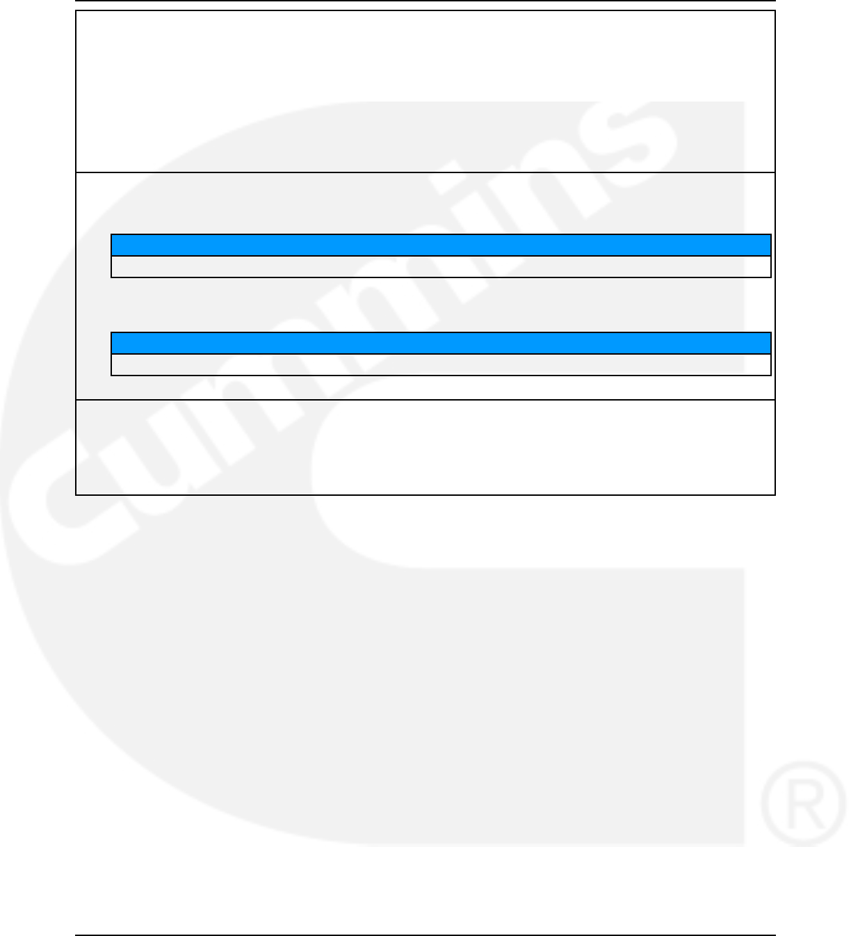
4. Operation 02-2014
Inspect:
1. Check bus work and supporting hardware for carbon tracking, cracks, corrosion or any other types of
deterioration. If replacement is necessary, contact your dealer or distributor.
2. Check stationary and movable contacts. If contact replacement is necessary, contact your dealer or distributor.
3. Check system hardware for loose connections.
4. Check all control wiring and power cables (especially wiring between or near hinged door) for signs of wear or
deterioration.
5. Check all control wiring and power cables for loose connections.
6. Check the cabinet interior for loose hardware.
Perform Routine Maintenance:
1. Tighten bus work, control wiring, power cables and system hardware as necessary.
NOTICE
Hardware torque values are given in the Service Manual.
2. Re-torque all cable lug connections.
NOTICE
Lug torque requirements are listed in the Service Manual.
Connect AC Power and Check Operation:
1. Connect the set starting battery (negative [-] lead last). Connect the utility AC power source, enable the
generator set power source. If applicable, connect power to the battery charger.
2. Verify proper operation of the battery charger.
3. Test system operation as described in this section. Close and lock the cabinet door.
64 962-0132 (Issue 8)

5 Digital Display Menu System
This section describes the Digital Display Menu System and navigation through the menus. The
menus display status information, events, and setup menus. Setup menus contain parameters
with adjustable values. The descriptions in this section include ranges for the parameters and
default values. The digital display is an option with Level 1 controls and is standard with Level 2
controls. The system menus can also be accessed with the PC service tool.
The Digital Display Menu System is a 2-line by 20-character graphical display screen and six
buttons. The screen or menu displays status information, parameters, events and messages.
The buttons change screens and parameters. Two buttons have names: Home and Previous
Menu. These buttons are used for navigation. Messages include navigational indicators for the
other four buttons.
5.1 Main Menus
The main menu system consists of three top-level menus that list vertical menus (or submenus).
The submenus display status information. This information cannot be changed in the main
menus. The main menus contain eight submenus including the Setup Menus.
5.2 Password and Setup Menus
Before you can navigate and change setup parameters, you must enter a password; however,
you can bypass the password and examine but not change parameters. When parameters are
changed in any setup menu, you are prompted to either save the changes or restore the old
values.
5.3 Navigation
The following image represents the typical functions of the Main Menu navigational buttons.
962-0132 (Issue 8) 65
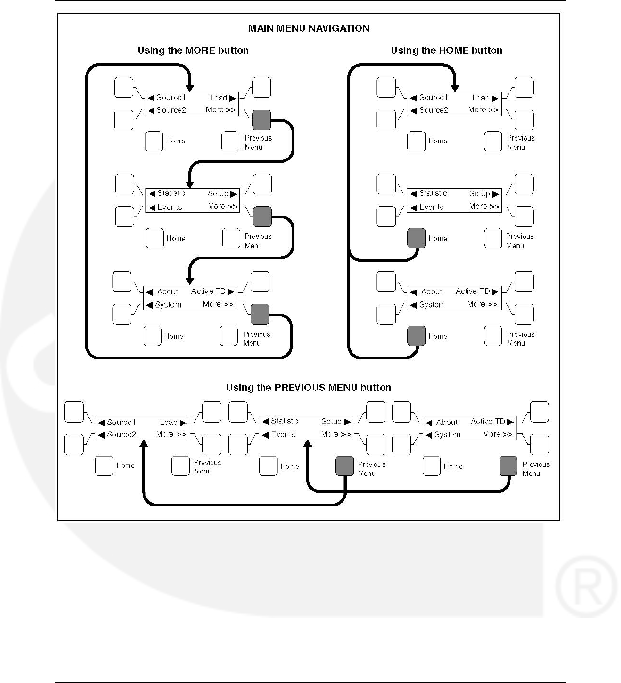
5. Digital Display Menu System 02-2014
FIGURE 52. NAVIGATION
5.4 Main Menu Descriptions
5.4.1 First Main Menu
• The Source 1 and Source 2 buttons move between submenus that monitor aspects to both
power sources:
• Line-to-Line Voltage
66 962-0132 (Issue 8)

02-2014 5. Digital Display Menu System
• Frequency
• Source Connected
• Running Time
• Pressing the Home button returns to the First Main Menu display within any of the Source
1, Source 2, or Load submenus.
• The Load button moves through submenus to display information on the load connected
source:
• Voltage Output
• Amps and Frequency
• Power Factor and Output
• The More button advances to the Second Main Menu.
• The Previous Menu button is not active at this level.
5.4.1.1 Source 1 and Source 2 Submenus
Use the push button to the left of the display screen to navigate through the following screens:
•Volts L12 L23 L31:
• The Level 1 control will only read line-to-line voltages.
• The Level 2 control is capable of reading line-to-line and line-to-neutral voltages,
depending on the application.
• Source 1 and Source 2 reads three-phase voltage for three-phase systems and
single-phase voltage for single-phase systems.
• The Level 1 control will only read single-phase voltages for Source 2.
• If the voltage is measured at 10 volts or less, the display reads 0.
• On Level 1 controllers (Source 2), only one voltage will be displayed at L12.
• On Level 1 controllers (Source 1), displays 3-phase voltage for 3-phase systems
or single-phase voltage for single-phase systems.
•Volts L1N L2N L3N:
• Level 2 reads line-to-neutral voltages, level 1 will not
• Numbers do not display if the system has no neutral.
• This screen does not display with Level 1 controllers
•Frequency: Displays the sensed line frequency for Source 1 or Source 2.
•Source 1 (or 2): Displays the position of contactors for either Source 1 or Source 2.
•Run Time Source 1 (2): Displays the total time the transfer switch has been connected to
either Source 1 or Source 2.
5.4.1.2 Load Submenus
NOTICE
This subset is not available on Level 1 Controls and is optional on Level 2 Controls.
962-0132 (Issue 8) 67

5. Digital Display Menu System 02-2014
Use the Source 1 and Source 2 push button to the left of the display screen to navigate through
the following screens:
•Volts L12 L23 L31: Line-to-Line Load Voltage Screen
•Volts L1N L2N L3N: Line-to-Neutral Voltage for Load
•Amps L1 L2 L3: Line Currents for Load
•Frequency: Sensed line frequency for Load connected source
•Real Power kW: Real Power of the transfer switch
•Apparent Power KVA: Total Apparent Power of the transfer switch
•Power Factor: Average Power Factor of the transfer switch. This will be displayed as lead
or lag.
•Neutral Current: Neutral Current of the transfer switch.
5.4.2 Second Main Menu
• The Statistic button displays information about either source:
• Run Time
• Average Transfer Time
• Total Number of Transfers
• Total Number of Failures
• Battery and (optional) Charger status
• Control on Time
• The Events button displays the last 50 events or fault codes recorded on the controller.
• The Home button returns to the First Main Menu.
• The Setup button enters the password protected adjustment program:
• Adjust Sensors
• Set Time Delays
• Test and Exercise
• Exercise Exceptions
• Transition Mode Trim
• Load Sequencer Enable
• The More button advances to the Third Main Menu.
• The Previous Menu button returns to the First Main Menu.
5.4.2.1 Events Submenus
The Events program displays information about either source. The controller stores and records
the last fifty events in chronological order, beginning with the most recent event. The date and
time are listed with each event.
* Indicates that the event is currently active.
Use the push button to the left of the display screen to navigate through the screens.
68 962-0132 (Issue 8)

02-2014 5. Digital Display Menu System
5.4.2.2 Setup Submenus
The Setup button enters the password-protected adjustment programs to:
• Adjust Sensors
• Set Time Delays
• Test and Exercise
• Exercise Exceptions
• Transition Mode Trim
• Load Sequencer Enable
5.4.2.2.1 Entering the Password Program
Press the Setup button to access the Enter Password menu.
The password is 574.
1. Use the + and - buttons to select a number.
2. Use the right arrow button to move the cursor to the next field.
3. When the password is set, press the right triangle button to enter the Setup program.
5.4.3 Third Main Menu
• The About button displays general information about the transfer switch and controller.
• The System button provides access to data from surrounding devices communicating
through a LonWorks network. If the optional network card is not included with the transfer
switch, the System button is not active.
• The Home button returns to the First Main Menu.
• The Active TD button displays all active time delays.
• The More button returns the display to the First Main Menu.
• The Previous Menu button returns to the Second Main Menu.
5.4.3.1 About Submenus (Prior to Software Version 1.20.250)
The About submenus contain read-only information about the transfer switch and controller.
•Name of Switch: Displays the name of the switch as defined in the Event Handling
Requirement.
•Software Version: Displays the current firmware version of the controller.
•Build Date: Displays the manufacturing date of the controller.
•ATS Configuration: Displays the configuration of the controller. Changes are made by
servicing personnel using the PC service tool.
Data:
• Test Mode
• Util-Gen
• Utility-Utility
• Genset-Genset
962-0132 (Issue 8) 69

5. Digital Display Menu System 02-2014
• Unknown
•ATS Type: Displays the mode of operation the control is using. Adjustments can be made
by service personnel using the PC service tool.
Data:
• OT = Open Transition
• BT = Bypass Transition
• Unknown
•ATS Board Level: Displays the ATS board level (1 or 2).
NOTICE
This menu was not included in early versions of software.
•Network Module: This screen indicates if a Network Communications Module is installed
and enabled.
• Hardware Detected + Software Enabled = OK
• Hardware NOT Detected + Software Enabled = Not Installed
• Hardware Detected + Software NOT Enabled = Not Enabled
• Hardware NOT Detected + Software NOT Enabled = Not Available
•Relay Module: This screen indicates if the Relay Module hardware is installed.
Data:
• OK
• Not Installed
•Load Module: This screen indicates if the Load Current Module hardware is installed. This
feature is not available on Level 1 Controllers.
Data:
• OK
• Not Installed
5.4.3.2 About Submenus (Software Version 1.20.250 and Greater)
The About submenus contain read-only information about the transfer switch and controller.
•Name Tag: Displays the name of the switch as defined in the Event Handling
Requirement.
•Software Version: Displays the current firmware version of the controller.
•Bootcode Version: Displays the current bootcode version of the controller.
•Build Date: Displays the manufacturing date of the controller.
•Switch Mechanism: Displays the switch mechanism of the controller.
•ATS Configuration: Displays the configuration of the controller. Changes are made by
servicing personnel using the PC service tool.
70 962-0132 (Issue 8)

02-2014 5. Digital Display Menu System
Data:
• Off line
• Util-Gen
• Util-Util
• Gen-Gen
•ATS Type: Displays the mode of operation the control is using. Adjustments can be made
by service personnel using the PC service tool.
Data:
• OT = Open Transition
• BT = Bypass Transition
•ATS Board Level: Displays the ATS board level (1 or 2).
•Network Module: This screen indicates if a Network Communications Module is installed
and enabled.
• Hardware Detected + Software Enabled = OK
• Hardware NOT Detected + Software Enabled = Not Installed
• Hardware Detected + Software NOT Enabled = Not Enabled
• Hardware NOT Detected + Software NOT Enabled = Not Available
•Relay Module: This screen indicates if the Relay Module hardware is installed.
Data:
• OK
• Not Installed
•Load Module: This screen indicates if the Load Current Module hardware is installed. This
feature is not available on Level 1 Controllers.
Data:
• OK
• Not Installed
5.4.3.3 Active TD Submenus (Prior to Software Version 1.12)
•Test in Process: Shows time delay activity, the type of time delay and a countdown. If
there is no active time delays, the message "No Timer Active" is displayed.
NOTICE
Active TD menus were not available in early versions of software.
962-0132 (Issue 8) 71

5. Digital Display Menu System 02-2014
5.4.3.4 Active TD Submenus (Software Version 1.12 and Greater)
The Active TD submenus generally show the time delay activity, type of time delay and
countdown. This is not specific to the Test in Process submenu.
•TDNE: Pressing the Active TD menu button shows that TDNE is one of the active time
delays enabled in the control.
•Changeover in: This menu shows a Preferred Source Changeover Timer and remaining
time (Utility-to-Utility and Genset-to-Genset applications only).
•No Timer Active: This message is displayed only if there are no active time delays.
5.4.4 Setup Menu Navigation and Description
5.4.4.1 Setup Group 1
This group allows programming the operational parameters of the switch for Source 1 and
Source 2.
The Sensor submenus are used for setting the:
• Phase Type
• Nominal Type
• Under-voltage Settings
• Over-voltage Settings
• Time Delays
• Frequency Settings
• Imbalance Settings
• Phase Loss
• Phase Rotation
The Sync Check sensor submenus allow programming synchronous conditions for Source 1
and Source 2 that must be met before transferring from one to the other source.
5.4.4.1.1 Sensor 1 and Sensor 2 Submenus (Prior to Software Version 1.12)
When entering numerical values:
Use the + and - buttons to select numerical values or toggle through a list of selections.
When entering numerical values, the - button lowers the value to its lowest range, then begins
again at the top end of the range. The + button increases the value to its highest range, then
begins again at the low end of the range.
Use the right-facing arrow button to move the cursor to the next field.
•Sensor 1 and Sensor 2: These submenus are identical, except:
• S1 refers to Source 1
• S2 refers to Source 2
72 962-0132 (Issue 8)
02-2014 5. Digital Display Menu System
NOTICE
For 2-wire system, select 1 phase-2 wire.
For a single phase-3 wire system, select 1 phase-3 wire.
For a 3 phase system, select 3 phase.
•S1 or S2 Nominal Voltage: System voltage for Source 1 or Source 2. Enter the system
voltage between 110 and 600 VAC.
NOTICE
Level 1 Controls are Line-to-Line voltages and Level 2 Controls are Line-to-Neutral
voltages.
•S1 or S2 UV Pickup: Under-Voltage sensor pickup for Source 1 or Source 2. Enter a
number between 85 and 100% of the nominal voltage (Default 90%).
•S1 or S2 UV Dropout: Under-Voltage sensor dropout voltage. Enter a number between 75
and 98% of the under-voltage pickup percentage (Default 90%).
•S1 or S2 UV Time Delay: Under-Voltage dropout time delay. Enter a time between 0.0
and 1.0 seconds (Default 0.5 seconds).
•S1 or S2 OV Enable: Over-Voltage sensing enable. Choose Enabled or Disabled (Default
Enabled).
•S1 or S2 OV Pickup: Over-Voltage pickup. This adjusts the over-voltage pickup as a
percentage of the over-voltage dropout. Enter a number between 95 and 99% (Default
95%).
•S1 or S2 OV Dropout: Over-Voltage dropout. Enter a percentage between 105 and 135%
of the nominal voltage (Default 110%).
•S1 or S2 OV Time Delay: Over-Voltage time delay. Enter a range between 0.5 and 120
seconds (Default 3 seconds).
•S1 or S2 Frequency Sensor: Monitors line frequency on A-Phases of both sources
(Default Enabled).
•Nominal Frequency: Enter a frequency between 45 and 65 Hz (Default 60 Hz).
•Frequency Pickup: Enter a percentage between 5 and 20% of the nominal frequency
(Default 10%).
•Frequency Dropout: Enter a percentage between 2 and 5% of the frequency pickup
(Default 1%).
•Frequency Delay: Enter a time between 0.1 and 15.0 seconds (Default 5 seconds).
•S1 or S2 Imbalance Sensor (Level 2 Controllers Only): Detects unbalanced voltages on
3-phase sources (Default Disabled).
•Imbalance Dropout (Level 2 Controllers Only): Enter a percentage between 2 and 10%
(Default 5%).
•Imbalance Delay (Level 2 Controllers Only): Enter a time between 2 and 20 seconds
(Default 5 seconds).
•S1 or S2 Loss of Phase (Level 2 Controllers Only): The loss of single phase sensing can
be enabled or disabled (Default Disabled).
962-0132 (Issue 8) 73

5. Digital Display Menu System 02-2014
•Phase Rotation (Level 2 Controllers Only): The phase rotation sensing can be enabled or
disabled (Default Enabled).
5.4.4.1.2 Sensor 1 and Sensor 2 Submenus (Software Version 1.12 and Greater)
When entering numerical values:
Use the + and - buttons to select numerical values or toggle through a list of selections.
When entering numerical values, the - button lowers the value to its lowest range, then begins
again at the top end of the range. The + button increases the value to its highest range, then
begins again at the low end of the range.
Use the right-facing arrow button to move the cursor to the next field.
•Sensor 1 and Sensor 2: These submenus are identical, except:
• S1 refers to Source 1
• S2 refers to Source 2
NOTICE
For a single-phase, 2-wire system, select 1 phase-2 wire.
For a single phase-3 wire system, select 1 phase-3 wire.
For a 3 phase system, select 3 phase.
•Delta or Wye Conn (Level 2 Controllers Only): Delta or Wye configuration. This menu is
only displayed with Level 2 controllers. Chose Delta or Wye.
•S1 or S2 Nominal Voltage: System voltage for Source 1 or Source 2. Enter the system
voltage between 110 and 600 VAC.
NOTICE
Level 1 Controls are Line-to-Line voltages and Level 2 Controls are Line-to-Neutral
voltages.
•S1 or S2 UV Pickup: Under-Voltage sensor pickup for Source 1 or Source 2. Enter a
number between 85 and 100% of the nominal voltage (Default 90%).
•S1 or S2 UV Dropout: Under-Voltage sensor dropout voltage. Enter a number between 75
and 98% of the under-voltage pickup percentage (Default 90%).
•S1 or S2 UV Time Delay: Under-Voltage dropout time delay. Enter a time between 0.0
and 4.0 seconds (Default 0.5 seconds).
•S1 or S2 OV Enable: Over-Voltage sensing enable. Choose Enabled or Disabled (Default
Enabled).
•S1 or S2 OV Pickup: Over-Voltage pickup. This adjusts the over-voltage pickup as a
percentage of the over-voltage dropout. Enter a number between 95 and 99% (Default
95%).
•S1 or S2 OV Dropout: Over-Voltage dropout. Enter a percentage between 105 and 135%
of the nominal voltage (Default 110%).
•S1 or S2 OV Time Delay: Over-Voltage time delay. Enter a range between 0 and 120
seconds (Default 3 seconds).
74 962-0132 (Issue 8)

02-2014 5. Digital Display Menu System
•S1 or S2 Frequency Sensor: Monitors line frequency on A-Phases of both sources
(Default Enabled).
•Nominal Frequency: Enter a frequency between 45 and 65 Hz (Default 60 Hz).
•Frequency Pickup: Enter a percentage between 5 and 20% of the nominal frequency
(Default 10%).
•Frequency Dropout: Enter a percentage between 1 and 5% of the frequency pickup
(Default 1%).
•Frequency Delay: Enter a time between 0.1 and 15.0 seconds (Default 5 seconds).
•S1 or S2 Imbalance Sensor (Level 2 Controllers Only): Detects unbalanced voltages on
3-phase sources (Default Disabled).
•Imbalance Dropout (Level 2 Controllers Only): Enter a percentage between 2 and 10%
(Default 4%).
•Imbalance Delay (Level 2 Controllers Only): Enter a time between 2 and 20 seconds
(Default 5 seconds).
•S1 or S2 Loss of Phase (Level 2 Controllers Only): The loss of single phase sensing can
be enabled or disabled (Default Disabled).
•Phase Rotation (Level 2 Controllers Only): The phase rotation sensing can be enabled or
disabled (Default Enabled).
5.4.4.2 Setup Group 2
The Time Delay submenus allow programming time for the:
• Engine Start
• Power Source 1 to Source 2
• Power Source 2 to Source 1
• Engine Cool-down
• Programmed Transition
• Elevator Pre-Transfer
• Generator set-to-Generator set Engine Controls
Test submenus allow programming the front panel test switch to test the source with or without
load. If the configuration is genset-to-genset, Source 1 or Source 2 is selectable.
Exerciser submenus allows programming an exercise routine for Power Source 2 and are
available only on utility-to-genset controls. The number of exercise programs that can be set is
dependent upon the software version installed and the type of control. Exerciser submenus also
allow for adding and deleting exercise exceptions. Up to 8 routines and exceptions can be
programmed using the PC service tool.
5.4.4.2.1 Time Delay Submenus (Prior to Software Version 1.12)
When entering numerical values:
Use the + and - buttons to select numerical values or toggle through a list of selections.
When entering numerical values, the - button lowers the value to its lowest range, then begins
again at the top end of the range. The + button increases the value to its highest range, then
begins again at the low end of the range.
962-0132 (Issue 8) 75

5. Digital Display Menu System 02-2014
Use the right-facing arrow button to move the cursor to the next field.
•TDNE: In a Normal to Emergency transfer this function allows Source 2 to stabilize before
the load is applied. Enter a time from 0 to 120 seconds (Default 10 seconds).
•TDEN: In an Emergency to Normal transfer this allows Source 1 to stabilize before
retransfer. Enter a time from 0 to 30 minutes (Default 10 minutes).
•TDESa: Sets the time delay for Engine Start on generator set (a) used in utility-generator
and generator-generator mode. Prevents nuisance generator set starting during brief
power interruptions. This menu does not appear in utility-to-utility installations. Enter a
range from 0 to 120 seconds (Default 3.0 seconds).
•TDECa: Sets the time delay for Engine Cool-down following a retransfer. This menu does
not appear in utility-to-utility installations. Enter a time from 0 to 30 minutes (Default 10
minutes).
•TDPT: Sets the time delay for programmed transition, a setting of 0.0 disables the
program. Enter a time from 0 to 60 seconds (Default 0 seconds).
•TDEL: Sets the time delay to wait for an elevator pre-transfer signal. Enter a time from 0 to
60 seconds (Default 0 seconds).
•TDESb (Level 2 Controllers Only): Sets the Engine Start time delay for generator set (b).
Enter a time from 0 to 120 seconds (Default 3 seconds).
•TDECb (Level 2 Controllers Only): Sets the time delay for Engine Cool-down to begin.
Enter a time of 0 to 30 minutes (Default 10 minutes).
•Changeover Enable (Level 2 Controllers Only):Changeover Enabled/Disabled. Select
Enabled or Disabled.
•Changeover Delay (Level 2 Controllers Only): If Changeover Enabled is enabled, this
menu sets the amount of time a single generator can be run before switching to the other
generator. Enter a time from 1 to 336.0 hours (Default 24 hours).
5.4.4.2.2 Time Delay Submenus (Software Version 1.12 and Greater)
When entering numerical values:
Use the + and - buttons to select numerical values or toggle through a list of selections.
When entering numerical values, the - button lowers the value to its lowest range, then begins
again at the top end of the range. The + button increases the value to its highest range, then
begins again at the low end of the range.
Use the right-facing arrow button to move the cursor to the next field.
NOTICE
TDNE, TDESa, TDESb, TDEL and TDPT values up to 20 seconds are adjustable in 1
second increments. Values over 20 seconds are adjustable in 5 second increments.
NOTICE
For long engine start time delays (over 15 seconds) a remote battery source should be
used.
•TDNE: In a Normal to Emergency transfer this function allows Source 2 to stabilize before
the load is applied. Enter a time from 0 to 120 seconds (Default 10 seconds).
76 962-0132 (Issue 8)

02-2014 5. Digital Display Menu System
•TDEN: In an Emergency to Normal transfer this allows Source 1 to stabilize before
retransfer. Enter a time from 0 to 30 minutes (Default 10 minutes).
•TDESa: Sets the time delay for Engine Start on generator set (a) used in utility-generator
and generator-generator mode. Prevents nuisance generator set starting during brief
power interruptions. This menu does not appear in utility-to-utility installations. Enter a
range from 0 to 120 seconds (Default 3.0 seconds).
•TDECa: Sets the time delay for Engine Cool-down following a retransfer. This menu does
not appear in utility-to-utility installations. Enter a time from 0 to 30 minutes (Default 10
minutes).
•TDPT: Sets the time delay for programmed transition, a setting of 0.0 disables the
program. Enter a time from 0 to 60 seconds (Default 0 seconds).
•TDEL: Sets the time delay to wait for an elevator pre-transfer signal. Enter a time from 0 to
60 seconds (Default 0 seconds).
•TDESb (Level 2 Controllers only, set as gen-to-gen): Sets the Engine Start time delay for
generator set (b). Enter a time from 0 to 120 seconds (Default 3 seconds).
•TDECb (Level 2 Controllers only, set as gen-to-gen): Sets the time delay for Engine Cool-
down to begin. Enter a time of 0 to 30 minutes (Default 10 minutes).
•Changeover Enable (Level 2 Controllers only, set as gen-to-gen):Changeover
Enabled/Disabled. Select Enabled or Disabled.
•Changeover Delay (Level 2 Controllers only, set as gen-to-gen): If Changeover Enabled is
enabled, this menu sets the amount of time a single generator can be run before switching
to the other generator. Enter a time from 1 to 336.0 hours (Default 24 hours).
5.4.4.2.3 Test Submenus
The following menu is used only in Utility-to-Genset applications
•With/Without Load: Allows an operator to automatically test the transfer switch, generator
and power system.
• Sets the function of the Test Switch on the front panel (Default Test with Load).
The following menu is used only in Genset-to-Genset and Utility-to-Utility applications
•Source 1/Source 2: Allows for the selection of the preferred source (Default Source 1,
gen-to-gen and utility-to-utility only).
5.4.4.2.4 Exerciser Submenus (Software Versions Prior to 1.5.190)
These submenus are available only in Utility-to-Genset applications.
Only one program is available for Level 1 controllers.
•Exercise Enable: Enables or disables all the functions of exercising the generators(s).
•Next Exercise: Displays the time remaining until the next exercise cycle. This display is
readable only when the exerciser is Enabled (may not be displayed in software version
1.0).
•Program 1: This screen allows disabling Exercise Program 1 only.
•Start Day 1: The first four programming submenus for the exercise cycle. Sets the day an
exercise cycle will occur. Select a day between Sunday (0) and Saturday (6).
962-0132 (Issue 8) 77

5. Digital Display Menu System 02-2014
•Start Time 1: Sets a time for the exercise cycle to begin. Enter a time within a 24 hour
period: hh=0 - 23, mm = 0-59.
•Duration 1: Sets the length of time the exercise cycle will run. Enter a time within a 24
hour period: hh=0 - 23, mm = 0-59.
•Program 1 Repeat: Sets an interval the exercise cycle will repeat. Enter a cycle between 0
and 52 weeks. Typical values are 1 or 2.
•Exercise 1: Enables or disables exercising the generator(s) with or without a load.
Level 2 controllers allow for two exercise programs to be set up from the Setup menu screen.
Six additional programs and eight exceptions can be setup using the PC service tool.
•Program 2 (Level 2 Controllers Only): This screen allows disabling Exercise Program 2
only.
•Start Day 2 (Level 2 Controllers Only): Sets the day of the second exercise cycle. Enter a
day between Sunday (0) and Saturday (6).
•Start Time 2 (Level 2 Controllers Only): Sets the time the second exercise cycle will begin.
Enter a time within a 24 hour period: hh=0-23, mm=0-59.
•Duration 2 (Level 2 Controllers Only): Sets a time limit the second exercise cycle will run.
Enter a time within a 24 hour period: hh=0-23, mm=0-59.
•Program 2 Repeat (Level 2 Controllers Only): Sets an interval the second exercise cycle
will repeat. Enter a range from 0-52 weeks. Typical values are 1 or 2.
•Exercise 2 (Level 2 Controllers Only): Enables or disables the second exercise program to
run the generator(s) with or without load.
5.4.4.2.5 Exerciser Submenus (Software Versions 1.5.190 and Greater)
These submenus are available only in Utility-to-Genset applications.
Only one program is available for Level 1 controllers.
•Exercise Feature: Enables or disables all the functions of exercising the generators(s).
NOTICE
Instead of "Exercise Feature", this menu is titled "Exercise Enable" in some early
versions of software. This menu is no longer included with current software.
•Next Exercise In: Displays the time remaining until the next exercise cycle. If no exercises
are enabled, the message "No Next Exercise" is displayed.
•Exercise 1 Enable: This screen allows disabling Exercise 1 only (Default Disabled).
•Exercise 1 Start: The first four programming submenus for the exercise cycle. Sets the
day an exercise cycle will occur. Select a day between Sunday (0) and Saturday (6).
(Default Sunday)
•Exercise 1 Start: Sets a time for the exercise cycle to begin. Enter a time within a 24 hour
period: hh=0 - 23, mm = 0-59. (Default 00:00)
•Exercise 1 Duration: Sets the length of time the exercise cycle will run. Enter a time
within a 24 hour period: hh=0 - 23, mm = 0-59. (Default 00:00)
•Exercise 1 Repeat: Sets an interval the exercise cycle will repeat. Enter a cycle between 0
and 52 weeks. Typical values are 1 or 2. (Default 0 Weeks)
78 962-0132 (Issue 8)

02-2014 5. Digital Display Menu System
•Exercise 1: Enables or disables the first exercise program to run the generator(s) with or
without a load. (Default Without Load)
Level 2 controllers allow for two exercise programs to be set up from the Setup menu screen.
Six additional programs and eight exceptions can be setup using the PC service tool.
•Exercise 2 Enable (Level 2 Controllers Only): This screen allows disabling Exercise
Program 2 only. (Default Disabled)
•Exercise 2 Start (Level 2 Controllers Only): Sets the day of the second exercise cycle.
Enter a day between Sunday (0) and Saturday (6). (Default Sunday)
•Exercise 2 Start (Level 2 Controllers Only): Sets the time the second exercise cycle will
begin. Enter a time within a 24 hour period: hh=0-23, mm=0-59. (Default 00:00)
•Exercise 2 Duration (Level 2 Controllers Only): Sets a time limit the second exercise
cycle will run. Enter a time within a 24 hour period: hh=0-23, mm=0-59. (Default 00:00)
•Exercise 2 Repeat (Level 2 Controllers Only): Sets an interval the second exercise cycle
will repeat. Enter a range from 0-52 weeks. Typical values are 1 or 2. (Default 0 Weeks)
•Exercise 2 (Level 2 Controllers Only): Enables or disables the second exercise program to
run the generator(s) with or without load. (Default Without Load)
5.4.4.2.6 Exerciser Exceptions Submenus (Software Versions 1.5.190 and Greater)
These submenus are available only in Utility-to-Genset applications.
Level 2 Controllers allow for adding and deleting exceptions to the two exercise programs set up
from the Setup menu screen.
•Exceptions Active: Indicates the number of active exercise exceptions. If there are no
active exceptions, the message "No Exceptions Active" is displayed.
•Cancel Active Excpts: This screen allows cancelling all exceptions (Default Normal).
•Exception 1: This screen allows enabling/disabling Exception 1 only (Default Disabled).
•Excpt 1 Start Date: Sets the month and day for Exception 1. Enter a starting date that the
exerciser will not run: mo = 1-12, dy = 1-31.
•Excpt1 Start Time: Sets a time of day for Exception 1. Enter a starting time of day that the
exerciser will not run: hr = 0-23, nm = 0-59.
•Except 1 Duration: Sets the time period that Exception 1 will override an exercise. Enter a
time: dy = 1-31, hr = 2-23, mn = 0-59.
•Exception 1 Repeat: This screen allows enabling/disabling Exception 1 repeating (Default
Disabled).
•Exception 2 (Level 2 Controllers Only): This screen allows enabling/disabling Exception 2
only (Default Disabled).
•Exception 2 Start Date (Level 2 Controllers Only): Sets the month and day for Exception
2. Enter a starting date that the exercise will not run: mo = 1-12, dy = 1-31.
•Excpt 2 Start Time (Level 2 Controllers Only): Sets a time of day for Exception 2. Enter a
time of day that the exercise will not run: hh=0-23, mm=0-59. (Default 00:00)
•Except 2 Duration (Level 2 Controllers Only): Sets the time period that Exception 2 will
override an exercise. Enter a time: dy = 1-31, hr = 0-23, mn = 0-59.
962-0132 (Issue 8) 79
5. Digital Display Menu System 02-2014
•Exception 2 Repeat (Level 2 Controllers Only): This screen allows enabling/disabling
Exception 2 repeating (Default Disabled).
5.4.4.2.7 Exerciser Submenus (Software Versions 1.12-1.13.244)
These submenus are available only in Utility-to-Genset applications.
Only one program is available for Level 1 controllers.
NOTICE
Level 2 controllers allow for two exercise programs to be set up from the Setup menu
screen.
•Exercise Feature: Enables or disables all the functions of exercising the generators(s).
NOTICE
Instead of "Exercise Feature", this menu is titled "Exercise Enable" in some early
versions of software. This menu is no longer included with current software.
•Next Exercise In: Displays the time remaining until the next exercise cycle. If no exercises
are enabled, the message "No Next Exercise" is displayed.
•Exercise 1 Enable: This screen allows disabling Exercise 1 only (Default Disabled).
•Exercise 1 Start: The first four programming submenus for the exercise cycle. Sets the
day an exercise cycle will occur. Select a day between Sunday (0) and Saturday (6).
(Default Sunday)
•Exercise 1 Start: Sets a time for the exercise cycle to begin. Enter a time within a 24 hour
period: hh=0 - 23, mm = 0-59. (Default 00:00)
•Exercise 1 Duration: Sets the length of time the exercise cycle will run. Enter a time
within a 24 hour period: hh=0 - 23, mm = 0-59. (Default 00:00)
•Exercise 1 Repeat: Sets an interval the exercise cycle will repeat. Enter a cycle between 0
and 52 weeks. Typical values are 1 or 2. (Default 0 Weeks)
NOTICE
0 = exercise one time only
1 = exercise once a week
2 = exercise every other week
•Exercise 1: Enables or disables the first exercise program to run the generator(s) with or
without a load. (Default Without Load)
Level 2 controllers allow for two exercise programs to be set up from the Setup menu screen.
Six additional programs and eight exceptions can be setup using the PC service tool.
•Exercise 2 Enable (Level 2 Controllers Only): This screen allows disabling Exercise
Program 2 only. (Default Disabled)
•Exercise 2 Start (Level 2 Controllers Only): Sets the day of the second exercise cycle.
Enter a day between Sunday (0) and Saturday (6). (Default Sunday)
80 962-0132 (Issue 8)

02-2014 5. Digital Display Menu System
•Exercise 2 Start (Level 2 Controllers Only): Sets the time the second exercise cycle will
begin. Enter a time within a 24 hour period: hh=0-23, mm=0-59. (Default 00:00)
•Exercise 2 Duration (Level 2 Controllers Only): Sets a time limit the second exercise
cycle will run. Enter a time within a 24 hour period: hh=0-23, mm=0-59. (Default 00:00)
•Exercise 2 Repeat (Level 2 Controllers Only): Sets an interval the second exercise cycle
will repeat. Enter a range from 0-52 weeks. Typical values are 1 or 2. (Default 0 Weeks)
NOTICE
0 = exercise one time only
1 = exercise once a week
2 = exercise every other week
•Exercise 2 (Level 2 Controllers Only): Enables or disables the second exercise program to
run the generator(s) with or without load. (Default Without Load)
5.4.4.2.8 Exerciser Exceptions Submenus (Software Versions 1.13.244-1.5.190)
These submenus are available only in Utility-to-Genset applications.
Level 1 Controllers allow for setting two exceptions and Level 2 Controllers allow for setting
exceptions to the eight exercise programs setup from the digital display screen.
•Exception Remaining: Indicates the time remaining for the exception of the longest
duration. If there are no active exceptions, the message "No Excepts Active" is displayed
on the first line.
•Cancel Active Excpts: This screen allows cancelling all exceptions (Default Normal).
•View/Edit Exception: This screen allows for selecting an Exception and displaying its
status. Enter a number between 1 and 8 (Default 1). If a password is not entered:
• Only the View/Edit Exercise and View/Edit Exception menus can be modified.
• When the View/Edit Exercise or View/Edit Exception menus are modified, the Save
Changes/Cancel Changes submenu is displayed upon exiting the Exercise
submenus.
NOTICE
The number selected here must match the Exercise number selected in the
"View/Edit Exercise" menu.
•Exception #: This menu is used to enable/disable the Exception selected in the previous
menu (Default Disabled)
•Execpt 1 Start Date: Sets the month and day for Exception 1. Enter a starting date that
the exercise will not run: mo = 1-12, dy = 1-31.
•Excpt 1 Start Time: Sets a time of day for Exception 1. Enter a starting time of day that
the exercise will not run: hr = 0-23, mn = 0-59.
•Except # Duration: Sets the time period that the exception will override the same
numbered exercise. Enter a time: days = 1-31, hr = 0-23, mn = 0-59.
•Exception # Repeat: This menu allows for enabling/disabling repeating the Exception
(Default Disabled).
962-0132 (Issue 8) 81

5. Digital Display Menu System 02-2014
5.4.4.3 Setup Group 3
The Mode submenu allows programming the type of transition the switch uses.
The Clock submenus program the time and date, as well as daylight savings time.
The Sequencer submenu displays the Load Sequencer software feature, available only with
LonWorks Network Communication Module. This program allows the user to send a
predetermined sequence of event announcements in a timed, sequential order to turn the load
off and on.
5.4.4.3.1 Mode Submenu (Prior to Software Version 1.20.250)
Transfer Mode: The transfer mode is preset and cannot be changed.
5.4.4.3.2 Mode Submenu (Software Version 1.20.250 and Greater)
•Transfer Mode:
• Program Transition
• Open Sync Check
NOTICE
Available settings vary from genset to genset.
5.4.4.3.3 Clock Submenus
The Clock submenus allow the user to set the actual date and time, as well as select the
Daylight Saving Time option.
•Date: Sets the actual day and date. Enter a month between Jan (1) and Dec (12), a date
between 1 and 31 and a year between 1 and 9999.
•Time: Sets the actual time of day. Enter the actual time within a 24 hour period: hh = 1-23,
mm = 0-59, ss = 0-59.
•Daylight Saving: Activates the Daylight Savings time option. Selecting Enabled
automatically updates the clock +/- one hour on the appropriate days (Default Disabled).
NOTICE
The Daylight Savings Time program is set for North America. If you are anywhere
outside of North America, the time should be changed manually.
• The first Sunday in April - moves the time forward one hour.
• The last Sunday in October - moves the time back one hour.
5.4.4.3.4 Sequencer Submenus
Sequencer is available only with the optional Network Communication Module. The module
must be installed and enabled with the PC service tool before these screens are displayed.
•Load Sequencer: When enabled, allows event announcements to be sent to the transfer
switch.
•Sequence Activation: Sets activation for certain operational modes. Choose Transfer, Re-
transfer or All.
82 962-0132 (Issue 8)

02-2014 5. Digital Display Menu System
•Sequence Length: The control can activate a maximum of 8 relay output signals. Enter
the number of relay output signals desired to activate: 1 through 8.
•Output 1 Time Delay: When Load Sequencer is triggered, the controller deactivates all
remote relay output signals. Starting with Relay 1, the controller counts down the specified
time delay, the activates Relay 1. Enter a time from 0 to 60 seconds.
The process repeats until all relay signals have been sequenced. The maximum time delay
for all 8 signals is 8 minutes.
NOTICE
Menus continue through Output 8, depending on the number of Sequence Lengths
specified.
5.4.4.4 Changing Setup Parameters (Software Prior to Version 1.12)
Pressing the 1 phase-2 wire button in any submenu causes a cursor to appear in the location of
the editable field. In most cases, there is only one field to edit.
Use the + and - buttons to select numerical values or to toggle through a list of selections.
Default values are shown in parenthesis.
Use the right-facing arrow button to move the cursor to the next field.
When entering numerical values, the - button lowers the value to its lowest range, then begins
again at the top end of the range. The + button increases the value to its highest range, then
begins again at the low end of the range.
If changes are made, press the right-facing arrow button to enter the new value and return to
the previous menu.
Changing any data within the Setup submenus will invoke a Save/Restore screen when exiting
the Setup submenu groups.
If the Previous Menu button is pressed during an editing session, the data will not be changed.
If the Home button is pressed during an editing session, the Save/Restore screen is invoked.
5.4.4.5 Changing Setup Parameters (Software Version 1.12 and Greater)
Pressing the 1 phase-2 wire button in any submenu causes a cursor to appear in the location of
the editable field. In most cases, there is only one field to edit.
Use the + and - buttons to select numerical values or to toggle through a list of selections.
Default values are shown in parenthesis.
Use the right-facing arrow button to move the cursor to the next field.
When entering numerical values, the - button lowers the value to its lowest range, then begins
again at the top end of the range. The + button increases the value to its highest range, then
begins again at the low end of the range.
If changes are made, press the right-facing arrow button to enter the new value and return to
the previous menu.
Changing any data within the Setup submenus will invoke a SAVE CHANGES/CANCEL
CHANGES screen when exiting the Setup submenu groups.
962-0132 (Issue 8) 83

5. Digital Display Menu System 02-2014
If the PREVIOUS MENU button is pressed during an editing session, the data will not be
changed.
If the Home button is pressed during an editing session, the SAVE CHANGES/CANCEL
CHANGES screen is invoked.
84 962-0132 (Issue 8)

6 Wiring Considerations for Closed
Transition Switches
6.1 Application Considerations for Closed Transition
Transfer Switches
Closed transition power transfer introduces risk to the power system because two live sources
are momentarily connected together. The following simple installation practices can minimize
these risks.
• Prevent multiple transfer switches from transferring at the same time. Multiple transfer
switches transferring simultaneously can result in the genset voltage being unstable during
transfer. Two methods for preventing simultaneous transfer are:
• Staggering time delays between switches and
• Interconnecting aux contacts with inhibit functions.
• Prevent the two sources from remaining connected indefinitely by connecting the ATS fail
to disconnect output to the shunt trip input of one of the breakers feeding the ATS. This
function is actually required by many utilities.
Staggering Time Delays
Setting time delays on different transfer switches to different values will prevent the switches
from transferring at the same time. For example setting the Emergency to Normal Time Delays
(TDEN) to different values on each switch will prevent the switches from re-transferring to the
normal source at the same time after the source has returned after a failure or at the end of a
test. When using this method care should be taken to make sure that all of the sensing settings
are the same on each of the switches to make sure that the switches recognize the source as
being available at the same time.
Note that it is only necessary to stagger the time delays when transferring between live
sources. After a utility failure it is not necessary to stagger time delays for switching loads on to
the genset unless the genset needs time to recover after taking on the individual loads as is
often the case when starting large motors.
6.2 Re-transfer and transfer inhibit functions
The transfer and re-transfer inhibit functions can be used to prevent multiple transfer switches
from transferring at the same time. For example to prevent two switches from re-transferring
from the genset to the utility at the same time wire the normally closed contact that indicates
the first ATS is connected to the normal source into the retransfer inhibit input of the transfer
switch that is intended to transfer second. Ground the common aux contact on the first switch
so that the re-transfer inhibit input on the second switch is grounded when the first transfer
switch is not connected to the normal source. This will inhibit the second switch from beginning
its retransfer sequence (including all time delays) until after the first transfer switch has
962-0132 (Issue 8) 85
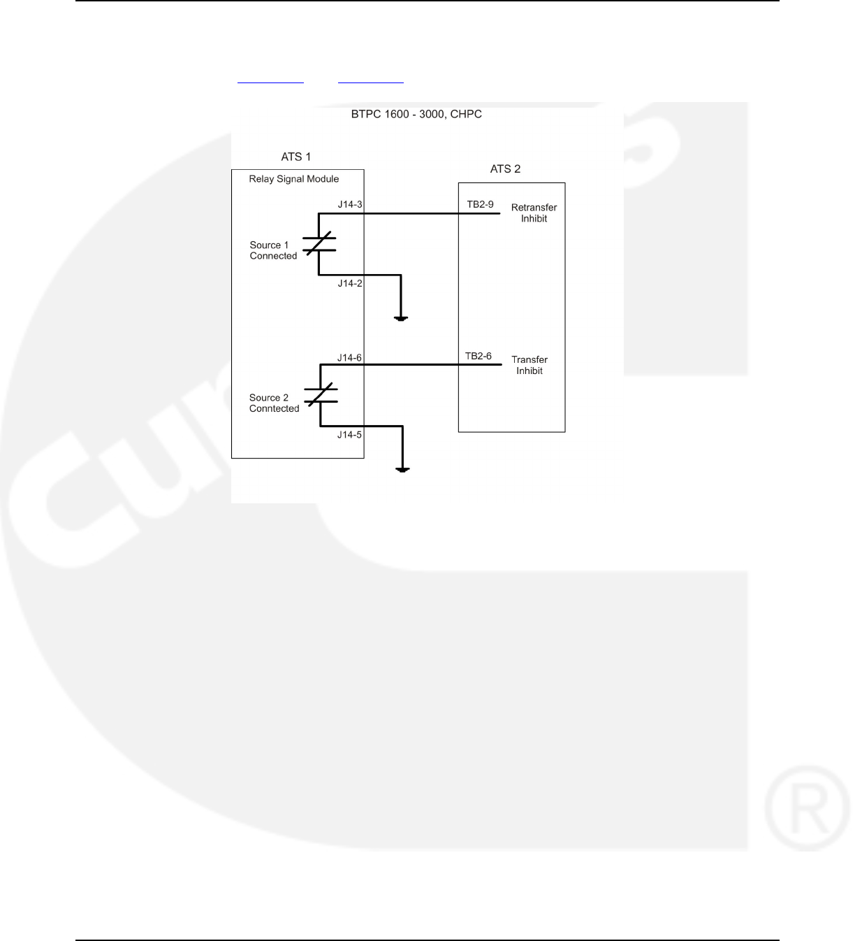
6. Wiring Considerations for Closed Transition Switches 02-2014
transferred back to the normal source. A similar wiring scheme can be used when transferring to
the emergency source so that only one switch transfers at a time. Switch position outputs are
available on the relay signal module which is included with all Cummins closed transition ATS
models. See Figure 53 and Figure 54 which illustrate how this can be accomplished with all of
Cummins’ closed transition transfer switch models.
FIGURE 53. BTPC 1600-3000, CHPC
86 962-0132 (Issue 8)
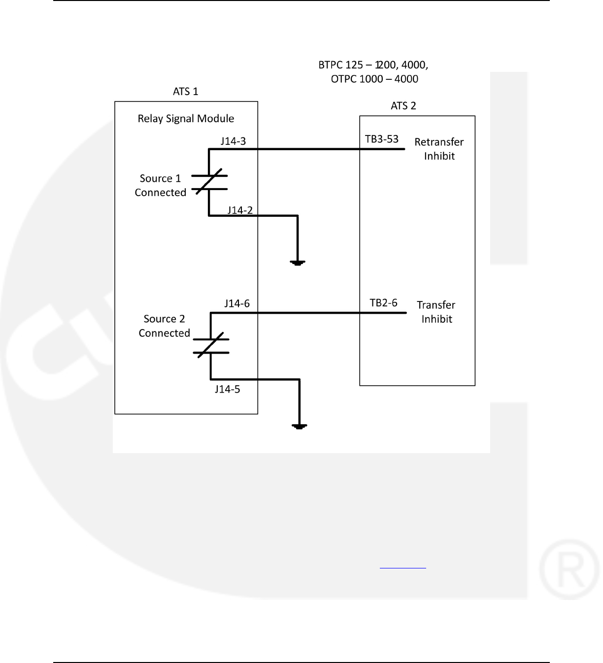
02-2014 6. Wiring Considerations for Closed Transition Switches
FIGURE 54. BTPC 125-1200, 4000, OTPC 1000-4000
6.3 Fail to disconnect
The Fail to Disconnect relay is active when the transfer switch remains connected to both
sources for more than 100 msec during a closed transition transfer. It should be wired to the
shunt trip of the breaker feeding the ATS on either the normal or the emergency side. The fail to
disconnect relay is located on the relay signal module. See Figure 55.
962-0132 (Issue 8) 87
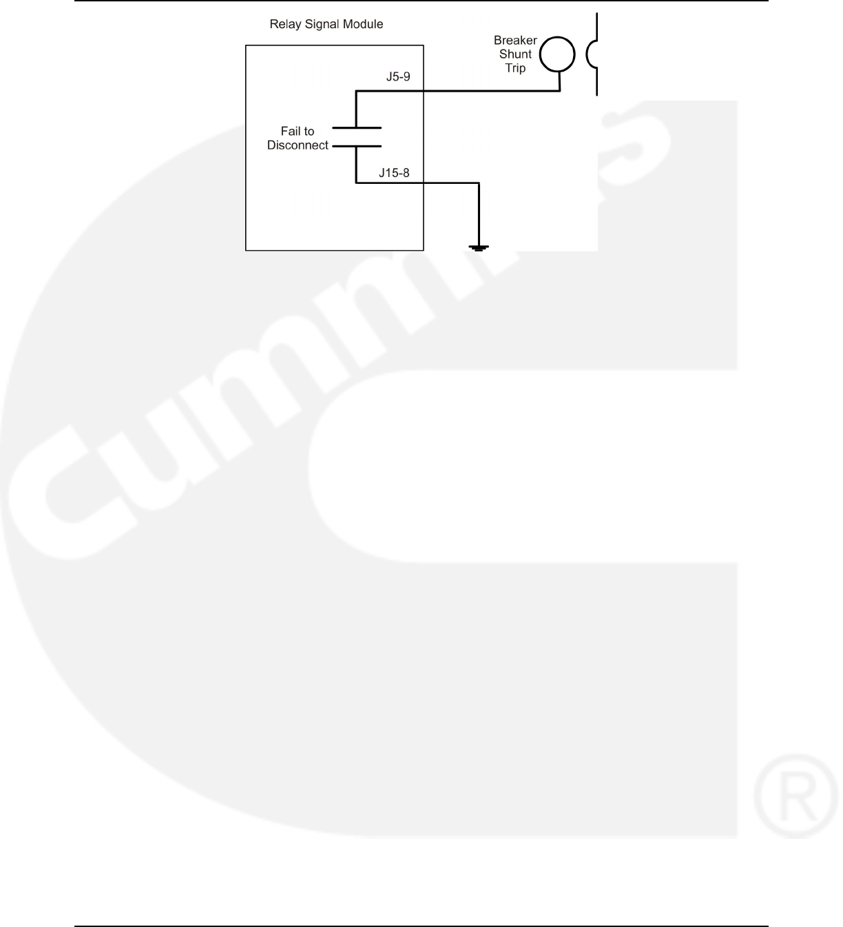
6. Wiring Considerations for Closed Transition Switches 02-2014
FIGURE 55. BREAKER SHUNT TRIP - USING THE FAIL TO DISCONNECT OUTPUT TO SHUNT-TRIP
A BREAKER.
88 962-0132 (Issue 8)
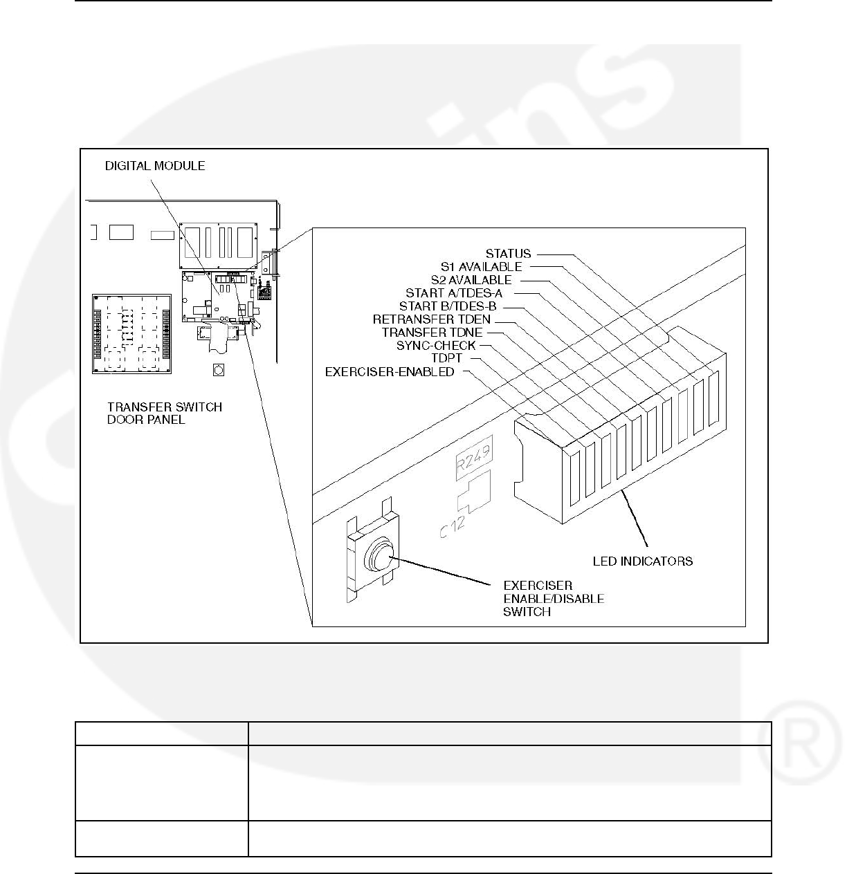
7 Troubleshooting
7.1 Control Module LED Indicators and Switch
The digital module located on the inside of the switch enclosure door contains ten LED
indicators. The indicators provide some information about the current control status. These
indicators may be helpful in troubleshooting the transfer switch when the Digital Display is not
available.
FIGURE 56. LED LOCATION ON DIGITAL MODULE (SHOWN ON THE 40 TO 125 AMP SWITCH)
TABLE 3. DIGITAL MODULE LED INDICATORS
Indicator Definition
Status Blinks at 1/2 Hz rate when the controller has power and the program is running without
error. This indicator flashes the event code of an active event until the event is
acknowledged with the Reset switch on the front panel. This indicator is sometimes
referred to as the heart beat because it blinks constantly when the controller does not
have an active event.
S1 Available Lights when Power Source 1 has acceptable voltage and frequency limits. This
indicator lights when the Source 1 Available indicator on the control panel lights.
962-0132 (Issue 8) 89

7. Troubleshooting 02-2014
Indicator Definition
S2 Available Lights when Power Source 2 has acceptable voltage and frequency limits. This
indicator lights when the Source 2 Available indicator on the control panel lights.
Start A/TDES-A 1. Lights constantly when the control has commanded Source 2 to start
2. Blinks at 1/2 Hz rate during the time delay to engine start (TDESa)
Start B/TDES-B This indicator is only used for genset-to-genset applications when Source 1 is a
generator not a utility.
1. Lights constantly when the control has commanded Source 1 to start
2. Blinks at 1/2 Hz rate during the time delay to engine start (TDESb)
Retransfer/TDEN 1. Lights when the control energizes the Retransfer relay
2. Blinks at 1/2 Hz rate during the time delay to retransfer (TDEN)
Transfer/TDNE 1. Lights when the control energizes the Transfer relay
2. Blinks at 1/2 Hz rate during the time delay to transfer (TDNE)
Sync-Check Blinks at 1-second rate when the in-phase sensor is active (maximum of 120 seconds).
TDPT Time Delay Programmed Transition
Blinks at 1/2 Hz rate during the programmed transition time delay
Exerciser Enabled Lights when the Exerciser clock is enabled and blinks during an exercise period. The
small switch next to the indicator enables and disables the exerciser. The operator can
also enable and disable the exerciser from the Digital Display when it is available.
7.2 Fault Flash-Out
The control flashes an active fault code on the Digital Module Status indicator until it is
acknowledged with the Reset switch on the front panel. The control flashes each digit of the
fault code with a pause between digits and a longer pause between repetitions.
The control moves acknowledged events to the event history file. This file can hold a maximum
of 50 fault and non-fault events. The digital display and the PC Service Tool can read the
contents of the Event history file.
7.3 Exerciser Enable/Disable Switch
The Exerciser Enable/Disable switch enables the control to exercise the genset during future
scheduled exercise periods and lights the Exerciser Enabled indicator or disables the scheduled
exercise period and turns the indicator off. This button is used by service personnel to disable
unexpected transfers while servicing the switch.
7.4 Troubleshooting Transfer Switch With the Digital
Display
The Digital Display shows two types of events: fault events and non-fault events. The last 50
events, both fault and non-fault events, can be viewed with the Digital Display. You can also
read all events in the event history file by using the PC Service Tool.
90 962-0132 (Issue 8)
02-2014 7. Troubleshooting
7.4.1 Fault Events
Fault events should be considered alarms for the transfer switch operator. They indicate that the
transfer switch is not operating correctly.
7.4.1.1 Fault Codes and Messages
The following table lists the fault codes and fault message, and gives corrective actions for each
fault code.
TABLE 4. FAULT CODES AND MESSAGES
343 Controller Checksum Error
441 Low Controller Battery
1113 ATS Fail to Close: Transfer
1114 ATS Fail to Close: Retransfer
597 Battery Charger Malfunction
477* Network Battery Low
1468 Network Communications Error
* This fault code only applies to older transfer switches that included an Network Communications Module (NCM) with
batteries.
The controller displays the fault message on the Digital Display and flashes the asterisk
indicator. You must press the Reset button on the control panel to acknowledge a fault and
clear the display.
7.4.1.2 Troubleshooting Fault Codes
TABLE 5. TROUBLESHOOTING
WARNING
Some ATS service procedures present hazards that can result in severe personal injury or death. Only
qualified service personnel with knowledge of electricity and machinery hazards should perform service.
See Safety Precautions.
CONTROLLER CHECKSUM ERROR (343)
The checksum of the Flash EPROM does not match the checksum stored in the controller
Corrective Action:
1. Reset the control by removing power.
2. Remove and re-install Digital Module batteries.
3. Contact Cummins/Onan Service if checksum error is repeated on power up.
4. Reset real-time clock.
LOW CONTROLLER BATTERY (441)
Low Lithium battery voltage
Corrective Action:
1. Replace Digital Module batteries.
2. Press the Reset button on the front panel.
3. Reset real-time clock.
962-0132 (Issue 8) 91

7. Troubleshooting 02-2014
7.5 Fault Event Definitions
7.5.1 Controller Checksum Error
The controller checks the Flash EPROM checksum after each microprocessor reset. The
checksum is stored in nonvolatile EEPROM. If a checksum error fault occurs, the controller still
attempts a normal boot-up sequence.
The controller Fault Flash-out subsystem flashes this fault on the Status indicator until the fault
is acknowledged (reset). Reset the control by removing power (including the batteries). If
checksum error is repeated on power up, replace the Digital Module.
7.5.2 Low Controller Battery
The controller monitors the voltage of the Lithium batteries that supply power to the controller. If
the battery voltage drops to 5 VDC, the controller sets the fault status to active.
The controller Fault Flash-out subsystem flashes this fault until the fault is acknowledged
(reset).
7.5.3 ATS Fail to Close: Transfer
The controller first verifies that the transfer switch moved from Source 1 to Neutral within the
time limit defined in the Fail to Close Time Delay. The controller also verifies that the transfer
switch moved from Neutral to Source 2 within the time limit defined in the Fail to Close Time
Delay.
If the Fail to Close time limit is exceeded, the controller changes the fault status to active. The
fault remains active until the Reset button is pressed.
7.5.4 ATS Fail to Close: Re-Transfer
The controller first verifies that the transfer switch moved from Source 2 to Neutral within the
time limit defined in the Fail to Close Time Delay. The controller also verifies that the transfer
switch moved from Neutral to Source 1 within the time limit defined in the Fail to Close Time
Delay.
If the Fail to Close time limit is exceeded, the controller changes the fault status to active. The
fault remains active until the Reset button is pressed.
7.5.5 Battery Charger Malfunction
The controller monitors the status of the optional battery charger. If the Battery Charger Fault
input is active, this event is active.
The controller Fault Flash-out subsystem flashes this fault until the fault is acknowledged
(reset).
7.5.6 Network Battery Low
This event is detected by the optional Network Communications Module (NCM) and is
communicated to the controller. If the battery voltage drops, the controller sets the fault status to
active.
The controller Fault Flash-out subsystem flashes this fault on the Status indicator until the fault
is acknowledged (reset).
92 962-0132 (Issue 8)
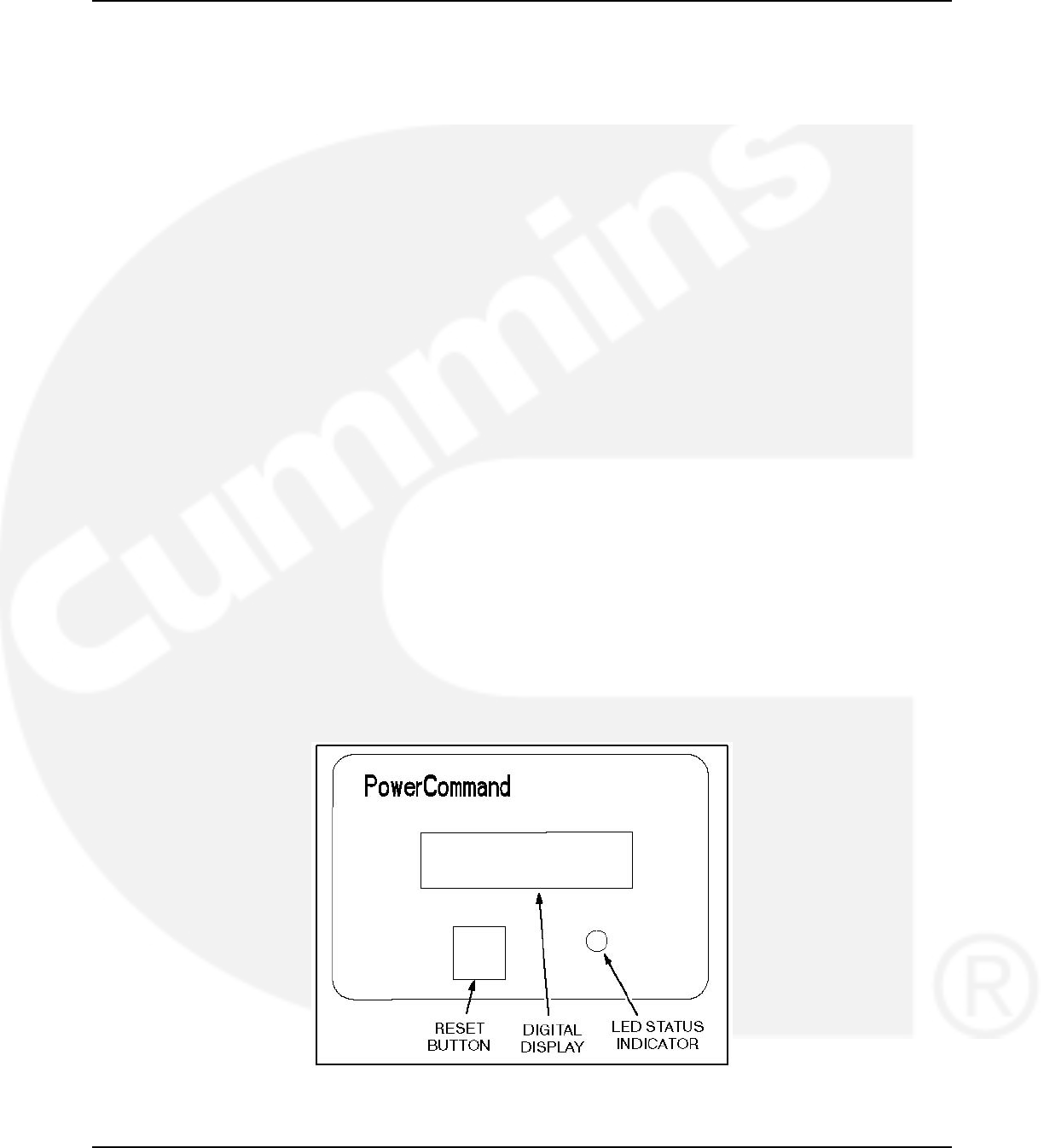
02-2014 7. Troubleshooting
7.5.7 Network Communications Error
This event is detected by the Network Communications Module (NCM) and is communicated to
the transfer switch controller. This indicates that the device is no longer communicating with
other devices on the network.
The controller Fault Flash-out subsystem flashes this fault until the fault is acknowledged
(reset).
7.6 15/12-Amp Battery Charger Troubleshooting and
Faults
The 15/12-amp battery charger includes one set of Form-B alarm contacts (corresponding to the
status LED on the control panel). When red, this LED indicates a fault condition. The control
panel also displays fault codes.
When a fault occurs, the red fault LED lights and a brief description of the fault and the numeric
fault code is displayed on the digital display. To correct the fault, find the fault code number and
take the suggested corrective actions. If the problem persists, call an authorized Cummins
Power Generation distributor for help.
7.6.1 Clearing Faults
Most displayed faults are cleared by removing the fault. However, faults 379 - OVER CURR,
442 - HIGH BATT VOLT, and 9115 - BATT FAIL can only be cleared by cycling completely
through the Setup menus or by powering down the charger after the fault is corrected. (More
information on Setup menus is included in the Battery Charger Operator's Manual.)
7.6.2 Fault Alarm Output Connector
The battery charger includes a fault output relay that is activated (contacts close) when faults
occur. The contacts are rated at 2 amps/30 VDC. This feature can be used by wiring a fault
indicator to the fault alarm output connector located on the front of the battery charger. A 2-pin
plug connector (323-1678-02) is shipped with the 15/12-amp transfer switch battery charger.
FIGURE 57. 15/12-AMP CHARGER CONTROL PANEL
962-0132 (Issue 8) 93

7. Troubleshooting 02-2014
7.7 Code 101 – Source 1 Connected (Event)
Logic:
Source 1 is connected to the transfer switch.
Description:
This event is active whenever the Source 1 position input is active. There is an associated LED
output on the front panel, a relay output on the Relay Module, and a Digital Display screen that
also indicate Source 1 is connected.
Possible Cause:
Source 1 limit switch feedback indicates switch position closed.
Diagnosis and Repair:
No further action required.
7.8 Code 102 – Source 1 Available (Event)
Logic:
Source 1 has reached the specified voltage and frequency targets.
Description:
This event is active whenever the Source 1 sensors (over/under voltage, over/under frequency,
phase rotation, loss of phase, voltage imbalance) indicate that Source 1 is within acceptable
limits. There is an associated LED output on the front panel and a relay output on the Relay
Module.
Possible Causes:
1. Voltage feedback is within specification of the voltage select.
a. Level 1, nominal voltage is line-to-line.
b. Level 2, nominal voltage is line-to-neutral.
2. Frequency feedback is within specification of the frequency select.
Diagnosis and Repair:
No further action required.
7.9 Code 103 – Source 2 Connected (Event)
Logic:
Source 2 is connected to the transfer switch.
94 962-0132 (Issue 8)

02-2014 7. Troubleshooting
Description:
This event is active whenever the Source 2 position input is active. There is an associated LED
output on the front panel, a relay output on the Relay Module, and a Digital Display screen that
also indicate Source 2 is connected.
Possible Cause:
Source 2 limit switch feedback indicates switch position closed.
Diagnosis and Repair:
No further action required.
7.10 Code 104 – Source 2 Available (Event)
Logic:
Source 2 has reached the specified voltage and frequency targets.
Description:
This event is active whenever the Source 2 sensors (over/under voltage, over/under frequency,
phase rotation, loss of phase, voltage imbalance) indicate that Source 2 is within acceptable
limits. There is an associated LED output on the front panel and a relay output on the Relay
Module.
Possible Causes:
1. Voltage feedback is within specification of the voltage select.
a. Level 1, nominal voltage is line-to-line.
b. Level 2, nominal voltage is line-to-neutral.
2. Frequency feedback is within specification of the frequency select.
Diagnosis and Repair
No further action required.
7.11 Code 105 – Emergency Start A (Event)
Logic:
Source A has received a start command from the transfer switch.
Description:
This event is active whenever the controller requires the Source 2 genset to start and reach
rated speed — otherwise known as an emergency start. There is also a discrete output called
Emergency Start A. Conditions which may prompt an emergency start are loss of nominal
voltage or frequency of Source B, a test in progress with Source A as preferred source, or
exercise transfer switch with Source A as the preferred source.
962-0132 (Issue 8) 95

7. Troubleshooting 02-2014
Possible Causes:
1. Loss of nominal voltage or frequency of Source B.
2. Test in progress with Source A as preferred source.
3. Exercise transfer switch with Source A as preferred source.
Diagnosis and Repair:
No further action required.
7.12 Code 106 – Test Start A (Event)
Logic:
Source A has received a test start command from the control or the network.
Description:
This event is active whenever the controller performs a Test sequence. The controller also
activates the Emergency Start A output in order for the generator to interpret that a
Test/Exercise start is called for. The genset will not start if only the Test Start A event is active.
The test input may be sent from front panel, service tool, or network.
Possible Causes:
1. Test input sent from front panel or service tool.
2. Test input sent from network.
Diagnosis and Repair:
No further action required.
7.13 Code 107 – Emergency Start B (Event)
Logic:
Source B has received a start command from the transfer switch.
Description:
NOTICE
Only applicable in genset-to-genset configuration. Generator B is Source 1.
This event is active whenever the controller requires the Source 1 genset to start and reach
rated speed — otherwise known as an emergency start. There is also a discrete output called
Emergency Start B. Conditions which may prompt an emergency start are loss of nominal
voltage or frequency of Source A, a test in progress with Source B as preferred source, or
exercise transfer switch with Source B as the preferred source.
Possible Causes:
1. Loss of nominal voltage and frequency of Source A.
96 962-0132 (Issue 8)

02-2014 7. Troubleshooting
2. Test in progress with Source B as preferred source.
3. Exercise transfer switch with Source B as preferred source.
Diagnosis and Repair
No further action required.
7.14 Code 108 – Test Start B (Event)
Logic:
Source B has received a test start command from the control or the network.
Description:
NOTICE
Only applicable in genset-to-genset configuration. Generator B is Source 1.
This event is active whenever the controller performs a Test sequence. The controller also
activates the Emergency Start B output in order for the generator to interpret that a
Test/Exercise start is called for. The genset will not start if only the Test Start B event is active.
The test input may be sent from front panel, service tool, or network
Possible Causes:
1. Test input sent from front panel or service tool.
2. Test input sent from network.
Diagnosis and Repair:
No further action required.
7.15 Code 109 – Time Delay Engine Start A (Event)
Logic:
Source A engine start in user configured delayed time set-point.
Description:
This event is active whenever the Time Delay Start A timer is active. This event is inactive
whenever the timer expires or is not active. The control activates this output whenever the
control requires generator A to start.
The digital display shows this event when it becomes active. In addition, it displays an active
countdown, in seconds, of the time delay.
The digital display shows this event when it becomes active. In addition, it displays an active
countdown, in seconds, of the time delay.
This delay prevents the generator set from starting during short power interruptions. Timing
starts at the Source 1 power interruption. If the user-defined duration (0 – 15 seconds) of
interruption exceeds the time delay, the control systems starts Generator A.
962-0132 (Issue 8) 97

7. Troubleshooting 02-2014
Possible Cause:
Time Delay Engine Start A trim is more than 0 seconds after start command has been received.
Diagnosis and Repair:
No further action required.
7.16 Code 111 – Time Delay Engine Start B (Event)
Logic:
Source B engine start in user configured delayed time set-point.
Description:
NOTICE
Only applicable in genset-to-genset configuration. Generator B is Source 1.
This event is active whenever the Time Delay Start B timer is active. This event is inactive
whenever the timer expires or is not active. The control activates this output whenever the
control requires genset B to start.
The digital display shows this event when it becomes active. In addition, it displays an active
countdown, in seconds, of the time delay.
The digital display shows this event when it becomes active. In addition, it displays an active
countdown, in seconds, of the time delay.
This delay prevents the generator set from starting during short power interruptions. Timing
starts at the Source 1 power interruption. If the user-defined duration (0 – 15 seconds) of
interruption exceeds the time delay, the control systems starts Generator B.
Possible Cause:
Time delay engine start B trim is more than 0 seconds after start command has been received.
Diagnosis and Repair:
No further action required.
7.17 Code 112 – Time Delay Transfer (Event)
Logic:
Switch has commanded to transfer away from the preferred source with configured time delay
normal to emergency trim.
Description:
This event is active whenever the Time Delay Source 1 to Source 2 timer is active — also called
the time delay transfer. This event is inactive whenever the timer expires or is not active. The
control activates this output when the control is counting down to transfer the switch from
Source 1 to Source 2. The digital display displays this event when it becomes active. In addition,
it displays an active countdown, in seconds, of the time delay.
98 962-0132 (Issue 8)

02-2014 7. Troubleshooting
This time delay begins after Source 2 becomes available and allows Source 2 to stabilize before
the load is applied. This delay will initiate when the preferred source fails, there is a test in
progress with time delay, or an exercise transfer switch with time delay.
Possible Causes:
1. Preferred source failed and time delay normal to emergency trim is greater than 0 seconds.
2. Test in progress with time delay normal to emergency trim greater than 0 seconds.
3. Exercise transfer switch with time delay normal to emergency trim greater than 0 seconds.
Diagnosis and Repair:
No further action required.
7.18 Code 113 – Time Delay Retransfer (Event)
Logic:
Switch has commanded to retransfer back to the preferred source with configured time delay
emergency to normal trim.
Description:
This event is active whenever the Time Delay Source 2 to Source 1 timer is active—also called
the time delay retransfer. This event is inactive whenever the timer expires or is not active. The
control activates this output when the control is counting down to transfer the switch from
Source 2 to Source 1.
The digital display shows this event when it becomes active. In addition, it displays an active
countdown, in seconds, of the time delay.
Possible Causes:
1. Preferred source recovered and time delay emergency to normal trim is greater than 0
seconds.
2. Test in progress with time delay emergency to normal trim greater than 0 seconds.
3. Exercise transfer switch with time delay emergency to normal trim greater than 0 seconds.
Diagnosis and Repair:
No further action required.
962-0132 (Issue 8) 99

7. Troubleshooting 02-2014
7.19 Code 114 – Engine Cool-Down A (Event)
Logic:
Time Delay Engine Cool-down A timer has started, but not expired.
Description:
This event is active whenever the Time Delay Engine Cool-down Timer is active and is inactive
when the timer expires or is inactive. The control activates this output whenever the control is
cooling down the genset. The digital display shows this event when it becomes active. In
addition, it displays an active countdown, in seconds, of the time delay.
This time delay allows the generator to cool down under no load conditions before the control
turns it off.
Possible Causes:
Time delay engine cool-down A timer is greater than 0 seconds.
Diagnosis and Repair:
No further action required.
7.20 Code 115 – Program Transition (Event)
Logic:
The switch has executed a program transition between sources.
Description:
This event is active whenever the programmed transition timer is active (whenever the control is
delaying the transfer switch in the neutral position). This event is inactive whenever the timer
expires or is not active. The digital display shows this event when it becomes active. In addition,
it displays an active countdown, in seconds, of the time delay.
Programmed Transition stops the switch in the neutral position for a user-defined interval of
time. This delay allows residual current from inductive loads to decay to an acceptable level
before transfer is complete.
Possible Causes:
Time delay program transition timer is greater than 0 seconds.
Diagnosis and Repair:
No further action required.
7.21 Code 116 – Transfer Pending (Event)
Logic:
There is a pending transfer active in the elevator relay module.
100 962-0132 (Issue 8)

02-2014 7. Troubleshooting
Description:
Whenever the Elevator Pre-transfer output is active, the controller sets this to active. The control
activates this event whenever a transfer pending signal is needed in the power system – this is
typically used as an early warning signal for elevator systems. When the timer expires, the
event will go to inactive.
The digital display shows this event when it becomes active. In addition, it displays an active
countdown, in seconds, of the time delay.
Possible Causes:
The elevator relay input has been activated.
Diagnosis and Repair:
No further action is required.
7.22 Code 117 – Test in Progress (Event)
Logic:
The control is operating under a test sequence.
Description:
This event is active whenever a test sequence is active. There is an associated LED output on
the front panel and a relay output on the Relay Module. This allows the ATS operator to
automatically test the transfer switch, generator, and power system.
When this event is active, the Test/Exercise Active LED on the front panel is lit and the
Test/Exercise relay on the relay module is activated.
Test input may be sent from the front panel, service tool, or network.
Possible Causes:
1. Test input sent from front panel or service tool.
2. Test input sent from network.
Diagnosis and Repair:
No further action required.
7.23 Code 118 – Exercise Active (Event)
Logic:
The control is operating under an exercise sequence.
Description:
This event is active whenever an exercise is active. There is an associated LED output on the
front panel and a relay output on the Relay Module. This allows the ATS operator to program
and store multiple engine-generator exercise events.
962-0132 (Issue 8) 101

7. Troubleshooting 02-2014
When this event is active, the Test/ Exercise Active LED on the front panel is lit and the
Test/Exercise relay on the relay module is activated.
This feature is only available with transfer switches with front panel display.
Possible Cause:
Exercise input programmed on front panel or service tool.
Diagnosis and Repair:
No further action required.
7.24 Code 119 – Sync Check (Event)
Logic:
The sync check sensor has been activated and is verifying if sources A and B meet conditions
for synchronicity.
Description:
This event is active whenever as in-phase transfer (using the Sync Check Sensor) is pending.
During this time, the Sync Check Sensor determines the acceptable conditions for a closed-
transition or open transition with sync check transfers.
Possible Causes:
1. A closed transition command has been activated (applicable only to CT capable switches).
2. An open transition with Sync Check has been activate.
Diagnosis and Repair:
No further action required.
7.25 Code 121 – S1 Under Voltage (Event)
Logic:
Control has sensed that Source 1 voltage dropped below the specified dropout voltage
percentage and the under voltage time delay has expired.
Description:
This event is active whenever Source 1 voltage is less than the acceptable limits. When the
sensor detects a low voltage condition over a user-defined time period, this event is triggered. It
should be noted that both the drop-out voltage and the time period are user-defined.
Possible Causes:
1. Nominal voltage set incorrectly.
2. Source 1 voltage is lower than the specified dropout voltage of the nominal voltage.
3. Source 1 phase multiplier and offsets need adjustment.
102 962-0132 (Issue 8)

02-2014 7. Troubleshooting
Diagnosis and Repair:
Contact support channel.
7.26 Code 122 – S1 Over Voltage (Event)
Logic:
Control has sensed that Source 1 voltage exceeded the specified dropout voltage percentage
and the over voltage time delay has expired.
Description:
This event is active whenever Source 1 voltage is greater than the acceptable limits. When the
sensor detects a high voltage condition over a specified time period, this event is triggered. It
should be noted that both the drop-out voltage and the time period are user-defined.
Possible Causes:
1. Nominal voltage set incorrectly.
2. Source 1 voltage is lower than the specified dropout voltage of the nominal voltage.
3. Source 1 phase multiplier and offsets need adjustment.
Diagnosis and Repair:
Contact support channel.
7.27 Code 123 – S1 Frequency Fail (Event)
Logic:
Source 1 frequency is out of specified tolerance range.
Description:
This event is active whenever Source 1 frequency is outside acceptable limits, as defined by the
user.
Possible Causes:
1. Incorrect frequency settings.
2. Frequency is outside of the dropout range.
Diagnosis and Repair:
Contact support channel.
7.28 Code 124 – S1 Loss Phase (Event)
Logic:
The relative phase angle between any line-to-line voltage has dropped to less than 90 degrees.
962-0132 (Issue 8) 103

7. Troubleshooting 02-2014
Description:
This event is active whenever Source 1 is missing one or more of its three phase voltages, or
when the phase angle between any two lines drops below 90 degrees.
This feature is mainly used to protect three-phase devices, like motors. It is only available on
Level 2 controls, in a three-phase application. This feature initiates a transfer away from a
source that has lost a single phase and it prevents transfer to a source that has lost a single
phase.
Possible Causes:
1. One of the three phases is open or has been shorted.
2. Sensing Leads to Power Module are loose or broken.
Diagnosis and Repair:
Contact support channel.
7.29 Code 125 – S1 Imbalance Fail (Event)
Logic:
Sensor has detected there is an unbalanced voltage condition on a three-phase system for
source 1.
Description:
This event is active whenever there is a significant imbalance between the phases of Source 1.
The voltage must deviate from the average voltage by a user-specified value between 2 and
10% (drop-out).
This feature is used for equipment protection. It is used in three-phase applications and informs
the operator when there is a significant voltage imbalance between the phases of Source 1 or
Source 2. The imbalance is typically caused by severe single phase loading. To prevent
nuisance faults, the setting can be increased up to ten percent of nominal voltage.
Possible Cause:
Incorrect imbalance settings.
Diagnosis and Repair:
Contact support channel.
7.30 Code 126 – S2 Under Voltage (Event)
Logic:
Control has sensed that Source 2 voltage dropped below the specified dropout voltage
percentage and the under voltage time delay has expired.
104 962-0132 (Issue 8)

02-2014 7. Troubleshooting
Description:
This event is active whenever Source 2 voltage is less than the acceptable limits. When the
sensor detects a low voltage condition over a specified time period, this event is triggered. It
should be noted that both the drop-out voltage and the time period are user-defined.
Possible Causes:
1. Nominal voltage set incorrectly.
2. Source 2 voltage is lower than the specified dropout voltage of the nominal voltage.
3. Source 2 phase multiplier and offsets need adjustment.
Diagnosis and Repair:
Contact support channel.
7.31 Code 127 – S2 Over Voltage (Event)
Logic:
Control has sensed that Source 2 voltage exceeded the specified dropout voltage percentage
and the over voltage time delay has expired.
Description:
This event is active whenever Source 2 voltage is greater than the acceptable limits. When the
sensor detects a high voltage condition over a specified time period, this event is triggered. It
should be noted that both the drop-out voltage and the time period are user-defined.
Possible Causes:
1. Nominal voltage set incorrectly.
2. Source 2 voltage is lower than the specified dropout voltage of the nominal voltage.
3. Source 2 phase multiplier and offsets need adjustment.
Diagnosis and Repair:
Contact support channel.
7.32 Code 128 – S2 Frequency Fail (Event)
Logic:
Source 2 frequency is out of specified tolerance range.
Description:
This event is active whenever Source 2 frequency is outside acceptable limits, as defined by the
user.
Possible Causes:
1. Incorrect frequency settings.
962-0132 (Issue 8) 105

7. Troubleshooting 02-2014
2. Frequency is outside of the dropout range.
Diagnosis and Repair:
Contact support channel.
7.33 Code 129 – S2 Loss Phase (Event)
Logic:
The relative phase angle between any line-to-line voltage has dropped to less than 90 degrees.
Description:
This event is active whenever Source 2 is missing one or more of its three phase voltages, or
when the phase angle between any two lines drops below 90 degrees.
This feature is mainly used to protect three-phase devices, like motors. It is only available on
Level 2 controls, in a three-phase application. This feature initiates a transfer away from a
source that has lost a single phase and it prevents transfer to a source that has lost a single
phase.
Possible Causes:
1. One of the three phases is open or has been shorted.
2. Sensing Leads to Power Module are loose or broken.
Diagnosis and Repair:
Contact support channel.
7.34 Code 131 – S2 Imbalance Fail (Event)
Logic:
Sensor has detected there is an unbalanced voltage condition on a three-phase system for
source 2.
Description:
This event is active whenever there is a significant imbalance between the phases of Source 2.
The voltage must deviate from the average voltage by a user-specified value between 2 and
10% (drop-out).
This feature is used for equipment protection. It is used in three-phase applications and informs
the operator when there is a significant voltage imbalance between the phases of Source 2.
Possible Cause:
Incorrect imbalance settings.
Diagnosis and Repair:
Contact support channel.
106 962-0132 (Issue 8)

02-2014 7. Troubleshooting
7.35 Code 132 – Phase Rotation Failure (Event)
Logic:
Source 1 and Source 2 do not have the same phase rotation.
Description:
This event is active whenever Source 1 and Source 2 voltages have difference phase
sequences. This feature is used to protect against equipment damage. It is only available on
Level 2 controls. This feature is required in fire pump applications and is enabled by default.
This feature monitors the phase rotation of the non-connected source in relation to the
connected source. When the non-connected source is out of phase rotation with the connected
source, transfer is inhibited. This generally occurs on new installations or after storm damage or
generator rewiring.
The phase rotation shall only be checked if both sources have acceptable voltage and
frequency.
Possible Causes:
1. Invalid phase rotation.
2. Distortion caused by customer loads.
Diagnosis and Repair:
Contact support channel.
7.36 Code 133 – Motor Disconnect (Event)
Logic:
Motor disconnect input has been detected by the control.
Description:
This event is active whenever the ATS Motor Disconnect input is active. This input causes the
controller to enter a non-automatic mode – it does not try to move the transfer switch
mechanism.
Possible Cause:
Motor disconnect input is in the OFF position.
Diagnosis and Repair:
Verify linear motor disconnect switch is in AUTO.
7.37 Code 134 – Load Shed (Event)
Logic:
The transfer switch was signaled to shed load from the generator.
962-0132 (Issue 8) 107

7. Troubleshooting 02-2014
Description:
This event is active whenever the Load Shed input is active or the nviLoadShedCmd input is
active. Load Shed causes the transfer switch to disconnect from an otherwise available source
in order to reduce the load demand on that source. The switch is moved to the Neutral position.
Possible Causes:
1. The Load Shed relay (optional) was energized because the transfer switch was signaled to
shed load from the generator.
2. Connections at J15-15 and J15-16 were energized causing a logic input from the load shed
to the control.
Diagnosis and Repair:
No further action is required.
7.38 Code 135 – Transfer Inhibit (Event)
Logic:
The control has received a transfer inhibit command.
Description:
This event is active whenever the Transfer Inhibit input is active, or the nviTransferInhCmd input
is active. Transfer Inhibit is used to prevent the ATS from automatically transferring the load to
Source 2.
While the Transfer Inhibit is active, the Not in Auto signal will be turned on.
Possible Cause:
(J27-4) TB2-6 (Transfer Inhibit) is receiving a ground signal. Not in auto signal will be turned on.
Diagnosis and Repair:
Load transfers can only take place by pressing the override button on the switch panel or
disabling the transfer inhibit input.
7.39 Code 136 – Retransfer Inhibit (Event)
Logic:
Switch has commanded to retransfer back to the preferred source but is inhibited by outside
input.
Description:
This event is active whenever the Retransfer Inhibit input is active, or the nviReTransferInhCmd
input is active. Even though the Not-in-Auto light is lit, the transfer switch will function correctly.
Transfer Inhibit is used to prevent the ATS from automatically transferring the load back to
Source 1.
When this event is active, (J27-1) TB3-53 (Retransfer Inhibit) is receiving a ground signal. Not in
auto signal will be turned on.
108 962-0132 (Issue 8)

02-2014 7. Troubleshooting
Possible Cause:
(J27-1) TB3-53 (Retransfer Inhibit) is receiving a ground signal. Not in auto signal will be turned
on.
Diagnosis and Repair:
No further action required.
7.40 Code 137 – Bypassed to S1 (Event)
Logic:
The Bypass mechanism has been placed into S1 position.
Description:
This event is active when operator manually connects the Bypass switch to Source 1. Upon
detecting the Bypass Source 1 input is active, the control activates the Not In Auto LED,
activates the Not In Auto relay output, and changes the Bypassed Source 1 event status to
active.
Possible Causes:
1. The handle has moved to the bypass S1 position.
2. The limit switch AB41 has been closed.
Diagnosis and Repair:
No further action required.
7.41 Code 138 – Bypassed to S2 (Event)
Logic:
The bypass mechanism has been placed into S2 position.
Description:
This event is active when operator manually connects the Bypass switch to Source 2. Upon
detecting the Bypass Source 2 input is active, the control activates the Not In Auto LED,
activates the Not In Auto relay output, and changes the Bypassed Source 2 event status to
active.
Possible Causes:
1. The handle has moved to the bypass S2 position.
2. The limit switch AB33 has been closed.
Diagnosis and Repair:
No further Action Required.
962-0132 (Issue 8) 109

7. Troubleshooting 02-2014
7.42 Code 139 – Not in Auto (Fault)
Logic:
The Switch is not in the automatic mode of operation.
Description:
1. The Motor Disconnect Switch is Off.
2. The Transfer Inhibit signal is active.
3. The Retransfer Inhibit signal is active.
4. The Load Shed signal is active.
5. The Bypass switch is connected.
6. C1 capacitor is cracked.
Diagnosis and Repair:
1. Move Motor Disconnect Switch to Auto.
2. Remove Transfer Inhibit signal.
3. Remove Retransfer Inhibit signal.
4. Remove Load Shed signal.
5. Disconnect bypass switch.
6. Check C1 capacitor.
a. Remove C1 capacitor.
b. Inspect capacitor for physical damage.
c. If possible, test capacitor with a digital multimeter.
d. Replace as necessary.
7.43 Code 141 – Service Tool (Event)
Logic:
The control is connected to the Service Tool via serial link.
Description:
This event is active whenever the PC service tool is connected to the controller. The purpose for
this event is to provide a chronological service history, which is stored in the ATS.
Possible Cause:
The control has received the connect command from the computer.
Diagnosis and Repair:
No further action is required.
110 962-0132 (Issue 8)

02-2014 7. Troubleshooting
7.44 Code 143 – Sync Enable (Event)
Logic:
The control is ready to run the sync check sensor.
Description:
This event is only displayed if active synchronicity is enabled. This event becomes active when
the control sends a Sync Enable message to a network control generator. In Closed Transition
applications with active synchronizing, the controller will use the Sync Enable command instead
of the Speed Adjust command. The controller activates the Sync Enable command just before
activating the Sync Check Sensor. When the generator control receives the Sync Enable input
and it detects the Source-1 bus voltages, the generator control will automatically synchronize its
speed and phase to match the Source-1 bus.
Possible Cause:
The Sync Enable command has activated the Sync Check Sensor.
Diagnosis and Repair:
No Further action required.
7.45 Code 144 – Speed Adjust (Event)
Logic:
Switch is monitoring frequency of S1 and S2 and communicated to generator to alter speed
before retransferring back to the preferred source based upon configured value.
Description:
This event is used to send a Speed Adjust message to a network generator control. The
controller sends the message and logs the event. This signal causes the genset to increase
speed by ½ Hz to sync with the utility. This signal ends when the transfer is complete.
Possible Causes
Generator is given speed command to retransfer to utility during close transition operation.
Diagnosis and Repair:
No further action required.
7.46 Code 145 – Fail to Sync (Event)
Logic:
Sources failed to synchronize (voltage, frequency, phase) within a two-minute limit during a
transfer.
962-0132 (Issue 8) 111

7. Troubleshooting 02-2014
Description:
This event indicates the two power sources have failed to synchronize either voltage, phase or
frequency within the hardcoded time limit of 120 seconds.
The event stays active until the Reset/Lamp Test button on the front panel is pressed. The Fail
to Sync output stays closed until the Reset button is pressed.
After a Fail to Sync event occurs, another Fail to Sync event may occur or, if set up to do so,
the transfer switch may go to open transition. If not set up to go to open transition, a series of
Fail to Sync events may repeat until the system synchronizer is adjusted or repaired.
Possible Causes:
1. Frequency difference between the two sources is not within 1.0 Hz.
2. Average voltage difference between the two sources is not within 5 – 25 volts (AC).
3. Relative phase angle between the two sources is not within 25° or is moving towards 0°.
Diagnosis and Repair:
No further action required.
7.47 Code 146 – Sequencer Output 1-8 (Event)
Logic:
The transfer switch is performing load (add) sequencing with other switches connected in the
network.
Description:
The Load Sequencer feature consists of eight programmable timers which can control eight
different network devices in a timed sequence. Each Load Sequencer output is an independent
Event Announcement, This is necessary for the Network Control Module (NCM) to receive and
transmit event changes. When these outputs are active, the transfer switch is typically inhibiting
another transfer switch from loading the active source. This allows a gentle loading of a transfer
switch when performing a transfer or retransfer sequence. The Event Handler generates an
Event Announcement whenever the Load Sequencer outputs (1-8) change state.
Possible Cause:
The load sequencer feature has been activated and the switch has received the sequencer
signal.
Diagnosis and Repair:
No further action is required.
7.48 Code 155 – Network Wink (Event)
Logic:
Transfer switch was manually given a command to send an identification signal via network to
all other nodes that are connected.
112 962-0132 (Issue 8)

02-2014 7. Troubleshooting
Description:
The network wink event is active whenever the Network Control Module (NCM) performs a
logical write command to the controller. Network wink events are used by network service
technicians to identify a particular network device in order to identify it from other devices. The
controller responds to an active network wink event by placing a Network Wink message on the
digital display.
Possible Cause:
Transfer switch was manually given a command to send a network wink.
Diagnosis and Repair:
No further action required.
7.49 Code 156 – Common Alarm A (Event)
Logic:
Source 2 is not available.
Description:
When this event is active and the digital relay module is utilized, if Genset A is not available this
fault will signal to the transfer switch to execute a time delay engine start (TDES) for Genset B
and transfer to that source once it is available. It will “lock out” Genset A until the fault is
cleared. This is primarily used in generator to generator applications.
Possible Causes:
1. Genset A has a common alarm failure.
2. Digital relay module common alarm input is shorted to battery power.
Diagnosis and Repair:
Contact support channel.
7.50 Code 157 – Common Alarm B (Event)
Logic:
Source 1 is not available.
Description:
When this event is active and the digital relay module is utilized, if Genset B is not available this
fault will signal to the transfer switch to execute a time delay engine start (TDES) for Genset A
and transfer to that source once it is available. It will “lock out” Genset B until the fault is
cleared. This is primarily used in generator to generator applications.
Possible Causes:
1. Genset B has a common alarm failure.
2. Digital relay module common alarm input is shorted to battery power.
962-0132 (Issue 8) 113

7. Troubleshooting 02-2014
Diagnosis and Repair:
Contact support channel.
7.51 Code 158 – Loss of Power (Event)
Logic:
The constant DC voltage of the controller has fallen below the normal operating point but kept
above the basic operation voltage.
Description:
If this event is displayed on the front panel, the controller will shut itself down within 5 seconds
of the message being displayed.
If this event is listed in the Event History log, it indicates that the control went to sleep after not
receiving AC power from either source for 30 seconds.
The controller signals the network card and other devices that the ATS controller is going to
shutdown due to lack of power. This signal triggers a time-delay start or other sequences. After
these sequences are complete the controller shuts itself off in order to conserve the back-up
batteries. The network card responds by not communicating to the controller.
Possible Cause:
Transfer switch has voltage input failure causing voltage dip to control.
Diagnosis and Repair:
Contact support channel.
7.52 Code 159 – TD Stop B (Event)
Logic:
Time Delay Stop Event B. The ATS begins timing delay when the load is retransferred to
Source A.
Description:
This event is active when the controller initiates a time delay before shutting down Generator B
after a retransfer. This is done to ensure stability on Source 1 before shutdown.
Possible Cause:
ATS retransferred to Source A.
Diagnosis and Repair:
No further action required.
114 962-0132 (Issue 8)

02-2014 7. Troubleshooting
7.53 Code 161 – High Neutral Amps (Event)
Logic:
Neutral current exceeded specified current threshold over a predetermined period of time.
Description:
NOTICE
This event is detected only on switches equipped with the Load Monitoring bar graph.
The control issues a warning when the neutral current exceeds a user specified value between
100% to 150% of the rated current during a specified time period between 10 to 60 seconds.
Possible Causes:
1. Current transformers wired incorrectly.
2. Bad current transformers.
3. Current transformer improperly calibrated.
Diagnosis and Repair:
Contact support channel.
7.54 Code 162 –Preferred Source 1 (Event)
Logic:
Source 1 is designated the preferred source.
Description:
This event is active when the preferred source variable changes from Source 2 to Source 1.
Possible Cause:
The operator selects source 1 as the preferred source.
Diagnosis and Repair:
No further action required.
7.55 Code 163 –Preferred Source 2 (Event)
Logic:
Source 2 is designated the preferred source.
Description:
This event is active when the preferred source variable changes from Source 1 to Source 2.
962-0132 (Issue 8) 115

7. Troubleshooting 02-2014
Possible Cause:
The operator selects source 2 as the preferred source.
Diagnosis and Repair:
No further action required.
7.56 Code 164 – Source 1 Stopped (Event)
Logic:
Source 1 has been stopped.
Description:
After Source 1 has been shut down, this event indicates the genset is no longer running.
Possible Causes:
Genset B has been shut down.
Diagnosis and Repair:
No further action required.
7.57 Code 165 – Source 2 Stopped (Event)
Logic:
Source 2 has been stopped.
Description:
After Source 2 has been shut down, this event indicates the genset is no longer running.
Possible Causes:
Genset A has been shut down.
Diagnosis and Repair:
No further action required.
7.58 Code 167 – Control Lockout (Event)
Logic:
Transfer switch faults out on a “Fail-to-Close” or “Fail-to-Open” during either the transfer or re-
transfer.
Description:
This event occurs when any of faults listed below occur.
116 962-0132 (Issue 8)

02-2014 7. Troubleshooting
Possible Causes:
1. Source 1 fails to open.
2. Source 1 fails to close.
3. Source 2 fails to open.
4. Source 2 fails to close.
Diagnosis and Repair:
In all four cases, the control lockout condition can be terminated by pressing to reset button on
the front panel. However, it is recommended that the source of the lockout be investigated using
InPower.
1. Refer to Fault Code 2397.
2. Refer to Fault Code 2396.
3. Refer to Fault Code 1453.
4. Refer to Fault Code 1452.
7.59 Code 168 – Panel Lock (Event)
Logic:
Key Switch is in the Panel Lock Position.
Description:
NOTICE
This event will only occur on transfer switches equipped with the optional security key
switch.
This event is active when the key switch is in the Panel Lock position. When the Key Switch is
in the Panel Lock position, the front panel Test and Override pushbuttons are disabled and no
changes to the setup menus can be made.
Possible Cause:
Key Switch is in the Panel Lock position.
Diagnosis and Repair:
1. Key Switch is in the Panel Lock position.
a. Turn Key Switch to the Program position.
7.60 Code 169 – Max Parallel Time Exceeded (Event)
Logic:
Maximum Parallel Time has completed a user-defined time period.
962-0132 (Issue 8) 117

7. Troubleshooting 02-2014
Description:
At the beginning of a closed transition, a user-defined Maximum Parallel Time Delay is initiated.
After the predetermined set time has expired, the original source is removed.
Possible Cause:
Transfer switch has exceeded max parallel time trim.
Diagnosis and Repair:
No action required.
7.61 Code 441 – Low Controller Battery (Event)
Logic:
Controller battery has dropped below 5.2 VDC.
Description:
Insufficient voltage is supplied to the controller.
Possible Causes:
1. No Battery.
2. Battery no longer holds charge.
Diagnosis and Repair:
Contact support channel.
7.62 Code 597 –Battery Charger Malfunction (Fault)
Logic:
The controller monitors the status of the optional battery charger. If the battery charger Fault
input is active, this event is active.
Description:
For transfer switches that include a genset battery charger, this event signals the controller that
the genset battery charger is malfunctioning and may need to be replaced.
This is not a standard factory connection. For more information, contact your dealer or
distributor.
The event remains active until the Reset button on the front panel is pressed.
Possible Causes:
1. For 277, 380, 416, and 600 VAC chargers - Bad battery charger fuse(s).
2. For 120, 208, and 240 VAC chargers – Tripped circuit breakers.
3. Bad connection at optional relay module.
4. Refer to OEM manual.
118 962-0132 (Issue 8)

02-2014 7. Troubleshooting
Diagnosis and Repair:
Contact support channel.
7.63 Code 1113 – ATS Fail to Close: Transfer (Fault)
Logic:
Transfer switch failed to move in the predetermined time period.
Description:
For utility-to-genset applications, this event is active if the transfer switch failed to move from
Source 1 to Neutral or Neutral to Source 2 within a preset time limit.
For utility-to-utility and genset-to-genset applications, this event is active if the transfer switch
failed to move from the preferred source to the backup source within a preset time limit.
For open transition transfer switches, the controller first verifies the transfer switch moved from
Source 1 to Neutral within the time limit defined in the Fail to Open Time Delay. The controller
also verifies that the transfer switch moved from Neutral to Source 2 within the time limit defined
in the Fail to Close Time Delay.
For closed transition transfer switches, the controller verifies that the ATS retransferred from
Source 1 to Source 2 within the time limits.
Possible Causes:
1. Transfer switch “Fail to Close Time Limit” setting needs adjustment or is incorrect.
2. No Transfer signal.
3. No Programmed Transition signal.
4. Transfer switch S2 limit switch has failed/improperly adjusted.
5. Faulty limit switch wiring and/or digital board.
6. Linear actuator does not move when energized.
7. Mechanical damage to switch mechanism.
Diagnosis and Repair:
Contact support channel.
7.64 Code 1114 – ATS Fail to Close: RE-Transfer (Fault)
Logic:
The control detects a “Fail to Close” fault whenever the transfer switch does not move within the
time interval after the command to transfer to the normal source (S1). A “Fail to Close” fault will
be detected if the transfer switch either “Fails to Open” or it “Fails to Close”. The front panel
reset button must be pressed to exit this condition.
Description:
For utility-to-genset applications, this event is active if the transfer switch failed to move from
Source 2 to Neutral or Neutral to Source 1 within a preset time limit.
962-0132 (Issue 8) 119

7. Troubleshooting 02-2014
For utility-to-utility and genset-to-genset applications, this event is active if the transfer switch
failed to move from the preferred source to the backup source within a preset time limit.
For open transition transfer switches, the controller first verifies the transfer switch moved from
Source 2 to Neutral within the time limit defined in the Fail to Open Time Delay. The controller
also verifies that the transfer switch moved from Neutral to Source 1 within the time limit defined
in the Fail to Close Time Delay.
For closed transition transfer switches, the controller verifies that the ATS retransferred from
Source 2 to Source 1 within the time limits.
Possible Causes:
1. Transfer switch “Fail to Close Time Limit” setting needs adjustment or is incorrect.
2. No Transfer signal.
3. No Programmed Transition signal.
4. Transfer switch S2 limit switch has failed/improperly adjusted.
5. Faulty limit switch wiring and/or digital board.
6. Linear actuator does not move when energized.
7. Mechanical damage to switch mechanism.
Diagnosis and Repair:
Contact support channel.
7.65 Code 1121 – ATS Fail to Disconnect (Fault)
Logic:
Controller has sense that neither source has opened during a parallel transition.
Description:
This event is active when both sources have paralleled, there is a failure to open either power
source, and all attempts to automatically separate them within a set period of time have failed.
This event applies to only closed transition modes and is needed to trip an external circuit
breaker. The event remains active until the Reset button on the front panel is pressed.
Possible Causes:
1. Time Delay Fail to disconnect to low.
2. Mechanical fault or damage preventing or slowing switch movement.
3. Limit switches not working or being activated.
Diagnosis and Repair:
Contact support channel.
120 962-0132 (Issue 8)

02-2014 7. Troubleshooting
7.66 Code 1452 – Fail to Close S2 (Fault)
Logic:
Full transition from Source 1 to Source 2 was not established.
Description:
While attempting to transfer the load to Source 2, the control was not able to close Source 2
contacts within a certain time interval after the command. A Fail to Close fault will be detected if
the transfer switch fails to open or it fails to close. This event is followed by a Control Locked
Out event.
Possible Causes:
1. Transfer switch “Fail to Close Time Limit” setting needs adjustment or is incorrect.
2. No Transfer signal.
3. No Programmed Transition signal.
4. Switch is jammed or stuck.
5. Limit switches not working or being activated.
6. Linear actuator does not move when energized.
Diagnosis and Repair:
Contact support channel.
7.67 Code 1453 – Failed to Open S2 (Fault)
Logic:
Source 2 did not open during retransfer in allotted time.
Description:
While attempting to transfer the load to Source 1, the control was not able to open the Source 2
contacts within the user-defined Fail to Open time limit. This event is followed by a “Control Lock
Out” event.
Possible Causes:
1. No Transfer signal.
2. Linear actuator does not move when energized.
3. No Programmed Transition signal.
4. Switch is jammed or stuck.
5. Limit switches not working or being activated.
Diagnosis and Repair:
Contact support channel.
962-0132 (Issue 8) 121

7. Troubleshooting 02-2014
7.68 Code 1468 – Network Communications Error (Fault)
Logic:
The LonWorks card has generated a network communication error fault.
Description:
This event is detected by the Network Communications Module (NCM) and is communicated to
the transfer switch controller. This indicates that the device is no longer communicating with
other devices on the network. The controller Fault Flash-out subsystem flashes this fault until
the fault is reset.
Possible Causes:
1. The ATS network card has been disconnected from the other elements in the network.
2. The ATS network card has lost network information.
3. The ATS network card is not commissioned correctly.
4. One of the elements connected to the transfer switch is not communicating correctly.
5. One of the elements connected to the transfer switch is not commissioned correctly.
6. Bad network card.
Diagnosis and Repair:
Contact support channel.
7.69 Code 2396 – Failed to Close S1 (Fault)
Logic:
Full transition from Source 2 to Source 1 was not established.
Description:
While attempting to transfer the load to Source 1, the control was not able to close Source 1
contacts within a certain time interval after the command. A Fail to Close fault will be detected if
the transfer switch fails to open or it fails to close. This event is followed by a Control Locked
Out event.
Possible Causes:
1. Transfer switch “Fail to Close Time Limit” setting needs adjustment or is incorrect.
2. No Transfer signal.
3. No Programmed Transition signal.
4. Switch is jammed or stuck.
5. Limit switches not working or being activated.
6. Linear actuator does not move when energized.
122 962-0132 (Issue 8)

02-2014 7. Troubleshooting
Diagnosis and Repair:
Contact support channel.
7.70 Code 2397 – Fail to Open S1 (Fault)
Logic:
Source 1 did not open during transfer in allotted time.
Description:
While attempting to transfer the load to Source 1, the control was not able to open the Source 2
contacts within the user-defined Fail to Open time limit. This event is followed by a “Control Lock
Out” event.
Possible Causes:
1. No Transfer signal.
2. No Programmed Transition signal.
3. Switch is jammed or stuck.
4. Limit switches not working or being activated.
5. Linear actuator does not move when energized.
Diagnosis and Repair:
Contact support channel.
962-0132 (Issue 8) 123

7. Troubleshooting 02-2014
This page is intentionally blank.
124 962-0132 (Issue 8)