962 0134OM 0134 Onan RSS100 RSS200 Transfer Switch Operator's Manual (08 2007)
User Manual: 962-0134 Onan RSS100 RSS200 Transfer Switch Operator's manual (08-2007)
Open the PDF directly: View PDF ![]() .
.
Page Count: 20

2008 Cummins Inc. All rights reserved.
Operator Manual
Transfer Switch
RSS100 and RSS200
English 8-2007 962−0134

2008 Cummins Inc. All rights reserved.
i
Table of Contents
SECTION TITLE PAGE
SAFETY PRECAUTIONS ii. . . . . . . . . . . . . . . . . . . . . . . . . . . . . . . . . . . . . . . . . . . . . . . . . . .
1. INTRODUCTION 1-1. . . . . . . . . . . . . . . . . . . . . . . . . . . . . . . . . . . . . . . . . . . . . . . . . . . . . . . . .
About This Manual 1-1. . . . . . . . . . . . . . . . . . . . . . . . . . . . . . . . . . . . . . . . . . . . . . . . . . . . . .
Transfer Switch Function 1-1. . . . . . . . . . . . . . . . . . . . . . . . . . . . . . . . . . . . . . . . . . . . . . . .
2. DESCRIPTION 2-1. . . . . . . . . . . . . . . . . . . . . . . . . . . . . . . . . . . . . . . . . . . . . . . . . . . . . . . . . . .
Transfer Switch With Control 2-1. . . . . . . . . . . . . . . . . . . . . . . . . . . . . . . . . . . . . . . . . . . . .
ATS Status LEDs 2-1. . . . . . . . . . . . . . . . . . . . . . . . . . . . . . . . . . . . . . . . . . . . . . . . . . . . .
Membrane Pushbuttons 2-1. . . . . . . . . . . . . . . . . . . . . . . . . . . . . . . . . . . . . . . . . . . . . . .
Control Time Delays 2-3. . . . . . . . . . . . . . . . . . . . . . . . . . . . . . . . . . . . . . . . . . . . . . . . . . . .
Time Delay Engine Start (TDES) 2-3. . . . . . . . . . . . . . . . . . . . . . . . . . . . . . . . . . . . . . .
Time Delay Engine Cooldown (TDEC) 2-3. . . . . . . . . . . . . . . . . . . . . . . . . . . . . . . . . . .
Time Delay Normal to Emergency (TDNE) (Transfer) 2-3. . . . . . . . . . . . . . . . . . . . . .
Time Delay Emergency to Normal (TDEN) (Retransfer) 2-3. . . . . . . . . . . . . . . . . . . .
3. OPERATION 3-1. . . . . . . . . . . . . . . . . . . . . . . . . . . . . . . . . . . . . . . . . . . . . . . . . . . . . . . . . . . . .
Transfer Switches with an Operator Panel 3-1. . . . . . . . . . . . . . . . . . . . . . . . . . . . . . . . .
Override 3-2. . . . . . . . . . . . . . . . . . . . . . . . . . . . . . . . . . . . . . . . . . . . . . . . . . . . . . . . . . . . . . .
Complete System Test 3-2. . . . . . . . . . . . . . . . . . . . . . . . . . . . . . . . . . . . . . . . . . . . . . . . . .
Generator Exerciser 3-3. . . . . . . . . . . . . . . . . . . . . . . . . . . . . . . . . . . . . . . . . . . . . . . . . . . .
Setting An Exercise Period 3-3. . . . . . . . . . . . . . . . . . . . . . . . . . . . . . . . . . . . . . . . . . . .
Canceling Repeat Exercise Periods 3-3. . . . . . . . . . . . . . . . . . . . . . . . . . . . . . . . . . . . .
Canceling An Active Exercise Period 3-3. . . . . . . . . . . . . . . . . . . . . . . . . . . . . . . . . . . .
Power Source Failure During An Active Exercise Period 3-3. . . . . . . . . . . . . . . . . . .
4. TROUBLESHOOTING 4-1. . . . . . . . . . . . . . . . . . . . . . . . . . . . . . . . . . . . . . . . . . . . . . . . . . . .
Operator Panel LED Indicators 4-1. . . . . . . . . . . . . . . . . . . . . . . . . . . . . . . . . . . . . . . . . . .
Troubleshooting the Transfer Switch 4-3. . . . . . . . . . . . . . . . . . . . . . . . . . . . . . . . . . . . . .
How to Obtain Service 4-6. . . . . . . . . . . . . . . . . . . . . . . . . . . . . . . . . . . . . . . . . . . . . . . . . .
2008 Cummins Inc. All rights reserved.
ii
Safety Precautions
This manual includes the following symbols to indi-
cate potentially dangerous conditions. Read the
manual carefully and know when these conditions
exist. Then take the necessary steps to protect per-
sonnel and the equipment.
DANGER This symbol warns of immediate
hazards that will result in severe personal injury
or death.
WARNING This symbol refers to a hazard or
unsafe practice that can result in severe per-
sonal injury or death.
CAUTION This symbol refers to a hazard or
unsafe practice that can result in personal inju-
ry or product or property damage.
ELECTRICAL SHOCK CAN CAUSE
SEVERE PERSONAL INJURY OR DEATH
High voltage in transfer switch components pres-
ents serious shock hazards that can result in severe
personal injury or death. Read and follow these in-
structions.
Keep the transfer switch cabinet cover secured with
the provided mounting hardware. Only authorized
personnel are allowed to access the inside of the
cabinet.
Due to the serious shock hazard from high voltages
within the cabinet, all service and adjustments to
the transfer switch must be performed only by a
trained and experienced electrician or an autho-
rized Cummins Onan service representative.
If the cabinet must be opened for any reason:
1. Disconnect the AC utility power from the trans-
fer switch by opening the circuit breaker in the
main panel that feeds the transfer switch.
2. Move the operation selector switch on the gen-
erator set to Stop/Off.
3. Disconnect the negative (−) cable from the
generator set starting batteries.
GENERAL PRECAUTIONS
Place rubber insulative mats or dry wood platforms
over metal or concrete floors when working on any
electrical equipment. Do not wear damp clothing
(particularly wet shoes) or allow skin surfaces to be
damp when handling any electrical equipment.
Jewelry is a good conductor of electricity and
should be removed when working on the electrical
equipment.
Wear safety glasses whenever servicing the trans-
fer switch.
Do not smoke near the batteries.
Do not work on this equipment when mentally or
physically fatigued, or after consuming alcohol or
any drug.
WARNING
INCORRECT SERVICE OR REPLACEMENT OF PARTS CAN RESULT IN
DEATH, SEVERE PERSONAL INJURY, AND/OR EQUIPMENT DAMAGE. SER-
VICE PERSONNEL MUST BE TRAINED AND EXPERIENCED TO PERFORM
ELECTRICAL AND/OR MECHANICAL SERVICE.
RSS-1
2008 Cummins Inc. All rights reserved.
1-1
1. Introduction
ABOUT THIS MANUAL
This manual covers transfer switch models pro-
duced under the Cummins® Power Generation
brand name. This manual provides information nec-
essary for operation of an RSS transfer switch with
a control.
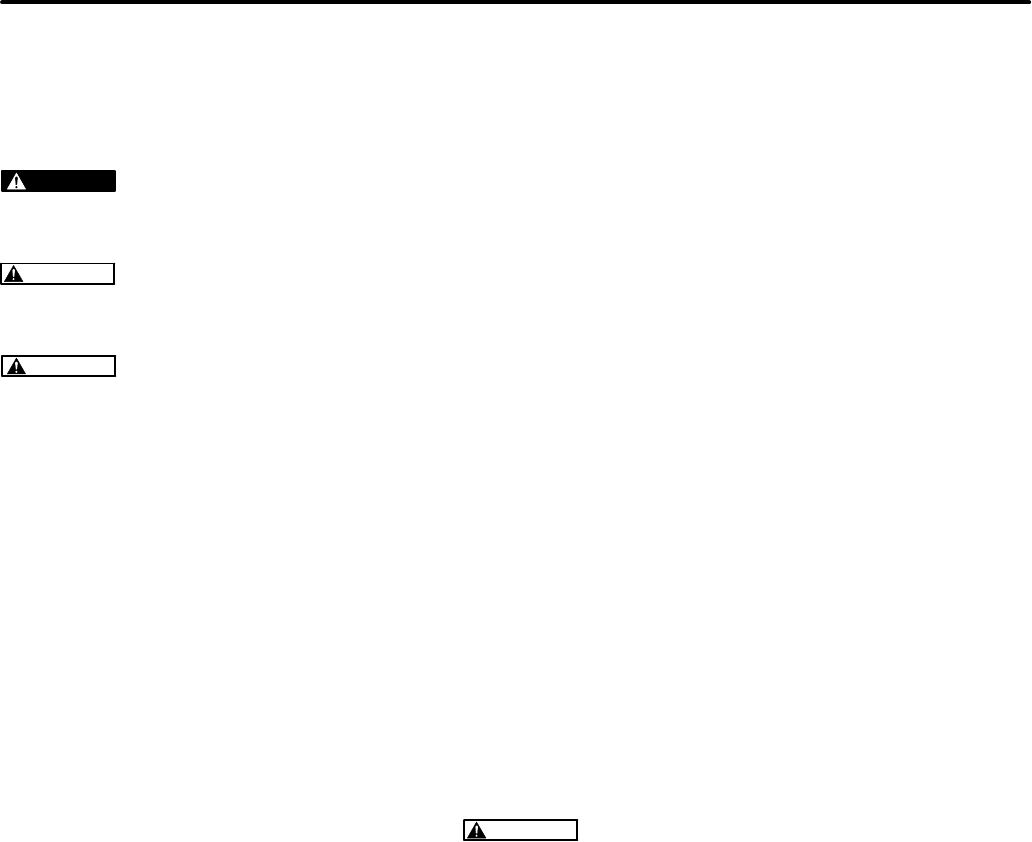
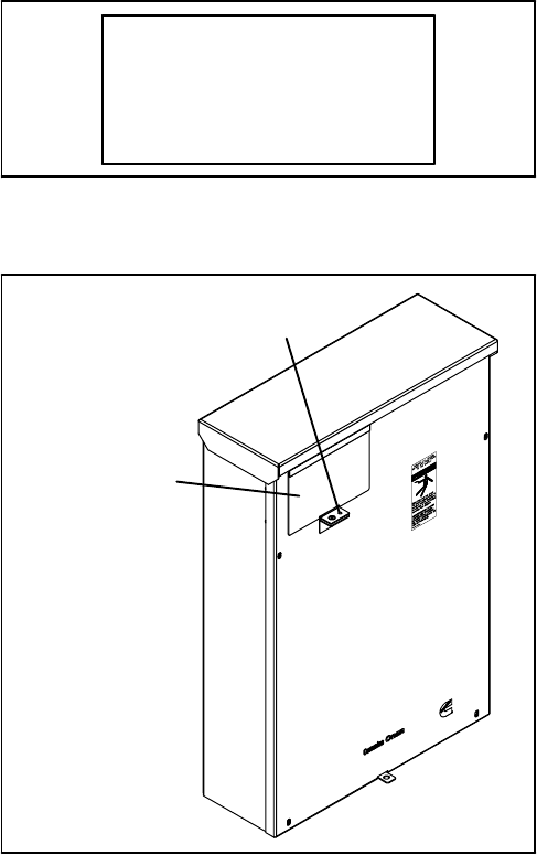
The RSS transfer switch with a control includes an
operator panel located behind the hinged panel in
the upper left hand corner on the front of the enclo-
sure, as shown in Figure 1-1.
THE OPERATOR
PANEL IS LOCATED
BEHIND THE
HINGED COVER
FIGURE 1-1. RSS TRANSFER SWITCH
TRANSFER SWITCH FUNCTION
Transfer switches are an essential part of a standby
power system. The utility (normal power source) is
backed up by a generator (emergency power
source). Should the utility fail, the transfer switch
automatically switches the electrical load from the
utility to the generator. When utility power returns,
the transfer switch automatically switches the elec-
trical load back to the utility.
Automatic transfer switches, capable of automatic
operation without operator intervention, perform the
basic function of transferring the load to the avail-
able power source. A controller monitors each
source for allowable voltage and frequency range.
The transfer switch performs the following func-
tions:
1. Senses the interruption of utility power.
2. Sends a start signal to the generator.
3. Senses generator power is available.
4. Transfers the load to the generator.
5. Senses the return of utility power.
6. Retransfers the load to the utility.
7. Sends a stop signal to the generator.
2008 Cummins Inc. All rights reserved.
1-2
THIS PAGE LEFT INTENTIONALLY BLANK

2008 Cummins Inc. All rights reserved.
2-1
2. Description
This section describes how the basic components
of a transfer switch function.
TRANSFER SWITCH WITH CONTROL
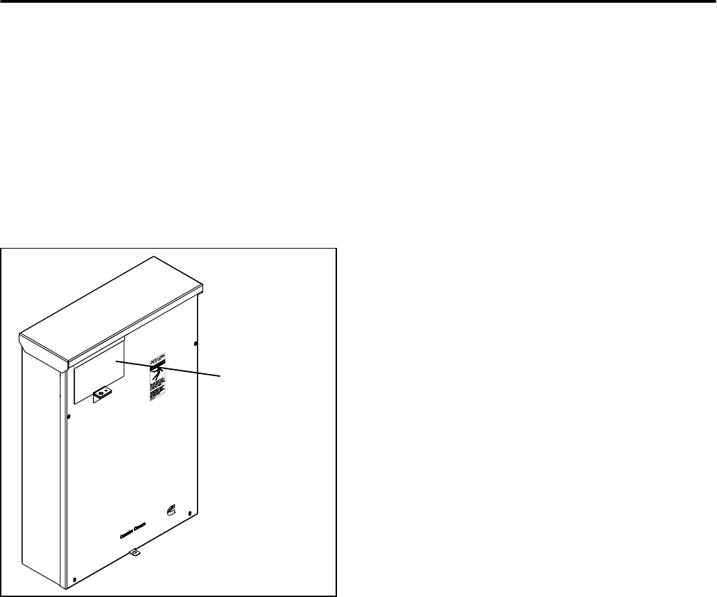
Figure 2-1 shows the operator panel used with
transfer switches with a control. The panel’s fea-
tures are divided into two groups:
SATS Status LEDs
SMembrane Pushbuttons
ATS Status LEDs
The operator panel includes six LEDs that provide
Automatic Transfer Switch (ATS) status informa-
tion.
Utility Power Available − This green LED is lit
when the utility power source has acceptable output
voltage.
Generator Power Available − This amber LED is lit
when the Generator power source has acceptable
output voltage and frequency.
Both power source LEDs can be lit simultaneously.
Utility Power Connected − This green LED is lit
when the transfer switxh is connected to utility pow-
er which is supplying power to the load.
If this LED is flashing, it means that the transfer
switch has failed to connect to or disconnect from
utility power, when commanded by the control.
Generator Power Connected − This amber LED is
lit when the transfer switch is connected to the gen-
erator set which is supplying power to the load.
If this LED is flashing it means the transfer switch
has failed to connect to or disconnect from the gen-
erator set, when commanded by the control.
Test − This amber LED is lit when there is an active
test period. It flashes twice per second when the
Test pushbutton is pressed to set or cancel a test
period.
Exercise − This amber LED is lit when repeat ex-
ercise periods are set. It flashes twice per second
when the Set Exercise pushbutton is pressed to set
or cancel an exercise. It flashes once per second
during an active exercise period.
Membrane Pushbuttons
The operator panel includes three membrane push-
buttons.
Test − The Test pushbutton is used to start or cancel
a test period.
Override − The Override pushbutton is used to ter-
minate or bypass some time delays, to stop the
Power Connected LEDs from flashing as a result of
a failure to connect to or disconnect from a power
source, and to cancel an active exercise period.
Set Exercise − The Set Exercise pushbutton is
used to enable or disable repeatable exercise peri-
ods using the exerciser. The exerciser is built into
the controller. The exercise period runs for 20 min-
utes and it repeats every 28 days when an exercise
is enabled.
2008 Cummins Inc. All rights reserved.
2-2
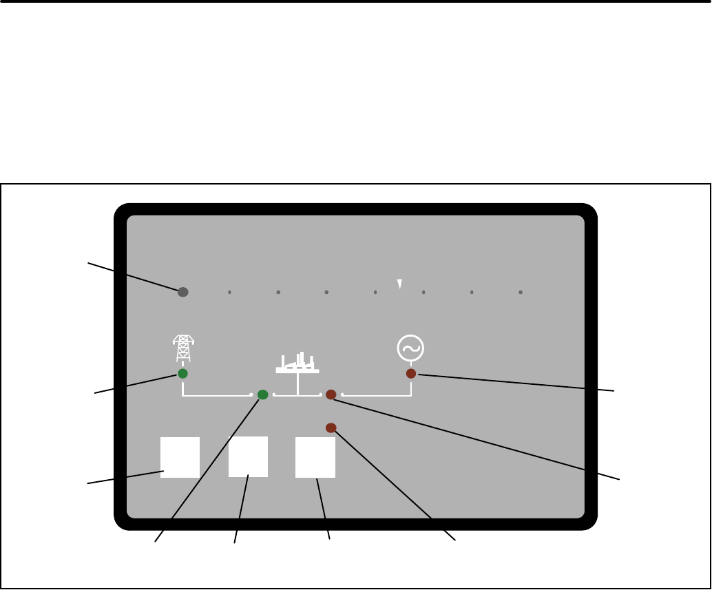
Test Override Set Generator
Exercise
Exercise
Test
Control operation could be delayed by external source.
PowerCommand
UTILITY
POWER
AVAILABLE
LED
GENERATOR POWER
AVAILABLE LED
UTILITY
POWER
CONNECTED
LED
GENERATOR
POWER
CONNECTED
LED
ACTIVE SET OR
PROGRAMMED
EXERCISE LED
TEST
ACTIVITY LED
TEST
PUSHBUTTON
OVERRIDE
PUSHBUTTON
SET EXERCISE
PUSHBUTTON
FIGURE 2-1. CABINET DOOR (SHOWN WITHOUT HINGED COVER)
2008 Cummins Inc. All rights reserved.
2-3
CONTROL TIME DELAYS
For transfer switches with an operator panel, the
transfer switch control uses various time delays to
break from one power source and connect to the
other source.
In the following descriptions of time delays, it is im-
portant to remember that:
SWhen the transfer switch is connected to the
Normal side, it is connected to the Utility
power source.
SWhen the transfer switch is connected to the
Emergency side, it is connected to the Gen-
erator power source.
Time Delay Engine Start (TDES)
This time delay prevents the generator set from
starting during brief utility power interruptions. This
timer starts the instant the utility fails, as detected by
the Undervoltage Sensor.
When the control senses a utility failure, the control
starts the Time Delay Engine Start (TDES) timer.
This time delay is set to 3 seconds.
If utility power returns while the TDES timer is ac-
tive, the timer is reset. When the timer expires, the
control signals the generator set to start. The timer
is not reset until utility power returns. If the Override
pushbutton is pressed while the TDES timer is ac-
tive, the TDES timer is immediately terminated and
the control signals the generator set to start.
Time Delay Engine Cooldown (TDEC)
This time delay allows the generator set to cool down
(under no load conditions) after the switch returns to
utility power.
The Time Delay Engine Cooldown (TDEC) starts
timing when the load is retransferred to utility power.
This time delay is set to 10 minutes.
When the TDES expires, the stop signal is sent to
the generator’s control to shut down the generator
and the timer is reset. Pressing the Override push-
button has no effect on this time delay.
Time Delay Normal to Emergency (TDNE)
(Transfer)
This time delay allows the generator set to stabilize
before the load is applied.
While connected to the utility, this time delay starts
after utility power fails and the generator set be-
comes available (the amber Generator Power
Available LED is lit). This time delay also starts after
the generator set becomes available when a with
load Test or Exercise period is activated.
The time delay is set to 5 seconds. If the generator
set fails any time during a TDNE, the control resets
the timer and restarts it once the generator set is
again available.
If the Override pushbutton is pressed while the
TDNE timer is active, the TDNE is terminated imme-
diately and the control transfers the load to the gen-
erator set.
Time Delay Emergency to Normal (TDEN)
(Retransfer)
While connected to Generator power, this time
delay allows utility power to stabilize before the load
is transferred back (retransferred) to the utility. This
delay also allows the generator set to operate under
load for a minimum amount of time before transfer-
ring the load back to utility power.
This time delay starts with the transfer switch con-
nected to the generator set and after the utility be-
comes available following an outage (The green
Utility Power Available LED is lit). This time delay
also starts when an active Test or Exercise period is
ended. After the delay, the transfer switch can re-
transfer the load to the utility power source.
The time delay is set to 10 minutes. If the utility fails
any time during this time delay, the control resets
the timer and restarts it once utility power becomes
available. If the generator set fails at any time during
this time delay while power is available, the timer
expires and the normal retransfer sequence takes
place.
If the Override pushbutton is pressed while the
TDEN timer is active, the TDEN timer is terminated
immediately and the transfer switch retransfers the
load back to the utility.
2008 Cummins Inc. All rights reserved.
2-4
THIS PAGE LEFT INTENTIONALLY BLANK
2008 Cummins Inc. All rights reserved.
3-1
3. Operation
Transfer Switch
Test Override Set Exercise
Exercise
Test
Control operation could be delayed by external source.
PowerCommand
FIGURE 3-1. CONTROL PANEL
TRANSFER SWITCHES WITH AN
OPERATOR PANEL
The transfer switch provides three operator push-
buttons and six LEDs that indicate operation status.
To access the operator panel, remove the screw se-
curing the panel cover and open the cover (see Fig-
ure 3-2).
PANEL COVER
SCREW TO
BE REMOVED
FIGURE 3-2. OPERATOR PANEL COVER
2008 Cummins Inc. All rights reserved.
3-2
OVERRIDE
The Override pushbutton is used to:
STerminate the following system time delays:
−Time Delay Engine Start (TDES)
−Time Delay Normal to Emergency (TDNE)
−Time Delay Emergency to Normal (TDEN)
SStop the Utility Power Connected LED from
flashing as a result of a failure to connect to
or disconnect from the utility when command-
ed.
SStop the Generator Power Connected LED
from flashing as a result of a failure to con-
nect to or disconnect from the generator set
when commanded.
SCancel an active exercise period.
The engine cooldown (TDEC) time delay is not af-
fected by pressing this pushbutton.
COMPLETE SYSTEM TEST
A complete system test is recommended to verify
that the electrical system is working properly. Test-
ing the system once every three months is required
to make sure the transfer switch will transfer the
load to the generator set, should there be a utility
power failure.
To complete a system and periodic test,
1. Switch the main circuit breaker from the “ON”
to the “OFF” position.
2. Make sure the following occurs.
a. The generator control receives a signal to
start the generator set.
b. After the generator set starts and the TDNE
expires, the load is transferred from the util-
ity to the generator set.
3. Switch the main circuit breaker from the “OFF”
to the “ON” position.
4. Make sure the following occurs.
a. After a 10-minute TDEN time delay, the load
is transferred back to the utility.
b. Once the transfer switch is connected to util-
ity power, the generator set receives a sig-
nal to cool down the generator set.
c. After a 10-minutes TDEC time delay, the
generator set stops.
NOTE: When ending a test, you can bypass the re-
transfer time delay (TDEN) and cause the
immediate load retransfer by pressing the
Override button. The generator set stops af-
ter the engine cooldown time delay (TDEC).
2008 Cummins Inc. All rights reserved.
3-3
GENERATOR EXERCISER
The generator set should be run at least once every
28 days to make sure it operates properly. The exer-
ciser will automatically start the generator set and
let it run for 20 minutes once every 28 days. The au-
tomatic exercise is set by pressing the Set Exercise
pushbutton.
Setting An Exercise Period
The operator has to be present at the transfer
switch to set the start time of the exercise. There are
two ways to start an exercise period. It can be set to
start immediately and repeat at this time every 28
days or it can be set to start 12 hours from now and
repeat at that time every 28 days.
There is a 12-hour offset feature so that the opera-
tor does not have to be present at an inconvenient
time. For example, you can set the exercise at 3:00
PM so that it will start at 3:00 AM.
Step 2 below shows how to set the 12-hour offset
and step 3 below shows how to set an immediate
exercise period.
1. Verify that the Exercise LED is off.
2. To set and exercise period that will start 12
hours from now and repeat every 28 days
from that time, press and hold the Set Exercise
pushbutton for 5 seconds. The Exercise LED
flashes at a rate of twice per second for 5 sec-
onds and then stays on when the exercise peri-
od is set. A delayed 20 minute exercise period
will start in 12 hours. The Exercise LED flashes
at a rate of once per second during the exercise
period. When the exercise period is over, the
Exercise LED quits flashing and remains on to
signify that repeat exercise periods are en-
abled.
3. To start an immediate exercise period and
have it repeat, press and hold the Set Exercise
pushbutton for 5 seconds. The Exercise LED
flashes at a rate of twice per second for 5 sec-
onds and then stays on. Momentarily press the
Set Exercise pushbutton a second time within
ten seconds and an exercise period will start
immediately. Momentarily pressing and releas-
ing the Set Exercise pushbutton a second time
starts an immediate 20 minute exercise period
instead of waiting for 12 hours. The Exercise
LED flashes at a rate of once per second during
the exercise period. When the exercise period
is over, the Exercise LED stops flashing and re-
mains on to signify that repeat exercise periods
are enabled.
4. Record the exercise start time for future refer-
ence.
Canceling Repeat Exercise Periods
With the control panel Exercise LED on steady,
press and hold the Set Exercise pushbutton for 5
seconds. The Exercise LED flashes at a rate of
twice per second for 5 seconds and then goes out to
signify that repeat exercise periods are cancelled.
Canceling An Active Exercise Period
Active exercise periods can be canceled by press-
ing the Override pushbutton on the control panel.
Power Source Failure During An Active
Exercise Period
If either power source fails during an active exercise
period, the control immediately terminates the exer-
cise and proceeds with the automatic mode of op-
eration.
2008 Cummins Inc. All rights reserved.
3-4
THIS PAGE LEFT INTENTIONALLY BLANK
2008 Cummins Inc. All rights reserved.
4-1
4. Troubleshooting
This section includes a description of the control
LED indicators and provides preliminary trouble-
shooting checks.
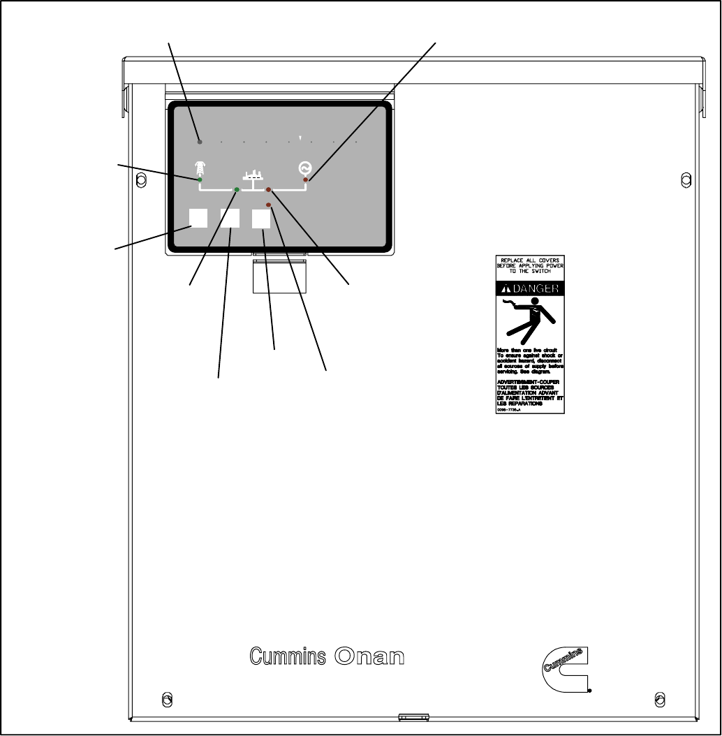
OPERATOR PANEL LED INDICATORS
The operator panel contains six LED indicators that
provide some information about the current control
status and may be helpful in troubleshooting the
transfer switch (see Figure 4-1). Descriptions of
these indicators are included in Table 4-1.
Test Override Set Generator
Exercise
Exercise
Test
Control operation could be delayed by external source.
PowerCommand
UTILITY
POWER
AVAILABLE
LED
GENERATOR
POWER
AVAILABLE
LED
UTILITY POWER
CONNECTED LED
GENERATOR
POWER
CONNECTED
LED
ACTIVE SET OR
PROGRAMMED
EXERCISE LED
TEST
ACTIVITY
LED
TEST
PUSHBUTTON
OVERRIDE
PUSHBUTTON
SET EXERCISE
PUSHBUTTON
FIGURE 4-1. CONTROL PANEL

2008 Cummins Inc. All rights reserved.
4-2
TABLE 4-1. OPERATOR PANEL LED INDICATORS
Indicator Definition
Utility Power Available This indicator lights when the utility source voltage sensor has determined that Utility
power is available and is within acceptable voltage limits.
Utility Connected 1. Lights constantly when the transfer switch is connected to the Utility.
2. Blinks once per second when the transfer switch has failed to connect to or
disconnect from the Utility when commanded.
3. Is off when the transfer switch is not connected to the Utility.
Generator Power Available This indicator lights when the generator source voltage sensor has determined that
generator power is within acceptable voltage and frequency limits.
Generator Connected 1. Lights constantly when the transfer switch is connected to the Generator.
2. Blinks once per second when the transfer switch has failed to connect to or
disconnect from the Generator when commanded.
3. Is off when the transfer switch is not connected to the Generator.
Exercise The following describes the Exercise LED when an exercise is enabled.
1. Lights constantly when repeat exercise periods have been set.
2. Blinks twice per second when the Set Exercise button is pressed and held to set
or cancel an exercise period.
3. Blinks once per second when an exercise period is active.
4. Is off when no repeat exercise periods are set.
Test 1. This indicator blinks at two times per second rate during the two seconds that the
Test button is pressed to acknowledge that a test has been activated or when the
remote test input is grounded.
2. The indicator lights constantly during the test and goes out once the test is termi-
nated or normal power has failed.
3. The indicator blinks at two times per second rate during the two seconds to ac-
knowledge that the Test button has been pressed to cancel a Test. The light then
goes out.

2008 Cummins Inc. All rights reserved.
4-3
TROUBLESHOOTING THE TRANSFER
SWITCH
Use the troubleshooting guide (Table 4-2) to help
diagnose transfer switch problems with transfer
switches that include a control panel. Common
problems are listed with their possible causes. Re-
fer to the corrective action column for the appropri-
ate corrective procedure.
TABLE 4-2. TROUBLESHOOTING TRANSFER SWITCHES WITH AN OPERATOR PANEL
AC power within the cabinet presents a shock hazard that can cause severe personal
injury or death. Do not remove the front panel under any circumstances.
Improper operation of the generator presents a hazard that can cause severe personal
injury or death. Observe all safety precautions in your generator manuals.
WARNING
WARNING
Problem Possible Cause Corrective Action
The Generator does not start
when the utility fails
There may be a generator problem. Move the generator’s operation selector
switch to the Run/On position.
1. If the generator starts and the trans-
fer switch transfers, the generator
may not have received the start sig-
nal from the controller. Contact your
local Cummins distributor for ser-
vice.
2. If the generator does not start, con-
tact your local Cummins distributor
for service.
The generator is running but
the transfer switch did not
transfer the load to the gener-
ator. The Generator Available
LED is off.
The generator circuit breaker has been
tripped or is in the Off position.
Reset the circuit breaker on the genera-
tor. If the problem still persists, contact
your local Cummins distributor for ser-
vice.
The generator is running but
the transfer switch did not
transfer the load to the gener-
ator. The Generator Available
LED is on.
A time delay normal to emergency
(TDNE) may be timing.
Wait until the time delay has expired or
press the Override pushbutton on the
control panel. If the problem still per-
sists, contact your local Cummins dis-
tributor for service.
The generator is running but
the transfer switch did not
transfer the load to the gener-
ator. The Utility Connected
LED is flashing.
The control was unsuccessful in its at-
tempts to open the Utility side of the
transfer switch. After 5 attempts to move
the transfer switch, the Utility Connected
LED flashes, indicating that it failed to
open.
Press the Override pushbutton on the
control panel to reset the control so that
it will attempt to open the Utility side of
the transfer switch. If the problem still
persists, contact your local Cummins
distributor for service.
Utility power is restored but
the transfer switch does not
transfer to the utility. The Utili-
ty Power Available LED is off.
The main service circuit breaker has
been tripped or is in the Off position.
Reset the circuit breaker on the main
service panel. If the problem still per-
sists, contact your local Cummins dis-
tributor for service.
Utility power is restored but
the transfer switch does not
transfer to the utility. The Uti-
lity Power Available LED is
on.
A time delay emergency to normal
(TDEN) may be timing.
Wait until the time delay has expired or
press the Override pushbutton on the
control panel. If the problem still per-
sists, contact your local Cummins dis-
tributor for service.

2008 Cummins Inc. All rights reserved.
4-4
TABLE 4-2. TROUBLESHOOTING TRANSFER SWITCHES WITH AN OPERATOR PANEL (CONTINUED)
AC power within the cabinet presents a shock hazard that can cause severe personal
injury or death. Do not remove the front panel under any circumstances.
Improper operation of the generator presents a hazard that can cause severe personal
injury or death. Observe all safety precautions in your generator manuals.
WARNING
WARNING
Problem Corrective ActionPossible Cause
Utility power is restored but
the transfer switch does not
transfer to the utility. The
Generator Connected LED is
flashing.
The control was unsuccessful in its at-
tempts to open the Generator side of the
transfer switch. After 5 attempts to move
the transfer switch, the Generator Con-
nected LED flashes, indicating that it
failed to open.
Press the Override pushbutton on the
control panel to reset the control so that
it will attempt to open the Generator side
of the transfer switch. If the problem still
persists, contact your local Cummins
distributor for service.
The generator did not shut
down after the transfer switch
has transferred the load to
the utility.
1. A time delay engine cooldown
(TDEC) may be timing.
2. The selector switch on the generator
control panel may not be in the
correct position.
1. Wait for the time delay to expire. The
time delay may last up to 30 minutes.
2. Make sure the generator control is
set to the Remote position.
If the problem persists, move the gener-
ator control selector switch to the Off
position to shut down the generator.
Contact your local Cummins distributor
for service.
The generator is running for
no apparent reason.
1. The selector switch on the generator
control panel may not be in the
correct position.
2. There may be an active test or
Exercise period. Check to see if the
Test or Exercise LEDs are blinking.
1. Make sure the generator control is
set to the Remote position.
2. Wait for exercise or test period to
expire or press the Override button
to stop and exercise or the test
button to stop a test.
If the problem persists, move the gener-
ator control selector switch to the Off
position to shut down the generator.
Contact your local Cummins distributor
for service.

2008 Cummins Inc. All rights reserved.
4-5
TABLE 4-2. TROUBLESHOOTING TRANSFER SWITCHES WITH AN OPERATOR PANEL (CONTINUED)
AC power within the cabinet presents a shock hazard that can cause severe personal
injury or death. Do not remove the front panel under any circumstances.
Improper operation of the generator presents a hazard that can cause severe personal
injury or death. Observe all safety precautions in your generator manuals.
WARNING
WARNING
Problem Corrective ActionPossible Cause
The generator did not exer-
cise when expected to.
1. The selector switch on generator
control panel may not be in the cor-
rect position.
2. An exercise period may not be set
or is set but not yet started.
3. There may be generator problems.
1. Verify that the operation selector
switch on the generator control pan-
el is set to the Remote position.
2. Check the Exercise LED on the con-
trol panel to see if it is lit.
a. If the Exercise LED is not lit, no
exercise period has been set.
Refer to the generator exerciser
section for information on setting
an exercise.
b. If the Exercise LED is lit but not
flashing, the exercise period has
not yet started. Exercisers do not
display exercise start and stop
times.
3. Try starting the generator using its
start-stop controls. If it does not
crank, check the starting batteries
and cable connections. If it cranks
but does not start, check the fuel
supply.
If the problem persists, contact your lo-
cal Cummins distributor for service.
2008 Cummins Inc. All rights reserved.
4-6
HOW TO OBTAIN SERVICE
When the transfer switch requires servicing, con-
tact your nearest Cummins Power Generation dis-
tributor. Factory-trained Parts and Service repre-
sentatives are ready to handle all your service
needs.
To contact your local Cummins Power Generation
(CPG) distributor in the United States or Canada,
call 1-800-888-6626 (this automated service uti-
lizes touch-tone phones only). By selecting Option
1 (press 1), you will be automatically connected to
the distributor nearest you.
If you are unable to contact a distributor using the
automated service, consult the Yellow Pages. Typi-
cally, our distributors are listed under:
Generators-Electric,
Engines-Gasoline or Engines-Diesel, or
Recreational Vehicles-Equipment,
Parts and Service.
If it is necessary to contact a distributor regarding
the transfer switch, always give the complete Model
and Serial number. This information (included on
the model and serial number label − see Figure 4-2)
is necessary to properly identify your unit among
the many types manufactured.
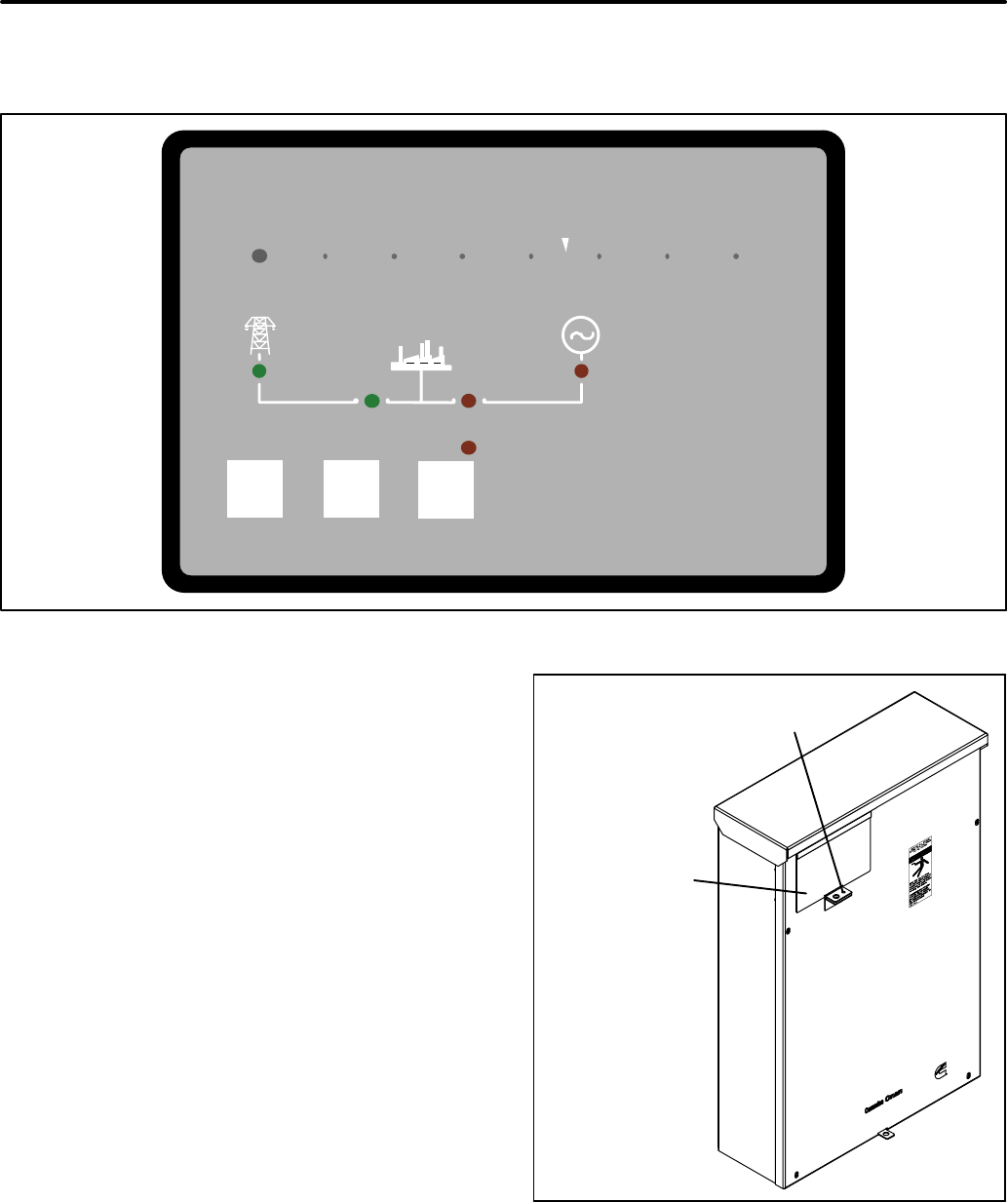
For models with a control, the label is located on the
back of the operator panel cover. To view the label
(see Figure 4-2), remove the screw securing the op-
erator panel cover and open the cover (see Figure
4-3).
Model No. ____________
Serial No. ____________
FIGURE 4-2. MODEL AND SERIAL NUMBER LABEL
PANEL COVER
SCREW TO
BE REMOVED
FIGURE 4-3. OPERATOR PANEL COVER

2008 Cummins Inc. All rights reserved.
Cummins Power Generation
1400 73rd Ave. NE
Minneapolis, MN 55432 USA
Phone 1 763 574 5000
Toll-free 1 800 888 6626
Fax 1 763 574 5298
Email www.cumminsonan.com/contact
www.cumminsonan.com
CumminsR, OnanR, the “C” logo, and “Performance you rely on.”
are trademarks of Cummins Inc.
E2007 Cummins Power Generation, Inc. All rights reserved.
