965_0178 965 0178 Onan E125V E140V Elite Series Operator's Manual (07 1997)
User Manual: 965-0178 Onan E125V E140V Elite series Operator's manual (07-1997)
Open the PDF directly: View PDF ![]() .
.
Page Count: 23
@WQTYNM QT E%C%1%0-,\'(./
.\0.
*$%'3
*$
*76:5 058659
Emissions Supplement:
900-1
021
Date:
07-2000
Insert
with-
Manual Number
&
Date:
See
Table
1
Models:
See
Table
1
965-0176
981-0153
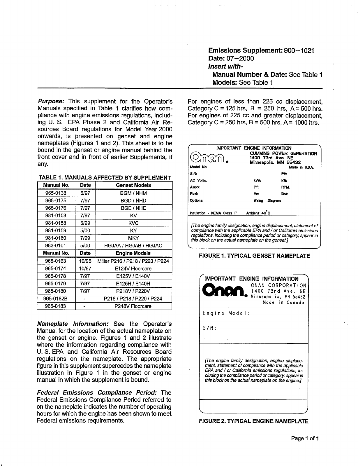
Purpose:
This supplement for the Operator's
Manuals specified in Table
1
clarifies how com-
pliance with engine emissions regulations, includ-
ing
U.
S.
EPA Phase 2 and California Air Re-
sources Board regulations for Model Year 2000
onwards, is presented on genset and engine
nameplates (Figures
1
and 2). This sheet is to be
bound in the genset or engine manual behind the
front cover and in front of earlier Supplements, if
any.
7/97
1
BGE
/
NHE
7/97
I
KV
TABLE
1.
MANUALS AFFECTED
BY
SUPPLEMENT
Manual
No.
I
Date
1
Genset Models
965-0138
I
5/97
I
BGM
/
NHM
I
965-0175
I
7/97
1
BGD
I
NHD
I
I
981-0158
I
6/99
I
KVC
I
981-0159
I
5/00
I
KY
981-0160
I
7/99
I
MKY
I
983-0101
1
5/00
I
HGJAAIHGJABIHGJAC
1
For engines of less than 225 cc displacement,
Category C
=
125 hrs, B
=
250 hrs, A
=
500
hrs.
For engines
of
225 cc and greater displacement,
Category C
=
250 hrs, B
=
500
hrs, A
=
1000
hrs.
r
IMPORTANT ENGINE INFORMATION
CURRMlNS
POWER
GENERATlOM
1400
73rd
Avo. NE
Minneapolis,
MN
55432
Made
in
USA
Modd
No:
PH
kVA:
kW:
pf:
RPM
Ha
Bat:
wring
DiagME
InsuIatbn
-
NEMA
Qan
F
Ambiant
40°C
flhe engine family designation, engine displacement, statement
of
compliance with the applicable
EPA
and/or California emissions
regulations, including the compliance period or category; appear in
this block on the actual nameplate on the genset.]
Manual
No.
I
Date
I
Engine Models
965-0163
I
10/95
I
Miller P216
/
P218
/
P220
I
P224
FIGURE
I.
TYPICAL GENSET NAMEPLATE
965-0174
I
10/97
I
E124V Floorcare
965-0178
I
7/97
I
E125V/ E140V
I
965-0179
I
7/97
I
E125H
I
E140H
I
965-0180
I
7/97
I
P218V
I
P220V
965-0182B
1
-
I
P216
/
P218
/
P220
I
P224
I
965-0183
I
-
I
P248V Floorcare
I
Nameplate Information:
See the Operator's
Manual for the location of the actual nameplate on
the genset or engine. Figures
1
and 2 illustrate
where the information regarding compliance with
U.
S.
EPA and California Air Resources Board
regulations on the nameplate. The appropriate
figure in this supplement supercedes the nameplate
illustration in Figure 1 in the genset or engine
manual in which the supplement is bound.
Federal Emissions Compliance Period:
The
Federal Emissions Compliance Period referred
to
on the nameplate indicates the number of operating
hours for which the engine has been shown to meet
Federal emissions requirements.
f
IMPQRTAMT
ENGINE
INFORMATION
)
ONAN CORPORATION
1400
73rd
Ave.
NE
Minneapolis,
MN
55432
Made in Canada
Engine
Model:
SIN:
rhe
engine family designation, engine displace-
ment, statement of compliance with the applicable
EPA
and
/
or California emissions regulations, in-
cluding
the
compliance period
or
category; appear in
this
block on the actual nameplate on the engine.]
FIGURE
2.
TYPICAL ENGINE NAMEPLATE
Page
1
of
1
Redistribution or publication of this document,
by any means, is strictly prohibited.

Beforeoperating the engine, read this manualand become
familiar with it and the equipment.Safe and efficient
operation canbeachieved only if the equipment is
properly operated and maintained.
The following symbols,found throughout this manual, alert you
to potentially dangerous conditions to the operator, service per-
sonnel,or the equipment.
This symbol warns of immediate hazards
which will result in severe personal injury or death.
4(/-,-+ This symbol refers toahazard or unsafe
practice whichcan result in severe personal injury or
death.
)(21,.- This symbol refers toahazard or unsafe
practice whichcan result in personal injury or product or
property damage.
Fuels,electrical equipment, batteries,exhaust gases and
moving parts present potential hazards that can result in severe
personalinjury.Take care in following these recommended
procedures.All local, stateand federalcodes should be
consulted and complied with.
4(/-,-+ This engine is not designed or intended for
usein any type of aircraft.Use of this engine in aircraft can
result in engine failureand cause severepersonal injury or
death.
GENERAL
•Provide appropriate fire extinguishers and install them in
convenient locations.Usean extinguisher rated ABC by
NFPA.
•Make sure that all fasteners on the engine are secureand
accurately torqued. Keep guards in position over fans,
driving belts,etc.
•Ifit is necessary to make adjustments while the engine is
running, useextreme caution when close to hot exhausts,
moving parts,etc.
•Used engine oils havebeen identified by some stateand
federalagencies as causing cancer or reproductive
toxicity.When checking or changing engine oil, take care
not to ingest, breathe the fumes,or contact used oil.
•Do not work on this equipment when mentally or
physically fatigued,or after consuming any alcohol or
drug that makes the operation of equipment unsafe.
BATTERIES
•Before starting work on the engine,disconnect batteries
to prevent inadvertent starting of the engine. Disconnect
negative(–) cable first.
•DO NOT SMOKE while servicing batteries.Leadacid bat-
teries give offahighly explosive hydrogen gas whichcan
beignited by flame,electricalarcing or by smoking.
•Verify battery polarity beforeconnecting battery cables.
Connect negative (–) cable last.
PROTECT AGAINST MOVING PARTS
•Donot wear looseclothing in the vicinity of moving parts,
suchas PTO shafts,flywheels, blowers, couplings,fans,
belts,etc.
•Keep your hands away from moving parts.
FUEL SYSTEM
•DO NOT fill fuel tanks while engine is running.
•DO NOT smoke or usean open flame in the vicinity of the
engine or fuel tank. Internalcombustion engine fuels are
highly flammable.
•Fuel line must be of steel piping,adequately secured, and
free from leaks.Piping at the engine should beapproved
flexible line. Do not usecopper piping for flexible lines as
copper will work harden and become brittle enough to
break.
•Be sureall fuel supplies haveapositive shutoff valve.
•Benzene and lead,found in some gasoline,havebeen
identified by some stateand federalagencies as causing
cancer or reproductive toxicity.When checking,draining
or adding gasoline, take care not to ingest, breathe the
fumes,or contact gasoline.
EXHAUST SYSTEM
•Exhaust products of any internalcombustion engine are
toxicand cancause injury,or death if inhaled. When
operating the engine in a confined area, make sure the
ventilation system is operating properly.
•DO NOT use exhaust gases to heat a compartment.
•Make sure that your exhaust system is free of leaks.Make
sure that exhaust manifolds are secureand are not
warped by bolts unevenly torqued.
EXHAUST GAS IS DEADLY!
Exhaust gases contain carbon monoxide, a poisonous gas that
cancause unconsciousness and death. It is an odorless and
colorless gas formed during combustion of hydrocarbon fuels.
Symptoms of carbon monoxide poisoning are:
•Dizziness •Vomiting
•Headache •Muscular Twitching
•Weakness and Sleepiness •Throbbing in Temples
If you experienceany of these symptoms,get out into freshair
immediately, shut down the unit and do not use it until it has
been inspected.
The best protection against carbon monoxide inhalation is
proper installation and regular,frequent inspections of the
completeexhaust system. If you noticea change in the sound
or appearanceof exhaust system, shut the unit down immedi-
ately and have it inspected and repaired at onceby a competent
mechanic.
KEEP THE UNIT AND SURROUNDING AREA CLEAN
•Make sure that oily rags are not left on or near the engine.
•Removeall unnecessary greaseand oil from the unit.
Accumulated greaseand oil cancause overheating and
subsequent engine damage and present apotential fire
hazard.
Safety Precautions
Redistribution or publication of this document,
by any means, is strictly prohibited.

1
Title Page
Safety PrecautionsInside Front Cover........................................................
Introduction 2...............................................................................
Operation 5................................................................................
Periodic Maintenance8......................................................................
Adjustments 13............................................................................
Troubleshooting 17.........................................................................
Specifications18...........................................................................
Important Information for California Engine Users 19. ..........................................
WARNING Improper service or replacement of parts
can result in severe personal injury and equipment
damage. service personnel must be qualified to perform
electricaland/or mechanical service.
CALIFORNIA PROPOSITION 65WARNING
Engine exhaust from this product contains chemicals
known to the State of California tocausecancer, birth
defects,and other reproductive harm .
Table of Contents
Redistribution or publication of this document,
by any means, is strictly prohibited.
2
ABOUT THIS MANUAL
This manualcovers the operation and maintenance
of the vertical-shaft EliteSeries of engines.Each
operator of the power equipment should study this
engine manualcarefully and observeall of its
instructions and precautions.Proper useand peri-
odicmaintenanceare responsibilities of the opera-
tor(s)and are essential for top performance.
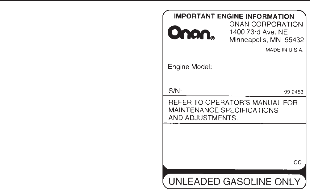
MODEL IDENTIFICATION
Whenever contacting anOnan dealer or distributor
for information,parts or service, always provide the
model number and the serial number marked on the
nameplateof the engine. Figure 1 illustrates a typi-
cal engine nameplateand Figure 2 the location of
the nameplate on the engine.
Genuine Onan replacement parts obtained from an
Onandealer or distributor are recommended.
E140V–N/11264D
L951234567
390SN5390U1G2RA
THIS ENGINE MEETS U.S.EPAPH1AND 1995–1998
CALIFORNIA EMISSIONS REGULATIONS FOR ULGE ENGINES
FIGURE 1. TYPICAL ENGINE NAMEPLATE
Introduction
Redistribution or publication of this document,
by any means, is strictly prohibited.
3
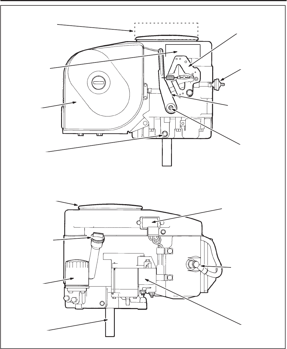
AIR CLEANER
OIL FILTER
BATTERY CHARGING
VOLTAGE REGULATOR
(On engines equipped
with electric starter)
RECOIL STARTER
(If so equipped)
ENGINE
NAMEPLATE
ELECTRIC STARTER
(If so equipped)
OIL DRAIN
FUEL FILTER
OIL FILL CAP
AND DIPSTICK
=\)''.
=\)''-
SPARK PLUG
GOVERNOR ARM
(see Adjustments)
GOVERNOR SHAFT
(see Adjustments)
ENGINE
CONTROL PLATE
(see Adjustments)
CRANKSHAFT
FLYWHEEL AIR
INLET SCREEN
FIGURE 2.TYPICAL ENGINE CONFIGURATION
Redistribution or publication of this document,
by any means, is strictly prohibited.
4
FUEL RECOMMENDATIONS
Useclean,fresh unleaded gasoline having amini-
mum octane rating (Anti-KnockIndex) of 87.
During some times of the year only mandated “oxy-
genated” gasolines may beavailable. Theseare
acceptable for use, but not preferable. Leaded gas-
oline may be used but will result in the extramainte-
nance required for removing combustion chamber
and spark plug deposits.Do not use gasoline or
gasoline additives (de-icers)containing methanol
becausemethanol canbecorrosive to fuel system
components.
)(21,.- Do not use gasoline or gasoline ad-
ditives containing methanol because methanol
canbecorrosive to fuel system components.
Avoid using highly leaded gasolines and lead
additives because of the extraengine mainte-
nance that will be required.
4(/-,-+ Gasoline is highly flammable and
cancause severe personal injury or death. Do
not smoke if you smell gasoline or are near fuel
tanks or gasoline-burning equipment or are in
anarea sharing ventilation with such equip-
ment.Keep flames, sparks,pilot lights,electri-
calarcs and arc-producing equipment and all
other sources of ignition well away.
ENGINE OIL RECOMMENDATIONS
Use premium quality motor oil. Look for the API
(AmericanPetroleumInstitute) classification and
useClass SG or SH oil (alsoSG/CD, SG/CE, SH/
CD or SH/CE). Also look for the SAE (Society of Au-
tomotiveEngineers) viscosity grade. Referring to
Table 1, choose the viscosity grade appropriate for
the ambient temperatures expected during the peri-
od of time until the next scheduled oil change.
Single-grade SAE 30 oil is preferable when temper-
atures areconsistently above freezing. Multigrade
oils arebetter when wide temperature variations
areexpected.
TABLE 1. OIL VISCOSITY VS.TEMPERATURE
EXPECTED AMBIENT
TEMPERATURES
SAE
VISCOSITY
GRADE
32°F(0°C)and higher30
10 °F to 100°F(–12°C to 38 °C)15W-40
(OnaMax)
0 °F to 80 °F(–18°C to 27°C)10W-30
10W-40
–20°F to 50 °F(–28°C to 10 °C)5W-30
STARTING BATTERIES
Anengine equipped withan electric starter requires
a12 volt starting battery.Prompt starting requires
sufficient battery capacity and battery cable size.
Neither cranking performance nor starter service
life will be satisfactory withan undersized battery.
Regular,monthly maintenance of batteries may be
required. See Periodic Maintenanceand any
instructions available from the equipment or battery
manufacturer.It should be noted that as long as the
equipment is operated regularly, the automatic bat-
tery recharging system on the engine should be
able to maintain battery charge. See OUT-OF-
SERVICE PROTECTION under Operation regard-
ing battery care during storage for prolonged peri-
ods.
EXHAUST SYSTEM
EXHAUST GAS IS DEADLY!Mobile engine-pow-
ered equipment must never be operated inside
buildings or other enclosed spaces without ample
freshair ventilation.
Stationary engine-powered equipment installed in-
side buildings or other enclosed spaces must be
equipped withaleak-free exhaust system that car-
ries all exhaust gases to the outside, well away from
all windows,doors, vents and other openings into
the building or enclosure.
It is the responsibility of the equipment operator(s)
tocheck for exhaust leaks on adaily basis and to
haveall leaks repaired beforecontinuing to operate
the equipment.
Redistribution or publication of this document,
by any means, is strictly prohibited.

5
EXHAUST GAS IS DEADLY!
Exhaust gases contain carbon monoxide, an odorless and colorless gas.Carbon monoxide is poi-
sonous and cancause unconsciousness and death. Symptoms of carbon monoxide poisoning in-
clude:
•Dizziness •Throbbing in Temples
•Nausea•Muscular Twitching
•Headache •Vomiting
•Weakness and Sleepiness •Inability toThink Coherently
IF YOU OR ANYONE ELSE EXPERIENCE ANY OF THESE SYMPTOMS, GET OUT INTO THE FRESH
AIR IMMEDIATELY.If symptoms persist, seek medicalattention. Shut down the engine and do not
operateit until it has been inspected and repaired.
Make certain the exhaust system is properly installed. Inspect it every time the engine is started
and after every eight hours of continuous operation.
PRE-START CHECKS
Before the first start of the day and after every eight
hours of operation perform the maintenance
instructed in DAILY(8 HOUR)MAINTENANCE un-
derPeriodic Maintenance .Keep alog of mainte-
nanceand the hours runand performany mainte-
nance that may be due. Also,if the equipment has
been in storage, return the engine to serviceas
instructed under RETURNING THE ENGINE TO
SERVICE in this section.
Always follow the equipment manufacturer’s oper-
ating instructions and observeall precautions when
operating power equipment.
4(/-,-+ Moving parts cancause severe
personalinjury or death. Hot exhaust parts can
cause severeburns.Stay clear of hot or moving
parts.Make sureall protective shields and
guards are secure in placebefore starting up
the equipment.
STARTING
1. Check the oil level if this is the first start of the
day and add oil as necessary.
)(21,.- Starting the engine without oil
will cause severe engine damage. Always
keep the engine oil level between the Full
and Add marks on the dipstick.
2.Fill the fuel tank,if necessary, and open any fuel
line shutoff valve.
3.Release the clutch if the engine is so equipped.
4. Onequipment witha single throttle/choke con-
trol,push the knobor lever to its “start” or
“choke” position. On equipment with separate
controls,pull the choke knobout to its full-choke
position.
Note:Try starting without the choke in warm
weather or when the engine is warm.
5. Push the throttle knobor lever to the middle of
its speed range.
6.If so equipped, turn the ignition key switch to its
runposition.
7.Pull the recoil starter handle tocrank the en-
gine. If the engine is equipped withan electric
starter, turn the key switch to its start position
and hold it there until the engine starts.Do not
crank for more than 30 seconds at a time and
wait at least one minutebetween tries when
cranking withan electric starter.See Trouble-
shooting if the engine does not start after sever-
al tries.
8. After the engine starts,keep your hand on the
choke knob and slowly push it in to the full-open
choke position,pulling back if necessary to
keep the engine running smoothly. (On single-
control systems,move the knobor lever away
from the “start” or “choke” position to the “fast”
or “high” speed position.) The colder the weath-
er the longer it will take the engine to start run-
ning smoothly with the choke fully open. Do not
operate the equipment until the engine has
warmed up sufficiently to run smoothly with the
choke fully open.
Operation
Redistribution or publication of this document,
by any means, is strictly prohibited.

6
ENGINE BREAK-IN
Engine break-in as a result of proper care during the
first hours of operation of anew or rebuilt engine re-
sults in the ideal fitting of all internal moving metal
parts, which is essential for top engine perfor-
mance. For controlled engine break-in:
1. Operate the equipment as it is intended tobe
operated. However,for the first 1-1/2 hours,if
possible,operate the equipment at about half
the available engine power,occasionally oper-
ating at full engine power for brief periods.
Also,if possible, avoid prolonged low-speed,
low-power operation during engine break-in.
2.Proper engine oil is especially critical during
break-in because of the higher engine temper-
atures that canbe expected. See REC-
OMMENDED ENGINE OIL in Introduction.
Change the oil if it is not appropriate for the am-
bient temperatures during the break-in period.
See Table 1.
3.Check the oil level twiceaday or after every 4
hours of operation during the first 24 hours of
operation.
4. Change the oil and oil filter after the first 24
hours of operation and have the valves read-
justed by aqualified mechanic.
OPERATION IN DUSTY CONDITIONS
1. Keep the engine cooling fins and flywheel air
inlet screen clean.
2.Performair cleaner maintenance more often
thannormal—as required. See Table 2.
3.Change the engine oil and oil filter more often
than normal. See Table 2.
OPERATION IN HOT WEATHER
Pay particular attention to the following items when
operating the engine in temperatures above 100°F
(38°C):
1. Keep the flywheel air inlet screen and cylinder
cooling fins clean. See to it that nothing ob-
structs air flow toand from the engine.
2.Check the oil level more frequently.
3.Change the oil and oil filter moreoften than nor-
mal. See Table 2.
4. Make sure the engine oil viscosity is appropri-
atefor the ambient temperatures and change
the oil if necessary.See Table 1.
OPERATION IN COLD WEATHER
Pay particular attention to the following items when
operating the engine in temperatures below freez-
ing:
1. Make sure the engine oil viscosity is appropri-
atefor the ambient temperatures and change
the oil if necessary.See Table 1. If the tempera-
turedrops before you have the chance to
change the oil, warm up the engine by moving
the equipment intoaheated spacebeforeat-
tempting to start the engine or change oil.
4(/-,-+ EXHAUST GAS IS DEADLY!
Never operate mobile engine-powered
equipment indoors without ample freshair
ventilation.
2.Use fresh fuel and fill the fuel tank after each
day’s use to reduce problems with moisture
condensation.
3.Keep the battery in a well-charged condition.
4. After each use push the equipment throttle
knobor lever to the middle of its speed range so
that if ice forms on the linkage during storage it
will be easier to start the engine.
Redistribution or publication of this document,
by any means, is strictly prohibited.

7
OUT-OF-SERVICE PROTECTION
Protect anengine that will be out of service for more
than 30 days as follows:
1. Run the engine until it reaches normal operat-
ing temperature, shut off the fuel supply and let
the engine run until it stops.Also,if the equip-
ment will not be operated for more than 120
days,add afuel preservative (OnaFresh TM) to
the equipment fuel tank. Follow the instructions
on the container label. Unless apreservative
(stabilizer)is added, the gasoline will deterio-
ratecausing fuel system corrosion,gum forma-
tion and varnish-like deposits whichcan lead to
hard starting and rough operation.
4(/-,-+ Gasoline preservatives (stabi-
lizers)are toxic.Follow the instructions on
the container label. Avoid skin contact.
Wash your hands with soapand water after
dispensing the fluid.
2.Drain the oil from the engine while it is still
warm. Refill withfresh oil and attacha tag stat-
ing the viscosity of the oil used.
3.Remove the spark plugand squirt 1 ounce
(2 tablespoons or 28 grams) of rust inhibitor or
SAE 30 oil into the cylinder.Crank the engine
over afew times and reinstall the spark plug.
4. Performair cleaner maintenanceas instructed
in Periodic Maintenance .
5. Clean the governor linkage and wrap it witha
cleancloth for protection.
6.Plug the exhaust outlet to prevent moisture,
dirt,bugs,etc. from entering.
7.Provide a suitable cover for the entire unit.
8. If so equipped,disconnect the battery (nega-
tive[–] cable first)and follow the battery or
equipment manufacturer’s storage instruc-
tions.
RETURNING THE ENGINE TO SERVICE
1. Remove the cover and all protective wrapping
and the plug from the exhaust outlet.
2.Check the tag on the oil base. Change the oil if
the viscosity is not appropriate for the expected
ambient temperatures.See Table 1.
3.Check the fuel filter and fuel lines to make sure
they are secureand havenocracks or leaks.
4. Check to see that the choke, throttle and gover-
nor linkages move freely.
5. If so equipped, cleanand check the battery ac-
cording to the battery or equipment manufac-
turer’s instructions and connect the battery
cables (positive[+ ] cable first).
6.Start the engine. The initial startup may be slow
and there may be smoke and rough operation
for afew minutes until the oil in the cylinder
burns off. If the engine does not start, cleanor
replace the spark plugas it may havebeen
fouled by the oil added to the cylinder when the
equipment was stored.
OnaFreshis a trademark of the OnanCorporation.
Redistribution or publication of this document,
by any means, is strictly prohibited.

8
Periodicmaintenance is essential for top engine
performance. UseTable 2 as aguide for normal pe-
riodicmaintenance. Under hot or dusty operating
conditions some maintenance operations should
beperformed more frequently, as indicated by the
footnotes in the table. Keep alog of maintenance
performed and the hours run. Recording mainte-
nance will help you keep it regular and provide a ba-
sis for supporting warranty claims.
Maintenance, replacement or repair of emission
control devices and systems may be performed by
any engine repair establishment or individual. How-
ever, warranty work must becompleted by an
authorized Onan dealer or distributor.
TABLE 2.PERIODIC ENGINE MAINTENANCE SCHEDULE
MAINTENANCE FREQUENCY
MAINTENANCE OPERATION Every Day
or Every 8
Hours
Every 50
Hours Every
MonthEvery 100
HoursEvery
200 Hours Every 400
Hours
Inspect Engine • 1
CheckOil Level •
CleanAir Cleaner FoamWrapper• 3
CleanCylinder Cooling Fins• 3
CheckStarting Battery (if so equipped) • 5
Change Engine Oil and Oil Filter• 2,3,4
ReplaceFuel Filter (if so equipped) •
ReplaceAir Cleaner Element• 3
Adjust Engine ValveClearance• 2,6
Inspect,Cleanand Re-gapSparkPlug•
ReplaceSparkPlug•
1Checkfor oil,fuel and exhaust leaks,loose parts and unusual noises and vibrations.
2Performafter the first 24 hours of operation as apart of engine break-in.
3Perform more often when operating in dusty conditions.
4Perform more often when operating in hot conditions.
5See instructions for battery care provided by the equipment or battery manufacturer.
6Must be performed by aqualified mechanic(equipment or Onan dealer).
Periodic Maintenance
Redistribution or publication of this document,
by any means, is strictly prohibited.
9
DAILY(8 HOUR)MAINTENANCE
The operator should check the following before the
first start of the day and after every eight hours of
operation:
1. Inspect fuel lines and fittings for leaks.Repair
leaks immediately.
2.Look and listen for exhaust system leaks while
the engine is running. Look for cracks and se-
vere rusting in the muffler and tailpipe. Haveall
leaks repaired beforecontinuing to operate the
equipment.
4(/-,-+ Hot exhaust parts cancause
severeburns.Allow the engine time tocool
before servicing the exhaust system.
3.Check the engine for dirt and debris and clean
the flywheel air inlet screen and cylinder cool-
ing fins as necessary.
)(21,.- A clogged flywheel air inlet
screen or dirty cooling fins cancause over-
heating and engine damage. Keep the cool-
ing fins and air inlet screen clean.
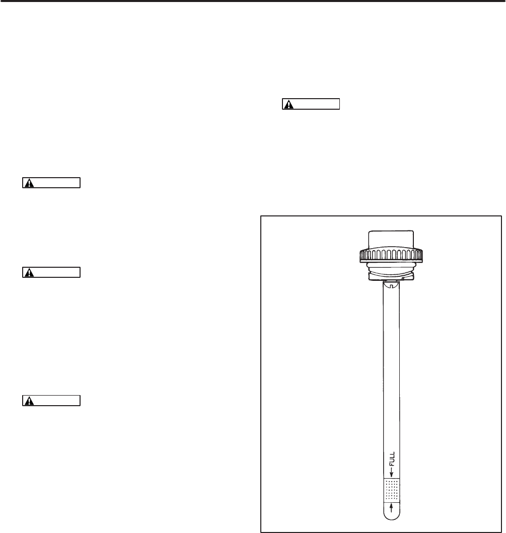
4. Check the engine oil level. The equipment
must be parked on alevel surfaceand the en-
gine stopped. Toget anaccurate reading, wait
aminute or so toallow the oil to settle in the
crankcaseif the engine has been running.
4(/-,-+ Crankcase pressurecanblow
hot engine oil out the fill tubecausing se-
vereburns.Always stop the engine before
removing the oil fill cap.
Turn the oil fill cap (Figure 3)counterclockwise
and then lift it from the fill tube. Wipe the dip
stickcleanand push it back into the oil fill tube
until the cap seats and then withdraw it tocheck
the oil level.
If the oil level is low, add API Class SG or SH oil
(alsoSG/CD, SG/CE, SH/CD or SH/CE) hav-
ing anSAE viscosity grade appropriate for the
expected temperatures, as indicated by
Table 1.
DO NOT FILL TO A LEVEL ABOVE THE FULL
MARK ON THE DIPSTICK.Drain the excess
oil if too much has been added.
)(21,.- Too much oil cancause high oil
consumption,high operating temperatures
and oil foaming. Too little oil cancause se-
vere engine damage. Keep the oil level be-
tween the Full and Add marks on the dip-
stick.
Reinstall the dipstickand capafter checking or
adding oil, turning it clockwise until it is secure.
<C\((0)
FIGURE 3.OIL FILL CAP AND DIPSTICK
Redistribution or publication of this document,
by any means, is strictly prohibited.

10
ENGINE OIL AND FILTER CHANGE
4(/-,-+ Stateand federalagencies have de-
termined that contact with used engine oil can
causecancer or reproductive toxicity.Take
care to limit skin contact and breathing of va-
pors as muchas possible. Use rubber gloves
and wash exposed skin.
Refer toTable 2 for scheduled oil change and filter
replacement.See Figure 2 on page 3 for oil filter
and oil drain locations.
1. Run the engine until it is warm. Stop the engine
and disconnect the spark plugand,if so
equipped, the battery (negative[–] cable).
4(/-,-+ Accidental starting of the en-
gine can result in severe personal injury or
death. Always disconnect the spark plug
and the battery (negative[–] cable) before
changing oil.
2.Remove the oil fill cap.
4(/-,-+ Crankcase pressurecanblow
hot engine oil out the fill opening causing
severeburns.Always stop the genset be-
fore removing the oil fill cap.
3.Placeapan under the oil drain opening and re-
move the oil drain plug. Reinstall the plug se-
curely after the oil has drained completely.
4. Spin off the oil filter canister,drain the oil and
discard the filter according to local regulations.
5. Thoroughly wipe off the filter mounting surface.
6.Make sure the gasket is in place on the filter
canister and apply a thin film of oil to the gasket.
7.Spin on the new filter canister by hand until the
gasket just touches the mounting padand then
turn it anadditional 1/2 to 3/4 turn. Do not over-
tighten.
8. Refill withAPI Class SG or SH oil (alsoSG/CD,
SG/CE, SH/CD or SH/CE) having anSAE vis-
cosity grade appropriate for the expected tem-
peratures,as indicated by Table 1. See Speci-
ficationsfor the oil capacity.
DO NOT FILL TO A LEVEL ABOVE THE FULL
MARK ON THE DIPSTICK.Drain the excess
oil if too much has been added.
)(21,.- Too much oil cancause high oil
consumption,high operating temperatures
and oil foaming. Too little oil cancause se-
vere engine damage. Keep the oil level be-
tween the Full and Add marks on the dip-
stick.
9. Reconnect the spark plugand battery.
10.Start the engine and run it for a short time while
checking for oil leaks around the drain plugand
oil filter.Do not overtighten: tighten only as nec-
essary to eliminate leaks.
11.Used oil is harmful to the environment.Pour
the used oil intoa sealed container and deliver
it to the nearest recycling center.
Redistribution or publication of this document,
by any means, is strictly prohibited.
11
AIR CLEANER MAINTENANCE
Refer toTable 2 for scheduled foam wrapper main-
tenanceand air cleaner element replacement.See
Figure4.
FoamWrapper Maintenance
When performing maintenance on the foam wrap-
per only,do not remove the inner air cleaner cover.
Removeand wash the foam wrapper in water and
detergent.Squeeze the foam wrapper dry like a
sponge. Rinse withclean water and allow it to dry.
Coat the wrapper evenly with one tablespoon
(14 grams)of SAE 30 engine oil. Knead the oil into
the wrapper and wring out the excess oil.
Failure toadequately wring out excess oil from the
wrapper may causeadrop in engine power due toa
restriction of inlet air.
Install the foam wrapper over the paper air cleaner
element by stretching it over the inner cover.Com-
pletely cover all exposed paper pleats on the air
cleaner paper element.Replace the foam wrapper
when it becomes torn or stretched.
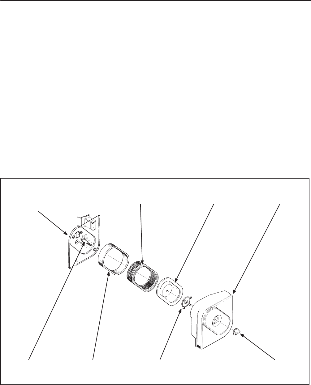
Air Cleaner Element Replacement
Tokeep anything from entering the carburetor and
engine while the air cleaner element is off,pull the
chokeknob to the full-choke position toclose the
choke plate in the carburetor.Remove the outer
cover and wipe away loose dust and debris from the
air cleaner assembly.Remove the inner air cleaner
mounting nut and cover.Remove the air filter paper
element and foam wrapper from the engine. Wipe
off dust and debris from the air cleaner base.
Install the new paper element and secure it with the
inner cover and mounting nut.Tighten the nut 1-1/2
turns after seating it on the cover.Reinstall the foam
wrapper and outer cover.
MOUNTING NUTFOAM WRAPPER
AIR CLEANER
ASSEMBLY BASE AIR CLEANER ELEMENT
SEAL
OUTER COVERINNER COVER
MOUNTING NUT
FIGURE 4. AIR CLEANER ASSEMBLY
Redistribution or publication of this document,
by any means, is strictly prohibited.

12
COOLING SYSTEM MAINTENANCE
Refer toTable 2 for scheduled cleaning of the cylin-
der cooling fins.
Usecompressed air or apressure washer toclean
the cylinder cooling fins.Take the following precau-
tions.
1. Wear safety glasses.
4(/-,-+ Always wear safety glasses
when using compressed air or apressure
washer toavoid severe eye damage.
2.Let the engine cool,especially when using a
pressure washer.The temperature stresses
caused by cleaning ahot engine cancrack the
cylinder.
3.Observeall of the manufacturer’s instructions
and precautions when using apressure
washer.
FUEL FILTER REPLACEMENT
Refer toTable 2 for scheduled fuel filter replace-
ment and Figure 2 for the location of the fuel filter (if
so equipped). Also refer to the equipment Opera-
tor’s Manual regarding any supplemental fuel filters
that may havebeen provided and the recom-
mended frequency for their replacement.
Take care not to spill fuel when disconnecting the
fuel line from the filter.Allow the engine tocool be-
foredisconnecting the fuel line so that it cannot ig-
niteany fuel that may be spilled. Closeany shutoff
valve that may be provided in the fuel line. If the filter
is of the in-line type,it is usually removable by loos-
ening the inlet and outlet hoseclamps.
4(/-,-+ Gasoline is highly flammable and
cancause severe personal injury or death.
Let the engine cool and closeany fuel line shut-
off valvebefore disconnecting the fuel line from
the filter.
Donot smoke if you smell gasoline or are near
fuel tanks or gasoline-burning equipment or are
in anarea sharing ventilation with such equip-
ment.Keep flames, sparks,pilot lights,electri-
calarcs and arc-producing equipment and all
other sources of ignition well away.
SPARK PLUG MAINTENANCE AND
REPLACEMENT
Refer toTable 2 for scheduled spark plug inspection
and replacement and toSpecificationsfor gap
specifications.
To prevent crossthreading the spark plugalways
threadit in by hand until it seats.If the spark plug is
being reused, turn it witha wrenchanadditional 1/4
turn. If the spark plug is new, turn it anadditional 3/8
to1/2 turn. If you havea torque wrench, tighten the
sparkplug to 20 lbs-ft (26 N-m).
Redistribution or publication of this document,
by any means, is strictly prohibited.

13
CARBURETOR ADJUSTMENTS
Theseengines have precision-manufactured car-
buretors whichare not adjustable.
ENGINE SPEED AND CHOKE
ADJUSTMENTS
Normally there is no need toadjust engine speed.
Theseinstructions are for the equipment manufac-
turer in setting upand adjusting the equipment.
When setting up the equipment, Engine Speed Ad-
justments,Choke Adjustment and Control Cable
Adjustments must be performed in the order they
appear in this section.
Service personnel should note that following reas-
sembly of either the carburetor or intake manifold to
the engine,it is necessary to reposition the gover-
nor arm (Figure 2) on the governor shaft BEFORE
making speed adjustments soas tocompensate for
the slightly different alignment of parts.See the en-
gine ServiceManual.
Engine speed adjustment must beattempted only
by aqualified mechanic and the adjustments must
bemade using anaccurate tachometer.Set the
low-idle and high-idle speeds to the values speci-
fied in the equipment Operator’s Manual. In the ab-
senceof such specifications it is recommended that
low-idle speed beadjusted to 1400 RPM and high-
idle speed to 3400 RPM.
4(/-,-+ Adjusting the engine speed toa val-
ueabove that specified by the equipment
manufacturecould cause the equipment to op-
erateat speeds in violation of Federaland State
Standards for Safety for the equipment.
4(/-,-+ Moving parts cancause severe per-
sonalinjury or death. Take care when measur-
ing engine speed witha tachometer and follow
the meter instructions.You must beaqualified
mechanic.
Adjustments
Redistribution or publication of this document,
by any means, is strictly prohibited.
14
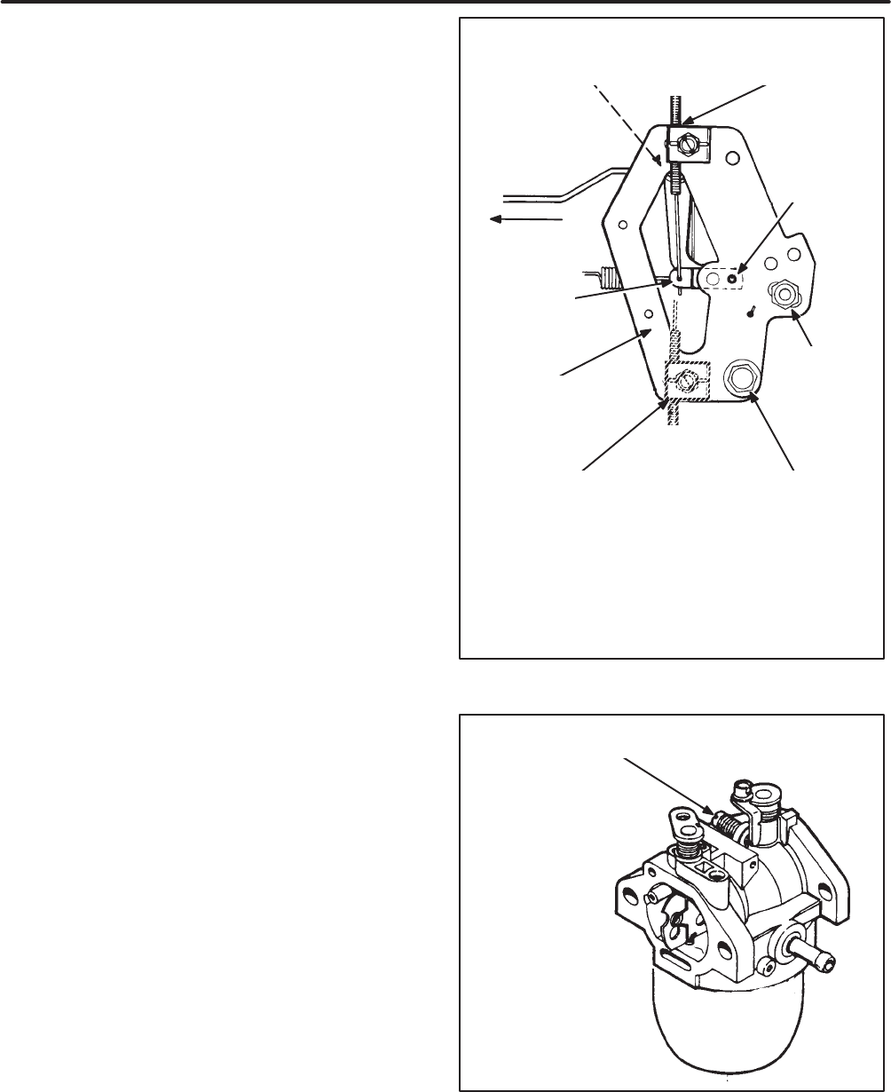
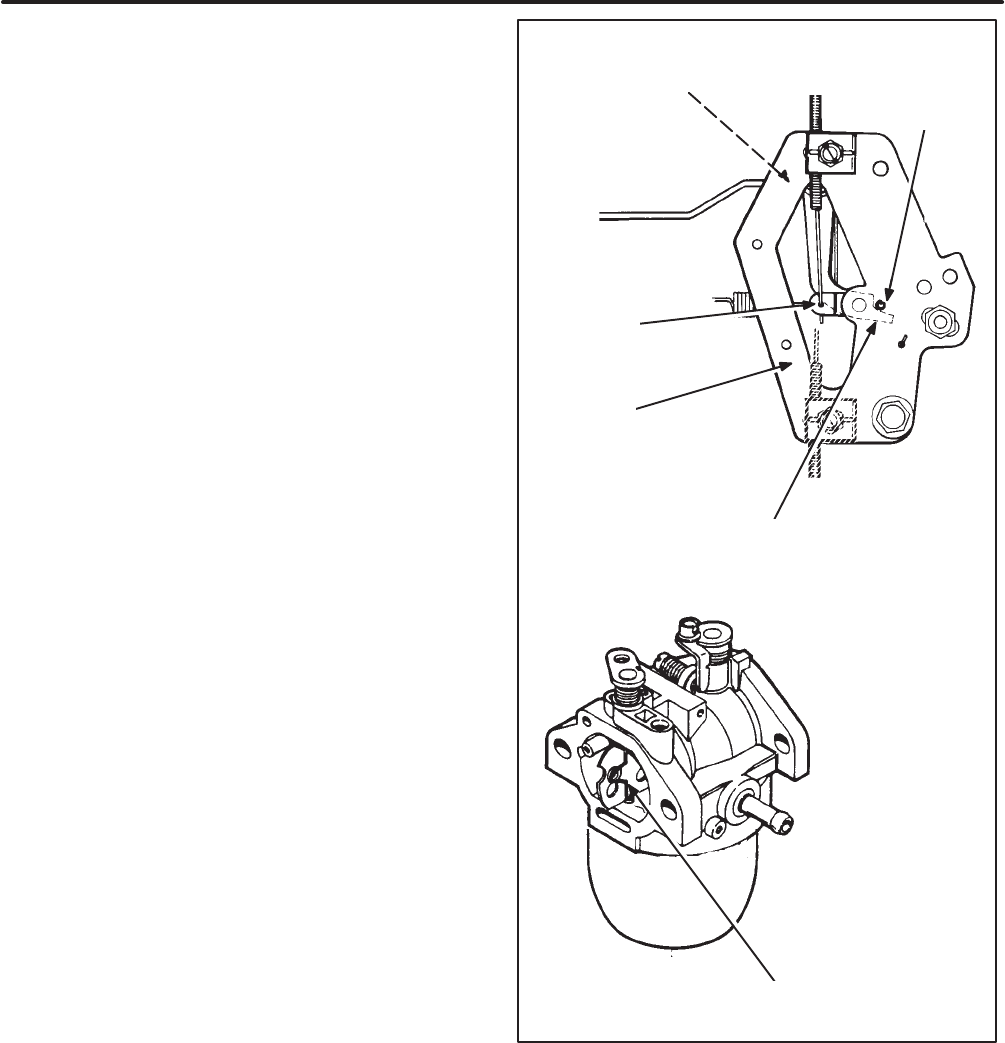
Engine Speed Adjustments
Referring toFigures 5and 6, adjust high-idle and
low-idle as follows:
1. Remove the outer cover of the air cleaner (Fig-
ure 4) for easier access toadjustments and set
up the tachometer according to the instructions
with the tachometer.
2.Start the engine,observing all of the equipment
manufacturer’s instructions and precautions.
3.While the engine is running,move the throttle
control lever on the engine control plate toalign
its lock pin hole with the corresponding hole in
the control plateand insert apin (1/8 inch drill
bit) to lock the lever in place. Loosen the throttle
cable clamp if necessary.
4. Loosen the choke rod swivel clamp screw and
push the choke rod towards the carburetor so
that the choke will be fully open.
5. Adjust high-idle speed to specifications by
rotating the engine control platearound its piv-
ot bolt—away from the carburetor to increase
speed and toward the carburetor to decrease
speed. To do this,loosen the control plate pivot
bolt 1/8 turnand the the control plate set bolt
1/4 turn. Retighten both of the control plate
bolts upon obtaining the specified speed. Re-
checkand readjust the high-idle speed if nec-
essary.
6.Adjust low-idle speed to specifications by
turning the idle speed screw on the carburetor.
First release the throttle control lever by remov-
ing the lock pin inserted in Step 3 and then
moveit down to its lowest position.
7.Shut off the engine and readjust the choke. See
Choke Adjustment in this section.
38?;5 B?4
3?>DB?<
@<1D5 C5D
2?<D
3?>DB?< @<1D5
@9F?D 2?<D
5>79>5
3?>DB?<
@<1D5
D8B?DD<5
3?>DB?<
<5F5B
<?3; @9>
8?<5
0&-+ 9>%
#*%,"SS$
D8B?DD<5 312<5
1>4 3<1=@
38?;5 B?4 CG9F5< 3<1=@
#KNPQTM LUTYWUR VRJYN$
1<D5B>1D5 D8B?DD<5
312<5 1>4 3<1=@
Do not loosen the CONTROL PLATE PIVOT AND
SET BOLTS unless you areaqualified mechanic
and haveanaccurate tachometer to set the
high-idle speed in accordance with the equipment
manufacturer’s specifications
FIGURE 5. ENGINE SPEED ADJUSTMENTS
94<5 C@554 14:ECD9>7
C3B5G ?> 31B2EB5D?B
FIGURE 6.IDLE SPEED SCREW
Redistribution or publication of this document,
by any means, is strictly prohibited.
15
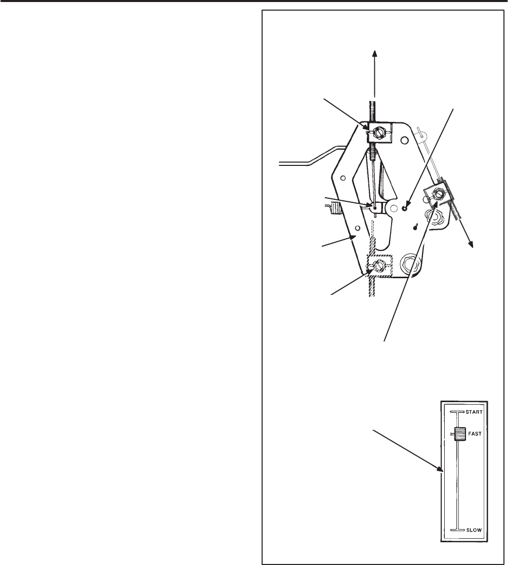
Choke Adjustment
Theseinstructions presume that engine speed ad-
justments havealready been made or that readjust-
ments areconsidered unnecessary.Referring to
Figure 7, readjust the choke as follows:
1. Shut off the engine and remove the outer cover
of the air cleaner for easier access toadjust-
ments and the filter element tobeable to view
the position of the choke plate. See Figure 4.
2.Loosen the choke rod swivel clamp screw so
that the rod is free to move in the choke swivel
clamp.
2.Move the throttle control lever on the engine
control plate toalign its lock pin hole with the
corresponding hole in the control plateand in-
sert apin (1/8 inch drill bit) to lock the lever in
place. Make sure the pin extends aboveand
past the choke lever, as shown, to function as a
stop for the choke lever.Loosen the throttle
and choke cable clamp(s) if necessary.
3.Push the choke rod towards the carburetor,
making sure the choke is fully open.
4. Rotate the choke lever towards the carburetor
until the lever bears against the pin stop and
tighten the choke rod swivel clamp screw.
5. Remove the lock pin in the control plateand
checkoperation of the choke linkage. If the
linkage binds, replace the components that are
damaged.
6.Reassemble the air cleaner.
7.Adjust the throttle and choke control cables.
See Control Cable Adjustments in this section.
=1;5 CEB5 D85 <?3; @9> 5HD5>4C @1CD
D85 38?;5 <5F5B D? 6E>3D9?> 1C 1 CD?@
6?B D85 <5F5B
<?3; @9>
8?<5
0&-+ 9>%
#*%, SS$
38?;5 B?4 CG9F5< 3<1=@
#KNPQTM LUTYWUR VRJYN$
D8B?DD<5
3?>DB?<
<5F5B
5>79>5
3?>DB?<
@<1D5
38?;5 B?4
31B2EB5D?B 38?;5 @<1D5
#ZQXQKRN [PNT YPN JQW OQRYNW NRNSNTY QX WNSUZNM$
FIGURE 7.CHOKE ADJUSTMENT
Redistribution or publication of this document,
by any means, is strictly prohibited.
16
Control Cable Adjustments
Theseinstructions presume that engine speed and
choke adjustments havealready been made or that
readjustments areconsidered unnecessary.
The equipment may have either a single-cable or a
two-cable system for throttle and choke control.
Single-Cable Control Systems:Referring toFig-
ure 8, adjust the throttle/choke cable as follows:
1. Shut off the engine and loosen the throttle
cable clamp.
2.Move the throttle control lever on the engine
control plate toalign its lock pin hole with the
corresponding hole in the control plateand in-
sert apin (1/8 inch drill bit) to lock the lever in
place. Push the speed control lever on the
equipment to the high speed position (not to
the “start”or “choke” position—see the illustra-
tion).
3.Hook the cable wire into the throttle control le-
ver,if necessary,pull out the cable slackand
tighten the cable clamp. Remove the lock pin in
the control plate.
Two-Cable Control Systems:Referring toFig-
ure 8, adjust the throttle and choke cables as fol-
lows:
1. Shut off the engine and loosen the throttle
cable clamp.
2.Move the throttle control lever on the engine
control plate toalign its lock pin hole with the
corresponding hole in the control plateand in-
sert apin (1/8 inch drill bit) to lock the lever in
place. Push the speed control lever on the
equipment to its highest speed position.
3.Hook the cable wire into the throttle control le-
ver,if necessary,pull out the cable slackand
tighten the cable clamp. Remove the lock pin in
the control plate.
4. Pushin the equipment choke knob to its full-
open position.
5. Hook the cable wire into the choke control le-
ver,if necessary,push the choke rod towards
the carburetor,pull out the cable slackand
tighten the cable clamp.
D8B?DD<5
312<5 1>4
3<1=@
1<D5B>1D5
D8B?DD<5 312<5
3<1=@ <?31D9?>
@E<< 312<5 C851D8 D89C G1I
D? B5=?F5 312<5 C<13;
38?;5 312<5 3<1=@ ?>
DG?\312<5 CICD5=C
#UT UYPNW XQMN UO VRJYN$
D8B?DD<5
3?>DB?<
<5F5B
@E<< 312<5
C851D8
D89C G1I
D? B5=?F5
312<5
C<13;
DI@931< C9>7<5\312<5
5AE9@=5>D D8B?DD<5&38?;5
3?>DB?<
<?3; @9>
8?<5
0&-+ 9>%
#*%, SS$
5>79>5
3?>DB?<
@<1D5
38?;5 B?4
FIGURE 8. CONTROL CABLE ADJUSTMENTS
Redistribution or publication of this document,
by any means, is strictly prohibited.

17
Table 3 provides basic troubleshooting guidance. If
you fail to resolve the problem after taking the cor-
rectiveactions suggested, contact the equipment
or Onan dealer.
4(/-,-+ Many troubleshooting procedures
present hazards that can result in severe per-
sonalinjury or death. Only qualified serviceper-
sonnel with knowledge of fuels,electricity, and
machinery hazards should perform service pro-
cedures.Review the safety precautions on the
inside cover page.
4(/-,-+ Hot engine parts cancause severe
burns.Always allow the engine time tocool
beforeperforming any maintenance or service.
TABLE 3.TROUBLESHOOTING
Problem CorrectiveAction
1. The engine fails tocrank (elec-
tric start engines). a.Release the clutch (if so equipped).
b.Cleanand tighten the positive( + )and negative( –)battery
cable connections at the battery and the engine.
c.Recharge the battery.Refer to the equipment or battery
manufacturer’s recommendations.
2.The engine cranks slowly (elec-
tric start),or the recoil starter is
hard to pull.
a.Release the clutch (if so equipped).
b.Ifelectric start, cleanand tighten the positive( + )and nega-
tive( –)battery cable connections at the battery and the en-
gine.
c.If electric start, recharge the battery.Refer to the equip-
ment or battery manufacturer’s recommendations.
d. Change engine oil tooil having the proper viscosity for the
ambient temperature. See Table 1.
3.The engine cranks but fails to
start.a.Check the fuel tank and fill if necessary.
b.Open any closed fuel shut off valve.
c.Check engine oil level and add oil as necessary.
d. Reconnect and reclamp the choke and throttle cables,if
necessary.See Adjustments.
e. Service the air cleaner.
f. Replace the fuel filter(if provided).
g. Inspect and clean or replace the spark plugand re-gap it.
4. The engine runs and then stops.a.Check the fuel tank and fill if necessary.
b.Check the engine oil level and add oil as necessary.Drain
excess oil if the level is above the dipstickFull mark.
c.Reconnect and reclamp the choke and throttle cables,if
necessary.See Adjustments.
5. The engine exhausts black
smoke. a.Service the air cleaner.
b.Reconnect and reclamp the choke and throttle cables,if
necessary.See Adjustments.
Troubleshooting
Redistribution or publication of this document,
by any means, is strictly prohibited.

18
MODEL E125VMODEL E140V
Engine Type 1-Cylinder,4-Stroke Cycle, Spark-Ignited, OHV, Air-Cooled.
Vertical-Shaft
Bore3.31 inches (84.2 mm) 3.31 inches (84.2 mm)
Stroke 2.76 inches (70.0 mm) 2.76 inches (70.0 mm)
Displacement23.7 inches 3(390 cc)23.7 inches 3(390 cc)
Compression Ratio 8.5 :18.5 :1
Power at Rated Speed (3600 RPM)12.5 HP (9.3 kW)14.0 HP (10.4 kW)
Oil Capacity (withFilter)*1.7 quart (1.6 l) 1.7 quart (1.6 l)
Intake ValveClearance (Cold) 0.006 inches (0.15 mm) 0.006 inches (0.15 mm)
Exhaust ValveClearance (Cold) 0.006 inches (0.15 mm) 0.006 inches (0.15 mm)
SparkPlugGap0.035 inches (0.89 mm) 0.035 inches (0.89 mm)
SparkPlugTightening Torque20 lbs-ft (26 N-m) 20 lbs-ft (26 N-m)
Ignition Timing (Non-adjustable,elec-
tronic, magneto ignition) 23°BTDC 23°BTDC
*–See Periodic Maintenancefor oil filling instructions.
Specifications
Redistribution or publication of this document,
by any means, is strictly prohibited.

19
Theseengines meet the requirements of Califor-
nia’s Exhaust Emissions Standards for 1995 and
later for Utility and Lawnand Garden Equipment
Engines.
As a California user of these engines,pleasebe
aware that unauthorized modifications or replace-
ment of fuel,exhaust, air intake,or speed control
system components that affect engine emissions
areprohibited. Unauthorized modification, removal
or replacement of the engine label is prohibited.
You should carefully review Operator (Owner),
Installation and other manuals and information you
receive with your engine or equipment.If you are
unsure that the installation, use,maintenance or
serviceof your engine or equipment is authorized,
you should seek assistance from anapproved
Onanengine dealer or anapproved dealer for your
equipment.
Californiaengine users may useTables 4as aids in
locating information related to the California Air Re-
sources Board requirements for emissions control.
TABLE 4. EMISSIONS CONTROL INFORMATION
Engine Warranty Information
The Californiaemissions control warranty statement is located
in the same packet of information as this manual when the en-
gine is shipped from the factory.
Engine ValveLashSee Specifications.
Engine Ignition Timing See Specifications.
Engine Fuel Requirements The engine is certified to operate on unleaded gasoline. See
Fuel Recommendations in Introduction.
Engine Lubricating Oil Requirements See Engine Oil Recommendations in Introduction.
Engine Fuel MixtureSettingsTheseengines have precision-manufactured carburetors
whichare not adjustable.
Engine Adjustments See Adjustments.
Engine Emission Control System The engine emission control system consists of internalengine
modifications.
Important Information
for California Engine Users
Redistribution or publication of this document,
by any means, is strictly prohibited.

Cummins Power Generation
1400 73rdAvenueN.E.
Minneapolis, MN 55432
763-574-5000
Fax: 763-528–7229
Cummins and Onanare registered trademarks of Cummins Inc.
Redistribution or publication of this document,
by any means, is strictly prohibited.
