965 0250 Onan BF (spec A F) Engine Service & Parts Manual (12 1987)
User Manual: 965-0250 Onan BF (spec A-F) Engine Service & Parts Manual (12-1987)
Open the PDF directly: View PDF ![]() .
.
Page Count: 54
Service
and
Parts
Manual
965-0250
12-87
(SPEC
A-F)
Printed
in
US
A

Safety
Precautions
It
is recommended that you read your engine manual and
become thoroughly acquainted with your equipment
be-
fore you start the engine.
Fuels, electrical equipment, batteries, exhaust gases and
moving parts present potential hazards that could result in
serious, personal injury. Take
care
in
following
these
recommended procedures.
Safety
cadar
0
All
local, state and federal codes should
be
consulted
and complied with.
0
This engine is not designed or intended for use in
aircraft. Any such use is at the owner's
sole
risk.
General
'
Provide appropriate fire extinguishers and install them
in convenient locations. Usean extinguisher rated ABC
by NFPA.
Make sure that all fasteners on
the
engine are secure
and accurately torqued. Keep guards in position over
fans, driving
belts,
etc.
If
it
is necessaryto makeadjustments while theengine is
running, use extreme caution when close to hot ex-
hausts, moving parts,
etc.
Protect
Against
Moving
Parb
Do
not wear loose clothing in the vicinity of moving
parts, such as
PTO
shafts, flywheels, b;lowers, coup
lings, fans,
belts,
etc.
Keep
your hands away from moving
parts.
B8tterler
Before
starting work on the engine, disconnect batter-
ies to prevent inadvertent starting
of the engine.
DO
NOT SMOKE while servicing batteries. Lead acid
batteriesgiveoff ahighly explosive hydrogen gaswhich
can
be
ignited by flame,electrical arcing or by smoking.
0
Verify battery
polarity
before
connecting battery
cables.
Connect negative cable
last.
Fuel
System
0
DO
NOT
fill
fuel tanks while engine
is
running.
0
DO
NOT smoke or use an open flame in the vicinity of
the engine or fuel tank. Internal combustion engine
fuels
are highly flammable.
Fuel lines must
be
of steel piping, adequately secured.
and free from leaks. Piping at the engine should be
approved flexible line.
Do
not use copper piping for
flexible lines as copper will work harden and become
brittle enough to break.
0
Be
sure
all fuel supplies have a positive shutoff valve.
Y
'
Exhswt
System
0
Exhaust products of any internal combustion engine
are toxic andcan cause injury, or death if inhaled.
All
engine applications, especially those within a confined
area, should
be
equipped with an exhaust system to
discharge gases to the outside atmosphere.
0
Do
not use exhaust gases to heat a,compartment
0
Make sure that your exhaust system is free of leaks.
Ensure that exhaust manifolds are secure and are not
warped by bolts unevenly torqued.
Exhaust
Gas
is
Deadly!
Exhaust gases contain carbon monoxide, a poisonous gas
that might
cause
unconsciousness and death.
It
is an
odorless and colorless gas formed during combustion of
hydrocarbon fuels. Symptoms of carbon monoxide poi-
soning,are:
Dizziness
0
'vomiting
0
Headache
0
Muscular Twitching
0
Weakness and Sleepiness
0
Throbbing in Temples
If you experience any of thesesymptoms, get
out
into fresh
air immediately, shut down the unit and do not use until
it
has been inspected.
The best protection against carbon monoxide inhalation is
proper installation and regular, frequent inspections of the
complete exhaust system. If you notice a change in the
sound orappearanceof exhaust system, shut the unit down
immediately and have
it
inspected and repaired
at
once bya
competent mechanic.
c
'Coonng
System.
Coolants under pressure have a higher boiling point
than water.
DO
NOT open a radiator pressure cap when
coolant temperature
is
above
212OF
(lOO°C)
or while
. engine
is
running.
Keep
the
Unit
and Surrounding
Area
Clean
Make sure that oily rags'are not
left
on or'near the
engine.
0
Remove all unnecessary grease and oil from the unit.
Accumulated grease and oil can cause overheating and
'subsequent engine damage and present a potential fire
hazard.
9
.
E4
Redistribution or publication of this document,
by any means, is strictly prohibited.
,
J
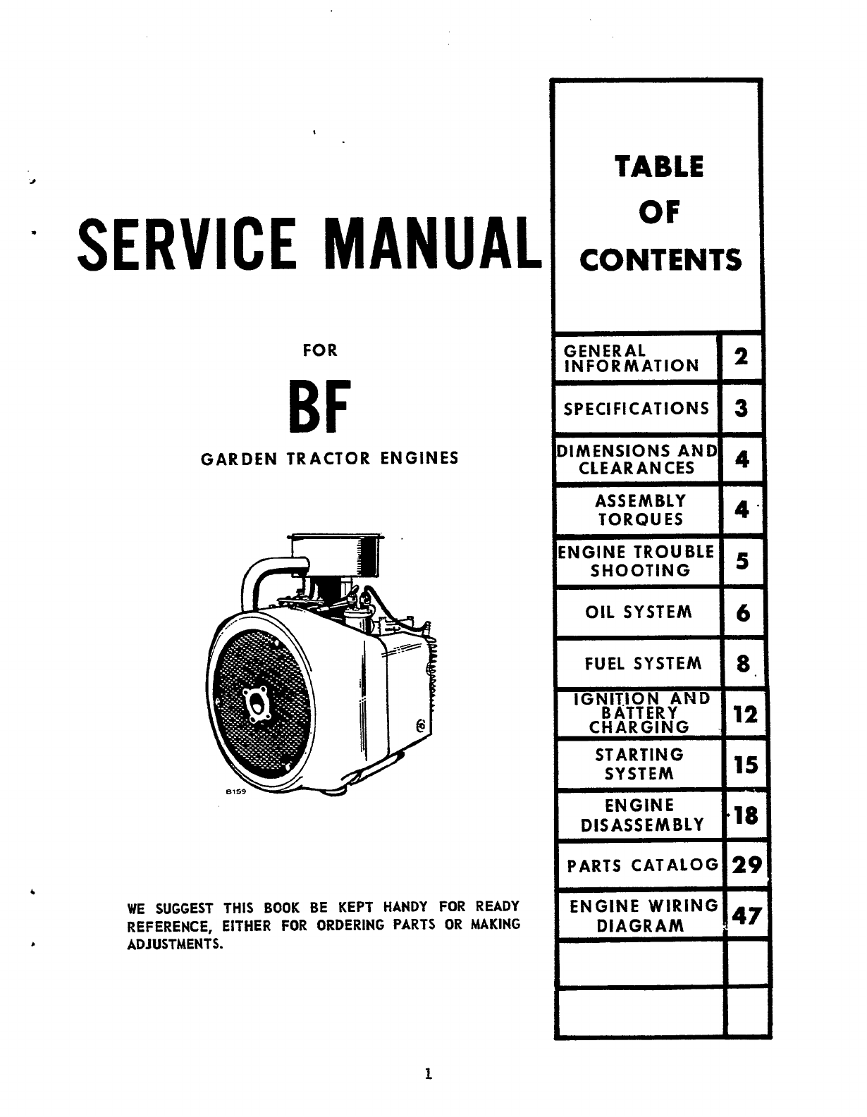
SERVICE
MANUAL
FOR
BF
GARDEN TRACTOR ENGINES
WE SUGGEST THIS
BOOK
BE KEPT HANDY
FOR
READY
REFERENCE, EITHER FOR ORDERING PARTS
OR
MAKING
ADJUSTMENTS.
TABLE
OF
CONTENTS
GENERAL
IN
FOR
MAT
ION
w
SPECIFICATIONS
I
3
bIMENSIONS AND
CLEARANCES
ASS
EM
BLY
TORQUES
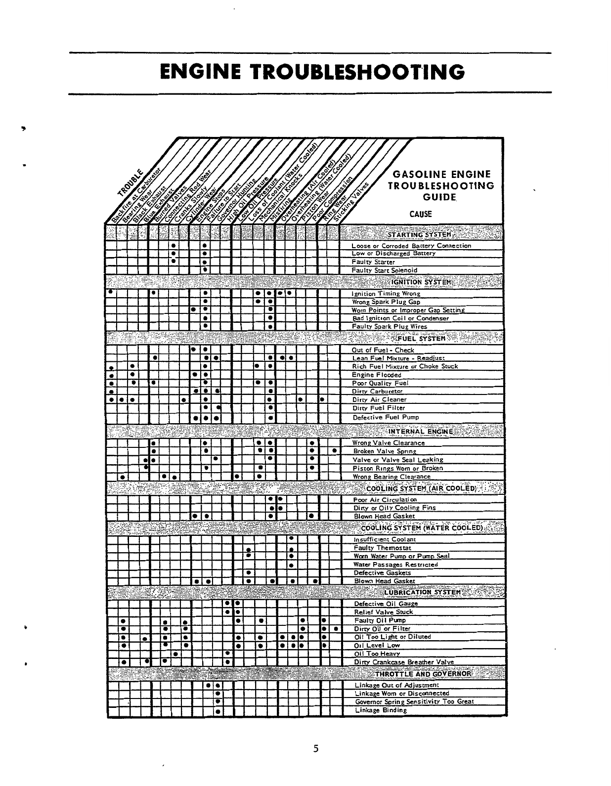
iNGlNE TROUBLE
SHOOTING
16
OIL
SYSTEM
18
FUEL
SYSTEM
BATTERY
CHARGING
STARTING
SYSTEM
t
ENGINE
DISASSEMBLY
PARTS
CATALOGl2!
ENGINE WIRING
1
Redistribution or publication of this document,
by any means, is strictly prohibited.
GENERAL
INFORMATION
This manual contains proper information for the servic-
ing and overhaul of your Onan engine.
Use
the
parts
catalog in the rear portion
of
this book to help you with
disassembly and assembly procedures.
NOTE:
Flywheel end
of
engine
is
considered the front.
Leif and righf
sides
are determined looking at front
of engine.
If it
is
necessary to contact your dealer or the factory
about this engine, always supply the complete Model
and Spec Number as well
as
the Serial Number shown
on the engine nameplate. The engine nameplate
is
located
on
left side of blower housing (end opposite
oil filter).
Refer to the Troubleshooting Guide for assistance
in
locating and correcting troubles which
may
occur.
If
a major repair or overhaul becomes necessary, the
erlgine should be carefully checked and necessary
repairs
made
by
a
competent mechanic. Maintain
factory
limits
and
clearances
as
shown, replacing worn parts
when necessary.
0
AVOID
POSSIBLE
PERSONAL INJURY
OR
WE
REPRESENTATIVE
MUST
PERFORM
At1
QUIPMENT DAMAGE,
AN
AUTHORIZED
SER-
iERVlCE.
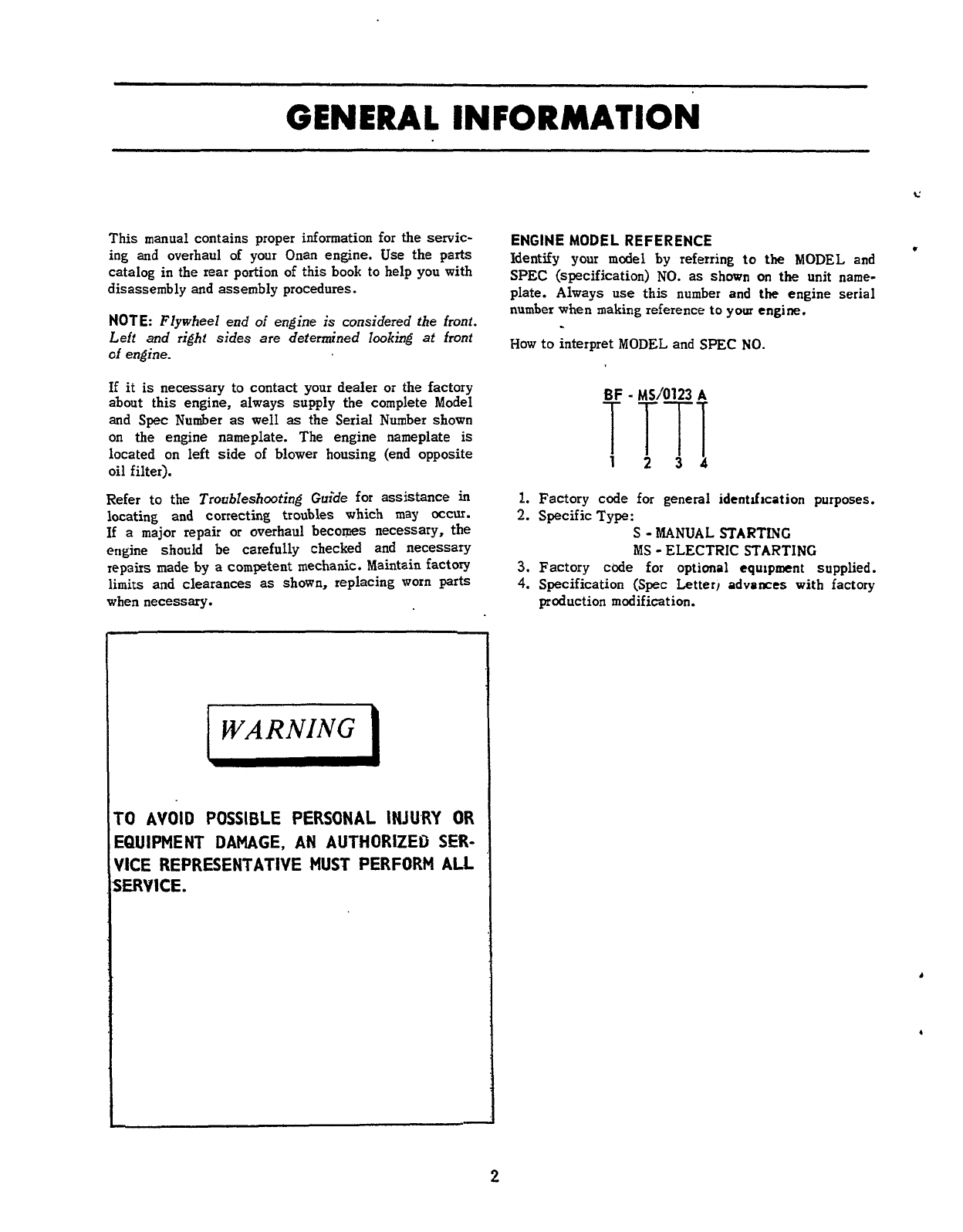
ENGINEMODELREFERENCE
*
Identify
your
model by referring
to
the
MODEL
and
SPEC
(specification)
NO.
as
shown
on
the
unit name-
plate. Always use this number and the engine serial
number
when
making reference to your engine.
How
to interpret
MODEL
and SPEC
NO.
-
12
34
I.
Factory code
for
general identlfrcation purposes.
2.
Specific Type:
S
-MANUAL STARTING
MS
-
ELECTRIC STARTING
3.
Factory cbde
for
optional equipment supplied.
4.
Specification (Spec Letter)
advances
with factory
production modification.
2
Redistribution or publication of this document,
by any means, is strictly prohibited.
SPEC1
FI
CATIONS
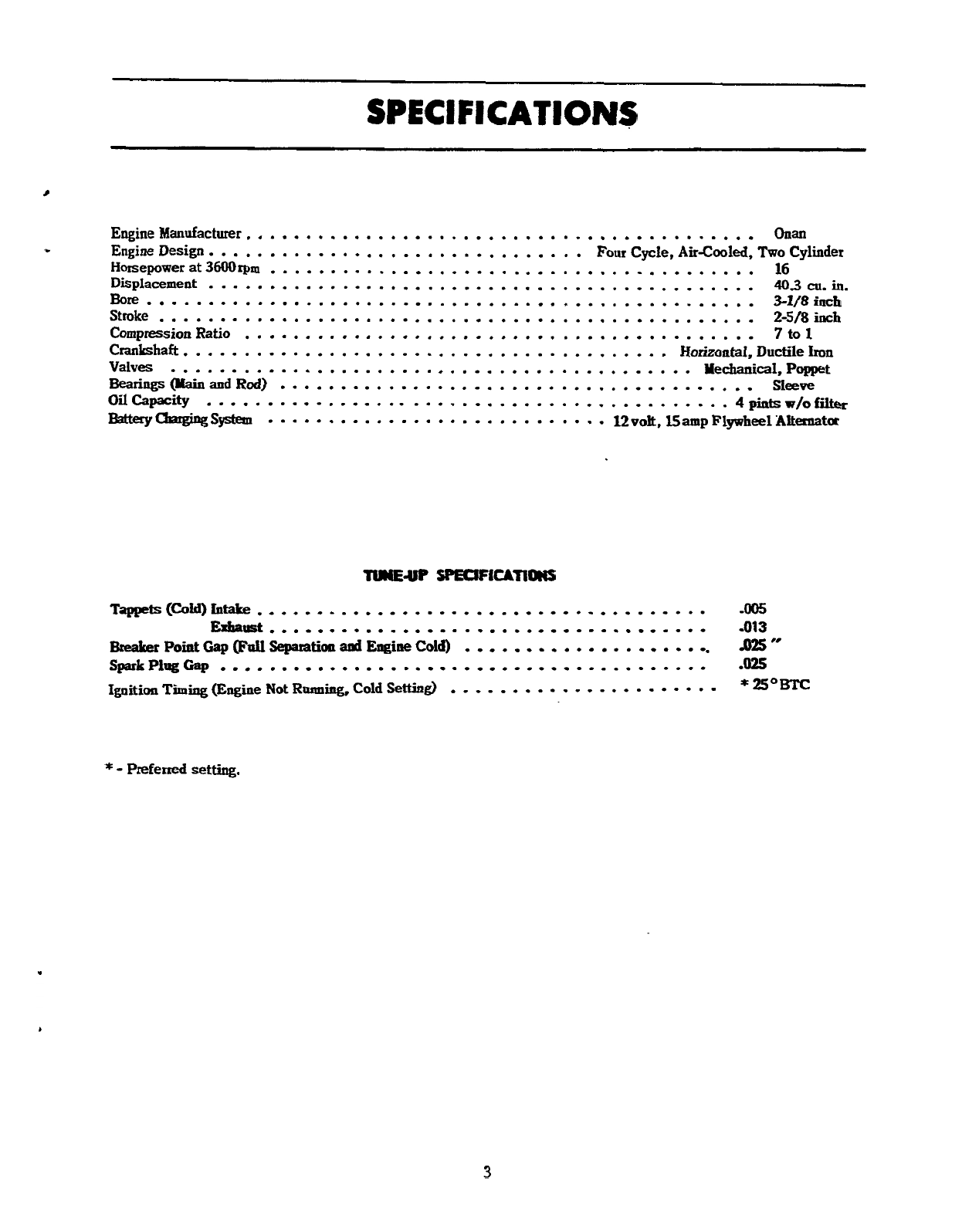
Engine Manufacturer.
.........................................
Onan
.
Engine Design.
..............................
Four
Cycle, AirGooled,
Two
Cylinder
Horsepower
at
3600rpm
........................................
16
Displacement
.............................................
403
cu.
in.
Stroke
.................................................
2-5/8
inch
Compression
Ratio
..........................................
7
to
1
Crankhaft.
.......................................
Horizontal, Ductile
Iron
Valves
...........................................
Yechanical,Poppet
Bearings
(yain
and
Rod)
.......................................
Sleeve
Oil
Capacity
...........................................
4
pints
w/o
filler
BatteryuSystem
............................
12vo~,l55ampFlywheel~&~t~
Bore..................................................
3-1/8inch
--UP
spEcIF1UTIOIIs
Tapeets(C0WLntake
.....................................
-005
Breaker
Point
Gap
(Full
Separation
and
Engine
Cold)
Ignition
Timing
(Engine
Not
Rruming,
Cold
Setting)
Exhaust..........................-.....-...
.013
SparkPlugCap
........................................
.OS
.....................
-025
..
*
=om
......................
*
-
Preferred setting.
3
Redistribution or publication of this document,
by any means, is strictly prohibited.
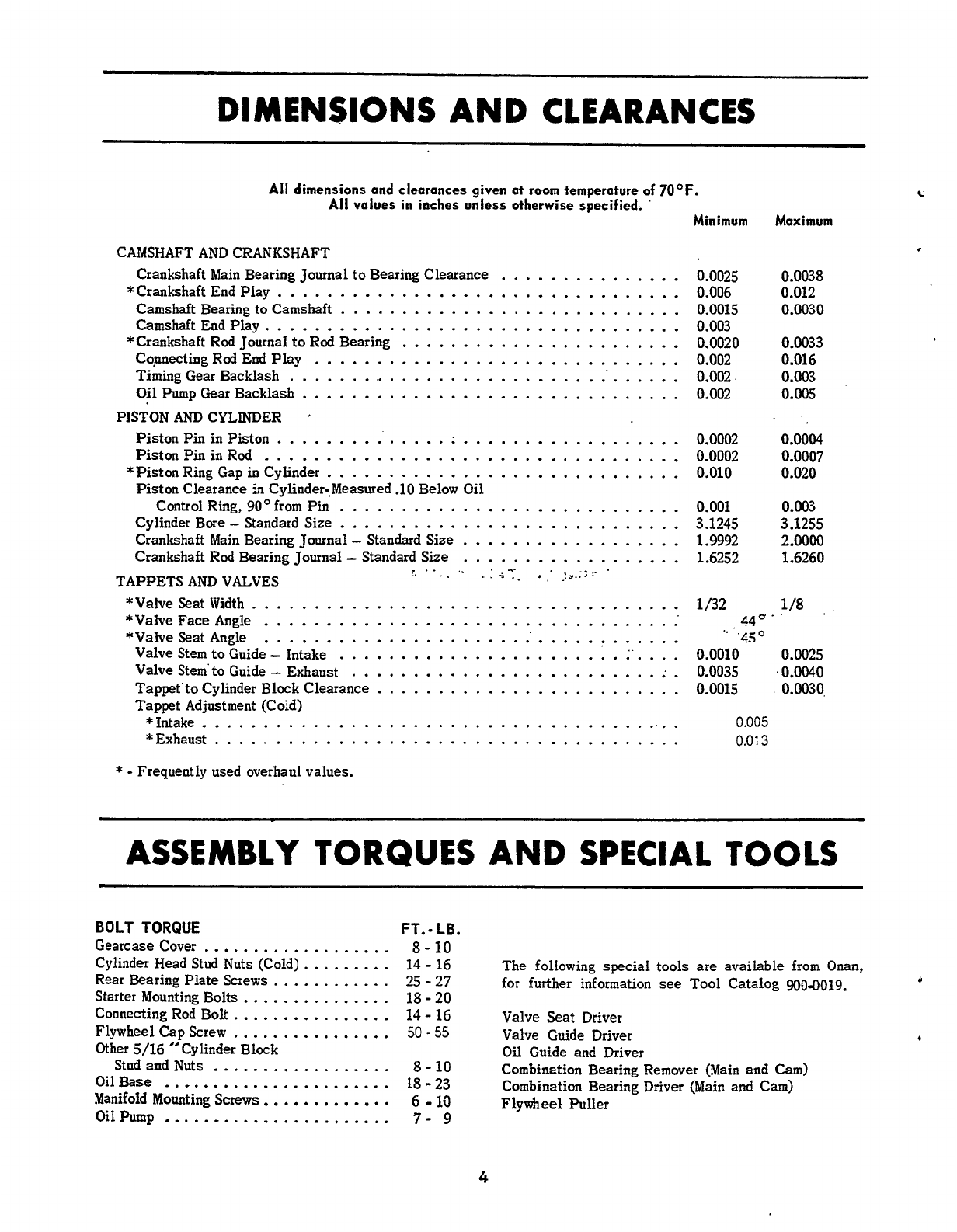
DIMENSIONS
AND
CLEARANCES
All
dimensions and clearances given at
room
temperature of 7OoF .
c'
All
values
in
inches unless otherwise
specified
.
'
Minimum
Maximum
CAMSHAFT
AND
CRANKSHAFT
Crankshaft Main Bearing Journal to Bearing Clearance
Camshaft Bearing
to
Camshaft
............................
...............
*Crankshaft End Play
.................................
Camshaft End Play
..................................
Cqnnecting Rod End Play
..............................
Timing Gear Backlash
..................................
*Crankshaft Rod Journal to Rod Bearing
.......................
Oil Pump Gear Backlash
...............................
Piston
Pin
in Piston
..............
:
..................
Piston
Pin
in Rod
..................................
Piston Clearance 51 Cylinder.. Measured
-10
Below Oil
PISTON
AND
CYLINDER
'
*Piston Ring Gap
in
Cylinder
.............................
Control Ring.
90'
from Pin
............................
Cylinder Bore
-
Standard Size
............................
Crankshaft Main Bearing Journal
-
Standard Size
..................
Crankshaft Rod Bearing Journal
-
Standard Size
..................
.........
.......
....
.
.
E
..
..
...Y....
TAPPETS
AND
VALVES
*Valve Seat Width
...................................
*Valve Face Angle
...................................
*Valve Seat Angle
...................................
Valve Stem to Guide
-
Intake
.......................
:'
Valve Stem'to Guide
-
Exhaust
.........................
;
Tappet Adjustment (Cold)
....
.
Tappet'to Cylinder Block Clearance
.........................
*Intake
........................................
*Exhaust
......................................
*
.
Frequently used overhaul values
.
0.0025
0.006
0.0015
0.003
0.0020
0.002
0.002
0.002
0.0002
0.0002
0.010
0.0038
0.012
0.0030
0.0033
0.016
0.003
.
0.005
0.0004
0.0007
0.020
0.001 0.003
3.1245 3.1255
1.9992
2.0000
1.6252 1.6260
1
/32 1/8.
'
440
.
'
0.0010 0.0025
0.0035
.
0.0040
0.0015
.
0.0030,
..
'450
0.005
0.01
3
ASSEMBLY
TORQUES
AND
SPECIAL
TOOLS
BOLT
TORQUE
FT
.
.
LB
.
Gearcase Cover
...................
8
.
10
14
.
16
Rear Bearing Plate Screws
............
25
.
27
Starter Mounting Bolts
...............
18
.
20
Connecting Rod Bolt
................
14
.
16
50
.
55
Other
5/16
"Cylinder Block
Stud and Nuts
..................
8
.
10
OilBase
.......................
18-23
Manifoid Mounting
Screws
.............
6
.
10
Oilhunp
.......................
7-
9
Cylinder Head Stud Nuts (Cold)
.........
Flywheel Cap
Screw
................
The
following
special tools
are
available from Onan.
for further information
see
Tool Catalog
900-0019
.
0
Valve Seat Driver
Valve Guide Driver
Oil
Guide and Driver
Combination Bearing Remover
(Main
and Cam)
Combination Bearing Driver (Main and Cam)
Flywheel
Puller
4
Redistribution or publication of this document,
by any means, is strictly prohibited.
OIL
SYSTEM
c
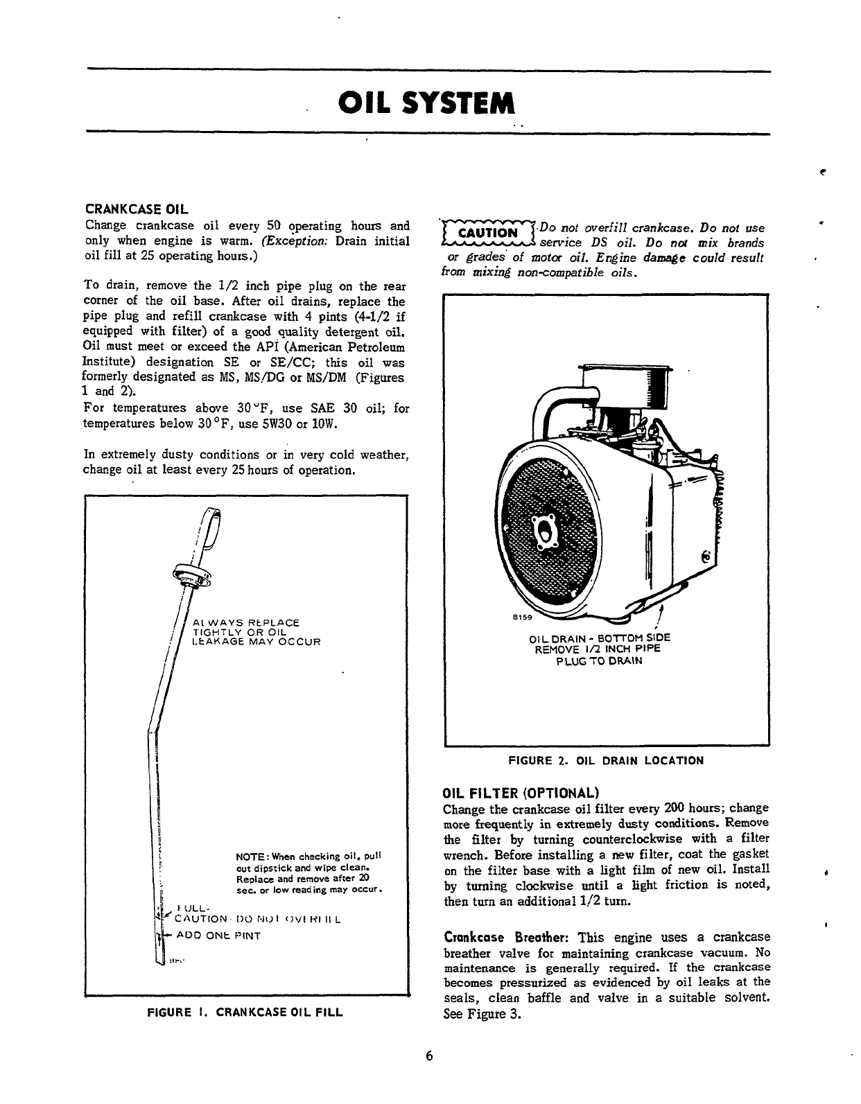
CRANKCASE
01
L
Change crankcase oil every
50
operating hours and
only
when engine
is
warm. (Exception: Drain initial
oil
fill
at
25
operating hours.)
To
drain, remove the
1/2
inch pipe plug
on
the rear
corner of the oil base. After oil drains, replace the
pipe plug and refill crankcase with 4 pints (4-1/2
if
equipped with filter) of a
good
quality detergent oil.
Oil must meet or exceed the
API
(American Petroleum
Institute) designation
SE
or
SE/CC;
this oil was
formerly designated as
MS,
MS/DG
or MS/DM (Figures
1
and
2).
For
temperatures above
30"F,
use
SAE
30
oil; for
temperatures below
30
OF,
use
5W30
or
1OW.
In
extremely dusty conditions or
in
very cold weather,
change oil at least every
25
hours of operation.
I
i.
N0TE:When
checking
oil,
pull
out
dipstick
and
wipe
clean.
Replace and
remove
after
20
sec.
or
low
reading
may occur.
j
FIGURE
I.
CRANKCASE
OIL
FILL
.Do
not
overfill crankcase.
Do
not
use
service
DS
oil.
Do
not
mix brands
.
or
grades
of
motor
oil.
Engine
damage
could
result
from
mixing non-compafible
oils.
01
L
DRAIN
-
BO7TOM
SIDE
REMOVE
I/2
INCH PIPE
PLUG
TO
DRAIN
FIGURE
2.
OIL
DRAIN
LOCATION
OIL
FILTER
(OPTIONAL)
Change the crankcase
oil
filter every 200
hours;
change
more frequently
in
extremely dusty conditions. Remove
the filter
by
turning counterclockwise with a filter
wrench. Before installing a
new
filter, coat the gasket
on
the filter base with
a
light
fih
of new
oil.
Install
by turning clockwise until
a
light friction
is
noted,
then turn an additional 1/2 turn.
Crankcase
Breather:
This
engine
uses
a
crankcase
breather valve for maintaining crankcase vacuum.
No
maintenance
is
generally required.
If
the crankcase
becomes pressurized as evidenced by oil leaks at the
seals, clean baffle and valve
in
a suitable solvent.
See
Figure
3.
+
I
6
Redistribution or publication of this document,
by any means, is strictly prohibited.
c
HEX
HEAD
CAP
SCREW
,a
I
WASHER
.-
A
.
cfJ
REEDVALVE
ATHER
BAFFLE
GASKET
HAS
A
CORRECTWAY
AND
AN
INCORRECT
WAY
TO
INSTALL.
CHECK
CLOSELY
FOR PROPER
ElTl
FIGURE
3.
CRANKCASE BREATHER
PRESSURE
LUBRlCATlON
Pressure
lubricated engines
use
an
oil
pump
to
lubri-
cate
engine parts.
If
oil pressure
is
low, the pump
should be checked.
OIL
PUMP
IN
CRANKCASE
TURN
ON
LEFT
SIDE-
UNSCREW
OIL
PUMP
FROM
INTAKE
CU
To
reassemble
revers
OIL
PUMP ASSEHB
.L
.,,A
/
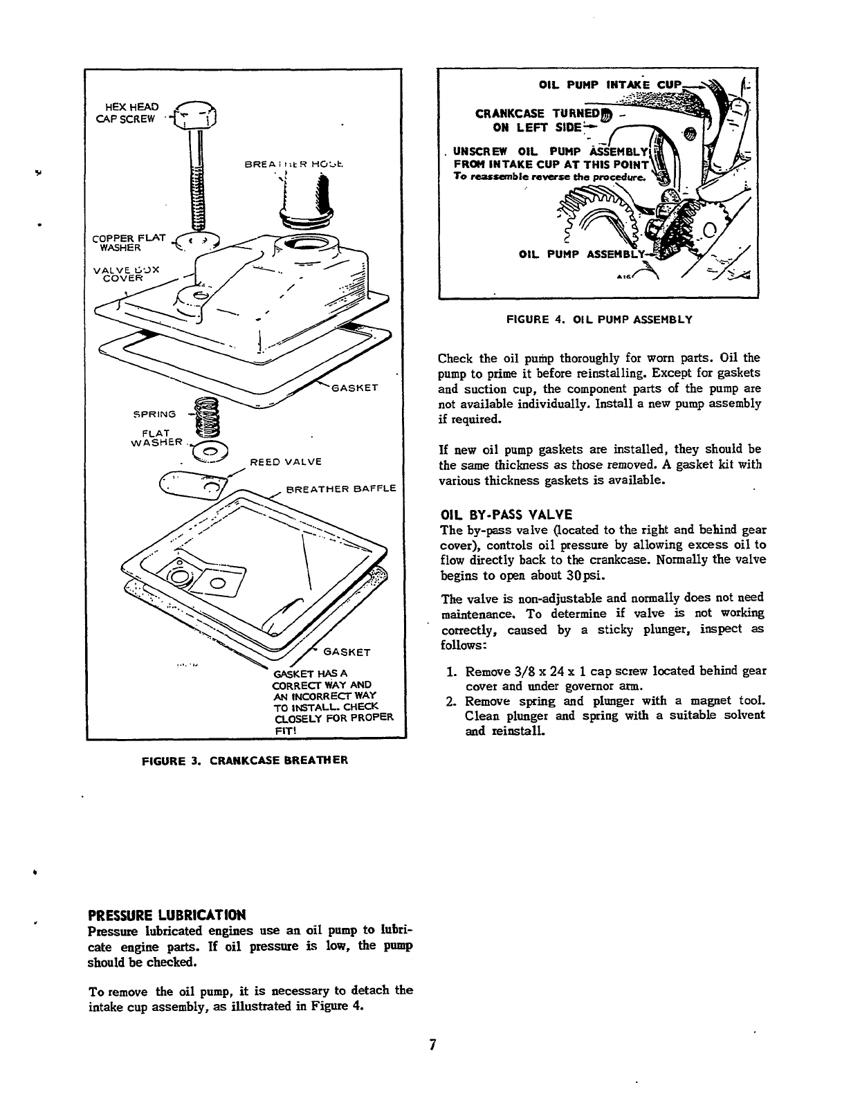
FIGURE
4.
OIL
PUMP ASSEMBLY
Check the oil pump thoroughly
for
worn
parts.
Oil the
pump
to
prime it before reinstalling. Except for gaskets
and suction cup, the component parts
of
the pump are
not available individually. Install a new pump assembly
if
required.
If
new oil pump gaskets
are
installed, they should be
the
same
thickness
as
those removed.
A
gasket
kit
with
various thickness gaskets
is
available.
OIL
BY-PASS
VALVE
The by-pass valve (located to the right and behind gear
cover), controls oil pressure by allowing excess oil to
flow
directly back to the crankcase. Normally the valve
begins
to
open
about 3Opsi.
The
valve
is
non-adjustable and normally does not
need
maintenance.
To
determine
if
valve
is
not working
'
correctly, caused by a sticky plunger, inspect
as
follows:
1.
Remove
3/8
x
24
x
1
cap screw located behind gear
cover and under governor ann.
2.
Remove
spring
and plunger with a magnet tool.
Clean plunger and spring with
a
suitable solvent
and
reinstall.
To
remove
the
oil pump,
it
is
necessary to detach
the
intake cup assembly,
as
illustrated in Figure 4.
7
Redistribution or publication of this document,
by any means, is strictly prohibited.
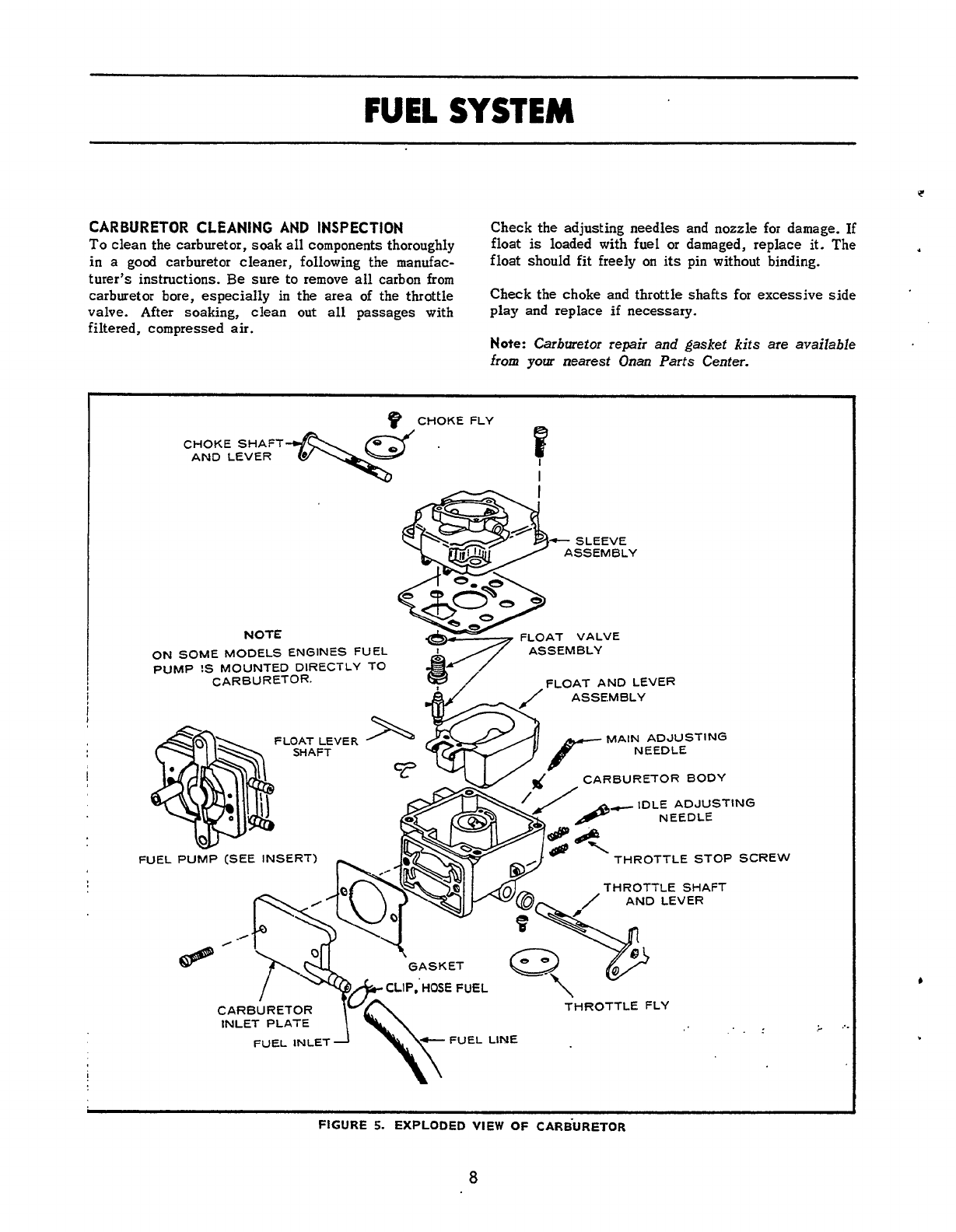
FUEL
SYSTEM
CARBURETOR CLEANING AND INSPECTION
To
clean the carburetor,
soak
all
components thoroughly
in
a
good carburetor cleaner, following the manufac-
turer’s instructions. Be sure to remove
all
carbon from
carburetor bore, especially in the area of the throttle
valve. After soaking, clean
out
all
passages with Play and replace
if
necessary.
filtered, compressed air.
Check the adjusting needles and nozzle for damage. If
float
is
loaded with fuel or damaged, replace it. The
float should fit freely
on
its
pin without binding.
Check the choke
and
throttle shafts for excessive side
Note:
Carburetor repair and
gaskef
kits are available
from
your
nearest
Onan Parts Center.
e
CHOKE FLY
I
I
CHOKE SHAFT
AND LEVER
-
SLEEVE
ASSEMBLY
FLOAT VALVE
ASSEMBLY
FLOAT AND LEVER
NOTE
ON SOME MODELS ENGINES FUEL
PUMP
!S
MOUNTED DIRECTLY TO
CARBU R ET0
R.
v<v
dc
CARBURETOR BODY
MAIN ADJUSTING
NEEDLE
FLOAT LEVER
SHAFT
IDLE ADJUST
NEEDLE
THROTTLE SHAFT
AND LEVER
FUEL PUMP
(SEE
INSERT)
GASKET
a
CARBURL
I
VI\
INLET PLATE
‘ING
7
-/I--
THROTTLE STOP SCREW
FUEL INLETA
,>
./.
FIGURE
5.
EXPLODED
VIEW
OF
CARBURETOR
8
Redistribution or publication of this document,
by any means, is strictly prohibited.
PUMP
COVER
i
EXPLODED
VIRN.OF
FUEL
PUMP
w
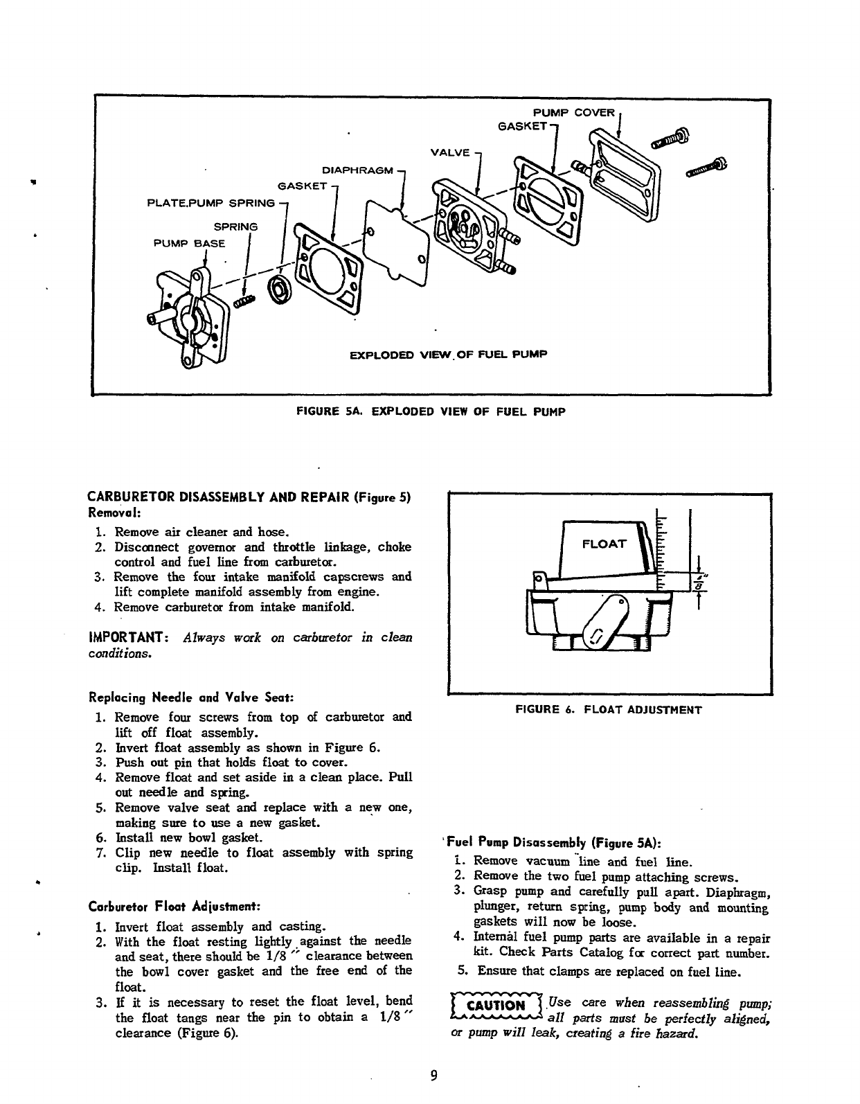
FIGURE
SA.
EXPLODED VIEW
OF
FUEL PUMP
CARBURETOR DISASSEMBLY AND REPAIR
(Figure
5)
Removal:
1.
Remove
air
cleaner
and
hose.
2.
Disconnect governor and throttle linkage, choke
control and fuel line from carburetor.
3.
Remove the
four
intake manifold capscrews and
lift complete manifold assembly from engine.
4.
Remove carburetor from intake manifold.
IMPORTANT:
Always
work
on carburetor in clean
conditions.
Replacing
Needle and Valve
Seat:
1.
Remove four screws from top
of
carburetor and
lift
off float assembly.
2.
Invert float assembly
as
shown in Figure
6.
3.
Push out pin that
holds
float
to
cover.
4.
Remove float and
set
aside
in
a clean place. Pull
out
needle and spring.
5.
Remove valve seat and replace with
a
new
one,
making sure
to
use
a
new gasket.
6.
Install new bowl gasket.
7.
Clip new needle
to
float
assembly with spring
clip.
Install
float.
Carburetor
Float
Adiustment:
1.
Invert float assembly and casting.
2.
With the float resting lightly .against the needle
and
seat,
there
should
be
118
”
clearance between
the bowl cover gasket and the free end
of
the
float.
3.
If
it
is
necessary to reset the float level, bend
the float tangs near the
pin
to
obtain a
1/8”
clearance (Figure
6).
I
I
FIGURE
6.
FLOAT ADJUSTMENT
’Fuel
Pump Disassembly
(Figure
5A):
i.
Remove
vacuum’-line
and fuel line.
2.
Remove the two fuel pump attaching screws.
3.
Grasp pump and carefully
pull
apart. Diaphragm,
plunger, return
spring,
pump
body
and mounting
gaskets
will
now
be
loose.
4.
Internal fuel pump
parts
are available in a repair
kit.
Check
Parts
Catalog
for
correct
part
number.
5.
Ensure that clamps
are
replaced on fuel line.
CAUTION
,Use
care when reassembling
pump;
m
all
parts
must be perfectly aligned,
or
pump
will
leak,
creating
a
fire hazard.
9
Redistribution or publication of this document,
by any means, is strictly prohibited.
ARBURETOR
ADJUSTMENTS
he carburetor has
a
main fuel valve adjusting screw
id an idle valve adjusting screw (Figure
7).
A
low
xed adjustment
screw
is
shown in Figure
8.
:itiaI Adiustment:
1.
Turn main fuel valve clockwise until it just closes.
Do
not open main fuel jet
more
Ez3
than
1/2
turn beyond
the
maximum
power
point
as
this could cause
spark
plug
fouling
etc.
2.
Now
open
main fuel valve
2
turns counterclock-
wise.
3.
Close idle valve insame manner and
open
it one
turn (counterclockwise).
1.
This initial adjustment will permit engine to
start
and warm up prior to final adjustment.
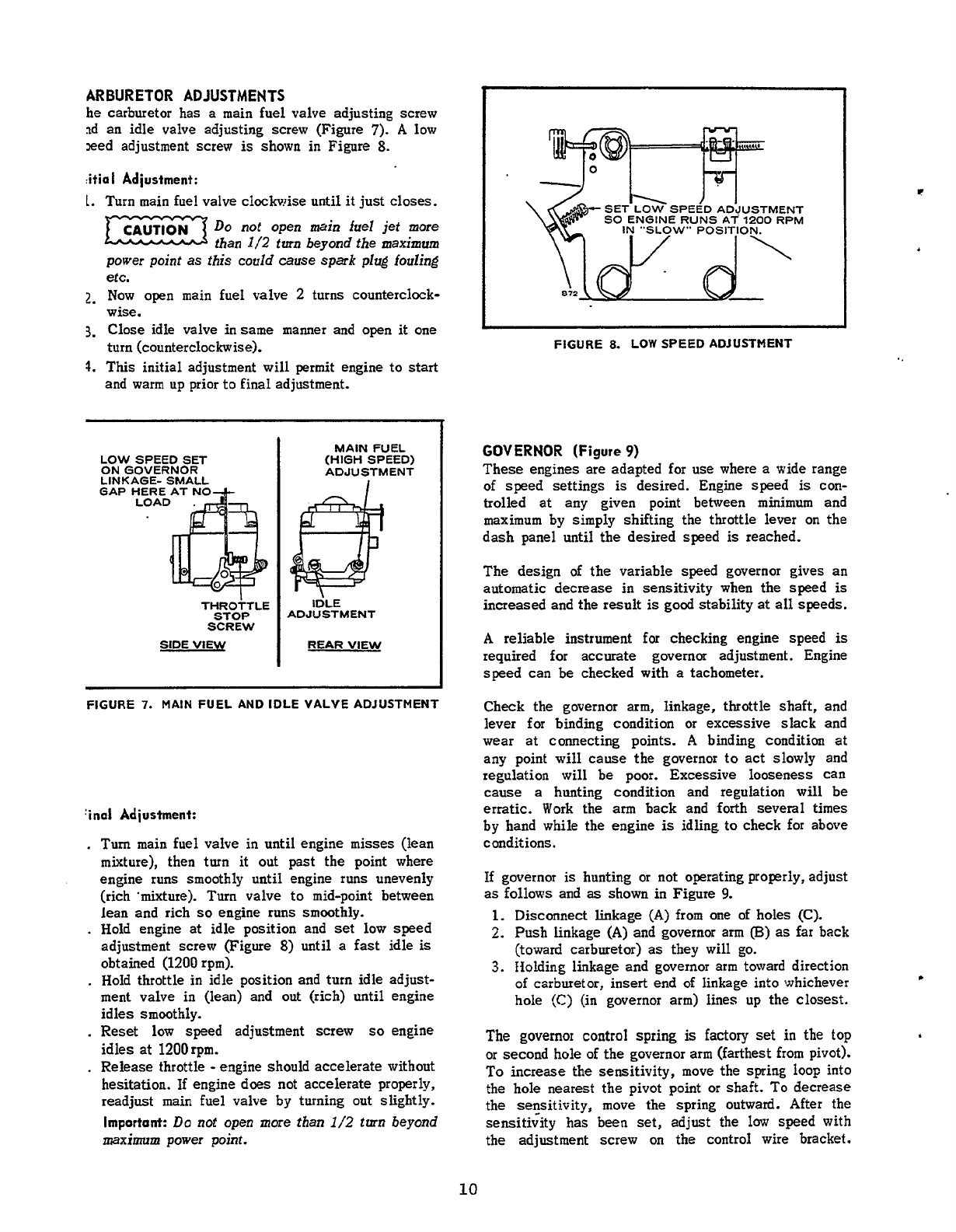
CAUTION
LOW SPEED SET
ON
GOVERNOR
GAP HERE AT NO
LOAD
LINKAGE- SMALL
THRO~TLE
STOP
SCREW
SIDE
VIEW
MAIN FUEL
(HIGH SPEED)
ADJUSTMENT
IDLE
ADJUSTMENT
REAR
VIEW
FIGURE
7.
MAIN FUEL AND IDLE VALVE ADJUSTMENT
?no1
Adiustment:
.
Turn main fuel valve in until engine
misses
(lean
mixture), then turn
it
out past the point where
engine runs smoothly until engine runs unevenly
(rich 'mixture). Turn valve to mid-point between
lean and rich
so
engine runs smoothly.
.
Hold engine
at
idle position and set low speed
adjustment screw (Figure
8)
until
a
fast idle
is
obtained
(1200
rpm).
.
Hold throttle
in
idle position and turn idle adjust-
ment valve in (lean) and out (rich)
until
engine
idles smoothly.
.
Reset
low
speed adjustment screw
so
engine
idles
at
1200
rpm.
.
Release throttle
-
engine should accelerate without
hesitation. If engine does not accelerate properly,
readjust main fuel valve by turning out slightly.
Important:
Do
not open
more
than
1/2
turn
beyond
maximum
power point.
SET LOW SPEED ADJUSTMENT
SO
ENGINE RUNS
AT
1200
RPM
IN
"SLOW" POSITION.
FlGURE
8.
LOW SPEED ADJUSTMENT
GOVERNOR
(Figure
9)
These engines are adapted for use where
a
wide range
of
speed settings
is
desired. Engine speed
is
con-
trolled at any given point between minimum and
maximum by simply shifting the throttle lever
on
the
dash panel until the desired speed
is
reached.
The
design
of
the
variable speed governor gives an
automatic decrease in sensitivity when the speed
is
increased and the result
is
good stability
at
all
speeds.
A
reliable instrument for checking engine speed
is
required for
accurate
governor adjustment. Engine
speed can be checked with
a
tachometer.
Check the governor
arm,
linkage, throttle shaft, and
lever
for
binding condition or excessive slack and
wear at connecting points.
A
binding condition at
any point will cause the governor
to
act
slowly and
regulation will be poor. Excessive looseness can
cause
a
hunting condition and regulation will be
erratic.
Work the
arm
back and forth several
times
by hand while the engine
is
idling
to
check
for
above
conditions.
If governor
is
hunting or not operating properly, adjust
as
follows and
as
shown in Figure
9.
1.
Disconnect linkage
(A)
from one
of
holes
(C).
2.
Push linkage
(A)
and governor arm
(B)
as
far back
(toward carburetor)
as
they will
go.
3.
Holding linkage and governor arm toward direction
of Carburetor, insert end
of
linkage into whichever
hole
(C)
(in governor arm)
lines
up the
closest.
The
governor
control spring
is
factory
set
in
the
top
or second hole of the governor arm (farthest from pivot).
To
increase the sensitivity, move the spring loop into
the
hole
nearest the pivot point or shaft.
To
decrease
the secsitivity, move the spring outward. After the
sensitivity has been set, adjust the low speed with
the adjustment screw
on
the control wire bracket.
10
Redistribution or publication of this document,
by any means, is strictly prohibited.
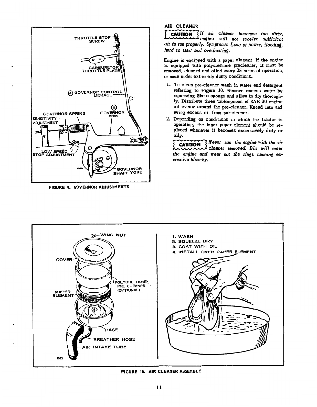
Y
THROTTLE PLATE
@
GOVERNOR
CONT
GOVERNOR
FIGURE
9.
GOVERNOR ADJUSTMENTS
AIR CLEANER
-If
air
cleaner
becomes
too
dirty,
engine
will
not receive sufficient
air to
run
properly.
Symptoms:
Loss
of
power,
flooding,
hard
to
start
and
overheating.
Engine
is
equipped with
a
paper element.
If
the engine
is
equipped with polyurethane precleaner,
it
must
be
removed, cleaned
and
oiled
every
25
hours
of
operation,
or
more under extremely dusty conditions.
1.
To
clean precleaner wash in water and detergent
referring to Figure
10.
Remove excess water
by
squeezing like
a
sponge and allow to dry thorough-
ly. Distribute three tablespoons
of
SAE
30
engine
oil evenly around the precleaner. Knead into and
wring excess
oil
from precleaner.
2.
Depending
on
conditions in which the tractor
is
operating, the inner paper element should be
re-
placed whenever it becomes excessively
dirty
or
oily.
Never
run
the engine with the
air
cleaner
removed. Dirt
will
enter
the
engine
and.
wear
out the
rings
causing
ex-
cessive
blow-by.
OLY
URETHAN
E:
PRE
CLEANER
.
BREATHER
HOSE
INTAKE TUBE
1.
WASH
2.
SQUEEZE
DRY
3.
COAT WITH
OIL
4.
INSTALL OVER PAPER ELEMENT
FIGURE
IO.
AIR CLEANER ASSEMBLY
11
Redistribution or publication of this document,
by any means, is strictly prohibited.
IGNITION
AND
BATTERY
CHARGING
BREAKER
POINTS
To maintain maximum efficiency from the engine,
change the breaker points every
200
hours
of
operation.
Proceed
as
follows when engine
is
cold:
.
'
1.
Remove the two screws and the cover
on
the
breaker box.
2.
Remove the two spark plugs
so
engine can be
easily rotated by hand. Check condition of spark
plugs at this time.
3.
Refer to Figure
11.
Remove mounting nut
(A)
and
pull the points out of the box just far enough
so
screw
(B)
can
be removed and leads disconnected.
4.
Remove screw
(C)
and replace condenser with
a
new one.
5.
Replace points with
a
new set but do not complete-
ly tighten mounting nut
(A).
6.
Remove the air intake hose that connects to blower
housing. This provides an
access
to
view timing
mark.
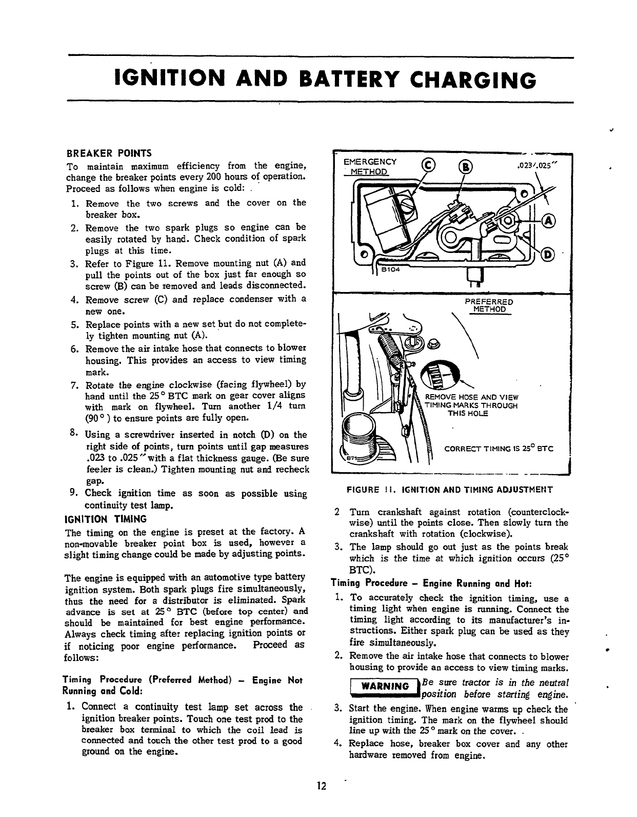
7.
Rotate the engine clockwise (facing flywheel) by
hand until the
25'
BTC mark
on
geer cover aligns
with mark
on
flywheel.
Turn
another
1/4
turn
(90'
)
to ensure points are fully
open.
8.
Using
a
screwdriver inserted in notch
@)
on
the
right side
of
points, turn points until gap measures
-023
to .025"with
a
flat
thickness gauge.
(Be
sure
feeler
is
clean.) Tighten mounting
nut
and recheck
gap-
9.
Check ignition
time
as
soon
as
possible using
continuity test lamp.
IGNITION TIMING
The timing
on
the engine
is
preset
at
the factory.
A
non-movable breaker point
box
is
used, however
a
slight timing change could
be
made by adjusting points.
The engine
is
equipped with an automotive type battery
ignition system. Both spark plugs fire simultaneously,
thus the need for a distributor
is
eliminated.
Spark
advance
is
set
at
25'
BTC
(before top center) and
should
be
maintained for best engine performance.
Always check timing after replacing ignition points or
if
noticing poor engine performance. Proceed
as
follows
:
Timing Procedure (Preferred
Method)
-
Engine
Not
Running
and
Cold:
1.
Connect
a
continuity test lamp
set
across
the
ignition breaker points. Touch one
test
prod to the
breaker box terminal
to
which the coil lead
is
connected and touch the other test prod to a good
ground on the engine.
25'
BTC
---.-.--
.--
-
--
FIGURE
I
I.
IGNITION
AND
TIMING
ADJUSTMENT
A
Turn
crankshaft against rotation (counterclock-
wise) until the points close. Then slowly turn the
crankshaft with rotation (clockwise).
3.
The lamp should go out just
as
the points break
which
is
the time at which ignition occurs
(25'
BTC).
Timing
Procedure
-
Engine Running
ond
Hot:
1.
To accurately check the ignition timing, use
a
timing light when engine
is
running. Connect the
timing light according
to
its
manufacturer's in-
structions. Either spark plug can be
used
as
they
fire simultaneously.
2. Remove the air intake hose that connects to blower
housing to provide
an
access
to view timing marks.
Be
sure
tractor
is
in
the neutrd
n
position
before
sfarfing
engine.
3.
Start the engine. When engine warms up check the
ignition timing. The mark
on
the flywheel should
line
up
with
the
25O
mark on the cover.
.
4.
Replace hose, breaker box cover and any other
hardware removed from engine.
WARN,NG
12
Redistribution or publication of this document,
by any means, is strictly prohibited.
SPARK
Q.Q2!5"
PLUG GAP
GASOLINE
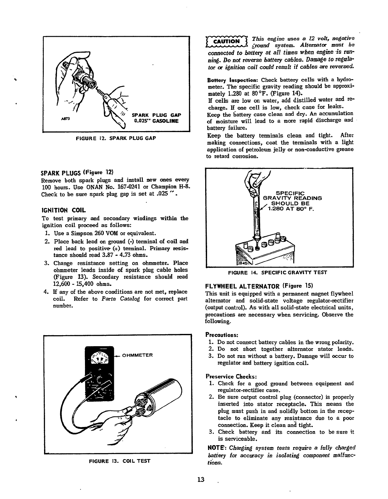
FIGURE
12.
SPARK PLUG GAP
SPARK PLUGS
(Figure
12)
Remove both spark plugs and install new
ones
every
100
hours.
Use
ONAN
No.
167-0241
or Champion
H-8.
Check to be sure spark plug gap
is
set at
-025
"
.
IGNITION
COIL
To
test primary and secondary windings within the
ignition coil proceed
as
follows:
1.
Use
a Simpson
260
VOM
or
equivalent.
2.
Place back lead
on
ground
(-)
terminal
of
coil and
red lead to positive
(+)
terminal. Primary
resis-
tance should read
3.87
-
4.73
ohms.
3.
Change resistance setting
on
ohmmeter.
Place
ohmmeter leads inside of spark plug cable holes
(Figure
13).
Secondary resistance
should
read
12,600
-
15,400
ohms.
4.
If any of the above conditions
are
not
met,
replace
coil. Refer to Parts Catalog for correct part
number.
OHMMETER
,
FIGURE
13.
COILTEST
This
engine
uses
a
I2
volf,
negative
<round
system. Altemta
must
be
connected to battery
at
all times when engine
.is
ran-
ning.
Do
not
reverse
battery
cables.
Damage to regula-
tor
a
ignition coil
could
result
if
cables are reversed.
Battery
Inspection:
Check battery
cells
with a
hydro-
meter. The specific gravity reading should be approxi-
mately
1.280
at
80OF.
(Figure
14).
If
cells
are low
on
water,
add distilled water and
re-
charge.
If
one
cell
is
low, check
case
for leaks.
Keep the 6attery case clean and dry.
An
accumulation
of moisture will lead to a more rapid discharge
and
battery failure.
Keep the battery terminals clean and tight. After
making connections, coat the terminals with
a
light
application of petroleum jelly
or
non-conductive grease
to retard corrosion.
FIGURE
14.
SPECIFIC GRAVITY TEST
FLYWHEEL ALTERNATOR (Figure
15)
This
unit
is
equipped with
a
permanent magnet flywheel
alternator and solid-state voltage regulator-rectifier
(output control).
As
with all solid-state electrical units,
precautions are necessary when servicing. Observe the
following.
Precautions:
1.
Do
not connect battery cables
in
the wrong polarity.
2.
Do not short together alternator stator leads.
3.
Do
not
run
without a battery. Damage will occur to
regulator and battery ignition coil.
Preservice Checks:
1.
Check for
a
good ground between equipment and
regulator-rectifier case.
2.
Be sure output control plug (connector)
is
properly
inserted into stator receptacle.
This
means the
plug
must
push in and solidly bottom in
the
recep-
tacle to eliminate any resistance due
to
a
poor
connection. Keep
it
clean ana tight.
3.
Check battery and
its
connection to be sure
it
is
serviceable.
NOTE':
Charging system
fests
require
a
fully
charged
batfery
for
accuracy in isolating
component
malfmc-
tions.
13
.
Redistribution or publication of this document,
by any means, is strictly prohibited.

TESTING BATTERY CHARGING SYSTEM
Type
of
Failure
No
charge to battery.
I
Test
1.
With battery connected, check
B+
to
Ground voltage with DC voltmeter.
If
voltmeter reads
13.8
volts or higher,
place load (headlights) on battery to
reduce battery voltage to below
13.6
volts. Observe ammeter.
a.
If charge rate increases.
b.
If charge rate does not increase.
2.
Disconnect plug from regulator-
rectifier and
test
AC
voltage
at
plug
(two
white wires, reading back
into alternator).
Voltage reads much
less
than
28
volts AC.
1.
Check B+
to
Ground voltage with
DC voltmeter.
a.
If over
14.7
volts DC
b.
If
under
14.7
volts DC
074-1
VOLTAGE
RE
I
FIGURE
15.
FLYWHEEL ALTERNATOR
SYSTEM
Results
System okay. Battery was
charged fully.
Check for defective stator
or regulator.
Defective Stator or magnet
group.
Regulator not functioning.
Alternator
system
okay.
Check battery charge
-
may
be
low.
14
Redistribution or publication of this document,
by any means, is strictly prohibited.
STARTING
SYSTEM
ELECTRIC
STARTER
(Spec
A
&
Spec
B)
Normally the starter will require little or no service
other than possible brush replacement. However,
if
through accident
or
misuse, the starter requires service
or overhaul, the following information will provide the
information necessary to perform this service.
STARTER
DISASSEMBLY
(Figure
16,
Spec
A;
Figure
MA,
Spec
B)
1.
Remove the through-bolts and separate the end
cap, the housing and the armature.
2.
Disassemble the drive assembly and the drive end
cap by loosening the self-locking nut.
I
FIGURE
16.
STARTER DISASSEMBLY
(SPEC.
A)
1
FIGURE
16A.
STARTER
DISASSEMBLY
(SPEC.
B)
INSPECTION
OF
PARTS
(Spec
A
&
Spec
B)
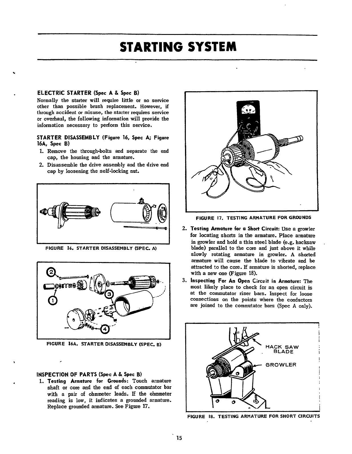
1.
Testing Armature for Grounds:
Touch armature
shaft
or
core and the end
of
each commutator bar
with
a
pair
of
ohmmeter leads.
If
the
ohmmeter
reading
is
low,
it
indicates
a
grounded
armature.
Replace grounded armature.
See
Figure
17.
FIGURE
17.
TESTING ARMATURE
FOR
GROUNDS
2.
Testing Armature for a
Short
Circuit:
Use
a
growler
for locating shorts in the armature.
Place
armature
in growler
and
hold
a
thin
steel
blade
(e.g.
hacksaw
blade) parallel to the core and just above
it
while
slowly rotating armature in growler.
A
shorted
armature will cause the blade to vibrate and
be
attracted
to
the core.
If
armature
is
shorted, replace
with
a
new one
(FigFe
18).
3.
Inspecting
For
An
Open
Circuit in Armature:
The
most likely place
to
check for an open circuit
is
at
the commutator riser bars. Inspect for loose
connections on the points where the conductors
are joined to the commutator bars (Spec
A
only).
HACK
SAW
.
BLADE
i
GROWLER
I
I
I
FIGURE
18.
TESTING ARMATURE
FOR
SHORT CIRCUITS
15
Redistribution or publication of this document,
by any means, is strictly prohibited.
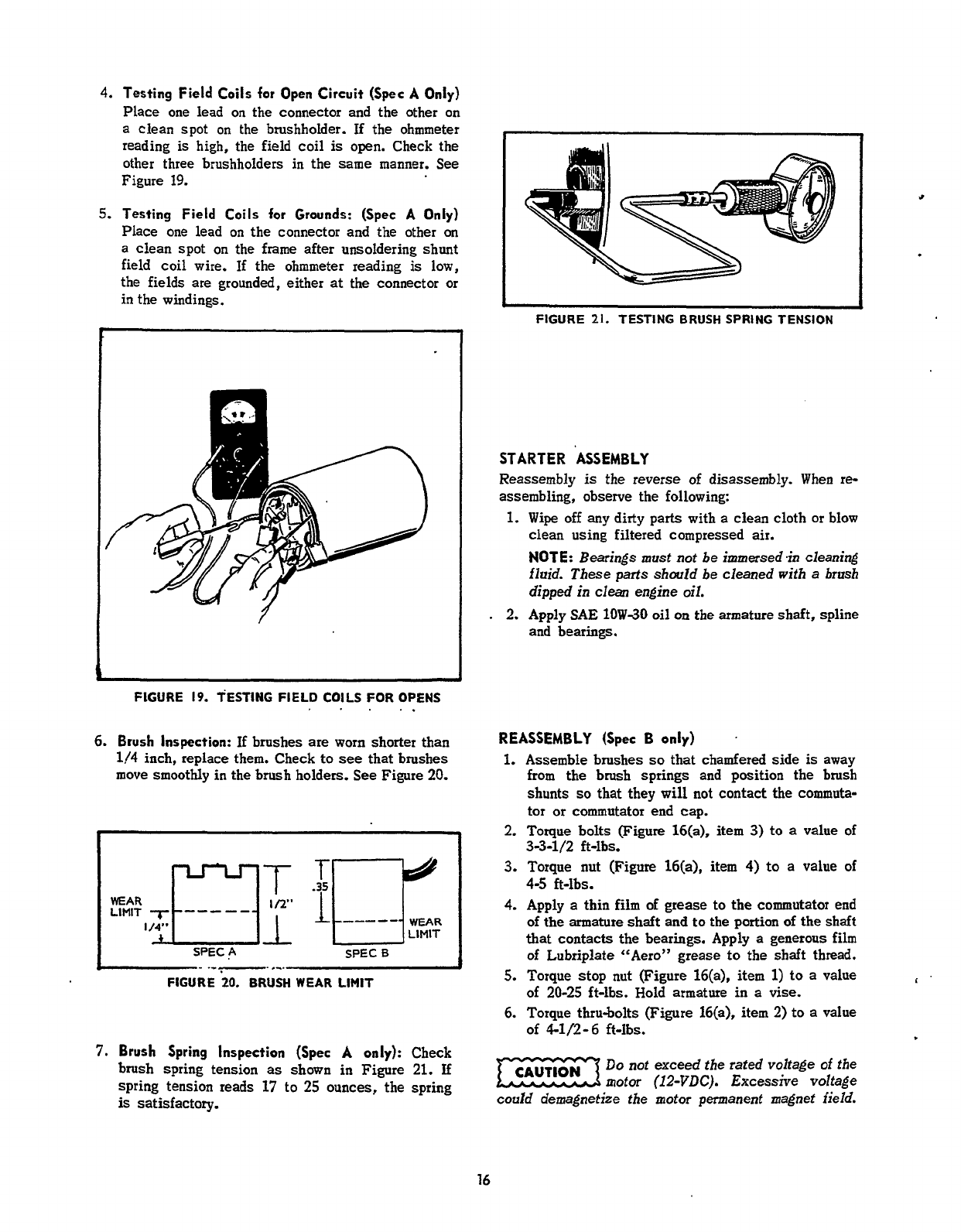
4.
Testing
Field
Coils
for
Open Circuit (Spec
A
Only)
Place one lead
on
the connector and the other on
a clean spot on the brushholder. If the ohmmeter
reading
is
high, the
field
coil
is
open. Check the
other three brushholders in the same manner. See
Figure 19.
5.
Testing
Field
Coils
for
Grounds: (Spec
A
Only)
Place one lead on the connector and the other
on
a clean spot
on
the
frame
after unsoldering shunt
field coil wire. If the ohmmeter reading
is
low,
the
fields
are grounded, either
at
the connector or
in
the windings.
FIGURE
19.
TESTING
FIELD
COILS
FOR
OPENS
,
.
.
..
6.
Brush Inspection:
If
brushes
are
worn
shorter than
114
inch, replace them. Check to
see
that brushes
move smoothly in the brush holders. See
Figure
20.
SPEC
A
SPEC
0
FIGURE
20.
BRUSH WEAR LIMIT
7.
Brush
Spring
Inspection
(Spec
A
only):
Check
brush spring tension
as
shown in Figure
21.
If
spring tension reads
17
to
25
ounces, the spring
is
satisfactory.
FIGURE
21.
TESTING
BRUSH SPRING
TENSION
STARTER
ASSEMBLY
Reassembly
is
the reverse
of
disassembly. When re-
assembling, observe the following:
1.
Wipe
off any dirty parts with
a
clean cloth or blow
clean using filtered compressed
air.
NOTE:
Bearings must not be
immersed
in cleaning
fluid. These parts should be cleaned with
a
brush
dipped in
clean
engine
oil.
.
2.
Apply SAE
1OW-30
oil
on
the armature shaft, spline
and bearings.
REASSEMBLY
(Spec
B
only)
.
1.
Assemble brushes
so
that chamfered side
is
away
from the brush springs and position the brush
shunts
so
that they will not contact the
commuta-
tor
or commutator end cap.
2.
Torque
bolts (Figure
16(a),
item
3)
to
a
value of
3.
Torque nut (Figure
16(a),
item
4)
to a value of
4-5
ft-lbs.
4.
Apply
a
thin
film
of
grease to the commutator end
of
the
armature
shaft and
to
the portion
of
the shaft
that contacts the bearings. Apply
a
generous
film
of
Lubriplate “Aero” grease
to
the
shaft
thread.
5.
Torque stop nut (Figure 16(a),
item
1)
to
a value
of 20-25 ft-lbs. Hold armature in
a
vise.
6.
Torque thru-bolts (Figure 16(a), item
2)
to
a
value
33-1/2
ft-lbs.
of
41/2-
6
ft-Ibs.
Do
not exceed the rated voltage
of
the
motor
(12-VDC).
Excessive
voltage
could
demagnetize the motor permanenf magnef field.
I
16
Redistribution or publication of this document,
by any means, is strictly prohibited.

.
n
i
BATTERY
VOLTMmR
124
1
-
CRANKING
MOTOR
NOTE.
&incry
a,
smer
wire
size
at
least
#IO.
Max.
length6
fr.
I
FIGURE
22.
NO
LOAD
TEST
INSPECTING
REASSEMBLED
STARTER
1.
No
Load
Test:
Connect the starting motor
as
shown
in
Figure
22.
The values for this test
are
as
follows:
Spec
A
SpecB
Battery Voltage
.
.
.
.
. .
.
. .
11.5
volts
12.0
volts
RPM
.............
8000rpm(min)
4,800-6,lOO
Maximum Current
Draw
.
.
.
25
amperes
32
amperes
NOTE:
1.
To
ensare good
electrical
contact,
make
sure
starter to engine mounting
surfaces
are
fzee
of
dirt
or
oil.
2.
When tightening attaching
bolts
and nut, starter
gear should
be
held into
ring
gear to
assure
proper
backlash.
3.
Battery to
slating
motor wire must be tightened
securely.
Starter
hotors
are not designed
far
continuous operation.
Do
not operate
more
than
30
seconds
per
“Ok’
cycle.
Do
no;
operate
starter
more
than
10
seconds
in
a
stall condition
if
engine wiI1 not rotate. Serious damage could result if
these time Zimits are exceeded.
17
Redistribution or publication of this document,
by any means, is strictly prohibited.
ENGINE
DISASSEMBLY
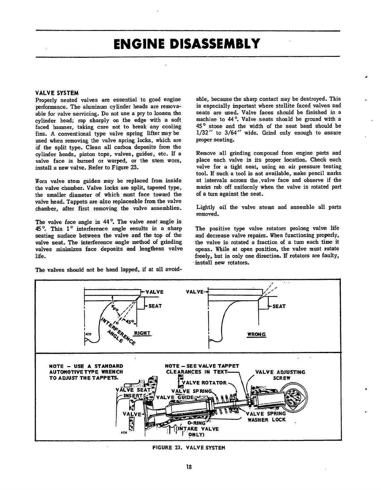
VALVE
SYSTEM
Properly seated valves
are
essential to good engine
performance. The aluminum cylinder heads
are
remova-
able
for
valve servicing.
Do
not
use
a
pry to loosen the
cylinder head; rap sharply
on
the edge with
a
soft
faced hammer, taking care not to break any cooling
fins.
A
conventional type valve spring lifter may
be
used when removing the valve spring locks, which are
of the
split
type. Clean all carbon deposits from the
cylinder heads, piston tops, valves, guides, etc.
If
a
valve face
is
burned or warped,
or
the stem worn,
install a new valve. Refer to Figure
23.
Worn valve stem guides may
be
replaced from inside
the valve chamber. Valve locks are split, tapered type,
the
smaller
diameter
of
which must face toward the
valve head. Tappets are also replaceable from the valve
chamber, after first removing the valve assemblies.
The
valve face angle
is
449
The valve
seat
angle
is
45'.
This
1'
interference angle results in
a
sharp
seating surface between the valve and the top of the
valve seat. The interference angle method
of
grinding
valves minimizes
face
deposits
and
lengthens valve
life.
The valves should not
be
hand lapped,
if
at
all
avoid-
able, because the sharp contact may be destroyed. This
is
especially
important where stellite faced valves and
seats are used. Valve
faces
should be finished
in
a
machine to
44'.
Valve seats should be ground with a
45'
stone and the width
of
the
seat
band should be
1/32"
to
3/64"
wide. Grind only enough to
assure
proper seating.
Remove
all
grinding compound from engine parts and
place each valve in
its
proper location. Check each
valve
for
a
tight seat,
using
an
air pressure testing
tool.
If
such a tool
is
not available, make pencil marks
at intervals acrass the.valve face and observe
if
the
marks rub off uniformly when the valve
is
rotated part
of a turn against the
seat.
Lightly
oil
the valve
stems
and assemble all parts
removed.
The positive
type
valve rotators prolong valve
life
and decrease valve repairs. When functioning properly,
the valve
is
rotated a fraction of
a
turn each
time
it
opens. While at
open
position, the valve must rotate
freely, but in only one direction.
If
rotators are faulty,
.
install new rotators.
NOTE
-
USE
A STANDARD NOTE
-SEE
VALVE TAPPET
AUTOMOTIVE TYPE WRENCH
TO
ADJUST THE TAPPETS CLEARANCES IN
TU(
ALVE ROTATOR
WASHER
LOC
.
FIGURE
23.
VALVE
SYSTEM
18
Redistribution or publication of this document,
by any means, is strictly prohibited.
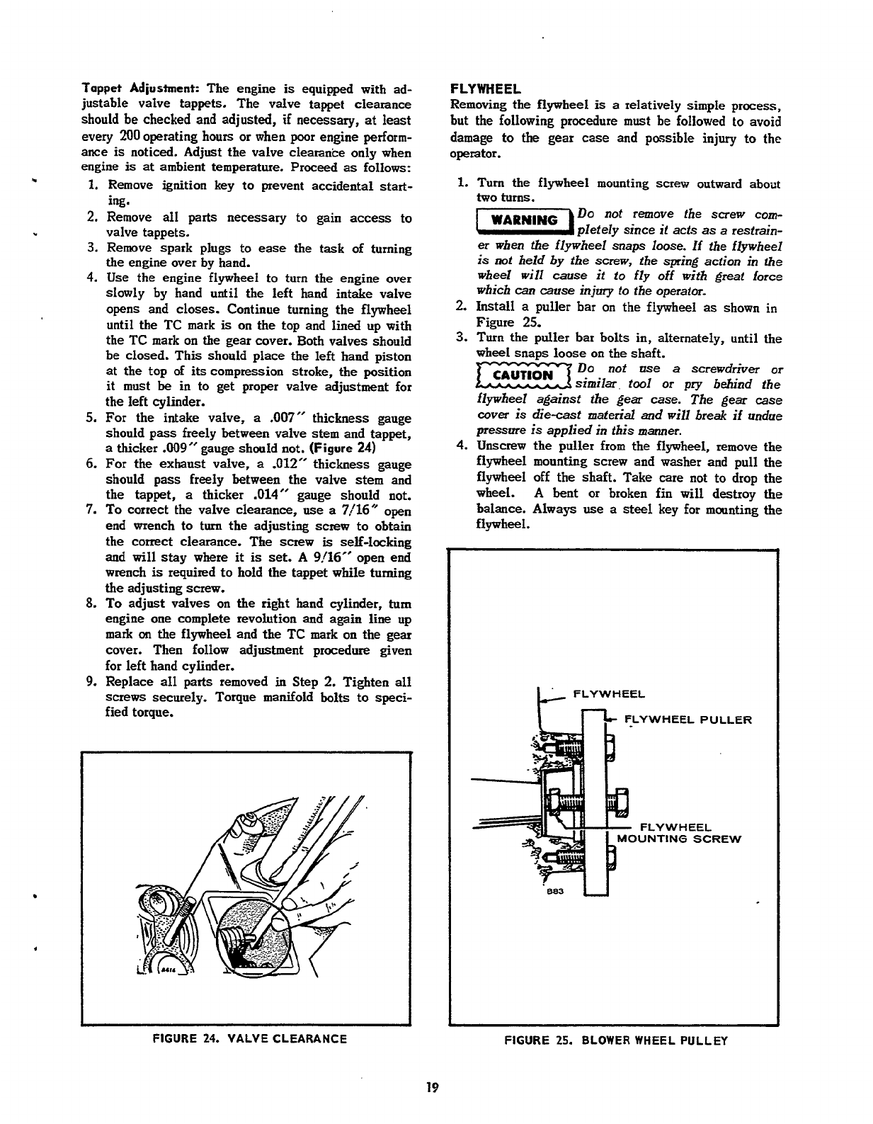
Tappet
Adiustmment:
The engine
is
equipped with ad-
justable valve tappets. The valve tappet clearance
should
be
checked and adjusted,
if
necessary, at least
every
200
operating hours or
when
poor engine perform-
ance
is
noticed. Adjust the valve clearance only when
engine
is
at
ambient temperature. Proceed
as
follows:
1.
Remove ignition key to prevent accidental start-
ing.
2.
Remove all
parts
necessary to gain
access
to
valve tappets.
3.
Remove spark plugs
to
ease the task of turning
the engine over by hand.
4.
Use
the engine flywheel to turn the engine
over
slowly by hand until the left hand intake valve
opens and
closes.
Continue turning the flywheel
until the TC mark
is
on
the
top and lined up with
the
TC
mark
on
the gear cover.
Both
valves should
be closed. This should place the
left
hand piston
at the top of
its
compression stroke, the position
it must
be
in to get proper valve adjustment for
the left cylinder.
5.
For
the intake valve,
a
.007" thickness gauge
should
pass
freely between valve stem and tappet,
a
thicker
.009"
gauge should
not.
(Figure
24)
6.
For the exhaust valve,
a
.012"
thickness gauge
should pass freely between the valve
stem
and
the tappet,
a
thicker
.014"
gauge should not.
7.
To
correct the valve clearance,
use
a
7/16"
open
end
wrench to turn the adjusting screw
to
obtain
the correct clearance.
The
screw
is
self-locking
and
will
stay
where it
is
set.
A
9/16"
open end
wrench
is
required to hold the tappet while turning
the adjusting screw.
8.
To
adjust valves
on
the right hand cylinder,
turn
engine one complete revolution
and
again
line
up
mark
on
the
flywheel and
the
TC
mark
on
the gear
cover. Then follow adjustment procedure given
for left hand cylinder.
9.
Replace
all
parts
removed
in
Step
2.
Tighten
all
screws securely. Torque manifold bolts
to
speci-
fied torque.
h
FIGURE
24.
VALVE CLEARANCE
FLYWHEEL
Removing the flywheel
is
a relatively simple process,
but the following procedure must
be
followed
to
avoid
damage
to
the gear
case
and possible injury
to
the
operator.
1.
Turn
the flywheel mounting
screw
outward about
two turns.
Do
not remove fhe screw
com-
pletely since
if
acts
as
a
restrain-
er
when the flywheel
snaps
loose. If the flywheel
is
not held by the
screw,
the spring action in
the
wheel
will
cause it to fly off with great force
which
cart
cause
injury
to the operaior.
Figure
25.
wheel snaus loose
on
the shaft.
2.
Install
a
puller bar
on
the flywheel
as
shown in
3.
Turn the puller bar bolts in, alternately, until the
Do
not use
a
screwdriver
or
similar,
tool
or
pry
behind the
flywheel against the
gear
case.
The
gear
case
cover
is
die-cast
maferid
and
will
break if undue
pressure
is
applied in this manner.
4.
Unscrew the puller from the flywheel, remove the
flywheel mounting screw and washer and pull the
flywheel off the shaft. Take
care
not to drop the
wheel. A bent or broken fin will destroy
the
balance. Always
use
a
steel
key for mounting the
flywheel.
FEEWHEEL
PULLER
FLYWHEEL
UNTING
SCREW
FIGURE
25.
BLOWER WHEEL PULLEY
19
Redistribution or publication of this document,
by any means, is strictly prohibited.
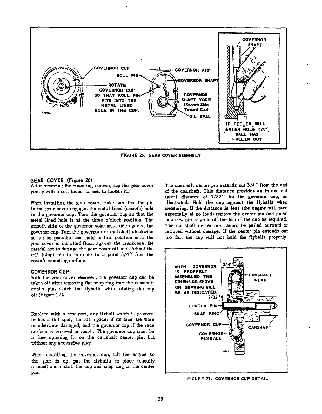
GOVERNOR
ARM
GOVERNOR CUP
ROLL PIN GOVERNOR SHAF
-
ROTATE
GOVERNOR'CUP
SO
THAT ROLL PIN GOVERNOR
FITS INTO THE SHAFT YOKE
METAL LINED
Si&
HOLE IN THE CUP. CUP)
SEAL
GOVERNOR
IF
FEELER
UlLL
ENTER
-WL%
Sa".
.
BALL
HAS
FALLEN
OUT
I
FIGURE
26.
GEAR COVER ASSEMBLY
GEAR
COVER
(Figure
26)
After removing the mounting screws, tap the gear cover
gently with
a
soft faced hammer to loosen it.
When
installing the gear cover, make sure that the pin
in
the gear cover engages the metal Iined (smooth) hole
in
the governor cup. Turn the governor cup
so
that the
metal lined hole
is
at the three o'clock position. The
smooth
side
of the governor yoke must ride against the
governor cup. Turn the governor
arm
and shaft clockwise
as
far
as
possible and hold in this position until the
gear cover
is
installed flush
against
the
crankcase. Be
careful not to damage the gear cover oil
seal.
Adjust the
roll (stop) pin to protrude to a point
3/4"
from the
cover's mounting surface.
GOVERNOR
CUP
With the gear cover removed, the governor cup can be
taken
off
after removing the snap ring from
the
camshaft
center pin. Catch the flyballs while sliding the cup
off
(Figure
27).
Replace with a new part, any flyball which
is
grooved
or has a flat spot; the ball spacer
if
its
arms
are
worn
or otherwise damaged; and the governor cup
if
the
race
surface
is
grooved
or
rough. The governor cup must be
a
free
spinning fit
on
the
camshaft center pin, but
without any excessive play.
When installing the governor cup,
tilt
the engine
so
the
gear
is
up, put the flyballs in place (equally
spaced) and install the cup and snap ring on the center
pin.
The camshaft center pin extends
out
3/4"
from
the
end
of
the camshaft.
This
distance
provides
an
in
and
out
travel
distance of
7/32"
for the
governor
cup,
as
illustrated. Hold the cup against
the
flyballs
when
measuring.
If
the
distance
is
less
(tbe
engine
will race
especially at
no
load) remove the center
pin
and
press
in a new pin or grind off the hub
of
the
cup
as
required.
The camshaft center pin cannot
be
pulled outward or
removed without damage.
If
the center pin extends
out
too far, the cup will not hold
the
flyballs
properly.
BE
AS INDICA
CENTER
IW,
%q
.
CAMSHAFT
WHEN GOVERNOR
IS
PROPERLY
ASSEMBLED THE
DIMENSION SHOWN
ON DRAWING WILL
BE
AS INDICATED.
CENTER PIN
GOVERNOR CUP
GOV
ERNOR
FLYBALL
3
FIGURE
27.
GOVERNOR
CUP
DETAIL
20
Redistribution or publication of this document,
by any means, is strictly prohibited.
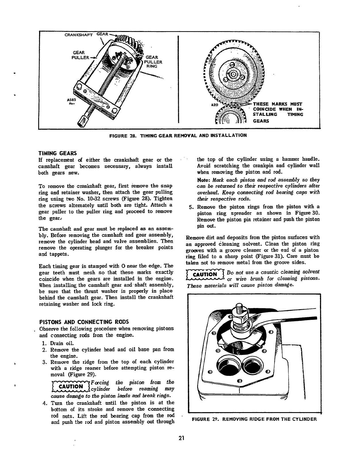
CRANKSHAFT
GEAR
FIGURE
28.
TIMING GEAR REMOVAL AND INSTALLATION
TIMING
GEARS
if
replacement
of
either the crankshaft gear or the
camshaft
gear becomes necessary, always install
both gears new.
To
remove the crankshaft gear,
first
iemove the snap
ring and retainer washer, then attach the gear pulling
ring using two
No.
10-32
screws (Figure
28).
Tighten
the screws alternately until both are tight. Attach
a
gear puller to the puller ring and proceed
to
remove
the gear..
The camshaft and
gear
must be replaced
as
an
assem-
bly. Before removing the camshaft and gear assembly,
remove
the cylinder head and valve assemblies. Then
remove the operating plunger for the breaker points
and tappets.
Each timing gear
is
stamped with
0
near the edge. The
gear teeth must mesh
so
that these marks exactly
coincide when the gears are installed in the engine.
When installing the camshaft gear and. shaft assembly,
be sure that the thrust washer
is
properly in place
behind the camshaft gear. Then install the crankshaft
retaining washer and lack ring.
PISTONS AND CONNECTING
RODS
,
Observe the following procedure when removing pistons
and connecting
rods
from the engine.
1.
Drain oil.
2.
Remove the cylinder head and oil base
pan
from
the engine.
3.
Remove the ridge from the top of each cyleder
with
a
ridge reamer
before
attempting piston re-
moval (Figure
29).
Facing the piston
from
the
cylinder before reaming may
cause
damage
to
the piston lands and break rings.
4.
Turn the crankshaft until the piston
is
at
the
bottom
of
its
stroke and remove the connecting
rod nuts.
Lift
the rcd bearing cap from the
rod
and push the
rod
and piston assembly out through
RKS
MUST
WHEN
IN-
TIMING
'
'
.
the top of the cylinder using
a
hammer handle.
Avoid scratching the crankpin and cylinder wall
when removing
the
piston and
rod.
Note:
Mark
each piston and
rod
assembly
so
they
can
be
returned
to
their respecfive cylinders after
overhaul. Keep connecting
rod
bearing
caps
with
their respective
rods.
5.
Remove the piston rings from the piston with
a
piston ring spreader
as
shown in Figure30.
Remove the piston pin retainer and push the piston
pin
out.
Remove dirt and deposits from the piston surfaces with
an
approved cleaning solvent. Clean the piston ring
grooves
with
a
groove cleaner or the end
of
a piston
ring filed to
a
sharp point (Figure
31).
Care
must be
taken not to remove
metal
from the groove sides.
Do
not
use
a
caustic cleaning solvent
or
wire
brush
for
cleaning pistons.
These
materials
will cause piston damage.
h
I
It
I
FIGURE
29.
REMOVING RIDGE FROM THE CYLINDER
21
Redistribution or publication of this document,
by any means, is strictly prohibited.
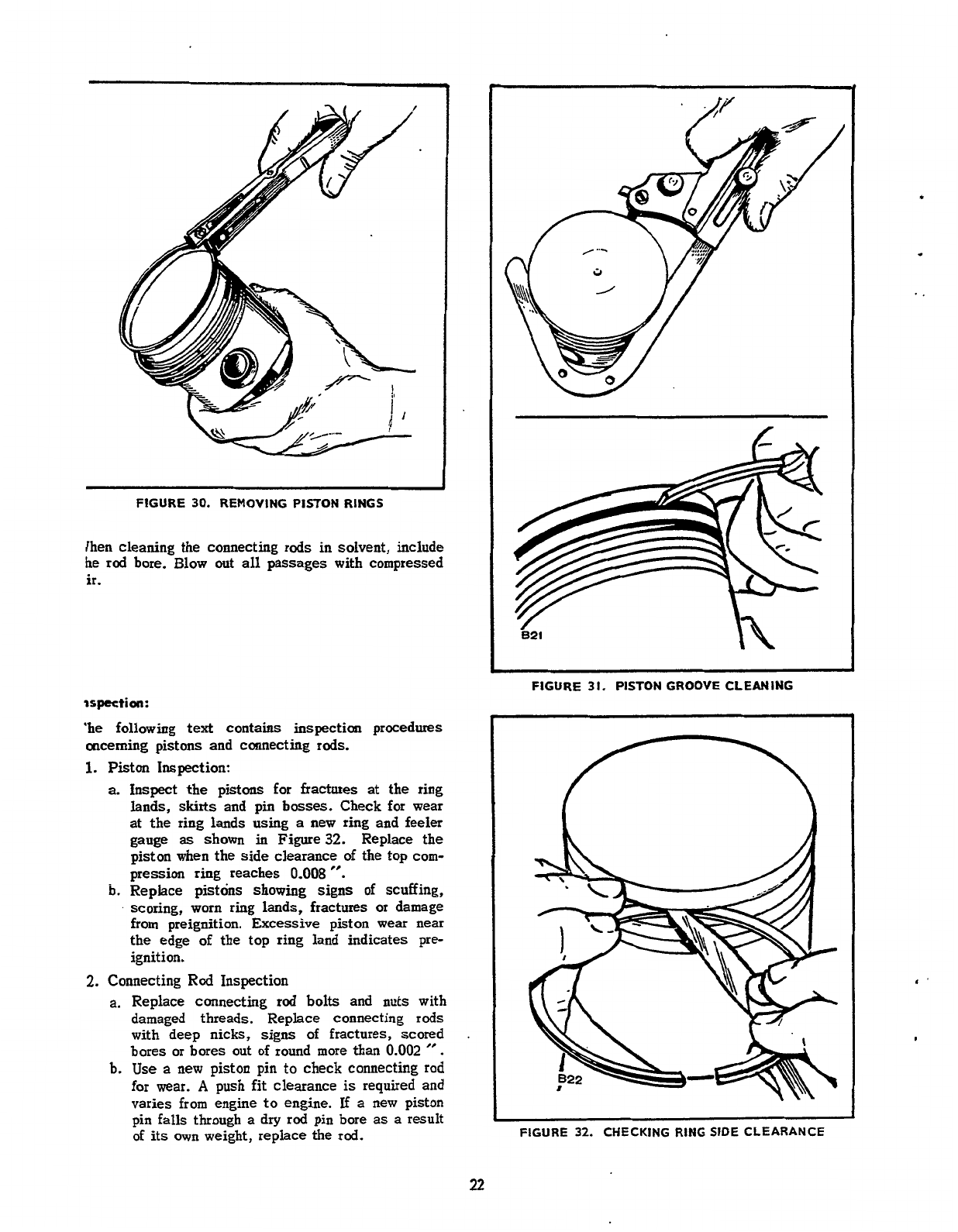
FIGURE
30.
REMOVING PISTON RINGS
[hen cleaning the connecting rods in solvent, include
he
rod
bore.
Blow out all passages with compressed
ir
.
ispution:
‘he
following
text
contains inspection procedures
oncerning pistons and Connecting rods.
1.
Piston Inspection:
a.
inspect the pistons
for
fractures
at
the ring
lands,
skirts
and
pin
bosses. Check for wear
at
the ring lands using
a
new ring and feeler
gauge
as
shown
in
Figure32. Replace the
piston when the side clearance of the top com-
pression ring reaches
0.008
”.
b.
Replace pistons showing signs
of
scuffing,
scoring, worn ring lands, fractures or damage
from preignition. Excessive piston wear near
the edge
of
the top ring land indicates pre-
ignition.
2.
Connecting
Rod
Inspection
a.
Replace connecting
rod
bolts
and nuts with
damaged threads. Replace connecting rods
with deep nicks, signs
of
fractures, scored
bares or bores out
of
round more than
0.002
”
.
b.
Use
a
new
piston pin
to
check
connecting
rod
for wear.
A
push fit clearance
is
required and
varies from engine
to
engine.
If
a
new piston
pin falls through
a
dry rod pin bore as
a
result
of
its
own
weight, replace the rod.
821
~~
FIGURE
31.
PISTON GROOVE CLEANING
FIGURE
32.
CHECKING RING
SIDE
CLEARANCE
22
Redistribution or publication of this document,
by any means, is strictly prohibited.
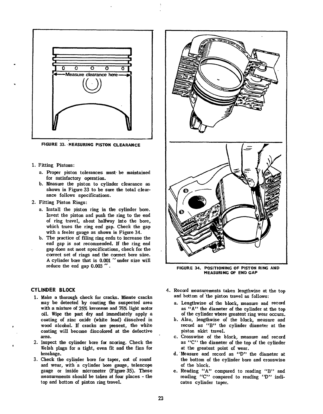
FIGURE
33.
MEASURING
PISTON
CLEARANCE
1.
Fitting Pistons:
a.
Proper
piston tolerances
must.
be
maintained
for satisfactory operation.
b. Measure the piston to cylinder clearance
as
shown in Figure
33
to
be
sure the
total
clear-
ance follows specifications.
2.
Fitting Piston Rings:
a.
Install
the piston ring in the cylinder
bore.
Invert the piston and push the ring
to
the end
of
ring travel, about halfway into the bore,
which trues the ring end gap. Check the gap
with
a
feeler
gauge as shown
in
Figure
34.
b.
The practice
of
filing ring ends to increase the
end gap
is
not recommended.
If
the ring end
gap does not
meet
specifications, check
for
the
correct set
of
rings and
the
carrect bore
size.
A
cylinder bore
that
is
0.001
”
under
size
will
reduce the end gap
0.003
”
.
CYLINDER BLOCK
1.
Make
a
thorough check
for
cracks. Minute cracks
may be detected by ccating the suspected
area
with
a
mixture
of
25%
kerasene and
75%
light motor
oil.
Wipe
the part dry and immediately apply
a
coating
of
zinc oxide (white lead) dissolved
in
coating will become
discolored
at
the defective
area.
2.
Inspect the cylinder bore far scaring. Check the
Welsh
plugs
for
a
tight, even
fit
and the fins for
breakage.
3.
Check the cylinder bore for taper,
out
of round
and
wear,
with’a cylinder bore gauge, telescope
gauge or inside micrometer (Figure
35).
These
measurements should be taken
at
four
pIaces
-
the
top and bottom of piston ring travel.
L
wood alcohol.
If
cracks
are
present, the white
I
FIGURE
34.
POSITIONING
OF
PISTON
RING AND
MEASURING
OF
END
GAP
4.
Record measurements taken lengthwise at the top
and bottom
of
‘the piston travel
as
follows:
a.
Lengthwise of the black, measure and record
as
“A”
the
diameter
of
the cylinder at the top
of the cylinder where greatest ring wear
occurs.
b.
Also,
lengthwise
of
the blak, measure and
record
as
“By’
the cylinder diameter
at
the
piston skirt travel.
c.
Crosswise
of
the
block, measure and record
as
“C” the diameter
of
the top
of
the cylinder
at
the greatest point of wear.
d.’Measure and recard as
“D”
the diameter
at
the bottom
of
the cylinder bore and crosswise
of the block.
e.
Reading
“A”
compared to reading
“B”
and
reading
“C”
compared
to
reading
“D’?
indi-
cates cylinder taper.
Redistribution or publication of this document,
by any means, is strictly prohibited.
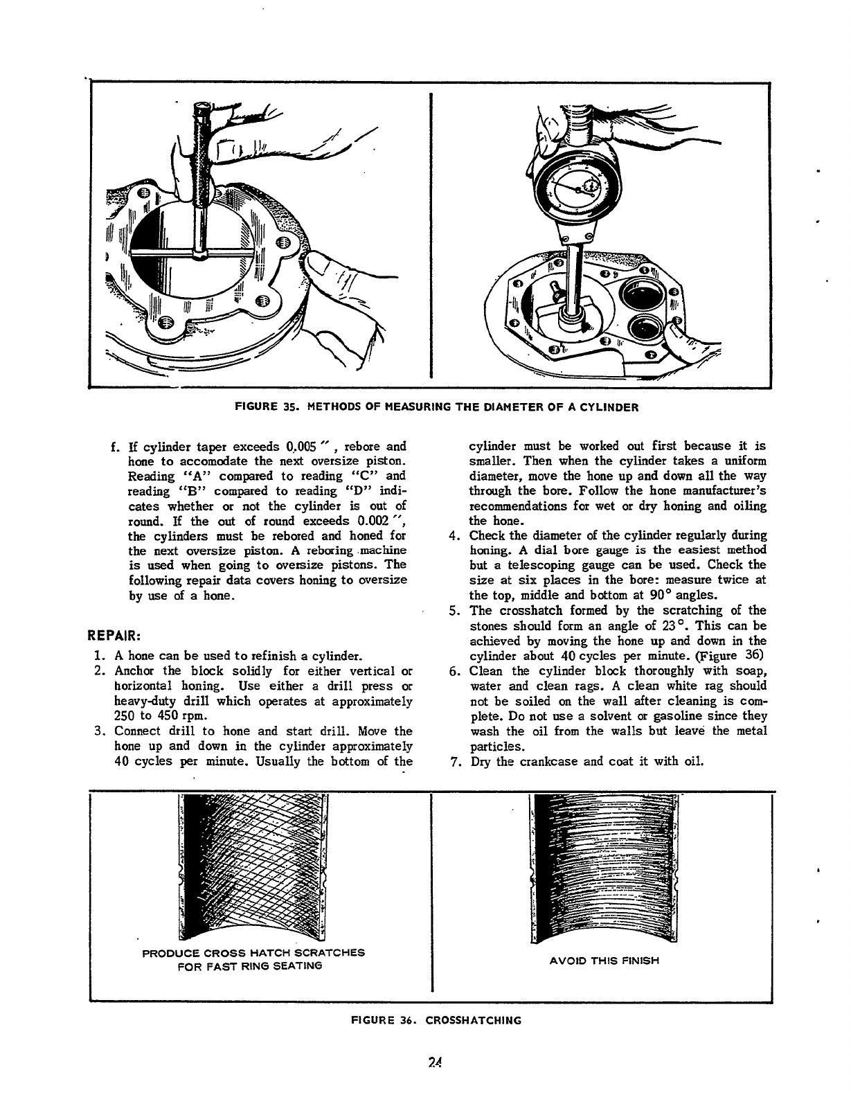
W
I
FIGURE
35.
METHODS OF MEASURING
THE
DIAMETER OF
A
CYLINDER
f.
If
cylinder taper exceeds
O,.OOS
”
,
rebore and
hone to accomodate the next oversize piston.
Reading “A” compared
to
reading “C” and
reading
“B”
compared
to
reading
“D”
indi-
cates whether
or
not the cylinder
is
out of
round.
If
the
out
of round exceeds
0.002”,
the
cylinders must be rebored and honed for
the next
oversize
piston.
A
reboring.machine
is
used when going
to
oversize pistons. The
following repair data covers honing
to
oversize
by
use
of
a
hone.
REPAIR:
1.
A
hone can be used
to
refinish a cylinder.
2.
Anchor the block solidly for either vertical or
horizontal honing. Use either a drill press or
heavy-duty drill which operates at approximately
250
to 450rpm.
3.
Connect drill to hone and start drill. Move the
cylinder must
be
worked out fist because it
is
smaller. Then when the cyliider takes a uniform
diameter, move the hone up and down
all
the way
through the bore. Follow the hone rnanufactu~er’s
recommendations
for
wet or
dry
honing and oiling
the hone.
4.
Check the
diameter
of the cylinder regularly during
honing.
A
dial
bore
gauge
is
the easiest method
but
a
telescoping gauge can
be
used.
Check the
size
at
six places in the bore: measure
twice
at
the top, middle and bottom at
90’
angles.
5.
The crosshatch formed by the scratching
of
the
stones should form an angle
of
23’.
This can be
achieved by moving the hone
up
and down in the
cylinder about 40 cycles
per
minute. (Figure
36)
6.
Clean
the
cylinder block thoroughly with soap,
water and clean rags.
A
clean white rag should
not be soiled
on
the wall after cleaning
is
com-
plete.
Do
not
use
a solvent
or
gasoline since they
wash the oil from the walls but leave the
metal
hone up and down in the cylinder approximately
40 cycles
per
minute. Usually
the
bottom
of
the particles.
7.
Dry
the
crankcase
and
coat
it
with oil.
PRODUCE CROSS HATCH SCRATCHES
FOR
FAST
RING SEATING
AVOID
THIS FINISH
FIGURE
36.
CROSSHATCHING
24
Redistribution or publication of this document,
by any means, is strictly prohibited.
CRANKSHAFT
Inspect the bearing journals.
If
they
are
scored and
cannot
be
smoothed
out
by
dressing
down,
replace
the crankshaft.
Whenever making major
repairs
on
the engine, always
inspect the drilled passages
of
the crankshaft. Clean
them
to
remove any foreign material and to
assure
proper
lubrication
of
the connecting
rods.
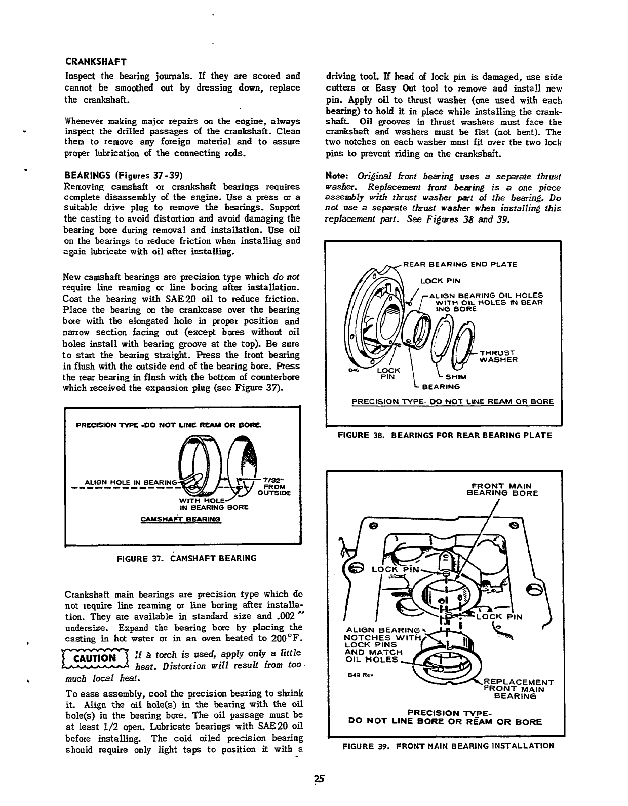
BEARINGS
(Figures
37-39)
Removing camshaft or crankshaft bearings requires
complete disassembly of the engine. Use
a
press
or
a
suitable drive plug to remove the bearings. Support
the casting
to
avoid distortion and avoid damaging the
bearing bore during removal
and
installation. Use
oil
on
the bearings to reduce friction when installing and
again lubricate with
oil
after installing.
New camshaft bearings are precision type which
do
not
require line reaming or line boring after installation.
Coat the bearing with
SAE20
oil to reduce friction.
Place the bearing
on
the crankcase over the bearing
bore with the elongated hole
in
proper
position and
narrow section facing out (except bores without oil
holes install with bearing groove
at
the top). Be sure
to start the bearing straight.
Press
the front bearing
in flush with the outside end
of
the bearing bore.
Press
the rear bearing in flush with the bottom
of
counterbore
which received the expansion plug
(see
Figure
37).
PRECISION
NPE:
-DO
NOT
LINE
REAM
OR
BORE
AUQN
HOLE
IN
BEARING
------------
WITH
HOLE/
~
IN
BEARIN(3
BORE
FIGURE
37.
CAMSHAFT BEARING
Crankshaft main bearings are precision type which do
not
require line reaming
or
line boring
after
installa-
tion. They
are
available in standard
size
and
-002
”
undersize. Expand the bearing bore by placing the
casting
in
hot water or in
an
oven heated
to
200’F.
1
:f
B
torch
is
used,
apply only
a
little
heat. Distortion will result
from
too.
I
much local heat.
To
ease assembly, cool the precision bearing to skink
it.
Align the oil hole(s)
in
the bearing with the
oil
hole(s)
in
the bearing bore. The oil passage must be
at
least
1/2
open.
Lubricate bearings with
SAE20
oil
before installing. The cold oiled precision bearing
should
require only light
taps
to position
it
with
a
driving tool. If head
of
lock
pin
is
damaged,
use
side
cutters
or
Easy
Out
tool
to
remove and install
new
pin.
Apply
oil
to thrust washer
(one
used
with
each
bearing)
to
hold
it
in place while installing the crank-
shaft.
Oil
grooves
in
thrust washers must face the
crankshaft
and
washers
must
be
flat
(not
bent). The
two notches
on
each washer
must
fit over the two lock
pins
to
prevent riding
on
the crankshaft.
Note:
Original front bearing
uses
a
separate thrust
washer. Replacement
front
beaing
is
a
one piece
assembly with thrust washer
pari
of
the
bearing.
Do
not use
a
separate thrust
washer
when installing this
replacement part.
See
Figures
38
and
39.
REAR
BEARING END
PLATE
LOCK
PIN
-ALIGN BEARING
OIL
t
ITH
OIL
HOLES
IN
IOLES
BEAR
-FIG.
1
SHIM
BEARING
PRECISION
TYPE-
00
NOT
LINE
REAM
OR
BORE
-~
FIGURE
38.
BEARINGS
FOR
REAR
BEARING PLATE
FRONT
MAIN
BEARING BORE
ALIGN
BEARING5
-L#d
NOTCHES WITH
049
Rev
REPLACEMENT
FRONT
MAIN
.
.
.
.
-.
.
BEARING
PRECISION
TYPE-
DO
NOT
LINE
BORE
OR
REAM
OR
BORE
FIGURE
39.
FRONT
MAIN
BEARING INSTALLATION
Redistribution or publication of this document,
by any means, is strictly prohibited.

848
&+-I
I.
MEASURE
ENDPLAY
HERE
J
(REFER
TO
DIMENSIONS
AND
CLEARANCES)
FIGURE
40.
CRANKSHAFT ENDPLAY
CRANKSHAFT
ENDPLAY
After the rear bearing end plate has been tightened
using the torque recommended in Assembly Torques
check the crankshaft endplay
as
shown in Figure
40.
If
there
is
too much endplay (see Dimensions and
Clearances for minimum and maximum endplay), remove
the
rear
bearing
end plate
and
add
a
shim
between
the thrust washer and plate. Reinstall the end plate
making
sure
the thrust washer and shim notches line
up
with the
lock
pins. Torque and recheck endplay of
the crankshaft.
Checking Bearing Clearance
with
Plastigauge:
1.
Make certain that all parts are marked
or
identified
so
that they
are
reinstalled
in
their original
positions.
I
c
I
..
1
FIGURE
41.
MEASURING
BEARING CLEARANCE
2.
Place
a
piece of correct size Plastigauge in the
bearing cap the
full
width of the crankshaft
rod
surface about
.1/4
inch off center (Figure
41).
3..
Rotate' the crank about
30'
from
bottom dead
center and reinstall the bearing cap; tighten the
bolts to the torque specified in the Table
of
Torqdes and Clearances.
Do
not turn the crank-
shaft.
.
4.
Remove the bearing cap. Leave the flattened
Plastigauge
on
the
part
to
which
it
has adhered
and compare the widest point with the graduations
on the Plastigauge envelope to determine bearing
clearance
.
OIL
SEALS
(Figure
42)
The bearing plate must be removed
to
replace the oil
seal. Drive the oil
seal
out
from the inside.
Before installing the seals,
fill
the
space
between
lips with
a
multi-purpose grease.
This
will improve
sealing.
,
REAR BEARING PLATE
GEAR COVER MOUNTING FACE
OF GEAR COVER THIS SURFACE SHOULD
BE CLEANED
OF
ALL
OIL
SEAL OLD SEALING COM-
POUND BEFORE INSTAL-
LING SEAL.
THIS
SURFACE SHOULD
BE CLEANED
OF
ALL DRIVE
OR
PRESS Oli
OLD SEALING COM- SEAL TO SHOULDER
A877
POUND BEFORE INSTAL- 'OF THE PLATE BORE
LING SEAL.
GEAR COVER OIL SEAL REAR BEARING PLATE
OIL SEAL
~~~ ~~
FIGURE
42.
GEAR COVER AND REAR BEARING PLATE OIL SEALS
26
Redistribution or publication of this document,
by any means, is strictly prohibited.
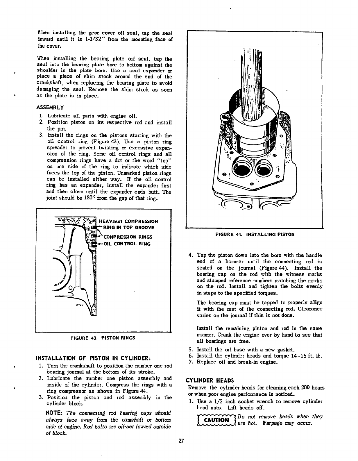
.
\\hen installing the
gear
cover
oil
seal,
tap the
seal
inward until it
is
2-1./32”
from the mounting face of
the
cover.
When installing the bearing plate
oil
seal,
tap the
seal
into
the bearing plate bore to bottom against the
shoulder
in
the plate
bore.
Use
a
seal
expander or
place
a
piece of shim stock around the end of the
crankshaft, when replacing the bearing plate
to
avoid
damaging the seal.
Remove
the shim stock
as
soon
as the plate
is
in place.
ASSEMBLY
1.
Lubricate
all
parts
with engine
oil.
2.
Position piston on
its
respective rod and install
the pin.
3.
Install the rings
on
the pistons starting with the
oil control ring (Figure
43).
Use
a
piston ring
spreader to prevent twisting or excessive expan-
sion
of
the ring.
Some
oil control rings and
all
compression rings have
a
dot
or the word cct~p77
on
one side of the ring to indicate which side
faces the top of the piston. Unmarked piston rings
can
be
installed either way. If the
oil
control
ring has an expander,
install
the
expander first
and then
close
until the expander
ends
butt. The
joint should
be
180”
from the gap of that ring.
EAVIEST COMPRESSION
RING IN TOP GROOVE
COHPRESION RINGS
-OIL CONTROL RING
FIGURE
43.
PISTON RINGS
INSTALLATION
OF
PISTON IN CYLINDER:
b
1.
Turn
the crankshaft
to
position the number one rod
bearing journal
at
the
bottom of
its
stroke.
2.
Lubricate the number one piston assembly and
inside of the cylinder. Compress the rings with
a
ring compressor
as
shown in Figure44.
3.
Position the piston and rod assembly
in
the
cylinder block.
NOTE:
The connecting
rod
bearing
caps
should
always face away from the camshaft
cr
bottom
side
of
engine.
Rod
bolts
are
off-set towad outside
of
block.
*
FIGURE
44.
INSTALLING PISTON
4.
Tap the piston down into the bore with
the
handle
end
of
a
hammer until the connecting rod
is
seated
on
the journal (Figure44). Install the
bearing cap
on
the rod with the witness
marks
and stamped reference numbers matching
the
marks
on the rod.
Install
and tighten the bolts evenly
in
steps
to
the specified torques.
The bearing cap must
be
tapped to properly align
it
with
the
rest
of the connecting rod. Clearance
varies
on
the journal
if
this
is
not done.
Install
the remaining piston
and
rod
in
the
same
manner. Crank the engine over by hand
to
see
that
all
bearings are free.
5.
Install the
oil
base with
a
new gasket.
6.
Install the cylinder heads and torque
14-16
ft- Ib.
7.
Replace
oil
and break-in engine.
CYLINDER HEADS
Remove the cylinder heads for cleaning
each
200
hours
or when poor engine performance
is
noticed.
1.
Use
a
1/2
inch socket wrench
to
remove cylinder
head nuts. Lift heads off.
Do
not remove
heads
when they
mare hot.
Warpage
may
occur.
27
Redistribution or publication of this document,
by any means, is strictly prohibited.

2.
After removing heads, clean out
all
carbon de-
posits. Be careful not
to
damage the outer sealing
edges where gaskets
fit.
The heads are made
of
aluminum and can
be
damaged by
careless
handling.
3.
Use new head gaskets and clean both the heads
and the cylinder block thoroughly where the head
gaskets rest.
4.
Place
heads
in
pasition
and follow head torque
tightening sequence shown
in
Figure
45.
Start
out
tightening
all
Nuts to
5
ft-lb, then
10
ft-lb,
etc.,
until
all
Nuts
are
taqued
14-16
ft-lb.
5.
Recheck torque befare engine
has
run
a
total
of
-
25
hours.
I
I
N0.2
CYLINDER
I
N0.1
CYLINDER
I
FIGURE
45.
CYLINDER
HEAD TORQUE
SEQUENCE
.
Redistribution or publication of this document,
by any means, is strictly prohibited.
INTRODUCTION
.
This catalog applies to Tractor Application
BF
Engines.
Parts
are arranged
in
groups of related-items. Each
illustrated part is identified by
a
reference number corresponding to the same reference number in the parts list for
that
group.
Parts illustrations are typical. Using the
Model
and Spec
No.
from
the
nameplate, select parts from this
catalog that apply
to
your engine. Unless otherwise mentioned in the description,
parts
are
interchangeable
between models.
Right
and left
sides
are determined
by
facing the blower end (front)
of
the engine.
TABLE
OF
CONTENTS
TITLE
PAGE
INTRODUCTION
.................................................................
29
STANDARD ENGINE GROUPS
...................................................
29
31
Block,
Cylinder..
3233
Gearcase, Oil Base
and
Oil Pump
349%
Fuel System
....................................................................
36,37
Carburetor Parts..
..............................................................
38,39
Alternator, Blower Housing, Governor and Starter.
...............................
40,41
Ignition System..
...............................................................
42
Starter Parts
-
Spec
A..
43
Starter Parts
-
Begin Spec
B
44
44
Optional Group
Filter,
Oil
Spin-On.
46
1
Box,
Breaker
-
Top Adjusted
47
2
Carburetor with
Integral
Fuel Pump
48,49
3
......................................
...............................................................
...............................................
Camshaft, Crankshaft, Flywheel and Piston
.........................................................
....................................................
Service
Kits and Miscellaneous..
................................................
OPTIONAL EQUIPMENT GROUPS..
..............................................
45
Number
.
............................................................
....................................................
.............................................
STANDARD ENGINE PARTS SECTION
This
section
contains the engine
parts
used
on
standard engines.
29
Redistribution or publication of this document,
by any means, is strictly prohibited.
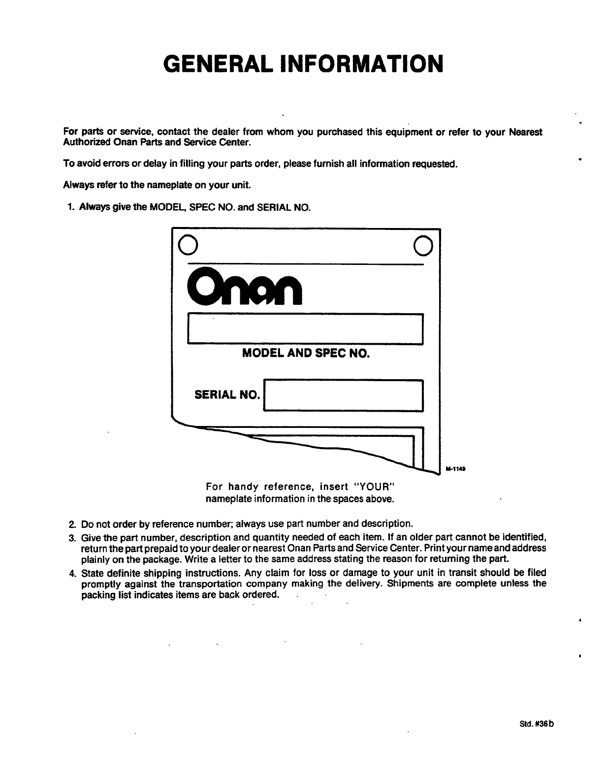
GENERAL
INFORMATION
For parts or service, contact the dealer from whom you purchased this equipment or refer to your
Nearest
Authorized Onan Parts and Service Center.
To
avoid
errors or delay in filling your parts order, please furnish ail information requested.
Always refer to the nameplate on your
unit.
1.
Always give the
MODEL,
SPEC
NO.
and
SERIAL
NO.
0
MODEL
AND
SPEC
NO.
SERIAL
NO.
a1
For handy reference, insert
“YOUR”
nameplate information in the spaces above.
2. Do not order by reference number; always use part number and description.
3.
Give the part number, description and quantity needed of each item. If an older part cannot be identified,
return the part prepaid
to
your dealer or nearest Onan Parts and Service Center. Print your name and address
plainly on the package. Write a letter to the same address stating the reason for returning the part.
4.
State definite shipping instructions. Any claim for loss or damage to your unit in transit should
be
filed
promptly against the transportation company making
the
delivery. Shipments are complete unless the
packing list indicates items are back ordered.
.
.
Redistribution or publication of this document,
by any means, is strictly prohibited.
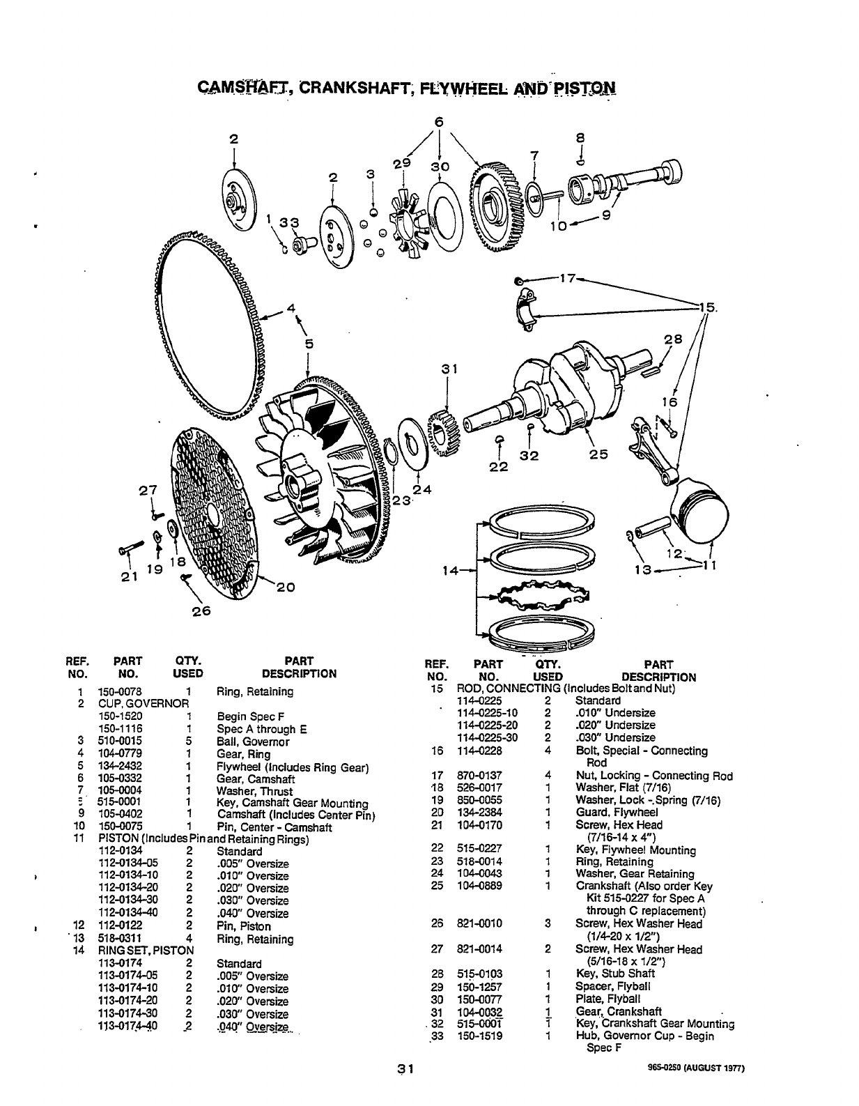
REF.
NO.
1
2
3
4
5
6
1.
9
10
11
12
'
13
14
6
2
-
..
.
PART
QTY.
PART REF. PART
QTY.
PART
15
ROD,
CONNECTING (Includes Boltand Nut)
114-0225 2 Standard
'
114-0225-10 2 .010"Undersize
114-0225-20 2 .020" Undersize
114-0225-30
2
.030"
Undersize
DESCRIPTION
NO.
USED DESCRIPTION
NO.
NO.
USED
150-0078
1
Ring, Retaining
CUP, GOVERNOR
150-1 520
1
Begin SpecF
150-1116
1
Spec
A
through E
510-0015
5
Ball, Governor
104-0779
1
Gear, Ring
16
114-0228
4
Bolt,
Special
-
Connecting
134-2432
1
Flywheel (Includes Ring Gear)
105-0332
1
Gear, Camshaft
105-0004
1
Washer,Thrust .18 526-0017
515-0001
1
Key, Camshaft Gear Mounting 19 850-0055 1 Washer, Lock -.Spring (7/16)
105-0402
1
Camshaft (Includes Center Pin) 20 134-2384
1
Guard, Flywheel
21 104-0170
1
Screw, Hex Head
150-0075
1
Pin, Center
-
Camshaft
PISTON (Includes Pin and Retaining Rings) (7/16-14
x
4")
112-0134 2 Standard 22 515-0227 1 Key, Flywheel Mounting
112-0134-05 2
.OOS
Oversize
23
518-0014 1 Ring, Retaining
112-0134-10 2 .010" Oversize 24
1O4-0043
1
Washer, Gear Retaining
112-0134-20
2 .020" Oversize 25 104-0889
1
Crankshaft
(Also
order Key
112-0134-30
2
.030"
Oversize Kit 515-0227
for
Spec
A
112-0134-40
2
,040"
Oversize through C replacement)
112-0122
2
Pin, Piston 26 8214010
3
Screw, Hex Washer Head
RING
SET.
PISTON 27 821-0014 2 Screw, Hex Washer Head
113-0174 2 Standard (5116-18
x
1/2")
113-0174-05
2
.005
Oversize 28 515-0103
113-0174-10 2
.OW
Oversize
113-0174-20 2 .020" Oversize
113-0174-30 2 .030" Oversize
113-017.4-40 -2
.Ow
Qv~rsjzg
.
32
51s-ooci-
i'
'Key, Crankshaft Gear Mounting
Rod
17 870-0137
4
Nut, Locking
-
Connecting Rod
1 Washer, Flat (7/16)
51
8-031
1
4 Ring, Retaining
(1/4-20
x
1/2")
1 Key, Stub Shaft
29 150-1257
1
Spacer, Flyball
30 150-0077
1
Plate, Flyball
31 104-0032
1
Gear,, Crankshaft
.33 150-1519
1
Hub, Governor Cup
-
Begin
Spec F
31
965-0250
(AUGUST
191
Redistribution or publication of this document,
by any means, is strictly prohibited.
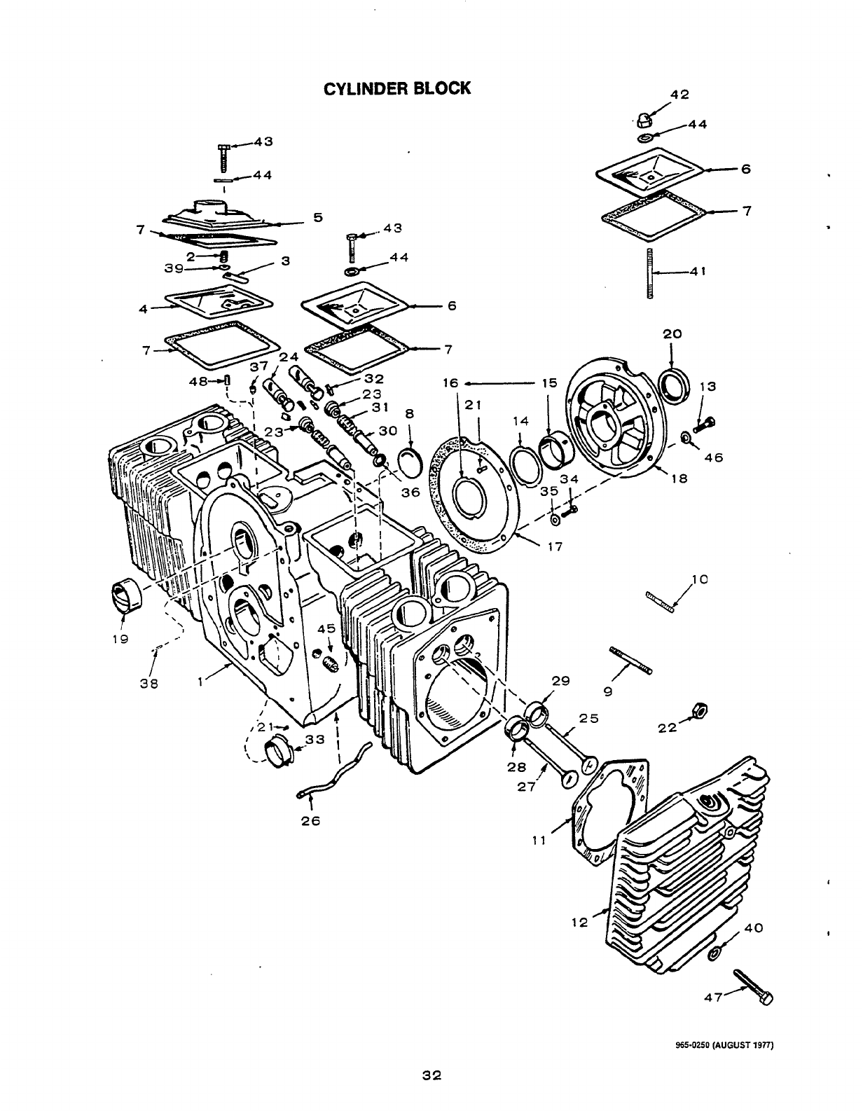
CYLINDER
BLOCK
965-0250
(AUGUST
1977)
32
Redistribution or publication of this document,
by any means, is strictly prohibited.
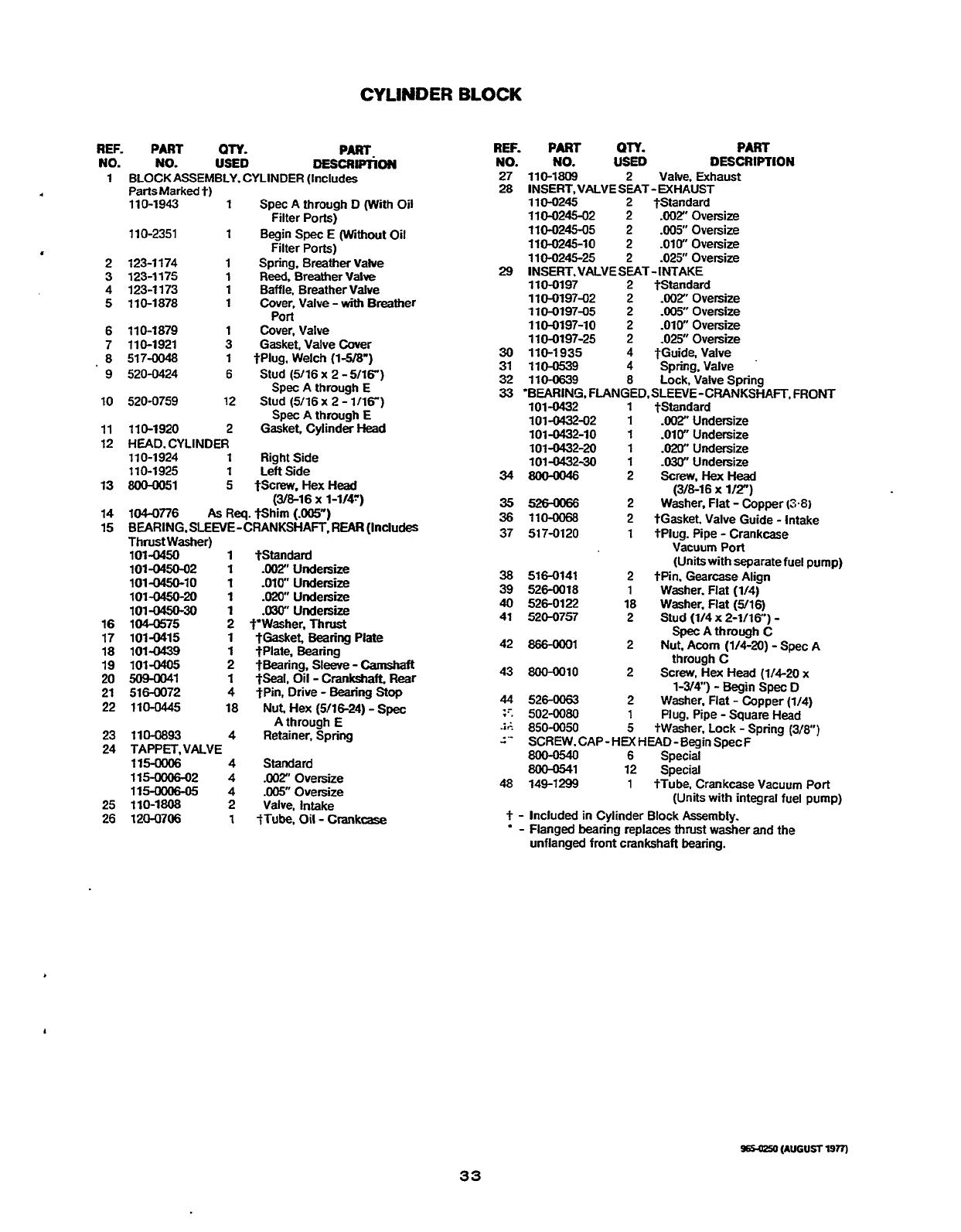
REF.
PART
OTY.
PART-
NO. NO.
USED
MscRlPnoN
1
BLOCK ASSEMBLY.CYLlNDER (Includes
PartsMarked
t)
11
0-1943
1
Spec A through D (With Oil
110-2351
1
Begin
Spec
E
(Without Oil
Filter Ports)
Filter
Ports)
2 123-1174
1
Spring. Breather Valve
3
123-1175
1
Reed,
Breather Valve
4 123-1173
1
Baffle, Breather Valve
5
110-1878
1
Cover, Valve
-
with
Breather
6 110-1879
1
Cover. Valve
7
110-1921 3
Gasket, Valve Cover
8 517-0048
1
tPlug. Welch
(148")
Spec A through
E
Spec
A
through
E
Port
9 520-0424 6
Stud
(5116
x
2
-
5/16")
10 520-0759 12
Stud
(5116
x
2
-
1/16")
11
110-1920 2
Gasket. Cylinder
Head
12
HEAD. CYLINDER
1
10-1 924
1
Right Side
110-1925
1
LeftSide
13
8ooM)51
5
tScn?w,HexHead
14
104-0776
As
Req.
*him
(.005")
15
BEARING.SLEEVE-Cf3ANKSHAFT.
REAR
(Includes
Thrust Washer)
101-0450
1
$Standard
101-0450-02
1
.002"Undetsize
101-0450-10
1
-010"
Undersize
101-045o-2O
1
.020"Undersize
101-045o-3O
1
.WUndersize
16
1060575 2
f'Washer,Thnrst
17 101-0415
1
tGasket.
Bearing
Plate
18 101-0439
1
$Plate. Bearing
19 101-0405 2
tBearing,
Sleeve
-
camshaft
20
5o40041
1
-peal,
Oil
-
Crankshaft. Rear
21
516-0072
4
$Pin, Drive
-
Bearing
Stop
22 110-0445
18
Nut. Hex
(5/16-24)
-
Spec
23 110-0893
4
Retainer, Spring
24
TAPPET, VALVE
(3@-16
x
1-1/47)
A through
E
115-ooo6
4
Standard
1156006-02
4
.002"0versize
115-0006-05 4
.W
Oversize
25 110-1808 2
Valve, Intake
26
120-!3706
1
tTube. Oil
-
Crankcase
REF.
PART
Q'W.
PART
NO.
NO.
USED
DESCRIPTION
27 110-1809 2
Valve, Exhaust
110-0245
2
tStandard
110-0245-02 2
.WYOversize
110-0245-05 2
.005"0versize
110-0245-10 2 .OW
Oversize
110-0245-25
2
-02.5"
Oversize
110-0197 2
?Standard
110-019742 2
-002"
Oversize
110-019745 2
-00s'
Oversize
110-0197-10 2
-010"
Oversize
110-0197-25 2 -025"
Oversize
30
110-1935 4
tGuide. Valve
31 110-0539 4
Spring.Valve
'
32 110-0639
8
Lock, Valve Spring
28
1NSERT.VALVESEAT
-EXHAUST
29
1NSERT.VALVESEAT-INTAKE
33
'BEARING.
FLANGED.SLENE-CRANKSHAFT.
FRONT
101-0432
1
tStandard
101-043242
1
.002"
Undersize
101-0432-10
1
-010"
Undersize
101-0432-20
1
.020"Undersize
101-0432-30
1
-030"
Undersize
34800-0046
2
Screw.HexHead
(3B-16
x
l/T)
35526-0066
2
Washer, Flat
-
Copper
(3.8)
36
11-
2
tGasket. Valve Guide
-
Intake
37
517-0120
1
tPlug. Pipe
-
Crankcase
38
516-0141 2
tPin. Gearcase Align
39
526-0018
1
Washer. Flat
(1/4)
40
526-0122 18
Washer, Flat
(316)
SpecAthroughC
42
86S-WO1
2
Nut,
Acorn
(1/4-20)
-
Spec
A
through C
43
8oO-0010
2
Screw,
Hex
Head
(1/4-20
x
1-3/4")
-
Begin
Spec
D
44
526-0063 2
Washer. Flat
-
Copper
(1/4)
:?.
502-0080
1
Plug. Pipe
-
Square Head
i;
850-0050
5
tWasher, Lock
-
Spring
(3/8)
2"
Vacuum
Port
(Unitswith separatefuel pump)
41 520757
2
Stud
(1/4
X
2-1/16")
-
SCREW.CAP-
HEX
HEAD- Begin SpecF
800-0540
6
Special
8OO-0541 12
Special
48
149-1299
1
+Tube. Crankcase Vacuum
Port
(Units with integral fuel pump)
+
-
Included in Cylinder Block
Assembly.
.
-
Flanged bearing replaces thrust washer and the
unflanged front crankshaft bearing.
D65&50
(AUGUST
19n)
33
Redistribution or publication of this document,
by any means, is strictly prohibited.
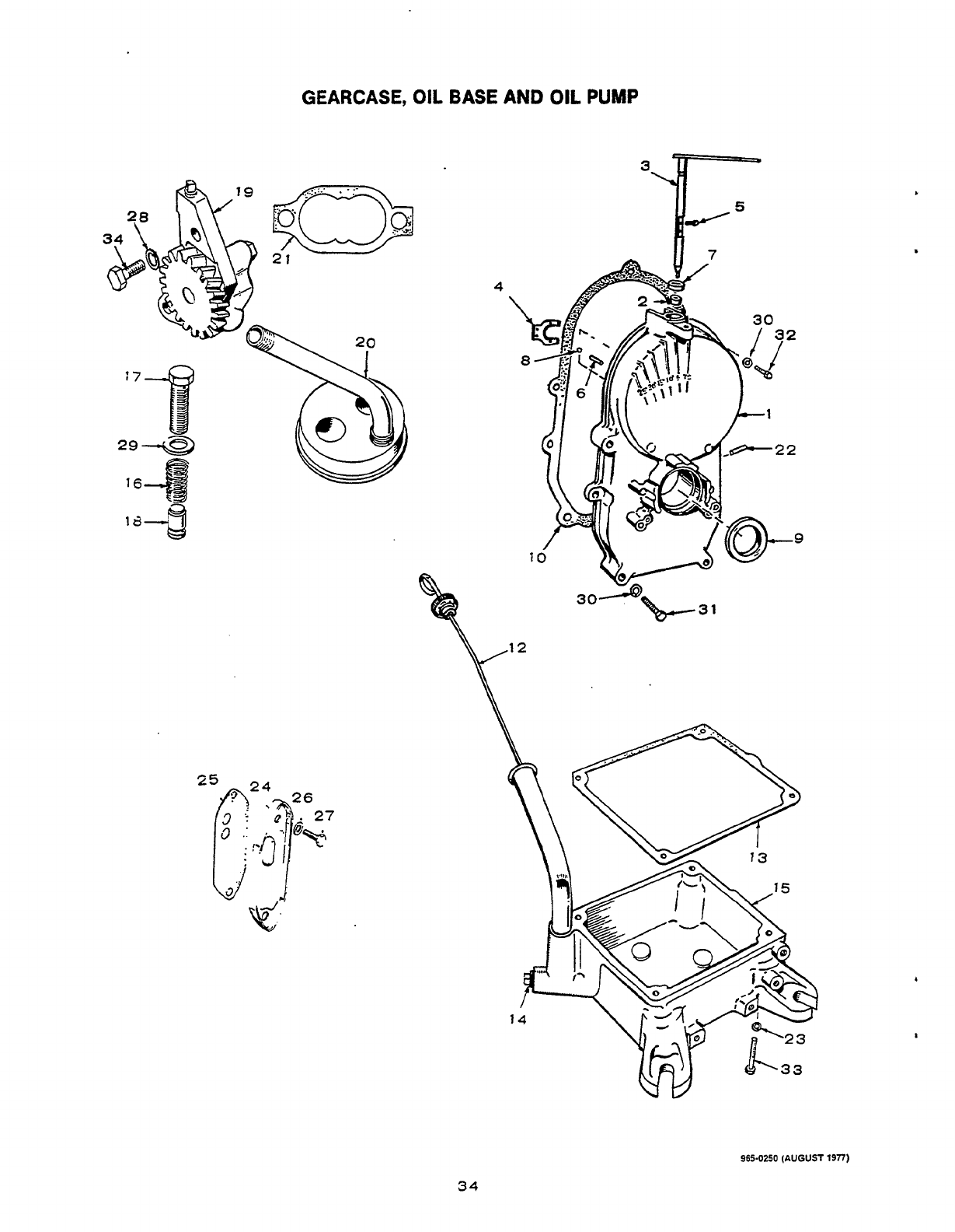

GEARCASE,
OIL
BASE
AND
OIL
PUMP
REF.
PART
OTY.
PART
NO.
NO.
USED
DESCRIPTION
1
GEARCASE
ASSEMBLY (IncludesParts Marked')
103-0501
1
Begin
Spec
D
103-0409
1
Spec
A
through
C
Engines With Separate Fuel
Pump
Engines With Carburetor and
Integral Fuel Pump
(Does
not
include vacuum line tube)
103-0498
1
Begin
Spec
D
103-0396
1
Spec A through
C
2 510-0105
1
'Bearing,
Sleeve
-
Governor
Shaft
3
'SHAFT
AND
ARM
ASSEMBLY-GOVERNOR
150-1470
1
BeginSpecD
150-1349
1
SpecAthmughC
4
150-1187
1
'Yoke. Shaft
-
Governor
5 815-0046
2
'Screw. Pan
Head
6 516-0130
1
'Pin. Dowel
-
Cup
Stop
75040008
1
'Seal.
Oil
-
Governor
Shaft
8
510-0014
1
'Ball.
Bearing
-
Governor
95040040
1
'Seal. Oil
-
Crankshaft
(8-32
x
38")
Shaft
10
103-0408
1
Gasket, Gearcase
12 123-1138
1
Cap and Indicator. Oil Fill
13 102-0693
1
Gasket, Oil
Base
14
505-0056
2
Plug. Pipe
-
Oil Drain
15
102-0730
1
Base,
Oil
-
Includes Plugs
16 120-0140
1
Spring,
Bypass
Valve
17 801-0050
1
Screw,HexHead
(3/8-24
x
1")
-
Bypass
Valve
REF.
PW
NO.
NO.
18
120-0398
19
1200491
20
120-0713
21 1204161
22
149-1299
23
850-0050
24
122-0359
25 122-0321
26
526-0122
27
800-0026
28
85(M040
29
526-0066
30
5260065
31
800-0032
32
800-0034
33
80M3056
34
80Q.0007
QTY.
USED
1
1
1
1
1
4
1
1
2
2
2
1
5
4
PART
DESCRIPTION
Plunger,
Bypass
Valve
Pump,
Oil
(Internal
parts
not
sold
separately)
Cup.
Oil
Pump Intake
Gasket Kit
-
Oil Pump
'Tube. Vacuum Line
-
Gearcase
Port
Washer,
Lock
-
Spring
(3/8)
Cover,
Oil
Outlet
-
Spec
A
thru D
Gasket.
Oil
Outlet
-
Spec
A
thru
D
Washer.Flat (5/16)-SpecAthru
D
Screw,
Hex Head
-
Spec
A
thN
D
(5116-18
x
3/4")
Washer, Lock
-
Spring
(li4)
Washer, Flat
-
Copper
(3/8)
Washer, Flat
-
Copper (5716)
Screw. Hex Head
Screw. Hex Head
Screw, Hex Head
Screw, Hex Head
(5/16-18
x
1-3i4)
i5/16-18
x
2-1/4")
(3'8-16
x
2-1/27
(1/4-20
x
7")
*
-
IncludedinGearcaseAssembly
35
Redistribution or publication of this document,
by any means, is strictly prohibited.
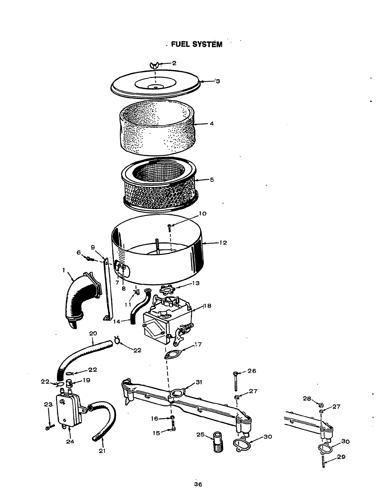
-
FUELSYSTEM
'
'
21
'3
-12
I
I
I
30
.
36
Redistribution or publication of this document,
by any means, is strictly prohibited.
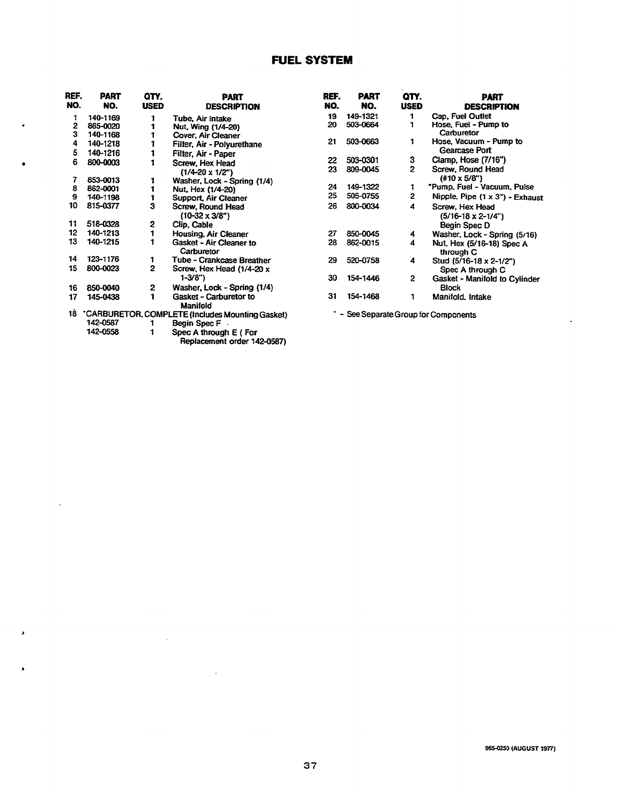
FUEL
SYSTEM
REF.
PART
NO.
NO.
1
140-1169
2 865-0020
3
140-1168
4 140-1218
5
140-1216
68004003
7 853-0013
8 862-0001
9
140-1198
10 815-0377
11
518-0328
12 140-1213
13 140-1215
14 123-1176
15
800-0023
16
850-0040
17
145-0438
ow.
USED
1
1
1
1
1
1
1
1
1
3
2
1
1
1
2
2
1
PART
DESCRIPTION
Tube,
Air Intake
Nut. Wing
(V4-20)
Cover,
Air
Cleaner
Filter, Air
-
Polyurethane
Filter, Air
-
Paper
Screw.
Hex Head
(1/4-20
x
l/Z)
Washer. Lock
-
Spring
(1/4)
Nut. Hex
(1/4-20)
Support
Air
Cleaner
Screw,
Round Head
(10-32
x
38")
Clip, Cable
Housing. Air Cleaner
Gasket
-
Air Cleaner
to
Tube
-
Crankcase Breather
Screw,
Hex
Head
(114-20
x
Washer,
Lock
-
Spring
(114)
Gasket
-
Carburetor
to
Carburetor
1-3/a')
Manifold
REF.
PART
NO.
NO.
19
149-1321
20
503-0664
21
503-0663
22
503-0301
23
8o40045
24 149-1322
25 505-0755
26
8oMK)3Q
27
850-0045
28 862-0015
29 520-0758
30 154-1446
31 154-1468
QTY.
USED
1
1
1
3
2
1
2
4
4
4
4
2
1
PART
DESCRIPTION
Cap. Fuel Outlet
Hose.
Fuel
-
Pump
to
Carburetor
Hose.
Vacuum
-
Pump
to
Gearcase Port
Clamp,
Hose
(7/16")
Screw.
Round
Head
Nipple. Pipe
(1
x
3")
-
Exhaust
Screw,
Hex
Head
Begin Spec
D
through C
Spec A through
C
Block
(#lo
x
518")
'Pump.
Fuel
-
Vacuum.
Pulse
(5116-18
x
2-1/47
Washer, Lock
-
Spring
(5116)
Nut. Hex
(5/16-18)
Spec
A
Stud
(916-18
x
2-1/27
Gasket
-
Manifold to Cylinder
Manifold. Intake
18
'CARBURETOR. COMPLETE(1ncludes Mounting Gasket)
Replacement
order
142-0587)
-
-
See
Separate Group
for
Components
142-0587
1
BeginSpecF .
142-0558
1
Spec
A through E
(
For
9654250
(AUGUST
1977)
37
Redistribution or publication of this document,
by any means, is strictly prohibited.
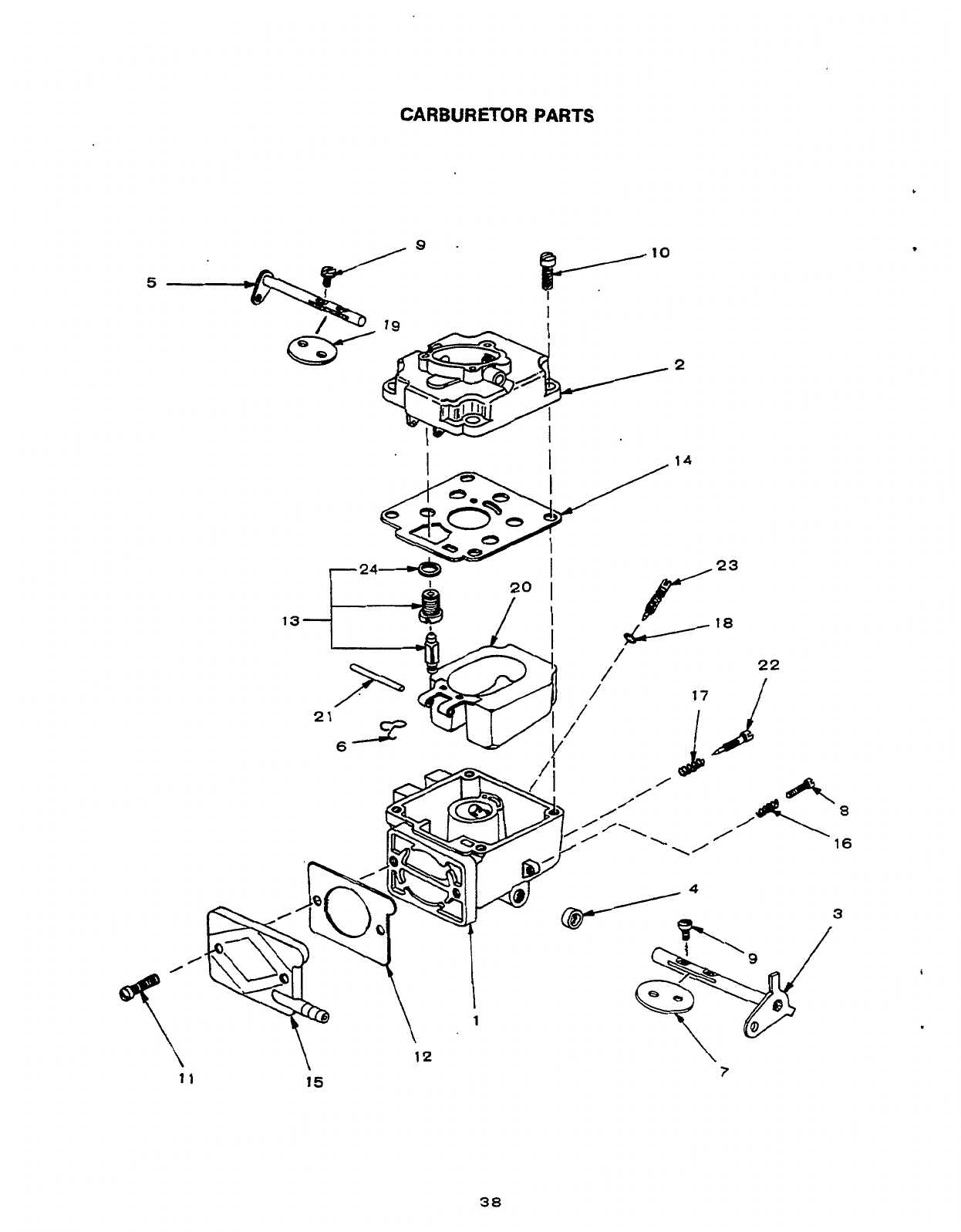
CARBURETOR PARTS
5
Y
I
I
10
/2
22
7
11
15
38
Redistribution or publication of this document,
by any means, is strictly prohibited.
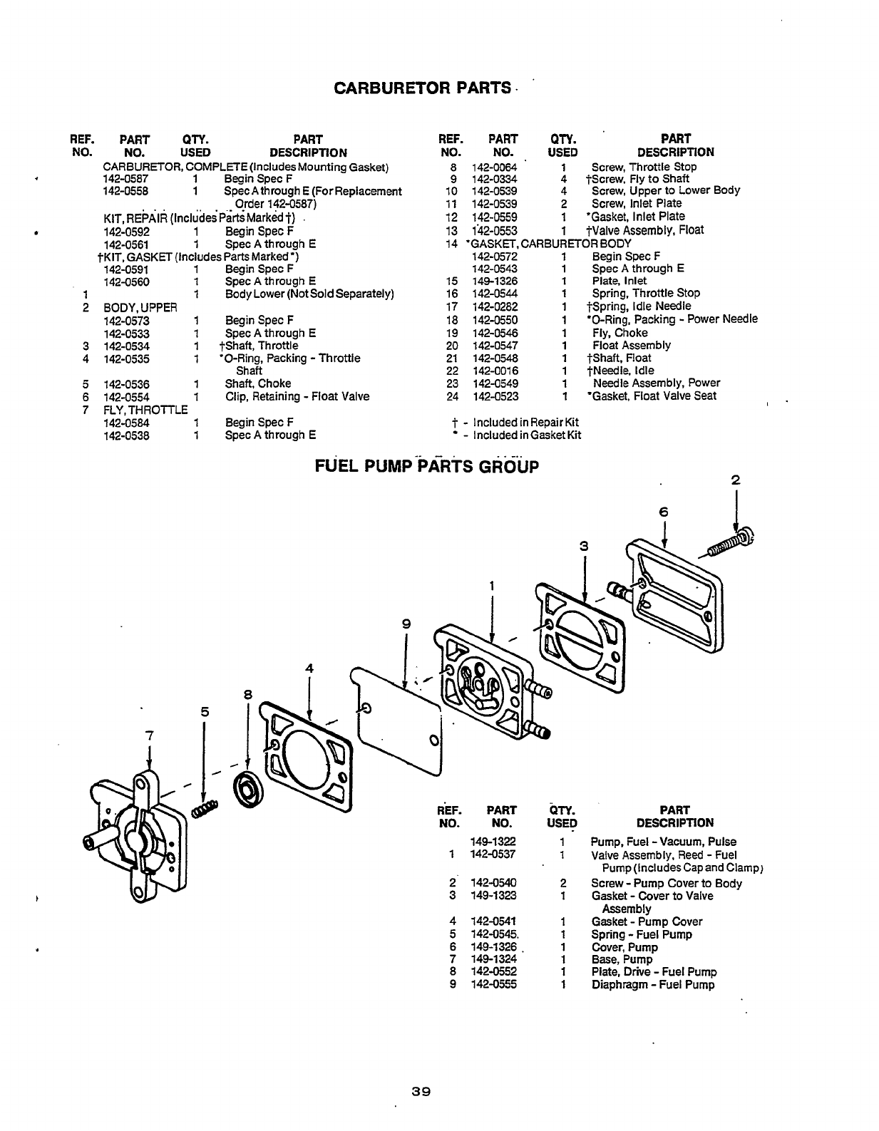
CARBURETOR
PARTS
L
REF.
PART
QTY.
PART
NO.
NO.
USED
DESCRIPTION
CARBURETOR, COMPLETE (Includes Mounting Gasket)
142-0587
1
BeginSpecF
142-0558
1
SpecAthrough E(ForRep1acement
Order 142-0587)
KIT,REPAlR
(IncludesPartsMarkedt)
.
142-0592 1 Begin SpecF
142-0561
1
Spec
A
through
E
?KIT, GASKET (Includes Parts Marked
*)
142-0591
1
BeginSpecF
142-0560
1
Spec A through E
142-0573 1 Begin SpecF
142-0533 1 Spec A through E
3 142-0534
1
?Shaft, Throttle
4 142-0535
1
'0-Ring, Packing
-
Throttle
5
142-0536 1 Shaft, Choke
6 142-0554
1
Clip, Retaining
-
Float Valve
7
FLY,THROTTLE
142-0584 1 Begin SpecF
142-0538 1 Spec A through
E
1
1
Body Lower (Not
Sold
Separately)
2
BODY,UPPER
Shaft
REF.
PART
QN.
PART
NO.
NO. USED
DESCRIPTION
8
142-0064
1
Screw, Throttle Stop
9
142-0334 4 *Screw, Fly to Shaft
4
10 142-0539
11 142-0539 2 Screw, Inlet Plate
1
'Gasket, Inlet Plate
12
142-0559
13 142-0553
1
?Valve Assembly, Float
14 'GASKET, CARBURETOR BODY
142-0572
1
Begin SpecF
142-0543 1 SpecA through
E
Screw, Upper to Lower Body
15 149-1326
1
Plate, Inlet
16 142-0544
1
Spring, Throttle
Stop
17 142-0282 1 +Spring, Idle Needle
18 142-0550
1
'0-Ring. Packing
-
Power Needle
19 142-0546
1
Fly. Choke
20 142-0547
1
Float Assembly
21 142-0548
1
*Shaft. Float
22 142-0016
1
?Needle, Idle
23 142-0549
1
Needle Assembly, Power
24 142-0523
1
'Gasket, Float Valve Seat
-f
-
Included in Repair
Kit
-
Included in Gasket Kit
FUEL
PUMP
-PARTS
GROUP
2
6
1
REF.
PART
Qn.
PART
NO. NO.
USED
DESCRIPTION
149-132
1
Pump, Fuel -Vacuum, Pulse
Valve Assembly, Reed
-
Fuel
1 Pump (Includes Cap and Clamp)
1
142-0537
2 142-0540 2 Screw
-
Pump Cover
to
Body
3 149-1323
1
Gasket
-
Cover to Valve
4
142-0541
1
Gasket
-
Pump Cover
5 142-0545. 1 Spring
-
Fuel Pump
6
149-1326.
1
Cover,Pump
7
149-1324
1
Base,Pump
8
142-0552
1
Plate, Drive
-
Fuel Pump
9 142-0555
1
Diaphragm
-
Fuel Pump
Assembly
39
Redistribution or publication of this document,
by any means, is strictly prohibited.
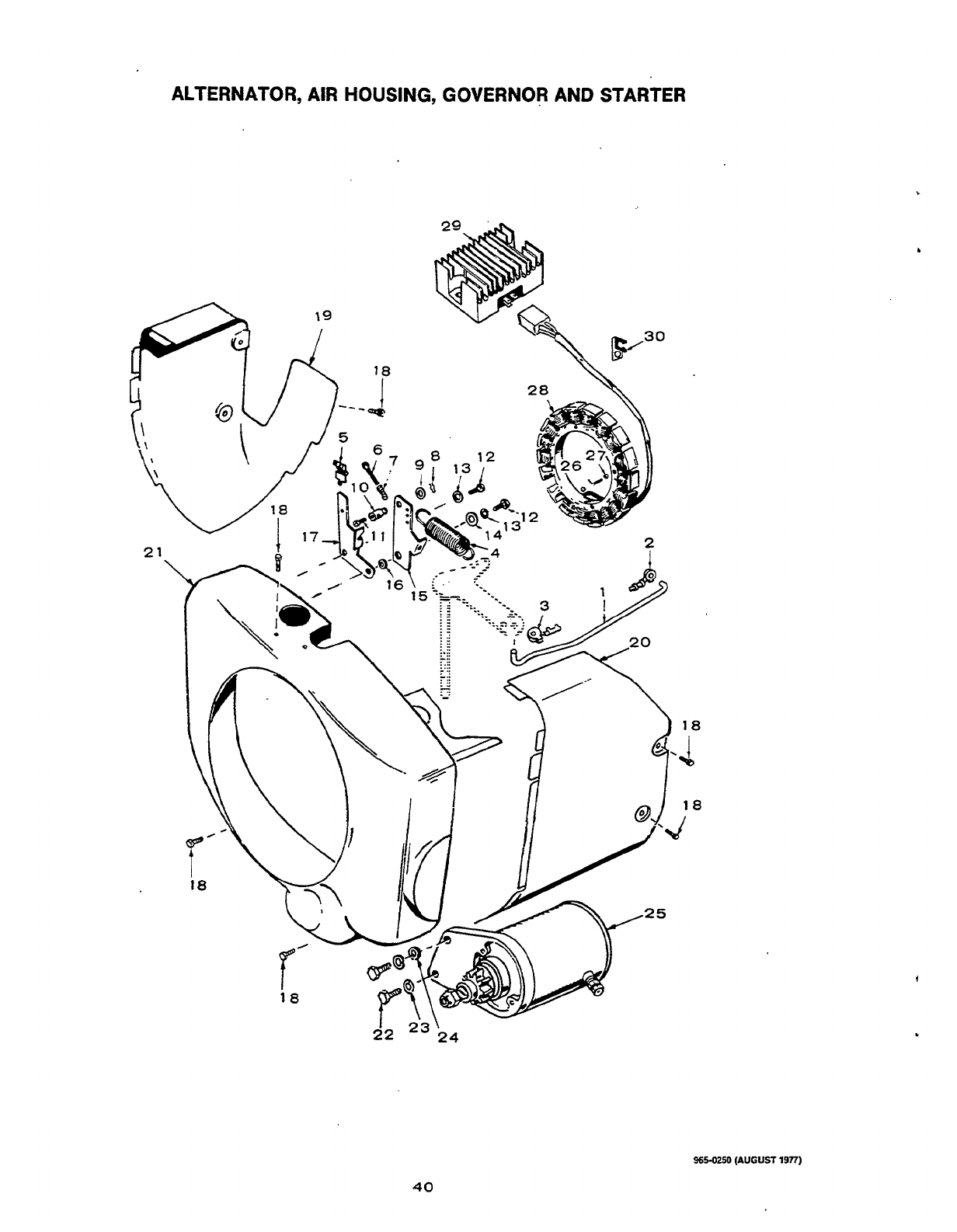
ALTERNATOR,
AIR
HOUSING, GOVERNOR AND STARTER
965-0250
(AUGUST
1977)
40
Redistribution or publication of this document,
by any means, is strictly prohibited.
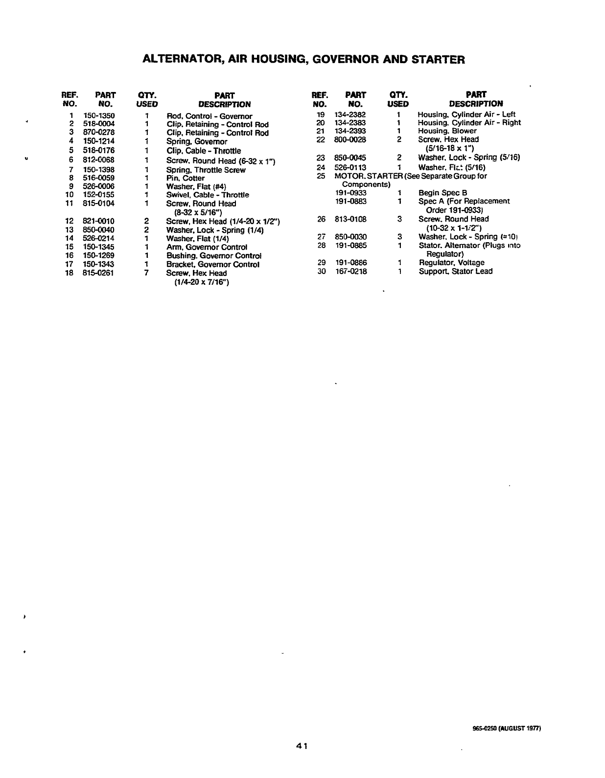
U
REF.
PART
NO.
NO.
1
150-1350
2 518-0004
3 870-0278
4
150-1214
5
518-0176
6 812-0068
7
150-1398
8
516-0059
9 5260006
10 152-0155
11
815-0104
12 821-0010
13
850-0040
14 526-0214
15 150-1345
16 150-1269
17
150-1343
18
815-0261
ALTERNATOR,
AIR
HOUSING,
GOVERNOR
AND
STARTER
QTY.
USED
1
1
1
1
1
1
1
1
1
1
1
2
2
PART
DESCRlPTION
Rod.
Control
-
Governor
Clip. Retaining
-
Control Rod
Clip, Retaining
-
Control
Rod
Spring.
Governor
Clip. Cable -Throttle
Screw. Round Head
(6-32
x
1")
Spring. Throttle Screw
Pin. Cotter
Washer, Flat
(M)
Swivel, Cable
-
Throttle
Screw. Round Head
(8-32
x
5/16")
Screw, Hex Head
(1/4-20
x
l/2")
Washer, Lock
-
Spring
(1/4)
Washer, Fiat
(1/4)
Arm.
Governor Control
Bushing. Governor Control
Bracket. Governor Control
Screw. Hex
Head
(11620
X
7/16")
REF.
PART
QTY.
PART
NO.
NO.
USED
DESCRIPTION
19
134-2382
1
Housing. Cylinder
Air
-
Left
20
134-2383
1
Housing. Cylinder
Air
-
Right
21 134-2393
1
Housing. Blower
22 800-0028 2
Screw. Hex Head
(316-18
x
1")
23 850-0045
2
Washer. Lock
-
Spring
(5'76)
24 526-0113
1
Washer. Flr!
(5116)
25
MOTOR-STARTER (SeeSeparateGroup for
191-0933
1
BeginSpecB
191-0883
1
Spec
A
(For Replacement
26 813-0108 3
Screw. Round Head
27
850-0030 3
Washer. Lock
-
Spring
(=lo!
28
191-0885
1
Stator. Alternator
(Plugs
into
29 191-0886
1
Regulator, Voltage
30
167-0218
1
Suppon
Stator Lead
Components)
Order
191-0933)
(10-32
x
1-li2)
Regulator)
965-0250
(AUGUST
19TI)
41
Redistribution or publication of this document,
by any means, is strictly prohibited.
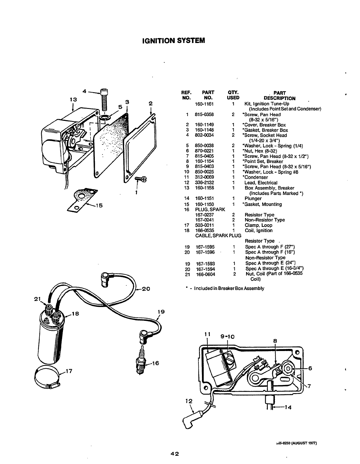
IGNITION
SYSTEM
4-a
REF.
PART
QTY.
PART
NO.
NO.
USED
DESCRIPTION
.
160-1161
1
Kit, Ignition Tune-up
(Includes Point Set and Condenser)
1
815-0358
2
'Screw, Pan Head
2 160-1149
1
'Cover, Breaker Box
3 160-1148
1
'Gasket, Breaker Box
4
802-0034 2 'Screw, Socket Head
5
850-0038 2 'Washer. Lock
-
Spring (1/4)
6 870-0221
1
'Nut, Hex (8-32)
7 815-0405
1
'Screw. Pan Head (8-32 x
1/2")
8 160-1154
9 815-0403
1
'Screw, Pan Head (8-32 x 5/16)
10
850-0025
1
'Washer, Lock
-
Spring #8
11 312-0069
1
'Condenser
12 336-2132
1
Lead, Electrical
13
160-1158
1
Box Assembly, Breaker
14
160-1151
1
Plunger
15 160-1150
1
'Gasket, Mounting
16 PLUG.SPARK
167-0237 2 Resistor Type
167-0241 2 Non-Resistor Type
17 503-0311
1
Clamp, Loop
18 166-0535
1
Coil.
Ignition
CABLE, SPARK PLUG
19 167-1595
1
Spec
A
through
F
(27")
20 167-1596
.
1
SpecA through F (16")
19 167-1593
1
Spec
A
through E (24")
20
167-1594
1
Spec A through
E
(16-3/4")
21 166-0604 2 Nut,
Coil
(Part
of
166-0535
-
Includedin BreakerBox Assembly
(8-32
x
5/16")
(1/4-20 x 3/4")
1
'Point Set, Breaker
(Includes Park Marked
*)
Resistor Type
.
Non-Resistor Type
Coil)
&5-0250
(AUGUST
19?7)
42
Redistribution or publication of this document,
by any means, is strictly prohibited.

STARTER
PARTS
-
SPEC
A
REF.
PART
NO.
NO.
‘91-0883
1
191-0906
?
:31-0907
..
?91-0908
2
191-0909
9
191-0910
6
191-0911
7 191-0912
8
191-0913
9 191-0917
QN.
USED
1
PART
DESCRIPTION
Motor. Starter
(For
Housing.
Starter
End Cap Assembly
Armature, Starter
Drive Plate Assembly
Drive Gear Assembly
Bolt, Through
Brush. Field
Brush. Ground
Spring, Brush
Replacement Order #191-0933)
9650250
(AUGUSTl977)
43
Redistribution or publication of this document,
by any means, is strictly prohibited.
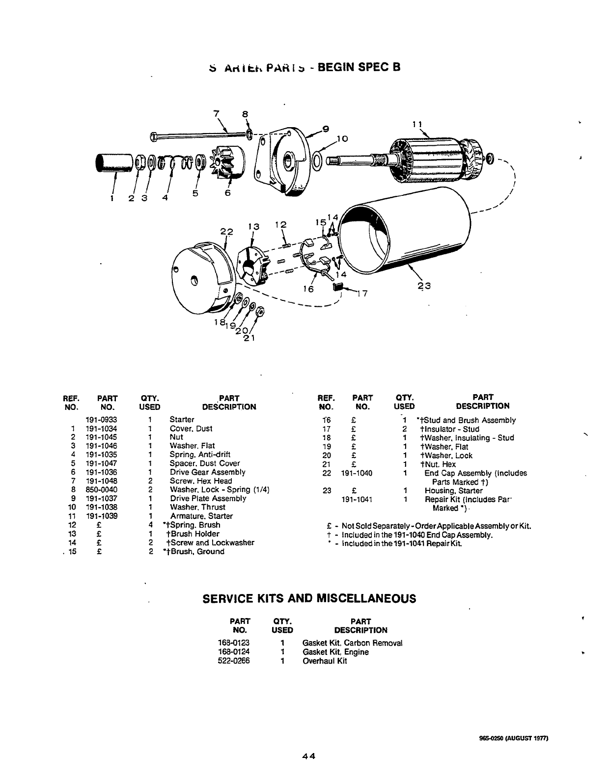
s
~d
i
ti,
PA^
i
3
-
BEGIN
SPEC
B
78
\
\
I
/
REF. PART
NO.
NO.
191-0933
1
191-1034
2 191-1045
3 191-1046
4 191-1035
5
191-1047
6 191-1036
7 191-1048
8
850-0040
9 191-1037
10 191-1038
11
191-1039
12
f
13
f
14
f
.
15
f
18
I//
1920
21
QN.
PART
USED DESCRIPTION
1
Starter
1
Cover. Dust
1
Nut
1
Washer. Flat
1
Spring, Anti-drift
1
Spacer. Dust Cover
1
Drive Gear Assembly
2 Screw. Hex Head
2
Washer. Lock -Spring (114)
1 Drive Plate Assembly
1
Washer, Thrust
1
Armature. Starter
4 '?Spring. Brush
1
*Brush Holder
2 *Screw
and
Lockwasher
2 '$Brush. Ground
REF.
PART
QTY.
PART
NO.
NO.
USED DESCRIPTION
1'6
f
17
f
18
f
19
f
20
E
21
f
22 191-1040
23
f
191-1041
'tStud and Brush Assembly
tlnsulator
-
Stud
twasher. Insulating
-
Stud
tWasher. Flat
tWasher. Lock
tNut. Hex
End
Cap Assembly (includes
Parts
Marked
t)
Housing, Starter
Repair Kit (Includes Par.
Marked
*)
.
f
-
Not
SoldSeparately-OrderApplicableAssemblyor
Kit.
t
-
Included in the191-1040 End Cap Assembly.
*
-
includedinthel91-1041 RepairKit
SERVICE
KITS
AND MISCELLANEOUS
PART
QTY.
PART
NO. USED DESCRIPTION
168-0123
1
Gasket Kit, Carbon Removal
168-01
24
1
Gasket Kit, Engine
522-0266
1
Overhaul Kit
96u)2so
(AUGUSr
1977)
44
Redistribution or publication of this document,
by any means, is strictly prohibited.
c
OPTIONAL
EQUIPMENT
PARTS
SECTION
This section contains
illustrated
parts listing
of
factory
installed options
for
these Industrial
Engines. Options may not be applicable to
all
models;
for
field conversions additional parts
are
usually required. Optional parts listed in this section are in addition
or
in place
of
those
shown
in
the
standard engine parts section.
45
9650250
(AUGUST
1977)
Redistribution or publication of this document,
by any means, is strictly prohibited.

OPTiONAL
GROUP
NUMBER
1
SPIN-ON
OIL
FILTER
REF.
PART
NO.
NO.
1
502-0080
2 526-0065
3
800-0028
4
122-0338
5
122-0347
6
122-0321
7
815-0194
8
122-0320
9
122-0360
QTY.
USED
1
2
2
1
1
1
2
1
1
PART
DEWRIPTION
Plug.
Adapter
(118")
Washer. Flat
-
Copper
(5%")
Screw.
Hex
Head
(5116
x
1")
Filter,
Oil
Seal.
Air
Gasket.
Filter Adapter
Screw. t?exHead
WET
Lockwasher
(10-32
x
3/8)
Adapter.
Oil
Filter
Drain,
Oil
Filter
c
46
Redistribution or publication of this document,
by any means, is strictly prohibited.

OPTIONAL
GROUP
NUMBER
2
TOPADJUSTEDBREAKERBOX
REF.
PART
NO.
NO.
160-1210
ltji)-:2?3
1
169-1232
2 812-0108
3
526-0M18
4
509-0065
5
815-9358
6
312-0196
7
802-0034
8
850-0038
9 160-1183
10
160-1219
11
160-1150
12
160-1151
QTY.
USED
1
1
1
1
1
1
1
1
2
2
1
I
1
1
PART
DESCRIPTION
Complete (Includes Mounting
Gasket)
(Includes
Point
Set and Condenser)
Box
Assembly. Breaker
-
Kit. Ignition Tune-up
Cover
Assembly (Includes parts marked
-)
'Screw. Machine
-
Round Head
'Washer. Flat
(7
IC)
'"0"
Ring
(10-24
x
1-1
2.)
Screw. Slotted
-
Hex Head
Condenser
(30
Mfd)
Screw. Cap
-
Socket Head
(V4
x
20
x
34")
Washer. Lock
-
Spring
(114")
Point
Assembly.
Breaker
Base. Breaker Box
Gasket,
Mounting
Plunger
(8-32
x
5.16")
9650250
(AUGUST
14n)
47
Redistribution or publication of this document,
by any means, is strictly prohibited.
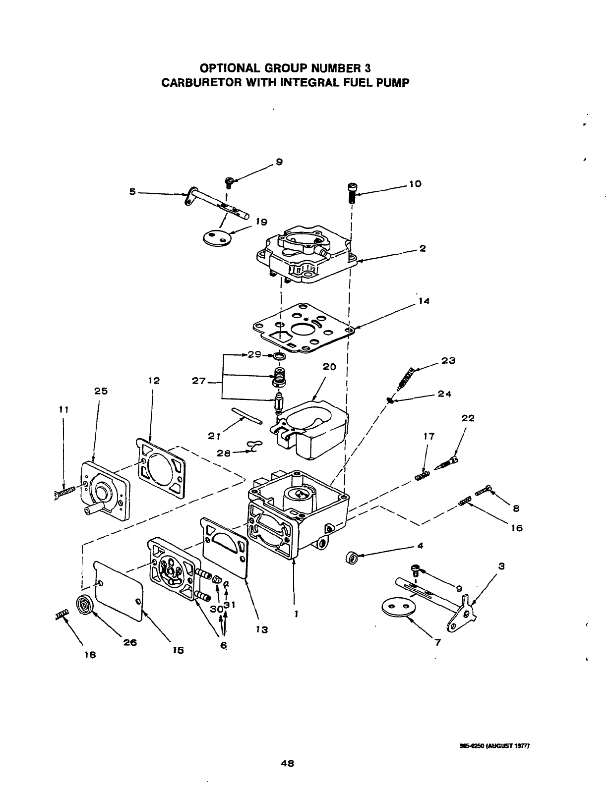
OPTIONAL
GROUP
NUMBER
3
CARBURETOR
WITH
INTEGRAL
FUEL
PUMP
2
48
Redistribution or publication of this document,
by any means, is strictly prohibited.
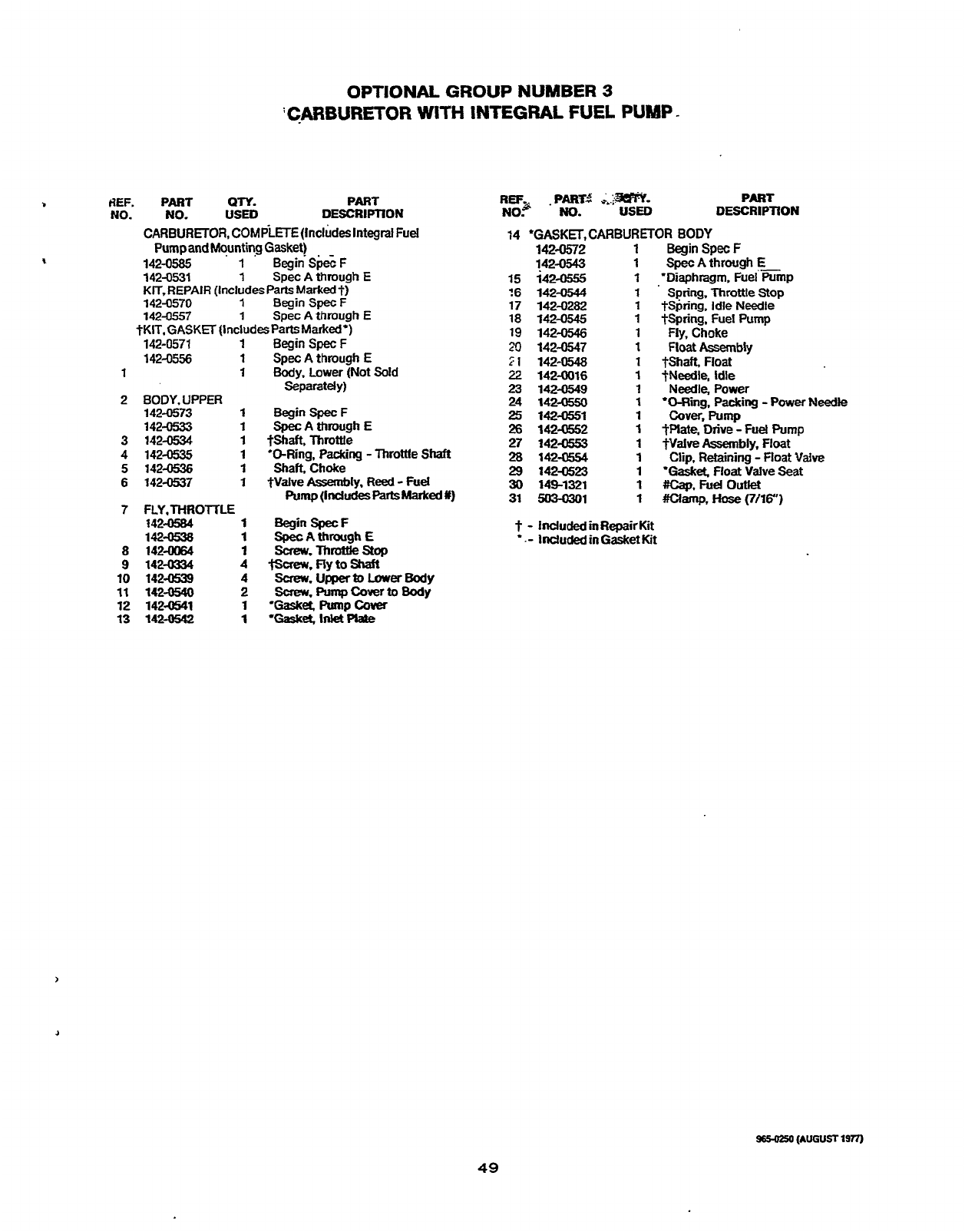
HEF.
NO.
OPTIONAL
GROUP
NUMBER
3
'CARBURETOR
WITH
INTEGRAL
FUEL
PUMP
-
Par
QTY. PART
NO.
USED
DESCRIPTION
CARBURETOR, COMPLETE(lnc1udes
Integral
Fuel
PumpandMquntirg
Gasket)
. -
142-0585
1
BeginSpecF
142-0531
1
Spec
A
through
E
KIT.REPAlR
(Includes
Parts
Marked?)
142-0570
1
BeginSpecF
142-0557
1
Spec
A
through
E
tKIT.GASKEF
llncludesParts
Marked')
.142-0571
1
142-0556
1
1 1
2 80DY.UPPER
142-0573
1
142.O533 1
3
142-0534
1
4
142-0535
1
5
142-0536
1
6
142-0537
1
7
FLY.THROITLE
142-0584
1
14Z-0538
1
a
142-0064
1
9
142-0334
4
10
142-0539
4
11
142-0540
2
12
142-0541
1
13
142-0542
1
Begin
Spec
F.
Spec
A
through
E
Body.
Lower (Not
Sold
Separately)
Begin
Spec
F
Spec
A
through
E
tshaft.
Throttle
'@Ring.
Packing
-
Throttle
Shaft
Shaft,
Choke
*Valve
Assembly.
Reed
-
Fuel
PUmp(ldUdeSPiNtSMarked#)
Begin
SpecF
SpecAthroughE
Screw.
Throttle
stop
tsaew.
Fly
to
shaft
screrv.u~toLowerBody
Swew.
Pump
Cover
to
Body
'Gasket
Pumpcwer
'Gaset
Inlet
pbte
REF.
.PART.$
-..>--
PART
NO?
NO.
USED
DESCRIPTION
14 'GASKl3,CARBURETOR BODY
142-0572
1
BeginSpecF
142-0543
1
SpecAthrough
E-
15
142-0555
1
'Diaphragm, Fuel
Pump
?6
142-0544
1
Spring,
Throttle
Stop
17 142-0282
1
+Spring.
ldle Needle
18
142-0545
1
tspring,
Fuel Pump
19 142-0546 1
Fly,
Choke
20
142-0547
I
FloatAssembly
21
142-0548
1
tSha&
Float
22
142-0016
1
?Needle. Idle
23
142-0549
1
Need1e.Power
24 142-0550
1
'O-Ring.
Packing
-
Power
Needle
25
142-0351
1
cover,Pump
26
142-0552
1
?Plate,
Drive
-
Fuel
Pump
27 142-0553
1
$Valve
Assembly.
Float
28
142-0554
1
Clip, Retaining
-
Float
Vaive
29
1424523 1
'Gaska
Float
Valve Seat
31
s[Kwxu)l
1
#clamp,
ftose
(7/16")
30
149-1321
1
#cap,Fueloutlet
t
-
IndudedmRepairKit
*.-
IndudedinGasketKit
9650250
(AUGUST
lsn)
49
Redistribution or publication of this document,
by any means, is strictly prohibited.

Redistribution or publication of this document,
by any means, is strictly prohibited.

Redistribution or publication of this document,
by any means, is strictly prohibited.

Onan
Corporation
1400
73rd
Avenue
N.
E.
Minneapolis, MN
55432
Telex:
275477
Fax:
612-574-8087
Onan
is
a
registered trademark
6f
Onan Corporation
61
2-574-5000
Redistribution or publication of this document,
by any means, is strictly prohibited.
